
Validation and Verification of ANSYS FLUENT Boiling ...
22
Validation and Verification of ANSYS FLUENT Boiling Capabilities May 20, 2020 • DECEMBER 2019 Gustavo Montoya Mohammed Azhar Amine Ben Hadj Ali Jay Sanyal Markus Braun ASME V&V 2020 Virtual Symposium
-
Upload
khangminh22 -
Category
Documents
-
view
6 -
download
0
Transcript of Validation and Verification of ANSYS FLUENT Boiling ...

Validation and Verification of ANSYS FLUENT Boiling Capabilities
May 20, 2020
• DECEMBER 2019
Gustavo Montoya
Mohammed Azhar
Amine Ben Hadj Ali
Jay Sanyal
Markus Braun
ASME V&V 2020Virtual Symposium
2
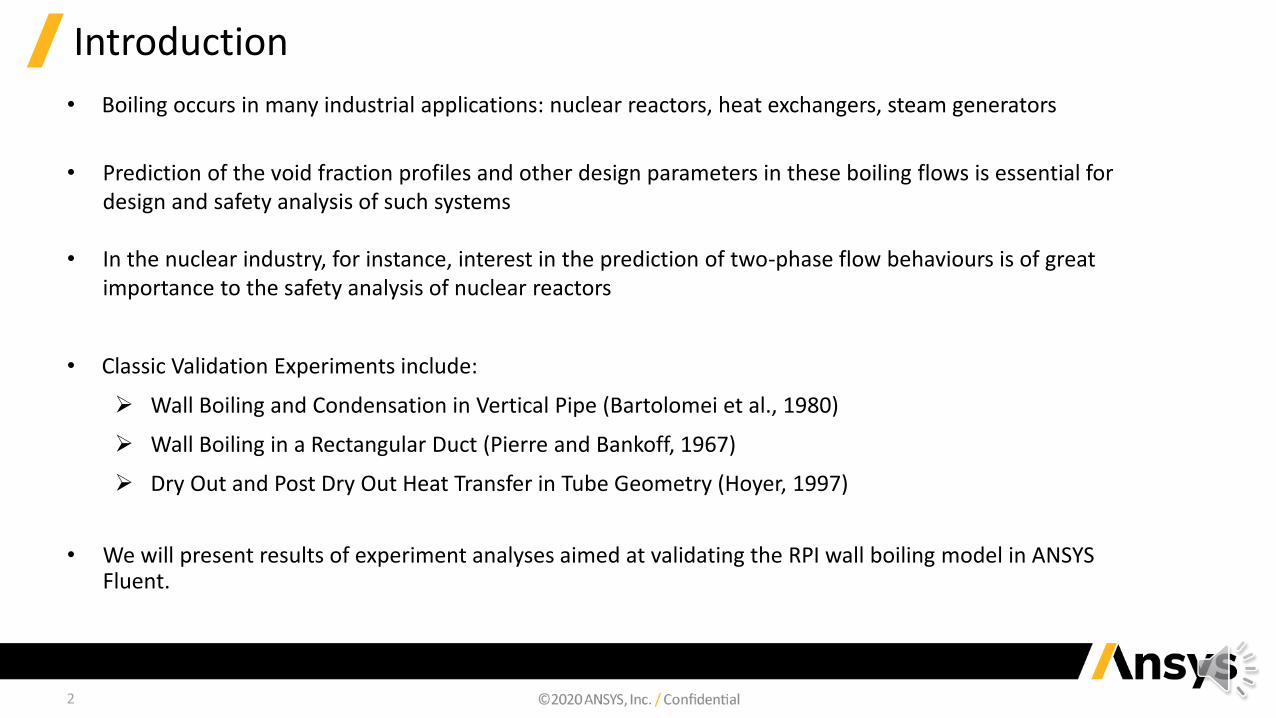
Introduction
• Boiling occurs in many industrial applications: nuclear reactors, heat exchangers, steam generators
• Prediction of the void fraction profiles and other design parameters in these boiling flows is essential for design and safety analysis of such systems
• In the nuclear industry, for instance, interest in the prediction of two-phase flow behaviours is of great importance to the safety analysis of nuclear reactors
• Classic Validation Experiments include:
➢ Wall Boiling and Condensation in Vertical Pipe (Bartolomei et al., 1980)
➢ Wall Boiling in a Rectangular Duct (Pierre and Bankoff, 1967)
➢ Dry Out and Post Dry Out Heat Transfer in Tube Geometry (Hoyer, 1997)
• We will present results of experiment analyses aimed at validating the RPI wall boiling model in ANSYS Fluent.
3
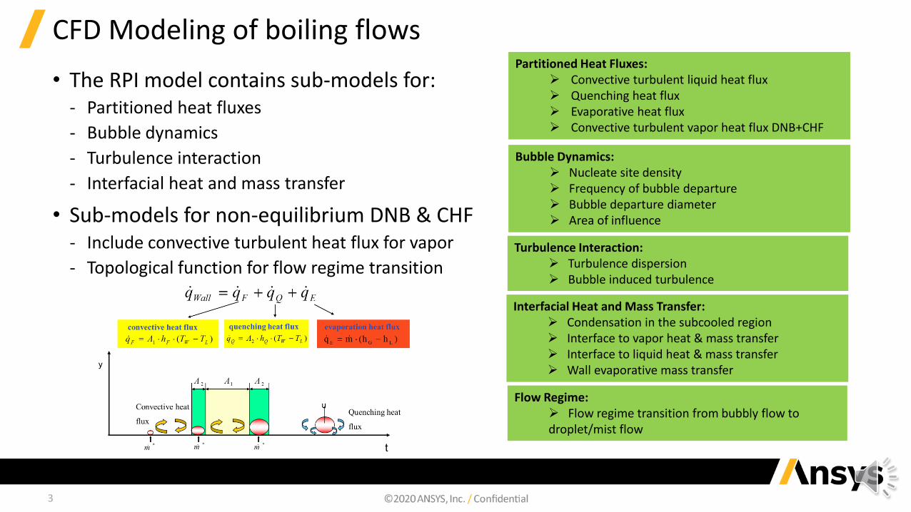
CFD Modeling of boiling flows
• The RPI model contains sub-models for:‐ Partitioned heat fluxes
‐ Bubble dynamics
‐ Turbulence interaction
‐ Interfacial heat and mass transfer
• Sub-models for non-equilibrium DNB & CHF‐ Include convective turbulent heat flux for vapor
‐ Topological function for flow regime transition
Partitioned Heat Fluxes:➢ Convective turbulent liquid heat flux➢ Quenching heat flux➢ Evaporative heat flux➢ Convective turbulent vapor heat flux DNB+CHF
Bubble Dynamics:➢ Nucleate site density➢ Frequency of bubble departure ➢ Bubble departure diameter➢ Area of influence
Turbulence Interaction: ➢ Turbulence dispersion➢ Bubble induced turbulence
Interfacial Heat and Mass Transfer:➢ Condensation in the subcooled region➢ Interface to vapor heat & mass transfer➢ Interface to liquid heat & mass transfer➢ Wall evaporative mass transfer
Flow Regime: ➢ Flow regime transition from bubbly flow to droplet/mist flow

4
V&V studies (Classical cases): Bartolomei et al., 1980
• Geometry‐ Pipe flow; axial symmetry
‐ Inner radius of pipe R = 6.015 mm
‐ Total pipe length LT= 1.4 m
‐ Heated section length LH= 1.0 m
• Flow parameters‐ Upward directed water flow
‐ Pressure @Inlet pin = 6.89 MPa
‐ Parameter Investigation
• Mass flux @Inlet Gin
• Liquid Temperature @Inlet Tin
• Wall heat flux qwall
Experiment Number
𝐪𝐰𝐚𝐥𝐥 [𝐌𝐖
𝐦𝟐 ]𝐆𝐢𝐧 [
𝐤𝐠
𝐦𝟐𝐬] 𝐓𝐢𝐧 [𝐊]
2 1.2 1500 495
3 0.8 1500 519
5 0.8 1000 503
5
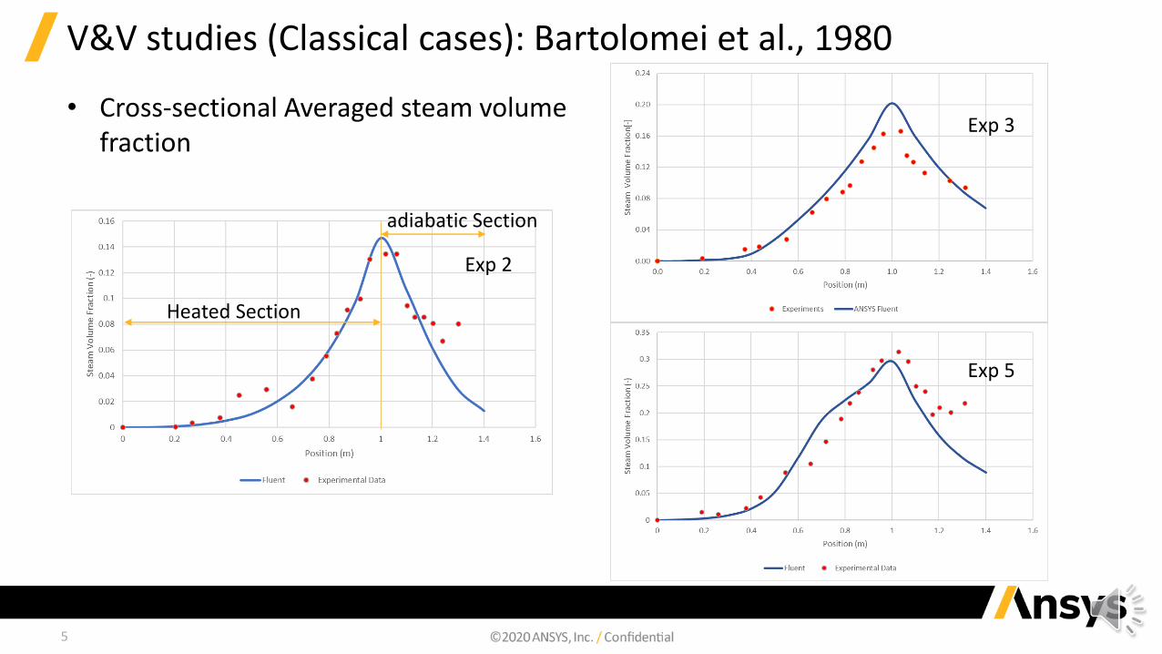
V&V studies (Classical cases): Bartolomei et al., 1980
• Cross-sectional Averaged steam volume fraction
Exp 2
Exp 3
Exp 5
Heated Section
adiabatic Section

6
V&V studies (Classical cases): Bartolomei et al., 1980
• Influence of drag and non-drag forces – Experiment 2
Fig 1
Fig 2
Fig 3
Fig 4
Fig 5
Fig 6

7
V&V studies (Classical cases): Hoyer et al., 1997
• Geometry‐ Pipe flow; axial symmetry
‐ Inner radius of pipe R = 10, 14.9 and 15mm
‐ Total pipe length LT= 7.0 m
• Flow parameters‐ Upward directed water flow
‐ Pressure @Inlet pin = 7.01 MPa
‐ Parameter Investigation
• Mass flux @Inlet Gin
▪ 497-1495 ൗ𝑘𝑔𝑚2𝑠
• Liquid Temperature @Inlet Tin
▪ Not given
• Wall heat flux qwall
▪ 350 – 863 𝑘𝑊
𝑚2
• Among the available cases the following have to be selected to investigate the influence of various parameters
Cases Diameter(mm)
Mass Flux Heat Flux Heat Flux Peak
1 10 1495 797 Constant
2 14.9 1002 863 Constant
3 15 1001 748 Mid
4 15 1003 617 Top

8
V&V studies (Classical cases): Hoyer et al., 1997
• Wall temperature profiles
Constant Heat Flux Constant Heat Flux
Non-uniform Heat Flux
Non-uniform Heat Flux
10mm 14.9mm
15mm 15mm
9
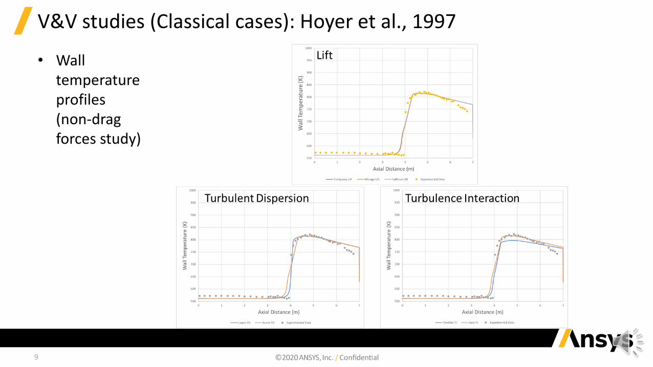
V&V studies (Classical cases): Hoyer et al., 1997
• Wall temperature profiles (non-drag forces study)

10
V&V studies (Classical cases): Pierre and Bankoff, 1966
• Geometry‐ Rectangular duct flow
‐ Cross section 11 x 44.45mm
‐ Total length 1.5494 m
‐ Heated section 1.2574m
‐ 0.292m from the inlet
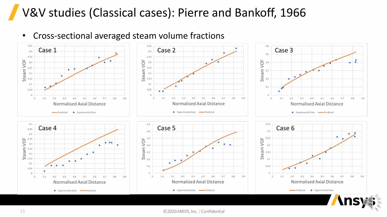
𝐶𝑎𝑠𝑒𝑠 𝑃𝑟𝑒𝑠𝑠𝑢𝑟𝑒(𝑝𝑠𝑖𝑎)
𝐼𝑛𝑙𝑒𝑡 𝑉𝑒𝑙𝑜𝑐𝑖𝑡𝑦
(𝒇𝒕
𝒔)
𝐻𝑒𝑎𝑡 𝐹𝑙𝑢𝑥
(𝐵𝑡𝑢
ℎ)
𝐼𝑛𝑙𝑒𝑡 𝑆𝑢𝑏𝑐𝑜𝑜𝑙(𝒅𝒆𝒈 𝑭)
1 200 3.78 2.28 0.5
2 300 2.52 2.28 1.8
3 400 2.52 4.56 4.8
4 400 2.52 4.56 9.5
5 400 3.78 6.84 1.2
6 400 3.78 6.84 8.1
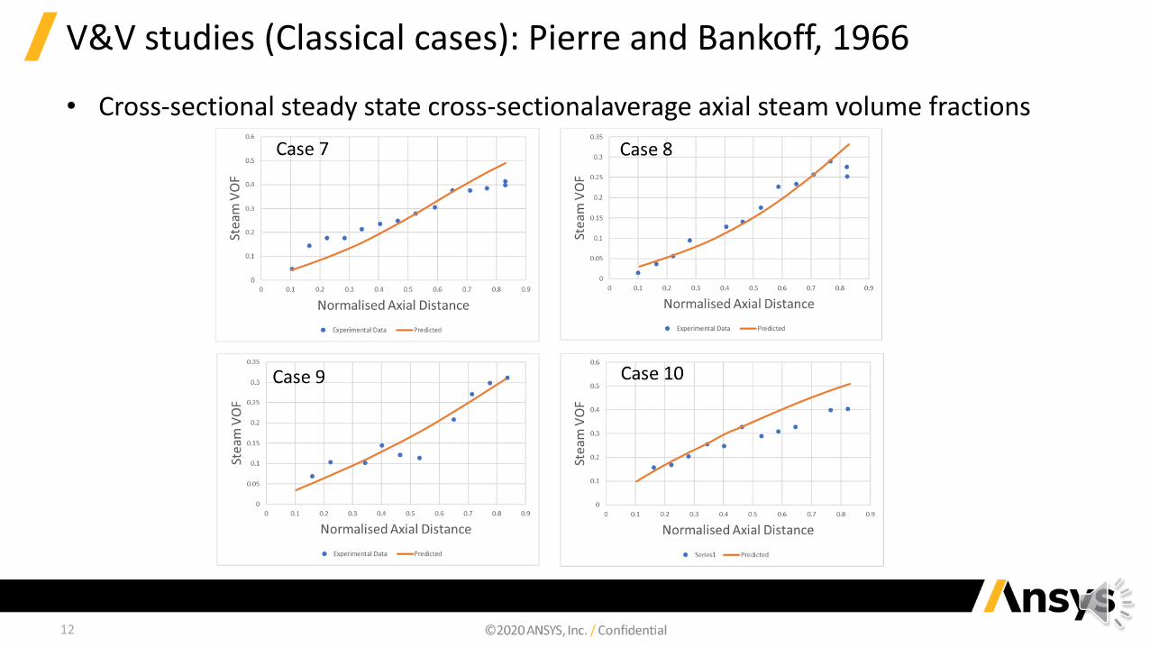
7 600 3.78 9.12 4.2
8 600 3.78 9.12 12.6
9 800 2.52 4.56 4.9
10 800 3.78 9.12 4.7
11
V&V studies (Classical cases): Pierre and Bankoff, 1966
• Cross-sectional averaged steam volume fractions
12
V&V studies (Classical cases): Pierre and Bankoff, 1966
• Cross-sectional steady state cross-sectionalaverage axial steam volume fractions
13
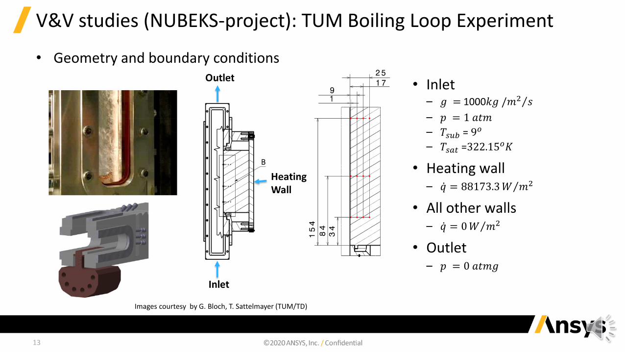
V&V studies (NUBEKS-project): TUM Boiling Loop Experiment
• Geometry and boundary conditions
• Inlet– 𝑔 = 1000 Τ𝑘𝑔 /𝑚2 𝑠
– 𝑝 = 1 𝑎𝑡𝑚
– 𝑇𝑠𝑢𝑏 = 9𝑜
– 𝑇𝑠𝑎𝑡 =322.15𝑜𝐾
• Heating wall– ሶ𝑞 = 88173.3 Τ𝑊 𝑚2
• All other walls– ሶ𝑞 = 0 Τ𝑊 𝑚2
• Outlet – 𝑝 = 0 𝑎𝑡𝑚𝑔
Images courtesy by G. Bloch, T. Sattelmayer (TUM/TD)
14
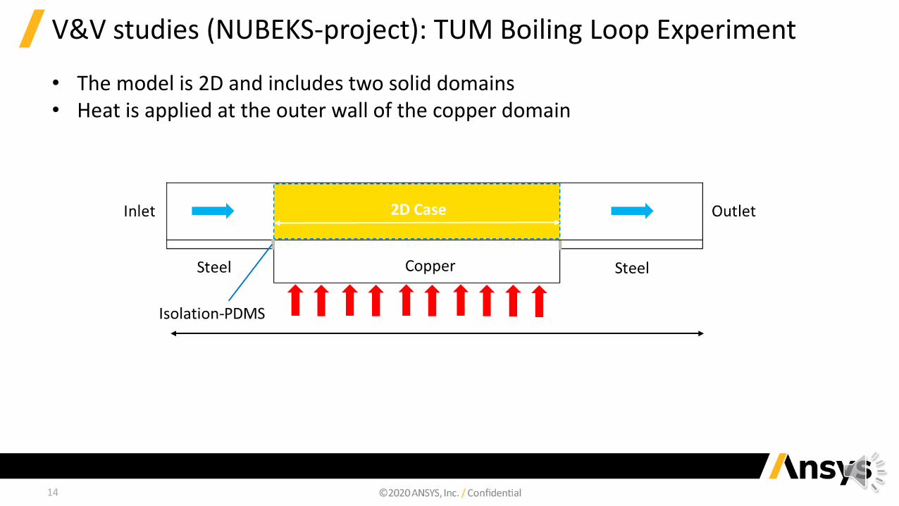
V&V studies (NUBEKS-project): TUM Boiling Loop Experiment
• The model is 2D and includes two solid domains• Heat is applied at the outer wall of the copper domain

15
V&V studies (NUBEKS-project): TUM Boiling Loop Experiment
• The mesh used for the simulations is a structure cartesian grid
• Geometry is identical to the experimental facility
• The cell count is 14,590

16
V&V studies (NUBEKS-project): TUM Boiling Loop Experiment
• Model Setup:Analysis type Steady state Coupled solver
Pseudo time step = 0.01s
Model RPI Model Critical Heat Flux
Interfacial Forces Vapour phase diameter Boiling diameter
Drag Grace (exponent = 0)
Lift Tomiyama
Lubrication force None
Turbulent dispersion Burns et al. (FAD)
Turbulence interaction Sato
Heat transfer Two-resistance(Regime-blended Nusselt number formulations)
Mass transfer Boiling
17
V&V studies (NUBEKS-project): TUM Boiling Loop Experiment
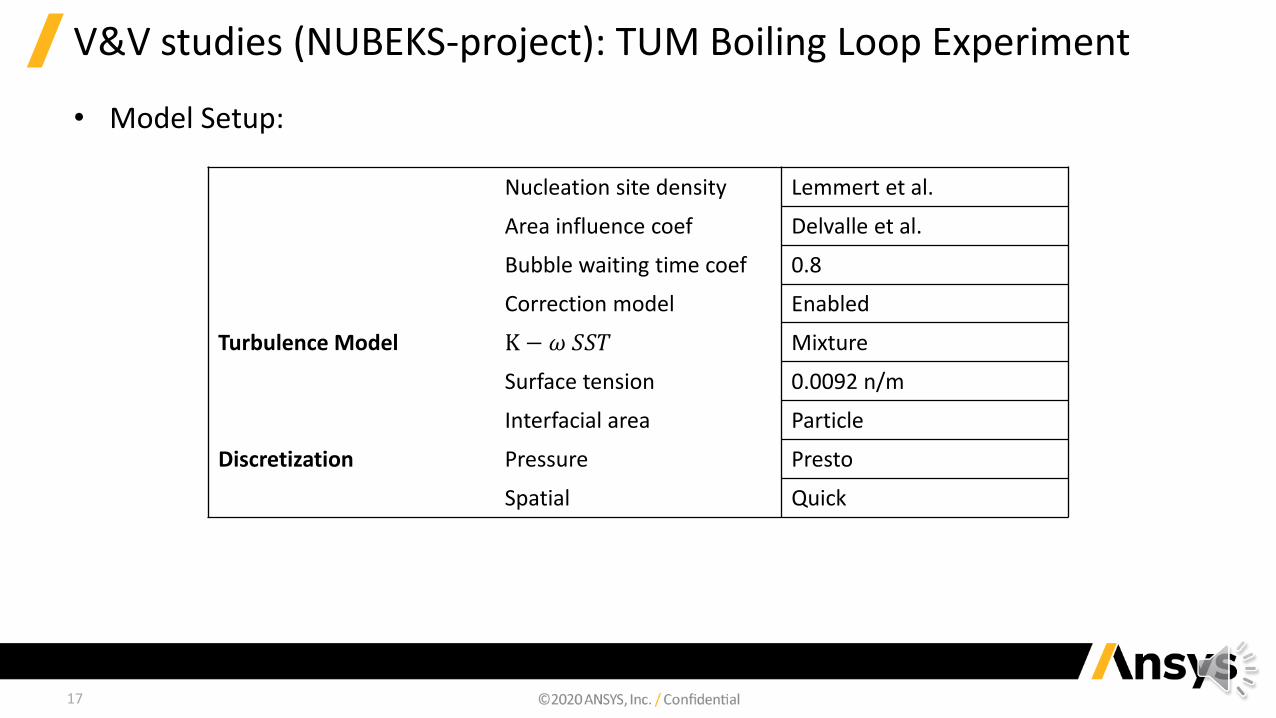
• Model Setup:
Nucleation site density Lemmert et al.
Area influence coef Delvalle et al.
Bubble waiting time coef 0.8
Correction model Enabled
Turbulence Model K − 𝜔 𝑆𝑆𝑇 Mixture
Surface tension 0.0092 n/m
Interfacial area Particle
Discretization Pressure Presto
Spatial Quick
18
V&V studies (NUBEKS-project): TUM Boiling Loop Experiment
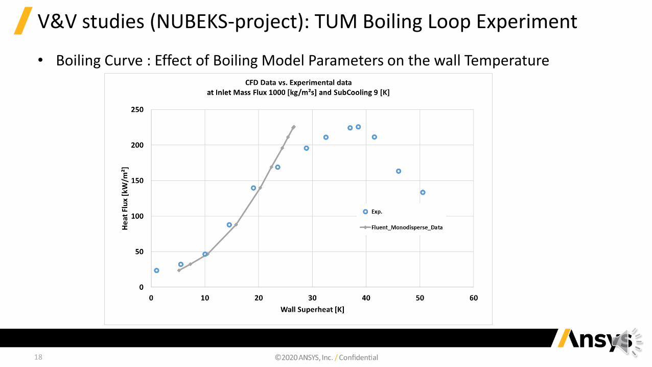
• Boiling Curve : Effect of Boiling Model Parameters on the wall Temperature
19
V&V studies (NUBEKS-project): TUM Boiling Loop Experiment
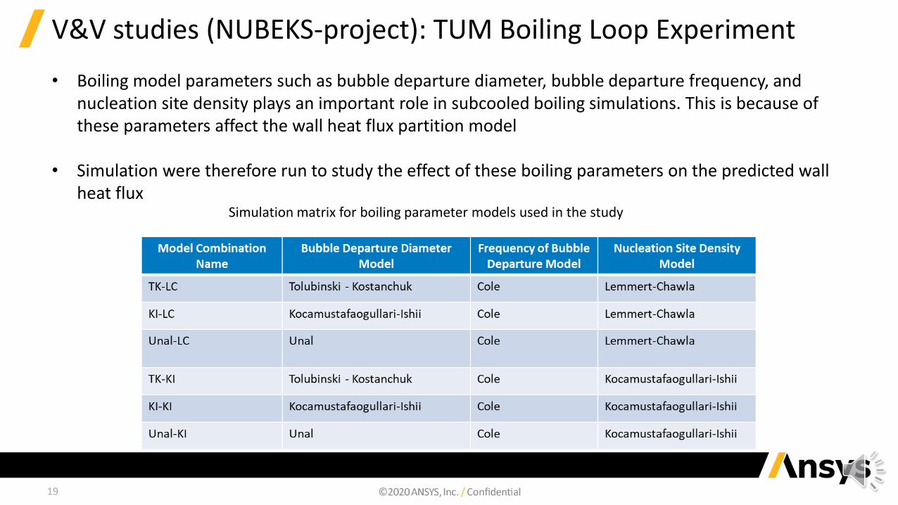
• Boiling model parameters such as bubble departure diameter, bubble departure frequency, and nucleation site density plays an important role in subcooled boiling simulations. This is because of these parameters affect the wall heat flux partition model
• Simulation were therefore run to study the effect of these boiling parameters on the predicted wall heat flux
Simulation matrix for boiling parameter models used in the study
20
V&V studies (NUBEKS-project): TUM Boiling Loop Experiment
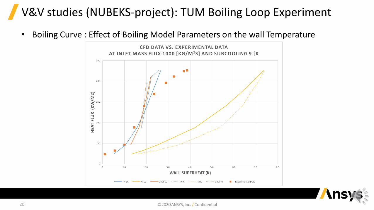
• Boiling Curve : Effect of Boiling Model Parameters on the wall Temperature

21
Conclusions
• Several simulations have been carried out under various combinations of different interfacial sub-models in order to study the effect of various boiling capabilities in CFD.
• Acceptable agreement has been obtained between the simulated results and the experimental data.
• The largest solution sensitivity have been found regarding changes in the drag, turbulent dispersion force, and bubble departure frequency.
• The predicted dry out (CHF) and measured location are in good agreement in the novel TUM experimental data.
• The Tolubinski-Konstanchuk / Lemmert-Chawla shows the best agreement against experiments which are FLUENT default settings.
• The Kocamustafaogullari-Ishii / Lemmert-Chawla and Kocamustafaogullari-Ishii / Kocamustafaogullari-Ishii combination has been found to highly over predict the wall superheat.
• The next step in our investigation will be to considered a polydispersed size approach, such as the Inhomogeneous Discrete Method or iDM in FLUENT, which is equivalent to the iMUSIG model of CFX. This should allow a much more realistic approach to both wall boiling and wall to bulk void transition.

Please address all your questions to:[email protected]