Review Flow boiling in microchannels and microgravity
36
Review Flow boiling in microchannels and microgravity Chiara Baldassari 1 , Marco Marengo * Department of Industrial Engineering, Università degli Studi di Bergamo, Viale Marconi 5, 24044 Dalmine (BG), Italy article info Article history: Received 12 May 2011 Accepted 9 January 2012 Available online xxx Keywords: Two-phase flow Flow boiling Microchannels Microgravity Eötvös number abstract A critical review of the state of the art of research on internal forced convection boiling in microchannels and in microgravity conditions is the main object of the present paper. In many industrial applications, two-phase flows are used for heavy-duty and reliable cooling and heating processes. The boiling phenomena are essential for evaporator heat exchangers, even in a very small scales, such as for PC cooling, refrigerators, HVAC systems. Even if the study of boiling is a standard research since a century, there are many aspects which are still under discussion, especially for forced convection boiling in small tubes. As the present review is pointing out, some literature results are still incongruous, giving critical uncertainties to the design engineers. The use of non-dimensional param- eters is rather useful, but, especially in case of boiling, may provide an erroneous picture of the phenomena in quantitative and qualitative meaning. The idea to consider the channel microsize together with the microgravity effects in a single review is due to the fact that the transition between confined and unconfined bubble flows may be defined using dimensionless numbers, such as the Eötvös number Eo ¼ g(r L r V )L 2 /s and its analogs, which are at the same time linked to the tube diameter and the gravity forces. In fact the Eötvös number tends to zero either when the gravity tends to zero or when the tube diameter tends to zero, but physical phenomena appear different considering separately either only the tube size or only the microgravity condition. Since the global picture of such physical process in flow boiling remains unclear, we claim the necessity to define in the most complete way the status-of-the-art of such an important research field and critically investigate the successes and the weaknesses of the current scientific literature. Noteworthy, the distinction between a macroscale and a microscale regime is misleading, since it could bring to consider a drastical variation of the physical phenomena, which is in fact not occurring until extremely low values of the channel dimension. Instead there is a typical flow pattern, the confined bubble flow, which is the dominant flow mechanism in small channels and in microgravity. Furthermore the vapor quality is a very important parameter, whose role is not well described in the present pattern classification. The values and combinations of the dimensionless numbers at which such pattern appears is the main issue of the present researches. Noteworthy, the meaning of “micro” is here used, as in the present literature, in a broad meaning, not strictly linked to the actual size of the channel, but to a change of patterns (and other physical characteristics) linked to a given dimensionless scale. Ó 2012 Elsevier Ltd. All rights reserved. Contents 1. Introduction ....................................................................................................................... 00 2. On non-dimensional numbers relevant to two-phase flow studies in microchannels and microgravity ........................................ 00 2.1. Non-dimensional numbers relevant to two-phase flow studies in microchannels .................................................... 00 2.1.1. On the Eötvös number ................................................................................................ 00 2.1.2. On the Weber number ................................................................................................ 00 2.1.3. On the Kandlikar numbers ............................................................................................. 00 2.2. Ranges of non-dimensional numbers employed in microchannels flow boiling experiments ........................................... 00 * Corresponding author. Tel.: þ39 (0)35 2052002; fax: þ39 (0)35 2052077. E-mail address: [email protected] (M. Marengo). 1 Tel.: þ39 (0)35 2052002; fax: þ39 (0)35 2052077. Contents lists available at SciVerse ScienceDirect Progress in Energy and Combustion Science journal homepage: www.elsevier.com/locate/pecs 0360-1285/$ e see front matter Ó 2012 Elsevier Ltd. All rights reserved. http://dx.doi.org/10.1016/j.pecs.2012.10.001 Progress in Energy and Combustion Science xxx (2012) 1e36 Please cite this article in press as: Baldassari C, Marengo M, Flow boiling in microchannels and microgravity, Progress in Energy and Combustion Science (2012), http://dx.doi.org/10.1016/j.pecs.2012.10.001
Transcript of Review Flow boiling in microchannels and microgravity

at SciVerse ScienceDirect
Progress in Energy and Combustion Science xxx (2012) 1e36
Contents lists available
Progress in Energy and Combustion Science
journal homepage: www.elsevier .com/locate/pecs
Review
Flow boiling in microchannels and microgravity
Chiara Baldassari 1, Marco Marengo*
Department of Industrial Engineering, Università degli Studi di Bergamo, Viale Marconi 5, 24044 Dalmine (BG), Italy
a r t i c l e i n f o
Article history:Received 12 May 2011Accepted 9 January 2012Available online xxx
Keywords:Two-phase flowFlow boilingMicrochannelsMicrogravityEötvös number
* Corresponding author. Tel.: þ39 (0)35 2052002; fE-mail address: [email protected] (M. Mar
1 Tel.: þ39 (0)35 2052002; fax: þ39 (0)35 2052077
0360-1285/$ e see front matter � 2012 Elsevier Ltd.http://dx.doi.org/10.1016/j.pecs.2012.10.001
Please cite this article in press as: BaldassariScience (2012), http://dx.doi.org/10.1016/j.p
a b s t r a c t
A critical review of the state of the art of research on internal forced convection boiling in microchannelsand in microgravity conditions is the main object of the present paper.
In many industrial applications, two-phase flows are used for heavy-duty and reliable cooling andheating processes. The boiling phenomena are essential for evaporator heat exchangers, even in a verysmall scales, such as for PC cooling, refrigerators, HVAC systems. Even if the study of boiling is a standardresearch since a century, there are many aspects which are still under discussion, especially for forcedconvection boiling in small tubes. As the present review is pointing out, some literature results are stillincongruous, giving critical uncertainties to the design engineers. The use of non-dimensional param-eters is rather useful, but, especially in case of boiling, may provide an erroneous picture of thephenomena in quantitative and qualitative meaning. The idea to consider the channel microsize togetherwith the microgravity effects in a single review is due to the fact that the transition between confinedand unconfined bubble flows may be defined using dimensionless numbers, such as the Eötvös numberEo ¼ g(rL�rV)L2/s and its analogs, which are at the same time linked to the tube diameter and the gravityforces. In fact the Eötvös number tends to zero either when the gravity tends to zero or when the tubediameter tends to zero, but physical phenomena appear different considering separately either only thetube size or only the microgravity condition. Since the global picture of such physical process in flowboiling remains unclear, we claim the necessity to define in the most complete way the status-of-the-artof such an important research field and critically investigate the successes and the weaknesses of thecurrent scientific literature. Noteworthy, the distinction between a macroscale and a microscale regime ismisleading, since it could bring to consider a drastical variation of the physical phenomena, which is infact not occurring until extremely low values of the channel dimension. Instead there is a typical flowpattern, the confined bubble flow, which is the dominant flow mechanism in small channels and inmicrogravity. Furthermore the vapor quality is a very important parameter, whose role is not welldescribed in the present pattern classification. The values and combinations of the dimensionlessnumbers at which such pattern appears is the main issue of the present researches. Noteworthy, themeaning of “micro” is here used, as in the present literature, in a broad meaning, not strictly linked to theactual size of the channel, but to a change of patterns (and other physical characteristics) linked toa given dimensionless scale.
� 2012 Elsevier Ltd. All rights reserved.
Contents
1. Introduction . . . . . . . . . . . . . . . . . . . . . . . . . . . . . . . . . . . . . . . . . . . . . . . . . . . . . . . . . . . . . . . . . . . . . . . . . . . . . . . . . . . . . . . . . . . . . . . . . . . . . . . . . . . . . . . . . . . . . . . 002. On non-dimensional numbers relevant to two-phase flow studies in microchannels and microgravity . . . . . . . . . . . . . . . . . . . . . . . . . . . . . . . . . . . . . . . . 00
2.1. Non-dimensional numbers relevant to two-phase flow studies in microchannels . . . . . . . . . . . . . . . . . . . . . . . . . . . . . . . . . . . . . . . . . . . . . . . . . . . . 002.1.1. On the Eötvös number . . . . . . . . . . . . . . . . . . . . . . . . . . . . . . . . . . . . . . . . . . . . . . . . . . . . . . . . . . . . . . . . . . . . . . . . . . . . . . . . . . . . . . . . . . . . . . . . 002.1.2. On the Weber number . . . . . . . . . . . . . . . . . . . . . . . . . . . . . . . . . . . . . . . . . . . . . . . . . . . . . . . . . . . . . . . . . . . . . . . . . . . . . . . . . . . . . . . . . . . . . . . . 002.1.3. On the Kandlikar numbers . . . . . . . . . . . . . . . . . . . . . . . . . . . . . . . . . . . . . . . . . . . . . . . . . . . . . . . . . . . . . . . . . . . . . . . . . . . . . . . . . . . . . . . . . . . . . 00
2.2. Ranges of non-dimensional numbers employed in microchannels flow boiling experiments . . . . . . . . . . . . . . . . . . . . . . . . . . . . . . . . . . . . . . . . . . . 00
ax: þ39 (0)35 2052077.engo)..
All rights reserved.
C, MarengoM, Flow boiling in microchannels andmicrogravity, Progress in Energy and Combustionecs.2012.10.001

Nomenclature
A cross sectional area of the pipe [m2]Bl boiling number [e]Bo Bond number [e]Ca capillarity number [e]CD drag coefficient [e]cp specific heat at constant pressure [J/kg K]CHF critical heat flux [W/m2]Cn convection number [e]Co confinement number [e]d diameter [m]D2 cross sectional area of a microchannel [m2]DhH hydraulic diameter based on the heated perimeter, see
footnote 23 [m]Eo Eötvös number [e]F force [N]fp triplet frequency [Hz]g gravitational acceleration [m/s2]G mass flux [kg/m2s]Ga Garimella number, convective confinement number
[e]H height [m]h heat transfer coefficient [W/m2K]hLV latent heat of vaporization [J/kg]j superficial velocity [m/s]Kemp empirical constant [e]K1 Kandlikar first number [e]K2 Kandlikar second number [e]L characteristic dimension [m]lc capillary length [m]ldrag drag length [m]LH axial heated length [m]p pressure [Mpa]Pr Prandtl number [e]q mass flow rate [kg/s]q00 heat flux [W/m2]r radius [m]R2 linear correlation coefficient
Re Reynolds number [e]T temperature [K]u mean velocity [m/s]We Weber number [e]x vapor quality [e]
Greeka thermal diffusivity [m2/s]d0 initial thickness of liquid film [m]dmin minimum thickness of liquid film [m]ε void fractionq contact angle [�]p pi greco [e]r density [kg/m3]s surface tension [N/m]m dynamic viscosity [Pa s]mg microgravity [m/s2]n kinematic viscosity [m2/s]
Subscriptsadh adhesionadv advancingb bubbleb, critical bubble, criticalF fluidh hydraulici phase iin inletL liquidLO total flow (liquid plus vapor) assumed to flow as liquidLV liquid vaporrec recedings surface conditionssat saturated conditionssub subcooledth thresholdV vaporVO total flow (liquid plus vapor) assumed to flow as vaporW wall
C. Baldassari, M. Marengo / Progress in Energy and Combustion Science xxx (2012) 1e362
2.3. Non-dimensional numbers maps employed in microchannel flow boiling experiments in microgravity . . . . . . . . . . . . . . . . . . . . . . . . . . . . . . . . 003. Macro to microscale transition in two-phase flows . . . . . . . . . . . . . . . . . . . . . . . . . . . . . . . . . . . . . . . . . . . . . . . . . . . . . . . . . . . . . . . . . . . . . . . . . . . . . . . . . . . . 00
3.1. Standard criteria . . . . . . . . . . . . . . . . . . . . . . . . . . . . . . . . . . . . . . . . . . . . . . . . . . . . . . . . . . . . . . . . . . . . . . . . . . . . . . . . . . . . . . . . . . . . . . . . . . . . . . . . . . . . . 003.2. Microgravity conditions . . . . . . . . . . . . . . . . . . . . . . . . . . . . . . . . . . . . . . . . . . . . . . . . . . . . . . . . . . . . . . . . . . . . . . . . . . . . . . . . . . . . . . . . . . . . . . . . . . . . . . 00
3.2.1. The wettability effect and a new dimensionless number: the ratio between the adhesion and drag forces . . . . . . . . . . . . . . . . . . . . . . 004. Flow boiling heat transfer in microchannels . . . . . . . . . . . . . . . . . . . . . . . . . . . . . . . . . . . . . . . . . . . . . . . . . . . . . . . . . . . . . . . . . . . . . . . . . . . . . . . . . . . . . . . . . . . 00
4.1. Heat transfer mechanisms . . . . . . . . . . . . . . . . . . . . . . . . . . . . . . . . . . . . . . . . . . . . . . . . . . . . . . . . . . . . . . . . . . . . . . . . . . . . . . . . . . . . . . . . . . . . . . . . . . . . 004.2. Boiling models . . . . . . . . . . . . . . . . . . . . . . . . . . . . . . . . . . . . . . . . . . . . . . . . . . . . . . . . . . . . . . . . . . . . . . . . . . . . . . . . . . . . . . . . . . . . . . . . . . . . . . . . . . . . . . 004.3. Heat transfer coefficients . . . . . . . . . . . . . . . . . . . . . . . . . . . . . . . . . . . . . . . . . . . . . . . . . . . . . . . . . . . . . . . . . . . . . . . . . . . . . . . . . . . . . . . . . . . . . . . . . . . . . 00
4.3.1. The heat transfer coefficient versus vapor quality . . . . . . . . . . . . . . . . . . . . . . . . . . . . . . . . . . . . . . . . . . . . . . . . . . . . . . . . . . . . . . . . . . . . . . . . 004.3.2. The heat transfer coefficient versus superheat DT . . . . . . . . . . . . . . . . . . . . . . . . . . . . . . . . . . . . . . . . . . . . . . . . . . . . . . . . . . . . . . . . . . . . . . . . 00
5. Flow patterns and maps . . . . . . . . . . . . . . . . . . . . . . . . . . . . . . . . . . . . . . . . . . . . . . . . . . . . . . . . . . . . . . . . . . . . . . . . . . . . . . . . . . . . . . . . . . . . . . . . . . . . . . . . . . . . 005.1. Flow patterns . . . . . . . . . . . . . . . . . . . . . . . . . . . . . . . . . . . . . . . . . . . . . . . . . . . . . . . . . . . . . . . . . . . . . . . . . . . . . . . . . . . . . . . . . . . . . . . . . . . . . . . . . . . . . . . 005.2. Flow pattern maps . . . . . . . . . . . . . . . . . . . . . . . . . . . . . . . . . . . . . . . . . . . . . . . . . . . . . . . . . . . . . . . . . . . . . . . . . . . . . . . . . . . . . . . . . . . . . . . . . . . . . . . . . . 00
6. Flow boiling in microgravity conditions . . . . . . . . . . . . . . . . . . . . . . . . . . . . . . . . . . . . . . . . . . . . . . . . . . . . . . . . . . . . . . . . . . . . . . . . . . . . . . . . . . . . . . . . . . . . . . . 006.1. Flow pattern features . . . . . . . . . . . . . . . . . . . . . . . . . . . . . . . . . . . . . . . . . . . . . . . . . . . . . . . . . . . . . . . . . . . . . . . . . . . . . . . . . . . . . . . . . . . . . . . . . . . . . . . . 006.2. Heat transfer . . . . . . . . . . . . . . . . . . . . . . . . . . . . . . . . . . . . . . . . . . . . . . . . . . . . . . . . . . . . . . . . . . . . . . . . . . . . . . . . . . . . . . . . . . . . . . . . . . . . . . . . . . . . . . . 00
7. General considerations and conclusions . . . . . . . . . . . . . . . . . . . . . . . . . . . . . . . . . . . . . . . . . . . . . . . . . . . . . . . . . . . . . . . . . . . . . . . . . . . . . . . . . . . . . . . . . . . . . . . 007.1. Considerations on the Eötvos number and flow patterns for different gravity levels . . . . . . . . . . . . . . . . . . . . . . . . . . . . . . . . . . . . . . . . . . . . . . . . . . 007.2. Conclusions . . . . . . . . . . . . . . . . . . . . . . . . . . . . . . . . . . . . . . . . . . . . . . . . . . . . . . . . . . . . . . . . . . . . . . . . . . . . . . . . . . . . . . . . . . . . . . . . . . . . . . . . . . . . . . . . . 00Acknowledgments . . . . . . . . . . . . . . . . . . . . . . . . . . . . . . . . . . . . . . . . . . . . . . . . . . . . . . . . . . . . . . . . . . . . . . . . . . . . . . . . . . . . . . . . . . . . . . . . . . . . . . . . . . . . . . . . . 00References . . . . . . . . . . . . . . . . . . . . . . . . . . . . . . . . . . . . . . . . . . . . . . . . . . . . . . . . . . . . . . . . . . . . . . . . . . . . . . . . . . . . . . . . . . . . . . . . . . . . . . . . . . . . . . . . . . . . . . . . 00
Please cite this article in press as: Baldassari C, MarengoM, Flow boiling in microchannels andmicrogravity, Progress in Energy and CombustionScience (2012), http://dx.doi.org/10.1016/j.pecs.2012.10.001

C. Baldassari, M. Marengo / Progress in Energy and Combustion Science xxx (2012) 1e36 3
1. Introduction 2. On non-dimensional numbers relevant to two-phase flowstudies in microchannels and microgravity
Many researchers are nowadays working on diabatic two-phaseflow experiments, i.e. liquid and vapor flowing with evaporation orcondensation. Convective boiling and two-phase flow heat transfercharacteristics in microchannels have become an important issuebecause they are dominant parameters in the performance ofcooling systems for electronic devices, highly efficient compactheat exchangers, fuel cell and advanced phase change heat sinksystems. Even for the detailed analysis of fuel flows in the moderninjectors, where the nozzle gaps are in the order of tens of micronswith very high velocities, the knowledge of the flow patterns andthe heat transfer is decisive to support numerical simulations of thespray formation.
The main question is whether for very small tubes the under-lying physics change, since many of the controlling mechanismsalter passing from macroscale to microscale two-phase flows, ascapillary forces become stronger, while buoyancy force effects areweakened. It is very chancy to extrapolate macroscale two-phaseflow boiling methods to microchannels, and, while the generaltrend of single-phase flow heat transfer in microscale seems to bereasonably well understood, this is not the case for boiling heattransfer.
In space applications the use of passive thermal components,such as heat pipes, loop heat pipes and future pulsating heat pipes,and active components such as miniaturized pumped systems,makes very important the thorough understanding of the flowboiling mechanisms, in order to simulate precisely the heat transferconditions in satellites and in thermal components for extraplan-etary exploration.
This reviewwants to examinate the state of the art of research inthis field focusing on works done on phase change of a singlecomponent fluid and characterized by small Eötvös numbers(Eo ¼ g(rL�rV)L2/s < 5), i.e. small diameters and/or low gravityenvironment.
Table 1Non-dimensional numbers relevant to two-phase studies in microchannels.
Non-dimensional number
Boiling number Bl ¼ q00=GhLV
Bond number Bo ¼ gðrL � rV Þd2h=sCapillarity number Ca ¼ mLjL=s ¼ mLGð1� xÞ=rLs, CaLO ¼ mLG=rLsConfinement number Co ¼ ½s=gðrL � rV Þd2h�1=2Convection number Cn ¼ ½1� x=x�0:9$½rV=rL�0:5
Eötvös number Eo ¼ gðrL � rV ÞL2=sGarimella number e convective confinement number Ga ¼ Bo0:5 � ReLO
Jakob number Ja ¼ cpðTs � TsatÞhLV
Kandlikar first number K1 ¼ ððq00=hLVÞðdh=rV ÞÞ=ðG2dh=rLÞ ¼ ððq00=GhLVÞ2ðrL=rV ÞÞ ¼ Bl
Kandlikar second number K2 ¼ ððq00=hLVÞ2ðdh=rV ÞÞ=s ¼ ðq00=hLVÞ2ðdh=rVsÞ
Prandtl number Pr ¼ v=a
Reynolds number ReL ¼ rLjLdh=mL ¼ Gð1� xÞdh=mL ReLO ¼ Gdh=mL ReV ¼ rV jV dh=mVReVO ¼ Gdh=mV
Weber number WeL ¼ rLj2L dh=s ¼ G2ð1� xÞ2dh=rLs WeV ¼ rV j2Vdh=s ¼ G2x2dh=rVs
WeVO ¼ G2dh=rLs
a The practical difference between Bo and Eo is that in the definition of Bo the hydraulphysical dimension, as underlined in Section 2.1.1.
Please cite this article in press as: Baldassari C, MarengoM, Flow boiling inScience (2012), http://dx.doi.org/10.1016/j.pecs.2012.10.001
The purpose is first to classify, from the point of view of non-dimensional groups, the state of the art of the literatureregarding microchannels and microgravity, both characterizedfrom having a low Eötvös number. The most important dimen-sionless parameters in phase change heat transfer are listed inSection 2.1, while in Section 2.2 the ranges of the non-dimensionalparameters employed in this review are given. Since many papersare using different symbols a great effort to homogenise the variousnomenclatures has been done.
2.1. Non-dimensional numbers relevant to two-phase flow studiesin microchannels
In the following definitions, the velocity is considered asthe superficial velocity that is, for the phase i: ji ¼ qi/riA [1]. Thesuperficial velocity of the liquid, jL, is defined as the ratio of thevolumetric flow rate of the liquid phase and the total cross sectionalarea of the two-phase flow, obtaining jL ¼ G/rL(1�x). In the sameway, the superficial velocity of the vapor, jV, is: jV ¼ Gx/rx. Also thecross sectional void fraction ε, defined as the ratio between themean area of the section occupied by the vapor divided by the totaltube cross section, ε ¼ AV/A, will be considered.
The non-dimensional numbers relevant to two-phase studies inmicrochannels are summarized in Table 1.
2.1.1. On the Eötvös numberIn the definition of the Eötvös number (Table 1) the character-
istic dimension L could be the diameter of the tube or any otherphysically relevant parameter [3] for the channel size. It is worthnoting that in the case of noncircular tubes, Eo is often defined byreplacing Lwith the hydraulic diameter. Given the fact that L shouldbe the characteristic dimension in the direction of the gravitational
Significance
It represents the ratio of the evaporation mass flux tothe total mass flux flowing in a channel [3]Ratio between gravity and surface tension forcesa
Ratio of viscous to surface tension forcesRatio between surface tension forces and gravity.Modified Martinelli parameter, introduced by Shah [2]in correlating flow boiling dataRatio between gravity and surface tension forcesWeighted ratio between gravity dot inertia forces andsurface tension dot viscous forcesRatio of sensible to latent energy absorbed duringliquidevapor phase change
2rL=rV It represents the ratio of the evaporation momentum forceand the inertia force [3]It represents the ratio of the evaporation momentum forceand the surface tension force [3]Ratio between kinematic viscosity and thermal diffusivity
¼ Gxdh=mV Ratio of inertia and viscous forces
WeLO ¼ G2dh=rLs Ratio of the inertia to the surface tension forces
ic diameter, dh, is used while in the definition of Eo, L is dh but also another relevant
microchannels andmicrogravity, Progress in Energy and Combustion
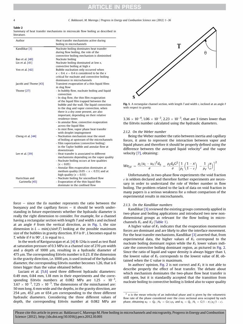
Table 2Summary of heat transfer mechanisms in microscale flow boiling as described inliterature.
Author Heat transfer mechanisms active duringboiling in microchannels
Kandlikar [3] Nucleate boiling dominates heat transferduring flow boiling, the role of theconvective boiling mechanism is diminished
Bao et al. [40] Nucleate boilingLin et al. [41] Nucleate boiling dominated at low x,
convective boiling at high xYen et al. [42] Bubble nucleation only occurred when
x < 0.4. x ¼ 0.4 is considered to be the xcritical for nucleate and convective boilingdominance in microchannels
Jacobi and Thome [43] Transient evaporation of a thin liquid filmsin slug flow
Thome [27] - In bubbly flow, nucleate boiling and liquidconvection
- In slug flow, the thin film evaporationof the liquid film trapped between thebubble and the wall. The liquid convectionto the slug and vapor convection, whenthere is a dry zone present, are alsoimportant, depending on their relativeresidence times
- In annular flow, convective evaporationacross the liquid film
- In mist flow, vapor phase heat transferwith droplet impingement
Cheng et al. [44] - Nucleation mechanism near the onsetof boiling at upstream of the microchannels
- Film vaporization (convective boiling)in the Taylor bubble and annular flow atdownstream
Lee et al. [39] - Heat transfer is associated to differentmechanisms depending on the vapor quality
- Nucleate boiling occurs at low qualities(x < 0.05)
- Annular film evaporation dominates atmedium quality (0.05 < x < 0.55) and athigh quality (x > 0.55)
Harirchian andGarimella [45]
- Nucleate boiling for unconfined flow- Evaporation of the thin liquid filmdominate in the confined flow
Fig. 1. A rectangular channel section, with length T and width s, inclined at an angle q
with respect to gravity.
2 u is the mean velocity of an individual phase and is given by the volumetricflow rate of the phase considered over the cross sectional area occupied by eachphase, obtaining uV ¼ QV
:
=AV ¼ Gx=εrV and uL ¼ QL
:
=AL ¼ Gð1� xÞ=rLð1� εÞ.
C. Baldassari, M. Marengo / Progress in Energy and Combustion Science xxx (2012) 1e364
force e since the Eo number represents the ratio between thebuoyancy and the capillary forces e it should be worth under-standing in future experiments whether the hydraulic diameter isreally the right dimension to consider. For example, for a channelhaving a rectangular section with length T and width s and inclinedat an angle q from the vertical direction, as in Fig. 1, the sizedimension is L ¼ min(s/sinq;T) looking at the possible maximumsize of the bubbles in gravity direction. If q is 0�, L becomes equal toT, while if q is 90�, L is equal to s.
In the work of Ravigururajan et al. [4] R-124a is used as test fluidat saturation pressure of 0.3 MPa in a channel size of 270 mmwidthand a depth of 1000 mm, resulting in a hydraulic diameter of475 mm. The corresponding Eötvös number is 0.23. If the dimensionin the gravity direction, i.e.1000 mm, is used instead of the hydraulicdiameter, the corresponding Eötvös number becomes 1.26, that is 6times bigger than the value obtained before.
Luciani et al. [5,6] used three different hydraulic diameters:0.49 mm, 0.84 mm, 1.18 mm in their experiments and the corre-sponding Eötvös numbers at 0.082 MPa are 1.25 � 10�3,3.67 � 10�3, 7.25 � 10�3. The dimensions of the minichannel are:50mm long, 6mmwide and the depths, in the gravity direction, are254 mm, 452 mm or 654 mm corresponding to the three differenthydraulic diameters. Considering the three different values ofdepth, the corresponding Eötvös number at 0.082 MPa are
Please cite this article in press as: Baldassari C, MarengoM, Flow boiling inScience (2012), http://dx.doi.org/10.1016/j.pecs.2012.10.001
3.36 � 10�4, 1.06 � 10�3, 2.23 � 10�3, that are 3 times lower thanthe Eötvös number calculated using the hydraulic diameters.
2.1.2. On the Weber numberBeing theWeber number the ratio between inertia and capillary
forces, it aims to represent the interaction between vapor andliquid phases and therefore it should be properly defined using thedifference between the averaged liquid velocity2 and the vaporvelocity [7], obtaining:
WeLV ¼ rLðuL � uV Þ2dhs
¼ rLdhG2
s
�1rL
�1� x1� ε
�� 1rV
�xε
��2
Unfortunately, in two-phase flow experiments the void fractionε is seldom declared and therefore further experiments are neces-sary in order to understand the role of Weber number in flowboiling. The problem related to the lack of data on void fraction inmany papers is a serious weakness for a robust comparison of theexperimental results in microchannels.
2.1.3. On the Kandlikar numbersKandlikar [3] reviewed the existing groups commonly applied in
two-phase and boiling applications and introduced two new non-dimensional groups as relevant for the flow boiling in micro-channels K1 and K2 (Table 1).
A higher value of K1 indicates that the evaporation momentumforces are dominant and are likely to alter the interface movement.For the heat transfer mechanisms, Kandlikar [3] asserted that, fromexperimental data, the higher values of K1 correspond to thenucleate boiling dominant region while the K1 lower values indi-cate the convective boiling dominant region, as pictured in Fig. 2.Since the ratio of liquid and vapor density is always bigger than 1,the lowest value of K1 corresponds to the lowest value of Bl, ob-tained when the G value is maximum.
In authors’ opinion, Fig. 2 is not correct and K1 it is not able todescribe properly the effect of heat transfer. The debate aboutwhich mechanism dominates the two-phase flow heat transfer isstill open, but it is standardly accepted that the transition fromnucleate boiling to convective boiling is linked also to vapor quality
microchannels andmicrogravity, Progress in Energy and Combustion

Fig. 2. Heat transfer mechanisms as a function of the K1 value.
Fig. 3. Eötvös number map of data in literature.
C. Baldassari, M. Marengo / Progress in Energy and Combustion Science xxx (2012) 1e36 5
and K1 alone does not include such parameter. For example in Yenet al. [42] bubble nucleation only occurred when x < 0.4, hencex ¼ 0.4 is to be considered a critical vapor quality to distinguishbetween nucleate and convective boiling in microchannels.Looking at the K1 values associated to [42], the range is1.3 * 10�5 < K1 < 8.32 * 10�4, depending on G range (100 kg/(m2s) < G < 800 kg/(m2s)), and only convective boiling should beobserved. In Bao et al. [40] nucleate boiling always dominates, evenif the range of K1 is quite broad, going from 1.6 * 10�8 to 7 * 10�2,depending on G range (50 kg/(m2s) < G < 1800 kg/(m2s)). Fromthese few examples, it is clear that K1 alone cannot describeadequately the heat transfer mechanisms.
K2 governs themovement of the interface at the contact line; thehigh evaporation momentum force causes the interface to over-come the retaining surface tension force. The contact angle is notincluded in the definition of K2, but it plays an important role inbubble dynamics and should be included in a comprehensiveanalysis (see paragraph 3.2.1). Nevertheless Kandlikar asserts thatthe use of the non-dimensional groups K1 and K2 in conjunctionwith theWeber number and the Capillary number (both containingthe vapor quality) is expected to provide a better tool for analyzingthe experimental data and developing more representativemodels [3].
2.2. Ranges of non-dimensional numbers employed inmicrochannels flow boiling experiments
The purpose of this section is to present the ranges of the non-dimensional numbers introduced in Section 2.1.
Starting from the data sets ([8e13]) analyzed in 2004 byKandlikar [3] and adding all the data coming from the other paperslisted in this review, a database of microchannel flow boilingexperiments was created and in this section we present the rangesof non-dimensional numbers employed in all these experimentalinvestigations. The maximum and minimum values, potentiallyobtainable with the experimental conditions applied duringa specific investigation, are calculated for each non-dimensionalnumber. The thermodynamic and transport properties for thefluids were calculated based on REFPROP version 8.0 of NIST.Furthermore, it must be said that not all the authors specify ina clear way the range of experimental conditions of their tests anda round-robin database is still missing. The data of Huo et al. [14]and Shiferaw et al. [15] are considered together even if the exper-imental data, which are related to the same experimental setup, arein fact different for many parameters, such as for example the heattransfer coefficients (see for a comparison Figs. 6 and 7 in [14] andFig. 2 in [15]).
Fig. 3 depicts the literature Eo number values.All the Eötvös numbers have been calculated using the hydraulic
diameter as the characteristic dimension L and, if not differently
Please cite this article in press as: Baldassari C, MarengoM, Flow boiling inScience (2012), http://dx.doi.org/10.1016/j.pecs.2012.10.001
underlined, this is maintained all along the paper in order to assureparameter homogeneity. For the majority of the papers presentedin this review Eo is lower than 5.
Note that the experimental data obtained in [16] withdh ¼ 2.88 mm and dh ¼ 4.26 mm and those obtained in [14,15]with dh ¼ 4.26 mm have not been considered in the figureabove since Eo � 10. It would be interesting to study boiling inhypergravity conditions for channel having dh � 2 mm (Fig. 3);with hypergravity we mean the range from 1 to 20 g which isobtained using for example the Large Diameter Centrifuge (LDC).The hypergravity data fall in regions not yet investigated in theliterature and may give interesting information. Notice that notall the considered works can be classified as “microscale flowboiling” according with the threshold value of Eo ¼ 1.6 proposedby Ullmann and Brauner [17] for the transition from macroscaleto microscale.
In Figs. 4e11 are presented the ranges ofWeLO,WeVO, CaLO, ReLO,ReVO, Bl, K1 and K2 calculated for the data sets presented in thisreview.
2.3. Non-dimensional numbers maps employed in microchannelflow boiling experiments in microgravity
In this section the ranges of non-dimensional numbersemployed in recent experimental investigations in microgravityconditions are presented; the gravity in these tests is reducedthanks to parabolic flight, even if in the works of Ohta [18,19] andCelata et al. [20,21] the gravity is set to 0.0981 m/s2, while Lucianiet al. [5,6] use a gravity value equal to 0.05 m/s2.
The maximum and minimum values, obtainable fromdeclared experimental conditions, are calculated for each non-dimensional number. The thermodynamic and transport prop-erties for the fluids were calculated based on NIST REFPROP 8.0except for HFE-7100, since its equation of state is not yet given.For this fluid, the tests were done at 327 K [5,6], but the physicalproperties listed from 3M website are tabulated respectively at:s at 298 K, hLV at 334 K, while rL and mL are plotted also for327 K.
In Fig. 12 the ranges of the Eötvös numbers, calculated using thehydraulic diameter as the characteristic dimension L, are presented.
microchannels andmicrogravity, Progress in Energy and Combustion

1,E-02
1,E-01
1,E+00
1,E+01
1,E+02
1,E+03
1,E+04
1,E+05
0 0,5 1 1,5 2 2,5 3 3,5 4 4,5 5 5,5 6
dh [mm]
We L
O [-
]
R134a,R-236fa,R-245fa [69]
R11, R123 [40]
H2O [8]
R134a [9]
R113 [10]
R141b [11]
R124 [4]
R123, FC-72 [12]
R134a [16]
HCFC123 [42]
R113 [64]
R134a [60]
R141b [72]
R134a, R245fa [35]
R134a, R245fa, R236fa [63]
R134a [14][15]
R134a [50]
R134a, R-245fa [83]
deionized water [46]
Fig. 4. WeLO number map of data in literature.
C. Baldassari, M. Marengo / Progress in Energy and Combustion Science xxx (2012) 1e366
Note that all the experiments [5,6,19e21,87] were conductedduring parabolic flights in conditions of microgravity, terrestrialgravity and slight hypergravity. In Fig.12 data for Eo� 10 obtained in[19e21,87] in the case of terrestrial gravity and hypergravity are not
1,E+00
1,E+01
1,E+02
1,E+03
1,E+04
1,E+05
1,E+06
0 0,5 1 1,5 2 2,5
dh [m
We V
O [
-]
Fig. 5. WeVO number map
Please cite this article in press as: Baldassari C, MarengoM, Flow boiling inScience (2012), http://dx.doi.org/10.1016/j.pecs.2012.10.001
included because they are outside of the range of interest of thereview. In microgravity conditions, Eo is lower than 1 because theEötvös number corresponding to a test inmicrogravity tends to zero.The consequences of such behavior are examinated in Section 3.2.
3 3,5 4 4,5 5 5,5 6
m]
R134a,R-236fa,R-245fa [69]
R11, R123 [40]
H2O [8]
R134a [9]
R113 [10]
R141b [11]
R124 [4]
R123, FC-72 [12]
R134a [16]
HCFC123 [42]
R113 [64]
R134a [60]
R141b [72]
R134a, R245fa [35]
R134a, R245fa, R236fa [63]
R134a [14][15]
R134a [50]
R134a, R-245fa [83]
deionized water [46]
of data in literature.
microchannels andmicrogravity, Progress in Energy and Combustion

1,E-04
1,E-03
1,E-02
1,E-01
1,E+00
0 0,5 1 1,5 2 2,5 3 3,5 4 4,5 5 5,5 6
dh [mm]
Ca L
O [-
]
R134a,R-236fa,R-245fa [69]
R11, R123 [40]
H2O [8]
R134a[9]
R113 [10]
R141b [11]
R124 [4]
R123, FC-72 [12]
R134a [16]
HCFC123 [42]
R113 [64]
R134a [60]
R141b [72]
R134a, R245fa [35]
R134a, R245fa, R236fa [63]
R134a [14][15]
R134a [50]
R134a, R-245fa [83]
deionized water [46]
Fig. 6. CaLO map of data in literature.
C. Baldassari, M. Marengo / Progress in Energy and Combustion Science xxx (2012) 1e36 7
In Figs.13e20 are presented the ranges ofWeLO,WeVO, ReLO, ReVO,CaLO, Bl, K1 and K2 calculated only for the microgravity data sets. InFigs.14,16,19and20 thedata fromLucianiet al. [5,6] arenon includedsince the vapor density of HFE-7100 is not known to the authors.
1,E+01
1,E+02
1,E+03
1,E+04
1,E+05
1,E+06
0 0,5 1 1,5 2 2,5
dh [m
Re L
O[-]
Fig. 7. ReLO map of d
Please cite this article in press as: Baldassari C, MarengoM, Flow boiling inScience (2012), http://dx.doi.org/10.1016/j.pecs.2012.10.001
3. Macro to microscale transition in two-phase flows
While in single-phase heat transfer the threshold betweenmicroscale and macroscale can be determined on the basis
3 3,5 4 4,5 5 5,5 6
m]
R134a, R236fa, R245fa [69]
R11, R123 [40]
H2O [8]
R134a[9]
R113 [10]
R141b [11]
R124 [4]
R123, FC-72 [12]
R134a [16]
HCFC123 [42]
R113 [64]
R134a [60]
R141b [72]
R134a, R245fa [35]
R134a, R245fa, R236fa [63]
R134a [14][15]
R134a [50]
R134a, R-245fa [83]
deionized water [46]
ata in literature.
microchannels andmicrogravity, Progress in Energy and Combustion

1,E+02
1,E+03
1,E+04
1,E+05
1,E+06
1,E+07
0 0,5 1 1,5 2 2,5 3 3,5 4 4,5 5 5,5 6
dh [mm]
Re V
O [
-]
R134a, R236fa, R245fa [69]
R11, R123 [40]
H2O [8]
R134a[9]
R113 [10]
R141b [11]
R124 [4]
R123, FC-72 [12]
R134a [16]
HCFC123 [42]
R113 [64]
R134a [60]
R141b [72]
R134a, R245fa [35]
R134a, R245fa, R236fa [63]
R134a [14][15]
R134a [50]
R134a, R-245fa [83]
deionized water [46]
Fig. 8. ReVO map of data in literature.
C. Baldassari, M. Marengo / Progress in Energy and Combustion Science xxx (2012) 1e368
of scaling effects3 [22,23], in flow boiling the transition betweenmicro- and macroscale has not been well defined yet.
In fact a universal accepted criterion for the definition of micro-macro transition does not exist. We also believe that it is notnecessary, aside from a practical taxonomy.
In Ref. [24] a classification for the transition from macroscale tomicroscale heat transfer based on the hydraulic diameter dh wasproposed. The size ranges recommended by Kandlikar are: micro-channels (50e600 mm), minichannels (600 mme3 mm) andconventional channels (dh > 3 mm). In Ref. [25] Thome under-lines that “such criterion does not reflect the influence of channelsize on the physical mechanisms, as the effect of reduced pressureon bubble sizes and flow transitions”. Furthermore the criteriondoes not take in consideration the properties of the test fluid andshould be rejected as too rough.
Thome [25] asserts that a macro to microscale transition crite-rion might be related to the bubble departure diameter, which isdefined as the point at which the bubble departure size reaches thechannel diameter. If the diameter of a growing bubble reaches theinternal diameter of the tube before detachment, then the bubblecan only grow in length as it flows downstream and the result isthat only one bubble can exist in the channel cross-section ata time. Hence, this condition of confined bubble flow4 is suggestedby Thome et al. [26] to be the threshold beyond which macroscaletheory is no longer applicable.
3 In single-phase heat transfer, after a period of uncertain results (1990e2007), itis nowadays clear that no peculiar physics has been detected in microscale [22],even if some phenomena are not negligible as the scale reduces; these are, forexample, the so-called scaling effects in the thermal entrance length, axialconduction and viscous heating. In recent works, such as in [23], it has been foundthat, taking into account the scaling effects, there is a general agreement withmacroscale phenomena. Hence in most of the engineer applications, the use ofempirical correlations well known in macroscale is still possible, when the properchannel size and surface roughness are used.
4 Confined bubble flow describes the situation where bubbles grow in lengthrather than in diameter, also known as the elongated bubble regime.
Please cite this article in press as: Baldassari C, MarengoM, Flow boiling inScience (2012), http://dx.doi.org/10.1016/j.pecs.2012.10.001
We stress that a macro to micro transition also occurs for a fixedchannel diameter, when, due to bubble coalescence downstream,there is a point along a tube where the bubble diameter may reachthe channel section size. When the bubbles are able to detach fromthe tube surface with small sizes, any bulk force (as gravity) actingnormally or radially is able to drift the bubbles downstreamingcombining vectors of the flow drag force and the bulk force. Butwhen the bubbles are completely filling the tube section, the gravityand other bulk forces are playing a role in the dynamics of the flow,only if they are alignedwith the tube or channel axes. Therefore, dueto bubble coalescence for example, it is possible that a transitionfrom macro to microscale is occurring along the flow, during itsdevelopment in the tube for the same tube diameter. Such effectscan be also originated by the pressure drop (see paragraph 3.1).
Some evidences of macro to microscale transition are summa-rized in [27]. From theflowpatternpointof view, stratified-wavyandfully stratifiedflowsdisappeared in small horizontal channels; in factno stratified flow exists if the tube diameter is sufficiently small, andthis could be an indication of the lower boundary ofmacroscale two-phase flow. The upper boundary ofmicroscale two-phase flowmightbe the point in which the effect of gravity becomes negligible,meaning that in microgravity conditions there should be onlymicroscale features. This was proved not to be true (see paragraph6.1). From the heat transfer point of view, the results in [27] seem tosuggest an increase of the heat transfer coefficient passing from themacroscale to the microscale regime defined above.
Rigorously either the microscale has only a simple relation withthe channel size, i.e. it is the maximum value of micrometers abovewhich the physical phenomena, given the same fluid and physicalflowcondition such as G, x, are showing a rapid variation in terms ofpatterns, pressure drop and heat transfer, or could be improperlydefined as a given scale or a given characteristic length taking intoaccount also the physical properties of the fluid. Under such givensize, some of the usual physical phenomena in macroscale (i.e. fora larger scale) should change. For example, the capillary length lc isdefined as
microchannels andmicrogravity, Progress in Energy and Combustion

1,E-07
1,E-06
1,E-05
1,E-04
1,E-03
1,E-02
1,E-01
1,E+00
0 0,5 1 1,5 2 2,5 3 3,5 4 4,5 5 5,5 6
dh [mm]
Bl [
-]
R134a,R-236fa,R-245fa [69]
R11, R123 [40]
deionized water [8]
R134a[9]
R113 [10]
R141b [11]
R124 [4]
R123, FC-72 [12]
HCFC123 [42]
R113 [64]
R134a [60]
R141b [72]
R134a, R245fa [35]
R134a, R245fa, R236fa [63]
R134a [14][15]
R134a [50]
R134a, R-245fa [83]
deionized water [46]
R134a [16]
Fig. 9. Boiling number map of data in literature.
C. Baldassari, M. Marengo / Progress in Energy and Combustion Science xxx (2012) 1e36 9
lc ¼ s
gðr � r Þ2
�L V
�1
where s, g, rL and rV are the surface tension, gravitational acceler-ation and densities of the liquid and vapor at the saturated pres-sure, respectively; lc could be useful because the bubble departure
1,E-12
1,E-11
1,E-10
1,E-09
1,E-08
1,E-07
1,E-06
1,E-05
1,E-04
1,E-03
1,E-02
1,E-01
1,E+00
1,E+01
0 0,5 1 1,5 2 2,5
dh [
K1
[-]
Fig. 10. K1 number map
Please cite this article in press as: Baldassari C, MarengoM, Flow boiling inScience (2012), http://dx.doi.org/10.1016/j.pecs.2012.10.001
diameter usually is considered proportional to the capillary length.This may lead to a reduction in the departure frequency for highsurface tension fluids.
In our opinion no physical sharp distinction occurs betweena macro and a micro regime, since, until an extremely low value ofthe channel size, the fundamental physical phenomena are simply
3 3,5 4 4,5 5 5,5 6
mm]
R134a,R236fa,R245fa [69]
R11, R123 [40]
H2O [8]
R134a[9]
R113 [10]
R141b [11]
R124 [4]
R123, FC-72 [12]
R134a [16]
HCFC123 [42]
R113 [64]
R134a [60]
R141b [72]
R134a, R245fa [35]
R134a, R245fa, R236fa [63]
R134a [14][15]
R134a [50]
R134a, R-245fa [83]
deionized water [46]
of data in literature.
microchannels andmicrogravity, Progress in Energy and Combustion

1,E-08
1,E-07
1,E-06
1,E-05
1,E-04
1,E-03
1,E-02
1,E-01
1,E+00
1,E+01
0 0,5 1 1,5 2 2,5 3 3,5 4 4,5 5 5,5 6
dh [mm]
K2
[-]
R134a,R236fa,R245fa [69]
R11, R123 [40]
H2O [8]
R134a[9]
R113 [10]
R141b [11]
R124 [4]
R123, FC-72 [12]
R134a [16]
HCFC123 [42]
R113 [64]
R134a [60]
R141b [72]
R134a, R245fa [35]
R134a, R245fa, R236fa [63]
R134a [14][15]
R134a [50]
R134a, R-245fa [83]
deionized water [46]
Fig. 11. K2 number map of data in literature.
C. Baldassari, M. Marengo / Progress in Energy and Combustion Science xxx (2012) 1e3610
the same, i.e. there is no “microscale” or “macroscale”, but onlya change of the flow patterns, and therefore of the heat transfermechanisms, linked to different values of flow parameters anddimensionless numbers. Keeping in mind this observation, we stillacknowledge the practical usefulness of studying which could bethe best dimensionless numbers able to follow the effects of lengthscales on the variations of the main two-phase characteristics, suchas flow patterns, heat transfer coefficients, pressure drops and soon. Hence, one should be aware that etymologically the term“micro” is then used broadly speaking, since the “microscale” couldbe reached in channels of millimetric size.
3.1. Standard criteria
In literature five different criteria are used to distinguishbetween microscale and macroscale and in this review they arepresented and compared.
0,0
0,5
1,0
1,5
2,0
2,5
3,0
0 1 2 3 4 5 6 7 8 9
dh [mm]
Eo
[-]
FC-72 micro g [20][21][87]
R-113 micro g [19]
HFE-7100 micro g[5][6]
HFE-7100 1g [5][6]
HFE-7100 1.8g [5][6]
Fig. 12. Eötvös number map of microgravity literature data (open symbols).
Please cite this article in press as: Baldassari C, MarengoM, Flow boiling inScience (2012), http://dx.doi.org/10.1016/j.pecs.2012.10.001
Kew and Cornwell [28] recommended a confinement number,Co, to distinguish between micro and macroscale. Co, introduced inTable 1, is the ratio between the capillary length lc and the hydraulicdiameter. Kew and Cornwell [28] found deviations in the flowregimes from those observed in large channels and that existingflow boiling heat transfer correlations do not perform well whenapplied to narrow channels having Co > 0.5; therefore they setCo ¼ 0.5 as the threshold for microscale flows. In Ref. [29] anexperimental microscale heat transfer database was proposed. Theconsidered hydraulic diameters are compared with the thresholddiameter criterion of Kew and Cornwell [28], showing that abouthalf of the experimental test sections described in Table 3 of [29]can be classified as microscale according to such criterion.
In 2003, Li and Wang [30] recommended using the capillarylength, lc, to distinguish between micro and macroscale and givethe following condensation flow regimes based on the tubediameter d:
1,E-01
1,E+00
1,E+01
1,E+02
1,E+03
0 1 2 3 4 5 6 7 8 9dh [mm]
We L
O [
-]
FC-72 [87]
FC-72 [20]
FC-72 [21]
R-113 [19]
HFE-7100 [5]
HFE-7100 [6]
Fig. 13. WeLO map of only microgravity literature data.
microchannels andmicrogravity, Progress in Energy and Combustion

1,E+01
1,E+02
1,E+03
1,E+04
1,E+05
0 1 2 3 4 5 6 7 8 9
dh [mm]
We V
O [-
]
FC-72 [87]
FC-72 [20]
FC-72 [21]
R-113 [19]
Fig. 14. WeVO map of only microgravity literature data.
1,E+02
1,E+03
1,E+04
1,E+05
0 1 2 3 4 5 6 7 8 9
dh [mm]
Re L
O [-
]
FC-72 [87] FC-72 [20]
FC-72 [21] R-113 [19]
HFE-7100 [5] HFE-7100 [6]
Fig. 15. ReLO map of only microgravity literature data.
1,E-03
1,E-02
1,E-01
0 1 2 3 4 5 6 7 8 9
dh [mm]
Ca
LO
[-]
FC-72 [87] FC-72 [20]
FC-72 [21] R-113 [19]
HFE-7100 [5] HFE-7100 [6]
Fig. 17. Capillary number map of only microgravity literature data.
1,E-05
1,E-04
1,E-03
1,E-02
0 1 2 3 4 5 6 7 8 9
dh [mm]
Bl [
-]
FC-72 [87] FC-72 [20]
FC-72 [21] R113 [19]
HFE-7100 [5] HFE-7100 [6]
Fig. 18. Boiling number map of only microgravity literature data.
C. Baldassari, M. Marengo / Progress in Energy and Combustion Science xxx (2012) 1e36 11
- d > dth gravity forces are dominant and the flow regimes aretypical of macroscale
- d < dc the effect of gravity on the flow regime can be ignoredcompletely; the flow is symmetric with respect to bulk forcesand it is a microscale flow
1,E+03
1,E+04
1,E+05
1,E+06
0 1 2 3 4 5 6 7 8 9
dh [mm]
Re V
O [-
]
FC-72 [87] FC-72 [20]
FC-72 [21] R-113 [19]
Fig. 16. ReVO map of only microgravity literature data.
Please cite this article in press as: Baldassari C, MarengoM, Flow boiling inScience (2012), http://dx.doi.org/10.1016/j.pecs.2012.10.001
- dc < d < dth gravity and surface tension forces are equallydominant; a slight stratification of the flow distribution wasobserved.
The values of tube diameter, dc and dth, in terms of lc aredc ¼ 0.224lc and dth ¼ 1.75lc.
1,E-07
1,E-06
1,E-05
1,E-04
1,E-03
1,E-02
0 1 2 3 4 5 6 7 8 9
dh [mm]
K1
[-]
FC-72 [87] FC-72 [20]
FC-72 [21] R-113 [19]
Fig. 19. K1 number map of only microgravity literature data.
microchannels andmicrogravity, Progress in Energy and Combustion

1,E-05
1,E-04
1,E-03
1,E-02
1,E-01
0 1 2 3 4 5 6 7 8 9
dh [mm]
K2
[-]
FC-72 [87] FC-72 [20]
FC-72 [21] R-113 [19]
Fig. 20. K2 number experimental map of only microgravity literature data.
Table 3Summary of the behavior of heat transfer coefficient recently presented in literature.
Authors, test fluid and testsection diameter
Heat transfer coefficient depends on
Bao et al. [40]R-11 and R-123, d ¼ 1.95 mm.
Figs. 42 and 43
- q00
- independent of G- independent of x
Bertsch et al. [69] - on x; h decreases for x > 0.5- slightly on G; h increases weakly withG
- on q00; h increases with itConsolini et al. [70]R134a, R236fa, R245fa d ¼ 510 mm
and d ¼ 790 mm
- h increases with q00
- minimal effect of G and x on h
Dupont et al. [71]d ¼ 0.5e2 mm in increments of
0.166 mm
- h decreases with diameter for x< 0.04- for 0.04 < x < 0.18 h increases,reaching a peak, and then it decreaseswith the diameter
- h increases with diameter for x > 0.18Depending on the thermophysicalproperties of the fluid and the operatingconditions, each zone can disappear ormove as a function of quality x
Harirchian and Garimella [45] - themicrochannel cross sectional area;h increases with decreasing crosssectional area for microchannelsmaller than 0.089 mm2 while formicrochannel area > 0.089 mm2 h isindependent of channel dimensions
- on q00; h increases with itHarirchian and Garimella [48] - on x for R-134a; h increases with
increasing of x till vapor quality of 20%after which it drops for furtherincreases in x
- on x for FC-77; h increases withincreasing exit vapor quality untilthe point of dryout after which hdecreases
Huo et al. [14], R-134a d ¼ 2.01and d ¼ 4.26 mm
- h has a complex behavior especiallyfor x> 0.2. The trends of h versus x arethe same as in [15], but the values of hare different, as outlined in 2.2
Lee et al. [39] - on x; h decreases with it- on q00; h increases with it
Lin et al. [41,72]R-141b, d ¼ 1.1 mm Fig. 44
- strongly on x at low and high q00 . Atlow q00 h has a peak at about x¼ 0.6. Athigh q00 h has a peak for small x andthen fell with x and becomes inde-pendent from q’’
- at intermediate q’’ is independent on xOng et al. [63]R134a, R236fa, R245fad ¼ 1.030 mm Figs. 49 and 50
- on q00 at low x R245fa in a 1.030 mmchannel
- h increases with q00 for a wide range ofx for R134a and R236fa at low G
- the fluid properties. In fact for low x, hfor R134a is the highest followed byR236fa and R245fa reflecting theirvalues of reduced pressure
- on G for R134a and R236fa. It appearsthat the transition to annular flowoccurs at lower x with increasing G. hincreases after the transition occur-rence for both fluids
Shiferaw et al. [15]R134a, d ¼ 2.01 mm and d ¼
4.26 mm Figs. 46 and 47
- on q00 till x ¼ 0.5 for the 4.26 mm tubeand till x ¼ 0.3 for the 2.01 mm tube.
- on system pressure (h increases withthe pressure)
- independent on x for x < 0.5 for the4.26 mm tube and for x < 0.3 for the2.01 mm tube
- independent on G for low qualityShiferaw et al. [60]R134a, d ¼ 1.1 mm Fig. 48
- h increases with the pressure (prob-ably due to the fact that bubble
C. Baldassari, M. Marengo / Progress in Energy and Combustion Science xxx (2012) 1e3612
In 2006 Cheng and Wu [31], based on the critical and thresholddiameters obtained by Li and Whang [30], classified phase changeheat transfer in channels according to Bo as follows:
- microchannel if Bo< 0.05, the effect of gravity can be neglected- mesochannel if 0.05 < Bo < 3, surface tension effect becomesdominant and gravitational effect is small
- macrochannel if Bo > 3, the surface tension is small incomparison with gravitational force.
Note that this criterion is more stringent than the one given byKew and Cornwell [28], which observed deviation frommacroscalewhen Bo < 4,5 that corresponds to diameters lower thandthjBn¼4 ¼ 2
ffiffiffiffiffiffiffiffiffiffiffiffiffiffiffiffiffiffiffiffiffiffiffiffiffiffiffis=gðrL � rV Þ
pA recent and reasonable criterion to identify the threshold has
been recently proposed by Ullmann and Brauner [17] on the basis offlow pattern maps, using Eo. On the basis of flow pattern mapdeviation for experiments in pipes, Ullmann and Brauner proposeda microscale threshold of Eo � 1.6.
In 2010 Harirchian and Garimella [32] developed a new transi-tion criterion based on the fact that bubble confinement dependson channel size and on the mass flux since the bubble diametersvaries with the flow rate. Using FC-77 flow visualizations, theydivided their experimental values into two groups: confined andunconfined flow, as in Fig. 21 6 where the solid line is a fit of thetransition points between these two flows. This transition is rep-resented by the equation:
Bo0:5 � ReLO ¼ 1mL
�gðrL � rV Þ
s
�0:5GD2 ¼ 160
and Bo0.5 � ReLO is called by Harirchian and Garimella “convectiveconfinement number” and is denoted as Ga in this review; when Gais equal to 160 the threshold betweenmicro andmacroscale occurs.
This criterion considers as microchannels those channels havingGa < 160 while for larger convective confinement numbers, thevapor bubbles are not confined and the channels is considered asa macroscale channel. Harirchian and Garimella criterion [32]seems able to predict the confined or unconfined nature of theflow for experimental observations in literature having water,
departure diameter decreases as thesystem pressure increases)
- on q00
- for low q00 and G and for x < 0.5, h isindependent on x
5 In fact Bo ¼ 1/Co2.6 In figure Re indicate the Reynolds number calculated using the liquid phase
mass flux and so it corresponds to ReLO defined in nomenclature.
Please cite this article in press as: Baldassari C, MarengoM, Flow boiling in microchannels andmicrogravity, Progress in Energy and CombustionScience (2012), http://dx.doi.org/10.1016/j.pecs.2012.10.001

Table 3 (continued)
Authors, test fluid and testsection diameter
Heat transfer coefficient depends on
Yen et al. [42], HCFC123d ¼ 210 mm dh ¼ 214 mm Fig. 45
- on x- on the shaped cross-sections forx < 0.4. In this range h is higher forthe square microchannel becausecorners in the square microchannelacted as effective active nucleationsites
0
0,5
1
1,5
2
0 0,1 0,2 0,3 0,4 0,5 0,6 0,7 0,8 0,9 1
Reduced Pressure [-]
d th [
mm
]
R134a Eo=4 [28]
R134a Eo=3.06 [30]
R134a Eo=3 [31]
R134a Eo=1.6 [17]
R134a Eo=2.56 [32]
Fig. 22. Comparison of selected macro to microscale transition criteria for R134a asa function of reduced pressure.
0
1
2
3
4
5
6
0 0,1 0,2 0,3 0,4 0,5 0,6 0,7 0,8 0,9 1
Reduced Pressure [-]
d th [
mm
]
water Eo=4 [28]
water Eo=3.06 [30]
water Eo=3 [31]
water Eo=1.6 [17]
water Eo=2.56 [32]
Fig. 23. Comparison of selected macro to microscale transition criteria for water asa function of reduced pressure.
C. Baldassari, M. Marengo / Progress in Energy and Combustion Science xxx (2012) 1e36 13
dielectric liquids and refrigerants as working fluids. In Ref. [32] it isunderlined that both visualized flow boiling patterns as well as heatflux data are hence necessary to use such criterion. Therefore thereis the necessity of more complete tests in order to establish whichrange of values of the convective confinement number Ga is able tocharacterize the transition macro to microscale.
Convective confinement number is proportional to mass fluxand inversely proportional to liquid dynamic viscosity; expressingthe convective confinement number in terms of Eo, the critical Eonumber becomes EoGa ¼ (160/ReLO)2.
Remarking that Kewand Cornwell [28] assumedmicroscale flowwhen Co > 0.5, it is interesting to note that Eo � 1.6, according toUlman and Brauner criterion [17], means Co � 0.79. For the samefluid, i.e., R134a, at the saturation temperature of 0 �C, the twocriteria yield the transition between micro- and macroscale of1.21 mm [17] and 1.92 mm [28], respectively.
Rewriting all the above criteria in terms of the Eötvös number, itis found that Kewand Cornwell criterion [28] corresponds to Eo¼ 4,the Li and Wang threshold [30] to macroscale is Eo ¼ 3.06, Chengand Wu classification [31] to Eo ¼ 3 and the convection confine-ment number criterion [32] to Eo ¼ (160/ReLO)2. From the calcula-tion of the threshold diameter dth, that is the threshold belowwhich there are deviations frommacroscale flows, according to thecriteria expressed above, it has been obtained:
dth ¼ 2ffiffiffiffiffiffiffiffiffiffiffiffiffiffiffiffiffiffiffiffiffiffi
s
gðrL � rV Þr
that corresponds to Co ¼ 0.5 (Eo ¼ 4) [28].
dth ¼ 1:75ffiffiffiffiffiffiffiffiffiffiffiffiffiffiffiffiffiffiffiffiffiffi
s
gðrL � rV Þr
that corresponds to dth ¼ 1.75lc
(Eo ¼ 3.06) [30].
Fig. 21. Experimental confinedandunconfinedflowandthetransitionbetween them[32].
Please cite this article in press as: Baldassari C, MarengoM, Flow boiling inScience (2012), http://dx.doi.org/10.1016/j.pecs.2012.10.001
dth ¼ffiffiffi3
p$
ffiffiffiffiffiffiffiffiffiffiffiffiffiffiffiffiffiffiffiffiffiffis
gðrL � rV Þr
that corresponds to Bo ¼ 3 (Eo ¼ 3) [31].
dth ¼ffiffiffiffiffiffiffi1:6
p ffiffiffiffiffiffiffiffiffiffiffiffiffiffiffiffiffiffiffiffiffiffis
gðrL � rV Þr
that corresponds to Eo ¼ 1.6 [17].
dth ¼ 160ReLO
ffiffiffiffiffiffiffiffiffiffiffiffiffiffiffiffiffiffiffiffiffiffis
gðrL � rV Þr
that corresponds to Eo ¼ (160/ReLO)2
[32].In Figs. 22 and 23 the macro to microscale transition criteria
listed above are applied to R134a and water. The threshold diam-eter is presented as a function of the reduced pressure7; it becomessmaller as the saturation pressure increases. In order to estimatethe threshold diameter for the convection confinement numbercriterion [32], we consider 102 < ReLO < 105 as from the map ofliterature data presented in Fig. 7. This means that the thresholddiameters associated to these ReLO values are:
dth ¼ 1:6ffiffiffiffiffiffiffiffiffiffiffiffiffiffiffiffiffiffiffiffiffiffiffiffiffi
s
gðrL � rV Þr
for ReLO ¼ 102
dth ¼ 1:6$10�3ffiffiffiffiffiffiffiffiffiffiffiffiffiffiffiffiffiffiffiffiffiffi
s
gðrL � rV Þr
for ReLO ¼ 105
7 The reduced pressure is pred ¼ psat/pcrit.
microchannels andmicrogravity, Progress in Energy and Combustion

Fig. 25. Convective confinement number Ga vs. Eötvös number map for literature data.
C. Baldassari, M. Marengo / Progress in Energy and Combustion Science xxx (2012) 1e3614
that correspond, respectively, to Eo ¼ 2.56 and Eo ¼ 2.56 � 10�6. Itmust be underlined that ReLO ¼ 105 characterizes a turbulent flow,which is very difficult in a microchannel; so the threshold diametercorresponding to this value of ReLO, that would be in the order ofa few mm, cannot have any comparison with the present data.Figs. 22 and 23 present the threshold diameter below whichdeviations from macroscale flows occur.
To understand which of the experiments cited in this papercould be classified as microscale according to [17], Fig. 24 plots theratios between the hydraulic diameters used in some of the citedpapers and the threshold diameter calculated according to [17].
For a specified hydraulic diameter, there are different valuessince the authors made experiments with several pressure/temperature values and so the threshold diameters are different.Twelve papers out of twenty have a ratio between hydraulicdiameter and the threshold diameter lower than 1 and so can beclassified as microscale according to [17].
Plotting in Fig. 25 Eo and Ga numbers associated to the databasepresented in this work, it emerges that eight papers out of nineteencan be considered as microscale according to both criteria based onEo [17] and Ga [32]. There are four papers where the experimentalconditions for microscale [50,63,70,72] satisfy the Eo criterion butnot the Ga criterion; in Fig. 25 there are some experimental worksthat can be classify asmicroscale or asmacroscale depending on thespecific testing conditions.
As concluding remarks of this “macro to micro” section, it isnecessary to underline that since the micro-to macroscalethreshold has been practically associated with bubble confinement,a more refined correlation is still necessary to define a univocal anduniversal criterion for the transition from unconfined to confinedbubble flow. Better characterized experimental data are necessaryto improve the knowledge in this field and some effects, like bubbleconfinement, the prevalence of surface tension over buoyancy andthe importance of inertial forces in the force balance, have still to beinvestigated and analyzed in detail.
Finally it is also evident that, since the pressure drop in micro-channels is very significant, a transition from an unconfined toa confined flow may appear along the tube or the channel due tothe decrease of the local pressure. Such transition has not beeninvestigated in the literature yet. In order to clarify this issue, the
Fig. 24. Comparison between the experimental hydraulic diameters and the thresholddiameter of Ullman and Brauner [17].
Please cite this article in press as: Baldassari C, MarengoM, Flow boiling inScience (2012), http://dx.doi.org/10.1016/j.pecs.2012.10.001
Lockhard and Martinelli approach [33] as generalized by Chisholm[34], is here used to calculate the pressure drop for R-134a in theexperimental conditions described in [35]. The threshold diametersobtained, in agreement with [17] are plotted as a function of thelength of the channel in Figs. 26 and 27. In Fig. 26 the authorsdecided to consider a reasonable maximum channel length of450 mm; the resulting pressure drop is not very important, due tothe low value of G. In Fig. 27 indeed, due to the higher value of G, thechannel length considered was 300 mm for the lower vapor qualitywhile it decreases as the vapor quality increases since the pressuredrop becomes too high. The maximum pressure drop considered is0.59 MPa.
To summarize the behavior of the threshold diameter [17] alongthe channel, due to the pressure drop, the authors decide tocalculate where, in an R-134a channel having dh ¼ 1 mm andpsat ¼ 1 MPa, there is a macro to micro transition, according to [17],for different G values. This is represented in Fig. 28 for inlet vaporquality x ¼ 0.1, x ¼ 0.3 and x ¼ 0.5.
It must be noted that for x ¼ 0.1 and G � 800 kg/ms2, dh ¼ 1 mmcannot be considered as “microchannel”, according to [17], until the
1,05
1,052
1,054
1,056
1,058
1,06
1,062
1,064
0 50 100 150 200 250 300 350 400 450
L channel [mm]
Thr
esho
ld d
iam
eter
[m
m]
x=0,1x=0,3x=0,5
Fig. 26. Increasing threshold diameter along the channel for R-134a with G ¼ 200 kg/m2s, psat ¼ 0.69 MPa, dh ¼ 0.509 mm and different inlet vapor quality (x ¼ 0.1, x ¼ 0.3,x ¼ 0.5), based on the recommendation of [17].
microchannels andmicrogravity, Progress in Energy and Combustion

1
1,05
1,1
1,15
1,2
1,25
1,3
1,35
1,4
0 50 100 150 200 250 300L channel [mm]
Thr
esho
ld d
iam
eter
[m
m]
x=0,1x=0,3x=0,5
Fig. 27. Increasing of the threshold diameter along the channel for R-134a withG ¼ 2094 kg/m2s, psat ¼ 0.69 MPa, dh ¼ 0.509 mm and different inlet vapor quality(x ¼ 0.1, x ¼ 0.3, x ¼ 0.5), based on the recommendation of [17].
0
2
4
6
8
10
12
14
0 0,1 0,2 0,3 0,4 0,5 0,6 0,7 0,8 0,9 1
Reduced Pressure [-]
d th [m
m]
R134a Eo=1,6 [17]
Fig. 29. Threshold hydraulic diameter, calculated according to the Ullman and Braunercriterion [17] as a function of reduced pressure for R-134a with a residual gravity equalto 0.01 g.
0
5
10
15
20
25
30
35
40
0 0,1 0,2 0,3 0,4 0,5 0,6 0,7 0,8 0,9 1
Reduced Pressure [-]
d th [m
m]
water Eo=1,6 [17]
Fig. 30. Threshold hydraulic diameter, calculated according to the Ullman and Braunercriterion [17], as a function of reduced pressure for water with a residual gravity equalto 0.01 g.
C. Baldassari, M. Marengo / Progress in Energy and Combustion Science xxx (2012) 1e36 15
channel length of 1 m. For x ¼ 0.3 the transition to confined bubbleflow occurs (at 70 cm after the inlet for G � 800 kg/ms2) and thesame for x ¼ 0.5 (at 55 cm after the inlet for G � 800 kg/ms2).
3.2. Microgravity conditions
Although the criterion based on Eötvos number [17] seemsa good idea for identifying the threshold between micro- andmacroscale (or better confined and unconfined bubble flow),simply it does not work in microgravity. In fact when g tends tozero, Eo is by definition less than 1.6. In Figs. 29 and 30 thethreshold diameters between macro and micro, calculatedaccording to the Eötvos number criterion [17], are presented witha residual gravity equal to 0.01 g.
It is a paradox to see in Fig. 30 that in microgravity, with water,the “microscale” regime should occur for a channel diameter of 30thousands microns, confirming that the actual distinction betweenmicro and macroscale has to do more with flow patterns than withreal scales.
Applying the criterion based on Eötvos number [17] to classifythe micro to macro transition, in Fig. 31 appears that all themicrogravity experimental tests examined in this review have anhydraulic diameter that is below the threshold diameter.
0,0
0,1
0,2
0,3
0,4
0,5
0,6
0,7
0,8
0,9
1,0
600 800 1000 1200 1400 1600 1800 2000
G [kg/ms2]
Cha
nnel
leng
th"t
hres
hold
"[m
]
x=0,5x=0,3x=0,1
Fig. 28. Location of “macro to micro” transition along a channel with dh ¼ 1 mm [17],as function of G for R-134a, psat ¼ 1 MPa and for three different inlet vapor quality(x ¼ 0.1, x ¼ 0.3, x ¼ 0.5).
Please cite this article in press as: Baldassari C, MarengoM, Flow boiling inScience (2012), http://dx.doi.org/10.1016/j.pecs.2012.10.001
The Ullman and Brauner criterium for macro to micro transition[17] is not valid in microgravity; in fact recent experiments of flowboiling in microgravity by Celata et al. [20] have evidenced thatthere are also macroscale behaviors in microgravity.
0
0,1
0,2
0,3
0,4
0,5
0,6
0,7
0,8
0 1 2 3 4 5 6 7 8 9
dh [mm]
d h/d
th [-
]
FC-72 [20][21][87]
R-113 [19]
HFE-7100 [5][6]
Fig. 31. Comparison between the experimental hydraulic diameters and the thresholddiameter of Ullman and Brauner [17].
microchannels andmicrogravity, Progress in Energy and Combustion

Fig. 32. Convective confinement number vs. Eötvös number map for microgravityliterature data.
θadvθrec
Vapor
Liquid
Fluid velocity
Fig. 33. Advancing and receding contact angles.
Fig. 34. Qualitative behavior of ldrag/dh as function of G(1�x) with the increase of thesurface tension. When the dimensionless bubble radius r /d is higher than l /d the
C. Baldassari, M. Marengo / Progress in Energy and Combustion Science xxx (2012) 1e3616
In order to understand if the Ga criterion could be consideredvalid in microgravity conditions, Fig. 32 presents the Eo and Ganumbers associated to the microgravity database presented in thispaper.
It emerges that only the experimental data from Luciani et al.[5,6] can be considered as microscale according to also Ga criterion[32]. The experimental work by Celata et al. [21,87] can be classifiedas microscale or as macroscale depending on the specific testingconditions; in fact only the data corresponding to the lower internaldiameter, i.e. 2 mm, satisfy the convective confinement numbercriterion [32].
In Ref. [5] there are no flow pattern investigations, while inRef. [6] Luciani et al. observed only an evolution of the bubblestructure from slug to churn flow inmicrogravity conditions and nomore flow patterns. Celata et al. in [21,87] did not evidence the flowpattern correspondent to the 2 mm internal diameter and so it isnot possible to verify if it corresponds to the confined flowaccording to the Ga criterior.
This criterion seems to be valid in microgravity, but there is stillthe necessity of more complete tests in order to establish if therange of values of Ga that is able to characterize the transitionmacro to microscale could be applied to microgravity to charac-terize the confined flow.
3.2.1. The wettability effect and a new dimensionless number: theratio between the adhesion and drag forces
A new dimensionless number, defining the ratio between theadhesion force and the drag force is proposed here in order tobetter represent the effect of drag on bubble nucleation, i.e. to helpto understand when the drag force is strong enough to detacha bubble. In microgravity situations in particular, where the dragforce is the only responsible force for the detachment, suchdimensionless number is correlated with the possibility thata bubble departs from the nucleate site. The drag force is defined asCDðp=2ÞrLr2b j2L where CDzRe�1
L while the adhesion force is2prbsjcos qadv � cos qrecj,8 where the contact angles are repre-sented in Fig. 33.
The ratio between these two forces is therefore
FadhFdrag
¼ 2prbsjcos qadv � cos qrecjCD
p2rLr
2b j
2L
¼ 4sjcos qadv � cos qrecjReLrLj2L rb
¼ Kemp
8 qadv e qrec are the advancing and receding contact angles as in Fig. 33.
Please cite this article in press as: Baldassari C, MarengoM, Flow boiling inScience (2012), http://dx.doi.org/10.1016/j.pecs.2012.10.001
When 2rb z dh it is possible to push the bubble for almost anyliquid velocity, but when dh/rb [ 1 the adhesion force maydominate and the bubble scarcely moves under the drag forceeffect. In the case of large tubes, it is the local liquid velocity aroundthe bubble which plays the determinant role, together with anybulk force such as gravity.
Setting the ratio between the adhesion and drag forces equal tounity (Kemp ¼ 1), it is possible to define a “drag length” or “criticalbubble radius” as:
ldrag ¼ rb;critical ¼ 4sjcos qadv � cos qrecjrLj2L
ReL
The authors call rb,critical the bubble radius forwhichKemp is equalto 1. Kemp will be a function of the liquid flow dynamics around thebubble and shouldbedefined in future studies; therefore ldragwill beconsidered here as more appropriate to a general discussion. Ifrb > ldrag the bubble detaches from the surface, that means that thedrag force plays the dominant role, while when the adhesion forcedominates, rb < ldrag and the bubbles cannot move only under thedrag force. Physically for a bubble moving in a channel havinghydraulic diameter dh, rb � dh. Using the expressions defined inSections 2.1.2 and 2.1.4. For ReL and jL, ldrag can also be calculated as:
ldrag ¼ 4sjcos qadv � cos qrecjrLdhmLGð1� xÞ
Remembering that, since the maximum size of the bubblecannot exceed the channel diameter, ldrag � dh, hence it is possibleto study the detachment of the bubble due to the drag force only forldrag/dh � 1, i.e. for high enough values of G(1�x), while for ldrag/dh > 1 only bubbles with the same radius as the channel diametercan be dragged away. In Fig. 33 the behavior of ldrag/dh is plotted asa function of G(1�x). The region with very small values of ldrag/dhwill correspond to bubbly flow regime even in microgravityconditions since the bubbles nucleate and the drag force can detachthem. In Fig. 34 Tsat and qadv e qrec are fixed. For an increasingsurface tension, the drag length increases.
b h drag h
bubbles will detach only under the liquid drag effect. In the box on the left thecondition is that the minimum bubble size to have drag detachment becomes equal tothe channel diameter.
microchannels andmicrogravity, Progress in Energy and Combustion

C. Baldassari, M. Marengo / Progress in Energy and Combustion Science xxx (2012) 1e36 17
In Fig. 35 the behavior of ldrag/dh is plotted for different fluidsand also the maximum value of this ratio is represented. The fluidsconsidered are R134a and R245fa [35], FC-72 [20], with propertiescorresponding to temperatures of 308 K, 308 K and 348 K respec-tively, and advancing and receding contact angles values of 6� and3� for an interface refrigerant-glass [36].
In Fig. 35, the very small values of ldrag/dh correspond to theregion where the drag force largely dominates; in Fig. 34 it is alsoevidenced that in this same region bubbly flow occurs, since thedrag force can immediately detach the bubbles. For FC-72 thebubble cannot detach from the surface for themass flux values usedin the experiment [20], i.e. G < 355 kg/m2s. In the range355 < G < 2000 kg/m2s the solid triangles symbols are onlysimulated. From the simulations, below G < 500 kg/m2s thebubbles will not detach. The use of advancing and receding contactangle values of 6� and 3� for refrigerant-glass stresses the impor-tance of a low value of hysteresis [37] to obtain the domination ofthe drag force on the adhesion force.
In order to understand the relative importance of drag forceswith respect to buoyancy, future experiments in microgravityshould be carried onwith the aim ofmapping slug and bubbly flowsas a function of ldrag for the different experimental conditions.
In 2007 Celata et al. [20] provided evidence that there is alsoamacroscale behavior inmicrogravity; they described the results ofan experimental investigation on the flow patterns of FC-72 withtwo different inner diameters of the test section; a Pyrex tube 4mmand 6 mm in diameter. The absence of buoyancy force among theforces acting on a bubble during its nucleation, growth anddetachment on the heated wall, causes a longer period of growthand, therefore, a larger diameter at the detachment. Therefore, thegravity level affects both bubble size and shape, but such functionaldependence is also interrelated with vapor quality and with fluidvelocity. In 2008 Celata [38] suggested that a further parameter, thedrag force, should be taken into account for a wider validity of thethreshold identification. In fact if drag force is predominant overbuoyancy, bubble size in microgravity is expected to be similar tothe terrestrial gravity value. If these two forces are of the sameorder of magnitude the bubble size has to be larger to allow thedrag force to detach the bubble, considering also that buoyancy ismissing in microgravity. Gravity level is therefore expected to havean impact on bubble size and shape when fluid velocity is lowerthan a critical value, while when the fluid velocity is bigger thanthis value, the gravitational effects become unimportant.
Wemay also consider that in microgravity, for experiments withwater, which has an inherent high hysteresis on many materials
Fig. 35. The behavior of ldrag/dh plotted for different fluids as function of G(1�x),considering advancing and receding contact angles values of 6� and 3� typical fora refrigerant on glass.
Please cite this article in press as: Baldassari C, MarengoM, Flow boiling inScience (2012), http://dx.doi.org/10.1016/j.pecs.2012.10.001
and a high surface tension, the flow will be mostly a confinedbubble flow, since the ldrag will tend to be large, i.e. the bubbles willnucleate and then grow until the whole size of the channel is notfilled. Only very high mass flow rates G are likely able to producebubbly flows.
4. Flow boiling heat transfer in microchannels
Differently from single-phase flow heat transfer, the currentknowledge of flow boiling heat transfer in macroscale cannot beextended tout-court to microscale, where bubble confinementplays amore relevant role with the decreasing of the channel size. Itis then necessary to use a new heat transfer method that incor-porates features of the physical process of microchannel flow andevaporation.
4.1. Heat transfer mechanisms
Flow boiling heat transfer consists of a nucleate boilingcomponent, resulting from the nucleating bubbles and theirsubsequent growth and departure from the heated surface, anda convective boiling component, resulting from the convectivedynamic effect. In Kandlikar’s opinion [3] these two mechanismsare closely interrelated. Presently, researchers are divided into twogroups, one considering that nucleate boiling is prevailing and theother asserting that convective boiling is the dominant heattransfer mechanism. Several recent studies try to shed light on thisdebate and they are summarized in [29,39], but until now thedominant heat transfer mechanism inside mini and microchannelsis still an open question. Since the two-phase flows are often innon-equilibrium conditions (oscillations, regime variations, lack offully developed conditions) it would be better to define a time andspace averaged coefficient, called HTC, heat transfer coefficient,rather than a convection coefficient, which is directly linked to theNewton laws, i.e. to equilibrium, stationary conditions. Since manypapers are referring in any case to a convection coefficient, werespect this tradition, underlining that the meaning of “h” is, forflow boiling, not appropriate.
In the nucleate boiling regime the heat transfer coefficient isa function of the heat flux and system pressure, but is independentof vapor quality and mass flux. In the convective boiling regime theheat transfer coefficient depends on vapor quality and mass flux,but is not a function of heat flux.
In Ref. [29] there is a microscale heat transfer database includingthe heat transfer trends; in most of the papers included in thedatabase, nucleate boiling has been suggested to be the dominantheat transfer mechanism in microscale channels. Thome [27]asserts that this last statement is not true and originates from themisconception that an evaporation process depending on the heatflux necessarily means that nucleate boiling is the controllingmechanism. Thome underlines also that another diffuse inaccuracyis to simple label microchannel flow boiling data as being nucleateboiling dominated, only because this seems to be the case for thebubbly flow regime, which occurs at very low vapor qualities [27].Furthermore experimental flow boiling studies, reporting thatnucleate boiling was dominant at low x, equally show that the flowregime observed at such conditions was elongated bubble flow andsuch two conclusions are then contradictory. Many empiricalprediction methods for boiling in microchannels are essentiallymodifications of macroscale flow boiling methods and thus assumethat nucleate boiling is an important heat transfer mechanismwithout proof of its existence as the two principal microchannelflow regimes are in fact slug and annular flow [27].
Also Celata [38] asserts that many researchers have addressedtheir experimental results in microscale as governed by the
microchannels andmicrogravity, Progress in Energy and Combustion

C. Baldassari, M. Marengo / Progress in Energy and Combustion Science xxx (2012) 1e3618
nucleate boiling or the convective boiling regime, depending onthe heat transfer coefficient trend only as a function of thermalehydraulic parameters. Table 2 gives a summary of the microscaleflow boiling heat transfer mechanisms available in literature[40e45].
Jacobi and Thome [43] have shown that nucleate boiling is notthe dominant heat transfer mechanism and that the heat flux effectcan be explained and predicted by the thin film evaporation processoccurring around elongated bubbles in the slug flow regimewithout any nucleation sites. They states that transient evaporationof a thin liquid film surrounding elongated bubbles is the dominantheat transfer mechanism in slug flow and the model described in[26] is able to predict the heat transfer data for different liquidswithout including nucleate boiling. The mechanisms concerningthe development and the progression of a liquidevapor interfacethrough a minichannel are still unclear; hence, the completepicture of the “heat transfer map” for flow boiling heat transfer inmicrochannel has not yet been established [25].
In Ref. [46] the experimental heat transfer coefficient fordeionized water in a single microchannel (dh ¼ 100 mm) is found tobe independent on G and vapor quality. Though this behaviorseems to suggest nucleate boiling as the dominant heat transfermechanism, the major flow pattern is similar to annular flow,which does not present h independent of G and x. This discrepancyis attributed to the fast and long elongated bubbles that grow fromsingle bubbles in a microchannel; the continuous supply of heatthrough the thin liquid film speeds up the continual growth ofelongated bubbles and finally creates an annular flow [46]. Thereare other visual investigations which testify the occurrence of theannular flow regime, which would not support the nucleate boilingmechanism, even for low values of the vapor quality (this beinginterrelated with the size of the diameter), such as Revellin andThome [47], who conducted experiments of flow visualization of R-134a and R-245fa inside 0.5 and 0.8 mm diameter pipe.
In 2008 Celata [38] underlined that there are still a number ofopen issues which have to be addressed in order to have a clearerpicture of the boiling heat transfer mechanisms in microchannel;they can be so summarized as:
- If nucleate boiling is the dominant regime, then the surfacefinish of the microchannel should be measured and reporteddue to its importance on the heat transfer;
- a data benchmark with the same fluid, same tube diameter,same test conditions, has to be carried on to double check theuniversality of the data;
- if the pressure drop is large in the test sections, as it is often thecase, then the flashing effect on the enthalpy change has to betaken into account when determining and reporting the localvapor quality;-the influence of the test section fluid inlet conditions on themeasured data has not yet been thoroughly ascertained; two-phase flow structure inside the microchannel can be affectedby subcooled boiling prior the test section entrance;-most of the data regarding the visualization study in two-phaseflow comes from the adiabatic part of the glass transparenttube.9 It would be useful having more information about thephenomena occurring inside the diabatic zone of the tube fromthe visualization of boiling heat transfer; using indium-tin-oxide coating, enabling joule effect heating and simultaneousvisualization, is encouraged for a better physical insight.
9 Usually the heaters are opaque; hence the camera for visualization is positionedjust after the heater.
Please cite this article in press as: Baldassari C, MarengoM, Flow boiling inScience (2012), http://dx.doi.org/10.1016/j.pecs.2012.10.001
In 2011 Harirchian and Garimella [48] summarize their recentexperimental investigations and analyses on microchannel flowboiling. They gave answers to some of the issues above and, from[48], it emerges the importance of extensive experimental work inorder to reach a more comprehensive understanding of themicrochannel flow boiling. This include heat transfer mechanisms,flow regime maps based on flow pattern visualizations, quantita-tive criteria for the transition macro to microscale, the effects ofimportant geometric and flow parameters on flow regimes andheat transfer coefficient. A state of the art of the research on thesepoints is the purpose of the next sections.
4.2. Boiling models
As already remarked in paragraph 3.1, Jacobi and Thome [17]demonstrated that the transient thin film evaporation and notnucleate boiling is the dominant heat transfer mechanism.Moreover they showed that the heat flux dependence of the heattransfer coefficient can be explained and predicted by the thin filmevaporation process occurring around elongated bubbles in theslug flow regime without any nucleation sites. They proposed ananalytical “two-zone” model to describe evaporation in micro-channels in the elongated bubble (slug) flow regime and theyshowed that the thin film heat transfer mechanism along thelength of the bubbles was very dominant compared to the liquidconvection occurring in the liquid slugs; their model predictedthat the two-phase flow boiling heat transfer coefficient isproportional to qn, where q is the heat flux and n depended on theelongated bubble frequency and initial liquid film thickness laiddown by the passing bubble. So the thin film evaporation heattransfer mechanism, without any local nucleation sites in slugflows, yields the same type of functional dependency as theboiling curve. Afterwards Thome et al. [26] and Dupont et al. [49]developed a new three-zone elongated bubble flow model for slugflow. They proposed the first mechanistic heat transfer model todescribe evaporation in microchannels with a three-zone flowboiling model that describes the transient variation in the localheat transfer coefficient during sequential and cyclic passage of (i)a liquid slug, (ii) an evaporating elongated bubble and (iii) a vaporslug when film dryout has occurred at the end of the elongatedbubble.
The main assumptions that have been made in developing themodel for the elongated bubble flow are
-the d0, the initial thickness of the liquid film, is very small ifcompared with the inner radius of the channel;-vapor and liquid travel at the same velocity;-the heat flux is uniform and constant;-the fluid is saturated liquid at the entrance of the channel;-vapor and liquid remain at saturation temperature, neither theliquid nor the vapor is superheated.
This phenomenological model contains five empiricalconstants: three to predict the bubble frequency, one to set the filmdryout thickness dmin, and one to correct the method they use topredict the initial film thickness do. Their values were determinedusing a broad heat transfer database derived from the literaturecovering seven fluids.10 The model has three adjustable parametersthat will be determined from comparison with experimental data:dmin
11, assumed to be on the same order of magnitude as the surfaceroughness e mainly unknown in the experimental studies, Cdo, the
10 R-11, R-12, R-113,R-123, R-134a, R-141b, CO2.11 From [49] the specific values of dmin ranged from 0.01 to 3 mm.
microchannels andmicrogravity, Progress in Energy and Combustion

Fig. 36. Three-zone heat transfer model for elongated bubble flow regime in micro-channels: diagram illustrating a triplet comprised of a liquid slug, an elongated bubbleand a vapor slug [26].
Fig. 37. The experimental measurements of local heat transfer coefficient as a functionof vapor quality for R-123 in 1.95 mm tube [40] are compared with the prediction ofthe model [26]. Eo ¼ 5.18.
C. Baldassari, M. Marengo / Progress in Energy and Combustion Science xxx (2012) 1e36 19
empirical correction factor on the prediction of do, fp, the tripletfrequency,12 that is a complex function of the bubble formation andcoalescence process. Fig. 36 depicts a schematic of the model thatillustrates the strong dependency of heat transfer on the bubblefrequency, the length of the bubbles and liquid slugs and the initialliquid film thickness and its thickness at dryout.
In the three-zone, film evaporation is postulated as originatingby pure conduction through the film thickness with no presence ofbubble nucleation. Thus the authors claimed that the slug flow heattransfer coefficient is governed by thin film evaporation. The three-zone model predicts the heat transfer coefficient of each zone andthe local time-averaged heat transfer coefficient of the cycle13 ata fixed location along a microchannel during evaporation of anelongated bubble, at a constant, uniform heat flux boundarycondition [27]. The input parameters required by themodel are: thelocal vapor quality, the heat flux, the internal diameter, the massflow rate and the fluid physical properties at the local saturationpressure. This model so far only covers heat transfer in the elon-gated bubble (slug) flow regime with and without intermittentdryout; even if this is the most dominant flow regime in micro-channels, there are other patterns, such as the annular flow, and sofurther extensions of the model at least to annular flow arenecessary (see also Chapter 7 for a comparison among the differentregimes).
Visual investigations showed the occurrence of the annular flowregime even for low values of the vapor quality [50] and Agostiniand Thome [51] havemade a preliminary extension to annular flow.Harirchian and Garimella [52] proposed flow regime-based modelsfor predictions of heat transfer coefficient in the annular andannular/wispy-annular regions while they suggest the empiricalcorrelation of Cooper [53] for the bubbly flow and a modified threezone model of Thome et al. [26] for the slug flow region. In themodified model [52] the value of the surface roughness is used fordmin and the values of the other four parameters are optimized; thepredictions of this modified model show good agreement with theslug flow experimental data [52].
A physical and mathematical heat transfer model for constantwall temperature and constant heat flux boundary conditions havebeen developed by Whan Na and Chung [54] for annular flow.Cioncolini and Thome are working on the development of the heattransfermodel in annular flow; in 2011 they presented a turbulencemodel [55] that is part of a unified annular flowmodeling suite that
12 See note 4 to understand the meaning of “triplet”.13 The cycle is: a liquid slug, an elongated bubble and a vapor slug; it is a sort of“triplet” and a new cycle begins with the next liquid slug.
Please cite this article in press as: Baldassari C, MarengoM, Flow boiling inScience (2012), http://dx.doi.org/10.1016/j.pecs.2012.10.001
includes methods to predict the entrained liquid fraction [56] andthe axial frictional pressure gradient [57].
Several comparisons of the three-zone flow boiling model havebeen made against independent experimental results; in Figs. 37and 38 from [49], the results of Bao et al. [40] are well predictedby the model.
However, in [29] and [58] it is evidenced that this model, withits general empirical constants [49], only predicts 45% of theexperimental points within �30%. Future works, carried on asa combined two-phase flow/two-phase heat transfer study, are stillnecessary [58].
Some other comparisons between experimental data and three-zone model prediction are reported in [15,59,60]. The observedcharacteristics of the heat transfer coefficient h in [15], see Table 3in Section 4.3.1, are similar to those conventionally interpreted asevidence that flow boiling in large tubes is dominated by nucleateboiling; however, the three-zone evaporation model [26] suggeststhat, for small channels, the same behavior can be explained if
Fig. 38. The experimental measurements of local heat transfer coefficient as a functionof vapor quality for R-11 in 1.95 mm tube [40] are compared with the prediction of themodel [26]. Eo ¼ 4.26.
microchannels andmicrogravity, Progress in Energy and Combustion

Fig. 39. Comparison between the experimental local heat transfer coefficient versusvapor quality [15] with the three-zone model [26] for various heat flux values andP ¼ 8 bar: (a) d ¼ 4.26 mm, Eo ¼ 28.1 (b) d ¼ 2.01 mm, Eo ¼ 6.26.
C. Baldassari, M. Marengo / Progress in Energy and Combustion Science xxx (2012) 1e3620
transient evaporation of the thin liquid film surrounding elongatedbubbles, without nucleate boiling contribution, is the dominantheat transfer mechanism.
In Ref. [15] it is underlined that the mechanistic three-zoneevaporation model [26] for higher vapor quality x, the heat trans-fer coefficient h becomes independent of q00 and it decreases with x;this could be caused by partial (intermittent) dryout but the model[26] does not predict the conditions of the decreasing of h, whichexperimentally occurred at high x as for example in Fig. 39. In thisfigure [15] the experimental measurements of local heat transfercoefficient as a function of x are comparedwith the prediction of themodel [26]. Although the three zonemodel [26] should only be usedin the slug flow regime forwhich itwas developed, it was found [15]that the model [26] can make satisfactory predictions at qualitiesexpected to be in the annular flow regime, up to the onset of partialdryout. The churn/annular transition boundary shown in Fig. 39 ispredicted by Chen et al. regime maps [16] and it indicates theextension of the model prediction in the annular regime; furtherinvestigation is required because there may be some differencesbetween the flow conditions within the heated test section [15] andthoseobserved inanadiabatic section following the test section [16].The model overpredicts h for the 4.26 mm tube for the entire range,with the difference between the experimental and model data thatincreases with increasing q00. The effect of q00 on the experimental hgets smaller as q00 is increased; this is not well predicted by themodel. Also for the 2.01 mm tube, the prediction is better at lowerheat flux values and the data is again over-predicted as q00 increases.
Shiferaw et al. [60] presented another detailed analysis of thethree-zone evaporation model in 2009; they underlined that thethree zone model [26] predicts fairly well the 1.1 mm tube heattransfer results at low quality, especially the low pressure results,that are experimental data that would be interpreted convention-ally as nucleate boiling. In Ref. [60] there is also a good prediction14
of the three zone model with experimental data in the case inwhich dryout appeared to occur early at low quality. However, themodel cannot predict the decreasing heat transfer coefficients athigh qualities near the exit of the test section, attributed to dryout;further studies are necessary in order to find an independentevaluation of the three parameters necessary to make the modelself-sufficient and to improve the partial dryout model [60].
Consolini and Thome in 2010 [61], maintaining the purelyconvective boiling nature suggested in the three-zone model,include coalescence (Fig. 40) in the description of the thin evapo-rating film and thus account for its influence on heat transfer. Theypresented a simplified analysis of one-dimensional slug flow withbubble coalescence [61]. In Ref. [62] the coalescence of two bubblesinto an elongated bubble was observed in parallel multiplemicrochannels; this paper underlines how a previously formedvapor slug can influence the growth of following bubbles and theirbehavior.
Coalescing bubble flow has been identified as one of the char-acteristic flow patterns to be found in microscale systems, occur-ring at intermediate vapor qualities between the isolated bubbleand the fully annular regimes.
In fact, within the general classification of slug flow, Revellin andThome [35] and more recently Ong and Thome [63], segregated theregimes into an isolated bubble flow and a coalescing bubble flowin the range of vapor qualities, where the characteristic bubble
14 This prediction of dryout has been done when critical film thickness is madealmost equal to the measured average roughness of the tube (1.28 mm) and theother two parameters are Cd0 set to 2.2 times its standard value (from the databasein [49] the standard value is equal to 0.29), and the bubble generation frequency setto 1.75 times the value recommended by Dupont et al. [49].
Please cite this article in press as: Baldassari C, MarengoM, Flow boiling inScience (2012), http://dx.doi.org/10.1016/j.pecs.2012.10.001
frequency reduces from a peak value to zero (representing thetransition to annular flow).15 During coalescence, the breakupprocess of the liquid slugs induces a redistribution of liquid amongthe remaining flow structures, including the film surroundingindividual bubbles; the effects of bubble coalescence and thin filmdynamics are included in this micro-channel two-phase heattransfer model.
The new model [61] has been confronted against experimentaldata taken within the coalescing bubble flow mode, identified bya diabatic microscale flow pattern map. The comparisons for threedifferent fluids (R-134a, R-236fa and R-245fa) gave encouragingresults with 83% of the database predicted within a �30% errorband. In the model the equations are based on flow patterns andthus rely on the accuracy of the adopted flow pattern map toidentify the coalescing bubble flow regime boundaries, i.e. xc andxa.16 Since generally flow pattern transition equations are indicativemore of a band of transition vapor qualities rather than an exactvalue, the predictions in the neighborhood of the transitionboundaries may be subjected to higher errors than those that arewell within the coalescing bubble flow mode.
In Fig. 41 there is the comparison between the model [61] andthe experimental data from [41] for R-141b; the model reproducesthe increase in heat transfer with heat flux but it shows a general
15 In general terms, the frequency presents a maximum value, fmax, at the vaporquality related to the transition between the isolate bubble and coalescing bubblemodes, and declines then to zero at the transition to annular flow. These two vaporqualities are denoted with xc and xa.16 See note [15] for the meaning of xc and xa.
microchannels andmicrogravity, Progress in Energy and Combustion

Fig. 40. Schematic diagram of coalescence of two bubbles [61].
Fig. 41. Experimental heat transfercoefficients [41]as functionof vaporqualitycomparedwith the prediction [61] for R-141b at 1 bar and at different heat fluxes Eo ¼ 0.83.
Fig. 43. A plot of the experimental heat transfer coefficient versus vapor quality atdifferent mass fluxes for HCFC123, q00 ¼ 39 kWm�2 and p ¼ 350 kPa. Eo ¼ 4.78.
Fig. 44. Flow boiling data for R-141b in 1.1 mm tube, G ¼ 510 kg/m2 s. 0.87 < Eo < 0.96.In Ref. [72] the saturation pressure at which these experimental data were obtained isnot clear and so the authors of this review prefer to use the range of pressure 0,135-0,22 MPa declared in the paper to calculate Eo.
C. Baldassari, M. Marengo / Progress in Energy and Combustion Science xxx (2012) 1e36 21
under-prediction of the experimental results that becomes morepronounced at the highest heat fluxes.
In Ref. [61] the authors assert that their approach, which hasbeen developed for a constant heat flux, could potentially beextended to the time varying heat flux case.
Among the large number of papers which could be eventuallyadded to the present review, some worth a citation: the correla-tions of Lazarek and Black [64] and Tran et al. [65], the empiricalmethod of Kandlikar and Balasubramanian [66], the adaptation of
Fig. 42. Plot of experimental heat transfer coefficients as function of vapor quality forR123 for different heat fluxes, with G ¼ 452 kg m�2 s�1 and pinlet ¼ 450 kPa [40].Eo ¼ 5.18.
Please cite this article in press as: Baldassari C, MarengoM, Flow boiling inScience (2012), http://dx.doi.org/10.1016/j.pecs.2012.10.001
Chen’s superposition model by Zhang et al. [67] and Bertsch et al.[68]. While in [64] and [65] the experimental data are correlated tothe parameters that influenced the heat transfer behavior andnucleate boiling is suggested to be the dominant heat transfermechanism [66,67], and more recently [68] try to revise methodsoriginally developed for the macro-scale assuming nucleate boilingas a dominant mechanism.
4.3. Heat transfer coefficients
4.3.1. The heat transfer coefficient versus vapor qualityIn Table 3 there is a summary of the literature results on the
behavior of heat transfer coefficient and on the different variableswhose heat transfer depends on [69e72].
In Figs. 42 and 43 17 the experimental values of h are plottedversus vapor quality including the subcooled boiling data [40].
17 The thermodynamic vapor quality xth is given by: xth ¼ h�hsat,L/hsat,V�hsat,Lwhere hsat,L and hsat,V are the specific enthalpy of the saturated liquid and vaporwhile h is the total specific enthalpy of the fluid which is determined from the inletenthalpy and the heat transferred to the fluid.
microchannels andmicrogravity, Progress in Energy and Combustion

Fig. 45. Local heat transfer coefficient h versus vapor quality x for different shapedcross sections at the same q and G [42]. For the circular channel Eo ¼ 0.046, while forthe square channel Eo ¼ 0.048.
0
5
10
15
20
25
0,0 0,1 0,2 0,3 0,4 0,5 0,6 0,7 0,8 0,9 1,0
x [-]
Hea
t tra
nsfe
r co
effic
ient
[kW
/m2 K
]
109 kW/m^295 kW/m^282 kW/m^267 kW/m^254 kW/m^241 kW/m^227 kW/m^214 kW/m^2x = 0.5
Fig. 46. Local heat transfer coefficient as function of vapor quality for R-134a withdifferent heat fluxes; G ¼ 300 kgm�2 s�1, p ¼ 8 bar, dh ¼ 4.26 mm, Eo ¼ 28.1.
0
2
4
6
8
10
12
14
16
18
0,0 0,1 0,2 0,3 0,4 0,5 0,6 0,7 0,8 0,9 1,0 x [-]
h [k
W/m
2 K]
16kW/m^227 kW/m^234 kW/m^253 kW/m^2
69 kW/m^271 kW/m^2
Fig. 48. Local heat transfer coefficient as a function of x for R-134a with different heatfluxes; dh ¼ 1.1 mm, G ¼ 200 kg/m2s, P ¼ 8 bar at different heat flux [60]. Eo ¼ 1.87.
Fig. 49. Heat transfer coefficients for R134a at Tsat ¼ 29 �C for G ¼ 300 kg/m2s ina 1.030 mm [63]. The decreasing heat transfer trend in the isolated bubble regimeseems to be due to the transition from bubbly flow to elongated bubble flow at verysmall x. Eo ¼ 1.59.
C. Baldassari, M. Marengo / Progress in Energy and Combustion Science xxx (2012) 1e3622
Lin et al. [72] found a complex dependency of h on q00 and also onx, as presented in Fig. 44. Yen et al. [42] presented the experimentaldata of Fig. 45. Shiferaw et al. [15] obtained the trends for h showedin Figs. 46 and 47; in Fig. 48 the h behavior is investigated by Shi-feraw et al. [60]. An accurate flow boiling heat transfer data ispresented by Ong et al. [63] in Figs. 49 and 50.
Lee et al. [39] proposed a new three-range two-phase heattransfer coefficient correlation, one for each quality region (seeTable 2); this correlation, that incorporates the effects of Bl and
0
5
10
15
20
25
0,0 0,1 0,2 0,3 0,4 0,5 0,6 0,7 0,8 0,9 1,0
x [-]
Hea
t tra
nsfe
r co
effic
ient
[kW
/m2 K
]
123 kW/m^2108 kW/m^297 kW/m^282 kW/m^268 kW/m^254 kW/m^241 kW/m^227 kW/m^2x = 0.3
Fig. 47. Local heat transfer coefficient as function of vapor quality for R-134a withdifferent heat fluxes; G ¼ 300 kg m�2 s�1, q ¼ 39 kWm�2, p ¼ 8 bar, dh ¼ 2.01 mm.Eo ¼ 6.26.
Please cite this article in press as: Baldassari C, MarengoM, Flow boiling inScience (2012), http://dx.doi.org/10.1016/j.pecs.2012.10.001
WeLO for the medium quality range, shows good predictive capa-bility for R134a and water.
Agostini and Thome [51] categorized the trends in local flowboiling heat transfer coefficient based on a review of 13 studies; theheat transfer trends versus vapor quality are represented in Fig. 51.
Fig. 50. Effect of mass flux for R134a at Tsat ¼ 29 �C with DTsub ¼ 4 K in a 1.030 mmtube [63]. Eo ¼ 1.59.
microchannels andmicrogravity, Progress in Energy and Combustion

Fig. 51. Heat transfer coefficient versus vapor quality documented by Agostini andThome [51].
0
2
4
6
8
0,00 0,05 0,10 0,15
1/(TW-TF) [K]
h exp
[kW
/m2 K
]
experimental data corresponding to heat flux = 55kW/m^2 linear fit with equation y=58.587 x
Fig. 52. Plot of experimental heat transfer coefficient as function of 1/(TW�TF) for R11,with G ¼ 446 kgm�2s�1 and inlet pressure ¼ 463 kPa [40]. Eo ¼ 4.37.
0
2
4
6
8
10
12
0,00 0,05 0,10 0,151/(TW-TF) [K]
h exp
[kW
/m2 K
]
experimental data corresponding to heat flux = 105kW/m^2
linear fit with equation y=101.94x
Fig. 53. Plot of experimental heat transfer coefficient as a function of 1/(TW�TF) forR11, with G ¼ 446 kgm�2s�1 and inlet pressure ¼ 463 kPa [40]. Eo ¼ 4.37.
0
2
4
6
8
10
12
0,00 0,05 0,10 0,15
1/(TW-TF) [K]
h exp
[kW
/m2 K
]
experimental data corresponding to heat flux = 85kW/m^2
linear fit with equation y=92.81 x
Fig. 54. Plot of experimental heat transfer coefficient as a function of 1/(TW�TF) forR123, with G ¼ 335 kgm�2s�1 and inlet pressure ¼ 360 kPa [40]. Eo ¼ 4.8.
C. Baldassari, M. Marengo / Progress in Energy and Combustion Science xxx (2012) 1e36 23
Here the boiling trend is identified by the different variableswhose heat transfer depends on and the number refers to alter-native behaviors observed with these variables. For example QX1means that the heat transfer coefficient depends on the heat fluxand vapor quality and presents the behavior named 1 among thethree ones observed with these variables. Agostini and Thomefound that the behaviors are QX1 and X1 for the most part of thetrends examined. Their conclusions can be summarized:
-for x < 0.5 h increases with q00 and decreases, or is relativelyconstant, with respect to x;-for x> 0.5 h decreases sharply with x and it does not depend onq00 or G;-an increasing in q00 tends to increase h; this is not more true athigh x-the effect of G varies from no effect to an increasing ora decreasing effect.
Referring to Fig. 51, Thome asserts [58] that the three-zonemodel [26] responds to the effects of q00, Tsat and G and itresponds to some of these trends by the onset of dryout of theliquid film (going from a two-zone to a three-zone model at thatpoint). The model cannot explain such contrasting trends and,partially following Thome [58], additional phenomena, such aschannel geometry and instability effects must come into play inmicrochannel flow boiling.
4.3.2. The heat transfer coefficient versus superheat DTBao et al. [40] summarize the experimental data for R-11 and R-
123 inside a copper tube with a diameter of 1.95 mm for tests overa wide range of conditions. The heat transfer coefficient at eachheating section is determined from the following equation:
h ¼ q00
TW � TF
Figs. 52 and 53 show the heat transfer coefficient as a function of 1/(TW�TF) for R-11 for two different values of the average appliedheat flux, 55 kW/m2 and 105 kW/m2 [40]. From the linear best fit ofFig. 52 the value of the heat flux is 58.587 kW/m2 (R2 ¼ 0.986) andthis agrees with the experimental average heat flux value.
From the linear best fit of Fig. 53, the value of the heat flux is101.94 kW/m2 (R2 ¼ 0.995) and this agrees with the experimentalaverage heat flux value.
Fig. 54 shows the heat transfer coefficient as a function of 1/(TW�TF) for R-123 for an average applied heat flux equal to 85 kW/
Please cite this article in press as: Baldassari C, MarengoM, Flow boiling inScience (2012), http://dx.doi.org/10.1016/j.pecs.2012.10.001
m [2,40]. From the linear best fit of Fig. 54 the value of the heat fluxis 92.81 kW/m2 (R2 ¼ 0.995) and this agrees with the experimentalaverage heat flux value.
The authors considered only the experimental data of Bao et al.[40] because it was not possible to consider other experimental
microchannels andmicrogravity, Progress in Energy and Combustion

Table 4Summary of the observations on flow patterns in mini-microchannels recentlypresented in literature. Some of these flow patterns are presented in the followingfigures.
Author Observations on flow patterns
Chen et al. [16]Figs. 55 and 56
Dispersed bubble, bubbly, slug, churnand annular flow. Occasionally mistflowwas observed in the bigger tubes ata very high vapor velocity whileconfined bubble flowa was found insmaller tubes at a lower vapor andliquid velocity. It was only observed inthe 1.10 mm tube at all experimentalpressures and in the 2.01 mm tube onlyat 6.0 bar. This indicates that surfacetension became the dominant force inthe smaller tubes at the lower fluidvelocities and this agrees with theconfinement criterion by Kew andCornwell [28] for which theconfinement effect should be observedat a diameter of tube between 1.7 and1.4 mm at 6e14 bar. With the increaseof fluid velocities, inertial force andfriction gradually replace theimportance of surface tension.
Harirchian and Garimella[32,80] Fig. 57
Five flow regimes e bubbly, slug, churn,wispy-annular and annular flow e
were identified. Vapor bubbles areconfined within the channel cross-section in slug flow and in confinedannular flow.
Cornwell and Kew [81]Lin et al. [11,82]
Three flow patterns are commonlyencountered during flow boiling inminichannels/microchannels: isolatedbubble, confined bubble or plug/slugb,and annular flow.
Ong and Thome [63] Isolated bubble, coalescing bubble andannular flow.
Revellin and Thome [35]Fig. 59
The microscale flow patterns were firstclassify in the ‘classical’ manner asfollows: bubbly flow, bubbly/slug flow,slug flow, slug/semi-annular flow,semi-annular flow, wavy annular flowand smooth annular flow. Then, ratherthan limiting the observations into thetraditional flow regimes and anadiabatic map, a novel diabatic map(see 5.2) classifies flows into threetypes: isolated bubble, coalescingbubble and annular flow zones.
Revellin et al. [50] and [83] Bubbly flow, slug flow, semi-annularflow and annular flow. It is evidencedthat the thin film surrounding thebubbles becomes more uniform as thediameter decreases and this is theevidence that buoyancy has still a role.The higher G is, the earlier annular flowis encountered while bubbly flow tendsto disappear at high G because smallbubbles quickly coalesce to formelongated ones.
Ribatski et al. [29] Bubbly flow is seldom observed due tothe fact that its lifespan is very short asbubbles coalesce or grow to the channelsize very quickly
Shiferaw et al. [60] Fig. 58 At low q00 confined bubble flow andthen, increasing q00 , elongated bubble,slug, wavy annular, annular flowrespectively.
Zhang et al. [84] No bubbly or plug flow, mostly annularflow with a very thin layer of liquid.
a It is similar to slug flow but with elongated spherical top and bottom bubbles.b Slug flow, is found at low and intermediate vapor qualities in micro-channel
systems.
C. Baldassari, M. Marengo / Progress in Energy and Combustion Science xxx (2012) 1e3624
works due to the lack of right information about the temperaturesof the heated wall and the fluid. In literature, in fact, it is usuallypossible to find only h as a function of x and there are not experi-mental values of wall and fluid temperatures.
5. Flow patterns and maps
5.1. Flow patterns
An important aspect of two-phase flow patterns in micro-channels is how to identify them, qualitatively and/or quantita-tively. The difficulty of identifying flow regimes and theirtransitions visually comes from the difficulties both in obtaininggood high-speed images and in the interpretation of the flow(subjectivity and pattern definition depending on the author), andalso in choosing the channel size that determines either macro ormicroscale or the transition between them. In Kandlikar’s opinionin 2002, the literature on flow patterns in microchannels is insuf-ficient to draw any conclusions but it is possible to underline thatthe effect of surface tension is quite significant bringing the liquidto form small uniformly spaced slugs that fill the tube, sometimesforming liquid rings. In his review in 2006, Thome [58] assertedthat at a very low G the two-phase flow in microchannelsapproaches capillary flow as a natural limit, where all the liquidflow is trapped between pair of menisci with dry wall vapor flow inbetween; no stratified flow is observed in microchannels due to thepredominance of surface tension over gravity forces so that thetube orientation has negligible influence on the flow patterns.
The three-zone heat transfer model proposed by Thome et al.[26] illustrates the strong dependency of heat transfer on thebubble frequency, the length of the bubbles and liquid slugs and theliquid film thickness. For these reasons, it is opportune to apply anoptical measurement technique to quantitatively characterize flowpattern transitions and to measure the frequency, velocity andlength of vapor bubbles inmicrochannels, in particular at the exit ofmicroevaporators in which the flows are formed. So the betterapproach is to use quantitative means to identify flow patterns, forwhich various techniques are available; one is the two laser/twodiode optical technique developed by Revellin et al. [50] formicrochannels.
It is important to underline that the bubble size and the bubblebehavior is influenced also by subcooling. Kandlikar et al. [73]concluded that the bubble growth rate strongly depended uponsubcooling. Low pressure subcooled flow boiling inside a verticalconcentric annulus (dh ¼ 13 mm) examined by Zeitoun et al. [74]showed that the mean size and lift duration of the bubblesincreased at decreasing liquid subcooling. Chang et al. [75] exam-ined the behavior of near-wall bubbles in subcooled flow boiling ofwater in a vertical one side heated rectangular channel(dh ¼ 4.44 mm) and described the coalescence of the bubbles. Yinet al. [76] studied the bubble generation for R-134a in a horizontalannular duct (dh ¼ 10.31 mm); they showed that the liquid sub-cooling exhibited a significant effect on the bubble size and thatraising the refrigerant mass flux and subcooling suppressed thebubble generation. In 2009 Chen et al. [77] explored the heattransfer and bubble behavior in subcooled boiling flow of R-407C ina horizontal narrow annular duct. They examined in particular thebubble characteristics such as the mean bubble departure diameterand frequency from the heating surface by mean of flow visuali-zation in order to improve the understanding of the subcooled flowboiling processes in a narrow channel. In Ref. [77] it is underlinedthat a higher wall superheat and a higher imposed heat flux areneeded to initiate the boiling for a higher subcooling and, recordingthe bubble motion at a given DTsub, it emerges that the bubbles arelarger at a lower liquid subcooling. This is due to the weaker vapor
Please cite this article in press as: Baldassari C, MarengoM, Flow boiling in microchannels andmicrogravity, Progress in Energy and CombustionScience (2012), http://dx.doi.org/10.1016/j.pecs.2012.10.001

Fig. 55. Flow patterns observed for R-134a in the 1.1 mm internal diameter tube at 10 bar [16]. Eo ¼ 2.1.
Fig. 56. Flow patterns observed for R-134a in the 2.01 mm internal diameter tube at 10 bar [16]. Eo ¼ 7.03.
C. Baldassari, M. Marengo / Progress in Energy and Combustion Science xxx (2012) 1e36 25
condensation and to the more bubble coalescence at a lower DTsub.Increasing the inlet subcooling results in a reduction of the bubbledeparture frequency and of the number of active nucleation sites.
Recently Zhuan et al. [78] analyzed the process of bubblegrowth, condensation, and collapse in subcooled boiling in themicro-channel through simulation. The degree of subcoolinginfluences bubble growth and collapse; an annular flow seldomoccurs in subcooled boiling for wide ranges of mass and heatfluxes and this is a big difference with the saturated boiling whereslug and annular flows usually appear in the microchannel. Insubcooled boiling, the bubble flow occurs with higher heat fluxcompared with saturated boiling at the same mass flux and, in
Fig. 57. Boiling flow patterns in microchannels [32].
Please cite this article in press as: Baldassari C, MarengoM, Flow boiling inScience (2012), http://dx.doi.org/10.1016/j.pecs.2012.10.001
accordance with [79], the ONB heat flux increases as the sub-cooling increases.
Table 4 summarizes the observations on flow patterns inmicrochannels
In Figs. 55, 56, 58, 59 there are some flow patterns observed forR134a during the experiments [16,35,60].
Fig. 58. Typical patterns for R134a in 1.1 mm internal diameter tube, G ¼ 200 kg/m2s,p ¼ 8 bar [60]. Eo ¼ 1.87.
microchannels andmicrogravity, Progress in Energy and Combustion

Fig. 59. Flow observations for R-134a, D ¼ 0.5 mm, L ¼ 70.70 mm, G ¼ 500 kgm�2s�1, Tsat ¼ 30 �C and DTsub ¼ 3 �C, at exit of heater takenwith a high definition digital video camera.(a) Bubbly flow at x ¼ 2%; (b) bubbly/slug flow at x ¼ 4%; (c) slug flow at x ¼ 11%; (d) slug/semi-annular flow at x ¼ 19%; (e) semi-annular flow at x ¼ 40%; (f) wavy annular flow atx ¼ 82%; (g) smooth annular flow at x ¼ 82% [35]. Eo ¼ 0.39.
C. Baldassari, M. Marengo / Progress in Energy and Combustion Science xxx (2012) 1e3626
Fig. 57 presents the summary of boiling flow patterns of Har-irchian and Garimella [32] for different microchannel sizes andmass fluxes. Five flow patterns are observed: bubbly (B), slug (S),churn (C) wispy-annular (W) and annular (A); sometimes there isalternating bubbly/slug flow (B/S), alternating churn/wispy-annular flow (C/W) or alternating churn/annular flow (C/A). InFig. 57 the empty “rectangles” represents single-phase flow.
Fig. 60. Diabatic coalescing bubble map for evaporating flow in circular uniformlyheated microchannels: R-134a, D ¼ 0.5 mm, L ¼ 70 mm, Tsat ¼ 30 �C, q ¼ 50 kW m�2
and DTsub ¼ 0 �C [35]. Transition boundaries, center curve of each group, are shownwith their error bandwidth. Eo ¼ 0.39.
5.2. Flow pattern maps
In order to better evaluate heat transfer coefficients it is desirableto develop a flow pattern map to predict the flow regimes of two-phase flow in microchannels; flow pattern maps are used to deter-mine theflowpatterns that exist underdifferentoperating conditionsand to predict the transition fromone type of two-phase flowpatternto another type. Regarding the flow pattern transition predictionmethods, there is the need of incorporating the properties of the gasand liquidphases inorder togeneralize themaptowork forother thanthe original fluid. In literature there are some proposed flow patternmaps based on airewater flows but they are not listed in this reviewbecause we are interested only in single substance two-phase flow.
In 2006 Chen et al. [16] underlined that none of the existing flowpattern maps were able to predict their observations; they identi-fied the Weber number as the most useful parameter to predict thetransition boundaries that include the effect of diameter. In 2007Revellin and Thome [83] showed that the flow pattern transitiondepends on the coalescence rates and that the observed transitionsdid not compare well neither with the existing macroscale flowmap for refrigerants nor with amicroscale map for airewater flows.So they proposed [35] a new type of flow pattern map for evapo-rating flow in microchannels. The new type of diabatic map [35],presented in Fig. 60, classifies flows as follows:
a. the isolated bubble (IB) regime, where the bubble generationrate is much larger than the bubble coalescence rate andincludes both bubbly and slug flows;
b. the coalescing bubble regime (CB), where the bubble coales-cence rate is much larger than the bubble generation rate andexists up to the end of the coalescence process;
c. the annular regime (A), whose extent is limited by x at theonset of CHF;
d. dryout regime (PD): begins at x corresponding to the onset ofCHF and PD refers to the post-dryout region, after passingthrough CHF at the critical vapor quality.
Please cite this article in press as: Baldassari C, MarengoM, Flow boiling inScience (2012), http://dx.doi.org/10.1016/j.pecs.2012.10.001
The lower end of the transition lines below the horizontal blackline represents an extrapolation below the lowest G tested, wheretwo-phase flow instabilities occur. Using the laser/diodemeasurement technique described in [50] the bubble frequencywas detected and it was found that, at a fixed G, it increases with q00
and x until it reaches a peak; after that the frequency decreases,first very sharply and then slightly less sharply, to a bubblefrequency of zero. The first sharp fall off is due to the coalescence ofall the smaller bubbles into long bubbles and the slower fall off isfrom the coalescence of the long bubbles into even longer and thusfewer bubbles, until the annular flow is reached. The transitionprediction methods are also described in [35] and the equations forcalculating x at which a transition occurs, showed in Fig. 60, areevaluated for R134a properties at 30 �C in terms of Bl, ReL,WeL,WeV.The vapor quality transition location IB/CB does not depend on thechannel diameter but is a function of q00; on the other hand, the CB/A transition, corresponding to the vapor quality at which the bubblefrequency reaches zero- the end of the presence of liquid slugs anddistinct vapor bubbles- is not influenced by q00.
The diabatic flow pattern map described above, has beenadvanced by a mechanistic approach proposed by Revellin et al.
microchannels andmicrogravity, Progress in Energy and Combustion

Fig. 61. Comparison of experimental flow pattern transition lines for R134 with thenew proposed flow transition lines for the 1.030 mm channel at Tsat ¼ 31 �C andDTsub ¼ 4 K [63]. Eo ¼ 1.63.
Fig. 63. Comparison of experimental flow pattern transition lines for R245fa with thenew proposed flow transition lines for the 1.030 mm channel at Tsat ¼ 31 �C andDTsub ¼ 4 K [63]. Eo ¼ 1.03.
C. Baldassari, M. Marengo / Progress in Energy and Combustion Science xxx (2012) 1e36 27
[85] using an elongated bubble velocity model proposed by Agos-tini et al. [86]. This elongated bubble velocity model predicts thatelongated bubbles travel faster as their lengths increase andpredicts the bubble frequency and the mean bubble length asa function of the vapor quality in a micro-evaporator. This model isa step forward towards a theoretically based diabatic flow patternmap that yields bubble frequencies and bubble lengths.
The experimental flow pattern observations by Ong and Thomein 2009 [63] for R134a in a 1.030 mm channel, show good agree-ment with the extrapolation of the flow pattern map by Revellinand Thome [35]. On the other hand, the CB/Annular transition didnot work as well for the fluids R236fa and R245fa. Thus, based onthis new larger database for these three fluids, Ong and Thomemodified the IB/CB transition correlation and also the CB/Annulartransition expression to account for the effects of reduced pressureof these two refrigerants to this larger channel. The new expres-sions compare well with the new observations for R134a, R236faand R245fa for channel diameters from 0.509 to 1.030 mm, for Gabove 200 kg/m2 s and reduced pressures from 1.842 to 7.926 bar.The new proposed flow transition lines with error boundaries forall the three fluids are shown in Figs. 61e63.
Fig. 62. Comparison of experimental flow pattern transition lines for R236fa with thenew proposed flow transition lines for the 1.030 mm channel at Tsat ¼ 31 �C andDTsub ¼ 4 K [63]. Eo ¼ 1.46.
Please cite this article in press as: Baldassari C, MarengoM, Flow boiling inScience (2012), http://dx.doi.org/10.1016/j.pecs.2012.10.001
In 2010 Harirchian and Garimella [32] proposed a comprehen-sive flow regime map for microchannel flow boiling with quanti-tative transition criteria for flow pattern transitions in order todetermine the flow pattern that exists under a given set of condi-tions. The map was developed for boiling of FC-77 for a wide rangeof experimental parameters and channel dimensions; the map usesnon-dimensional parameters of Bl � ReLO and Bo0.5 � ReLO, theconvective confinement number introduced in Section 3.1, as thecoordinates and it presented four regions, each associated to a flowregime: slug, confined annular, bubbly and alternating churn/annular/wispy-annular flow. A modified version of this flowregime map has been presented in 2012 [52] to include the effect ofthe heated length of the microchannels on two-phase flow devel-opment; this new map has the phase change number, Npch,18 as they-axis, differently from Bl� ReLO that was the y-axis of the previousversion [32]. Fig. 64 19 presents this modified version of the map,which enables the determination of the distance from the inlet ofthe microchannels where different flow transitions occur.
6. Flow boiling in microgravity conditions
Boiling heat transfer under microgravity conditions is to bewidely applied to the high performance heat exchange processes inspace and the experimental results for microgravity boiling arehelpful to understand terrestrial boiling phenomena because thegravitational force, which appears to be one of the importantparameters dominating the bubble motion and the heat transfer, ismarkedly decreased. Furthermore, the presence of gravity canmaskeffects that are present, but are comparatively small. Both lowgravity and earth laboratory researchers interact in order to fostercollaborative work on the physics of two-phase systems, usingreduced gravity as a specific tool to facilitate access to interfacialphenomena. The knowledge about the fundamentals of flowboiling in microgravity is still quite limited. The availability of flightopportunities is scarce and so the experimental activity in this areais still quite fragmented, and, consequently, coherence in existing
18 Npch ¼ BlðLH=DhHÞðrL � rV=rV Þ where DhH ¼ cross sectional area of a micro-channel/(microchannel width þ2$microchannel depth).19 In figure Re indicates the Reynolds number calculated using the liquid phasemass flux and so it corresponds to ReLO defined in nomenclature.
microchannels andmicrogravity, Progress in Energy and Combustion

Fig. 64. Flow regime map using the phase change number [52].
Table 5Summary of the observations on the flow patterns gravity effects recently presentedin literature.
Author, test fluid and diameterof test section
Observations on the flow patterngravity effects
Ohta [19]Freon 1138 mm
For the subcooled condition: at 1g thebubbly flow in the inlet region changesto the alternate froth and annular flowin the exit region while at mg, voidfraction markedly increases even in theinlet region due to the decrease inbubble velocity, which in turn promotesthe transition to annular flow at lowerquality.For moderate x: the annular flow isobserved along the entire tube lengthfor 1g and mg but in this case theturbulence in the annular liquid film isreduced.At high x, the flow pattern is almostindependent of gravity.
Celata et al.FC-724 and 6 mm [20,21,87]
Figs. 65 and 66
The observed flow patterns at lowgravity are bubbly, plug anda disordered intermittent flow.In bubbly flow, for low G and low q",gravity level affects both bubble shapeand size. For higher G differences inbubble size and flow pattern at the twogravity levels tend to disappear. Withincreasing q00 , the flow patterns becomeintermittent with elongated bubbles forboth gravity conditions. Furtherincreasing in q00 cause Taylor bubblesa tobecome longer and liquid slug tobecome shorter. Bubbly-intermittentflow transition at mg is anticipated withrespect to the transition at 1g.
Luciani et al. [6] Fig. 69 Very big differences in bubble size andflow patterns between 1g and mg:classical bubbly flow structure at 1gwhile at mg there is an evolution ofbubble structure from slug to churnflow.
C. Baldassari, M. Marengo / Progress in Energy and Combustion Science xxx (2012) 1e3628
data is somewhat missing. As regards the critical heat flux data,there is almost no existing fundamental work [18].
Celata and Zummo [21] concluded that a systematic study offlow boiling heat transfer is necessary in order to better establishthe flow boiling heat transfer knowledge in microgravity, becausethe available results on heat transfer are contradictory, spanningfrom increase to decrease with respect to terrestrial gravity andinclude no effect of gravity level. It is also fundamentally importantto determine the flow condition threshold for which microgravitydoes not affect flow boiling heat transfer, i.e. the threshold beyondwhich inertial effects are dominant over buoyancy.
a Taylor bubbles are the bullet-shaped vapor bubbles with a diameter similar tothe channel diameter that characterize plug flow. These bubbles are elongated in thedirection of the channel axis and the length can vary from one diameter up toseveral channel diameters.
6.1. Flow pattern features
The effect of gravity levels on heat transfer strongly depends onthe flowpatterns and, therefore their knowledge has a fundamentalrole. Table 5 gives a summary of the observations on the effect ofgravity level on the flow pattern features from different authors.
The results obtained with the 4 mm for 1 g and mg in [20] aredepicted in Fig. 65.
In bubbly flow, Fig. 65a) and b), the spherical shape at 0 g agreeswith the fact that when the interfacial forces are predominant oninertial and buoyancy forces, the surface of the bubble is minimizedand the shape tends to be spherical. Celata et al. [20] underlinedthat since for low G inertial forces can be neglected, the Eo number,described in Section 2.1.1, is useful to evaluate the influence ofinterfacial forces on buoyancy. Inmicrogravity condition Eo numberis small and therefore the bubble surface is minimized and thisresults in a spherical shape. Celata et al. [20] attributed the largerdiameter of bubbles at 0 g situation to the detaching mechanismsthat is characterized by a long growth because of the absence ofbuoyancy.
In the bubbly-plug flow in Fig. 65c), the elongated bubblediameter reaches the tube diameter at 0 g while at 1 g the bubblediameter is smaller. Furthermore, at 0 g the bubbles are separatedby liquid slugs containing few small bubbles while at terrestrialgravity the liquid slugs contain a lot of irregular bubbles. The samebehavior is observed for the intermittent flow in Fig. 65d), e) and f)where the increasing in the heat flux is accompanied by longer
Please cite this article in press as: Baldassari C, MarengoM, Flow boiling inScience (2012), http://dx.doi.org/10.1016/j.pecs.2012.10.001
bubbles and shorter liquid slugs and the disorder in the vaporeliquid configuration is higher at 1 g than at 0 g, as underlined in[20].
Celata et al. [20] underlined that the effects of gravity level onflow pattern decrease with an increasing mass flux; in Fig. 66 thereare the flow patterns for 0-g and 1-g obtained for high G. Thebubbly flow in Fig. 66a) and the intermittent flow in Fig. 66b) areless influenced by the gravity level if compared with the flowpatterns of Fig. 65.
Summarizing the flow patterns observations presented byCelata et al. in [20,21,87], bubbly flow occurs in both tube diame-ters, 4 and 6 mm, in the subcooled flow boiling region and in thenear zero quality area for saturated flow boiling region. Forincreasing values of x, two types of intermittent flow are observed:plug flow for G < 230 kg/m2s and a more disordered intermittentflow for higher values of G. Celata et al. underlined [20] thatG ¼ 230 kg/m2s represents the boundary between an ordered flow(plug flow) and a disordered and chaotic flow and that the corre-sponding inlet value of Reynolds number is 1970, that is very closeto the region of the transition from laminar to turbulent flow insingle-phase flow.
Celata et al. analyzed flow pattern data [20] with four flowpattern maps developed for gaseliquid flow, without phasechange; one was developed for normal gravity conditions [88] and
microchannels andmicrogravity, Progress in Energy and Combustion
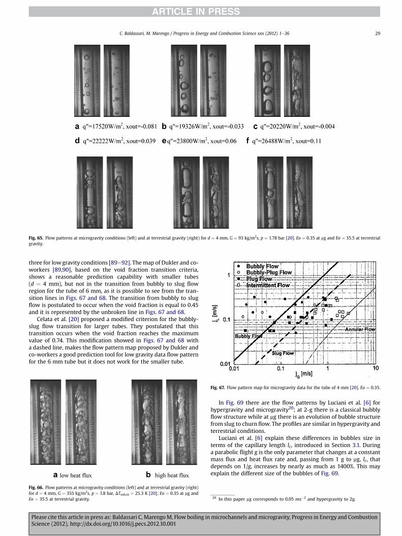
Fig. 65. Flow patterns at microgravity conditions (left) and at terrestrial gravity (right) for d ¼ 4 mm, G ¼ 93 kg/m2s, p ¼ 1.78 bar [20]. Eo ¼ 0.35 at mg and Eo ¼ 35.5 at terrestrialgravity.
C. Baldassari, M. Marengo / Progress in Energy and Combustion Science xxx (2012) 1e36 29
three for lowgravity conditions [89e92]. Themap of Dukler and co-workers [89,90], based on the void fraction transition criteria,shows a reasonable prediction capability with smaller tubes(d ¼ 4 mm), but not in the transition from bubbly to slug flowregion for the tube of 6 mm, as it is possible to see from the tran-sition lines in Figs. 67 and 68. The transition from bubbly to slugflow is postulated to occur when the void fraction is equal to 0.45and it is represented by the unbroken line in Figs. 67 and 68.
Celata et al. [20] proposed a modified criterion for the bubbly-slug flow transition for larger tubes. They postulated that thistransition occurs when the void fraction reaches the maximumvalue of 0.74. This modification showed in Figs. 67 and 68 witha dashed line, makes the flow pattern map proposed by Dukler andco-workers a good prediction tool for low gravity data flow patternfor the 6 mm tube but it does not work for the smaller tube.
Fig. 66. Flow patterns at microgravity conditions (left) and at terrestrial gravity (right)for d ¼ 4 mm, G ¼ 355 kg/m2s, p ¼ 1.8 bar, DTsub,in ¼ 25.3 K [20]; Eo ¼ 0.35 at mg andEo ¼ 35.5 at terrestrial gravity.
Fig. 67. Flow pattern map for microgravity data for the tube of 4 mm [20]. Eo ¼ 0.35.
Please cite this article in press as: Baldassari C, MarengoM, Flow boiling inScience (2012), http://dx.doi.org/10.1016/j.pecs.2012.10.001
In Fig. 69 there are the flow patterns by Luciani et al. [6] forhypergravity and microgravity20; at 2-g there is a classical bubblyflow structure while at mg there is an evolution of bubble structurefrom slug to churn flow. The profiles are similar in hypergravity andterrestrial conditions.
Luciani et al. [6] explain these differences in bubbles size interms of the capillary length lc, introduced in Section 3.1. Duringa parabolic flight g is the only parameter that changes at a constantmass flux and heat flux rate and, passing from 1 g to mg, lc, thatdepends on 1/g, increases by nearly as much as 1400%. This mayexplain the different size of the bubbles of Fig. 69.
20 In this paper mg corresponds to 0.05 ms�2 and hypergravity to 2g.
microchannels andmicrogravity, Progress in Energy and Combustion

Fig. 69. Conditions of hypergravity (top) andmicrogravity (bottom) for dh¼ 0.84mm, q00 ¼ 33
Fig. 68. Flow pattern map for microgravity data for the 6 mm tube [20]. Eo ¼ 0.8.
C. Baldassari, M. Marengo / Progress in Energy and Combustion Science xxx (2012) 1e3630
Please cite this article in press as: Baldassari C, MarengoM, Flow boiling inScience (2012), http://dx.doi.org/10.1016/j.pecs.2012.10.001
6.2. Heat transfer
When the heat transfer coefficient, measured in microgravityconditions, is compared with the values obtained at terrestrialgravity, two conflicting trends are obtained. In some experimentsthere is an enhancement of the heat transfer coefficient, in otherones there is deterioration of it. In parabolic flights the shortduration of microgravity conditions (22 s) does not allow a fulldevelopment of flow boiling heat transfer, thus spoiling theexperimental evidence. In Table 6 there is a summary of micro-gravity two-phase flow heat transfer research until 1994 [93]; thepapers on gaseliquid two-phase flow are not considered becausethe purpose of the present review is two-phase flow with phasechange of a single fluid component.
In 1997 Ohta [19] noted some problems in the existing researchin microgravity flow boiling: the available heat transfer data wereobtained only in the subcooled and low quality region, the effect ofgravity was not clarified in awider quality range and no critical heatflux measurement for the fundamental boiling system has beenconducted under microgravity. He measured the heat transfercoefficients of the test fluid Freon 113 for a given quality and heatflux by using a transparent heated tube having an internal diameter
kWm�2,Q¼ 2.6�10�4 kg s�1, Tsat¼ 54 �C [6]. Eo¼ 1.44 at 2 g and Eo¼ 3.67�10�3 at 0 g.
microchannels andmicrogravity, Progress in Energy and Combustion

Table 6Microgravity two-phase flow heat transfer research, concerning phase change of a single fluid component, until 1994 [93].
Authors Reduced gravityfacility
Test fluid Test section geometry Results
Papell [94] (1962) NASA Learjet Water 7.9 mm ID L ¼ 16.5 cm Microgravity heat transfer coefficient 16% higherFeldmanis [95] (1966) KC-135 Water 9.5 mm ID L ¼ 91.4 cm Higher boiling heat transfer coefficients at
microgravity (not explicitly measured)Reinarts et al. [96] (1992) KC-135 R-12 8.7 mm ID L ¼ 35.5 cm 26% lower condensation heat transfer coefficients
at microgravityOhta et al. [97] (1994) MU-300 Aircraft R-113 8 mm ID L ¼ 6.8 cm In the bubbly and annular flow regime: no
microgravity effectsWith nucleate boiling suppressed, the heat transfercoefficients were lower at microgravity
Table 7Effects of gravity on the heat transfer mechanisms [19].
Low quality (bubbly flow regime) Moderate quality(annular flow regime)
High quality (annular flow regime)
Dominant mode of heat transfer(at low mass velocity)
Low heat flux Nucleate boiling in subcooled orsaturated bulk flow of liquid
Two-phase forcedconvection
Two-phase forced convection
High heat flux Nucleate boiling Nucleate boiling inannular liquid film
Nucleate boiling in annular liquid film
Table 8Summary of the observations on the influence of gravity on heat transfer coefficient, recently presented in literature.
Author, test fluid and diameter of test section Observations on the heat transfer coefficient gravity effects
Ohta [98] a
Freon 1138 mm
- No gravity effects at high q"- In bubbly flow regime and low x, h is rather insensitive to gravity despite the distinct change of bubblebehavior
- No gravity effects for high x- h deteriorates in mg for medium x
Celata [21,87] FC-72 6, 4 and 2 mm Fig. 70 � mg leads to a larger bubble size which is accompanied by a deterioration of h- As the fluid velocity increases, the influence of g level on h tends to decrease, but this also depends on x
Luciani et al. [5] HFE-7100 0.49, 0.84, 1.18 mm,Fig. 71
- During mg, h is higher in comparison with the 1 g, and 1.8 g values- h is higher in the inlet minichannel and then decreases in the flow direction from the inlet to the outlet channelfor all gravity levels. In fact, as soon as the vapor occupies the whole of the minichannel, h falls to reach a valuethat characterizes heat transfer with only vapor phase
Luciani et al. [6] HFE-7100 0.49 mm Fig. 72 - h is higher in the inlet of minichannel independent of the g value and this agrees with the fact that at the inletthe flow has a low percentage of isolated bubbles
-h then decreases with the flow direction x and remains constant in the plain of the channel section- in mg h is higher and at the inlet is almost twice the value in 1 g, and 1.8 g- no differences between 1 g, and 1.8 g
a As in Table 7, only the results at low G are listed. From the experiments, the boundary of low and high G is around G ¼ 300 kg/m2s and the effects of gravity in extremelylow mass velocity G � 100 kg/m2s have not been clarified.
Fig. 70. Zero gravity map for the inter-relation between fluid velocity and quality ongravity effect in heat transfer [87].
0
1
2
3
4
5
6
0 10 20 30 40 50 60
x flow direction (mm)
h [k
W/m
2 K]
microgravity
hypergravity
terrestrial gravity
Fig. 71. Local heat transfer coefficient as a function of the main flow axis(q00 ¼ 32 kWm�2, Q¼ 2.6 � 10�4 kg s�1, x ¼ 0.26, dh ¼ 0.84 mm) [5]. Eo ¼ 3.67� 10�3 inmg, Eo ¼ 0.72 at terrestrial gravity and Eo ¼ 1.3 in hypergravity.
C. Baldassari, M. Marengo / Progress in Energy and Combustion Science xxx (2012) 1e36 31
Please cite this article in press as: Baldassari C, MarengoM, Flow boiling in microchannels andmicrogravity, Progress in Energy and CombustionScience (2012), http://dx.doi.org/10.1016/j.pecs.2012.10.001

0
2
4
6
8
10
12
14
16
0 10 20 30 40 50 60 x flow direction (mm)
h [k
W/m
2 K]
microgravity
hypergravity
terrestrial gravity
Fig. 72. Local heat transfer coefficient as a function of the main flow axis depending onthe gravity level (heat flux q00 ¼ 45 kWm�2, Q ¼ 4.2 � 10�4 kg s�1, dh ¼ 0.49 mm) [6].Eo ¼ 1.25 � 10�3 in mg, Eo ¼ 0.25 at terrestrial gravity and Eo ¼ 0.44 in hypergravity.
Table 10Flow pattern observed in [11,63,83] having an Eötvos number equal to 1.03.
Eötvos x Diameter
dh ¼ 0.8 mm dh ¼ 1.1 mm dh ¼ 1.03 mm
1.03 x < 0.005 Bubbly [83] Confinedbubble [11]
Isolated bubble [63]
x < 0.03 Bubbly,bubbly-slug [83]
Slug tochurn [11]
Isolated bubble [63]
x < 0.16 Bubbly-slugto slug [83]
Churn toannular [11]
Coalescing bubble [63]
x < 0.3 Slug to semiannular [83]
Annular [11] Annular [63]
x < 0.4 Semi annularto annular [83]
Annular [11] Annular [63]
x > 0.4 Annular [83] Annular [11] Annular [63]
Table 11Two group of experimental papers, [11,20,21,87] and [20,21,50,87], characterized bythe same Eo number.
Author Fluid dh Eo g-level
Celata et al. [20,21,87] FC-72 6 mm 0.8 0.01 gLin et al. [11] R-141b 1.1 mm 0.83 1 ga
Celata et al. [20,21,87] FC-72 4 mm 0.35 0.01 gRevellin et al. [50] R134a 0.5 mm 0.38 1 gb
a In Ref. [11] the quality correspondent to the transition was associated to twodifferent mass fluxes (G ¼ 365 kg/m2s and G ¼ 505 kg/m2s); since G does notinfluence Eo, the authors decide to consider the maximum quality range corre-spondent to each transition.
b All the data were observed for G ¼ 500 kg/m2s.
Table 12
C. Baldassari, M. Marengo / Progress in Energy and Combustion Science xxx (2012) 1e3632
of 8 mm. The experimental conditions covering all measurementsare: system pressure P¼ 0.11e0.22 MPa; mass velocity G¼ 150 and600 kg (m2 s)�1; inlet quality xin ¼ 0e0.8; q00 ¼ 5 � 103e1.5 � 105 Wm�2. Despite the change of g level, a constant flowratewas realized. The inlet quality of the heated tubewas increasedby the preheaters up to xin ¼ 0.8 at mass velocityG ¼ 150 kg m�2 s�1 for Freon under atmospheric pressure. For themeasurements of h for a given x, a constant value of q00 is suppliedcontinuously. Since g effects become weak at high G, most experi-ments were performed at lowmass velocity, G¼ 150 kg/m2s. In thispaper, reduced gravity level of about 10�2 g was referred asmicrogravity. No marked gravity effect on the heat transfer wasobserved in the case of high G because the bubble detachment ispromoted by the shear force exerted by the bulk liquid flow andthus no marked change in the bubble behavior and in the heattransfer is recognized with varying gravity level. The effects ofgravity on the heat transfer mechanisms are classified in Table 7 bythe combination of mass velocity, quality and heat flux.
The heat transfer due to two-phase forced convectionchanges with gravity: it is enhanced at 2 g and deteriorates atmg. In the case of low heat flux and high quality, the effects ofgravity on the behavior of annular liquid film are decreasedbecause of the increasing in thickness of annular liquid film andthe reduction of turbulence in it. In fact, the effect of the shearforce exerted by the vapor core flow with the increased velocityexceeds that of the gravitational force on the behavior of annularliquid film. No marked gravity effect was observed whennucleate boiling was the dominant mode of heat transfer. Athigh quality, observing the transition of h after the stepwise
Table 9Experimental papers [11,63,83] having the same Eo number.
Author Fluid dh Eo g-level
Lin et al. [11] R-141b 1.1 mm 1.03 1 ga
Ong et al. [63] R-245fa 1.03 mm 1.03 1 gRevellin et al. [83] R134a 0.8 mm 1.04 1 gb
a In Ref. [11] the quality correspondent to the transition was associated to twodifferent mass fluxes (G ¼ 365 kg/m2s and G ¼ 505 kg/m2s); since G does notinfluence Eo, the authors decide to consider the maximum quality range corre-spondent to each transition.
b In Ref. [83] the flow patterns are presented only for the 0.5 mm channel; theauthors decide to use these flow patterns as data for the 0.8 mm channels since in[63] it is underlined that the 0.8 mm diameter did not show any significant differ-ence to the 0.5 mm channel although bubbly/slug flow was present over a widerrange of mass flux.
Please cite this article in press as: Baldassari C, MarengoM, Flow boiling inScience (2012), http://dx.doi.org/10.1016/j.pecs.2012.10.001
increase of heat flux, Ohta [19] found that the value that criticalheat flux assumes under microgravity is not so different fromthe result of the terrestrial measurements. The results ofmicrogravity flow boiling experiments conducted in 1993e1999by Ohta are summarized in [98].
Table 8 gives a summary of the observations on the effect ofgravity level on the heat transfer coefficient from different authors.
The inter-relation between the fluid velocity and exit quality onthe gravity effect in heat transfer has preliminarily been quantifiedby Celata and Zummo [21,87]; they asserted that the influence ofgravity on h decreases with increasing of fluid velocity and theyconcluded that for low x, gravity influence can be neglected for fluidvelocity greater than 25 cm/s while for x > 0.3 h is unaffected bygravity level even at low velocities. In Fig. 70 a scheme of theexperimental flow patterns observed at 10�2 g [21,87] clarifies thecondition. The dashed line delimits the gravity influence region
Flow pattern observed in [11,20,21,50,87] in conditions of terrestrial gravity andmicrogravity classified in terms of Eötvos number.
Gravity level
1 g 0 g
Eötvos 0.35 x < 0.04 Bubbly [50] Bubbly [20,21,87]x < 0.19 Slug [50] Slug and intermittent
[20,21,87]x < 0.4 Semi-annular [50] Intermittent flow
[20,21,87]x < 0.82 Annular [50] Not examinated
0.8 x < 0.005 Confined bubble [11] Bubbly [20,21,87]x < 0.03 Slug to churn [11] Bubbly [20,21,87]x < 0.16 Churn to annular [11] Bubbly-slug and
slug [20,21,87]x < 0.3 Annular [11] Slug [20,21,87]x < 0.4 Annular [11] Intermittent [20,21,87]x > 0.4 Annular [11] Not examinated
microchannels andmicrogravity, Progress in Energy and Combustion

C. Baldassari, M. Marengo / Progress in Energy and Combustion Science xxx (2012) 1e36 33
from the region unaffected by gravity level; this dashed line movestowards higher ReL for higher tube diameter while it movestowards lower ReL for lower tube diameter.
Luciani et al. [5]useaninversemethodtoestimate theheat transfercoefficient of HFE-7100 in a rectangular minichannel. In Fig. 71 it ispossible to seewhat is summarized inTable 8. Luciani [5] asserted thatthe microgravity generates vapor pocket structures which fill thewidth of the minichannel to explain that h is locally higher.
Fig. 72 presents the experimental data published in [6] byLuciani et al. thanks to the experiments done during parabolicflights on board A300 Zero-G [5].
The authors [6] underlined that the results obtained inmicrogravity do not correspond with the theory; in fact generallymicrogravity conditions lead to a larger bubble size which isaccompanied by a deterioration in the heat transfer rate while in[6] the heat transfer in microgravity conditions is higher. None ofthe existing models can predict the behavior of the boiling heattransfer coefficient when the gravity level changes; more tests arenecessary to improve the knowledge and to validate futuremodels.
7. General considerations and conclusions
7.1. Considerations on the Eötvos number and flow patterns fordifferent gravity levels
With the purpose to compare the literature experimental datahaving the same Eo number, Table 9 provides a group of experi-mental papers each characterized by the same Eo number atterrestrial gravity.
In Table 10 are shown the flow patterns and flow pattern tran-sitions corresponding to data of Table 9. Note that the isolatedbubble regime includes both bubbly and slug flows.
From Table 10 it emerges that, independently from the diameter,the experiments with the same Eo numbers show the same flowpattern at least for a vapor quality x > 0.3. It would be interestingcomparing experimental data having the same Eo number and verydifferent diameters, for example, data obtained using a 5 mm and0.5 mm channel size. So far, in literature such data do not exist andhence a specific experimental activity is still necessary.
With the purpose to compare the literature experimental datahaving the same Eo number and different gravity levels, two groupsof experimental papers are presented in Table 11.
In Table 12 there are the observations on flow pattern and onflow pattern transitions corresponding to the data of Table 11.
From Table 12 it emerges that the Eo number is not sufficient tocharacterize the flow patterns, since, for the same Eo value, thecorresponding flow patterns at terrestrial gravity and microgravityare different. Hence there is the necessity of systematic experi-mental tests made at the same Eo number in order to check if thesedimensionless parameters could describe what is really changingfrom macroscale to microscale, i.e. the confinement of the bubbles.So far, Eo number is not a good parameter to describe this transitionand is not adequate to make a comparison between microgravityand microscale, since, as evidenced above, it is not significant inmicrogravity situations.
7.2. Conclusions
A large number of studies exist on two-phase flow in micro-channelsandmicrogravityandthis reviewwants tobeacritical guideto discover the good points, the uncertainties and the misconcep-tions. The boiling flow in microchannels is interesting and complex,and the research needs further experimental data for flow patterns,heat transfer coefficients and for the validation of theboilingmodels.
Please cite this article in press as: Baldassari C, MarengoM, Flow boiling inScience (2012), http://dx.doi.org/10.1016/j.pecs.2012.10.001
At microscale, it is very difficult to maintain a reasonable objectivityin the flow pattern identification, and this is the reason for theexistence of flow pattern maps that are quite different one from theother.Moreover, working at small dimensions, the importance of therelative errors during measurements of heat fluxes is much higher.Theseare someof themain reasonswhy theexperiments on the two-phaseflowcharacterization atmicroscale are still being carried on insuch an extensiveway. Avast amount of comparable and robust datafrom independent laboratories are necessary to obtain objectiveresults, and better characterized experimental data, including heattransfer data associated to flow pattern visualization and void frac-tion, are necessary to improve a coherent knowledge in this field.There is still a lackof a systematical evaluationof errorsandstatisticalaccuracy in thepresentation of the experimental results. The startingof a round-robin activity inmany laboratoryworldwideusing similarand certified test rigs, critically looking at the most importantphysical parameters, is absolutely urgent.
Defining the right length scale for which a transition betweenmacroscale to microscale phenomena should occur is only a mereexercise of categorization. Is there really one macroscale and onemicroscale regime in flow boiling? Considering the definition forwhich the flowboilingmicroscale is set when the bubbles are fillingcompletely the channel section (the so-called “confined bubbleflow”), there could be tubes of millimeters in which such conditionstill appears. Therefore it is better to speak about different patterns,rather than focusing on a feeble distinction linked to the channelsize. Of course, like for single-phase flows, going toward very smalltubes of fewmicrons size or even nanoscale diameters, the physicalphenomena can really change, since many classical hypotheses oncontinuum, on viscous dissipation and so on, may ceased to becompletely valid.
The paper is proposing in synoptic tables all the dimensionlessnumbers used in the field, with the introduction also of a recentnumber, here defined as Garimella number. A new consideration onthe effect of wettability is introduced together with the concept ofa “drag length”, i.e. a scale to define when the growing bubblesfrom a boiling surface are moved by the drag forces. This numbercould be particularly interesting for microgravity experiments.Critical considerations on the numbers are given, such as for the so-called Kandlikar numbers, K1 and K2.
Maps of the dimensionless number ranges spanned by theliterature data are given, together with a thorough discussion onthe necessity to cover particular unexplored ranges, even withhypergravity experiments. A comparison among the differentcriteria for the transition from macro to microscale phenomena isproposed, together with the rare considerations on the effect ofpressure drop along the tube, the vapor quality and the issue of themicrogravity environment.
The review is discussing the heat transfer mechanism and thestrong debate that is stirring the scientific community about thedominant phenomena in flow boiling. Instead of standing on oneside, the authors give all the elements to judge and compare, finallyconsidering that there are still experimental uncertainties, mis-concepts andweaknesses. A brief and partial excursus in the field ofboiling model is helping to address the main problem of under-standing the physical mechanisms and the difficulty to compare thedifferent results.
A resume of the heat transfer coefficients is labeled togetherwith the most interesting and feasible results. The open issue of theheat transfer coefficient as a function of thewall temperature is alsodiscussed.
A critical review of the flow patterns and the quality of theobservations is offered as a stimulus for a more homogeneousapproach, which may give the impulse for round-robin activities inorder to define all the parameters.
microchannels andmicrogravity, Progress in Energy and Combustion

C. Baldassari, M. Marengo / Progress in Energy and Combustion Science xxx (2012) 1e3634
Finally a comprehensive analysis of the few researchwork in thefield of flow boiling in microgravity conditions is givenwith the lastresults, both for flow patterns and for heat transfer mechanisms. Afirst tempative to resume and compare the results in form of tablesis suggested.
Finally, the review hopes to address some necessary futureexperiments to fill the open questions of the field
- compare experimental results, having the same Eötvosnumber, obtained in different gravity conditions;
- collect experimental data having Eo near 1.6 to improve theknowledge of the influence of Eötvos number on the macro tomicroscale transition;
- study boiling in microgravity and especially hypergravityconditions for channel having dh � 3 mm because there isa critical lack of data in the Eötvos number map of the existingliterature;
- further experiments are necessary in order to understand therole of Weber number in flow boiling;
- the void fraction should be more largely evaluatted since it isa very important but still neglected parameter. Despite thedifficulty to measure it, the comparison of the different resultsappears weak without its proper evaluation;
- future works are necessary to find the threshold for whichgravity level does not affect heat transfer and to clarify theincreasing or decreasing of heat transfer coefficient inmicrogravity;
- study the effect of drag on bubble detachment and slidingtogether with the effect of surfacewettability both in terrestrialand in microgravity conditions.
Acknowledgments
The work was financed by Italian Ministery of Universitythrough the project PRIN 2009 “Experimental and NumericalAnalysis of Two-Phase Phenomena in Microchannel Flows forGround and Space Applications”. Wewould like to acknowledge Dr.Stefano Dall’Olio for the experimental set-up in Bergamo, Dr. Ste-fano Zinna, Eng. Antonello Cattide and Dr. Mauro Mameli for thehelp and the discussions. The authors are grateful to Gian PieroCelata and John Richard Thome for their figures from the originalpapers.
References
[1] Crowe CT. Multiphase flow handbook. Taylor and Francis Group; 2006.[2] Shah MM. Chart correlations for saturated boiling heat transfer: equations and
further study. ASHRAE Transactions 1982;88(Part I):185e96.[3] Kandlikar SG. Heat transfer mechanisms during flow boiling in microchannels.
Journal of Heat Transfer 2004;126:8e16.[4] Ravigururajan TS, Cuta J, McDonald CE, Drost MK. Effect of heat flux on two-
phase flow characteristics of refrigerant flows in a micro-channel heatexchanger. In: Proceedings of national heat transfer conference, HTD-329(7).ASME; 1996. p. 167e78.
[5] Luciani S, Brutin D, Le Niliot C, Rahli O, Tadrist L. Flow boiling in minichannelsunder normal, hyper and microgravity: local heat transfer analysis usinginverse methods. Journal of Heat Transfer 2008;130:101502e11.
[6] Luciani S, Brutin D, Le Niliot C, Tadrist L, Rahli O. Boiling heat transfer ina vertical microchannel:local estimation during flow boiling with a nonintrusive method. Multiphase Science and Technology 2009;21(4):297e328.
[7] Hinze JO. Fundamentals of the hydrodynamic mechanism of splitting indispersion processes. AIChE Journal 1955;1(3):289e95.
[8] Steinke ME, Kandlikar SG. Flow boiling and pressure dropin parallel micro-channels. In: Proceedings of first international conference on microchannelsand minichannels; 2003, April 24e25. p. 567e79. Rochester, New York.
[9] Yan Y, Lin T. Evaporation heat transfer and pressure drop of refrigerant R-134ain a small pipe. International Journal of Heat Mass Transfer 1998;41:4183e94.
[10] Wambsganss MW, France DM, Jendrzejczyk JA, Tran TN. Boiling heat transferin horizontal small-diameter tube. ASME Journal of Heat Transfer 1993;115:963e72.
Please cite this article in press as: Baldassari C, MarengoM, Flow boiling inScience (2012), http://dx.doi.org/10.1016/j.pecs.2012.10.001
[11] Lin S, Kew PA, Cornwell K. Flow boiling of refrigerant R141B in small tubes.Transactions of IchemE 2001;79(A):417e24.
[12] Yen TH, Kasagi N, Suzuki Y. Forced convective boiling heat transfer at lowmass and heat fluxes. In: Proceedings of the international symposium oncompact heat exchangers. Grenoble: Edizioni ETS; 2002. p. 190.
[13] Kamidis DE, Ravigururajan TS. Single and two-phase refrigerant flow in mini-channels. In: Proceedings of 33rd national heat transfer conference; 1999,August 15e17. Albuquerque, New Mexico.
[14] Huo X, Chen L, Tian YS, Karayiannis TG. Flow boiling and flow regimes in smalldiameter tubes. Applied Thermal Engineering 2004;24:1225e39.
[15] Shiferaw D, Huo X, Karayannis TG, Kenning DBR. Examination of heat transfercorrelations and a model for flow boiling of R134a in small diameter tubes.International Journal of Heat and Mass Transfer 2007;50:5177e93.
[16] Chen L, Tian YS, Karayiannis TG. The effect of tube diameter on vertical two-phase flow regimes in small tubes. International Journal of Heat Mass Transfer2006;49:4220e30.
[17] Ullmann A, Brauner N. The prediction of flow pattern maps in minichannels.Multiphase Science and Technology 2007;19(1):49e73.
[18] Ohta H. Review of reduced gravity boiling heat transfer: Japanese research.Japan Society of Microgravity Application 2003;20(4):272e85.
[19] Ohta H. Experiments on microgravity boiling heat transfer by using trans-parent heaters. Nuclear Engineering and Design 1997;175:167e80.
[20] Celata GP, CumoM, Gervasi M, Zummo G. Flow pattern analysis of flow boilingin microgravity. Multiphase Science and Technology 2007;19(2):183e210.
[21] Celata GP, Zummo G. Flow boiling heat transfer in microgravity: recentprogress. Multiphase Science and Technology 2009;21(3):187e212.
[22] Morini GL. Single-phase convective heat transfer in laminar and transitionalregime in microchannels. In: ECI international conference on heat transferand fluid flow in microscale; 2008, September 21e26. Whistler.
[23] Celata GP, Lorenzini M, McPhail SJ, Morini GL, Zummo G. Experimentalanalysis of liquid forced convection in rough microtubes. In: Proc. of 5theurotherm European thermal science conference; 2008, May 19e22.Eindhoven.
[24] Kandlikar SG. Two-phase flow patterns, pressure drop and heat transferduring boiling in minichannel and microchannel flow passages of compactheat exchanger. Compact heat exchangers and enhancement technology forthe process industries. New York: Begell House; 2001. p. 319e34.
[25] Thome JR. Boiling in microchannels: a review of experiment and theory.International Journal of Heat and Fluid Flow 2004;25:128e39.
[26] Thome JR, Dupont V, Jacobi AM. Heat transfer model for evaporation inmicrochannels, part I: presentation of the model. International Journal of Heatand Mass Transfer 2004;47:3375e85.
[27] Thome JR. Wolverine engineering data book III.[28] Kew PA, Cornwell K. Correlations for the prediction of boiling heat transfer in
small diameter channels. Applied Thermal Engineering 1997;17:705e15.[29] Ribatski G, Wojtan L, Thome JR. An analysis of experimental data and
prediction methods for two-phase frictional pressure drop and flow boilingheat transfer in micro-scale channels. Experimental Thermal and FluidScience 2006;31:1e19.
[30] Li JM, Wang BX. Size effect on two-phase regime for condensation in micro/mini tubes. Heat Transfer Asian Research 2003;32:65e71.
[31] Cheng P, Wu HY. Mesoscale and microscale phase change heat transfer.Advances in Heat Transfer 2006;39:461e563.
[32] Harichian T, Garimella S. A comprehensive flow regime map for microchannelflow boiling with quantitative transition criteria. International Journal of Heatand Mass Transfer 2010;53:2694e702.
[33] Lockhart RW, Martinelli RC. Proposed correlation of data for isothermal two-phase, two component flow in pipes. Chemical Engineering Progress 1949;45:39e48.
[34] Chisholm D. A theoretical basis for the LockharteMartinelli correlation fortwo-phase flow. International Journal of Heat Mass Transfer 1967;10:1767e78.
[35] Revellin R, Thome JR. A new type of diabatic flow pattern map for boiling heattransfer in microchannels. Journal of Micromechanics and Microengineering2007;17:788e96.
[36] Vadgama B, Harris DK. Measurements of the contact angle between R134aand both aluminum and copper surfaces. Experimental Thermal and FluidScience 2007;31:979e84.
[37] Gao L, McCarthy TJ. Contact angle hysteresis explained. Langmuir 2006;22:6234e7.
[38] Celata GP. Single and two-phase flow heat transfer in micropipes. In: 5thEuropean thermal-sciences conference; 2008. The Netherlands.
[39] Lee J, Mudawar I. Two-phase flow in high-heat-flux micro-channel heat sinkfor refrigeration cooling applications: part II-heat transfer characteristics.International Journal of Heat and Mass Transfer 2005;48:941e55.
[40] Bao ZY, Fletcher DF, Haynes BS. Flow boiling heat transfer on Freon R11 andHFCFC123 in narrow passages. International Journal of Heat and MassTransfer 2000;43:3347e58.
[41] Lin S, Kew PA, Cornwell K. Two-phase heat transfer to a refrigerant in a 1 mmdiameter tube. In: 6th UK heat transfer conference in Edinburgh; September1999.
[42] Yen TH, Shoji M, Takemura F, Suzuki Y, Kasagi N. Visualization of convec-tive boiling heat transfer in single microchannels with different shapedcross-sections. International Journal of Heat and Mass Transfer 2006;49:3884e94.
microchannels andmicrogravity, Progress in Energy and Combustion

C. Baldassari, M. Marengo / Progress in Energy and Combustion Science xxx (2012) 1e36 35
[43] Jacobi AM, Thome JR. Heat transfer model for evaporation of elongated bubbleflows in microchannels. Journal of Heat Transfer 2002;124:1131e6.
[44] Cheng P, Wang G, Quan X. Recent work on boiling and condensation inmicrochannels. ASME Journal of Heat Transfer 2009;(4):131.
[45] Harirchian T, Garimella SV. The critical role of channel cross-sectional area inmicrochannel flow boiling heat transfer. International Journal of MultiphaseFlow 2009;35:904e13.
[46] Huh C, Kim MH. Pressure drop, boiling heat transfer and flow patternsduring flow boiling in a single microchannel. Heat Transfer Engineering2007;28(8e9):730e7.
[47] Revellin R, Thome JR. Experimental investigation of R-134a and R-245fa two-phase flow in microchannels for different flow conditions. In: ECI interna-tional conference on heat transfer and fluid flow in microscale; 2005. 25e30September, Castelvecchio Pascoli, Italy.
[48] Harirchian T, Garimella SV. Boiling heat transfer and flow regimes inmicrochannels-a comprehensive understanding. Journal of Electronic Pack-aging 2011;133:011001e10.
[49] Dupont V, Thome JR, Jacobi AM. Heat transfer model for evaporation inmicrochannels, part II: comparison with the database. International Journal ofHeat and Mass Transfer 2004;47:3387e401.
[50] Revellin R, Dupont V, Ursenbacher T, Thome JR, Zun I. Characterization of dia-batic two-phase flows in microchannels: flow parameter results for R-134a ina 0.5 mm channel. International Journal of Multiphase Flow 2006;32:755e74.
[51] Agostini B, Thome JR. Comparison of an extended database for flow boilingheat transfer coefficients in multi-microchannels elements with the three-zone model. ECI heat transfer and fluid flow in microscale. CastelvecchioPascoli, Italy, Sept. 25e30; 2005.
[52] Harirchian T, Garimella S. Flow regime-based modeling of heat transfer andpressure drop in microchannel flow boiling. International Journal of Heat andMass Transfer 2012;55:1246e60.
[53] Cooper MG. Saturated nucleate pool boiling-a simple correlation. In: 1st UKnational heat transfer conference. IChemE symposium series, vol. 86(2); 1984.p. 785e93.
[54] WhanNa Y, Chung JN. Two-phase annular flow and evaporative heat transfer ina microchannel. International Journal of Heat and Fluid Flow 2011;32:440e50.
[55] Cioncolini A, Thome JR. Algebraic turbulence modeling in adiabatic andevaporating annular two-phase flow. International Journal of Heat and FluidFlow 2011;32:805e17.
[56] Cioncolini A, Thome JR. Prediction of the entrained liquid fraction in verticalannular gaseliquid two-phase flow. International Journal of Multiphase Flow2010;36-4:293e302.
[57] Cioncolini A, Thome JR, Lombardi C. Unified macro-to-microscale method topredict two-phase frictional pressure drops of annular flows. InternationalJournal of Multiphase Flow 2009;35-12:1138e48.
[58] Thome JR. State of the art overview of boiling and two-phase flows inmicrochannels. Heat Transfer Engineering 2006;27-9:4e19.
[59] Shiferaw D, Karayannis TG, Kenning DBR. A comparison with the three-zonemodel for flow boiling heat transfer in small diameter tubes. In: 13th inter-national heat transfer conference; 2006. Sydney, Australia.
[60] Shiferaw D, Karayannis TG, Kenning DBR. Flow boiling in a 1.1 mm tube withR134a: experimental results and comparison with model. InternationalJournal of Thermal Sciences 2009;48:331e41.
[61] Consolini L, Thome JR. A heat transfer model for evaporation of coalescingbubbles in micro-channel flow. International Journal of Heat and Fluid Flow2010;31:115e25.
[62] Liu TJ, Tian Y, Peng XF. Bubble characteristics during boiling microchannels.In: 3rd international conference on microchannels and minichannels; June13e15, 2005. Toronto, Ontario, Canada.
[63] Ong CL, Thome JR. Flow boiling heat transfer of R134a, R236fa and R245fa ina horizontal 1.030 mm circular channel. Experimental Thermal and FluidScience 2009;33:651e63.
[64] Lazarek GM, Black SH. Evaporative heat transfer, pressure drop and criticalheat flux in a small vertical tube with R-113. International Journal of Heat andMass Transfer 1982;25-7:945e60.
[65] Tran TN, Wambsganss MW, France DM. Small circular- and rectangularchannel boiling with two refrigerants. International Journal of MultiphaseFlow 1996;22-3:485e98.
[66] Kandlikar SG, Balasubramanian P. An extension of the flow boiling correlationto transition, laminar and deep laminar flows in mini-channels and micro-channels. Heat Transfer Engineering 2004;25-3:86e93.
[67] Zhang W, Hibiki T, Mishima K. Correlation for flow boiling heat transfer inmini-channels. International Journal of Heat and Mass Transfer 2004;47:5749e63.
[68] Bertsh SS, Groll EA, Garimella SV. Review and comparative analysis of studieson saturated flow boiling in small channels. Nanoscale and Microscale Ther-mophysical Engineering 2008;13-3:187e227.
[69] Bertsch SS, Groll EA, Garimella SV. Effects of heat flux, mass flux, vaporquality, and saturation temperature on flow boiling heat transfer in micro-channels. International Journal of Multiphase Flow 2009;35:142e54.
[70] Consolini L, Thome JR. Micro-channel flow boiling heat transfer of R-134a, R-236fa and R-245fa. Microfluid Nanofluid 2009;6:731e46.
[71] Dupont V, Thome JR. Evaporation in microchannels: influence of the channeldiameter on heat transfer. Microfluid Nanofluid 2005;1:119e27.
[72] Lin S, Kew PA, Cornwell K. Two-phase heat transfer to a refrigerant in a 1 mmdiameter tube. International Journal of Refrigeration 2001;24:51e6.
Please cite this article in press as: Baldassari C, MarengoM, Flow boiling inScience (2012), http://dx.doi.org/10.1016/j.pecs.2012.10.001
[73] Kandlikar SG, Mizo V, Cartwright M, Ikenze E. Bubble nucleation and growthcharacteristics in subcooled flow boiling of water. In: ASME national heattransfer conference, vol. 4; 1997. p. 11e8.
[74] Zeitoun O, Shoukri M. Bubble behavior and mean diameter in subcooled flowboiling. ASME Journal of Heat Transfer 1996;118:110e6.
[75] Chang SH, Bang IC, Baek WP. A photographic study on the near-wall bubblebehavior in subcooled flow boiling. International Journal of Thermal Science2002;41:609e18.
[76] Yin CP, Yan YY, Lin TF, Yang BC. Subcooled flow boiling heat transfer of R-134aand bubble characteristics in a horizontal annular duct. International Journalof Heat Mass Transfer 2000;43:1885e96.
[77] Chen CA, Chang WR, Li KW, Lie YM, Lin TF. Subcooled flow boiling heattransfer of R-407C and associated bubble characteristics in a narrow annularduct. International Journal of Heat and Mass Transfer 2009;52:3147e58.
[78] Zhuan R, Wang W. Simulation of subcooled flow boiling in a micro-channel.International Journal of Refrigeration 2011;34:781e95.
[79] Celata GP, Cumo M, Mariani A. Experimental evaluation of the onset of sub-cooled flow boiling at high liquid velocity and subcooling. InternationalJournal of Heat Mass Transfer 1997;40(12):2879e85.
[80] Harirchian T, Garimella SV. Effects of channel dimension, heat flux, and massflux on flow boiling regimes in microchannels. International Journal ofMultiphase Flow 2009;35:349e62.
[81] Cornwell K, Kew PA. Boiling in small channels. In: Proceedings of conferenceon energy efficiency in process technology. Athens: Elsevier; 1992. p. 624e38.
[82] Lin S, Kew PA, Cornwell K. Two-phase flow regimes and heat transfer in smalltubes and channels. In: Proceedings of 11th international heat transferconference, vol. 2; 1998. p. 45e50. Kyongju, Korea.
[83] Revellin R, Thome JR. Experimental investigation of R-134a and R-245fa two-phase flow in microchannels for different flow conditions. InternationalJournal of Heat and Fluid Flow 2007;28(1):63e71.
[84] Zhang L, Koo JM, Jiang L, Asheghi M, Goodson KE, Santiago JG, et al.Measurements and modeling of two-phase flow in microchannels with nearlyconstant heat flux boundary conditions. Journal of MicroelectromechanicalSystems 2002;11(1):12e9.
[85] Revellin R, Agostini B, Thome JR. Elongated bubbles in microchannels, Part II:experimental study and modeling of bubble collision. International Journal ofMultiphase Flow 2008;34:602e13.
[86] Agostini B, Revellin R, Thome JR. Elongated bubbles in microchannels, Part I:experimental study and modeling of elongated bubble velocity. InternationalJournal of Multiphase Flow 2008;34:590e601.
[87] Celata GP. Flow boiling heat transfer in microgravity: recent results. Micro-gravity Science Technology 2007;XIX-3/4:13e7.
[88] McQuillan KW, Whalley PB. Flow patterns in vertical two-phase flow. Inter-national Journal of Multiphase Flow 1985;11:161e75.
[89] Colin C, Fabre JA, Dukler AE. Gas-liquid flow at microgravity conditions-I.Dispersed bubble and slug flow. International Journal of Multiphase Flow1991;17:533e44.
[90] Dukler AE, Fabre JA, McQuillen JB, Vernon R. Gas-liquid flow at microgravityconditions: flow patterns and their transitions. International Journal ofMultiphase Flow 1988;14:389e400.
[91] Zhao L, Rezkallah KS. GA-liquid flow patterns at microgravity conditions.International Journal of Multiphase Flow 1993;19:751e63.
[92] Jayawardena SS, Balakotaiah V, Witte LC. Pattern transition maps for micro-gravity two-phase flows. AIChE Journal 1997;43:1637e40.
[93] Rite RW, Rezkallah KS. Heat transfer in forced-convective two-phase flowsunder microgravity conditions: analysis. Multiphase Science and Technology2001;13:113e37.
[94] Papell SS. An instability effect on two-phase heat transfer for subcooled waterflowing under conditions of zero gravity. American Rocket Society 17thAnnual Meeting and Space Flight Exposition; 1962.
[95] Feldmanis CJ. Pressure and temperature changes in closed loop forced convec-tion boiling and condensing processes under zero gravity conditions. In: Annualtechnical meeting proceedings. Institute of Environmental Sciences; 1966.
[96] Reinarts TR, Best FR, Hill WS. Definition of condensation two-phase flowbehaviors for spacecraft design. In: EL-Genk MS, Hoover MD, editors. AIPconference, vol. 1. New York: American Institute of Physics; 1992. p. 1216e25.Proc. No. 246.
[97] Ohta H, Fukiyama H, Inoue K, Yamada Y, Ishikura S, Yoshida S. Microgravityflow boiling in a transparent tube. In: 10th international heat transferconference; 1994. Brighton (England), No. 111.
[98] Ohta H. Microgravity heat transfer in flow boiling. Advances in Heat Transfer2003;37.
Chiara Baldassari, M.Sc. She got the High School degree at Liceo Scientifico “L.Lotto” inTrescore Balneario with a final score of 98/100 in 2000. Bachelor and Master Degree inPhysics at the Catholic University of Brescia with 110 cum laude and a M.Sc. Thesisabout dosimetric characterization of intensity modulated radiation therapy at theMedical Physics department of “Ospedali Riuniti” of Bergamo. She taught math andphysics in high schools for two years and she is research assistant of General Physics atthe University of Bergamo since 2007. In July 2007, she was awarded a scholarship toinvestigate “Materials and devices for the Hydrogen economy” at the College ofEngineering of the University of Bergamo at Dalmine. From 2009 she is PhD student,working in the Thermo Fluid Heat Transfer group, studying the onset of nucleateboiling in minitubes.
microchannels andmicrogravity, Progress in Energy and Combustion

C. Baldassari, M. Marengo / Progress in Energy and Combustion Science xxx (2012) 1e3636
Prof. Marco Marengo Degree in Physics, Ph.D. in Energy Engineering at Poli-tecnico of Milan. Associate Professor of Thermal Physics at University of Bergamo.From 2003 to 2006 he was the University Responsible for the European Research.Editor of the International Journal “Atomization & Sprays Journal”, Begell House.Referee for many international journals, among them: “Experiment in Fluids”,“Atomization & Sprays Journal”, “International Journal of Heat and Mass Transfer”.European Newsletter Editor for ILASS Europe from 2003 to 2009. He has beeninvolved in many research projects with Italian and European Space Agency and
Please cite this article in press as: Baldassari C, MarengoM, Flow boiling inScience (2012), http://dx.doi.org/10.1016/j.pecs.2012.10.001
he is active in the parabolic campaigns with experiment on flow boiling. VisitingProfessor at University of Mons-Hainaut since 2005. Member of the journal edito-rial boards of “Journal of Heat Pipe Science and Technology” and “InternationalReview of Chemical Engineering”. He published more than 140 scientific papersin Journals and International Conferences and he gave 26 invited lectures in Inter-national Conferences and in University workshops. Prof. Marengo has 5 Europeanpatents. He is founder of the academic spin-off UNIHEAT srl and the start-upICENOVA srl.
microchannels andmicrogravity, Progress in Energy and Combustion