Flow boiling in microgravity: Part 2 – Critical heat flux interfacial behavior, experimental data,...
16
Flow boiling in microgravity: Part 2 – Critical heat flux interfacial behavior, experimental data, and model Christopher Konishi a , Hyoungsoon Lee a , Issam Mudawar a,⇑ , Mohammad M. Hasan b , Henry K. Nahra b , Nancy R. Hall b , James D. Wagner b , Rochelle L. May b , Jeffrey R. Mackey c a Purdue University Boiling and Two-Phase Flow Laboratory (PU-BTPFL), School of Mechanical Engineering, 585 Purdue Mall, West Lafayette, IN 47907, USA b NASA Glenn Research Center, 21000 Brookpark Road, Cleveland, OH 44135, USA c Vantage Partners, LLC, 3000 Aerospace Parkway, Brook Park, OH 44142, USA article info Article history: Received 9 August 2014 Received in revised form 21 October 2014 Accepted 21 October 2014 Available online 21 November 2014 Keywords: Microgravity Flow boiling Interfacial behavior Critical heat flux abstract This study is the second part of a two-part investigation of flow boiling critical heat flux (CHF) in micro- gravity, which is simulated in parabolic flight experiments. Using FC-72 as working fluid, flow boiling experiments are conducted in a rectangular channel fitted with two opposite heated walls, allowing either one or both heated walls to be activated during a test. While the first part explored flow boiling conditions leading to CHF, this part addresses events just before CHF, during the CHF transient, and immediately following CHF. For both single-sided and double-sided heating, interfacial behavior just before CHF is char- acterized by dominant wavy vapor layers covering the heated walls, where liquid is able to access the walls only in wetting fronts corresponding to the wave troughs. CHF is associated with successive lift-off of wetting fronts from the walls, consistent with the Interfacial Lift-off Model, which has been validated extensively in past studies using single-sided heating in both lg e and 1 g e . It is shown this model predicts lg e double-sided flow boiling CHF with excellent accuracy. Additionally, the model points to convergence of CHF values for lg e and 1 g e for inlet velocities greater than about 1 m/s. Therefore, by maintaining velocities above this threshold allows designers of space systems to achieve inertia- dominated performance as well as to adopt prior data and correlations developed from terrestrial studies. Ó 2014 Published by Elsevier Ltd. 1. Introduction 1.1. Implementation of flow boiling and condensation in future space missions For decades, thermal management onboard manned space vehi- cles has been tackled by conventional single-phase systems that absorb the heat by raising the sensible heat of an appropriate cool- ant, and reject it to deep space via a space radiator. This type of sys- tem has been used successfully on all of NASA’s Space Shuttles. However, there is now specific interest in long duration space mis- sions, especially the manned mission to Mars, which are expected to pose many technological challenges, especially the need to greatly increase energy efficiency and reduce both the weight and volume of the entire systems [1,2], including the Thermal Control System (TCS) responsible for maintaining the temperature and humidity of the operating environment. These benefits will be realized by shifting from present single-phase liquid thermal man- agement to two-phase counterpart. By capitalizing on both sensi- ble and latent heat of the coolant instead of sensible heat alone, two-phase systems can yield orders of magnitude enhancement in flow boiling and condensation heat transfer coefficients while significantly reducing the temperature of the heat dissipating device compared to single-phase systems. Two-phase thermal management systems utilizing flow boiling and condensation have attracted significant interest in recent years in many applications demanding efficient heat removal from high- power-density devices, including computer data centers, hybrid vehicle power electronics and avionics [3,4]. The effectiveness of these systems has been demonstrated using a variety of boiling configurations, including pool [5,6], macro-channel flow [7,8], micro-channel flow [9], jet [10,11], and spray [12–14], as well as hybrid schemes combining the merits of two or more boiling configurations [15,16]. However, the feasibility of a particular boiling configuration in a space vehicle’s TCS is dependent on a number of considerations, which include, aside from reduced weight and volume, low pump- ing power and the ability to manage phase separation in a closed http://dx.doi.org/10.1016/j.ijheatmasstransfer.2014.10.052 0017-9310/Ó 2014 Published by Elsevier Ltd. ⇑ Corresponding author. Tel.: +1 (765) 494 5705; fax: +1 (765) 494 0539. E-mail address: [email protected] (I. Mudawar). URL: https://engineering.purdue.edu/BTPFL (I. Mudawar). International Journal of Heat and Mass Transfer 81 (2015) 721–736 Contents lists available at ScienceDirect International Journal of Heat and Mass Transfer journal homepage: www.elsevier.com/locate/ijhmt
-
Upload
independent -
Category
Documents
-
view
5 -
download
0
Transcript of Flow boiling in microgravity: Part 2 – Critical heat flux interfacial behavior, experimental data,...
International Journal of Heat and Mass Transfer 81 (2015) 721–736
Contents lists available at ScienceDirect
International Journal of Heat and Mass Transfer
journal homepage: www.elsevier .com/locate / i jhmt
Flow boiling in microgravity: Part 2 – Critical heat flux interfacialbehavior, experimental data, and model
http://dx.doi.org/10.1016/j.ijheatmasstransfer.2014.10.0520017-9310/� 2014 Published by Elsevier Ltd.
⇑ Corresponding author. Tel.: +1 (765) 494 5705; fax: +1 (765) 494 0539.E-mail address: [email protected] (I. Mudawar).URL: https://engineering.purdue.edu/BTPFL (I. Mudawar).
Christopher Konishi a, Hyoungsoon Lee a, Issam Mudawar a,⇑, Mohammad M. Hasan b, Henry K. Nahra b,Nancy R. Hall b, James D. Wagner b, Rochelle L. May b, Jeffrey R. Mackey c
a Purdue University Boiling and Two-Phase Flow Laboratory (PU-BTPFL), School of Mechanical Engineering, 585 Purdue Mall, West Lafayette, IN 47907, USAb NASA Glenn Research Center, 21000 Brookpark Road, Cleveland, OH 44135, USAc Vantage Partners, LLC, 3000 Aerospace Parkway, Brook Park, OH 44142, USA
a r t i c l e i n f o a b s t r a c t
Article history:Received 9 August 2014Received in revised form 21 October 2014Accepted 21 October 2014Available online 21 November 2014
Keywords:MicrogravityFlow boilingInterfacial behaviorCritical heat flux
This study is the second part of a two-part investigation of flow boiling critical heat flux (CHF) in micro-gravity, which is simulated in parabolic flight experiments. Using FC-72 as working fluid, flow boilingexperiments are conducted in a rectangular channel fitted with two opposite heated walls, allowing eitherone or both heated walls to be activated during a test. While the first part explored flow boiling conditionsleading to CHF, this part addresses events just before CHF, during the CHF transient, and immediatelyfollowing CHF. For both single-sided and double-sided heating, interfacial behavior just before CHF is char-acterized by dominant wavy vapor layers covering the heated walls, where liquid is able to access thewalls only in wetting fronts corresponding to the wave troughs. CHF is associated with successivelift-off of wetting fronts from the walls, consistent with the Interfacial Lift-off Model, which has beenvalidated extensively in past studies using single-sided heating in both lge and 1 � ge. It is shown thismodel predicts lge double-sided flow boiling CHF with excellent accuracy. Additionally, the model pointsto convergence of CHF values for lge and 1 � ge for inlet velocities greater than about 1 m/s. Therefore, bymaintaining velocities above this threshold allows designers of space systems to achieve inertia-dominated performance as well as to adopt prior data and correlations developed from terrestrial studies.
� 2014 Published by Elsevier Ltd.
1. Introduction realized by shifting from present single-phase liquid thermal man-
1.1. Implementation of flow boiling and condensation in future spacemissions
For decades, thermal management onboard manned space vehi-cles has been tackled by conventional single-phase systems thatabsorb the heat by raising the sensible heat of an appropriate cool-ant, and reject it to deep space via a space radiator. This type of sys-tem has been used successfully on all of NASA’s Space Shuttles.However, there is now specific interest in long duration space mis-sions, especially the manned mission to Mars, which are expectedto pose many technological challenges, especially the need togreatly increase energy efficiency and reduce both the weightand volume of the entire systems [1,2], including the ThermalControl System (TCS) responsible for maintaining the temperatureand humidity of the operating environment. These benefits will be
agement to two-phase counterpart. By capitalizing on both sensi-ble and latent heat of the coolant instead of sensible heat alone,two-phase systems can yield orders of magnitude enhancementin flow boiling and condensation heat transfer coefficients whilesignificantly reducing the temperature of the heat dissipatingdevice compared to single-phase systems.
Two-phase thermal management systems utilizing flow boilingand condensation have attracted significant interest in recent yearsin many applications demanding efficient heat removal from high-power-density devices, including computer data centers, hybridvehicle power electronics and avionics [3,4]. The effectiveness ofthese systems has been demonstrated using a variety of boilingconfigurations, including pool [5,6], macro-channel flow [7,8],micro-channel flow [9], jet [10,11], and spray [12–14], as well ashybrid schemes combining the merits of two or more boilingconfigurations [15,16].
However, the feasibility of a particular boiling configuration in aspace vehicle’s TCS is dependent on a number of considerations,which include, aside from reduced weight and volume, low pump-ing power and the ability to manage phase separation in a closed
Nomenclature
A cross-sectional area of flow channelAw,w area of wetting frontb ratio of wetting front length to wavelengthCf,i interfacial friction coefficientc wave speedci imaginary component of wave speedcp specific heat at constant pressurecr real component of wave speedD hydraulic diameterf friction factorG mass velocityg gravityge Earth’s gravitational accelerationH height of flow channel’s cross-sectionhfg latent heat of vaporizationk wave numberL lengthLd development length of flow channelLe exit length of channelLh heated length of channelMAE mean absolute error_m mass flow rate
N number of data pointsp pressurePi interfacial perimeterPw wall friction perimeterq00m critical heat fluxq00w wall heat fluxq00w;w wetting front heat fluxRe Reynolds numberT temperaturet timeTin inlet temperatureTsat saturation temperatureTw wall temperatureDTsub,in inlet subcooling, Tsat � Tin
U mean inlet liquid velocity; mean axial velocityui interfacial velocityW width of flow channel’s cross-sectionx flow qualityy coordinate normal to heated wall
z axial distancezo axial location where vapor layer velocity just exceeds li-
quid layer velocityz⁄ axial location for determining vapor layer thickness and
critical wavelength in Interfacial Lift-off Model
Greek symbolsa vapor void fractionCfg evaporation rate per unit distanced mean vapor layer thicknessg interfacial perturbationg0 amplitude of interfacial perturbationh flow orientation anglek wavelengthkc critical wavelengthl dynamic viscosityq densityq00 modified densityr surface tensionsi interfacial shear stresssw wall shear stress
Subscriptsest estimatedexp experimental (measured)f saturated liquid; bulk liquidg saturated vapori interfacialin inlet to heated portion of flow channelk phase k, k = g or fm maximum (CHF); heated wall identifier (m = 1 for H1,
m = 2 for H2)n normal to heated wall; thermocouple location along
heated wallo outlet from heated portion of flow channelpred predictedsat saturationsub subcoolingw wall; wetting front
722 C. Konishi et al. / International Journal of Heat and Mass Transfer 81 (2015) 721–736
TCS loop in microgravity. These considerations preclude spray andjet configurations as viable options. Pool boiling is also veryproblematic in microgravity because it has been shown to producemassive bubbles upon the heated wall that significantly decreasecritical heat flux (CHF) compared to terrestrial pool boiling [17].These reasons are why flow boiling, using macro-channels ormicro-channels, is presently the configuration most favored forthe space vehicle’s TCS. Even in microgravity, flow inertia in flowboiling serves to maintain high CHF by flushing bubbles away fromthe heated wall before they coalesce into insulating blankets, andby maintaining liquid replenishment of the heated wall. This isespecially important to heat-flux-controlled devices, such as avion-ics, where CHF occurrence can lead to physical meltdown, burnout,or catastrophic damage to the heat-dissipating surface andsurrounding components.
But, while the merits of flow boiling are well acknowledged,design engineers lack the data and technical knowhow to assessthe influence of reduced gravity on flow boiling CHF. Flow boilingis obviously highly influenced by the large density differencesbetween liquid and vapor, which, in the terrestrial environment,
yield an appreciable buoyancy force that helps dictate both flowbehavior and heat transfer effectiveness. However, in reducedgravity, especially microgravity, body force is much weaker, mean-ing flow behavior is dictated more by other forces such as inertiaand surface tension. This brings into question the applicability ofterrestrial flow boiling data, models and correlations to reducedgravity. To correct this knowledge gap, flow boiling experimentsmust be performed in reduced gravity, aided by flow visualizationmethods, to facilitate a comprehensive fundamental understand-ing of interfacial behavior and the roles of dominant forces.
1.2. Postulated mechanisms for flow boiling CHF in Earth gravity
CHF is arguably the most important design parameter for flowboiling systems involving thermal management of heat-flux-con-trolled surfaces. Most attempts to model flow boiling CHF concernvertical upflow in Earth gravity, which is the orientation that pro-vides both stable two-phase flow and favorable CHF values. Themost crucial component of these models is predicting the physicalmechanism responsible for initiating – triggering – flow boiling
C. Konishi et al. / International Journal of Heat and Mass Transfer 81 (2015) 721–736 723
CHF. Four popular mechanisms have been proposed: BoundaryLayer Separation, Bubble Crowding, Sublayer Dryout, and InterfacialLift-off. The Boundary Layer Separation Model [18,19] utilizesanalogy between wall gas injection – transpiration – into asingle-phase liquid boundary layer and wall vapor effusion in flowboiling. As injection velocity into a liquid boundary layer isincreased to a critical value, the velocity gradient near the wallbecomes vanishingly small, causing the boundary layer to separatefrom the wall. By analogy, CHF is assumed to occur when the rateof vapor effusion perpendicular to the wall in flow boiling reachesa threshold that triggers sharp reduction in velocity gradient ofliquid flow adjacent to the heated wall, which causes separationof the liquid boundary layer and extinguishes liquid replenishmentof the heated wall. The Bubble Crowding Model [20,21] is based onan entirely different depiction of the flow adjacent to the heatedwall. Here, severe boiling causes accumulation of oblong bubblesnear the wall, and CHF is postulated to occur when the bubblylayer becomes too crowded with bubbles to permit turbulent fluc-tuations in the core liquid to supply adequate liquid to the wall.The Sublayer Dryout Model [22] depicts the formation of oblongvapor blankets along the heated wall, trapping thin liquid sublay-ers, which are sustained by liquid replenishment from the bulkliquid. CHF is postulated to occur when the heat supplied fromthe wall exceeds the enthalpy of bulk liquid replenishing thesublayer. The Interfacial Lift-off Model [23,24] is based on theobservation that vigorous boiling generates vapor patches alongthe heated wall, which coalesce into a fairly continuous wavyvapor layer. Cooling of the wall is sustained mostly by vigorousboiling in ‘‘wetting fronts,’’ which correspond to the wavy layertroughs making contact with the wall. CHF is postulated to occurwhen the momentum of vapor produced in the wetting frontsnormal to the heated wall becomes sufficiently intense to lift theinterface away from the wall, extinguishing liquid replenishmentof the wall.
Given that these flow boiling models have been developedmostly for vertical upflow in Earth gravity, the validity of thetrigger mechanisms proposed in the development of these modelsto reduced gravity will require performing systematic flow boilingexperiments aided by flow visualization methods to capturedominant interfacial behavior.
1.3. Pressure drop in microgravity flow boiling
Although research on boiling heat transfer in reduced gravityspans over half a century, the majority of published literatureconcerns pool boiling and adiabatic two-phase flow patterns. Withonly a few studies addressing flow boiling in reduced gravity,especially microgravity (lge), there is now a critical shortage ofliterature specifically related to fluid flow, pressure drop, nucleateboiling heat transfer and CHF in lge flow boiling.
A few investigators explored pressure drop in lge flow boiling.Luciani et al. [25,26] performed parabolic flight experiments toinvestigate flow boiling of HFE-7100 in rectangular channels(6.0 � 0.254, 6.0 � 0.454, 6.0 � 0.654 mm2 by 50-mm long). Thelge and hypergravity (1.8 � ge) pressure drop data from theseexperiments were also analyzed by Brutin et al. [27] and comparedto terrestrial (1 � ge) data. They found the two-phase frictionalpressure drop to increase with increasing gravity, which theyattributed to an observed decrease in void fraction increasing theportion of the channel’s cross-sectional area dedicated to liquidflow. Interestingly, this trend contradicts experimental findingsfrom adiabatic two-phase flow studies [28–30], which found thetwo-phase frictional pressure drop to increase in lge, especiallyat low flow rates. Misawa [31] performed both drop tower and par-abolic flight experiments to investigate flow boiling of R-113 inlge. They used a square channel (5 � 5 mm2 by 500-mm long)
equipped with a heating film, and two electrically heated coiledtubes (4 and 12.8-mm diameter, 500 and 480-mm long). The wallshear stress in lge was found to be 1.18 times larger than in 1 � ge,which they attributed to larger bubbles in the low-quality regionin lge.
1.4. Flow boiling CHF in microgravity
Published lge pool boiling studies provide ample evidence thatCHF is reduced significantly in lge compared to 1 � ge [32–34].Absent a body force to remove vapor bubbles from the heated wall,the decrease in CHF is attributed mostly to bubble coalescence intoan unusually large bubble encompassing the entire heated wall. Aspointed out earlier, flow boiling provides a practical and effectivemeans to preventing the formation of massive bubbles by relyingon liquid inertia to flush discrete bubbles away from the heatedwall and sustain liquid replenishment of the wall. But, while theeffectiveness of flow boiling might seem quite obvious, supportingexperimental evidence is very limited, given that very few studieshave been dedicated exclusively to flow boiling CHF in lge.
Ohta [35] obtained limited flow boiling CHF data in lge at highinlet quality, but noted that they could not measure CHF accuratelyin the absence of local wall temperature measurements along theheated wall. Ma and Chung [36] investigated subcooled flow boilingof FC-72 across a heated 0.254-mm platinum wire in a 2.1-s droptower. They measured a substantial shift in the lge boiling curveto lower heat fluxes compared to 1 � ge, indicating significantreduction in heat transfer effectiveness. CHF was also significantlylower in lge. However, differences in both heat transfer rate andCHF between lge and 1 � ge decreased with increasing flow rate.
Zhang et al. conducted subcooled flow boiling CHF experimentswith FC-72 both at 1 � ge [37–41] and in reduced gravity [42,43].They employed a 2.5 � 5.0 mm2 rectangular flow channel thatwas fitted along one of the 2.5-mm sides with a 101.6-mm longheated copper wall. In their terrestrial experiments, the flow chan-nel was tilted to different orientations relative to Earth gravity.Using one heated wall allowed them to isolate the component ofEarth gravity perpendicular to the heated wall. The flight experi-ments were used to measure CHF in lge, Lunar gravity (0.17 � ge)and Martian gravity (0.38 � ge).
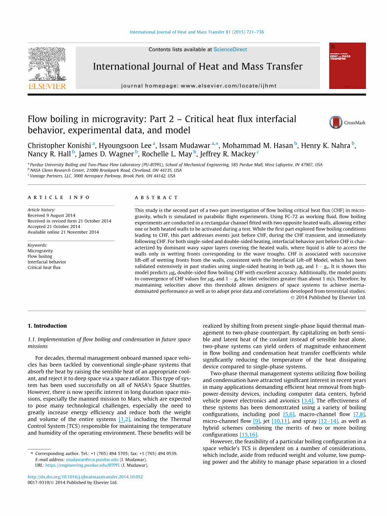
Fig. 1(a) and (b) shows CHF behavior for different flow orienta-tions at 1 � ge [37]. The orientations h = 0� and 180� correspondingto horizontal flow with the heated wall facing upwards and down-wards, respectively, and h = 90� and 270� corresponding to verticalupflow and downflow, respectively. Fig. 1(a) shows interfacialbehavior at CHF- (just preceding CHF) for slightly subcooled flowand U = 0.1 m/s. At this low velocity, orientation has an appreciableinfluence on CHF because of low flow inertia, evidenced by largedifferences in CHF magnitude among the four orientations atU = 0.1 m/s. Fig. 1(a) shows four distinct CHF regimes: (i) Pool-Boil-ing Regime for h = 0�, (ii) Wavy Vapor Layer Regime for h = 90�, (iii)Stratification Regime for h = 180�, and (iv) Vapor StagnationRegime for h = 270�. In the Pool Boiling Regime (h = 0�), bubblescoalesce along the heated wall before being detached by buoyancyand driven into the liquid core, with weak tendency to flow withthe liquid. The Wavy Vapor Layer Regime achieved at h = 90� isthe culmination of bubble coalescence into vapor patches thatpropagate along the heated wall mimicking a continuous wavyvapor layer. The Stratification Regime corresponding to h = 180�is associated with stratification of vapor along the heated wallabove the liquid. The Vapor Stagnation Regime captured ath = 270� is the result of buoyancy force just balancing the dragforce exerted by liquid on the vapor. Two additional low velocityCHF regimes not shown in Fig. 1(a) are Separated Concurrent VaporFlow Regime that was encountered at velocities slightly greaterthan U = 0.1 m/s, where liquid drag begins to exceed buoyancy,
(a) (b)
Fig. 1. Slightly subcooled (DTsub,o = 3 �C) flow boiling CHF regimes at 1 � ge corresponding to different flow orientations for inlet liquid velocities (a) U = G/qf = 0.1 m/s and (b)U = G/qf = 1.5 m/s. CHF regime and magnitude are highly dependent on orientation for the lower velocity and independent of orientation for the higher velocity [37].
724 C. Konishi et al. / International Journal of Heat and Mass Transfer 81 (2015) 721–736
and Vapor Counter Flow Regime, captured at velocities below0.1 m/s, where buoyancy exceeds liquid drag, pushing the vaporbackwards towards the channel inlet. Fig. 1(b) depicts interfacialbehavior at CHF� for slightly subcooled flow at U = 1.5 m/s. At thishigh velocity, CHF is dominated by inertia, which overcomes anybuoyancy effects, resulting in all orientations yielding the sameWavy Vapor Layer Regime and fairly equal CHF values. Fig. 1(b)demonstrates the effectiveness of high velocity at overcomingbody force effects.
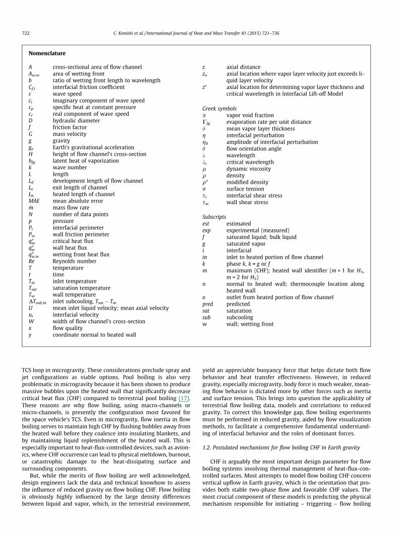
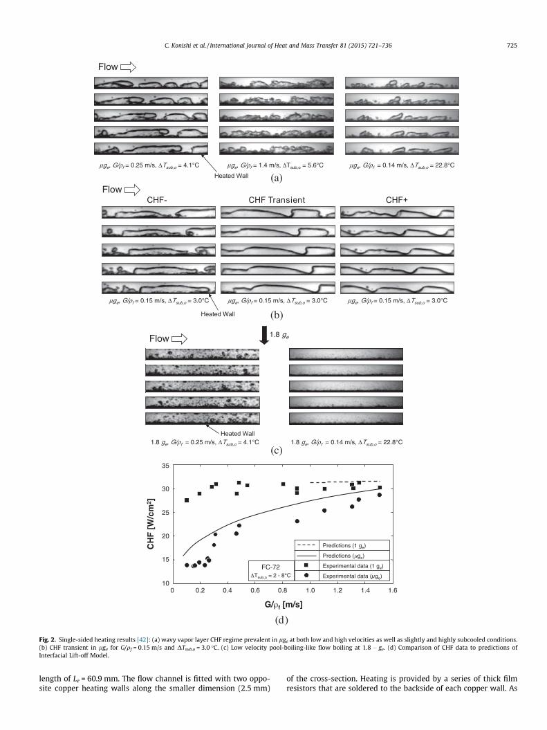
Fig. 2(a) shows images of flow-boiling CHF obtained by Zhanget al. [42] in lge parabolic flight experiments. Unlike Fig. 1(a),which shows significant variations of CHF mechanism and magni-tude at low velocity in 1 � ge, the same Wavy Vapor Layer Regimeis observed in lge regardless of flow velocity or subcooling.Fig. 2(b) shows interfacial behavior during the CHF transient inlge for slightly subcooled flow and U = 0.15 m/s. Just prior toCHF, vapor patches are shown propagating along the heated wall,taking the form of a wavy vapor layer. The heat is transferred fromthe wall to the bulk liquid in wetting fronts between the vaporpatches. During the CHF transient, a wetting front is shown begin-ning to lift from the wall. At CHF+, all wettings fronts are detachedfrom the wall, causing a continuous insulating wavy vapor layer toengulf the entire wall. This behavior is consistent with the Interfa-cial Lift-off CHF Model originally proposed by Galloway and Muda-war [23,24].
Fig. 2(c) depicts sequential images of flow boiling at low veloci-ties and both low and high subcooling, which were obtained duringhypergravity (1.8 � ge). The strong buoyancy force perpendicular tothe heated wall is shown removing bubbles before they have theopportunity to coalesce with neighboring bubbles. Notice also thatthis boiling behavior mimics pool boiling at 1 � ge. Strong conden-sation effects at high subcooling greatly reduce bubble size.
Fig. 2(d) shows the variations of CHF data by Zhang et al. [42]with velocity in lge and 1 � ge horizontal flow boiling. Noticehow CHF in lge increases appreciably with increasing velocity,but the dependence is much weaker at l � ge. At the lowest veloc-ity, CHF in lge is only 50% of that at 1 � ge. Increasing flow velocity
is shown reducing differences between lge and 1 � ge, with CHFvalues converging around 1.5 m/s. Fig. 2(d) also shows CHF predic-tions based on the Interfacial Lift-off Model. Since this model isintended specifically for flow boiling conditions fostering the WavyVapor Layer Regime, predictions are provided for the entire veloc-ity range at lge, but only for high velocities at 1 � ge, where theWavy Vapor Layer Regime is observed.
1.5. Objectives of study
This study is the second part of a two-part study investigatingflow boiling of FC-72 in lge, which is simulated in a series of par-abolic flight maneuvers. The first part of this study [44] includedfindings from both high-speed video analysis of interfacial featuresand heat transfer measurements for different inlet velocities. Thispart of the study is focused on interfacial behavior associated spe-cifically with flow boiling CHF, and development of a CHF modelfor a double-sided heated rectangular channel. This study is partof a NASA project with the goal of developing the Flow Boilingand Condensation Experiment (FBCE) for the International SpaceStation (ISS).
2. Experimental methods
Microgravity flow boiling experiments were performed onboardZero-G Corporation’s modified Boeing 727 parabolic flight aircraft.Details of the experimental methods used in this study are pro-vided in the first part of this study, so only key aspects of thesemethods are highlighted. Shown in Fig. 3(a) is a schematic of thetwo-phase flow loop that is constructed to deliver FC-72 at thedesired pressure, temperature and flow rate to the Flow BoilingModule (FBM). The FBM features transparent construction to facil-itate high-speed video motion analysis of interfacial features.Fig. 3(b) shows key dimensions of the FBM: cross-sectional heightof H = 5.0 mm and width of W = 2.5 mm, upstream developmentlength of Ld = 327.9 mm, heated length of Lh = 114.6 mm, and exit
μge, G/ρf = 0.25 m/s, ΔTsub,o = 4.1°C μge, G/ρf = 1.4 m/s, ΔTsub,o = 5.6°C μge, G/ρf = 0.14 m/s, ΔTsub,o = 22.8°C
Flow
Heated Wall
1.8 ge, G/ρf = 0.14 m/s, ΔTsub,o = 22.8°C
1.8 ge
1.8 ge, G/ρf = 0.25 m/s, ΔTsub,o = 4.1°C
Flow
Heated Wall
(a)
(b)
(c)
CHF- CHF Transient CHF+Flow
Heated Wall
μge, G/ρf = 0.15 m/s, ΔTsub,o = 3.0°C μge, G/ρf = 0.15 m/s, ΔTsub,o = 3.0°C μge, G/ρf = 0.15 m/s, ΔTsub,o = 3.0°C
(d)
Fig. 2. Single-sided heating results [42]: (a) wavy vapor layer CHF regime prevalent in lge at both low and high velocities as well as slightly and highly subcooled conditions.(b) CHF transient in lge for G/qf = 0.15 m/s and DTsub,o = 3.0 �C. (c) Low velocity pool-boiling-like flow boiling at 1.8 � ge. (d) Comparison of CHF data to predictions ofInterfacial Lift-off Model.
C. Konishi et al. / International Journal of Heat and Mass Transfer 81 (2015) 721–736 725
length of Le = 60.9 mm. The flow channel is fitted with two oppo-site copper heating walls along the smaller dimension (2.5 mm)
of the cross-section. Heating is provided by a series of thick filmresistors that are soldered to the backside of each copper wall. As

(b) (c)
(a)
Fig. 3. (a) Schematic diagram of flow loop. (b) Key dimensions of flow channel. (c) Thermocouple layout in two heated walls.
726 C. Konishi et al. / International Journal of Heat and Mass Transfer 81 (2015) 721–736
shown in Fig. 3(c), Type-E thermocouples are inserted into shallowholes in each copper wall between the resistors. The thermocou-ples are designated by Twm,n, where m represents the heated wall(H1or H2) and n the axial wall thermocouple location.
Four days of parabolic flight were dedicated to obtaining thedata and video records presented in this study. The operating con-ditions are as follows: FC-72 inlet mean liquid velocity of U = 0.1–1.9 m/s, mass velocity of G = 224.2–3347.5 kg/m2 s, inlet tempera-ture of Tin = 56.5–64.7 �C, inlet subcooling of DTsub,in = 2.8–8.1 �C,and outlet pressure of po = 118.2–148.3 kPa (17.1–21.5 psi).
3. Experimental results
3.1. Experimental pressure drop trends
Pressure drop is measured by STS absolute pressure transducersconnected to taps in the channel immediately upstream and down-stream of the copper heated walls. These pressures are measuredcontinuously during every parabola with an accuracy of ±0.05%.The operator of the flow boiling facility can activate either one ofthe heated walls (H1) or both walls (H1 and H2) simultaneously.
(a)
(b)
Fig. 4. Variation of pressure drop across the heated portion of the channel with wallheat flux for different inlet velocities for (a) single-sided heating and (b) double-sided heating.
C. Konishi et al. / International Journal of Heat and Mass Transfer 81 (2015) 721–736 727
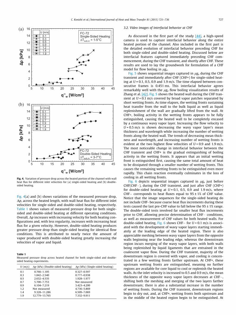
Fig. 4(a) and (b) shows variations of the measured pressure drop,Dp, across the heated length, with wall heat flux for different inletvelocities for single-sided and double-sided heating, respectively.Table 1 shows values of measured pressure drop for both single-sided and double-sided heating at different operating conditions.Overall, Dp increases with increasing velocity for both heating con-figurations and, with less regularity, increases with increasing heatflux for a given velocity. However, double-sided heating producesgreater pressure drop than single-sided heating for identical flowconditions. This is attributed to nearly twice the amount ofvapor produced with double-sided heating greatly increasing thevelocities of vapor and liquid.
Table 1Measured pressure drop across heated channel for both single-sided and double-sided heating experiments.
U (m/s) Dp (kPa) (Double-sided heating) Dp (kPa) (Single-sided heating)
0.1 0.766–1.105 0.327–0.5970.3 1.842–2.540 0.777–0.9380.5 2.632–4.535 1.928–1.9770.7 5.700–7.753 Not measured0.9 6.104–7.219 3.423–4.2001.2 Not measured 4.736–5.8691.4 9.328–11.286 6.509–7.0691.9 12.779–13.765 7.332–9.911
3.2. Video images of interfacial behavior at CHF
As discussed in the first part of the study [44], a high-speedcamera is used to capture interfacial behavior along the entireheated portion of the channel. Also included in the first part isthe detailed evolution of interfacial behavior preceding CHF forboth single-sided and double-sided heating. Discussed below areinterfacial features captured immediately preceding CHF com-mencement, during the CHF transient, and shortly after CHF. Theseresults are used to lay the groundwork for formulation of a CHFmodel for flow boiling in lge.
Fig. 5 shows sequential images captured in lge during the CHFtransient and immediately after CHF (CHF+) for single-sided heat-ing at U = 0.1, 0.5, 0.9 and 1.9 m/s. The time elapsed between con-secutive frames is 0.451 ms. This interfacial behavior agreesremarkably well with the lge flow boiling visualization results ofZhang et al. [42]. Fig. 5 shows the heated wall during the CHF tran-sient at U = 0.1 m/s covered by broad vapor patches separated byshort wetting fronts. As time elapses, the wetting fronts sustainingheat transfer from the wall to the bulk liquid as well as liquidreplenishment of the wall are gradually lifted from the wall. AtCHF+, boiling activity in the wetting fronts appears to be fullyextinguished, causing the heated wall to be completely encasedby a continuous wavy vapor layer. Increasing the flow velocity toU = 0.5 m/s is shown decreasing the wavy vapor layer’s meanthickness and wavelength while increasing the number of wettingfronts along the heated wall. The trends of decreasing mean thick-ness and wavelength, and increasing number of wetting fronts isevident at the two highest flow velocities of U = 0.9 and 1.9 m/s.The most noticeable change in interfacial behavior between theCHF transient and CHF+ is the gradual extinguishing of boilingactivity in the wetting fronts. It appears that an initial wettingfront is extinguished first, causing the same total amount of heatto be dissipated through a smaller number of wetting fronts. Thiscauses the remaining wetting fronts to be extinguished even morerapidly. This chain reaction eventually culminates in the loss ofcooling in all wetting fronts.
Fig. 6 depicts sequential images captured in lge just beforeCHF(CHF�), during the CHF transient, and just after CHF (CHF+)for double-sided heating at U = 0.1, 0.5, 0.9 and 1.9 m/s, whereCHF� corresponds to heat fluxes equal to 95 ± 1% of CHF value.Notice that the image sequences for the single-sided heating donot include CHF- because coarse heat flux increments during thesetests caused the last pre-CHF value to fall below the 95 ± 1% range.The double-sided tests involved far smaller heat flux incrementsprior to CHF, allowing precise determination of CHF� conditions,as well as measurement of CHF values for both heated walls. Fordouble-sided heating, Fig. 6 shows CHF� for U = 0.1 m/s is associ-ated with the development of wavy vapor layers starting immedi-ately at the leading edge of the heated region. There is alsoappreciable meshing between wavy vapor layers from the oppositewalls beginning near the leading edge, whereas the downstreamregion incurs merging of the wavy vapor layers, with both wallsbeing replenished by liquid ligaments that are entrained in thecoalescent vapor flow. During the CHF transient, majority of thedownstream region is covered with vapor, and cooling is concen-trated in a few wetting fronts farther upstream. At CHF+, theseupstream wetting fronts are extinguished, meaning no furtherregions are available for core liquid to cool or replenish the heatedwalls. As the inlet velocity is increased to 0.5 and 0.9 m/s, the meanthickness of the opposite wavy vapor layers decreases at CHF�,shifting both the meshing and merging of the two layers fartherdownstream; there is also a substantial increase in the numberof wetting fronts. During the CHF transient, downstream regionsbegin to dry out, and, at CHF+, wetting fronts both upstream andin the middle of the heated region begin to be extinguished. At
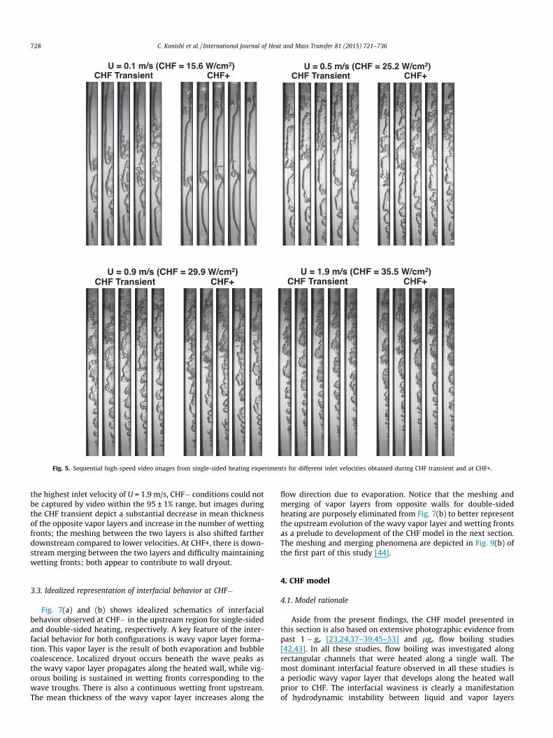
Fig. 5. Sequential high-speed video images from single-sided heating experiments for different inlet velocities obtained during CHF transient and at CHF+.
728 C. Konishi et al. / International Journal of Heat and Mass Transfer 81 (2015) 721–736
the highest inlet velocity of U = 1.9 m/s, CHF� conditions could notbe captured by video within the 95 ± 1% range, but images duringthe CHF transient depict a substantial decrease in mean thicknessof the opposite vapor layers and increase in the number of wettingfronts; the meshing between the two layers is also shifted fartherdownstream compared to lower velocities. At CHF+, there is down-stream merging between the two layers and difficulty maintainingwetting fronts; both appear to contribute to wall dryout.
3.3. Idealized representation of interfacial behavior at CHF�
Fig. 7(a) and (b) shows idealized schematics of interfacialbehavior observed at CHF� in the upstream region for single-sidedand double-sided heating, respectively. A key feature of the inter-facial behavior for both configurations is wavy vapor layer forma-tion. This vapor layer is the result of both evaporation and bubblecoalescence. Localized dryout occurs beneath the wave peaks asthe wavy vapor layer propagates along the heated wall, while vig-orous boiling is sustained in wetting fronts corresponding to thewave troughs. There is also a continuous wetting front upstream.The mean thickness of the wavy vapor layer increases along the
flow direction due to evaporation. Notice that the meshing andmerging of vapor layers from opposite walls for double-sidedheating are purposely eliminated from Fig. 7(b) to better representthe upstream evolution of the wavy vapor layer and wetting frontsas a prelude to development of the CHF model in the next section.The meshing and merging phenomena are depicted in Fig. 9(b) ofthe first part of this study [44].
4. CHF model
4.1. Model rationale
Aside from the present findings, the CHF model presented inthis section is also based on extensive photographic evidence frompast 1 � ge [23,24,37–39,45–53] and lge flow boiling studies[42,43]. In all these studies, flow boiling was investigated alongrectangular channels that were heated along a single wall. Themost dominant interfacial feature observed in all these studies isa periodic wavy vapor layer that develops along the heated wallprior to CHF. The interfacial waviness is clearly a manifestationof hydrodynamic instability between liquid and vapor layers

Fig. 6. Sequential high-speed video images from double-sided heating experiments for different inlet velocities obtained at CHF�, during CHF transient and at CHF+.
(b)(a)
Fig. 7. Schematics of upstream wavy vapor layer and wetting front development at CHF- for (a) single-sided heating and (b) double-sided heating. Downstream meshing andmerging of vapor layers from the opposite walls for double-sided heating are purposely eliminated to better represent the upstream development of the vapor layers.
C. Konishi et al. / International Journal of Heat and Mass Transfer 81 (2015) 721–736 729
730 C. Konishi et al. / International Journal of Heat and Mass Transfer 81 (2015) 721–736
moving at different velocities. The second dominant feature is con-tact of the wavy interface with the wall in discrete ‘‘wetting fronts’’corresponding to the wave troughs. At CHF�, vigorous boiling isobserved in the wetting front, while portions of the vapor layeraround the wave peaks appear dry. This feature points to the wet-ting fronts as the last source for cooling and liquid replenishmentfor the heated wall. Two forces control the formation of a wettingfront. A pressure force associated with interfacial curvature aroundthe wave troughs pushes the interface towards the heated wall.The pressure force is opposed by momentum generated by intensevapor effusion in the wetting front normal to, and away from thewall. Interfacial contact with the wall is ensured and wetting frontsare maintained at CHF� because the pressure force exceeds thevapor momentum. CHF is postulated to commence when the vapormomentum increases to just overcome the pressure force. Thisevent causes lifting of the interface from the wall, which extin-guishes the wetting front. Heat that was dissipated at the justextinguished wetting front must now be conducted axially throughthe wall and dissipated to neighboring wetting fronts. Thisincreases the momentum of vapor effusion in the neighboringwetting fronts, fostering rapid extinguishing of these wettingfronts as well. This process can best be described as a chain reac-tion, where wetting fronts are extinguished in succession and atan increasing rate. Loss of wetting fronts leaves the wall essentiallydry, an event that is captured by the wall thermocouples in theform of a sharp and unsteady rise in the wall temperature. Theseinterfacial events at CHF� are key components of the InterfacialLift-off Model first proposed by Galloway and Mudawar [23,24]for single-sided heating.
However, the model sought here must tackle double-sidedheating and accurately predict data for both 1 � ge and lge. Likethe original Galloway and Mudawar model, the present modelincorporates four major components: (1) a separated flow modelto determine axial variations of mean liquid and vapor velocities,and mean thickness of the wavy vapor layers, (2) an instabilitymodel of the wavy vapor layer to determine the wavelength, wet-ting front axial span, and pressure force created by interfacial cur-vature, (3) an Interfacial Lift-off Criterion – CHF trigger mechanism– to determine the heat flux in wetting fronts required to producesufficient vapor momentum to exceed the curvature pressureforce, and (4) a surface energy balance to relate the average wallheat flux for the entire heated wall to the heat flux concentratedin the wetting fronts propagating along the wall.
4.2. Separated flow model
A separated flow model is constructed to determine axial vari-ations of mean liquid and vapor velocities, and mean thickness ofthe wavy vapor layers. Illustrated in Fig. 8(a) is an idealized repre-sentation of vapor layers growing along both heated walls with theliquid flowing in between. The flow, therefore, consists of threeclearly identifiable layers. The control volume method is used toapply mass, momentum and energy conservation to the individualphases and/or the entire flow. In Fig. 8(a), Cfg,1 and ui1 representthe rate of evaporation per unit distance between the liquid layerand vapor layer 1, and streamwise velocity of the liquid–vaporinterface in between. Similarly, Cfg,2 and ui2 represent the rate ofevaporation per unit distance between the liquid layer and vaporlayer 2 and the streamwise velocity of the liquid–vapor interfacein between. The assumptions employed in the separated flowmodel are: (1) the heated walls provide equal heat fluxes, (2) thevapor layers are initiated at the leading edge (z = 0) for each heatedwall (this assumption is justified by the slightly subcooled inletliquid conditions), (3) velocities are uniform across the individuallayers (i.e., the two-phase flow is one-dimensional), (4) pressureis uniform across the channel’s cross-section, (5) the middle liquid
layer preserves its subcooling in the axial direction, and (6) thevapor maintains saturation temperature corresponding to localpressure at every z location.
Applying mass conservation to a control volume of length Dzencompassing the entire cross-section yields d _m=dz ¼ 0, whichimplies _m is constant, also G is constant since G ¼ _m=A and A isconstant. Applying energy conservation to the vapor layers yieldsthe following relations for mean velocities, Ug1 and Ug2, of thevapor layers along heated walls H1 and H2, respectively, in termsof the mean thicknesses of the respective layers,
Ug1 ¼q00wz
qgd1 cp;f DTsub;in þ hfg
� � ð1aÞ
and Ug2 ¼q00wz
qgd2 cp;f DTsub;in þ hfg
� � ð1bÞ
Continuity is used to derive an expression for the mean velocity ofthe liquid layer. For equal heat flux, q00w, applied along both heatedwalls,
Uf ¼UH
H � d1 � d2� 2q00wz
qf H � d1 � d2ð Þ cp;f DTsub;in þ hfg
� � : ð2Þ
Fig. 8(b) shows momentum conservation for control volumes oflength Dz encompassing the three individual layers of the flow. Fornow, an arbitrary gravitational acceleration, g, is assumed with thechannel oriented at angle h relative to the horizontal plane, andg � 0 in microgravity. Summing momentum and force terms yieldsthe following relations for heated wall vapor layer 1, liquid layerand heated wall vapor layer 2, respectively,
ddz
qgU2g1Ag1
� �� Cfg1ui1 ¼ �Ag1
dpdz� sw;g1Pw;g1 � si1Pi1
� qgAg1g sin h; ð3aÞ
ddz
qf U2f Af
� �þ Cfg1ui1 þ Cfg2ui2
¼ �Afdpdz� sw;f Pw;f � si1Pi1 � si2Pi2 � qf Af g sin h; ð3bÞ
andddz
qgU2g2Ag2
� �� Cfg2ui2 ¼ �Ag2
dpdz� sw;g2Pw;g2 � si2Pi2
� qgAg2 g sin h ð3cÞ
where Ag1, Af, Ag2, ui1, ui2, sw,g1, sw,f, sw,g2, Pw,g1, Pw,f, Pw,g2, si1, si2, Pi1,and Pi2 are the flow area for vapor layer 1, flow area for the liquidlayer, flow area for vapor layer 2, interfacial velocity between vaporlayer 1 and the liquid layer, interfacial velocity between vapor layer2 and the liquid layer, wall shear stress for vapor layer 1, wall shearstress for the liquid layer, wall shear stress for vapor layer 2, wallfriction perimeter for vapor layer 1, wall friction perimeter for theliquid layer, wall friction perimeter for vapor layer 2, interfacialshear stress between vapor layer 1 and the liquid layer, interfacialshear stress between vapor layer 2 and the liquid layer, interfacialperimeter between vapor layer 1 and the liquid layer, and interfa-cial perimeter between vapor layer 2 and the liquid layer. The flowareas are defined in Fig. 8(a) in terms of the channel dimensions (Wand H) and thicknesses of vapor layer 1, d1, and vapor layer 2, d2.Fig. 8(b) provides definitions for all wall friction and interfacialperimeters.
Visual observations from prior flow boiling studies [42,43]revealed the vapor generated at the leading edge of the heated wallhas no initial streamwise velocity. Therefore, it is assumed theliquid–vapor interface does not contribute streamwise momentumto the control volumes (ui1 = ui2 = 0). Eqs. (3a)–(3c) can be pre-sented in terms of flow quality of vapor layer 1, x1, void fraction
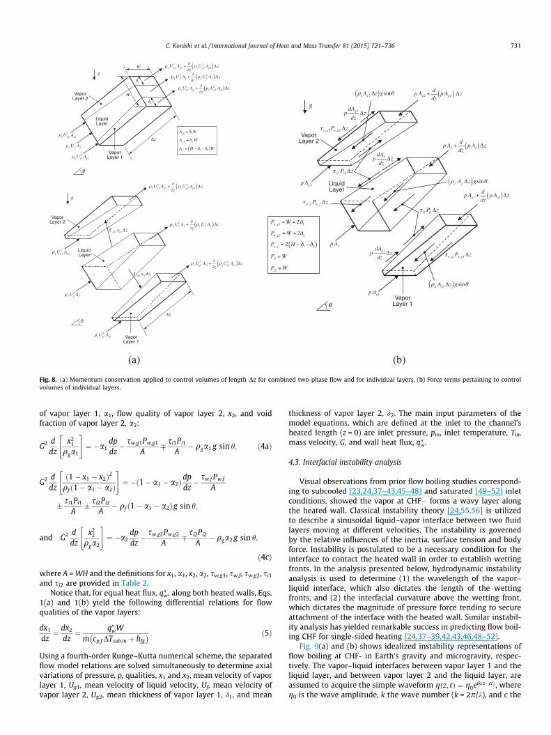
(a) (b)
Fig. 8. (a) Momentum conservation applied to control volumes of length Dz for combined two-phase flow and for individual layers. (b) Force terms pertaining to controlvolumes of individual layers.
C. Konishi et al. / International Journal of Heat and Mass Transfer 81 (2015) 721–736 731
of vapor layer 1, a1, flow quality of vapor layer 2, x2, and voidfraction of vapor layer 2, a2:
G2 ddz
x21
qga1
" #¼ �a1
dpdz� sw;g1Pw;g1
A� si1Pi1
A� qga1 g sin h; ð4aÞ
G2 ddz
1� x1 � x2ð Þ2
qf 1� a1 � a2ð Þ
" #¼ � 1� a1 � a2ð Þdp
dz� sw;f Pw;f
A
� si1Pi1
A� si2Pi2
A� qf 1� a1 � a2ð Þg sin h;
and G2 ddz
x22
qga2
" #¼ �a2
dpdz� sw;g2Pw;g2
A� si2Pi2
A� qga2 g sin h;
ð4cÞ
where A = WH and the definitions for x1, a1, x2, a2, sw,g1, sw,f, sw,g2, si1
and si2 are provided in Table 2.Notice that, for equal heat flux, q00w, along both heated walls, Eqs.
1(a) and 1(b) yield the following differential relations for flowqualities of the vapor layers:
dx1
dz¼ dx2
dz¼ q00wW
_m cp;f DTsub;in þ hfg� � : ð5Þ
Using a fourth-order Runge–Kutta numerical scheme, the separatedflow model relations are solved simultaneously to determine axialvariations of pressure, p, qualities, x1 and x2, mean velocity of vaporlayer 1, Ug1, mean velocity of liquid velocity, Uf, mean velocity ofvapor layer 2, Ug2, mean thickness of vapor layer 1, d1, and mean
thickness of vapor layer 2, d2. The main input parameters of themodel equations, which are defined at the inlet to the channel’sheated length (z = 0) are inlet pressure, pin, inlet temperature, Tin,mass velocity, G, and wall heat flux, q00w.
4.3. Interfacial instability analysis
Visual observations from prior flow boiling studies correspond-ing to subcooled [23,24,37–43,45–48] and saturated [49–52] inletconditions, showed the vapor at CHF� forms a wavy layer alongthe heated wall. Classical instability theory [24,55,56] is utilizedto describe a sinusoidal liquid–vapor interface between two fluidlayers moving at different velocities. The instability is governedby the relative influences of the inertia, surface tension and bodyforce. Instability is postulated to be a necessary condition for theinterface to contact the heated wall in order to establish wettingfronts. In the analysis presented below, hydrodynamic instabilityanalysis is used to determine (1) the wavelength of the vapor–liquid interface, which also dictates the length of the wettingfronts, and (2) the interfacial curvature above the wetting front,which dictates the magnitude of pressure force tending to secureattachment of the interface with the heated wall. Similar instabil-ity analysis has yielded remarkable success in predicting flow boil-ing CHF for single-sided heating [24,37–39,42,43,46,48–52].
Fig. 9(a) and (b) shows idealized instability representations offlow boiling at CHF- in Earth’s gravity and microgravity, respec-tively. The vapor–liquid interfaces between vapor layer 1 and theliquid layer, and between vapor layer 2 and the liquid layer, areassumed to acquire the simple waveform g z; tð Þ ¼ g0eik z�ctð Þ, whereg0 is the wave amplitude, k the wave number (k = 2p/k), and c the
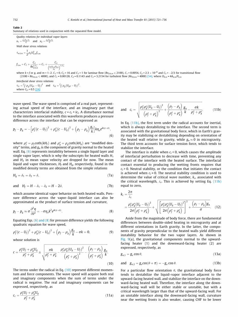
Table 2Summary of relations used in conjunction with the separated flow model.
Quality relations for individual vapor layers
x1 ¼qg Ug1a1
G and x2 ¼qg Ug2a2
G
Wall shear stress relations
sw;k;m ¼12qkU2
k;mf k;m
f k;m ¼ C1 þC2
Re1=C3D;k;m
¼ C1 þC2
qkUk;m Dk;m
lk
� �1=C3
where k = f or g, and m = 1–2. C1 = 0, C2 = 16 and C3 = 1 for laminar flow (ReD,k,m 6 2100), C1 = 0.0054, C2 = 2.3 � 10–8 and C3 = �2/3 for transitional flow(2100 < ReD,k,m 6 4000), and C1 = 0.00128, C2 = 0.1143 and C3 = 3.2154 for turbulent flow (ReD,k,m > 4000) [54], where Dk,m = 4Ak,m/Pk,m
Interfacial shear stress relations
si1 ¼Cf ;i2 qg Ug1 � Uf
� �2 and si2 ¼Cf ;i2 qg Ug2 � Uf
� �2;
where Cf,i = 0.5 [24]
732 C. Konishi et al. / International Journal of Heat and Mass Transfer 81 (2015) 721–736
wave speed. The wave speed is comprised of a real part, represent-ing actual speed of the interface, and an imaginary part thatcharacterizes interfacial stability, c = cr + ici. A disturbance normalto the interface associated with this waveform produces a pressuredifference across the interface that can be expressed as
pf � pg ¼ � q00f c � Uf� �2 þ q00g c � Ug
� �2 þ qf � qg
� � gn
k
h ikgoeik z�ctð Þ;
ð6Þ
where q00f ¼ qf coth kHf� �
and q00g ¼ qgcoth kHg� �
are ‘‘modified den-sity’’ terms, and gn is the component of gravity normal to the heatedwall. Eq. (6) represents instability between a single liquid layer andsingle vapor layer, which is why the subscripts for heated walls H1
and H2 in mean vapor velocity are dropped for now. The meanliquid and vapor thicknesses, Hf and Hg, respectively, found in themodified density terms are obtained from the simple relations
Hg ¼ d1 ¼ d2 ¼ d; ð7aÞ
and Hf ¼ H � d1 � d2 ¼ H � 2d; ð7bÞ
which assume identical vapor behavior on both heated walls. Pres-sure difference across the vapor–liquid interface can also beapproximated as the product of surface tension and curvature,
pf � pg � r @2g@z2 ¼ �rgok2eik z�ctð Þ: ð8Þ
Equating Eqs. (6) and (8) for pressure difference yields the followingquadratic equation for wave speed,
q00f c � Uf
� �2 þ q00g c � Ug� �2 þ qf � qg
� � gn
k� rk ¼ 0; ð9Þ
whose solution is
c ¼q00f Uf þ q00gUg
q00f þ q00g�
ffiffiffiffiffiffiffiffiffiffiffiffiffiffiffiffiffiffiffiffiffiffiffiffiffiffiffiffiffiffiffiffiffiffiffiffiffiffiffiffiffiffiffiffiffiffiffiffiffiffiffiffiffiffiffiffiffiffiffiffiffiffiffiffiffiffiffiffiffiffiffiffiffiffiffiffiffiffiffiffiffiffiffiffiffiffiffiffiffiffirk
q00f þ q00g�
q00f q00g Ug � Uf
� �2
q00f þ q00g� �2 �
qf � qg
� �q00f þ q00g� � gn
k
vuuuut :
ð10Þ
The terms under the radical in Eq. (10) represent different momen-tum and force components. The wave speed will acquire both realand imaginary components when the sum of terms under theradical is negative. The real and imaginary components can beexpressed, respectively, as
cr ¼q00f Uf þ q00gUg
q00f þ q00gð11aÞ
and ci ¼
ffiffiffiffiffiffiffiffiffiffiffiffiffiffiffiffiffiffiffiffiffiffiffiffiffiffiffiffiffiffiffiffiffiffiffiffiffiffiffiffiffiffiffiffiffiffiffiffiffiffiffiffiffiffiffiffiffiffiffiffiffiffiffiffiffiffiffiffiffiffiffiffiffiffiffiffiffiffiffiffiffiffiffiffiffiffiffiffiffiffiq00f q00g Ug � Uf
� �2
q00f þ q00g� �2 þ
qf � qg
� �q00f þ q00g� � gn
k� rk
q00f þ q00g
vuuuut : ð11bÞ
In Eq. (11b), the first term under the radical accounts for inertial,which is always destabilizing to the interface. The second term isassociated with the gravitational body force, which in Earth’s grav-ity may be stabilizing or destabilizing depending on orientation ofthe heated wall relative to gravity, while gn � 0 in microgravity.The third term accounts for surface tension force, which tends tostabilize the interface.
The interface is stable when ci < 0, which causes the amplitudeof interfacial perturbation to decrease with time, preventing anycontact of the interface with the heated surface. The interfacialcontact essential to producing the wetting fronts requires thatci > 0. Neutral stability, or the condition that initiates the contactis achieved when ci = 0. The neutral stability condition is used todetermine the value of critical wave number, kc, associated withthe critical wavelength, kc. This is achieved by setting Eq. (11b)equal to zero,
kc ¼2pkc
¼q00f q
00g Ug � Uf
� �2
2r q00f þ q00g� � þ
ffiffiffiffiffiffiffiffiffiffiffiffiffiffiffiffiffiffiffiffiffiffiffiffiffiffiffiffiffiffiffiffiffiffiffiffiffiffiffiffiffiffiffiffiffiffiffiffiffiffiffiffiffiffiffiffiffiffiffiffiffiffiffiffiffiffiffiffiffiffiffiffiffiffiq00f q00g Ug � Uf
� �2
2r q00f þ q00g� �
24
35
2
þqf � qg
� �gn
r
vuuut : ð12Þ
Aside from the magnitude of body force, there are fundamentaldifferences between double-sided heating in microgravity and atdifferent orientations in Earth gravity. In the latter, the compo-nents of gravity perpendicular to the heated walls yield differentinstability behavior for the two vapor layers. As shown inFig. 9(a), the gravitational components normal to the upward-facing heater (1) and the downward-facing heater (2) areexpressed, respectively, as
gn;1 ¼ ge cos h; ð13aÞ
and gn;2 ¼ gecos hþ pð Þ ¼ �ge cos h: ð13bÞ
For a particular flow orientation h, the gravitational body forcetends to destabilize the liquid–vapor interface adjacent to theupward-facing heated wall, and stabilize the interface on the down-ward-facing heated wall. Therefore, the interface along the down-ward-facing wall will be either stable or unstable, but with acritical wavelength larger than that of the upward-facing wall. Foran unstable interface along the downward-facing wall, curvaturenear the wetting fronts is also weaker, causing CHF to be lower
(a) (b)
Fig. 9. Hydrodynamic instability of wavy vapor layers along heated walls of double-sided heated channel at CHF� (a) for inclined channel at 1 � ge and (b) for microgravity.
C. Konishi et al. / International Journal of Heat and Mass Transfer 81 (2015) 721–736 733
for the downward-facing wall compared to the upward-facing. It isimportant to note that these effects are more pronounced for lowinlet velocities, where the influence of body force is most signifi-cant. However, by greatly increasing the inlet velocity, body forceeffects become comparatively insignificant, and CHF differencesbetween the two walls less discernible. Notice that in Earth’s grav-ity, vertical upflow produces zero gravitational body forces normalto the opposite heated walls and equal CHF values for both walls.
In microgravity, the body force component is negligible, whichreduces Eq. (12) to
kc ¼2pr q00f þ q00g
� �q00f q00g Ug � Uf
� �2 : ð14Þ
Also, in the absence of gravity, CHF is the same for the two oppositeheated walls. Flow visualization results from [37–43] have demon-strated the existence of a continuous upstream liquid wettingregion, z⁄, defined as
z� ¼ z0 þ kc z�ð Þ; ð15Þ
where z0 is the distance from the leading edge of the heated wall tothe location where the vapor velocity just exceeds the liquid veloc-ity. Beyond z⁄, the vapor velocity continues to increase faster thanthe liquid velocity, resulting in hydrodynamic instability of thewavy vapor–liquid interface. Determination of kc using Eq. (14)and z⁄ using Eq. (15) requires iteration. The separated flow modelprovides the flow parameters required to calculate criticalwavelength.
4.4. Interfacial Lift-off Criterion
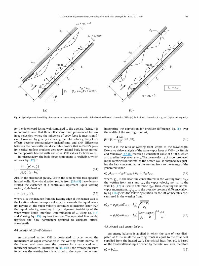
As discussed earlier, CHF is postulated to occur when themomentum of vapor emanating in the wetting fronts normal tothe heated wall overcomes the pressure force associated withinterfacial curvature. Illustrated in Fig. 10(a), the average pressureforce over the wetting front is equated to the vapor momentum.
Integrating the expression for pressure difference, Eq. (8), overthe width of the wetting front, bk,
pf � pg ¼4prd
bk2c
sin bpð Þ; ð16Þ
where b is the ratio of wetting front length to the wavelength.Extensive video analysis of the wavy vapor layer at CHF� by Sturgisand Mudawar [47,48] revealed a consistent value of b = 0.2, whichalso used in the present study. The mean velocity of vapor producedin the wetting front normal to the heated wall is obtained by equat-ing the heat concentrated in the wetting front to the energy of thegenerated vapor:
q00w;wAw;w ¼ cp;f DTsub;in þ hfg
� �qgUg;nAw;w; ð17Þ
where, q00w;w is the heat flux concentrated in the wetting front, Aw,w
the wetting front area, and Ug,n the vapor velocity normal to thewall. Eq. (17) is used to determine Ug,n. Then, equating the normalvapor momentum, qgU2
g;n, to the average pressure difference givenby Eq. (16) yields the following relation for the lift-off heat flux con-centrated in the wetting front,
q00w;w ¼ qg cp;f DTsub;in þ hfg
� � ffiffiffiffiffiffiffiffiffiffiffiffiffiffiffipf � pg
qg
s
¼ qg cp;f DTsub;in þ hfg� � 4pr
qg
sin bpð Þb
" #1=2d1=2
kc: ð18Þ
4.5. Heated wall energy balance
An energy balance is applied in which the sum of heat dissi-pated at CHF� in all the wetting fronts is equal to the total heatsupplied from the heated wall. The critical heat flux, q00m, is basedon the total wall heat input divided by the total wall area, therefore
q00m ¼ bq00w;w: ð19Þ
(a)
(b)
Fig. 10. (a) Schematic representation of Interfacial Lift-off from heated wall in wetting front at CHF. (b) Procedure used to calculate CHF.
m2 ]
25
30
35
40
45CHF Model Predictions 1 ge
(Vertical Upflow)
µge
734 C. Konishi et al. / International Journal of Heat and Mass Transfer 81 (2015) 721–736
Combining Eq. (19) with the expression for heat flux in the wettingfront given by Eq. (18) gives the following relation for CHF:
q00m ¼ qg cp;f DTsub;in þ hfg� � 4prb sin bpð Þ
qg
" #1=2d1=2
kc
�����z�
; ð20Þ
where the vapor layer thickness, d, and critical wavelength, kc, arecalculated at z⁄, where the wavy vapor layer is generated.
U [m/s]0 0.2 0.4 0.6 0.8 1.0 1.2 1.4 1.6 1.8 2.0
q” m
[W/c
10
15
20
H1
H2
MAE
Double-Sided Heating Data
5.0%5.7%
5
0
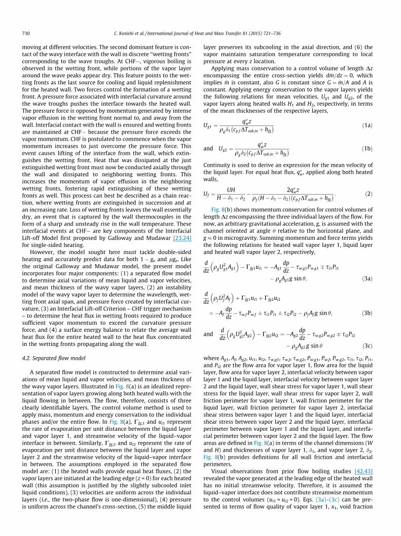
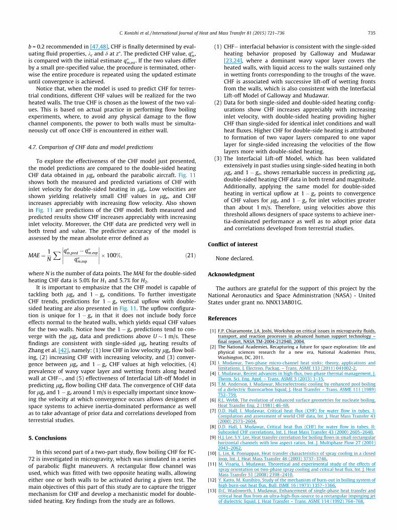
Fig. 11. Comparison of measured and predicted variations of CHF with inletvelocity for double-sided heating in lge, along with predicted CHF for double-sidedheating in vertical upflow at 1 � ge.
4.6. CHF model calculation procedure
The CHF model is composed of four major components, and iscapable of predicting CHF for subcooled flow boiling in terrestrialand microgravity environments. Combining the different equationsassociated with the four components requires multiple iterationsto arrive at a convergent CHF value. Fig. 10(b) provides a step-by-step procedure for this iterative solution. The procedure is ini-tiated by setting the subcooled inlet conditions at the leading edgeof the heaters (z = 0) in terms of temperature Tin, pressure pin, andinlet flow velocity U. The computations begins with a guessedvalue for critical heat flux, q00m;est , which is used in the separatedflow model to determine mean liquid velocity, Uf, as well as meanvapor velocity, Ug, and mean vapor layer thickness, d, for bothheated walls. These parameters are obtained for every z locationalong the heated length using a fourth-order Runge–Kutta numer-ical scheme. Next, CHF is determined for subcooled flow boiling ineither Earth gravity or microgravity. In Earth’s gravity (g = 1 � ge),CHF is influenced by gravitational body force, therefore the Interfa-cial Lift-off Model will yield different values for upward-facing anddownward-facing heated walls, and therefore different CHF values.
In microgravity (g � 0), body force is negligible, therefore identicalCHF values are predicted for both heated walls.
A key step in the iterative solution is to determine z0, whereUg = Uf, using the separated flow model. This is followed by calcu-lating critical wavelength, kc, and axial span of the upstream wet-ting front, z⁄, which requires multiple iterations. Using the value of
C. Konishi et al. / International Journal of Heat and Mass Transfer 81 (2015) 721–736 735
b = 0.2 recommended in [47,48], CHF is finally determined by eval-uating fluid properties, kc and d at z⁄. The predicted CHF value, q00m,is compared with the initial estimate q00m;est . If the two values differby a small pre-specified value, the procedure is terminated, other-wise the entire procedure is repeated using the updated estimateuntil convergence is achieved.
Notice that, when the model is used to predict CHF for terres-trial conditions, different CHF values will be realized for the twoheated walls. The true CHF is chosen as the lowest of the two val-ues. This is based on actual practice in performing flow boilingexperiments, where, to avoid any physical damage to the flowchannel components, the power to both walls must be simulta-neously cut off once CHF is encountered in either wall.
4.7. Comparison of CHF data and model predictions
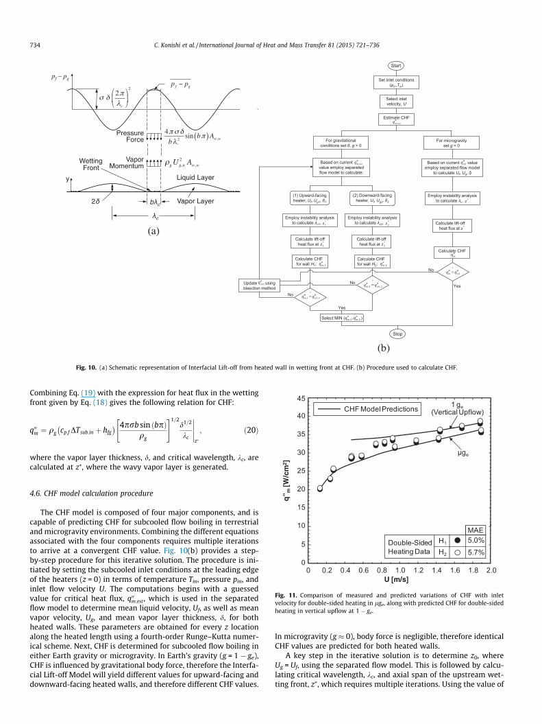
To explore the effectiveness of the CHF model just presented,the model predictions are compared to the double-sided heatingCHF data obtained in lge onboard the parabolic aircraft. Fig. 11shows both the measured and predicted variations of CHF withinlet velocity for double-sided heating in lge. Low velocities areshown yielding relatively small CHF values in lge, and CHFincreases appreciably with increasing flow velocity. Also shownin Fig. 11 are predictions of the CHF model. Both measured andpredicted results show CHF increases appreciably with increasinginlet velocity. Moreover, the CHF data are predicted very well inboth trend and value. The predictive accuracy of the model isassessed by the mean absolute error defined as
MAE ¼ 1N
X q00m;pred � q00m;exp
q00m;exp
����������� 100%; ð21Þ
where N is the number of data points. The MAE for the double-sidedheating CHF data is 5.0% for H1 and 5.7% for H2.
It is important to emphasize that the CHF model is capable oftackling both lge and 1 � ge conditions. To further investigateCHF trends, predictions for 1 � ge vertical upflow with double-sided heating are also presented in Fig. 11. The upflow configura-tion is unique for 1 � ge in that it does not include body forceeffects normal to the heated walls, which yields equal CHF valuesfor the two walls. Notice how the 1 � ge predictions tend to con-verge with the lge data and predictions above U � 1 m/s. Thesefindings are consistent with single-sided lge heating results ofZhang et al. [42], namely: (1) low CHF in low velocity lge flow boil-ing, (2) increasing CHF with increasing velocity, and (3) conver-gence between lge and 1 � ge CHF values at high velocities, (4)prevalence of wavy vapor layer and wetting fronts along heatedwall at CHF�, and (5) effectiveness of Interfacial Lift-off Model inpredicting lge flow boiling CHF data. The convergence of CHF datafor lge and 1 � ge around 1 m/s is especially important since know-ing the velocity at which convergence occurs allows designers ofspace systems to achieve inertia-dominated performance as wellas to take advantage of prior data and correlations developed fromterrestrial studies.
5. Conclusions
In this second part of a two-part study, flow boiling CHF for FC-72 is investigated in microgravity, which was simulated in a seriesof parabolic flight maneuvers. A rectangular flow channel wasused, which was fitted with two opposite heating walls, allowingeither one or both walls to be activated during a given test. Themain objectives of this part of this study are to capture the triggermechanism for CHF and develop a mechanistic model for double-sided heating. Key findings from the study are as follows.
(1) CHF� interfacial behavior is consistent with the single-sidedheating behavior proposed by Galloway and Mudawar[23,24], where a dominant wavy vapor layer covers theheated walls, with liquid access to the walls sustained onlyin wetting fronts corresponding to the troughs of the wave.CHF is associated with successive lift-off of wetting frontsfrom the walls, which is also consistent with the InterfacialLift-off Model of Galloway and Mudawar.
(2) Data for both single-sided and double-sided heating config-urations show CHF increases appreciably with increasinginlet velocity, with double-sided heating providing higherCHF than single-sided for identical inlet conditions and wallheat fluxes. Higher CHF for double-side heating is attributedto formation of two vapor layers compared to one vaporlayer for single-sided increasing the velocities of the flowlayers more with double-sided heating.
(3) The Interfacial Lift-off Model, which has been validatedextensively in past studies using single-sided heating in bothlge and 1 � ge, shows remarkable success in predicting lge
double-sided heating CHF data in both trend and magnitude.Additionally, applying the same model for double-sidedheating in vertical upflow at 1 � ge points to convergenceof CHF values for lge and 1 � ge for inlet velocities greaterthan about 1 m/s. Therefore, using velocities above thisthreshold allows designers of space systems to achieve iner-tia-dominated performance as well as to adopt prior dataand correlations developed from terrestrial studies.
Conflict of interest
None declared.
Acknowledgment
The authors are grateful for the support of this project by theNational Aeronautics and Space Administration (NASA) - UnitedStates under grant no. NNX13AB01G.
References
[1] F.P. Chiaramonte, J.A. Joshi, Workshop on critical issues in microgravity fluids,transport, and reaction processes in advanced human support technology –final report, NASA TM-2004-212940, 2004.
[2] The National Academies, Recapturing a future for space exploration: life andphysical sciences research for a new era, National Academies Press,Washington, DC, 2011.
[3] I. Mudawar, Two-phase micro-channel heat sinks: theory, applications andlimitations, J. Electron. Packag. – Trans. ASME 133 (2011) 041002-2.
[4] I. Mudawar, Recent advances in high-flux, two-phase thermal management, J.Therm. Sci. Eng. Appl. – Trans. ASME 5 (2013) 1–15.
[5] T.M. Anderson, I. Mudawar, Microelectronic cooling by enhanced pool boilingof a dielectric fluorocarbon liquid, J. Heat Transfer – Trans. ASME 111 (1989)752–759.
[6] R.L. Webb, The evolution of enhanced surface geometries for nucleate boiling,Heat Transfer Eng. 2 (1981) 46–69.
[7] D.D. Hall, I. Mudawar, Critical heat flux (CHF) for water flow in tubes. I:Compilation and assessment of world CHF data, Int. J. Heat Mass Transfer 43(2000) 2573–2604.
[8] D.D. Hall, I. Mudawar, Critical heat flux (CHF) for water flow in tubes. II:Subcooled CHF correlations, Int. J. Heat Mass Transfer 43 (2000) 2605–2640.
[9] H.J. Lee, S.Y. Lee, Heat transfer correlation for boiling flows in small rectangularhorizontal channels with low aspect ratios, Int. J. Multiphase Flow 27 (2001)2043–2062.
[10] L. Lin, R. Ponnappan, Heat transfer characteristics of spray cooling in a closedloop, Int. J. Heat Mass Transfer 46 (2003) 3737–3746.
[11] M. Visaria, I. Mudawar, Theoretical and experimental study of the effects ofspray orientation on two-phase spray cooling and critical heat flux, Int. J. HeatMass Transfer 51 (2008) 2398–2410.
[12] Y. Katto, M. Kunihiro, Study of the mechanism of burn-out in boiling system ofhigh burn-out heat flux, Bull. JSME 16 (1973) 1357–1366.
[13] D.C. Wadsworth, I. Mudawar, Enhancement of single-phase heat transfer andcritical heat flux from an ultra-high-flux-source to a rectangular impinging jetof dielectric liquid, J. Heat Transfer – Trans. ASME 114 (1992) 764–768.

736 C. Konishi et al. / International Journal of Heat and Mass Transfer 81 (2015) 721–736
[14] M.E. Johns, I. Mudawar, An ultra-high power two-phase jet-impingementavionic clamshell module, J. Electron. Packag. – Trans. ASME 118 (1996) 264–270.
[15] M.K. Sung, I. Mudawar, Experimental and numerical investigation of single-phase heat transfer using a hybrid jet-impingement/micro-channel coolingscheme, Int. J. Heat Mass Transfer 49 (2006) 682–694.
[16] M.K. Sung, I. Mudawar, Correlation of critical heat flux in hybrid jetimpingement/micro-channel cooling scheme, Int. J. Heat Mass Transfer 49(2006) 2663–2672.
[17] T. Oka, Y. Abe, Y.H. Mori, A. Nagashima, Pool boiling of n-Pentane, CFC-113,and water under reduced gravity: parabolic flight experiments with atransparent heater, J. Heat Transfer – Trans. ASME 117 (1995) 408–417.
[18] S.S. Kutateladze, A.I. Leont’ev, Some applications of the asymptotic theory ofthe turbulent boundary layer, in: Proc. Third Int. Heat Transfer Conf., Chicago,IL, vol. 3, 1966, pp. 1–6.
[19] L.S. Tong, Boundary-layer analysis of the flow boiling crisis, Int. J. Heat MassTransfer 11 (1968) 1208–1211.
[20] W. Hebel, W. Detavernier, M. Decreton, A contribution to the hydrodynamicsof boiling crisis in a forced flow of water, Nucl. Eng. Des. 64 (1981)443–445.
[21] J. Weisman, B.S. Pei, Prediction of critical heat flux in flow boiling at lowqualities, Int. J. Heat Mass Transfer 26 (1983) 1463–1477.
[22] C.H. Lee, I. Mudawar, A mechanistic critical heat flux model for subcooled flowboiling based on local bulk flow conditions, Int. J. Multiphase Flow 14 (1988)711–728.
[23] J.E. Galloway, I. Mudawar, CHF mechanism in flow boiling from a short heatedwall. Part 1: Examination of near-wall conditions with the aid ofphotomicrography and high-speed video imaging, Int. J. Heat Mass Transfer36 (1993) 2511–2526.
[24] J.E. Galloway, I. Mudawar, CHF mechanism in flow boiling from a short heatedwall. Part 2: Theoretical CHF model, Int. J. Heat Mass Transfer 36 (1993) 2527–2540.
[25] S. Luciani, D. Brutin, C. Le Niliot, O. Rahli, L. Tadrist, Flow boiling inminichannels under normal, hyper-, and microgravity: local heat transferanalysis using inverse methods, J. Heat Transfer – Trans. ASME 130 (2008)1–13.
[26] S. Luciani, D. Brutin, C. Le Niliot, O. Rahli, Boiling heat transfer in a verticalmicrochannel: local estimation during flow boiling with a non intrusivemethod, Multiphase Sci. Technol. 21 (2009) 297–328.
[27] D. Brutin, V.S. Ajaev, L. Tadrist, Pressure drop and void fraction during flowboiling in rectangular minichannels in weightlessness, Appl. Therm. Eng. 51(2013) 1317–1327.
[28] I. Chen, R. Downing, E.G. Keshock, M. Al-Sharif, Measurements and correlationof two-phase pressure drop under microgravity conditions, J. Thermophys.Heat Transfer 5 (1991) 514–523.
[29] B. Choi, T. Fujii, H. Asano, K. Sugimoto, A study of gas–liquid two-phase flowin a horizontal tube under microgravity, Ann. N.Y. Acad. Sci. 974 (2002) 316–327.
[30] L. Zhao, K.S. Rezkallah, Pressure drop in gas–liquid flow at microgravityconditions, Int. J. Multiphase Flow 21 (1995) 837–849.
[31] M. Misawa, An experimental and analytical investigation of flow boiling heattransfer under microgravity conditions (Ph.D. thesis), University of Florida,1993.
[32] J. Kim, J.F. Benton, D. Wisniewski, Pool boiling heat transfer on small heaters:effect of gravity and subcooling, Int. J. Heat Mass Transfer 45 (2002) 3919–3932.
[33] T. Oka, Y. Abe, K. Tanaka, Y.H. Mori, A. Nagashima, Observational study of poolboiling under microgravity, JSME Int. J. 35 (1992) 280–286.
[34] J.F. Zhao, J. Li, N. Yan, S.F. Wang, Bubble behavior and heat transfer in quasi-steady pool boiling in microgravity, Microgravity Sci. Technol. 21 (2009) 175–183.
[35] H. Ohta, Experiments on microgravity boiling heat transfer by usingtransparent heaters, Nucl. Eng. Des. 175 (1997) 167–180.
[36] Y. Ma, J.N. Chung, An experimental study of critical heat flux (CHF) inmicrogravity forced-convection boiling, Int. J. Multiphase Flow 27 (2001)1753–1767.
[37] H. Zhang, I. Mudawar, M.M. Hasan, Experimental assessment of the effects ofbody force, surface tension force, and inertia on flow boiling CHF, Int. J. HeatMass Transfer 45 (2002) 4079–4095.
[38] H. Zhang, I. Mudawar, M.M. Hasan, Experimental and theoretical study oforientation effects on flow boiling CHF, Int. J. Heat Mass Transfer 45 (2002)4463–4478.
[39] H. Zhang, I. Mudawar, M.M. Hasan, A method for assessing the importance of bodyforce on flow boiling CHF, J. Heat Transfer – Trans. ASME 126 (2004) 161–168.
[40] H. Zhang, I. Mudawar, M.M. Hasan, Investigation of interfacial behavior duringthe flow boiling CHF transient, Int. J. Heat Mass Transfer 47 (2004) 1275–1288.
[41] H. Zhang, I. Mudawar, M.M. Hasan, Photographic study of high-flux subcooledflow boiling and critical heat flux, Int. Commun. Heat Mass Transfer 34 (2007)653–660.
[42] H. Zhang, I. Mudawar, M.M. Hasan, Flow boiling CHF in microgravity, Int. J.Heat Mass Transfer 48 (2005) 3107–3118.
[43] H. Zhang, I. Mudawar, M.M. Hasan, CHF model for subcooled flow boiling inEarth gravity and microgravity, Int. J. Heat Mass Transfer 50 (2007) 4039–4051.
[44] C. Konishi, H. Lee, I. Mudawar, M.M. Hasan, H.K. Nahra, N.R. Hall, J.D. Wagner,R.L. May, J.R. Mackey, Flow boiling in microgravity: Part 1 - Interfacial behaviorand experimental heat transfer results, Int. J. Heat Mass Transfer 81 (2015)705–720.
[45] C.O. Gersey, I. Mudawar, Effects of heater length and orientation on the triggermechanism for near-saturated flow boiling critical heat flux. I: Photographicstudy and statistical characterization of the near-wall interfacial features, Int.J. Heat Mass Transfer 38 (1995) 629–641.
[46] C.O. Gersey, I. Mudawar, Effects of heater length and orientation on the triggermechanism for near-saturated flow boiling critical heat flux. II: Critical heatflux model, Int. J. Heat Mass Transfer 38 (1995) 643–654.
[47] J.C. Sturgis, I. Mudawar, Critical heat flux in a long, rectangular channelsubjected to onesided heating. I: Flow visualization, Int. J. Heat Mass Transfer42 (1999) 1835–1847.
[48] J.C. Sturgis, I. Mudawar, Critical heat flux in a long, rectangular channelsubjected to onesided heating. II: Analysis of critical heat flux data, Int. J. HeatMass Transfer 42 (1999) 1849–1862.
[49] C.R. Kharangate, I. Mudawar, M.H. Hasan, Experimental and theoretical studyof critical heat flux in vertical upflow with inlet vapor void, Int. J. Heat MassTransfer 55 (2012) 360–374.
[50] C.R. Kharangate, I. Mudawar, M.H. Hasan, Photographic study and modeling ofcritical heat flux in horizontal flow boiling with inlet vapor void, Int. J. HeatMass Transfer 55 (2012) 4154–4168.
[51] C. Konishi, I. Mudawar, M.M. Hasan, Investigation of the influence oforientation on critical heat flux for flow boiling with two-phase inlet, Int. J.Heat Mass Transfer 61 (2013) 176–190.
[52] C. Konishi, I. Mudawar, M.M. Hasan, Criteria for negating the influence ofgravity on flow boiling critical heat flux with two-phase inlet conditions, Int. J.Heat Mass Transfer 65 (2013) 203–218.
[53] C. Konishi, I. Mudawar, M.M. Hasan, Investigation of localized dryout versusCHF in saturated flow boiling, Int. J. Heat Mass Transfer 67 (2013) 131–146.
[54] M.S. Bhatti, R.K. Shah, Turbulent and transitional convective heat transfer inducts, in: S. Kakac, R.K. Shah, W. Aung (Eds.), Handbook of Single-PhaseConvective Heat Transfer, John Wiley and Sons, New York, 1987.
[55] H. Lamb, Hydrodynamics, sixth ed., Dover Publications, New York, 1945.[56] L.M. Milne-Thompson, Theoretical Hydrodynamics, fourth ed., Macmillan,
New York, 1960.