Optimization of the interfacial electron transfer by ...
270
HAL Id: tel-02917993 https://tel.archives-ouvertes.fr/tel-02917993 Submitted on 20 Aug 2020 HAL is a multi-disciplinary open access archive for the deposit and dissemination of sci- entific research documents, whether they are pub- lished or not. The documents may come from teaching and research institutions in France or abroad, or from public or private research centers. L’archive ouverte pluridisciplinaire HAL, est destinée au dépôt et à la diffusion de documents scientifiques de niveau recherche, publiés ou non, émanant des établissements d’enseignement et de recherche français ou étrangers, des laboratoires publics ou privés. Optimization of the interfacial electron transfer by nanostructuring and surface modification yara Aceta To cite this version: yara Aceta. Optimization of the interfacial electron transfer by nanostructuring and surface modifi- cation. Other. Université Rennes 1, 2018. English. NNT : 2018REN1S113. tel-02917993
-
Upload
khangminh22 -
Category
Documents
-
view
0 -
download
0
Transcript of Optimization of the interfacial electron transfer by ...
HAL Id: tel-02917993https://tel.archives-ouvertes.fr/tel-02917993
Submitted on 20 Aug 2020
HAL is a multi-disciplinary open accessarchive for the deposit and dissemination of sci-entific research documents, whether they are pub-lished or not. The documents may come fromteaching and research institutions in France orabroad, or from public or private research centers.
L’archive ouverte pluridisciplinaire HAL, estdestinée au dépôt et à la diffusion de documentsscientifiques de niveau recherche, publiés ou non,émanant des établissements d’enseignement et derecherche français ou étrangers, des laboratoirespublics ou privés.
Optimization of the interfacial electron transfer bynanostructuring and surface modification
yara Aceta
To cite this version:yara Aceta. Optimization of the interfacial electron transfer by nanostructuring and surface modifi-cation. Other. Université Rennes 1, 2018. English. NNT : 2018REN1S113. tel-02917993
THESE DE DOCTORAT DE
L'UNIVERSITE DE RENNES 1
COMUE UNIVERSITE BRETAGNE LOIRE
ECOLE DOCTORALE N° 596 Matière Molécules et Matériaux Spécialité : Chimie Physique
Optimization of the Interfacial Electron Transfer by Nanostructuring and Surface Modification Optimisation de Transfert de Charge Interfacial par Nanostructuration et Modification de Surface Thèse présentée et soutenue au Pôle Numérique Rennes Beaulieu, le 29 octobre 2018
Unité de recherche : Institut des Sciences Chimiques de Rennes - UMR CNRS 6226
Par
Yara ACETA
Rapporteurs avant soutenance :
Iluminada Gallardo Professeure, Universidad Autónoma de Barcelona
Elodie Anxolabéhère-Mallart
Directeur de Recherche CNRS, Université Paris Diderot
Composition du Jury :
Catherine Debiemme-Chouvy – Président du jury Directeur de Recherche CNRS, Sorbonne Université Iluminada Gallardo Professeure, Universidad Autónoma de Barcelona Elodie Anxolabéhère-Mallart Directeur de Recherche CNRS, Université Paris Diderot Charles Cougnon Chargé de Recherche CNRS, Université d’Angers Philippe Hapiot – Directeur de thèse Directeur de recherche CNRS, Université de Rennes 1 Yann R. Leroux – Co-directeur de thèse Chargé de Recherche CNRS, Université de Rennes 1


A mi madre,
por su continuo apoyo y amor.

Acknowledgements
First and foremost, I would like to thank Dr. Philippe Hapiot and Dr. Yann Leroux
for their supervision during the course of my thesis at Rennes. In particular, I wish
to thank Dr. Hapiot for his guidance and patience, the valuable time dedicated to our
discussions had helped me develop personally as well as professionally. I am especially
grateful to Dr. Leroux, without his support this work would not have been possible.
Je voudrais lui remercier pour sa presence sans faille, et en meme temps, pour me
laisser-faire librement; c’etait difficile mais j’ai beaucoup appris. Merci Yann. I would
also like to thank Dr. Corinne Lagrost for her advices and collaboration, I regret not
having had the opportunity to share a research project with her.
I would like to express my gratitude to the examination committee members, Dr.
Elodie Anxolabehere-Mallart (Director of Research at the University Paris-Diderot),
Dr. Charles Cougnon (Researcher at University of Angers), Dr. Catherine Debiemme-
Chouvy (Director of Research at Sorbonne University), and very especially Prof. Dr.
Iluminada Gallardo (Autonomous University of Barcelona) for their generous dedica-
tion in reading this manuscript and their precious time and feedback.
Additionally thanks must go to Dr. Hapiot for performing the DFT calculations repor-
ted in Chapter 3, and to Dr. Leroux for the synthesis of C(ArN2+)4 and the ferrocene
derivatives (PhMe)2Fc and Ph2EFc among other organic molecules used in Chapter
2. A special thanks goes to Dr. Lagrost who performed the characterization of aryl
diazonium modified-electrodes by XPS and analyzed the data, and Dr. Bergamini for

showing me how to acquire high quality AFM images. I would also like to thank Domin-
ique Paris for fabricating all the electrochemical cells I used in SECM experiments, and
Muriel Escadeillas from the Centre Regional de Mesures Physiques de l’Ouest who per-
formed metal trace elemental analysis by ICP-MS. Thanks must also go to everybody
in the Matiere Condensee et Systemes Electroactifs group for their help and friendship
throughout my time here.
I am specially thankful to my friends and family. Francisco Piqueras, Miguel A.
Lorenzo, Hassiba Smida and Sean D. Lynch, I owe you much gratitude for your love
and continuous support. In both the good and the bad times, I feel very fortunate to
be part of your life. Gracias.
This thesis was carried out in the Institute of Chemistry (UMR CNRS 6226) at Uni-
versity of Rennes 1 thanks to the financial support of the French Ministry of Research
and Higher Education.


List of Abbreviations
AFM Atomic Force Microscopy
Boc tert-Butyloxycarbonyl
BTB 1-(2-Bisthienyl)benzene
CV Cyclic Voltammetry
DA Dopamine
DCM Dichloromethane
DFT Density Functional Theory
DMSO Dimethyl Sulfoxide
EAOPs Electrochemical Advanced Oxidation Processes
ECR Electrochemical Current Rectifier
EIS Electrochemical Impedance Spectroscopy
EQCM Electrochemical Quartz Crystal Microbalance
ERS Spin Resonance Spectroscopy
ET Electron Transfer
EtOH Ethanol
Fc Ferrocene
FcMeOH Ferrocenemethanol
FcDM Ferrocenedimethanol
FTIR Fourier Transform Infrared spectroscopy
GC Glassy Carbon
HOPG Highly Oriented Pyrolytic Graphite
ICP-MS Inductively Coupled Plasma Mass Spectrometry
ITO Iridium Tin Oxide
MeCN Acetonitrile
Me2Fc 1,1’-Dimethylferrocene
Me10Fc Decamethylferrocene
ORR Oxygen Reduction Reaction
PC Propylene Carbonate
Ph2EFc 1-(Biphenylethynyl)ferrocene
(PhMe)2Fc 1,1’-Di(methylphenyl)ferrocene
PPF Pyrolyzed Photoresist Film
ROS Reactive Oxygen Species
SAM Self Assembly Monolayer
SE Spectroscopy Ellipsometry
SEM Scanning Electron Microscope
SECM Scanning Electrochemical Microscopy
STM Scanning Tunneling Microscopy
TB 1-(2-thienyl)benzene
TES Triethylsilyl
TIPS Tri(isopropyl)silyl
TMS Trimethylsilyl
UME Ultramicroelectrode
XPS X-ray Photoelectron Spectroscopy


Contents
Introduction 3
1 Aryldiazonium salts 9
1.1 Introduction . . . . . . . . . . . . . . . . . . . . . . . . . . . . . . . . . 13
1.2 Surface modification by aryldiazonium salts . . . . . . . . . . . . . . . 15
1.2.1 Electrochemical reduction of aryldiazonium salts . . . . . . . . . 16
1.2.1.1 Reduction at the electrode surface . . . . . . . . . . . 16
1.2.1.2 Other methodologies of reduction . . . . . . . . . . . . 17
1.2.2 Electrochemical behavior of diazonium salts . . . . . . . . . . . 18
1.3 From multilayer to monolayers . . . . . . . . . . . . . . . . . . . . . . . 22
1.3.1 Aryl multilayers . . . . . . . . . . . . . . . . . . . . . . . . . . . 22
1.3.2 Aryl monolayers . . . . . . . . . . . . . . . . . . . . . . . . . . . 24
1.4 Post-functionalization procedures . . . . . . . . . . . . . . . . . . . . . 31
1.5 Characterization of modified surfaces . . . . . . . . . . . . . . . . . . . 34
1.5.1 Chemical analysis of modified surfaces . . . . . . . . . . . . . . 34
1.5.2 Thickness of organic films . . . . . . . . . . . . . . . . . . . . . 35
1.5.3 Compactness of organic films . . . . . . . . . . . . . . . . . . . 36
1.6 Conclusion . . . . . . . . . . . . . . . . . . . . . . . . . . . . . . . . . . 37
Objectives 41
2 Alkyl-ferrocene monolayer carbon in different solvents.Voltammetry and impedance spectroscopy investigations 49
2.1 Background . . . . . . . . . . . . . . . . . . . . . . . . . . . . . . . . . 53
2.1.1 Influence of the solvent/electrolyte in the electrochemicalproperties of ferrocene-terminated monolayers . . . . . . . . . . 53
i
ii CONTENTS
2.1.2 Redox active molecules for improving the charge densitystorage on carbon materials . . . . . . . . . . . . . . . . . . . . 62
2.1.3 Electrochemical capacitors: cyclic voltametry and electrochem-ical impedance spectroscopy . . . . . . . . . . . . . . . . . . . . 64
2.2 Results and Discussion . . . . . . . . . . . . . . . . . . . . . . . . . . . 69
2.2.1 Cyclic voltammetry investigations . . . . . . . . . . . . . . . . . 69
2.2.1.1 Alkyl-ferrocene monolayer on different carbons . . . . 82
2.2.1.2 Asymmetry in aqueous electrolyte solution . . . . . . . 88
2.2.2 Impedance spectroscopy investigations . . . . . . . . . . . . . . 90
2.3 Experimental section . . . . . . . . . . . . . . . . . . . . . . . . . . . . 101
2.3.1 Reagents . . . . . . . . . . . . . . . . . . . . . . . . . . . . . . . 101
2.3.2 Electrochemical measurements . . . . . . . . . . . . . . . . . . . 101
2.3.2.1 Instrumentation . . . . . . . . . . . . . . . . . . . . . 101
2.3.2.2 Methodology . . . . . . . . . . . . . . . . . . . . . . . 102
2.3.3 Preparation of modified substrates . . . . . . . . . . . . . . . . 103
2.3.4 Interfacial apparent capacitance . . . . . . . . . . . . . . . . . . 105
2.3.4.1 From CV experiments . . . . . . . . . . . . . . . . . . 105
2.3.4.2 From EIS experiments . . . . . . . . . . . . . . . . . . 106
2.3.5 Surface characterization . . . . . . . . . . . . . . . . . . . . . . 107
2.4 Conclusion . . . . . . . . . . . . . . . . . . . . . . . . . . . . . . . . . . 108
3 Current rectification and molecular sieving propertiesof thin organic films 113
3.1 Background . . . . . . . . . . . . . . . . . . . . . . . . . . . . . . . . . 117
3.2 Results and Discussion . . . . . . . . . . . . . . . . . . . . . . . . . . . 123
3.2.1 Characterization of the organic films . . . . . . . . . . . . . . . 123
3.2.2 Molecular sieving properties . . . . . . . . . . . . . . . . . . . . 130
3.2.3 Electrochemical current rectification properties . . . . . . . . . . 134
3.3 Experimental section . . . . . . . . . . . . . . . . . . . . . . . . . . . . 140
3.3.1 Reagents . . . . . . . . . . . . . . . . . . . . . . . . . . . . . . . 140
3.3.2 Electrochemical measurements . . . . . . . . . . . . . . . . . . . 140
3.3.2.1 Instrumentation . . . . . . . . . . . . . . . . . . . . . 140
CONTENTS iii
3.3.2.2 Methodology . . . . . . . . . . . . . . . . . . . . . . . 141
3.3.3 Surface characterization . . . . . . . . . . . . . . . . . . . . . . 144
3.3.3.1 Spectroscopy Ellipsometry . . . . . . . . . . . . . . . . 144
3.3.3.2 X-ray Photoelectron Spectroscopy . . . . . . . . . . . 144
3.3.3.3 Atomic Force Microscopy . . . . . . . . . . . . . . . . 145
3.3.4 Density Functional Theory Calculations . . . . . . . . . . . . . 146
3.4 Conclusion . . . . . . . . . . . . . . . . . . . . . . . . . . . . . . . . . . 147
4 Intermediates detection during oxygen reduction reaction:a SECM footprinting strategy 151
4.1 Background . . . . . . . . . . . . . . . . . . . . . . . . . . . . . . . . . 155
4.2 Results and Discussion . . . . . . . . . . . . . . . . . . . . . . . . . . . 160
4.2.1 Characterization of the polyaromatic layers . . . . . . . . . . . . 160
4.2.2 Detection of reactive oxygen species . . . . . . . . . . . . . . . . 163
4.3 Experimental section . . . . . . . . . . . . . . . . . . . . . . . . . . . . 177
4.3.1 Reagents . . . . . . . . . . . . . . . . . . . . . . . . . . . . . . . 177
4.3.2 Electrochemical measurements . . . . . . . . . . . . . . . . . . . 178
4.3.2.1 Instrumentation . . . . . . . . . . . . . . . . . . . . . 178
4.3.2.2 Methodology . . . . . . . . . . . . . . . . . . . . . . . 179
4.3.3 Pyrolytic photoresist films fabrication . . . . . . . . . . . . . . . 183
4.3.4 Ag/AgCl quasi-reference electrode fabrication . . . . . . . . . . 184
4.4 Conclusion . . . . . . . . . . . . . . . . . . . . . . . . . . . . . . . . . . 185
Conclusion and Perspectives 191
Bibliography 197
List of figures 231
List of tables 237
List of schemes 239
Resume en Francais 243

iv CONTENTS


Introduction
Modification of surfaces constitutes a field of research of great interest. Nowadays,
science and technology advance into the nanoscale level and, it is a fact that as smaller
an object becomes as much increases its surface/volume ratio until reaching the point
in which that object becomes ”all surface”. Besides, it is the surface and not the bulk
material that interacts with the surrounding environment, hence by altering the surface
in a controlled manner we can modulate the properties of the material towards that
environment, i.e., chemical reactivity and physical properties. However, to develop
materials with new or improved properties, it is necessary to know how to shape the
matter at the nanoscale level. Nanostructuring involves a broad range of surface modi-
fication procedures, one of the most interesting is the introduction of arrangements of
functional molecules on the surface. The polymerization and adsorption of thiol or di-
sulfide compounds are well-known methods. Nevertheless, they have some drawbacks,
the main is the relatively weak surface-molecule bond strength, which can make the
system unstable. In this context, a covalent bond would be desirable.
Diazonium salts were discovered during the diazotization of aryl amines for the syn-
thesis of azo dyes by the German scientist Peter Greiss in 1858. However, it was
not until the year 1992 when Saveant et al. demonstrated a new reaction of these
compounds: they reported the ”Covalent modification of carbon surfaces by grafting of
functionalized aryl radicals produced from electrochemical reduction of diazonium salts”.
This method for surface modification leads to strong C-C covalent bonds between the
3
aryl groups and carbon surfaces. Since the large existing variety of aryldiazonium com-
pounds, a wide range of modifications are possible. Furthermore, the organic layer
could be post-functionalized by conventional chemical reactions to suit different ap-
plications. The applications that currently attract more attention are those related
to analytic and biotechnological purposes and materials development for energy stor-
age devices. These various applications fundamentally require a good physicochemical
characterization of the surfaces and the understanding of the interfacial processes.
This thesis focus on surface modification at the monolayer, near-monolayer and mul-
tilayer level (films of less than 10 nm-thickness) by aryldiazonium electro-reduction,
with particular attention to the electron charge transfer process at the electrochemical
interface between the modified surfaces (typically carbon and occasionally gold sub-
strates) and a condensed phase constituted by the solvent and the electrolyte. Three
different electrochemical methods have mainly been used throughout this thesis, cyc-
lic voltammetry, electrochemical impedance spectroscopy and scanning electrochemical
microscopy. This work is within the framework of the fundamental research and con-
tributes to the study of the electron transfer through modified carbon or gold surfaces
of electroactive species immobilized on the electrode surface or in solution, and to the
understanding of their physicochemical properties and applications.
The thesis is structured in the following manner: Chapter 1 reviews the current liter-
ature regarding the use of aryldiazonium salts for surface modification, focusing on the
electrochemical reduction of aryldiazonium salts. Their synthesis and chemical reactiv-
ity are briefly overview, and different strategies for accurately functionalize surfaces by
controlling the thickness and distribution of the molecules on the surfaces are described
more in depth. The post-functionalization of the resulting aryl layers are commented,
with particular emphasis in ”click” chemistry procedures. Thereafter, the objectives
are summarized in more detail before presenting the three chapters that refer to the
studies involved in the thesis. All three are connected by the use of aryldiazonium salts
at different levels of layer thickness, from the monolayer to the multilayer, electroactive
4
and non-electroactive layers with and organized or dendritic structure. Note that each
chapter begins with a discussion of the literature related to the corresponding topic
investigated.
Chapter 2 is the first work completed in relation with the thesis, focusing on the in-
fluence of the solvent in the electron transfer of the ferrocene-terminated C11-alkyl
monolayer on carbon electrodes. A protection-deprotection strategy allows the forma-
tion of a covalently attached monolayer, which is post-functionalized in a second step
with an alkyl ferrocene-terminated electroactive chain. Cyclic voltammetry and elec-
trochemical impedance spectroscopy experiments allow us to study the electrochemical
properties of the electron transfer in different media and to evaluate its applicability
for increasing the charge density for energy storage applications.
Chapter 3 being the second work of the thesis and focused on the electro-reduction
of a tetrahedral-shape pre-organized aryldiazonium salt, leading in this case to the
formation of a non-electroactive ultrathin film (few layer-thickness) on gold and carbon
electrodes. The organic layer shows very particular properties towards the electron
transfer of ferrocene and derivatives in solution that have been investigated by cyclic
voltammetry. The investigation of the electrochemical properties is complemented with
a complete characterization of the modified surfaces by means of X-Ray Photoelectron
Spectroscopy (XPS), Atomic Force Microscopy (AFM), Infrared (IR) spectroscopy and
ellipsometry.
Chapter 4 is the final study of the thesis, focusing on the use of scanning electrochem-
ical microscopy for the detection of reactive intermediates during oxygen reduction
reaction on platinum ultramicroelectrodes. A foot-printing approach is used where the
interaction with sensitive organic aryl layers evidences the production of reactive oxy-
gen species. The role of different sensitive layers, applied potentials and electrolytes
are investigated. Finally, the general conclusions and future perspectives are detailed.
5


Chapter 1
Aryldiazonium salts

Abstract
Surface modification with aryl layers containing different molecules or functional com-
ponents has become increasingly popular in recent decades since it allows the devel-
opment of materials with new or improved properties. This raising interest is mainly
related to the ability to control the modification at the molecular level, and also to
the development of new techniques that let characterize the molecular constructions,
i.e., XPS or AFM. The level of sophistication of molecular designs and the level of
knowledge related to layer fabrication have increased and as a consequence also the
potential applications in different areas of science. This chapter discusses the literature
about aryldiazonium salts for surface modification applications. Particular attention
is paid to the electro-reduction of these compounds and the existing strategies for
controlling the thickness of the organic layers during the electro-grafting process. The
most relevant characterization techniques and the post-functionalization procedures are
described, emphasizing the ”click” chemistry since it was used throughout this thesis.
keywords: aryldiazonium salt, synthesis, electrochemistry, multilayer, monolayer,
click chemistry, characterization
11

1.1 Introduction
Diazonium salts were discovered in 1858 by the German chemist Johann Peter Griess
during the diazotization of amines for the synthesis of azo dyes.[1] Their structure is
RN2+X– where R can be an aryl or alkyl group and X– a weak nucleophilic organic or
inorganic anion. Although it is theoretically possible to make a wide variety of combin-
ations of R and X, the nature of the two groups strongly influences the final stability of
the salt, resulting in some cases unstable or even explosive. For example, while alkyls
diazonium salts are hazardous to be synthesized in the laboratory, aryldiazonium salts
are much more stable because of the conjugation between the aromatic ring and the
diazo group. The combination with a stabilizing counterion makes possible the isolation
of aryldiazonium salts in crystalline form. In fact, some diazonium tetrafluoroborates
are commercially available.[2]
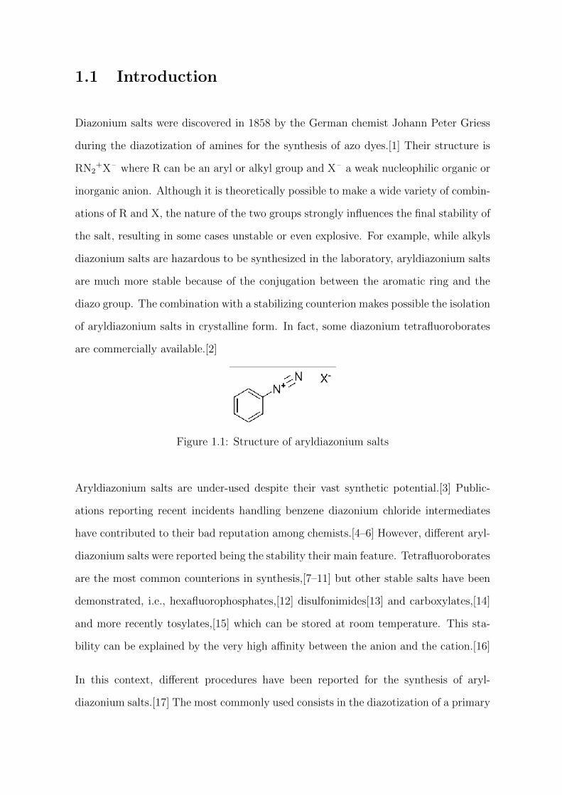
Figure 1.1: Structure of aryldiazonium salts
Aryldiazonium salts are under-used despite their vast synthetic potential.[3] Public-
ations reporting recent incidents handling benzene diazonium chloride intermediates
have contributed to their bad reputation among chemists.[4–6] However, different aryl-
diazonium salts were reported being the stability their main feature. Tetrafluoroborates
are the most common counterions in synthesis,[7–11] but other stable salts have been
demonstrated, i.e., hexafluorophosphates,[12] disulfonimides[13] and carboxylates,[14]
and more recently tosylates,[15] which can be stored at room temperature. This sta-
bility can be explained by the very high affinity between the anion and the cation.[16]
In this context, different procedures have been reported for the synthesis of aryl-
diazonium salts.[17] The most commonly used consists in the diazotization of a primary
amine with a source of nitrite in the presence of an acid such as HBF4, which provides
protons and the necessary counterions. The temperature is kept under 0 C to avoid
the decomposition of the product into nitrogen and the aryl cation, which can undergo
secondary reactions with the nucleophiles present during the reaction.
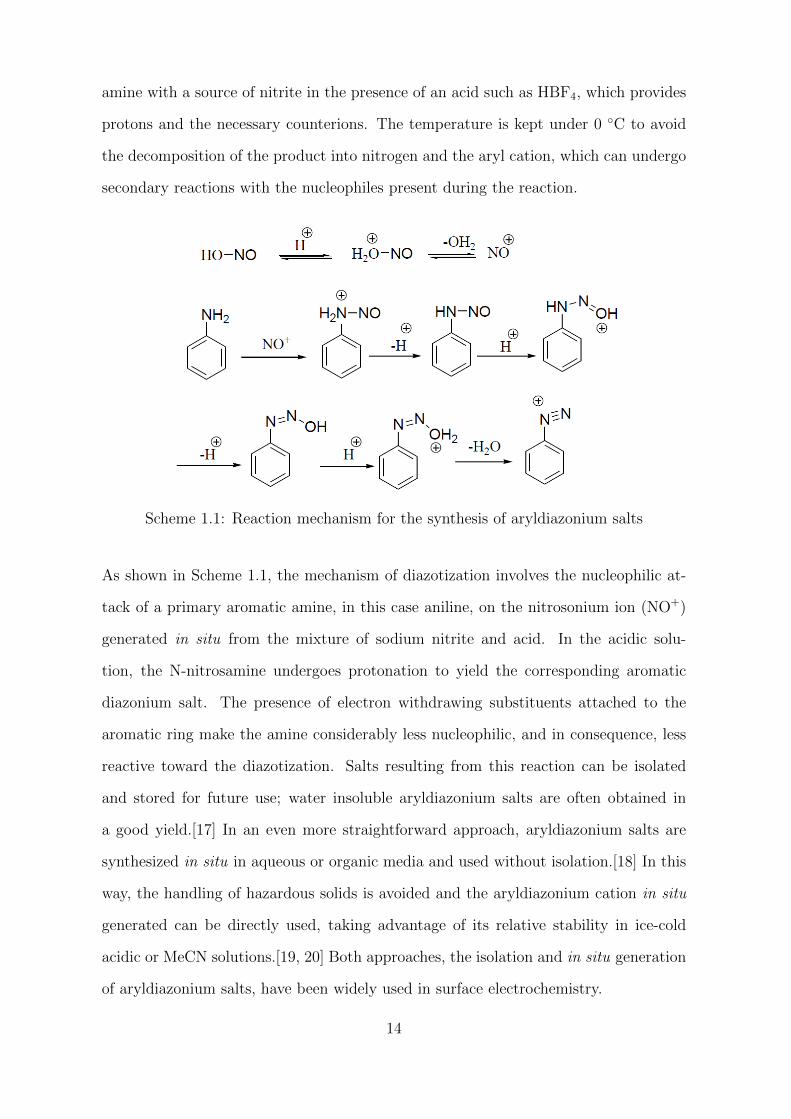
Scheme 1.1: Reaction mechanism for the synthesis of aryldiazonium salts
As shown in Scheme 1.1, the mechanism of diazotization involves the nucleophilic at-
tack of a primary aromatic amine, in this case aniline, on the nitrosonium ion (NO+)
generated in situ from the mixture of sodium nitrite and acid. In the acidic solu-
tion, the N-nitrosamine undergoes protonation to yield the corresponding aromatic
diazonium salt. The presence of electron withdrawing substituents attached to the
aromatic ring make the amine considerably less nucleophilic, and in consequence, less
reactive toward the diazotization. Salts resulting from this reaction can be isolated
and stored for future use; water insoluble aryldiazonium salts are often obtained in
a good yield.[17] In an even more straightforward approach, aryldiazonium salts are
synthesized in situ in aqueous or organic media and used without isolation.[18] In this
way, the handling of hazardous solids is avoided and the aryldiazonium cation in situ
generated can be directly used, taking advantage of its relative stability in ice-cold
acidic or MeCN solutions.[19, 20] Both approaches, the isolation and in situ generation
of aryldiazonium salts, have been widely used in surface electrochemistry.
14
1.2 Surface modification by aryldiazonium salts
Different chemical and electrochemical approaches have been developed for surface
modification.[18] In general, chemical procedures requires the immersion of the sur-
face in a solution containing a molecule capable of interacting spontaneously with the
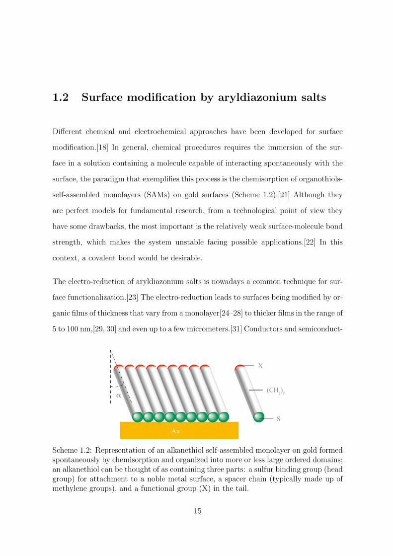
surface, the paradigm that exemplifies this process is the chemisorption of organothiols-
self-assembled monolayers (SAMs) on gold surfaces (Scheme 1.2).[21] Although they
are perfect models for fundamental research, from a technological point of view they
have some drawbacks, the most important is the relatively weak surface-molecule bond
strength, which makes the system unstable facing possible applications.[22] In this
context, a covalent bond would be desirable.
The electro-reduction of aryldiazonium salts is nowadays a common technique for sur-
face functionalization.[23] The electro-reduction leads to surfaces being modified by or-
ganic films of thickness that vary from a monolayer[24–28] to thicker films in the range of
5 to 100 nm,[29, 30] and even up to a few micrometers.[31] Conductors and semiconduct-
Scheme 1.2: Representation of an alkanethiol self-assembled monolayer on gold formedspontaneously by chemisorption and organized into more or less large ordered domains;an alkanethiol can be thought of as containing three parts: a sulfur binding group (headgroup) for attachment to a noble metal surface, a spacer chain (typically made up ofmethylene groups), and a functional group (X) in the tail.
15
ors surfaces could be easily modified by electrochemically-induced aryldiazonium reduc-
tion leading to a fast modification (seconds-minutes) of the substrate.[32] Furthermore,
insulators[33] could also be modified by adding chemical reductants in solution,[34] by
the formation of diazotes[35] or by spontaneous grafting[36] which makes this technique
very versatile. Since the flexibility of the synthetic methods previously described, a wide
variety of surfaces bearing functional groups can be achieved. For all these reasons, the
electro-reduction of aryldiazonium salts was proposed for a wide number of applications,
ranging from corrosion protection,[37] active plasmonic devices,[38] supercapacitors[39]
and molecular diodes,[40, 41] to name a few.
1.2.1 Electrochemical reduction of aryldiazonium salts
1.2.1.1 Reduction at the electrode surface
Dediazoniation is one of the most important reactions of aryldiazonium salts.[12] It
occurs by loss of the diazo group either by a heterolytic or homolytic mechanism to
generate the corresponding aryl cation (Ar+) or the aryl radical (Ar•). As far as the
electrochemical reduction of aryldiazonium salts is concerned, we will be only interested
in the homolytic pathway.
ArN+≡N + e− → Ar• + N2 (1.1)
Reduction of aryldiazonium salts at the surface of an electrode follows the homolytic
pathway. The electro-reduction of an aryldiazonium cation was demonstrated by An-
drieux and Pinson[42] to be a concerted process with the cleavage of dinitrogen and
generation of the corresponding aryl radical (Equation 1.1). The latter, extremely re-
active, can then react with the surface. This step is particularly efficient since the aryl
radicals are produced in the vicinity of the electrode surface.
16
First evidence of aryl radicals production by electro-reduction of aryldiazonium salts
was reported by Elofson in 1958.[43] The reduction of diazotized amines in acid solution
on a dropping mercury electrode was investigated by polarography at increasing con-
centration of aryldiazonium salt. It was found a non-linear relation between the current
of the first reduction peak and the concentration of the aryldiazonium salt. The current
of the first reduction peak reached a constant value, indicating, as authors stated, an
absorption process as result of the one-electron reduction of the aryldiazonium salt to
a free radical, which was stabilized by interaction on the mercury electrode surface.
Aryl-mercury derivatives were found after by coulometry analysis of the mercury pool.
Some objections can be raised given the tendency of mercury to adsorb species; how-
ever, later works by Elofson[44, 45] demonstrated the aryl radical production in MeCN
solution during electro-reduction of aryldiazonium salts. Radical production was in-
directly demonstrated through Pschorr reaction, which consists of an intramolecular
substitution of aromatic compounds via aryldiazonium salts. The dediazoniation of the
aryldiazonium compounds was electrochemically promoted by electrolysis, and the ex-
pected reaction products were confirmed by melting point, infrared and mass spectral
analysis. A few years later, aryl radical production was confirmed by direct spectro-
scopic detection during electrochemical reactions.[46]
1.2.1.2 Other methodologies of reduction
Electrochemical reduction of aryldiazonium salts requires a specific experimental setup.
Usually, an aryldiazonium salt is dissolved (10−2 to 10−3 mol L−1) in an aprotic solvent
containing the electrolyte; a standard three electrode setup is used in CV or chro-
noamperometry, where the working electrode is the surface that will be modified. The
working electrode is dipped into the electrochemical cell containing the aryldiazonium
solution and polarized for a few seconds or minutes using a potentiostat. However, it is
not always possible to electrically connect the material to be functionalized, either be-
cause it is not a conductor like organic polymers or dielectrics, or because it is not ”elec-
17
trically connectable” to a potentiostat like gold nanoparticles or carbon black powders.
The reduction can then be carried out by adding a reducing agent (i.e., cuprous salt,
ascorbic acid or ferrocene) in the solution containing the diazonium salts.[12] In this
case, the concentration of aryldiazonium salt in solution should be higher than that of
electrochemical experiments, around 0.1 mol L−1. The reduction of aryldiazonium salts
can also be spontaneous, that means, without adding reducing agents or applying an
electrochemical potential. In this way, spontaneous modifications of metal surfaces such
as aluminium alloys or copper have been demonstrated.[47] This spontaneous process
is based on the relative potential of the metal surface when is dipped into the aryl-
diazonium salt solution. It is also possible to promote the reduction of aryldiazonium
salts thermally by heating the solution slightly,[48] or using light to induce the photo-
chemical decomposition of the aryldiazonium salt.[49] These alternative methodologies
for reducing aryldiazonium salts are out of the scope of this thesis, which will follow
the most straightforward path of the electrochemical reduction.
1.2.2 Electrochemical behavior of diazonium salts
In 1992, Saveant et al.[23] reported a new reaction of aryldiazonium compounds:
the ”Covalent modification of carbon surfaces by grafting of functionalized aryl rad-
icals produced from electrochemical reduction of diazonium salts”. A strong cova-
lent bond between the grafted molecule and the carbon surface was observed. This
was later confirmed by spectroscopic analyses for carbon surfaces,[50–54] and also
semiconductors,[55–57] gold[58, 59] and iron[37] surfaces. Theoretical calculations sup-
port the experimental conclusions, especially regarding the covalent nature of the bond-
ing between the aryl group and metal surfaces.[60] Other evidences that support the
covalent bonding layer-surface are its resistance to ultrasonication in different organic
solvents,[9] and its stability at high temperatures.[61] These results are incompatible
with a molecule-surface interaction type Van der Waals forces or hydrogen bonds.
18
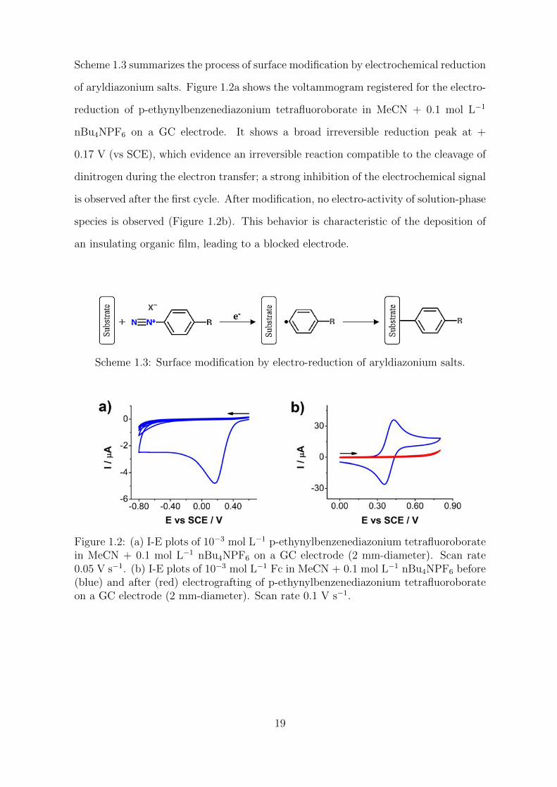
Scheme 1.3 summarizes the process of surface modification by electrochemical reduction
of aryldiazonium salts. Figure 1.2a shows the voltammogram registered for the electro-
reduction of p-ethynylbenzenediazonium tetrafluoroborate in MeCN + 0.1 mol L−1
nBu4NPF6 on a GC electrode. It shows a broad irreversible reduction peak at +
0.17 V (vs SCE), which evidence an irreversible reaction compatible to the cleavage of
dinitrogen during the electron transfer; a strong inhibition of the electrochemical signal
is observed after the first cycle. After modification, no electro-activity of solution-phase
species is observed (Figure 1.2b). This behavior is characteristic of the deposition of
an insulating organic film, leading to a blocked electrode.
Scheme 1.3: Surface modification by electro-reduction of aryldiazonium salts.
Figure 1.2: (a) I-E plots of 10−3 mol L−1 p-ethynylbenzenediazonium tetrafluoroboratein MeCN + 0.1 mol L−1 nBu4NPF6 on a GC electrode (2 mm-diameter). Scan rate0.05 V s−1. (b) I-E plots of 10−3 mol L−1 Fc in MeCN + 0.1 mol L−1 nBu4NPF6 before(blue) and after (red) electrografting of p-ethynylbenzenediazonium tetrafluoroborateon a GC electrode (2 mm-diameter). Scan rate 0.1 V s−1.
19
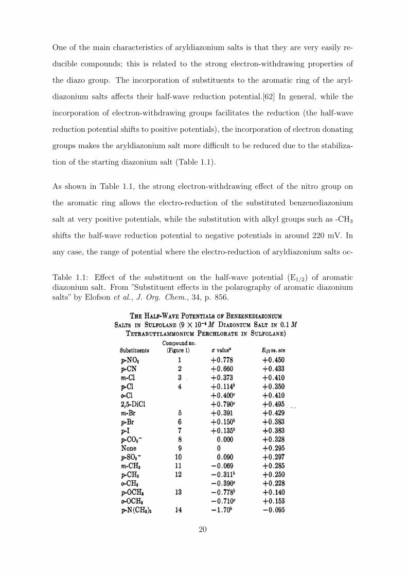
One of the main characteristics of aryldiazonium salts is that they are very easily re-
ducible compounds; this is related to the strong electron-withdrawing properties of
the diazo group. The incorporation of substituents to the aromatic ring of the aryl-
diazonium salts affects their half-wave reduction potential.[62] In general, while the
incorporation of electron-withdrawing groups facilitates the reduction (the half-wave
reduction potential shifts to positive potentials), the incorporation of electron donating
groups makes the aryldiazonium salt more difficult to be reduced due to the stabiliza-
tion of the starting diazonium salt (Table 1.1).
As shown in Table 1.1, the strong electron-withdrawing effect of the nitro group on
the aromatic ring allows the electro-reduction of the substituted benzenediazonium
salt at very positive potentials, while the substitution with alkyl groups such as -CH3
shifts the half-wave reduction potential to negative potentials in around 220 mV. In
any case, the range of potential where the electro-reduction of aryldiazonium salts oc-
Table 1.1: Effect of the substituent on the half-wave potential (E1/2) of aromaticdiazonium salt. From ”Substituent effects in the polarography of aromatic diazoniumsalts” by Elofson et al., J. Org. Chem., 34, p. 856.
20

curs (usually from + 0.2 to – 0.8 V vs SCE in aprotic solvents) is low by comparison
with other families of organic compounds. Precisely, the comparison of the electro-
chemical behavior of aryldiazonium salts with a different family of organic compounds,
the aryl halides, allowed Pinson and Podvorica[33] to clarify some aspects about this
peculiar electrochemical behavior of aryldiazonium salts. Unlike aryldiazonium salts,
aryl halides have never shown grafting properties towards the electrode surface. They
undergoes a first one-electron reduction (through a concerted mechanism or not) to
aryl radical, depending on the lifetime of the aryl radical it can diffuse to the bulk
of the solution where reacts with the solvent, or stays at the electrode surface, where
undergoes a second one-electron reduction to aryl anion (Scheme 1.4).
The different electrochemical behavior of aryl halides and aryldiazonium salts can be
explained by the aryl radical generated from the starting aryl halide, which is very eas-
ily reduced to aryl anion and has no opportunity to react with the electrode surface. In
consequence, no electrografting is observed for this family of compounds. On the con-
trary, the electrochemical behavior of diazonium salts is related, as stated before, with
the electron-withdrawing character of the diazo group, and also with the mechanism
of the electron transfer. The concerted mechanism ensures the formation of the aryl
radical just on the electrode surface. This aryl radical, unlike the aryl radicals gen-
erated from the one-electron reduction of aryl halides compounds, can be reduced to
aryl anion but at much more negative potential than that of the starting aryldiazonium
salt, having the opportunity to react with the electrode surface giving rise to what is
called electro-grafting.[33]
Scheme 1.4: Mechanism of reduction of aryl halides compounds. From ”Attachment ofaromatic layers to conductive or semi-conductive surfaces by reduction of diazoniumsalts” by Pinson and Podvorica, Chem. Soc. Rev., 34, p. 431. Copyright The RoyalSociety of Chemistry 2005.
21
1.3 From multilayer to monolayers
1.3.1 Aryl multilayers
Electrochemical reduction of aryldiazonium salts on carbon and metal surfaces routinely
leads to the formation of multilayers (thickness ranging from 10 to 100 nm).[18] As we
stated before, the grafting of aryldiazonium salts allows the modification of surfaces
with aryl molecules by covalent bonding. Consequently, the attachment of the mo-
lecules to the surface is an irreversible process, and only a mechanical polishing can
regenerate the surface.[9]
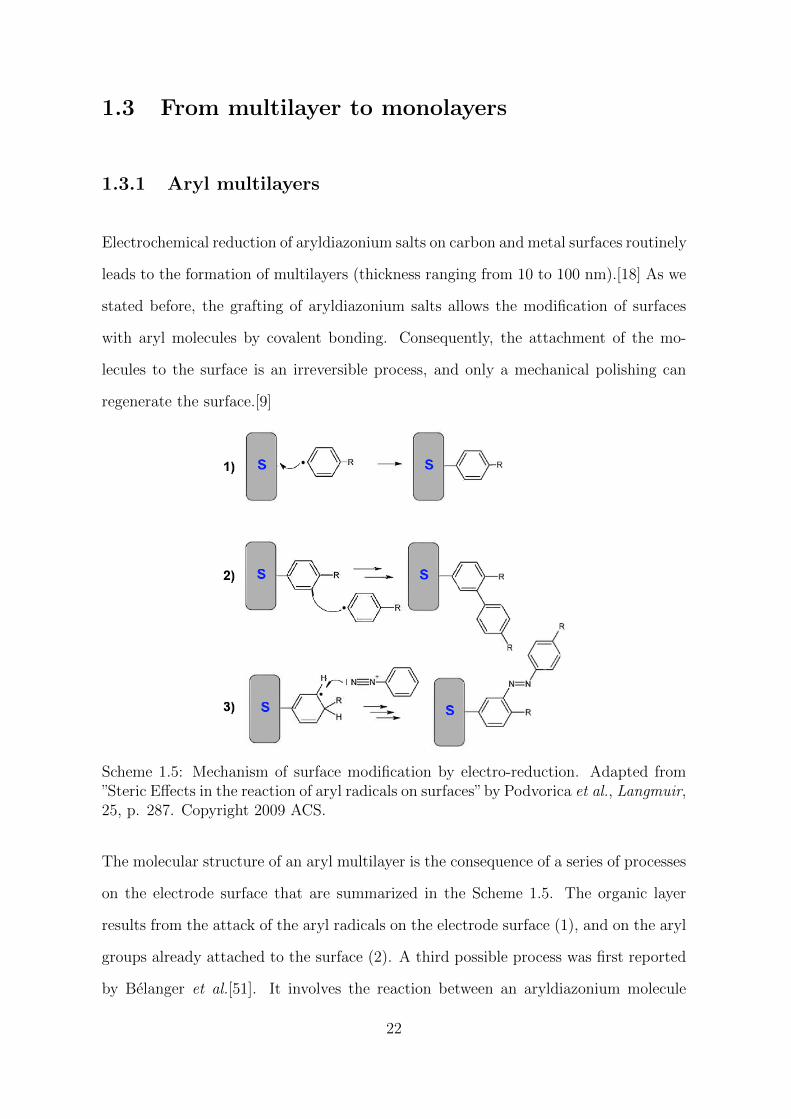
Scheme 1.5: Mechanism of surface modification by electro-reduction. Adapted from”Steric Effects in the reaction of aryl radicals on surfaces”by Podvorica et al., Langmuir,25, p. 287. Copyright 2009 ACS.
The molecular structure of an aryl multilayer is the consequence of a series of processes
on the electrode surface that are summarized in the Scheme 1.5. The organic layer
results from the attack of the aryl radicals on the electrode surface (1), and on the aryl
groups already attached to the surface (2). A third possible process was first reported
by Belanger et al.[51]. It involves the reaction between an aryldiazonium molecule
22
in solution and an intermediate cyclohexadienyl radical on the film surface (3). This
process is not kinetically favored and leads to the formation of azo bonds (-N=N-)
inside the layer.[63] Therefore, the structure of multilayers could be described as a
polyaryl structure covalently bonded to the electrode surface,[64–66] with the possible
presence of azo bonds inside the aromatic structure.
Indeed, aryl multilayers do not show a well-defined structure at the molecular level and
they lack of ordered molecular domains. The growth of the aryl layer has been described
as a nucleation process; this means that the attack of the aryl radical is kinetically more
favored on an already grafted phenyl group than on the electrode surface.[52, 67] Dur-
ing the growth of the multilayer, the transfer of electrons between the surface of the
electrode and the aryldiazonium molecules in solution often becomes difficult, until no
electron transfer occurs through the organic layer (See Figure 1.2a where no electron
transfer was observed after the first reduction cycle of p-ethynylbenzenediazonium salt).
Most probably, the growth continues through a radical chain mechanism on the layer,
although experimentally it has been observed that the organic layer thickness is lim-
ited, and the growth is therefore a self-limiting process.[68] This limiting growth of the
organic layers was also observed even when aryl radicals are generated in the solution,
i.e., by adding a reducing agent. However, the concurrence of side reactions like dimer-
ization of the aryl radicals in solution, or deactivation of the aryl radicals by reaction
with the solvent could explain the formation of thinner films in these conditions.[69]
Very thick aryl layers (micrometer level) can be achieved by incorporating a redox act-
ive molecule to the structure. This strategy ensures the transport of electrons through
the organic layer and its growth, allowing the reduction of the aryldiazonium salts in
solution to continue (Scheme 1.6). For example, the grafting of aryldiazonium salts
containing electroactive moieties such as nitrobenzene, anthraquinone or benzophen-
one led to thick conducting aryl films ranging from 20 nm to around 1 µm-thickness
on carbon and gold surfaces.[70] Some aryldiazonium molecules without incorporating
electroactive molecules also allow the formation of very thick films. This is the case
23
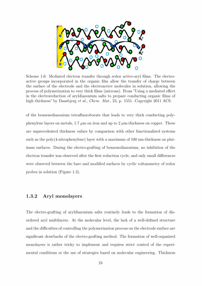
Scheme 1.6: Mediated electron transfer through redox active-aryl films. The electro-active groups incorporated in the organic film allow the transfer of charge betweenthe surface of the electrode and the electroactive molecules in solution, allowing theprocess of polymerization to very thick films (microns). From ”Using a mediated effectin the electroreduction of aryldiazonium salts to prepare conducting organic films ofhigh thickness” by Daasbjerg et al., Chem. Mat., 23, p. 1551. Copyright 2011 ACS.
of the benzenediazonium tetrafluoroborate that leads to very thick conducting poly-
phenylene layers on metals, 1.7 µm on iron and up to 2 µm-thickness on copper. These
are unprecedented thickness values by comparison with other functionalized systems
such as the poly(4-nitrophenylene) layer with a maximum of 100 nm-thickness on plat-
inum surfaces. During the electro-grafting of benzenediazonium, no inhibition of the
electron transfer was observed after the first reduction cycle, and only small differences
were observed between the bare and modified surfaces by cyclic voltammetry of redox
probes in solution (Figure 1.3).
1.3.2 Aryl monolayers
The electro-grafting of aryldiazonium salts routinely leads to the formation of dis-
ordered aryl multilayers. At the molecular level, the lack of a well-defined structure
and the difficulties of controlling the polymerization process on the electrode surface are
significant drawbacks of the electro-grafting method. The formation of well-organized
monolayers is rather tricky to implement and requires strict control of the experi-
mental conditions or the use of strategies based on molecular engineering. Thickness
24
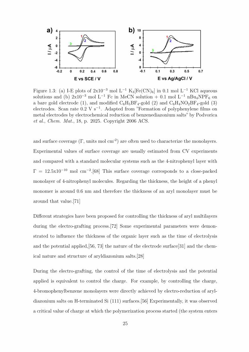
Figure 1.3: (a) I-E plots of 2x10⁻³ mol L−1 K3[Fe(CN)6] in 0.1 mol L−1 KCl aqueoussolutions and (b) 2x10⁻³ mol L−1 Fc in MeCN solution + 0.1 mol L−1 nBu4NPF6 ona bare gold electrode (1), and modified C6H5BF4-gold (2) and C6H4NO2BF4-gold (3)electrodes. Scan rate 0.2 V s−1. Adapted from ”Formation of polyphenylene films onmetal electrodes by electrochemical reduction of benzenediazonium salts” by Podvoricaet al., Chem. Mat., 18, p. 2025. Copyright 2006 ACS.
and surface coverage (Γ, units mol cm-2) are often used to characterize the monolayers.
Experimental values of surface coverage are usually estimated from CV experiments
and compared with a standard molecular systems such as the 4-nitrophenyl layer with
Γ = 12.5x10⁻¹⁰ mol cm−2.[68] This surface coverage corresponds to a close-packed
monolayer of 4-nitrophenyl molecules. Regarding the thickness, the height of a phenyl
monomer is around 0.6 nm and therefore the thickness of an aryl monolayer must be
around that value.[71]
Different strategies have been proposed for controlling the thickness of aryl multilayers
during the electro-grafting process.[72] Some experimental parameters were demon-
strated to influence the thickness of the organic layer such as the time of electrolysis
and the potential applied,[56, 73] the nature of the electrode surface[31] and the chem-
ical nature and structure of aryldiazonium salts.[28]
During the electro-grafting, the control of the time of electrolysis and the potential
applied is equivalent to control the charge. For example, by controlling the charge,
4-bromophenylbenzene monolayers were directly achieved by electro-reduction of aryl-
diazonium salts on H-terminated Si (111) surfaces.[56] Experimentally, it was observed
a critical value of charge at which the polymerization process started (the system enters
25
in a multilayer regime); this ”critical charge” was observed to be dependent on the po-
tential applied. It was found that the optimal experimental conditions were those where
the potential applied was equal to the reduction peak potential of the aryldiazonium
salt, and the charge was close to the critical value. Note that on carbon or metal
surfaces, the layer grows following a nucleation mechanism. Therefore, a limitation of
the charge or the potential applied during the electro-grafting could result in a non-
homogeneous coverage or partial modification of the surface. Hence, this is not always
an adequate strategy.
The influence of the applied potential on the thickness of different aryl layers was stud-
ied by McCreery et al.[73] Aryldiazonium salts of biphenyl (BP), nitrobiphenyl (NBP)
and nitroazobenzene (NAB) were reduced on PPF electrodes by a single voltammetric
scan from + 0.4 V to 0, - 0.2, - 0.3, - 0.4, and - 0.6 V vs Ag/Ag+ in an aprotic electrolyte
solution. Thickness values of the resulting layers were estimated by AFM ”scratching”
experiments. Furthermore, all the salts were reduced by consecutive voltammetric
scans from + 0.4 V to - 0.6 V to investigate the effect of the time as an additional
parameter (Table 1.2).
As shown in Table 1.2, the thickness increases monotonically with the cathodic poten-
tial. Usually, the time of electrolysis (or no. of cycles) is not a determinant parameter
if we consider the electro-grafting as a self-limiting process. In this case, the thickness
of the organic films increased with the no. of cycles until reaching multilayer values:
2.3 nm (BP), 4.2 nm (NBP) and 6.4 nm (NAB) at ten reduction cycles. In this case,
the growth of the multilayers is consistent with previous publications, which reported
conducting properties of these films. Thus, the electrical properties of some organic
films make challenging to obtain monolayers by simple control of the experimental
conditions.
26
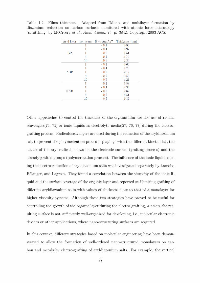
Table 1.2: Films thickness. Adapted from ”Mono- and multilayer formation bydiazonium reduction on carbon surfaces monitored with atomic force microscopy“scratching” by McCreery et al., Anal. Chem., 75, p. 3842. Copyright 2003 ACS.
Other approaches to control the thickness of the organic film are the use of radical
scavengers[74, 75] or ionic liquids as electrolyte media[27, 76, 77] during the electro-
grafting process. Radicals scavengers are used during the reduction of the aryldiazonium
salt to prevent the polymerization process, ”playing” with the different kinetic that the
attack of the aryl radicals shows on the electrode surface (grafting process) and the
already grafted groups (polymerization process). The influence of the ionic liquids dur-
ing the electro-reduction of aryldiazonium salts was investigated separately by Lacroix,
Belanger, and Lagrost. They found a correlation between the viscosity of the ionic li-
quid and the surface coverage of the organic layer and reported self-limiting grafting of
different aryldiazonium salts with values of thickness close to that of a monolayer for
higher viscosity systems. Although these two strategies have proved to be useful for
controlling the growth of the organic layer during the electro-grafting, a priori the res-
ulting surface is not sufficiently well-organized for developing, i.e., molecular electronic
devices or other applications, where nano-structuring surfaces are required.
In this context, different strategies based on molecular engineering have been demon-
strated to allow the formation of well-ordered nano-structured monolayers on car-
bon and metals by electro-grafting of aryldiazonium salts. For example, the vertical
27
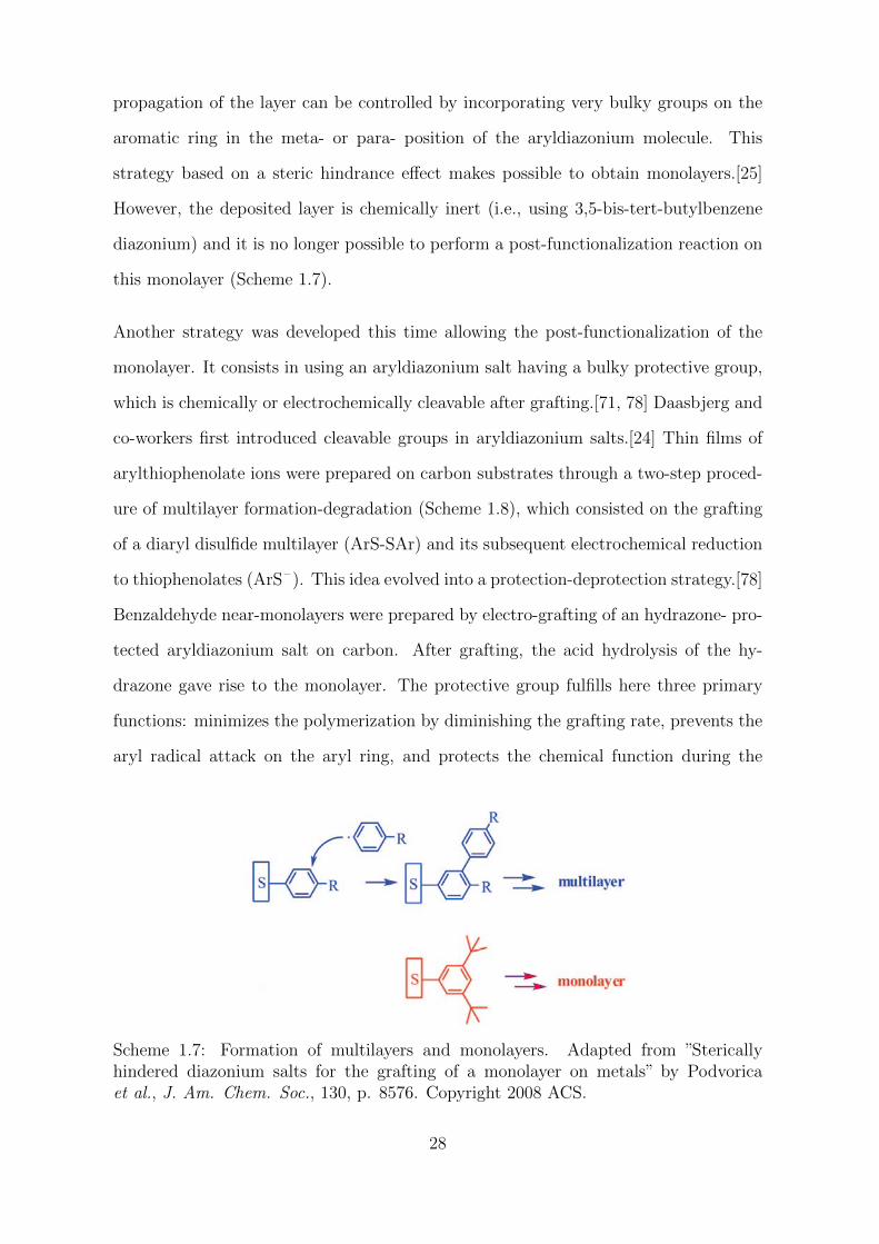
propagation of the layer can be controlled by incorporating very bulky groups on the
aromatic ring in the meta- or para- position of the aryldiazonium molecule. This
strategy based on a steric hindrance effect makes possible to obtain monolayers.[25]
However, the deposited layer is chemically inert (i.e., using 3,5-bis-tert-butylbenzene
diazonium) and it is no longer possible to perform a post-functionalization reaction on
this monolayer (Scheme 1.7).
Another strategy was developed this time allowing the post-functionalization of the
monolayer. It consists in using an aryldiazonium salt having a bulky protective group,
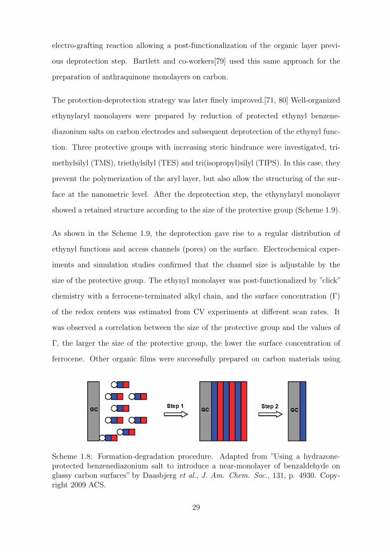
which is chemically or electrochemically cleavable after grafting.[71, 78] Daasbjerg and
co-workers first introduced cleavable groups in aryldiazonium salts.[24] Thin films of
arylthiophenolate ions were prepared on carbon substrates through a two-step proced-
ure of multilayer formation-degradation (Scheme 1.8), which consisted on the grafting
of a diaryl disulfide multilayer (ArS-SAr) and its subsequent electrochemical reduction
to thiophenolates (ArS– ). This idea evolved into a protection-deprotection strategy.[78]
Benzaldehyde near-monolayers were prepared by electro-grafting of an hydrazone- pro-
tected aryldiazonium salt on carbon. After grafting, the acid hydrolysis of the hy-
drazone gave rise to the monolayer. The protective group fulfills here three primary
functions: minimizes the polymerization by diminishing the grafting rate, prevents the
aryl radical attack on the aryl ring, and protects the chemical function during the
Scheme 1.7: Formation of multilayers and monolayers. Adapted from ”Stericallyhindered diazonium salts for the grafting of a monolayer on metals” by Podvoricaet al., J. Am. Chem. Soc., 130, p. 8576. Copyright 2008 ACS.
28
electro-grafting reaction allowing a post-functionalization of the organic layer previ-
ous deprotection step. Bartlett and co-workers[79] used this same approach for the
preparation of anthraquinone monolayers on carbon.
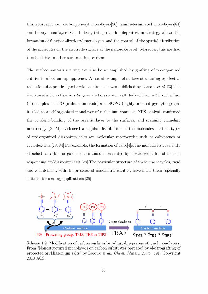
The protection-deprotection strategy was later finely improved.[71, 80] Well-organized
ethynylaryl monolayers were prepared by reduction of protected ethynyl benzene-
diazonium salts on carbon electrodes and subsequent deprotection of the ethynyl func-
tion. Three protective groups with increasing steric hindrance were investigated, tri-
methylsilyl (TMS), triethylsilyl (TES) and tri(isopropyl)silyl (TIPS). In this case, they
prevent the polymerization of the aryl layer, but also allow the structuring of the sur-
face at the nanometric level. After the deprotection step, the ethynylaryl monolayer
showed a retained structure according to the size of the protective group (Scheme 1.9).
As shown in the Scheme 1.9, the deprotection gave rise to a regular distribution of
ethynyl functions and access channels (pores) on the surface. Electrochemical exper-
iments and simulation studies confirmed that the channel size is adjustable by the
size of the protective group. The ethynyl monolayer was post-functionalized by ”click”
chemistry with a ferrocene-terminated alkyl chain, and the surface concentration (Γ)
of the redox centers was estimated from CV experiments at different scan rates. It
was observed a correlation between the size of the protective group and the values of
Γ, the larger the size of the protective group, the lower the surface concentration of
ferrocene. Other organic films were successfully prepared on carbon materials using
Scheme 1.8: Formation-degradation procedure. Adapted from ”Using a hydrazone-protected benzenediazonium salt to introduce a near-monolayer of benzaldehyde onglassy carbon surfaces” by Daasbjerg et al., J. Am. Chem. Soc., 131, p. 4930. Copy-right 2009 ACS.
29
this approach, i.e., carboxyphenyl monolayers[26], amine-terminated monolayers[81]
and binary monolayers[82]. Indeed, this protection-deprotection strategy allows the
formation of functionalized-aryl monolayers and the control of the spatial distribution
of the molecules on the electrode surface at the nanoscale level. Moreover, this method
is extendable to other surfaces than carbon.
The surface nano-structuring can also be accomplished by grafting of pre-organized
entities in a bottom-up approach. A recent example of surface structuring by electro-
reduction of a pre-designed aryldiazonium salt was published by Lacroix et al.[83] The
electro-reduction of an in situ generated diazonium salt derived from a 3D ruthenium
(II) complex on ITO (iridium tin oxide) and HOPG (highly oriented pyrolytic graph-
ite) led to a self-organized monolayer of ruthenium complex. XPS analysis confirmed
the covalent bonding of the organic layer to the surfaces, and scanning tunneling
microscopy (STM) evidenced a regular distribution of the molecules. Other types
of pre-organized diazonium salts are molecular macrocycles such as calixarenes or
cyclodextrins.[28, 84] For example, the formation of calix[4]arene monolayers covalently
attached to carbon or gold surfaces was demonstrated by electro-reduction of the cor-
responding aryldiazonium salt.[28] The particular structure of these macrocycles, rigid
and well-defined, with the presence of nanometric cavities, have made them especially
suitable for sensing applications.[35]
Scheme 1.9: Modification of carbon surfaces by adjustable-porous ethynyl monolayers.From ”Nanostructured monolayers on carbon substrates prepared by electrografting ofprotected aryldiazonium salts” by Leroux et al., Chem. Mater., 25, p. 491. Copyright2013 ACS.
30
1.4 Post-functionalization procedures
Aryldiazonium salts offer a wide variety of possibilities regarding the functional groups
or molecular systems that can be introduced to modify the physicochemical proper-
ties of the materials.[85–89] Aryldiazonium salts can be synthesized already bearing
the chemical function, or structure that provides the properties sought for the surface.
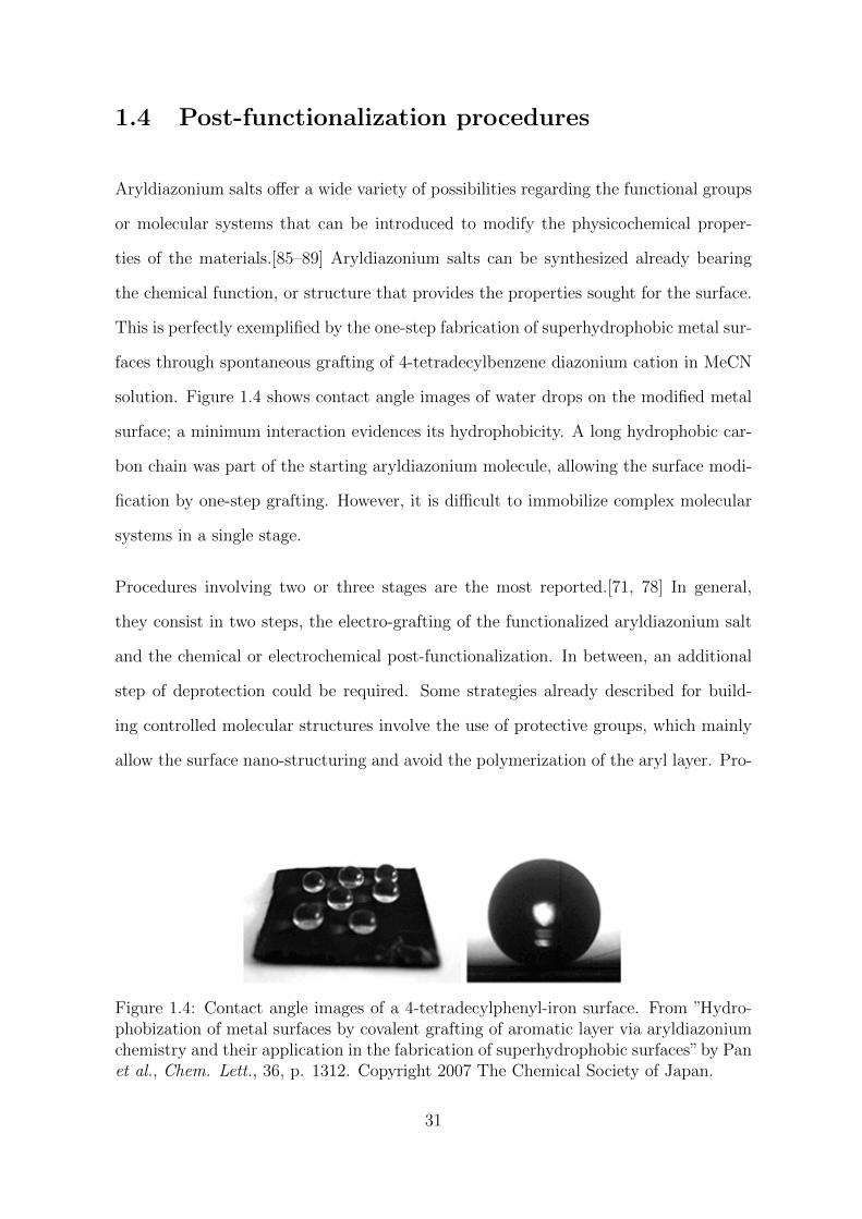
This is perfectly exemplified by the one-step fabrication of superhydrophobic metal sur-
faces through spontaneous grafting of 4-tetradecylbenzene diazonium cation in MeCN
solution. Figure 1.4 shows contact angle images of water drops on the modified metal
surface; a minimum interaction evidences its hydrophobicity. A long hydrophobic car-
bon chain was part of the starting aryldiazonium molecule, allowing the surface modi-
fication by one-step grafting. However, it is difficult to immobilize complex molecular
systems in a single stage.
Procedures involving two or three stages are the most reported.[71, 78] In general,
they consist in two steps, the electro-grafting of the functionalized aryldiazonium salt
and the chemical or electrochemical post-functionalization. In between, an additional
step of deprotection could be required. Some strategies already described for build-
ing controlled molecular structures involve the use of protective groups, which mainly
allow the surface nano-structuring and avoid the polymerization of the aryl layer. Pro-
Figure 1.4: Contact angle images of a 4-tetradecylphenyl-iron surface. From ”Hydro-phobization of metal surfaces by covalent grafting of aromatic layer via aryldiazoniumchemistry and their application in the fabrication of superhydrophobic surfaces”by Panet al., Chem. Lett., 36, p. 1312. Copyright 2007 The Chemical Society of Japan.
31
tective groups can also perform other functions related with the chemoselectivity in
a subsequent chemical reaction or simple protect the chemical function during the
electro-grafting. In this case, a third step of protection is required.
Different chemical reactions have been described for post-functionalizing aryl layers.
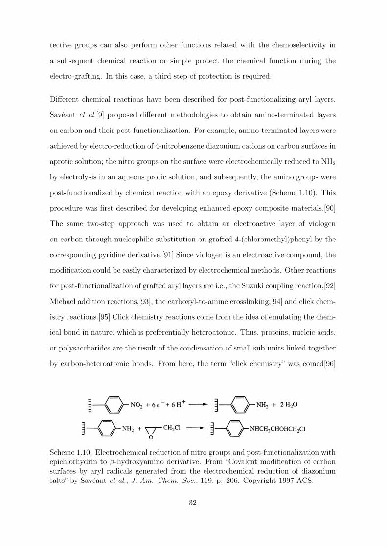
Saveant et al.[9] proposed different methodologies to obtain amino-terminated layers
on carbon and their post-functionalization. For example, amino-terminated layers were
achieved by electro-reduction of 4-nitrobenzene diazonium cations on carbon surfaces in
aprotic solution; the nitro groups on the surface were electrochemically reduced to NH2
by electrolysis in an aqueous protic solution, and subsequently, the amino groups were
post-functionalized by chemical reaction with an epoxy derivative (Scheme 1.10). This
procedure was first described for developing enhanced epoxy composite materials.[90]
The same two-step approach was used to obtain an electroactive layer of viologen
on carbon through nucleophilic substitution on grafted 4-(chloromethyl)phenyl by the
corresponding pyridine derivative.[91] Since viologen is an electroactive compound, the
modification could be easily characterized by electrochemical methods. Other reactions
for post-functionalization of grafted aryl layers are i.e., the Suzuki coupling reaction,[92]
Michael addition reactions,[93], the carboxyl-to-amine crosslinking,[94] and click chem-
istry reactions.[95] Click chemistry reactions come from the idea of emulating the chem-
ical bond in nature, which is preferentially heteroatomic. Thus, proteins, nucleic acids,
or polysaccharides are the result of the condensation of small sub-units linked together
by carbon-heteroatomic bonds. From here, the term ”click chemistry” was coined[96]
Scheme 1.10: Electrochemical reduction of nitro groups and post-functionalization withepichlorhydrin to β-hydroxyamino derivative. From ”Covalent modification of carbonsurfaces by aryl radicals generated from the electrochemical reduction of diazoniumsalts” by Saveant et al., J. Am. Chem. Soc., 119, p. 206. Copyright 1997 ACS.
32
and a series of criteria were established that define this set of reactions. Briefly, click
chemistry reactions must be modular, wide-ranging, stereospecific with high yield and
generate only harmless byproducts. Regarding the experimental conditions, the sim-
plicity of the process, the reagents availability, the harmlessness of the solvents and the
robustness of the reaction towards changes in the conditions are key factors. In this
context, it was reported the copper (I)-catalyzed Huisgen 1,3-dipolar cycloaddition[97]
as a member of the family of click chemistry reactions. It consists of the regioselective
reaction of terminal alkynes (-C≡CH) and azides (-N=N+=N-) to give highly stable
triazole products. The reaction is regioselective in the presence of copper (I)-catalyst,
which is generated in situ from a copper (II) salt and a reducing agent, typically ascor-
bic acid. It is a very robust reaction that can be carried out at room temperature in
water, without special precautions.
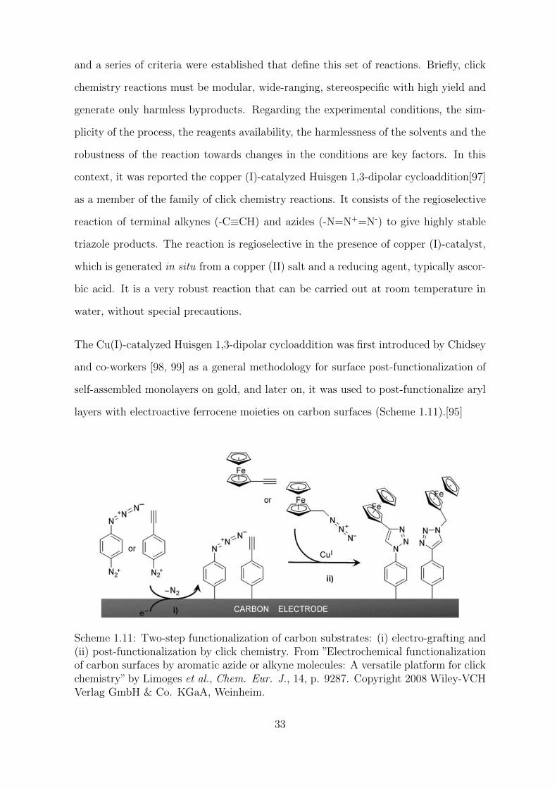
The Cu(I)-catalyzed Huisgen 1,3-dipolar cycloaddition was first introduced by Chidsey
and co-workers [98, 99] as a general methodology for surface post-functionalization of
self-assembled monolayers on gold, and later on, it was used to post-functionalize aryl
layers with electroactive ferrocene moieties on carbon surfaces (Scheme 1.11).[95]
Scheme 1.11: Two-step functionalization of carbon substrates: (i) electro-grafting and(ii) post-functionalization by click chemistry. From ”Electrochemical functionalizationof carbon surfaces by aromatic azide or alkyne molecules: A versatile platform for clickchemistry” by Limoges et al., Chem. Eur. J., 14, p. 9287. Copyright 2008 Wiley-VCHVerlag GmbH & Co. KGaA, Weinheim.
33
As shown in Scheme 1.11, the functionalization of carbon substrates occurs through a
two-step process: (i) the electro-reduction of either a phenylazide or phenylacetylene
diazonium salt on the carbon electrode; and (ii) the Cu(I)-catalyzed cycloaddition
between the azide or alkyne immobilized and the corresponding molecule bearing the
ferrocene moiety. This simple procedure allows the covalent attachment of molecular
structures to aryl layers in a two-step process by means electrochemical grafting and
click chemistry. As we have seen before, different strategies such as using protecting
groups during the electro-grafting lead to a fine control of the thickness of aryl layers
and the molecule distribution on the electrode surface. The nano-structuring of aryl
layers in combination with click chemistry post-functionalization procedures opens the
door to a wide range of applications.
1.5 Characterization of modified surfaces
Numerous techniques of analysis (i.e. optical, spectroscopic, electrochemical or by
imaging) allow the characterization of surfaces modified by electrochemical reduction
of aryldiazonium salts; we discuss some of them here.
1.5.1 Chemical analysis of modified surfaces
X-ray photoelectron spectroscopy (XPS) is a spectroscopic technique widely used in
the surface analysis since it provides quantitative information about the elemental
composition and chemical and electronic state of the elements within a material. It is
typically accomplished, in high vacuum or ultra-high vacuum conditions, by irradiating
the sample surface with a mono-energetic beam of X-rays which produces the emission
of photoelectrons that are detected in an electron energy analyzer. This technique
allows surface chemical analysis to a depth of about 10 nm. Using an X-ray source,
the electrons associated with each atom can be subtracted from the attraction of the
34
nucleus and emitted in the form of photoelectrons. The binding energy they had before
leaving the atom is characteristic of the emitting atom and its chemical environment.
For one chemical element, we can distinguish several contributions. An XPS spec-
trum is composed of peaks at different binding energies (in eV) and intensities, which
varies as a function of the number of photoelectrons emitted. The processing of the
data obtained allows a kind of elemental analysis of the modified surfaces.[100, 101]
As example, the XPS analysis of a 4-nitrophenyl modified GC electrodes shows, prior
reduction of the nitro groups on the surface, a peak at 406 eV corresponding to the
nitrogen of the nitro groups;[102] the presence of other nitrogen species with lower
binding energy at 400 eV suggests the existence of azo groups inside the organic layer.
After electrochemical reduction of the nitro groups, many different nitrogen-derived
functions are found: nitro groups, nitroso groups, hydroxilamino and amino groups.
The presence of nitro groups on 4-nitrophenyl modified surfaces can be also evidenced
by polarization modulation IR reflection absorption (PMIRRAS).[9, 103] The two char-
acteristics absorption bands associated to the anti-symmetric and symmetric vibrations
of the nitro group in nitrobenzene are found at 1485 and 1265 cm−1.
1.5.2 Thickness of organic films
The thickness of the organic layers grafted on a surface is often estimated by spectro-
scopy ellipsometry (SE) or atomic force microscopy (AFM).
SE is an optical technique which allows the non-destructive characterization of thin
films by investigating the dielectric properties (complex refractive index) of the sample.
It measures changes of the polarization of the light that is reflected or transmitted from
the sample and, it can be used to characterize film thickness with angstrom resolution,
or i.e., determine the roughness and optical constants of materials.[104]
AFM is a versatile and atomic-resolution type of scanning probe microscopy useful
in the characterization of surface morphology and interaction forces. Images are ac-
35
quired by raster scanning a small area of the sample with a sharp probe attached to
a cantilever. Typically, this micro-cantilever can be operated in three different modes:
non-contact mode, contact mode, and tapping mode. Contact and tapping mode are
the most frequently used in surface characterization. The first allows, i.e., the atomic
manipulation of the sample surface in a controlled way by well setting the forces between
the tip and the sample; and the second, also called semi-contact mode, keeps the probe
close enough to the sample surface for acquiring high-resolution data while preventing
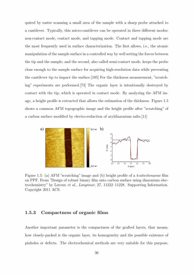
the cantilever tip to impact the surface.[105] For the thickness measurement, ”scratch-
ing” experiments are performed.[73] The organic layer is intentionally destroyed by
contact with the tip, which is operated in contact mode. By analyzing the AFM im-
age, a height profile is extracted that allows the estimation of the thickness. Figure 1.5
shows a common AFM topographic image and the height profile after ”scratching” of
a carbon surface modified by electro-reduction of aryldiazonium salts.[11]
Figure 1.5: (a) AFM ”scratching” image and (b) height profile of a 4-nitrobenzene filmon PPF. From ”Design of robust binary film onto carbon surface using diazonium elec-trochemistry” by Leroux et al., Langmuir, 27, 11222–11228. Supporting Information.Copyright 2011 ACS.
1.5.3 Compactness of organic films
Another important parameter is the compactness of the grafted layers, that means,
how closely-packed is the organic layer, its homogeneity and the possible existence of
pinholes or defects. The electrochemical methods are very suitable for this purpose,
36
in particular, cyclic voltammetry. The electrochemical response of redox probes in
solution is usually used to detect and monitor the formation and ”quality” of aryl
films on the electrode surface. Usually, the cyclic voltammetry of a redox probe in
solution is recorded before and after modifying the electrode surface with the organic
layer. It is important to choose the redox probe in solution carefully. In general, we
can distinguish two different types of redox probes: outer-sphere redox probes and
inner-sphere. The former are insensitive to most surface defects since they do not
”interact” with the surface for transferring the electrons. [Ru(NH3)6]3+/2+ and Fc+/0
are part of this group, their electron transfer is not inhibited by, i.e., the presence of
a monolayer; the electron transfer, in this case, occurs by electron tunneling. On the
contrary, inner-sphere redox probes require, as dopamine, to be adsorbed on the surface
for transferring the electrons. Therefore, DA is sensitive to the surface chemistry, and
a non-defective mono- and multilayer inhibit its electron transfer. If the grafted layer
is not compact, the surface electrode can be ”observed” through the defects, and the
redox probe undergoes electron transfer. DA is a redox probe especially suitable for
detecting pinholes or defects on the layers.[106] Other electrochemical methods such
as SECM can provide electrochemical information, as well as topographic information
(i.e., homogeneity or existence of defects). In general, all the microscopies (AFM or
STM) are useful techniques for studying the compactness of grafted aryl layers and
other surface properties.[56, 58]
1.6 Conclusion
Surface modification and nano-structuring with aryl layers containing different func-
tional groups have become increasingly popular since these functional groups could
confer new or enhanced properties to the materials or can be used as anchoring points
for post-functionalization procedures. In this context, the electro-reduction of aryl-
diazonium salts is a straightforward approach for the preparation of functional aryl
37
layers. It allows the modification by covalent bonding of a wide range of materials such
as carbon, metals or semiconductors. Unlike chemisorbed systems, covalently bon-
ded aryl layers show good thermal stability and resistance to different organic media.
However, electro-reduction of aryldiazonium salts routinely leads to the formation of
disordered aryl multilayers, and at the molecular level, they lack a well-defined struc-
ture. These main drawbacks have been faced in the last decades; different strategies
have been proposed for controlling the growth of the organic layer during the electro-
grafting and for nano-structuring the electrode surface. Some experimental parameters
such as the transferred charge during the electro-grafting process influence the thick-
ness of the organic layer, but it is not possible to prepare well-structured layers only by
controlling the experimental conditions. In this direction, the introduction of cleavable
bulky protective groups as substituents in meta- or para-position on the aryl ring of
the aryldiazonium salt prevents the polymerization of the aryl layer, allow the sur-
face nano-structuring and, previous deprotection step, the introduction of molecular
structures. The post-functionalization opens the door to a wide number of applica-
tions: development of (bio)sensors, molecular electronic devices, photo-electroactive
layers for electrochemical photosynthesis, surfaces with particular properties such as
catalytic, bactericide and hydrophobic among others. Many chemical reactions allow
this post-functionalization process, but undoubtedly the most attractive are the ”click”
chemistry reactions. They allow the modular coupling of reagents with high yield and
selectivity under mild conditions. Without a doubt, the continual development of more
sophisticated molecular designs is joined to the improvement of the techniques for sur-
face characterization at the nanoscale, mainly the spectroscopies such as XPS and the
surface enhanced infrared techniques and the microscopies such as AFM, STM, and
SECM, to name a few.
38


Objectives

The review of the literature has demonstrated that aryldiazonium salts are ideal build-
ing blocks for designing surfaces with tailored properties. This is mainly due to their
great structural diversity, their ability to covalently modify different conductor and
semiconductor surfaces using relatively simple and fast procedures, and the progress of
these modification methods towards nanometric control of the arrangement of molecules
on the surface. These advances are also linked to the improvement and development of
new surface characterization techniques, allowing a more accurate understanding of the
molecular constructions. Thus, the level of sophistication of molecular designs and the
level of knowledge related to layer fabrication have increased and, as a consequence,
also the potential applications in different areas of science.
This thesis therefore focuses on aryl layers and the surface modification at the mono-
layer, near-monolayer and multilayer level (films of less than 10 nm-thickness) by aryl-
diazonium electro-reduction, when the electroactive molecule is attached to the surface
or in solution, and with particular attention to the electron transfer process at the
electrochemical interface between the modified surfaces (typically carbon or gold) and
a condensed phase constituted by the solvent and the electrolyte. For the modifica-
tion and characterization of aryl layers, and to observe the electrochemical properties
of these modifications, three different electrochemical methods have mainly been used:
cyclic voltammetry, electrochemical impedance spectroscopy and scanning electrochem-
ical microscopy. This work is within the framework of the fundamental research and
contributes to the study of the electron transfer through modified carbon or gold sur-
faces of electroactive species immobilized on the electrode surface or in solution, and
to the understanding of their physicochemical properties and applications.
In this context, three are the main objectives of this thesis that are translated in
three different studies, all them linked by the use of the aryldiazonium salts. First,
the investigation of the electrochemical properties of the ferrocene-terminated C11-
alkyl on-carbon monolayers in different solvents, and its applicability for increasing
the charge density in charge storage devices such as supercapacitors. Monolayers of
43
ferrocene derivatives attached to the electrode surfaces are very interesting systems
for understanding fundamental aspects of electron transfer reactions at the interface
electrode/solution, since they allow the control of different parameters such as the con-
centration of electroactive molecules or their organization on the electrode surface.[71]
In particular, the condensed-phase redox reaction of ferrocene to ferrocenium in or-
ganic or aqueous solutions is especially interesting. It occurs with little or no molecular
reorganization,[107] and in turns allows the investigation of the effect of the reorganiza-
tion of the solvent during the electron transfer reaction, which should be a determinant
factor under these conditions.[108, 109] Thus, we will investigate this modification on
carbon electrodes in a series of solvents covering a wide range of dielectric constants
and determine the optimal reaction medium to maximize the energy storage in both
the electrochemical double layer and the faradaic reaction. For this purpose, we will
use two complementary methods in electrochemistry, cyclic voltammetry and electro-
chemical impedance spectroscopy.
Second, we are interested in evaluate how the introduction of pre-organized aryl-
diazonium molecules could affect the organization, structure and chemical composi-
tion of the resulting aryl layer in classical conducting surfaces such as carbon and
gold, and in turns how the organic layer organization influence the electron transfer
of redox probes in solution. There are only a few examples in the literature of pre-
organized aryldiazonium salts in which a bottom-up electrochemical approach is used
for fabricating well-organized surfaces, the publications of Lagrost et al.[28, 35] regard-
ing the calixarenes and a recent publication of Lacroix et al.[83] where a symmetrical
heteroleptic Ru(II) complex was synthesized and deposited on surface by diazonium
electro-reduction process, leading to a self-organized monolayer of ruthenium com-
plex molecules. In this context, our purpose is the electro-grafting of the previously
synthesized tetrahedral-shape preorganized Tetrakis(4-phenyldiazonium tetrafluorob-
orate)methane (C(ArN2+)4) on carbon and gold surfaces, and its physicochemical and
electrochemical characterization. The study will be accomplished by cyclic voltam-
44
metry of ferrocene and ferrocene derivatives in solution; the influence of the electrolyte
in the oxidation of ferrocene will be also evaluated. For completing this investigation,
a full physicochemical characterization of the aryl layer will be performed by means
techniques such as XPS, AFM and SE among others.
Finally, we focus on the detection of intermediate species during oxygen reduction in
aqueous media on platinum electrodes. Oxygen reduction in aqueous media is of high
interest from a technological and biological point of view. The ORR is one of the most
important cathodic process in fuel cells and a difficult challenge in electrocatalysis
since a four-electron transformation from oxygen to water is desirable.[110, 111] Also
in the body, ORR is the most important reaction in life processes such as biological
respiration. Oxygen reduction takes places naturally in the body but, during oxidative
stress periods in the cell, high concentrations of reactive oxygen species are generated,
this species are related with inflammatory processes and cell damage but also with
cell protection strategies against bacteria.[112] The generally admitted description of
ORR in water as a simple competitive pathway process between 2-electron and 4-
electron reduction is often inadequate. Electron transfer steps could be accompanied
by homogeneous or heterogeneous chemical steps and oxygen-oxygen bond breaking
leading to possible numerous intermediates.[113] This chemical reactions are usually as
fast that the detection and characterization of intermediates by classical electrochemical
methods remains difficult. Our aim here is the determination of intermediates during
the ORR on platinum by SECM using a foot-printing strategy.[114] This approach is
based on the use of sensitive surfaces to evidence the formation of reactive oxygen
species during the ORR. The role of different sensitive layers, applied potentials and
electrolytes will be investigated.
45


Chapter 2
Alkyl-ferrocene monolayer carbon
in different solvents. Voltammetry
and impedance spectroscopy
investigations.


Abstract
The electrochemical properties of functionalized carbon with ferrocene alkyl monolayers
were examined both by cyclic voltammetry and impedance spectroscopy in different
organic and aqueous electrolyte solutions, covering a wide range of dielectric constant
values (from around 9 to 80). Edge plane pyrolytic graphite electrodes were modified
by means a protection-deprotection strategy. The functionalization method was based
on the electrografting of a covalently attached monolayer, which in a second step was
functionalized by a ferrocene-terminated long C11-alkyl chain. Ion-pairing formation
between the anions (from the electrolyte) in solution and the ferrocenium cation upon
oxidation was observed to strongly influence the electrochemical response of the system.
The functionalization of the carbon material considerably increased the transferred
charge density with the advantage that it did not alter the structure of the carbon
surface.
keywords: ferrocene monolayer, voltammetry, impedance, energy storage, charging
time, organic electrolyte, aqueous electrolyte
Representation of ferrocene-terminated monolayer on carbon

2.1 Background
2.1.1 Influence of the solvent/electrolyte in the electrochem-
ical properties of ferrocene-terminated monolayers
Much significant electron transfer reactions take place in condensed phase.[115] It is
therefore important to understand how the environment affects the electrochemical
properties of redox couples. An especially interesting type of condensed-phase redox
reactions is the oxidation of ferrocene to ferrocenium cation in organic or aqueous
electrolyte solutions. It occurs with little or no molecular structural changes,[108, 109]
and it is therefore expected a dominant influence of the solvent reorganization on the
electron transfer properties. For example, polar solvents have been shown to have
a strong influence on the properties of electrochemical systems.[116] This influence
comes from the different solvation energy of reagents and products, and often results
in changes of reaction rates of several orders of magnitude. These effects derived from
the reaction conditions in the equilibrium are well established, while those derived
from the non-equilibrium are not as much, i.e. the effects derived from the solvent
dynamics during the reaction or how fast the solvent responds to a change in the
charge distribution during the course of a reaction. Polar solvent dynamics and electron
transfer reactions have been extensively studied over the past few decades.[117–121]
As far as our study is concerned and in general, we will consider that the more polar
the solvent, the stronger the interaction between polar molecules and the faster the
solvation response of the solvent.
From here, monolayers of ferrocene derivatives attached to the electrode surface are
very interesting systems. From the earlier works by Chidsey,[122] many different stud-
ies has been carried out concerning self-assembled monolayers on gold[21] and equi-
valent systems on carbon,[18] often derived from electrografting of aryldiazonium and
post-functionalization. These systems are very interesting for understanding the fun-
damental aspects of electron transfer reactions at the electrode/solution interface, since
they allow controlling the structure on the electrode surface,[123] for example, the dis-
tance ferrocene-surface by the length of the alkyl chain[124] and the ferrocene surface
concentration.[80]. In this type of system, electron transfer reactions involve changes in
the charge of species immobilized on the organic layer. Such is the case of the electro-
chemical oxidation of ferrocene (non-charged species) to ferrocenium cation (positively
charged species). Changes in the charge of surface species open the door to different
types of electrostatic interactions, which may affect the rate or driving force of the
electrochemical reaction.
The electron transfer of self-assembled ferrocene monolayers on gold are the most
investigated systems concerning the influence of the dielectric environment on the
electron transfer properties.[125–134] The influence of the anions (from the electro-
lyte) on the electron transfer properties,[131, 134] the changes in the structure of the
monolayer,[130, 132, 133, 135] and the mass transport through the monolayer[128]
have been widely investigated. Cyclic voltammetry and electrochemical quartz crys-
tal microbalance (EQCM) are the most used methods for investigating, often coupled
with surface enhanced infrared spectroscopic techniques; the most common solvent
employed is water; and the most repeated sequence of anions in the literature since
the 90s involves PF6– , ClO4
– , BF4– , NO3
– , Cl– , SO42– , NH2SO3
– and F– .[131, 134]
These anions show varied hydration energies in water, ranging from the hydrophobic
hexafluorophosphate, perchlorate and tetrafluoroborate anions that are poorly solvated
in water to the most hydrated anions such as the chloride or fluoride. It is known that
poorly solvated counterions tend to associate with charged species in solution by ion-
pairing interaction.[136] The same happens in organic solvents; anions such as PF6–
and ClO4– are poorly solvated in organic solvents with low values of dielectric constant,
like CH2Cl2, or with dielectric properties close to those observed in water, like some
alcohols.[108]
54
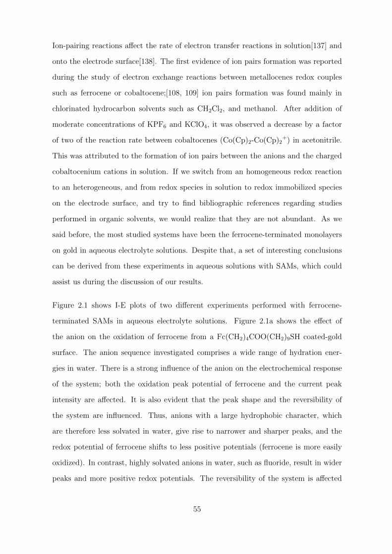
Ion-pairing reactions affect the rate of electron transfer reactions in solution[137] and
onto the electrode surface[138]. The first evidence of ion pairs formation was reported
during the study of electron exchange reactions between metallocenes redox couples
such as ferrocene or cobaltocene;[108, 109] ion pairs formation was found mainly in
chlorinated hydrocarbon solvents such as CH2Cl2, and methanol. After addition of
moderate concentrations of KPF6 and KClO4, it was observed a decrease by a factor
of two of the reaction rate between cobaltocenes (Co(Cp)2-Co(Cp)2+) in acetonitrile.
This was attributed to the formation of ion pairs between the anions and the charged
cobaltocenium cations in solution. If we switch from an homogeneous redox reaction
to an heterogeneous, and from redox species in solution to redox immobilized species
on the electrode surface, and try to find bibliographic references regarding studies
performed in organic solvents, we would realize that they are not abundant. As we
said before, the most studied systems have been the ferrocene-terminated monolayers
on gold in aqueous electrolyte solutions. Despite that, a set of interesting conclusions
can be derived from these experiments in aqueous solutions with SAMs, which could
assist us during the discussion of our results.
Figure 2.1 shows I-E plots of two different experiments performed with ferrocene-
terminated SAMs in aqueous electrolyte solutions. Figure 2.1a shows the effect of
the anion on the oxidation of ferrocene from a Fc(CH2)4COO(CH2)9SH coated-gold
surface. The anion sequence investigated comprises a wide range of hydration ener-
gies in water. There is a strong influence of the anion on the electrochemical response
of the system; both the oxidation peak potential of ferrocene and the current peak
intensity are affected. It is also evident that the peak shape and the reversibility of
the system are influenced. Thus, anions with a large hydrophobic character, which
are therefore less solvated in water, give rise to narrower and sharper peaks, and the
redox potential of ferrocene shifts to less positive potentials (ferrocene is more easily
oxidized). In contrast, highly solvated anions in water, such as fluoride, result in wider
peaks and more positive redox potentials. The reversibility of the system is affected
55
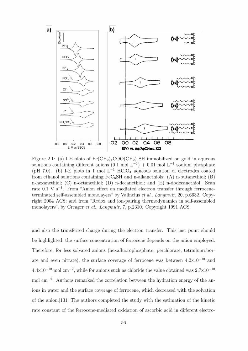
Figure 2.1: (a) I-E plots of Fc(CH2)4COO(CH2)9SH immobilized on gold in aqueoussolutions containing different anions (0.1 mol L−1) + 0.01 mol L−1 sodium phosphate(pH 7.0). (b) I-E plots in 1 mol L−1 HClO4 aqueous solution of electrodes coatedfrom ethanol solutions containing FcC6SH and n-alkanethiols: (A) n-butanethiol; (B)n-hexanethiol; (C) n-octanethiol; (D) n-decanethiol; and (E) n-dodecanethiol. Scanrate 0.1 V s−1. From ”Anion effect on mediated electron transfer through ferrocene-terminated self-assembled monolayers”by Valincius et al., Langmuir, 20, p.6632. Copy-right 2004 ACS; and from ”Redox and ion-pairing thermodynamics in self-assembledmonolayers”, by Creager et al., Langmuir, 7, p.2310. Copyright 1991 ACS.
and also the transferred charge during the electron transfer. This last point should
be highlighted, the surface concentration of ferrocene depends on the anion employed.
Therefore, for less solvated anions (hexafluorophosphate, perchlorate, tetrafluorobor-
ate and even nitrate), the surface coverage of ferrocene was between 4.2x10⁻¹⁰ and
4.4x10⁻¹⁰ mol cm−2, while for anions such as chloride the value obtained was 2.7x10⁻¹⁰
mol cm−2. Authors remarked the correlation between the hydration energy of the an-
ions in water and the surface coverage of ferrocene, which decreased with the solvation
of the anion.[131] The authors completed the study with the estimation of the kinetic
rate constant of the ferrocene-mediated oxidation of ascorbic acid in different electro-
56
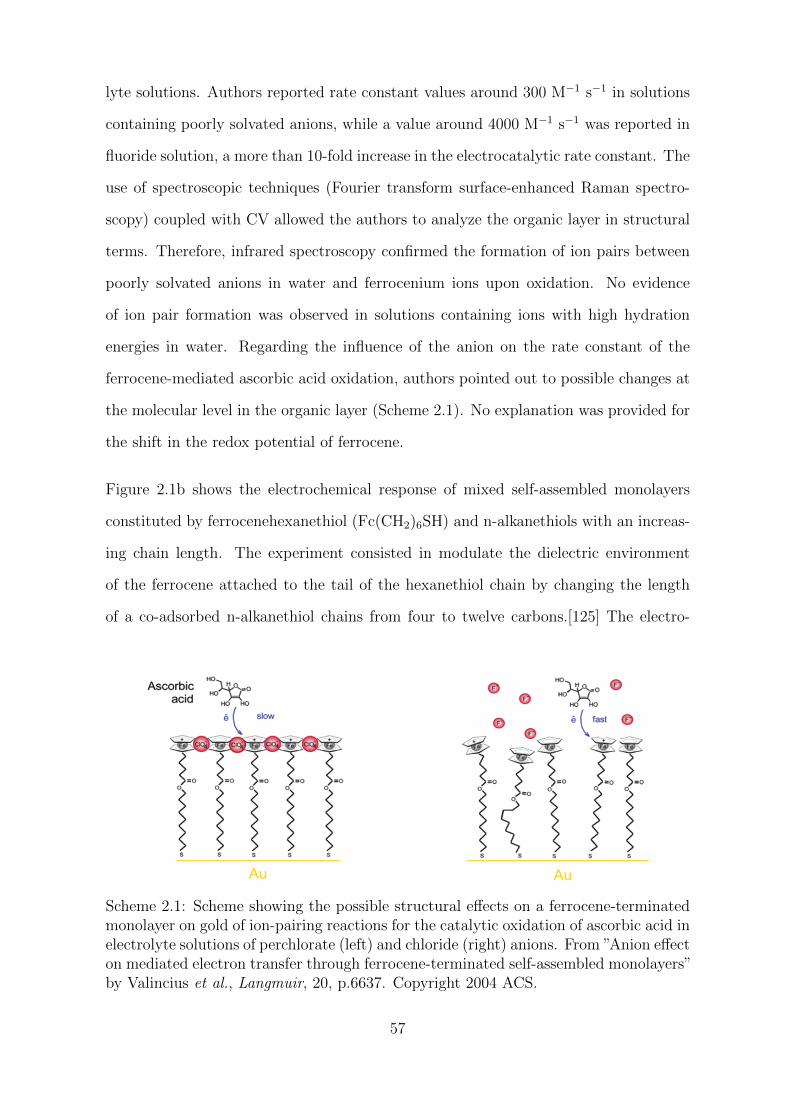
lyte solutions. Authors reported rate constant values around 300 M−1 s−1 in solutions
containing poorly solvated anions, while a value around 4000 M−1 s−1 was reported in
fluoride solution, a more than 10-fold increase in the electrocatalytic rate constant. The
use of spectroscopic techniques (Fourier transform surface-enhanced Raman spectro-
scopy) coupled with CV allowed the authors to analyze the organic layer in structural
terms. Therefore, infrared spectroscopy confirmed the formation of ion pairs between
poorly solvated anions in water and ferrocenium ions upon oxidation. No evidence
of ion pair formation was observed in solutions containing ions with high hydration
energies in water. Regarding the influence of the anion on the rate constant of the
ferrocene-mediated ascorbic acid oxidation, authors pointed out to possible changes at
the molecular level in the organic layer (Scheme 2.1). No explanation was provided for
the shift in the redox potential of ferrocene.
Figure 2.1b shows the electrochemical response of mixed self-assembled monolayers
constituted by ferrocenehexanethiol (Fc(CH2)6SH) and n-alkanethiols with an increas-
ing chain length. The experiment consisted in modulate the dielectric environment
of the ferrocene attached to the tail of the hexanethiol chain by changing the length
of a co-adsorbed n-alkanethiol chains from four to twelve carbons.[125] The electro-
Scheme 2.1: Scheme showing the possible structural effects on a ferrocene-terminatedmonolayer on gold of ion-pairing reactions for the catalytic oxidation of ascorbic acid inelectrolyte solutions of perchlorate (left) and chloride (right) anions. From ”Anion effecton mediated electron transfer through ferrocene-terminated self-assembled monolayers”by Valincius et al., Langmuir, 20, p.6637. Copyright 2004 ACS.
57
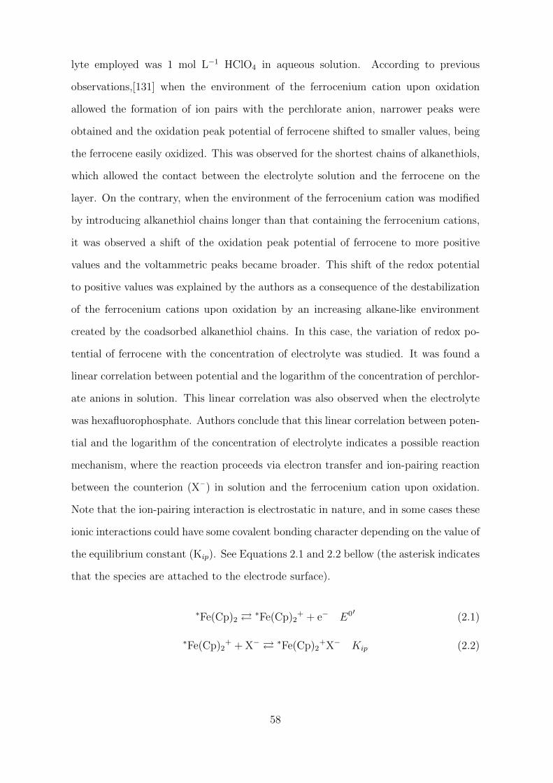
lyte employed was 1 mol L−1 HClO4 in aqueous solution. According to previous
observations,[131] when the environment of the ferrocenium cation upon oxidation
allowed the formation of ion pairs with the perchlorate anion, narrower peaks were
obtained and the oxidation peak potential of ferrocene shifted to smaller values, being
the ferrocene easily oxidized. This was observed for the shortest chains of alkanethiols,
which allowed the contact between the electrolyte solution and the ferrocene on the
layer. On the contrary, when the environment of the ferrocenium cation was modified
by introducing alkanethiol chains longer than that containing the ferrocenium cations,
it was observed a shift of the oxidation peak potential of ferrocene to more positive
values and the voltammetric peaks became broader. This shift of the redox potential
to positive values was explained by the authors as a consequence of the destabilization
of the ferrocenium cations upon oxidation by an increasing alkane-like environment
created by the coadsorbed alkanethiol chains. In this case, the variation of redox po-
tential of ferrocene with the concentration of electrolyte was studied. It was found a
linear correlation between potential and the logarithm of the concentration of perchlor-
ate anions in solution. This linear correlation was also observed when the electrolyte
was hexafluorophosphate. Authors conclude that this linear correlation between poten-
tial and the logarithm of the concentration of electrolyte indicates a possible reaction
mechanism, where the reaction proceeds via electron transfer and ion-pairing reaction
between the counterion (X– ) in solution and the ferrocenium cation upon oxidation.
Note that the ion-pairing interaction is electrostatic in nature, and in some cases these
ionic interactions could have some covalent bonding character depending on the value of
the equilibrium constant (Kip). See Equations 2.1 and 2.2 bellow (the asterisk indicates
that the species are attached to the electrode surface).
∗Fe(Cp)2 ∗Fe(Cp)2
+ + e− E0′ (2.1)
∗Fe(Cp)2+ + X− ∗Fe(Cp)2
+X− Kip (2.2)
58
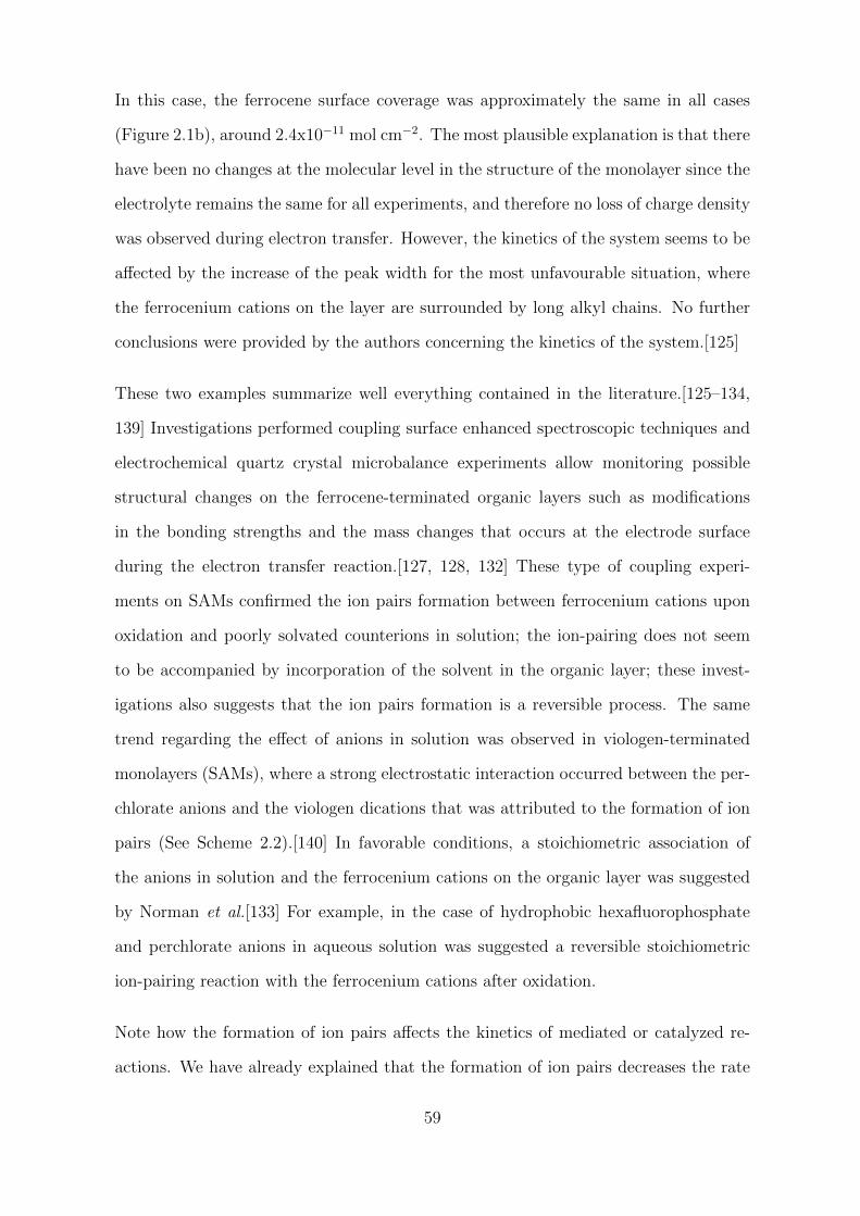
In this case, the ferrocene surface coverage was approximately the same in all cases
(Figure 2.1b), around 2.4x10⁻¹¹ mol cm−2. The most plausible explanation is that there
have been no changes at the molecular level in the structure of the monolayer since the
electrolyte remains the same for all experiments, and therefore no loss of charge density
was observed during electron transfer. However, the kinetics of the system seems to be
affected by the increase of the peak width for the most unfavourable situation, where
the ferrocenium cations on the layer are surrounded by long alkyl chains. No further
conclusions were provided by the authors concerning the kinetics of the system.[125]
These two examples summarize well everything contained in the literature.[125–134,
139] Investigations performed coupling surface enhanced spectroscopic techniques and
electrochemical quartz crystal microbalance experiments allow monitoring possible
structural changes on the ferrocene-terminated organic layers such as modifications
in the bonding strengths and the mass changes that occurs at the electrode surface
during the electron transfer reaction.[127, 128, 132] These type of coupling experi-
ments on SAMs confirmed the ion pairs formation between ferrocenium cations upon
oxidation and poorly solvated counterions in solution; the ion-pairing does not seem
to be accompanied by incorporation of the solvent in the organic layer; these invest-
igations also suggests that the ion pairs formation is a reversible process. The same
trend regarding the effect of anions in solution was observed in viologen-terminated
monolayers (SAMs), where a strong electrostatic interaction occurred between the per-
chlorate anions and the viologen dications that was attributed to the formation of ion
pairs (See Scheme 2.2).[140] In favorable conditions, a stoichiometric association of
the anions in solution and the ferrocenium cations on the organic layer was suggested
by Norman et al.[133] For example, in the case of hydrophobic hexafluorophosphate
and perchlorate anions in aqueous solution was suggested a reversible stoichiometric
ion-pairing reaction with the ferrocenium cations after oxidation.
Note how the formation of ion pairs affects the kinetics of mediated or catalyzed re-
actions. We have already explained that the formation of ion pairs decreases the rate
59
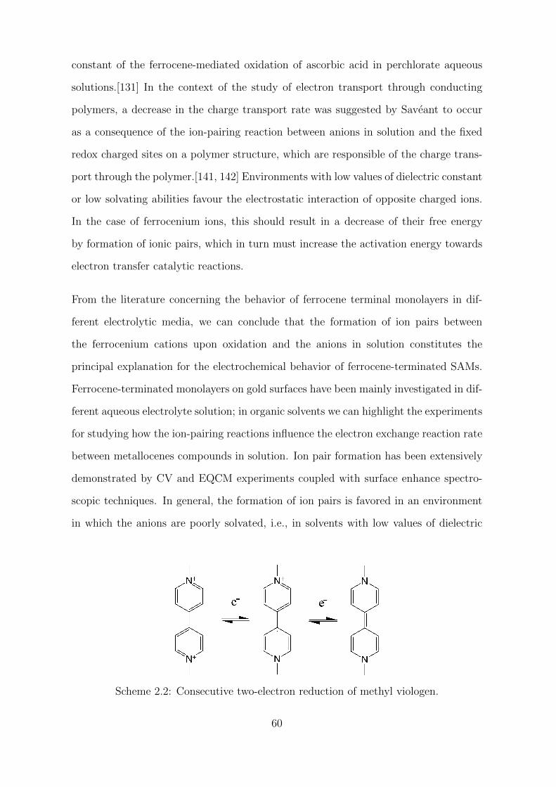
constant of the ferrocene-mediated oxidation of ascorbic acid in perchlorate aqueous
solutions.[131] In the context of the study of electron transport through conducting
polymers, a decrease in the charge transport rate was suggested by Saveant to occur
as a consequence of the ion-pairing reaction between anions in solution and the fixed
redox charged sites on a polymer structure, which are responsible of the charge trans-
port through the polymer.[141, 142] Environments with low values of dielectric constant
or low solvating abilities favour the electrostatic interaction of opposite charged ions.
In the case of ferrocenium ions, this should result in a decrease of their free energy
by formation of ionic pairs, which in turn must increase the activation energy towards
electron transfer catalytic reactions.
From the literature concerning the behavior of ferrocene terminal monolayers in dif-
ferent electrolytic media, we can conclude that the formation of ion pairs between
the ferrocenium cations upon oxidation and the anions in solution constitutes the
principal explanation for the electrochemical behavior of ferrocene-terminated SAMs.
Ferrocene-terminated monolayers on gold surfaces have been mainly investigated in dif-
ferent aqueous electrolyte solution; in organic solvents we can highlight the experiments
for studying how the ion-pairing reactions influence the electron exchange reaction rate
between metallocenes compounds in solution. Ion pair formation has been extensively
demonstrated by CV and EQCM experiments coupled with surface enhance spectro-
scopic techniques. In general, the formation of ion pairs is favored in an environment
in which the anions are poorly solvated, i.e., in solvents with low values of dielectric
Scheme 2.2: Consecutive two-electron reduction of methyl viologen.
60
constant. The association of the counterions with the ferrocenium ions upon oxidation
have been demonstrated to stabilize the cation, contributing to the integrity of the or-
ganic layer and displacing the redox potential of ferrocene to lower values. The kinetics
of the redox reactions are also dependent to the ion-pairing; it have been observed by
CV the increase of the peak width when the ions in solution are highly solvated by the
solvent, or in other words, the reaction rate of oxidation of ferrocene immobilized in
organic layers decreases when the formation of ionic pairs is not favored in the reaction
medium (See Figure 2.1). Regarding the loss of charge density observed in different
electrolyte solutions and different ferrocene-immobilized systems, it could be related
with changes at molecular level in the organic layer. This point is controversial in the
literature, since it is not clear that the oxidation of ferrocene in the organic layer could
lead to a spatial restructuring of the organic layer.
As we stated before, two are the main purposes in this chapter, first the investigation of
the electrochemical properties of alkyl-ferrocene on-carbon monolayers in different elec-
trolyte solutions, where the literature has already been discussed. The second purpose
of this chapter is the evaluation of this modification, the C11-alkyl ferrocene-terminated
monolayer onto pyrolytic graphite electrodes, by means electrochemical methods for in-
creasing the charge density in charge storage devices. Therefore, our current concern
involves the literature regarding the impedimetric investigations of carbon materials
modified by electroactive monolayers or small electroactive molecules to enhance the
charge density of electrochemical supercapacitor devices, and the different methodo-
logies for determining the capacitance of this type of modified carbon materials from
electrochemical measurements.
61
2.1.2 Redox active molecules for improving the charge density
storage on carbon materials
Carbon materials are widely considered for electrochemical supercapacitor applications
especially because of their low price, high active surfaces, and the possibility of chemical
functionalization.[143–148] Improvements of the charge storage have been obtained by
an adequate choice of the carbon material (See for example the “Simon-Gogotsi” effect
related to size pore influence on the capacitance [146]) but also by the introduction
of mineral redox active compounds or by grafting of organic molecules.[149–152] In
an electrochemical supercapacitor, the charge storage is due both to a “real” electro-
chemical double layer capacitance (namely movement of ions at the carbon/solution
interface) and faradaic processes. They are often qualified as pseudo-capacitor because
the charge/discharge process is not purely capacitive.[153] The obvious advantage is a
considerable increase of the charge density that could be stored in the materials due to
additional faradaic contributions and purely capacitive processes. More recent papers
have addressed the question of the coupling between both capacitive and faradaic pro-
cesses in carbon materials showing all the interest of these hybrid approaches.([148, 153]
and references therein) Many different electrodes have been proposed; among the nu-
merous possibilities of modifications, the functionalization of carbons by small redox
molecules is currently the subject of large interest.[154]
In the literature, among the possibilities of small redox groups for modifying car-
bon materials, investigators often favor the use of multielectronic redox couples like
quinones or catechols because each redox unit could store more than one charge per
redox units.[155, 156] Derivatives are often anthraquinones but several other quinones
have also been considered. These redox couples are two-electron systems, which is an
advantage because two electrons could be stored by redox units. However, quinones
are not real 2 e– systems but are 2 e– + 2 H+ systems (or 2 e– + 1 H+ at high pH) and
their electrochemistry follows complicated mechanism schemes, and their reversibility
62
depends on solvent and proton availability. The reversibility of the system is generally
only achieved in aqueous solvents and for a very specific range of pH. Even in the most
favorable conditions, the global redox kinetics remains slow (see the work of E. Laviron
[157–159]) or at least much slower than a fast redox couple like ferrocene/ferrocenium
that present little reorganization upon charge transfer, and in turn could be used in
many different electrolyte solutions.
Improvements of the carbon-based supercapacitors performance have been obtained by
an adequate choice of the carbon material considering a thin control of the structure
and porosity of the material itself.[160] To keep this structural advantage, it is interest-
ing to retain the initial structure of the carbon material and not to block or limits the
transport of ions from the solution to the carbon substrate by introducing a blocking
chemical functionalization. As we stated before, the faradaic process could be intro-
duced by deposition of a thin film of an electroactive molecule by simple adsorption or
grafting, but the modification should not alter the double layer capacitance to max-
imize the synergy between the faradaic and double layer capacitive processes. In this
direction, it was recently published by Cougnon et al.[161] a protection-deprotection
strategy for a controlled grafting of cathecol moieties on a microporous carbon material
for supercapacitor electrodes working in 1 mol L−1 H2SO4. The modification method
is based on the spontaneous grafting of catechol aryldiazonium salts bearing protect-
ing groups such as the bulky tri(isopropyl)silyl group. The use of protective groups
allows to retain or modulate the porous structure of the material, which is modified
only externally, where the catechol moieties (after deprotection step) are in turn elec-
troactive by direct contact with the solvent containing the protons necessary for the
redox process. Authors reported an increase in the specific charge and a positive shift
in the redox potential which together result in a better specific energy performance of
the system.
From here, we propose the evaluation of the C11-alkyl ferrocene-terminated mono-
layer on edge plane pyrolytic graphite electrodes.[11, 71, 80] The general interest of
63
this modification is the formation of a robust covalently attached ferrocene-terminated
monolayer where the ferrocene molecules, in optimized conditions, exhibit fast charge
transport from the carbon substrate to the redox moieties; other important features of
this modification are its flexibility and the presence of size-controlled nanometric chan-
nel (pores) for ion passage, allowing the combination of the fast faradaic process with
the mass transport through the organic layer, which is required for purely capacitive
processes. The modification procedure is based on the electrografting of a protected-
ethynylaryldiazonium salt that, after deprotection step, is modified by click chemistry
with an azido-ferrocene derivative. The use of the bulky tri(isopropyl)silyl group as
protecting group limits the grafting process to a monolayer and allow a spatially con-
trolled distribution of the molecules on the electrode surface. The size of the protecting
group determines the size of the pores on the organic layer. The resulting ferrocene
monolayer on carbon is equivalent to those obtained by adsorption of alkanethiol ferro-
cene derivatives on gold surface (self-assembled monolayers), with the difference that
the former is attached to the carbon surface by covalent bonding. To our knowledge,
there is no literature related with the use of these on-carbon pseudo ”self-assembled
monolayers” for energy storage purposes.
2.1.3 Study of electrochemical capacitors: cyclic voltametry
and electrochemical impedance spectroscopy
The electrodes characteristics for electrochemical supercapacitors applications are usu-
ally investigated by cyclic voltammetry and electrochemical impedance spectroscopy.
Such combine approach has shown its interest in the investigations of modified carbon
materials and they are probably the most common methods employed for determining
the specific charge storage of these systems.[144, 147, 148] Cyclic voltammetry provides
information corresponding to the integrated charges. If such quantities are less detailed
information than the corresponding differential data extracted by EIS, they are also
64
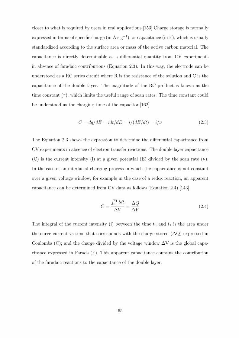
closer to what is required by users in real applications.[153] Charge storage is normally
expressed in terms of specific charge (in A s g−1), or capacitance (in F), which is usually
standardized according to the surface area or mass of the active carbon material. The
capacitance is directly determinable as a differential quantity from CV experiments
in absence of faradaic contributions (Equation 2.3). In this way, the electrode can be
understood as a RC series circuit where R is the resistance of the solution and C is the
capacitance of the double layer. The magnitude of the RC product is known as the
time constant (τ), which limits the useful range of scan rates. The time constant could
be understood as the charging time of the capacitor.[162]
C = dq/dE = idt/dE = i/(dE/dt) = i/ν (2.3)
The Equation 2.3 shows the expression to determine the differential capacitance from
CV experiments in absence of electron transfer reactions. The double layer capacitance
(C) is the current intensity (i) at a given potential (E) divided by the scan rate (ν).
In the case of an interfacial charging process in which the capacitance is not constant
over a given voltage window, for example in the case of a redox reaction, an apparent
capacitance can be determined from CV data as follows (Equation 2.4).[143]
C =
∫ t1t0idt
∆V=
∆Q
∆V(2.4)
The integral of the current intensity (i) between the time t0 and t1 is the area under
the curve current vs time that corresponds with the charge stored (∆Q) expressed in
Coulombs (C); and the charge divided by the voltage window ∆V is the global capa-
citance expressed in Farads (F). This apparent capacitance contains the contribution
of the faradaic reactions to the capacitance of the double layer.
65
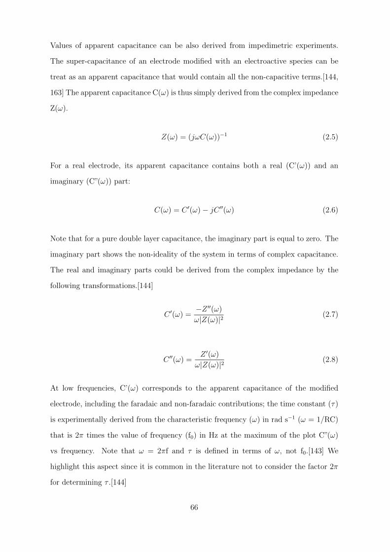
Values of apparent capacitance can be also derived from impedimetric experiments.
The super-capacitance of an electrode modified with an electroactive species can be
treat as an apparent capacitance that would contain all the non-capacitive terms.[144,
163] The apparent capacitance C(ω) is thus simply derived from the complex impedance
Z(ω).
Z(ω) = (jωC(ω))−1 (2.5)
For a real electrode, its apparent capacitance contains both a real (C’(ω)) and an
imaginary (C”(ω)) part:
C(ω) = C ′(ω)− jC ′′(ω) (2.6)
Note that for a pure double layer capacitance, the imaginary part is equal to zero. The
imaginary part shows the non-ideality of the system in terms of complex capacitance.
The real and imaginary parts could be derived from the complex impedance by the
following transformations.[144]
C ′(ω) =−Z ′′(ω)
ω|Z(ω)|2(2.7)
C ′′(ω) =Z ′(ω)
ω|Z(ω)|2(2.8)
At low frequencies, C’(ω) corresponds to the apparent capacitance of the modified
electrode, including the faradaic and non-faradaic contributions; the time constant (τ)
is experimentally derived from the characteristic frequency (ω) in rad s−1 (ω = 1/RC)
that is 2π times the value of frequency (f0) in Hz at the maximum of the plot C”(ω)
vs frequency. Note that ω = 2πf and τ is defined in terms of ω, not f0.[143] We
highlight this aspect since it is common in the literature not to consider the factor 2π
for determining τ .[144]
66
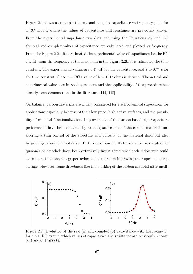
Figure 2.2 shows as example the real and complex capacitance vs frequency plots for
a RC circuit, where the values of capacitance and resistance are previously known.
From the experimental impedance raw data and using the Equations 2.7 and 2.8,
the real and complex values of capacitance are calculated and plotted vs frequency.
From the Figure 2.2a, it is estimated the experimental value of capacitance for the RC
circuit; from the frequency at the maximum in the Figure 2.2b, it is estimated the time
constant. The experimental values are 0.47 µF for the capacitance, and 7.6x10⁻⁴ s for
the time constant. Since τ = RC a value of R = 1617 ohms is derived. Theoretical and
experimental values are in good agreement and the applicability of this procedure has
already been demonstrated in the literature.[144, 148]
On balance, carbon materials are widely considered for electrochemical supercapacitor
applications especially because of their low price, high active surfaces, and the possib-
ility of chemical functionalization. Improvements of the carbon-based supercapacitors
performance have been obtained by an adequate choice of the carbon material con-
sidering a thin control of the structure and porosity of the material itself but also
by grafting of organic molecules. In this direction, multielectronic redox couples like
quinones or catechols have been extensively investigated since each redox unit could
store more than one charge per redox units, therefore improving their specific charge
storage. However, some drawbacks like the blocking of the carbon material after modi-
Figure 2.2: Evolution of the real (a) and complex (b) capacitance with the frequencyfor a real RC circuit, which values of capacitance and resistance are previously known:0.47 µF and 1600 Ω.
67
fication should be prevented in order to maximize the synergy between faradaic and
non-faradaic processes. Procedures for a controlled modification of the carbon-based
materials are available. For example, the protection-deprotection modification proced-
ure, based on the grafting of redox active molecules bearing bulky protective groups,
has been shown to be useful in preserving the double layer capacitive properties of the
initial carbon material. In connection with this scheme, we propose the evaluation of
on-carbon ferrocene-terminated monolayers. This electroactive monolayers show fast
electron transfer rates and reversibility in a wide range of electrolytes and solvents, and
size controlled nanometric access channels or pores for ion passage from the solution
to the carbon surface. CV and EIS are commonly used to study the performance of
new materials and modifications, and for determining the capacity for charge storage
of the system. Three different methodologies are proposed in the literature where the
electrode is understood as a RC series circuit, and characteristic parameters such as
capacitance, resistance and time constant of the system can be determined.
68
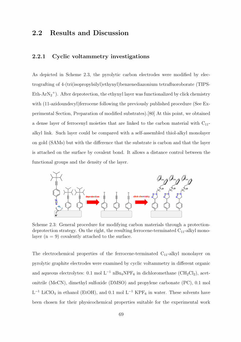
2.2 Results and Discussion
2.2.1 Cyclic voltammetry investigations
As depicted in Scheme 2.3, the pyrolytic carbon electrodes were modified by elec-
trografting of 4-(tri(isopropylsilyl)ethynyl)benzenediazonium tetrafluoroborate (TIPS-
Eth-ArN2+). After deprotection, the ethynyl layer was functionalized by click chemistry
with (11-azidoundecyl)ferrocene following the previously published procedure (See Ex-
perimental Section, Preparation of modified substrates).[80] At this point, we obtained
a dense layer of ferrocenyl moieties that are linked to the carbon material with C11-
alkyl link. Such layer could be compared with a self-assembled thiol-alkyl monolayer
on gold (SAMs) but with the difference that the substrate is carbon and that the layer
is attached on the surface by covalent bond. It allows a distance control between the
functional groups and the density of the layer.
Scheme 2.3: General procedure for modifying carbon materials through a protection-deprotection strategy. On the right, the resulting ferrocene-terminated C11-alkyl mono-layer (n = 9) covalently attached to the surface.
The electrochemical properties of the ferrocene-terminated C11-alkyl monolayer on
pyrolytic graphite electrodes were examined by cyclic voltammetry in different organic
and aqueous electrolytes: 0.1 mol L−1 nBu4NPF6 in dichloromethane (CH2Cl2), acet-
onitrile (MeCN), dimethyl sulfoxide (DMSO) and propylene carbonate (PC), 0.1 mol
L−1 LiClO4 in ethanol (EtOH), and 0.1 mol L−1 KPF6 in water. These solvents have
been chosen for their physicochemical properties suitable for the experimental work
69
and to cover a wide range of dielectric constant values (from around 9 to 80). Instead
of study different anions (from the electrolyte) with different hydration energies, we
chose different organic solvents with different ability for the solvation of hydrophobic
anions such as PF6– and ClO4
– .
The electrochemical behavior of the ferrocene monolayer was studied by cyclic voltam-
metry in each electrolyte solution at increasing scan rates (from 0.1 to 0.9 V s−1); a
new modified electrode was prepared each time, thus avoiding a possible ”memory”
effect of the organic layer when is plunged into different electrolyte solutions. Cyclic
voltammograms of Figure 2.3 show the response of the modified electrodes in all the
organic electrolytes at scan rate 0.2 V s−1; the response in aqueous solution + 0.1 mol
L−1 KPF6 is a particular case and will be discuss separately towards the end of this
section. Figure 2.3a shows the response in all organic electrolytes; a reversible electro-
chemical system is visible that corresponds to the reversible oxidation of the grafted
ferrocene groups. The peak potential varies linearly with the scan rate in agreement
with a grafted electrochemical system (Figures 2.4 as example). Cyclic voltammograms
on Figure 2.4 show the response of the modified electrode in MeCN and DMSO con-
taining 0.1 mol L−1 nBu4NPF6 and their corresponding current peak vs scan rate plots,
which show a linear relation as expected for a surface-confined redox system.[164] In
all media, the voltammograms exhibit well-defined current peaks corresponding to the
reversible or quasi-reversible oxidation of the ferrocene centers. Deviations correspond-
ing to the ohmic drop appear for the curves registered at higher scan rates, above 0.5
V s−1 (Figures 2.4a and b). This ohmic drop was more important at high scan rates
in low dielectric constant solvents, such as CH2Cl2 and EtOH, given that no ohmic
potential drop correction was applied during the experiments. In any case, curves re-
gistered at low scan rates are not importantly affected by ohmic drop, and thus they
will be considered for detailed analysis.
Cyclic voltammograms on Figure 2.3a show the response in all the organic electrolyte
solutions. A rapid inspection of the responses shows that there is a significant differ-
70
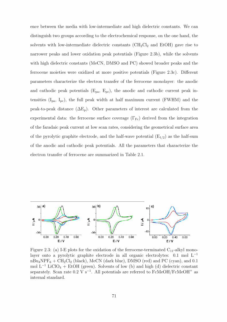
ence between the media with low-intermediate and high dielectric constants. We can
distinguish two groups according to the electrochemical response, on the one hand, the
solvents with low-intermediate dielectric constants (CH2Cl2 and EtOH) gave rise to
narrower peaks and lower oxidation peak potentials (Figure 2.3b), while the solvents
with high dielectric constants (MeCN, DMSO and PC) showed broader peaks and the
ferrocene moieties were oxidized at more positive potentials (Figure 2.3c). Different
parameters characterize the electron transfer of the ferrocene monolayer: the anodic
and cathodic peak potentials (Epa, Epc), the anodic and cathodic current peak in-
tensities (Ipa, Ipc), the full peak width at half maximum current (FWHM) and the
peak-to-peak distance (∆Ep). Other parameters of interest are calculated from the
experimental data: the ferrocene surface coverage (ΓFc) derived from the integration
of the faradaic peak current at low scan rates, considering the geometrical surface area
of the pyrolytic graphite electrode, and the half-wave potential (E1/2) as the half-sum
of the anodic and cathodic peak potentials. All the parameters that characterize the
electron transfer of ferrocene are summarized in Table 2.1.
Figure 2.3: (a) I-E plots for the oxidation of the ferrocene-terminated C11-alkyl mono-layer onto a pyrolytic graphite electrode in all organic electrolytes: 0.1 mol L−1
nBu4NPF6 + CH2Cl2 (black), MeCN (dark blue), DMSO (red) and PC (cyan), and 0.1mol L−1 LiClO4 + EtOH (green). Solvents of low (b) and high (d) dielectric constantseparately. Scan rate 0.2 V s−1. All potentials are referred to FcMeOH/FcMeOH+ asinternal standard.
71
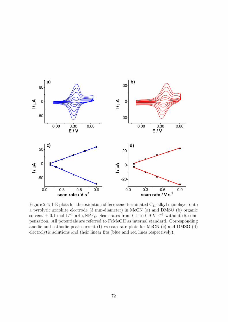
Figure 2.4: I-E plots for the oxidation of ferrocene-terminated C11-alkyl monolayer ontoa pyrolytic graphite electrode (3 mm-diameter) in MeCN (a) and DMSO (b) organicsolvent + 0.1 mol L−1 nBu4NPF6. Scan rates from 0.1 to 0.9 V s−1 without iR com-pensation. All potentials are referred to FcMeOH as internal standard. Correspondinganodic and cathodic peak current (I) vs scan rate plots for MeCN (c) and DMSO (d)electrolytic solutions and their linear fits (blue and red lines respectively).
72
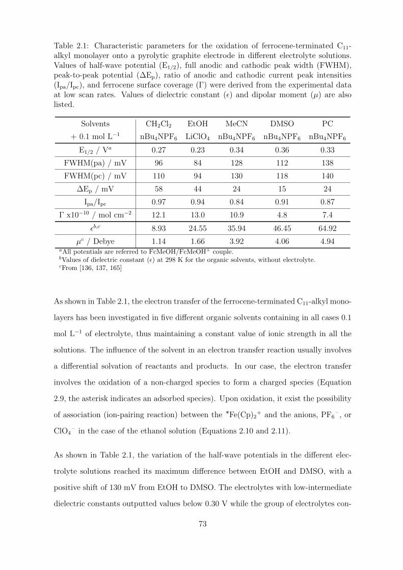
Table 2.1: Characteristic parameters for the oxidation of ferrocene-terminated C11-alkyl monolayer onto a pyrolytic graphite electrode in different electrolyte solutions.Values of half-wave potential (E1/2), full anodic and cathodic peak width (FWHM),peak-to-peak potential (∆Ep), ratio of anodic and cathodic current peak intensities(Ipa/Ipc), and ferrocene surface coverage (Γ) were derived from the experimental dataat low scan rates. Values of dielectric constant (ε) and dipolar moment (µ) are alsolisted.
Solvents CH2Cl2 EtOH MeCN DMSO PC
+ 0.1 mol L−1 nBu4NPF6 LiClO4 nBu4NPF6 nBu4NPF6 nBu4NPF6
E1/2 / Va 0.27 0.23 0.34 0.36 0.33
FWHM(pa) / mV 96 84 128 112 138
FWHM(pc) / mV 110 94 130 118 140
∆Ep / mV 58 44 24 15 24
Ipa/Ipc 0.97 0.94 0.84 0.91 0.87
Γ x10−10 / mol cm−2 12.1 13.0 10.9 4.8 7.4
εb,c 8.93 24.55 35.94 46.45 64.92
µc / Debye 1.14 1.66 3.92 4.06 4.94aAll potentials are referred to FcMeOH/FcMeOH+ couple.bValues of dielectric constant (ε) at 298 K for the organic solvents, without electrolyte.cFrom [136, 137, 165]
As shown in Table 2.1, the electron transfer of the ferrocene-terminated C11-alkyl mono-
layers has been investigated in five different organic solvents containing in all cases 0.1
mol L−1 of electrolyte, thus maintaining a constant value of ionic strength in all the
solutions. The influence of the solvent in an electron transfer reaction usually involves
a differential solvation of reactants and products. In our case, the electron transfer
involves the oxidation of a non-charged species to form a charged species (Equation
2.9, the asterisk indicates an adsorbed species). Upon oxidation, it exist the possibility
of association (ion-pairing reaction) between the *Fe(Cp)2+ and the anions, PF6
– , or
ClO4– in the case of the ethanol solution (Equations 2.10 and 2.11).
As shown in Table 2.1, the variation of the half-wave potentials in the different elec-
trolyte solutions reached its maximum difference between EtOH and DMSO, with a
positive shift of 130 mV from EtOH to DMSO. The electrolytes with low-intermediate
dielectric constants outputted values below 0.30 V while the group of electrolytes con-
73
stituted by MeCN, DMSO, and PC gave half-wave potential values higher than 0.30 V.
Thus, ferrocene is more readily oxidized in CH2Cl2 and EtOH solutions. The positive
shift in the half-wave potential of ferrocene observed in MeCN, DMSO and PC electro-
lyte solutions could be explain by the stronger solvation of the anions PF6– or ClO4
–
in these polar solvents. The high solvation energies of these anions in polar solvents
limit the formation of ion pairs between them and the ferrocenium cations upon oxida-
tion. On the contrary, the anions are poorly solvated in CH2Cl2 and EtOH electrolyte
solutions; the ion pairs formation between the anions and the ferroceniums is therefore
favored. The ion pairs formation stabilizes the electrogenerated cations, and probably
also stabilizes the structure of the monolayer, doing the electron transfer of ferrocene
thermodynamically easier in these non-polar (CH2Cl2) and water-like (EtOH) media.
These observations are in agreement with the literature.[108, 131] Ion-pairing reac-
tions involving anions such as PF6– or ClO4
– are favored in non-polar or water-like
solvents, where these hydrophobic anions are poorly solvated; also, the positive shift
of the half-wave potential was previously observed in ferrocene-terminated monolayers
on gold when the ferrocenium cation was not stabilized by ion-pairing formation with
the anions from the electrolyte.[125] Note that solvents with low-intermediate dielectric
constants allow the formation of ion pairs, unlike high dielectric constant solvents.[136]
∗Fe(Cp)2 ∗Fe(Cp)2
+ + e− E0′ (2.9)
∗Fe(Cp)2+ + PF6
− ∗Fe(Cp)2+PF6
− K1 (2.10)
∗Fe(Cp)2+ + ClO4
− ∗Fe(Cp)2+ClO4
− K2 (2.11)
In the literature, the redox potential of ferrocene immobilized on gold surfaces was
found to be dependent of the concentration of anions from the electrolyte in solu-
tion. Therefore, according to a possible mechanism of electron transfer followed by an
ion-pair association between the ferroceniums and the counterions, we can derive an
expression from the Nernst equation that relates the apparent standard potential (E0’)
of ferrocene with the concentration of ion in solution as follows.[125]
74
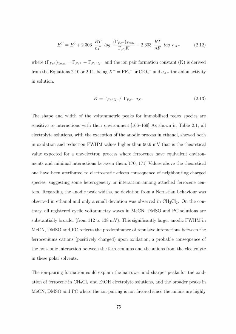
E0′ = E0 + 2.303RT
nFlog
(ΓFc+)Total
ΓFcK− 2.303
RT
nFlog aX− (2.12)
where (ΓFc+)Total = ΓFc+ + ΓFc+X− and the ion pair formation constant (K) is derived
from the Equations 2.10 or 2.11, being X− = PF6– or ClO4
– and aX− the anion activity
in solution.
K = ΓFc+X−/ ΓFc+ aX− (2.13)
The shape and width of the voltammetric peaks for immobilized redox species are
sensitive to interactions with their environment.[166–169] As shown in Table 2.1, all
electrolyte solutions, with the exception of the anodic process in ethanol, showed both
in oxidation and reduction FWHM values higher than 90.6 mV that is the theoretical
value expected for a one-electron process where ferrocenes have equivalent environ-
ments and minimal interactions between them.[170, 171] Values above the theoretical
one have been attributed to electrostatic effects consequence of neighbouring charged
species, suggesting some heterogeneity or interaction among attached ferrocene cen-
ters. Regarding the anodic peak widths, no deviation from a Nernstian behaviour was
observed in ethanol and only a small deviation was observed in CH2Cl2. On the con-
trary, all registered cyclic voltammetry waves in MeCN, DMSO and PC solutions are
substantially broader (from 112 to 138 mV). This significantly larger anodic FWHM in
MeCN, DMSO and PC reflects the predominance of repulsive interactions between the
ferroceniums cations (positively charged) upon oxidation; a probable consequence of
the non-ionic interaction between the ferroceniums and the anions from the electrolyte
in these polar solvents.
The ion-pairing formation could explain the narrower and sharper peaks for the oxid-
ation of ferrocene in CH2Cl2 and EtOH electrolyte solutions, and the broader peaks in
MeCN, DMSO and PC where the ion-pairing is not favored since the anions are highly
75

solvated by these polar organic solvents (See ??). Also, that could explain why for
MeCN, DMSO and PC electrolyte solutions the anodic and cathodic full peak widths
are almost equals, only a negligible variation was observed from the anodic to the cath-
odic FWHM values. However, an increase of the FWHM was observed in the case of
CH2Cl2 and EtOH from the anodic to the cathodic process, indicating the probably
dissociation of the ion pairs *Fe(Cp)2+PF6
– or *Fe(Cp)2+ClO4
– during the reduction
of the ferrocenium ions to ferrocene; this dissociation does not take place in MeCN,
DMSO and PC electrolyte solutions since there was no previous ion-pairing interac-
tion. This could explain the no substantial differences observed between the anodic
and cathodic FWHM, concluding that the environment of the electroactive groups on
the organic layer hardly changed during the electron transfer in MeCN, DMSO and
PC electrolyte solutions. All these observations concerning the full peak width are
supported by the literature where it have been observed by CV the increase of the
peak width of oxidation of ferrocene when the anions (from the electrolyte) in solution
are highly solvated by the solvent, and therefore the formation of ion pairs was not
favored.([131, 132, 134] and other references therein)
As shown in Figure 2.3, the peak intensities showed a strong dependence on the reac-
tion medium. Thus, solvents with the lower dielectric constants (CH2Cl2 and EtOH)
presented well-defined peaks and greater current intensities, while solvents with the
higher dielectric constants (MeCN, DMSO and PC) showed broader peaks and lower
current intensity values. It was discarded that the observed differences in current in-
tensities were due to a degradation of the organic layer in MeCN, DMSO and PC
solutions. A control experiment was performed in which the voltammogram of a mod-
ified electrode was sequentially registered in all the organic electrolyte solutions, using
the electrochemical response of ferrocene in CH2Cl2 as reference. The characteristic
electrochemical response of ferrocene in CH2Cl2 was always recovered after each solvent.
Hence, this diminution of the current peak intensities in MeCN, DMSO and PC is not
consequence of the degradation of the organic layer in these media. The smaller cur-
76
rent peak intensities in MeCN, DMSO and PC electrolyte solutions are connected by
the kinetics of the system with the larger peak widths observed in these media. These
observations go in the direction of a possible influence of the medium on the kinetics of
the reaction. The kinetics of the reaction seems to decrease with the greater solvation
of the anions by polar solvents; on the contrary, kinetics is favored in environments
where the anions are poorly solvated (CH2Cl2 and ethanol), resulting in narrower and
more intense peaks. At this point we can point out that both the kinetics and ther-
modynamics of the system are affected by the different solvation of the hydrophobic
anions in the organic solvents, which in turn is related to the formation of ion pairs in
non-polar or water-like environments.
Concerning the reversibility of the electron transfer, the ratios of anodic and cathodic
current peak intensities (Ipa/Ipc) were calculated for each electrolyte solution. (Ipa/Ipc)
values close to the unit or slightly below were obtained in CH2Cl2 and EtOH elec-
trolyte solutions, indicating that the oxidation of ferrocene was reversible in these
media. In MeCN, DMSO and PC solutions, quasi-reversible electron transfers took
place. In terms of stability, it was registered a 25 % loss of faradaic current after 1000
charge/discharge cycles in CH2Cl2 + 0.1 mol L−1 nBu4NPF6 solution. Certainty, a
previous process of purification and drying of the organic solvent would be advisable
to improve the stability of the system, avoiding possible side reactions with impurities
during the electron transfer.
At this stage, it is interesting to analyze the transferred charge during the electron
transfer by studying the ferrocene surface coverage (ΓFc), which was calculated from Γ
= Q/nFA (where n is the number of electrons in the electron transfer, F is the Faraday
constant and A the surface area of the electrode). Considering the geometrical surface
area of the pyrolytic graphite electrode, we derived the surface coverage of ferrocene
in each electrolyte solution. First, we observed that the ferrocene surface coverage
varies with the reaction medium when it would be expected to be conserved, since
there are the same electroactive centers in all cases; and second, the values of surface
77
coverage are unusually higher than those expected for a monolayer on a flat surface.
For example, the surface coverage was 12.1x10⁻¹⁰ mol cm−2 in CH2Cl2 containing 0.1
mol L−1 nBu4NPF6 and 13.0x10⁻¹⁰ mol cm−2 in EtOH containing 0.1 mol L−1 LiClO4,
which are about 3 times higher than the value reported by Leroux[71] for the ferrocene-
terminated C1-alkyl monolayer on a glassy carbon electrode in EtOH containing 0.1
mol L−1 LiClO4 (ΓFc = 4.4x10⁻¹⁰ mol cm−2).
The first observation concerns the decrease of charge density or surface coverage when
passing i.e., from the ethanol electrolyte solution to dimethyl sulfoxide. This latter
showed a surface coverage almost three times lower than ethanol, when it would be
expected the charge density to be constant since the population of ferrocenes is ap-
proximately the same between experiments. This particular feature was previously
observed in equivalent systems like ferrocene-terminated monolayers on gold surface
(SAMs)[131, 134] and carbon.[139] Although currently, there is not a conclusive ex-
planation for the decrease in charge density (or coverage) in the literature, there are
some evidences that could be consider for the discussion.
Many attempts have been made to correlate the chemical composition and structure
of ferrocene-terminated monolayers with their redox behavior, most of them focus on
the role of the anions from the electrolyte and their ability to ion-pairing with the fer-
rocenium ion after oxidation.[131, 133–135] One experiment described in the literature
is specially interesting in our discussion.[131] It concerns the study of the electrochem-
ical behavior of Fc(CH2)4COO(CH2)9SH coated-gold electrodes in different electrolyte
solutions with anions having different solvation energies in water, when the solvent was
always water. In our case, instead of to change the anion, we chose two hydrophobic
anion electrolytes with similar solvation properties and ionic sizes when the organic
solvent varies, from very low dielectric constant and non-polar to high dielectric and
polar media. Despite the obvious differences, both experiments are comparable in
general terms as both are a solvent-related anion solvation problem.
78

Valincius et al.[131] observed a strong influence of the anion on the electrochemical
response of the system; both the oxidation peak potential of ferrocene and the current
peak intensity were affected by the media. It was also influenced the peak shape and the
reversibility of the system (See Figure 2.1a). Anions with a large hydrophobic character,
which are therefore less solvated in water, gave rise to narrower and sharper peaks, and
the redox potential of ferrocene shifted to less positive potentials (ferrocene was more
easily oxidized). In contrast, highly solvated anions in water, such as fluoride, resulted
in wider peaks and more positive redox potentials. In turn, the surface concentration
of ferrocene was dependent on the anion employed, as we observed when we change
the organic solvent and in turns the solvation of the anions and the extent of the ion-
pairing reaction. Valincius et al. observed that the less solvated the anions are, the
higher the surface concentration of ferrocene; the same thing was observed in our case.
Infrared spectroscopy experiments confirmed the formation of ion pairs between poorly
solvated anions and ferrocenium ions upon oxidation; no evidence of ion pair formation
was observed in solutions containing ions strongly solvated by the solvent.
Other experiments described in the literature showed that if the media remains the
same (electrolyte and solvent), and the dielectric environment of the ferrocene is altered
by introducing, for example, non-electroactive co-adsorbed alkyl chains around the
ferrocene groups (Figure 2.1b), the ferrocene surface concentration is not affected, but
the kinetics and thermodynamics of the process are affected.[125] This suggest that the
loss of charge density could be related to changes at the molecular level in the structure
of the monolayer, as the reaction medium varies. However, the literature does not
contain definitive evidence to support these possible reorganization of the monolayer
as result of the electrochemical oxidation of ferrocene. Changes in the bonding strength
between the alkyl chain and the gold surface have been observed,[135] the reorientation
of the ferrocene molecules during the electron transfer has also been proposed,[130] or
even a severe restructuring of the organic layer.[133]
79
Finally, a value of 0 mV is expected for the peak-to-peak separation at low scan rates,
as diffusion does not play a role with regard to species adsorbed onto the electrode
surface.[171] However, experimentally this value differs from zero and increases with
the scan rate. In our case, the greatest values of peak-to-peak separation correspond to
the solvents with low-intermediate dielectric constants (CH2Cl2 and EtOH), which are
around 40 - 60 mV; while high dielectric constants media showed values ranging from 15
to 25 mV, that is the case of MeCN, DMSO and PC. It is well known that solvents with
low dielectric constants raise the resistance of the electrochemical cell,[171] then peak-
to-peak distances larger than 0 mV are not a surprising result, which is not contrary
to the conclusion that the redox species are adsorbed onto the electrode.[167]
From the experimental data in Table 2.1 and a review of the literature, we can con-
clude that both the kinetics and thermodynamics of the ferrocene-terminated C11-alkyl
monolayer electron transfer are influenced by the electrolyte solution, in particular for
the solvent employed. A differential solvation of the hydrophobic anions in the organic
solvents produces variations in the extent of the ion-pairing reaction between the an-
ions in solution and the ferrocenium cations upon oxidation. As consequence of the
ion-pairing reaction in CH2Cl2 and EtOH electrolyte solutions, the redox potential of
ferrocene shifts to more negative potentials as predicted by the Nernst equation con-
sidering that the reaction proceeds via electron transfer and ion-pairing reaction. This
shift in the potential could be attributed to the stabilization of the electrogenerated
ferrocenium cations, contributing in turn to the integrity of the organic layer. The val-
ues of full width at half maximum (FWHM) obtained in CH2Cl2 and EtOH electrolyte
solutions, especially in EtOH, for the oxidation of the ferrocene-terminated C11-alkyl
monolayer indicate that ferrocenes on the surface have equivalent environments, and
therefore all the available surface ferrocenes are reversible oxidized at the same half-
wave potential yielding sharp and well-defined peaks without loss in the transferred
charge. In this case, the ion-pairing reaction between the ferroceniums and the anions
could be reversible and stoichiometric (1:1) as suggested elsewhere in the literature.
80
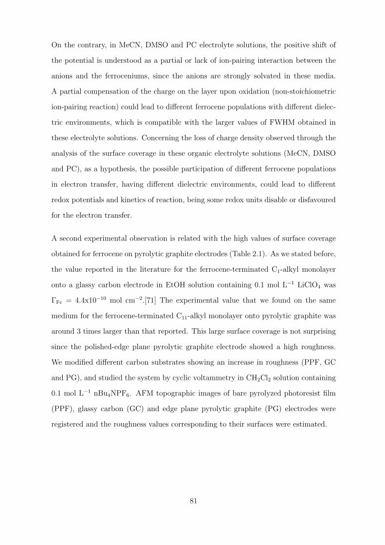
On the contrary, in MeCN, DMSO and PC electrolyte solutions, the positive shift of
the potential is understood as a partial or lack of ion-pairing interaction between the
anions and the ferroceniums, since the anions are strongly solvated in these media.
A partial compensation of the charge on the layer upon oxidation (non-stoichiometric
ion-pairing reaction) could lead to different ferrocene populations with different dielec-
tric environments, which is compatible with the larger values of FWHM obtained in
these electrolyte solutions. Concerning the loss of charge density observed through the
analysis of the surface coverage in these organic electrolyte solutions (MeCN, DMSO
and PC), as a hypothesis, the possible participation of different ferrocene populations
in electron transfer, having different dielectric environments, could lead to different
redox potentials and kinetics of reaction, being some redox units disable or disfavoured
for the electron transfer.
A second experimental observation is related with the high values of surface coverage
obtained for ferrocene on pyrolytic graphite electrodes (Table 2.1). As we stated before,
the value reported in the literature for the ferrocene-terminated C1-alkyl monolayer
onto a glassy carbon electrode in EtOH solution containing 0.1 mol L−1 LiClO4 was
ΓFc = 4.4x10⁻¹⁰ mol cm−2.[71] The experimental value that we found on the same
medium for the ferrocene-terminated C11-alkyl monolayer onto pyrolytic graphite was
around 3 times larger than that reported. This large surface coverage is not surprising
since the polished-edge plane pyrolytic graphite electrode showed a high roughness.
We modified different carbon substrates showing an increase in roughness (PPF, GC
and PG), and studied the system by cyclic voltammetry in CH2Cl2 solution containing
0.1 mol L−1 nBu4NPF6. AFM topographic images of bare pyrolyzed photoresist film
(PPF), glassy carbon (GC) and edge plane pyrolytic graphite (PG) electrodes were
registered and the roughness values corresponding to their surfaces were estimated.
81
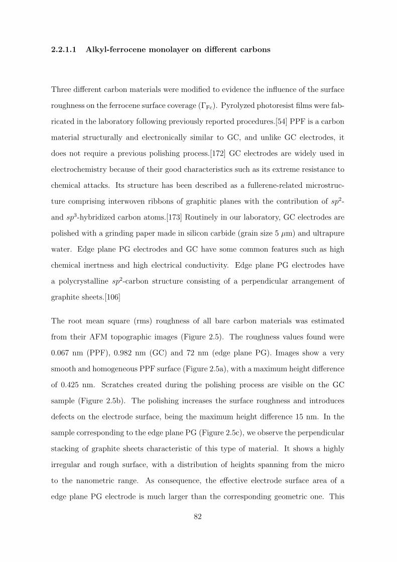
2.2.1.1 Alkyl-ferrocene monolayer on different carbons
Three different carbon materials were modified to evidence the influence of the surface
roughness on the ferrocene surface coverage (ΓFc). Pyrolyzed photoresist films were fab-
ricated in the laboratory following previously reported procedures.[54] PPF is a carbon
material structurally and electronically similar to GC, and unlike GC electrodes, it
does not require a previous polishing process.[172] GC electrodes are widely used in
electrochemistry because of their good characteristics such as its extreme resistance to
chemical attacks. Its structure has been described as a fullerene-related microstruc-
ture comprising interwoven ribbons of graphitic planes with the contribution of sp2-
and sp3-hybridized carbon atoms.[173] Routinely in our laboratory, GC electrodes are
polished with a grinding paper made in silicon carbide (grain size 5 µm) and ultrapure
water. Edge plane PG electrodes and GC have some common features such as high
chemical inertness and high electrical conductivity. Edge plane PG electrodes have
a polycrystalline sp2-carbon structure consisting of a perpendicular arrangement of
graphite sheets.[106]
The root mean square (rms) roughness of all bare carbon materials was estimated
from their AFM topographic images (Figure 2.5). The roughness values found were
0.067 nm (PPF), 0.982 nm (GC) and 72 nm (edge plane PG). Images show a very
smooth and homogeneous PPF surface (Figure 2.5a), with a maximum height difference
of 0.425 nm. Scratches created during the polishing process are visible on the GC
sample (Figure 2.5b). The polishing increases the surface roughness and introduces
defects on the electrode surface, being the maximum height difference 15 nm. In the
sample corresponding to the edge plane PG (Figure 2.5c), we observe the perpendicular
stacking of graphite sheets characteristic of this type of material. It shows a highly
irregular and rough surface, with a distribution of heights spanning from the micro
to the nanometric range. As consequence, the effective electrode surface area of a
edge plane PG electrode is much larger than the corresponding geometric one. This
82
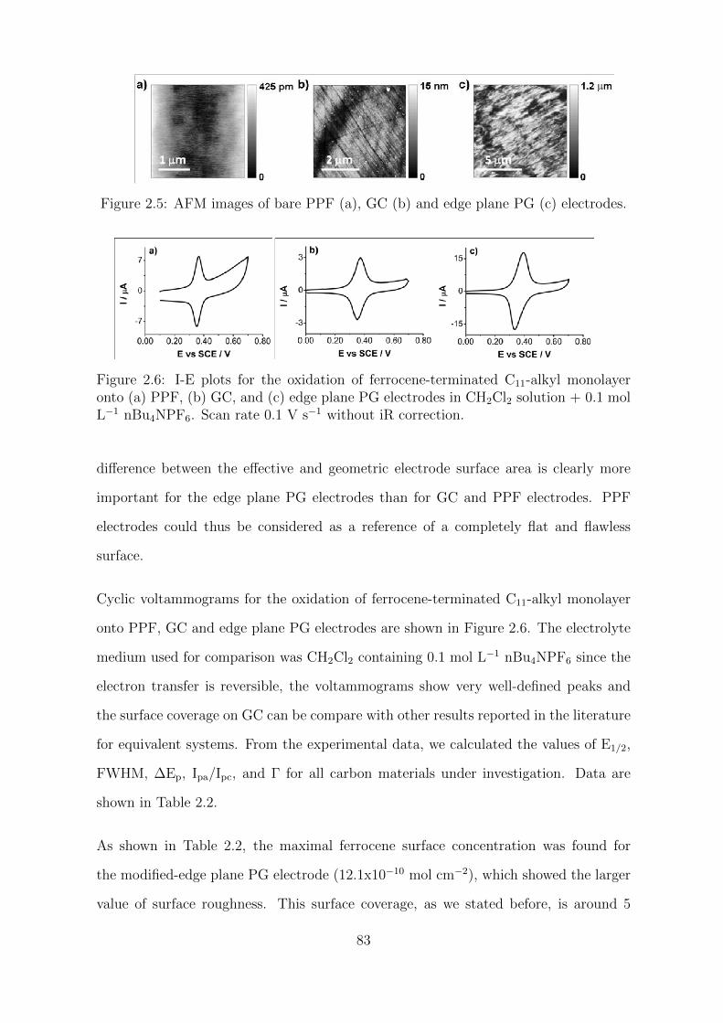
Figure 2.5: AFM images of bare PPF (a), GC (b) and edge plane PG (c) electrodes.
Figure 2.6: I-E plots for the oxidation of ferrocene-terminated C11-alkyl monolayeronto (a) PPF, (b) GC, and (c) edge plane PG electrodes in CH2Cl2 solution + 0.1 molL−1 nBu4NPF6. Scan rate 0.1 V s−1 without iR correction.
difference between the effective and geometric electrode surface area is clearly more
important for the edge plane PG electrodes than for GC and PPF electrodes. PPF
electrodes could thus be considered as a reference of a completely flat and flawless
surface.
Cyclic voltammograms for the oxidation of ferrocene-terminated C11-alkyl monolayer
onto PPF, GC and edge plane PG electrodes are shown in Figure 2.6. The electrolyte
medium used for comparison was CH2Cl2 containing 0.1 mol L−1 nBu4NPF6 since the
electron transfer is reversible, the voltammograms show very well-defined peaks and
the surface coverage on GC can be compare with other results reported in the literature
for equivalent systems. From the experimental data, we calculated the values of E1/2,
FWHM, ∆Ep, Ipa/Ipc, and Γ for all carbon materials under investigation. Data are
shown in Table 2.2.
As shown in Table 2.2, the maximal ferrocene surface concentration was found for
the modified-edge plane PG electrode (12.1x10⁻¹⁰ mol cm−2), which showed the larger
value of surface roughness. This surface coverage, as we stated before, is around 5
83
Table 2.2: Characteristic parameters for the oxidation of the ferrocene-terminated C11-alkyl monolayer onto PPF, GC and edge plane PG carbon electrodes in CH2Cl2 solution+ 0.1 mol L−1 nBu4NPF6. Values of E1/2, FWHM, ∆Ep, Ipa/Ipc, Γ were calculated fromthe experimental data at scan rate 0.1 V s−1. Surface geometric areas and roughnessvalues for all carbon materials are highlighted.
Carbon material PPF GC PG
Surface area / cm2 0.42 0.031 0.071
Roughness / nm 0.067 0.982 72
E1/2 / Va 0.36 0.36 0.37
FWHM(pa) / mV 46 80 96
∆Ep / mV 15 21 58
Ipa/Ipc 0.99 1.01 0.97
Γ x10−10 / mol cm−2 2.3 4.6 12.1aAll potentials are referred to SCE.
times larger than that expected for a perfectly flat surface such as PPF (2.3x10⁻¹⁰
mol cm−2), and 3 times larger than the value registered at a GC electrode (4.6x10⁻¹⁰
mol cm−2). The surface coverage obtained at the PPF is accordant with the theoretical
value that can be calculated for a monolayer of ferrocene molecules on a flat surface, this
value is around 2x10⁻¹⁰ mol cm−2 considering a size of the protecting group (TIPS)
of around 9.2 A diameter. The surface coverage obtained at the GC electrode is in
agreement with the literature (4.4x10⁻¹⁰ mol cm−2 in EtOH solution + 0.1 mol L−1
LiClO4).[71] A close-packed monolayer was obtained onto GC, and a dense layer was
indeed immobilized on the pyrolytic graphite electrode. The low value of full peak
width obtained at PPF indicates small interactions between the ferrocene moieties
on the surface layer, being smaller than that value expected for an adsorbed system
that follows the Langmuir isotherm model. We can thus conclude that the layer on
PPF is not a crowded monolayer of ferrocenes, as expected considering the previous
nanostructuring of the surface with the bulky protecting groups.
Further examination of the voltammetric curves shown in Figures 2.3 and 2.6 indicates
that the double layer capacitance changes significantly after oxidation of the ferrocene
moieties. For example, by calculating the differential capacitance from the I-E plot
84
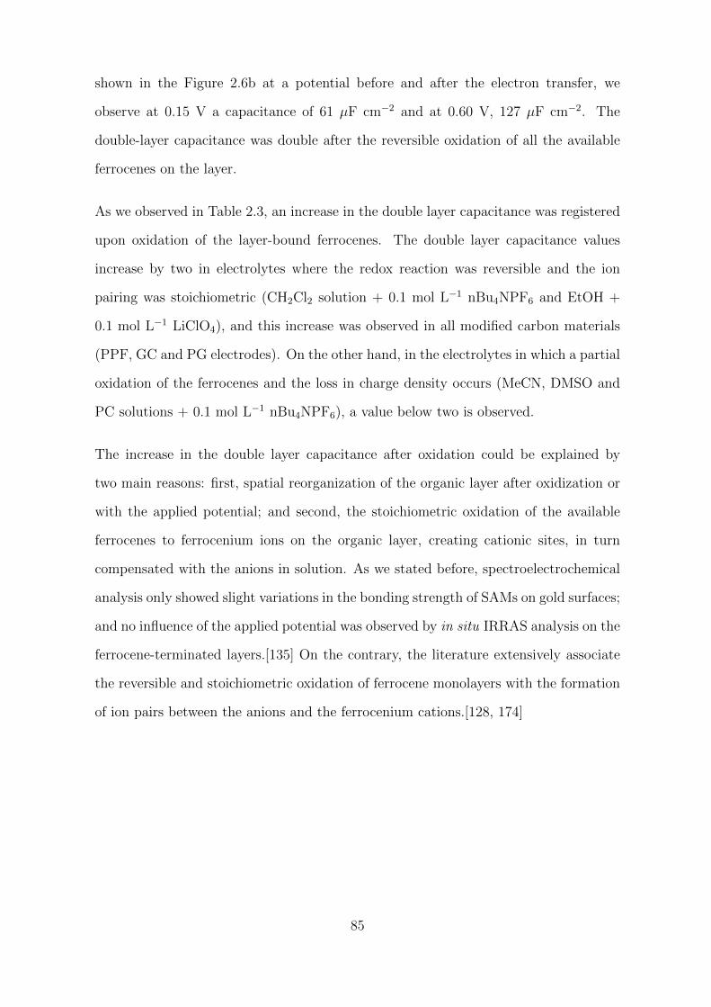
shown in the Figure 2.6b at a potential before and after the electron transfer, we
observe at 0.15 V a capacitance of 61 µF cm−2 and at 0.60 V, 127 µF cm−2. The
double-layer capacitance was double after the reversible oxidation of all the available
ferrocenes on the layer.
As we observed in Table 2.3, an increase in the double layer capacitance was registered
upon oxidation of the layer-bound ferrocenes. The double layer capacitance values
increase by two in electrolytes where the redox reaction was reversible and the ion
pairing was stoichiometric (CH2Cl2 solution + 0.1 mol L−1 nBu4NPF6 and EtOH +
0.1 mol L−1 LiClO4), and this increase was observed in all modified carbon materials
(PPF, GC and PG electrodes). On the other hand, in the electrolytes in which a partial
oxidation of the ferrocenes and the loss in charge density occurs (MeCN, DMSO and
PC solutions + 0.1 mol L−1 nBu4NPF6), a value below two is observed.
The increase in the double layer capacitance after oxidation could be explained by
two main reasons: first, spatial reorganization of the organic layer after oxidization or
with the applied potential; and second, the stoichiometric oxidation of the available
ferrocenes to ferrocenium ions on the organic layer, creating cationic sites, in turn
compensated with the anions in solution. As we stated before, spectroelectrochemical
analysis only showed slight variations in the bonding strength of SAMs on gold surfaces;
and no influence of the applied potential was observed by in situ IRRAS analysis on the
ferrocene-terminated layers.[135] On the contrary, the literature extensively associate
the reversible and stoichiometric oxidation of ferrocene monolayers with the formation
of ion pairs between the anions and the ferrocenium cations.[128, 174]
85
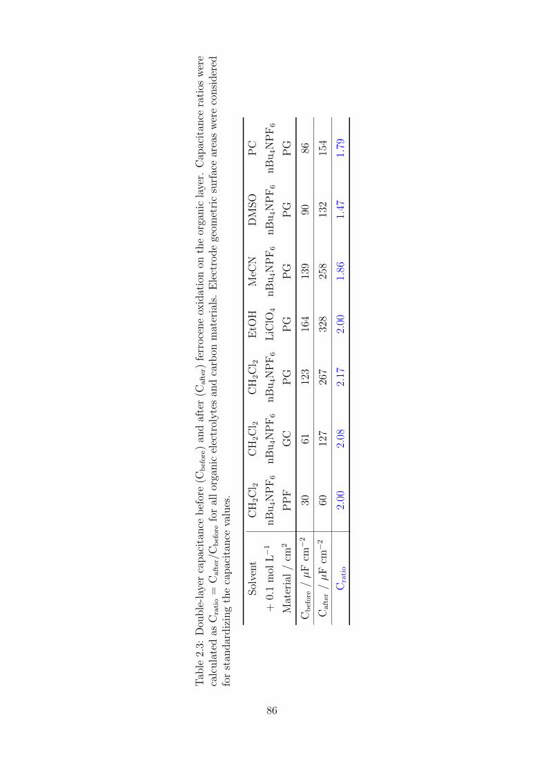
Tab
le2.
3:D
ouble
-lay
erca
pac
itan
ceb
efor
e(C
before
)an
daf
ter
(Cafter
)fe
rroce
ne
oxid
atio
non
the
orga
nic
laye
r.C
apac
itan
cera
tios
wer
eca
lcula
ted
asC
ratio
=C
after
/Cbefore
for
all
orga
nic
elec
trol
yte
san
dca
rbon
mat
eria
ls.
Ele
ctro
de
geom
etri
csu
rfac
ear
eas
wer
eco
nsi
der
edfo
rst
andar
diz
ing
the
capac
itan
ceva
lues
.
Sol
vent
CH
2C
l 2C
H2C
l 2C
H2C
l 2E
tOH
MeC
ND
MSO
PC
+0.
1m
olL−1
nB
u4N
PF6
nB
u4N
PF6
nB
u4N
PF6
LiC
lO4
nB
u4N
PF6
nB
u4N
PF6
nB
u4N
PF6
Mat
eria
l/
cm2
PP
FG
CP
GP
GP
GP
GP
G
Cbefore
/µ
Fcm−2
3061
123
164
139
9086
Cafter
/µ
Fcm−2
6012
726
732
825
813
215
4
Cratio
2.00
2.08
2.17
2.00
1.86
1.47
1.79
86
The stoichiometric oxidation of the available ferrocenes in CH2Cl2 and EtOH electrolyte
solutions to ferrocenium ions could increase the double-layer capacitance by a factor
of two, considering that the redox reaction is the transition from an uncharged species
to another with a charge of +1. Thus, some correlations with the surface coverage and
the double-layer capacitance are observed by carefully considering the data in Table
2.3. For example, the surface concentration of ferrocene increased from PPF to GC in
a factor of two, and we observed an increase in a factor of two in the double-layer capa-
citance before and after redox reaction; and from GC to PG, the surface concentration
increased in a factor of 2.6, while the capacitance increased in a factor of almost 2.2.
Discrepancies in the case of PG are expected since, as we demonstrated, the effective
surface of the edge plane PG electrodes widely differs from its geometric surface area,
unlike PPF and GC electrodes. On the other hand, the electrolyte solutions in which it
was observed a loss in charge density (MeCN, DMSO and PC) showed capacitance ra-
tios below two, being compatible with a partial oxidation of the ferrocenes available in
the organic layer. This reinforces the hypothesis of a partial oxidation of the available
ferrocenes in MeCN, DMSO and PC electrolyte solutions, and could explains the loss
in charge density in these media. A partial oxidation of ferrocenes are probably derived
from the possible participation of different ferrocene populations with different dielec-
tric environments (ferroceniums associated and not associated with the anions PF6–
and ClO4– ), being some redox units disable or disfavoured for the electron transfer.
From here, we can conclude that the stoichiometric oxidation of the available ferrocenes
in CH2Cl2 and EtOH electrolyte solutions, related with the ion-pairing reaction in
these media probably seems responsible for the 2-fold increase in the double layer
capacitance after ferrocene oxidation. Although the spatial reorganization of the layer
upon oxidation is still a possibility, the hypothesis of a partial oxidation of the available
ferrocenes in MeCN, DMSO and PC electrolyte solutions, probably derived from the
possible participation of different ferrocene populations, ferroceniums associated and
not associated with the anions, is reinforced from these results.
87
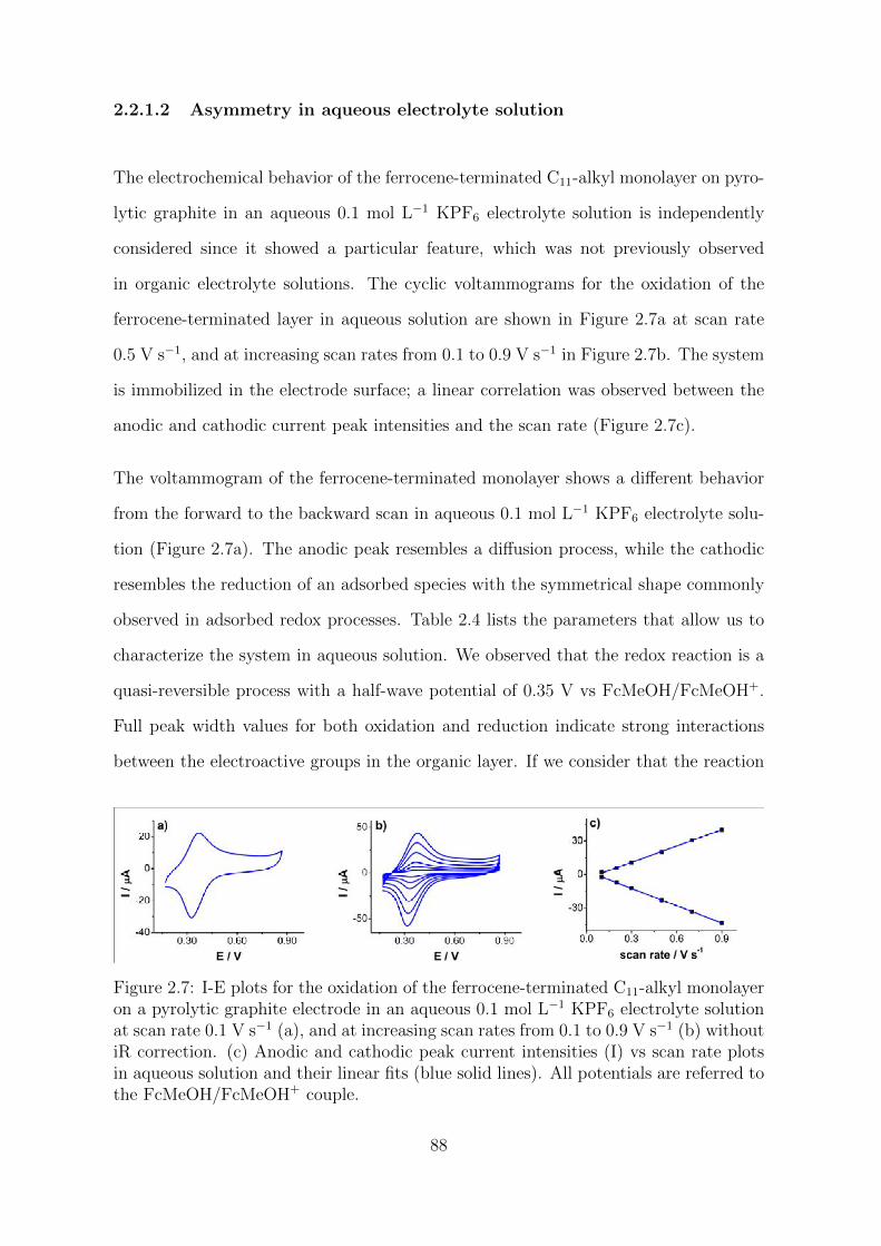
2.2.1.2 Asymmetry in aqueous electrolyte solution
The electrochemical behavior of the ferrocene-terminated C11-alkyl monolayer on pyro-
lytic graphite in an aqueous 0.1 mol L−1 KPF6 electrolyte solution is independently
considered since it showed a particular feature, which was not previously observed
in organic electrolyte solutions. The cyclic voltammograms for the oxidation of the
ferrocene-terminated layer in aqueous solution are shown in Figure 2.7a at scan rate
0.5 V s−1, and at increasing scan rates from 0.1 to 0.9 V s−1 in Figure 2.7b. The system
is immobilized in the electrode surface; a linear correlation was observed between the
anodic and cathodic current peak intensities and the scan rate (Figure 2.7c).
The voltammogram of the ferrocene-terminated monolayer shows a different behavior
from the forward to the backward scan in aqueous 0.1 mol L−1 KPF6 electrolyte solu-
tion (Figure 2.7a). The anodic peak resembles a diffusion process, while the cathodic
resembles the reduction of an adsorbed species with the symmetrical shape commonly
observed in adsorbed redox processes. Table 2.4 lists the parameters that allow us to
characterize the system in aqueous solution. We observed that the redox reaction is a
quasi-reversible process with a half-wave potential of 0.35 V vs FcMeOH/FcMeOH+.
Full peak width values for both oxidation and reduction indicate strong interactions
between the electroactive groups in the organic layer. If we consider that the reaction
Figure 2.7: I-E plots for the oxidation of the ferrocene-terminated C11-alkyl monolayeron a pyrolytic graphite electrode in an aqueous 0.1 mol L−1 KPF6 electrolyte solutionat scan rate 0.1 V s−1 (a), and at increasing scan rates from 0.1 to 0.9 V s−1 (b) withoutiR correction. (c) Anodic and cathodic peak current intensities (I) vs scan rate plotsin aqueous solution and their linear fits (blue solid lines). All potentials are referred tothe FcMeOH/FcMeOH+ couple.
88
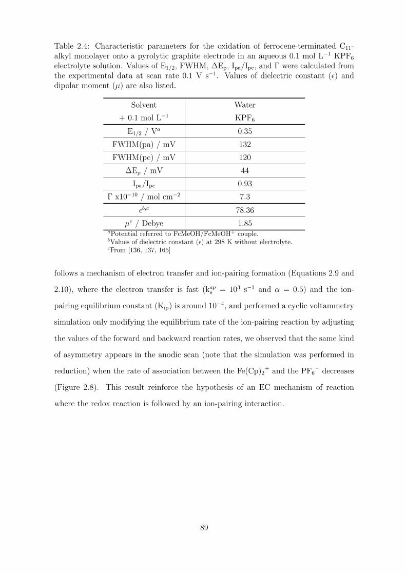
Table 2.4: Characteristic parameters for the oxidation of ferrocene-terminated C11-alkyl monolayer onto a pyrolytic graphite electrode in an aqueous 0.1 mol L−1 KPF6
electrolyte solution. Values of E1/2, FWHM, ∆Ep, Ipa/Ipc, and Γ were calculated fromthe experimental data at scan rate 0.1 V s−1. Values of dielectric constant (ε) anddipolar moment (µ) are also listed.
Solvent Water
+ 0.1 mol L−1 KPF6
E1/2 / Va 0.35
FWHM(pa) / mV 132
FWHM(pc) / mV 120
∆Ep / mV 44
Ipa/Ipc 0.93
Γ x10−10 / mol cm−2 7.3
εb,c 78.36
µc / Debye 1.85aPotential referred to FcMeOH/FcMeOH+ couple.bValues of dielectric constant (ε) at 298 K without electrolyte.cFrom [136, 137, 165]
follows a mechanism of electron transfer and ion-pairing formation (Equations 2.9 and
2.10), where the electron transfer is fast (kaps = 103 s−1 and α = 0.5) and the ion-
pairing equilibrium constant (Kip) is around 10−4, and performed a cyclic voltammetry
simulation only modifying the equilibrium rate of the ion-pairing reaction by adjusting
the values of the forward and backward reaction rates, we observed that the same kind
of asymmetry appears in the anodic scan (note that the simulation was performed in
reduction) when the rate of association between the Fe(Cp)2+ and the PF6
– decreases
(Figure 2.8). This result reinforce the hypothesis of an EC mechanism of reaction
where the redox reaction is followed by an ion-pairing interaction.
89
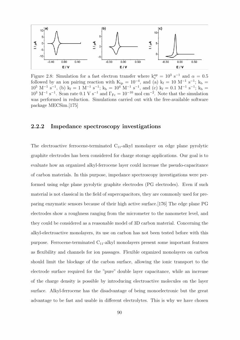
Figure 2.8: Simulation for a fast electron transfer where kaps = 103 s−1 and α = 0.5
followed by an ion pairing reaction with Kip = 10−4, and (a) kf = 10 M−1 s−1; kb =105 M−1 s−1, (b) kf = 1 M−1 s−1; kb = 104 M−1 s−1, and (c) kf = 0.1 M−1 s−1; kb =103 M−1 s−1. Scan rate 0.1 V s−1 and ΓFc = 10−10 mol cm−2. Note that the simulationwas performed in reduction. Simulations carried out with the free-available softwarepackage MECSim.[175]
2.2.2 Impedance spectroscopy investigations
The electroactive ferrocene-terminated C11-alkyl monolayer on edge plane pyrolytic
graphite electrodes has been considered for charge storage applications. Our goal is to
evaluate how an organized alkyl-ferrocene layer could increase the pseudo-capacitance
of carbon materials. In this purpose, impedance spectroscopy investigations were per-
formed using edge plane pyrolytic graphite electrodes (PG electrodes). Even if such
material is not classical in the field of supercapacitors, they are commonly used for pre-
paring enzymatic sensors because of their high active surface.[176] The edge plane PG
electrodes show a roughness ranging from the micrometer to the nanometer level, and
they could be considered as a reasonable model of 3D carbon material. Concerning the
alkyl-electroactive monolayers, its use on carbon has not been tested before with this
purpose. Ferrocene-terminated C11-alkyl monolayers present some important features
as flexibility and channels for ion passages. Flexible organized monolayers on carbon
should limit the blockage of the carbon surface, allowing the ionic transport to the
electrode surface required for the ”pure” double layer capacitance, while an increase
of the charge density is possible by introducing electroactive molecules on the layer
surface. Alkyl-ferrocene has the disadvantage of being monoelectronic but the great
advantage to be fast and usable in different electrolytes. This is why we have chosen
90
to evaluate the possibilities of alkyl-ferrocene immobilized systems.
From here, the edge plane pyrolytic graphite electrodes were modified by electrografting
of 4-(tri(isopropylsilyl)ethynyl) benzenediazonium tetrafluoroborate (TIPS-Eth-ArN2).
Considering the geometrical surface area of the electrode, from the integration of the
faradaic peak current, we derived a surface coverage around 12 10−10 mol cm−2. It
shows that a dense layer was indeed immobilized on the carbon surface. The corres-
ponding EIS responses of the electrode are shown on Figure 2.9 before and after carbon
modification when the solvent is CH2Cl2; we performed the EIS experiments at the two
potentials that are marked by the lines on the CV of Figure 2.9a.
EIS of the bare pyrolytic graphite electrode in CH2Cl2 are shown on Figure 2.9. We
performed these experiments at two different potentials that are marked by the lines
on the CV: - 0.08 V and 0.30 V vs the FcMeOH/FcMeOH+ couple. As observed on the
EIS spectra at - 0.08 V vs FcMeOH/FcMeOH+, the response does not correspond to a
pure capacitance behavior. (For a pure capacitance in an RC scheme, the phase-angle
changes from 90 at low frequencies to 0 at high frequencies).[177] This is visible on
the phase variation at low frequencies or on the corresponding Nyquist plot showing
the variation of the imaginary part Z” as function of the real part Z’ of the complex
impedance. This observation is common for carbon electrodes and is generally ascribed
to the heterogeneity of the surface both in terms of topological structures and chemical
groups on the surfaces.[148, 178] As shown on the AFM images (Figure 2.10), edge
planes pyrolytic graphite presents numerous fissures and pores and the electrode be-
haves as a collection of impedances with different values and time constants leading to
the response observed in EIS. Roughness (rms) values were estimated from the AFM
topographic images of a bare edge plane PG electrode and a ethynylaryl-modified PG
electrode (after deprotection step). The roughness values were 72.38 nm and 88.21 nm.
From this experiment, it is important to note that there is no major change in the
EIS response of the pyrolytic edge planes carbon functionalized electrode. One could
just observe that the phase is slightly more constant at low frequency and closer to
91
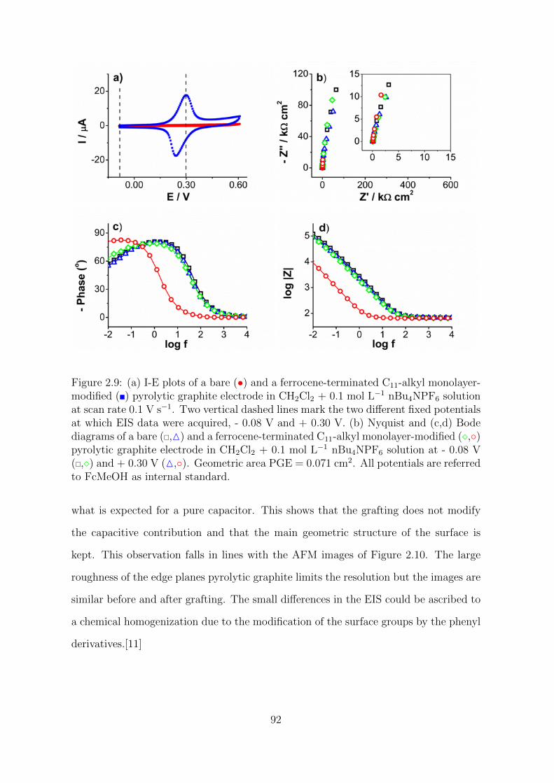
Figure 2.9: (a) I-E plots of a bare (•) and a ferrocene-terminated C11-alkyl monolayer-modified () pyrolytic graphite electrode in CH2Cl2 + 0.1 mol L−1 nBu4NPF6 solutionat scan rate 0.1 V s−1. Two vertical dashed lines mark the two different fixed potentialsat which EIS data were acquired, - 0.08 V and + 0.30 V. (b) Nyquist and (c,d) Bodediagrams of a bare (,M) and a ferrocene-terminated C11-alkyl monolayer-modified (,)pyrolytic graphite electrode in CH2Cl2 + 0.1 mol L−1 nBu4NPF6 solution at - 0.08 V(,) and + 0.30 V (M,). Geometric area PGE = 0.071 cm2. All potentials are referredto FcMeOH as internal standard.
what is expected for a pure capacitor. This shows that the grafting does not modify
the capacitive contribution and that the main geometric structure of the surface is
kept. This observation falls in lines with the AFM images of Figure 2.10. The large
roughness of the edge planes pyrolytic graphite limits the resolution but the images are
similar before and after grafting. The small differences in the EIS could be ascribed to
a chemical homogenization due to the modification of the surface groups by the phenyl
derivatives.[11]
92
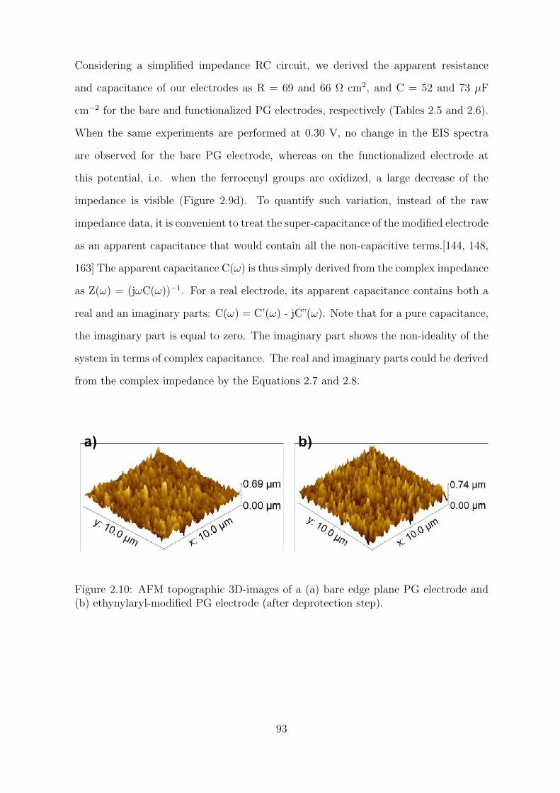
Considering a simplified impedance RC circuit, we derived the apparent resistance
and capacitance of our electrodes as R = 69 and 66 Ω cm2, and C = 52 and 73 µF
cm−2 for the bare and functionalized PG electrodes, respectively (Tables 2.5 and 2.6).
When the same experiments are performed at 0.30 V, no change in the EIS spectra
are observed for the bare PG electrode, whereas on the functionalized electrode at
this potential, i.e. when the ferrocenyl groups are oxidized, a large decrease of the
impedance is visible (Figure 2.9d). To quantify such variation, instead of the raw
impedance data, it is convenient to treat the super-capacitance of the modified electrode
as an apparent capacitance that would contain all the non-capacitive terms.[144, 148,
163] The apparent capacitance C(ω) is thus simply derived from the complex impedance
as Z(ω) = (jωC(ω))−1. For a real electrode, its apparent capacitance contains both a
real and an imaginary parts: C(ω) = C’(ω) - jC”(ω). Note that for a pure capacitance,
the imaginary part is equal to zero. The imaginary part shows the non-ideality of the
system in terms of complex capacitance. The real and imaginary parts could be derived
from the complex impedance by the Equations 2.7 and 2.8.
Figure 2.10: AFM topographic 3D-images of a (a) bare edge plane PG electrode and(b) ethynylaryl-modified PG electrode (after deprotection step).
93
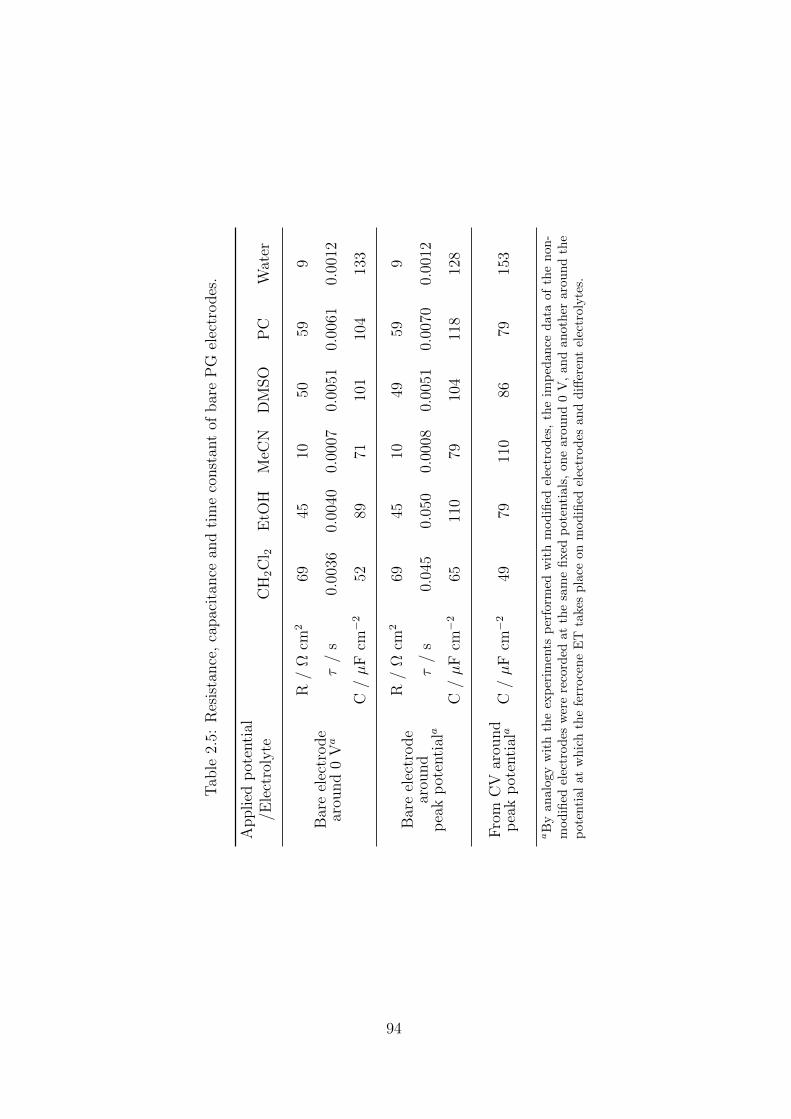
Tab
le2.
5:R
esis
tance
,ca
pac
itan
cean
dti
me
const
ant
ofbar
eP
Gel
ectr
odes
.
Applied
pot
enti
al/E
lect
roly
teC
H2C
l 2E
tOH
MeC
ND
MSO
PC
Wat
er
Bar
eel
ectr
ode
arou
nd
0V
a
R/
Ωcm
269
4510
5059
9
τ/
s0.
0036
0.00
400.
0007
0.00
510.
0061
0.00
12
C/µ
Fcm−2
5289
7110
110
413
3
Bar
eel
ectr
ode
arou
nd
pea
kp
oten
tial
a
R/
Ωcm
269
4510
4959
9
τ/
s0.
045
0.05
00.
0008
0.00
510.
0070
0.00
12
C/µ
Fcm−2
6511
079
104
118
128
Fro
mC
Var
ound
pea
kp
oten
tial
aC
/µ
Fcm−2
4979
110
8679
153
aB
yan
alogy
wit
hth
eex
per
imen
tsp
erfo
rmed
wit
hm
odifi
edel
ectr
od
es,
the
imp
edan
ced
ata
ofth
enon
-m
odifi
edel
ectr
od
esw
ere
reco
rded
atth
esa
me
fixed
pot
enti
als,
one
arou
nd
0V
,an
dan
other
arou
nd
the
pot
enti
alat
whic
hth
efe
rroce
ne
ET
take
spla
ceon
modifi
edel
ectr
odes
and
diff
eren
tel
ectr
olyte
s.
94
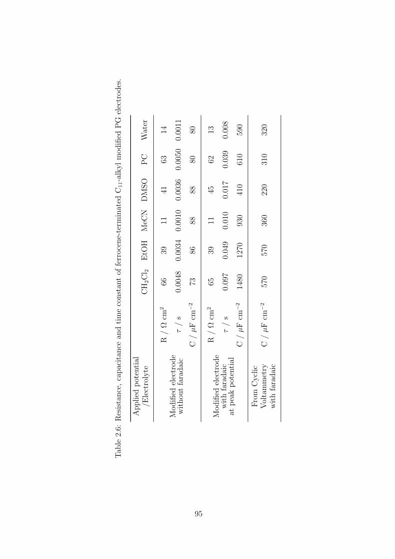
Tab
le2.
6:R
esis
tance
,ca
pac
itan
cean
dti
me
const
ant
offe
rroce
ne-
term
inat
edC
11-a
lkyl
modifi
edP
Gel
ectr
odes
.
Applied
pot
enti
al/E
lect
roly
teC
H2C
l 2E
tOH
MeC
ND
MSO
PC
Wat
er
Modifi
edel
ectr
ode
wit
hou
tfa
radai
c
R/
Ωcm
266
3911
4163
14
τ/
s0.
0048
0.00
340.
0010
0.00
360.
0050
0.00
11
C/µ
Fcm−2
7386
8888
8080
Modifi
edel
ectr
ode
wit
hfa
radai
cat
pea
kp
oten
tial
R/
Ωcm
265
3911
4562
13
τ/
s0.
097
0.04
90.
010
0.01
70.
039
0.00
8
C/µ
Fcm−2
1480
1270
930
410
610
590
Fro
mC
ycl
icV
olta
mm
etry
wit
hfa
radai
cC
/µ
Fcm−2
570
570
360
220
310
320
95
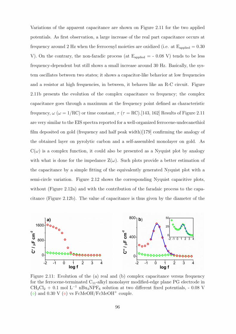
Variations of the apparent capacitance are shown on Figure 2.11 for the two applied
potentials. As first observation, a large increase of the real part capacitance occurs at
frequency around 2 Hz when the ferrocenyl moieties are oxidized (i.e. at Eapplied = 0.30
V). On the contrary, the non-faradic process (at Eapplied = - 0.08 V) tends to be less
frequency-dependent but still shows a small increase around 30 Hz. Basically, the sys-
tem oscillates between two states; it shows a capacitor-like behavior at low frequencies
and a resistor at high frequencies, in between, it behaves like an R-C circuit. Figure
2.11b presents the evolution of the complex capacitance vs frequency; the complex
capacitance goes through a maximum at the frequency point defined as characteristic
frequency, ω (ω = 1/RC) or time constant, τ (τ = RC).[143, 162] Results of Figure 2.11
are very similar to the EIS spectra reported for a well-organized ferrocene-undecanethiol
film deposited on gold (frequency and half peak width)[179] confirming the analogy of
the obtained layer on pyrolytic carbon and a self-assembled monolayer on gold. As
C(ω) is a complex function, it could also be presented as a Nyquist plot by analogy
with what is done for the impedance Z(ω). Such plots provide a better estimation of
the capacitance by a simple fitting of the equivalently generated Nyquist plot with a
semi-circle variation. Figure 2.12 shows the corresponding Nyquist capacitive plots,
without (Figure 2.12a) and with the contribution of the faradaic process to the capa-
citance (Figure 2.12b). The value of capacitance is thus given by the diameter of the
Figure 2.11: Evolution of the (a) real and (b) complex capacitance versus frequencyfor the ferrocene-terminated C11-alkyl monolayer modified-edge plane PG electrode inCH2Cl2 + 0.1 mol L−1 nBu4NPF6 solution at two different fixed potentials, - 0.08 V() and 0.30 V () vs FcMeOH/FcMeOH+ couple.
96
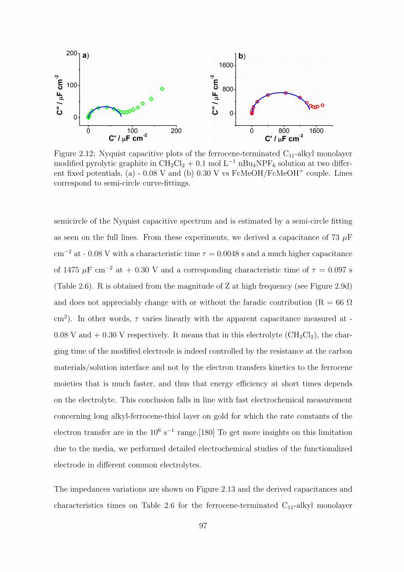
Figure 2.12: Nyquist capacitive plots of the ferrocene-terminated C11-alkyl monolayermodified pyrolytic graphite in CH2Cl2 + 0.1 mol L−1 nBu4NPF6 solution at two differ-ent fixed potentials, (a) - 0.08 V and (b) 0.30 V vs FcMeOH/FcMeOH+ couple. Linescorrespond to semi-circle curve-fittings.
semicircle of the Nyquist capacitive spectrum and is estimated by a semi-circle fitting
as seen on the full lines. From these experiments, we derived a capacitance of 73 µF
cm−2 at - 0.08 V with a characteristic time τ = 0.0048 s and a much higher capacitance
of 1475 µF cm−2 at + 0.30 V and a corresponding characteristic time of τ = 0.097 s
(Table 2.6). R is obtained from the magnitude of Z at high frequency (see Figure 2.9d)
and does not appreciably change with or without the faradic contribution (R = 66 Ω
cm2). In other words, τ varies linearly with the apparent capacitance measured at -
0.08 V and + 0.30 V respectively. It means that in this electrolyte (CH2Cl2), the char-
ging time of the modified electrode is indeed controlled by the resistance at the carbon
materials/solution interface and not by the electron transfers kinetics to the ferrocene
moieties that is much faster, and thus that energy efficiency at short times depends
on the electrolyte. This conclusion falls in line with fast electrochemical measurement
concerning long alkyl-ferrocene-thiol layer on gold for which the rate constants of the
electron transfer are in the 106 s−1 range.[180] To get more insights on this limitation
due to the media, we performed detailed electrochemical studies of the functionalized
electrode in different common electrolytes.
The impedances variations are shown on Figure 2.13 and the derived capacitances and
characteristics times on Table 2.6 for the ferrocene-terminated C11-alkyl monolayer
97
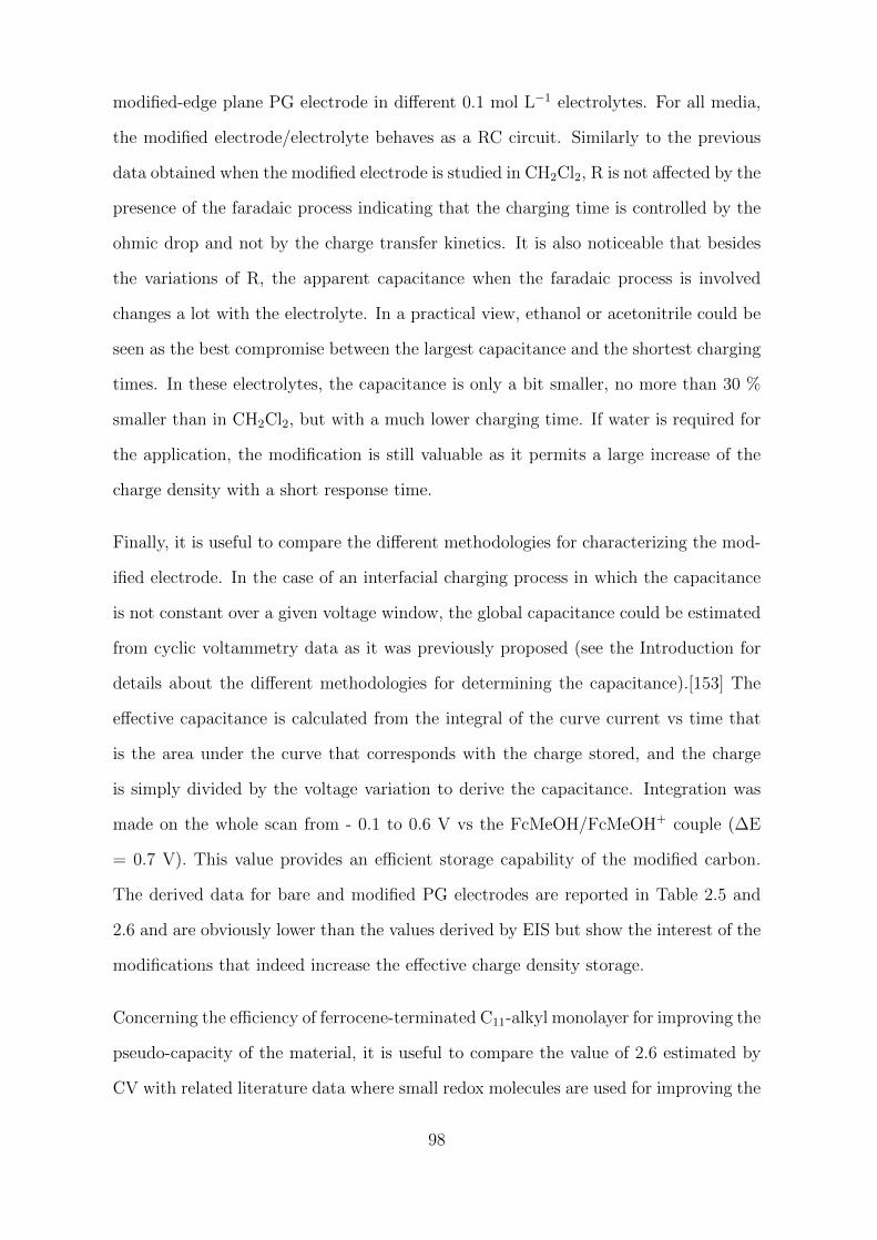
modified-edge plane PG electrode in different 0.1 mol L−1 electrolytes. For all media,
the modified electrode/electrolyte behaves as a RC circuit. Similarly to the previous
data obtained when the modified electrode is studied in CH2Cl2, R is not affected by the
presence of the faradaic process indicating that the charging time is controlled by the
ohmic drop and not by the charge transfer kinetics. It is also noticeable that besides
the variations of R, the apparent capacitance when the faradaic process is involved
changes a lot with the electrolyte. In a practical view, ethanol or acetonitrile could be
seen as the best compromise between the largest capacitance and the shortest charging
times. In these electrolytes, the capacitance is only a bit smaller, no more than 30 %
smaller than in CH2Cl2, but with a much lower charging time. If water is required for
the application, the modification is still valuable as it permits a large increase of the
charge density with a short response time.
Finally, it is useful to compare the different methodologies for characterizing the mod-
ified electrode. In the case of an interfacial charging process in which the capacitance
is not constant over a given voltage window, the global capacitance could be estimated
from cyclic voltammetry data as it was previously proposed (see the Introduction for
details about the different methodologies for determining the capacitance).[153] The
effective capacitance is calculated from the integral of the curve current vs time that
is the area under the curve that corresponds with the charge stored, and the charge
is simply divided by the voltage variation to derive the capacitance. Integration was
made on the whole scan from - 0.1 to 0.6 V vs the FcMeOH/FcMeOH+ couple (∆E
= 0.7 V). This value provides an efficient storage capability of the modified carbon.
The derived data for bare and modified PG electrodes are reported in Table 2.5 and
2.6 and are obviously lower than the values derived by EIS but show the interest of the
modifications that indeed increase the effective charge density storage.
Concerning the efficiency of ferrocene-terminated C11-alkyl monolayer for improving the
pseudo-capacity of the material, it is useful to compare the value of 2.6 estimated by
CV with related literature data where small redox molecules are used for improving the
98
Figure 2.13: (a,c) Phase-angle and (b,d) log |Z| versus log frequency of the ferrocene-terminated C11-alkyl monolayer modified-edge plane PG electrode in () CH2Cl2, ()MeCN, (O) DMSO and (/) PC + 0.1 mol L−1 nBu4NPF6, in () EtOH + 0.1 mol L−1
LiClO4, and in (B) water + 0.1 mol L−1 KPF6 at (a,b) an applied potential wherethere is no faradic contribution and (c,d) at an applied potential where the ferrocenylmoieties are oxidized.
pseudo-capacitance. A simple way to make comparisons is by considering the increase
of capacitance before and after modification. Indeed, the characteristics of pseudo-
capacitor are generally reported in capacitance per mass (F g−1) or charge per mass unit
as our results are reported in capacitance per surface unit (F cm−2), which is adapted
to a planned electrode. After the grafting of the alkyl-ferrocene layers and optimization
of the electrolyte/solvent, we observed an increase of 6.6 in EtOH and 7.8 of the average
pseudo-capacitance. By comparison, the best reported increases after the introduction
of small redox molecules like quinones on pristine carbons materials are around 2 -
2.5.[154] The comparative large increase obtained with alkyl-ferrocene monolayer arises
from the structure and the electrochemical characteristics of alkyl-ferrocene but also
because such monolayer is compatible with a large choice of electrolytes and solvents.
99
Indeed as seen on 2.6, the faradaic pseudo-capacitance in water is around half of those in
CH2Cl2 or EtOH showing the interest of an optimization of the solvent. At this stage,
the origin of this variation of the pseudo-capacitance concerns mainly the faradaic
process as the double layer does change in a much lower extend. We could ascribe this
variation of the pseudo-capacitance to a differential solvation of the electrolyte anions in
the organic solvents, which produces variations in the extent of the ion-pairing reaction
that follows the ferrocene electron transfer in a possible EC mechanism of reaction.
As already reported in the literature, the introduction of a redox active monolayer on
a carbon capacitor is a convenient way for improving the global charge density of these
materials. In this field, we show the interest of using an organized long chain alkyl-
layer with a fast charge transfer redox moieties like ferrocene for increasing the charge
capacity in active carbon materials. After modification and optimization of the solvent,
we observed a considerable increase of the charge density storage by a ratio around 7
which is higher than most of the reports of literature. Of course, such results still need
to be tested with other carbon materials but they already show the potential interest
of such monolayer in charge storage application. As for a “classical” capacitance, the
characteristic time of the layer depends on the electrolyte, since the charge transfer
kinetics from the carbon to the active alkyl-ferrocene moiety is very fast and not a
limiting factor. Moreover, we highlight the importance of the solvent not only for the
RC time but also for maximizing the value of the faradaic charge. Because of the
versatility of the carbon modification process, similar alkyl-redox monolayers could be
considered for the modification of many different types of nano-structured carbon as
those presenting a large specific surface and controlled porosity. Redox groups other
than ferrocene, as those presenting higher electronic stoichiometry could also been used
but at the condition that their global charge transfer kinetics remains fast and allows
a large choice of solvents.
100
2.3 Experimental section
2.3.1 Reagents
All commercially available reagents were used as received.
Organic solvents were used without further purification (See Table 2.7 below).
Table 2.7: Structural formula and purity grade of all organic solvents
All aqueous solutions were made employing ultrapure water (18.2 MΩ-cm).
Non-commercially reagents were synthesized in the laboratory:
• 4-(tri(isopropylsilyl)ethynyl) benzenediazonium tetrafluoroborate
(TIPS-Eth-ArN2+) was synthesized according to the literature.[11]
• (11-azidoundecyl)ferrocene was synthesized following a previously
published procedure.[181]
2.3.2 Electrochemical measurements
2.3.2.1 Instrumentation
All the electrochemical measurements were performed using a standard three electrode
setup at a controlled potential with a potentiostat Autolab PGSTAT 302N (Metrohm)
equipped with an ADC10M and a FRA2 module. The set of electrodes consisted
101
of a 3 mm-diameter edge-plane pyrolytic graphite (PG) or a 2 mm-diameter glassy
carbon (GC) disk electrodes as working electrode, a platinum wire as the auxiliary
electrode, and a saturated calomel electrode (SCE, KCl sat.) as the reference. The
latter was isolated from the working solution employing a salt bridge, which contained
the electrolyte solution. When necessary, a conventional gas inlet was used for bubbling
argon inside the electrochemical cell to displace oxygen, which is chemically reactive and
electrochemically reducible. Occasionally, low roughness and flat carbon surfaces were
required as working electrodes. In this case, pyrolyzed photoresist films (PPF) were
homemade fabricated according to described methods[182]. Since the larger surface
area of these flat working electrodes, a platinum mesh was used as the counter electrode
instead of a platinum wire.
2.3.2.2 Methodology
Cyclic voltammetry and impedance measurements. I-E plots of bare and (11-
azidoundecyl)ferrocene modified-edge plane PG electrodes were registered at increas-
ing scan rates from 0.1 to 0.9 V s−1 in different electrolyte solutions: 0.1 mol L−1
nBu4NPF6 in CH2Cl2, MeCN, DMSO and PC, 0.1 mol L−1 LiClO4 in EtOH, and 0.1
mol L−1 KPF6 in water. Fresh modified-PG electrodes were used for each electrolyte,
avoiding a possible ”memory” effect of the organic layer. The experimental sequence
followed for each electrolyte solution was: modification of the carbon surface (PPF,
GC or edge-plane PG electrodes), voltammetric study, and impedimetric study. This
sequence allowed the correlation of the data extracted from CV and EIS. At the end
of each experiment, the voltammogram of the immobilized system was registered in
CH2Cl2 + 0.1 mol L−1 nBu4NPF6 as reference, and FcMeOH was added to the studied
electrolyte solution to standardize the potential according to the FcMeOH/FcMeOH+
couple. All voltammograms were registered without ohmic drop correction. From the
I-E plots, since the modification is a surface immobilized system, it must follow the
Langmuir isotherm model.[167, 171] The electrochemical parameters extracted from
102
the I-E curves were: Epa, Epc, Ipa, Ipc, anodic and cathodic FWMH (full width at
half maximum) and ∆Ep. Other parameters calculated from the experimental data
were the surface coverage of ferrocene (ΓFc), and the half-wave potential (E1/2). The
reversibility of the system was studied through the ratio of the current peak intensit-
ies (Ipa/Ipc). The characteristic kinetic parameters, the apparent electron transfer rate
constant (kaps ) and the electron transfer coefficient (α) of the ferrocene electron transfer
could not be determined. Electrochemical impedance measurements were performed,
after cyclic voltammetry experiments, in each electrolyte solution when the working
electrode was a bare edge-plane PG or an (11-azidoundecyl)ferrocene modified-edge
plane PG electrode. The ac frequencies for impedance experiments ranged from 10
kHz to 0.01 Hz, with an amplitude of ±10 mV. Lissajous curves were monitored at
each frequency to ensure that no changes in the linearity of the circuit occur during
the experiment.
2.3.3 Preparation of modified substrates
• Electrochemical grafting of the protected aryldiazonium salt.
Surface modification of all working electrodes (PPF, GC and edge-plane PG
electrodes) was performed by cyclic voltammetry (five consecutive cycles from +
0.6 to - 0.8 V vs SCE at scan rate 0.05 V s−1,) in an acetonitrile solution of 10−2
mol L−1 aryldiazonium salt TIPS-Eth-ArN2+ + 0.1 mol L−1 nBu4NPF6. After
grafting, the electrodes were thoroughly rinsed with acetone and dried under
argon. Figure 2.14 shows the voltammograms for the electrochemical grafting of
the aryldiazonium salt TIPS-Eth-ArN2+. We observed the usual electrochemical
response; an irreversible reduction of the aryldiazonium salt on carbon surface
and the inhibition of the electrochemical signal after the first reduction cycle.
At this point, a well-structured monolayer of protected ethynylaryl groups is
attached to the carbon substrate by covalent bond.
103
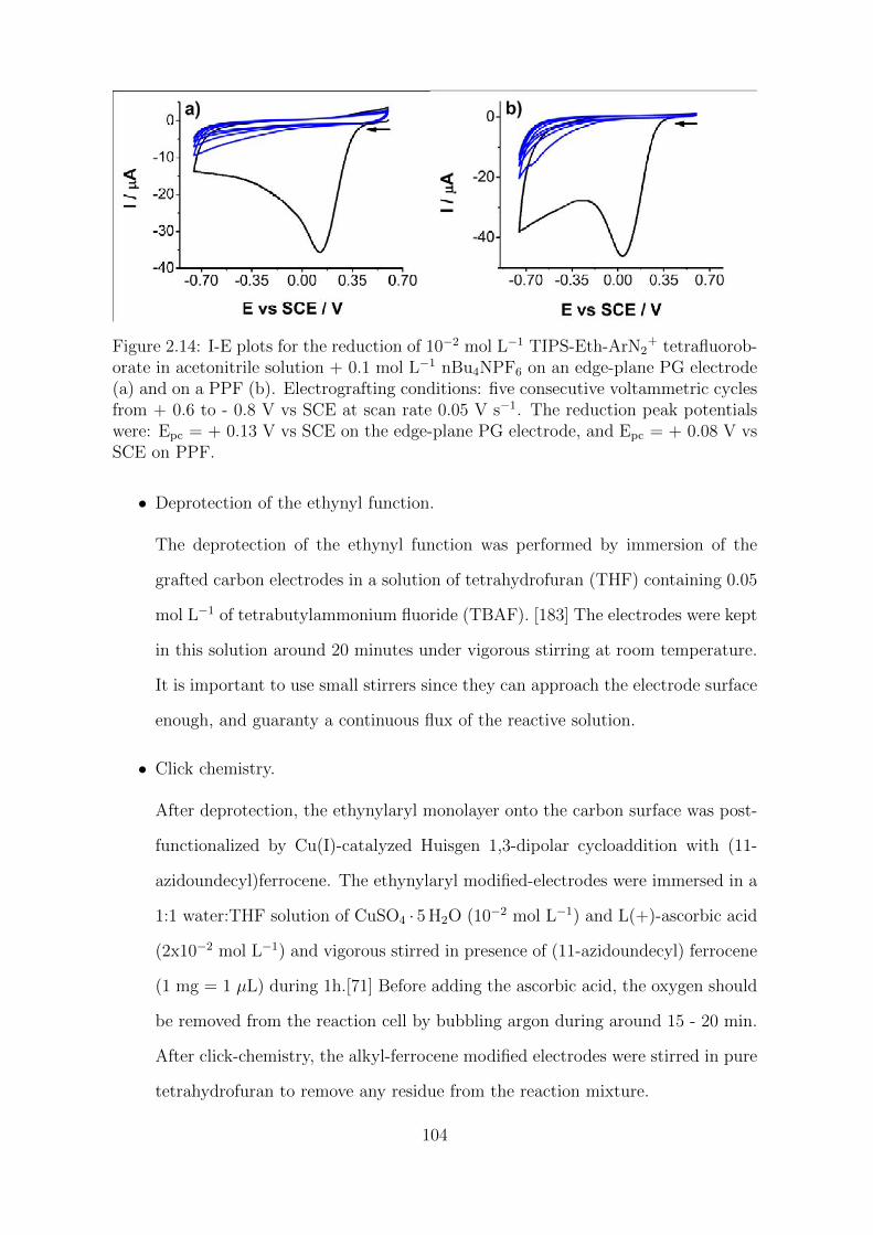
Figure 2.14: I-E plots for the reduction of 10−2 mol L−1 TIPS-Eth-ArN2+ tetrafluorob-
orate in acetonitrile solution + 0.1 mol L−1 nBu4NPF6 on an edge-plane PG electrode(a) and on a PPF (b). Electrografting conditions: five consecutive voltammetric cyclesfrom + 0.6 to - 0.8 V vs SCE at scan rate 0.05 V s−1. The reduction peak potentialswere: Epc = + 0.13 V vs SCE on the edge-plane PG electrode, and Epc = + 0.08 V vsSCE on PPF.
• Deprotection of the ethynyl function.
The deprotection of the ethynyl function was performed by immersion of the
grafted carbon electrodes in a solution of tetrahydrofuran (THF) containing 0.05
mol L−1 of tetrabutylammonium fluoride (TBAF). [183] The electrodes were kept
in this solution around 20 minutes under vigorous stirring at room temperature.
It is important to use small stirrers since they can approach the electrode surface
enough, and guaranty a continuous flux of the reactive solution.
• Click chemistry.
After deprotection, the ethynylaryl monolayer onto the carbon surface was post-
functionalized by Cu(I)-catalyzed Huisgen 1,3-dipolar cycloaddition with (11-
azidoundecyl)ferrocene. The ethynylaryl modified-electrodes were immersed in a
1:1 water:THF solution of CuSO4 · 5 H2O (10−2 mol L−1) and L(+)-ascorbic acid
(2x10⁻² mol L−1) and vigorous stirred in presence of (11-azidoundecyl) ferrocene
(1 mg = 1 µL) during 1h.[71] Before adding the ascorbic acid, the oxygen should
be removed from the reaction cell by bubbling argon during around 15 - 20 min.
After click-chemistry, the alkyl-ferrocene modified electrodes were stirred in pure
tetrahydrofuran to remove any residue from the reaction mixture.
104
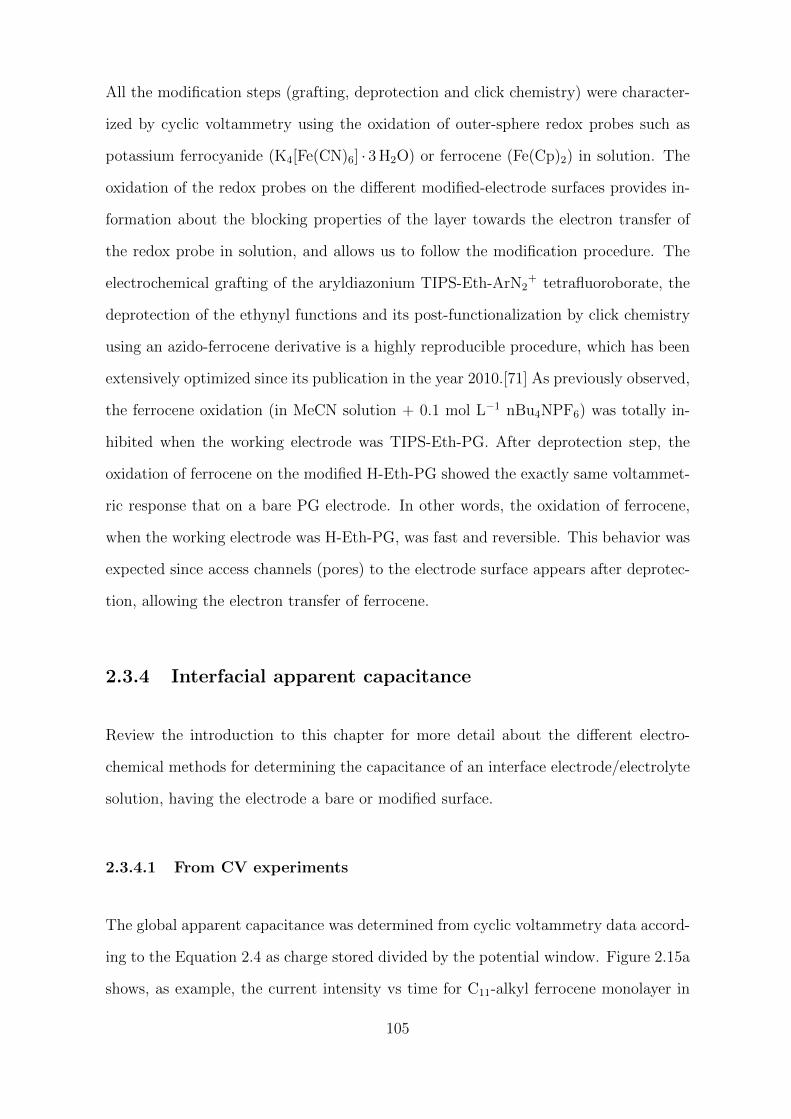
All the modification steps (grafting, deprotection and click chemistry) were character-
ized by cyclic voltammetry using the oxidation of outer-sphere redox probes such as
potassium ferrocyanide (K4[Fe(CN)6] · 3 H2O) or ferrocene (Fe(Cp)2) in solution. The
oxidation of the redox probes on the different modified-electrode surfaces provides in-
formation about the blocking properties of the layer towards the electron transfer of
the redox probe in solution, and allows us to follow the modification procedure. The
electrochemical grafting of the aryldiazonium TIPS-Eth-ArN2+ tetrafluoroborate, the
deprotection of the ethynyl functions and its post-functionalization by click chemistry
using an azido-ferrocene derivative is a highly reproducible procedure, which has been
extensively optimized since its publication in the year 2010.[71] As previously observed,
the ferrocene oxidation (in MeCN solution + 0.1 mol L−1 nBu4NPF6) was totally in-
hibited when the working electrode was TIPS-Eth-PG. After deprotection step, the
oxidation of ferrocene on the modified H-Eth-PG showed the exactly same voltammet-
ric response that on a bare PG electrode. In other words, the oxidation of ferrocene,
when the working electrode was H-Eth-PG, was fast and reversible. This behavior was
expected since access channels (pores) to the electrode surface appears after deprotec-
tion, allowing the electron transfer of ferrocene.
2.3.4 Interfacial apparent capacitance
Review the introduction to this chapter for more detail about the different electro-
chemical methods for determining the capacitance of an interface electrode/electrolyte
solution, having the electrode a bare or modified surface.
2.3.4.1 From CV experiments
The global apparent capacitance was determined from cyclic voltammetry data accord-
ing to the Equation 2.4 as charge stored divided by the potential window. Figure 2.15a
shows, as example, the current intensity vs time for C11-alkyl ferrocene monolayer in
105
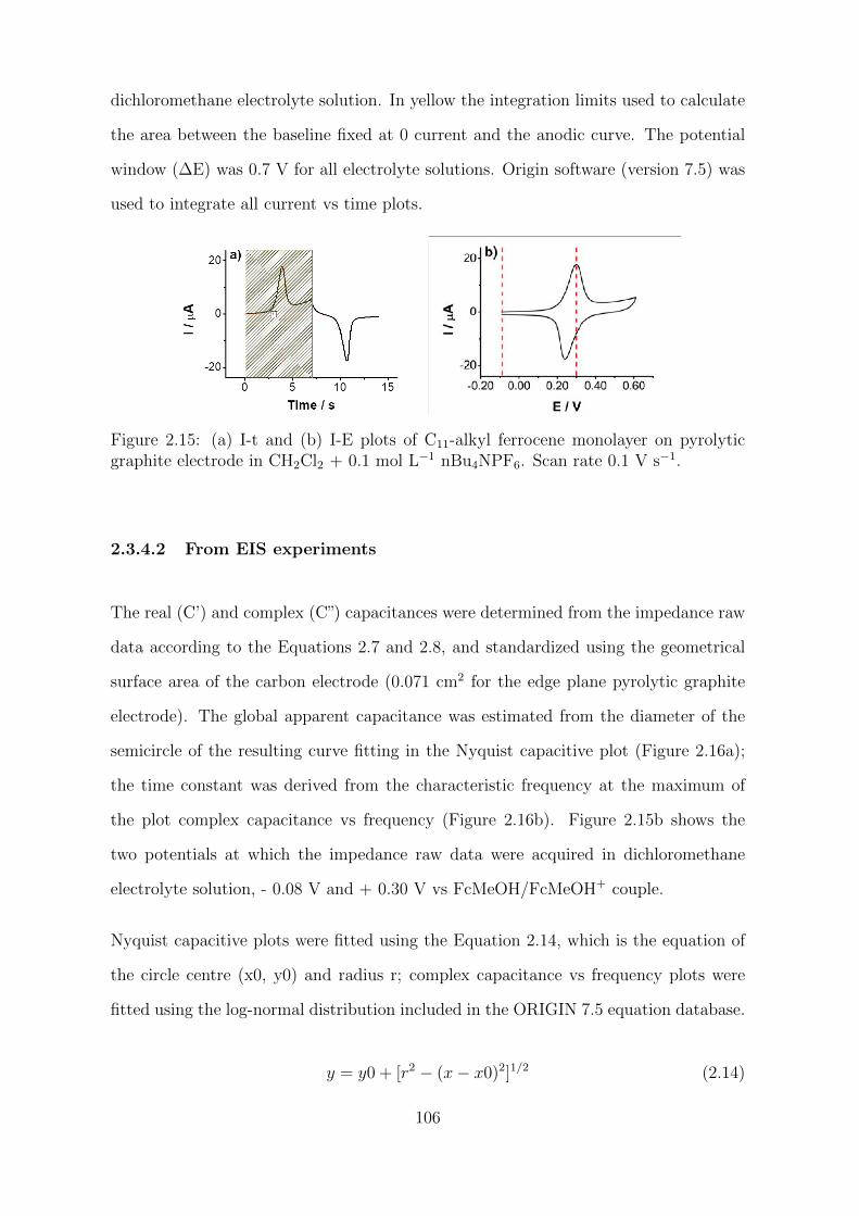
dichloromethane electrolyte solution. In yellow the integration limits used to calculate
the area between the baseline fixed at 0 current and the anodic curve. The potential
window (∆E) was 0.7 V for all electrolyte solutions. Origin software (version 7.5) was
used to integrate all current vs time plots.
Figure 2.15: (a) I-t and (b) I-E plots of C11-alkyl ferrocene monolayer on pyrolyticgraphite electrode in CH2Cl2 + 0.1 mol L−1 nBu4NPF6. Scan rate 0.1 V s−1.
2.3.4.2 From EIS experiments
The real (C’) and complex (C”) capacitances were determined from the impedance raw
data according to the Equations 2.7 and 2.8, and standardized using the geometrical
surface area of the carbon electrode (0.071 cm2 for the edge plane pyrolytic graphite
electrode). The global apparent capacitance was estimated from the diameter of the
semicircle of the resulting curve fitting in the Nyquist capacitive plot (Figure 2.16a);
the time constant was derived from the characteristic frequency at the maximum of
the plot complex capacitance vs frequency (Figure 2.16b). Figure 2.15b shows the
two potentials at which the impedance raw data were acquired in dichloromethane
electrolyte solution, - 0.08 V and + 0.30 V vs FcMeOH/FcMeOH+ couple.
Nyquist capacitive plots were fitted using the Equation 2.14, which is the equation of
the circle centre (x0, y0) and radius r; complex capacitance vs frequency plots were
fitted using the log-normal distribution included in the ORIGIN 7.5 equation database.
y = y0 + [r2 − (x− x0)2]1/2 (2.14)
106
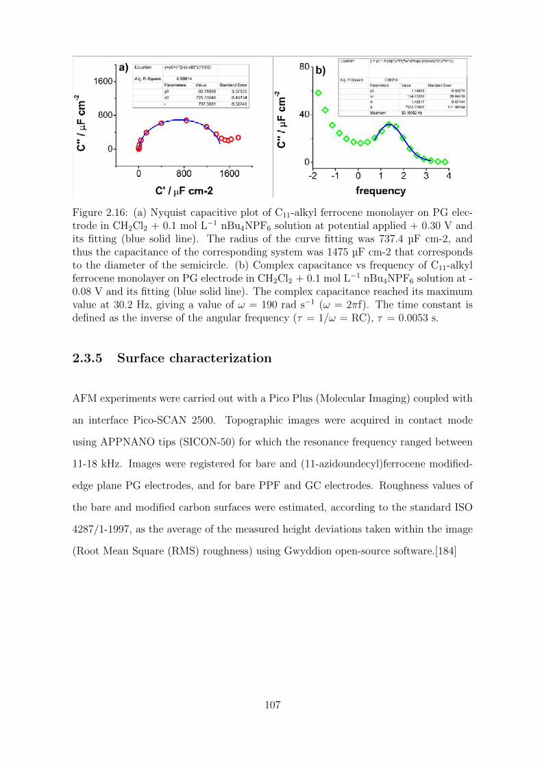
Figure 2.16: (a) Nyquist capacitive plot of C11-alkyl ferrocene monolayer on PG elec-trode in CH2Cl2 + 0.1 mol L−1 nBu4NPF6 solution at potential applied + 0.30 V andits fitting (blue solid line). The radius of the curve fitting was 737.4 µF cm-2, andthus the capacitance of the corresponding system was 1475 µF cm-2 that correspondsto the diameter of the semicircle. (b) Complex capacitance vs frequency of C11-alkylferrocene monolayer on PG electrode in CH2Cl2 + 0.1 mol L−1 nBu4NPF6 solution at -0.08 V and its fitting (blue solid line). The complex capacitance reached its maximumvalue at 30.2 Hz, giving a value of ω = 190 rad s−1 (ω = 2πf). The time constant isdefined as the inverse of the angular frequency (τ = 1/ω = RC), τ = 0.0053 s.
2.3.5 Surface characterization
AFM experiments were carried out with a Pico Plus (Molecular Imaging) coupled with
an interface Pico-SCAN 2500. Topographic images were acquired in contact mode
using APPNANO tips (SICON-50) for which the resonance frequency ranged between
11-18 kHz. Images were registered for bare and (11-azidoundecyl)ferrocene modified-
edge plane PG electrodes, and for bare PPF and GC electrodes. Roughness values of
the bare and modified carbon surfaces were estimated, according to the standard ISO
4287/1-1997, as the average of the measured height deviations taken within the image
(Root Mean Square (RMS) roughness) using Gwyddion open-source software.[184]
107
2.4 Conclusion
There were two objectives in this chapter, first the investigation of the electrochemical
properties of alkyl-ferrocene on-carbon monolayers in different electrolyte solutions;
and second, the evaluation of the impact of this modification to the double layer capa-
citance of the interface carbon/solution by electrochemical means. The electrochemical
properties of functionalized carbon with ferrocene alkyl monolayers were examined both
by cyclic voltammetry and impedance spectroscopy in different organic and aqueous
electrolyte solutions, covering a wide range of dielectric constant values (from around
9 to 80). Edge plane pyrolytic graphite electrodes were modified by using a protection-
deprotection strategy. The functionalization method was based on the electrografting
of a covalently attached monolayer, which in a second step was functionalized by a
ferrocene-terminated long C11-alkyl chain.
From the cyclic voltammetry investigations, we can conclude that the ion-pairing form-
ation between the counterions in solution and the ferrocenium cation upon oxidation
was observed to strongly influence the electrochemical response of the system. Both
the kinetics and thermodynamics of the ferrocene-terminated C11-alkyl monolayer elec-
tron transfer were influenced by the solvent through a differential solvation of the hy-
drophobic anions PF6– and ClO4
– , which produced variations in the extent of the
ion-pairing reaction between the anions in solution and the ferrocenium cations upon
oxidation. Evidence of a possible mechanism of reaction involving the electron transfer
of ferrocene and an ion-pairing process are supported by the experimental data and
the literature. From the literature, ion pair formation has been extensively demon-
strated by CV and EQCM experiments coupled with surface enhanced spectroscopic
techniques.[127, 132, 133, 135] In general, the formation of ion pairs is favored in an
environment in which the anions are poorly solvated, i.e., in solvents with low values
of dielectric constant.[136] The association of the counterions with the ferrocenium
ions upon oxidation have been demonstrated to stabilize the cation, therefore displa-
108
cing the redox potential of ferrocene to lower values.[125] Additionally, it was found
a linear correlation between the redox potential of ferrocene and the logarithm of the
concentration of PF6– and ClO4
– in solution, which suggest a possible reaction process
via electron transfer and ion-pairing reaction between the anions in solution and the
ferrocenium cations upon oxidation.[131, 134, 138]
From the experimental data:
• Thermodynamics. It was observed a shift to more positive potentials of the half-
wave potential of ferrocene in MeCN, DMSO and PC electrolyte solutions, where
the anions are strongly solvated, and in turn limiting the ion-pairs formation
between anions and the ferrocenium cations upon oxidation. On the contrary, the
ion-pairing in CH2Cl2 and EtOH stabilized the ferrocenium cations, and probably
also the structure of the monolayer, displacing the half-wave potential of ferrocene
to more negative values (ferrocene was easily oxidized in these media). Thus, the
largest positive shift of the half-wave potential was observed in DMSO, with a
difference of 130 mV over EtOH.
• Kinetics. The different peak shape and width and current peak intensities ob-
served between the group constituted by CH2Cl2 and EtOH and the group con-
stituted by MeCN, DMSO and PC indicates that the kinetics of the electron
transfer is also influenced by the different solvation energies of the anions in the
organic solvents. In CH2Cl2 and EtOH, where the ion pairs formation is favored
by the nature of the solvents, narrower and sharper peaks with larger current
peak intensities were observed. Also, the lower peak widths suggest an equival-
ent dielectric environment and minimal interactions of the ferrocenium cations
upon oxidation. In MeCN, DMSO and PC, dipolar solvents with high dielectric
constant where the anions are highly solvated, it was observed broader peaks
and smaller current peak intensities that reflects the predominance of repuls-
ive interactions between the ferrocenium cations, and some heterogeneity, with
109
the possible existence of different ferrocene populations with different dielectric
environments affecting the kinetics of the electrochemical reaction.
Concerning the loss of charge density observed in MeCN, DMSO and PC, as hypothesis,
the possible participation of different ferrocene populations in the electron transfer,
having different dielectric environments, could lead to different redox potentials and
kinetics of reaction, being some redox units totally disable or disfavoured for the elec-
tron transfer. However, a possible restructuring of the organic layer or reorientation of
the ferrocenium cations after oxidation have been suggested in the literature and can
not be discarded from these experiments.
From the impedimetric investigations, we can conclude that the introduction of a
redox active monolayer on a carbon capacitor is a convenient way for improving the
global charge density of these materials. After grafting of the alkyl-ferrocene layers
and optimization of the electrolyte/solvent, we observed a considerable increase of the
charge density storage by a ratio around 7 which is higher than most of the reports
of literature.[154] Indeed, such results are limited by the carbon material employed,
which shows a much lower contribution to the double layer capacitance than those
porous carbon-based materials commonly used in real applications. Therefore, this
modification still need to be tested with other carbon materials to really show the po-
tential interest of such monolayer in charge storage applications. The most significant
outcome of this work is that the dynamics of the charge storage process is governed by
the internal series resistance of the cell and not by the kinetic of the faradaic process,
since the charge transfer kinetics from the carbon to the active alkyl-ferrocene moiety
is very fast and not a limiting factor. Moreover, we highlight the importance of the
solvent not only for the RC time but also for maximizing the value of the faradaic
charge.
110


Chapter 3
Molecular sieving and current
rectification properties of thin
organic films.

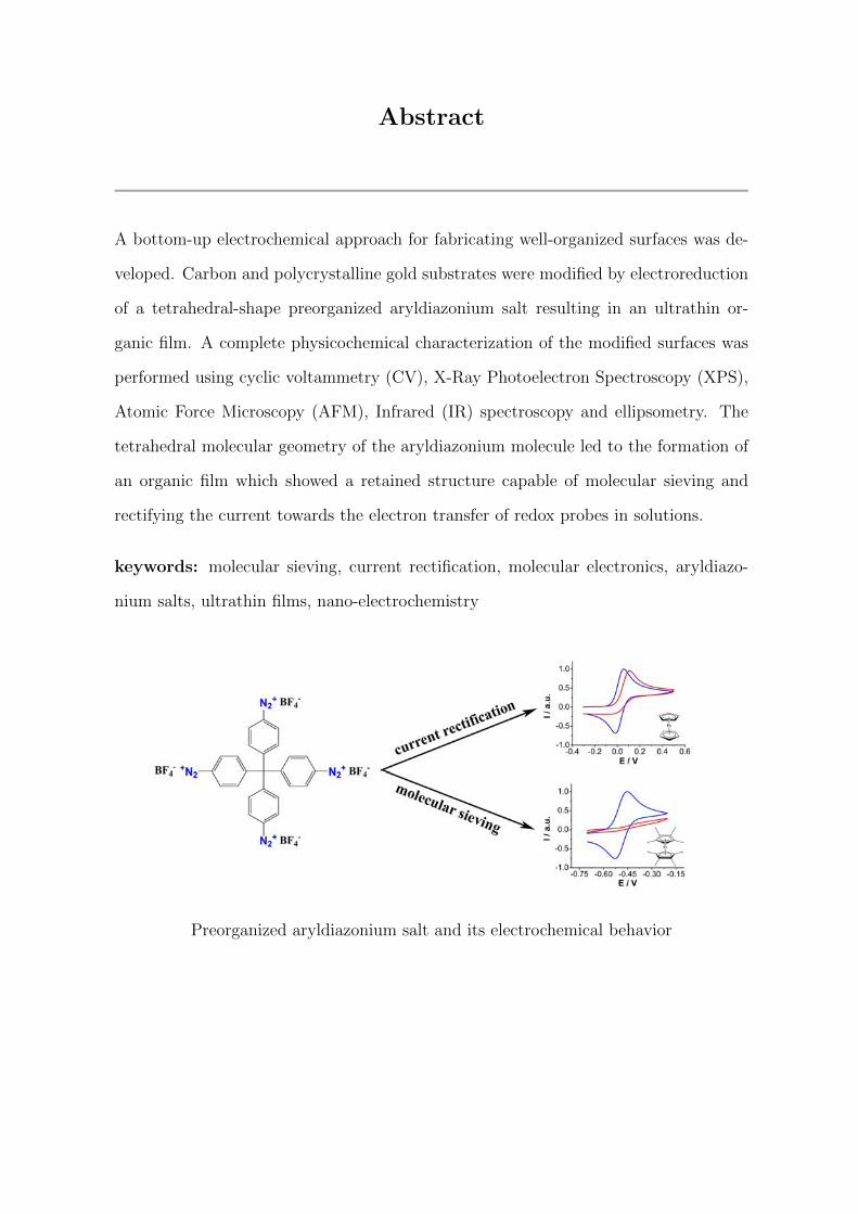
Abstract
A bottom-up electrochemical approach for fabricating well-organized surfaces was de-
veloped. Carbon and polycrystalline gold substrates were modified by electroreduction
of a tetrahedral-shape preorganized aryldiazonium salt resulting in an ultrathin or-
ganic film. A complete physicochemical characterization of the modified surfaces was
performed using cyclic voltammetry (CV), X-Ray Photoelectron Spectroscopy (XPS),
Atomic Force Microscopy (AFM), Infrared (IR) spectroscopy and ellipsometry. The
tetrahedral molecular geometry of the aryldiazonium molecule led to the formation of
an organic film which showed a retained structure capable of molecular sieving and
rectifying the current towards the electron transfer of redox probes in solutions.
keywords: molecular sieving, current rectification, molecular electronics, aryldiazo-
nium salts, ultrathin films, nano-electrochemistry
Preorganized aryldiazonium salt and its electrochemical behavior

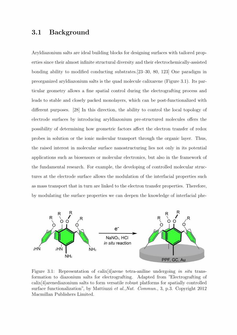
3.1 Background
Aryldiazonium salts are ideal building blocks for designing surfaces with tailored prop-
erties since their almost infinite structural diversity and their electrochemically-assisted
bonding ability to modified conducting substrates.[23–30, 80, 123] One paradigm in
preorganized aryldiazonium salts is the quad molecule calixarene (Figure 3.1). Its par-
ticular geometry allows a fine spatial control during the electrografting process and
leads to stable and closely packed monolayers, which can be post-functionalized with
different purposes. [28] In this direction, the ability to control the local topology of
electrode surfaces by introducing aryldiazonium pre-structured molecules offers the
possibility of determining how geometric factors affect the electron transfer of redox
probes in solution or the ionic molecular transport through the organic layer. Thus,
the raised interest in molecular surface nanostructuring lies not only in its potential
applications such as biosensors or molecular electronics, but also in the framework of
the fundamental research. For example, the developing of controlled molecular struc-
tures at the electrode surface allows the modulation of the interfacial properties such
as mass transport that in turn are linked to the electron transfer properties. Therefore,
by modulating the surface properties we can deepen the knowledge of interfacial phe-
Figure 3.1: Representation of calix[4]arene tetra-aniline undergoing in situ trans-formation to diazonium salts for electrografting. Adapted from ”Electrografting ofcalix[4]arenediazonium salts to form versatile robust platforms for spatially controlledsurface functionalization”, by Mattiuzzi et al.,Nat. Commun., 3, p.3. Copyright 2012Macmillan Publishers Limited.
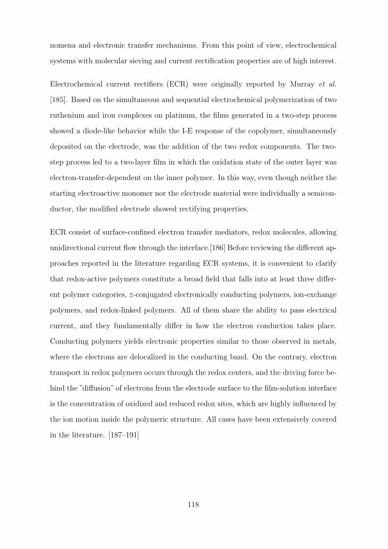
nomena and electronic transfer mechanisms. From this point of view, electrochemical
systems with molecular sieving and current rectification properties are of high interest.
Electrochemical current rectifiers (ECR) were originally reported by Murray et al.
[185]. Based on the simultaneous and sequential electrochemical polymerization of two
ruthenium and iron complexes on platinum, the films generated in a two-step process
showed a diode-like behavior while the I-E response of the copolymer, simultaneously
deposited on the electrode, was the addition of the two redox components. The two-
step process led to a two-layer film in which the oxidation state of the outer layer was
electron-transfer-dependent on the inner polymer. In this way, even though neither the
starting electroactive monomer nor the electrode material were individually a semicon-
ductor, the modified electrode showed rectifying properties.
ECR consist of surface-confined electron transfer mediators, redox molecules, allowing
unidirectional current flow through the interface.[186] Before reviewing the different ap-
proaches reported in the literature regarding ECR systems, it is convenient to clarify
that redox-active polymers constitute a broad field that falls into at least three differ-
ent polymer categories, π-conjugated electronically conducting polymers, ion-exchange
polymers, and redox-linked polymers. All of them share the ability to pass electrical
current, and they fundamentally differ in how the electron conduction takes place.
Conducting polymers yields electronic properties similar to those observed in metals,
where the electrons are delocalized in the conducting band. On the contrary, electron
transport in redox polymers occurs through the redox centers, and the driving force be-
hind the ”diffusion” of electrons from the electrode surface to the film-solution interface
is the concentration of oxidized and reduced redox sites, which are highly influenced by
the ion motion inside the polymeric structure. All cases have been extensively covered
in the literature. [187–191]
118
Since the earliest works on electroactive polymers, an extensive number of publications
reporting different strategies to realize ECR appeared. Examples include electroche-
mical rectification on redox-active self-assembled monolayers (SAMs) including ferro-
cene terminated-monolayers [192], gold nanoparticles [193], the more complex approach
of incorporating ferrocenyl dendrimers as redox mediators for current rectification to-
wards redox species in solution [186, 194], or electroactive biological molecules [195],
to name a few. For example, the latter consisted in the bio-functionalization of an
undecanethiol modified-gold electrode by physisorption of a hemoprotein, which made
possible the current rectification by inhibition of the direct electron transfer between
the redox probe (ferro/ferricyanide) in solution and the surface of the electrode. An
EC mechanism describes the charge transfer between the redox centers of the protein
and the redox probe in solution that involves an outer-sphere electron transfer (3.1)
and a bimolecular chemical reaction (3.2).
Fe3+(hemin) + e− Fe2+(heme) E (3.1)
Fe2+(heme) + Fe3+(ferri)→ Fe2+(ferro) + Fe3+(hemin) C (3.2)
This is one of the common schemes for ECR design. Organic layers deposited on
conducting substrates to prevent the direct access of the redox probe in solution to the
electrode surface, and an electrode-confined electroactive molecule that mediates the
electron transfer between the redox probe and the electrode. The direction in which the
current flows is given by the relative potentials of the mediator and the redox probe,
and the electron transfer between the surface of the electrode and the mediator occurs
by electron tunneling through the organic layer.
Despite the versatility and robustness of the aryldiazonium modifications, only very few
examples of ECR fabricated by electro-reduction of aryldiazonium salts were demon-
strated. Indeed, the reduction of classical aryldiazonium ions, as the most commonly
used p-nitrophenyl diazonium ion, leads to the formation of multilayered dendritic in-
119
sulating films which limits the mechanism of electron transfer by tunneling [33, 51, 102].
However, the reduction of specifically designed aryldiazonium salts, such as biphenyl
or nitrobiphenyl, was first reported by McCreery et al. [196] and further demonstrated
by Lacroix et al. [197, 198] incorporating, in this case, redox units of thiophene to yield
organic films having ECR properties.
Ultrathin films (around 5 nm thickness) of two different thiophene derivatives, 1-(2-
bisthienyl)benzene (BTB) and 1-(2-thienyl)benzene (TB), were achieved by grafting
of their corresponding aryldiazonium salts.[197] Studies carried out by CV showed
an electrochemical response according to a diode-like behavior towards ferrocene and
decamethylferrocene in solution (ferrocene is shown in Figure 3.2a). No electrochemical
signal was observed in the range of potential where ferrocene is classically reversibly
oxidized on a bare electrode. However, at the potential where charges are injected into
the organic films, or in other words, the potential at which the films are oxidized, the
irreversible oxidation of ferrocene was observed.
Figure 3.2: I-E plots of 0.01 mol L−1 Fc (a) and 0.01 mol L−1 1,4-amino-diphenylamine(b) in acetonitrile + 0.1 mol L−1 LiClO4 on a (1) bare glassy carbon electrode, anda (2) 1-(2-bisthienyl)benzene (BTB), and (3) 1-(2-thienyl)benzene (TB) glassy carbonmodified electrode. Scan rate 0.1 V s−1. Adapted from ”Electrochemical switches basedon ultrathin organic films: from diode-like behavior to charge transfer transparency”by Lacroix et al., J. Phys. Chem. C, 112, p.18640. Copyright 2008 American ChemicalSociety; and from ”Tunable electrochemical switches based on ultrathin organic films”,by Lacroix et al., J. Am. Chem. Soc., 129, p.1890. Copyright 2007 American ChemicalSociety.
120
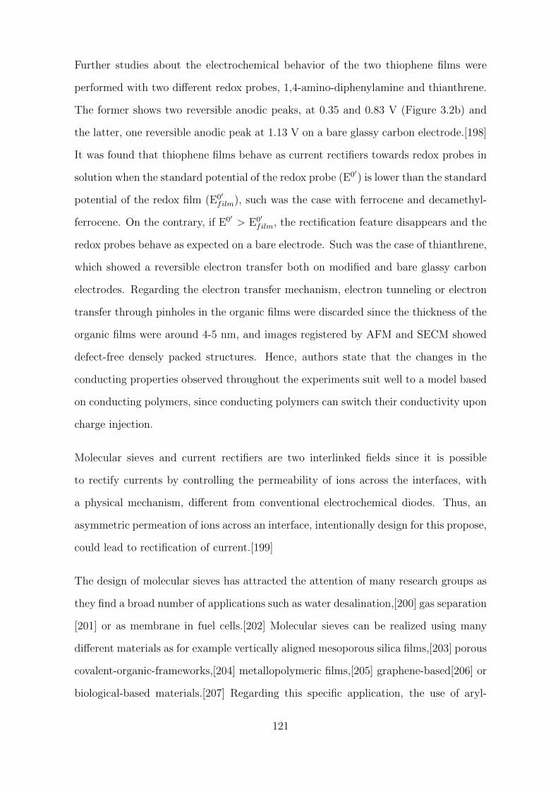
Further studies about the electrochemical behavior of the two thiophene films were
performed with two different redox probes, 1,4-amino-diphenylamine and thianthrene.
The former shows two reversible anodic peaks, at 0.35 and 0.83 V (Figure 3.2b) and
the latter, one reversible anodic peak at 1.13 V on a bare glassy carbon electrode.[198]
It was found that thiophene films behave as current rectifiers towards redox probes in
solution when the standard potential of the redox probe (E0′) is lower than the standard
potential of the redox film (E0′
film), such was the case with ferrocene and decamethyl-
ferrocene. On the contrary, if E0′ > E0′
film, the rectification feature disappears and the
redox probes behave as expected on a bare electrode. Such was the case of thianthrene,
which showed a reversible electron transfer both on modified and bare glassy carbon
electrodes. Regarding the electron transfer mechanism, electron tunneling or electron
transfer through pinholes in the organic films were discarded since the thickness of the
organic films were around 4-5 nm, and images registered by AFM and SECM showed
defect-free densely packed structures. Hence, authors state that the changes in the
conducting properties observed throughout the experiments suit well to a model based
on conducting polymers, since conducting polymers can switch their conductivity upon
charge injection.
Molecular sieves and current rectifiers are two interlinked fields since it is possible
to rectify currents by controlling the permeability of ions across the interfaces, with
a physical mechanism, different from conventional electrochemical diodes. Thus, an
asymmetric permeation of ions across an interface, intentionally design for this propose,
could lead to rectification of current.[199]
The design of molecular sieves has attracted the attention of many research groups as
they find a broad number of applications such as water desalination,[200] gas separation
[201] or as membrane in fuel cells.[202] Molecular sieves can be realized using many
different materials as for example vertically aligned mesoporous silica films,[203] porous
covalent-organic-frameworks,[204] metallopolymeric films,[205] graphene-based[206] or
biological-based materials.[207] Regarding this specific application, the use of aryl-
121
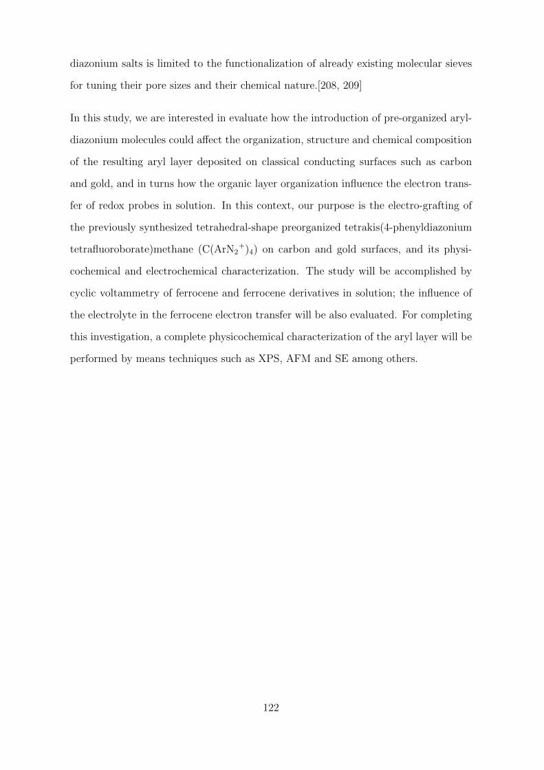
diazonium salts is limited to the functionalization of already existing molecular sieves
for tuning their pore sizes and their chemical nature.[208, 209]
In this study, we are interested in evaluate how the introduction of pre-organized aryl-
diazonium molecules could affect the organization, structure and chemical composition
of the resulting aryl layer deposited on classical conducting surfaces such as carbon
and gold, and in turns how the organic layer organization influence the electron trans-
fer of redox probes in solution. In this context, our purpose is the electro-grafting of
the previously synthesized tetrahedral-shape preorganized tetrakis(4-phenyldiazonium
tetrafluoroborate)methane (C(ArN2+)4) on carbon and gold surfaces, and its physi-
cochemical and electrochemical characterization. The study will be accomplished by
cyclic voltammetry of ferrocene and ferrocene derivatives in solution; the influence of
the electrolyte in the ferrocene electron transfer will be also evaluated. For completing
this investigation, a complete physicochemical characterization of the aryl layer will be
performed by means techniques such as XPS, AFM and SE among others.
122
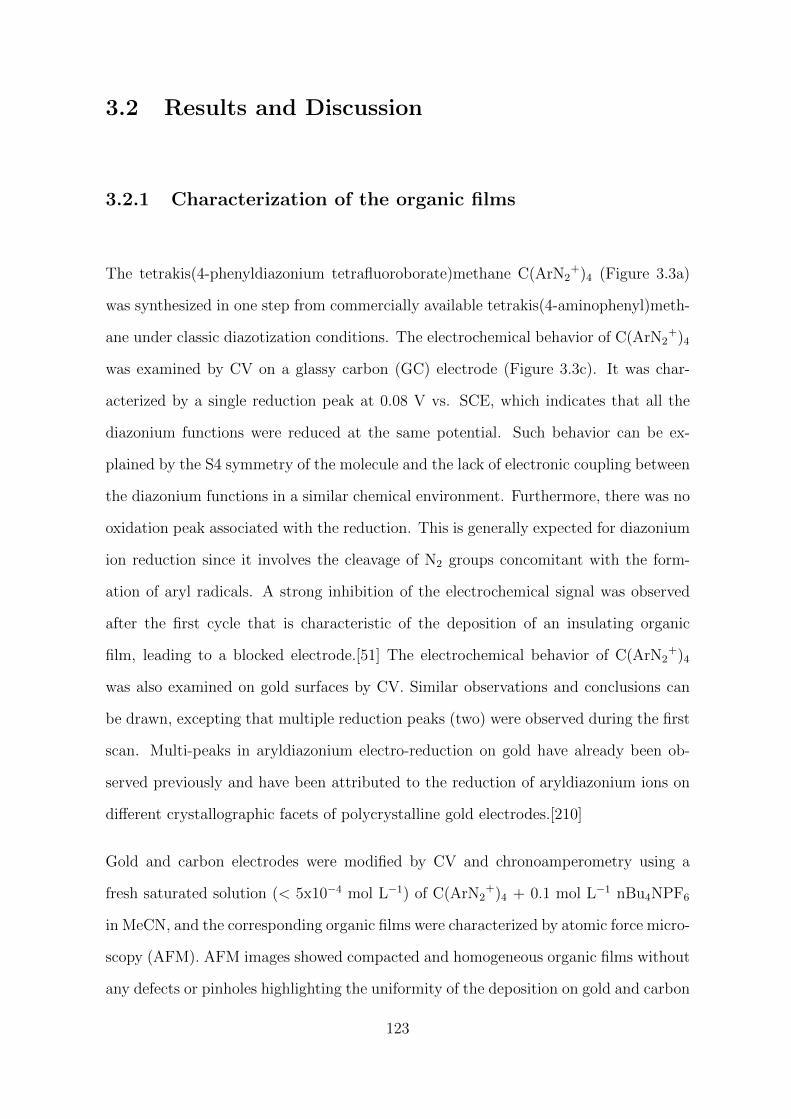
3.2 Results and Discussion
3.2.1 Characterization of the organic films
The tetrakis(4-phenyldiazonium tetrafluoroborate)methane C(ArN2+)4 (Figure 3.3a)
was synthesized in one step from commercially available tetrakis(4-aminophenyl)meth-
ane under classic diazotization conditions. The electrochemical behavior of C(ArN2+)4
was examined by CV on a glassy carbon (GC) electrode (Figure 3.3c). It was char-
acterized by a single reduction peak at 0.08 V vs. SCE, which indicates that all the
diazonium functions were reduced at the same potential. Such behavior can be ex-
plained by the S4 symmetry of the molecule and the lack of electronic coupling between
the diazonium functions in a similar chemical environment. Furthermore, there was no
oxidation peak associated with the reduction. This is generally expected for diazonium
ion reduction since it involves the cleavage of N2 groups concomitant with the form-
ation of aryl radicals. A strong inhibition of the electrochemical signal was observed
after the first cycle that is characteristic of the deposition of an insulating organic
film, leading to a blocked electrode.[51] The electrochemical behavior of C(ArN2+)4
was also examined on gold surfaces by CV. Similar observations and conclusions can
be drawn, excepting that multiple reduction peaks (two) were observed during the first
scan. Multi-peaks in aryldiazonium electro-reduction on gold have already been ob-
served previously and have been attributed to the reduction of aryldiazonium ions on
different crystallographic facets of polycrystalline gold electrodes.[210]
Gold and carbon electrodes were modified by CV and chronoamperometry using a
fresh saturated solution (< 5x10⁻⁴ mol L−1) of C(ArN2+)4 + 0.1 mol L−1 nBu4NPF6
in MeCN, and the corresponding organic films were characterized by atomic force micro-
scopy (AFM). AFM images showed compacted and homogeneous organic films without
any defects or pinholes highlighting the uniformity of the deposition on gold and carbon
123
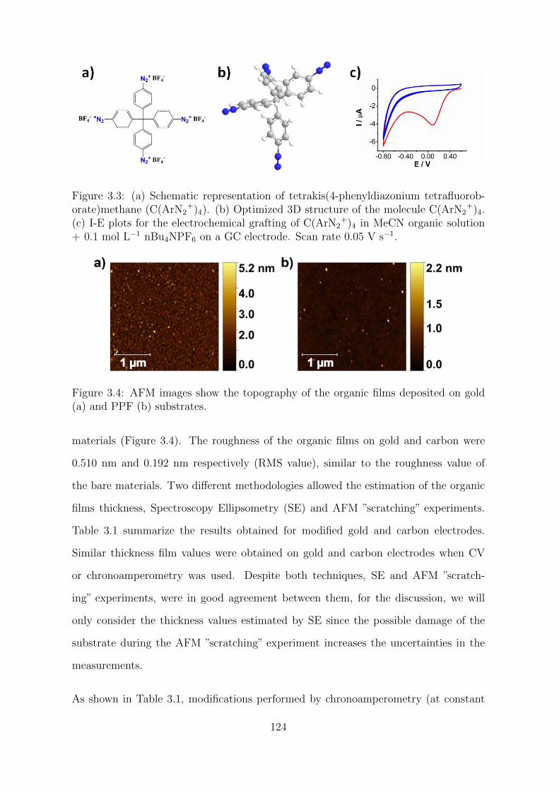
Figure 3.3: (a) Schematic representation of tetrakis(4-phenyldiazonium tetrafluorob-orate)methane (C(ArN2
+)4). (b) Optimized 3D structure of the molecule C(ArN2+)4.
(c) I-E plots for the electrochemical grafting of C(ArN2+)4 in MeCN organic solution
+ 0.1 mol L−1 nBu4NPF6 on a GC electrode. Scan rate 0.05 V s−1.
Figure 3.4: AFM images show the topography of the organic films deposited on gold(a) and PPF (b) substrates.
materials (Figure 3.4). The roughness of the organic films on gold and carbon were
0.510 nm and 0.192 nm respectively (RMS value), similar to the roughness value of
the bare materials. Two different methodologies allowed the estimation of the organic
films thickness, Spectroscopy Ellipsometry (SE) and AFM ”scratching” experiments.
Table 3.1 summarize the results obtained for modified gold and carbon electrodes.
Similar thickness film values were obtained on gold and carbon electrodes when CV
or chronoamperometry was used. Despite both techniques, SE and AFM ”scratch-
ing” experiments, were in good agreement between them, for the discussion, we will
only consider the thickness values estimated by SE since the possible damage of the
substrate during the AFM ”scratching” experiment increases the uncertainties in the
measurements.
As shown in Table 3.1, modifications performed by chronoamperometry (at constant
124
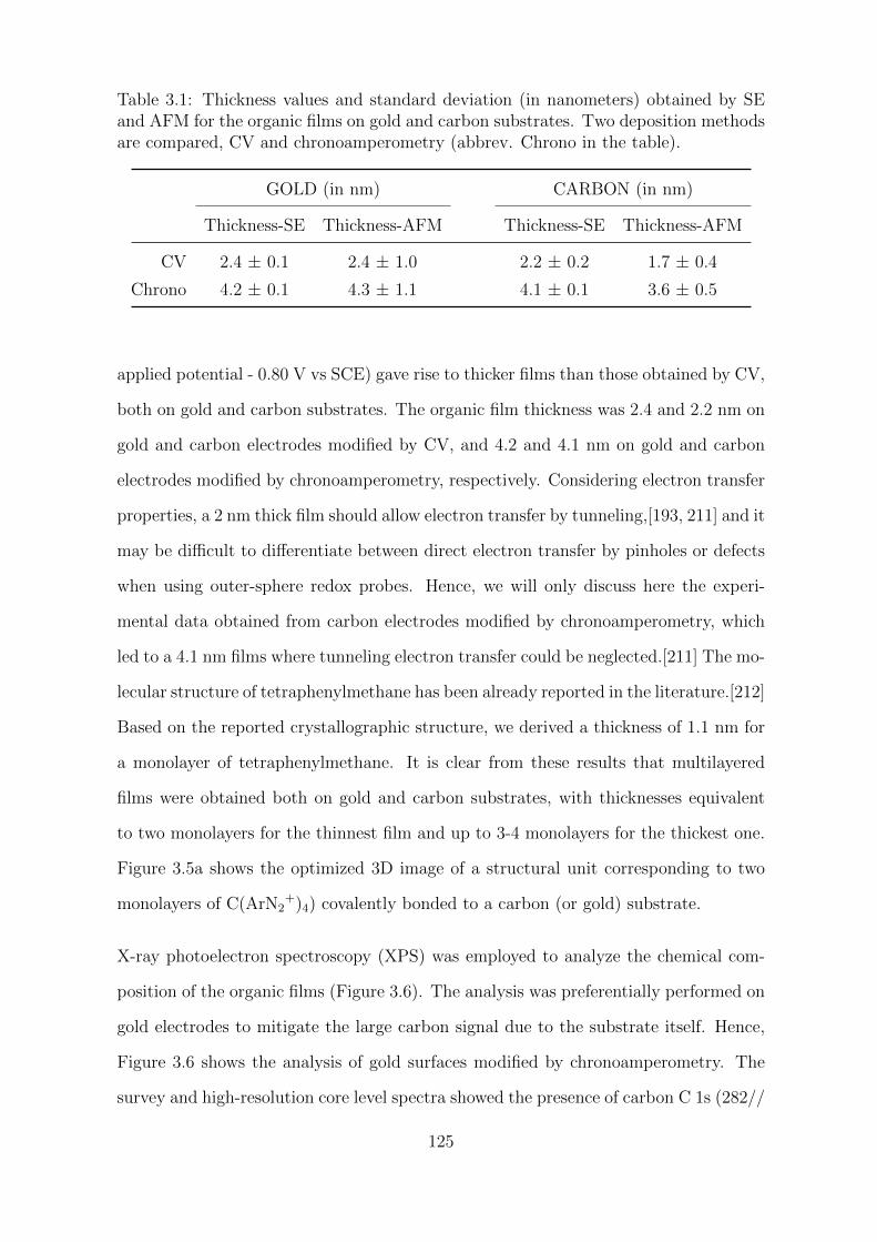
Table 3.1: Thickness values and standard deviation (in nanometers) obtained by SEand AFM for the organic films on gold and carbon substrates. Two deposition methodsare compared, CV and chronoamperometry (abbrev. Chrono in the table).
GOLD (in nm) CARBON (in nm)
Thickness-SE Thickness-AFM Thickness-SE Thickness-AFM
CV 2.4 ± 0.1 2.4 ± 1.0 2.2 ± 0.2 1.7 ± 0.4
Chrono 4.2 ± 0.1 4.3 ± 1.1 4.1 ± 0.1 3.6 ± 0.5
applied potential - 0.80 V vs SCE) gave rise to thicker films than those obtained by CV,
both on gold and carbon substrates. The organic film thickness was 2.4 and 2.2 nm on
gold and carbon electrodes modified by CV, and 4.2 and 4.1 nm on gold and carbon
electrodes modified by chronoamperometry, respectively. Considering electron transfer
properties, a 2 nm thick film should allow electron transfer by tunneling,[193, 211] and it
may be difficult to differentiate between direct electron transfer by pinholes or defects
when using outer-sphere redox probes. Hence, we will only discuss here the experi-
mental data obtained from carbon electrodes modified by chronoamperometry, which
led to a 4.1 nm films where tunneling electron transfer could be neglected.[211] The mo-
lecular structure of tetraphenylmethane has been already reported in the literature.[212]
Based on the reported crystallographic structure, we derived a thickness of 1.1 nm for
a monolayer of tetraphenylmethane. It is clear from these results that multilayered
films were obtained both on gold and carbon substrates, with thicknesses equivalent
to two monolayers for the thinnest film and up to 3-4 monolayers for the thickest one.
Figure 3.5a shows the optimized 3D image of a structural unit corresponding to two
monolayers of C(ArN2+)4) covalently bonded to a carbon (or gold) substrate.
X-ray photoelectron spectroscopy (XPS) was employed to analyze the chemical com-
position of the organic films (Figure 3.6). The analysis was preferentially performed on
gold electrodes to mitigate the large carbon signal due to the substrate itself. Hence,
Figure 3.6 shows the analysis of gold surfaces modified by chronoamperometry. The
survey and high-resolution core level spectra showed the presence of carbon C 1s (282//
125
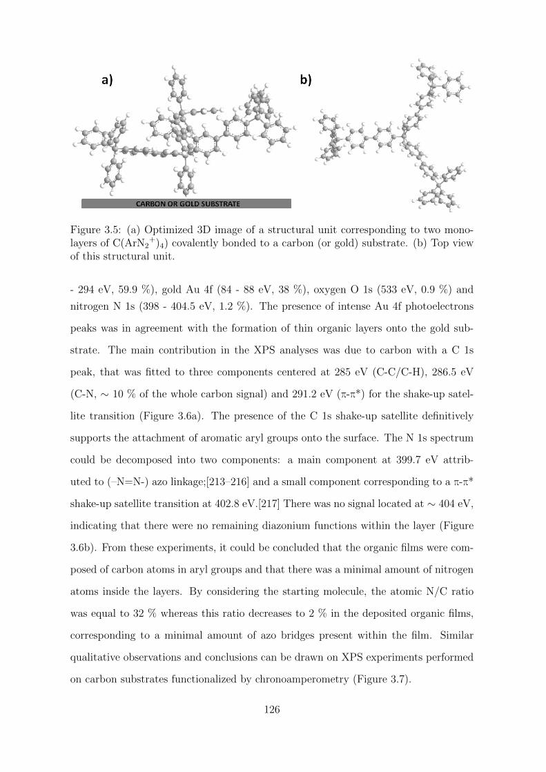
Figure 3.5: (a) Optimized 3D image of a structural unit corresponding to two mono-layers of C(ArN2
+)4) covalently bonded to a carbon (or gold) substrate. (b) Top viewof this structural unit.
- 294 eV, 59.9 %), gold Au 4f (84 - 88 eV, 38 %), oxygen O 1s (533 eV, 0.9 %) and
nitrogen N 1s (398 - 404.5 eV, 1.2 %). The presence of intense Au 4f photoelectrons
peaks was in agreement with the formation of thin organic layers onto the gold sub-
strate. The main contribution in the XPS analyses was due to carbon with a C 1s
peak, that was fitted to three components centered at 285 eV (C-C/C-H), 286.5 eV
(C-N, ∼ 10 % of the whole carbon signal) and 291.2 eV (π-π*) for the shake-up satel-
lite transition (Figure 3.6a). The presence of the C 1s shake-up satellite definitively
supports the attachment of aromatic aryl groups onto the surface. The N 1s spectrum
could be decomposed into two components: a main component at 399.7 eV attrib-
uted to (–N=N-) azo linkage;[213–216] and a small component corresponding to a π-π*
shake-up satellite transition at 402.8 eV.[217] There was no signal located at ∼ 404 eV,
indicating that there were no remaining diazonium functions within the layer (Figure
3.6b). From these experiments, it could be concluded that the organic films were com-
posed of carbon atoms in aryl groups and that there was a minimal amount of nitrogen
atoms inside the layers. By considering the starting molecule, the atomic N/C ratio
was equal to 32 % whereas this ratio decreases to 2 % in the deposited organic films,
corresponding to a minimal amount of azo bridges present within the film. Similar
qualitative observations and conclusions can be drawn on XPS experiments performed
on carbon substrates functionalized by chronoamperometry (Figure 3.7).
126
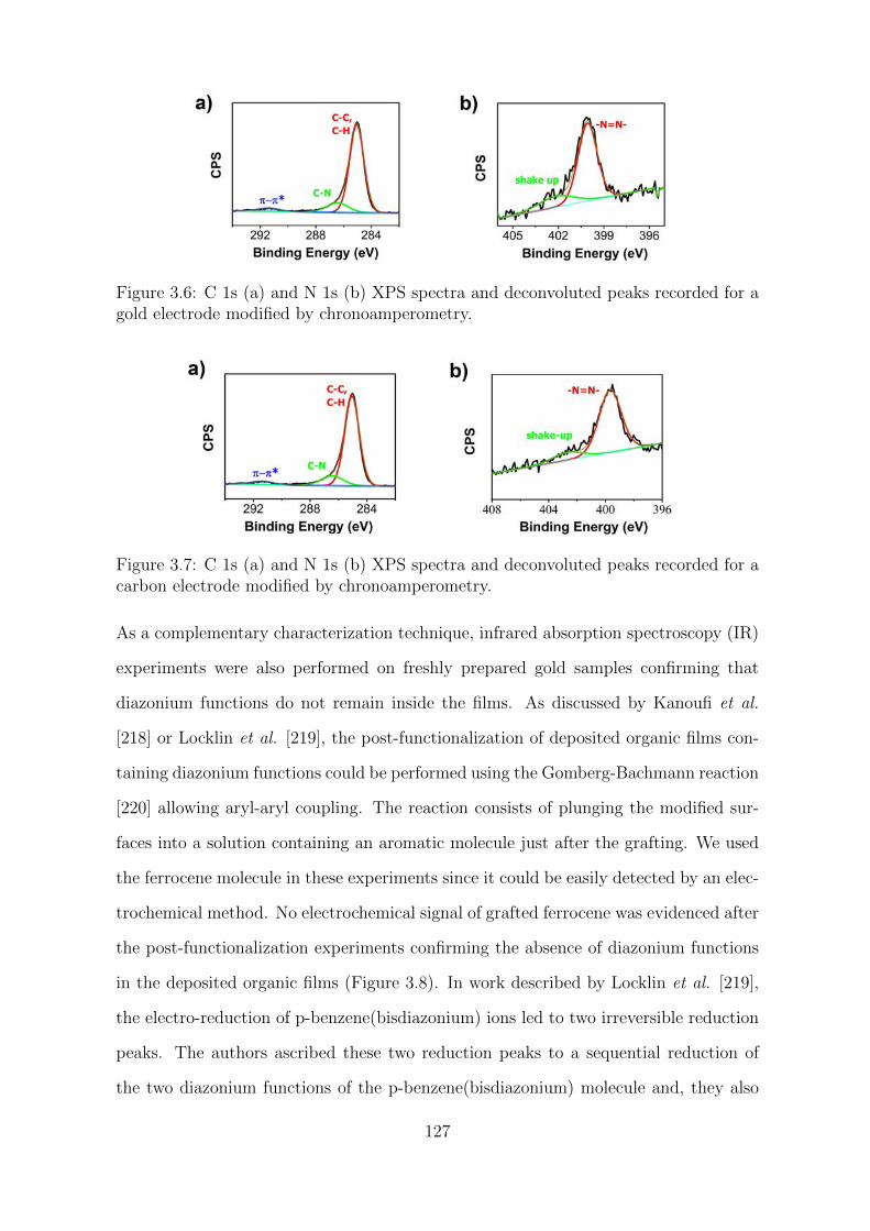
Figure 3.6: C 1s (a) and N 1s (b) XPS spectra and deconvoluted peaks recorded for agold electrode modified by chronoamperometry.
Figure 3.7: C 1s (a) and N 1s (b) XPS spectra and deconvoluted peaks recorded for acarbon electrode modified by chronoamperometry.
As a complementary characterization technique, infrared absorption spectroscopy (IR)
experiments were also performed on freshly prepared gold samples confirming that
diazonium functions do not remain inside the films. As discussed by Kanoufi et al.
[218] or Locklin et al. [219], the post-functionalization of deposited organic films con-
taining diazonium functions could be performed using the Gomberg-Bachmann reaction
[220] allowing aryl-aryl coupling. The reaction consists of plunging the modified sur-
faces into a solution containing an aromatic molecule just after the grafting. We used
the ferrocene molecule in these experiments since it could be easily detected by an elec-
trochemical method. No electrochemical signal of grafted ferrocene was evidenced after
the post-functionalization experiments confirming the absence of diazonium functions
in the deposited organic films (Figure 3.8). In work described by Locklin et al. [219],
the electro-reduction of p-benzene(bisdiazonium) ions led to two irreversible reduction
peaks. The authors ascribed these two reduction peaks to a sequential reduction of
the two diazonium functions of the p-benzene(bisdiazonium) molecule and, they also
127
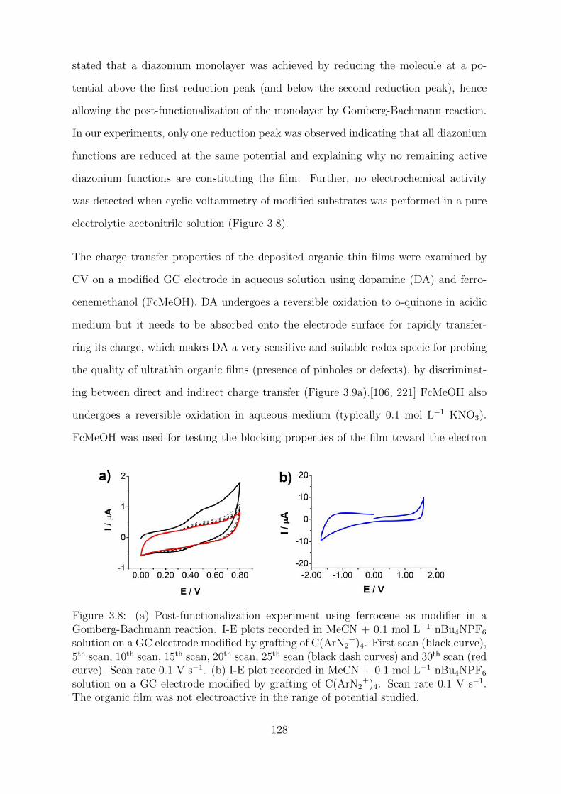
stated that a diazonium monolayer was achieved by reducing the molecule at a po-
tential above the first reduction peak (and below the second reduction peak), hence
allowing the post-functionalization of the monolayer by Gomberg-Bachmann reaction.
In our experiments, only one reduction peak was observed indicating that all diazonium
functions are reduced at the same potential and explaining why no remaining active
diazonium functions are constituting the film. Further, no electrochemical activity
was detected when cyclic voltammetry of modified substrates was performed in a pure
electrolytic acetonitrile solution (Figure 3.8).
The charge transfer properties of the deposited organic thin films were examined by
CV on a modified GC electrode in aqueous solution using dopamine (DA) and ferro-
cenemethanol (FcMeOH). DA undergoes a reversible oxidation to o-quinone in acidic
medium but it needs to be absorbed onto the electrode surface for rapidly transfer-
ring its charge, which makes DA a very sensitive and suitable redox specie for probing
the quality of ultrathin organic films (presence of pinholes or defects), by discriminat-
ing between direct and indirect charge transfer (Figure 3.9a).[106, 221] FcMeOH also
undergoes a reversible oxidation in aqueous medium (typically 0.1 mol L−1 KNO3).
FcMeOH was used for testing the blocking properties of the film toward the electron
Figure 3.8: (a) Post-functionalization experiment using ferrocene as modifier in aGomberg-Bachmann reaction. I-E plots recorded in MeCN + 0.1 mol L−1 nBu4NPF6
solution on a GC electrode modified by grafting of C(ArN2+)4. First scan (black curve),
5th scan, 10th scan, 15th scan, 20th scan, 25th scan (black dash curves) and 30th scan (redcurve). Scan rate 0.1 V s−1. (b) I-E plot recorded in MeCN + 0.1 mol L−1 nBu4NPF6
solution on a GC electrode modified by grafting of C(ArN2+)4. Scan rate 0.1 V s−1.
The organic film was not electroactive in the range of potential studied.
128
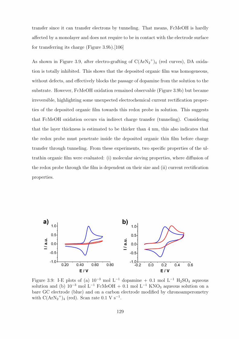
transfer since it can transfer electrons by tunneling. That means, FcMeOH is hardly
affected by a monolayer and does not require to be in contact with the electrode surface
for transferring its charge (Figure 3.9b).[106]
As shown in Figure 3.9, after electro-grafting of C(ArN2+)4 (red curves), DA oxida-
tion is totally inhibited. This shows that the deposited organic film was homogeneous,
without defects, and effectively blocks the passage of dopamine from the solution to the
substrate. However, FcMeOH oxidation remained observable (Figure 3.9b) but became
irreversible, highlighting some unexpected electrochemical current rectification proper-
ties of the deposited organic film towards this redox probe in solution. This suggests
that FcMeOH oxidation occurs via indirect charge transfer (tunneling). Considering
that the layer thickness is estimated to be thicker than 4 nm, this also indicates that
the redox probe must penetrate inside the deposited organic thin film before charge
transfer through tunneling. From these experiments, two specific properties of the ul-
trathin organic film were evaluated: (i) molecular sieving properties, where diffusion of
the redox probe through the film is dependent on their size and (ii) current rectification
properties.
Figure 3.9: I-E plots of (a) 10−3 mol L−1 dopamine + 0.1 mol L−1 H2SO4 aqueoussolution and (b) 10−3 mol L−1 FcMeOH + 0.1 mol L−1 KNO3 aqueous solution on abare GC electrode (blue) and on a carbon electrode modified by chronoamperometrywith C(ArN2
+)4 (red). Scan rate 0.1 V s−1.
129
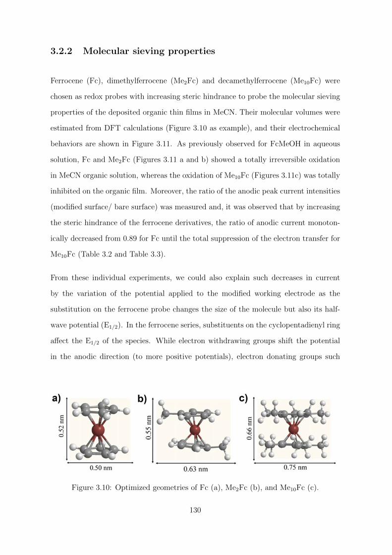
3.2.2 Molecular sieving properties
Ferrocene (Fc), dimethylferrocene (Me2Fc) and decamethylferrocene (Me10Fc) were
chosen as redox probes with increasing steric hindrance to probe the molecular sieving
properties of the deposited organic thin films in MeCN. Their molecular volumes were
estimated from DFT calculations (Figure 3.10 as example), and their electrochemical
behaviors are shown in Figure 3.11. As previously observed for FcMeOH in aqueous
solution, Fc and Me2Fc (Figures 3.11 a and b) showed a totally irreversible oxidation
in MeCN organic solution, whereas the oxidation of Me10Fc (Figures 3.11c) was totally
inhibited on the organic film. Moreover, the ratio of the anodic peak current intensities
(modified surface/ bare surface) was measured and, it was observed that by increasing
the steric hindrance of the ferrocene derivatives, the ratio of anodic current monoton-
ically decreased from 0.89 for Fc until the total suppression of the electron transfer for
Me10Fc (Table 3.2 and Table 3.3).
From these individual experiments, we could also explain such decreases in current
by the variation of the potential applied to the modified working electrode as the
substitution on the ferrocene probe changes the size of the molecule but also its half-
wave potential (E1/2). In the ferrocene series, substituents on the cyclopentadienyl ring
affect the E1/2 of the species. While electron withdrawing groups shift the potential
in the anodic direction (to more positive potentials), electron donating groups such
Figure 3.10: Optimized geometries of Fc (a), Me2Fc (b), and Me10Fc (c).
130
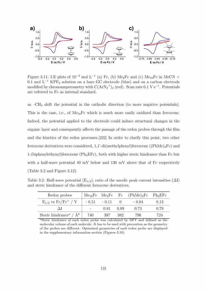
Figure 3.11: I-E plots of 10−3 mol L−1 (a) Fc, (b) Me2Fc and (c) Me10Fc in MeCN +0.1 mol L−1 KPF6 solution on a bare GC electrode (blue) and on a carbon electrodemodified by chronoamperometry with C(ArN2
+)4 (red). Scan rate 0.1 V s−1. Potentialsare referred to Fc as internal standard.
as –CH3 shift the potential in the cathodic direction (to more negative potentials).
This is the case, i.e., of Me10Fc which is much more easily oxidized than ferrocene.
Indeed, the potential applied to the electrode could induce structural changes in the
organic layer and consequently affects the passage of the redox probes through the film
and the kinetics of the redox processes.[222] In order to clarify this point, two other
ferrocene derivatives were considered, 1,1’-di(methylphenyl)ferrocene ((PhMe)2Fc) and
1-(biphenylethynyl)ferrocene (Ph2EFc), both with higher steric hindrance than Fc but
with a half-wave potential 40 mV below and 130 mV above that of Fc respectively
(Table 3.2 and Figure 3.12).
Table 3.2: Half-wave potential (E1/2), ratio of the anodic peak current intensities (∆I)and steric hindrance of the different ferrocene derivatives.
Redox probes Me10Fc Me2Fc Fc (PhMe)2Fc Ph2EFc
E1/2 vs Fc/Fc+ / V - 0.51 - 0.11 0 - 0.04 0.13
∆I - 0.81 0.89 0.73 0.79
Steric hindrancea / A3 740 397 382 796 724aSteric hindrance of each redox probe was calculated by DFT and defined as themolecular volume of each molecule. It has to be used with precaution as the geometryof the probes are different. Optimized geometries of each redox probe are displayedin the supplementary information section (Figures 3.10).
131
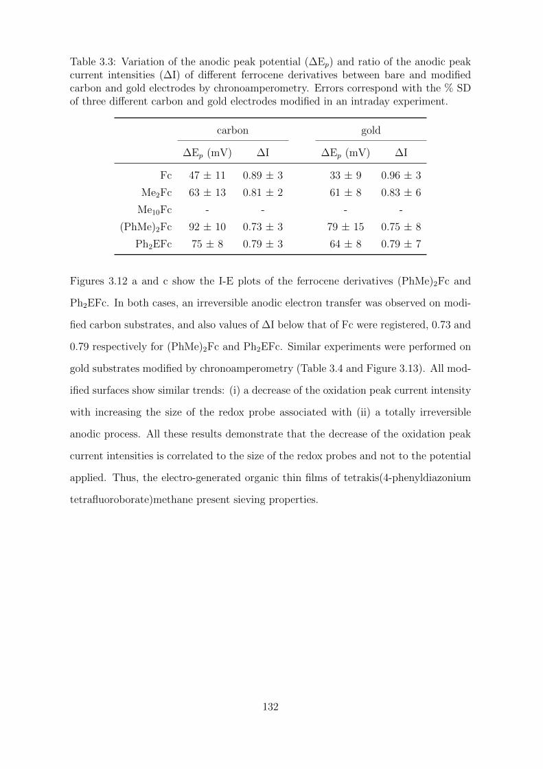
Table 3.3: Variation of the anodic peak potential (∆Ep) and ratio of the anodic peakcurrent intensities (∆I) of different ferrocene derivatives between bare and modifiedcarbon and gold electrodes by chronoamperometry. Errors correspond with the % SDof three different carbon and gold electrodes modified in an intraday experiment.
carbon gold
∆Ep (mV) ∆I ∆Ep (mV) ∆I
Fc 47 ± 11 0.89 ± 3 33 ± 9 0.96 ± 3
Me2Fc 63 ± 13 0.81 ± 2 61 ± 8 0.83 ± 6
Me10Fc - - - -
(PhMe)2Fc 92 ± 10 0.73 ± 3 79 ± 15 0.75 ± 8
Ph2EFc 75 ± 8 0.79 ± 3 64 ± 8 0.79 ± 7
Figures 3.12 a and c show the I-E plots of the ferrocene derivatives (PhMe)2Fc and
Ph2EFc. In both cases, an irreversible anodic electron transfer was observed on modi-
fied carbon substrates, and also values of ∆I below that of Fc were registered, 0.73 and
0.79 respectively for (PhMe)2Fc and Ph2EFc. Similar experiments were performed on
gold substrates modified by chronoamperometry (Table 3.4 and Figure 3.13). All mod-
ified surfaces show similar trends: (i) a decrease of the oxidation peak current intensity
with increasing the size of the redox probe associated with (ii) a totally irreversible
anodic process. All these results demonstrate that the decrease of the oxidation peak
current intensities is correlated to the size of the redox probes and not to the potential
applied. Thus, the electro-generated organic thin films of tetrakis(4-phenyldiazonium
tetrafluoroborate)methane present sieving properties.
132
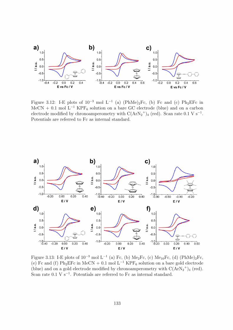
Figure 3.12: I-E plots of 10−3 mol L−1 (a) (PhMe)2Fc, (b) Fc and (c) Ph2EFc inMeCN + 0.1 mol L−1 KPF6 solution on a bare GC electrode (blue) and on a carbonelectrode modified by chronoamperometry with C(ArN2
+)4 (red). Scan rate 0.1 V s−1.Potentials are referred to Fc as internal standard.
Figure 3.13: I-E plots of 10−3 mol L−1 (a) Fc, (b) Me2Fc, (c) Me10Fc, (d) (PhMe)2Fc,(e) Fc and (f) Ph2EFc in MeCN + 0.1 mol L−1 KPF6 solution on a bare gold electrode(blue) and on a gold electrode modified by chronoamperometry with C(ArN2
+)4 (red).Scan rate 0.1 V s−1. Potentials are referred to Fc as internal standard.
133
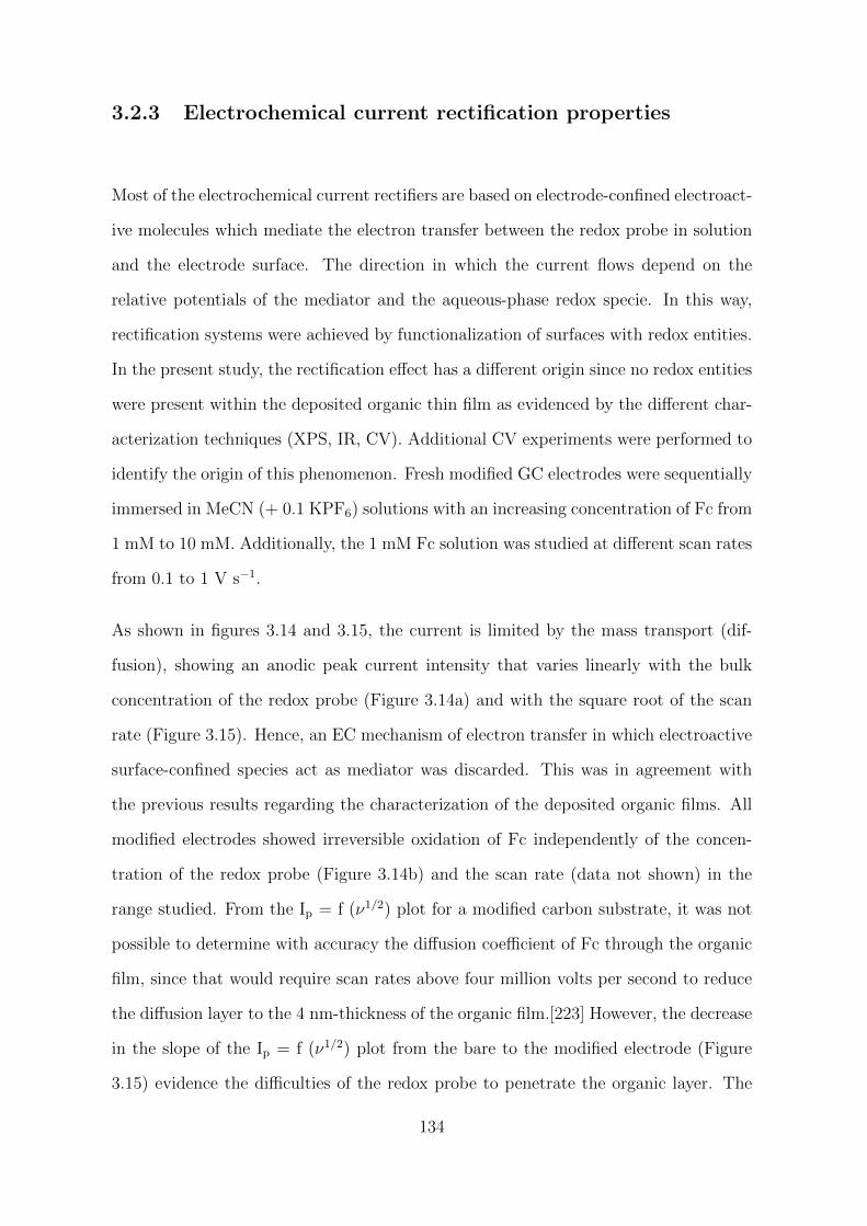
3.2.3 Electrochemical current rectification properties
Most of the electrochemical current rectifiers are based on electrode-confined electroact-
ive molecules which mediate the electron transfer between the redox probe in solution
and the electrode surface. The direction in which the current flows depend on the
relative potentials of the mediator and the aqueous-phase redox specie. In this way,
rectification systems were achieved by functionalization of surfaces with redox entities.
In the present study, the rectification effect has a different origin since no redox entities
were present within the deposited organic thin film as evidenced by the different char-
acterization techniques (XPS, IR, CV). Additional CV experiments were performed to
identify the origin of this phenomenon. Fresh modified GC electrodes were sequentially
immersed in MeCN (+ 0.1 KPF6) solutions with an increasing concentration of Fc from
1 mM to 10 mM. Additionally, the 1 mM Fc solution was studied at different scan rates
from 0.1 to 1 V s−1.
As shown in figures 3.14 and 3.15, the current is limited by the mass transport (dif-
fusion), showing an anodic peak current intensity that varies linearly with the bulk
concentration of the redox probe (Figure 3.14a) and with the square root of the scan
rate (Figure 3.15). Hence, an EC mechanism of electron transfer in which electroactive
surface-confined species act as mediator was discarded. This was in agreement with
the previous results regarding the characterization of the deposited organic films. All
modified electrodes showed irreversible oxidation of Fc independently of the concen-
tration of the redox probe (Figure 3.14b) and the scan rate (data not shown) in the
range studied. From the Ip = f (ν1/2) plot for a modified carbon substrate, it was not
possible to determine with accuracy the diffusion coefficient of Fc through the organic
film, since that would require scan rates above four million volts per second to reduce
the diffusion layer to the 4 nm-thickness of the organic film.[223] However, the decrease
in the slope of the Ip = f (ν1/2) plot from the bare to the modified electrode (Figure
3.15) evidence the difficulties of the redox probe to penetrate the organic layer. The
134

redox probe needs to diffuse inside the pores of the organic layer before the charge
transfer. A change of the charge of the redox probe is accompanied by variations of
the electrolyte composition present inside the film as reported for charge/discharge
processes of conducting polymers where it is possible to control the electrochemical
response by changing the size of the anion in polyaniline.[224] By analogy with our
case, this should create movements of cations and anions entering or leaving the film
by the same pore channels than those used by the probe. It is thus interesting to
evaluate how the size of the supporting salts constituting the electrolyte could affect
the electrochemical response of the probe. In that purpose, a series of supporting salts
presenting different size of cation or anion was considered (Figure 3.16).
Figure 3.14: (a) Variation of the anodic peak current intensity with the concentrationof Fc from 10−3 to 10−2 mol L−1 on a GC electrode modified by chronoamperometrywith C(ArN2
+)4. Linear fit in red (R-square = 0.9993). (b) Corresponding I-E plotsof Fc at different concentrations in MeCN + 0.1 mol L−1 KPF6. Scan rate 0.1 V s−1.Potential refers to Fc as internal standard.
135
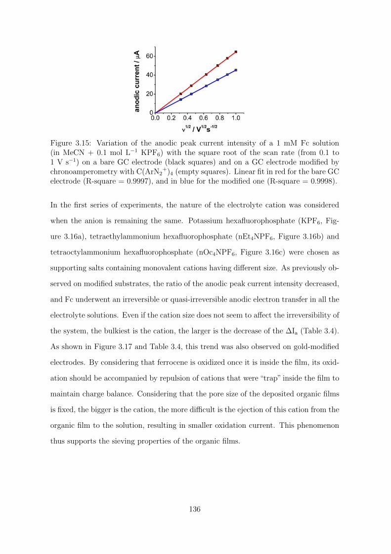
Figure 3.15: Variation of the anodic peak current intensity of a 1 mM Fc solution(in MeCN + 0.1 mol L−1 KPF6) with the square root of the scan rate (from 0.1 to1 V s−1) on a bare GC electrode (black squares) and on a GC electrode modified bychronoamperometry with C(ArN2
+)4 (empty squares). Linear fit in red for the bare GCelectrode (R-square = 0.9997), and in blue for the modified one (R-square = 0.9998).
In the first series of experiments, the nature of the electrolyte cation was considered
when the anion is remaining the same. Potassium hexafluorophosphate (KPF6, Fig-
ure 3.16a), tetraethylammonium hexafluorophosphate (nEt4NPF6, Figure 3.16b) and
tetraoctylammonium hexafluorophosphate (nOc4NPF6, Figure 3.16c) were chosen as
supporting salts containing monovalent cations having different size. As previously ob-
served on modified substrates, the ratio of the anodic peak current intensity decreased,
and Fc underwent an irreversible or quasi-irreversible anodic electron transfer in all the
electrolyte solutions. Even if the cation size does not seem to affect the irreversibility of
the system, the bulkiest is the cation, the larger is the decrease of the ∆Ia (Table 3.4).
As shown in Figure 3.17 and Table 3.4, this trend was also observed on gold-modified
electrodes. By considering that ferrocene is oxidized once it is inside the film, its oxid-
ation should be accompanied by repulsion of cations that were “trap” inside the film to
maintain charge balance. Considering that the pore size of the deposited organic films
is fixed, the bigger is the cation, the more difficult is the ejection of this cation from the
organic film to the solution, resulting in smaller oxidation current. This phenomenon
thus supports the sieving properties of the organic films.
136
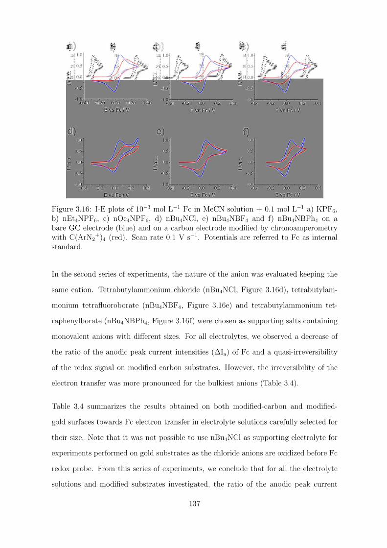
Figure 3.16: I-E plots of 10−3 mol L−1 Fc in MeCN solution + 0.1 mol L−1 a) KPF6,b) nEt4NPF6, c) nOc4NPF6, d) nBu4NCl, e) nBu4NBF4 and f) nBu4NBPh4 on abare GC electrode (blue) and on a carbon electrode modified by chronoamperometrywith C(ArN2
+)4 (red). Scan rate 0.1 V s−1. Potentials are referred to Fc as internalstandard.
In the second series of experiments, the nature of the anion was evaluated keeping the
same cation. Tetrabutylammonium chloride (nBu4NCl, Figure 3.16d), tetrabutylam-
monium tetrafluoroborate (nBu4NBF4, Figure 3.16e) and tetrabutylammonium tet-
raphenylborate (nBu4NBPh4, Figure 3.16f) were chosen as supporting salts containing
monovalent anions with different sizes. For all electrolytes, we observed a decrease of
the ratio of the anodic peak current intensities (∆Ia) of Fc and a quasi-irreversibility
of the redox signal on modified carbon substrates. However, the irreversibility of the
electron transfer was more pronounced for the bulkiest anions (Table 3.4).
Table 3.4 summarizes the results obtained on both modified-carbon and modified-
gold surfaces towards Fc electron transfer in electrolyte solutions carefully selected for
their size. Note that it was not possible to use nBu4NCl as supporting electrolyte for
experiments performed on gold substrates as the chloride anions are oxidized before Fc
redox probe. From this series of experiments, we conclude that for all the electrolyte
solutions and modified substrates investigated, the ratio of the anodic peak current
137
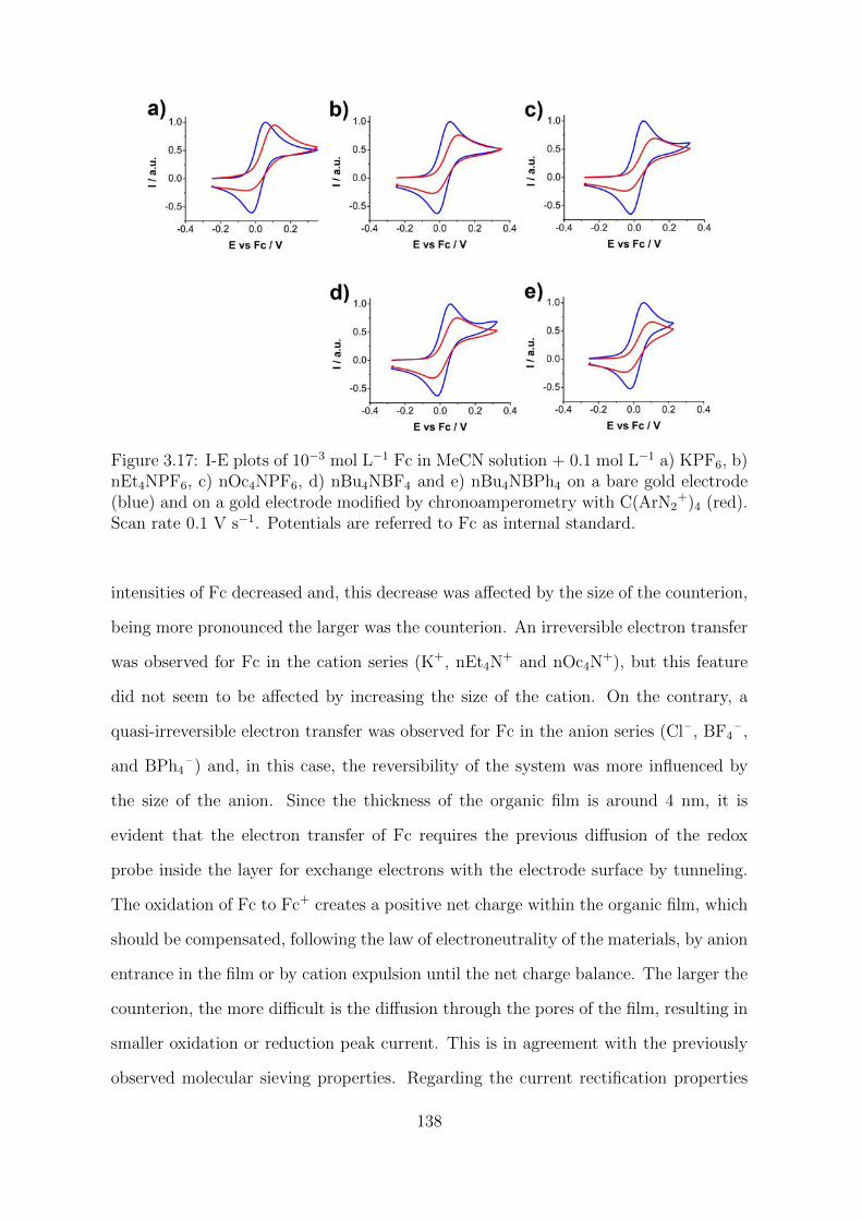
Figure 3.17: I-E plots of 10−3 mol L−1 Fc in MeCN solution + 0.1 mol L−1 a) KPF6, b)nEt4NPF6, c) nOc4NPF6, d) nBu4NBF4 and e) nBu4NBPh4 on a bare gold electrode(blue) and on a gold electrode modified by chronoamperometry with C(ArN2
+)4 (red).Scan rate 0.1 V s−1. Potentials are referred to Fc as internal standard.
intensities of Fc decreased and, this decrease was affected by the size of the counterion,
being more pronounced the larger was the counterion. An irreversible electron transfer
was observed for Fc in the cation series (K+, nEt4N+ and nOc4N
+), but this feature
did not seem to be affected by increasing the size of the cation. On the contrary, a
quasi-irreversible electron transfer was observed for Fc in the anion series (Cl– , BF4– ,
and BPh4– ) and, in this case, the reversibility of the system was more influenced by
the size of the anion. Since the thickness of the organic film is around 4 nm, it is
evident that the electron transfer of Fc requires the previous diffusion of the redox
probe inside the layer for exchange electrons with the electrode surface by tunneling.
The oxidation of Fc to Fc+ creates a positive net charge within the organic film, which
should be compensated, following the law of electroneutrality of the materials, by anion
entrance in the film or by cation expulsion until the net charge balance. The larger the
counterion, the more difficult is the diffusion through the pores of the film, resulting in
smaller oxidation or reduction peak current. This is in agreement with the previously
observed molecular sieving properties. Regarding the current rectification properties
138
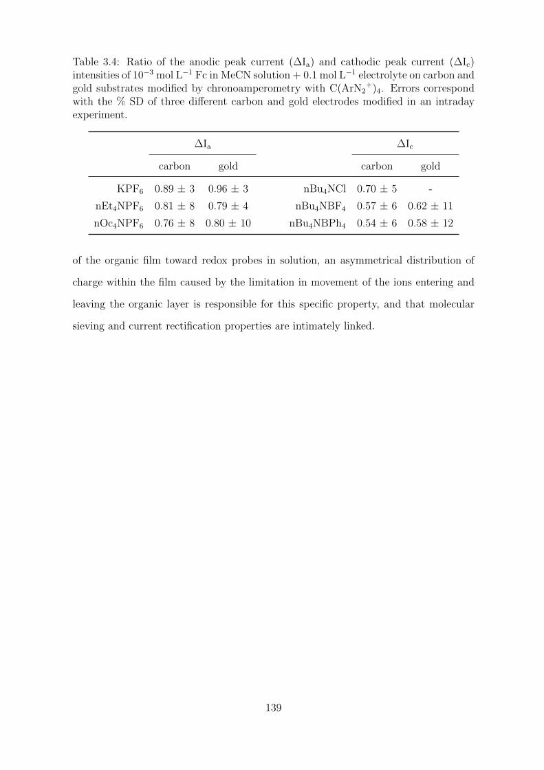
Table 3.4: Ratio of the anodic peak current (∆Ia) and cathodic peak current (∆Ic)intensities of 10−3 mol L−1 Fc in MeCN solution + 0.1 mol L−1 electrolyte on carbon andgold substrates modified by chronoamperometry with C(ArN2
+)4. Errors correspondwith the % SD of three different carbon and gold electrodes modified in an intradayexperiment.
∆Ia ∆Ic
carbon gold carbon gold
KPF6 0.89 ± 3 0.96 ± 3 nBu4NCl 0.70 ± 5 -
nEt4NPF6 0.81 ± 8 0.79 ± 4 nBu4NBF4 0.57 ± 6 0.62 ± 11
nOc4NPF6 0.76 ± 8 0.80 ± 10 nBu4NBPh4 0.54 ± 6 0.58 ± 12
of the organic film toward redox probes in solution, an asymmetrical distribution of
charge within the film caused by the limitation in movement of the ions entering and
leaving the organic layer is responsible for this specific property, and that molecular
sieving and current rectification properties are intimately linked.
139
3.3 Experimental section
3.3.1 Reagents
All commercially available reagents were used as received.
Non-commercially reagents were synthesized in the laboratory:
• Tetrakis(4-phenyldiazonium tetrafluoroborate)methane (C(ArN2+)4) was synthes-
ized from the corresponding commercial amine following the classical procedure
of diazotisation of aromatic amines.
• Ferrocene derivatives:
– 1,1’-Di(methylphenyl)ferrocene ((PhMe)2Fc)
– 1-(Biphenylethynyl)ferrocene (Ph2EFc)
3.3.2 Electrochemical measurements
3.3.2.1 Instrumentation
All the electrochemical measurements were performed using a standard three-electrode
setup at a controlled potential with a potentiostat Autolab PGSTAT 302N (Metrohm).
The set of electrodes consisted of a 2 mm-diameter polycrystalline gold (Au) or glassy
carbon (GC) disk electrodes (IJ Cambria) as working electrode (surface area 0.03 cm2),
a platinum wire as the auxiliary electrode, and a saturated calomel electrode (SCE,
KCl sat.) as the reference. The latter was isolated from the working solution employing
a salt bridge, which contained the electrolyte solution. When necessary, a conventional
gas inlet was used for bubbling argon inside the electrochemical cell to displace oxygen,
140
which is chemically reactive and electrochemically reducible. Occasionally, low rough-
ness and flat carbon and gold surfaces were required as working electrodes. In this case,
pyrolyzed photoresist films (PPF) were homemade fabricated according to described
methods[182], and gold wafer substrates were purchased from Aldrich (surface area 3
cm2). Since the larger surface area of these flat working electrodes, a platinum mesh
was used as the counter electrode instead of a platinum wire.
3.3.2.2 Methodology
Preparation of modified substrates. Surface modifications were performed by
cyclic voltammetry (ν = 0.05 V s−1, five consecutive cycles from + 0.6 to - 0.8 V vs SCE)
or fixed potential chronoamperometry (300 s at - 0.8 V vs SCE) in a saturated solution
(< 5x10⁻⁴ mol L−1) of C(ArN2+)4 + 0.1 mol L−1 nBu4NPF6 in acetonitrile (MeCN),
previously deaerate with argon (20 min). The modified electrodes were rinsed with a
copious amount of MeCN and acetone, stirred 20 min in THF solution and dried under
argon. Before modification, the disc electrodes were polished successively with 2400
and 4000 silicon carbide abrasive discs and ultrapure water and thoroughly rinsed with
ultrapure water and acetone. In case of flat working electrodes, no polish treatment is
necessary before modification, PPF electrodes were rinsed with acetone and dried under
argon and, gold substrates were cleaned using piranha solution, thoroughly rinsed with
ultrapure water and acetone, and dried under argon.
Cyclic voltammetry measurements. I-E plots of GC and Au electrodes were
registered at scan rate 0.1 V s−1 in different redox probe and electrolyte solutions, before
and after modification by both CV and chronoamperometry. Five different 10−3 mol
L−1 redox probe solutions + 0.1 mol L−1 KPF6 in MeCN were studied (redox probes are
listed in Table 3.5); and also six different solutions of 10−3 mol L−1 ferrocene + 0.1 mol
L−1 electrolyte in MeCN (electrolytes are listed in Table 3.6). From the I-E plots, two
characteristic parameters of the voltammogram were determined, the peak potential
141
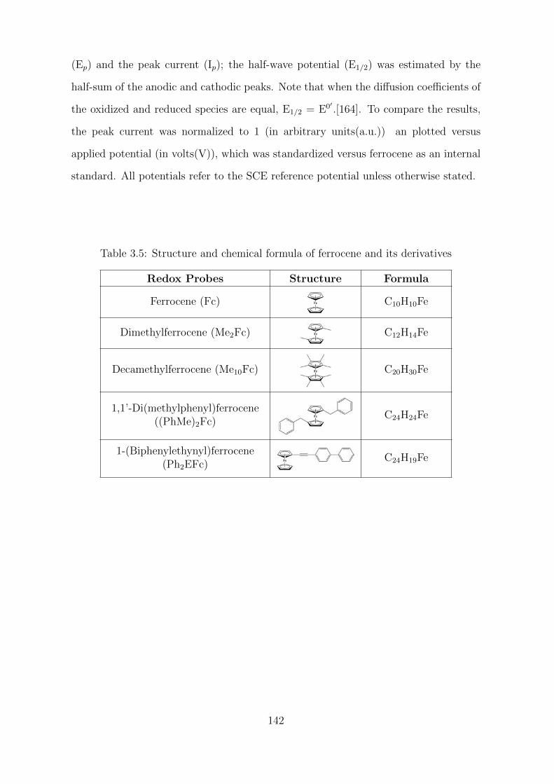
(Ep) and the peak current (Ip); the half-wave potential (E1/2) was estimated by the
half-sum of the anodic and cathodic peaks. Note that when the diffusion coefficients of
the oxidized and reduced species are equal, E1/2 = E0′ .[164]. To compare the results,
the peak current was normalized to 1 (in arbitrary units(a.u.)) an plotted versus
applied potential (in volts(V)), which was standardized versus ferrocene as an internal
standard. All potentials refer to the SCE reference potential unless otherwise stated.
Table 3.5: Structure and chemical formula of ferrocene and its derivatives
Redox Probes Structure Formula
Ferrocene (Fc) C10H10Fe
Dimethylferrocene (Me2Fc) C12H14Fe
Decamethylferrocene (Me10Fc) C20H30Fe
1,1’-Di(methylphenyl)ferrocene((PhMe)2Fc)
C24H24Fe
1-(Biphenylethynyl)ferrocene(Ph2EFc)
C24H19Fe
142
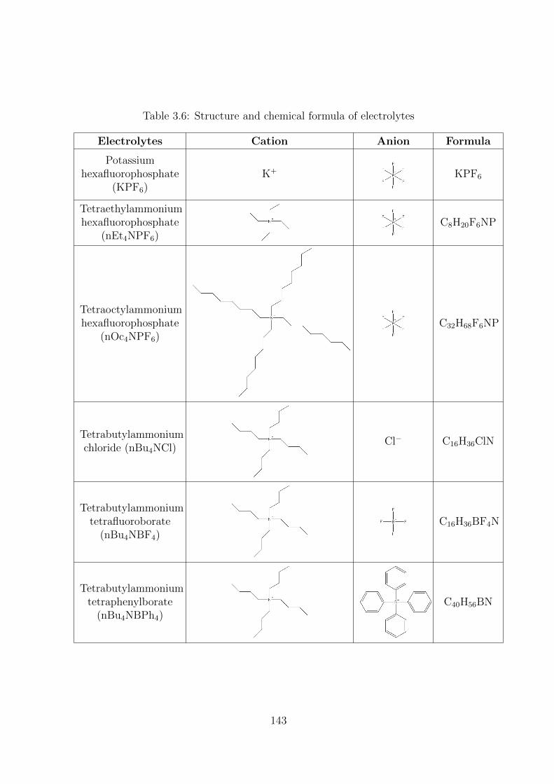
Table 3.6: Structure and chemical formula of electrolytes
Electrolytes Cation Anion Formula
Potassiumhexafluorophosphate
(KPF6)K+ KPF6
Tetraethylammoniumhexafluorophosphate
(nEt4NPF6)C8H20F6NP
Tetraoctylammoniumhexafluorophosphate
(nOc4NPF6)C32H68F6NP
Tetrabutylammoniumchloride (nBu4NCl)
Cl− C16H36ClN
Tetrabutylammoniumtetrafluoroborate
(nBu4NBF4)C16H36BF4N
Tetrabutylammoniumtetraphenylborate
(nBu4NBPh4)C40H56BN
143
3.3.3 Surface characterization
3.3.3.1 Spectroscopy Ellipsometry
The thickness of the organic films was measured by Spectroscopy Ellipsometry with an
αSE ellipsometer (J.A. Woollam, Co.) using a model-based analysis approach. Prior to
modification with the aryldiazonium molecule, the SE data of the bare substrate were
registered to build a substrate optical model which represents the nominal structure
of the non-modified material; the refractive index (n) and the extinction coefficient
(k) were 0.4 and 3.5 for gold, and 2.4 and 1.1 for bare PPF electrodes respectively.
This substrate model was used after modification to establish the contribution of the
substrate to the SE experimental data and thus, estimate the thickness of the organic
layer according to the Cauchy model. Finally, the goodness of the fit was quantified
by the Mean Squared Error (MSE) to validate our results. In all cases, the fitting
reproduced the structures and features of the SE experimental data. The values of
thickness obtained are the average of ten measurements performed on three different
substrates (PPF and gold wafer electrodes).
3.3.3.2 X-ray Photoelectron Spectroscopy
X-ray photoelectron spectroscopy data were collected with a Kratos Axis Nova spec-
trometer using the Al Kα X-ray source working at 1486.6 eV and using a spot size
of 0.7x0.3 mm2. Survey spectra (0 - 1000 eV) were acquired with an analyzer pass
energy of 160 eV (0.5 eV/step); high resolution spectra used a pass energy of 40 eV
(0.1 eV/step). Binding energies were referenced to C1s peak at 285 eV. The core level
spectra were peak-fitted using the CasaXPS software, Ltd. (version 2.3.18).
144
3.3.3.3 Atomic Force Microscopy
Atomic force microscopy experiments were performed on modified PPF and modified
gold wafer substrates using a NT- MDT Ntegra microscope. Topographic images were
obtained in semi-contact mode using ACTA tips (AppNano Inc.) for which the reson-
ance frequency is around 300 kHz. Scratching experiments were performed with the
same tips to estimate the thickness of the organic layers according to the McCreery
AFM “scratch” procedure.[73] The term “AFM scratching” is used here to describe
intentional damage to an organic layer grafted on a relatively hard substrate. These
experiments were obtained by scanning the surface in contact mode on a 500 × 500
nm square with a force setpoint sufficient to remove the organic layer. After scratch-
ing, the damaged surface imaged in semi-contact mode presented a square-shaped zone
surrounded by swept amounts of matter. The images were treated using Gwyddion
open-source software.[184] The thickness of the organic layer was extracted from the
depths of the scratched zones averaged on different profiles. Scratching experiments
were also performed on bare Au and PPF surfaces to evaluate the eventual damaging
of the substrate. In this case, the heights of the scratched zones were measured and
subtracted to those obtained on the modified surfaces to obtain corrected organic layer
heights, taking into account the substrate damaging. Furthermore, the roughness of
the organic films deposited on gold and carbon substrates was estimated, according to
the standard ISO 4287/1-1997, as the average of the measured height deviations taken
within the image (Root Mean Square (RMS) roughness).
145
3.3.4 Density Functional Theory Calculations
The conformation of all ferrocene derivatives were optimized using density functional
theory (DFT) calculations at the B3LYP/6-31G* level using the Gaussian 09 Revision
B.01 package with the default parameters.[225] The molecular volume is computed as
the volume inside a contour of 0.001 electron/bohr3 using a Monte-Carlo method of
integration and the SCF density. The number of points per bohr3 is 100 with a cutoff
= 10-4 and used with the “Vol=Tight” option for a better accuracy that is better than
10 %.[226]
146
3.4 Conclusion
The electro-reduction of a tetrahedral-shape pre-organized tetra-aryldiazonium salt,
tetrakis(4-phenyldiazonium tetrafluoroborate)methane C(ArN2+)4, led to the depos-
ition of ultrathin organic films on gold and carbon substrates. Various characterization
techniques as XPS, IR and CV showed that all diazonium functions are reduced in the
organic layer, which appears to be mainly composed of carbon and hydrogen atoms.
Molecular sieving properties were evidenced by cyclic voltammetry of solution-phase
redox probes in aqueous and organic solutions. Substrates modified by this technique
also behave as electrochemical current rectifiers (ECR). Due to the lack of redox re-
lay in the layer, it appears to be different from the classical ECR as described by
Murray et al.[185] The transport of the redox molecules and the counterions through
the layer has been evidenced as responsible of the electrochemical current rectifica-
tion properties of the modified materials. Both molecular sieving and electrochemical
current rectification properties are related to the specific organization of the grafted
ultrathin organic layer. Observation of both molecular sieving and electrochemical
current rectification properties has never been observed previously for organic films
electro-generated by the reduction of aryldiazonium ions that do not present this tet-
rahedral pre-organization.[72, 227–229]
147


Chapter 4
Intermediates detection during
multielectronic oxygen reduction
reaction on modified carbon
materials: a SECM footprinting
strategy.

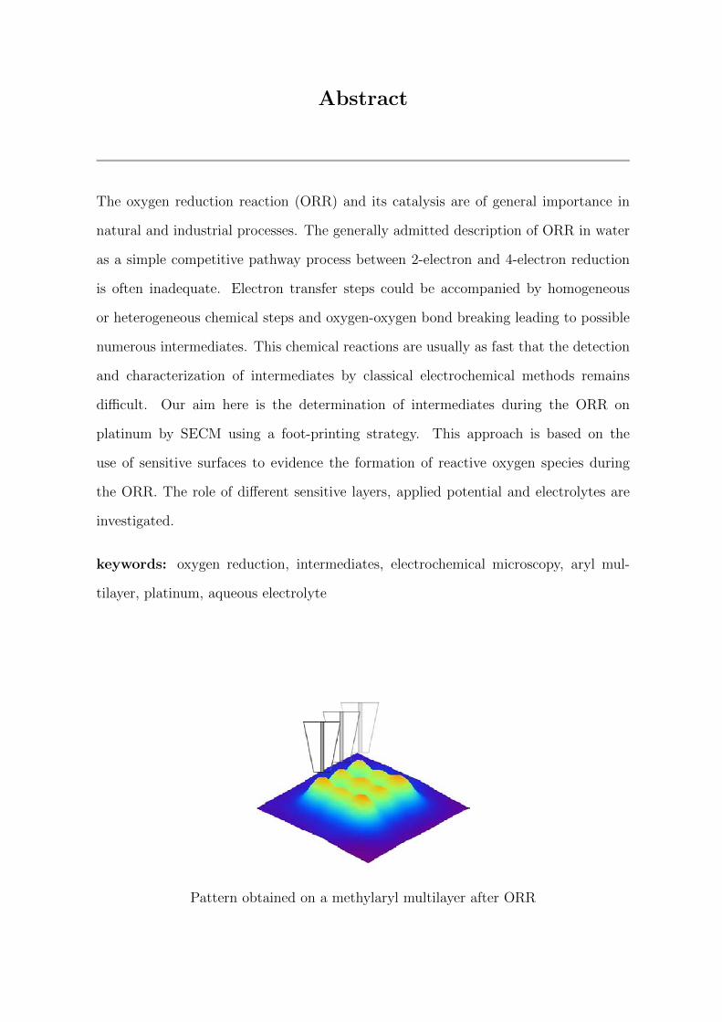
Abstract
The oxygen reduction reaction (ORR) and its catalysis are of general importance in
natural and industrial processes. The generally admitted description of ORR in water
as a simple competitive pathway process between 2-electron and 4-electron reduction
is often inadequate. Electron transfer steps could be accompanied by homogeneous
or heterogeneous chemical steps and oxygen-oxygen bond breaking leading to possible
numerous intermediates. This chemical reactions are usually as fast that the detection
and characterization of intermediates by classical electrochemical methods remains
difficult. Our aim here is the determination of intermediates during the ORR on
platinum by SECM using a foot-printing strategy. This approach is based on the
use of sensitive surfaces to evidence the formation of reactive oxygen species during
the ORR. The role of different sensitive layers, applied potential and electrolytes are
investigated.
keywords: oxygen reduction, intermediates, electrochemical microscopy, aryl mul-
tilayer, platinum, aqueous electrolyte
Pattern obtained on a methylaryl multilayer after ORR

4.1 Background
Scanning Electrochemical Microscopy (SECM)[230, 231] has already demonstrated all
its interest for probing at the local scale a variety of biological, chemical and elec-
trochemical processes occurring at interfaces.[232] SECM in feedback mode provides
a chemical view of a surface from the solution side and is complementary to other
electrochemical methods such as cyclic voltammetry.[231] SECM was used with suc-
cess for the study of electrocatalysis phenomena and for what concerns the present
study, the catalysis of oxygen reduction reaction (ORR). The contributions of Bard
and co-workers are noteworthy in this regards;[233–240] mainly focusing on the SECM
rapid-screening of catalysts arrays for the optimization of oxygen reduction in fuel cells
applications.
Oxygen reduction in aqueous media is therefore of high interest from a technological
and biological point of view. ORR is one of the most important cathodic process in
fuel cells and a difficult challenge in electrocatalysis.[110, 111] Further, ORR is an
important reaction in life processes such as biological respiration. Oxygen reduction
takes places naturally in the body but, during oxidative stress periods in the cell,
high concentrations of reactive oxygen species are generated, this species are related
with inflammatory processes and cell damage but also with cell protection strategies
against bacteria.[112] In aqueous medium, ORR occurs mainly by two pathways: the
4-electron reduction pathway from O2 to water, and the 2-electron reduction pathway
to H2O2.[113] However, such global reaction schemes do no reflect the mechanistic
pathways especially for what concerns the transient reactive oxygen species (ROS)
that are key intermediates even if not explicitly considered.[241] ORR is a multistep
process in which radicals and non radicals are generated (Scheme 4.1); radicals such
as superoxyde (O2•– ), perhydroxyl (HO2
•) and hydroxyl (HO•), and non radicals such
as hydrogen peroxide (H2O2). They are part of the reactive oxygen species, and their
electro-generation during the oxygen reduction was early evidenced by pulse radiolysis
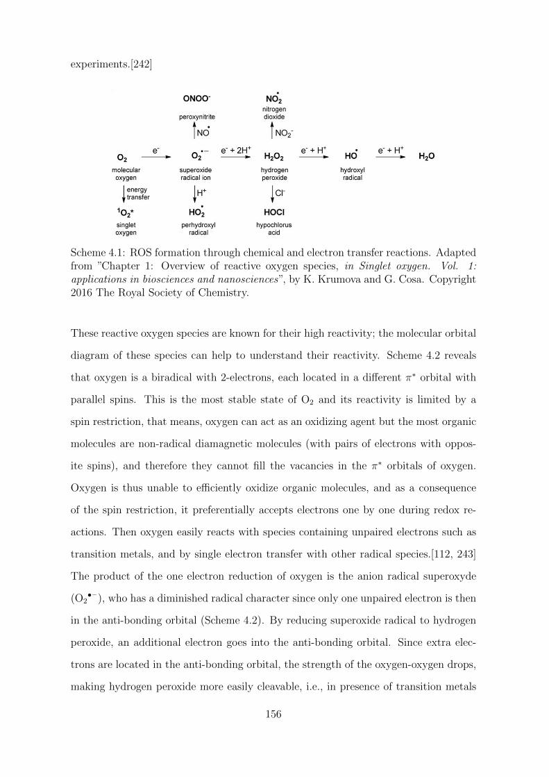
experiments.[242]
Scheme 4.1: ROS formation through chemical and electron transfer reactions. Adaptedfrom ”Chapter 1: Overview of reactive oxygen species, in Singlet oxygen. Vol. 1:applications in biosciences and nanosciences”, by K. Krumova and G. Cosa. Copyright2016 The Royal Society of Chemistry.
These reactive oxygen species are known for their high reactivity; the molecular orbital
diagram of these species can help to understand their reactivity. Scheme 4.2 reveals
that oxygen is a biradical with 2-electrons, each located in a different π∗ orbital with
parallel spins. This is the most stable state of O2 and its reactivity is limited by a
spin restriction, that means, oxygen can act as an oxidizing agent but the most organic
molecules are non-radical diamagnetic molecules (with pairs of electrons with oppos-
ite spins), and therefore they cannot fill the vacancies in the π∗ orbitals of oxygen.
Oxygen is thus unable to efficiently oxidize organic molecules, and as a consequence
of the spin restriction, it preferentially accepts electrons one by one during redox re-
actions. Then oxygen easily reacts with species containing unpaired electrons such as
transition metals, and by single electron transfer with other radical species.[112, 243]
The product of the one electron reduction of oxygen is the anion radical superoxyde
(O2•– ), who has a diminished radical character since only one unpaired electron is then
in the anti-bonding orbital (Scheme 4.2). By reducing superoxide radical to hydrogen
peroxide, an additional electron goes into the anti-bonding orbital. Since extra elec-
trons are located in the anti-bonding orbital, the strength of the oxygen-oxygen drops,
making hydrogen peroxide more easily cleavable, i.e., in presence of transition metals
156
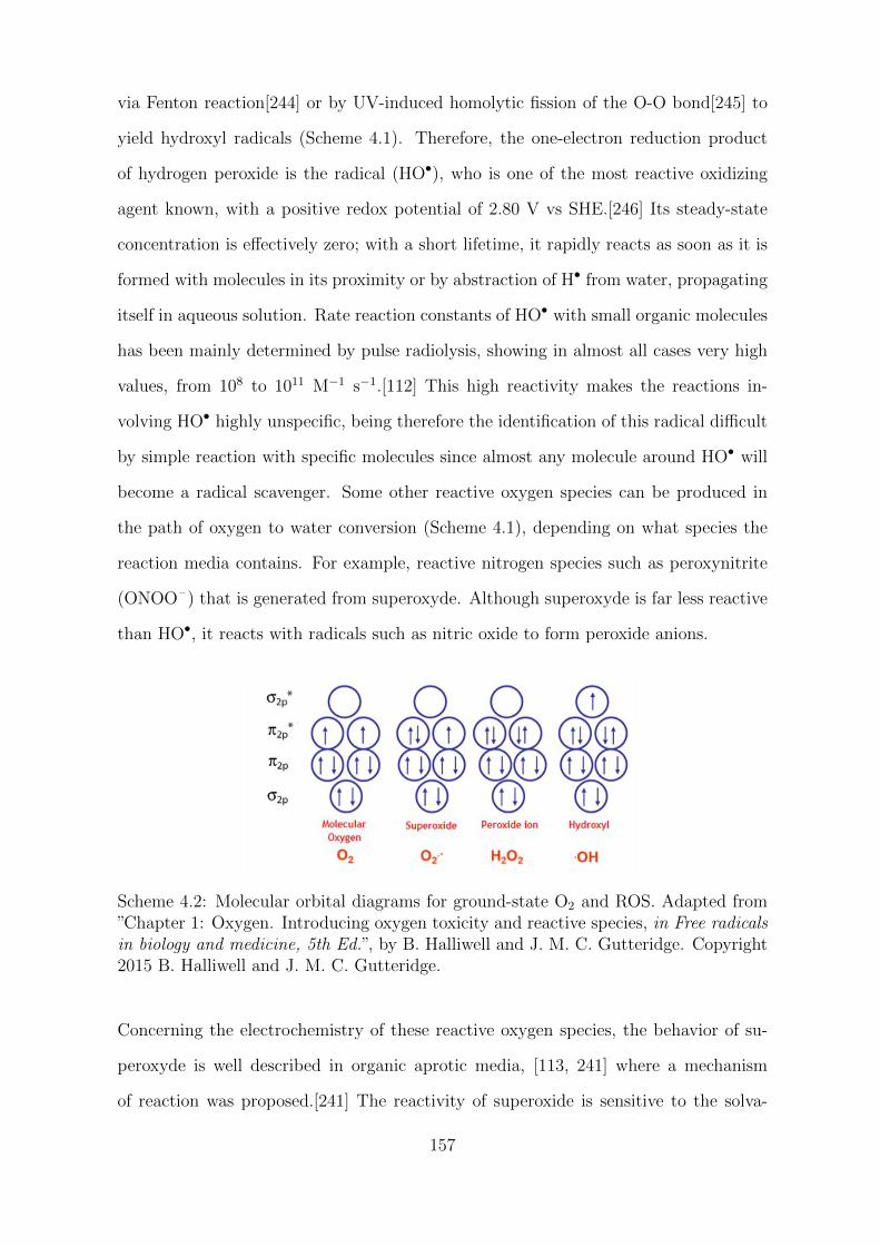
via Fenton reaction[244] or by UV-induced homolytic fission of the O-O bond[245] to
yield hydroxyl radicals (Scheme 4.1). Therefore, the one-electron reduction product
of hydrogen peroxide is the radical (HO•), who is one of the most reactive oxidizing
agent known, with a positive redox potential of 2.80 V vs SHE.[246] Its steady-state
concentration is effectively zero; with a short lifetime, it rapidly reacts as soon as it is
formed with molecules in its proximity or by abstraction of H• from water, propagating
itself in aqueous solution. Rate reaction constants of HO• with small organic molecules
has been mainly determined by pulse radiolysis, showing in almost all cases very high
values, from 108 to 1011 M−1 s−1.[112] This high reactivity makes the reactions in-
volving HO• highly unspecific, being therefore the identification of this radical difficult
by simple reaction with specific molecules since almost any molecule around HO• will
become a radical scavenger. Some other reactive oxygen species can be produced in
the path of oxygen to water conversion (Scheme 4.1), depending on what species the
reaction media contains. For example, reactive nitrogen species such as peroxynitrite
(ONOO– ) that is generated from superoxyde. Although superoxyde is far less reactive
than HO•, it reacts with radicals such as nitric oxide to form peroxide anions.
Scheme 4.2: Molecular orbital diagrams for ground-state O2 and ROS. Adapted from”Chapter 1: Oxygen. Introducing oxygen toxicity and reactive species, in Free radicalsin biology and medicine, 5th Ed.”, by B. Halliwell and J. M. C. Gutteridge. Copyright2015 B. Halliwell and J. M. C. Gutteridge.
Concerning the electrochemistry of these reactive oxygen species, the behavior of su-
peroxyde is well described in organic aprotic media, [113, 241] where a mechanism
of reaction was proposed.[241] The reactivity of superoxide is sensitive to the solva-
157
tion of O2•– but even more important is the stabilization of peroxide by protons. In
aprotic media, the peroxide dianion O22– , removed from an ionic environment and
non-coordinated to any metal ion, is highly unstable species. Thus the likelihood that
superoxide will act as a one-electron oxidant under conditions where an isolated perox-
ide dianion is the product is nil (See Figure 4.1 for the reversible electro-reduction of
oxygen to superoxyde on gold; the voltammogram is perfectly reversible since super-
oxyde is stabilized in dried aprotic media such as DMSO or DMF). On the other hand,
when protons or metals ions are available to stabilize the peroxide anion, the thermody-
namics changes and oxygen is reduced to peroxide in a 2-electron process.[241] Figure
4.1 (on the right) shows the reversible one-electron reduction of oxygen to superoxide in
dried DMSO, and its conversion to a 2-electron process when a small amount of weak
acid (phenol) is added. The mechanism proposed was as shown in Equations 4.1 - 4.4,
where the protonation of the superoxide radical is followed by the disproportionation of
the resulting perhydroxyl radical by another molecule of O2•– , to finally yield hydrogen
peroxide.[113, 241]
O2 + e− → O2•− E (4.1)
O2•− + H+ → HO2
• C (4.2)
HO2• + O2
•− → O2 + HO2− DISP (4.3)
HO2− + H+ → H2O2 (4.4)
Despite extensive studies over the past decades, the mechanistic aspects of the O2 elec-
trode reactions in aqueous solution are not yet understood. As we previously stated,
transient species are generated in the multielectronic pathway from oxygen to water,
and these species cannot be followed by classical electrochemical techniques. In a pre-
vious publications, we have shown that reactive oxygen species could be detected by
means SECM and a sensitive layer in DMF after adding phenol.[114] The SECM tip is
maintained in the proximity of the sensitive surface to trap the reactive intermediate.
158
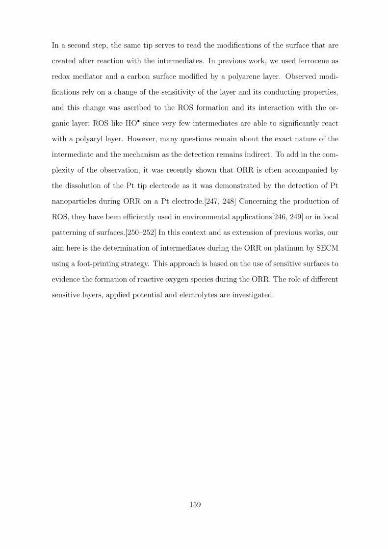
In a second step, the same tip serves to read the modifications of the surface that are
created after reaction with the intermediates. In previous work, we used ferrocene as
redox mediator and a carbon surface modified by a polyarene layer. Observed modi-
fications rely on a change of the sensitivity of the layer and its conducting properties,
and this change was ascribed to the ROS formation and its interaction with the or-
ganic layer; ROS like HO• since very few intermediates are able to significantly react
with a polyaryl layer. However, many questions remain about the exact nature of the
intermediate and the mechanism as the detection remains indirect. To add in the com-
plexity of the observation, it was recently shown that ORR is often accompanied by
the dissolution of the Pt tip electrode as it was demonstrated by the detection of Pt
nanoparticles during ORR on a Pt electrode.[247, 248] Concerning the production of
ROS, they have been efficiently used in environmental applications[246, 249] or in local
patterning of surfaces.[250–252] In this context and as extension of previous works, our
aim here is the determination of intermediates during the ORR on platinum by SECM
using a foot-printing strategy. This approach is based on the use of sensitive surfaces to
evidence the formation of reactive oxygen species during the ORR. The role of different
sensitive layers, applied potential and electrolytes are investigated.
159
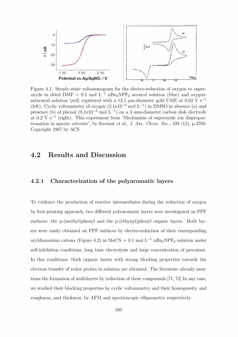
Figure 4.1: Steady-state voltammogram for the electro-reduction of oxygen to super-oxyde in dried DMF + 0.1 mol L−1 nBu4NPF6 aerated solution (blue) and oxygen-saturated solution (red) registered with a 12.5 µm-diameter gold UME at 0.02 V s−1
(left). Cyclic voltammetry of oxygen (2.1x10⁻³ mol L−1) in DMSO in absence (a) andpresence (b) of phenol (0.1x10⁻³ mol L−1) on a 3 mm-diameter carbon disk electrodeat 0.2 V s−1 (right). This experiment from ”Mechanism of superoxide ion dispropor-tionation in aprotic solvents”, by Saveant et al., J. Am. Chem. Soc., 109 (12), p.3769.Copyright 1987 by ACS.
4.2 Results and Discussion
4.2.1 Characterization of the polyaromatic layers
To evidence the production of reactive intermediates during the reduction of oxygen
by foot-printing approach, two different polyaromatic layers were investigated on PPF
surfaces: the p-(methyl)phenyl and the p-(ethynyl)phenyl organic layers. Both lay-
ers were easily obtained on PPF surfaces by electro-reduction of their corresponding
aryldiazonium cations (Figure 4.2) in MeCN + 0.1 mol L−1 nBu4NPF6 solution under
self-inhibition conditions, long time electrolysis and large concentration of precursor.
In this conditions, thick organic layers with strong blocking properties towards the
electron transfer of redox probes in solution are obtained. The literature already men-
tions the formation of multilayers by reduction of these compounds.[71, 72] In any case,
we studied their blocking properties by cyclic voltammetry and their homogeneity and
roughness, and thickness, by AFM and spectroscopic ellipsometry respectively.
160
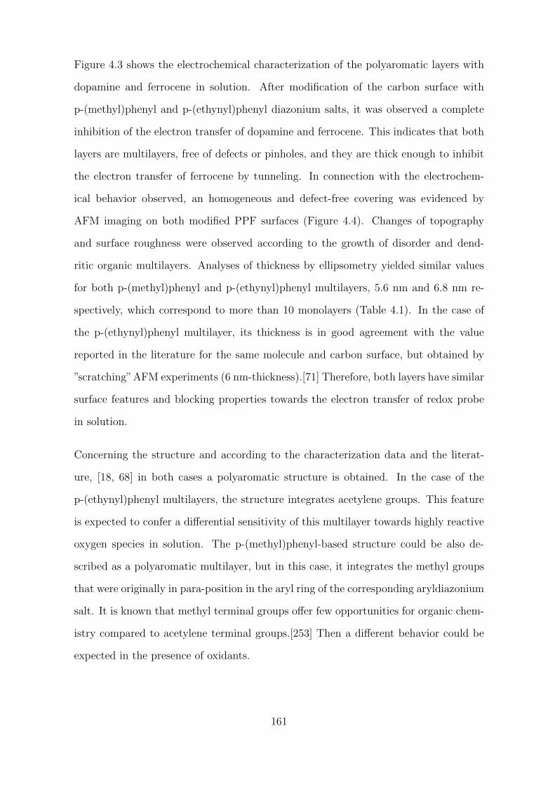
Figure 4.3 shows the electrochemical characterization of the polyaromatic layers with
dopamine and ferrocene in solution. After modification of the carbon surface with
p-(methyl)phenyl and p-(ethynyl)phenyl diazonium salts, it was observed a complete
inhibition of the electron transfer of dopamine and ferrocene. This indicates that both
layers are multilayers, free of defects or pinholes, and they are thick enough to inhibit
the electron transfer of ferrocene by tunneling. In connection with the electrochem-
ical behavior observed, an homogeneous and defect-free covering was evidenced by
AFM imaging on both modified PPF surfaces (Figure 4.4). Changes of topography
and surface roughness were observed according to the growth of disorder and dend-
ritic organic multilayers. Analyses of thickness by ellipsometry yielded similar values
for both p-(methyl)phenyl and p-(ethynyl)phenyl multilayers, 5.6 nm and 6.8 nm re-
spectively, which correspond to more than 10 monolayers (Table 4.1). In the case of
the p-(ethynyl)phenyl multilayer, its thickness is in good agreement with the value
reported in the literature for the same molecule and carbon surface, but obtained by
”scratching”AFM experiments (6 nm-thickness).[71] Therefore, both layers have similar
surface features and blocking properties towards the electron transfer of redox probe
in solution.
Concerning the structure and according to the characterization data and the literat-
ure, [18, 68] in both cases a polyaromatic structure is obtained. In the case of the
p-(ethynyl)phenyl multilayers, the structure integrates acetylene groups. This feature
is expected to confer a differential sensitivity of this multilayer towards highly reactive
oxygen species in solution. The p-(methyl)phenyl-based structure could be also de-
scribed as a polyaromatic multilayer, but in this case, it integrates the methyl groups
that were originally in para-position in the aryl ring of the corresponding aryldiazonium
salt. It is known that methyl terminal groups offer few opportunities for organic chem-
istry compared to acetylene terminal groups.[253] Then a different behavior could be
expected in the presence of oxidants.
161
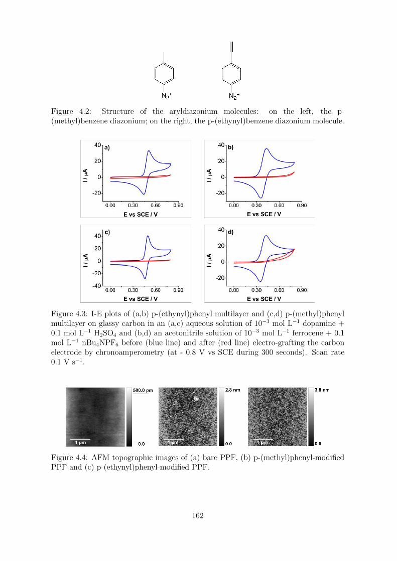
Figure 4.2: Structure of the aryldiazonium molecules: on the left, the p-(methyl)benzene diazonium; on the right, the p-(ethynyl)benzene diazonium molecule.
Figure 4.3: I-E plots of (a,b) p-(ethynyl)phenyl multilayer and (c,d) p-(methyl)phenylmultilayer on glassy carbon in an (a,c) aqueous solution of 10−3 mol L−1 dopamine +0.1 mol L−1 H2SO4 and (b,d) an acetonitrile solution of 10−3 mol L−1 ferrocene + 0.1mol L−1 nBu4NPF6 before (blue line) and after (red line) electro-grafting the carbonelectrode by chronoamperometry (at - 0.8 V vs SCE during 300 seconds). Scan rate0.1 V s−1.
Figure 4.4: AFM topographic images of (a) bare PPF, (b) p-(methyl)phenyl-modifiedPPF and (c) p-(ethynyl)phenyl-modified PPF.
162
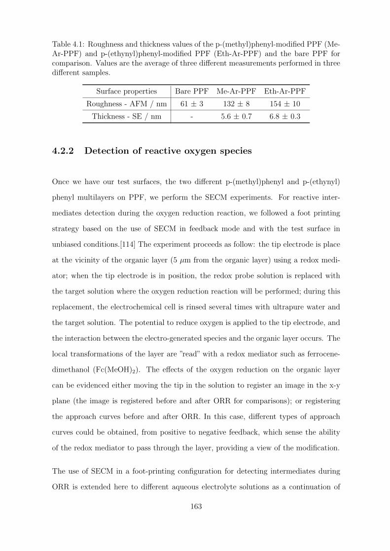
Table 4.1: Roughness and thickness values of the p-(methyl)phenyl-modified PPF (Me-Ar-PPF) and p-(ethynyl)phenyl-modified PPF (Eth-Ar-PPF) and the bare PPF forcomparison. Values are the average of three different measurements performed in threedifferent samples.
Surface properties Bare PPF Me-Ar-PPF Eth-Ar-PPF
Roughness - AFM / nm 61 ± 3 132 ± 8 154 ± 10
Thickness - SE / nm - 5.6 ± 0.7 6.8 ± 0.3
4.2.2 Detection of reactive oxygen species
Once we have our test surfaces, the two different p-(methyl)phenyl and p-(ethynyl)
phenyl multilayers on PPF, we perform the SECM experiments. For reactive inter-
mediates detection during the oxygen reduction reaction, we followed a foot printing
strategy based on the use of SECM in feedback mode and with the test surface in
unbiased conditions.[114] The experiment proceeds as follow: the tip electrode is place
at the vicinity of the organic layer (5 µm from the organic layer) using a redox medi-
ator; when the tip electrode is in position, the redox probe solution is replaced with
the target solution where the oxygen reduction reaction will be performed; during this
replacement, the electrochemical cell is rinsed several times with ultrapure water and
the target solution. The potential to reduce oxygen is applied to the tip electrode, and
the interaction between the electro-generated species and the organic layer occurs. The
local transformations of the layer are ”read” with a redox mediator such as ferrocene-
dimethanol (Fc(MeOH)2). The effects of the oxygen reduction on the organic layer
can be evidenced either moving the tip in the solution to register an image in the x-y
plane (the image is registered before and after ORR for comparisons); or registering
the approach curves before and after ORR. In this case, different types of approach
curves could be obtained, from positive to negative feedback, which sense the ability
of the redox mediator to pass through the layer, providing a view of the modification.
The use of SECM in a foot-printing configuration for detecting intermediates during
ORR is extended here to different aqueous electrolyte solutions as a continuation of
163
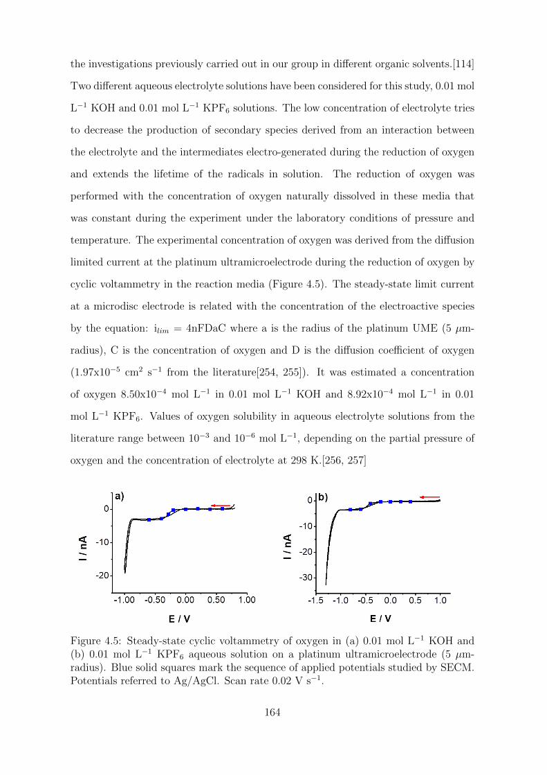
the investigations previously carried out in our group in different organic solvents.[114]
Two different aqueous electrolyte solutions have been considered for this study, 0.01 mol
L−1 KOH and 0.01 mol L−1 KPF6 solutions. The low concentration of electrolyte tries
to decrease the production of secondary species derived from an interaction between
the electrolyte and the intermediates electro-generated during the reduction of oxygen
and extends the lifetime of the radicals in solution. The reduction of oxygen was
performed with the concentration of oxygen naturally dissolved in these media that
was constant during the experiment under the laboratory conditions of pressure and
temperature. The experimental concentration of oxygen was derived from the diffusion
limited current at the platinum ultramicroelectrode during the reduction of oxygen by
cyclic voltammetry in the reaction media (Figure 4.5). The steady-state limit current
at a microdisc electrode is related with the concentration of the electroactive species
by the equation: ilim = 4nFDaC where a is the radius of the platinum UME (5 µm-
radius), C is the concentration of oxygen and D is the diffusion coefficient of oxygen
(1.97x10⁻⁵ cm2 s−1 from the literature[254, 255]). It was estimated a concentration
of oxygen 8.50x10⁻⁴ mol L−1 in 0.01 mol L−1 KOH and 8.92x10⁻⁴ mol L−1 in 0.01
mol L−1 KPF6. Values of oxygen solubility in aqueous electrolyte solutions from the
literature range between 10−3 and 10−6 mol L−1, depending on the partial pressure of
oxygen and the concentration of electrolyte at 298 K.[256, 257]
Figure 4.5: Steady-state cyclic voltammetry of oxygen in (a) 0.01 mol L−1 KOH and(b) 0.01 mol L−1 KPF6 aqueous solution on a platinum ultramicroelectrode (5 µm-radius). Blue solid squares mark the sequence of applied potentials studied by SECM.Potentials referred to Ag/AgCl. Scan rate 0.02 V s−1.
164

Figures 4.6 a, b, c and d shows the SECM experiments performed in 0.01 mol L−1 KOH,
before oxygen reduction (Figures 4.6 a and b) and after oxygen reduction (Figures 4.6
c and d); Figures 4.6 e, f, g and h shows the SECM experiments performed in 0.01 mol
L−1 KPF6, before oxygen reduction (Figures 4.6 e and f) and after oxygen reduction
(Figures 4.6 g and h). Therefore, SECM images on the left show all the experiments
performed on the p-(ethynyl)phenyl multilayer, and figures on the right show all the
experiments on the p-(methyl)phenyl multilayer. In each media, we studied the effect
of the applied potential during the ORR; the half-wave potential of oxygen reduction
in the basic solution was - 0.28 V vs Ag/AgCl, and in the neutral solution (0.01
mol L−1 KPF6), it was - 0.44 V vs Ag/AgCl. Note that the surface of the platinum
ultramicroelectrode is not a single-crystal surface; the electrodes are routinely polished
with silicon carbide abrasive paper and ultrapure water. We chose a sequence of applied
potentials covering a wide range from oxidation to reduction until reach the plateau
of the ORR. (See Figure 4.5 that shows the cyclic voltammetry for oxygen reduction
in KOH and KPF6 solutions; after oxygen reduction, a sharp increase in the cathodic
current is clearly observed as a result as a result of the evolution of molecular hydrogen.
All potentials studied by SECM in each media are marked in the voltammograms as
blue solid squares.)
Each applied potential studied by SECM is a sequence of two pulses in chronoampero-
metry. Following a previously described procedure,[114] the platinum ultramicroelec-
trode is subjected during a total of 20 seconds to an applied potential by a series of
two square wave pulses in chronoamperometry from 0 to Eapplied (vs Ag/AgCl). The
tip electrode is moved to different points (eight in total) in an x-y plane maintaining
constant the distance tip-organic layer at 5 µm. The only parameter that varies is the
potential applied, which sequentially shifts to more negative values as marked in the
voltammograms (See Figure 4.5).
As shown in Figure 4.6, before oxygen reduction, both organic multilayers showed an
insulating behavior, blocking the electron transfer of the ferrocene derivative in solution;
165
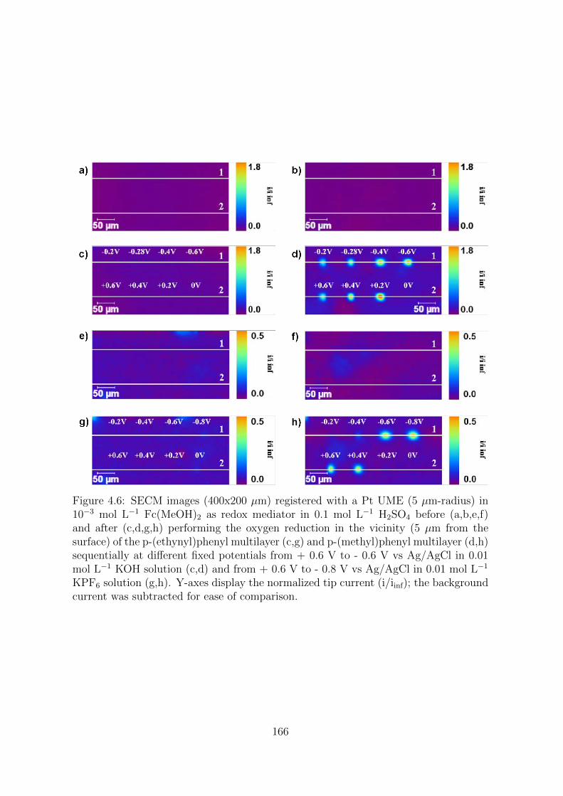
Figure 4.6: SECM images (400x200 µm) registered with a Pt UME (5 µm-radius) in10−3 mol L−1 Fc(MeOH)2 as redox mediator in 0.1 mol L−1 H2SO4 before (a,b,e,f)and after (c,d,g,h) performing the oxygen reduction in the vicinity (5 µm from thesurface) of the p-(ethynyl)phenyl multilayer (c,g) and p-(methyl)phenyl multilayer (d,h)sequentially at different fixed potentials from + 0.6 V to - 0.6 V vs Ag/AgCl in 0.01mol L−1 KOH solution (c,d) and from + 0.6 V to - 0.8 V vs Ag/AgCl in 0.01 mol L−1
KPF6 solution (g,h). Y-axes display the normalized tip current (i/iinf); the backgroundcurrent was subtracted for ease of comparison.
166
the two organic layers showed a very homogeneous electrochemical response, with no
surface defects or large current variations in both the neutral and the basic solution.
After performing the reduction of oxygen at different applied potentials and at different
points on the surface of the organic layer, it was observed no modification in the case
of the p-(ethynyl)phenyl multilayer that remains totally insulating, still blocking the
electron transfer of ferrocenedimethanol in solution; this was observed in both neutral
and basic solutions. In the case of the p-(methyl)phenyl multilayer, modifications
are visible after exposure to reactive oxygen species both in neutral and basic solution,
when the applied potentials were the half-wave potentials or those corresponding to the
plateau of the oxygen reduction (- 0.6 and - 0.8 V vs Ag/AgCl in the case of the KPF6
solution, and - 0.4 V and - 0.6 V vs Ag/AgCl in the case of the KOH solution); but also,
for applied potentials in the anodic region, where in view of the cyclic voltammetry
curves, no electron transfer reaction occurs and the current intensities were almost zero
(a few tenths of a nanoamper). To rule out possible artifacts such as the displacement
of the oxygen reduction potential during the experiment, the voltammogram of oxygen
reduction was registered at the beginning and at the end of the experiment; there
were no significant differences in the half-wave potential of oxygen that justified the
modification at anodic potentials on the organic layer observed both at neutral and
basic pH. For a easier comparison between experiments, the current-distance profiles
should be examined (Figure 4.7).
167
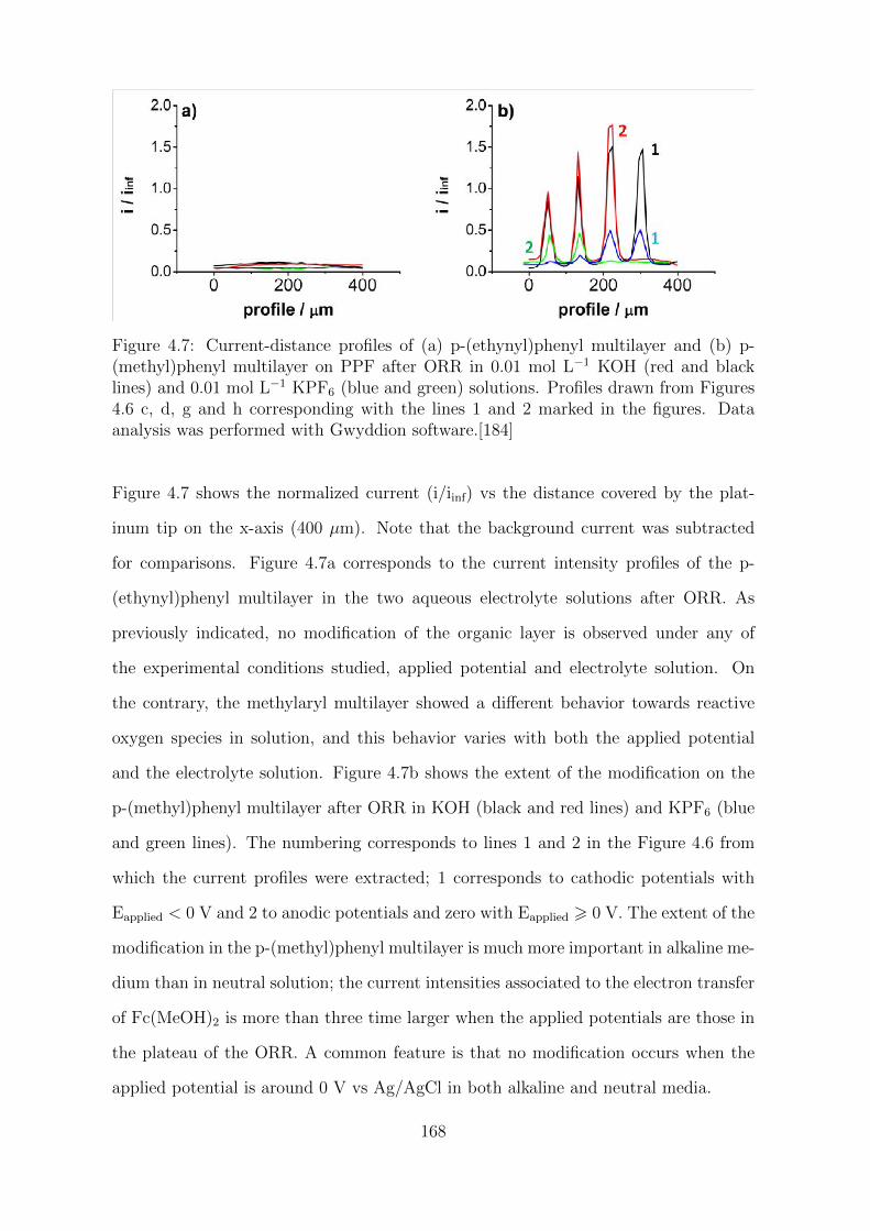
Figure 4.7: Current-distance profiles of (a) p-(ethynyl)phenyl multilayer and (b) p-(methyl)phenyl multilayer on PPF after ORR in 0.01 mol L−1 KOH (red and blacklines) and 0.01 mol L−1 KPF6 (blue and green) solutions. Profiles drawn from Figures4.6 c, d, g and h corresponding with the lines 1 and 2 marked in the figures. Dataanalysis was performed with Gwyddion software.[184]
Figure 4.7 shows the normalized current (i/iinf) vs the distance covered by the plat-
inum tip on the x-axis (400 µm). Note that the background current was subtracted
for comparisons. Figure 4.7a corresponds to the current intensity profiles of the p-
(ethynyl)phenyl multilayer in the two aqueous electrolyte solutions after ORR. As
previously indicated, no modification of the organic layer is observed under any of
the experimental conditions studied, applied potential and electrolyte solution. On
the contrary, the methylaryl multilayer showed a different behavior towards reactive
oxygen species in solution, and this behavior varies with both the applied potential
and the electrolyte solution. Figure 4.7b shows the extent of the modification on the
p-(methyl)phenyl multilayer after ORR in KOH (black and red lines) and KPF6 (blue
and green lines). The numbering corresponds to lines 1 and 2 in the Figure 4.6 from
which the current profiles were extracted; 1 corresponds to cathodic potentials with
Eapplied < 0 V and 2 to anodic potentials and zero with Eapplied > 0 V. The extent of the
modification in the p-(methyl)phenyl multilayer is much more important in alkaline me-
dium than in neutral solution; the current intensities associated to the electron transfer
of Fc(MeOH)2 is more than three time larger when the applied potentials are those in
the plateau of the ORR. A common feature is that no modification occurs when the
applied potential is around 0 V vs Ag/AgCl in both alkaline and neutral media.
168
The differential behavior between the p-(ethynyl)phenyl and the p-(methyl)phenyl mul-
tilayers could be explained in terms of reactivity towards the hydroxyl radicals probably
generated as intermediate during the oxygen reduction on platinum. The former did
not undergo modification after ORR at any potential or reaction media, while the
later was affected in both media and almost at all applied potentials except around 0
V. Indeed, the oxygen reduction in aqueous solution is a multielectronic process that
leads to the formation of radical and non radical species; radicals such as superoxyde
(O2•– ), perhydroxyl (HO2
•) and hydroxyl (HO•), and non radicals such as hydrogen
peroxide (H2O2).[243] However, hydroxyl radicals are the most reactive among them
and must be preferentially produced on a platinum surface. There are three possible
reactions between HO• and organic molecules: the abstraction of H atoms, the elec-
trophilic addition on unsaturated bonds, and the electron transfer process. From pulse
radiolysis experiments, it have been proposed different reaction mechanisms towards
hydroxyl radicals for systems that could be assumed to be close or equivalent to those
investigated, acetylene[258, 259] and methane[260] molecules in an aqueous basic solu-
tion. The reaction between the HO• and acetylene mainly proceeds by electrophilic
addition to the carbon-carbon triple bond. The addition product is the enol form of
the formylmethyl radical that is stabilized by resonance and will dissapears bimolecu-
larly by reaction with water.[258, 259] However, hydrogen abstraction is the dominant
reaction pathway for the attack of HO• on saturated hydrocarbons.[260, 261] For ex-
ample, the reaction between hydroxyl radicals and methane involves the abstraction of
H atoms that results in the formation of CH3• radicals,[260] which are species much
more reactive than the stabilized enol intermediates and could therefore induce other
radical reactions (propagation reactions) in the organic layer, thus contributing to its
further oxidative degradation. Additionally to the oxidation of the substituents, HO•
radicals can also attack the aromatic ring to form phenolic adducts. In the case of
the para-substituted methylbenezene molecules, the electrophilic attack to the ring is
kinetically favored (k = 2.62x10⁹ M−1 s−1) compared to the abstraction of H atoms in
the substituent (k = 1.43x10⁸ M−1 s−1).[260, 262]
169
In connection with the modification of the p-(methyl)phenyl multilayers observed in an
aqueous KPF6 solution after ORR, it has recently been published a dissertation where
an starting insulating polyphenylene multilayer, grafted on gold from its corresponding
benzene aryldiazonium cation, was used with the same SECM approach and under
similar experimental conditions that those used in this experiments.[263] A platinum
tip (25 µm-diameter) was approached to the vicinity of the polyphenylene layer using
ferrocene methanol in 0.1 mol L−1 KPF6 solution; without changing the solution, a
potential of - 1 V vs Ag/AgCl was applied during 20 seconds to the platinum tip.
Changes on the organic layer before, during and after reducing oxygen were monitored
by surface plasmon resonance (SPR). Changes in the minimum angle of reflection were
registered 2 seconds after the reaction started; but the greatest modification of the
organic layer was recorded once the working electrode was turned off, a decrease in
the SPR signal of 82 % was then recorded. This behavior was attributed to a radical
reaction induced in the organic layer after the attack of the reactive oxygen species
during the oxygen reduction reaction. SECM approach curves were also registered
before and after modification; prior ORR, a negative feedback indicated the blocking
properties of the organic layer towards the electron transfer of ferrocenemethanol in
solution, while after ORR, a positive feedback was registered. This indicates that the
redox probe was able to permeate the organic layer and undergo the electron transfer.
The study confirmed our previous observation in 0.01 mol L−1 KPF6 solution with
the p-(methyl)phenyl multilayer at applied potentials at the plateau of the oxygen re-
duction. In fact, a very good reproducibility was achieved in this medium allowing
patterns to be drawn on the organic layer (Figure 4.8). Notice that ferrocene dimeth-
anol is well adapted as mediator to long time SECM experiments as it electrochemical
response is highly stable. As seen on Figure 4.8, clear spots are visible after exposi-
tion to O2 reduction where ferrocene dimethanol shows a faster electron transfer, being
able to pass through the organic layer. Hence, the unsaturated bonds integrated in the
p-(ethynyl)phenyl multilayer seem to prevent or delay the oxidative damage of the pol-
yaromatic structure during the exposition to oxygen reactive species, acting as a sort
170
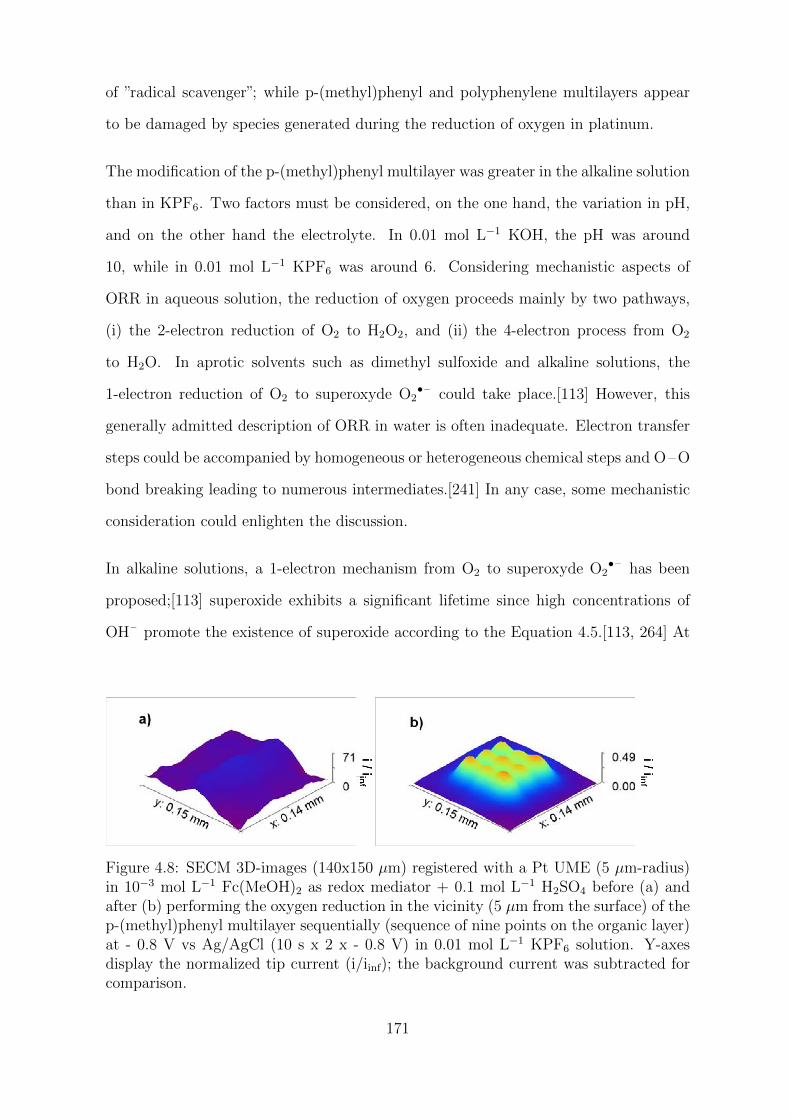
of ”radical scavenger”; while p-(methyl)phenyl and polyphenylene multilayers appear
to be damaged by species generated during the reduction of oxygen in platinum.
The modification of the p-(methyl)phenyl multilayer was greater in the alkaline solution
than in KPF6. Two factors must be considered, on the one hand, the variation in pH,
and on the other hand the electrolyte. In 0.01 mol L−1 KOH, the pH was around
10, while in 0.01 mol L−1 KPF6 was around 6. Considering mechanistic aspects of
ORR in aqueous solution, the reduction of oxygen proceeds mainly by two pathways,
(i) the 2-electron reduction of O2 to H2O2, and (ii) the 4-electron process from O2
to H2O. In aprotic solvents such as dimethyl sulfoxide and alkaline solutions, the
1-electron reduction of O2 to superoxyde O2•– could take place.[113] However, this
generally admitted description of ORR in water is often inadequate. Electron transfer
steps could be accompanied by homogeneous or heterogeneous chemical steps and O–O
bond breaking leading to numerous intermediates.[241] In any case, some mechanistic
consideration could enlighten the discussion.
In alkaline solutions, a 1-electron mechanism from O2 to superoxyde O2•– has been
proposed;[113] superoxide exhibits a significant lifetime since high concentrations of
OH– promote the existence of superoxide according to the Equation 4.5.[113, 264] At
Figure 4.8: SECM 3D-images (140x150 µm) registered with a Pt UME (5 µm-radius)in 10−3 mol L−1 Fc(MeOH)2 as redox mediator + 0.1 mol L−1 H2SO4 before (a) andafter (b) performing the oxygen reduction in the vicinity (5 µm from the surface) of thep-(methyl)phenyl multilayer sequentially (sequence of nine points on the organic layer)at - 0.8 V vs Ag/AgCl (10 s x 2 x - 0.8 V) in 0.01 mol L−1 KPF6 solution. Y-axesdisplay the normalized tip current (i/iinf); the background current was subtracted forcomparison.
171
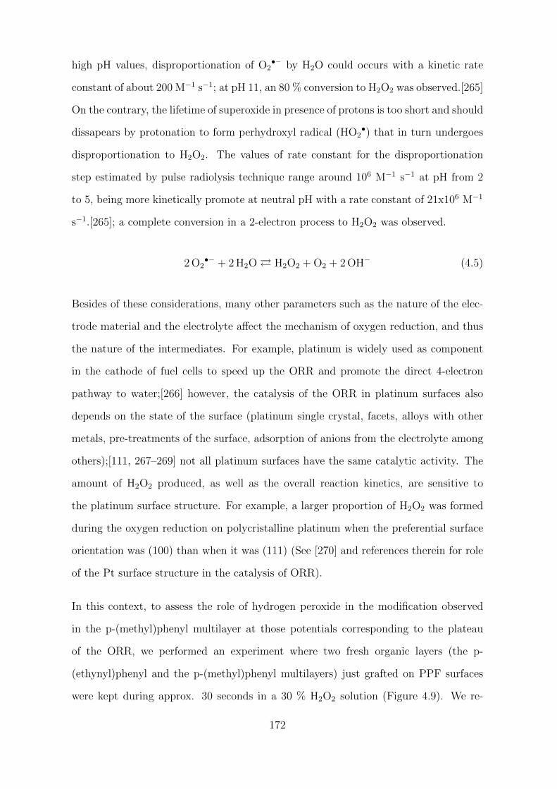
high pH values, disproportionation of O2•– by H2O could occurs with a kinetic rate
constant of about 200 M−1 s−1; at pH 11, an 80 % conversion to H2O2 was observed.[265]
On the contrary, the lifetime of superoxide in presence of protons is too short and should
dissapears by protonation to form perhydroxyl radical (HO2•) that in turn undergoes
disproportionation to H2O2. The values of rate constant for the disproportionation
step estimated by pulse radiolysis technique range around 106 M−1 s−1 at pH from 2
to 5, being more kinetically promote at neutral pH with a rate constant of 21x106 M−1
s−1.[265]; a complete conversion in a 2-electron process to H2O2 was observed.
2 O2•− + 2 H2O H2O2 + O2 + 2 OH− (4.5)
Besides of these considerations, many other parameters such as the nature of the elec-
trode material and the electrolyte affect the mechanism of oxygen reduction, and thus
the nature of the intermediates. For example, platinum is widely used as component
in the cathode of fuel cells to speed up the ORR and promote the direct 4-electron
pathway to water;[266] however, the catalysis of the ORR in platinum surfaces also
depends on the state of the surface (platinum single crystal, facets, alloys with other
metals, pre-treatments of the surface, adsorption of anions from the electrolyte among
others);[111, 267–269] not all platinum surfaces have the same catalytic activity. The
amount of H2O2 produced, as well as the overall reaction kinetics, are sensitive to
the platinum surface structure. For example, a larger proportion of H2O2 was formed
during the oxygen reduction on polycristalline platinum when the preferential surface
orientation was (100) than when it was (111) (See [270] and references therein for role
of the Pt surface structure in the catalysis of ORR).
In this context, to assess the role of hydrogen peroxide in the modification observed
in the p-(methyl)phenyl multilayer at those potentials corresponding to the plateau
of the ORR, we performed an experiment where two fresh organic layers (the p-
(ethynyl)phenyl and the p-(methyl)phenyl multilayers) just grafted on PPF surfaces
were kept during approx. 30 seconds in a 30 % H2O2 solution (Figure 4.9). We re-
172
Figure 4.9: SECM approach curves registered with a Pt UME (5 µm-radius) in 10−3 molL−1 Fc(MeOH)2 as redox mediator + 0.1 mol L−1 H2SO4 on PPF surfaces modified with(a) p-(ethynyl)phenyl multilayer and (b) p-(methyl)phenyl multilayer before (black)and after (blue) treatment with a 30 % H2O2 solution. Note that plots registeredbefore and after are totally overlayed.
gistered the approach curves before and after the treatment with H2O2 at different
points on the organic layers. As shown in Figure 4.9, for both organic layers before and
after treatment in H2O2, the approach curves show a negative feedback, indicating that
the electron transfer of the redox mediator is hindered by the organic layer. Note that
plots registered before and after are overlayed; no significant differences were observed
in either of the two layers after exposure to a 30 % H2O2 solution.
These findings suggest that hydrogen peroxide may not be directly involved in the dam-
age of the p-(methyl)phenyl multilayer during the ORR on the Pt UME. Nevertheless,
it has been previously proposed in the literature that hydrogen peroxide can undergo
reduction at metals such as platinum or be catalytically decomposed to HO• in presence
of transition metals such as iron (II).[247, 249, 271] As it is known, hydrogen peroxide
is a weak oxidant, while HO• is one of the most active oxidants known.[246] Although
the exact identity of the species involved in the layer modification cannot be derived
from these series of experiments, preliminary investigations carried out in 0.01 mol L−1
KPF6 aqueous solution with gold and carbon ultramicroelectrodes on the methylaryl
multilayer, reveal a possible non-catalytic mechanism of hydroxyl radical production.
To develop a further understanding about the nature of the species responsible of the
layer modification future works can consider experimental conditions in which the 2-
173
electron pathway for reduction of oxygen is favored. Oxygen under certain conditions
is preferentially reduced to H2O2, specifically, at carbon electrodes or at pre-reduced
Pt surfaces in acidic aqueous solution.[256, 272]
An open question arising from the reactivity observed with carbon and gold electrodes is
whether traces of ferrocene dimethanol possibly present in the target solution (0.01 mol
L−1 KPF6) during the ORR were able to mediate the decomposition of H2O2 to HO• by
Fenton-like reaction, and in turn damage the methylaryl multilayer. The electro-Fenton
reactions have been widely studied in the framework of the electrochemical advanced
oxidation processes (EAOPs) for waste water remediation, and there is a consensus in
the literature on the role of hydroxyl radicals as the primary oxidizing agent involved in
the destruction of the organic matter.[273–275] It is very well established the production
of HO• radicals from the in situ electrogenerated H2O2 in presence of metals by electro-
Fenton reaction in the cathode (Equations 4.6 and 4.7).[244, 276]
O2 + 2 H+ + 2 e− H2O2 (4.6)
Fe2+ + H2O2 → Fe3+ + HO• + HO− (4.7)
The most favourable experimental conditions for an efficient electro-Fenton process
are: non-catalytic cathodic materials such as carbon derivatives, graphite or mercury,
where the production of hydrogen peroxide is maximized, ambient temperature, acidic
medium (pH 2 - 4), and the presence of metal catalysts such as salts of iron (II) and
(III), copper (I), cobalt (III) among others; although the salts of iron (II) and (III)
are the best catalysts since they act efficiently at lower concentrations, typically 10−4
mol L−1.[246] In our case, the experimental conditions are not the most favorable for
an electro-Fenton process, with a pH around 6 in the KPF6 solution, where platinum
and gold electrodes, unlike carbon, can be considered catalytic for a direct conversion
of oxygen to water following a 4-electron pathway, and with no metals in solution,
only possible traces of ferrocene from the redox mediator used to approach the tip to
174
the surface. Other sources of metal ions such as iron, copper, cobalt, chromium and
nickel were previously discarded by ICP-MS analysis of the electrolytes (nBu4NPF6 and
KPF6), reagents (4-(methyl)benzenediazonium tetrafluoroborate) and water used for
the modification of the PPF surfaces and during the SECM experiments; traces of iron,
copper and nickel were only found in concentrations below 0.02 ppm in the electrolyte
KPF6. In any case, production of H2O2 by the reduction of oxygen develops in most
cathodes materials, but even so, a source of metal ions is required for its decomposition.
Concerning the possible catalytic activity of ferrocene and its derivatives towards the
decomposition of H2O2 by a Fenton-like reaction, some recent works have considered
this approach for the removal of methylene blue and other organic molecules such as
antibiotics from aqueous solutions.[277–279] However, from these publications the role
of ferrocene as a catalyst cannot be asserted since other side processes or reactions such
as hydrogen evolution, reduction of hydrogen peroxide in the cathode, decomposition
of hydrogen peroxide by applying a source of light, or adsorption of the organic mo-
lecule coexist during its degradation, which has been inadequately attributed to the
production of hydroxyl radicals by catalytic hydrogen peroxide decomposition in the
presence of ferrocene. Considering the stability of ferrocene,[107] and the fact that if it
was present, it was at concentrations certainly lower than those detectable by electro-
chemical means on an ultramicroelectrode; its participation in the modification of the
methylaryl multilayer seems unlikely. Nevertheless, to avoid the possible contribution
of a Fenton-like reaction to the production of hydroxyl radicals during the ORR, future
works should consider the use of aqueous soluble non-metal mediators.
Finally, in relation to the modification observed on the methylaryl multilayer at anodic
applied potentials in both electrolyte media, in particular at + 0.6 V, + 0.4 V and +
0.2 V vs Ag/AgCl in 0.01 mol L−1 KOH and at + 0.6 V and + 0.4 V vs Ag/AgCl in
0.01 mol L−1 KPF6 (See Figures 4.6 d and h), it is well known that hydroxyl radicals
are directly generated from the electrochemical oxidation of water.[249] However, no
electron transfer occurs at these applied potentials when observing the corresponding
175
cyclic voltammetry plots (See Figure 4.5); only a few tens of nanoampers were registered
at these applied potentials. During the investigation of the influence of the applied
potential on the modification of the organic layers, this unexpected damage observed
on the methylaryl multilayer at anodic applied potentials a priori cannot be justify
by an electrochemical production of reactive oxygen species during the oxidation of
water at the platinum ultramicroelectrode. This observation is not yet understood;
the influence of the concentration of oxygen in the aqueous solutions should be further
considered, i.e. in an experimental approach allowing the total elimination of dissolved
oxygen in the solution, or the use of radical scanvengers non electroactive in this range
of potential (from + 0.2 V to + 0.6 V) to assert the formation of radicals during the
anodic scan.
176
4.3 Experimental section
4.3.1 Reagents
All commercially available reagents were used as received.
Non-commercially reagents were synthesized in the laboratory:
• 4-(ethynyl)benzenediazonium tetrafluoroborate (Eth-ArN2+BF4
– ) was synthes-
ized as follows, from the corresponding commercial amine following the classical
procedure of diazotisation of aromatic amines: 4-(ethynyl)aniline (10−2 mol L−1)
was dissolved in 7.5 mL of aqueous HBF4 25 % wt solution (3x10⁻² mol L−1).
After cooling in an ice bath, sodium nitrite (1.5x10⁻² mol L−1) was added to
the solution dropwise under vigorous stirring. After reaction and filtering, the
diazonium salt was washed with 5 % NaBF4, cold water, cold methanol and di-
ethyl ether. 1H-NMR (300 MHz, CDCl3): δ = 8.47 (d, 2H, J = 9.00 Hz), 7.98
(d, 2H, J = 9.00 Hz), 4.26 (s, 1H).
• 4-(methyl)benzenediazonium tetrafluoroborate (Me-ArN2+BF4
– ) was prepared
from 4-(methyl)aniline (10−2 mol L−1) following the procedure already described
for Eth-ArN2+BF4
– . 1H-NMR (300 MHz, CDCl3): δ = 8.35 (d, 2H, J = 8.45
Hz), 7.76 (d, 2H, J = 8.45 Hz), 2.64 (s, 3H).
All aqueous solutions were made employing ultrapure water (18.2 MΩ-cm).
177
4.3.2 Electrochemical measurements
4.3.2.1 Instrumentation
• For PPF surface modification. All the surface modifications were performed us-
ing a standard three-electrode setup at a controlled potential with a potentiostat
Autolab PGSTAT 302N (Metrohm). The set of electrodes consisted of a small
square (15x15 mm2) of pyrolyzed photoresist film (PPF) as working electrode, a
platinum mesh as the auxiliary electrode, and a saturated calomel electrode (SCE,
KCl sat.) as reference. The latter was isolated from the working solution em-
ploying a salt bridge, which contained the electrolyte solution. When necessary,
a conventional gas inlet was used for bubbling argon inside the electrochemical
cell to displace oxygen. Pyrolyzed photoresist films (PPFs) were homemade fab-
ricated according to described methods[182]. See Procedure of PPF fabrication
in this Section.
• For SECM experiments. SECM experiments were performed with a three- elec-
trode setup, comprising a 10 µm-diameter Pt UME (IJ Cambria) with a RG =
7, a Pt wire as the auxiliary electrode, and a homemade Ag/AgCl (0.1 mol L−1
KCl) electrode as reference. Figure 4.10 shows SEM images of a just polished
platinum UME embedded and sealed in a quartz glass body. A homemade SECM
equipment was used comprising the positioning elements, translator stages, mo-
tor controllers, data acquisition system, and software written by Wittstock et
al.[280] that provides complete control over all of the above elements and also,
over an adjustable stage for the UME tilt angle correction (See Scheme 4.3 for
a typical scanning electrochemical microscope with the essential components).
SECM images and approach curves were recorded using a CHI910 potentiostat
from CH Instruments. Additional experiments were performed using as WE a
gold SECM tip of 12.5 µm-diameter (IJ Cambria) and a carbon fiber disc tip of
10 µm-diameter (Kation Europe).
178
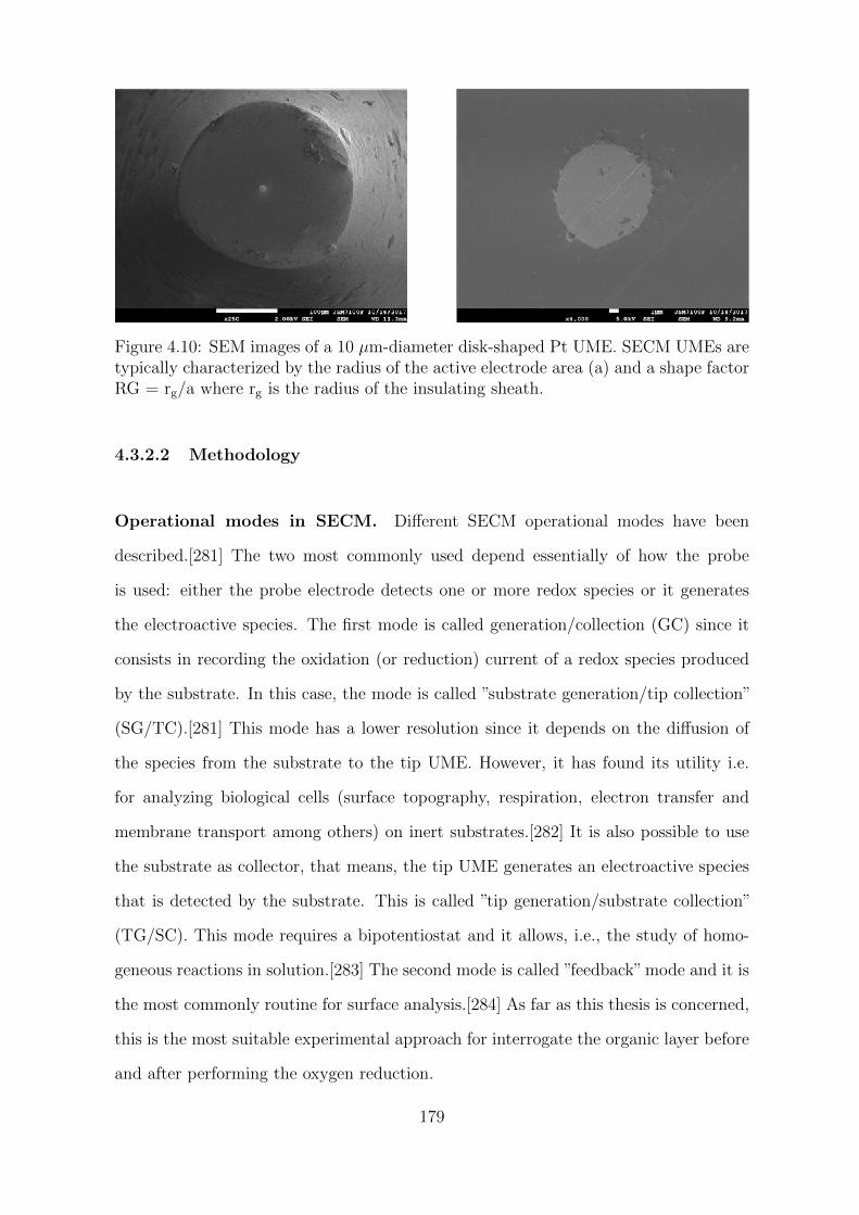
Figure 4.10: SEM images of a 10 µm-diameter disk-shaped Pt UME. SECM UMEs aretypically characterized by the radius of the active electrode area (a) and a shape factorRG = rg/a where rg is the radius of the insulating sheath.
4.3.2.2 Methodology
Operational modes in SECM. Different SECM operational modes have been
described.[281] The two most commonly used depend essentially of how the probe
is used: either the probe electrode detects one or more redox species or it generates
the electroactive species. The first mode is called generation/collection (GC) since it
consists in recording the oxidation (or reduction) current of a redox species produced
by the substrate. In this case, the mode is called ”substrate generation/tip collection”
(SG/TC).[281] This mode has a lower resolution since it depends on the diffusion of
the species from the substrate to the tip UME. However, it has found its utility i.e.
for analyzing biological cells (surface topography, respiration, electron transfer and
membrane transport among others) on inert substrates.[282] It is also possible to use
the substrate as collector, that means, the tip UME generates an electroactive species
that is detected by the substrate. This is called ”tip generation/substrate collection”
(TG/SC). This mode requires a bipotentiostat and it allows, i.e., the study of homo-
geneous reactions in solution.[283] The second mode is called ”feedback” mode and it is
the most commonly routine for surface analysis.[284] As far as this thesis is concerned,
this is the most suitable experimental approach for interrogate the organic layer before
and after performing the oxygen reduction.
179
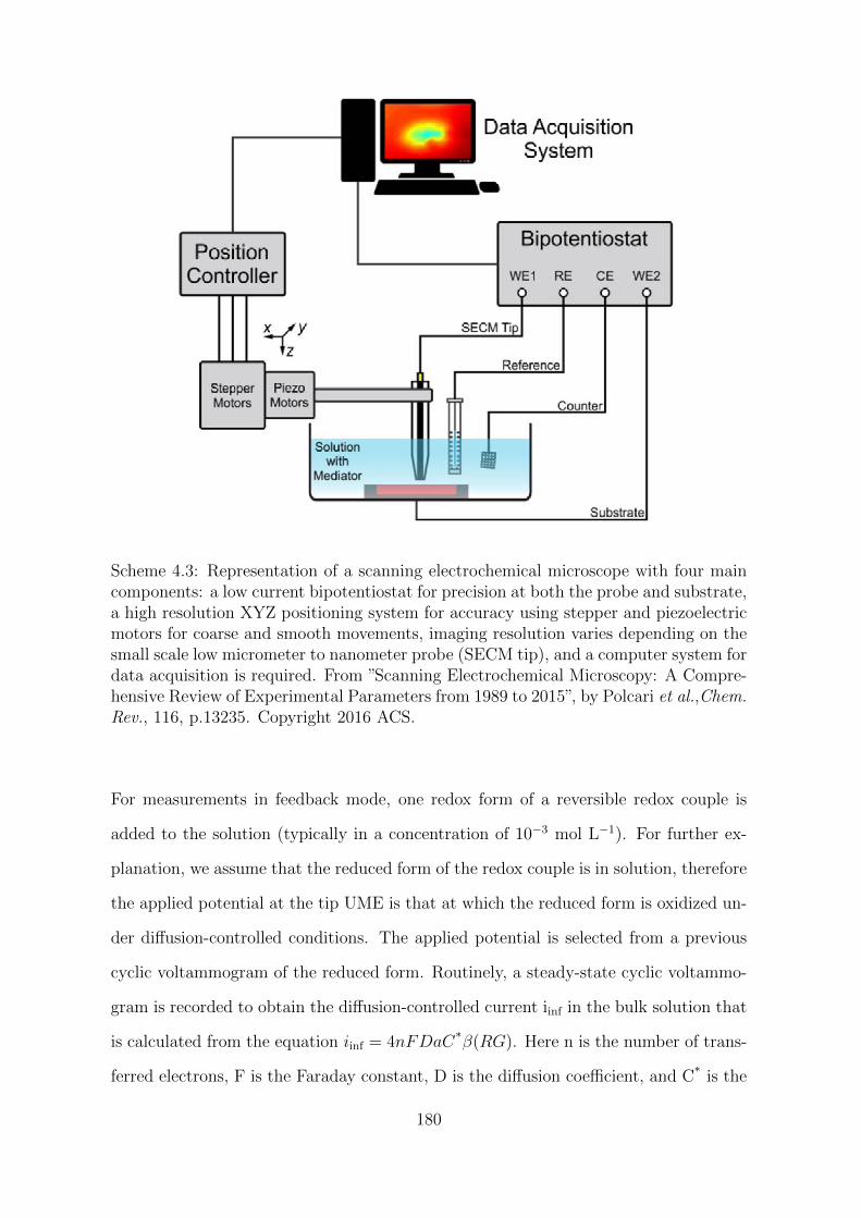
Scheme 4.3: Representation of a scanning electrochemical microscope with four maincomponents: a low current bipotentiostat for precision at both the probe and substrate,a high resolution XYZ positioning system for accuracy using stepper and piezoelectricmotors for coarse and smooth movements, imaging resolution varies depending on thesmall scale low micrometer to nanometer probe (SECM tip), and a computer system fordata acquisition is required. From ”Scanning Electrochemical Microscopy: A Compre-hensive Review of Experimental Parameters from 1989 to 2015”, by Polcari et al.,Chem.Rev., 116, p.13235. Copyright 2016 ACS.
For measurements in feedback mode, one redox form of a reversible redox couple is
added to the solution (typically in a concentration of 10−3 mol L−1). For further ex-
planation, we assume that the reduced form of the redox couple is in solution, therefore
the applied potential at the tip UME is that at which the reduced form is oxidized un-
der diffusion-controlled conditions. The applied potential is selected from a previous
cyclic voltammogram of the reduced form. Routinely, a steady-state cyclic voltammo-
gram is recorded to obtain the diffusion-controlled current iinf in the bulk solution that
is calculated from the equation iinf = 4nFDaC*β(RG). Here n is the number of trans-
ferred electrons, F is the Faraday constant, D is the diffusion coefficient, and C* is the
180
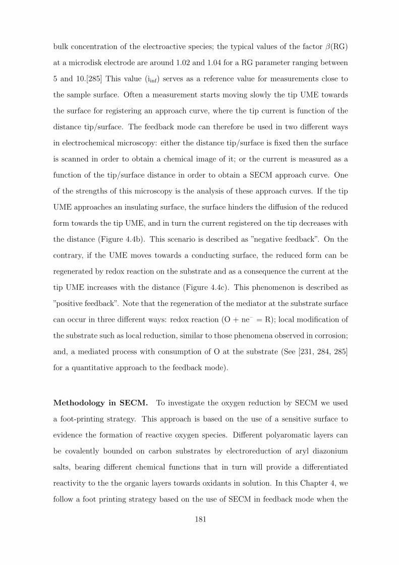
bulk concentration of the electroactive species; the typical values of the factor β(RG)
at a microdisk electrode are around 1.02 and 1.04 for a RG parameter ranging between
5 and 10.[285] This value (iinf) serves as a reference value for measurements close to
the sample surface. Often a measurement starts moving slowly the tip UME towards
the surface for registering an approach curve, where the tip current is function of the
distance tip/surface. The feedback mode can therefore be used in two different ways
in electrochemical microscopy: either the distance tip/surface is fixed then the surface
is scanned in order to obtain a chemical image of it; or the current is measured as a
function of the tip/surface distance in order to obtain a SECM approach curve. One
of the strengths of this microscopy is the analysis of these approach curves. If the tip
UME approaches an insulating surface, the surface hinders the diffusion of the reduced
form towards the tip UME, and in turn the current registered on the tip decreases with
the distance (Figure 4.4b). This scenario is described as ”negative feedback”. On the
contrary, if the UME moves towards a conducting surface, the reduced form can be
regenerated by redox reaction on the substrate and as a consequence the current at the
tip UME increases with the distance (Figure 4.4c). This phenomenon is described as
”positive feedback”. Note that the regeneration of the mediator at the substrate surface
can occur in three different ways: redox reaction (O + ne– = R); local modification of
the substrate such as local reduction, similar to those phenomena observed in corrosion;
and, a mediated process with consumption of O at the substrate (See [231, 284, 285]
for a quantitative approach to the feedback mode).
Methodology in SECM. To investigate the oxygen reduction by SECM we used
a foot-printing strategy. This approach is based on the use of a sensitive surface to
evidence the formation of reactive oxygen species. Different polyaromatic layers can
be covalently bounded on carbon substrates by electroreduction of aryl diazonium
salts, bearing different chemical functions that in turn will provide a differentiated
reactivity to the the organic layers towards oxidants in solution. In this Chapter 4, we
follow a foot printing strategy based on the use of SECM in feedback mode when the
181
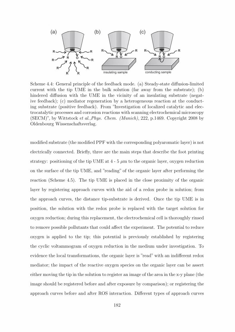
Scheme 4.4: General principle of the feedback mode. (a) Steady-state diffusion-limitedcurrent with the tip UME in the bulk solution (far away from the substrate); (b)hindered diffusion with the UME in the vicinity of an insulating substrate (negat-ive feedback); (c) mediator regeneration by a heterogeneous reaction at the conduct-ing substrate (positive feedback). From ”Investigation of localized catalytic and elec-trocatalytic processes and corrosion reactions with scanning electrochemical microscopy(SECM)”, by Wittstock et al.,Phys. Chem. (Munich), 222, p.1469. Copyright 2008 byOldenbourg Wissenschaftsverlag.
modified substrate (the modified PPF with the corresponding polyaromatic layer) is not
electrically connected. Briefly, three are the main steps that describe the foot printing
strategy: positioning of the tip UME at 4 - 5 µm to the organic layer, oxygen reduction
on the surface of the tip UME, and ”reading” of the organic layer after performing the
reaction (Scheme 4.5). The tip UME is placed in the close proximity of the organic
layer by registering approach curves with the aid of a redox probe in solution; from
the approach curves, the distance tip-substrate is derived. Once the tip UME is in
position, the solution with the redox probe is replaced with the target solution for
oxygen reduction; during this replacement, the electrochemical cell is thoroughly rinsed
to remove possible pollutants that could affect the experiment. The potential to reduce
oxygen is applied to the tip; this potential is previously established by registering
the cyclic voltammogram of oxygen reduction in the medium under investigation. To
evidence the local transformations, the organic layer is ”read” with an indifferent redox
mediator; the impact of the reactive oxygen species on the organic layer can be assert
either moving the tip in the solution to register an image of the area in the x-y plane (the
image should be registered before and after exposure by comparison); or registering the
approach curves before and after ROS interaction. Different types of approach curves
182
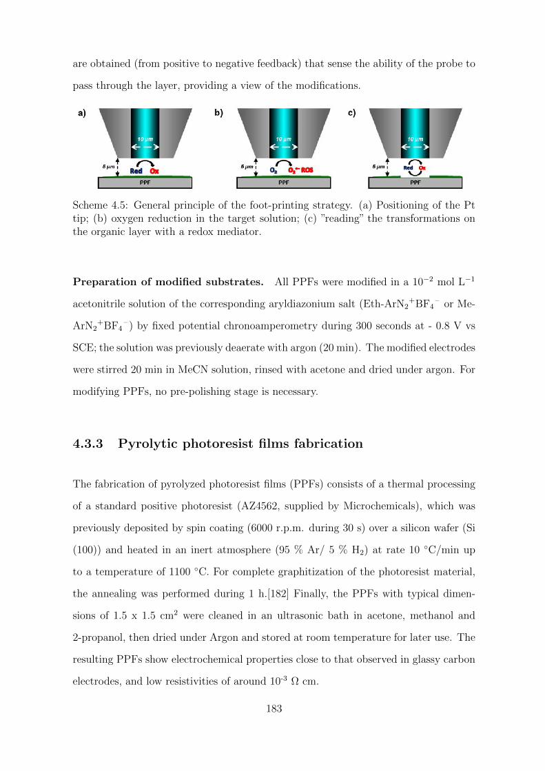
are obtained (from positive to negative feedback) that sense the ability of the probe to
pass through the layer, providing a view of the modifications.
Scheme 4.5: General principle of the foot-printing strategy. (a) Positioning of the Pttip; (b) oxygen reduction in the target solution; (c) ”reading” the transformations onthe organic layer with a redox mediator.
Preparation of modified substrates. All PPFs were modified in a 10−2 mol L−1
acetonitrile solution of the corresponding aryldiazonium salt (Eth-ArN2+BF4
– or Me-
ArN2+BF4
– ) by fixed potential chronoamperometry during 300 seconds at - 0.8 V vs
SCE; the solution was previously deaerate with argon (20 min). The modified electrodes
were stirred 20 min in MeCN solution, rinsed with acetone and dried under argon. For
modifying PPFs, no pre-polishing stage is necessary.
4.3.3 Pyrolytic photoresist films fabrication
The fabrication of pyrolyzed photoresist films (PPFs) consists of a thermal processing
of a standard positive photoresist (AZ4562, supplied by Microchemicals), which was
previously deposited by spin coating (6000 r.p.m. during 30 s) over a silicon wafer (Si
(100)) and heated in an inert atmosphere (95 % Ar/ 5 % H2) at rate 10 C/min up
to a temperature of 1100 C. For complete graphitization of the photoresist material,
the annealing was performed during 1 h.[182] Finally, the PPFs with typical dimen-
sions of 1.5 x 1.5 cm2 were cleaned in an ultrasonic bath in acetone, methanol and
2-propanol, then dried under Argon and stored at room temperature for later use. The
resulting PPFs show electrochemical properties close to that observed in glassy carbon
electrodes, and low resistivities of around 10-3 Ω cm.
183
4.3.4 Ag/AgCl quasi-reference electrode fabrication
Ag/AgCl quasi-reference electrodes were fabricated by electrolysis of a 0.1 mol L−1
aqueous solution of KCl when the working electrode was a silver wire, the counter
electrode was a platinum mesh and the reference a saturated calomel electrode (SCE,
KCl sat.). Both the reference and the counter were isolated from the working solu-
tion employing a salt bridge containing the electrolyte solution. The electrolysis was
performed during 1 h at a fixed potential of 0.1 V vs SCE, according to the potential
required to cover the silver wire used as working electrode with an homogeneous film
of AgCl (Equation 4.8). After electrolysis, the silver surface has darkened and lost
its characteristic shine. The resulting quasi-reference Ag/AgCl electrodes were tested
with a voltmeter against a SCE (KCl sat.) in an 0.1 mol L−1 KCl aqueous solution,
being the difference in potential of around 44 mV.[286]
AgCl(s) + e− Ag(s) + Cl− E0 = 0.22 vs SHE (4.8)
184
4.4 Conclusion
In aqueous media, ORR is generally described as a mixture of 2- and 4-electron re-
duction processes leading to the formation of H2O2 and H2O. However, such global
reaction schemes do not reflect the mechanistic pathways especially for what concerns
the transient reactive oxygen species, which are key intermediates even if not explicitly
considered. In this context, our aim was the detection of intermediates during the
ORR on platinum by SECM using a foot-printing strategy.[114] The role of different
sensitive layers, applied potential and electrolytes were investigated.
Two different polyaromatic multilayers were successfully grafted by aryldiazonium
chemistry on PPF surfaces, the p-(ethynyl)phenyl multilayer and the p-(methyl)phenyl
multilayer. Both multilayers were characterized showing similar thickness values and
blocking properties towards the electron transfer of ferrocene and dopamine in solu-
tion; no electron transfer was observed and the absence of defects or pinholes was
also confirmed by AFM imaging experiments. From the SECM experiments, a differ-
ential behavior between the p-(ethynyl)phenyl and the p-(methyl)phenyl multilayers
was observed and explained in terms of their reactivity towards the hydroxyl radicals
probably generated as intermediate during the oxygen reduction on platinum. The
former did not undergo modification after ORR at any potential or reaction media,
while the later was affected in both media and almost at all applied potentials, anodic
and cathodic, except around 0 V. This differential behavior could be attributed to the
”radical scavenger” properties of the unsaturated bonds integrated in the ethynylaryl
multilayer, which seem to prevent or delay the oxidative damage of the polyaromatic
structure during the exposition to oxygen reactive species, unlike that observed in the
methylaryl multilayer.
Concerning the influence of the electrolyte and the pH, low concentrations of electrolyte
were expected to avoid side reactions of the reactive oxygen species electro-generated
185
on the platinum electrode. Two different aqueous electrolyte solutions with different
pH values were considered. The larger damage on the methyl layer was observed when
the electrolyte was KOH (pH ∼ 10). It is difficult to extract conclusions regarding the
effect of the pH but from the literature,[113, 265] and despite that different mechan-
isms of reaction have been described depending on the pH of the aqueous solutions,
pulse radiolysis experiments indicate a total conversion of oxygen to hydrogen peroxide
between pH values from 2 to 5, and a yield of 80 % in the case of alkaline solu-
tions (pH ∼ 11). These considerations should be taken with caution given the widely
demonstrated influence of the nature of the electrode on the catalysis of the oxygen
reduction.[111, 268]
Although from these series of experiments, the oxidizing species responsible of the
damage on the methyl layer cannot be derived, the direct participation of H2O2 was
discarded; this is consistent with its moderate oxidizing properties. At those potentials
corresponding to the plateau of the ORR, preliminary investigations carried out in
0.01 mol L−1 KPF6 aqueous solution with gold and carbon ultramicroelectrodes on the
methylaryl multilayer, revealed a possible non-catalytic mechanism of hydroxyl radical
production as damage to the organic layer was also observed when the working electrode
was gold and carbon. The unfavored experimental conditions for an electro-Fenton
process in KPF6 solution (pH∼ 6), the lack of metals able to catalyze the decomposition
of H2O2 and the unlike catalytic activity of traces of ferrocene dimethanol towards the
decomposition of H2O2 are contrary to the hypothesis of the non-catalytic production of
hydroxyl radicals from H2O2 electro-generated on platinum, gold and carbon. However,
further confirmation of these preliminary results is required and future investigation
could consider experimental conditions in which the 2-electron pathway for reduction of
oxygen is favored, and also the use of aqueous soluble non-metal mediators to avoid the
possible contribution of a Fenton-like reaction to the production of hydroxyl radicals
during the ORR.
An unexpected modification of the methylaryl multilayer was registered in both elec-
186

trolyte solutions at applied potentials in the anodic region, where no electroactivity was
observed by cyclic voltammetry experiments. The participation of radical species in
the damage of the organic layer at these anodic applied potentials should be further in-
vestigated since a priori, this observation is not compatible with the electro-generation
of any reactive oxygen species during i.e. the oxidation of water. In this regard, further
experiments could consider the influence of the concentration of oxygen in the aqueous
solutions and the use of radical scavengers non-electroactive in this range of potential
to assert a possible formation of radicals during the anodic scan.
187


Conclusion and Perspectives
During this thesis, we have demonstrated the interest and versatility of aryldiazonium
salts in fundamental research of phenomena such as the study and optimization of elec-
tron transfer properties at the electrode/solution interface and in applications such as
oxygen reduction catalysis and electrochemical energy storage systems, which are fields
of great interest nowadays. We have shown how the surface properties of materials such
as carbon can be modulated by electrochemical reduction of aryldiazonium salts. First,
with the introduction of an on-carbon ferrocene-terminated electroactive system with
a monolayer type organization. In this case, we have observed the great influence of
the reaction media on the electron transfer kinetics and thermodynamics of the im-
mobilized electroactive molecule. This influence was demonstrated to be linked to a
differential solvation of the different organic solvents on the electrolyte in solution and,
therefore, to the possibility of this latter to form ionic pairs with the oxidized form of
ferrocene. The resistance, apparent capacitance and time constant of the immobilized
electroactive system on carbon were successfully determined from electrochemical im-
pedance measurements. The reaction medium was optimized to maximize the energy
storage of the mixed capacitive system, consisting of the electrochemical double layer
and the faradaic contribution. We have demonstrated that a controlled modification
of the carbon surface allows maximizing the synergy between the inherent-material
properties for energy storage (electrochemical double layer) and the contribution of
the ferrocene electron transfer to the charge storage system, achieving improvements
of charge density far superior to those reported in the literature for equivalent systems
191
based on carbon modification with quinones. Further investigation could consider the
evaluation of this modification with other carbon materials more adapted for real ap-
plications in electrochemical supercapacitors and charge storage devices.
Second, we have demonstrated the interest of introducing aryldiazonium molecules with
a pre-organized structure by electro-reduction of the tetrahedral-shape pre-organized
tetra-aryldiazonium salt, tetrakis(4-phenyldiazonium tetrafluoroborate)methane. Its
electro-reduction led to the deposition of an ultrathin film on gold and carbon surfaces,
which was further confirmed by XPS, AFM, SE and CV experiments. This was a
first occurrence where both molecular sieving and electrochemical current rectification
properties towards the electron transfer of redox probes in solution has been observed
for non-electroactive organic films electro-generated by the reduction of aryldiazonium
ions. Only a few examples in the literature concerning the electrochemical reduction of
aryldiazonium salts consider this bottom-up approach for structuring surfaces. Due the
remarkable properties observed here, more efforts could be oriented to the synthesis and
study of pre-organized systems based on aryldiazonium salts for surface modification.
Third and finally, an important time period of this thesis has been dedicated to the
study of the catalysis of oxygen reduction in aqueous media on polycrystalline plat-
inum electrodes. The technique and methodology used are adapted to the objective
previously defined as the determination of reactive oxygen species during the ORR
and the impact of parameters such as the applied potential and the reaction media
during the ORR. To evidence the production of highly reactive species, we used the
SECM imaging approach, which is well adapted to the study of oxygen catalysis as
evidenced by the extensive literature on the subject, as it allows a rapid screening
at the local level of samples evidencing their topography and electroactivity in one
time experience. The experimental approach, previously developed in the group, is
known as ”foot-printing”. It is based on the use of different organic layers that are
sensitive to the presence of oxidizing species. The role of different organic layers was
investigated. SECM experiments reported differential behaviours between ethynylaryl
192
and the methylaryl multilayers, which may be explained in terms of their reactivity
towards hydroxyl radicals. Preliminary experiences with gold and carbon electrodes
evidence a possible non-catalytic production of hydroxyl radicals that presumably are
the only species with sufficient oxidizing ability to react with polyaromatic layers as
those studied here. No significant differences were observed when the reaction me-
dium was modified; however, an interesting observation was the modification of the
methylaryl layer at applied potentials corresponding to the anodic region, where no
electro-activity was observed by cyclic voltammetry. The overall observations here re-
ported have not been fully understood and many questions remain about the exact
nature of the intermediate and the mechanism as the detection remains indirect. Thus,
future work may consider characterization of the chemical composition of the layer
after exposure to oxidizing species and ensure radical production in the anodic region,
i.e., by using radical scavengers in solution. Catalytic or non-catalytic production of
these radicals could be considered in future investigations under rigorous control of the
experimental conditions.
193


Bibliography
[1] Griefs P. Vorlaufige notiz uber die einwirkung von salpetriger saure auf
amidinitro-und aminitrophenylsaure. Justus Liebigs Ann. Chem., 106(1):123–
125, 1858.
[2] N. Oger, E. Le Grognec, and F. X. Felpin. Handling diazonium salts in flow for
organic and material chemistry. Org. Chem. Front., 2(5):590–614, 2015.
[3] S. Patai. The Chemistry of Diazonium and Diazo Groups. John Wiley & Sons,
1978.
[4] J. M. Sullivan. Explosion during preparation of benzenediazonium-2-carboxylate
hydrochloride. J. Chem. Educ., 48(6):419, 1971.
[5] Dow Chemical Company. Private communication., 2014.
[6] M. Sheng, D. Frurip, and D. Gorman. Reactive chemical hazards of diazonium
salts. J. Loss Prevent. Proc., 38:114–118, 2015.
[7] D. T. Flood. Flurobenzene. Org. Synth., 2:295, 1943.
[8] M. Cygler, M. Przybylska, and R. M. Elofson. The crystal structure of benze-
nediazonium tetrafluoroborate, C6H5N2+BF4
– . Rev. Can. Chim., 60(22):2852–
2855, 1982.
[9] P. Allongue, M. Delamar, B. Desbat, O. Fagebaume, R. Hitmi, J. Pinson, and
J. M. Saveant. Covalent modification of carbon surfaces by aryl radicals gener-
ated from the electrochemical reduction of diazonium salts. J. Am. Chem. Soc.,
119(1):201–207, 1997.
[10] A. Chausse, M. M. Chehimi, N. Karsi, J. Pinson, F. Podvorica, and C. Vautrin-Ul.
The electrochemical reduction of diazonium salts on iron electrodes. the formation
of covalently bonded organic layers and their effect on corrosion. Chem. Mater.,
14(1):392–400, 2002.
[11] Y. R. Leroux, F. Hui, J. M. Noel, C. Roux, A. J. Downard, and P. Hapiot.
Design of robust binary film onto carbon surface using diazonium electrochem-
istry. Langmuir, 27(17):11222–11228, 2011.
[12] C. Galli. Radical reactions of arenediazonium ions: An easy entry into the chem-
istry of the aryl radical. Chem Rev., 88(5):765–792, 1988.
[13] M. Barbero, I. Degani, S. Dughera, and R. Fochi. Halodediazoniations of dry
arenediazonium o-benzenedisulfonimides in the presence or absence of an electron
transfer catalyst. Easy general procedures to prepare aryl chlorides, bromides,
and iodides. J. Org. Chem., 64(10):3448–3453, 1999.
[14] C. Colas and M. Goeldner. An efficient procedure for the synthesis of crystal-
line aryldiazonium trifluoroacetates–synthetic applications. Eur. J. Org. Chem.,
1999(6):1357–1366, 1999.
[15] V. D. Filimonov, M. Trusova, P. Postnikov, E. A. Krasnokutskaya, Y. M. Lee,
H. Y. Hwang, H. Kim, and K.-W. Chi. Unusually stable, versatile, and pure are-
nediazonium tosylates: their preparation, structures, and synthetic applicability.
Org. Lett., 10(18):3961–3964, 2008.
[16] C. Romming. The structure of benzene diazonium chloride. Acta Chem. Scand.,
17(5), 1963.
[17] H. Zollinger. Diazo Chemistry I: Aromatic and Heteroaromatic Compounds.
Diazo Chemistry. Wiley-VCH Verlag GmbH & Co., 1994.
[18] D. Belanger and J. Pinson. Electrografting: A powerful method for surface
modification. Chem. Soc. Rev., 40(7):3995–4048, 2011.
198
[19] S. Baranton and D. Belanger. Electrochemical derivatization of carbon sur-
face by reduction of in situ generated diazonium cations. J. Phys. Chem. B,
109(51):24401–24410, 2005.
[20] S. Baranton and D. Belanger. In situ generation of diazonium cations in organic
electrolyte for electrochemical modification of electrode surface. Electrochim.
Acta, 53(23):6961–6967, 2008.
[21] A. Ulman. Formation and structure of self-assembled monolayers. Chem. Rev.,
96(4):1533–1554, 1996.
[22] D. M. Shewchuk and M. T. McDermott. Comparison of diazonium salt derived
and thiol derived nitrobenzene layers on gold. Langmuir, 25(8):4556–4563, 2009.
[23] M. Delamar, R. Hitmi, J. Pinson, and J. M. Saveant. Covalent modification of
carbon surfaces by grafting of functionalized aryl radicals produced from elec-
trochemical reduction of diazonium salts. J. Am. Chem. Soc., 114:5883–5884,
1992.
[24] L. T. Nielsen, K. H. Vase, M. Dong, F. Besenbacher, S. U. Pedersen, and K. Daas-
bjerg. Electrochemical approach for constructing a monolayer of thiophenolates
from grafted multilayers of diaryl disulfides. J. Am. Chem. Soc., 129:1888–1889,
2007.
[25] C. Combellas, F. Kanoufi, J. Pinson, and F. I. Podvorica. Sterically hindered
diazonium salts for the grafting of a monolayer on metals. J. Am. Chem. Soc.,
130:8576–8577, 2008.
[26] L. Lee, H. Ma, P. A. Brooksby, S. A. Brown, Y. Leroux, P. Hapiot, and A. J.
Downard. Covalently anchored carboxyphenyl monolayer via aryldiazonium ion
grafting: A well-defined reactive tether layer for on-surface chemistry. Langmuir,
30(24):7104–7111, 2014.
199
[27] O. Fontaine, J. Ghilane, P. Martin, J. C. Lacroix, and H. Randriamahazaka. Ionic
liquid viscosity effects on the functionalization of electrode material through the
electroreduction of diazonium. Langmuir, 26(23):18542–18549, 2010.
[28] A. Mattiuzzi, I. Jabin, C. Mangeney, C. Roux, O. Reinaud, L. Santos, J.-F.
Bergamini, P. Hapiot, and C. Lagrost. Electrografting of calix[4]arenediazonium
salts to form versatile robust platforms for spatially controlled surface function-
alization. Nat. Commun., 3:1–8, 2012.
[29] L. Cao, G. Fang, and Y. Wang. Electroreduction of viologen phenyl diazonium
salts as a strategy to control viologen coverage on electrodes. Langmuir,
33(4):980–987, 2017.
[30] A. Bousquet, M. Ceccato, M. Hinge, S. U. Pedersen, and K. Daasbjerg. Redox
grafting of diazotated anthraquinone as a means of forming thick conducting
organic films. Langmuir, 28:1267–1275, 2012.
[31] A. Adenier, C. Combellas, F. Kanoufi, J. Pinson, and F. I. Podvorica. Forma-
tion of polyphenylene films on metal electrodes by electrochemical reduction of
benzenediazonium salts. Chem. Mater., 18(8):2021–2029, 2006.
[32] J. M. Hicks, Z. Y. Wong, D. J. Scurr, N. Silman, S. K. Jackson, P. M. Mendes,
J. W. Aylott, and F. J. Rawson. Tailoring the electrochemical properties of
carbon nanotube modified indium tin oxide via in situ grafting of aryl diazonium.
Langmuir, 33:4924–4933, 2017.
[33] J. Pinson and F. I. Podvorica. Attachment of organic layers to conductive or semi-
conductive surfaces by reduction of diazonium salts. Chem. Soc. Rev., 34:429–439,
2005.
[34] A. Gohier, F. Nekelson, M. Helezen, P. Jegou, G. Deniau, S. Palacin, and
M. Mayne-L’Hermite. Tunable grafting of functional polymers onto carbon nan-
200
otubes using diazonium chemistry in aqueous media. J. Mater. Chem., 21:4615–
4622, 2011.
[35] L. Troian-Gautier, D. E. Martinez-Tong, J. Hubert, F. Reniers, M. Sferrazza,
A. Mattiuzzi, C. Lagrost, and I. Jabin. Controlled modification of polymer sur-
faces through grafting of calix[4]arene-tetradiazoate salts. J. Phys. Chem. C,
120:22936–22945, 2016.
[36] A. Mesnage, X. Lefevre, P. Jegou, G. Deniau, and S. Palacin. Spontaneous
grafting of diazonium salts: Chemical mechanism on metallic surfaces. Langmuir,
28:11767–11778, 2012.
[37] C. Combellas, M. Delamar, F. Kanoufi, J. Pinson, and F. I. Podvorica. Spon-
taneous grafting of iron surfaces by reduction of aryldiazonium salts in acidic
water: Applications to the inhibition of iron corrosion. Passivation of metals and
semiconductors, and properties of thin oxide layers, 17:3968–3975, 2005.
[38] D. Schaming, V.-Q. Nguyen, P. Martin, and J. C. Lacroix. Tunable plasmon res-
onance of gold nanoparticles functionalized by electroactive bisthienylbenzene oli-
gomers or polythiophene. The Journal of Physical Chemistry C, 118(43):25158–
25166, 2014.
[39] T. Menanteau, C. Benoıt, T. Breton, and C. Cougnon. Enhancing the perform-
ance of a diazonium-modified carbon supercapacitor by controlling the grafting
process. Electrochem. Commun., 63:70–73, 2016.
[40] H. Yan, A. J. Bergren, and R. L. McCreery. All-carbon molecular tunnel junc-
tions. Journal of the American Chemical Society, 133:19168–19177, 2011.
[41] S. Y. Sayed, A. Bayat, M. Kondratenko, Y. Leroux, P. Hapiot, and R. L.
McCreery. Bilayer molecular electronics: All-carbon electronic junctions con-
taining molecular bilayers made with “click” chemistry. J. Am. Chem. Soc.,
135(35):12972–12975, 2013.
201
[42] C. P. Andrieux and J. Pinson. The standard redox potential of the phenyl rad-
ical/anion couple. J. Am. Chem. Soc., 125(48):14801–14806, 2003.
[43] R. M. Elofson. The polarographic reduction of diazotized aromatic amines. Rev.
Can. Chim., 36(8):1207–1210, 1958.
[44] F. F. Gadallah and R. M. Elofson. Arylation of aromatic compounds by electro-
chemical reduction of benzenediazonium tetrafluoroborate in aprotic solvents. J.
Org. Chem., 34(11):3335–3338, 1969.
[45] R. M. Elofson and F. F. Gadallah. Pschorr reaction by electrochemical generation
of free radicals. i. phenanthrene synthesis. J. Org. Chem., 36(13):1769–1771,
1971.
[46] A. J. Bard, J. C. Gilbert, and R. D. Goodin. Application of spin trapping to
the detection of radical intermediates in electrochemical transformations. J. Am.
Chem. Soc., 96(2):620–621, 1974.
[47] B. L. Hurley and R. L. McCreery. Covalent bonding of organic molecules to Cu
and Al alloy 2024 T3 surfaces via diazonium ion reduction. J. Electrochem. Soc.,
151(5):B252–B259, 2004.
[48] F. Barriere and A. J. Downard. Covalent modification of graphitic carbon sub-
strates by non-electrochemical methods. J. Solid State Electrochem., 12(10):1231–
1244, 2008.
[49] A. Wataru. Photochemistry of the Diazonium and Diazo Groups, chapter 9 in
Diazonium and Diazo Groups, pages 341–487. Wiley-Blackwell, 2010.
[50] Y. C. Liu and R. L. McCreery. Reactions of organic monolayers on carbon
surfaces observed with unenhanced raman spectroscopy. J. Am. Chem. Soc.,
117(45):11254–11259, 1995.
[51] C. Saby, B. Ortiz, G. Y. Champagne, and D. Belanger. Electrochemical modi-
fication of glassy carbon electrode using aromatic diazonium salts. 1. Blocking
202
effect of 4-Nitrophenyl and 4-Carboxyphenyl groups. Langmuir, 13:6805–6813,
1997.
[52] J. K. Kariuki and M. T. McDermott. Nucleation and growth of functionalized
aryl films on graphite electrodes. Langmuir, 15(19):6534–6540, 1999.
[53] J. L. Bahr, J. Yang, D. V. Kosynkin, M. J. Bronikowski, R. E. Smalley, and J. M.
Tour. Functionalization of carbon nanotubes by electrochemical reduction of aryl
diazonium salts: a bucky paper electrode. J. Am. Chem. Soc., 123(27):6536–6542,
2001.
[54] P. A. Brooksby and A. J. Downard. Electrochemical and atomic force microscopy
study of carbon surface modification via diazonium reduction in aqueous and
acetonitrile solutions. Langmuir, 20(12):5038–5045, 2004.
[55] C. H. Villeneuve, J. Pinson, M. C. Bernard, and P. Allongue. Electrochem-
ical formation of close-packed phenyl layers on si (111). J. Phys. Chem. B,
101(14):2415–2420, 1997.
[56] P. Allongue, C. H. de Villeneuve, G. Cherouvrier, R. Cortes, and M.-C. Bern-
ard. Phenyl layers on h–si (111) by electrochemical reduction of diazonium
salts: monolayer versus multilayer formation. J. Electroanal. Chem., 550:161–
174, 2003.
[57] M. P. Stewart, F. Maya, D. V. Kosynkin, S. M. Dirk, J. J. Stapleton, C. L.
McGuiness, D. L. Allara, and J. M. Tour. Direct covalent grafting of conjugated
molecules onto si, gaas, and pd surfaces from aryldiazonium salts. J. Am. Chem.
Soc., 126(1):370–378, 2004.
[58] M.-C. Bernard, A. Chausse, E. Cabet-Deliry, M. M. Chehimi, J. Pinson, F. Pod-
vorica, and C. Vautrin-Ul. Organic layers bonded to industrial, coinage, and
noble metals through electrochemical reduction of aryldiazonium salts. Chem.
Mater., 15(18):3450–3462, 2003.
203
[59] J. Lyskawa and D. Belanger. Direct modification of a gold electrode
with aminophenyl groups by electrochemical reduction of in situ generated
aminophenyl monodiazonium cations. Chem. Mater., 18(20):4755–4763, 2006.
[60] D. Jiang, B. G. Sumpter, and S. Dai. Structure and bonding between an aryl
group and metal surfaces. J. Am. Chem. Soc., 128(18):6030–6031, 2006.
[61] M. Toupin and D. Belanger. Thermal stability study of aryl modified carbon
black by in situ generated diazonium salt. J. Phys. Chem. C, 111(14):5394–5401,
2007.
[62] R. M. Elofson and F. F. Gadallah. Substituent effects in the polarography of
aromatic diazonium salts. J. Org. Chem., 34(4):854–857, 1969.
[63] P. Doppelt, G. Hallais, J. Pinson, F. Podvorica, and S. Verneyre. Surface modific-
ation of conducting substrates. existence of azo bonds in the structure of organic
layers obtained from diazonium salts. Chem. Mater., 19(18):4570–4575, 2007.
[64] M. Delamar, G. Desarmot, O. Fagebaume, R. Hitmi, J. Pinsonc, and J. M.
Saveant. Modification of carbon fiber surfaces by electrochemical reduction of aryl
diazonium salts: Application to carbon epoxy composites. Carbon, 35(6):801–
807, 1997.
[65] K. Boukerma, M. M. Chehimi, J. Pinson, and C. Blomfield. X-ray photoelectron
spectroscopy evidence for the covalent bond between an iron surface and aryl
groups attached by the electrochemical reduction of diazonium salts. Langmuir,
19(15):6333–6335, 2003.
[66] L. Laurentius, S. R. Stoyanov, S. Gusarov, A. Kovalenko, R. Du, G. P Lopin-
ski, and M. T. McDermott. Diazonium-derived aryl films on gold nanoparticles:
Evidence for a carbon–gold covalent bond. ACS Nano, 5(5):4219–4227, 2011.
[67] A. Laforgue, T. Addou, and D. Belanger. Characterization of the deposition
204
of organic molecules at the surface of gold by the electrochemical reduction of
aryldiazonium cations. Langmuir, 21(15):6855–6865, 2005.
[68] M. M. Chehimi. Aryl Diazonium Salts: New Coupling Agents in Polymer and
Surface Science. John Wiley & Sons, 2012.
[69] F. I. Podvorica, F. Kanoufi, J. Pinson, and C. Combellas. Spontaneous grafting
of diazoates on metals. Electrochim. Acta, 54(8):2164–2170, 2009.
[70] M. Ceccato, A. Bousquet, M. Hinge, S. U. Pedersen, and K. Daasbjerg. Using
a mediating effect in the electroreduction of aryldiazonium salts to prepare con-
ducting organic films of high thickness. Chem. Mater., 23(6):1551–1557, 2011.
[71] Y. R. Leroux, H. Fei, J. M. Noel, C. Roux, and P. Hapiot. Efficient covalent
modification of a carbon surface: Use of a silyl protecting group to form an
active monolayer. J. Am. Chem. Soc., 132(40):14039–14041, 2010.
[72] C. Combellas, D.-E. Jiang, J. Pinson, and F. I. Podvorica. Steric effects in the
reaction of aryl radicals on surfaces. Langmuir, 25:286–293, 2009.
[73] F. Anariba, S. H. DuVall, and R. L. McCreery. Mono-and multilayer formation by
diazonium reduction on carbon surfaces monitored with atomic force microscopy
”scratching”. Anal. Chem., 75:3837–3844, 2003.
[74] T. Menanteau, E. Levillain, and T. Breton. Electrografting via diazonium chem-
istry: from multilayer to monolayer using radical scavenger. Chem. Mater.,
25(14):2905–2909, 2013.
[75] T. Menanteau, E. Levillain, A. J. Downard, and T. Breton. Evidence of monolayer
formation via diazonium grafting with a radical scavenger: electrochemical, AFM
and XPS monitoring. Phys. Chem. Chem. Phys., 17(19):13137–13142, 2015.
[76] G. Shul, C. A. Ruiz, D. Rochefort, P. A. Brooksby, and D. Belanger. Electro-
chemical functionalization of glassy carbon electrode by reduction of diazonium
cations in protic ionic liquid. Electrochim. Acta, 106:378–385, 2013.
205
[77] J. Carvalho Padilha, J. M. Noel, J. F. Bergamini, J. Rault-Berthelot, and
C. Lagrost. Functionalization of carbon materials by reduction of diazonium
cations produced in situ in a brønstedt acidic ionic liquid. ChemElectroChem,
3(4):572–580, 2016.
[78] K. Malmos, M. Dong, S. Pillai, P. Kingshott, F. Besenbacher, S. U. Pedersen, and
K. Daasbjerg. Using a hydrazone-protected benzenediazonium salt to introduce
a near-monolayer of benzaldehyde on glassy carbon surfaces. J. Am. Chem. Soc.,
131(13):4928–4936, 2009.
[79] J. M. Chretien, M. A. Ghanem, P. N. Bartlett, and J. D. Kilburn. Covalent
tethering of organic functionality to the surface of glassy carbon electrodes by
using electrochemical and solid-phase synthesis methodologies. Chem. Eur. J.,
14(8):2548–2556, 2008.
[80] Y. R. Leroux and P. Hapiot. Nanostructured monolayers on carbon substrates
prepared by electrografting of protected aryldiazonium salts. Chem. Mater.,
25:489–495, 2013.
[81] L. Lee, Y. R. Leroux, P. Hapiot, and A. J. Downard. Amine-terminated monolay-
ers on carbon: Preparation, characterization, and coupling reactions. Langmuir,
31(18):5071–5077, 2015.
[82] L. Lee, P. A. Brooksby, Y. R. Leroux, P. Hapiot, and A. J. Downard. Mixed
monolayer organic films via sequential electrografting from aryldiazonium ion
and arylhydrazine solutions. Langmuir, 29(9):3133–3139, 2013.
[83] V. Q. Nguyen, X. Sun, F. Lafolet, J.-F. Audibert, F. Miomandre, G. Lemercier,
F. Loiseau, and J. C. Lacroix. Unprecedented self-organized monolayer of a ru (ii)
complex by diazonium electroreduction. J. Am. Chem. Soc., 138(30):9381–9384,
2016.
206
[84] L. Yang, Y. Xu, X. Wang, J. Zhu, R. Zhang, P. He, and Y. Fang. The ap-
plication of β-cyclodextrin derivative functionalized aligned carbon nanotubes
for electrochemically dna sensing via host–guest recognition. Anal. Chim. Acta,
689(1):39–46, 2011.
[85] M. Dequaire, C. Degrand, and B. Limoges. Biotinylation of screen-printed car-
bon electrodes through the electrochemical reduction of the diazonium salt of
p-aminobenzoyl biocytin. J. Am. Chem. Soc., 121(29):6946–6947, 1999.
[86] A. J. Downard. Electrochemically assisted covalent modification of carbon elec-
trodes. Electroanal., 12(14):1085–1096, 2000.
[87] R. Blankespoor, B. Limoges, B. Schollhorn, J. L. Syssa-Magale, and D. Yazidi.
Dense monolayers of metal-chelating ligands covalently attached to carbon
electrodes electrochemically and their useful application in affinity binding of
histidine-tagged proteins. Langmuir, 21(8):3362–3375, 2005.
[88] B. P. Corgier, A. Laurent, P. Perriat, L. J Blum, and C. A. Marquette. A versatile
method for direct and covalent immobilization of dna and proteins on biochips.
Angew. Chem., 119(22):4186–4188, 2007.
[89] J. J. Gooding. Advances in interfacial design for electrochemical biosensors and
sensors: Aryl diazonium salts for modifying carbon and metal electrodes. Elec-
troanal., 20(6):573–582, 2008.
[90] B. Barbier, J. Pinson, G. Desarmot, and M. Sanchez. Electrochemical bonding
of amines to carbon fiber surfaces toward improved carbon-epoxy composites. J.
Electrochem. Soc., 137(6):1757–1764, 1990.
[91] A. H. Holm, R. Møller, K. H. Vase, M. Dong, K. Norrman, F. Besenbacher,
S. U. Pedersen, and K. Daasbjerg. Nucleophilic and electrophilic displacements
on covalently modified carbon: introducing 4, 4′-bipyridinium on grafted glassy
carbon electrodes. New J. Chem., 29(5):659–666, 2005.
207
[92] E. Coulon, J. Pinson, J. D. Bourzat, A. Commercon, and J. P. Pulicani. Surface-
modified carbon felts: possible supports for combinatorial chemistry. J. Org.
Chem., 67(24):8513–8518, 2002.
[93] N. H. Nguyen, C. Esnault, F. Gohier, D. Belanger, and C. Cougnon. Electrochem-
istry and reactivity of surface-confined catechol groups derived from diazonium
reduction. bias-assisted michael addition at the solid/liquid interface. Langmuir,
25(6):3504–3508, 2009.
[94] G. Liu, T. Bocking, and J. J. Gooding. Diazonium salts: Stable monolayers on
gold electrodes for sensing applications. J. Electroanal. Chem., 600(2):335–344,
2007.
[95] D. Evrard, F. Lambert, C. Policar, V. Balland, and B. Limoges. Electrochemical
functionalization of carbon surfaces by aromatic azide or alkyne molecules: A
versatile platform for click chemistry. Chem. Eur. J., 14(30):9286–9291, 2008.
[96] H. C. Kolb, M. G. Finn, and K. B. Sharpless. Click chemistry: Diverse chemical
function from a few good reactions. Angew. Chem., 40(11):2004–2021, 2001.
[97] V. V. Rostovtsev, L. G. Green, V. V. Fokin, and K. B. Sharpless. A stepwise
huisgen cycloaddition process: Copper (i)-catalyzed regioselective “ligation” of
azides and terminal alkynes. Angew. Chem., 114(14):2708–2711, 2002.
[98] J. P. Collman, N. K. Devaraj, and C. E. D. Chidsey. “clicking” functionality onto
electrode surfaces. Langmuir, 20(4):1051–1053, 2004.
[99] J. P. Collman, N. K. Devaraj, T. P. A. Eberspacher, and C. E. D. Chidsey.
Mixed azide-terminated monolayers: A platform for modifying electrode surfaces.
Langmuir, 22(6):2457–2464, 2006.
[100] Siegfried Hofmann. Auger- and X-ray Photoelectron Spectroscopy in Materials
Science: A User-Oriented Guide. Springer Science & Business Media, 2012.
208
[101] P Van Der Heide. X-ray Photoelectron Spectroscopy: An Introduction to Prin-
ciples and Practices. John Wiley & Sons, Hoboken, 2011.
[102] A. L. Gui, G. Liu, M. Chockalingam, G. Le Saux, E. Luais, J. B. Harper, and
J. J. Gooding. A comparative study of electrochemical reduction of 4-nitrophenyl
covalently grafted on gold and carbon. Electroanalysis, 22(16):1824–1830, 2010.
[103] A. Adenier, M. C. Bernard, M. M. Chehimi, E. Cabet-Deliry, B. Desbat,
O. Fagebaume, J. Pinson, and F. Podvorica. Covalent modification of iron sur-
faces by electrochemical reduction of aryldiazonium salts. J. Am. Chem. Soc.,
123(19):4541–4549, 2001.
[104] H. Fujiwara. Spectroscopic Ellipsometry: Principles and Applications. John
Wiley & Sons, London, 2007.
[105] V. V. Tsukruk and S. Singamaneni. Scanning Probe Microscopy of Soft Matter:
Fundamentals and Practices. John Wiley & Sons, Hoboken, 2012.
[106] R. L. McCreery. Advanced carbon electrode materials for molecular electrochem-
istry. Chem. Rev., 108(7):2646–2687, 2008.
[107] D. Astruc. Why is ferrocene so exceptional? Eur. J. Inorg. Chem., 2017(1):6–29,
2017.
[108] E. S. Yang, M. S. Chan, and A. C. Wahl. Electron exchange between ferrocene
and ferrocenium ion. Effects of solvent and of ring substitution on the rate. J.
Phys. Chem., 84(23):3094–3099, 1980.
[109] T. Gennett, D. F. Milner, and M. J. Weaver. Role of solvent reorganization
dynamics in electron-transfer processes. theory-experiment comparisons for elec-
trochemical and homogeneous electron exchange involving metallocene redox
couples. J. Phys. Chem., 89(13):2787–2794, 1985.
209
[110] J. K. Nørskov, J. Rossmeisl, A. Logadottir, L. Lindqvist, J. R. Kitchin,
T. Bligaard, and H. Jonsson. Origin of the overpotential for oxygen reduction at
a fuel-cell cathode. J. Phys. Chem. B, 108(46):17886–17892, 2004.
[111] N. M. Markovic, T. J. Schmidt, V. Stamenkovic, and P. N. Ross. Oxygen re-
duction reaction on Pt and Pt bimetallic surfaces: A selective review. Fuel cells,
1(2):105–116, 2001.
[112] B. Halliwell and J. M. C. Gutteridge. Free Radicals in Biology and Medicine.
Oxford University Press, USA, 2015.
[113] D. T. Sawyer and J. S. Valentine. How super is superoxide? Acc. Chem. Res.,
14(12):393–400, 1981.
[114] J.-M. Noel, A. Latus, C. Lagrost, E. Volanschi, and P. Hapiot. Evidence for OH
radical production during electrocatalysis of oxygen reduction on Pt surfaces:
consequences and application. J. Am. Chem. Soc., 134(5):2835–2841, 2012.
[115] R. A. Marcus and N. Sutin. Electron transfers in chemistry and biology. Biochim.
Biophys. Acta, 811(3):265–322, 1985.
[116] Hans Heitele. Dynamic solvent effects on electron-transfer reactions. Angew.
Chem. Int. Ed. Engl., 32(3):359–377, 1993.
[117] L. D. Zusman. Outer-sphere electron transfer in polar solvents. Chem. Phys.,
49(2):295–304, 1980.
[118] D. F. Calef and P. G. Wolynes. Classical solvent dynamics and electron transfer.
1. Continuum theory. J. Phys. Chem., 87(18):3387–3400, 1983.
[119] J. T. Hynes. Outer-sphere electron-transfer reactions and frequency-dependent
friction. J. Phys. Chem., 90(16):3701–3706, 1986.
[120] H. Sumi and R. A. Marcus. Dynamical effects in electron transfer reactions. J.
Chem. Phys., 84(9):4894–4914, 1986.
210
[121] M. Sparpaglione and S. Mukamel. What is the solvent longitudinal time scale
controlling electron transfer rates? J. Chem. Phys., 88(2):1465–1466, 1988.
[122] C. E. D. Chidsey, C. R. Bertozzi, T. M. Putvinski, and A. M. Mujsce. Coadsorp-
tion of ferrocene-terminated and unsubstituted alkanethiols on gold: electroactive
self-assembled monolayers. J. Am. Chem. Soc., 112(11):4301–4306, 1990.
[123] P. Hapiot, C. Lagrost, and Y. R. Leroux. Molecular nano-structuration of carbon
surfaces through reductive diazonium salts grafting. Curr. Opin. Electrochem.,
7:103–108, 2018.
[124] A. J. Downard. Potential-dependence of self-limited films formed by reduction
of aryldiazonium salts at glassy carbon electrodes. Langmuir, 16(24):9680–9682,
2000.
[125] G. K. Rowe and S. E. Creager. Redox and ion-pairing thermodynamics in self-
assembled monolayers. Langmuir, 7(10):2307–2312, 1991.
[126] S. E. Creager and G. K. Rowe. Redox properties of ferrocenylalkane thiols coad-
sorbed with linear n-alkanethiols on polycrystalline bulk gold electrodes. Anal.
Chim. Acta, 246(1):233–239, 1991.
[127] H. C. De Long, J. J. Donohue, and D. A. Buttry. Ionic interactions in electroact-
ive self-assembled monolayers of ferrocene species. Langmuir, 7(10):2196–2202,
1991.
[128] K. Shimazu, I. Yagi, Y. Sato, and K. Uosaki. Electrochemical quartz crystal mi-
crobalance studies of self-assembled monolayers of 11-ferrocenyl-1-undecanethiol:
structure-dependent ion-pairing and solvent uptake. J. Electroanal. Chem.,
372(1-2):117–124, 1994.
[129] M. T. Cruanes, H. G. Drickamer, and L. R. Faulkner. Characterization of charge
transfer processes in self-assembled monolayers by high-pressure electrochemical
techniques. Langmuir, 11(10):4089–4097, 1995.
211
[130] A. S. Viana, A. H. Jones, L. M. Abrantes, and M. Kalaji. Redox induced orient-
ational changes in a series of short chain ferrocenyl alkyl thiols self-assembled on
gold (111) electrodes. J. Electroanal. Chem., 500(1-2):290–298, 2001.
[131] G. Valincius, G. Niaura, B. Kazakeviciene, Z. Talaikyte, M. Kazemekaite,
E. Butkus, and V. Razumas. Anion effect on mediated electron transfer through
ferrocene-terminated self-assembled monolayers. Langmuir, 20(16):6631–6638,
2004.
[132] B. Kazakeviciene, G. Valincius, G. Niaura, Z. Talaikyte, M. Kazemekaite, V. Ra-
zumas, D. Plausinaitis, A. Teiserskiene, and V. Lisauskas. Mediated oxidation
of ascorbic acid on a homologous series of ferrocene-terminated self-assembled
monolayers. Langmuir, 23(9):4965–4971, 2007.
[133] L. L. Norman and A. Badia. Microcantilevers modified with ferrocene-terminated
self-assembled monolayers: Effect of molecular structure and electrolyte anion on
the redox-induced surface stress. J. Phys. Chem. C, 115(5):1985–1995, 2010.
[134] E. R. Dionne, T. Sultana, L. L. Norman, V. Toader, and A. Badia. Redox-induced
ion pairing of anionic surfactants with ferrocene-terminated self-assembled mono-
layers: Faradaic electrochemistry and surfactant aggregation at the monolayer
/liquid interface. J. Am. Chem. Soc., 135(46):17457–17468, 2013.
[135] D. D. Popenoe, R. S. Deinhammer, and M. D. Porter. Infrared spectroelectro-
chemical characterization of ferrocene-terminated alkanethiolate monolayers at
gold. Langmuir, 8(10):2521–2530, 1992.
[136] C. Reichardt and T. Welton. Solvents and Solvent Effects in Organic Chemistry.
John Wiley & Sons, 2011.
[137] Y. Marcus. Properties of Solvents. Wiley, 1998.
[138] J. M. Saveant. Effect of ion pairing on the mechanism and rate of electron
transfer. Electrochemical aspects. J. Phys. Chem. B, 105(37):8995–9001, 2001.
212
[139] J. Jalkh, Y. R. Leroux, C. Lagrost, and P. Hapiot. Comparative electrochemical
investigations in ionic liquids and molecular solvents of a carbon surface modified
by a redox monolayer. J. Phys. Chem. C, 118(49):28640–28646, 2014.
[140] H. C. De Long and D. A. Buttry. Ionic interactions play a major role in de-
termining the electrochemical behavior of self-assembling viologen monolayers.
Langmuir, 6(7):1319–1322, 1990.
[141] J. M. Saveant. Electron hopping between localized sites: effect of ion pairing on
diffusion and migration; general rate laws and steady-state responses. J. Phys.
Chem., 92(15):4526–4532, 1988.
[142] J. M. Saveant. Electron hopping between localized sites: Coupling with elec-
troinactive counterion transport. J. Phys. Chem., 92(5):1011–1013, 1988.
[143] B. E. Conway. Electrochemical Supercapacitors: Scientific Fundamentals and
Technological Applications. Springer Science & Business Media, 2013.
[144] P. L. Taberna, P. Simon, and J. F. Fauvarque. Electrochemical characteristics
and impedance spectroscopy studies of carbon-carbon supercapacitors. J. Elec-
trochem. Soc., 150(3):A292–A300, 2003.
[145] M. Toupin, D. Belanger, I. R. Hill, and D. Quinn. Performance of experimental
carbon blacks in aqueous supercapacitors. J. Power Sources, 140(1):203–210,
2005.
[146] P. Simon and Y. Gogotsi. Materials for electrochemical capacitors. Nat. Mater.,
7:845–854, 2008.
[147] J. Segalini, B. Daffos, P. L. Taberna, Y. Gogotsi, and P. Simon. Qualitative elec-
trochemical impedance spectroscopy study of ion transport into sub-nanometer
carbon pores in electrochemical double layer capacitor electrodes. Electrochim.
Acta, 55(25):7489–7494, 2010.
213
[148] C. Cougnon, E. Lebegue, and G. Pognon. Impedance spectroscopy study of a
catechol-modified activated carbon electrode as active material in electrochemical
capacitor. J. Power Sources, 274:551–559, 2015.
[149] J. R. Miller and P. Simon. Fundamentals of electrochemical capacitor design and
operation. Electrochem. Soc. Interface, 17(1):31, 2008.
[150] G. Pognon, T. Brousse, L. Demarconnay, and D. Belanger. Performance and
stability of electrochemical capacitor based on anthraquinone modified activated
carbon. J. Power Sources, 196(8):4117–4122, 2011.
[151] K. Fic, M. Meller, and E. Frackowiak. Interfacial redox phenomena for enhanced
aqueous supercapacitors. J. Electrochem. Soc., 162(5):A5140–A5147, 2015.
[152] G. Wang, L. Zhang, and J. Zhang. A review of electrode materials for electro-
chemical supercapacitors. Chem. Soc. Rev., 41(2):797–828, 2012.
[153] T. Brousse, D. Belanger, and J. W. Long. To be or not to be pseudocapacitive?
J. Electrochem. Soc., 162(5):A5185–A5189, 2015.
[154] T. Brousse, C. Cougnon, and D. Belanger. Grafting of quinones on carbons as
active electrode materials in electrochemical capacitors. J. Brazil Chem. Soc.,
29(5):989–997, 2018.
[155] K. Naoi, S. Suematsu, and A. Manago. Electrochemistry of poly (1,5-
diaminoanthraquinone) and its application in electrochemical capacitor mater-
ials. J. Electrochem. Soc., 147(2):420–426, 2000.
[156] K. Kalinathan, D. P. DesRoches, X. Liu, and P. G. Pickup. Anthraquinone
modified carbon fabric supercapacitors with improved energy and power densities.
J. Power Sources, 181(1):182–185, 2008.
[157] E. Laviron. Electrochemical reactions with protonations at equilibrium: Part
VIII. The 2e, 2H+ reaction (nine-member square scheme) for a surface or for
214
a heterogeneous reaction in the absence of disproportionation and dimerization
reactions. J. Electroanal. Chem. Interfacial Electrochem., 146(1):15–36, 1983.
[158] E. Laviron. Electrochemical reactions with protonations at equilibrium: Part X.
The kinetics of the p-benzoquinone/hydroquinone couple on a platinum electrode.
J. Electroanal. Chem. Interfacial Electrochem., 164(2):213–227, 1984.
[159] E. Laviron. Electrochemical reactions with protonations at equilibrium:
Part XIII. Experimental study of the homogeneous electron exchange in
quinone/dihydroquinone systems. J. Electroanal. Chem. Interfacial Electrochem.,
208(2):357–372, 1986.
[160] C. Largeot, C. Portet, J. Chmiola, P. L. Taberna, Y. Gogotsi, and P. Simon.
Relation between the ion size and pore size for an electric double-layer capacitor.
J. Am. Chem. Soc., 130(9):2730–2731, 2008.
[161] E. Touze, F. Gohier, B. Daffos, P. L. Taberna, and C. Cougnon. Improvement of
electrochemical performances of catechol-based supercapacitor electrodes by tun-
ing the redox potential via different-sized o-protected catechol diazonium salts.
Electrochim. Acta, 265:121–130, 2018.
[162] S. Evans. Differential capacity measurements at carbon electrodes. J. Electro-
chem. Soc., 113(2):165–168, 1966.
[163] P. R. Bueno, F. Fabregat-Santiago, and J. J. Davis. Elucidating capacitance
and resistance terms in confined electroactive molecular layers. Anal. Chem.,
85(1):411–417, 2012.
[164] J.M. Saveant. Elements of Molecular and Biomolecular Electrochemistry: An
Electrochemical Approach to Electron Transfer Chemistry. John Wiley & Sons,
Hoboken, 2006.
[165] A. Weissberger, E. Simon Proskauer, J. A. Riddick, and E. E. Toops. Organic
solvents: Physical properties and methods of purification. Completely revised
215
second edition by John A. Riddick and Emory E. Toops. Interscience Publishers,
1955.
[166] R. F. Lane and A. T. Hubbard. Electrochemistry of chemisorbed molecules. I.
Reactants connected to electrodes through olefinic substituents. J. Phys. Chem.,
77(11):1401–1410, 1973.
[167] E Laviron. Surface linear potential sweep voltammetry: Equation of the peaks
for a reversible reaction when interactions between the adsorbed molecules are
taken into account. J. Electroanal. Chem. Interfacial Electrochem., 52(3):395–
402, 1974.
[168] A. P. Brown and F. C. Anson. Cyclic and differential pulse voltammetric behavior
of reactants confined to the electrode surface. Anal. Chem., 49(11):1589–1595,
1977.
[169] J. R. Lenhard and R. W. Murray. Chemically modified electrodes. 13. Monolayer
/multilayer coverage, decay kinetics, and solvent and interaction effects for ferro-
cenes covalently linked to platinum electrodes. J. Am. Chem. Soc., 100(25):7870–
7875, 1978.
[170] S. Trasatti. Acquisition and analysis of fundamental parameters in the adsorp-
tion of organic substances at electrodes. J. Electroanal. Chem. Interfacial Elec-
trochem., 53(3):335–363, 1974.
[171] A. J. Bard and R. L. Faulkner. Electrochemical Methods: Fundamentals and
Applications. John Wiley & Sons, New York, 2001.
[172] S. Ranganathan, R. McCreery, S. M. Majji, and M. Madou. Photoresist-derived
carbon for microelectromechanical systems and electrochemical applications. J.
Electrochem. Soc., 147(1):277–282, 2000.
[173] P. J. F. Harris. Fullerene-related structure of commercial glassy carbons. Philos.
Mag., 84(29):3159–3167, 2004.
216
[174] A. S. Viana, M. Kalaji, and L. M. Abrantes. Electrochemical quartz crystal mi-
crobalance study of self-assembled monolayers and multilayers of ferrocenylthiol
derivatives on gold. Langmuir, 19(22):9542–9544, 2003.
[175] http://www.garethkennedy.net/MECSim.html. Accessed: 10.08.2018.
[176] C. E. Banks and R. G. Compton. Edge plane pyrolytic graphite electrodes in
electroanalysis: An overview. Anal. Sci., 21(11):1263–1268, 2005.
[177] E. Barsoukov and J. R. Macdonald. Impedance Spectroscopy: Theory, Experi-
ment, and Applications. John Wiley & Sons, 2018.
[178] J. P. Randin and E. Yeager. Differential capacitance study on the edge orient-
ation of pyrolytic graphite and glassy carbon electrodes. J. Electroanal. Chem.
Interfacial Electrochem., 58(2):313–322, 1975.
[179] P. R. Bueno, G. Mizzon, and J. J. Davis. Capacitance spectroscopy: A versatile
approach to resolving the redox density of states and kinetics in redox-active
self-assembled monolayers. J. Phys. Chem. B, 116(30):8822–8829, 2012.
[180] C. Amatore, E. Maisonhaute, B. Schollhorn, and J. Wadhawan. Ultrafast voltam-
metry for probing interfacial electron transfer in molecular wires. ChemPhys-
Chem, 8(9):1321–1329, 2007.
[181] J. M. Casas-Solvas, A. Vargas-Berenguel, L. F. Capitan-Vallvey, and F. Santoyo-
Gonzalez. Convenient methods for the synthesis of ferrocene- carbohydrate con-
jugates. Org. Lett., 6(21):3687–3690, 2004.
[182] F. J. del Campo, P. Godignon, L. Aldous, E. Pausas, M. Sarrion, M. Zabala,
R. Prehn, and R. G. Compton. Fabrication of PPF electrodes by a rapid thermal
process. J. Electrochem. Soc., 158(1):H63–H68, 2011.
[183] T. W. Green and P. G. M. Wuts. Protective Groups in Organic Synthesis. John
Wiley & Sons, 1991.
217
[184] Gwyddion Open Source Soft.: http://gwyddion.net/. Accessed: 09.07.2018.
[185] H. D. Abruna, P. Denisevich, M. Umana, T. J. Meyer, and R. W. Murray. Recti-
fying interfaces using two-layer films of electrochemically polymerized vinylpyrid-
ine and vinylbipyridine complexes of ruthenium and iron on electrodes. J. Am.
Chem. Soc., 103:1–5, 1981.
[186] Y. Liu, E. Wang, and S. Dong. Rectification behaviors based on redox-active
molecular systems. Electrochem. Commun., 13:906–908, 2011.
[187] C. P. Andrieux, J. M. Dumas-Bouchiat, and J. M. Saveant. Catalysis of elec-
trochemical reactions at redox polymer electrodes. Kinetic model for stationary
voltammetric techniques. J. Electroanal. Chem., 131:1–35, 1982.
[188] C. E. D. Chidsey and R. W. Murray. Electroactive polymers and macromolecular
electronics. Science, 231(4733):25–31, 1986.
[189] H. Mao and P. G. Pickup. In situ measurement of the conductivity of polypyrrole
and poly[1-methyl-3-(pyrrol-1-ylmethyl)pyridinium]+ as a function of potential
by mediated voltammetry. Redox conduction or electronic conduction? J. Am.
Chem. Soc., 112(5):1776–1782, 1990.
[190] H. Mao and P. G. Pickup. Polypyrrole-based anion-exchange polymers. J. Phys.
Chem., 96(13):5604–5610, 1992.
[191] P. R. Teasdale, L. A. Kane-Maguire, G. M. Spinks, and G. G. Wallace. Conductive
Electroactive Polymers: Intelligent Polymer Systems. CRC Press, Boca Raton,
2009.
[192] K. S. Alleman, K. Weber, and S. E. Creager. Electrochemical rectification at a
monolayer-modified electrode. J. Phys. Chem., 100:17050–17058, 1996.
[193] J. B. Shein, L. M. H. Lai, P. K. Eggers, M. N. Paddon-Row, and J. J. Gooding.
Formation of efficient electron transfer pathways by adsorbing gold nanoparticles
218
to self-assembled monolayer modified electrodes. Langmuir, 25(18):11121–11128,
2009.
[194] S.-K Oh, L. A. Baker, and R. M. Crooks. Electrochemical rectification using
mixed monolayers of redox-active ferrocenyl dendrimers and n-alkanethiols. Lang-
muir, 18:6981–6987, 2002.
[195] Y. Liu, A. Offenhausser, and D. Mayer. Electrochemical current rectification at
bio-functionalized electrodes. Bioelectrochemistry, 77:89–93, 2010.
[196] A.O. Solak, L. R. Eichorst, W. J. Clark, and R. L. McCreery. Modified carbon
surfaces as ”organic electrodes” that exhibit conductance switching. Anal. Chem.,
75(2):296–305, 2003.
[197] C. Fave, Y. Leroux, G. Trippe, H. Randriamahazaka, V. Noel, and J. C. Lacroix.
Tunable electrochemical switches based on ultrathin organic films. J. Am. Chem.
Soc., 129:1890–1891, 2007.
[198] C. Fave, V. Noel, J. Ghilane, G. Trippe-Allard, H. Randriamahazaka, and J. C.
Lacroix. Electrochemical switches based on ultrathin organic films: From diode-
like behavior to charge transfer transparency. J. Phys. Chem. C, 112(47):18638–
18643, 2008.
[199] T. Yamamoto and M. Doi. Electrochemical mechanism of ion current rectification
of polyelectrolyte gel diodes. Nat. Commun., 5:1–8, 2014.
[200] Y. Zhu, K. M. Gupta, Q. Liu, J. Jiang, J. Caro, and A. Huang. Synthesis
and seawater desalination of molecular sieving zeolitic imidazolate framework
membranes. Desalination, 385:75–82, 2016.
[201] A. Ghoufi, K. Benhamed, L. Boukli-Hacene, and G. Maurin. Electrically induced
breathing of the MIL-53(Cr) metal-organic framework. ACS Cent. Sci., 3(5):394–
398, 2017.
219
[202] M. C. Duke, J. C. Diniz Da Costa, G. Q. Lu, M. Petch, and P. Gray. Car-
bonised template molecular sieve silica membranes in fuel processing systems:
Permeation, hydrostability and regeneration. Journal of Membrane Science,
241:325–333, 2004.
[203] N. Vila, E. Andre, R. Ciganda, J. Ruiz, D. Astruc, and A. Walcarius. Molecu-
lar sieving with vertically aligned mesoporous silica films and electronic wiring
through isolating nanochannels. Chem. Mater., 28:2511–2514, 2016.
[204] S. Kandambeth, B. P. Biswal, H. D. Chaudhari, K. C. Rout, K. H. Shebeeb,
S. Mitra, S. Karak, A. Das, R. Mukherjee, U. K. Kharul, and R. Banerjee.
Selective molecular sieving in self-standing porous covalent-organic-framework
membranes. Adv. Mat., 29:1603945, 2017.
[205] S. Belanger, K. J. Stevenson, S. A. Mudakha, and J. T. Hupp. “Perfect” electro-
chemical molecular sieving by thin and ultrathin metallopolymeric films. Lang-
muir, 15:837–843, 1999.
[206] S. P. Koenig, L. Wang, J. Pellegrino, and J. S. Bunch. Selective molecular sieving
through porous graphene. Nat. Nanotech., 7:728–732, 2012.
[207] D.-J. Seo, Z. Gou, H. Fujita, T. Fujii, and A. Sakoda. Simple fabrication of
molecular sieving carbon for biogas upgrading via a temperature controlled car-
bonization of Phyllostachys pubescens. Renewable Energy, 86:693–702, 2016.
[208] Z. Li and S. Dai. Surface functionalization and pore size manipulation for carbons
of ordered structure. Chem. Mater., 17:1717–1721, 2005.
[209] X. Wang, R. Liu, M. M. Waje, Z. Chen, Y. Yan, K. N. Bozhilov, and P. Feng.
Sulfonated ordered mesoporous carbon as a stable and highly active protonic acid
catalyst. Chem. Mater., 19:2395–2397, 2007.
[210] A. Benedetto, M. Balog, P. Viel, F. Le Derf, M. Salle, and S. Palacin. Electro-
220
reduction of diazonium salts on gold: Why do we observe multi-peaks? Elec-
trochim. Acta, 53:7117–7122, 2008.
[211] S. Lhenry, J. Jalkh, Y. R. Leroux, J. Ruiz, R. Ciganda, D. Astruc, and P. Hapiot.
Tunneling dendrimers. Enhancing charge transport through insulating layer using
redox molecular objects. J. Am. Chem. Soc., 136:17950–17953, 2014.
[212] K. Claborn, B. Kahr, and W. Kaminsky. Calculations of optical properties of
the tetraphenyl-X family of isomorphous crystals (X = C, Si, Ge, Sn, Pb). Crys-
tEngComm, 4(46):252–256, 2002.
[213] S. Gam-Derouich, B. Carbonnier, M. Turmine, P. Lang, M. Jouini, D. B. Hassen-
Chehimi, and M. M. Chehimi. Electrografted aryl diazonium initiators for
surface-confined photopolymerization: A new approach to designing functional
polymer coatings. Langmuir, 26(14):11830–11840, 2010.
[214] R. Schmidt, E. McNellis, W. Freyer, D. Brete, T. Gießel, C. Gahl, K. Reuter, and
M. Weinelt. Azobenzene-functionalized alkanethiols in self-assembled monolayers
on gold. Appl. Phys. A, 93:267–275, 2008.
[215] S. Ulrich, U. Jung, T. Strunskus, C. Schutt, A. Bloedorn, S. Lemke, E. Ludwig,
L. Kipp, F. Faupel, O. Magnussen, and R. Herges. X-ray spectroscopy charac-
terization of azobenzene-functionalized triazatriangulenium adlayers on Au(111)
surfaces. Phys. Chem. Chem. Phys., 17:17053–17062, 2015.
[216] C. Gahl, R. Schmidt, D. Brete, S. Paarmann, and M. Weinelt. Charge-transfer
dynamics in azobenzene alkanethiolate self-assembled monolayers on gold. Surf.
Sci., 643:183–189, 2016.
[217] Y. Nakayama, T. Takahagi, F. Soeda, A. Ishitani, M. Shimomura, and T. Kuni-
take. XPS study of oriented organic molecules. J. Colloid Interface Sci.,
122(2):464–474, 1988.
221
[218] H. Hazimeh, S. Pioge, N.e Pantoustier, C. Combellas, F. I. Podvorica, and
F. Kanoufi. Radical chemistry from diazonium-terminated surfaces. Chem. Ma-
ter., 25:605–612, 2013.
[219] N. Marshall and J. Locklin. Reductive electrografting of benzene (p-bisdiazonium
hexafluorophosphate): A simple and effective protocol for creating diazonium-
functionalized thin films. Langmuir, 27:13367–13373, 2011.
[220] M. Gomberg and W. E. Bachmann. The synthesis of biaryl compounds by means
of the diazo reaction. J. Am. Chem. Soc., 46(10):2339–2343, 1924.
[221] S. H. DuVall and R. L. McCreery. Control of catechol and hydroquinone electron-
transfer kinetics on native and modified glassy carbon electrodes. Anal. Chem.,
71(20):4594–4602, 1999.
[222] M. L. Traulsen, H. W. P. de Carvalho, P. Zielke, and J. D. Grunwaldt. The effect
of electrical polarization on electronic structure in LSM electrodes: An Operando
XAS, RIXS and XES study. J. Electrochem. Soc., 164(10):F3064–F3072, 2017.
[223] D. Macdonald. Transient Techniques in Electrochemistry. Springer Science &
Business Media, New York, 2012.
[224] M. Lapkowski and E. Vieil. Control of polyaniline electroactivity by ion size
exclusion. Synth. Met., 109:199–201, 2000.
[225] Gaussian 09, Revision A.02, M. J. Frisch, G. W. Trucks, H. B. Schlegel, G. E.
Scuseria, M. A. Robb, J. R. Cheeseman, G. Scalmani, V. Barone, G. A. Petersson,
H. Nakatsuji, X. Li, M. Caricato, A. Marenich, J. Bloino, B. G. Janesko, R. Gom-
perts, B. Mennucci, H. P. Hratchian, J. V. Ortiz, A. F. Izmaylov, J. L. Sonnen-
berg, D. Williams-Young, F. Ding, F. Lipparini, F. Egidi, J. Goings, B. Peng,
A. Petrone, T. Henderson, D. Ranasinghe, V. G. Zakrzewski, J. Gao, N. Rega,
G. Zheng, W. Liang, M. Hada, M. Ehara, K. Toyota, R. Fukuda, J. Hasegawa,
222
M. Ishida, T. Nakajima, Y. Honda, O. Kitao, H. Nakai, T. Vreven, K. Thros-
sell, J. A. Montgomery, J. E. Peralta, F. Ogliaro, M. Bearpark, J. J. Heyd,
E. Brothers, K. N. Kudin, V. N. Staroverov, T. Keith, R. Kobayashi, J. Nor-
mand, K. Raghavachari, A. Rendell, J. C. Burant, S. S. Iyengar, J. Tomasi,
M. Cossi, J. M. Millam, M. Klene, C. Adamo, R. Cammi, J. W. Ochterski, R. L.
Martin, K. Morokuma, O. Farkas, J. B. Foresman, and D. J. Fox., 2016.
[226] Gaussian 09 User’s Reference. Manual Version 8.0 (2009). Page 272.
[227] M. G. Paulik, P. A. Brooksby, A. D. Abell, and A. J. Downard. Grafting aryl
diazonium cations to polycrystalline gold: Insights into film structure using gold
oxide reduction, redox probe electrochemistry, and contact angle behavior. J.
Phys. Chem. C, 111:7808–7815, 2007.
[228] H. H. Yang and R. L. McCreery. Effects of surface monolayers on the electron-
transfer kinetics and adsorption of methyl viologen and phenothiazine derivatives
on glassy carbon electrodes. Anal. Chem., 71:4081–4087, 1999.
[229] M. D. Raicopol, C. Andronescu, R. Atasiei, A. Hanganu, E. Vasile, A. M. Brezoiu,
and L. Pilan. Organic layers via aryl diazonium electrochemistry: Towards modi-
fying platinum electrodes for interference free glucose biosensors. Electrochim.
Acta, 206:226–237, 2016.
[230] A. J. Bard, F. R. F. Fan, J. Kwak, and O. Lev. Scanning electrochemical micro-
scopy. Introduction and principles. Anal. Chem., 61(2):132–138, 1989.
[231] J. Kwak and A. J. Bard. Scanning electrochemical microscopy. Theory of the
feedback mode. Anal. Chem., 61(11):1221–1227, 1989.
[232] D. Polcari, P. Dauphin-Ducharme, and J. Mauzeroll. Scanning electrochemical
microscopy: A comprehensive review of experimental parameters from 1989 to
2015. Chem. Rev., 116(22):13234–13278, 2016.
223
[233] B. Liu and A. J. Bard. Scanning electrochemical microscopy. 45. Study of the
kinetics of oxygen reduction on platinum with potential programming of the tip.
J. Phys. Chem. B, 106(49):12801–12806, 2002.
[234] J. L. Fernandez, N. Mano, A. Heller, and A. J. Bard. Optimization of “wired”
enzyme O2-electroreduction catalyst compositions by scanning electrochemical
microscopy. Angew. Chem. Int. Ed., 43(46):6355–6357, 2004.
[235] J. L. Fernandez, D. A. Walsh, and A. J. Bard. Thermodynamic guidelines for
the design of bimetallic catalysts for oxygen electroreduction and rapid screening
by scanning electrochemical microscopy. M-Co (M: Pd, Ag, Au). J. Am. Chem.
Soc., 127(1):357–365, 2005.
[236] J. L. Fernandez, V. Raghuveer, A. Manthiram, and A. J. Bard. Pd-Ti and Pd-
Co-Au electrocatalysts as a replacement for platinum for oxygen reduction in
proton exchange membrane fuel cells. J. Am. Chem. Soc., 127(38):13100–13101,
2005.
[237] Y. C. Weng, F. R. F. Fan, and A. J. Bard. Combinatorial biomimetics. Optimiza-
tion of a composition of copper (II) poly-L-histidine complex as an electrocatalyst
for O2 reduction by scanning electrochemical microscopy. J. Am. Chem. Soc.,
127(50):17576–17577, 2005.
[238] D. A. Walsh, J. L. Fernandez, and A. J. Bard. Rapid screening of bimetallic
electrocatalysts for oxygen reduction in acidic media by scanning electrochemical
microscopy. J. Am. Chem. Soc., 153(6):E99–E103, 2006.
[239] J. L. Fernandez, J. M. White, Y. Sun, W. Tang, G. Henkelman, and A. J. Bard.
Characterization and theory of electrocatalysts based on scanning electrochemical
microscopy screening methods. Langmuir, 22(25):10426–10431, 2006.
[240] C. M. Sanchez-Sanchez, J. Rodrıguez-Lopez, and A. J. Bard. Scanning electro-
chemical microscopy. 60. Quantitative calibration of the SECM substrate gen-
224
eration/tip collection mode and its use for the study of the oxygen reduction
mechanism. Anal. Chem., 80(9):3254–3260, 2008.
[241] C. P. Andrieux, P. Hapiot, and J. M. Saveant. Mechanism of superoxide ion
disproportionation in aprotic solvents. J. Am. Chem. Soc., 109(12):3768–3775,
1987.
[242] G. Czapski and L. M. Dorfman. Pulse radiolysis studies. V. Transient spectra
and rate constants in oxygenated aqueous solutions. J. Phys. Chem., 68(5):1169–
1177, 1964.
[243] K. Krumova and G. Cosa. Chapter 1. Overview of Reactive Oxygen Species. In
Singlet Oxygen: Applications in Biosciences and Nanosciences, volume 1, pages
1–21. The Royal Society of Chemistry, 2016.
[244] E. Brillas, J. C. Calpe, and J. Casado. Mineralization of 2,4-D by advanced
electrochemical oxidation processes. Water Res., 34(8):2253–2262, 2000.
[245] D. M. Hambly and M. L. Gross. Laser flash photolysis of hydrogen peroxide to
oxidize protein solvent-accessible residues on the microsecond timescale. J. Am.
Soc. Mass Spectr., 16(12):2057–2063, 2005.
[246] E. Brillas, I. Sires, and M. A. Oturan. Electro-Fenton process and related elec-
trochemical technologies based on Fenton’s reaction chemistry. Chem. Rev.,
109(12):6570–6631, 2009.
[247] S. J. Percival, J. E. Dick, and A. J. Bard. Cathodically dissolved platinum result-
ing from the O2 and H2O2 reduction reactions on platinum ultramicroelectrodes.
Anal. Chem., 89(5):3087–3092, 2017.
[248] J. H. Bae, R. F. Brocenschi, K. Kisslinger, H. L. Xin, and M. V. Mirkin. Dissol-
ution of Pt during oxygen reduction reaction produces Pt nanoparticles. Anal.
Chem., 89(23):12618–12621, 2017.
225
[249] I. Sires, E. Brillas, M. A. Oturan, M. A. Rodrigo, and M. Panizza. Electrochem-
ical advanced oxidation processes: Today and tomorrow. A review. Environ. Sci.
Pollut. Res., 21(14):8336–8367, 2014.
[250] N. Ktari, P. Poncet, H. Senechal, L. Malaquin, F. Kanoufi, and C. Combellas.
Patterning of polystyrene by scanning electrochemical microscopy. Biological ap-
plications to cell adhesion. Langmuir, 26(22):17348–17356, 2010.
[251] N. Ktari, C. Combellas, and F. Kanoufi. Local oxidation of polystyrene by scan-
ning electrochemical microscopy. J. Phys. Chem. C, 115(36):17891–17897, 2011.
[252] H. Shiku, I. Uchida, and T. Matsue. Microfabrication of alkylsilanized glass
substrate by electrogenerated hydroxyl radical using scanning electrochemical
microscopy. Langmuir, 13(26):7239–7244, 1997.
[253] P. J. Garrat. Alkylations of alkynyl carbanions. In Comprehensive Organic
Synthesis, pages 271–292. Pergamon, Oxford, 1991.
[254] R. T. Ferrell and D. M. Himmelblau. Diffusion coefficients of nitrogen and oxygen
in water. J. Chem. Eng. Data, 12(1):111–115, 1967.
[255] R. E. Davis, G. L. Horvath, and C. W. Tobias. The solubility and diffusion coef-
ficient of oxygen in potassium hydroxide solutions. Electrochim. Acta, 12(3):287–
297, 1967.
[256] J. J. Lingane. Chronopotentiometric study of oxygen reduction at a platinum
wire cathode. J. Electroanal. Chem., 2(4):296–309, 1961.
[257] E. Narita, F. Lawson, and K. N. Han. Solubility of oxygen in aqueous electrolyte
solutions. Hydrometallurgy, 10(1):21–37, 1983.
[258] R. F. Anderson and D. Schulte-Frohlinde. Reactions induced by hydroxyl radical
attack on acetylene in aqueous solution. A pulse radiolysis study. J. Phys. Chem.,
82(1):22–26, 1978.
226
[259] J. P. Senosiain, S. J. Klippenstein, and J. A. Miller. The reaction of acetylene
with hydroxyl radicals. J. Phys. Chem. A, 109(27):6045–6055, 2005.
[260] M. Anbar, D. Meyerstein, and P. Neta. Reactivity of aliphatic compounds to-
wards hydroxyl radicals. J. Chem. Soc. B, pages 742–747, 1966.
[261] F.-D. Kopinke and A. Georgi. What controls selectivity of hydroxyl radicals in
aqueous solution? Indications for a cage effect. J. P. Chem. A, 121(41):7947–
7955, 2017.
[262] M. Anbar, D. Meyerstein, and P. Neta. The reactivity of aromatic compounds
toward hydroxyl radicals. J. Phys. Chem., 70(8):2660–2662, 1966.
[263] A. Hartmann. Advanced electrochemical analysis: Boron-doped diamond elec-
trodes, electrocatalytic films, and combined SECM - SPR. PhD dissertation, In-
stitut fur Analytische und Bioanalytische Chemie, 2017.
[264] C. Zhang, F.-R. F. Fan, and A. J. Bard. Electrochemistry of oxygen in concen-
trated naoh solutions: solubility, diffusion coefficients, and superoxide formation.
J. Am. Chem. Soc., 131(1):177–181, 2008.
[265] D. T. Sawyer and E. T. Seo. One-electron mechanism for the electrochemical
reduction of molecular oxygen. Inorg. Chem., 16(2):499–501, 1977.
[266] C. Song and J. Zhang. Electrocatalytic oxygen reduction reaction. In PEM Fuel
Cell Electrocatalysts and Catalyst Layers, pages 89–134. Springer, 2008.
[267] D. T. Sawyer and L. V. Interrante. Electrochemistry of dissolved gases: II.
Reduction of oxygen at platinum, palladium, nickel and other metal electrodes.
J. Electroanal. Chem., 2(4):310–327, 1961.
[268] A. M. Gomez-Marın, R. Rizo, and J. M. Feliu. Oxygen reduction reaction at Pt
single crystals: A critical overview. Catal. Sci. Technol., 4(6):1685–1698, 2014.
227
[269] V. Briega-Martos, E. Herrero, and J. M. Feliu. Effect of pH and water structure
on the oxygen reduction reaction on platinum electrodes. Electrochim. Acta,
241:497–509, 2017.
[270] J. S. Spendelow and A. Wieckowski. Electrocatalysis of oxygen reduction and
small alcohol oxidation in alkaline media. Phys. Chem. Chem. Phys., 9(21):2654–
2675, 2007.
[271] F. Haber and J. Weiss. The catalytic decomposition of hydrogen peroxide by
iron salts. Proc. R. Soc. London Series A, 147(861):332–351, 1934.
[272] Y. Liu, X. Quan, X. Fan, H. Wang, and S. Chen. High-yield electrosynthesis
of hydrogen peroxide from oxygen reduction by hierarchically porous carbon.
Angew. Chem., 127(23):6941–6945, 2015.
[273] C. Walling. Intermediates in the reactions of Fenton type reagents. Acc. Chem.
Res., 31(4):155–157, 1998.
[274] P. Bautista, A. F. Mohedano, J. A. Casas, J. A. Zazo, and J. J. Rodriguez.
An overview of the application of Fenton oxidation to industrial wastewaters
treatment. J. Chem. Technol. Biotechnol., 83(10):1323–1338, 2008.
[275] P. Canizares, C. Saez, A. Sanchez-Carretero, and M. A. Rodrigo. Synthesis of
novel oxidants by electrochemical technology. J. Appl. Electrochem., 39(11):2143,
2009.
[276] M. A. Oturan. An ecologically effective water treatment technique using elec-
trochemically generated hydroxyl radicals for in situ destruction of organic pol-
lutants: Application to herbicide 2,4-D. J. Appl. Electrochem., 30(4):475–482,
2000.
[277] Q. Wang, S. Tian, and P. Ning. Ferrocene-catalyzed heterogeneous Fenton-like
degradation of methylene blue: Influence of initial solution pH. Ind. Eng. Chem.
Res., 53(15):6334–6340, 2014.
228
[278] K. Y. A. Lin and J. T. Lin. Ferrocene-functionalized graphitic carbon nitride as
an enhanced heterogeneous catalyst of Fenton reaction for degradation of Rhod-
amine B under visible light irradiation. Chemosphere, 182:54–64, 2017.
[279] G. Divyapriya, I. Nambi, and J. Senthilnathan. Ferrocene functionalized graphene
based electrode for the electro-Fenton oxidation of ciprofloxacin. Chemosphere,
2018.
[280] G. Wittstock, T. Asmus, and T. Wilhelm. Investigation of ion-bombarded
conducting polymer films by scanning electrochemical microscopy (SECM).
Fresenius J. Anal. Chem., 367(4):346–351, 2000.
[281] A. J. Bard and M. V. Mirkin. Scanning Electrochemical Microscopy. CRC Press,
2012.
[282] S. Amemiya, J. Guo, H. Xiong, and D. A. Gross. Biological applications of
scanning electrochemical microscopy: chemical imaging of single living cells and
beyond. Anal. Bioanal. Chem., 386(3):458–471, 2006.
[283] F. Zhou, P. R. Unwin, and A. J. Bard. Scanning electrochemical microscopy.
16. Study of second-order homogeneous chemical reactions via the feedback and
generation/collection modes. J. Phys. Chem., 96(12):4917–4924, 1992.
[284] S. E. Pust, W. Maier, and G. Wittstock. Investigation of localized catalytic and
electrocatalytic processes and corrosion reactions with scanning electrochemical
microscopy (SECM). Phys. Chem. (Muenchen), 222(10):1463–1517, 2008.
[285] C. Lefrou and R. Cornut. Analytical expressions for quantitative scanning elec-
trochemical microscopy (SECM). ChemPhysChem, 11(3):547–556, 2010.
[286] D. J. G. Ives and G. J. Janz. Reference Electrodes. Theory and Practice. Academic
Press, 1961.
229

230
List of Figures
1.1 Chemical structure of aryldiazonium salts . . . . . . . . . . . . . . . . 13
1.2 Electro-grafting of the p-ethynylbenzenediazonium tetrafluoroborate on
carbon and blocking properties of the resulting multilayer towards the
electron transfer of ferrocene in solution . . . . . . . . . . . . . . . . . 19
1.3 Electrochemical behavior of different polyphenylene films towards the
electron transfer of K3[Fe(CN)6] in aqueous solution . . . . . . . . . . . 25
1.4 Contact angle images of a superhydrophobic aromatic layer on metal . 31
1.5 ”Scratching” AFM experiments allowing the estimation of aryl layers
thickness from electro-reduction of aryldiazonium salts . . . . . . . . . 36
2.1 Images showing the influence of the electrolyte and the alkyl chain length
on the electrochemical response of immobilized ferrocene-terminated mono-
layers on gold . . . . . . . . . . . . . . . . . . . . . . . . . . . . . . . . 56
2.2 Evolution of the capacitance with the frequency for a RC circuit used
during the validation of the procedure for estimating the apparent ca-
pacitance of an electroactive monolayer from the impedance raw data . 67
2.3 Cyclic voltammetry of ferrocene-terminated C11-alkyl monolayers onto
pyrolytic graphite in all organic electrolyte solutions . . . . . . . . . . . 71
231
2.4 Cyclic voltammetry of ferrocene-terminated C11-alkyl monolayers onto
pyrolytic graphite in MeCN and DMSO electrolyte solutions at different
scan rates and their corresponding current versus scan rate plots . . . . 72
2.5 AFM images of bare PPF, GC and edge plane PG electrodes . . . . . . 83
2.6 Cyclic voltammetry of ferrocene-terminated C11-alkyl monolayers onto
PPF, GC, and edge plane PG electrodes in CH2Cl2 electrolyte solution 83
2.7 Cyclic voltammetry of ferrocene-terminated C11-alkyl monolayer on pyro-
lytic graphite in aqueous electrolyte solution at different scan rates and
its corresponding current versus scan rate plot . . . . . . . . . . . . . . 88
2.8 Cyclic voltammetry simulation for an immobilized electroactive species
that undergoes fast electron transfer followed by an ion-pairing reaction 90
2.9 Cyclic voltammetry of bare pyrolytic graphite and ferrocene-terminated
C11-alkyl monolayer modified pyrolytic graphite in CH2Cl2 electrolyte
solution, and Nyquist and Bode diagrams of bare pyrolytic graphite and
ferrocene-terminated C11-alkyl monolayer modified pyrolytic graphite in
CH2Cl2 electrolyte solution at two different fixed applied potentials . . 92
2.10 AFM topographic 3D-images of a bare edge plane PG electrode and an
ethynylaryl-modified PG electrode (after deprotection step) . . . . . . . 93
2.11 Evolution of the real and complex capacitance versus frequency for
the ferrocene-terminated C11-alkyl modified-edge plane PG electrode in
CH2Cl2 electrolyte solution at two different fixed potentials . . . . . . . 96
2.12 Nyquist capacitive plots of the ferrocene-terminated C11-alkyl modified
pyrolytic graphite in CH2Cl2 electrolyte solution at two different fixed
potentials . . . . . . . . . . . . . . . . . . . . . . . . . . . . . . . . . . 97
232

2.13 Bode diagrams (phase and impedance module versus frequency) of the
ferrocene-terminated C11-alkyl modified pyrolytic graphite in all electro-
lyte solutions at two different fixed potentials . . . . . . . . . . . . . . 99
2.14 I-E plots for the reduction of TIPS-Eth-ArN2+ tetrafluoroborate on two
different carbons: edge-plane pyrolytic graphite and PPF . . . . . . . . 104
2.15 I-t and I-E plots of C11-alkyl ferrocene monolayer on pyrolytic graphite
in CH2Cl2 electrolyte solution . . . . . . . . . . . . . . . . . . . . . . . 106
2.16 Nyquist and Bode capacitive plots of C11-alkyl ferrocene monolayer on
pyrolytic graphite in CH2Cl2 electrolyte solution and their fittings . . . 107
3.1 Representation of calixarene tetra-aniline undergoing in situ transform-
ation to diazonium salts for electrografting . . . . . . . . . . . . . . . . 117
3.2 Electrochemical switches based on ultrathin organic films: from diode-
like behavior to charge transfer transparency . . . . . . . . . . . . . . . 120
3.3 Representation of Tetrakis(4-phenyldiazonium tetrafluoroborate)methane
(C(ArN2+)4) and its electro-grafting on glassy carbon by CV . . . . . . 124
3.4 AFM topographic images showing the organic film (from the electro-
grafting of C(ArN2+)4) deposited on wafer gold and PPF surfaces . . . 124
3.5 Optimized 3D image of a structural unit corresponding to two monolay-
ers of C(ArN2+)4) covalently bonded to a carbon (or gold) substrate . . 126
3.6 C 1s and N 1s XPS spectra and deconvoluted peaks recorded for a wafer
gold modified by chronoamperometry with the C(ArN2+)4 cation . . . 127
3.7 C 1s and N 1s XPS spectra and deconvoluted peaks recorded for a PPF
modified by chronoamperometry with the C(ArN2+)4 cation . . . . . . 127
233
3.8 Post-functionalization of the organic film (from the electro-grafting of
C(ArN2+)4) using ferrocene as modifier in a Gomberg-Bachmann reac-
tion, and cyclic voltammetry of the organic film in MeCN electrolyte
solution showing that it is not electroactive . . . . . . . . . . . . . . . . 128
3.9 Electrochemical behavior of the organic film (from the electro-grafting
of C(ArN2+)4) towards the electron transfer of dopamine and FcMeOH
in aqueous solution . . . . . . . . . . . . . . . . . . . . . . . . . . . . . 129
3.10 Optimized geometries of Fc, Me2Fc, and Me10Fc from density functional
theory calculations . . . . . . . . . . . . . . . . . . . . . . . . . . . . . 130
3.11 I-E plots of Fc, Me2Fc and Me10Fc in MeCN + 0.1 mol L−1 KPF6
solution on a bare GC electrode and a carbon electrode modified by
chronoamperometry with C(ArN2+)4 . . . . . . . . . . . . . . . . . . . 131
3.12 I-E plots of (PhMe)2Fc, Fc and Ph2EFc in MeCN + 0.1 mol L−1 KPF6
solution on a bare GC electrode and a carbon electrode modified by
chronoamperometry with C(ArN2+)4 . . . . . . . . . . . . . . . . . . . 133
3.13 I-E plots of Fc, Me2Fc, Me10Fc, (PhMe)2Fc, Fc and Ph2EFc in MeCN +
0.1 mol L−1 KPF6 solution on a bare gold electrode and a gold electrode
modified by chronoamperometry with C(ArN2+)4 . . . . . . . . . . . . 133
3.14 Linear correlation of the anodic peak current intensity with the con-
centration of ferrocene on a glassy carbon electrode modified by chro-
noamperometry with C(ArN2+)4 . . . . . . . . . . . . . . . . . . . . . . 135
3.15 Linear correlation of the anodic peak current intensity of ferrocene with
the square root of the scan rate from 0.1 to 1 V s−1 on a bare glassy
carbon electrode and a glassy carbon modified by chronoamperometry
with C(ArN2+)4 . . . . . . . . . . . . . . . . . . . . . . . . . . . . . . . 136
234
3.16 I-E plots of Fc in KPF6, nEt4NPF6, nOc4NPF6, nBu4NCl, nBu4NBF4
and nBu4NBPh4 acetonitrile solution on a bare glassy carbon electrode
and a glassy carbon modified by chronoamperometry with C(ArN2+)4 . 137
3.17 I-E plots of Fc in KPF6, nEt4NPF6, nOc4NPF6, nBu4NBF4 and nBu4NBPh4
acetonitrile solution on a bare gold electrode and a gold electrode mod-
ified by chronoamperometry with C(ArN2+)4 . . . . . . . . . . . . . . . 138
4.1 CVs for the reduction of oxygen in dried aprotic solvents . . . . . . . . 160
4.2 Structure of the aryldiazonium molecules: the p-(methyl)benzene diazonium
and the p-(ethynyl)benzene diazonium . . . . . . . . . . . . . . . . . . 162
4.3 Electrochemical behavior of the p-(ethynyl)phenyl multilayer and p-
(methyl)phenyl multilayer deposited onto glassy carbon towards the elec-
tron transfer of dopamine and ferrocene in solution . . . . . . . . . . . 162
4.4 AFM topographic images of bare PPF, and PPF modified with the p-
(methyl)benzene and p-(ethynyl)benzene diazonium salts . . . . . . . . 162
4.5 Steady-state cyclic voltammetry of oxygen in 0.01 mol L−1 KOH and
0.01 mol L−1 KPF6 aqueous solutions on a platinum UME . . . . . . . 164
4.6 SECM images (400x200 µm) registered with Fc(MeOH)2 as redox me-
diator before and after performing the oxygen reduction on a Pt UME
in the vicinity of the p-(ethynyl)phenyl multilayer and p-(methyl)phenyl
multilayer sequentially at different potentials in KOH and KPF6 elec-
trolyte solutions . . . . . . . . . . . . . . . . . . . . . . . . . . . . . . . 166
4.7 Current-distance profiles of the p-(ethynyl)phenyl multilayer and the
p-(methyl)phenyl multilayer onto PPF after ORR in KOH and KPF6
electrolyte solutions. . . . . . . . . . . . . . . . . . . . . . . . . . . . . 168
235
4.8 SECM 3D-images (140x150 µm) before and after performing the oxygen
reduction in the vicinity of the methylaryl multilayer sequentially at nine
different points on the organic layer . . . . . . . . . . . . . . . . . . . . 171
4.9 SECM control experiment (approach curves) to assert the role of H2O2
in the modification of the p-(methyl)phenyl multilayer during ORR . . 173
4.10 SEM images of a 10 µm-diameter disk-shaped Pt UME . . . . . . . . . 179
236
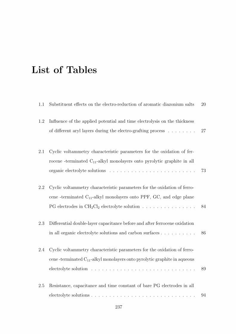
List of Tables
1.1 Substituent effects on the electro-reduction of aromatic diazonium salts 20
1.2 Influence of the applied potential and time electrolysis on the thickness
of different aryl layers during the electro-grafting process . . . . . . . . 27
2.1 Cyclic voltammetry characteristic parameters for the oxidation of fer-
rocene -terminated C11-alkyl monolayers onto pyrolytic graphite in all
organic electrolyte solutions . . . . . . . . . . . . . . . . . . . . . . . . 73
2.2 Cyclic voltammetry characteristic parameters for the oxidation of ferro-
cene -terminated C11-alkyl monolayers onto PPF, GC, and edge plane
PG electrodes in CH2Cl2 electrolyte solution . . . . . . . . . . . . . . . 84
2.3 Differential double-layer capacitance before and after ferrocene oxidation
in all organic electrolyte solutions and carbon surfaces . . . . . . . . . . 86
2.4 Cyclic voltammetry characteristic parameters for the oxidation of ferro-
cene -terminated C11-alkyl monolayers onto pyrolytic graphite in aqueous
electrolyte solution . . . . . . . . . . . . . . . . . . . . . . . . . . . . . 89
2.5 Resistance, capacitance and time constant of bare PG electrodes in all
electrolyte solutions . . . . . . . . . . . . . . . . . . . . . . . . . . . . . 94
237
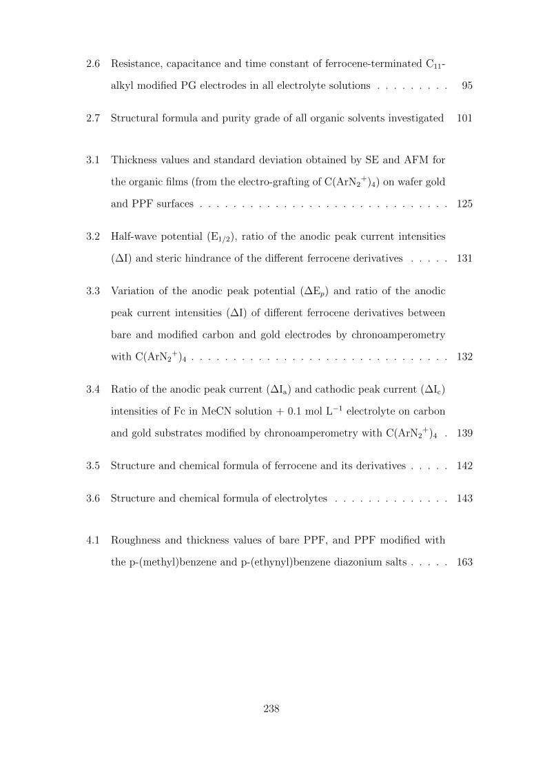
2.6 Resistance, capacitance and time constant of ferrocene-terminated C11-
alkyl modified PG electrodes in all electrolyte solutions . . . . . . . . . 95
2.7 Structural formula and purity grade of all organic solvents investigated 101
3.1 Thickness values and standard deviation obtained by SE and AFM for
the organic films (from the electro-grafting of C(ArN2+)4) on wafer gold
and PPF surfaces . . . . . . . . . . . . . . . . . . . . . . . . . . . . . . 125
3.2 Half-wave potential (E1/2), ratio of the anodic peak current intensities
(∆I) and steric hindrance of the different ferrocene derivatives . . . . . 131
3.3 Variation of the anodic peak potential (∆Ep) and ratio of the anodic
peak current intensities (∆I) of different ferrocene derivatives between
bare and modified carbon and gold electrodes by chronoamperometry
with C(ArN2+)4 . . . . . . . . . . . . . . . . . . . . . . . . . . . . . . . 132
3.4 Ratio of the anodic peak current (∆Ia) and cathodic peak current (∆Ic)
intensities of Fc in MeCN solution + 0.1 mol L−1 electrolyte on carbon
and gold substrates modified by chronoamperometry with C(ArN2+)4 . 139
3.5 Structure and chemical formula of ferrocene and its derivatives . . . . . 142
3.6 Structure and chemical formula of electrolytes . . . . . . . . . . . . . . 143
4.1 Roughness and thickness values of bare PPF, and PPF modified with
the p-(methyl)benzene and p-(ethynyl)benzene diazonium salts . . . . . 163
238
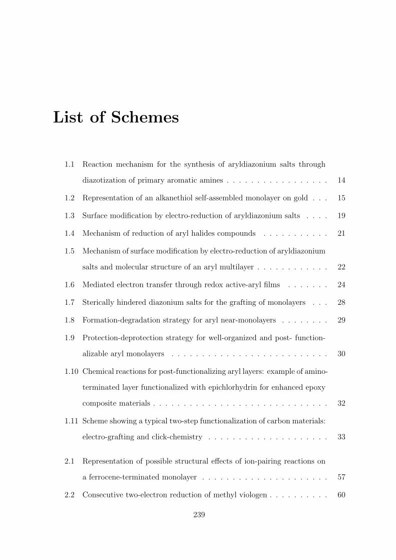
List of Schemes
1.1 Reaction mechanism for the synthesis of aryldiazonium salts through
diazotization of primary aromatic amines . . . . . . . . . . . . . . . . . 14
1.2 Representation of an alkanethiol self-assembled monolayer on gold . . . 15
1.3 Surface modification by electro-reduction of aryldiazonium salts . . . . 19
1.4 Mechanism of reduction of aryl halides compounds . . . . . . . . . . . 21
1.5 Mechanism of surface modification by electro-reduction of aryldiazonium
salts and molecular structure of an aryl multilayer . . . . . . . . . . . . 22
1.6 Mediated electron transfer through redox active-aryl films . . . . . . . 24
1.7 Sterically hindered diazonium salts for the grafting of monolayers . . . 28
1.8 Formation-degradation strategy for aryl near-monolayers . . . . . . . . 29
1.9 Protection-deprotection strategy for well-organized and post- function-
alizable aryl monolayers . . . . . . . . . . . . . . . . . . . . . . . . . . 30
1.10 Chemical reactions for post-functionalizing aryl layers: example of amino-
terminated layer functionalized with epichlorhydrin for enhanced epoxy
composite materials . . . . . . . . . . . . . . . . . . . . . . . . . . . . . 32
1.11 Scheme showing a typical two-step functionalization of carbon materials:
electro-grafting and click-chemistry . . . . . . . . . . . . . . . . . . . . 33
2.1 Representation of possible structural effects of ion-pairing reactions on
a ferrocene-terminated monolayer . . . . . . . . . . . . . . . . . . . . . 57
2.2 Consecutive two-electron reduction of methyl viologen . . . . . . . . . . 60
239
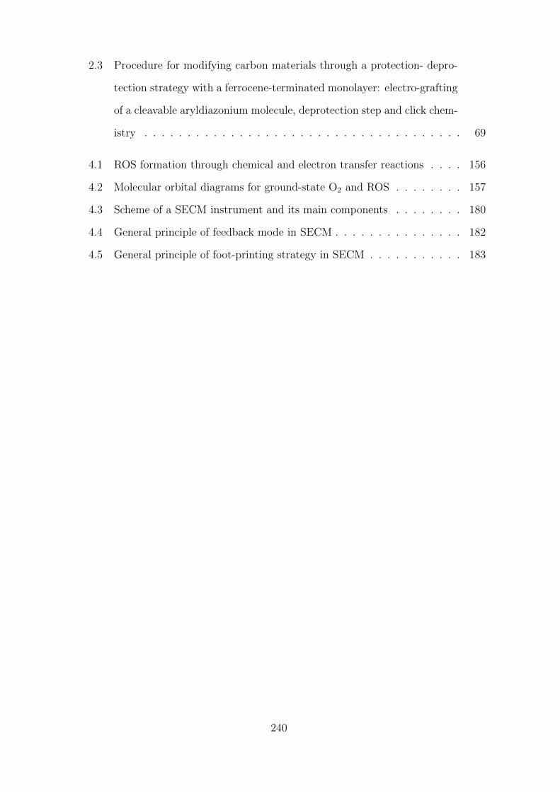
2.3 Procedure for modifying carbon materials through a protection- depro-
tection strategy with a ferrocene-terminated monolayer: electro-grafting
of a cleavable aryldiazonium molecule, deprotection step and click chem-
istry . . . . . . . . . . . . . . . . . . . . . . . . . . . . . . . . . . . . . 69
4.1 ROS formation through chemical and electron transfer reactions . . . . 156
4.2 Molecular orbital diagrams for ground-state O2 and ROS . . . . . . . . 157
4.3 Scheme of a SECM instrument and its main components . . . . . . . . 180
4.4 General principle of feedback mode in SECM . . . . . . . . . . . . . . . 182
4.5 General principle of foot-printing strategy in SECM . . . . . . . . . . . 183
240


Resume en Francais
La fonctionnalisation de surfaces est une discipline de recherche qui presente de nom-
breux interets. De nos jours, les sciences et technologies s’inventent a l’echelle nano-
metrique. De fait, plus un objet diminue en taille, plus son ration Surface/Volume
augmente, jusqu’a que cet objet puisse etre considere comme uniquement surfacique.
De plus, c’est la surface et non le cœur d’un materiau qui interagit avec son environ-
nement. C’est pourquoi, en modifiant une surface de facon controlee, nous pouvons
moduler les proprietes d’un materiau vis-a-vis de son environnement, i.e. sa reactivite
chimique et ses proprietes physiques. Cependant, afin de developper des materiaux
avec de nouvelles proprietes, il est necessaire de savoir comment moduler la matiere a
l’echelle nanometrique. La nanosctructuration peut impliquer une multitude de proce-
dures de fonctionnalisation de surfaces; une des plus interessantes etant la possibilite
de pouvoir arranger de facon organisee des molecules fonctionnelles sur une surface.
La polymerisation et l’adsorption de thiols ou composes dithioles sont des methodes
de fonctionnalisation de surfaces bien connues. Neanmoins, elles ont des inconvenients;
et le plus important est surement la faible energie de liaison existant entre la surface
et la molecule immobilisee, qui peut rendre le systeme instable. Dans ce contexte,
l’utilisation de liaisons covalentes est souhaitable.
Les sels d’aryles diazonium sont des briques elementaires ideales pour la conception
de surfaces possedant des proprietes specifiques de par leurs diversites structurelles et
leur capacite a modifier des surfaces conductrices par electrochimie. La modification
243
de surfaces par des films organiques constitues de differentes molecules ou groupements
fonctionnels est devenue de plus en plus populaires ces dernieres decennies, puisqu’elle
permet le developpement de materiaux avec des proprietes nouvelles ou ameliorees.
Cet interet croissant est lie principalement a la possibilite de controler la modification
a l’echelle moleculaire, mais aussi au developpement de nouvelles techniques permet-
tant la caracterisation de ces films, i.e. XPS ou AFM. Le niveau de sophistication des
molecules synthetisees ainsi que le niveau de connaissance lie a la fabrication de ces
couches organiques ont augmentes considerablement, tout comme le nombre applic-
ations potentielles dans des disciplines scientifiques tres variees. Les applications les
plus developpees actuellement sont celles en lien avec l’analytique, les biotechnologies
et le developpement de materiaux pour des dispositifs de stockage de l’energie. Ces
differentes applications requierent inevitablement une excellente caracterisation physi-
cochimique des surfaces etudiees et la comprehension des phenomenes interfaciaux.
Cette these est dediee a l’etude du transfert electronique au travers de differentes
couches organiques, generees par electro-reduction de sels d’aryles diazonium, d’ epais-
seurs variables (monocouches, couches ultraminces et multicouches) ou l’espece electro-
active est soit attachee a la surface ou en solution. Trois techniques electrochimiques
differentes ont ete utilisees au cours de cette these: la voltammetrie cyclique (CV),
la spectroscopie d’impedance electrochimique (EIS) et la microscopie electrochimique
(SECM). Le travail entrepris dans cette these est un travail de recherche fondamentale
et contribue a l’etude du transfert electronique a l’interface electrode/solution, et a la
comprehension de leurs proprietes physicochimiques.
Ce manuscrit est structure comme suit: le premier chapitre presente la litterature ac-
tuelle concernant l’utilisation de sels d’aryles diazonium pour la fonctionnalisation de
surfaces, et plus particulierement utilisant la reduction electrochimique de ces sels.
Leurs syntheses et reactivites chimiques sont rapidement decrites. Les differentes
strategies existantes pour fonctionnaliser ces surfaces avec precision (controle de l’
epaisseur et de l’organisation moleculaire) sont decrites plus en details. Les proce-
244
dures servant a post-fonctionnaliser ces couches organiques sont aussi decrites, en se
concentrant principalement sur celles employant la «Click Chemistry». Ensuite, les
objectifs sont resumes plus en detail avant de presenter les trois chapitres decrivent
et commentent les differentes etudes entreprises pendant cette these. Elles ont toutes
en lien l’utilisation de l’electro-reduction de sels d’aryles diazonium pour former des
couches organiques de differentes epaisseurs, allant de la monocouche aux multicouches,
qu’elles soient electroactives ou non et possedant ou non une structure organisee.
Le deuxieme chapitre est dedie a l’etude de l’influence du solvant sur le transfert elec-
tronique de monocouches d’alkylferrocene greffees sur surfaces carbonees. La strategie
de protection-deprotection, developpee au laboratoire ces dernieres annees, permet le
greffage covalent de monocouches fonctionnelles, qui sont post-fonctionnalisees dans
un second temps par une chaine alkyl portant un groupement ferrocenyl terminal elec-
troactif. Les proprietes electrochimiques (transfert electronique) de ces surfaces fonc-
tionnalisees ont ete etudiees par voltammetrie cyclique et spectroscopie d’impedance
electrochimique. Ces etudes ont ete menees dans differents solvants organiques et en
solution aqueuse, couvrant une large gamme de constantes dielectriques (de 9 a 80 en-
viron). Nous avons considere leur utilisation pour augmenter la densite de charge dans
des dispositifs de stockage de l’energie. Les etudes en voltammetrie cyclique nous ont
permis de conclure que la formation de paires d’ions entre l’electrolyte (les anions) et
les cations ferroceniums, generes apres oxydation des groupements ferrocenyls greffes,
influencait fortement la reponse electrochimique du systeme. La cinetique et la ther-
modynamique du transfert electronique de la monocouche d’alkyl-ferrocene sont toutes
deux influencees par le solvant utilise, au travers des differences de solvatation existant
entre les anions PF6– et ClO4
– . Ceci se traduit par une variation dans la formation
de paires d‘ions entre les anions en solution et les cations ferroceniums. D’apres les
experiences d’impedance, nous pouvons conclure que l’introduction d’une monocouche
electroactive a la surface de substrats carbones est un moyen tres efficace d’augmenter
la densite de charge globale du materiau. Apres greffage de la monocouche d’alkyl-
245
ferrocene et optimisation du systeme electrolyte/solvant, nous observons une augment-
ation tres importante du stockage de densite de charges du materiau d’un facteur 10,
ce qui est bien plus important que la plupart des resultats obtenus dans la litterature.
Le troisieme chapitre se concentre sur l’electro-reduction d’un sel d’aryle diazonium
pre-organise de forme tetraedrique, aboutissant dans ce cas au depot d’un film orga-
nique ultrafin non-electroactif sur or et sur carbone. Ce film organique presente une
structure specifique avec des proprietes particulieres vis-a-vis d’electrolytes et sondes
redox en solution. Des proprietes de tamisage moleculaire ont pu etre mises en evid-
ence par voltammetrie cyclique de sondes redox en solutions aqueuses et organiques.
Les materiaux fonctionnalises par cette methode se comportent comme des rectific-
ateurs de courant electrochimique (ECR). Il apparait que le processus de rectification
soit different de ceux decrits dans la litterature, impliquant l’utilisation de relais redox
dans la couche organique modifiant le materiau. Le transport des sondes redox et
des ions (de l’electrolyte) au travers du film organique electro-depose a ete demontre
comme etant responsable des proprietes de rectification du courant electrochimiques du
materiau ainsi fonctionnalise. Les proprietes de tamisage moleculaire et de rectification
du courant electrochimique ont toutes deux pour origine l’organisation specifique du
film organique electro-greffe. L’observation conjointe de ces deux proprietes n’a jamais
ete observee precedemment pour des films organiques electro-generes par la reduction
de sels d’aryles diazonium et ne presentant pas cette pre-organisation en forme de
tetraedre. Les investigations des proprietes electrochimiques ont ete completees par en
ensemble de techniques de caracterisation de surface : spectroscopie de photoelectrons
X (XPS), microscopie a force atomique (AFM), spectroscopie IR et ellipsometrie.
Le quatrieme et dernier chapitre de cette these presente l’etude et l’utilisation de la
microscopie electrochimique (SECM) pour la detection d’intermediaires pendant les
reactions de reduction du dioxygene (ORR) sur ultramicroelectrode (UME) de platine.
Ces intermediaires sont tres reactifs et sont tres importants, car nous les retrouvons
dans beaucoup de processus naturelles et industrielles. Une strategie «d’empreinte» est
246
utilise ici, ou l’interaction de ces intermediaires vis-a-vis de deux differentes couches or-
ganiques sensitives permet de mettre en evidence la production d’especes reactives lors
de la reduction du dioxygene. Le role du potentiel applique ainsi que de l’electrolyte ont
ete etudies. Un effet protecteur du a la presence de groupements insatures acetyleniques
dans la couche organique semble proteger cette derniere de sa degradation vis-a-vis
d’especes hautement reactives, formees lors de la reduction du dioxygene.
Dans ce manuscrit, nous avons demontre que les proprietes electrochimiques de sondes
redox en solution ou greffees a la surface d’un materiau peuvent etre modulees par
l’introduction de films organiques, permettant la realisation de recherches fondamentales
dans des champs disciplinaires aussi important que le stockage de l’energie ou de la
catalyse.
247


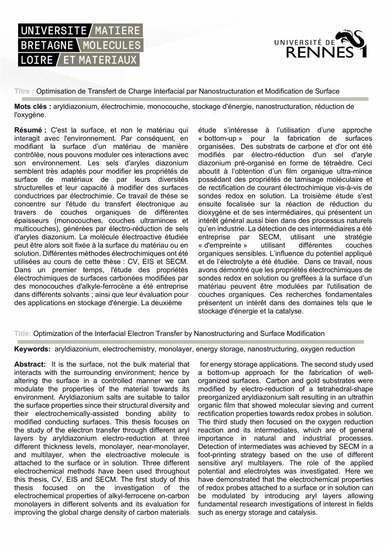
Titre : Optimisation de Transfert de Charge Interfacial par Nanostructuration et Modification de Surface
Mots clés : aryldiazonium, électrochimie, monocouche, stockage d'énergie, nanostructuration, réduction de l'oxygène.
Résumé : C'est la surface, et non le matériau qui interagit avec l'environnement. Par conséquent, en modifiant la surface d’un matériau de manière contrôlée, nous pouvons moduler ces interactions avec son environnement. Les sels d'aryles diazonium semblent très adaptés pour modifier les propriétés de surface de matériaux de par leurs diversités structurelles et leur capacité à modifier des surfaces conductrices par électrochimie. Ce travail de thèse se concentre sur l'étude du transfert électronique au travers de couches organiques de différentes épaisseurs (monocouches, couches ultraminces et multicouches), générées par électro-réduction de sels d'aryles diazonium. La molécule électroactive étudiée peut être alors soit fixée à la surface du matériau ou en solution. Différentes méthodes électrochimiques ont été utilisées au cours de cette thèse : CV, EIS et SECM. Dans un premier temps, l'étude des propriétés électrochimiques de surfaces carbonées modifiées par des monocouches d'alkyle-ferrocène a été entreprise dans différents solvants ; ainsi que leur évaluation pour des applications en stockage d'énergie. La deuxième
étude s’intéresse à l’utilisation d’une approche « bottom-up » pour la fabrication de surfaces organisées. Des substrats de carbone et d'or ont été modifiés par électro-réduction d'un sel d'aryle diazonium pré-organisé en forme de tétraèdre. Ceci aboutit à l’obtention d’un film organique ultra-mince possédant des propriétés de tamisage moléculaire et de rectification de courant électrochimique vis-à-vis de sondes redox en solution. La troisième étude s'est ensuite focalisée sur la réaction de réduction du dioxygène et de ses intermédiaires, qui présentent un intérêt général aussi bien dans des processus naturels qu’en industrie. La détection de ces intermédiaires a été entreprise par SECM, utilisant une stratégie « d'empreinte » utilisant différentes couches organiques sensibles. L’influence du potentiel appliqué et de l’électrolyte a été étudiée. Dans ce travail, nous avons démontré que les propriétés électrochimiques de sondes redox en solution ou greffées à la surface d’un matériau peuvent être modulées par l'utilisation de couches organiques. Ces recherches fondamentales présentent un intérêt dans des domaines tels que le stockage d'énergie et la catalyse.
Title: Optimization of the Interfacial Electron Transfer by Nanostructuring and Surface Modification
Keywords: aryldiazonium, electrochemistry, monolayer, energy storage, nanostructuring, oxygen reduction
Abstract: It is the surface, not the bulk material that interacts with the surrounding environment; hence by altering the surface in a controlled manner we can modulate the properties of the material towards its environment. Aryldiazonium salts are suitable to tailor the surface properties since their structural diversity and their electrochemically-assisted bonding ability to modified conducting surfaces. This thesis focuses on the study of the electron transfer through different aryl layers by aryldiazonium electro-reduction at three different thickness levels, monolayer, near-monolayer, and multilayer, when the electroactive molecule is attached to the surface or in solution. Three different electrochemical methods have been used throughout this thesis, CV, EIS and SECM. The first study of this thesis focused on the investigation of the electrochemical properties of alkyl-ferrocene on-carbon monolayers in different solvents and its evaluation for improving the global charge density of carbon materials
for energy storage applications. The second study used a bottom-up approach for the fabrication of well-organized surfaces. Carbon and gold substrates were modified by electro-reduction of a tetrahedral-shape preorganized aryldiazonium salt resulting in an ultrathin organic film that showed molecular sieving and current rectification properties towards redox probes in solution. The third study then focused on the oxygen reduction reaction and its intermediates, which are of general importance in natural and industrial processes. Detection of intermediates was achieved by SECM in a foot-printing strategy based on the use of different sensitive aryl multilayers. The role of the applied potential and electrolytes was investigated. Here we have demonstrated that the electrochemical properties of redox probes attached to a surface or in solution can be modulated by introducing aryl layers allowing fundamental research investigations of interest in fields such as energy storage and catalysis.