Feasibility Study - Microgravity Space Printer Project - ČVUT ...
64
Master Thesis Czech Technical University in Prague F2 Faculty of Mechanical Engineering Enterprise Management and Economics Microgravity Space Printer Project - Feasibility Study Bc. Jan Lukačevič Supervisor: Ing. Miroslav Žilka PhD August 2017
-
Upload
khangminh22 -
Category
Documents
-
view
2 -
download
0
Transcript of Feasibility Study - Microgravity Space Printer Project - ČVUT ...

Master Thesis
CzechTechnicalUniversityin Prague
F2 Faculty of Mechanical EngineeringEnterprise Management and Economics
Microgravity Space Printer Project -Feasibility Study
Bc. Jan Lukačevič
Supervisor: Ing. Miroslav Žilka PhDAugust 2017

ii
ZADÁNÍ DIPLOMOVÉ PRÁCE
I. OSOBNÍ A STUDIJNÍ ÚDAJE
381523Osobní číslo:JanJméno:LukačevičPříjmení:
Fakulta strojníFakulta/ústav:
Zadávající katedra/ústav: Ústav řízení a ekonomiky podniku
Strojní inženýrstvíStudijní program:
Řízení a ekonomika podnikuStudijní obor:
II. ÚDAJE K DIPLOMOVÉ PRÁCI
Název diplomové práce:
Studie proveditelnosti projektu Microgravity Space Printer
Název diplomové práce anglicky:
Microgravity Space Printer Project - Feasibility Study
Pokyny pro vypracování:
1. Úvod, cíle a úkoly diplomové práce
2. Teoretická východiska práce - projektové řízení a plánování, nástroje projektového managementu, studie proveditelnosti
a její struktura
3. Praktická část - technický popis projektu, věcná dekompozice cíle, personální zajištění, harmonogram, rozpočet projektu,
analýza rizik
4. Závěr
Seznam doporučené literatury:
ROSENAU, Milton D. Řízení projektů. 1. vyd. Praha: Computer Press, 2000, xiv, 344 s. Business books (Computer Press).
ISBN 80-7226-218-1.
SVOZILOVÁ, Alena. Projektový management. 2. aktual. a dopl. vyd. Praha: Grada Publishing, a.s. 2011, 392 s. ISBN
978-80-247-3611-2.
FOTR, Jiří, Lenka ŠVECOVÁ a kol. Manažerské rozhodování: Postupy, metody a nástroje. 2. přeprac. vyd., Praha:
Ekopress, 2015, 474 s. ISBN 978-80-8692-959-0.
BURKE, Roy. Project Management: Planning and Control Techniques, 5. vyd., Viley, 2013, 448s. ISBN 978-1-118-66076-8
Jméno a pracoviště vedoucí(ho) diplomové práce:
Ing. Miroslav Žilka Ph.D., ústav řízení a ekonomiky podniku MÚ
Jméno a pracoviště druhé(ho) vedoucí(ho) nebo konzultanta(ky) diplomové práce:
Termín odevzdání diplomové práce: 28.07.2017Datum zadání diplomové práce: 10.04.2017
Platnost zadání diplomové práce: 25.08.2017
_________________________________________________________________________________
Podpis děkana(ky)Podpis vedoucí(ho) ústavu/katedryPodpis vedoucí(ho) práce
III. PŘEVZETÍ ZADÁNÍ
Diplomant bere na vědomí, že je povinen vypracovat diplomovou práci samostatně, bez cizí pomoci, s výjimkou poskytnutých konzultací.
Seznam použité literatury, jiných pramenů a jmen konzultantů je třeba uvést v diplomové práci.
.
Datum převzetí zadání Podpis studenta
© ČVUT v Praze, Design: ČVUT v Praze, VICCVUT-CZ-ZDP-2015.1

AcknowledgementsI love deadlines. I love the whooshingnoise they make as they go by. Thankyou to my family, my supervisor and Col.Chris Hadfield for teaching me how to bea zero.
DeclarationI declare that this work is all my own workand I have cited all sources I have used inthe bibliography.
In Prague, August 8 , 2017
Prohlašuji, že jsem předloženou prácivypracoval samostatně, a že jsem uvedlveškerou použitou literaturu.
V Praze, 8. srpna 2017
v
Abstract"Feasibility study of the Micro GravitySpace Printer Experiment” is a thesis orig-inally based on a real scientific experi-ment developed by a research team atthe Czech Technical University in Prague.The experiment is being developed withthe support of governmental and non-governmental institutions. The thesis in-troduces theoretical basis for the project,technical description as well as its plan-ning and organisational matters in a formof a feasibility study.
Keywords: additive manufacturing, 3Dprinting, feasibility study, space industry
Supervisor: Ing. Miroslav Žilka PhDKarlovo náměstí 13121 35 Praha 2
AbstraktDiplomová práce "Studie proveditelnostiprojektu Micro Gravity Sprinter" je zalo-žena na reálném vědeckém experimentuvyvíjeném výzkumným týmem na Českémvysokém učení technickém v Praze. Tentoexperiment je vyvíjen ve spolupráci s vlád-ními i nevládními organizacemi v oblastikosmického výzkumu. Práce předkládá te-oretická východiska a termíny, které jsouaplikovány v praktické části formou studieproveditelnosti.
Klíčová slova: aditivní výroba, 3D tisk,studie proveditelnosti, kosmický výzkum
Překlad názvu: Studie proveditelnostiprojektu Microgravity Space Printer
vi
Contents1 Introduction 11.1 Aims . . . . . . . . . . . . . . . . . . . . . . . . . 12 Theoretical Part 32.1 Project Management & Planning 32.1.1 Project . . . . . . . . . . . . . . . . . . . . 32.1.2 Project Management . . . . . . . . 42.1.3 Life cycle of a project . . . . . . . . 5
2.2 Approaches to ProjectManagement . . . . . . . . . . . . . . . . . . . 102.2.1 Traditional ProjectManagement . . . . . . . . . . . . . . . . . . 11
2.2.2 Agile Management . . . . . . . . . 112.2.3 Concurrent Engineering . . . . . 13
2.3 Feasibility Study. . . . . . . . . . . . . . 142.4 Creation of a Project Budget . . . 162.4.1 Standard items in a projectbudget . . . . . . . . . . . . . . . . . . . . . . . 17
2.4.2 Methodology in a budgetestimation . . . . . . . . . . . . . . . . . . . . 17
2.5 Project Management Tools . . . . . 182.5.1 Breakdown Structures . . . . . . 182.5.2 Gantt Chart . . . . . . . . . . . . . . . 202.5.3 Modern Tools in ProjectManagement . . . . . . . . . . . . . . . . . . 20
2.6 Risk Management . . . . . . . . . . . . . 222.6.1 Process of risk management . 232.6.2 Risk Categorisation . . . . . . . . 242.6.3 Risk Register . . . . . . . . . . . . . . 252.6.4 Mitigation strategies . . . . . . . 25
3 Practical Part 273.1 Technical Description of theExperiment . . . . . . . . . . . . . . . . . . . . 273.1.1 Introduction . . . . . . . . . . . . . . . 273.1.2 Objectives of the project . . . . 293.1.3 Scientific Background . . . . . . . 293.1.4 Design of the experiment . . . . 32
3.2 Organisation of the project . . . . . 383.2.1 Work Breakdown Structure . 383.2.2 Timeline of the project . . . . . 403.2.3 Work Packages . . . . . . . . . . . . 423.2.4 Gantt Chart . . . . . . . . . . . . . . . 42
3.3 Financial Aspects of the Project 433.3.1 Budget Estimation . . . . . . . . . 443.3.2 Financial resources . . . . . . . . . 45
3.4 Environmental Aspects of theProject . . . . . . . . . . . . . . . . . . . . . . . . 46
3.5 Risk Management of the project 463.5.1 Risk Register . . . . . . . . . . . . . . 463.5.2 Mitigation Strategies . . . . . . . 47
3.6 Evaluation of the project . . . . . . 493.6.1 Potential up-scale anddown-scale alternatives . . . . . . . . . 50
4 Conclusions 53Bibliography 55
vii
Figures2.1 The Project Management Triangle 42.2 Typical Life Cycle of a SpaceProject. . . . . . . . . . . . . . . . . . . . . . . . . 6
2.3 Four Quadrants of the projectlandscape . . . . . . . . . . . . . . . . . . . . . . 10
2.4 Linear Project Management LifeCycle Model . . . . . . . . . . . . . . . . . . . 11
2.5 Comparison of the Agile andWaterfall Models[7] . . . . . . . . . . . . . 12
2.6 Evolution of Enclosures developedusing Agile Method . . . . . . . . . . . . . 13
2.7 Gantt Chart of The PREDATORExperiment project . . . . . . . . . . . . . 21
2.8 Product Development Boardvisualised in Trello . . . . . . . . . . . . . . 22
2.9 Risk Management Process Steps 23
3.1 Homogeneous Magnetic Field . . . 303.2 Helmholtz Coils at the Universityof Iceland Laboratory . . . . . . . . . . . 31
3.3 3D Rendering of the PreliminaryMechanical Design . . . . . . . . . . . . . . 33
3.4 Altitude vs Flight Time . . . . . . . 343.5 3D Model of a suggestedpressurised vessel . . . . . . . . . . . . . . . 35
3.6 Logic Scheme describing theprocess flow . . . . . . . . . . . . . . . . . . . . 37
3.7 High level Work BreakdownStructure of the project . . . . . . . . . . 39
3.8 Simplified visualisation of the Dphase of The MG Sprinter project 41
3.9 Gantt Chart . . . . . . . . . . . . . . . . . 433.10 Preliminary Budget Estimationfor the MG Sprinter Project . . . . . . 44
Tables3.1 Risk Register, part 1 . . . . . . . . . . 473.2 Risk Register, part 2 . . . . . . . . . . 48
viii
Chapter 1Introduction
"Feasibility study of the Micro Gravity Space Printer Experiment” is a thesisoriginally based on a real scientific experiment developed by a research teamat the Czech Technical University in Prague. The experiment was developedalong with a wide variety of experts in the respective fields from The EuropeanSpace Agency (ESA), German Space Agency (DLR), German Centre for aMicrogravity Research (ZARM), Swedish Space Corporation (SSC), andSwedish National Space Board (SNSB).
In order to introduce this topic the thesis presents technical terms andframeworks used in project management and its phases, along with some ofthe common and less common approaches and tools that are being utilisedin a classic approach to project management. Additionally, it puts all of theaforementioned parts in context and extends the theory with some of the latesttools and that are being used in mechanical, as well as space engineering.
1.1 Aims
The main aim of this thesis is to draw up a feasibility study of the MicroGravity Space Printer project. This complex task consists of multiple subtasks;in order to create such study, it is needed to compose a baseline project plan,and consider the project from various perspectives (technical, financial andorganisational) as well as to present a comprehensive evaluation of the project.
To follow the main aim, the thesis presents several objectives: to introducesome of the fundamental terms that are being widely used in the area ofproject management; furthermore, to provide an overview of methodologyand tools used to create and manage space projects and thirdly, demonstratecapabilities of these tools and methods by applying them on a specific project- The Microgravity Space Printer of which the feasibility study is presentedin this thesis.
1

2
Chapter 2Theoretical Part
2.1 Project Management & Planning
2.1.1 Project
Today, the term ’a project’ tends to be overused, encompassing activitiesranging from social to entrepreneurial in nature without awareness of thetrue meaning of what a project is. The term itself is very specifically definedas demonstrated by Robert K. Wysocki in his book[1], Effective ProjectManagement:
“A project is a sequence of unique, complex, and connected activities thathave one goal or purpose and that must be completed by a specific time, withinbudget, and according to specification.”
According to project management experts and theorists, this particulardefinition may differ as the interpretation of the term is approached fromvarious viewpoints. However, it is important to mention that even thoughtwo or more projects may appear to be identical, each project is, from thedefinition, unique as the circumstances and requirements change over time.To put this into context of space research and the space industry in relationto space projects, specification of the project goes one step further as theobjectives and an overall purpose of the project are defined by the projectinitiator in the so-calledmission statement. This statement relates to a specificmission or a project and contains technical and programmatic constraints,as well as key performance parameters that are to be applied to the project.Moreover, another important aspect of a project is its "temporariness". Shoulda project lack a limited and defined time period, it may turn into a complexprocess. The temporariness and uniqueness are mostly characterised in aproject by:. A starting and closing date (or a date when it is determined that the
project cannot be completed in accordance with the initial goals);. Specific requirements and aims that are a purpose of the project;
3

2. Theoretical Part .................................... Particular composition of a team (and their then-skillset) that is assigned
to complete the project.
Another substantial part of a project that defines its scope and suggests theprobability of a successful completion of its goals is a range and availabilityof resources. It is certain that completely different outcomes can be achieveddepending on the way the resources are being allocated. This can be describedusing “The Project Management Triangle”, sometimes referred as “TripleConstraint”. The diagram basically builds on the following three premises:..1. There is a limited amount of resources: the quality of the outcomes is
determined by the deadlines, budget constrains and desired features;..2. Person responsible for the project can only trade between these con-strained variables;..3. Changes in one constraint require necessary changes in remaining con-strains in order to compensate, otherwise the quality of outcomes willsuffer.
Figure 2.1: The Project Management Triangle
2.1.2 Project Management
Every project needs a certain level of governance in order to be successful.This can be rather difficult; therefore an entire discipline has been createdand keeps on evolving to make the management of projects as effective aspossible. For the purpose of this thesis, the following definition can be used:
4

............................ 2.1. Project Management & Planning
“Project management is the planning, organizing, directing and controllingof company resources for a relatively short-term objective that has been estab-lished to complete specific goals and objectives.”
This being said, project management can be understood as a way ofapplying knowledge, skills, tools, and technologies to accomplish goals set forthe project [2]. It is a complex effort which encompasses a diverse portfolio ofactivities such as defining the requirements, gathering resources, governanceof people, controlling, monitoring, and evaluating of ongoing and finishedprocesses.
2.1.3 Life cycle of a project
Each project can be divided into several phases that focus on differentaspects of the project. The reason to divide them into certain logical orderis to improve the conditions for the monitoring and auditing of activitiesthat are contained in each phase. Furthermore, this is meant to ease theorientation within the project to all stakeholders involved, and to increase theprobability of the overall project success. Typically, each phase defines whichtypes of activities shall be carried out, what specific outcomes are requiredto be completed, and how they are verified and evaluated. As well, who isparticipating in its parts. There are several systems that divide project intophases. According to Cleland and King [3], the division is as follows:..1. Conceptualisation - In the initial phases, a formulation of elementary
intentions and questions is necessary. This comprises the evaluation ofpotential merits of a project, time and budget estimation required forthe project completion, and a preliminary risk analysis...2. Planning - Essentially, this phase focuses on elaboration of previousoutcomes of the extent of frameworks used for the project. a moreformalized set of plans to accomplish the initially developed goals areestablished, and therefore preparation of tools and methods, resourcesidentification, a realistic time line, more precise budget calculations, andproper definition of potential risks and suggestion of mitigation strategies;a preparation of detailed plans required for a realisation of the projecttake a place...3. Execution - During the execution phase, most of the work related ac-tivities are performed. Previously prepared resources and tools are beingutilised in order to complete the goals set for the project. Throughoutthis phase, various performance tests take place and the project is beingthoroughly examined to ensure successful completion...4. Termination - Sometimes this phase is called "Closing". At this stage,the project is terminated, and remaining resources are reallocated to otherprojects. The project goes through an in-depth analysis and evaluationto gather inputs that might be used for a better project management offuture projects.
5
2. Theoretical Part ...................................Another system used in project management is the Project Management
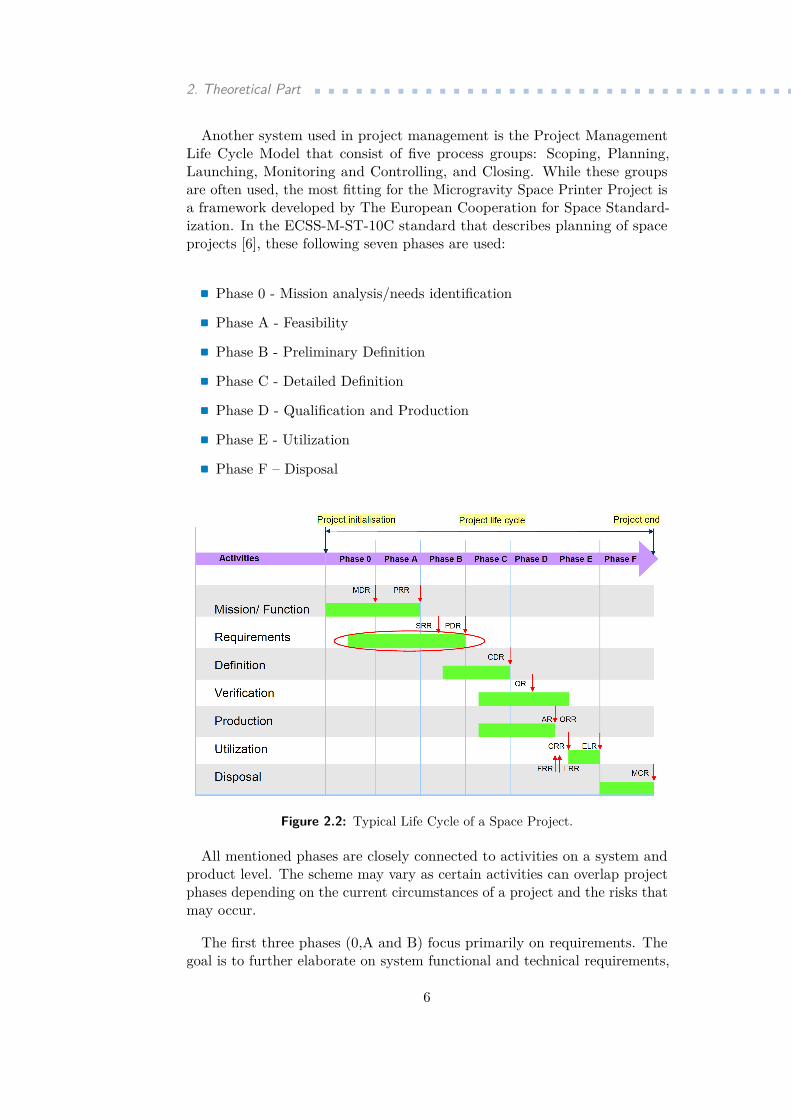
Life Cycle Model that consist of five process groups: Scoping, Planning,Launching, Monitoring and Controlling, and Closing. While these groupsare often used, the most fitting for the Microgravity Space Printer Project isa framework developed by The European Cooperation for Space Standard-ization. In the ECSS-M-ST-10C standard that describes planning of spaceprojects [6], these following seven phases are used:
. Phase 0 - Mission analysis/needs identification. Phase A - Feasibility. Phase B - Preliminary Definition. Phase C - Detailed Definition. Phase D - Qualification and Production. Phase E - Utilization. Phase F – Disposal
Figure 2.2: Typical Life Cycle of a Space Project.
All mentioned phases are closely connected to activities on a system andproduct level. The scheme may vary as certain activities can overlap projectphases depending on the current circumstances of a project and the risks thatmay occur.
The first three phases (0,A and B) focus primarily on requirements. Thegoal is to further elaborate on system functional and technical requirements,
6
............................ 2.1. Project Management & Planning
as well as to identify major system concepts to adhere to the previously setmission statement. At the same time, taking into account the technical andprogrammatic limitations identified by the project initiator. Moreover, it issubstantial to identify all resources and activities required develop the spaceand ground segments of the project. These three phases also include some ofthe the initial assessments of technical and programmatic risk and initiationof pre-development activities (as it will be elaborated further in a detaileddescription of these phases). The following two phases (C and D) are thecore of the ground preparation of the actual space product. These phasesconsist of all processes required to design and produce the space and groundsegments, and their products. Actions required to launch, command, fullymake use of as well as to maintain the orbital elements of the space segmentbelong to the phase E. All the actions and activities in this phase also applyfor all the segments on ground. Finally in the Phase F activities are leadingto safely dispose all products launched into space as well as ground segmentand to evaluate the mission success and to gather major findings and lessonslearnt for future projects.
As seen in the Figure 2.2, development of a space project is a continuoussequence of activities that are being recorded using a project documentation.To achieve the most effective spending o resources and desired quality ofthe outcomes within the scope of the project, each of the phases ends witha milestone that comes in as a review of the phase. During the review,project documentation is carefully examined and progress on the experimentis presented to the relevant stakeholder. The outcomes of the review thendecide on the readiness of the project to move to the following phase or torework some of the outputs and products.
As this particular Project Life Cycle perfectly fits the scope of this thesisand the project, for better understanding of the task division and establishingof the work breakdown structure as well time line of the project in thepractical part of the thesis, further explanation of each of the project phasesis necessary. These phases are also closely related to reviews that in the spaceproject management play an important role as they serve as milestones..Phase 0 (Mission analysis/needs identification)
In the Phase 0, some of the major tasks include the elaboration ofthe mission statement in terms of identification and characterizationof the mission needs, expected performance, dependability and safetygoals and mission operating constraints with respect to the physical andoperational environment. Furthermore, in the Phase 0 begins the processof specifying functional, operational and requirements of the project andan elementary risk analysis is conducted. This phase ends with TheMission Definition Review (MDR) which ideally results in continuationof the project in the Phase A..Phase A (Feasibility)Is the most relevant phase for the scope of this thesis, normally comprisetasks related to planning and discovering feasibility of the project. In this
7
2. Theoretical Part ...................................phase, it is needed to establish a series of plans, such as a preliminarymanagement plan, system engineering plan and product assurance planfor the project. Comparison of previously identified needs and systemconcepts is used to estimate levels of uncertainty and risks. Propositionof elementary design, technical solutions and completion of requirementsmanagement that started in the Phase 0 and further elaboration ofthe risk assessment is also conducted. In the Preliminary RequirementsReview that is associated with this phase it is determined which technicaland operational solutions will be used and it must be ensured thatmanagement, engineering and product assurance plans are released..Phase B (Preliminary definition)Yet another of the preparation phases of the project. In this phase themain focus is on finalising the project management, engineering andproduct assurance plans and as a follow-up, the baseline time scheduleand baseline cost at completion calculation is performed. Some of themanagerial tasks are conducted, such as a creation of the preliminaryorganisational breakdown structure (OBS) and the work breakdownstructure. However, more detailed engineering designs (such as decidingon preferred technical and system solutions) are specified. Unlike in thePhase 0 and Phase A, there are two reviews associated with the Phase B.Throughout the entire phase The System Requirements Review (SRR)is held and at the end of the Phase, The Preliminary Design Review(PDR) takes place. e. Within the scope of SRR is to release specificationfor up-to-date technical requirements, to assess the definition of thepreliminary design and to assess the preliminary program focusing onverification of the processes within the project. For the PDR, as thename suggests, it is necessary to verify preliminary design of the conceptsselected in previous phases and to release the final engineering, productassurance and management plans..Phase C (Detailed definition)May dramatically vary from one project to another. This vastly dependson previously chosen model philosophy and the verification approach.In the Phase C, selected critical components are tested in developmentand produced, this also applies to engineering models. As the projectproceeds, risk assessment is updated and interfaces (both external andinternal) are defined in detail. Upon the end of the Phase C, The CriticalDesign Review is held. The major outcome is utilised to decide on thereadiness of the project and possibility to move to the Phase D. This isdone by assessing the final design (that has to by released in Phase C)as well as the assembly, integration and experiment test planning. Flighthardware manufacturing plans and the test plans are also evaluated.Based on the PDR, the user manual is released..Phase D (Qualification and production) This phase focuses mostlyon completion of various elements. Activities related to qualification
8
............................ 2.1. Project Management & Planning
testing and verification needs to completed. Phase D can extend torather long period as all of the manufacturing, assembly and testingof the flight software and hardware must be completed within thisphase. As the project proceeds, it requires more in-depth reviewing. Forthat reason, three different reviews are conducted. The QualificationReview (QR) concurrently with the activities within the phase, then TheAcceptance Review (AR) and The Operational Readiness Review (ORR)that conclude this project phase. Each of the reviews has a differentscope. The QR aims at confirming that the verification process displaysthat the selected design meets previously set requirements. The AR thenaims at demonstration of a function of the verification process. In short,the objective is to verify if all the deliverable products and systems areavailable in accordance with the previously approved product deliverablelist and to determine the acceptability of various waivers and changes inthe original plan proposed by the production and project team. For themost part, the AR provides the project with the acceptance certificatein order to proceed to final stages of the project. During the ORR, allother accompanying activities are verified as well as the readiness ofthe operations team that is responsible for the actual operation andmaintenance of the project during the launch and flight. That relates tothe procedures developed for the flight and their compatibility with allsystems involved in..Phase E (Operations/utilization) As in the Phase C, processes andactions in this phase usually vary, since the objectives and goals for eachproject differ. This complicates giving a comprehensive overview of tasksthat are usually accomplished during Phase E. Generally speaking, itis the phase which is often the one seen as the project itself. For spaceproject, it is the launch and operation activities during the flight mission,thus activities such as performing all on-orbit operations to accomplishthe mission aims and objectives and mission support related tasks areconducted. This phase is associated with 4 project reviews. Prior tolaunch, The Flight Readiness Review (FRR) is held and The LaunchReadiness Review (LRR) immediate prior to launch. This is followedby the Commissioning Results Review (CRR) that is conducted aftercommissioning activities and lastly, The End-Of-Life Review (ELR) isheld at the designated completion of the mission. Name of each of thereviews speaks for itself. The main review objectives are closely relatedto final checks prior to launch, respectively during and at the end offlight. The ELR serves as a bridge to the last phase of the project andin order to pass the ELR, it is important to verify that the mission hascompleted the objectives, considering the circumstances..Phase F (Disposal) In the final phase, the disposal plan implementa-tion must be ensured. The disposal plan consists of activities that aresafely terminating the mission. At the end of this phase, The MissionClose-Out Review (MCR) is held, following the objective that all of the
9
2. Theoretical Part ...................................disposal activities are sufficiently completed.
2.2 Approaches to Project Management
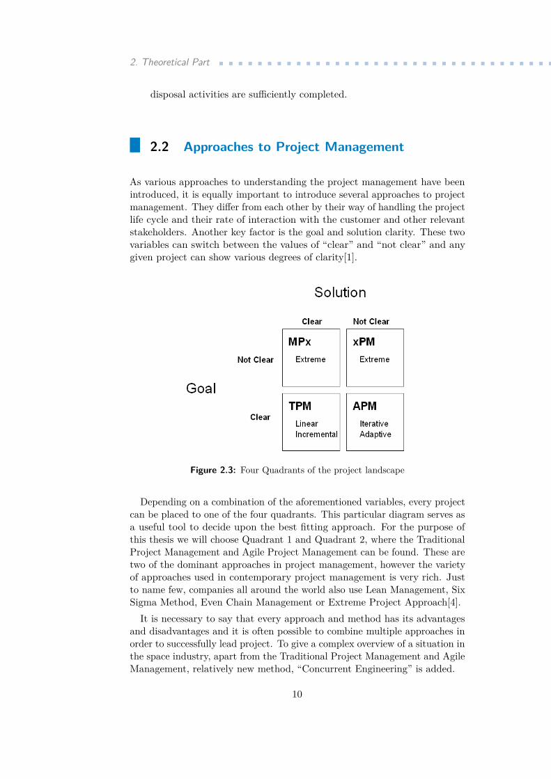
As various approaches to understanding the project management have beenintroduced, it is equally important to introduce several approaches to projectmanagement. They differ from each other by their way of handling the projectlife cycle and their rate of interaction with the customer and other relevantstakeholders. Another key factor is the goal and solution clarity. These twovariables can switch between the values of “clear” and “not clear” and anygiven project can show various degrees of clarity[1].
Figure 2.3: Four Quadrants of the project landscape
Depending on a combination of the aforementioned variables, every projectcan be placed to one of the four quadrants. This particular diagram serves asa useful tool to decide upon the best fitting approach. For the purpose ofthis thesis we will choose Quadrant 1 and Quadrant 2, where the TraditionalProject Management and Agile Project Management can be found. These aretwo of the dominant approaches in project management, however the varietyof approaches used in contemporary project management is very rich. Justto name few, companies all around the world also use Lean Management, SixSigma Method, Even Chain Management or Extreme Project Approach[4].
It is necessary to say that every approach and method has its advantagesand disadvantages and it is often possible to combine multiple approaches inorder to successfully lead project. To give a complex overview of a situation inthe space industry, apart from the Traditional Project Management and AgileManagement, relatively new method, “Concurrent Engineering” is added.
10
.......................... 2.2. Approaches to Project Management
2.2.1 Traditional Project Management
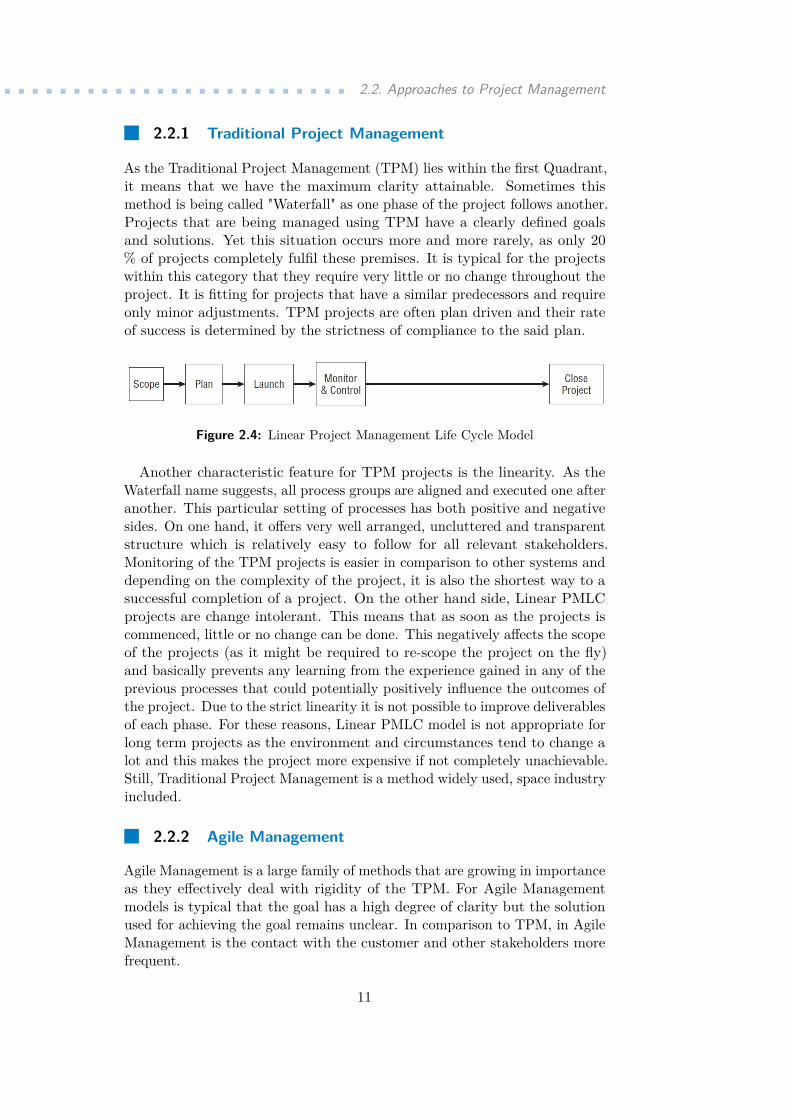
As the Traditional Project Management (TPM) lies within the first Quadrant,it means that we have the maximum clarity attainable. Sometimes thismethod is being called "Waterfall" as one phase of the project follows another.Projects that are being managed using TPM have a clearly defined goalsand solutions. Yet this situation occurs more and more rarely, as only 20% of projects completely fulfil these premises. It is typical for the projectswithin this category that they require very little or no change throughout theproject. It is fitting for projects that have a similar predecessors and requireonly minor adjustments. TPM projects are often plan driven and their rateof success is determined by the strictness of compliance to the said plan.
Figure 2.4: Linear Project Management Life Cycle Model
Another characteristic feature for TPM projects is the linearity. As theWaterfall name suggests, all process groups are aligned and executed one afteranother. This particular setting of processes has both positive and negativesides. On one hand, it offers very well arranged, uncluttered and transparentstructure which is relatively easy to follow for all relevant stakeholders.Monitoring of the TPM projects is easier in comparison to other systems anddepending on the complexity of the project, it is also the shortest way to asuccessful completion of a project. On the other hand side, Linear PMLCprojects are change intolerant. This means that as soon as the projects iscommenced, little or no change can be done. This negatively affects the scopeof the projects (as it might be required to re-scope the project on the fly)and basically prevents any learning from the experience gained in any of theprevious processes that could potentially positively influence the outcomes ofthe project. Due to the strict linearity it is not possible to improve deliverablesof each phase. For these reasons, Linear PMLC model is not appropriate forlong term projects as the environment and circumstances tend to change alot and this makes the project more expensive if not completely unachievable.Still, Traditional Project Management is a method widely used, space industryincluded.
2.2.2 Agile Management
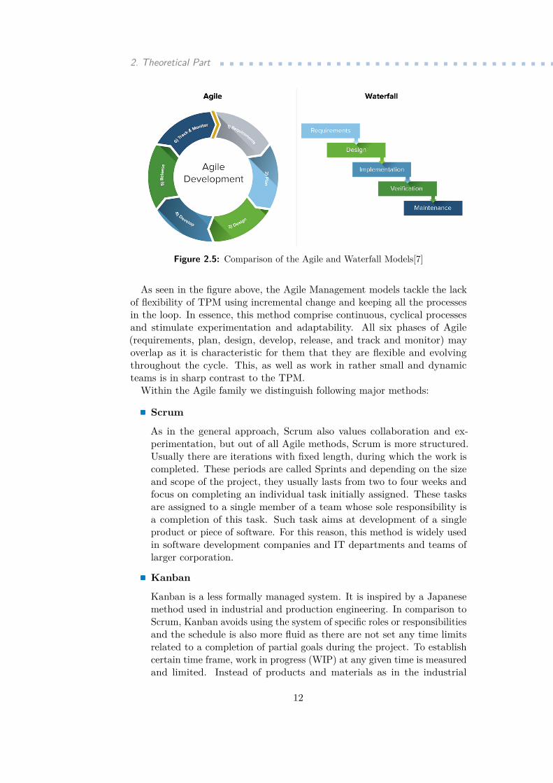
Agile Management is a large family of methods that are growing in importanceas they effectively deal with rigidity of the TPM. For Agile Managementmodels is typical that the goal has a high degree of clarity but the solutionused for achieving the goal remains unclear. In comparison to TPM, in AgileManagement is the contact with the customer and other stakeholders morefrequent.
11
2. Theoretical Part ...................................
Figure 2.5: Comparison of the Agile and Waterfall Models[7]
As seen in the figure above, the Agile Management models tackle the lackof flexibility of TPM using incremental change and keeping all the processesin the loop. In essence, this method comprise continuous, cyclical processesand stimulate experimentation and adaptability. All six phases of Agile(requirements, plan, design, develop, release, and track and monitor) mayoverlap as it is characteristic for them that they are flexible and evolvingthroughout the cycle. This, as well as work in rather small and dynamicteams is in sharp contrast to the TPM.
Within the Agile family we distinguish following major methods:. Scrum
As in the general approach, Scrum also values collaboration and ex-perimentation, but out of all Agile methods, Scrum is more structured.Usually there are iterations with fixed length, during which the work iscompleted. These periods are called Sprints and depending on the sizeand scope of the project, they usually lasts from two to four weeks andfocus on completing an individual task initially assigned. These tasksare assigned to a single member of a team whose sole responsibility isa completion of this task. Such task aims at development of a singleproduct or piece of software. For this reason, this method is widely usedin software development companies and IT departments and teams oflarger corporation..Kanban
Kanban is a less formally managed system. It is inspired by a Japanesemethod used in industrial and production engineering. In comparison toScrum, Kanban avoids using the system of specific roles or responsibilitiesand the schedule is also more fluid as there are not set any time limitsrelated to a completion of partial goals during the project. To establishcertain time frame, work in progress (WIP) at any given time is measuredand limited. Instead of products and materials as in the industrial
12

.......................... 2.2. Approaches to Project Management
engineering method of the same name, team members simply pull work(like Kanban papers) from the pool of available tasks into the WIPcategory. This method allows a continuous work with minimise risk ofcreation of bottlenecks.
Both of the introduced methods suggest that they are ideally used insoftware development, and that is actually the most common way they arebeing employed nowaydays. Agile Methods may not be optimal for themanagement of the entire space projects, but can serve very well in thedevelopment of various subsystems and independent parts of the project.A great example could be a components design for the Pressure DifferenceDependency on Altitude Verificator Experiment [8] (PREDATOR) supportedby the European Space Agency and developed by a team consisting of studentsfrom several faculties of Czech Technical University in Prague. Agile Methodhas been used in a combination with 3D printing which allowed fast andflexible adjustment of an enclosure developed to protect pressure sensors usedfor the experiment. Products of every iteration corresponded to functionaland operational requirements of the experiment.
Figure 2.6: Evolution of Enclosures developed using Agile Method
2.2.3 Concurrent Engineering
"Concurrent Engineering (CE) is a systematic approach to integrated productdevelopment that emphasizes the response to customer expectations. It em-bodies team values of co-operation, trust and sharing in such a manner that
13
2. Theoretical Part ...................................decision making is by consensus, involving all perspectives in parallel, fromthe beginning of the product life cycle."1
Another project work methodology of designing and developing products iscalled Concurrent Engineering. While the Traditional Project Managementand other similar design methods on the same bases continue linearly, in thisparticular methodology all subsystems are designed concurrently (hence thename). Experts of all disciplines and subsystems that are part of the projectcooperate using working-in-joint sessions. This method is used by the mostprogressive teams in the space industry, such as NASA Team X, CNES (FrenchSpace Agency), Thales Alenia Space or German Aerospace Center (DLR).European Space Agency is using this methodology to perform feasibilitystudies at specially dedicated facility named Concurrent Design Facility (CDF).In initial stages, establishing a working structure for concurrent engineering isa more complicated process than with other methods, and needs to be learntand accepted by all team members. Use of this system requires constantcommunication with other teams developing other subsystems nonethelessthis feature enables to identify mistakes in much earlier stages. This resultsin higher efficiency and reduction of the design time.
2.3 Feasibility Study
A feasibility study is a document which serves as comprehensive report ofall known aspects and relevant information describing a project that is upfor an assessment and potential realisation. The purpose is to present allthe realisation alternatives and evaluate (as the name suggests) feasibilityof a project. Mostly we create feasibility studies for investment projectsor construction projects but this document can be also used as a relevantsupportive material for space projects. It should give an overview of theproject with its advantages, disadvantages and specifics which may influenceits milieu. In other words, it analyses how successful a project can be, takingin account for aspects that affect it.
In order to maintain certain level of clarity, feasibility studies are usuallyusing a general template and follow a similar structure. This ensures that allfactors are taken into account and feasibility studies can be compared andevaluated in case of multiple projects are available. According to the CzechMinistry of Regional Development methodology[9], the general structure of afeasibility study consists of following topics:..1. Content of the feasibility study - mainly introduces the range of
the feasibility study, presents its structure and serves as an orientationwithin the document...2. Introduction - includes formal information: purpose of the feasibilitystudy, project initiator credentials and the date when the study has been
1This is an official definition of Concurrent Engineering by the European Space Agency’sConcurrent Design Facility
14
................................... 2.3. Feasibility Study
created...3. Brief evaluation of a project - in about 1 or 2 pages, a brief summaryof the key points elements of the feasibility study is presented. Usuallyusing a table, an overview of cash flow as well as the risk analysisoutcomes are visually represented for easier understanding. Financialeffectiveness, chances to realise the project from all different aspects andresults of the risk analysis are all summed up there...4. Brief description of the project and its phases - includes a complexdescription of key project characteristics and its phases. It answers fun-damental questions regarding the project such as what is the motivationand purpose of the project; what services or products are deliverables ofthe project and how they solve the initial problem; who is an owner oran investor of the project; what is a capacity and location of the project,what are the project phases and what are their specific characteristics aswell as what are the other project specifics...5. Market Analysis, Marketing Strategy and Marketing Mix - in-cludes a description of all marketing aspects of the project. This answersquestions regarding the customer’s needs, competitiveness of the project.It is based on analysis of the situation and proceeds towards strategyand implementation. Specifically, it includes:..a. Market analysis and demand estimation..b. Marketing strategy..c. Marketing mix..6. Project Management - includes the plan and layout of the projectwhich corresponds to realisation of the project. This comprise all of theproject planning, organisational matters, controlling, monitoring, andaudit of all processes, organisational units and human resources...7. Technical and technological solutions for the project - sums uptechnical and technological aspects of the project such as parametersof the technology and machines used in the project; also, operational,functional and other requirements that need to be met to enable a fullfunctionality. Furthermore, a plan that includes material and energyflows and information regarding durability and lifetime period of usedtechnology...8. Environmental aspects of the project - description of all positiveand negative aspects originating from the project...9. Investment strategy - definition of the investments structure and itsstratification. Investment amount estimation and amortisation scheme....10. Current assets controlling strategy - definition of the current as-sets structure, including material, unfinished production and products;
15
2. Theoretical Part ...................................furthermore, a required liquidity estimation scheme, control of the short-term offer and demand....11. Financial plan and analysis of the project - a complex overview offinancial aspects of the project which is structured in following points:. Basic calculation & Break-even point analysis. Financial plan including:..a. Costs and revenues estimation plan..b. Planned condition of assets..c. Cash flow progression plan...12. Effectiveness & sustainability of the project - project assessmentutilising basic viable criteria, such as Net Present Value, Internal Rateof Return, Payback Time and Profitability Index...13. Risk analysis - substantial tasks comprise an identification, definitionand specification of project risks; their categorisation and suggestedmitigation strategies, evaluation of the risk analysis....14. Time line of the project - as the name suggest, this chapter includesa time line and expected schedule of the project. It is beneficial to createa plan with sufficient clarity which marks beginning and ends of keytasks of the project as well as allows to identify potential overlaps....15. Final evaluation of the project - the final chapter of the feasibilitystudy includes complex and in-depth evaluation of the project, presentingthe final decision regarding the realisation of the project. It uses allbaseline aspects mentioned before in previous chapters and it can alsosuggest recommendations to increase a chance to realise the project.
For the purpose of this thesis, it is substantial to understand that somemajor modifications need to be done. The presented general structure fitsmajority of the investment projects but since Micro Gravity Space Printerdoes not fall into the category, certain measures need to be taken. Theprimary purpose of the feasibility study remains to be an overview allowing tounderstand the project in its complexity. As some of the aspects of projectsare rarely present in space research, chapters such as Investment Strategy,Current assets Controlling Strategy or Market analysis are to be left out; theothers are arranged in an order which follows a logical sequence and ensureshigh clarity of the document.
2.4 Creation of a Project Budget
An integral part of a project plan is a project budget. The project budgetincludes the plan of utilisation of financial resources throughout the projectand serves as a key characteristic of the project itself. It is a necessary tool
16
..............................2.4. Creation of a Project Budget
which is used as a source for other plans within the project and has a decisivecharacter in terms of resources allocation, the project scope and the qualityof project outcomes.
The budget is usually created upon two occasions:. In the conceptual phase of the project, such as the feasibility studypreparation. At that stage, it is used as a baseline for cooperation,partnership and investment meetings, therefore the amount of disclosedinformation is limited.. In the planning phase of the project: at that stage it is an inseparablepart of the project plan and it is desirable to achieve as high accuracyas possible given all other uncertainties during the planning stage of theproject.
2.4.1 Standard items in a project budget
Every project budget consists of a wide variety of estimated costs. It isbeneficial to divide them into several categories as each type might be sourcedfrom a different kind of funding and these costs also have different level ofpriority. We distinguish following categories:.Direct costs
Direct costs include all articles that are directly related to the projectbudget and can account for specific items, tasks and processes. As directcosts we usually consider: work; material; purchase or rental of usedtechnology; travel expenses; licenses and insurance of the project.. Indirect costsAs indirect costs we usually consider items that do not directly account tospecific items but it has been decided by the project manager or economicdepartment using calculated coefficients to include them. These canbe: personal costs (such as salaries of the management and employeesin supportive roles); costs related to marketing and external services;building and technology maintenance costs; taxes and other fees..Other costsAre a special category. This category includes costs that could not bedirectly linked to any of the previous categories and they are estimatedusing various analyses. These can include: risk reserves (in case of aproject failure or an occurrence of any major risks endangering the successof the project) and bonuses or benefits paid to the sales department.
2.4.2 Methodology in a budget estimation
As the project budget is being prepared beforehand of the actual realisation,it is necessary to conduct a budget estimation. There is a wide range ofpossible techniques and methods. Some of which are:
17
2. Theoretical Part ....................................Company methodologies and standards - major companies that
are using project management have detailed frameworks to estimatebudgets, these are usually based on calculations and internal policies.. Expert estimations - a project manager conducts an analysis of po-tential costs alongside with the project team members using a detailedwork package overview and projection of indirect and other costs.. Statistical methods - budget estimation is based on statistical calcu-lations and mathematical models that count with the circumstances andfuture conditions for the project..Historical information - using information gathered during previousprojects, a new project budget estimation is prepared by modifying andadjusting the previous budget to new circumstances.
The budget estimation is usually conducted in a series of subsequent steps.These steps are gradually adding more layers to the budget plan and eventuallymake it a very complex document. The steps go as follows:..1. Linking direct costs to specific items related to them - as it was mentioned
in section 2.4.1, this can be achieved by giving a detailed description ofparticular work tasks and processes and breaking them down into timeschedule. Based upon that, specific tariffs are applied...2. Evaluation and time distribution of costs - linking material costs, purchaseand rental of the technology and licences is not considered as complicated...3. Assessment of the project member needs - to satisfy the needs withinthe team, such as travel expenses...4. Consideration of indirect project costs...5. Qualitative and quantitative analysis of project risks - calculation ofreserves and costs related to mitigation strategies...6. Cash flow assessment - calculating costs related to the cash flow mainte-nance and including them in the budget plan...7. Final assessment - assessing the acceptability of the budget in relationto the project scope and quality and certain level and considering modi-fications and adjustments to meet the expectations and objectives of theprojects.
2.5 Project Management Tools
2.5.1 Breakdown Structures
In project management, Work Breakdown Structure is the most known toolto clearly mark the hierarchical structure of all work required to complete a
18
.............................. 2.5. Project Management Tools
project. However, it is closely related to other Breakdown Structures which itis using as a source of information and further elaborate on them. In order tounderstand the WBS, other break down structures that are usually utilisedneed to be mentioned:.Resource Breakdown Structure (RBS)
To start with, in a project we need to enlist our resources. The ResourceBreakdown Structure lists all the human resources in relation to theirfunction and arrange them in a hierarchical structure. This improvesthe facilitation of a project management and control..Organisation Breakdown Structure (OBS)In order to define mutual or interdependent and other relationships withinthe project, the Organisation Breakdown Structure is used. It aids todefine the organisational relationships and is used as the framework forassigning work responsibilities. There is an intersection of the OBS andWBS which identifies points of management accountability for the workthat is being referred to as Control Accounts..Risk Break Down Structure (RBS)Similarly to the Risk Analysis later utilised in the practical part ofthis thesis, the risk breakdown structure identifies and arranges projectrisks by their category. However, the difference is that the risks in RBSare placed into the hierarchical structure as they are identified, andthe structure is organised by origin of the risk so that the overall riskexposure of the project provides with higher visual clarity. Despite itsvisual appeal, this structure is not suitable for very complex projects..Work Break Down Structure (WBS)The actual Work Breakdown Structure usually combines the aforemen-tioned breakdown structures. As an example, the WBS explains whatkind of work has to be done to satisfy the needs of RBS. This is donefrom the baseline structures included in the RBS and the elementarylevel of decomposition in there. Items and deliverables are hierarchicallydecomposed to allow a better identification of success criteria (meaningwhat needs to be done in order to complete each of the work tasks).To decompose the tasks, multiple approaches can be taken. They areusually divided between organisational approaches, verb-type approachesand noun-type approaches. Noun-type approaches tend to define theproject work deliverables (as the name suggests) in terms of the com-ponents; verb-type approaches, that are used the most in space projectmanagement describe the deliverable of the project verb as actions andactivities that need to be carried out to deliver these products. Lastly,the organisational approaches describe the deliverable project work inrelation to the specific organisation units responsible for the specific partof the projects. Within these, the choice or structuring the work relates
19
2. Theoretical Part ...................................to the organisational characteristics, such as location of the project (incase of geographically complex projects), department/division structureor process-wise.
2.5.2 Gantt Chart
Gantt chart is one of the graphic methods used during the planning andmonitoring phase of the project. It serves as a tool that allows us to organiseand arrange tasks which belong to the project in a series of logical subsequentsequences as well as to define key moments (milestones) of a project. Thisallow us to clearly determine optimal moment to begin for each activity theway that the project is completed according to an intended schedule.
This method has been in use for more than 100 years as it has beendeveloped by Henry L. Gantt during the Wold War I. For its clarity and easyway of creation, it has been incorporated into modern software tools such asMS Project or GanttProject. However, in its original shape, Gantt chartsalso do have certain disadvatantages:.Gantt Charts do not reflect on dependencies between individual tasks
- If there is other than a time dependence or a priority of a particulartask, Gantt chart can not effectively sort out this issue.. They are dependent on well defined and detailed Work BreakdownStructure - In case there is any important task or a milestone missing,it is not obvious from the first sight. This can cause severe issues andresult in great delays or a potential failure of a project.. They are not appropriate for very complex projects - The main advantageof a Gantt Chart is how easy and clear is to read and get oriented inthem. This functionality is lost in case of large scale projects.
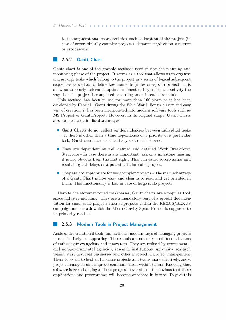
Despite the aforementioned weaknesses, Gantt charts are a popular tool,space industry including. They are a mandatory part of a project documen-tation for small scale projects such as projects within the REXUS/BEXUScampaign underneath which the Micro Gravity Space Printer is supposed tobe primarily realised.
2.5.3 Modern Tools in Project Management
Aside of the traditional tools and methods, modern ways of managing projectsmore effectively are appearing. These tools are not only used in small teamsof enthusiastic evangelists and innovators. They are utilised by governmentaland non-governmental agencies, research institutions, university researchteams, start ups, real businesses and other involved in project management.These tools aid to lead and manage projects and teams more effectively, assistproject managers and improve communication within teams. Knowing thatsoftware is ever changing and the progress never stops, it is obvious that theseapplications and programmes will become outdated in future. To give this
20
.............................. 2.5. Project Management Tools
Figure 2.7: Gantt Chart of The PREDATOR Experiment project
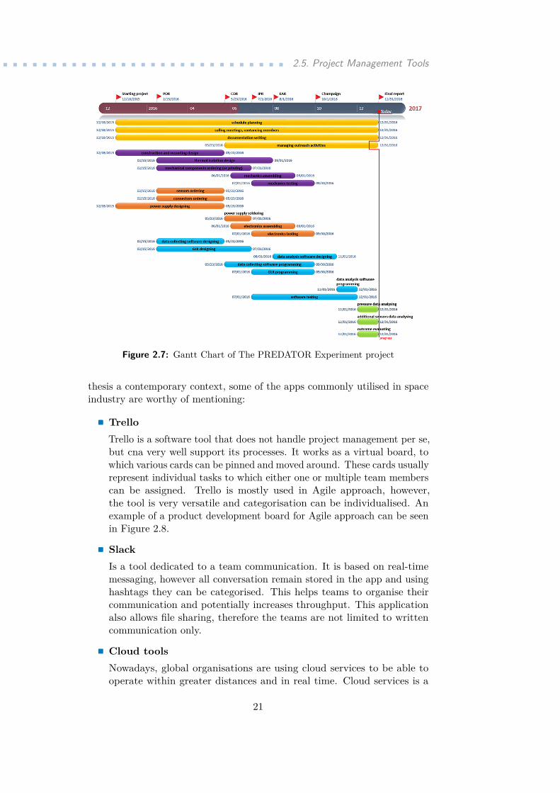
thesis a contemporary context, some of the apps commonly utilised in spaceindustry are worthy of mentioning:.Trello
Trello is a software tool that does not handle project management per se,but cna very well support its processes. It works as a virtual board, towhich various cards can be pinned and moved around. These cards usuallyrepresent individual tasks to which either one or multiple team memberscan be assigned. Trello is mostly used in Agile approach, however,the tool is very versatile and categorisation can be individualised. Anexample of a product development board for Agile approach can be seenin Figure 2.8.. SlackIs a tool dedicated to a team communication. It is based on real-timemessaging, however all conversation remain stored in the app and usinghashtags they can be categorised. This helps teams to organise theircommunication and potentially increases throughput. This applicationalso allows file sharing, therefore the teams are not limited to writtencommunication only..Cloud toolsNowadays, global organisations are using cloud services to be able tooperate within greater distances and in real time. Cloud services is a
21
2. Theoretical Part ...................................
Figure 2.8: Product Development Board visualised in Trello
broad category of tools which operate via internet. It can be either aplatform as a service, an infrastructure as a service or software as aservice. Organisations in space industry are using all three. For an enduser, such as individual scientists or project managers, is software as aservice the most common one. Aside from Trello, Slack, Asana and othertools, the most utilised is G Suite, formerly known as Google Documents.
2.6 Risk Management
Real threat to project success are various risks. They often impose additionalchallenges to management and negatively project in cost, schedule as wellas the actual technical performance Risk management is an appropriateanswer to control them and it well performed risk analysis can save costs andpositively impact the project in general.
Project risk management follows various objectives, which range fromidentification and assessment of a space project, through the risk reduction(or mitigation) and effective control of those risks that cannot be completelyremoved. This is achieved in systematic manner and requires educated andproactive approach. Within a project, risk management is an evolving process,and as the project advances, so does the identification, definition and potentialmitigation of risks.
Space project risk management operates with various methods, startingwith system and engineering analyses, safety analyses, process and componentsdependability and cost analysis. Major objective for risk management is a
22
.................................. 2.6. Risk Management
proper categorisation and ranking of risks per their criticality for projectsuccess. This enables to focus and manage fundamental issues.
At the beginning, certain project’s risk management policy needs to beestablished. In accordance with this policy, processes of risk managementare carried out, considering optimisation of available resources. Per se, riskmanagement helps engineers and team managers by incorporating risk aspectsin management and engineering activities and judgements during the wholeof the project life cycle, including the preparation of project requirementsdocumentation. This is done using an integrated, holistic approach. Suchapproach is generally beneficial for activities in areas such as:.management, cost, and schedule;. control over risk consequences;. development, production, testing, operation, maintenance, and disposal,
all together with their interfaces.
2.6.1 Process of risk management
Figure 2.9: Risk Management Process Steps
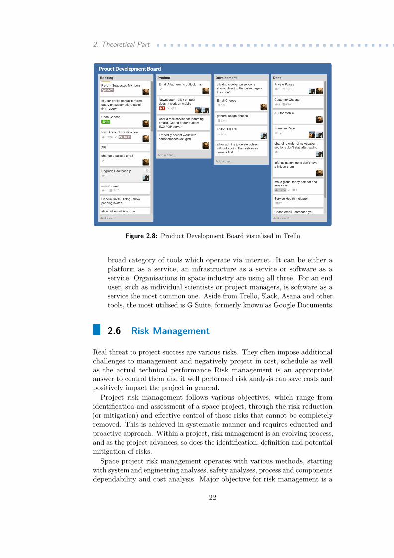
In Step 1, the aforementioned project’s risk management needs to beestablish. Another important foundation for the whole process is a creationof risk management plan, however this has to be done in cooperation withother areas, mainly consisting of system and operation engineering andproduct assurance. The risk management process requires full cooperationand information coordination between the disciplines of the project.
23
2. Theoretical Part ...................................In Step 2, the goal is to define and project risk scenarios and using the
policy and plan from the previous step calculate the PxS ratio and rank themaccording to their potential impact afterwards.
In Step 3, the main objective is to carefully analyse to what extent arethe previously listed risk scenarios acceptable. Based on this analyses, usingavailable resources determine suitable risk mitigation strategies.
In Step 4, all tasks are related to monitoring, continuous updating andcommunicating the risks with stakeholders responsible for work in affectedareas. All four steps are repeated in cycles during the entire duration of theproject as the circumstances and amount of resources change over time. It isimportant to understand that a complex set of internal and external factorscan change the situation within the project immediately and unforeseen risksin the initial phase of establishing policies and plans may have a criticalimpact on successful completion of the project.
2.6.2 Risk Categorisation
To properly list all the risk and prepare sufficient mitigation strategies,certain system of categorisation needs to be put in order. In space projectmanagement and risk management of space projects, following categories ofrisks are commonly used:
Risk ID:. TC – technical/implementation.MS – mission (operational performance). SF – safety. VE – vehicle. PE – personnel. EN – environmental
In space project risk management, risks are evaluated using two dominantfactors: Probability and Severity. For both of them, there exist standardisedscales in accordance with ECSS-M-ST-80C that are in use and every consideredrisk can be assessed on the respective scale.
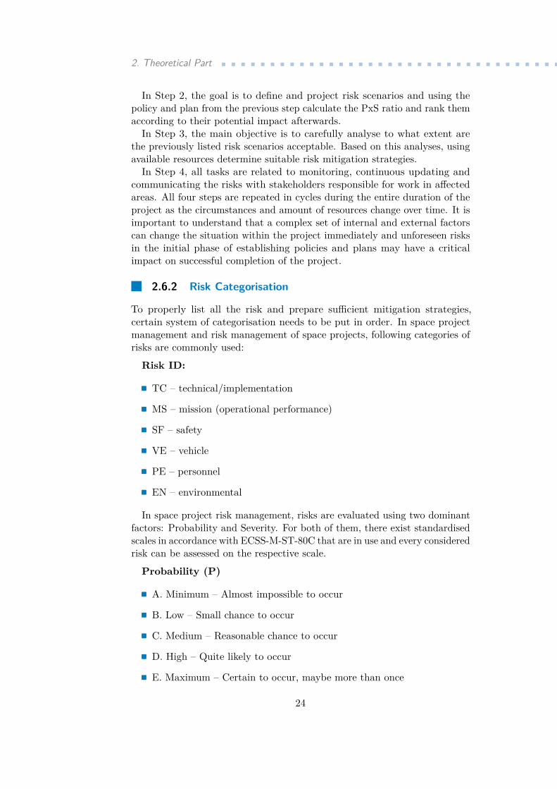
Probability (P). A. Minimum – Almost impossible to occur. B. Low – Small chance to occur. C. Medium – Reasonable chance to occur. D. High – Quite likely to occur. E. Maximum – Certain to occur, maybe more than once
24
.................................. 2.6. Risk Management
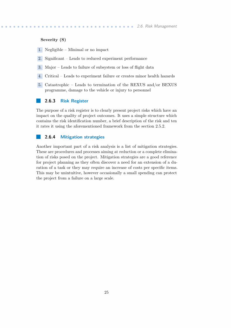
Severity (S)..1. Negligible – Minimal or no impact..2. Significant – Leads to reduced experiment performance..3. Major – Leads to failure of subsystem or loss of flight data..4. Critical – Leads to experiment failure or creates minor health hazards..5. Catastrophic – Leads to termination of the REXUS and/or BEXUSprogramme, damage to the vehicle or injury to personnel
2.6.3 Risk Register
The purpose of a risk register is to clearly present project risks which have animpact on the quality of project outcomes. It uses a simple structure whichcontains the risk identification number, a brief description of the risk and tenit rates it using the aforementioned framework from the section 2.5.2.
2.6.4 Mitigation strategies
Another important part of a risk analysis is a list of mitigation strategies.These are procedures and processes aiming at reduction or a complete elimina-tion of risks posed on the project. Mitigation strategies are a good referencefor project planning as they often discover a need for an extension of a du-ration of a task or they may require an increase of costs per specific items.This may be unintuitive, however occasionally a small spending can protectthe project from a failure on a large scale.
25

26
Chapter 3Practical Part
Taking into consideration all the specifics of the scientific experiments andprojects, it is necessary to modify the structure of the feasibility study.This mostly affects chapters regarding Market Analysis, Marketing Strategy,Current assets controlling strategy and Investment strategy as they are notrelevant for this particular scientific feasibility study. For that reason, thesechapters are absent.
3.1 Technical Description of the Experiment
3.1.1 Introduction
3D printing is a technology that is growing in important across all the technicalindustries. It has already taken an important role in mechanical engineeringand aerospace engineering and automotive industry as a way of speeding upthe design and development of new products. This technology, still oftenbranded as “rapid prototyping” is slowly finding its way to the space industry.
As other technologies advance, it is becoming more and more apparentthat long term deep missions will soon become a reality. This imposesmajor challenges related to a degradation of materials and components ofa spacecraft. Such issue can be addressed by developing a technology thatwill be more sustainable and able to reuse available resources. Reflecting oncurrent development in space exploration, printing in space seems like a viableand sustainable option for production of spare parts and later even biologicaltissue replacements. 3D printers can become a substantial tool for deep spaceexploration and long-term human space flight as they can reduce the massthat needs to be transported to Earth’s orbit due to the fact that instead ofcomplete (and often eventually useless) components and spare parts, onlythe printing material would be carried and utilised for printing whatever isneeded. Furthermore, in the future, there might be more options as miningand other ways of obtaining resources are being explored. Currently, only alimited research is being conducted in this field (and using this project wouldenable to create foundations for further research and ultimate advancementof this technology.
So called In Space Manufacturing contains work in many development
27
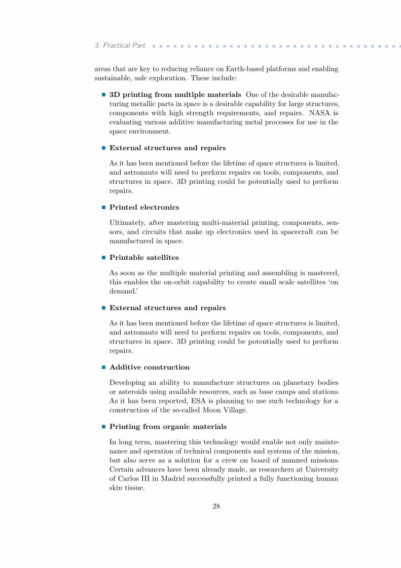
3. Practical Part ....................................areas that are key to reducing reliance on Earth-based platforms and enablingsustainable, safe exploration. These include:. 3D printing from multiple materials One of the desirable manufac-
turing metallic parts in space is a desirable capability for large structures,components with high strength requirements, and repairs. NASA isevaluating various additive manufacturing metal processes for use in thespace environment.. External structures and repairs
As it has been mentioned before the lifetime of space structures is limited,and astronauts will need to perform repairs on tools, components, andstructures in space. 3D printing could be potentially used to performrepairs..Printed electronics
Ultimately, after mastering multi-material printing, components, sen-sors, and circuits that make up electronics used in spacecraft can bemanufactured in space..Printable satellites
As soon as the multiple material printing and assembling is mastered,this enables the on-orbit capability to create small scale satellites ‘ondemand.’. External structures and repairs
As it has been mentioned before the lifetime of space structures is limited,and astronauts will need to perform repairs on tools, components, andstructures in space. 3D printing could be potentially used to performrepairs..Additive construction
Developing an ability to manufacture structures on planetary bodiesor asteroids using available resources, such as base camps and stations.As it has been reported, ESA is planning to use such technology for aconstruction of the so-called Moon Village..Printing from organic materials
In long term, mastering this technology would enable not only mainte-nance and operation of technical components and systems of the mission,but also serve as a solution for a crew on board of manned missions.Certain advances have been already made, as researchers at Universityof Carlos III in Madrid successfully printed a fully functioning humanskin tissue.
28
.........................3.1. Technical Description of the Experiment
3.1.2 Objectives of the project
The project follows multiple objectives on different priority and importancelevel. This needs to be taken into consideration while evaluating the overallsuccess of the projects.. To design and build a printing device capable of printing in reduced
gravity environment with low operational requirements.. To research on material of samples printed in microgravity in comparisonwith normal Earth environment. It is expected that components printedin the microgravity conditions will have different material characteristicsfrom the ones printed on Earth which negatively effects their durabilityand potential use as spare parts.. To develop a printing material composed of thermally-resilient plasticand ferromagnetic dust which are melted together. This material isexposed to a magnetic field underneath the printer’s bed and therefore itattracts the printed material and thus compensating the lack of gravitythat is naturally present on Earth but missing during long term spacemissions.. To develop a pressurised vessel inside of which will be the printing devicesituated. This will ensure stable conditions throughout the flight.. To provide greater statistical sampling for mechanical property data ofspecimen printed in space.. To isolate the effect of microgravity on the FDM process and study thisphenomenon more in-depth.
3.1.3 Scientific Background
As this thesis mostly focuses on comprehensive overview and evaluation ofthe project from the managerial perspective, it is pointless to use detailed andthorough descriptions of the scientific phenomenons that the experiment isbuilt upon. However, some of the critical ones need to be mentioned as theyplay major role in definition of requirements, selection of particular solutionsfor technical systems and helps us understand costs of particular componentsthe discussed experiment consists of.. Effects of reduced gravity
In space, further away from the planet Earth, the effects of its gravita-tional field decrease. For most of the solid or stationary machines andsystems this does not impose any major risks or negatively effects theiroperation. At this moment, this reality affects mostly astronauts as alife in gravity reduced environment causes loss of muscular tissue andconfusion of vestibular system. A situation changes when it comes tomobile systems and technologies of 3D printing. As most of the methods
29
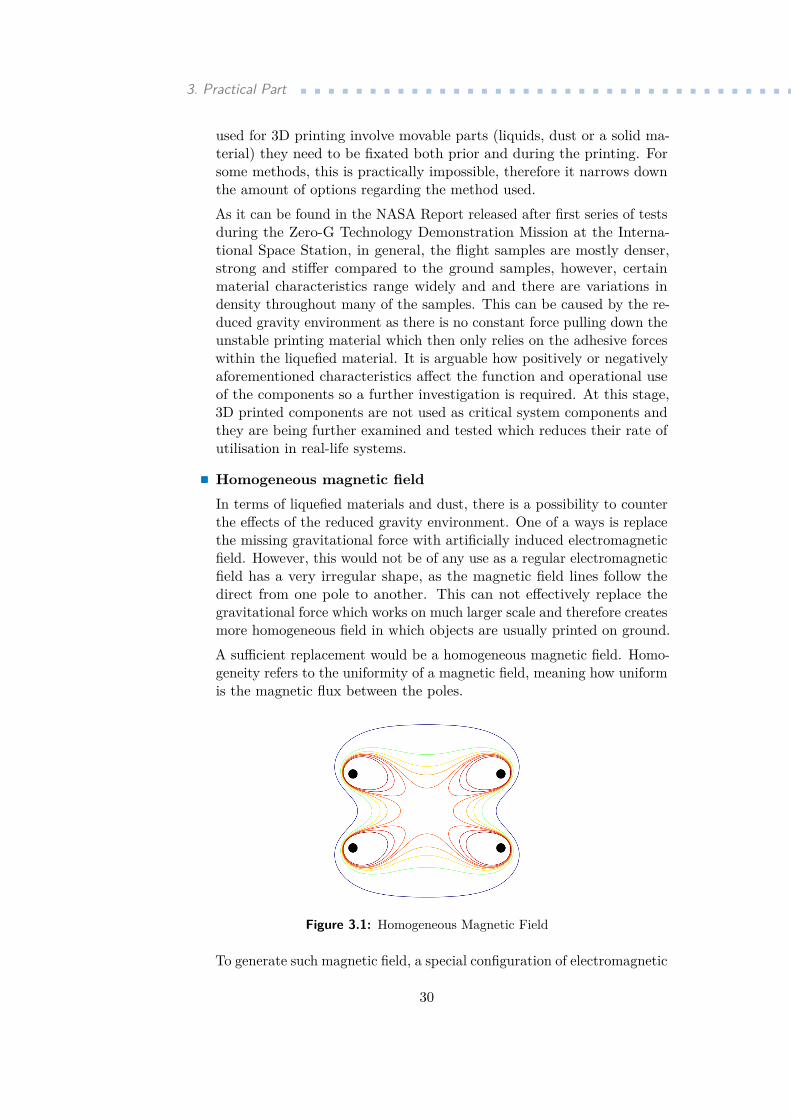
3. Practical Part ....................................used for 3D printing involve movable parts (liquids, dust or a solid ma-terial) they need to be fixated both prior and during the printing. Forsome methods, this is practically impossible, therefore it narrows downthe amount of options regarding the method used.As it can be found in the NASA Report released after first series of testsduring the Zero-G Technology Demonstration Mission at the Interna-tional Space Station, in general, the flight samples are mostly denser,strong and stiffer compared to the ground samples, however, certainmaterial characteristics range widely and and there are variations indensity throughout many of the samples. This can be caused by the re-duced gravity environment as there is no constant force pulling down theunstable printing material which then only relies on the adhesive forceswithin the liquefied material. It is arguable how positively or negativelyaforementioned characteristics affect the function and operational useof the components so a further investigation is required. At this stage,3D printed components are not used as critical system components andthey are being further examined and tested which reduces their rate ofutilisation in real-life systems..Homogeneous magnetic fieldIn terms of liquefied materials and dust, there is a possibility to counterthe effects of the reduced gravity environment. One of a ways is replacethe missing gravitational force with artificially induced electromagneticfield. However, this would not be of any use as a regular electromagneticfield has a very irregular shape, as the magnetic field lines follow thedirect from one pole to another. This can not effectively replace thegravitational force which works on much larger scale and therefore createsmore homogeneous field in which objects are usually printed on ground.A sufficient replacement would be a homogeneous magnetic field. Homo-geneity refers to the uniformity of a magnetic field, meaning how uniformis the magnetic flux between the poles.
Figure 3.1: Homogeneous Magnetic Field
To generate such magnetic field, a special configuration of electromagnetic
30
.........................3.1. Technical Description of the Experiment
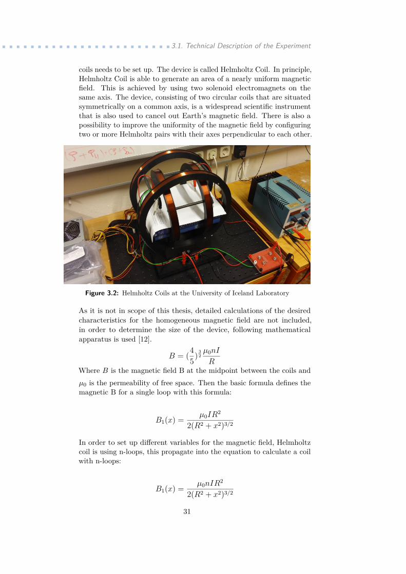
coils needs to be set up. The device is called Helmholtz Coil. In principle,Helmholtz Coil is able to generate an area of a nearly uniform magneticfield. This is achieved by using two solenoid electromagnets on thesame axis. The device, consisting of two circular coils that are situatedsymmetrically on a common axis, is a widespread scientific instrumentthat is also used to cancel out Earth’s magnetic field. There is also apossibility to improve the uniformity of the magnetic field by configuringtwo or more Helmholtz pairs with their axes perpendicular to each other.
Figure 3.2: Helmholtz Coils at the University of Iceland Laboratory
As it is not in scope of this thesis, detailed calculations of the desiredcharacteristics for the homogeneous magnetic field are not included,in order to determine the size of the device, following mathematicalapparatus is used [12].
B = (45) 3
2µ0nI
RWhere B is the magnetic field B at the midpoint between the coils andµ0 is the permeability of free space. Then the basic formula defines themagnetic B for a single loop with this formula:
B1(x) = µ0IR2
2(R2 + x2)3/2
In order to set up different variables for the magnetic field, Helmholtzcoil is using n-loops, this propagate into the equation to calculate a coilwith n-loops:
B1(x) = µ0nIR2
2(R2 + x2)3/2
31
3. Practical Part ....................................And finally, a point halfway between the two loops has an x value equalto R/2, so calculate the field strength at that point:
B1
(R
2
)= µ0nIR
2
2(R2 + (R/2)2)3/2 .
Whereµ0 = the permeability constantµ0 = 4π × 10−7 T · m/A = 1.257 × 10⁻⁶ T · m/A,I = coil current, in amperes,R = coil radius, in meters,x = coil distance, on axis, to point, in meters..MaterialsIn order to make the homogeneous magnetic field an effective replace-ment of the missing gravitational force, it is required to use a materialthat is affected by the magnetic field. Typically, these are ferromagneticmaterials, such as metals. Metals are not widely used for 3D printing asthey require very high temperatures for melting and manipulation andcreation of a desired component as well as very particular conditions andcontrolled environment throughout the cooling process. The cooling pro-cess greatly affects the final material characteristics of a metal componentand currently developed methods are unable to achieve so. Thereforethe current 3D printing technology nowadays uses plastic materials.To cope with that, a new composite material needs to be developedin order to make a method proposed for this project functioning. Oneof the options is to create a composite material that combines bothof the desired qualities. It is ferromagnetic, therefore manipulable bya homogeneous magnetic field, and at the same time exhibit all thequalities of plastic materials: low melting temperature, easy manipulation,acceptable material characteristics. Considered source for the plasticbasis would be Teflon or ABS, while the ferromagnetic dust could besome of the iron oxides.
3.1.4 Design of the experiment
The Design of the experiment is very complex as it comprise technical designs(mechanical, electronics, thermal and software) as well as a particular seriesof stages in which the experiment is carried out. For a better clarity, theoverall design will be explained in following categories.Technical design of the experiment Technical design of the ex-
periment vastly depends on requirements and constrains set by theparameters of the space flight. In the original scenario, it is considered
32

.........................3.1. Technical Description of the Experiment
to use rockets provided by the REXUS programme. This programmeenables students from universities and higher education colleges from allaround Europe to conduct scientific and technological experiments onsounding rockets.Within the REXUS programme, for a payload delivery is normally useda single-stage rocket using an improved Orion motor. This determinesmaximum dimensions for the considered payload. The baseline for themechanical design is the outer structure with 14 inch diameter andvarious sizes of aluminium shells. The experimental device must fit insideof such container in order to maintain structural integrity of a vehicle.
Figure 3.3: 3D Rendering of the Preliminary Mechanical Design
Experimental device is using components from Prusa i3 Mk2S printerwith major modifications to its structure. As seen in the 3D rendering,a pair of heated printing nozzles is placed on a bridge between legs thatserve as a support. It has been decided that with the limited time spentin the microgravity conditions, it is better to optimise space within thepayload container and use multiple nozzles. This allows a simultaneousprinting process and increases the amount of samples that can be usedfor later examination. Apart from the nozzles, the device has a movableprinter bed, feeder which moves the printing material through the nozzle,set of legs based on threaded rods and set of motors allowing the nozzlemovement in horizontal and vertical direction. This movement is ensuredby a set of small step motors. One motor is powering the feeder, twomotors are responsible for horizontal and vertical movement. Underneaththe printing bed there is an Arduino unit responsible for the control ofexperiment as well as the heating systems. All components are in a verycompact set-up to ensure that construction is sturdy enough to survivethe acceleration during the start of the rocket.For a successful measurement, it is substantial to understand the flight
33
3. Practical Part ....................................
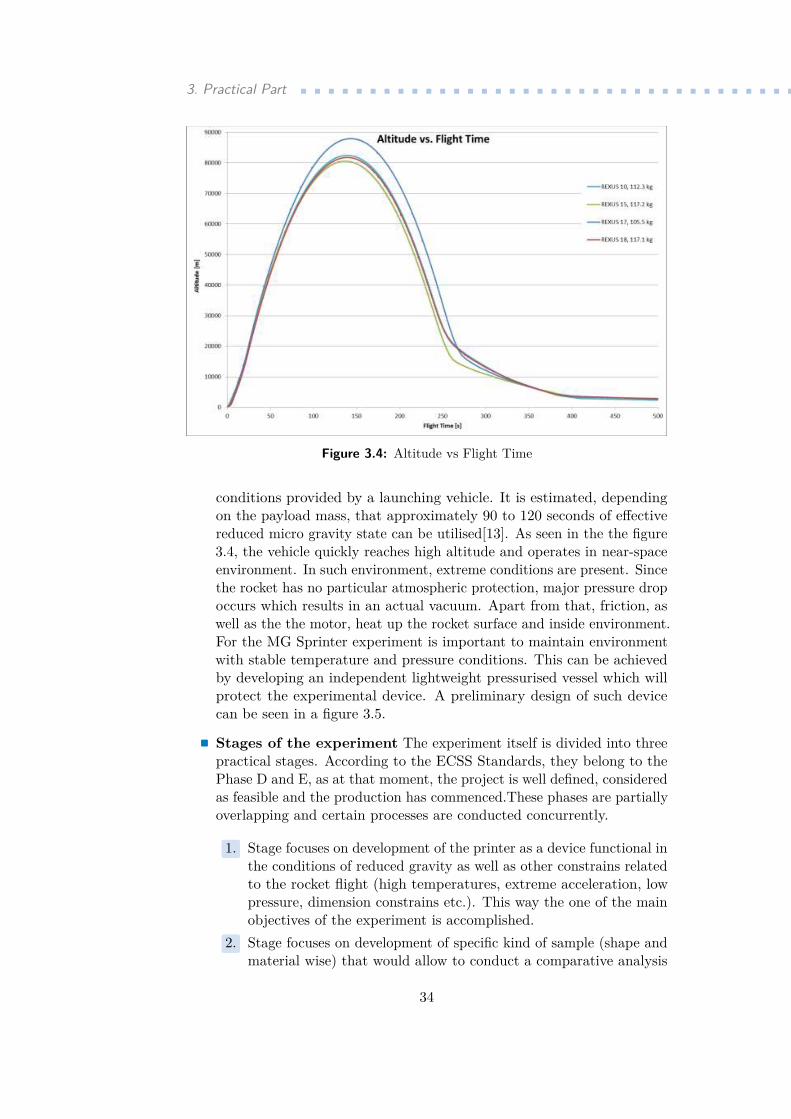
Figure 3.4: Altitude vs Flight Time
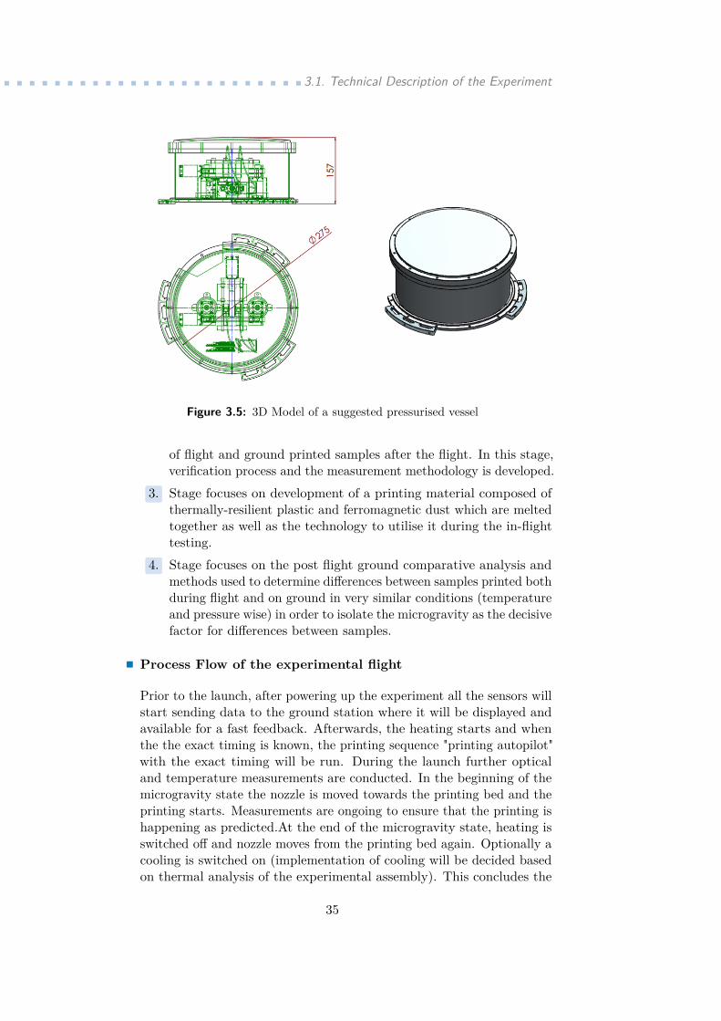
conditions provided by a launching vehicle. It is estimated, dependingon the payload mass, that approximately 90 to 120 seconds of effectivereduced micro gravity state can be utilised[13]. As seen in the the figure3.4, the vehicle quickly reaches high altitude and operates in near-spaceenvironment. In such environment, extreme conditions are present. Sincethe rocket has no particular atmospheric protection, major pressure dropoccurs which results in an actual vacuum. Apart from that, friction, aswell as the the motor, heat up the rocket surface and inside environment.For the MG Sprinter experiment is important to maintain environmentwith stable temperature and pressure conditions. This can be achievedby developing an independent lightweight pressurised vessel which willprotect the experimental device. A preliminary design of such devicecan be seen in a figure 3.5.. Stages of the experiment The experiment itself is divided into threepractical stages. According to the ECSS Standards, they belong to thePhase D and E, as at that moment, the project is well defined, consideredas feasible and the production has commenced.These phases are partiallyoverlapping and certain processes are conducted concurrently...1. Stage focuses on development of the printer as a device functional in
the conditions of reduced gravity as well as other constrains relatedto the rocket flight (high temperatures, extreme acceleration, lowpressure, dimension constrains etc.). This way the one of the mainobjectives of the experiment is accomplished...2. Stage focuses on development of specific kind of sample (shape andmaterial wise) that would allow to conduct a comparative analysis
34
.........................3.1. Technical Description of the Experiment
Figure 3.5: 3D Model of a suggested pressurised vessel
of flight and ground printed samples after the flight. In this stage,verification process and the measurement methodology is developed...3. Stage focuses on development of a printing material composed ofthermally-resilient plastic and ferromagnetic dust which are meltedtogether as well as the technology to utilise it during the in-flighttesting...4. Stage focuses on the post flight ground comparative analysis andmethods used to determine differences between samples printed bothduring flight and on ground in very similar conditions (temperatureand pressure wise) in order to isolate the microgravity as the decisivefactor for differences between samples..Process Flow of the experimental flight
Prior to the launch, after powering up the experiment all the sensors willstart sending data to the ground station where it will be displayed andavailable for a fast feedback. Afterwards, the heating starts and whenthe the exact timing is known, the printing sequence "printing autopilot"with the exact timing will be run. During the launch further opticaland temperature measurements are conducted. In the beginning of themicrogravity state the nozzle is moved towards the printing bed and theprinting starts. Measurements are ongoing to ensure that the printing ishappening as predicted.At the end of the microgravity state, heating isswitched off and nozzle moves from the printing bed again. Optionally acooling is switched on (implementation of cooling will be decided basedon thermal analysis of the experimental assembly). This concludes the
35
3. Practical Part ....................................flight part of the experiment. During the ground part of the experiment,printer is exposed to the same conditions that were measured during theflight (temperature and pressure development) and a new set of samplesis printed out. Afterwards, the data recorded during both (flight andground) printing sessions are evaluated to ensure that microgravity hasbeen isolated as the main effect on printed materials. This process flowis is visualised in the diagram in Annex of the thesis.
36
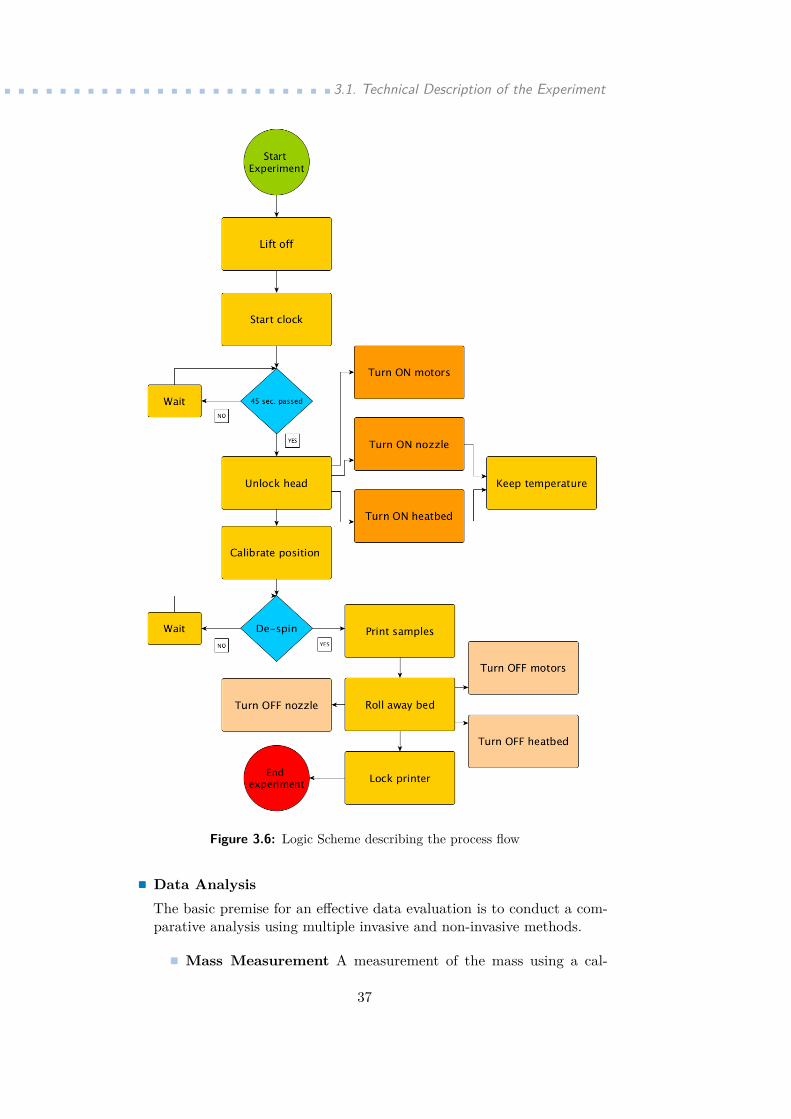
.........................3.1. Technical Description of the Experiment
Figure 3.6: Logic Scheme describing the process flow
.Data AnalysisThe basic premise for an effective data evaluation is to conduct a com-parative analysis using multiple invasive and non-invasive methods..Mass Measurement A measurement of the mass using a cal-
37
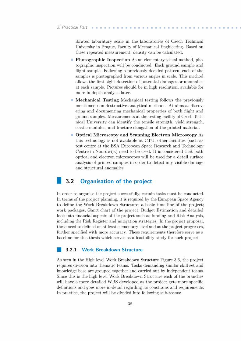
3. Practical Part ....................................ibrated laboratory scale in the laboratories of Czech TechnicalUniversity in Prague, Faculty of Mechanical Engineering. Based onthese repeated measurement, density can be calculated..Photographic Inspection As an elementary visual method, pho-tographic inspection will be conducted. Each ground sample andflight sample. Following a previously decided pattern, each of thesamples is photographed from various angles in scale. This methodallows the first sight detection of potential damages or anomaliesat each sample. Pictures should be in high resolution, available formore in-depth analysis later..Mechanical Testing Mechanical testing follows the previouslymentioned non-destructive analytical methods. At aims at discov-ering and documenting mechanical properties of both flight andground samples. Measurements at the testing facility of Czech Tech-nical University can identify the tensile strength, yield strength,elastic modulus, and fracture elongation of the printed material..Optical Microscopy and Scanning Electron Microscopy Asthis technology is not available at CTU, other facilities (such astest centre at the ESA European Space Research and TechnologyCentre in Noordwijk) need to be used. It is considered that bothoptical and electron microscopes will be used for a detail surfaceanalysis of printed samples in order to detect any visible damageand structural anomalies.
3.2 Organisation of the project
In order to organise the project successfully, certain tasks must be conducted.In terms of the project planning, it is required by the European Space Agencyto define the Work Breakdown Structure; a basic time line of the project;work packages, Gantt chart of the project; Budget Estimation and detailedlook into financial aspects of the project such as funding and Risk Analysis,including the Risk Register and mitigation strategies. In the project proposal,these need to defined on at least elementary level and as the project progresses,further specified with more accuracy. These requirements therefore serve as abaseline for this thesis which serves as a feasibility study for such project.
3.2.1 Work Breakdown Structure
As seen in the High level Work Breakdown Structure Figure 3.6, the projectrequires division into thematic teams. Tasks demanding similar skill set andknowledge base are grouped together and carried out by independent teams.Since this is the high level Work Breakdown Structure each of the brancheswill have a more detailed WBS developed as the project gets more specificdefinitions and goes more in-detail regarding its constrains and requirements.In practice, the project will be divided into following sub-teams:
38
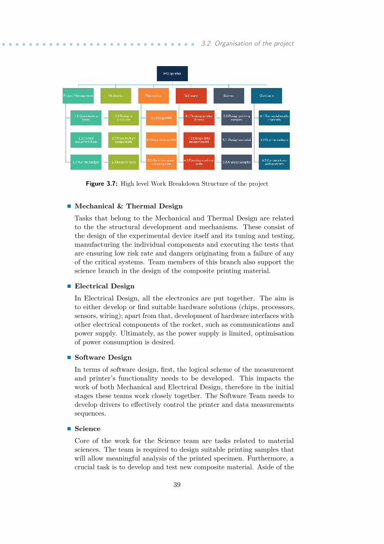
.............................. 3.2. Organisation of the project
Figure 3.7: High level Work Breakdown Structure of the project
.Mechanical & Thermal DesignTasks that belong to the Mechanical and Thermal Design are relatedto the the structural development and mechanisms. These consist ofthe design of the experimental device itself and its tuning and testing,manufacturing the individual components and executing the tests thatare ensuring low risk rate and dangers originating from a failure of anyof the critical systems. Team members of this branch also support thescience branch in the design of the composite printing material.. Electrical DesignIn Electrical Design, all the electronics are put together. The aim isto either develop or find suitable hardware solutions (chips, processors,sensors, wiring); apart from that, development of hardware interfaces withother electrical components of the rocket, such as communications andpower supply. Ultimately, as the power supply is limited, optimisationof power consumption is desired.. Software DesignIn terms of software design, first, the logical scheme of the measurementand printer’s functionality needs to be developed. This impacts thework of both Mechanical and Electrical Design, therefore in the initialstages these teams work closely together. The Software Team needs todevelop drivers to effectively control the printer and data measurementssequences.. ScienceCore of the work for the Science team are tasks related to materialsciences. The team is required to design suitable printing samples thatwill allow meaningful analysis of the printed specimen. Furthermore, acrucial task is to develop and test new composite material. Aside of the
39
3. Practical Part ....................................actual analysis of the printed samples, team members are required todevelop comprehensive methodology for the material analysis..OutreachNowadays, outreach of experiments is growing in importance. It wasunderstood that the communication with both wide public and a scientificcommunity are beneficial for spreading the results and can provide withlong term sustainable funding of future projects. In the outreach, theteam will be responsible for communication on social media channelssuch as Facebook and Twitter, create content and maintain the projectwebsite as well as to directly communicate with public and other relevantstakeholders..Project ManagementAlthough each of the team is in a way self-governed and managed by itsleader. This branch stands alone, as the project needs an independentleadership, control and constant monitoring. With this complexity of aproject, a project manager supports other teams with the administrationand documentation of the entire project. Apart from that, he runsthe budget and closely cooperate with the Outreach team in regards ofcommunicating with project initiators. It is expected that the ProjectManagement will consist of two people, the project manager and his/herdeputy.
Other than the Project Team Branch, each of the small teams will consistof at least three or four members so they could replace and help each otherthroughout the development if needed. As this is a student experiment team,there is a strong emphasis on learning of new team members. This way newteam members would avoid unnecessary obstacles made in previous projectsand they could focus on the development and gaining the learning experience.
Additionally, each team will be also responsible for its own chapter in theproject documentation; coordinated from above by the project manager. Thisway, a smooth documentation of the whole process of the project is ensured.
3.2.2 Timeline of the project
Project such as Microgravity Space Printer is suitable for various developmentschemes. Of the schemes within a geopolitical region, the most suitable seemto be the REXUS (Rocket Experiments for University Students) programme.
As it is expected to realise the full scale project within the REXUS pro-gramme, workload related to creation of the project time line and planningof the schedule is reduced. REXUS projects are using the StandardisedECSS Project Life Cycle Model[6], therefore phases mentioned in the Chapter2.1.3 are adopted. The structure is simplified and uses lower amount ofreviews as milestones. For REXUS programme, the project is divided intopre-development phase prior to the application for the programme supportitself, and the actual development which commences as soon as the project
40
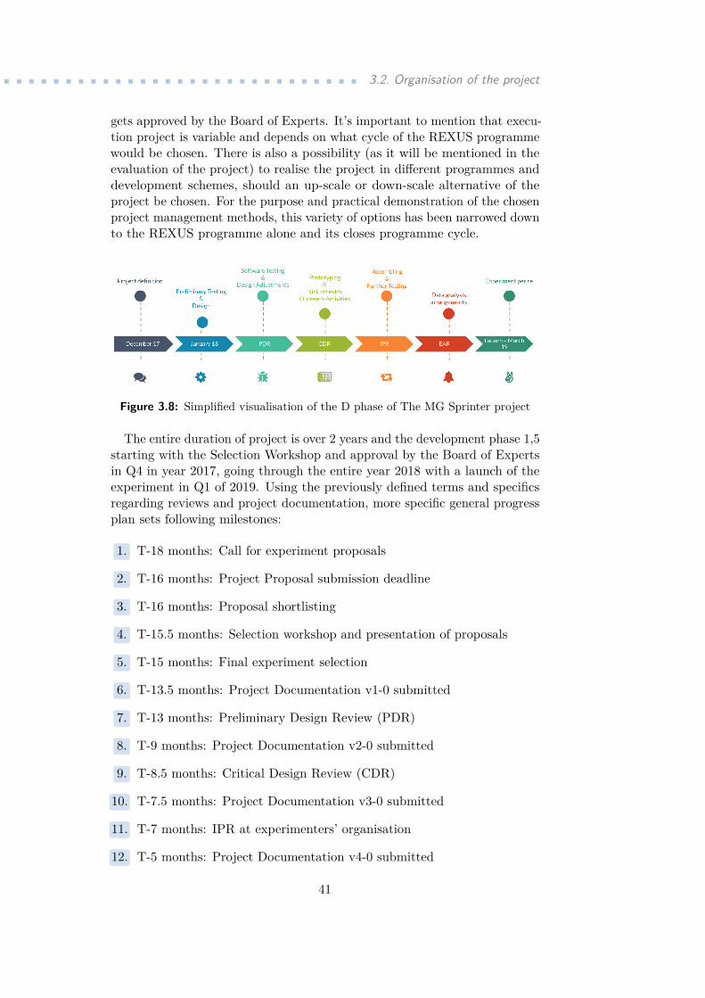
.............................. 3.2. Organisation of the project
gets approved by the Board of Experts. It’s important to mention that execu-tion project is variable and depends on what cycle of the REXUS programmewould be chosen. There is also a possibility (as it will be mentioned in theevaluation of the project) to realise the project in different programmes anddevelopment schemes, should an up-scale or down-scale alternative of theproject be chosen. For the purpose and practical demonstration of the chosenproject management methods, this variety of options has been narrowed downto the REXUS programme alone and its closes programme cycle.
Figure 3.8: Simplified visualisation of the D phase of The MG Sprinter project
The entire duration of project is over 2 years and the development phase 1,5starting with the Selection Workshop and approval by the Board of Expertsin Q4 in year 2017, going through the entire year 2018 with a launch of theexperiment in Q1 of 2019. Using the previously defined terms and specificsregarding reviews and project documentation, more specific general progressplan sets following milestones:..1. T-18 months: Call for experiment proposals..2. T-16 months: Project Proposal submission deadline..3. T-16 months: Proposal shortlisting..4. T-15.5 months: Selection workshop and presentation of proposals..5. T-15 months: Final experiment selection..6. T-13.5 months: Project Documentation v1-0 submitted..7. T-13 months: Preliminary Design Review (PDR)..8. T-9 months: Project Documentation v2-0 submitted..9. T-8.5 months: Critical Design Review (CDR)...10. T-7.5 months: Project Documentation v3-0 submitted...11. T-7 months: IPR at experimenters’ organisation...12. T-5 months: Project Documentation v4-0 submitted
41
3. Practical Part .......................................13. T-4.5 months: Experiment Acceptance Review...14. T-4 months: Delivery of Experiments to Integration Week (ITW)...15. T-2.5 months: Bench Test...16. T-0.5 months: Spin and Balance Test...17. T+0 months: Launch Campaign of the experiment...18. T+0.5 month: Flight Report Documentation from experimenters sub-mitted...19. T+1 month: Distribution of the REXUS post flight Report used forflight data analysis...20. T+3 moths: Project Documentation v5-0 submitted including experimentresults...21. T+4 months: Publication of Final Report/Results Seminar
3.2.3 Work Packages
To successfully create a Gantt chart for the Micro Gravity Space Printerproject, work packages need to be created and defined. A work packageis an elementary unit that organisational charts (such as Gantt chart) aremade of. It includes description of the task as well as start and end datesfor the task. Work packages are usually prepared by team members who arefamiliar with the peculiarities of the task they are responsible for thus theycan very well estimate the duration of tasks. As this is a feasibility study,exact personal management is not known yet, therefore tasks from the Highlevel Work Breakdown Structure are used and broken further into sub tasksand respective work packages.
3.2.4 Gantt Chart
Regarding the time schedule, The MG Sprinter Gantt chart is based on thetime line outlined in the section 3.2.2.
42
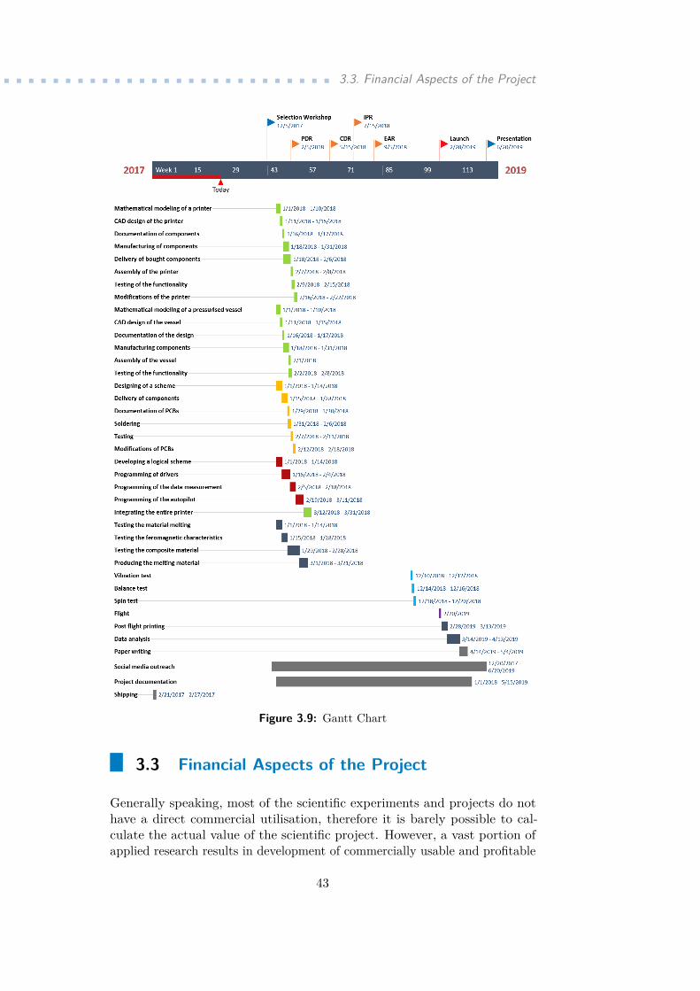
............................ 3.3. Financial Aspects of the Project
Figure 3.9: Gantt Chart
3.3 Financial Aspects of the Project
Generally speaking, most of the scientific experiments and projects do nothave a direct commercial utilisation, therefore it is barely possible to cal-culate the actual value of the scientific project. However, a vast portion ofapplied research results in development of commercially usable and profitable
43

3. Practical Part ....................................technologies.
3.3.1 Budget Estimation
Figure 3.10: Preliminary Budget Estimation for the MG Sprinter Project
Following the previously set project division, the preliminary budget repre-sents costs of each project team and major expected expenses. These mostlyaccount for material costs, such as specific technical components, systemsand materials used for construction. As the project has an internationalbackground, it is important to include travel expenses. Various tests, reviewpresentations and the actual flight campaign take place abroad and at leastpart of the team (usually team members that are the most relevant for eachrespective review) should attend these meetings. Reasoning for the figures ineach of the branches are described in its respective category:.Mechanics
Underneath this category, an array of items opens up. As it has beenmentioned in the technical design of the experiment, most of the costsconsists of the 3D printers (as it is required to use multiple ones - twoat least - and modify them to function in a space environment and thedevice responsible for generation of uniform magnetic field. Figures for allthe items have been chosen after careful market analysis and calculatingthe average price of each device. It is important to mention that theestimation is rather conservative and intentionally is using values fromthe upper range of the available products.. ElectronicsItems in this category exceed normal prices of components available ona regular market. This is caused by a particular selection of components.As in space research, electronics must have much wider temperatureoperation range, reliability and sufficient radiation protection. Therefore,even basic components require space certification, which dramaticallyincreases their price.
44
............................ 3.3. Financial Aspects of the Project
. SoftwareAs of software, only some computing programme licences and driversare required and most of the solutions will be tailor made by the teammembers themselves. For this reason, this item is estimated as relativelylow. In case of any major increases, this can be sourced from the Riskreserve.. ScienceThe highest cost in terms of the science team will be the new compositematerial development, however, thermal-resilient plastic is available onmarket for relatively cheap price if it is purchased in large quantities.Therefore, the estimated costs are derived from the price lists of wholesalestores. Additionally, it has no meaning to buy all of the measurementsdevices such as optical and electron microscopes. Purchase of thesedevices would undoubtedly multiplied the entire project budget..MiscellaneousIn this category, all the other expenses are covered. Since the team ofapproximately 15 to 20 people will spend working for nearly two yearstogether, it is important to invest into building an efficient team anddevelop functioning group dynamics. Furthermore, including expenseson social media (such as sponsored posts on Facebook or Instagram) cannot be omitted. As it has been mentioned in the introduction of thissection, the budget estimation also covers travel expenses that exceedsthe maximum amount guaranteed by the REXUS programme organisers.
3.3.2 Financial resources
In project planning, it is crucial to not only identify potential costs, but alsodetermine ways of sustaining the budget and funding each of the respectiveitems on the list. There is a need to diversify the funding and ways of coveringexpenses. If there is a way how to decrease costs without imminent decreaseof quality and deteriorating from the objectives, it increases the chance ofrealising the project. In the estimated budget, there are several major items.For some of them, such as the printers, certain savings can be achieved bycooperating with 3D printer producers, such as Prusa Research. Donation ora partnership would be an option.
Other than that, facilities, such as workshops used for manufacturing andassembly, testing rooms and devices used for the analysis of printed samplescan be provided the Czech Technical University in Prague - Alma mater ofthe project team - or affiliated institutions. This can save up a lot of costsand it has proven as a sufficient solution in the past with The PREDATORExperiment team.
The PREDATOR Experiment was supported by the research programno. SGS15/212/OHK3/3T/13, “Safe and Safety Elements in Aerospace andSpace Technology II”, of the Czech Technical University in Prague. It is alsoexpected to use similar ways of funding the remaining expenses.
45
3. Practical Part ....................................Another great advantage of taking part in the REXUS programme is wide
financial support. Participating organisations are committed to cover therocket launch itself (which would be otherwise extraordinarily expensive)as well as to support teams financially. All project teams selected for theprogramme has a privilege of sending two fully covered team members toevery review.
Lastly, in regular teams, one of the major items would be salary-relatedcosts of the team members. This is a huge advantage of a student project, asall the team members are required to be full time university students andtherefore work on the project is a learning experience and not an actual jobper se. Optionally, university scholarships can be used an incentive.
3.4 Environmental Aspects of the Project
Every regular feasibility study includes environmental aspects of the project,assess potential health risks and evaluates impact on the environment. Thisis usually listed in Environmental Risk Register and its subsequent analysis.The situation with space project usually differs as they are designated tofunction in outer space, outside of the environment that is commonly affectedby terrestrial construction or investment projects. For this reason, the list ofrisks would not be sufficient for a complete analysis, all potential risks - atleast remotely related to the damage of a natural environment or imposingthreats to human health - are included in an extensive Risk Analysis inchapter 3.5.3.
3.5 Risk Management of the project
As in every project, there is a threat of a complete or partial failure of theproject due to project risks. Due to a complexity of the MG Sprinter Project,a variety of risk has been identified. Risks with greater magnitude are notmentioned as they exceed the acceptable levels. In a following section theproject Risk Register can be found.
3.5.1 Risk Register
In the following Risk Register, relevant risks are listed. To understand thestructure, each category of risks has been explained. Only risks that havethe PxS product of a value "low" and "very low" are listed. Medium, Highand Very High Risks are not acceptable in space project risk management.Should any risk of this magnitude occur, a new team process needs to beimplemented or a new baseline (in the risk management plan) needs to beestablished.
46

............................ 3.5. Risk Management of the project
ID Risk P S PxS Mitigation
MS00 Nozzle gets clogged B 4 low Mit. Strategy 1MS10 Measurement data does not
get saved in memoryA 1 very low Mit. Strategy 2
MS20 Material of mechanicalstructure might degrade inhigher temperatures
A 4 very low Mit. Strategy 3
MS30 Uniform magnetic field caninfluence other electronics
B 3 low Mit. Strategy 4
MS40 Temperature outside oper-ating range of components
B 3 low Mit. Strategy 5
MS50 Pressurised vessel failure inlow pressure
B 4 low Mit. Strategy 6
MS60 Electrostatic dischargemight cause failure tocomponents
B 3 low Mit. Strategy 7
MS70 Software program in microcontroller fails during flight
C 3 low Mit. Strategy 8
MS71 (Residual of MS70) B 1 very low Mit. Strategy 9MS80 Flight vibration destabilise
the printer calibrationB 2 very low Mit. Strategy 10
MS90 G-force during the startdestabilise the printer cali-bration
B 2 very low Mit. Strategy 11
MS100 Printing Material may de-grade before the flight
C 3 low Mit. Strategy 12
MS101 (Residual of MS100) A 1 very low Mit. Strategy 13MS110 Autopilot memory fails B 1 very low Mit. Strategy 14MS120 Experiment not delivered
on time at ESRANGEB 4 low Mit. Strategy 15
MS130 Experiment is influenced byemission of other experi-ments
B 3 low Mit. Strategy 16
Table 3.1: Risk Register, part 1
3.5.2 Mitigation Strategies
In the section 3.5.3, 25 potential risks are listed. Although they are all ratedwith "low" or "very low" magnitude, it is important to develop and formulatemitigation strategies in order to cause minimal damage, deviation for theproject scope and limit potential financial expenses. Mitigation strategiescan be grouped together, as some of the risks belong to the same categoryand the way to reduce the risk or completely mitigate it is similar..Mitigation strategies 1, 3, 6, 10, 11, 19 are of a similar nature: Risks are
47
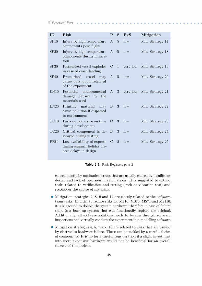
3. Practical Part ....................................ID Risk P S PxS Mitigation
SF10 Injury by high temperaturecomponents post flight
A 5 low Mit. Strategy 17
SF20 Injury by high temperaturecomponents during integra-tion
A 5 low Mit. Strategy 18
SF30 Pressurised vessel explodesin case of crash landing
C 1 very low Mit. Strategy 19
SF40 Pressurised vessel maycause cuts upon retrievalof the experiment
A 5 low Mit. Strategy 20
EN10 Potential environmentaldamage caused by thematerials used
A 3 very low Mit. Strategy 21
EN20 Printing material maycause pollution if dispersedin environment
B 3 low Mit. Strategy 22
TC10 Parts do not arrive on timeduring development
C 3 low Mit. Strategy 23
TC20 Critical component is de-stroyed during testing
B 3 low Mit. Strategy 24
PE10 Low availability of expertsduring summer holiday cre-ates delays in design
C 2 low Mit. Strategy 25
Table 3.2: Risk Register, part 2
caused mostly by mechanical errors that are usually caused by insufficientdesign and lack of precision in calculations. It is suggested to extendtasks related to verification and testing (such as vibration test) andreconsider the choice of materials..Mitigation strategies 2, 8, 9 and 14 are closely related to the softwareteam tasks. In order to reduce risks for MS10, MS70, MS71 and MS110,it is suggested to double the system hardware, therefore in case of failurethere is a back-up system that can functionally replace the original.Additionally, all software solutions needs to be run through softwareinspections and virtually conduct the experiment in a modelling software..Mitigation strategies 4, 5, 7 and 16 are related to risks that are causedby electronics hardware failure. These can be tackled by a careful choiceof components. It is up for a careful consideration if a slight investmentinto more expensive hardware would not be beneficial for an overallsuccess of the project.
48
............................... 3.6. Evaluation of the project
.Mitigation strategies 12, 13, 21 and 22 is related to the risk that iscaused by a potentially imperfect process of a material development. Itis suggested to prolong the development and include more testing focusingon a long term degradation and relaxation of the printing material..Mitigation strategies 15, 23, 24 and 25 are related to logistics. Thismeans that for logistical tasks there needs to be more time allocated andgreater time reserves created..Mitigation strategies 17, 18 and 20 mitigate health risks. In order tocope with these, user manuals for manipulation need to be created andwork safety policies must be enforced.
3.6 Evaluation of the project
The Microgravity Space Printer is a very complex project with fields of interestthat span from research, development of a new technology with a consider-able societal and environmental impact (in a positive manner). Followingevaluation is divided into several categories and takes into consideration verypeculiar nature of the project as well as its specifics:. Evaluation of environmental impacts
This touches the environmental aspects of the project: the MG Sprinterproject itself imposes very little risks to human and natural environment.Risks are mostly related environmental pollution, however, it can be saidthat there are any materials which would pose any health risk or causean environmental damage.In long term, the project and projects subsequent to this one can actuallyhave positive impact as the technology presented in the MG Sprinterresearch is theoretically more efficient and decreases material costs, whichis a beneficial factor for natural environment.
. Financial evaluation of the projectRegarding the financial aspects of the project, the project can be con-sidered as relatively inexpensive. In comparison with experiments of asimilar scope, costs are lower. To give an example, Upgraded Pulsat-ing Heat pipe Only for Space (U-Phos), another REXUS project, hadan overall budget of 47,700 Euro. Therefore, 16,080 Euro for the MGSprinter project appears to be a reasonable budget estimation. Fundingopportunities presented for this project seem to be realistic and verypromising. It might be interesting to focus on establishing partnershipswith subjects with a particular interest which could push the costs evenlower. The entire project is widely affected by available funding op-portunities provided by the university, nevertheless, from the financialperspective, the project definitely looks feasible.
49
3. Practical Part .....................................Technical and technological solution of the project
Regarding the technical solution of the project, it is an indeed interestingtechnological concept. However, such complex project may be difficultto keep within the defined scope. Development of the printer itself isalready a challenge as well as the lightweight pressurised vessel. Newlydeveloped composite material is yet another challenge. It is expected thatthe team will build upon experience of the previous REXUS/BEXUSteam, therefore a knowledge transfer sessions are suggested.
. Evaluation of the project organisationIn terms of organisational matters, a major advantage of the project isthe fact that it closely adheres to the European Cooperation for SpaceStandardization norms and standards. With this particular projectproposal, guidance provided by the European Space Agency is making itvery strong and significantly improves the quality of the project. Thetime estimation, beginning with individual tasks and going throughwork packages and work of individual team is sober and realistic. Itprovides the project team with sufficient time to keep the quality of theoutcomes high. On the other side, a potential risk is a time availabilityof the individual members. As it is a student project, some initiallyunforeseen motivation and commitment issues may propagate as theproject progresses further and work load increases. For that reason,it is suggested to focus on the team motivation and development ofhealthy team dynamics and more importantly, thorough recruitmentprocess. Over all, the project at this moment is well prepared and canbe recommended for realisation.
3.6.1 Potential up-scale and down-scale alternatives
Although the original scope of the project has been well estimated to meetthe requirements for sufficient scientific advancement and at the same timeusing all the available resources to maximum, it is important to present bothup-scale and down-scale alternatives of the project. The final decision ofwhich alternative should be realised vastly depends on circumstances, suchas funding and human resources, as well as the institutional support..Up-Scale Alternative
It may occur, that a better funding opportunity will present itself or theremay be a better opportunity for the experimental rocket flight. Someof the opportunities could be a flight with MASER or MAXUS rocket,which present with better micro-gravity conditions and can improve thequality of the measurement and thus the overall quality of the outcomes.This depends on opportunities provided by space agencies and privatesector. Should such up-scale happen, it is required to redefine the projectand especially the funding and management of human resources. Betterflight conditions presents the team with higher complexity of problems,
50

............................... 3.6. Evaluation of the project
therefore a shift from a student team towards professional researchers isthe following step. Such project can be PRODEX funding..Down-Scale AlternativeOn contrary, a cut in funding may occur. Should such situation happen,certain measures must be taken. It is obvious that with limited funding,the scope of a project would have to be redefined. This would probablyresult in reconsidering the project objectives. As an obvious choice, thecomposite material development would be dropped just as the utilisationof a uniform magnetic field. A new main objective would most likely aimat developing the printing device and extend the known information ofsamples printed in space and behaviour of FMD technology in reducedgravity environment. Still, such project provides with enough newinformation that its realisation would be justified.
In conclusion, there different alternatives have been presented. Two ofthem are able to provide us with extraordinary scientific results which maybe turned into profitable business in case of a project success. This wouldrequire a creation of a new, subsequent project that would build upon theresults.
Project Microgravity Space Printer is well design and covers all sorts ofaspects. It has a potential to combine a learning experience at a highereducation institution, advancement of human knowledge, development of anew technology and a business opportunity. It carries a very low amountof risks and even pessimistic, down-scale alternative presents an interestingproject with a very good price-to-value ratio. The Micro Gravity SpacePrinter project can be definitely recommended for realisation.
51

52

Chapter 4Conclusions
The Microgravity Space Printer Project is an ambitious experiment aimingat developing an innovative technology. A great advantage is its immediateutilisation: it solves a long term issue for which there are currently notexisting sufficient solution. It is therefore filling the gap and thus easy to seea potential development. This technology can be also used on Earth. Withcertain level of modification, it can take control of a significant part of amarket. Uniform magnetic field can be generated in a way that it improvesmaterial characteristics in designated directions.
To conclude this thesis, it is appropriate to give several recommenda-tions which may improve the quality of the project outcomes. Some of therecommendations are:
In The Micro Gravity Space Project - Feasibility Study, we have had anopportunity to learn more about project management, its traditional as wellas unconventional contemporary methods and tools. We have become familiarwith the project life cycle and risk management and some of the ways theseare approached in space project management.
This all was required to set a baseline for the practical part of the thesis.In the practical part, we have used the theoretical knowledge to introduce theMicro Gravity Space Printer project - an effort suggested to be carried out bya student team. Scientific background, technical description, organisationaland other aspects of the project: this all had to be described in order toevaluate the project and assess its chance for a successful realisation.
53

54
Bibliography
[1] ROBERT K. WYSOCKI. Effective project management: traditional, agile,extreme. 6th ed. Hoboken, N.J: Wiley, 2011. ISBN 9781118016190.
[2] SVOZILOVÁ, Alena. Projektový management: systémový přístup k řízeníprojektů. 3., aktualizované a rozšířené vydání. Praha: Grada publishing,2016. Expert (Grada). ISBN 978-80-271-0075-0.
[3] CLELAND, David I. a William Richard KING. Systems analysis andproject management. 3rd ed. New York: McGraw-Hill, c1983. ISBN0070113114
[4] ROSENAU, Milton D. Řízení projektů. Vyd. 3. Brno: Computer Press,c2007. Business books. ISBN 978-80-251-1506-0.
[5] BURKE, Rory. Project management: planning and control techniques.Fifth edition. ISBN 978-1-118-66076-8.
[6] CSS-M-ST-10C Rev. 1 ESA-ESTEC. Space Project Management: Projectplanning and implementation. Requirements & Standards Division No-ordwijk, The Netherlands, 2009
[7] What is Agile Project Management? Available from:https://www.smartsheet.com/everything-you-need-to-know-about-agile-project-management
[8] TŮMOVÁ, Zuzana; TROJAN, Ondřej; GABRIEL, Michal; LUKAČEVIČ,Jan. Pressure Difference dependency on Altitude vericaTOR. 2017
[9] SIEBER, Patrik. Studie proveditelnosti: Feasibility study : metodickápříručka. Praha: Ministerstvo pro místní rozvoj ČR, 2004.
[10] PRATER, T.J; BEAN, Q.A.; BESHEARS, R.D.; ROLIN, T.D.;WERKHEISER, N.J.; ORDONEZ, E.A.; RYAN, R.M. and LEDBETTERIII F.E. Summary Report on Phase I Results From the 3D Printing inZero-G Technology Demonstration Mission, Volume I. Marshall SpaceFlight Center, Huntsville, Alabama. 2016
[11] RAMSDEN, Ed. Hall-effect sensors: theory and applications. 2nd ed.Boston: Elsevier/Newnes, c2006. ISBN 9780750679343.
55

Bibliography ......................................[12] GRIFFITHS, David J. Introduction to electrodynamics. 3rd ed. Upper
Saddle River, N.J.: Prentice Hall, c1999. ISBN 0-13-805326-x.
[13] SCHÜTTAUF K., KINNAIRD A., REXUS User Manual. 2016
[14] ECSS-M-ST-80C. Space Project Management: Risk management. Re-quirements & Standards Division Noordwijk, The Netherlands, 2008
56