La Crosse Boiling Water Reactor - Nuclear Regulatory ...
190
WILLIAM L. BERG, President and CEO DAIRYLAND POWER COO PE RATIVE December 28, 2010 In reply, please refer to LAC-14154 DOCKET NO. 50-409 Document Control Desk U. S. Nuclear Regulatory Commission Washington, DC 20555 SUBJECT: Dairyland Power Cooperative La Crosse Boiling Water Reactor (LACBWR) Possession-Only License DPR-45 Decommissioning Plan Revision - November 2010 REFERENCES: (1) DPC Letter (LAC-12460), Taylor to Document Control Desk, dated December 21, 1987, submitting original LACBWR Decommissioning Plan (2) NRC Letter, Erickson to Berg, dated August 7, 1991, issuing Order to Authorize Decommissioning of LACBWR (3) NRC Letter, Brown to Berg, dated September 15, 1994, issuing Confirmatory Order modifying Decommissioning Order A revision of the LACBWR Decommissioning Plan (D-Plan) has been completed. The D-Plan functions as a Final Safety Analysis Report (FSAR) at LACBWR and submittal of revisions to this FSAR fulfills requirements found in 10 CFR 50.71(e)(4). The main objective of this comprehensive revision was to accommodate construction and implementation of an Independent Spent Fuel Storage Installation at the LACBWR site. As determined in accordance with 10 CFR 50.59 requirements, these changes to the LACBWR D-Plan do not require prior NRC approval. All changes have been reviewed by the plant Operations Review Committee and the independent Safety Review Committee; both groups have given approval of these changes. The D-Plan is also considered a Post-Shutdown Decommissioning Activities Report (PSDAR). NRC notification under 10 CFR 50.82(a)(7) is required if changes are inconsistent with or make significant schedule changes to those described in the PSDAR. Schedule changes in this revision of the D-Plan required notification to the NRC. This notification of a change to the LACBWR decommissioning schedule was made to the State of Wisconsin and the NRC by letter dated December 7, 2010. A Touchstone Energy® Cooperative fZ ' M 3200 East Ave. S. * PO Box 81]7 La Crosse, WI 54602-0817 • 608-787-1258 ° 608-787-1469 fax • www.dairynet.com
-
Upload
khangminh22 -
Category
Documents
-
view
0 -
download
0
Transcript of La Crosse Boiling Water Reactor - Nuclear Regulatory ...

WILLIAM L. BERG,President and CEO
DAIRYLAND POWERCOO PE RATIVE
December 28, 2010
In reply, please refer to LAC-14154
DOCKET NO. 50-409
Document Control DeskU. S. Nuclear Regulatory CommissionWashington, DC 20555
SUBJECT: Dairyland Power CooperativeLa Crosse Boiling Water Reactor (LACBWR)Possession-Only License DPR-45Decommissioning Plan Revision - November 2010
REFERENCES: (1) DPC Letter (LAC-12460), Taylor to Document Control Desk,dated December 21, 1987, submitting original LACBWRDecommissioning Plan
(2) NRC Letter, Erickson to Berg, dated August 7, 1991, issuingOrder to Authorize Decommissioning of LACBWR
(3) NRC Letter, Brown to Berg, dated September 15, 1994, issuingConfirmatory Order modifying Decommissioning Order
A revision of the LACBWR Decommissioning Plan (D-Plan) has been completed. The D-Planfunctions as a Final Safety Analysis Report (FSAR) at LACBWR and submittal of revisions tothis FSAR fulfills requirements found in 10 CFR 50.71(e)(4). The main objective of thiscomprehensive revision was to accommodate construction and implementation of anIndependent Spent Fuel Storage Installation at the LACBWR site. As determined in accordancewith 10 CFR 50.59 requirements, these changes to the LACBWR D-Plan do not require priorNRC approval. All changes have been reviewed by the plant Operations Review Committee andthe independent Safety Review Committee; both groups have given approval of these changes.
The D-Plan is also considered a Post-Shutdown Decommissioning Activities Report (PSDAR).NRC notification under 10 CFR 50.82(a)(7) is required if changes are inconsistent with or makesignificant schedule changes to those described in the PSDAR. Schedule changes in thisrevision of the D-Plan required notification to the NRC. This notification of a change to theLACBWR decommissioning schedule was made to the State of Wisconsin and the NRC byletter dated December 7, 2010.
A Touchstone Energy® Cooperative fZ ' M
3200 East Ave. S. * PO Box 81]7 La Crosse, WI 54602-0817 • 608-787-1258 ° 608-787-1469 fax • www.dairynet.com

Document Control DeskPage 2December 28, 2010
All pages of the LACBWR D-Plan have been updated with changes in formatting andnumbering, and are enclosed with this letter. The location of specific changes in content aredesignated with a change bar in the right-hand margin. Justifications for the changes areprovided in a separate enclosure. Please replace all pages of the LACBWR D-Plan with thepages enclosed showing a revision date of November 2010. Also enclosed for replacement is anupdate to the Initial Site Characterization Survey for SAFSTOR (TR-138).
If you have any questions concerning any of these changes, please contact Jeff McRill of mystaff at 608-689-4202.
Sincerely,
DAIRYLAND POWER COOPERATIVE
William L. Berg, President and CEO
WLB:JBM:two
Enclosures
cc: Kristina BanovacProject ManagerU.S. Nuclear Regulatory Commission
NRC Docket No. 50-409
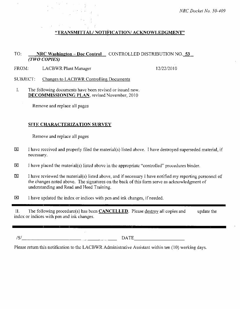
"TRANSMITTAL/ NOTIFICATION/ ACKNOWLEDGMENT"
TO: NRC Washington - Doc Control CONTROLLED DISTRIBUTION NO. 53(TWO COPIES)
FROM: LACBWR Plant Manager 12/22/2010
SUBJECT: Changes to LACBWR Controlling Documents
I. The following documents have been revised or issued new.DECOMMISSIONING PLAN, revised November, 2010
Remove and replace all pages
SITE CHARACTERIZATION SURVEY
Remove and replace all pages
LxI I have received and properly filed the material(s) listed above. I have destroyed superseded material, ifnecessary.
CK I have placed the material(s) listed above in the appropriate "controlled" procedures binder.
E[ I have reviewed the material(s) listed above, and if necessary I have notified my reporting personnel ofthe changes noted above. The signatures on the back of this form serve as acknowledgment ofunderstanding and Read and Heed Training.
FK I have updated the index or indices with pen and ink changes, if needed.
II. The following procedure(s) has been CANCELLED. Please destroy all copies and update theindex or indices with pen and ink changes.
/S/ DATE
Please return this notification to the LACBWR Administrative Assistant within ten (10) working days.

ACP-06.4Issue 5
ATTACHMENT I
10 CFR 50.59 SCREEN FORM
Document No. Not Applicable 50.59 Screen Rev. No. 0
Activity TitleLACBWR Decommissioning Plan
Activity Description
2010 annual review and update of the LACBWR Decommissioning Plan.
Document Listing
1. LACBWR Decommissioning Plan, December 2009.2. LACBWR Possession-Only License, Docket No. 50-409, Amendment No. 69, date of
issuance April 11, 1997.3. LACBWR Possession-Only License, Appendix A, Technical Specifications, Amendment
No. 70, date of issuance April 3, 2006.4. NRC to DPC, Confirmatory Order Modifying NRC Order Authorizing Decommissioning of
Facility, dated September 15, 1994.
Design Functions
The Decommissioning Plan functions as a Final Safety Analysis Report (FSAR) at LACBWRand submittal of revisions to this FSAR fulfill requirements found in 10 CFR 50.71 (e)(4). TheDecommissioning Plan (D-Plan) is also considered a Post-Shutdown DecommissioningActivities Report (PSDAR).
Page 1 of 2

-,,,,
ACP-06.4Issue 5
ATTACHMENT I
10 CFR 50.59 SCREEN FORM
10 CFR 50.59 Screening Questions Yes No1. Does the proposed activity involve a change to a structure, system, or
component (SSC) that adversely affects a design function described in the DDecommissioning Plan?
2. Does the proposed activity involve a change to a procedure that adverselyaffects how SSC design functions, described in the Decommissioning Plan, E]Lare performed or controlled?
3. Does the proposed activity revise or replace evaluation methodologydescribed in the Decommissioning Plan that is used in the safety analyses, or 0which establishes the design bases?
4. Does the proposed activity involve a test or experiment not described in theDecommissioning Plan, where a SSC is utilized or controlled in a manner that El His outside the reference bounds of the design for that SSC or is inconsistentwith analyses or descriptions in the Decommissioning Plan?
5. Does the proposed activity require a change to LACBWR Possession-Only EiLicense, Appendix A, Technical Specifications? ][
6. Will the proposed change result in a significant environmental impact not
previously evaluated in NUREG-0586, Supp. 1, "Generic EnvironmentalImpact Statement on Decommissioning of Nuclear Facilities," dated ][
November 2002?Conclusion
Any of questions 1, 2, 3, or 4 are answered YES; questions 5 and 6 are answered NO. 50.59Evaluation shall be performed. This Screen form does not need to be retained.Questions 5 or 6 are answered YES. NRC approval is required prior to implementation of theactivity; proceed to license amendment process. This Screen form does not need to be retained.All screening questions have been answered NO. 50.59 Evaluation or NRC approval is notrequired. Implement the activity per the applicable procedure for the type of activity. Attach thisScreen form, as approved, to documentation for the activity. Provide justification that a 50.59Evaluation is not required in the space below.
Justification
Changes arise from annual review and update of the D-Plan. Changes provide updated doselevels and activity concentrations, decay-corrected to current values. Changes also providedescription of facility modifications being performed for ISFSI implementation. NRC notificationunder 10 CFR 50.82(a)(7) is required if changes are inconsistent with or make significantschedule changes to those described in the PSDAR. Such notification has been made to theNRC and State of Wisconsin of the changes in schedule described in this revision to the D-Plan.These D-Plan changes are administrative and have no adverse effect on any design bases norcreate any significant environmental impact not previously evaluated.
Signatures50.59 Screen Preparer (print name): (Signature) Date:
ORC Approval and Meeting No. (Chairman Signature) Date:/ ',- 3 _ _ _ _ _ _ _ _ _ _
Page 2 of 2
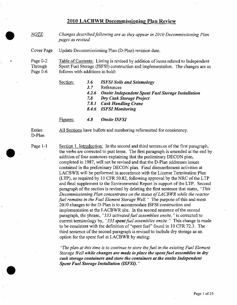
2010 LACBWR Decommissionin2 Plan Review
NOTE: Changes described following are as they appear in 2010 Decommissioning Planpages as revised
Cover Page Update Decommissioning Plan (D-Plan) revision date.
Page 0-2 Table of Contents: Listing is revised by addition of items related to IndependentThrough Spent Fuel Storage (ISFSI) construction and implementation. The changes are asPage 0-6 follows with additions in bold:
Section: 3.6 ISFSI Soils and Seismology3.7 References4.2.6 Onsite Independent Spent Fuel Storage Installation7.8 Dry Cask Storage Project7.8.1 Cask Handling Crane8.4.6 ISFSI Monitoring
Figures: 4.8 Onsite ISFSI
Entire All Sections have bullets and numbering reformatted for consistency.D-Plan
Page 1-1 Section 1, Introduction: In the second and third sentences of the first paragraph,the verbs are corrected to past tense. The first paragraph is amended at the end byaddition of four sentences explaining that the preliminary DECON plan,completed in 1987, will not be revised and that the D-Plan addresses issuescontained in the preliminary DECON plan. Final dismantlement activities atLACBWR will be performed in accordance with the License Termination Plan(LTP), as required by 10 CFR 50.82, following approval by the NRC of the LTPand final supplement to the Environmental Report in support of the LTP. Secondparagraph of the section is revised by deleting the first sentence that states, "ThisDecommissioning Plan concentrates on the status of LA CB WR while the reactorfuel remains in the Fuel Element Storage Well." The purpose of this and most2010 changes to the D-Plan is to accommodate ISFSI construction andimplementation at the LACBWR site. In the second sentence of the secondparagraph, the phrase, "333 activated fuel assemblies onsite," is corrected tocurrent terminology by, "333 spent fuel assemblies onsite. " This change is madeto be consistent with the definition of "spent fuel" found in 10 CFR 72.3. Thethird sentence of the second paragraph is revised to include dry storage as anoption for the spent fuel at LACBWR by stating:
"The plan at this time is to continue to store the fuel in the existing Fuel ElementStorage Well while changes are made to place the spent fuel assemblies in drycask storage containers and store the containers at the onsite IndependentSpent Fuel Storage Installation (ISFSI). "
Page I of 25

2010 LACBWR Decommissionin2 Plan Review
In the final sentence of the second paragraph of the section, the term offsite isadded to describe a second interim storage facility if available as an option forspent fuel storage in addition to the onsite ISFSI being implemented.
Section 1.1, Selection of SAFSTOR: The first paragraph of the section isrewritten to update regulatory action on the 1996 decommissioning rule. Asecond paragraph is added to describe the three methods of decommissioning nowestablished in the current guidance found in NUREG-0586.
Page 1-2 Section 1.1, Selection of SAFSTOR: Verbs in all of Section 1.1 are changed topast tense. Following the summary of ENTOMB, in the last sentence of the firstparagraph, original is added to describe the decommissioning rule whenproposed. In the first sentence of the third paragraph, the unavailability of afederal repository "for about 20 years" is replaced by "the foreseeable future."
Page 1-3 Section 1.1, Selection of SAFSTOR: In the paragraph at the top of the page, thephrase, "available for the dismantling" is corrected to "available fordismantlement." The second paragraph is updated to current decommissioningexperience as applicable in the U.S. by the following:
"The remaining factor to be discussed is safety. As of October 2009, 24powerreactors have been shut down in the United States, 11 of which have been fullydismantled and decommissioned. Experience has shown that the process can beperformed safely. "
In the third paragraph discussion of the Waste Confidence Decision of 1984, isupdated by adding "which is codified as amended in 10 CFR 51.23."
Section 1.2, References: An updated reference for information in the section isadded as:
1.2.5 Regulatory Guide 1.184, "Decommissioning of Nuclear PowerReactors," July 2000.
Page 2-2 Section 2.2, Initial Construction and Licensing History: In the last paragraph ofthe section, the last sentence is changed to past tense.
Section 2.3, Operating Record: Changed verb in second paragraph to past tense.
Page 2-3 Section 2.4, Decision for Shutdown: In last paragraph of section, "333 irradiatedfuel assemblies" is changed to "333 spent fuel assemblies" consistent with thedefinition in 10 CFR 72.3. The acronym (FESW) is identified.
Section 2.5.1, Failed Fuel: In the first paragraph, second sentence the acronymFESW replaces Fuel Element Storage Well.
Page 2-4 Section 2.5.1, Failed Fuel: In the last paragraph of the section the last sentence
Page 2 of 25

2010 LACBWR Decommissioning Plan Review
stating, "The majority of the material is located on horizontal surfaces in the FuelElement Storage Well, " is deleted and replaced by, "The FESW will be emptiedof all spent fuel assemblies and fuel debris which will be placed in dry caskstorage containers and moved to storage at the ISFSI." This change states thepurpose of ISFSI implementation.
Page 2-3 Section 2.5.2, Fuel Element Storage Well Leakage: The acronym FESW replacesAnd Fuel Element Storage Well in the first sentence. A new sentence is added to thePage 2-4 end of the section to state that, "Following removal of all spent fuel assemblies
and fuel debris for dry storage at the ISFSI, the storage racks will be removedand disposed of, the FESW will be drained and decontaminated to eliminateleakage." Purpose of this change is to state DPC's plan to drain and dismantleFESW structures, systems, and components (SSCs).
Page 3-1 Section 3.1.1, Site Location and Description of Site Layout: After addition of theacronym (G-3) at the end of the second sentence in the first paragraph, a generaldescription of the ISFSI at the Genoa site is given by addition of three sentencesstating:
"The Independent Spent Fuel Storage Installation (ISFSI) is located south ofthe G-3 plant, on land which was previously used for an access road to anabandoned boat landing on the Mississippi River. The ISFSI site is aboutmidway between the Mississippi River on the west and Highway 35 on the eastand is between the two closed ash landfills of the Genoa site. Access to the newboat landing follows the property's east and south boundaries. "
Page 3-1 Section 3.1.2, The Authority of the Exclusion Area and Licensee Authorities: AAnd second paragraph is added to the section to provide information that the entirePage 3-2 Genoa site is included in the Part 50 license. A third paragraph is added that
provides a description of the ISFSI location in relation to LACBWR, a descriptionof the ISFSI boundaries, and a statement of the licensee's ISFSI access controlauthority. The new paragraphs state:
"By letter dated May 8, 2008, in response to request by DPC, the NRC agreedthat the geographical area included within the LACBWR Part 50 license is theentire 163.5 acres owned or otherwise controlled by DPC. Further, the NRCfound that the site where the ISFSI is being constructed is part of the NRC-licensed site under License DPR-45.
The ISFSI is located 2,232feet south-southwest of the Reactor Building center.The ISFSI will be surrounded by a protected area fence, an isolation zone
fence, and vehicle barrier system. These protective barriers will be within theISFSI Controlled Area Boundary fence established at the perimeter of the 38.9acre ISFSI site (See Figure 3.4). The ISFSI Controlled Area Boundary isestablished to limit dose to the public during normal operations and designbasis accidents in accordance with the requirements of 10 CFR 72.104 and 10
Page 3 of 25

2010 LACBWR Decommissionin2 Plan Review
CFR 72.106. The controlled area, as defined in 10 CFR 72.3, means the areaimmediately surrounding an ISFSIfor which the licensee exercises authorityover its use and within which ISFSI operations are performed. DPC shalllikewise exclude access to the ISFSI Controlled Area Boundary if adverseradiological conditions require."
Page 3-2 Section 3.2, Transportation, Industrial and Military Facilities within Proximity tothe Plant: In first paragraph correction is made to the Burlington Northern SantaFe Railway and the acronym (BNSF) is identified and later used to replaceBurlington Northern.
Page 3-3 Section 3.3.3, Local Meteorology: In first sentence of second paragraph,clarification is added to the description of the data contained in Table 3-1 byadding 'from 1982-1984."
Page 3-6 Section 3.4.4, Flooding and Probable Maximum Flood: A description of ISFSIelevations in relation to flood elevation is added to the end of the section bystating, "The ISFSI area is constructed to a grade elevation of 640.8 feet MSLwith a top of pad elevation of 643.5 feet to raise the pad above the standardproject flood elevation of 643.2feet."
Page 3-6 Section 3.4.6, Flooding Protection Requirements: In the first paragraph, theAnd acronym (USGS) is added after United States Geological Survey. Discussion isPage 3-7 added to the end of the section explaining that the NAC-MPC storage system
flood design basis bounds flood conditions of the ISFSI site as follows:
"For flood conditions at the ISFSI, the NAC Multi-Purpose Canister (NAC-MPC) storage system is evaluated for afully-immersing design basis flood witha water depth of SO feet and a steady-stateflow velocity of 15feet per second.The analysis shows that the NAC-MPC storage system performance is notaffected by the design basis flood, and demonstrates that the concrete cask willnot slide and will not overturn in the design-basis flood. The hydrostaticpressure exerted by the 50foot depth of water does not produce significantstress in the canister. The NAC-MPC design basis bounds the LACBWR siteprobable maximum flood elevation of 658feet MSL with flow velocity of 1.91feet per second."
Page 3-8 Section 3.4.7, Ultimate Heat Sink and Low Flow Conditions: A sentence is addedto end of section to indicate that dry storage of spent fuel at the ISFSI does notrequire cooling water, stating, "With all spent fuel assemblies in dry storage atthe ISFSI, spent fuel cooling is no longer dependent on river flow. "
Section 3.5.1, Basic Geologic and Seismic Information: The spelling ofPaleozoic is corrected in the first paragraph.
Page 4 of 25

2010 LACBWR Decommissioning Plan Review
Page 3-14 Section 3.6, ISFSI Soils and Seismologv: A new section is added that providesAnd description of the soil improvements and seismological design of the ISFSI site:Page 3-15
"The soil parameters were analyzed from borings made in the area of theISFSL A site dimension of 122 feet by 148feet, including the 32feet by 48feetISFSI pad area, was improved by vibrocompaction to a depth of 35 feet. The 11feet of in-situ soils above elevation 621feet were removed. Drain rock wasplaced and compacted in 8-inch lifts to an elevation of 625 feet at which point alayer of geotextile fabric was installed. Imported structural backfill was thenplaced in controlled compacted lifts to raise the improved area to a finalelevation of 640.8feet. All soils work was completed per project earth workspecifications.
The liquefaction analysis for the post-improvement site soils used the conepenetration testing (CPT) based method and considered a design groundwaterelevation of 639feet and a final grade elevation of 640.8feet with and withoutISFSI pad loading. The results of the liquefaction evaluation indicated thatfactors ofsafety for all sandy soil layers below elevation 621feet wereacceptable. The soils improvement above elevation 621 feet resulted in all soildensities in the improved area to be considered non-liquefiable.
The soil structure interaction analysis of the ISFSI site soils improvementresulted in acceptable ISFSI pad accelerations of 0.402g horizontal and 0.18gvertical. For the center of gravity of the stored Vertical Concrete Cask (VCC)the resulting accelerations were 0.442g horizontal and 0.18g vertical TheNA C-MPC Final Safety Analysis Report (FSAR) acceptance criteria for theVCC are 0.45g horizontal and 0.30g vertical accelerations."
Page 3-16 Section 3.7, References: Three updated references for information in the sectionare added as:
3.7.15 NA C International, Inc., NA C Multi-Purpose Canister Final SafetyAnalysis Report, Revision 7, Section 11.A.2.6.
3.7.16 Sargent & Lundy Report No. SL-010167, ISFSI Soil RemediationSummary.
3.7.17 NRC Letter, Banovac to Berg, dated May 8, 2008.
Figures Figure 3.4, Genoa Site Map is revised to show the ISFSI location and ControlledArea Boundary fence.
Page 4-1 Section 4.1, General Plant Description: A short paragraph is added to the end ofthe section to describe the ISFSI on the Genoa site by stating, "An IndependentSpent Fuel Storage Installation for dry storage of the LACBWR spent fuelinventory is being established on the Genoa site south of the G-3 coal pile. "
Page 5 of 25

2010 LACBWR Decommissioning Plan Review
Section 4.2.1, Reactor Building: In the second paragraph, the acronym (FESW)is added and then used later in replacing storage well cooling system with theFESW cooling system.
Page 4-3 Section 4.2.1, Reactor Building: In the second paragraph the acronym FESWreplacesfuel element storage well. In fourth paragraph of page, the word wet isadded to describe spent fuel storage in the FESW with the acronym used toreplace forms of storage well in three instances. At the end of the paragraph,DPC's intent to dismantle FESW SSCs is stated by, "Following removal of allspent fuel assemblies and fuel debris for dry storage at the ISMSI, the storageracks will be removed and disposed of, the FESW will be drained anddecontaminated."
Page 4-3 Section 4.2.1, Reactor Building: Dry cask loading operations requiredAnd modifications to be made to the Reactor Building to return watertight integrity toPage 4-4 the biological shield upper cavity and provide support for cask loading, cask
preparation, and cask transfer operations. These modifications were designed tobe Seismic Category I structures. The design of the modifications was reviewedunder the LACBWR design review and acceptance process. The installationswere reviewed under the LACBWR 10 CFR 50.59 process and performed inaccordance with the LACBWR work control process and requirements of theLACBWR Quality Assurance Program Description (QAPD) and Dry CaskStorage Quality Assurance Project Plan (QAPP). New information describingthese modifications is added to the end of the section as follows:
"The Reactor Building is being modified to facilitate movement of spentfuelassemblies from the FESW to the NA C-MPC System Transportable StorageCanister (TSC). The TSC is located inside the Transfer Cask (TFR) during fuelloading operations. The TFR/TSC assemblage will reside in the cask poolwithin the water-filled upper cavity during spent fuel assembly transfer from theFESW to the TSC.
The 10-6" wide opening from the mezzanine floor elevation 667feet to the fuelhandling floor elevation 701 feet was previously created in the northern sectionof the upper cavity bio-shield and liner to permit removal of the LACBWRreactor pressure vessel. This opening will be used to facilitate movement of theTFR/TSC between the cask pool and the mezzanine floor to the north whereTSC preparation operations will take place (e.g., welding, drying, etc.). TheReactor Building mezzanine floor will be reinforced in that location by addingsteel struts beneath a cantilevered section of the floor. In order to providesufficient water coverage over the spent fuel assemblies during movement intothe TSCfrom the FESW, a water-tight removable gate, 16 '-9" high by 9 '-4"wide, will be installed in the bio-shield opening above approximate elevation679'-3" extending to elevation 696feet. The cask pool gate will be supported bya 12' high structure installed at elevation 667feet. The caskpool gate is
Page 6 of 25

2010 LACBWR Decommissioning Plan Review
designed with inflatable pneumatic seals having a defined acceptable leakagerate. Appropriate interfacing modifications to the bio-shield liner at the edgesof the opening will be installed to ensure water retention in the area betweenthe upper cavity liner and the cask pool gate. The cask pool gate storage standwill support the 6-ton cask pool gate when not in use.
The 10' high by 10' inner diameter cask pool will be installed at elevation 669'3" atop a 20'-10" high support structure attached to the reactor supportcylinder at elevation 648'-5". The cask pool will have a 16Y2" wide horizontalflange welded to the top of the shell, the outer circumference of which will betied into the existing upper cavity liner using L-shaped stainless steel angle atapproximate elevation 679'-37. This arrangement will provide a barrier toprevent water in the upper cavity area above the cask poolfrom leaking aroundthe outside of the cask pool into the cavity below.
The upper cavity liner and bio-shield contained a number of penetrations fromreactor operation that will be sealed using steel plates welded to the upper cavityliner to maintain the pressure boundary of the upper cavity. The cask pool willalso include two penetrations, one at the bottom and one on the sideapproximately 7"6" above the tank bottom. These penetrations will connect topiping and valves for filling, draining, and processing water from the pool andupper cavity to permit removal of the cask pool gate, and to perform otheractivities such as water clean-up, cask annulus flushing, and inventory control.Each 2-inch diameter pipe will include two manual valves in series justoutboard of the cask pool to ensure redundant isolation."
Page 4-5 Section 4.2.3, Waste Treatment Building and LSA Storage Building: In the lastparagraph of the section, Low Specific Activity is added and LSA is parenthesizedas an acronym to provide definition of what the LSA Building means.
Page 4-5 Section 4.2.5. Onsite Independent Spent Fuel Storage Installation: New sectionThrough is added to provide an overview and description of the ISFSI by the following:Page 4-7
"The LA CB WR Dry Cask Storage Project establishes an Independent SpentFuel Storage Installation (ISFSI) under general license provisions of 10 CFR72, Subpart K on the Genoa site. The ISFSI site is about midway between theMississippi River on the west and Highway 35 on the east. The ISFSI is located2,232feet south-southwest of the Reactor Building center on land which waspreviously used for an access road between the two closed ash landfills of theGenoa site.
The ISFSI will be used for interim storage of LA CB WR spent fuel assemblies inthe NAC International, Inc. Multi-Purpose Canister (NAC-MPC) System. TheNRC issued 10 CFR 72 Certificate of Compliance (CoC) No. 1025 whichconfers approval of the NAC-MPC storage system design. The design basis forthe NA C-MPC System is provided in the NAC-MPC Final Safety Analysis
Page 7 of 25

2010 LACBWR Decommissioning Plan Review
Report (FSAR). The NRC approved Amendment 6 to the NAC-MPC CoC andTechnical Specifications to incorporate LA CB WR spent fuel assemblies asapproved contents for storage in the NAC-MPC System. The effective date ofthe license amendment was October 4, 2010.
The NA C-MPC System is comprised of the Transportable Storage Canister(TSC), the Vertical Concrete Cask (VCC), and the Transfer Cask (TFR). TheTSC is designed to be transported in the NAC Transport Cask (STC) licensed bythe NRC pursuant to 10 CFR 71 CoC No. 71-9235for shipment of the NAC-MPC canister. The NA C-MPC System designed for and to be used at LACBWRis designated MPC-LACBWR. The LACBWR spent fuel inventory will beplaced into five MPC-LACBWR dry storage casks. Each MPC-LACBWR TSCcan accommodate up to 68fuel assemblies for a total of 340 fuel storage cellsamong the five TSCs. Thirty-two of the 68fuel cell locations in each TSC aredesigned for a damaged fuel canister. Seven spare locations are available in thefifth TSC.
The spent fuel assemblies will be loaded underwater into a TSC within a TFRlocated in the cask pool. The TSC/TFR will be removed from the cask pool andthe TSC will be prepared for storage by draining, helium fill, vacuum drying,and closure lid seal welding. The TSC/TFR will be moved outdoors and theTSC will be placed in the VCC by positioning the TFR on top of the VCC andlowering the TSC within the TFR through the transfer adapter to the VCCbelow. The VCC containing the TSC will then be placed in storage on theISESI pad.
The TSC assembly consists of a right circular cylindrical shell with a weldedbottom plate, afuel basket, a closure lid with closure ring, and two sets ofredundant port covers. The cylindrical shell, plus the bottom plate and lid,constitutes the confinement boundary. The stainless steelfuel basket is a rightcircular cylinder with 68fuel tubes including 32 oversized tubes designed toaccommodate LA CB WR damaged fuel cans, laterally supported by a series ofstainless steel support disks. The support disks are retained by spacers onradially located tie rods. The spent fuel assemblies will be contained in squarestainless steelfuel tubes that include Boral on up to four sides for criticalitycontrol.
The VCC is the storage overpack for the TSC and provides structural support,shielding, protection from environmental conditions, and natural convectioncooling of the TSC during long term storage. The VCC is a reinforced concretestructure with a carbon steel inner liner. The VCC has an annular air passageto allow the natural circulation of air around the TSC. The air inlet and outletvents take non-planar paths to the VCC cavity to minimize radiation streaming.The decay heat is transferred from the spent fuel assemblies to the tubes in thefuel basket, through the heat transfer disks, to the TSC wall. Heat flows byconvection from the TSC wall to the circulating air, as well as by radiation from
Page 8 of 25

2010 LACBWR Decommissionin2 Plan Review
the TSC wall to the VCC inner liner. The heat flow to the circulating air fromthe TSC wall and the VCC liner is exhausted through the air outlet vents. Thetop of the VCC is closed by a single shielded lid incorporating a carbon steelplate for gamma shielding and concrete for neutron shielding. The VCC lidwill be bolted in place.
The TFR, with its lifting yoke, is a qualified heavy lifting device designed,fabricated, and proof load tested to the requirements of NUREG-0612 andANSI N14. 6. The TFR provides shielding during TSC movements betweenwork stations, the VCC, or the transport cask. It is a multi-wall (steel/leadINS-4-FR/steel) design and has a bolted top retaining ring to prevent a fuel-loadedcanister from being inadvertently removed through the top of the TFR.Retractable, hydraulically operated, bottom shield doors on the TFR are usedduring TSC transfer operations. To minimize contamination of the TSC, cleanwater will be circulated in the gap between the TFR and the TSC during caskpool loading operations.
The ISFSI pad made of reinforced concrete will be 48feet in length, and 32feetin width, and 3feet thick. The empty TFR and five VCCs containing fuel-loaded TSCs will be placed in a storage array on the ISFSI pad. The ISFSI willbe surrounded by a protected area fence, an isolation zone fence, and vehiclebarrier system. These protective barriers will be within the ISFSI ControlledArea Boundary fence. The ISFSI pad will be supplied with lighting, electronicsurveillance and security systems. The ISFSI Administration Building is acommercial structure approximately 60feet by 30feet located 400feet northeastof the ISFSI pad. The ISFSIAdministration Building will provide space forsecurity monitoring and ISFSI operations support."
Figures Figure 4.1, Containment Building Elevation: The figure is updated to depictmodifications within the reactor cavity.
Figure 4.8, Onsite ISESI: A new figure is added depicting the ISFSI pad,storage array, and immediate vicinity.
Page 5-1 Section 5.1, Spent Fuel Inventory: First paragraph is updated to include ISFSIimplementation by stating, "All spent fuel will be placed in dry storage casks andmoved to the onsite Independent Spent Fuel Storage Installation."
Page 5-3 Section 5.2.2, Forced Circulation System, Section 5.2.3, Seal Injection System,Through and 5.2.4, Decay Heat System: Minor changes in capitalization, verb tense,Page 5-5 equipment titles, acronyms, and other edits are made in the sections for correction
and consistency.
Page 5-5 Section 5.2.5, Emergency Core Spray System: In first paragraph, verbs arechanged to past tense and final sentence of paragraph is deleted as unnecessary.Second and third paragraphs are also deleted as being extraneous detailed
Page 9 of 25

2010 LACBWR Decommissionina Plan Review
information for a system that has been removed. System Status is shortened bysimply stating, "This system has been removed."
Section 5.2.6, Primary Purification System: In first paragraph, verb is changed topast tense.
Page 5-6 Section 5.2.8, Alternate Core Spray System: Minor changes in capitalization,verb tense, equipment titles, acronyms, and other edits are made in the section forcorrection and consistency. System Status is shortened by removing unnecessaryinformation about the closed isolation valve, 6-inch supply line removal, anddesignation as HPSW. The 6-inch supply penetration to the upper cavity will besealed during cask pool installation as part of the cask pool installation. Thesystem designation will not be changed.
Section 5.2.9, Control Rod Drive Auxiliaries: System Status is shortened bysimply stating, "This system has been removed."
Page 5-7 Section 5.2.11, Fuel Element Storage Well System: In the paragraph at the top ofthe page, the phrase, "Spent fuel elements" is changed to, "Spent fuelassemblies" for consistency. A similar change is made to the System Statussection. Minor changes in capitalization, verb tense, equipment titles, acronyms,and other edits are made in the section for correction and consistency. Plans forthe FESW are added in the System Status section by stating, "Following removalof all spent fuel assemblies and fuel debris for dry storage at the ISFSI, thestorage racks will be removed and disposed of; the FESW will be drained anddecontaminated."
Page 5-7 Section 5.2.12, Component Cooling Water System: Minor changes inAnd capitalization, verb tense, equipment titles, acronyms, and other edits are made inPage 5-8 the section for correction and consistency. System Status is shortened to, "The
system remains operable," with components presently being cooled by CCWmoved to the first paragraph.
Page 5-8 Section 5.2.14, Shutdown Condenser System: Second paragraph has sentencesAnd deleted as being extraneous detailed information for a system that has beenPage 5-9 removed. Last paragraph of the section on page 5-9 has a verb changed to past
tense and an undefined acronym replaced by the proper title.
Page 5-9 Section 5.2.15, Hydraulic Valve Accumulator System: System description isreorganized and minor changes in capitalization, verb tense, and equipment titlesare made in the section for consistency.
Page 5-10 Section 5.2.17, Demineralized Water System: The title of Genoa Unit 3 iscorrected as is statement concerning level indication which was removed under anapproved facility change. System Status of Condensate Storage Tank being
Page 10 of 25

2010 LACBWR Decommissionin2 Plan Review
drained is added while statement of tank being covered in Condensate System isdeleted.
Section 5.2.18, Overhead Storage Tank: Minor changes in capitalization, verbtense, equipment titles, acronyms, and other edits are made in the section forcorrection and consistency. Use of the system for cask loading operations isadded. System Status is updated by stating, "After the transfer of all spent fuelto dry storage at the onsite ISFSI, the OHST system will be drained anddismantled."
Page 5-11 Section 5.2.21, High Pressure Service Water System: In first paragraph, secondsentence, system pressure is maintained by the Genoa Unit 3jockey pump insteadof the LPSW system. Minor changes in capitalization, equipment titles, andacronyms are made.
Page 5-12 Section 5.2.23, Condensate System and Feedwater Heaters, through SectionThrough 5.2.30, Waste Collection System: Minor changes in capitalization, verb tense,Page 5-15 equipment titles, acronyms, and other edits are made in the sections for correction
and consistency.
Page 5-15 Section 5.2.3 1, Fuel Transfer Bridge: System Status is updated for ISFSIimplementation by stating, "The fuel transfer bridge will be used to transferindividual spent fuel assemblies from the Fuel Element Storage Well to the drycask storage container. After the transfer of all spent fuel to dry storage at theonsite ISFSI, the fuel transfer bridge will no longer be required."
Page 5-16 Section 5.2.33.1, Normal AC Distribution, through Section 5.2.33.3, EmergencyAnd Diesel Generators 1A and 1B: Minor changes in capitalization, verb tense,Page 5-17 equipment titles, acronyms, and other edits are made in the sections for correction
and consistency.
Page 5-17 Section 5.2.33.4, 120-V Non-Interruptible Buses: Section is shortened to a singleparagraph for update and states:
"The 120-V Non-Interruptible Buses maintained a continuous non-interruptiblepower supply using static inverters to a portion of the essential plant controlcircuitry, communications equipment and radiological monitoring equipment.The static inverters used 125-VDC input and supplied 120-VAC output to theirrespective distribution panels. The static inverters have been removed and thedistribution panels have been renamed ]A 120-VAC Essential Power,Regulated Bus Auxiliary Panel, and 1C 120-VA C Essential Power."
Page 5-18 Section 5.2.33.5, 125-V DC Distribution: System description is updated to reflectinstallation and use of smaller capacity battery charger in Diesel Building bycompletion of an approved Facility Change. Minor changes in capitalization andequipment titles are made in the section for consistency. System Status of
Page 11 of 25

2010 LACBWR Decommissionin2 Plan Review
Electrical Power Distribution System is updated to reflect how configurationchanges, made possible by approved procedures, permit a single diesel generatorto supply the entire plant 480-V AC system during station power loss.
Page 5-18 Section 5.2.34, Post Accident Sampling Systems: Minor changes incapitalization, equipment titles, and acronyms are made in the section and itssubsections for consistency. System Status is updated for ISFSI implementationby stating, "After the transfer of all spent fuel to dry storage at the onsite ISFSI,the Post-Accident Sampling Systems will no longer be required."
Page 5-19 Section 5.3, Radionuclide Inventory Estimates: Third sentence in first paragraphis changed to present tense.
Page 5-21 Section 5.4.2, System Radiation Levels: In the listing of survey points, currentThrough dose rates are updated to 2010 measurements.Page 5-23
Page 6-1 Section 6.1, Objectives: First bulleted item stating, "safely store irradiatedfuiel,"is changed to "safely store spent fuel" consistent with the definition in 10 CFR72.3.
Section 6.2, Organization and Responsibilities: In the first sentence of the secondparagraph, plant manager's responsibility is revised to include the ISFSI bystating, "is responsible for the safety of the facility and ISFSI, their dailyoperation and surveillance. " In the same paragraph, second sentence qualityassurance and security programs has been made plural
Page 6-2 Section 6.2, Organization and Responsibilities: In the second paragraph of thepage, Operator responsibility to tour the facility is clarified to "when spent fuel isstored in the fuel element storage well." Following spent fuel removal, 24-hoursurveillance and monitoring of spent fuel storage conditions will be performed byISFSI personnel. In the fourth and fifth paragraphs, Health Physics andInstrument Technician responsibilities are expanded to include the ISFSI. In thefifth paragraph irradiated fuel is changed for consistency to spent fuel.
Page 6-4 Section 6.4.1, Training Program Description: In subsection 6.4.1.2, a statement isadded concerning the change in training requirements following ISFSIimplementation:
"These programs and requirements will change when all spent fuel is at theISFSI. CFH training and proficiency will no longer be required. Training inISFSI administration, security, monitoring, and maintenance will be fullyimplemented."
Page 6-8 Section 6.4.3.4, Certified Fuel Handler Training Program: In first paragraph, theneed for this training program is clarified to "while spent fuel is stored in the
Page 12 of 25

2010 LACBWR Decommissionin2 Plan Review
Fuel Element Storage Well. " The acronym CFH has been deleted asunnecessary. Following spent fuel removal, certified and proficient fuel handlerswill no longer be required. The second paragraph of the section has been movedas more appropriate to Section 10, "SAFSTOR Operator Training andCertification Program."
Page 6-8 Section 6.5, Quality Assurance: The four existing paragraphs describing QAAnd requirements in the D-Plan have been revised, re-organized, and expanded toPage 6-9 include Dry Cask Storage Project activities as reflected in changes to the Quality
Assurance Program Description. The majority of the changes to the LACBWRQAPD relate to the inclusion of 10 CFR 72, Subpart G as holding applicablerequirements that will be met to assure dry cask storage activities. The LACBWRQAPD, which has been approved by the NRC, meets the requirements of 10 CFR50, Appendix B. As such, the LACBWR QAPD is acceptable as stated in 10 CFR72.140(d), and establishes a quality assurance program satisfying each of theapplicable criteria of 10 CFR 72 Subpart G. The intent to apply LACBWR'spreviously approved quality assurance program to ISFSI activities was declared tothe NRC by letter dated August 24, 2009. The section with changed content inbold reads as follows:
"Decommissioning and SAFSTOR activities will be performed in accordance withthe NRC-approved Quality Assurance Program Description (QAPD) forLACBWR. The QAPD has been developed to assure safe and reliable operationof LACBWR in a SAFSTOR condition and transition to an Independent SpentFuel Storage Installation. The program is designed to meet the requirements of10 CFR 50, Appendix B as applicable to the possession-only license conditionand 10 CFR 72, Subpart G as applicable to the onsite dry cask storage of spentnuclear fuel.
The QAPD addresses all 18 criteria of 10 CFR 50, Appendix B, and 10 CFR 72,Subpart G, and applies to all activities affecting the functions of the structures,systems, and components that are associated with a possession-only licensecondition using a graded approach, and the Dry Cask Storage Project,respectively. These activities include design, installation, operations,maintenance, repair, fuel handling, testing, modifications, and radioactivewaste shipments. Design and fabrication of storage and shipping casks forradioactive material are addressed by the Dry Cask Storage System Certificateof Compliance holder's quality assurance program and will not be conductedunder the QAPD. Safety Related as defined in 10 CFR 50.2 is no longerapplicable in the possession-only license condition. A graded approach is usedto implement the QAPD by establishing managerial and administrative controlscommensurate with the complexity and regulatory requirements of the activitiesundertaken.
Scheduled activities during SAFSTOR shall be performed within scheduleintervals. A schedule interval is a time frame within which each scheduled
Page 13 of 25

2010 LACBWR Decommissioning Plan Review
activity shall be performed, with a maximum allowable extension not to exceed 25percent of the schedule interval.
For Important to Safety (ITS) activities, as defined in 10 CFA 72, Subpart G, aQuality Assurance Project Plan (QAPP) was established to define the qualityassurance requirements to be implemented during the Dry Cask Storage Projectat the LACBWR site. The QAPP does not supplant the QAPD which is used toassure safe and reliable operation of the LA CB WR plant in a SAFSTORcondition. The QAPP utilizes the QAPD as the base document of the Dry CaskStorage Project's overall quality assurance program. The QAPP referencesand provides clarification to each applicable section of the QAPD thatcollectively meet the quality assurance requirements of 10 CFR 50 Appendix B,10 CFR 71 Subpart H, and 10 CFR 72 Subpart G.
The QAPP applies to all activities associated with the design, fabrication,installation, and preparation for operation of an Independent Spent FuelStorage Installation and any related plant modifications and other site activitiesas designated by the Plant Manager. Design and fabrication of the Dry CaskStorage System (DCSS) will not be performed under the QAPP; however,selection, qualification, and performance-based overview of the selected DCSSdesigner and DCSS fabrication will be conducted in accordance with theQAPP. "
Page 6-9 Section 6.6, Schedule: In the first paragraph, a sentence is added from aparagraph that has been deleted at the end of the section stating, "At the time ofthe original Decommissioning Plan in 1987, DPC anticipated the plant wouldbe in SAFSTOR for a 30-50 year period."
The third paragraph of the section that described DECON being planned for 2019has been deleted as no longer being operative. DPC management has revised theschedule for final decommissioning of LACBWR; more details are provided inchanges following in the section.
Page 6-10 Section 6.6, Schedule: In the first paragraph at the top of page 6-10, the thirdsentence is amended in describing efforts to place an ISFSI on site "bycommencing the Dry Cask Storage Project." The sentence describing theduration of the project as being 3 years has been deleted as ISFSI implementationapproaches completion. Discussion of transport of spent fuel to Yucca Mountainhas been changed to offsite due to uncertainty in the federal repository issue.
After the paragraph that discusses Private Fuel Storage, new information is addedconcerning acceleration in the final decommissioning of the LACBWR facility.The information is self-explanatory and is added as follows:
"DPC Staff completed an extensive review and analysis of the comparative costsand benefits of the current decommissioning schedule and various accelerated
Page 14 of 25

2010 LACBWR Decommissioning Plan Review
schedules. From this analysis, the DPC Board of Directors approvedaccelerating the removal of radioactive metalfrom the LA CB WR facility. Byletter dated December 7, 2010, DPC gave notification to the NRC of a change inschedule that would accelerate the decommissioning of the LACBWR facilitystarting with a 4-year period of systems removal beginning in 2012. Thisactivity will include the removalfor shipment of large bore (16 and 20-inch)reactor coolant piping and pumps of the Forced Circulation system and otherequipment once connected to the reactor pressure vessel or primary system suchas Control Rod Drive Mechanisms, Decay Heat, Primary Purification, SealInjection, and Main Steam.
This phase of decommissioning activity does not result in significantenvironmental impacts and has been reviewed as documented in the "GenericEnvironmental Impact Statement (GEIS) on Decommissioning of NuclearFacilities," NUREG-0586, Supplement 1, November 2002. As stated in theGEIS, licensees can rely on information in this Supplement as a basis formeeting the requirements in 10 CFR 50.82(a)(6)(ii). The GEIS characterizesthe environmental impacts resulting from this decommissioning activity asgeneric and small. Potential site-specific environmental impacts not determinedin the GEIS will be addressed in the License Termination Plan (LTP)forLA CBWR.
DPC's review and analysis found that the Nuclear Decommissioning Trust(NDT) was sufficiently funded to allow dismantlement to begin in 2012,immediately after spent fuel removal is completed. Costs of the metal removalproject will befundedfrom the NDT. DPC's approved strategy requirescontinuing evaluation of the costs of the decommissioning activity as itprogresses. During this time the LTP will be formulated determining thedisposition of concrete structures and site end use. The LTP will include anupdated site-specific estimate of remaining decommissioning costs. DPC'sdecommissioning strategy for LA CB WR with accelerated systems removalprovides flexibility in that provisions are afforded to evaluate the costs andbenefits of alternative methodologies for concrete removal, and delay LTPimplementation if necessary to assure adequate NDTfunds are available for thefinal decommissioning process. Figure 6.2 depicts the revised schedule."
Page 6-11 Section 6.7.1, SAFSTOR Funding: In the first paragraph of the section, the DPCspent fuel management and funding plan applicability, pursuant to 10 CFR50.54(bb), is expanded to include spent fuel storage costs at the ISFSI by additionof the statement, "This plan applies also to ISFSI operations."
In the second paragraph of the section, the title, Decommissioning Trust Fund, iscorrected to the legal title it bears, Nuclear Decommissioning Trust and theacronym (NDT) is identified. NDT or NDTfunds is then used in three places inthe paragraph replacing Decommissioning Trust Fund NDT is also used in thesixth paragraph of the section.
Page 15 of 25

2010 LACBWR Decommissionin2 Plan Review
Page 6-12 Section 6.7.2, Decommissioning Cost Financing: In the first paragraph of thesection, correction is made again to the title and acronym of the NuclearDecommissioning Trust (NDT). The same correction is made to NDT in thefourth paragraph of the section.
A new paragraph describing the 2010 decommissioning cost study update isadded following description of the 2007 cost study update. The paragraph statesthe following:
"A cost study update was completed in November 2010 to more accuratelyassess future costs of the remaining dismantlement needed and tofacilitateDPC decommissioning and license termination planning. This update placedthe cost to complete decommissioning at $67.8 million in Year 2010 dollars.During this process, ISFSI decommissioning costs were identified uniquely as aspecific item within the cost study and estimated to be $1.6 million in Year 2010dollars. The DPC Board of Directors will establish an externalfundingmechanism for ISFSI decommissioning costs in accordance with 10 CFR 72.30to assure adequate funds will be available for the final decommissioning cost ofthe LACBWR ISFS."
Page 6-13 Section 6.7.2, Decommissioning Cost Financing: In the second paragraph ofSection 6.7.2 on page 6-13, it is added that the DPC Board of Directors remaincommitted to assuring that adequate funding will be available for the finaldecommissioning of the LACBWR facility and ISFS.
Section 6.8, Special Nuclear Material (SNM) Accountability: In secondparagraph it is clarified that LACBWR spent fuel inventory is stored underwaterin the FESW or in dry storage casks located at the onsite ISFSI. Purpose ofchange is to accommodate ISFSI implementation.
Section 6.9.1, Fire Protection Plan: Information is added to accommodate ISFSIimplementation in LACBWR fire protection planning. In the first paragraph it isstated that the FESW can be safely maintained and controlled during fire in eacharea of the plant while spent fuel is stored wet. Description is added to end ofsame paragraph stating the intent of LACBWR fire protection with ISFSIoperations by stating:
"With implementation of ISFSI operations fire protection planning for theLACBWR facility will adapt to the absence offuel stored wet and will focus onISFSIfire protection. As long as radiological hazards remain at the LA CB WRfacility, fire protection planning will be commensurate with the risks associatedwith the reduction in those radiological hazards."
Page 6-14 Section 6.9.1, Fire Protection Plan: In third bulleted item of page, the worddeconned is corrected to decontaminated. A new paragraph is added to the end
Page 16 of 25

2010 LACBWR Decommissioning Plan Review
of the section to provide description of the ISFSI fire hazards analysis and ISFSIcompliance with 10 CFR 72.122(c) general design criteria. The new paragraphreads as follows:
"The fire protection plan at the ISFSI is based on the fire hazards analysisperformed in support of the Dry Cask Storage Project. The ISFSI fire hazardsanalysis demonstrated that the explosion and heat effects of crediblefire andexplosion hazards at the Genoa site will not significantly increase the risk ofradioactivity release to the environment. Therefore, storage of spent nuclearfuel at the LA CB WR ISFSI is in accordance with 10 CFR 72.122(c) generaldesign criteria. The ISFSIfire protection features and administrative controlswill ensure that the Genoa site fire and explosion hazards are acceptable andwithin the cask system design basis for fuel-loaded Vertical Concrete Casks(VCCs) located at or in route to the ISFSI."
Page 6-15 Section 6.9.2, Fire Protection Program: A new paragraph is added at thebeginning of the section that provides a general description of the ISFSI fireprotection program and states:
"The fire protection program for the ISFSI consists mainly of administrativecontrols to limit flammable liquids and combustible materials in the area of thefuel-loaded VCCs and is implemented by ISFSI procedures. There will be noorganized fire brigade at the ISFSI. Personnel monitoring dry cask storageconditions may extinguish incipient fires, but Genoa Fire Department will besummoned for fire emergencies at the ISFSI site."
Section 6.9.2.2, Fire Detection System: A short description of ISFSIAdministration Building fire detectors is added.
Page 6-16 Section 6.9.2.4, Fire Suppression Water System: After completion of anapproved facility change, pressure maintenance of the High Pressure WaterSystem is changed from the Low Pressure Service Water System (LPSW) to theGenoa Unit 3 jockey pump.
Section 6.9.2.6, Portable Fire Extinguishers and Other Fire Protection Equipment:In the first paragraph Halon is removed as a type of fire extinguisher becauseHalon units have been retired at LACBWR. A short mention is added that "TheISFSI is supplied with its own complement of portable fire extinguishers." Inthe final paragraph of the section a correction is made at "sprinkler heads andsprinkler equipment are located in the Maintenance Shop emergency locker."
Page 6-17 Section 6.9.2.7, The Fire Brigade: A correction is made to change Duty ShiftSupervisor to Operations Shift Supervisor to avoid confusion with the futureaddition of the ISFSI Security Shift Supervisor.
Page 17 of 25

2010 LACBWR Decommissionin2 Plan Review
Section 6.9.2.8, Outside Fire Service Assistance: Genoa Fire Department supportduring emergencies will include LACBWR or the ISFSI.
Page 6-17 Section 6.9.2.9, Reporting: An addition is made to provide reportingrequirements for ISFSI fire emergencies by the following:
3) Any incident requiring outside fire service assistance within the ISFSIControlled Area Boundary shall be reported by the ISFSI Security ShiftSupervisor using an ISFSI Security Incident Report.
Page 6-18 Section 6.9.2.10, Training: In the first paragraph, Security badged visitors iscorrected to Security badged personnel. The second paragraph is revised toclarify that Fire Brigade training is applicable to only Operations and Securitypersonnel assigned duties at the LACBWR plant. The second paragraph reads asfollows with additions in bold:
"Operations and Security personnel have Fire Brigade responsibilities and aregiven basic practicalfire fighting and specific fire protection program instructionannually. Fire Brigade members shall also participate in at least one drillannually."
A new paragraph is added at the end of the section to clarify the response role ofISFSI personnel during fire and to indicate that there will not be an organized firebrigade at the ISFSI. The new paragraph states:
"ISFSI personnel will be termed designated employees, and as such will not bemembers of an organized fire brigade. These personnel will be properly trainedto use portable fire extinguishers to fight incipient fires in the employee'simmediate work area."
Section 6.10, Security during SAFSTOR and/or Decommissioning: In the firstparagraph, maintenance of security is expanded to the LACBWR facility andISESI. The last paragraph of the section has a sentence added stating, "ISESIsecurity requirements are addressed and implemented as applicable."
Section 6.11, Testing and Maintenance of SAFSTOR Systems: In the secondparagraph a statement is added indicating that 10 CFR 50.65 is no longerapplicable during dry cask storage. The sentence states:
"When all spent fuel is at the ISFSI, Maintenance Rule Program requirementswill no longer be applicable."
Page 6-19 Section 6.12.3.1, Stack: The discussion of stack effluents is clarified byindicating that with dry cask storage krypton-85 will no longer be a component ofany effluent release. A new sentence is added stating:
Page 18 of 25

2010 LACBWR Decommissioning Plan Review
"With all spent fuel stored at the ISFSI, no concentration of Kr-85 will beavailable as a source of radioactivity in effluent releases."
Page 6-20 Section 6.13, Records: The section is revised to include record requirements for
ISFSI operation. Four bulleted items are changed or added in bold as follows:
0 Baseline surveys performed in and around the LACBWRfacility and ISFSI.
0 Analysis and evaluations of total radioactivity concentrations at the LACBWRfacility and ISFSI.
0 Records for ISFSI construction, dry cask storage system fabrication, anddry cask loading.
N Any other records or documents, which would be needed to facilitatedecontamination and dismantlement of the LACBWR facility or ISFSI and arenot controlled by other means.
Figure 6.1 La Crosse Boiling Water Reactor SAFSTOR Staff: The organization chart has ablock signifying ISFSI Operations and Security added under Plant Manager. Anote is added at bottom clarifying who will be performing ISFSI duties and states," *Duties to be performed by existing LA CB WR staff and security force."
Figure 6.2 LACBWR Schedule: Figure is updated to reflect decommissioning planning andschedule changes as discussed previously in Section 6.6.
Page 7-1 Section 7.2, SAFSTOR Modifications: In the final paragraph of the section,clarification is added to indicate that with dry cask storage krypton-85 will nolonger be a component of any effluent release. A new sentence states:
"With all spent fuel stored at the Independent Spent Fuel Storage Installation(ISFSI) in seal-welded canisters protected by concrete overpacks, there is noconcentration of the isotope Kr-85 available for release from the LACBWRplant."
Section 7.3, Significant SAFSTOR Licensing Actions: In the second paragraphof the section, "and also of the same date," and "proposed" are deleted in thedescription of License Amendment No. 66 as being unnecessary. On page 7-2,after the description of License Amendment No. 69, a new paragraph is added toprovide information of License Amendment No. 71 which has been submitted forDry Cask Storage Project needs. The amendment remains in the NRC review andapproval process at this time. The new paragraph reads as follows:
"License Amendment No. 71 was submitted July 28, 2009, requesting changesto the LACBWR Appendix A, Technical Specifications in support of theLACBWR Dry Cask Storage Project. The request seeks approval of a revised
Page 19 of 25

2010 LACBWR Decommissioning Plan Review
definition of FUEL HANDLING, approval of a reduction of the minimumwater coverage over stored spent fuel from 16feet to llfeet, 6Y2 inches, and asmall number of editorial changes to clarify heavy load controls and reflectinclusion of the cask pool as part of an "extended" Fuel Element Storage Well.These changes were requested to accommodate efficient dry cask storage systemloading operations and reduce overall occupational dose to personnel duringthese operations."
Page 7-3 Section 7.5, Removal of Unused Equipment during SAFSTOR: The fourthparagraph is clarified to commit to the requirements of 10 CFR 50.59 by stating,"Removal of plant equipment will be performed in accordance with therequirements of 10 CFR 50.59."
Page 7-4 Section 7.6.1, Temporary Lifting Device: In conjunction with reformatting, theAnd section is re-organized and shortened by the deletion of overly detailedPage 7-5 information about the Temporary Lifting Device (TLD) runway construction used
in removal of the reactor pressure vessel. A reasonable amount of historicalinformation about the TLD, basically unchanged from the previous revision, ispresented by the following:
"A Temporary Lifting Device/Gantry Rail System (TLD) was erected andinstalled inside and outside the RB. The TLD system consisted of a temporaryrunway structure and rolling trolley which incorporated hydraulic strand jacksfor lifting the RPV The runway structure consisted of 37-feet girders inside theRB and 74-feet girders outside the RB. The runway structure design inside theRB met NUREG-0612 criteria. The runway structure design outside the RB wasnot required to meet NUREG-0612 criteria, as NUREG-0612 pertains to liftsand equipment inside buildings where spent fuel is stored.
The trolley was a moveable platform with four two-wheeled bogie end trucks (8total double flanged wheels) designed to run on the box girder rails. Two of thetrucks had electric mechanical drives. Each drive consisted of a gearbox,motor, and brake. There were two driven/braked wheels in the 8 wheel set. Thebrake was automatically set when the momentary directional motion switch wasreleased to the neutral position. The trolley had two travel speeds; 1. 62feet perminute (FPM) and 6.80 FPM. Both travel speeds were very slow. At the slowerspeed it would have taken over an hour to traverse the runway from south tonorth. Two hydraulic strandjack hoisting systems were mounted on top of thetrolley platform. The strandjack systems were independent from each otherand were specially fabricated to meet the specifications for the LACB WR RPVlift and transport. Hoisting speed was 0.5 FPM. The strand jacks werecomprised of 36 strands per jack; failure of any given strand would not result inloss of control of the suspended load. Failure of over 75% of the strands wouldhave had to occur before the remaining strands could not carry the load. Twoseparate electrical sources were used to power the two strandjack power packsand one trolley drive system through three dedicated load disconnect switches.
Page 20 of 25
2010 LACBWR Decommissionins Plan Review
The strand jack system was designed such that the load would remain securedat the height lifted upon loss of power or hydraulic pressure. The trolleyassembly was designed to meet NUREG-0612 criteria.
The TLD was constructed of components within the Bigge equipment inventoryalong with new fabricated assemblies. Prior to TLD use for the RPVlift, a loadtest of 110% of the load lifted outside the RB (service load 639,000 lbs/test load703,000 lbs) was conducted. Since a load test of 150% of the load lifted insidethe RB (service load 380,000 lbs/test load 570,000 lbs) was less than the outsideload test weight, the inside load test was not performed. The percent increasesabove static weight or service load were consistent with NQA-1 and ANSIN14.6.
The custom built RPV attachment/hlandlingfixture used inside the RB was loadtested in accordance with ANSI N14.6-1993, Section 7, "Special lifting devicesfor critical loads." Section 7.3.1(a) required the test load to be three times (3x)the weight the fixture would support. The handling fixture load test wasdocumented for record.
All TLD equipment was removed following RPV removal with the exception oftwo rocker bearing assemblies installed on the bio-shield at elevation 701 'andtwo bearing assemblies mounted at the RB wall opening. "
Page 7-6 Section 7.6.3, 50.59 Evaluations: The numbered listing of the eight criteriaexamined in the LACBWR 50.59 review process is deleted as unnecessary.
Page 7-8 Section 7.8, Dry Cask Storage Project: A new section is added givingdescription of the Dry Cask Storage Project and related ISFSI licensinginformation and reference:
"The LACBWR Dry Cask Storage Project establishes an ISFSI under generallicense provisions of 10 CFR 72, Subpart K, on the Genoa site. The ISFSI islocated 2,232feet south-southwest of the Reactor Building center on landwhich was previously used for the access road between the two closed ashlandfills of the Genoa site. The ISFSI will be used for interim storage ofLA CB WR spent fuel assemblies in the NA C International, Inc. (NA C) Multi-Purpose Canister (MPC) System. 10 CFR 72.212 requires a general licensee toconduct and document an array of reviews to confirm that the physical ISFSIsite and the site organization are prepared to implement dry spent fuel storageand that the generically designed dry spent fuel storage cask chosen for usebounds applicable site-specific design criteria and conditions. This evaluationis documented in the LACBWR ISFSI 10 CFR 212 Report and meets therequirements set forth in 10 CFR 72.212(b)(2)(i), (b)(3), and (b)(4) thatmandate such written evaluations prior to use of the cask system under a Part72 general license.
Page 21 of 25

2010 LACBWR Decommissioning Plan Review
Refer to the NA C-MPC Storage System Certificate of Compliance No. 1025 andFinal Safety Analysis Report for details of the MPC-LACBWR design,operation, and safety analyses. Decommissioning Plan Section 4.2.1 discussesmodifications made to the Reactor Building for dry cask loading operations andSection 4.2.5 discusses the onsite ISESI."
Page 7-8 Section 7.8.1, Cask Handling Crane: A new section is added providingAnd description of the single failure proof lift system that will be used during dryPage 7-9 storage cask transfer operations and states the following:
"American Crane and Equipment Corporation (ACECO) was contracted tosupply an 85-ton capacity temporary cask handling system for the Dry CaskStorage Project. The temporary cask handling system consists of the caskhandling crane being supplied by ACECO; and a temporary runway systembeing supplied by Rigging International. The cask handling crane consists of arefurbished single failure proof trolley and hoist previously utilized at MaineYankee designed, manufactured, and tested in accordance with ASME NOG-1-1998 and NUREG 0554. The temporary runway system is a new structuredesigned, manufactured, and tested in accordance with the requirements ofASME NOG-1-2004 for a Type I Crane (i.e. single failure proof crane).Features are included in the crane design to assure that any credible failure ofa single component will not result in the loss of capability to stop and hold thecritical load.
Dry cask storage system component lifts will be made using the single failureproof cask handling crane. All other lifts of equipment in the Reactor Buildingare performed in accordance with the requirements of NUREG-0612,LA CB WR heavy load control procedures, and activity-specific rigging plans."
Page 7-9 Section 7.9, Environmental Impact: In the second paragraph limited is deletedbefore dismantlement activities due to planned acceleration of LACBWRdecommissioning. ISFSI activity not within the scope of the GEIS is addressed inthe licensing process for the ISFSI by completion of the LACBWR ISFSI 10 CFR72.212 Report rather than will be addressed
Page 8-1 Section 8, Health Physics: At end of paragraph it is added that exposures will bemaintained ALARA "at LA CB WR and the onsite ISFSI."
Page 8-2 Section 8.2.3, Radiation Exposure Limits: An introductory statement is added forexplanation stating, "Radiation exposure to individuals at LACBWR will becontrolled and limited in accordance with the following:" and the followinglimits are renumbered. The description of "Daily Administrative Limit" is deletedafter being removed from the Operating Manual earlier under a process thatincluded a 50.59 review. The daily limit was a holdover from operations whenhigher doses were routine. Today, doses are much lower and it is not appropriate
Page 22 of 25

2010 LACBWR Decommissioning Plan Review
to have such a high daily limit. ALARA planning and review control dosedistribution during work; annual limits are not exceeded.
Page 8-3 Section 8.2.3.3, The NRC establishes the annual occupational dose limits, hasbeen renumbered, annual replaces following in the initial passage which has alsobeen underlined as the section topic. At the end of the introduction, the phrase"annual limits" is deleted as redundant.
Page 8-8 Section 8.4.6, ISFSI Monitoring: A new section is added to provide informationAnd about ISFSI radiological conditions and monitoring:Page 8-9
"Spent fuel will be placed in dry storage at the ISFSI in the MPC-LACB WRsystem which will provide an inert environment; passive shielding, cooling andcriticality control; and a confinement boundary closed by welding. Thestructural integrity of the system precludes the release of contents in any of thedesign basis normal conditions and off-normal or accident events, therebyassuring public health and safety during use of the system.
The MPC-LACBWR 5-cask array is evaluated to determine the minimumdistance necessary to achieve a controlled area boundary dose of 25 mrem/yearas required by 10 CFR 72.104(a). In the NAC-MPC FSAR, Section IO.A,annual exposures, based on an 8 760-hour residence year, were determinedfrom the center of a single cask and a 5-cask array. The NAC-MPC FSARincludes a plot of the 25 mrem/year footprint and the boundary required. Arectangular boundary a minimum of 300feetfrom the pad center around theISFSI ensures compliance with the requirements of 10 CFR 72.104(a) that doserate will not exceed 25 mrem/year at the Controlled Area Boundary.
Prior to ISFSI construction, baseline radiation sampling and surveys wereperformed at the ISFSI site. With implementation of ISFSI operations, thefuel-loaded Vertical Concrete Cask (VCC) dose rates will be verified to becompliant with limits specified in Technical Specifications for the NAC-MPCSystem to maintain dose rates ALARA at locations on the VCCs wheresurveillance is performed and to reduce offsite exposures. Radiologicalconditions at the ISFSI will be monitored routinely to evaluate the continuedeffectiveness of the dry storage cask confinement boundary."
Page 8-11 Section 8.6.3, Dismantlement (Metallic): It is added that metallic waste will besent to a reprocessor or disposal site as an option.
Page 9-1 Section 9, SAFSTOR Accident Analysis: Throughout section, reference citationsare changed due to renumbering.
Section 9.1, Introduction: First paragraph is revised to clarify that SAFSTORaccident analyses apply to wet storage conditions in the FESW, and that the NAC-MPC FSAR provides dry cask storage accident discussion which will not be
Page 23 of 25

2010 LACBWR Decommissioning Plan Review
addressed in the Decommissioning Plan. The paragraph states the following withchanges in bold:
"While spent fuel is in wet storage during SAFSTOR, the only major concern isprotecting the fuel in the Fuel Element Storage Well (FESW). Once all spentfuel is placed in dry storage, accidents associated with the onsite ISFSI arediscussed in the NAC-MPC Final Safety Analysis Report and the LACBWRISFS1 10 CFR 72.212 Report. Accidents associated with dry cask storage at theISFSI will not be addressed in this Decommissioning Plan."
In the second paragraph of the same section, changes are made for consistency toclarify spent fuel stored in the FESW.
Page 9-2 Section 9.2, Spent Fuel Handling Accident: In the first paragraph the acronymand FESW is used replacing Fuel Element Storage Well.Page 9-3
The curie content remaining as of October 2009 and calculated values for WholeBody Dose and Skin Dose as of October 2009 are updated to October 2010.
Page 9-3 Section 9.3, Shipping Cask or Heavy Load Drop into FESW: In the firstAnd paragraph the acronym FESW is used replacing Fuel Element Storage Well. ThePage 9-4 curie content remaining as of October 2009 and calculated values for Whole Body
Dose and Skin Dose as of October 2009 are updated to October 2010.
Page 9-5 Section 9.5, FESW Pipe Break: In first paragraph, discharge to the FESW isrevised to state, "underwater in the FESW." The discharge pipe is beingextended for reduced water level during dry cask loading operations. In secondparagraph an abbreviated drain level is clarified by elevation 679feet.
Page 9-7 Section 9.7, Loss of Offsite Power: The first sentence of the fourth paragraph iscorrected grammatically by stating, "If neither EDG can be started, FESW andCCW pumps cannot run."
Section 9.8, Seismic Event: In last sentence of first paragraph, spent fuel iscorrected and the acronym FESW is used.
Page 9-8 Section 9.9, Wind and Tornado: In last sentence of first paragraph, spentfiuel iscorrected and the acronym FESW is used.
Page 10-1 Section 10.1, Introduction: In first paragraph, clarification is added at the end thatcertification of Operations personnel is only necessary "while spent fuel is in wetstorage in the FESW." A second paragraph, removed from Section 6, is addedwith a statement that CFH training is no longer needed following transfer of allspent fuel to the ISFSI. The new paragraph states,
Page 24 of 25

2010 LACBWR Decommissionin2 Plan Review
"The Operator Training and Certification Programs ensure that people trainedand qualified to operate LACBWR will be available during the SAFSTORperiod. Licensee certification of personnel makes it unnecessary for the NRC toperiodically conduct license examinations for persons involved in infrequentactivities and prevents delays due to obtaining NRC Fuel Handler Licenses forany evolutions that may require fuel movements. When all spent fuel is in drystorage at the ISFSI, CFH training and proficiency will no longer be required."
Section 10.2, Applicability: The acronym CFH is identified and used.
Page 10-1 Section 10.3, Initial Certification: The acronyms CFH and FESW are used.And With renumbering, the entire section is reorganized with minor wording changes.Page 10-2
INITIAL SITE CHARACTERIZATION SURVEY FOR SAFSTOR (LAC-TR-138):
Cover Page Update revision date.
Entire Where used, Containment Building and abbreviation CB have been changed toReport Reactor Building and abbreviated RB for consistency with previous updates to
the D-Plan and relevant material.
Page 24 Attachment I curie content values decay-corrected to October 2009 are updatedto October 2010 values.
Page 26 Attachment 3 curie content values decay-corrected to October 2009 are updatedThrough to October 2010 values.Page 28
Page 25 of 25

LA CROSSE BOILING WATER REACTOR
(LACBWR)
DECOMMISSIONING
PLAN
I
RevisedNovember 2010
DAIRYLAND POWER COOPERATIVELA CROSSE BOILING WATER REACTOR (LACBWR)
4601 State Road 35Genoa, WI 54632-8846
I

TABLE OF CONTENTS
Page No.1. Introduction 1-1
1.1 Selection of SAFSTOR 1-1
1.2 References 1-3
2. La Crosse Boiling Water Reactor Operating History 2-1
2.1 Introduction 2-1
2.2 Initial Construction and Licensing History 2-1
2.3 Operating Record 2-2
2.4 Decision for Shutdown 2-2
2.5 Operating Events which Affect Decommissioning 2-3
2.5.1 Failed Fuel 2-32.5.2 Fuel Element Storage Well Leakage 2-3
2.6 References 2-4
3. Facility Site Characteristics 3-1
3.1 Geography and Demography Characteristics 3-1
3.1.1 Site Location and Description of Site Layout 3-13.1.2 The Authority of the Exclusion Area and Licensee Authorities 3-1
3.2 Transportation, Industrial and Military Facilities withinProximity to the Plant 3-2
3.3 Meteorology 3-2
3.3.1 Meteorological Measurement Program 3-23.3.2 General Climatology 3-33.3.3 Local Meteorology 3-3
3.4 Hydrology 3-5
3.4.1 Hydrologic Description 3-53.4.2 Drainage 3-53.4.3 Downstream Water Use 3-53.4.4 Flooding and Probable Maximum Flood 3-63.4.5 Potential Dam Failures 3-63.4.6 Flooding Protection Requirements 3-63.4.7 Ultimate Heat Sink and Low Flow Conditions 3-73.4.8 Ground Water 3-8
3.5 Geology, Seismology and Geotechnical Engineering 3-8
3.5.1 Basic Geologic Seismic Information 3-83.5.2 Proximity of Capable Tectonic Structures in the Plant Vicinity 3-93.5.3 Surface Faulting at the Site 3-12
D-PLAN 0-1 November2010 I

TABLE OF CONTENTS
Page No.3.5.4 Stability of Slopes and Subsurface Materials 3-123.5.5 Stability of Subsurface Materials and Foundations 3-13
3.6 ISFSI Soils and Seismology 3-14
3.7 References 3-15
4. Facility Description 4-1
4.1 General Plant Description 4-1
4.2 Buildings and Structures 4-1
4.2.1 Reactor Building 4-14.2.2 Turbine Building 4-44.2.3 Waste Treatment Building 4-54.2.4 Cribhouse 4-54.2.5 Onsite Independent Spent Fuel Storage Installation 4-5
5. Plant Status 5-1
5.1 Spent Fuel Inventory 5-1
5.2 Plant Systems and their Status 5-3
5.2.1 Reactor Vessel and Internals 5-35.2.2 Forced Circulation System 5-35.2.3 Seal Injection System 5-45.2.4 Decay Heat Cooling System 5-55.2.5 Emergency Core Spray System 5-55.2.6 Boron Injection System 5-55.2.7 Primary Purification System 5-55.2.8 Alternate Core Spray System 5-65.2.9 Control Rod Drive Auxiliaries 5-65.2.10 Gaseous Waste Disposal System 5-65.2.11 Fuel Element Storage Well System 5-65.2.12 Component Cooling Water System 5-75.2.13 Shield Cooling System 5-85.2.14 Shutdown Condenser System 5-85.2.15 Hydraulic Valve Accumulator System 5-95.2.16 Well Water System 5-95.2.17 Demineralized Water System 5-95.2.18 Overhead Storage Tank 5-105.2.19 Station and Control Air System 5-105.2.20 Low Pressure Service Water System 5-115.2.21 High Pressure Service Water System 5-115.2.22 Circulating Water System 5-115.2.23 Condensate System and Feedwater Heaters 5-125.2.24 Reactor Feedwater Pumps 5-125.2.25 Full-Flow Condensate Demineralizer System 5-125.2.26 Steam Turbine 5-13
D-PLAN 0-2 November 2010

TABLE OF CONTENTS
Page No.5.2.27 60-Megawatt Generator 5-135.2.28 Turbine Oil and Hydrogen Seal Oil System 5-135.2.29 Heating, Ventilation, and Air-Conditioning Systems 5-145.2.30 Waste Collection Systems 5-155.2.31 Fuel Transfer Bridge 5-155.2.32 Communications Systems 5-165.2.33 Electrical Power Distribution 5-165.2.34 Post-Accident Sampling Systems 5-185.2.35 Containment Integrity Systems 5-19
5.3 Radionuclide Inventory Estimates 5-19
5.4 Radiation Levels 5-19
5.4.1 Plant Radiation Levels 5-195.4.2 System Radiation Levels 5-20
5.5 Plant Personnel Dose Estimate 5-24
5.6 Sources 5-24
5.7 Radiation Monitoring Instrumentation 5-24
5.7.1 Fixed Plant Monitors 5-245.7.2 Portable Monitors 5-255.7.3 Laboratory-Type Monitors 5-25
6. Decommissioning Program 6-1
6.1 Objectives 6-1
6.2 Organization and Responsibilities 6-1
6.3 Contractor Use 6-3
6.4 Training Program 6-4
6.4.1 Training Program Description 6-46.4.2 General Employee Training (GET) 6-46.4.3 Technical Training 6-56.4.4 Other Decommissioning Training 6-86.4.5 Training Program Administration and Records 6-8
6.5 Quality Assurance 6-8
6.6 Schedule 6-9
6.7 SAFSTOR Funding and Decommissioning Cost Financing 6-116.7.1 SAFSTOR Funding 6-116.7.2 Decommissioning Cost Financing 6-12
6.8 Special Nuclear Material (SNM) Accountability 6-13
6.9 SAFSTOR Fire Protection Program 6-13
6.9.1 Fire Protection Plan 6-136.9.2 Fire Protection Program 6-15
D-PLAN 0-3 November 2010 1

TABLE OF CONTENTS
Page No.6.10 Security during SAFSTOR and/or Decommissioning 6-18
6.11 Testing and Maintenance of SAFSTOR Systems 6-18
6.12 Plant Monitoring Program 6-19
6.12.1 Baseline Radiation Surveys 6-196.12.2 In-Plant Monitoring 6-196.12.3 Release Point / Effluent Monitoring 6-196.12.4 Environmental Monitoring 6-20
6.13 Records 6-20
7. Decommissioningz Activities 7-1
7.1 Preparation for SAFSTOR 7-1
7.2 SAFSTOR Modifications 7-1
7.3 Significant SAFSTOR Licensing Actions 7-1
7.4 Area and System Decontamination 7-2
7.5 Removal of Unused Equipment During SAFSTOR 7-3
7.6 Reactor Pressure Vessel Removal 7-37.6.1 Temporary Lifting Device 7-47.6.2 NUREG-0612 Compliance 7-57.6.3 50.59 Evaluations 7-67.6.4 References 7-7
7.7 B/C Waste Removal 7-8
7.8 Dry Cask Storage Project 7-8
7.8.1 Cask Handling Crane 7-8
7.9 Environmental Impact 7-19
8. Health Physics 8-1
8.1 Organization and Responsibilities 8-1
8.2 ALARA Program 8-1
8.2.1 Basic Philosophy 8-18.2.2 Application of ALARA 8-28.2.3 Radiation Exposure Limits 8-2
8.3 Radiation Protection Program 8-4
8.3.1 Personnel Monitoring 8-48.3.2 Respiratory Protection Program 8-58.3.3 Protective Clothing 8-68.3.4 Access Control 8-68.3.5 Postings 8-6
8.4 Radiation Monitoring 8-6
D-PLAN 0-4 November 2010 1
TABLE OF CONTENTS
Page No.8.4.1 Airborne Radioactivity Surveys 8-78.4.2 Radiation Surveys 8-78.4.3 Contamination Surveys 8-88.4.4 Liquid Activity Surveys 8-88.4.5 Environmental Surveys 8-88.4.6 ISFSI Radiation Monitoring 8-8
8.5 Radiation Protection Equipment and Instrumentation 8-9
8.5.1 Portable Instruments 8-98.5.2 Installed Instrumentation 8-98.5.3 Personnel Monitoring Instrumentation 8-108.5.4 Counting Room Instrumentation 8-10
8.6 Radioactive Waste Handling and Disposal 8-10
8.6.1 Resin 8-108.6.2 Dry Active Waste (DAW) 8-108.6.3 Dismantlement (Metallic) 8-11
8.7 Records 8-11
8.8 Industrial Health and Safety 8-11
9. SAFSTOR Accident Analysis 9-1
9.1 Introduction 9-1
9.2 Spent Fuel Handling Accident 9-1
9.3 Shipping Cask or Heavy Load Drop into FESW 9-3
9.4 Loss of FESW Cooling 9-4
9.5 FESW Pipe Break 9-5
9.6 Uncontrolled Waste Water Discharge 9-6
9.7 Loss of Offsite Power 9-6
9.8 Seismic Event 9-6
9.9 Wind and Tornado 9-7
9.10 References 9-8
10. SAFSTOR Operator Traininz and Certification Program 10-1
10.1 Introduction 10-1
10.2 Applicability 10-1
10.3 Initial Certification 10-1
10.4 Proficiency Training and Testing 10-2
10.5 Certification 10-2
10.6 Physical Requirements 10-3
10.7 Documentation 10-3
D-PLAN 0-5 November 2010 1

TABLE OF CONTENTS
Figure 3.1
Figure 3.2
Figure 3.3
Figure 3.4
Figure 3.5
Figure 3.6
Figure 3.7
Figure 3.8
Figure 4.1
Figure 4.2
Figure 4.3
Figure 4.4
Figure 4.5
Figure 4.6
Figure 4.7
Figure 4.8
Figure 6.1
Figure 6.2
Table 3-1
Table 5-1
LIST OF FIGURES
General Site Location Map
Population Dispersion
Effluent Release Boundary
Genoa Site Map
Monthly Average Meteorological Data
Wind Speed Frequency Distribution
East Bank River Slope
Generalized Soil Profile
Containment Building Elevation
Containment Building General Arrangement
Main Floor of Turbine Building, El. 668'0"
Mezzanine Floor of Turbine Building, El. 654'0"
Grade Floor of Turbine Building, El. 640'0"
Reactor Building Opening
Reactor Building Bi-Parting Door
Onsite ISFSI
LACBWR Organization Chart
LACBWR Schedule
LIST OF TABLES
Wind Direction Frequency Distribution at LACBWR Siteand La Crosse NWS
Spent Fuel Radioactivity Inventory
Page No.
3-3
5-1
D-PLAN 0-6 November2010 I

1. INTRODUCTION
The Decommissioning Plan describes Dairyland Power Cooperative's (DPC) plans for the futuredisposition of the La Crosse Boiling Water Reactor (LACBWR). DPC chose to place LACBWRin the SAFSTOR mode, so this plan describes the plant's status and provides a safety analysis forthe SAFSTOR period. A separate preliminary DECON Plan was submitted to outline DPC'sintention to ultimately decommission the plant and site to radiologically releasable levels andterminate the license in accordance with Nuclear Regulatory Commission (NRC) requirements.The preliminary DECON Plan was completed in December 1987 and there are currently no plansto revise the preliminary DECON Plan. This Decommissioning Plan addresses the issuescontained in the preliminary DECON Plan. The License Termination Plan (LTP) for LACBWRwill detail final dismantlement activities, processes for demolition of structures, site remediation,survey of residual contamination, and determination of site end-use. A final supplement to theEnvironmental Report in support of the LTP will address all environmental impacts of thelicense termination stage.
There are 333 spent fuel assemblies onsite. The plan at this time is to continue to store the fuelin the existing Fuel Element Storage Well while changes are made to place the spent fuelassemblies in dry cask storage containers and store the containers at the onsite Independent SpentFuel Storage Installation (ISFSI). DPC currently expects the fuel to remain onsite until a federalrepository, offsite interim storage facility, or licensed temporary monitored retrievable storagefacility is established and ready to receive LACBWR fuel.
1.1 SELECTION OF SAFSTOR
Effective August 28, 1996, the NRC's final decommissioning rule amended the regulations ondecommissioning procedures. The rule clarified ambiguities in previous regulation, reducedunnecessary requirements, provided additional flexibility, and codified procedures andterminology that had been used on a case-by-case basis. The 1996 rule extended the use of theprocess described in 10 CFR 50.59, "Changes, Tests, and Experiments," to allow licensees tomake changes to facilities undergoing decommissioning if determined that prior NRC approvalwas not required.
The "Generic Environmental Impact Statement (GEIS) on Decommissioning of NuclearFacilities," NUREG-0586, Supplement 1, evaluates the environmental impact of three methodsfor decommissioning. The Supplement updates information in the 1988 GElS and discusses thethree decommissioning methods; a short summary of each follows:
DECON is the alternative in which the equipment, structures, and portions of a facilityand site containing radioactive contaminants are removed or decontaminated to a levelthat permits the property to be released for unrestricted use shortly after cessation ofoperations.
SAFSTOR is the alternative in which the nuclear facility is placed and maintained insuch condition that the nuclear facility can be safely stored and subsequentlydecontaminated (deferred decontamination) to levels that permit release for unrestricteduse.
D-PLAN 1-1 November2010

1. INTRODUCTION - (cont'd)
ENTOMB is the alternative in which radioactive contaminants are encased in astructurally long-lived material, such as concrete. The entombed structure isappropriately maintained and continued surveillance is carried out until the radioactivitydecays to a level permitting unrestricted release of the property. This alternative wouldbe allowable for nuclear facilities contaminated with relatively short-lived radionuclidessuch that all contaminants would decay to levels permissible for unrestricted use within aperiod on the order of 100 years.
For a power reactor, the choice was either DECON or SAFSTOR. Due to some of the long-livedisotopes in the reactor vessel and internals, ENTOMB alone was not an allowable alternativeunder the original proposed rule.
The choice between SAFSTOR and DECON was based on a variety of factors includingavailability of fuel and waste disposal, land use, radiation exposure, waste volumes, economics,safety, and availability of experienced personnel. Each alternative had advantages anddisadvantages. The best option for a specific plant was chosen based on an evaluation of thefactors involved.
The overriding factor affecting the decommissioning decision for LACBWR was that a federalrepository was not expected to be available for fuel storage in the foreseeable future. With thefuel in the Fuel Element Storage Well, the only possible decommissioning option wasSAFSTOR. Limited decontamination and dismantling of unused systems could be performedduring this period.
There were other reasons to choose the SAFSTOR alternative. The majority of pipingradioactive contamination was Co-60 (5.27 yr half-life) and Fe-55 (2.7 yr half-life). If the plantwas placed in SAFSTOR for 50 years, essentially all the Co-60 and Fe-55 would have decayedto stable elements. Less waste volume would be generated and radiation doses to personnelperforming the decontamination and dismantling activities would be significantly lower.Therefore, delayed dismantling supported the ALARA (As Low As Reasonably Achievable)goal. The reduction in dismantling dose would exceed the dose the monitoring crew receivedduring the SAFSTOR period.
The shutdown of LACBWR occurred before the full funding for DECON was acquired. TheSAFSTOR period has permitted the accumulation of the full DECON funding. SAFSTORfunding and decommissioning cost financing are discussed in Section 6.7. The majority ofstudies showed that while the total cost of SAFSTOR with delayed DECON was greater thanimmediate DECON, the present value was less for the SAFSTOR with delayed DECON option.
The main disadvantage of delayed DECON was that the plant would continue to occupy the landduring the SAFSTOR period. The land could not be released for other purposes. DPC alsooperates a 350 MWe coal-fired power plant on the site. Due to the presence of the coal-firedfacility, DPC would continue to occupy and control the site, regardless of the nuclear plant'sstatus. Therefore, the continued commitment of the land to LACBWR during the SAFSTORperiod was not a significant disadvantage.
A second disadvantage of delaying the final decommissioning was that the people who operatedthe plant would not be available for the DECON period. When immediate DECON is selected,
D-PLAN 1-2 November 2010

1. INTRODUCTION - (cont'd)
some of the experienced plant staff would be available for dismantlement. Their knowledge of* plant characteristics and events would be extremely helpful. In the absence of these
knowledgeable people, all information would have to be obtained from plant records. WhenSAFSTOR is chosen, efforts must be made to maintain excellent records to compensate for thelack of staff continuity.
The remaining factor to be discussed is safety. As of October 2009, 24 power reactors have beenshut down in the United States, 11 of which have been fully dismantled and decommissioned.Experience has shown that the process can be performed safely.
The NRC issued its Waste Confidence Decision on August 31, 1984, which is codified asamended in 10 CFR 51.23. In it, the NRC found "reasonable assurance that, if necessary, spentfuel generated in any reactor can be stored safely and without significant environmental impactsfor at least 30 years beyond the expiration of that reactor's operating license at that reactor's spentfuel storage basin, or at either onsite or offsite independent spent fuel storage installations."Therefore, DPC's plan to maintain the spent fuel at LACBWR, until a federal repository, interimstorage facility, or licensed temporary monitored retrievable storage facility is ready to accept thefuel, is acceptable from the safety standpoint, as well as necessary from the practical standpoint.
After evaluating the factors involved in selecting a decommissioning alternative, DPC decided tochoose an approximately 30-50 year SAFSTOR period, followed by DECON. The exactduration of the SAFSTOR period will be dependent on the availability of a high-level wastestorage facility, availability of waste disposal, economics, personnel exposure, and various
* institutional factors. If any major changes are made in DPC's decommissioning plans, a revisionto this plan will be prepared.
1.2 REFERENCES
1.2.1 Nuclear Regulatory Commission, proposed rule on Decommissioning Criteria forNuclear Facilities, Federal Register, Vol. 50, No. 28, February 11, 1985.
1.2.2 Nuclear Regulatory Commission, Waste Confidence Decision, Federal Register, Vol. 49,No. 171, August 31, 1984.
1.2.3 "Decommissioning - Demonstrating the Solution to a Problem for the Next Century,"Nuclear Engineering International, Vol. 32, No. 399, October 1987, p. 48.
1.2.4 Proceedings from the 1987 International Decommissioning Symposium, Conf-871018,October 4-8, 1987.
1.2.5 Regulatory Guide 1.184, "Decommissioning of Nuclear Power Reactors," July 2000.
D-PLAN 1-3 November 2010 1

2. LA CROSSE BOILING WATER REACTOR OPERATING HISTORY
2.1 INTRODUCTION
The La Crosse Boiling Water Reactor (LACBWR) is owned and was operated by DairylandPower Cooperative (DPC) of La Crosse, Wisconsin.
LACBWR was a nuclear power plant of nominal 50 MW electrical output, which utilized aforced-circulation, direct-cycle boiling-water reactor as its heat source. The plant is located onthe east bank of the Mississippi River in Vernon County, Wisconsin, approximately 1 mile southof the village of Genoa, Wisconsin, and approximately 19 miles south of the city of La Crosse,Wisconsin.
The plant was one of a series of demonstration plants funded in part by the U.S. Atomic EnergyCommission (AEC). The nuclear steam supply system and its auxiliaries were funded by theAEC, and the balance of the plant was funded by DPC. The Allis-Chalmers Company was theoriginal licensee; the AEC later sold the plant to DPC and provided DPC with a provisionaloperating license.
2.2 INITIAL CONSTRUCTION AND LICENSING HISTORY
Allis-Chalmers, under a contract with the AEC, had the responsibility for the design, fabrication,construction, and startup of the reactor. Allis-Chalmers retained Sargent & Lundy Engineers asarchitect-engineers for the project and the Maxon Construction Company as constructors. DPCfurnished the plant site and all equipment, facilities, and services necessary for a complete andoperable nuclear plant.
Allis-Chalmers Atomic Energy Division and the AEC entered into a contract, AT( 11-1)-850,on June 6, 1962, to construct a second round demonstration nuclear power plant. The lastmodification to the contract was No. 8, dated June 16, 1967.
DPC and the AEC entered into a contract, AT(l 1-1)-851 on June 6, 1962, to buy steam from thenuclear power plant to operate a turbine-generator for production of electricity.
On November 5, 1962, Allis-Chalmers applied for a Construction Authorization.
The AEC issued Construction Authorization, CAPR-5 on March 29, 1963.
On August 3, 1965, Allis-Chalmers applied for an Operating Authorization; amendments to theapplication continued through March 8, 1967.
The AEC issued Provisional Operating Authorization No. DPRA-5 to Allis-Chalmers onJuly 3, 1967.
DPC applied for an Operating Authorization on October 4, 1967.
Provisional Operating Authorization No. DPRA-6 was issued to DPC on October 31, 1969,under Docket No. 115-5.
D-PLAN 2-1 November 2010 1

2. LA CROSSE BOILING WATER REACTOR OPERATING HISTORY - (cont'd)
DPC applied to the AEC to convert POA No. DPRA-6 to a 10 CFR Part 50 provisional operatinglicense on May 22, 1972.
The AEC issued Provisional Operating License No. DPR-45 under Docket 50-409 to DPC onAugust 28, 1973.
DPC applied to the AEC to convert POL No. DPR-45 to a full-term facility operating license onOctober 9, 1974. The 40-year term would expire on March 28, 2003.
In 1977, the Systematic Evaluation Program (SEP) was initiated by the Nuclear RegulatoryCommission (NRC) to review the designs of older operating nuclear power plants, includingLACBWR, in order to reconfirm and document their safety. The purpose of the review was toprovide (1) an assessment of the significance of differences between current technical positionson safety issues and those that existed when a particular plant was licensed, (2) a basis fordeciding on how these differences should be resolved in an integrated plant review, and (3) adocumented evaluation of plant safety. The conversion of the provisional operating license to afull-term operating license was tied to the completion of the SEP safety assessment. TheIntegrated Plant Safety Assessment for LACBWR was issued as NUREG-0827 in June 1983.Addendum 1 to NUREG-0827 was released in August 1986. DPC performed a consequencestudy to evaluate wind, tornado and seismic events. The study was accepted by the NRC inletters dated September 9, 1986 and April 6, 1987. DPC provided a schedule for completion ofitems necessary for safe shutdown during a seismic, wind or tornado event on December 11,1986. Work on scheduled items was terminated due to the plant shutdown.
2.3 OPERATING RECORD
LACBWR achieved initial criticality on July 11, 1967, and the low power testing program wascompleted by September 1967. In November 1967, the power testing program began. Thepower testing program culminated in a 28-day power run between August 14 and September 13,1969.
DPC operated the facility as a base-load plant on its system since November 1, 1969, when theAEC accepted the facility from Allis-Chalmers.
LACBWR was permanently shut down on April 30, 1987.
During this time the reactor was critical for a total of 103,287.5 hours. The 50 MW generatorwas on the line for 96,274.6 hours. Total gross electrical energy generated (MWH) was4,046,923. The unit availability factor was 62.9%.
2.4 DECISION FOR SHUTDOWN
On April 24, 1987, the decision was made by the DPC Board of Directors to permanently shutdown LACBWR. The official announcement to the public of this decision was made on April27, 1987.
D-PLAN 2-2 November 2010

2. LA CROSSE BOILING WATER REACTOR OPERATING HISTORY - (cont'd)
The major reason for the decision was projected cost savings associated with the operation of thecooperative's coal-fired plants because of recently renegotiated coal and coal transportationcontracts.
Other factors included the low growth rate in electrical demand forecast for DPC's service areaand the current regional surplus of generating capacity.
Final reactor shutdown was completed at 0905 hours on April 30, 1987. The availability factorfor LACBWR in 1987 had been 96.4%.
Final reactor defueling was completed on June 11, 1987. Eleven fuel cycles over the 20 years ofoperation have resulted in a total of 333 spent fuel assemblies being stored in the LACBWR FuelElement Storage Well (FESW).
2.5 OPERATING EVENTS WHICH AFFECT DECOMMISSIONING
2.5.1 Failed Fuel
During refueling operations following the first few fuel cycles, several fuel elements wereobserved to have failed fuel rods. These fuel failures were severe enough to have allowed fissionproducts to escape into the FESW and reactor coolant. These fission product particles thenentered, or had the potential to enter and lodge in or plate out in, the following systems:
1) Forced Circulation2) Purification3) Decay Heat4) Main Condenser5) Fuel Element Storage Well6) Overhead Storage Tank7) Emergency Core Spray8) Condensate system between main condenser and condensate demineralizer resin beds9) Reactor Vessel10) Seal Injection11) Waste Water12) Reactor Coolant Post-Accident Sampling System13) Control Rod Drive System
Therefore, extra precautions will be taken in monitoring for and containing any fission productand transuranic radionuclide contaminants during the eventual disassembly of the above listedsystems. The FESW will be emptied of all spent fuel assemblies and fuel debris which will beplaced in dry cask storage containers and moved to storage at the ISFSI.
2.5.2 Fuel Element Storage Well Leakage
The stainless steel liner in the FESW has had a history of leakage. From the date of initialservice until 1980, the leakage increased from approximately 2 gallons per hour (gph) to justover 14 gph. In 1980, epoxy was injected behind the liner and leakage was reduced toapproximately 2 gph. In 1993, the FESW pump seals were discovered to be defective and were
D-PLAN 2-3 November 2010

2. LA CROSSE BOILING WATER REACTOR OPERATING HISTORY - (cont'd)
replaced, which reduced the leak rate to approximately I gph. FESW leakage has stabilized overthe years to an average of approximately 21 gallons per day. FESW water level is continuouslymonitored in the control room and verified periodically by local inspection. The control roomlevel instrument(s) generate an audible alarm when FESW level decreases to a selected levelwhich is significantly above the minimum allowable level as specified in the technicalspecifications. Following removal of all spent fuel assemblies and fuel debris for dry storage atthe ISFSI, the storage racks will be removed and disposed of; the FESW will be drained anddecontaminated to eliminate leakage.
2.6 REFERENCES
2.6.1 DPC Letter, LAC-4935, Madgett to Director of NRR, dated October 5, 1977.
2.6.2 DPC Letter, LAC-6274, Linder to Director of NRR, dated May 9, 1979.
2.6.3 DPC Letter, LAC-8553, Linder to Director of NRR, dated September 7, 1982.
D-PLAN 2-4 November 2010 1

3. FACILITY SITE CHARACTERISTICS
3.1 GEOGRAPHY AND DEMOGRAPHY CHARACTERISTICS
3.1.1 Site Location and Description of Site Layout
The La Crosse Boiling Water Reactor (LACBWR) is located on the east bank of the MississippiRiver approximately 19 miles south of the city of La Crosse, Wisconsin, and I mile south of thepopulated portion of the village of Genoa, Wisconsin. The site is, in the most part, owned by theDairyland Power Cooperative (DPC) and includes LACBWR and the 350-megawatt coal-firedgenerating facility, Genoa Unit 3 (G-3). The Independent Spent Fuel Storage Installation (ISFSI) islocated south of the G-3 plant, on land which was previously used for an access road to anabandoned boat landing on the Mississippi River. The ISFSI site is about midway between theMississippi River on the west and Highway 35 on the east and is between the two closed ashlandfills of the Genoa site. Access to the new boat landing follows the property's east and southboundaries. Figure 3.4 depicts the Genoa Site.
The site is on fill in the river-bottom area of the east bank of the Mississippi River and includes aportion of a wooded hillside to the east of the nuclear unit. The site also contains DPC's 161 -KVand 69-KV transmission switching center.
Attached to this Decommissioning Plan is the Initial Site Characterization Survey for SAFSTOR.Within this document (LAC-TR-138) the LACBWR Affected Area Map is presented on page 5.This area is bounded by the LACBWR Site Enclosure fence. Definitive historical site assessmentwill be performed in support of the eventual License Termination Plan process.
The municipalities, including villages, towns and cities within a 25-mile radius of the facility, areshown in Figure 3.1. The population dispersion out to 5 miles is shown on Figure 3.2.
3.1.2 The Authority of the Exclusion Area and Licensee Authorities
The site exclusion area referenced in 10 CFR 100, Section 3(a) was initially established asapproximately 1,109 feet in radius from the center of the Reactor Building. The area to whichaccess will potentially be excluded during a postulated accident while in SAFSTOR is the areawithin the Effluent Release Boundary (ERB). The ERB is the licensee (DPC) property line withinthe former 1,109 ft. radius exclusion area (See Figure 3.3.). DPC exercises direct control over itsown employees and visitors on the site to exclude them if adverse radiological conditions require.Additionally, DPC maintains a letter of agreement with the Vernon County Sheriffs Department forthem to provide any necessary assistance.
By letter dated May 8, 2008, in response to request by DPC, the NRC agreed that the geographicalarea included within the LACBWR Part 50 license is the entire 163.5 acres owned or otherwisecontrolled by DPC. Further, the NRC found that the site where the ISFSI is being constructed ispart of the NRC-licensed site under License DPR-45.
The ISFSI is located 2,232 feet south-southwest of the Reactor Building center. The ISFSI will besurrounded by a protected area fence, an isolation zone fence, and vehicle barrier system. Theseprotective barriers will be within the ISFSI Controlled Area Boundary fence established at theperimeter of the 38.9 acre ISFSI site (See Figure 3.4). The ISFSI Controlled Area Boundary is
D-PLAN 3-1 November 2010

3. FACILITY SITE CHARACTERISTICS - (cont'd)
established to limit dose to the public during normal operations and design basis accidents inaccordance with the requirements of 10 CFR 72.104 and 10 CFR 72.106. The controlled area, asdefined in 10 CFR 72.3, means the area immediately surrounding an ISFSI for which the licenseeexercises authority over its use and within which ISFSI operations are performed. DPC shalllikewise exclude access to the ISFSI Controlled Area Boundary if adverse radiological conditionsrequire.
3.2 TRANSPORTATION, INDUSTRIAL AND MILITARY FACILITIES WITHINPROXIMITY TO THE PLANT
There are no military facilities located within a 5-mile radius of the LACBWR site. Theonly industrial facility of any significant size is the G-3 plant located approximately 200 feet fromthe nuclear plant and sharing the same site. There are no major manufacturing facilities of any typein this area; it is principally used for agriculture. Transportation routes include the BurlingtonNorthern Santa Fe (BNSF) Railway line from Chicago, Illinois, to the west coast which crossesthrough the original exclusion area. The BNSF Railway line is a twin-track line of welded steeltrack and constitutes a major rail corridor for the railroad. Wisconsin State Trunk Highway 35 alsocrosses through the original exclusion area. The Mississippi River main channel which is used forbarge transportation crosses through the original exclusion area. The Milwaukee Railroad singletrack line from Minneapolis, Minnesota, to St. Louis, Missouri, is on the opposite side of theMississippi River from the plant and was abandoned from 1980 to 1981. The line has since beenrestored to service but is not frequently used. State Trunk Highway 56 originates in the village ofGenoa and runs east towards Viroqua, the county seat. The origin point for Highway 56 isapproximately 1 V2 miles north of the reactor plant.
On the Iowa and Minnesota side of the river, State Trunk Highway 26 runs within 4 miles of theoriginal exclusion area. All the mentioned highway facilities are two-lane paved roadways withunlimited access.
The car count on the road (Highway 35) passing through the nuclear facility original exclusion areais 2,950 cars per 24 hours, as determined by the Vernon County Wisconsin Highway Department in1984.
There does exist north of the plant, approximately .9 mile, a U.S. Army Corps of Engineers Lockand Dam on the Mississippi River. This lock is not classified as an industrial facility, although itemploys approximately 11 individuals.
3.3 METEOROLOGY
3.3.1 Meteorological Measurement Program
The LACBWR meteorological measurement program consists of onsite equipment located withinthe Mississippi River valley. Meteorological parameters monitored are wind speed, wind direction,and temperature. Data is also available from the National Weather Service (NWS), approximately35 km (21.7 mi.) north of LACBWR.
D-PLAN 3-2 November 2010 1

3. FACILITY SITE CHARACTERISTICS - (cont'd)
3.3.2 General Climatology
The plant site area exhibits a typical continental type of climate. Temperature extremes in theLa Crosse/LACBWR region are more marked because of the river-valley location. Averagetemperatures vary from -7.1 °C (19.2°F) in the three months of winter to 21.9'C (71.4 0F) in thesummer months. A maximum temperature of 42.21C (108.00) was recorded in July 1936, with aminimum low of-41.7°C (-43.0°F) recorded in January 1873, both in La Crosse. Monthlyprecipitation in the area averages between 5.1 cm (2.0 in.) and 10.7 cm (4.2 in.) from Marchthrough October and 2.5 cm (1 in.) and 5.1 cm (2 in.) for the rest of the year. Average annualprecipitation is 79.2 cm (31.2 in.). Monthly snow and sleet averages between 12.7 cm (5 in.) and35.6 cm (14 in.) from November through March, the largest amount normally occurring duringMarch. The normal annual amount of snow and sleet is 110.5 cm (43.5 in.).
The prevailing winds are subjected to the channeling effects of the river valley. This channelingdirects almost all of the regional scale cross-valley winds into the north-south orientation of thevalley. Wind speeds are also lower as a result of vertical decoupling caused by the river valley. Insummer, low wind speeds cause air stagnation in the valley during periods of hot humid weather,and in winter some deepening of inversion conditions can cause a stagnant layer of cold air on thevalley floor.
3.3.3 Local Meteorology
Onsite meteorological data was collected at two levels (top of stack and 10-meter surface tower)from 1976 to 1994 and provides the data that follows.
Wind direction frequency distributions for the surface and stack levels from 1982-1984 are shownin Table 3-1. The distributions demonstrate the strong predominance of wind directions from theSSE and NNW sectors for the surface and S and N sectors for the stack. The Mississippi Rivervalley has a north-south orientation at the plant site, and it would be expected that winds should bepredominantly from the north and south because of the river valley's channeling effect. It issuspected that the layout of the buildings on site reduces the frequency of winds observed from thesouthwest to west.
D-PLAN 3-3 November 2010

3. FACILITY SITE CHARACTERISTICS - (cont'd)
TABLE 3-1
WIND DIRECTION FREQUENCY DISTRIBUTIONAT LACBWR SITE AND LA CROSSE NWS
(Percentage 1982-1984)
East La CrosseSurface Stack Bluff NWS
N 10.4 15.9 5.6 5.5NNE 2.1 5.1 4.7 1.9
NE 1.8 2.5 3.7 1.1ENE 2 1.8 4.9 1.3
E 3 1.9 5.5 6.7ESE 3.1 2.3 5.9 9.1
SE 6.1 5.2 6.2 10.6SSE 20.9 10.2 7.5 10.9
S 14.1 22.5 10.8 12.1SSW 3.4 6.6 9.5 3.4
SW 1.4 2.8 5.6 2.3WSW 1.0 2.2 4.2 1.6
W 1.3 2.9 5.6 7.7WNW 2.7 3.7 6.7 6.1
NW 9.3 7.2 6.8 10.9NNW 17.7 7.3 6.8 8.6
The stack wind directions demonstrate a higher percentage of winds coming from the S to Ndirections than the surface distribution, due to the better exposure of the stack sensor from thosedirections. It is obvious that winds from the eastern and western sectors (at either level) are veryinfrequent because of the bluffs approximately 305m (1,000 feet) east of the site and theinterference of buildings on the site to the west. The similarity between topographical features ofthe site and the La Crosse NWS station are shown in the wind direction frequency distribution inTable 3-1. The major differences in the La Crosse distribution are due to the better exposure ofthe instrumentation at the airport, and LACBWR's proximity to the eastern bluff.
Monthly average temperature and wind speed data is presented for both the La Crosse andLACBWR sites in Figure 3.5. There is excellent correlation between the temperature records forboth sites, with some small differences in the winter period. The differences for the months ofDecember through February are most likely the result of a micrometeorological heat island effectat the LACBWR site. The warmer winter temperatures result from the influence that the largeconcrete buildings and roads have on local environment. Wind speeds for both the stack and thesurface follow each other quite closely, with the stack wind speeds on the average approximately65 percent higher than the surface wind speeds at the LACBWR site. La Crosse NWS windspeeds average 42 percent higher than site surface wind speeds. All locations also exhibit thetypical case of higher wind speeds in the spring and fall than in the summer and winter months.
High wind speeds, in excess of 11.2 m/s (25 mph) are not prevalent at either the surface or stacklocations, equaling 0.0 and 1.3 percent, respectively. Low wind speeds (Figure 3.6) are veryprevalent at the surface site due to the sheltering effects of the nearby bluffs and buildings.
D-PLAN 3-4 November 2010 1

3. FACILITY SITE CHARACTERISTICS - (cont'd)
Overall, there is very good agreement between LACBWR and La Crosse NWS wind speed,direction, and temperature data. The minor differences that do exist are due to differences in rivervalley influences and sheltering effects.
3.4 HYDROLOGY
3.4.1 Hydrologic Description
The LACBWR site is in the Mississippi River valley. In the vicinity of the site, the valley isdeeply cut into highly dissected uplands. From La Crosse to Prairie du Chien, approximately 40miles south, the valley varies between 2/2 and 42 miles in width. The valley walls rise sharply500 to 600 feet from river level.
There is little or no agricultural use of the river valley floor which consists primarily of marshyland, islands between river channels and extensions of low lying flood plain cut by ponds, sloughsand meandering stream channels. Numerous short, steep-sided valleys that have been cut into theuplands by tributary streams intercept the main river valley. Both walls of the main channel arewooded. The flat upland areas and some of the tributary valleys are cultivated and grazed.
The main channel of the river varies greatly in width above and below the site. A series of damsare operated by the U.S. Army Corps of Engineers for navigational purposes. Above Dam No. 8(about /4 mile north of the site) the river is nearly four miles wide. Below the site, the river isrelatively narrow for a distance of 20 miles, then gradually widens as the river approaches DamNo. 9, 33 miles south of the site.
3.4.2 Drainage
The site is on a filled-in area south of the original Genoa-I steam plant. Therefore, drainage at thesite must be provided. There is allowance for runoff from the high valley walls to the east. Thesite is favorably located with respect to this runoff, however, because of two short valleys east ofthe bluffs bordering the site. One valley drains to the north and one to the south, so that onlyprecipitation that falls on the bluff adjacent to the site and on a small portion of the upland areacontributes to runoff directly across the site. This runoff is presently channeled along thehighway and railroad to prevent interference with traffic. No problems of flash floods haveoccurred at the site.
3.4.3 Downstream Water Use
For a distance of 40 miles downstream of the site, virtually all municipal water supplies for citiesand towns along the river are obtained from ground water. On the basis of readily availablepublished records, the nearest major city using the river water for direct human consumption isDavenport, Iowa, about 195 miles downstream. The nearest user of river water for industrialpurposes, excluding the adjacent fossil plant, is the steam-power plant in Lansing, Iowa, about15 miles downstream. River water is used at this plant for condenser cooling. There is no otherknown user of river water for industrial purposes between the reactor site and Prairie du Chien, 40miles down-river.
D-PLAN 3-5 November 2010 1
3. FACILITY SITE CHARACTERISTICS - (cont'd)
3.4.4 Flooding and Probable Maximum Flood
The flood profile at the LACBWR site has a return frequency (as described by the U.S. ArmyCorps of Engineers) of 635.2 feet above mean sea level (MSL) for a 50-year flood, 637.2 feetMSL for 100-year, and 640.0 for a 500-year. The site fill is at 639 feet. The NRC, during theSystematic Evaluation Program, determined that the maximum historic flood (1965) was 638.2feet MSL. The standard project flood is 643.2 feet MSL and the probable maximum flood is 658feet MSL. The period of record keeping for evaluation of flooding, in the region of the La Crosseplant, goes back to records kept by the United States Weather Bureau in La Crosse, Wisconsin,from approximately 1873 on. Site surface run-off flooding for a local probable maximumprecipitation was determined to meet NRC criteria as the total run-off would be approximately 6.4inches above grade and the equipment is protected to a level of approximately 1 foot or moreabove grade. This was in compliance with the applicable Regulatory Guide criteria based on alocal run-off area of the 35-acre water shed to the east of the facility.
The ISFSI area is constructed to a grade elevation of 640.8 feet MSL with a top of pad elevationof 643.5 feet to raise the pad above the standard project flood elevation of 643.2 feet.
3.4.5 Potential Dam Failures
The U.S. Army Corps of Engineers maintains a lock and dam less than a mile upstream from thefacility. The lock and dam was constructed in the 1930's. The NRC technical reviewers notedthat Lock and Dam No. 8, upstream from LACBWR, has its right bank earth-bermed to controlwater and direct flow to the dam spillway, which is located in the main river channel. Locks arelocated on the east bank, adjacent to which is the U.S. Army Corps of Engineers' Field Office.
The failure of the main dam or adjacent earth-berms will have a variable effect on the watersurface elevations at the LACBWR site. Barges depend on the river discharge for adequatechannel depth. The nominal operating pool elevations of Lock and Dam No. 8 are 631 feet MSL(upstream) and 620 feet MSL (downstream). The difference in elevation between head and tailwaters of the dam is 0.8 feet at the five-year discharge flow rate of 134,000 cfs. The elevationdifference decreases with increasing discharge, so that at a 500-year discharge flow rate(321,000 cfs), the difference is reduced to 0.4 feet. Additional increases in discharge result in asmaller difference in elevation up to the elevation at which the dam is submerged.
Should the dam fail with discharges ranging from 100,000 cfs to 300,000 cfs, the increase in damtail water elevations will be attenuated as water reaches the LACBWR site. Consequent increaseof water elevation will certainly be less than 1 foot of elevation at the site. It was concluded thatthe effect of a catastrophic failure of Lock and Dam No. 8, during high flow conditions, wouldhave negligible effect on water surface elevations measured at the LACBWR site.
3.4.6 Flooding Protection Requirements
Historical flooding protection at the LACBWR site was consistent with the initial design criteriaof meeting the passive protection needs of a 100-year return frequency flood. These designcriteria were based on the return frequencies established by the United States Geological Survey(USGS). During the Systematic Evaluation Program, the NRC reviewed, through a consultant,current criteria which establish a return frequency more in the approximate range of one in amillion years. In this particular review, it was determined that in order to comply with criteria for
D-PLAN 3-6 November 2010 1

3. FACILITY SITE CHARACTERISTICS - (cont'd)
a probable maximum flood certain evaluations would have to be completed. The existing reactorsite did not comply with passive protection requirements to the level of one-in-a-million-yearreturn frequency (probable maximum flood). The site was required to review the stability ofcertain structures at this flood level. It was determined that the Reactor Building and ventilationstack would be able to withstand this flood. Procedures have been established which requirecertain actions to be taken at various water levels. A river elevation of 630 feet MSL activates theflood-alert stage in which management is alerted of the condition and monitoring is increased. Aflood warning condition is declared at 635 feet MSL. At this point, flood control operations arecoordinated with any resources needed. Any anticipated temporary dike construction iscommenced depending on estimated final flood level.
At 639 feet MSL, a flood emergency is declared. At 643 feet MSL a flood crisis level is declared.At this point, actions are taken to minimize the differential pressure on the Reactor Building. Thewarning available to the facility of flood cresting is 4-5 days following crest at Minneapolis,Minnesota.
For flood conditions at the ISFSI, the NAC-MPC storage system is evaluated for a fully-immersing design basis flood with a water depth of 50 feet and a steady-state flow velocity of 15feet per second. The analysis shows that the NAC-MPC storage system performance is notaffected by the design basis flood, and demonstrates that the concrete cask will not slide and willnot overturn in the design-basis flood. The hydrostatic pressure exerted by the 50 foot depth ofwater does not produce significant stress in the canister. The NAC-MPC design basis bounds theLACBWR site probable maximum flood elevation of 658 feet MSL with flow velocity of 1.91feet per second.
3.4.7 Ultimate Heat Sink and Low Flow Conditions
The ultimate heat sink of LACBWR is the Mississippi River. Low flow to the site occurs in thefall and winter and the most frequently recorded lowest monthly average flow occurs in February.Minimum flows have also been recorded in August and September during periods of drought.Records of minimum and average flows maintained over the period of 1930 to 1955 at the USGSStation at La Crosse were reviewed and are summarized as follows. These low flows should varyonly slightly from those at the site.
Summary Flow Data for the Mississippi River at La Crosse Station 1930-1955:
Condition Discharging Cu. Ft./Sec.
All Time Low Flow Rate 3,200December 30 and 31, 1933
Median of Annual Minimum Flow Rates 8,100(Averaged over 1 day)
Overall Average Flow Rate 1930-1955 27,970
As described in Section 9, "SAFSTOR Accident Analysis," substantial time is available forrestoration of spent fuel cooling. If water is added to the FESW, any consequences of water heat
D-PLAN 3-7 November 2010 1

3. FACILITY SITE CHARACTERISTICS - (cont'd)
up can be delayed or prevented. With all spent fuel assemblies in dry storage at the ISFSI, spentfuel cooling is no longer dependent on river flow.
3.4.8 Ground Water
As the site has valley sand overlaying a layer of Eau Claire sandstone of the Cambrian Age whichis underlaid by Mount Simon sandstone, wells have been driven in areas closest to the site but notin valleys characterized by sub-layers of Mount Simon sandstone. Deep wells penetrating theMount Simon layer flow to the surface indicating an artesian head above the level of the rivervalley floor. Use of water from these artesian aquifers has been limited because the chemicalquality of this deep water is poorer than that from shallow aquifers. As a result, there has been noextensive withdrawal of water and no serious decrease in the artesian head. Therefore, anaccidental release of contaminants cannot enter the artesian aquifer.
3.5 GEOLOGY, SEISMOLOGY, AND GEOTECHNICAL ENGINEERING
3.5.1 Basic Geologic and Seismic Information
LACBWR is located within the Wisconsin Driftless section of the Central Lowland physiographicprovince. The Wisconsin Driftless section was not glaciated during the Pleistocene Epoch and ischaracterized by flat lying naturally dissected sedimentary rocks of early Paleozoic age.Moderate to strong relief has been produced on the unglaciated landscape which has beenmodified only slightly by a mantle of loess and glacial outwash in the larger valleys of the area.Maximum relief in the region is about 1000 feet.
Bedrock in the site region consists of Pre-Cambrian crystalline rocks exposed at the crest of theWisconsin Dome by early Paleozoic (Cambrian and Ordovician, 572 million years before present[mybp] to 435 mybp) sedimentary strata. Basement rocks in the site vicinity are of graniticcomposition. The Paleozoic rocks are 1200-1300 feet thick in the site vicinity and consist ofdolomites, sandstones and shales. About 600 feet of this sequence is exposed along the bluffs onboth sides of the Mississippi River in the plant vicinity. Prior to the Pleistocene Epoch (morethan 2 mybp) the river had carved a gorge as much as 150 to 210 feet deeper than can be seentoday. It was buried by post-glacial sediment.
The site is located within the Central Stable Region tectonic province. The Central Stable Regionconsists of a vast area of large circular uplifts and sedimentary basins, and broad synclines andarches. Major structural features include the Wisconsin Dome and Arch, Lake Superior syncline,Forest City Basin, Michigan Basin, and Illinois Basin. These structures were formed during theLate Pre-Cambrian and Early Paleozoic (more than 435 mybp).
Major uplift and down-warping also occurred during Late Paleozoic (330 mybp to 240 mybp).Some minor tilting occurred during and following the Pleistocene glaciation (2 mybp to10,000 ybp). The site is located on the southwest flank of the Wisconsin Dome and the westernflank of the Wisconsin Arch, a southward projection of the Wisconsin Dome. For this reason,sedimentary strata in the site vicinity dip less than 20 feet per mile to the southwest.
Many faults have been mapped in the site region. None of these faults are considered to becapable according to 10 CFR 100, Appendix A. These faults are discussed in Section 3.5.2. A"capable fault" is a fault which has exhibited one or more of the following characteristics:
D-PLAN 3-8 November 2010

3. FACILITY SITE CHARACTERISTICS - (cont'd)
1) Movement at or near the ground surface at least once within the past 35,000 years ormovement of a recurring nature within the past 500,000 years.
2) Macro-seismicity instrumentally determined with records of sufficient precision todemonstrate a direct relationship with the fault.
3) A structural relationship to a capable fault according to characteristics (1) or (2) of thisparagraph such that movement on one could be reasonably expected to beaccompanied by movement on the other.
The site lies on the east bank of the Mississippi River. Local drainage has dissected the uplandareas into a pinnate pattern. The site is north of one of the drainages (Italian Hollow) whichopens into the Mississippi Valley perpendicularly from the east. The Mississippi Valley is broad(2.6 miles at the site) and is bounded on both sides by vertical bluffs several hundred feet highcomposed of relatively flat lying early Paleozoic strata (570 mybp to 410 mybp).
The plant is founded on about 15 to 20 feet of hydraulic fill on the river flood plain. Beneath thefill are from 115 to 135 feet of fine sand that was deposited as alluvium and glacial outwash. Thebedrock below these glacial fluvial deposits is sandstone of the Dresbachian Group of Cambrianage (570 mybp to 500 mybp).
3.5.2 Proximity of Capable Tectonic Structures in the Plant Site Vicinity
The NRC has been sponsoring research programs since the early 1970's in an attempt todetermine if there are bases for delineating seismotectonic provinces and earthquake sourcestructures in the eastern and central United States. Much new geologic and seismic informationhas been developed as a direct result of these studies, but positive evidence substantiatingprovince boundaries and specific earthquake generating tectonic structures has not been found.The most successful results have been attained in the Mississippi Embayment region where areactivated Precambrian rift zone (Reelfoot Rift) is indicated to be responsible for the relativelyhigh seismicity there. Some success has also been achieved with respect to the Central StableRegion (site province) in developing seismic and geologic evidence that suggests the presence ofseismic source zones. The study, based on an independent examination of large geologicstructures that appear to be spatially related to seismicity, proposes ten seismic source zones.These zones are related to either basement rifts or to major uplifts and basins. The nearest ofthese major zones to LACBWR is the Cincinnati Arch, the northwest segment of which(Kankakee Arch) trends to within 200 miles southeast of the site. There is no geologic evidence,however, that any of these major tectonic structures (except for the Reelfoot Rift, also called theNew Madrid Fault zone) are capable or that they are associated with capable structures.
Numerous faults have been mapped in the site region. Many investigations have been carried outconcerning these faults by the state geological surveys, oil companies, mining companies, andconsultants to utilities and agencies constructing nuclear facilities. Geologic history interpretedfrom all of these studies indicates that the last major tectonic activity took place during the periodbetween post-Pennsylvanian (290 mybp) and pre-Cretaceous (138 mybp). The general absence ofmiddle to late Paleozoic (410 mybp to 330 mybp), Mesozoic (240 mybp to 36 mybp) andCenozoic (63 mybp to 2 mybp) strata make it extremely difficult to pinpoint the age of the lastmovement along these faults. However, Pleistocene (younger than 2 mybp) deposits are
D-PLAN 3-9 November 2010 1

3. FACILITY SITE CHARACTERISTICS - (cont'd)
relatively common in the region except in the Wisconsin Driftless Area. Investigations in the* region have not found evidence that Pleistocene deposits are offset nor that accumulations of
Pleistocene deposits are thicker on the down thrown side of faults than on the up thrown side,even though such characteristics have been extensively searched for. Additionally, drainagepatterns in the region that trend across mapped faults show no offset along the fault traces.Therefore, the faults are at least pre-Pleistocene and not capable according to Appendix A of10 CFR 100.
The following is a brief discussion of each of the more significant faults in the site region within aradius of 200 miles.
The closest mapped fault of any size to the LACBWR site is the Mifflin fault, which is located onthe northeast flank of an anticline, the Mineral Point anticline. It is located in Iowa andLa Fayette Counties, Wisconsin, about 45 miles southeast of the site. The fault strikes N 400 Wfor about 10 miles and is offset with the northeast side down at least 65 feet. About 1000 feet ofstrike-slip displacement has also been indicated. Last movement on the fault is believed to haveoccurred in Late Paleozoic (330 mybp to 240 mybp).
The Sandwich fault is a major regional fault in northern Illinois about 150 miles southwest of thesite. The Sandwich fault is an 85-mile long vertical fault that strikes northwest-southeast, and isdown to the northeast a maximum of 900 feet. A subsidiary fault is present near the north end ofthe Sandwich fault with 150 feet displacement down to the south, forming a graben between thetwo faults. The nearest age of last movement that can be determined is post-Silurian and pre-Pleistocene as no intervening age rocks are present in association with the fault. Duringsubsurface investigations for an expansion of the General Electric Company's Fuel RecoveryOperation near the Dresden nuclear site, a complex fault zone was found. This fault zone wasconsidered to be related to the same tectonic events that caused deformation on the Sandwichfault zone. These investigations showed that the fault zone at the GE facility did not offset thePennsylvanian Spoon formation, thus demonstrating that last movement occurred more than280 million years ago.
The Plum River fault zone (formerly the Savanna fault) is located 120 miles south-southeast ofthe site in northwestern Illinois and eastern Iowa. It strikes east-west and is due west of thenorthern end of the Sandwich fault. The fault zone consists of a series of echelon faults withsouth sides up from 100 to 400 feet. This fault zone is associated with the Savanna anticline, amajor fold in the region. Last movement on this fault zone took place between post-middleSilurian (425 mybp) and pre-middle Illinoian (700 thousand years bp).
The Madison fault and the Janesville fault are about 50 miles southeast of the site. They trendparallel in a general east-west strike with the Madison fault being the northernmost. The northside of both faults is down relative to the south side. The Janesville is the most well known of thetwo and has been mapped in the subsurface for a distance of 75 miles. It is composed of twobranches, the predominant east-west one, and another that strikes northeast-southwest. Bothfaults are interpreted to have last moved sometime between post-S ilurian and pre-Cretaceous (410mybp to 138 mybp).
O The Appleton and Green Bay faults are located 180 and 130 miles northeast of the site. Bothfaults have been postulated based on abrupt changes in elevation (south sides down) on the
D-PLAN 3-10 November 2010 1

3. FACILITY SITE CHARACTERISTICS - (cont'd)
Precambrian basement. The faults are dated as post-Silurian to pre-Cretaceous (410 mybp to 138mybp).
Several faults are mapped in the Precambrian basement in Minnesota and northern Wisconsinbased on geophysical evidence. These faults, in general, are oriented in a northeast to north-northeast direction. Two of these faults are the Douglas and Lake Owen faults which bound thenorth and south flanks of the Lake Superior syncline respectively. A southwest extension of theLake Owen fault is the Hastings fault which approaches to about 110 miles from the site. Due tothe lack of post-Precambrian rocks over these faults, it is impossible to determine an upper limitof last movement. They probably experienced activity during late Precambrian (600 mybp) andthroughout the Paleozoic (570 mybp to 240 mybp). There is no evidence that they are capable.
Faulting has been identified in the Chicago area. A fault zone is inferred in the basement rocksfrom gravity and seismic data, north of, and parallel to, the Sandwich fault zone. The south sideis down relative to the north side. It is not known whether or not the fault extends into theoverlying Paleozoic rocks. Twenty-five minor faults are mapped in the Chicago area based onseismic data. These faults are dated as post-Silurian (410 mybp) and pre-Pleistocene (2 mybp).There is no surface evidence for these faults, but from the seismic data, displacements of up to 55feet are recognized. The fault zone which trends west-northwest consists of blocks that have beendown-dropped both to the north and to the south within the zone.
The LaSalle anticlinal belt trends along the eastern flank of the Illinois Basin to within 200 milesof the site. Faults have been postulated on the west flank of the LaSalle anticlinal belt, theOglesby and Tuscola faults. There is no direct evidence for faulting but they are based on thepresence of changes in dip of the rock strata and as much as 1200 feet of stratigraphic differenceon the west side of the anticline. Movement on these faults, if they exist, is interpreted to be pre-Cretaceous (more than 138 mybp).
The nearest region containing possible known capable faults is the Mississippi Embayment orNew Madrid fault systems which is about 370 miles from the site. Extensive investigations in thisarea by the USGS, local universities, and state geological surveys, funded in part by the NRC,have indicated that recent faulting and earthquake activity are related to the reactivation of anorth-south striking Precambrian and Paleozoic rift zone. Although seismicity of the NewMadrid fault system must be considered in the seismic analysis of the LACBWR plant, it is notsignificant, by virtue of its distance from the site, in a consideration of potential surface faulting atthe site.
Little is known about faulting in the rock beneath the site, but no faults have been mapped in the400 to 600 feet high bluffs immediately east of the site. It is possible that minor faults mapped inthe lead-zinc mining district southeast of the site are representative of faulting in the immediatesite vicinity, although the lead-zinc district is in an area of relatively strong tectonic deformation.It is possible that minor faults are present in rock beneath the site, but based on low seismicity, alack of any indication of fault displacements in outcrops in the area, and the lack of evidence forrecent fault displacement in the region, it is concluded that faults beneath the site, if they exist, arenot capable.
D-PLAN 3-11 November 2010 I
3. FACILITY SITE CHARACTERISTICS - (cont'd)
3.5.2.1 Conclusions of the NRC
"There are no geologic conditions in the site vicinity that represent hazards to the facility.Numerous faults are mapped in the site region, but investigations of all of these faults during thecourse of validating several nuclear power plant sites in the region, in addition to studies for theLACBWR, have not found any evidence of capable faulting. Additionally, the area is one ofrelatively low seismicity. Therefore, capable faulting does not need to be considered in theanalysis of this site."
3.5.3 Surface Faulting at the Site
LACBWR is located one mile south of Genoa, Vernon County, Wisconsin, on the east bank of theMississippi River. The LACBWR facilities are situated on about 15 feet of hydraulic fill whichoverlies approximately 100-130 feet of glacial outwash and fluvial deposits. Due to the absenceof bedrock exposures at the plant site, the geologic investigation was restricted to an examinationof the rock-bluffs in the site vicinity. The following observations were compiled from severalvantage points:
" Bluffs on both sides of the Mississippi River are heavily vegetated;
" Scattered outcrops are visible;
" Bluff tops appear to be sub-horizontal at a relatively constant elevation;
" Valleys on one side of the Mississippi River do not appear to be linearly continuous withvalleys on the opposite side;
" Several widely spaced joints are visible;
" A lithologic contact (bluff to light gray sandy dolomite to dolomitic sandstone overlyingyellow-brown sandstone with gray siltstone interbeds) could be discontinuously observedin the bluff face immediately east of LACBWR. This contact appeared to be sub-horizontal and was not observed.to be off-set by folding or faulting; and
" No closely-spaced joints, shear zones, or faults were observed in the bluffs east ofLACBWR or in either valley immediately north and south of the plant.
3.5.3.1 Conclusions of the NRC
Based upon the preceding observations, there is no apparent evidence to indicate that faulting hasaffected the Late Cambrian-Ordovician age rocks exposed in the bluffs east of LACBWR. It istherefore apparent, based upon the available evidence, that there are no faults in the vicinity of theLACBWR site that have the potential to represent a seismic hazard to site safety.
3.5.4 Stability of Slopes and Properties of Subsurface Materials
3.5.4.1 Properties of Subsurface Materials. The initial soil investigations at the LACBWR sitewere conducted in 1962. Between 1962 and 1980 soil test borings were made at 36 locations inthe site vicinity, Of this number, five were associated with subsurface investigations in the power
D-PLAN 3-12 November 2010 1

3. FACILITY SITE CHARACTERISTICS - (cont'd)
station area, four were associated with the switchyard area, and one was drilled to locate an offsiteborrow area for construction fill materials. The remaining 23 were associated with subsurfaceinvestigations in the main plant facility area. DPC has boring logs depicting the soil conditionsencountered in these investigations. Field investigation effort included standard penetration tests(SPT) and split-barrel sampling in accordance with ASTM D-1586-67 procedures. Relativelyundisturbed samples were also obtained at several locations in thin-walled tubes using anOsterberg piston sampler. Laboratory testing of soil samples was accomplished to determineindex properties and to establish soil strength parameters. Testing included specific gravitydeterminations in accordance with ASTM D-854-58, particle size analysis testing in accordancewith ASTM D-422-63, relative density determinations in accordance with ASTM D-2049-69 andcyclic triaxial testing in accordance with the procedures of NUREG-003 1.
3.5.4.2 Plant Facilities. The reactor containment structure, turbine building, diesel generatorbuilding, stack, waste disposal building and the gas vault are supported on cast-in-place concretepiles driven to develop a 50-ton capacity and filled with concrete specified to have a minimum28-day compressive strength of 3500 psi. Using the data presented, the NRC staff independentlyestimated the bearing capacity of the in-place piles. Results indicate that the piles can beexpected to safely carry a loading of greater than 50 tons per pile without significant settlementunder static loading conditions. The cribhouse and associated water intake and discharge pipingare not designated as Seismic Category I structures.
3.5.4.3 Slope Stability. Review of available onsite and offsite topographic data indicates there areno onsite slopes whose failure could cause radiological consequences adversely affecting thepublic health and safety. One offsite slope, the east bank of the Mississippi River adjacent to theplant cribhouse site, was identified from topographic data and evaluated for safety in conjunctionwith this topic. A generalized typical section for this slope is presented in Figure 3.7.
A stability analysis of this slope was performed using conservative solid strength parametersdeveloped from the results of the site subsurface investigation. In the analysis an angle of internalfriction of 270 was assigned each soil layer and the slope stabilizing influence of the slopeprotection riprap material was conservatively ignored. Results of the analysis indicate the factorof safety against failure under static loading conditions is greater than 1.5. The NRC concludedthat an adequate margin of safety exists under static loading conditions.
Due to the fact that the cribhouse and the associated water intake and discharge piping are theonly plant structures in the vicinity which will potentially be affected by a postulated failure ofthe east river bank slope, and these structures are not designated as Seismic Category I structures,a dynamic (pseudostatic) slope stability analysis is not appropriate and was not performed.
3.5.4.4 Conclusions of the NRC
Based on the review of available site data and on information obtained during an NRC staff visitto the site, it was concluded that the stability of slopes associated with the LACBWR site does notpose a safety concern for this plant.
3.5.5 Stability of Slopes and Properties of Subsurface Materials
3.5.5.1 Liquefaction and Seismic Settlement. The safe shutdown earthquake (SSE) peak groundacceleration postulated for the La Crosse site is 0.11 g with an equivalent duration (NEQ) of 5
D-PLAN 3-13 November2010 I

3. FACILITY SITE CHARACTERISTICS - (cont'd)
cycles. Results of standard penetration tests (SPT) undertaken by DPC in 1980 show a range inN-values in clean sand below the water table beneath the turbine building of from 12-34 blows/ft.SPT N-values taken beneath the stack ranged from 23 to over 50 blows/ft. Based on the NRCstaffs review of the site foundation conditions, the borings under the turbine and stackfoundations are considered representative for other adjacent structures that are pile supportedincluding the reactor containment building.
Results of an NRC staff safety evaluation concerning liquefaction potential at the LACBWR sitewere reported in August 1980. Based upon an evaluation of information provided by DPC, thestaff concluded in that report that the materials under the existing turbine building, stack, and thereactor containment structure are adequately safe against liquefaction effects for an earthquake upto a magnitude 5.5 with a peak ground acceleration of 0.12g.
Based upon the information presented by DPC that all plant Seismic Category I structures aresupported upon piles and the results of the NRC staffs previous studies, the staff concluded thatinduced settlements of Seismic Category I structures would not be significant under the postulateddynamic conditions.
3.5.5.2 Turbine Building Floor Support Grouting. In July 1980, borings drilled under the turbinebuilding (Borings DM-12 and DM-13) encountered voids at several locations beneath the "ongrade" concrete floor slab. In order to identify the lateral and vertical extent of the voids and toinvestigate potential for voids under other safety-related structures, DPC accomplished anexploratory drilling program at the site. Results of the program indicated voids ranging in depthsup to 10 in. existed only within the turbine building area. Although voids of this relatively smallsize would not significantly affect lateral support to the 310 fifty to seventy ft. long pilessupporting the turbine building or the integrity of the overall turbine building pile foundationunder dynamic loading conditions, DPC accomplished an injection grouting program to fill thevoids and restore continuous "on-grade" support to the turbine building concrete floor. About 460cu. ft. of grout was injected under a floor area of approximately 10,000 sq. ft. The groutingprogram was completed on October 28, 1980.
3.5.5.3 Conclusions of the NRC
"Based on the review of licensee's submittal and of other available referenced data, the NRC staffconcurs with DPC's conclusion that the pile supported structures, systems and components are notexpected to experience excessive settlements under static or dynamic conditions."
3.6 ISFSI SOILS AND SEISMOLOGY
The soil parameters were analyzed from borings made in the area of the ISFSI. A site dimensionof 122 feet by 148 feet, including the 32 feet by 48 feet ISFSI pad area, was improved byvibrocompaction to a depth of 35 feet. The 11 feet of in-situ soils above elevation 621 feet wereremoved. Drain rock was placed and compacted in 8-inch lifts to an elevation of 625 feet atwhich point a layer of geotextile fabric was installed. Imported structural backfill was then placedin controlled compacted lifts to raise the improved area to a final elevation of 640.8 feet. All soilswork was completed per project earthwork specifications.
The liquefaction analysis for the post-improvement site soils used the cone penetration testing(CPT) based method and considered a design groundwater elevation of 639 feet and a final grade
D-PLAN 3-14 November 2010 I

3. FACILITY SITE CHARACTERISTICS - (cont'd)
elevation of 640.8 feet with and without ISFSI pad loading. The results of the liquefaction* evaluation indicated that factors of safety for all sandy soil layers below elevation 621 feet were
acceptable. The soils improvement above elevation 621 feet resulted in all soil densities in theimproved area to be considered non-liquefiable.
The soil structure interaction analysis of the ISFSI site soils improvement resulted in acceptableISFSI pad accelerations of 0.402g horizontal and 0.18g vertical. For the center of gravity of thestored Vertical Concrete Cask (VCC) the resulting accelerations were 0.442g horizontal and0.1 8g vertical. The NAC-MPC Final Safety Analysis Report (FSAR) acceptance criteria for theVCC are 0.45g horizontal and 0.30g vertical accelerations.
3.7 REFERENCES
3.7.1 U. S. Department of Commerce, "Local Climatological Data with Comparative Data," LaCrosse, Wisconsin, 1981.
3.7.2 Thornbury, W. D., 1965, Regional Geomorphology of the United States, John Wiley andSons, Inc., New York.
3.7.3 Dames and Moore, 1979, Review of Liquefaction Potential, La Crosse Boiling WaterReactor (LACBWR), near Genoa, Vernon County, Wisconsin; prepared for Dairyland PowerCooperative, March 12, 1979.
3.7.4 Eardley, A. J., 1973, Tectonic Division of North America, In Gravity and Tectonics,edited by DeJong and R. Scholten, John Wiley Publishing Co.
3.7.5 King, P. B., 1969, Discussion to Accompany the Tectonic Map of North America, USGS-Department of the Interior Publication.
3.7.6 Barstow, N. L., K. G. Brill, 0. W. Nuttli, and P. W. Pormerey, 1981, An Approach toSeismic Zonation for Siting Nuclear Electric Power Generating Facilities in the Eastern UnitedStates; prepared for USNRC, NUREG/CR- 1577, May 1981.
3.7.7 Heyl, A. V., A. F. Agnew, E. J. Lyons, and C. H. Behre, Jr., 1959, The Geology of theUpper Mississippi Valley, Zinc-Lead District; Professional Paper No. U. S. Geol. Survey.
3.7.8 Templeton, J. S., and H. B. Willman, 1952, Central Northern Illinois Guidebook for the16th Annual Field Conference of the Tri-State Geological Society; Guidebook Series 2, IllinoisState Geological Survey.
3.7.9 U.S. Nuclear Regulatory Commission, 1978, Safety Evaluation Report for GeneralElectric Fuel Storage Capacity Expansion - Morris, Illinois; Geology and Seismology inputtransmitted by December 19, 1978, memo to L. C. Rouse from J. C. Stepp.
3.7.10 Kolata, D. P. and T. C. Buschbach, 1976, Plum River Fault Zone of Northwestern Illinois;* Circular 491, Illinois State Geological Survey.
3.7.11 Thwaites, F. T., 1957, Map of Buried Precambrian of Wisconsin, Wisconsin Geol. Survey(Rev. from 1931).
D-PLAN 3-15 November 2010

3. FACILITY SITE CHARACTERISTICS - (cont'd)
3.7.12 McGinnis, L. D., 1966, Crustal Tectonics and Precambrian Basement in NortheasternIllinois, Illinois State Geological Survey, Report of Investigation 219, 29 pp.
3.7.13 Buschbach, T. C., and G. E. Heim, 1972, Preliminary Geological Investigations of RockTunnel Sites for Flood and Pollution Control in the Greater Chicago Area, Environ. Sed. Notes,No. 52, Illinois State Geological Survey, 1972.
3.7.14 Green, D. A., 1957, Trenton Structure in Ohio, Indiana, and Northern Illinois; Bull. Am.Assoc. Petroleum Geol., 41, pp. 627-642.
3.7.15 NAC International, Inc., NAC Multi-Purpose Canister Final Safety Analysis Report,Revision 7, Section 11 .A.2.6.
3.7.16 Sargent & Lundy Report No. SL-010167, ISFSI Soil Remediation Summary.
3.7.17 NRC Letter, Banovac to Berg, dated May 8, 2008.
D-PLAN 3-16 November2010 I
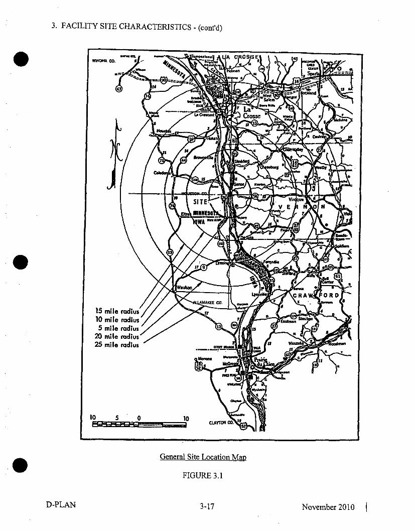
3. FACILITY SITE CHARACTERISTICS - (cont'd)
General Site Location Map
FIGURE 3.1
D-PLAN 3-17 November 2010 1

3. FACILITY SITE CHARACTERISTICS - (cont'd)62E
t{HW HH3.-89-
WNW
w26
WSW
EHE
E•
ESE
rotal Segmeant Popualation i.0 to 5 Mile 6M-
POPULATION TOTALSRINGTOTAL MILES CUM4ULAMlV1INIES OPULArTION -P~. t•S OPULATION
0-2 07 -1 4712-s ,-S I o71
Estimated
Permanent Population (6/8-2) Is
MN = 148 (13.R2%) WI = 923 (86.18%)
IA = 0
Population Dispersion
FIGURE 3.2
D-PLAN 3-18 November2010 1

3. FACILITY SITE CHARACTERISTICS - (cont'd)
Effluent Release Boundary
FIGURE 3.3
3-19 November 2010D-PLAN

3. FACILITY SITE CHARACTERISTICS - (cont'd)
I
*
Genoa Site Map
FIGURE 3.4
D-PLAN 3-20 November 2010 1

3. FACILITY SITE CHARACTERISTICS - (cont'd)
MONTHLY AVERAGE TEMPERATURE DATALACBWR and LACROSSE NWS SITES
26 1982 - 1984242220."1816
1412to
Doegrees 8-Celsius 6
42 -G- LACBWR Surface0
-2-X LaCrosse NWS
-6
-10-12
JAN FEB MAR APR MAY JUN JdL AUG SEP OCT NOV DEC
20- MONTHLY AVERAGE WIND SPEED DATA19 LACBWR and LACROSSE NWS SITES18. 1982 - 198417-16154 .& Surface - Stock - LaCrosse NWS14-13-
Wind 11Speed t09(mph) 9
43-
JAN FEB MAR APR MAY JUN 9iL AUG SEP 0CT NOV DEC
Monthly Average Meteorological Data
FIGURE 3.5
D-PLAN 3-21 November 2010

3. FACILITY SITE CHARACTERISTICS - (cont'd)
12.LACBWR SURFACE - IOM
WIND SPEED FREQUENCY DISTRIBUTION;1982 - 1984
('
Frequencyof
OccurrenCe(7.)
Frequencyof
Occurrence
-t0
9
7
65
4
3
2
i
00
t2
itto.
9
8
7
65
4
3
2
91AD
16 5il 20 22 24 26i 28 30 32 34 36 3 @402 4 5 5 10 12 14
LACBWR STACK -lOOMWIND SPEED FREQUENCY DISTRIBUTION
1982 - 1984
2 4 6 8 10 12 14 16 18 20 22 2425 26'i8'303i23i4"368'iHourly Wind Speeds (mph)
Wind Speed Freauencv Distribution
FIGURE 3.6
D-PLAN 3-22 November 2010 1

3. FACILITY SITE CHARACTERISTICS - (cont'd)
't, "•irse SO"t
16Mississippi River
W..........~
Gray Miedu Send7
,ý,
East Bank River Slope
FIGURE 3.7
D-PLAN 3-23 November 2010

3. FACILITY SITE CHARACTERISTICS - (cont'd)
AVERAGEMSL
ELEV.
+639
///
+619 -<
+614 y-
//
<.599 -4
Depth Ft.Plant Grade
0 •
0
2025
40
-130+509
Generalized Soil Profile
FIGURE 3.8
D-PLAN 3-24 November 2010

4. FACILITY DESCRIPTION
4.1 GENERAL PLANT DESCRIPTION
LACBWR was a nuclear power plant of nominal 50 MW electrical output which utilized aforced-circulation, direct-cycle boiling-water reactor as its heat source.
The reactor and its auxiliary systems were within a steel containment building. The turbine-generator and associated equipment, the control room for both turbine and reactor controls, andplant shops and offices were in a conventional building adjacent to the Reactor Building.
Miscellaneous structures which were associated with the power plant, and were located adjacentto the Turbine Building, include the electrical switchyard, Cribhouse, Waste Treatment Building,LSA Storage Building, oil pump house, stack, warehouses, administration building, annexbuilding, guard house, outdoor fuel oil tanks, underground septic tanks, gas storage tank vaults,underground oil tanks and the condenser circulating water discharge seal well at Genoa Unit 3.
Miscellaneous onsite improvements included roads, walks, parking areas, yard lighting, firehydrants required for plant protection, access to and use of rail siding facilities, fencing,landscaping, and communication services.
An Independent Spent Fuel Storage Installation for dry storage of the LACBWR spent fuelinventory is being established on the Genoa site south of the G-3 coal pile.
4.2 BUILDING AND STRUCTURES
4.2.1 Reactor Building
The Reactor Building (same as Containment Building, Figs. 4.1 and 4.2) is a right circularcylinder with a hemispherical dome and semi-ellipsoidal bottom. It has an overall internal heightof 144 feet and an inside diameter of 60 feet, and it extends 26'-6" below grade level. The shellthickness is 1.16 inch, except for the upper hemispherical dome which is 0.60 inch thick.
The building contained most of the equipment associated with the nuclear steam supply system,including the reactor vessel and biological shielding, the fuel element storage well (FESW), theforced circulation pumps, the shutdown condenser, and process equipment for the reactor waterpurification system, decay heat cooling system, shield cooling system, seal injection system,emergency core spray system, boron injection system, and the FESW cooling system.
The Reactor Building was designed to withstand the instantaneous release of all the energy of theprimary system to the Reactor Building atmosphere at an initial ambient temperature of 800 F,neglecting the heat losses from the building and heat absorption by internal structures. Thedesign pressure was 52 psig, compared to a calculated maximum pressure buildup of 48.5 psigfollowing the maximum credible accident while in operation. The Reactor Building shell wasdesigned and constructed according to the ASME Boiler and Pressure Vessel Code, Sections II,VIII, and IX, and Nuclear Code Cases 1270N, 1271N, and 1272N.
D-PLAN 4-1 November 2010

4. FACILITY DESCRIPTION - (cont'd)
The interior of the shell is lined with a 9-inch-thick layer of concrete, to an elevation of 727'-10"* to limit direct radiation doses in the event of a fission-product release within the Reactor
Building.
The Reactor Building is supported on a foundation consisting of concrete-steel piles and a pilecapping of concrete approximately 3 feet thick. This support runs from the bottom of the semi-ellipsoidal head at about elevation 612'-4" to an elevation of 621 '-6". The 232 piles that supportthe containment structure are driven deep enough to support over 50 tons per pile.
The containment bottom head above elevation 621 '-6" and the shell cylinder from the bottomhead to approximately 9 inches above grade elevation 639 feet are enveloped by reinforcedconcrete laid over a '/2 inch thickness of pre-molded expansion joint filler. The reinforcedconcrete consists of a lower ring, mating with the pile capping concrete. The ring isapproximately 41 feet thick at its bottom and 22 feet thick at a point 1 /2 feet below the top dueto inner surface concavity. The ring then tapers externally to a thickness of 9 inches at the top(elevation 627'-6") and extends up the wall of the shell cylinder to elevation 639'-9". The fillerand concrete are not used, however, where cavities containing piping and process equipment areimmediately adjacent to the shell.
Except for areas of the shell adjacent to other enclosures, the exterior surface of the shell aboveelevation 639'-9" is covered with 1 V2 inch thick siliceous fiber insulation, faced with aluminum.The insulation of the dome is Johns-Manville Spintex of 9 lb/ft3 density, faced with embossedaluminum sheet approximately 0.032 inch thick. The insulation of the vertical walls is Johns-
* Manville Spintex of 6 lb/ ft3 density, faced with corrugated embossed aluminum sheetapproximately 0.0 16 inch thick. The insulation minimizes heat losses from the building andmaintains the required metal temperature during cold weather, and reduces the summer air-conditioning load.
The shell includes two airlocks. The principal access to the shell is through the personnel airlockthat connects the Reactor Building to the Turbine Building. The airlock is 21'-6" long betweenits two rectangular doors that measure 5'-6" by 7'. The Reactor Building can also be exited, ifnecessary, through the emergency airlock, which is 7 feet long and 5 feet in diameter, with twocircular doors of 32V2 inch diameter (with a 30-inch opening). Both airlocks are at elevation642'-9" and lead to platform structures from which descent to grade level can be made.
There is an 8 feet by 10 feet freight door opening in the Reactor Building that was intended toaccommodate large pieces of equipment. The door is bolted internally to the door frame in theshell.
To facilitate reactor pressure vessel removal and dry cask storage, an opening was created in theReactor Building. The opening has a total length of 58'-8". The width of the upper 24'-8" of theopening is 16'-9/4" and the width of the lower 34' of the opening is 10'-6". The opening isclosed by a weather tight, insulated, roll-up, bi-parting door. The opening and door are depictedin Figures 4.6 and 4.7.
* Cables and bulkhead conductors from the Turbine Building provide electrical service to theReactor Building through penetrations in the northwest quadrant of the building shell. Themajority of pipe penetrations leave the Reactor Building 1 to 10 feet below grade level and entereither at the northwest quadrant into the pipe tunnel that runs to the Turbine Building, or on the
D-PLAN 4-2 November 2010 1

4. FACILITY DESCRIPTION - (cont'd)
northeast side into the tunnel connecting the Turbine Building, Reactor Building, stack, and thewater treatment and waste gas storage areas.
A 45,000-gallon storage tank in the dome of the Reactor Building supplied water for theemergency core spray system and the building spray system. The storage tank provides a sourceof water inventory for fuel handling operations and the FESW.
A 50-ton traveling bridge crane with a 5-ton auxiliary hoist is located in the upper part of theReactor Building. The bridge completely spans the building and travels on circular trackssupported by columns around the inside of the building just below the hemispherical upper head.A trolley containing all the lifting mechanisms travels on the bridge to near the crane rail, and itpermits crane access to any position on the main floor under the trolley travel-diameter. Thelifting cables of both the 50-ton and the 5-ton hoists are also long enough to reach down throughhatchways into the basement area. Hatches at several positions in the main and intermediatefloors may be opened to allow passage of the cables and equipment.
The spent fuel is stored wet in racks in the bottom of the FESW located adjacent to the reactorbiological shielding in the Reactor Building. The storage rack system is a two-tier configurationsuch that each storage location is capable of storing two fuel assemblies, one above the other.Fuel assemblies stored in the lower tier are always accessible (e.g., for periodic inspection) bymoving, at most, one other assembly. Each storage rack consists of a welded assembly of fuelstorage cells spaced 7 inches on center. A neutron absorbing B4C Polymer Composite plate isincorporated between each adjacent fuel storage cell in each orthogonal direction. Horizontalseismic loads are transmitted from the rack structures to the FESW walls at three elevations (thetop grid of the upper tier rack section, the top grid of the lower tier rack section and the bottomgrid of the lower tier rack section) through adjustable pads attached to the rack structures. Thevertical dead-weight and seismic loads are transmitted to the FESW floor by the rack supportfeet. The fuel storage racks and associated seismic bracing are fabricated from Type 304stainless steel. Following removal of all spent fuel assemblies and fuel debris for dry storage atthe ISFSI, the storage racks will be removed and disposed of; the FESW will be drained anddecontaminated.
The Reactor Building is being modified to facilitate movement of spent fuel assemblies from theFESW to the NAC-MPC System Transportable Storage Canister (TSC). The TSC is locatedinside the Transfer Cask (TFR) during fuel loading operations. The TFR/TSC assemblage willreside in the cask pool within the water-filled upper cavity during spent fuel assembly transferfrom the FESW to the TSC.
The 10'-6" wide opening from the mezzanine floor elevation 667 feet to the fuel handling floorelevation 701 feet was previously created in the northern section of the upper cavity bio-shieldand liner to permit removal of the LACBWR reactor pressure vessel. This opening will be usedto facilitate movement of the TFR/TSC between the cask pool and the mezzanine floor to thenorth where TSC preparation operations will take place (e.g., welding, drying, etc.). The ReactorBuilding mezzanine floor will be reinforced in that location by adding steel struts beneath acantilevered section of the floor. In order to provide sufficient water coverage over the spentfuel assemblies during movement into the TSC from the FESW, a water-tight removable gate,16'-9" high by 9'-4" wide, will be installed in the bio-shield opening above approximateelevation 679'-3" extending to elevation 696 feet. The cask pool gate'will be supported by a 12'high structure installed at elevation 667 feet. The cask pool gate is designed with inflatable
D-PLAN 4-3 November 2010 1

4. FACILITY DESCRIPTION - (cont'd)
pneumatic seals having a defined acceptable leakage rate. Appropriate interfacing modifications* to the bio-shield liner at the edges of the opening will be installed to ensure water retention in the
area between the upper cavity liner and the cask pool gate. The cask pool gate storage stand willsupport the 6-ton cask pool gate when not in use.
The 10' high by 10' inner diameter cask pool will be installed at elevation 669'-3" atop a 20'-10" high support structure attached to the reactor support cylinder at elevation 648'-5". The caskpool will have a 16V2" wide horizontal flange welded to the top of the shell, the outercircumference of which will be tied into the existing upper cavity liner using L-shaped stainlesssteel angle at approximate elevation 679'-3". This arrangement will provide a barrier to preventwater in the upper cavity area above the cask pool from leaking around the outside of the caskpool into the cavity below.
The upper cavity liner and bio-shield contained a number of penetrations from reactor operationthat will be sealed using steel plates welded to the upper cavity liner to maintain the pressureboundary of the upper cavity. The cask pool will also include two penetrations, one at thebottom and one on the side approximately 7'-6" above the tank bottom. These penetrations willconnect to piping and valves for filling, draining, and processing water from the pool and uppercavity to permit removal of the cask pool gate, and to perform other activities such as waterclean-up, cask annulus flushing, and inventory control. Each 2-inch diameter pipe will includetwo manual valves in series just outboard of the cask pool to ensure redundant isolation.
4.2.2 Turbine Building
The general location of the Reactor and Turbine Buildings is shown in Figure 4.3. The TurbineBuilding contained a major part of the power plant equipment. The turbine-generator was on themain floor. Other equipment was located below the main floor. This equipment included thefeedwater heaters, reactor feedwater pumps, air ejector, vacuum pump, full-flow demineralizers,condensate pumps, air compressors, air dryer, oil purifier, service water pumps, componentcooling water coolers and pumps, demineralized water system, domestic water heater, turbine oilreservoir, oil tanks and pumps, turbine condenser, unit auxiliary transformer, 2400-volt and480-volt switchgear, motor control centers, diesel engine-generator sets, emergency storagebatteries, inverters and other electrical, pneumatic, mechanical and hydraulic systems andequipment required for a complete power plant. A 30/5-ton capacity, pendant-operated overheadelectrical traveling crane spanned the Turbine Building. The crane has access to majorequipment items located below the floor through numerous hatches in the main floor. A 40-toncapacity, pendant-operated overhead electric crane spanned the space between turbine buildingloading dock and Waste Treatment Building.
The Turbine Building also contained the main offices, the Control Room (for both turbine-generator and reactor), locker room facilities, laboratory, shops, counting room, personnelchange room, and decontamination facilities, heating, ventilating and air conditioning equipment,rest rooms, storeroom, and space for other plant services. In general, these areas were separatedfrom power plant equipment spaces. The Control Room is on the main floor on the side of theTurbine Building that is adjacent to the Reactor Building. The general arrangement of theReactor and Turbine Buildings is shown in Figures 4.3 through 4.5.
D-PLAN 4-4 November 2010 I

4. FACILITY DESCRIPTION - (cont'd)
4.2.3 Waste Treatment Building and LSA Storage Building
* The Waste Treatment Building (WTB) is located to the northeast of the Reactor Building. Thebuilding contains facilities and equipment for decontamination and the collection, processing,storage, and disposal of low level solid radioactive waste materials in accordance with theProcess Control Program.
The grade floor of the WTB contains a shielded compartment which encloses a 320 ft3 stainlesssteel spent resin receiving tank with associated resin receiving and transfer equipment. A highintegrity disposal liner can be located in the adjacent shielded cubicle.
Adjacent to these shielded resin handling cubicles are two open cubicles, one of which is about3' above grade. The grade level area contains two back-washable radioactive liquid waste filters,the spent resin liner level indication panel and the spent resin liner final dewatering piping,container, and pumps. The second above-grade area is a decontamination facility, consisting of asteam cleaning booth, a decontamination sink, and heating/ventilation/air conditioning units.
The remaining grade or above-grade areas contain a shower/wash/frisking area, and the dryactive waste (DAW) compactor unit and temporary storage space for processed DAWcontainers.
Beneath the grade floor are two shielded cubicles. One cubicle, to which access is gained byremoval of floor shield plugs, is available for the storage of up to nine higher activity solid waste. drums. The other area, to which access is gained by a stairway, contains the dewatering ionexchanger, the WTB sump and pump, and additional waste storage space.
The WTB ventilation is routed through a HEPA filter to the stack plenum. The building isnormally maintained at a negative pressure. The general arrangement of the WTB is shown onFigure 4.5.
The Low Specific Activity (LSA) Storage Building is southwest of the Turbine Building. It isused to store processed, packaged and sealed low level dry active waste materials, and sealedlow level activity components for a period of approximately 5 years. The building has thecapacity for 500 DOT17H-55 gallon drums of waste. No liquids are stored in this building.There are no effluent releases from this building during normal use.
4.2.4 Cribhouse
The Cribhouse is located on the bank of the Mississippi River to the west of the plant andthrough its intake structure, provides the source of river water to the various pumps supplyingriver water to the plant. The Cribhouse contains the diesel-driven high pressure service waterpumps, traveling screens, low pressure service water pumps and the circulating water pumps.
4.2.5 Onsite Independent Spent Fuel Storage Installation
* The LACBWR Dry Cask Storage Project establishes an Independent Spent Fuel StorageInstallation (ISFSI) under general license provisions of 10 CFR 72, Subpart K on the Genoa site.The ISFSI site is about midway between the Mississippi River on the west and Highway 35 onthe east. The ISFSI is located 2,232 feet south-southwest of the Reactor Building center on land
D-PLAN 4-5 November 2010 1

4. FACILITY DESCRIPTION - (cont'd)
which was previously used for an access road between the two closed ash landfills of the Genoasite.
The ISFSI will be used for interim storage of LACBWR spent fuel assemblies in the NACInternational, Inc. Multi-Purpose Canister (NAC-MPC) System. The NRC issued 10 CFR 72Certificate of Compliance (CoC) No. 1025 which confers approval of the NAC-MPC storagesystem design. The design basis for the NAC-MPC System is provided in the NAC-MPC FinalSafety Analysis Report (FSAR). The NRC approved Amendment 6 to the NAC-MPC CoC andTechnical Specifications to incorporate LACBWR spent fuel assemblies as approved contentsfor storage in the NAC-MPC System. The effective date of the license amendment was October4,2010.
The NAC-MPC System is comprised of the Transportable Storage Canister (TSC), the VerticalConcrete Cask (VCC), and the Transfer Cask (TFR). The TSC is designed to be transported inthe NAC Transport Cask (STC) licensed by the NRC pursuant to 10 CFR 71 CoC No. 71-9235for shipment of the NAC-MPC canister. The NAC-MPC System designed for and to be used atLACBWR is designated MPC-LACBWR. The LACBWR spent fuel inventory will be placedinto five MPC-LACBWR dry storage casks. Each MPC-LACBWR TSC can accommodate up to68 fuel assemblies for a total of 340 fuel storage cells among the five TSCs. Thirty-two of the 68fuel cell locations in each TSC are designed for a damaged fuel canister. Seven spare locationsare available in the fifth TSC.
The spent fuel assemblies will be loaded underwater into a TSC within a TFR located in the caskpool. The TSC/TFR will be removed from the cask pool and the TSC will be prepared forstorage by draining, helium fill, vacuum drying, and closure lid seal welding. The TSC/TFR willbe moved outdoors and the TSC will be placed in the VCC by positioning the TFR on top of theVCC and lowering the TSC within the TFR through the transfer adapter to the VCC below. TheVCC containing the TSC will then be placed in storage on the ISFSI pad.
The TSC assembly consists of a right circular cylindrical shell with a welded bottom plate, a fuelbasket, a closure lid with closure ring, and two sets of redundant port covers. The cylindricalshell, plus the bottom plate and lid, constitutes the confinement boundary. The stainless steelfuel basket is a right circular cylinder with 68 fuel tubes including 32 oversized tubes designed toaccommodate LACBWR damaged fuel cans, laterally supported by a series of stainless steelsupport disks. The support disks are retained by spacers on radially located tie rods. The spentfuel assemblies will be contained in square stainless steel fuel tubes that include Boral on up tofour sides for criticality control.
The VCC is the storage overpack for the TSC and provides structural support, shielding,protection from environmental conditions, and natural convection cooling of the TSC duringlong term storage. The VCC is a reinforced concrete structure with a carbon steel inner liner.The VCC has an annular air passage to allow the natural circulation of air around the TSC. Theair inlet and outlet vents take non-planar paths to the VCC cavity to minimize radiationstreaming. The decay heat is transferred from the spent fuel assemblies to the tubes in the fuelbasket, through the heat transfer disks, to the TSC wall. Heat flows by convection from the TSCwall to the circulating air, as well as by radiation from the TSC wall to the VCC inner liner. Theheat flow to the circulating air from the TSC wall and the VCC liner is exhausted through the airoutlet vents. The top of the VCC is closed by a single shielded lid incorporating a carbon steel
D-PLAN 4-6 November 2010 1

4. FACILITY DESCRIPTION - (cont'd)
plate for gamma shielding and concrete for neutron shielding. The VCC lid will be bolted inplace.
The TFR, with its lifting yoke, is a qualified heavy lifting device designed, fabricated, and proofload tested to the requirements of NUREG-0612 and ANSI N14.6. The TFR provides shieldingduring TSC movements between work stations, the VCC, or the transport cask. It is a multi-wall(steel/lead/NS-4-FR/steel) design and has a bolted top retaining ring to prevent a fuel-loadedcanister from being inadvertently removed through the top of the TFR. Retractable,hydraulically operated, bottom shield doors on the TFR are used during TSC transfer operations.To minimize contamination of the TSC, clean water will be circulated in the gap between theTFR and the TSC during cask pool loading operations.
The ISFSI pad made of reinforced concrete will be 48 feet in length, and 32 feet in width, and 3feet thick. The empty TFR and five VCCs containing fuel-loaded TSCs will be placed in astorage array on the ISFSI pad. The ISFSI will be surrounded by a protected area fence, anisolation zone fence, and vehicle barrier system. These protective barriers will be within theISFSI Controlled Area Boundary fence. The ISFSI pad will be supplied with lighting, electronicsurveillance and security systems. The ISFSI Administration Building is a commercial structureapproximately 60 feet by 30 feet located 400 feet northeast of the ISFSI pad. The ISFSIAdministration Building will provide space for security monitoring and ISFSI operationssupport.
D-PLAN 4-7 November 2010 1
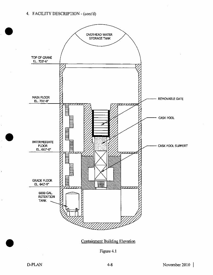
4. FACILITY DESCRIPTION - (cont'd)
REMOVABLE GATE
CASK POOL
CASK POOL SUPPORT
Containment Buildini Elevation
Figure 4.1
D-PLAN 4-8 November 2010 1

4. FACILITY DESCRIPTION - (cont'd)
I : 'I
Containiment Buildingz General Arrangzement
Figure 4.2
D-PLAN 4-9 November 2010
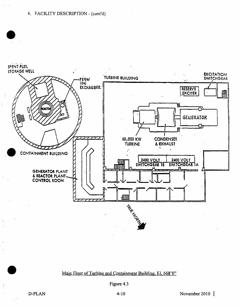
4. FACILITY DESCRIPTION - (cont'd)
SPENT FUELSTORAGE WELL
Main Floor of Turbine and Containment Building, El. 668'0"
Figure 4.3
D-PLAN 4-10 November 2010 1

4. FACILITY DESCRIPTION - (cont'd)
SPENT FUELSTORAGE WELL
Mezzanine Floor of Turbine and Containment Building, El. 654'0"
Figure 4.4
D-PLAN 4-11 November 2010 1

4. FACILITY DESCRIPTION - (cont'd)
FORCEDCIRCULATIOIS TURBINE BUILDING
CED PUMP IB, I.p FULL F
HEATER NO. 3 DIMINIp BLDG. 4 t64 iC Z--47J
0
-. CONDENSER
M6CIIZIIA. DIESEL
MAIN LABORATORYI[
WASTS FILTER6 ELECTRICA.L OILMAINTENANCE CuSTORM
3uj ROOKDECONTAM-INATION AREA
LUZ COUNTING
HOWER & ROOMfASH AREA
JILDING
Grade Floor of Turbine, Containment, and Waste Treatment Building, El. 640'0"
Figure 4.5
D-PLAN 4-12 November 2010 1

4. FACILITY DESCRIPTION - (cont'd)
HIS rafUOM Of" AACTOR..SUILOING WALL. REMMOW
Reactor Building Opening
Figure 4.6
4-13 November 2010
D-PLAN

4. FACILITY DESCRIPTION - (cont'd)
0 Reactor Building Bi-Parting Door
Figure 4.7
D-PLAN 4-14 November 2010 I

4. FACILITY DESCRIPTION - (cont'd)
Onsite ISFSI
Figure 4.8
D-PLAN 4-15 November 2010 1

5. PLANT STATUS
5.1 SPENT FUEL INVENTORY
During June 1987 all fuel assemblies were removed from the reactor vessel. Currently there are333 spent fuel assemblies stored in the spent fuel pool. All spent fuel will be placed in drystorage casks and moved to the onsite Independent Spent Fuel Storage Installation.
This spent fuel consists of three different types of fuel assemblies. Type I (82 assemblies) andType 11 (73 assemblies) were fabricated by Allis-Chalmers (A-C) and Type Il (178 assemblies)by EXXON. All of the fuel assemblies are 10xl0 arrays of Type 348 stainless steel clad rodswith stainless steel and Inconel spacers and fittings. The initial enrichment of the uranium in theType I and Type II fuel was 3.63% and 3.92% respectively and the nominal average initialenrichment of the Type III fuel was 3.69%. The Type III assemblies contain 96 fueled rods and4 inert Zircaloy-filled rods.
The 72 fuel assemblies removed from the reactor in June 1987 have assembly average exposuresranging from 4,678 to 19,259 megawatt-days per metric ton of uranium (MWD/MTU). Theexposures of the 261 fuel assemblies discharged during previous refuelings range from 7,575 to21,532 MWD/MTU. The oldest fuel stored was discharged from the reactor in August 1972.Forty-nine of the A-C fuel assemblies discharged prior to May 1982 contain one or more fuelrods with visible cladding defects and 54 additional A-C fuel assemblies discharged prior toDecember 1980 contain one or more leaking fuel rods as indicated by higher than normal fissionproduct activity observed during dry sipping tests.
The estimated radioactivity inventory in the 333 spent fuel assemblies is tabulated in Table 5-1.
TABLE 5-1
SPENT FUEL RADIOACTIVITY INVENTORY
January 1988 (a)
Radio- Half Life Activity Radio- Half Lifenuclide (Years) (b) (Curies) nuclide (Years) (b) (Curies)
144Ce 7.801 E-1 2.636 E+6 90Sr 2.770 E+I 1.147 E+6
137CS 3.014 E+1 1.666 E+6 241pu 1.440 E+1 1.138 E+6106Ru 1.008 E+0 1.524 E+6 51Fe * 2.700 E+0 5.254 E+5
95Zr(Nb) 1.754E-1 3.555 E+5 95Zr * 1.750 E-1 3.52 E+2(9.58E-2)
134CS 2.070 E+0 3.291 E+5 59Ni * 8.000 E+4 2.87 E+2
(a) Computer Program, FACT-I, DPC, July 1987, and hand calculations.(b) Computer Program, TPASGAM, Nuclide Identification Package, J. Keller, Analytical
Chemistry Division, ORNL, June 1986.Activity in fuel assembly hardware based on neutron activation analysis.
D-PLAN 5-1 November 2010

5. PLANT STATUS - (cont'd)
TABLE 5-1 - (cont'd)
Radio- Half Life Activity Radio- Half Lifenuclide (Years) (b) (Curies) nuclide (Years) (b) (Curies)
85KrI 'OmAg
89Sr
12 7 rnTe
60Co *
103Ru147pm
63Ni *
14tCe242Cm
241Am
238pu
239pu
240pu
154Eu
244Cm
51Cr *
129 1nTe
3H59Fe *
152Eu242mAm
1.072 E+I
6.990 E-1
1.385 E-1
2.990 E-1
5.270 E+O
1.075 E-1
2.620 E+0
1.000 E+2
8.890 E-2
4.459 E-1
4.329 E+2
8.774 E+1
2.410 E+4
6.550 E+3
8.750 E+0
1.812 E+1
7.590 E-2
9.340 E-2
1.226 E+I
1.220 E-1
1.360 E+I
1.505 E+2
1.160 E+5
1.018 E+5
1.009 E+5
8.238 E+4
6.395 E+4
6.334 E+4
4.129 E+4
3.540 E+4
2.638 E+4
1.858 E+4
1.474 E+4
1.262 E+4
8.837 E+3
7.165 E+3
4.020 E+3
3.603 E+3
3.002 E+3
1.170 E+3
5.510 E+2
5.120 E+2
5.110 E+2
4.900 E+2
9 9Tc
125 Sb155Eu234U
24 3Am
1131nCd
94Nb *135Cs
238U
156Eu
242pu
236U
12h1nSn
237Np235U
15 1Sm
1268n
79Se
1291
9 3Zr
1311
2.120 E+5
2.760 E+0
4.960 E+0
2.440 E+5
7.380 E+3
1.359 E+I
2.000 E+4
3.000 E+6
4.470 E+9
4.160 E-2
3.760 E+5
2.340 E+7
7.600 E+1
2.140 E+6
7.040 E+8
9.316 E+I
1.000 E+5
6.500 E+4
1.570 E+7
1.500 E+6
2.200 E-2
2.76 E+2
2.73 E+2
1.68 E+2
6.37 E+I
6.31 E+I
1.78 E+I
1.59 E+I
1.40 E+I
1.22 E+I
8.63 E+0
8.58 E+0
6.32 E+04.44 E+0
2.19 E+0
1.89 E+0
1.51 E+0
7.01 E-i
5.52 E-i
3.90 E-i
1.11 E-1
2.00 E-3
(a) Computer Program, FACT-I, DPC, July 1987, and hand calculations.(b) Computer Program, TPASGAM, Nuclide Identification Package, J. Keller, Analytical
Chemistry Division, ORNL, June 1986.Activity in fuel assembly hardware based on neutron activation analysis.
D-PLAN 5-2 November 2010 1

5. PLANT STATUS - (cont'd)
5.2 PLANT SYSTEMS AND THEIR STATUS
5.2.1 Reactor Vessel and Internals
The reactor vessel consisted of a cylindrical shell section with a formed integral hemisphericalbottom head and a removable hemispherical top head bolted to a mating flange on the vesselshell to provide for vessel closure. The vessel had an overall inside height of 37 feet, an insidediameter of 99 inches, and a nominal wall thickness of 4 inches (including 3/16-inch of integrallybonded stainless steel cladding). The reactor vessel was a ferritic steel (ASTM A-302-Gr-B)plate with integrally bonded Type 304L stainless steel cladding. The flanges and large nozzleswere ferritic steel (ASTM A-336) forgings. The small nozzles were made of Inconel pipe.
The reactor internals consisted of the following: a thermal shield, a core support skirt, a plenumseparator plate, a bottom grid assembly, steam separators, a thermal shock shield, a baffle platestructure with a peripheral lip, a steam dryer with support structure, an emergency core spraytube bundle structure combined with fuel holddown mechanism, control rods and the reactorcore.
5.2.1.1 System Status: All fuel assemblies have been removed from the reactor vessel. Startupsources have been disposed of. The reactor vessel with head installed, internals intact, and 29control rods in place was filled with low density cellular concrete. Attachments to the reactorvessel flange were removed to a diameter of 119 inches. All other nozzles and appurtenanceswere cut to within the diameter of the flange. Under-vessel nozzles and appurtenances wereremoved from an envelope of within 6 inches of bottom dead center of the reactor vessel shellbottom. The reactor pressure vessel was removed from the Reactor Building and shipped to theBarnwell Waste Management Facility in June 2007.
5.2.2 Forced Circulation System
The Forced Circulation system was designed to circulate sufficient water through the reactor tocool the core and to control reactor power from 60 to 100 percent. Primary water passed upwardthrough the core, and then down through the steam separators to the re-circulating water outletplenum. The water then flowed to the 16-inch Forced Circulation pump suction manifoldthrough four 16-inch nozzles and was mixed with reactor feedwater that entered the manifoldthrough four 4-inch connections. From the manifold, the water flowed through 20-inch suctionlines to the two 15,000 gpm variable-speed Forced Circulation pumps. Hydraulically-operatedrotoport valves were installed at the suction and discharge of each pump. The 20-inch pumpdischarge lines returned the water to the 16-inch Forced Circulation pump discharge manifold.From the manifold, the water flowed through four equally spaced 16-inch reactor inlet nozzles tothe annular inlet plenum, and then downward along the bottom vessel head to the core inletplenum.
The system piping was designed for a maximum working pressure of 1450 psig at 650'F (apressure above the maximum reactor working pressure to allow for the static head and the pumphead). Since the piping from the reactor to the rotoport valves was within the biological shieldand not accessible, the valves and piping were clad with stainless steel. The piping between therotoport valves and the pumps was low-alloy steel.
D-PLAN 5-3 November 2010 I

5. PLANT STATUS - (cont'd)
Each Forced Circulation pump had an auxiliary oil system and a hydraulic coupling oil system.Each auxiliary oil system supplied oil to cool and lubricate the three (1 radial and 2 thrust) pumpcoupling bearings. Each hydraulic coupling oil system supplied cooled oil at a constant flow rateto the hydraulic coupling.
5.2.2.1 System Status: The Forced Circulation system and attendant oil systems have beendrained. The Forced Circulation pumps, auxiliary oil pumps, and hydraulic coupling oil pumpshave been electrically disconnected. All 16-inch and 20-inch Forced Circulation system pipingwas filled with low density cellular concrete. Four 16-inch Forced Circulation inlet nozzles andfour 16-inch outlet nozzles were cut to allow removal of the reactor pressure vessel. Pipinglocated within the reactor cavity was also cut at the biological shield, segmented into manageablepieces, and disposed of. Pumps and piping in the shielded cubicles remain.
5.2.3 Seal Injection System
The Seal Injection system provided cooling and sealing water for the seals on the two ForcedCirculation pumps and the 29 control rod drive units.
The Seal Injection system had two positive-displacement pumps, supplied with water from theSeal Injection reservoir. The reservoir was supplied from the Condensate Demineralizer systemwith a backup supply from the overhead storage tank. One pump was required for operationwith the other on standby.
A cartridge-type filter was provided in the pump suction header. A deaerator, vented to the SealInjection reservoir, was located on the suction of the pumps to remove entrained air from thesystem in the event air was introduced during makeup to the system.
Bladder-type accumulators were connected to the suction and discharge of each Seal Injectionpump. The suction accumulators reduced pump and piping vibrations. The dischargeaccumulators dampened the pulsating flow from the pumps to provide the constant flow raterequired for stable system conditions.
The water to the Forced Circulation pump seals passed through a full-flow filter. There weretwo filters arranged in parallel with one normally in service and the other in standby. Each sealsupply line contained a flow control valve, check valve, and a three-way valve for switchinginjection points on the seal. Both valves in each supply line could be operated from the ControlRoom.
The water to the control rod drive seals was filtered in the same manner. The water passedthrough a flow control valve which maintained a constant flow rate to the seals. The individualsupply lines to the 29 control rod drive units had a throttle valve and flow indicator for settingthe required flow rate to each seal. The normal leakoff from the seals (0.15 gpm or less) wasdrained to the reactor basement floor sump.
Continuous blowdown of water from the control rod drive upper housing was removed through aconnection on each control rod drive upper housing flange. Each line contained a throttle valve,and all lines joined at a common manifold, from which suction was taken by the control rodnozzle effluent pumps. The pumps discharged into the inlet of the Decay Heat system, whichwas directly connected to the Forced Circulation system.
D-PLAN 5-4 November2010 I

5. PLANT STATUS - (cont'd)
5.2.3.1 System Status: This system is drained and not maintained operational.
5.2.4 Decay Heat Cooling System
The Decay Heat Cooling system was a single high pressure closed loop containing a pump,cooler, interconnecting piping, and the necessary instrumentation.
The decay heat loop was connected across the 20-inch Forced Circulation pump 1 A supply andreturn lines on the reactor side of the Forced Circulation pump isolation valves. Bothconnections to the forced circulation piping were located outside the reactor biological shield.Reactor water from the Forced Circulation pump supply line passed through an 8-inch line to thesuction side of the Decay Heat pump. The water was then discharged through a 6-inch line intothe Decay Heat cooler where it was cooled and returned to the Forced Circulation pump returnline.
A 2-inch blowdown line to the Main Condenser was located downstream of the Decay Heatcooler. This was used to remove the excess water due to seal inleakage and thermal expansion ofthe water. Another 2-inch line downstream of the Decay Heat cooler connected to the reactorvessel head vent line which could be used to promote better circulation of the water within thereactor vessel head.
5.2.4.1 System Status: This system is drained and not maintained operational.
5.2.5 Emergency Core Spray System
The Emergency Core Spray system consisted of a spray header with individual spray lines foreach fuel assembly mounted inside the reactor vessel. The low pressure supply line alloweddemineralized water from the Overhead Storage Tank, or the service water from the HighPressure Service Water supply line, to flow directly to the core spray header.
5.2.5.1 System Status: This system has been removed.
5.2.6 Boron Injection System
The purpose of the Boron Injection system was to inject enough sodium pentaborate solution intothe primary system to make the reactor subcritical in the event of stuck control rods.
5.2.6.1 System Status: This system has been removed.
5.2.7 Primary Purification System
The Primary Purification system was a high pressure, closed loop system consisting of aregenerative cooler, purification cooler, pump, two ion exchangers and filters.
The functions of the Primary Purification system were:
N To maintain optimum reactor water quality (pH and conductivity) to minimize corrosion,
D-PLAN 5-5 November 2010 I
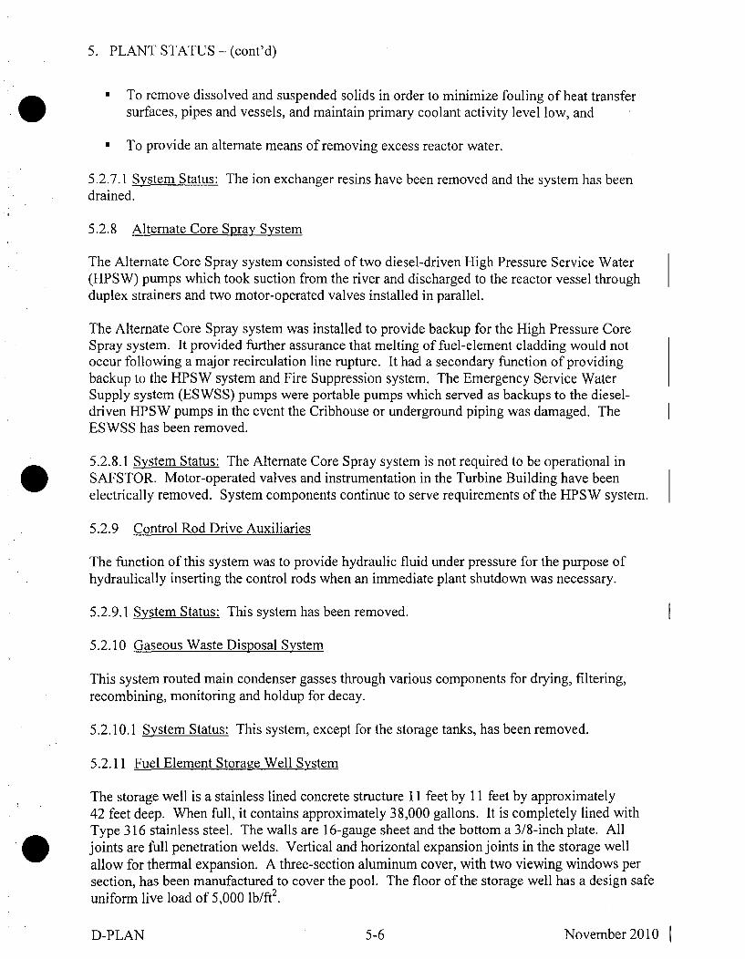
5. PLANT STATUS - (cont'd)
" To remove dissolved and suspended solids in order to minimize fouling of heat transfersurfaces, pipes and vessels, and maintain primary coolant activity level low, and
" To provide an alternate means of removing excess reactor water.
5.2.7.1 System Status: The ion exchanger resins have been removed and the system has beendrained.
5.2.8 Alternate Core Spray System
The Alternate Core Spray system consisted of two diesel-driven High Pressure Service Water(HPSW) pumps which took suction from the river and discharged to the reactor vessel throughduplex strainers and two motor-operated valves installed in parallel.
The Alternate Core Spray system was installed to provide backup for the High Pressure CoreSpray system. It provided further assurance that melting of fuel-element cladding would notoccur following a major recirculation line rupture. It had a secondary function of providingbackup to the HPSW system and Fire Suppression system. The Emergency Service WaterSupply system (ESWSS) pumps were portable pumps which served as backups to the diesel-driven HPSW pumps in the event the Cribhouse or underground piping was damaged. TheESWSS has been removed.
5.2.8.1 System Status: The Alternate Core Spray system is not required to be operational inSAFSTOR. Motor-operated valves and instrumentation in the Turbine Building have beenelectrically removed. System components continue to serve requirements of the HPSW system.
5.2.9 Control Rod Drive Auxiliaries
The function of this system was to provide hydraulic fluid under pressure for the purpose ofhydraulically inserting the control rods when an immediate plant shutdown was necessary.
5.2.9.1 System Status: This system has been removed.
5.2.10 Gaseous Waste Disposal System
This system routed main condenser gasses through various components for drying, filtering,recombining, monitoring and holdup for decay.
5.2.10.1 System Status: This system, except for the storage tanks, has been removed.
5.2.11 Fuel Element Storage Well System
The storage well is a stainless lined concrete structure 11 feet by 11 feet by approximately42 feet deep. When full, it contains approximately 38,000 gallons. It is completely lined withType 316 stainless steel. The walls are 16-gauge sheet and the bottom a 3/8-inch plate. Alljoints are full penetration welds. Vertical and horizontal expansion joints in the storage wellallow for thermal expansion. A three-section aluminum cover, with two viewing windows persection, has been manufactured to cover the pool. The floor of the storage well has a design safeuniform live load of 5,000 lb/ft2.
D-PLAN 5-6 November 2010 1

5. PLANT STATUS - (cont'd)
Spent fuel assemblies are stored in two-tiered racks in the Fuel Element Storage Well (FESW)until removed to cask storage. A transfer canal connects the upper portion of the well to theupper cavity and is closed with a water-tight gate and a concrete shield plug. The water level inthe well is normally maintained at an elevation of > 695 feet with fuel in upper rack.
FESW cooling is accomplished by drawing water through a 6-inch penetration at elevation 679feet, or a 4-inch line at elevation 679 feet 11 inches, and pumping it through the FESW coolerand returning it to the well, with either of two FESW pumps. The return line enters the top of thestorage well and extends down to discharge at elevation 695 feet. The bottom inlet line ends atthe biological shield wall and is sealed with a welded plug.
Cleanup is provided by the FESW ion exchanger. A 4-inch line from the Overhead StorageTank is used to flood the well or pump water back to the Overhead Storage Tank. Overflow anddrain pipes from the well and cavity are routed to the retention tanks. Normal makeup to thestorage well is provided by demineralized water through one of two fill valves which areremotely operated from Benchboard E in the Control Room.
The FESW cooling system is conservatively designed to remove the decay heat of a full core oneweek after shutdown, with the storage well water at 120'F and the ultimate heat sink, the river, at850F.
5.2.11.1 System Status: The Fuel Element Storage Well contains 333 spent fuel assemblies andwill remain in operation as part of the SAFSTOR Program as long as wet fuel storage or wet fuelhandling is necessary. Following removal of all spent fuel assemblies and fuel debris for drystorage at the ISFSI, the storage racks will be removed and disposed of; the FESW will bedrained and decontaminated.
5.2.12 Component Cooling Water System
The Component Cooling Water (CCW) system provided controlled quality cooling water to thevarious heat exchangers and pumps in the Reactor Building during plant operation. It alsoserved as an additional barrier between radioactive systems and the river. Currently, the systemprovides cooling water to the FESW heat exchanger and the two Reactor Building AirConditioner compressors.
The CCW system is a closed system consisting of two pumps, two heat exchangers, a surge tank,and the necessary piping, valves, controls, and instrumentation to distribute the cooling water.The CCW pumps, coolers, and the surge tank are located in the Turbine Building. Water flowsfrom the pumps, to the cooler, and then to the component cooling water supply header in theReactor Building. The flow requirements of the components cooled by the CCW system were asfollows during plant operation:
D-PLAN 5-7 November 2010

5. PLANT STATUS - (cont'd)
Design Nominal(GPM) (GPM)
1) FCP Hydraulic Coupling Coolers ----------------............................. 60 602) FCP Lube Oil Coolers 30 303) Shield Cooler ................................... 75 754) Control Rod Nozzle Effluent Pumps ........................................ 30 305) P urifi cation Pum p ---------------------------------------------......................... 15 156) Purification Cooler 260 2007) Reactor Building Air Conditioners --------------------....................... 60 each 1208) D ecay H eat Pum p ...................................................................... 20 209) D ecay H eat C ooler 5 ................................................................. 570 10010) Fuel Elem ent Storage W ell Cooler --------------------....................... 260 10011) Sam ple Coolers 5a........................................................................ 5-10 each 4012) Failed Fuel Element Location System Cooler ------------------------- 40 013) Station A ir C om pressors ------------------------------------ ---------------------- 20 each 014) PASS
a) R eactor C oolant Sam ple ------------------------....................... 10 5b) Containment Atmosphere Sample ............................... 40 0
TOTAL ............................ 1560 855
Water from each of the components, listed above, flows to the CCW return header. This headerleaves the Reactor Building and connects to the suction of the CCW pumps. A sample streamfrom the supply header is monitored for radioactivity and returned to the suction header. Thetemperature of the water in the supply header is automatically controlled by varying the LowPressure Service Water flow to the tube side of the CCW coolers.
5.2.12.1 System Status: This system remains operable.
5.2.13 Shield Cooling System
The Shield Cooling system was designed to maintain the temperature of the thermal shield andbiological shield concrete below 140'F and 150TF, respectively.
5.2.13.1 System Status: All system components external to the biological shield have been
removed, but because they are inaccessible the cooling coils have been abandoned in place.
5.2.14 Shutdown Condenser System
The primary function of the Shutdown Condenser was to provide a backup heat sink for thereactor, in the event the reactor was isolated from the main condenser, by the closure of eitherthe Reactor Building Steam Isolation valve or the Turbine Building Steam Isolation valve. Inaddition, the Shutdown Condenser acted as an over-pressure relief system in limiting over-pressure transients.
The Shutdown Condenser was located on a platform 10 feet above the main floor in the ReactorBuilding. Steam from the 10-inch main steam line passed through a 6-inch line, two parallelinlet steam control valves, back to a 6-inch line and into the tube side of the condenser where itwas condensed by evaporating cooling water on the shell side. The steam generated in the shell
D-PLAN 5-8 November 2010 1

5. PLANT STATUS - (cont'd)
was exhausted to the atmosphere through a 14-inch line which penetrates the Reactor Building.The main steam condensate was collected in the lower section and returned to the reactor vesselby gravity flow.
A vent line containing two parallel control valves was connected to the 6-inch condensate returnline. The valves discharged directly to the Reactor Building atmosphere and were capable ofremote manual operation to vent the primary system directly to the Reactor Building atmosphereunder emergency conditions. They performed the function of Reactor Emergency Flooding VentValves to equalize water level in the building with that in the reactor vessel, for a below-corebreak, and Manual Depressurization System to rapidly depressurize the reactor vessel, on failureof the High Pressure Core Spray coincident with a major leak.
5.2.14.1 System Status: This system has been removed.
5.2.15 Hydraulic Valve Accumulator System
The function of the Hydraulic Valve Accumulator system was to supply the necessary hydraulicforce to operate the five piston-type valve actuators, which operated the five rotoport valves inthe Forced Circulation and Main Steam systems. The system consisted of a water accumulatortank, a water return sump tank, two air compressors, two water pumps, piping, valves, and thenecessary instrumentation and controls. Approximately 300 gallons of demineralized water wasmaintained in the water accumulator tank by pumps which took suction from the water returnsump tank. The water in the accumulator tank was maintained under 140 psi air pressure by theair compressors. The pressurized water was then directed to pistons for hydraulic valveoperation.
5.2.15.1 System Status: This system has been drained. The air compressors, water pumps, andother equipment have been electrically disconnected and are not maintained operational.
5.2.16 Well Water System
Water for this system is supplied from two deep wells. Well No. 4 is located 115 feet southeastof the containment vessel center, and Well No. 3 is located 205 feet northeast of this centerline.The wells are 12 inches in diameter, with 8-inch pump casings and piping. The upper 40 feet ofcasing is set in concrete. The pumps are sealed submersible pumps. They take suction throughstainless steel strainers, and they discharge into pressure tanks.
The system supplies water to the plant and office for sanitary and drinking purposes. Watersupplied by the system is used at personnel and material decontamination stations. It is used ascooling water for the two Turbine Building air-conditioning units and in the heating boilerblowdown flash tank and sample cooler. The well water system is the source of supply tolaundry equipment.
5.2.16.1 System Status: This system is maintained in continuous operation.
5.2.17 Demineralized Water System
The Virgin Water Tank provides the supply to the Demineralized Water transfer pumps which
D-PLAN 5-9 November 2010 1

5. PLANT STATUS - (cont'd)
distribute demineralized water throughout the plant, including to the Overhead Storage Tank andthe Fuel Element Storage Well makeup in the Reactor Building. Water is demineralized inbatches at Genoa Unit 3, transferred to LACBWR where it is sampled, and, if of acceptablequality, stored in the Virgin Water Tank.
The Condensate Storage Tank and the Virgin Water Tank are actually two sections of an integralaluminum tank located on the office building roof. The lower section of this tank is theCondensate Storage Tank, and it has a capacity of 19,100 gallons. The upper, virgin-water,section will hold 29,780 gallons and has level indication in the Control Room.
5.2.17.1 System Status: The Demineralized Water system remains in service, mainly as a sourceof water for the Fuel Element Storage Well and the heating boiler. The Condensate StorageTank has been drained.
5.2.18 Overhead Storage Tank
The Overhead Storage Tank (OHST) is located at the top of, and is an integral part of, theReactor Building. The OHST system consists of the approximately 45,000-gallon tank, the tanklevel instrumentation and controls, and the piping to the first valve of the systems served by thetank.
The OHST now serves as a reservoir for water used to flood the Fuel Element Storage Well, caskpool, and upper cavity during cask loading operations. During operation, the OHST acted as areceiver for rejecting refueling water using the Primary Purification system. The OHST alsosupplied the water for the Emergency Core Spray system and Reactor Building Spray system,and was a backup source for the Seal Injection system.
5.2.18.1 System Status: The OHST remains in use, primarily for a source of makeup water tothe Fuel Element Storage Well and for cask loading operations. A 4-inch line from the OHST isused to flood the well or pump water back to the OHST using FESW system pumps, valves, andpiping. After the transfer of all spent fuel to dry storage at the onsite ISFSI, the OHST systemwill be drained and dismantled
5.2.19 Station and Control Air System
There are two single-stage positive displacement lubricated type compressors. The completecompressor consists of an encapsulated compressor system, inlet system, cooling system, andcontrol system. The encapsulated compressor includes compressor unit, fluid managementsystem, and motor section. One compressor is normally running, and the other compressor canbe started when necessary. The air receivers act as a volume storage unit for the station.
The air receiver outlet lines join to form a header for supply to the station and the control airsystems. Station air is provided to the Cribhouse, where it is piped to near the suction of theLow Pressure Service Water pumps; to the High Pressure Service Water tank to charge the tank;and to the generator and reactor plants at all floor levels, for station usage as needed.
Control air is supplied from the receiver discharge header through a refrigerated air dryer andcoalescing filter to various instruments and valves in the reactor and generator plants. Alarms
D-PLAN 5-10 November 2010 1

5. PLANT STATUS - (cont'd)
are provided in the Control Room to warn of low control air header pressure and compressorfailures.
5.2.19.1 System Status: This system is maintained in continuous operation.
5.2.20 Low Pressure Service Water System
The system is supplied by two vertical pumps located in the Cribhouse through a duplex strainerunit. The Low Pressure Service Water (LPSW) system supplies the Component Cooling Watercoolers and Circulating Water pump mechanical seals, and is the normal supply to the HighPressure Service Water (HPSW) system through the motor-driven HPSW pump. During plantoperation the LPSW system also supplied the Turbine Oil coolers, generator hydrogen systemcoolers, Condenser Vacuum pump, and Reactor Feedwater pumps.
5.2.20.1 System Status: This system is maintained in continuous operation.
5.2.21 High Pressure Service Water System
The High Pressure Service Water (HPSW) system supplies fire suppression water and isavailable as backup cooling water for the Component Cooling Water coolers. During normaloperation, HPSW system pressure is maintained by the Genoa Unit 3 jockey pump. A motor-driven HPSW pump with suction from the LPSW system is available for periods of highdemand. With the motor-driven pump cycling in automatic, HPSW system pressure ismaintained 110 to 135 psig at the expansion tank pressure switch elevation, 25 feet above sitegrade elevation. The pump is protected by a 35-psig low suction pressure trip. Backup supply isavailable from two HPSW diesel pumps. IA HPSW diesel pump will start automatically ifsystem pressure decreases to 90 psig. 1B HPSW diesel pump will start automatically if systempressure decreases to 80 psig. The HPSW diesel pumps will maintain system pressure atapproximately 150 psig. System pressure swings are cushioned by the air space in the HPSWsurge tank.
The HPSW system is divided into two main loops. The internal loop serves the TurbineBuilding, Reactor Building, and Waste Treatment Building interior hose stations and sprinklersystems. The external loop supplies outside fire hydrants and Cribhouse sprinklers. The externalloop is also cross-connected with the Fire Suppression system of the adjacent coal-firedgenerating facility, Genoa Unit 3. This cross-connect provides excess HPSW diesel pumpcapacity to this operating plant.
5.2.21.1 System Status: This system is maintained in operation to provide fire protection.
5.2.22 Circulating Water System
Circulating water is drawn into the Cribhouse intake flume from the river through travelingscreens by circulating water pumps 1 A and 1 B, which are located in separate open suction bays.Each pump discharges into 42-inch pipe; the pipes join a common 60-inch pipe leading to themain condenser in the Turbine Building. At the condenser, the 60-inch pipe branches into two42-inch pipes feeding the top section of the water boxes. The main condenser is a two-passdivided water box type. Circulating water enters the top section of the condenser tube side and is
D-PLAN 5-11 November 2010 1

5. PLANT STATUS - (cont'd)
discharged from the bottom section tube side. The condenser tubes extend the length of thecondenser and are fastened at each end to the tube sheets inserted between the water boxes andthe shell.
The 42-inch condenser circulating water outlet lines tie into a common 60-inch line whichdischarges to the seal well from Genoa Unit 3, located approximately 600 feet downstream fromthe LACBWR Cribhouse.
5.2.22.1 System Status: This system is maintained operational for periodic use for dilution ofliquid waste discharges.
5.2.23 Condensate System and Feedwater Heaters
The Condensate system took condensed steam from the condenser hotwell and delivered it underpressure to the suction of the reactor feed pumps. Two identical full-capacity condensate pumpstook suction from the hotwell, and pumped the condensate through a full-flow demineralizingsystem, the air ejector condensers, the gland steam exhaust condenser and two feedwater heatersbefore entering the feed pumps.
The Condensate system also supplied the turbine exhaust sprays, the reactor feed pump shaftsealing cooling system, the normal makeup to the seal injection system, and gland seal steamgenerator. Hotwell level was maintained by automatic makeup from, or overflow to, theCondensate Storage Tank.
5.2.23.1 System Status: This system has been removed, with the exception of three feedwaterheaters that remain in place with piping connections removed. The Condensate Storage Tankhas been drained.
5.2.24 Reactor Feedwater Pumps
The Reactor Feedwater pumps took preheated condensate from No. 2 feedwater heater anddelivered it through No. 3 feedwater heater to the reactor. The pumps boosted the systempressure from about 200 psi to approximately 1300 psi. The pump coupling arrangement wassuch that pump speed, and therefore capacity, could be varied to control reactor water level.Each pump was a separate unit containing all the auxiliaries, controls, and other componentsnecessary for independent operation.
5.2.24.1 System Status: The Reactor Feedwater pumps have been removed.
5.2.25 Full-Flow Condensate Demineralizer System
The Full-Flow Condensate Demineralizer system consisted of three service tanks, each with one-half system capacity and arranged in parallel. Its purpose was to remove ionic impurities fromthe condensate system water before admitting it to the reactor. Each service tank was capable ofdelivering 700 gpm. With one of the three tanks on standby, the system was capable ofdelivering 1400 gpm to satisfy primary system requirements. The standby service tank wasavailable for service whenever the effluent conductivity of the inservice tanks rose to anunacceptable level. Each of the three demineralizer tanks normally contained 45-50 ft3 of pre-
D-PLAN 5-12 November 2010 1

5. PLANT STATUS - (cont'd)
regenerated mixed resins with a cation/anion ratio of 2 to 1. The three service tanks weredesigned for 400 psig operation, and normal flow was supplied by the condensate pumps. Acirculating pump was provided to circulate water through the standby demineralizer tank prior toplacing it into service.
5.2.25.1 System Status: This system, except for six empty tanks located in the Full-Flow room,has been removed.
5.2.26 Steam Turbine
The turbine was a high pressure, condensing, reaction, tandem compound, reheat 3600 rpm unitrated at 60,000 kW with the following steam conditions: 1250 psig, 5470 F, exhausting at1.0" Hg Absolute. The turbine consisted of a high pressure and intermediate pressure and a lowpressure element.
5.2.26.1 System Status: Steam piping in the Turbine Building, turbine inlet valves, and othercomponents have been removed for reprocessing and disposal. Complete removal of the SteamTurbine system is in progress.
5.2.27 60-Megawatt Generator
The 60-MW generator was a high-speed turbine-driven wound-rotor machine that was rated at76,800 kVA, 85 percent PF, 3600 rpm, 60 cycle, 3 phase, 13,800-V AC, and 3213 amp. Thegenerator was cooled by a hydrogen system, lubricated by a forced-flow lubricating system, andexcited by a separate exciter attached to the end of the generator shaft through a reduction gear.A reserve exciter was provided.
5.2.27.1 System Status: The main and reserve exciters have been removed. The generator rotorhas been removed and unconditionally released for reuse. Complete removal of the 60-MWgenerator system is in progress.
5.2.28 Turbine Oil and Hydrogen Seal Oil System
The Turbine Oil system received cooled oil from the lube oil coolers to supply the necessarylubricating and cooling oil (via a bearing oil pressure regulator) to the turbine and generatorbearings, exciter bearings, and exciter reduction gear. During normal operation, the necessaryoil pressures were provided by the attached lube oil pump. During startup and shutdown, an ACmotor-driven auxiliary lube oil pump provided oil pressure. Backup protection consisted of theAC turbine bearing oil pump and the DC emergency bearing oil pump.
The Hydrogen Seal Oil system received cooled oil from the lube oil coolers and supplied this oil,via a pressure regulator, to the inboard and outboard hydrogen seals of the generator. Backupprotection was provided in the event the normal supply pressure dropped or was lost, with an AChydrogen seal oil pump and a DC emergency hydrogen seal oil pump.
Flexibility of the Turbine Oil system was brought about by the piping arrangement that allowedthe lubricating oil to be transferred or purified from several sources. With the lube oil transferpump, turbine oil could be transferred from the lube oil reservoir to either the clean oil or dirty
D-PLAN 5-13 November 2010 1
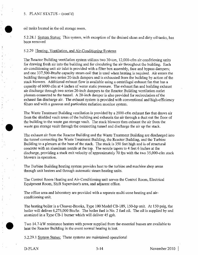
5. PLANT STATUS - (cont'd)
oil tanks located in the oil storage room.
5.2.28.1 System Status: This system, with exception of the drained clean and dirty oil tanks, hasbeen removed
5.2.29 Heating, Ventilation, and Air-Conditioning Systems
The Reactor Building ventilation system utilizes two 30-ton, 12,000-cfm air conditioning unitsfor drawing fresh air into the building and for circulating the air throughout the building. Eachair-conditioning unit air inlet is provided with a filter box assembly, face and bypass dampers;and one 337,500-Btu/hr capacity steam coil that is used when heating is required. Air enters thebuilding through two series 20-inch dampers and is exhausted from the building by action of thestack blowers. Additional exhaust flow is available using a centrifugal exhaust fan that has acapacity of 6000 cfm at 4 inches of water static pressure. The exhaust fan and building exhaustair discharge through two series 20-inch dampers to the Reactor Building ventilation outletplenum connected to the tunnel. A 20-inch damper is also provided for recirculation of theexhaust fan discharge air. The exhaust system is provided with conventional and high-efficiencyfilters and with a gaseous and particulate radiation monitor system.
The Waste Treatment Building ventilation is provided by a 2000-cfm exhaust fan that draws airfrom the shielded vault areas of the building and exhausts the air through a duct out the floor ofthe building to the waste gas storage vault. The stack blowers then exhaust the air from thewaste gas storage vault through the connecting tunnel and discharge the air up the stack.
The exhaust air from the Reactor Building and the Waste Treatment Building are discharged intothe tunnel connecting the Waste Treatment Building, the Reactor Building, and the TurbineBuilding to a plenum at the base of the stack. The stack is 350 feet high and is of structuralconcrete with an aluminum nozzle at the top. The nozzle tapers to 4 feet 6 inches at thedischarge, providing a stack exit velocity of approximately 70 fps with the two 35,000-cfm stackblowers in operation.
The Turbine Building heating system provides heat to the turbine and machine shop areasthrough unit heaters and through automatic steam heating units.
The Control Room Heating and Air-Conditioning unit serves the Control Room, ElectricalEquipment Room, Shift Supervisor's area, and adjacent office.
The office area and laboratory are provided with a separate multi-zone heating and air-conditioning unit.
The heating boiler is a Cleaver-Brooks, Type 100 Model CB- 189, 150-hp unit. At 150 psig, theboiler will deliver 6,275,000 Btu/hr. The boiler fuel is No. 2 fuel oil. The oil is supplied by andatomized in a Type CB- 1 burner which will deliver 45 gph.
Two 14.7-kW resistance heaters with power supplied from the essential busses are available toheat the Reactor Building in the event normal heating is lost.
5.2.29.1 System Status: These systems are maintained operational
D-PLAN 5-14 November 2010 1

5. PLANT STATUS - (cont'd)
5.2.30 Waste Collection Systems
The functions of the Waste Collection and Treatment System are:
" To collect and store radioactive liquid waste generated in the plant.
" To collect and transfer depleted ion exchange resins to a shipping container.
" To process the collected waste as required for safe and economical disposal.
The Turbine Building Liquid Waste system collects the liquid waste from the Turbine Building,the Waste Treatment Building, the waste gas storage vault, and the tunnel area in two storagetanks (4500 gallons and 3000 gallons) located in the tunnel between the Reactor Building and theTurbine Building.
The Reactor Building Liquid Waste system consists of two retention tanks, each with a capacityof 6000 gallons, a liquid waste transfer pump, two sump pumps, and the necessary piping toroute the waste liquid to the retention tanks and from the retention tanks out of the ReactorBuilding.
After a tank's contents are recirculated, a sample is withdrawn from the tank and analyzed forradioactivity concentrations prior to discharge. The total amount of liquid waste discharged tothe circulating water discharge line is measured with a flow totalizer water meter which canhandle flow rates up to 100 gpm and a flow rate monitor with Control Room readout.
Spent resin will be transferred to the spent resin receiving tank, where it will be held until thereis a sufficient quantity available for shipment to an approved processing facility. The resin willbe transferred to an approved shipping container where it will be dewatered and made ready forshipment.
5.2.30.1 System Status: The Waste Collection systems are maintained operational.
5.2.31 Fuel Transfer Bridge
The fuel transfer bridge is a specially-designed structure which is power-driven north and southon rails recessed in the floor at elevation 701' of the Reactor Building.
The bridge traverses over the areas where service operations are performed at the reactor cavity,transfer canal, spent fuel storage pool and the new fuel storage racks. The bridge serves as thestructural support for the fuel transfer hoist, and it provides an operating platform for personnel.
5.2.31.1 System Status: The fuel transfer bridge is kept operational and is tested routinely. Thefuel transfer bridge will be used to transfer individual spent fuel assemblies from the FuelElement Storage Well to the dry cask storage container. After the transfer of all spent fuel to drystorage at the onsite ISFSI, the fuel transfer bridge will no longer be required.
D-PLAN 5-15 November 2010 1

5. PLANT STATUS - (cont'd)
5.2.32 Communications Systems
The communications systems installed or otherwise available in the plant are:
1) Central office trunk line telephone service for off-plant local and long distance calls.
2) PABX (Private Automatic Branch Exchange) for interplant and intraplant calls and foroff-plant calls to or from the site.
3) Paging system for in-plant and site calls.
4) DPC ultra high-frequency radio network, for voice communications within DPC systemsand headquarters, including mobile units.
5) Microwave system for calls between LACBWR, Genoa Unit 3, La Crosse, and Alma, andfor calls to local numbers in La Crosse.
6) Portable transceivers (handie-talkie) for mobile interplant and site voice communication.
5.2.32.1 System Status: The various communications systems are presently maintainedoperational.
5.2.33 Electrical Power Distribution
5.2.33.1 Normal AC Distribution
69-kV power is supplied to the reserve auxiliary transformer located in the LACBWRswitchyard through a three-phase air-disconnect switch and three 30-amp, 69-kV fuses. ReserveFeed Breakers 252R1A and 252R1B supply the 2400-V Bus IA and Bus lB from the 69/2.4-kVreserve auxiliary transformer.
The 2400/480-V Auxiliary Transformers IA and lB receive their power from the 2400-V Buses1A and lB through breaker 252AT1A from Bus lA to Transformer I A, and through breaker252AT1B from Bus 1B to Transformer lB. The auxiliary transformers supply the 480-V Buses1A and lB through Main Feed Breakers 452M1A for Bus 1A and 452M1B for Bus lB.
The 480-V buses supply larger equipment directly. They also supply motor control centers(MCCs) which furnish power to motors and other associated equipment connected to themthrough their respective breakers, including the MCC 120-V AC Distribution Panels whichsupply equipment and instrumentation. The regular lighting cabinets are supplied from 480-VBuses lA and 1B.
5.2.33.2 480-V Essential Buses IA and 1B
The 480-V Essential Bus 1A switchgear is normally supplied with electrical power from the480-V Bus 1A through breaker 452-52A. In the event of a loss of station power, the 480-VEssential Bus IA is supplied with electrical power from Emergency Diesel Generator IAthrough breaker 452 EGA. Breakers 452-52A and 452 EGA are electrically interlocked to
D-PLAN 5-16 November 2010 1
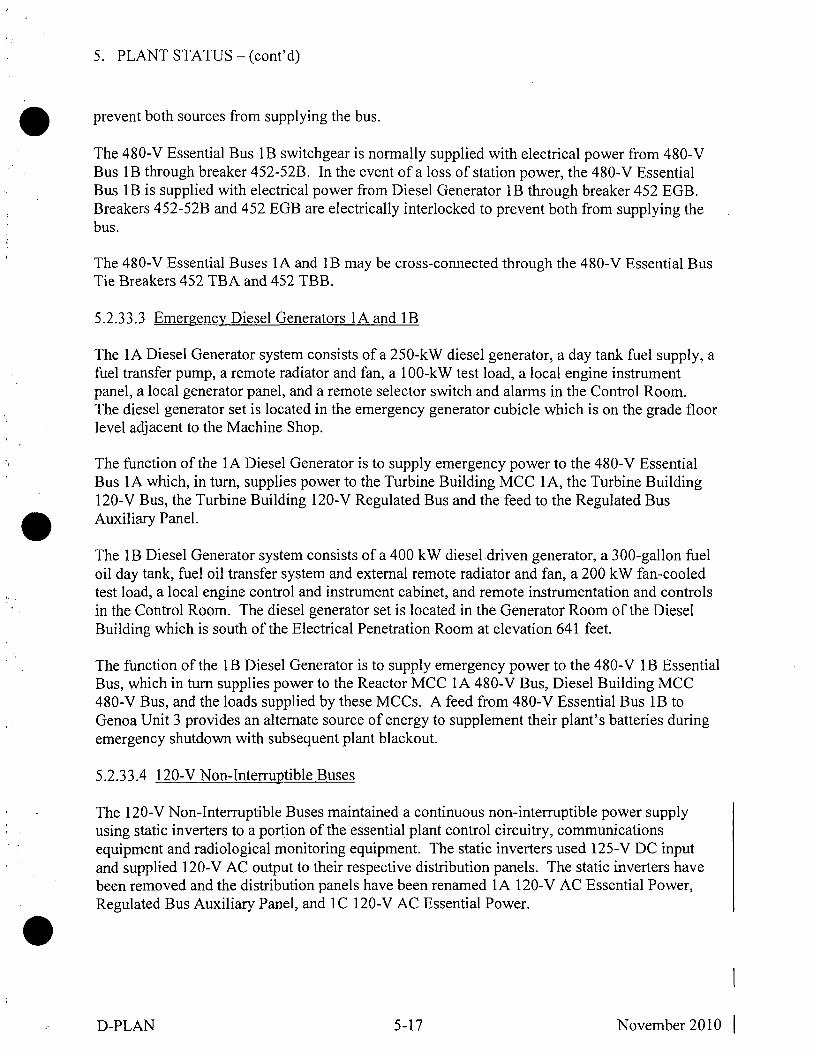
5. PLANT STATUS - (cont'd)
prevent both sources from supplying the bus.
The 480-V Essential Bus lB switchgear is normally supplied with electrical power from 480-VBus lB through breaker 452-52B. In the event of a loss of station power, the 480-V EssentialBus lB is supplied with electrical power from Diesel Generator lB through breaker 452 EGB.Breakers 452-52B and 452 EGB are electrically interlocked to prevent both from supplying thebus.
The 480-V Essential Buses 1A and lB may be cross-connected through the 480-V Essential BusTie Breakers 452 TBA and 452 TBB.
5.2.3 3.3 Emergency Diesel Generators lA and lB
The 1A Diesel Generator system consists of a 250-kW diesel generator, a day tank fuel supply, afuel transfer pump, a remote radiator and fan, a 100-kW test load, a local engine instrumentpanel, a local generator panel, and a remote selector switch and alarms in the Control Room.The diesel generator set is located in the emergency generator cubicle which is on the grade floorlevel adjacent to the Machine Shop.
The function of the 1A Diesel Generator is to supply emergency power to the 480-V EssentialBus 1 A which, in turn, supplies power to the Turbine Building MCC 1 A, the Turbine Building120-V Bus, the Turbine Building 120-V Regulated Bus and the feed to the Regulated BusAuxiliary Panel.
The 1 B Diesel Generator system consists of a 400 kW diesel driven generator, a 300-gallon fueloil day tank, fuel oil transfer system and external remote radiator and fan, a 200 kW fan-cooledtest load, a local engine control and instrument cabinet, and remote instrumentation and controlsin the Control Room. The diesel generator set is located in the Generator Room of the DieselBuilding which is south of the Electrical Penetration Room at elevation 641 feet.
The function of the lB Diesel Generator is to supply emergency power to the 480-V 1 B EssentialBus, which in turn supplies power to the Reactor MCC lA 480-V Bus, Diesel Building MCC480-V Bus, and the loads supplied by these MCCs. A feed from 480-V Essential Bus 1B toGenoa Unit 3 provides an alternate source of energy to supplement their plant's batteries duringemergency shutdown with subsequent plant blackout.
5.2.33.4 120-V Non-Interruptible Buses
The 120-V Non-Interruptible Buses maintained a continuous non-interruptible power supplyusing static inverters to a portion of the essential plant control circuitry, communicationsequipment and radiological monitoring equipment. The static inverters used 125-V DC inputand supplied 120-V AC output to their respective distribution panels. The static inverters havebeen removed and the distribution panels have been renamed 1 A 120-V AC Essential Power,Regulated Bus Auxiliary Panel, and 1 C 120-V AC Essential Power.
D-PLAN 5-17 November 2010 I

5. PLANT STATUS - (cont'd)
5.2.33.5 125-V DC Distribution
The 125-V DC distribution systems supply DC power to all equipment requiring it. The 125-VDC distribution systems were divided into three separate and independent systems each with itsown battery, battery charger, and distribution buses. The buses could be cross-connected butwere normally isolated from each other. The Reactor Plant and Diesel Building batteries andchargers have been removed. A new smaller capacity battery charger has been installed in theDiesel Building to provide reliability to the system. The Diesel Building Battery Charger,Generator Plant Battery, and Generator Plant Battery Charger remain as sources of DC power tothe 125-V DC distribution system. The once three separate systems have been interconnected byusing installed bus tie breakers.
For the system, the Diesel Building Battery Charger provides the normal DC supply with theGenerator Plant Battery as the reserve supply. The battery floats on the line maintaining a fullcharge, and provides emergency DC power in the event of a loss of AC power to the batterycharger or failure of the charger. Due to age, the Generator Plant Battery Charger is maintainedavailable as a standby unit.
5.2.33.6 System Status: The Electrical Power Distribution system is maintained operational andrequired surveillance tests are performed on the Emergency Diesel Generators and 125-V DCbatteries. The Electrical Power Distribution system is configured to provide backup dieselgenerator power to the entire 480-V AC system. This configuration provides continuedoperation of normal lighting systems, air conditioning systems, and sanitary well water supplyfor habitability reasons and plumbing system use during loss of station power.
5.2.34 Post-Accident Sampling Systems
The Post-Accident Sampling Systems (PASS) are designed to permit the removal for analysis ofsmall samples of either Reactor Building atmosphere, reactor coolant, or stack gas when normalsample points are inaccessible following an accident. These samples will aid in determining theamount of fuel degradation and the amount of hydrogen buildup in the Reactor Building.Samples will be removed to the laboratory for analysis.
5.2.34.1 Reactor Building Atmosphere PASS Description
The Reactor Building Atmosphere PASS consists of a vacuum pump that takes suction from theReactor Building atmosphere at the 714' elevation. The sample is drawn through a bypass line orto a remote sample cylinder and discharged back to the Reactor Building at the 671' elevation.
5.2.34.2 Stack Gas PASS Description
The Stack Gas PASS makes use of the same equipment that provides the normal stack gassample flow. The vacuum pump for stack gas sampling draws the extra flow, above what thestack monitors draw, to make the total flow isokinetic to the stack discharge. This flow can bediverted through the post-accident sample canister by opening manual isolation valves. Thesample canister is connected to the system by two quick disconnects and, therefore, can be easilyremoved from the system and taken to the laboratory for analysis. The sample canister diversionvalve is controlled from the local control panel in the No. 3 Feedwater Heater area.
D-PLAN 5-18 November2010 I

5. PLANT STATUS - (cont'd)
5.2.34.3 Reactor Coolant PASS Description
The Reactor Coolant PASS took primary coolant from an incore flux monitoring flushingconnection, through 2 solenoid-operated isolation valves with a heat exchanger between them, toa motor-operated pressure reducing valve. Downstream of the pressure reducing valve, thecoolant sample could be diluted with demineralized water which then flowed through the samplecylinder or its bypass valve, through another solenoid isolation valve, and back to the ReactorBuilding basement or to the waste water tanks.
5.2.34.4 System Status: The Stack Gas PASS is maintained in continuous operation. TheReactor Coolant PASS has been removed. The Reactor Building Atmosphere PASS is retainedin place. After the transfer of all spent fuel to dry storage at the onsite ISFSI, the Post-AccidentSampling Systems will no longer be required.
5.2.3 5 Containment Integrity Systems
With the plant in the SAFSTOR condition, there is no longer a postulated accident that wouldresult in containment pressurization or that takes credit for containment integrity.
5.2.35.1 System Status: Containment integrity systems are not required to be operable.
5.3 RADIONUCLIDE INVENTORY ESTIMATES
Testing was conducted in-house, using Health Physics personnel, to determine the location andthe quantities of the radionuclides present at LACBWR. Several different types of samples andsampling techniques were used to qualify/quantify the radionuclide inventory. Each method isdescribed in the initial site characterization survey for SAFSTOR. All samples were gammascanned using HPGe detectors coupled to a gamma spectroscopy computer system. Thisequipment has been calibrated to NBS traceable sources and is checked periodically to maintainthis calibration.
5.4 RADIATION LEVELS
5.4.34 Plant Radiation Levels
Upon entering the initial phase of LACBWR's SAFSTOR mode, base line gamma radiationsurveys were performed throughout the plant. General area radiation levels are listed below.These levels will be routinely monitored and tracked. Specific area hot spots will also be lookedfor and recorded on each area survey.
Area General Area Gamma Radiation Levels
Reactor Building:Shutdown Condenser Platform 10-20 mRem/hr701' Level 6-12 mRem/hrMezzanine Level East 5-10 mRem/hrMezzanine Level West 20-30 mRem/hrWest Nuclear Instrument Platform 40-90 mRem/hr
D-PLAN 5-19 November 2010 1

5. PLANT STATUS - (cont'd)
East Nuclear Instrument PlatformPurification Cooler PlatformGrade Floor North and EastGrade Floor WestUpper Control Rod Drive AreaBasementPrimary Purification DemineralizerRetention Tank AreaLower Control Rod Drive AreaForced Circulation Pump Cubicles
Turbine Building:Main FloorMezzanineStop Valve AreaGrade FloorFeedwater Heater AreaTunnelMachine ShoplB Diesel RoomElectrical Penetration Room
Waste Treatment Building:Main FloorBasement
10-20 mRem/hr5-10 mRem/hr7-20 mRem/hr
75-120 mRem/hr60-120 mRem/hr
10-40 mRem/hr7-17 mRem/hr
250-400 mRem/hr60-150 mRem/hr
150-400 mRem/hr
<1-3 mRem/hr<1-4 mRem/hr
10-85 mRem/hr1- 10 mRem/hr5-20 mRem/hr
10-50 mRemihr<1 mRem/hr<1 mRem/hr
2-7 mRem/hr
1-20 mRem/hr10-100 mRem/hr
Building Exteriors:Exterior of Waste Treatment Building
Exterior of Reactor Building
5.4.35 System Radiation Levels
<1 except for south side where thereis one spot between 3-4 mRem/hr
<1 except for one spot on south sidereading 7 mRem/ hr
During SAFSTOR the major radioactively contaminated systems at LACBWR will be monitoredin order to trend system cleanups and radioactivity decay. A program consisting of 100 surveypoints located throughout the plant has been iestablished. Initial system contact readings havebeen taken and will be monitored on a frequency determined to adequately trend any radiationlevel changes. The individual survey locations may change during the SAFSTOR period as plantparameters change.
The following is a list of the initial survey points, their initial dose rates, and the current surveypoint dose rates.
Note: All readings are contact dose rates.
D-PLAN 5-20 November 2010 1

5. PLANT STATUS - (cont'd)
SurveyPoint #
123456789
1011121314151617181920212223242526272829303132333435363738
Survey Point Location
Condensate Line to and from OHSTCondensate Line to and from OHSTCondensate Line to and from OHST1 A Condensate Pump Discharge LineEmergency Overflow LineEmergency Overflow Bypass LineIce Melt LineIA Reactor Feed PumpNear 1 B Reactor Feed Pump Discharge ValveSide of #3 Feedwater HeaterReheater Level Control ChamberSouth End of ReheaterGland Exhaust Condenser Loop SealMain Steam LineMain Steam LineOffgas System Flame Arrestor1 B Waste Water Pump1 A Waste Water PumpEnd of 3000 Gallon Waste TankEnd of 4500 Gallon Waste TankSide of Gland Seal Steam GeneratorSide of Gland Seal Steam GeneratorMain Steam Bypass LineTurbine Inlet Valve BodyMain Steam LineReheat to Flash Tank LineFlash TankSeal Injection Heater#2 Feedwater Heater Bypass LineFeedwater Heater Bypass LineBottom of Gland Exhaust CondenserTop of Gland Exhaust CondenserCondensate into Air Ejector LineAir EjectorLow Pressure Turbine Manhole CoverEnd of High Pressure TurbinePrimary Purification IA Filter Inlet LinePrimary Purification Pump
InitialDose Rate(mRem/hr)
252433122733316112626133548508
2660170120
1100160172324115
3110024170207862
38140
CurrentDose Rate(mRem/hr)
<1
4
<1
26
1110
<1
1
7
* Survey Point removed due to dismantlement activities.
D-PLAN 5-21 November 2010 1

5. PLANT STATUS - (cont'd)
SurveyPoint #
39404142434445464748
4950515253545556575859
60616263646566676869707172737475
Survey Point LocationExhaust Ventilation DuctReactor Bldg. Grade Level N Shield Wall1A Fuel Element Storage Well Pump1B Fuel Element Storage Well PumpFESW Filter Discharge LineFESW System CoolerHydraulic Valve Actuation System HeaderBase of Hydraulic Valve AccumulatorWall at Electrical PenetrationHandrail on NW Nuclear Instrumentation (NI)PlatformShield Wall on N NI PlatformPrimary Purification to OHST LineAbove Primary Purification Cooler Inlet ValveCold Leg of Reactor High Level Transmitter LineSeal Injection ReservoirReactor Cavity Drain LinelA Core Spray Pump Discharge LineReactor Water Level Sightglass LineReactor Water Level Sightglass LineReactor Bldg. Mezzanine Level N Shield WallSteam Trap Reactor Bldg. Mezzanine Level NWWallFuel Element Storage Well LineFuel Element Storage Well LineFuel Element Storage Well LineFuel Element Storage Well Skimmer LineWall near Fuel Transfer Canal DrainRelief Valve Platform at Level TransmitterShutdown CondenserShutdown Condenser Condensate Linel B Retention Tank1 A Retention TankBy Primary Purification Cation TankDecay Heat CoolerDecay Heat CoolerDecay Heat Cooler Bypass ValveDecay Heat Pump Suction LineHandrail at Shutdown Condenser Condensate Valves
InitialDose Rate(mRem/hr)
96
7080180
1000602430100
46
2546304410
1801004
23
40042060903580116
300130242518703228
CurrentDose Rate(mRem/hr)
<1<1
9102414011328
<1<15
74
5
22101435
24413310184
* Survey Point removed due to dismantlement activities.
D-PLAN 5-22 November 2010
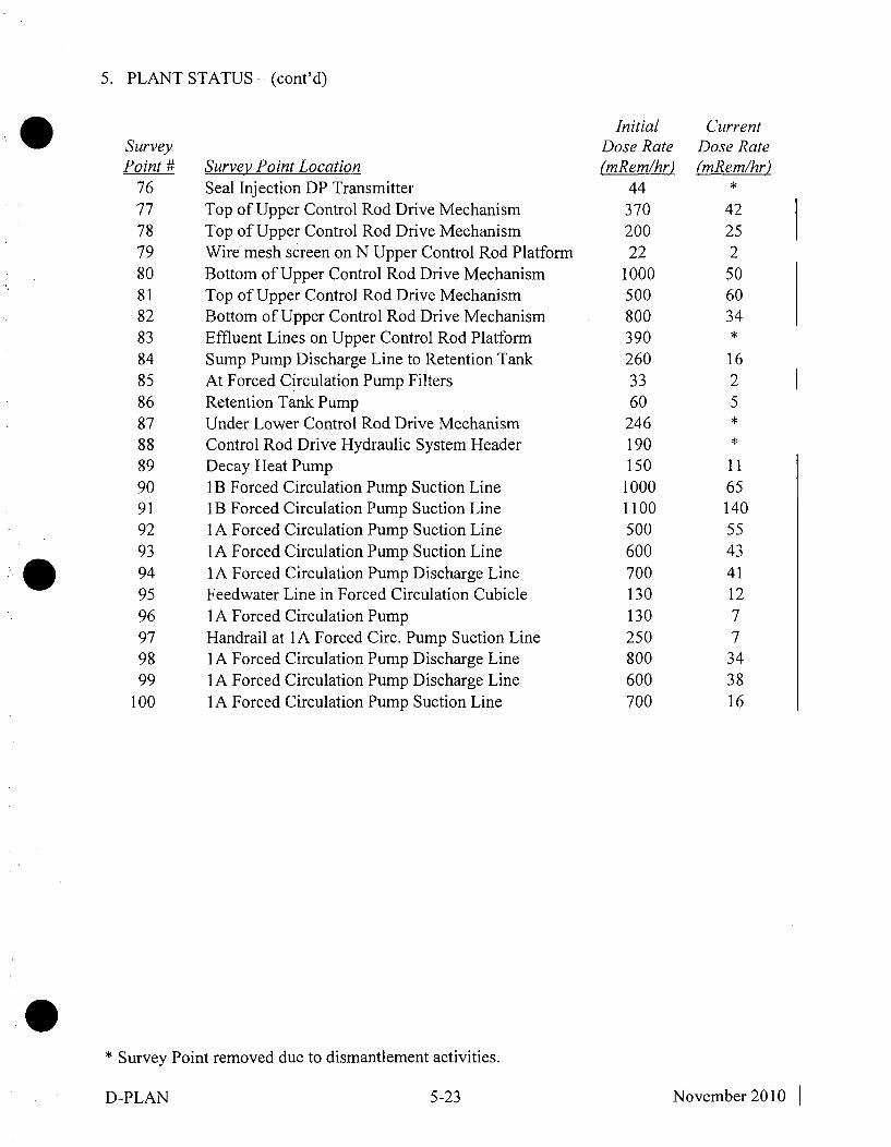
5. PLANT STATUS - (cont'd)
SurveyPoint H
767778798081828384858687888990919293949596979899
100
Survey Point LocationSeal Injection DP TransmitterTop of Upper Control Rod Drive MechanismTop of Upper Control Rod Drive MechanismWire mesh screen on N Upper Control Rod PlatformBottom of Upper Control Rod Drive MechanismTop of Upper Control Rod Drive MechanismBottom of Upper Control Rod Drive MechanismEffluent Lines on Upper Control Rod PlatformSump Pump Discharge Line to Retention TankAt Forced Circulation Pump FiltersRetention Tank PumpUnder Lower Control Rod Drive MechanismControl Rod Drive Hydraulic System HeaderDecay Heat Pump1 B Forced Circulation Pump Suction Line11B Forced Circulation Pump Suction Line1 A Forced Circulation Pump Suction Line1A Forced Circulation Pump Suction Line1 A Forced Circulation Pump Discharge LineFeedwater Line in Forced Circulation Cubicle1 A Forced Circulation PumpHandrail at 1A Forced Circ. Pump Suction Line1 A Forced Circulation Pump Discharge Line1 A Forced Circulation Pump Discharge Line1 A Forced Circulation Pump Suction Line
InitialDose Rate(mRem/hr)
4437020022
10005008003902603360
246190150
10001100500600700130130250800600700
CurrentDose Rate(mRem/hr)
42252506034
1625
11
651405543411277
343816
* Survey Point removed due to dismantlement activities.
D-PLAN 5-23 November2010 I

5. PLANT STATUS - (cont'd)
5.5 PLANT PERSONNEL DOSE ESTIMATE
During normal/routine SAFSTOR operations at LACBWR, average whole body radiation dosereceived by plant personnel should be no more than 0.600 Rem per individual per year. Thisaverage dose is expected to decrease during the SAFSTOR period due to isotopic decay.Individual doses will be dependent upon work being performed. Plant personnel will not beallowed to exceed 5.0 Rem/year.
5.6 SOURCES
As authorized by the facility license, sealed sources for radiation monitoring equipmentcalibration will continue to be possessed and used. Additionally, sources will be used asauthorized without restriction to chemical or physical form for sample analysis, instrumentcalibration and as associated with radioactive apparatus and components.
5.7 RADIATION MONITORING INSTRUMENTATION
Radiation monitoring instrumentation for the LACBWR consists of fixed plant surveillanceequipment, portable survey meters, laboratory-type counting instrumentation, and personnelmonitoring equipment.
The Radiation Monitoring system performs the following functions:
" Provides a permanent record of radioactivity levels of plant effluents.
" Provides alarms and automatic valve closure to prevent excessive radioactive releases toenvironment.
" Provides warning of leakage of radioactive gas, liquid, or particulate matter within theplant.
" Provides continuous radiation surveillance in normally accessible plant areas.
" Provides portable instrumentation for use in conducting radiation surveys.
" Provides instrumentation for personnel and material contamination surveillance, includingthat necessary for control of egress from restricted areas.
" Provides pocket dosimeters and necessary charging and readout equipment for personnelradiation exposure control and estimates.
5.7.1 Fixed Plant Monitors
The plant fixed surveillance monitoring equipment consists of liquid monitors, air monitors, andarea monitors.
5.7.1.1 Liquid Monitors. The liquid monitors consist of a modular nim bin electronic system inthe Control Room coupled to a Nal scintillation detector. The Nal scintillation detector is
D-PLAN 5-24 November 2010 1

5. PLANT STATUS - (cont'd)
coupled to a photomultiplier tube base-preamplifier.
5.7.1.2 Reactor Building Air Exhaust Gaseous and Particulate Monitor. A monitor is located onthe Reactor Building mezzanine level. This monitor has a fixed filter particulate detector and agaseous detector. It takes suction from the outlet of the Reactor Building ventilation filters.
5.7.1.3 Stack Monitor. A monitor is installed to sample the stack emissions. This monitor drawsair from the stack through an isokinetic nozzle. This monitor detects particulate and gaseousactivity released to the stack. This monitor alarms locally and in the control room.
5.7.1.4 Fixed Location Monitors. Area radiation monitors are used to detect and measure gammaradiation fields at various remote locations. There are fifteen remote units located throughout theplant. The measured dose rate is displayed on meters located in the Control Room.
5.7.2 Portable Monitors
Portable instruments are located throughout the plant. Instruments are available to detect variouslevels of beta, gamma, and alpha radiation.
5.7.3 Laboratory-Type Monitors
Laboratory instruments are available to determine contamination levels and radioisotopeconcentrations. These instruments consist of internal proportional counters, gamma analyzers,and liquid scintillation counters.
D-PLAN 5-25 November2010

6. DECOMMISSIONING PROGRAM
6.1 OBJECTIVES
The primary objective of the Decommissioning Program at LACBWR will be to safely monitorthe facility and prevent any unplanned release of radioactivity to the environment. Some of thegoals during the SAFSTOR period are as follows:
" To safely store spent fuel while minimizing risk to the public health and safety.
" To maintain a radiation protection program that ensures SAFSTOR activities haveminimal effect on the environment, the general public, and site personnel.
" To maintain systems required during SAFSTOR period.
" To handle radioactive waste generated during the SAFSTOR period in accordance withplant procedures and applicable requirements.
" To limit plant personnel radiation exposure to levels as low as reasonably achievable(ALARA).
" To dismantle unused systems with assurance that no unacceptable environmental impactsor other adverse effects are created from these activities.
" To maintain qualified and trained staff.
6.2 ORGANIZATION AND RESPONSIBILITIES
The organization of the SAFSTOR staff at LACBWR is as indicated in Figure 6.1. The staffmay change as activities being performed vary and staffing needs change. The organization isdirected by a Plant Manager, who reports directly to the Dairyland Power Cooperative VicePresident, Generation. The individuals who report directly to the Plant Manager each havedistinct functions in ensuring the safety of the facility during the SAFSTOR mode.
The Plant Manager is responsible for the safety of the facility and ISFSI, their daily operationand surveillance, long range planning, and licensing. Quality assurance activities and securitycontrol and support are provided by a Cooperative-wide quality assurance and security programs.The Plant Manager is responsible for operation of any onsite security required as well asensuring compliance with the Quality Assurance Program Description (QAPD). The PlantManager is responsible to ensure that adequate staff is present to comply with the terms of thelicense, training commitments and responsibilities are met, and that the personnel reporting arefit for duty.
The Operations, Training/Relief Supervisor is responsible for the day to day activities of theShift Supervisors and Operators. This supervisor is responsible for the coordination of allTechnical Specification required tests. This supervisor is responsible for proper implementationof the LACBWR Training Program.
D-PLAN 6-1 November2010 I
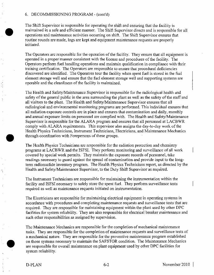
6. DECOMMISSIONING PROGRAM - (cont'd)
The Shift Supervisor is responsible for operating the shift and ensuring that the facility ismaintained in a safe and efficient manner. The Shift Supervisor directs and is responsible for alloperations and maintenance activities occurring on shift. The Shift Supervisor ensures thatroutine rounds are made, logs are kept and equipment maintenance requests are properlyinitiated.
The Operators are responsible for the operation of the facility. They ensure that all equipment isoperated in a proper manner consistent with the license and procedures of the facility. TheOperators perform fuel handling operations and maintain qualification in compliance with theirtraining certification. The Operators are responsible to ensure that procedural deficienciesdiscovered are identified. The Operators tour the facility when spent fuel is stored in the fuelelement storage well and ensure that the fuel element storage well and supporting systems areoperable and the cleanliness of the facility is maintained.
The Health and Safety/Maintenance Supervisor is responsible for the radiological health andsafety of the general public in the area surrounding the plant as well as the safety of the staff andall visitors to the plant. The Health and Safety/Maintenance Supervisor ensures that allradiological and environmental monitoring programs are performed. This individual ensures thatall radiation exposure controls are in place and ensures that contamination and daily, monthlyand annual exposure limits on personnel are complied with. The Health and Safety/MaintenanceSupervisor is responsible for the ALARA program and ensures that all personnel at LACBWRcomply with ALARA requirements. This supervisor also assigns the day-to-day work of theHealth Physics Technicians, Instrument Technicians, Electricians, and Maintenance Mechanicsthrough coordination with Forepersons of these groups.
The Health Physics Technicians are responsible for the radiation protection and chemistryprograms at LACBWR and the ISFSI. They perform monitoring and surveillance of all workcovered by special work permits. They maintain the exposure records of personnel, takereadings necessary to guard against the spread of contamination and provide input to the long-term radionuclide inventory program. The Health Physics Technicians report, as directed by theHealth and Safety/Maintenance Supervisor, to the Duty Shift Supervisor as required.
The Instrument Technicians are responsible for maintaining the instrumentation within thefacility and ISFSI necessary to safely store the spent fuel. They perform surveillance testsrequired as well as maintenance requests initiated on instrumentation.
The Electricians are responsible for maintaining electrical equipment in operating systems inaccordance with procedures and completing maintenance requests and surveillance tests that arerequired. They are responsible for maintaining equipment within the plant used by other DPCfacilities for system reliability. They are also responsible for electrical breaker maintenance andsuch other responsibilities as assigned by supervision.
The Maintenance Mechanics are responsible for the completion of mechanical maintenancetasks. They are responsible for the completion of maintenance requests and surveillance tests ofa mechanical nature. They are responsible for the preventive maintenance program establishedon those systems necessary to maintain the SAFSTOR condition. The Maintenance Mechanicsare responsible for overall maintenance on plant equipment used by other DPC facilities forsystem reliability.
D-PLAN 6-2 November2010 I

6. DECOMMISSIONING PROGRAM - (cont'd)
The Administrative Assistant is responsible for overall administration of LACBWR. TheAdministrative Assistant processes and maintains file records of all LACBWR programs,procedures, document changes, budget information, written communications, and numerousother records related to SAFSTOR activities. The Administrative Assistant ensures that clericalfunctions are performed adequately. This person maintains all budget expense and projectaccounts and coordinates preparation of the LACBWR budget. Duties include assigning to staffpersonnel required responses to regulatory agencies, other Dairyland departments, etc., andensuring that these tasks are completed by the established deadline.
Additional administrative personnel are made available to the Administrative Assistant asneeded, and assist in the clerical tasks at LACBWR. Such additional personnel are qualified toperform required communication functions and are assigned other tasks, as necessary, by theAdministrative Assistant.
The Licensing Engineer is responsible for facility licensing during the SAFSTOR condition,during preparations for dry cask storage, and eventual license termination activities. TheLicensing Engineer is the principal liaison on behalf of the Plant Manager for contact with theNuclear Regulatory Commission and other regulatory agencies.
The Radiation Protection Engineer is responsible for radiation protection, projections andtrending. This engineer is responsible for working with the Health and Safety/MaintenanceSupervisor in ensuring that an aggressive ALARA program is carried out and that contaminationand background radiation exposure are reduced as low as reasonably achievable during theSAFSTOR period.
The Reactor Engineer performs administrative functions in support of SAFSTOR operations andassists with plans for dry cask storage. The Reactor Engineer monitors stored fuel conditionsand provides nuclear safety oversight. This engineer monitors the condition of structures,systems and components important to safety. Presently, the Reactor Engineer is assignedresponsibilities of the LACBWR Accountability Representative as discussed in Section 6.8.
The Safety Review Committee (SRC) is the offsite review group responsible for oversight offacility activities. A quorum of four persons, including the chairman, is required. No more thana minority of the quorum shall have line responsibility for operation of the facility. The SRCshall meet at least once per year.
The Operations Review Committee (ORC) is the onsite review committee and is responsible forthe review of day-to-day operations. A quorum of at least four individuals drawn from themanagement staff at the site, including the Plant Manager or designated alternate as chairman, isrequired. The ORC shall meet at least once per calendar quarter. The SRC and the ORC reviewmaterial as required by the QAPD.
6.3 CONTRACTOR USE
The use of contractors at LACBWR will continue as required throughout the SAFSTOR andDECON periods. The use of contractors will complement areas where DPC expertise or staffingis inadequate to perform specific tasks. Contractor employment during the SAFSTOR and
D-PLAN 6-3 November 2010 1

6. DECOMMISSIONING PROGRAM - (cont'd)
DECON periods will continue to be governed by the requirements of the QAPD. Contractorswill be selected in each case on a basis of ability, price, past performance, and regulatoryrequirements.
DPC will retain full responsibility for the performance of contractor tasks and will provide thesupervision necessary to ensure that the tasks performed by contractors are in full compliancewith the QAPD, the purchase agreement, and other appropriate regulations.
6.4 TRAINING PROGRAM
6.4.1 Training Program Description
6.4.1.1 LACBWR has established General Employee Training (GET) requirements for allpersonnel who may be assigned to perform work at LACBWR.
6.4.1.2 In addition to GET, programs have been designed to initially qualify personnel, andmaintain their proficiency, in the following areas:
1) Health Physics Technician (HPT)2) Operator3) Certified Fuel Handler (CFH)
These programs and requirements will change when all spent fuel is at the ISFSI. CFH trainingand proficiency will no longer be required. Training in ISFSI administration, security,monitoring, and maintenance will be fully implemented.
6.4.1.3 Special infrequently performed evolutions relating to decommissioning activities maybe included for training as they approach. These evolutions may typically be:
1) Cask Handling2) Systems Internals and Equipment Decontamination and Dismantling3) Special Tests4) Any other evolution determined by plant management to require special training.
6.4.2 General Employee Training (GET)
6.4.2.1 All personnel, either assigned to LACBWR or who may be assigned duties atLACBWR will receive GET commensurate with their assignment. This training will include, asappropriate:
1) Emergency Plan Training2) Security Plan Training3) Radiation Protection Training4) Quality Assurance Training5) Respiratory Protection Training6) Industrial Safety, First Aid, and Fire Protection
D-PLAN 6-4 November2010 I

6. DECOMMISSIONING PROGRAM - (cont'd)
6.4.3 Technical Training
The following areas consist of a formal initial training program, followed by a recurringcontinuing training program.
6.4.3.1 The Health Physics Technician (HPT) Initial Training Program consists of thefollowing topics:
1) Science Traininga) Nuclear Theoryb) Chemistry
i) Non-radiologicalii) Radiochemistry
c) Radiological Protection and Control (including surveys)
2) Systems Traininga) Effluent Systems Sampling and Control
3) Emergency Plan Traininga) Onsite Survey Team Memberb) Nearsite Survey Team Memberc) Duty HPd) Re-entry Team Memberse) PASS Samplingf) Medical Emergency
4) Environmental Program
5) Waste Disposal
6) Personnel Monitoring, including Internal Deposition Counting
7) Respiratory Protection Program
8) Radiation Monitoring and Instrumentation
9) Administrative Requirements
10) First Aid Training
6.4.3.2 The Health Physics Technician (HPT) Continuing Training Program consists of thefollowing:
1) The program will be of 12-month duration, and will be repeated each 12 months.
2) Health and Safety management will review significant industry events and distribute,as required reading to all technicians, those events determined to be applicable toLACBWR HPT's.
D-PLAN 6-5 November 2010 1

6. DECOMMISSIONING PROGRAM - (cont'd)
3) Health and Safety management will review LACBWR events and distribute, asrequired reading to all technicians, those events determined to be relevant andsignificant.
4) Emergency Plan Training commensurate with duties.
5) Procedure changes will be reviewed by Health and Safety management and thosedetermined to be relevant to the performance of a technician's duties will bedistributed as required reading.
6) The Health and Safety/Maintenance Supervisor may initiate additional training for thetechnicians at any time. This training could be for, but not limited to, any of thefollowing:a) Equipment upgrade/replacement.b) Infrequent and/or important tasks.c) Significant procedure or department policy changes.d) Significant performance problems.
7) The Health and Safety/Maintenance Supervisor will ensure all JourneymanTechnicians successfully complete the HP continuing training. Records ofsatisfactory completion will be maintained by Health and Safety management. Thecontinuing training will cover the following topics.a) Intra-laboratory comparisons in radio-chemistry (crosscheck analysis).b) Emergency Plan training.
8) A meeting will be conducted, at least semiannually, by the Health andSafety/Maintenance Supervisor for all technicians for the purpose of discussing anypertinent information on the following topics:a) Significant Plant/Industry events.b) Equipment Changes.c) Management/Technician Concerns.d) Performance Problems.e) Minutes of these meetings will be taken.
6.4.3.3 Operator Training Program
1) Operators assigned to LACBWR will be qualified to perform the duties of AuxiliaryOperator (AO) and Control Room Operator (CRO).
2) The Operator Initial Training Program consists of the following:
a) Part I - The initial GET and Indoctrination is presented to give the new employeebackground information concerning the LACBWR organization, radiation safety,payroll practices, and general plant description and administration.
b) Part II - The second part of the training program, "Initial Plant QualificationProgram," provides a comprehensive outline of material considered necessary for
D-PLAN 6-6 November 2010 1

6. DECOMMISSIONING PROGRAM - (cont'd)
the training of individuals to qualify them for all operator duties. Periodic writtenand/or oral examinations, plus actual demonstrations of proficiency in practicalfactors, will be required of the trainees to determine their progress in the program.
c) Operator Sciences Trainingi) Nuclear Theoryii) Radiological Protection and Controliii) Electrical Theory, as applied to operatorsiv) Chemistry
d) Operator Systems Trainingi) Plant Specific Systemsii) Design Basesiii) Flow Pathsiv) Componentsv) Instrumentation and Controlvi) Operational Aspects
e) Control Room Training by familiarization and manipulation under the supervisionof a qualified CRO, consisting of training and exercises which apply the operatingphilosophy, procedures, and attitudes needed as an operator at LACBWR. TheControl Room Training will be documented in the operator Practical FactorsRecord. Topics include:i) Normal operationsii) Malfunctionsiii) Surveillancesiv) Proceduresv) Technical Specificationsvi) Emergency response actions
f) Emergency Trainingi) Emergency Plan and EPP'sii) Plant Emergency Proceduresiii) Review of Incident Reports and LER's.
g) In addition, operator trainees will take part in the LACBWR Continuing TrainingProgram when assigned to an operating crew. This program is intended as areview for personnel and as such is not intended to serve as the sole means oftraining for operator trainees. All quiz and examination scores attained bytrainees in the requalification program will be used to aid the trainee and not todetermine his status in the program. No lecture attendance or retrainingrequirements are to be based on test results.
h) The candidate will normally get the necessary signatures for the AuxiliaryOperator Watch Card, then Control Room Operator Watch Card and, whilestanding these watches, work to complete each Progress Card. As the ProgressCards are completed, the training personnel shall prepare and administer a writtenexam. The trainee must receive a score of > 80% to pass exam.
D-PLAN 6-7 November2010 I

6. DECOMMISSIONING PROGRAM - (cont'd)
6.4.3.4 Certified Fuel Handler Training Program. A training and certification program hasbeen implemented to maintain a staff properly trained and qualified to maintain the spent fuel, toperform any fuel movements that may be required, and to maintain LACBWR in accordancewith the possession-only license while spent fuel is stored in the Fuel Element Storage Well.This program provides the training, proficiency testing, and certification of fuel handlingpersonnel. A detailed description of the Certified Fuel Handler Program is provided in Section10.
6.4.4 Other Decommissioning Training
It is anticipated that other technical topics will be presented to personnel on an as-needed basis.Current administrative guidelines will be followed to establish new procedures and to ensure thetraining is completed.
6.4.5 Training Program Administration and Records
The LACBWR Plant Manager is responsible for ensuring that the training requirements andprograms are satisfactorily completed for site personnel. The Operations, Training/ReliefSupervisor is responsible for the organization and coordination of training programs, forensuring that records are maintained and kept up-to-date, and assisting in training materialpreparation and classroom instruction.
6.5 QUALITY ASSURANCE
Decommissioning and SAFSTOR activities will be performed in accordance with the NRC-approved Quality Assurance Program Description (QAPD) for LACBWR. The QAPD has beendeveloped to assure safe and reliable operation of LACBWR in a SAFSTOR condition andtransition to an Independent Spent Fuel Storage Installation. The program is designed to meetthe requirements of 10 CFR 50, Appendix B as applicable to the possession-only licensecondition and 10 CFR 72, Subpart G as applicable to the onsite dry cask storage of spent nuclearfuel.
The QAPD addresses all 18 criteria of 10 CFR 50, Appendix B, and 10 CFR 72, Subpart G, andapplies to all activities affecting the functions of the structures, systems, and components that areassociated with a possession-only license condition using a graded approach, and the Dry CaskStorage Project, respectively. These activities include design, installation, operations,maintenance, repair, fuel handling, testing, modifications, and radioactive waste shipments.Design and fabrication of storage and shipping casks for radioactive material are addressed bythe Dry Cask Storage System Certificate of Compliance holder's quality assurance program andwill not be conducted under the QAPD. Safety Related as defined in 10 CFR 50.2 is no longerapplicable in the possession-only license condition. A graded approach is used to implement theQAPD by establishing managerial and administrative controls commensurate with thecomplexity and regulatory requirements of the activities undertaken.
Scheduled activities during SAFSTOR shall be performed within schedule intervals. A scheduleinterval is a time frame within which each scheduled activity shall be performed, with amaximum allowable extension not to exceed 25 percent of the schedule interval.
D-PLAN 6-8 November 2010 1

6. DECOMMISSIONING PROGRAM - (cont'd)
For Important to Safety (ITS) activities, as defined in 10 CFR 72, Subpart G, a QualityAssurance Project Plan (QAPP) was established to define the quality assurance requirements tobe implemented during the Dry Cask Storage Project at the LACBWR site. The QAPP does notsupplant the QAPD which is used to assure safe and reliable operation of the LACBWR plant ina SAFSTOR condition. The QAPP utilizes the QAPD as the base document of the Dry CaskStorage Project's overall quality assurance program. The QAPP references and providesclarification to each applicable section of the QAPD that collectively meet the quality assurancerequirements of 10 CFR 50 Appendix B, 10 CFR 71 Subpart H, and 10 CFR 72 Subpart G.
The QAPP applies to all activities associated with the design, fabrication, installation, andpreparation for operation of an Independent Spent Fuel Storage Installation and any related plantmodifications and other site activities as designated by the Plant Manager. Design andfabrication of the Dry Cask Storage System (DCSS) will not be performed under the QAPP;however, selection, qualification, and performance-based overview of the selected DCSSdesigner and DCSS fabrication will be conducted in accordance with the QAPP.
6.6 SCHEDULE
The current schedule for decommissioning activities at LACBWR is depicted in Figure 6.2.Following final reactor shutdown in April 1987, the transition from operating plant topossession-only facility required numerous administrative changes. Staff level was reduced,license required plans were revised, and operating procedures were curtailed or simplified asconditions and NRC approval allowed. The LACBWR Decommissioning Plan was approved inAugust 1991, and the facility entered the SAFSTOR mode. License renewal granted at the sametime accommodated the proposed SAFSTOR period for a term to expire March 29, 2031. At thetime of the original Decommissioning Plan in 1987, DPC anticipated the plant would be inSAFSTOR for a 30-50 year period.
To make better use of resources during the SAFSTOR period, some incrementaldecontamination and dismantlement activities were desirable. By Confirmatory Order from theNRC in 1994, changes in the facility meeting 10 CFR 50.59 requirements were permitted andlimited gradual dismantlement progressed. As of November 2008, approximately 2 millionpounds of material related to the removal of unused components or whole systems, completed inover 100 specific approved changes to the facility, have been reprocessed or disposed of as dryactive waste. This total does not include reactor vessel and B/C waste disposal.
The 2-year Reactor Pressure Vessel Removal (RPV) Project was completed in June 2007 withdisposal of the intact RPV at the Barnwell Waste Management Facility (BWMF). Disposal ofthe RPV was completed at this time prior to the planned closing of BWMF to out-of-compactwaste in July 2008. RPV removal was not specifically addressed in the originaldecommissioning schedule. The removal of this large component, as defined in 10 CFR 50.2,was an activity requiring notice be made pursuant to 10 CFR 50.82, Termination of License,(a)(7). This notice was made by submittal to the NRC on August 18, 2005. Section 7.6describes the RPV Removal Project in greater detail.
The original schedule indicated that during the SAFSTOR period, DPC expected to ship theactivated fuel to a federal repository, interim storage facility, or licensed temporary monitored
D-PLAN 6-9 November 2010 1

6. DECOMMISSIONING PROGRAM - (cont'd)
retrievable storage facility. The timing of this action would be dependent on the availability ofthese facilities and their schedule for receiving activated fuel. In 2007, DPC began efforts toplace an Independent Spent Fuel Storage Installation (ISFSI) on site by commencing the DryCask Storage Project. An onsite ISFSI is the available option that provides flexibility for licensetermination of the LACBWR facility. With respect to the federal repository option, a marker fortransport of spent fuel offsite has also been added to Figure 6.2 as best available information canprovide.
As to another option, DPC is a part of the consortium of utilities that formed the Private FuelStorage (PFS) Limited Liability Company for the sole purpose of developing a temporary site forthe storage of spent nuclear fuel for the industry. The Nuclear Regulatory Commission issuedMaterials License No. SNM-2513 pursuant to 10 CFR 72, dated February 21, 2006, for the PFSFacility.
DPC Staff completed an extensive review and analysis of the comparative costs and benefits ofthe current decommissioning schedule and various accelerated schedules. From this analysis, theDPC Board of Directors approved accelerating the removal of radioactive metal from theLACBWR facility. By letter dated December 7, 2010, DPC gave notification to the NRC of achange in schedule that would accelerate the decommissioning of the LACBWR facility startingwith a 4-year period of systems removal beginning in.2012. This activity will include theremoval for shipment of large bore (16 and 20-inch) reactor coolant piping and pumps of theForced Circulation system and other equipment once connected to the reactor pressure vessel orprimary system such as Control Rod Drive Mechanisms, Decay Heat, Primary Purification, SealInjection, and Main Steam.
This phase of decommissioning activity does not result in significant environmental impacts andhas been reviewed as documented in the "Generic Environmental Impact Statement (GEIS) onDecommissioning of Nuclear Facilities," NUREG-0586, Supplement 1, November 2002. Asstated in the GEIS, licensees can rely on information in this Supplement as a basis for meetingthe requirements in 10 CFR 50.82(a)(6)(ii). The GEIS characterizes the environmental impactsresulting from this decommissioning activity as generic and small. Potential site-specificenvironmental impacts not determined in the GElS will be addressed in the License TerminationPlan (LTP) for LACBWR.
DPC's review and analysis found that the Nuclear Decommissioning Trust (NDT) wassufficiently funded to allow dismantlement to begin in 2012, immediately after spent fuelremoval is completed. Costs of the metal removal project will be funded from the NDT. DPC'sapproved strategy requires continuing evaluation of the costs of the decommissioning activity asit progresses. During this time the LTP will be formulated determining the disposition ofconcrete structures and site end use. The LTP will include an updated site-specific estimate ofremaining decommissioning costs. DPC's decommissioning strategy for LACBWR withaccelerated systems removal provides flexibility in that provisions are afforded to evaluate thecosts and benefits of alternative methodologies for concrete removal, and delay LTPimplementation if necessary to assure adequate NDT funds are available for the finaldecommissioning process. Figure 6.2 depicts the revised schedule.
D-PLAN 6-10 November 2010

6. DECOMMISSIONING PROGRAM - (cont'd)
6.7 SAFSTOR FUNDING AND DECOMMISSIONING COST FINANCING
6.7.1 SAFSTOR Funding
Pursuant to 10 CFR 50.54(bb), Dairyland Power Cooperative (DPC) has promulgated thefollowing SAFSTOR spent fuel management and funding plan for LACBWR. This plan appliesalso to ISFSI operations.
Independent of funding costs for SAFSTOR, DPC has established the Nuclear DecommissioningTrust (NDT) and reports annually to the Nuclear Regulatory Commission the status of NDTfunds. DPC understands that none of the funds in the NDT may be used for spent fuel removalor for developing an Independent Spent Fuel Storage Facility (ISFSI). DPC has no plans to useany of the NDT funds for an ISFSI or for spent fuel removal purposes.
DPC continues to fund the expense of SAFSTOR activities, including wet or dry fuel storagecosts, from the annual operating and maintenance budget. As part of generation expenses,SAFSTOR costs are recovered in rates that DPC charges distribution cooperative members underlong-term, all requirements wholesale power contracts. DPC's rates to member cooperatives areannually submitted to the United States Rural Utilities Service (RUS) as part of RUS oversightof DPC operations. DPC is required by RUS lending covenants and RUS regulations to set ratesat levels sufficient to recover costs and to meet certain financial performance covenants. DPChas always met those financial performance covenants and has satisfied the RUS regulationsconcerning submission and approval of its rates.
DPC's 25 member cooperatives set their own rates through participation in the DPC board ofdirectors. The operations and maintenance budget approved by the DPC Board, andincorporated into rates submitted to and approved by the RUS, will be funded and available topay SAFSTOR expenses as incurred.
DPC has found no need to separately fund SAFSTOR costs outside the regular operating andmaintenance budget. SAFSTOR costs are relatively small compared to DPC's annual O&Mcosts for generation and transmission facilities, and DPC has continued the long-standing policyof recovering SAFSTOR costs as part of regular rates. DPC has seen no need to change thefunding plan for SAFSTOR under those circumstances.
In August 2007, the DPC Board of Directors authorized to proceed with a dry cask storageproject, including the planning, engineering and licensing, and construction and operation of anonsite ISFSI for the LACBWR spent fuel. Funds for ISFSI construction and operation will begenerated through DPC operating and maintenance budgets. DPC does not intend to use anyfunds from the NDT for dry cask storage purposes.
DPC's annual budget for operating and maintenance activities at LACBWR accommodatesSAFSTOR activities and includes funds for performing limited dismantlement at the LACBWRfacility. Accomplishing limited dismantlement activities during SAFSTOR reduces the amountthat will ultimately be necessary for decommissioning LACBWR after removal of the fuel. Thisapproach takes advantage of the collective experience and familiarity of the LACBWR staff withthe plant, and builds further conservatism into the funding plan for ultimate decommissioning ofthe facility.
D-PLAN 6-11 November 2010

6. DECOMMISSIONING PROGRAM - (cont'd)
6.7.2 Decommissioning Cost Financing
In late 1983, the Dairyland Power Cooperative Board of Directors resolved to provide resourcesfor the final dismantlement of LACBWR. DPC began making deposits to a decommissioningfund in 1984. The Nuclear Decommissioning Trust (NDT) was established in July 1990 as anexternal fund outside DPC's administrative control holding fixed income and equity investments.The NDT, with requisite funding and accumulated earnings, was established to assure adequatefunds would be available for the final decommissioning cost of LACBWR.
The cost of DECON was based on the selection of total radiological cleanup as the option to bepursued for LACBWR. At the time of preparation of this plan in 1987, decommissioning costwas based on studies by Nuclear Energy Services, Inc., available generic decommissioning costguidance, and technology as it existed. In the Safety Evaluation Report dated August 7, 1991,related to the order authorizing decommissioning and approval of the Decommissioning Plan, theNRC found the estimate of $92 million in Year 2010 dollars reasonable for the final dismantlingcost of LACBWR.
An improved site-specific decommissioning cost study was performed by Sargent & Lundy(S&L) in 1994 and provides basis for the current cost estimate and funding. The S&L studydetermined the cost to complete decommissioning to be $83.4 million in Year 1994 dollars withcommencement of decommissioning assumed to occur in 2019. A cost study revision completedin July 1998 placed the cost to complete decommissioning at $98.7 million in Year 1998 dollars.A cost study revision, prompted by significant changes in radioactive waste burial costs, as wellas lessons learned on decontamination factors and methods, was prepared in November 2000 andplaced the cost to complete decommissioning at $79.2 million in Year 2000 dollars. During2003, the cost study was revisited again to include changes in escalation rates, progress inlimited dismantlement, and a revised reactor vessel weight definition. This update placed thecost to complete decommissioning at $79.5 million in Year 2003 dollars.
In preparation for removal of the reactor pressure vessel (RPV), cost figures were broughtcurrent to $84.6 million in Year 2005 dollars. As of December 2006, NDT funds wereapproximately $83.4 million. NDT funds for B/C waste and RPV removals, approved by theBoard of Directors, have been drawn in the amount of $18.2 million. Following B/C waste andRPV disposal a revision to the cost estimate was performed in September 2007 that placed thecost to complete decommissioning at $62.5 million in Year 2007 dollars.
A cost study update was completed in November 2010 to more accurately assess future costs ofthe remaining dismantlement needed and to facilitate DPC decommissioning and licensetermination planning. This update placed the cost to complete decommissioning at $67.8 millionin Year 2010 dollars. During this process, ISFSI decommissioning costs were identifieduniquely as a specific item and estimated to be $1.6 million in Year 2010 dollars. The DPCBoard of Directors will establish an external funding mechanism for ISFSI decommissioningcosts in accordance with 10 CFR 72.30 to assure adequate funds will be available for the finaldecommissioning cost of the LACBWR ISFSI.
D-PLAN 6-12 November 2010

6. DECOMMISSIONING PROGRAM - (cont'd)
Cooperative management believes that the balance in the nuclear decommissioning funds,* together with future expected investment income on such funds, will be sufficient to meet all
future decommissioning costs.
The DPC Board of Directors remains committed to assuring that adequate funding will beavailable for the final decommissioning of the LACBWR facility and ISFSI and is prepared totake such actions as it deems necessary or appropriate to provide such assurance, based upon itsreview of the most recent decommissioning cost estimate and other relevant developments in thisarea.
Every five years during the SAFSTOR period, a review of the decommissioning cost estimatewill be performed in order to assure adequate funds are available at the time finaldecommissioning is performed.
6.8 SPECIAL NUCLEAR MATERIAL (SNM) ACCOUNTABILITY
The LACBWR Accountability Representative is the person responsible for the custodial controlof all SNM located at the LACBWR site and for the accounting of these materials. Therepresentative is appointed in writing by the Dairyland Power Cooperative President & CEO.
The LACBWR spent fuel inventory is stored underwater in two-tiered storage racks within theFuel Element Storage Well located in the Reactor Building or in dry storage casks located at theonsite ISFSI. Additional small quantities of SNM are contained in neutron and calibration
* sources, which are appropriately stored at various locations in the LACBWR plant.All fuel handling and all shipment and receipt of SNM are accomplished according to approvedwritten procedures. Appropriate accounting records will be maintained and appropriateinventories, reports and documentation will be accomplished by or under the direction of theLACBWR Accountability Representative in accordance with the requirements set forth in10 CFR 70, 10 CFR 72, 10 CFR 73, and 10 CFR 74.
6.9 SAFSTOR FIRE PROTECTION
6.9.1 Fire Protection Plan
LACBWR can safely maintain and control the Fuel Element Storage Well in the case of theworst postulated fire in each area of the plant while spent fuel is stored wet. Withimplementation of ISFSI operations fire protection planning for the LACBWR facility will adaptto the absence of fuel stored wet and will focus on ISFSI fire protection. As long as radiologicalhazards remain at the LACBWR facility, fire protection planning will be commensurate with therisks associated with the reduction in those radiological hazards.
The fire protection plan at LACBWR is to prevent fire, effectively respond to fire, and tominimize the risk to the public from fire emergencies. The goals of the fire protection plan arefire prevention and fire protection. This fire protection plan, implemented through the fireprotection program, provides defense-in-depth to fire emergencies and addresses the followingobjectives:
D-PLAN 6-13 November 2010

6. DECOMMISSIONING PROGRAM - (cont'd)
" Prevent fires. By administratively controlling ignition sources, flammable liquidinventory, and combustible material accumulation, fire risk is reduced. Welding and otherhot work shall be performed only under Special Work Permit conditions and the use of afire watch shall be required. Routine fire and safety inspections by LACBWR staff shallbe conducted to ensure flammable liquids are properly stored and combustible material isremoved. These inspections shall also require identification of fire hazards and result inaction to reduce those hazards. General cleanliness and good housekeeping shall continueas an established practice and shall be checked during inspection.
" Rapidly detect, control, and extinguish fires that do occur and could result in aradiological hazard. Fire detection systems are installed to detect heat and smoke inspaces and areas of the protected premises of LACBWR. If fire detection systems orcomponents are unavailable, increased monitoring of affected areas by personnel shallcompensate for any loss of automatic detection. Fire barriers provide containment againstthe spread of fire between areas and provide protection to personnel responding to fireemergencies. Areas of high fire loading are provided with automatic reaction-type firesuppression systems or manually initiated fire suppression systems. These installedsystems provide immediate fire suppression automatically or provide the means toextinguish fires without fire exposure to personnel manually initiating them. Manual fireextinguishing equipment is installed in all areas of the LACBWR facility. All fireprotection equipment and systems are maintained, inspected, and tested in accordancewith established guidelines. Compensatory actions and procedures for the impairment orunavailability of fire protection equipment are provided. A trained fire brigade, availableat all times shall respond immediately to all fire emergencies. The function of theresponse by the fire brigade shall be to evaluate fire situations, to extinguish incipientstage fires, and to quickly realize the need for, and then summon, outside assistance. Forany situation where a fire should progress beyond the incipient stage, qualified outside fireservices shall provide assistance.
" Minimize the risk to the public, environment, and plant personnel resulting from firethat could result in a release of radioactive materials. Surface contamination has beenreduced to minimal levels in most areas of the facility by cleanup efforts and the effects oflong-term decay. Contamination surveys are performed routinely and areas identified forattention are decontaminated further. Good radiological work practices and contaminationcontrol are maintained. Radioactive waste generated is containerized and shipped forprocessing in accordance with approved procedures. Liquid effluents are collected inplant drain systems, processed, and monitored during discharge. Plant personnel arealerted to elevated radioactivity levels by area radiation monitors and air monitoringsystems that are in operation at all times in buildings of the radiological controlled area.Gaseous and particulate air activities are continuously monitored prior to their release tothe environment. Procedures and protocols exist to ensure risk is minimized to the publicand members of the outside fire service.
The fire protection plan at the ISFSI is based on the fire hazards analysis performed in support ofthe Dry Cask Storage Project. The ISFSI fire hazards analysis demonstrated that the explosionand heat effects of credible fire and explosion hazards at the Genoa site will not significantlyincrease the risk of radioactivity release to the environment. Therefore storage of spent nuclearfuel at the LACBWR ISFSI is in accordance with 10 CFR 72.122(c) general design criteria. The
D-PLAN 6-14 November2010 I

6. DECOMMISSIONING PROGRAM - (cont'd)
ISFSI fire protection features and administrative controls will ensure that the Genoa site fire andexplosion hazards are acceptable and within the cask system design basis for fuel-loaded VerticalConcrete Casks (VCCs) located at or in route to the ISFSI.
6.9.2 Fire Protection Program
The fire protection program for the ISFSI consists mainly of administrative controls to limitflammable liquids and combustible materials in the area of the fuel-loaded VCCs and isimplemented by ISFSI procedures. There will be no organized fire brigade at the ISFSI.Personnel monitoring dry cask storage conditions may extinguish incipient fires, but Genoa FireDepartment will be summoned for fire emergencies at the ISFSI site.
The fire protection program for the LACBWR facility is based on sound engineering practicesand established standards. The function of the fire protection program is to provide the specificmechanisms by which the fire protection plan is implemented. The fire protection programutilizes an integrated system of administrative controls, equipment, personnel, tests, andinspections. Components of the fire protection program are:
6.9.2.1 Administrative Controls are the primary means by which the goal of fire prevention isaccomplished. Administrative controls also ensure that fire protection program documentcontent is maintained relevant to its fire protection function. By controlling ignition sources,combustible materials, and flammable liquids, and by maintaining good housekeeping practices,the probability of fire emergency is reduced. Procedures are routinely reviewed for adequacyand are revised as conditions warrant.
6.9.2.2 Fire Detection System. The LACBWR plant fire detection system is designed to provideheat and smoke detection. A Class B protected premises fire alarm system is installed whichuses ionization or thermal-type fire detectors. Detectors cover areas throughout the plant andoutlying buildings. The plant fire alarm system control panel is located in the Control Room.Alarms as a result of operation of a protection system or equipment, such as water flowing in asprinkler system, the detection of smoke, or the detection of heat, are sounded in the ControlRoom. Alarm response is initiated from the Control Room.
The Administration Building fire detection system provides alarm functions using a combinationof thermal detectors ionization detectors, and manual pull stations. Audible alarms are soundedthroughout the building and provide immediate notice to occupants of fire emergency. Thecontrol panel for the Administration Building fire detection system is located within the SecurityElectrical Equipment Room.
The ISFSI Administration Building is equipped with three 120-V AC, ceiling mounted, UL listedsmoke detectors.
6.9.2.3 Fire Barriers are those components of construction (walls, floors, and doors) that arerated in hours of resistance to fire by approving laboratories. Any openings or penetrations inthese fire barriers shall be protected with seals or closures having a fire resistance rating equal tothat of the barrier. The breaching of fire barriers is administratively controlled to ensure theirfire safety function is maintained.
D-PLAN 6-15 November 2010 1
6. DECOMMISSIONING PROGRAM - (cont'd)
6.9.2.4 Fire Suppression Water System. The fire suppression water system is designed toprovide a reliable supply of water for fire extinguishing purposes in quantities sufficient tosatisfy the maximum possible demand. Fire suppression water is supplied by the High PressureService Water System (HPSW) which is normally pressurized from the Genoa Unit 3 jockeypump. Two HPSW diesel pumps provide fire suppression water when started manually or whenstarted automatically by a decrease in HPSW pressure to <90 psig for HPSW Diesel Pump IA or<80 psig for HPSW Diesel Pump lB. Fire suppression water can be supplied from Genoa Unit 3as a backup system to the HPSW system.
Fire suppression water is available from an external underground main at five 6-inch firehydrants spaced at 200-foot intervals around the plant. Four outside hose cabinets contain thenecessary hoses and equipment for hydrant operation.
Fire suppression water is available at five hose cabinets in the Turbine Building, one hose reel inthe lB Diesel Generator Building, and one hose cabinet in the Waste Treatment Building. Firesuppression water is available from hose reels located on each of four levels in the ReactorBuilding.
Fire suppression water is also supplied to sprinkler systems in areas with high fire loads.Sprinkler systems suppress fire in these areas without exposure to personnel. Automaticsprinkler systems are installed in the Oil Storage Room and in the Crib House HPSW dieselpump and fuel tank area. A manually initiated sprinkler system is installed in 1 A DieselGenerator Room. An automatic reaction-type deluge system protects the Reserve AuxiliaryTransformer located in the LACBWR switchyard.
6.9.2.5 Automatic Chemical Extinguishing Systems are installed in two areas of LACBWRcontaining high fire loads. The lB Diesel Generator Room is protected by a CO 2 Floodingsystem. The Administration Building Records Storage Room is protected by a Halon system.These systems automatically extinguish fire using chemical agents, upon detection by theirassociated fire protection circuits. Fire in these areas is extinguished without exposure topersonnel.
6.9.2.6 Portable Fire Extinguishers and Other Fire Protection Equipment. Dry chemical andC02 portable fire extinguishers rated for Class A, B, and C fires are located throughout all areasof the LACBWR facility. These extinguishers provide the means to immediately respond toincipient stage fires. Spare fire extinguishers are located on the Turbine Building grade floor.The ISFSI is supplied with its own complement of portable fire extinguishers.
Portable smoke ejectors are provided for the removal of smoke and ventilation of spaces. Smokeejectors are located in the Change Room, on the Turbine Building mezzanine floor, and in theMaintenance Shop.
Four outside hose cabinets contain necessary lengths and sizes of fire hose for use with the yardfire hydrants. These hose cabinets also contain hose spanner and hydrant wrenches, nozzles,gate valves, coupling gaskets, and ball-valve wye reducers.
Tool kits are located in the Crib House outside fire cabinet and in the Maintenance Shopemergency locker. Spare sprinkler heads and other sprinkler equipment are located in the
D-PLAN 6-16 November2010 I

6. DECOMMISSIONING PROGRAM - (cont'd)
Maintenance Shop emergency locker. Rechargeable flashlights are wall-mounted in variouslocations and at entries to spaces. Portable radios are available at various locations and used forFire Brigade communication.
6.9.2.7 The Fire Brigade is an integral part of the fire protection program. The Fire Brigade atLACBWR shall be organized and trained to perform incipient fire fighting duties. Personnelqualified to perform Operations Department duties and all LACBWR Security personnel shall bedesignated as Fire Brigade members and trained as such. Fire Brigade responsibilities shall beassigned to members of these groups while on duty.
The Fire Brigade shall be a minimum of two people at all times. The Operations ShiftSupervisor (or his designee) shall respond to the fire scene as the Fire Brigade Leader. Onemember of the Security detail shall respond, as directed by the Fire Brigade Leader, and performduties as the second Fire Brigade member.
The Control Room Operator shall communicate the status of fire detection system alarms orspecific hazard information with the Fire Brigade, shall monitor and maintain fire header waterpressure, and shall expeditiously summon outside fire service assistance as directed by the FireBrigade Leader. The Control Room Operator shall use the page system to announce reports offire, evacuation orders, and other information as requested by the Fire Brigade Leader.
6.9.2.8 Outside Fire Service Assistance. The LACBWR Fire Brigade is organized and trained asan incipient fire brigade. Fire Brigade Leaders are responsible for recognizing fire emergenciesthat progress beyond the limits of incipient stage fire fighting. Fire Brigade Leaders shall thenimmediately request assistance from outside fire services.
The LACBWR Emergency Plan contains a letter of agreement with the Genoa Fire Department.This letter of agreement states that the Genoa Fire Department is responsible for providingrescue and fire fighting support to LACBWR during emergencies. Upon request by the GenoaFire Chief, all fire departments of Vernon County can be coordinated and directed to support theGenoa Fire Department during an emergency at LACBWR or the ISFSI.
6.9.2.9 Reporting. Fire emergencies shall be documented under the following reportingguidelines:
1) Any fire requiring Fire Brigade response shall be reported by the Operations ShiftSupervisor using a LACBWR Incident Report.
2) Any incident requiring outside fire service assistance within the LACBWR SiteEnclosure (LSE fence) shall require activation of the Emergency Plan and shallrequire declaration of Unusual Event.
3) Any incident requiring outside fire service assistance within the ISFSI ControlledArea Boundary shall be reported by the ISFSL Security Shift Supervisor using anISFSI Security Incident Report.
D-PLAN 6-17 November 2010 1

6. DECOMMISSIONING PROGRAM - (cont'd)
6.9.2.10 Training. Security badged personnel and contractors located at LACBWR shall receiveindoctrination in the areas of fire reporting, plant evacuation routes, fire alarm response, andcommunications systems under General Employee Training.
Operations and Security personnel have Fire Brigade responsibilities and are given basicpractical fire fighting and specific fire protection program instruction annually. Fire Brigademembers shall also participate in at least one drill annually.
ISFSI personnel will be termed designated employees, and as such will not be members of anorganized fire brigade. These personnel will be properly trained to use portable fireextinguishers to fight incipient fires in the employee's immediate work area.
Personnel not subject to Fire Brigade responsibilities shall receive training prior to performingfire watch duties.
6.9.2.11 Records. Fire Protection records shall be retained in accordance with Quality Assurancerecords requirements.
6.10 SECURITY DURING SAFSTOR AND/OR DECOMMISSIONING
During the SAFSTOR status associated with the LACBWR facility and ISFSI, security will bemaintained at a level commensurate with the need to ensure safety is provided to the public fromunreasonable risks.
Guidance and control for security program implementation are found within the LACBWRSecurity Plan, Safeguards Contingency Plan, Security Force Training and Qualification Plan,Security Control Procedures, Fitness for Duty Program, Unescorted Access AuthorizationProgram, and Behavior Observation Program. The Security Plan for Transportation ofLACBWR Hazardous Materials is found in the Process Control Program. ISFSI securityrequirements are addressed and implemented as applicable.
6.11 TESTING AND MAINTENANCE OF SAFSTOR SYSTEMS
Testing and maintenance continues for those systems designated as being required forSAFSTOR. Routine preventive maintenance is performed at specified intervals. Correctivemaintenance is performed when identified as necessary. Instrument calibrations and otherroutine testing continue at specified intervals for equipment required to be operable duringSAFSTOR.
The LACBWR Maintenance Rule Program implements requirements of 10 CFR 50.65. Theprogram identifies structures, systems, and components (SSCs) to be monitored under the rule,establishes goals for those SSCs, and provides a process for corrective action implementation forfailure of identified SSCs. When all spent fuel is at the ISFSI, Maintenance Rule Programrequirements will no longer be applicable.
D-PLAN 6-18 November 2010 1

6. DECOMMISSIONING PROGRAM - (cont'd)
6.12 PLANT MONITORING PROGRAM
Activities and plant conditions at LACBWR will continue to be maintained to protect the healthand safety of both the public and plant workers. Baseline radiation surveys have been performedto establish the initial radiological conditions at LACBWR during SAFSTOR. An in-plant, aswell as surrounding area, surveillance program will be established and maintained to assure plantconditions are not deteriorating and environmental effects of the site are negligible.
6.12.1 Baseline Radiation Surveys
Baseline surveys have been performed to establish activity levels and nuclide concentrationsthroughout the plant and surrounding area. These surveys included:
" Specific area dose rates and contamination levels.
" Specified system piping and component contact dose rate.
" Radionuclide inventory in specified plant systems.
" Radionuclide concentration in the soil and sediment in close proximity of the plant.
Baseline conditions will be compared with routine monitoring values to determine theplant/system trends during SAFSTOR. Some specific monitoring points may be reassignedduring the SAFSTOR period if it is determined that a better characterization can be obtainedbased on radiation levels measured or due to decontamination or other activities which areconducted and experience achieved.
6.12.2 In-Plant Monitoring
Routine radiation dose rate and contamination surveys will be taken of plant areas along withmore specific surveys needed to support activities at the site. A pre-established location contactdose rate survey will be routinely performed to assist in plant radionuclide trending. Thesepoints are located throughout the plant on systems that contained radioactive liquid/gases duringplant operation.
6.12.3 Release Point/Effluent Monitoring
During the SAFSTOR period, effluent release points for radionuclides will be monitored duringall periods of potential discharge, as in the past. The two potential discharge points are the stackand the liquid waste line.
6.12.3.1 Stack - the effluents of the stack will be continuously monitored for particulate andgaseous activity. The noble gas detector(s) have been recalibrated to an equivalent Kr-85energy. The stack monitor will be capable of detecting the maximum Kr-85 concentrationpostulated from any accident during the SAFSTOR period. Filters for this monitor will bechanged and analyzed for radionuclides on a routine basis established in the ODCM. With allspent fuel stored at the ISFSI, no concentration of Kr-85 will be available as a source ofradioactivity in effluent releases.
D-PLAN 6-19 November 2010 1

6. DECOMMISSIONING PROGRAM - (cont'd)
6.12.3.2 Liquid discharge - the liquid effluents will be monitored during the time of release.Each batch release will be gamma analyzed before discharge to ensure ODCM requirements willnot be exceeded.
All data collected concerning effluent releases will be maintained and will be included in theannual effluent report.
6.12.4 Environmental Monitoring
Surrounding area dose rates as well as fish, air, liquid, and earth samples will continue to betaken and analyzed to ensure the plant is not adversely affecting the surrounding environmentduring SAFSTOR. The necessary samples and sample frequencies will be specified in theODCM.
All data collected will be submitted in the annual environmental report.
6.13 RECORDS
The Quality Assurance Program Description (QAPD) establishes measures for maintainingrecords which cover all documents and records associated with the decommissioning, operation,maintenance, repair, and modification of structures, systems, and components covered by theQAPD.
Any records which are generated for the safe and effective decommissioning of LACBWR andthe ISFSI will be placed in a file explicitly designated as the decommissioning file. Examples ofrecords which would be required to be placed in the decommissioning file are:
" Records of spills or spread of radioactive contamination, if residual contamination remainsafter cleanup.
" Records of contamination remaining in inaccessible areas.
" Plans for decontamination (including processing and disposal of wastes generated).
" Baseline surveys performed in and around the LACBWR facility and ISFSI.
" Analysis and evaluations of total radioactivity concentrations at the LACBWR facility andISFSI.
" Records for ISFSI construction, dry cask storage system fabrication, and dry cask loading.
" Any other records or documents, which would be needed to facilitate decontamination anddismantlement of the LACBWR facility or ISFSI and are not controlled by other means.
D-PLAN 6-20 November 2010

0.
LA CROSSE BOILING WATER REACTOR SAFSTOR STAFF
I PLANT MANAGER IISFSI OPERATIONS & SECURITY * + ORC, SRC, QA I
-I-
I IOPERATIONS, TRAINING/RELIEF
SUPERVISOR
4 Shift Supervisors
6 Operators
HEALTH & SAFETY /MAINTENANCE SUPERVISOR
3 Health Physics Technicians
2 Instrument Technicians
2 Electricians
3 Mechanics
ADMINISTRATIVEASSISTANT
Additional AdministrativePersonnel as Needed
LICENSING ENGINEER REACTOR / RADIATIONPROTECTION ENGINEER **
Assumes Cooperative-wide Security & QA
*Duties to be performed by existing LACBWR staff and security force.**Duties to be performed with assistance of qualified consultants when necessary.
D-PLAN FIGURE 6.1 November2010

D-PLAN FIGURE 6.2 November 2010

7. DECOMMISSIONING ACTIVITIES
7.1 PREPARATION FOR SAFSTOR
The plant was shut down on April 30, 1987. Reactor defueling was completed June 11, 1987.Since the plant shut down, some systems were secured. Additional systems were shut downfollowing determination of lay-up methodology. Others awaited changes to plant TechnicalSpecifications before operational status could be evaluated. Section 5.2 discusses the plantsystems and their current status.
In addition to preparation of this Decommissioning Plan, proposed revisions to TechnicalSpecifications, the Security Plan, the Emergency Plan, and the Quality Assurance ProgramDescription were completed. An addendum to the Environmental Report and a preliminaryDECON plan were also submitted.
7.2 SAFSTOR MODIFICATIONS
The LACBWR staff reviewed the facility to determine if any modifications should be imple-mented to enhance safety or improve monitoring during the SAFSTOR period while fuel isstored onsite. Some modifications were evaluated as being beneficial and therefore have beenperformed.
The majority involve the Fuel Element Storage Well System (FESW). A redundant FESW levelindicator has been added. A second remote manually operated FESW makeup line has beeninstalled, which supplies water from the Overhead Storage Tank. Also, a local direct means ofmeasuring FESW water level has been installed.
The air activity monitoring system has been replaced with new equipment. The gas activitymonitors have been recalibrated to a Kr-85 equivalent. Kr-85 will be the predominant gaseousisotope during the SAFSTOR period. With all spent fuel stored at the Independent Spent FuelStorage Installation (ISFSI) in seal-welded canisters protected by concrete overpacks, there willbe no concentration of the isotope Kr-85 available for release from the LACBWR plant.
7.3 SIGNIFICANT SAFSTOR LICENSING ACTIONS
DPC's authority to operate LACBWR under Provisional Operating License DPR-45, pursuant to10 CFR Part 50, was terminated by License Amendment No. 56, dated August 4, 1987, and apossess but not operate status was granted. The Decommissioning Plan was submittedDecember 1987 with a chosen decommissioning alternative of SAFSTOR. License AmendmentNo. 63, dated August 18, 1988, amended the operating license to Possession-Only License DPR-45 with a term to expire March 29, 2003.
The NRC directed the licensee to decommission the facility in its Decommissioning Order ofAugust 7, 1991. License Amendment No. 66, issued with the Decommissioning Order providedevaluation and approval of the proposed Decommissioning Plan, SAFSTOR TechnicalSpecifications, and license renewal to accommodate the SAFSTOR period for a term to expireMarch 29, 2031.
D-PLAN 7-1 November 2010 1

7. DECOMMISSIONING ACTIVITIES - (cont'd)
* The Decommissioning Order was modified September 15, 1994, by Confirmatory Order to allowthe licensee to make changes in the facility or procedures as described in the Safety AnalysisReport, and to conduct tests or experiments not described in the Safety Analysis Report, withoutprior NRC approval, if a plant-specific safety and environmental review procedure containingsimilar requirements as specified in 10 CFR 50.59 was applied.
The Initial Site Characterization Survey for SAFSTOR was completed and published October1995 and is attached as revised to this Decommissioning Plan.
License Amendment No. 69, containing the SAFSTOR Technical Specifications, was issuedApril 11, 1997. This amendment revised the body of the license and the Appendix A, TechnicalSpecifications. The changes to the license and Technical Specifications were structured toreflect the permanently defueled and shutdown status of the plant. These changes deleted allrequirements for emergency electrical power systems and maintenance of containment integrity.
License Amendment No. 71 was submitted July 28, 2009, requesting changes to the LACBWRAppendix A, Technical Specifications in support of the LACBWR Dry Cask Storage Project.The request seeks approval of a revised definition of FUEL HANDLING, approval of areduction of the minimum water coverage over stored spent fuel from 16 feet to 11 feet, 6/2
inches, and a small number of editorial changes to clarify heavy load controls and reflectinclusion of the cask pool as part of an "extended" Fuel Element Storage Well. These changeswere requested to accommodate efficient dry cask storage system loading operations and reduce. overall occupational dose to personnel during these operations.
The SAFSTOR Decommissioning Plan is considered the post-shutdown decommissioningactivities report (PSDAR). The PSDAR public meeting was held on May 13, 1998.
Review of and revisions to this Decommissioning Plan, the Security Plan, the Emergency Plan,the Quality Assurance Program Description, the Offsite Dose Calculation Manual, and othermaterial, continue at intervals as required.
7.4 AREA AND SYSTEM DECONTAMINATION
The decontamination program during the SAFSTOR period will be a continuation of routinedecontamination work performed at LACBWR. Plant areas and component outer surfaces willbe decontaminated to reduce the requirements for protective equipment use and to reduce thepotential for the translocation of radioactive material. Decontamination methods that are usedare dependent upon a number of variables, such as surface texture, material type, contaminationlevels, and the tenacity with which the radioactive material clings to the contaminated surfaces.
Surface areas are primarily decontaminated using hand wiping, wet mopping, and wetvacuuming techniques. Detergents and other mild chemicals may be used with any of thesetechniques. The residual water cleaning solutions are collected by floor drains and processedthrough the liquid waste system. Most areas are routinely decontaminated to levels below2000 dpm/ft2 (about 500 dpml/100 cm 2). Many areas are maintained below the Lower Limit ofDetection (LLD). Efforts will be made to maintain all accessible areas in the plant as free ofsurface contamination as is reasonably achievable.
D-PLAN 7-2 November 2010 1

7. DECOMMISSIONING ACTIVITIES - (cont'd)
Small tools and components will be periodically decontaminated by wiping with cleaning agents,dishwasher, ultrasonic cleaning, or other methods. Some unused equipment may be decontami-nated as a prior step to removal for disposal as commercial or radioactive solid waste. Someunused equipment may be decontaminated prior to continued use in unrestricted areas.
Larger systems and components in accessible areas may be decontaminated using hydrolazers,abrasives, chemicals or other methods, after appropriate ALARA and economic evaluations areconducted.
7.5 REMOVAL OF UNUSED EQUIPMENT DURING SAFSTOR
During the SAFSTOR period, some equipment and plant components will no longer beconsidered useful or necessary to maintain the plant in the SAFSTOR condition. Someequipment located in unrestricted areas may be transferred directly for use at another location ordisposed of as commercial solid waste.
Some unused equipment or components located within restricted areas, which have notpreviously been used for applications involving radioactive materials will be thoroughlysurveyed and documented as having no detectable radioactive material (less than LLD) prior totransfer to another user or disposal as commercial solid waste.
Other unused equipment or plant system components which have previously been used forapplications involving radioactive materials may be removed, thoroughly surveyed andtransferred to another licensed user, or disposed of as low level solid radioactive waste material.Some equipment may be decontaminated and will be surveyed to verify that it contains nodetectable radioactive material (less than LLD), prior to transfer to an unlicensed user, or fordisposal as commercial solid waste.
Removal of plant equipment will be performed in accordance with 10 CFR 50.59 requirements.
Asbestos removed from plant systems will be handled in accordance with the Dairyland PowerCooperative asbestos control program.
7.6 REACTOR PRESSURE VESSEL REMOVAL
DPC entered contract agreement July 2005 with Duratek, Inc. (later to become Energy Solutions,LLC) for removal and disposal of the intact Reactor Pressure Vessel (RPV) at the BarnwellWaste Management Facility (BWMF) in South Carolina. Major subcontractors included BiggePower Constructors, ARES Corp., Bluegrass Concrete Cutting, Inc., Pacific Intemational GroutCo., and Patent Construction Systems. Engineering and project development progressed through2005 and 2006. The RPV, forced circulation loop piping, and pumps were filled with lowdensity cellular concrete (LDCC) in March 2006. The LDCC fixed in place components andcontamination internal to the RPV. Site mobilization and major project activity commencedSeptember 2006.
The opening in the Reactor Building (RB) required removal of one polar crane runway supportcolumn. Restoration of the polar crane to full capacity by installation of an alternate supportplate and components was completed to allow use of the polar crane in support of project
D-PLAN 7-3 November 2010 1

7. DECOMMISSIONING ACTIVITIES - (cont'd)
activities. Three upper cavity shield plugs, 15' diameter, 15" thick, weighing 30 tons each, werestaged, cut into 18 pieces, and removed to clear obstruction to the project. Portions of theconcrete floor at elevation 701' were cut and removed to clear travel path obstruction andprovide access to the octagonal biological shield (bio-shield) structure. Two floor and beamshoring supports were installed.
Core drilling was performed in areas of the RB wall and the bio-shield openings for rigging andcutting wire access. Cores were drilled to allow precise diamond wire saw cuts that createdmanageable sized blocks. An opening in the steel and concrete exterior RB wall was completed,then closed by installation of a weather-tight, insulated, roll-up, bi-parting door in November2006. The RB opening (described in Section 4.2.1) and bi-parting door are depicted in Figures4.6 and 4.7.
A 10'-6" opening was made in the 4' to 6' thick concrete bio-shield from elevation 701' down toelevation 667'. From access in the cavity, RPV nozzles and appurtenances were cut from theRPV to near bottom dead center and to a critical diameter of 119" by March 2007. Temporarylifting device erection and installation began as nozzle cutting was being completed.
The grout-filled RPV weighing 370,000 lbs. was disconnected from its support, lifted 20',translated outside the RB, and placed upright into a staged steel cylindrical package. Thepackage with RPV was filled with concrete, seal welded, down-ended, and heavy-hauled to anon-site rail siding. The RPV package weighing 624,500 lbs. was loaded onto a special transportrail car, and shipped with final burial at the BWMF completed June 6, 2007.
7.6.1 Temporary Lifting Device
A Temporary Lifting Device/Gantry Rail System (TLD) was erected and installed inside andoutside the RB. The TLD system consisted of a temporary runway structure and rolling trolleywhich incorporated hydraulic strand jacks for lifting the RPV. The runway structure consisted of37-feet girders inside the RB and 74-feet girders outside the RB. The runway structure designinside the RB met NUREG-0612 criteria. The runway structure design outside the RB was notrequired to meet NUREG-0612 criteria, as NUREG-0612 pertains to lifts and equipment insidebuildings where spent fuel is stored.
The trolley was a moveable platform with four two-wheeled bogie end trucks (8 total doubleflanged wheels) designed to run on the box girder rails. Two of the trucks had electricmechanical drives. Each drive consisted of a gearbox, motor, and brake. There were twodriven/braked wheels in the 8 wheel set. The brake was automatically set when the momentarydirectional motion switch was released to the neutral position. The trolley had two travel speeds;1.62 feet per minute (FPM) and 6.80 FPM. Both travel speeds were very slow. At the slowerspeed it would have taken over an hour to traverse the runway from south to north. Twohydraulic strand jack hoisting systems were mounted on top of the trolley platform. The strandjack systems were independent from each other and were specially fabricated to meet thespecifications for the LACBWR RPV lift and transport. Hoisting speed was 0.5 FPM. Thestrand jacks were comprised of 36 strands per jack; failure of any given strand would not result. in loss of control of the suspended load. Failure of over 75% of the strands would have had tooccur before the remaining strands could not carry the load. Two separate electrical sourceswere used to power the two strand jack power packs and one trolley drive system through three
D-PLAN 7-4 November2010 I

7. DECOMMISSIONING ACTIVITIES - (cont'd)
dedicated load disconnect switches. The strand jack system was designed such that the loadwould remain secured at the height lifted upon loss of power or hydraulic pressure. The trolleyassembly was designed to meet NUREG-0612 criteria.
The TLD was constructed of components within the Bigge equipment inventory along with newfabricated assemblies. Prior to TLD use for the RPV lift, a load test of 110% of the load liftedoutside the RB (service load 639,000 lbs/test load 703,000 lbs) was conducted. Since a load testof 150% of the load lifted inside the RB (service load 380,000 lbs/test load 570,000 lbs) was lessthan the outside load test weight, the inside load test was not performed. The percent increasesabove static weight or service load were consistent with NQA- 1 and ANSI N 14.6.
The custom built RPV attachment/handling fixture used inside the RB was load tested inaccordance with ANSI N 14.6-1993, Section 7, "Special lifting devices for critical loads."Section 7.3.1 (a) required the test load to be three times (3x) the weight the fixture would support.The handling fixture load test was documented for record.
All TLD equipment was removed following RPV removal with the exception of two rockerbearing assemblies installed on the bio-shield at elevation 701' and two bearing assembliesmounted at the RB wall opening.
7.6.2 NUREG-0612 Compliance
RPV removal project activities that occurred inside the RB were performed in compliance withNUREG-0612 due to the close proximity of the RPV lift to the stored spent fuel. Additionalinformation relative to NUREG-0612, and TLD compliance with other applicable codes andstandards, was provided in Bigge Document No. 2150-D 1. Compliance to NUREG-0612,Section 5.1, was met by implementing the following measures for each of the criteria:
5.1(1) The project implemented detailed operator training, handling system design, loadhandling instructions, and conducted equipment inspection to ensure reliableoperation of the handling system.
5.1(2) The safe load travel path was included in procedures and operator training. Theengineered load path was such that the RPV was not carried over or nearirradiated fuel or important to safety (ITS) SSCs.
5.1(3) Mechanical stops were provided to prevent movement of heavy loads overirradiated fuel or in proximity to ITS equipment.
Guidance in NUREG-0612, Section 5.1 allows for certain deficiencies if alternate compensatorymeasures are credited; however, no deficiencies in defense-in-depth criteria were noted.Additional measures were included that could be given credit for. The items providing defense-in-depth were: increased hoisting system reliability by providing an increased factor of safety,increased inspections, and significant spent fuel decay. The lift supervisor also held CertifiedCrane Operator (CCO), as designated by the National Commission for the Certification of CraneOperators.
D-PLAN 7-5 November 2010 1

7. DECOMMISSIONING ACTIVITIES - (cont'd)
Facility Change 30-06-08, "RPV Supports Disconnection, Lift and Transit," documentedcompliance with the seven criteria in NUREG-0612, Section 5.1.1, for overhead handlingsystems that handle heavy loads in the area of the spent fuel pool. The criteria fully addressedwere: (1) safe load paths; (2) procedures; (3) crane operators training and qualification; (4)codes and standards for special lifting devices; (5) codes and standards for lifting devices notspecifically designed; (6) codes and standards for crane inspection, testing and maintenance; and(7) codes and standards for crane design.
NUREG-0612, Section 5.1.4 discusses boiling water reactors, but does not address the RPV as apotential heavy load. Section 5.1.4 states that in addition to meeting the general guidelines ofSection 5.1.1, either the lifting devices should meet the guidelines in Section 5.1.6, or the effectsof a heavy load drop should be analyzed. TLD design met the requirements of Section 5.1.6.The runway and trolley structural steel were designed to twice (2x) the design safety factor tomeet the requirements of AISC and for SSE seismic conditions with the lifted load to the designcriteria of Bigge Document No. 2150-D 1. Jacking components were designed to twice (2x)normal design safety factors of ANSI B30.1, and below the hook lifting devices were designed totwice (2x) normal design safety factors in accordance with ANSI N14.6-1993, Section 7. The in-place structure was designed for normal and seismic load cases with the lifted load to meet plantdesign basis acceptance limits.
TLD design met NUREG-0612, Section 5.1.6(3) requirements in that all interfacing lift pointssuch as lifting lugs or trunnions had a design safety factor often times (1Ox) the maximum static
* plus dynamic load.
TLD design met the defense-in-depth approach. Although there were no deficiencies, certainadditional measures could be given credit. The TLD was used solely for lifting and removal ofthe RPV. Compliance to NUREG-0612 was in the context that the TLD was not planned as newpermanent plant equipment or replacing the existing polar crane, but was used as a TemporaryLifting Device to lift the RPV.
7.6.3 50.59 Evaluations
RPV Removal Project work was performed under nine major Facility Changes (FCs) for which50.59 Evaluations were conducted and are listed below:
" FC 30-06-05, LACBWR Reactor Pressure Vessel Grouting
" FC 37-06-31, Biological Shield Cutting and Removal
" FC 37-06-35, 50/5-Ton Polar Crane Runway Restoration
" FC 37-06-32, Reactor Building Modification
" FC 37-06-34, Reactor Building Restoration Activities
* * FC 30-06-06, RPV Bottom Head Nozzle and Appurtenances Removal
" FC 30-06-07, Reactor Pressure Vessel Nozzle Removal
D-PLAN 7-6 November2010 I

7. DECOMMISSIONING ACTIVITIES - (cont'd)
" FC 37-06-33, TLD/Gantry System Install, Test and Disassembly
" FC 30-06-08, RPV Supports Disconnection, Lift and Transit
Calculations and analyses in support of the conclusions of these 50.59 Evaluations are listed inSection 7.6.4. RPV Removal Project work was performed under twenty-three additional FCs forwhich 50.59 Screens were adequate in determining that the proposed activities created no newfailure modes or other adverse effects.
7.6.4 References
7.6.4.1 Bigge Document 2150-D1, "Engineering Design Basis, Engineering, Rigging andOnsite Transport Services, Phase 2 - Reactor Pressure Vessel Removal Project, La CrosseBoiling Water Reactor Nuclear Plant," April 26, 2007, Rev. 2.
7.6.4.2 Bigge Calculation No. 2150-C 10, "Strand Jack Trolley Adequacy," Rev. 1.
7.6.4.3 Bigge Calculation No. 2150-C30, "TLD Runway Structure," Rev. 2.
7.6.4.4 Bigge Calculation No. 2150-C50A, "RPV Lift Lug and Miscellaneous Hook Rigging,"Rev. 0.
7.6.4.5 Bigge Calculation No. 2150-C50B, "RPV Head Adequacy," Rev. 0.
7.6.4.6 Bigge Calculation No. 2150-CTLD Seismic, "TLD Runway & Trolley StructureSeismic," Rev. 0.
7.6.4.7 ARES Calculation No. 0526301.1 1-S-001, "Regeneration of LACBWR 1982Containment Building Model for Seismic and Structural Analysis," Rev. 0.
7.6.4.8 ARES Calculation No. 0526301.11-S-002, "Seismic Analysis of Modified LACBWRContainment Building with SAP2000," Rev. 1.
7.6.4.9 ARES Calculation No. 0526301.11-S-003, "Structural Analysis of LACBWR ModifiedContainment Building Outer Shield Wall to Support Crane Girder Loads During RPV Removal,"Rev. 1.
7.6.4.10 ARES Calculation No. 0526301.11 -S-005, "Structural Reinforcing of the ContainmentBuilding Outer Shield Wall Opening to Maintain Polar Crane Capacity," Rev. 0.
7.6.4.11 ARES Calculation No. 0526301.11-S-006, "Structural Analysis for Shoring of Floor atEl. 701' Due to Concrete Cutting Inside the Reactor Building," Rev. 0.
7.6.4.12 ARES Calculation No. 052630 1.11-S-007, "Structural Integrity Analysis of Spent FuelStorage Well and Racks Inside the Reactor Building," Rev. 1.
D-PLAN 7-7 November 2010 1

7. DECOMMISSIONING ACTIVITIES - (cont'd)
7.6.4.13 ARES Calculation No. 0526301.11 -S-008, "Seismic Analysis of LACBWR'sTemporary Lifting Device (TLD) Structure for Removing RPV from the Reactor Building," Rev.0.
7.6.4.14 ARES Calculation No. 0526301.12-S-001, "Structural Analysis of SupportReinforcement for Bi-Parting Door at Containment Building Opening," Rev. 0.
7.6.4.15 ARES Report No. 0526301.11-002, "Phase 2, LACBWR Reactor Pressure VesselRemoval Structural Analysis and Design Criteria," Rev. 0.
7.7 B/C WASTE REMOVAL
Included in the scope of work during the RPV project was removal of irradiated hardware andother B/C wastes. Processing of waste stored in the FESW began in April 2006. This wasteconsisted of 73 irradiated zircaloy fuel shrouds, 24 irradiated stainless steel fuel shrouds, 10irradiated control rod blades, and 2 antimony-beryllium startup sources. A control rod extensionshear, control rod blade crimper, and hydraulic crusher shear were used to process componentsinto cylindrical waste liners. Startup sources were placed in liners without processing. TheDuratek CNS 3-55 Shipping Cask was used in the transport of two liners of irradiated hardwarewaste and disposal was completed at the BWMF in July 2006. Other B/C waste included resins,filters, and waste barrel contents that were collected in three liners and shipped for disposal inJune 2007.
7.8 DRY CASK STORAGE PROJECT
The LACBWR Dry Cask Storage Project establishes an ISFSI under general license provisionsof 10 CFR 72, Subpart K, on the Genoa site. The ISFSI is located 2,232 feet south-southwest ofthe Reactor Building center on land which was previously used for the access road between thetwo closed ash landfills of the Genoa site. The ISFSI will be used for interim storage ofLACBWR spent fuel assemblies in the NAC International, Inc. (NAC) Multi-Purpose Canister(MPC) System. 10 CFR 72.212 requires a general licensee to conduct and document an array ofreviews to confirm that the physical ISFSI site and the site organization are prepared toimplement dry spent fuel storage and that the generically designed dry spent fuel storage caskchosen for use bounds applicable site-specific design criteria and conditions. This evaluation isdocumented in the LACBWR ISFSI 10 CFR 72.212 Report and meets the requirements set forthin 10 CFR 72.212(b)(2)(i), (b)(3), and (b)(4) that mandate such written evaluations prior to useof the cask system under a Part 72 general license.
Refer to the NAC-MPC Storage System Certificate of Compliance No. 1025 and Final SafetyAnalysis Report for details of the MPC-LACBWR design, operation, and safety analyses.Decommissioning Plan Section 4.2.1 discusses modifications made to the Reactor Building fordry cask loading operations and Section 4.2.5 discusses the onsite ISFSI.
7.8.1 Cask Handling Crane
American Crane and Equipment Corporation (ACECO) was contracted to supply an 85-toncapacity temporary cask handling system for the Dry Cask Storage Project. The temporary caskhandling system consists of the cask handling crane being supplied by ACECO; and a temporary
D-PLAN 7-8 November 2010 1

7. DECOMMISSIONING ACTIVITIES - (cont'd)
runway system being supplied by Rigging International. The cask handling crane consists of arefurbished single failure proof trolley and hoist previously utilized at Maine Yankee designed,manufactured, and tested in accordance with ASME NOG-1-1998 and NUREG 0554. Thetemporary runway system is a new structure designed, manufactured, and tested in accordancewith the requirements of ASME NOG-1-2004 for a Type 1 Crane (i.e. single failure proof crane).
Features are included in the crane design to assure that any credible failure of a single componentwill not result in the loss of capability to stop and hold the critical load.
Dry cask storage system component lifts will be made using the single failure proof caskhandling crane. All other lifts of equipment in the Reactor Building are performed in accordancewith the requirements of NUREG-0612, LACBWR heavy load control procedures, and activity-specific rigging plans.
7.9 ENVIRONMENTAL IMPACT
Review of post-operating license stage environmental impacts was documented in a supplementto the Environmental Report for LACBWR dated December 1987. LACBWR dismantlementand decommissioning activities have resulted in no significant environmental impact notpreviously evaluated in the NRC's Environmental Assessment in support of the August 7, 1991,Decommissioning Order or the Final Environmental Statement (FES) related to operation ofLACBWR, dated April 21, 1980 (NUREG-0191).
The environmental impact of all completed or planned dismantlement activities is SMALL asdetermined by the "Generic Environmental Impact Statement on Decommissioning of NuclearFacilities (GEIS)," NUREG-0586, Supplement 1, November 2002. The environmental impact ofISFSI construction and operation at the LACBWR site is an activity not within the scope of theGEIS and is addressed in the licensing process for the activity.
Site-specific potential environmental impacts not determined in the GEIS are:
" Offsite land use activities" Aquatic ecology as to activities beyond the operational area" Terrestrial ecology as to activities beyond the operational area" Threatened and endangered species" Socioeconomic" Environmental justice
The License Termination Plan (LTP) for LACBWR will detail final dismantlement activities,processes for demolition of structures, site remediation, survey of residual contamination, anddetermination of site end-use. A final supplement to the Environment Report in support of theLTP will address all environmental impacts of the license termination stage.
D-PLAN 7-9 November 2010 I

8. HEALTH PHYSICS
During the SAFSTOR period of LACBWR, radiation protection and health physics programs willbe provided to ensure the health and safety of LACBWR workers. The programs will alsoprovide the necessary monitoring and control of radiological conditions to protect the health andsafety of the general public and to ensure compliance with LACBWR license requirements. Inaddition, programs will be provided to maintain radiation exposures as low as reasonablyachievable (ALARA) at LACBWR and the onsite ISFSI.
8.1 ORGANIZATION AND RESPONSIBILITIES
The organization described below is the organization as it is expected to exist during theSAFSTOR activities. The organization may be changed slightly during the SAFSTOR period asstaffing levels requirements change. Responsibilities assigned to a position which is deleted willbe assigned to another individual in order to maintain continuity.
The LACBWR Plant Manager has the overall responsibility for all onsite activities includingassurance that ALARA policies and the radiation protection program are carried out. He is thechairman of the ORC. He is also responsible for approving all plant procedures.
Health and Safety management shall provide the first-line supervision, training and technicalassistance to the Health and Safety department. Management personnel will report directly to thePlant Manager. They shall assure that all ALARA policies and all aspects of the RadiationProtection Program are implemented. They shall also be members of the ORC. Health andSafety management will be responsible for all departmental budgeting and scheduling.
The Health Physics Technicians will perform chemical and radiological sampling, surveys andanalysis as directed by Health and Safety management. In addition, they will also be responsiblefor conducting the personnel monitoring program, maintaining radiation protection records andmonitoring work in progress within the radiologically restricted area.
8.2 ALARA PROGRAM
8.2.1 Basic Philosophy
The radiation exposure criteria set forth shall be for the protection of personnel against radiationhazards arising from work associated with LACBWR. As good practice, no person under18 years of age shall be employed by DPC to be occupationally exposed to ionizing radiation. Acontinuous effort should be made to reduce levels of radiation and radioactivity in order tomaintain radiation doses at the lowest achievable value below the established limits of 10 CFR20.1201.
A further goal of the Health and Safety Procedures in use at LACBWR shall be to reducepersonnel exposures to radiation and radioactive material to As Low As Reasonably Achievable(ALARA).
D-PLAN 8-1 November 2010 1

8. HEALTH PHYSICS - (cont'd)
8.2.2 Application of ALARA
8.2.2.1 To obtain the goal of ALARA, the Total Effective Dose Equivalent (TEDE) to bereceived during a specific job and the total allowable for the year for the entire operation of thefacility should be balanced.
8.2.2.2 The occupational dose received by an individual shall be considered with respect tohis/her yearly internal and external accumulation. The individual's TEDE dose should bebalanced with the TEDE dose received by the entire LACBWR work force including temporaryDPC/contract employees to aid the overall ALARA program.
8.2.2.3 An ALARA review may be conducted if the following thresholds are expected to beexceeded:
1) Between 100 and 500 milliRem total collective deep dose equivalent (DDE) forperforming a job.
2) Potential intake greater than 50 DAC-HRS for an individual and respiratory devicesare not planned to be used. An ALARA review form used for this application shouldbe governed by total Person Rem and DAC-HR estimates, based upon current surveysand job-time estimates, and total Person Rem for past similar jobs based upon an SWPdose accountability file.
* 8.2.2.4 An ALARA review shall be conducted if the following thresholds are expected to be
exceeded:
1) Greater than 500 milliRem collective DDE for performing a job.
2) Potential intake greater than 100 DAC-HRS for an individual and respiratory devicesare not planned to be used.
8.2.2.5 Documentation of ALARA engineering work and cost benefits shall be maintained infiles.
8.2.2.6 Health and Safety management will conduct ALARA reviews of Actual versus Projected(goal) exposures. Person Rem exposures will be reviewed regularly with the Plant Manager.Included should be a review of the effectiveness of specific steps that were taken to reduceradiation exposure (ALARA Engineering).
8.2.3 Radiation Exposure Limits
Radiation exposure to individuals at LACBWR will be controlled and limited in accordance withthe following:
8.2.3.1 Occupational Dose Limit Guideline. LACBWR will provide a guideline for the control of* occupational dose to individual adults to the following annual limits. Any individual exceedance
of these limits will require approval by the Plant Manager.
D-PLAN 8-2 November 2010 1

8. HEALTH PHYSICS - (cont'd)
1) Total effective dose equivalent (TEDE) 2.5 Rem.
2) The sum of the deep-dose equivalent and the committed dose equivalent to anyindividual organ or tissue other than the lens of the eye being equal to 25 Rem.
3) An eye dose equivalent of 7.5 Rem.
4) A shallow-dose equivalent of 25 Rem to the skin or to each of the extremities.
5) The dose received by an embryo/fetus during the entire pregnancy due to theoccupational exposure of a declared pregnant worker shall not exceed 0.25 Rem (250mRem).
8.2.3.2 Occupational Dose Limit. LACBWR shall control the occupational dose to individualadults to the following annual limits. Any individual exceedance of these limits will requireapproval by the ORC.
1) Total effective dose equivalent (TEDE) less than 4 Rem.
2) The sum of the deep-dose equivalent and the committed dose equivalent to anyindividual organ or tissue other than the lens of the eye being equal to 40 Rem.
3) An eye dose equivalent of 12 Rem.
4) A shallow-dose equivalent of 40 Rem to the skin or to each of the extremities.
5) The dose received by an embryo/fetus during the entire pregnancy due to theoccupational exposure of a declared pregnant worker shall not exceed 0.4 Rem (400mRem).
8.2.3.3 The NRC establishes annual occupational dose limits to individual adults, except forPlanned Special Exposures authorized under 10 CFR 20.1206, to the following:
1) Total effective dose equivalent (TEDE) 5 Rem.
2) The sum of the deep-dose equivalent and the committed dose equivalent to anyindividual organ or tissue other than the lens of the eye being equal to 50 Rem.
3) An eye dose equivalent of 15 Rem.
4) A shallow-dose equivalent of 50 Rem to the skin or to each of the extremities.
5) The dose received by an embryo/fetus during the entire pregnancy due to theoccupational exposure of a declared pregnant worker should not exceed 0.50 Rem(500 mRem).
8.2.3.4 The Health and Safety Department shall be contacted as soon as possible when entry intoan area of known or suspected high airborne radioactivity has or will occur. The Health and
D-PLAN 8-3 November 2010 1
8. HEALTH PHYSICS - (cont'd)
Safety Department shall provide air sampling and recommend protective measures for entry tosuch areas. Engineering measures that can be taken to reduce or eliminate the airbornecontamination areas are the recommended methods to reduce/eliminate internal deposition.Respiratory protection will be used only after a review to ensure an excessive increase in theexternal dose received, due to the use of respirators, will not occur. Suspected exposure toairborne contamination for inhalation/ingestion or waterborne concentrations of radioactivematerials shall be investigated by lung deposition counting and/or urinalysis.
8.2.3.5 An adult worker may be authorized to receive doses in addition to and accounted forseparately from the doses received under the normal occupational limits. These are known asPlanned Special Exposures and will be used only under unusual/emergency situations. PlannedSpecial Exposures will be authorized only in accordance with 10 CFR 20.1206.
8.3 RADIATION PROTECTION PROGRAM
The radiation protection program that will be utilized during the SAFSTOR period will be anextension of the program that was used during the period of reactor operations at LACBWR. Thisprogram is in compliance with the requirements of 10 CFR 20. Implementation of the radiationprotection program will be done at LACBWR through Health and Safety procedures. Thefollowing section describes the radiation protection program.
8.3.1 Personnel Monitoring
To ensure that the radiation exposure limits of 10 CFR 20 are not exceeded, a personnel radiationexposure monitoring system will be maintained. Two basic means shall be used to evaluate eachindividual's radiation exposure:
" Badges - to give integrated dose measurements over relatively long periods of time.
" Self-Reading Dosimeters - to give interim indication of accumulated doses.
Badges and self-reading dosimeters will be worn by all plant personnel entering the radiologicalcontrolled area. They will be worn at or above the waist and on the front of the body, unless theHealth and Safety management specifies that the badges be worn differently. Extremitydosimetry will be worn by all personnel when conditions exist that could cause a significantlyhigher than whole body dose to be received by a worker's extremities.
Long-term visitors expecting to receive a radiation exposure of 50 mRem will be issued badgesand dosimeters and will be monitored in the same manner as the regular plant personnel.
Casual and short-term visitors (those for whom exposures are expected to be insignificant) will beissued pocket dosimeters only.
Badge records received from the badge processor will be evaluated and maintained. Periodicquality testing of badges and pocket dosimeters will be conducted.
Bioassays will be performed in accordance with the requirements of 10 CFR 20.1204 and inconformance to the recommendations of Regulatory Guide 8.26, "Application of Bioassay for
D-PLAN 8-4 November 2010

8. HEALTH PHYSICS - (cont'd)
Fission and Activation Products," and Regulatory Guide 8.32, "Criteria for Establishing a TritiumBioassay Program."
The LACBWR internal lung deposition counter will be used to detect any internal lungcontamination for:
" All new employees who will routinely work with radioactive material.
" Any individual suspected of having received any internal lung deposition.
" Upon termination of any employee who worked with radioactive material.
If it is determined that any employee has a significant internal lung deposition of any isotope, theindividual may be required to submit a urine and/or fecal specimen.
All personnel leaving a restricted area will be required to conduct a personnel contaminationsurvey using the contamination detection instrument provided at the exit.
8.3.2 Respiratory Protection Program
A respiratory protection program will be maintained during the SAFSTOR period.
The Health and Safety/Maintenance Supervisor is responsible for the Respiratory Program atLACBWR. The Health and Safety/Maintenance Supervisor or designated alternate will evaluatethe total job hazard, recommend engineering controls if appropriate, specify respiratory protectionif control cannot be otherwise obtained, and forbid the use of respirators if conditions warrant.The Health and Safety Department is responsible for the selection, care, and maintenance of allrespiratory protection equipment that falls under the scope of the respiratory protection program.
The acceptable manner for limiting the internal exposure of personnel is to control radioactivityconcentration in the air breathing zones. Whenever possible, this will be accomplished by theapplication of engineering control measures such as containment, decontamination, specialventilation equipment, and design. The use of personal respiratory protective equipment as aprimary control is undesirable and is acceptable only on a non-routine basis or in an emergencysituation.
Equipment such as hoods, blowers, and filtered exhaust systems will be used to provide controlsfor routine operations and, whenever possible, for non-routine operations. In some cases, suchcontrols may be inadequate or impractical and the use of protective breathing apparatus will beapproved on a short-term basis.
The periods of time for which respirators may be worn continuously, and the overall time of uses,should be kept to a minimum. The wearer shall leave the area for relief from respirator use incase of equipment malfunction, undue physical or psychological discomfort, or any othercondition that, in the opinion of the user, his supervisor or the Health and Safety Department,might cause significant reduction in the protection afforded the user.
D-PLAN 8-5 November 2010 I

8. HEALTH PHYSICS - (cont'd)
Respiratory protection equipment will be issued to individuals only after documentation has beenreceived that shows that the person has satisfactorily completed:
" a medical exam," respiratory protection training, and• a respiratory fit test (does not apply to in-line supplied air hoods and Self-Contained
Breathing Apparatus).
8.3.3 Protective Clothing
Personnel working in contaminated areas of LACBWR are provided with protective clothing tominimize the potential for personnel contamination. Routine entry into a contaminated area willrequire a minimum protective clothing requirement of:
" coveralls" head covering" gloves" shoe coverings
Specific jobs may require additional protective clothing. These additional requirements will bedetermined by the Health and Safety Department and will be listed on the Special Work Permitfor the job.
* During the SAFSTOR period, the laundry facility will remain operational to ensure an adequatesupply of clean protective clothing.
8.3.4 Access Control
To limit radiation exposures, personnel access is controlled in areas where such exposure ispossible. This control consists of a system of physical barriers, warning signs and signals.
A Special Work Permit (SWP) will be issued as authorization for personnel to perform work of anon-routine nature in a specific area which involves unusual hazards. SWPs will be used toinform personnel of these hazards and the safeguards/protective measures which need to be takenduring the work to ensure their well being.
8.3.5 Postings
Postings shall be in accordance with the requirements of 10 CFR 20, Subpart J, as applicable.
8.4 RADIATION MONITORING
A program for routine surveys and monitoring will be continued during the SAFSTOR period atLACBWR. This program will continue to assure all personnel are aware of the possible hazardsinvolved before entering a potential radiation area or a potentially contaminated area. This will be
* done to ensure that the potential hazards are adequately defined, that adequate controls areinstituted so that radiation exposure to personnel working in radiation areas or working with
D-PLAN 8-6 November 2010 1

8. HEALTH PHYSICS - (cont'd)
radioactive materials is minimized, and that each person carries out his work in a radiologicallysafe manner.
Survey data records will be maintained to assist in the evaluation of the radiological conditionsand trends at LACBWR during SAFSTOR activities.
The radiological monitoring program will include the following surveys:
" airborne activity surveys" dose rate surveys" contamination surveys* liquid activity surveys" environmental surveys
8.4.1 Airborne Radioactivity Surveys
In addition to using the fixed location or mobile air monitors, particulate airborne activity shallalso be determined as needed by drawing a sufficient quantity of air through a filter paper. Thesamples shall be counted for beta-gamma activity in gas-flow proportional detector and scalerequipment. Alpha activity of a sample shall be determined by means of a windowless gas-flowproportional detector and a scaler when alpha radioactivity is suspected of being present.Samples are analyzed for specific isotopic concentrations, by the use of a gamma analyzer.Particulate samples of the stack releases will be obtained and analyzed weekly to determinerelease rates.
Non-routine air samples to establish protection requirements for maintenance activities or toverify airborne radioactivity conditions during work activities are obtained and analyzed whenroutine samples are not sufficient for monitoring plant conditions.
8.4.2 Radiation Surveys
Radiation surveys are conducted for the following purposes:
" Measure and document radiation and contamination levels in areas of interest.
" Identify trends in radiation and contamination levels, particularly during work in progress.
" Determine appropriate protective measures for personnel working in restricted areas.
* Provide information so that workers can maintain their doses ALARA.
* Identify locations and situations where special dosimetry is required.
In addition to the measurements made by the fixed-location area radiation monitors, themeasurement of external dose-rates shall be accomplished by portable survey instruments. Theoperation of the survey instruments shall be in accordance with the operating instructions outlinedin each particular instrument manual or by procedure. Instruments covering high, intermediate,and low ranges shall be available on site.
D-PLAN 8-7 November 2010 1

8. HEALTH PHYSICS - (cont'd)
Surveys will be conducted by the Health and Safety Department to determine general area doserates. They will also monitor areas to locate any radiological hot spots. Surveys will beperformed on a routine basis established by procedures.
Special radiation surveys of particular items or areas are performed on an "as needed" basis.Examples of special radiation surveys are the removal of equipment or materials from a restrictedarea, leak testing of sealed radioactive sources, or the shipment or receipt of radioactive materialpackages.
8.4.3 Contamination Surveys
Contamination surveys will be conducted routinely by the Health and Safety Department asestablished by procedure to determine area contamination levels.
Special contamination surveys of particular items or areas are performed on an "as needed" basis.Examples of special contamination surveys are the removal of equipment or materials from arestricted area, leak testing of sealed radioactive sources, or the shipment or receipt of radioactivematerial packages.
A dry filter paper or cloth disc will be wiped over approximately one square foot (12"x12" squareor 12'-long S-shaped) of the surface being monitored. Swipes will be counted for beta-gammaactivity in a gas-flow proportional detector or with a 27r GM probe or equivalent in fixedgeometry sample holder as necessary. Alpha activity of a swipe will be determined by means of awindowless gas-flow proportional detector and a scaler or equivalent, when alpha radioactivity issuspected of being present.
8.4.4 Liquid Activity Surveys
Samples of water containing radioactivity are collected and analyzed on a routine basis. Spentfuel pool water is analyzed to detect indications of degradation of the fuel stored in the pool.Samples of liquid radioactive wastes and processed wastes are analyzed to ensure levels ofradioactivity are below the levels permitted for release. Samples are analyzed by Health andSafety Department personnel in accordance with established procedures.
8.4.5 Environmental Surveys
Environmental samples will be taken within the surrounding areas of the plant. These sampleswill be analyzed to determine any effects plant effluent releases may have on the environment.This program will be conducted as per the ODCM.
8.4.6 ISFSI Radiation Monitoring
Spent fuel will be placed in dry storage at the ISFSI in the MPC-LACBWR system which willprovide an inert environment; passive shielding, cooling and criticality control; and a confinementboundary closed by welding. The structural integrity of the system precludes the release of
* contents in any of the design basis normal conditions and off-normal or accident events, therebyassuring public health and safety during use of the system.
D-PLAN 8-8 November 2010 1

8. HEALTH PHYSICS - (cont'd)
The MPC-LACBWR 5-cask array is evaluated to determine the minimum distance necessary toachieve a controlled area boundary dose of 25 mrem/year as required by 10 CFR 72.104(a). Inthe NAC-MPC FSAR, Section 1 0.A, annual exposures, based on an 8760-hour residence year,were determined from the center of a single cask and a 5-cask array. The NAC-MPC FSARincludes a plot of the 25 mrem/year footprint and the boundary required. A rectangular boundarya minimum of 300 feet from the pad center around the ISFSI ensures compliance with therequirements of 10 CFR 72.104(a) that dose rate will not exceed 25 mrem/year at the ControlledArea Boundary.
Prior to ISFSI construction, baseline radiation sampling and surveys were performed at the ISFSIsite. With implementation of ISFSI operations, the fuel-loaded Vertical Concrete Cask (VCC)dose rates will be verified to be compliant with limits specified in Technical Specifications for theNAC-MPC System to maintain dose rates ALARA at locations on the VCCs where surveillanceis performed and to reduce offsite exposures. Radiological conditions at the ISFSI will bemonitored routinely to evaluate the continued effectiveness of the dry storage cask confinementboundary.
8.5 RADIATION PROTECTION EQUIPMENT AND INSTRUMENTATION
A variety of equipment and instruments are used as part of the radiation protection program.Equipment and instrumentation are selected to perform a particular function. Sensitivity, ease ofoperation and maintenance, and reliability are factors that are considered in the selection of aparticular instrument. As the technology of radiation detection instrumentation improves, newinstruments are obtained to more accurately measure radioactivity and ensure an effectiveradiation protection program.
This equipment can be broken down into several specific groups each with its own dedicatedfunctions. These groups are:
" Portable Instruments" Installed Instrumentation" Personnel Monitoring Instrumentation" Counting Room Instrumentation
This equipment will be used, checked and calibrated by trained personnel according to in-plantprocedures.
8.5.1 Portable Instruments
There will be sufficient types and quantities of portable instruments to provide adequate beta,gamma, and alpha surveys at LACBWR. This equipment will have the ability to detect thesetypes of radiation over the potential ranges that will be present during SAFSTOR. Portable doserate instruments will be source checked prior to use, and they will be calibrated semiannually.
8.5.2 Installed Instrumentation
There will be sufficient types and quantities of installed instrumentation to provide continuous in-plant and effluent release monitoring. This will assure the safe reliable monitoring of both area
D-PLAN 8-9 November 2010

8. HEALTH PHYSICS - (cont'd)
dose rates and airborne activity concentration throughout the area. These instruments will be. response tested monthly and calibrated once every 18 months.
8.5.3 Personnel Monitoring Instrumentation
Friskers and personnel instrumentation monitors will be provided throughout the plant to providepersonnel contamination monitoring. These monitors will be of the type and sensitivitiesnecessary to minimize the spread of in-plant contamination and prevent the introduction ofcontamination to outside areas. This equipment will be checked daily during normal workdaysand calibrated semiannually.
8.5.4 Counting Room Instrumentation
Laboratory equipment will be available to perform gross alpha and beta analyses and gammaisotopic analyses of samples collected in the plant. There will also be equipment available in alow background area to provide adequate analysis of environmental samples. A quality controlprogram will be in effect for this equipment to ensure the accurate and proper operation of theequipment. Gross alpha/beta counters wilt be calibrated annually. The HPGe detectors will becalibrated every two years.'
8.6 RADIOACTIVE WASTE HANDLING AND DISPOSAL
. Radioactive waste generated at LACBWR during the SAFSTOR period will primarily consist ofthe following:
" Resin" Dry active waste (DAW)" Dismantlement (Metallic)
Radioactive waste generation will be maintained as low as possible to minimize the volume ofmaterial requiring reprocessing and disposal.
8.6.1 Resin
Spent resin will be transferred to the spent resin receiving tank where it will be held until there isa sufficient quantity available for shipment to an approved processing facility. The resin will betransferred to an approved shipping container where it will be dewatered and made ready forshipment.
8.6.2 Dry Active Waste (DAW)
Any material used within the restricted area will be considered radioactive and will be disposed ofas DAW, unless it can be demonstrated to be within established releasable limits. The generationof this material will be maintained as low as possible to reduce the total waste volume generated
S onsite. The material generated will be placed into approved shipping containers.
D-PLAN 8-10 November 2010 1

8. HEALTH PHYSICS - (cont'd)
8.6.3 Dismantlement (Metallic)
During the SAFSTOR period, LACBWR employees will pursue limited dismantlement of thefacility. This project will generate metallic wastes from system removal. This metallic waste willbe placed in approved shipping containers and sent to an approved reprocessor.
Disposal of all radioactive waste will be in accordance with all pertaining guidelines.
8.7 RECORDS
Records generated in the performance of the radiation protection program will be maintained asrequired to provide the necessary documentation of the program and in accordance with theQAPD. These records will be maintained in a designated storage area.
8.8 INDUSTRIAL HEALTH AND SAFETY
LACBWR will continue to participate in Dairyland Power Cooperative's industrial safety programas prescribed by the DPC Safety Department. These programs will include:
" Accident prevention" Hazardous waste management and control" Asbestos control" Hearing conservation
D-PLAN 8-11 November 2010 1

9. SAFSTOR ACCIDENT ANALYSIS
9.1 INTRODUCTION
The probability of an accident occurring during the SAFSTOR period is considerably less thanduring plant operation. The focus of the potential accidents has also changed. During operation,the focus was on minimizing the plant transient and cooling the reactor core. While spent fuel isin wet storage during SAFSTOR, the only major concern is protecting the fuel in the FuelElement Storage Well (FESW). Once all spent fuel is placed in dry storage, accidents associatedwith the onsite ISFSI are discussed in the NAC-MPC Final Safety Analysis Report and theLACBWR ISFSI 10 CFR 72.212 Report. Accidents associated with dry cask storage at theISFSI will not be addressed in this Decommissioning Plan.
The spent fuel stored in the FESW, while not benign, is not as much a hazard as the fuel in theoperating reactor was. Since April 30, 1987, the fission product inventory has decreased and thedecay heat generation is significantly less. These factors reduce the consequences of anyaccident affecting the spent fuel. As time passes, the consequences will continue to decrease.
The reactor's design basis accidents were reviewed to determine which could still occur duringSAFSTOR. Some other accident scenarios which were not previously considered design basisaccidents were also evaluated. A list of 8 postulated accidents was identified. These events are:
" Spent Fuel Handling Accident" Shipping Cask or Heavy Load Drop into FESW" Loss of FESW Cooling" FESW System Pipe Break" Uncontrolled Liquid Waste Discharge" Loss of Offsite Power" Earthquakes" Wind and Tornado
Each of these postulated events was evaluated based on the revised plant status to identify theirpotential consequences during the SAFSTOR period. The following sections discuss theseaccidents.
One additional event involving fire was examined. Fire protection is covered in Section 6.9.The potential safety consequences of any fire scenario fall within the scope of other evaluatedevents.
9.2 SPENT FUEL HANDLING ACCIDENT
This accident postulates a fuel assembly falling from the hoist into the FESW. The probabilityof this accident is extremely small, since minimal fuel handling will be performed during theSAFSTOR period until the fuel assemblies are removed from the FESW. Periodic inspectionsmay be conducted during the years the fuel remains onsite. In the almost 20 years of operationand associated fuel handling at LACBWR, no fuel assemblies were ever dropped.
In this event, it is assumed that the cladding of all the pins in two fuel assemblies ruptures. Thefuel handling crew evacuates when the local area radiation monitor alarms. Reactor Building
D-PLAN 9-1 November 2010

9. SAFSTOR ACCIDENT ANALYSIS - (cont'd)
ventilation dampers would be closed manually from the Control Room on high activity, but for. this analysis, no containment integrity is assumed.
The assumptions used in evaluating this event during SAFSTOR were similar to those used inthe FESW reracking analyses (References 9.10.1 and 9.10.2). The fuel inventory calculated forOctober 1987 was used. The only significant gaseous fission product available for release is Kr-85. The plenum or gap Kr-85 represents about 15% (215.7 Curies) of the total Kr-85 in the fuelassembly. However, for conservatism and commensurate with Reference 9.10.1, 30% of thetotal Kr-85 activity, or 431.4 Curies, is assumed to be released in this accident scenario. (Due todecay, as of October 2010 only 22.6% of the Kr-85 activity remains- 97.7 Curies.)
No credit was taken for decontamination in the FESW water or for containment integrity, so allthe activity was assumed to be released into the environment. Meteorologically stable conditionsat the Exclusion Area Boundary (1109 ft, 338m) were assumed, with a release duration of two(2) hours commensurate with 10 CFR 100 and Regulatory Guides 1.24 and 1.25.
A stack release would be the most probable, but a ground release is not impossible given certainconditions. Therefore, offsite doses were calculated for 3 cases. The first is at the worst receptorlocation for an elevated release, which is 500m E of the Reactor Building. The next case is thedose due to a ground level release at the Exclusion Area Boundary. The maximum dose at theEmergency Planning Zone boundary (Reference 9.10.3) for a ground level release is alsocalculated. Adverse meteorology is assumed for all cases.
O Elevated Release
Average Kr-85 Release Rate
431.4 Curies = 6.00 E-2 Ci/sec2 hrs x 3600 sec/hr
X
Worst Case Q for 0-2 hours at 500m E = 2.3 E-4 sec/m 3
Kr-85 average concentration at 500m E
6.00 E-2 Ci/sec x 2.3 E-4 sec/m 3 = 1.38 E-5 Ci/m 3
Immersion Dose Conversion at 500m E
Kr-85 Gamma Whole Body Dose Factor (Regulatory Guide 1.109)
1.61 E+I mRem/yr x 106 gCi x 1.142 E-4 y = 1,839 mRem/hrýtCi/m3 Ci hr Ci/m 3
Whole Body Dose at 500m E
1839 mRem/hr x 1.38 E-5 Ci/m3 x 2 hr = 0.05 mRem (as of 10/10 - 0.01 mRem)Ci/m 3
D-PLAN 9-2 November 2010 1

9. SAFSTOR ACCIDENT ANALYSIS - (cont'd)
Kr-85 Beta/Gamma Skin Dose Factor (Regulatory Guide 1.109)
mRem/yr 106 iCi yr mRem/hr1.34E±3 x xl.142E-4-=l1.53 E5
VtCi/m 3 Ci hr Ci/m 3
Skin Dose at 500m E
mRem/hr1.53 E5 x 1.38E -5 Ci/m 3 x 2hr = 4.2 mRem (as of 10/10 = 1.0 mRem)
Ci/m3
Ground Level Release at EAB
Worst Case X for 2 hrs at 338m NE or 33 8m SSE using Regulatory Guide 1.25
Q
2.2 E-3 secm3
Whole Body Dose at 338m Skin Dose at 339m
10/87 = 40.4 mRem10/10 = 9.2 mRem
10/87 = 0.49 mRem10/10 = 0.11 mRem
Ground Level Release at Emergency Planninz Zone Boundary
Worst Case X for 2 hrs at 1 00m EQ
1.02 E-2 secm 3
Whole Body Dose at 100m E Skin Dose at 100m E
10/87 = 187 mRem10/10 = 42.3 mRem
10/87 = 2.25 mRem10/10 = 0.51 mRem
As can be seen, the estimated maximum whole body dose is more than a factor of 30,000 belowthe 10 CFR 100 dose limit of 25 Rem (25,000 mRem) to the whole body within a 2-hour period.
9.3 SHIPPING CASK OR HEAVY LOAD DROP INTO FESW
This accident postulates a shipping cask or other heavy load falling into the FESW. Reference9.10.1 stated that extensive local rack deformation and fuel damage would occur during a caskdrop accident, but with an additional plate (installed during the reracking) in place, a droppedcask would not damage the pool liner or floor sufficiently to adversely affect the leak- tightintegrity of the storage well (i.e., would not cause excessive water leakage from the FESW).
For this accident, it is postulated that all 333 spent fuel assemblies located in the FESW aredamaged. The cladding of all the fuel pins ruptures. The same assumptions used in the SpentFuel Handling Accident (Section 9.2) are used here. A total of 35,760 Curies of Kr-85 is
D-PLAN 9-3 November 2010 1

9. SAFSTOR ACCIDENT ANALYSIS - (cont'd)
released within the 2-hour period. The doses calculated are as follows. (Due to decay, as ofOct. 2010 only 22.6% of the Kr-85 activity remains - 8,096 Curies.)
Elevated Release
Whole Body Dose at 500m E Skin Dose at 500m E
10/87 = 350 mRem10/10 = 79.2 mRem
10/87 = 4.2 mRem10/10 = 1.0mRem
Ground Level Release at EAB
Whole Body Dose at 338m Skin Dose at 338m
10/87 = 3.34 Rem10/10 = 0.8 Rem
10/87 = 40.2 mRem10/10 = 9.1 mRem
Ground Level Release at Emergency Plannine Zone Boundary
Whole Body Dose at 100m E Skin Dose at 100m E
10/87 = 15.6 Rem10/10 = 3.5 Rem
10/87 = 186 mRem10/10 = 42 mRem
As can be seen, the estimated maximum whole body dose is more than a factor of 400 below the10 CFR 100 dose limit of 25 Rem (25,000 mRem) to the whole body within a 2-hour period.
9.4 LOSS OF FESW COOLING
This accident postulates a loss of FESW cooling. The most likely causes of a loss of cooling are:
" Both FESW pumps fail or FESW piping has to be isolated for maintenance;
" The Component Cooling Water (CCW) System is out of service due to failure of bothpumps or other reason. The CCW System removes heat from the FESW cooler.
" The Low Pressure Service Water (LPSW) System is out of service due to failure of bothpumps or other reason. The LPSW System removes heat from the CCW coolers.
If the third possibility is the cause, cooling to the CCW coolers can be restored by cross-connecting the High Pressure Service Water System to the coolers, in lieu of LPSW.
After the final discharge of fuel to the FESW, a conservative calculation of the FESW heatuprate was performed using the estimated decay heat source in the spent fuel on January 1, 1988.This calculation indicated that coolant boiling could occur approximately 5 days after the loss ofcooling.
In July 1993, a test was conducted to determine the actual heat-up rate of the FESW with allcooling and coolant circulation to the pool isolated. This test, as documented in LACBWR
D-PLAN 9-4 November 2010 1

9. SAFSTOR ACCIDENT ANALYSIS - (cont'd)
Technical Report, LAC-TR-137, showed that the pool temperature increased from 80'F to only. 1 14°F in 15.5 days. The test was terminated at 1 14°F to limit increasing radioactivity in the poolwater, but extrapolation of the data indicates the temperature would stabilize at approximately150 0 F.
Substantial time is therefore available for restoration of FESW cooling. No immediate action isnecessary during this postulated accident.
9.5 FESW PIPE BREAK
This accident postulates a break in the FESW system piping, other than in the pump dischargepiping between the redundant check valves and the pool liner. A load analysis was performed onthis approximately 20 feet of piping. It was concluded that all stresses are within ASME Codeallowable. (Reference 9.10.1 calls this line the spent fuel pool drain line.) The series checkvalves were added during the 1980 FESW reracking. In November 1999, the FESW return linewas rerouted to enter the top of the storage well and extends down to discharge underwater in theFESW. The bottom inlet line now ends at the biological shield wall and is sealed with a weldedplug.
If the postulated break occurs, the lowest the FESW could drain is approximately elevation 679feet. At this level all spent fuel will remain covered. The operator would be alerted to thisaccident by receipt of the FESW Level Lo/High alarm. Any makeup water added may run outthe break, depending on the size of the break. In the vicinity of most of the FESW piping and. isolation valves, the radiation dose would not be substantially increased due to the loss of water.A repair team would be able to access the break location or piping isolation valves and eitherisolate the break or effect temporary repairs. FESW level could then be restored to normal.
There would be no immediate urgency to restore the level. No release of contamination isassociated with this event. Active FESW cooling would be lost during this accident, but a testconducted during July 1993 with normal water level in the FESW indicates that considerabletime is available to take action. This test, as documented in LACBWR Technical Report, LAC-TR-137, showed that with all cooling and coolant circulation to the pool isolated, FESW watertemperature increased from 80'F to only 1 14'F in 15.5 days. This test was terminated at 1 14TFto limit increasing radioactivity in the pool water. Extrapolation of the data indicated thetemperature would have stabilized at approximately 150TF. Due to the smaller water volume toact as the heat sink in the FESW pipe break accident the initial heat up rate of the FESW waterwould be approximately twice as great as that during the 1993 test. The heat removal rate fromthe FESW at a given temperature will be reduced somewhat since the wetted wall area is reducedby approximately 42%. The heat removal at a given temperature, by evaporation of the FESWcoolant and condensation on the FESW cover and walls, will be essentially unchanged. Sinceheat removal rate increases rapidly as the temperature in the FESW increases, engineeringjudgment indicates the temperature in the FESW will stabilize at a temperature somewhat above150TF, but boiling is not expected to occur. The total heat source in the FESW is only about 12.2kW.
. As with the loss of FESW cooling event, if water is added to the FESW, any consequences ofwater heat up can be delayed or prevented. Water can be added from the Demineralized WaterSystem or the Overhead Storage Tank.
D-PLAN 9-5 November 2010

9. SAFSTOR ACCIDENT ANALYSIS - (cont'd)
9.6 UNCONTROLLED WASTE WATER DISCHARGE
* This accident postulates that an operator starts pumping a Waste Water or Retention Tank to theriver which is not sampled or for which the sample was incorrectly analyzed. If the contents ofthe tank are of normal activity, this event will not be detected until the lineup is being securedafter pumping, if then.
If the liquid in the tank is of high activity, the liquid waste monitor will alarm and the Auto FlowControl Valve (54-22-002) automatically will close, terminating the discharge. If the automaticvalve does not close, an operator will try to close it from the Control Room. If it cannot beclosed, an operator will close a local valve or secure the pump to terminate the discharge.
After the discharge is terminated, a sample of the tank will be taken to analyze the uncontrolledrelease. Waste water is diluted by LACBWR Circulating Water and Low Pressure ServiceWater flow, in addition to circulating water from the adjacent coal-fired plant, prior to beingdischarged into the river.
9.7 LOSS OF OFFSITE POWER
This accident postulates a loss of offsite power. If both Emergency Diesel Generators and aHigh Pressure Service Water (HPSW) Diesel start, FESW cooling can be provided and adequateinstrumentation is available to monitor FESW conditions from the Control Room. All that isneeded is for an operator to cross-connect HPSW to the Component Cooling Water (CCW)coolers.
If an HPSW Diesel and 1B Emergency Diesel Generator start, FESW cooling can be provided.If 1 A Emergency Diesel Generator (EDG) starts, but lB does not, adequate cooling can beprovided only if the essential buses are tied together.
If one or more EDG's start, but neither HPSW diesel starts, no ultimate heat sink for the FESWwould be available. The consequences would be the same as in the Loss of FESW CoolingEvent (Section 9.4).
If neither EDG can be started, FESW and CCW pumps cannot run. The consequences again arethe same as a Loss of FESW Cooling Event. Some instrumentation will be lost immediately andthe rest will be lost if packaged uninterruptible power supplies (UPS) are depleted. The operatorwould have to check the FESW locally periodically.
As discussed in Section 9.4, the fuel pool heatup test conducted in 1993 indicated that thetemperature of the pool water would stabilize at less than boiling. Therefore, no immediateaction needs to be taken and sufficient time is available to take corrective actions to restorepower.
9.8 SEISMIC EVENT
This accident postulates that a design basis earthquake occurs. The magnitude of the seismicevent and damage incurred is the same as that assumed during the Systematic EvaluationProgram (SEP) and the Consequence Study prepared as part of the SEP Integrated Assessment(References 9.10.4-9.10.7). The major concern of the previous evaluation was to safely shut
D-PLAN 9-6 November2010 I

9. SAFSTOR ACCIDENT ANALYSIS - (cont'd)
down the plant and maintain adequate core cooling to prevent fuel damage. The focus now is toprevent damage to the spent fuel stored in the FESW.
Seismic analysis has shown the Reactor Building structure, LACBWR stack and Genoa Unit 3stack are capable of withstanding the worst postulated seismic event at the LACBWR site.Reference 9.10.1 documented that the storage well, itself, the racks and the bottom-entry linebetween the check valves and the storage well can withstand the postulated loads.
The potential consequences of most interest due to a seismic event could include loss of alloffsite and onsite power and a break in the FESW System piping. This event, therefore, can beconsidered as a combination of a Loss of Offsite Power Event (Section 9.7) and FESW PipeBreak (Section 9.5). As with these individual events, considerable time is available for responseto a seismic event, with the FESW System pipe break requiring the earlier response. Access tothe break location may be more difficult following a seismic event due to failure of otherequipment in the plant. The time available, though, should be more than sufficient to initiatemitigating actions. (Refer to Section 9.5).
9.9 WIND AND TORNADO
This accident postulates that design basis high wind or tornado event occurs. The magnitude ofthe event and damage incurred is the same as that assumed during the Systematic EvaluationProgram (SEP) and the Consequence Study prepared as part of the SEP Integrated Assessment(References 9.10.4-9.10.9). The major concern of the previous analyses was to ensure thatadequate cooling of the reactor core was maintained. The focus now is to prevent damage to thespent fuel stored in the FESW.
The previous evaluations determined that the Reactor Building would withstand this event. TheTurbine Building, Diesel Building, Cribhouse and Switchyard may be damaged. The probabilityof the LACBWR or Genoa Unit 3 stacks failing and impacting the Reactor Building wasdetermined to be low enough that it need not be considered. Personnel outside the ReactorBuilding may not survive.
An opening in the steel and concrete exterior Reactor Building wall was created, then closed byinstallation of a weather-tight, insulated, roll-up, bi-parting door in November 2006. TheReactor Building opening (described in Section 4.2.1) and bi-parting door are depicted in Figures4.6 and 4.7. The 50.59 Evaluation of this modification to the Reactor Building structureconcluded that since the governing load case does not include wind loading, but does includeseismic loading, the seismic event governs. If the Reactor Building bi-parting door is open, orthe closed bi-parting door is breached during a wind or tornado event, there are no structures,systems, or components important to safety that could be impacted in a direct linear path bywind-driven material entering the Reactor Building opening. The FESW is on the opposite sideof the Reactor Building from the opening and at a low oblique angle. If an impact withequipment were to occur from wind-driven material, the event is bounded by the FESW PipeBreak analysis (Section 9.5). If wind-driven material were to enter the FESW, the event isbounded by the analysis of the Shipping Cask or Heavy Load Drop into FESW event (Section9.3). The aluminum FESW cover is typically installed during the short periods of time theReactor Building is open providing a defense-in-depth feature against wind-driven materialentering the FESW. The bi-parting door panels are designed to withstand a 25-psf Exposure "B"wind load. The original Reactor Building wall design was 20 psf external wind load. The
D-PLAN 9-7 November 2010

9. SAFSTOR ACCIDENT ANALYSIS - (cont'd)
modification to the Reactor Building does not result in more than a minimal increase in the. likelihood of occurrence of a malfunction of a structure, system, or component important tosafety previously evaluated.
The potential plant consequence of primary concern is the loss of all offsite and onsite power.As discussed in Section 9.7, Loss of Offsite Power, considerable time is available before actionmust be taken to protect the fuel.
9.10 REFERENCES
9.10.1 NRC Letter, Ziemann to Linder, dated February 4, 1980.
9.10.2 NRC Letter, Reid to Madgett, dated October 22, 1975.
9.10.3 DPC Letter, Taylor to Document Control Desk, LAC-12377, dated September 29, 1987.
9.10.4 DPC Letter, Linder to Paulson, LAC-10251, dated October 11, 1984.
9.10.5 NRC Letter, Zwolinski to Linder, dated January 16, 1985.
9.10.6 DPC Letter, Linder to Zwolinski, LAC-10639, dated March 15, 1985.
9.10.7 NRC Letter, Zwolinski to Taylor, dated September 9, 1986.
. 9.10.8 DPC Letter, Taylor to Zwolinski, LAC-12052, dated January 14, 1987.
9.10.9 NRC Letter, Bernero to Taylor, dated April 6, 1987.
9.10.10 FC 37-06-34, Reactor Building Restoration Activities.
D-PLAN 9-8 November 2010 1

10. SAFSTOR OPERATOR TRAINING AND CERTIFICATION PROGRAM
10.1 INTRODUCTION
This program describes the training and certification for Operations Department personnel whoas supervisors and operators are associated with the operation, surveillance, and maintenance ofLACBWR while spent fuel is in wet storage in the FESW.
The Operator Training and Certification Programs ensure that people trained and qualified tooperate LACBWR will be available during the SAFSTOR period. Licensee certification ofpersonnel makes it unnecessary for the NRC to periodically conduct license examinations forpersons involved in infrequent activities and prevents delays due to obtaining NRC Fuel HandlerLicenses for any evolutions that may require fuel movements. When all spent fuel is in drystorage at the ISFSI, CFH training and proficiency will no longer be required.
10.2 APPLICABILITY
LACBWR Technical Specifications require that all fuel handling shall be directly supervised bya Certified Fuel Handler (CFH). The following members of the plant staff attain certification,maintain qualification, and demonstrate proficiency in accordance with the CFH TrainingProgram:
" Shift Supervisors" Control Room Operators" Staff members appointed by the Plant Manager
Additional personnel assigned Operations Department responsibilities are required to maintainCFH qualification.
10.3 INITIAL CERTIFICATION
Candidates for CFH shall participate in a training program covering the following topic areas:
10.3.1 Reactor Theory (as applicable to the storage and handling of spent fuel) training willinclude characteristics of the stored spent fuel, subcritical multiplication, factors affectingreactivity and criticality, and the basis for fuel handling restrictions and procedures.
10.3.2 Design and Operating Characteristics (spent fuel handling and storage equipment) willinclude training in the functions and use of fuel handling tools, cranes, FESW, and FESWsupport systems and equipment. Prior to dry cask storage operations this training will includedry storage cask handling and loading, dry storage cask preparation, cask handling equipment,and procedures.
10.3.3 Monitoring and Control Systems will include training on the FESW monitoring systemsand area radiation monitors.
D-PLAN 10-1 November2010

10. SAFSTOR OPERATOR TRAINING AND CERTIFICATION PROGRAM - (cont'd)
10.3.4 Radiation Protection Radiation training will include theory of radioactive emissions,* control of radiation exposure, use of radiation detection and monitoring equipment, protective
clothing and respiratory protection, and contamination control procedures. Training willemphasize the principles and practices associated with maintaining exposures as low asreasonably achievable (ALARA).
10.3.5 Normal and Emergency Procedures training will include the Emergency Plan and anyoperations and emergency procedures associated with the operation of LACBWR systems andequipment during SAFSTOR. This area shall also include training in the handling andprocessing of radioactive wastes.
10.3.6 Administrative Controls (applicable during the SAFSTOR period) training will includeLACBWR Technical Specifications, Security Plan, Quality Assurance Program Description andplant administrative procedures associated with the operation, surveillance, and maintenance ofLACBWR.
Training will be provided through a combination of classroom instruction, audio-visualinstruction, self-study, and on-the-job training.
Satisfactory completion of the training shall be based on passing of a comprehensive writtenexamination including each of the above areas and an oral examination. Minimum passing gradefor the written examination shall be 70% in each area and 80% overall. The oral examinationshall be administered by a member of the plant management staff. Results of the oral
* examination shall be on a pass/fail basis. Weaknesses noted as a result of the written or oralexamination shall be documented and remedial training provided.
10.4 PROFICIENCY TRAINING AND TESTING
Proficiency training shall be used to maintain the qualification level of certified personnel.Proficiency training will include periodic training through the use of classroom training,audio/visual instruction, self-study assignments, and/or on-the-job training. Frequency andtopics to be included in the proficiency training will depend on actual activities planned or inprogress and identified weaknesses. As a minimum, training in the six areas included in theinitial certification program shall be covered at least once every 2 years.
A biennial written examination, combined with an annual oral examination administered in thoseyears when no written exam is given, shall be used to demonstrate the proficiency of certifiedpersonnel. Examinations will be similar to, but not as comprehensive as, the initial certificationexaminations. Minimum passing grade for proficiency examinations shall be 70% in eachsection and 80% overall. Oral examinations shall be on a pass/fail basis.
10.5 CERTIFICATION
Upon successful completion of the initial certification training program, the Plant Manager or hisdelegate shall certify the individual as a Certified Fuel Handler. Normally an employee willcomplete the initial certification within one year after entering the program. After initialcertification, personnel will be recertified every two years based on the successful completion ofthe Proficiency Training and Testing Program
D-PLAN 10-2 November 2010 1

10. SAFSTOR OPERATOR TRAINING AND CERTIFICATION PROGRAM - (cont'd)
10.6 PHYSICAL REQUIREMENTS
As a prerequisite to acceptance into the training program and for recertification, a candidate mustsuccessfully pass a medical examination designed to ensure that the candidate is in generallygood health and is otherwise physically qualified to safely perform the assigned work. Minorcorrectable health deficiencies, such as eyesight or hearing, will not per se prevent certification.
The medical examination will meet or exceed the requirements of ANSI Standard N546-1976,"American National Standard - Medical Certification and Monitoring of Personnel Requiring
Operator Licenses for Nuclear Power Plants."
10.7 DOCUMENTATION
Initial Certification and Proficiency Training shall be documented and maintained for certifiedpersonnel while employed at LACBWR. The records shall include the dates of training, resultsof all quizzes and examinations, copies of written examinations, oral examination records, andinformation on results of physical examinations.
D-PLAN 10-3 November2010 I

LAC-TR- 138
LACBWR
INITIAL
SITE CHARACTERIZATION SURVEY
FOR SAFSTOR
By:
Larry NelsonHealth and Safety/Maintenance Supervisor
October 1995
Revised: October 2010
Dairyland Power Cooperative3200 East Avenue South
La Crosse, WI 54601

LAC-TR- 138PAGE 1
LACBWR
INITIAL SITE CHARACTERIZATION SURVEY FOR SAFSTOR
1.0 INTRODUCTION
The La Crosse Boiling Water Reactor (LACBWR) is owned and was operated byDairyland Power Cooperative.
LACBWR was a nuclear power plant of nominal 50 Mw electrical output, which utilizeda forced-circulation, direct-cycle boiling-water reactor as its heat source. The plant islocated on the east bank of the Mississippi River in Vernon County, Wisconsin,approximately 1 mile south of the village of Genoa, Wisconsin, and approximately 19miles south of the city of La Crosse, Wisconsin.
The plant was one of a series of demonstration plants funded in part by the U.S. AtomicEnergy Commission (AEC). The nuclear steam supply system and its auxiliaries werefunded by the AEC, and the balance of the plant was funded by the Dairyland PowerCooperative. The Allis-Chalmers Company was the original licensee; the AEC later soldthe plant to the Dairyland Power Cooperative (DPC) and provided them with aprovisional operating license.
La Crosse Boiling Water Reactor achieved initial criticality on July 11, 1967, and the lowpower testing program was completed by September 1967. In November 1967, thepower testing program began. The power testing program culminated in a 28-day powerrun between August 14 and September 13, 1969.
Dairyland Power Cooperative has operated the facility as a base-load plant on its systemsince November 1, 1969, when the Commission accepted the facility from Allis-Chalmers.
The La Crosse Boiling Water Reactor was permanently shut down on April 30, 1987.
Final reactor shutdown was completed at 0905 hours on April 30, 1987. The availabilityfactor for LACBWR in 1987 had been 96.4%.
Final reactor defueling was completed on June 11, 1987. Eleven fuel cycles over the 20years of operation have resulted in a total of 333 irradiated fuel assemblies being storedin the LACBWR Fuel Element Storage Well.
During this time the reactor was critical for a total of 103,287.5 hours. The 50 MWgenerator was on the line for 96,274.6 hours. Total gross electrical energy generated(MWH) was 4,046,923. The unit availability factor was 62.9%.

LAC-TR-138PAGE 2
2.0 OPERATING EVENTS WHICH COULD AFFECT PLANT CLEANUP
(1) Failed Fuel
During refueling operations following the first few fuel cycles, several fuel elementswere observed to have failed fuel rods. These fuel failures were severe enough to haveallowed fission products to escape into the Fuel Element Storage Well and reactorcoolant. These fission product particles then entered, or had the potential to enter andlodge in or plate out in, the following systems:
1) Forced Circulation2) Purification3) Decay Heat4) Main Condenser5) Fuel Element Storage Well6) Overhead Storage Tank7) Emergency Core Spray8) Condensate system between main condenser and condensate demineralizer
resin beds9) Reactor Vessel
10) Seal Injection11) Waste Water12) Reactor Coolant Post-Accident Sampling System13) Control Rod Drive System
(2) Fuel Element Storage Well Leakage
The stainless steel liner in the Fuel Element Storage Well (FESW) has had a history ofleakage. From the date of initial service until 1980, the leakage increased fromapproximately 2 gallons per hour (gph) to just over 14 gph. In 1980, epoxy was injectedbehind the liner and leakage was reduced to approximately 2 gph. In 1993, the FESWpump seals were discovered to be defective and were replaced which reduced the leakrate to approximately 1 gph. FESW leakage has stabilized over the years to an average ofapproximately 21 gallons per day. This leakage is contained within the steel shell of theReactor Building.
(3) Release of Contaminated Water to the Controlled Area, July 2, 1982 at 0630
The failure to close the resin inlet valve in the resin addition line to the number one fullflow demineralizer following the addition of resins subsequently caused the release ofwater to the Turbine Building Floor through the gasket on a bulls-eye sight glass in thatline. Approximately 75 gallons of contaminated water could not be accounted for in thewaste water storage tanks. Approximately 20 gallons of this water is estimated to haveentered the ground in the radiological controlled area outside the west turbine hall doorand the turbine hall truck bay door. Contaminated ground was removed over a 3 sq. ftarea by the west turbine hall door and 2 sq. yard area by the truck bay door. It was placedin waste storage barrels and later sent to burial at Barnwell, S.C.

LAC-TR-138PAGE 3
July 2, 1982 Spill Area

LAC-TR-138PAGE 4
3.0 CLASSIFICATION OF THE GENOA SITE AREA BY CONTAMINATIONPOTENTIAL
As per NUREG 5849 "Manual For Conducting Radiological Surveys in Support ofLicense Termination" the LACBWR site will be placed into two separate classificationsin accordance with section 4.2 of the NUREG. These classifications are defined asfollows:
Affected Areas: Areas that have potential radioactive contamination (based on plantoperating history) or known radioactive contamination. This would normally includeareas where radioactive materials were used and stored, and where records indicate spillsor other unusual occurrences that could have resulted in spread of contamination. Areasimmediately surrounding or adjacent to locations where radioactive materials were used,stored, or spilled are included in this classification because of the potential for inadvertentspread of contamination.
At LACBWR the affected area will be that area located within the LSE boundary.Movement of radioactive material occurred throughout this area, therefore a potential forthe inadvertent spread of contamination in this area could have occurred. (See map).
Unaffected Areas: All areas not classified as affected. These areas are not expected tocontain residual radioactivity, based on knowledge of site history and previous surveyinformation.
The area outside the LACBWR LSE fence will be classified as the unaffected area.

LAC-TR- 138PAGE 5
LACBWR AFFECTED AREA MAP
4,

LAC-TR-138PAGE 6
4.0 CHARACTERIZATION SURVEYS
In order to provide an initial site characterization survey for LACBWR the followingradionuclide determination tests were performed.
(1) Spent fuel radionuclide inventory(2) Core internal /RX radionuclide inventory(3) Plant loose surface radionuclide inventory(4) Plant systems internal radionuclide inventory(5) Reactor biological shield activation survey(6) Circulating cooling water outfall area radionuclide inventory(7) Site soil contamination determination survey
The results of these individual surveys provide the initial LACBWR site characterizationdata that will be needed during the decommissioning period. This data will be used toassist in the performance of the final Site Termination Survey which will be performed atthe end of the decommissioning period.
4.1 Spent Fuel Radionuclide Inventory
During June 1987 all fuel assemblies were removed from the reactor vessel.Currently there are 333 spent fuel assemblies stored in the spent fuel pool.
The 72 fuel assemblies removed from the reactor in June 1987 have assemblyaverage exposures ranging from 4,678 to 19,259 megawatt-days per metric ton ofuranium. The exposures of the 261 fuel assemblies discharged during previousrefuelings range from 7,575 to 21,532 MWD/MTU. The oldest fuel stored wasdischarged from the reactor in August 1972. Forty-nine of the A-C fuelassemblies discharged prior to May 1982 contain one or more fuel rods withvisible cladding defects and 54 additional A-C fuel assemblies discharged prior toDecember 1980 contain one or more leaking fuel rods as indicated by higher thannormal fission product activity observed during dry sipping tests.
The established radioactivity inventory in the 333 spent fuel assemblies wasperformed by using the computer program Fact 1 and hand calculationsperformed by Dr. S. Raffety (Nuclear Engineer) during July of 1987. Activity inthe fuel assembly hardware is based on neutron activation on this hardware. Allactivity values have been decay corrected to January 1988.

LAC-TR- 138PAGE 7
Spent Fuel Radioactivity InventoryJanuary 1988
RadionuclideCe- 144
Cs-137
Ru- 106
Zr(Nb)-95
Cs- 134
Kr-85
Ag-il0mn
Sr-89
Te-127m
Co-60
Ru-103
Pm- 147
Ni-63
Ce-141
Cm-242
Am-241
Pu-238
Pu-239
Pu-240
Eu-154
Cm-244
Cr-51
Te-129m
H-3
Fe-59
Eu-152
Am-242m
Half Life(Years)
7.801 E-1
3.014 E+I1
1.008 E+01.754E- 1 (9.58E-2)
2.070 E+0
1.072 E+I
6.990 E-I
1.385 E-1
2.990 E-1
5.270 E+0
1.075 E-1
2.620 E+0
1.000 E+2
8.890 E-2
4.459 E-I
4.329 E+2
8.774 E+1
2.410 E+4
6.550 E+3
8.750 E+0
1.812 E+1
7.590 E-2
9.340 E-2
1.226 E+I
1.220 E-i
1.360 E+1
1.505 E+2
Activity(Curies)
2.636 E+6
1.666 E+6
1.524 E+6
3.555 E+5
3.291 E+5
1.160 E+5
1.018 E+5
1.009 E+5
8.238 E+4
6.395 E+4
6.334 E+4
4.129 E+4
3.540 E+4
2.638 E+4
1.858 E+4
1.474 E+4
1.262 E+4
8.837 E+3
7.165 E+3
4.020 E+3
3.603 E+3
3.002 E+3
1.170 E+3
5.5 10 E+2
5.120 E+2
5.110 E+2
4.900 E+2
RadionuclideSr-90
Pu-241
Fe-55
Zr-95
Ni-59
Tc-99
Sb-125
Eu-155
U-234
Am-243
Cd-I 13m
Nb-94
Cs-135
U-238
Eu- 156
Pu-242
U-236
Sn-121m
Np-237
U-235
Sm-151
Sn- 126
Se-79
1-129
Zr-93
1-131
Half Life(Years)
2.770 E+1
1.440 E+I
2.700 E+0
1.750 E-i
8.000 E+4
2.120 E+5
2.760 E+0
4.960 E+0
2.440 E+5
7.380 E+3
1.359 E+I
2.000 E+4
3.000 E+6
4.470 E+9
4.160 E-2
3.760 E+5
2.340 E+7
7.600 E+1
2.140 E+6
7.040 E+8
9.316 E+I
1.000 E+5
6.500 E+4
1.570 E+7
1.500 E+6
2.200 E-2
Activity(Curies)
1.147 E+6
1.138 E+6
5.254 E+5
3.52 E+2
2.87 E+2
2.76 E+2
2.73 E+2
1.68 E+2
6.37 E+I
6.31 E+I
1.78 E+I
1.59 E+I
1.40 E+I
1.22 E+I
8.63
8.58
6.32
4.44
2.19
1.89
1.51
7.01 E-1
5.52 E-i
3.90 E-i
1.11 E-i
2.00 E-3
Total Activity = 1.00 E7 curies
NOTE: Attachment 1 is an inventory of the Spent Fuel Radioactivity decay corrected.

LAC-TR- 138PAGE 8
4.2 Core Intemals/RX Components Radionuclide Inventory
Reactor components inand near the reactor core during power operation becomeradioactive due to nuclear interaction with the large neutron flux present in thisregion. Most of the residual radioactivity is produced by n,y reactions with theatomic nuclei of the target material although n,P reactions, for example theproduction of C- 14 from N- 14, are also significant.
The residual radioactivity in the materials of the various LACBWR reactorcomponents has been estimated using activation analysis theory and, whereavailable, actual data from laboratory analyses of irradiated metal samples. Bestestimates of neutron fluxes in and irradiation histories of specific componentswere used in these calculations. Original material chemical compositions wereobtained from actual material certification records when readily available butstandard compositions for specified materials were used in some cases.Radioactive decay of the activation product nuclides has been taken into accountto obtain the best estimate values for the residual radioactivity as of January 1,1988.
As of January 1, 1988, the largest contribution (210,000 Ci) to the radioactivityinventory in LACBWR activated metal components is the isotope Fe-55(HL = 2 .7 y). The next largest contributor (101,000 Ci) is Co-60 (HL = 5.27y).The activity of these two relatively short-lived isotopes will decrease verysignificantly during the proposed SAFSTOR period. The major long-livedcontributor to the radioactivity inventory (10,700 Ci) is Ni-63 (HL =100y). Theactivity of other activation product nuclides have been lumped together in twocategories, those with half lives less than 5 years and those with half lives greaterthan 5 years. The group with HL <5y consists mostly of Zr-95 (64d) in Zircaloycomponents and Cr-51 (27.7d) and Fe-59 (44.6d) in stainless steel componentsalong with small quantities of Sn- 113 (115d), Sn- 119 (293d), Sn-123 (129d), Hf-175 (70d), Hf-181 (42.4d), W-181 (121d) and W-185 (75.1d). The group withHL > 5y consists mostly of Ni-59 (8x10 4y) with small quantities of C-14 (5730y),Zr-93 (1.5x10 6y), Sn-121 (50y), Cd-113 (14.6y), Nb-94 (2x10 4y) and Tc-99(2.13x10 5y).
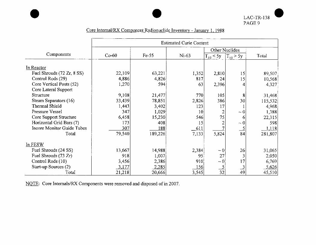
0 LAC-TR-138PAGE 9
Core Intemal/RX Component Radionuclide Inventory - January 1, 1988
Estimated Curie Content
Other NuclidesComponents Co-60 Fe-55 Ni-63 T112 < 5y TI/2 > 5y Total
In ReactorFuel Shrouds (72 Zr, 8 SS) 22,109 63,221 1,352 2,810 15 89,507Control Rods (29) 4,886 4,826 817 24 15 10,568Core Vertical Posts (52) 1,270 594 63 2,396 4 4,327Core Lateral SupportStructure 9,108 21,477 770 105 8 31,468Steam Separators (16) 33,439 78,851 2,826 386 30 115,532Thermal Shield 1,443 3,402 123 17 1 4,968Pressure Vessel 347 1,029 10 2 -0 1,388Core Support Structure 6,458 15,230 546 75 6 22,315Horizontal Grid Bars (7) 173 408 15 2 -0 598Incore Monitor Guide Tubes 307 188 611 7 5 1,118
Total 79,540 189,226 7,133 5,824 84 281,807
In FESWFuel Shrouds (24 SS) 13,667 14,988 2,384 -0 26 31,065Fuel Shrouds (73 Zr) 918 1,007 95 27 3 2,050Control Rods (10) 3,456 2,386 910 -0 17 6,769Start-up Sources (2) 3,177 2285 156 5 3 5,626
Total 21,218 20,666 3,545 32 49 45,510
NOTE: Core Internals/RX Components were removed and disposed of in 2007.

LAC-TR- 138PAGE 10
4.3 Plant Loose Surface Radionuclide Inventory
A plant smear survey was performed of all accessible interior building surfaces inan attempt to determine the amount of loose surface contamination in the plant.The specific isotopic identification of the contamination was also determined.Each smear was gamma scanned to determine not only a correlation factor inptCi per DPM/l 00 cm2 but also the percentile of each radioisotope present in themixture. From previous, part 61, analysis of plant smears, it has been determinedthat Fe-55 is the major beta emitter in the plant and is in approximately the samepercentage as Co-60. Fe-55 will be the only beta emitting isotope listed as acontaminant. Alpha activity on the surfaces has been checked by the use of anInternal Proportional Counter and has been found to be negligible and so will notbe considered. The survey did indicate that the major isotopes present in theplant's loose surface contamination are the following isotopes:
Isotope 1/2 LifeCo-60 5.27 yearsCs-137 30.1 yearsMn-54 312.2 daysFe-55 2.7 years
It must be realized when reviewing the results of this survey that a 100%smearing of plant surfaces was not performed and therefore the following data issubject to significant error.
The majority of the loose surface contamination throughout the plant is found inthe plant contaminated areas. The plant areas that were classified as contaminatedareas at plant shutdown in 1987 are listed below.
a) Waste Treatment Building(1) decon area(2) basement(3) resin liner room(4) high level storage pit
b) Turbine Building(1) stop valve area(2) full flow room(3) condensate bay(4) area under main condenser(5) feed pump bed plates(6) tunnel - includes 4500 WT cubicle and crawlway to stack
c) Reactor Building(1) 701 south by FESW(2) mezz around core spray pumps(3) west NI platform(4) purification platform(5) FESW IX cubicle(6) purification pump area(7) basement - includes UCRD platform, purification IX cubicle,
retention tank cubicle, subbasement, and FCP cubicles.

LAC-TR- 130PAGE 11
PLANT LOOSE SURFACE CONTAMINATION - JANUARY 1988
Isotopes Present, in tCi Total AreaktCi
Location Co-60 Cs-137 Mn-54 Ce-144 Co-57 Cs-134 Fe-55 Content
Turbine Building, (TB)
a) Main Floor 0.83 0.07 -- 0.83 1.73
b) Mezzanine - including stop valve area 0.49 0.14 0.04 0.49 1.16
c) Grade Floor - includes feedwater heater area 0.42 0.06 0.02 0.42 0.92
d) Tunnel 0.81 0.18 0.06 0.81 1.86
Reactor Building (RB)
a) Above grade 3.16 0.20 0.39 -- -- -- 3.16 6.91
b) Below grade 31.44 7.40 2.36 0.04 0.04 0.08 31.44 72.80
Waste Treatment Building 7.57 0.48 0.66 -- -- -- 7.57 16.28
Totals 44.72 8.53 3.53 0.04 0.04 0.08 44.72 101.66

LAC-TR-138PAGE 12
4.4 Plant System Internal Radionuclide Inventory
The internal surfaces of many inplant systems were exposed to radionuclide contaminantsduring plant operation. To obtain the most accurate analysis of these systems,piping/component destruction would be necessary. This was determined to be anundesirable method of analysis at this time.
A method of nondestructive sampling was developed. Each system that would besampled was looked at and a nondestructive entry point was found. Once the system wasopen, the piping was dried and a 1 cm2 area was scraped to bare metal. As the scrapingwas being done, the corrosion layer that was being removed was vacuumed into a glassfiber filter 47 mm in diameter. This filter was then gamma scanned for radionuclideidentification using the computer-based gamma spectroscopy unit connected to a GeLidetector.
A sample of the crud layer from the bottom of the FESW was obtained using a vacuumsystem. This crud was mixed with the water and an aliquot was taken and gammascanned. This was used to determine the activity in the FESW crud layer. Because of theinaccessibility of the bottom of the reactor vessel, the gamma spectrum obtained from theFESW sample was used as the gamma spectrum for any crud layer in the vessel bottom.Conversation with representatives from other facilities who have looked at their reactorvessel bottom indicates a very small crud layer in the vessel.
Each sample was also alpha counted to determine the total alpha content. The individualalpha isotopic mixture was not determined. Alpha analysis was performed with aCanberra Internal Proportional counter.
In systems where the piping/component radiation levels varied significantly, the radiationlevel of the sample area was found. The remainder of the system was surveyed and thepiping/component area was classified by radiation level. This technique allowed thesampled area uCi/cm2 value to correspond with a radiation level. As the system radiationlevel varied, a uCi/cm2 radiation level value was used to proportion the system areas tothat of the sample area, thus allowing a total system uCi content to be determined. Aftersampling, each system was returned to an as-found condition.
Fe-55, will be the only beta emitting isotope to be considered in the plant isotopiccontent. This will be in the same percentage as that of the Co-60 found in the systems.The isotopic composition occurring in the piping systems consists of the major nuclideslisted as follows:
Isotope 1/2 lifeCo-60 5.27 yearsCs-137 30.1 yearsMn-54 312.2 daysFe-55 2.7 years
This testing of piping systems is not an absolute value. Significant error can beassociated with this sampling technique due to the inability to actually analyze a systemcomponent or pipe.
The values listed are subject to error due to the required non-destructive samplingtechniques used and the inability to sample all components and areas.

LAC-TR-138 @PAGE 13
PLANT SYSTEMS INTERNAL RADIONUCLIDE INVENTORY - JANUARY 1988
Nuclide Activity, in [tCi ystem Total
Plant System Fe-55 Alpha Co-60 Cs-137 Mn-54 Cs-134 Nb-95 Co-57 Zn-65 [tCi Content
RB Ventilation
Offgas -upstream of filters
Offgas -downstream of filters
TB drains
RB drains
TB Waste Water
RB Waste Water
Main Steam
Turbine
Primary Purification
Emergency Core Spray
Overhead Storage Tank
Seal Inject
1.6 E3
6.0 E2
6.5 E2
1.7 E4
3.8 E4
3.6 E3
2.1 E5
2.6 E5
9.3 E2
8.9 E4
1.8 E3
1.3 E4
1.6 E3
-- 1.6 E3 1.7 E2 1.3 E2 1.40
-- 6.0 E2 4.4 E4 1.0 E2 --
4.0 El
3.2
6.8
7.9 El
2.9 E2
1.8
1.2 El
5.0
3.4 El
3.8
6.5 E2
1.7 E4
3.8 E4
3.6 E3
2.1 E5
2.6 E5
9.3 E2
8.9 E4
1.8 E3
1.3 E4
1.6 E3
8.3 E2 --
5.0 E3 7.8 E2
2.4 E3 2.6 E3
1.2 E2 1.5 E2
2.3 E3 1.7 E4
-- 2.0 E4
2.0 E2 1.8 E2
-- 8.8 E3
1.1 E2 1.4 E2
7.8 E2 9.5 E2
5.5 El 1.5 E2
-- 5.6 El
1 .0 E3
3.5 E3
4.5 E4
2.1 E3
4.0 E4
8.1 E4
7.5 E3
4.4 E5
5.4 E5
2.2 E3
1.9 E5
3.9 E3
2.8 E4
3.4 E3
1.3E2 1.4E3
-- - -- 2.1 E3
7.5

LAC-TR-138PAGE 14
PLANT SYSTEMS INTERNAL RADIONUCLIDE INVENTORY - JANUARY 1988 - (cont'd)k ...... ]
Nuclide Activity, in 1iCi System Total
Plant System Fe-55 Alpha Co-60 Mn-54 Co-57 Co-58 Zn-65 Other 1iCi Content
Decay Heat
Boron Inject
Reactor Coolant PASS
Alternate Core Spray
Shutdown Condenser
Control Rod DriveEffluent
Forced Circulation
Reactor-Vesseland Internals
Condensate afterbeds & Feedwater
Condensate to beds
1.0 E5
1.4 E5
9.9 E3
2.0 E4
2.3 E5
1.5 E5
1.5 E6
4.9 E2
6.6 E2
4.6 El
9.4 El
1.1 E3
7.2 E2
7.0 E3
1.0 ES
1.4 E5
9.9 E3
2.0 E4
2.3 E5
1.5 E5
1.5 E6
3.1 E4
4.2 E4
2.9 E3
5.9 E3
6.9 E4
4.6 E4
4.4 E5
1.6 E2
2.1 E2
1.5 El
3.0 El
3.5 E2
2.3 E2
2.3 E3
3.2 E3
4.3 E3
3.0 E2
6.1 E2
7.1 E3
4.7 E3
4.5 E4
3.5 E3
4.7 E3
3.3 E2
6.7 E2
7.8 E3
5.1 E3
5.0 E4
2.4 E5
3.3 E5
2.3 E4
4.7 E4
5.5 E5
3.6 E5
3.5 E6
5.9 E6
4.6 E5
9.3 E4
2.5 E6 1.2 E4 2.5 E6 7.6 E5 3.9 E3 7.8 E4 8.6 E4
2.1 E5
3.9 E4
2.8 E2
3.1 El
2.1 E5
3.9 E4
3.2 E4
1.3 E4
-- 1.6 E3
1.5E1 6.3E2
3.1 E3
6.7 E2 Fe-59 = 5.2 E2
Nb -95 = 1.1 E2Ru-103 = 4.9 El
Ce- 144 = 1.2 E2I ________________

0 LAC-TR138PAGE 15
PLANT SYSTEMS INTERNAL RADIONUCLIDE INVENTORY - JANUARY 1988 - (cont'd)
Nuclide Activity, in [tCi System Total
Plant System Fe-55 Alpha Co-60 Mn-54 Cs-137 Ce-144 Zn-65 Other tCi Content
Fuel Element StorageWell System 8.5 E5 3.9 E2 8.5 E5 1.4 E4 -- 1.0 E4 -- 1.7 E6
Fuel Element StorageWell - all but floor 1.3 E3 4.9 1.3 E3 6.0 E2 4.6 E3 -- 4.5 E2 8.3 E3
Fuel Element StorageWell floor 2.6 E7 7.6 E3 2.6 E7 5.0 E5 4.1 E4 -- 1.1 E5 Cs-134 = 1.3 E2 5.3 E7
Co-58 = 1.3 E2
Resin Lines 1.3 E5 1.0 E2 1.3 E5 4.2 E4 -- 4.0 E2 2.2 E3 Fe-59 = 1.7 E3 3.1 E5Co-57 = 4.8 ElCo-58 = 2.1 E3Nb-95 = 3.5 E2Ru-103 = 1.6 E2
Main Condenser 1.1 E7 8.5 E3 1.1 E7 3.6 E6 -- 3.4 E4 1.9 E5 Fe-59 = 1.4 E5 2.6 E7Co-57 = 4.1 E3Co-58 = 1.7 E5Nb-95 = 3.0 E4Ru-103 = 1.4 E4
NOTE: Attachment 3 is an inventory of the plant system - Internal Radionuclide Inventory decay corrected.

LAC-TR- 138PAGE 16
4.5 Reactor Biological Shield Activation Survey
During 1993 LACBWR revised the decommissioning cost study. It was feltnecessary at this time that a determination be made as to the extent of activationof the biological shield. The amount of biological shield activated will directlyeffect the cost of removal and disposal.
On October 20, 1993, an outside contractor completed boring of the biologicalshield. The initial boring site had to be abandoned due to the presence of shieldcooling system piping. This hampered the drilling and at one point caused the bitto become stuck. The boring site was moved approximately two feet below theoriginal site.
The boring through the biological shield was surveyed and analyzed on October21, 1993. The borings were removed in several sections and are designated asbelow. These are listed as from the outside of the shield wall to the inside. Theseboring sections are being kept on the West TB Grade for further analysis.
1A-2A - 9.5 inches long2A-3A - 14inches long3A-4A - 27 inches long4A-5A - 15 inches long5A-6A - 2 inches long6A-7A - 39 inches long
Section 6A-7A, being closest to the reactor, was surveyed using an RO-3 portableradiation detector to determine activities present. The following dose rates wereobtained. These are listed as distances from the inside shield wall.
0 inches - 130 mrem/hour6 inches - 130 mrem/hour
12 inches - 55 mremihour18 inches - 16 mrem/hour24 inches - 6 mrem/hour30 inches - 2.5 mrem/hour36 inches - 1.2 mrem/hour39 inches - <1 mrem/hour
A smear of this core section was taken with the following results:
Co-60 8.42 E-3 VtCi/smearEu-152 1.27 E-2 ptCi/smear
No other surveys of this core were taken due to the fact that the dose readingindicated complete activation of this section.

LAC-TR- 138PAGE 17
One inch sections of the remaining cores were cut and gamma-scanned todetermine the depth of the concrete activation.
Distance frominside shield wall
39 inches
42 inches
48 inches
49 inches
52 inches
56 inches
Co-60(h!Ci/sample)
1.79 E-3
4.49 E-4
1.77 E-4
8.13 E-5
2.01 E-5
NP
Eu- 152(LLCi/sample)
9.57 E-4
3.82 E-4
3.67 E-4
2.36 E-4
9.08 E-5
NP
Surveys of these sections with a frisker indicated <100 CPM increase overbackground. Smears indicated <MDA loose surface contamination. Analysisindicates that the biological shield is activated at a distance of 56" from the insideof the shield wall.

LAC-TR- 13 8PAGE 18
BIOLOGICAL SHIELD CORERADIATION SURVEY
...
1601501401301201101009080706050403020100
7 I II I~ I - I II_ I I I I I i I I I
I __ __0__ __ __ I
-1-iii 2 H I- _
I ______ _____
I _ _ _1 __ __
II_____
0so cm
5 10 15 20 25 30 35 40 45DISTANCE- INCHES

LAC-TR-138PAGE 19
4.6 Circulating Cooling Water Outfall Area Radionuclide Inventory
As part of LACBWR's dismantlement cost study it was determined that the extentof contamination in the circulating cooling water outfall area be determined.During February 1994 EMS (Environmental Marine Services) was contracted tosend divers to LACBWR to perform a sampling survey in the outfall area. Thissampling survey would be used to estimate the radionuclide inventory that existsin the plant outfall. The divers report that the area from the Mississippi River'sedge to approximately 60' from the edge is covered with large rip rap and nosample could be obtained. From the 60' area a silt sample was takenapproximately every 10' out and 110' from the rivers edge. The divers then turneddownstream with the river current. They continued to obtain silt samples every10' out to 150' from the outfall. The following table lists the activities found inthese samples.
1Ci/kg as of February 1994
Sample DistancesFrom Outfall (ft) Co-60 Cs-137
1 60 1,070 1,980
2 70 1,260 2,200
3 80 1,330 2,230
4 90 813 1,870
5 100 216 362
6 110 82.3 127
7 120 8.96 21.4
8 130 NF 7.22
9 140 NF 20.11
10 150 9.33 22.6
(NF = None Found)
An attempt to obtain samples at various depths was tried. The divers didn't havethe necessary equipment to perform this sampling so cross contaminationoccurred. Because of this no determination of the depth of the contamination canbe made. The data we presently have would indicate a clean up area 20' wide by95' long.
4.7 Initial Site Soil Contamination Determination Survey
In accordance with NUREG/CR-5849 "Manual for Conducting RadiologicalSurveys in Support of License Termination" an initial site soil survey wasperformed during August - September 1995. The LACBWR affected area (areawithin the LSE fence) was marked out into 10 m2 areas for sample locationidentification. No samples were taken under surface coverings such as blacktop.After gridding of the area was complete one surface soil sample was collectedfrom the top 15 cm of the soil in each grid location. Each sample collected wasapproximately 1 - 2 kg.

LAC-TR-138PAGE 20
Grass, rocks, sticks and foreign objects were removed from each sample to thedegree practical. Each sample was then dried and placed in a disposable marinellicontainer for gamma analysis. All samples were allowed to sit for at least 72hours to reduce the affect of any short lived natural decay chains. All sampleswere then counted for 3 hours on the ENV HPGE. The following is a listing ofactivity found in these samples. No natural occurring isotope is listed. The actualsample gamma scans are being kept for further review if needed. All samplelocations can be found using their corresponding number using the enclosed sitegrid map.
NOTE: All activity values are in pCi/kg
Sample SampleGrid # Co-60 Cs-137 Grid# Co-60 Cs-137 Eu-155
1 10.5 106 27 13.9 58.4
2 34.8 81.6 28 <MDA 78.7
3 2.9 126 29 <MDA 74.1
4 16.7 78.5 30 <MDA 68.3
5 4.8 92.1 31 <MDA 64.2
6 8.8 80.2 32 <MDA 27.7
7 <MDA 51 33 31.2 129
8 <MDA 12.2 34 <MDA 171
9 <MDA 23.2 35 <MDA 91.7 53.5
10 <MDA 38.9 36 <MDA 61 20.3
11 <MDA 71 37 40.9 124 40.4
12 <MDA 93.3 38 <MDA 44.6
13 767 983 39 <MDA 130
14 100 312 40 <MDA 49
15 5.8 58.9 41 <MDA 74.9
16 <MDA 22.5 42 <MDA 55.6
17 <MDA 15 43 20.7 211
18 <MDA 14.4 44 9.1 145
19 <MDA 43.5 45 36.5 310
20 <MDA 44.2 46 19.5 197 30.8
21 <MDA 72.6 47 85.1 177 27.7
22 <MDA 55.6 48 12 158
23 <MDA 45.5 49 56.4 329
24 <MDA 67.9 50 23.8 99
25 7.4 31 51 19.3 192 33.4
26 10.7 28.7 52 17.4 353 11.9
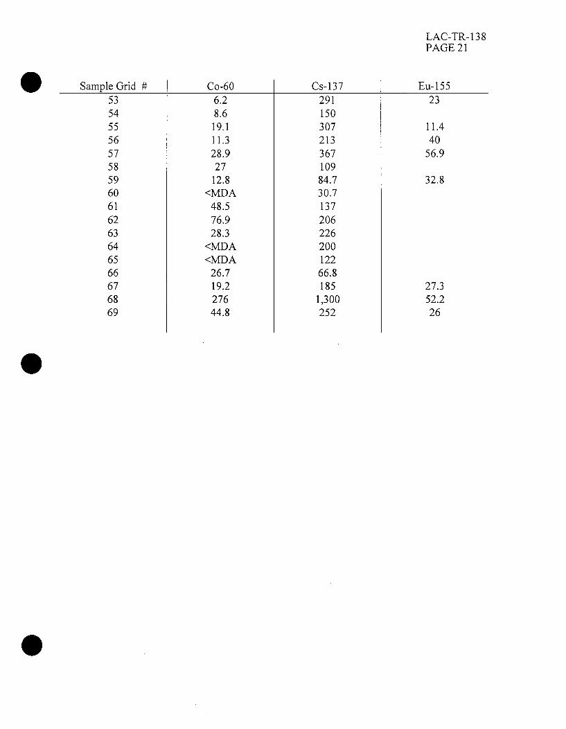
LAC-TR- 138PAGE 21
Sample Grid # Co-60 Cs-137 Eu-15553 6.2 291 2354 8.6 15055 19.1 307 11.456 11.3 213 4057 28.9 367 56.958 27 10959 12.8 84.7 32.860 <MDA 30.761 48.5 13762 76.9 20663 28.3 22664 <MDA 20065 <MDA 12266 26.7 66.867 19.2 185 27.368 276 1,300 52.269 44.8 252 26

LAC-TR- 138PAGE 22
SITE SOIL SAMPLING GRID MAP
StACo
RUIACTORBOX WINC
TURBINEBUIIDII,
ADKINBUILDING
\ 4
.~5 ~33,,30
\ 'Ile
SWITCHYARD .7
.q7

LAC-TR-138PAGE 23
The unaffected area around LACBWR but within the owner controlled area wasalso checked. These samples were taken and analyzed as the samples taken fromthe affected area. The following results were obtained.
Location Co-60 Cs-137Area W of #2 warehouse <MDA 77.3
Area S of parking lot <MDA 25.5Area N of LACBWR admin building <MDA 149
Area by G-3 ash silo <MDA 38.2Area outside G-3 offices <MDA 76.3
Area by G-3 outfall <MDA 17.2All results are in pCi/kg
To determine potential background Cs-i 37 levels for the area surroundingLACBWR several soil samples were taken at various locations outside the ownercontrol area. These samples were collected and analyzed as per NUREG/CR-5849 as all the other samples. The following results were obtained.
Location3.3 miles S @ boat landingalong the Bad Axe River
Pedretti Farm SubstationE of plant
Radio Tower NE of plant
Junction of Cty Hwy 0 and K
E of Stoddard @ Junction ofCty Hwy O and 162
NOTE: All a
Co-60
22.7
<MDA
<MDA
<MDA
Cs-137
381
227
35.00
188.00
66.5<MDA
ctivities are in pCi/kg

LAC-TR- 138PAGE 24
ATTACHMENT 1
SPENT FUEL RADIOACTIVITY INVENTORY
Decay-Corrected to October 2010
Half Life Activity Half LifeRadionuclide (Years) (Curies) Radionuclide (Years) (Curies)
Ce- 144
Cs-137
Ru- 106
Cs-134
Kr-85
Co-60
Pm-147
Ni-63
Am-241
Pu-23 8
Pu-239
Pu-240
Eu-154
Cm-244
H-3
Eu- 152
Am-242m
7.801 E-1
3.014 E+1
1.008 E+0
2.070 E+0
1.072 E+1
5.270 E+0
2.620 E+0
1.000 E+2
4.329 E+2
8.774 E+1
2.410 E+4
6.550 E+3
8.750 E+0
1.812 E+1
1.226 E+I
1.360 E+I
1.505 E+2
4.40 E-3
9.87 E+5
0.25
162
2.67 E+4
3.21 E+3
101
3.02 E+4
1.42 E+4
1.05 E+4
8.83 E+3
7.15 E+3
663
1.51 E+3
152
160
441
Sr-90
Pu-241
Fe-55
Ni-59
Tc-99
Sb- 125
Eu-155
U-234
Am-243
Cd-i13m
Nb-94
Cs-135
U-238
Pu-242
U-236
Sn-121m
Np-237
U-235
Sm- 151
Sn-126
Se-79
1-129
Zr-93
2.770 E + 1
1.429 E+1
2.700 E+0
8.000 E+4
2.120 E+5
2.760 E+0
4.960 E+0
2.440 E+5
7.380 E+3
1.359 E+I
2.000 E+4
3.000 E+6
4.470 E+9
3.760 E+5
2.340 E+7
7.600 E+1
2.140 E+6
7.040 E+8
9.316 E+I
1.000 E+5
6.500 E+4
1.570 E+7
1.500 E+6
6.49 E+5
3.81 E+5
1.53 E+3
287
276
0.90
7.00
63.7
63.0
5.58
15.9
14.0
12.2
8.58
6.32
3.61
2.19
1.89
1.27
0.70
0.55
0.39
0.11
Total Activity = 2.12 E+6 Curies

0 LAC-TR-1*PAGE2f
ATTACHMENT 2
CORE 1NTERNAL/RX COMPONENT RADIONUCLIDE INVENTORY
Estimated Curie Content
Components Co-60 Fe-55 Ni-63Other Nuclides]
T1/2 > 5y Total
In Reactor
Fuel Shrouds (72 Zr, 8 SS)
Control Rods (29)
Core Vertical Posts (52)
Core Lateral Support Structure
Steam Separators (16)
Thermal Shield
Pressure Vessel
Core Support Structure
Horizontal Grid Bars (7)
Incore Monitor Guide Tubes
Total
In FESW
Fuel Shrouds (24 SS)
Fuel Shrouds (73 Zr)
Control Rods (10)
Start-up Sources (2)
REACTOR VESSEL WASPROCESSED, PACKAGED AND
DISPOSED OF IN 2007
"IN FESW" COMPONENTS LISTEDWERE PROCESSED, PACKAGED
AND DISPOSED OF IN 2006
___________________________________________________________________ f

LAC-TR- 1PAGE 2"W
ATTACHMENT 3
PLANT SYSTEMS INTERNAL RADIONUCLIDE INVENTORY - OCTOBER 2010
Nuclide Activity, in LiCi System TotalptCi ContentPlant System
-I-
RB VentilationOffgas -upstream of filterOffgas -downstream of filters
TB drains
RB drains
TB Waste Water
RB Waste Water
Main Steam
Turbine
Primary Purification
Emergency Core Spray
Overhead Storage Tank
Seal Inject
Fe-55
5
SYSTEM
SYSTEM
49
111
10
611
757
3
259
SYSTEM
38
5
Alpha Co-60-~1 I I- t
80 101
Cs-137
REMOVED
REMOVED
40
3
7
79
290
2
12
REMOVED
34
4
854
1,908
181
10,543
13,054
47
4,468
653
80
2,963
1,422
71
1,363
119
462
33
186
3,906
3,444
269
12,596
14,101
171
4,739
1,187
122

LAC-TR- 13 8•&PAGE 27TW
ATTACHMENT 3
PLANT SYSTEMS INTERNAL RADIONUCLIDE INVENTORY - OCTOBER 2010 - (cont'd)
Nuclide Activity, in jiCi System Total__Ci ContentPlant System
Fe-55 Alpha Co-60
Decay Heat
Boron Inject
Reactor Coolant PASS
Alternate Core Spray
Shutdown Condenser
Control Rod Drive Effluent
Forced Circulation
Reactor Vessel and Internals
Condensate after beds & Feedwater
Condensate to beds
291
SYSTEM
SYSTEM
58
SYSTEM
437
4,367
SYSTEM
SYSTEM
SYSTEM
490
REMOVED
REMOVED
94
REMOVED
720
7,000
REMOVED
REMOVED
REMOVED
5,021
1,004
7,531
75,310
5,802
1,156
8,688
86,667
i

LAC-TR-138PAGE 283
ATTACHMENT 3
PLANT SYSTEMS INTERNAL RADIONUCLIDE INVENTORY - OCTOBER 2010 - (cont'd)
Nuclide Activity. in jiCiPlant System Fe-55 Alpha Co-60
System TotalpCi ContentCs-137
Fuel Element StorageWell System
Fuel Element Storage Well
- all but floor,
Fuel Element Storage Well floor
Resin lines
2,475
4
75,693
378
32,024
390
5
7,600
100
8,500
42,676
65
1,305,379
6,527
552,276
2,726
24,300
45,541
2,800
1,412,972
7,005
592,800Main Condenser