Analytical study of nuclear-coupled density-wave instability in a natural circulation pressure tube...
18
Nuclear Engineering and Design 195 (2000) 27 – 44 Analytical study of nuclear-coupled density-wave instability in a natural circulation pressure tube type boiling water reactor A.K. Nayak a, *, P.K. Vijayan a , D. Saha a , V. Venkat Raj a , Masanori Aritomi b a Reactor Design and De6elopment Group, Bhabha Atomic Research Centre, Trombay, Bombay 400085, India b Research Laboratory for Nuclear Reactors, Tokyo Institute of Technology, 2 -12 -1 Ohokayama, Meguro -ku, Tokyo 152, Japan Received 1 December 1998; received in revised form 2 August 1999; accepted 2 August 1999 Abstract An analytical model has been developed to study the nuclear-coupled density-wave instability in the Indian advanced heavy water reactor (AHWR) which is a natural circulation pressure tube type boiling water reactor. The model considers a point kinetics model for the neutron dynamics and a lumped parameter model for the fuel thermal dynamics along with the conservation equations of mass, momentum and energy and equation of state for the coolant. In addition, to study the effect of neutron interactions between different parts of the core, the model considers a coupled multipoint kinetics equation in place of simple point kinetics equation. Linear stability theory was applied to reveal the instability of in-phase and out-of-phase modes in the boiling channels of the AHWR. The results indicate that the stability behavior of the reactor is greatly influenced by the void reactivity coefficient, fuel time constant, radial power distribution and channel inlet orificing. The delayed neutrons were found to have a strong influence on the Type I and Type II instabilities observed at low and high channel powers, respectively. Also, it was found that the coupled multipoint kinetics model and the modal point kinetics model predict the same threshold power for out-of-phase instability if the coupling coefficient in the former model is half the eigen value separation between the fundamental and the first harmonic mode in the latter model. Decay ratio maps were predicted considering various operating parameters of the reactor, which are useful for its design. © 2000 Elsevier Science S.A. All rights reserved. www.elsevier.com/locate/nucengdes 1. Introduction The Advanced Heavy Water Reactor (AHWR) being designed in India is a 750-MWth pressure tube type boiling light water cooled and heavy water moderated reactor (Sinha and Kakaodkar, 1990). One of the attractive features of this reac- * Corresponding author. Tel.: +91-22-5505050, ext. 2592; fax: +91-22-5505151. E-mail address: [email protected] (A.K. Nayak) 0029-5493/00/$ - see front matter © 2000 Elsevier Science S.A. All rights reserved. PII:S0029-5493(99)00202-2
Transcript of Analytical study of nuclear-coupled density-wave instability in a natural circulation pressure tube...
Nuclear Engineering and Design 195 (2000) 27–44
Analytical study of nuclear-coupled density-wave instabilityin a natural circulation pressure tube type boiling water
reactor
A.K. Nayak a,*, P.K. Vijayan a, D. Saha a, V. Venkat Raj a,Masanori Aritomi b
a Reactor Design and De6elopment Group, Bhabha Atomic Research Centre, Trombay, Bombay 400085, Indiab Research Laboratory for Nuclear Reactors, Tokyo Institute of Technology, 2-12-1 Ohokayama, Meguro-ku, Tokyo 152, Japan
Received 1 December 1998; received in revised form 2 August 1999; accepted 2 August 1999
Abstract
An analytical model has been developed to study the nuclear-coupled density-wave instability in the Indianadvanced heavy water reactor (AHWR) which is a natural circulation pressure tube type boiling water reactor. Themodel considers a point kinetics model for the neutron dynamics and a lumped parameter model for the fuel thermaldynamics along with the conservation equations of mass, momentum and energy and equation of state for thecoolant. In addition, to study the effect of neutron interactions between different parts of the core, the modelconsiders a coupled multipoint kinetics equation in place of simple point kinetics equation. Linear stability theory wasapplied to reveal the instability of in-phase and out-of-phase modes in the boiling channels of the AHWR. The resultsindicate that the stability behavior of the reactor is greatly influenced by the void reactivity coefficient, fuel timeconstant, radial power distribution and channel inlet orificing. The delayed neutrons were found to have a stronginfluence on the Type I and Type II instabilities observed at low and high channel powers, respectively. Also, it wasfound that the coupled multipoint kinetics model and the modal point kinetics model predict the same thresholdpower for out-of-phase instability if the coupling coefficient in the former model is half the eigen value separationbetween the fundamental and the first harmonic mode in the latter model. Decay ratio maps were predictedconsidering various operating parameters of the reactor, which are useful for its design. © 2000 Elsevier Science S.A.All rights reserved.
www.elsevier.com/locate/nucengdes
1. Introduction
The Advanced Heavy Water Reactor (AHWR)being designed in India is a 750-MWth pressuretube type boiling light water cooled and heavywater moderated reactor (Sinha and Kakaodkar,1990). One of the attractive features of this reac-
* Corresponding author. Tel.: +91-22-5505050, ext. 2592;fax: +91-22-5505151.
E-mail address: [email protected] (A.K. Nayak)
0029-5493/00/$ - see front matter © 2000 Elsevier Science S.A. All rights reserved.
PII: S0029 -5493 (99 )00202 -2
A.K. Nayak et al. / Nuclear Engineering and Design 195 (2000) 27–4428
tor is that the heat removal from the core takesplace by natural circulation during start-up,power-raising and accidental conditions in addi-tion to the rated full power operating condition.This enhances passive safety by eliminating therecirculation pumps, which are normally presentin conventional forced circulation boiling waterreactors (BWRs). To obtain required natural cir-culation flow rate, the height of the riser (or outletfeeders as in the case of the AHWR) is compara-tively much larger than a forced circulation BWR(for the same power rating). This in turn maycause a large two-phase pressure drop in the riserportion compared to the single-phase portion ofthe reactor coolant system composed of down-comers, inlet feeders and single-phase portion ofcore. Natural circulation being the designed heatremoval mode, it is also not possible to throttlesufficiently at the inlet of each channel which maysuppress the thermal hydraulic oscillations (morepopularly known as density-wave instability)caused by the dominance of two-phase pressuredrop in the reactor coolant system, which mayfurther initiate reactivity oscillations through thevoid-reactivity coupling. State-of-the-art reviewon such nuclear-coupled instabilities occurring inBWRs has been provided recently by March-Leuba and Rey (1993). This review suggests thatthere are many incidents of instabilities, whichhad occurred, in commercial BWRs in the past.However, the topic generated additional interestafter the oscillations observed in the two operat-ing reactors, viz., LaSalle 2, USA (US NRC,1988) and Coarso, Italy (Gialdi et al., 1985). Theoscillations in the LaSalle reactor caused corewide instability, wherein the neutron flux, flowrate and void fraction oscillated almost in-phasewith one another at every point in the core, whicheventually resulted in reactor scramming. The os-cillation in the Coarso plant was an out-of-phaseinstability in which one half of the core oscillated180° out-of-phase with the other half.
Instabilities of both the above types are unde-sirable from the viewpoints of reactor design,control and safety. Many investigations have beencarried out in the recent past to model and under-stand both the above types of instabilities bynumerical time domain and frequency domain
analysis codes. Some of the benchmarked numeri-cal codes used to simulate the LaSalle 2 andCoarso oscillations are TOSDYN-2 (Takigawa etal., 1987), STANDY (Muto et al., 1990), RE-TRAN (Araya et al., 1991) and TRACG(Takeuchi et al., 1994). These codes successfullysimulated the instability behaviour in these plantsand the causes of instabilities and the method ofsuppressing them were also found out. However,the time domain analysis codes take long CPUtime and are not useful in determining the stabil-ity boundaries to study the physical mechanism ofthe instabilities. For this, analysis in frequencydomain is always preferred. Some of the wellknown frequency domain analysis codes areNUFREQ-N (Park et al., 1986) and LAPUR(March-Leuba, 1990). Both these codes arebenchmarked and can solve the instability prob-lem of a BWR considering the parallel channelsand the whole loop under normal and accidentalconditions. Fundamental studies in the field ofBWR instabilities have also been carried out bynumerous investigators using frequency domainanalysis. March-Leuba and Blakeman (1991)showed that the dominance of in-phase and out-of-phase instabilities in BWRs depends on therelative gain of the inlet flow and neutronic feed-back. Hashimoto (1993) showed by modal expan-sion that in the low flow and high power region ofa BWR, out-of-phase oscillation can occur forcertain values of subcriticality and void reactivityfeed back. Rao et al. (1995) found out the influ-ence of the fuel time constant and void reactivitycoefficient on the instability of in-phase modeconsidering a single channel of the LaSalle 2reactor. Uehiro et al. (1996) applied the aboveanalytical model to study the in-phase and out-of-phase instabilities in the parallel boiling channelsof the above reactor. They found out that theinteractions between the channels due to neutrondiffusion influence the out-of-phase oscillation.Moreover, these studies reveal that the nuclear-coupled instability is a very complex problemwhich depends on the behaviour of channel ther-mal hydraulic oscillations, radial and axial powerdistribution in the core, reactivity feed back ef-fects due to the void and fuel temperature, andthe fuel time constant. These instabilities may
A.K. Nayak et al. / Nuclear Engineering and Design 195 (2000) 27–44 29
occur in forced circulation BWRs under naturalcirculation conditions after a pump trip transientwhen the core exit quality is high due to low flowand high power. This may cause a large negativevoid reactivity coefficient and two-phase pressuredrop to initiate instabilities. Such instabilities canalso occur in a natural circulation BWR (forexample, the Dodewaard reactor) as predictedrecently by Van Bragt and Van der Hagen(1998a). They considered a single channel of theabove reactor and found out that the stabilitybehaviour of the reactor is strongly dependent onthe state of thermohydraulic subsystem (VanBragt and Van der Hagen, 1998b). They alsoobserved that the Type-I and Type-II thermohy-draulic oscillations, which occur at low and highpowers, respectively, are influenced by the neu-tron and fuel dynamics in a different manner.
From these studies, it may be anticipated thatthe AHWR may also experience similar nuclear-coupled thermohydraulic instabilities under cer-tain conditions. Previous studies (Nayak et al.,1998) have shown that the AHWR may experi-ence density-wave instability for certain operatingconditions and geometric parameters of the reac-tor coolant system. Further to this, it is alsorequired to generate the stability maps consider-ing the neutronic feed back effects at variousconditions which are useful for the design of thereactor. Since each channel in the AHWR isconnected to the steam drum and the header withvery long inlet and outlet feeder pipes, respec-tively, the period of density-wave oscillation isexpected to be much larger than a conventionalvessel type BWR. The effects of neutron and fueldynamics on these low frequency density-waveoscillations occurring due to the interactions ofthe multiple long parallel paths having differentpower, resistances and with the external loop (i.e.downcomers) under natural circulation conditionhave not been studied earlier. The purpose of thispaper is to carry out investigations on the nu-clear-coupled density-wave instabilities of bothin-phase and out-of-phase modes in the AHWR,and to study the influence of the void reactivitycoefficient, fuel time constant and the power dis-tribution in the core on these instabilities from thereactor core design point of view.
For this purpose, a mathematical model hasbeen developed to study the nuclear-coupled den-sity-wave instability in the AHWR. This modelsolves analytically by linearising the conservationequations of mass, momentum and energy and theequation of state for the coolant along with apoint kinetics model for the neutron dynamicsand a lumped heat transfer model for the fuelthermal dynamics. To study the interaction be-tween different parts of the core through neutrondiffusion, a coupled multipoint kinetics modelwas applied in place of simple point kineticsmodel for the neutron dynamics. In addition, themodel considers the thermohydraulic interactionsof parallel multiple channels with the inlet andoutlet feeders together with the external loop (i.e.downcomers). The characteristic equation hasbeen derived and the stability behaviour for in-phase and out-of-phase mode of oscillations wereinvestigated from the roots of the characteristicequation.
2. Primary heat transport (PHT) system of theAHWR
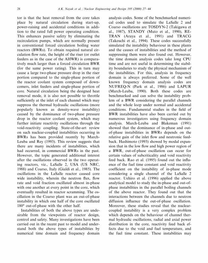
The design concept of the AHWR is describedin (Nayak et al., 1998). The schematic of the PHT
Fig. 1. Schematic of AHWR primary heat transport system.
A.K. Nayak et al. / Nuclear Engineering and Design 195 (2000) 27–4430
System of the AHWR is shown in Fig. 1. Asshown in the figure, the PHT system containsmany parallel channels (408 numbers) which areconnected between the header and the steamdrums (four numbers) by an equal number of inletand outlet feeders, respectively. Each steam drumis connected to the header by four downcomers.The channels have an inside diameter of 120 mmand contain fuel bundles consisting of 52 numberof fuel rods and eight number of water rods. Theouter diameter of the fuel rod is 11.2 mm and thatof the water rod is 6 mm. There are six spacerslocated in the fuel bundles and they are separatedat equal distances along the length of fuel. Theactive fuel length is about 3.5 m and the height ofthe loop above the core is about 30 m. The insidediameter of inlet feeders is about 97 mm and thatof the outlet feeders is about 122 mm. The steamdrums have a length of 10 m and an insidediameter of 3 m and are kept horizontal. Duringnormal operating condition the steam drum pres-sure is maintained at 70 bar. This is a typicaldesign configuration of the AHWR considered inthe present analysis. Boiling takes place in thecore and the two-phase mixture leaving the core isseparated into steam and water in the steamdrum. The separated steam flows into the turbineand an equal mass rate of feed water enters thesteam drum. The coolant circulation in the PHTsystem takes place by natural circulation.
3. Analytical model
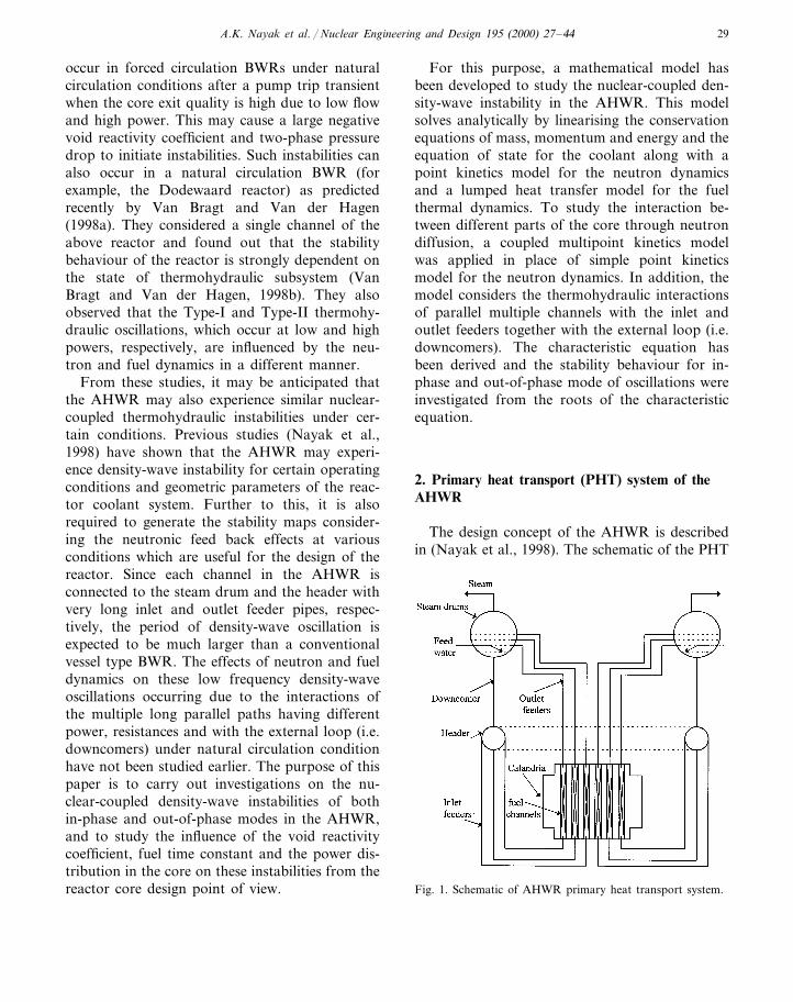
To solve the problem of stability for theAHWR concept, a simplified loop of the AHWRwas considered in the analysis as shown in Fig. 2.As shown in the figure, all the steam drums anddowncomers are lumped into an equivalent steamdrum and downcomer, respectively. All the chan-nels in the core are connected between the headerand the steam drum by the same number of inletfeeders and outlet feeders, respectively.
The analytical model consists of: (i) a thermo-hydraulic stability model; (ii) a point kinetics or acoupled multipoint kinetics model; and (iii) alumped fuel heat transfer model. The thermohy-draulic stability model assumes the flow to be
Fig. 2. Schematic of the simplified loop of AHWR consideredin analysis.
incompressible and Boussinesq approximation tobe valid for variation of density with temperaturein the single-phase region of the loop. Also itassumes that in the two-phase region the flow ishomogeneous, (p/(t in energy conservation equa-tion is neglected, two-phases are in thermo-dy-namic equilibrium, axial uniform heat flux profile(Nayak et al., 1998), heat losses in the loop pip-ings are neglected, carry-over and carry-under inthe steam drum are neglected and mixing of feedwater in the steam drum is complete (i.e. nothermal stratification).
With these assumptions the conservation equa-tions of mass, momentum and energy for one-di-mensional two-phase flow are given by:
A(r
(t+(w(z
=0 (1)
1A(w(t
+1
A2
(
(z(w26)+
g6+
f2DA2(w
26)+(p(z
=0
(2)
rA(h(t
+w(h(z
=!qhA heated region
0 unheated region(3)
The equation of state in the two-phase region isgiven by:
r= f(p,h) (4)
The frictional pressure drop in the two-phaseregion was estimated using the Baroczy (1966)correlation. The local pressure drop due to bends,restrictions and spacers was estimated as:
A.K. Nayak et al. / Nuclear Engineering and Design 195 (2000) 27–44 31
Dpk=Kw2/2rA2 (5)
The governing equations are linearised by super-imposing small perturbations of w %, h %, p %, 6% andq %h over steady state values where:
w %=w̄(z)oest; h %=h( (z)oest; p %= p̄(z)oest; 6%
= 6̄(z)oest; q %h= q̄hoest (6)
In Eq. (6) o is a small quantity and w̄, h( , p̄, 6̄ andq̄h are the averages of perturbed flow rate, enthalpy,pressure, specific volume and heat added/unit vol-ume to the coolant, respectively, and s is thestability parameter. Substituting them in the con-servation equations, the solution of the perturbedequations for various segments of the loop can beobtained by integration as follows.
In the single-phase heated region,
w %=w %in=constant (7)
h %=1
rss,avs�
−qh,ssw %
wss
+q %hn
[1−e−tsps] (8)
−Dp %sp=� s
A+
fwss
rss,avDA2
nw %Lsp−
gs
Cps�−qh,ssw %wss
+q %hn�
Lsp+wss
rss,avAs(e−tsps−1)
n(9)
where
tsp= (rss,avALsp/wss) (10)
In the adiabatic single-phase region, the perturbedequations for flow rate, enthalpy and pressure dropcan be obtained from Eqs. (7)–(9), respectively, bysubstituting qh,ss and q %h to be zero.
In the two-phase heated region,
w %=w %sp
+As
6 ss,av2
6fghfg
�P
r1
(er1Lc−er1Lsp)+Q
r2
(er2Lc−er2Lsp)n(11)
h %= [Per1Lc+Qer2Lc] (12)
−Dp %=� s
A+
fwss6ss,av
DA2
n×
�w %spLtp+
As6fg6 ss,av
2 hfg
!Pr1
!1r1
(er1Lc−er1Lsp)−er1LspLtp"
+!Q
r2
!1r2
(er2Lc−er2Lsp)−er2LspLtp"""n
+
(6fg/hfg)� fw ss
2
2DA2−g6 ss,av
2 +2wsssA6ss,av
n�P
r1
(er1Lc−er1Lsp)+Qr2
(er2Lc−er2Lsp)n
+w ss
2 6fgA2hfg
×
[P(er1Lc−er1Lsp)+Q(er2Lc−er2Lsp)] (13)
where
P= [−h %sp(r2+Asrf/wss)−qh,ssAw %sp/w ss2
+q %hA/wss]/(r1−r2)er1Lsp (14)
Q= (h %sp−Per1Lsp)/er2Lsp (15)
r1,2= [−C19 (C12−4C2)0.5]/2 (16)
C1=As/6ss,avwss (17)
C2= (qh,ss/6 ss,av2 )(A2s/w ss
2 )(6fg/hfg) (18)
and h %sp is the perturbed enthalpy at the inlet ofboiling region of the channel, which can be esti-mated from Eq. (8).
In the adiabatic two-phase region,
w %=w %in+ (wss/6ss)(6fg/hfg)h %in[1−e−tLs] (19)
h %=h %ine−tLs (20)
−Dp %=� s
A+
fwss6ss
DA2
n�w %inL+
wss6fg
6sshfg
h %in!L+
wss6ss
As{e−tLs−1}
"n−6fghfg� fw ss
2
2DA2−g6 ss
2 +2wsssA6ss
n�{e−tLs−1}h %in
wss6ss
Asn
+w ss
2
A2
6fghfg
{e−tLs−1}h %in (21)
where
tL= (rinAL/wss) (22)
Similarly, the perturbed pressure drop due tobends, orifices, spacers and other restrictions invarious regions are given by,
in the single-phase region,
Dp %k,sp= (Ksp/rA2)wssw %in (23)
in the two-phase region,
Dp %k,tp= (Ktp/2A2)[w ss2 h %in(6fg/hfg)+2wss6ssw %in]
(24)
A.K. Nayak et al. / Nuclear Engineering and Design 195 (2000) 27–4432
The perturbed heat added/unit volume ofcoolant (q %h) that appears in the above calculationdepends on the neutron and fuel dynamics, whichare estimated as discussed below.
3.1. Neutron kinetics
The point kinetics approximation is adopted forthe neutron field dynamics as given by:
dn(t)dt
=k(t)(1−b)−1
ln(t)+ %
6
m=1
lmCm(t) (25)
dCm(t)dt
=k(t)bmn(t)
l−lmCm(t) (26)
Eqs. (25) and (26) are linearised by perturbingover the steady state as discussed in Section 3 andthe perturbed equations can be easily solved aftereliminating the steady state conditions to obtain:
n %nss
=k %
ls+ %6
m=1
sbm
s+lm
(27)
where n % is the perturbed neutron density and k % isthe perturbed reactivity which is related to thevoid reactivity coefficient and Doppler coefficientas:
k %=Cag %av+CDT %f,av (28)
In Eq. (28) g %av and T %f,av are the perturbed voidfraction and fuel temperature, respectively, aver-aged over the heated channel length. They can beestimated from the coolant density and the fuelheat transfer equations as discussed below.
3.2. Fuel heat transfer model
Assuming only radial heat transfer, the fuelheat transfer equation can be written as:
mfCf
dTf,av
dt=Q(t)−Hfaf(Tf,av(t)−Tsat) (29)
where mf is the mass of fuel rods; Cf is the specificheat capacity of fuel; Hf is an effective heat trans-fer coefficient; Q(t) is the heat generation rate inthe fuel rods; Tf,av(t) is the length average fueltemperature; af is the heat transfer area of fuelrods and Tsat is the coolant saturationtemperature.
Perturbing Eq. (29) over the steady state forTf,av(t) and Q(t) and cancelling the steady stateterms, we get:
T %f,av(mfCfs+Hfaf)=Q % (30)
where Q % is the perturbed heat generation rate inthe fuel rod.
Applying the heat balance equation for the heattransfer from fuel to coolant
Hfaf(Tf,av−Tsat)=qhAcLc (31)
Perturbing Eq. (31) over the steady state andcancelling the steady state terms we get
T %f,av=q %hAcLc/Hfaf (32)
Substituting Eq. (32) into Eq. (30) and rear-ranging we get
q %h=qh,ss
Q %Qss
� 11+mfCfs/Hfaf
n(33)
Since the heat generation rate in fuel is propor-tional to the neutron density, Eqs. (27) and (28)can be substituted into Eq. (33) to yield
q %h=Gfg %av (34)
where
Gf=Ca/(1+tfs)(ls+ %
6
m=1
sbm
s+lm
)
1qh,ss
−CDAcLc
Hfaf(1+tfs)(ls+ %6
m=1
sbm
s+lm
)
(35)
and tf= (mfCf)/(Hfaf) is the fuel time constant.The density of two-phase mixture is given by
r=grg+ (1−g)rf (36)
Perturbing Eq. (36) over the steady state andcancelling for steady state condition, we get
g %= −r %/rfg= (r ss2 /rfg)
6fghfg
h % (37)
The channel average perturbed void fraction canbe obtained by integration as:
gav’ =
1Lc
& Lc
z=L sp
r ss2 6fg
rfghfg
h %dz (38)
which can be approximated after some algebraicsimplification as:
A.K. Nayak et al. / Nuclear Engineering and Design 195 (2000) 27–44 33
g %av=c1w %in+c2q %h (39)
where
c1=1Lc
6fghfg
16 ss,av
2
1hfg
�X1
r1
(er1Lc−er1Lsp)
+X2
r2
(er2Lc−er2Lsp)n
(40)
c2=1Lc
6fghfg
16 ss,av
2
1hfg
�Y1
r1
(er1Lc−er1Lsp)
+Y2
r2
(er2Lc−er2Lsp)n
(41)
X1=−qh,ssA
w ss2�
1+ [(e−tsps−1)/rins ](wss/A)(r2+Asrin
wss
)n
×/[(r1−r2)er1Lsp] (42)
X2= [{(qh,ss/wss)(e−tsps−1)/rins}−X1e
r1Lsp]/er2Lsp
(43)
Y1=��e−tsps−1
rins��
r2+Asrin
wss
�+
Awss
n/(r1−r2)
×er1Lsp (44)
Y2= −�e−tsps−1
rins+Y1e
r1Lspn/er2Lsp (45)
Substituting Eq. (39) into Eq. (34) an expressionfor the perturbed heat added per unit volume ofcoolant (q %h) to any channel i for a perturbation ofinlet flow rate (w %in) in the ith channel can be easilyobtained as given by:
(q %h)i= (Gfc1
1−Gfc2
)i(w %in)i (46)
3.3. Coupled multipoint kinetics model
During an out-of-phase instability, neutron dif-fusion from channel to channel may be an impor-tant factor due to change in void fraction amongthe channels which the point kinetics model doesnot take into account. This may result in a differentq %h for any channel than that calculated using Eq.(46). For this purpose, a coupled multipoint kinet-ics model was applied in place of simple pointkinetics model for the neutron kinetics. The model
considers the reactor to contain ‘N ’ number ofsubcores which are subcritical, isolated by reflectorsand influenced each other only through leakageneutrons number of which is proportional to theaverage neutron flux over each subcore. Eachsubcore may contain one channel or group ofchannels having the same power and resistances.
Taking the model as ‘N ’ bare homogeneousreactors, the coupled multipoint kinetics equationfor the ith subcore is given by:
dni(t)dt
=ki(t)(1−bi)−1
lini(t)+ %
6
m=1
lm,iCm,i(t)
+ %N
j=1j" i
aij
nj(t)li
(47)
where aij is the coupling coefficient that determinesthe reactivity contributed by the interaction of jthsubcore with the ith subcore. In the analysis, aij isassumed to be constant which can be estimatedfrom the steady state condition of Eq. (47) as:
kiex=ki,ss−1= − %
N
j=1j" i
aij
nj,ss
ni,ss
(48)
For small excess reactivity
ri,ss=ki,ss−1= − %N
j=1,j" i
aij
nj,ss
ni,ss
(49)
Perturbing Eq. (47) and Eq. (26) for the ith subcoreand solving them together as before for the pointkinetics equation, the perturbed neutron density inthe ith subcore can be obtained as:
n %ini,ss
=�
k %ih+ %N
j=1j" i
aij
n j’
ni,ss
n/Ui (50)
where
h=1− %6
m=1
sbm,i
s+lm,i
(51)
Ui= lis+ (1− %N
j=1j" i
aij
nj,ss
ni,ss
) %6
m=1
sbm,i
s+lm,i
+ %N
j=1j" i
aij
nj,ss
ni,ss
(52)
Similar expressions can be derived to obtain theperturbed neutron density in other subcores whichcan be substituted into Eq. (50) and simplified toobtain the perturbed heat generation rate in the ithsubcore as:
A.K. Nayak et al. / Nuclear Engineering and Design 195 (2000) 27–4434�Q %Qss
�i
=h %N
j=1
Xijk j’nj,ss
ni,ss
(53)
where
[Xij ]N×N= [Tij ]N×N−1 (54)
and
Tij=! Uifor i= j
−a ijfor i" j(55)
The perturbed heat added per unit volume ofcoolant for any subcore can be obtained by sub-stituting Eq. (55) into Eq. (33).
3.4. Characteristic equation
For constant inlet subcooling, the equations forperturbed flow rate, enthalpy and pressure dropfor single-phase and two-phase regions of theAHWR loop can be expressed as functions ofperturbed flow rate in the steam drum (w %SD)alone. Since all parallel paths are connected be-tween the header and the steam drum (Fig. 2) so
(w %SD)= %n
i=1
(w %in)i (56)
Also, the perturbed pressure drop for all parallelpaths between the header and the steam drum isthe same, i.e.
p %H−p %SD=Dp %H-SD=G1(w %in)1=G2(w %in)2= ·········
=Gi(w %in)i= ········=Gn(w %in)n (57)
where G(w %in)i is the sum of the perturbed pressuredrop components in the single-phase and two-phase region of the channel i associated with itsinlet and outlet feeders.
Similarly, the perturbed pressure drop betweenthe steam drum and header can be expressed as
p %SD−p %H=Dp %SD-H=GT(w %SD) (58)
For the characteristic equation the condition isthat the perturbed pressure drop around theclosed loop is zero, which can be obtained byadding Eqs. (57) and (58) and rearranging asgiven by
�Fij �= 5n
i=1
Gi
GT
+ %n
i=1
5n
j" i
Gi
GT
=0 (59)
The stability of the system is investigated fromthe roots of the characteristic equation. If any ofthe roots are having a positive real part, thesystem is considered unstable and for zero realpart the system is considered to be neutrally sta-ble. The system is considered stable if all the rootshave negative real part.
In the AHWR as shown in Fig. 1, both in-phase and out-of-phase oscillations may occur.The out-of-phase mode oscillation has character-istics similar to parallel channel thermohydraulicoscillations with coupled spatial neutron dynam-ics. But during an in-phase mode of oscillation,oscillations occur in the boiling channels and inthe downcomers without any phase difference be-tween them.
From Eq. (57) we can express the ratio ofperturbed flow rate oscillation between channels iand j as
(w %in)i/(w %in)j= (Gj/Gi)=Re ju (60)
where R is the ratio of amplitude and u is thephase difference. The nature of oscillation, i.e.in-phase or out-of-phase can be determined bysubstituting the roots of the characteristic Eq. (59)into Eq. (60).
4. Results and discussion
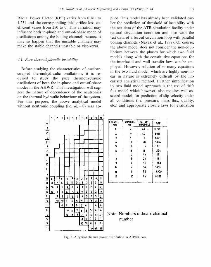
In the AHWR, the power distribution in thecore varies both radially and axially. However,the axial power distribution is more or less uni-form as discussed in our earlier paper (Nayak etal., 1998), and hence, the uniform axial powerdistribution assumption may not have much effecton the nuclear coupled thermohydraulic instabil-ity calculations. On the other hand, the radialpower distribution may affect the above instabil-ity. Fig. 3 shows a typical radial power distribu-tion in the AHWR core. Channels having similaraxial and radial power profiles and resistances aregrouped into one channel type. Each channelnumber shown in the figure groups the channelshaving identical radial and axial power profiles.The channel inlet orificing requirement so as tohave nearly uniform channel exit quality is shownin Table 1. It can be observed from Fig. 3 that the
A.K. Nayak et al. / Nuclear Engineering and Design 195 (2000) 27–44 35
Radial Power Factor (RPF) varies from 0.761 to1.231 and the corresponding inlet orifice loss co-efficient varies from 250 to 0. This variation mayinfluence both in-phase and out-of-phase mode ofoscillations among the boiling channels because itmay so happen that the unstable channels maymake the stable channels unstable or vice-versa.
4.1. Pure thermohydraulic instability
Before studying the characteristics of nuclear-coupled thermohydraulic oscillations, it is re-quired to study the pure thermohydraulicoscillations of both the in-phase and out-of-phasemodes in the AHWR. This investigation will sug-gest the nature of dependency of the neutronicson the thermal hydraulic behaviour of the system.For this purpose, the above analytical modelwithout neutronic coupling (i.e. q %h=0) was ap-
plied. This model has already been validated ear-lier for prediction of threshold of instability withthe test data of the ATR simulation facility undernatural circulation condition and also with thetest data of a forced circulation loop with parallelboiling channels (Nayak et al., 1998). Of course,the above model does not consider the non-equi-librium between the phases for which two fluidmodels along with the constitutive equations forthe interfacial and wall transfer laws can be em-ployed. However, solution of so many equationsin the two fluid model, which are highly non-lin-ear in nature is extremely difficult by the lin-earised analytical method. Further simplificationto two fluid model approach is the use of driftflux model which however, also requires well as-sessed models for prediction of slip velocity underall conditions (i.e. pressure, mass flux, quality,etc.) and appropriate closure laws for evaluation
Fig. 3. A typical channel power distribution in AHWR core.

A.K. Nayak et al. / Nuclear Engineering and Design 195 (2000) 27–4436
Table 1Details of radial power factor and inlet orificing in different channel types of the AHWR
Inlet orifice coefficientChannel type No. of channels in a channel typeRadial power factor (RPF)
2501 600.7612 1.011 0 40
0 43 1.23101.124 284
305 41.011301.124 126
1.1507 30 40301.150 288
1.1039 80 448010 521.016
130 520.909110.93512 130 44
of wall friction and heat transfer for quantifyinginterfacial non-equilibrium. Because, it is wellknown that consideration of thermal non-equi-librium between phases may not predict thethreshold of stability at high subcooling accu-rately (Saha and Zuber, 1978) and from the re-sults of Peng et al. (1984) it is clear that the valuesof distribution parameters in the drift flux modelinfluence the stability behaviour greatly. Henceconsidering the above, the homogeneous equi-librium model was considered applicable for thecore design of the AHWR in the present work.
Fig. 4 shows a typical flow stability map con-sidering the hottest channels of the AHWR (i.e.channel Type 3 having RPF=1.231 and Kin=0.0). The analysis considers two parallel boilingchannels along with the associated inlet and outletfeeders of the reactor. The stability boundary hasbeen plotted as in the reference (Nayak et al.,1998) on Npch versus Nsub plane. The results indi-cate that the out-of-phase thermohydraulic oscil-lations are more likely to occur among the boilingchannels than the oscillations of the in-phasemode because of the dampening effect of the extrasingle-phase friction in the downcomer, whichstabilises the in-phase mode oscillation. Also itcan be observed that the difference in Type-IIinstability boundary between two modes of oscil-lation is much larger than that for Type-I instabil-ity boundary which is in agreement with theresults of Van Bragt and Van der Hagen (1998b).However, the difference in the Type-I instability
boundary between two modes of oscillation is alsosignificant unlike that observed in the DodewaardBWR. The frequency of oscillation has been cal-culated at the threshold point from the imaginarypart of the root of the characteristic equation andalso shown for both modes of oscillation in thesame figure. The frequency of oscillation forType-II instability is larger compared to that forType-I instability. This is because the Type-I in-stability occurs at low power when the flow veloc-
Fig. 4. In-phase and out-of-phase thermohydraulic stabilityboundary in boiling channels of the AHWR.
A.K. Nayak et al. / Nuclear Engineering and Design 195 (2000) 27–44 37
ity is smaller under natural circulation conditionsthan that for the Type-II instability which occursat much higher power. Hence, the fluid takeslonger time to pass through the two-phase regioncompared to the Type-II oscillation case. In gen-eral, it is also found that the frequency of oscilla-tion is very much less for the AHWR channelscompared to that predicted for the Dodewaardnatural circulation BWR (Van Bragt and Van derHagen, 1998b). This is because the period ofoscillation in the AHWR channels is very largedue to large two-phase region of the outlet feederpipes whose length may be several times of thechimney height of the Dodewaard BWR.
4.2. Coupled neutronic thermohydraulic instability
It will be interesting to study the influence ofthe neutronic coupling on the thermohydraulicinstability studied above. For this purpose, thevoid reactivity coefficient (Ca) and the Dopplerreactivity coefficient (CD) were used from thepredictions of a three-dimensional neutronicscomputer code named as SERIES for the AHWR.They are estimated to be −0.005 and (−3×10⁻⁵+19.34×10⁻⁹ T) for the void reactivitycoefficient and Doppler reactivity coefficient, re-spectively, at the normal operating conditions.The fuel time constant is estimated to be about 8s for the AHWR fuel at the normal operatingconditions. However, all these parameters arelikely to change with burn-up and operating con-ditions. Further, in order to investigate their influ-ence on the low frequency thermohydraulicoscillations observed in this reactor, all theseparameters have been varied to study their influ-ence on the instability.
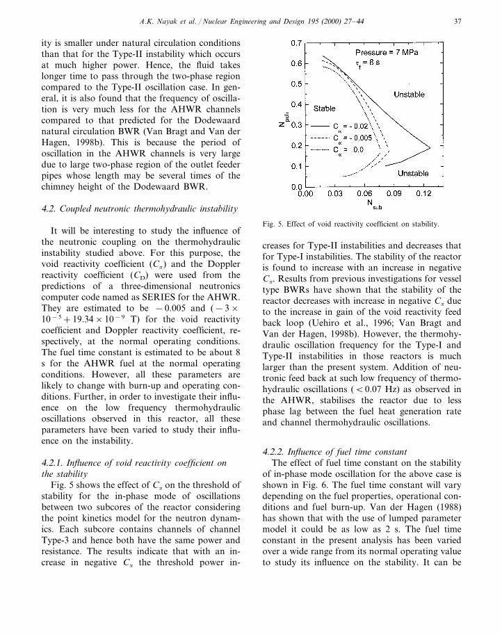
4.2.1. Influence of 6oid reacti6ity coefficient onthe stability
Fig. 5 shows the effect of Ca on the threshold ofstability for the in-phase mode of oscillationsbetween two subcores of the reactor consideringthe point kinetics model for the neutron dynam-ics. Each subcore contains channels of channelType-3 and hence both have the same power andresistance. The results indicate that with an in-crease in negative Ca the threshold power in-
Fig. 5. Effect of void reactivity coefficient on stability.
creases for Type-II instabilities and decreases thatfor Type-I instabilities. The stability of the reactoris found to increase with an increase in negativeCa. Results from previous investigations for vesseltype BWRs have shown that the stability of thereactor decreases with increase in negative Ca dueto the increase in gain of the void reactivity feedback loop (Uehiro et al., 1996; Van Bragt andVan der Hagen, 1998b). However, the thermohy-draulic oscillation frequency for the Type-I andType-II instabilities in those reactors is muchlarger than the present system. Addition of neu-tronic feed back at such low frequency of thermo-hydraulic oscillations (B0.07 Hz) as observed inthe AHWR, stabilises the reactor due to lessphase lag between the fuel heat generation rateand channel thermohydraulic oscillations.
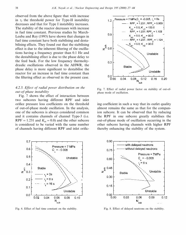
4.2.2. Influence of fuel time constantThe effect of fuel time constant on the stability
of in-phase mode oscillation for the above case isshown in Fig. 6. The fuel time constant will varydepending on the fuel properties, operational con-ditions and fuel burn-up. Van der Hagen (1988)has shown that with the use of lumped parametermodel it could be as low as 2 s. The fuel timeconstant in the present analysis has been variedover a wide range from its normal operating valueto study its influence on the stability. It can be
A.K. Nayak et al. / Nuclear Engineering and Design 195 (2000) 27–4438
observed from the above figure that with increasein tf the threshold power for Type-II instabilitydecreases and that for Type I instability increases.The stability of the reactor decreases with increasein fuel time constant. Previous studies by March-Leuba and Rey (1993) have shown that changes infuel time constant have both stabilising and desta-bilising effects. They found out that the stabilisingeffect is due to the inherent filtering of the oscilla-tions having a frequency greater than 0.1 Hz andthe destabilising effect is due to the phase delay tothe feed back. For the low frequency thermohy-draulic oscillations observed in the AHWR, thephase delay is more significant to destabilise thereactor for an increase in fuel time constant thanthe filtering effect as observed in the present case.
4.2.3. Effect of radial power distribution on theout-of-phase instability
Fig. 7 shows the effect of interaction betweentwo subcores having different RPF and inletorifice pressure loss coefficients on the thresholdof out-of-phase mode oscillation. In the analysis,one of the subcores is always considered commonand it contains channels of channel Type-3 (i.e.RPF=1.231 and Kin=0.0) and the other subcoreis considered to be varied with the same numberof channels having different RPF and inlet orific-
Fig. 7. Effect of radial power factor on stability of out-of-phase mode of oscillation.
ing coefficient in such a way that its outlet qualityalmost remains the same as that for the compan-ion subcore. It can be observed that by reducingthe RPF in one subcore greatly stabilises theout-of-phase mode of oscillation occurring in theother subcore having channels with higher RPFthereby enhancing the stability of the system.
Fig. 6. Effect of fuel time constant on the stability. Fig. 8. Effect of delayed neutrons on the stability.
A.K. Nayak et al. / Nuclear Engineering and Design 195 (2000) 27–44 39
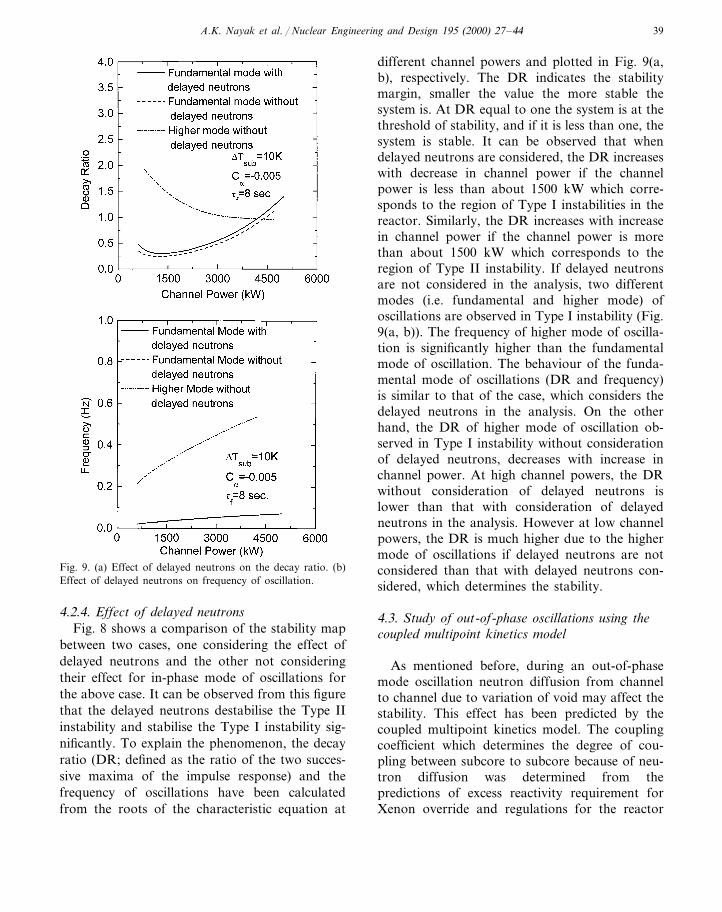
Fig. 9. (a) Effect of delayed neutrons on the decay ratio. (b)Effect of delayed neutrons on frequency of oscillation.
different channel powers and plotted in Fig. 9(a,b), respectively. The DR indicates the stabilitymargin, smaller the value the more stable thesystem is. At DR equal to one the system is at thethreshold of stability, and if it is less than one, thesystem is stable. It can be observed that whendelayed neutrons are considered, the DR increaseswith decrease in channel power if the channelpower is less than about 1500 kW which corre-sponds to the region of Type I instabilities in thereactor. Similarly, the DR increases with increasein channel power if the channel power is morethan about 1500 kW which corresponds to theregion of Type II instability. If delayed neutronsare not considered in the analysis, two differentmodes (i.e. fundamental and higher mode) ofoscillations are observed in Type I instability (Fig.9(a, b)). The frequency of higher mode of oscilla-tion is significantly higher than the fundamentalmode of oscillation. The behaviour of the funda-mental mode of oscillations (DR and frequency)is similar to that of the case, which considers thedelayed neutrons in the analysis. On the otherhand, the DR of higher mode of oscillation ob-served in Type I instability without considerationof delayed neutrons, decreases with increase inchannel power. At high channel powers, the DRwithout consideration of delayed neutrons islower than that with consideration of delayedneutrons in the analysis. However at low channelpowers, the DR is much higher due to the highermode of oscillations if delayed neutrons are notconsidered than that with delayed neutrons con-sidered, which determines the stability.
4.3. Study of out-of-phase oscillations using thecoupled multipoint kinetics model
As mentioned before, during an out-of-phasemode oscillation neutron diffusion from channelto channel due to variation of void may affect thestability. This effect has been predicted by thecoupled multipoint kinetics model. The couplingcoefficient which determines the degree of cou-pling between subcore to subcore because of neu-tron diffusion was determined from thepredictions of excess reactivity requirement forXenon override and regulations for the reactor
4.2.4. Effect of delayed neutronsFig. 8 shows a comparison of the stability map
between two cases, one considering the effect ofdelayed neutrons and the other not consideringtheir effect for in-phase mode of oscillations forthe above case. It can be observed from this figurethat the delayed neutrons destabilise the Type IIinstability and stabilise the Type I instability sig-nificantly. To explain the phenomenon, the decayratio (DR; defined as the ratio of the two succes-sive maxima of the impulse response) and thefrequency of oscillations have been calculatedfrom the roots of the characteristic equation at
A.K. Nayak et al. / Nuclear Engineering and Design 195 (2000) 27–4440
using computer code SERIES. This was esti-mated to be about 3.5 mk considering the reac-tor core to be divided in to two equal subcores.
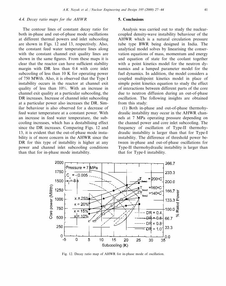
4.3.1. Comparison of stability maps between thecoupled multipoint kinetics model and modal pointkinetics model
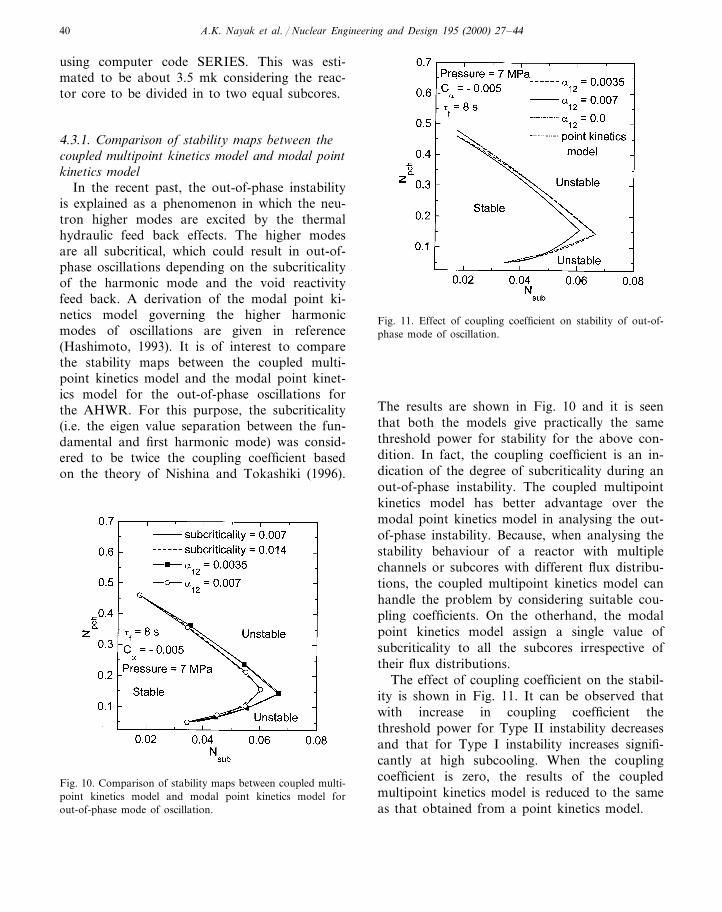
In the recent past, the out-of-phase instabilityis explained as a phenomenon in which the neu-tron higher modes are excited by the thermalhydraulic feed back effects. The higher modesare all subcritical, which could result in out-of-phase oscillations depending on the subcriticalityof the harmonic mode and the void reactivityfeed back. A derivation of the modal point ki-netics model governing the higher harmonicmodes of oscillations are given in reference(Hashimoto, 1993). It is of interest to comparethe stability maps between the coupled multi-point kinetics model and the modal point kinet-ics model for the out-of-phase oscillations forthe AHWR. For this purpose, the subcriticality(i.e. the eigen value separation between the fun-damental and first harmonic mode) was consid-ered to be twice the coupling coefficient basedon the theory of Nishina and Tokashiki (1996).
Fig. 11. Effect of coupling coefficient on stability of out-of-phase mode of oscillation.
The results are shown in Fig. 10 and it is seenthat both the models give practically the samethreshold power for stability for the above con-dition. In fact, the coupling coefficient is an in-dication of the degree of subcriticality during anout-of-phase instability. The coupled multipointkinetics model has better advantage over themodal point kinetics model in analysing the out-of-phase instability. Because, when analysing thestability behaviour of a reactor with multiplechannels or subcores with different flux distribu-tions, the coupled multipoint kinetics model canhandle the problem by considering suitable cou-pling coefficients. On the otherhand, the modalpoint kinetics model assign a single value ofsubcriticality to all the subcores irrespective oftheir flux distributions.
The effect of coupling coefficient on the stabil-ity is shown in Fig. 11. It can be observed thatwith increase in coupling coefficient thethreshold power for Type II instability decreasesand that for Type I instability increases signifi-cantly at high subcooling. When the couplingcoefficient is zero, the results of the coupledmultipoint kinetics model is reduced to the sameas that obtained from a point kinetics model.
Fig. 10. Comparison of stability maps between coupled multi-point kinetics model and modal point kinetics model forout-of-phase mode of oscillation.
A.K. Nayak et al. / Nuclear Engineering and Design 195 (2000) 27–44 41
4.4. Decay ratio maps for the AHWR
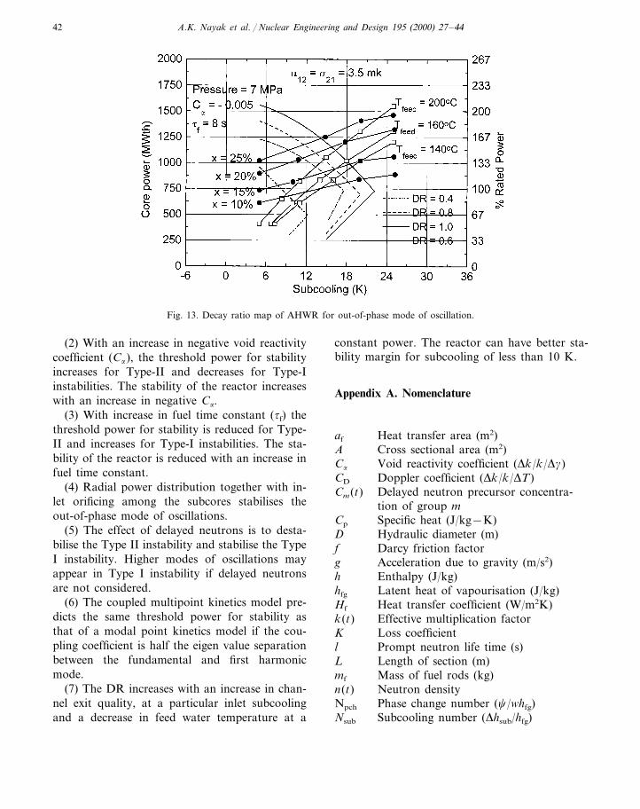
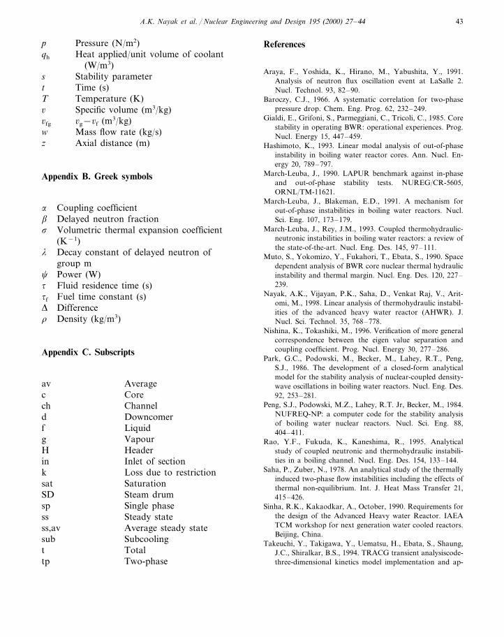
The contour lines of constant decay ratio forboth in-phase and out-of-phase mode oscillationsat different thermal powers and inlet subcoolingare shown in Figs. 12 and 13, respectively. Also,the constant feed water temperature lines alongwith the constant channel exit quality lines areshown in the same figures. From these maps it isclear that the reactor can have sufficient stabilitymargin with DR less than 0.4 with core inletsubcooling of less than 10 K for operating powerof 750 MWth. Also, it is observed that the Type Iinstability occurs in the reactor at channel exitquality of less than 10%. With an increase inchannel exit quality at a particular subcooling, theDR increases. Increase of channel inlet subcoolingat a particular power also increases the DR. Sim-ilar behaviour is also observed for a decrease offeed water temperature at a constant power. Withan increase in feed water temperature, the sub-cooling increases, which has a destabilising effectsince the DR increases. Comparing Figs. 12 and13, it is evident that the out-of-phase mode insta-bility is of more concern in the AHWR since theDR for this type of instability is higher at anypower and channel inlet subcooling conditionsthan that for in-phase mode instability.
5. Conclusions
Analysis was carried out to study the nuclear-coupled density-wave instability behaviour of theAHWR which is a natural circulation pressuretube type BWR being designed in India. Theanalytical model solves by linearising the conser-vation equations of mass, momentum and energyand equation of state for the coolant togetherwith a point kinetics model for the neutron dy-namics and a lumped parameter model for thefuel dynamics. In addition, the model considers acoupled multipoint kinetics model in place ofsimple point kinetics equation to study the effectof interactions between different parts of the coredue to neutron diffusion during an out-of-phaseoscillation. The following insights are obtainedfrom this study:
(1) Both in-phase and out-of-phase thermohy-draulic instability may occur in the AHWR chan-nels at 7 MPa operating pressure depending onthe channel power and core inlet subcooling. Thefrequency of oscillation of Type-II thermohy-draulic instability is larger than that for Type-Iinstability. The difference of threshold power be-tween in-phase and out-of-phase oscillations forType-II thermohydraulic instability is larger thanthat for Type-I instability.
Fig. 12. Decay ratio map of AHWR for in-phase mode of oscillation.
A.K. Nayak et al. / Nuclear Engineering and Design 195 (2000) 27–4442
Fig. 13. Decay ratio map of AHWR for out-of-phase mode of oscillation.
(2) With an increase in negative void reactivitycoefficient (Ca), the threshold power for stabilityincreases for Type-II and decreases for Type-Iinstabilities. The stability of the reactor increaseswith an increase in negative Ca.
(3) With increase in fuel time constant (tf) thethreshold power for stability is reduced for Type-II and increases for Type-I instabilities. The sta-bility of the reactor is reduced with an increase infuel time constant.
(4) Radial power distribution together with in-let orificing among the subcores stabilises theout-of-phase mode of oscillations.
(5) The effect of delayed neutrons is to desta-bilise the Type II instability and stabilise the TypeI instability. Higher modes of oscillations mayappear in Type I instability if delayed neutronsare not considered.
(6) The coupled multipoint kinetics model pre-dicts the same threshold power for stability asthat of a modal point kinetics model if the cou-pling coefficient is half the eigen value separationbetween the fundamental and first harmonicmode.
(7) The DR increases with an increase in chan-nel exit quality, at a particular inlet subcoolingand a decrease in feed water temperature at a
constant power. The reactor can have better sta-bility margin for subcooling of less than 10 K.
Appendix A. Nomenclature
Heat transfer area (m2)af
Cross sectional area (m2)AVoid reactivity coefficient (Dk/k/Dg)Ca
Doppler coefficient (Dk/k/DT)CD
Cm(t) Delayed neutron precursor concentra-tion of group m
Cp Specific heat (J/kg−K)D Hydraulic diameter (m)
Darcy friction factorfg Acceleration due to gravity (m/s2)
Enthalpy (J/kg)hhfg Latent heat of vapourisation (J/kg)
Heat transfer coefficient (W/m2K)Hf
k(t) Effective multiplication factorLoss coefficientKPrompt neutron life time (s)lLength of section (m)LMass of fuel rods (kg)mf
Neutron densityn(t)Phase change number (c/whfg)Npch
Nsub Subcooling number (Dhsub/hfg)
A.K. Nayak et al. / Nuclear Engineering and Design 195 (2000) 27–44 43
Pressure (N/m2)pqh Heat applied/unit volume of coolant
(W/m3)s Stability parameter
Time (s)tTemperature (K)TSpecific volume (m3/kg)66g−6f (m3/kg)6fgMass flow rate (kg/s)wAxial distance (m)z
Appendix B. Greek symbols
Coupling coefficienta
b Delayed neutron fractions Volumetric thermal expansion coefficient
(K−1)Decay constant of delayed neutron ofl
group mPower (W)c
Fluid residence time (s)t
Fuel time constant (s)tf
D DifferenceDensity (kg/m3)r
Appendix C. Subscripts
Averageavc Core
Channelchd Downcomer
LiquidfVapourgHeaderHInlet of sectioninLoss due to restrictionkSaturationsatSteam drumSDSingle phasesp
ss Steady stateAverage steady statess,avSubcoolingsubTotaltTwo-phasetp
References
Araya, F., Yoshida, K., Hirano, M., Yabushita, Y., 1991.Analysis of neutron flux oscillation event at LaSalle 2.Nucl. Technol. 93, 82–90.
Baroczy, C.J., 1966. A systematic correlation for two-phasepressure drop. Chem. Eng. Prog. 62, 232–249.
Gialdi, E., Grifoni, S., Parmeggiani, C., Tricoli, C., 1985. Corestability in operating BWR: operational experiences. Prog.Nucl. Energy 15, 447–459.
Hashimoto, K., 1993. Linear modal analysis of out-of-phaseinstability in boiling water reactor cores. Ann. Nucl. En-ergy 20, 789–797.
March-Leuba, J., 1990. LAPUR benchmark against in-phaseand out-of-phase stability tests. NUREG/CR-5605,ORNL/TM-11621.
March-Leuba, J., Blakeman, E.D., 1991. A mechanism forout-of-phase instabilities in boiling water reactors. Nucl.Sci. Eng. 107, 173–179.
March-Leuba, J., Rey, J.M., 1993. Coupled thermohydraulic-neutronic instabilities in boiling water reactors: a review ofthe state-of-the-art. Nucl. Eng. Des. 145, 97–111.
Muto, S., Yokomizo, Y., Fukahori, T., Ebata, S., 1990. Spacedependent analysis of BWR core nuclear thermal hydraulicinstability and thermal margin. Nucl. Eng. Des. 120, 227–239.
Nayak, A.K., Vijayan, P.K., Saha, D., Venkat Raj, V., Arit-omi, M., 1998. Linear analysis of thermohydraulic instabil-ities of the advanced heavy water reactor (AHWR). J.Nucl. Sci. Technol. 35, 768–778.
Nishina, K., Tokashiki, M., 1996. Verification of more generalcorrespondence between the eigen value separation andcoupling coefficient. Prog. Nucl. Energy 30, 277–286.
Park, G.C., Podowski, M., Becker, M., Lahey, R.T., Peng,S.J., 1986. The development of a closed-form analyticalmodel for the stability analysis of nuclear-coupled density-wave oscillations in boiling water reactors. Nucl. Eng. Des.92, 253–281.
Peng, S.J., Podowski, M.Z., Lahey, R.T. Jr, Becker, M., 1984.NUFREQ-NP: a computer code for the stability analysisof boiling water nuclear reactors. Nucl. Sci. Eng. 88,404–411.
Rao, Y.F., Fukuda, K., Kaneshima, R., 1995. Analyticalstudy of coupled neutronic and thermohydraulic instabili-ties in a boiling channel. Nucl. Eng. Des. 154, 133–144.
Saha, P., Zuber, N., 1978. An analytical study of the thermallyinduced two-phase flow instabilities including the effects ofthermal non-equilibrium. Int. J. Heat Mass Transfer 21,415–426.
Sinha, R.K., Kakaodkar, A., October, 1990. Requirements forthe design of the Advanced Heavy water Reactor. IAEATCM workshop for next generation water cooled reactors.Beijing, China.
Takeuchi, Y., Takigawa, Y., Uematsu, H., Ebata, S., Shaung,J.C., Shiralkar, B.S., 1994. TRACG transient analysiscode-three-dimensional kinetics model implementation and ap-

A.K. Nayak et al. / Nuclear Engineering and Design 195 (2000) 27–4444
plication for space dependent analysis. Nucl. Technol. 105,162–183.
Takigawa, Y., Takeuchi, Y., Tsunoyama, S., Ebata, S., Chan,K.C., Tricoli, C., 1987. Coarso limit cycle analysis withthree-dimensional transient code TOSDYN-2. Nucl. Tech-nol. 79, 210–218.
Uehiro, M., Rao, Y.F., Fukuda, K., 1996. Linear stabilityanalysis on instabilities of in-phase and out-of-phasemodes in boiling water reactors. J. Nucl. Sci. Technol. 33,628–635.
US NRC, 1988. Augmented Inspection Team (AIT) report,Report no. 50-373/88008.
Van Bragt, D.D.B., Van der Hagen, T.H.J.J., 1998a. Stabilityof natural circulation boiling water reactors: part I—de-scription, stability model and theoretical analysis in termsof dimensionless groups. Nucl. Technol. 121, 40–51.
Van Bragt, D.D.B., Van der Hagen, T.H.J.J., 1998b. Stabilityof natural circulation boiling water reactors: part II—parametric study of coupled neutronic-thermohydraulicstability. Nucl. Technol. 121, 52–62.
Van der Hagen, T.H.J.J., 1988. Experimental and theoreticalevidence for a short effective fuel time constant in a boilingwater reactor. Nucl. Technol. 83, 171–181.
.