
Shelland Tube HE feer Sem5
26
UNIVERSITI TEKNOLOGI MARA FAKULTI KEJURUTERAAN KIMIA PROCESS ENGINEERING LABORATORY II (CPE554) NAME : MOHAMED FIRDAUS BIN NORDIN GROUP : EH242 5A EXPERIMEN T : SHELL AND TUBE HEAT EXCHANGER DATE : 19 SEPTEMBER 2014 PROG/CODE : EH242 SUBMIT TO : ENCIK MOHAMAD SUFIAN BIN SO’AIB No Title Allocated Marks (%) Marks 1 Abstract 5 2 Introduction 5 3 Objectives 5 4 Theory 5 5 Procedures/Methodology 10 6 Apparatus 5 7 Results 10 8 Calculation 10 9 Discussion 20 10 Conclusion 10 11 Recommendations 5 12 References 5 13 Appendices 5 TOTAL 100 Remarks: Checked by: Rechecked by: 1
Transcript of Shelland Tube HE feer Sem5

UNIVERSITI TEKNOLOGI MARAFAKULTI KEJURUTERAAN KIMIA
PROCESS ENGINEERING LABORATORY II (CPE554)NAME
:MOHAMED FIRDAUS BIN NORDIN
GROUP : EH242 5AEXPERIMENT
: SHELL AND TUBE HEAT EXCHANGER
DATE : 19 SEPTEMBER 2014PROG/CODE : EH242SUBMIT TO : ENCIK MOHAMAD SUFIAN BIN SO’AIB
No Title AllocatedMarks (%)
Marks
1 Abstract 52 Introduction 53 Objectives 54 Theory 55 Procedures/Methodology 106 Apparatus 57 Results 108 Calculation 109 Discussion 2010 Conclusion 1011 Recommendations 512 References 513 Appendices 5
TOTAL 100
Remarks:
Checked by: Rechecked by:
1

Date: Date:
2

Table of content
CONTENT PAGE
Abstract 3
Introduction 4
Objectives 4
Theory 5-6
Apparatus 7
Experimental procedure 9-10
Result 11
Sample of calculation 12-15
Discussion 16
Conclusion 16
Recommendations 17
References 17
Appendices 18-19
3

4

Abstract
The experiment is about heat exchanger. It involve model of shell and tube heat exchanger. The objectives of the experiment are to calculate the heat transfer and heat loss for energy balance study, to calculate the LMTD (log-mean temperature difference) and to calculate the heat transfer coefficients. The experiment was conducted successfully and the result was tabulated. As the experiment ended, it shows that the heat cannot be easily transferred from cold body to hot body without being catalyse. Counter-current flow configuration of the shell and tube heat exchanger has a higher effectiveness than the co-current flow configuration. Other than that, the experiment shows that when the flow rate of one of the stream increases, the rate of heat transfer willalso increases. It also shows that the LMTD for co-current flow is higher than the counter-current flow. It can be said that, counter current flow configuration of heat exchanger is more preferred for practical application.
5

Introduction
Shell and Tube Heat Exchangers are one of the most popular types of exchanger due to the flexibility the designer has to allow for a wide range of pressures and temperatures. There are two main categories of Shell and Tube exchanger:1. Heat exchanger used in the petrochemical industry which tend
to be covered by standards from TEMA, Tubular Exchanger Manufacturers Association;
2. Heat exchanger used in the power industry such as feed waterheaters and power plant condensers.
Regardless of the type of industry the exchanger is to be usedin there are a number of common features.A shell and tube exchanger consists of a number of tubes mounted inside a cylindrical shell. Two fluids can exchange heat, one fluid flows over the outside of the tubes while the second fluid flows through the tubes. The fluids can be singleor two phase and can flow in a parallel or a cross/counter flow arrangement.
The shell and tube exchanger consists of four major parts: Front Header—this is where the fluid enters the tube side of
the exchanger. It is sometimes referred to as the StationaryHeader.
Rear Header—this is where the tube side fluid leaves the exchanger or where it is returned to the front header in exchangers with multiple tube side passes.
Tube bundle—this comprises of the tubes, tube sheets, baffles and tie rods etc. to hold the bundle together.
Shell—this contains the tube bundle.
The oil refineries and other chemical processes usually use this type of heat exchanger. Besides, shell and tube heat exchanger also suitable for higher-pressure applications.
6

Objectives
The experiment’s aims are
1. To calculate the heat transfer and heat loss for energy balance study.
2. To calculate the LMTD (log-mean temperature difference).3. To calculate the heat transfer coefficients.
7

Theory
Two fluids, of different starting temperatures, flow through the heat exchanger. One flows through the tubes (the tube side) and the other flows outside the tubes but inside the shell (the shell side). Heat is transferred from one fluidto the other through the tube walls, either from tube side to shell side or vice versa. The fluids can be either liquids or gases on either the shell or the tube side. In order to transfer heat efficiently, a large heat transfer area should be used, leading to the use of many tubes. In this way, waste heat can be put to use. This is an efficient way to conserve energy.
Heat exchangers with only one phase (liquid or gas) on each side can be called one-phase or single-phase heat exchangers. Two-phase heat exchangers can be used to heat a liquid to boil it into a gas (vapor), sometimes called boilers, or cool a vapor to condense it into a liquid (called condensers), with the phase change usually occurring on the shell side. Boilers in steam engine locomotives are typically large, usually cylindrically-shaped shell-and-tube heat exchangers. In large power plants with steam-driven turbines, shell-and-tube surface condensers are used tocondense the exhaust steam exiting the turbine into condensate water which is recycled back to be turned into steam in the steam generator.
Formulas for CalculationCo-current Flow heat balance:mtCpt (t2 - t1) = msCps(T1 - T2) = q
Counter-current Flow heat balance:mtCpt (t2 - t1) = msCps(T1 - T2) = qwhere, mt = mass flowrate of cold fluid in thetube (kgs-1)
ms = mass flowrate of hot fluid in the shell (kgs-1) Cpt = specific heat of cold fluid in thetube (kJkg-1°C-1)
8

Cps = specific heat of hot fluid in the shell(kJkg-1°C-1) t1, t2 = temperature of cold fluidentering/leaving the tube (°C) T1, T2 = temperature of hot fluid entering/leaving
the shell (°C) q = heat exchange rate between fluid (kW)
The general equation for heat transfer across the tube surfacein a shell and tube heat exchanger:q = Uo Ao Tm = Ui AiTm (3)where,
Ao = outside area of the tube (m2)Ai = inside area of the tube (m2)
Tm = mean temperature difference (°C)Uo = overall heat transfer coefficient based on
the outside area of the tube (kWm-2°C-1)Ui = overall heat transfer coefficient based on
the inside area of the tube (kWm-2°C-1)
The coefficients Uo and Ui:1Uo
=1ho
+1hod
+doln(do/di)
2kw+
dodihid
+dodihi
and,1Ui
=1hi
+1hid
+diln(do/di )
2kw+
didohod
+didoho
where,ho = outside fluid film coefficient (kWm-2°C-1)hi = inside fluid film coefficient (kWm-2°C-1)hod = outside dirt coefficient (fouling factor) (kWm-2°C-1)hid = inside dirt coefficient (kWm-2°C-1)kw = thermal conductivity of the tube wall material (kWm-
1°C-1)do = tube outside diameter (m)di = tube inside diameter (m)
LMTD (log-mean temperature difference):ΔTlm=
ΔT1−ΔT2
ln(ΔT1ΔT2)
9

Apparatus
10
Hotwater
Rotameter
Monitoring panel
Shell and TubeHeat Exchanger
Valve
Coldwatertank

Apparatus description:
Shell : I.D. = 85 mmLength = 500 mmMaterial = borosilicate glassTubes : O.D. = 9.53 mmI.D. = 7.75 mmLength = 500 mmTube count = 10 (single pass)Tube pitch = 18 mm (triangle)Baffle = 8Baffle cut = 20%Material = stainless steel 316LExchange area : 0.15 m2 (approx.)
11

Experimental procedures
General Start-up
1. A quick inspection was performed to make sure that the equipment is in a proper working condition.
2. All valves were checked to be initially closed, except V1and V2.
3. Hot water tank was filled up via a water supply hose connected to valve V27. The valve was closed once the tank is full.
4. The cold water tank was filled up by opening valve V28 and the valve was leave opened for continues water supply.
5. A drain hose was connected to the cold water drain point.6. Main power was switched on. The heater for the hot water
tank was switched on and temperature controller was set to 50oC.
7. Water temperature in the hot water tank is allowed to reach the set-point.
8. The equipment ready to be run.
Experiment 1.A: Counter-current Shell and Tube Heat Exchanger
1. General start-up procedures were performed.2. The valve was switched to counter-current Shell and Tube
Heat Exchanger arrangement.3. Pumps P1 and P2 were switched on.
12

4. Valves V3 and V14 were opened and adjusted to obtain the desired flow rates for hot water and cold water streams, respectively.
5. The system was allowed to reach steady state for 10 minutes.
6. FT1, FT2, TT1, TT2, TT3 and TT4 were recorded.7. Pressure drop measurements for shell-side and tube-side
were recorded for pressure drop studies.8. Steps 4 to 7is repeated for the different combinations of
flow rate FT1 and FT2 as in the results sheet.9. Pumps P1and P2 is switched off after complete the
experiment.
Experiment 1.B: Co-current Shell and Tube Heat Exchanger
1. General start-up procedures were performed.2. The valve was switched to co-current Shell and Tube Heat
Exchanger arrangement.3. Pumps P1 and P2 were switched on.4. Valves V3 and V14 were opened and adjusted to obtain the
desired flow rates for hot water and cold water streams, respectively.
5. The system was allowed to reach steady state for 10 minutes.
6. FT1, FT2, TT1, TT2, TT3 and TT4 were recorded.7. Pressure drop measurements for shell-side and tube-side
were recorded for pressure drop studies.8. Steps 5 to 8 were repeated for different combinations of
flow rate FT1 and FT2 as in the result sheet,9. Pumps P1 and P2 were switched off after the experiment
complete.
General Shut-down
1. Heater is switched off. Hot water temperature was leave to reach below 40oC.
2. Pumps P1 and P2 is switched off.13
3. Main power is switched off.4. All water is drained off in the process lines. Water in
the hot and cold water tanks is retained for next laboratory session.
5. All valves are closed.
14

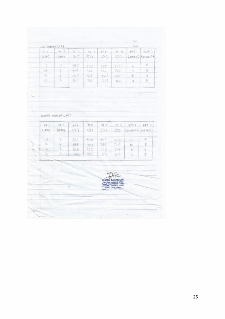
Result
Counter-current
FT1(L/min)
FT2(L/min)
TT1(oC)
TT2(oC)
TT3(oC)
TT4(oC)
HeatTransfer
(kW)
HeatLosses(kW)
10 2 50.0 47.6 41.7 32.9 1.2206 0.504910 4 49.8 46.8 39.2 32.9 1.7480 0.323010 6 50.0 46.5 37.8 32.8 2.0812 0.335110 8 50.3 46.3 36.8 32.8 2.2757 0.485710 10 49.7 46.5 36.0 32.6 2.3591 0.4723
q (kW) LMTD Ao Ai Uo Ui
1.3275 10.42 0.12 0.096 1.0616 1.30531.5471 11.75 0.12 0.096 1.0973 1.34912.1544 12.59 0.12 0.096 1.4260 1.75332.5968 13.05 0.12 0.096 1.6582 2.03882.5550 12.81 0.12 0.096 1.6621 2.0436
Co-current
FT1(L/min)
FT2(L/min)
TT1(oC)
TT2(oC)
TT3(oC)
TT4(oC)
HeatTransfer (kW)
HeatLosses(kW)
10 2 49.7 47.3 32.7 41.1 1.1513 0.505610 4 49.9 46.6 32.7 38.8 1.6926 0.585910 6 49.7 46.1 32.7 37.4 1.9564 0.529010 8 50.1 46.1 32.5 36.4 2.1647 0.665710 10 50.3 45.7 32.3 35.7 2.3592 0.7475
q (kW) LMTD Ao Ai Uo Ui
1.2305 11.79 0.12 0.096 0.8697 1.06931.5473 13.56 0.12 0.096 0.9509 1.16912.1544 13.91 0.12 0.096 1.2907 1.58692.5410 13.78 0.12 0.096 1.5367 1.88932.7620 13.60 0.12 0.096 1.6924 2.0808
15

16

Sample of Calculation
Tube side calculation:
Tin = 306.4 K
Tout = 315.2 K
Dout = 9.53 mm
Din = 7.75 mm
Ρ H2O = 1000kg/m3
Volumetric flow rate,V = 2LPM = 0.033X10⁻³ m3/s
Mass flow rate = 0.4kg/s
Area = r∏ 2
= (3.875x10∏ -3)2
= 4.717x10⁻⁵
Ut = V/A
= 0.033X10⁻³/4.717X10-5
Re = es Du
=( (997kg/m3)(0.7m/s)(7.75x10-3))/ (0.798x10⁻³)
= 6777.851 > 4000 (turbulent)
Pr=CpμtK f
=(( 4186j/kg.˚C(769x10-6))/0.62
17

=5.192
Nu=1.86∗((Re*Pr )0.33(diL )0.33) ,
( μμw )0.14
Is neglected
Nu = 1.86*{(6777.851*5.192) 0.33 (7.75∗10−3
500∗10−3 )0.33
= 14.881
Tube Co-efficient:
Nu=(hideKf )14.881 =( hi (9.53x10⁻³))/0.62
Hi = 968.124
Shell side calculation:
In order to determine the heat transfer coefficient for fluidfilm in shell, first calculate the cross-sectional area offlow As for tube rows in the middle of the shell as follows:
As=(pt−d∘)Dslbpt
As=(0.018−(0.00953 )0.00775∗0.05330.018
As=1.944∗10−4m2
18

us=VsAs = 0.033x10⁻³/ 1.944x10-4
= 0.1698 m/s
As the arrangement is triangular so use the below formula tofind equivalent diameter of shell,
De=1.10d∘
(pt2−0.917d∘2)
De=1.100.00953
(0.0182−0.917∗0.009532)
De=0.028m
Re=997∗0.0075∗0.0280.798∗10−3
Re=271.114
Re < 2100 laminar
Find the value of Jh and Jf corresponding to the Reynolds no in
the respective charts
Jh = 2.5x10⁻²
Jf = 7x10⁻²
Find the Pr No:
Nu=jh*Re*Pr0.33∗( μμw )
0.14
Nu =2.5x10-2 *271.114*(5.192)0.33(1)0.14
19

Nu = 11.672
Heat transfer:
)()(ln
)()()/ln(
42
31
4231
21
21
TTTT
TTTTTTTTTlm
ΔT2 = 47.6 -41.7 = 5.4
ΔT1 = 50 - 32.9 = 17.1
ΔTlm1 = (5.4 – 17.1)/ln (5.4/17.1)
= 10.42
ΔTlm2 = 2.4677
Qreleased = mcΔTlm
= (0.167)(4.189)(2.4677)
= 1.7255
Qabsorbed = mcΔTlm
= (0.033)(4.189)(10.42)
=1.4542
Heat lost= 1.7255-1.4542
= 0.5049
Total exchange area
Outer area of tube = 2ΠrLN
Where N = no of tube
Ao = 2Π(4.765×10^-3)(0.5)(10)
= 0.12
20

Ai = 0.096
ho = (0.683kf/de)re0.466pr1/3
= (0.683(0.62)/0.0258)(271.114)0.466(5.192)1/3
= 386.799 W
1Uo
=1386.799 +
0.00953ln(0.00953/0.0075)2(16 )
+0.009530.0075(540.85)
U∘=1.0616
Ui=1.3053
21

Discussion
Before starting the experiment, the equipment was checkedto make sure there is no defect that can affect result of the experiment. Water is filled into the hot water tank as it is empty before heating it.
During the experiment, the data were recorded depend on the flow rate. As the data obtained, the calculation was made to verify the objectives of the experiment. The temperature data shows that the counter-current and co-current heat exchanger’s exit temperature of the hot fluid is higher than the exit temperature of the cold fluid. This indicates that the heat cannot transfer easily from cold body to hot body. The increase of flow rate increases the rate of heat transfer.In the experiment, the heat loss in counter-current flow is approximately 26% while the heat loss in co-current flow is approximately 30% which are slightly higher. The theory in which the amount of heat loss from hot water should be equal to the heat gain by the cold water cannot be achieved in this experiment. It is because, during the process of heat transfer, the heat may be loss to the surrounding. The calculated LMTD shows that LMTD for co-current flow is higher that counter-current flow. However, the overall heat transfer coefficient for counter-current flow is higher than the co-current flow. This shows that counter-current flow heat exchanger has a higher effectiveness.
Conclusion
As the experiment ends, it shows that the heat cannot be easily transferred from cold body to hot body without being catalyse. This occurs in experiment when exit temperature of the hot fluid is always higher than the exit temperature of the cold fluid. However, in counter-current flow configuration, the exit temperature of the cold fluid is
22

higher than the exit temperature of the cold fluid in co-current configuration.
Counter-current flow configuration of the shell and tube heat exchanger has a higher effectiveness than the co-current flow configuration. It is because the overall heat transfer coefficient for counter-current flow is higher than the co-current flow. Other than that, the experiment shows that when the flow rate of one of the stream increases, the rate of heattransfer will also increases. It also shows that the LMTD forco-current flow is higher than the counter-current flow. It can be said that, counter current flow configuration of heat exchanger is more preferred for practical application.
Recommendations
1. The reading of temperature should be taken after the flowrate of water stable. This to prevent the error in the calculation when the false reading is taken at unstable flow rate.
2. The unit must be synchronised throughout the calculation to prevent the error in the result.
3. When handling the equipment, student must wear an appropriate attire and personal protection equipment suchas laboratory coat and helmet. This is to prevent injuries caused by dangerous substances such as hot water.
4. If the student facing problem with the equipment, ask forhelp from laboratory assistant. This is to make sure that
23

the experiment can be done smoothly without giving any error and danger.
References
1. Brogan, R.J. Shell and Tube Heat Exchanger. Thermopedia. [Online] [Cited: 2 October, 2014.] http://www.thermopedia.com/content/1121/.
2. Frank P.Incropera, David P.Dewitt, Theodore L.Bergman, Adrienne S.Lavine. Principles of Heat and Mass Transfer. Singapore : John Wiley & Sons,2013.
3. Rase, Howard F; Chemical Reactor Design and for Process and plants; Volume 1; 1st edition.
4.Max S. Peter & Klaus D. Timmerhaus; Plant Design and Economic for Chemical Engineering; 4th edition; Page 576.
5.Coulson and Richardson; Chemical Engineering; Volume 1, 6th edition
Appendices
24
25

26


![Ionic dimers in He droplets: Interaction potentials for Li[sub 2][sup +]–He,Na[sub 2][sup +]–He, and K[sub 2][sup +]–He and stability of the smaller clusters](https://static.fdokumen.com/doc/165x107/634156f0c38f655be209fcfa/ionic-dimers-in-he-droplets-interaction-potentials-for-lisub-2sup-henasub.jpg)