
Spectroscopy of the hyperfine structure of antiprotonic 4 He and 3 He
10
Hyperfine Interact (2011) 199:337–346 DOI 10.1007/s10751-011-0329-1 Spectroscopy of the hyperfine structure of antiprotonic 4 He and 3 He Susanne Friedreich · Dániel Barna · Andreas Dax · Ryu Hayano · Dezs ˝ o Horváth · Masaki Hori · Bertalan Juhász · Oswald Massiczek · Anna Sótér · Thomas Pask · Eberhard Widmann Published online: 27 April 2011 © The Author(s) 2011. This article is published with open access at Springerlink.com Abstract The spin magnetic moment μ p s of the antiproton can be determined by comparing the measured transition frequencies in p 4 He + with three-body QED calculations. A comparison between the proton and antiproton can then be used as a test of CPT invariance. The highest measurement precision of the difference between the proton and the antiproton spin magnetic moments to date is 0.3%. A new experimental value of the spin magnetic moment of the antiproton was obtained as μ p s =−2.7862(83)μ N , slightly better than the previously best measurement. This agrees with μ p s within 0.24%. In 2009, a new measurement with antiprotonic 3 He has been started. A comparison between the theoretical calculations and experimental results would lead to a stronger test of the theory and address systematic errors therein. A measurement of this state will be the first HF measurement on p 3 He + . We report here on the new experimental setup and the first tests. Keywords Antiproton · Antiprotonic helium · Hyperfine structure · Spectroscopy · Laser · Microwave · Three-body quantum electrodynamics S. Friedreich (B ) · B. Juhász · O. Massiczek · T. Pask · E. Widmann Stefan Meyer Institute for Subatomic Physics, Austrian Academy of Sciences, 1090 Vienna, Austria e-mail: [email protected] D. Barna · A. Dax · R. Hayano · M. Hori Department of Physics, University of Tokyo, Tokyo 113-0033, Japan D. Barna · D. Horváth KFKI Research Institute for Particle and Nuclear Physics, 1525 Budapest, Hungary D. Horváth Institute of Nuclear Research of the Hungarian Academy of Sciences, 4001 Debrecen, Hungary M. Hori · A. Sótér Max-Planck-Institut für Quantenoptik, 85748 Garching, Germany
Transcript of Spectroscopy of the hyperfine structure of antiprotonic 4 He and 3 He
Hyperfine Interact (2011) 199:337–346DOI 10.1007/s10751-011-0329-1
Spectroscopy of the hyperfine structure of antiprotonic4He and 3He
Susanne Friedreich · Dániel Barna · Andreas Dax · Ryu Hayano · Dezso Horváth ·Masaki Hori · Bertalan Juhász · Oswald Massiczek · Anna Sótér ·Thomas Pask · Eberhard Widmann
Published online: 27 April 2011© The Author(s) 2011. This article is published with open access at Springerlink.com
Abstract The spin magnetic moment μps of the antiproton can be determined by
comparing the measured transition frequencies in p4He+ with three-body QEDcalculations. A comparison between the proton and antiproton can then be usedas a test of CPT invariance. The highest measurement precision of the differencebetween the proton and the antiproton spin magnetic moments to date is 0.3%. Anew experimental value of the spin magnetic moment of the antiproton was obtainedas μ
ps = −2.7862(83)μN , slightly better than the previously best measurement. This
agrees with μps within 0.24%. In 2009, a new measurement with antiprotonic 3He has
been started. A comparison between the theoretical calculations and experimentalresults would lead to a stronger test of the theory and address systematic errorstherein. A measurement of this state will be the first HF measurement on p3He+.We report here on the new experimental setup and the first tests.
Keywords Antiproton · Antiprotonic helium · Hyperfine structure · Spectroscopy ·Laser · Microwave · Three-body quantum electrodynamics
S. Friedreich (B) · B. Juhász · O. Massiczek · T. Pask · E. WidmannStefan Meyer Institute for Subatomic Physics, Austrian Academy of Sciences,1090 Vienna, Austriae-mail: [email protected]
D. Barna · A. Dax · R. Hayano · M. HoriDepartment of Physics, University of Tokyo, Tokyo 113-0033, Japan
D. Barna · D. HorváthKFKI Research Institute for Particle and Nuclear Physics, 1525 Budapest, Hungary
D. HorváthInstitute of Nuclear Research of the Hungarian Academy of Sciences, 4001 Debrecen, Hungary
M. Hori · A. SótérMax-Planck-Institut für Quantenoptik, 85748 Garching, Germany

338 S. Friedreich et al.
1 Introduction
Antiprotonic helium has been measured for the first time at KEK in Japan in1991 [1]. It was observed that antiprotons which are slowed down and stopped ina helium target will form antiprotonic helium and survive several microseconds. Ifan antiproton is approaching a helium atom at its ionization energy (24.6 eV) orbelow, the antiproton can eject one of the two electrons in the ground state fromthe helium atom, replace it and thus get captured. This exotic, metastable three-body system, consisting of one electron in the ground state, the helium nucleus andthe antiproton precessing around the nucleus, is called antiprotonic helium [2–4].They occupy circular states with n ∼ l, where l is the angular momentum quantumnumber. The electron remains in the ground state. The antiproton is, due to itshigh mass, most likely to occupy states with high angular momentum, i.e. a principalquantum number n = n0 ≡ √
M∗/me ∼ 38, M∗ being the reduced mass of the system.As this neutral system retains one electron, it is further protected from collisionswith external atoms by the Pauli exclusion principle. The external Auger decay ofthe remaining electron is suppressed by the large ionisation energy compared to then → n − 1 level spacing of a few eV. The presence of the electron also removes thel-degeneracy of the states with the same n, therefore protecting them against Starkmixing. About 97% of these exotic atoms find themselves in states dominated byAuger decay and ionize within nanoseconds (∼ 10 ns) due to the Auger excitation ofthe electron. Stark mixing occurs due to the induced electrical field of the ions. Theantiprotons then decay within picoseconds and annihilate with one of the nucleonsof the helium nucleus because of the overlap of their wavefunctions. Only a smallfraction of 3% of antiprotonic helium atoms remain in metastable, radiative decaydominated states with energy level spacings of ∼ 2 eV. �l is large and thus Augerdecay is suppressed. Therefore, these states are relatively long lived having a lifetimeof about 1.5 microseconds before they also decay. This small time window can beused to do the measurements of the hyperfine structure. At the end of the cascade,when Auger decay is no longer suppressed, the second electron is ejected in lessthan 10 ns, degeneracy occurs, Stark mixing becomes dominant and the antiprotonannihilates in the nucleus.
2 The hyperfine structure of antiprotonic helium
The interaction of the magnetic moments of its constituting particles gives rise to asplitting of the energy levels. The coupling of the electron spin �Se and the orbitalangular momentum of the antiproton �L leads to the primary splitting of the stateinto a doublet structure, in the order of νHF = 10 − 15 GHz. This spin-orbit splittingis referred to as hyperf ine (HF) splitting. The spin-orbit interaction of the antiprotonorbital angular momentum and antiproton spin �Sp in combination with the contactspin-spin and the tensor spin-spin interactions between the particles result in afurther splitting of these HF states into quadruplets, the so-called super-hyperfine(SHF) splitting, of about νSHF = 150 − 300 MHz. In antiprotonic 4He the nucleushas no spin and thus there is only a quadruplet substructure, while for 3He a nuclearspin exists which also couples with electron and antiproton magnetic moment. Thus,one obtains a further substructure and a splitting into eight SHF substates instead of
HFS spectroscopy with p4He+ and p3He+ 339
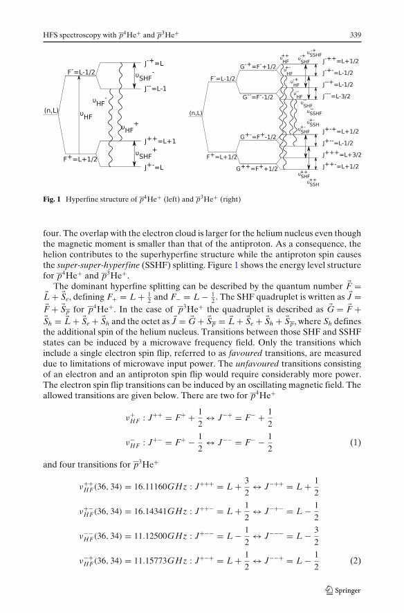
Fig. 1 Hyperfine structure of p4He+ (left) and p3He+ (right)
four. The overlap with the electron cloud is larger for the helium nucleus even thoughthe magnetic moment is smaller than that of the antiproton. As a consequence, thehelion contributes to the superhyperfine structure while the antiproton spin causesthe super-super-hyperfine (SSHF) splitting. Figure 1 shows the energy level structurefor p4He+ and p3He+.
The dominant hyperfine splitting can be described by the quantum number �F =�L + �Se, defining F+ = L + 1
2 and F− = L − 12 . The SHF quadruplet is written as �J =
�F + �Sp for p4He+. In the case of p3He+ the quadruplet is described as �G = �F +�Sh = �L + �Se + �Sh and the octet as �J = �G + �Sp = �L + �Se + �Sh + �Sp, where Sh definesthe additional spin of the helium nucleus. Transitions between those SHF and SSHFstates can be induced by a microwave frequency field. Only the transitions whichinclude a single electron spin flip, referred to as favoured transitions, are measureddue to limitations of microwave input power. The unfavoured transitions consistingof an electron and an antiproton spin flip would require considerably more power.The electron spin flip transitions can be induced by an oscillating magnetic field. Theallowed transitions are given below. There are two for p4He+
ν+HF : J++ = F+ + 1
2↔ J−+ = F− + 1
2
ν−HF : J+− = F+ − 1
2↔ J−− = F− − 1
2(1)
and four transitions for p3He+
ν++HF(36, 34) = 16.11160GHz : J+++ = L + 3
2↔ J−++ = L + 1
2
ν+−HF(36, 34) = 16.14341GHz : J++− = L + 1
2↔ J−+− = L − 1
2
ν−−HF(36, 34) = 11.12500GHz : J+−− = L − 1
2↔ J−−− = L − 3
2
ν−+HF(36, 34) = 11.15773GHz : J+−+ = L + 1
2↔ J−−+ = L − 1
2(2)

340 S. Friedreich et al.
The goal of this experiment is to measure the transitions between the SHF (SSHF)substates. From the measured frequency difference between two transitions it ispossible to calculate the antiprotonic magnetic moment by comparison with thethree-body QED calculations. The theoretical calculations have been developed bytwo different groups [5–7]. They used the same Hamiltonian for their calculations butthe energy eigenvalues have been obtained using different variational methods. Thehyperfine structures for p3He+ and p4He+ have been calculated most accurately byKorobov [8, 9].
3 Experimental method
The experimental technique is a three-step process, referred to as laser-microwave-laser spectroscopy. After antiprotonic helium is formed, the atoms in the hyperfinesubstates are in thermal equilibrium and all equally populated. Therefore, at first onehas to create a population asymmetry between the SHF substates of the (n,l) state.This depopulation is induced by a laser which is applied for about 15–20 ns. Thelaser wavelength is fixed to the transition from one of the HF states of the radiativedecay-dominated parent state to the Auger decay dominated daughter state, causinga population transfer between them. Subsequently, a microwave pulse is appliedover a narrow frequency range around the transition frequency of the SHF (p4He+)or SSHF (p3He+) substates of the parent state. If it is on resonance with one ofthe transitions this will cause a population transfer between the substates and thusrefilling of one of the previously depopulated states. A second laser is then fixedagain to the same transition as before in order to measure the transferred population.The technique is displayed in Fig. 2.
There are several limitations to the choice of the measured state, such as lasercapability or HF laser splitting. For p4He+ the laser transition of the (n,l) = (37,35)state to (n′, l′) = (38, 34) state had been chosen and successfully measured. This lasertransition is easily stimulated. The splitting of the two laser transitions f+ and f−
between the HF states of parent and daughter state (see Fig. 2) are large enough,�f = 1.27 GHz compared to the Doppler broadening, �νD = 420 MHz , so that thehyperfine states can be resolved. This state is also highly populated compared toothers in p4He+ [10]. The new state that will be measured in p3He+ is (n,l) = (36,34),which has similar characteristics to the (n,l) = (37,35) state of p4He+.
The antiprotons for the experiment are provided at the AD (Antiproton Decel-erator) at CERN, with a pulsed beam of (1 − 3) × 107 antiprotons at an energy of5.3 MeV, with a repetition rate of about 100 s. The antiproton pulse is stopped in ahelium gas target which is cooled down to a temperature of 6K. The gas pressure is inthe range of several hundred mbar. A signal is measured by detecting the annihilationdecay products. The created pions go through two Cherenkov counters mountedaround the target area and the resulting photons are detected by photomultipliersthat are gated off during the initial p pulse arrival in order to record only theannihilations due to the metastable state depopulation.
The annihilation time spectrum shows a first sharp prompt peak after the ppulse which is caused by the majority of states that annihilate within picosecondsof formation due to the relatively short lived (∼10 ns) daughter state merging into

HFS spectroscopy with p4He+ and p3He+ 341
f-
f+
ba
Pea
k-to
-tot
al-r
atio
0.014
0.012
0.010
0.008
0.006
0.004
0.002
0.000
Frequency [Hz]
414.145 414.146 414.147 414.148 414.149 x10³
Fig. 2 a Hyperfine structure of p3He+. Wavy lines denote M1 transitions that correspond to a spinflip of the electron (HF transitions) which can be detected with our laser-microwave-laser method,while double arrows symbolise M1 transitions with spin flips of the antiproton or the helion, dashedlines refer to laser-induced E1 transitions. b Laser resonance profile for p3He+, displaying the twosharp peaks for the laser transitions f+ and f−. There are four SHF lines, but two of them lie closerto each other (G−−, G−+) and thus only the G+− and G++ lines are visible (on the left peak)
an exponential tail due to the metastable states cascading slowlier towards thenucleus. This constitutes the background for the laser-induced annihilation signalsand is called ADATS (Analog Delayed Annihilation Time Spectrum). The measuredannihilation signal, i.e. the induced population transfer, is indicated by the ratio ofthe (laser-annihilation) peak area to the background. The second laser peak is mainlydetermined by the microwave induced transition between the hyperfine substates. Italso depends on the time delay with respect to the first laser-induced annihilationpeak and collisional relaxation effects. Both laser peaks can change in amplitudedue to statistical fluctuations, p beam intensity and laser power. Therefore, thesecond laser-annihilation peak can be normalized to the first one. The two hyperfinetransitions can now be obtained as distinct lines by displaying the peak-to-total ofthe second laser-annihilation signal normalized to the peak-to-total of the first laser-annihilation peak as a function of the microwave frequency.
4 New value for the antiproton magnetic moment
A precise measurement of the antiprotonic helium hyperf ine structure (HFS) canbe compared to three-body quantum electrodynamic (QED) calculations as a testof their predictions. If theory and experiment agree, a comparison between themeasured transition frequencies and three body QED can be used to determine theantiproton spin magnetic moment μ
ps . Compared to the proton magnetic moment it
further provides a test of CPT invariance. The HFS of the (n,l) = (37, 35) state ofp4He+ has now been thoroughly measured in terms of the energy eigenvalues.
342 S. Friedreich et al.
12.924,0
12.924,2
12.924,4
12.924,6
12.924,8
12.925,0
12.925,2
12.925,4
12.925,6
0 100 200 300 400 500
HF
(MH
z)Pressure (mbar)
0 100 200 300 400 500
Pressure (mbar)
data Korobov 01 Korobov 09
12.896,0
12.896,2
12.896,4
12.896,6
12.896,8
12.897,0
12.897,2
12.897,4
data Korobov 01 Korobov 09
νHF
(MH
z)ν
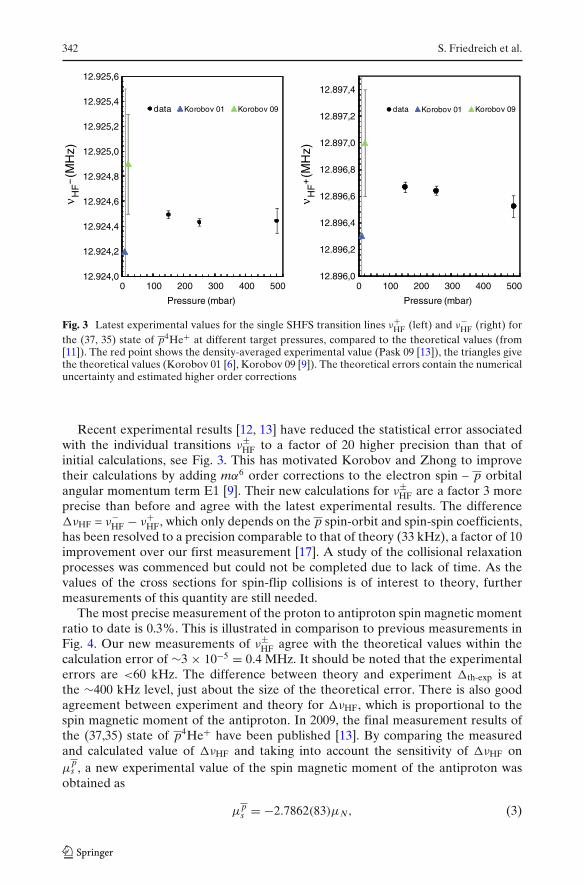
Fig. 3 Latest experimental values for the single SHFS transition lines ν+HF (left) and ν−
HF (right) forthe (37, 35) state of p4He+ at different target pressures, compared to the theoretical values (from[11]). The red point shows the density-averaged experimental value (Pask 09 [13]), the triangles givethe theoretical values (Korobov 01 [6], Korobov 09 [9]). The theoretical errors contain the numericaluncertainty and estimated higher order corrections
Recent experimental results [12, 13] have reduced the statistical error associatedwith the individual transitions ν±
HF to a factor of 20 higher precision than that ofinitial calculations, see Fig. 3. This has motivated Korobov and Zhong to improvetheir calculations by adding mα6 order corrections to the electron spin – p orbitalangular momentum term E1 [9]. Their new calculations for ν±
HF are a factor 3 moreprecise than before and agree with the latest experimental results. The difference�νHF = ν−
HF − ν+HF, which only depends on the p spin-orbit and spin-spin coefficients,
has been resolved to a precision comparable to that of theory (33 kHz), a factor of 10improvement over our first measurement [17]. A study of the collisional relaxationprocesses was commenced but could not be completed due to lack of time. As thevalues of the cross sections for spin-flip collisions is of interest to theory, furthermeasurements of this quantity are still needed.
The most precise measurement of the proton to antiproton spin magnetic momentratio to date is 0.3%. This is illustrated in comparison to previous measurements inFig. 4. Our new measurements of ν±
HF agree with the theoretical values within thecalculation error of ∼3 × 10−5 = 0.4 MHz. It should be noted that the experimentalerrors are <60 kHz. The difference between theory and experiment �th-exp is atthe ∼400 kHz level, just about the size of the theoretical error. There is also goodagreement between experiment and theory for �νHF, which is proportional to thespin magnetic moment of the antiproton. In 2009, the final measurement results ofthe (37,35) state of p4He+ have been published [13]. By comparing the measuredand calculated value of �νHF and taking into account the sensitivity of �νHF onμ
ps , a new experimental value of the spin magnetic moment of the antiproton was
obtained as
μps = −2.7862(83)μN, (3)
HFS spectroscopy with p4He+ and p3He+ 343
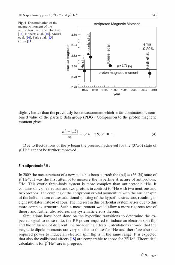
Fig. 4 Determination of themagnetic moment of theantiproton over time. Hu et al.[14], Roberts et al. [15], Kreisslet al. [16], Pask et al. [13](from [11])
2.76
2.78
2.80
2.82
2.84
2.86
1975 1980 1985 1990 1995 2000 2005 2010
Pas
k et
al.
Kre
issl
et a
l.
proton magnetic moment
Rob
erts
et a
l.
Hu
et a
l.
nucl
ear
mag
neto
n
year
Antiproton Magnetic Moment
µ = 2.79 µN
error~0.29%
slightly better than the previously best measurement which so far dominates the com-bined value of the particle data group (PDG). Comparison to the proton magneticmoment gives
μps − |μp
s |μ
ps
= (2.4 ± 2.9) × 10−3. (4)
Due to fluctuations of the p beam the precision achieved for the (37,35) state ofp4He+ cannot be further improved.
5 Antiprotonic 3He
In 2009 the measurement of a new state has been started: the (n,l) = (36, 34) state ofp3He+. It was the first attempt to measure the hyperfine structure of antiprotonic3He. This exotic three-body system is more complex than antiprotonic 4He. Itcontains only one neutron and two protons in contrast to 4He with two neutrons andtwo protons. The coupling of the antiproton orbital momentum with the nuclear spinof the helium atom causes additional splitting of the hyperfine structure, resulting ineight substates instead of four. The interest in this particular system arises due to thismore complex structure. Such a measurement would allow a more rigorous test oftheory and further also address any systematic errors therein.
Simulations have been done on the hyperfine transitions to determine the ex-pected signal to noise ratio, the RF power required to induce an electron spin flipand the influence of different line broadening effects. Calculations showed that themagnetic dipole moments are very similar to those for 4He and therefore also therequired power to induce an electron spin flip is in the same range. It is expectedthat also the collisional effects [18] are comparable to those for p4He+. Theoreticalcalculations for p3He+ are in progress.

344 S. Friedreich et al.
0 50 100 mm
50K shielding 6K stage
Waveguide (microwave pulse)Mic rowave-Cavity
Laser beam
(He-filled)
Antiproton beam
Iris
Meshes(stainless steel)
Fig. 5 Drawing of the central part of the new setup, a cut through the cryostat (left). The microwavecavity for the 11 GHz transitions in antiprotonic 3He mounted on the coldhead of the new,compressor-based cryostat (right)
6 New experimental setup
As described above, the antiprotons enter a small target, a cylindrical stainlesssteel cavity, filled with helium gas. The laser beam is sent into the target fromthe opposite side. The microwave pulse is provided by a vector network analyzer(VNA) and amplified by a travelling wave tube amplifier (TWTA). The signal is thenforwarded to the microwave cavity through a waveguide system. This experimentwith antiprotonic 3He required an entirely new setup, refer therefore to Fig. 5. Thetransition frequencies between the super-hyperfine substates of antiprotonic 3Heare different from those in 4He. Two new microwave cavities have to be designedin order to measure all four possible super-hyperfine transitions (see Fig. 2). Thecavity for 11 GHz has already been tested and first measurements carried out. A newcryostat with compressor-based cooling system has been built. The microwave cavityis now cooled directly by mounting it on a coldhead. In comparison to the previoussetup, now only the cavity is filled with the helium gas and by means of the coldheadcooled down to about 6 K. Liquid nitrogen and liquid helium are no longer neededto cool the cavity down. The cooling process is much faster than with the old systemand it can be operated continuously, thus saving a lot of beamtime previously neededfor refilling of the coolants.
The heart of our setup is the microwave cavity, a cylindrical resonator. There are afew fundamental requirements to be considered when building and testing this cavity.The resonance frequency of the cavity needs to be at the center between two of thefour SSHF transitions in antiprotonic 3He. There are four such transitions that canbe induced using a microwave – two at about 11 GHz and two around 16 GHz. Inorder to measure the transitions which lie close to each other with one single cavity,a broad resonance is required to allow scanning over a broad frequency range ofabout 100 MHz at possibly equal power and magnetic field strengths. The centralfrequency of a cylindrical microwave cavity is defined by its dimensions – length

HFS spectroscopy with p4He+ and p3He+ 345
and radius. The broad resonance is achieved by overcoupling the waveguide to thecavity through an iris. The iris is a rectangular aperture in the cavity. Adjusting thedimensions allows the width (and as a consequence also the central frequency) of theresonance to be tuned. If we assume a closed cavity with no iris, one would obtaina sharp resonance at its central frequency and therefore only one of the transitionscould be measured with the same cavity. By overcoupling the cavity to the waveguidesystem a sufficiently broad resonance can be obtained and thus both transitionscan be measured with the same cavity at an equal power level. The only drawbackis that considerably higher input power will be required. A microwave cavity isa very sensitive system and needs careful simulations and designing to fulfill therequirements for the experiment. The microwave part of the setup has been designedusing the High Frequency Structure Simulator (HFSS) Software. It is essential tosimulate the correct dimensions for the cavity in order to have the right frequency inresonance. Further, one has to make sure to exclude other modes resonating, whichmay interfere with the required field mode. There are several methods to investigatewhich modes exist and if the right mode is actually picked up. The TM110 modehas been chosen since this is the lowest mode with the least number of nodes (zero)in the propagation direction of the antiproton beam. It is preferable to have a fieldas homogeneous as possible in axial direction of the cavity, so that the antiprotonsentering the cavity experience the same field magnitude over the whole range.
7 Outlook
It is planned to study density dependence effects with p3He+ as has been donealso for p4He+. The density dependence is found to be much smaller for the M1transitions, the electron spin flip transitions induced by the microwave, than for theE1 transitions induced through laser stimulation. A theory group in Moscow predictsthat nevertheless there is no such dependence, which should be proved with this study[19]. Antiprotonic 4He will be investigated again for two reasons. On the one hand,we want to verify previous results with our new setup and thus exclude any problemswith regards to the new hardware. Further, a study of collisional effects that couldnot be finished in 2009 due to lack of statistics shall be concluded in order to verifythe theory on relaxation collisions.
Acknowledgements We want to thank our collaborators of the ASACUSA spectroscopy group atthe Antiproton Decelerator at CERN for their help during the beamtime. We are especially gratefulto Fritz Caspers for his advice on and help with RF issues and to Vladimir Korobov and GrigoryYa. Korenman for fruitful discussions on the theoretical framework. This work has received fundingfrom the Austrian Science Fund (FWF): [I-198-N20], the Austrian Federal Ministry of Science andResearch, the Japan Society for the Promotion of Science (JSPS), the Hungarian National ScienceFunds (OTKA K72172), the European Science Foundation (EURYI) and the Munich AdvancedPhotonics Cluster (MAP) of the Deutsche Forschungsgemeinschaft (DFG) for this three-year projectto measure the hyperfine structure of p3He+.
Open Access This article is distributed under the terms of the Creative Commons AttributionNoncommercial License which permits any noncommercial use, distribution, and reproduction inany medium, provided the original author(s) and source are credited.

346 S. Friedreich et al.
References
1. Iwasaki, M., Nakamura, S.N., Shigaki, K., Shimizu, Y., Tamura, H., Ishikawa, T., Hayano, R.S.,Takada, E., Widmann, E., Outa, H., Aoki, M., Kitching, P., Yamazaki, T.: Phys. Rev. Lett. 67,1246–1249 (1991)
2. Yamazaki, T., Widmann, E., Hayano, R.S., Iwasaki, M., Nakamura, S.N., Shigaki, K., Hartmann,F.J., Daniel, H., von Egidy, T., Hofmann, P., Kim, Y.-S., Eades, J.: Nature 361, 238–240 (1993)
3. Yamazaki, T., Morita, N., Hayano, R.S., Widmann, E., Eades, J.: Phys. Rep. 366, 183–329 (2002)4. Hayano, R.S., Hori, M., Horváth, D., Widmann, E.: Rep. Prog. Phys. 70(12), 1995–2065 (2007)5. Bakalov, D., Korobov, V.I.: Phys. Rev. A 57, 1662–1667 (1998)6. Korobov, V.I., Bakalov, D.: J. Phys. B 34, 519 (2001)7. Kino, Y., Yamanaka, N., Kamimura, M., Kudo, H.: Hyperfine Interact. 146–147, 331–336 (2003)8. Korobov, V.: Phys. Rev. A 73, 022509 (2006)9. Korobov, V., Zhong, Z.-X.: Phys. Rev. A 80, 042506 (2009)
10. Hori, M., Eades, J., Widmann, E., Yamaguchi, H., Sakaguchi, J., Ishikawa, T., Hayano, R.S.,Torii, H.A., Juhász, B., Horváth, D., Yamazaki, T.: Phys. Rev. Lett. 89, 093401 (2002)
11. Widmann, E.: Acta Phys. Pol. B 41, 249–259 (2010)12. Pask, T., Barna, D., Dax, A., Hayano, R.S., Hori, M., Horváth, D., Juhász, B., Malbrunot, C.,
Marton, J., Ono, N., et al.: J. Phys. B At. Mol. Opt. Phys. 41, 081008 (2008)13. Pask, T., Barna, D., Dax, A., Hayano, R.S., Hori, M., Horváth, D., Friedreich, S., Juhász, B.,
Massiczek, O., Ono, N., Sótér, A., Widmann, E.: Phys. Lett. B 678, 55–59 (2009)14. Hu, E., et al.: Nucl. Phys. A 254, 403 (1975)15. Roberts, B.L., et al.: Phys. Rev. D 12, 1232 (1975)16. Kreissl, A., Hancock, A.D., Koch, H., Th. Kohler, Poth, H., Raich, U., Rohmann, D., Wolf, A.,
Tauscher, L., Nilsson, A., Suffert, M., Chardalas, M., Dedoussis, S., Daniel, H., von Egidy, T.,Hartmann, F.J., Kanert, W., Plendl, H., Schmidt, G., Reidy, J.J.: Z. Phys. C 37, 557–561 (1988)
17. Widmann, E., Eades, J., Ishikawa, T., Sakaguchi, J., Tasaki, T., Yamaguchi, H., Hayano, R.S.,Hori, M., Torii, H.A., Juhász, B., Horváth, D., Yamazaki, T.: Phys. Rev. Lett. 89, 243402 (2002)
18. Korenman, G.Y., Yudin, S.N.: J. Phys. B At. Mol. Opt. Phys. 39(6), 1473–1484 (2006)19. Torii, H.A., Hayano, R.S., Hori, M., Ishikawa, T., Morita, N., Kumakura, M., Sugai, I., Yamazaki,
T., Ketzer, B., Hartmann, F.J., von Egidy, T., Pohl, R., Maierl, C., Horváth, D., Eades, J.,Widmann, E.: Phys. Rev. A 59, 223–229 (1999)


![Ionic dimers in He droplets: Interaction potentials for Li[sub 2][sup +]–He,Na[sub 2][sup +]–He, and K[sub 2][sup +]–He and stability of the smaller clusters](https://static.fdokumen.com/doc/165x107/634156f0c38f655be209fcfa/ionic-dimers-in-he-droplets-interaction-potentials-for-lisub-2sup-henasub.jpg)