9 Condensation and Boiling Heat Transfer
34
CHAPTER 9 Condensation and Boiling Heat Transfer 9-1 INTRODUCTION Our preceding discussions of convection heat transfer have considered homogeneous single- phase systems. Of equal importance are the convection processes associated with a change of phase of a fluid. The two most important examples are condensation and boiling phenomena, although heat transfer with solid-gas changes is important in a number of applications. In many types of power or refrigeration cycles one is interested in changing a vapor to a liquid, or a liquid to a vapor, depending on the particular part of the cycle under study. These changes are accomplished by boiling or condensation, and the engineer must understand the processes involved in order to design the appropriate heat-transfer equipment. High heat-transfer rates are usually involved in boiling and condensation, and this fact has also led designers of compact heat exchangers to utilize the phenomena for heating or cooling purposes not necessarily associated with power cycles. 9-2 CONDENSATION HEAT-TRANSFER PHENOMENA Consider a vertical flat plate exposed to a condensable vapor. If the temperature of the plate is below the saturation temperature of the vapor, condensate will form on the surface and under the action of gravity will flow down the plate. If the liquid wets the surface, a smooth film is formed, and the process is called film condensation. If the liquid does not wet the surface, droplets are formed that fall down the surface in some random fashion. This process is called dropwise condensation. In the film-condensation process the surface is blanketed by the film, which grows in thickness as it moves down the plate. A temperature gradient exists in the film, and the film represents a thermal resistance to heat transfer. In dropwise condensation a large portion of the area of the plate is directly exposed to the vapor; there is no film barrier to heat flow, and higher heat-transfer rates are experienced. In fact, heat-transfer rates in dropwise condensation may be as much as 10 times higher than in film condensation. Because of the higher heat-transfer rates, dropwise condensation would be preferred to film condensation, but it is extremely difficult to maintain since most surfaces become wetted after exposure to a condensing vapor over an extended period of time. Various surface coatings and vapor additives have been used in attempts to maintain dropwise condensation, 487
-
Upload
khangminh22 -
Category
Documents
-
view
0 -
download
0
Transcript of 9 Condensation and Boiling Heat Transfer

hol29362_ch09 11/3/2008 17:54
# 101675 Cust: McGraw-Hill Au: Holman Pg. No.487 K/PMS 293
Title: Heat Transfer 10/e Server: Short / Normal / Long
DESIGN SERVICES OF
S4CARLISLEPublishing Services
C H A P T E R
9 Condensation and BoilingHeat Transfer
9-1 INTRODUCTIONOur preceding discussions of convection heat transfer have considered homogeneous single-phase systems. Of equal importance are the convection processes associated with a change ofphase of a fluid. The two most important examples are condensation and boiling phenomena,although heat transfer with solid-gas changes is important in a number of applications.
In many types of power or refrigeration cycles one is interested in changing a vapor to aliquid, or a liquid to a vapor, depending on the particular part of the cycle under study. Thesechanges are accomplished by boiling or condensation, and the engineer must understandthe processes involved in order to design the appropriate heat-transfer equipment. Highheat-transfer rates are usually involved in boiling and condensation, and this fact has alsoled designers of compact heat exchangers to utilize the phenomena for heating or coolingpurposes not necessarily associated with power cycles.
9-2 CONDENSATION HEAT-TRANSFERPHENOMENA
Consider a vertical flat plate exposed to a condensable vapor. If the temperature of theplate is below the saturation temperature of the vapor, condensate will form on the surfaceand under the action of gravity will flow down the plate. If the liquid wets the surface, asmooth film is formed, and the process is called film condensation. If the liquid does not wetthe surface, droplets are formed that fall down the surface in some random fashion. Thisprocess is called dropwise condensation. In the film-condensation process the surface isblanketed by the film, which grows in thickness as it moves down the plate. A temperaturegradient exists in the film, and the film represents a thermal resistance to heat transfer. Indropwise condensation a large portion of the area of the plate is directly exposed to thevapor; there is no film barrier to heat flow, and higher heat-transfer rates are experienced.In fact, heat-transfer rates in dropwise condensation may be as much as 10 times higherthan in film condensation.
Because of the higher heat-transfer rates, dropwise condensation would be preferredto film condensation, but it is extremely difficult to maintain since most surfaces becomewetted after exposure to a condensing vapor over an extended period of time. Various surfacecoatings and vapor additives have been used in attempts to maintain dropwise condensation,
487

hol29362_ch09 11/3/2008 17:54
# 101675 Cust: McGraw-Hill Au: Holman Pg. No.488 K/PMS 293
Title: Heat Transfer 10/e Server: Short / Normal / Long
DESIGN SERVICES OF
S4CARLISLEPublishing Services
Figure 9-1 (a) Steam condensation on a copper plate. The right side of the plate is clean copperwhere steam condenses as a continuous film. The left side has a coating of cupricoleate, which promotes dropwise condensation. The horizontal object is athermocouple probe with a diameter of 1.7 mm. In this case the heat-transfercoefficient for the dropwise condensation is about seven times that for the filmwisecondensation. (b) Dropwise condensation of steam at atmospheric pressure onvertical gold-plated copper surface. The surface diameter is 25 mm and the goldthickness is 0.2 µm. Note clearing of central portion following coalescence andrunoff of drops into puddle at bottom center.
(a)
(b)
Source: Photographs courtesy of Professor J. W. Westwater, University of Illinois, Urbana.
488

hol29362_ch09 11/3/2008 17:54
# 101675 Cust: McGraw-Hill Au: Holman Pg. No.489 K/PMS 293
Title: Heat Transfer 10/e Server: Short / Normal / Long
DESIGN SERVICES OF
S4CARLISLEPublishing Services
C H A P T E R 9 Condensation and Boiling Heat Transfer 489
Figure 9-2 Film condensation on a vertical flat plate.
Tw
y
dx
δ
Tg
x
δδ–yδ
dx
ρg(δ–y)dxδρρυg(δ–y)dxρ δ
µ dudy
dxv
but these methods have not met with general success. Some of the pioneer work on dropcondensation was conducted by Schmidt [26] and a good summary of the overall problem ispresented in Reference 27. Measurements of Reference 35 indicate that the drop conductionis the main resistance to heat flow for atmospheric pressure and above. Nucleation sitedensity on smooth surfaces can be of the order of 108 sites per square centimeter, and heat-transfer coefficients in the range of 170 to 290 kW/m2 · ◦C [30,000 to 50,000 Btu/h · ft2 · ◦F]have been reported by a number of investigators.
Figure 9-1 is a photograph illustrating the different appearances of dropwise and film-wise condensation. The figure caption explains the phenomena.
Film condensation on a vertical plate may be analyzed in a manner first proposed byNusselt [1]. Consider the coordinate system shown in Figure 9-2. The plate temperatureis maintained at Tw, and the vapor temperature at the edge of the film is the saturationtemperature Tg. The film thickness is represented by δ, and we choose the coordinatesystem with the positive direction of x measured downward, as shown. It is assumed thatthe viscous shear of the vapor on the film is negligible at y= δ. It is further assumed thata linear temperature distribution exists between wall and vapor conditions. The weight ofthe fluid element of thickness dx between y and δ is balanced by the viscous shear force aty and the buoyancy force due to the displaced vapor. Thus
ρg(δ− y) dx=µdudydx+ ρvg(δ− y) dx [9-1]
Integrating and using the boundary condition that u= 0 at y= 0 gives
u= (ρ− ρv)gµ
(δy− 1
2y2)
[9-2]
The mass flow of condensate through any x position of the film is thus given by
Mass flow = m=∫ δ
0ρ
[(ρ− ρv)g
µ
(δy− 1
2y2)]dy
= ρ(ρ− ρv)g δ3
3µ[9-3]
when unit depth is assumed. The heat transfer at the wall in the area dx is
qx= −k dx ∂T∂y
]y=0
= k dxTg − Twδ
[9-4]
hol29362_ch09 11/3/2008 17:54
# 101675 Cust: McGraw-Hill Au: Holman Pg. No.490 K/PMS 293
Title: Heat Transfer 10/e Server: Short / Normal / Long
DESIGN SERVICES OF
S4CARLISLEPublishing Services
490 9-2 Condensation Heat-Transfer Phenomena
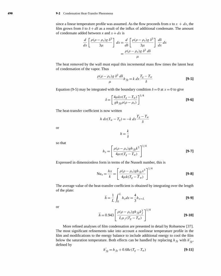
since a linear temperature profile was assumed. As the flow proceeds from x to x + dx, thefilm grows from δ to δ+ dδ as a result of the influx of additional condensate. The amountof condensate added between x and x+ dx is
d
dx
[ρ(ρ− ρv)g δ3
3µ
]dx= d
dδ
[ρ(ρ− ρv)g δ3
3µ
]dδ
dxdx
= ρ(ρ− ρv)g δ2 dδ
µ
The heat removed by the wall must equal this incremental mass flow times the latent heatof condensation of the vapor. Thus
ρ(ρ− ρv)g δ2 dδ
µhfg = k dxTg − Tw
δ[9-5]
Equation (9-5) may be integrated with the boundary condition δ= 0 at x= 0 to give
δ=[
4µkx(Tg − Tw)ghfgρ(ρ− ρv)
]1/4
[9-6]
The heat-transfer coefficient is now written
h dx(Tw− Tg)= −k dxTg − Twδ
or
h= k
δ
so that
hx =[ρ(ρ− ρv)ghfgk3
4µx(Tg − Tw)
]1/4
[9-7]
Expressed in dimensionless form in terms of the Nusselt number, this is
Nux = hx
k=[ρ(ρ− ρv)ghfgx3
4µk(Tg − Tw)
]1/4
[9-8]
The average value of the heat-transfer coefficient is obtained by integrating over the lengthof the plate:
h= 1
L
∫ L
0hxdx= 4
3hx=L [9-9]
or
h= 0.943
[ρ(ρ− ρv)ghfgk3
f
Lµf (Tg − Tw)
]1/4
[9-10]
More refined analyses of film condensation are presented in detail by Rohsenow [37].The most significant refinements take into account a nonlinear temperature profile in thefilm and modifications to the energy balance to include additional energy to cool the filmbelow the saturation temperature. Both effects can be handled by replacing hfg with h′
fg,defined by
h′fg =hfg + 0.68c(Tg − Tw) [9-11]

hol29362_ch09 11/3/2008 17:54
# 101675 Cust: McGraw-Hill Au: Holman Pg. No.491 K/PMS 293
Title: Heat Transfer 10/e Server: Short / Normal / Long
DESIGN SERVICES OF
S4CARLISLEPublishing Services
C H A P T E R 9 Condensation and Boiling Heat Transfer 491
where c is the specific heat of the liquid. Otherwise, properties in Equations (9-7) and (9-10)should be evaluated at the film temperature
Tf = Tg + Tw2
With these substitutions Equation (9-10) may be used for vertical plates and cylinders andfluids with Pr> 0.5 and cT/hfg ≤ 1.0.
For laminar film condensation on horizontal tubes, Nusselt obtained the relation
h= 0.725
[ρ(ρ− ρv)ghfgk3
f
µf d(Tg − Tw)
]1/4
[9-12]
where d is the diameter of the tube. When condensation occurs on a horizontal tube bankwith n tubes placed directly over one another in the vertical direction, the heat-transfercoefficient may be calculated by replacing the diameter in Equation (9-12) with nd. Theanalysis of Reference 48 has shown that Equation (9-12) can be used for an isothermalsphere if the constant is changed to 0.815.
When a plate on which condensation occurs is sufficiently large or there is a sufficientamount of condensate flow, turbulence may appear in the condensate film. This turbulenceresults in higher heat-transfer rates. As in forced-convection flow problems, the criterionfor determining whether the flow is laminar or turbulent is the Reynolds number, and forthe condensation system it is defined as
Ref = DHρV
µf= 4AρV
Pµf
where
DH = hydraulic diameter
A= flow area
P = shear, or “wetted,” perimeter
V = average velocity in flow
Butm= ρAV
so that
Ref = 4m
Pµf[9-13]
where m is the mass flow through the particular section of the condensate film. For a verticalplate of unit depth, P = 1; for a vertical tube, P =πd. The critical Reynolds number isapproximately 1800, and turbulent correlations for heat transfer must be used at Reynoldsnumbers greater than this value. The Reynolds number is sometimes expressed in terms ofthe mass flow per unit depth of plate �, so that
Ref = 4�
µf[9-14]
In calculating the Reynolds numbers the mass flow may be related to the total heattransfer and the heat-transfer coefficient by
q=hA(Tsat − Tw)= mhfg [9-15]

hol29362_ch09 11/3/2008 17:54
# 101675 Cust: McGraw-Hill Au: Holman Pg. No.492 K/PMS 293
Title: Heat Transfer 10/e Server: Short / Normal / Long
DESIGN SERVICES OF
S4CARLISLEPublishing Services
492 9-3 The Condensation Number
where A is the total surface area for heat transfer. Thus
m= q
hfg= hA(Tsat − Tw)
hfg
Ref = 4hA(Tsat − Tw)hfgPµf
[9-16]
ButA=LW and P =W
where L and W are the height and width of the plate, respectively, so that
Ref = 4hL(Tsat − Tw)hfgµf
[9-17]
The laminar condensation equations presented above match experimental data very wellas long as the film remains smooth and well behaved. In practice, it has been found thatripples will develop in the film for Reynolds numbers as low as 30 or 40. When this occurs,the experimental values of h can be 20 percent higher than predicted by Equation (9-12).Because this is such a common occurrence, McAdams [3] was prompted to suggest that the20 percent increase be adopted for design purposes. For our discussions here we shall useEquation (9-10) without the increase, recognizing that this is a conservative approach thatprovides a safety factor in design problems. If one wishes to employ the 20 percent highercoefficient, the resulting equation for vertical plates is
h= 1.13
[ρ(ρ− ρv)ghfgk3
Lµ(Tg − Tw)
]1/4
[9-18]
If the vapor to be condensed is superheated, the preceding equations may be used tocalculate the heat-transfer coefficient, provided the heat flow is calculated on the basis of thetemperature difference between the surface and the saturation temperature correspondingto the system pressure. When a noncondensable gas is present along with the vapor, theremay be an impediment of the heat transfer since the vapor must diffuse through the gasbefore it can condense on the surface. The reader should consult References 3 and 4 formore information on this subject.
Inclined Surfaces
If a plate or cylinder is inclined at an angle φ with the horizontal, the net effect on the aboveanalysis is to replace the gravitational force with its component parallel to the heat-transfersurface, or
g′ = g sin φ [9-19]
Therefore, for laminar flow, we suggest that inclined surfaces be treated with the simplesubstitution indicated in Equation (9-19).
9-3 THE CONDENSATION NUMBERBecause the film Reynolds number is so important in determining condensation behavior,it is convenient to express the heat-transfer coefficient directly in terms of Re. We includethe effect of inclination and write the heat-transfer equations in the form
h=C[ρ(ρ− ρv)k3g sin φhfg
µL(Tg − Tw)
]1/4
[9-20]

hol29362_ch09 11/3/2008 17:54
# 101675 Cust: McGraw-Hill Au: Holman Pg. No.493 K/PMS 293
Title: Heat Transfer 10/e Server: Short / Normal / Long
DESIGN SERVICES OF
S4CARLISLEPublishing Services
C H A P T E R 9 Condensation and Boiling Heat Transfer 493
where the constant is evaluated for a plate or cylindrical geometry. From Equation (9-15)we can solve for Tg − Tw as
Tg − Tw= mhfg
hA[9-21]
where A, once again, is the surface area for heat transfer. Substituting Equation (9-21) in(9-20) and solving for h gives
h3/4 =C
[ρ(ρ− ρv)g sin φk3 A/L
µm
]1/4
[9-22]
This may be restructured as
h3/4 =C
[ρ(ρ− ρv)gk3
µ2
µP
4m
4 sin φ A/P
L
]1/4
and we may solve for h as
h=C4/3[ρ(ρ− ρv)gk3
µ2
µP
4m
4 sin φ A/P
L
]1/3
[9-23]
We now define a new dimensionless group, the condensation number Co, as
Co =h[
µ2
k3ρ(ρ− ρv)g]1/3
[9-24]
so that Equation (9-23) can be expressed in the form
Co =C4/3(
4 sin φ A/P
L
)1/3
Re−1/3f [9-25]
For a vertical plate A/PL= 1.0, and we obtain, using the constant from Equation (9-10),
Co = 1.47 Re−1/3f for Ref < 1800 [9-26]
For a horizontal cylinder A/PL=π and
Co = 1.514 Re−1/3f for Ref < 1800 [9-27]
When turbulence is encountered in the film, an empirical correlation by Kirkbride [2]may be used:
Co = 0.0077 Re0.4f for Ref > 1800 [9-28]
9-4 FILM CONDENSATION INSIDEHORIZONTAL TUBES
Our discussion of film condensation so far has been limited to exterior surfaces, where thevapor and liquid condensate flows are not restricted by some overall flow-channel dimen-sions. Condensation inside tubes is of considerable practical interest because of applicationsto condensers in refrigeration and air-conditioning systems, but unfortunately these phenom-ena are quite complicated and not amenable to a simple analytical treatment. The overall flowrate of vapor strongly influences the heat-transfer rate in the forced convection-condensationsystem, and this in turn is influenced by the rate of liquid accumulation on the walls. Becauseof the complicated flow phenomena involved we shall present only two empirical relationsfor heat transfer and refer the reader to Rohsenow [37] for more complete information.

hol29362_ch09 11/3/2008 17:54
# 101675 Cust: McGraw-Hill Au: Holman Pg. No.494 K/PMS 293
Title: Heat Transfer 10/e Server: Short / Normal / Long
DESIGN SERVICES OF
S4CARLISLEPublishing Services
494 9-4 Film Condensation Inside Horizontal Tubes
Chato [38] obtained the following expression for condensation of refrigerants at lowvapor velocities inside horizontal tubes:
h= 0.555
[ρ(ρ− ρv)gk3h′
fg
µd(Tg − Tw)
]1/4
[9-29]
where the modified enthalpy of vaporization is given by
h′fg =hfg + 0.375cp,l(Tg − Tw)
Liquid properties in Equation (9-29) are evaluated at the film temperature while hfg and ρvare evaluated at the saturation temperature Tg.
Equation (9-29) is restricted to low vapor Reynolds numbers such that
Rev= dGv
µv< 35,000 [9-30]
where Rev is evaluated at inlet conditions to the tube. For higher flow rates an approximateempirical expression is given by Akers, Deans, and Crosser [39] as
hd
kf= 0.026 Pr1/3
f Re0.8m [9-31]
where now Rem is a mixture Reynolds number, defined as
Rem= d
µf
[Gf +Gv
(ρf
ρv
)1/2]
[9-32]
The mass velocities for the liquid Gf and vapor Gv are calculated as if each occupied theentire flow area. Equation (9-31) correlates experimental data within about 50 percent when
Rev= dGv
µv> 20,000 Ref = dGf
µf> 5000
EXAMPLE 9-1 Condensation on Vertical Plate
A vertical square plate, 30 by 30 cm, is exposed to steam at atmospheric pressure. The platetemperature is 98◦C. Calculate the heat transfer and the mass of steam condensed per hour.
SolutionThe Reynolds number must be checked to determine if the condensate film is laminar or turbulent.Properties are evaluated at the film temperature:
Tf = 100 + 98
2= 99◦C ρf = 960 kg/m3
µf = 2.82 × 10⁻⁴ kg/m · s kf = 0.68 W/m · ◦C
For this problem the density of the vapor is very small in comparison with that of the liquid,and we are justified in making the substitution
ρf (ρf − ρv)≈ ρ2f
In trying to calculate the Reynolds number we find that it is dependent on the mass flow ofcondensate. But this is dependent on the heat-transfer coefficient, which is dependent on theReynolds number. To solve the problem we assume either laminar or turbulent flow, calculate

hol29362_ch09 11/3/2008 17:54
# 101675 Cust: McGraw-Hill Au: Holman Pg. No.495 K/PMS 293
Title: Heat Transfer 10/e Server: Short / Normal / Long
DESIGN SERVICES OF
S4CARLISLEPublishing Services
C H A P T E R 9 Condensation and Boiling Heat Transfer 495
the heat-transfer coefficient, and then check the Reynolds number to see if our assumption wascorrect. Let us assume laminar film condensation. At atmospheric pressure we have
Tsat = 100◦C hfg= 2255 kJ/kg
h= 0.943
[ρ2f ghfgk
3f
Lµf (Tg− Tw)
]1/4
= 0.943
[(960)2(9.8)(2.255 × 10⁶)(0.68)3
(0.3)(2.82 × 10⁻⁴)(100 − 98)
]1/4
= 13,150 W/m2 · ◦C [2316 Btu/h · ft2 · ◦F]
Checking the Reynolds number with Equation (9-17), we have
Ref = 4hL(Tsat − Tw)hfgµf
= (4)(13,150)(0.3)(100 − 98)
(2.255 × 10⁶)(2.82 × 10⁻⁴)= 49.6
so that the laminar assumption was correct. The heat transfer is now calculated from
q=hA(Tsat − Tw)= (13,150)(0.3)2(100 − 98)= 2367 W [8079 Btu/h]
The total mass flow of condensate is
m= q
hfg= 2367
2.255 × 106= 1.05 × 10⁻³ kg/s = 3.78 kg/h [8.33 lbm/h]
Condensation on Tube Bank EXAMPLE 9-2
One hundred tubes of 0.50-in (1.27-cm) diameter are arranged in a square array and exposed toatmospheric steam. Calculate the mass of steam condensed per unit length of tubes for a tube walltemperature of 98◦C.
SolutionThe condensate properties are obtained from Example 9-1. We employ Equation (9-12) for thesolution, replacing d by nd, where n= 10. Thus,
h= 0.725
[ρ2f ghfgk
3f
µf nd(Tg− Tw)
]1/4
= 0.725
[(960)2(9.8)(2.255 × 10⁶)(0.68)3
(2.82 × 10⁻⁴)(10)(0.0127)(100 − 98)
]1/4
= 12,540 W/m2 · ◦C [2209 Btu/h · ft2 · ◦F]
The total surface area is
A
L= n πd= (100)π(0.0127)= 3.99 m2/m
so the heat transfer is
q
L=hA
L(Tg− Tw)
= (12,540)(3.99)(100 − 98)= 100.07 kW/m

hol29362_ch09 11/3/2008 17:54
# 101675 Cust: McGraw-Hill Au: Holman Pg. No.496 K/PMS 293
Title: Heat Transfer 10/e Server: Short / Normal / Long
DESIGN SERVICES OF
S4CARLISLEPublishing Services
496 9-5 Boiling Heat Transfer
The total mass flow of condensate is then
m
L= q/L
hfg= 1.0007 × 10⁵
2.255 × 106= 0.0444 kg/s = 159.7 kg/h [352 lbm/h]
9-5 BOILING HEAT TRANSFERWhen a surface is exposed to a liquid and is maintained at a temperature above the saturationtemperature of the liquid, boiling may occur, and the heat flux will depend on the differencein temperature between the surface and the saturation temperature. When the heated surfaceis submerged below a free surface of liquid, the process is referred to as pool boiling. If thetemperature of the liquid is below the saturation temperature, the process is called subcooled,or local, boiling. If the liquid is maintained at saturation temperature, the process is knownas saturated, or bulk, boiling.
The different regimes of boiling are indicated in Figure 9-3, where heat-flux data from anelectrically heated platinum wire submerged in water are plotted against temperature excessTw− Tsat. In region I, free-convection currents are responsible for motion of the fluid nearthe surface. In this region the liquid near the heated surface is superheated slightly, and itsubsequently evaporates when it rises to the surface. The heat transfer in this region can becalculated with the free-convection relations presented in Chapter 7. In region II, bubblesbegin to form on the surface of the wire and are dissipated in the liquid after breaking awayfrom the surface. This region indicates the beginning of nucleate boiling.As the temperatureexcess is increased further, bubbles form more rapidly and rise to the surface of the liquid,where they are dissipated. This is indicated in region III. Eventually, bubbles are formedso rapidly that they blanket the heating surface and prevent the inflow of fresh liquid fromtaking their place. At this point the bubbles coalesce and form a vapor film that covers the
Figure 9-3 Heat-flux data from an electrically heated platinum wire, from Farber andScorah [9].
Interface evaporation Bubbles Film
0.1 1.0 10 100 1000 10,000
log
h
Boiling curve
Pure convection heat transferred by super-heated liquid risingto the liquid-vaporinterface where evap-oration takes place.
Nuc
leat
e bo
iling
. B
ubbl
esco
nden
se in
sup
erhe
ated
liqui
d et
c. a
s in
Cas
e I
Nuc
leat
e bo
iling
.
Bub
bles
ris
e to
inte
rfac
e
Part
ial
nucl
eate
boi
ling
and
unst
able
nuc
leat
e fi
lm
Stab
le f
ilmbo
iling
Rad
iatio
nco
min
g in
to
pla
yI IV VIVII III
ab
0.1 1.0 10 100 1000 10,000
Temperature excess, ∆Tx = Tw – Tsat
˚F
˚C
Sphe
roid
al s
tate
begi
nnin
g

hol29362_ch09 11/3/2008 17:54
# 101675 Cust: McGraw-Hill Au: Holman Pg. No.497 K/PMS 293
Title: Heat Transfer 10/e Server: Short / Normal / Long
DESIGN SERVICES OF
S4CARLISLEPublishing Services
C H A P T E R 9 Condensation and Boiling Heat Transfer 497
surface. The heat must be conducted through this film before it can reach the liquid and effectthe boiling process. The thermal resistance of this film causes a reduction in heat flux, andthis phenomenon is illustrated in region IV, the film-boiling region. This region representsa transition from nucleate boiling to film boiling and is unstable. Stable film boiling iseventually encountered in region V. The surface temperatures required to maintain stablefilm boiling are high, and once this condition is attained, a significant portion of the heatlost by the surface may be the result of thermal radiation, as indicated in region VI.
An electrically heated wire is unstable at point a since a small increase in �Tx at thispoint results in a decrease in the boiling heat flux. But the wire still must dissipate the sameheat flux, or its temperature will rise, resulting in operation farther down to the boiling curve.Eventually, equilibrium may be reestablished only at point b in the film-boiling region. Thistemperature usually exceeds the melting temperature of the wire, so that burnout results.If the electric-energy input is quickly reduced when the system attains point a, it may bepossible to observe the partial nucleate boiling and unstable film region.
In nucleate boiling, bubbles are created by the expansion of entrapped gas or vapor atsmall cavities in the surface. The bubbles grow to a certain size, depending on the surfacetension at the liquid-vapor interface and the temperature and pressure. Depending on thetemperature excess, the bubbles may collapse on the surface, may expand and detach fromthe surface to be dissipated in the body of the liquid, or at sufficiently high temperaturesmay rise to the surface of the liquid before being dissipated. When local boiling conditionsare observed, the primary mechanism of heat transfer is thought to be the intense agitationat the heat-transfer surface, which creates the high heat-transfer rates observed in boiling.In saturated, or bulk, boiling the bubbles may break away from the surface because of thebuoyancy action and move into the body of the liquid. In this case the heat-transfer rate isinfluenced by both the agitation caused by the bubbles and the vapor transport of energyinto the body of the liquid.
Experiments have shown that the bubbles are not always in thermodynamic equilibriumwith the surrounding liquid (i.e., the vapor inside the bubble is not necessarily at the sametemperature as the liquid). Considering a spherical bubble as shown in Figure 9-4, thepressure forces of the liquid and vapor must be balanced by the surface-tension force at thevapor-liquid interface. The pressure force acts on an area of πr2, and the surface tensionacts on the interface length of 2πr. The force balance is
πr2(pv−pl)= 2πrσ
or
pv−pl = 2σ
r[9-32a]
Figure 9-4 Force balance on a vaporbubble.
Pressure force = πr2(pv – pl)πSurface tension force = 2 r σ σπ
r2(pv – pl) = 2 π r σππ σπ
pv
pl
σ
r

hol29362_ch09 11/3/2008 17:54
# 101675 Cust: McGraw-Hill Au: Holman Pg. No.498 K/PMS 293
Title: Heat Transfer 10/e Server: Short / Normal / Long
DESIGN SERVICES OF
S4CARLISLEPublishing Services
498 9-5 Boiling Heat Transfer
wherepv= vapor pressure inside bubble
pl = liquid pressure
σ= surface tension of vapor-liquid interface
Now, suppose we consider a bubble in pressure equilibrium (i.e., one that is not growingor collapsing). Let us assume that the temperature of the vapor inside the bubble is thesaturation temperature corresponding to the pressure pv. If the liquid is at the saturationtemperature corresponding to the pressure pl, it is below the temperature inside the bubble.Consequently, heat must be conducted out of the bubble, the vapor inside must condense,and the bubble must collapse. This is the phenomenon that occurs when the bubbles collapseon the heating surface or in the body of the liquid. In order for the bubbles to grow andescape to the surface, they must receive heat from the liquid. This requires that the liquidbe in a superheated condition so that the temperature of the liquid is greater than the vaportemperature inside the bubble. This is a metastable thermodynamic state, but it is observedexperimentally and accounts for the growth of bubbles after leaving the surface in someregions of nucleate boiling.
A number of photographic studies of boiling phenomena have been presented byWestwater et al. [17, 40, 41] that illustrate the various boiling regimes.
Figure 9-5 is a photograph illustrating several boiling regimes operating at once. Thehorizontal 6.1-mm-diameter copper rod is heated from the right side and immersed in
Figure 9-5 A copper rod (6.1 mm in diameter) heated on the right side and immersed inisopropanol. Boiling regimes progress from free-convection boiling at the coolerend of the rod (left) to nucleate, transition, and finally film boiling at the right end.
Source: Photograph courtesy of Professor J. W. Westwater, University of Illinois, Urbana.

hol29362_ch09 11/3/2008 17:54
# 101675 Cust: McGraw-Hill Au: Holman Pg. No.499 K/PMS 293
Title: Heat Transfer 10/e Server: Short / Normal / Long
DESIGN SERVICES OF
S4CARLISLEPublishing Services
Figure 9-6 Methanol boiling on a horizontal 9.53-mm-diametercopper tube heated internally by condensing steam.(a) �Tx= 37◦C, q/A= 242.5 kW/m2, nucleate boiling;(b) �Tx= 62◦C, q/A= 217.6 kW/m2, transition boiling;(c) �Tx= 82◦C, q/A= 40.9 kW/m2, film boiling.
(a)
(b)
(c)
Source: Photographs courtesy of Professor J. W. Westwater, University ofIllinois, Urbana.
499

hol29362_ch09 11/3/2008 17:54
# 101675 Cust: McGraw-Hill Au: Holman Pg. No.500 K/PMS 293
Title: Heat Transfer 10/e Server: Short / Normal / Long
DESIGN SERVICES OF
S4CARLISLEPublishing Services
500 9-5 Boiling Heat Transfer
isopropanol. As a result of the temperature gradient along the rod, it was possible to observethe different regimes simultaneously. At the left end of the rod, the surface temperature isonly slightly greater than the bulk fluid temperature, so that free-convection boiling isobserved. Farther to the right, higher surface temperatures are experienced, and nucleateboiling is observed. Still farther to the right, transition boiling takes place; finally, filmboiling is observed at the wall. Note the blanketing action of the vapor film on the right-hand portion of the rod.
More detailed photographs of the different boiling regimes using methanol are givenin Figure 9-6. The vigorous action of nucleate boiling is illustrated in Figure 9-6a. At highersurface temperatures the bubbles start to coalesce, and transition boiling is observed, as inFigure 9-6b. Finally, at still higher temperatures the heat-transfer surface is completely cov-ered by a vapor film, and large vapor bubbles break away from the surface. A more vigorousfilm-boiling phenomenon is illustrated in Figure 9-7 for methanol on a vertical tube. Thevapor film rises up to the surface and develops into very active turbulent behavior at the top.
Figure 9-7 A steam-heated vertical19.05-mm-diametercopper tube displayingturbulent film boilingin methanol.�Tx= 138◦Cq/A= 38.8 kW/m2.
Source: Photograph courtesy of ProfessorJ. W. Westwater, University of Illinois,Urbana.

hol29362_ch09 11/3/2008 17:54
# 101675 Cust: McGraw-Hill Au: Holman Pg. No.501 K/PMS 293
Title: Heat Transfer 10/e Server: Short / Normal / Long
DESIGN SERVICES OF
S4CARLISLEPublishing Services
C H A P T E R 9 Condensation and Boiling Heat Transfer 501
The process of bubble growth is a complex one, but a simple qualitative explanationof the physical mechanism may be given. Bubble growth takes place when heat is con-ducted to the liquid-vapor interface from the liquid. Evaporation then takes place at theinterface, thereby increasing the total vapor volume. Assuming that the liquid pressureremains constant, Equation (9-32a) requires that the pressure inside the bubble be reduced.Corresponding to a reduction in pressure inside the bubble will be a reduction in the vaportemperature and a larger temperature difference between the liquid and vapor if the bubblestays at its same spatial position in the liquid. However, the bubble will likely rise fromthe heated surface, and the farther away it moves, the lower the liquid temperature willbe. Once the bubble moves into a region where the liquid temperature is below that of thevapor, heat will be conducted out, and the bubble will collapse. Hence the bubble growthprocess may reach a balance at some location in the liquid, or if the liquid is superheatedenough, the bubbles may rise to the surface before being dissipated.
There is considerable controversy as to exactly how bubbles are initially formed onthe heat-transfer surface. Surface conditions—both roughness and type of material—canplay a central role in the bubble formation-and-growth drama. The mystery has not beencompletely solved and remains a subject of intense research. Excellent summaries of thestatus of knowledge of boiling heat transfer are presented in References 18, 23, 49, and 50.The interested reader is referred to these discussions for more extensive information than ispresented in this chapter. Heat-transfer problems in two-phase flow are discussed by Wallis[28] and Tong [23].
Before specific relations for calculating boiling heat transfer are presented, it is sug-gested that the reader review the discussion of the last few pages and correlate it with somesimple experimental observations of boiling. For this purpose a careful visual observationof the boiling process in a pan of water on the kitchen stove can be quite enlightening.
Rohsenow [5] correlated experimental data for nucleate pool boiling with the followingrelation.
Cl�Tx
hfg Prs
l
=Csf[q/A
µlhfg
√gcσ
g(ρl − ρv)]0.33
[9-33]
whereCl = specific heat of saturated liquid, Btu/lbm · ◦F or J/kg · ◦C
�Tx = temperature excess = Tw− Tsat, ◦F or ◦Chfg = enthalpy of vaporization, Btu/lbm or J/kgPrl = Prandtl number of saturated liquidq/A = heat flux per unit area, Btu/h · ft2 or W/m2
µl = liquid viscosity, lbm/h · ft, or kg/m · sσ = surface tension of liquid-vapor interface, lbf /ft or N/mg = gravitational acceleration, ft/s2 or m/s2
ρl = density of saturated liquid, lbm/ft3 or kg/m3
ρv = density of saturated vapor, lbm/ft3 or kg/m3
Csf = constant, determined from experimental datas = 1.0 for water and 1.7 for other liquids
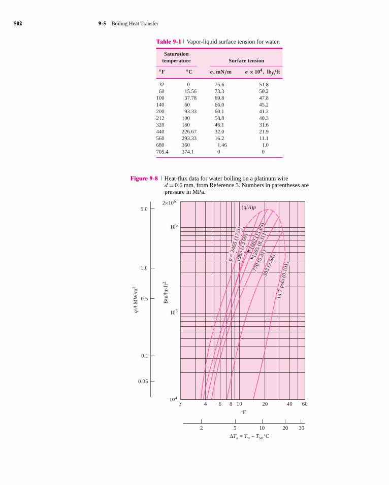
Values of the surface tension are given in Reference 10, and a brief tabulation of the vapor-liquid surface tension for water is given in Table 9-1.
The functional form of Equation (9-33) was determined by analyzing the significantparameters in bubble growth and dissipation. Experimental data for nucleate boiling ofwater on a platinum wire are shown in Figure 9-8, and a correlation of these data by theRohsenow equation is shown in Figure 9-9, indicating good agreement. The value of the
hol29362_ch09 11/3/2008 17:54
# 101675 Cust: McGraw-Hill Au: Holman Pg. No.502 K/PMS 293
Title: Heat Transfer 10/e Server: Short / Normal / Long
DESIGN SERVICES OF
S4CARLISLEPublishing Services
502 9-5 Boiling Heat Transfer
Table 9-1 Vapor-liquid surface tension for water.
Saturationtemperature Surface tension
◦F ◦C σ, mN/m σ × 104, lbf/ft
32 0 75.6 51.860 15.56 73.3 50.2
100 37.78 69.8 47.8140 60 66.0 45.2200 93.33 60.1 41.2212 100 58.8 40.3320 160 46.1 31.6440 226.67 32.0 21.9560 293.33 16.2 11.1680 360 1.46 1.0705.4 374.1 0 0
Figure 9-8 Heat-flux data for water boiling on a platinum wired= 0.6 mm, from Reference 3. Numbers in parentheses arepressure in MPa.
q/A
MW
/m2
˚F
104
2 4 6 8 10 20 40 60
2 5 10 20 30
0.05
0.1
0.5
1.0
5.02×10⁶
106
105
Btu
/hr-
ft2
∆Tx = Tw – Tsat˚C
(q/A)p
14.7
psi
a (0
.101
)
383
(2.6
4)
770
(5.3
1)
1602
(11
.05)
1205
(8.
31)
1985
(13
.69)
p =
246
5 (1
7.0)

hol29362_ch09 11/3/2008 17:54
# 101675 Cust: McGraw-Hill Au: Holman Pg. No.503 K/PMS 293
Title: Heat Transfer 10/e Server: Short / Normal / Long
DESIGN SERVICES OF
S4CARLISLEPublishing Services
C H A P T E R 9 Condensation and Boiling Heat Transfer 503
Figure 9-9 Correlation of pool-boiling data by Equation (9-33),from Rohsenow [5].
+
+++
++
+
+
0.01 0.1 10
14.7 psia383 psia770 psia
1,205 psia
1,602 psia
2,465 psia
Cl
hfg
1
Prl1.7∆Tx
q/A
m lh f
g
g cg
(ρl−
ρ v)
σ
Cl
hfg∆Tx = 0.013
q/A
lhfg
Cl l
kl
gc
g ( l − v)
σ 0.33 1.7
100
10
1.0
0.1
ρ ρµ
µ
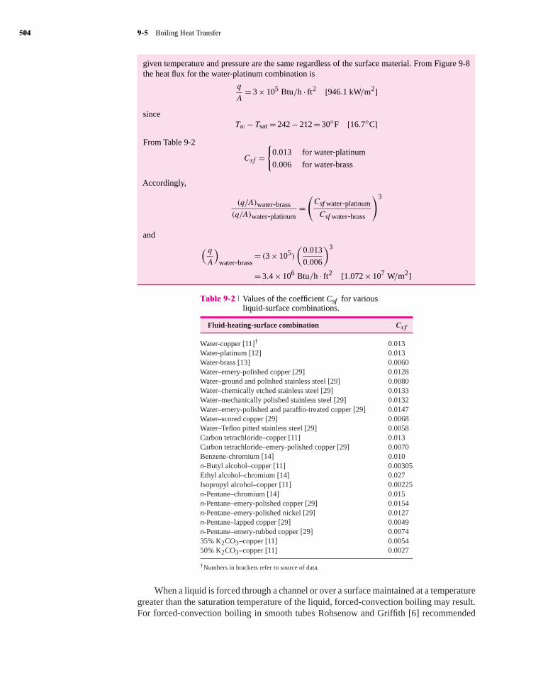
constant Csf for the water-platinum combination is 0.013. Values for other fluid-surfacecombinations are given in Table 9-2. Equation (9-33) may be used for geometries other thanhorizontal wires, and in general it is found that geometry is not a strong factor in determiningheat transfer for pool boiling. This would be expected because the heat transfer is primarilydependent on bubble formation and agitation, which is dependent on surface area, and notsurface shape. Vachon, Nix, and Tanger [29] have determined values of the constants inthe Rohsenow equation for a large number of surface-fluid combinations. There are severalextenuating circumstances that influence the determination of the constants. Additionalinformation given in Reference [57] indicates that depth of fluid as well as surface size andshape may have an effect on the values of the constants used in the Rohsenow equation.
Boiling on Brass Plate EXAMPLE 9-3
A heated brass plate is submerged in a container of water at atmospheric pressure. The platetemperature is 242◦F. Calculate the heat transfer per unit area of plate.
SolutionWe could solve this problem by determining all the properties for use in Equation (9-33) andsubsequently determining the heat flux. An alternative method is to use the data of Figure 9-8 inconjunction with Table 9-2. Upon writing Equation (9-33), we find that if the heat flux for oneparticular water-surface combination is known, the heat flux for some other surface may easilybe determined in terms of the constants Csf for the two surfaces since the fluid properties at any
hol29362_ch09 11/3/2008 17:54
# 101675 Cust: McGraw-Hill Au: Holman Pg. No.504 K/PMS 293
Title: Heat Transfer 10/e Server: Short / Normal / Long
DESIGN SERVICES OF
S4CARLISLEPublishing Services
504 9-5 Boiling Heat Transfer
given temperature and pressure are the same regardless of the surface material. From Figure 9-8the heat flux for the water-platinum combination is
q
A= 3 × 10⁵ Btu/h · ft2 [946.1 kW/m2]
sinceTw− Tsat = 242 − 212 = 30◦F [16.7◦C]
From Table 9-2
Csf ={
0.013 for water-platinum
0.006 for water-brass
Accordingly,
(q/A)water-brass
(q/A)water-platinum=(Csf water-platinum
Csf water-brass
)3
and( qA
)water-brass
= (3 × 10⁵)
(0.013
0.006
)3
= 3.4 × 10⁶ Btu/h · ft2 [1.072 × 10⁷ W/m2]
Table 9-2 Values of the coefficient Csf for variousliquid-surface combinations.
Fluid-heating-surface combination Csf
Water-copper [11]† 0.013Water-platinum [12] 0.013Water-brass [13] 0.0060Water–emery-polished copper [29] 0.0128Water–ground and polished stainless steel [29] 0.0080Water–chemically etched stainless steel [29] 0.0133Water–mechanically polished stainless steel [29] 0.0132Water–emery-polished and paraffin-treated copper [29] 0.0147Water–scored copper [29] 0.0068Water–Teflon pitted stainless steel [29] 0.0058Carbon tetrachloride–copper [11] 0.013Carbon tetrachloride–emery-polished copper [29] 0.0070Benzene-chromium [14] 0.010n-Butyl alcohol–copper [11] 0.00305Ethyl alcohol–chromium [14] 0.027Isopropyl alcohol–copper [11] 0.00225n-Pentane–chromium [14] 0.015n-Pentane–emery-polished copper [29] 0.0154n-Pentane–emery-polished nickel [29] 0.0127n-Pentane–lapped copper [29] 0.0049n-Pentane–emery-rubbed copper [29] 0.007435% K2CO3–copper [11] 0.005450% K2CO3–copper [11] 0.0027
†Numbers in brackets refer to source of data.
When a liquid is forced through a channel or over a surface maintained at a temperaturegreater than the saturation temperature of the liquid, forced-convection boiling may result.For forced-convection boiling in smooth tubes Rohsenow and Griffith [6] recommended

hol29362_ch09 11/3/2008 17:54
# 101675 Cust: McGraw-Hill Au: Holman Pg. No.505 K/PMS 293
Title: Heat Transfer 10/e Server: Short / Normal / Long
DESIGN SERVICES OF
S4CARLISLEPublishing Services
C H A P T E R 9 Condensation and Boiling Heat Transfer 505
that the forced-convection effect be computed with the Dittus-Boelter relation of Chapter 6[Equation (6-4)] and that this effect be added to the boiling heat flux computed from Equation(9-33). Thus ( q
A
)total
=( qA
)boiling
+( qA
)forced convection
[9-34]
For computing the forced-convection effect, it is recommended that the coefficient 0.023be replaced by 0.019 in the Dittus-Boelter equation. The temperature difference betweenwall and liquid bulk temperature is used to compute the forced-convection effect.
The concept of adding the forced convection and boiling heat fluxes has been developedfurther in Reference 46 with good results; however, the terms in the equations are muchmore complicated and too elaborate to present here. An individual working in this fieldshould consult this reference.
Forced-convection boiling is not necessarily as simple as might be indicated by Equa-tion (9-34). This equation is generally applicable to forced-convection situations where thebulk liquid temperature is subcooled, in other words, for local forced-convection boiling.Once saturated or bulk boiling conditions are reached, the situation changes rapidly. A fullydeveloped nucleate boiling phenomenon is eventually encountered that is independent ofthe flow velocity or forced-convection effects. Various relations have been presented forcalculating the heat flux in the fully developed boiling state. McAdams et al. [21] suggestedthe following empirical relation for low-pressure boiling water:
q
A= 2.253(�Tx)
3.96 W/m2 for 0.2<p< 0.7 MPa [9-35]
For higher pressures Levy [22] recommends the relationq
A= 283.2p4/3(�Tx)
3 W/m2 for 0.7<p< 14 MPa [9-36]
In these equations �Tx is in degrees Celsius and p is in megapascals.If boiling is maintained for a sufficiently long length of tube, the majority of the flow
area will be occupied by vapor. In this instance the vapor may flow rapidly in the centralportion of the tube while a liquid film is vaporized along the outer surface. This situationis called forced-convection vaporization and is normally treated as a subject in two-phaseflow and heat transfer. Several complications arise in this interesting subject, many of whichare summarized by Tong [23] and Wallis [28].
The peak heat flux for nucleate pool boiling is indicated as point a in Figure 9-3 andby a dashed line in Figure 9-8. Zuber [7] has developed an analytical expression for thepeak heat flux in nucleate boiling by considering the stability requirements of the interfacebetween the vapor film and liquid. This relation is
( qA
)max
= π
24hfgρv
[σg(ρl − ρv)
ρ2v
]1/4 (1 + ρv
ρl
)1/2
[9-37]
where σ is the vapor-liquid surface tension. This relation is in good agreement with exper-imental data. In general, the type of surface material does not affect the peak heat flux,although surface cleanliness can be an influence, dirty surfaces causing increases of approx-imately 15 percent in the peak value.
The peak heat flux in flow boiling is a more complicated situation because the rapidgeneration of vapor produces a complex two-phase flow system that strongly influences themaximum heat flux that may be attained at the heat-transfer surface. Near the heated surfacea thin layer of superheated liquid is formed, followed by a layer containing both bubblesand liquid. The core of the flow is occupied, for the most part, by vapor. The heat transfer at

hol29362_ch09 11/3/2008 17:54
# 101675 Cust: McGraw-Hill Au: Holman Pg. No.506 K/PMS 293
Title: Heat Transfer 10/e Server: Short / Normal / Long
DESIGN SERVICES OF
S4CARLISLEPublishing Services
506 9-5 Boiling Heat Transfer
the wall is influenced by the boundary-layer development in that region and also by the rateat which diffusion of vapor and bubbles can proceed radially. Still further complicationsmay arise from flow oscillations that are generated under certain conditions. Gambill [24]has suggested that the critical heat flux in flow boiling may be calculated by a superpositionof the critical heat flux for pool boiling [Equation (9-37)] and a forced-convection effectsimilar to the technique employed in Equation (9-34). Levy [25] has considered the effectsof vapor diffusion on the peak heat flux in flow boiling, and Tong [23] presents a summaryof available data on the subject.
An interesting peak heat-flux phenomenon is observed when liquid droplets impingeon hot surfaces. Experiments with water, acetone, alcohol, and some of the Freons indicatethat the maximum heat transfer is observed for temperature excesses of about 165◦C, forall the fluids. The peak flux is a function of the fluid properties and the normal componentof the impact velocity. A correlation of experimental data is given in Reference 30 as
Qmax
ρLd3λ= 1.83 × 10⁻³
(ρL
2V 2d
ρvf σgc
)0.341
[9-38]
where
Qmax = maximum heat transfer per dropρL = density of liquid dropletV = normal component of impact velocityρvf = vapor density evaluated at film temperature (Tw+ Tsat)/2σ = surface tensiond = drop diameterλ = modified heat of vaporization, defined by
λ=hfg + cpv(Tw− Tsat
2
)
While not immediately apparent from this equation, the heat-transfer rates in dropletimpingement are quite high, and as much as 50 percent of the droplet is evaporated duringthe short time interval of impact and bouncing. The case of zero impact velocity is of histor-ical note and is called the Leidenfrost phenomenon [31]. This latter case can be observed bywatching water droplets sizzle and dance about on a hot plate. Very high heat-transfer ratesare also experienced when a liquid jet impinges on a hot surface maintained at temperaturessignificantly greater than the saturation temperature. Both nucleate- and film-boiling phe-nomena can be observed, and relations for calculating the heat-transfer rates are presentedin Reference 36.
Sun and Lienhard [34] have presented a relation for the peak boiling heat flux onhorizontal cylinders that is in good agreement with experimental data. The relation is
q′′max
q′′maxF
= 0.89 + 2.27 exp(−3.44√R′) for 0.15<R′ [9-39]
where R′ is a dimensionless radius defined by
R′ =R[g(ρl − ρv)
σ
]1/2
and q′′maxF is the peak heat flux on an infinite horizontal plate derived in Reference 33 as
q′′maxF = 0.131
√ρv hfg[σg(ρl − ρv)]1/4 [9-40]
Here, σ is the surface tension.

hol29362_ch09 11/3/2008 17:54
# 101675 Cust: McGraw-Hill Au: Holman Pg. No.507 K/PMS 293
Title: Heat Transfer 10/e Server: Short / Normal / Long
DESIGN SERVICES OF
S4CARLISLEPublishing Services
C H A P T E R 9 Condensation and Boiling Heat Transfer 507
Bromley [8] suggests the following relation for calculation of heat-transfer coefficientsin the stable film-boiling region on a horizontal tube:
hb = 0.62
[k3gρv(ρl − ρv)g(hfg + 0.4cpv�Tx)
dµv �Tx
]1/4
[9-41]
where d is the tube diameter. This heat-transfer coefficient considers only the conduc-tion through the film and does not include the effects of radiation. The total heat-transfercoefficient may be calculated from the empirical relation
h=hb(hb
h
)1/3
+hr [9-42]
wherehr is the radiation heat-transfer coefficient and is calculated by assuming an emissivityof unity for the liquid. Thus
hr = σε(T 4w− T 4
sat)
Tw− Tsat[9-43]
where σ is the Stefan-Boltzmann constant and ε is the emissivity of the surface. Note thatEquation (9-42) will require an iterative solution for the total heat-transfer coefficient.
The properties of the vapor in Equation (9-41) are to be evaluated at the film temperaturedefined by
Tf = 1
2(Tw+ Tsat)
while the enthalpy of vaporization hfg is to be evaluated at the saturation temperature.
9-6 SIMPLIFIED RELATIONS FOR BOILING HEATTRANSFER WITH WATER
Many empirical relations have been developed to estimate the boiling heat-transfer coeffi-cients for water. Some of the simplest relations are those presented by Jakob and Hawkins[15] for water boiling on the outside of submerged surfaces at atmospheric pressure(Table 9-3). These heat-transfer coefficients may be modified to take into account the influ-ence of pressure by using the empirical relation
hp=h1
(p
p1
)0.4
[9-44]
Table 9-3 Simplified relations for boiling heat-transfer coefficients to water at atmospheric pressure,�Tx= Tw− Tsat , ◦C.
Approximate ApproximateSurface
q
A, kW/m2 h, W/m2 · ◦C range of �T , ◦C range of h, W/m2 · ◦C
Horizontal qA < 16 1042(�Tx)1/3 0–7.76 0–2060
16< qA < 240 5.56(�Tx)3 7.32–14.4 2180–16,600
Vertical qA < 3 537(�Tax)1/7 0–4.51 0–670
3< qA < 63 7.96(�Tx)3 4.41–9.43 680–6680

hol29362_ch09 11/3/2008 17:54
# 101675 Cust: McGraw-Hill Au: Holman Pg. No.508 K/PMS 293
Title: Heat Transfer 10/e Server: Short / Normal / Long
DESIGN SERVICES OF
S4CARLISLEPublishing Services
508 9-6 Simplified Relations for Boiling Heat Transfer with Water
where
hp = heat-transfer coefficient at some pressure ph1 = heat-transfer coefficient at atmospheric pressure as determined from Table 9-3p = system pressurep1 = standard atmospheric pressure
For forced-convection local boiling inside vertical tubes the following relation is rec-ommended [16]:
h= 2.54(�Tx)3ep/1.551 W/m2 · ◦C [9-45]
where�Tx is the temperature difference between the surface and saturated liquid in degreesCelsius and p is the pressure in MPa. The heat-transfer coefficient has the units of wattsper square meter per degree Celsius. Equation (9-45) is valid over a pressure range of5 to 170 atm.
EXAMPLE 9-4 Flow Boiling
Water at 5 atm flows inside a tube of 1-in [2.54-cm] diameter under local boiling conditions wherethe tube wall temperature is 10◦C above the saturation temperature. Estimate the heat transfer ina 1.0-m length of tube.
SolutionFor this calculation we use Equation (9-45), noting that
�Tx= 10◦C
p= (5)(1.0132 × 10⁵ N/m2)= 0.5066 MPa
The heat-transfer coefficient is then calculated as
h= (2.54)(10)3e0.5066/1.551
= 3521 W/m2 · ◦C [620 Btu/h · ft2 · ◦F]
The surface area for a 1-m length of tube is
A=πdL=π(0.0254)(1.0)= 0.0798 m2
so the heat transfer is
q=hA(Tw− Tsat)
= (3521)(0.0798)(10)= 2810 W/m
EXAMPLE 9-5 Water Boiling in a Pan
Water at 1 atm boils in a stainless-steel kitchen pan with �Tx= 8◦C. Estimate the heat flux thatwill be obtained. If the same pan operates as a pressure cooker at 0.17 MPa, what percent increasein heat flux might be expected?
SolutionWe will use the simplified relation of Table 9-3 for the estimates. We do not know the value of q/Aand so must choose one of the two relations for a horizontal surface from the table. We anticipatenucleate boiling, so choose
h= 5.56(�Tx)3 = 5.56(8)3 = 2847 W/m2 · ◦C

hol29362_ch09 11/3/2008 17:54
# 101675 Cust: McGraw-Hill Au: Holman Pg. No.509 K/PMS 293
Title: Heat Transfer 10/e Server: Short / Normal / Long
DESIGN SERVICES OF
S4CARLISLEPublishing Services
C H A P T E R 9 Condensation and Boiling Heat Transfer 509
and the heat flux is
q/A=h�T = (2847)(8)= 22,770 W/m2 = 22.8 kW/m2
This value falls within the applicable range of the equation used (16<q/A< 240 kW/m2). We maynote from Table 9-2 that the values ofCsf for platinum–water or stainless steel–water combinationsare approximately equal at 0.013, so one might anticipate that the heat flux displayed for Figure 9-8would be approximately the same for a stainless-steel surface. At �Tx= 8◦C an extrapolation ofthe figure does give a value for the heat flux that is in approximate agreement with the 22.8 kW/m2
value calculated above.For operation as a pressure cooker we obtain the value of h from Equation (9-44)
hp=h1(p/p1)0.4 = (2847)(0.17/0.101)0.4 = 3506 W/m2 · ◦C
or a value 23 percent higher than that obtained at 1 atm. The corresponding heat flux is
q/A=h�T = (3506)(8)= 28 kW/m2
9-7 THE HEAT PIPEA device that makes use of change-of-phase heat transfer in a novel way is the heat pipe,illustrated in Figure 9-10 for a horizontal position. A circular pipe has a layer of wickingmaterial covering the inside surface, as shown, with a hollow core in the center. A con-densable fluid is also contained in the pipe, and the liquid permeates the wicking materialby capillary action. When heat is added to one end of the pipe (the evaporator), liquid isvaporized in the wick and the vapor moves to the central core. At the other end of the pipe,heat is removed (the condenser) and the vapor condenses back into the wick. Liquid isreplenished in the evaporator section by capillary action.
Although the basic concept will work in the absence of gravity, the heat pipe may betilted so that the condenser is at a higher elevation than the evaporator. In this case, theaction of gravity serves to speed the flow of liquid down through the wicking material. Thisis called a favorable tilt. In contrast, when the condenser is placed at a lower elevation thanthe evaporator the action of gravity will impede the flow of liquid in the wick and the heatpipe is said to have an adverse tilt.
Figure 9-10 Basic heat pipe configuration in horizontal position. Heat addition in theevaporator causes vapor release from the wick. Heat removal in thecondenser causes condensation of vapor and return of liquid throughthe wick by capillary action.
InsulationHeat AdditionEvaporator
Heat rejection
Condenser
Vessel Wick Vapor

hol29362_ch09 11/3/2008 17:54
# 101675 Cust: McGraw-Hill Au: Holman Pg. No.510 K/PMS 293
Title: Heat Transfer 10/e Server: Short / Normal / Long
DESIGN SERVICES OF
S4CARLISLEPublishing Services
510 9-7 The Heat Pipe
Several combinations of fluid and pipe materials have been used for heat-pipe con-struction, and some typical operating characteristics are summarized in Table 9-4. Veryhigh heat fluxes are obtained; for this reason research efforts are being devoted to optimumwick designs, novel configurations for specialized applications, etc.Anumber of wick mate-rials have been employed in practice, ranging from mesh screens, stainless steel fibers, andsintered fibers and powders, to etched microgrooves/channels.
The heat pipe illustrated in Figure 9-10 is called a fixed-conductance heat pipe becauseits thermal resistance is not a strong function of heat load when a single condensing fluidis employed. The basic design may be modified to operate as a variable-conductance heatpipe as shown in Figure 9-11.
A reservoir containing a noncondensable gas is connected to the heat-removal end ofthe heat pipe. This gas may then form an interface with the vapor and “choke off ” part ofthe condensation to the wick. With increased heat addition, more vapor is generated withan increase in vapor pressure, and the noncondensable gas is forced back into the reservoir,thereby opening up additional condenser area to remove the additional heat. For a reductionin heat addition, just the reverse operation is observed. If the heat-source temperature dropsbelow a certain minimum value, depending on the specific fluid and gas combinations in theheat pipe, a complete shutoff can occur. So the control feature can be particularly useful forfast warm-up applications in addition to its value as a temperature leveler for variable-loadconditions.
Heat pipes are particularly useful in energy-conservation equipment where it is desiredto recover heat from hot gases for air-preheat or supplemental heating applications. In somecases the heat pipe can take the place of more costly combinations of pumps, piping, anddual-heat-exchanger configurations. Further information on heat pipe theory and design isgiven in References 51–56.
Table 9-4 Typical axial heat fluxes for heat pipes.
Temperature, ◦C Fluid Pipe material Axial heat flux, kW/cm2
−160 Liquid nitrogen Stainless steel 0.067−70 to +60 Liquid NH3 Stainless steel 0.3
−100 Methanol Copper 0.45200 Water Copper 0.67750 Potassium Nickel, stainless steel 5.6850 Sodium Nickel, stainless steel 9.3
Figure 9-11 Variable-conductance heat pipe configuration. Thenoncondensable-gas reservoir may be used to providea temperature-control device.
Vapor
Gas-vapor interface Wick
Condensatereturn flow
Heat removal Heat addition
Heat additionHeat removalOuter shell
Gas reservoir

hol29362_ch09 11/3/2008 17:54
# 101675 Cust: McGraw-Hill Au: Holman Pg. No.511 K/PMS 293
Title: Heat Transfer 10/e Server: Short / Normal / Long
DESIGN SERVICES OF
S4CARLISLEPublishing Services
C H A P T E R 9 Condensation and Boiling Heat Transfer 511
Heat-Flux Comparisons EXAMPLE 9-6
Using the data of Table 9-4, compare the axial heat flux in a heat pipe using water as the workingfluid (at about 200◦C) with the heat flux in a solid copper bar 8 cm long experiencing a temperaturedifferential of 100◦C.
SolutionThe heat flux per unit area is expressed as
q/A= −k(�T/�x)
From Table A-2 the thermal conductivity of copper is 374 W/m · ◦C, so that for an 8-cm length
q/A= −(374)(−100)/0.08 = 467.5 kW/m2 = 0.04675 kW/cm2
From Table 9-4 the typical axial heat flux for a water heat pipe is
(q/A)axial = 0.67 kW/cm2
Thus the heat pipe transfers more than 10 times the heat of a pure copper rod with a substan-tial temperature gradient. This example illustrates why the heat pipe enjoys wide applicationpossibilities.
9-8 SUMMARY AND DESIGN INFORMATIONBoiling and condensation phenomena are very complicated, as we have shown in thepreceding sections. The equations presented in these sections may be used to calculate heat-transfer coefficients for various geometries and fluid-surface combinations. For many pre-liminary design applications only approximate values of heat flux or heat-transfercoefficient are required, and Tables 9-5 to 9-7 give summaries of such information. Ofcourse, more accurate values should be obtained for the final design of heat-transferequipment.
Table 9-5 Approximate values of condensation heat-transfer coefficients for vapors at 1 atm,according to References 3 and 45.
h Tg − Tw,
Fluid Geometry W/m2 · ◦C Btu/h · ft2 · ◦F ◦C
Steam Vertical surface 4000–11,300 700–2000 22–3Horizontal tubes, 15- to 76-mm diameter 9600–24,400 1700–4300 20–2
Diphenyl Vertical surface, turbulent, 3.66 m 680–2400 120–430 72–13Horizontal tube, 43-mm diameter 1280–2270 225–400 15–5
Dowtherm A Vertical surface 3.66 m turbulent 680–3060 120–540 40–20
Ethanol Vertical surface, 152 mm 1130–2000 200–350 55–11Horizontal tube, 51-mm diameter 1800–2550 320–450 22–6
Propanol Horizontal tube, 51-mm diameter 1400–1700 250–300 26–13
Butanol Horizontal tube, 51-mm diameter 1400–1700 250–300 26–13
Benzene Horizontal tubes, 15- to 33-mm diameter 1300–2150 230–380 45–13

hol29362_ch09 11/3/2008 17:54
# 101675 Cust: McGraw-Hill Au: Holman Pg. No.512 K/PMS 293
Title: Heat Transfer 10/e Server: Short / Normal / Long
DESIGN SERVICES OF
S4CARLISLEPublishing Services
512 Review Questions
Table 9-6 Relative magnitudes of nucleate boilingheat-transfer coefficients at 1 atm relativeto value for water.
Fluid hfluid/hwater
Water 1.020% sugar 0.8710% Na2SO4 0.9426% glycerin 0.8355% glycerin 0.7524% NaCl 0.61
Isopropanol 0.70Methanol 0.53Toluene 0.36Carbon tetrachloride 0.35n-Butanol 0.32
Table 9-7 Approximate burnout heat flux at 1 atm, accordingto References 3, 43, and 44.
(q/A)max
Fluid-surface Btu/h · ft2 �Tx,
combination kW/m2 ×10−3 ◦C
Water, copper 620–850 200–270Copper-chrome plated 940–1260 300–400 23–28Steel 1290 410 30
Benzene, copper 130 43.5Aluminum 160 50.5
Propanol, nickel-plated 210–340 67–110 42–50copper
Butanol, nickel-plated 250–330 79–105 33–39copper
Ethanol, aluminum 170 55Copper 250 80.5
Methanol, copper 390 125Chrome-plated copper 350 111Steel 390 125
Liquid H2 30 9.53 2Liquid N2 100 31.7 11Liquid O2 150 47.5 11
REVIEW QUESTIONS1. Why are higher heat-transfer rates experienced in dropwise condensation than in film
condensation?2. How is the Reynolds number defined for film condensation?3. What is meant by subcooled and saturated boiling?4. Distinguish between nucleate and film boiling.5. How is forced-convection boiling calculated?6. Why does radiation play a significant role in film-boiling heat transfer?

hol29362_ch09 11/3/2008 17:54
# 101675 Cust: McGraw-Hill Au: Holman Pg. No.513 K/PMS 293
Title: Heat Transfer 10/e Server: Short / Normal / Long
DESIGN SERVICES OF
S4CARLISLEPublishing Services
C H A P T E R 9 Condensation and Boiling Heat Transfer 513
LIST OF WORKED EXAMPLES9-1 Condensation on vertical plate9-2 Condensation on tube bank9-3 Boiling on brass plate9-4 Flow boiling9-5 Water boiling in a pan9-6 Heat-flux comparisons
PROBLEMS9-1 Using Equation (9-28) as a starting point, develop an expression for the average heat-
transfer coefficient in turbulent condensation as a function of only the fluid properties,length of the plate, and temperature difference; that is, eliminate the Reynolds numberfrom Equation (9-28) to obtain a relation similar to Equation (9-10) for laminarcondensation.
9-2 Show that the condensation Reynolds number for laminar condensation on a verticalplate may be expressed as
Ref = 3.77
[L3(Tg − Tw)3ρf (ρf − ρv)gk3
f
µ5f h
3fg
]1/4
9-3 Develop an expression for the total condensate flow in a turbulent film in terms ofthe fluid properties, the temperature difference, and the dimensions of the plate.
9-4 Plot Equations (9-26) and (9-28) as
log
h
[µ2f
k3f ρf (ρf − ρv)g
]1/3
versus log Ref . Discuss this plot.9-5 A vertical plate 30 cm wide and 1.2 m high is maintained at 80◦C and exposed to
saturated steam at 1 atm. Calculate the heat transfer and the total mass of steamcondensed per hour.
9-6 A 40 by 40 cm plate is inclined at an angle of 30◦ with the vertical and exposed towater vapor at 1 atm. The plate is maintained at 98◦C. Calculate the heat-transfer andmass-flow rate of condensate.
9-7 A 50 by 50 cm square vertical plate is maintained at 95◦C and exposed to saturatedsteam at 1 atm pressure. Calculate the amount of steam condensed per hour.
9-8 Calculate the rate of condensation on a 1.5 by 1.5 m vertical plate maintained at 40◦Fand exposed to saturated water vapor at 55◦F; hfg = 2376 kJ/kg at 55◦F.
9-9 A vertical plate 40 by 40 cm is exposed to saturated vapor ammonia at 38◦C andthe plate surface is maintained constant at 30◦C. Calculate the condensation rate ifhfg = 1111 kJ/kg at 38◦C.
9-10 Compare the results of Equation (9-36) with that of Table 9-3.

hol29362_ch09 11/3/2008 17:54
# 101675 Cust: McGraw-Hill Au: Holman Pg. No.514 K/PMS 293
Title: Heat Transfer 10/e Server: Short / Normal / Long
DESIGN SERVICES OF
S4CARLISLEPublishing Services
514 Problems
9-11 Saturated steam at 100 lb/in2 abs condenses on the outside of a horizontal 1-in-diameter tube. The tube wall temperature is maintained at 280◦F. Calculate the heat-transfer coefficient and the condensate flow per unit length of tube. Take Tsat = 328◦Fand hfg = 889 Btu/lb.
9-12 An uninsulated, chilled water pipe carrying water at 2◦C passes through a hot, humidfactory area where the temperature is 35◦C and the relative humidity is 80 percentbecause of steam-operated equipment in the factory. If the pipe is 5 cm in diameterand the exposed length is 7.5 m, estimate the condensate that will drip off the pipe.For this estimate assume that the pipe is exposed to saturated vapor at the partialpressure of the water vapor in the air.
9-13 A certain pressure cooker is designed to operate at 20 lb/in2 gauge. It is well knownthat an item of food will cook faster in such a device because of the higher steamtemperature at the higher pressure. Consider a certain item of food as a horizontal4-in-diameter cylinder at a temperature of 95◦F when placed in the cooker. Cal-culate the percentage increase in heat transfer to this cylinder for the 20-lb/in2-gauge condition compared with condensation on the cylinder at standard atmosphericpressure.
9-14 Saturated steam at 690 kPa abs condenses on the outside of a horizontal 1-in-diametertube. The tube wall temperature is maintained at 138◦C. Calculate the heat-transfercoefficient and the condensate flow per unit length of tube.
9-15 Saturated steam at 1 atm pressure condenses on the outside of a 30-cm-diameter tubewhose surface is maintained at 95◦C. The tube is 15 m long. Calculate the amount ofsteam condensed per hour.
9-16 Condensing carbon dioxide at 20◦C is in contact with a horizontal 10-cm-diametertube maintained at 15◦C. Calculate the condensation rate per meter of length ifhfg = 153.2 kJ/kg at 20◦C.
9-17 A square array of four hundred 6.35-mm tubes is used to condense steam at atmo-spheric pressure. The tube walls are maintained at 88◦C by a coolant flowing insidethe tubes. Calculate the amount of steam condensed per hour per unit length of thetubes.
9-18 Saturated water vapor at 1 atm enters a horizontal 5-cm-diameter tube 1.5 m long.Estimate the condensation for a tube wall temperature of 98◦C.
9-19 Steam at 1 atm is to be condensed on the outside of a bank of 10 × 10 horizontal tubes2.54 cm in diameter. The tube surface temperature is maintained at 95◦C. Calculatethe quantity of steam condensed for a tube length of 0.61 m.
9-20 A square array of 2.54-cm-diameter tubes contains 100 tubes each having a lengthof 0.91 m. The distance between centers is 45.7 mm and the tube wall temperatureis 97◦C. The tubes are exposed to steam at 1 atm. Calculate the condensation rate inkilograms per hour.
9-21 In a large cold-storage plant, ammonia is used as the refrigerant and in one application1.2 × 107 kJ/h must be removed by condensing the ammonia at 29.4◦C with anarray of tubes with walls maintained at 25.6◦C. Select several tube sizes, lengths,and array dimensions that might be used to accomplish the task. hfg = 1148 kJ/kgat 29◦C.
9-22 An ammonia condenser uses a 20 by 20 array of 6.35-mm-diameter tubes 0.305 mlong. The ammonia condenses at 32.2◦C and the tube walls are maintained at 27.8◦Cby a water flow inside. Calculate the rate of condensation of ammonia. hfg at 32.2◦Cis 1135 kJ/kg.
chemical
Highlight
chemical
Highlight

hol29362_ch09 11/3/2008 17:54
# 101675 Cust: McGraw-Hill Au: Holman Pg. No.515 K/PMS 293
Title: Heat Transfer 10/e Server: Short / Normal / Long
DESIGN SERVICES OF
S4CARLISLEPublishing Services
C H A P T E R 9 Condensation and Boiling Heat Transfer 515
9-23 A condenser is to be designed to condense 10,000 kg/h of refrigerant 12 (CCl2F2) at37.8◦C. A square 25 by 25 array of 12-mm-diameter tubes is to be used, with waterflow inside the tubes maintaining the wall temperature at 32.2◦C. Calculate the lengthof the tubes. hfg = 130 kJ/kg at 37.8◦C.
9-24 Refrigerant 12 (CCl2F2) is condensed inside a horizontal 12-mm-diameter tube ata low vapor velocity. The condensing temperature is 32.2◦C and the tube wall is at26.7◦C. Calculate the mass condensed per meter of tube length. hfg = 133.5 kJ/kg at32.2◦C.
9-25 A heated vertical plate at a temperature of 107◦C is immersed in a tank of waterexposed to atmospheric pressure. The temperature of the water is 100◦C, and boilingoccurs at the surface of the plate. The area of the plate is 0.3 m2. What is the heat lostfrom the plate in watts?
9-26 The surface tension of water at 212◦F is 58.8 dyn/cm for the vapor in contact withthe liquid. Assuming that the saturated vapor inside a bubble is at 213◦F while thesurrounding liquid is saturated at 212◦F, calculate the size of the bubble.
9-27 Assuming that the bubble in Problem 9-26 moves through the liquid at a velocityof 4.5 m/s, estimate the time required to cool the bubble 0.3◦C by calculating theheat-transfer coefficient for flow over a sphere and using this in a lumped-capacityanalysis as described in Chapter 4.
9-28 A heated 30 by 30 cm square copper plate serves as the bottom for a pan of waterat 1 atm pressure. The temperature of the plate is maintained at 119◦C. Estimate theheat transferred per hour by the plate.
9-29 Compare the heat flux calculated from the simple relations of Table 9-3 with the curvefor atmospheric pressure in Figure 9-8. Make the comparisons for two or three valuesof the temperature excess.
9-30 Water at 4 atm pressure flows inside a 2-cm-diameter tube under local boiling con-ditions where the tube wall temperature is 12◦C above the saturation temperature.Estimate the heat transfer in a 60-cm length of tube.
9-31 Compare the heat-transfer coefficients for nucleate boiling of water, as shown inFigure 9-8, with the simplified relations given in Table 9-3.
9-32 Using Equations (9-14) and (9-7), develop Equation (9-26).
9-33 A platinum wire is submerged in saturated water at 5.3 MPa. What is the heat flux fora temperature excess of 10◦C?
9-34 Water at 1 atm flows in a 1.25-cm-diameter brass tube at a velocity of 1.2 m/s. Thetube wall is maintained at 110◦C, and the average bulk temperature of the water is96◦C. Calculate the heat-transfer rate per unit length of tube.
9-35 A kettle with a flat bottom 30 cm in diameter is available. It is desired to boil 2.3 kg/hof water at atmospheric pressure in this kettle. At what temperature must the bottomsurface of the kettle be maintained to accomplish this?
9-36 A 5-mm-diameter copper heater rod is submerged in water at 1 atm. The temperatureexcess is 11◦C. Estimate the heat loss per unit length of the rod.
9-37 Compare the heat-transfer coefficients for boiling water and condensing steam on ahorizontal tube for normal atmospheric pressure.
9-38 A certain boiler employs one hundred 2-cm-diameter tubes 1 m long. The boiler isdesigned to produce local forced-convection boiling of water at 3 MPa pressure with�Tx = 10◦C. Estimate the total heat-transfer rate and the amount of saturated vaporthat can be produced at 3 MPa.

hol29362_ch09 11/3/2008 17:54
# 101675 Cust: McGraw-Hill Au: Holman Pg. No.516 K/PMS 293
Title: Heat Transfer 10/e Server: Short / Normal / Long
DESIGN SERVICES OF
S4CARLISLEPublishing Services
516 Problems
9-39 A horizontal tube 3 mm in diameter and 7.5 cm long is submerged in water at 1.6 atm.Calculate the surface temperature necessary to generate a heat flux of 0.2 MW/m2.
9-40 Copper electric heating rods 2.5 cm in diameter are used to produce steam at 34-kPa-gauge pressure in a nucleate-pool-boiling arrangement where �Tx = 4◦C. Estimatethe length of rod necessary to produce 908 kg/h of saturated vapor steam.
9-41 Estimate the nucleate-pool-boiling heat-transfer coefficient for a water–26% glycerinmixture at 1 atm in contact with a copper surface and �Tx = 15◦C.
9-42 Compare Equations (9-35) and (9-36) with Equation (9-45).
9-43 Estimate the nucleate-pool-boiling heat flux for water at 1 atm in contact with groundand polished stainless steel and �Tx = 17◦C.
9-44 Calculate the peak heat flux for boiling water at atmospheric pressure on a horizontalcylinder of 1.25-cm OD. Use the Lienhard relation.
9-45 How much heat would be lost from a horizontal platinum wire, 1.0 mm in diameterand 12 cm long, submerged in water at atmospheric pressure if the surface temperatureof the wire is 110◦C?
9-46 A horizontal pipe at 94◦C is exposed to steam at atmospheric pressure and 100◦C.The pipe is 4.0 cm in diameter. Calculate the condensation rate per meter of length.
9-47 Liquid water at 1 atm and 98◦C flows in a horizontal 2.5-cm-diameter brass tubemaintained at 110◦C. Calculate the heat-transfer coefficient if the Reynolds numberbased on liquid bulk conditions is 40,000.
9-48 A steel bar 1.25 cm in diameter and 5 cm long is removed from a 1200◦C furnace andplaced in a container of water at atmospheric pressure. Estimate the heat-transfer ratefrom the bar when it is first placed in the water.
9-49 Estimate the peak heat flux for boiling water at normal atmospheric pressure.
9-50 Heat-transfer coefficients for boiling are usually large compared with those for ordi-nary convection. Estimate the flow velocity that would be necessary to produce a valueof h for forced convection through a smooth 6.5-mm-diameter brass tube comparablewith that which could be obtained by pool boiling with�Tx = 16.7◦C, p= 690 kPa,and water as the fluid. See Problem 9-11 for data on properties.
9-51 A horizontal tube having a 1.25-cm OD is submerged in water at 1 atm and 100◦C.Calculate the heat flux for surface temperatures of (a) 540◦C, (b) 650◦C, and(c) 800◦C. Assume ε= 0.8, and use Equation (9-41).
9-52 Water at a rate of 1.0 liter/h in the form of 0.4-mm droplets at 25◦C is sprayed on ahot surface at 280◦C with an impact velocity of 3 m/s. Estimate the maximum heattransfer that can be achieved with this arrangement.
9-53 A square array of 196 tubes 1.25 cm in diameter is used to condense steam at 1 atmpressure. Water flowing inside the tubes maintains the outside surface temperature at92◦C. Calculate the condensation rate for tube lengths of 2.0 m.
9-54 A vertical plate maintained at 91◦C is exposed to saturated steam at 1 atm pressure.Determine the height of plate to just produce a Reynolds number of 1800. What wouldthe condensation rate be under these conditions?
9-55 Determine the boiling heat flux for a water–ground and polished stainless-steel com-bination for a temperature excess of 15◦C at 1 atm.
9-56 Calculate the heat-transfer coefficient for forced-convection local boiling of water at5 atm in a vertical tube. The temperature excess is 10◦C.
9-57 Calculate the condensation rate for saturated steam at 1 atm exposed to a horizontal30-cm-diameter cylinder maintained at 94◦C.

hol29362_ch09 11/3/2008 17:54
# 101675 Cust: McGraw-Hill Au: Holman Pg. No.517 K/PMS 293
Title: Heat Transfer 10/e Server: Short / Normal / Long
DESIGN SERVICES OF
S4CARLISLEPublishing Services
C H A P T E R 9 Condensation and Boiling Heat Transfer 517
9-58 A 20-cm-square vertical plate is maintained at 93◦C and exposed to saturated watervapor at 1 atm pressure. Calculate the condensation rate and film thickness at thebottom of the plate.
9-59 Consider the copper-finned tube of Problem 2-121. Estimate the heat transfer thatwould result from submerging this tube in water at 1 atm with base tube temperaturesat 108◦C, 111◦C, and 117◦C.
9-60 Water is placed in a stainless-steel pan on a kitchen stove. Estimate the heat transferrate from a 25-cm-diameter pan when the bottom surface is maintained at 104◦C.
9-61 A gas flame is placed around a shallow stainless steel pan having a bottom diameterof 12.5 cm and walls 5 cm high. The gas flame may be assumed to produce uniformheating, and the pan is filled with water to a depth of 2.5 cm. Estimate the heat transferrate to the water if the surface temperature of the pan is maintained at 104◦C.
9-62 Estimate the heat transfer coefficient from a horizontal Teflon-plated stainless-steeltube to water at atmospheric pressure with a temperature excess of 17◦C. What wouldthe heat transfer be for a 1-cm-diameter tube, 1 m long?
9-63 A horizontal tube bank employs 10 columns of tubes, with each column 15 rows high.The 12-mm-diameter tubes are exposed to condensing steam at 1 atm. If the tube walltemperature is maintained at 86◦C, calculate the condensation rate per meter of tubelength.
9-64 A vertical plate 25 cm wide by 50 cm high at 85◦C is exposed to steam at 1 atm.Estimate the condensation rate in kg/h. Also estimate the film thickness at the bottomof the plate.
Design-Oriented Problems
9-65 Acondenser is to be designed to condense 1.3 kg/s of steam at atmospheric pressure.Asquare array of 1.25-cm-OD tubes is to be used with the outside tube walls maintainedat 93◦C. The spacing of the tubes is to be 1.9 cm between centers, and their length is3 times the square dimension. How many tubes are required for the condenser, andwhat are the outside dimensions?
9-66 A heat exchanger is to be designed to condense 600 kg/h of steam at atmosphericpressure. A square array of four hundred 1.0-cm-diameter tubes is available for thetask, and the tube wall temperature is to be maintained at 97◦C. Estimate the lengthof tubes required.
9-67 The design situation for the desalinization system of Problem 8-173 obviously dependson the condensation heat-transfer coefficient from the transmitting material to the air-vapor mixture inside. Assuming an inclination angle of 40 degrees, estimate the con-densation coefficient for several values of interior and surface temperatures. Assumethat the condensation process is that of saturated vapor at the mixture temperature andneglect the presence of the air. (This is not a particularly good assumption becausethe condensation is influenced by diffusion through the air.) Assume different valuesfor the length of the inclined surface.
REFERENCES1. Nusselt, W. “Die Oberflachenkondensation des Wasserdampfes.” VDI Z., vol. 60, p. 541, 1916.
2. Kirkbride, C. G. “Heat Transfer by Condensing Vapors on Vertical Tubes,” Trans. AIChE, vol. 30,p. 170, 1934.
3. McAdams, W. H. Heat Transmission, 3rd ed. New York: McGraw-Hill, 1954.

hol29362_ch09 11/3/2008 17:54
# 101675 Cust: McGraw-Hill Au: Holman Pg. No.518 K/PMS 293
Title: Heat Transfer 10/e Server: Short / Normal / Long
DESIGN SERVICES OF
S4CARLISLEPublishing Services
518 References
4. Kern, D. Q. Process Heat Transfer. New York: McGraw-Hill, 1950.
5. Rohsenow, W. M. “A Method of Correlating Heat Transfer Data for Surface Boiling Liquids,”Trans. ASME, vol. 74, p. 969, 1952.
6. Rohsenow, W. M., and P. Griffith. “Correlation of Maximum Heat Flux Data for Boiling ofSaturated Liquids,” AIChE-ASME Heat Transfer Symp., Louisville, Ky., 1955.
7. Zuber, N. “On the Stability of Boiling Heat Transfer,” Trans. ASME, vol. 80, p. 711, 1958.
8. Bromley, L. A. “Heat Transfer in Stable Film Boiling,” Chem. Eng. Prog., vol. 46, p. 221, 1950.
9. Farber, E. A., and E. L. Scorah. “Heat Transfer to Water Boiling under Pressure,” Trans. ASME,vol. 70, p. 369, 1948.
10. Handbook of Chemistry and Physics. Cleveland, Ohio: Chemical Rubber Publishing Company,1960.
11. Piret, E. L., and H. S. Isbin. “Natural Circulation Evaporation Two-Phase Heat Transfer,” Chem.Eng. Prog., vol. 50, p. 305, 1954.
12. Addoms, J. N. “Heat Transfer at High Rates to Water Boiling outside Cylinders,” Sc.D. thesis,Massachusetts Institute of Technology, Cambridge, Mass., 1948.
13. Cryder, D. S., andA. C. Finalbargo. “Heat Transmission from Metal Surfaces to Boiling Liquids:Effect of Temperature of the Liquid on Film Coefficient,” Trans. AIChE, vol. 33, p. 346, 1937.
14. Cichelli, M. T., and C. F. Bonilla. “Heat Transfer to Liquids Boiling under Pressure,” Trans.AIChE, vol. 41, p. 755, 1945.
15. Jakob, M., and G. Hawkins. Elements of Heat Transfer, 3rd ed. New York: John Wiley & Sons,1957.
16. Jakob, M. Heat Transfer, vol. 2, p. 584. New York: John Wiley & Sons, 1957.
17. Haley, K. W., and J. W. Westwater. “Heat Transfer from a Fin to a Boiling Liquid,” Chem. Eng.Sci., vol. 20, p. 711, 1965.
18. Rohsenow, W. M. (ed.). Developments in Heat Transfer. Cambridge, Mass.: The M.I.T. Press,1964.
19. Leppert, G., and C. C. Pitts. “Boiling,” Adv. Heat Transfer, vol. 1, 1964.
20. Gebhart, C. Heat Transfer. New York: McGraw-Hill, 1961.
21. McAdams, W. H., et al. “Heat Transfer at High Rates to Water with Surface Boiling,” Ind. Eng.Chem., vol. 41, pp. 1945–55, 1949.
22. Levy, S. “Generalized Correlation of Boiling Heat Transfer,” J. Heat Transfer, vol. 81C,pp. 37–42, 1959.
23. Tong, L. S. Boiling Heat Transfer and Two-Phase Flow, 2nd ed. New York: John Wiley & Sons,1997.
24. Gambill, W. R. “Generalized Prediction of Burnout Heat Flux for Flowing, Sub-cooled, WettingLiquids,” AIChE Rep. 17, 5th Nat. Heat Transfer Conf., Houston, 1962.
25. Levy, S. “Prediction of the Critical Heat Flux in Forced Convection Flow,” USAEC Rep. 3961,1962.
26. Schmidt, E., W. Schurig, and W. Sellschop. “Versuche über die Kondensation von Wasserdampfin Film- und Tropfenform,” Tech. Mech. Thermodyn. Bull., vol. 1, p. 53, 1930.
27. Citakoglu, E., and J. W. Rose. “Dropwise Condensation: Some Factors Influencing the Validityof Heat Transfer Measurements,” Int. J. Heat Mass Transfer, vol. 11, p. 523, 1968.
28. Wallis, G. B. One-Dimensional Two-Phase Flow. New York: McGraw-Hill, 1969.
29. Vachon, R. I., G. H. Nix, and G. E. Tanger. “Evaluation of Constants for the Rohsenow Pool-Boiling Correlation,” J. Heat Transfer, vol. 90, p. 239, 1968.
30. McGinnis, F. K., and J. P. Holman. “Individual Droplet Heat Transfer Rates for Splattering onHot Surfaces,” Int. J. Heat Mass Transfer, vol. 12, p. 95, 1969.
31. Bell, K. J. “The Leidenfrost Phenomenon: A Survey,” Chem. Eng. Prog. Symp. Ser., no. 79,p. 73, 1967.

hol29362_ch09 11/3/2008 17:54
# 101675 Cust: McGraw-Hill Au: Holman Pg. No.519 K/PMS 293
Title: Heat Transfer 10/e Server: Short / Normal / Long
DESIGN SERVICES OF
S4CARLISLEPublishing Services
C H A P T E R 9 Condensation and Boiling Heat Transfer 519
32. Rohsenow, W. M. “Nucleation with Boiling Heat Transfer,” ASME Pap. 70-HT-18.
33. Zuber, N., M. Tribus, and J. W. Westwater. “The Hydrodynamic Crises in Pool Boiling ofSaturated and Subcooled Liquids,” Int. Dev. Heat Transfer, pp. 230–35, 1963.
34. Sun, K. H., and J. H. Lienhard. “The Peak Boiling Heat Flux on Horizontal Cylinders,” Int.J. Heat Mass Trans., vol. 13, p. 1425, 1970.
35. Graham, C., and P. Griffith. “Drop Size Distributions and Heat Transfer in Dropwise Conden-sation,” Int. J. Heat Mass Transfer, vol. 16, p. 337, 1973.
36. Ruch, M. A., and J. P. Holman. “Boiling Heat Transfer to a Freon-113 Jet Impinging Upwardonto a Flat Heated Surface,” Int. J. Heat Mass Transfer, vol. 18, p. 51, 1974.
37. Rohsenow, W. M. “Film Condensation,” chap. 12 in Handbook of Heat Transfer. New York:McGraw-Hill, 1973.
38. Chato, J. C. J. Am. Soc. Refrig. Air Cond. Eng., February 1962, p. 52.
39. Akers, W. W., H. A. Deans, and O. K. Crosser. “Condensing Heat Transfer within HorizontalTubes,” Chem. Eng. Prog. Symp. Ser., vol. 55, no. 29, p. 171, 1958.
40. Westwater, J. W., and J. G. Santangelo. Ind. Eng. Chem., vol. 47, p. 1605, 1955.
41. Westwater, J. W. Am. Sci., vol. 47, p. 427, 1959, photo by Y. Y. Hsu.
42. Fritz, W. Verdampfen und Kondensieren, Z. VDI, Beih, Verfahrenstech., no. 1, 1943.
43. Sauer, E. T., H. B. Cooper, and W. H. McAdams. “Heat Transfer to Boiling Liquids,” Mech.Eng., vol. 60, p. 669, 1938.
44. Weil, L. “Échanges thermiques dans les liquides bouillants,” Fourth Int. Congr. Ind. Heating,group I, sec. 13, Rep. 210, Paris, 1952.
45. Chilton, T. H., A. P. Colburn, R. P. Genereaux, and H. C. Vernon: Trans. ASME, Pet. Mech. Eng.,vol. 55, p. 7, 1933.
46. Bjorge, R. W., G. R. Hall, and W. M. Rohsenow. “Correlations of Forced Convection BoilingHeat Transfer Data,” Int. J. Heat Mass Transfer, vol. 25, p. 753, 1982.
47. Westwater, J. W. “Gold Surfaces for Condensation Heat Transfer,” Gold Bulletin, vol. 14,pp. 95–101, 1981.
48. Dhir, V. K., and J. H. Lienhard. “Laminar Film Condensation on Plane andAxisymmetric Bodiesin Non-Uniform Gravity,” J. Heat Trans., vol. 93, p. 97, 1971.
49. Rohsenow, W. M., and J. P. Hartnett (eds.). Handbook of Heat Transfer, chap. 13. New York:McGraw-Hill, 1973.
50. Lienhard, J. H. A Heat Transfer Textbook, chap. 10. Englewood Cliffs, N.J.: Prentice-Hall, 1981.
51. Peterson, G. P. Introduction to Heat Pipes. New York: John Wiley, 1994.
52. Feldman, K. T., and G. H. Whiting. “Applications of the Heat Pipe,” Mech. Eng., vol. 90, p. 48,November 1968.
53. Dutcher, C. H., and M. R. Burke. “Heat Pipes: A Cool Way of Cooling Circuits,” Electronics,pp. 93–100, February 16, 1970.
54. Grover, G. M., T. P. Cotter, and G. F. Erickson. “Structures of Very High Thermal Conductance,”J. Appl. Phys., vol. 35, p. 1990, 1964.
55. Tien, C. L. “Fluid Mechanics of Heat Pipes,” Ann. Rev. Fluid Mechanics, vol. 7, p. 167, 1975.
56. Chi, S. W. Heat Pipe Theory and Practice. New York: Hemisphere Publishing Co., 1976.
57. Pioro, I. L., “Experimental evaluation of constants for the Rohsenow pool boiling correlation,”Int. J. Heat and Mass Transfer, vol. 42, pp. 2003–13, 1999.

hol29362_ch09 11/3/2008 17:54
# 101675 Cust: McGraw-Hill Au: Holman Pg. No.520 K/PMS 293
Title: Heat Transfer 10/e Server: Short / Normal / Long
DESIGN SERVICES OF
S4CARLISLEPublishing Services