Energy Conservation and Condensation Control - Universal ...
80
Energy Conservation and Condensation Control
-
Upload
khangminh22 -
Category
Documents
-
view
2 -
download
0
Transcript of Energy Conservation and Condensation Control - Universal ...

Energy Conservation and Condensation Control
Color logos
Black only logos
Reverse logos

Page 2 DN-15 Energy Conservation and Condensation Control
Energy Conservation and Condensation ControlEnergy ConservationAmericans spend almost 90% of their time inside buildings. More than 2/3 of the electricity generated and 1/3 of the total energy (including fossil fuels and electricity) in the U.S. are used to heat, cool and operate buildings. Significant energy could be saved if buildings were built to or exceeded minimum national energy code standards. Saving energy will result in fewer power plants and natural resources being used to provide electricity and natural gas. It also means fewer emissions to the atmosphere. Emissions have been attributed to smog, acid rain, and global climate change.
Energy codes provide minimum building requirements that are cost effective in saving energy. The U.S. Energy Conservation and Production Act (ECPA) requires that each state certify that it has a commercial building code that meets or exceeds ANSI/ASHRAE/IESNA Standard 90.11. In this sense, "commercial" means all buildings that are not low-rise residential (three stories or less above grade). This includes office, industrial, warehouse, school, religious, dormitories, and high-rise residential buildings. Some states implement codes similar to ASHRAE Standard 90.1 and some have other codes or no codes. The status of energy codes by states is available from the Building Codes Assistance Project (BCAP) (www:bcap-energy.org/backissues.html. Building to minimum energy codes is a cost-effective method of saving energy. The designer is not constrained in aesthetic expression in applying the range of available high performance building systems to meet the performance criteria of ASHRAE 90.1.
Sustainability or green building programs such as LEED™2 or EnergyStar3 encourage energy savings beyond minimum code requirements. The energy saved is a cost savings to the build-ing owner through lower monthly utility bills, and smaller and thus less expensive heating, ventilating and air-conditioning (HVAC) equipment. Less energy use also means fewer emis-sions to the atmosphere from fossil fuel power plants. Some government programs offer tax incentives for energy-saving features. Other programs offer reduced mortgage rates. The En-ergyStar program offers simple computer programs to determine the utility savings and lease upgrades associated with energy saving upgrades. Sustainable buildings often have features that have been shown to increase worker productivity, decrease absenteeism, and increase student test scores in schools.
The planned design of an energy-conserving or sustainable building requires the architect's understanding of the effects of design decisions on energy performance. More than half of the true total costs incurred during the economic life of a building may be attributable to operat-

DN-15 Energy Conservation and Condensation Control Page 3
ing and energy costs. An integrated design approach considers how the walls interact with the building and its HVAC system. Using this approach early in the design phase helps optimize initial building costs and reduce long-term heating and cooling energy costs. This integrated design approach is recommended for cost-effective, energy-efficient, sustainable buildings.
Precast concrete panels have many built-in advantages when it comes to saving energy and protecting the building from the environment. Their versatility leads to unique solutions for many energy conservation problems. The relative importance of particular design strategies for any given building depends to a large extent on its location. For instance, buildings in northern, heating-season-dominated climates are designed differently than those in southern, cooling-season-dominated climates.
Several factors influence the actual energy performance of the building envelope. Some of these are recognized in energy codes and sustainability programs because they are relatively easy to quantify. Others are more complex and are left to the discretion of the designer.
Much of the information and design criteria that follow are taken from or derived from the ASHRAE Handbook of Fundamentals4, and the ANSI/ASHRAE/IESNA Standard 90.1. It is impor-tant to note that all design criteria are not given and the criteria used may change from time to time as the ASHRAE Handbook and Standard are revised. It is therefore essential to consult the applicable codes and revised references for the specific values and procedures that govern in a particular area when designing the energy conservation systems of a particular structure.
Building OrientationBuilding orientation plays an important role in building energy consumption. If possible, the long axis of the building should be oriented in the east-west direction to help control the effect of the sun on heating and cooling loads. Solar gain through glazing on the east side of the building in the morning and on the west side in the afternoon when the sun is low increases the heat gain in the building. This increases the air-conditioning load on a build-ing and makes it more difficult to control the building temperature in different portions of a building. However, east glazing will help warm an office building in early morning hours after night-temperature setbacks.
To maximize solar heating, glazing should be located on the south wall since winter sunshine in cold climates is predominantly from the south. South-facing glass should be shaded to minimize solar exposure in the summer while allowing maximum solar exposure in the winter.
In the southern regions of the U.S., the primary emphasis is on cooling. Glass should be more pre-dominant on the north side of buildings in these regions to minimize heat gains from the sun.

Page 4 DN-15 Energy Conservation and Condensation Control
Building ShapeBuilding shape influences energy performance in two ways. First, it determines the surface area of the building skin. The larger the skin area, the greater the heat gain (summer) or loss (winter). Second, shape influences how much of the floor area can be illuminated using natu-ral light from the sun, called daylighting. The old ''E'' and "H" shaped buildings were designed to provide maximum exposure of occupants to operable windows, but had the added benefit of providing optimal daylighting.
GlazingGlazing (the clear portion of windows) in buildings requires special consideration during the design stage. The type, amount and orientation of glazing will profoundly affect heating, cool-ing, and daylighting requirements, HVAC system selection, human comfort, and environmen-tal satisfaction. Today's high-performance glazing comes in many forms: those with low emis-sivity (low-E), those filled with inert gas to further lower U-factors, and those that are spectrally selective. Heat gain through a sunlit glass area is many times greater than through an equal area of precast concrete and its effect is usually felt almost immediately. Direct solar gains also cause glare in the work space. Properly designed shading devices can modify the thermal ef-fects of windows to a very great extent. Glazing with low solar heat gain and high visible light transmittance provide the most benefits in most climates. More information on glazing is avail-able through the National Fenestration Rating Council (NFRC) (www.nfrc.org) and the chapter on fenestration in the ASHRAE Handbook of Fundamentals.
DaylightingDaylighting saves energy by using natural light from the sun rather than artificial lighting for illumination. Controlling the type and amount of glazing influences the benefits of daylighting. The potential energy savings from daylighting is particularly significant in commercial build-ings because of the large lighting requirements in these buildings. Lighting can account for approximately one-third of the building energy costs. Daylighting controls can be used to dim or turn off lights along the building perimeter when daylighting is prevalent . Daylighting is not as effective as direct sunshine; rather it is controlled low-glare sunshine moderated by shading. Daylighting should be maximized through location and size of windows and through use of glazing systems and shading devices appropriate to building orientation and space use.

DN-15 Energy Conservation and Condensation Control Page 5
ColorColor (albedo) of precast concrete panels can be used to improve the energy conserving features of the walls. Panels with high albedo (gener-ally lighter in color) can help reduce the urban heat island effect. Albedo, which in this case is synonymous with solar reflectance, is the ratio of the amount of solar radiation reflected from a material surface to the amount that shines on the surface. Solar radiation includes the ultraviolet, as well as the visible spectrum. Albedo is measured on a scale of 0.0 to 1.0, from not reflective to 100% reflective. Generally, materials that appear to be light-colored in the visible spectrum have high albedo and those that ap-pear dark-colored have low albedo, Table 1. Because reflectance in the solar radiation spectrum determines albedo, color in the visible spectrum is not always a true indicator of albedo.
On exterior surfaces, high albedo surfaces (generally light colors) decrease solar heat gain; low albedo (dark colors) increase solar heat gain. For instance, a low-albedo north wall and high-albedo east and west walls and roof form the most energy-conserving arrangement in a northern hemisphere climate that uses both heating and cooling. For ex-ample, changing an uninsulated wall in Miami from a low albedo to a high albedo can reduce annual cooling energy flux (heat flow through the building envelope) by about 15%. High albedo surfaces are especially important where cooling dominates the energy requirements. It should be noted, however, that the color of the exterior walls has less effect on energy con-sumption when the walls have high R-values and thermal mass. The benefit of high-albedo surfaces in decreasing cooling loads is often greater than the benefit of low-albedo surfaces in decreasing heating loads even in cold climates. This occurs due to the decreased benefit of the sun in the winter due to its lower angle, shorter days, and often more cloudy conditions.
Light-colored exterior surfaces also help reduce urban heat islands. Urban areas are up to 7 °F warmer than the surrounding areas. This difference is attributed to more buildings and pave-ments that have taken the place of vegetation. Trees provide shade that reduces temperatures at the surface. Vegetation including trees provides transpiration and evaporation that cool their surfaces and the air surrounding them. Where buildings and paved surfaces are required, using materials with higher albedos wiII reduce the heat island effect, save energy by reducing the demand for air conditioning, and improve air quality. Smog greatly increases whenever air temperatures exceed 75 °F. Using trees and light-colored surfaces can help reduce the number of hours an urban temperature is above 75 °F, and thereby reduce smog.
Planting deciduous trees that lose their leaves in the winter, such as oak and maple, helps keep a building and the surrounding area cool. During the winter months when no leaves are present, the building benefits from solar gains. Trees planted on the south and west sides of building are particularly effective in providing shading and reducing solar gains in buildings.
Material Surface Solar Reflectance
Black acrylic paint 0.05
New asphalt 0.05
Black rubber or bitumen roof material 0.06
Aged asphalt 0.1
"White" asphalt shingle 0.2
Aged concrete 0.2 to 0.3
New concrete (traditional) 0.4 to 0.5
New concrete with white portland cement 0.7 to 0.8
Aged average white membrane roof 0.77
White acrylic paint 0.8
Average white membrane roof 0.82
Table 1 Solar reflectance (albedo) of select material surfaces.5,6,7,8

Page 6 DN-15 Energy Conservation and Condensation Control
WindWind can decrease the exterior still-air film that usually surrounds a building and contributes to the insulating R-values of wall elements, thus increasing heating and cooling loads. This effect is most predominant in uninsulated concrete walls and becomes less marked as the R-value and thermal mass increase. Wind also carries solar heat away from a building and evapo-rates moisture on wet surfaces, thus possibly cooling the skin to temperatures lower than the ambient air. High winds create pressure differences across walls which will increase air leakage through the walls. Cold air leakage to the inside must be heated and probably humidified. This also requires an expenditure of energy. Planting non-deciduous evergreen trees on the wind-ward (generally north and west) side of buildings decreases energy losses in winter.
TextureTexture of precast panels has a minor effect on energy conservation. Increasing the surface roughness of the wall exterior causes an increase in the amount of sunlight absorbed and reduces the effect of wind on heat loss and gain. Ribbed panels act as baffles to wind, thereby reducing conductive heat loss and infiltration. Although this has a somewhat smaller effect than proper color selection, it can help to reduce total energy consumption. However rough-ness and ribs can also decrease solar reflectivity and increase solar heating.
Air InfiltrationAir infiltration has significant effects on the amount of energy required to heat and cool a building. Air leaks into or out of the building envelope through gaps between building materi-als. The amount of leakage is dependent on the size of the gaps and pressure differences due to building height, indoor-outdoor temperature differences, and wind pressure. Air leakage increases as pressure differences increase. Additional information on air infiltration is provided later.
ShadingShading is a fundamental design strategy for preventing solar heat gain and diffusing bright sunlight. Integrated building elements such as recessed window walls, vertical fins, and various other sculptured shapes facilitate the design of many types of shading devices for windows, including vertical and horizontal sunshades. In the cooler months, when the sun's angle of in-cidence is low, the shading devices may be angled to let the sunshine in and help reduce heat-ing loads, as shown in Figure 1. The shading approach selected can reinforce and enhance the design content and form of the building, in some cases becoming the prime form-giving

DN-15 Energy Conservation and Condensation Control Page 7
element. Shading may have to be modified or compromised in order to meet other important requirements. Figure 1 shows preferred cross sections (in elevation) for economical use of pre-cast concrete as shading elements. Note that in each case, the spandrel and sunscreening ele-ments are integral and may be lifted into place in one operation. The designer should be aware of the possibility of glass breakage from sharp shading lines if heat treated glass is not used where required.
To address daylighting solutions and potential glare problems, the best strategy is to model the movement of the sun on the building in the early design stages using computer simulations. Shading using horizontal or vertical plane(s) projecting out in front of or above a window can be designed to block the summer sun, allow most of the winter sun, and provide a view for occupants. If the plane projects far enough from the building, a single projection may be suffi-cient, as in the case of generous roof overhangs or windows recessed deeply between vertical fins. Alternatively, more modest projections can be equally effective in shading but they must be more closely spaced. Closely spaced horizontal or vertical planes may begin to dominate the view out of a window and in any case change the scale of the window. The proportion of the space divided by the shading planes becomes as important as the overall window propor-tion in determining the aesthetic effect of the fenestration.
In summer, vertical fins will shade the early morning and late afternoon sun while horizontal fins keep out the high-altitude mid-day sun. In winter these shades will not interfere with the sun because of its low altitude and southerly azimuth at sunrise and sunset.
Horizontal shading is most effective on southern exposures, but if not extended far enough beyond the windows, it will permit solar impingement at certain times of the day. Designs may be flat or sloping; sloping versions may be of shorter length, but obstruct more of the sky view, Figures 2 and 3. The detached screen panel parallel to the wall in Figure 4 was used to block the rays of the sun, while still allowing light to enter the windows. Sun-shading may also be provided through the use of a free-standing perimeter structure set in front of the actual building enclosure, Figure 5.
Horizontal shading can have a significant impact on heat gain through windows. In Miami, overhangs with a projections factor of 0.5 can reduce annual energy flux (heat flow through the building envelope) by about 15%. The relative impact declines to about a 10% reduction
Figure 1 Shading elements.

Page 8 DN-15 Energy Conservation and Condensation Control
in northern climates. A projection factor is defined as the horizontal length of the overhang divided by distance from the bottom of the glass to the underside of the projection. So a projection about half the height of the window, directly above the window, will have a projection factor of about 0.5. Permanent projections can be used to help meet the solar heat gain coefficient (SHGC) requirement when using ANSI/ASHRAE/IESNA Standard 90.1-2001.
In windy areas, the solar screens can be made to serve the double purpose of wind-breaks. Trees adjacent to the building can also serve the function of sun shading and windbreaks.
Sunscreen panels, which have pockets to receive precast double tees, form the south, east and west faces of the midrise office building in Figure 6 while the north face features flat panels with punched openings.
Solar control through the use of shading devices is most effec-tive when designed specifically for each façade, since time and duration of solar radiation vary with the sun's altitude and azi-muth. The designer can predict accurately the location and an-gles of the sun, designing overhangs or fins to shade exactly the area desired. This type of envelope response can be seasonal (shade during certain times of the year) or daily (shade during certain hours of the day).
The versatility of precast concrete was used to change the win-dow opening configuration with respect to wall orientation in order to maximize solar gains in the winter and minimize them in the summer, Figure 7. Since the windows are small relative to the wall surface, the window units were splayed back on two different planes (at the sill and jamb) so that the windows could be recessed and shaded.
East and west facing windows are more effectively shaded by vertical projecting planes, Figure 8. Vertical projections from either side of the window narrow the peripheral view from the window. The further south a building is located, the more important shading east- and west-facing windows becomes, and the less important shading south-facing windows be-
Figure 2 Horizontal sunscreen. (Courtesy © Brian Gassel/TVS & Assoc.)
Figure 3 Horizontal light shelves. (Courtesy © Steve Rosenthal)
Figure 4 Detached sunscreens. (Courtesy © Brian Gassel/TVS & Assoc.)
Figure 5 Free-standing screen. Figure 6 Variation of panel shape. (Courtesy © Balthazar Korab)

DN-15 Energy Conservation and Condensation Control Page 9
comes. This is due to the high position of the summer sun in southern latitude with the resulting decrease in direct sunlight transmitted by the south-facing windows.
In Figure 9 the top floor is cantilevered over the main floor to shade the windows. All second floor windows on the east and west sides are oriented directly south or north for sun control. The vertical wingwall shading devices completely shade the windows during the four summer months.
The use of three-dimensionally profiled precast concrete win-dow wall units permits windows to be recessed within an en-closing concrete surround. The sides may be vertical or angled. Deeply recessed windows are particularly effective in minimiz-ing solar heat gains without reducing natural light and view. Eggcrate shading works well on walls facing southeast, and is particularly effective for a southwest orientation. Because of its high shading efficiency, the eggcrate device (deeply recessed windows) is often used in hot climates. The deep, recessed window areas and massive overhangs in Figure 10 illustrate the total flexibility of design that precast concrete offers the architect.
Three foot deep "eyebrows," Figure 11, was the shading de-vice used to keep out the sun's rays in the summer and reduce cooling loads.
Precast concrete and inclined glass can work together for op-timum use of daylighting. Direct sun strikes the glass at an angle and is reflected, reducing glare, while indirect sunlight reflects off the sill of the precast concrete panel and through the glass to provide safe natural light at the perimeter of the building, Figure 12. By keeping the direct rays of the sun out of the building, cooling loads are considerably reduced and daylighting is maximized. "Eyelid" or hooded shading devices and inclined glass can be very effective in controlling the pen-etration of the sun into a building by reducing the area of glass exposed to the sun, Figure 13. This shading device softens the brightness contrast between the interior and exterior. Rounded head, sills and jambs or deep window wells could also be used to soften brightness contrasts, Figure 14.
Figure 8 Use of vertical projections.
Figure 10 Deep recessed win-dows. (Courtesy © Glen Allison)
Figure 9 Cantilevered floor used to shade windows.
Figure 7 Variation of window opening orientation.
Figure 11 Deep recessed windows and overhang (eggcrate device). (Courtesy
© MBA)
Figure 12 Inclined glass. (Courtesy © Steve Rosenthal)

Page 10 DN-15 Energy Conservation and Condensation Control
Thermal Resistance (R-Value)Common thermal properties of materials and air spaces are based on steady state tests, which measure the heat that pass-es from the warm side to the cool side of the test specimen. Thermal mass of concrete, which is not based on steady-state tests, is discussed in Thermal Mass. Daily temperature swings
and heat storage effects are accounted for in ther-mal mass benefits. The results of steady-state tests provide the thermal resistance (R-value) of the air, material, or combination of materials tested. Tests of homogenous materials also sometimes provide the thermal conductivity. The R-value per inch of a homogenous material is equal to the inverse of its thermal conductivity. The R-value for a material with
a specific thickness is its thickness divided by thermal conductivity.
The overall (total) R-value of a building wall is computed by adding together the R-values of the materials (Rmaterials) in the section, the indoor and outdoor air film surfaces (Rfi and Rfo) and air spaces (Ra) within the section.
Rtotal = Rfi + Rmaterials + Ra + Rfo
or
Rtotal = Rfi + Rconcrete + Rinsulation + Ra + Rfo
Equation 1
These equations are only applicable for layered systems where each layer is composed of a homogenous material. In framing or other systems where members or elements penetrate the insulation layer, the series-parallel or zone method from the ASHRAE Handbook of Funda-mentals must be used.
The U-factor is the reciprocal of the total R-value (U = 1/Rtotal).
Tables 2 and 3 give the thermal resistances of air films and 3.5 in. air spaces, respectively. The R-values of air films adjacent to surfaces and air spaces differ depending on whether they are vertical, sloping, or horizontal and, if horizontal, whether heat flow is up or down. Also, the R-values of air films are affected by the velocity of air at the surfaces and by their reflective properties.
Tables 4 and 5 provide thermal properties of most commonly used building materials. The R -values of most construction materials vary somewhat depending on the temperature and
Figure 13 Hooded shading device.
Figure 14 Jambs, head, or sill (Rotate 90°).

DN-15 Energy Conservation and Condensation Control Page 11
thickness. Note that expanded polystyrene and extruded polystyrene board insulation have different thermal and physical properties. Expanded polystyrene (EPS) or bead board is com-posed of small beads of insulation fused together. Extruded polystyrene (XPS) is usually pig-mented blue, pink or green, and has a continuous closed cell structure. XPS generally has a higher thermal resistance, higher compressive strength, and reduced moisture absorption compared to EPS. Mineral fiber and fiberglass batt insulation are not included in the table, but are generally labeled by the manufacturer. The most common batts for walls are R11, R13 and R19, with the R indicating R-value.
Glazing thermal performance is measured by thermal transmittance (U-factor), solar heat gain coefficient (SHGC) and visible light transmission (VLT). A SHGC will minimize solar heat gains and reduce cooling loads. Some products with low SHGC also have a low VLT that will reduce daylighting benefits. Products with a low SHGC and high VLT are often a good choice. Since
Table 2 Thermal resistances, Rf , of surfaces.
Indoor–Still Air, Rfi Outdoor–Moving air, Rfo
Non-reflective surface
Non- reflective surface
Reflective surface
Position of surface
Direction of heat flow
Alumnium coated paper,
polishedBright
alumnium foil15 mph wind, Winter design
7.5 mph wind, Summer design
Vertical Horizontal 0.68 1.35 1.70 0.17 0.25
HorizontalUp 0.61 1.10 1.32 0.17 0.25
Down 0.92 4.55 4.55 0.17 0.25
Air space
Non-reflective surfaces
Reflective surfaces
Position of air space
Direction of heat flow
Mean temp. °F
Temp. diff. °F One side2 One side3 Both sides3
Vertical
Horizontal (walls)
Winter
50 50
10 30
1.01 0.91
2.32 1.89
3.40 2.55
3.63 2.67
Horizontal (walls)
Summer
2.15 3.40 3.6990 10 0.85
Horizontal
Up (roofs)Winter
50 50
10 30
0.93 0.84
1.95 1.58
2.66 2.01
2.80 2.09
Down (floors)50 50
30 10
1.22 1.24
3.86 4.09
8.17 9.27
9.60 11.15
Down (roofs)Summer
3.41 8.19 10.0790 10 1.00
Table 3 Thermal resistances, Ra , of air spaces1.

Page 12 DN-15 Energy Conservation and Condensation Control
MaterialDensity,
lb/ft3
Resistance, R per inch of
thinkness, hr · ft2 · °F/Btu
Specific heat, Btu/
(lb · °F)
Insulation, rigid
Cellular glass 8.0 3.03 0.18
Glass fiber, organic bonded 4.0–9.0 4.00 0.23
Mineral fiber, resin bonded 15 3.45 0.17
Extruded polystyrene (XPS), extruded cont. closed cell
1.8–3.5 5.00 0.29
Expanded polystyrene (EPS), molded bead
1.0 1.25 1.5
1.75 2.0
3.85 4.00 4.17 4.17 4.35
—
—
Cellular polyurethane/ polyisocyanurate (unfaced)
1.5 6.25–5.56b 0.38
Cellular phenolic, closed cell 3 8.2
Cellular phenolic, open cell 1.8–2.2 4.4
Polyicynene 0.5 3.6
Miscellaneous
Gypsum board 50 0.88 0.26
Particle board 50 1.06 0.31
Plaster
Cement, sand aggregate 116 0.20 0.20
Gypsum, lightweight aggregate 45 0.63 —
Gypsum, sand aggregate 105 0.18 0.20
Wood, hard (maple, oak) 38–47 0.94–0.80 0.39
Wood soft (pine, fir) 24–41 1.35–0.89 0.39
Plywood 34 1.25 0.39a See Table 6 for concrete. b An aged value of 6.0 if currently recommended.
Table 4 Thermal properties of various building materials at 75 °F a.
Window SystemU-factor,
Btu/hr · ft2 ·°FSHGC
Double glazing with low-E coating and argon gas fill in an aluminum frame with thermal break
0.36 0.36
Double glazing with a low-E coating in an aluminum frame with thermal break
0.40 0.36
Double glazing in an aluminum frame with thermal break
0.56 0.65
Single glazing in an aluminum frame with no thermal break
1.13 0.65
* Values will vary by manufacturer; check with supplier.
Table 5 Therma; properties of window with an aluminum frame.*
Table 6 Thermal properties of concrete.
Thickness, in.
Resistance, R
Specific heat, Btu/
(lb · °F)Description
Concrete density,
lb/ft3
Per inch of thickness,
hr · ft2 · °F/Btu
For thickness
shown, hr · ft2 · °F/Btu
Concretes including
normal weight, light-
weight and lightweight insulating concretes
145 140 130 120 110100 90 80 70 60 50 40 30 20
0.063 0.068 0.083 0.10 0.13 0.16 0.21 0.27 0.36 0.44 0.59 0.71 0.91 1.25
0.20 0.20 0.20 0.20 0.20 0.20 0.20 0.20 0.20 0.20 0.20 0.20 0.20 0.20
Normal weight solid panels, 140 to 150 pcf, sand and gravel ag-gregate
145
2 3 4 5 6 8
0.13 0.19 0.25 0.31 0.38
0.50
0.20
Structural lightweight solid panels
110
2 3 4 5 6 8
0.26 0.38 0.51 0.64 0.76 1.02
0.20
Based on values in the 2001 ASHRAE Handbook of Fundamentals and ANSI/ASHRAE/IESNA Standard 90.1-2001. Values do not include air film resistance. See Table 7 for R-values with air film resistance.

DN-15 Energy Conservation and Condensation Control Page 13
glazing types have proliferated in recent years, refer to the ASHRAE Handbook of Fundamentals or the NFRC for glazing and fenestration properties. Table 5 provides some typical values.
Table 6 gives the thermal properties of various weight concretes in the "normally dry" con-dition. Normally dry is the condition of concrete containing an equilibrium amount of free water after extended exposure to room temperature air at 35 to 50 percent relative humid-ity. Thermal conductivities and resistances of other building materials are usually reported for oven dry conditions. However, concrete starts out wet and is rarely in the oven dry condition. Higher moisture content in concrete causes higher thermal conductivity and lower thermal resistance. However, normally dry concrete in combination with insulation generally provides about the same R-value as equally insulated oven dry concrete.
A number of typical concrete wall R-values are given in Tables 6 and 7. These wall tables can be applied to sandwich type panels, as well as single wythe panels insulated on one side. The U-factor of the wall is the inverse of the R-value with air film resistances from Table 7. To use Table 7, first determine the R-value of the insulation to be used either from Table 4 or from the insulation man-ufacturer. Manufacturers of insulation are required by law to provide the R-value of their material.
For concrete walls with metal furring or studs, wall R-values can be determined using Tables 7 and 8. Determine the R-value of the concrete portion from Table 7 and add it to the effective R-value from the insulation/framing layer from Table 8.
Table 7 R-values for solid concrete and sandwich panel wallsa.
R-value of insulation resistance, hr · ft2 · °F/Btu
Concrete density,
lb/ft3 tb, in.
No air films,
no insul. None 1 2 3 4 5 6 8 10 12 15 16 18
145
2 0.13 0.98 2.0 3.0 4.0 5.0 6.0 7.0 9.0 11.0 13.0 16.0 17.0 19.0
3 0.19 1.04 2.0 3.0 4.0 5.0 6.0 7.0 9.0 11.0 13.0 16.0 17.0 19.0
4 0.25 1.10 2.1 3.1 4.1 5.1 6.1 7.1 9.1 11.1 13.1 16.1 17.1 19.1
5 0.31 1.16 2.2 3.2 4.2 5.2 6.2 7.2 9.2 11.2 13.2 16.2 17.2 19.2
6 0.38 1.23 2.2 3.2 4.2 5.2 6.2 7.2 9.2 11.2 13.2 16.2 17.2 19.2
8 0.50 1.35 2.4 3.4 4.4 5.4 6.4 7.4 9.4 11.4 13.4 16.4 17.4 19.4
110
2 0.25 1.10 2.1 3.1 4.1 5.1 6.1 7.1 9.1 11.1 13.1 16.1 17.1 19.1
3 0.38 1.23 2.2 3.2 4.2 5.2 6.2 7.2 9.2 11.2 13.2 16.2 17.2 19.2
4 0.51 1.36 2.4 3.4 4.4 5.4 6.4 7.4 9.4 11.4 13.4 16.4 17.4 19.4
5 0.64 1.49 2.5 3.5 4.5 5.5 6.5 7.5 9.5 11.5 13.5 16.5 17.5 19.5
6 0.76 1.61 2.6 3.6 4.6 5.6 6.6 7.6 9.6 11.6 13.6 16.6 17.6 19.6
8 1.02 1.87 2.9 3.9 4.9 5.9 6.9 7.9 9.9 11.9 13.9 16.9 17.9 19.9a Only for insulation with no metal or solid concrete penetrating the insulation layer. R-values will be impacted by the presence of these items and additional calcula-tions will be required according to series-parallel or zome method. Air film resistances of 0.68 for inside and 0.17 for outside are included in R-values unless otherwise noted. These are standard air film resistances for winter conditions and are conservative for summer conditions.
b The thickness, t, is the sum of the thickness of the concrete wythes for a sandwich panel wall.

Page 14 DN-15 Energy Conservation and Condensation Control
Table 8 Effective R-values for walls with insulation in cavity between metal furring or studs.
Depth of framing and cavity, (in.)
Rated R-Value of Insulation
0 1 2 3 4 5 6 7 8 9 10 11 12
Effective R-Value if continuous insulation uninterrupted by framing (includes gypsum board)
0.5 1.5 2.5 3.5 4.5 5.5 6.5 7.5 8.5 9.5 10.5 11.5 12.5
Effective R-value if insulation is installed in cavity between metal framing (includes gypsum board)
0.5 0.9 0.9 1.1 1.1 1.2 na na na na na na na na
0.8 1 1 1.3 1.4 1.5 1.5 1.6 na na na na na na
1.0 1 1.1 1.4 1.6 1.7 1.8 1.8 1.9 1.9 na na na na
1.5 1.1 1.2 1.6 1.9 2.1 2.2 2.3 2.4 2.5 2.5 2.6 2.6 2.7
2.0 1.1 1.2 1.7 2.1 2.3 2.5 2.7 2.8 2.9 3 3.1 3.2 3.2
2.5 1.2 1.3 1.8 2.3 2.6 2.8 3 3.2 3.3 3.5 3.6 3.6 3.7
3.0 1.2 1.3 1.9 2.4 2.8 3.1 3.3 3.5 3.7 3.8 4 4.1 4.2
3.5 1.2 1.3 2 2.5 2.9 3.2 3.5 3.8 4 4.2 4.3 4.5 4.6
4.0 1.2 1.3 2 2.6 3 3.4 3.7 4 4.2 4.5 4.6 4.8 5
4.5 1.2 1.3 2.1 2.6 3.1 3.5 3.9 4.2 4.5 4.7 4.9 5.1 5.3
5.0 1.2 1.4 2.1 2.7 3.2 3.7 4.1 4.4 4.7 5 5.2 5.4 5.6
5.5 1.3 1.4 2.1 2.8 3.3 3.8 4.2 4.6 4.9 5.2 5.4 5.7 5.9
Depth of framing and cavity, (in.)
Rated R-Value of Insulation
13 14 15 16 17 18 19 20 21 22 23 24 25
Effective R-Value if continuous insulation uninterrupted by framing (includes gypsum board)
13.5 14.5 15.5 16.5 17.5 18.5 19.5 20.5 21.5 22.5 23.5 24.5 25.5
Effective R-value if insulation is installed in cavity between metal framing (includes gypsum board)
0.5 na na na na na na na na na na na na na
0.8 na na na na na na na na na na na na na
1.0 na na na na na na na na na na na na na
1.5 na na na na na na na na na na na na na
2.0 3.3 3.3 3.4 na na na na na na na na na na
2.5 3.8 3.9 3.9 4 4 4.1 4.1 4.1 na na na na na
3.0 4.3 4.4 4.4 4.5 4.6 4.6 4.7 4.7 4.8 na na na na
3.5 4.7 4.8 4.9 5 5.1 5.1 5.2 5.2 5.3 5.4 5.4 5.4 5.5
4.0 5.1 5.2 5.3 5.4 5.5 5.6 5.7 5.8 5.8 5.9 5.9 6 6
4.5 5.4 5.6 5.7 5.8 5.9 6 6.1 6.2 6.3 6.4 6.4 6.5 6.6
5.0 5.8 5.9 6.1 6.2 6.3 6.5 6.6 6.7 6.8 6.8 6.9 7 7.1
5.5 6.1 6.3 6.4 6.6 6.7 6.8 7 7.1 7.2 7.3 7.4 7.5 7.6

DN-15 Energy Conservation and Condensation Control Page 15
The above design example shows how to calculate R-value and U-fac-tor for a wall using material R-values taken from Tables 2 through 7.
The R-values of walls assemblies are generally only calculated for the winter condition since the difference between the summer and win-ter conditions is small. This example is valid only for insulation with no metal or solid concrete penetrating the insulation layer. R-values will be impacted by the presence of these items and additional calcula-tions will be required according to series-parallel or zone method.
Thermal bridges such as metal wythe connections or a full thickness of concrete along sandwich panel edges will reduce the R-value of the wall. The net effect of metal ties is to increase the U-value by 10 to 15 percent, depending on type, size and spacing. For example, a wall as shown in Figure 15 would have a U-value of 0.13 if the effect of the ties if neglected. If the effect of 1/4 in. diameter ties at 16 in. on center is included, U = 0.16; at 24 in. spacing, U = 0.15. Ongoing research indicates these numbers are conservative. As another example, steel ties representing 0.06 percent of an insulated panel area can reduce the panel R-value by 7 percent9.
Thermal bridging is minimized by the use of engineered resin, low conductivity wythe con-nectors in insulated concrete panel construction. These composite material connectors, along with their ability to enable edge to edge insulation coverage in the concrete sandwich panels, can significantly reduce thermal bridging and help the insulation layer to retain up to 99.7 percent of its listed R-value.
Thermal bridges may lead to localized cold areas where surface condensation can occur, particularly where the interior relative humidity is maintained at high levels. This may cause annoying or damaging wet streaks. Icicles have been reported on the interior side of some buildings in cold climates. In most cases the problem has been traced to excessive air exfiltra-tion through major openings in the wall, often at precast anchor locations. Since steel anchors form a high conductivity path, they offer likely locations for condensation to occur. Corrosion protection or increased thickness of the anchors may provide extended service for these steel connections.
The effect of metal tie thermal bridges on the heat transmittance can be calculated with rea-sonable accuracy by the zone method described in the ASHRAE Handbook of Fundamentals. With the zone method, the panel is divided into Zone A, which contains the thermal bridge, and Zone B, where thermal bridges do not occur, as shown in Figure 15. The width of Zone A is calculated as W = m + 2d, where m is the width or diameter of the metal or other conduc-tive bridge material, and d is the distance from the panel surface to the metal. After the width (W) and area (A) of Zone A are calculated, the heat transmissions of the zonal sections are determined and converted to area resistances, which are then added to obtain the total resis-
Wall LayerR
WinterR
SummerTable
A. Surface, outside air film 0.17 0.25 5.3.2
B. Concrete, 2 in. (145 pcf ) 0.13 0.13 5.3.7
C. EPS insulation (1.25 pcf ), 1½ in. 6.00 6.00 5.3.4
D. Concrete, 2 in. (145 pcf ) 0.13 0.13 5.3.7
E. Surface, inside air film 0.68 0.68 5.3.2
Total R = 7.11 7.19
U = 1/R 0.14 0.14
Example No. 1 Calculate R-value of wall assembly.
Figure 15 Metal tie thermal bridges.

Page 16 DN-15 Energy Conservation and Condensation Control
tance (Rt) of that portion of the panel. The resistance of Zone A is combined with that of Zone B to obtain the overall resistance and the gross transmission value Uo, where Uo is the overall weighted average heat transmission coefficient of the panel.
The effect of solid concrete path thermal bridges can be calculated by the characteristic sec-tion method. In this method, the panel is divided into two regions. The first region is treated as a perfectly insulated panel without any thermal bridge. The second region is treated as a solid concrete panel without any insulation. The total thermal resistance of the panel is calculated as the resistances of these two regions added together in parallel.
The portion of the panel that is treated as a solid concrete panel without any insulation is larger than the actual solid concrete region that exists in the panel. There is an affected zone around each solid concrete region that is added to the actual area of the solid concrete to obtain the size of the concrete region used in the calculation. The size of the affected zone Ez is computed as:
Ez = 1.4 – 0.1tinα + [0.4tcf + 0.1(tcb – tcf)]β Equation 2
In this equation, tin, tcf and tcb are the thicknesses of the insulation layer, concrete face wythe, and concrete back wythe, respectively. This is an empirical equation with all dimensions ex-pressed in inches. The parameters α and β account for the insulation and concrete conductiv-ity values (kin and kcon) that are used to construct the panel. Their values are computed as:
α = 1 + 2.25kin – 0.26
0.26( ) Equation 3
and
β = 1 + 1.458kcon – 12.05
12.05( ) Equation 4
In these equations, kin and kcon have units of Btu (in/hr)(ft2)(°F).
To calculate an R-value, a panel is divided into two regions: a solid concrete region and a per-fectly insulated region, as explained previously. Ez is calculated using Equation 2 and the area of each region is then calculated. The thermal resistance of the solid concrete region (Rs) is then added in parallel with the thermal resistance of the perfectly insulated region (Rp) to obtain the thermal resistance of the panel R:
1R
=As
'
Rs
+Ap
'
Rp
Equation 5
A's and A'p represent the areas of the solid concrete region (As) and perfectly insulated panel

DN-15 Energy Conservation and Condensation Control Page 17
region (Ap) divided by the total panel area At (i.e. A's = As/At, A'p = Ap/At). The procedure is illustrated in Example No. 2.
Where:
Ap = area of insulated panel zone
As = area of solid concrete
At = total area of panel
A' = portion of each zone
A'p = portion of insulated panel zone
A's = portion of solid concrete zone
Ez = affected zone
kcon = conductivity of concrete
kin = conductivity of insulation
tcb = thickness of back concrete wythe
tcf = thickness of face concrete wythe
tin = thickness of insulation layer
α = insulation conductivity coefficient factor
β = concrete conductivity coefficient factor
Problem: Determine the R-value for the sandwich panel shown above for conductivities of 10.0 Btu · (in./hr) · (ft2)°F and 0.15 Btu · (in./hr) · (ft2)(°F) for the concrete and insulation, respec-tively. Face and back wythe thicknesses are 3 in., and the insulation layer thickness is 2 in.
Solution: Calculate the parameters α and β:
α = 1- 2.25
kin - 0.260.26
⎛
⎝⎜
⎞
⎠⎟=1+ 2.25
0.15- 0.260.26
⎛
⎝⎜
⎞
⎠⎟ = 0.05
β = 1+1.458
kcon -12.0512.05
⎛
⎝⎜
⎞
⎠⎟=1+1.458
10.00 -12.0512.05
⎛
⎝⎜
⎞
⎠⎟ =0.75
From the panel thicknesses, the affected zone dimension Ez is computed as:
Ez = 1.4 - 0.1(tn)(α) + [0.4tc + 0.1 (tcb – tcf)] β
Ez = 1.4 - 0.1(2)(0.05) + 0.4(3)(0.75)
Example No. 2 Determination of R-value for sandwich panel.

Page 18 DN-15 Energy Conservation and Condensation Control
Ez = 2.3 in
Add Ez to the actual solid concrete areas to obtain the areas of the panel to treat as solid con-crete (shown as dashed lines above).
Calculate the areas of the panel (At), solid concrete region (As), and perfectly insulated region (Ap):
At = panel area = (40')(12') = 480 ft2 = 69,120 in2
As = concrete area = 2(14.3)(144) + 8(16.6)(16.6) = 6,323 in2
Ap = insulated area = 69,120 – 6.323 = 62,797 in2
This resistance of that portion of the panel that is treated as perfectly insulated is calculated from the resistances of the concrete, insulation, and surfaces in series.
The resistance of that portion of the panel that is treated as solid concrete is calculated from the resistances of the concrete and surfaces in series.
Calculate the fractional areas of the panel that are treated as solid concrete and as insulated:
Insulated Path
K Thickness U = k/tR – 1/U Winter
R = 1/U Summer
A Outside surface – – – 0.17 0.25
B Concrete 10.00 3 3.33 0.30 0.30
C Insulation 0.15 2 0.08 12.50 12.50
D Concrete 10.00 3 3.33 0.30 0.30
E Inside surface – – – 0.68 0.68
13.95 14.03
As/At = 6,323/69,120 = 0.091
Ap/At = 62,797/69,120 = 0.909
Concrete Path
K Thickness U = k/tR – 1/U Winter
R = 1/U Summer
A Outside surface – – – 0.17 0.25
B Concrete 10.00 8 1.25 0.80 0.80
C Insulation – – – 0.68 0.68
1.65 1.73

DN-15 Energy Conservation and Condensation Control Page 19
Compute the R-value of the panel treating the solid concrete and perfectly insulated regions in parallel.
Winter: Summer:
1R
=0.90913.95
+0.0911.65
1R
=0.90914.03
+0.0911.73
R = 8.31 hr · ft2 . °F/Btu R = 8.52 hr · ft2 . °F/Btu
ASHRAE Standard 90.1 also recognizes the detrimental thermal bridging effects of steel fram-ing within walls. For example, ASHRAE specifies an effective insulation/framing R-value of 5.1 for R13 insulation in a 4 inch metal stud cavity for concrete wall construction. For the effects of other metal framing depths and insulation R-values in precast concrete walls see Table 8.
Heat CapacityHeat capacity (HC) is used in energy codes to determine when a wall has enough thermal mass to use the mass criteria or mass credit. Heat capacity is the ability to store heat per unit of wall area and includes all layers in a wall. For a single later wall, HC is calculated by multiplying the density of the material by its thickness times the specific heat of the material. Heat capac-ity for a multilayered wall is the sum of the heat capacities for each layer. The heat capacity of non-concrete layers is generally small and can typically be ignored in calculations.
Specific heat describes a material's ability to store heat energy. As a material absorbs energy, its temperature rises. A material with a high specific heat, such as water, can absorb a great deal of heat energy per pound of material, with little rise in temperature. The same weight of a ma-terial with low specific heat, such as steel or copper, rises to higher temperatures with only a small quantity of heat absorbed. Because specific heat defines the relation-ship between heat energy and temperature for a given weight of material, it can also be used to determine the change in temperature for a material as it absorbs or releases energy. Specific heat is defined as the quantity of heat energy in Btus required to raise the temperature of one pound of a material by 1°F. The specific heat of concrete can generally be assumed to be 0.2 Btu/lb · °F. Specific heat of selected other materials is provided in Table 9.
Energy codes generally require a heat capacity greater than 6 Btu/ft2 · °F in order to use mass wall criteria. These criteria generally allow a lower wall R -value, The ANSI/ASHRAE/IESNA Standard 90.1-2001 requires a heat ca-pacity greater than 7 Btu/ft2 · °F, except lightweight concrete walls with a unit weight not greater than 120 pcf need only have a heat capacity of 5 Btu/ft2 · °F, or greater. Table 9 provides heat capacities of concrete walls, These walls meet the minimum requirements for mass walls criteria in almost all cases.
Concrete Thickness, In.
Heat Capacity, Btu/ft2 · °F
145 pcf 110 pcf
3 7.2 5.5
4 9.6 7.3
5 12.0 9.2
6 14.4 11.0
7 16.8 12.8
8 19.2 14.6
9 21.6 16.5
10 24.0 18.3
11 26.4 20.2
12 28.8 22.0
Table 9 Heat capacity of concrete.

Page 20 DN-15 Energy Conservation and Condensation Control
Thermal MassThe thermal mass provided by concrete buildings saves energy in many climates. Thermal mass shifts peak loads to a later time and re-duces peak energy. Laboratory, analytical and field studies support this concept. Thermal resistance (R-values) and thermal transmit-tance (U-factors), discussed in Part 2 Thermal Resistance (R-Value), do not take into account the effects of thermal mass, and by them-selves, are inadequate in describing the heat transfer properties of construction assemblies with significant amounts of thermal mass.
As previously discussed, common thermal properties of materi-als and air spaces are based on steady state tests, which measure the heat that passes from the warm side to the cool side of the test specimen. Thermal transmittance (U-factor) and its reciprocal, overall R-value is generally considered the most significant indica-tion of heat gain because low mass buildings constructed of metal or wood frame have heat losses proportional to the overall area-weighted U-factor of the building envelope (walls and roof ). Also, U-factors and R-values are relatively easy to calculate since they are based on steady-state conditions.
However, the steady-state condition is rarely realized in actual prac-tice. External conditions (temperatures, position of the sun, pres-ence of shadows, etc.) vary throughout a day, and heat gain is not instantaneous through most solid materials, resulting in the phe-nomenon of time lag (thermal inertia). As temperatures rise on one side of a wall, heat begins to flow toward the cooler side. Before heat transfer can be achieved, the wall must undergo a tempera-ture increase. The thermal energy necessary to achieve this increase is related to heat capacity.
Due to its density, concrete has the capacity to absorb and store large quantities of heat. This thermal mass allows concrete to react very slowly to changes in outside temperature. This characteristic of thermal mass reduces peak heating and cooling loads and delays the time at which these peak loads occur by several hours, Fig. 16a. Mass effects vary with climate, building type, orientation, position of mass within the wall, and other factors, so quantifying their effects is more challenging than calculating R-values. Mass effect, glass area, air infiltration, ventilation, building orientation, exterior color, shad-
Figure 16 a-c Heating and cooling load comparisons.

DN-15 Energy Conservation and Condensation Control Page 21
ing or reflections from adjacent structures, surrounding surfaces or vegetation, building shape, number of stories, wind direction and speed all affect energy use.
Analytical and experimental studies have shown that the use of materials with thermal mass in buildings reduces heating and cooling peak loads, and thus reduces equipment size com-pared with lightweight materials. Small equipment that runs continuously uses less energy than large equipment that is run intermittently as it responds to peak loads. By lowering peak loads, energy is saved. Peak cooling loads in office buildings are often in mid afternoon. Prop-erly designed thermal mass can shift a portion of the load and undesirable heat gain from mid afternoon until later when the building is unoccupied or when peak load electricity costs are less. Also thermal mass on the interior building surface will help absorb heat gains in the office space.
Energy use differences between light and heavy materials are illustrated in the hour-by-hour computer analyses shown in Figure 16. Figure 16a compares the heat flow through three walls having the same U-factor, but made of different materials. The concrete wall consisted of a layer of insulation sandwiched between inner and outer wythes of 2-in. concrete with a combined weight of 48.3 psf. The metal wall, weighing 3.3 psf, had insulation sandwiched between an exterior metal panel and 1/2 in. drywall. The wood frame wall weighed 7.0 psf and had wood siding on the outside, insulation between 2x4 studs, and 1/2 in. drywall on the inside. The walls were exposed to simulated outside temperatures that represented a typical spring day in a moderate climate. The massive concrete wall had lower peak loads by about 13 percent for heating and 30 percent for cooling than the frame or non-mass walls. Actual results for buildings depend on the location, time of year, and building design.
Concrete walls of various thicknesses that were exposed to the same simulated outside tempera-tures are compared in Figure 16b. The walls had a layer of insulation sandwiched between con-crete on the outside and 1/2 in. drywall on the inside; U-factors were the same. The figure shows that the more massive the wall, the lower the peak loads and the more the peaks were delayed.
Figure 16c compares concrete sandwich panels having an outer wythe of 2 in., various thick-nesses of insulation, and various thicknesses of inner wythes. All walls had U-factors of 0.091 and were exposed to the same simulated outside temperatures. The figure shows that by in-creasing the thickness of the inner concrete wythe, peak loads were reduced and delayed.
ASHRAE Standard 90.1 acknowledges the thermal mass benefits of concrete walls in specify-ing lower minimum insulation R-value and higher maximum wall U-factors for mass (concrete) wall construction. For example, in a region with 5401-7200 HDD65 (Chicago), the minimum R-value for the wall insulation is R 13 + R 3.8 ci. For the same region the maximum wall U-factor for concrete walls is 0.123 and for steel framed walls the maximum U-factor is 0.084.
In fact, research conducted by Oak Ridge National Laboratory (ORNL) on the computer mod-eling and simulation of dynamic thermal performance of insulated concrete walls versus tra-

Page 22 DN-15 Energy Conservation and Condensation Control
ditional wood frame shows that insulated concrete sandwich walls constructed with composite connector technology utilizes the thermal mass effect of concrete to create an "equivalent wall per-formance R-value" sev-eral times greater than what is estimated by a traditional material R-value calculation.10 In this study, six climates were evaluated – At-lanta, Denver, Miami, Minneapolis, Phoenix, and Washington, D.C. Of these cities, the difference was most dramatic in Phoenix, where a comparable R-value of convention-al wood frame exterior wall would need to be 2.9 times higher than the steady state R-val-ue of an insulated con-crete sandwich panel
wall to produce the same energy loads. Therefore a comparative wood frame wall R-value would need to have an R 31 to achieve the same effect as an R 11 insulated concrete sandwich panel wall constructed with composite connector technology.
Energy saving benefits of thermal mass are most pronounced when the outside tem-perature fluctuates above and below the balance temperature of the building, causing a reversal of heat flow within the wall. The balance point is generally between 50 and 70 °F, depending on the internal gains due to people, equipment and solar effects. These ideal conditions for thermal mass exist on a daily basis at all locations in the United States and Canada during at least some months of the year. Thermal mass is most effective in
Table 10a Design considerations for building with high internal heat gains.
Climate Classification
Relative Importance of Design Considerations*
Thermal Mass
Increase Insulation
External Fins2
Surface ColorDaylighting
Reduce Inflitration
Light Dark
Winter
Long Heating Season (6,000 Degree Days or more)
With sun and wind 1 2 2 2 3 3
With sun without wind 1 2 2 3 3
Without sun and wind 2 1 3 3
Without sun with wind 1 2 2 1 3 3
Moderate Heating Season (3,000-6,000 Degree Days)
With sun and wind 2 2 1 1 2 2
With sun without wind 2 2 2 2
Without sun and wind 1 2 2 2
Without sun with wind 1 2 2 1 2 2
Short Heating Season (3,000 Degree Days or less)
With sun and wind 3 1 1 1
With sun without wind 3 1 1 1
Without sun and wind 2 1 1 1
Without sun with wind 2 1 1 1
Summer
Long Cooling Season (1,500 hr @ 80°F)
Dry or humid 3 3 3 2 3
Moderate Cooling Season (600–1,500 hr. @ 80°F)
Dry or humid 3 2 2 2 3
Short Cooling Season (Less than 600 hr. @ 80°F)
Dry or humid 3 1 1 2 3
* Higher numbers indicate greater importance.1. Includes office buildings, factories and commercial buildings.2. Provide shading and protection from direct wind.3. With sun: Sunshine during at least 60 percent of daylight time.4. With wind: Average wind velocity over 9 mph.

DN-15 Energy Conservation and Condensation Control Page 23
conserving energy in the sun-belt regions in the Southern and Western United States, because these daily temperature fluc-tuations occur throughout the year. Thermal mass also works well when daily temperatures have large variations between the daytime high and nighttime low and when outdoor air can be used for nighttime ventila-tion. These conditions are most prevalent in the western states. Designs employing thermal mass for energy conservation should be given a high priority in these areas.
Another factor affecting the behavior of thermal mass is the availability of internal heat gains. This includes heat gen-erated inside the building by lights, equipment, appliances and people. It also includes heat from the sun entering through windows. Generally, during the heating season, benefits of thermal mass increase with the availability of internal heat gains; Tables 10a and 10b may be used as a guide. Thus, office buildings which have high internal heat gains from lights, people, and large glass areas represent an ideal application for thermal mass designs. This is especially true if the glass has been located to take maximum advantage of the sun. During the cooling season, thermal mass "coupled" or exposed to the building occupied spaces will absorb internal gains, thereby shifting the peak cooling periods. Concrete ex-posed to the interior and not covered by insulation and gypsum wallboard is best able to absorb internal gains, thereby saving cooling energy.
The first phase of a botanical center used the high mass characteristics of precast concrete to store heat and stabilize temperatures, Figure 17. The walls consist of 12-inch sandwich
Table 10b Design considerations for building with low internal heat gains.1
Climate Classification
Relative Importance of Design Considerations*
Thermal Mass
Increase Insulation
External Fins2
Surface ColorReduce
InflitrationLight Dark
Winter
Long Heating Season (6,000 Degree Days or more)
With sun and wind3, 4 3 2 3 3
With sun without wind 3 3 3
Without sun and wind 3 2 3
Without sun with wind 3 2 2 3
Moderate Heating Season (3,000-6,000 Degree Days)
With sun and wind 1 2 1 2 3
With sun without wind 1 2 2 3
Without sun and wind 2 1 3
Without sun with wind 1 2 1 1 3
Short Heating Season (3,000 Degree Days or less)
With sun and wind 2 1 1 2
With sun without wind 2 1 1 2
Without sun and wind 1 1 2
Without sun with wind 1 1 2
Summer
Long Cooling Season (1,500 hr @ 80°F)
Dry5 or humid6 3 2 2 3
Moderate Cooling Season (600–1,500 hr. @ 80°F)
Dry 2 1 1 2
Humid 2 1 1 3
Short Cooling Season (Less than 600 hr. @ 80°F)
Dry or humid 1 1
* Higher numbers indicate greater importance.1. Includes low-rise residential buildings and some warehouses.2. Provide shading and protection from direct wind.3. With sun: Sunshine during at least 60 percent of daylight time.4. With wind: Average wind velocity over 9 mph.5. Dry: Daily average relative humidity less than 60 percent during summer.6. Humid: Daily average relative humidity greater than 60 percent during summer.

Page 24 DN-15 Energy Conservation and Condensation Control
panels having a 3-inch outer wythe, 3 inches of insulation, and a 6 inch inner wythe resulting in an R-value of 16. The inside 6 inch layer of concrete provided approximately 480,000 pounds of mass for storage of passive solar heat. The high mass radiates heat back into the structure in the late afternoon and evening. Precast concrete was also used for its light color and its ability to reflect sunlight into the garden area.
Only computer programs such as DOE2, BLAST, Energy10, and Energy Plus that take into ac-count hourly heat transfer on an annual basis (8,760 hours) are adequate in determining en-ergy loss in buildings with mass walls and roofs.
Building codes and standards provide prescriptive and performance paths for meeting requirements using thermal mass. Prescriptive paths have required minimum or maximum values in easy-to-use tables for each building component. Generally, R-value requirements for mass walls are less than those for wood or steel frame walls. To obtain a range of R-values, the precast concrete walls may have insulation applied to the interior or the insulation may be fully incorporated into a sandwich wall panel.
Performance paths are used to trade one energy saving measure for another. For instance, if the wall insulation does not meet the prescriptive requirements, but the ceiling insulation exceeds
Figure 17 Application of high thermal mass. (Courtesy Quad City Botanical Center, Rock Island, Ill., Change-Environmental Architecture)

DN-15 Energy Conservation and Condensation Control Page 25
the prescriptive requirements, then using a performance method may show compliance of the whole building with the code. Prescriptive paths are commonly used for typical buildings in states with newly adopted codes. Once designers become familiar with performance soft-ware, these become more popular. Some performance methods can be used to show energy savings beyond code, and are used for sustainability programs or state tax credits.
The performance paths in energy codes generally allow the use of an easy-to-use computer trade-off program or a detailed energy budget method. Generally the more complicated the compliance tool, the more flexibility the designer is allowed. Tradeoff tools also allow for inno-vation in design and materials. ENVSTD is an easy-to-use program for determining compliance of the building envelope of commercial buildings with ASHRAE 90.1. COMcheck-EZ™ (www.EnergyCodes.gov) is an easy-to-use program for determining commercial building compli-ance for ASHRAE 90.1, IECC (www.lccSafe.org) and many state codes.
COMcheck-Plus™ is a more detailed program using the whole building approach to determine compliance. This program is useful when buildings have special features such as large skylight areas. A detailed computer-based energy analysis program such as DOE2 or Energy Plus cal-culate yearly energy consumption for a building on an hourly basis. Such programs are useful when using the energy budget method because other simpler compliance tools do not take into account special features of the building or its components. The energy budget method compares the annual energy use of a building that meets prescriptive requirements with the proposed building to determine compliance. Codes provide rules and guidelines for the ener-gy budget method. All of these performance path methods incorporate thermal mass effects.
Energy codes often specify insulation requirements for mass walls based on whether the in-sulation is on the interior of the wall, integral or on the exterior. Interior insulation isolates the mass from the interior, reducing the ability of the thermal mass to moderate the indoor tem-perature. Integral insulation refers to thermal mass on both sides of the insulation, as with an insulated sandwich panel wall. In cold climates where heating is the predominant energy cost, the position of insulation within the wall has little effect. It should be noted that regardless of insulation placement, insulated mass walls combine the benefits of insulation and mass and are often quite energy efficient.
ClimatesCauses of condensation are predominantly climate dependent. The first cause occurs when outside conditions are cold and is due to moist interior air condensing on cold surfaces; locations with these conditions will be called "cold." The second cause occurs when outside conditions are warm and humid and is due to humid air entering the building and condens-ing on cooler surfaces; locations with these conditions will be called "warm." Generally either of these conditions requires weeks rather than a few days for problems to occur. Some loca-

Page 26 DN-15 Energy Conservation and Condensation Control
tions experience long enough warm and cold seasons to develop both types of condensation; these climates will be called "mixed."
Buildings in drier climates generally have less condensation problems than those in more humid climates. Generally the U.S. can be divided into humid and dry by a north-south line drawn through the center of the state of Texas. Areas east are humid and those west are dry. The excep-tion is the northwest, where the coast of Washington and Oregon are also humid; these locations are called "marine." In drier climates, moisture that gets on or into walls will tend to dry to the inside and outside more read-ily than in more humid climates. For instance, when The Disney Company built Disney World in Orlando in the 1970s, many of the structures were constructed of the same painted wood construction and practices preva-lent in Disneyland in southern California. These structures did not hold up well in the warm humid climate of central Florida.
However, even though buildings are more forgiving in drier climates, con-densation has the potential to occur in warm, cold, or mixed climates if walls are not properly designed. The different climate types are defined on the map in Figure 18 and described in Table 11.
Condensation ControlMoisture which condenses on the interior of a building is unsightly and can cause damage to the building and its contents. Even more undesirable is the condensation of moisture within a building wall where it is not readily noticed until damage has occurred. Moisture accumulation can cause wood to rot and metal to corrode.
Fungi and biological growth such as molds have the potential to grow in the presence of mois-ture or at relative humidities on the wall surface of 70% or higher. In general a favorable com-bination of the following conditions are required for growths to germinate, sprulate, and grow:
1. Fungal spores settling on the surface
2. Oxygen availability
3. Optimal temperatures (40 to 100°F)
4. Nutrient availability
5. Moisture (liquid or vapor above 70%RH)
Although concrete does not provide nutrients for mold growth, nutrients may be abundant as dirt and dust particles on the surface of the concrete. The first four conditions are met in
Zone No. DescriptionRepresentative U.S.
Cities
1A, 2A and 3A south of the humid line
Warm, humidMiami, FL;Houston, TX
2B Warm, dry Phoenix, AZ
3A north of the humid line, 4A
Mixed, humidMemphis, TN;Baltimore, MD
3B, 3C, 4B Mixed, dryEl Paso, TX; San Francisco, CA; Albuquerque, NM
4C* Cool, marine Salem, OR
5A, 6A* Cold, humidChicago, IL; Burlington, VT
5B, 6B* Cold, dryBoise, ID; Helena, MT
7* Very cold Duluth, MN
8* Subarctic Fairbanks, AK
* For Canadian locations, Climate Zones are defined on the basis of Heating Degree Days Base 65°F (HDD65F)Zone 4C: 3600 < HDD65F ≤ 5,400Zone 5: 5400 < HDD65F ≤ 7,200Zone 6: 7200 < HDD65F ≤ 9,000Zone 7: 9000 < HDD65F ≤ 12,600Zone 8: 12,600 < HDD65F ≤ 5400
Table 11 Climate zones for moisture.

DN-15 Energy Conservation and Condensation Control Page 27
almost every building. So, the primary method in controlling biological growth is to avoid high humidities and surface condensation. The key is to manage moisture by adhering to sound construction practices that minimize the potential for condensation.
Guidance in this chapter to eliminate condensation and prevent mold is from three recog-nized sources11,12,13 and can be summarized as follows
1. Increase surface temperature or reduce moisture level in the air.
2. Install a vapor retarder or vapor resistant material on the inside of insulation in cold cli-mates.
3. Install a vapor resistant material on the outside of insulation in warm climates.
4. Prevent or reduce air infiltration.
Figure 18 Climate zones for moisture.

Page 28 DN-15 Energy Conservation and Condensation Control
5. Prevent or reduce rainwater leakage.
6. Pressurize or depressurize the building, depending on the climate, so as to prevent warm, moist air from entering the building envelope.
Good quality concrete is not damaged by moisture-concrete walls actually gain strength if they stay moist.
Sources of MoistureMoisture can enter building walls from the interior, exterior, soil, or the building materials themselves.
Interior sources of moisture include people, kitchen and restroom facilities, and indus-trial processes. The average person produces 2.6 pints per day through respiration and perspiration. This amount increases with physical activity. Nearly all of the water used for indoor plants enters the indoor air. Five to seven small plants release 1 pint per day of water. In residential facilities, a shower can contribute 0.3 pints per minute and a kitchen 5 pints per day for a family of four. Active vents that remove moist indoor air to the out-doors should be provided in showers and kitchens.
Industrial processes, storage of moist materials, swimming pools, and ice rinks all contrib-ute to indoor sources of moisture. Buildings with these conditions should be designed for the particular moisture conditions anticipated. In all cases, guidelines of ANSI/ASHRAE Standard 6214 should be followed for proper ventilation of indoor air.
Outdoor sources include precipitation and infiltration. Rain and melting snow cause problems when the ground against walls is not pitched to move water away, or when plants that require frequent watering are located near walls. Vegetation near buildings should be able to survive without watering or a buffer area of decorative gravel can be placed. Landscaping near buildings has led to automatic sprinkler systems that "water" building walls. Moisture from precipitation should be controlled to prevent it from enter-ing the walls or building. A primary and secondary line of defense should always be pro-vided. For instance if joint sealant is used to prevent precipitation from entering a wall, a second line of joint sealant should be provided behind the first to keep out moisture should the first deteriorate.
Infiltration of moist air is caused by several sources. Due to the stack effect in buildings (warm air rises), outdoor air enters the building through cracks and joints near the bot-tom of the building and exits near the top. This effect is greater for taller buildings. Also, heating and cooling systems should have adequate air intake systems. Otherwise when the system is operating and exhausting air, it will depressurize the building and air can be drawn into the building through cracks, joints, and building materials. When the mois-

DN-15 Energy Conservation and Condensation Control Page 29
ture content of outdoor air is greater than the indoor air, for example in warm humid climates, infiltration and depressur-ization bring moisture into the building. Moist air also enters the building through cracks, joints, and building materials when the vapor pressure of the outdoor air is greater than the indoor air. Again, this occurs on warm humid days or cooler days with high relative humidity.
Soil has the potential to provide a continuous supply of moisture to concrete through slabs and foundations. Capil-lary breaks between the foundation and above grade walls can reduce this potential. The ground should be sloped away from buildings and adequate drainage and waterproofing should be provided. As land becomes more scarce and costly, more buildings are being built on less desirable sites that pre-viously ponded water; drainage must be properly considered in these areas. Also, any water draining from adjacent sites onto the subject building site needs to be properly chan-neled away from buildings. Vapor retarders should be installed beneath all concrete floor slabs in direct contact with the concrete to prevent moisture from moving up into the building. The vapor retarder should be installed above a granular subbase layer and di-rectly beneath the concrete slab.
Building materials contribute significantly to moisture inside buildings, known as "moisture of construction," during the first years after construction. Concrete contributes significant moisture since it starts as a saturated material. Precast concrete dries during storage and continues to dry in the built structure until the pores near the surface reach an equilibrium moisture content with the indoor air. Wood and materials stored outdoors are also contributors. Many buildings have noticeable condensation the first year after construction that will subside in subsequent years. Dehumidification and adequate ven-tilation can help alleviate condensation due to moisture of construction.
Condensation on SurfacesCauses. Condensation occurs on surfaces inside buildings when the surface temperature is less than the dew point of the indoor air. The dew point of the air depends on its relative humidity. Dew-point temperatures to the nearest °F for various temperatures and relative hu-midities are shown in Table 12. In the summer in humid climates the relative humidity (RH) of the indoor air is generally in the range of 50 to 80%. In the winter in cold climates the relative humidity of the indoor air is generally in the range of 20 to 40%.
Table 12 Dew-point temperatures, °F1
Dry bulb or room
temperature, °F
Relative Humidity (RH), %
10 20 30 40 50 60 70 80 90 100
40 -8 5 13 19 24 28 31 34 37 40
45 -4 9 17 23 28 32 36 39 42 45
50 -1 13 21 27 32 37 41 44 47 50
55 3 17 25 31 37 41 45 49 52 55
60 6 20 29 36 41 46 50 54 57 60
65 10 24 33 40 46 51 55 59 62 65
70 13 28 37 45 51 55 60 64 67 70
75 17 31 42 49 55 60 65 68 72 75
80 20 36 46 54 60 65 69 73 77 80
85 24 39 50 58 64 70 74 78 82 85
90 27 44 54 62 69 74 79 83 87 90
1. Temperatures are based on a barometric pressure of 29.92 in. Hg.

Page 30 DN-15 Energy Conservation and Condensation Control
Relative humidity is the ratio of the amount moisture in the air to the amount of moisture the air can hold (saturation). Colder air holds less moisture. In climates like Chicago the average relative humidity outdoors averages approximately 70%. Yet, the amount of moisture in the outdoor air is much less in the winter because the air holds less moisture. When this drier air is brought inside and heated up, the resulting relative humidity at 70°F is low; often in the range of 15 to 25%.
Example No. 3—Condensation on a beverage canCondensation may occur on a beverage can inside of a 75°F building during summer, but not at the same temperature in winter. In the summer at 75°F and 80%RH, the dew point is 68°F. If the temperature of the can is less than 68°F, condensation will occur on the can. In winter at 75°F and 3O%RH, the dew point is 42°F. If the can is less than 42°F condensation will occur on the can. Also, at the low RH in the winter, moisture that would condense on the can will evaporate quickly and may not be noticed.
Condensation on surfaces occurs most frequently due to cool indoor surface temperatures or high indoor humidity levels. These can be the result of many factors:
1. Inadequate heating and ventilation can result in cooler surface temperatures near the bottom of walls. Heating must be provided near floor level or with enough circulation to heat the lower portion of rooms.
2. Furniture or partitions placed up against walls may prevent adequate heating or air flow and produce cool surfaces.
3. Closets, which are rarely conditioned, can also have inadequate ventilation and cool sur-faces.
4. Insufficient, damaged, or wet wall insulation can cause cool surfaces.
5. Thermal bridges, or areas of the wall that are not insulated as well as others, can also pro-duce cooler surface temperatures.
6. High humidity caused by swimming pools, ice rinks, or industrial processes can cause condensation on indoor surfaces.
7. Cold air from air-conditioners blowing in the region of warm humid air can cause conden-sation on indoor surfaces.
The potential for condensation can be determined if wall temperatures and relative humidity of the air are known. The temperature gradient through any portion of a wall is directly pro-portional to its thermal resistance. Therefore, the temperature gradient Δtn through a material with a thermal resistance Rn can be calculated using Equation 5:
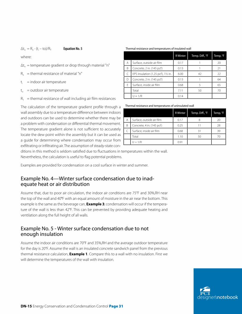
DN-15 Energy Conservation and Condensation Control Page 31
Δtn = Rn · (ti – to)/RT Equation No. 5
where:
Δtn = temperature gradient or drop through material "n"
Rn = thermal resistance of material "n"
ti = indoor air temperature
to = outdoor air temperature
RT = thermal resistance of wall including air film resistances
The calculation of the temperature gradient profile through a wall assembly due to a temperature difference between indoors and outdoors can be used to determine whether there may be a problem with condensation or differential thermal movement. The temperature gradient alone is not sufficient to accurately locate the dew point within the assembly but it can be used as a guide for determining where condensation may occur from exfiltrating or infiltrating air. The assumption of steady-state con-ditions in this method is seldom satisfied due to fluctuations in temperatures within the wall. Nevertheless, the calculation is useful to flag potentiaI problems.
Examples are provided for condensation on a cool surface in winter and summer.
Example No. 4—Winter surface condensation due to inad-equate heat or air distributionAssume that, due to poor air circulation, the indoor air conditions are 75°F and 30%,RH near the top of the wall and 40°F with an equal amount of moisture in the air near the bottom. This example is the same as the beverage can, Example 3; condensation will occur if the tempera-ture of the wall is less than 42°F. This can be prevented by providing adequate heating and ventilation along the full height of all walls.
Example No. 5 - Winter surface condensation due to not enough insulationAssume the indoor air conditions are 70°F and 35%,RH and the average outdoor temperature for the day is 20°F. Assume the wall is an insulated concrete sandwich panel from the previous thermal resistance calculation, Example 1. Compare this to a wall with no insulation. First we will determine the temperatures of the wall with insulation.
Thermal resistance and temperatures of insulated wall
R Winter Temp. Diff., °F Temp, °F
A Surface, outside air film 0.17 1 20
B Concrete, 2 in. (145 pcf ) 0.13 1 21
C EPS insulation (1.25 pcf ), 1½ in. 6.00 42 22
D Concrete, 2 in. (145 pcf ) 0.13 1 64
E Surface, inside air film 0.68 5 65
Total 7.11 50 70
U = 1/R 0.14
Thermal resistance and temperatures of uninsulated wall
R Winter Temp. Diff., °F Temp, °F
A Surface, outside air film 0.17 8 20
B Concrete, 4 in. (145 pcf ) 0.25 11 28
C Surface, inside air film 0.68 31 39
Total 1.10 50 70
U = 1/R 0.91

Page 32 DN-15 Energy Conservation and Condensation Control
The thermal resistance of the wall, RT equals 7.11. The temperature difference across the wall, ti – to, equals 70°F – 20°F = 50°F. The temperature difference across any layer is calculated us-ing Equation No. 5. The temperature difference across the air film equals O.17(50)/7.11 or 1°F. The remaining temperature differences are calculated in the same manner and shown above. The temperature differences are subtracted from the indoor air temperature (or added to the outdoor temperature) to determine temperatures at boundaries between materials and are shown above in the right column. The inside surface of the wall, between the concrete and the inside air film, is 65°F.
The following shows the determination of the thermal resistance and temperatures of an un-insulated wall.
Note that the air temperature of the room is 70°F and the temperature of the insulated wall surface inside the room is 65°F while that of the uninsulated wall surface is 39°F. The surface film resistance plays a much larger role in an uninsulated wall. The temperature gradient across the inside air film is 5°F for the insulated wall and 31°F for the uninsulated wall. The dew point of air at 70°F and 35%RH is 42°F. Since the inside surface of the uninsulated wall is 39°F, con-densation will form on the inside surface.
Also note that the average outdoor air temperature for the day was used in calculations. This average rather than the lowest daily temperature was used for two reasons. First, thermal mass of the concrete will tend to moderate the indoor surface temperature so that using an extreme temperature expected for just a few hours may be too conservative. Secondly, if a condensation occurrence is predicted for only a few hours, it will often occur and evaporate without causing problems.
Thermal bridges, such as a full thickness of concrete along panel edges, will behave similar to the uninsulated wall in Example No. 5. Thermal bridges may also occur at;
• Junctions of floors and walls, walls and ceilings, walls and roofs
• Around wall or roof openings
• At perimeters of slabs on grade
• At connections, if insulation is penetrated
• Any place metal, concrete, or a highly conductive material penetrates an insulation layer, such as metal shear connectors
Condensation can develop at these locations especially if they are in corners or portions of a building that receive poor ventilation.
Example No. 6 - Summer surface condensation

DN-15 Energy Conservation and Condensation Control Page 33
Condensation on wall surfaces also occurs in summer conditions. Cold air from air-conditioners blowing in the region of warm humid air can cause condensation on indoor surfaces. This most frequently happens when wall air-conditioner units are placed near window or door frames that al-low humid air to enter the conditioned space.
Assume the average daily outdoor conditions are 80°F and 75%RH. As-sume this air can enter a room in a gap between the top of an air-con-ditioning unit and the bottom of a window. Assume the air conditioning unit blows enough cool air in the vicinity of a wall so that the wall surface temperature is 65°F. Since the dew point of the moist air is 71°F, conden-sate will form on the cool wall surface. This illustrates the need to provide adequate joint sealing to prevent the entry of humid air.
Prevention of Condensation on Wall SurfacesAll air in buildings contains water vapor. If the inside surface temperature of a wall is too cold, the air contacting this surface will be cooled below its dew-point temperature and water will condense on that surface. Condensation on interior room surfaces can be controlled both by suitable construction and by precautions such as: (1) reducing the interior RH or dew point temperature by dehumidification equipment or ventilation; (2) raising the temperatures of interior surfaces that are below the dew point, generally by use of insulation.
The interior air dew point temperature can be lowered by removing moisture from the air, either through ventilation or dehumidification. Adequate surface temperatures can be main-tained during the winter by incorporating sufficient thermal insulation, using double glazing, circulating warm air over the surfaces, or directly heating the surfaces, and by paying proper attention during design to the prevention of thermal bridging.
Condensation within Walls and Use of Vapor RetardersAlthough condensation due to air movement is usually much greater than that due to vapor diffusion for most buildings, the contribution from water vapor diffusion can still be significant. In a well-designed building, the effects of air movement and water vapor diffusion in walls and roofs are considered.
Vapor RetardersAir barriers (also called air retarders) and vapor retarders (also called vapor barriers) are often
Example No. 6 Condensation within exterior wall.

Page 34 DN-15 Energy Conservation and Condensation Control
confused. An air barrier is used to reduce the amount of infiltration (or leakage) or exfiltration of air into a conditioned space. A vapor retarder is used to prevent, or more correctly greatly reduce, water vapor (moisture) from moving through building materials. A vapor retarder can be used as an air barrier. An air barrier on the outside of a building in a cold climate generally needs to let moisture escape, so should not function as a vapor retarder. If the air barrier will also be serving as a vapor retarder, or if it has a low permeance to vapor diffusion, then its position within the building envelope must be carefully considered in relation to the other envelope components.
The principal function of a vapor retarder is to impede the passage of moisture as it diffuses through the assembly of materials in a building envelope, to control the location of the dew point in the assembly and to ensure there is a manageable flow of moisture across the assem-bly. The basic principles, simply stated are:
• Moisture migrates through building materials due to a difference in temperature or RH or both between the inside and outside.
• Sometimes this moisture migration will cause condensation. The correct type and place-ment of insulation and a vapor retarder will prevent condensation on cold portions within a wall.
• The vapor retarder or vapor retarding materials are generally placed on the side of the wall that is warm most of the year.
• If a vapor retarder with low permeance is selected, the materials on the opposite side should have higher permeance so the wall is able to dry to that side, is necessary.
These principles are covered in depth in the sections that follow.
Most codes and references consider a material or membrane with a permeance of 1 perm or less a vapor retarder; less than 0.1 perms is considered vapor impermeable and between 0.1 and 1 perm is considered semi-impermeable. Materials or membranes with a permeance greater than 10 are considered permeable. In the range of 1 to 10 perms, materials are consid-ered semi-permeable.
Concrete as a vapor retarderNormal weight, quality concrete can be considered a semi-impermeable vapor retarder in thickness of 3 in. or more. Published values of concrete permeability are approximately 3 perm-in., so that 3 in. of concrete has a permeance of approximately 1 perm, provided it re-mains relatively crack-free. Permeance is a function of the water-cement ratio of the concrete. A low water-cement ratio, such as that used in most precast concrete members, results in concrete with low permeance.
DN-15 Energy Conservation and Condensation Control Page 35
Where climatic conditions demand insulation, sufficient concrete or an additional vapor re-tarder is generally necessary in order to prevent condensation. Thicknesses of 1 in. or more of rigid extruded polystyrene board (XPS) or 2 to 3 in. of expanded polystyrene (EPS), if properly applied, will serve as its own vapor retarder. In such cases, for cold climates, the insulation can be installed on a complete bed of adhesive applied to the interior of the inner wythe of the wall with joints fully sealed with adhesive, to provide a complete barrier to both air and vapor movement.
CodesThe International Energy Conservation Code (lECC)15 requires a vapor retarder with of 1 perm or less on the inside of insulation in cold climates. However it allows for an exception where moisture or its freezing will not damage the materials, or where other means are provided to prevent condensation. This requirement is workable for concrete since 3 in. of concrete has a perm of approximately 1 perm. The important concepts are whether condensation will occur and, if it does, will it damage the materials.
The Massachusetts energy code is more restrictive.16 This code requires a vapor retarder of 0.1 perms on the indoor side of the insulation. Concrete wall systems can generally meet the code under the exceptions that require calculations because the condensing surface is the warm side of the insulation, and the temperature at that surface is kept above the dew point of the indoor air. This code also requires that the materials and finishes on the outdoor side of the insulation have permeances at least 10 times greater than that or the inside. This require-ment is needed to allow the wall to dry to the outdoor side since the low permeance will not allow it to dry to the indoor side. Codes that have blanket requirements such as these for all wall systems may cause more moisture problems since low permeance materials sometimes prevent walls from drying.
Other materialsBuilding materials have water vapor permeances from very low to very high, see Table 13. Actual values for a given material vary depending on the moisture content of the material. Two commonly used test methods are the water method (wet cup) and desiccant method (dry cup) methods in ASTM E96, "Standard Test Methods for Water Vapor Transmission of Materials." Specimens are sealed over the tops of cups containing either water or desiccant, placed in a controlled atmosphere usually at 50% relative humidity, and weight changes measured. The change in weight represents the rate of moisture passing through the specimen.
When properly used, low permeance materials keep moisture from entering a wall assembly. Materials with higher permeance allow construction moisture and moisture which enters in-advertently, or by design, to escape.

Page 36 DN-15 Energy Conservation and Condensation Control
When a material such as plaster or gypsum board has a permeance which is too high for the intended use, a vapor retarder can be used directly behind such products. Polyethylene sheet, aluminum foil and building paper with various coatings are commonly used. Proprietary va-por retarders, usually combinations of foil and polyethylene or asphalt, are frequently used in freezer and cold storage construction. When vapor retarders are added sheets or coatings, they should be clearly identified by the designer and be clearly identifiable by the general contractor.
Water vapor diffusion occurs when water vapor molecules diffuse through solid interior materials. The passage of water vapor through material is in itself generally not harmful. It becomes of conse-quence when, at some point along the vapor flow path, a temperature level is encountered that is below the dew-point temperature and condensate accumulates. The rate of vapor movement is dependent on the permeability of the materi-als, the vapor pressure, and tem-perature differentials. Generally, the greater the temperature difference between inside and outside and the more permeable the materials, the more vapor will travel through the wall. Vapor pressures increase with temperature even if the rela-tive humidities stay the same. So, generally, the colder the outside temperature, the greater the pres-sure of the water vapor in the warm inside air compared to the cooler outside air. Water vapor pressures at saturation (100%RH) are provid-ed in Table 14. Leakage of moist air through small cracks may be a greater problem than vapor diffu-
sion.
Material M perms μ perm-in.
Concrete (1:2:4 mix)b – 3.2
Wood (sugar pine) – 0.4 – 5.4
Extruded polystyrene (XPS) 1.2
Expanded polystyrene, bead (EPS) – 2.0 – 5.8
Polyisocyanurate – 4.0 – 6.6
Polyicynene 50
Glass fiber batt 120
Kraft paper 1
Plaster on gypsum lath (with studs) 20
Gypsum wallboard, 0.375 in. 50
Polyethylene, 2 mil 0.16
Polyethylene, 4 mil 0.08
Polyethylene, 6 mil 0.06
Aluminum foil, 0.35 mil 0.05
Aluminum foil, 1 mil 0.00
Built-up roofing (hot mopped) 0.00
Duplex sheet, asphalt laminated, aluminum foil one side 0.002c
Paint
1 coat primer plus 2 coats latex on gypsum wallboard 3 to 20
1 coat primer plus 2 coats acrylic on gypsum wallboard 7
1 coat primer plus 2 coats synthetic on gypsum wallboard 3
1 coat primer plus 2 coats oil on gypsum wallboard 5
2 coats asphalt paint on plywood 0.4c
2 coats enamel on smooth plaster 0.5 – 1.5
Various primers plus 1 coat flat oil paint on plaster 1.6 – 3.0
Breather type membrane 3 – 25
a ASHRAE Handbook of Fundamentals and other sources. Values vary depending on the moisture content of the material.
b Permeances for concrete vary on the concrete's water-cement ratio and other factors.c Dry-cup.
Table 13 Typical permeance (M) and permeability (μ) valuesa.

DN-15 Energy Conservation and Condensation Control Page 37
ApplicationThe location of the vapor retarder is dependent on the wall construction and climate. A solid precast concrete wall with appropriate joint sealant will act as a semi-imper-meable vapor retarder in many climates. If a separate air barrier membrane is used, it should be clearly identified in the construction documents, preferably on the drawings. While a vapor retarder does not need to be perfectly con-tinuous, care should be taken to minimize the occurrence of small discontinuities or imperfections such as unsealed laps, cuts, and pin holes. The vapor retarder in a wall sys-tem should be continuous from the floor to the underside of the ceiling slab to prevent moisture from bypassing the vapor retarder. Wall penetration such as outlets and win-dow frames, should also be sealed.
Low-permeance paints, vinyl wall paper, or other similar materials that act as vapor retarders should not be placed on the interior surface of concrete walls. Since concrete acts also as a vapor retarder, an additional vapor retarder prevents moisture within the wall from drying.
Three common precast systems and their applicability for use in various climate zones (see Fig. 18) are presented in Figure 19. These walls allow concrete to dry without accumulating within the wall. The traditional practice for frame walls of placing a vapor retarder behind gypsum wallboard in cold climates is not recommended for these walls. The recommendations were developed using typical indoor relative humidities during winter for all building types. Indoor relative humidities greater than these during December, January, and February have the po-tential to cause condensation within these or any wall system not properly designed.
The three walls in Figure 19 are insulated to meet the requirements of the 2004 International Energy Conservation Code (IECC).15 The total wall including the concrete, insulation, and inte-rior finishes are considered in the design of a wall with low potential for moisture problems. Providing insulation as required by codes such as ASHRAE 90.1 or the IECC generally provides cost effective levels of insulation for precast concrete walls. Insulation requirements are de-pendent on climate. The map in Figure 18 is used to determine the climate zone number and letter required for determining compliance with the IECC. The amount of insulation required for the three walls is shown in Figure 19. For international locations, Appendix B of ASHRAE
Temp,.°F
SVP,in. Hg
Temp.,°F
SVP,in. Hg
Temp.,°F
SVP,in. Hg
Temp., °F
SVP,in. Hg
-30 0.007 17 0.089 38 0.229 59 0.504
-20 0.013 18 0.093 39 0.238 60 0.522
-10 0.022 19 0.098 40 0.248 61 0.541
-5 0.029 20 0.103 41 0.258 62 0.560
0 0.038 21 0.108 42 0.268 63 0.580
1 0.040 22 0.113 43 0.278 64 0.601
2 0.042 23 0.118 44 0.289 65 0.622
3 0.044 24 0.124 45 0.300 66 0.644
4 0.046 25 0.130 46 0.312 67 0.667
5 0.049 26 0.136 47 0.324 68 0.691
6 0.051 27 0.143 48 0.336 69 0.715
7 0.054 28 0.150 49 0.349 70 0.739
8 0.057 29 0.157 50 0.363 71 0.765
9 0.060 30 0.164 51 0.376 72 0.791
10 0.063 31 0.172 52 0.391 73 0.819
11 0.066 32 0.180 53 0.405 74 0.847
12 0.069 33 0.188 54 0.420 75 0.875
13 0.073 34 0.195 55 0.436 76 0.905
14 0.077 35 0.203 56 0.452 77 0.935
15 0.081 36 0.212 57 0.469 78 0.967
16 0.085 37 0.220 58 0.486 79 0.999
80 1.032
Note: 1 in. Hg = 0.491 psi. Actual vapor pressure = SVP x (%RH).
Table 14 Water vapor pressures at saturation (SVP) for various temperatures.

Page 38 DN-15 Energy Conservation and Condensation Control
90.1-2004 provides tables with climate zone numbers and letters. This appendix also provides the climate zones in tabular form by U.S. county.
A precast concrete sandwich panel wall with concrete on both sides of rigid insulation, Figure 19a, is recommended for Climate Zones 1 through 7 (all except subarctic climates). Expanded polystyrene (EPS) or extruded expanded polystyrene insulation (XPS) may be used. The in-sulation board shown in the wall details is placed within the concrete during the precasting process prior to building construction. The overall thermal resistance of a sandwich panel is greater (more energy saving) if the ties connecting the concrete wythes are plastic, composite fiberglass or epoxy coated carbon grid rather than metal.
A precast concrete wall with continuous rigid insulation, Figure 19b, is recommended for Cli-mate Zones 1 through 7 (all except subarctic climates). XPS insulation may be used in Climate Zones 1 through 7 and EPS insulation may be used in Climate Zones 1 through 5. The lower permeance of the XPS is recommended for the colder climates, Zones 6 and 7. The insulation board must be applied continuously and in direct contact with the precast concrete. This can be done using adhesive, stick pins, or mechanical fasteners.
Continuous insulation uninterrupted by metal framing is beneficial because metal framing reduces the effectiveness of fiberglass batt insulation and other insulation by more than half. For example, R13 insulation has an effective R-value of 6 when placed between steel frame members spaced 16 in. on center. The continuous insulation also reduces the potential for cold spots on the interior and exterior surfaces caused by metal framing. These can sometimes lead to condensation and shadowing or other unsightly moisture problems on the inside and outside surfaces of buildings. The potential for shadowing in a sandwich panel wall is less if the ties connecting the concrete wythes are plastic, fiberglass composite, or epoxy coated carbon grid rather than metal.
Wood and steel frame walls have cavities where moisture can accumulate, causing wood to rot and metal to corrode. The sandwich panel wall and concrete wall with rigid insulation have no wall cavities within the structural portion of the wall, thus reducing the possibility of unno-ticed moisture accumulation and related damage. The only cavity is the air space between the insulation and gypsum wallboard, if wallboard is desired. This cavity is designed to keep the wallboard dry, XPS insulation is particularly moisture resistant and has low water absorption compared to other insulation materials while EPS has lower moisture absorption compared to non-foam insulation materials.
A precast concrete wall with batt insulation (and kraft paper where appropriate), Figure 19c, is recommended for Climate Zones 1 through 5. To prevent potential moisture accumulation within the wall and related problems, this type of wall construction is not recommended for the colder climates, Zones 6, 7, and 8. The fiberglass insulation is installed between metal fram-ing, A 1-in., minimum air space is required between the batts and the concrete to prevent

DN-15 Energy Conservation and Condensation Control Page 39
Figure 19 Typical wall details.

Page 40 DN-15 Energy Conservation and Condensation Control
the potential for moisture to accumulate in the batt insulation. The air space between the metal framing and the precast concrete reduces the potential for cold spots on the interior and exterior surfaces caused by the framing. These can sometimes lead to condensation and shadowing or other unsightly moisture problems on the inside and outside surfaces of build-ings. In Climate Zones 3A (above the warm humid line), 4, and 5, kraft-faced batts are required to prevent condensation within the walls during the winter. The three walls in Figure 19, with appropriate joint sealant, will act as semi-impermeable vapor retarders and allow concrete to dry without moisture accumulating within the walls. These constructions allow the outside layer of concrete to dry to the outside and the rest of the wall to dry to the inside. Latex paint with a permeance of 5 to 10 perms on the drywall is generally adequate. The sandwich panel wall and wall with rigid insulation are assumed to have 1½ to 2 in. of insulation in Zone 4, 2 in. in Zone 5, 2 to 2½ in. in Zone 6, and 2½ to 3 in. in Zone 7. The wall with batt insulation is assumed to have R13 fiberglass batts. The location of the cold surfaces within a wall depends on the climate. Moisture generally moves into wall systems from indoors when it is cold out-side, and into wall systems from outdoors when it is warm outside. Actual water vapor and moisture-laden air movement depends on the temperature and relative humidity indoors and outdoors, the moisture content of the materials, and their absorption properties.
Cold Climates (Zones 5, 6, and 7)In these climates the vapor retarding surface should be applied on or near the warm side (inner surface) of assemblies. For the concrete sandwich panel wall, the insulation, inside con-crete wythe and painted gypsum wallboard, if used, act as the semi-impermeable vapor re-tarder during the winter. For the precast wall with rigid insulation, the insulation and painted gypsum wallboard on the inside act as a semi-permeable vapor retarder during the winter. For the precast wall with batt insulation, the kraft paper and painted gypsum wallboard act as a semipermeable vapor retarder during the winter. For all three walls, the exterior concrete wythe acts as a semi-impermeable vapor retarder during the summer. Providing an additional low permeance vapor retarder on the inside of the wall would create a "double vapor retarder" and prevent moisture that accumulates within the wall from leakage or condensation from drying to the inside. For this reason, a low permeance vapor retarder on the inside of this wall system is not recommended.
For the sandwich panel wall and the precast wall with rigid insulation, the relative humidity of the indoor space in the coldest winter months is assumed to be not more than 25% in Zone 5, 20% in Zone 6, and 10% in Zone 7. For the precast wall with batt insulation, the relative hu-midity of the indoor space in the coldest winter months is assumed to be not more than 25% in Zone 5. The recommendations were developed using these typical indoor relative humidi-ties during winter. Indoor relative humidities greater than these during December, January, and February have the potential to cause condensation within these or any wall system not

DN-15 Energy Conservation and Condensation Control Page 41
properly designed. Calculations may be required when exterior sheathing is used on the cold outdoor side since it may act as a vapor retarder on the cold side of the wall.
Fittings installed in outer walls, such as electrical boxes without holes and conduits, should be completely sealed against moisture and air passage, and they should be installed on the warm side insulation. Also, high thermal conductance paths such as at connections inward from or near the colder surfaces may cause condensation within the construction.
Warm Humid Climates (1A, 2A, 3A south of the humid line)In these climates, the exterior surface should have a lower vapor permeance than the interior surface. For all three walls, the exterior concrete acts as a semi-impermeable vapor retarder dur-ing the warm humid months. For the concrete sandwich panel wall, the inside concrete wythe and painted gypsum wallboard, if used, act as the semipermeable vapor retarder during the cool months. For the precast wall with rigid insulation, the insulation and painted gypsum wallboard on the inside act as a semi-permeable vapor retarder during the cool months. For the precast wall with batt insulation, the painted gypsum wallboard acts as a semi-permeable vapor retarder during the cool months. Low permeance paints, vinyl wallpaper, or other materials that act as vapor retarders should not be placed on the interior surface of the wall. Moisture from outdoors often accumulates behind these materials when used in these climates. Kraft paper is not recom-mended on the insulation in these climates because it also prevents the wall from drying.
In warm humid climates during rainy periods, exterior walls can absorb large quantities of moisture that are later driven inward by warm temperatures and solar effects. The concrete and rigid insulation (where provided) each have a moderately low permeance that helps pre-vent this moisture from moving inward. Some exterior paints and finishes can also provide an adequate level of resistance to moisture intrusion. The concrete and rigid insulation should be continuous and sealed to prevent the moisture from moving inward.
The operation of the cooling system is more important in warm and humid climates than any other climate. Since the latent load (that required to remove moisture) is often greater than the sensible load (that required to bring down the temperature), the system needs to be designed to remove the latent load without cycling off because it has reached the desired temperature set point. Oversized air conditioners may cycle off before the latent load is removed. Setting the chilled water supply temperature too high will have the same effect of not being able to remove the latent load. Also, many people erroneously think that setting the thermostat lower will remove moisture problems. Low thermostat settings on hot humid days has the opposite effect; they make surfaces colder and more prone to condensation.
Warm Dry, Mixed, and Marine Climates (lB, 2B, 3A north of the humid line, 3B, 3C, 4)

Page 42 DN-15 Energy Conservation and Condensation Control
The need for vapor retarders and low permeance materials is less in these climates than in cold or warm humid climates. Condensation can occur by the mechanisms discussed for cold climates, but the duration of these conditions is usually short enough that the materials sub-sequently dry without problems if surfaces are semi-permeable or semi-impermeable. The strategy for these climates is to allow the wall system to dry either to the outside or inside, or preferably, to both sides, since more damage is caused by improperly placed vapor retarders than by omitting one. The three precast concrete walls allow this drying to either side. The ex-terior concrete wythe acts as a semi-impermeable vapor retarder during the warm months. For the concrete sandwich panel wall, the inside concrete wythe and painted gypsum wallboard, if used, act as the semipermeable vapor retarder during the cool months. For the precast wall with rigid insulation, the insulation and painted gypsum wallboard on the inside act as a semi-permeable vapor retarder during the cool months. For the precast wall with batt insulation, the painted gypsum wallboard acts as a semipermeable vapor retarder during the cool months.
For the sandwich panel wall and the precast wall with XPS insulation, the relative humidity of the indoor space in the coldest winter months is assumed to be not more than 40% in Zone 4. For the precast wall with EPS insulation, the relative humidity of the indoor space in the coldest winter months is assumed to be not more than 30% in Zones 4A and 4B and 35% in Zone 4C. For the precast wall with batt insulation, the relative humidity of the indoor space in the coldest winter months is assumed to be not more than 30% in Zone 4A and 35% in Zones 4B and 4C. The recommendations were developed using these typical indoor relative humidi-ties during winter. Indoor relative humidities greater than these during December, January, and February have the potential to cause condensation within these or any wall system not properly designed.
Special Applications and Building TypeThese recommendations are for general use under normal building operating conditions. Spe-cial precautions are required for buildings with high indoor humidities or spaces with sensitive electronic equipment or artifacts. These include swimming pools, ice rinks, cold storage, com-puter rooms, libraries, hospitals, nursing homes, museums, and some manufacturing facilities. Low permeance vapor retarders are often needed to separate indoor swimming pools or other special applications from the rest of the building.

DN-15 Energy Conservation and Condensation Control Page 43
DetailsFigures 20 through 30 provide conceptual details on how to construct the precast system to achieve energy savings while providing an air barrier and reducing the potential for mois-ture problems. The recommendations and details presented are based on specific analyses, engineering judgment, and best available practices at the time of publication. Performance testing of the details has not been performed. Detail drawings are provided in order to assist competent professionals in the detailing of the building insulation envelope. Reinforcing des-ignations, structural connections, wythe thickness, and insulation indicated in drawings are to be used for reference only and are not intended to substitute for project specific judgment.
Water LeakageThe exterior surface of the precast system acts as a rain screen to prevent rain and snow from entering the building. As shown in Figures 20 and 21, joints in the precast generally have either two layers of sealant, or sealant and a secondary method of defense against water pen-etration. Joints around windows, doors, and other penetrations through the precast building are designed with a primary and secondary method of defense against rainwater penetration.
Floor SystemsThe provided details are for a double T floor system. Details for hollow core floor systems will be similar, including insulation requirements. The main concept is to separate the floor slabs from the exterior concrete by insulation to reduce thermal bridges. This will reduce energy losses and the potential for condensation and moisture problems.
Figures 22 and 23 present two options for insulating floors above unconditioned spaces such as parking structures. In these cases the concrete floor acts as a semi-impermeable vapor retarder. Figure 22 with rigid insulation is preferable. If spray-on or batt insulation are used as shown in Figure 23, it should be wrapped around the precast concrete webs.
Need for analysisIn any building with additional sources of moisture, such as from swimming pools, industrial processes, or storage of moist items, a moisture analysis of the walls and roofs for actual condi-tions should be performed. For instance, hospitals in cold climates often maintain RH levels at 50%, as opposed to the 20 to 40% RH in the in most buildings during winter in these climates. This higher RH can cause moisture problems if the building envelope is not properly designed. An analysis is also advisable for very cold, cold, mixed, or cool marine climates or other cli-mates where experience is not available to indicate how a wall will perform. It is important to

Page 44 DN-15 Energy Conservation and Condensation Control
Figure 20 Typical spandrel/column detail–Option A.

DN-15 Energy Conservation and Condensation Control Page 45
Figure 21 Typical spandrel/column detail–Option B.

Page 46 DN-15 Energy Conservation and Condensation Control
Figure 22 Typical floor detail–rigid insulation.
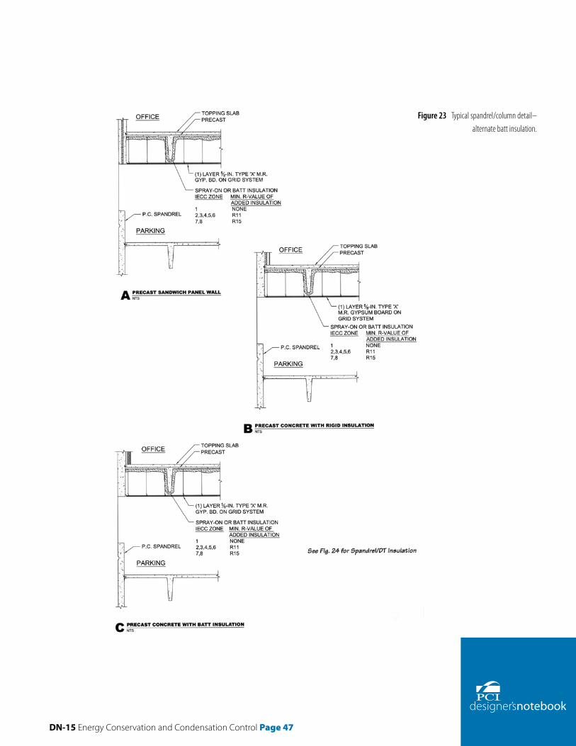
DN-15 Energy Conservation and Condensation Control Page 47
Figure 23 Typical spandrel/column detail–alternate batt insulation.

Page 48 DN-15 Energy Conservation and Condensation Control
Figure 24 Typical non-loadbearing spandrel/DT detail.

DN-15 Energy Conservation and Condensation Control Page 49
Figure 25 Typical window sill detail.

Page 50 DN-15 Energy Conservation and Condensation Control
Figure 26 Typical window head detail.

DN-15 Energy Conservation and Condensation Control Page 51
Figure 27 Typical loadbearing spandrel with corbel/DT detail.

Page 52 DN-15 Energy Conservation and Condensation Control
Figure 28 Typical loadbearing spandrel with corbel/dapped DT detail.

DN-15 Energy Conservation and Condensation Control Page 53
Figure 29 Typical pocketed loadbear-ing spandrel/DT

Page 54 DN-15 Energy Conservation and Condensation Control
Figure 30 Typical roof parapet detail.

DN-15 Energy Conservation and Condensation Control Page 55
determine whether and where the temperature within the envelope system will fall below the dew point temperature. Accurate analyses take into ac-count moisture absorption of materials as well as moisture movement through walls.
ASTM publishes an excellent book on moisture mod-els.13 These models predict moisture and temperature conditions in wall and roof assemblies for particular climate and indoor design conditions. The models utilize mathematical solutions to moisture and heat transfer mechanisms. Some predict moisture transfer by air movement and liquid water flow as well as vapor diffusion. Some can model the changes in material prop-erties such as permeance and sorption with moisture content. Use of these models requires knowledge of building physics, material properties, and the model limitations. Historically a simplified method known as the dew point method has been used to identify potential con-densation problems. This is a simplified steady-state analysis that has many limitations. If used with worst case conditions that only take place a few days a year, it will identify condensation that may not be a problem due to the ability of the materials to absorb the moisture or for the system to dry within a few days. For this reason, monthly averages are generally used. Since it considers only steady-state conditions, it is not exact. The vapor diffusion properties of ma-terials often vary with moisture content, which are not considered in the dew point method. Also, it is often frequently misused in identifying where and how much condensation occurs. However, the dew point method is a good indicator of the potential for moisture problems. The ASHRAE Handbook of Fundamentals and ASTM C755 provide excellent descriptions and examples of the dew point method.
An example also follows.
An analysis will be performed to determine whether condensation will form within the wall for the temperature and relative humidity conditions indicated on each side of the wall.
Step 1. The vapor pressures of the indoor and outdoor air may be determined from saturated vapor pressures listed in Table 15 and the assumed temperatures and relative humidities. The actual vapor pressure is the saturated vapor pressure at the given temperature times the rela-tive humidity:
The selection of appropriate outside air temperatures requires considerable judgment. The ef-fects of heat storage in materials must be recognized, as must the fact that wall or roof surface temperatures can be higher than air temperature because of solar radiation, and colder than air temperature because of clear sky radiation. These temperature modifications vary with the col-or, texture, thickness, weight and orientation of the surface materials and with the intensity of the radiation. Generally the average January temperatures without solar effects and the average July temperatures with solar effects are recommended for determining the potential for con-
Temp, °F RH, %Vapor pressure at saturation,
in. Hg
Actual vapor pressure, in. Hg
Indoor 70 30 0.739 0.222
Outdoor 0 80 0.038 0.030
Table 15 Vapor pressures.

Page 56 DN-15 Energy Conservation and Condensation Control
densation. The effect of solar radiation and humid outdoor conditions alter the dew point. Most building veneer systems are not water-proof and ab-sorb moisture.
When this moisture is heated by the sun, the vapor pressure in the veneer increases and drives the moisture inward.
Step 2. Determine the thermal resistance of the wall and temperatures within the wall using Eq. Nos. 1 and 2 as in Example Nos. 1 and 5:
Thermal bridges are not considered in this example and would need to be analyzed separately.
The temperature existing at any point in a wall under any given exterior and interior temperature conditions is of great signifi-cance in designing problem-free building enclosures. An ability to calculate the thermal gradient permits the designer to fore-cast the magnitude of the movements caused by external tem-perature changes, to predict the location of condensation and freezing planes in the wall, and to assess the suitability of any construction. The temperature gradient will not, in itself, give the designer all the information required to select and assemble building components, but it is an essential first step.
Step 3. The saturated vapor pressures at various surfaces and in-terfaces within the wall section may be obtained from tempera-tures determined in Step 2 and Table 13.
These saturated vapor pressures (SVP or Ps) are plotted in Figure 31 to form the SVP gradient, Ps, through the wall section.
Step 4. To check the location where condensation is likely to take place, the vapor pressure gradient necessary for vapor transfer continuity, Pc, is plotted as shown in Figure 31. The vapor pres-sure gradient, Pc, is obtained by a calculation procedure similar to that used to determine the temperature gradient, described
Figure 31 Thermal and water vapor gradients for extreme winter conditions.
Thermal resistance and temperatures of insulated wall
R-value Winter Temp. Diff., °F Temp, °FSVP,
in. Hg
A Surface, inside 0.68 5 70 0.739
B Gypsum wallboard, ½ in. 0.45 3 65 0.622
C EPS insulation (1.25 pcf ), 2 in. 8.00 58 62 0.560
D Concrete, 6 in. (145 pcf ) 0.38 3 4 0.046
E Surface, outside 0.17 1 1 0.040
Total 9.68 70 0 0.038
U = 1/R 0.10

DN-15 Energy Conservation and Condensation Control Page 57
in Step 2. It is based upon the total vapor pressure drop (0.222 – 0.030 = 0.192 in. Hg) and the respective vapor permeances of the different components of the wall from Table 12.
Δpn = zn(Δpwall) / zwall Equation No. 6
where:
Δpn = vapor pressure gradient or drop through material "n", in. Hg
Δpwall = vapor pressure gradient or drop through wall, in. Hg
zn = vapor pressure resistance of material "n", rep (rep = 1/perm)
zwall = vapor pressure resistance of wall, rep
and
zn = 1/M or n/μ Equation No. 7
where:
M = vapor permeance, perms
n = thickness of material, in.
μ = vapor permeability, perm · in.
Continuous vapor flow conditions are preserved provided the actual vapor pressure, pa does not exceed the saturation vapor pressure, Ps. If Pa does exceed or cross Ps, condensation will occur. In this case, Pa exceeds Ps in between the insulation and concrete layers and condensa-tion is expected to occur here. For discontinuous vapor flow (when condensation occurs), the vapor flow to and away from the condensation surface must be recalculated. The difference will be equal to the condensation rate. The vapor flow to or from a point is equal to the actual vapor pressure difference divided by the vapor resistance to or from that point.
Vapor reisitance and vapor pressure for continuity.
SVP, in. Hg M or μ/n, perm zn, repΔpn,
in. HgPa,
in. Hg
ASurface, inside primer and paint, 1 coat
0.739 2 0.5 0.033 0.222
B Gypsum wallboard, ½ in. 0.622 38 0.027 0.002 0.189
C EPS insulation (1.25 pcf ), 2 in. 0.560 4/2 = 2 0.5 0.033 0.187
D Concrete, 6 in. (145 pcf ) 0.046 3.2/6 = 0.53 1.87 0.124 0.154
E Surface, outside 0.040 0 0 0.030
Total 0.038 2.90 0.192 0.030

Page 58 DN-15 Energy Conservation and Condensation Control
Reducing Pa so that it is less than Ps can be achieved either by:
1. Changing the various vapor flow resistances to reduce the values of Pa. For example, add a vapor retarder on the side of the wall with the higher vapor pressure (warm side) or use an insulation with a lower vapor permeance.
2. Changing the various thermal resistances of the wall components to raise the tempera-ture. This will raise the values of Ps.
3. A combination of two of the above items.
Air infiltration, exfiltration, and air barriersInfiltration and exfiltration are air leakage into and out of a building through cracks or joints between infill components and structural elements, interstices around windows and doors, between the sill plate and foundation, through floors and walls, at the top and bottom of walls, and at openings for building services such as plumbing. Approximately 5 to 20% of air leakage occurs at doors and windows, and 20 to 50% occurs through walls. Infiltration and exfiltration are often a major source of energy loss in buildings. Exfiltrating air carries away heating and cooling energy, while infiltrating air may bring in moisture and pollution as well as reduce the effectiveness of a rain screen wall system.
Moisture can move into or across a wall assembly by means of vapor diffusion and air move-ment. Diffusion is a slow, controlled process driven only by vapor pressure differentials, and rarely causes any significant moisture accumulation. Air migration occurs from air pressure differentials independent of moisture pressure differentials. If air, especially exfiltrating, warm, humid air, can Ieak into the enclosure, then this will be the major source of moisture. Conden-sation due to air movement is usually much greater than that due to vapor diffusion for most buildings. However, when air leakage is controlled or avoided, the contribution from vapor diffusion can still be significant. In a well designed wall, attention must therefore be paid to the control of air flow and vapor diffusion.
An air barrier and vapor retarder are both needed, and in many instances a single material can be used to provide both of these as well as other functions. The principal function of the air barrier is to stop the outside air from entering the building through the walls, windows, or roof, and inside air from exfiltrating through the building envelope to the outside. This applies whether the air is humid or dry, since air leakage can result in problems other than the deposi-tion of moisture in cavities.
Uncontrolled air (and its associated water vapor), exfiltration in cold climates and infiltration in hot, humid climates can wreak havoc, causing corrosion and structural damage, mold and bacterial growth, and energy loss. It can also create HVAC problems by disrupting indoor air pressure relationships and degrading indoor air quality (IAQ), which can lead to health prob-

DN-15 Energy Conservation and Condensation Control Page 59
lems for sensitive individuals.
Atmospheric air pressure differences between the inside and outside of a building envelope exist because of the action of wind, the density difference between outside cold heavy air and inside warm light air creating a "stack effect" and the operation of equipment such as fans. The pressure differences will tend to equalize, and the air will flow through holes or cracks in the building envelope carrying with it the water vapor it contains. A thorough analysis of air leak-age is very complex, involving many parameters, including wall construction, building height and orientation.
Air barriers (sometimes called air retarders) will reduce infiltration and exfiltration. This will re-duce the potential for moisture problems due moist air migrating into a wall and building. This moisture can be warm humid air from outside during the summer or warm conditioned air from inside in the winter.
An air barrier is required to have a leakage rate less than 0.06 cfm/ft2 at a differential pressure of 0.3 in. H2O (1.57 psf ) according to ASTM E1677, "Standard Specification for an Air Retarder (AR) or Material or System for LowRise Frame Walls." This value however is considered high for buildings in Canada where a value of 0.004 cfm/ft2 at 0.3 in. H2O is sometimes required. This is the maximum air leakage for a total assembled air barrier system (total wall system or main areas plus joints) when tested according to ASTM E2178, "Standard Test Method for Air Perme-ance of Building Materials."
Materials such as precast concrete panels, polyethylene, gypsum board, metal sheeting or glass qualify as air barriers since they are low air permeable materials when joints are properly sealed; whereas concrete block, acoustic insulation, open cell polystyrene insulation or fiber-board would not. Air permeances of selected materials are presented in Table 16.
Materials and the method of assembly chosen to build an air barrier must meet several re-quirements if they are to perform the air leakage control function successfully.
1. Continuous. The air barrier must be continuous throughout the building envelope. For example, the low air permeability materials of the wall must be continuous with the low air barrier materials of the roof (e.g., the roofing membrane) and connected to the air barrier material of the window frame. All of the air barrier components should be sealed together so there are no gaps in the envelope airtightness. Where interior finishing (drywall) serves as the air barrier, if it is not finished or continuous above suspended ceilings or behind con-vector cabinets, there will be large gaps in the air barrier system's continuity. Connection should be made between:
a. Foundation and walls
b. Walls and windows or doors

Page 60 DN-15 Energy Conservation and Condensation Control
c. Different wall systems, such as brick and precast concrete, or curtain wall and precast concrete, and corners
d. Joints in gypsum wallboard and precast panels
e. Walls and roof
f. Walls, floors and roof at construction, control, and expansion joints. The interior air barrier above a dropped ceiling needs to be connected to the underside of the above floor.
g. Walls, floors, and roof to utility, pipe, and duct penetrations
2. Load capacity. Each membrane or assembly of materials intended to support a differential air pressure load must be designed and constructed to carry that load, inward or outward, or it must receive the necessary support from other elements of the wall. These loads are the combined wind, stack, and fan pressures on the building envelope. If the air barrier system is made of flexible materials then it must be supported on both sides by materials capable of resisting the peak air pressure loads; or it must be made of self-supporting materials, such as board products adequately fastened to the structure. The air barrier should be designed so that adjacent materials are not displaced under differential air pressures. If an air pressure difference cannot move air, it will act to displace the materials that prevent the air from flowing. Tape and sealant must also resist these pressures and have long-term resistance. Concrete is the ideal material for an air barrier because of its durability and strength in resist-ing these loads. Sealant between panels and at joints must be designed to resist these loads.
3. Joints. The air barrier of each assembly should be joined to air barriers of adjacent assem-blies in a manner allowing for the relative movement of the assemblies and components due to thermal and moisture variation, creep, and structural deflection. These joints in the air barrier and joints at penetra-tions of the air barrier system should be of low air permeability materials.4. Durable. The air barrier assem-
bly must be durable in the same sense that the building is durable, and be made of materials that are known to have a long service life or be positioned so that they may be serviced from time to time.
MaterialAverage leakage, crm/ft2 of surface
at 0.3 in. H2O
Solid precast concrete wall No measurable leakage
Aluminum foil vapor barrier No measurable leakage
6 mil polyethylene No measurable leakage
Extruded polystyrene insulation No measurable leakage
Closed cell foam insulation 0.0002
3 in. polyicyenne 0.001
½ in. fibreboard sheathing 0.31
Breather type building membranes 0.0022 – 0.71
Uncoated brick wall 0.31
Uncoated concrete block 0.41
1 in. expanded polystyrene 0.93
a National Research Council, Canada www.nrc-cnrc.gc.ca
Table 16 Measured air leakage for selected building materials.a

DN-15 Energy Conservation and Condensation Control Page 61
5. Vapor permeance. When a vapor retarder is used on the inside of insulation in a cold or mixed climate [see vapor retarder section], an air barrier used on the outside should be permeable to water vapor. If both the inside vapor retarder and the outside air barrier are not permeable, then a ''double vapor retarder" condition is created. Moisture that gets between the two through rain penetration or leakage through joints will not be able to readily dry. Vapor permeability allows moisture behind the air barrier to exit the wall by vapor diffusion to the outside. According to ASTM E1677: "In a moderate to cold climate the opaque wall must either be permeable to water vapor, or when the permeance of the materials on the exterior is less than 1 perm it may be beneficial to insulate on the outside. When the exterior is permeable, moisture vapor from the opaque wall can escape to the outdoors without accumulating in the wall. When the exterior is insulated the temperature of the opaque wall is increased to minimize wall moisture accumulation. Designers should evaluate the amount of insulation necessary to keep condensation from forming in the wall assembly when the air barrier is rated as a vapor retarder less than 1 perm and exterior applied."
Building pressure. In warm humid climates, a positive building pressure will help prevent the infiltration of humid air. In cold climates the building pressure should be neither strongly posi-tive or negative. A strong negative pressure could pull in combustion products from outdoors. A strong positive pressure could drive moisture into the building walls and other elements.
Adequate ventilation. Because concrete buildings have less air leakage, heating and cooling systems should have adequate air intake systems to provide fresh air in buildings. This is more critical in concrete than steel frame buildings because there is less air leakage. Without an ad-equate intake source, concrete buildings are under negative pressure, potentially resulting in poor indoor air quality. In all cases, guidelines of ANSI/ASHRAE Standard 6217 should be followed for proper ventilation of indoor air.
Application. The location of the air barrier is dependent on the wall construction and climate. Precast concrete as a material acts as an air barrier and has a negligible air leakage and infiltra-tion rate. A properly designed and constructed precast concrete building will save energy due to this low infiltration. This requires the air barrier be continuous by sealing joints between panels, openings at connectors, around door and window frames, and at penetrations. The building envelope including the precast concrete should provide continuous resistance to air flow through joints at floors, ceilings, and roof. Where it is impractical to seal joints between panels, gypsum wallboard acts as an air barrier if the floor/wall and ceiling/wall joints are tight-ly fitted and sealed with a joint sealant.
Air barrier membranes and building wraps such as Tyvek© are being used more frequently in new construction. They are not required in precast concrete buildings because the concrete
Page 62 DN-15 Energy Conservation and Condensation Control
acts as an air barrier and has a lower air permeance than Tyvek (see "breather type mem-branes" in Table 16).
In cold climates (Zones 5, 6, and 7), it is strongly recommended that the visible interior surface of a building envelope be installed and treated as the primary air barrier and vapor retarder. A concrete panel with the concrete on the indoor surface generally serves this dual function as air barrier and vapor retarder. Where floors and cross walls are of solid concrete, it is necessary to seal only the joints, as floors and walls themselves do not constitute air paths. Where hollow partitions, such as steel studs are used, the interior finish of the envelope can be made into the continuous air barrier. Where this is impractical, polyethylene film should be installed across these junctions and later sealed to the interior finish material. Where it is im-practical to use a concrete panel system as the continuous air barrier system, an interior finish of gypsum wallboard, or plaster, painted with two coats of vapor retarding paint will provide a satisfactory air barrier/vapor retarder in many instances if the floor/wall and ceiling/wall joints are tightly fitted and sealed with joint sealant.
While it is preferable that the air barrier system be placed on the warm indoor side of an insulated assembly, where thermal stresses will be at a minimum, it is not an essential require-ment. (This does not necessarily mean on the inside surface of the wall.) The position of the air barrier in a wall is more a matter of suitable construction practice and the type of materials to be used. However, if an air barrier membrane is used and is positioned on the outside of the insulation, consideration must be given to its water vapor permeability, as discussed in Item No. 5 above. One rule of thumb is to choose an air barrier material on the outside that is ten to twenty times more permeable to water vapor diffusion than the vapor retarder material on the inside of the wall.
In warm and humid climates (Zones lA, 2A, and 3A), an air barrier (or low air-permeance materials properly sealed) on the outside of the wall works well because it helps prevent the infiltration of the warm humid air. An architectural precast panel with appropriate joint sealant will serve as an air barrier in this climate. Exterior surfaces should be less permeable than in-side surfaces, once again, to help reduce the amount of moisture entering the walls. Note that this is the opposite of what is recommended for cold climates. In mixed, dry warm, and cool marine climates (see Table11), an air barrier (or properly sealed Iow air-permeance materials) is recommended. An architectural precast panel with appropriate joint sealant will serve as an air barrier in this climate.
Considerations at WindowsThe principal potential moisture problems with windows are the following:
1. Poor sealing of the wall air barrier and vapor retarder at window joints with the wall.

DN-15 Energy Conservation and Condensation Control Page 63
2. Penetration of rainwater into the wall construction beneath the windows.
3. Condensation of moisture or frost formation on the inside of windows in cold weather and subsequent drainage of the water onto the sill and into the wall construction.
4. Excessive leakage of warm moist air into the building in summer weather to add to the air conditioning load.
Air barriers and vapor retarders must be carefully sealed at window openings to prevent air leakage into wall construction at the window frames. Likewise the design of window sills and the sealant techniques must be such that rainwater drainage is diverted to the outside without wetting the insulated construction beneath the windows. This requires that thermal insulation be held away from the collecting surface so moisture can proceed down to collection systems without wetting the insulation. Impaling pins allow this to be accomplished easily, and they are available with shoulders holding back-up discs and insulation away from the panel.
Double and triple glazed windows should be used in Climate Zones 4, 5, 6, and 7 where there are extended periods of cold weather to reduce surface condensation and drainage. An indoor relative humidity of 40% can be maintained without excessive condensation on double-glazed windows for outside temperatures down to 15°F. At colder temperatures indoor RH levels are generally lower and the potential for condensation will generally be lower. Windows with ar-gon fill allow for colder temperatures before condensate accumulates. The ASHRAE Handbook of Fundamentals provides more guidance on potential condensation. The drainage of window condensation should not be allowed to remain on the window sills or to run down the inside walls. Windows in hospitals and swimming pool areas are exposed to higher than average indoor RH levels in cold climates and must be carefully designed to prevent condensation.
Excessive window leakage can be avoided by specifying the maximum acceptable leakage observed when windows are tested in accordance National Fenestration Rating Council (NFRC www.NFRC.org) Test Method 400. Air leakage should not exceed 4 cfm/ft2. These values are available from the manufacturer.
Application of InsulationWhere insulation is required on a precast concrete wall, it may be applied to the panel (nor-mally to the interior surface) or it may be fully incorporated in the panel, resulting in a sand-wich wall panel.
There are basically several approaches for the application of insulation to large flat surfaces:
1. Supplementary framing (e.g. steel studs) can be added to provide cavities for the instal-lation of batts or rigid insulation and to support subsequent components of the assem-bly. There should be an air space between the framing and the panels to minimize ther-

Page 64 DN-15 Energy Conservation and Condensation Control
mal bridging. Additionally, batts and other moisture sensitive materials should never be in contact with concrete,especially concrete that is subjected to wet-ting by rain or other sources of moisture.
2. Rigid insulation can be fastened to concrete sur-faces with adhesives, by impaling it on adhered pins ("stick clips"), and with various types of furring and mechanical fasteners.
Adhesives: This is the most obvious method of fas-tening anything to a large flat surface and there are a number of adhesives available for this use. Selection of the proper adhesive is important. It should be com-patible with the type of insulation being used. The ve-hicles or thinners in some adhesives will attack foam plastic insulation. Also, some protein-based adhesives can provide nutrition for fungi and other micro-or-ganisms unless they have preservatives included in their make-up.
The adhesive should not be applied in daubs. The use of daubs of adhesive creates an air space between the surface and the insulation. If the insulation is on the inner surface of the assembly, warm moist air circulat-
ing in this space will cause condensation. If the insulation is on the outer surface of the assem-bly, cold air circulating in this space will "short circuit" the insulation.
It is better to apply a full bed of adhesive or a grid of beads of adhesive, Figure 32. A full adhe-sive bed is the preferable method from an adhesion point of view but where it is on the cold side of the insulation (e.g., applying insulation to the interior surface) it may act as a vapor trap preventing drying of any moisture which penetrates the interior air/vapor barrier. In this situa-tion therefore the grid approach should be used.
Stick Clips: These are thin metal or plastic pins with a large perforated flat head at one end. The head is fastened to the concrete surface with a high quality adhesive which keys into the perforations. The clips are applied in a grid pattern, then the insulation is impaled on the pins and secured in place with a type of spring washer which is simply pushed over the end of the pin against the insulation. Sharp "teeth" on the washer grip the pin, Figure 33. Although this method also relies on adhesive, the entire surface does not have to be covered, thus making it easier to clean the surface and permitting the use of high performance (and hence costly) adhesives. As previously discussed, this method will reduce the R-value of the insulation. For
Figure 32 Application of rigid insulation with adhesives.

DN-15 Energy Conservation and Condensation Control Page 65
example, pins representing 0.06% of an insulated pan-el area can reduce the panel R-value by 6%. Insulation would retain its full R-value if plastic pins are used.
Furring Systems: There are a number of types of plas-tic, wood or metal furring which can be applied over the insulation and fastened, through it, to the concrete surface. Fig. 34 illustrates one of the approaches. The furring is usually applied along the joint between two insulation boards to that one piece of furring contributes to the support of two insulation boards. Depending on the size of the insulation boards and the amount of sup-port required by any subsequent finish, furring may also be applied in the middle of the insulation boards. Metal furring will decrease the effectiveness of the insulation and may also require special preparation of the insula-tion. The decrease in the R-value of the insulation due to metal furring can be determined using Table 8.
The insulation may be held in place temporarily prior to application of the furring by light daubs of adhesive. These should be very light to avoid holding the insula-tion away from the surface as discussed above in the section of adhesives.
The furring can be fastened with power-driven fasteners or a special type of concrete nail which is driven into a predrilled hole. The available length of fasteners usually limits the thickness of insulation to about 4 in.
Where this method is used to apply insulation to the in-side of a wall, the interior finish is applied by screwing or nailing it to the furring members.
Insulation may be plant or jobsite applied:
1. Mechanical: Most commonly performed at jobsite. If done in precast concrete plant, see note below.
2. Adhesive: As above.
3. Spraying: Normally accomplished at jobsite after instal-lation. If done in precast concrete plant, see note below.
Figure 33 Use of stick clips to install rigid insulation.
Figure 34 Furring systems.

Page 66 DN-15 Energy Conservation and Condensation Control
4. Poured: Face to be insulated must be face-up during casting. Bulkheads permit simple application of insulation following concrete casting and initial curing. Very lightweight concrete mixes should be checked for variation due to shrinkage to avoid possible de-lamination. For soft insulations the note below is also valid.
5. Wet Application: Insulation should have a bondable surface. Shear ties should be used between concrete and insulation.
Note: For all insulation applied in the precast concrete plant, by whatever method, the initial cost saving in application should be weighed against the cost of added protection during handling and transportation and possible protection against inclement weather. The latter will depend mostly on the type of insulation used.
Where precast concrete cladding is applied over a previously erected wall, as would be the case with (Fig. 35) a concrete end shear wall, it is necessary to leave holes in such walls for access to the connection points for the precast concrete panels. Care must be taken in filling these holes after the precast concrete panels are installed in order to maintain the integrity of the envelope's airtightness and thermal resistance. The thermal consideration is especially true where the insulation is installed on the outer surface of the inner wall prior to erection of the precast concrete panels, when recommended to avoid thermal bridges at the slabs. One solu-
Figure 35 Cladding erected over previously erected wall.

DN-15 Energy Conservation and Condensation Control Page 67
tion is to fill around the panel connections with pre-packaged foam-in-place urethane. The ef-fect of these holes on the envelope's airtightness will be less of a concern where the approach of treating the interior finish as the primary air barrier is adopted. This is not to suggest that the holes should not be properly sealed when this approach is adopted. They also represent weaknesses in the wall's secondary line of defense against rain penetration.
Access to the back of the panels for sealing the joints is not a problem where the inner wall is erected after the precast concrete panels, and where the inner wall is a steel stud type, or where there is no inner wall. This, of course, assumes the panel joints are offset from the slabs and cross-walls or exterior columns.
Precast Concrete Sandwich PanelsPrecast concrete sandwich wall panels can provide an aesthetically pleasing, durable exterior finish, a paint-ready, durable interior surface, and effective thermal and moisture protection for a building. Such panels normally comprise an exterior layer (or wythe) of concrete, a layer of insulation, an interior layer of concrete, and a connection system passing through the insula-tion, tying the layers of concrete together. If required, the panels can also include an external air layer so that they can function as part of a rain-screen system.
Precast concrete sandwich walls are ideally suited for energy conservation. In addition to the low thermal conductivity (high R-value) of the included insulation layer, concrete sandwich walls include the mass and heat capacity of concrete, providing thermal damping (Mass Ef-fect—See page 14). A range of R-values can be obtained by varying the insulation thickness and material or, in some cases, by varying the unit weight of the concrete. The effects of ther-mal damping can vary with the climate and the building use. However, a concrete sandwich wall will almost always provide both reductions and delays of the peak loads affecting a build-ing. Therefore, even with equal R-values, a concrete sandwich wall will provide greater energy savings than a wall constructed of lightweight (low mass) materials. This effect is recognized by the major building codes and can be considered during the panel design.
In addition to providing insulation for the building, sandwich panels must resist structural ef-fects, including lateral forces, gravity loads, and temperature effects. Lateral forces may include seismic, wind, soil, and blast effects. Gravity loads can include self-weight, as well as loads imposed by floor or roof structures. Temperature effects arise due to the natural temperature differential that wilI occur through the thickness of the sandwich panel, as well as the tempera-ture gradients that must occur through the thickness of each concrete layer.
In general, sandwich panels are considered as loadbearing or as cladding (or curtainwall) pan-els. Loadbearing panels are designed to effectively act as slender columns, transferring floor, roof, and self-weight loads to foundation or supporting structures. In contrast, cladding panels are designed to transfer only their self-weight to foundation or supporting structures. Both

Page 68 DN-15 Energy Conservation and Condensation Control
panel types must be designed to resist lateral forces applied normal to the plane of the panel and may be designed to resist in-plane forces applied by roof or floor diaphragms.
Unlike panels with post-installed insulation systems, precast sandwich panels provide protec-tion to the insulation layer against flames and heat. They therefore limit the production of toxic gases during building fires and do not promote the spreading of flames to adjacent com-ponents. Also in contrast to panels with post-installed insulation systems, precast sandwich panels protect the insulation against rodent and impact damage. Finally, in contrast to panels with interior, post-installed insulation, properly detailed precast sandwich panels do not create conditions that support mold growth.
Sandstone-colored precast concrete, with two tones of aggregate, creates a banding effect on the new 8-story county hospital façade, Figure 36. Most of the building (98,000 square feet) is clad with precast concrete insulated sandwich wall panels for energy efficiency and to elimi-nate condensation. The panels feature a 2-inch exterior wythe, 2 inches of rigid insulation and, a 6-inch interior wythe. The design team wanted a building that could be maintained without difficulty and that would retain its consistency of texture and color for many years.
The use of insulated architectural precast concrete panels for a military academic facility, Figure 37, afforded several advantages over other types of cladding. It was a cost effective system, providing both the exterior and interior finish. The interior surface was given a light broom finish and painted. Also, overall construction time was reduced due to rapid installation of the panels.
Figure 36 Insulated sandwich wall panels. John H. Stroger, Jr. Hospital of Cook County, Chicago, Ill. CCH Design Group headed by Loebl Schlossman & Hackl. (Courtesy ©Hedrick Blessing)
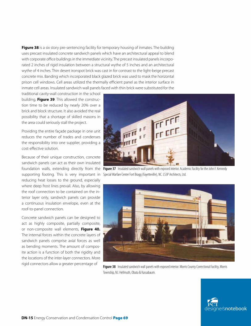
DN-15 Energy Conservation and Condensation Control Page 69
Figure 38 is a six story pre-sentencing facility for temporary housing of inmates. The building uses precast insulated concrete sandwich panels which have an architectural appeal to blend with corporate office buildings in the immediate vicinity. The precast insulated panels incorpo-rated 2 inches of rigid insulation between a structural wythe of 5 inches and an architectural wythe of 4 inches. Thin desert ironspot brick was cast in for contrast to the light-beige precast concrete mix. Banding which incorporated black glazed brick was used to mask the horizontal prison cell windows. Cell areas utilized the thermally efficient panel as the interior surface in inmate cell areas. Insulated sandwich wall panels faced with thin brick were substituted for the traditional cavity-wall construction in the school building, Figure 39. This allowed the construc-tion time to be reduced by nearly 20% over a brick and block structure. It also avoided the real possibility that a shortage of skilled masons in the area could seriously stall the project.
Providing the entire façade package in one unit reduces the number of trades and condenses the responsibility into one supplier, providing a cost-effective solution.
Because of their unique construction, concrete sandwich panels can act as their own insulated foundation walls, extending directly from the supporting footing. This is very important in reducing heat losses to the ground, especially where deep frost lines prevail. Also, by allowing the roof connection to be contained on the in-terior layer only, sandwich panels can provide a continuous insulation envelope, even at the roof-to-panel connection.
Concrete sandwich panels can be designed to act as highly composite, partially composite, or non-composite wall elements, Figure 40. The internal forces within the concrete layers of sandwich panels comprise axial forces as well as bending moments. The amount of compos-ite action is a function of both the rigidity and the locations of the inter-layer connectors. More rigid connectors allow a greater percentage of
Figure 37 Insulated sandwich wall panels with exposed interior. Academic Facility for the John F. Kennedy Special Warfare Center Fort Bragg (Fayetteville), NC. LS3P Architects, Ltd.
Figure 38 Insulated sandwich wall panels with exposed interior. Morris County Correctional Facility, Morris Township, NJ. Hellmuth, Obata & Kassabaum.

Page 70 DN-15 Energy Conservation and Condensation Control
the external forces to be resisted by axial loads within the concrete layers (creating a couple). As the rigidity of the connector system is reduced, the portion of external load resisted by axial loads is also reduced, leading to a reduction in strength. Further, as the rigidity of the connector system is reduced, the shear displacement between concrete layer increases, leading to signifi-cantly reduced panel stiffness.
As indicated above, highly composite pan-els are constructed with rigid inter-layer connectors. A common rigid connection system comprises distributed steel ele-ments resembling bar joists, with a chord
member embedded in each concrete layer and with web members crossing the insulation plane. Another common rigid connector system comprises discrete, through-thickness solid sections distributed along the panel length and width.
Although a highly composite panel normally provides the lightest and thinnest wall section for resistance of lateral or gravity loads, the negative effects of the resulting thermal bridges (reduced thermal performance of panels as well as creation of zones of surface condensation) must be evaluated by the design team.
Depending on the rigidity of the connector system (ties or ribs) wythe interaction may be to-tal or partial. Non-composite panels, Figure 40a, are those in which one wythe is supported from the other by relatively flexible ties, and/or hangers, allowing differential movement of the wythes with changing temperatures and humidity conditions. Non-composite panels with an air space allow for ventilation of the outer wythe and pressure equalization. For non-composite panels, one wythe is usually assumed to be "structural" and all loads are carried by that wythe. The structural wythe is normally thicker and stiffer than the non-structural wythe, and is usually located on the interior (warm) side of the panel to reduce thermal stresses due to temperature variation. Occasionally it may be the exterior wythe, particularly in the case of sculptured panels such as ribbed panels, that serves the structural function. Note that metal ties or concrete that penetrate the insulation may reduce its R-value.
For equal overall thickness of panel, a composite element (Fig. 40b) will have greater lateral stiff-ness. However, because the deformation of the outer wythe will affect the inner wythe, experi-ence indicates that the lateral bowing of composite panels with mild steel reinforcement is less predictable than that of non-composite panels. While the introduction of prestress in both wy-thes of a composite panel has no effect on thermal bowing, it can be used to induce an inward
Figure 39 Insulated sandwich wall panels painted on the interior. Jack Britt High School, Fayetteville, NC. Shuller, Ferris, Lindstrom & Associates.
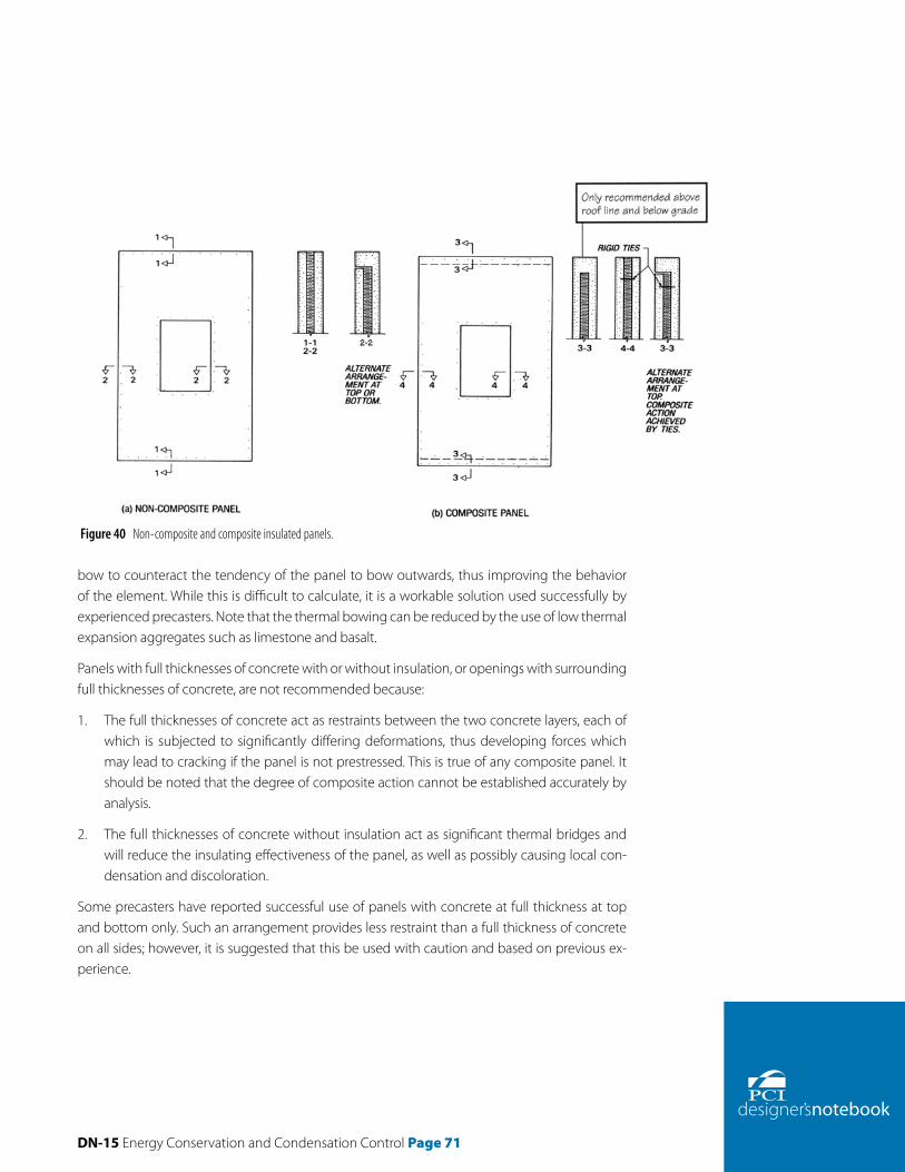
DN-15 Energy Conservation and Condensation Control Page 71
bow to counteract the tendency of the panel to bow outwards, thus improving the behavior of the element. While this is difficult to calculate, it is a workable solution used successfully by experienced precasters. Note that the thermal bowing can be reduced by the use of low thermal expansion aggregates such as limestone and basalt.
Panels with full thicknesses of concrete with or without insulation, or openings with surrounding full thicknesses of concrete, are not recommended because:
1. The full thicknesses of concrete act as restraints between the two concrete layers, each of which is subjected to significantly differing deformations, thus developing forces which may lead to cracking if the panel is not prestressed. This is true of any composite panel. It should be noted that the degree of composite action cannot be established accurately by analysis.
2. The full thicknesses of concrete without insulation act as significant thermal bridges and will reduce the insulating effectiveness of the panel, as well as possibly causing local con-densation and discoloration.
Some precasters have reported successful use of panels with concrete at full thickness at top and bottom only. Such an arrangement provides less restraint than a full thickness of concrete on all sides; however, it is suggested that this be used with caution and based on previous ex-perience.
Figure 40 Non-composite and composite insulated panels.

Page 72 DN-15 Energy Conservation and Condensation Control
A more satisfactory arrangement, where solid concrete is required for bearing, is to provide freedom of movement at the other 3 sides, as shown in Figure 40b.
Precasters who advocate the use of non-composite sandwich panels emphasize the advan-tage of the structural wythe being protected by the insulation from extremes of temperature, thus minimizing the bowing of the structural wythe and eliminating thermal stresses in the structure. The exterior wythe is free to expand and contract with variations in temperature and thus will remain crack-free.
Precasters who advocate the use of composite panels point out that the structural wythe of a non-composite panel must carry all of the applied loads in addition to the weight of the other wythe thus increasing overall dimensions, weight and expense, whereas a composite panel can be designed to share the loads between the wythes thus reducing dimensions, weight and expense.
Insulation and concrete thermal properties were discussed on pages 8 to 14. The insulation should have low water absorption (ideal) or a water-repellent coating (less than ideal) should be used to minimize absorption of water from the fresh concrete, as this can have an adverse effect on the performance of the insulation. In all cases, rigid cellular insulation used in sand-wich panels should not be moisture sensitive. Extruded polystyrene board insulation (XPS) is moisture resistant.
The physical properties of the insulations typically used in sandwich panels are listed on Table 17a. The ASTM references of these insulations are listed in Table 17b.
Table 17a Properties of insulation.
Polystyrene PolyisocyanuratePhenolic
Cellular Glass
Expanded Extruded Unfaced Faced
Density (pcf ) 0.7–0.9 1.1–1.4 1.8 1.3–1.6 1.8–2.2 3.0 2.0–6.0 2.0–6.0 2.0–3.0 6.7–9.2
Water absorption (& volume) < 4.0 < 3.0 < 2.0 < 0.3 < 3.0 1.0–2.0 < 3.0 < 0.5
Comp. strength (psi) 5–10 13–15 25 15–25 40–60 100 16–50 16 10–16 65
Tensile strength (psi) 18–25 25 50 105 45–140 500 60 50
Linear coeff. of expansion (in/in/°F) x 10-6 25–40 25–40 30–60 10–20 1.6–4.6
Shear strength (psi) 20–35 – 35 50 20–100 12 50
Flexural strength (psi) 10–25 30–40 50 40–50 60–75 100 50–210 40–50 25 60
Thermal conductivity (Btu – in/hr/ft2/°F) at 75°F
0.32–0.28 0.26–0.25 0.23 0.20 0.18 0.10–0.15 0.16–0.23 0.35
Max. use temp. 165°F 165°F 250°F 300°F 900°F
Note: 1 lb per cu ft = 16.02 kg/m3, 1 psi = 0.006895 MPa; 1 in/in/°F = 1.800 mm/mm/°C; 1 Btu-in/hr/ft2/°F = 0.1442 Wm/M2/C, tc = (tf = 32/1.8).

DN-15 Energy Conservation and Condensation Control Page 73
In some facilities, sandwich panels are exposed to extremely high in-terior operating temperatures. The physical property of an insulation to withstand these temperatures can cause the panel to fail to perform as intended throughout the lifetime of the building. For instance, polysty-rene insulation has a relatively low melting temperature. This type of insulation will begin to shrink and warp when temperatures reach 165°F. Selection of a pro-tected polyurethane or polyisocyanurate insulation with melting temperatures above 210°F can prevent possible structural weakness or thermal instability. Calcium silicate insulations can withstand higher temperatures. The specifier should choose the insulation to be compatible with and resistant to the conditions to which it will be exposed.
The thickness of the insulation will be determined by the thermal characteristics of the ma-terial and the design temperatures of the structure. A minimum thickness of 1 in. is recom-mended. The deflection characteristics of the inter-wythe connectors should be considered in relation to the insulation thickness. Although one does not necessarily limit the other, the two must be designed to be compatible.
Wythe connectors should be installed with minimal voids in the insulation to avoid forming concrete thermal bridges between wythes. Voids should be filled with insulation. Low conduc-tivity connectors greatly improve thermal performance.
The maximum thicknesses and sizes of insulation commercially available, consistent with the shape of the panel, are recommended. This will minimize joints and the resulting thermal bridges. Lapped and taped (with a tape that is not moisture sensitive or glued) abutting ends of single layer insulation, or staggered joints with double layer insulation, will minimize thermal inefficiencies at joints, if desired thickness is not available.
The insulation itself may be capable of transferring a certain amount of shear between the wythes, the value being dependent upon the thickness and properties of the insulation. It may be necessary to break the bond between the insulation and the concrete wythes of non-composite panels by physical or chemical methods to eliminate unintended restraint. This will allow relatively free movement between the wythes for the dissipation of temperature and other volume change stresses. While such bond may be destroyed in time, it is strongest at the initial stages of casting, when the concrete has its least tensile strength.
Panels may be manufactured by incorporating bond breakers of polyethylene sheeting or re-inforced paper sheets over the insulation, or by applying form release agents to the insula-
Type of insulation ASTM designation ASTM type
Expanded polystyrene ASTM C-578 Types I, II, VIII, IX, XI
Extruded polystyrene ASTM C-578 Types IV, V, VI, VII, X
Polyurethane ASTM C-591 Types 1, 2, 3
Polyisocyanurate ASTM C-591 Types 1, 2, 3
Phenolic ASTM C-1126 Types I, II, III
Table 17b ASTM standard references for various types of insulation.

Page 74 DN-15 Energy Conservation and Condensation Control
tion or by using two layers of insulation with staggered joints which will allow movement between the two insulation sheets. This intended movement may be inhibited if the layers are not placed in a level plane. Similarly, the use of sheeting as a bond breaker can be nullified by unevenness in the bottom layer of concrete and hence the insulation. Under certain condi-tions, air gaps may be utilized between the insulation and the outer wythe. This also ensures prevention of shear transfer.
The use of tape or sheeting to bridge insulation joints with a single layer of insulation mini-mizes concrete bridges between the wythes. Polyethylene sheeting on the warm side of the insulation also serves as a vapor retarder. In this case, it is necessary to seal around mechani-cal ties between the wythes to provide continuity of the vapor retarder. It should be noted that a 3 in. minimum thickness of the inner structural concrete wythe is normally regarded as a satisfactory vapor retarder, provided that it is quality concrete, has a low water-to-cement ratio and remains crack-free. See pages 28 to 32 for appropriate placement of vapor retarders depending on climate.
Wythe minimum thicknesses is dependent upon structural requirements, finish, reinforce-ment protection, handling considerations and past experience. Wythes should be kept close to equal thicknesses for composite panels.
In order to minimize differential temperature across the thickness of the non-structural wythe (non-composite panels), it should be as thin as architectural details will permit. A non-com-posite panel usually requires a thicker wythe(s) than a composite panel with the same load and span conditions. The following limitations are applicable:
1. At the thinnest point, thickness should not be less than 2 in. but preferably a minimum of 2.5 in. or 1.5 in. without reinforcing bar in the area.
2. Thickness should be sufficient to provide proper reinforcement cover.
3. Thickness should be sufficient to provide required anchorage of the wythe connector devices.
4. At no point should the thickness be less than three times the maximum aggregate size.
The thickness of the structural wythe should be determined by structural analysis, and by the need to accommodate architectural details. In general, the structural wythe should not be less than 3 in. thick. In certain cases, a thinner wythe may be successfully used with rather high quantities of reinforcement and with a higher risk of cracking and bowing. If the wythes are prestressed, the wythe should not be less than 2.5 in. thick. The wythe thickness may be controlled by the specified fire resistance for the project.
The other limitations listed above for the non-structural wythe also should be considered. Loadbearing structural wythes are, in most cases, supported at the bottom edge. They may
DN-15 Energy Conservation and Condensation Control Page 75
have a lateral tie near the top and a mid-height connection to the adjacent panels to prevent differential bowing. Non-Ioadbearing composite or non-composite panels can be supported by hanging from suitably designed connections. It is worth noting that top hung panels ec-centrically supported will bow outwards less than bottom supported units.
Panel size. Sandwich wall panels are manufactured in virtually all the same shapes and sizes as solid panels. In general, the larger the panel, the greater the economy because there are fewer pieces to form, strip, load, transport, erect, and connect. The maximum size is limited only by the handling capability of the plant, erection equipment, transportation restrictions, and the ability of the panel to resist the applied stresses. Local precasters should be contacted to verify optimal panel configurations. Sandwich panels have been made as wide as 5 ft and a tall as 75 ft. Overall thickness has varied from 5 in. to greater than 12 in. Insulation thicknesses have commonly varied from 1 to 4 in.
Special procedures which will reduce the differential shrinkage rate, or differential tempera-ture rate permit the larger panels. Such procedures include: (1) use of low shrinkage concrete, and (2) jointing of the non-structural wythe. Any joints should preferably be complete all the way to the insulation and should be provided at corners of large openings in the panels.
Wythe Connectors. Wythe connectors serve a variety of functions. If the panel is cast and stripped in a flat position, the connectors must be capable of resisting the tension created between the wythes during stripping. The connectors are also used to transfer wind and seis-mic forces between the wythes. In composite panels, the connectors provide resistance to in-plane bending shear between the wythes. In non-composite panels, the type and arrange-ment of connectors are detailed to minimize in-plane shear transfer so that the wythes may act independently. Wythe connectors may also be required to support the weight of the archi-tectural wythe when the wall panel is bearing only on the structural wythe. Wythe connectors may be used in various combinations. For example, in a composite panel design, solid blocks of concrete may be used for in-plane shear transfer while metal C-ties can be used to prevent the wythes from separating. Mechanical wythe connectors penetrate the insulation and are bonded to each wythe.
Shear connectors are used to transfer (in-plane) shear forces between the two wythes. Be-cause sandwich wall panels are usually designed as one-way structural elements, shear forces are generated due to longitudinal bending in the panels. In some cases, the shear connectors may be used to transfer the weight of a non-structural wythe to the structural wythe. Some shear connectors are intentionally stiff in one direction and flexible in the other. These are called one-way shear connectors. Examples of these are longitudinal steel wire trusses, M-ties, flat sleeve anchors and small diameter bent bars. These connectors are shown in Figure 41.
Tension connectors are tension elements only and are not capable of transferring in-plane shear forces between the wythes. They are used in non-composite panels to transfer normal

Page 76 DN-15 Energy Conservation and Condensation Control
forces between wythes and in composite panels as auxiliary connectors to the shear connectors when the spacing of the shear connectors is large. Because these connectors are unable to transfer shear, their contribution to composite action is usually neglected. Examples of tension connectors are plastic pins, metal C-ties, hairpins, and continuous welded ladders. There connectors are shown in Figure 42.
Wire tie connectors are usually 12 to 14 gauge, and preferably of stainless steel, Type 304 or 316. Galvanized metal or plastic ties may also be accept-able. Ties of welded wire fabric and reinforcing bars are sometimes used. Ties should be arranged or coated so that galvanic reaction between the tie and reinforcement will not occur. In buildings with high relative humidi-ties, over 60% it may be desirable to use plastic ties to avoid condensation at the tie locations. Plastic rather than metal ties will maintain the rated R-value of the insulation and reduce heat flow through the wall. Consider-ation may have to be given to the effect of the plastic tie on the fire resis-tance of the wall.
General Architectural Design Considerations for precast concrete sand-wich panels are similar to the design of single wythe architectural precast concrete pan-els. However, there are some special considerations for precast concrete sandwich wall panels.
Bowing in sandwich panels is a defection caused by differential wythe shrinkage, ec-centric prestress, thermal gradients through the panel thickness, differential modulus of elasticity between the wythes and creep from storage of the panels in a defected posi-tion. These actions cause one wythe to lengthen or shorten relative to the other. When wythes are interconnected, such differential wythe movement may result in curvature of the panel, i.e., bowing. Because most sandwich panels exhibit some degree of composite interaction due to shear transfer by either bonded insulation and/or by the stiffness of wythe connectors, bowing in all types of sandwich panels is common.
Some useful observations made by those experienced with composite sandwich panels are:
• Panels bow outwards most of the time.
• Panels heated by the afternoon sun will bow more than those that are not, i.e., panels on the south and west elevations will bow more than those on the east and north elevations.
• Panels bow daily due to transient thermal gradients.
Figure 41 Typical shear connections.
Figure 42 Tension/compression ties.

DN-15 Energy Conservation and Condensation Control Page 77
• Sandwich panels experience a greater thermal gradient than solid panels of equal thick-ness. This is due to the superior thermal properties of sandwich panels.
• Panels stored in a bowed position will tend to remain in the bowed position after erection. This may be due to "Iocked-in" creep.
• Differential shrinkage can occur between the wythes due to relative humidity differences between interior and exterior exposures.
• Panels containing wythes with different moduli of elasticity, such as panels with wythes containing different concrete strengths but with equal levels of prestress, will bow due to differential shortening and creep of the wythes after prestress transfer.
In order to maintain integrity of caulking, connections should be detailed so that adjacent panels move together perpendicular to their plane. The connections should also be detailed so that volume change forces do not build up parallel to the plane of the panels.
It is important that the designer realize that any calculation of anticipated sandwich panel bowing is approximate. The exact amount of actual bowing cannot be determined. It is essen-tial that all parties understand there will be bowing, that experience with similarly configured panels is the best method of predicting the magnitude of bow, and that the panel connec-tions be detailed accordingly.
For panels with large openings, joints in the outer wythes at the corners of such opening are desirable. These joints should preferably be completely through to the insulation layer and may subsequently be sealed or treated architecturally, in the same manner as the joints be-tween panels.
Control joints may be required in large non-composite panels to break the outer wythe into unite which will not craze or crack due to extreme temperature changes, or shrinkage and creep of the concrete. The pattern for such control joints becomes an important architectural feature and aligning such joints with adjacent panels must be done carefully. These can be minimized by having the real panel joint expressed as a recess, but this may not be possible if the outer wythe is already of minimum thickness. Alternatively, the pattern may be varied and only maintained in alternate panels, so that a small misalignment will not be noticeable. The problem of crazing or cracking and the need for control joints in the outer wythe can be reduced by prestressing the panels.
At corners, the bowing of panels perpendicular to each other may cause unacceptable sepa-ration and possible damage to the joint sealant. It may be desirable to restrain bowing at the corners with one or more connections between panels or to a corner column. Good corner details are essential and should be carefully detailed, Fig. 43. Mitered corners should have a quirk detail and be restrained with the panels adequately prestressed or reinforced to resist

Page 78 DN-15 Energy Conservation and Condensation Control
the restraint forces. The panel-to-panel connections should be detailed to minimize significant in-plane volume change restraint forces. Panels are not easy to weatherseal even with returns as the bowing will be in different planes. In addition, the panel with even a small return will be stiffer than its neighbor, and both joints on either side of a corner may suffer. A separate corner unit, which is not necessarily flush with the adjacent panels, can be effectively used to camouflage bowing in the two different planes.
If other materials are incorporated in a wall with precast concrete sandwich wall panels, no attempt should be made to make this material flush with the concrete surface, as it is unlikely that this material will act and bow exactly like the concrete panels. Anything connected or ad-jacent to the sandwich panels must be able to accommodate such movement. If it is essential that they are in the same theoretical plane, it is suggested that they be framed around with material which is not flush with the walls, similar to suggestions for corner columns. A door or window frame can be attached to the inside wythe since the movement is confined to the exterior wythe.
Window frames should have thermal breaks between the exterior frame and the interior frame. Although extruded aluminum window frames are more commonly used in precast concrete cladding, other framing materials such as aluminum-clad wood, vinyl, fiberglass, or aluminum with a thermal break, will experience less heat loss through the frame. A substantial part of the total heat loss through a window can occur through its frame. Care must also be taken to avoid placing moisture sensitive materials in contact with concrete.
— Martha G. VanGeem, P.E., Manager Building Science & Sustainability, LEED™ Accredited Professional, CTL Group, Illinois
References1. ANSI/ASHRAE/IESNA Standard 90.1–1999—Energy Standard for Buildings Except Low-Rise Res-
idential Building, American Society of Heating, Ventilating, and Air-Conditioning Engineers (ASHRAE), Atlanta. http://www.aehrae.org
2. Leadership in Energy and Environmental Design, U.S. Green Building Council. www.US-GBC.org
3. U.S. Environmental Protection Agency. www.EnergyStar.gov
4. ASHRAE Handbook of Fundamentals-2001, American Society of Heating, Refrigerating, and Air-Conditioning Engineers, Atlanta, GA. www.ASHRAE.org
5. Levinson, Ronnen and Akbari, Hashem, "Effects of Composition and Exposure on the Solar Reflectance of Portland Cement Concrete," Publication No. LBNL-48334, Lawrence Berke-ley National Laboratory, 2001, 39 pages. http://eetd.lblgov/HeatIsIand/
Figure 43 Corner variations of sandwich panels.

DN-15 Energy Conservation and Condensation Control Page 79
6. Pomerantz, M., Pon, B., and Akuari, H., "The Effect of Pavements' Temperatures on Air Temperatures in Large Cities," Publication No. LBNL-43442, 2000, Lawrence Berkeley National Laboratory, 20 pages. http://eetd.lbl.gov/Heatlsland/
7. Berdahl, P. and Bretz, S. "Spectral Solar Reflectance of Various Roof MateriaIs", Cool Building and Paving Mate-rials Workshop, Gaithersburg, Maryland, July 1994, 14 pages. http://eetd.lbl.gov/Heatlsland/
8. Pomerantz, M., Akuari, H., et al, "Examples of Cooler Reflective Streets for Urban Heat Islands: Cement Con-crete and Chip Seals," Lawrence Berkeley National Laboratory. http://eetd.lbl.gov/Heatlsland/
9. VanGeem, M. G., "Effects of Ties on Heat Transfer Through Insulated Concrete Sandwich Panel Walls," Pro-ceedings of the ASHRAE/DOE/BTECC/CIBSE Conference on Thermal Performance of the Exterior Envelopes of Buildings IV, Orlando, December 1989, ASHRAE, Atlanta, 1989, pp. 206-223. www.ASHRAE.org
10. "Thermal Performance of Prefabricated Concrete Sandwich Wall Panels," J. Kosny, P. Childs and A. Desjarlais, Oak Ridge National Laboratory Buildings Technology Center, October 2001
11. ASHRAE Handbook of Fundamentals - 2001, American Society of Heating, Refrigerating, and Air-Condition-ing Engineers, Atlanta, GA, Chapters 23, 24, and 25. www.ASHRAE.org
12. Treschsel, Heinz, Moisture Control in Buildings, Publication No. MNL 18, ASTM, West Conshohocken, PA, 1994. www.ASTM.org
13. Treschsel, Heinz, Moisture Analysis and Condensation Control in Building Envelopes, Publication No. MNL 40, ASTM, West Conshohocken, PA, 2001. www.ASTM.org
14. ANSI/ASHRAE Standard 62-2001– Ventilation for Acceptable Indoor Air Quality, American Society of Heating, Ventilating, and Air-Conditioning Engineers (ASHRAE), Atlanta. http://www.ashrae.org
15. International Energy Conservation Code (IECG), International Code Council, Inc., Country Club Hills, IL. www.ICCsafe.org
16. Massachusetts Energy Code. www.mass.gov/bbrs/780CMRChapter13.pdf.
17. ASHRAE Standard 62-2004, "Ventilation for Acceptable Indoor Air Quality," American Society of Heating, Refrigerating, and Air-Conditioning Engineers, Atlanta, www.ASHRAE.org
DisclaimerThe recommendations and details presented in Figures 19-30 are based on specific analyses, engineering judgment, and best available practices at the time of publication. Performance testing of the details has not been performed. Detail drawings are provided in order to assist competent professionals in the detailing of the building insulation envelope. Reinforcing designations, structural connections, wythe thickness, and insulation indicated in drawings are to be used for reference only and are not intended to substitute for project specific judgment. PCI makes no warranties, either written or implied, of details provided.

200 West Adams Street I Suite 2100 I Chicago, IL 60606-5230Phone: 312-786-0300 I Fax: 312-621-1114 I www.pci.org
200 West Adams StreetSuite 2100 Chicago, IL 60606
Phone: 312-786-0300Fax: 312-621-1114
www.pci.org
200 West Adams Street I Suite 2100 I Chicago, IL 60606-5230Phone: 312-786-0300 I Fax: 312-621-1114 I www.pci.org
200 West Adams StreetSuite 2100 Chicago, IL 60606
Phone: 312-786-0300Fax: 312-621-1114
www.pci.org
200 West Adams Street I Suite 2100 I Chicago, IL 60606-5230Phone: 312-786-0300 I Fax: 312-621-1114 I www.pci.org
200 West Adams StreetSuite 2100 Chicago, IL 60606
Phone: 312-786-0300Fax: 312-621-1114
www.pci.org