Pore-blocking and pore-assisting factors during capillary condensation and evaporation
Upload
independentCategory
view
3download
0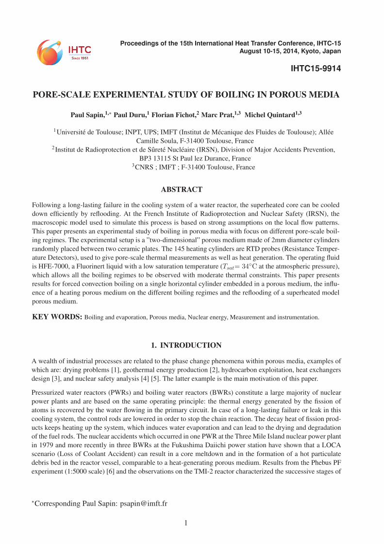
Proceedings of the 15th International Heat Transfer Conference, IHTC-15August 10-15, 2014, Kyoto, Japan
IHTC15-9914
PORE-SCALE EXPERIMENTAL STUDY OF BOILING IN POROUS MEDIA
Paul Sapin,1,∗ Paul Duru,1 Florian Fichot,2 Marc Prat,1,3 Michel Quintard1,3
1Universite de Toulouse; INPT, UPS; IMFT (Institut de Mecanique des Fluides de Toulouse); Allee
Camille Soula, F-31400 Toulouse, France2Institut de Radioprotection et de Surete Nucleaire (IRSN), Division of Major Accidents Prevention,
BP3 13115 St Paul lez Durance, France3CNRS ; IMFT ; F-31400 Toulouse, France
ABSTRACT
Following a long-lasting failure in the cooling system of a water reactor, the superheated core can be cooled
down efficiently by reflooding. At the French Institute of Radioprotection and Nuclear Safety (IRSN), the
macroscopic model used to simulate this process is based on strong assumptions on the local flow patterns.
This paper presents an experimental study of boiling in porous media with focus on different pore-scale boil-
ing regimes. The experimental setup is a ”two-dimensional” porous medium made of 2mm diameter cylinders
randomly placed between two ceramic plates. The 145 heating cylinders are RTD probes (Resistance Temper-
ature Detectors), used to give pore-scale thermal measurements as well as heat generation. The operating fluid
is HFE-7000, a Fluorinert liquid with a low saturation temperature (Tsat= 34◦C at the atmospheric pressure),
which allows all the boiling regimes to be observed with moderate thermal constraints. This paper presents
results for forced convection boiling on a single horizontal cylinder embedded in a porous medium, the influ-
ence of a heating porous medium on the different boiling regimes and the reflooding of a superheated model
porous medium.
KEY WORDS: Boiling and evaporation, Porous media, Nuclear energy, Measurement and instrumentation.
1. INTRODUCTION
A wealth of industrial processes are related to the phase change phenomena within porous media, examples of
which are: drying problems [1], geothermal energy production [2], hydrocarbon exploitation, heat exchangers
design [3], and nuclear safety analysis [4] [5]. The latter example is the main motivation of this paper.
Pressurized water reactors (PWRs) and boiling water reactors (BWRs) constitute a large majority of nuclear
power plants and are based on the same operating principle: the thermal energy generated by the fission of
atoms is recovered by the water flowing in the primary circuit. In case of a long-lasting failure or leak in this
cooling system, the control rods are lowered in order to stop the chain reaction. The decay heat of fission prod-
ucts keeps heating up the system, which induces water evaporation and can lead to the drying and degradation
of the fuel rods. The nuclear accidents which occurred in one PWR at the Three Mile Island nuclear power plant
in 1979 and more recently in three BWRs at the Fukushima Daiichi power station have shown that a LOCA
scenario (Loss of Coolant Accident) can result in a core meltdown and in the formation of a hot particulate
debris bed in the reactor vessel, comparable to a heat-generating porous medium. Results from the Phebus PF
experiment (1:5000 scale) [6] and the observations on the TMI-2 reactor characterized the successive stages of
∗Corresponding Paul Sapin: [email protected]
1

IHTC15-9914
a LOCA accident and the resulting debris bed. If a water source is available, the decay heat can be efficiently
removed by reflooding. In order to assess the coolability of this particle bed, the intense boiling mechanisms
encountered must be modeled properly. The thermohydraulics of heated porous media has been studied both
experimentally and theoretically so as to estimate the increase of pressure in the primary cooling circuit, the
hydrogen production and the release of fission products.
In the PRELUDE experimental setup (Fig. 1(a)) at IRSN, the heating debris bed is represented by a bed of
steel balls (from 2 to 8mm diameter) heated by induction. The reflooding of this hot porous medium has
been studied with water to validate a local thermal non-equilibrium model. The macroscopic properties of
this model, required to simulate properly the available experiments, depend on the boiling regimes and flow
patterns at the pore scale.
An experimental setup (Fig. 1(b)) consisting of a ”two-dimensional” porous medium made of heating cylinders
has thus been developed to observe the encountered microscopic phenomena. This paper presents experimental
results for boiling and for the reflooding process.
(a) (b)
Fig. 1 (a) PRELUDE experimental setup; (b) ”Two-dimensional” model porous medium.
2. PREVIOUS STUDIES
The modelization of the reflood of a heat-generating porous medium is highly complex. In order to take account
of the encountered phenomena at the microscopic scale, macroscopic models can be obtained by up-scaling
the problem as was done with the method of volume averaging in [7].
For the safety analysis of PWRs, a macroscopic model [5, 8, 9] has been developed at IRSN using the volume
averaging method. With the assumption that the gas-liquid interface velocity can be neglected in the up-scaling
process, which is called the quasi-static hypothesis, the momentum balance equations are generalized Darcy’s
laws for each fluid phase, with Forchheimer terms accounting for inertial effects (Eqn. (1) and (2)):
αρg(∂vg∂t
+ vg · ∇vg) = −α∇pg + αρgg − εα2(μg
Kkrgvg + εα
ρg
ηηrgvg|vg|) (1)
(1− α)ρl(∂vl∂t
+ vl · ∇vl) = −(1− α)∇pl + (1− α)ρlg − ε(1− α)2(μl
Kkrlvl + ε(1− α)
ρlηηrl
vl|vl|) (2)
In these equations, the macroscopic pressure, density and the intrinsic velocity of the β-phase (β=g,l for gas
and liquid) are respectively pβ, ρβ and vβ. The void fraction α represents the fraction of a fluid volume
occupied by the gas phase. For spherical particle beds, as used in the PRELUDE experimental setup, the
intrinsic permeability K and passability η are respectively calculated thanks to the Carman-Kozeny relation
2

IHTC15-9914
[10] and the Ergun’s law [11]. The relative permeability krβ and passability ηrβ are obtained with the Brooks-
Corey relations [12].
Saturation is an important parameter for the description of a gas-liquid two-phase flow in a rigid porous
medium. Consider the total volume VT of a representative elementary volume of such a medium, that can
be expressed as: VT = Vl + Vg + Vs. The saturation S represents the fraction of the pore space occupied
by the liquid phase: S = Vl / (Vl + Vg ). The capillary pressure, modeled as a function of saturation, is also
introduced in the equations to account for the effects of pressure between the wetting and the non-wetting
phases.
As for the heat and mass transfer problem, the three phases (solid, liquid, gas) are considered to be in local
thermal non-equilibrium. The macro-scale enthalpy and temperature of the β-phase (β=g,l,s for gas, liquid
and solid) are respectively represented by hβ and Tβ. The macro-scale energy balance equations relative to
each phase (Eqn. (3),(4),(5)) are obtained thanks to the up-scaling of the micro-scale mass and energy balance
equations:∂(αερghg)
∂t+∇(αερgvghg) = ∇(K∗
g · ∇Tg) + mghsatg + φsg − φgi (3)
∂((1− α)ερlhl
)∂t
+∇((1− α)ερlvlhl) = ∇(K∗l · ∇Tl) + mlh
satl + φsl − φli (4)
∂((1− ε)ρshs)
∂t= ∇(K∗
s · ∇Ts)− φsl − φsg − φsi +�s (5)
The macroscopic coefficients involved in these equations are the effective thermal dispersion tensors K∗β and
the thermal coefficients used in the definitions of thermal exchanges between phases φsβ and φβi, involving the
temperature differences and the spatial gradients of these differences. Indeed, the up-scaling of the microscopic
problem provides equations involving the macroscopic temperatures as well as their local deviations. Solving
the mixed problem with the two types of variables would be obviously too complex; this is why the deviations
are expressed as functions of the averaged temperatures and their spatial gradients.
The macroscopic coefficients may be calculated by solving the closure problems thus obtained. Duval et al.[13] have determined analytically these coefficients for simple configurations : Solid-Liquid-Gas (SLG) and
Solig-Gas-Liquid (SGL) stratified flows. Since the gas-liquid interface is considered stationary, only the heat
exchanges for evaporation or condensation of a fluid can be described properly. In other terms, the nucleation
phenomenon remains unmodeled. The heat exchanges for the nucleate, transition and film boiling regimes,
encountered during a reflooding process, are thus underestimated.
To improve this model, Bachrata et al. [14] proposed to use correlations from the literature to estimate the
contribution of boiling to the local heat exchanges. A modified version of the Berenson’s correlation [15]
is used to estimate the heat transfer coefficient for the film boiling regime. The critical heat flux (CHF) is
calculated with the CATHARE correlation [16] based on the Groeneveld table [17]. The wall-to-fluid heat flux
is then expressed as a function of the CHF for the transition boiling regime. In the nucleate boiling regime,
the forced convection hcv and nucleate boiling hnb heat transfer coefficients are obtained respectively with
the Dittus-Boelter correlation [18] and the Thom’s correlation [19]. For the local wall-to-fluid heat transfer
coefficient hwall calculation, these contributions are weighted by a factor depending on void fraction:
hwall = (1− α)hnb + ((1− α)hcv,l + αhcv,g) (6)
where hcv,l and hcv,g are respectively obtained from the SLG and SGL configurations.
3
IHTC15-9914
Boiling heat transfer has been extensively studied since Nukiyama first characterized it in 1934 [20]. In convec-
tive flows, the correlations for boiling heat transfer are essentially of three types: the summation models [21],
the asymptotic models [22] and models based on flow patterns [23]. The heuristic model to estimate forced
convective nucleate boiling proposed in equation (6) is similar to a summation model. This improvement seems
well under way since no correlation is available to evaluate boiling heat transfer in porous media. Besides, the
improved model is in good agreement with the PRELUDE experimental results [24].
However, regardless of the chosen macro-to-micro criterion [25] and according to the characteristics of the
observed debris beds, microscopic boiling takes place in the considered porous media during a reflooding,
while the correlations considered above were developed for macroscopic boiling. Furthermore, the interaction
between bubbles generated by close heating elements in a porous medium might in particular influence the
predicted CHF value, since the coalescence phenomenon is facilitated. Indeed, improvement of the CHF value
by using porous-layer coatings has been shown both theoretically and experimentally by Liter and Kaviany
[3].
The experimental setup designed for this study aims to provide local thermal measurements (heat flux and
temperature) for boiling in porous media, with the objective of obtaining indications for the type of correlations
that must be used to estimate the effective parameters of the thermal non-equilibrium macroscopic model. The
assumptions on the local flow patterns made to build this model can also be questioned thanks to the pore-scale
visualizations.
3. EXPERIMENTAL SETUP
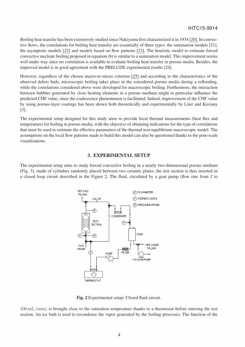
The experimental setup aims to study forced convective boiling in a nearly two-dimensional porous medium
(Fig. 3), made of cylinders randomly placed between two ceramic plates; the test section is thus inserted in
a closed loop circuit described in the Figure 2. The fluid, circulated by a gear pump (flow rate from 2 to
Fig. 2 Experimental setup: Closed fluid circuit.
100mL /min), is brought close to the saturation temperature thanks to a thermostat before entering the test
section. An ice bath is used to recondense the vapor generated by the boiling processes. The function of the
4

IHTC15-9914
tank is to trap non condensed vapor and the possibly remaining non condensible gases (air principally). A valve
on the top of this plenum chamber allows these gases to be evacuated and to release the pressure in the loop.
So the setup can be used itself to degas the fluid.
The 3MTM NovecTM Engineered Fluid HFE-7000 was chosen as the operating fluid for many reasons. First,
all the boiling regimes can be observed with moderate thermal constraints because its saturation temperature is
very low: Tsat = 34◦C at the atmospheric pressure. Besides, safety is ensured during the manipulations since it
is a low-toxicity, non-flammable and dielectric fluid. The HFE is, though, highly volatile and with an important
global warming potential (370 for a 100-year integrated time horizon). The fluid circuit is filled by vacuum
with degassed HFE, in order to avoid the presence of air, which would significantly change the saturation
temperature. For both the boiling phenomenon and the study of flows in porous media, the hydrophobicity
is a matter of importance. The HFE is highly hydrophilic (contact angle close to 0◦ with ceramics), as is
water, which is necessary since the experiments have to be conducted in similar conditions as the PRELUDE
experiment. As for the capillary effects, the ratio between the HFE and the water surface tension is about 4.7,
so the HFE capillary length Lcap (defined in equation (7)) is 2.6 times as high as water’s.
Lcap =
√σ
ρg(7)
The test section is a ”two-dimensional” porous medium made of 145 heating cylinders randomly placed be-
tween two ceramic plates, spaced from one another by 3mm (Fig. 3). To obtain visualizations at the pore scale,
one of the plates is transparent. The diameter of the steel balls constituting the debris bed in the PRELUDE
experimental setup range between 2 and 8mm. The diameter of the heating cylinders has thus been chosen
to be 2mm, so that the capillary effects in this experimental setup are representative of those in the previous
experiments.
Fig. 3 Experimental setup: Test section (Dimensions in mm).
The constitutive elements of the model porous medium are cylindrical Resistance Temperature Detectors
(RTDs). They are used not only as heaters, thanks to the Joule effect, but also as heat flux and temperature
sensors. In a RTD probe, a fine coiled platine wire is wrapped around an insulating core and sealed in a ce-
ramic coating (Fig. 4). The temperature of such an element can be measured by measuring the platine wire
resistance (100Ω at 0◦C for the used PT100 probes); indeed, the platine resistance changes with temperature
according to a simple and well-known law. Because of this dependency of the resistance upon the temperature,
it is necessary to control the heat flux transmitted to each cylinder (Joule effect depending on R(T )). A micro-
electronic servo-control system, running at 1000Hz, is thus connected to each probe, in order to measure and
control both the heat flux and the temperature of the element. To avoid having too many control modules, most
of the elements are controlled by groups of four or five. In these groups, the RTDs are mounted in parallel, to
5

IHTC15-9914
Fig. 4 RTD ELEMENT
maintain them in thermal equilibrium: if an element heats up more than the others, its resistance increases so
that the current passing through it -and hence the Joule effect- decreases. Twenty elements distributed in the
test section are controlled individually (Fig. 5), to provide precise measurements near the CHF or the Leiden-
frost temperature. This way the different boiling regimes can be characterized, with the aim in mind to obtain
Nukiyama’s curves for porous media. A simple heat conduction analysis of the ceramic coating evaluates the
Fig. 5 Individually controlled elements
response time of the cylinders at 0.4 s. This time delay is non-negligible in comparison to the timing of tran-
sition between film and nucleate boiling regimes observed in the reflooding tests presented later in this paper.
However, providing Nukiyama’s curves for porous medium requires established regimes, so this time delay
has no impact for these measurements. The thermal control command is given to each module via a computer.
The servo-control systems are then autonomous, only the desired probes are linked to the computer to acquire
thermal measurements in real-time (Fig. 6).
Fig. 6 Data acquisition
6

IHTC15-9914
4. RESULTS
As a first step, the thermal resistance of the probe ceramic coating has to be determined (Fig. 4). For the
temperature measurement with RTD probes, an usual problem is to avoid self-heating, because this leads to
a temperature difference between the cylinder wall temperature and the platine wire temperature effectively
measured. Since self-heating is used in our experiment as the power source, this temperature difference must
be known at every time. That is why ceramic coating resistances have been measured thanks to infrared ther-
mography for different thermal equilibriums.
4.1 Forced convection boiling on a single horizontal cylinder embedded in a porous medium
Once this correction applied, forced convection boiling on a cylinder, selected from the bundle of cylinders
presented in Figure 5, has been studied. The chosen probe is the number 11 (numbered according to Figure 5)
because it is located in the middle of the test section. By controlling the heat flux imposed to the single element,
the main boiling regimes have been observed and a Nukiyama’s curve (Fig. 8) has been obtained. The assembly
of the heating elements between the two ceramic plates has been simply modelized in MATLAB. Thanks to
a heat conduction model, with natural convection in air on external boundaries and forced convection boiling
with HFE on inside boundaries, the heat losses and the effectively transmitted heat fluxes have been estimated.
The fluid circulates at a flow rate of 21.4mL /min. The temperature of the liquid impacting the studied element
(Tl = 24.4◦C) is also evaluated by this model, from the measurement of the liquid temperature at the inlet of
the test section. At the cylinder level, pressure is 1.18 bar, which corresponds to a saturation temperature of
39.9◦C. Subcooling effects are thus important.
�
�
�
�
�
�
�
�
��� ��� ��� �� � � �� �� �� ��
������������
qwall
(W/cm²�
������ ���������ΔTsat
= Twall
- Tsat
(°C)
����������������
���������������
���
Fig. 7 Onset of nucleate boiling on a single element amongst a bundle of horizontal cylinders in a crossward
flow
By increasing step-by-step the power applied to the cylinder, onsets of nucleate boiling are observed. Under the
conditions described earlier, the first nucleation is observed for a wall superheat of 10.5◦C (Fig. 7). The wall
superheat ΔTsat is defined as the difference of temperature between the outer wall of the cylinder and the fluid
saturation temperature (39.9◦C): ΔTsat = Twall − Tsat. In the partial nucleate boiling regime (Fig. 9(a)),
isolated vapor bubbles are generated at the different nucleation sites. The intense boiling regime, observed for
higher heat fluxes, is characterized by the formation of vapor pockets (Fig. 9(b)). Below the critical heat flux
(qchf = 23.7W / cm2), the liquid remains in contact with the heating cylinder wall despite the coalescence
of bubbles. The heat exchange reaches a maximum just before the burnout point, at which a vapor film is
formed at the heater surface. The so-called boiling crisis is violent and leads to an increase in wall superheat
and an important reduction in the heat transfer rate. The film boiling regime (Fig. 9(c)) is maintained while
decreasing the heat flux: the vapor film thickness decreases until the heat flux reaches a minimum at the so-
called Leidenfrost point, for which ΔTsat = 110.9◦C and qmin = 12.5W / cm2. Thanks to the control
7

IHTC15-9914
�
�
��
��
��
��
��� �� �� ��� ���
������������
qwall
(W/cm²)
������ ���������ΔTsat
= Twall
- Tsat
(°C)
����������������
���������������
������������������
�����������
Fig. 8 Nukiyama’s curve for subcooled forced convective boiling a single horizontal cylinder embedded in a
porous medium
(a) (b) (c)
Fig. 9 (a) Partial nucleate boiling; (b) Intense nucleate boiling; (c) Film boiling.
of temperature, the transition boiling regime can also be maintained. However, the large fluctuations of the
recorded temperatures (about 20◦C for each point) make these measurements unreliable.
The generation of vapor slugs in the film boiling regime is well brought into focus in Figure 9(c). The behavior
of these slugs in a heated porous medium is hardly predictable (coalescence with other slugs or vapor films,
simple Taylor bubbles. . . ) for a large number of pores. It will thus be very instructive to observe how the
confinement affects the boiling and convective heat exchanges.
4.2 Forced convection boiling in a heating porous medium
The purpose of this experiment is to obtain Nukiyama’s curves for an element within a heating porous medium.
This means that all the cylinders are set to apply a constant heat flux, while a single element in the very middle
of the others is heated up individually to observe all the boiling regimes, with the aim of measuring an influence
of the local void fraction on the boiling phenomena.
The heat flux imposed to the surrounding cylinders Qs varies from 0mW (results presented in the previous
section) to 350mW. The flow rate is still set to 21.4mL /min which corresponds to a filtration speed of
3.4mm / s in the test section. The influence on the nucleate boiling and the film boiling regimes are respectively
presented in Figures 10(a) and 10(b).
8

IHTC15-9914
�
�
��
��
��
��
��
��� ��� � �� �� �� �� �� � �
������������
qwall
(W/cm²)
������ ���������ΔTsat
= Twall
- Tsat
(°C)
Qs = 20mW
Qs = 50 mW
Qs = 100 mW
Qs= 150 mW
(a)
��
��
��
��
��
��
��
�
�
��
�� ��� ��� ��� ��� ��� ���
������������
qwall
(W/cm²)
������ ���������ΔTsat
= Twall
- Tsat
(°C)
Qs = 20 mW
Qs = 50 mW
Qs = 100 mW
Qs = 150 mW
(b)
Fig. 10 Influence of a heating porous medium on the (a) Nucleate boiling regime and the (b) Film boiling
regime.
As expected, the vapor generated by the porous medium mainly influences the nucleate boiling regime (Fig. 10(a))
by changing the value of the critical heat flux: the increase in local void fraction helps the formation of a va-
por film around the studied cylinder. The CHF has also been measured for different imposed fluxes Qs, the
results are presented in Figure 11. As explained earlier, the case in which no surrounding cylinder is heated
(Qs= 0mW) is subject to subcooling effects. The difference with the other curves is thus not only due to the
presence of vapor but also to the local fluid temperature.
As for the film boiling regimes observed (Fig. 10(b)), the higher the amount of vapor, the lower the heat-
exchange rate. Indeed, in this regime, the quality of the heat transfer depends strongly on the thickness of the
vapor film. Besides, the presence of gas helps the film to be maintained for smaller fluxes, which explains the
differences in the measured minimum heat fluxes qmin.
��
��
��
��
��
��
�
�
� � �� � � �� �
��������������
��
qchf
(W/cm²)
�������� ������ ��������������������������Qs ��!
Fig. 11 Influence of a surrounding heat-generating porous medium on the critical heat flux
4.3 Bottom reflooding of a heat-generating porous medium
The aim of this section is to actually simulate a reflooding process. The porous medium is thus heated with a
homogeneous and constant heat flux up to an equilibrium temperature and is perfectly dried out: only HFE va-
por remains in the test section. The quenching of this hot and heat-generating porous medium from the bottom
can then be achieved with the liquid at a temperature close to the saturation. With a flow rate of 21.4mL /mindelivered by the gear pump, the velocity of the quenching front in the porous medium is 3.4mm / s without
9

IHTC15-9914
phase change. The valve at the outlet of the test section is open to prevent an important increase of pressure
due to intense boiling. So, the saturation is reached for a temperature of 34◦C. For the first experiment, the test
section is heated with a power of 80mW per element. The equilibrium temperatures range between 70 and
90◦C, depending on the position of the cylinder. The temperature evolution of the four in-line elements 13-16
(numbered according to the Figure 12(b)) during the reflooding is presented in Figure 12(a).
"#
$#
%#
&#
'#
(#
)#
*##
# % *# *% +# +%
,������������������- �
��������
��������� ������ ��
�����������������������
����������� �������
����������������������
�������������������
���������� ����� !�
.� ����������������
/���������0����
(a) (b)
Fig. 12 (a) Reflooding of four in-line elements represented in (b)
The initial temperature of the probes located in the middle of the test section (cylinders 14 and 15) is higher
than that of the probes located on the edges (cylinders 13 and 16). This is due to the important thermal mass
of the ceramic plate on the borders of the bundle of probes (Fig. 3). The quenching begins approximately 5 safter the beginning of recording; at this time, one can observe a slow cooling of the recorded elements, which
is due to the vapor flow generated below. For the central elements, the liquid is obviously put in contact with
these superheated cylinders at approximately t= 15 s. However, it appears that the cylinders on the edges
first enter in contact with the quenching front well in advance. Here, the visualization of the reflooding test
provides us precious indications: the by-pass effect due to the staggered arrangement of the bundle leads to the
development of instabilities on the edges. The first temperature drop is in fact due to liquid jets.
��
��
��
��
��
��
�
� � � � �� ��
���������� ���������
�������
������� ������ �����������
������������
�� ������ ��� �������
�� ������ ��� �������
��� ������
� �� � � �
(a) (b)
Fig. 13 Evolution of the temperature of cylinders at different heights in the middle of the test section
10

IHTC15-9914
Figure 13(a) shows the temperature evolution during the reflooding of the cylinders 2-6-10-14 and 18 (Fig. 13(b)),
located at different heights in the middle of the test section. The differences in the initial temperature of the
cylinders 2-6-10-14 result from the natural convection taking place inside and outside the tube bundle. As
regards the temperature of element 18, its low initial value is also due to an important non-heated thermal
mass of ceramic above this last line. By detecting the moment when the quenching front touches each probe,
it is possible to determine its position and thus its velocity. This has been carried out for this test and for the
reflooding of bundles heated with power sources of 100, 120, 140 and 160mW. The results are presented in
Figure 14(a) for the cylinders located at the middle of the test section.
#
%
*#
*%
+#
+%
"#
"%
$#
# % *# *% +# +% "#
1�������������������������� ������
������������� � ���������������
2����#��
2���*##��
2���*+#��
2���*$#��
2���*�#��
(a)
#
#3%
*
*3%
+
+3%
'# (# )# *## **# *+# *"# *$# *%# *&# *'#
�������� ���������,����
4��
5��� ���� �� � ��������������� � ���������������
(b)
Fig. 14 (a) Tracking of the quenching front; (b) Quenching front velocity for different heating powers.
The obtained average quenching front velocities are presented in the Figure 14(b). As expected, the liquid front
velocity decreases with the increasing power source imposed to the porous medium.
5. CONCLUSIONS
The presented experiments have validated many experimental settings and have shown the feasibility of our
project to visualize and quantify pore-scale boiling mechanisms. The results already obtained give us precious
informations for boiling of HFE-7000 in our specific configuration. They also confirm the need for a specific
heat-transfer model like the one proposed by Bachrata et al. taking into account various pore-scale boiling
regimes. The influence of the local void fraction on the characteristics of the different boiling regimes, espe-
cially on the film boiling regime, has been put into focus. This regime is indeed particularly influent during the
reflooding of a nuclear reactor because the initial temperatures are significantly higher than the water Leiden-
frost temperature. Therefore, the further analysis of the experiments needs to focus on a local measurement of
the void fraction inside the two-dimensional porous medium, thanks to the high speed visualization. Control-
ling the cylinders with different electronic mountings will also allow us to reach higher heat fluxes for every
point in the test section, the aim being to obtain Nukiyama’s curves for an uniformly heated medium. The
possibility of heating only part of the cylinders can also provide interesting results. Indeed, by heating only a
determined ratio of the cylinders, the situation in a reactor core, where only the fuel fragments release thermal
energy, is more faithfully reproduced.
ACKNOWLEDGMENTS
This work is supported by the French Institute of Radioprotection and Nuclear Safety (IRSN) and Electricite
de France (EDF). Thanks also go to H. Ayroles and R. Soeparno for all the time they spent on the experimental
setup development.
11

IHTC15-9914
NOMENCLATUREΔTsat Wall superheat: Tw − Tsat, K
m Evaporation rate, kg /m3 / s
g Standard gravity, m2 / s
K∗β Effective thermal dispersion tensor, W /m /K
vβ Averaged speed in the β phase, m / s
�s Volumetric thermal source, W /m3
h Volumetric heat transfer coefficient, W /m3 /K
hβ Averaged specific enthalpy of the β phase, J / kg
hsatβ Specific enthalpy of saturated β phase, J / kg
I Electric intensity, A
K Macroscopic permeability , m2
krβ Relative permeability of the β phase
Lcap Capillary length, m
pβ Averaged pressure of the β phase, Pa
Q Heat flux , W
q Surface heat flux , W /m2
R Electric resistance, Ω
S Saturation
T Temperature, K
Tβ Averaged temperature of the β phase, K
Subscripts
β Phase index: β = g, l, s
cv Convective exchange
g Gas phase
i Interface
inj Injection (inlet of the test section)
l Liquid phase
nb Nucleate boiling
s Solid phase
sat Saturation
Greek lettersα Void fraction or gas saturation
η Macroscopic passability, m
12
IHTC15-9914
ηrβ Relative passability of the β phase
μβ Viscosity of the β phase, Pa · sφ Volumetric heat flux , W /m3
ρ Density, kg /m3
σ Surface tension, N /m
ε Porosity
REFERENCES
[1] M. Prat, “Recent advances in pore-scale models for drying of porous media,” Chemical engineering journal, vol. 86,
no. 1, pp. 153–164, 2002.
[2] A. Woods, “Liquid and vapor flow in superheated rocks,” Annual Review of Fluid Mechanics, vol. 31, no. 1,
pp. 171–199, 1999.
[3] S. G. Liter and M. Kaviany, “Pool-boiling CHF enhancement by modulated porous-layer coating: theory and ex-
periment,” International Journal of Heat and Mass Transfer, vol. 44, no. 22, pp. 4287–4311, 2001.
[4] R. Lipinski, “A coolability model for postaccident nuclear reactor debris,” Nucl. Technol.;(United States), vol. 65,
no. 1, 1984.
[5] F. Fichot, F. Duval, N. Tregoures, C. Bechaud, and M. Quintard, “The impact of thermal non-equilibrium and
large-scale 2D/3D effects on debris bed reflooding and coolability,” Nuclear Engineering and Design, vol. 236,
pp. 2144–2163, 2006.
[6] D. Jacquemain, S. Bourdon, A. de Braemaeker, and M. Barrachin, “Phebus fpt1 final report,” Document PHEBUSPF, 2000.
[7] S. Whitaker, The method of volume averaging, vol. 13. Springer Netherlands, 1999.
[8] F. Petit, F. Fichot, and M. Quintard, “Ecoulement diphasique en milieu poreux: modele a non-equilibre local,”
International Journal of Thermal Sciences, vol. 38, no. 3, pp. 239–249, 1999.
[9] F. Duval, F. Fichot, and M. Quintard, “A local thermal non-equilibrium model for two-phase flows with phase-
change in porous media,” International Journal of Heat and Mass Transfer, vol. 47, no. 3, pp. 613–639, 2004.
[10] P. C. Carman, “The determination of the specific surface area of powder I,” J. Soc. Chem. Ind., vol. 57, pp. 225–234,
1937.
[11] S. Ergun, “Fluid flow through packed columns,” Chem. Eng. Prog., vol. 48, 1952.
[12] R. H. Brooks and A. T. Corey, “Properties of porous media affecting fluid flow,” J. Irrig. Drain. Div. Am. Soc. Civ.Eng. IR2, vol. 92, pp. 61–89, 1966.
[13] F. Duval, Modelisation du renoyage d’un lit de particules: contribution a l’estimation des proprietes de transportmacroscopiques. PhD thesis, Institut National Polytechnique de Toulouse, 2002.
[14] A. Bachrata, F. Fichot, G. Repetto, M. Quintard, and J. Fleurot, “Quench front progression in a superheated
porous medium: experimental analysis and model development,” Journal of Energy and Power Engineering, vol. 7,
pp. 514–523, 2013.
[15] P. J. Berenson, “Film-boiling heat transfer from a horizontal surface,” Journal of Heat Transfer U.S., vol. 83, 1961.
[16] N. Chikhi and F. Fichot, “Reflooding model for quasi-intact rod configuration: Quench front tracking and heat
transfer closure laws,” Nuclear Engineering and Design, vol. 240, no. 10, pp. 3387–3396, 2010.
[17] D. C. Groeneveld, S. C. Cheng, and T. Doan, “AECL-UO critical heat flux lookup table,” Heat Transfer Engineer-ing, vol. 7, no. 1-2, pp. 46–62, 1986.
[18] F. Dittus and L. Boelter, Heat Transfer in Automobile Radiators of the Tubular Type. University of California Press,
1930.
[19] J. Thom, W. Walker, T. Fallon, and G. Reising, “Boiling in subcooled water during flow up hasted tubes or annuli,”
Proc. Inst. Mech. Eng., vol. 180, pp. 226–246, 1966.
13

IHTC15-9914
[20] S. Nukiyama, “The maximum and minimum values of the heat q transmitted from metal to boiling water under
atmospheric pressure,” J. Soc. Mech. Eng. Japan, vol. 37, pp. 367–374, 1934.
[21] J. Chen, “Correlation for boiling heat transfer to saturated fluids in convective flows,” I&EC Process Design andDevelopment, vol. 5, no. 3, pp. 322–329, 1966.
[22] D. Steiner and J. Taborek, “Flow boiling heat transfer in vertical tubes correlated by an asymptotic model,” HeatTransfer Engineering, vol. 13, no. 2, pp. 43–69, 1992.
[23] J. R. Thome, V. Dupont, and A. M. Jacobi, “Heat transfer model for evaporation in microchannels. Part I: pre-
sentation of the model,” International Journal of Heat and Mass Transfer, vol. 47, no. 14-16, pp. 3375–3385,
2004.
[24] A. Bachrata, Modeling of reflood of severely damaged reactor core. PhD thesis, 2012.
[25] J. R. Thome, “Boiling in microchannels: a review of experiment and theory,” International Journal of Heat andFluid Flow, vol. 25, no. 2, pp. 128–139, 2004.
14
Copyright © 2022 FDOKUMEN