Solute Transport in Cyclically Deformed Porous Tissue Scaffolds with Controlled Pore Cross-Sectional...
12
Original Article Solute Transport in Cyclically Deformed Porous Tissue Scaffolds with Controlled Pore Cross-Sectional Geometries Jorn Op Den Buijs, M.Sc., 1 Lichun Lu, Ph.D., 2 Steven M. Jorgensen, B.Sc., 1 Dan Dragomir-Daescu, Ph.D., 3 Michael J. Yaszemski, M.D., Ph.D., 2 and Erik L. Ritman, M.D., Ph.D. 1 The objective of this study was to investigate the influence of pore geometry on the transport rate and depth after repetitive mechanical deformation of porous scaffolds for tissue engineering applications. Flexible cubic imaging phantoms with pores in the shape of a circular cylinder, elliptic cylinder, and spheroid were fabricated from a biodegradable polymer blend using a combined 3D printing and injection molding technique. The specimens were immersed in fluid and loaded with a solution of a radiopaque solute. The solute distribution was quantified by recording 20 mm pixel-resolution images in an X-ray microimaging scanner at selected time points after intervals of dynamic straining with a mean strain of 8.6 1.6% at 1.0 Hz. The results show that application of cyclic strain significantly increases the rate and depth of solute transport, as compared to diffusive transport alone, for all pore shapes. In addition, pore shape, pore size, and the orientation of the pore cross-sectional asymmetry with respect to the direction of strain greatly influence solute transport. Thus, pore geometry can be tailored to increase transport rates and depths in cyclically deformed scaffolds, which is of utmost importance when thick, metabolically functional tissues are to be engineered. Introduction T issue engineering frequently utilizes porous scaf- folds. One use of scaffolds is to cultivate cells on the scaffold in vitro and subsequently implant the construct in vivo. Before implantation, bioreactors may be used to per- fuse the engineered tissue to provide cells beyond the dif- fusion distance with the essential oxygen (O 2 ) and nutrients, and to remove toxic waste as a result of cell metabolism and scaffold degradation. 1,2 However, lack of proper mass trans- port after application in vivo may result in cell density de- creasing from the periphery to the center of the construct due to chemotaxis and=or necrosis of cells beyond the diffusion distance, 3–5 which may ultimately lead to functional failure of the implant. An alternative approach is to directly implant acellular scaffolds, coated or embedded with bioactive mol- ecules (e.g., growth factors), to induce in vivo ingrowth of vascularized tissue. 6 Still, the infiltration of cells and micro- vessels into deep layers of the scaffold depends on adequate rate of solute transport. Therefore, approaches are required to supply the scaffold with nutrients and O 2 between the time of implantation and the establishment of blood sup- ply. 3,7 Under static conditions, nutrient transfer is governed by diffusion, that is, transport driven by a concentration gradi- ent. However, diffusive transport is relatively slow (e.g., Fermor et al. 8 reported diffusivities of approximately 2.510 7 cm 2 s 1 for uncharged dextrans in the surface zone of cartilage) and generally accounts for supplying cells at a depth of only a few hundred micrometers from the surface within a reasonable time. 9 In particular, for articular carti- lage, which lacks a vascular bed, the notion arose that a pumping action due to joint mobility could contribute to cartilage nutrition. 10 This was later supported by absorption= desorption measurements during repetitive loading of car- tilage explants. 11,12 Tissue engineers took advantage of this idea by showing that application of dynamic deformational loading to cartilage constructs promoted tissue ingrowth 1 Physiological Imaging Research Laboratory, Department of Physiology and Biomedical Engineering, Mayo Clinic College of Medicine, Rochester, Minnesota. 2 Tissue Engineering and Biomaterials Laboratory, Department of Physiology and Biomedical Engineering and Department of Orthopedic Surgery, Mayo Clinic College of Medicine, Rochester, Minnesota. 3 Division of Engineering and Department of Physiology and Biomedical Engineering, Mayo Clinic College of Medicine, Rochester, Minnesota. This work was performed at Mayo Clinic, Rochester, Minnesota. TISSUE ENGINEERING: Part A Volume 15, Number 8, 2009 ª Mary Ann Liebert, Inc. DOI: 10.1089=ten.tea.2008.0382 1989
-
Upload
independent -
Category
Documents
-
view
1 -
download
0
Transcript of Solute Transport in Cyclically Deformed Porous Tissue Scaffolds with Controlled Pore Cross-Sectional...

Original Article
Solute Transport in Cyclically DeformedPorous Tissue Scaffolds with Controlled
Pore Cross-Sectional Geometries
Jorn Op Den Buijs, M.Sc.,1 Lichun Lu, Ph.D.,2 Steven M. Jorgensen, B.Sc.,1
Dan Dragomir-Daescu, Ph.D.,3 Michael J. Yaszemski, M.D., Ph.D.,2 and Erik L. Ritman, M.D., Ph.D.1
The objective of this study was to investigate the influence of pore geometry on the transport rate and depth afterrepetitive mechanical deformation of porous scaffolds for tissue engineering applications. Flexible cubic imagingphantoms with pores in the shape of a circular cylinder, elliptic cylinder, and spheroid were fabricated from abiodegradable polymer blend using a combined 3D printing and injection molding technique. The specimenswere immersed in fluid and loaded with a solution of a radiopaque solute. The solute distribution was quantifiedby recording 20 mm pixel-resolution images in an X-ray microimaging scanner at selected time points afterintervals of dynamic straining with a mean strain of 8.6� 1.6% at 1.0 Hz. The results show that application ofcyclic strain significantly increases the rate and depth of solute transport, as compared to diffusive transportalone, for all pore shapes. In addition, pore shape, pore size, and the orientation of the pore cross-sectionalasymmetry with respect to the direction of strain greatly influence solute transport. Thus, pore geometry can betailored to increase transport rates and depths in cyclically deformed scaffolds, which is of utmost importancewhen thick, metabolically functional tissues are to be engineered.
Introduction
Tissue engineering frequently utilizes porous scaf-folds. One use of scaffolds is to cultivate cells on the
scaffold in vitro and subsequently implant the constructin vivo. Before implantation, bioreactors may be used to per-fuse the engineered tissue to provide cells beyond the dif-fusion distance with the essential oxygen (O2) and nutrients,and to remove toxic waste as a result of cell metabolism andscaffold degradation.1,2 However, lack of proper mass trans-port after application in vivo may result in cell density de-creasing from the periphery to the center of the construct dueto chemotaxis and=or necrosis of cells beyond the diffusiondistance,3–5 which may ultimately lead to functional failureof the implant. An alternative approach is to directly implantacellular scaffolds, coated or embedded with bioactive mol-ecules (e.g., growth factors), to induce in vivo ingrowth ofvascularized tissue.6 Still, the infiltration of cells and micro-vessels into deep layers of the scaffold depends on adequate
rate of solute transport. Therefore, approaches are requiredto supply the scaffold with nutrients and O2 between thetime of implantation and the establishment of blood sup-ply.3,7
Under static conditions, nutrient transfer is governed bydiffusion, that is, transport driven by a concentration gradi-ent. However, diffusive transport is relatively slow (e.g.,Fermor et al.8 reported diffusivities of approximately2.5�10�7 cm2 s�1 for uncharged dextrans in the surface zoneof cartilage) and generally accounts for supplying cells at adepth of only a few hundred micrometers from the surfacewithin a reasonable time.9 In particular, for articular carti-lage, which lacks a vascular bed, the notion arose that apumping action due to joint mobility could contribute tocartilage nutrition.10 This was later supported by absorption=desorption measurements during repetitive loading of car-tilage explants.11,12 Tissue engineers took advantage of thisidea by showing that application of dynamic deformationalloading to cartilage constructs promoted tissue ingrowth
1Physiological Imaging Research Laboratory, Department of Physiology and Biomedical Engineering, Mayo Clinic College of Medicine,Rochester, Minnesota.
2Tissue Engineering and Biomaterials Laboratory, Department of Physiology and Biomedical Engineering and Department of OrthopedicSurgery, Mayo Clinic College of Medicine, Rochester, Minnesota.
3Division of Engineering and Department of Physiology and Biomedical Engineering, Mayo Clinic College of Medicine, Rochester,Minnesota.
This work was performed at Mayo Clinic, Rochester, Minnesota.
TISSUE ENGINEERING: Part AVolume 15, Number 8, 2009ª Mary Ann Liebert, Inc.DOI: 10.1089=ten.tea.2008.0382
1989

in vitro and improved their mechanical properties.13,14 Be-cause most tissues experience a certain degree of repetitivemechanical strain, the concept of mechanical loading has alsobeen applied to improve in vitro engineered cardiovascu-lar constructs,15,16 heart valves,17 smooth muscle tissue,18
bone,19 and fibroblast scaffolds for tendon and ligamentengineering.20 Although other factors such as fluid shear andincreased protein expressions play a role in the observedimprovements over static controls,18,19 enhanced nutrienttransport and waste removal due to rhythmic deformation ofthe porous scaffolds likely contributed.21
Measurements of transport rates through porous scaffoldshave been previously made by applying a pressure gradientover the scaffold and quantifying the flow through thescaffold,3,22 or by sampling the concentration in the sur-rounding fluid reservoir.23 However, these techniques areunable to measure the solute distribution inside the speci-mens, which ultimately determines where cells can or cannotsurvive. Confocal microscopy has been used to quantifytransport of fluorescent solutes in cartilage,12 but the limitedpenetration depth of optical methods requires thin, translu-cent specimens (<1 mm). To overcome these limitations, anX-ray microimaging technique was developed to quantifythe movement of solutes through pores in polymeric scaf-folds (>5 mm) while they were repeatedly squeezed.24 X-raymicroimaging and micro-CT have become widely used im-aging modalities in biomedical research,25 enabling imagingwithin opaque specimens at micrometer spatial resolutionwithout the need to destroy the sample.26 Micro-CT has beenapplied to track bone ingrowth into scaffolds in vitro27 andin vivo.5,28,29 The accurate scaffold pore geometry as obtainedwith micro-CT can also be used to quantitatively analyzepore interconnectivity,30 or, in combination with computa-tional fluid dynamics, to predict fluid stream lines upon(hypothetical) perfusion of the scaffold.31–33 Moreover, pre-cise quantitative information about the local concentration ofan X-ray absorbing contrast agent (for instance as a surrogatefor nonradiopaque nutritional solutes or metabolic waste)can be obtained with micro-CT.34
The specific aim of this study was to quantify solutetransport induced by mechanical compression in cubic im-aging phantoms with a range of selected pore geometries,representing simplified tissue engineering scaffolds. Defor-mable, biodegradable specimens with programmable porecross-sectional shapes were fabricated using a 3D printingand injection molding technique. The imaging phantomswere immersed in fluid, loaded with an X-ray absorbing dye,and mechanically compressed inside a custom-made X-raymicroscanner. The recorded X-ray images were quantita-tively analyzed as to the rate and spatial distribution ofsolute transport in the porous phantoms.
Materials and Methods
Scaffold material
Polypropylene fumarate (PPF) with a number-averagemolecular weight (Mn) of 3460 g mol�1 and a weight-averagemolecular weight (Mw) of 7910 g mol�1 and polycapro-lactone fumarate (PCLF) with an Mn of 3520 g mol�1 and anMw of 6050 g mol�1 were used to prepare PPF=PCLF blends.PPF and PCLF were synthesized as described earlier.35 ThePCLF sample used here was synthesized using a,o-telechelic
PCL diol with a nominal Mn of 530 g mol�1 and fumarylchloride in the presence of potassium carbonate.36
Both PPF and PCLF are biodegradable, crosslinkable, andbiocompatible.37–39 Crosslinked PPF and PCLF have distinctcharacteristics because of different density of crosslinkablesegment on the polymer backbone. Crosslinked PPF is a stiffmaterial with an average tensile modulus E¼ 1.3 GPa, whilecrosslinked PCLF is a flexible material with E¼ 2.1 MPa.Material properties, particularly mechanical properties, canbe modulated through varying the composition of PPF inPPF=PCLF blends.40 In the present study, one PPF=PCLFblend with PPF weight composition of 25% and PCLFcomposition of 75% was prepared by first dissolving PPFand PCLF sufficiently in a co-solvent methylene chloride(CH2Cl2) and then evaporating the solvent in a vacuumoven.
Scaffold fabrication
A previously described method41 was used to manufac-ture image phantoms with programmable pore structures, assimplified models of tissue scaffolds. Computer-aided design(CAD) models were created using SolidWorks (SolidWorksCorp., Concord, MA), meshed into stereolithography (STL)files, and converted to 2D sliced data files with a thickness of76 mm using the ModelWorks software (Solidscape Corp.,Merrimack, NH). The 3D phase-change ink jet printer, Pat-ternMaster, was used to create 3D injection molds by print-ing the 2D sliced data files layer by layer with a buildmaterial (polystyrene) and a support material (wax). Afterprinting, the polystyrene was dissolved by immersing theprinted cubes into acetone for 30 min. to leave wax molds.Subsequently, the wax molds were put into a Teflon holder,and PPF=PCLF polymerizing mixture was injected undervacuum. The PPF=PCLF polymer blend was then cross-linked by free-radical polymerization with benzoyl peroxide,dimethyl toluidine, 1-vinyl-2-pyrrolidinone, and methylenechloride as free-radical initiator, accelerator, crosslinker, anddiluent, respectively. About 100mL of initiator solution (50 mgof benzoyl peroxide in 250 mL of 1-vinyl-2-pyrrolidinone)and 40 mL of accelerator solution (20 mL of dimethyl tolui-dine in 980mL of methylene chloride) were added and mixed.To facilitate crosslinking, specimens were put into the ovenat 408C for 1 h. After crosslinking was completed, the spec-imens were detached from the Teflon holder and the waxwas dissolved in a cleaner solution (BIOACT VS-O; Petro-ferm, Inc., Fernandina Beach, FL) at 40–608C for 1 h. Finally,the specimens were dried completely at ambient temper-ature.
Scaffold and pore geometry
Cubic injection molds (5.0 mm on a side) were printed,such that imaging phantoms with pores consisting of a singlechannel through the middle of the specimen could be gen-erated. Pores with the following cross-sectional and longi-tudinal shapes were designed: circular cylinder, ellipticcylinder, and spheroid. Five specimens were generated foreach shape. After crosslinking of the polymer in the mold,the final dimensions were slightly altered compared to theoriginal design, presumably due to shrinkage of the polymer.To accurately determine the dimensions of the finally createdphantoms, they were scanned in air (no fluid and=or contrast
1990 OP DEN BUIJS ET AL.

agent present) with micro-CT at 20 mm voxel resolution usinga custom-made X-ray imaging system.26 No swelling orshrinking of the specimens after immersion in fluid wasobserved.
Experimental setup
Experiments were carried out at room temperature. Theimaging phantoms were glued to the bottom of a fluid res-ervoir placed underneath the loading platen of a custom-made compression device. The setup was mounted inside acustom-made high-resolution X-ray imager (Fig. 1). The fluidreservoir was filled with 99.5% glycerol with a viscosity of*1.0 Pa s, which closely matched the viscosity of the iodine-based contrast medium, decreasing gravitational settling ofthe tracer and therefore enabling X-ray exposure times ofseveral seconds. A solution of the radiopaque contrast agentsodium iodide (NaI; Sigma-Aldrich, Inc., St. Louis, MO) inglycerol (25.8 mg mL�1 I�) was rendered visible to the eyewith a drop of blue food coloring. A needle syringe with blunttip was used to infuse the contrast agent into the specimen’spore until it was completely filled, and the syringe was thenslowly withdrawn from the fluid reservoir. After this infusion,convective transport was induced by cycles of compressionand release applied to the top face of the specimen. Thecompression amplitude was measured using X-ray projectionimages of the specimen in the uncompressed state and in themaximally compressed state. The percentage of compressionwas calculated from the images as:
H�H0
H0
�������� � 100%, (1)
where H0 and H are the phantom height at rest and uponmaximal compression, respectively. The compression ratewas set at 1.0 Hz.
Projection X-ray imaging protocol
The specimens were imaged in a custom-made high-resolution X-ray system consisting of a spectroscopy X-ray
source with a molybdenum anode and zirconium foil filter sothat the Ka emission radiation (17.5 keV) photons predomi-nate in the emitted X-ray spectrum. The specimen’s X-rayimage was converted into a light image in a Terbium-dopedfiber optic glass plate coupled to a charge-coupled device(CCD) array. The CCD image, consisting of 1340�1300 pixels,was then recorded. The pixel size in the X-ray image was20mm, so that the spatial resolution is approximately 40 mmand, hence, pore diameter differences of *500 mm are readilyresolved. Specimens were placed at 5.5 cm from the detector,and the distance between X-ray source and detector was98.5 cm. X-ray exposure time was 5.0 s, and a scintillator de-cay time of 0.5 s was allowed for. The compression device wasswitched on and off from outside the lead-lined scanner-housing. Images of the fluid-filled specimens were recordedbefore and right after injection of the contrast agent. Further,during passive experiments (compression turned off ), imageswere recorded after 1, 3, 5, and 10 min. During active exper-iments (compression turned on) images were recorded after5, 10, … , 50, 75, 100, 150, 200, and 300 compression cycles, bytemporarily pausing the cyclic compression during the im-aging time of 5.7 s, with the specimen in the uncompressedstate. The total imaging time was less than 2 min per experi-ment, during which passive removal may have contributed totransport. However, based on the measurements duringpassive removal, it is expected that passive removal contrib-uted less than 10% to the total solute transport during thetime required for imaging.
Image analysis
The transmitted X-ray intensity I, at each pixel, is given by:
I¼ I0 exp �X
i
lixi
!, (2)
where I0 is the incident X-ray intensity, mi is the linear at-tenuation coefficient of material i, and xi is the thicknessof material i along the X-ray beam illuminating the pixelafter passing through the imaging phantom. The total X-ray
FIG. 1. Schematic diagram (left) and photograph (right) of the experimental setup. The specimen is placed inside a fluidreservoir underneath a compression device. A molybdenum X-ray source is used to generate projection images of thespecimen pore injected with X-ray contrast agent.
SOLUTE TRANSPORT IN CYCLICALLY DEFORMED TISSUE SCAFFOLDS 1991
attenuationP
i
lixi is mainly due to the iodine in the channel,
the polymer material which the specimen is made of, and theglycerol in the surrounding fluid reservoir. The attenuationdue to iodine in the pore was then calculated by subtractingthe attenuation before contrast agent injection from the at-tenuation measured with iodine present in the pore. Theaverage attenuation due to iodine was obtained by averagingthe attenuation over the entire pore volume. Under the as-sumption that the attenuation coefficient of the iodine islinearly proportional to the iodine concentration (because thepore dimension remains unchanged in between compres-sions), the average iodine concentration in the channel wascalculated as a fraction of the average iodine concentrationcalculated immediately after injection.
Statistical analysis
To statistically compare the results of the image analysis,the remaining fraction of iodine (as measured after 300 s ofpassive removal or after 300 compression cycles at 1.0 Hz)was evaluated with one-way analysis of variance (ANOVA).This fraction was calculated in specimens with different
channel shapes and compared with the 0.5 mm circular cy-lindrical channel by a Tukey-Kramer honestly significantdifference test (#p< 0.05). For each channel shape, the effectof passive and deformation-induced transport was com-pared by a two-tailed t-test (*p< 0.05).
Results
Scaffold pore geometry
Representative micro-CT images (20 mm voxel resolution)of the specimens are shown in Figure 2. These images wereused to quantify the actual (as distinct from the pro-grammed) pore dimensions (Table 1). The average side di-mension of all specimens was 4.50� 0.18 mm.
Scaffold compression
Figure 3 shows representative projection X-ray images ofthe scaffold in the uncompressed state compared to thecompressed state. It can be noted that the spheroid is mainlycompressed in the middle, whereas its openings to the res-ervoir are slightly narrowed during compression. From thefront view of the specimen with elliptic channel, it can be
FIG. 2. Representative mi-cro-CT images (20 mm voxelsize) of the specimens withpores in the form of a circularcylinder (1.5 mm), spheroid,and elliptic cylinder. White isscaffold material; black is air.
Table 1. Channel Dimensions of Initial Computer-Aided Design (CAD) Models
and Actual Specimens After Manufacturing as Measured with Micro-CT
Circular cylinder channel diameter (mm)
CAD design 0.5 1.0 1.5 2.0Micro-CT measured 0.37� 0.030 0.94� 0.026 1.38� 0.048 1.89� 0.028
Elliptic cylinder channel diameter (mm) Spheroid channel diameter (mm)
Minor axis Major axis At openings Maximum
CAD design 0.6 2.0 0.55 2.0Micro-CT measured 0.54� 0.043 1.75� 0.043 0.73� 0.076 1.89� 0.017
For the circular cylinder, scaffolds with four different diameters were generated. For the elliptic cylinder, the minor and major axisdimensions of the channel cross section are given. For the spheroid, the diameter at the channel openings, and the maximum diameter in themiddle are given. All specimens were cubic with an average side dimension of 4.50� 0.18 mm.
1992 OP DEN BUIJS ET AL.

observed that when the major axis of the elliptic cross-sectionis perpendicular to the direction of compression, it is highlydeformed (65� 5% compression along the semi-minor axis,see Table 2). In contrast, the elliptic cross section becomesmore circular when its major axis is in the same direction asthe compression.
On average, the percentage of scaffold compression was8.6� 1.6% of the original specimen height and not signifi-cantly different among the different scaffolds as tested byANOVA. Thus, the scaffold compression amplitude did notdepend on the pore shape. For the circular cylindrical chan-nels with different diameters, the percentage of compressionof the channel decreased with increasing diameter (Table 2).
Solute transport
Projection X-ray images show the removal of the iodinefrom the scaffold channel, as caused by passive removal orremoval induced by consecutive cycles of deformation of thescaffold (Fig. 4). The images demonstrate that after 300 s ofpassive removal without compression, most of the iodine is
still present in the channels. Particularly in the case of thecircular cylinder, it can be seen that a portion of the contrastagent is slowly removed, in part due to gravity-induced nat-ural convection as a result of the slight difference in densitybetween the fluid containing NaI and the fluid without thecontrast agent. In addition, it can be observed that after 300cycles of compression at 1.0 Hz (i.e., corresponding to 300 s),most of the contrast agent is removed from the phantom withthe elliptical cross section pore. In contrast, only approxima-tely 50% of iodine is removed from the circular pore, and mostof the dye remains inside the spheroidal pore.
The average iodine concentration inside the channel wascalculated relative to the iodine concentration right after in-jection. This quantitative analysis shows the effect of the poreshape on the removal rate during compression cycles (Fig. 5).The remaining fraction of iodine in the channel after 300 s isshown (Fig. 6A) for all channel shapes as a result of bothpassive and deformation-induced removal. A statisticallysignificant difference between passive and strain-inducedremoval was found for all pore shapes. The remaining frac-tion of iodine 300 s after passive removal was statistically
FIG. 3. Projection X-ray images of the uncompressed specimen and the specimen at maximal level of compression. Sideviews are shown for the 1.5-mm-diameter circular cylinder (top left) and spheroid channel (bottom left). The elliptical channelis shown from the front with the compression perpendicular to (top right) and in parallel with (bottom right) the major axis ofthe elliptical cross section.
Table 2. Percentage Compression of the Channels of the Specimens,
Measured Along the Vertical Direction
Channel geometry CAD diameter (mm) Channel compression (%)
Circular 0.5 45� 61.0 48� 41.5 33� 3a
2.0 26� 1a
Elliptic (strain parallel to semi-minor axis) 0.6 65� 5a
Elliptic (strain parallel to semi-major axis) 2.0 18� 1a
Spheroid 2.0 17� 1a
aSignificantly different from 0.5 mm ( p< 0.05).
SOLUTE TRANSPORT IN CYCLICALLY DEFORMED TISSUE SCAFFOLDS 1993

different from the 0.5 mm circular only for the 2.0 mm pore,likely due to increased gravitational settling. After 300 s ofstrain-induced removal, the remaining fraction of iodine wassignificantly different from the 0.5 mm pore for the 1.5 mmcircular pore, the spheroid pore, and the elliptic pore (in bothdirections of compression). With the exception of the 2.0 mmcircular pore, the remaining fraction of iodine in the channel
after 300 s correlated well with the channel compression (Fig.6B). Upon exclusion of the 2.0 mm circular pore, linear re-gression yielded a relationship of y¼� 0.00131xþ 0.9735,with R2¼ 0.9803. Increased gravitational settling in the2.0 mm pore likely caused the increased rate of solutetransport as would have been expected based on the per-centage of channel compression.
FIG. 4. Consecutive projection X-ray images taken during compression-induced and passive removal of NaI from thespecimen channels. Compression was performed at 1.0 Hz, such that 300 s correspond to 300 compressions. (A) Circular pore(1.5 mm diameter). (B) Spheroid pore. (C) Elliptic pore.
1994 OP DEN BUIJS ET AL.
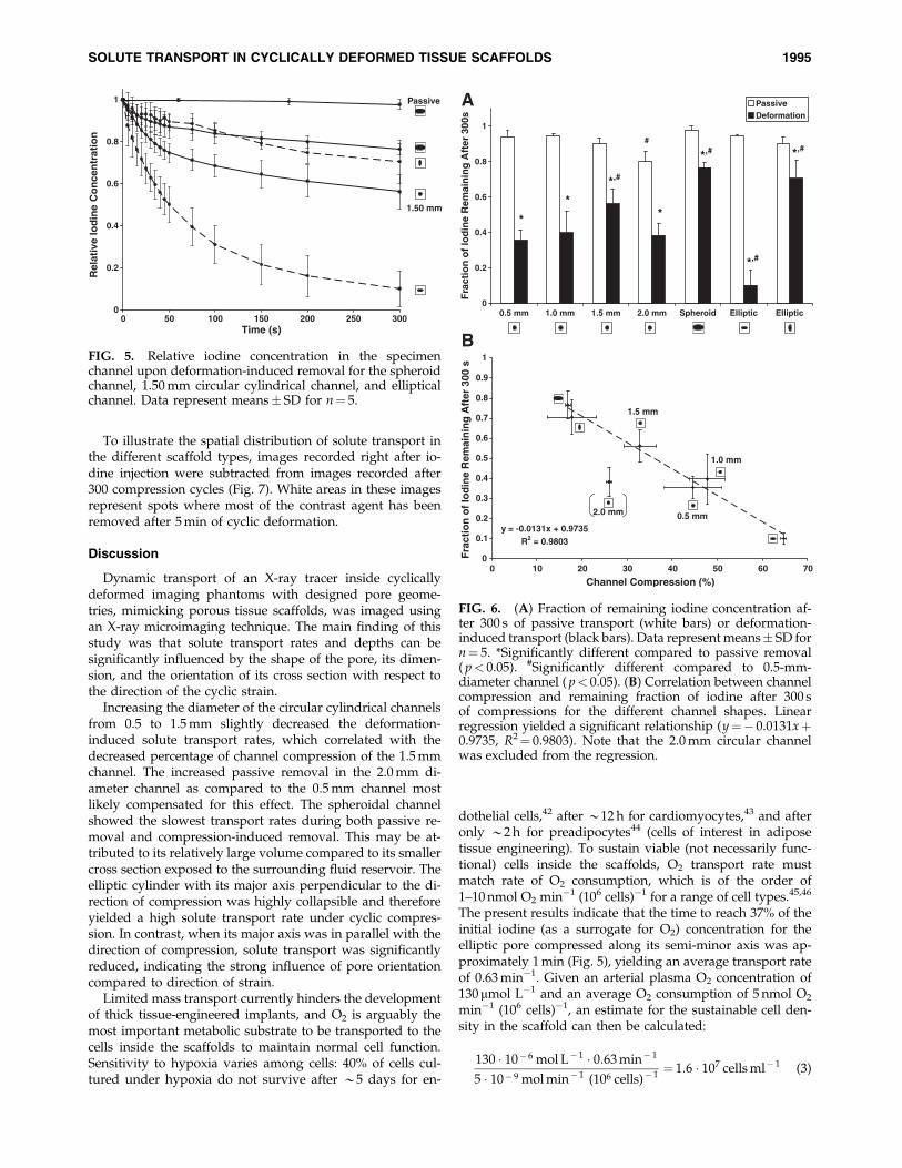
To illustrate the spatial distribution of solute transport inthe different scaffold types, images recorded right after io-dine injection were subtracted from images recorded after300 compression cycles (Fig. 7). White areas in these imagesrepresent spots where most of the contrast agent has beenremoved after 5 min of cyclic deformation.
Discussion
Dynamic transport of an X-ray tracer inside cyclicallydeformed imaging phantoms with designed pore geome-tries, mimicking porous tissue scaffolds, was imaged usingan X-ray microimaging technique. The main finding of thisstudy was that solute transport rates and depths can besignificantly influenced by the shape of the pore, its dimen-sion, and the orientation of its cross section with respect tothe direction of the cyclic strain.
Increasing the diameter of the circular cylindrical channelsfrom 0.5 to 1.5 mm slightly decreased the deformation-induced solute transport rates, which correlated with thedecreased percentage of channel compression of the 1.5 mmchannel. The increased passive removal in the 2.0 mm di-ameter channel as compared to the 0.5 mm channel mostlikely compensated for this effect. The spheroidal channelshowed the slowest transport rates during both passive re-moval and compression-induced removal. This may be at-tributed to its relatively large volume compared to its smallercross section exposed to the surrounding fluid reservoir. Theelliptic cylinder with its major axis perpendicular to the di-rection of compression was highly collapsible and thereforeyielded a high solute transport rate under cyclic compres-sion. In contrast, when its major axis was in parallel with thedirection of compression, solute transport was significantlyreduced, indicating the strong influence of pore orientationcompared to direction of strain.
Limited mass transport currently hinders the developmentof thick tissue-engineered implants, and O2 is arguably themost important metabolic substrate to be transported to thecells inside the scaffolds to maintain normal cell function.Sensitivity to hypoxia varies among cells: 40% of cells cul-tured under hypoxia do not survive after *5 days for en-
dothelial cells,42 after *12 h for cardiomyocytes,43 and afteronly *2 h for preadipocytes44 (cells of interest in adiposetissue engineering). To sustain viable (not necessarily func-tional) cells inside the scaffolds, O2 transport rate mustmatch rate of O2 consumption, which is of the order of1–10 nmol O2 min�1 (106 cells)�1 for a range of cell types.45,46
The present results indicate that the time to reach 37% of theinitial iodine (as a surrogate for O2) concentration for theelliptic pore compressed along its semi-minor axis was ap-proximately 1 min (Fig. 5), yielding an average transport rateof 0.63 min�1. Given an arterial plasma O2 concentration of130mmol L�1 and an average O2 consumption of 5 nmol O2
min�1 (106 cells)�1, an estimate for the sustainable cell den-sity in the scaffold can then be calculated:
130 � 10� 6 mol L� 1 � 0:63 min� 1
5 � 10� 9 mol min� 1 (106 cells)� 1¼ 1:6 � 107 cells ml� 1 (3)
1.50 mm
Passive
0
0.2
0.4
0.6
0.8
1
0 50 100 150 200 250 300Time (s)
Rel
ativ
e Io
din
e C
on
cen
trat
ion
FIG. 5. Relative iodine concentration in the specimenchannel upon deformation-induced removal for the spheroidchannel, 1.50 mm circular cylindrical channel, and ellipticalchannel. Data represent means� SD for n¼ 5.
0
0.2
0.4
0.6
0.8
1
0.5 mm 1.0 mm 1.5 mm 2.0 mm Spheroid Elliptic Elliptic
Fra
ctio
n o
f Io
din
e R
emai
nin
g A
fter
300
s
PassiveDeformation
*
**
*,#
*,#
*,#
*,##
A
B
2.0 mm
1.5 mm
1.0 mm
0.5 mmy = -0.0131x + 0.9735
R2 = 0.9803
0
0.1
0.2
0.3
0.4
0.5
0.6
0.7
0.8
0.9
1
0 10 20 30 40 50 60 70
Channel Compression (%)
Fra
ctio
n o
f Io
din
e R
emai
nin
g A
fter
300
s
FIG. 6. (A) Fraction of remaining iodine concentration af-ter 300 s of passive transport (white bars) or deformation-induced transport (black bars). Data represent means� SD forn¼ 5. *Significantly different compared to passive removal( p< 0.05). #Significantly different compared to 0.5-mm-diameter channel ( p< 0.05). (B) Correlation between channelcompression and remaining fraction of iodine after 300 sof compressions for the different channel shapes. Linearregression yielded a significant relationship (y¼� 0.0131xþ0.9735, R2¼ 0.9803). Note that the 2.0 mm circular channelwas excluded from the regression.
SOLUTE TRANSPORT IN CYCLICALLY DEFORMED TISSUE SCAFFOLDS 1995

This is still one to two orders of magnitude lower than celldensities in most human vascularized tissues; however, cy-clic strain may induce sufficient temporary convective nu-trient transport to maintain viable cells, while ingrowth ofmicrovessels proceeds after implantation of the scaffold.Even more, although solute convection dominates transportin these experiments, the diffusion coefficient of O2 in aque-ous solution is likely higher as compared to NaI in glyceroldue to lower solvent viscosity and lower molecular weight(32 g mol�1 for O2 vs. 149.9 g mol�1 for NaI), which couldincrease the sustainable cell density.
Increased convective transport properties of the scaffoldwill trade off with its ability to provide temporary mechan-ical support at the site of implantation. Pores with ellipticalcross-section oriented with the semi-minor axis along thestrain direction may yield high transport rates, but the ef-fective scaffold stiffness will be lower than when a pore with,for example, a circular cross-section is used. The need forscaffolds with an adequate balance between mechanical andmass transport properties thus requires the ability to pre-cisely control the scaffold topology.47 In contrast to com-monly used methods to create porous sponges of scaffoldmaterials (e.g., particulate leaching48,49 or gas foaming50), thesolid freeform technique used in this study allows the fab-rication of scaffolds with programmable pore labyrinths.Designer-scaffolds have more predictable mechanical prop-
erties, mass transport rates, and spatial distributions than doscaffolds generated with such traditional methods.
This study has several limitations. Pore diameters of theimaging phantoms ranged from 370 mm to 1.91 mm, althoughthe current results may also be relevant for pores withsmaller dimensions. Optimal pore sizes for tissue engineer-ing scaffolds have been suggested to lie between 100 and500 mm, depending on the cell type.51 It should be noted thatthese smaller dimensions are largely based on studies usingscaffolds fabricated with salt-leaching techniques. In con-trast, bone ingrowth has been successfully demonstrated inscaffolds with pore sizes greater than 1.0 mm as manufac-tured by SFF52 or a combination of phase-inversion and par-ticulate extraction.53
Scaffolds with simple pores comprised of single straightchannels with various shapes were used, whereas morerealistic scaffolds would have pore labyrinths comprisedof interconnected channels in three dimensions. Using thedescribed scaffold fabrication technique, it is possible tomanufacture more complex pore structures. A qualitativedemonstration of the techniques described in this paper, ap-plied to a simple pore network of 1.0 mm diameter inter-connected circular channels in a single plane, is shown inFigure 8. Imaging the contrast agent distribution after cyclicdeformation in three dimensions would require a tomo-graphic method such as micro-CT. The relatively long
FIG. 7. Grayscale images of themeasured intensities right after injec-tion, subtracted from the measuredintensity after 300 compression cycles.White pixels mean that contrast agentwas completely removed at this po-sition. Difference images are shownfor the 1.5 mm circular cylinder pore(top left), the spheroid (top right), andthe elliptic pore in both directions(bottom).
1996 OP DEN BUIJS ET AL.

acquisition times associated with micro-CT (of the order ofminutes) could introduce motion artifacts due to diffusionand=or gravitational settling of the X-ray tracer. Recent de-velopments in high-speed X-ray microimaging may be suffi-ciently fast to accomplish CT scans in seconds.54 Anotherpotential solution to this problem may be the recently devel-oped cryostatic micro-CT method55 in which specimens aresnap-frozen during the solute transport process and scannedwhile frozen.
In vivo, many tissues are subjected to specific mechanicalcues. For instance, bone and cartilage undergo dynamiccompression during joint mobility, whereas tendons, muscle,and blood vessel walls can experience large dynamic tensilestrains. Although the effects of cyclic stretch on solutetransport were not investigated in the current study, poregeometry affects solute transport most likely in a similar wayunder cyclic stretch as it does during cyclic compression:highly deforming pore geometries, such as the elliptic cyl-inder with its semi-minor axis in the strain direction, willyield high solute transport rates. Further studies are neededto confirm this prediction.
The X-ray contrast agent NaI is based on the high atomicweight of the element iodine. In addition, the concentration ofNaI was higher than most physiological substances to ensurea reasonable signal-to-noise ratio in the images. This resultedin gravitation-induced convection of the tracer, explaining thesomewhat higher passive removal rate as would have beenexpected based on diffusional transport alone. To reduce theinfluence of gravitational settling, glycerol with a viscosity of*1.0 Pa s (as compared to 1.0 mPa s for water and 1.31 mPa sfor human blood plasma56) was used as the solvent. This will
have likely decreased the diffusion of the iodine because thediffusion coefficient is inversely proportional to viscosity ac-cording to the Stokes-Einstein equation.57 The impact of vis-cosity on the convective part of the compression-inducedsolute transport is less clear. Increased viscosity increases theresistance to flow, which could potentially inhibit convectivetransport; however, increased resistance simultaneously in-creases the pressure inside the channel because the compres-sion device now has to deliver a slightly higher force toachieve the same amount of deformation. It could well be thatthese two mechanisms cancel each other out to a great extent.
Conclusion
The results demonstrate that shape, size, and orientation ofpores in a tissue scaffold have great effects on solute transportduring cyclic mechanical deformation. This has implicationsfor the design of the pore system of thick, deformable im-plants in which enhanced solute transport rates are desired tofacilitate tissue ingrowth. Additionally, pore geometry maybe adjusted to achieve ideal release constants in deformableporous drug delivery systems.
Acknowledgments
This work was in part supported by Mayo Foundationand NIH Grant EB000305. The authors thank Dr. Kee-WonLee for scaffold manufacturing and Mr. James A. Gruetz-macher for polymer synthesis.
Disclosure Statement
No competing financial interests exist.
FIG. 8. (A) Projection X-ray images of an imaging phantom with simple 2D pore network in the uncompressed state andat maximal level of compression (16.6% of the original height). (B) Consecutive projection X-ray images taken duringcompression-induced and passive removal of NaI from the phantom channels.
SOLUTE TRANSPORT IN CYCLICALLY DEFORMED TISSUE SCAFFOLDS 1997

References
1. Mygind, T., Stiehler, M., Baatrup, A., Li, H., Zou, X.,Flyvbjerg, A., Kassem, M., and Bunger, C. Mesenchymalstem cell ingrowth and differentiation on coralline hy-droxyapatite scaffolds. Biomaterials 28, 1036, 2007.
2. Carrier, R.L., Rupnick, M., Langer, R., Schoen, F.J., Freed, L.E.,and Vunjak-Novakovic, G. Perfusion improves tissue archi-tecture of engineered cardiac muscle. Tissue Eng 8, 175, 2002.
3. Karande, T.S., Ong, J.L., and Agrawal, C.M. Diffusion inmusculoskeletal tissue engineering scaffolds: design issuesrelated to porosity, permeability, architecture, and nutrientmixing. Ann Biomed Eng 32, 1728, 2004.
4. Ramrattan, N.N., Heijkants, R.G., van Tienen, T.G., Schou-ten, A.J., Veth, R.P., and Buma, P. Assessment of tissueingrowth rates in polyurethane scaffolds for tissue engi-neering. Tissue Eng 11, 1212, 2005.
5. Silva, M.M., Cyster, L.A., Barry, J.J., Yang, X.B., Oreffo, R.O.,Grant, D.M., Scotchford, C.A., Howdle, S.M., Shakesheff,K.M., and Rose, F.R. The effect of anisotropic architecture oncell and tissue infiltration into tissue engineering scaffolds.Biomaterials 27, 5909, 2006.
6. Yamamoto, M., Tabata, Y., Kawasaki, H., and Ikada, Y.Promotion of fibrovascular tissue ingrowth into poroussponges by basic fibroblast growth factor. J Mater Sci MaterMed 11, 213, 2000.
7. Volkmer, E., Drosse, I., Otto, S., Stangelmayer, A., Stengele,M., Kallukalam, B.C., Mutschler, W., and Schieker, M. Hy-poxia in static and dynamic 3D culture systems for tissueengineering of bone. Tissue Eng Part A 14, 1331, 2008.
8. Fermor, B., Christensen, S.E., Youn, I., Cernanec, J.M., Da-vies, C.M., and Weinberg, J.B. Oxygen, nitric oxide and ar-ticular cartilage. Eur Cell Mater 13, 56; discussion 65, 2007.
9. Brown, D.A., MacLellan, W.R., Laks, H., Dunn, J.C., Wu,B.M., and Beygui, R.E. Analysis of oxygen transport in adiffusion-limited model of engineered heart tissue. Bio-technol Bioeng 97, 962, 2007.
10. Maroudas, A., Bullough, P., Swanson, S.A., and Freeman,M.A. The permeability of articular cartilage. J Bone JointSurg Br 50, 166, 1968.
11. O’Hara, B.P., Urban, J.P., and Maroudas, A. Influence ofcyclic loading on the nutrition of articular cartilage. AnnRheum Dis 49, 536, 1990.
12. Evans, R.C., and Quinn, T.M. Solute convection in dynam-ically compressed cartilage. J Biomech 39, 1048, 2006.
13. Mauck, R.L., Seyhan, S.L., Ateshian, G.A., and Hung, C.T.Influence of seeding density and dynamic deformationalloading on the developing structure=function relationshipsof chondrocyte-seeded agarose hydrogels. Ann Biomed Eng30, 1046, 2002.
14. Hung, C.T., Mauck, R.L., Wang, C.C., Lima, E.G., and Ate-shian, G.A. A paradigm for functional tissue engineering ofarticular cartilage via applied physiologic deformationalloading. Ann Biomed Eng 32, 35, 2004.
15. Boerboom, R.A., Rubbens, M.P., Driessen, N.J., Bouten, C.V.,and Baaijens, F.P. Effect of strain magnitude on the tissueproperties of engineered cardiovascular constructs. AnnBiomed Eng 36, 244, 2008.
16. Akhyari, P., Fedak, P.W., Weisel, R.D., Lee, T.Y., Verma, S.,Mickle, D.A., and Li, R.K. Mechanical stretch regimen en-hances the formation of bioengineered autologous cardiacmuscle grafts. Circulation 106, I137-42, 2002.
17. Engelmayr, G.C., Jr., Rabkin, E., Sutherland, F.W., Schoen,F.J., Mayer, J.E., Jr., and Sacks, M.S. The independent role of
cyclic flexure in the early in vitro development of an en-gineered heart valve tissue. Biomaterials 26, 175, 2005.
18. Kim, B.S., Nikolovski, J., Bonadio, J., and Mooney, D.J.Cyclic mechanical strain regulates the development of en-gineered smooth muscle tissue. Nat Biotechnol 17, 979, 1999.
19. Ignatius, A., Blessing, H., Liedert, A., Schmidt, C., Neidlinger-Wilke, C., Kaspar, D., Friemert, B., and Claes, L. Tissueengineering of bone: effects of mechanical strain on osteo-blastic cells in type I collagen matrices. Biomaterials 26, 311,2005.
20. Joshi, S.D., and Webb, K. Variation of cyclic strain parame-ters regulates development of elastic modulus in fibroblast=substrate constructs. J Orthop Res 26, 1105, 2008.
21. Mauck, R.L., Hung, C.T., and Ateshian, G.A. Modeling ofneutral solute transport in a dynamically loaded porouspermeable gel: implications for articular cartilage biosyn-thesis and tissue engineering. J Biomech Eng 125, 602, 2003.
22. O’Brien, F.J., Harley, B.A., Waller, M.A., Yannas, I.V., Gib-son, L.J., and Prendergast, P.J. The effect of pore size onpermeability and cell attachment in collagen scaffolds fortissue engineering. Technol Health Care 15, 3, 2007.
23. Lou, X., Munro, S., and Wang, S. Drug release characteristicsof phase separation pHEMA sponge materials. Biomaterials25, 5071, 2004.
24. Op Den Buijs, J., Lee, K.W., Jorgensen, S.M., Wang, S.,Yaszemski, M.J., and Ritman, E.L. High resolution X-rayimaging of dynamic solute transport in cyclically deformedporous tissue scaffolds. Proc SPIE, 6919, 1A, 2008.
25. Ritman, E.L. Micro-computed tomography-current statusand developments. Annu Rev Biomed Eng 6, 185, 2004.
26. Jorgensen, S.M., Demirkaya, O., and Ritman, E.L. Three-dimensional imaging of vasculature and parenchyma in in-tact rodent organs with X-ray micro-CT. Am J Physiol 275,
H1103, 1998.27. Hagenmuller, H., Hofmann, S., Kohler, T., Merkle, H.P.,
Kaplan, D.L., Vunjak-Novakovic, G., Muller, R., and Meinel,L. Non-invasive time-lapsed monitoring and quantificationof engineered bone-like tissue. Ann Biomed Eng 35, 1657,2007.
28. Jones, A.C., Arns, C.H., Sheppard, A.P., Hutmacher, D.W.,Milthorpe, B.K., and Knackstedt, M.A. Assessment of boneingrowth into porous biomaterials using MICRO-CT. Bio-materials 28, 2491, 2007.
29. van Lenthe, G.H., Hagenmuller, H., Bohner, M., Hollister,S.J., Meinel, L., and Muller, R. Nondestructive micro-computed tomography for biological imaging and quan-tification of scaffold-bone interaction in vivo. Biomaterials28, 2479, 2007.
30. Moore, M.J., Jabbari, E., Ritman, E.L., Lu, L., Currier, B.L.,Windebank, A.J., and Yaszemski, M.J. Quantitative analysisof interconnectivity of porous biodegradable scaffolds withmicro-computed tomography. J Biomed Mater Res A 71, 258,2004.
31. Sandino, C., Planell, J.A., and Lacroix, D. A finite elementstudy of mechanical stimuli in scaffolds for bone tissue en-gineering. J Biomech 41, 1005, 2008.
32. Jones, J.R., Poologasundarampillai, G., Atwood, R.C., Ber-nard, D., and Lee, P.D. Non-destructive quantitative 3Danalysis for the optimisation of tissue scaffolds. Biomaterials28, 1404, 2007.
33. Cioffi, M., Boschetti, F., Raimondi, M.T., and Dubini, G.Modeling evaluation of the fluid-dynamic microenviron-ment in tissue-engineered constructs: a micro-CT basedmodel. Biotechnol Bioeng 93, 500, 2006.
1998 OP DEN BUIJS ET AL.

34. Gossl, M., Beighley, P.E., Malyar, N.M., and Ritman, E.L.Role of vasa vasorum in transendothelial solute transport inthe coronary vessel wall: a study with cryostatic micro-CT.Am J Physiol Heart Circ Physiol 287, H2346, 2004.
35. Wang, S., Lu, L., and Yaszemski, M.J. Bone-tissue-engineering material poly(propylene fumarate): correlationbetween molecular weight, chain dimensions, and physicalproperties. Biomacromolecules 7, 1976, 2006.
36. Wang, S., Lu, L., Gruetzmacher, J.A., Currier, B.L., andYaszemski, M.J. Synthesis and characterizations of biode-gradable and crosslinkable poly(epsilon-caprolactone fuma-rate), poly(ethylene glycol fumarate), and their amphiphiliccopolymer. Biomaterials 27, 832, 2006.
37. Peter, S.J., Miller, S.T., Zhu, G., Yasko, A.W., and Mikos,A.G. In vivo degradation of a poly(propylene fumarate)=beta-tricalcium phosphate injectable composite scaffold.J Biomed Mater Res 41, 1, 1998.
38. Yaszemski, M.J., Payne, R.G., Hayes, W.C., Langer, R.,and Mikos, A.G. In vitro degradation of a poly(propylenefumarate)-based composite material. Biomaterials 17, 2127,1996.
39. Jabbari, E., Wang, S., Lu, L., Gruetzmacher, J.A., Ameenud-din, S., Hefferan, T.E., Currier, B.L., Windebank, A.J., andYaszemski, M.J. Synthesis, material properties, and biocom-patibility of a novel self-cross-linkable poly(caprolactonefumarate) as an injectable tissue engineering scaffold. Bio-macromolecules 6, 2503, 2005.
40. Wang, S., Kempen, D.H., Simha, N.K., Lewis, J.L., Wind-ebank, A.J., Yaszemski, M.J., and Lu, L. Photo-cross-linkedhybrid polymer networks consisting of poly(propylene fu-marate) and poly(caprolactone fumarate): controlled physi-cal properties and regulated bone and nerve cell responses.Biomacromolecules 9, 1229, 2008.
41. Lee, K.W., Wang, S., Lu, L., Jabbari, E., Currier, B.L., andYaszemski, M.J. Fabrication and characterization of poly(propylene fumarate) scaffolds with controlled pore struc-tures using 3-dimensional printing and injection molding.Tissue Eng 12, 2801, 2006.
42. Dore-Duffy, P., Balabanov, R., Beaumont, T., Hritz, M.A.,Harik, S.I., and LaManna, J.C. Endothelial activation follow-ing prolonged hypobaric hypoxia. Microvasc Res 57, 75, 1999.
43. Mehrhof, F.B., Muller, F.U., Bergmann, M.W., Li, P., Wang,Y., Schmitz, W., Dietz, R., and von Harsdorf, R. In car-diomyocyte hypoxia, insulin-like growth factor-I-inducedantiapoptotic signaling requires phosphatidylinositol-3-OH-kinase-dependent and mitogen-activated protein kinase-dependent activation of the transcription factor cAMPresponse element-binding protein. Circulation 104, 2088,2001.
44. Patrick, C.W., Jr. Adipose tissue engineering: the future ofbreast and soft tissue reconstruction following tumor resec-tion. Semin Surg Oncol 19, 302, 2000.
45. Petit, C., Pietri-Rouxel, F., Lesne, A., Leste-Lasserre, T.,Mathez, D., Naviaux, R.K., Sonigo, P., Bouillaud, F., and
Leibowitch, J. Oxygen consumption by cultured human cellsis impaired by a nucleoside analogue cocktail that inhibitsmitochondrial DNA synthesis. Mitochondrion 5, 154, 2005.
46. Casey, T.M., and Arthur, P.G. Hibernation in noncontractingmammalian cardiomyocytes. Circulation 102, 3124, 2000.
47. Hollister, S.J. Porous scaffold design for tissue engineering.Nat Mater 4, 518, 2005.
48. Wake, M.C., Gupta, P.K., and Mikos, A.G. Fabrication ofpliable biodegradable polymer foams to engineer soft tis-sues. Cell Transplant 5, 465, 1996.
49. Lu, L., and Mikos, A.G. The importance of new processingtechniques in tissue engineering. MRS Bull 21, 28, 1996.
50. Nam, Y.S., Yoon, J.J., and Park, T.G. A novel fabricationmethod of macroporous biodegradable polymer scaffoldsusing gas foaming salt as a porogen additive. J BiomedMater Res 53, 1, 2000.
51. Ikada, Y. Challenges in tissue engineering. J R Soc Interface3, 589, 2006.
52. Hollister, S.J., Lin, C.Y., Saito, E., Schek, R.D., Taboas, J.M.,Williams, J.M., Partee, B., Flanagan, C.L., Diggs, A., Wilke,E.N., Van Lenthe, G.H., Muller, R., Wirtz, T., Das, S., Fein-berg, S.E., and Krebsbach, P.H. Engineering craniofacialscaffolds. Orthod Craniofac Res 8, 162, 2005.
53. Holy, C.E., Fialkov, J.A., Davies, J.E., and Shoichet, M.S. Useof a biomimetic strategy to engineer bone. J Biomed MaterRes A 65, 447, 2003.
54. Socha, J.J., Westneat, M.W., Harrison, J.F., Waters, J.S., andLee, W.K. Real-time phase-contrast x-ray imaging: a newtechnique for the study of animal form and function. BMCBiol 5, 6, 2007.
55. Kantor, B., Jorgensen, S.M., Lund, P.E., Chmelik, M.S.,Reyes, D.A., and Ritman, E.L. Cryostatic micro-computedtomography imaging of arterial wall perfusion. Scanning 24,
186, 2002.56. Kasser, U., Kroemer, H., Altrock, G., and Heimburg, P. Re-
ference ranges of viscoelasticity of human blood. Biorheol-ogy 25, 727, 1988.
57. Kleinstreuer, C. Biofluid Dynamics: Principles and SelectedApplications. Boca Raton, FL: CRC=Taylor & Francis, 2006.
Address correspondence to:Erik L. Ritman, M.D., Ph.D.
Physiological Imaging Research LaboratoryDepartment of Physiology and Biomedical Engineering
Alfred 2–409Mayo Clinic College of Medicine
200 First St. SWRochester, MN 55905
E-mail: [email protected]
Received: July 7, 2008Accepted: November 25, 2008
Online Publication Date: January 15, 2009
SOLUTE TRANSPORT IN CYCLICALLY DEFORMED TISSUE SCAFFOLDS 1999