Achieving large slip with superhydrophobic surfaces: Scaling laws for generic geometries
10
Achieving large slip with superhydrophobic surfaces: Scaling laws for generic geometries Christophe Ybert, a Catherine Barentin, Cécile Cottin-Bizonne, Pierre Joseph, and Lydéric Bocquet Laboratoire de Physique de la Matière Condensée et Nanostructures, UMR 5586, Université Claude Bernard Lyon 1 et CNRS, 69622 Villeurbanne Cedex, France Received 16 February 2007; accepted 16 October 2007; published online 3 December 2007 We investigate the hydrodynamic friction properties of superhydrophobic surfaces and quantify their superlubricating potential. On such surfaces, the contact of the liquid with the solid roughness is minimal, while most of the interface is a liquid-gas one, resulting in strongly reduced friction. We obtain scaling laws for the effective slip length at the surface in terms of the generic surface characteristics roughness length scale, depth, solid fraction of the interface, etc.. These predictions are successfully compared to numerical results in various geometries grooves, posts or holes. This approach provides a versatile framework for the description of slip on these composite surfaces. Slip lengths up to 100 m are predicted for an optimized patterned surface. © 2007 American Institute of Physics. DOI: 10.1063/1.2815730 I. INTRODUCTION The design and fabrication of micro- and nanopatterned nonwetting surfaces have received much attention in recent years. 1,2 This was initially motivated by the peculiar static- wetting properties of such surfaces, associated with the so- called superhydrophobic effect. The natural nonwettability of the flat substrate, as quantified by the liquid contact angle, is enhanced by the underlying roughness, reaching values close to 180°. 3 Depending on the characteristics of the liquid-solid interface, two different classes of superhydrophobic states are exhibited, namely the so-called Wenzel and Cassie states. For the Wenzel case, 4 the liquid impregnates the roughness, while for the Cassie fakir state, 5 the liquid interface is re- stricted to the top of the roughness, the roughness being oc- cupied by a gas phase. The relative stability of the two states depends on the surface structure characteristics height and lateral scale, etc. 6 and the experimental conditions liquid pressure, etc.. 2,7 While a strong dissipation is expected in the Wenzel state as the liquid flow follows the contour of the roughness, it was predicted by Philip 8,9 that a composite in- terface in the Cassie state should display a low friction- superlubricating behavior. Such a superlubricating behavior is particularly attrac- tive in the context of micro- and nanofluidic devices. As downsizing leads to an increased surface-to-volume ratio, su- perlubricating properties of textured nonwetting surfaces provide a way to bypass the huge increase in hydrodynamic resistance that comes with system miniaturization. 10 Accord- ingly, surface effects become key factors in the understand- ing of the motion of liquids at ever smaller scales. A reduced wall friction is associated with a breakdown of the no-slip boundary condition of the hydrodynamic velocity field at the surface, leading to wall slippage. Slippage is described by the Navier boundary condition BC 11 for the velocity field at the surface, b eff z v = v w , where b eff is the effective slip length, v w is the slip velocity at the wall, and z is the normal coor- dinate to the wall. Since the first experiments involving rolling drops, 12 a few experimental works have reported the characterization of friction properties of superhydrophobic surfaces. 13–19 All experimental studies confirm large slippage on microtextured 13,14 and nanotextured 16–19 nonwetting sur- faces, which are orders of magnitude higher than what is achievable with liquid on smooth nonwetting walls. Typi- cally, slip lengths in the micrometer range have been dem- onstrated on superhydrophobic surfaces, while it remains within the tens of nanometers range on a smooth hydropho- bic surface. 20–23 On the theoretical side, flows on composite interfaces combining solid and gas areas were first tackled theoreti- cally by Philip 8,9 and more recently by Lauga and Stone 24 and Cottin-Bizonne et al. 25 Numerical approaches have also been followed, either at the molecular scale using molecular dynamics 6,25 or at larger mesoscopic scales using, e.g., Lattice-Boltzmann methods. 26 At the hydrodynamic level, the composite surface is modeled as a spatially dependent boundary condition, with a no-slip BC on the solid surface and a shear-free BC on the liquid-vapor interface. However, the hydrodynamic flow on a mixed BC is dif- ficult to solve in practice and analytical results are only available in simple geometries. These latter essentially re- duce to the case of a flow on stripes either parallel or per- pendicular to the external flow, as solved by Philip and Lauga-Stone, so that results for more complex geometries, even the rather simple case of a regular array of posts, are still lacking. In particular, for a given nanotexture character- ized by its morphology, height, length scale, etc. investi- gated experimentally, 17–19 there exists no prediction for the amount of slippage that is to be expected. Even simple ques- tions such as whether slippage on an array of posts is ex- a Electronic mail: [email protected]. URL: http:// lpmcn.univ-lyon1.fr/interfacesfluides/. PHYSICS OF FLUIDS 19, 123601 2007 1070-6631/2007/1912/123601/10/$23.00 © 2007 American Institute of Physics 19, 123601-1 Downloaded 11 Dec 2007 to 134.214.97.16. Redistribution subject to AIP license or copyright; see http://pof.aip.org/pof/copyright.jsp
Transcript of Achieving large slip with superhydrophobic surfaces: Scaling laws for generic geometries

Achieving large slip with superhydrophobic surfaces:Scaling laws for generic geometries
Christophe Ybert,a� Catherine Barentin, Cécile Cottin-Bizonne,Pierre Joseph, and Lydéric BocquetLaboratoire de Physique de la Matière Condensée et Nanostructures, UMR 5586,Université Claude Bernard Lyon 1 et CNRS, 69622 Villeurbanne Cedex, France
�Received 16 February 2007; accepted 16 October 2007; published online 3 December 2007�
We investigate the hydrodynamic friction properties of superhydrophobic surfaces and quantify theirsuperlubricating potential. On such surfaces, the contact of the liquid with the solid roughness isminimal, while most of the interface is a liquid-gas one, resulting in strongly reduced friction. Weobtain scaling laws for the effective slip length at the surface in terms of the generic surfacecharacteristics �roughness length scale, depth, solid fraction of the interface, etc.�. These predictionsare successfully compared to numerical results in various geometries �grooves, posts or holes�. Thisapproach provides a versatile framework for the description of slip on these composite surfaces. Sliplengths up to 100 �m are predicted for an optimized patterned surface. © 2007 American Instituteof Physics. �DOI: 10.1063/1.2815730�
I. INTRODUCTION
The design and fabrication of micro- and nanopatternednonwetting surfaces have received much attention in recentyears.1,2 This was initially motivated by the peculiar static-wetting properties of such surfaces, associated with the so-called superhydrophobic effect. The natural nonwettability ofthe flat substrate, as quantified by the liquid contact angle, isenhanced by the underlying roughness, reaching values closeto 180°.3 Depending on the characteristics of the liquid-solidinterface, two different classes of superhydrophobic statesare exhibited, namely the so-called Wenzel and Cassie states.For the Wenzel case,4 the liquid impregnates the roughness,while for the Cassie �fakir� state,5 the liquid interface is re-stricted to the top of the roughness, the roughness being oc-cupied by a gas phase. The relative stability of the two statesdepends on the surface structure characteristics �height andlateral scale, etc.�6 and the experimental conditions �liquidpressure, etc.�.2,7 While a strong dissipation is expected inthe Wenzel state as the liquid flow follows the contour of theroughness, it was predicted by Philip8,9 that a composite in-terface in the Cassie state should display a low friction-superlubricating behavior.
Such a superlubricating behavior is particularly attrac-tive in the context of micro- and nanofluidic devices. Asdownsizing leads to an increased surface-to-volume ratio, su-perlubricating properties of textured nonwetting surfacesprovide a way to bypass the huge increase in hydrodynamicresistance that comes with system miniaturization.10 Accord-ingly, surface effects become key factors in the understand-ing of the motion of liquids at ever smaller scales. A reducedwall friction is associated with a breakdown of the no-slipboundary condition of the hydrodynamic velocity field at thesurface, leading to wall slippage. Slippage is described by
the Navier boundary condition �BC�11 for the velocity field atthe surface, beff�zv=vw, where beff is the effective slip length,vw is the slip velocity at the wall, and z is the normal coor-dinate to the wall.
Since the first experiments involving rolling drops,12 afew experimental works have reported the characterization offriction properties of superhydrophobic surfaces.13–19
All experimental studies confirm large slippage onmicrotextured13,14 and nanotextured16–19 nonwetting sur-faces, which are orders of magnitude higher than what isachievable with liquid on smooth nonwetting walls. Typi-cally, slip lengths in the micrometer range have been dem-onstrated on superhydrophobic surfaces, while it remainswithin the tens of nanometers range on a smooth hydropho-bic surface.20–23
On the theoretical side, flows on composite interfaces�combining solid and gas areas� were first tackled theoreti-cally by Philip8,9 and more recently by Lauga and Stone24
and Cottin-Bizonne et al.25 Numerical approaches have alsobeen followed, either at the molecular scale using moleculardynamics6,25 or at larger mesoscopic scales using, e.g.,Lattice-Boltzmann methods.26 At the hydrodynamic level,the composite surface is modeled as a spatially dependentboundary condition, with a no-slip BC on the solid surfaceand a shear-free BC on the liquid-vapor interface.
However, the hydrodynamic flow on a mixed BC is dif-ficult to solve in practice and analytical results are onlyavailable in simple geometries. These latter essentially re-duce to the case of a flow on stripes �either parallel or per-pendicular to the external flow�, as solved by Philip andLauga-Stone, so that results for more complex geometries,even the rather simple case of a regular array of posts, arestill lacking. In particular, for a given nanotexture �character-ized by its morphology, height, length scale, etc.� investi-gated experimentally,17–19 there exists no prediction for theamount of slippage that is to be expected. Even simple ques-tions such as whether slippage on an array of posts is ex-
a�Electronic mail: [email protected]. URL: http://lpmcn.univ-lyon1.fr/interfaces�fluides/.
PHYSICS OF FLUIDS 19, 123601 �2007�
1070-6631/2007/19�12�/123601/10/$23.00 © 2007 American Institute of Physics19, 123601-1
Downloaded 11 Dec 2007 to 134.214.97.16. Redistribution subject to AIP license or copyright; see http://pof.aip.org/pof/copyright.jsp

pected to be larger than for a stripe geometry remain withoutany answer up to now.
Thus, a quantitative understanding of liquid friction pastsuperhydrophobic surfaces is still challenging. The design ofoptimized interfaces faces a lack of predictive tools linkingthe wall characteristics—texture geometry �pattern type anddimensions� and chemistry �setting the intrinsic slip lengthover the smooth solid�—to the final slippage properties.
In the present work, we propose analytical expressionsfor the slip length on superhydrophobic surfaces in the formof scaling laws in terms of the texture properties. We quan-tify furthermore how dissipation into the gas layer and thecurvature of the liquid-gas interface may affect the final re-sult. These predictions are successfully compared to numeri-cal calculations of the slip lengths both by direct resolutionof the hydrodynamic equations and by finite-element meth-ods. Altogether, these results are used to discuss the merits ofdifferent generic surface geometries—stripes, pillars,holes—with respect to the resulting frictional properties. Fi-nally, we show how these simple analytical laws can be usedto link basic surface parameters to the surface slip length inorder to anticipate and optimize the surface frictionalproperties.
II. A SCALING LAW APPROACH FOR SLIPPAGE
We examine in this part the problem of an idealizedsuperhydrophobic surface in the Fakir state �sketched inFig. 1� where a liquid slab lies on top of the surfaceroughness.
The liquid-gas interface is assumed to be flat �no menis-cus curvature�, so that the modeled superhydrophobic sur-face appears as a perfectly smooth surface with a pattern ofBCs. The latter BCs are taken as no-slip over solid/liquidareas and shear-free over gas/liquid regions �Fig. 1�. We de-note as L the roughness periodicity and a the typical lengthscale of solid/liquid areas. The fraction of such solid/liquidareas will be denoted �s. We assume that the fluid is de-scribed by the Stokes equation, i.e., that the Reynolds num-ber is very small. This is a pertinent limit for microfluidicdevices. Overall, the situation we investigate is similar tothose studied in the simple geometries previously consideredin Refs. 8, 9, 24, and 25.
In this idealized surface description, it should be recog-nized that two of the assumptions have a possible influenceon the surface frictional properties. First, by assuming flatmenisci, we have neglected an additional mechanism for mo-
mentum transfer between liquid and wall.27 Second, by as-suming a shear-free BC over the gas/liquid regions, the vis-cous dissipation taking place in the underlying gas phase hasbeen neglected. Both effects are expected to increase thesurface friction, i.e., decrease the effective slip length. Theresults obtained in this section, therefore, provide an upperlimit for the slip length. How curvature of the liquid-gasinterface and dissipation in the gas phase affect the sliplength will be discussed in Sec. III.
In the following, our aim is to define an effective bound-ary condition for the composite interface in the form of aneffective �averaged� Navier BC:
��w� = �l��w� = �eff�uw� , �1�
where �l is the liquid dynamic viscosity, �eff is the effectivesurface friction coefficient, and ��w�, ��w�, and �uw� are, re-spectively, the averaged shear stress, shear rate, and �slip�velocity at the interface. This BC here expressed in the formof a stress balance at the interface can also be rewritten tointroduce the effective slip length beff characterizing theinterface,
beff��w� = �uw� with beff =�l
�eff. �2�
Let us emphasize that the effective slip length beff is thepertinent BC for the hydrodynamic problem at scales largerthan those characterizing the underlying roughness �L�. Theroughness scales are therefore integrated out in the definitionof beff.
A. Limit of vanishing solid areas: �s\0
We first consider the case in which the solid fraction �s
is very small. This is the interesting limit to obtain superlu-bricating surfaces, for which slippage effects are expected tobe the largest.
In such a limit, the wall is almost frictionless, and closeto the interface the flow is plug-like and described by theimposed plug-flow velocity U. Accordingly, the averagedslip velocity simply reads in this situation �uw��U.
Let us now estimate the averaged viscous stress at thewall ��w� in this limit. The residual friction stress is onlyimposed on the solid parts, i.e., over a fraction �s of thesurface. This leads to an averaged shear stress
��w� = �s � �l��w�s, �3�
where ��w�s is the local shear rate on the solid surface. Toestimate this quantity, we recall that the Stokes equation hasa Laplacian form, which strongly couples the spatial depen-dence of the velocity profile along the different axes �x ,y ,z�.This implies that ��w�s= ��vx /�z�s�U /a, with a the typicalsize of the solid area.
Gathering the above results, one obtains that the effec-tive slip length scales as beff�a /�s. We thus write in thelimit of small solid fraction �s
FIG. 1. �Color online� Sketch of the liquid interface at a superhydrophobicwall in the Cassie state. L, e: roughness periodicity and height; a: typicallength scale for solid/liquid contact areas.
123601-2 Ybert et al. Phys. Fluids 19, 123601 �2007�
Downloaded 11 Dec 2007 to 134.214.97.16. Redistribution subject to AIP license or copyright; see http://pof.aip.org/pof/copyright.jsp

beff ��s→0
�a
�s, �4�
with � a numerical prefactor, which is expected to depend onthe underlying geometry of the surface �stripes, posts, etc.�.This relationship is the main result of this paper.
First, it is interesting to compare this scaling law �4� toexisting analytical predictions in simple geometries. For pe-riodic grooves oriented parallel8,9 �respectively, perpen-dicular24� to the flow, the exact expression for beff actuallyreads
beff =− L
log�cos
2�1 − �s�� �5�
�respectively, 1 /2 of Eq. �5��. In the limit of vanishing solidfraction �s, it therefore predicts beff to depend only logarith-mically on �s through beff�−L log �s. For this groove ge-ometry, the solid fraction simply reads �s=a /L so that thescaling law approach �4� now becomes
beff ��s→0
L . �6�
In agreement with the exact calculation, our approach, there-fore, predicts no dependency of the effective slip length onthe solid fraction �s to leading order in �s �i.e., up to thelogarithmic term�.
We now consider a more complex geometry of majorpractical interest: a bidimensional �2D� pattern of posts. Inthis situation, the solid fraction now reads �s= �a /L�2 so thatEq. �4� predicts that
beff ��s→0
�L
��s
. �7�
Since no exact calculation is available for post patterns, wehave checked the validity of the above scaling law using anumerical calculation for the slip length. To this end, weused a previously reported numerical approach.25 We onlybriefly recall here the basic steps of this approach and referthe reader to Ref. 25 for a more detailed description. A shearflow is considered over a composite surface characterized bya heterogeneous slip length pattern. The boundary is mod-eled by a pattern of local slip lengths on a planar surface.The characteristics of the flow far away from the surface andan effective slip length are determined by solving the hydro-dynamic equations with the hydrodynamic BC given by thelocal slip length, using an integral method.
Using this numerical approach, the effective slip lengthwas computed for a square lattice of solid patches of squarecross section. The computed slip lengths beff /L are plotted inFig. 2 against 1 /��s for different solid fractions in the range�s30%. The agreement with the prediction �7� is shown tobe excellent, therefore validating the proposed scaling law.As an additional check, these results were complemented bynumerical results obtained from 3D finite-element methods�see Sec. III B for details� in the same geometry �square lat-tice of solid patches of either square or disk shape�. Asshown in Fig. 2, the agreement is again excellent, with alldata collapsing on a single straight line. A linear regressionperformed on the numerical calculation data allows us to
access the coefficients of the scaling behavior, Eq. �7�,beff /L 0.325 /��s−0.44. This formula provides a useful andvery simple expression for the slip length on patterned sur-faces of posts.
To finish, we show that it is simple to relax the assump-tion of a no-slip BC on the solid areas, assuming a finiteintrinsic slip length bs. Slippage over a bare, smooth surface�here denoted as “intrinsic slippage”� has been intensivelyinvestigated over the past decade.28 An intrinsic slip lengthbs of a few tens of nanometers is demonstrated over smooth,hydrophobic surfaces.20–23
Going back to the above derivation of the scaling law inthe limit �s→0, one expects that a finite slip length on thesolid will reduce the shear rate ��w�s over the solid regions:��w�s�U / �a+bs�. The averaged shear stress over the totalsurface now reads ��w�=�s�lU / �a+bs�. One gets accord-ingly a modified scaling law for the effective slip length,
beff ��s→0
a + bs
�s. �8�
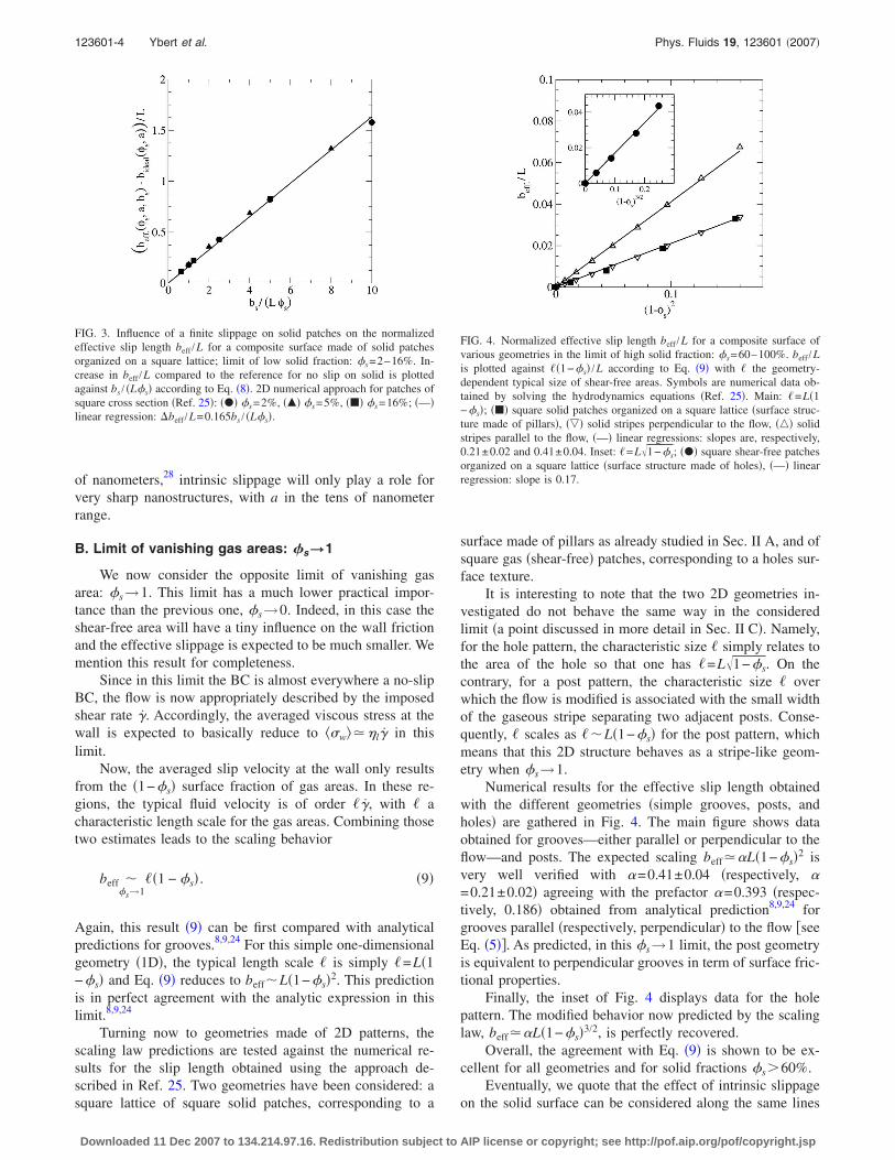
This modified scaling is tested on the square lattice ge-ometry of solid patches in Fig. 3. The difference between theeffective slip length beff��s ,a ,bs� with intrinsic slippage bs
on the solid, and the no-slip prediction �ideal case shown inFig. 2� bideal�beff��s ,a ,bs=0�, is plotted against bs /�s. Thisfigure confirms the soundness of the scaling law �8�, which,therefore, allows us to quantify the impact of an intrinsicsolid slip on the overall effective slip over superhydrophobicsurfaces.
Additionally, it is important to note that bs /�s does notdepend on the geometry of the surface so that the increase ofthe effective slip length due to the intrinsic slip is indepen-dent of the details of the underlying surface texture �stripesor posts�. Moreover, Eq. �8� shows that such a term will playa role only if the size of the solid region, a, is of the order ofthe intrinsic slip length: bs�a. With bs limited to a few tens
FIG. 2. Normalized effective slip length beff /L for a composite surface madeof solid patches organized on a square lattice; limit of low solid fraction:�s=2−30%. beff /L is plotted against 1 /��s according to Eq. �4� with �s
= �a /L�2. 2D numerical approach �Ref. 25�: ��� solid patches of squarecross section; 3D finite-element calculation: solid patches of ��� squarecross section, ��� circular cross section; �—� linear regression: beff /L=0.325 /��s−0.44.
123601-3 Achieving large slip with superhydrophobic surfaces Phys. Fluids 19, 123601 �2007�
Downloaded 11 Dec 2007 to 134.214.97.16. Redistribution subject to AIP license or copyright; see http://pof.aip.org/pof/copyright.jsp
of nanometers,28 intrinsic slippage will only play a role forvery sharp nanostructures, with a in the tens of nanometerrange.
B. Limit of vanishing gas areas: �s\1
We now consider the opposite limit of vanishing gasarea: �s→1. This limit has a much lower practical impor-tance than the previous one, �s→0. Indeed, in this case theshear-free area will have a tiny influence on the wall frictionand the effective slippage is expected to be much smaller. Wemention this result for completeness.
Since in this limit the BC is almost everywhere a no-slipBC, the flow is now appropriately described by the imposedshear rate �. Accordingly, the averaged viscous stress at thewall is expected to basically reduce to ��w� �l� in thislimit.
Now, the averaged slip velocity at the wall only resultsfrom the �1−�s� surface fraction of gas areas. In these re-gions, the typical fluid velocity is of order ��, with � acharacteristic length scale for the gas areas. Combining thosetwo estimates leads to the scaling behavior
beff ��s→1
��1 − �s� . �9�
Again, this result �9� can be first compared with analyticalpredictions for grooves.8,9,24 For this simple one-dimensionalgeometry �1D�, the typical length scale � is simply �=L�1−�s� and Eq. �9� reduces to beff�L�1−�s�2. This predictionis in perfect agreement with the analytic expression in thislimit.8,9,24
Turning now to geometries made of 2D patterns, thescaling law predictions are tested against the numerical re-sults for the slip length obtained using the approach de-scribed in Ref. 25. Two geometries have been considered: asquare lattice of square solid patches, corresponding to a
surface made of pillars as already studied in Sec. II A, and ofsquare gas �shear-free� patches, corresponding to a holes sur-face texture.
It is interesting to note that the two 2D geometries in-vestigated do not behave the same way in the consideredlimit �a point discussed in more detail in Sec. II C�. Namely,for the hole pattern, the characteristic size � simply relates tothe area of the hole so that one has �=L�1−�s. On thecontrary, for a post pattern, the characteristic size � overwhich the flow is modified is associated with the small widthof the gaseous stripe separating two adjacent posts. Conse-quently, � scales as ��L�1−�s� for the post pattern, whichmeans that this 2D structure behaves as a stripe-like geom-etry when �s→1.
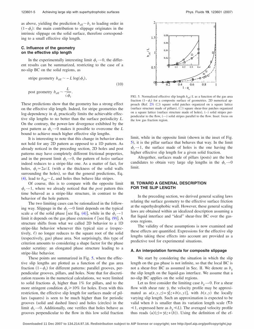
Numerical results for the effective slip length obtainedwith the different geometries �simple grooves, posts, andholes� are gathered in Fig. 4. The main figure shows dataobtained for grooves—either parallel or perpendicular to theflow—and posts. The expected scaling beff �L�1−�s�2 isvery well verified with �=0.41±0.04 �respectively, �=0.21±0.02� agreeing with the prefactor �=0.393 �respec-tively, 0.186� obtained from analytical prediction8,9,24 forgrooves parallel �respectively, perpendicular� to the flow �seeEq. �5��. As predicted, in this �s→1 limit, the post geometryis equivalent to perpendicular grooves in term of surface fric-tional properties.
Finally, the inset of Fig. 4 displays data for the holepattern. The modified behavior now predicted by the scalinglaw, beff �L�1−�s�3/2, is perfectly recovered.
Overall, the agreement with Eq. �9� is shown to be ex-cellent for all geometries and for solid fractions �s�60%.
Eventually, we quote that the effect of intrinsic slippageon the solid surface can be considered along the same lines
FIG. 3. Influence of a finite slippage on solid patches on the normalizedeffective slip length beff /L for a composite surface made of solid patchesorganized on a square lattice; limit of low solid fraction: �s=2–16%. In-crease in beff /L compared to the reference for no slip on solid is plottedagainst bs / �L�s� according to Eq. �8�. 2D numerical approach for patches ofsquare cross section �Ref. 25�: ��� �s=2%, ��� �s=5%, ��� �s=16%; �—�linear regression: �beff /L=0.165bs / �L�s�.
FIG. 4. Normalized effective slip length beff /L for a composite surface ofvarious geometries in the limit of high solid fraction: �s=60–100%. beff /Lis plotted against ��1−�s� /L according to Eq. �9� with � the geometry-dependent typical size of shear-free areas. Symbols are numerical data ob-tained by solving the hydrodynamics equations �Ref. 25�. Main: �=L�1−�s�; ��� square solid patches organized on a square lattice �surface struc-ture made of pillars�, ��� solid stripes perpendicular to the flow, ��� solidstripes parallel to the flow, �—� linear regressions: slopes are, respectively,0.21±0.02 and 0.41±0.04. Inset: �=L�1−�s; ��� square shear-free patchesorganized on a square lattice �surface structure made of holes�, �—� linearregression: slope is 0.17.
123601-4 Ybert et al. Phys. Fluids 19, 123601 �2007�
Downloaded 11 Dec 2007 to 134.214.97.16. Redistribution subject to AIP license or copyright; see http://pof.aip.org/pof/copyright.jsp
as above, yielding the prediction beff�bs to leading order in�1−�s�: the main contribution to slippage originates in theintrinsic slippage on the solid surface, therefore correspond-ing to a small effective slip length.
C. Influence of the geometryon the effective slip length
In the experimentally interesting limit �s→0, the differ-ent results can be summarized, restricting to the case of ano-slip BC on the solid regions, as
stripe geometry beff � − L log��s� ,
�10�
post geometry beff �L
��s
.
These predictions show that the geometry has a strong effecton the effective slip length. Indeed, for stripe geometries thelog-dependency in �s practically limits the achievable effec-tive slip lengths to no better than the surface periodicity L.On the contrary, the power-law divergence exhibited by thepost pattern as �s→0 makes it possible to overcome the Lbound to achieve much higher effective slip lengths.
It is interesting to note that this change in behavior doesnot hold for any 2D pattern as opposed to a 1D pattern. Asalready noticed in the preceding section, 2D holes and postpatterns may have completely different frictional properties,and in the present limit �s→0, the pattern of holes surfaceindeed reduces to a stripe-like one. As a matter of fact, forholes, �s 2a /L �with a the thickness of the solid wallssurrounding the holes�, so that the general predictions, Eq.�4�, lead to beff�L, and holes thus behave like stripes.
Of course, this is to compare with the opposite limit�s→1, where we already noticed that the post pattern thistime behaved as a stripe-like structure, in contrast to thebehavior of the hole pattern.
The two limiting cases can be rationalized in the follow-ing way. Slippage in the �s→0 limit depends on the typicalscale a of the solid phase �see Eq. �4��, while in the �s→1limit it depends on the gas phase extension � �see Eq. �9��. Astructure shifts from what we called 2D behavior to a 1Dstripe-like behavior whenever this typical size a �respec-tively, �� no longer reduces to the square root of the solid�respectively, gas� phase area. Not surprisingly, this type ofcriterion amounts to considering a shape factor for the phaseunder scrutiny: an elongated phase structure leading to astripe-like behavior.
These points are summarized in Fig. 5, where the effec-tive slip lengths are plotted as a function of the gas areafraction �1−�s� for different patterns: parallel grooves, per-pendicular grooves, pillars, and holes. Note that for discreti-zation reasons in the numerical calculations, we were limitedto solid fractions �s higher than 1% for pillars, and to themore stringent condition �s 10% for holes. Even with thisrestriction, the effective slip length for surfaces made of pil-lars �squares� is seen to be much higher than for periodicgrooves �solid and dashed lines� and holes �circles� in thelimit �s→0. Additionally, one verifies that holes behave asgrooves perpendicular to the flow in this low solid fraction
limit, while in the opposite limit �shown in the inset of Fig.5�, it is the pillar surface that behaves that way. In the limit�s→1, the surface made of holes is the one having thehigher effective slip length for a given solid fraction.
Altogether, surfaces made of pillars �posts� are the bestcandidates to obtain very large slip lengths in the �s→0limit.
III. TOWARD A GENERAL DESCRIPTIONFOR THE SLIP LENGTH
In the preceding section, we derived general scaling lawsrelating the surface geometry to the effective surface frictionat the superhydrophobic wall. However, these general scalinglaws are obtained within an idealized description assuming aflat liquid interface and “ideal” shear-free BC over the gas-eous regions.
The validity of these assumptions is now examined andthese effects are quantified. Expressions for the effective sliplengths taking these effects into account are provided as apredictive tool for experimental situations.
A. An interpolation formula for composite slippage
We start by considering the situation in which the sliplength on the gas phase is not infinite, so that the local BC isnot a shear-free BC as assumed in Sec. II. We denote as bg
the slip length on the liquid-gas interface. We assume that ano-slip BC applies on the solid regions.
Let us first consider the limiting case bg→0. For a shearflow with shear rate �, the velocity profile may be approxi-mated as u�x ,y ,z�= ��z+b�x ,y��, with b�x ,y� the locallyvarying slip length. Such an approximation is expected to bevalid when b is smaller than its variation length scale ��b�1, expressed here as bg�L�. The averaged velocity profilethus reads �u��z�= ��z+ �b��. Using the definition of the ef-
FIG. 5. Normalized effective slip length beff /L as a function of the gas areafraction �1−�s� for a composite surface of geometries. 2D numerical ap-proach �Ref. 25� ��� square solid patches organized on a square lattice�surface structure made of pillars�, ��� square shear-free patches organizedon a square lattice �surface structure made of holes�, �--� solid stripes per-pendicular to the flow, �—� solid stripes parallel to the flow. Inset: focus onthe low gas fraction region.
123601-5 Achieving large slip with superhydrophobic surfaces Phys. Fluids 19, 123601 �2007�
Downloaded 11 Dec 2007 to 134.214.97.16. Redistribution subject to AIP license or copyright; see http://pof.aip.org/pof/copyright.jsp
fective slip length, this velocity profile is expected to identifywith �u��z�= ��z+beff�. This yields the following expressionfor the effective slip length in this limit:
beff = �1 − �s�bg. �11�
One may show this result more rigorously using aperturbative approach of the flow field in bg. The referenceflow field corresponds to bg=0, which reads, for a shear rate� at infinity, u0= �z. The first-order correction for the flowfield over a composite surface with no-slip region S0 andpartial slip region Sg thus verifies �l�u1=�P1, together withthe following boundary condition on the liquid-gasinterface: �bg�z�u0+u1��w= �u1�w. In the limit bg→0, onehas �u1�w bg� so that in the end �uw�= �1−�s�bg�, andbeff= �1−�s�bg as shown above.
For large bg, no such simple prediction could be ob-tained. However, it is possible to propose an interpolationformula that will prove to be useful in the following. Thisinterpolation is based on the two known limits: for bg→0,beff= �1−�s�bg; for bg→�, beff�bideal with bideal the effec-tive slip length obtained in the idealized case where a shear-free BC is assumed at the liquid/gas interface. bideal is givenby the expressions discussed in Sec. II �typically bideal
�a /�s�.A heuristic formula interpolating between these two lim-
iting cases is
1
beff=
1
�1 − �s�bg+
1
bideal. �12�
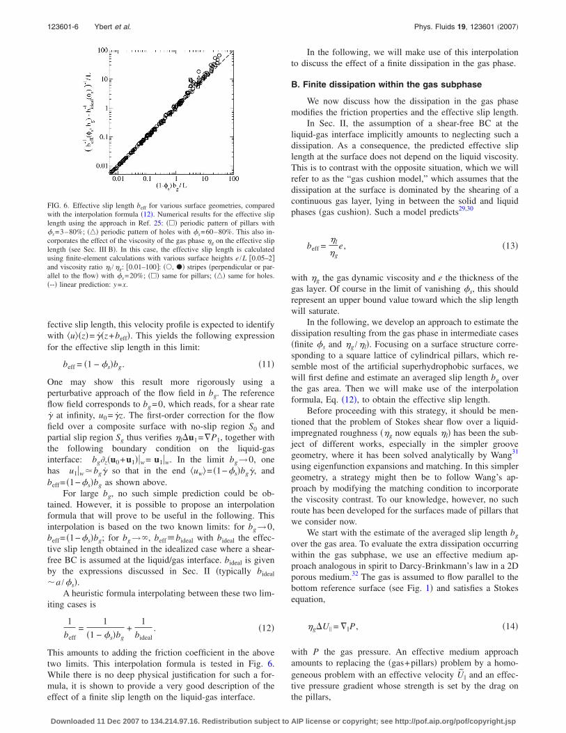
This amounts to adding the friction coefficient in the abovetwo limits. This interpolation formula is tested in Fig. 6.While there is no deep physical justification for such a for-mula, it is shown to provide a very good description of theeffect of a finite slip length on the liquid-gas interface.
In the following, we will make use of this interpolationto discuss the effect of a finite dissipation in the gas phase.
B. Finite dissipation within the gas subphase
We now discuss how the dissipation in the gas phasemodifies the friction properties and the effective slip length.
In Sec. II, the assumption of a shear-free BC at theliquid-gas interface implicitly amounts to neglecting such adissipation. As a consequence, the predicted effective sliplength at the surface does not depend on the liquid viscosity.This is to contrast with the opposite situation, which we willrefer to as the “gas cushion model,” which assumes that thedissipation at the surface is dominated by the shearing of acontinuous gas layer, lying in between the solid and liquidphases �gas cushion�. Such a model predicts29,30
beff =�l
�ge , �13�
with �g the gas dynamic viscosity and e the thickness of thegas layer. Of course in the limit of vanishing �s, this shouldrepresent an upper bound value toward which the slip lengthwill saturate.
In the following, we develop an approach to estimate thedissipation resulting from the gas phase in intermediate cases�finite �s and �g /�l�. Focusing on a surface structure corre-sponding to a square lattice of cylindrical pillars, which re-semble most of the artificial superhydrophobic surfaces, wewill first define and estimate an averaged slip length bg overthe gas area. Then we will make use of the interpolationformula, Eq. �12�, to obtain the effective slip length.
Before proceeding with this strategy, it should be men-tioned that the problem of Stokes shear flow over a liquid-impregnated roughness ��g now equals �l� has been the sub-ject of different works, especially in the simpler groovegeometry, where it has been solved analytically by Wang31
using eigenfunction expansions and matching. In this simplergeometry, a strategy might then be to follow Wang’s ap-proach by modifying the matching condition to incorporatethe viscosity contrast. To our knowledge, however, no suchroute has been developed for the surfaces made of pillars thatwe consider now.
We start with the estimate of the averaged slip length bg
over the gas area. To evaluate the extra dissipation occurringwithin the gas subphase, we use an effective medium ap-proach analogous in spirit to Darcy-Brinkmann’s law in a 2Dporous medium.32 The gas is assumed to flow parallel to thebottom reference surface �see Fig. 1� and satisfies a Stokesequation,
�g�U� = ��P , �14�
with P the gas pressure. An effective medium approachamounts to replacing the �gas+pillars� problem by a homo-geneous problem with an effective velocity U� and an effec-tive pressure gradient whose strength is set by the drag onthe pillars,
FIG. 6. Effective slip length beff for various surface geometries, comparedwith the interpolation formula �12�. Numerical results for the effective sliplength using the approach in Ref. 25: ��� periodic pattern of pillars with�s=3–80%; ��� periodic pattern of holes with �s=60–80%. This also in-corporates the effect of the viscosity of the gas phase �g on the effective sliplength �see Sec. III B�. In this case, the effective slip length is calculatedusing finite-element calculations with various surface heights e /L �0.05–2�and viscosity ratio �l /�g: �0.01–100�: ��, �� stripes �perpendicular or par-allel to the flow� with �s=20%; ��� same for pillars; ��� same for holes.�--� linear prediction: y=x.
123601-6 Ybert et al. Phys. Fluids 19, 123601 �2007�
Downloaded 11 Dec 2007 to 134.214.97.16. Redistribution subject to AIP license or copyright; see http://pof.aip.org/pof/copyright.jsp

− ��P = �Fd, �15�
with �=1 /L2 the number density of pillars and Fd the dragforce per unit of length experienced by a single pillar. Thelatter is of the form Fd=−���s�U�, where ���s� is the frictioncoefficient, the �s dependency of which accounts for hydro-dynamic interactions between pillars and can be found in theliterature.33 For example, for a square array of pillars, a se-ries expansion in �s leads to
4�g
���s�= −
1
2ln �s − 0.738 + �s − 0.887�s
2 + 2.039�s3
+ O��s4� , �16�
accurate to within 5% in the range of practical interest �s
30%. Combining Eqs. �14� and �15� with the definition of���s�, one obtains the relation
�U� =����s�
�gU� , �17�
complemented by the BCs U��z=0�= �uw�g and U��z=−e�=0. It resolves straightforwardly and yields an averaged vis-cous surface stress of
��w�g = �g�uw�gq
tanh qe, �18�
with q2=����s� /�g. According to Eqs. �1� and �2�, this pre-dicts for the averaged slip length bg over the gas areas
bg =e�l
�g
tanh qe
qe, �19�
with q��s� given above, an expression reminiscent of theBeavers and Joseph BC on porous media.34
To estimate the effective slip length, we now use thisprediction together with the interpolation formula, Eq. �12�,to obtain
1
beff=
1
�1 − �s�e�l
�g
tanh qe
qe
+1
bideal, �20�
where we recall that bideal stands for the effective slip lengthfor the composite surface with a negligible dissipation in thegas �shear-free BC�, as discussed in Sec. II.
To assess the validity of this approach, we have con-ducted numerical resolution of the Stokes equations usingfinite-element methods implemented through Comsol©. Thecomputed geometry is like the one sketched in Fig. 1 with anundeformable planar liquid interface separating a liquidphase and a gas phase, with a given viscosity ratio �g /�l. Aplanar upper wall �not sketched� encloses the liquid slabseparated from the liquid interface by a distance H �H waschosen large enough so that the results matched the H→�limit�. Symmetries were used to reduce the size of the com-putation cell. A Couette flow is simulated by imposing avelocity U of the top planar wall.
The resulting flow field is computed, from which wehave extracted the effective slip length beff over the entiresurface, as done previously. We also measured the averaged
slip length bg over the gas areas. The latter is defined fromthe averaged shear stress ��w�g and the averaged slip velocity�uw�g over the gas phase according to Navier-like relation-ships of the form �1� and �2�.
Let us first discuss the result for the averaged slip lengthbg. The comparison between the theoretical prediction �19�and the numerical results using finite-element computationsis shown in Fig. 7. For the explored viscosity ratios �l /�g,the gas layer thickness e /L, and the solid fraction �s, ouranalytical prediction proves very satisfactory and remains al-ways within 20% of the numerical value.
We can now test the global result for the effective sliplength, in Eq. �20�. This phenomenological relationship istested by comparing with the results of the 3D finite-elementcalculation—where both beff and bg are measured—but alsoby comparing with the 2D numerical approach25 with a flatcomposite interface with mixed BC: no-slip and partial slipwith slip length bg. This is done in Fig. 6, where �beff
−1
−bideal−1 �−1 is plotted against �1−�s�bg. As already noted, the
interpolating formula �20� appears to be astonishingly effi-cient. It describes with very good precision the effect of thefinite dissipation within the underneath subphase. CombiningEqs. �16� and �20� allows us to quantify the influence of thesubphase dissipation on the effective slip length.
C. Pressure dependency: Meniscus curvature effect
In this section, we discuss qualitatively the effect of apressure drop �P= Pg− Pl between the liquid and the under-lying gas phase. A pressure drop is associated with a curva-ture of the liquid-vapor meniscus, leading to a reduction ofslippage. Our aim in this section is to provide an upper limitfor the pressure drop �P below which curvature effects canbe neglected. To this end, we shall focus on the case in whichthe gas meniscus is oriented outward �protruding by a dis-tance � into the liquid phase�, which can be handled in asimple way within the present description. This situation was
FIG. 7. Effective slip length bg over gas areas as obtained from finite-element calculations, compared with theoretical predictions according to Eq.�19�. The surface is made of cylindrical pillars of height e arranged on asquare lattice and the viscosity ratio �l /�g between the two phases is variedfrom 0.1 to 100; solid and empty symbols correspond, respectively, to e /L=0.25 and e /L=1. ��, �� �s=30%, ��, �� �s=20%, ��, �� �s=10%,��, �� �s=3%, �-·-� perfect match: y=x.
123601-7 Achieving large slip with superhydrophobic surfaces Phys. Fluids 19, 123601 �2007�
Downloaded 11 Dec 2007 to 134.214.97.16. Redistribution subject to AIP license or copyright; see http://pof.aip.org/pof/copyright.jsp
recently shown to be relevant experimentally whenever nodirect control can be exerted on the gas subphase,35 and weexpect the present analysis to capture the general featuresoccurring at curved interfaces.27,36
To obtain how pressure-induced curvature effectsmodify the slip length, we follow a similar approach to thatin the preceding section. The additional dissipation resultingfrom the boundary curvature will be incorporated as a finiteslip length bg applied on the liquid-gas interface. In the caseof a curved gas meniscus, this effective slip length bg shouldcorrespond to the local radius of curvature,37 which readsbg��2 /� in a parabolic approximation.
This relationship, based on the local expression of thestress tensor in the tangential/normal vector frame,37 can ac-tually be recovered with a simple scaling argument. Startingfrom the expression for the drag force F=4�lRu experi-enced by a spherical bubble moving at velocity u,38,39 weexpect the additional drag exerted on the cap to be of theform
�F�g � �l��uw�g. �21�
The averaged shear stress resulting from this drag force issimply ��w�g= �F�g /�2 with � the typical length scale for thegas areas so that in the end one recovers for the effective sliplength over the gas areas
bg � �2/� . �22�
We are now in a situation similar to the one considered inSec. III B except for the origin of bg. The effective sliplength can be obtained using the interpolation formula �12�.
It is first interesting to compare this prediction with arecent analytical work considering the 1D situation of a shearflow parallel to grooves.36 In this geometry, a first-order per-turbative approach was developed that allowed to quantifythe effect of meniscus curvature in the limit ��� ��=L−a�. Considering the limit of large solid fraction �s, ourscaling approach provides in this 1D situation the followingcurvature correction to the effective slip length:
beff − bideal � − �1 − �s�� , �23�
which is obtained by combining Eqs. �9�, �12�, and �22�. Thisresult agrees fully with the first-order correction term foundin Ref. 36.
In the more interesting limit of a 2D surface pattern with�s→0, the ideal flat surface slip length is now given by Eq.�4�. We thus obtain
beff = �
L2 +1
bideal−1
�24�
with bideal /L 0.325 /��s−0.44 �see Sec. II�. This resultshows that in the limit bg=L2 /�bideal, the effective sliplength beff does saturate at the gas spherical cap radius ofcurvature. Coming back to macroscopic variables, this radiusof curvature can be traced back to the pressure differencebetween the liquid and the gas phase through the Laplaceequation, �P= Pg− Pl=2�lg� /L2, with �lg the liquid/gas sur-face tension. A pressure difference between the liquid and thegas thus induces a saturation of the effective slip length at a
value beff→2�lg /�P. To fix ideas, for �P�1 bar, beff satu-rates at beff�1 �m.
These results allow us to estimate the domain of pressuredifference �P, for which the curvature effects do not affectthe slippage on the superhydrophobic surface. According toEq. �24�, this amounts to L2 /��bideal, with bideal the sliplength when curvature effects are negligible. This can berewritten
�P ��lg
bideal. �25�
This condition shows that situations with larger sliplengths are more sensitive to curvature effects. However, oncan note that a reasonable pressure difference in the order oftens of mbars will not affect a slip length in the hundreds ofmicrometers range. It should therefore be moderately limit-ing in the design of reduced friction interfaces. This is sup-ported by the absence of pressure effects reported in Ref. 19or the low curvature reported in Ref. 13.
We eventually remark that such curvature effects are ex-pected to be more important for surfaces with a roughnessmade of holes, for which the gas is not connected to a res-ervoir. Depending on the condition for surface immersion,gas may be trapped in the holes with a non-negligible excesspressure. Such effects have indeed been observed in Ref. 35,with a geometry of holes of size ��650 nm, thus resultingin a strongly reduced slip length.
IV. DISCUSSION
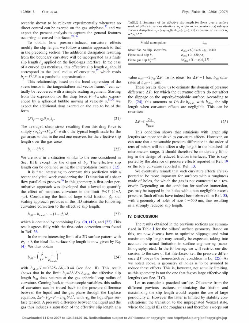
The results obtained in the previous sections are summa-rized in Table I for the pillars’ surface geometry. Based onthis, we now discuss how to optimize slippage, and whatmaximum slip length may actually be expected, taking intoaccount the actual limitation in surface engineering �nano-lithography, etc.�. In the following, we will restrict our dis-cussion to the case of flat interfaces, i.e., the pressure differ-ence �P obeys the �nonrestrictive� condition in Eq. �25�. Aswe noted above, a geometry of holes is to be avoided toreduce these effects. This is, however, not actually limiting,as this geometry is not the one that favors large effective sliplengths �see Sec. II C�.
Let us consider a practical surface. Of course from thedifferent previous sections, minimizing the friction andmaximizing the slip length would require the use of largeperiodicity L. However the latter is limited by stability con-siderations: the transition to the impregnated Wenzel state,where the liquid fills the roughness and therefore sweeps out
TABLE I. Summary of the effective slip length for flows over a surfacemade of pillars in various situations. bg origin and expressions: �a� sublayerviscous dissipation bg= �e�l /�g�tanh�qe� / �qe�; �b� curvature of menisci bg
=2�lv /�P.
Model assumptions beff
Ideal: flat, no-slip, shear-free bideal=L�0.325 /��s−0.44�Finite solid slip bs bideal+0.165bs /�s
Finite gas slip bg�a�,�b� �bideal
−1 + ��1−�s�bg�−1�−1
123601-8 Ybert et al. Phys. Fluids 19, 123601 �2007�
Downloaded 11 Dec 2007 to 134.214.97.16. Redistribution subject to AIP license or copyright; see http://pof.aip.org/pof/copyright.jsp
the gas lubricating pockets, is indeed associated with thedisappearance of superlubricating properties.6,19 A reason-able compromise may lie in the range L� few �m for whichpressure differences of tens of mbars—typical for gravity-driven microfluidic flows—can be withstood by an air/waterinterface. Note that for a precise value of the stability limit,one should actually take into account all surface geometricparameters, including, for instance, the structure height.25
Now for microfabricated or nanofabricated surface pat-terns, the exact geometry of the surface is known a prioriand Eqs. �4�, �8�, �12�, and �19� allow us to estimate theexpected frictional properties of this surfaces. However, formost superhydrophobic surfaces reported, the structure ge-ometry is not as controlled, and a key parameter such as thesolid fraction �s has to be estimated or measured. It is there-fore very convenient to relate this parameter to a macro-scopic observable such as the effective contact angle �eff onthe surface. With �0 the contact angle on the bare surface �inthe range of 100–120° for hydro- or fluorocarbon coatings�,�eff relates to �s through the Cassie-Baxter relation,5
cos �eff = �s�cos �0 + 1� − 1. �26�
Fixing the typical height of the structures to e=L=5 �m andassuming a pillars-like type of geometry, it is therefore pos-sible to predict the frictional properties beff of the surface asa function of its macroscopic effective contact angle �eff. Forpillars, Eq. �4� gives
beff �L� cos �0 + 1
cos �eff + 1− � , �27�
with �=0.325 and �=0.44 the numerical factors. This ex-pression shows that close to �eff=180°, beff strongly diverges,like
beff �L
180 − �eff. �28�
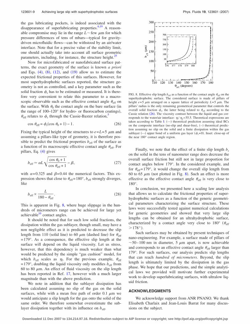
This is apparent in Fig. 8, where huge slippage in the hun-dreds of micrometers range can be achieved for large yetachievable10 contact angles.
It should be noted that for such low solid fractions, thedissipation within the gas sublayer, though small, may have anon negligible effect as it is predicted to decrease the sliplength from 110 �solid line� to 60 �m �dashed line� for �eff
=179°. As a consequence, the effective slip length at thesurface will depend on the liquid viscosity. Let us stress,however, that this dependency is much weaker than whatwould be predicted by the simple “gas cushion” model, forwhich beff scales as �l. For the previous example, �eff
=179°, doubling the liquid viscosity only modifies beff from60 to 80 �m. An effect of fluid viscosity on the slip lengthhas been reported in Ref. 17, however with a much largermagnitude than with the above prediction.
We note in addition that the sublayer dissipation hasbeen calculated assuming no slip of the gas on the solidsurfaces, while with a mean free path of order 0.1 �m wewould anticipate a slip length for the gas onto the solid of thesame order. We therefore somewhat overestimate the sub-layer dissipation together with its influence on beff.
Finally, we note that the effect of a finite slip length bs
on the solid in the tens of nanometer range does decrease theoverall surface friction but still not in large proportion forcontact angles below 179°. In the considered example, andfor �eff=179°, it would change the overall slip length from60 to 65 �m �not plotted in Fig. 8�. Such an effect is moreeffective as the effective contact angle �eff is very close to180°.
In conclusion, we presented here a scaling law analysisthat allows us to calculate the frictional properties of super-hydrophobic surfaces as a function of the generic geometri-cal parameters characterizing the surface structure. Theselaws were successfully tested against numerical calculationsfor generic geometries and showed that very large sliplengths can be obtained for an ultrahydrophobic surface,characterized by a contact angle very close to 180° ��eff
�178° �.Such surfaces may be obtained by present techniques of
nano-engineering. For example, a surface made of pillars of�50–100 nm in diameter, 5 �m apart, is now achievableand corresponds to an effective contact angle �eff larger than179°. For such surfaces, our analysis predicts slip lengthsthat can reach hundred of micrometers. Beyond, the sliplength is ultimately limited by the dissipation in the gasphase. We hope that our predictions, and the simple analyti-cal laws we provided will motivate further experimentalwork to develop superlubricating surfaces, with ultralow liq-uid friction.
ACKNOWLEDGMENTS
We acknowledge support from ANR PNANO. We thankElisabeth Charlaix and Jean-Louis Barrat for many discus-sions on the subject.
FIG. 8. Effective slip length beff as a function of the contact angle �eff on thesuperhydrophobic surface. The considered surface is made of pillars ofheight e=5 �m arranged on a square lattice of periodicity L=5 �m. Thepillars’ radius is the only remaining geometrical parameter that controls theoverall solid fraction �s, the latter being related to �eff according to theCassie relation �26�. The viscosity contrast between the liquid and gas cor-responds to the water/air interface: �l /�g=55.5. Theoretical expressions aretaken according to Table I: �—� theoretical prediction assuming ideal BCson the composite interface �no-slip and shear-free�, �--� theoretical predic-tion assuming no slip on the solid and a finite dissipation within the gassublayer �-·-� upper bond of a uniform gas layer ��s=0�. Inset: close-up ofthe near 180° contact angle region.
123601-9 Achieving large slip with superhydrophobic surfaces Phys. Fluids 19, 123601 �2007�
Downloaded 11 Dec 2007 to 134.214.97.16. Redistribution subject to AIP license or copyright; see http://pof.aip.org/pof/copyright.jsp
1J. Bico, U. Thiele, and D. Quere, “Wetting of textured surfaces,” ColloidsSurf., A 206, 41 �2002�.
2A. Lafuma and D. Quere, “Superhydrophobic states,” Nature Mater. 2,457 �2003�.
3L. C. Gao and T. J. McCarthy, “A commercially available perfectly hy-drophobic material �theta�a� / theta�r�=180 degrees /180 degrees�,”Langmuir 23, 9125 �2007�.
4R. N. Wenzel, “Resistance of solid surfaces to wetting by water,” Ind.Eng. Chem. 28, 988 �1936�.
5A. Cassie and S. Baxter, “Wettability of porous surfaces,” Trans. FaradaySoc. 40, 546 �1944�.
6C. Cottin-Bizonne, J. L. Barrat, L. Bocquet, and E. Charlaix, “Low-friction flows of liquid at nanopatterned interfaces,” Nature Mater. 2, 237�2003�.
7D. Quere, A. Lafuma, and J. Bico, “Slippy and sticky microtextured sol-ids,” Nanotechnology 14, 1109 �2003�.
8J. Philip, “Flows satisfying mixed no-slip and no-shear conditions,” Z.Angew. Math. Phys. 23, 353 �1972�.
9J. Philip, “Integral properties of flows satisfying mixed no-slip and no-shear conditions,” Z. Angew. Math. Phys. 23, 960 �1972�.
10J. W. Kim and C. J. Kim, “Nanostructured surfaces for dramatic reductionof flow resistance in droplet-based microfluidics,” Fifteenth IEEE Interna-tional Conference on Micro Electro Mechanical Systems, Technical Digest�IEEE, Piscataway, NJ, 2002�, pp. 479–482.
11C. Navier, Mémoire sur les Lois du Louvement des Fluides �l’AcadémieRoyale des Sciences de l’Institut de France, Paris, 1823�, Vol. VI.
12D. Richard and D. Quere, “Viscous drops rolling on a tilted non-wettablesolid,” Europhys. Lett. 48, 286 �1999�.
13J. Ou, B. Perot, and J. P. Rothstein, “Laminar drag reduction in micro-channels using ultrahydrophobic surfaces,” Phys. Fluids 16, 4635 �2004�.
14J. Ou and J. P. Rothstein, “Direct velocity measurements of the flow pastdrag-reducing ultrahydrophobic surfaces,” Phys. Fluids 17, 103606�2005�.
15S. Gogte, P. Vorobieff, R. Truesdell, A. Mammoli, F. van Swol, P. Shah,and C. J. Brinker, “Effective slip on textured superhydrophobic surfaces,”Phys. Fluids 17, 051701 �2005�.
16C. H. Choi, U. Ulmanella, J. Kim, C. M. Ho, and C. J. Kim, “Effective slipand friction reduction in nanograted superhydrophobic microchannels,”Phys. Fluids 18, 087105 �2006�.
17C. H. Choi and C. J. Kim, “Large slip of aqueous liquid flow over ananoengineered superhydrophobic surface,” Phys. Rev. Lett. 96, 066001�2006�.
18L. Bocquet, P. Tabeling, and S. Manneville, “Comment on large slip ofaqueous liquid flow over a nanoengineered superhydrophobic surface,”Phys. Rev. Lett. 97, 109601 �2006�.
19P. Joseph, C. Cottin-Bizonne, J. M. Benoit, C. Ybert, C. Journet, P. Tabel-ing, and L. Bocquet, “Slippage of water past superhydrophobic carbonnanotube forests in microchannels,” Phys. Rev. Lett. 97, 156104 �2006�.
20O. I. Vinogradova and G. E. Yakubov, “Dynamic effects on force mea-
surements. 2. Lubrication and the atomic force microscope,” Langmuir19, 1227 �2003�.
21C. Cottin-Bizonne, B. Cross, A. Steinberger, and E. Charlaix, “Boundaryslip on smooth hydrophobic surfaces: Intrinsic effects and possible arti-facts,” Phys. Rev. Lett. 94, 056102 �2005�.
22L. Joly, C. Ybert, and L. Bocquet, “Probing the nanohydrodynamics atliquid-solid interfaces using thermal motion,” Phys. Rev. Lett. 96, 046101�2006�.
23P. Huang and K. S. Breuer, “Direct measurement of slip length in electro-lyte solutions,” Phys. Fluids 19, 028104 �2007�.
24E. Lauga and H. A. Stone, “Effective slip in pressure-driven Stokes flow,”J. Fluid Mech. 489, 55 �2003�.
25C. Cottin-Bizonne, C. Barentin, E. Charlaix, L. Bocquet, and J. L. Barrat,“Dynamics of simple liquids at heterogeneous surfaces: Molecular-dynamics simulations and hydrodynamic description,” Eur. Phys. J. E 15,427 �2004�.
26M. Sbragaglia, R. Benzi, L. Biferale, S. Succi, and F. Toschi, “Surfaceroughness-hydrophobicity coupling in microchannel and nanochannelflows,” Phys. Rev. Lett. 97, 204503 �2006�.
27S. Richardson, “On the no-slip boundary-condition,” J. Fluid Mech. 59,707 �1973�.
28E. Lauga, M. P. Brenner, and H. A. Stone, Handbook of ExperimentalFluid Dynamics �Springer, New York, 2005�.
29O. I. Vinogradova, “Drainage of a thin liquid-film confined between hy-drophobic surfaces,” Langmuir 11, 2213 �1995�.
30P. de Gennes, “On fluid wall slippage,” Langmuir 18, 3413 �2002�.31C. Y. Wang, “Flow over a surface with parallel grooves,” Phys. Fluids 15,
1114 �2003�.32H. Brinkman, “On the permeability of media consisting of closely packed
porous particles,” Appl. Sci. Res., Sect. A 1, 81 �1947�.33A. S. Sangani and A. Acrivos, “Slow flow through a periodic array of
spheres,” Int. J. Multiphase Flow 8, 343 �1982�.34G. S. Beavers and D. D. Joseph, “Boundary conditions at naturally per-
meable wall,” J. Fluid Mech. 30, 197 �1967�.35A. Steinberger, C. Cottin-Bizonne, P. Kleimann, and E. Charlaix, “High
friction on a bubble mattress,” Nature Mater. 6, 665 �2007�.36M. Sbragaglia and A. Prosperetti, “A note on the effective slip properties
for microchannel flows with ultra-hydrophobic surfaces,” Phys. Fluids 19,043603 �2007�.
37P. Panzer, M. Liu, and D. Einzel, “The effects of boundary curvature onhydrodynamic fluid-flow: Calculation of slip lengths,” Int. J. Mod. Phys. B6, 3251 �1992�.
38W. Rybczyński, “On the translatory motion of a fluid sphere in a viscousmedium �in german�,” Bull. Int. Acad. Pol. Sci. Lett., Cl. Sci. Math. Nat.,Ser. A 2, 40 �1911�.
39J. Hadamard, “Mouvement permanent lent d’une sphère liquide et vis-queuse dans un liquide visqueux,” C. R. Acad. Sci. Paris 152, 1735�1911�.
123601-10 Ybert et al. Phys. Fluids 19, 123601 �2007�
Downloaded 11 Dec 2007 to 134.214.97.16. Redistribution subject to AIP license or copyright; see http://pof.aip.org/pof/copyright.jsp