Direct Freeform Fabrication of Seeded Hydrogels in Arbitrary Geometries
14
1325 INTRODUCTION T HE GENERATION OF CELL-SEEDED IMPLANTS with struc- tures that mimic native tissue, both in anatomic geometries and intratissue cell distributions, is a major challenge in tissue engineering. Indeed, the therapeutic promise of tissue engineering was most famously dem- onstrated in pioneering work by Charles Vacanti and col- leagues in which tissue-engineered cartilage was shaped into the form of a human ear. 1 In additional work, this idea was extended to demonstrate the generation of car- tilage of arbitrary shapes, 2 as well as many specific an- atomic geometries including temporomandibular disc 3 and joint, 4 meniscus, 5 trachea, 6 intervertebral disc, 7 nasal tip, 8 and nasal septum. 9 These principles apply to other tissues as well, particularly bone, where the reproduction of anatomically shaped tissue has been demonstrated in the generation of femoral shaft 10 and mandibular condyle 4 in rats and culminating in the generation of a distal phalanx in a human patient. 11 Previous studies demonstrating the engineering of tis- sues in complex geometries used a variety of techniques to achieve control of shape. Tissues with complex two- dimensional surface geometries have been generated by casting cell-seeded hydrogel onto substrate base layers with desired surface shapes. 12 Three-dimensional (3-D) tissues with complex geometries have been fabricated through seeding of cells onto molded scaffolds 13 or in- jection molding of cell-seeded hydrogels. 14 While these techniques were able to create constructs with complex shapes, they lacked the ability to easily create parts with spatial heterogeneities. Other studies have investigated methods to reproduce zonal spatial variations in articular cartilage constructs. TISSUE ENGINEERING Volume 12, Number 5, 2006 © Mary Ann Liebert, Inc. Direct Freeform Fabrication of Seeded Hydrogels in Arbitrary Geometries DANIEL L. COHEN, B.S., 1 EVAN MALONE, M.S., 1 HOD LIPSON, Ph.D., 1,2 and LAWRENCE J. BONASSAR, Ph.D. 1,3 ABSTRACT A major challenge in tissue engineering is the generation of cell-seeded implants with structures that mimic native tissue, both in anatomic geometries and intratissue cell distributions. By combining the strengths of injection molding tissue engineering with those of solid freeform fabrication (SFF), three-dimensional (3-D) pre-seeded implants were fabricated without custom-tooling, enabling effi- cient production of patient-specific implants. The incorporation of SFF technology also enabled the fabrication of geometrically complex, multiple-material implants with spatially heterogeneous prop- erties that would otherwise be challenging to produce. Utilizing a custom-built robotic SFF plat- form and gel deposition tools, alginate hydrogel was used with calcium sulfate as a crosslinking agent to produce pre-seeded living implants of arbitrary geometries. The process was determined to be sterile and viable at 94 5%. The GAG and hydroxyproline production was found to be sim- ilar to that of other implants fabricated using the same materials with different shaping methods. The geometric fidelity of the process was quantified by using the printing platform as a computer- ized measurement machine (CMM); the RMS surface roughness of printed samples in the z-di- mension was found to be 0.16 0.02 mm. 1 Department of Mechanical and Aerospace Engineering, 2 Department of Computer and Information Science, 3 Department of Biomedical Engineering, Cornell University, Ithaca, New York.
-
Upload
independent -
Category
Documents
-
view
1 -
download
0
Transcript of Direct Freeform Fabrication of Seeded Hydrogels in Arbitrary Geometries
1325
INTRODUCTION
THE GENERATION OF CELL-SEEDED IMPLANTS with struc-tures that mimic native tissue, both in anatomic
geometries and intratissue cell distributions, is a majorchallenge in tissue engineering. Indeed, the therapeuticpromise of tissue engineering was most famously dem-onstrated in pioneering work by Charles Vacanti and col-leagues in which tissue-engineered cartilage was shapedinto the form of a human ear.1 In additional work, thisidea was extended to demonstrate the generation of car-tilage of arbitrary shapes,2 as well as many specific an-atomic geometries including temporomandibular disc3
and joint,4 meniscus,5 trachea,6 intervertebral disc,7 nasaltip,8 and nasal septum.9 These principles apply to othertissues as well, particularly bone, where the reproductionof anatomically shaped tissue has been demonstrated in
the generation of femoral shaft10 and mandibularcondyle4 in rats and culminating in the generation of adistal phalanx in a human patient.11
Previous studies demonstrating the engineering of tis-sues in complex geometries used a variety of techniquesto achieve control of shape. Tissues with complex two-dimensional surface geometries have been generated bycasting cell-seeded hydrogel onto substrate base layerswith desired surface shapes.12 Three-dimensional (3-D)tissues with complex geometries have been fabricatedthrough seeding of cells onto molded scaffolds13 or in-jection molding of cell-seeded hydrogels.14 While thesetechniques were able to create constructs with complexshapes, they lacked the ability to easily create parts withspatial heterogeneities.
Other studies have investigated methods to reproducezonal spatial variations in articular cartilage constructs.
TISSUE ENGINEERINGVolume 12, Number 5, 2006© Mary Ann Liebert, Inc.
Direct Freeform Fabrication of Seeded Hydrogels in Arbitrary Geometries
DANIEL L. COHEN, B.S.,1 EVAN MALONE, M.S.,1 HOD LIPSON, Ph.D.,1,2
and LAWRENCE J. BONASSAR, Ph.D.1,3
ABSTRACT
A major challenge in tissue engineering is the generation of cell-seeded implants with structures thatmimic native tissue, both in anatomic geometries and intratissue cell distributions. By combiningthe strengths of injection molding tissue engineering with those of solid freeform fabrication (SFF),three-dimensional (3-D) pre-seeded implants were fabricated without custom-tooling, enabling effi-cient production of patient-specific implants. The incorporation of SFF technology also enabled thefabrication of geometrically complex, multiple-material implants with spatially heterogeneous prop-erties that would otherwise be challenging to produce. Utilizing a custom-built robotic SFF plat-form and gel deposition tools, alginate hydrogel was used with calcium sulfate as a crosslinkingagent to produce pre-seeded living implants of arbitrary geometries. The process was determinedto be sterile and viable at 94 � 5%. The GAG and hydroxyproline production was found to be sim-ilar to that of other implants fabricated using the same materials with different shaping methods.The geometric fidelity of the process was quantified by using the printing platform as a computer-ized measurement machine (CMM); the RMS surface roughness of printed samples in the z-di-mension was found to be 0.16 � 0.02 mm.
1Department of Mechanical and Aerospace Engineering, 2Department of Computer and Information Science, 3Department ofBiomedical Engineering, Cornell University, Ithaca, New York.

These approaches created spatially heterogeneous con-structs by depositing multiple layers of chondrocytes15
or chondrocyte-seeded hydrogels.16,17 While these tech-niques produced zonal organization in engineered tissues,they were limited to spatially varying the construct prop-erties along a single axis only. Furthermore, while thesetechniques were feasible in the case of in vitro constructfabrication, it is not inherently feasible to adapt them forin vivo, or in situ, fabrication. For example, it would bechallenging to place pre-formed hydrogel sheets througha small orifice while achieving proper alignment andbonding, such as would be necessary for incorporationinto a minimally invasive implantation scheme.
Solid freeform fabrication (SFF) technology has beenused both to aid in the fabrication of tissues with com-plex geometries, as well to enable the production of con-structs with spatial variations along multiple axes. SFF,often referred to as rapid prototyping, is analogous to 3-D printing. In SFF, layers of material are deposited orfused subsequently until a complete freeform geometryhas been built.
SFF schemes have been used to engineer tissues withcomplex geometries by using rapid prototyping tech-niques and computer-aided manufacturing (CAM) to fab-ricate traditional porous scaffolds that are subsequentlyseeded with cells.18 This approach was capable of creat-ing scaffolds of high geometric complexity; however,problems inherent with traditional scaffolding techniquespersisted, such as seeding-depth limitations. A secondSFF-assisted approach to creating geometrically compleximplants overcame seeding-depth limitations by rapidprototyping molds and injection of pre-seeded hydro-gel.19 A third SFF-based technique created pre-seededgeometrically complex implants without the need for amold by photo-crosslinking PEO and PEGM layer-by-layer.20 However, none of these three SFF-based tech-niques enabled the fabrication of implants with complexzonal variations in three dimensions (i.e., 3-D spatial vari-ation in cell-type, cell density, etc.). Furthermore, thesetechniques are not ideal for minimally invasive implan-tation schemes. The SFF of traditional porous scaffolds18
and molds19 relied on in vitro fabrication of the implantsand likely require invasive surgery to implant a full-sizedconstruct. The photo-crosslinking technique20 is not com-pletely suitable for in situ fabrication because it imposesmajor constraints upon the environment in which con-structs may be fabricated. For example, in the case of invivo fabrication, it may not be feasible to separate the tis-sue of the patient widely and steadily enough for a poolof polymer to be maintained in a stable fashion. Also, itmay be difficult to fit a light source into the fabricationcavity at an orientation that is nearly perpendicular to thedirection of the filling of the polymer well. Additionally,orientation of the layers is important with SFF, due to theorientation’s impact on mechanical properties; however,
COHEN ET AL.
the photo-crosslinking technique is restricted to creatinglayer orientation in a direction perpendicular to gravitybecause the orientation of the surface of the liquid poly-mer pool is governed by gravitational force. The disad-vantageous constraints imposed upon the printing envi-ronment by the polymer pool are also shared bytechniques that deposit hydrogel into baths of crosslink-ers.21
More recently, studies have investigated approachesusing SFF technology that were capable of producing cellconstructs with both geometric complexity and multi-ax-ial zonal organization. Collagen I and pluronic F-127were recently used in an SFF process to produce viablecell-gel constructs with complex geometries layer-by-layer.22 While the technology was also capable of fabri-cating components with complex zonal organization,22
constructs created with PF-127 and collagen I are gener-ally not three dimensionally stable in culture. Further-more, since the gelation was not initiated prior to the de-position of the material, but rather by means of heat flow,strict thermal constraints were placed upon the fabrica-tion environment, which may adversely affect certain insitu or in vivo fabrication approaches. Thus, no SFF pro-cesses exist to create pre-seeded, arbitrarily shaped, spa-tially heterogeneous constructs that are three dimension-ally stable in culture and minimally impose constraintsupon the printing environment.
The approach presented herein used a gantry robotto deposit pre-seeded alginate hydrogel layer-by-layer.This technology was capable of producing implantswith both complex geometry and zonal organizationthat were three dimensionally stable in culture. Sincethe gel was pre-seeded and crosslinking was initiatedprior to deposition, this technique relaxed the con-straints imposed upon the printing environment be-cause, unlike other techniques, it neither required seed-ing of the construct after deposition nor required addedenergy to the material during deposition, such as spe-cific light or temperature conditions. The only energyneeded during deposition was that required to extrudethe gel; this power source can easily be located exter-nally to the printing environment without interferingwith the in situ printing objective, unlike light and ther-mal energy sources. Alginate serves as a favorable celldelivery material since it is: 1) three dimensionally sta-ble in culture, 2) non-toxic, 3) extrusion compatible, 4)pre-seeding compatible, and 5) crosslinking can be ini-tiated prior to deposition.
The objectives of this study were to: 1) develop a pro-cess to print pre-cell-seeded alginate gels in arbitraryshapes; 2) document the sterility and viability of the pro-cess; 3) determine the mechanical properties and extra-cellular matrix production characteristics of printed sam-ples; and 4) characterize the geometric fidelity of theprinting technique.
1326

MATERIALS AND METHODS
Robotic platform
The solid freeform fabrication robotic platform was anopen-architecture CAM system that consisted of a gantryrobot and a set of interchangeable deposition tools (Fig.1).23 The deposition tools were attached to the X-Y axesof the gantry robot, and the hydrogel was deposited ontothe Z stage, which served as the build surface.
The gantry robot had a workspace of 30 � 30 � 30 cmand was capable of carrying a deposition tool of up to 5 kg. The X-Y axes of the gantry had a maximum tra-verse speed of 0.05 m/s and a maximum acceleration of2.1 g. High traverse acceleration was important in orderto maintain constant velocity around corners with smallradii of curvature. The gantry robot could position the tipof the deposition tool with 25 �m precision.
The deposition tool was a linear actuator-driven syringewith interchangeable syringe tips that served as nozzles ofvarious diameters, ranging from 0.33 to 0.84 mm. The max-imum volumetric flow rate was 1.4 mL/s. A disposable sy-ringe served as the material bay of the deposition tool. Thematerial bay simply slid out of the deposition tool to facil-itate multiple-material print jobs in which the material car-tridge was frequently interchanged in mid-print.
Once the system was loaded with printing material, aCAD model was sent to the robot’s control system instereolithography (STL) format, a computer file format
3-D PRINTING OF LIVING IMPLANTS
commonly used in rapid prototyping applications. Cus-tom-written software sliced the model and planned toolpaths within each layer. The tool-path planner prescribeda contour boundary path followed by raster fill-paths. Thetrajectory was sent from the computer to the robot andprinting commenced (Fig. 2).
Cell isolation and culture
Cartilage was harvested from the femeropatellargroove of 1- to 3-day-old calves. The tissue was digestedfor 18 h at 37°C and 5% CO2 in Dulbecco’s modifiedEagle medium (DMEM) containing 0.3% collagenase.The digest solution was filtered with a 100 �m cellstrainer. The articular chondrocytes were isolated fromthe strained digest solution by centrifugation at 412 g for7 min. Cells were washed twice with phosphate-bufferedsaline (PBS).24 The initial viability was determined us-ing trypan blue (Mediatech, Herndon, VA).
Samples were cultured in DMEM with 10% fetalbovine serum. A 1% antibiotic-antimyotic (10,000 U/mLpenicillin G sodium, 10,000 �g/mL streptomycin sulfate,25 �g/mL amophoterocin B in 0.85% saline) was alsoadded to the growth medium, except during the sterilitytest. The cells were cultured at 37°C and 5% CO2.14
Gel deposition
During the printing experiments, a tip diameter of 0.84 mm was selected. The robot planned the tool paths
1327
FIG. 1. Robotic printing platform. (A) CAD rendering of gantry robot. (B) Close-up view of deposition tool. (Color imagesare available online at www.liebertonline.com/ten).
BA
for material streams with a width of 1.2 mm and a heightof 0.8 mm. The gel flow rate was 0.6 mL/min. At thestart of each new path, the deposition started 0.2 s beforethe motion of the gantry robot.
Chemical formulation and cell encapsulation
The chondrocytes were suspended in PBS and spun-down into a pellet with a centrifuge. Low-viscosity,high G-content non-medical grade LF10/60 alginate(FMC Biopolymer, Drammen, Norway) was dissolvedat a concentration of 20 mg/mL, passed through a 0.22�m filter, and added to the cell pellet to achieve a den-sity of 50 � 106 cells/mL. The alginate-cell suspensionwas vortexed and mixed in a 2:1 ratio with autoclaved10 mg/mL CaSO4 in PBS. After mixing, the resultinghydrogel had a cell density of 33 � 106 cells/mL. Dueto the time-dependent gelation process, the window foroptimal printing was �15 min from the time that thecrosslinker is mixed with the alginate. The hydrogelwas loaded into a syringe and inserted into the deposi-tion tool.
COHEN ET AL.
Viability test
The viability of the deposition process was measuredby testing viability immediately before and after the print-ing process. The process viability was defined as the ra-tio of cell viability after harvesting but before gel seed-ing to the cell viability immediately after deposition.Twenty-four disks, 6 mm in diameter � 2 mm in height,were printed into a 24-well plate. Each sample was pulledfrom the plate and tested with the Live/Dead ViabilityAssay (Molecular Probes, Eugene, OR). The sampleswere exposed to 0.15 �M calcein AM and 2 �M ethid-ium homodimer-1 (EthD-1) for 60 min at room temper-ature. The stained samples were analyzed under a NikonTE2000-S microscope equipped with an epiflourescenceattachment and a Spot RT digital camera. The viabilitywas calculated as the average of the ratios of live overtotal cells in a given field.
Sterility
An empty autoclave bag was sealed and autoclaved.The sealed bag was placed under a sterile hood, a slit wascut into the bottom end of the bag, and a sterile 24-wellplate was inserted. The bag was resealed with tape andready for printing. The autoclave bag served as a sterileenvelope around the plate, which protected the printedsamples from contamination.
To test the effectiveness of the envelope concept, 24disks, 6 mm in diameter � 2 mm in height, were printedinto an envelope-protected sterile plate and cultured for8 days without antibiotics or antimyotics. After the in-cubation period, media from each well were pulled andtested for bacterial presence with 100 �M BacLightGreen Stain (Molecular Probes), according to the manu-facturer’s instructions. Bacterial counts were performedusing a hemacytometer (Hausser Scientific, Horsham,PA) and a Nikon TE2000-S microscope equipped withan epiflourescence attachment and a digital camera.
DNA content and ECM accumulation
Disks, 6 mm � 2 mm, were printed into a 24-wellplate. The disks were cultured for a period of time rang-ing from 0 to 142 days. Disks were removed from cul-ture, weighed, lyophilized, and weighed again. All of thedry samples were digested in 1 mL of papain digest buffer(0.1 mol/L sodium phosphate, 10 mmol sodium EDTA[BDH], 10 mmol cysteine hydrochloride [Sigma-Aldrich,St. Louis, MO], and 3.8 U/mL papain [Sigma]) at 65°Cfor 24 h.
The digest was analyzed for DNA content, as a markerof cell quantity. The assay was carried out in 96-wellplates (Nalge Nunc, Rochester, NY). In each well, 190�L of 0.1 �g/mL Hoechst 33258 dye in TES buffer wasadded to 10 �L of the digested samples. Calf thymusDNA was used as a standard and the absorbance was read
1328
FIG. 2. Screenshot of trajectory planner. (a) CAD modelloaded into trajectory planning software before tool-path gen-eration. (b) Planned tool-paths. (Color images are available on-line at www.liebertonline.com/ten).

using a Tecan microplate reader with the excitation wave-length set at 348 nm and the emission wavelength set at456 nm.25
The digest was also analyzed for glycosaminoglycans(GAG) as a marker of proteoglycans. The assay was car-ried out in 96-well plates. In each well, 50 �L of digestwas mixed with 250 �L of dye containing 16 mg/L 1,9-dimethylmethylene blue (DMMB) and 3.04 g/L glycine(pH 1.5). The absorbance was read at 595 nm using a mi-croplate reader. Chondroitin-6-sulfate from shark carti-lage (Sigma) was used to construct the standard curve.26
Additionally, the digest was analyzed for hydroxypro-line as a marker of collagen. One hundred �L of eachsample’s digest was hydrolyzed in 100 �L of 2N NaOHat 110°C for 18 h. The following were combined intoscrew-cap microfuge tubes: 20 �L 5N HCl, 100 �L digested hydrolyzed sample, 100 �L 0.01 M CuSO4, 100�L 2.5 N NaOH, and 100 �L 6% H2O2. After the addi-tion of H2O2, the tubes were allowed to sit at room tem-perature for about 5 min while being shaken occasion-ally to remove gas bubbles. The tubes were then vortexedand placed in a heat block at 80°C for 5 min. The tubeswere placed in an ice bath until cooled to room temper-ature. Four hundred �L of 3N H2SO4 and 200 �L ofDMAB were added to each tube. Each well of a 96-wellplate was filled with 200 �L of a treated sample and ab-sorbance was read at 540 nm.27
Mechanical characterization
Disks less than 1-hour-old, 6 mm � 2 mm, wereprinted and placed in an ELF 3200 (EnduraTec, Min-netonka, MN) mechanical test-frame in an unconfinedcompression chamber between two parallel plates. A1000 g load cell (Sensotec, Columbus, OH) was attachedto the bottom plate and a displacement sensor to the topplate. The bottom plate was filled with PBS in order tocompletely encompass the sample with fluid. The twoplates started at a distance corresponding to 0% strainand stepped 0.1 mm towards each other every 100 s un-til 45% strain was achieved. Stress and strain data wereacquired at a frequency of 5 Hz.28
The stress-strain curve of each printed sample was analyzed by first finding the equilibrium stress corre-sponding to each imposed strain (0–45%). The linear re-gion of the equilibrium stress-strain curve was fit linearly;the slope of this line was the Young’s modulus of thesample.
Geometric fidelity
The geometric fidelity of the printing process was de-termined by using the printing platform as a coordinatemeasuring machine (CMM). A metal needle was attachedto the deposition tool with a wire soldered to the needle.Another wire was attached to the metal base plate of the
3-D PRINTING OF LIVING IMPLANTS
printer and an electrical power source. Since the hydro-gels being measured were electrically conductive, whenthe needle touched the alginate hydrogel, current flowedfrom the power source through the base plate, throughthe hydrogel sample, and back to the tip–thus complet-ing the electrical circuit. Positional data was logged whenthe robot sensed that the electrical circuit was completed.By stepping over the entire part in 0.35 mm X-Y coor-dinate increments, a map of the surface points of the hy-drogel sample was constructed.
Using the surface map, the average height of the X-Yplane boundary points was calculated, these points rep-resenting the height of the base plate. The Z coordinatesof all points were shifted down by the mean boundaryheight in order to align the base plate with the X-Y plane.The list of points was truncated to exclude all points thatrepresented the base plate itself (i.e., all points with zero-valued Z coordinates were removed). The mean X and Ycoordinates were calculated and then the X and Y coor-dinates of the points were shifted by the mean values inorder to center the samples in the X-Y plane.
The overall average height of the sample was calculatedby finding the mean z-value of the points. The averageheight, excluding the edge effect, was calculated by find-ing the mean z-value of the points that were in the innerX-Y region of the geometry; that is, all points whose X andY coordinates fell within 90 � 90% of the total X-Y cross-section. The RMS surface roughness was determined to bethe standard deviation of these inner points.
In order to calculate the X-Y geometric fidelity, thepoint list was further truncated to exclude all points withz-values below half the total average height; doing so re-moves the effect of the sloping interface between thewalls of the geometry and the base plate. The X-Y bound-ary points were identified using a standard convex hull
1329
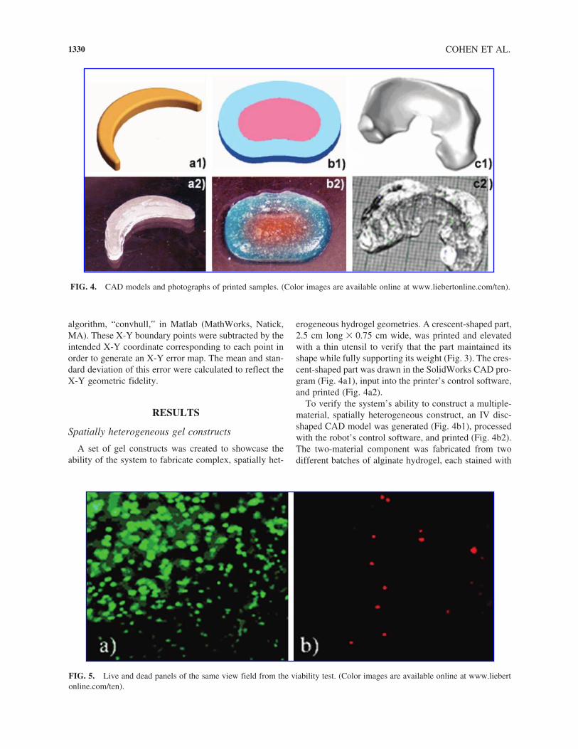
FIG. 3. Printed crescent suspended with tool.
algorithm, “convhull,” in Matlab (MathWorks, Natick,MA). These X-Y boundary points were subtracted by theintended X-Y coordinate corresponding to each point inorder to generate an X-Y error map. The mean and stan-dard deviation of this error were calculated to reflect theX-Y geometric fidelity.
RESULTS
Spatially heterogeneous gel constructs
A set of gel constructs was created to showcase theability of the system to fabricate complex, spatially het-
COHEN ET AL.
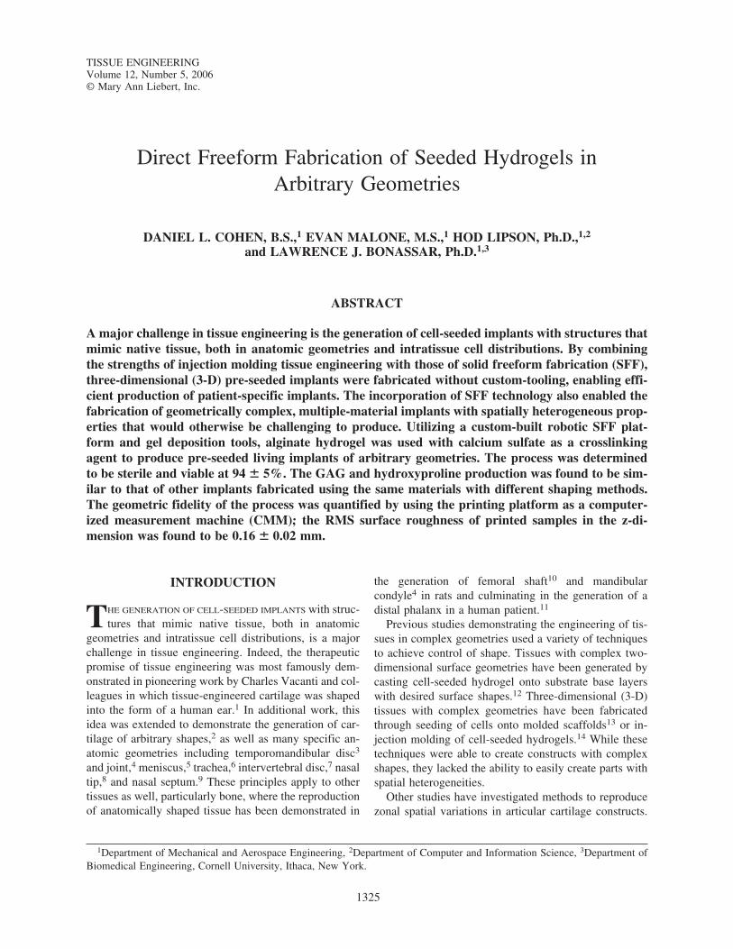
erogeneous hydrogel geometries. A crescent-shaped part,2.5 cm long � 0.75 cm wide, was printed and elevatedwith a thin utensil to verify that the part maintained itsshape while fully supporting its weight (Fig. 3). The cres-cent-shaped part was drawn in the SolidWorks CAD pro-gram (Fig. 4a1), input into the printer’s control software,and printed (Fig. 4a2).
To verify the system’s ability to construct a multiple-material, spatially heterogeneous construct, an IV disc-shaped CAD model was generated (Fig. 4b1), processedwith the robot’s control software, and printed (Fig. 4b2).The two-material component was fabricated from twodifferent batches of alginate hydrogel, each stained with
1330
FIG. 4. CAD models and photographs of printed samples. (Color images are available online at www.liebertonline.com/ten).
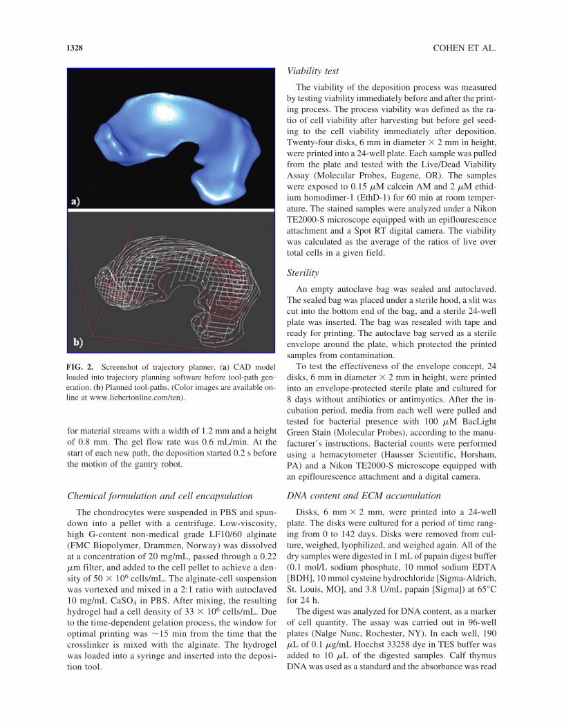
FIG. 5. Live and dead panels of the same view field from the viability test. (Color images are available online at www.liebertonline.com/ten).

a dye of a different color. Utilizing the multiple-materialcapabilities of the robotic platform, the robot stopped atnumerous points throughout the print and requested achange of materials, as prescribed by the robot’s tool pathplanner. At each of these points, the material bay and syringe tip unit of the deposition tool were manuallyswapped with the designated material bay/syringe tip unitand printing commenced.
In order to demonstrate the system’s ability to createimplants with complex geometries, a CAD model of anovine meniscus was constructed from a CT scan (Fig.4c1) and printed (Fig. 4c2).
Viability and sterility
Viability tests successfully detected both live (Fig. 5a)and dead (Fig. 5b) cells in printed gels. The viability ofthe printing process was determined to be 94 � 5% (n �15). The viability appeared to be spatially uniform. Byinspection with phase contrast microscopy and fluores-cence microscopy, the cell distribution was observed tobe homogeneous. When inspected by phase contract mi-croscopy, no abnormal morphology was observed.
After 8 days of incubating a printed gel samples with-out any antibiotics or antimyotics, less than 1 bacteriumper 0.9 �L was detected (n � 12).
ECM accumulation
GAG content increased in printed samples over timein incubation to 18.9 � 4.2 �g/�g DNA (n � 4–17) by3 weeks (Fig. 6). Printed disks were cultured beyond 3weeks to �18 weeks, but GAG level did not change sig-nificantly.
Hydroxyproline content increased in the printed sam-ples over time in incubation as well. Hydroxyproline con-tent reached 0.92 � 0.15 �g/�g DNA (n � 4–17) by 14weeks (Fig. 7). At 18 weeks, the disks did not appear to
3-D PRINTING OF LIVING IMPLANTS
change shape grossly when compared to disks exposedto media immediately after printing (Fig. 8).
Mechanical properties
It was observed that the Young’s modulus of samplesincreased with time after fabrication. The compressiveelastic modulus of a typical printed disk that was less than1 h old was determined to be 1.8 � 0.1 kPa (n � 6).
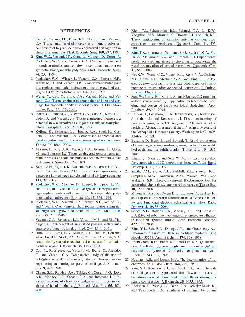
Geometric fidelity
When the point maps of the entire printed samples(Fig. 9) were considered, the average height of a sin-gle layer was determined to be 0.80 � 0.03 mm andthe RMS surface roughness was 0.33 � 0.01 mm.When only the points with X-Y coordinates located inthe inner region of the printed samples, the edge ef-fect was ignored and the resulting average height was1.14 � 0.06 mm and the RMS surface roughness was0.16 � 0.02 mm.
When the X-Y error was analyzed at the mid-heightplane (Fig. 10), the average X-Y error was found to be0.58 � 0.07 mm. The standard deviation of the X-Y er-ror was found to be 0.27 � 0.03 mm.
DISCUSSION
The objective of this research was to develop a tech-nique for directly fabricating pre-seeded constructs in ar-bitrary geometries with multi-axial zonal organization. Inorder for the technique to be considered a feasible tissue-engineering approach, we focused on a set of benchmarksincluding process viability, process sterility, ECM pro-duction by printed samples, and mechanical properties ofprinted samples.
1331
FIG. 6. GAG content DNA normalized with time in culture.
FIG. 7. Hydroxyproline content DNA normalized with timein culture.
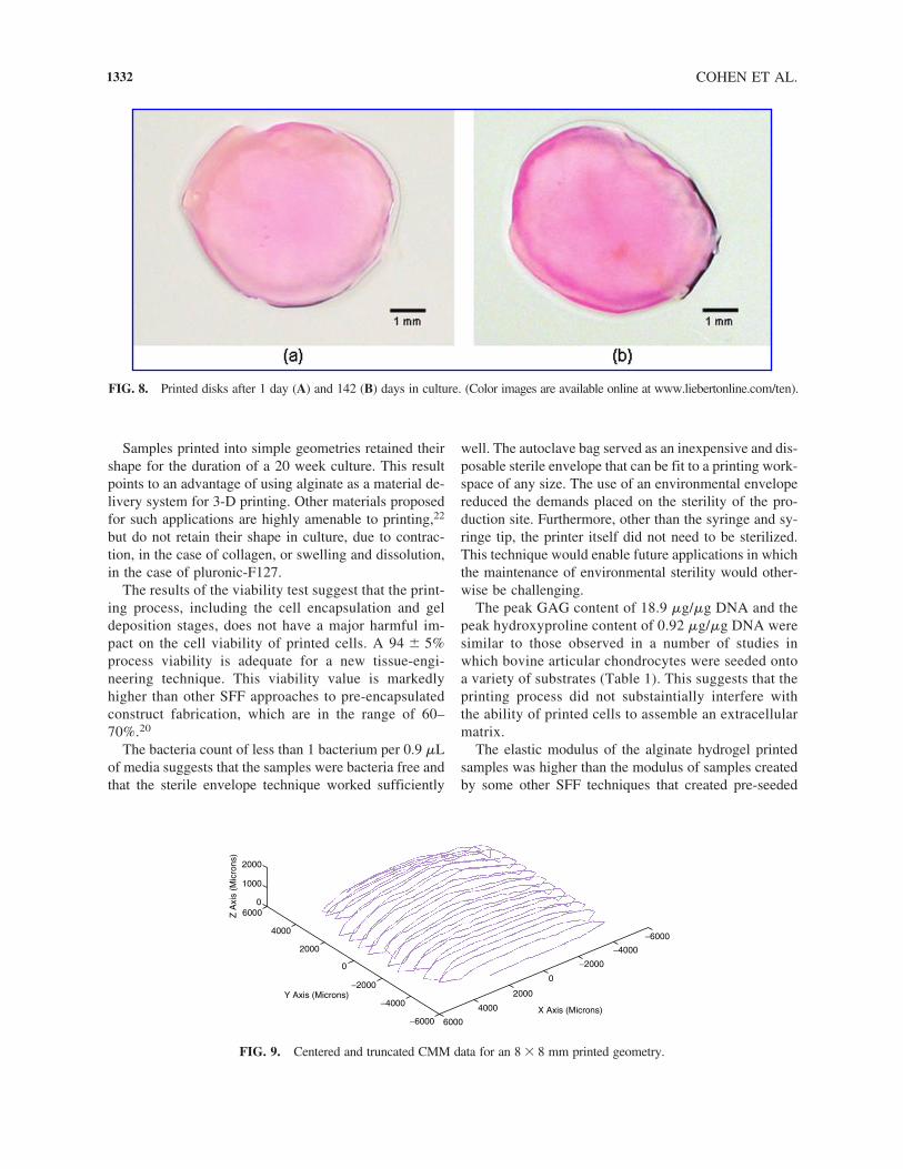
Samples printed into simple geometries retained theirshape for the duration of a 20 week culture. This resultpoints to an advantage of using alginate as a material de-livery system for 3-D printing. Other materials proposedfor such applications are highly amenable to printing,22
but do not retain their shape in culture, due to contrac-tion, in the case of collagen, or swelling and dissolution,in the case of pluronic-F127.
The results of the viability test suggest that the print-ing process, including the cell encapsulation and geldeposition stages, does not have a major harmful im-pact on the cell viability of printed cells. A 94 � 5%process viability is adequate for a new tissue-engi-neering technique. This viability value is markedlyhigher than other SFF approaches to pre-encapsulatedconstruct fabrication, which are in the range of 60–70%.20
The bacteria count of less than 1 bacterium per 0.9 �Lof media suggests that the samples were bacteria free andthat the sterile envelope technique worked sufficiently
COHEN ET AL.
well. The autoclave bag served as an inexpensive and dis-posable sterile envelope that can be fit to a printing work-space of any size. The use of an environmental envelopereduced the demands placed on the sterility of the pro-duction site. Furthermore, other than the syringe and sy-ringe tip, the printer itself did not need to be sterilized.This technique would enable future applications in whichthe maintenance of environmental sterility would other-wise be challenging.
The peak GAG content of 18.9 �g/�g DNA and thepeak hydroxyproline content of 0.92 �g/�g DNA weresimilar to those observed in a number of studies inwhich bovine articular chondrocytes were seeded ontoa variety of substrates (Table 1). This suggests that theprinting process did not substaintially interfere with the ability of printed cells to assemble an extracellularmatrix.
The elastic modulus of the alginate hydrogel printedsamples was higher than the modulus of samples createdby some other SFF techniques that created pre-seeded
1332
−6000
−6000
−4000
−4000
−2000
−2000
2000
4000
60000
1000
2000
Z A
xis
(Mic
rons
)
Y Axis (Microns)
X Axis (Microns)
00
2000
4000
6000
FIG. 9. Centered and truncated CMM data for an 8 � 8 mm printed geometry.
FIG. 8. Printed disks after 1 day (A) and 142 (B) days in culture. (Color images are available online at www.liebertonline.com/ten).

implants. The modulus of alginate-printed samples washigher than those created with the photo-crosslinking SFFtechnique.20 Also, alginate hydrogels are much stifferthan those made from pluronic F-127, which has been in-vestigated as a build material for SFF tissue-engineeringapproaches.22 Furthermore, the mechanical properties ofprinted alginate implants could be easily improvedthrough the addition of calcium in or after the printingprocess.
The tissue-engineering approach detailed hereincombines the strengths of molding techniques withthose of solid freeform fabrication technology. Thistechnology successfully encapsulates bovine chondro-cytes in alginate hydrogel and deposits them in arbi-trary geometries while maintaining sterility and viabil-ity. Unlike injection molding of pre-seeded alginate
3-D PRINTING OF LIVING IMPLANTS
hydrogel, this technique does not require molds, nordoes it require any custom tooling to fabricate an im-plant. Also, due to the inherent benefits of SFF, im-plants with complex geometries can be fabricated thatcould not otherwise be molded or easily fabricated us-ing other methods such as layering sheets.
This tissue-engineering approach combines thestrength and biocompatibility of hydrogel injectionmolding with the geometric freedom and inherent pa-tient-specificity capabilities of SFF. The method couldallow for efficient fabrication of patient-specific im-plants without the cost and delay normally associatedwith creating custom tooling. Furthermore, this tech-nique reduces the constraints imposed upon the fabri-cation environment, which is an important concern forin situ and minimally invasive in vivo implant fabrica-tion. This technology could enable fabrication of geo-metrically complex, multiple-material implants thatwould otherwise not be producible. Also, this approachcould enable the fabrication of large implants thatwouldotherwise be difficult to seed with cells due to trans-port limitations.
ACKNOWLEDGMENTS
This work was funded by Cornell University. The au-thors would also like to thank Suzanne Maher at the Hos-pital for Special Surgery (New York, NY) for technicalassistance with CT scans of ovine meniscus.
1333
TABLE 1. COMPARISON OF ECM PROPERTIES
AlginateAlginate injection Alginate
beads molding SFF(weeks) (weeks) (weeks)
GAG 2826 1828 18.9 � 4.2(�g/�g DNA) (3) (10) (3)Hydroxyproline 2826 1.828 0.92 � 0.15(�g/�g DNA) (3) (10) (14)
1.929
(6)
FIG. 10. Cross-section of CMM map truncated at mid-height. (Color images are available online at www.liebertonline.com/ten).
REFERENCES
1. Cao, Y., Vacanti, J.P., Paige, K.T., Upton, J., and Vacanti,C.A. Transplantation of chondrocytes utilizing a polymer-cell construct to produce tissue-engineered cartilage in theshape of a human ear. Plast. Reconstr. Surg. 100, 297, 1997.
2. Kim, W.S., Vacanti, J.P., Cima, L., Mooney, D., Upton, J.,Puelacher, W.C., and Vacanti, C.A. Cartilage engineeredin predetermined shapes employing cell transplantation onsynthetic biodegradable polymers. Plast. Reconstr. Surg.94, 233, 1994.
3. Puelacher, W.C., Wisser, J., Vacanti, C.A., Ferraro, N.F.,Jaramillo, D., and Vacanti, J.P. Temporomandibular jointdisc replacement made by tissue-engineered growth of car-tilage. J. Oral Maxillofac. Surg. 52, 1172, 1994.
4. Weng, Y., Cao, Y., Silva, C.A., Vacanti, M.P., and Va-canti, C.A. Tissue-engineered composites of bone and car-tilage for mandible condylar reconstruction. J. Oral Max-illofac. Surg. 59, 185, 2001.
5. Ibarra, C., Jannetta, C., Vacanti, C.A., Cao, Y., Kim, T.H.,Upton, J., and Vacanti, J.P. Tissue engineered meniscus: apotential new alternative to allogeneic meniscus transplan-tation. Transplant. Proc. 29, 986, 1997.
6. Kojima, K., Bonassar, L.J., Ignotz, R.A., Syed, K., Cor-tiella, J., and Vacanti, C.A. Comparison of tracheal andnasal chondrocytes for tissue engineering of trachea. Ann.Thorac. 76, 1884, 2003.
7. Mizuno, H., Roy, A.K., Vacanti, C.A., Kojima, K., Ueda,M., and Bonassar, L.J. Tissue-engineered composites of an-nulus fibrosus and nucleus pulposus for intervertebral discreplacement. Spine 29, 1290, 2004.
8. Kamil, S.H., Kojima, K., Vacanti, M.P., Bonassar, L.J., Va-canti, C.A., and Eavey, R.D. In vitro tissue engineering togenerate a human-sized auricle and nasal tip. Laryngoscope113, 90, 2003.
9. Puelacher, W.C., Mooney, D., Langer, R., Upton, J., Va-canti, J.P., and Vacanti, C.A. Design of nasoseptal carti-lage replacements synthesized from biodegradable poly-mers and chondrocytes. Biomaterials 15, 774, 1994.
10. Puelacher, W.C., Vacanti, J.P., Ferraro, N.F., Schloo, B.,and Vacanti, C.A. Femoral shaft reconstruction using tis-sue-engineered growth of bone. Int. J. Oral Maxillofac.Surg. 25, 223, 1996.
11. Vacanti, C.A., Bonassar, L.J., Vacanti, M.P., and Shuffle-barger, J. Replacement of an avulsed phalanx with tissue-engineered bone. N. Engl. J. Med. 244, 1511, 2001.
12. Hung, C.T., Lima, E.G., Mauch, R.L., Taki, E., LeRoux,M.A., Lu, H.H., Stark, R.G., Guo, X.E., and Ateshian, G.A.Anatomically shaped osteochondral constructs for articularcartilage repair. J. Biomech. 36, 1853, 2003.
13. Cao, Y., Rodriguez, A., Vacanti, M., Ibarra, C., Arevalo,C., and Vacanti, C.A. Comparative study of the use ofpoly(glycolic acid), calcium alginate and pluronics in theengineering of autologous porcine cartilage. J. Biomater.Sci. 9, 475, 1998.
14. Chang, S.C., Rowley, J.A., Tobias, G., Genes, N.G., Roy,A.K., Mooney, D.J., Vacanti, C.A., and Bonassar, L.J. In-jection molding of chondrocyte/alginate constructs in theshape of facial implants. J. Biomed. Mat. Res. 55, 503,2001.
COHEN ET AL.
15. Klein, T.J., Schumacher, B.L., Schmidt, T.A., Li, K.W.,Voegtline, M.S., Masuda, K., Thonar, E.J., and Sah, R.L.Tissue engineering of stratified articular cartilage fromchondrocyte subpopulations. Osteoarth. Cart. 11, 595,2003.
16. Kim, T.K., Sharma, B., Williams, C.G., Ruffner, M.A., Ma-lik, A., McFarland, E.G., and Elisseeff, J.H. Experimentalmodel for cartilage tissue engineering to regenerate thezonal organization of articular cartilage. Osteoarth. Cart.11, 653, 2003.
17. Ng, K.W., Wang, C.C., Mauck, R.L., Kelly, T.A., Chahine,N.O., Costa, K.D., Ateshian, G.A., and Hung, C.T. A lay-ered agarose approach to fabricate depth-dependent inho-mogeneity in chondrocyte-seeded constructs. J. Orthop.Res. 23, 134, 2005.
18. Sun, W., Starly, B., Darling, A., and Gomez, C. Computer-aided tissue engineering: application to biomimetic mod-eling and design of tissue scaffolds. Biotechnol. Appl.Biochem. 39, 49, 2004.
19. Ballyns, J., Gleghorn, J., Niebrzydowski, V., Rawlinson,J., Maher, S., and Bonassar, L.J. Tissue engineering ofmeniscus using microCT imaging, CAD and injectionmolding. Abstract presented at the 51st Annual Meeting ofthe Orthopaedic Research Society, Washington D.C., 2005.Abstract no. 292.
20. Busaina, D., Hunt, E., and Boland, T. Rapid prototypingof tissue-engineering constructs, using photopolymerizablehydrogels and stereolithography. Tissue Eng. 10, 1316,2004.
21. Khalil, S., Nam, J., and Sun, W. Multi-nozzle depositionfor construction of 3D biopolymer tissue scaffolds. RapidPrototyp. J. 11, 9, 2005.
22. Smith, C.M., Stone, A.L., Parkhill, R.L., Stewart, R.L.,Simpkins, M.W., Kachurin, A.M., Warren, W.L., andWilliams, S.K. Three-dimensional BioAssembly tool forgenerating viable tissue-engineered constructs. Tissue Eng.10, 1566, 2004.
23. Malone E., Rasa K., Cohen D. L., Isaacson T., Lashley H.,and Lipson H. Freeform fabrication of 3D zinc-air batter-ies and functional electro-mechanical assemblies. RapidPrototyp. J. 10, 58, 2004.
24. Genes, N.G., Rowley, J.A., Mooney, D.J., and Bonassar,L.J. Effect of substrate mechanics on chondrocyte adhesionto modified alginate surfaces. Arch. Biochem. Biophys.422, 161, 2004.
25. Kim, Y.J., Sah, R.L., Doong, J.Y., and Grodzinsky A.J.Fluorometric assay of DNA in cartilage explants usingHoechst 33258. Anal. Biochem. 174, 168, 1988.
26. Enobakhare, B.O., Bader D.L., and Lee D.A. Quantifica-tion of sulfated glycosaminoglycans in chondrocyte/algi-nate cultures, by use of 1,9-dimethylmethylene blue. Anal.Biochem. 243, 189, 1996.
27. Neuman, R.E., and Logan, M.A. The determination of hy-droxyproline. J. Biol. Chem. 184, 299, 1950.
28. Kim, Y.J., Bonassar, L.J., and Grodzinsky, A.J. The roleof cartilage streaming potential, fluid flow and pressure inthe stimulation of chondrocyte biosynthesis during dy-namic compression. J. Biomech. 28, 1055, 1995.
29. Beekman, B., Verzijl, N., Bank, R.A., von der Mark, K.,and TeKoppelle, J.M. Synthesis of collagen by bovine
1334

chondrocytes cultured in alginate; posttranslational modi-fications and cell-matrix interaction. Exp. Cell Res. 237,135, 1997.
30. Hott, M.E., Megerian, C.A., Beane, R., and Bonassar, L.J.Fabrication of tissue engineered tympanic membranepatches using computer-aided design and injection mold-ing. Laryngoscope 114, 1290, 2004.
31. Ragan, P.M., Chin, V.I., Hung, H.H., Masuda, K.,Thonar, E.J., Arner, E.C., Grodzinsky, A.J., and Sandy,J.D. Chondrocyte extracellular matrix synthesis and turn-over are influenced by static compression in a new algi-
3-D PRINTING OF LIVING IMPLANTS
nate disk culture system. Arch. Biochem. Biophys. 383,256, 2000.
Address reprint requests to:Lawrence J. Bonassar, Ph.D.
Department of Biomedical EngineeringCornell University
218 Upson HallIthaca, NY 14853
E-mail: [email protected]
1335


This article has been cited by:
1. Jeffrey J. Ballyns , Daniel L. Cohen , Evan Malone , Suzanne A. Maher , Hollis G. Potter , Timothy Wright , Hod Lipson ,Lawrence J. Bonassar . 2010. An Optical Method for Evaluation of Geometric Fidelity for Anatomically Shaped Tissue-EngineeredConstructsAn Optical Method for Evaluation of Geometric Fidelity for Anatomically Shaped Tissue-Engineered Constructs.Tissue Engineering Part C: Methods 16:4, 693-703. [Abstract] [Full Text] [PDF] [PDF Plus]
2. Kivilcim Buyukhatipoglu , Robert Chang , Wei Sun , Alisa Morss Clyne . 2010. Bioprinted Nanoparticles for Tissue EngineeringApplicationsBioprinted Nanoparticles for Tissue Engineering Applications. Tissue Engineering Part C: Methods 16:4, 631-642.[Abstract] [Full Text] [PDF] [PDF Plus]
3. Aleksander Skardal , Jianxing Zhang , Lindsi McCoard , Xiaoyu Xu , Siam Oottamasathien , Glenn D. Prestwich . 2010.Photocrosslinkable Hyaluronan-Gelatin Hydrogels for Two-Step BioprintingPhotocrosslinkable Hyaluronan-Gelatin Hydrogelsfor Two-Step Bioprinting. Tissue Engineering Part A 16:8, 2675-2685. [Abstract] [Full Text] [PDF] [PDF Plus]
4. Abraham D. Stroock , Claudia Fischbach . 2010. Microfluidic Culture Models of Tumor AngiogenesisMicrofluidic CultureModels of Tumor Angiogenesis. Tissue Engineering Part A 16:7, 2143-2146. [Abstract] [Full Text] [PDF] [PDF Plus]
5. Minggan Li , Xiaoyu Tian , Ning Zhu , David J. Schreyer , Xiongbiao Chen . 2010. Modeling Process-Induced Cell Damagein the Biodispensing ProcessModeling Process-Induced Cell Damage in the Biodispensing Process. Tissue Engineering Part C:Methods 16:3, 533-542. [Abstract] [Full Text] [PDF] [PDF Plus]
6. Ross A. Marklein, Jason A. Burdick. 2010. Controlling Stem Cell Fate with Material Design. Advanced Materials 22:2, 175-189.[CrossRef]
7. Joseph T. Delaney, Albert R. Liberski, Jolke Perelaer, Ulrich S. Schubert. 2010. Reactive inkjet printing of calcium alginatehydrogel porogens—a new strategy to open-pore structured matrices with controlled geometry. Soft Matter 6:5, 866. [CrossRef]
8. Daniel L. Cohen, Hod Lipson. 2010. Geometric feedback control of discrete-deposition SFF systems. Rapid Prototyping Journal16:5, 377-393. [CrossRef]
9. Najmuddin J. Gunja, Dan J. Huey, Regis A. James, Kyriacos A. Athanasiou. 2009. Effects of agarose mould compliance andsurface roughness on self-assembled meniscus-shaped constructs. Journal of Tissue Engineering and Regenerative Medicine 3:7,521-530. [CrossRef]
10. M G Li, X Y Tian, X B Chen. 2009. A brief review of dispensing-based rapid prototyping techniques in tissue scaffold fabrication:role of modeling on scaffold properties prediction. Biofabrication 1:3, 032001. [CrossRef]
11. Kivilcim Buyukhatipoglu, Wonjin Jo, Wei Sun, Alisa Morss Clyne. 2009. The role of printing parameters and scaffold biopolymerproperties in the efficacy of a new hybrid nano-bioprinting system. Biofabrication 1:3, 035003. [CrossRef]
12. Jeffrey J. Ballyns, Lawrence J. Bonassar. 2009. Image-guided tissue engineering. Journal of Cellular and Molecular Medicine 13:8a,1428-1436. [CrossRef]
13. Travis J. Klein , Jos Malda , Robert L. Sah , Dietmar W. Hutmacher . 2009. Tissue Engineering of Articular Cartilage withBiomimetic ZonesTissue Engineering of Articular Cartilage with Biomimetic Zones. Tissue Engineering Part B: Reviews 15:2,143-157. [Abstract] [Full Text] [PDF] [PDF Plus]
14. V Mironov, T Trusk, V Kasyanov, S Little, R Swaja, R Markwald. 2009. Biofabrication: a 21st century manufacturing paradigm.Biofabrication 1:2, 022001. [CrossRef]
15. Paul J. Bracher, Malancha Gupta, George M. Whitesides. 2009. Shaped Films of Ionotropic Hydrogels Fabricated Using Templatesof Patterned Paper. Advanced Materials 21:4, 445-450. [CrossRef]
16. Catherine K. Kuo, Peter X. Ma. 2008. Maintaining dimensions and mechanical properties of ionically crosslinked alginate hydrogelscaffoldsin vitro. Journal of Biomedical Materials Research Part A 84A:4, 899-907. [CrossRef]
17. Jungwoo Lee , Meghan J. Cuddihy , Nicholas A. Kotov . 2008. Three-Dimensional Cell Culture Matrices: State of theArtThree-Dimensional Cell Culture Matrices: State of the Art. Tissue Engineering Part B: Reviews 14:1, 61-86. [Abstract] [PDF][PDF Plus]
18. Natalja E. Fedorovich , Joost R. De Wijn , Abraham J. Verbout , Jacqueline Alblas , Wouter J.A. Dhert . 2008. Three-DimensionalFiber Deposition of Cell-Laden, Viable, Patterned Constructs for Bone Tissue PrintingThree-Dimensional Fiber Deposition ofCell-Laden, Viable, Patterned Constructs for Bone Tissue Printing. Tissue Engineering Part A 14:1, 127-133. [Abstract] [PDF][PDF Plus]
19. Robert Chang , Jae Nam , Wei Sun . 2008. Effects of Dispensing Pressure and Nozzle Diameter on Cell Survival from SolidFreeform Fabrication–Based Direct Cell WritingEffects of Dispensing Pressure and Nozzle Diameter on Cell Survival from SolidFreeform Fabrication–Based Direct Cell Writing. Tissue Engineering Part A 14:1, 41-48. [Abstract] [PDF] [PDF Plus]
20. Evan Malone, Megan Berry, Hod Lipson. 2008. Freeform fabrication and characterization of Zn-air batteries. Rapid PrototypingJournal 14:3, 128-140. [CrossRef]
21. Vladimir Mironov, Vladimir Kasyanov, Christopher Drake, Roger R Markwald. 2008. Organ printing: promises and challenges.Regenerative Medicine 3:1, 93-103. [CrossRef]
22. Robert Chang, Jae Nam, Wei Sun. 2008. Effects of Dispensing Pressure and Nozzle Diameter on Cell Survival from Solid FreeformFabrication–Based Direct Cell Writing. Tissue Engineering 14:1, 41-48. [CrossRef]
23. Natalja E. Fedorovich, Joost R. De Wijn, Abraham J. Verbout, Jacqueline Alblas, Wouter J.A. Dhert. 2008. Three-DimensionalFiber Deposition of Cell-Laden, Viable, Patterned Constructs for Bone Tissue Printing. Tissue Engineering 14:1, 127-133.[CrossRef]
24. Nak Won Choi, Mario Cabodi, Brittany Held, Jason P. Gleghorn, Lawrence J. Bonassar, Abraham D. Stroock. 2007. Microfluidicscaffolds for tissue engineering. Nature Materials 6:11, 908-915. [CrossRef]
25. Natalja E. Fedorovich , Jacqueline Alblas , Joost R. de Wijn , Wim E. Hennink , Ab J. Verbout , Wouter J.A. Dhert .2007. Hydrogels as Extracellular Matrices for Skeletal Tissue Engineering: State-of-the-Art and Novel Application in OrganPrintingHydrogels as Extracellular Matrices for Skeletal Tissue Engineering: State-of-the-Art and Novel Application in OrganPrinting. Tissue Engineering 13:8, 1905-1925. [Abstract] [PDF] [PDF Plus]