On the Influence of Nozzle Geometries on Supersonic Curved ...
Upload
independentCategory
view
3download
0
INTERNATIONAL JOURNAL OF RESEARCH IN AERONAUTICAL AND MECHANICAL ENGINEERING
ISSN (ONLINE): 2321-3051
Vol.2 Issue.11,
November 2014.
Pgs: 1-14
Neeraj kumar1, Dilbagh Singh2 Harry Garg3, Nirmal Kant Singh4
1
Simulation of Different Geometries and Flow Parameters of the Micro channel Heat Sinks
Neeraj kumar1, Dilbagh Singh2 Harry Garg3, Nirmal Kant Singh4
1,4National institute of Technology (NIT) Kurukshetra, India, 136119
2NILLM UNIVERSITY, KAITHAL, 136027
3Central Scientific Instruments Organisation (CSIR-CSIO), Chandigarh, India, 160030
Corresponding author email id: [email protected]
Abstract
Micro channel Heat Sinks are used for heat transfer for miniature electronic circuits. The high performance of the micro channel depends upon the number of parameters like geometrical & flow parameters. There is wide variation in the performance of the micro channel heat sinks as the geometry of these channels changes. The performance is measured in terms of the thermal resistance of the channels. A three- dimensional numerical model of the interrupted micro channel heat sink is presented to study the effect of pumping power and thermal resistance and heat transfer characteristics due to various dimensions of micro channel. Numerical investigation was conducted to predict pumping power and thermal resistance in a rectangular cross section micro channel heat sink by numerical analysis of different geometries. The pumping power and thermal resistance was analysed with different cooling liquid used as water and ethylene glycol while micro channel substrate used was made of copper. The fluid flow and heat transfer mechanism of the newly proposed micro channel heat sink are analysed. Keywords: Simulation; Heat sinks; microelectronic; electronic circuits.
1. Introduction
The developments in the micro electro mechanical devices naturally require a critical design consideration for efficientt removal of internally generated heat in microelectronic components.
Significant amount of research has been made to develop innovative cooling techniques that have the potential to deliver high-heat flux rates for microelectronic applications. A number of studies have investigated the thermal design optimization of micro-channel heat sinks to determine the geometric dimensions that give optimum performance. Over the past few decades, there is an increasing interest in the development of heat sink processes for heat dissipation and many design methodologies regarding how to optimize heat sinks have been proposed For optimal design of plate- and pin-fin. Most of the
research in the area of micro channel heat exchangers has focused on solving the problem of electronics cooling, where heat generated by the microelectronic components is removed by a coolant flowing through channels located as close as possible to the heat source. Hong and Cheng [1] presented a numerical study on laminar forced
INTERNATIONAL JOURNAL OF RESEARCH IN AERONAUTICAL AND MECHANICAL ENGINEERING
ISSN (ONLINE): 2321-3051
Vol.2 Issue.11,
November 2014.
Pgs: 1-14
Neeraj kumar1, Dilbagh Singh2 Harry Garg3, Nirmal Kant Singh4
2
convection of water in offset strip-fin micro channels network heat sinks for microelectronic cooling. The heat transfer and fluid flow characteristics in offset strip-fin micro channel, the heat transfer enhancement mechanism and the effects of geometric size of strip fin on the heat sink performance were analysed. Recently Kim & Kim [2] have proposed a closed-form total thermal resistance correlation for the thermal design optimization of micro-channels. In addition to providing excellent heat transfer, the high conductivity typical in this class of fluids offers the potential of efficient, compact pumping. Of various such metals reviewed in literature liquid gallium has been found to be most suitable candidate.[3]The Pentium 4 processor in 2004 which produced heat fluxes of 30 W/cm2 is now replaced by semi-conductor chips producing more than a 100 W/cm2. The need to remove such high levels of heat fluxes in cooling systems poses a great challenge to thermal engineers who require new ways to enhance heat transfer rates. The performance, reliability and life expectancy of the electronic equipment hence depends on managing the operating temperature effectively. Micro-channels fabricated in metals with good conducting properties (e.g. copper) subjected to high heat fluxes from electronic chips exemplifies as a practical and economically feasible way of energy removal. The very first people to conceive the idea of high heat flux removal from micro-channels were Tuckerman and Pease [4].The idea involved using a substrate with several fins and micro-channels in parallel conducting heat efficiently from the substrate to the coolant. Water was used as a fluid under laminar conditions flowing through micro channels embedded in a silicon wafer. The experiment employed heat flux of up to 7.9 MW/m2and a maximum temperature difference of
71°C between the substrate and the inlet water. A large pressure drop200kPa was recorded with plain micro-channels and 380kPa with pin fin-enhanced micro-channels. Given the deviation in past published results related to heat transfer of flow in micro-channels, there are no generally recognized correlations predicting their heat transfer characteristics. Though there has been a general agreement in published results that the heat transfer coefficient increases with increasing heat flux, there is hardly any numerical work done to obtain valid results for the application of high heat fluxes equal to or more than 100 W/cm2on micro-channels employing water flows. A numerical investigation has been carried out in the present study using the FLUENT. Since the pioneering work of Tuckerman and Pease in 1981, many studies have been conducted on micro-channel heat sinks as summarized by Phillips [5] and more recently, by Morini. The need for cooling in high power dissipation (100 W/cm2) systems in several scientific and commercial applications such as microelectronics requires something beyond the conventional cooling solutions. A number of studies have investigated the thermal design optimization of micro-channel heat sinks to determine the geometric dimensions that give optimum performance. For the heat transfer study purpose, the channel walls were assumed to behave as fins. The experimental study of Miner and Ghoshal[6] showed that heat transfer coefficients of the order 10W/cm2/K are achievable using different liquid metals as fluid. Besides analytical models, several numerical methods have been used to study the thermal performance of micro-channels heat sinks.[7]Gao et al. 2002 also studied the transition Reynolds number in micro channels by investigating how it varies with the channel height
In this paper micro channel heat sink is presented to study the effect of pumping power and thermal resistance and heat transfer characteristics due to various dimensions of micro channel. As the fluid is passing through the different section of the micro channel the distribution of the fluid in the passage is disturb the flow condition of the fluid that affect the velocity and thermal boundary layer of the flow. As flow is reached fully developed there is no change in the velocity of the fluid layer. The thermal and velocity boundary layer are playing a significant role in the fluid flow in micro channel. The different shapes of micro channel are used to dissipate the large amount of heat from the system or electronic circuit. As a practical cooling fluid, the liquid metal must satisfy the following requests: non-poisonous, non-caustic material, low viscosity, high thermal conductivity and heat capacity. Most studies in this approach employed the classical fin theory which models the solid walls separating micro channels as thin fins. The

INTERNATIONAL JOURNAL OF RESEARCH IN AERONAUTICAL AND MECHANICAL ENGINEERING
ISSN (ONLINE): 2321-3051
Vol.2 Issue.11,
November 2014.
Pgs: 1-14
Neeraj kumar1, Dilbagh Singh2 Harry Garg3, Nirmal Kant Singh4
3
heat transfer process is simplified as one- dimensional, constant convection heat transfer coefficient and uniform fluid temperature. However, the nature of the heat transfer process in MCHS is conjugated heat conduction in the solid wall and convection to the cooling fluid. Using a nano fluid as the heat transfer working fluid has gained much attention in recent years. Xuan and Roetzel (2000) proposed two theoretical models to predict the heat transfer characteristics of nano fluid flow in a tube [8-9]. Li and Xuan (2002), Xuan and Li (2003). [10] and Pak and Cho (1998) experimentally measured the convection heat transfer and pressure drop for nano fluid tube flows. Their results indicated that the heat transfer coefficient was greatly enhanced and depended on the flow Reynolds number, particle Peclet number, particle size and shape, and particle volume fraction. These studies also indicated that the presence of nano particles did not cause an extra pressure drop in the flow. Recently, Yang et al. (2005) carried out an experimental study attempting to construct a heat transfer correlation among the parameters that affected heat transfer [11].
2.0 ANALYSIS PROCEDURE The combination of the thermal resistance models and the optimisation algorithm served as useful tool in the design of the micro channel heat sink. The thermal resistance in the heat sink arises from three sources: conduction resistance in the heat sink, including the fin effects; convection resistance between the micro channel surfaces & the coolant & the resistance due to the temperature arise of the cooling fluid.
Rth= Rcond+Rconv+Rcap (1) The total thermal resistance is calculated: Rth=Tmax-Tmin/Q (2) According to theoretical approach Pumping is defined as the product of flow rate and the pressure drop
mathematically is defined as Ω = v.∆p (3) The analysis is based on the following assumptions:
• Steady state flow.
• Incompressible fluid.
• Laminar flow.
• Constant properties of both fluids and solid. Effects of viscous dissipation are negligible.
3.0 COMPUTATIONAL DOMAIN Fig. 1 shows computational domain of single micro channel heat sink. Various parameters considered in this
study are shown in figure. tsb and ts represents thickness of solid substrate width from heated surface (base) and channel thickness wall respectively shown.

INTERNATIONAL JOURNAL OF RESEARCH IN AERONAUTICAL AND MECHANICAL ENGINEERING
ISSN (ONLINE): 2321-3051
Vol.2 Issue.11,
November 2014.
Pgs: 1-14
Neeraj kumar1, Dilbagh Singh2 Harry Garg3, Nirmal Kant Singh4
4
ts wc ts
Fig 1 Computational Domain
tsb define the width of solid region it is also referred to as wall thickness. wc denotes channel width while hc represents channel depth and their ratio being called as aspect ratio. Substrate materials are considered as copper (cu) whose properties along with the fluid of liquid water (H2O) and ethylene glycols are given in Table.
3.1 EXPERIMENTAL DESIGN AND PROCEDURE: The process parameters & their values are given in Table. A rectangular Copper micro channel of size 2.5 mm ×2.1mm ×1mm was used for experimental work. Different Geometrical & flow parameters are chosen as these directly affect the response parameters. The single channel geometry is chosen & all the corresponding flow parameters are selected with respect to the chosen geometry. The shape & size of the channel varies depending upon the selection of different geometrical parameters. Thermal resistance and pumping power for various dimensions of different geometries of the micro channel of heat sink are chosen. The Reynolds number chosen is in the laminar range of 50-200 & the simulation has been done using FLUENT for the optimum analysis. The Table 1 shows the input parameters of the micro channel height (hc), width (wc), substrate thickness (ts) and fluid flow with different Reynolds number. Table 1 shows the input parameters of different values.. Table 2 and Table 3 show the response for the water and the ethylene glycol with different resistance and the pumping power. Though there are lot of parameters but to ease the computation three different geometrical parameters and one flow parameter is chosen. The geometrical parameters are to be chosen as the height of the micro channel (hc), width of micro channel (wc) and the thickness of substrate (ts) There is variation in geometrical parameters as height of channel, width of channel, thickness of substrate. The flow parameter used as Reynolds No. & are chosen for both water and ethylene glycol. The flow is varying with different velocities for each geometry parameter. The analysis is done on basis of the simulation of the micro channel heat sink. The geometry of the micro channel heat sink is considered to be as parametric to optimise the different parameters of the micro channel heat sink.
tsb
hc

INTERNATIONAL JOURNAL OF RESEARCH IN AERONAUTICAL AND MECHANICAL ENGINEERING
ISSN (ONLINE): 2321-3051
Vol.2 Issue.11,
November 2014.
Pgs: 1-14
Neeraj kumar1, Dilbagh Singh2 Harry Garg3, Nirmal Kant Singh4
5
Table1: Input Parameters
S.NO. Re hc wc ts
1 150 1 0.5 0.7
2 200 1.5 0.3 0.3
3 150 1 0.5 0.5
4 150 1 0.5 0.5
5 100 1.5 0.7 0.7
6 100 1.5 0.3 0.3
7 100 1.5 0.7 0.3
8 150 1 0.7 0.5
9 50 1 0.5 0.5
10 100 0.5 0.7 0.3
11 100 0.5 0.7 0.7
12 150 2 0.5 0.5
13 200 1.5 0.7 0.3
14 200 0.5 0.7 0.7
15 150 1 0.1 0.5
16 200 1 0.5 0.5
17 200 0.5 0.3 0.3
18 100 0.5 0.3 0.3
19 200 1.5 0.7 0.7
20 200 0.5 0.7 0.3
21 150 1 0.5 0.5
22 150 1 0.5 0.5
23 150 1 0.5 0.5
24 100 1.5 0.3 0.7
25 200 0.5 0.3 0.7
26 150 1 0.5 0.1
27 150 0.5 0.5 0.5
28 150 1 0.5 0.5
29 150 1 0.5 0.5
30 200 1.5 0.3 0.7
31 100 0.5 0.3 0.7

INTERNATIONAL JOURNAL OF RESEARCH IN AERONAUTICAL AND MECHANICAL ENGINEERING
ISSN (ONLINE): 2321-3051
Vol.2 Issue.11,
November 2014.
Pgs: 1-14
Neeraj kumar1, Dilbagh Singh2 Harry Garg3, Nirmal Kant Singh4
6
Table 2: Response for Water
S.No Rcond Rconv Rth pp
1.
0.09 0.001189 3.49E-05 8.31E-06
2.
0.056 7.82E-05 2.21E-05 1.35E-05
3.
0.078 0.000677 3.04E-05 8.31E-06
4.
0.078 0.000677 3.04E-05 8.31E-06
5.
0.062 0.000445 2.42E-05 9.92E-06
6.
0.056 7.82E-05 2.21E-05 1.35E-05
7.
0.04 0.000129 1.85E-05 9.92E-06
8.
0.073 0.000733 2.87E-05 7.89E-06
9.
0.078 0.000677 3.04E-05 8.31E-06
10.
0.099 0.001448 3.85E-05 6.97E-06
11.
0.131 0.005227 5.11E-05 6.97E-06
12.
0.044 0.000101 1.73E-05 1.40E-05
13.
0.047 0.000129 1.85E-05 9.92E-06
14.
0.131 0.005227 5.11E-05 6.97E-06
15.
0.245 0.000733 9.53E-05 1.26E-05
16.
0.064 0.000309 2.50E-05 8.31E-06
17.
0.145 0.001558 5.65E-05 5.95E-06
18.
0.214 0.006855 8.30E-05 5.95E-06
19.
0.047 0.000129 1.85E-05 9.92E-06
20.
0.117 0.003041 4.55E-05 6.97E-06
21.
0.078 0.000677 3.04E-05 8.31E-06
22.
0.078 0.000677 3.04E-05 8.31E-06
23.
0.090 0.001189 3.49E-05 8.31E-06
INTERNATIONAL JOURNAL OF RESEARCH IN AERONAUTICAL AND MECHANICAL ENGINEERING
ISSN (ONLINE): 2321-3051
Vol.2 Issue.11,
November 2014.
Pgs: 1-14
Neeraj kumar1, Dilbagh Singh2 Harry Garg3, Nirmal Kant Singh4
7
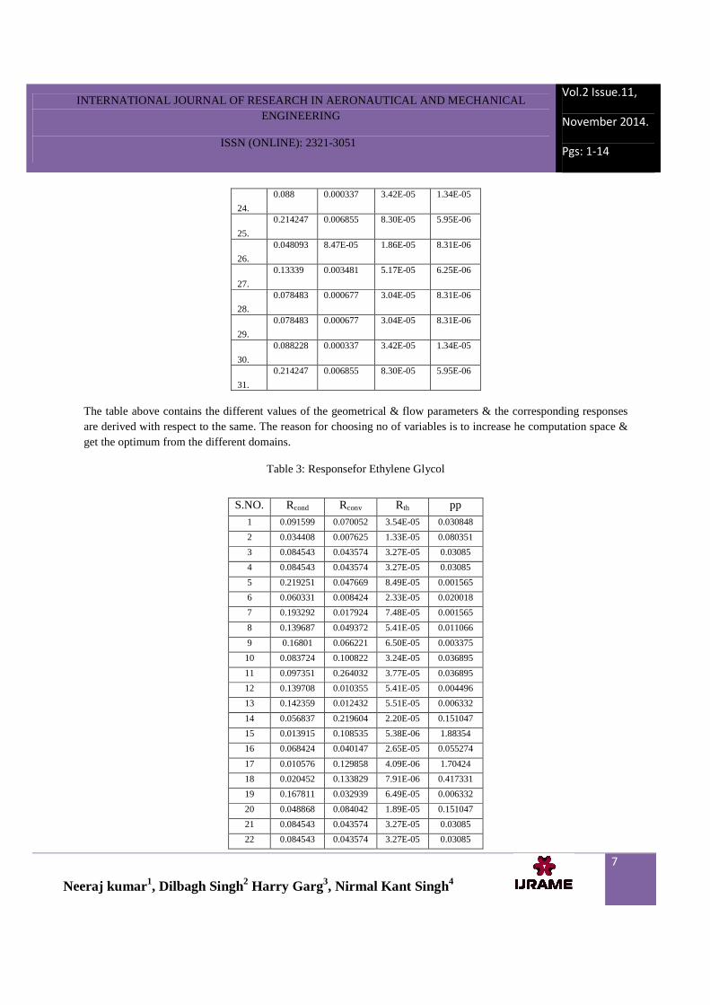
The table above contains the different values of the geometrical & flow parameters & the corresponding responses are derived with respect to the same. The reason for choosing no of variables is to increase he computation space & get the optimum from the different domains.
Table 3: Responsefor Ethylene Glycol
24.
0.088 0.000337 3.42E-05 1.34E-05
25.
0.214247 0.006855 8.30E-05 5.95E-06
26.
0.048093 8.47E-05 1.86E-05 8.31E-06
27.
0.13339 0.003481 5.17E-05 6.25E-06
28.
0.078483 0.000677 3.04E-05 8.31E-06
29.
0.078483 0.000677 3.04E-05 8.31E-06
30.
0.088228 0.000337 3.42E-05 1.34E-05
31.
0.214247 0.006855 8.30E-05 5.95E-06
S.NO. Rcond Rconv Rth pp
1 0.091599 0.070052 3.54E-05 0.030848
2 0.034408 0.007625 1.33E-05 0.080351
3 0.084543 0.043574 3.27E-05 0.03085
4 0.084543 0.043574 3.27E-05 0.03085
5 0.219251 0.047669 8.49E-05 0.001565
6 0.060331 0.008424 2.33E-05 0.020018
7 0.193292 0.017924 7.48E-05 0.001565
8 0.139687 0.049372 5.41E-05 0.011066
9 0.16801 0.066221 6.50E-05 0.003375
10 0.083724 0.100822 3.24E-05 0.036895
11 0.097351 0.264032 3.77E-05 0.036895
12 0.139708 0.010355 5.41E-05 0.004496
13 0.142359 0.012432 5.51E-05 0.006332
14 0.056837 0.219604 2.20E-05 0.151047
15 0.013915 0.108535 5.38E-06 1.88354
16 0.068424 0.040147 2.65E-05 0.055274
17 0.010576 0.129858 4.09E-06 1.70424
18 0.020452 0.133829 7.91E-06 0.417331
19 0.167811 0.032939 6.49E-05 0.006332
20 0.048868 0.084042 1.89E-05 0.151047
21 0.084543 0.043574 3.27E-05 0.03085
22 0.084543 0.043574 3.27E-05 0.03085

INTERNATIONAL JOURNAL OF RESEARCH IN AERONAUTICAL AND MECHANICAL ENGINEERING
ISSN (ONLINE): 2321-3051
Vol.2 Issue.11,
November 2014.
Pgs: 1-14
Neeraj kumar1, Dilbagh Singh2 Harry Garg3, Nirmal Kant Singh4
8
Table 2 shows the response for the water which shows different value of the thermal resistance, conduction, convection and the pumping power with variable geometry parameters. The different plots for the same are also shown in the subsequent work. The reason to chosen different thermal resistance is to examine the most critical thermal resistance of the total thermal resistance. Table 3 shows the response for the ethylene glycol which shows the different value of thermal resistance, conduction, convection and the pumping power with variable geometry parameters.
4.0 RESULTS AND DISCUSSION
Results are discuss with the help of various graphs and plots as shown in Fig. the velocity and temperature contour are shown in Fig. for the coolant water and ethylene glycol .the temperature contour for the liquid water is shown in Fig. 2 and for the ethylene glycol is shown in Fig.3.Similarly for the velocity contour as shown in Fig. 4 and 5 for water and ethylene glycol.
There are the various plots are shown in Fig. for different geometry parameters for optimize the result of micro channel heat sink. Table 1 shows the input parameters of different geometries of micro channel heat sink and the Table 2 and 3 shows the results for the thermal resistance and the pumping power.
Fig.2 Temp Contour of water Temperature contour for water is shown in figure 2. The thermal boundary layers are shown in the figure the temperature range is varying as shown in figure.
23 0.084543 0.043574 3.27E-05 0.03085
24 0.082323 0.030127 3.19E-05 0.020018
25 0.012853 0.463331 4.97E-06 1.70424
26 0.059953 0.009444 2.32E-05 0.03085
27 0.282088 0.250094 1.09E-04 0.000471
28 0.084543 0.043574 3.27E-05 0.03085
29 0.084543 0.043574 3.27E-05 0.03085
30 0.047238 0.027218 1.83E-05 0.080351
31 0.02484 0.477563 9.61E-06 0.417328

INTERNATIONAL JOURNAL OF RESEARCH IN AERONAUTICAL AND MECHANICAL ENGINEERING
ISSN (ONLINE): 2321-3051
Vol.2 Issue.11,
November 2014.
Pgs: 1-14
Neeraj kumar1, Dilbagh Singh2 Harry Garg3, Nirmal Kant Singh4
9
Fig.3 Temp contour of ethylene glycol Temperature contour of ethylene glycol is shown in figure the thermal boundary layers are shown in figure.
Fig. 4 velocity contour for ethylene
Velocity contour for ethylene glycol is shown on figure 4 velocity boundary layer is shown in figure.
Fig. 5 velocity contour for water

INTERNATIONAL JOURNAL OF RESEARCH IN AERONAUTICAL AND MECHANICAL ENGINEERING
ISSN (ONLINE): 2321-3051
Vol.2 Issue.11,
November 2014.
Pgs: 1-14
Neeraj kumar1, Dilbagh Singh2 Harry Garg3, Nirmal Kant Singh4
10
The velocity and temprature contour is shown Fig.from the temprature contour for theethylene glycol the temprature is high so more coolant is required to remove the heat from the system . in the case of water the heat removed the system is easily as compared to ethylene glycol the max. heat is dissipate from the system.the maximum temprature reached the value is low as compared to ethylene glycol.
4.1 Plots for liquid Water:
The different plots for water considering different response parameters are shown & plotted below. plots are plotted between the Reynolds number and the heat transfer coefficient and temprtaure difference that shows the variation in the temprtaure of the micro channel and the amount of heat is transfered through the channel. as the optimization for the best geometrical parameter of the micro channel that can be prescribed by the various results are obtained from the simulation . the variation in heat transfer coeffiecient and the temprature difference are shown in the plots.
Fig.6 Temp Plot vs Reynold’s No
From the fig. 6 the maximum temprature difference is reached a value 95 k at the maximum velocity as there is also varaition of geometry parameters.
0
20
40
60
80
100
120
150 150 100 100 200 200 200 150 200 150 100
td(k
)
Re
0.00E+00
2.00E+04
4.00E+04
6.00E+04
8.00E+04
1.00E+05
1.20E+05
1.40E+05
1.60E+05
1.80E+05
15
0
15
0
10
0
10
0
20
0
20
0
20
0
15
0
20
0
15
0
10
0
htc
(w/m
^2
k)
Re

INTERNATIONAL JOURNAL OF RESEARCH IN AERONAUTICAL AND MECHANICAL ENGINEERING
ISSN (ONLINE): 2321-3051
Vol.2 Issue.11,
November 2014.
Pgs: 1-14
Neeraj kumar1, Dilbagh Singh2 Harry Garg3, Nirmal Kant Singh4
11
Fig.7 Heat Transfer Coefficient vs Reynold’s No
From the above Figure 7 which shows the value of heat transfer cofficient reached the maximum value at velocity reache is an average value. maximum value of ∆T higher th heat treansfer cofficient . The maximum value of heat transfer cofficient is 1.70e+05w/m^2k. It was noticed that heat transfer coeffciient varies a lot with change in different Reynold’s No.
From the Fig. 8 the maximum value of velocity &the maximum value of Rth. is 45m^2k/w at the Re number from 100 to 200.
Fig.8:Thermal Resistance vs Reynold’s No
4.2 Plots for liquid Ethylene Glycol:
Fig.9Temp. difference vs Reynold’s No.
0
10
20
30
40
50
150 150 100100 200 200 200 150200 150 100
Rth
(m^
2k
/w)
Re
0
20
40
60
80
100
120
150 150 100 100 200 200 200 150 200 150 100
td(k
)
Re

INTERNATIONAL JOURNAL OF RESEARCH IN AERONAUTICAL AND MECHANICAL ENGINEERING
ISSN (ONLINE): 2321-3051
Vol.2 Issue.11,
November 2014.
Pgs: 1-14
Neeraj kumar1, Dilbagh Singh2 Harry Garg3, Nirmal Kant Singh4
12
The maximum value of temprature difference in the case of ethylenne glycol is reached a value 5k to 110k at the higher rate of flow the value of temprature difference is maximum.
Fig.10 Heat Transfer Coefficient vs Reynold’s No.
Fig. 10shows the value of heat transfer cofficient reached the maximum at the minimum value of temprature difference higher the heat treansfer cofficient . the maximum value of heat transfer cofficient is 16000w/m^2k.
Fig.11Thermal Resistance vs Reynold’s No.
maximum value of velocity the maximum value of Rth. the value of thermal resistnace is reached at 355m^2k/w at the Re number from50 to 200.
5.0 CONCLUSION
In the present study, a numerical investigation has been carried out to determine the heat transfer characteristics and the pumping power micro-channel employing water and ethylene glycol flows in the laminar regime. The
0
2000
4000
6000
8000
10000
12000
14000
16000
18000
15
0
15
0
10
0
10
0
20
0
20
0
20
0
15
0
20
0
15
0
10
0
htc
(w/m
^2
k)
Re
0
50
100
150
200
250
300
350
400
15
0
15
0
10
0
10
0
20
0
20
0
20
0
15
0
20
0
15
0
10
0
Rth
(m^
2k
/w)
Re
INTERNATIONAL JOURNAL OF RESEARCH IN AERONAUTICAL AND MECHANICAL ENGINEERING
ISSN (ONLINE): 2321-3051
Vol.2 Issue.11,
November 2014.
Pgs: 1-14
Neeraj kumar1, Dilbagh Singh2 Harry Garg3, Nirmal Kant Singh4
13
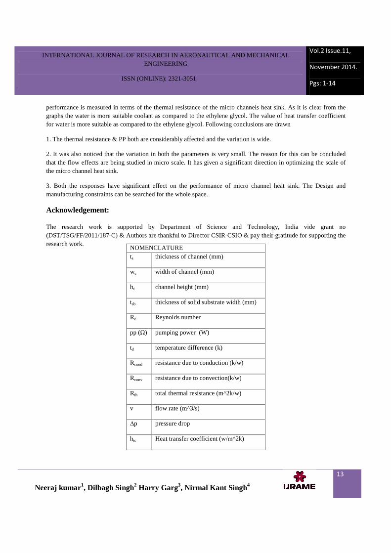
performance is measured in terms of the thermal resistance of the micro channels heat sink. As it is clear from the graphs the water is more suitable coolant as compared to the ethylene glycol. The value of heat transfer coefficient for water is more suitable as compared to the ethylene glycol. Following conclusions are drawn
1. The thermal resistance & PP both are considerably affected and the variation is wide.
2. It was also noticed that the variation in both the parameters is very small. The reason for this can be concluded that the flow effects are being studied in micro scale. It has given a significant direction in optimizing the scale of the micro channel heat sink.
3. Both the responses have significant effect on the performance of micro channel heat sink. The Design and manufacturing constraints can be searched for the whole space.
Acknowledgement:
The research work is supported by Department of Science and Technology, India vide grant no (DST/TSG/FF/2011/187-C) & Authors are thankful to Director CSIR-CSIO & pay their gratitude for supporting the research work.
NOMENCLATURE ts thickness of channel (mm)
wc width of channel (mm)
hc channel height (mm)
tsb thickness of solid substrate width (mm)
Re Reynolds number
pp (Ω) pumping power (W)
td temperature difference (k)
Rcond resistance due to conduction (k/w)
Rconv resistance due to convection(k/w)
Rth total thermal resistance (m^2k/w)
v flow rate (m^3/s)
∆p pressure drop
htc Heat transfer coefficient (w/m^2k)
INTERNATIONAL JOURNAL OF RESEARCH IN AERONAUTICAL AND MECHANICAL ENGINEERING
ISSN (ONLINE): 2321-3051
Vol.2 Issue.11,
November 2014.
Pgs: 1-14
Neeraj kumar1, Dilbagh Singh2 Harry Garg3, Nirmal Kant Singh4
14
REFERENCES: [1] F. Hong, P. Cheng, Three dimensional numerical analyses and optimization of offset strip-fin microchannel heat sinks, Int. Commun. Heat Mass Transf. 36(2009) 651e656. [2] Kim, S. J., and Kim, D., Forced Convection in Microstructures for Electronic Equipment Cooling, ASME J. Heat Transfer, vol. 121, 1999 pp. 639–645,. [3] Intel Pentium processor data sheet. [Online].Available:ftp://download.intel.com/designPentium4/datashts/303128.pdf. [4] D.B. Tuckerman, R.F.W. Pease, High-performance heat sinking for VLSI, IEEE Electron Device Letters 2 (1981) 126–129.
[5] G.L. Morini, Single-phase convective heat transfer in micro-channels: overview of experimental results, Int. J. Thermal Sci. 43 (2004) 631–651. [6] A. Miner and U. Ghoshal, 2004. “Cooling of high-power-density microdevices using liquid metal coolants”, Applied Physics Letters 85 p. 506-508. [7] Gao P., Person S. Le, and Favre-Marinet M., “Scale Effects on Hydrodynamics and Heat Transfer in Two-Dimensional Mini and Micro channels”, International Journal of Thermal Sciences, vol.41, (2002) pp. 1017–1027.
[8-9]. Li, Q., Xuan, Y., 2002. Convective heat transfer and flow characteristics of Cu–water nano fluid. Science in China E 45, 408–416. [10]. Pak, B.C., Cho, Y.L., 1998. Hydrodynamic and heat transfer study of dispersed fluids with submicron metallic oxide particles. Experimental Heat Transfer 11, 151–170.
[11]. Yang, Y., Zhang, Z., Grulke, E.A., Anderson,W.B.,2005.Heat transfer properties of nano particle in fluid dispersions (nano fluids) in laminar
Copyright © 2022 FDOKUMEN