
Heat Transfer Enhancement by Finned Heat Sinks with Micro-structured Roughness
10
This content has been downloaded from IOPscience. Please scroll down to see the full text. Download details: IP Address: 130.192.33.169 This content was downloaded on 08/09/2014 at 06:51 Please note that terms and conditions apply. Heat Transfer Enhancement by Finned Heat Sinks with Micro-structured Roughness View the table of contents for this issue, or go to the journal homepage for more 2014 J. Phys.: Conf. Ser. 494 012009 (http://iopscience.iop.org/1742-6596/494/1/012009) Home Search Collections Journals About Contact us My IOPscience
Transcript of Heat Transfer Enhancement by Finned Heat Sinks with Micro-structured Roughness

This content has been downloaded from IOPscience. Please scroll down to see the full text.
Download details:
IP Address: 130.192.33.169
This content was downloaded on 08/09/2014 at 06:51
Please note that terms and conditions apply.
Heat Transfer Enhancement by Finned Heat Sinks with Micro-structured Roughness
View the table of contents for this issue, or go to the journal homepage for more
2014 J. Phys.: Conf. Ser. 494 012009
(http://iopscience.iop.org/1742-6596/494/1/012009)
Home Search Collections Journals About Contact us My IOPscience

Heat Transfer Enhancement by Finned Heat Sinks with
Micro-structured Roughness
L Ventola1, E Chiavazzo
1, F Calignano
2, D Manfredi
2, P Asinari
1
1 Multi-Scale Modeling Laboratory, Energy Dept., Politecnico di Torino, Corso Duca
degli Abruzzi 24,Turin, Italy 2 Center for Space Human Robotics @Polito, Istituto Italiano di Tecnologia, Corso
Trento 21, Turin, Italy
Email: [email protected]
Abstract. We investigated the benefits of micro-structured roughness on heat transfer
performance of heat sinks, cooled by forced air. Heat sinks in aluminum alloy by direct metal
laser sintering (DMLS) manufacturing technique were fabricated; values of the average surface
roughness �� from 1 to 25 microns (standard milling leads to roughness around 1 micron)
under turbulent regimes (Reynolds number based on heating edge from 3000 to 17000) have
been explored. An enhancement of 50% in thermal performances with regards to standard
manufacturing was observed. This may open the way for huge boost in the technology of
electronic cooling by DMLS.
1. Introduction
The ability of electronic devices to dissipate heat is an important aspect in electronics. Electronic
cooling represents a commercial sector where a variety of solutions has been explored [1]. Skipping
the very little performative solutions based on natural convection, thermal management of most of
electronic devices, desktop and notebook computers to name a few, is based on forced convection of
air as refrigerant, and usually rely on chip-attached or adhesively bonded extruded aluminum heat
sinks [1, 2].
Concerning cooling of high power devices as high performance supercomputers, high thermal
fluxes have already driven the development of liquid-based cooling loops. However, despite higher
heat fluxes expected by these solutions, it is difficult to imagine a wide spread of the latter technology
in notebook computers, which will remain dominated by cooling based on forced air convection.
Thermal performance of the air cooled heat sinks must be further improved due to ever-increasing
thermal challenges arising in next-generation electronics systems [3]. Hence, in the present paper, we
focused on forced (single-phase) convection only.
In particular we investigated the capability of direct metal laser sintering (DMLS) manufacturing
technique to produce micro-structured rough surface heat sinks [4].
Usually heat sinks have been produced by milling manufacturing technique; surface roughness of
those heat sinks is very low, around 1 micron. Through DMLS we are able to produce heat sinks
whose surface roughness can vary over a wide range of values. This point is very important because
the roughness strongly influences the convective heat transfer. The ability of roughness to enhance
heat transfer in fully developed flow has been studied for many years. Theory and experimental
correlations have been developed for this phenomenon. Early works focused on close packed, granular
MicroTherm’2013 — Microtechnology and Thermal Problems in Electronics IOP PublishingJournal of Physics: Conference Series 494 (2014) 012009 doi:10.1088/1742-6596/494/1/012009
Content from this work may be used under the terms of the Creative Commons Attribution 3.0 licence. Any further distributionof this work must maintain attribution to the author(s) and the title of the work, journal citation and DOI.
Published under licence by IOP Publishing Ltd 1

surface roughness [5, 6]. On the other hand, artificial-roughness-based solutions designed to enhance
heat transfer (e.g. repeated ribs) have been studied [7, 8, 9]. In the latter cases, usually geometrical
structured patterns are designed on the surface experiencing convective heat transfer. Recently it has
become evident that the roughness has an even greater impact at the leading edge (or entrance region)
of heat transfer surfaces, where the thermo-fluid dynamic structures (namely velocity and thermal
boundary layer) start growing and they are very thin; thus they are more sensitive to structures that
modify the flow field. This is the case of electronic cooling applications, because in this field
geometric dimensions involved are usually very small and therefore the fraction of heat transfer at
leading edge is far from negligible. Therefore we expect heat sinks produced by DMLS have better
performance in heat dissipation than traditional those produced by milling.
In this work, through an experimental analysis in a wind tunnel, we compared the thermal
performance of surfaces obtained by traditional milling to those obtained by DMLS. In particular two
geometry will be tested, a flat heat sink and a finned heat sink (see figure 1).
For each setup, the average convective heat transfer coefficient ℎ of two samples (with regards to the
bare surface exposed to the air) was measured: A milled copper sample and an aluminum alloy
(AlSi10Mg) sample produced by DMLS.
(a)
(b)
(c)
(d)
Figure 1. Longitudinal view of (a) flat and (c) finned heat sink; isometric view of (b) flat
and (d) finned heat sink.
2. Direct Metal Laser Sintering process
The DMLS additive manufacturing process involves the use of a 3D CAD model of the part to product
whereby a .stl file is created; then the required support structures are generated with the help of a
dedicated software like Magics (from Materialise). The main functions of the supports structures are to
hold unsupported geometries in place and to prevent the distortion of the part during fabrication, to fix
the part to the building platform and to conduct excess heat away from the part. The complete built
file, including parts and supports, is then sliced into layers with a chosen thickness (30 µm) and sent to
the DMLS software. In an early stage the powders are sieved and put inside the dispenser in the
building chamber filled with inert gas (Ar) in order to reach a level of oxygen lower than 0.1%. Once
the process has started, the metallic powder is deposited with a stainless steel recoater blade on a
building platform of similar material.
In this study a DMLS machine from EOS M270 Xtended machine was employed. This machine
uses a 200W Ybfiber continuous laser beam with the wavelength of 1060 – 1100 nm. The focused
diameter of laser beam is 0.1 mm. The maximum scan speed is 7000 mm/s. The building volume of
the machine is 250 mm x 250 mm x 215 mm. The high-powered Yb-fiber optic laser fully melts the
powder particles of the sliced .stl file at each layer. The substrate platform then drops one layer
thickness in the z axis before the material is recoated, and the process is repeated until the entire build
is complete. At the end, the building platform with the parts is removed from the building chamber
and it is put into a furnace for a stress relieving treatment: for the Al alloy employed in this work this
means 2 hours at 300°C. Only after this the supports can be removed and the parts detached.
MicroTherm’2013 — Microtechnology and Thermal Problems in Electronics IOP PublishingJournal of Physics: Conference Series 494 (2014) 012009 doi:10.1088/1742-6596/494/1/012009
2

The part is fabricated with different exposure DMLS process parameters for core, downskin,
upskin and contour respectively [4]. In detail, downskin refers to the first two layers at the base of the
part, while upskin refers to the last three layers at the top of the part. Core represents the remaining
layers between the downskin and the upskin of the part. For each layer, after the hatching of the core
region is completed, contour exposure is applied with lower laser power in order to improve the
surface finish of the sintered part. The scan lines of every layer within the core region are rotated by
67° with respect to the scan lines of the preceding layer, as illustrated in a previous study [10].
Starting from the results obtained on the optimization of process parameters on surface finish of
AlSiMg sample produced by DMLS, values which can modify and increase the surface roughness
were chosen and two samples were manufactured.
Two samples produced by DMLS are analysed in this study. First sample dimensions are 11.1mm x
11.1mm x 5mm. The upper face is the surface exposed to the air flow, and the one on which the
convective heat transfer takes place, while the other surfaces are isothermal. Second sample
dimensions are 11.1mm x 11.1mm x 5mm, with a fin built on the upper face. Fin measures 11.1mm x
10mm x 2mm. In figure. 2 are shown the flat and finned heat sink obtained by DMLS and the
corresponding copper ones. The samples were characterized by a 3D optical scanner ATOS Compact
Scan 2M (GOM GmbH), and a numerical reconstruction of the flat heat sink surface is shown in
figure 3. Surface roughness of copper samples is 1 micron, while surface roughness of flat and finned
heat sink is 25 and 18 micron respectively.
(a)
(b)
Figure 2. Picture of milled copper and DMLS Aluminum alloy heat sinks (a) flat (b) finned.
Figure 3. Numerical reconstruction of
DMLS flat heat sink surface: z-axis has
been magnified to show the nature of
roughness obtained by DMLS process.
MicroTherm’2013 — Microtechnology and Thermal Problems in Electronics IOP PublishingJournal of Physics: Conference Series 494 (2014) 012009 doi:10.1088/1742-6596/494/1/012009
3

3. Experimental setup and procedure
We developed a sensor for the measurement of convective heat transfer coefficient. This sensor is
based on the key idea of using a thermal guard. A heater in the bottom of the sample generate a
controlled heat flux. The sample is surrounded by temperature controlled “guard" made of copper.This
guard is kept at the same temperature of the sample, to force the heat to flows into the sample only.
This ensures that the heat flux through the sample is essentially one-dimensional, going from the
heater to the air flow passing through the sample itself. Temperature are measured by thermocouples
in the sample and in the upstream and downstream (referring to fluid flow) part of the guard. The
upstream and downstream part of the guard experience different values of convective heat transfer
coefficient, due to leading edge effect. Hence, the guard will be slightly non isothermal, and some
(undesired) temperature gradient between the sample and the guard (of the order of 0.2 K) could arise.
For this reason a thermal insulating shield made of Teflon is placed between sample and guard. Its
function is to minimize parasite heat flux due to residual temperature gradients between sample and
guard, In order to make them negligible.
The main portion of the power � provided by the heater to the sample is transferred into the air
flow by convective heat transfer, while a minor, but far from negligible, portion of � is transferred to
the wind channel walls through radiative heat transfer. Denoting by ��and �� the convective heat flux
and the radiative heat flux respectively, the former could be calculated using the following equation:
�� � �� � �� ���� ��
�� (1)
where � is the sample area, �� is the sample temperature, �� is the wind channel temperature,
5.6710���/��/ � is the Stefan-Boltzmann constant, �is the sample emissivity.
The sample emissivity has been estimated using an Infra-Red thermal camera. Values of 0.28 and
0.20 have been measured for Copper and aluminum alloy sample surface emissivity respectively.
The average temperature values of air and wind tunnel walls are 300 K and 299 K respectively.
Their values are quite the same for all the tests. On the other hand ��assumes very different values in
each test, varying in the range of 307! 335 K. Consequently also �� assumes different values in each
test. However, the maximum �� experienced in the tests is less than 6% of the overall power �
provided by the heater.
The flow loop of the experimental system is shown schematically in figure 4. The sensor was
mounted on one side of a horizontally oriented rectangular flow channel, which realizes a small open-
loop wind tunnel. The channel has a smooth inner surface, a section of 228mm x 158mm (hydraulic
diameter "# 187mm) and an entrance length of 5m (corresponding roughly to 26 hydraulic
diameters). At the end of the channel, downstream from the test section, a vein anemometer was
installed for measuring the axial velocity. The inner wall and air temperature are measured at the
same location where the anemometer is located.
Figure 4. Schematic of experimental setup.
MicroTherm’2013 — Microtechnology and Thermal Problems in Electronics IOP PublishingJournal of Physics: Conference Series 494 (2014) 012009 doi:10.1088/1742-6596/494/1/012009
4

4. Results
Two different test cases were analyzed: case A and case B refer to the flat and finned heat sinks,
respectively. For each test case, the average convective heat transfer coefficients (with regards to the
surface exposed to the air flow) of the two samples was compared: A milled copper sample and an
aluminum alloy (AlSi10Mg) sample produced by DMLS. Convective heat transfer coefficient was
evalued for different velocities, in order to explore the nature of the heat transfer phenomenon in a
wide range of Reynolds numbers. To each value of mean velocity inside the wind tunnel $ we
associated the following dimensionless Reynolds number �%&, calculated according to the formula:
�%& $'
(�2�
with ( 1.493x10�.�� /⁄ being kinematic viscosity of air and ' = 20�� being the characteristic
length of heat source. Conversely, the average convective heat transfer coefficient ℎ was expressed in
terms of dimensionless number 1$/�23 4⁄ , whereas:
1$ = ℎ '5(3)
is the dimensionless Nusselt number and
�2 = (6(4)
is dimensionless Prandtl number with 6 = 2.224x10�. being the thermal diffusivity of air. To
compare DMLS samples and milled samples we introduced the thermal performance enhancement
defined as:
78 = ℎ9:&; − ℎ<=>>?@ℎ9:&;
100A%C(5)
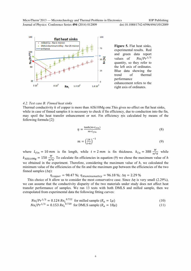
4.1. Test case A: Flat heat sinks
We ran 40 tests for DMLS sample and 15 tests for milled copper sample, and extrapolated from
experimental data the following fitting curves:
1$/�23 4⁄ = 0.082�%&E.FFG (6)
for milled sample (�H = 1I)
1$/�23 4⁄ = 0.093�%&E.J4� (7)
for DMLS sample (�H = 25I). In figure 5 experimental points and interpolating curves are shown.
Enhancement obtained is quite constant over the whole range of explored �%&, with a minimum and
maximum value of 47.7% and 56.4% respectively.
MicroTherm’2013 — Microtechnology and Thermal Problems in Electronics IOP PublishingJournal of Physics: Conference Series 494 (2014) 012009 doi:10.1088/1742-6596/494/1/012009
5
4.2. Test case B: Finned heat sinks
Thermal conductivity 5 of copper is more than AlSi10Mg one.This gives no effect on flat heat sinks,
while in case of finned samples it is necessary to check if fin efficiency, due to conduction into the fin,
may spoil the heat transfer enhancement or not. Fin efficiency Kis calculated by means of the
following formula [2]:
K = LMNO(<∗&QRS)<∗&QRS
(8)
� = T �#U∗VW�3 (9)
where 'X=Y = 10�� is fin length, while Z = 2�� is fin thickness. 5[\ = 388 ]<^_ while
5`abc3Ede = 150 ]<^_. To calculate fin efficiencies in equation (9) we chose the maximum value of ℎ
we obtained in the experiment. Therefore, considering the maximum value of ℎ, we calculated the
minimum value of the efficiencies of the fin and the maximum gap between the efficiencies of the two
finned samples (∆K):
K�fgg?� = 98.47%;Ki>\<=Y\<�>>fj = 96.18%; ∆K = 2.29%
This choice of ℎ allow us to consider the most conservative case. Since ∆K is very small (2.29%),
we can assume that the conductivity disparity of the two materials under study does not affect heat
transfer performance of samples. We ran 13 tests with both DMLS and milled sample, then we
extrapolated from experimental data the following fitting curves:
1$/�23 4⁄ = 0.124�%&E.J�� for milled sample (�� = 1I) (10)
1$/�23 4⁄ = 0.153�%&E.J�E for DMLS sample (�� = 18I) (11)
Figure 5. Flat heat sinks,
experimental results. Red
and green data report
values of 1$/�23 4⁄
quantity, so they refer to
the left axis of ordinates.
Blue data showing the
trend of thermal
performance
enhancement refers to the
right axis of ordinates.
MicroTherm’2013 — Microtechnology and Thermal Problems in Electronics IOP PublishingJournal of Physics: Conference Series 494 (2014) 012009 doi:10.1088/1742-6596/494/1/012009
6

Figure 6. Finned heat sinks, experimental results.
In figure 6 we report the experimental results, the fitting curves and the thermal performance
enhancement. Clearly the latter is nearly constant all over the explored Reynolds number range, and it
amounts to 20%. It is very important to point out that fin efficiency is a parameter concerning
conduction into the material only. Therefore it is plausible that the values of convective heat transfer
coefficient measured on two samples are very different although the fin efficiency of the two samples
is approximately equal.
4.3. Comments
It is important to know the range of velocity and Reynolds number values for industrial application
heat sinks. Comparing the latter with the range of the Reynolds number explored in our experimental
campaign, it is possible to predict if the enhancement in heat transfer showed in our study will be
achieved also when DMLS rough heat sinks works under fluid dynamics conditions typical of
industrial applications.
Length of flat heat sinks or finned heat sinks basis plate usually vary from 2 to 15 cm, depending
on the heat flux to dissipate. On the other hand velocity of cooling air for finned heat sinks electronic
devices usually ranges from 1 to 5 m/s [11]. Consequently, according to equation (2) , in the most of
industrial electronic cooling devices �%& varies from 1.3k104 to 5.0k10�. Hence we can argue that
the experimental results shown in this work have been ran in a range of fluid dynamic conditions
which are of interest for electronic cooling devices for industrial applications. Consequently it is
possible to suppose the enhancement in heat transfer through DMLS manufacturing showed in the
present work will be achieved also if DMLS rough heat sinks will be applied to common industrial
electronic cooling devices.
It is appropriate to consider the problem of pressure losses in the electronic cooling device air
circuits. Usually heat sinks are designed in order to obtain an optimum trade-off between heat transfer
performance and pressure losses. In this study pressure losses associated to tested heat sinks have not
been characterized. However it is reasonable to expect an increase in pressure losses when a rough
heat sink is used instead of a smooth one. In spite of the presence of heat sinks is a source of pressure
losses, it should be taken into account that a big portion of pressure losses in air circuits are due to
other component rather than heat sinks. Pressure losses due to other component remain approximately
constant, while varying type of heat sink. As usually done, pressure losses can be subdivided in
distributed pressure losses along channel length and concentrated pressure losses due to fan intake,
bends and restriction along the circuit, to name a few. Reynolds analogy states that in first
1.8 104 1.3 104 8 103 3 103
MicroTherm’2013 — Microtechnology and Thermal Problems in Electronics IOP PublishingJournal of Physics: Conference Series 494 (2014) 012009 doi:10.1088/1742-6596/494/1/012009
7

approximation 1$l; = ml;, where 1$l; and ml; are the dimensionless heat and momentum transfer
coefficient on the heat sinks respectively.
Increasing 1$l; proportionally increase the dissipating heat flux, being heat sinks the component
of the circuit which mainly experience heat transfer phenomenon, whilst increasing ml; proportionally
increase only pressure losses associated to heat sinks, while pressure losses due to other component
remain constant. Hence we can suppose that, when a rough heat sink is used instead of a smooth one,
the benefit in enhancing heat transfer should be more effective than the negative effects of increasing
pressure losses.
In this work, the effect of DMLS process surface roughness on thermal performance of air cooled
heat sinks has been investigated. Nevertheless there are several technologies for electronic cooling,
other than air cooled heat sinks. For example, confined jet impingement, heat pipe and so on. It is
interesting to compare the presented technique with others, in order to prove the relevance of the
obtained results in the electronic cooling research field. In general, air cooled heat sinks are designed
to take advantage of extended surfaces, for example plate fins or pin fins. Jet impingement can also be
incorporated into the design to further enhance the heat transfer. Because available space is limited
and low power consumption is desired, the heat sink performance becomes the focus of many studies.
In fact the latter is a widespread method in computers and CPU cooling due to its low price,
effectiveness and reliability [12]. Recently, the class of techniques based on liquid or two-phase
coolant fluids, as heat pipes to name one, became very attractive. Heat transfer mechanism in heat pipe
combines the principles of both thermal conductivity and phase transition to tremendously increase
heat transfer rate [12]. Despite this class of techniques allow to dissipate very high heat fluxes
(compared to air cooled heat sinks) they are still relatively expensive. Hence, despite the common
belief that the limits of air-cooling have been reached, yet a number of interesting approaches can be
found in the literature. For example in [13] an innovative transient thermal management solutions that
utilize PCMs (phase change materials) to design hybrid PCM-based air cooled heat sinks is presented.
It provides a solution to deal with peak transient heat loads in portable applications exploiting the
ability of PCMs to store energy in the form of latent heat.
We can reasonably suppose that a lot of electronic applications (like notebooks) will remain
dominated by cooling based on forced air convection in the next future. Consequently it is important
to find techniques, like the one exposed in this work, capable to improve thermal performance of air
cooled devices to face the ever-increasing thermal challenges arising in next-generation electronics
systems.
5. Conclusions
In this study average convective heat transfer coefficient of different heat sinks was measured using
air as refrigerant fluid in turbulent regime. Copper heat sinks produced by traditional milling were
compared to aluminum alloy (AlSi10Mg) heat sinks produced by DMLS. Effects of micro-structured
roughness on thermal performance were shown. These are very huge because little geometrical
dimensions are involved in heat transfer phenomenon (see leading edge), as usual in electronic
cooling. Our results offer an evidence of the possible impact of DMLS on electronic cooling since a
50% and 20% enhancement (compared to milled samples) is observed for flat and finned heat sinks,
respectively. We also show that the lower thermal conductivity of aluminum alloy plays a negligible
role on heat transfer performances in our setup. Enhancement on flat heat sinks is larger than finned
sinks, because average roughness of the former is higher than that of the latter. Building rough fins is
not as easy as doing rough flat surfaces, but in future studies this will be one of the first improvements
that will be pursued from the point of view of DLMS machining. These results open the way for a
huge boost in the technology of electronic cooling by DMLS. As an outlook, based on the present
results, we plan further studies focusing on investigation and optimization of micro-structured surfaces
obtained by DMLS with regards to heat transfer.
MicroTherm’2013 — Microtechnology and Thermal Problems in Electronics IOP PublishingJournal of Physics: Conference Series 494 (2014) 012009 doi:10.1088/1742-6596/494/1/012009
8

6. References
[1] Sergent J and Krum A 1998 Thermal Management Handbook for Electronic Assemblies (New
York: McGraw-Hill)
[2] Bejan A and Kraus A D 2003 Heat Transfer Handbook (Hoboken,NJ: John Wiley & Sons)
[3] Garimella S V, Fleischer A S, Murthy J Y, Keshavarzi A, Prasher R, Patel C, Bhavnani S H,
Venkatasubramanian R, Mahajan R, Joshi Y, Sammakia B, Myers B A, Chorosinski L,
Baelmans M, Sathyamurthy P and Raad P E 2008 Thermal challenges in next-generation
electronic systems IEEE Trans. Compon. Packag. Manuf. Technol. 31 801-815.
[4] Calignano F, Manfredi D, Ambrosio E P,Iuliano L and Fino P 2013 Influence of process
parameters on surface roughness of aluminum parts produced by DMLS Int. J. Adv. Manuf.
Technol. 67 2743-51
[5] Nikuradse J 1950 Laws of flow in rough pipes N.A.C.A. tech. mem. 1292
[6] Dipprey D F and Sabersky R H 1963 Heat and momentum transfer in smooth and rough tubes
at various Prandtl numbers Int. J. Heat Mass Transfer. 6 329-332.
[7] Webb R L, Eckert E R G and Goldstein R J 1971 Heat transfer and friction in tubes with
repeated-rib roughness Int. J. Heat Mass Transfer. 14 601-617
[8] Li X W, Meng J A and Li Z X 2007 Experimental study of single-phase pressure drop and heat
transfer in a micro-fin tube Exp. Therm Fluid Sci. 32 641-648
[9] Li X W, Meng J A and Li Z X 2011 Roughness enhanced mechanism for turbulent convective
heat transfer Int. J. Heat Mass Transfer 54 1775-81
[10] Manfredi D, Calignano F, Krishnan M, Canali R, Ambrosio E P and Atzeni E 2013 From
powders to dense metal parts: characterization of a commercial AlSiMg alloy processed
through direct metal laser sintering Materials 6 856-869
[11] Shaukatullah M, Storr W R, Hansen B J and Gaynes M A 1996 Design and optimization of pin
fin heat sinks for low velocity applications IEEE Trans. Compon. Packag. Manuf.
Technol.19 486-494
[12] Gururatana S 2012 Heat transfer augmentation for electronic cooling Am. J. Appl. Sci. 9 436-
439
[13] Rodgers P, Eveloy V, and Pecht M G 2005 Limits of air-cooling: status and challenges 21st
IEEE SEMI-THERM Symp. 1 116-124
Acknowledgments
Authors would like to acknowledge the THERMALSKIN project: Revolutionary surface coatings by
carbon nanotubes for high heat transfer efficiency (FIRB 2010 – “Futuro in Ricerca", grant
RBFR10VZUG).
MicroTherm’2013 — Microtechnology and Thermal Problems in Electronics IOP PublishingJournal of Physics: Conference Series 494 (2014) 012009 doi:10.1088/1742-6596/494/1/012009
9