Oscillation results for difference equations with oscillating coefficients
Upload
khangminh22Category
view
0download
0
LOCAL AND OVER -ALL HEAT TRANSFER COEFFICIENTS IN BAFFLED
HEAT EXCHANGERS
by
KRISHNASWAMI NARAYANAN
A THESIS
submitted to
OREGON STATE UNIVERSITY
in partial fulfillment of the requirements for the
degree of
DOCTOR OF PHILOSOPHY
June 1962
e

APPROVED:
P ofessor of Chemical Engineering
In Charge of Major
ead of Department of Chemical Engineering
Chairman of School Graduate Committee
can of ra uate School
Date thesis is presented July 24, 1961
Typed by Carol Baker

ACKNOWLEDGEMENTS
The author takes the opportunity to wake the following acknowledge cents:
To the National Science Foundation for the granting of a fellowship to conduct this research.
To Dr. J. G. Knudsen for his inspiring encourage- ment and guidance throughout the duration of this investigation.
To Mr. R. C. Mang, departmental machinist, for his assistance in some of the construction.
To Mr. R. H. Bergstad, r.ho helped wake part of the experimental runs.
To the Department of Chemical Engineering and Mathematics for the use of their facilities and equipment.
1

TABLE OF CONTENTS
Chapter Page
I INTRODUCTION 1
II THEORY AND PREVIOUS WORK 4
Heat Transfer to Normal Cylinders 7 Factors Influencing Shell -Side Heat Transfer 3
Methods of determining Local Heat Transfer Coefficients 12
Correlation of Shell -Side Heat Transfer Data 13
III EXPERIMENTAL EQUIPMENT 18 Model Heat Exchanger 13 Baffles 24 Sensing Probe 24 Power Supplies 34 Resistance Measuring Equipment 33 Air Source and Cooling System 33
IV EXPERIMENTAL PROGRAM 43
V EXPERIMENTAL PROCEDURES 52
VI THEORY OF HEAT TRANSFER PROBES 58
VII ANALYSIS OF DATA 58 Heat Transfer Data 59 Heat Transfer at Baffles 71 Effect of Change of Tube
Arrangement 75 Flow Pattern and Nusselt Number
Distribution Along the Tube 7G Variations in the Heat Transfer Coefficient Around the Tube 77
Results for Segmental Baffles 77 Pressure Drop Data 78
VIII CONCLUSIONS 82
IX RECOMMENDATIONS 37
X NOMENCLATURE 89
BIBLIOGRAPHY 92 APPENDIX A 96 APPENDIX B 102 APPENDIX C 105 APPENDIX D 103 APPENDIX E 122
-
{
-
- -
-
-
row
...,.,.e ., .s
-
....,,,
..
- -
,...
;00o i - . - , -
-
1..... .
-
A . . , . 4 . .., ..., .. . ,
J
.

LIST OF TABLES
Table Page
I. Dimensions of Heat Exchanger Compounds 20
II. Experimental Program ,
III. Positions of Heat Transfer Measurement 49
IV. Example Data Sheet 51
V. Calibration of Thermistors 104
VI. Velocities in Various Channels in Orifice Baffled Tube Bundle 107
VII. Correlation of Average Heat T ansfer Data !t Baffles with 9 -inch Spacing, Baffle Type I 108
VIII. Correlation of Average Heat Transfer Data 10 Baffles with 4 -inch Spacing, Baffle Type I 109
IX. Correlation of Average Heat Transfer Data 4 Baffles with 9 -inch Spacing, Baffle Type II 110
X. Correlation of Average Heat Transfer Data 4 Baffles with 9 -inch Spacing, Baffle Type III (Baffle Opening 0.8125 inches) 111
r
Correlation of the Heat Transfer Data at Baffle.. 112
XII. Correlation of Heat Transfer Data at Baffle 1 120
XIII. Correlation of Shell -Side Geometry to Reynolds Number Exponent 121
XIV. Annular Orifice Pressure Drop Function 121
, .. , . . . I.
.,....,.....,.-: :.r...,...
k. _.a.,.,..
' - .
'
.... - .... e
............
- --

LIST OF FIGURES
Figure
1.
2.
Model Heat Exchanger and Associated Equipment
Tube Bundle Assembly
Page
19
21
3. Tie -Rod and Baffle Assembly 22
4. Drawing of Assembled Probe "A" 28
5. Drawing of Assembled Probe "B" 31
6. Drawing of Assembled Probe "C" 32
7. Sensing Probes 33
3. Power Supply for Probe "A" 35
9. Power Supply for Probes "B" and "C "... 37
10. Diagram for Resistance Measuring Equipment 39
11. Diagram of Air Flow System 41
12. Type I Baffle 44
13. Type II Baffle 45
14. Type III Baffle 47
15. Correlation of Shell -Side Heat Transfer Data 63
16. Correlation of Shell -Side Heat Transfer Data 66
17. Correlation of Shell -Side Heat Transfer Data 67
13. Correlation of Shell -Side Heat Transfer Data 70
19. Correlation of Shell -Side Heat Transfer Data at Baffles 72
20. Orifice- Pressure -Drop Function versus Reynolds Number 80
.,..... -
A....:
".
. e
.. . . ,... i . . . .
. . . . 4 . 1 , . . .
, -
..... i
i ...... -
.. .. - ...........,
-
. -
. .. , q . R IN . . e . i . . e

Figure Page
21. Variation of Nusselt Number Along Tube 97
22. Variation of Nusselt Number Along Tube 98
23. Variation of Nusselt Number Along Tube 99
24. Variation of Nusselt Number Along Tube 100
25. Variation of Nusselt Number Along Tube 101

LOCAL AND OVER -ALL HEAT TRANSFER COEFFICIENTS IN BAFFLED HEAT EXCHANGERS
CHAPTER I
INTRODUCTION
The process of heat transfer is one of the most
important unit operations for many industries. For
chemical industries, in particular, one of the most com-
mon methods to achieve this is by forced convection in
which heat is transferred between two flowing fluid
streams in a heat exchanger. The usual heat exchanger
consists of a tube bundle placed in a suitable shell and
so arranged so that fluids may flow on the inside and the
outside of the tubes. The tube -side heat transfer coef-
ficients are generally large because of the turbulence on
the tube side. To increase the shell -side heat transfer
coefficients, baffles are installed in the shell -side to
increase the turbulence and prevent formation of stagnant
areas. For the design of heat exchangers, a basic under-
standing of the flow patterns and heat transfer rates is
important. Most of the available design equations are
based on data obtained from studies of the overall per-
formance of heat exchangers.
Unlike the tube -side, the shell -side geometry is
fairly complicated, which makes the understanding of shell -
side processes more difficult than tube -side processes.

2
The shell -side heat transfer coefficients depend on the
geometry and various dimensions of the system such as
baffle type, baffle spacing, baffle size, tube diameter,
tube pitch and baffle -to -tube clearance. The most common
types of baffles are segmental or half moon baffles, ori-
fice baffles and disk and doughnut baffles. The segmental
baffle is the most commonly used one because of the low
pressure drop and simplicity of installation.
Extensive research has been conducted in the Depart-
ment of Chemical Engineering, Oregon State University,
under the sponsorship of the National Science Foundation,
to better understand the basic mechanism of shell -side
fluid flow and heat transfer. Ambrose (1), Gurushankariah
(10), Lee (14) and Williams (24) have studied various
aspects of shell -side heat transfer with both segmental
and orifice baffled systems using a model heat exchanger,
over a wide range of experimental conditions. These
studies were all made with systems using a 1 -inch tube
diameter and tube pitches of 1Vh and 2 -3/16 inches.
The present investigation was undertaken to make a
detailed study of a system using tubes of V% inch diameter
and a pitch of 1 -1/16 inches at a constant flow rate and
compare the results obtained with those of Ambrose (1),
Gurushankariah (10), Lee (14) and Williams (24). The
study included the use of two types of orifice baffles

3
and a segmental baffle. Detailed study of local and
overall heat transfer coefficients were made in a repre-
sentative region of the model exchanger, particularly in
the vicinity of the baffle.
From this study it was possible, using the data on
heat transfer coefficients, flow rate and pressure drop
1) to correlate the experimental data in terms of an
average Nusselt number, Prandtl number of the fluid and
a weighted shell -side Reynolds number, 2) to correlate
the local value of the Nusselt number at the baffle with
the Prandtl number of the fluid, an equivalent Reynolds
number at the baffle and a diameter ratio, 5) to determine
the effect of baffle -to -tube clearance on the shell -side
heat transfer rates, 4) to determine the effect of baffle
spacing on the shell -side heat transfer rate and 5) to
correlate the amount of fluid flowing through each
baffle -to -tube clearance with the pressure drop across
the baffle.

4
CHAPTER II
THEORY AND PREVIOUS WORK
The modes of heat transfer important in heat
exchangers are conduction and convection. The rate' of
heat transfer by conduction is proportional to the
surface area and the temperature gradient.
dt -k A (1) dx
where
=
q = rate of heat transfer
A = area of heat transfer
k = thermal conductivity of the medium
dt = temperature gradient in the direction of dx heat flow.
The rate of heat transfer by convection is propor-
tional to the surface area and the temperature difference
between the surface and the bulk of the fluid.
q = h A (ts s
-t ) f
(2)
where
rate of heat transfer
A = area of heat transfer
(ts s -tf)
f = temperature difference between the
surface and the fluid
h = heat transfer coefficient
When heat is transferred from one fluid to the other in a
shell -and -tube heat exchanger the mechanism of heat
I r
.
=:;-; q
.
4
4
- .
q =

5
transfer occurs in three distinct steps.
(1) Tube-side heat transfer by convection from the tube -side fluid to the tube wall.
(2) Conduction through the thickness of the tube wall.
(3) Shell -side heat transfer by convection from the outer tube wall to the shell -side fluid.
Thus, neglecting scale formation, the overall heat
transfer coefficient can be expressed as the sum of three
components.
U i where
h. =
h s
=
A. =
A s
A = lm
kw =
x =
1 h.A. ii
w
w lm A h A 1
S S
(3)
overall heat transfer coefficient based on A.
tube -side heat transfer coefficient
shell -side heat transfer coefficient
inside area of tubes
outside area of tubes
logarithmic mean area of A. and As s
thermal conductivity of tube wall
thickness of tube wall
Thus, in order to calculate the value of the overall heat
transfer coefficient, U, which is essential for proper
design of heat transfer equipment, the terms on the right
side of equation (3) must be known accurately. The con-
duction term of equation (3) is easily and accurately
evaluated because of the availability of thermal
1 +
U = i
3
=
w
.
i

6
conductivity for common heat exchanger materials.
Quite extensive work has been done in case of tube -
side heat transfer and the coefficient, hi, can be eval-
uated from the knowledge of tube size, flow conditions
and the fluid properties. A number of empirical relation-
ships are available for calculating the tube -side heat
transfer coefficients to a reasonable degree of accuracy,
Knudsen and Katz (13, p. 394) and McAdams (16, p. 219).
A commonly used expression is the Dittus- Boelter
equation (13, p. 394).
0.8 o.4 (, 'li `i = O O`'" `i i G ) . v , (li)
k /
. b b b
where
h. = tube -side heat transfer coefficient i
d. = inside diameter of tube i
k = thermal conductivity of the fluid
G. = mass velocity of the fluid inside the tubes
= viscosity of the fluid in the tubes
Cp = specific heat of the fluid r
The subscript "b" indicates that the properties are
evaluated at the fluid bulk temperature. Equation (4)
is satisfactory for heating fluids (for cooling the
exponent on (Ci} 'a
/ k)b is 0.3 instead of 0.4) under the following conditions.
(1) Fluid properties are evaluated at arithmetic mean bulk temperature
.
111
I \

(2) Re >10,000
(3) 0.7 < Pr 100
(4) L/di 60
where
7
L = length of the tube
There are other correlations available which are
improvements on the Dittus- Boelter equation. With the
help of these equations the tube -side heat transfer
coefficient can be evaluated accurately.
Thus, to determine the overall heat transfer coef-
ficient for a shell- and -tube heat exchanger, the shell -
side coefficient has to be determined. This coefficient,
hs, is difficult to evaluate because of the complexity
of flow patterns in the shell. A literature survey
pertinent to the present investigation follows.
1. Heat Transfer Normal to Single Cylinders
Giedt (8, p. 375 -581), Winding and Cheney (26) and
Lapp (27) have studied in detail the local heat transfer
coefficient around a cylinder placed normal to stream of
fluid and the result of their investigations are in good
agreement. A plot of the Nusselt number, (hd /k), versus
the angle from the leading edge of the cylinder gave two
types of behavior depending upon the type of flow. Zapp
(27, 544 -56) obtained a minimum Nusselt number at an angle
of 84° from the leading edge for a 0.9% turbulence at a
4.
)

8
Reynolds number of 1.1 x 10⁵ and two minima at 85° and
135° for a turbulence of 3% at the same Reynolds number.
The first minimum at 85° corresponds to a point where
the laminar boundary layer transforms into a turbulent
flow region. The second minimum is the point of separa-
tion, i. e., it is the point where the turbulent boundary
layer separates from the cylinder.
Local heat transfer coefficients have also been
calculated by Levy (15) for submerged bodies for fixed
Prandtl numbers. Schmidt and Wenner (17) obtained an
empirical relationship for the prediction of local
Nusselt numbers in cross flow around cylindrical tubes.
Nu = 1.41 (Re)"5 (Pr)"4 [ J-
1 - (8 ) (5) R77.
for Q < 80° and Re ( 5 x 10⁵
where
= angle from the leading edge
Nu = Nusselt number
Re = Reynolds number
Pr = Prandtl number
2. Factors Influencing Shell -Side Heat Transfer
(a) Segmental baffles
The present investigation concerns predominantly a
study of orifice baffled systems and therefore reference
is being made only to pertinent literature on orifice
3 )
J
A

9
baffles. A detailed literature survey relating to other
baffled systems, especially to segmental baffles, has
been reported by Ambrose (1) and Gurushankariah (10).
Considerable amount of work has been done to better
understand the mechanism of fluid flow and heat transfer
across banks of tubes. The factors which affect the
shell -side coefficients are the nature of the fluid, flow
rate and the shell -side geometry. The first two factors
present little difficulty. The geometry on the shell -
side is determined by the type of baffles, tube pitch,
tube diameter and clearances between various parts of
the shell -side.
The most commonly used baffles in a shell -and -tube
system are segmental, orifice and disk and doughnut
baffles. The segmental baffles are most widely used
and normally the baffle cut is made at 75 percent of
the inside diameter of the shell. In baffled shell -side
flow, any arrangement which favors a thorough mixing after
interacting with heat transfer surface, would result in an
increased heat transfer rate. For a given heat exchanger
length and a given flow rate, the rate of heat transfer
increases with a decrease in baffle spacing. This fact
has been confirmed by Ambrose (1), Gurushankariah (10)
and Lee (14). This increase in heat transfer rate is
attributed to the increase in the velocity of the fluid
when the baffle spacing is reduced.

10
The effect of baffle cut of segmental baffles on the
shell -side heat transfer coefficient has been worked out
by Donohue (6) from the experimental results of Short (18)
and Tinker (22). Donohue shows that a decrease in baffle
cut increases the heat transfer coefficient.
The roles of tube size and spacing in the shell -side
heat transfer are difficult to treat separately. For a
constant tube to baffle hole clearance, the heat transfer
coefficient increases with a decrease in tube size.
Short's work (19) shows that an increase in tube pitch
causes an increase in heat transfer coefficient. This
result was confirmed by Ambrose (1).
The clearance between various parts of the exchanger
affect the heat transfer rate. If the clearances are
reduced, the heat transfer coefficient increases as does
the pressure drop across the system. Thus from the point
of view of design an optimum heat transfer rate is needed
at the point pumping costs are a minimum. A study of
the effect of these clearances on the heat transfer
rate has been discussed by Donohue (6, p. 2509),
Tinker (23, p. 110 -115) and Ambrose (1, p. 115)
The flow of fluid in the shell -side of a baffled
exchanger is highly complicated and considerable work
has been done on the flow pattern and the various
types of flow zones that occur in the shell.

11
Donohue (6, p. 2499), Tinker (21, p. 39 -96), (22, p. 97-
109),(23, p. 110 -116) and Katz and Gupta (12) have
attempted analysis of shell -side flow. Katz and Gupta
(12, p. 5) considered three flow zones for the shell -
side flow namely, a longitudinal flow zone, an eddy zone
and a cross flow zone. The most complete analysis of
the flow is undoubtedly that of Tinker (21) (22) (23).
(b) Orifice baffles
The orifice baffle has tube holes large enough so
that there is a sufficient clearance to allow the fluid
to flow, with a reasonable pressure drop through the
annular orifice formed between the tube and tube hole.
A decrease in this clearance increases the heat transfer
rate due to the increase in the velocity and also increases
the pressure drop across the orifice (18) (14) (24). An
increase in baffle spacing decreases the heat transfer
rate due to an increase in mixing length, which occurs
when the spacing is increased, is very small compared to
the above mentioned effect. The optimum spacing of orifice
baffles has been shown by Short (19, p. 781) as being
roughly four times the effective diameter of the region
between the baffles.
Donohue (6, 1,. 2503) and Tinker (23, p. 112) have
shown that any shell to baffle clearance decreases the
heat transfer coefficient because some of the fluid is
_

12
bypassed around the edge channels and do not contribute
to heat transfer.
From the pressure drop point of view the orifice
baffles present the greatest drop amongst the three
types of baffles (19, p. nl). The present investigation
also leads to the same conclusion.
Methods of Determining Local Heat Transfer Coefficients
Due to the diversity of problems arising in measuring
shell -side heat transfer coefficients several methods have
been used to determine the local values of the heat trans-
fer coefficient, each with its own advantages and disadvan-
tages. Of the several methods, mention may be made of
Thomson, et al. (20, p. 177-170, Schmidt and Wenner
(17, p. 2 Zapp (27, p. 23 -26),, Dwyer, et al. (7, p.
5 -7) and Giedt (8, p. 375-377) all of whom used heat
transfer probes. Mass transfer employing the sublima-
tion of Naphthalene and making use of the analogy between
heat and mass transfer have been used also ( 26, p. 1087-
1093).
Gould and Nyborg (9, p. 249 -250) have made boundary
layer measurements using the imbedded thermistor technique
with the use of a 10 kilocycle audio wave utilizing the
phenomenon of viscous heating and microstreaming near the
tube wall. The use of the thermistor enabled them to
determine the temperature in a highly localized field and
3.

13
also the heat transfer rates. The use of thermistor is
preferred because of its high temperature coefficient
of resistance. Hartwig, et al. (Il, p. 238) have reported
the use of miniature thermocouples for the measurement of
localized heat fluxes.
Two heat transfer probes were designed for the
present investigation utilizing the high temperature
sensitivity of the thermistor. In one probe, thermistors
of about 0.05 inch diameter were imbedded symmetrically
in a plastic tube. The thermistors were subjected to a
potential difference and the power input and the resist-
ance were measured from which the local heat transfer
coefficients could be calculated. The second probe
consisted of a thermistor ring which was again heated
electrically but this time with an intention of measuring
the average value of the coefficient around the tube.
Besides, these probes, a probe based on Giedt's method
was designed using thermistors as temperature sensing
elements.
4. Correlation of Shell -Side Heat Transfer Data
(a) Segmental baffles
A brief description of the correlation of the shell-
side data for the segmental baffle case is shown below.
A detailed description of this has been presented by
-

14
Gurushankariah (10, p. 19 -23). Insufficiency of experi-
mental data along with complexity of flow in the shell -
side has resulted in most of the correlations being
empirical in nature. The method of correlation depends
on the use of modified flow rate defined differently by
different investigators.
Donohue (6, p. 2502) uses a geometric mean weighted
mass velocity based on the cross flow velocity and the
flow through the baffle window. He proposed the following
empirical equation for a tubular heat exchanger.
0.6 0.33 35 0.14
Ckd) 0.25 (`Gel rC }i
(
(6) / \ / ``J
where
h = heat transfer coefficient
d = outside diameter of the tube
k = thermal conductivity of the shell -side fluid
G = weighted mass velocity, w e
w = mass flow rate
Ab = baffle window area
Af = cross flow area
}z = average shell -side fluid viscosity
P-w viscosity of fluid at surface temperature
Cp = specific heat
Ambrose (1, p. 89 -94), Bergelin, et al. (3, p. 841)
and Williams and Katz (25, p. 26) correlated their data
=
Ab Àf
1
J
=

15
with an equation of similar form. Short (18, p. 6) used
an average mass velocity based on three equally weighted
parts and arrived at the following equation.
0.32
(11- 15.8 ( P - e dG
s B
where
0.86 0.55 0.6
(5)
= tube pitch
L = active length of the exchanger
B = baffle height
S = baffle spacing
shell diameter S
(7)
G s
= mass flow rate in the shell without baffles
Equation (7) is more difficult to use compared to
equation (6) but is more versatile because it takes into
account the shell -side geometry factors.
(b) Orifice baffles
Since orifice baffles are not commonly used, little
has been done on shell -side heat transfer coefficients
with orifice baffles. The experimental work of Short (19)
was concerned with orifice baffles and he arrived at the
following empirical relationship for an effective mass
velocity, to be used for calculating the shell -side
Reynolds number.
\0..5
0.6
d J )
1.72
k `
J
p
d =

16
Gx Gb (d -d )d 83 ¡ 2 1 1 + G sI
0'55 2 0.4> (8)
p d. `\ s
A a
The effective mass velocity, Gx, was then used in the
following expression for the determination of the
shell -side heat transfer coefficient (19).
h d d 0.5 0.32 J.6 5 11 = 0.57 p- 1 (
C J C Short's relationship for the case where a single velocity
at the space between the baffle was used was
> h d l (C
II \ 0.52
(p-idly) 0.6 ) á
s (l0)
where
n = 0.3 0.25
The symbols in the above equations are:
Gx = effective shell -side mass velocity
Gs s
= mass velocity based on flow area between baffles
Gb = mass velocity based on flow area at baffle
A = an annular area between baffle hole and tube
d1 1
= outside diameter of tube
d2 = diameter of baffle hole
d s
= shell diameter
0.55
CL) 1
S
( )
k
d G n 1
1.5 s 2.5 l s L k k p S) )
,
d2-ál
2 P
a
L
a
/2
`
1 I`
1

17
The above correlations are based on tests on some com-
mercial heat exchanger units using several petroleum
oils and water as the shell -side fluid. In another
work, Short (18) made use of a slightly different method
for correlation of data on orifice baffles. He used an
average mass velocity, Gav, av
defined as
4d2 G = a b
+G s - 4d Gs s
s
a av a a s
(12)
This was then used in the following empirical relation-
ship for the determination of the heat transfer coef-
ficient
(13)
In using the above mentioned average mass velocity,
'av' Short made the assumption that ! pipe diameters
were required for the fluid to drop to the velocity it
had upstream from the orifice.
Sullivan and Bergelin (4, p. 85 -94) presented heat
transfer and pressure drop about a single baffle with
and without leakage through the baffle. Pressure drop
across a baffle was related to the baffle -to -tube clear-
ance through which leakage occurred. For this analysis
an annular orifice coefficient was used. The effect of
the leakage area on the pressure drop and also heat
transfer was discussed qualitatively.
sl J+ s` J
i
(4scil) = 0.82 (p-dl 0.4
(CP f
(d1Gav 0.6
` \ k \ P ) )

18
CHAPTER III
EXPERIMENTAL EQUIPMENT
The experimental equipment used in the present
investigation was originally designed and used by
Ambrose (1). The apparatus has been modified somewhat
to make it more versatile, and different baffles, tubes
and heat transfer probes were used. The set up consisted
primarily of a model heat exchanger, sensing probes, D.C.
power supplies, thermistor bridge and other special
metering devices, and an air source. A general view of
the heat exchanger and associated equipment is shown in
Figure 1.
1. Model Heat Exchanger
The model heat exchanger consisted of a tube bundle
inside a shell. The shell was fabricated from a cast
lucite pipe 45 inches long, 6 inch nominal diameter and
1/8 inch wall thickness. The exact dimensions of the
shell and tolerances are shown in Table 1. Further
details on the construction of the shell are available
in reference (1, p. 32 -56), The tube bundle consisted
of eighteen and nineteen three- quarter inch aluminum
condenser tubes, 48 inches long, six 3/16 inch steel
tie rods, plastic end plates and plastic baffles
(Figure 2). The tube sheet assembly was made from one

Figure 1. Model Heat Exchanger and Associated Equipment.
, ,`_ e
i.
-.- u rr _..-. - .: .-....- ®' . Jtz
_ ----.
Y
_ . a - .
1
t

20
Table 1. Dimensions of Heat Exchanger Compounds
MODEL EXCHANGER SHELL
Inside diameter
Outside diameter
Length
5.719 + .03 inches
5.937 + .03 inches
45 inches
BAFFLES
Baffle diameter
Baffle hole diameter
5.594 + 0.002 inches
Type I (orifice type 18 tubes) 0.7812
0.8125
0.8750
+
+
+
.001
.001
.001
0.9070 + .001
Type II (orifice type 19 tubes) 0.8125 + .001
Type III (segmental type 18 tubes) 0.8125 + .001
Height at cut (Type III) 4.290 + .002 inches
TUBES
Outside diameter 0.750 + .001 inches
r+,

Figure 2. Tube Bundle Assembly.
.r:

Figure 3. Tie -Rod and Baffle Assembly.
ti
.`~ .
".ìs- j ..,-; -1%446
° '.n 41)14*- r . ..,
. r
'-7. .{, N6 s .
-
1 .,, -,
--sti
t r
MOD
.61.
41111..
-+,
_
*t10 . .. . *1/4"4"ik& 416%0
.%kl% i " . qkw.
,1411101,4440%%. , %%

,V?
1:a inch thick lucite plastic sheet and one Yfk inch thick
lucite sheet and two sheets of rubber gasketing mater-
ial. The end plates were 71/2 inches square. These
sheets and gasket material were fastened with twelve
% inch bolts. The tube holes in the tube sheets were
1/64 inch larger in diameter then the tubes themselves
to avoid leakage.
The tie -rods were 5/16 inch steel rods, 50 inches
long, threaded with 10 =24 threads. These held the
baffles in place by means of two 10 -24 nuts one on each
side of the baffle. The tie rods were also fastened
to the tube sheet for rigidity and proper alignment.
The baffles were made from 1/8 inch thick lucite
sheet and were machined from a 6 inch square of plastic.
Ten such squares were clamped together and machined to
a diameter of 5.594 inches. The tube sheets were clamped
to the finished baffles and tube holes, 49/64 inches in
diameter, were then drilled through the entire stack to
produce uniform results. The baffles were then reamed
to the proper diameters as indicated in Table I. The
order of the baffles during the drilling and the reaming
processes were noted by numbering the individual baffles
so that the effect of any slight flaw incurred during
these processes was minimized. A photograph of the
baffle and tie -rod assembly is shown in Figure 2. Figure
3 shows the tube bundle assembled for installation before

24
slipping into the shell
2. Baffles
The experimental work consisted of studying three
different types of baffle systems.
1. Orifice baffle, Type I
2. Orifice baffle, Type II
. Segmental baffle, Type III
Ten baffles of each of the above types were made for
the investigation. Type I orifice baffle was an off -
center baffle with 18 tube holes for r inch tubes. Type
II orifice baffle was a centric baffle with 19 tube holes
for inch tubes. Type III baffle was identical to
Type I baffle except it was a segmental baffle with a
75% cut.
3. Sensing Probe
Three sensing probes were designed for measuring
heat transfer coefficients in the model heat exchanger.
Two of these probes were designed to measure local values
of the heat transfer coefficient around the tube at any
spot in the exchanger and were also capable of being
readily shifted to other tube positions in the exchanger.
The third probe was designed to determine the average
value of coefficient around the tube at any spot in the
exchanger.
N

25
Sensing probe "A" was similar to that used by
Ambrose (1, p. 41 -48). Thermistors were imbedded
symmetrically below heated foils to measure the surface
temperature. Williams (24) using the probe designed by
Ambrose found that slight indentations on the Saran Wrap,
used as an insulator for the thermocouples, caused con-
siderable change of the measured value of the coefficient.
Thermistors were chosen instead of thermocouples because
of their inherent sensitivity and ease of measurement
of resistance and most important of all their use did
not require any electrical insulation between them and
the heated foil.
The sensing probe was 8 inches long and was made
out of ' inch lucite rod. A 3/16 inch hole was drilled
through the longitudinal axis of the probe to permit
connection to the foil and thermistors. A ;t, inch long
section at both ends of the probe was machined to 5/8
inch diameter to fit inside of a machined inch aluminum
tube which held the probe in position in the exchanger.
Three 1 inch wide by .002 inch slots, spaced 14, inch
apart, were machined around the circumference of the
rod. The probe consisted of two parts which could be
screwed together to form the assembled probe. A 3/16
inch plastic spacer was introduced between the threaded
units and 7 size 55 holes were drilled, at 45° intervals,
A

26
at the point of contact of this spacer and the edge of
section having the male threads. Below each of these
holes were drilled 7 size 60 holes in the threaded sec-
tion of the unit. In the place where the 8th hole would
lie, 2 sets of 1/8 inch wide and 1/8 inch deep bus -bar
slots were made over the entire length of the probe.
Bus of different lengths were fitted in these so
that the three foil strips connected to these would be
in series. The bus -bars were secured in the plastic
base by 0 -80 machine screws.
The installation of the probe was done by placing
the probe with the spacer in between the two threaded
sections and laying the thermistors in their respective
holes and connecting the leads and soldering them. A
copper ring was provided in a slot in the spacer to act
as a common pole for one end of all thermistors. All
wired leads were taken out of the same side of the probe.
The thermistor connecting wires were 29 gauge double
cotton covered copper wire. Two pieces of 12 gauge,
foravar insulated, copper wire were used as leads for
carrying power to the foils for heating and were secured
to the proper bus -bars by flattening, drilling and tap-
ping one end of the leads and connecting to the proper
screw on the bus -bars. These two wires came out of the
same end of the probe as the thermistor leads. Thus one
end of the probe was free of wires. The probe was then

27
attached to a ri inch aluminum tube by glue after the wires
were passed through the tube. The thermistor leads were
wired to a standard octal plug mounted on the probe
holder tube and the power wires were attached to two
terminals.
The thermistors were seven Keystone Type L- 0503 -56K
with a resistance of 56,000 ohms + 10% at 37.8° C. The
thermistors were installed in the holes drilled for them
with a slight amount of protruding above the plastic
surface. This excess was then smoothed off with a fine
emery cloth so as to give a smooth outline to the
thermistor in contact with the plastic and also offer
good thermal contact between the thermistor and the
heated foil. A drawing of the assembled probo is shown
in Figure 4.
Three 1 inch wide pieces of nichrome resistance
ribbon were installed in the .002 inch slot around the
plastic and secured by the copper bus -bars. In mounting
the ribbon care was taken to assure uniform and smooth
contact at the bus -bars and plastic edge. The nichrome
ribbon was supplies by Wilbur B. Driver Co., Newark,
N.J. under the trade name of "Tophet C ". It had a
specific resistance of 0.263 ohms per foot and a thermal
conductivity of 7.63 BTU per hour per square foot per
degree Fahrenheit per foot. The ribbon was 1.000 inch
wide and .002 inch + 10% thick.

Riss 55 Holes
.. 31414e--- 3 -1" 3/16" spacer
, i
L
"
0.002W by 1" Grooves
DRAWING OF ASSEMBLED PROBE "A"
FIGURE 4
a ils+ 2
""1
-
- -J- L-- 1
-_ --el
1 ¡

29
Probe "B" was designed with the idea of speeding
up the time required for the probe to come to equilibrium.
As the foil system, in Probe "A", requires the dissipa-
tion of about 50 to 100 watts of power, the time for
the system to come to equilibrium can be as much as one
half hour. Thermistors have very small heat capacity.
Likewise such a probe is simple to construct and operate
with advantages.
The probe "B" was 6 .f:, inches long and made of V. inch
lucite rod. It consisted of a section with male threads
and another section with corresponding female threads.
A special, 1/4 inch wide, hollow spacer, which slipped
over the threads, was located between the two sections.
Eight No. 55 holes were drilled at 45° intervals around
the surface of the spacer. One end of the hollow spacer
was fitted with a copper ring which acted as a common
terminal for the thermistor. Nine 0 =80 threads were
tapped for mounting 0 =80 screws which acted as contact
screws for the other leads of the thermistors. The
contacting wires, gauge 29 DCC, were led out through
nine 0-80 holes on the threaded part. Then the other
threaded section was screwed in and tightened. This
completed the assembly of the probe. The thermistors
were the same as those used in probe "A ". The wires
were taken through the aluminum probe holder tube and

30
soldered to an 11 pin connector. These leads were to
act as both a power input and a temperature sensing
device. The assembled probe was finished by grinding
the protruding thermistors so that a smooth surface
was obtained. Any depressions were filled with a putty
made of ordinary glue and fine silver dust. A diagram
of the "B" probe is shown in Figure 5.
The probe "C" was designed to measure average heat
transfer coefficients at any particular spot in the
exchanger. It was designed on the same principle as
probe "3" and consisted of a single ring thermistor
instead of an assembly of 3 thermistors. Two copper
pieces were placed on either side of the thermistor
when installing it in the probe to offer a larger
convective (psuedo -) area for heat transfer. The therm-
istor was a General Electric W751 washer thermistor,
which was machined on the outside to 0.750 + .001 inch
and on the inside to 0.525 inch. The thermistor was
sandwiched between the copper pieces to which two 26
gauge enameled copper wires were attached. The probe
was then assembled by screwing on the female threaded
section. Then the wires were passed through the aluminum
probe holder tube and attached to a Cinch -Jones type
terminal strip. A diagram of the probe is shown in
Figure 6. Figure 7 shows a photograph of all three
probes.
r ...

3/4"
Thermisterr Holder 0 -80 Contact Screws
j. 3/4".}.--- 2" 2-1/8" -014- 3/4"114
Thermistors
DRAWING OF ASSEMBLED PROBE "B"
FIGURE 5
---.+ 440----
...=n1M T
1
.
Ar

3/4" 5/8"
--
5/16" Copper Rings
Thermistor Ring
143/4"4,_ 1" _ - 2" 3/4" 41
Thermistor Lucite Rod
DRAWING OF ASSEMBLED PROBE "C"
FIGURE 6
7-- -mil
///AF
1

Figure 7. Sensing Probes.
M
ti --a ^,sr'
o
`tY-+a4r.. --
t.
'- f,
íá
3 4
It__LEMEAHEP112L
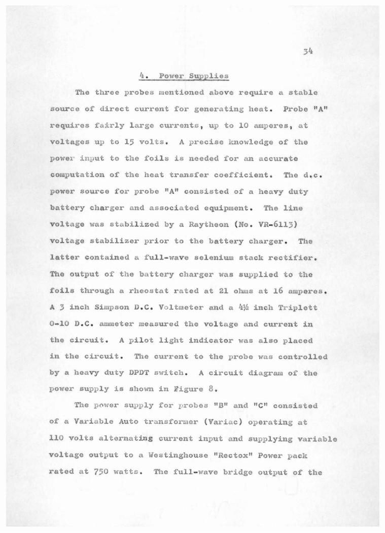
The three probes mentioned above require a stable
source of direct current for generating heat. Probe "A"
requires fairly large currents, up to 10 amperes, at
voltages up to 15 volts. A precise knowledge of the
power input to the foils is needed for an accurate
computation of the heat transfer coefficient. The d.c.
power source for probe "A" consisted of a heavy duty
battery charger and associated equipment. The line
voltage was stabilized by a Raytheon (No. VR -6113)
voltage stabilizer prior to the battery charger. The
latter contained a full -wave selenium stack rectifier.
The output of the battery charger was supplied to the
foils through a rheostat rated at 21 ohms at 16 amperes.
A 3 inch Simpson D.C. Voltmeter and a 41/2 inch Triplett
0 -10 D.C. ammeter measured the voltage and current in
the circuit. A pilot light indicator was also placed
in the circuit. The current to the probe was controlled
by a heavy duty DPDT switch. A circuit diagram of the
power supply is shown in Figure 8.
The power supply for probes "B" and "C" consisted
of a Variable Auto transformer (Variac) operating at
110 volts alternating current input and supplying variable
voltage output to a Westinghouse "Rectox" Power pack
rated at 750 watts. The full wave bridge output of the

0-10 D.C.Ammeter
BATTERY CHARGER
POWER SUPPLY FOR PROBE "A"
FIGURE
-
® TO FOILS

36
pack was supplied to probes "B" and "C". Power to probe
"B" passed first through a capacitive input filter con-
sisting of a 2 section 40 -40 microfarad, 450 volt
electrolytic condenser and a 1.5 henry filter choke.
The output of the filter was metered by a Simpson 41 inch,
0 to 25 D.C. voltmeter. The eight thermistors in the
probe were in parallel and placed under the same potential
difference. One leg of all thermistors passed through
an 11- position circuit opening switch, which introduced
a Simpson, 41'2 inch, 0 to 1 milliammeter in series with
the thermistor to measure the thermistor current. Thus
all the eight thermistor currents could be measured by
placing the meter in series with one thermistor at a
time. The knowledge of voltage and current for any
thermistor gives. the power input as well as the resistance,
which is a measure of temperature. A circuit diagram of
the power supply for the "B" and "C" probes are shown in
Figure 9.
The power for probe "C" was taken directly from the
Westinghouse power pack and passed through a rheostat,
rated at 360 ohms at 1.1 amperes, used as a voltage
divider. A Simpson, 3 inch, 0 to 30 D.C. V ,ltmeter and
0 to 150 DC milliammeter were placed in the circuit to
measure voltage and thermistor current respectively.
This circuit is shown in Figure 9.

1.5 Hy.
Filter Choke
kiZrÿQ
Selenium Rectifier
Voitmete
::illiammeter
Milliammeter
POWER SUPPLY FOR PROBES "B" AND "C"
FIQJRE I
Voltmeter
;:-.41
I
I
'-110 :0 1110
-o
O o o
. o o o

38
5. Resistance Measuring Equipment
The measuring equipment for probe "A" is a modified
Wheatstone Bridge designed for rapid measurement of
resistances. The bridge is made up of two precision
10 -turn micropots and 1% bridge ratio resistors and a
Simpson, 3 inch, 50 -0 -50 microammeter as the null detector.
The bridge input was through an Amphenal 15 -pin connector
which was selected by an 11- position rotary switch. The
bridge had a self contained 3 -volt power supply consisting
of two ZN-9 mercury batteries. The bridge was calibrated
against a Leeds and Northrup Model 4725 precision
Wheatstone bridge. The wiring diagram for the bridge
is shown in Figure 10. The resistance values were used
in determining the surface temperature of the foil,
which in turn was used to calculate the heat transfer
coefficient. The accuracy of the bridge is + 10 ohms
in the range of operation, which for the thermistors
used corresponds to + .01° F.
Probes "B" and "C" do not require any special
measuring equipment except the voltmeter and ammeter
already described. This makes the calculations much
simpler.
Air Source and Coaling System
The present investigation used air on the shell =side

11 -position selector I . a
-_
1114 : l
l 1
1
BRIDGE RESISTORS
O4. .w.
10000 0 .,s 100 l,ms
50 -0 -50 "icro.- Iter
DIAGRAM OF RESISTANCE MEASURING EQUIPMENT
FIGURE 10
J
1000 0
,
-
NCI.* 1 X
ß
t t-T-1 t
- I, I,_

40
fluid, which was delivered by a Roots- Connersville blower.
The discharge air from the blower was cooled. The cooled
air was passed through a calming section and a metering
orifice before entering the model exchanger. Manometers
to measure the orifice pressure drop, the heat exchanger
pressure drop and also baffle pressure drop were provided
as were gauges to measure inlet pressure at the orifice
and at the exchanger inlet. A schematic diagram of the
air flow system is shown in Figure 11.
The air was supplied by a 5V4 inch by G inch Roots
blower, operating at 1750 RPM rated at 280 cfm at 314 psig.
The blower was driven by a Century, 15 HP, 220 Volt, 3
phase induction motor operating at 3500 rpm.
Air from the blower passed through a 2 -inch pipe
to the coolers. A by pass valve permitted the passage
of only a part of the air through the coolers. The
cooler consisted of 5 inch diameter by 36 inches long
tubular heat exchanger and two 6 by 6 by 13 inch tinned
copper coolers in parallel. The air flowed in the
tube -side and cold water in the shell -side.
The cooled air entered a calming section made of a
4 inch diameter, 16 inch long pipe, filled with 12 inch
lengths of 1/2 inch pipe. The air after leaving the
calming section passed through an orifice meter with an
orifice plate of 1-, 1N- and 1Y2 -inch orifice holes
'
¡--,

AIR INTAKE
/ROOTS TYPE
BLOWER
COOLING WATER INLET
COOLING WATER OUTLET
TUBULAR COOLER
FINNED COOLER
VALVES
MUFFLER
MODEL HEAT EXCHANGER
PRESSURE GAGE
PRESSURE DROP MANOMETER -
FINNED COOLER
1
IF DISCHARGE TO ATMOSPHERE
ORIFICE
CALMING SECTION
FIGURE II AIR FLOW SYSTEM
1
PRESSURE GAGE
FLOW MANOMETERS
t
I ;-T
.
1
I
i
i
.
W
{
I

42
each of which could be used for a particular flow range.
The orifices were calibrated by Ambrose (1, p. 162 -166).
Two manometers each with fluids of density 0.830
and 2.95 respectively, were provided for the measurement
of pressure differential across orifice, exchanger and
baffles.
Two pressure gauges were installed, one connected
to the pressure upstream from the orifice and the other
at the exchanger inlet. These gauges were calibrated
by Ambrose (1, p. 167).
Further details on the system are available in
reference (1).

43
CHAPTER IV
EXPERIMENTAL PROGRAM
The objective of the investigation was to study in
detail the local shell -side heat transfer rates through-
out the model exchanger at constant mass flow rates.
The variables under investigation were baffle spacing,
tube arrangement, type of baffle and baffle hole opening.
The flow rate was chosen from a consideration of pressure
drop and Reynolds number through the exchanger.
Baffle type I was studied for four baffle hole
diameters and two baffle spacings. The baffle hole
diameters were 0.7812, 0.8125, 0.8750 and 0.9070 inches
and baffle spacings were 4 and 9 inches. From symmetry
consideration only six tubes, (see Figure 12) out of the
18 tubes present in the tube bundle were studied. The
study was confined to the space between baffles 2 and3,
from the upstream end of the exchanger, for the case of
the 9 inch spacing and between baffles 2 and 3 and 8 and
9 for the 4 inch spacing.
Baffle type II was studied for the case of a baffle
hole diameter of 0.8125 inches and baffle spacing of 9
inches. Seven out of the nineteen tubes present were
studied between baffles 2 and 3. The diagram of baffle
type II along with tube numbering is shown in Figure 13.

TYPE I BAFFLE
FIGURE 12
44 '

TYPE II BAFFLE
FIGURE 13
45
1
L 1 J

Tube 3 was studied at three flow rates.
Baffle type III was studied for a case of a baffle
hole diameter of 0.8125 inch and a baffle spacing of 9
inches. From symmetry considerations 6 out of the 18
tubes in the tube bundle were studied between baffles
2 and 3 and 3 and 4, which is equivalent to a study on
10 tubes. A diagram of baffle type III is shown in
Figure 14.
Table II shows in detail the experimental program
adopted. The investigation consisted in measuring local
heat transfer coefficients at positions indicated in
Table III. The vicinity of the baffle was investigated
carefully as rapid change in heat transfer rate occurred
in that area.
The numbering of thermistors in the probe was
clockwise looking from the downstream end, starting
from the copper bus -bar. The numbering scheme is shown
in Figures 4 and 5 for probes "A" and "B
For probe A the necessary data for calculating
the heat transfer coefficient were the resistances of
thermistors measuring the temperature of air stream as
well as the ones measuring the surface temperature of
the foil and the current through the foils.
For probes "B" and "C" a knowledge of the voltage
and current through the probes and the resistance of the
46

Tube 1
TYPE III RAFFLE
FIGURE 14
1
47
o O

Table II. Experimental Program.
Baffle type Spacing Hole Number of diameter tubes inches investigated
I (Orifice) 9 inch 0.7812 6
0.8125 6
0.8750 6
0.9070 6
0.7812 2
0.8125 6
4 inch 0.8750 6
0.9070 6
II (Orifice) 9 inch 0.8125 9*
III (Segmental) 9 inch 0.8125 10
Flow rate: 72 + / -J..
Runs were made at 45 and 105 cfm also for tube 3.
48
.

Li 9
Table III. Positions of Heat Transfer Measurement.
4 baffles Downstream distance from baffle 1
0.0 inch 9.0 9.25 9.50
10.00 10.50 11.00 12.00 13.00 14.00 15.00 16.00 17.00 17.50 17.75 18.00 27.00
10 baffles Downstream baffle 1
from Downstream from baffle 3
0.0 0.0 4.o 0.25 4.25 0.50 4.5o 0.50 5.00 1.00 6.00 2.00 7.00 3.00 7.50 5.50 7.75 3.75 8,00 4.00

50
air thermistor were needed for calculating the heat
transfer coefficient.
The flow rate was calculated from the flow orifice
size, orifice manometer reading, specific gravity of the
fluid, pressures at the inlet to the orifice and the
exchanger, atmospheric pressure and the air thermistor
resistance.
An example of the original data sheet for probe "A ",
containing all the terms listed above has been given in
Table IV. The data sheets for probes "B" and "C" were
similar to that shown in Table IV except that instead
of recording the thermistor resistances the voltage and
current in the thermistor circuit were recorded. Probe
"B" had eight current values and a voltage value whereas
probe "C" had one voltage and current reading. The data
obtained using probes "B" and "C" have not been indicated
here. These data have been used for comparing the
behavior of various types of heat transfer probes by
Bergstad (5) .
The flow rate used during the investigation was
held at 72 cfm + 7 cfm at 60° F and one atmosphere
pressure, for most of the runs.

Exch.
man
omet
er
(inches fluid)
mÚ
on
number
.t re ç
inche
le
,
manometer
t er
ches
fluid)
-
psig
Vet psig
n
de
ow
L
-_
'.
I
Table IV. Example Data Sheet
Spacing: 4" Orifice size 1.250"
Baffle type I Hole diameter
Specific gravity 0.830 Pressure 752
= 0.8125" Tube number:3
0 .r4 4) Z w,-' 0 '::0 u)
Thermistor resistance, Ohms g o r1 ?-1
El 41 u
74 04
',:. g O; o 0
2 3 4 5 6 7 Air 'az:'---
rli 04
527 OD1 13750 115500 118000 120375 123000 126000 121875 175000 .00 11.5 .3 .10 0.95
528 01)2 99750 102125 104625 105500 105875 105875 98500 180000 p.00 11.5 .3 .10 #.95
529 143)2 08750 111250 110500 112375 112000 114125 106875 177500 '-.).00 1.3 .3 L.10 .95
530 14D2 02375 106250 104375 106500 107500 109875 101875 180000 5.00 11.3 .:; L.10 0.95
531 1D2 95875 95875 97000 95375 96875 99000 95625 177500 .00 1.3 .$ L.10 ..95
532 2D2 81875 82375 80500 84500 80500 85500 80000 178000 .00 1.3 .3 L.10 0.95
533 31)2 7475o 73250 73750 77000 77000 80000 76759 177500 .00 1.5 .3 .10 1.95
534 141U2 79075 77500 77250 78250 75000 77250 75000 177500 .00 11.5 .3 .10 0.95
535 34 4112 77000 77250 76625 74625 74375 77500 75000 177500 .00 1.5 7.3 .10 .95
536 01)3 93125 99000 96750 99500 98500 100250 96500 17750o .03 1.5 .3 .10 1.95
--- - -- Code: D stands for downstream of the baffle number following
U stands for upstream of the baffle number following
o
5 x 1
4
y N

5 2
CHAPTER V
EXPERIMENTAL PROCEDURES
The procedures for operating the experimental
equipment and recording the readings were similar to
those of Ambrose (1, p. 67 -71), Gurushankariah (10, p.
40 -42) and Lee (14, p, 32- 5). The following steps
were involved.
A. Preparatory Steps:
1. The probes were placed in the position where the heat transfer coefficient was to be measured. The orientation of the probe was noted in the readings.
2. The tube position, tube number, baffle spacing, flow orifice size, and the barometric pressure were recorded.
3. The air temperature thermistor was placed in the inlet section of the exchanger and with every measurement an air temperature measure= ment was taken.
4. The cooling water was allowed to flow through the air coolers.
5. The by -pass valve in the air system was complete- ly opened and the main valve to the exchanger closed.
6. The power supply for probe "A" was switched on.
B. Starting and Data Taking:
7. The blower was then turned on and the flow rate adjusted to the desired value by the by -pass and main valves.
3. The probe currents were adjusted to suitable values by adjusting rheostats and variacs.

53
9. The probes were centered as far as possible and then the system was allowed to reach steady state, denoted by a constant reading of the thermistors. The time required for probe "A" to come to a steady state was of the order of fifteen minutes to half an hour compared to five minutes and ten minutes required by probes "B" and "C" respectively.
10. The resistances of the thermistor of probe "A" were measured with a Wheatstone bridge along with the thermistor. Each set of readings were repeated once after a time interval. Only readings which checked within + 100 ohms were accepted. This would correspond to an accuracy of .05° F in the range of operation of the thermistors.
Voltage and current readings were taken for probes "B" and "C" similarly and recorded.
11. The foil current for probe "A" was recorded.
12. The orifice flow manometer, pressure drop manometers, pressure gauges at the inlet of the orifice and exchanger were recorded.
13. This completed one set of runs. After this the probe was moved to the next position and procedures from 10 to 12 repeated.
C. Shut -off procedure:
14. The power to the foils was turned off as was the power to probes "B" and "C ". The timer on the power supply for probe "A" was set to zero and the power switch off.
15. The by -pass valve was opened completely and the main valve was shut. The blower was then turned off.
16. The cooling water shut off.
The rest of the procedures adopted here were the
same as described by Ambrose (1, p. 67 -71).

54
CHAPTER VI
THEORY OF HEAT TRANSFER PROBES
PROBE A
Ambrose (1, p. 72 -713) by making an energy balance
around a small volume of the central resistance ribbon
of the sensing probe arrived at the following equation
for calculating the heat transfer coefficient ( eq. 10,
p. 74)
o i 2R
+
kz d"t9 grad cond h A dL
where
t - ta
( i (14)
k = thermal conductivity of the ribbon
z = thickness of the ribbon
w width of the ribbon
t = local ribbon temperature
L = length of ribbon
current through the ribbon
resistivity of ribbon
to u = air temperature
h = local heat transfer coefficient
gcond
grad
A
energy conducted into the probe
energy radiated from the ribbon
area of ribbon exposed to flow
w w A
a
=
i =
R T.
=
=

55
Since for a cylindrical probe L = rO, where is the
enclosed angle in degrees
dL = rdA
from this
d2t 2
1 d`t 2
rl = dL2 r (IQ`
substituting(15) in (14)
i 0
kz d2t 2
grad gcond h = + 2 ' A - A wr (1(4
(15)
(16)
Ambrose further showed that the conduction and radiation
terms were negligible compared to the convection term.
The present probe "A" had less conduction than the probe
used by Ambrose because of a smaller conduction area for
nearly the same convection area. The probe equation
then becomes
.2 R
h =
t-t a
kz d`t
wr2 2 2 dO
Since R = 0.263 ohms /ft
w = 1.000 inches
z = 0.002 inches
r = 0.375 inches
k = 7.63 DTU /hr ft2 °F/ft
equation (17) becomes
h = 10.77 i2 + 4277 d2t AQ4:.
t-t a
(17)
A
t a
w
:
,IMEMONON
(IC)
t,r
+

56
Equation (18) was used to calculate the heat transfer
data measured with probe "A".
PROBES B AND C
Thermistors are temperature sensitive semiconductors
which have a large negative temperature coefficient of
resistance. The resistance- temperature relationship
for a thermistor is given by the following equation
where
1 Rt = Ro e
B 1
o (19)
Rt t
resistance of thermistor at temperature t
Ro o
resistance of thermistor at temperature to o
P a constant for the thermistor material
Thus a knowledge of Ro, to and (3 is required to use the
thermistor as a temperature measuring device. Appendix
B shows these values for the thermistors used along
with the procedure for calculation. If a potential
difference is applied across a thermistor placed in
still air, then the current heats the thermistor
above the temperature of the surrounding air. The
temperature difference thus attained is proportional
to the power input to the thermistor.
V = (t-ta) (20)
where
V = potential difference abross thermistor
current
=
=
I
i =
1

57
constant for the material
t = temperature of thermistor
to = ambient temperature
If such a heated system was exposed to a fluid flow so
that forced convection caused cooling of the heated
thermistor, then the resistance of the thermistor would
be affected and likewise the voltage and current. From
a knowledge of voltage and current the local heat transfer
coefficients could be calculated. The energy balance
for the thermistor is
where
V i = q nA (L-t ) kA dt
cv a eddx (21)
Acv = area for convective heat transfer cv
Acd cd area for conductive heat transfer
So the problem reduces to one of knowing the loss of
heat by conduction. A theoretical analysis of probe "B"
is presented in Appendix B. Bergstad (5) made a compari-
son of these probes and thus determined the conduction
term. Becker, et al. (2) have described various proper-
ties and uses of thermistor.
Details on calculation of heat transfer coefficient
and flow rate are shown in Appendix B.
p =
=
a

58
CHAPTER VII
ANALYSIS OF DATA
Analysis of data obtained in the present investi-
gation consisted of (1) determining the verage shell -
side heat transfer rates .nd comparing them with
results of Lee (14, p. 9 -76), Ambrose, (1, p. 89 -115)
and Williams (24); (2) comparing the pressure drop data
to those obtained by Bergelin and Sulliv.n (4, p. 89 -90),
Lee (14, p. 74 -?9) and Williams (24, p. 44 -49); and,
(3) studying the local coefficients obtained and determin-
ing the mechanism of flow existing in the model exchanger.
An average heat transfer coefficient over the entire tube
bundle was correlated in terms of the average Nusselt
number for the tube bundle, the Prandtl number and the
Reynolds number.
The average Nusselt number for the bundle was
obtained by averaging the mean coefficient for each
tube in the bundle. The mean coefficients for e ch tube
were obtained by an integral average of the local value
of the he t transfer coefficients in a represent .tive
section of the exchanger. Thus the average Nusselt
number represents an average for the whole exchanger.
The heat transfer data at the baffle center was
also correlated in terms of the Nusselt number at the
baffle center, the Prandtl number, the Reynolds number

59
and a diameter ratio (d1/ d ) . This data was compared
to those obtained by Lee (14, p. 50 -55) and Williams
(24, p. 36 -:7).
Further qualitative analysis was made on the effect
of pitch, baffle spacing, and tube diameter on the ex-
ponent on the Reynolds number. This study was necessary
because the exponent obtained in the present work was
different from those reported by Lee (14) and Williams.
A study of the variation of heat transfer coefficient
between two central baffles was made to give an indica-
tion of the types of flow patterns around tubes. The
data on segmental baffles was compared to that of
Ambrose (1).
The pressure drop data were calculated using a
pressure drop function and an equivalent Reynolds
number at the baffle. A comparison was made with the
results of Bergelin and Sullivan (4, p. 90), Lee (14,
p. 24 -26) and Williams (24, p. 44 -47).
Heat Transfer Data
1. Analysis and Comparison of Average Heat Transfer Data for Orifice Baffles
The heat transfer data were correlated using the
hsd11 and %% dimensionless terms
k .:v
(dlGe) for the shell -side flow. The verage ... Nusselt
number, (hsd1) , was evaluated in the following
,
,
µ
k
l k 1 /
\ J

6o
wanner. The local values of heat transfer coefficients
around the tube were averaged to obtain an arithmetic
average heat transfer coefficient at a location on a
tube in the exchanger. From this value of the heat
transfer coefficient, the average Nusselt number was
calculated for that location. These Nusselt numbers
were plotted versus their corresponding positions
along the tube to obtain a Nusselt number distribution
curve along the length of the tube between two baffles.
The mean Nusselt number for a tube,
( k
, hd I
was ob-
1_ m
tamed from this by integrating the curve and dividing
the result by the length of the interval. These proced-
ures are expressed mathematically as follows 7
(lid hd 1
i) = 'N?
(
k 1 k k (22)
and
(hdi)
\ k /
(s -7--- k av : 2.
h s d l)
fr=1
( hdl 1 dL (23)
k J 1
where
f lid
L
= loe J. Nusselt number
1 7
L
=
tu
o
k j k
Khdl)
i=1
m i ( 211) =
J
n
> L k ]

61
lidl\ = arithmetic average Nusselt number k
))
(
hd 1 = mean Nusselt number for a tube
k en
n = number of tube, 1,2 n
L = length of the interval
hsdl\ av = average Nusselt number for the bundle
\k
The weighted shell -side Reynolds number, ld1Ge
,
`P I
was calculated using a mass velocity, Ge, which is the
geometric wean of the mass velocity midway between the
baffles and the mass velocity at the baffles based on
the free flow area in each case.
Ge = W = e Á
e
;ú = b
4 AbAf
(25)
The flow area, Af, was defined as the free flow area
and was obtained by subtracting the outside area of
the tubes from the inside cross sectional area of the
shell. The net flow area at the baffle, Ab, was obtained
by summing the areas of the annuli formed at the tube
holes and leakage area of the region between the baffles
and shell. The quantity
k /
C` k
1 `d for a __._ J
av .
baffle types I and II is plotted versus on
/
logarithwitic coordinates in Figure 15. Experimental
1
z

62
data for the two baffle spacings used lie on straight
lines. A least squares analysis of the data for the
4- baffle case of type I baffle resulted in the following
empirical equation represented by line A in Figure 151
ÇLri-!í 0.76 s 1 d
.0543 i av k
d1Ge
/11
7.2 x 10³ < Ree < 1.25 x 10⁴
(26)
The average deviation of the data was less then + 2,5%.
The data for the 10 baffle case for baffle type I
is shown by line B in Figure 15, which lies consider-
ably above line A. A least squares analysis of the
data resulted in the following empirical equation:
1.107
1. dl/ C ) a .00302 (d1Ge) (27) av k 1. %u
7.5 x 10³ < Ree < 1.07 x lU
The average deviation of the data was less than + 2.5%.
The exponents on Reynolds number are different from
those obtained by Lee (14) and Williams (24) who reported
values of 0.6L% The above data was analyzed assuming
an exponent of 0.68 on the Reynolds number and the least
squares analysis resulted in the following equations for
the 4- baffle and 10 baffle case respectively (baffle
type I): :
0.63
(u1 dl / av (Cp i) _ = 0,1274 ó10e (28)
k k \ }x
Cpa I =
ll /
`
e
l

200
1 1 I
4 4 BAFFLE TYPE I
O 10 BAFFLE TYPE I
ó 4 BAFFLE TYPE II
41 LEE
20
3000 6000 10000 2000 4
(Re)e
CORRELATION OF SHELL -SIDE HEAT TRANSFER DATA
FIGURE 15
f
o
63
100
v 60
..
--1
40
-

(c,1
1 e)
G Cjasall / 0.2389
a_ av Sa
o.68 64
(29)
The average deviations of the data from the above
equations were less than + 5% for both cases. A further
comparison showed that the equation
C d G 0.68
= 0.0362 (L)078 ( 1 ( äo )
z av l iJ /J
could be used to correlate the data for both baffle
cases. This equation is of the same form as the one
derived by Lee (14) but the heat transfer coefficient
values are somewhat lower. This relationship showed an
average deviation of + 5%.
The data for type II baffle has been plotted in
Figure 15. Only a 4- baffle case was investigated for
this baffle. Runs were also made varying the flow
rate to obtain a range of Reynolds number. The least
squares analysis of the data resulted in the following
equation:
(li d C -i 0.67
s 1 r,`1 = 0.0675 ( d 1 G e
)
` k av k }t (31)
with an average deviation less than + 2.5 %. A least IMO
squares analysis assuming an exponent of 0.76 on the
Reynolds number gives
(32)
.Ir., V.044
-Y3
= l
l l
/ \
h d C /// d G 0.76 s l
' = 0.0475 C l e`
k Jay k /
-
/
-)-Ys

65
from which the data deviates by an average of less than
+ 3.5%. Previous investigators have reported an exponent NMI
of 0.68 on the Reynolds number. Although the data for
the type I baffle satisfactorily fit equations (28) and
(29), in which the exponent on the Reynolds number is
0.68, it more closely fits equations (26) and (27)
which have somewhat higher exponents. From Nusselt
number distribution curve, it is clearly seen that the
heat transfer rates on tube number 2 are considerably
higher than the other tubes of the bundle. From Figure
12 it is seen that the location of the tube 2 in the
bundle is unique in the sense that it has more free
space adjacent to it than the other tubes. This would
indicate that an increase in free flow space near the
tube increases the heat transfer rate. A decrease in
tube pitch also decreases the heat transfer coefficient
in the tube bundle. Figures 16 and 17 show a plot of
av ( X
h d s
C "' 7
versus dlGe for individual tubes of
k the bundle and also the average values for the 4 and 10
baffle cases respectively. These figures also show
tube 2 to be high.
The heat transfer rates observed in the present
case were considerably smaller than those observed by
Lee (14). The low heat transfer coefficients obtained
in the present work are attributed to the following
p `

1.9
1.7 z
8 A!'FLESI
Tube 1
Tube
Tube 3
Tube 4
Tube 5
Tube 6
LEAST SQUARE
/ / _ / A / / //i / / / / /i i / /i
1.60 - - -
3.8 3.9 4.0
log (Ro)o
CORRELATION OF SHELL -SIDE HEAT TRANSFER DATA
noun 16
4.1
66
4
o O 2
/
_
-e
._
-T
r,
-fi
p

2.0
1.8
1.7 3.8 3.9 6 .0
log (Re)e
CORRELATION OF SHELL -SIDE HEAT TRANSFER DATA
FIGURE 17
10 BAFFLES
Q Tube 1 p Tube 2
Tube 3
0 Tube 4
Tube 5
Tube 6
® LEAST SQUARE
67
0
-
4._
t 1.9
3.
-

63
factors; (1) The tube diameter used in the present
study were smaller than those used by Lee, which causes
a lower heat transfer rate. The present data lie in
the same range as these obtained by Short (18) using
5/8 inch tubes. (2) The tube pitch of 1-1/16 inches,
studied in the present exchanger, is much smaller com-
pared to 2 -3/16 inches used by Lee. The larger tube -
pitch increases the heat transfer coefficient as has
been shown by Short (19, p. 780). The higher heat
transfer coefficient on tube because of the free area
adjacent to it, supports this line of reasoning. (5)
Lee (14) used the probe using only two foils with an
unheated portion upstream to the central ribbon. The
presence of this unheated section upstream causes an
increase in the coefficient compared to tube heated over
its entire length. Lee (14, p. 48 -50) showed that this
effect could be as high as 10%.
The deviation of the exponent from the usual value
of 0.68 is attributed to the geometry used in the
present system. Compared to the exchanger studied by
Lee, the present investigation used a smaller tube,
smaller pitch (for the same baffle spacings), and more
tubes in the tube bundle. The results given by equa-
tions (26) and (27) indicate a possible effect of
geometry on the exponent of the Reynolds number as it
2,
a

69
is obtained in the equation.
To determine the effect of baffle geometry and
spacing of baffles, the exponents on the Reynolds num-
ber in equations (26), (27) and (31) were plotted
against a term containing the number of tubes, pitch,
tube diameter and number of baffles. Figure 18 shows
a plot of the exponent versus the factor
(L)
(L)
(L (dL n)
where n is the number of tubes in Ll%
the bundle. The dotted line shown indicates the range
of exponent observed in the present work. Lee's data
have also been indicated. This plot represents a pos-
sible empirical correlation relating the exponent to
geometrical factors. It applies only over the short
range of Reynolds number investigated in the present
work and must be further studied over wide ranges in
order to test its validity.
The effect of baffle -to -tube clearance on the heat
transfer rate is of importance to the present investi-
gation. In all cases it was seen that the Nusselt
number at the baffle decreased with the increase in
the clearance. This is in agreement with Lee (14, p.55).
Further investigation needs to be done to exactly
understand how this affects this heat transfer coef-
ficient for various geometries.

Ç
a M`
C
X
1.2
0.9
.8
C.7
NARAYANAN
LEE
G. o
i
10 p 30
(i) 1P/ \i1;7n1 x 10'5
CORRELATION OF SNELL.SIDE GEOIQTRY FACTORS
FIGURE l0
1.:
70

Ambrose (1, p. 94) and Lee (14, p. 57) shoved
that under fixed flow rate conditions a decrease in
baffle spacing would cause an increase in the heat
transfer rate. This has again been confirmed here as
seen from Figure 15. However, the heat transfer at
the baffle center is only affected slightly by baffle
spacing.
Heat Transfer Data at Baffle
The heat transfer data at the baffle center were
correlated by an equation similar to that used by Lee
(14) as follows
(hsdil = .000327 ("1)
0.87 (11)
1.05
(33) / b k / u
e P
for 1600 < U e bib < 3000
u
The average deviation of the data from this equation
was less than + 2.5 %. The data and the above equation
(obtained by a least squares analysis) are plotted in
Figure 19. The exponents on terms
(
d G E.:a
) and d 1 _
d e
could not be determined directly from. the data because
of lack of data at varying flow rates. Using exponents
reported by Lee, a least squares analysis of the data
gives
0.68 0.57 hsdi
k b k (,..Lf_
-15 = 0.1620 ((Ill
W) e
(34) (
71
2.
C `f3 pµ )
MO
/
/

200
loo
60
I
4 BAFFLES l (Central)
10 BAFFLES (Central)
Q 4 BAFFLES ( Baffle 1)
e 10 BAFFLES ( Baffle 1)
Q WILLIAMS (No
S
4600
o
1ä000 ZQ000 40000 8600
(Re)eb d 0.,65
((
Vide)
CORRELATION OF SHELL -SIDE HEAT TRANSFER DATA AT 3AFFLES
FIGURE 19
41,:.
Baffles)
r
40
e ,
72
2
-FLEE
1
/° ,_ Q
+ +
- .

73
with an average deviation of less than + 15%.
The Nusselt number used for this correlation was
an arithmetic average of the two Nusselt Numbers at the
two central baffles. The equivalent Reynolds Number at
the baffle was evaluated using the equivalent diameter
at the orifice, d e
= d2 d1 1
. The mass velocity,
Gb, b,
was calculated from the mass rate of flow by divid-
ing it by the area of flow at the baffle, i.e.,
G b
W/Ab b
For the purpose of comparison, the data on heat
transfer at the baffle have been compared with those
obtained by Lee (14) and Williams(24). This comparison
is shown in Figure 19. It is seen from this graph
that the Nusselt Numbers lie somewhat between Lee's
values and those obtained by Williams who used no up-
stream baffles. Williams, using an upstream baffle,
also obtained heat transfer data which agreed closely
with the values of Lee, showing thereby that upstream
disturbances have a marked effect on the baffle heat
transfer coefficient. In the present study, the geom-
etry, spacing and other parameters were quite different
from those used by Lee and Williams. The results shown
in Figure 19 indicate a definite effect of upstream
baffles on the heat transfer coefficient at the baffle.
-
. = .

711
Williams' results show that low coefficients result
when no upstream baffles are present. Lee's results
show the coefficients for 4 and 10 baffle cases when
the tube pitch is large (2 -3/16 inches). These present
data indicate coefficients resulting for 4 and 10
baffle cases when the tube pitch is small (1 -1/16 inch-
es). These results indicate that as tube pitch becomes
smaller the effect of upstream baffle decreases and
results in a lowering of the heat transfer coefficient
both at the baffle and throughout the exchanger.
The values of Nusselt numbers at baffle 1 for the
4 and 10 baffle case are shown also in Figure 19. The
values for 4- baffle case lie slightly above the values
at other baffle centers. But the values for the 10-
baffle case lie almost on the line of Lee. For the 4-
baffle case, baffle number 1 was about 11 inches from
the entrance to the shell. This distance was suffi-
cient to eliminate most of the disturbances at the
shell entrance and give a coefficient at the baffle
which is characteristic of the bundle and similar to
those existing at other baffles. However, for the 10-
baffle case inlet turbulences are apparent because of
the high coefficients which were observed. In this
case the first baffle was about 6 inches from the
entrance to the shell.
.
4

75
The baffle Nusselt number for the type II baffle
is somewhat lower than those obtained for the type I
baffles. It appears that the unsymmetrical configura-
tion of the type I baffle causes some channeling and
cross flow in the exchanger which does not happen with
the symmetrical arrangement of baffle II. The cross
flow brings about increased turbulence which could
cause the higher observed coefficient. This is more
fully explained in the succeeding section.
3. Effect of Change of Tube Arrangement
Two types of orifice baffles were studied. One
was an 18 =-tube arrangement shown in Figure 12 and the
other was a 19 -tube arrangement shown in Figure 13.
The former has an irregular geometry compared to the
latter. A sot of runs were made with both types at a
baffle hole diameter of 0.8125 inches and at a con-
stant flow rate. From the Nusselt number distribution
curves, it is seen that the heat transfer coefficients
for type II baffles were markedly lower than the corres-
ponding values for type I baffles. The effect of
assymetry and the irregularity of tube 2 is also seen
here. Therefore it is reasonable to conclude from this
that symmetry results in a more uniform but low heat
transfer rate throughout the bundle. The reason for
this could be explained in terms of cross -flow occurring
.

7u
across the tube bundle for an assymLetric geometry (as
in case of type I) which increases the heat transfer
rate. In the case of baffle type I, tube 2 would be
the one responsible for resulting this cross -flow:
Velocities in various channels of the exchanger were
calculated and are shown in Figures 12 and 13. The
different velocities in these channels could result in
a cross flow.
4. Flow Pattern and Nusselt Number Distribution along the Tube
The present study consisted of a detailed investi-
gation of heat transfer rates in a region between two
baffles. With the aid of this an analysis of the flow
pattern can be made. Appendix E shows the plot of mean
Nusselt Number versus the probe position, for all the
cases investigated. From these curves, it can be seen
that the flow past a tube can be divided into four
zones defined as
(i) Zone I: Starting at the baffle and extending to a point where the Nusselt Number reaches a maximum.
(ii) Zone II: Which extends from the point of maximum Nusselt Number to a point of minimum Nusselt Number.
(iii) Zone III: Extends from the point of minimum Nusselt Number to a region where the Nusselt Number is fairly constant.
(iv) Zone IV: Extends from the downstream end of zone III to the point of maximum heat transfer at the baffle.
_

77
These zones can be seen in the curves for Nusselt
Number distribution. The results obtained here are
similar to those obtained by Lee (14, p. 57 -66). The
results are tabulated and compared to Lee's results.
5. Variations in Heat Transfer Coefficient Around the Tube
The variations in heat transfer coefficient around
of - the tube were in most cases less than + 10% of the
average value at that point for both baffle types. At
higher flow rates this variation became still smaller
and the local coefficients attained a uniform value
close to the average.
6. Results for Segmental Baffles
A comparison was made between type III (segmental)
baffle and the results obtained by Ambrose on a four-
baffle tube bundle with 14 -one inch tubes placed on a
1% inch triangular pitch. The values obtained in the
present investigation are considerably lower compared
to those obtained by Ambrose at same Reynolds numbers.
Ambrose's data were taken at 60 cfm while the present
investigation was conducted at 75 cfm. As only one
baffle spacing and Reynolds number were investigated,
the data obtained were insufficient to arrive at any
correlation.

78
Pressure Drop Data
The shell -side pressure drop in an orifice baffled
heat exchanger is composed of three factors. Out of
these the most important factor is the pressure drop
due to flow through the baffle opening. Entrance
losses and skin function play a minor part in the over-
all pressure drop. Pressure drop across a single
baffle was obtained in the present baffle using two
different methods.
a) The pressure drop across single baffle
was evaluated from the overall pressure drop by use of
the relation
Ap, A p - o en
Ape eo
where
ap b
n
pressure drop across single baffle
Ap en
overall pressure drop across exchanger
Ap eo
n
with n baffles
overall pressure drop across exchanger with no baffles
number of baffles
b) Pressure drop across single baffle was also
directly me. sured using a pressure probe. (This was
found to be almost the same as calculated by the pre-
vious method.)
The pressure drop in an exchanger without baffles
very small compared to one with baffle indicating
as t»
a
=
=
=
=
a
was

79
that the main cause for the pressure drop in an exchanger
is due to the baffles.
The method of Bergelin and Sullivan (4, p. 90)
based on the use of an orifice -pressure drop function,
0, defined as
= 2 D 2
`"c -de
was used to correlate the friction loss data. The
orifice -pressure -drop function, 0, is a dimensionless
quantity which is proportional to the pressure drop
across a baffle.
Figure 20 is a plot of 0 versus the equivalent
Reynolds number at the baffle hole, ( deQb . All \ P /
the points lie close to the solid line which represents
the data of Sullivan and Bergelin. The dotted line
indicates the results of Lee (14) and Williams (24) .
This dotted line lies somewhat above the results
of Bergelin and Sullivan and the present investigation.
The reason for the deviation is probably due to the
differences in tube pitch, The present work as well
as that of Bergelin and Sullivan was on compact tube
bundles using 1 -1/16 inch pitch and 3/4 inch and 5/8
inch tubes respectively. Lee and Williams used 1 inch
diameter tubes with 2 -3/16 inch pitch. Extensive study
is necessary with several tube diameters and tube
pitches in order to determine the quantitative effect
0 Pb
7:4
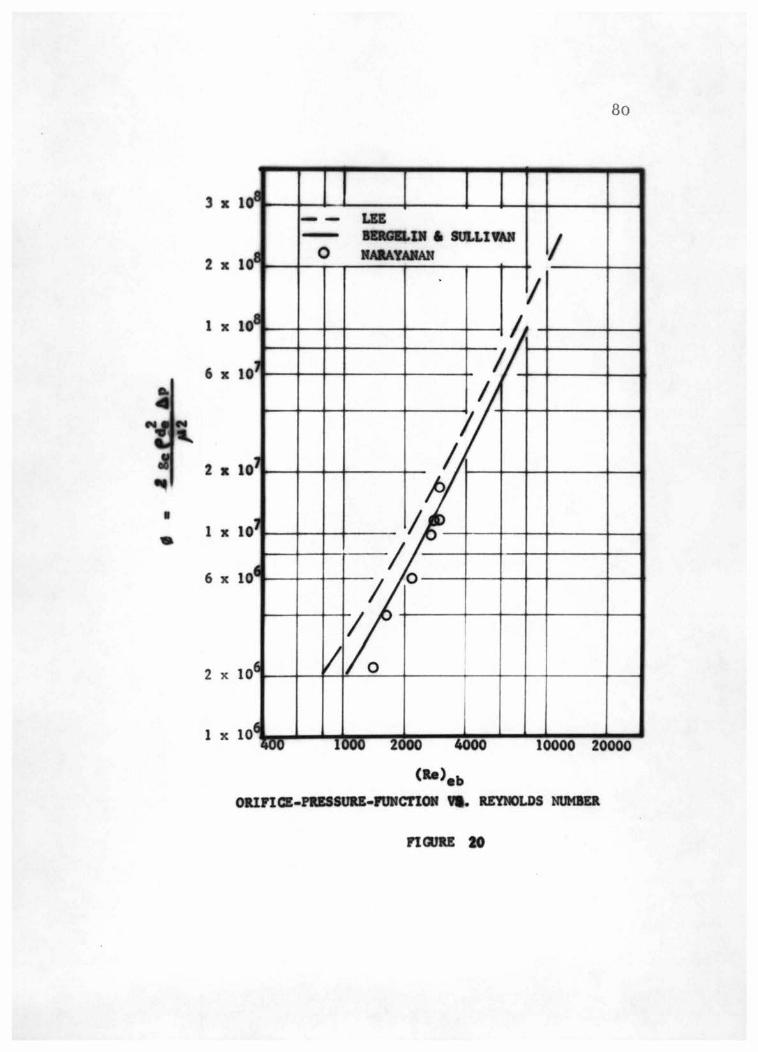
3 x 10
2 x 10
1 x 10
6 x 10
N
1 x 10
6 x 10
2 x 10
1 x 10
,
.
- - LEE
BERGELIN & SULLIVAN O NARAYANAN
/ /
IA' /
/ 1
O
/ O
I
- I
1 400 10000 20000
(Re)eb ORIFICE- PRESSURE -FUNCTION VS. REYNOLDS NUMBER
FIGURE 20
80
I
i
Z000 .
°Y 2x10

81
of these variables. Results to date are not sufficient
to give ¡A complete correlation involving all geometric
variables.

CHAPTER VIII
CONCLUSIONS
Local shell -side heat transfer coefficients were
measured in a model heat exchanger with 3/4 inch tubes:
Three types of baffles were studied with a triangular
pitch of 1 -1/16 inches. Four baffle hole openings
were studied for baffle type I and one baffle hole
opening for baffle types II and III. Baffle spacings
of 4 and 9 inches were studied for all representative
tubes of the bundle at a constant air flow rate of
about 70 cfm.
The following drawn owing conclusions are from . n
analysis of the data.
1. Average Heat Transfer Data
The average Nusselt number obtained in this invest-
igation for baffle types I and II agreed resonably well
with those of other investigators for both baffle
spacings. The results were always somewhat low, but
this is explained on the basis of the compact tube
bundle used in the present investigation. Previous
work (1) , (10), (14) and (24) concerns a study using a
larger tube diameter and tube pitches compared to the
present work. The effect of the compact geometry was
observed in the exponent of the Reynolds number. This
82

83
exponent is a function of the tube pitch, tube diameter,
baffle spacing and the number of tubes in the bundle.
A tentative correlation is obtained showing the effect
of these variables but must be substantiated by further
worts. The data agreed with an equation of the type
derived by Lee (14) within 5 %.
The unsymmetrical tube arrangement of baffle type
I showed higher average heat transfer coefficients than
the symmetrical arrangement of baffle type II. An
analysis of the flow rates in various channels of the
exchanger showed evidence of considerable cross flow
and hence turbulence in the unsymmetrical case which
could account for the higher coefficients. One tube
in particular in the unsymmetrical case was in a region
of high velocity and had a high coefficient for all
baffle hole sizes.
2. Heat Transfer at Baffle Center
The local heat transfer rate at the baffle center
differed somewhat from the data reported in literature.
The data were lower than those obtained by Lee (14)
who used larger tube diameter and tube pitch but were
higher than those of Williams (24) for a single orifice
baffle. The coefficient at the baffle is a function
of baffle spacing, baffle hole diameter, tube pitch and
tube diameter. The present work indicates that a

34
reduction of the tube pitch and diameter reduces the
coefficient at the baffle center. The effect of the
upstream baffle is apparently reduced at the lower tube
pitches and diameters. Heat transfer coefficients at
baffle 1 were high for the 4 inch baffle spacing hence
showing the effect of the shell entrance on the flow
but were similar to the coefficients at the other baffles
for the 9 inch spacing indicating that the flow through
the bundle becomes uniform in about this length.
3. Shell -Side Geometry
The effect of changing the shell -side geometry by
a large amount was noticed in the present work by an
increase in the exponent on the Reynolds number. The
combined effect of tube diameter, tube pitch, number
of tubes in the bundle, baffle hole opening and number
of baffles was noticed when the results were compared
to those of other investigators. An increase in the
number of baffle caused an increase in the Nusselt num-
ber. An increase in the baffle hole diameter at a
constant flow rate caused a decrease in the Nusselt
number, which is in agreement with (14) and (24). The
tube arrangement in the shell caused a change in the
Nusselt number depending on whether there was a sym-
metrical or unsymmetrical arrangement. An unsymmetrical
bank of tubes resulted cross flow and thus increased

85
the Nusselt number.
4. Flow Patterns and Nusselt Number Distribution
The Nusselt number distribution curve along the
tubes between two baffles was used to analyze the flow
pattern occurring along the tube in the tube bundle.
Four distinct flow zones were noticed, which is in
agreement with previous investigators (14L).
The velocities in various ducts in the shell -side
were calculated and used as a basis for explaining
cross -flow in the bundle.
5. Comparison of Data on Segmental Baffles
The data obtained with baffle type III (segmental)
were compared to the results of Ambrose (1) on a Nusselt
number distribution curve. The data compared well with
that of (1) but was somewhat lower because of the
crowded geometry in the present case. The Nusselt num-
ber curve however, has a similar shape. Due to lack
of experimental data at a number of flow rates no quanti-
tative expressions relating the Nusselt number to the
flow rate could be obtained.
6. Orifice -Pre, sure -Drop
An orifice-pressure-drop function, 0, as defined
by Bergelin and Sullivan (4) was found satisfactory to
correlate the orifice pressure drop and the flow through
the orifice. The present results agreed well with the

o
results of Bergelin and Sullivan. The results were
however, slightly below those of Lee (14) and Williams
(24), This discrepancy can be explained on the basis
of the more compact tube bundle used in the present
work as well as that of Bergelin and Sullivan.

37
CHAPTER IX
RECOMMENDATIONS
Ambrose (1), Gurushankariah (10, Lee (14) and
Williams (24) have studied in detail the local heat
transfer coefficient in the model heat exchanger using
fairly large tube diameter and tube pitches, The
present work was a study of heat transfer coefficients
using smaller tube diameter and tube pitch. As a result
the tube bundle was very compact and the flow pattern
became complicated. Comparing the results of this work
with those of the above mentioned workers a definite
need for experimental work on the effect of shell -side
geometry on the heat transfer and fluid flow is evident
to provide quantitative relationships involving the
several geometric variables.
A detailed study of the effect of geometry, using
either a simple three -tube triangular tube bundle or a
seven -tube arrangement where the effect of tube arrange-
ment could also be studied is strongly recommended.
The three -tube assembly is recommended for detailed
study on tube pitches from 3/4 inches to 5 - inches and
tube diameters of inch to 2 inches at several flow
rates. Several baffle hole openings should also be
studied. The seven -tube arrangement will be more
1iz

88
complicated to analyze but can be used to study the
effect of change in arrangement. Such a study would
definitely clarify the various mechanisms of flow and
heat transfer occurring at various geometries,
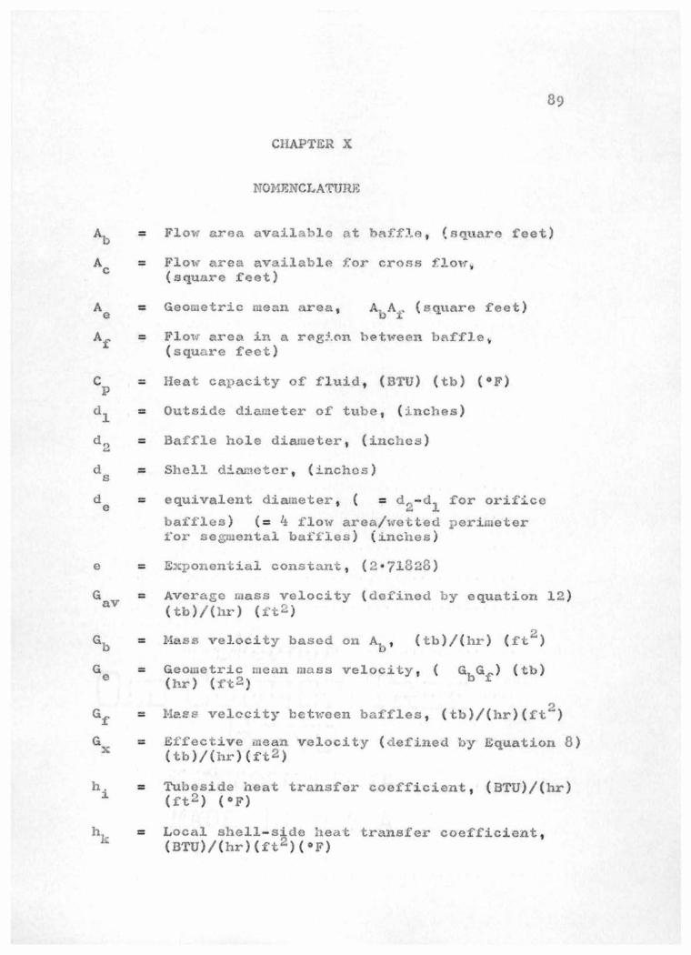
39
CHAPTER X
NOMENCLATURE
Ab = Flow area available at baffle, (square feet)
Ac c
= Flow area available for cross flow, (square feet)
A e
= Geometric mean area, AbAf (square feet)
A f
= Flow area in a region between baffle, (square feet)
Cp = Heat capacity of fluid, (BTU) (tb) (°F)
dl 1
= Outside diameter of tube, (inches)
d, = Baffle hole diameter, (inches)
d s
= Shell diameter, (inches)
de e
= equivalent diameter, ( = d6-d1 for orifice
baffles) (= 4 flow area /wetted perimeter for segmental baffles) (inches)
e = Exponential constant, (2.71828)
G av
= Average mass velocity (defined by equation 12) (tb)/(hr)
Gb b
= Mass velocity based on Ab, (tb) /(hr) (ft2)
= Geometric mean mass velocity, ( GbGf) (tb) (hr) (ft2)
G f
= Mass velocity between baffles, (tb) /(hr)(ft2)
G x
= Effective mean velocity (defined by Equation 8) (tb) (ft2)
h. = Tubeside heat transfer coefficient, (BTU) /(hr) (ft2) (°F)
h = Local shell -sarde heat transfer coefficient, (BTU) (ft 2 )(°F)
,
,
(ft2)
Ge
i

h 1
90
arithmetic average shell -side heat transfer coefficient at a location, (BTU) /(hr)(ft2)( °F)
h mean shell-side heat transfer coefficient along a tube, (BTU) /(hr)(ft2)( °F)
hs
k
L
n
= average shell -side heat transfer coefficient for the bundle, (BTU) /(hr)(ft2)( °F)
current, (amperes)
= Thermal conductivity, (BTU)/(hr)(ft2)(°F/ft)
active length of exchanger, (feet)
number of tubes
= tube pitch, (inches)
°P)b =
(AP) =
pressure specific
pressure of 0.830
drop across a baffle, inches of 0.830 gravity fluid
drop across the exchanger, inches specific gravity fluid
( 4P) o
= pressure drop across the flow orifice, inches of 0.830 specific gravity fluid
Ro o
Rt t
s
t
u
heat flux, (BTU) /(hr)
air flow rate, cu ftlimin)
resistance of thermistor at temperature to, (ohms)
resistance of thermistor at temperature t, (ohms)
radius, (inches)
= baffle spacing, (inches)
= tube surface temperature, ( °F)
= temperature of fluid, ( °F)
= fluid velocity, (feet) /(sec)
= potential difference, (volts)
=
= m
i =
=
=
P
(
q
Q =
=
=
r =
to
v
a

91
w = width of resistance ribbon, (inches)
P = thermistor constant, ( °R)
= thermistor dissipation constant, ( °F) /(milli- watt)
61 _ angle, (degrees)
viscosity of fluid, (tb) /(ft)(hr)
e = density of the fluid, (TB) /(ft3)
Dimensionless Groups
(Nu)b : Nusselt number at baffle ¡ hd1
(Nu)av : Average Nussolt number
hs av
(Pr) Prandtl number (52t k
(Re) av
: Average Reynolds number I cilGav )
1\ Ju
(Re) : Geometric mean Reynolds number, / `I1Ge
(Re)eb
FI
eb : Equivalent Reynolds number at baffle
(\ \deGb)
(Re)X : Effective Reynolds number
0 Orifice pressure drop function, n
gc n(D p)b ae"
=
k //II b
=
2
/.
`\
Íd1Gx) 1\
:
1
P

92
BIBLIOGRAPHY
1. Ambrose, Tommy W. Local shell -side heat transfer coefficients in baffled tubular heat exchangers. Ph.D Thesis. Corvallis, Oregon State College, 1957. 133 numb. leaves,
2. Becker, G. A., C. B. Green, and G. L. Pearson. Properties and uses of Thermistors - Thermally sensitive resistors. Electrical Engineering 65: 711 -7254 1946.
3. Bergelin, O. P., O. A. Brown and A. P. Colburn. Heat transfer and fluid friction during flow across banks of tubes. V. Transactions of the American Society of Mechanical Engineers. 76: 341 -850. 1954.
4. Bergelin, O. P., and F. W. Sullivan. Heat transfer and fluid friction in a shell- and -tube exchanger with a single baffle. Chemical Engineering Progress Symposium series 52(18): 85 -94. Nov. 18, 1956.
5. Bergstad, R. H. Unpublished research on heat transfer probes. Corvallis, Oregon. Department of Chemical Engineering, 1961.
6. Donohue, Daniel A. Heat transfer and pressure drop in heat exchangers. Industrial and Engineering Chemistry 41(11): 2499 -2511. 1949.
7. Dwyer, O. E. et al. Heat transfer rates for cross - flow of water through a tube bank at Reynolds numbers up to a million. Upton, Brookhaven National Laboratory, n. d. 23 p. (Brookhaven National Laboratory 1518) (Microcard)
8.
9.
Giedt, W. H. Investigation of variation of point unit -transfer coefficient around a cylinder normal to an air stream. Transaction of the American Society of Mechanical Engineers 71: 375-381. 1949.
Gould, R. K. and W. L. Nyborg. Imbedded thermistor for boundary layer measurement. Acoustical Society of America Journal. 31: 249 1959.
-
1

10. Gurushankariah, M. S. Local shell -side heat trans- fer coefficients in the vicinity of baffles in tubular heat exchangers. Master's thesis. Corvallis, Oregon State College, 1958. 97 numb. leaves.
11. Hartwig, F. W. et al. Miniaturized heat meter for steady -state aerodynamic. heat- transfer measurements. Journal of the Aeronautical Sciences. 24: 239, 1957.
12. Katz, D. L. and R. K. Gupta. Use of flow patterns in predicting shell -side heat transfer coefficients for baffled shell- and -tube exchangers. Paper presented at the Industrial and Engineering Chemis- try Symposium on Fluid Mechanics in Chemical Engineering, Purdue University, Lafayette, Indiana. December 27 -28, 1956.
13. Knudsen, James G. and D. L. Katz. Fluid dynamics and heat transfer. New York, McGraw -Hill, 1948. 576 p .
14. Lee, Kyu Sung. Local shell -side heat transfer coefficients and pressure drop in a tubular heat exchanger with orifice baffles. Master's thesis. Corvallis, Oregnn State College, 1959. 118 numb. leaves.
15. Levy, Solomon. Heat transfer to constant -property laminar boundary -layer flows with power function free -stream velocity and wall temperature varia- tion. Journal of the Aeronautical Sciences. 19: 341 -348. 1952.
16. McAdams, William H. Heat transmission. 3rd ed. New York. McGraw -Hill, 1954. 532 p.
17. Schmidt, Ernst and Karl Wenner. Heat transfer over the circumference of a heated cylinder in transverse flow. Washington 1943. 15 p. (National Advisory Committee for Aeronautics) (Technical Memorandum No. 1050)
13 . Short, Byron E. Heat transfer and pressure drop in heat exchangers. Austin, The University of Texas, 1943. 55 p. (University of Texas. Bureau of Engineering Research. Bulletin No. 4524)
93

94
19. Short, Byron E. A review of heat transfer coef- ficients and friction factors in tubular heat exchangers. Transactions of the American Society of Mechanical Engineers 64: 779 -785. 1942.
20. Thomson, A. S. T. et al. Variation in heat trans- fer rates around tubes in cross flow. In: The Institution of Mechanical Engineers and the American Society of Mechanical Engineers' proceed- ings of the general discussions on heat transfer, Sept. 11 -13, 1951. London, Institution of Mech- anical Engineers, 1952. p. 177 -180.
21. Tinker, Townsend. Shell -side characteristics of shell and tube heat exchangers. Part I. Analysis of the fluid flow pattern in shell and tube heat exchangers and the effect of flow distribution on the heat exchanger performance. In: The Institution of Mechanical Engineers and the American Society of Mechanical Engineers' proceed - ings of the general discussion on heat transfer, Sept. 11 -13, 1951. London, Institution of Mechanical Engineers, 1952. p. 89 -96.
22. Tinker, Townsend. Shell -side characteristics of shell and tube heat exchangers. Part II. A co- ordination of the test performance of several shell and tube heat exchangers on the basis of "effective flow areas" calculated from the dimen- sional characteristics and mechanical clearances of the exchangers. In: The Institution of Mechanical Engineers and the American Society of Mechanical Engineers' proceedings of the general discussion on heat transfer, Sept. 11 -15, 1951. London, Institution of Mechanical Engineers, 1952. p. 97 -109.
25. Tinker, Townsend. Shell side characteristics of shell and tube heat exchangers. Part III. A quantitative analysis of the effect of dimensional characteristics and mechanical clearances on the shell side performance of attypical shell and tube heat exchanger. In: The Institution of Mechanical Engineers and the American Society of Mechanical Engineers' proceedings of the general discussion on heat transfer, Sept, 11 -13, 1951. London, Institution of Mechanical Engineers, 1952. p. 110 =116.
1

95
24. Williams, Peter S. Heat transfer and pressure profiles in the vicinity of an annular orifice. Master's thesis. Corvallis, Oregon State College, 1961. 86 numb. leaves.
25. Williams, R. B. and Katz, D. L. Performances of finned tubes in shell and tube heat exchangers. Ann Arbor, University of Michigan, 1951. 154 p. (University of Michigan. Engineering Research Institute. Project M 592)
26. Winding, C. C. and A. J. Cheney, Jr. Mass and heat transfer in tube banks. Industrial and Engineering Chemistry 40: 1037-1093. 1948.
27, 'Lapp, George Michael, Jr. The effect of turbulence on local heat transfer coefficients around a cylinder normal to an air stream. Master's thesis. Corvallis, Oregon State College, 1950. 79 numb. leaves.

96
APPENDIX A

140
120
100
ÿ
w
Mwlriw IIlsMOWN 2 (IMO 1
MY/11111 Of MOLT NM M
Figure 21.
00551011104 Ra .,rn 1D:0e4s )
0N142100 Or '.YI i : ... 00:. R'r WINO
7
tw i i 1
t t í 1 t t T
r.nn SAME 1 (0.7e1!7 r O r.
O r.rr Q nr l I,. a } ' 41. n. be f
O r,re
11 i
Iiii, . 1 . fi _''. '.
| | |
| /
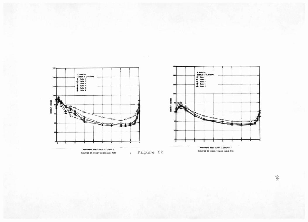
4 MTif WILE i (0.11239
nube i
O Toba 7
O Tuba 3
Tuba e
ruba 3
Tubaf
!e1O11411 /ri f23 2 (710Y
1363E11r A1YC.7 11110 ALONG Tull Figure 22
1
12
1
to
o
4 1YRis R1Ri t (0.1130) . -
IOW 1
O Tuba 7
4 robo 3
bba 6 . . . .-. f11ba 3
-y
"`. \ \ , . .0'
--.
3
among. I10M sAK1: t (t10iP3 )
6
VARIATION Of 347I323 .} 21L:.1C1 ALOAG FUZE )
IM
IM _
1 I I
i
-
OD

ISO
140
120
loo
20
r
4 SA/II.ö UAW. 1 (0.5070) O Tuba 1
O Tuba I Tuba 5
l 1
001.105.G1 /001 SARI.! 2 (INCHES )
memo 05 50114EI.T MOSS NANO Nd
E
Figure 23.
14
\ \ \
r
oONN{T.LVn rrcr ENIrI' ' (15050 )
VUIATION SUMS LLONG TIM CT
' -- r
M

2
l0
! .
WRtl l611L! 1 (0.7812.9-
o 1006 1
O 1.000 6
1
1N
120
1
II SWAM WM 1 711.781t9
TM. To es .
M
20
J 3
NEWRY met SWISS !(IKON") ]C..1i762,16 IeT'. INKS 8(IXOR!) Mane. 01 truss.! :W.eel MAC IOM
Figure 24.
OWX6262V' 2.01 "VISA I (DONS) OC.NN5118.00. PSIS MIIL! 8 (Um) 01114T102! 01 runs, :Wees N.O10 TOW
0 a

f I f
10 WILES _ Witt t (0.8150)
O N5. 1
O Tut. l NW 4
NM 5
aF=flILM' P101 Wsl.[ 2 (1008t8) X'/09t1258 sa! SMSLS 8 (100115)
wu15tu11 w alga* sr=u a sa
Figure 25.
a-
< <
2
a10St5[.W 1M!'. B.VML 8 (1v01u) xtOSTiI.W MP. S8L5 8 (INCURS)
11211471011 a tullo. Isms ONO /i
' 10 MIRO MIRI 1 10.110)
O 1 1
O Aar 1
tos 11
110
100
}
M
M
1}0
ro
0
i.. f
)

102
APPENDIX B
CALCULATION PROCEDURES
Flow Calculation
The flow rate was calculated using calibration
curves of Ambrose (1, p. 162 -166) for the orifice meter.
The equation for the lines in Figure 30 of Ambrose's
thesis were used to determine the factor 4 E .
The equations used in programming were:
and
, eE = 1.910 (Ap0.507 /
E =
irr-o I, .500 ( A )6 5°7
PE = 6.000 (41) ) 0.507
EL?, 9.450 ( AP o )0.507
-re;
for the 3/4 -, 1 -, 1%- and inch orifices respectively.
In the above equations
= flow rate at 1 atm and 63°F, cfm
e = density of air at exchanger inlet E
e0 density of air at orifice
AP o
= pressure drop across flow orifice, inches of 0.330 specific gravity fluid
Q
YC'o
Q.
0 Yro
1l-
6L
=
.
4
=
--Y757)

103
The pressure gauge calibration curves were also those
used by Ambrose (1, p. 167) and were
o
E
= 1.32 Po
= 1,25 PE
for the orifice gauge and the exchanger gauge respect-
ively. and are the dead weight pressure corres- Po PE o E
pouding to the gauge pressure. With a knowledge of the
air temperature the value of PE and Po could be calculated.
The equation for density was
P = 0.0808 OFT65--4-70 14.696
where t = temperature, °F
P = pressure, psia
Heat Transfer Coefficient Calculation
The heat transfer coefficients were calculated
using equation 18
h = 10.77i 2
+ 4277 t-t
a a
d`t 77-
The second derivative of temperature was calculated using
the Milne three -point method. The local heat transfer
coefficients were averaged and a Nusselt number was
calculated from it. The equation for the thermal
conductivity was
= 0.0132 4, .0000245 t a
P
"r'
k
_
P

104
The equation for the viscosity of air was
li = 0.044 + 0.00007 (ta-70)
The above calcualtions were performed on an
ALWAC III -E digital computer using floating point
arithmetic.
Calibration of Thermistors
The thermistors of probe "a" were calibrated
before installing and the calibration values are shown
in the table below.
Table V. Calibration of Thermistors.
Thermistor number
Resistance at 100.04 9F`, ohms
1 59768
2 60214
3 61437
4 64076
5 64076
6 6642o
7 60054
Air 59768
The value of e for the thermistors was 7750 + 50 °R.
The temperatures were calcualted using equation (19).

105
APPENDIX C
CALCULATION OF VELOCITIES IN VARIOUS PARALLEL CHANNELS IN THE EXCHANGER
Velocities were calculated in the various flow
channels indicated in figures 12 and 13 to obtain
information on the cross -flow present in the exchanger.
The calcualtions are indicated below.
The pressure drop across a channel is given by
(15, p. 542)
- A Pf = 2 C L G2max Re ax
This can be written as
Re -0.2
- P Af = G 2
04 max
e
which may be arranged to
de -0.2
v -0.2 ,-0.2 - OP f
= ov e2
d e
or
1.8 - = -7 y
oc.
de1.2
The pressure drop for all parallel channels must be
equal. Therefore,
1.8 V2 -
oll,
vi CZ,
= d el
1.2 de
2
1.2
vd1.8
d e,
1.2
J
-.0.2
Pd e
d
2
u-ü.4
Pf .
e
l.a a,
-
e "c
_

or
106
de de 0.66
)
( _11 V j
=V el
A
where the subscript "k" stands for the channel in
question.
Also
W = Q A v ATvav
where N. = number of channels of area A.
v. = velocity in channel i
substituting the value for vi from equation ( A), one
obtains
A v Atvav = >-- N.A.v. d i .66
d e. i=1
where k is the number of different types of channels.
Thus
V. _a av
A t
i=1
d J.A. e. 11 3.
d e.
J
gives the ratio of the velocity in the jtb channel to
the average. Table VI below shows these ratios in the
various zones for type I and II baffles. Zone numbers
are indicated in Figures 12 and 15.
;>. P iviAivi -
1
1 I
J i i J
v
1
L-
=

107
Table VI. Velocities in Various Channels in Orifice Baffled Tube Bundle.
Baffle type Channel type Area, sq. in. de e
v/v av
1 5.60 0,531 0.761
I r, 1.50 0.815 1.011
7.16 0.986 1.142
4 2.30 0.957 1.101
1 7.00 0.531 1.217 II
9.40 0.910 0.845
3
2

103
APPENDIX D
Table VII. Correlation of Average Heat Transfer Data 4 Baffles with 9 -inch Spacing, Baffle type I.
Baffle Tube Ae e (cl:N(adl hsdl s )
opening number (square \ p) k av k av k (inches) feet)
1 2
12500 12500
66.38 72.37
0.7812 3 0.03908 12400 59.72 63.29 71.51 4 12450 58.61 5 12500 64.16 6 12500 57.5o
9900 50.84 2 9840 60.16
0.3125 0.04616 9300 47.95 49.90 56.39 9780 46.84
5 9975 45.29 6 9975 48.40
n . ¿t .41
7800 44.40 2 7800 49.73
0.8750 3 0.05836 7800 43.29 44.75 50.56 4 7800 43.95 5 7800 42.40
1 7230 39.74 0.9070 0.06399 7230 4o.63 40.6o 45.90
5 7230 41.51
C
k
1
3
4
1
ado
3
Z-

109
Table 'III. Correlation of Average Heat Transfer Data 10 Baffles with 4 inch spacing, Baffle type I.
opening number (square `
G d d le ml sl sl Baffle Tube A
(inches) feet) 41. av
1
1
10700 10700
90.5 79.0
0.7812 6 0.03908 10400 97.5 7:J.0 Or 00 85.88
6 10400 73.0
1 9800 771-.50
1 9800 65.00 2 9850 83.00 2 9850 75.50 3 9750 79.00 3 9750 69.00
0.8125 4 0.04616 9750 71.00 70.06 81.97 4 9750 62.50
9750 81.50 5 9750 7.50 6 9750 72.00 6 9750 64.00
1 7900 55.00 1 7900 52.00
7900 59.00 7900 54.00
0.8750 4., 0.05836 7900 55.00 54.06 61.08 4 7900 53.00 5 7900 50.50
7350 53.00 7350 48.50 7350 52.00
0.9070 0.06399 7350 48.00 51.91 53.66 5 7350 56.00 5 7550 54.00
h h p
k J a \} k
5 )
3
1
1 3 3
/ ///

110
Table IX. Correlation of Average Heat Transfer Data, 4 Baffles with -inch Spacing, Baffle Type II.
Baffle opening (inches)
Tube number
A G e IleIIml
1/5
0.e125
0.8125
1
3
4
5
6
7
0.04628
0.04628
10100
10100
10100
10100
10100
10100
10100
7900
11900
43.07
42.18
37.96
41.29
41.73
41.73
43.29
34.40
45.90
41.61 47.02
38.87
51.86
2
3 - --
3 - --
isl hsdl
!t IG ii : ) / av uv

111
Table X. Correlation of Average Heat Transfer Data, 4 Baffles with 9 -inch Spacing, Baffle Type III (Baffle Opening 0.8125 inches).
number Tube A
e dlGe. d1
av
sdl) (square tt
feet) av
Correspond- ing
Ambrose's -1/2
C
v
1
2
10100
10100
10000
40.85
41.73
41.07
10100 42.62 102(high)
10000 40.40 87 (low) 6 0.08195 10000 39.96 43.42 49.06
7 10000 47.95
10000 46.62
9 10000 45.73
10000 49.28
gd
Y ïc
3
ç k c
iC
3 .
4
5
8
.
10
I
k
]1¡

Table XI. Correlation of the Heat Transfer Data at Baffle
Baffle opening
Ab
(square feet)
(c:
e
G )
0.35 (leG9 C11)
av
(116d1) -141(11) (!][..Y. Corresponding Lee's data
k k / k av
type I Baffle (Central Baffles)
0.7812 0.0124 1686 24420 142.1 139.5 240
1650 90.0
1619 120.0
1631 111.6
1630 128.0
1642 108.0
1645 142.1
1632 105.8
1629 138.7
1641 120.0
1650 157.5
1635 148.2
0.8125 0.0173 2223 18340 78.0 34.18 180
2215 71.5
2184 63.0
2220 83.5
2210 73.0
l ji
d
-'
4-
.
N ra

Table XI. Continued
Baffle opening (square
A, (deab /d G\
feet) )"1 / , av
0.03
) av
Correspond- ing Lee's data
0.8125 0.0173 2210 18340 77.0 84.13 130
2210 77.0
2220 80.0
2204 73.0
2204 72.0
2184 64.0
2187 57.7
2210 91.0
2200 88.5
2206 81.2
2206 75.3
2187 66.4
2187 63.3
0.8750 0.0276 2800 12880 63.26 67.63 1;5
2790 58.70
2790 55.3
2810 68.7
2800 62.6
e
C
dl e
' ' k
-t1
,
1-,
w
k
tdl C a
/

Table XI, Continued
Baffle opening
Ab b (square
feet) (c,1 G (cleat)) (he d1 Corresponding
av k av
Lee's data k /
0.8750
0.9070
0.0276
0.0332
2800
2800
2790
2760
2800
2800
2790
2790
2790
2750
2920
2917
2917
2950
2924
2920
2917
2917
2910
12880
10912
62.8
61.9
57.7
52.9
59.4
60.2
58.2
61.7
59.1
56.4
51.4
46.9
45.7
56.3
52.4
51.8
49.0
51.4
49.7
67.68
57.06
135
120
deGb1 (di
1i /
e
0..135
`ldl C P
k C
SS
I
r

Table XI. Continued
Baffle opening (inches)
Ab
(square feet)
CdeG.O
deGbl ¡d1 h d ó 1
h 8 d 1
C Rx Ir Corresponding Lee's data lu J
JJ) (
1 \ av e k ;ï i iï av
10 -Type I Baffles (Central Baffles) 0.7812 0.0124 1385 20,550 121.0 132.0 240
1404 142.0
1404 111.6
1403 97.2 1378 115.8
1361 141.4
1361 107.0
1361 100.0 0.8125 0.0173 2260 18,340 125.0 110 180
2250 113,8
2220 94.4
2200 89.4 2240 123.9
2220 104.6
2200 97.5 2200 97.7
2240 119.0
o. 5
\
) \
v,
" `1
/

Table XI. Continued
Baffle A,
opening (s qu lre (inches) feet) feet)
ti.C'rj G.b dl
/ cï
1
a e
. av
Corresponding Lee's data
0.8125 0.0173 2200 18,340 93.5 110 180 2210 92.8
2210 194.3
2200 83.8
2190 74.0
2200 82.4
2200 115.4
2200 100.8
2200 90.8
2210 97.4
2220 112.9
2190 79.5
2220 81.3
0.8750 0.0276 2810 12,850 71.1 75.0 135
2800 64.2
2790 63.4
2790 59.5
2810 70.9
2790 67.2
Cli çl, (hkdl
ll`` b
C
.
!c k It Ide8b1 \\ /

Table XI. Continued
0.85 -1/., Baffle A b
(d0G0 (d0G0 1
' Corresponding openings Lee's data (square iu / ) d ) k (inches) / ,
p av e b av feet)
0.8750 0.0276 2780 12,850 62.2 73.0 135
2780 62.0_
2790 66.8
2780 61.8
2780 61.3
277o 60.4
2810 77.3
2780 67.3
2780 68.1
2760 58.1
0.9070 0.0332 3030 11,100 70.0 70.0 120
3010 63.1
2995 57.8
2980 55.2
2999 62.0
2960 59.1
2960 59.4 H 2940 54.8 H
3000 69.0
(1
n á
k k
h d
\

Table XI. Continued
Baffle openings (inches)
Ab G e
0.35 b
dl
(square feet)
(d P av (de
Corresponding Lee's data
9.9070 0.0332 2980 11,1(»J 66.4 70.0 120
2970 64.6
2960 57.1
4-Type II Baffles (Central Baffles)
0.8125 0.0178 2250 18,400 73.1 67.0
2200 54.9
2205 59.8
2210 62.2
2200 57.0
2200 530 2205 59.9
2185 48.3
2180 47.8
2200 53.6
2200 51.8
2200 53.9
2205 64.2
2200 57.8
(deGb) -1/2 (hedi (hedi)
p / \ k k /. av
.
-
180
Cp u
lc

Table XI. Continued
Baffle Ab C,, 1
openings (square e a e bl 1
(inches) feet) / av c3
0.85
b
Corresponding Lee's data
0.8125 0.0178 2200
2200
2190
2190
2220
2210
2190
18,400 55.8
(63.7 V 2 . 0
59.3 70.6 63.6 59.1
67.0 180
h e di (hey Cz I /
'
( C \1:
a
-Y3

120.
Table XII. Correlation of Heat Transfer Data at Baffle 1.
Baffle av
(d°°5 opening
av )
---- (inches) ti
0.7812
0.8125
0.9750
0.9070
4 -type I baffles
24,420
18,340
12,330
10,912
120.0
86.00
76.0
70.6
10 -type I baffle 0.7812 20,550
0.8125 18,540 148.0 0.8750 12,850 118.6
11,100 113.0
4 -type II baffle
0.8125 18,400 84.7
k e
. .
a;Gb (1)-
\

121
Table XIII. Correlation of Shell -side Geometry to Reynolds Number exponent.
Baffle type Number of baffles /L\ /L) IL
-d-) s/n
Exponent:
I 4 1.44 x 10⁶ .76
10 3.24 x 10⁶ 6
1.107
II 4 1.50 x 10 6
0.67
Lee 4 1.14 x 10⁵ 0.68
10 2.57 x 10⁵ 5 0.63
Table XIV. Annular Orifice Pressure Drop Function.
Baffle opening (inches)
Reeb eb
x 10 -8
0.7812
4 - type
1650
I baffle
3.94 x 10⁻²
0.8125 2200 6.063 x 10⁻²
0.8750 2800 1.511 x 10⁻¹
0.9070 2950 1.688 x 10⁻¹
10 - type I baffles -2 0.7812 1400 2.2 x 10 -2
0.8125 2200 5.98 x 10⁻²
0.8750 2780 9.63 x 10
0.9070 2920 1.135 x 10 -1 -1
(L)
0

Flow rate cfrn.
Appendix E
m 0
,--1 4.4 (1-i ;4 o c
o A ,n g, cu 5
o 44 4:2 0 o +)
o o ~ o m ;-, g r4 0 0 e 4-) r-i 0
44 0 4 0 -ri 4-+
ó ó CCI x z 6-1 A4 P) C
(1) (2)
Local Heat Transfer Coefficients
(3) (5)
h4 h5 h6 h7 (Nu)
(7) 9
I-A-X-01-0D-2 0001 29.74 28.41 27.85 32.34 29.37 1).76 21.12 113.39 76.53 I-A-X-01-OD-2 0002 25.20 18.76 24.69 27.72 31.02 28.17 30.36 111.78 78.17 I-A-X-01-V.10-2 0003 30.67 25.51 21.31 21.27 24.89 21.21 23.27 101.28 76.63 I-A-X-01-4W-2 0004 17.26 14.50 18.52 23.88 23.89 19.75 16.91 81.16 76.02 I-A-X-01-1U-2 0005 12.80 11.92 15.58 19.08 19.09 16.30 14.41 65.78 76.02 1-A-X-01-11¿U-2 0006 11.86 11.35 13.76 16.22 16.03 14.52 13.36 58.65 75.83 I-A-X-01-1AD-2 0007 27.72 29.36 28.31 26.92 27.75 29.37 26.37 117.60 74.18 I-A-X-01-1/21)-2 0008 21.37 21.56 20.63 22.38 24.14 25.72 25.70 97.06 75.70 I-A-X-01-44D-2 0009 22.72 25.31 23.08 21.43 22.15 22.77 22.42 96.28 76.19 I-A-X-01-1D-2 0010 25.40 28.25 25.04 21.75 21.27 20.62 19.43 97.31 76.24 I-A-X-01-11/2D-2 0011 20.03 18.39 19.15 17.79 19.03 21.89 20.28 82.08 76.28 I-A-X-01-2D-2 0012 15.55 15.10 15.65 16.52 14.44 16.78 17.57 67.10 76.28 I-11-X-01-2Y2D-2 0013 14.12 12.83 15.46 9.55 15.00 15.59 16.80 59.66 76.28
D = Distance downstream from the baffle number following (inches) U = Distance upstream from the baffle number following (inches) A = 0.7812 in. D = 0.8125 in. C = 0.8750 in. D = 0.9070 in. X = 4 baffles Y = 10 baffles
N
;-;
i
(10)
hl h,, h 1xl
(4) (6) (8) (11)
w o
w

(1) (2) (3) (4) (5) (6) (7) (8) (9) (10) (11) 13.86 14.83 16.36 15.64 15.54 1. 3 16.62 65.91 76.28 I-A-X-01-3D-2 0014
I-A-X-01-31/21)-2 0015 13.42 14.29 15.67 16.33 16.24 16.58 15.96 64.98 77.75 I-A-X-01-4D-2 0016 13.28 13.42 15.34 16.12 16.02 16.20 15.33 63.21 76.94 I-A-X-01-5D-2 0017 13.36 13.08 14.60 15.99 15.31 15.24 14.23 60.85 76.94 I-A-X-01-51/2D-2 0018 13.27 12.34 13.54 14.86 14.80 14.43 13.62 57.72 76.46 I-A-X-01-3U-3 0019 13.19 12.11 12.72 13.86 14.42 13.94 13.08 55.62 76.46 1-A-x-01-21/2U-3 0020 12.42 11.46 11.84 12.68 13.03 13.06 12.76 52.24 74.76 I-A-X-01-2U-3 0021 12.35 11.29 11.56 11.86 12.60 12.77 12.81 51.02 74.76 T-A-X-01-11,217-3 0022 12.43 11.17 11.28 11.43 11.72 12.38 12.98 49.91 74.76 I-A-:i-01-1U-3 0023 13.02 11.21 11.35 11.39 11.44 12.38 13.67 50.46 74.76 I -A-X-01-U-3 0024 12.93 13.12 14.31 14.94 12.26 12.13 12.45 55.42 76.40 I-A-X-01-1/J7-3 0025 13.00 12.62 14.72 17.20 16.75 13.71 13.17 60.83 76.40 I-A-X-01-1/=u-3 0026 16.94 18.26 20.68 24.60 22.99 17.93 16.91 83.05 76.46 I-A-X-01-OU-3 0027 21.80 25.11 25.88 25.14 18.02 18.07 21.24 93.10 76.52 I-A-X-02-0D-1 0028 19.57 18.87 19.98 21.32 16.48 17.92 21.05 81.15 76.35 I-A-X-02-11,zU-2 0029 16.04 16.78 15.81 14.69 14.50 15.10 15.00 64.83 75.55 I-A-X-02-1u-2 0030 17.05 17.53 15.73 15.19 14.82 14.61 15.19 66.16 75.55 I-A-X-02-NU-2 0031 17.95 19.23 16.66 16.05 16.04 15.03 15.20 69.70 75.60 I-A-X-02-1/2U-2 0032 18.07 20.25 18.30 16.72 16.77 16.97 15.31 73.56 74.93 I-A-X-02-1/1U-2 0033 23.55 24.88 21.97 19.46 22.51 21.54 17.65 90.87 75.03 I-A-x-02-0D-2 0034 29.00 32.95 30.40 29.24 31.40 29.78 24.23 123.99 75.07 I-A-X-02-1/113-2 0035 22.00 19.02 23.02 24.57 30.54 28.90 24.76 103.57 79.57 I-A-X-02-IJ2D-2 0036 20.85 19.05 21.54 22.43 23.18 25.76 23.98 93.74 75.84 I-A-X-02-.Aí'1-2 0037 19.29 17.83 20.71 22.84 19.78 21.53 22.47 86.27 75.84 I-A-X-02-1D-2 0038 18.21 16.19 19.59 18.32 15.48 18.36 21.83 76.25 75.91 I-A-X-02-1izD-2 0039 17.14 19.91 20.96 23.07 20.55 15.29 14.98 78.85 75.76 I-A-X-02-2D-2 0040 18.65 15.75 18.11 17.19 19.89 21.10 22.14 79.52 75.71 I-A-X-02-21/2D-2 0041 17.95 15.55 17.29 17.42 20.13 21.64 21.40 78.59 75.71 I-A-X-02-3D-2 0042 17.58 21.18 20.07 19.87 17.30 14.86 13.24 74.09 75.94 I-A-X-02-33:2D-2 0043 16.10 14.83 15.23 15.71 18.39 19.37 18.60 70.47 75.94 I-A-x-02-4D-2 0044 17.46 16.78 15.78 16.33 18.83 20.22 19.58 74.70 75.28 I-A-X-02-5D-2 0045 12.50 15.26 17.71 19.81 19.45 18.26 15.69 70.87 75.28 I-Ia-X-02- j;2D-2 0046 12.69 14.25 16.67 18.23 18.13 17.78 15.68 67.63 76.68 I-A-X-02-3U-3 0047 12.05 14.18 16.15 17.38 17.31 16.64 14.52 64.46 76.68 I-A-x-02-2i2u-3 0048 12.40 14.28 16.07 17.21 17.15 16.86 14.70 64.77 76.68
_
ro u

(1) (2) ( ) (4) ( (6) ( ) (8) () (lo) (11) I-A-X-02-2U-3 0049 12.53 14.22 15.7 "1...2 1.7 1.. 14.86 64.11 7 I-A-x-02-1U-3 0050 12.42 13.71 15.30 16.22 16.14 15.99 14.69 62.25 76.68 I-A-X-02-1U-3 0051 12.88 13.68 15.21 16.18 16.10 15.99 14.90 62.50 76.68 I-A-X-02-)W-3 0052 12.72 13.90 15.29 15.91 15.82 15.40 14.72 61.79 76.68 I-A-X-021l2u-3 0053 13.86 14.89 16.21 16.61 16.06 15.96 15.72 65.10 76.68 I-A-X-02-%U-3 0054 14.81 16.21 18.35 18.85 16.33 16.42 16.87 70.70 75.68 I-A-X-02-OU-3 U055 23.64 31.30 26.76 27.57 28.84 27.76 20.18 111.60 75.65 I-A-X-02-OU-4 0056 21.01 33.20 29.63 28.14 28.14 28.42 25.99 116.62 75.65 I-A-X-02-0U-4 0057 17.09 15.17 19.79 22.60 25.78 24.28 27.00 90.97 75.65 I-A-X-03-OU-1 0058 16.85 22.40 21.36 20.12 22.28 19.11 19.01 85.22 75.80 I-A-X-034411-2 0059 .21.01 21.44 20.32 20.44 20.36 24.02 26.26 92.69 75.58 I-A-X-03-OD-2 0060 3304 35.93 30.32 27.33 27.30 29.37 29.55 128.25 75.58 I-A-X-03-W)-2 0061 26.32 31.67 31.01 32.22 30.84 27.19 22.38 121.48 75.58 I-A-X-03-1/2D-2 0062 18.98 19.20 21.91 23.96 26.03 26.02 21.75 95.03 76.10 1-A-X-03-71+D-2 0063 17.52 17.19 18.62 19.38 19.31 20.26 19.14 79.05 76.10 1-A-X-03-1D-2 0064 16.57 19.64 19.65 20.42 20.43 20.46 17.56 81.04 76.10 I-A-X-03-11AD-2 0065 17.46 17.01 15.78 14.50 15.01 15.52 13.53 65.45 76.10 I-A-x-03-11/21)-2 0066 11.64 13.03 14.61 14.76 16.39 14.89 12.92 59.13 76.10 I-A-X-03-2D-2 0067 11.32 12.17 13.34 13.72 15.02 13.15 12.15 34.67 75.21 I-A-X-03-4-2 0068 11.72 12.54 12.95 13.31 13.25 11.43 11.22 52.00 75.21 I-A-X-03-3D-2 0069 10.26 11.16 12.97 13.83 14.67 12.45 11.59 54.57 75.21 I-A-X-O3-3zD-2 0070 11.36 13.54 14.83 13.58 12.56 13.56 11.39 54.57 75.21 I-A-X-03-4D-2 0071 12.81 13.67 12.44 11.45 11.17 13.19 13.68 53.15 7521 I-A-X-03-5D-2 0072 10.24 10.43 11.35 13.49 13.t5 13.61 12.13 51.06 75.21 I-A-x-03-3U-3 0073 11.17 11.19 11.75 13.61 14.21 14.55 13.15 53.95 77.i1 1-A-X-03-3U-3 0074 10.00 11.69 13.00 14.42 14.41 13.42 11.58 53.28 76.21 1-A-X-03-21/2U-3 0075 9.92 12.03 12.76 14.37 13.57 12.99 11.13 52.24 76.65 I-A-X-03-2U-3 0076 11.33 11.65 11.36 11.89 12.12 13.48 12.65 50.78 75.84 I-A-X-03-11/21)-3 0077 11.96 12.15 11.61 12.08 12.11 13.82 12.87 52.06 75.84 I-A-X-03-1U-3 0078 11.96 12.19 11.94 12.44 12.61 14.43 13.18 53.34 75.84 I-A-x-03-j4u-3 0079 10.44 11.20 11.61 13.93 13.85 14.13 13.98 53.60 77.49 I-A-X-03-3X-3 0080 13.14 12.61 9.88 13.26 13.63 16.07 14.72 56.10 76.16 I-A-X-03-1P't0-3 0081 12.18 13.99 15.13 19.65 19.60 17.59 15.70 68.39 76.16 I-A-X-03-OU-3 0082 19.15 22.76 25.09 29.79 29.67 28.86 24.54 108.04 76.16
-
Ñ ,-

(1) (2} ( ) (4) (8) t } (10) (11) z-A-h-03-OU- o0 3 17.0 27.27 2. 9. 9 30.65 30.52 33.95 29. ó 5 110. 93 íÉ 7 .1 I-A-x-04-0U-1 0084 14.11 14.22 21.50 23.80 23.16 22.02 21..44 83.81 75.02 I-A-X-04-3,W-2 0085 20.20 19.38 22.91 26.72 26.59 24.56 20.01 95.75 76.30 I-A-X-04«.14:1J-2 0086 22.54 22.05 30.03 36.24 31.15 27.05 20.75 113.36 76.30 1-A-X-04-0U-2 0087 29.53 36.55 36.70 38.55 33.31 31.79 30.86 142.16 76.30 1:-A-X-04-3)0-2 0088 27.55 30.01 36.69 42.60 30.91 26.74 23.80 130.58 75.62 I-A-X-0440-2 0089 15.03 14.23 15.50 18.97 22.04 23.65 24.15 79.61 75.62 1-A-x-04-,40-2 0090 1.5.73 15.39 18.45 19.37 18.21 16.27 16.73 71.99 75.62 1-A-x-04-1D-2 0091 13.31 13.73 17.48 19.15 18.51 18.63 18.70 71.91 76.47 I-A-X-04-1i'-0-2 0092 12.66 12.15 13.73 15.51 16.14 16.44 17.43 62.47 76.47 I-A-X-04-2D-2 0093 15.85 16.61 16.84 15.51 14.28 14.12 14.33 64.47 76.58 1-A-X-04-21'wD-2 0094 11.04 12.24 13.80 14.04 12.98 12.27 11.90 53.24 75.98 1-A-X-04-3D-2 0095 9.39 9.90 11.48 12.11 11.75 11.29 10.93 46.24 75.97 1-A-X-04-3",:0-2 0096 8.55 8.93 10.40 10.98 11.61 10.96 10.64 43.29 75.97 I-A-X-04-4D-2 0097 8.99 9.12 9.77 10.39 11.72 11.76 11.82 44.36 76.47 I-A-A-04-.513-2 0098 9.91 10.81 12.17 12.28 11.61 10.89 11.13 47.48 75.89 1-:.-x-04-51/21)-2 0099 9.56 8.96 10.51 12.65 13.85 12.98 12.82 49.00 75.89 I-A-X-04-3U-3 0100 9.14 9.5o 11.67 13.16 12.52 11.85 11.98 48.12 75.89 1-A-x-04-2r'}U-3 0101 10.30 11.50 12.95 12.70 12.62 12.65 12.22 51.16 75.27 1-A-x-04-2U-3 0102 10.66 11.70 ,12.78 12.93 13.32 13.12 12.58 52.47 75.23 I-A-X-04-11/2U-3 0103 10.97 11.97 13.21 13.94 14.60 14.52 13.82 56.18 75.28 I-A-X-04-1U-3 0104 11.59 12.78 14.20 14.50 15.08 14.26 14.08 58.28 75.28 I-A-X-04-RU-3 0105 11.30 12.29 13.84 14.48 14.51 14.34 14.49 57.50 75.28 I-a-x-04-3u-3 0106 11.90 1;.47 14.81 15.06 14.93 14.17 14.60 59.73 75.28 I-A-X-04-M-3 0107 13.30 14.37 17.81 20.41 20.19 18.77 18.31 74.30 75.28 I-A-X-04-0u-3 0108 20.59 22.89 23.46 25.30 25.77 28.74 29.31 106.30 75.68 1-A-X-04..3637-3 0109 22.12 23.04 27.05 28.88 28.65 27.13 25.22 .109.97 75.68 I-A-x-04-0i7-4 0110 19.93 18.36 22.33 31.33 31.06 33.36 29.36 112.21 75.87 I-A-x-05-0u-1 0111 18.96 20.83 24.29 29.35 30.08 28.89 25.45 106.64 75.04 I-»A-x-054ii-2 0112 17.68 15.99 17.88 19.70 31.83 18.11 16.74 83.88 75.55 1-A-x-05-0U-2 0113 29.62 35.79 34.13 33.97 32.76 30.83 29.68 137.96 75.55 I-A-X-0540-2 0114 19.23 18.75 29.06 34.37 32.60 32.77 31.82 120.88 75.55 1-A-:X-05-¡ï?D-2 0115 20.46 19.92 23.05 28.53 28.36 28.90 26.42 106.79 75.55 1-A-X-ç35-1..D-2 0116 16.62 13.00 14.20 19.60 19.44 18.52 19.07 73.16 75.55 I-A-X-05-2D-2 0117 14.37 13.56 15.70 18.79 17.00 15.94 14.62 66.75 76.41 I-A-X-05-3D-2 0118 14.15 12.74 12.40 12.27 12.24 12.87 13.07 53.93 76.29
) (6) (
:
T
:
.
N
)

(1) (2) (3) (4) ( (6) (7) (8) (9) (10} (11) I-A-X-05- 4D-2 0119 12.56 12.22 12. 6 13.30 13.24 12.30 11.61 53.49 76.29 I-A-x-05- 5D-2 0120 13.10 12.77 14.42 15.50 15.06 14.91 14.00 60.63 76.34 I-A-X-05- 6D-2 0121 11.65 11.79 11.69 11.27 11.46 10.93 11.33 48.88 76.08 I-A-X-05- 2U-3 0122 12.32 12.32 12.11 11.47 11.52 10.95 11.82 50.31 76.08 I-A-X-05- 1U-3 0123 12.19 12.04 11.75 11.34 11.36 10.77 11.61 49.42 76.08 I-A-X-05- AU-3 0124 16.58 16.88 16.61 15.74 15.79 14.83 16.39 68.77 76.08 I-A-x-05- au-3 0125 27.86 27.54 27.38 25.78 30.23 24.36 26.63 115.66 76.08 I-A-x-05- AD-3 0126 24.99 24.77 24.25 23.21 23.25 22.11 24.09 101.58 76.08 I-A-X-05- jz1)-3 0127 18.29 18.31 18.12 16.94 17.42 16.32 17.62 74.97 76.09 I-A-x-05- 1D-3 0128 15.67 15.70 15.15 14.40 14.60 13.86 15.12 63.69 76.52 I-A-X-05- OD-4 0129 28.48 28.67 27.62 26.53 26.81 25.26 27.49 116.31 76.52 I-A-x-06- OU-1 0130 20.90 20.79 20.69 19.83 20.04 19.15 20.47 85.48 76.52 I-A-X-06- 1U-2 0131 17.25 18.52 18.58 17.51 17.85 16.66 17.46 74.62 76.52 I-A-x-06- ;2U-2 0132 19.59 19.88 18.89 17.66 17.64 16.50 18.49 77.50 76.52 I-A-x-06- OD-2 0133 38.91 39.86 38.85 35.66 35.96 33.86 38.38 157.52 76.52 I-A-x-06- %D-2 0134 37.16 37.46 36.83 33.75 34.42 32.48 36.77 149.93 76.52 I-A-x-06- 14D-2 0135 35.02 35.04 34.41 31.53 32.03 30.06 34.99 140.42 76.52 I-A-X-06- 1D-2 0136 14.56 14.20 14.19 13.33 13.42 12.79 14.05 58.17 76.52 I-A-x-06- 2D-2 0137 11.76 11.78 11.55 10.94 10.90 10.46 11.26 47.39 76.52 I-A-x-06- 3D-2 0138 10.77 10.80 10.60 10.08 10.07 9.62 10.51 43.65 76.52 I-A-x-06- 4D-2 0139 10.19 10.31 10.08 9.73 9.86 9.41 9.97 41.90 76.52 I-A-x-06- 5D-2 0140 9.33 9.33 9.26 3.88 8.94 8.62 9.14 38.39 75.80 I-A-x-06- 3U-3 0141 9.09 8.97 8.90 8.56 8.66 8.47 8.84 37.17 75.80 I-A-X-06- 2U-3 0142 9.91 10.11 9.91 9.58 9.71 9.37 9.46 41.13 75.80 I-A-x-06- 1U-3 0143 14.86 14.84 14.18 13.64 13.70 13.17 13.74 59.32 75.80 I-A-x-06- AU-3 0144 17.56 17.57 17.79 16.31 16.48 15.50 17.45 71.69 75.80 I-A-x-06- 0D-3 0145 32.09 39.10 38.39 35.08 35.84 33.70 40.09 153.42 75.80 I-A-x-06- AD-3 0146 34.12 32.23 33.23 31.31 31.45 29.83 32.50 135.74 75.80 I-A-x-06- AD-3 0147 31.65 31.84 30.46 28.89 29.03 27.88 31.26 127.49 75.80 I-A-x-06- 1D-3 0148 13.81 13.85 13.51 12.74 12.99 12.43 13.32 59.98 75.80 I-A-x-06- OD-4 0149 19.93 20.53 19.55 18.52 18.19 17.16 19.52 80.59 75.80 I-A-Y-D1- 0-1 0150 17.36 15.41 15.19 17.16 17.53 18.53 20.86 74.91 65.81 I-A-Y-01- 1/2U-2 0151 24.44 26.33 18.03 16.61 16.19 16.96 20.53 85.15 64.97 I-A-Y-01- OD-2 0152 25.84 23.61 21.94 22.83 31.03 32.48 33.20 116.88 64.25 I-A-Y-01- 3.D-2 0153 20.58 22.81 22.35 28.52 29.96 28.61 28.87 111.23 64.25c\
-.
.
.
,
,y . ,... .., : , r.., _.,.
-

(1) (2) ' (3) (4) (5) (6) (7) (8) (2) (10) (11) 0154 25.53 28,13 21.14 20.69 23.78 24.56 25.20 103.52 65.68
:L-A-Y-01-1ll-2 0155 19.61 22.49 20.82 19.00 18.10 18.50 19.80 84.60 65.63 l'-A-Y-01-2ll-2 0156 18.40 19.96 20.21 18.54 16.92 16.61 '17.43 73.40 65.17 I-A-Y-P1-3D--2 0157 17.90 16.64 15.46 15.32 15.45 15.72 16.86 69.48 65.17
0158 24.56 25.15 20.00 18.72 13.70 20.91 22.60 92.10 65.17 0159 27.68 28.64 24.31 21.02 22.53 23.59 27.29 107.13 65.17
I-A-Y-01-OU -3 0160 34.28 36.19 31.00 29.75 33.53 35.61 33.32 142.79 65.09 0161 18.52 19.20 15.22 14.40 15.10 17.75 20.03 73.43 65.09
I-A-Y-OI-OD-8 0162 28.31 29.33 25.82 24.00 23.95 25.53 27.52 112.83 65.09 1" -A-Y-()1-7ihD-8 0163 28.31 28.72 26.15 23.74 23.98 24.57 25.30 110.57 65.09 T-A-Y-01-WD-8 0164 22.98 24.14 19.17 20.40 24.41 24.35 22.90 96.81 65.09 I-A-Y-01-1D-8 0165 20.20 27.23 21.02 18.09 24.97 15.66 16.18 81.51 65.03 i-A-Y-01-2D-8 0166 17.85 21.70 17.64 16.09 15.26 15.04 14.39 57.71 65.08 I-A-Y-01-3o-8 0167 16.09 17.05 13.36 12.47 12.91 14.70 17.21 63.47 65.08 i -A-Y-01-1isU- 9 0168 18.04 18.01 13.75 13.32 15.41 17.55 19.94 70.94 65.08 I-A--Y-01-0U-9 0169 17.20 21.81 20.68 21.17 24.92 26.75 26.35 97.14 65.08 I-A-Y-06-0U-2 0170 33.90 38.26 30.16 28.80 22.58 19.73 19.32 118.08 63.91 ï--A-Y-06-/'l3-2 0171 21.64 29.03 25.20 22.55 19.75 22.15 21.15 98.84 63.91 I-A-Y-06-1D-2 0172 18.43 22.37 16.12 17.49 17.47 16.50 18.10 77.44 63.91 1-A-Y-06-2ll-2 0173 20.83 29.23 19.47 17.65 17.65 14.43 15.77 83.62 63.91 .1--A-Y-06-3D- 2 0174 27.78 43.48 23.96 18.07 13.09 17.91 20.44 103.81 63.23
0175 31.32 48.68 28.24 20.90 20.91 19.58 21.41 116.83 63.23 1-A-Y-.06-0U-3 0176 29.31 32.29 28.28 22.45 23.74 24.89 26.64 114.91 63.23 :L-A-Y-06-OD-8 0177 27.14 27.87 24.43 20.77 19.54 26.18 28.37 106.86 63.14 :i-A-Y-06-;.D-8 0178 19.77 20.69 16.87 16.39 15.35 17.40 13.40 76.52 63.14 I-:2-Y-06-iD-8 0179 16.90 17.60 13.79 12.90 13.28 14.13 14.04 62.91 63.14 I-A-Y-06-2D-8 0180 15.53 16.87 12.98 11.97 12.44 12.99 13.80 59.20 63.14 I-A-Y-06-30-8 0181 16.93 19.52 14.95 15.88 18.21 13.30 19.69 75.74 63.14 I-A-Y-r36-?U-9 0182 19.83 22.52 13.98 19.09 21.87 22.81 23.70 91.30 63.14 I- A-Y-t36-4U -9 0183 24.74 29.86 24.25 23.59 19.65 18.56 22.24 99.89 63.13 3-T.3-?L-01-OU-1 0184 16.45 14.62 14.80 16.33 16.28 16.51 17.00 69.09 71.97
0185 11.14 11.76 11.45 10.70 9.52 9.10 9.82 45.38 71.94 I-B-X-01-OD-2 0186 21.79 21.24 17.68 16.41 13.86 15.63 20.75 78.47 71.38 I-B-X-071-1/,D-2 0187 22.98 22.65 20.09 19.56 16.E-4 17.24 21.61 86.92 71.35 I-ß-X-01-1/4D-2 I-B-X-01-iD-2
0188 0189
22.13 17.01
21.92 16.49
20.67 17.15
20.61 17.51
17.93 17.28
17.95 18.20
22.02 18.64
88.29 75.35
71.36 71.38
cu
."1
" ' .
I-A- - Y-oï- D-2
I-A-Y-01-',áU-3 I-A-Y-01-'r'U-3
I-A-Y-01-%U-8
I-B-X-01-iU-2
'
'
1_,
I-A-Y-06-360-3

1) (2) ) (4) ( ) 6) ( ) (8) (9) (lo) (11) 0190 18.74 17.58 15.98 15.76 16.34 17.15 19.17 7f.39 71.37
I-B-X-01-2 D-2 0191 17.89 17.03 14.88 13.82 14.11 15.20 14.89 66.43 71.39 I-13-X-01-3 D-2 0192 13.75 13.45 12.62 12.08 12.03 12.04 11.58 53.94 71.38 I--B--X-01-5 D-2 0193 8.88 9.35 9.38 9.23 8.53 8.18 8.61 38.327 71.37
U-3 0194 8.79 8.45 8.82 8.90 8.47 8.38 10.54 38.43 70.53 I-B-X-01-2 U-3 0195 8.34 7.94 8.14 8.03 7.51 7.56 8.86 34.76 70.52 1-B-X-01-11zU-3 0196 8.11 7.61 7.97 8.19 7.68 7.81 9.42 35.01 70.53 ï--B-X-01-1 U-3 0197 8.33 8.01 8.39 8.22 7.21 7.38 9.46 35.12 70.54 I-B-X-01- 311-3 0198 8.82 8.12 8.86 8.63 7.26 7.73 10.68 37.04 70.54 I-B-X-01- AU-3 0199 10.89 10.79 11.45 11.14 9.47 10.29 14.09 48.14 70.54 I-B-x-01-0 U-3 0200 15.97 16.39 17.90 17.05 13.99 14.96 19.82 71.53 70.54 I-B-X-01-0 u-4 0201 14.50 13.96 14.39 12.38 12.40 14.72 19.30 62.62 70.54 I-B-x-02-0 D-1 0202 19.30 19.38 18.71 16.18 17.46 16.65 18.99 79.39 71.41 I-B-X-02-0 D-2 0203 17.83 19.23 18.69 17.57 17.52 17.99 18.92 78.65 71.27 I-B-X-02- AD-2 0204 20.83 25.42 24.48 21.11 19.57 21.84 23.58 96.87 71.27 I-B-X-02- IhD-2 0205 18.33 19.47 20.27 19.49 19.33 18.35 20.30 83.72 71.27 I-B-X--02-1 D-2 0206 19.11 18.79 19.16 18.83 18.69 18.08 19.87 81.97 71.21 I-B-X-02-1ÿ2D-2 0207 19.26 18.65 17.97 16.67 16.57 16.55 18.62 76.81 71.25 I-B-X-02-2 D-2 0208 17.96 17,81 17.16 16.77 16,69 15.88 16.62 73.44 70.62 I-B-X-02-3 D-2 0209 14.62 14.57 14.65 14.59 14.74 14.58 14.71 63.28 70.62 I-B-x-02-5 D-2 0210 13.67 13.63 13.64 13.39 12.95 12.44 12.99 57.28 70.62 I-B-X-02-3 U-3 0211 12.04 12.03 12.09 11.73 11.20 11.01 11.47 50.39 70.62 I-B-X-02-2 U-3 0212 10.32 10.11 9.98 9.71 9.49 9.22 9.71 42.35 70.56 I-13--X-02-11V2U-3 0213 11.10 10.98 10.72 10.73 10.38 10.01 10.63 46.06 70.62 I-B-X-02-1 U-3 0214 12.20 12.05 11.73 11.49 11.45 11.01 11.39 50.23 70.62 I-B-x-02- ;:211-3 0215 13.31 13.06 12.70 12.31 12.25 11.99 12.68 54.58 70.59 I-B-x-02- 'u-3 0216 15.52 15.47 15.83 15.34 15.22 14.58 16.07 66.77 70.59 I-B-x-02-0 U-3 0217 17.48 18.64 19.14 17.72 17.72 18.05 18.23 78.51 70.58 I-B-x-02-0 U-4 0218 16.88 17.79 18.63 17.43 17.10 18.30 17.72 76.63 70.55 I-B-x-03-0 U-1 0219 17.23 18.13 15.73 13.85 16.29 15.32 17.18 70.32 70.58 I-B-X-03-0 U-2 0220 22.27 21.26 17.23 15.14 15.06 16.34 20.51 79.02 70.61 I-&-X-03- 0221 22.99 23.47 22.74 20.40 19.21 19.87 21.86 93.11 70.59 I-13-x-03- 0222 20.15 20.49 20.64 19.19 20.45 19.40 18.53 85.89 70.58 I-B-X-03-1 D-2 0223 19.82 19.61 18.84 17.77 17.74 16.79 15.89 78.19 70.28 H I-B->X-03-lîzD-2 0224 15.49 13.80 12.95 11.44 10.75 12.43 15.17 56.92 70.27
_ .
I-B-x-Ol-1D--2
2-B-x-01-3 .
.
,
..
AD-2 1414--2
ó

1) (2) (4) ( ) 6) ( ) (8) ( ) (lo) (11 I-B-X-03-2 D-2 0225 12.44 11.65 12.13 11.7 11.20 11.0 12.37 51.29 70.23 I-B-X-03-2D-2 0226 12.55 11.55 10.40 9.94 9.60 10.99 12.68 48.07 70.-7 I-B-X-03-3 D-2 02a7 11.17 10.84 11.31 11.67 10.92 9.69 9.98 46.75 70.27 I-B-X-03-5 D-2 0228 10,03 8.74 9.12 8.82 8.08 3.17 9.09 38.44 70.21 I-B-X-03-3 u-3 0229 8.05 8.20 8.68 8.36 8.42 8.27 7.94 35,84 70.25
U-3 0230 8.91 9.15 9.98 9.83 9.04 8.88 8.52 39.82 70.23 0231 8.09 8.09 8.49 8.4o 8,52 8.31 8.59 36.23 70.54
I-n-x-03-1 U-3 0232 8.29 8.4o 9,14 8.52 8.72 8.54 8.73 37.37 70.54, I-n-x-03- ;11-3 0233 9.87 9.87 10.04 10.02 10,07 9.88 10.20 43.32 70.55 I-B-X-03- VIT-3 0234 11.37 11.90 12.48 12.01 11.86 11.32 11.39 51.01 70.52 I-13-X-03-0 U-3 0235 20.44 20.96 19.50 18.82 19.19 13.59 17.77 83.82 70.51 I-13-x-03-0 u-4 0236 16.52 17.41 17.25 16.93 15.79 15.38 15.90 71.36 70.53 I-B-x-04-0 D-1 0237 16.11 19.14 18.52 18,93 17.51 15.96 15.53 75.24 70.57 I-B-x-04-0 D-2 0238 18.97 18.44 16,53 15,66 14.06 13.95 18.14 71.59 69.57 I-B-X-04- AD-2 0239 21.1:: 21.30 20.01 20,24 16.85 18.86 23.41 87.77 71.54 I-B-X-04- 0240 19,72 19.16 18.94 19.69 17,73 20.01 22.97 35.12 70.86 I-B-X-04-1 D-2 0241 19.25 17.94 17.33 16.16 15,50 16.55 19.39 75.51 70.20 I-B-X-04-13ZD-2 0242 16.33 15,58 16.31 16.55 16,60 16.27 18.01 71.22 70.20 I-13-X-04-2 D-2 0243 15.12 14.79 14.82 14.08 13,51 14.41 16.61 70.20 I-11i.X-04-3 D-2 0244 11.52 10.82 10.45 10.15 9,46 9.63 10.07 44.40 70.20 1-n-x-04-5 D-2 0245 8.44 8.64 3.67 8.60 7.89 7.74 7.74 35.55 70.20 1-B-x-04-3 U-3 0246 7.84 7.89 8.01 8.o5 7.41 7.13 7.36 33.11 70.20 1-n-x-04-2 u-3 0247 7.71 7.7o 8.06 8.09 7.30 7.07 7.35 32.81 70.15
0248 7.81 7461 7.93 7.85 6.85 6.79 7.56 32.27 70.15 I-B-x-04-1 U-3 0249 8.00 7.84 8.23 8.30 7.11 6.84 7.86 7.86 33.35 70.15 I-B-x-04- 0250 8.89 8.73 9.34 9.32 7.83 7.95 9.01 37.59 70.15 I-n-x-o4- >'.U-3 0251 13.46 13.26 13.07 14.33 10.78 10.96 13.46 54.98 70.15 I-3-x-o4-0 U-3 0252 15.26 16,09 16.80 14.49 13,13 13.46 15.45 64.44 70.15 I-13-x-04-0 u-4 0253 14.74 14.52 13.30 12.49 13.42 12.43 12.31 57.68 70.15 I-L-X-05-0 D-1 0254 19.00 18.50 18.34 17.10 18.44 18.25 19.23 79.25 72.47 I-B-X-05-0 D-2 0255 22.77 23.23 21.71 20.10 19.76 19.11 21.26 90.98 71.82 1-B-X-05- AD-2 0256 23.56 23.48 23.25 22.10 21.28 20.49 22.62 96.38 71.83 I-B-X-05- 0257 18.55 18.49 18.35 17.97 18.11 17.86 18.59 78.64 71.83 I-B-X-05-1 D-2 0258 15.00 14.61 14.88 13.88 14.20 13.42 14.58 61.83 71.83 KI
J't3) '-- _._...
-
,
1-13-x-03-2 '
.
I-B-x-o3=13SU-3
}
'
'4D-2
,
63.63
-
I-13-x-04-1hU-3 '
,
,
.
AD-2
Z-B-X-0 -174D-2 02 15.47 8 14.94 14.28 14,18 13,58 15.06 6 .2 71.83 mD

(1) (2) ( ) (4) ( C) (6) ( ) (8) ( ) (10) (11) I-B-X-05-2D-2 02 0 1 . s 2 1 f . 75 14.28 13.73 13.65 13.10 14.82 0:9. 71.83 I-B-X-05-3D-2 0261 10.12 10.26 10.16 9.33 9.52 8.91 9.64 41.78 71.83 I-B-X-05-5D-2 0262 8.60 8.68 8.65 8.22 7.97 7.79 8.25 35.76 71.83 I-B-X-05-3U-3 0263 8.64 8.57 8.35 8.15 8.16 7.79 8.48 35.75 71.83 I-B-X-05-2U-3 0264 8.52 8.52 8.16 8.00 7.98 7.77 8.00 35.01 71.51 I-B-X-05-1;U-3 0265 8.39 8.44 8.38 8.11 7.85 7.49 8.17 34.95 71.51 I-B-X-05-1U-3 0266 9.00 8.99 8.68 8.49 8.38 8.03 8.50 36.94 71.51 I-B-X-05-1U-3 0267 10.76 10.82 10.72 10.29 10.14 9.68 10.39 44.77 71.51
0268 12.23 12.29 11.99 11.48 11.27 10.73 11.65 50.17 71.53 I-B-X-05-OU-3 0269 21.36 21.43 21.29 20.17 19.76 18.89 20.98 88.39 71.53 I-B-x-05-0U-4 0270 19.52 19.48 19.08 18.40 18.33 17.67 18.62 80.54 71.53 I-B-X-06-0D-1 0271 18.81 18.84 16.21 14.41 14.38 16.19 18.89 72.33 71.54 I-B-X-06-OD-2 0272 19.76 19.78 18.45 15.12 15.52 14.0.J7)
, i3 ...; 75.33 21 71.54 I-B-X-06-ÿ`,D-2 0273 24.02 23.67 22.65 19.14 19.25 21.06 24.36 94.70 71.54 I -B-x-06 -;zD -2 0274 21.35 21.62 20.79 19.71 16.86 17.58 18.60 83.87 71.58 I-B-X-06-1D-2 02?5 16.37 15.18 14.92 14.59 15.13 15.68 15.70 66.09 71.58 I-B-x-06-1D-2 0276 17.96 17.50 16.55 16.11 15._:: 14.71 15.87 69.89 71.58 I-B-X-06-2D-2 0277 13.27 13.20 14.49 13.99 13.31 13.06 13.43 58.21 71.58 I-B-X-06-3D-2 0278 12.41 11.51 11.75 11.53 10.20 10.99 12.05 49.42 71.58 I-B-X-06-5D-2 0279 9.29 8.95 9.15 8.86 8.20 8.18 8.67 37.67 71.58 I-B-x-06-3U-3 0280 8.97 8.78 9.01 8.90 8.15 7.97 8.29 36.95 72.19 I-I3-x-06-2U-3 0281 8.64 8.28 8.43 8.28 7.44 7.32 8.08 34.71 72.23
0282 8.39 7.99 8.02 7.86 7.24 7.12 8.02 33.61 72.18 I-U-x-06-1u-3 0283 9.00 8.31 8.37 8.49 7.72 7.39 8.52 35.55 72.19
0284 9.89 9..23 9.45 9.25 8.57 8.25 9.68 39.56 72.15 I-B-x-06-'í.U-3 0285 14.38 13.66 13.41 13.19 12.80 12.61 15.74 58.89 72.81 I-B-X-06-OU-3 0286 15.88 15.26 15.01 15.26 14.76 15.18 16.06 66.15 72.73 I-B-x-06-0U-4 0287 15.06 15.04 14.62 14.32 14.26 13.52 14.41 62.35 71.43 I-B-Y-01-OD-1 0288 29.99 30.49 29.03 27.13 27.14 25.92 28.84 122.52 71.04 I-B-Y-Ol-OD-2 0289 30.55 30.59 29.86 28.57 28.62 26.75 29.65 126.26 71.04 I-B-Y-01-;kD-2 0290 28.62 28.42 28.17 26.44 26.38 25.07 28.31 118.12 71.04
0291 20.17 20.12 19.33 18.71 18.76 18.21 20.06 83.50 71.05 I-B-Y-01-1D-2 0292 17.49 17.32 16.77 15.92 15.76 15.03 16.79 71.00 71.05 I-B-Y-01-2D-2 0293 17.11 16.91 16.45 15.46 15.47 14.99 16.66 69.72 71.07 I-B-Y-01-3D-2 0294 14.80 14.68 14.26 13.56 13.77 13.21 14.41 60.88 70.74
I-B-x-05-3U-3
I-B-x-o6-i/aU-3
I-B-x-06-4zU-3
I-B-Y-01-1/2D-2

(1) (2) (3) (4) (5) (6) (7) (8) (9? lo) (11)
I-B-Y-01-i2U-3 0295 14.07 13.97 13.83 13.26 13.41 12.92 14.11 56.95 72.34
I-13-Y-Ol-%,U-3 0296 16.36 16.03 16.23 15.36 15.16 14.56 16.18 67.73 72.38
I-B-Y-01-OD-3 0297 27.55 27.51 26.82 25.63 25.77 24.44 27.10 113.94 72.36
I-B-Y-01-OD-8 0298 22.60 22.72 22.18 21.27 21.13 20.24 22.31 94.06 71.05
I-B-Y-01-D-B 0299 24.57 24.47 23.94 22.72 22.57 21.84 24.18 101.30 71.08
I-B-Y-01-1/2D-8 0300 20.14 20.12 19.62 18.92 18.97 18.18 19.69 33.63 71.08
I-B-Y-01-iD-8 0301 16.85 16.85 16.68 15.96 15.83 15.18 16.42 70.15 71.08
I-B-Y-01-2D-8 0302 13.39 13.41 13.01 12.37 12.29 11.92 13.05 55.15 71.08
I-B-Y-01-3D-8 0303 12.51 12.55 12.07 11.60 11.60 11.13 12.03 51.48 71.08
I-B-Y-01-%J-9 0304 13.57 12.60 12.36 11.75 11.52 10.94 12.04 51.66 71.08
I-B-Y-01441-9 0305 15.57 15.54 15.33 14.29 14.08 13.38 15.01 63.64 71.08
I-B-Y-01-OU-9 0306 21.38 21.47 21.30 20.22 19.91 19.24 21.32 89.33 71.08
I-B-Y-02-OD-1 0307 31.05 38.79 39.68 39.81 33.42 30.12 31.09 150.40 73.10
I-B-Y-02-OD-2 0308 33.43 30.11 25.94 26.56 28.21 26.63 29.45 123.57 73.07
I-B-Y-02- j`kD-2 0309 27.57 26.22 27.36 26.64 25.93 28.25 31.56 119.32 72.46
I -B-Y-02-1/12D-2 0310 26.93 23.50 24.39 24.11 23.36 24.15 24.34 105.30 72.46
I-E-Y-02-1D-2 0311 20.20 16.39 17.34 18.72 18.62 17.32 19.39 78.91 72.46
I-B-Y-02-2D-2 0312 19.54 17.55 18.09 18.72 16.49 16.51 16.86 76.30 72.46
I-B-Y-02-3D-2 0313 17.33 16.38 16.64 16.26 12.81 13.33 16.33 67.26 72.46
0314 16.81 15.69 16.25 15.48 13.31 14.55 17.42 67.59 72.46
I -B-Y-02-;YU-3 0315 17.66 17.02 17.51 17.07 15.56 15.78 18.58 73.48 72.46
I-B-Y-02-OD-3 0316 24.35 24.95 24.19 23.78 23.33 22.86 25.99 104.47 72.46
I-B-Y-02-OD-8 0317 22.70 23.12 22.61 21.32 20.30 23.15 25.29 97.71 72.46
I -B-Y-02-1i:D-8 0318 24.31 24.40 24.08 22.63 22.95 25.56 26.41 105.01 72.46
I-B-Y-02-1/2D-8 0319 22.68 21.62 22.18 20.77 20.69 22.78 23.47 95.07 72.46
I-B-Y-02-1D-8 0320 17.78 17.66 17.09 15.82 15.69 16.17 18.43 73.31 72.37
I-B-Y-02-2D-8 0321 18.34 17.40 17.49 16.00 13.88 15.48 16.67 71.22 72.37
I-B-Y-02-3D-8 0322 15.31 14.44 14.82 15.17 14.52 13.74 14.13 63.11 72.37
0323 15.59 14.55 15.16 15.32 14.40 14.01 14.95 64.11 72.46
0324 17.01 16.50 17.20 16.95 15.63 15.64 16.74 71.47 71.74
I-B-Y-02-OU-9 0325 23.58 21.88 21.81 21.09 22.28 24.33 23.16 97.70 71.74
I-B-Y-03-OD-1 0326 33.05 32.53 32.22 30.27 30.48 28.69 32.53 13541 72.79
I-B-Y-03-OD-2 0327 41.73 41.49 39.78 37.34 36.78 34.25 39.71 165.94 73.07 w I-B-Y-03-1/:D-2 0328 28.22 28.47 27.47 25.76 25.72 24.40 27.16 115.46 72.44 N
0329 21.32 21.23 20.84 20.15 20.06 19.25 21.06 88.73 72.14
I=B-Y-01-IfU-9 I-B-Y-02-3U-9
I-B-Y-03-izD-2
I-B-Y-02--W-3

(1) (2 ( (4) ( ) (6) ( ) (8) () (10 11 I-13-Y-03-1D-2 0330 20.27 20.25 19. 1 1 .13 1:.23 1 .99 19. 0 t2.1 72.09 I-B-Y-03-2D-2 0331 16.46 16.44 15.95 15.04 15.16 14.59 16.22 67.81 72.09 I-B-Y-03-3D-2 0332 14.99 14.95 14.76 13.97 13.81 13.02 14.69 61.78 72.14 I-B-Y-03-1/2U-3 0333 14.26 14.15 14.03 13.36 13.21 12.51 13.70 58.67 72.01 I-B-Y-03-'rÉU-3 0334 16.57 16.58 16.35 15.41 15.25 14.35 15.90 68.03 72.01 I-B-Y-03-OD-3 0335 28.99 29.14 28.16 26.74 26.42 25.19 28.23 118.82 72.01 I-B-Y-03-OD-8 0336 22.41 22.48 22.07 21.15 21.05 20.07 21.93 93.12 72.01 I-B-Y-03-D-8 0337 25.25 25.16 24.83 23.58 23.80 22.7; 24.30 104.51 72.01 I -B-Y-03-D-8 0338 21.06 20.92 20.54 19.59 19.61 19.32 20.98 87.52 72.01 I-B-Y-03-1D-8 0339 17.14 16.97 16.70 15.85 15.59 14.80 16.42 69.77 72.01 I-B-Y-03-2D-8 0340 14.55 14.57 14.11 13.34 13.19 12.90 13.95 59.56 72.01 I-B-Y-03-3D-8 0341 13.02 13.04 12.67 12.08 11.78 11.36 12.30 53.16 72.01 I-13-Y-03-1/2U-9 0342 15.98 16.02 15.59 14.68 14.58 13.74 15.31 65.27 72.01 I-B-Y-03-1iU-9 0343 15.63 15.67 15.26 14.29 14.40 13.93 15.56 64.55 72.01 I-13-Y-03-OU- 9 0344 22.58 22.72 22.29 21.37 21.37 20.91 21.87 94.43 71.81 I-B-Y-04-0D-2 0345 28.49 27.17 25.77 26.42 25.47 24.13 26.81 113.54 72.43
0346 25.98 24.16 23.90 24.49 23.71 22.85 24.73 104.66 72.42 I-B-Y-04-?`zD-2 0347 23.92 23.51 23.23 22.18 21.09 21.65 21.06 96.53 72.42 I-B-Y-04-1D-2 0348 19.54 17.95 18.89 17.67 16.89 17.70 21.25 80.12 72.42 I-B-Y-04-2D-2 0349 16.47 16.46 16.83 15.19 13.54 13.81 13.71 65.37 72.42 I-B-Y-04-3D-2 0350 12.80 11.86 12.74 42.73 11.89 11.94 12.72 53.47 72.42
0351 12.30 10.88 11.35 11.81 11.66 11.14 12.25 50.13 72.42 I-f3-Y-04-;:U-3 0352 14.35 14.10 13.35 12.47 _1,.53 12.20 14.00 56.74 72.42 I-B-Y-04-OD-3 0353 19.87 20.04 20.36 19.71 17.87 17.80 19.77 83.76 72.27 I-13-Y-04-OD-8 0354 18.06 18.37 17.58 16.32 16.30 15.83 17.64 73.94 72.45 I-B-Y-04-1/rD-8 0355 :'1..7 20.92 20.43 20.83 19.89 20.43 21.66 89.61 72.45 I-Z3-Y-04-%D-8 0356 20.98 20.86 20.35 20.11 19.22 18.95 19.94 86.52 72.45 I-B-Y-04-1D-8 0357 16.31 15.48 15.14 13.73 13.79 13.98 15.66 64.17 72.45 I-B-Y-04-2D-8 0358 13.47 13.36 13.30 14.23 13.48 13.96 13.96 59.30 72.45 I-I3-Y-04-3D-8 0359 11.68 10.68 11.14 10.61 10.53 10.95 11.93 47.75 72.45 I -B-Y-04-1/2U- 9 0360 11.83 10.54 10.94 11.58 10.85 11.00 12.39 48.74 72.45
0361 13.57 12.71 13.03 12.56 12.39 13.44 14.62 56.97 72.45 I-B-Y-04-OU-9 0362 19.34 19.94 19.69 19.65 17.74 18.39 19.05 82.43 72.45 I -13-Y-05-OD-2 0363 29.55 30.03 29.60 26.77 26.63 25.91 28.71 121.06 70.81 I-13-Y-05-1,*:D-2 0364 28.42 28.24 27.09 25.79 25.86 24.93 27.38 115.38 69.80
I-B-Y-04-y+D-2
I-B-Y-04-'/4U-3
I -B-Y-04-1ifU- 9
Ñ

(1) (2) (3) (4) (5) (6) (7) (8) (9) (10) (11)
I-B-Y-05- Y,D-2 0365 25.25 25.28 24.65 23.23 23.47 22.88 24.83 104.21 72.33 I-B-Y-05- 1D-2 0366 21.75 21.58 20.55 19.13 19.23 17.75 20.30 86.27 72.33 I-B-Y-05- 2D-2 0367 17.37 17.06 16.47 15.87 15.41 14.85 16.56 69.88 72.33 I-B-Y-05- 3D-2 0368 13.93 13.66 13.09 12.74 11.72 12.36 13.82 56.21 72.33 I-B-Y-05- i15-3 0369 14.60 15.11 14.00 13.28 13.21 12.59 13.85 59.50 72.33 I-B-Y-05- Y,U-3 0370 16.95 17.71 16.78 15.13 15.17 14.19 15.66 68.59 72.33 I-B-Y-05- OD-3 0371 50.18 54.15 50.78 47,87 45.62 43.76 54.06 206.41 72.33 I-B-Y-05- OD-8 0372 21.35 23.09 21.18 20.22 20.41 19.50 21.53 90.80 72.33 I-B-Y-05- iwD-8 0373 22.19 22.38 21.33 20.24 20.25 19.44 21.87 90.75 72.33 I-B-Y-05- irD-8 0374 23.32 23.43 22.86 21.07 20.57 20.19 22.88 94.82 72.33 I-B-Y-05- 1D-8 0375 18.87 18.58 17.94 16.65 17.00 16.04 18.16 75.69 73.01 I-B-Y-05- 2D-8 0376 15.10 15.19 14.69 13.35 13.61 13.17 14.50 61.49 73.01 I-B-Y-05- 3D-8 0377 14.23 14.39 13.92 13.56 13.48 12.75 13.79 59.03 73.01 I-B-Y-05- 3z11-9 0378 17.23 17.07 16.39 15.65 15.49 15.01 16.49 69.61 73.01 I-B-Y-05- 0379 17.34 17.82 17.16 16.24 15.94 15.37 17.38 72.31 73.01 I-B--05- OU-9 0380 23.57 24.26 23.14 21.90 22.35 21.32 23.00 97.99 73.01 I-B-Y-06- 0D-2 0331 23.05 23.53 26.95 24.83 24.58 23.67 27.02 112.95 71.94 I-B-Y-06- ;;*D-2 0332 26.50 26.43 26.25 24.39 23.88 22.67 26.01 108.13 71.94 I-B-Y-06- i21)-2 0333 23.34 24.14 .22.35 20.09 20.24 20.89 22.66 94.68 71.94 I-B-Y-06- 1D-2 0384 23.64 19.76 19.17 13.57 16.65 16.73 19.59 82.34 71.94 I-B-Y-06- 2D-2 0385 17.14 16.91 16.23 15.10 14.43 15.20 17.50 69.07 71.94 I-B-Y-06- 3D-2 0386 13.08 12.13 12.17 12.07 12.08 11.44 12.48 52.48 71.94 I-B-Y-06- ihU-3 0387 12.59 12.48 12.33 11.06 10.33 10.95 12.39 50.43 71.94 I-B-Y-06- r4D-3 0388 14,35 13.54 12.81 12.30 11.79 12.02 13.07 55.53 71.60 I-B-Y-06- OD-3 0389 19.42 18.88 18.15 20.29 17.53 16.64 18.56 79.52 71.60 I-B-Y-06- OD-8 0390 19.71 20.06 19.39 18.77 17.15 17.98 19.42 81.34 72.61 I-B-Y-06- AD-8 0391 21.28 21.40 20.34 20.19 19.70 19.37 21.09 88.39 71.96 I-B-Y-06- /2D-8 0392 20.64 20.56 19.96 19.34 19.60 18.92 20.01 85.45 71.96 I-B-Y-06- 1D-8 0393 18.85 17.45 16.88 17.39 17.13 16.18 18.39 75.09 71.66 I-B-Y-06- 2D-8 0394 15.36 15.72 14.14 12.51 12.07 12.44 13.42 58.76 71.60 I-B-Y-06- 3D-8 0395 11.76 11.21 11.52 10.93 9.77 10.23 11.95 47.52 71.60 I-B-Y-06- ',1U-9 0396 11.57 11.50 11.46 11.69 11.04 11.02 12.13 49.38 71.60 I-B-Y-06- 3%,U-9 0397 13.64 13.42 12.27 11.66 10.33 10.92 12.55 52.09 71.60 I-B-Y-06- OU-9 0398 19.01 17.07 16.16 17.35 16.73 15.52 18.20 73.73 71.60 I-C-X-01- OD-1 0399 .9 15.87 16.83 16.39 15.3`- 15.78 15.20 15.41 67.64 73.11
. - w w

(1) (2) (3) (4) (5) (6) (7) (8) (9) (10 (11) I-C-X-01-OD-2 0400 15.22 15.29 14.91 14.64 14.64 13.77 14.80 63.26 73.11 I-C-x-01-3413-2 0401 16.42 16.41 16.49 15.92 15.78 15.46 16.66 69.30 73.11 I-C-x-01-12)-2 0402 17.37 17.45 17.20 16.59 16.64 15.99 17.26 72.55 72.81 I-C-x-01-1D-2 0403 15.46 15.33 14.71 13.97 14.11 13.62 15.01 62.57 72.81 I-C-X-01-2D-2 0404 13.61 13.53 13.30 12.54 12.45 12.10 13.24 55.55 72.45 1-C-x-01-3D-2 0405 10.79 10.58 10.58 10.29 10.06 9.87 10.40 44.40 72.45 1-C-x-01-5D-2 0406 8.27 8.21 8.51 8.28 3.16 7.84 8.10 35.12 72.45 1-c-x-01-31J-3 0407 8.16 8.07 7.90 7.68 7.71 7.42 7.70 33.45 72.45 1-c-x-01-2u-3 0408 8.02 7.64 7.46 7.38 7.34 7.02 7.34 31.95 72.45 1-C-x-01-1u-3 0409 7.56 7.61 7.45 7.18 7.19 7.02 7.46 31.51 72.45 1-C-x-01.42U-3 0410 7.96 7.93 7.84 7.66 7.42 7.31 7.93 33.09 72.45 I-C-x-ol-;'tu-3 0411 10.36 10.47 10.43 9.86 9.86 '9.79 10.48 43.60 72.45 I-C-x-01-'rt1_1-3 0412 14.22 14.58 14.44 13.33 13.24 12.54 13.67 58.75 72.45 I-C-x-01-0u-4 0413 13.39 13.46 13.20 12.62 12.35 12.07 13.31 55.32 72.45 I-C-x-02-0D-1 0414 16.49 16.53 18.46 17.81 12.84 14.67 17.00 69.64 73.93 I-C-X-02-0D-2 0415 18.41 18.21 15.80 13.40 15.81 16.02 14.65 68.72 73.93 1-C-x-02-1AD-2 0416 19.96 22.13 19.17 16.12 16.73 19.49 17.68 80.34 73.93 z-C-x-02-42:,-2 0417 17.90 17.65 17.53 16.29 17.11 16.08 17.05 73.20 73.93 I-C-X-02-2D-2 0418 17.30 16.32 16.17 16.00 15.73 15.95 16.30 69.63 73.93 I-C-X-02-2D-2 0419 15.69 14.38 13.19 12.21 12.15 13.08 15.07 58.61 73.93 I-C-X-02-3D-2 0420 13.76 12.10 11.32 10.83 10.77 11.84 13.52 51.49 73.93 1-c-x-02-5D-2 0421 10.65 9.49 9.25 8.85 8.60 9.59 11.15 41.36 73.93 1-C-x-02-31J-3 0422 9.92 8.90 8.83 8.62 8.36 9.29 10.43 39.38 73.93 1-c-x-02-217-3 0423 9.07 8.71 9.05 9.38 8.92 8.69 8.71 38.27 73.93 1-C-x-02-1u-3 0424 9.2o 8.93 9.18 9.36 8.58 8.44 9.05 38.40 73.93
0425 9.63 9.64 9.86 9.76 8.84 8.93 9.90 40.74 73.93 I-c-x-02-iÍ,U-3 0426 11.48 11.95 11.61 10.49 9.79 10.89 12.25 48.02 73.93 I-C-X-02-OU-3 0427 15.02 15.64 15.20 12.38 12.57 14.92 16.56 62.60 73.93 1-c-x-02-0u-4 0428 16.03 17.00 15.18 12.36 12.62 14.64 14.87 62.86 73.93 I-c-x-03-0D-1 0429 15.88 17.07 16.81 16.88 14.46 15.04 16.79 69.28 73.3o 1-c-x-03-0D-2 0430 17.48 16.85 14.32 12.77 12.31 12.33 14.84 61.91 73.30 1-c-x-03-1,rD-2 0431 19.97 18.29 16.03 15.17 15.33 14.85 16.67 71.35 73.3o 1-c-x-03-D-2 0432 37.54 22.57 22.35 16.55 19.11 16.57 18.25 81.49 73.30 1-C-x-03-1D-2 0433 15.12 13.81 14.62 15.28 15.18 14.12 14.32 62.85 73.3o I-C-X-03-2D-2 0434 13.63 11.81 11.45 10.99 10+94 11.88 12.94 51.29 73.32
.
.
I-C-x-o2-1/2U-3
w

(1) (2 ( (4) ( ) (6) (7) (8) (9) (l0} (11)
I-c-x-03-31)- I-C-X-03-3D-2 o 35 10. 30.02 10. 2 10.33 9.12 944 10.73 43.66 73.32 I-C-X-03-5D-2 0436 8.80 8.30 8.51 8.42 7.59 8.01 8.48 35.64 73.32 I-C-X-03-3U-3 0437 7.73 7.3o 7.68 7.73 7.38 7.21f 7.36 32.13 73.32 I-C-X-03-2U-3 0438 7.42 6.99 7.25 7.32 6.62 6.70 7.09 30.29 73.32 I-C-X»03-LU-3 0439 7.27 6.63 7.21 7.68 6.79 6.94 7.86 30.90 73.32 I-C-X-03-a,áU-3 0440 7.67 6.89 7.31 8.27 8.15 8.40 8.88 34.05 73.32
0441 10.47 9.51 9.11 9.7o 9.92 9.97 9.96 42.10 73.32 I-C-X-03-OU-3 0442 15.25 16.37 13.87 11.47 11.46 12.36 13.41 57.77 73.32 I-C-X-03-OU-4 0443 13.47 13.82 12.61 10.97 10.57 12.07 12.84 52.95 73.32 I-C-X-04-OD-1 0444 15.72 15.32 15.74 15.10 13.67 14.25 15.01 64.35 76.53 I-C-X-.04-0D-2 0445 14.25 14.01 14.38 14.83 12.51 12.45 14.50 59.49 74.61 I-c-x-o4-1r.D-2 0446 18.67 19.15 16.37 15.24 15.46 15.05 16.11 71.22 74.67 I-C-X-04--Y4D-2 0447 17.60 19.03 18.21 16.37 15.86 17.30 18.33 75.31 74.67 I-C-X-04-1D-2 0448 15.44 14.50 14.80 15.43 14.54 14.95 15.23 64.37 74.67 I-C-X-04-2D-2 0449 13.12 11.86 11.51 11.39 10.36 11.77 13.02 51.27 74.67 I-c-X-04-30-2 0450 10.82 9.95 9.98 9.61 9.44 9.89 10.64 43.15 74.69 I-c-X-04-5D-2 0451 9.41 8.59 8.90 9.22 9.10 9.16 9.51 39.20 74.69 I-c-X-o4-3u-3 0452 8.25 7.53 7.93 8.42 8.30 8.42 8 .69 35.31 74.69 I-C-x-o4-2U-3 0453 7.71 7.35 7.76 7.91 7.58 7.85 8.38 33.47 74.69 I-C-X-04-1U-3 0454 8.46 7.63 7.82 8.10 7.64 7.61 8.61 34.32 74.69 I-C-X-04-?U-3 0455 10.99 7.46 7.68 8.01 7.62 7.70 9.09 35.93 74.69 I-c-X-o4-lu-3 0456 11.26 9.73 9.57 10.45 9.90 9.97 11.08 44.14 74.69 I-C-X-04-OU-3 0457 15.35 14.21 13.87 14.31 13.10 13.05 14.32 60.25 74.69 I-c-X-04-oU-4 0458 14.28 13.54 12.71 14.58 13.26 12.67 13.82 58.20 74.69 I-C-X-05-OD-1 0459 14.30 14.30 14.27 13.51 14.65 13.23 14.67 60.84 72.84 I-C-X-05-OD-2 0460 14.97 14.54 14.27 13.72 13.90 13.53 15.39 61.70 73.84
0461 16.90 16.45 16.63 15.48 15.93 15.43 16.37 70.21 72.84 I-C-X-05-ji?D-2 0462 16.35 15.69 15.77 15.88 15.83 15.04 16.40 68.23 72.84 I-C-X-05-1D-2 0463 16.08 15.80 15.58 15.40 15.19 14.52 15.50 66.38 72.89 I-C-X-05-2D-2 0464 12.02 11.73 11.63 11.74 11.49 11.26 12.09 50.37 73.82 I-C-X-05-3D-2 0465 9.92 9.85 9.98 9.56 9.26 9.15 10.02 41.62 73.82 I-C-x-05-50-2 0466 8.25 7.96 8.06 7.78 7.82 7.74 8.25 34.33 73.82 I-C-X-05-3U-3 0467 7.71 7.50 7.39 7.01 6.81 7.14 7.83 31.61 73.82 I--C-X-05-2U-3 0468 7.55 7.44 7.23 7.01 7.06 7.26 7.5o 31.85 73.82 w I-C-X-05-1U-3 0469 8.02 8.06 7.69 7.37 6.96 7.04 7.60 32.41 73.82 "
-
.
I-c-x-03-UU-3
I-C-x-05-,D-2
1.,
6

(1) (2) (') (4) ( ) (6) (7) (8) () (10) (11) I-C-X-05- ,2U-3 0470 i..7
. .53 . , . 7 .33 .3> +.0u .12 u. . 36.19 73. 2 I-C-X-05- AU-3 0471 9.88 9.75 9.45 8.92 8.78 8.86 9.53 40.11 73.82 I-C-X-05- OU-3 0472 14.58 14.34 13.88 13.05 13.51 13.01 13.85 59.14 73.82 I-C-X-05- OU-4 0473 13.97 13.60 13.16 12.58 12.86 12.48 13.36 56.44 73.82 I-C-Y-01- OD-1 0489 27.39 25.25 24.98 24.41 24.85 22.75 26.88 108.54 71.32 I-C-Y-01- OD-2 0490 17.33 17.25 16.77 15.68 16.61 14.91 17.00 71.06 71.32 I-C-Y-01- AD-2 0491 19.15 18.44 17.32 17.84 17.82 16.64 18.24 77.14 71.32 I-C-Y-01- 'IA)-2 0492 16.0, 16.04 16.24 15.37 15.67 14.73 16.38 67.89 71.32 I-C-Y-01- 1D-2 0493 14.49 14.18 13.77 13.51 13.09 12.77 13.91 58.86 71.32 I-C-Y-01- 2D-2 0494 12.56 12.09 11.92 11.54 11.46 11.36 12.43 51.26 71.32 I-C-Y-01- 3D-2 0495 10.34 10.08 10.54 10.30 9.84 9.78 10.58 43.92 71.35 I-C-Y-01- ;zU- 3 0496 9.95 9.6o 9.89 9.87 9.45 9.38 10.21 42.03 71.33 I-C-Y-01- ;'+U-3 0497 11.48 11.18 11.59 11.26 10.87 10.72 11.63 48.4o 71.33 I-C-Y-01- OD-3 0498 15.42 15.68 15.67 14.76 14.15 13.73 15.16 64.26 71.33 I-C-Y-01- OD-8 0499 15.20 14.59 14.15 14.08 14.15 14.64 16.54 63.46 71.29 I-C-Y-01- AD-8 0500 16.15 16.35 16.35 15.78 16.72 16.62 17.60 70.95 71.29 I-C-Y-01- AD-8 0501 15.86 16.31 16.45 15.46 15.94 16.12 17.46 69.75 71.29 I-C-Y-01- 1D-8 0502 13.87 13.36 13.40 13.63 13.11 13.50 13.88 58.18 71.29 I-C-Y-01- 2D-8 0503 11.69 11.25 11.20 10.23 9.89 10.73 11.79 47.15 71.29 I-C-Y-01- 3D-8 0504 9.95 8.87 9.31 9.52 8.77 9.42 10.57 40.78 71.29 I-C-Y-01- i2U-9 0505 10.05 9.43 9.20 9.18 8.88 9.05 10.36 40.62 71.29 I-C-Y-01- 34U-9 0506 10.66 9.58 10.00 9.98 9.50 10.14 11.65 43.92 71.29 I-C-Y-01- OU-9 0507 14.34 14.00 13.83 13.03 12.95 13.75 15.13 59.58 71.29 I-C-Y-03- OD-1 0527 24.25 22.74 22.81 21.70 22.57 21.96 25.23 98.85 72.31 I-C-Y-03- OD-2 0528 16.72 17.31 17.37 16.36 16.37 15.44 15.95 70.92 72.24 I-C-Y-03- AD-2 0529 20.18 21.23 19.53 18.54 18.35 17.80 18.80 82.47 71.63 I-C-Y-03- rzD-2 0530 17.73 18.62 17.26 16.56 16.78 16.41 16.97 73.83 71.60 I-C-Y-03- 1D-2 0531 15.97 15.95 15.70 14.30 14.55 14.22 15.48 65.13 71.63 I-C-Y-03- 2D-2 0532 12.96 12.87 12.14 12.20 11.43 11.80 12.37 52.63 71.62 I-C-Y-03- 3D-2 0533 11.46 11.14 10.97 10.98 10.93 10.92 11.58 47.85 72.36 I-C-Y-03- ;2U-3 0534 12.39 11.91 11.60 11.19 10.57 10.45 11.26 48.70 72.36 I-c-Y-03- 34U-3 0535 11.95 11.96 11.51 10.56 10.47 10.53 11.29 48.02 72.36 I-C-Y-03- OD-3 0536 16.81 16.82 15.60 15.23 14.92 14.46 15.72 67.21 72.36 I-C-Y-03- OD-8 I-C-Y-83- AD-3
0537 0538
15.41 16.50
14.98 16.55
14.01 1 .
7 13.98 15.21
14.19 16.01
13.74 15.20
15.14 16.12
62.24 68.42
72.36 72.36
ú, CS\

(1) (2) (3) (4) (5) (6) (7) (8) (9) (10) (11) I-C-Y-03-1/20-8 0539 17.82 17.63 17.28 16.46 16.46 15.84 17.22 72.82 72.36 I-C-Y-03-1D-8 0540 15.26 15.75 15.38 14.53 14.25 13.43 15.07 63.60 72.36 I-C-Y-03-2D-8 0541 11.50 10.91 11.08 10.82 10.41 10.86 11.74 47.43 72.36 1-C-Y-03-30-8 0542 10.77 10.87 10.86 10.12 10.11 9.87 10.71 44.89 72.36
0543 10.03 9.73 9.97 9.67 9.69 9.32 9.91 41.92 72.36 0544 11.09 10.73 10.63 10.54 10.48 10.31 11.05 45.91 72.36
I-C-Y-03-00-9 0545 14.99 14.77 14.58 13.98 14.07 13.96 14.94 62.15 72.36 0565 22.03 24.81 23.90 27.60 24.78 23.50 20.11 102.24 74.95
I-C-Y-05-OD-2 0566 18.60 18.77 19.28 17.75 15.72 16.37 19.77 77.39 74.95 0567 19.45 20.12 20.10 18.81 17.29 17.27 19.61 81.38 74.95
I-C-Y-05-1/20-2 0568 17.65 17.91 17.86 16.80 16.10 16.48 18.01 74.12 74.95 I-C-Y-05-10-2 0569 14.31 14.02 13.95 13.37 13.65 13.05 14.03 59.12 72.68
0570 11.73 11.26 11.40 11.30 9.99 10.35 12.24 47.98 72.10 I-C-Y-05-3D-2 0571 9.74 9.40 10.26 10.26 9.10 9.48 10.98 42.42 72.11 I-C-Y-05-1/20-3 0572 11.45 10.36 10.20 10.48 10.53 11.00 11.52 46.29 72.11
0573 11.89 11.48 12.13 12.09 10.87 11.03 12.64 50.32 72.11 I-C-Y-05-00-3 0574 16.07 16.49 15.34 14.99 14.53 15.78 16.76 67.37 72.11
0575 15.76 18.31 17.50 15.41 14.00 14.87 15.29 68.10 72.11 0576 16.24 16.10 16.51 17.12 15.72 15.33 16.40 69.50 72.11 0577 15.77 16.26 15.63 15.17 15.82 16.22 16.54 68.28 72.11
I-C-Y-05-1D-8 0578 14.27 14.35 14.03 13.62 12.82 12.50 12.95 57.93 72.11 I-C-Y-05-2D-8 0579 10.05 9.61 10.18 10.23 9.58 9.90 10.74 43.07 72.11 I-C-Y-05-3D-8 0580 9.85 9.04 9.28 9.89 9.34 9.08 9.80 40.62 72.11 I-C-Y-05-1/20-9 0581 9.71 9.36 9.59 9.80 9.25 9.35 10.23 41.23 72.11 I-C-Y-05-%U-9 0582 10.66 11.13 10.83 10.54 9.74 10.01 11.00 45.29 72.11 I-C-Y-05-0U-9 0583 15.16 15.24 13.11 12.90 12.76 12.39 13.97 53.53 72.11 I-D-X-01-OD-1 0603 13.91 14.19 14.20 14.13 12.35 13.32 13.85 58.94 71.97 I-D-X-01-OD-2 0604 12.90 13.56 12.17 11.38 10.79 10.95 11.99 51.44 71.97 I-D-X-01-0-2 0605 13.83 14.26 14.48 13.25 12.91 13.19 14.20 59.02 72.95 I-0-X-01-1/20-2 0606 15.78 15.56 15.15 14.37 14.20 14.10 15.61 64.33 72.95 I-D-X-01-1D-2 0607 13.87 14.17 14.16 13.35 13.68 13.30 13.15 58.76 72.95 I-D-X-01-20-2 0608 12.08 12.08 12.07 11.69 11.16 10.60 11.46 49.83 72.95 I D-X-01-3D-2 0609 10.24 10.04 10.07 10.11 9.77 9.85 9.96 43.01 72.95 I-D-X-01-5D-2 0610 7.04 6.88 7.35 7.45 7.09 7.04 7.4o 30.87 72.95 I-D-X-01-3U-3 0611 7.02 6.65 6.63 6.66 6.58 6.77 6.99 29.05 72.95
I-C-Y-03-3U-9 I -C-Y-03-'/!U-9
I-C-Y-05-OD-1
I-C-Y-05-'íaD-2
I-C-Y-05-2D-2
I-C-Y-05-4U-3
I-C-Y-05-OD-8 I-C-Y-05-%D-8 I-C-Y-05-1/2D-8
w

(1) 2 ( ) (4) ( ) (6) (7) (8) ( ) (10) 11) I-D-X-01-2U-3 0612 7.02 6.74 O .3 .10 .27 5 2 .11 72.95
0613 7.39 7.17 7.32 7.45 6.75 6.78 7.36 30.84 72.95 I-D-x-ol..,4u-3 0614 7.60 7.27 7.66 7.43 6.78 7.09 8.02 32.12 72.95 1-0-x-01-%A.J-3 0615 8.57 9.04 8.92 8.39 7.60 8.10 9.01 36.62 72.95
0616 11.39 10.94 10.90 10.22 9.92 10.51 12.59 46.96 72.95 I-D-x-01-0D-4 0617 10.65 12.02 10.92 10.07 10.11 9.88 10.77 45.69 72.95
0633 14.10 13.57 14.11 13.48 13.20 13.13 13.73 58.60 71.79 1-D-X-03-0D-2 0634 13.85 13.44 13.27 12.27 12.63 12.50 13.64 56.34 71.77 I-D-X-034X-2 0635 15.12 15.66 15.05 13.86 13.22 13.41 14.79 62.18 71.77 I-D-A-03-1-2 0636 15.75 16.02 15.64 14.85 14.88 14.16 15.10 65.43 71.77 I-D-X-03-110-2 0637 14.38 14.39 14.88 14.69 13.23 12.39 12.65 59.37 71.81 1-D-X-03-2D-2 0638 11.88 11.08 11.28 11.10 10.27 10.57 11.79 47.91 71.81 1-13-X-03-3D-2 0639 10.54 10.43 10.15 9.70 9.31 9.73 9.90 42.87 71.81 1-D-x-03-5D-2 0640 8.09 7.96 7.95 7.79 7.43 7.70 8.05 33.78 71.81 1-0-x-03-31J-3 0641 7.47 7.41 7.51 7.41 6.92 7.06 7.43 31.48 71.81 1-D-x-03-21;-3 0642 7.20 7.06 7.23 7.21 6.74 6.95 7.54 30.69 71.81
0643 7.67 7.11 7.18 7.22 6.88 7.05 7.96 31.39 71.81 0644 7.59 7.34 7.67 7.69 7.14 7.62 8.42 32.87 71.81 0645 9.29 9.42 9.21 8.74 8.36 9.37 10.09 39.62 71.81
I-D-X-03-OU-3 0646 12.10 13.61 12.52 11.12 10.36 12.36 13.20 52.40 71.81 1-0-X-03-0U-4 0647 11.62 12.69 12.40 11.40 10.98 12.32 12.99 51.87 71.81 1-D-X-05-00-1 0663 16.56 16.59 16.19 15.40 14.93 14.33 15.52 67.36 72.19 1-D-X-05-0D-2 0664 12.02 12.13 11.42 11.20 10.99 10.51 11.40 49.00 72.19 I-D-X-05-1/11)-2 0665 13.80 13.98 13.85 13.17 13.01 12.81 13.50 57.88 72.19
0666 14.82 14.77 14.95 14.16 14.42 13.65 14.45 62.25 72.19 1-D-X-05-1D-2 0667 14.53 14.46 14.26 13.94 13.21 13.51 14.46 60.50 72.19 1-D-X-05-2D-2 0668 12.55 11.74 12.02 11.68 10.68 11.35 12.30 50.63 72.19 1-D-x-05-3D-2 0669 10.39 10.12 10.12 9.96 9.38 9.65 10.33 43.02 72.19 I-D-X-05-50-2 0670 8.57 8.40 8.57 8.31 7.87 8.12 8.52 35.89 72.19
0671 8.46 8.30 8.00 7.82 7.65 7.62 8.13 34.44 72.19 1-D-x-05-2u-3 0672 7.73 7.64 7.71 7.47 7.07 7.27 7.56 33.25 72.19 I-D-x-05-1u-3 0673 7.81 7.62 7.5o 7.57 7.15 7.12 7.54 32.18 72.19
0674 7.94 7.81 7.49 7.34 7.18 6.98 7.45 32.11 72.19 0675 9.11 9.14 8.75 8.57 8.23 8.27 8.81 37.45 72.19
1-D-x-05-0D-3 0676 12.69 12.44 12.00 11.66 11.27 11.29 12.35 51.47 72.19 I-D-X-05-OD-4 0677 11.95 12.32 11.96 11.22 10.89 10.82 11.64 49.68 72.19
.
.
I-D-X-01-1U-3
I-D-x-01-0D-3
.I=D:.X-03-0D-1
I-D-X-03-1U-3 I..D-X-03-3/4U-3 I-D-X-03-14U-3
I-D-X-05-1/2D--2
1-D-X-05-3U-3
I-D-X-05-1/2U--3 .
I-D-X-05-34U-3 t...
á

(1 (2) ( ) (4) ( ) (6) ( ) (8) ( (10) (11 I-D-Y-01-OD-1 0693 2. 5 2 .59 22.92 22.2 22.92 22.00 23.9 100.20 72.3 I-D-Y-01-OD-2 0694 17.53 18.18 16.73 15.79 15.22 14.30 16.15 69.99 72.36 I-D-Y-01-IeD-2 0695 15.98 15.26 15.13 14.90 15.46 14.88 15.93 66.02 72.36 I-D-Y-01 D-2 0696 16.19 16.66 16.38 15.56 15.30 14.84 15.68 68.02 74.24 I-D-Y-01-1D-2 0697 13.06 13.16 12.80 12.30 11.49 12.70 13.73 54.88 74.24 I-D-Y-01-2D-2 0698 11.68 11.58 11.52 11.85 10.69 10.91 31.15 48.80 74.24 I-D-Y-01-3D-2 0699 9.83 9.53 9.40 9.45 3.93 9.21 10.03 40.84 74.24
0700 10.83 10.49 10.29 10.24 9.98 9.93 10.77 44.61 74.24 I -D-Y-01-IU-3 0701 11.59 11.43 11.13 10.81 10.33 10.41 11.38 47.41 74.24 I-D-Y-01-OD-3 0702 15.76 15.57 14.72 14.55 13.68 13.46 14.92 63.13 74.24 I-D -Y-o1-OD-8 0703 14.11 13.70 13.13 13.20 13.52 12.79 13.62 57.85 72.01
0704 14.83 14.17 14.35 14.01 14.09 13.37 13.94 60.74 72.01 0705 15.31 15.65 15.06 14.75 14.57 14.19 15.08 64.29 72.01
I-D-Y-01-1D-8 0706 13.69 13.86 13.21 12.21 12.10 11.89 12.90 55.26 72.01 I-D-Y-01-2D-8 0707 10.83 10.59 10.26 9.76 9.82 9.71 10.29 43.89 72.01 I-D-Y-01-3D-8 0708 9.30 9.04 8..85 8.72 8.60 8.69 9.34 33.47 72.01 I-D-Y-01-IfaU-9 0709 9.27 8.51 8.47 8.64 9.54 8.71 9.16 37.54 72.01
0710 10.44 9.95 9.76 9.90 9.69 9.58 10.28 42.80 72.01 I-D-Y-01-OU-9 0711 13.38 13.41 12.76 12.68 12.16 12.23 13.10 55.18 72.01 I-D-Y-03-oi?-1 0731 22.01 27.28 27.91 27.54 25.18 20.98 20.19 105.12 74.02 I-D-Y-03-OD2 0732 14.52 14.58 15.14 14.27 13.37 13.76 15.27 62.03 74.02 I-D-Y-03-'í4D-2 0733 14.45 16.91 16.43 14.62 14.04 14.35 15.19 66.14 74.02 I-D-Y-03-1/2D-2 0734 15.52 15.72 16.09 15.96 15.87 15.87 16.38 64.48 74.02 I-D-Y-03-1D-2 0735 12.97 12.93 13.48 14.27 13.53 13.56 13.45 57.93 74.02 I-D-Y-03-2D-2 0736 10.90 10.44 10.36 10.65 10.13 10.29 10.70 45.07 74.02 I-D-Y-03-3D-2 0737 10.01 9.69 9.53 9.35 8.64 8.94 10.05 40.71 74.02 I-D-Y-03-IrzU-3 0738 9.88 10.33 10.08 9.16 9.13 9.50 9.50 42.10 74.02 I-D-Y-03-3%U-3 0739 12.33 12.67 11.36 11.24 9.90 10.25 10.89 48.37 74.02 I-D-Y-03-OD-3 0740 14.10 14.13 13.24 12.41 12.33 13.71 16.34 59.14 74.02 I-D-Y-03-OD-8 0741 14.40 14.87 13.52 13.58 13.34 12.90 13.91 59.44 72.29
0742 15.55 15.33 14.93 14.65 14.21 14.32 15.23 64.19 72.29 I-D-Y-03-;2D-8 0743 15.52 15.32 15.18 14.44 14.67 14.08 15.26 64.35 72.29 I-D-Y-03-1D-8 0744 12.24 12.30 12.56 13.24 13.36 13.21 13.55 55.78 71.91 I-D-Y-03-2D-8 0745 9.68 9.89 10.51 10.40 9.37 9.80 9.65 42.88 71.91 w I-D-Y-03-3D-8 0746 9.16 9.34 9.30 8.96 8.25 8.58 9.40 38.78 71.99 0 I-D-Y-03 i¿U-9 0747 9.27 9.43 9.43 9.34 8.39 8.55 9.30 39.25 71.99
I-D-Y-01-32U-3
I-D-Y011/D-8
I-D-Y-01-3!U-9
I-D-Y-03-if.D-8 .
I-D-Y-01-j.D-B

(1) (2) ( )
11.2 11.2 ) (6) (7) (8) (9) (1o) (11)
-1U- I-D-Y-03 9 0748 10 1 10.91 ll? 2 10.72 1U ' 6 .3 9.1 9.20 10.10 44.26 l. O 7 9 I-D-Y-03-OU-9 0749 12.72 13.47 12.88 12.67 12.56 11.89 12.62 54.82 71.90 I-D-Y-05-0D-1 0769 20.91 24.35 23.45 21.31 21.06 18.49 17.78 90.61 74.63 I-D-Y-05-OD-2 0770 15.61 16.18 16.22 16.56 16.62 15.65 15.30 69.06 74.63 I-D-Y-o5-1/kD-2 0771 18.30 18.75 18.41 17.40 14.85 14.40 16.24 72.97 74.00 I-D-Y-05-1/2D-2 0772 18.25 17.39 16.09 15.95 15.14 14.97 16.21 70.06 74.00 I-D-Y-o5-1D-2 0773 15.69 14.82 13.77 13.45 13.91 13.79 14.28 61.49 74.00 I-D-Y-o5-2D-2 0774 12.90 11.79 11.32 11.52 11.56 11.33 11.86 50.73 74.00 I-D-Y-05-3D-2 0775 11.28 10.26 10.18 10.03 10.21 10.38 11.54 45.56 73.38 1-D-Y-05-;x-3 0776 11.11 10.50 10.69 9.77 9.68 10.18 11.57 45.33 73.38 1-1)-Y-05-<<4J-3 0777 12.36 11.99 12.48 11.49 10.83 11.24 12.93 51.38 73.38 I-D-Y-05-0D-3 0778 16.16 17.44 16.48 14.77 14.19 13.97 14.74 66.42 72.76 I-D-Y-05-OD-8 0779 15.56 17.21 16.67 14.86 13.34 13.23 14.16 64.69 72.76 I-D-Y-05-2i4D-8 0780 16.90 15.53 15;08 14.15 14.39 14.79 17.12 66.73 73.43 I-D-Y-05-1/2D-8 0781 16.90 16.23 16.12 15.89 15.80 15.91 17.28 70.69 73.98 1-D-Y-05-1D-8 0782 15.11 14.48 14.29 13.94 13.41 13.73 14.80 61.80 73.98 1-0-Y-05-2D-8 0783 13.14 11.07 11.27 11.11 10.47 10.47 11.83 48.54 73.98 I-D-Y-05-3D-8 0784 10.73 10.44 10.34 9.90 9.85 9.63 10.30 43.87 72.73 I-D-Y-05-;21J--9 0785 11.03 11.05 10.32 9.87 10.10 9.86 10.43 44.79 72.73 I -D-Y-05-0ü--9 0786 11.77 11.64 11.87 11.45 10.93 10.68 11.63 49.30 72.09 1--D-Y-05-01J-9 0787 13.79 13.46 13.64 13.28 12.95 12.27 13.29 57.13 72.09 II-A-X-01-0D-1 0807 20.17 19.58 18.81 18.54 18.48 17.23 17.91 80.04 72.68 II -A-X-01-OD-2 0808 17.08 18.51 17.30 16.66 15.64 16.28 16.95 73.06 72.88 II-A-X-01-14)-2 0809 20.01 20.83 19.62 19.16 17.57 17.45 19.28 82.03 72.88 II-A-X-01-42D-2 0810 16.15 15.78 15.26 15.03 15.29 14.95 15.78 66.30 72.88 I.I-A-X-01-1D-2 .0811 20.96 20.87 20.49 19.93 20.32 19.67 20.91 87.68 72.88 11-::-X-01-2D-2 0812 11.03 10.92 10.98 10.81 10.75 10.08 10.42 45.97 71.53 II-A-X-01-3D-2 0813 9.18 9.16 9.24 9.09 9.03 8.47 8.80 38.61 72.83 I1-A-X-01-5L4-2 0814 8.30 8.40 8.09 7.78 7.64 7.24 7.58 33.74 74.10 11-A-X-01-3u-3 0815 8.00 7.95 8.18 8.07 7.56 7.40 7.78 33.68 72.83 11-.-X-01-2U-3 0816 7.96 7.87 7.74 7.42 7.09 6.88 7.41 32.11 72.83 II-A-x-01-1U-3 0817 7.19 7.06 6.95 6.79 6.59 6.25 6.89 29.29 72.80 II-A-x-01-;x-3 0818 7.85 8.01 7.69 7.30 7.24 6.78 7.36 32.08 72.80 11-A-x-01-;.1)-3 0819 9.02 9.24 8.63 8.29 8.10 7.86 8.57 36.80 74.82 II-A-X-01-OU-3 0820 13.39 13.31 12.65 11.92 12.51 12.24 12.94 54.95 73.14 II-A-x-01-01)-4 0821 13.72 13.57 13.21 13.77 14.06 14.49 14.27 59.80 73.26
(4
. .

(4) ( ) (6) (7) (8) (9) (10) (11) II-A-X-02-0D-1 0022 1 .79 15.32 15.33 15.11 15.53 1 .1 1 .20 5.15 72.07 II-A-x-02-0D-3 0323 16.04 16.38 15.84 14.24 12.72 12.65 13.75 62.19 72.07 Ii-x-X-02-i:1?-2 0824 17.12 17.96 16.93 16.18 15.27 14.17 15.44 69.20 72.07 II-A-x-02-`4D-2 0825 14.22 13.51 14.77 15.92 15.78 15.07 15,92 64.37 72.07 11-A-X-02-1D-2 0826 17.49 17.14 14.99 14.64 14.64 16,00 16,22 68.00 72.07 II-A-X-02-2?-2 0827 13.45 12.21 12.20 12.03 11.25 10,90 12,58 51.79 72.07 II-A-X-02-3D-2 0828 10.00 9.72 10.31 10.42 10.38 10.13 9.77 43.39 74.26 II-A--x-02-5D-2 0829 8.33 8.33 8.27 7.94 7.31 7.18 7.33 33.60 74.26 11-A-x-02-3U-3 0830 7.34 6.85 6.90 6.90 7.05 7.05 7.54 30.46 74.26 II-A-X-02-2U-3 0831 7.92 7.57 7.52 7.52 7.21 7.13 7.54 32.13 74.26 11-A-X-02-1U-3 0832 8.22 7.87 7.57 7.58 7.04 6.70 7.52 32.33 74.26 II-A-X-02-i>U-3 o333 8.37 7.38 7.67 7.72 7.25 7.00 7.91 32.98 73.67 11-A-X-02-01J-3 0834 9.74 8.95 9.27 9.43 9.27 9.28 10.19 40.54 13.67 11-,-x-02-0U-3 0835 14.07 13.75 12.70 12.90 12.75 12.61 14.34 57.09 73.67 II-A-X-02-01J-4 0836 13.10 12.67 12.08 11.92 12.30 11.56 12.81 53.00 73.67 II-A-X-o3-00-1 0837 18.19 19.23 13.65 16.58 15.58 16.20 17.24 74.32 73.1i5 II-A-X-03-01)-2 0838 14.35 14.33 14.15 14.04 14.14 13.32 13.92 59.99 73.45 II-1t-x-03-D-2 0839 18.33 18.14 16.75 16.63 16.60 16.03 17.59 73.35 73.45 II-A-x-03-D-2 0840 16.35 16.57 16.41 15.56 15.74 15.06 1;.90 68.14 73.45 II-A-X-03-1D-2 0841 13.18 13.70 13.61 12.82 12.56 11.67 12.15 54.77 73.45 II-A-X-03-2D-2 0842 11.14 11.39 11.13 10.74 10.36 9.85 10.73 46.01 73'-15 II-A-X-03-31)-2 0843 9.71 9.47 9.27 9.44 9.44 9.07 9.41 40.19 73.45 II-A-x-03-50-2 0844 7.85 7.81 7.87 7.59 7.19 6.96 7.40 32.17 73.45 II-A-x-o3-30-3 0845 6.59 6.58 6.65 6.54 6.30 6.15 6.43 27.64 73.45 11-A-x-03-2U-3 0846 5.90 5.84 5.62 6.54 5.31 5.09 5.35 23.62 73.45 11-,,x-03-1U-3 0847 6.10 6.06 6.05 5.85 5.67 5.62 5.91 25.21 i3.45 ll-A-x-o3-,U-3 0848 6.64 6.59 6.56 6.56 6.12 5.96 6.48 27.43 73.45 II-A-X-03-'iÏ=U-3 0849 8.00 7.89 8.23 7.94 7.55 7.23 7.86 33.41 73.45 I-A-x-03-OU-3 0850 11.56 11.79 11.82 11.24 11.28 10.36 13.06 48.31 73.45 II-A-x-03-0U-4 0851 11.68 11.61 11.53 11.14 10.62 10.14 13.54 47.79 73.45 II-A-X-O4-0D-1 0852 17.91 17.66 17.03 15.82 15.41 15.57 17.09 71.34 72.91 II-A-x-04-uD-2 0853 14.20 13.97 13.90 13.54 12.70 13.27 14.34 58.62 72.91 II-A-X-04-1/41-2 0854 16.67 18.47 17.07 16.28 16.23 15.94 16.69 71.81 72.91 II-A-X-04-AD-2 0855 17.53 18.19 18.04 15.90 15.64 16.99 17.43 73.32 72.91 II-A-X-04-1D-2 0856 16.91 16.82 16.24 15.14 14.57 14.25 13.62 65.77 72.91 II-A-X-04-2D-2 0857 11.53 10.32 11.11 11.25 11.27 10.95 11.17 47.45 72.91
.
(1) 2) (3)
Ñ

(1) (2) (3) (4) (5) (6) ( ) (8) (9) (10) (11) 11-A-x-04-30-2 0858 9. 3 9.7 10.15 10.17 9.7 9.57 "9.K9 2.30 72.91 11-H-x-04-50-2 0859 8.3/ 7.89 8.04 8.21 7.74 7.47 7.98 34.17 72,91 Ii-A-x-04-3U-3 0360 7.96 7.47 7.60 7.57 7.07 6.86 7.41 31.99 72.69 11-A-x-04-213-3 0361 6.57 6.20 6.18 6.17 5.72 5,75 6,36 26.47 72.69 II-A-x-04-1U-3 0862 7.34 6.90 7.11 7.34 7.21 6.39 6,95 30.11 73.00 wl-A-X-04-U-3 0363 7.18 6.86 7.29 7 . 29 7.18 6,99 7 , 41 30.73 73.0o 1i-A-x-04-;_.U-3 0864 9.23 8.69 8.71 8.61 8.04 7,62 8,73 36,51 73.0o 11-A-x-04--013-3 0865 12.27 12.05 12.21 12.24 11.29 11.66 13,16 51.81 73.00 11--A-X.-04-0U-4 0866 12.67 12.62 12.54 12.35 12.26 12,28 13,61 53.92 73.00 Il-a-x-05-0D-1 0867 16.86 16.56 14.35 15.11 13.67 13.37 14,88 64.38 73.27 1I-A-x-05-00-2 0868 16.49 16.05 15.31 13.57 13.63 13.73 16,14 64.19 73.27 II-A-X-05-'/O-2 0869 18.13 18.36 17.65 16.34 15.82 16.03 18.69 74.06 73,27 II-A-x-0,5-D -2 0870 18.67 18.97 18.28 17.24 16.03 16.56 18.56 76.10 73.27 11-A-X-05-10--2 0871 16.62 16.24 15.41 14.33 14.41 14.12 15.34 65021 73.27 11-A-x-05-20-2 0872 12.29 11.63 11.67 11.73 11.79 11.24 11.53 50.16 73.27 11,-X-05-30-2 Ii-A-Á-v-î3-2
0873 0874
9.69 á 7.65 9.53
, 7.49 9.79 7.,+;
9.56 r 7.52
9.40 ,. 7.42
8.74 6.91
9.31 7.23
40.44 31.81
73.27 73.27
11-A-X-05-3U-3 0875 7.32 7.26 7.38 7.25 6.83 6.73 7.08 30.54 73.27 11-A-1-01-2U-3 0876 7.56 7.53 7.49 749 7.22 6.84 7.07 31.40 73.27 11-A-x-05-1U-3 0877 8.28 8.23 3.29 9.07 7.66 7.32 7.91 34,16 73.27
0873 8.27 8.33 8.40 8.04 7.33 7.24 7.89 34.04 73.27 1I-A-1:-03-W0-3 0879 9.27 9.12 8.97 8.86 8.39 8.64 3.99 33.44 73,27
0880 13.95 14.43 14.04 13.20 12.59 12.42 13.81 57.85 73.27 I.I-A-x-05-013-4 0881 13.52 13.01 13.51 13.15 12.12 12.20 13,67 55.85 73.27 aI-pl-x-06-00-1 0882 f. n
18.14 18.13 17.10 15.91 14.89 14.44 17.09 71.09 72.98
-1-I-A-:;:-06-00-2 0883 15.96 16.17 14,61 13.65 13.82 13.78 15.72 63.74 72.98 0884 20.18 19.81 17.52 16.30 17.26 16.63 19.64 78.24 72.98
II-A-X-06-;fD-2 0885 17.91 18.10 17.92 16.15 16.65 16.45 18.44 74.73 72.98 0886 19.44 18.39 17.67 16.44 16.07 15.15 17.11 73.90 72.98
I3:-A- :-O6-2o-2 0887 12.41 12.27 11.65 11,01 10.93 11.08 11.84 49.89 71.98 II-<-x-05-3D-2 0888 9.58 9.16 9.01 9.05 8.79 8.62 8.90 38.78 72.98 II-A-x-06-5i.-2 0889 7.57 7.67 7.32 6.77 6.79 6.51 6.95 30.48 72.9E 1-I-A-X-06-313-3 0890 6.75 7.05 6.75 6.98 6.71 6.52 6.92 29.31 72.98 11-A-x-06--2e-3 0891 6.88 6.74 6.72 6.67 6.42 6.37 6.64 28,66 72.98
II-A-x-06-1u-3 0892 7.69 7.47 7.39 7.44 7.35 6.72 7.12 31.37 73.12 II-H-x-06-rA3-3 0893 8.12 8.01 0.27 8.21 8.03 7.66 8.15 34.58 73.12
II-a-x-a5-i4J-3
II-Et-x-05-ou-3
II-A-.,-06-1D-2,

(1) (2) (3) (4) (5) (6) (7) (8) (9) (10) (11) II-A-x-06-,ai-3 0894 10.04 10.10 9.51 8.78 8.73 9.10 10.20 40.71 73.12 II-k-x-06-0U-3 0895 15.29 14.86 14.73 14.20 13.80 13.33 15.09 62.04 73.12 ii-A-x-06-ou-4 0896 14.54 14.22 13.98 13.62 13.59 12.84 12.98 59.27 73.12 II-A-x-07-01)-1 0897 16.23 15.45 15.02 15.16 13.95 14.53 16.34 65.63 70.32 II-A-x-07-0D-2 0898 17.66 18.59 17.39 14.26 14.18 15.32 17.39 70.64 70.32 I1-A-x-07-',`rD-2 0899 19.81 22.04 19.89 16.60 16.79 18.25 19.07 81.84 69.81 II-A-x-07-1/21)-2 0900 18.66 19.52 19.51 17.55 17.66 17.08 17.23 78.67 71.75 II-A-x-07-1D-2 0901 16.47 15.15 15.13 14.47 12.78 13.63 15.29 63.72 72.36 II-A-x-07-2D-2 0902 14.31 13.44 13.16 12.46 12.26 11.82 12.21 55.62 72.27 II-A-X-07-3D-2 0903 11.65 10.79 10.83 10.80 10.56 10.22 10.82 46.99 72.22 II-A-x-07-51)-2 0904 7.31 6.83 6.74 6.64 6.59 6.85 7.18 29.66 72.57 11-A-x-07-3U-3 0905 7.04 6.74 6.73 6.69 6.67 6.61 7.05 29.33 72.83 11-A-x-07-21J-3 0906 6.92 6.79 6.73 6.68 6.42 6.36 6.89 28.83 72.89 II-A-x-07-1U-3 0907 7.82 7.62 7.51 7.48 7.17 7.15 7.90 32.43 72.89 II-A-x-07-1/2u-3 0908 8.52 8.39 8.57 8.37 8.30 7.91 8.44 36.05 72.89 II-A-X-07-;.U-3 0909 12.67 12.28 11.75 11.35 11.24 10.84 11.89 50.52 72.89 II-A-x-07-0U-3 0910 15.92 16.44 15.24 14.01 13.48 13.07 14.96 63.60 72.89 11-A-x-07-0u-4 0911 14.80 14.47 13.93 13.10 12.76 13.13 13.82 59.14 72.39 III-A-x-01-0D-1 0912 11..83 11.82 15.37 18.24 15.37 13.05 11.85 59.93 77.77 III-A-X-01-0D-2 0913 17.98 18.96 19.34 18.62 18.16 18.54 18.34 79.75 74.70 III-::-x-01 i 1?-2 0914 17.56 17.40 16.32 15.17 13.70 14.81 15.85 68.01 74.70 III-A-X-01-1D-2 0915 15.25 14.24 11.67 10.05 10.03 11.77 12.01 52.20 74.70 III-A-X-01-2D-2 0916 12.94 11.99 10.25 9.25 8.10 8.02 9.08 42.73 74.07 III-A-X-01-3D-2 0917 8.67 7.32 6.79 6.96 7.65 8.30 8.65 33.36 74.07 III-A-X-014D-2 0918 7.58 6.44 6.11 6.05 6.36 6.68 6.95 28.35 74.07 III-A-X-01-5D-2 0919 6.93 6.09 5.87 5.88 5.90 5.97 6.28 26.35 74.07 111-A-x-01-31J-3 0920 7.96 7.67 6.65 6.24 5.89 5.89 6.38 28.66 74.07 III-A-x-01-2u-3 0921 10.36 10.97 8.78 7.68 7.01 6.85 7.44 36.36 74.07 III-A-X-01-1u-3 0922 13.55 1.573 12.04 9.65 8.81 8.94 9.65 48.08 74.07 III-A-x-01-2U-3 0923 15.77 18.48 15.20 11.25 9.87 9.89 10.94 56.07 74.07 III--X-01-013-3 0924 17.35 18.62 17.74 13.82 11.08 11.55 12.65 63.08 74.07 III-A-x-01-D-3 0925 15.17 12.63 13.45 13.99 12.20 12.78 13.71 57.63 74.07 III-A-x-01-1D-3 0926 14.51 12.46 13.42 14.08 12.43 12.50 14.10 57.34 73.12 III-A-X-01-2D-3 0927 13.50 10.81 11.23 12.12 11.84 11.86 12.88 51.65 73.12 III-A-X-01-3D-3 0928 11.72 10.05 10,08 11.28 11,26 11,18 12,30 7E79 73112 111-A-X-01-40-3 0929 12.19 10.46 10.25 10.92 11.09 11.00 11.65 47.63 13.12
_
-
1-
w

(1) (2) ( ) (4) (5) (6 1
(7) (8) (9) (11) III- A- X- 01 -5D -3 0930 11.89 10.31 10.09 10.66 10.94 10.80 11.37 46.68 73.12 III- A- X- 01 -3U -4 0931 11.34 10.04 9.65 9.89 10.23 10.37 10.92 44.45 73.12 III- A- X- 01 -2U -4 0932 11.09 9.70 9.43 9.41 9.45 9.88 11.14 43.05 73.75 III- A- X- 01 -lu -4 0933 11.17 9.5o 10.41 10.17 9.36 10.43 12.34 45.06 73.75 III- A- X- 01 -3U -4 0934 12.20 11.62 10.25 9.86 9.75 11.06 12.97 47.72 73.75 III- A- x- 01 -ou-4 0935 18.00 17.90 15.57 15.95 16.25 15.39 16.77 71.15 73.75 III- A- X- 02 -OD -1 0936 14.24 14.91 15.43 15.17 14.46 12.86 13.64 61.74 73.21 III- A- X- 02 -OD -2 0937 21.87 18.96 15.97 16.91 16.49 15.42 18.19 75.89 73.21 III- A- -02 0938 13.09 11.87 12.70 12.84 14.53 14.93 15.01 58.22 73.21 III- A- X- 02 -1D -2 0939 11.74 10.90 10.22 11.40 12.49 14.32 14.41 52.40 73.21 III- A- X- 02 -2D -2 0940 8.74 8.56 8.37 8.41 7.49 7.03 7.38 34.33 73.21 III- A- X- 02 -3D -2 0941 7.19 7.13 7.04 7.23 6.50 5.86 5.70 28.62 73.21 III- A- X- 02 -4D -2 0942 6.57 6.60 6.63 6.40 5.83 5.41 5.36 26.27 73.21 III- A- X- 02 -5D -2 0943 6.18 6.46 6.86 6.73 6.21 5.82 5.81 27.04 73.21 III- A- X- 02 -3U -3 0944 7.41 7.98 8.54 9.00 10.22 7.15 6.43 34.79 73.21 III- A- X- 02 -2U -3 0945 8.37 8.41 10.43 11.56 11.46 11.09 9.85 43.67 73.21 III- A- X- 02 -1U -3 0946 11.03 11.82 12.87 13.92 14.48 12.82 11.91 54.47 73.21 III- A- X- 02- 1/2U -3 0947 12.94 14.90 15.99 16.94 14.91 13.05 12.72 62.18 73.21 III- A- X- 02 -Od -3 0948 22.31 19.42 16.57 17.00 16.84 16.42 20.04 78.83 73.21 III- A- X- 02 -1AD -3 0949 16.35 17.01 14.62 13.61 14.28 14.54 15.08 64.66 73.21 III- A- X- 02 -1D -3 0950 15.61 16.93 14.68 14.78 15.40 14.04 13.10 64.08 73.21 III- A- X- 02 -2D -3 0951 10.65 9.08 9.49 11.66 11.35 9.96 9.60 44.02 73.21 III- A- X- 02 -3D -3 0952 11.35 9.30 10.13 13.48 13.80 11.94 11.25 49.81 73.21 III- x- 02 -4D -3 0953 10.39 8.56 9.28 11.18 11.14 9.40 8.86 42.19 73.21 III- A- X- 02 -5D -3 0954 8.28 7.06 7.12 8.22 8.00 7.11 7.30 32.56 73.21 III- A- X- 02 -3u -4 0955 8.57 6.90 6.79 6.94 7.48 8.57 6.82 31.92 73.14 III- A- X- 02 -2U -4 0956 10.75 8.70 8.25 8.41 8.52 10.44 12.66 41.69 73.04 III- A- X- 02 -1U -4 0957 15.19 12.40 10.51 10.49 9.94 11.61 15.06 52.46 73.04 III- A- X- 02- 1;'U -4 0958 15.86 12.21 11.02 11.90 10.72 12.66 16.01 55.63 73.04 III- A- X- 02 -OU -4 0959 19.01 16.47 15.27 16.62 15.77 15.68 18.71 72.33 73.04 III- A- x- 03 -OD -1 0960 13.38 13.14 15.21 16.22 15.62 15.51 15.99 64.41 73.93 III- A- X- 03 -0D -2 0961 17.84 16.51 15.38 15.43 17.87 19.36 19.82 75.0o 73.98 III- A- X -03 -1ice -2 0962 14.28 10.64 10.42 11.80 14.75 15.92 16.76 58.05 73.33 III- A- X- 03 -1D -2 0963 10.33 10.54 10.44 10.44 11.33 10.64 9.58 44.98 73.33 III- A- X- 03 -2D -2 0964 8.98 7.28 7.05 7.26 8.08 8.55 9.22 34.63 73.33 III- A- X- 03 -3D -2 0965 7.91 6.83 6.13 5.80 5.92 6.28 6.85 28.06 73.33
P
.

(1) (2) (3) (4) (5) (6) III- A- x- 03 -4D -2 0966 7.22 6.45 5.99 5.40 III- A- x- 03 -5D -2 0967 7.22 7.02 6.73 6.20 III- A- X- 03 -3U -3 0968 9.22 9.86 8.63 8.24 III- A- x- 03 -2u -3 0969 11.05 12.31 10.95 9.56 III- A- x- 03 -1U -3 0970 14.07 16.06 14.12 12.02 III- 1.- X- 03 -::U -3 0971 15.27 18.10 15.65 13.11 III- A- x- 03 -0D -3 0972 19.04 20.07 21.31 18.40 III- A- X- 03 1/21)-3 0973 15.98 16.74 17.35 16.12 III- A- x- 03 -1D 0974 14.55 13.54 12.26 12.37 III- A- x- 03 -21)-3 0975 10.96 9.16 8.45 8.82 III- A- X- 03 -31)-3 0976 8.14 6.67 7.21 8.27 III- A- x- 03 -41)-3 0977 7.66 6.29 6.81 7.95 III- A- X- 03 -5D -3 0978 8.73 7.20 7.19 8.01 111- A- x- 03 -31J-4 0979 9.35 7.68 7.71 8.01 III- A- x- 03 -2U -4 0980 10.60 8.50 8.50 8.82 III- A- x- 03 -1u -4 0981 13.51 10.40 9.96 10.38 III- A- x- 03 -1/2U -4 0982 16.51 14.04 13.11 12.39 III- A- X- 03 -0U -4 0983 21.55 19.70 17.86 17.64 III- A- X- 04 -0D -1 0984 15.88 17.70 17.11 16.96 III- A- x- 04 -OD -2 0985 12.66 11.30 12.67 12.72 III- A- 04- 2D -2 0986 17.08 14.07 12.94 15.50 III- A- X- 04 -1D -2 0987 14.84 12.12 11.61 11.85 III- A- X- 04 -20 -2 0988 12.34 10.65 9.93 10.13 III- X- 04 -31)-2 0989 8.85 7.73 7.30 7.14 III- x- 04 -4D -2 0990 7.61 6.58 7.00 6.48 III- A- x- 04 -5D -2 0991 7.69 7.31 6.76 6.83 II1- A- x- 04 -3U - -3 0992 8.46 8.57 8.25 9.17 III- A- x- 04 -2U -3 0993 9.41 10.27 11.74 12.29 111- A- X- 04 -1U -3 0994 10.96 12.65 14.79 15.47 III- A- x- 04- -3 0995 11.62 13.71 15.76 16.23 III- A- x- 04 -OD -3 0996 15.31 17.67 17.60 18.44 III- A- X- 04- 1/21)-3 0997 14.80 15.57 16.50 16.43 1II- A- x- 014 -1D -3 0998 12.69 12.05 11.82 11.55 III- A- x- 04 -21)-3 0999 8.76 7.63 8.47 8.18 III- A- x- 04 -3D -3 1000 7.67 6.06 6.08 6.17 111- A- x- 04 -4D -3 1001 9.80 7.34 7.25 7.34
(7) 4.91 5.04 6.43 7.69 9.54
10.36 15.38 15.17 11.96 9.52 8.91 8.95 9.07 9.55 9.88 9.67
12.26 17.98 15.72 12.43 17.39 12.09 9.58 6.49 5.92 5.76 7.15 9.35
11.46 12.16 16.85 13.52 10.36 8.13 6.87 7.70
(8) 5.23 5.17 6.23 8.38
(9) 5.97 5.80 6.49 8.51
(10) 25.261 26.50 33.73 41.92
(11) 73.33 73.33 73.76 73.76
10.64 10.83 53.42 73.76 10.59 10.93 57.51 73.76 15.40 14.62 76.01 73.76 14.24 13.28 66.64 73.76 12.80 13.36 55.56 73.76 10.87 11.74 42.55 73.76 10.26 11.52 37.44 73.94 10.06 11.13 36.16 73.94 10.30 11.51 38.08 73.9'. 10.70 11.90 39.82 73.94 10.90 12.60 42.67 74.30 12.04 15.12 49.58 74.30 15.49 18.00 62.25 74.30 19.68 21.00 82.78 74.30 15.45 15.56 69.81 74.74 13.10 14.57 54.64 74.74 20.26 20.00 71.62 74.74 13.21 15.01 55.45 74.74 9.82 11.10 45.00 74.74 6.50 7.27 31.36 74.74 6.14 5.67 27.77 74.74 6.61 6.14 28.20 74.74 6.17 6.28 33.05 74.74 7.98 8.22 42.35 74.74 9.69 10.27 52.14 74.74
10.11 10.41 55.03 74.74 15.12 14.51 70.62 74.74 14.02 14.17 64.20 74.74 10.58 11.72 49.39 74.74 8.52 9.79 36.37 74.74 7.97 9.99 31.08 74.74 vt
8.70 10.02 35.56 74.74
.

(1) (2) (3) (4) (5) (6) (7) (8) (9) (10) (11) IT I- A- X- -5D -3 1002 9.97 7.74 7.48 1.45 9.09 10.63 12.21 39.49 711.711 III- A- X- 04 -3U -4 1003 10.31 8.17 8.06 7.94 9.61 11.08 12.39 41.31 711.74 III- A- X- 04 -2U -4 1004 10.65 8.39 8.48 8.50 9.79 10.92 12.71 42.46 74.711 III- A- X- 04 -1U -4 1005 12.18 9.62 10.36 10.49 11.81 12.50 14.23 49.65 71.74 III- A- OIs -;vU -4 1006 13.05 11.42 11.96 12.25 12.27 13.24 15.71 54.97 711.711 III- A- X- 04 -OU -4 1007 17.58 16.67 16.54 14.28 15.52 18.18 19.90 72.55 74.74 III- A- X- 05 -OD -1 1008 15.63 16.31 16.70 16.64 15.56 12.68 12.22 64.53 75.26 III- A- X- O -OD -2 1009 19.19 16.83 16.47 15.53 15.0n 18.13 21.72 75.15 75.2E III- A- X- -2 1010 15.05 14.00 12.21 10.74 11.50 14.06 14.49 56.13 75.26 III- A- X- 05 -1D -2 1011 11.08 9.51 10.61 10.17 9.22 9.04 10.10 42.65 75.26 III- A- X- 05 -2D -2 1012 8.94 7.83 10.00 3.01 7.49 8.52 3.52 36.57 75.26 III- A- X- 05 -3D -2 1013 1.45 6.81 7.96 3.67 6.80 5.94 6.13 30.43 75.26 III- A- 05 -413 -2 1014 6.81 6.46 7.33 7.68 6.06 5.72 5.64 27.83 75.2E III- A- X- 05 -5D -2 1015 7.42 7.53 7.80 7.61 6.25 5.99 6.01 29.73 75.26 III- A- X- 05 -3U -3 1016 8.81 9.67 9.45 8.32 6.86 5.99 6.19 33.81 75.26 III- A- X- 05 -2U -3 1017 10.81 12.02 11.73 10.47 8.60 7.32 7.57 ,- 75.2E III- A- X- 05 -1U -3 1018 13.11 13.99 14.63 12.06 10.08 9.61 10.21 51.18 75.26 III- A- X- 05 -1/2U -3 1019 15.02 15.63 16.43 12.99 10.52 10.55 11.31 56.53 75.26 III- A- X- 05 -OD -3 1020 18.56 20.97 21.08 18.46 14.66 14.58 14.96 75.37 75.26 III- A- X -05 -1 L3 -3 1021 12.44 13.54 12.52 10.63 10.66 12.45 13.08 52.17 75.26 III- A- X- 05 -1D -3 1022 12.85 11.81 9.74 8.90 9.08 10.31 11.10 45.12 75.26 III- A- X- 05 -2D -3 1023 3.68 7.82 8.34 3.68 9.45 3.86 8.85 37.11 75.26 III- A- X- 05 -3D -3 1024 6.92 6.59 6.93 7.39 3.59 3.29 7.67 32.04 74.26 III- A- X- 05 -4D -3 1025 5.97 5.58 6.00 6.57 7.74 3.06 7.91 29.26 74.17 III- A- X- O: -5D -3 1026 6.26 6.64 5.96 7.05 7.67 3.23 3.92 30.42 74.17 III- A- X- 05 -3U -4 1027 8.06 8.03 6.16 6.85 7.60 3.50 9.88 33.69 711.17 III- A- X- 05 -2U -4 1028 7.87 6.87 7.14 7.58 3.78 10.31 12.01 37.04 74.17 III- A- X- 05 -1U -4 1029 10.56 3.08 8.29 8.80 9.56 12.23 13.98 43.73 74.17 III- A- X- 05 -NU -4 1030 12.50 9.27 9.51 10.32 10.82 14.63 17.08 51.44 74.17 III- A- X- 05 -OU -4 1031 13.11 15.21 14.91 15.00 15.43 15.55 13.17 68.72 74.17 III- A- X- 06 -OD -1 1032 11.95 11.13 11.67 11.99 13.15 13.30 14.17 53.42 74.62 III- A- X- 06 -OD -2 1033 19.49 22.97 21.94 13.75 15.91 16.75 13.06 81.85 74.62 III- A- -06 -1 D -2 1034 14.97 16.01 15.91 13.06 12.85 13.43 13.19 60.77 74.62 III- A- X- 06 -1D -2 1035 14.03 15.19 13.25 10.83 9.86 10.14 10.19 5i.01 74.62 t III- A- X- 06 -2D -2 1036 8.46 8.00 8.47 8.29 7.57 7.42 7.39 33.99 74.62 0; III- A- X- 06 -3D -2 1037 5.83 5.73 6.68 6.77 6.10 6.06 6.21 26.49 74.62
r ,
'
$
,
.

(1) (2) (3) (4) (5) (6) (7) (8) (9) (10) (11) III-A-X-06-4D-2 1038 5.22 4.76 5.66 6.62 6.25 6.42 6.93 25.58 74.62 III-A-X-06-5D-2 1039 6.19 5.49 5.61 6.39 6.86 7.66 8.72 28.67 74.62 III-A-X-06-3U-3 1040 7.11 6.22 6.4o 7.36 8.64 9.71 10.68 34.29 74.62 III-=-.-X-O6-2U-3 1041 8.14 7.3o 7.6o 8.30 10.30 11.46 12.56 40.11 74.62 III-A-X-06-1U-3 1042 9.48 9.29 9.38 10.12 12.44 13.94 14.79 48.54 74.62 III-A-X-06-i>U-3 1043 10.84 10.77 10.80 11.36 14.26 15.85 16.82 55.41 74.62 III-A-X-O6-OD-3 1044 14.75 16.14 14.84 14.33 14.48 15.85 16.53 65.35 73.96 III-A-X-06-i?D-3 1045 13.51 13.92 13.98 16.05 16.92 17.24 15.11 65.23 73.96 III-A-X-06-1D-3 1046 10.53 9.86 9.96 10.98 13.06 12.77 11.43 48.04 73.96 III-A-X-06-2D-3 1047 8.00 7.25 6.8o 6.91 7.19 7.32 6.90 30.80 73.96 III-A-X-06-3D-3 1048 6.80 6.58 5.88 5.13 4.85 4.94 5.20 24.08 73.96 III-A-x-06-4D-3 1049 6.88 6.7o 6.08 5.19 4.77 4.86 5.19 24.27 73.96
1050 8.00 8.20 7.6o 6.59 5.26 5.41 5.90 28.72 73.96 III-A-X-06-3U-4 1051 9.46 10.38 9.54 8.43 6.29 6.34 6.63 34.90 73.96 III-A-X-o6-2U-4 1052 9.73 7.51 6.76 6.07 7.40 7.81 7.63 32.35 73.96 III-A-X-O6-1U-4 1053 13.07 15.27 13.48 11.71 8.87 9.36 9.96 49.95 73.96 III-A-X-06-rU-4 1054 14.87 17.18 15.06 13.02 10.14 10.80 10.92 56.23 73.96 III-A-X-06-0U-4 1055 13.28 14.03 17.22 17.44 14.88 15.67 14.22 65.23 73.96 II-A-X-02-00-2 1056 12.28 12.57 9.40 8.28 8.87 10.93 11.47 44.30 45.12 II-A-X-02-1D-2 1057 10.15 10.72 10.49 10.30 9.20 8.99 8.44 41.02 45.12 II-A-X-02-2D-2 1058 7.81 7.70 8.28 8.83 8.46 7.90 7.38 33.84 45.12 II-A-x-02-3D-2 1059 7.37 7.64 8.15 8.36 7.96 7.56 6.56 39.21 45.12 II-A-X-02-5D-2 1060 7.08 7.14 7.02 6.74 6.32 6.44 6.20 28.19 45.12 II-A-X-02-2U-3 1061 5.73 5.23 5.15 5.11 4.82 5.01 5.52 21.96 45.12 II-A-x-02-1u-3 1062 4.82 4.46 5.07 5.40 5.21 5.31 5.44 21.44 45.12 II-A-X-02-0U-3 1063 12.41 12.84 10.95 9.63 9.53 11.78 12.67 47.91 45.12 II-A-X-02-OU-3 1064 16.06 16.37 12.91 11.32 14.89 13.31 12.20 58.38 45.12 II-A-x-02-1u-3 1065 8.63 7.82 7.47 6.70 6.40 6.03 7.14 30.20 105.25 II-A-X-02-2U-3 1066 8.27 7.75 7.014 6.77 7.01 7.33 7.33 31.86 105.25 II-A-X-02-4U-3 1067 10.70 10.53 9.60 8.11 9.09 8.96 8.61 39.46 105.25 II-A-X-02-3D-2 1068 10.02 9.98 10.46 10.91 9.73 9.01 8.29 41.23 105.25 II-A-X-02-2D-2 1069 13.23 12.95 13.58 14.14 14.36 13.40 10.94 55.72 105.25 II-A-X-02-1D-2 1070 12.59 11.73 12.66 13.40 14.53 15.31 13.74 56.66 105.25 II-ii-X-02-OD-2 1071 17.11 16.86 12.71 11.87 12.67 15.39 16.48 62.03 105.25
III-A-x-06-5D-3
Copyright © 2022 FDOKUMEN