Internal wave attractors in 3D geometries - Archive ouverte HAL
Upload
independentCategory
view
1download
0
Chapter 2
On Valid and Invalid Three-DimensionalGeometries
Baris M. Kazar1, Ravi Kothuri1, Peter van Oosterom2 and Siva Ravada1
Abstract
Advances in storage management and visualization tools have expanded thefrontiers of traditional 2D domains like GIS to 3Dimensions. Recent propos-als such as CityGML and associated gateways bridge a long-standing gapbetween the terrestrial models from the GIS and the CAD/CAM worlds andshift the focus from 2D to 3D. As a result, efficient and scalable techniques forstorage, validation and query of 3D models will become a key to terrestrialdata management. In this paper, we focus on the problem of validation of3D geometries. First we present Oracle’s data model for storing 3D geome-tries (following the general OGC/ISO GML3 specifications). Then, we definemore specific and refined rules for valid geometries in this model. We showthat the solid representation is simpler and easier to validate than the GMLmodel but still retains the representative power. Finally, we present explicitexamples of valid and invalid geometries. This work should make it to easyto conceptualize valid and invalid 3D geometries.
2.1 Introduction
The combination of civil engineering surveying equipment, GPS, laser scan-ning and aerial and satellite remote sensing coupled with strong spatial re-search has enabled the growth and success of the GIS industry. These indus-tries typically cater to a wide variety of application-specific databases includ-
1Oracle USA, Inc.One Oracle Drive, Nashua, NH 03062, USA2Delft University of Technology, OTB, section GIS Technology,Jaffalaan 9, 2628 BX the NetherlandsBaris.Kazar, Ravi.Kothuri, [email protected], [email protected]
19

20 Kazar and Kothuri and van Oosterom and Ravada
ing cadastral databases for property/land management, and utility manage-ment in addition to popular location-based searching [G84, BKSS90, BDA04,MTP04, MA05] and services [J04, YS05]. Cadastral and Census databasestypically maintain exact geometry boundaries for personal properties or ad-ministrative boundaries. For example, most countries in the European Unionincluding the Netherlands maintain exact boundaries of properties and usethat information for better visualization, property tax calculation etc. TheUnited States Census Bureau maintains the database of exact geometricalshapes for various entities in different levels of the administrative hierarchy.The hierarchy consists of census blocks, block-groups, cities, counties, statesetc. In most of these GIS applications, the data is represented using 2Di-mensional geometries and stored inside a spatial database. The databasescan be quite huge storing up to tens and hundreds of millions of spatial ge-ometries. These geometries are typically stored, managed and queried usingefficient processing techniques developed in the spatial and database researchcommunity [A94, BKSS90, BKS94, DE04, G84, S89].
Till recently, 3D research has been primarily confined to the graphics,CAD/CAM, gaming, virtual reality and computational geometry communi-ties [FD97, SE02]. The rapid strides in scanner equipment and the declin-ing costs of the same in recent years has generated renewed enthusiasm in3D data management in various fields like GIS, CAD/CAM, medical andcity modeling. Recent proposals such as CityGML [KGP05, OGC06C] bridgea long-standing gap between the terrestrial models from the GIS and theCAD/CAM worlds and shift the focus from 2D to 3D. As a consequence,more and more city departments are planning to utilize 3D models for stor-ing building footprint information for city records databases. Figure 1 showsone such example of a 3D model for the city of Berlin.
Fig. 2.1 3D Model for the Buildings part in the City of Berlin (courtesy data fromthe www.citygml.org and LandXplorer visualization tool)

2 On Valid and Invalid Three-Dimensional Geometries 21
The renewed interest on the acquisition and storage of 3D data in theGIS industry and city departments is likely to result in large amounts of 3Dinformation in the near future. As a result, efficient and scalable techniquesfor storage and querying of 3D models will be essential to scalable terrestrialdata management. To address this need, Oracle Spatial [KAE04] enhanced itsSDO GEOMETRY data type to store 3D data and created additional func-tionality for the efficient storage, query and management of such 3D datainside the database. One important piece of successful data models is ”val-idation” which verifies whether or not the data generated by third parties,say, a city department, conforms to the data model supported. Validationis an essential and important component of 3D data modeling and enablessubsequent operations on valid data to run correctly and efficiently (withoutthe need to check for validity). Standardization organizations such as ISOand OGC have tried to give unambiguous and complete definitions of validgeometric primitives. But as it was already pointed out in [OT03] and [OT04]it turns out that the standards are not unambiguous and complete even inthe 2D case of polygons. It should further be noted that ISO [ISO03] provideabstract descriptions, but not a detailed implementation specification en-abling system interoperability. This aspect has been provided by OGC/ISO in[OGC99, OGC06a, OGC06b]. It is interesting to note that OGC did improvetheir definition [OGC06a] of a valid polygon in 2D by adding the conditionthat the outer boundary must have a counter clockwise orientation comparedto the previous definition [OGC99]. What is still missing is a good treatmentof tolerance values (also noted in [OT04]), which somehow is implied in theused terms such as spikes and also needed in a final digital machine to decideif two rings of a polygon do touch. Further different vendors of geo-DBMSsdid also have different interpretations of a valid polygon, both compared toeach other and to the ISO and OGC standards (again see [OT04]). Howeverit must be stated that in the meantime also the producers did take notice ofthis issue and significant improvements have been noticed (though a system-atic benchmark has not been repeated). For 3D geometric primitives there isan abstract ISO specification (again [ISO03]), but this is not the needed im-plementation specification. In [ASO05] a proposal was made to extend OracleSpatial with a polyhedron primitive. Despite the fact that much attention waspaid to the validation of this primitive, this paper did have some limitations.For example, it was stated that every edge in a valid polyhedron must exactlybe used two times, but in this paper we will show that also valid cases exitswhere an edge is used four (or higher even number) times. Also the paperdid focus on a single polyhedron (called in ISO terms ’simple solid’), and didnot discuss composite and multi solids. In this paper a more complete setof validation rules are given for the complete set of 3D geometric primitives.Also this paper gives more illustrations of valid and invalid polyhedrons (sim-ple solids), illustrating that quite complicated configurations are possible forwhich it is not easy to decide whether the primitive is valid.

22 Kazar and Kothuri and van Oosterom and Ravada
One could wonder if the subject of valid or invalid solids has not beentreated within CAD, with its long-standing 3D basis. There one has to dis-tinguish between the different type of CAD models: voxels, CSG (constructivesolid geometry) and boundary representation using (curved) surfaces [M97].Only the boundary representations are comparable to the discussion of validsolids. However, within CAD the focus is more on the shape of the (curved)boundary, than on the validness of the solid object. Most CAD systems workwith CSG and form complex objects from primitive objects. Validity of theresulting objects is typically assumed (due to the underlying nature of theprimitives). In practical GIS applications, Boundary representation is morenatural. The OGC’s GML defines solids in a boundary-representation format[GML03]. GML also allows composite solids to mimic CAD world’s conve-nience of making complex man-made objects. Oracle’s model closely followsOGC’s specifications in both aspects. In this paper, we illustrate how theOracle 3D model compares with the GML definitions and present explicitvalidation rules for checking for validity in a practical implementation. Thispaper will also help in shedding more light on the valid geometry definitionsof GML by providing explicit examples of valid and invalid geometries.
Section 2 defines the data model for storing 3D geometries in Oracle. Sec-tion 3 describes rules for determining ’structurally-valid’ polygons and sur-faces. Note that the definition of polygons is quite similar to those in GML.However, the contribution of that section is Lemma 1 (which can be convertedto an algorithm) to prove that polygons with inner rings can be convertedto composite surfaces without inner rings. Besides, this section also formsthe basis for solid modeling. Section 4 describes solid modeling in Oracleusing either ’simple solids’ or ’composite solids’ and how these differ fromthe standard definitions in GML. This section also establishes that simplerrepresentations using simple solids without inner rings in faces (or the equiv-alent composite solids) are sufficient to model 3D geometries (as long asthey don’t have arcs and parametric curves). By adopting this paradigm (ofsimple solids) for storing solids, much complexity is avoided and validationalgorithms are simplified. Section 5 describes validation rules and examplesfor collection geometries. The final section discusses the implementation de-tails of these rules (with pointers to the full report) and concludes the paperwith pointers for future research.
2.2 3D Geometry in Oracle Spatial
The SDO Geometry data type for storing 3D data in Oracle has the classstructure depicted in Figure 2. The SDO GEOMETRY is represented byan array of one or more elements. The element array can be used to repre-sent a point, linestring, surface, solid, or collection (heterogeneous collectionor homogenous collection such as multi-point, multi-curve, multi-surface, or
2 On Valid and Invalid Three-Dimensional Geometries 23
multi-solid). Two or more points form a line-string. A closed line-string iscalled a ring. One or more rings (1 outer and 0 or more inner rings) withinthe same plane form a polygon [OT04]. One or more polygons form a surface(called a composite if consisting of more than 1 polygon and the surface isconnected via shared parts of edges). Two or more outer rings of a compositesurface can be on the same or different planes. One outer surface and 0 ormore inner surfaces (represented as 1 or more in Figure 2) surfaces form asimple solid (Ssolid in Figure 2) if all the involved surfaces bound a closed vol-ume. One or more adjacent (sharing at least a 2D part of a face) simple solidsform a composite solid (referred to as CSolid in Figure 2). As we will show inthe next sections, any composite solid can be represented as simple solid byremoving the shared polygons. Composite solid is however very convenientfrom the user’s perspective and part of the ISO standard [ISO03]. The collec-tion types are formed as one or more elements of the appropriate type (e.g.,one or more points form a multi-point, one or more solids form a multi-solidetc.). Note that the elements of the multi-X (X=surface, or solid) are eitherdisjoint or touching via lower dimensional shared part of their boundary.
Buildings and other architectural elements of city models will likely be rep-resented using simple solids (Ssolids in Figure 2), composite solids (CSolidsin Figure 2), multi-solids or collection-type geometries. In this paper, wemainly focus on these types of ’complex’ geometries (and do not discussthe rest of the simpler types as they are simple extensions of the 2Dimen-sional counterparts). The above SDO GEOMETRY is realized as an imple-mentation object type called SDO GEOMETRY in the Oracle database.This object has attributes such as SDO GTYPE, SDO ELEM INFO andSDO ORDINATES. The SDO GTYPE specifies the type for the geometry.The SDO ORDINATES stores the ordinates of the vertices of the geometry.The SDO ELEM INFO is an array of element descriptors each describing howto connect the ordinates stored in the SDO ORDINATES field. The followingSQL shows the constructor for a Composite surface geometry composed of two(axis-aligned) rectangle polygons. More examples of the SDO GEOMETRYtype with additional examples can be found in Appendix B.
SDO_GEOMETRY (
3003, -- SDO_GTYPE: 3Dimensional surface type geometry
NULL, NULL, -- SDO_SRID for coordinate system ID
SDO_ELEM_INFO_ARRAY( -- SDO_ELEM_INFO constructor
1, -- starting offset for element
1006, -- Element type is a COMPOSITE SURFACE
2, -- Number of primitive polygon elements making up
-- the composite surface
1, -- starting offset of first polygon of Composite
-- surface
1003, -- Polygon element type
3, -- Axis-aligned rectangle specified by two corners
7, -- starting offset of second polygon of Composite

24 Kazar and Kothuri and van Oosterom and Ravada
-- surface
1003, -- Polygon element type
3 -- Axis-aligned rectangle specified by two corners,
)
SDO_ORDINATE_ARRAY ( -- Constructor for SDO_ORDINATES:
-- Store the actual ordinates of the vertices
2,0,2, -- 1st corner or 1st axis-aligned rect. polygon
4,2,2, -- 2nd corner of 1st axis-aligned rect. polygon
2,0,2, -- 1st corner of 2nd axis-aligned rect. polygon
4,0,4 -- 2nd corner of 2nd axis-aligned rect. polygon
)
)
Note that the class structure of Figure 2 closely follows the class structurefor 3D geometries in GML 3.1.1 [GML03] but with a notable restriction: arcsand parametric curves are not currently supported in the SDO Geometry.The validation rules and algorithms described in this paper work even whenarcs are incorporated into the data model.
Fig. 2.2 The Class structure for the SDO GEOMETRY data type
In the next sections, we describe how surfaces, solids and collections aredefined in Oracle and present specific validation rules with appropriate ex-amples. We skip points and lines as for these types the validation rules areno different than their 2D counterparts, they are relatively trivial, and thereis not much ambiguity in the OGC/ISO standards (no repeated notes, no

2 On Valid and Invalid Three-Dimensional Geometries 25
self intersection of edges). The only tricky part is the treatment of tolerancevalues (needed to decide if there is indeed an intersection or equal node), butthis will be discussed for surfaces.
2.3 Surfaces
In this section surfaces and their validation rules are discussed, as the closedsurfaces are the building block for defining solids (outer and possible innerboundaries). First the ring is discussed, the simple surfaces (polygon) andfinally the composite surface. This section does not present new validationrules but it presents the concepts and proves an important lemma needed forthe next section on solid modeling.
2.3.1 Rings
Based on our interpretation of the ring definition in OGC/ISO GML3, a ringcan be defined as a closed string of connected non-intersecting lines that liein the same plane. A ring R is typically specified as the sequence of n+1vertices R =< V1,V2, . . . ,Vn,V1 > where the first and the (n + 1)th vertex arethe same (to make the ring closed). All other vertices are distinct. Each pair< Vi,Vi+1 > represents a directed edge connecting the vertex Vi to Vi+1. Alsonote that no two edges of the ring can intersect (no self intersection). Theonly exception is the first edge < V1,V2 > and the last edge < Vn,V1 > cantouch at the vertex V1.
Validation Rules for a Ring:
• Closedness Test: The first and last vertices of the ring are identical.• Planarity Test: All vertices of the ring are on the same plane (within a
planarity-tolerance error).• Non-intersection of edges: If edge ei connects vertex < Vi,Vi+1 > and
edge e j connects < e j,e j+1 >, ei and e j have the following properties:
– If ( j = i+1 mod n), then ei and e j only touch at vertex Vj
– Otherwise, ei and e j do not intersect.
• Distinct Vertex Test: Adjacent vertices Vi, Vi+1 should not representthe same point in space. Vi, Vi+1 are considered to duplicates of thesame point if the distance between Vi, and Vi+1 is less than a toleranceerror.

26 Kazar and Kothuri and van Oosterom and Ravada
Note that the planarity tolerance discussed in bullet 2 and tolerance inbullet 4 are different. These tolerance values ensure that spikes and otherdegenerate cases are invalidated. Note that due to the tolerance also spikesto the inside and outside are not allowed (in [OT04] spikes to the inside wereallowed, but not to the outside, which was a bit asymmetric).
2.3.2 Polygon in GML
In GML [GML03], a Polygon is a planar Surface defined by one exteriorboundary and zero or more interior boundaries. Each interior boundary de-fines a hole in the Polygon. GML has the following assertions for Polygons(the rules that define valid Polygons):
a) Polygons are topologically closed.b) The boundary of a Polygon consists of a set of LinearRings that make up
its exterior and interior boundaries.c) No two Rings in the boundary cross and the Rings in the boundary of a
Polygon may intersect at a Point but only as a tangent.d) Polygon may not have cut lines, spikes or punctures.e) The interior of every Polygon is a connected point set.
The exterior of a Polygon with one or more holes is not connected. Eachhole defines a connected component of the exterior.
Simple Surface, Polygon in Oracle
A polygon P in Oracle strictly adheres to the definition in GML (nothing newhere). It is defined as a single contiguous area in a planar space bounded byone outer (or exterior) ring PRe as the exterior boundary and zero or more(interior) rings PRi1, . . . ,PRik which are interior to the outer ring and non-overlapping with one another. The inner rings should be oriented in oppositedirection as the outer ring. The outer ring itself can always be oriented inany manner. In addition to the mentioned assertions for polygons in GML,we also add the implicitly mentioned co-planarity of points.
Validation Rules for a Polygon:
The rules for polygons can be listed as follows.
• Validity of Rings: The rings in a polygon are valid (satisfy closedness,planarity, No Self-intersection tests, and distinct vertex).
• Co-planarity of Rings: Since the polygon defines an area in a plane,all rings are on the same plane (within tolerance).

2 On Valid and Invalid Three-Dimensional Geometries 27
• Proper orientation: The inner rings (if any) must have the oppositeorientation compared to the outer ring.
• Single Contiguous Area: Together the outer ring and the interior ringsdefine a single area. This means the inner rings cannot partition thepolygon into disjoint areas.
• Non-overlapping inner rings: Inner rings cannot overlap (tolerance)with each other but may touch at a point (under the single contiguousarea condition).
• Inner-outer disjointedness: Every inner-ring must be inside outer-ring and can only touch (tolerance) at a single point (under the singlecontiguous area condition).
Note that for 2Dimensional data, Oracle required that the vertices of theouter ring be specified in counterclockwise direction and those of the interiorrings in clockwise direction. Such orientation restrictions are not needed forpolygons and surface geometries (only the fact that the inner boundaries haveopposite orientation compared to the outer boundary). Orientation becomesmore important when these polygons/surfaces become components in a solidgeometry. Modeling the polygon on the 3D ellipsoid is difficult (co-planaritymay not be enforced as points on ellipsoidal surface are not on the sameplane) and is not discussed here.
Fig. 2.3 Example of a 3D polygon
2.3.3 Composite Surface
A composite surface is a contiguous area formed as a composition of M non-overlapping polygons. Note that the polygons may or may not be in the sameplane. GML does not give any explicit rules here.

28 Kazar and Kothuri and van Oosterom and Ravada
Validation Rules for Composite Surfaces:
The validation rules that we propose for composite surface are as follows.
• Validity of Polygons: Each of the M polygons has to be a valid polygon.• Non-overlapping but edge-sharing nature: Any two polygons Pi and
Pj should not overlap, i.e. if Pi and Pj are in the same plane, the area ofintersection of the two polygons has to be zero. However, two polygonsmay touch (tolerance) in a (part of a) line/edge.
• Contiguous area: Every polygon in the composite should be reachablefrom any other polygon by appropriate tracing of the shared (parts of)edges.
Fig. 2.4 Left: Valid composite-surface. Right: Invalid composite-surface: Not a singlecontiguous area. Right can be modeled as a homogenous (multi-surface) or heteroge-neous collection
Decomposition of a Polygon with inner rings into a Composite
Surface
Lemma 1: Any polygon P with an outer ring Po and (non-overlapping) innerrings Pi1, . . . ,Pin can always be decomposed into a composite surface S whereeach polygon has no inner rings with the following characteristics:
• Every edge/vertex in P is an edge in one of the polygons of S.• Area(P) = Union of Area(Q) for all Q in S.• No polygon of S has an inner ring• Every edge in S
– Either belongs to P and is traversed only once in S
– Or is an edge inside the outer ring Po and is traversed twice.
Proof: see Appendix A.

2 On Valid and Invalid Three-Dimensional Geometries 29
2.4 Solids
GML and ISO define specific representations for solids. Oracle’s definition ofthe solid is quite equivalent except that it does not allow arcs and parametriccurves in the solid specification. The GML definition of a solid is as follows[GML03]:
The extent of a solid is defined by the boundary surfaces (shells). A shellis represented by a composite surface, where every shell is used to represent asingle connected component of the boundary of a solid. It consists of a com-posite surface (a list of orientable surfaces) connected in a topological cycle(an object whose boundary is empty). Unlike a Ring, a shell’s elements haveno natural sort order. Like Rings, shells are simple. The element ‘exterior’specifies the outer boundary of the solid. Boundaries of solids are similar tosurface boundaries. In normal 3Dimensional Euclidean space, one (compos-ite) surface is distinguished as the exterior. In the more general case, this isnot always possible. The element ‘interior’ specifies the inner boundary of thesolid. Boundaries of solids are similar to surface boundaries.
In this paper, we will only focus on solid modeling in Euclidean spacesand restrict our attention to solids without arcs and parametric curves. Ora-cle supports two types of solids: a simple solid, and a composite solid. Bothrepresentations are equivalent but a composite solid may be more conve-nient to form for the user. Further composite solids are also required by theOGC/ISO standards.
One problem with this definition is: it allows inner rings in a polygon of acomposite surface. Consider a solid such as that in the following figure thathas an inner ring on its top surface. Is this solid, valid or invalid? The answerdepends on whether the inner ring in the top surface is complemented withinner walls too as shown in the subsequent figure.
Fig. 2.5 Is the white inner ring an empty surface-patch on the solid, not matchedwith other faces as shown on the left side? (In that case, the solid is not valid.) Ordoes it connect to other ’inner’ faces in which case it could become valid as shown onthe right side
30 Kazar and Kothuri and van Oosterom and Ravada
Oracle offers a simpler representation: all polygons only have an outerring but no inner ring (thus avoiding unnecessary computation). It turns outthat this simpler representation does not lose any power (i.e. can representany solid with polygons that have inner rings). Oracle supports two variants,simple solids and composite solids, that both exhibit this property.
2.4.1 Simple Solids in Oracle
In Oracle, a simple solid is defined as a ‘Single Volume’ bounded on the ex-terior by one exterior composite surface and on the interior by zero or moreinterior composite surfaces. To demarcate the interior of the solid from theexterior, the polygons of the boundary are oriented such that their normalvector always point ‘outward’ from the solid. In addition, each polygon of thecomposite surfaces has only an outer ring but no inner ring. (This is a restric-tion compared to the GML definitions, but without loosing any expressionpower).
Validation Rules for Simple Solids:
Based on these above definitions, we can define the rules/tests for validationof solids (again all operations are using tolerance values):
• Single Volume check: The volume should be contiguous.
– Closedness test: The boundary has to be closed. [Z00] show thatthe vector sum of the edges in the boundary traversal should be zero(i.e. every edge on the boundary needs to be traversed even numberof times: note that some implementations check for just 2 times butthat may disallow some valid solids as shown in Figure 9). Necessarycondition but not sufficient (Figure 11 left, Figure 12 left, Figure 13left are invalid)
– Connectedness test: For sufficiency, volume has to be connected.(Figure 11 right, Figure 12 right, Figure 13 right are valid). Thismeans each component (surface, solid) of the solid should be reachablefrom any other component.
• Inner-outer check:
– Every surface marked as an inner boundary should be ’inside’ thesolid defined by the exterior boundary.
– Inner boundaries may never intersect, but only touch under the con-dition that the solid remains connected (see above)
• Orientation check: The polygons in the surfaces are always orientedsuch that the normals of the polygons point outward from the solid that

2 On Valid and Invalid Three-Dimensional Geometries 31
they bound. Normal of a planar surface is defined by the right-handthumb rule (if the fingers of the right hand curl in the direction of thesequence of the vertices, the thumb points in the direction of the normal).The volume bounded by exterior boundary is computed as positive valueif every face is oriented such that each normal is pointing away fromthe solid due to the Green’s Theorem. Similarly, the volume boundedby interior boundary is computed as negative value. If each exterior andinterior boundary obeys this rule and they pass connectedness test aswell, then this check is passed.
• Element-check: Every specified surface is a valid surface.• No-inner-ring in polygons: In the composite surfaces of a solid, no
inner rings are allowed.
A solid cannot have polygons that overlap. Due to the use of tolerancessome very thin volume parts could collapse to spikes (dangling faces or edges).However, it is not possible to have spikes (either linear or areal shaped) as itis not allowed to have the vector sum of edges unequal to 0.
Theorem 1: Any valid solid S where polygons have inner rings can alsobe represented as a simple solid without inner rings in the faces.Proof: Consider a polygon P that has interior rings in S. During a traversalof P, every edge of P is traversed just once. Each of these edges is traverseda second time in the traversal of the rest of the polygons that close the solid.Replace polygon P (that has interior rings) in S by its equivalent compos-ite surface consisting of the no-interior-polygons P1, . . . ,Pk as in Lemma 1.Since every edge in P is traversed only once during a traversal of P1, . . . ,Pk,the boundary is preserved. All edges that are in P1, . . . ,Pk but not in P aretraversed exactly twice in opposite directions and are cancelled out in thetraversal. Thus preserving the solid-closedness properties. Other propertiesare also likewise preserved.
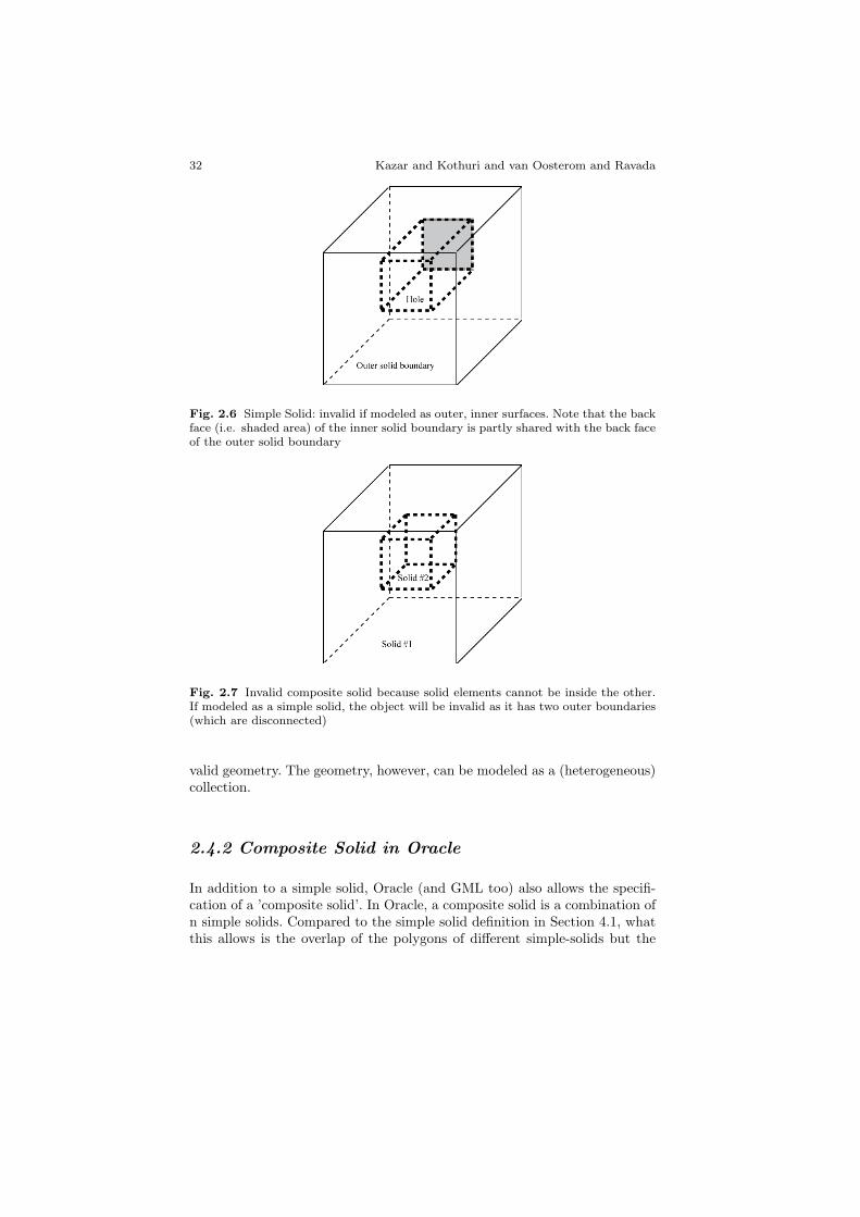
In Figure 6, simple solid has an outer boundary represented by a closedcomposite surface and a hole (Hole) represented by an inner composite sur-face. These two solids share a face. This solid is invalid since it violates theinner-outer disjointedness rule of a simple solid. However, this solid can bemodeled as a valid simple solid represented by a single outer composite sur-face without any inner surfaces (solid with dent).
The composite-solid in Figure 7 is composed of Solid 1 and Solid 2. Eventhough solids have common (shared) area, Solid 2 is inside Solid 1, whichviolates the No-volume-intersection of composite-solids and hence invalid.
The examples in Figures 8-13 give a number of valid and invalid simplesolids. The captions of the figures do explain why. From these figures it be-comes clear that the validation includes a non-trivial topological analysis ofthe inner and outer boundary elements. Let us consider another example.The geometry in Figure 15 is designated as a composite-solid geometry con-sisting of simple solids: Solid 1 and Solid 2. Solid 2 has an outer boundaryand an additional surface patch intersecting (overlapping) one of its faces.This violates the No-surface-patch rule of simple solids and hence is an in-
32 Kazar and Kothuri and van Oosterom and Ravada
Fig. 2.6 Simple Solid: invalid if modeled as outer, inner surfaces. Note that the backface (i.e. shaded area) of the inner solid boundary is partly shared with the back faceof the outer solid boundary
Fig. 2.7 Invalid composite solid because solid elements cannot be inside the other.If modeled as a simple solid, the object will be invalid as it has two outer boundaries(which are disconnected)
valid geometry. The geometry, however, can be modeled as a (heterogeneous)collection.
2.4.2 Composite Solid in Oracle
In addition to a simple solid, Oracle (and GML too) also allows the specifi-cation of a ’composite solid’. In Oracle, a composite solid is a combination ofn simple solids. Compared to the simple solid definition in Section 4.1, whatthis allows is the overlap of the polygons of different simple-solids but the

2 On Valid and Invalid Three-Dimensional Geometries 33
Fig. 2.8 The importance of checking the intersection between faces: all 3 simplesolids have the same node-edge connectivity, but the last (rightmost) one has inter-secting faces and is therefore invalid
Fig. 2.9 Simple solid with ‘inner’ boundary touching the outer boundary in one line(fat edges are used 4 times). The left solid is valid, while the right simple solid isinvalid (together the two ‘inner’ boundaries separate the solid into two parts). Notethat both solids do not really have inner boundaries (it is a more complex single outerboundary causing through holes touching the outer boundary in other places)
Fig. 2.10 Simple solid with inner boundary touching the outer boundary in two lines(fat edges are used 4 times). The left solid is the only solid with a true inner boundary(touching the outer boundary in two lines: right outer boundary in the fat line andthe back outer boundary in the fat dashed line). The left is a valid simple solid. Themiddle solid is also valid (because inner boundary does not continue through thewhole), while the right simple solid is invalid (as inner boundary does separate thesolid into two parts). Again note that the middle and right solids do not really haveinner boundaries (it is a more complex single outer boundary)

34 Kazar and Kothuri and van Oosterom and Ravada
Fig. 2.11 Invalid simple solids of previous figures becoming valid via adding anadditional handle making it possible to travel from one part to another part of theobject (completely via the interior). Note: where handle touches the face, a part of thefaces is removed (that is an interior ring is added within the exiting face to create theopen connection). So, all faces have always (and everywhere) on one side the objectand on the other side something else (outside, where the normal is pointing to)
Fig. 2.12 Left: simple solid with 6 internal (cube-shaped) boundaries separatingthe big cube into two parts (the internal one draw with fat lines is implied by the6 boundaries of the 6 smaller cube-shaped holes). Therefore the left simple solid isinvalid (note that removing one of the 6 holes, makes it valid again). Right: Invalidsimple solids of previous figures becoming valid via adding an additional handle mak-ing it possible to travel from one part to another part of the object (completely viathe interior). Right: the two parts are connected via a ’pipe’ making it a valid simplesolid again
boundary is still closed. Note that this does not allow overlapping polygonsin the same simple solid but only across multiple simple solids.
Following theorem shows the equivalence of a ’simple solid’ and a ’compos-ite solid’. Composite solids are defined for convenience: it is easier to combinetwo or more simple solids and make a composite. For the same reason, theyare also included in GML specification too. However, the composite solids inGML do allow inner rings in polygons whereas the Oracle model does notbut still equivalent (from Theorem 1 and Theorem 2).Theorem 2: Every valid composite solid can also be represented as a simplesolid.Proof: Composite solid always has solids attached to each other via partiallyor fully shared faces. Having detected these shared faces, one can get rid

2 On Valid and Invalid Three-Dimensional Geometries 35
Fig. 2.13 Left: valid simple solid (fat edge still used 4 times), but handle is addedthrough which it is possible to travel from one part to the other part via the interioronly, Right: invalid simple solid with one edge being used four times (fat line)
of these faces and redefine the solid without these shared areas. Figure 14illustrates an example.
Fig. 2.14 (a) Composite Solid consisting of two simple solids A and B. Sharedportion of bottom face of A (i.e. shaded area) in both A and B. (b) Equivalent SimpleSolid. Shared portion of bottom face of A should not be included in the boundary.
Validation Rules for Composite Solids
• Component Validity: Each component simple solid of a composite isvalid.
• Shared-face but no-volume intersection: Intersection of two simplesolid components of a composite solid has to be a zero volume (can benon-zero area).

36 Kazar and Kothuri and van Oosterom and Ravada
• Connectedness: The volume of the composite is contiguous, i.e. we cango from any point in one component to any other component withoutgoing out of the composite solid.
Since composite solids are equivalent to a simple solid, an alternate way issimply convert the composite to the equivalent simple solid and then validatethe resulting solid.
Fig. 2.15 Invalid Composite Solid: Cannot have surface patches on a solid
Fig. 2.16 If modeled as a Composite Solid, the object is invalid due to intersectionof solid elements. If modeled as a simple solid, the object is invalid due to ‘overlappingpolygons’ of composite surface
Consider a third example on composite-solids in Figure 16, which is com-posed of a cube and a triangular prism where a prism goes into the cubethrough its top face. This is an invalid geometry because it violates the No-volume intersection rule of composite-solids.
2 On Valid and Invalid Three-Dimensional Geometries 37
2.5 Collections
Following GML [GML03] specifications, collections in Oracle can be eitherhomogenous or heterogeneous. Let us look at each of these in turn.
2.5.1 Homogenous Collections
A homogenous collection is a collection of elements, where all elements are ofthe same type. A homogenous collection can be either a multi-point, multi-line, multi-surface, or multi-solid corresponding to the element type point,line, surface and solid. For example, in a multi-solid, all elements have to be(valid) solids.
Validation Rules for Homogenous Collections:
• All elements of same type and conform to the homogenous collection type(multi-point, multi-line, multi-surface, multi-solid).
• Each element should be valid.
In addition to the above rules, Oracle also adds a specific rule for determin-ing disjointedness of elements in a homogeneous collection in validation pro-cedures (this is a deviation from the GML specification). The reason to addthe disjointedness is to distinguish between composite solids and multi-solids.If the user does not want this restriction, he can model it as a heterogeneouscollection.
The geometry in Figure 16 is also invalid as a multi-solid because it violatesthe disjointedness rule for multi-solids. Note that the disjointedness in multi-solids not only implies no-volume intersection but also no-area intersection.The latter is represented by the geometry in Figure 17, which is invalid dueto the disjointedness (no-area intersection) rule of multi-solids.
2.5.2 Heterogeneous Collections
In a heterogeneous collection1, the elements can be a mixture of differenttypes. For example, a building (simple solid) with the windows/doors (sur-faces) can be modeled as a heterogeneous collection.
1 In Oracle documentation, a heterogeneous collection is referred to simply as a‘collection’. All homogeneous collections are referred to by their names (e.g. multi-line, multi-point, multi-surface, multi-solid).

38 Kazar and Kothuri and van Oosterom and Ravada
Fig. 2.17 Invalid multi-solid because solid elements are non-disjoint (but a validcomposite solid
Validation Rules for Heterogeneous Collections:
• Each element of the collection should be valid.
Figure 18 shows an example of a building modeled as a heterogeneouscollection: The building shape is modeled as a solid whereas the windowsand doors are modeled as surfaces.
Fig. 2.18 Building modeled as a Heterogeneous collection

2 On Valid and Invalid Three-Dimensional Geometries 39
2.6 Discussions and future work
In this paper, we presented a data model for storing 3D objects that occur inthe rapidly evolving area of city modeling. We examined different types anddescribed rules for validating these types of geometries based on OGC/ISOstandards [ISO03, OGC6a, OGC6b, OGC6c]. We then developed and pre-sented in this paper the more detailed, unambiguous validation rules andapplied them to different examples to determine validity or otherwise. Sucha data model and validation rules can form the backbone of 3D data mod-els needed for proper interoperability (having exactly the same definition ofthe geometric primitive during the exchange of 3D data). Our specific con-tributions include: simpler representation for solids (by eliminating the needfor inner rings in polygons) thereby simplifying the validation of solids, ex-plicit rules for validation of each geometry type, and concrete examples forvalid and invalid 3D geometries that bring out the concepts of the valida-tion model. This model and validation rules have been implemented in theOracle 11g database (the implementation details have not been included dueto space restrictions). The rules that are more involved to implement arethe Closedness test and the Reachability/Connectedness tests. Full detailson our implementation of these tests are available in [Oracle07]. Future workcould concentrate on performance evaluation of the 3D data model, valida-tion and query on large-scale city models. Specific optimizations based on3D query window sizes [KR01] could be investigated. Besides, the 3D datamodeling using SDO GEOMETRY can be compared with other models suchas Tetrahedron-based models [POK06] in terms of functionality and perfor-mance. Since the area of 3D modeling in databases is a fledgling topic, weneed to investigate on easy approaches for deriving 3D data by extruding2D footprints. By first converting arbitrary 2D polygons to a composite sur-face, via Lemma1, and then extruding them to 3D may be a good approach.Fast algorithms for doing this conversion may also be investigated (there ex-ist more efficient algorithms than the recursive construction in Lemma 1).Another important aspect in 3D modeling is visualization. Popular tools likeGoogle Sketchup work well with 3D surfaces but do not understand 3D solids.Other tools such as Landxplorer and Aristoteles visualize all types of 3D GMLgeometries. Commercial products from Autodesk work with their own pro-prietary 3D formats and are planning to publish to GML geometries. TheXj3D tools that are popular in the gaming community are also interoperat-ing with the GML forums. Using appropriate functions, the 3D data storedas SDO GEOMETRY can be converted to GML thereby opening it furtherto other interoperable formats. Future work can be devoted to developingfast rendering of the native 3D geometries.

40 Kazar and Kothuri and van Oosterom and Ravada
Acknowledgements
We would like to thank Friso Penninga for proof reading an earlier versionof this paper. The contribution of Peter van Oosterom to this publicationis the result of the research programme ’Sustainable Urban Areas’ (SUA)carried out by Delft University of Technology and the Bsik RGI project 3DTopography.
References
[Oracle07]. ‘Validation Rules and Algorithms for 3D Geoemtries in OracleSpatial’, 2007.
[ASO05] Calin Arens, Jantien Stoter and Peter van Oosterom, Modelling 3Dspatial objects in a geo-DBMS using a 3D primitive, In: Computers & Geo-sciences, Volume 31, 2, 2005, pp. 165-177.
[A94] Lars Arge, Mark de Berg, Herman J. Haverkort, Ke Yi: The PriorityR-Tree: A Practically Efficient and Worst-Case Optimal R-Tree. SIGMODConference 2004: 347-358.
[BKSS90] Beckmann, N., Kriegel, H., Schneider, R. and Seeger, B., The R*tree: An efficient and robust access method for points and rectangles. In Proc.ACM SIGMOD Int. Conf. on Management of Data, pages 322-331, 1990.
[BKS94] Brinkhof, T., Kriegel, H., and Seeger, B., Efficient processing of spa-tial joins using R-trees. In Proc. ACM SIGMOD Int. Conf. on Managementof Data, pages 237-246, 1994.
[BDA04] Nagender Bandi, Chengyu Sun, Amr El Abbadi, Divyakant Agrawal:Hardware Acceleration in Commercial Databases: A Case Study of SpatialOperations. VLDB 2004: 1021-1032.
[DE94] Dimitris Papadias, Yannis Theodoridis, Timos K. Sellis, Max J. Egen-hofer: Topological Relations in the World of Minimum Bounding Rectangles:A Study with R-trees. SIGMOD Conference 1995: 92-103.
[FD97] Foley, van Dam, Feiner, Hughes. Computer Graphics: Principles andPractice, The Systems Programming Series, 1997.
[G84] A. Guttman. R-trees: A dynamic index structure for spatial searching.Proc. ACM SIGMOD Int. Conf. on Management of Data, pages 4757, 1984.
2 On Valid and Invalid Three-Dimensional Geometries 41
[GML03] The Geographic Markup Language Specification. Version 3.1.1,http://www.opengeospatial.org.
[GSAM04] Thanaa M. Ghanem, Rahul Shah, Mohamed F. Mokbel, WalidG. Aref, Jeffrey Scott Vitter: Bulk Operations for Space-Partitioning Trees.ICDE 2004.
[HKV02] Marios Hadjieleftheriou, George Kollios, Vassilis J. Tsotras, Dim-itrios Gunopulos: Efficient Indexing of Spatiotemporal Objects. EDBT 2002:251-268.
[ISO03] ISO/TC 211/WG 2, ISO/CD 19107, Geographic information - Spa-tial schema, 2003.
[J04] Christian S. Jensen: Database Aspects of Location-Based Services.Location-Based Services 2004: 115-148.
[KGP05] Th. H. Kolbe, G. Groger, L. Plumer. CityGML: Interoperable Ac-cess to 3D City Models, In: Oosterom, P, Zlatanova, S., Fendel E. M. (editors)Geo-information for Disaster Management, Springer, pages 883-899, 2005.
[KAE04] Kothuri, R. Godfrind A, Beinat E. ‘Pro Oracle Spatial’, Apress,2004.
[KSSB99] Kothuri R., Ravada S., Sharma J., and Banerjee J., Indexingmedium dimentionality data, in Proc. ACM SIGMOD Int. Conf. On Man-agement of Data, 1999.
[KR01] Kothuri, R., Ravada, S., Efficient processing of large spatial queriesusing interior approximations, Symposium on Spatio-Temporal Databases,SSTD, 2001.
[L07]. Jung-Rae Hwang, Ji-Hyeon Oh, Ki-Joune Li: Query TransformationMethod by Dalaunay Triangulation for Multi-Source Distributed SpatialDatabase Systems. ACM-GIS 2001: 41-46.
[MP01] Nick Mamoulis, Dimitris Papadias: Multi-way Spatial Joins, ACMTODS, Vol 26, No. 4, pp 424-475, 2001.
[MTP05] Nikos Mamoulis, Yannis Theodoridis, Dimitris Papadias: Spa-tial Joins: Algorithms, Cost Models and Optimization Techniques. SpatialDatabases 2005: 155-184
[MA04] Mohamed F. Mokbel, Ming Lu, Walid G. Aref: Hash-Merge Join:A Non-blocking Join Algorithm for Producing Fast and Early Join Results.
42 Kazar and Kothuri and van Oosterom and Ravada
ICDE 2004: 251-263.
[M97] Mortenson, M. Geometric Modelling, second ed. Wiley, New York523pp., 1997.
[OGC99] Open GIS Consortium, Inc., OpenGIS Simple Features Specifica-tion For SQL, Revision 1.1, OpenGIS Project Document 99-049, 5 May 1999.
[OGC06a] Open Geospatial Consortium Inc., OpenGIS Implementation Spec-ification for Geographic information - Simple feature access - Part 1: Commonarchitecture, Version: 1.2.0, Reference number of this document: OGC OGC06-103r3, 2006.
[OGC06b] Open Geospatial Consortium Inc., OpenGIS Implementation Spec-ification for Geographic information - Simple feature access - Part 2: SQL op-tion, Version: 1.2.0, Reference number of this document: OGC 06-104r3, 2006.
[OGC06c] Open Geospatial Consortium Inc., Candidate OpenGIS CityGMLImplementation Specification , Reference number of this document: OGC 06-057r1, 2006.
[POK06] Penninga, F., van Oosterom, P. & Kazar, B. M., A TEN-basedDBMS approach for 3D Topographic Data Modelling, in Spatial Data Han-dling 2006.
[S89] H. Samet, The Design and Analysis of Spatial Data Structures, Addison-Wesley, 1989.
[SE02] Schneider J. P., and Eberly, D.H. Geometric Tools for ComputerGraphics, Morgan Kaufman, 2002.
[TS96] Y. Theodoridis and T. K. Sellis, A model for the prediction of r-treeperformance, In Proc. of ACM Symp. on Principles of Databases, 1996.
[OT03] P.J.M. van Oosterom, C.W. Quak and T.P.M. Tijssen, Polygons: theunstable foundation of spatial modeling, ISPRS Joint Workshop on ’Spatial,Temporal and Multi-Dimensional Data Modelling and Analysis’, Quebec, Oc-tober 2003.
[OT04] P.J.M. van Oosterom, C.W. Quak and T.P.M. Tijssen, About Invalid,Valid and Clean Polygons. In: Peter F. Fisher(Ed.); Developments in SpatialData Handling, 11th International Symposium on Spatial Data Handling,2004, pp. 1-16
2 On Valid and Invalid Three-Dimensional Geometries 43
[YE06] Yohei Kurata, Max J. Egenhofer: The Head-Body-Tail Intersectionfor Spatial Relations Between Directed Line Segments. GIScience 2006: 269-286 2005.
[YS05] Jin Soung Yoo, Shashi Shekhar: In-Route Nearest Neighbor Queries.GeoInformatica 9(2): 117-137 (2005).
[Z00] Zlatanova, S. On 3D Topological Relationships, DEXA Workshop, 2000.
Appendix A
Lemma 1: Any polygon P with an outer ring Po and (non-overlapping) in-terior rings Pi1, . . . ,Pin can always be decomposed into a composite surface S
where each polygon has no inner rings with the following characteristics:
• Every edge/vertex in P is an edge in one of the polygons of S.• Area(P) = Union of Area(Q) for all Q in S.• No polygon of S has an inner ring.• Every edge in S
– either belongs to P and is traversed only once in S
– or is an edge inside the outer ring Po and is traversed twice.
Proof: By induction on the number of inner rings. Let n=1. The polygon P
has one inner ring. On the inner ring find the two extreme (min, max) pointsImin, Imax along a specific axis of the plane of the polygon. Extend the min,max points along the dimension to meet the outer ring O of the polygon atOmin, Omax. The polygon P is now P1 and P2: the new edges < Omin, Imin >
and < Omax, Imax > are traversed twice: once in P1 and another time in reversedirection in P2. All other edges belong to P and are in either P1 or P2. Thenew edges do not cross any other edges, as Omin and Imin are the extremevertices. Hence P1 and P2 are valid polygons.
Hypothesis: Let the lemma be true for n=m-1.Consider a polygon P with m inner rings. Again, sort the rings along a
specific axis of the plane and find the ring that has a vertex with the minvalue on this axis (i.e. closest to the outer ring). Connect the vertex to eitherside of the outer ring along this axis. This ’cutting line’ cuts some innerrings (at least 1): For each such ring identify the first and the last vertexalong the cutting line for the ring. These vertices are the endpoints for thatinner ring and are connected to other rings that are cut or to the outer ringboundary. The cutting line cuts the outer ring and some inner rings intotwo parts. Without loss of generality, let us assume it cuts these rings intotop, and bottom halves. To identify these halves precisely for each ring r,first determine the extreme (leftmost and rightmost) points vL(r), vR(r) on
44 Kazar and Kothuri and van Oosterom and Ravada
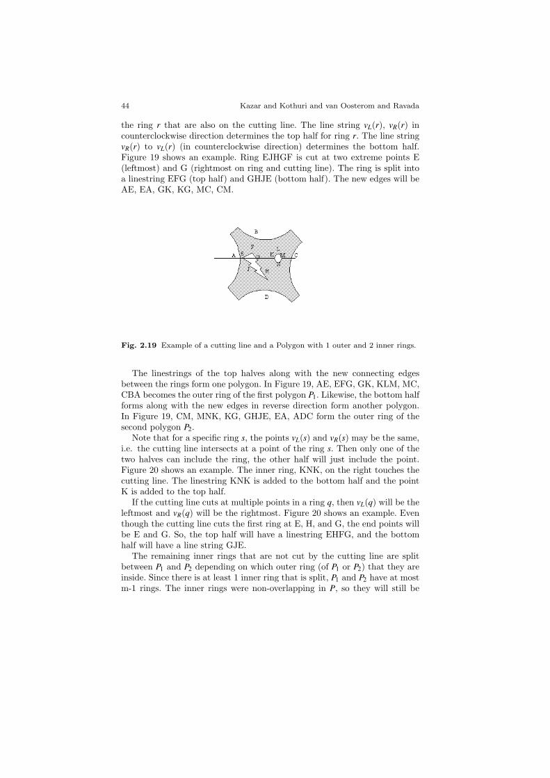
the ring r that are also on the cutting line. The line string vL(r), vR(r) incounterclockwise direction determines the top half for ring r. The line stringvR(r) to vL(r) (in counterclockwise direction) determines the bottom half.Figure 19 shows an example. Ring EJHGF is cut at two extreme points E(leftmost) and G (rightmost on ring and cutting line). The ring is split intoa linestring EFG (top half) and GHJE (bottom half). The new edges will beAE, EA, GK, KG, MC, CM.
Fig. 2.19 Example of a cutting line and a Polygon with 1 outer and 2 inner rings.
The linestrings of the top halves along with the new connecting edgesbetween the rings form one polygon. In Figure 19, AE, EFG, GK, KLM, MC,CBA becomes the outer ring of the first polygon P1. Likewise, the bottom halfforms along with the new edges in reverse direction form another polygon.In Figure 19, CM, MNK, KG, GHJE, EA, ADC form the outer ring of thesecond polygon P2.
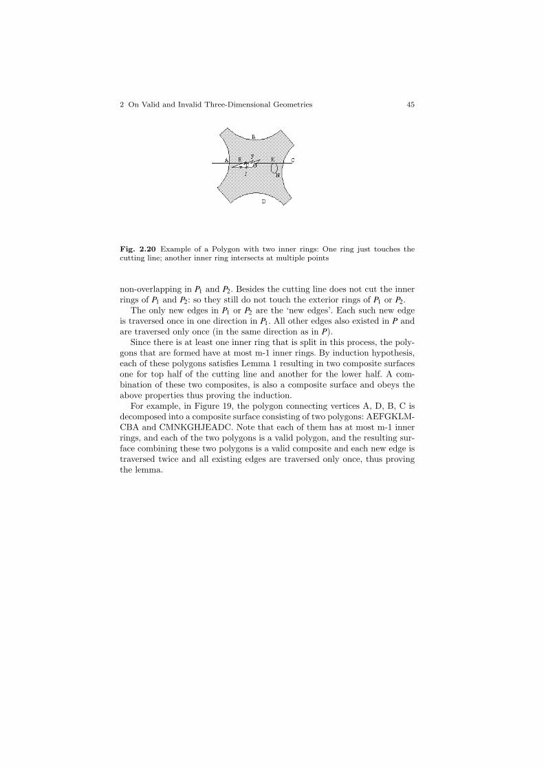
Note that for a specific ring s, the points vL(s) and vR(s) may be the same,i.e. the cutting line intersects at a point of the ring s. Then only one of thetwo halves can include the ring, the other half will just include the point.Figure 20 shows an example. The inner ring, KNK, on the right touches thecutting line. The linestring KNK is added to the bottom half and the pointK is added to the top half.
If the cutting line cuts at multiple points in a ring q, then vL(q) will be theleftmost and vR(q) will be the rightmost. Figure 20 shows an example. Eventhough the cutting line cuts the first ring at E, H, and G, the end points willbe E and G. So, the top half will have a linestring EHFG, and the bottomhalf will have a line string GJE.
The remaining inner rings that are not cut by the cutting line are splitbetween P1 and P2 depending on which outer ring (of P1 or P2) that they areinside. Since there is at least 1 inner ring that is split, P1 and P2 have at mostm-1 rings. The inner rings were non-overlapping in P, so they will still be
2 On Valid and Invalid Three-Dimensional Geometries 45
Fig. 2.20 Example of a Polygon with two inner rings: One ring just touches thecutting line; another inner ring intersects at multiple points
non-overlapping in P1 and P2. Besides the cutting line does not cut the innerrings of P1 and P2: so they still do not touch the exterior rings of P1 or P2.
The only new edges in P1 or P2 are the ‘new edges’. Each such new edgeis traversed once in one direction in P1. All other edges also existed in P andare traversed only once (in the same direction as in P).
Since there is at least one inner ring that is split in this process, the poly-gons that are formed have at most m-1 inner rings. By induction hypothesis,each of these polygons satisfies Lemma 1 resulting in two composite surfacesone for top half of the cutting line and another for the lower half. A com-bination of these two composites, is also a composite surface and obeys theabove properties thus proving the induction.
For example, in Figure 19, the polygon connecting vertices A, D, B, C isdecomposed into a composite surface consisting of two polygons: AEFGKLM-CBA and CMNKGHJEADC. Note that each of them has at most m-1 innerrings, and each of the two polygons is a valid polygon, and the resulting sur-face combining these two polygons is a valid composite and each new edge istraversed twice and all existing edges are traversed only once, thus provingthe lemma.

46 Kazar and Kothuri and van Oosterom and Ravada
Appendix B
Fig. 2.21 Examples of different types of 3D geometries
Copyright © 2022 FDOKUMEN