Release 2022 R1 Highlights Ansys Sherlock & Electronics ...
56
Release 2022 R1 Highlights Ansys Sherlock & Electronics Reliability
-
Upload
khangminh22 -
Category
Documents
-
view
0 -
download
0
Transcript of Release 2022 R1 Highlights Ansys Sherlock & Electronics ...

Release 2022 R1 HighlightsAnsys Sherlock & Electronics Reliability
2
Ansys Electronics Reliability Updates – 2022 R1
• Ansys Sherlock‐ Semi-Automated Reinforcement Element Workflow
Solution‐ Sherlock-Icepak – EDB File Export‐ Import of GDSII/EDB Files‐ Sherlock Automation APIs‐ Sherlock-optiSLang Connection Details‐ General Functionality Enhancements‐ Documentation Updates
• Ansys Mechanical‐ Trace Mapping – Support for Solid-Shell Elements‐ Reinforcement Element Enhancements
• Ansys LS-DYNA‐ Multiscale Analyses‐ Solder Reflow Simulations
• Ansys Icepak
• Ansys AEDT Mechanical
• Additional Resources

Ansys Sherlock
4
Ansys Sherlock – Typical Uses
Sherlock for Reliability
Sherlock as a Pre-Processor
Sherlock Integrations
Ansys Sherlock
Mechanical & LS-DYNA
AEDT Icepak
Granta MI
medini
Minerva
optiSLang
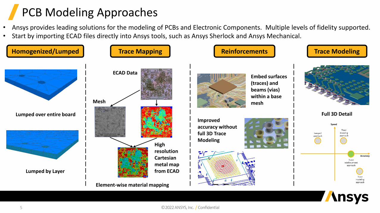
PCB Modeling Approaches• Ansys provides leading solutions for the modeling of PCBs and Electronic Components. Multiple levels of fidelity supported.• Start by importing ECAD files directly into Ansys tools, such as Ansys Sherlock and Ansys Mechanical.
ECAD Data
Mesh
High resolution Cartesian metal map from ECAD
Element-wise material mapping
Lumped over entire board
Lumped by Layer
Full 3D Detail
Embed surfaces (traces) and beams (vias) within a base mesh
Improved accuracy without full 3D Trace Modeling
Homogenized/Lumped Trace Mapping Trace ModelingReinforcements
5
6
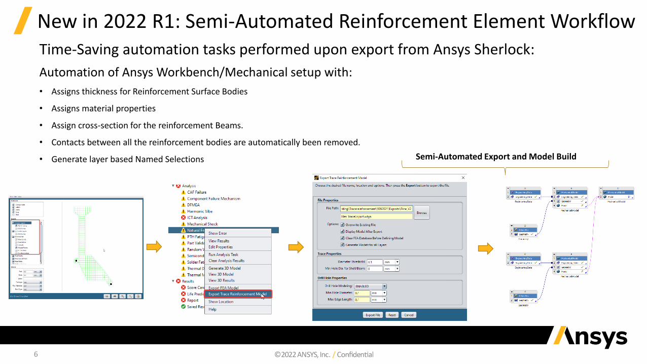
New in 2022 R1: Semi-Automated Reinforcement Element WorkflowTime-Saving automation tasks performed upon export from Ansys Sherlock:
Automation of Ansys Workbench/Mechanical setup with:
• Assigns thickness for Reinforcement Surface Bodies
• Assigns material properties
• Assign cross-section for the reinforcement Beams.
• Contacts between all the reinforcement bodies are automatically been removed.
• Generate layer based Named Selections Semi-Automated Export and Model Build

7
New in 2022 R1: Bending Stiffness for Smeared Reinforcement• Greatly improves the solution accuracy with 3D smeared reinforcing (REINF) models• Eliminates the need to use multiple REINF layers to capture the bending stiffness• Enhances the REINF modeling usability in the new PCP/Chip simulation workflow
Reinforcing w/o bending stiffness Reinforcing with bending stiffness Full 3D model (trace modeling)
Accurate simulation results: REINF with bending vs. full 3D model
Robust and accurate simulation of flexible PCBs under large deformation

8
New in 2022 R1: Reinforcing Performance Enhancements
• Motivated by the requirements to account for large models (full PCB and chip models)
• Improved performance in pre-processing‐ Allows large number of reinforcing members in one
base element
‐ Reduces time needed for load mapping
• Improved solution efficiency
• Improved performance in post-processing ‐ Significantly reduced time for querying min/max
member results
‐ Improved inter-member result smoothing
9
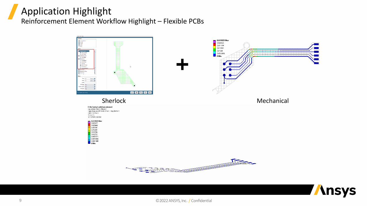
Application HighlightReinforcement Element Workflow Highlight – Flexible PCBs
Sherlock Mechanical

Sherlock-Icepak Connection
EDB File Export

11
New in 2022 R1: Sherlock-Icepak Connection (EDB File Export)• Users can now export a CCA using the EDB format that is used by Ansys AEDT.
‐ Ansys ECAD Database (*.def) file (Commonly referred to as an EDB file).
‐ EDB files can then be imported directly in to AEDT.
‐ If installed, AEDT can be opened automatically (including the resulting file import).
• Consequently, users can leverage the power of Ansys Sherlock to rapidly generate
high-fidelity PCB models for use with Ansys AEDT Icepak.
Supported Features in 2022 R1:
• Stackup Layers
• Board Outline
• Holes‐ Vias
‐ Plated Through-Holes
‐ Non-Plated Through-Holes
• Traces
• Cutouts
• Components
• Pads (Stored as Pins)
• Material PropertiesAnsys AEDT/Icepak
Ansys Sherlock

GDSII/EDB Import
13
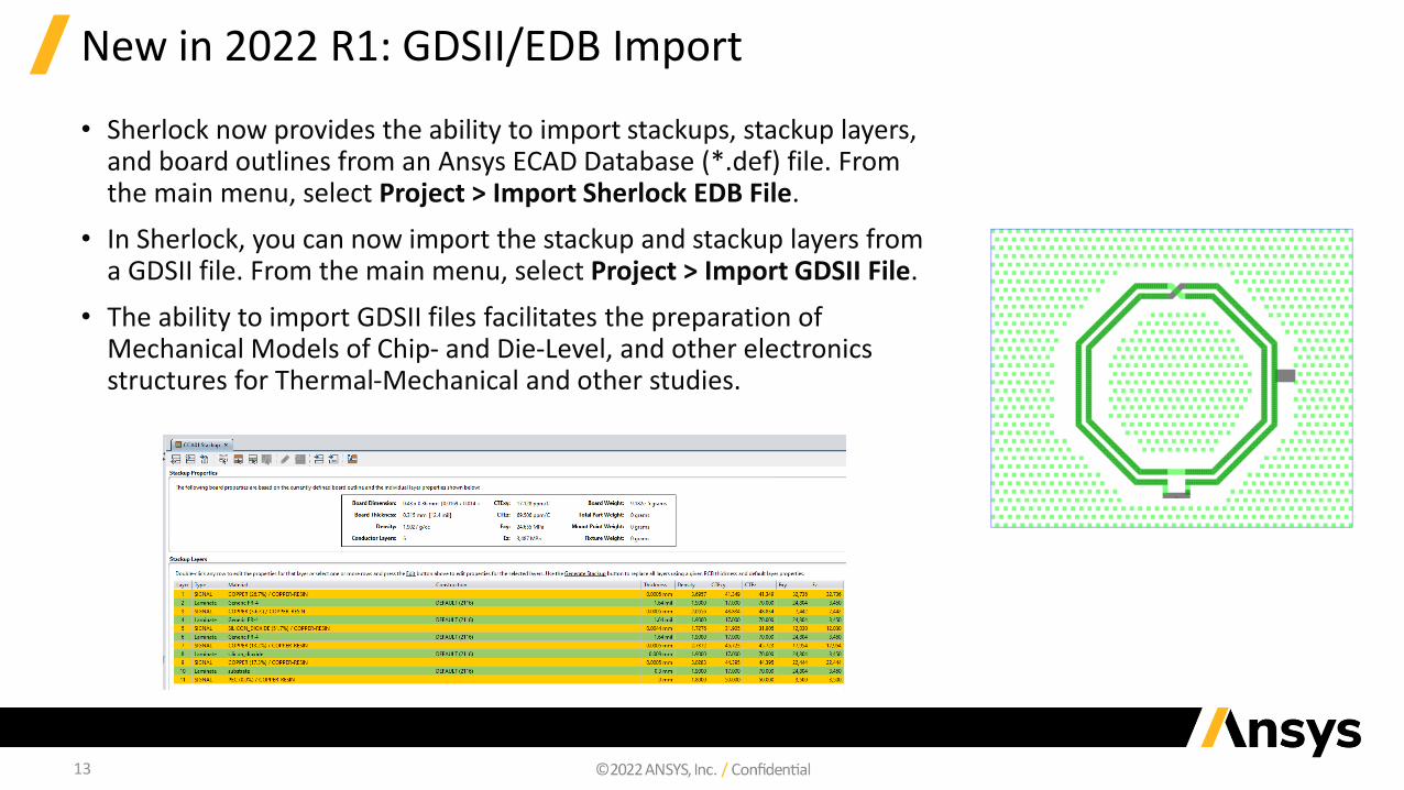
New in 2022 R1: GDSII/EDB Import
• Sherlock now provides the ability to import stackups, stackup layers, and board outlines from an Ansys ECAD Database (*.def) file. From the main menu, select Project > Import Sherlock EDB File.
• In Sherlock, you can now import the stackup and stackup layers from a GDSII file. From the main menu, select Project > Import GDSII File.
• The ability to import GDSII files facilitates the preparation of Mechanical Models of Chip- and Die-Level, and other electronics structures for Thermal-Mechanical and other studies.

Sherlock Automation APIs
15
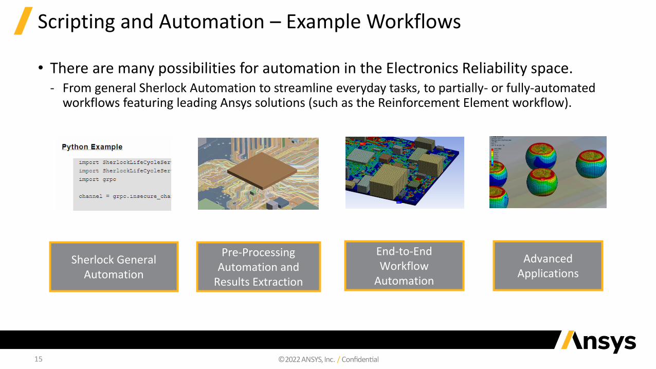
Scripting and Automation – Example Workflows
• There are many possibilities for automation in the Electronics Reliability space.‐ From general Sherlock Automation to streamline everyday tasks, to partially- or fully-automated
workflows featuring leading Ansys solutions (such as the Reinforcement Element workflow).
End-to-End Workflow
Automation
Sherlock General Automation
Pre-Processing Automation and
Results Extraction
Advanced Applications
16
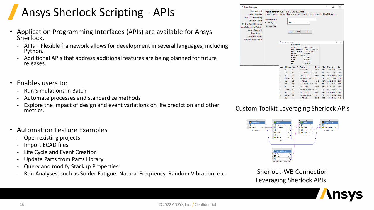
Ansys Sherlock Scripting - APIs
• Application Programming Interfaces (APIs) are available for Ansys Sherlock.‐ APIs – Flexible framework allows for development in several languages, including
Python.‐ Additional APIs that address additional features are being planned for future
releases.
• Enables users to:‐ Run Simulations in Batch‐ Automate processes and standardize methods‐ Explore the impact of design and event variations on life prediction and other
metrics.
• Automation Feature Examples‐ Open existing projects‐ Import ECAD files‐ Life Cycle and Event Creation‐ Update Parts from Parts Library‐ Query and modify Stackup Properties‐ Run Analyses, such as Solder Fatigue, Natural Frequency, Random Vibration, etc.
Custom Toolkit Leveraging Sherlock APIs
Sherlock-WB Connection Leveraging Sherlock APIs
17
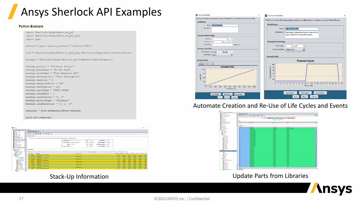
Ansys Sherlock API Examples
Stack-Up Information
Automate Creation and Re-Use of Life Cycles and Events
Update Parts from Libraries
18
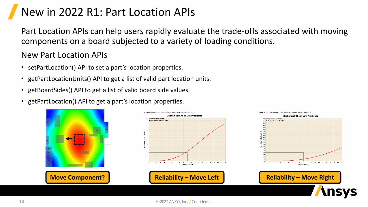
New in 2022 R1: Part Location APIs
Part Location APIs can help users rapidly evaluate the trade-offs associated with moving components on a board subjected to a variety of loading conditions.
New Part Location APIs
• setPartLocation() API to set a part’s location properties.
• getPartLocationUnits() API to get a list of valid part location units.
• getBoardSides() API to get a list of valid board side values.
• getPartLocation() API to get a part’s location properties.
Move Component? Reliability – Move Left Reliability – Move Right
19
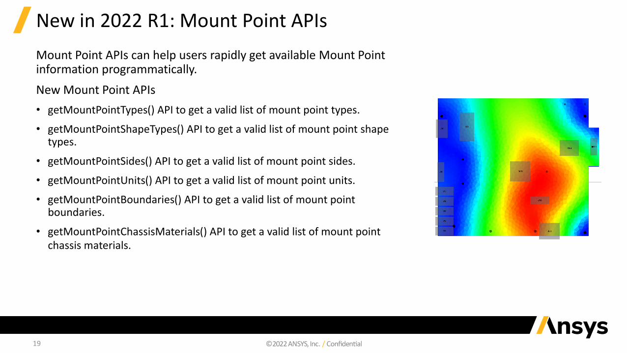
New in 2022 R1: Mount Point APIs
Mount Point APIs can help users rapidly get available Mount Point information programmatically.
New Mount Point APIs
• getMountPointTypes() API to get a valid list of mount point types.
• getMountPointShapeTypes() API to get a valid list of mount point shape types.
• getMountPointSides() API to get a valid list of mount point sides.
• getMountPointUnits() API to get a valid list of mount point units.
• getMountPointBoundaries() API to get a valid list of mount point boundaries.
• getMountPointChassisMaterials() API to get a valid list of mount point chassis materials.

Sherlock-optiSLang Connection
21
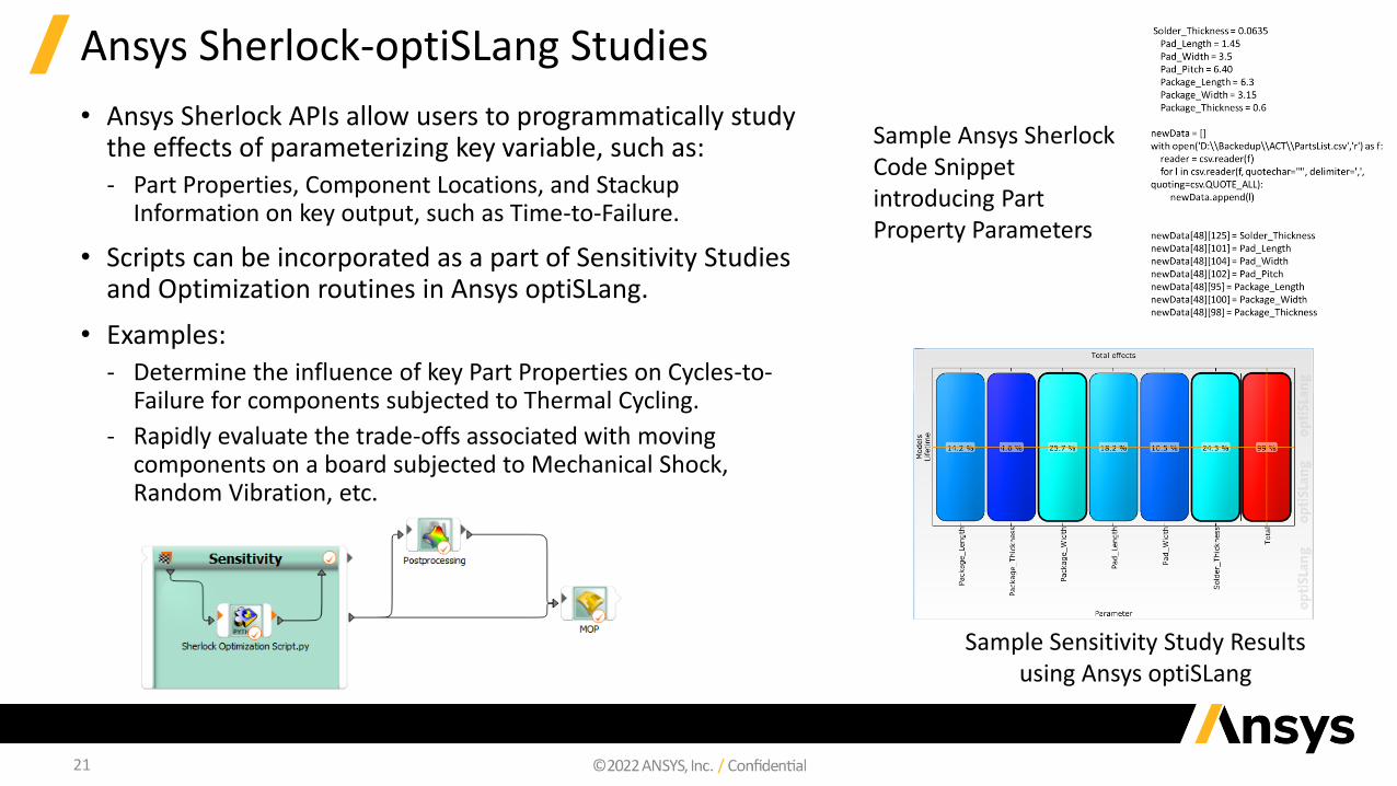
Ansys Sherlock-optiSLang Studies
• Ansys Sherlock APIs allow users to programmatically study the effects of parameterizing key variable, such as:‐ Part Properties, Component Locations, and Stackup
Information on key output, such as Time-to-Failure.
• Scripts can be incorporated as a part of Sensitivity Studies and Optimization routines in Ansys optiSLang.
• Examples:‐ Determine the influence of key Part Properties on Cycles-to-
Failure for components subjected to Thermal Cycling.
‐ Rapidly evaluate the trade-offs associated with moving components on a board subjected to Mechanical Shock, Random Vibration, etc.
Sample Ansys Sherlock Code Snippet introducing Part Property Parameters
Sample Sensitivity Study Results using Ansys optiSLang

Sherlock General Enhancements
23
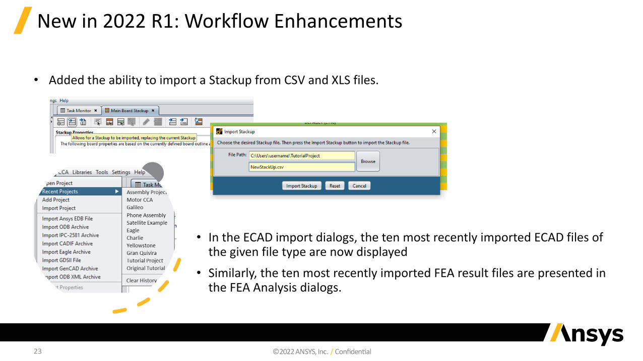
New in 2022 R1: Workflow Enhancements
• In the ECAD import dialogs, the ten most recently imported ECAD files of the given file type are now displayed
• Similarly, the ten most recently imported FEA result files are presented in the FEA Analysis dialogs.
• Added the ability to import a Stackup from CSV and XLS files.
24
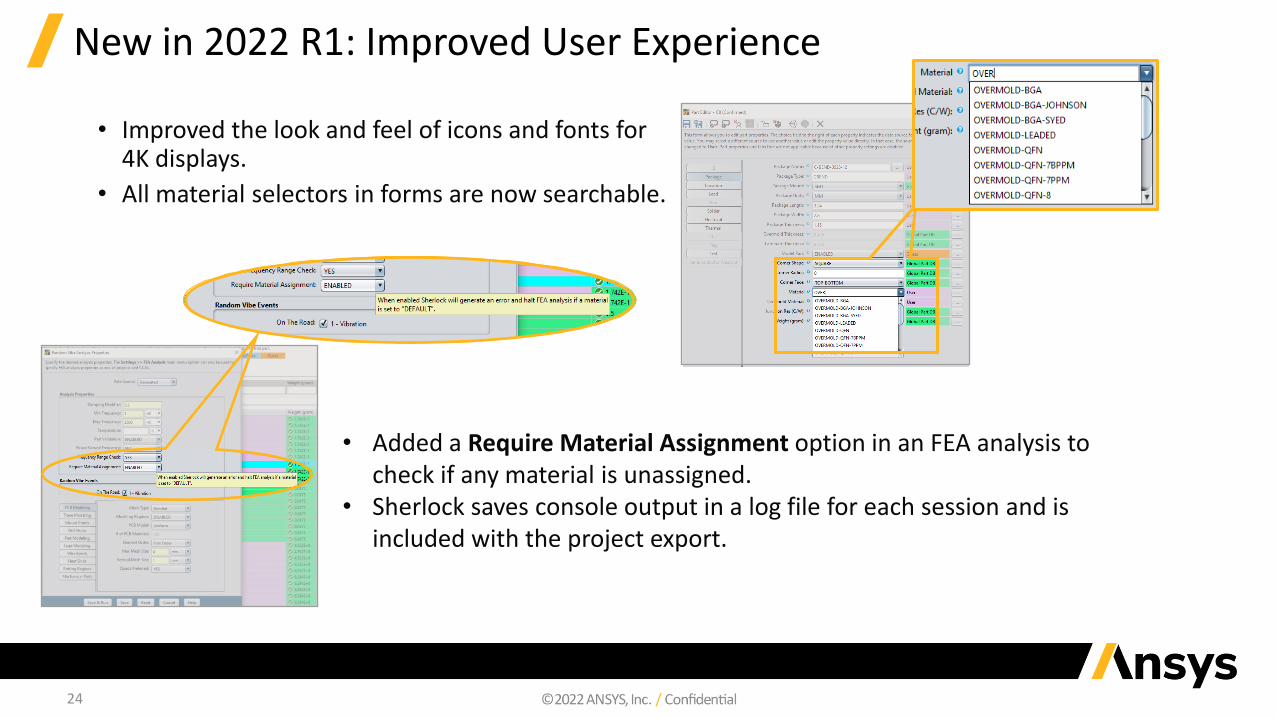
New in 2022 R1: Improved User Experience
• Improved the look and feel of icons and fonts for 4K displays.
• All material selectors in forms are now searchable.
• Added a Require Material Assignment option in an FEA analysis to check if any material is unassigned.
• Sherlock saves console output in a log file for each session and is included with the project export.

25
Additional Sherlock Enhancements in 2022 R1
• Added option in Advanced Settings to display and use part body weight to update part body's material density in FEA analyses only.
Refer to Sherlock Part Properties in the Sherlock User's Guide.
• Sherlock now provides the ability to edit the specific heat property of materials in the Materials Library. Some materials have a specific
heat property set already. This is useful for exporting to Electronics Desktop so that it can be used for Icepak simulations.
• Improved initial loading time of the Part Viewer and editor dialogs.
• Updated package model forms to hide the package thickness field for BGA packages. BGA packages use the Overmold and Laminate
Thickness fields instead.
• Added a Require Material Assignment option in an FEA analysis to check if any material is unassigned. If this option is enabled, the FEA
analysis will stop as soon as it finds a material that is not assigned. If this option is not enabled and Sherlock finds material that is not
assigned, a message appears in the Results Viewer.
• Added information tooltips to the Stackup Properties and Stackup table.
• Updated the Parts List and Part Editor so they no longer update the pad properties of QFN packages when selecting Update Pad
Properties.
• Updated the Part Editor to disable the solder tab if a BGA package is selected.
• Updated the Package Editor so that when a BGA package is added, the package does not have to be saved before adding ball parameters
26
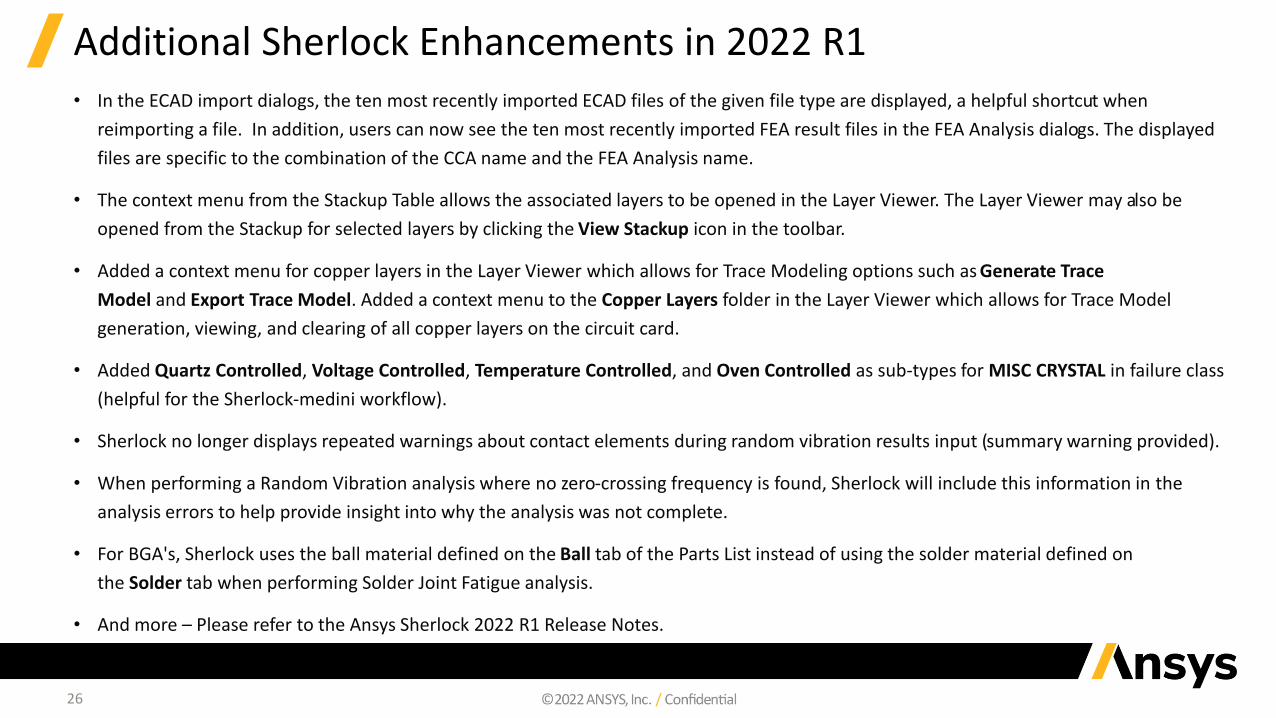
Additional Sherlock Enhancements in 2022 R1• In the ECAD import dialogs, the ten most recently imported ECAD files of the given file type are displayed, a helpful shortcut when
reimporting a file. In addition, users can now see the ten most recently imported FEA result files in the FEA Analysis dialogs. The displayed
files are specific to the combination of the CCA name and the FEA Analysis name.
• The context menu from the Stackup Table allows the associated layers to be opened in the Layer Viewer. The Layer Viewer may also be
opened from the Stackup for selected layers by clicking the View Stackup icon in the toolbar.
• Added a context menu for copper layers in the Layer Viewer which allows for Trace Modeling options such as Generate Trace
Model and Export Trace Model. Added a context menu to the Copper Layers folder in the Layer Viewer which allows for Trace Model
generation, viewing, and clearing of all copper layers on the circuit card.
• Added Quartz Controlled, Voltage Controlled, Temperature Controlled, and Oven Controlled as sub-types for MISC CRYSTAL in failure class
(helpful for the Sherlock-medini workflow).
• Sherlock no longer displays repeated warnings about contact elements during random vibration results input (summary warning provided).
• When performing a Random Vibration analysis where no zero-crossing frequency is found, Sherlock will include this information in the
analysis errors to help provide insight into why the analysis was not complete.
• For BGA's, Sherlock uses the ball material defined on the Ball tab of the Parts List instead of using the solder material defined on
the Solder tab when performing Solder Joint Fatigue analysis.
• And more – Please refer to the Ansys Sherlock 2022 R1 Release Notes.

27
Documentation Updates in Ansys Sherlock 2022 R1
• Available Theory Manuals‐ Solder Fatigue Caused by Thermal Cycling
• BGA Model
• Quad Flat No-Lead (QFN) Package
‐ Thermal Mech
‐ In-Circuit Testing (ICT)
‐ Random Vibration
‐ Mechanical Shock
• User Guide Updates‐ Overhauled ‘Ansys Workbench Integration’ Chapter to include the latest updates.
‐ Improved ‘Importing Projects and ECAD Archives’ sections.

Sherlock Beta Features
29
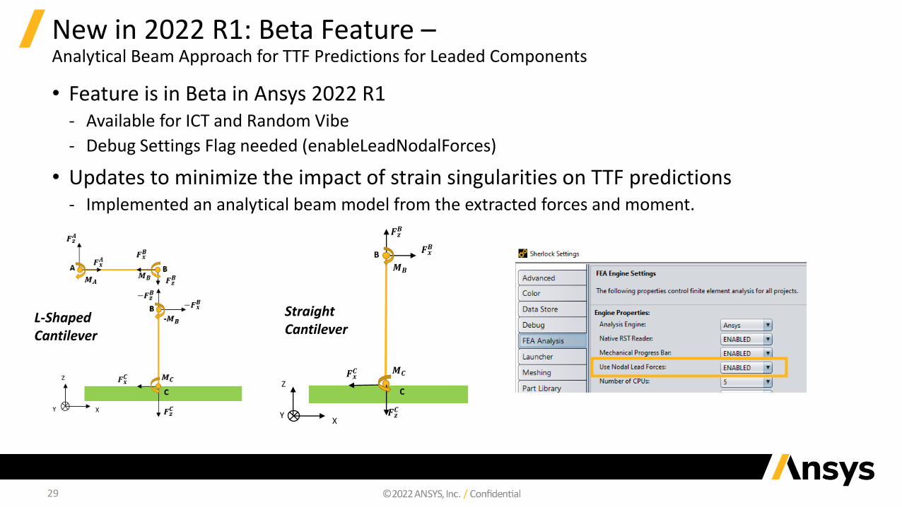
New in 2022 R1: Beta Feature –Analytical Beam Approach for TTF Predictions for Leaded Components
• Feature is in Beta in Ansys 2022 R1‐ Available for ICT and Random Vibe
‐ Debug Settings Flag needed (enableLeadNodalForces)
• Updates to minimize the impact of strain singularities on TTF predictions‐ Implemented an analytical beam model from the extracted forces and moment.
L-Shaped Cantilever
Straight Cantilever
B
Z
XY
𝑭𝒙𝑩
𝑭𝒛𝑩
C
𝑭𝒙𝑪
𝑭𝒛𝑪
𝑴𝑩
𝑴𝑪

Ansys Mechanical
31
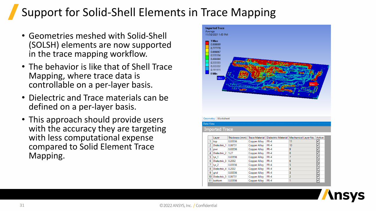
Support for Solid-Shell Elements in Trace Mapping
• Geometries meshed with Solid-Shell (SOLSH) elements are now supported in the trace mapping workflow.
• The behavior is like that of Shell Trace Mapping, where trace data is controllable on a per-layer basis.
• Dielectric and Trace materials can be defined on a per-layer basis.
• This approach should provide users with the accuracy they are targeting with less computational expense compared to Solid Element Trace Mapping.
32
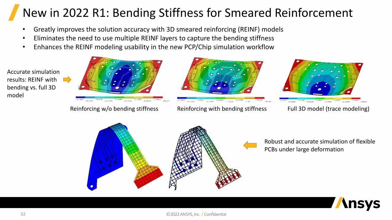
New in 2022 R1: Bending Stiffness for Smeared Reinforcement• Greatly improves the solution accuracy with 3D smeared reinforcing (REINF) models• Eliminates the need to use multiple REINF layers to capture the bending stiffness• Enhances the REINF modeling usability in the new PCP/Chip simulation workflow
Reinforcing w/o bending stiffness Reinforcing with bending stiffness Full 3D model (trace modeling)
Accurate simulation results: REINF with bending vs. full 3D model
Robust and accurate simulation of flexible PCBs under large deformation
33
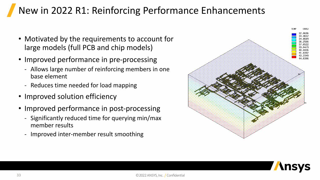
New in 2022 R1: Reinforcing Performance Enhancements
• Motivated by the requirements to account for large models (full PCB and chip models)
• Improved performance in pre-processing‐ Allows large number of reinforcing members in one
base element
‐ Reduces time needed for load mapping
• Improved solution efficiency
• Improved performance in post-processing ‐ Significantly reduced time for querying min/max
member results
‐ Improved inter-member result smoothing

Ansys LS-DYNA
35
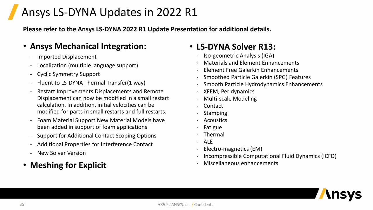
Ansys LS-DYNA Updates in 2022 R1
• Ansys Mechanical Integration:‐ Imported Displacement
‐ Localization (multiple language support)
‐ Cyclic Symmetry Support
‐ Fluent to LS-DYNA Thermal Transfer(1 way)
‐ Restart Improvements Displacements and Remote Displacement can now be modified in a small restart calculation. In addition, initial velocities can be modified for parts in small restarts and full restarts.
‐ Foam Material Support New Material Models have been added in support of foam applications
‐ Support for Additional Contact Scoping Options
‐ Additional Properties for Interference Contact
‐ New Solver Version
• Meshing for Explicit
• LS-DYNA Solver R13:‐ Iso-geometric Analysis (IGA)‐ Materials and Element Enhancements‐ Element Free Galerkin Enhancements‐ Smoothed Particle Galerkin (SPG) Features‐ Smooth Particle Hydrodynamics Enhancements‐ XFEM, Peridynamics‐ Multi-scale Modeling‐ Contact‐ Stamping‐ Acoustics‐ Fatigue‐ Thermal‐ ALE‐ Electro-magnetics (EM)‐ Incompressible Computational Fluid Dynamics (ICFD)‐ Miscellaneous enhancements
Please refer to the Ansys LS-DYNA 2022 R1 Update Presentation for additional details.
36
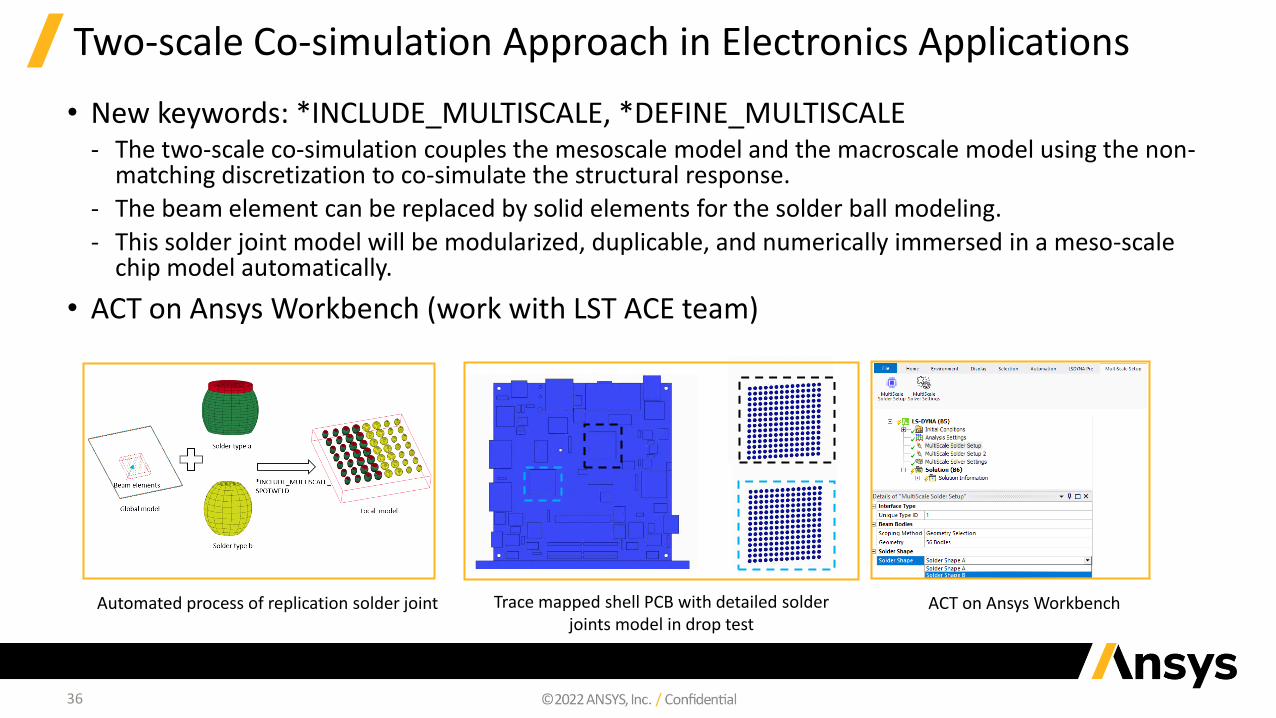
Two-scale Co-simulation Approach in Electronics Applications
• New keywords: *INCLUDE_MULTISCALE, *DEFINE_MULTISCALE‐ The two-scale co-simulation couples the mesoscale model and the macroscale model using the non-
matching discretization to co-simulate the structural response.
‐ The beam element can be replaced by solid elements for the solder ball modeling.
‐ This solder joint model will be modularized, duplicable, and numerically immersed in a meso-scale chip model automatically.
• ACT on Ansys Workbench (work with LST ACE team)
Automated process of replication solder joint Trace mapped shell PCB with detailed solder joints model in drop test
ACT on Ansys Workbench
37
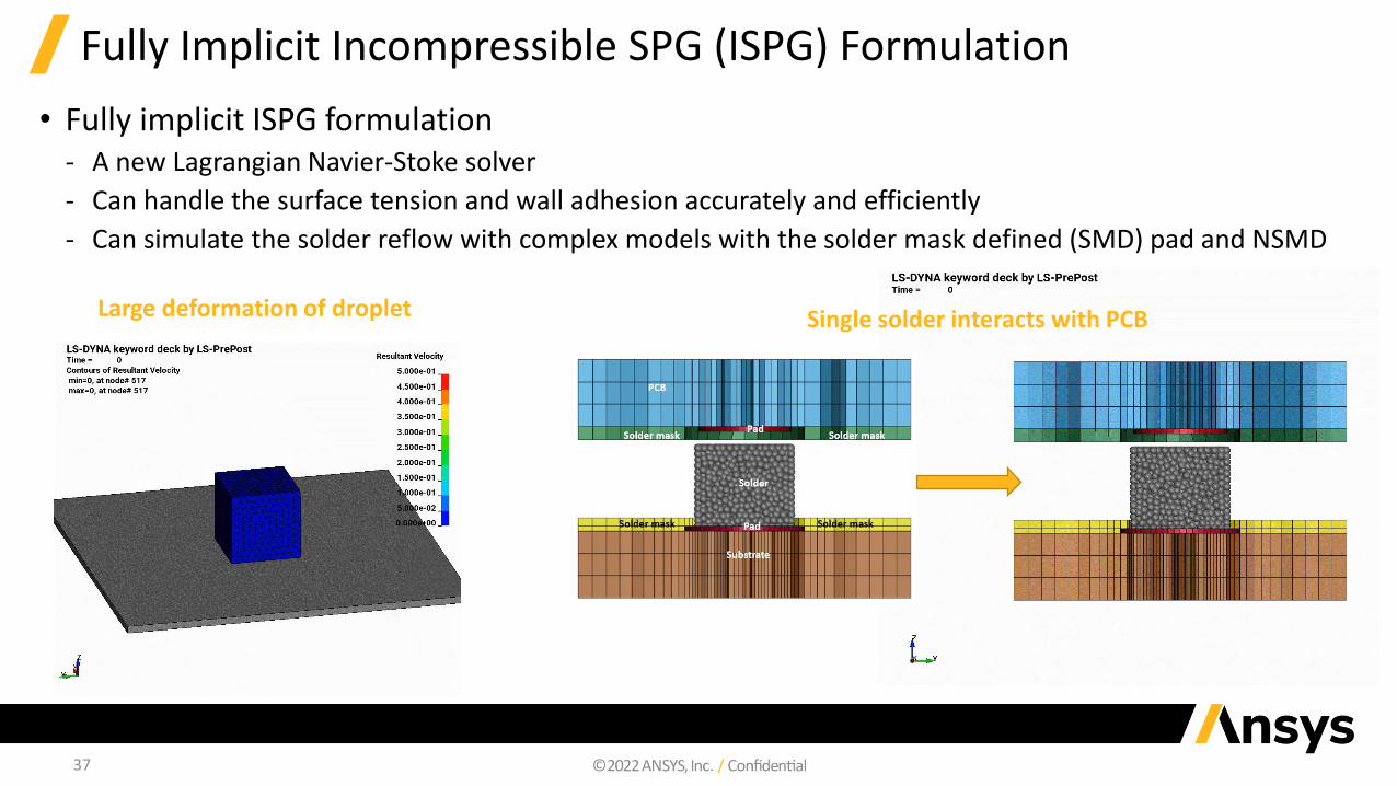
Fully Implicit Incompressible SPG (ISPG) Formulation
• Fully implicit ISPG formulation‐ A new Lagrangian Navier-Stoke solver
‐ Can handle the surface tension and wall adhesion accurately and efficiently
‐ Can simulate the solder reflow with complex models with the solder mask defined (SMD) pad and NSMD
Single solder interacts with PCBLarge deformation of droplet
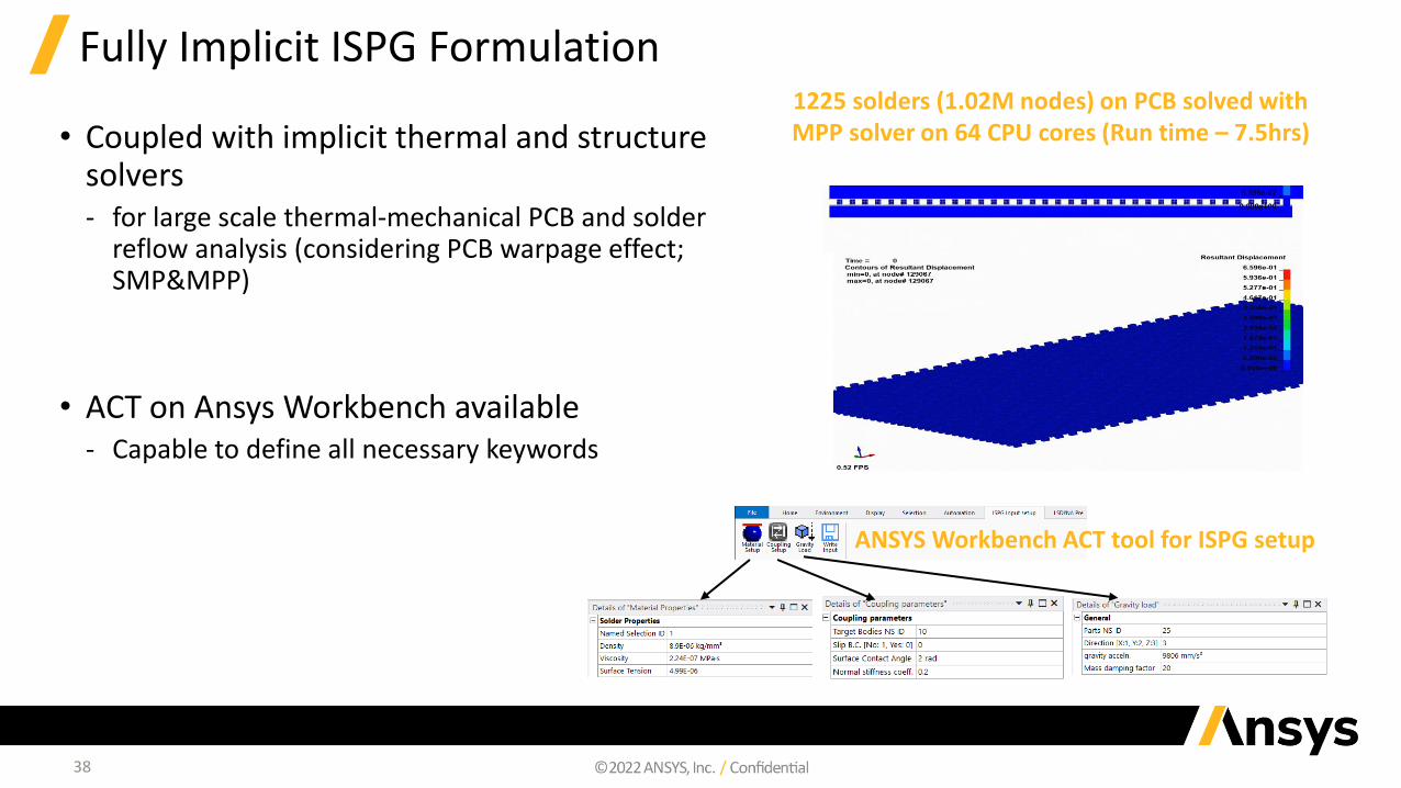
1225 solders (1.02M nodes) on PCB solved with MPP solver on 64 CPU cores (Run time – 7.5hrs)
38
Fully Implicit ISPG Formulation
• Coupled with implicit thermal and structure solvers ‐ for large scale thermal-mechanical PCB and solder
reflow analysis (considering PCB warpage effect; SMP&MPP)
• ACT on Ansys Workbench available‐ Capable to define all necessary keywords
ANSYS Workbench ACT tool for ISPG setup

Ansys Icepak
40
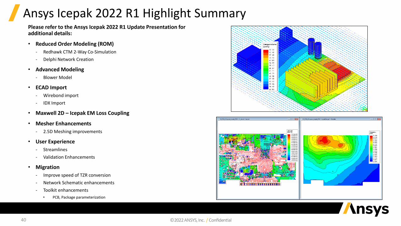
Ansys Icepak 2022 R1 Highlight SummaryPlease refer to the Ansys Icepak 2022 R1 Update Presentation for additional details:
• Reduced Order Modeling (ROM)
‐ Redhawk CTM 2-Way Co-Simulation
‐ Delphi Network Creation
• Advanced Modeling
‐ Blower Model
• ECAD Import
‐ Wirebond import
‐ IDX Import
• Maxwell 2D – Icepak EM Loss Coupling
• Mesher Enhancements
‐ 2.5D Meshing improvements
• User Experience
‐ Streamlines
‐ Validation Enhancements
• Migration
‐ Improve speed of TZR conversion
‐ Network Schematic enhancements
‐ Toolkit enhancements
• PCB, Package parameterization

Ansys AEDT Mechanical
42
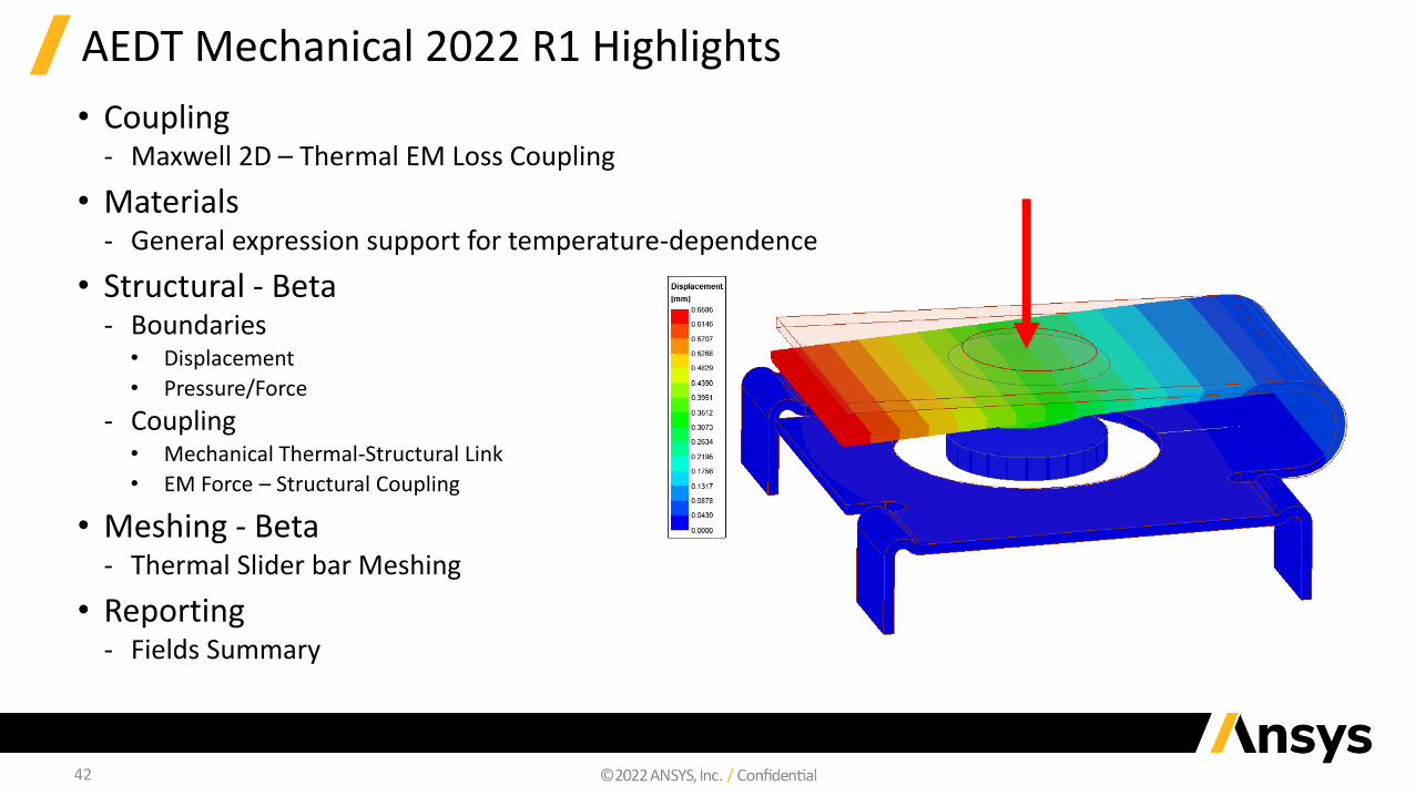
AEDT Mechanical 2022 R1 Highlights
• Coupling‐ Maxwell 2D – Thermal EM Loss Coupling
• Materials‐ General expression support for temperature-dependence
• Structural - Beta‐ Boundaries
• Displacement
• Pressure/Force
‐ Coupling• Mechanical Thermal-Structural Link
• EM Force – Structural Coupling
• Meshing - Beta‐ Thermal Slider bar Meshing
• Reporting‐ Fields Summary
43
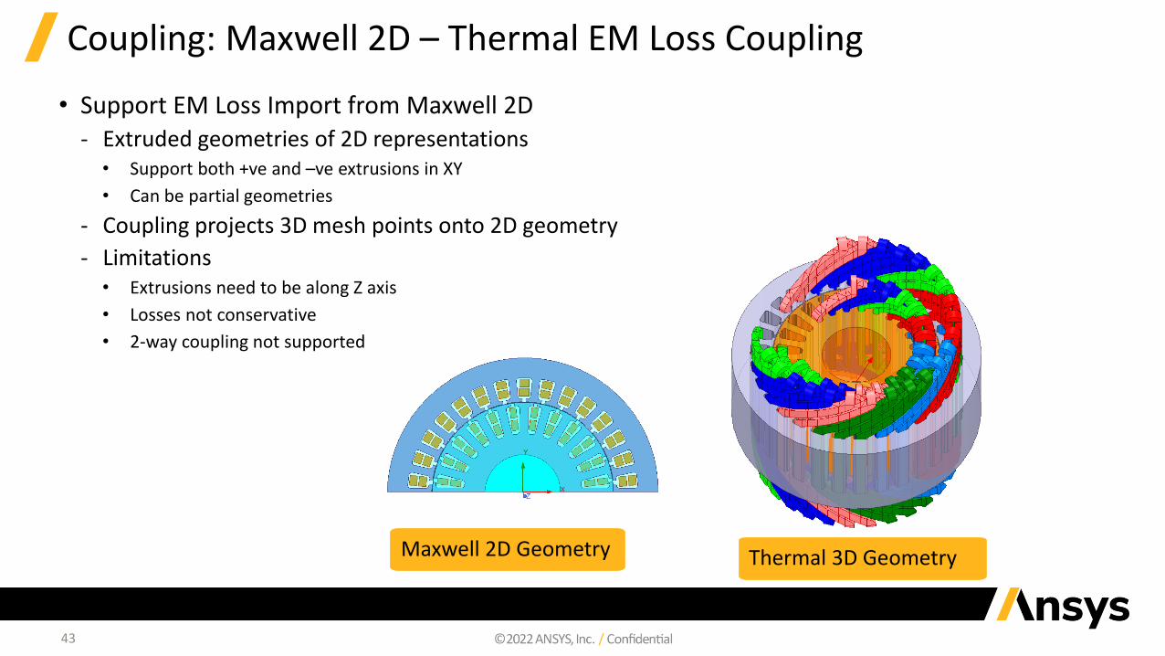
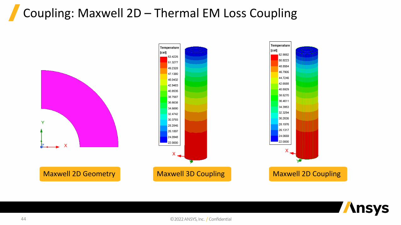
Coupling: Maxwell 2D – Thermal EM Loss Coupling
• Support EM Loss Import from Maxwell 2D‐ Extruded geometries of 2D representations
• Support both +ve and –ve extrusions in XY
• Can be partial geometries
‐ Coupling projects 3D mesh points onto 2D geometry
‐ Limitations• Extrusions need to be along Z axis
• Losses not conservative
• 2-way coupling not supported
Thermal 3D GeometryMaxwell 2D Geometry
44
Coupling: Maxwell 2D – Thermal EM Loss Coupling
Maxwell 2D Geometry Maxwell 3D Coupling Maxwell 2D Coupling
45
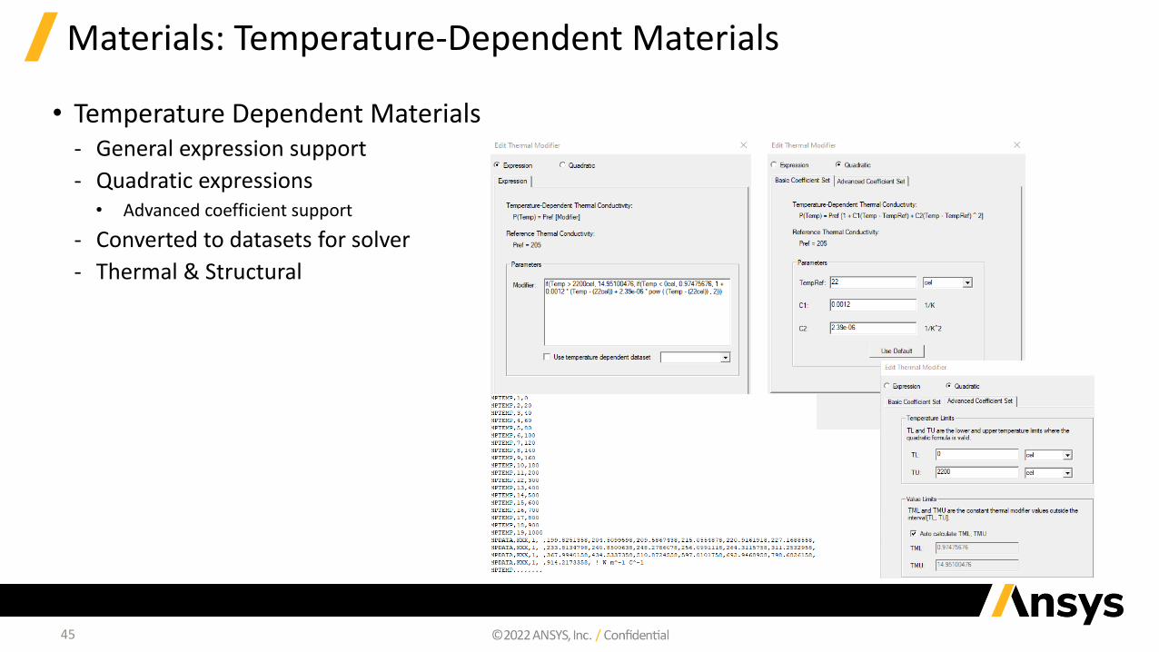
Materials: Temperature-Dependent Materials
• Temperature Dependent Materials‐ General expression support
‐ Quadratic expressions• Advanced coefficient support
‐ Converted to datasets for solver
‐ Thermal & Structural
46
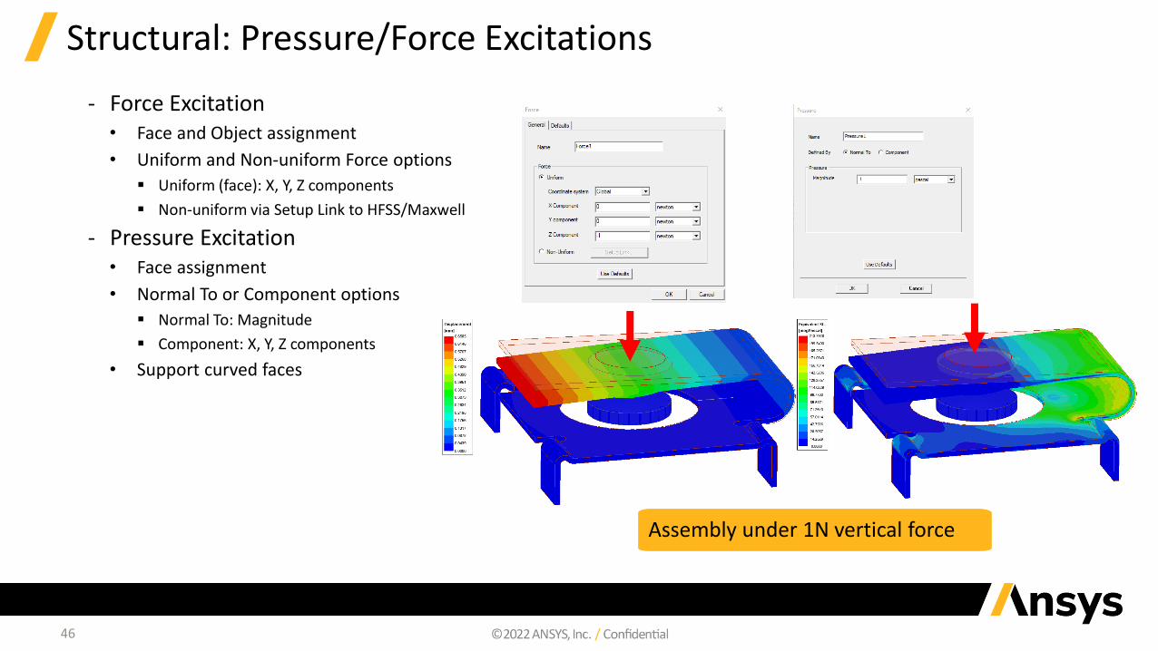
Structural: Pressure/Force Excitations
‐ Force Excitation• Face and Object assignment
• Uniform and Non-uniform Force options
▪ Uniform (face): X, Y, Z components
▪ Non-uniform via Setup Link to HFSS/Maxwell
‐ Pressure Excitation• Face assignment
• Normal To or Component options
▪ Normal To: Magnitude
▪ Component: X, Y, Z components
• Support curved faces
Assembly under 1N vertical force
47
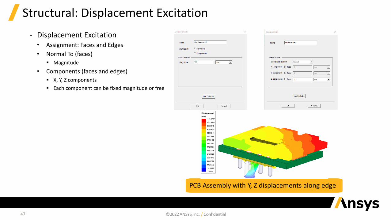
Structural: Displacement Excitation
‐ Displacement Excitation• Assignment: Faces and Edges
• Normal To (faces)
▪ Magnitude
• Components (faces and edges)
▪ X, Y, Z components
▪ Each component can be fixed magnitude or free
PCB Assembly with Y, Z displacements along edge
48
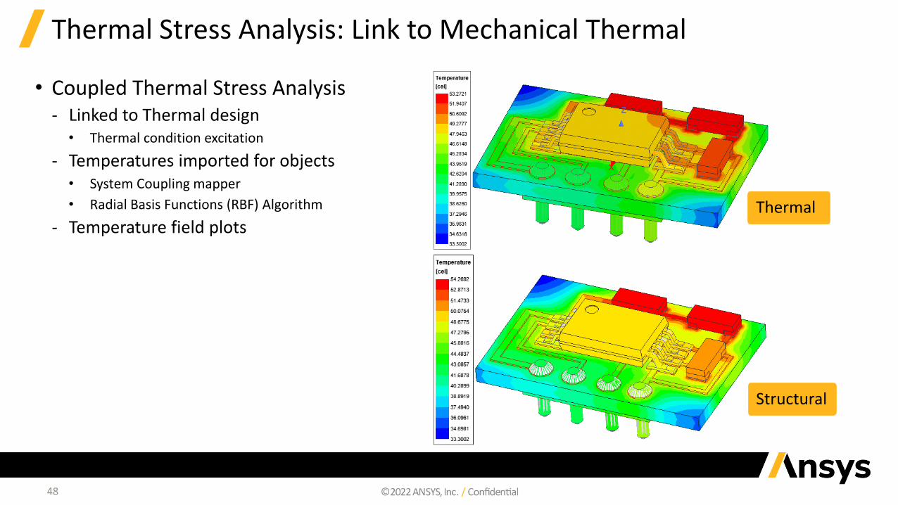
Thermal Stress Analysis: Link to Mechanical Thermal
• Coupled Thermal Stress Analysis ‐ Linked to Thermal design
• Thermal condition excitation
‐ Temperatures imported for objects• System Coupling mapper
• Radial Basis Functions (RBF) Algorithm
‐ Temperature field plotsThermal
Structural
49
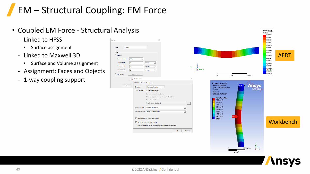
EM – Structural Coupling: EM Force
• Coupled EM Force - Structural Analysis ‐ Linked to HFSS
• Surface assignment
‐ Linked to Maxwell 3D• Surface and Volume assignment
‐ Assignment: Faces and Objects
‐ 1-way coupling support
AEDT
Workbench
50
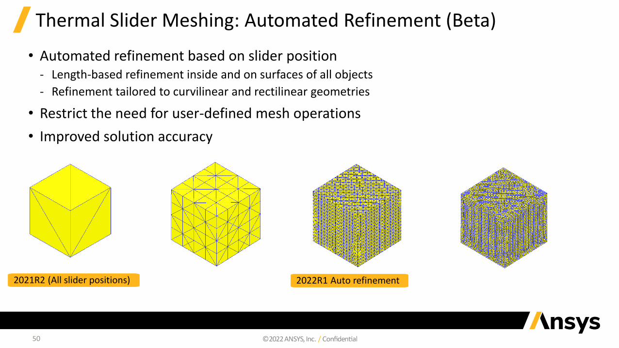
Thermal Slider Meshing: Automated Refinement (Beta)
• Automated refinement based on slider position‐ Length-based refinement inside and on surfaces of all objects
‐ Refinement tailored to curvilinear and rectilinear geometries
• Restrict the need for user-defined mesh operations
• Improved solution accuracy
2021R2 (All slider positions) 2022R1 Auto refinement
51
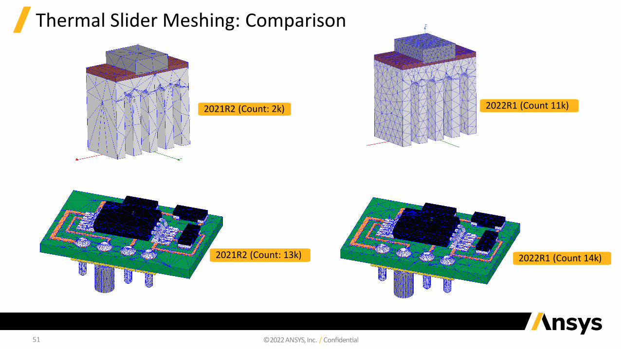
Thermal Slider Meshing: Comparison
2021R2 (Count: 2k) 2022R1 (Count 11k)
2021R2 (Count: 13k) 2022R1 (Count 14k)
52
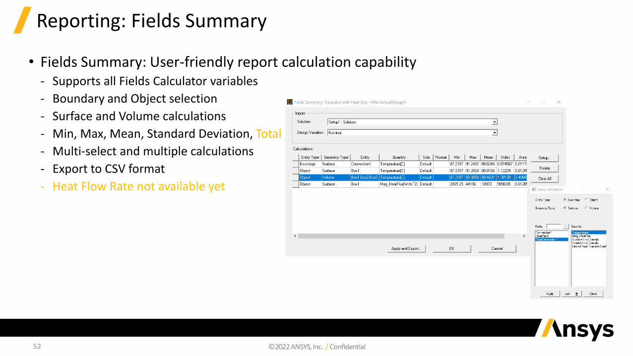
Reporting: Fields Summary
• Fields Summary: User-friendly report calculation capability‐ Supports all Fields Calculator variables
‐ Boundary and Object selection
‐ Surface and Volume calculations
‐ Min, Max, Mean, Standard Deviation, Total
‐ Multi-select and multiple calculations
‐ Export to CSV format
‐ Heat Flow Rate not available yet

Additional Resources

54
Ansys Learning Hub (ALH) Electronics Reliability Learning Room
- New and improved user experience
- 3-pronged learning paths including Basic, Fundamentals, Intermediate & Advanced Training
- Video Walk-throughs, on-demand webinars, technical papers, and more
- Ask questions directly to Ansys experts
Login here: https://catalog.ansys.com/ALH.cshtml
Direct Link (ALH Access Required):
https://jam8.sapjam.com/groups/QxhZIS5hvjR1EWlg4pCOD2/overview_page/owCBFHDqvFQ01u7FsvRRcx
55
Ansys Electronics Reliability YouTube Page
https://www.youtube.com/playlist?list=PLQMtm0_chcLzeB8zCeGmvBkFpT3oG7kFN