98-05065 R1 RMS.book
76
RMS Office 98-05065 R1 i OVERVIEW . . . . . . . . . . . . . . . . . . . . . . . . . . . . . . . . . . . . . . . . . . . . . . . . . . . . . 1 Additional Features . . . . . . . . . . . . . . . . . . . . . . . . . . . . . . . . . . . . . . . . . . . . . . . . . . . 1 CHAPTER 1 - SOFTWARE INSTALLATION AND OFFICE NAVIGATION . . . . . . . 3 SOFTWARE INSTALLATION . . . . . . . . . . . . . . . . . . . . . . . . . . . . . . . . . . . . . . . 3 STARTING RMS OFFICE . . . . . . . . . . . . . . . . . . . . . . . . . . . . . . . . . . . . . . . . . . 5 Profiles Menu . . . . . . . . . . . . . . . . . . . . . . . . . . . . . . . . . . . . . . . . . . . . . . . . . . . . . . . 6 System Menu . . . . . . . . . . . . . . . . . . . . . . . . . . . . . . . . . . . . . . . . . . . . . . . . . . . . . . . 6 Tools Menu . . . . . . . . . . . . . . . . . . . . . . . . . . . . . . . . . . . . . . . . . . . . . . . . . . . . . . . . . 8 RMS FOLDERS . . . . . . . . . . . . . . . . . . . . . . . . . . . . . . . . . . . . . . . . . . . . . . . . . . 9 Bin Folder . . . . . . . . . . . . . . . . . . . . . . . . . . . . . . . . . . . . . . . . . . . . . . . . . . . . . . . . . . 9 Data Folder . . . . . . . . . . . . . . . . . . . . . . . . . . . . . . . . . . . . . . . . . . . . . . . . . . . . . . . . 10 Names Folder . . . . . . . . . . . . . . . . . . . . . . . . . . . . . . . . . . . . . . . . . . . . . . . . . . . . . . 10 Profile Folder . . . . . . . . . . . . . . . . . . . . . . . . . . . . . . . . . . . . . . . . . . . . . . . . . . . . . . . 10 Base Maps Folder (Optional) . . . . . . . . . . . . . . . . . . . . . . . . . . . . . . . . . . . . . . . . . . 11 CHAPTER 2 - PROFILES . . . . . . . . . . . . . . . . . . . . . . . . . . . . . . . . . . . . . . . . . . . . 13 AGENCY PROFILE . . . . . . . . . . . . . . . . . . . . . . . . . . . . . . . . . . . . . . . . . . . . . . 14 CHEMICAL MIXTURE PROFILE . . . . . . . . . . . . . . . . . . . . . . . . . . . . . . . . . . . . 17 Creating a New Chemical Mixture . . . . . . . . . . . . . . . . . . . . . . . . . . . . . . . . . . . . . . . 20 Creating a Chemical Profile . . . . . . . . . . . . . . . . . . . . . . . . . . . . . . . . . . . . . . . . . . . 25 Creating a Personnel Profile . . . . . . . . . . . . . . . . . . . . . . . . . . . . . . . . . . . . . . . . . . . 28 Spray Configuration Profile . . . . . . . . . . . . . . . . . . . . . . . . . . . . . . . . . . . . . . . . . . . . 30 CHAPTER 3 - TOOLS . . . . . . . . . . . . . . . . . . . . . . . . . . . . . . . . . . . . . . . . . . . . . . . 35 EXPORT . . . . . . . . . . . . . . . . . . . . . . . . . . . . . . . . . . . . . . . . . . . . . . . . . . . . . . 36 MAP MANAGER . . . . . . . . . . . . . . . . . . . . . . . . . . . . . . . . . . . . . . . . . . . . . . . . 37 NAME MANAGER . . . . . . . . . . . . . . . . . . . . . . . . . . . . . . . . . . . . . . . . . . . . . . . 37 Name Database File Format . . . . . . . . . . . . . . . . . . . . . . . . . . . . . . . . . . . . . . . . . . . 37 REPORT WIZARD . . . . . . . . . . . . . . . . . . . . . . . . . . . . . . . . . . . . . . . . . . . . . . . 39 Generating a Session Report . . . . . . . . . . . . . . . . . . . . . . . . . . . . . . . . . . . . . . . . . . 39 Select Spray Session . . . . . . . . . . . . . . . . . . . . . . . . . . . . . . . . . . . . . . . . . . . . . . . . 40 Select Report Information . . . . . . . . . . . . . . . . . . . . . . . . . . . . . . . . . . . . . . . . . . . . . 41 Spray Campaign . . . . . . . . . . . . . . . . . . . . . . . . . . . . . . . . . . . . . . . . . . . . . . . . . . . . 41 Spray Swath Map . . . . . . . . . . . . . . . . . . . . . . . . . . . . . . . . . . . . . . . . . . . . . . . . . . . 42 Post Session Notes . . . . . . . . . . . . . . . . . . . . . . . . . . . . . . . . . . . . . . . . . . . . . . . . . . 43 Report Banner . . . . . . . . . . . . . . . . . . . . . . . . . . . . . . . . . . . . . . . . . . . . . . . . . . . . . . 44 Output Report . . . . . . . . . . . . . . . . . . . . . . . . . . . . . . . . . . . . . . . . . . . . . . . . . . . . . . 47 CHAPTER 4 - MAP MANAGER . . . . . . . . . . . . . . . . . . . . . . . . . . . . . . . . . . . . . . . 51 Viewing Data . . . . . . . . . . . . . . . . . . . . . . . . . . . . . . . . . . . . . . . . . . . . . . . . . . . . . . . 52 Base Maps . . . . . . . . . . . . . . . . . . . . . . . . . . . . . . . . . . . . . . . . . . . . . . . . . . . . . . . . 52 Object Information Query . . . . . . . . . . . . . . . . . . . . . . . . . . . . . . . . . . . . . . . . . . . . . 53 MAP MANAGER TOOL BAR . . . . . . . . . . . . . . . . . . . . . . . . . . . . . . . . . . . . . . . 53
-
Upload
khangminh22 -
Category
Documents
-
view
2 -
download
0
Transcript of 98-05065 R1 RMS.book

RMS Office98-05065 R1
i
OVERVIEW . . . . . . . . . . . . . . . . . . . . . . . . . . . . . . . . . . . . . . . . . . . . . . . . . . . . . 1Additional Features . . . . . . . . . . . . . . . . . . . . . . . . . . . . . . . . . . . . . . . . . . . . . . . . . . . 1
CHAPTER 1 - SOFTWARE INSTALLATION AND OFFICE NAVIGATION . . . . . . . 3SOFTWARE INSTALLATION . . . . . . . . . . . . . . . . . . . . . . . . . . . . . . . . . . . . . . . 3STARTING RMS OFFICE . . . . . . . . . . . . . . . . . . . . . . . . . . . . . . . . . . . . . . . . . . 5
Profiles Menu . . . . . . . . . . . . . . . . . . . . . . . . . . . . . . . . . . . . . . . . . . . . . . . . . . . . . . . 6System Menu . . . . . . . . . . . . . . . . . . . . . . . . . . . . . . . . . . . . . . . . . . . . . . . . . . . . . . . 6Tools Menu . . . . . . . . . . . . . . . . . . . . . . . . . . . . . . . . . . . . . . . . . . . . . . . . . . . . . . . . . 8
RMS FOLDERS . . . . . . . . . . . . . . . . . . . . . . . . . . . . . . . . . . . . . . . . . . . . . . . . . . 9Bin Folder . . . . . . . . . . . . . . . . . . . . . . . . . . . . . . . . . . . . . . . . . . . . . . . . . . . . . . . . . . 9Data Folder . . . . . . . . . . . . . . . . . . . . . . . . . . . . . . . . . . . . . . . . . . . . . . . . . . . . . . . . 10Names Folder . . . . . . . . . . . . . . . . . . . . . . . . . . . . . . . . . . . . . . . . . . . . . . . . . . . . . . 10Profile Folder . . . . . . . . . . . . . . . . . . . . . . . . . . . . . . . . . . . . . . . . . . . . . . . . . . . . . . . 10Base Maps Folder (Optional) . . . . . . . . . . . . . . . . . . . . . . . . . . . . . . . . . . . . . . . . . . 11
CHAPTER 2 - PROFILES . . . . . . . . . . . . . . . . . . . . . . . . . . . . . . . . . . . . . . . . . . . . 13AGENCY PROFILE . . . . . . . . . . . . . . . . . . . . . . . . . . . . . . . . . . . . . . . . . . . . . . 14CHEMICAL MIXTURE PROFILE . . . . . . . . . . . . . . . . . . . . . . . . . . . . . . . . . . . . 17
Creating a New Chemical Mixture . . . . . . . . . . . . . . . . . . . . . . . . . . . . . . . . . . . . . . . 20Creating a Chemical Profile . . . . . . . . . . . . . . . . . . . . . . . . . . . . . . . . . . . . . . . . . . . 25Creating a Personnel Profile . . . . . . . . . . . . . . . . . . . . . . . . . . . . . . . . . . . . . . . . . . . 28Spray Configuration Profile . . . . . . . . . . . . . . . . . . . . . . . . . . . . . . . . . . . . . . . . . . . . 30
CHAPTER 3 - TOOLS . . . . . . . . . . . . . . . . . . . . . . . . . . . . . . . . . . . . . . . . . . . . . . . 35EXPORT . . . . . . . . . . . . . . . . . . . . . . . . . . . . . . . . . . . . . . . . . . . . . . . . . . . . . . 36MAP MANAGER . . . . . . . . . . . . . . . . . . . . . . . . . . . . . . . . . . . . . . . . . . . . . . . . 37NAME MANAGER . . . . . . . . . . . . . . . . . . . . . . . . . . . . . . . . . . . . . . . . . . . . . . . 37
Name Database File Format . . . . . . . . . . . . . . . . . . . . . . . . . . . . . . . . . . . . . . . . . . . 37REPORT WIZARD . . . . . . . . . . . . . . . . . . . . . . . . . . . . . . . . . . . . . . . . . . . . . . . 39
Generating a Session Report . . . . . . . . . . . . . . . . . . . . . . . . . . . . . . . . . . . . . . . . . . 39Select Spray Session . . . . . . . . . . . . . . . . . . . . . . . . . . . . . . . . . . . . . . . . . . . . . . . . 40Select Report Information . . . . . . . . . . . . . . . . . . . . . . . . . . . . . . . . . . . . . . . . . . . . . 41Spray Campaign . . . . . . . . . . . . . . . . . . . . . . . . . . . . . . . . . . . . . . . . . . . . . . . . . . . . 41Spray Swath Map . . . . . . . . . . . . . . . . . . . . . . . . . . . . . . . . . . . . . . . . . . . . . . . . . . . 42Post Session Notes . . . . . . . . . . . . . . . . . . . . . . . . . . . . . . . . . . . . . . . . . . . . . . . . . . 43Report Banner . . . . . . . . . . . . . . . . . . . . . . . . . . . . . . . . . . . . . . . . . . . . . . . . . . . . . . 44Output Report . . . . . . . . . . . . . . . . . . . . . . . . . . . . . . . . . . . . . . . . . . . . . . . . . . . . . . 47
CHAPTER 4 - MAP MANAGER . . . . . . . . . . . . . . . . . . . . . . . . . . . . . . . . . . . . . . . 51Viewing Data . . . . . . . . . . . . . . . . . . . . . . . . . . . . . . . . . . . . . . . . . . . . . . . . . . . . . . . 52Base Maps . . . . . . . . . . . . . . . . . . . . . . . . . . . . . . . . . . . . . . . . . . . . . . . . . . . . . . . . 52Object Information Query . . . . . . . . . . . . . . . . . . . . . . . . . . . . . . . . . . . . . . . . . . . . . 53
MAP MANAGER TOOL BAR . . . . . . . . . . . . . . . . . . . . . . . . . . . . . . . . . . . . . . . 53

ii
Text Tool . . . . . . . . . . . . . . . . . . . . . . . . . . . . . . . . . . . . . . . . . . . . . . . . . . . . . . . . . 55File Menu . . . . . . . . . . . . . . . . . . . . . . . . . . . . . . . . . . . . . . . . . . . . . . . . . . . . . . . . . 56Layers Menu . . . . . . . . . . . . . . . . . . . . . . . . . . . . . . . . . . . . . . . . . . . . . . . . . . . . . . . 57View Menu . . . . . . . . . . . . . . . . . . . . . . . . . . . . . . . . . . . . . . . . . . . . . . . . . . . . . . . . 59File Tree Menu . . . . . . . . . . . . . . . . . . . . . . . . . . . . . . . . . . . . . . . . . . . . . . . . . . . . . 60Edit Objects Menu . . . . . . . . . . . . . . . . . . . . . . . . . . . . . . . . . . . . . . . . . . . . . . . . . . 61Tools Menu . . . . . . . . . . . . . . . . . . . . . . . . . . . . . . . . . . . . . . . . . . . . . . . . . . . . . . . . 62
PRINTING MAPS IN MAP MANAGER . . . . . . . . . . . . . . . . . . . . . . . . . . . . . . . . 62SHAPE FILE CONVERSION . . . . . . . . . . . . . . . . . . . . . . . . . . . . . . . . . . . . . . . 63
Exporting RMS Data to Shape File Format . . . . . . . . . . . . . . . . . . . . . . . . . . . . . . . 63Importing Shape Files to RMS Data Files . . . . . . . . . . . . . . . . . . . . . . . . . . . . . . . . 68Convert Templates . . . . . . . . . . . . . . . . . . . . . . . . . . . . . . . . . . . . . . . . . . . . . . . . . . 72

RMS Office98-05065 R1
1
OVERVIEWWelcome to the TeeJet Roadway Management System (RMS) Office Suite. The TeeJet RMSOffice product is a comprehensive software package designed specifically for the support ofroadway spraying applications using the TeeJet Legacy 6000 console. The Legacy 6000 con-sole must be loaded with RMS Application Rate Management software.
Roadway applications are more effectively managed using RMS Office. RMS Office allows thebuilding of specific profiles (small databases) for company, personnel, contracting agencies,chemicals, and chemical mixes, as well as vehicle and spray configurations. The export functionallows profile information to be transferred to the Legacy 6000 console via a PC Card.
When installed on the Legacy 6000, profile information is combined with a GPS-based map cre-ated during the application process. This will produce final roadway application data. The datafrom the completed roadway application session can then be transferred back to RMS Officewhere application reports are generated. Maps included with the reports can show all sprayactivity including boom and channel activity for an entire roadway spraying session.
This User Guide is configured into the following sections that comprise the RMS Office Suite:
• Chapter 1 - Software Installation and Office Navigation: provides an overview of basic
layout and software navigation
• Chapter 2 - Profiles: building small databases for agencies, chemicals, personnel, and
spray configurations
• Chapter 3 - Tools: several useful utilities include Export, Name Manager, and Report
Wizard, which allows for the building of a final report for spraying sessions
• Chapter 4 - Map Manager: a data viewing and management tool (although this is a part
of Tools, Map Manager requires a comprehensive chapter of its own)
Additional Features
Base Map Images
Geo-Tif (.DRG) image files are viewable in the background of most RMS mapping applicationssuch as Mapper and Record Spray Session, as well as Map Manager.
Names Database Manager
This utility application located under RMS Launcher/Tools allows for the construction of a list ofcommonly-used attribute names. Any of the names in the database can be accessed from anyof the mapping applications.

2
Export Application
This utility allows for the transfer of profiles from RMS Office to the Legacy 6000 console. Thiskeeps the Legacy 6000 profiles current and in-sinc with RMS Office.

RMS Office98-05065 R1
3
CHAPTER 1 - SOFTWARE INSTALLATION AND OFFICE NAVIGATION
SOFTWARE INSTALLATIONA CD ROM entitled Office CB 3.12 is included in the RMS Office kit. Insert the CD ROM into thecomputer to install the RMS Office software. The software is self-extracting, so users should beprompted to the menu illustrated below. If for some reason the software does not self-launch,access the CD ROM drive designated on the computer and located the (.EXE) file on the CD.Double click on the icon to begin software installation.
Figure 1-1: Software Installation
Software installation is intuitive and will navigate the user through a series of prompts and mes-sages. Follow the information displayed on the screen to successfully install the software.
Figure 1-2: Software Installation (continued)
Press the Next button
Select the “I agree” radio button and press the Next button

4 Chapter 1 - Software Installation and Office Navigation
Figure 1-3: Software Installation (continued)
Figure 1-4: Software Installation (continued)
Figure 1-5: Software Installation (continued)
The software installation has been successfully completed when the following screen is dis-played. Press the Finish button to exit from the screen.
Press the Next button. DO NOT change the default installation location and press the Next button again.
DO NOT change the folder name. Press the Next button again.
Press the Next button again. The system will copy a series of files to the computer. This may take a few minutes depending upon com-puter speed. File transfer status update

RMS Office98-05065 R1
5
Figure 1-6: Software Installation (continued)
A shortcut icon will be added to the computer desktop. The icon will look like this:
STARTING RMS OFFICETo start RMS Office, double click the RMS Office icon located on the computer desktop.
RMS Office is divided into three menu pages:
• Profiles
• System
• Tools
Access to these menus is available by selecting one of the tabs located at the bottom of theLauncher window. The number located on each tab indicates the function key that can bepressed to also access the appropriate menu.
Figure 1-7: Launcher Window
Press the Finish button to exit the Installation process.
Menu tabs

6 Chapter 1 - Software Installation and Office Navigation
Profiles Menu
The Profiles menu contains information such as agency, chemical mixture, chemical profile, per-sonnel, and spray configuration. These profiles are small databases that must be populatedprior to running the RMS Record Spray Session application. For additional information regard-ing Profiles, refer to Chapter 2 - RMS Profiles.
Figure 1-8: Profiles Menu
System Menu
The System menu contains the System Setup application. The units of measurement for theRMS Office software are established in this location. To begin the process, select System Setupon the System Launcher page and press Enter.
Figure 1-9: System Menu
System Setup must be run the first time RMS Office software is used. It is only necessary to runSystem Setup once unless changes are made to system units. Switching from English to Metricunits is an example of when updating System Setup would be appropriate a second time.

RMS Office98-05065 R1
7
Unit of Measure
The Unit of Measure menu item allows for the selection of the measurement unit used for themapping software. Choices include:
• English - distance is displayed in feet and miles, areas in square feet and acres, vehi-
cle speed in miles per hour, liquid volume in ounces and gallons, and weight in pounds.
• Metric - distance is displayed in meters and kilometers, areas in square meters and
hectares, vehicle speed in kilometers per hour, liquid volume in liters, and weight in
kilograms.
Table 1-1: Units of Measurement
Figure 1-10: Unit of Measurement Menu
To change the units of measurement, double click on the blue area (where it displays the units,select the appropriate units, and click on OK to accept the units.
Unit Name Description
English Distance - Feet (F) and Miles (Mi)Area - Square Feet (Ft2) and Acres (Ac)Vehicle speed - Miles per hour (MPH)Liquid volume - Ounces (Ou) and Gallons (Gal)Weight - Pounds (Lb)
Metric Distance - Meters (M) and Kilometers (Km)Area - Square Meters (M2) and Hectares (H)Vehicle speed - Kilometers per hour (Km/hr)Liquid volume - Liters (l)Weight - Kilograms (Kg)
Double click on the Unit of Measure field to launch the Unit of Measure window

8 Chapter 1 - Software Installation and Office Navigation
Tools Menu
The Tools menu contains utility programs such as Export, Map Manager, Name Manager, andReport Wizard. Each of these tools is explained in greater detail in Chapter 3 - Tools.
Figure 1-11: Tools Menu
Table 1-2: Tools Descriptions
Tool Description
Export The Export tool allows Profiles to be transferred to the Legacy 6000. Profiles and Names cannot be copied directly to the Legacy 6000 console. The Export program must be used.
Map Manager The Map Manager is used for data editing, viewing, and printing. This ver-sion of Map Manager includes layering and a full suite of drawing tools.
Name Manager The Name Manager is used to build databases for specific mapping themes such as “weed mapping” and “spray route campaigns”. A names database specific to “weed mapping” could contain the names of the most commonly-encountered weeds for the region. Instead of typing the names of weeds each time they are mapped, the name can easily be selected from an exist-ing database. For additional information, refer to Chapter 4 - Map Manager.
Report Wizard The Report Wizard allows for detailed reporting to be generated from road-side applications. It incorporates the Profiles information and any additional information entered by the operator during the actual roadside application process.

RMS Office98-05065 R1
9
RMS FOLDERSRMS folders are established on the computer in the same location where RMS Office isinstalled. The default location is the root directory of the hard drive, unless it was reassignedduring the installation process.
Figure 1-12: RMS Folders
Bin Folder
The Bin Folder contains all of the RMS Office executable (.EXE) files. All files located in thisfolder at the time of installation must remain in this folder for the RMS Office applications towork properly. Shortcuts to the executables located in this folder can be placed on the desktopfor easy access if they are desired. For example, to place a shortcut to Map Manager on thedesktop, look for the Map Manager executable (.EXE) file in this folder.
Figure 1-13: Bin Folder
located on the root directory during installation
folder names
Map Manager executable (.EXE) file

10 Chapter 1 - Software Installation and Office Navigation
Data Folder
The Data Folder is used for storing roadside data. This is simply a convenient location to storethe data. This software allows for other folders to be used as well.
Names Folder
The Names Folder is the storehouse for the names databases. One of the features of RMSOffice is the ability to construct names databases. The names of any of the RMS Mapping Appli-cations that may require attribute names for a graphic object (such as a point) can be accessedfrom this location. Names databases can be constructed for specific mapping themes such as“weed mapping” or “spray route campaigns”. A names database specific to “weed mapping”could contain the names of the most commonly-encountered weeds for the region. Instead oftyping the names of weeds each time they are mapped, the name can easily be selected froman existing database. All names databases created are stored in the Names Folder. For addi-tional information about the Name Manager application, refer to Chapter 3 - Name Manager.
Profile Folder
All profiles are stored in this location. Profiles contain information such as agency, chemical mix-ture, chemical profile, personnel, and spray configuration. These profiles are small databasesthat must be populated prior to running the RMS Record Spray Session application. For addi-tional information regarding Profiles, refer to Chapter 2 - RMS Profiles.

RMS Office98-05065 R1
11
Base Maps Folder (Optional)
The Base Maps Folder can be established if the user desires. To create this folder, select themenu File and the option New. Select “Folder” and name the folder “Base Maps”.
Figure 1-14: Creating a Base Maps Folder
All of the base map images (those images used in the background of the mapping softwareapplications) can be stored in this folder. This version of RMS Office allows for the display ofDigital Raster Graphics (.DRG) image files in the form of a Tagged Image File Format (.TIF),also known as a Geo-Tif. This image data is useful as a backdrop onto which other collecteddata, such as spray routes, no spray zones, and weed patch locations can be overlaid
Base Maps Folder
The base map images that are displayed in the background of the mapping software applica-tions are stored in the Base maps Folder.
Select File/ New/ Folder and name it “Base Maps”
Created folder

12 Chapter 1 - Software Installation and Office Navigation

RMS Office98-05065 R1
13
CHAPTER 2 - PROFILESProfiles are small databases that are created to store typical information pertaining to agencies,chemicals, chemical mixtures, personnel, spray configuration, and vehicles. This profile infor-mation is used to generate spray application reports once a spray session is completed. Thereare five individual profiles required to successfully start a roadside application session using theApplication Rate Management (ARM) software:
• Agency
• Chemical Mixture
• Chemical
• Personnel
• Spray Configuration
All profiles are created using RMS Office and then can be transferred using a PC Card to theLegacy 6000 using the Export program. For additional information on the export process, referto Chapter 3 - Tools.
To select the desired profile, access the RMS Office - Launcher and select the Profiles page.Profiles can be created, edited, and deleted at this point.
Figure 2-1: Profiles Page

14 Chapter 2 - Profiles
AGENCY PROFILEThe Agency Profile contains information about the agency or organization that is contracting theservices. To create or edit an agency profile, double click on “Agency Profile” located on theLauncher Page. The first page displayed is a list of agencies currently entered in the database.If no profiles exist (i.e., this is the first entry) the window will be empty.
Figure 2-2: Agency Profile
To create a new agency, press the New button.
To edit an existing agency, select the desired agency from the list and press the Enter button, ordouble click on the name of the agency.
Figure 2-3: Editing Agency Information
To delete an existing agency, highlight the desired agency name and press the Delete button.
New button
Double click to edit agency information

RMS Office98-05065 R1
15
Agency information can also be displayed (Active) or hidden. To select the status of the record,choose the Admin tab, located at the bottom of the Agency Profile window and double click onthe Agency Record Status window. Choose the appropriate setting and select “OK”.
Figure 2-4: Agency Record Status
All agency profiles are created in RMS Office and can then be transferred to the Legacy 6000console via a PC Card using the Export program. For additional information on the export pro-cess, refer to Chapter 3 - Tools.
To exit the Agency Profile, press the Exit button. The program will return to the RMS LauncherProfiles window.
Double click to launch the Agency Record Status window

16 Chapter 2 - Profiles
Table 2-1: Agency Profile Information (Main Page)
Table 2-2: Agency Profile Information (Contact Page)
Table 2-3: Agency Profile Information (Admin Page)
Profile Field Description
Agency ID A unique identification used to identify the specific agency.
Agency Name The name of the agency.
Division The agency division.
Street The physical street address of the agency.
City The city where the agency is located.
County/MD The county where the agency is located.
State/Province The state or province where the agency is located.
Country The country where the agency is located.
Zip/Postal Code The zip or postal code for the agency.
Profile Field Description
Contact Name The name of the person at the agency who can be contacted.
Phone Number The phone number of the contact person.
Profile Field Description
Record Status Setting a profile to ACTIVE will allow the file to be viewable and selectable when transferring data to the Legacy 6000. Setting the profile to HIDDEN prevents the file from being selectable and/or viewable to the operator and it cannot be transferred to the Legacy 6000. This will allow the system man-ager to limit the number of in-field selections an operator must make while in the field.

RMS Office98-05065 R1
17
CHEMICAL MIXTURE PROFILEBEFORE CREATING A NEW CHEMICAL MIXTURE PROFILE, CHEMICALS MUST BEENTERED INTO THE CHEMICAL DATABASE. REFER TO CREATING A CHEMICAL PRO-FILE FOR ADDITIONAL INFORMATION.
The Chemical Mixture Profile contains information regarding specific created chemical tank mix-tures. To access the Chemical Mixture Profile window, select Chemical Mixture Profile on theRMS Launcher window. The first page contains a list of chemical mixes currently entered intothe database. If no profiles exist (i.e., this is the first entry) the window will be empty.
Figure 2-5: Chemical Mixture Profile Window
To create a new chemical mixture, press the New button. Enter the desired information andpress the OK button. If for some reason the mixture shouldn’t be added to the database, pressthe Cancel button to return to the Chemical Mixture Profile list.
To edit an existing chemical mixture, select the desired mixture from the list and press the Enterbutton, or double click on the name of the mixture.
Figure 2-6: Editing Mixture Information
To delete an existing chemical mixture, highlight the desired mixture name and press the Deletebutton.
The New button is used to create new chemical mixtures
18 Chapter 2 - Profiles
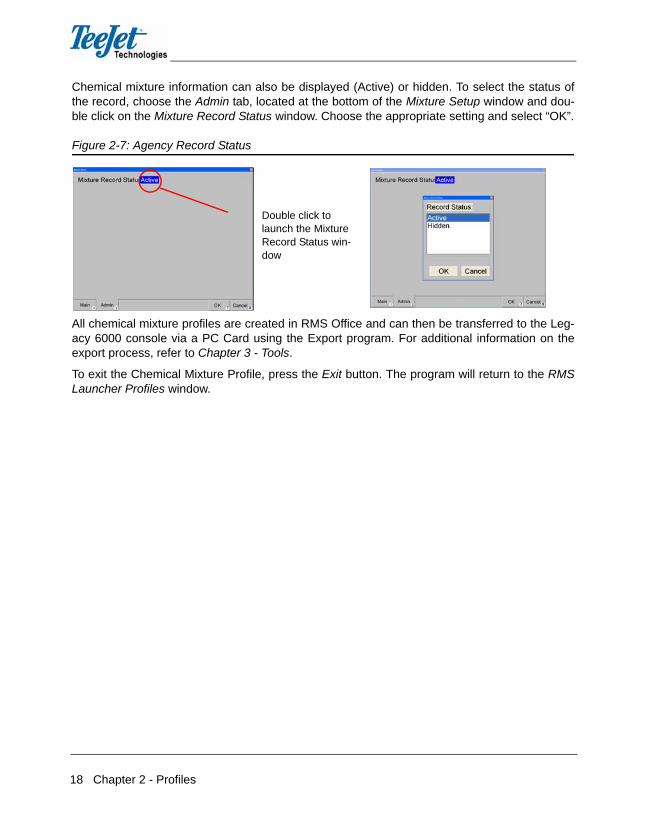
Chemical mixture information can also be displayed (Active) or hidden. To select the status ofthe record, choose the Admin tab, located at the bottom of the Mixture Setup window and dou-ble click on the Mixture Record Status window. Choose the appropriate setting and select “OK”.
Figure 2-7: Agency Record Status
All chemical mixture profiles are created in RMS Office and can then be transferred to the Leg-acy 6000 console via a PC Card using the Export program. For additional information on theexport process, refer to Chapter 3 - Tools.
To exit the Chemical Mixture Profile, press the Exit button. The program will return to the RMSLauncher Profiles window.
Double click to launch the Mixture Record Status win-dow

RMS Office98-05065 R1
19
Table 2-4: Chemical Mixture Profile Information (Main Page)
Table 2-5: Chemical Mixture Profile Information (Admin Page)
Profile Field Description
Mixture Name The name of the mixture being created. When a name is entered into this field, the RMS Chemical Calculator will be displayed. Completing this field is optional. When the chemical calculations for the mixture are complete, the system will automatically generate a Mixture Name.
Chemical # 1 The name of the first chemical in the mixture.
Concentration The concentration of Chemical 1 used in the mixture. The Chemical Calcula-tor will fill in this menu field automatically.
Target Rate The target rate entered into the Chemical Calculator for Chemical 1. The Chemical Calculator will fill in this menu field automatically.
Chemical # 2 The name of the second chemical used in the mixture. The Chemical Calcu-lator will fill in this menu field automatically.
Concentration The concentration of Chemical 2 used in the mixture. The Chemical Calcula-tor will fill in this menu field automatically.
Target Rate The target rate entered into the Chemical Calculator for Chemical 2. The Chemical Calculator will fill in this menu field automatically.
Chemical # 3 The name of the third chemical used in the mixture. The Chemical Calculator will fill in this menu field automatically.
Concentration The concentration of Chemical 3 used in the mixture. The Chemical Calcula-tor will fill in this menu field automatically.
Target Rate The target rate entered into the Chemical Calculator for Chemical 3. The Chemical Calculator will fill in this menu field automatically.
Profile Field Description
Record Status Setting a profile to ACTIVE will allow the file to be viewable and selectable when transferring data to the Legacy 6000. Setting the profile to HIDDEN prevents the file from being selectable and/or viewable to the operator and it cannot be transferred to the Legacy 6000. This will allow the system man-ager to limit the number of in-field selections an operator must make while in the field.

20 Chapter 2 - Profiles
Creating a New Chemical Mixture
BEFORE CREATING A NEW CHEMICAL PROFILE MIXTURE, CHEMICALS MUST BEENTERED INTO THE CHEMICAL PROFILE DATABASE. REFER TO CREATING A CHEMI-CAL PROFILE FOR ADDITIONAL INFORMATION.
To create a new chemical mixture, use the Chemical Mix Calculator. The Chemical Mix Calcula-tor is accessed through the Mixture Name menu field, located on the Chemical Mixture Mainmenu page. Before entering a new chemical mixture, please review the following informationthoroughly to understand how the process is completed.
Figure 2-8: Chemical Mix Calculator
Chemical Mix Calculator
The Chemical Mix Calculator is a powerful chemical mix utility program used to combine up tothree chemicals plus a carrier into a single mixture. The chemicals in the mixture must appear inthe Chemical Profiles list, so be sure they are entered before trying the mix a new chemical.
The Chemical Mix Calculator accesses the chemical profile for information such as chemicaltype and unit for each chemical added to the mixture. The calculator requires an application ratefor each chemical in the mixture, as well as the tank volume or amount of mixture to be created.When the chemicals are added to the mix, the Chemical Mix Calculator will determine theamount of each chemical and carrier required for the mixture tank volume.
Start the Chemical Mix Calculator by selecting the first mixture name in the Mixture Name menufield (double click the name).

RMS Office98-05065 R1
21
Figure 2-9: Open the Chemical Mix Calculator
On the RMS Office - Chemical Mixture Profile window, select the New tab (located at the bottomof the window). This will open the Mixture Setup window. To open the Chemical Mix Calculator,double click in the Mixture Name menu field.
Figure 2-10: Open Chemical Mix Calculator
Enter the first chemical by placing the cursor in the Chemical 1 menu field and either press theEnter button or double click. This will open a Select Record window. All of the Chemicals thatare currently in the system will be available for selection. For information regarding enteringchemicals, refer to Creating New Chemical Profiles.
Select the New tab to add a new Chemi-cal
Double click in the Mix-ture Name field to open the Chemical Mix Calculator

22 Chapter 2 - Profiles
Figure 2-11: Entering the First Chemical
Select the desired chemical from the list displayed on the Select Record window and press theEnter button or the OK button. The Chemical 1 menu field will be populated with the chemicalname.
Double click on the Application Rate field to open the Chemical 1 Rate window. The unit of mea-surement for the chemical will automatically be populated. The application rate information isavailable on the product label and can be entered during the Creating New Chemical Profilesprocess. This will eliminate the need to remember application rates in the future.
Press the Enter button or the OK button and the Application Rate menu field will be populated.
Figure 2-12: Entering Chemical 1 Application Rate
Repeat the process with the second chemical in the mixture. For illustration purposes, the sec-ond chemical will be “Oust”. Once both chemicals have been added to the Chemical Mix Calcu-lator, enter the total mix volume by placing the cursor in the Total Mix Volume menu field anddouble clicking or pressing the Enter button.
Place cursor in the first chemical field and enter or double click to open the Select Record window
Place cursor in the first chemical application rate and enter or double click to open the Chemi-cal 1 Rate window

RMS Office98-05065 R1
23
Figure 2-13: Calculating Total Mixture Volume
Enter the total volume to be applied and press the OK button or the Enter button. The field willbe populated. The Application Rate fields as well as the Total Mix Volume fields will be lockedso no additional adjustments can be made to these rates. If changes need to be made to therate at this point, these fields will manually need to be unlocked using the Unlock tab located atthe bottom of the window.
Calculating the Mixture
Once the chemicals are entered and the chemical application rates and total mix volume areestablished, the next step in the process is to calculate the mixture. To calculate the mixture,press the Calculate button, located on the lower left side of the window. The Chemical Calcula-tor will calculate the following values:
• TeeJet console rate
• Quantity of required material for Chemical 1
• Quantity of required material for Chemical 2
• Quantity of required carrier
• Application rate of carrier (calculated from the Maximum Mix Ratio entered for the dry
material in the Chemical Profile)
• Area that this mixture can cover based on application rates
Once all the chemicals are entered, place the cursor in the Total Mix Volume menu field and double click or press the Enter button to open the Total Mixture Vol-ume window

24 Chapter 2 - Profiles
Figure 2-14: Calculating the Chemical Mix
Once the calculation is complete, press the OK button to save the results and return to the Mix-ture Setup window. The fields will be populated based on the chemicals entered and the mixturewill be named appropriately.
Figure 2-15: Completed Mixture Setup
Press the OK button to return to the Chemical Mixture Profile page. Press the Exit button toreturn to the RMS Office Launcher.
Press the Cal-culate tab to Calculate the mixture vol-umes based on the chemicals entered

RMS Office98-05065 R1
25
Creating a Chemical Profile
Chemical Profiles are a collection of data stored in a database that including information regard-ing the name, manufacturer, and pertinent information of the chemicals used during the applica-tion process. To access the Chemical Profile window, select Chemical Profile on the RMSLauncher window. The first page contains a list of chemicals currently entered into the data-base. If no chemicals exist (i.e., this is the first entry) the window will be empty.
Figure 2-16: Chemical Profile Window
To create a new chemical, press the New button. Double click on the desired field, enter theappropriate information, and press the OK button. If for some reason the chemical shouldn’t beadded to the database, press the Cancel button to return to the Chemical Profile list.
To edit an existing chemical profile, select the desired mixture from the list and press the Enterbutton, or double click on the name of the chemical.
Figure 2-17: Adding Chemical Information
To delete an existing chemical, highlight the desired name and press the Delete button.

26 Chapter 2 - Profiles
Chemical information can also be displayed (Active) or hidden. To select the status of therecord, choose the Admin tab, located at the bottom of the Mixture Setup window and doubleclick on the Mixture Record Status window. Choose the appropriate setting and select “OK”.
Figure 2-18: Agency Record Status
All chemical profiles are created in RMS Office and can then be transferred to the Legacy 6000console via a PC Card using the Export program. For additional information on the export pro-cess, refer to Chapter 3 - Tools.
To exit the Chemical Profile, press the Exit button. The program will return to the RMS LauncherProfiles window.
Double click to open the Chemical Record Status win-dow

RMS Office98-05065 R1
27
Table 2-6: Chemical Profile Information (Main Page)
Table 2-7: Chemical Profile Information (Admin Page)
Profile Field Description
Chemical Name The name of the chemical being entered into the database.
Manufacturer The name of the chemical manufacturer.
EPA Reg # The chemical EPA registration number.
Com Code The chemical commodity code.
Type The type of chemical being entered. When entering this menu item, a dialog box will be displayed listing chemical types (dry, liquid, or dry flowable).
Measurement Unit The unit of measure associated with the chemical being entered. When entering this menu item, a dialog box will be displayed listing the unit choices available in either English or Metric units.
Maximum Mix Ratio The maximum concentration of dry material in a single gallon of liquid carrier. This menu field is only activated if the chemical type selected is “dry” or “dry flowable”.
Displacement The amount of liquid displaced by a unit of dry material in a single gallon of carrier. This menu field is only activated if the chemical type selected is “dry” or “dry flowable”. A typical displacement unit would be “liquid ounces”.
Profile Field Description
Record Status Setting a profile to ACTIVE will allow the file to be viewable and selectable when transferring data to the Legacy 6000. Setting the profile to HIDDEN prevents the file from being selectable and/or viewable to the operator and it cannot be transferred to the Legacy 6000. This will allow the system man-ager to limit the number of in-field selections an operator must make while in the field.

28 Chapter 2 - Profiles
Creating a Personnel Profile
Personnel Profiles are a collection of data stored in a database that includes information regard-ing the employees associated with a spraying application. Typically, a personnel profile is cre-ated for vehicle drivers and sprayer operators. To access the Personnel Profile window, selectPersonnel Profile on the RMS Launcher window. The first page contains a list of profiles cur-rently entered into the database. If no names exist (i.e., this is the first entry) the window will beempty.
Figure 2-19: Personnel Profile Window
To create a new personnel profile, press the New button. Double click on the desired field, enterthe appropriate information, and press the OK button. If for some reason the individual shouldn’tbe added to the database, press the Cancel button to return to the Personnel Profile list.
To edit an existing personnel profile, select the desired individual from the list and press theEnter button, or double click on the name of the person.
Figure 2-20: Adding Personnel Information
To delete an existing individual, highlight the desired name and press the Delete button.
Select the New but-ton to create a new entry

RMS Office98-05065 R1
29
Personnel information can also be displayed (Active) or hidden. To select the status of therecord, choose the Admin tab, located at the bottom of the Personnel Setup window and doubleclick on the Mixture Record Status window. Choose the appropriate setting and select “OK”.
Figure 2-21: Personnel Record Status
All personnel profiles are created in RMS Office and can then be transferred to the Legacy 6000console via a PC Card using the Export program. For additional information on the export pro-cess, refer to Chapter 3 - Tools.
To exit the Personnel Profile, press the Exit button. The program will return to the RMSLauncher Profiles window.
Table 2-8: Personnel Profile Information (Main Page)
Profile Field Description
Last Name The last name of the employee.
First Name The first name of the employee.
Employee ID The employee’s identification number.
SSN (SIN) The employee’s Social Security Number or Social Insurance Number.
Pesticide Lic # The employee’s pesticide license number.
Expiration The pesticide license expiration date.
Driver’s Lic # The employee’s drivers license number.
Supervisor The employee’s supervisor.
Phone The telephone number where the supervisor or employee can be contacted.
Double click to open the Person-nel Record Status window

30 Chapter 2 - Profiles
Table 2-9: Personnel Profile Information (Admin Page)
Spray Configuration Profile
Spray Configuration Profiles allow for the creation of different spray boom configurations for thefleet. When the actual spray application session begins, select the specific spray boom configu-ration for the vehicle.
To access the Spray Configuration Profile window, select Spray Configuration Profile on theRMS Launcher window. The first page contains a list of profiles currently entered into the data-base. If no names exist (i.e., this is the first entry) the window will be empty.
Figure 2-22: Spray Configuration Profile Window
To create a new spray configuration profile, press the New button. Double click on the desiredfield, enter the appropriate information, and press the OK button. If for some reason the config-uration shouldn’t be added to the database, press the Cancel button to return to the Spray Con-figuration Profile list.
To edit an existing spray configuration profile, select the desired configuration from the list andpress the Enter button, or double click on the name of the configuration.
Profile Field Description
Record Status Setting a profile to ACTIVE will allow the file to be viewable and selectable when transferring data to the Legacy 6000. Setting the profile to HIDDEN prevents the file from being selectable and/or viewable to the operator and it cannot be transferred to the Legacy 6000. This will allow the system man-ager to limit the number of in-field selections an operator must make while in the field.
Select the New but-ton to create a new entry

RMS Office98-05065 R1
31
Figure 2-23: Adding Spray Configuration Information
To delete an existing spray configuration, highlight the desired name and press the Delete but-ton.
Spray Configuration information can also be displayed (Active) or hidden. To select the status ofthe record, choose the Admin tab, located at the bottom of the Spray Configuration Setup win-dow and double click on the Configuration Record Status window. Choose the appropriate set-ting and select “OK”.
Figure 2-24: Spray Configuration Record Status
All spray configuration profiles are created in RMS Office and can then be transferred to theLegacy 6000 console via a PC Card using the Export program. For additional information on theexport process, refer to Chapter 3 - Tools.
To exit the Spray Configuration Profile, press the Exit button. The program will return to theRMS Launcher Profiles window.
Double click to open the Configu-ration Record Sta-tus window

32 Chapter 2 - Profiles
Table 2-10: Spray Configuration Profile Information (Main Page)
Table 2-11: Spray Configuration Profile Information (3-6 Page)
Profile Field Description
Spray Config Name Enter the name of the new spray configuration. Try to use a name that best describes the configuration.
Hand Gun Selecting this menu field activates the Hand Gun dialog box. If using a hand gun, select “yes”. If not using a hand gun, select “no”.
Boom 1 Width Selecting this menu field activates the Boom Width dialog box. Enter the width of Boom 1 in inches (centimeters). When entered, the boom section is drawn in the vehicle diagram located at the bottom of the page.
Offset Selecting this menu field activates the Boom Offset dialog. Enter the offset distance from the center line of the vehicle to the closest point in the boom to be programmed. Select which direction (left or right) from the center line of the vehicle to place the boom. If the boom is to be centered on the vehicle’s center line, select “Center” for the offset direction. Always use the vehicle graphic at the bottom of the page to ensure the created boom section is in the proper location.
Boom 2 Width Selecting this menu field activates the Boom Width dialog box. Enter the width of Boom 2 in inches (centimeters). When entered, the boom section is drawn in the vehicle diagram located at the bottom of the page.
Offset Same as Offset above
Profile Field Description
Boom 3 - 6 Width Selecting this menu field activates the Boom Width dialog box. Enter the width of Booms 3 - 6 in inches (centimeters). When entered, the boom sec-tion is drawn in the vehicle diagram located at the bottom of the page.
Offsets 3 - 6 Selecting this menu field activates the Boom Offset dialog. Enter the offset distance from the center line of the vehicle to the closest point in the boom to be programmed. Select which direction (left or right) from the center line of the vehicle to place the boom. If the boom is to be centered on the vehicle’s center line, select “Center” for the offset direction. Always use the vehicle graphic at the bottom of the page to ensure the created boom section is in the proper location.
RMS Office98-05065 R1
33
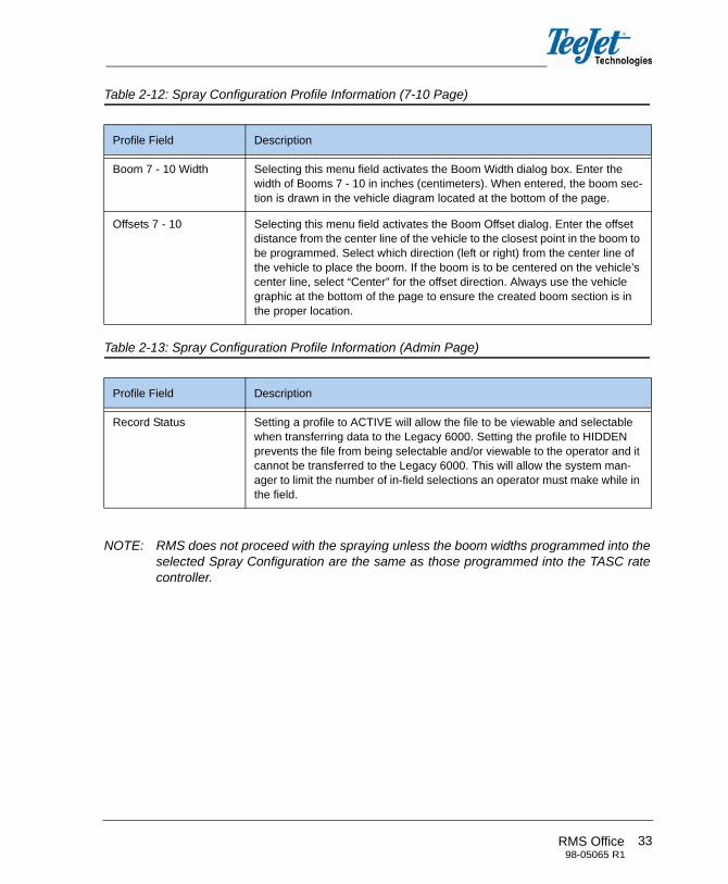
Table 2-12: Spray Configuration Profile Information (7-10 Page)
Table 2-13: Spray Configuration Profile Information (Admin Page)
NOTE: RMS does not proceed with the spraying unless the boom widths programmed into theselected Spray Configuration are the same as those programmed into the TASC ratecontroller.
Profile Field Description
Boom 7 - 10 Width Selecting this menu field activates the Boom Width dialog box. Enter the width of Booms 7 - 10 in inches (centimeters). When entered, the boom sec-tion is drawn in the vehicle diagram located at the bottom of the page.
Offsets 7 - 10 Selecting this menu field activates the Boom Offset dialog. Enter the offset distance from the center line of the vehicle to the closest point in the boom to be programmed. Select which direction (left or right) from the center line of the vehicle to place the boom. If the boom is to be centered on the vehicle’s center line, select “Center” for the offset direction. Always use the vehicle graphic at the bottom of the page to ensure the created boom section is in the proper location.
Profile Field Description
Record Status Setting a profile to ACTIVE will allow the file to be viewable and selectable when transferring data to the Legacy 6000. Setting the profile to HIDDEN prevents the file from being selectable and/or viewable to the operator and it cannot be transferred to the Legacy 6000. This will allow the system man-ager to limit the number of in-field selections an operator must make while in the field.

34 Chapter 2 - Profiles

RMS Office98-05065 R1
35
CHAPTER 3 - TOOLSRMS - Tools consists of four applications:
• Export
• Map Manager
• Name Manager
• Report Wizard
All four of these tools are accessed from the Tools menu.
Figure 3-1: Tools
Table 3-1: Tools Applications Descriptions
Tool Description
Export The Export tool allows for the transfer of information to the Legacy 6000 console.
Map Manager The Map Manager tool is used to view, edit, and manage data.
Name Manager Name Manager allows for the building of attribute databases and is used for naming objects during the mapping process.
Report Wizard The Report Wizard tool is used to generate detailed reports of roadside spray applications or sessions.

36 Chapter 3 - Tools
EXPORTThe Export tool is used to transfer information between RMS Office and the Legacy 6000. Asprofile information changes over time, the Legacy 6000 must be updated. Information can betransferred between RMS Office and the Legacy 6000 via a PC Card.
Information cannot be directly copied from Profiles and Names via the PC Card. The Export toolmust be used to compress and reformat the data. The following steps must be performed inorder for the data to be successfully transferred.
Exporting Information:
1. Once information has been updated in RMS Office, insert a PC Card into the PC Card drive.
2. Double click on Export which is located on the Tools tab of the RMS Launcher window.
Figure 3-2: Exporting Information
3. Select the PC Card Drive by choosing the Browse button and locating the card.
4. Select the profiles to be exported by checking the appropriate boxes to the left of the profile names.
Figure 3-3: Exporting Information
Browse button
check boxes to transfer profiles

RMS Office98-05065 R1
37
5. Press the Export button to begin the file transfer to the PC Card. An “Import” file will be created on the PC Card. Profiles and Names files will be exported to sub folders within the “Import” file. DO NOT MOVE OR MODIFY THESE FILES ON THE PC CARD.
6. Safely remove the PC Card from the drive.
7. Insert the PC Card into the Legacy 6000. Power on the Legacy 6000 console.
8. The Legacy 6000 will detect that new profile and names are ready for installation. Use the Arrow keys to make the appropriate selections to import the files.
9. The import process will perform a file comparison with the modified files. Files are updated with new information and will not be over-written. The import process moves files from the PC Card to the console’s flash memory. The files cannot be copied to the console - the Export process must be used.
MAP MANAGERMap Manager is a tool used for viewing, editing, and managing data. This tool will be discussedin detail in Chapter 4.
NAME MANAGERThe Name Manager application allows for the construction of a database of commonly-usedattributes. This database information can be accessed from any of the RMS applications suchas Mapper, EXT, or CAN. Using a names database helps to efficiently store, select, and namemapping objects while in the field during the application process. Database file names can becreated for specific tasks or themes.
All Names files are created in RMS Office and can then be transferred to the Legacy 6000 con-sole via a PC Card using the Export program.
Name Database File Format
Name database files are ASCII text files (.TXT). These can be created by several different edi-tors, spread sheets, and word processors. A single column of names typed onto an Excelspreadsheet can be copied to the Windows clipboard and pasted into any Names database.This makes it easy to move existing attribute information into the names database file format. Itmay be easier, however, to simply type the name attributes, one name per line into a word pro-cessor or editor, and save the file as a text file with the extension (.TXT).
All name databases that will be exported to the Legacy 6000 console must be stored in thedirectory C:\RMS\NAMES. Do not store names databases in any other folder. The programautomatically alphabetizes names entered into the database.

38 Chapter 3 - Tools
Figure 3-4: Name Manager
Figure 3-5: Name Manager Overview
Directory path of the Names database
clicking this creates a new Names database file
clicking this renames an existing Names database file clicking this deletes the
existing database file
All existing Names data-base files for the current directory are displayed in this location
All attributes for the “Roadside” database are listed in this location
clicking this adds a new attribute name to the data-base fileclicking this renames an
existing attribute name fileclicking this deletes the existing attribute data-base file
Close the Name Manager windowUse “Cut”, “Copy”, and “Paste” to move
names from one database file to another
RMS Office98-05065 R1
39
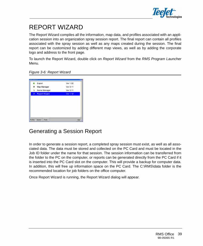
REPORT WIZARDThe Report Wizard compiles all the information, map data, and profiles associated with an appli-cation session into an organization spray session report. The final report can contain all profilesassociated with the spray session as well as any maps created during the session. The finalreport can be customized by adding different map views, as well as by adding the corporatelogo and address to the front page.
To launch the Report Wizard, double click on Report Wizard from the RMS Program LauncherMenu.
Figure 3-6: Report Wizard
Generating a Session Report
In order to generate a session report, a completed spray session must exist, as well as all asso-ciated data. The data must be stored and collected on the PC Card and must be located in theJob ID folder under the name for that session. The session information can be transferred fromthe folder to the PC on the computer, or reports can be generated directly from the PC Card if itis inserted into the PC Card slot on the computer. This will provide a backup for computer data.In addition, this will free up information space on the PC Card. The C:\RMS\data folder is therecommended location for job folders on the office computer.
Once Report Wizard is running, the Report Wizard dialog will appear.

40 Chapter 3 - Tools
Figure 3-7: Report Wizard Dialog
Select Spray Session
The first step in the report generation process is to select a spraying session. Browse the loca-tion of the job sessions. Data will reside either on the PC Card or in the folder designated tostore it (typically in the c:\RMS\data folder). Select the spray session from the list. Highlight thedesired spray session and press the Next button.
Figure 3-8: Select Spray Session
location of folder to save report files
available sessions

RMS Office98-05065 R1
41
Select Report Information
The report information dialog allows for the customization of the final spraying session report.With this dialog, the user can select the session profile information to be included in the report.The units of measurement can also be selected. The “Full Report” option will include all profilesassociated with the selected spray session. If the “Custom Report” option is selected, checkboxes will become available so individual selections are allowed by report information items onthe scroll menu.
Figure 3-9: Select Report Information
Once the desired information has been selected, press the Next button. A status box will be dis-played indicating that the information is being loaded. The process may take a few secondswhile information is loaded.
Spray Campaign
The Report Wizard Spray Campaign dialog will display the session (.EVP) map. An option isalso available to display a background map if one is available for display. In the following exam-ple session, a background map is used during the spray session. The background map selec-tion and completed spray campaign dialog are displayed, along with the background map. Oncethe Spray Campaign dialog is complete, press the Next button to move to the next Report Wiz-ard dialog window.
The “Full Report” option includes all of the report information features
The “Custom Report” option only includes those features specifically selected by the user

42 Chapter 3 - Tools
Figure 3-10: Spray Swath Map
If a background map is desired, select the map from the available options and it will be popu-lated when the Next button is selected.
Figure 3-11: Spray Swath Map with Background
Spray Swath Map
The Spray Swath Map allows for the selection and de-selection of various spray swath mapdata that was collected during the application process. The spray swath data is contained in the(.RCD) file. There should be an (.RCD) file for each product or mixture including the carrierapplied during a spraying session.
Map options are viewable by selecting and deselecting the various swath map options avail-able. If all of the map options are selected, all will be displayed on the final report.
In addition, grid coordinates can be selected for the background output. The two choices avail-able include:
• Latitude/longitude
• UTM
Once the desired spray swath map selections have been chosen, press the Next button to pro-ceed to the next Report Wizard window.
Select a background map if desired and it will be dis-played once the Next but-ton is selected.
Next button

RMS Office98-05065 R1
43
Figure 3-12: Spray Swath Map Options
Post Session Notes
The Post Session Notes dialog allows for the entry of notes to be appended at the end of thereport. Information can be included in a free form text box to be included in the final report.
Once the text has been entered, press the Next button to advance to the next Report Wizardwindow.
Figure 3-13: Post Session Notes
Selecting and deselect-ing these options change the information displayed on the spray swath maps.
44 Chapter 3 - Tools
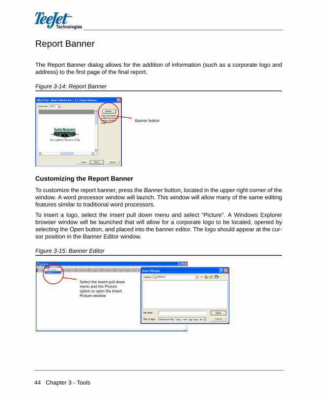
Report Banner
The Report Banner dialog allows for the addition of information (such as a corporate logo andaddress) to the first page of the final report.
Figure 3-14: Report Banner
Customizing the Report Banner
To customize the report banner, press the Banner button, located in the upper right corner of thewindow. A word processor window will launch. This window will allow many of the same editingfeatures similar to traditional word processors.
To insert a logo, select the Insert pull down menu and select “Picture”. A Windows Explorerbrowser window will be launched that will allow for a corporate logo to be located, opened byselecting the Open button, and placed into the banner editor. The logo should appear at the cur-sor position in the Banner Editor window.
Figure 3-15: Banner Editor
Banner button
Select the Insert pull down menu and the Picture option to open the Insert Picture window

RMS Office98-05065 R1
45
Figure 3-16: Banner Editor, Logo Placed
Once the logo has been added it can be positioned. Select the Edit pull down menu, followed bythe Edit Picture option. The Edit Current Picture Parameters window will be displayed, whichwill allow for the positioning of the logo. Select the OK button once the logo is in position.
Figure 3-17: Editing the Logo
Once the logo has been placed, text can be added such as the company name and address.Select the Paragraph pull-down menu to select the position of the text and insert text asdesired.
Select the Edit pull down menu and the Edit Picture option to open the Edit Current Picture Parame-ters window

46 Chapter 3 - Tools
Figure 3-18: Inserting Text
Once the desired logo and text have been entered, save the banner to a file by selecting theFile pull-down menu and selecting Copy to File. Selecting the Copy to File menu item willlaunch a prompt requesting a file name and location to save the file. Once the files is saved,select Exit to return to the Report Wizard Report Banner dialog.
Figure 3-19: Saving the Banner
Once the banner is saved, press the Next button on the Report Wizard. A message will be dis-played indicating a report is being generated.
Enter the desired textSelect the Paragraph pull down menu to position text and enter text as desired to customize the logo
Select the File pull down menu and Copy to File to save the banner

RMS Office98-05065 R1
47
Output Report
The final Report Wizard dialog is the Output Report window. From this area it is possible to printpreview, preview, print, and save the generated report. Previewing the report is always a goodidea before printing or saving the report.
Figure 3-20: Output Report
Print Setup
Print setup is used to establish the print parameters for the report. This determines what printeris used and the source of the paper. IT IS IMPORTANT TO NOTE THAT ALL REPORTS AREPRINTED IN LANDSCAPE ORIENTATION ON 8 1/2 X 11 INCH PAPER ONLY. ANY OTHERPAPER ORIENTATION WILL PRINT INCORRECTLY.
Figure 3-21: Print Setup
Preview
Preview allows the user to view the report before additional action is taken. This is a good fea-ture in order to check banner placement, to ensure data is accurate, and to double check infor-mation is available before the report is saved or printed.
48 Chapter 3 - Tools
Print is used to send the final report to the printer, which was established during Print Setup.
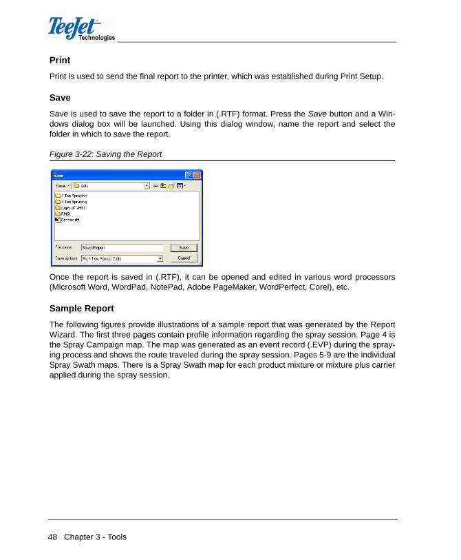
Save
Save is used to save the report to a folder in (.RTF) format. Press the Save button and a Win-dows dialog box will be launched. Using this dialog window, name the report and select thefolder in which to save the report.
Figure 3-22: Saving the Report
Once the report is saved in (.RTF), it can be opened and edited in various word processors(Microsoft Word, WordPad, NotePad, Adobe PageMaker, WordPerfect, Corel), etc.
Sample Report
The following figures provide illustrations of a sample report that was generated by the ReportWizard. The first three pages contain profile information regarding the spray session. Page 4 isthe Spray Campaign map. The map was generated as an event record (.EVP) during the spray-ing process and shows the route traveled during the spray session. Pages 5-9 are the individualSpray Swath maps. There is a Spray Swath map for each product mixture or mixture plus carrierapplied during the spray session.

RMS Office98-05065 R1
49
Figure 3-23: Report Pages 1 and 2
Figure 3-24: Report Pages 3 and 4
Figure 3-25: Report Pages 5 and 6

50 Chapter 3 - Tools
Figure 3-26: Report Pages 7 and 8
Figure 3-27: Report Page 9

RMS Office98-05065 R1
51
CHAPTER 4 - MAP MANAGERMap Manager is a data file viewing, editing, and management tool. Map Manager allows for theviewing of all roadside application data collected using the Legacy 6000 and RMS software.RMS data can also be converted to the ESRI (.SHP) file format using Map Manager. To startMap Manager, double click on Map Manager from the RMS Office Tools menu.
Figure 4-1: Map Manager
Table 4-1: Types of Data
Data Type Description
GMF General Mapping File
RCD Record File containing vehicle trajectory and application rates
EVP Event File
SHP ESRI Shape File
ARM Prescription Map File (not implemented yet)

52 Chapter 4 - Map Manager
Viewing Data
Map Manager can view any combination of RMS file types as well as zoom, pan, and print. Thefollowing illustration shows a roadside trajectory in the form of an (.EVP) file. The left side of theMap Manager window is the directory and file tree. The right side is the data viewing window.Data files are loaded into the window by double clicking on the file in the directory and file tree.Files can be viewed from different spray sessions within the same view window. Each map isloaded into the view window in layers, so when new files are opened, they are layered on top ofthe already opened files.
Figure 4-2: Map Manager
Base Maps
Background base maps, such as USGS topography maps can be viewed in Geo-Tif formats.Base maps are typically stored in the C:\RMS\basemaps folder.
Figure 4-3: Base Maps
Files that are currently in view on Map Manager

RMS Office98-05065 R1
53
Object Information Query
It is possible to query any type of data that appears in Map Manager. Using the pointer tool,select the area of the view that contains the item to be queried. The area selected will change toa fluorescent green color. If the object is double clicked, an Object Information window will belaunched, which will display object information such as the name, what layer the object is dis-played on, and the length of the object. If multiple objects are stacked on top of each other,information can be viewed for each object by selecting the arrows in the pull down menu of theObject(s) Found dialog window.
Figure 4-4: Information Query
MAP MANAGER TOOL BARThe tool bar allows for the manipulation of how data is viewed in the window. Drawing tools areaccessed from the tool bar as well as zoom, pan, and measure. Layers can be added, removed,and unloaded from view. The current or active layer is the layer that is in front of all the otherlayers. To remove or unload a layer, select it as current and select the Remove Layer button.Only the layer that is current can be removed.
Figure 4-5: Map Manager Tool Bar
The object selected will turn fluorescent green. If double-clicked, the Object Information window will be launched.
Current layer name

54 Chapter 4 - Map Manager
Table 4-2: Map Manager Tool Bar Buttons
Button Description
New File (Layer) - creates a new file (layer) and places it at the current (top) layer in the map view. A prompt will request a new file name.
Open File (Layer) - opens an existing file and allows for the selection of the top layer on the map view.
Save File (Layer) - saves the current (top) layer on the map view.
Save All - saves all the file (layers) displayed on the map view.
Print - prints the current map view with all visible layers.
Remove Layer - removes (not deletes) the current (top) layer from the view. This does not delete the file.
Layers On/Off - opens the Layers On/Off dialog. Turns layers on or off.
Zoom to Current Layer - zooms to the data extents of the current (top) layer.
Zoom to Extent - zooms to the data extents of all visible layers.
Undo Zoom - returns to the previous zoom state.
Selection Arrow - activates the selection (pointer) arrow.
Zoom In - enlarges (magnifies) the map view. There are two modes: drag box and point and click.
Zoom Out - increases the area displayed on the map view. There are two modes: drag box and point and click.
Pan - select this button and place the hand on the map view. While holding down the left mouse button, move the mouse and view the map in a “panning” fashion.
Measuring Tool - select this button to measure the distance between two points. There are two modes: mark and stream. Mark mode returns the distance between the end points (straight lines only). Stream mode returns the length of the line distance (curved lines).

RMS Office98-05065 R1
55
Table 4-3: Map Manager Tool Bar Buttons (Continued)
Text Tool
The Text tool allows for the addition of text to any (.GMF) generated map. To add text, select theText tool from the Tools menu bar. Left click the mouse at the location on the map where the textis to be placed. The Text Tool Dialog box will be launched. Type the desired text into the TextTool Dialog window. The window allows for the editing of text object properties such as font,
Button Description
Point Object - select this button and left click on the map view to place a point object in the view. During application, the user is notified when approaching a point. Highlight the object and right click to edit the object properties.
Hazard Object - select this button and left click on the map view to place a hazard object in the view. During application, the user is notified when approaching a hazard. Highlight the object and right click with the mouse to edit the properties.
Polygon Object - select and draw a polygon object in the map view. Double click the left mouse button to close and stop drawing the polygon. This object has two modes: mark and stream. Mark mode creates straight objects. Stream mode cre-ates curved objects. Highlight the object and right click with the mouse to edit the object properties.
Polyline Object - select and draw a polyline in the map view. Double click the left mouse button to stop drawing. This object has two modes: mark and stream. Mark mode creates straight objects. Stream mode creates curved objects. High-light the object and right click with the mouse to edit the object properties.
Circle Tool (Drag) - select to draw a circle by pressing and holding down on the left mouse button. Drag the mouse with the left button held down to create the desired radius. Release the left mouse button to create the circle object. Select and hold down the left mouse button on the circle tool and two other circle options (radius and 3-point) will appear in the drop down tool.
Circle Tool (Radius) - select and click the left mouse button at the center location of the desired circle on the map view. A small radius dialog box will be displayed. Enter the desired circle radius and select OK.
Circle Tool (3-Point) - select and click the left mouse button on three different locations that the circle perimeter is to intersect. Once the third point has been selected, the circle will be populated.
Text Tool - select this tool to add text to the maps.

56 Chapter 4 - Map Manager
size, and color. Once the desired edits are complete, press the Apply button to insert the textonto the map.
Figure 4-6: Text Tool Dialog Window
File Menu
Most of the tool button’s functionality is duplicated in the drop down menus. The File menuallows for various file related actions to occur, such as edit, save, delete, print, convert, and exitMap Manager.
Figure 4-7: File Menu Pull-down

RMS Office98-05065 R1
57
Table 4-4: File Menu Item Descriptions
Layers Menu
The Layers Menu allows for the manipulation and query of information associated with a maplayer in the map view window.
Figure 4-8: Layers Menu Pull-down
Menu Item Description
New New File (Layer) - creates a new file (layer) and places it on the current (top) layer in the map view. A prompt will request a new file name.
Open Opens Existing File (Layer) - allows for the selection of an existing file (layer) which will be displayed as the top layer in the map view.
Save Save File (Layer) - saves the current (top) layer in the map view.
Save As Save File As - saves the current (top) layer with a different file name. A Save As dialog window will request a new file name.
Save All Save All - saves all files (layers) displayed in the map view.
Convert Starts the conversation application which allows for the conversion of RMS data files to ESRI shape files and back.
Print Prints the current map view with all visible layers.
Delete Deletes the highlighted file in the file tree.
Properties Displays the file properties for the highlighted file in the file tree.
Exit Exits the Map Manager program.

58 Chapter 4 - Map Manager
Table 4-5: Layers Menu Item Descriptions
Menu Item Description
Select Current Allows for the selection of the current (top) layer. This can also be accom-plished from the Tools Menu bar.
Properties Activates the Layers Properties dialog box.
Remove Current Removes the current layer. This can also be accomplished from the Tools Menu bar.
Remove All Removes all layers from the map view.
On/Off Activates the Layers On/Off dialog window. This can also be accomplished from the Tools Menu bar.

RMS Office98-05065 R1
59
View Menu
The View Menu configures the Map Manager window.
Figure 4-9: View Menu Pull-down
Table 4-6: View Menu Item Descriptions
Menu Item Description
Tool Bar Standard Adds or removes the first set of Tool Bar items on the Map Manager window. Items affected are from New to Undo Layer.
Toolbar Cursor Adds or removes the second set of Tool Bar items on the Map Manager win-dow. Items affected are from Point to Text Tool.
Status Bar Adds or removes the Status Bar at the bottom of the Map Manager window and displays the current action as well as the coordinate position of the pointer.
Split Activates the split screen function, allowing the resizing of the map view and file tree.
Zoom To Current Zooms to the current layer’s data extents. This can also be accomplished from the Tools Menu bar.
Zoom To Extent Zooms to the data extent of all visible layers. This can also be accomplished from the Tools Menu bar.

60 Chapter 4 - Map Manager
Table 4-7: View Menu Item Descriptions (Continued)
File Tree Menu
The File Tree Menu allows for the control of file types that are viewed on the file tree.
Figure 4-10: File Tree Menu
Table 4-8: File Tree Menu Item Descriptions
Zoom To Previous Returns to the prior zoom state. This can also be accomplished from the Tools Menu bar.
Show Scalebar A map scale dialog window will be displayed on the map view.
Show Ratebars Selecting this when viewing (.RCD) files causes a rates scale dialog window to be displayed on the map view.
Show Tags Displays a small yellow tag next to each object in the map view. The tag contains information about the object.
Options Options allows for the editing of the system units and coordinates system.
Menu Item Description
Filter On The file tree will display only the files selected in the File Filter.
Modify File Filter Allows the selection of the files viewed when the filter is “On”.

RMS Office98-05065 R1
61
Edit Objects Menu
The Edit Objects Menu handles most of the graphics object editing including cut, copy, andpaste. Many of these object editing items can be selected as well by clicking the right mousebutton.
Figure 4-11: Edit Objects Menu
Table 4-9: Edit Objects Menu Items Descriptions
Menu Item Description
Undo Reverses the last edit made to the object.
Redo Reverses the “Undo”.
Cut Cuts the highlighted object from view.
Copy Makes a copy of the highlighted object.
Paste Pastes a copy of the highlighted object that was previously cut or copied.
Delete Deletes the highlighted object.
Edit Activates the Edit dialog window which allows for the modification of object attributes such as object names.
Properties Displays the Object Information dialog window.

62 Chapter 4 - Map Manager
Tools Menu
The Tools Menu has one option: Snap On/Off. The snap tool is used to “snap” the object item inthe map view to the nearest object during placement on the map. A good use for the snap tool isto find the distance between two points.
Figure 4-12: Tools Menu
PRINTING MAPS IN MAP MANAGERPressing the Print button on the button bar or selecting Print from the File menu will launch thePrint Settings dialog window. Print options are controlled on the window.
Figure 4-13: Print Settings Dialog Window

RMS Office98-05065 R1
63
Table 4-10: Print Settings Descriptions
SHAPE FILE CONVERSIONMap Manager contains a file option named Convert that provides a means of transferring databetween RMS data files and ESRI shape files. Convert was designed to be both flexible andsimple. It allows beginning users to perform conversions in several simple steps while offeringadvanced users full control over the data transfer process.
The conversion process is broken into two step:
• exporting RMS data files to shape files
• importing shape files to RMS data files
Shape files must be in NAD83 or WGS84 Lat/Long coordinates. No other projections or datumsare supported. ESRI shape files of (.SHP), (.SHX), and (.DBF) files all share the same filename.
Exporting RMS Data to Shape File Format
The export process allows for RMS data to be exported to a shape file. Export files one at a timeor batch multiple export files or folders. The export process is populated with several exporttemplates that can be edited to best fit user needs. New export templates can also be created.
Setting Description
Portrait Displays the map in a portrait mode.
Landscape Displays the map in a landscape mode.
Show Preview Displays a preview of the printed map in the Map Manager Map View. It is recommended that the maps be previewed before saving and printing.
Legend Text Adds a map title and additional text to the printed map. To add text, start typ-ing in the Legend Text box window.
Logo Include a corporate logo on the printed map. To add a logo, press the Browse button and select the desired logo file.
Scale Bar Includes a distance scale bar on the printed map.
Rate Bar Includes a rates legend on the printed map. The map view must contain an (.RCD) file.
Target Bar Includes a distance Application Target Rate legend on the printed map. The map must contain an (.ARM) file.

64 Chapter 4 - Map Manager
Export to Shape Dialog
The Export to Shape Dialog is used to select the file(s) to convert. It is also used to start theconversion process. Review this dialog prior to converting a file.
To access the Shape Export Dialog, select File, Convert, Shp Export.
Figure 4-14: Export to Shape Dialog
Table 4-11: Export to Shape Dialog Descriptions
Function Description
Export Tree Select the files to be exported from the Tree View. The Tree supports multi-ple selections. Select multiple files with standard explorer style CNTRL/LEFT click and SHIFT/LEFT click.
Include Sub Directories When selected, the program will export all the files selected and all the files located in the sub-directories. The program will search all sub-directories within the selected directories and keep opening files until nothing else is located. When this is de-selected, the program will export the selected files and only those files in the selected folders (not the sub-directories).
Filter File Types When selected, only filter type files and directories will be displayed (see Set Filter). When de-selected, all files and directories will be displayed.
Set Filter Select the file types to be displayed.
Export to Path Type in the export path for the shape files. The Export to Current Location check box cannot be checked if an export path is identified.
Browse Browse for the path location.

RMS Office98-05065 R1
65
Table 4-12: Export to Shape Dialog (Continued)
Export to Shape Setup Dialog
The Export to Shape Setup Dialog controls and establishes the parameters involved in theexport process. This dialog should be reviewed prior to exporting any files. The primary functionof the Export Setup dialog is to define which RMS objects are exported and to describe how theobjects are transferred/combined to create one or more shape files.
Figure 4-15: Export to Shape Setup Dialog Window
Function Description
Export to Current Loca-tion
When selected, all exported files will be stored in the same location as the original file. This is not valid for “All Files Into 1 File” exporting when files from multiple directories are selected. Perform an “All Files Into 1 File” export for a single job using this check box. De-select to send all of the exported files to the location specified in the export path edit control
Convert Starts the conversion process.
Show Output Shows or hides the output dialog. The shape file conversion progress is dis-played in the dialog window.
Stop Pauses the export process. A prompt will be displayed and will request whether to continue or abort the export process.

66 Chapter 4 - Map Manager
Figure 4-16: Export to Shape Setup Dialog Descriptions
Function Description
Create Import Tem-plates
When selected, the program will automatically generate an import template for any ARC-Polyline, Point-Point, and Polygon-Polygon object exported. This template is a reverse image of the export template used for the object. The new template name begins with the world “Import” followed by the name of the export template. For example, if PointToShp.tpl was exported, the import template would be Import[PointToShp].tpl.
2D Radio Button When selected, the program will load all available 2D templates into the template combo box. The templates are located in the \bin template folder.
3D Radio Button When selected, the program will load all available 3D templates into the template combo box. The templates are located in the \bin template folder.
Merge Points When selected, the program will merge all point types in a given file into a single shape point file. When de-selected, the program will export different point types in a given file to their own point shape files.
Merge Arcs When selected, the program will merge all arc types in a given file into a sin-gle shape arc file. When de-selected, the program will export different arc types in a given file to their own arc shape files.
Merge Polygons When selected, the program will merge all polygon types in a given file into a single shape polygon file. When de-selected, the program will export dif-ferent arc types in a given file to their own arc shape files.
Merge All Files Into 1 File
When selected, the program will merge all exported point shape files into a single point shape file, all arc files into a single arc shape file, and all poly-gon files into a single polygon shape file.
Arc (Polyline) Templates Polyline
Defines how to convert any polyline in the shape export.
Arc (Polyline) Templates Record
Defines how to represent a swath from a Record (.RCD) in a shape file.
Arc (Polyline) Templates ITV
Defines how to represent an interval in the record file in a shape file.
Arc (Polyline) Templates Handgun
Defines how to convert a handgun object in the shape file export.
Arc (Polyline) Templates Circle Arc
Defines how to convert a circle arc in the shape export.
Point Templates - Points Defines how to convert any point in the shape export

RMS Office98-05065 R1
67
Export to Shape Template Dialog
An export template is essentially a set of instructions for transferring the selected object type toa shape file. The Template Dialog provides a list of available templates for the selected conver-sion and allows for the management of the templates using the New, Delete, and Edit buttons.
The export template dialog is used to edit an existing template or create a new template. Whencreating a new template, a new template name must be selected in the appropriate templatecombo box, which is located in the Export Setup Dialog.
Figure 4-17: Export to Shape Template Dialog
Point Templates - Weather
Defines how to convert any weather point in the shape export.
Polygon Templates - Polygon
Defines how to convert any polygon in the shape export.
Polygon Templates - Circle
Defines how to convert any polygon circle in the shape export.
Polygon Templates - Circle Pie
Defines how to convert any polygon circle pie in the shape export.
Function Description

68 Chapter 4 - Map Manager
Table 4-13: Export to Shape Template Dialog Descriptions
Importing Shape Files to RMS Data Files
The second conversion process is importing shape files into RMS data files. For example, thereare many background files such as roadways that are in the shape format. These can beimported into a (.GMF) file and viewed in the background of any application, such as Mapper.
Import from Shape Dialog
Use the Import from Shape Dialog to select the files or folders to be converted from the shapefile format to a data file. Review the Import Setup dialog prior to running the import process.
Figure 4-18: Import from Shape Dialog
Function Description
Available Templates Displays all available templates located in the \bin template directory that match the 2D or 3D radio button selection.
Edit Allows for the editing of the current template selection.
Delete Allows for the deletion of the current template selection.
2D Radio Button When selected, the program will load all available 2D templates into the template combo box. The templates are located in the \bin template folder.
3D Radio Button When selected, the program will load all available 3D templates into the template comb box. The templates are located in the \bin template folder.
Object Types Displays all available object types for which templates can be created.
New Allows for the creation of a new template for the current object selection.

RMS Office98-05065 R1
69
Table 4-14: Import from Shape Dialog Description
Import Setup Dialog
The Import Setup Dialog is used to define what import templates are used for the import pro-cess. The type of data file to import data into is also selected at this time.
Function Description
Import Tree Select files to import from the import tree. The tree supports multiple selects. The user can make multiple selections with standard explorer style CNTRL/LEFT click and SHIFT/LEFT click.
Include Sub Directories When selected, the program will import all files selected and all files located in the sub-directories. The program locates all sub-directories within the directories. When de-selected, the program will import all files selected and only those files located inside the selected folders.
Filter File Types When selected, only shaped files and directories will be displayed (see Set Filter). When de-selected, all files and directories will be displayed.
Import to Path Type in the import path for the shape files. The Import to Current Location check box cannot be checked if an import path is identified.
Browse Browse for the path location.
Import to Shape File Location
When selected, all imported files will be stored in the same location as the original file. De-select to send all of the imported files to the location speci-fied in the import path edit control
Convert Starts the conversion process.
Show Output Shows or hides the output dialog. The shape file conversion progress is dis-played in the dialog window.
Stop Pauses the import process. A prompt will be displayed and will request whether to continue or abort the import process.

70 Chapter 4 - Map Manager
Figure 4-19: Import Setup Dialog
Table 4-15: Import Setup Dialog Description
Function Description
Create Export Tem-plates
When selected, the program will automatically generate an export template for any Point, Polyline, or Polygon object imported. This template is a reverse image of the import template used for the object. The new template name begins with the world “Export” followed by the name of the import tem-plate. For example, if ShpToPoint.tpl was imported, the export template would be Export[ShpToPoint].tpl.
2D Radio Button When selected, the program will load all available 2D templates into the tem-plate combo box. The templates are located in the \bin template folder.
3D Radio Button When selected, the program will load all available 3D templates into the tem-plate combo box. The templates are located in the \bin template folder.
Templates - Point Select the type of import conversion by choosing the conversion template. This template defines how to represent a point in a shape file in an RMS data file.
Templates - Polyline Select the type of import conversion by choosing the conversion template. This template defines how to represent an arc in a shape file as a polyline in an RMS data file.
Templates - Polygon Select the type of import conversion by choosing a conversion template. This template defines how to represent a polygon in a shape file in an RMS data file.
Import File Types Point Defines the file types to be imported - whether they are (.GMF) or (.RCD).
Import File Types Poly-line
Defines the file types to be imported - whether they are (.GMF) or (.RCD).
Import File Types Poly-gon
Defines the file types to be imported - whether they are (.GMF) or (.RCD).

RMS Office98-05065 R1
71
Import Template Dialog
The Import Template Dialog is used to edit an existing template or create a new template. Tocreate a new template, a new template name must be selected in the appropriate name tem-plate combo box located in the Import Setup dialog.
Figure 4-20: Import Template Dialog
Table 4-16: Import Template Dialog Description
Function Description
Available Templates Displays all available templates located in the \bin template directory that match the 2D or 3D radio button selection.
Edit Allows for the editing of the current template selection.
Delete Allows for the deletion of the current template selection.
2D Radio Button When selected, the program will load all available 2D templates into the template combo box. The templates are located in the \bin template folder.
3D Radio Button When selected, the program will load all available 3D templates into the template comb box. The templates are located in the \bin template folder.
Object Types Displays all available object types for which templates can be created.
New Allows for the creation of a new template for the current object selection.

72 Chapter 4 - Map Manager
Convert Templates
A template contains the information required to convert an RMS file object to a shape file object(Export), or create an RMS file object from a shape file object (Import). To better understandtemplates, it is important to understand the data that comprises the RMS file or shape fileobject.
An object (polygon, polyline/arc, or point) is just a shape - one or more positions with an associ-ated set of attributes or fields. The shape’s fields specify information about the shape, such asits name or ID. RMS file shapes and shape file objects are essentially the same. However, thefields associated with the shapes are different. To transfer the contents of an RMS file object toor from a shape file object, object fields must be specified so that RMS file fields can be trans-ferred to shape file fields and vice versa. The template is where the file transfer information isstored.
Experimenting with the Export or Import dialog will illustrate that different templates are pro-vided for each object type. This is due to the fact that fields for each RMS object type areunique. The Export or Import dialog only displays templates that make sense for a selectedobject type.
Templates are managed using the New, Delete, and Edit buttons which are located on the Tem-plates dialog. To create a new template, press the New button. To delete an existing template,press the Delete button. To edit an existing template, press the Edit button.
Figure 4-21: Field Transfer Template
To edit an exist-ing template, select the Edit button

RMS Office98-05065 R1
73
Establishing a Field Transfer Template
The Field Transfer Template window is used to establish a field transfer template. The TemplateName edit box will be displayed at the top of the window. Templates should be assigned aunique name that identifies the type of conversion it handles.
Below the Template Name edit box is the Field Transfer list. The list contains the field transfersor mappings that are performed between the given source file and the destination file objects.The source file object fields will be displayed in the lists’ left column and the destination fileobject fields will be displayed in the lists’ right column.
Use the New, Edit, and Delete buttons to change the entries in the list. New creates a new fieldtransfer. Edit allows for the altering of an existing transfer. Delete will allow for the removal of anexisting transfer.
Several buttons in the Field Transfer Template window only appear when the actual transferoccurs. Use the Up/Down Arrow buttons to change the order of the field transfers on the list.The order of the transfers determines the order that the program will write the fields to the shapefile. The Copy All button will copy all of the fields in the RMS file object to the shape file object.
Figure 4-22: Field Transfer Template
Configuring Field Transfers
The Field Transfer dialog is used to configure a single field transfer. The left side of the windowdefines how to transfer a source field to the destination field, which is shown on the right side.Each field setting on the left is followed by an arrow button and a matching field setting on theright. When the arrow button is active, it can be used to transfer the contents of the left setting tothe right. Pressing the Copy button at the bottom of the screen is equivalent to pressing all ofthe active arrow buttons (inactive buttons are gray).
Use the top pair of settings to define the names of the fields. These settings may take the formof a combo box or an edit box. If a combo box is present, one of the names can be selectedfrom the list. The list will contain all of the names located in or compatible with the field. If an editbox is present, type the name of the filed in the box.
The second pair of settings define the field’s type. These settings can either take the form of acombo box or a text box (which cannot be edited). If a combo box is present, the type can be
Template name
File Transfer list

74 Chapter 4 - Map Manager
selected. This will affect how the program will write the field to a file when it performs the con-version. If a specific type appears in the box on the left, it is best to choose the same forthe box on the right.
Figure 4-23: Configuring Field Transfers
The final pair of settings assign units of measure to the fields. These settings either take theform of a combo box or a text box (which cannot be edited). If a combo box is present, the unitof measure can be selected that the program should store in the field. Take care in selecting aunit of measure. If the field defines a name or some other non-numeric value, specify <None>for the unit of measure. If the field’s unit of measure is unknown, specify <Unknown>. When theprogram transfers the field, it will automatically perform the necessary units of measurementconversions. Therefore, it is important that the source fields and destination fields units of mea-sure are compatible. If the units of measure are incompatible, an error will occur. Press OK.
If the Units of Measure setting has a Browse button located to its right, a units of measure fieldcan be built. Pressing the Browse button will launch the Build Units of Measure window. Thewindow will allow for the selection of units of measurement from a long list of options.
Under some circumstances, the Field Transfer dialog’s appearance transforms. One such cir-cumstance arises when the source field’s name is set to <CONSTANT> or <COUNTER>.<CONSTANT> and <COUNTER> are special, user-defined fields. They do not exist in thesource file object. If the source field’s name is set to <CONSTANT>, a Value setting replacesthe source field’s Type setting. The Value setting is a string or number passed to the specifieddestination field for each object written to the file. If the source field name is set to <COUN-TER>, a First Number setting replaces the source field’s Type setting. As it’s name implies, theFirst Number setting represents the counter’s starting value. Each time the program transfersthe counter value to a specified data field, it increments the value by one.
Templates are a complex yet powerful tool. Creating templates takes some practice. However,once understood, they offer a limitless array of RMS/Shape file conversions.
Select the “...” to launch the Build Unit of Measure window