Product Overview 97/98 - DEMPAN
64
Product Overview 97/98 Pressure Switches Pressure Transmitters Pressure Controllers Temperature Transmitters Temperature Sensors Thermostats Solenoid Valves Displays . . . monitoring and control of pressure, temperature and flow REG. NR. 4095-02 tested
-
Upload
khangminh22 -
Category
Documents
-
view
3 -
download
0
Transcript of Product Overview 97/98 - DEMPAN

Product Overview 97/98
H
Pressure Switches
Pressure
Transmitters
Pressure
Controllers
Temperature
Transmitters
Temperature
Sensors
Thermostats
Solenoid Valves
Displays
. . . monitoring and control of pressure, temperature and flow
s
REG. NR. 4095-02
t e s t e d

Monitoring and
control
pressure,
temperature and flow
under control for
more than 50 years.
FEMA products are located –
inside numerous machines
and systems. What they do is
important. It serves safety and
cost effectiveness.
s
Components for
safety . . .
. . . reliability is
confirmed by
component tests of
the TÜV, DVGW and
of the PTB.
CE certificates of
conformity are
available where
necessary.
FEMA products help to
ensure that pressure, tem-
perature and flow do what
is required. The area of application
covers widely differing sectors:
– industrial heat generation and
distribution,
– gas technology and chemical
process engineering,
– water conditioning and environ-
mental protection,
– mechanical engineering and
many further industries.
FEMA pressure and temperature
switches as well as solenoid valves
in explosion protected version, all
of which are tested according to
the latest European directives, also
provide solutions in areas where
there is an explosion hazard.
DIN ISO 900
EN 2900
certification for our
customers
Certification according
to DIN ISO 900 provides
evidence that the cus-
tomers’ expectations are recog-
nized and put into practice.
Fulfilling your requirements is
our objective. This is how we
understand quality. We see in it an
obligation to continue on this path
consistently in order to be a com-
petent and reliable business partner
for you in the future as well.
We also
deliver
customized . . .
. . . if you have a
special problem.
Many monitoring and
control tasks can be solved
with our extensive product
range. Yet special tasks are a
special challenge to our specialists.
Should you have such a problem,
please describe it to us – individual
adaptation is one of our strengths.
REG. NR. 4095-02
t e s t e d

3
Program-Overview / List of contentsP
RE
SS
UR
E
Pressure Switches
Components tests, Housings 7
Pressure monitoring in Ex-areas 8
Overview – Technical data 10
Optional functions 11–12
Pressure switches 4 mbar up to 63 bar 13
Stainless steel and high grade steel pressure switches 14–16
Negative pressure switches / Vacuum Switches 15–17
For heating and gas applications
for steam and hot water (TÜV-tested) 19–21
for burnable gases (TÜV/DVGW tested) 20–22
for liquid fuels 20–21
for liquid gas 23
Pressure Limiters in Safety Engineering 23
Differential Pressure Switches
Pressure and differential pressure monitors 24–25for heating, cooling, steam and other applications
Differential pressure switches 24for gas applications, DVGW tested
Pressure Transmitters
Overview 26
Mechanical / Inductive 29–31
Transmitter 29–30
Controller (P-controller) 31
Electronical Sensor 27–28
Differential pressure transmitterfor air conditioning 32–33
Accessories for Pressure Switches and Pressure Transmitters
Pressure mediators / separating membranes 48
Siphons 49
Welding nipples 50
Shut-off valves 50
Pressure surge reducer 50
NPT adapter 50

4
Program-Overview / List of contentsT
EM
PE
RA
TU
RE
Temperature switches / Thermostats (mechanical) 53–54
Industrial room thermostats 53
Capillary tube thermostats 53
Rod thermostats 54
Frost protection thermostats 54
Two-Phase frost protection 36
Accessories 55–56
Flow switches / monitoring
For liquids and gas 25
Temperature transmitters
With attached sensor PT 100 37
For switchboard installation and PT 00 input 38
Temperature transmitters with high grade steel sensor 40
Average temperature transmitters for air ducts 39
Temperature Sensors PT 100 / PT 1000
For heating and air conditioning applications
Rod probe sensors 41
Air duct probe 41
Contact probe 41
Outdoors probe 41
Room probe 41
Average temperature sensor for air ducts 42
For general applications
Remote probe 42
Surface probe 42
Screw-in probe 42
Teflon-measuring probe 42
High grade steel sensors PT 00 40
Temperature switches / Thermostats (electronical)
Thermostat, 2-stage, for switchboard installation 38
Programmable display with 2 switching outputs 43
Accessories 55–56
Immersion tubes 56

5
Program-Overview / List of contentsH
IN
WE
IS
ES
OL
EN
OID
VA
LV
ES
EV
AL
UA
TIO
NU
NIT
S Accessories for transmitters
Adjustable digital LED display modules 45
Root extraction module 45
Priority Selector 46
Limit value switch, 1-stage 44
Limit value switch, 2-stage 44
Programmable digital displays with 2 outputs 43
Safety isolating switching amplifier 47
Signal separator (galvanic separation) 43
Control command module 45
Solenoid Valves
Overview 57
Solenoid valves for universal applications 58
For hot water and steam 59
For gas, liquid gas and heating oil 60
Accessories for valves 61
Small Solenoid valves 62
Pressure units conversion table 12
Technical brochures / data sheet 63
x Additional technical information available on request:
x Pressure switch brochure
x Pressure transmitter brochure
x Temperature brochure
Explanations x Shaded types are on stock.

Preference articlesThose articles which are underlayed with a screen usually are on stock.
6
Summary of types
Type page
AB 62
AE 50
AM 50
APV, APT 43
AS 50
ASL 25
ASW 25
AZ 331, AZ 32 45
AZ 21, AZ 3 45
AZ 3.1 B 12
AZ 3.1 B-V 12
AZ 3.1 B-M 57
DCM 13
DCMV 13
DDCM 24
DGM 22
DML 50
DMW 50
DNM 14
DNMV 14
DNS 15, 16
DOKU 12
DPS 25
DWAM 19, 23
DWAMV 19
DWR 20, 21
EA, EC 31
E 422 49
EHB, EHN 31
EM 310 46
EM 320 44
EMS 10 44
EN 31
EVC 31
EVN 31
EX 041 47
EX 011 47
Ex-DCM 13
Ex-DDCM 24
Ex-DGM 22
Ex-DNM 14
Ex-DNS 15
Ex-DWR 20
Ex-FT 54
Ex-TAM 53
Ex-TRM 53
Ex-TX 54
Ex-TXB 54
Ex-VCM 17
Ex-VNM 17
Ex-VNS 15
FA 29, 30
FC . . . 29, 30
FD 23
FF 135 56
FHB 29, 30
Type page
FHBN . . . 29, 30
FN . . . 29, 30
FT 54
FTB 54
FTS 35
FV 48
FVA 29, 30
FVC 29, 30
FVN 29, 30
G 31 61
G 31 GS 61
G 35-Ex 61
G 35-ExG 61
GB 62
GB . . . VA 62
GS 61
GT 4 43
H1, H2, H3 55
H10 46
HCD 24
K 430, K 480 49
K . . . G 31 F 60
K . . . G 31 M 60
K . . . G 35 F-Ex 60
K . . . G 35 M-Ex 60
L . . . G 31 F 59
L . . . G 31 FK 59
L . . . G 31 M 59
L . . . G 31 MK 59
LMS 42
LMT 30 38
MCP 1 45
NPT 1 50
P 17 . – . . . 40
P2 55
PAD 1 46
PAF . . . 41
PAL . . . 41
PD . . . 16
PDD 16
PE . . . 42
PF 42
PK . . . 42
PL . . . 41
PM . . . 42
PRT . . . 41
PS . . . 41
PZ 39
Type page
R 1/Ms 56
R 1/Nst 56
R 10 . . . 56
R 10/Ms 56
R 10/Nst 56
R 2/Ms 56
R 2/Nst 56
R 20/Ms 56
R 20/Nst 56
R 3/Ms 56
R 4, R 5 55
R 8 56
R 15 40
R 18 40
RA 31 45
RN 10 . . . 56
RN 20 . . . 56
SB 34
SDW 32
SDBAM 19
SK . . . 33
SL . . . 32
SLF 25
SN 27, 28
SNV 27, 28
ST . . . 55
SWF 25
T . . . G 31 F 58
T . . . G 31 FK 59
T . . . G 31 M 58
T . . . G 31 MK 59
T . . . G 35 F-Ex 58
T . . . G 35 M-Ex 58
TAM 53
TP . . . 36
TRM 53
TRMV 53
TSP . . . 37
TSS 38
TX 54
TXB 54
U 49
V 49
VCM 17
VCMV 17
VNM 17
VNMV 17
VNS 15, 16
WLP 55
WZ 2.2 12
Z 50
ZF . . . 11, 12
ZFT . . . 52
ZFM . . . 61

PO
97
24
.09
.97
/02
7
Components testsSpecial type series have been developed for special applicationsin the safety area:
VdTÜV
Pressure 100/1
Steam and hot waterPressure monitors and pressure limiters for steam and hot water in systems to
DIN 4751 T2 and TRD 604.
Series DA and DWR.
DVGW
DIN 3398 P. and 3
Fuel gases sPressure monitors and limiters for fuel gases in accordance with DVGW
Worksheet G 260. Series DGM and DWR.
TÜV
DIN 3398 P. 4
Liquid fuelsPressure monitors and pressure limiters for liquid fuels (heating oil).
Series DWR.
TÜV
Pressure 100/1 + DIN 3398 P. 4
Pressure limiters in safety engineeringfor safety-relevant pressure monitoring in liquid gas systems, chemical and processing
engineering systems.
- versions
EEx de II CT6
(pressure proof encapsulated)
For Ex areas ≥ Zone 1, all pressure switches can be delivered in pressure-proof
encapsulated design (Ex degree of protection EEx de II CT 6).
PTB approval: Ex-90.C.1059.
EEx-ia
(intrinsically safe)
For intrinsically safe control circuits (Ex degree of protection EEx-ia), the pressure
switches can be delivered with gold contacts, proximity switches as well as with the blue
terminals and cable entries customary in the EExi area.
An isolating switching amplifier, which transfers the control commands of the pressure
switch from an instrinsically safety control circuit (EEx is IIC) into a not intrinsically safe
active circuit, is required in addition to the pressure switch.
Switching housing with switching mechanismsThe switching housings consists of high quality and seawater-resistantaluminium diecastings. Three versions are available:
Housing 200 (normal version)Plug connection to DIN 43650
Degree of protection IP 54
Setpoint setting accessible from the outside.
IP 54
Housing 300With terminal connection box
Degree of protection IP 54, on request IP 65
Setpoint setting and terminal connections accessible only after removal of the terminal
box lid.
IP 54
(IP 65)
Ex Housing 700 (EEx-d version)All pressure and differential pressure switches can be equipped with these switch
housings
and are thus approved for Ex zones ≥ 1.
Degree of protection IP 65
Ex degree of protection EEx de II CT6
IP 65

Ex 0
Ex 0
Ex 04
PO
97
24
.09
.97
/02
8
Pressure monitoringin explosion-endangered areas
Pressure switches with special equipment can also be used in the
Ex area ≥ Zone 1.
The following alternatives are possible:
1. Pressure switch with pressure-proof encapsulated switchingdevice, degree of protection EEx de IIC T6The pressure switch in pressure-proof encapsulation can be used directly in the Ex
area (≥ Zone 1). Maximum switching voltage, switching capacity and ambient tempe-
rature must be taken into account and the rules for the installation in the Ex area must
be observed.
All pressure switches can be equipped with Ex switching mechanisms. Nevertheless,
special circuits as well as versions with adjustable switching differences are not possi-
ble.
2. Pressure switches in EExi versionAll pressure switch in normal version can be used in the Ex area ≥ Zone 1 if they are
incorporated in an „intrinsically safe circuit“. In principle the intrinsic safety is based on
that fact that the control circuit run in the Ex area carries only a small amount of energy
which is not able to generate ignitable sparks.
Isolating switching amplifiers, e. g. Type Ex 0 or Ex 04 must be tested by the PTB and
approved for Ex-installations.
Isolating switching amplifiers must in any event be installed outside the Ex zone.
Pressure switches which are intended for EEx-ia installations can be equipped with
blue terminals and cable entries. Because of the low voltages and currents which are
carried by the contacts of the microswitch, gold plated contacts are recommended
(additional function ZF 513).
3. Pressure switches with inductive proximity switches inaccordance with DIN 9234 (NAMUR)Instead of the mechanical microswitch, contactless proximity switches can also be
built into the pressure switches. Combination of pressure switches and proximity swit-
ches (ZF 52) and isolating switching amplifiers EX 0 is permissible for Ex zone ≥ ,
degree of protection EEx-ia. Here as well the isolating switching amplifier must be
installed outside the Ex zone.
4. Pressure switches with microswitch and series resistorfor line monitoringA combination of pressure switch with mechanical microswitch connected in series
with a .3 k series resistor (ZF 526 and ZF 527) and an isolating switching amplifier in
safety technology (Type EX 041) can also be used for Ex zone ≥ (degree of protection
EEx-ia).
The isolating switching amplifier in safety technology generates an intrinsically safe
control circuit and simultaneously monitors the supply line between the isolating swit-
ching amplifier and pressure switch for short circuit and line break. Please refer to the
chapter on pressure switches in safety technology.
5. Pneumatic pressure switchesNo electrical energy is used in these pressure switches ond no ignition sparks can
arise. A prerequisite is that compressed air with a pressure of .4 bar is available and
that the pneumatic output signal can be evaluated accordingly. Please refer to the data
sheet PN for details (please request).
These versions apply also for thermostats (with the exception of version 4)
Ex Zone or 2
Ex Zone or 2
Ex Zone or 2
Ex Zone or 2

PO
97
24
.09
.97
/02
9
Selection criteria for pressure monitors + limitersSee also page 8
C H E C K L I S T
1 MediumSteam, hot water, fuel gases, air, flue gases,
liquefied gas, liquid fuels, other media
1a Sensor materialStainless steel, non-ferrous metals, plastics (e. g. Perbunan).
Are all sensor materials resistant to the medium?
Oil- and grease-free for oxygen?
2 Type approvalIs a type approval (TÜV, DVGW, PTB, etc.) required for the
intended application?
3 FunctionMonitor, limiter, limiter with interlock (internal or external).
Pressure limiter in safety engineering?
4 Direction of actionShould the maximum pressure or the minimum pressure be
monitored? Does the pressure switch have a controller
function (e. g. pump on and off)?
5 Setting range Take the wanted setting range from the type overviews.
6 Switching diff.Only for controllers / monitors
The adjustable switching differential is important only for pressure
switches with controller function. The switching differential
(hysteresis) has no significance for limiter functions.
7 Max. permissibleoperating pressure
The maximum permissible operating pressure named in the
tables must be the same as or greater than the maximum
system pressure.
8 Ambientconditions
Medium temperature / ambient temperature / type of protection /
humidity / Ex zone / installation in the open – protective
measures
9 Design / SizePressure connection
Size, istallation position, installation possibility, pressure
connection with gasket.
0 Electric dataSwitching capacity
Switching element / change-over contact / normally closed
contact / normally open contact / switching capacity / interlocking /
gold contacts / contactless signal transmission.
This list of criteria does not claim to be complete. However, all items must be
checked. The stated sequence is expedient but not mandatory.

PO
97
24
.09
.97
/02
0
The most important technical datafor pressure switches with microswitches
Valid for all pressure switches with microswitches of the DCM, VCM, DNM, DA, DWR, DNS,
DDC series. The technical data of the component tested units deviate partly slightly.
(Please refer to type sheet).
Normal version -version (EEx-d)Plug connection Terminal connection
. . . 200 . . . 300 . . . 700
Switch housing Aluminium diecast GDAISi 12 Aluminium diecast GDAISi 12
Pressure connection G 1/2-external thread (pressure gauge connection) and G 1/4 internal thread.
DDCM internal thread 1/4 in differential pressure switches
Switching function and Floating change-over contact. Floating change-over contact.
connection drawing With rising pressure switching over With rising pressure switching over
(applies only for version single-pole from 3–1 to 3–2 single pole from 3–1 to 3–2
with microswitch)
Switching capacity
(applies only for version
with microswitch)
8 A at 250 V AC 3 A at 250 V AC
5 A at 250 V AC inductive 2 A at 250 V AC inductive
1 A at 24 V DC 0.1 A at 250 V DC
0.01 A at 250 V DC inductive
Installation position preferably vertical vertical
(see type sheet)
Degree of protection
(in vertical position)
IP 54 (on request IP 65 by ZF 351) IP 65
Ex degree of protection – EEx de IIC T6 tested to EN
50014/50018/50019 (CENELEC)
PTB-approval – Ex-90.C.1059
Electrical connection Plug connection (200 series) or Terminal connection
Terminal connection (300 series)
Cable entry Pg 11 Pg 11
Ambient temperature –15 to +70 hC (does not apply for
component tested versions)
–15 to +60 hC
Switching point Adjustable on the spindle. Adjustable on the spindle after the
In switching mechanism 300 the terminal box lid is removed.
terminal box lid must be removed.
Switching difference Adjustable or not adjustable Not adjustable
(see type overview)
Medium temperature Max. 70 hC, briefly 85 hC Max. 60 hCHigher medium temperatures are possible if the above limit values at the switching
mechanism are ensured by suitable measures (e. g. siphon)
Vacuum All pressure switches can operate under vacuum, the device is not damaged by this.
Repetition accuracy of the
switching points
<1 % of the working range (for pressure ranges > 1 bar)
Vibration strength Up to 4 g no noteworthy deviations. The switching difference is reduced slightly at
higher accelerations. More than 25 g not permissible.
Mechanical life With sinusoidal pressure application and room temperature, 0 x 06 switching cycles.
The expected life depends strongly upon the type of pressure application, therefore
this figure can serve only as rough estimate. With pulsating pressure or pressure
impacts in hydraulic systems, pressure surge reduction is recommended.
Insulation values Overvoltage category III, contamination class 3, reference surge voltage 4000 V.
Conformity to DIN VDE 00 (0.89) has been confirmed.
Oil and grease-free The parts of all pressure switches in contact with the medium are oil and grease-free.
The sensors are hermetically encapsulated, they contain no seals.

PO
97
24
.09
.97
/02
1
Pressure Switches and Pressure MonitorsSwitch units / optional function / connection diagrams
Plug connection Terminal Description Connection diagrams
Series 200 connection
Series 300
Normal version
microswitch, single pole switching over,
switching differential not adjustable
Terminal connection case
(series 300) instead of
. . . 301 plug connection case
. . . V or as above, but with additional setting spindle
ZF 203 . . . 303 for adjustment of the switching differential
ZF 205 ZF 305 Maximum limiter
with manual reset.
Interlocking with increasing pressure
ZF 206 ZF 306 Minimum limiter
with manual reset.
Interlocking with falling pressure.
ZF 307 Two microswitches, switching in parallel
or in succession. Fixed switching interval.
Terminal connection case.
ZF 209 Two microswitches,
switching in succession,
plug. Fixed switching interval.
ZF 217 Two microswitches,
switching in succession, plug, See data sheet S 2
adjustable switching interval.
ZF 212 ZF 312 Proximity switch to DIN 9 234
(Namur)
Contactless signalling.
May be used only in conjunction with Ex 01.
ZF 213 ZF 313 Gilded contacts single pole switching over.
Cannot be supplied with adjustable
switching differential.
Switching capacity:
max. 24 V DC, 00 mA; min. 5 V DC, 2 mA
ZF 512 Proximity switch to DIN 9 234
(Namur)
Contactless signalling. Only together with
safety isolating switching amplifier Ex 0.
ZF 513 Gilded contacts single pole switching over.
Not available with adjustable switching
difference. Switching capacity:
max. 24 V DC, 00 mA; min. 5 V DC, 2 mA
only with switching amplifier e. g. Ex 01.
ZF 526 Opener contact with resistor combination
for short circuit and wire breakage
monitoring. Only together with safety
isolating switching amplifier Ex 04
for monitoring maximum pressure.
ZF 527 Opener contact with manual reset and
resistor combination.
Only together with safety isolating switching
amplifier Ex 04 for monitoring maximum
pressure.
EE
xi-
de
sig
n
intrin
sic
ally
Casin
g300,cable
entry
and
term
inalblu
e.
Type
ofpro
tection
IP54

PO
97
24
.09
.97
/02
2
Pressure Switches and Pressure MonitorsSwitch units / optional functions / Adjustment Documents
Plug connection Terminal connection Description Connection diagrams
Series 200 Series 300
Plug connector with position
ST 218indication. 12 V–220 V AC/DC
(To be ordered separately)
Details see page 55.
ZF 350 Protection type IP 65
ZF 351 Protection type IP 65 and switch
housing with surface protection
ZF 601 Pneumatic switching element
with trigger function. Direction of action
reversible.
Pressure .4 bar
Example: Ordering text:
DCM 6 – 205 Pressure switch DCM 6 – 205
or DCM 6 with ZF 205Code of the switching unit
(e. g. maximum limiter)
Code of pressure range
Sensor system
Adjustment according to customer’s instruction:
ZF 1970 ZF 1970 one switching point
ZF 1972 ZF 1972 two switching points or defined switching differential
Adjustment and sealing according to customer’s instruction:
ZF 1971 – one switching point
ZF 1973 – two switching points or defined switching differential
ZF 1978 ZF 978 Lable of units according to customer’s instruction
ZF 1979 ZF 979 Special packing for oil and grease-free storage
DOKU Documents: additional documents, e. g. data sheets, mounting
instructions, TÜV-, DVGW- or PTB-certificate.
Certificates to EN 0 204
WZ 2.2 Test report 2.2, type series certificate
AZ 3.1 B AZ 3.1 B Inspection certificate, specific product test
AZ 3.1 B–V Inspection certificate for separating membranes
Pressure Units
Unit bar mbar kbar Pa kPa MPa lb/in2 (psi)
bar 1 000 0,00 05 00 0.1 14.50
mbar 0.00 0–6 00 0.1 0–4 0.045
kbar 000 06 08 05 00 4500
Pa 0–5 0.01 10–8 1 0,001 0–6 .45 · 0–4
kPa 0,01 10 10–5 1000 1 0.001 0.45
MPa 10 104 0.01 106 1000 1 45
In all FEMA-documents the pressure is stated in Pa, kPa, bar or mbar.
Important notice:All the stated pressure levels are
overpressure or vacuum compared
to atmospheric pressure.
Overpressure is marked with a
plus sign, vacuum with a
minus sign.

Typeseries
DCM
Pressure switches and Pressure monitors foroverpressure for non aggressive liquid and gaseous media
Range of Switching diff. Max. allowable Type
adjustment (Mean value) pressure
Product
Group A
Switching difference not adjustable
1 – 16 mbar 2 mbar 1 bar DCM 4016
4 – 25 mbar 2 mbar 1 bar DCM 4025
10 –100 mbar 12 mbar 10 bar DCM 1000
0.04– 0.25 bar 0.03 bar 6 bar DCM 025
0.1 – 0.6 bar 0.04 bar 6 bar DCM 06
0.2 – 1.6 bar 0.04 bar 6 bar DCM 1
0.2 – 2.5 bar 0.1 bar 16 bar DCM 3
0.5 – 6 bar 0.15 bar 16 bar DCM 6
0.5 – 6 bar 0.25 bar 25 bar DCM 625
1 – 10 bar 0.3 bar 16 bar DCM 10
3 – 16 bar 0.5 bar 25 bar DCM 16
4 – 25 bar 1.0 bar 60 bar DCM 25
10 – 40 bar 1.3 bar 60 bar DCM 40
16 – 63 bar 2.0 bar 130 bar DCM 63
Switching difference adjustable
0.04– 0.25 bar 0.03– 0.4 bar 6 bar DCMV 025
0.1 – 0.6 bar 0.04– 0.5 bar 6 bar DCMV 06
0.2 – 1.6 bar 0.07– 0.55 bar 6 bar DCMV 1
0.2 – 2.5 bar 0.15– 1.5 bar 16 bar DCMV 3
0.5 – 6 bar 0.25– 2.0 bar 16 bar DCMV 6
0.5 – 6 bar 0.4 – 2.5 bar 25 bar DCMV 625
1 –10 bar 0.5 – 2.8 bar 16 bar DCMV 10
3 –16 bar 0.7 – 3.5 bar 25 bar DCMV 16
4 –25 bar 1.3 – 6.0 bar 60 bar DCMV 25
10 –40 bar 2.0 – 6.6 bar 60 bar DCMV 40
16 –63 bar 3.0 –10 bar 130 bar DCMV 63
x Shaded types are on stock for small orders.
-version · Degree of protection EEx de IIC T6
Range of Switching diff.Max.
Materials Typeadjustment (Mean value)
allowable
pressure
Product
Group B
Switching difference not adjustable
1 –16 mbar 2 mbar 1 bar Perbunan Ex-DCM 4016
4 –25 mbar 2 mbar 1 bar Perbunan Ex-DCM 4025
0.04 – 0.25 bar 30 mbar 6 bar Cu + Ms Ex-DCM 025
0.1 – 0.6 bar 40 mbar 6 bar Cu + Ms Ex-DCM 06
0.2 – 1.6 bar 40 mbar 6 bar Cu + Ms Ex-DCM 1
Further pressure ranges please see following pages.
For additional technical information request technical data sheet or brochure.
DCM 025–1
DCM 25–40
DCM 4016–4025
Ex-DCM 025–1
PO
97
DC
M2
4.0
9.9
7/0
2
3

PO
97
DN
M2
4.0
9.9
7/0
2
4
Typeseries
DNM
Pressure switcheswith sensor system in stainless steel version
All parts of the DNM series of FEMA pressure switches which come into contact with the medium are
made of stainless steel. They are especially suitable for aggressive water and for NH3. The pressure
sensor is welded without added material.
Range of Switching diff.Max.
Materials* Typeadjustment (Mean value)
allowable
pressure
Product
Group A
Switching difference not adjustable
15 – 60 mbar 10 mbar 5 bar DNM 506
40 –160 mbar 12 mbar 5 bar DNM 516
100 –250 mbar 20 mbar 5 bar DNM 525
0.04 – 0.25 bar 0.03 bar 6 bar Sensor- DNM 025
0.1 – 0.6 bar 0.04 bar 6 bar housing* DNM 06
0.2 – 1.6 bar 0.06 bar 6 bar 1.4104 DNM 1
0.5 – 6 bar 0.15 bar 16 bar pressure DNM 6
0.5 – 6 bar 0.25 bar 25 bar below DNM 625
1 – 10 bar 0.3 bar 16 bar 1.4571 DNM 10
3 – 16 bar 0.5 bar 25 bar DNM 16
4 – 25 bar 1.0 bar 60 bar DNM 25
10 – 40 bar 1.3 bar 60 bar DNM 40
16 – 63 bar 2.0 bar 130 bar DNM 63
Switching difference adjustable
0.04 – 0.25 bar 0.06– 0.3 bar 6 bar DNMV 025
0.1 – 0.6 bar 0.08– 0.4 bar 6 barSensor-
DNMV 06
0.2 – 1.6 bar 0.1 – 0.6 bar 6 barhousing
DNMV 1
0.5 – 6 bar 0.25– 2.0 bar 16 bar1.4104
DNMV 6
3 – 16 bar 0.7 – 3.5 bar 25 barpressure
DNMV 16
10 – 40 bar 2.0 – 6.6 bar 60 barbellow
DNMV 40
16 – 63 bar 3.0 –10.0 bar 130 bar1.4571
DNMV 63
* Stainless steel .404 ≈ AISI 430 F.
High grade stainless steel .457 ≈ AISI (33 Ti).
-version · Degree of protection EEx de IIC T6
Range of Switching diff.Max.
Typeadjustment (Mean value)
allowable Materials*
pressure
Product
Group B
Switching difference not adjustable
15 – 60 mbar 10 mbar 5 bar Ex-DNM 506
40 –160 mbar 12 mbar 5 bar Ex-DNM 516
100 –250 mbar 20 mbar 5 bar Ex-DNM 525
0.04 – 0.25 bar 20 mbar 6 bar Ex-DNM 025
0.1 – 0.6 bar 25 mbar 6 bar Sensor- Ex-DNM 06
0.2 – 1.6 bar 30 mbar 6 bar housing Ex-DNM 1
0.2 – 2.5 bar 60 mbar 16 bar 1.4104 Ex-DNM 3
0.5 – 6 bar 0.10 bar 16 bar pressure Ex-DNM 6
0.5 – 6 bar 0.20 bar 25 bar bellow Ex-DNM 625
1 – 10 bar 0.15 bar 16 bar 1.4571 Ex-DNM 10
3 – 16 bar 0.2 bar 25 bar Ex-DNM 16
4 – 25 bar 0.5 bar 60 bar Ex-DNM 25
10 – 40 bar 0.7 bar 60 bar Ex-DNM 40
16 – 63 bar 1.0 bar 130 bar Ex-DNM 63
DNM 025–1
DNM 6–6
Ex-DNM 625–40

PO
97
DN
S2
4.0
9.9
7/0
2
5
Typeseries
DNS
Pressure and vacuum switcheswith high grade steel sensor system (1.4571)/AISI (36 Ti)
All sensor parts connected to the media are made of 1.4571.
Range of Switching diff. Max. allowable Type
adjustment (Mean value) pressure
Product
Group A
Switching difference not adjustable
–250/+100 mbar 45 mbar 3 bar VNS 301–201
–1/+0.1 bar 50 mbar 6 bar VNS 111–201
0.04 – 0.25 bar 30 mbar 6 bar DNS 025–201
0.1 – 0.6 bar 40 mbar 6 bar DNS 06–201
0.2 – 1.6 bar 60 mbar 6 bar DNS 1–201
0.2 – 2.5 bar 0.1 bar 16 bar DNS 3–201
0.5 – 6 bar 0.15 bar 16 bar DNS 6–201
1 –10 bar 0.3 bar 16 bar DNS 10–201
3 –16 bar 0.5 bar 25 bar DNS 16–201
Switching difference adjustable
–250/+100 mbar 70 –300 mbar 3 bar VNS 301–203
–1/+0.1 bar 90 –550 mbar 6 bar VNS 111–203
0.04 – 0.25 bar 60 –300 mbar 6 bar DNS 025–203
0.1 – 0.6 bar 80 –400 mbar 6 bar DNS 06–203
0.2 – 1.6 bar 100 –600 mbar 6 bar DNS 1–203
0.2 – 2.5 bar 0.15– 1.5 bar 16 bar DNS 3–203
0.5 – 6 bar 0.25– 2.0 bar 16 bar DNS 6–203
1 –10 bar 0.45– 2.5 bar 16 bar DNS 10–203
3 –16 bar 0.8 – 3.5 bar 25 bar DNS 16–203
-version · Degree of protection EEx de IIC T6
Range of Switching diff. Max. allowable Type
adjustment (Mean value) pressure
Product
Group B
Switching difference not adjustable
–250/+100 mbar 45 mbar 3 bar Ex-VNS 301
–1/+0.1 bar 50 mbar 6 bar Ex-VNS 111
0.04 – 0.25 bar 30 mbar 6 bar Ex-DNS 025
0.1 – 0.6 bar 40 mbar 6 bar Ex-DNS 06
0.2 – 1.6 bar 60 mbar 6 bar Ex-DNS 1
0.2 – 2.5 bar 0.1 bar 16 bar Ex-DNS 3
0.5 – 6 bar 0.15 bar 16 bar Ex-DNS 6
1 –10 bar 0.3 bar 16 bar Ex-DNS 10
3 –16 bar 0.5 bar 25 bar Ex-DNS 16
DNS 3–16
Ex-DNS 3–16

PO
97
DN
S/
PD
02
4.0
9.9
7/0
2
6
Typeseries
DNS
Pressure and vacuum switch (chemical version)with high grade steel sensor system (1.4571)/AISI (36 Ti),housing with surface protection
All sensors parts connected to the media are made of high grade stainless steel material 1.4571/
AISI (36 Ti). Switching housing with surface protection. Degree of protection: IP 65.
Range of Switching diff. Max. allowable Type
adjustment (Mean value) pressure
Product
Group A
Switching difference not adjustable
–250/+100 mbar 45 mbar 3 bar VNS 301–351
–1/+0.1 bar 50 mbar 6 bar VNS 111–351
0.04 – 0.25 bar 30 mbar 6 bar DNS 025–351
0.1 – 0.6 bar 40 mbar 6 bar DNS 06–351
0.2 – 1.6 bar 60 mbar 6 bar DNS 1–351
0.2 – 2.5 bar 0.1 bar 16 bar DNS 3–351
0.5 – 6 bar 0.15 bar 16 bar DNS 6–351
1 –10 bar 0.3 bar 16 bar DNS 10–351
3 –16 bar 0.5 bar 25 bar DNS 16–351
Switching difference adjustable
–250/+100 mbar 70 –300 mbar 3 bar VNS 301–353
–1/+0.1 bar 90 –550 mbar 6 bar VNS 111–353
0.04 – 0.25 bar 60 –300 mbar 6 bar DNS 025–353
0.1 – 0.6 bar 80 –400 mbar 6 bar DNS 06–353
0.2 – 1.6 bar 100 –600 mbar 6 bar DNS 1–353
0.2 – 2.5 bar 0.15– 1.5 bar 16 bar DNS 3–353
0.5 – 6 bar 0.25– 2.0 bar 16 bar DNS 6–353
1 –10 bar 0.45– 2.5 bar 16 bar DNS 10–353
3 –16 bar 0.7 – 3.5 bar 25 bar DNS 16–353
DNS 6–351
Typeseries
PD 0
Special pressure switch with 2 switching pointspump protection against dry operation and closed valves
Product description and applications
The PD series are special pressure switches with 2 switching points, e. g. for pump applications. The
lower switching point protects the pump against dry operation, the upper switching point against closed
valves.
The switch will switch off,
x when the pressure falls below the lower switching point (protection against dry operation
and
x when the pressure rises above the upper switching point (protection against closed
valve operation).
Switching point ranges
Lower switching Upper switching Max. permissible Type
point (bar) point (bar) pressure (bar)
(fixed) (adjustable)
Product-
Group A
5–0 6 PD 0
5–0 5 PDD 0*
* PDD 0: version for differential pressure, see also DDCM types.
Connection diagram
Switch I
protection against dry operation.
Switch II
protection against closed valve
operation.
PD 0

PO
97
VC
M2
4.0
9.9
7/0
2
7
Typeseries
VCMNegative Pressure Switch (Vacuum Switch)
The FEMA Negative Pressure Switches detect the pressure difference relative to the atmospheric pres-
sure. All data on switching pressure ranges and therefore also the scala divisions on the switch units are
to be understood as the difference in pressure between the atmospheric pressure at any one time and
the set switching pressure. The “zero” reference point on the scale of the unit corresponds to the atmos-
pheric pressure at the time.
Range of Switching diff.Max.
Typeadjustment (Mean value)
allowable Materials **
pressure
Product
Group A
Switching difference not adjustable
– 15/ + 6 mbar 2 mbar 1 bar Perbunan VCM 4156
–250/ + 100 mbar 25 mbar 1.5 bar Cu + Ms VCM 301
– 1*/ + 0.1 bar 45 mbar 3 bar Cu + Ms VCM 101
– 0.9/+ 0.5 bar 50 mbar 3 bar Cu + Ms VCM 095
–250/ + 100 mbar 45 mbar 3 bar 1.4104 VNM 301
– 1*/ + 0.1 bar 50 mbar 6 bar 1.4104 VNM 111
Switching differential adjustable
–250/ + 100 mbar 30–200 mbar 1.5 bar Cu + Ms VCMV 301
– 1*/ + 0.1 bar 80–350 mbar 3 bar Cu + Ms VCMV 101
– 0.9/+ 0.5 bar 90–400 mbar 3 bar Cu + Ms VCMV 095
–250/ + 100 mbar 70–450 mbar 3 bar 1.4104 VNMV 301
– 1*/ + 0.1 bar 90–650 mbar 6 bar 1.4104 VNMV 111
-version · Degree of protection EEx de IIC T6
Range of Switching diff.Max.
Typeadjustment (Mean value)
allowable Materials **
pressure
Product
Group B
Switching difference not adjustable
– 15/ + 6 mbar 2 mbar 1 bar Perbunan Ex-VCM 4156
–250/ + 100 mbar 25 mbar 1.5 bar Cu + Ms Ex-VCM 301
–250/ + 100 mbar 45 mbar 3 bar 1.4104 Ex-VNM 301
– 1*/ + 0.1 bar 45 mbar 3 bar Cu + Ms Ex-VCM 101
– 0.9/+ 0.5 bar 50 mbar 3 bar Cu + Ms Ex-VCM 095
– 1*/ + 0.1 bar 50 mbar 6 bar 1.4104 Ex-VNM 111
–250/ + 100 mbar 45 mbar 3 bar 1.4571 Ex-VNS 301
– 1*/ + 0.1 bar 50 mbar 6 bar 1.4571 Ex-VNS 111
* In the case of very high vacuum, close to the negative pressure of – bar which is only theoretically
possible, the switch can be adjusted only with reservations on account of the special conditions of
vacuum technology. The pressure switch itself will however not be damaged at maximum negative
pressure.
** Stainless steel .404 ≈ AISI 430 F
High grade steel .457 ≈ AISI (36 Ti)
Cu + Ms = Copper + Brass
VCM 301
VNM 111
Ex-VCM 101

PO
97
24
.09
.97
/02
8
Selection of pressure monitors / pressure limitersof special construction for steam and hot water systems
according to TRD 604 and DIN 475, P. .
Maximum pressure monitoring
Pressure limiter
with safety sensor DWAM . . . ,
DWAMV . . . , SDBAM . . .
On breakage or leakage in the sensor,
a pressure (PL) arises beneath the
safety membrane. The sensor switches
off to the safe side.
Minimum pressure monitoring
Minimum pressure monitors (DWR
series) can also be used as protection
against running out of water for
systems up to 350 kW.
Maximum pressure monitoring
Monitoring / controlling Limiting ande. g. heating on / off interlocking
Monitors
Safety sensor?
no yes
Switching diff. Switching diff. Switching diff. Switching diff.not adjustable adjustable not adjustable adjustable
DWR . . . DWR . . . 203 DWAM . . . DWAMV . . .
Limiters
Safety sensor?
no yes
External Internal External Internalinterlock interlock interlock interlock
DWR . . . DWR . . . 205 DWAM . . . SDBAM . . .
Minimum pressure monitoring
Monitors Limiters
External Internalinterlock interlock
DWR . . . DWR . . . DWR . . . 206
· · · ······· · · · · · · · n
· · · ································m · · · · · · · ·

PO
97
DA
24
.09
.97
/02
9
Typeseries
DA
Pressure switches “of special construction”, TÜV component
tested for steam and hot water boilers according to DIN 4751 Part 2
and TRD 604, with selfmonitoring safety sensor
The technical rules for steam boiler plants with high-pressure steam generators (TRD 604) require for
operation without supervision (BoB) the use of pressure control switches and limiting devices the relia-
bility of which has to be certified by a component test of the TÜV. The stringent requirements placed on
pressure limiting devices, that in the case of leaks or on rupture of the measuring bellows the
pressure switches must switch off to the safe side, have been fulfilled in the steam pressure
control switches (DWAM) and limiting devices (SDBAM).
Range of Switching diff. Maximum* TÜV
adjustment mean value operating identification Type
(bar) (bar) pressure (bar) mark
Product
Group A
Pressure control switches without differential adjustment for maximum pressure monitoring
0.1 – 0.6 0.04 5 TÜV*DW*94–132 DWAM 06
0.2 – 1.6 0.05 5 TÜV*DW*94–132 DWAM 1
0.4 – 2.5 0.07 5 TÜV*DW*94–132 DWAM 2.5
2 – 5 0.15 10 TÜV*DW*94–132 DWAM 5
1.2 – 6 0.2 10 TÜV*DW*94–132 DWAM 6
1.2 – 6 0.25 20 TÜV*DW*94–132 DWAM 625
4 –10 0.3 20 TÜV*DW*94–132 DWAM 10
3 –16 0.4 20 TÜV*DW*94–132 DWAM 16
6 –32 1.2 45 TÜV*DW*94–132 DWAM 32
Pressure control switches with differential adjustment for maximum pressure control
0.2 – 1.6 0.12 – 0.6 5 TÜV*DW*94–133 DWAMV 1
0.4 – 2.5 0.15 – 0.6 5 TÜV*DW*94–133 DWAMV 2.5
1.2 – 6 0.4 – 1.5 10 TÜV*DW*94–133 DWAMV 6
3 –16 0.8 – 2.5 20 TÜV*DW*94–133 DWAMV 16
6 –32 2.5 – 6.0 45 TÜV*DW*94–133 DWAMV 32
UnlockingRange of after a Maximum* TÜV
adjustment reduction of operating identification Type(bar) at least (bar) pressure (bar) mark
Pressure limiting devices for maximum pressure limiting
0.1 – 0.6 0.1 3.25 TÜV*SDB*94–134 SDBAM 06
0.2 – 1.6 0.12 3.25 TÜV*SDB*94–134 SDBAM 1
0.4 – 2.5 0.15 3.25 TÜV*SDB*94–134 SDBAM 2.5
2 – 5 0.3 10 TÜV*SDB*94–134 SDBAM 5
1.2 – 6 0.4 10 TÜV*SDB*94–134 SDBAM 6
1.2 – 6 0.6 20 TÜV*SDB*94–134 SDBAM 625
4 –10 0.6 20 TÜV*SDB*94–134 SDBAM 10
3 –16 0.8 20 TÜV*SDB*94–134 SDBAM 16
6 –32 3.0 45 TÜV*SDB*94–134 SDBAM 32
For maximum pressure applications, see also DWR type series, p. 20, 2
The DA series have the additional safety feature of a selfmonitoring safety sensor.
The DWR series have the advantage of being more universal:
y They can also be used for gas and liquid fuel.
y The DWR control switches can be used for maximum or minimum monitoring.
For minimum pressure applications see DWR series. For minimum pressure monitoring and limiting
the sensors of the DWR series are also selfmonitoring.
Maximum pressuremonitoring
The pressure control swit-
ches “of special construc-
tion” can also be used as
pressure limiters with
series connected electrical
interlock.
DWAM 1–2.5
SDBAM 6–16

PO
97
DW
R2
4.0
9.9
7/0
2
20
Typeseries
DWR
Pressure monitors for steam and hot water,fuel gases and liquid fuels
DWR 625
Special features
x “Of special construction” within the
meaning of “Pressure 00/”.
x Sensor made completely of stainless
steel.
x Can be used for maximum pressure
and minimum pressure monitoring as
monitor and limiting device with
internal or external interlock.
x With selfmonitoring sensor for
minimum pressure monitoring
and limiting.
x Available in EEx-d or EEx-i version.
x Medium and ambient temperature
–25 to +70 hC(for EEx-d version –5 to +60 hC).
x Normal version with plug connection.
Special version with terminal
connection and type of protection
IP 65 possible.
x CE certificate of conformity for gas
use available.
x Further design alternatives are
possible (see technical data sheet).
EX-DWR 6
* Operating pressure:
Column A applies for gas applications to
DIN 3398, P. 3. For other applications
column B is applied for.
Application Steam System according to TRD 604
Hotwater System according to DIN 475, P. 2
Burnable gases DVGW work sheet G 260
Liquid fuels e. g. fuel oils
Testing basis Registration No.
Pressure 00/, issue 4.83 TÜV. DWFS (SDBFS) 95–28
DIN 3398. P. 3. Issue 1.82 95.0 b 87
DIN 3398. P. 4. Issue 0.86 3 C02 895
Function Pressure monitor
Pressure limiter (with internal
or external interlock)
Direction of action For max. pressure and
min. pressure monitoring
Sensor “Special construction” by test
with 2 million switching cycles.
Type overview
Setting Switching Maximum Type
range difference operating pressure*
(Mean values) (bar)
(bar) A B
Product
Group A
Switching difference not adjustable
0.1 – 0.6 bar 0.04 6 6 DWR 06
0.2 – 1.6 bar 0.06 6 6 DWR 1
0.2 – 1.6 bar 0.08 10 16 DWR 116
0.2 – 2.5 bar 0.1 10 16 DWR 3
2 – 5 bar 0.15 10 16 DWR 5
0.5 – 6 bar 0.2 10 16 DWR 6
0.5 – 6 bar 0.25 20 25 DWR 625
4 –10 bar 0.3 20 25 DWR 10
3 –16 bar 0.5 20 25 DWR 16
4 –25 bar 1.0 50 63 DWR 25
10 –40 bar 1.3 50 63 DWR 40
Limiter with manual reset interlocking
Max. pressure limiter DWR . . .–205; Min. pressure limiter DWR . . .–206
Switching difference adjustable
0.1 – 0.6 bar 0.08–0.5 6 6 DWR 06–203
0.2 – 1.6 bar 0.15–0.6 6 6 DWR 1–203
0.2 – 1.6 bar 0.20–0.8 10 16 DWR 116–203
0.2 – 2.5 bar 0.17–1.2 10 16 DWR 3–203
2 – 5 bar 0.2 –1.5 10 16 DWR 5–203
0.5 – 6 bar 0.2 –1.4 10 16 DWR 6–203
0.5 – 6 bar 0.4 –2.5 20 25 DWR 625–203
4 –10 bar 0.5 –2.8 20 25 DWR 10–203
3 –16 bar 0.75–3.15 20 25 DWR 16–203
4 –25 bar 1.3 –6.0 50 63 DWR 25–203
10 –40 bar 2.3 –6.6 50 63 DWR 40–203
-versions (EEx de II CT6) e. g. for fuel gases (housing 700)
Product
Group B
0.1 – 0.6 bar 0.04 6 6 Ex-DWR 06
0.2 – 1.6 bar 0.06 6 6 Ex-DWR 1
0.2 – 1.6 bar 0.08 10 16 Ex-DWR 116
0.2 – 2.5 bar 0.1 10 16 Ex-DWR 3
2 – 5 bar 0.15 10 16 Ex-DWR 5
0.5 – 6 bar 0.2 10 16 Ex-DWR 6
0.5 – 6 bar 0.25 20 25 Ex-DWR 625
4 –10 bar 0.3 20 25 Ex-DWR 10
3 –16 bar 0.5 20 25 Ex-DWR 16
4 –25 bar 1.0 50 63 Ex-DWR 25
10 –40 bar 1.3 50 63 Ex-DWR 40
EExi-version (intrinsically safe) degree of protection with additional function ZF 53
Example for ordering: DWR 6-53
DVGW TÜV
P9
5-2
Vo
rläu
fig
eP
reis
liste
–g
ült
igb
is3
.0
3.
99
6
t e s t e d

PO
97
DW
R-B
24
.09
.97/0
2
2
Typeseries
DWR-B
Pressure limiters with manual resetfor steam and hot water, burnable gases and liquid fuels
DWR 625-205
Special features
x “Of special construction” within the
meaning of “Pressure 00/”.
x Sensor made completely of
stainless steel.
x Can be used for maximum pressure
and minimum pressure monitoring as
monitor and limiting device with
internal or external interlock.
x Medium and ambient temperature
–25 to +70 hC.
x Normal version with plug connection.
Special version with terminal
connection and type of protection
IP 65 possible.
x CE-certificate of conformity available.
x Further design alternatives are
possible (see technical data sheet).
Application Steam Systems according to TRD 604
Hot water Systems according to DIN 475, P. 2
Burnable gases DVGW work sheet G 260
Liquid fuels e. g. fuel oils
Testing basis Registration No
Pressure 00/*, Issue 4.83 TÜV.
SDB 97-30, SDB 97-309
DIN 3398, P. 3, Issue 1.82 95.0 b 87
DIN 3398, P. 4, Issue 0.86 3 C02 895
Function Pressure limiter
(with internal interlock)
Direction of action For max. pressure and
min. pressure monitoring
Sensor “Special design” by test
with 2 million switching cycles.
The pressure limiters are equipped with a reclosing lockout for the mechanical interlocking
of the switch-off state. If the switching point set on the pressure limiter is reached, the limiter
switches off, the switch-off state is retained even if the pressure changes again. Switching
back is possible only by manual actuation of the reset button. The pressure at the sensor
must have lowered so that unlocking is possible (for maximum pressure limiters) or raised
(for minimum pressure limiters). The values for the pressure change are listed in the type
overview.
Important: In the selection of the limiter, it is necessary to differentiate strictly
whether the device is used for maximum or minimum pressure monitoring. It is not
possible to reverse the direction of action at the pressure limiter.
Maximum pressure limiters
Setting Pressure change Type
range for unlocking
Product
Group A
0.1 – 0.6 bar 0.06 DWR 06–205
0.2 – 1.6 bar 0.09 DWR 1–205
0.2 – 1.6 bar 0.15 DWR 116–205
0.2 – 2.5 bar 0.20 DWR 3–205
2 – 5 bar 0.25 DWR 5–205
0.5 – 6 bar 0.30 DWR 6–205
0.5 – 6 bar 0.50 DWR 625–205
4 –10 bar 0.50 DWR 10–205
3 –16 bar 0.70 DWR 16–205
4 –25 bar 1.4 DWR 25–205
10 –40 bar 2.3 DWR 40–205
Minimum pressure limiters
0.1 – 0.6 bar 0.06 DWR 06–206
0.2 – 1.6 bar 0.09 DWR 1–206
0.2 – 1.6 bar 0.15 DWR 116–206
0.2 – 2.5 bar 0.20 DWR 3–206
2 – 5 bar 0.25 DWR 5–206
0.5 – 6 bar 0.30 DWR 6–206
0.5 – 6 bar 0.50 DWR 625–206
4 –10 bar 0.50 DWR 10–206
3 –16 bar 0.70 DWR 16–206
4 –25 bar 1.4 DWR 25–206
10 –40 bar 2.3 DWR 40–206
Maximum operating pressure and dimensions as for type series DWR.
You will find further maximum pressure limiters with safety sensor, type series SDBAM . . .,
on page 9. The types DWAM . . . can also be used with external interlock as maximum
pressure limiters.
DVGW TÜV
P9
5-2
Vo
rläu
fig
eP
reis
liste
–g
ült
igb
is3
.0
3.
99
6
t e s t e d

PO
97
DG
24
.09
.97/0
2
22
Typeseries
DG
Pressure Monitors for fuel gasesDVGW-tested to DIN 3398, part and part 3
The gas pressure monitors are suitable for all gases to the DVGW work-sheet G 260 and for air.
Tested to the requirements of DIN 3398 part and part 3. Ambient temperature: –25h to 60 hC.
Range ofSwitching Max. DVGW-
adjustmentdifferential working registration Materials Type
Product
(mean value) pressure No.Group A
15 – 60 mbar 6 mbar 0.8 bar 94.01b187 Cu + Ms DGM 306
20 –100 mbar 7 mbar 0.8 bar 94.01b187 Cu + Ms DGM 310
40 –250 mbar 10 mbar 0.8 bar 94.01b187 Cu + Ms DGM 325
100 –600 mbar 25 mbar 2 bar 94.01b187 Cu + Ms DGM 06
0.2–1.6 bar 40 mbar 3 bar 94.01b187 Cu + Ms DGM 1
15 – 60 mbar 10 mbar 5 bar 94.01b187 1.4104 DGM 506
40 –160 mbar 12 mbar 5 bar 94.01b187 1.4104 DGM 516
100 –250 mbar 20 mbar 5 bar 94.01b187 1.4104 DGM 525
EExi-version (intrinsically) · Degree of protection EEx-iaAs avove, but with additional function ZF 53.
Example for ordering: DGM 56–53
-version · Degree of protection EEx de IIC T6
Ambient temperature –15h to 60 hC.
Range ofSwitching Max. DVGW-
adjustmentdifferential working registration Materials Type
Product
(mean value) pressure No.Group B
15 – 60 mbar 6 mbar 0.8 bar 94.01b187 Cu + Ms Ex-DGM 306
20 –100 mbar 7 mbar 0.8 bar 94.01b187 Cu + Ms Ex-DGM 310
40 –250 mbar 10 mbar 0.8 bar 94.01b187 Cu + Ms Ex-DGM 325
100 –600 mbar 25 mbar 2 bar 94.01b187 Cu + Ms Ex-DGM 06
0.2–1.6 bar 40 mbar 3 bar 94.01b187 Cu + Ms Ex-DGM 1
15 – 60 mbar 10 mbar 5 bar 94.01b187 1.4104 Ex-DGM 506
40 –160 mbar 12 mbar 5 bar 94.01b187 1.4104 Ex-DGM 516
100 –250 mbar 20 mbar 5 bar 94.01b187 1.4104 Ex-DGM 525
Further pressure monitors for fuel gases see series DWR (page 20) and HCD (page 24).
Substitution of former types through DWR-series
New type series Former type series
no longer available will run out of production
DWR DGM DNA DWUM DBUM
DWR 06 DWUM 06 DBUM 06 *
DWR 1 DWUM 1 DBUM 1 *
DWR 3 DNA 3
DWR 5 DGM 6 DNA 6
DWR 6 DGM 6 DNA 6 DWUM 8 DBUM 8 *
DWR 625 DGM 6 DNA 6 DWUM 625 DBUM 625 *
DWR 10 DNA 10 DWUM 8 DBUM 8 *
DWR 16 DGM 16 DNA 16 DWUM 18 DBUM 18 *
DWR 25 DGM 25 DNA 25
* Substitution through DWR-type with integrated interlocking for minimum limiter,
e. g. DBUM = DWR -206
DGM 1
Ex-DGM 506

PO
97
DB
S/
FD
24
.09
.97/0
2
23
Typeseries
DBS
Maximum pressure limiterswith increased safety function
The pressure limiters with safety function offer a higher degree of safety in many respects
compared with normal pressure switches. They are therefore specially suitable for
chemical process engineering plants and in heating systems in which special attention
must be paid to safety in maximum pressure monitoring.
Range ofSwitching Max.
TÜV-testadjustment
differential allowableestablishment Type(mean pressure
values)(bar) (bar) (bar)
ProductGroup A
0.1– 0.6 0.04 5 TÜV*DW*94–132 DWAM 06-526
0.2– 1.6 0.05 5 TÜV*DW*94–132 DWAM 1-526
0.4– 2.5 0.07 5 TÜV*DW*94–132 DWAM 2.5-526
2 – 5 0.15 10 TÜV*DW*94–132 DWAM 5-526
1.2– 6 0.2 10 TÜV*DW*94–132 DWAM 6-526
1.2– 6 0.25 20 TÜV*DW*94–132 DWAM 625-526
4 –10 0.3 20 TÜV*DW*94–132 DWAM 10-526
3 –16 0.4 20 TÜV*DW*94–132 DWAM 16-526
6 –32 1.2 45 TÜV*DW*94–132 DWAM 32-526
Important:
The pressure limiters with safety function can be used onlywith a suitable isolating amplifier
(e. g. Ex 04).
Isolating amplifier with safety function see page 47.
Versions. . . 527
Maximum Pressure Limiter with internal interlock.
Microswitch with non positive opening operation, contacts: silver-plated.
ZF 576
Maximum Pressure Limiter – chemical industry version.
Housing with surface protection (chromated), IP 65
Further details see DWAM . . . 526
ZF 577
Maximum Pressure Limiter with internal interlock.
Microswitch with non positive opening operation, Contacts: silver-plated.
Further details see DWAM . . . 576
Ordering example: Maximum pressure limiter with safety function in EExi version
DWAM 10–526 + isolating amplifier with safety function Ex 04.
Safety featuresx Self-monitoring sensor “of special
design” made of stainless steel
x Positive opening operation
microswitch
x Gold-plated contacts
x Wire breakage and short circuit
monitoring
x Suitable for Ex areas zone ≥ 1.
(Protective category EEx-ia)
x TÜV tested according to VdTÜV
Memorandum “Pressure 100/1”
x Die-cast aluminium housing in
protective category IP 65
Connection diagram
Typeseries
FD
Maximum pressure limiter for liquid gas systemsTÜV tested, with manual reset interlock
Setting range 3–16 barThe series FD pressure limiters are constructed in accordance with the special directives of liquid gas
engineering. The requirements of TRB 80 Appendix II § 2 are fulfilled. All parts of the sensor coming
into contact with the medium are stainless steel .404 and .457. Over and above the requirements of
the TRB, the pressure sensor is of self-monitoring design, i. e. in the event of rupture of the pressure
bellows, the pressure limiter switches off to the safe side. The pressure sensor thus complies with
“Special Design” as defined in VdTÜV Code of Practice “Pressure 00/”. The pressure limiters are
operated in intrinsically safe control circuits (Explosion-proof Protection EEx-ia). When the Ex 04
isolating switching amplifier and a suitable resistor combination are used in the switching device of
the pressure limiter, the control circuit is additionally monitored for circuit break and short-circuit.
Important: They only may be used in conjunction with
Ex 04 isolating switching device.
SwitchingInterlock*
TÜV testing stationType
differential identific. mark
Product
Group A
0.5 extern 09-91-0109 FD 6–326
2.5 intern 09-91-0110 FD 16–327
Isolating switching amplifier see page 47. Ex 04
* Interlock on reaching to cutout point (maximum pressure set)FD 16–326
Pressure limiter DWAM . . .526 Isolating amplifier

PO
97
DD
C/
HC
D2
4.0
9.9
7/0
2
24
Typeseries
DDC
Differential Pressure Control Switchesfor liquid and gaseous media e. g. for hot/cold water, steam and gas
The FEMA differential pressure control switches are suitable for monitoring and controlling differential
pressures, flow monitoring and automatic checking of filter plants.
A double chamber system with stainless steel bellows resp. perbunan diaphragm accurately detects
the difference between the two applied pressures.The differential pressure to be monitored is infinitely
adjustable within the ranges mentioned in the summary of types. All differential pressure control swit-
ches can also be used in the negative pressure area.
The switching difference is not adjustable.
Range ofSwitching diff.
Max.Typeadjustment
(Mean value)allowable material
(differential pressure) pressure
Product
Group B
4 – 25 mbar 2 mbar 0.5 bar DDCM 252
10 – 60 mbar 15 mbar 1.5 bar Aluminium DDCM 662
20 –160 mbar 20 mbar 3 bar + Perbunan DDCM 1602
100 –600 mbar 35 mbar 3 bar DDCM 6002
0.2 – 1.6 bar 0.13 bar 15 bar DDCM 1
0.5 – 6 bar 0.2 bar 15 bar 1.4104 DDCM 6
3 – 16 bar 0.6 bar 25 bar DDCM 16
Also available with 2 switching points, see PDD 0, page 6.
-version · Degree of protection EEx de IIC T6
Range ofSwitching diff.
Max.Typeadjustment
(Mean value)allowable Material
(differential pressure) pressure
Product
Group B
4 – 25 mbar 2 mbar 0.5 bar Ex-DDCM 252
10 – 60 mbar 15 mbar 1.5 bar Aluminium Ex-DDCM 662
20 –160 mbar 20 mbar 3 bar + Perbunan Ex-DDCM 1602
100 –600 mbar 35 mbar 3 bar Ex-DDCM 6002
0.2 – 1.6 bar 0.13 bar 15 bar Ex-DDCM 1
0.5 – 6 bar 0.2 bar 15 bar 1.4104 Ex-DDCM 6
3 – 16 bar 0.6 bar 25 bar Ex-DDCM 16
Typeseries
HCD
Pressure switches and Differential pressureswitches DVGW-tested, for non-aggressive gas applications
The pressure switches of series HCD are suitable for neutral and non-aggressive gases. They can be
used for monitoring overpressure, vacuum as well as differential pressure. For detecting overpressure,
connection is made on the pressure side at the lower connecting piece G1/4, for detecting the vacuum
pressure at the upper connecting piece G1/8 (remove locking clamp). For detecting the diffenential pres-
sure, the high pressure is applied at the lower connecting piece (G1/4) and the low pressure at the upper
connection piece (G1/8)
The pressure switch is tested to DIN 3398 part approved by DVGW for air and fuel gases to DVGW-
standards G 260.
Range of Switching diff. Max. DVGW
adjustment (mbar) working Reg.-No. Type
(mbar) in in (mbar)
lower upper
range range
Product
Group A
0.2– 3 0.3– 0.5 100 94.01c050 HCD 6003
1 – 10 0.3– 1 100 94.01c050 HCD 6010
5 – 50 1.5– 3 200 94.01c050 HCD 6050
15 –150 4 –10 300 94.01c050 HCD 6150
The switching differential is not adjustable.
The low switching differentials are valid for the lower range of adjustment, the higher values for the upper
ranges.
Additional functions not possible.
DDCM 252-6002
Ex-DDCM –16

PO
97
DP
S/
SW
W/
SW
L2
4.0
9.9
7/0
2
25
Typeseries
DPS
Differential Pressure Switchesfor ventilation and air-conditioning
Differential pressure switch for filter, fan or air flowmonitoring in air-conditioning and ventilation systems.
Type summary
Setting range Switching differentialType
for upper switching pressure (standard values)
Product
Group B
40– 400 Pa 20 Pa DPS 400
200–1000 Pa 100 Pa DPS 1000
500–2500 Pa 150 Pa DPS 2500
Accessories supplied with the device:
2 m silicone hose, 2 connection pieces with mounting screws
2 self-tapping screws for mounting the housing
3 screw terminals for the electrical connection
Optional accessory
DPSL L-shaped bracket for installation
turned by 90h, e. g. in the ceiling area.
Switching capacity
.5 (0.4) A/250 VAC
Type of protection
IP 54
Maximum permissible
operating pressure
5000 Pa for all types.
Switching function
Single-pole change-over
Pressure connection
Plastic connection piece with
6 mm external diameter for
measuring hose with 5 mm
internal diameter. Connection
piece P for higher pressure,
P 2 for lower pressure.
Pressure medium
Air, as well as non-combusti-
ble and non-aggressive
gases.
Typeseries
SWWFlow monitoring in liquids and gases
Sensor of stainless steel
.457
Type of protection IP 65
Medium temperature 0–80 hC
Max. pressure
20 bar
The flow in fluids can be monitored reliablywith the flowsensorSWF 62 and the evaluation unit ASW454.
The sensitivity can be adjusted accurately with a coarse and fine potentiometer. The switching state is
indicated by LED.
FunctionThe flow monitors work according to the calorimetric principle.
Type summaryScrew-in Supply Type
thread voltage
Product
Group B
Sensors G [ SWF 62
Evaluation units 230 V AC ASW 454
(Relay, single-pole changeover; 24 V AC/DC ASW 454/24
8 A, max. 250 V AC)
For more information see product data sheet.
Typeseries
SWL
Airflow monitoringSensor for air ducts, device for cabinet installation
Medium temperature
–20 . . . +00 hC
Sensor
IP 32
The combination of airflow sensor (type SWL . . .) and evaluation unit (type ASL . . .) is suitable for airflow
monitoring in air-conditioning systems,ventilation and cooling systems and wherever flowprocesses in
air or neutral gases have to be detected. The sensitivity can be adjusted within 0.–20 m/s.
FunctionThe airflow monitors work according to the calorimetric principle.
Type summary
Supply voltage Type
Product
Group B
Sensor SLF 3
Evaluation units 230 V AC ASL 453
(Relay, single-pole changeover; 24 V AC/DC ASL 453/24
8 A, max. 250 V AC)
For more information see product data sheet.

PO
97
24
.09
.97/0
2
26
MODUFLEX
Pressure and differential pressure transmittersOverview
Type series Ranges Medium Output
signal
Mode of
action
Notes / application
SN Vacuum to 40 bar
Working ranges
steplessly
adjustable
Liquid and
gaseous
(stainless
steel
sensors)
0–0 V
0–20 mA
(3-wire
system)
4–20 mA
(2-wire
system)
piezoresistive High accuracy
Hermetically sealed
Stainless steel sensor
system.
F + E Vacuum to 40 bar
Differential
pressure up to
0 bar
Working ranges
steplessly
adjustable
Liquid and
gaseous
0–0 V
and
0–20 mA
or
4–20 mA
and
2–0 V
selectable
by switch
mechanical /
inductive
For general applications
with liquid and gaseous
media.
Series E with steep
characteristic for
controller function
(P-controller).
SL –5 to +5 mbar
0–5 mbar to 0–5 bar
Differential pressure
Working ranges
stepplessly adjustable
Gaseous 0–0 V
4–20 mA
(3-wire
system)
piezoresistive Ventilation / pneumatic
SK –5 to +5 mbar
to 0–20 mbar
Differential pressure
Working ranges fixed or
adjustable by jumper
Gaseous 0–0 V piezoresistive Ventilation systems and
air conditioning
AZ LED display module
for plugging on
transmitter
– Optional accessory for
SN, F, E, SL series
APV 630 Programmable displays
with 2 limit value switches
for voltage, current and
PT 00 / 000 inputs
Output
relays
2 x 230 V,
5 A AC
2 programmable
change-over
switches
All low-voltage plugs on the
transmitters can be hinged open.
Apart from simplified instal-
lation, it is possible to measure
the supply voltage and output
signal directly at the open plug.
Condition on delivery:
The transmitters are assembled completely in the factory(sensor + evaluation module + cover) and adjusted to therelevant nominal range. Additional modules and externalmodules are delivered separately.
Factory adjustment:
The devices are adjusted in the factory to the nominal range.Adjustment deviating from this according to customers’ datais an option offered as ZF 291.

PO
97
SN
32
4.0
9.9
7/0
2
27
MODU FLEX
Typeseries
SN 3
Pressure transmitters, piezoresistive,3-wire-system, 0–0 V (0–20 mA)for liquid and gaseous media, for high reliability and accuracy
Technical data
Operating voltage
24 V AC ± 20 % or 24 . . . 36 V DC
Pressure connection
G 1/2 outside and G 1/4 inside
Wrench size SW 30
Cable entry
2 x Pg 9 or plug connection which
can be opened for easy installation
Degree of protection
IP 65
Installation
Directly on pressure line or wall mounting
with mounting bracket H 10 (not included)
Materials
Sensor housing: 1.4571
Pressure membrane: 1.4401
Terminal housing: Makrolon
Service life
100 million cycles (typ.)
Total accuracy
≤ 0.5 % FS.
Setting
Zero point (starting/range) and slope
(ending range)
Series SN . . . 310 (with terminal connection) and SN . . . 350(with plug connection)The nominal ranges quoted in the following type summary of the types SN . . . 30 and SN . . . 350 can
be limited by 50 % of the nominal range by setting potentiometers on the evaluation electronics. The
smallest adjustable working range in each case is shown in column 2 of the following type summary.
The zero point can also be shifted by 50 % of the nominal range.
Series SN . . . 390The working ranges are fixed and cannot be changed. Other ranges only can be adjusted via factory!
Type summary
Working range Smallest settable Max. permissible
(nominal range) working range pressure Type
(bar) (bar) (bar)
Product
Group B
Two output signals 0–10 V and 0–20 mA, inversion possible, terminal connection
–0.25/+ 0.25 0.25 3 SNV 025-310
–1 / 0 0.5 3 SNV 101-310
0 – 0.6 0.3 3 SN 06-310
0 – 1 0.5 3 SN 1-310
0 – 2.5 1.25 6 SN 3-310
0 – 6 3 20 SN 6-310
0 – 10 5 20 SN 10-310
0 – 25 12.5 50 SN 25-310
Output signal 0–10 V, plug connection
–0.25/+ 0.25 0.25 3 SNV 025-350
–1 / 0 0.5 3 SNV 101-350
0 – 0.6 0.3 3 SN 06-350
0 – 1 0.5 3 SN 1-350
0 – 2.5 1.25 6 SN 3-350
0 – 6 3 20 SN 6-350
0 – 10 5 20 SN 10-350
0 – 25 12.5 50 SN 25-350
Output signal 0–10 V, plug connection, range fixed
–0.25/+ 0.25 not adjustable 3 SNV 025-390
–1 / 0 not adjustable 3 SNV 101-390
0 – 0.6 not adjustable 3 SN 06-390
0 – 1 not adjustable 3 SN 1-390
0 – 2.5 not adjustable 6 SN 3-390
0 – 6 not adjustable 20 SN 6-390
0 – 10 not adjustable 20 SN 10-390
0 – 25 not adjustable 50 SN 25-390
Optional modules and accessories see p. 48–50 and 42–46.
x LED display module, see page 45 AZ 3
not possible with . . . -390
x Programmable display, 2 switching outputs, see page 43 APV 630
x Test adapter, see page 46 PAD
Type series SN . . . 310
Two output signals 0–10 V
and 0–20 mA.
Working range adjustable
Display module possible
Plug-in evaluation module
(replacement possible).
Type series SN . . . 350
Working range adjustable
Display module possible
Evaluation module not
replaceable.
Type series SN . . . 390
Working range not adjustable
Evaluation module not
replaceable.
Additional modules
cannot be plugged on.

PO
97
SN
22
4.0
9.9
7/0
2
28
MODU FLEX
Typeseries
SN 2
Pressure transmitters, piezoresistive,2-wire-system, 4–20 mAfor liquid and gaseous media, for high reliability and accuracy
Technical Data
Operating voltage
1 . . . 36 V DC
Pressure connection
G 1/2 outside and G 1/4 inside
Wrench size SW 30
Cable entry
2 x Pg 9 or plug connection
to DIN 43650, which can be opened
for easy installation
Degree of protection
IP 65 (together with further
modules and/or cover)
Installation
Directly on pressure line or wall
mounting with mounting bracket H 0
(not included in the scope of supply)
Materials
Sensor housing: 1.4571
Pressure membrane: 1.4401
Terminal housing: Makrolon
Service life
100 million cycles (typ.)
Total accurancy
≤ 0.5 % FS
Setting
Zero point
(Starting range) and
slope resp. ending range
Type series SN . . . 210 (with terminal connection) and SN . . . 250(with plug connection)The nominal ranges can be limited by 50 % of the nominal range by setting potentiometers on the
evaluation electronics.The smallest adjustable working range in each case is shown in column 2 of the
following type summary. The zero point can also be shifted by 50 % of the nominal range.
Type series SN . . . 290The working ranges are fixed and cannot be changed. Other ranges only can be adjusted via factory!
Type summary
Working range Smallest settable Max. permissible
(nominal range) working range pressure Type
(bar) (bar) (bar)
Product
Group B
Output signal 4–20 mA, terminal connection, evaluation module replaceable
–0.25/+ 0.25 0.25 3 SNV 025-210
–1 / 0 0.5 3 SNV 101-210
0 – 0.6 0.3 3 SN 06-210
0 – 1 0.5 3 SN 1-210
0 – 2.5 1.25 6 SN 3-210
0 – 6 3 20 SN 6-210
0 – 10 5 20 SN 10-210
0 – 25 12.5 50 SN 25-210
Output signal 4–20 mA, plug connection
–0.25/+ 0.25 0.25 3 SNV 025-250
–1 / 0 0.5 3 SNV 101-250
0 – 0.6 0.3 3 SN 06-250
0 – 1 0.5 3 SN 1-250
0 – 2.5 1.25 6 SN 3-250
0 – 6 3 20 SN 6-250
0 – 10 5 20 SN 10-250
0 – 25 12.5 50 SN 25-250
Output signal 4–20 mA, plug connection, range fixed
–0.25/+ 0.25 not adjustable 3 SNV 025-290
–1 / 0 not adjustable 3 SNV 101-290
0 – 0.6 not adjustable 3 SN 06-290
0 – 1 not adjustable 3 SN 1-290
0 – 2.5 not adjustable 6 SN 3-290
0 – 6 not adjustable 20 SN 6-290
0 – 10 not adjustable 20 SN 10-290
0 – 25 not adjustable 50 SN 25-290
Optional modules and accessories see p. 48–50 and 42–46.
x LED display module, see page 45 AZ 2
not possible with . . . -250 and . . . -290
x Programmable display, 2 switching outputs, see page 43 APV 630
Type series SN . . . 210
Output signal 4–20 mA.
Working range adjustable
Display module possible
Plug-in evaluation module
(replaceable)
Type series SN . . . 250
Output signal 4–20 mA
Working range adjustable
Evaluation module not
replaceable.
Type series SN . . . 290
Output signal 4–20 mA
Working range fixed.
Evaluation module not
replaceable.

PO
97
F+
ED
2
4.0
9.9
7/0
2
29
MODU FLEX
Typeseries
F + ED
Pressure transmitter, mechanical-inductivefor liquid and gaseous media, e. g. for district heating and cooling
Pressure Transmitter in 3-wire system with 2 parallel output signals 0–0 Vand 0–20 mA or 2–10 V and 4–20 mA, selectable by switch.(e. g. one signal for a controller and one for a remote display)
SmallestWorking range
settableMax.
(nominal range)working range
permissibleSensor
Type
P0–PN (approx. values)pressure
material *
Product
Group B
Overpressure
0– 50 mbar 15 mbar 1.5 bar FC 305 + ED 1
0–100 mbar 25 mbar 1.5 bar FC 310 + ED 1
0–500 mbar 125 mbar 3 barCu + Ms
FC 05 + ED 1
0– 1 bar 250 mbar 3 bar FC 1 + ED 1
0– 50 mbar 20 mbar 5 bar FN 505 + ED 1
0–100 mbar 25 mbar 5 bar FN 510 + ED 1
0–250 mbar 65 mbar 6 barStainless
FN 025 + ED 1
0–500 mbar 125 mbar 6 barsteel
FN 05 + ED 1
0– 1 bar 250 mbar 6 bar1.4104
FN 1 + ED 1
0– 2.5 bar 0.7 bar 16 bar+
FN 3 + ED 1
0– 5 bar 1.25 bar 16 bar1.4571
FN 5 + ED 1
0– 10 bar 2.5 bar 25 bar FN 10 + ED 1
0– 25 bar 7 bar 60 bar FN 25 + ED 1
0– 40 bar 12 bar 130 bar FN 40 + ED 1
0–250 mbar 65 mbar 6 bar FA 025 + ED 1
0–500 mbar 125 mbar 6 bar High grade FA 05 + ED 1
0– 1 bar 250 mbar 6 bar stainless FA 1 + ED 1
0– 2.5 bar 0.7 bar 16 bar steel FA 3 + ED 1
0– 5 bar 1.25 bar 16 bar .457 FA 5 + ED 1
0– 10 bar 2.5 bar 25 bar FA 10 + ED 1
Vacuum
– 1 to 0 bar 250 mbar 3 bar Cu + Ms FVC 101 + ED 1
–250 to +250 mbar 125 mbar 1.5 bar Cu + Ms FVC 301 + ED 1
– 1 to 0 bar 250 mbar 6 bar 1.4104 FVN 111 + ED 1
– 1 to +1 bar 500 mbar 6 bar + FVN 112 + ED 1
– 1 to 5 bar 1.5 bar 25 bar FVN 105 + ED 1
–250 to +250 mbar 125 mbar 3 bar 1.4571 FVN 125 + ED 1
– 1 to 0 bar 250 mbar 6 bar 1.4571 FVA 111 + ED 1
Differential pressure
0– 25 mbar 8 mbar 0.5 bar Perbunan FHB 252 + ED 1
0– 50 mbar 15 mbar 1.5 bar + FHB 502 + ED 1
0–100 mbar 25 mbar 3 bar Aluminium FHB 100 + ED 1
0–500 mbar 125 mbar 10 bar FHBN 05 + ED 1
0– 1 bar 250 mbar 15 bar 1.4104 FHBN 1 + ED 1
0– 2.5 bar 0.7 bar 15 bar + FHBN 3 + ED 1
0– 5 bar 1.25 bar 15 bar 1.4571 FHBN 5 + ED 1
0– 10 bar 2.5 bar 25 bar FHBN 10 + ED 1
* Cu + Ms = Copper + Brass
Stainless steel .404 ≈ “AISI 430 F”
High grade stainless steel .457 0 ≈ “AISI (36 Ti)”
Optional modules and accessories see p. 48–50 and 42–46.
Limit value switches see page 44 Root extraction see page 45
Pressure mediators see page 48 Siphons, shut-off valves . . . see page 49, 50
x LED display module, 2| digits AZ 3
to be plugged on transmitter module, technical data see page 45
x Test adapter PAD
for providing access to supply and signal voltage, see page 46
x Programmable display with 2 switching outputs APV 630
technical data see page 43
Technical Data
Supply voltage
24 V AC ± 20 % or
22 . . . 36 V DC
Sensor element
Pressure bellows or membrane
Pressure connection
G 1/2 outside and G 1/4 inside
For types FH . . . G 1/4 inside
Cable entry
2 x Pg 11
Degree of protection
IP 65
Installation
Directly on the pressure line or
wall mounting with 2 screws
4 mm dia.
Accuracy class 1.0
1.6 for FH . . . 100, 252, 502
Pressure FN, FA . . . + ED 1
Differential pressureFHBN . . . + ED 1

PO
97
F+
ED
2/
F+
ED
32
4.0
9.9
7/0
2
30
MODU FLEX
Type series
F + ED 2F + ED 3
Pressure transmitter with plug connectionfor over pressure, vacuum, differential pressure
Pressure Transmitter in 3-wire system with 0–0 V or 4–20 mA output signalThe pressure and differential pressure transmitters of Series F... + ED 3 (with voltage output) and
F + ED 2 (with current output) are almost identical to the versions... ED 1. Either a voltage signal or
a current signal is available at the plug connection.
Particular attention is drawn to the fact that in the case of Series F ... + ED 2, the current
signal can fall to below 4 mA (down to approx. 2.5 mA). If the system has a fault signaling facility,
set the response threshold to below 2.5 mA.
Type summary
SmallestWorking range
settableMax.
(nominal range)working range
perm.
Sensor Type Type
P0–PN (approx. values)pressure
material Output signal Output signal
0 . . . 0 V 4 . . . 20 mA
Product
Group B
Overpressure
0– 50 mbar 15 mbar 1.5 bar FC 305 + ED 3 FC 305 + ED 2
0–100 mbar 25 mbar 1.5 bar Cu + FC 310 + ED 3 FC 310 + ED 2
0–500 mbar 125 mbar 3 bar Ms FC 05 + ED 3 FC 05 + ED 2
0– 1 bar 250 mbar 3 bar FC 1 + ED 3 FC 1 + ED 2
0– 50 mbar 20 mbar 2.5 bar FN 505 + ED 3 FN 505 + ED 2
0–100 mbar 25 mbar 5 bar FN 510 + ED 3 FN 510 + ED 2
0–250 mbar 65 mbar 6 bar FN 025 + ED 3 FN 025 + ED 2
0–500 mbar 125 mbar 6 bar FN 05 + ED 3 FN 05 + ED 2
0– 1 bar 250 mbar 6 bar 1.4104 FN 1 + ED 3 FN 1 + ED 2
0– 2.5 bar 0.7 bar 16 bar + FN 3 + ED 3 FN 3 + ED 2
0– 5 bar 1.25 bar 16 bar 1.4571 FN 5 + ED 3 FN 5 + ED 2
0– 10 bar 2.5 bar 25 bar FN 10 + ED 3 FN 10 + ED 2
0– 25 bar 7 bar 60 bar FN 25 + ED 3 FN 25 + ED 2
0– 40 bar 12 bar 130 bar FN 40 + ED 3 FN 40 + ED 2
0–250 mbar 65 mbar 6 bar FA 025 + ED 3 FA 025 + ED 2
0–500 mbar 125 mbar 6 bar FA 05 + ED 3 FA 05 + ED 2
0– 1 bar 250 mbar 6 bar1.4571
FA 1 + ED 3 FA 1 + ED 2
0– 2.5 bar 0.7 bar 16 bar FA 3 + ED 3 FA 3 + ED 2
0– 5 bar 1.25 bar 16 bar FA 5 + ED 3 FA 5 + ED 2
0– 10 bar 2.5 bar 25 bar FA 10 + ED 3 FA 10 + ED 2
Vacuum
– 1 to 0 bar 250 mbar 3 bar Cu + FVC 101 + ED 3 FVC 101 + ED 2
MS–250 to +250 mbar 125 mbar 1.5 bar FVC 301 + ED 3 FVC 301 + ED 2
– 1 to 0 bar 250 mbar 6 bar 1.4104 FVN 111 + ED 3 FVN 111 + ED 2
– 1 to 5 bar 1.5 bar 25 bar FVN 105 + ED 3 FVN 105 + ED 2
–250 to +250 mbar 125 mbar 3 bar 1.4571 FVN 125 + ED 3 FVN 125 + ED 2
– 1 to +1 bar 500 mbar 6 bar + FVN 112 + ED 3 FVN 112 + ED 2
– 1 to 0 bar 250 mbar 6 bar 1.4571 FVA 111 + ED 3 FVA 111 + ED 2
Differential pressure
0– 25 mbar 8 mbar 0.5 bar Per- FHB 252 + ED 3 FHB 252 + ED 2
0– 50 mbar 15 mbar 1.5 bar bunan FHB 502 + ED 3 FHB 502 + ED 2
0–100 mbar 25 mbar 3 bar + Alu- FHB 100 + ED 3 FHB 100 + ED 2
minium
0–500 mbar 125 mbar 10 bar FHBN 05 + ED 3 FHBN 05 + ED 2
0– 1 bar 250 mbar 15 bar 1.4104 FHBN 1 + ED 3 FHBN 1 + ED 2
0– 2.5 bar 0.7 bar 15 bar + FHBN 3 + ED 3 FHBN 3 + ED 2
0– 5 bar 1.25 bar 15 bar 1.4571 FHBN 5 + ED 3 FHBN 5 + ED 2
0– 10 bar 2.5 bar 25 bar FHBN 10 + ED 3 FHBN 10 + ED 2
Explanations and options see previous page.
Technical data
As series F + ED but
plug connection for easier
installation instead for
terminal connection.
Pressure FN . . .
Differential pressure FHBN . . .

PO
97
E2
4.0
9.9
7/0
2
3
MODU FLEX
Typeseries
E
Pressure controllers, mechanical-inductivefor liquid and gaseous media
Pressure controller, 3-wire system, with 2 parallel output signals 0–10 V and0–20 mA or 2–10 V and 4–20 mA, selectable by switch
The pressure controllers of the series E, in contrast to the pressure transmitters of series F, have a signifi-
cantly steeper characteristic and are therefore suitable for converting part ranges of overpressure,
vacuum and differential pressure into electrical output signals.They serve as proportional controllers or
actual value transmitters for the pressure-dependent control of pumps, fans, valves, filling levels etc.
The technical equipment of the pressure controllers of the series E is identical with that of the pressure
transmitters, the electronics module ED is used for both series.
The active range is set by the setting spindle (end value) and by the potentiometer (proportional range).
The scale serves as estimate for the end value of the scale.
Type summary
Proportional
rangeMax.
Setting rangeadjustable
permissibleSensor *
Type
(approx. values)pressure
material
Product
Group B
Overpressure
15 – 60 mbar 4 – 17 mbar 1.5 bar Cu + Ms EC 306 + ED 1
20 –100 mbar 5 – 20 mbar 1.5 bar Cu + Ms EC 310 + ED 1
15 – 60 mbar 8 – 40 mbar 5 bar EN 506 + ED 1
20 –160 mbar 9 – 45 mbar 5 bar EN 516 + ED 1
40 –250 mbar 15 – 70 mbar 6 bar1.4104
EN 025 + ED 1
0.1– 0.6 bar 20 –100 mbar 6 bar+
EN 06 + ED 1
0.2– 1.6 bar 35 –165 mbar 6 bar1.4571
EN 1 + ED 1
0.5– 6 bar 0.12– 0.6 bar 16 bar EN 6 + ED 1
3 – 16 bar 0.3 – 1.5 bar 25 bar EN 16 + ED 1
4 – 25 bar 0.6 – 3 bar 60 bar EN 25 + ED 1
40 –250 mbar 40 –140 mbar 6 bar EA 025 + ED 1
0.1– 0.6 bar 50 –150 mbar 6 bar EA 06 + ED 1
0.2– 1.6 bar 60 –200 mbar 6 bar 1.4571 EA 1 + ED 1
0.5– 6 bar 0.12– 0.6 bar 16 bar EA 6 + ED 1
3 – 16 bar 0.3 – 1.5 bar 25 bar EA 16 + ED 1
Vacuum
–250 to +100 mbar 10 – 50 mbar 1.5 bar Cu + Ms EVC 301 + ED 1
–1 to +0.1 bar 40 –200 mbar 3 bar Cu + Ms EVC 101 + ED 1
–1 to +0.1 bar 40 –200 mbar 6 bar 1.4104 EVN 111 + ED 1
+ 1.4571
Differential pressure
4 – 25 mbar 2.5 – 13 mbar 0.5 barPerbunan
EHB 252 + ED 1
10 – 60 mbar 3 – 15 mbar 1.5 bar+
EHB 662 + ED 1
20 –160 mbar 5 – 22 mbar 3 barAluminium
EHB 1602 + ED 1
100 –600 mbar 10 – 50 mbar 3 bar EHB 6002 + ED 1
0.2– 1.6 bar 85 –420 mbar 15 bar 1.4104 EHN 1 + ED 1
0.5– 6 bar 150 –750 mbar 15 bar + 1.4571 EHN 6 + ED 1
* Cu + Ms = Copper + Brass
Stainless steel .404 ≈ “AISI 430 F”
High grade stainless steel .457 0 ≈ “AISI (36 Ti)”
Optional modules and accessories see p. 48–50 and 42–46.
x LED display module, 2| digits AZ 3
to be plugged on transmitter module, technical data see page 45
x Test adapter PAD
for providing access to supply and signal voltage, see page 46
x Programmable display with 2 switching outputs APV 630
technical data see page 43
Technical Data
As series F.
Accuracy class 1.0
1.6 for EMB
Characteristic of a controller
of series E.
Pressure EN . . ./EA . . . + ED 1
Differential pressureEHN . . . + ED 1

PO
97
SB
/S
L2
4.0
9.9
7/0
2
32
MODU FLEX
Typeseries
SB
Pressure transmitter with stainless steel sensorflush with the front for the food industry, 2-wire, 4–20 mA
The normally customary pressure mediating fluid has been dispensed with in the pressure transmitters
of the SB series and contamination of the media to be measured if the measuring membrane is
damaged can therefore be ruled out. Thus the pressure transmitter is especially suitable for the food
industry or else where aggressive media have to be monitored. The metal thin film technology
guarantees high long-term and temperature stability.
Extended media compatibility due to membrane coating – Option Ilaflon-R
To extend the area of application, the stainless steel membranes (Material No. .4542) can be provided
with a highly resistant plastic coating (Ilaflon-R) which withstands even aggressive cleaning processes.
Type overview
Pressure range Max. permissibleType
(bar) pressure (bar)
Product
Group B
0– 1 2 SB 210-20– 1.6 3 SB 216-20– 2,5 5 SB 225-20– 4 8 SB 240-20– 6 12 SB 260-20–10 20 SB 310-20–16 32 SB 316-2
Highly resistant plastic coating (optional) Ilaflon-R
Operating voltage:
2–36 V DC. Terminal connection in the housing
Output signal: 4–20 mA (2-wire)
Current consumption: < 25 mA
Protection category: IP 65
Temperature range: –25 to +85 hC
Accuracy: < 0.2 % FS
Materials in contact with media: .4542,
also available with plastic coating (Ilaflon-R)
Pressure connection:
Pipe union DN 25 according to DIN 1 85
Delivery time approx. 6 weeks
Type SB
Type SB . . . with optional LED
display module AZ . . .
MODU FLEX
Typeseries
SL
Differential pressure transmitter, piezoresistivefor neutral gas, pressure ranges adjustable by potentiometer
The pressure and differential pressure transmitters in 3-wire technology with an output signal of 0–0 V
(± mA) or 0–20 mA is used predominantly for air handling units, e. g. for filter monitoring.
The sensor module with 2 pressure connections (hose with 6 mm internal diameter) can be installed on
a level surface with the mounting bracket H 0 (contained in the scope of supply).
The sensor can be used for overpressure (pressure connection to +), for vacuum (pressure connection
to –) or for differential pressure (high pressure to +, low pressure to –).
Working range Smallest Max. Type Type(nominal range) settable permissible Output signal Output signal
working pressurerange
(mbar) (mbar) (mbar)0–0 V 4–20 mA
Product
Group B
– 5 to + 5 5 350 SLV 5-3 SLV 5-2
–10 to +10 10 350 SLV 10-3 SLV 0-2
0– 5 2.5 350 SL 5-3 SL 5-2
0– 10 5 350 SL 10-3 SL 10-2
0– 20 10 350 SL 20-3 SL 20-2
0– 50 25 1000 SL 50-3 SL 50-2
0– 100 50 1000 SL 100-3 SL 100-2
0– 350 175 1000 SL 350-3 SL 350-2
0– 1000 500 2000 SL 1000-3 SL 1000-2
0– 2000 1000 4000 SL 2000-3 SL 2000-2
0– 5000 2500 10000 SL 5000-3 SL 5000-2
x LED display module, see page 45 AZ 3
x Programmable display, see page 43 APV 630
Other optional modules and accessories see page 48–50 and 42–46.
Operating voltage
24 V AC ± 20 % or
24 V . . . 36 V DC
Power consumption max. W
Cable entry
2 x Pg plug connection which
can be opened for easy installation
Degree of protection IP 65
Media non aggressive gases
Humidity 0–95 % r. F.
Linearity + hysteresis error
max. ± 1 % FS
Medium temperature
–0 to 70 hC
Ambient temperature 0–50 hC(compensated range)
Storage temperature
–20 to +85 hC

PO
97
SK
/S
KV
24
.09
.97/0
2
33
MODU FLEX
Typeseries
SK/SKV
Differential pressure transmitter, piezoresistivefor air conditioning / ventilation, with selectable working ranges
Technical Data
Output signal
0 . . . 0 V sink surrent ± mA
Operating voltage
24 V AC + 20 % or
24 V . . . 36 V DC
Power consumption
max. W
Pressure connection
5 x mm, for flexible hose dia i = 5 mm
Protection class
IP 65
Cable entry
Plug connection ST 7, with cable entry size
Pg ,with transparent lid which can be ope-
ned or easy installation and start-up. Thus
measuring the output signal is possible
without opening the transmitter housing.
Materials
Parts in contact with measured medium:
epoxy resin, polyester, silicone rubber,
aluminium. Housing: Makrolon.
Linearity and hysteresis error
(FS = Full scale)
max. ± % FS
Temperature drift
(compensated at 0–50 hC)
max. 0.2 %/K for SKV5
max. 0.24 %/K for SK 5
max. 0.2 %/K for SK 0, SK 20, SKV 0
Medium temperature / humidity
–0 to +70 hCMax. 95 % r. H.
Ambient temperature
0–50 hC
ZERO-Offset
with potentiometer, if needed
Connection diagram
Accessories
included in delivery:
– plug connection ST 7
–Mounting bracket H , including 2 screws
– Accessory kit SK-K consisting of 2 m of
silicone hose, 2 joining pipes with
extensions and 4 screws
– spare jumper
Optional accessories
– Plug-in bracket H 2 for mounting on
DIN rail, e. g. in cabinet.
– Limit value switches APV . . ., EM 320,
EMS 0
– Signal separator GT4
– Priority selection EM 30
SK
Featuresx SK-types with
4 working ranges
selectable by jumpers
x ZERO-Offset adjustable
x Joining pipes, silicone hose
and mounting material
included in delivery
x Plug can be opened for
easy installation
x Inversion
x Short circuit and reverse
polarity protected
Product description and applications
Differential pressure transmitter with an output signal of 0–0 V (± mA), for air conditioning
and other ventilation applications, e. g. for filter monitoring, pressure or flow control, max.
pressure control etc. The transmitter can be used for over pressure (pressure connection
to +), for vacuum (pressure connection to –) and for differential pressure high pressure to +,
low pressure to –).
Installation and accessories
The transmitter can be installed on a vertical surface, e. g. on the wall of the air handling unit or
on the air duct with the mounting bracket H included in scope of delivery.The joining pipes
with extensions, 2 m of silicone hose and all screws needed for mounting the transmitter and
accessories are also included.
Type summary
Nominal range Working ranges Max. permissible Type
selectable by jumpers pressure
(Pa) (Pa) (kPA)
Product
Group B
–500 to +500 – 20 SKV 5
–000 to +000 – 20 SKV 0
0 to 1000 0 to 1000 20 SK 0
0 to 500 0 to 500 SK 5*
0 to 200
0 to 100
0 to 2000 0 to 2000 20 SK 20
0 to 1000
0 to 400
0 to 200
Plug-in bracket for mounting on DIN rail H 2
Optional, different jumper setting ex factory ZF 29
* SK 5 is technically identical with SK 0, but the product will be delivered with the
frequently used jumper setting 0–500 Pa ex-factory. This avoids changing the
jumper when 0–500 Pa is needed.
Ordering information – “Different jumper setting ex-factory”
The transmitters can also be delivered with a different jumper setting ex-factory, by ordering
the optional function ZF 29. If needed the working range can again be changed later.
Mounting
bracket H
Joining pipe
with extension
Mounting on DIN rail, e.g. in cabinet
with plug-in bracket H 2
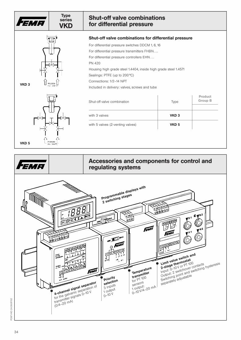
Typeseries
VKD
Shut-off valve combinationsfor differential pressure
Shut-off valve combinations for differential pressure
For differential pressure switches DDCM , 6, 6
For differential pressure transmitters FHBN . . .
For differential pressure controllers EHN . . .
PN 420
Housing high grade steel .4404, inside high grade steel .457
Sealings: PTFE (up to 200 hC)
Connections: /2–4 NPT
Included in delivery: valves, screws and tube
Shut-off valve combination Type
Product
Group B
with 3 valves VKD 3
with 5 valves (2-venting valves) VKD 5
PO
97
VK
D2
4.0
9.9
7/0
2
34
VKD 3
VKD 5
Accessories and components for control andregulating systems
Programmable displays with
2 switching stages
4-channel signal separator
for the galvanic separation of
transmitter signals 0–0 V
(0/4–20 mA)
Priority
selection
3 inputs
output
0–0 V
Temperature
transmitter
for PT 00
sensors
output:
0–0 V/4–20 mA
Limit value switch and
2-stage thermostat
Input: 0–0 V or PT 00
Output: 2 switchover contacts
Switching point and switching hysteresis
separately adjustable
x
x
x
x

PO
97
FTS
24
.09
.97/0
2
35
Typeseries
FTS
Two-phase frost protectionwith limiter contact and integrated priority selection
FTS
Technical Data
Supply voltage
24 V AC ± 20% or
24–36 V DC
Output signal
10–0 V
+ floating limiter contact
Power consumption
max. 1 W
Cable entry
2 x Pg 11 for electronic
Plug connection to DIN 43650
for limit value switch, can be
opened for easy installation.
Degree of protection
IP 65
Installation
With 2 size 4 mm screws directly
one the duct wall.
5 capillary tube holders, Type H 3.
are included in the supply.
Ambient temperature
12–50 hCCaution: at ambient temperatures
below 10 hC, the unit reacts and
signals “Risk of frost”.
Block circuit diagramm
Functions
With falling temperature the frost
protection generates a rising out-
put signal 0–0 V. If the temperature
drops further, a limiter contact
(single-pole changeover contact)
is actuated.
Maximum Selection
If the output signal of the controller
(Y signal) is looped through the
frost protection, a maximum selec-
tion of the two signals takes place. If
the Y signal from the controller is
larger than the output signal of the
frost protection, the controller deter-
mines the position of the heating
valve (normal operation). If the out-
put signal of the frost protection is
larger than the Y signal of the con-
troller (risk of frost), then the frost
protection determines the position
of the heating valve.
Self monitoring sensor
The sensor acting over the entire
length is self-monitoring, i. e. in the
case of breakage or damage of the
capillary tube, “Risk of frost” is
signaled. If the signal of the control-
ler is not looped through, then the
FTS outputs the frost control signal.
Cascades for large coils
For very large heating coils several
FTS can be used in cascade.
Range of action Capillary tube Type
Product
Group B
10 . . . 3 hC 6 m FTS 015
10 . . . 3 hC 3 m FTSB 015
Characteristic
Please refer to page 54 for frost protection thermostats.
Sensor Limiter Comporator
Outp
ut(V
olt)
Start of the working point (with falling temperature)
End of the constant range
Switching back point of the limiter contact
Switching point of the limiter contact
st phase
2nd phase
Controller

PO
97
TP
24
.09
.97/0
2
36
MODU FLEX
Typeseries
TP
Temperature transmitterswith PT 100 sensor, class A to DIN IEC 751
The temperature transmitters of the TP series consist of a fast responding PT 100 sensor, which is
installed in a 5 mm stainless steel tube with 40 mm immersion depth. Suitable immersion tubes in
brass and stainless steel are available.
The evaluation electronics is fitted directly onto the sensor.The supplyvoltage and output signal are con-
nected to a plug according to DIN 43 650.The evaluation electronics is accommodated well protected
(IP 65) in a Makrolon housing.
A digital display AZ 3 or AZ 331 for displaying the temperature ot the output signal in volts or any other
units can be fitted to the evaluation module in 3-wire system (see page 45).
Other accessories, e. g. programmable display with 2 switching outputs see page 43, limit value swit-
ches see page 44, priority selection see page 46.
Output signal 0–10 V
Temperature rangeMax. permissible
Typetemperature
Product
Group B
–50 . . . + 50 hC 150 hC TP 3– 55
–50 . . . +150 hC 180 hC TP 3–150
0 . . . +100 hC 150 hC TP 3–100
Output signal 4–20 mA
Temperature rangeMax. permissible
Typetemperature
Product
Group B
–50 . . . + 50 hC 150 hC TP 21– 55
–50 . . . +150 hC 180 hC TP 21–150
Accessories
Plug-on Digital LED Display AZ 31/AZ 331
(only possible on TP 3 . . .)
Display adjustable, the temperature can be displayed in any arbitrary units, e. g. hC, hF.
See also page 45.
Fastening flange for l 5 mm sensor R 8
Immersion tube, brass G| R 0, Ms
Immersion tube, brass G| NPT RN 0, Ms
Immersion tube, stainless steel G| R 0, Nst
Immersion tube, stainless steel G| NPT RN 0, Nst
Retaining spring FF 35
Technical data and drawing of immersion tubes, see page 56
Sensor element
PT 100 with tolerance class A
to DIN IEC 751
Temperature range
See type overview
Action direction
Rising temperature produces
rising output signal.
Installation position
arbitrary
Degree of protection
IP 65
Electrical connection
Plug connection St 7 (PG ) can be
opened for easy installation.
TP 3 . . .
TP 21 . . .
TP 3 . . .
with digital
display AZ 31

PO
97
TS
P2
4.0
9.9
7/0
2
37
Typeseries
TSP
Temperature transmitter modulesfor switchboard installationfor PT 00 sensors
The transmitters modules for switchboard installation convert the temperature at the PT00 temperature
sensor into standardized electrical signals of 0–0V (3-wire system) or 4–20 mA (2-wire system).
To rule out measured value drift due to line resistances in the sensor supply lines, connect the sensors to
the transmitter module in 3-wire system.
Output signal 0–10 V
Symbol Temp. Range Type
Product
Group A
–50 . . . +50 hC TSP 3– 55
0 . . . 100 hC TSP 3–100
0 . . . 200 hC TSP 3–200
0 . . . 400 hC TSP 3–400
Technical data TSP 3Output signal
0–10 V ± 1 mA
(3-wire system)
Max. output signal 12 V (overflow)
Supply voltage
24 V AC ± 20 % or
24 . . . 36 V DC
Power consumption
1.1 W
Ambient temperature
0 . . . 50 hC
Output signal 4–20 mA
Symbol Temp. range Type
Product
Group A
–50 . . . +50 hC TSP 2– 55
0 . . . 200 hC TSP 2–200
0 . . . 400 hC TSP 2–400
Technical data TSP 2Output signal
4–20 mA (2-wire system)
max. output signal 40 mA
(overflow)
Supply voltage Ub
12–36 V DC
(supply and signal)
Modules for further temperature ranges on request.
Suitable sensors see page 4, 42.
Other accessories, e. g. programmable display with 2 switching outputs see page 43, limit value swit-
ches see page 44, priority selection see page 46.

PO
97
LM
T/
TS
S2
4.0
9.9
7/0
2
38
MODU FLEX
Typeseries
LMT
Average temperature transmitterfor air ducts and mixing air coils
The LMT 30 records the average temperature over the entire length of the sensor rod. Therefore this
temperature transmitter is particularly suitable for air ducts in which temperature stratification can be
expected, e. g. in mixing chambers or directly behind an air heater.
The sensor consists of a PT 00 resistance which is effective over the entire length of 3.6 m.The average
temperature recorded by the sensor is converted into a proportional output signal of 0–0 V.
Technical DataOperating voltage
24 V AC ± 20 % or
24 V–36 V DC
Power consumption
max. 1 W
Output signal
0–10 V ± mA
Measuring element
PT 100
Length of the sensor rod
3.6 m
Minimum bending radius
approx. 100 mm
Ambient temperature at
the evaluation module
0–50 hC
Temperature at the sensor
–20 to +90 hC
Electrical connection
Plug connection with cable
entry PG , can be opened
for easy installation.
Temperature range Type
Product
Group B
0 . . . 30 hC LMT 30
See also: Average temperature sensors (page 42)
PT 100 LMS 21
PT 1000 LMS 31
Typeseries
TSS
Temperature switch, 2-stage (Thermostat)for PT 00 / PT 000 temperature sensors
All commercially available PT 00 or PT 000 sensors can be connected to the temperature switches
(thermostats). The switching point (S and S 2) and the switching difference (H and H 2) of each indivi-
dual switching stage can be set separately and independently of one another. It is possible to preselect
with a slide switch for each switching stage whether the switchover should take place with falling tempe-
rature (switch position MIN) orwith rising temperature (switch position MAX).All values can be set sepa-
rately for each switching stage.
Technical DataOperating voltage
24 V AC ± 20 % or
24 V–36 V DC
Power consumption
1.5 W
Output
2 relay contacts,
floating, single-pole switchover
Switching capacity
250 V AC, 8 A
250 V AC, 6 A (inductive)
Ambient temperature at the evaluation module
0–50 hC
Measuring element
PT 100 or PT 000
to DIN IEC 75
Degree of protection IP 30
Installation
On support rail NS 35/7.5 DIN 46277
Setting range Switching differenceSensor Type
(trimmer S (trimmer H
and S 2) and H 2)
Product
Group B
0–100 hC 2–22 K PT 100 TSS 2–010
0–200 hC 4–44 K PT 100 TSS 2–020
0–100 hC 2–22 K PT 1 000 TSS 3–010
Further temperature ranges on request.
User interface

Typeseries
PZ 17
Temperature transmitters, output signal 4–20 mAmade of high-grade steel, sensor PT 00, 2-wire
The temperature transmitters consist completely of high grade steel. The transmitter
module is housed for easy access in the housing head and can also be replaced as
required. A PT 00. Class B to DIN IEC 75 is used as sensor.
Cable entry Pg , type of protection: IP 65. max. perm. temperature at the transmitter head:
60 hC, supply voltage: 2–36 V DC, Output signal: 4–20 mA.
Transmitter with immersion tube (screw-in thread)Screw-in tread G |, 8 mm l
Max. perm.Immersion depth L (mm) pressure Type
(bar)
Product
Group B
100 40 PZ 171-100/. . .150 40 PZ 171-150/. . .200 35 PZ 171-200/. . .250 35 PZ 171-250/. . .
The pressure data apply up to a temperature of 250 hC
Transmitter with immersion tube (Union nut)Union nut G |, 8 mm l
Max. perm.Immersion depth L (mm) pressure Type
(bar)
Product
Group B
100 40 PZ 170-100/. . .150 40 PZ 170-150/. . .200 35 PZ 170-200/. . .250 35 PZ 170-250/. . .
The pressure data apply up to a temperature of 250 hC
Transmitter with rod probe, 8 mm l
Max. perm.Immersion depth L (mm) pressure Type
(bar)
Product
Group B
100 40 PZ 172-100/. . .150 40 PZ 172-150/. . .200 35 PZ 172-200/. . .250 35 PZ 172-250/. . .
The pressure data apply up to a temperature of 250 hC
Transmitter with air duct probe 8 mm l
Immersion depth L (mm) Type
Product
Group B
100 PZ 177-100/. . .150 PZ 177-150/. . .200 PZ 177-200/. . .250 PZ 177-250/. . .
Other accessories, e. g. programmable display with 2 switching outputs see page 43, limit
value switches see page 44, priority selection see page 46.
PO
97
PZ
72
4.0
9.9
7/0
2
39
Temperature ranges
Range No.
–50 . . . + 50 hC 55
–50 . . . + 100 hC 51
0 . . . 50 hC 50
0 . . . 100 hC 100
0 . . . 200 hC 200
0 . . . 300 hC 300
0 . . . 400 hC 400
0 . . . 500 hC 500
0 . . . 600 hC 600
Clamp bushing see page 40

Typeseries
P 17
Temperature sensors PT 00 / PT 000in high grade steel version
The temperature sensors consist completely of high grade steel (tube: .457, terminal
housing: .430). Sensor element: PT . . . . Class B to DIN IEC 75, 3-wire connection, cable
entry Pg , degree of protection IP 65.
Temperature range – 50 . . . 600 hC.
Immersion probe with screw-in thread G 1/2, 8 mm dia.
Max. perm.Immersion depth L (mm) pressure Type Type
(bar) PT 00 PT 000
100 40 P 171-100 P 271-100150 40 P 171-150 P 271-150200 35 P 171-200 P 271-200250 35 P 171-250 P 271-250
The pressure data apply up to a temperature of 250 hC
Immersion probe with union nut G 1/2, 8 mm dia,
Max. perm.Immersion depth L (mm) pressure Type Type
(bar) PT 00 PT 000
100 40 P 170-100 P 270-100150 40 P 170-150 P 270-150200 35 P 170-200 P 270-200250 35 P 170-250 P 270-250
The pressure data apply up to a temperature of 250 hC
Rod probe 8 mm dia.
Max. perm.Immersion depth L (mm) pressure Type Type
(bar) PT 00 PT 000
100 40 P 172-100 P 272-100150 40 P 172-150 P 272-150200 35 P 172-200 P 272-200250 35 P 172-250 P 272-250
The pressure data apply up to a temperature of 250 hC
Air duct probe 8 mm dia.
Max. perm.Immersion depth L (mm) pressure Type Type
(bar) PT 00 PT 000
100 40 P 177-100 P 277-100150 40 P 177-150 P 277-150200 35 P 177-200 P 277-200250 35 P 177-250 P 277-250
Clamp bushing G1/2
Sensor l Type
8 mm R 85 mm R 5
Immersion tubes G1/2 (only for P 7 . . ., P 27 . . . and PZ 7)
Immersion depth L (mm) Type
100 R 85-100150 R 85-150200 R 85-200250 R 85-250
PO
97
P7
24
.09
.97/0
2
40
R8 R85

PO
97
TS
24
.09
.97/0
2
4
Typeseries
TSTemperature sensors PT 00 / PT 000
Rod probe for installation into immersion tubesStainless steel tube, 5 dia, length 140 mm
Degree of protection IP 32
4-wire connection, class A to DIN IEC 751
Sensor Range Type
Product
Group A
PT 100 –50 . . . +130 hC PS 21
PT 1000 –50 . . . +130 hC PS 31
PS . . .
Suitable immersion tubes: R 10 . . ., RN 10 . . ., R 8. See page 56
Air duct probeRod probe made of plastic
Immersion depth 280 mm, fastening flange
Degree of protection IP 32
4-wire connection, class A to DIN IEC 751
Sensor Range Type
PT 100 –50 . . . +110 hC PL 21
PT 1000 –50 . . . +110 hC PL 31
PL . . .
Contact probewith clamping band for pipe installation up to 80 mm dia.
4-wire connection, class A to DIN IEC 751.
Degree of protection: IP 32
Sensor Range Type
PT 100 –50 . . . +110 hC PAL 21
PT 1000 –50 . . . +110 hC PAL 31
PAL . . .
Outdoors probefor recording the outdoors temperature with weather protection cap and installation bracket 4-wire
connection, class A to DIN IEC 75
Degree of protection: IP 43
Sensor Range Type
PT 100 –50 . . . +70 hC PAF 21
PT 1000 –50 . . . +70 hC PAF 31
PAF
Room temperature probeelegant plastic housing, white, with installation plate 2-wire connection, class B to DIN IEC 75
Sensor Range Type
PT 100 –30 . . . +70 hC PRT 21
PT 1000 –30 . . . +70 hC PRT 31
PRT . . . Accessories
Temperature switch for PT00 / PT000 sensors input see page 38,programmable display see page 46.

PO
97
TS
24
.09
.97/0
2
42
Typeseries
TSTemperature sensors PT 00 / PT 000
Average value sensor for air ductsFor recording the average temperature in air ducts (mixing chambers). The sensor records the tempe-
rature over the entire length (3.6 m) and forms a average value of this. Protection type: IP 65.
Sensor Range Type
Product
Group A
PT 100 –30 . . . +90 hC LMS 21
PT 1000 –30 . . . +90 hC LMS 31
Temperature switch for PT00 / PT000 sensors input see page 38,programmable display see page 46.
LMS
Remote probe for high temperaturesStainless steel tube, 5 dia., length 183 mm, material: 1.4541
1 m cable protected with metal braid
4-wire connection, class A to DIN IEC 751
Sensor Range Type
PT 100 –50 . . . +600 hC PF 21
PT 1000 –50 . . . +600 hC PF 31
PF . . . Suitable immersion tubes: R 0 . . ., RN 0 . . ., R 8. Clamp bushing R 5.
See page 56 and 40.
Surface probeStainless steel plate 25 x 28 mm with fastening holes, 0.3 m cable
2-wire connection, class B to DIN IEC 751
Sensor Range Type
PK . . . PT 100 –50 . . . +120 hC PK 21
PT 1000 –50 . . . +120 hC PK 31
Screw-in probefor pressure-tight installation in tanks or piplines. Material: stainless steel .430
Thread M 0 x . Dimensions and sealing screws to DIN 90. pressure: 00 bar
1 m cable with PTFE insulation
2-wire connection, class B to DIN IEC 751
Sensor Range Type
PE . . . PT 100 –50 . . . +250 hC PE 21
PT 1000 –50 . . . +250 hC PE 31
Measuring probe embedded in PTFE (Teflon)(without cavity) with connection cable connected waterproof. m cable, tube 7 mm dia.
4-wire connection, class A to DIN IEC 751
Sensor Range Type
PT 100 –200 . . . +300 hC PM 21
PM . . .

PO
97
AP
24
.09
.97/0
2
43
Typeseries
AP
Programmable display, with 2 limit value switches
for PT 00, PT 000 or voltage and current signals
Technical data
Input signals
Freely selectable by setting
jumpers
Housing front
48 x 96 mm (DIN)
Actual value display
3|-digit, LED 12.5 mm, red,
automatic “–”-sign
Decimal point
Programmable
Measuring rate
2.5 measurements/second
Keyboard
lockable with jumper
Programmable switching
outputs
2 changeover switches
Output relay switching
capacity
2 x 230 V, 5 A AC
Supply voltage
230 V, 50–60 Hz, 3 VA
Degree of protection (front)
IP 60. DIN 40.050
Working temperature
–0 to +50 hC
Type of connection
Lift terminals
Front cut-out
H x B: 44.5 x 90.5 mm
Installation depth
15 mm
Various routines for setting the following parameters are integrated in the digital display which
is controlled by microprocessor:
Measuring range (starting and end point)
Display range (starting and end point)
Position of the decimal point
2 limit values (relays) and their hysteresis
Drop-down or pull-in delay of the relays
Enquiry of the minimum and maximum measured value
Rounding up and down the last digit
Average formation
Serial port (RS 232)
All routines and parameters can be set by keys on the front.The switching status of the relays is
displayed by LEDs.
Type summary
Input signals Display range Suitable for Typesensor
Product
Group B
0– 1 V DCPressure and
APV 6300–10 V DC
–999 to +999 temperature0–20 mA DC
transmitter4–20 mA DC
PT 00/PT 000 –150 hC to +199.9 hC Temperature APT 650(other values can –200 hC to +800 hC sensors
be set) PT 00/PT 000
Typeseries
GT
Signal SeparatorGalvanic separation of analogue transmitter signals
The analogue output signals of a transmitter can be galvanically separated from the evaluation device
using a signal separator. In this way interference which affects the transmitter signal can be suppressed
and influences from earth loops prevented.
The signal separator is absolutely essential for transmitters whose output signals have to be transmitted
over long distances and for signal lines which are exposed to strong electromagnetic radiation.
The 4-channel configuration and the limitation to voltage signals results in very good value for money.
Inputs
Voltage signals,
e. g. 0–0V, 2–0V,
0–5V, 0–
All voltage ranges between
0 and 0V
Input resistance
Ri > 220 k-Ohm
Outputs
Voltage signals
: from input signal
max. output signal current ± 1 mA
Transformation Ratio
:
Channels
4 channels, usable in parallel
Type Channels Working range
Product
Group B
GT 4 4 between 0 and 0 VSupply Voltage
24V AC ± 20 % or
24–36V DC
4 Inputs 0 . . . 0 V
4 Outputs 0 . . . 0 V

PO
97
EM
S/
EM
32
02
4.0
9.9
7/0
2
44
Typeseries
EMS
Limit value switch, 2-stagefor input signals 0–10 V
All transmitters generating an output signal of 0–0 Vcan be connected to the limit value switch EMS 0.
The switching point (S and S 2) and the switching difference (H and H 2) of each individual switching
stage can be adjusted separately and independently of one another. It is possible to preselect with one
slide switch each per switching stage whether the switchover should take place with a falling value
(switching position MIN) or rising value (switch position MAX). The switching points can be set separa-
tely for each switching stage.
Setting range Switching differenceType
(Trimmer S 1 and S 2) (Trimmer H 1 and H 2)
Product
Group B
0–100 % 2–22 % EMS 10
Technical dataSupply voltage
24 V AC ± 20 % or
24–36 V DC
Power consumption
1.5 W
Output
2 relay contacts floating,
single-pole switchover
Switching capacity
250 V AC, 8 A
250 V AC, 6 A (inductive)
Ambient temperature
0–50 hC
Input signal
0–0 V DC
Degree of protection
IP 30
Installation
On support rail
NS 35/7.5 DIN 46277
User interface
Typeseries
EM 320
Limit value switch, -stageInput 0–10 V
The purpose of the limit value switch EM 320 is for converting a constant output signal 0–0 V into a
switching signal. It can be actuated by all modules which deliver an output signal 0–0 V. A floating
switchover contact is available so that pumps, solenoid valves or other actuators can be switched.
Operating voltage
24 V AC ± 20 % . . . 60 Hz
or 24–36 V DC
Setting range
0–95 % (0–9.5V)
Input
Constant voltage signal 0–15V–
Output
3 A, max. 240 V AC
Type
Product
Group B
Limit value switch
Input signal 0-10 V EM 320
Floating relay contact 3 A / 250 V AC

PO
97
24
.09
.97/0
2
45
MODU FLEX
Accessories for pressure and temperature transmittersAdditional modules
Display
LED-display, 7 mm high
Display range
–199 . . . +199 (AZ 31, AZ 21)
–1999 . . . +1999 (AZ 331, AZ 321)
Supply voltage
24 V AC or 24 V DC
From the basic module
by ribbon cable.
Signal voltage: (input) 0–10 V
Signal input through ribbon
cable from the evaluation
module or from other
modules/wire-system.
Supply voltage
24 V AC ± 20 % or
24 V–36 V DC
Supply through ribbon cable
from other modules.
Power consumption
max. 1 W
Digital LED display (for plugging onto transmitters)With the display modules AZ, the output of a transmitter from the MODUFLEX system is made visible on
a LED display.
The starting and end value of the display can be adjusted between –99 and +99 resp. –999 and
+999. so that an arbitrary display range can be assigned to any pressure range.The decimal point can
be switched over with a slide switch.
The y signals of the transmitter can thus be displayed in any arbitrary unit, e. g. V, mA, bar, mbar, %, psi,
hC, m, cm (filling height), m3, cm3 (volume) etc.
In addition the display module in its condition on delivery (factor setting 0–0.0) is suitable for the accu-
rate adjustment of the working range of a transmitter.
Display 2| digit Display 3| digit–199 . . . +199 –1999 . . . +1999
Type Type Product
Group B
3-wire system AZ 31 AZ 331
2-wire system AZ 21 AZ 321
Root extraction (for plugging onto transmitters)With the root extraction module RA 3, a y-signal of 0–0 V output by the transmitter is converted into a
root extracted output signal. 0–0 V and 0–20 mA
The root extraction of the pressure proportional signal is necessary, for example, if a signal is necessary,
for example, if a signal proportional to the throughput volume has to be generated by acquisition of the
differential pressure across a diaphragm (filter/pump).
Suitable for Output signal Type
Product
Group B
YR = öäää10 · yall 3-wire systemsand RA 31
YI = öäää20 · yI(Input signal 0–10 V)
Typeseries
MCP
Control command modulefor manipulated variable input
The control command module which can be fitted onto standard rails can be set to 2 operating modes
by changeover switch.
Auto: The signal voltage (0–0 V) of a transmitter or a controller is switched through (e. g. to an actua-
tor).
The floating contacts S –S 2 are closed simultaneously (freely available).
Manu: The signal voltage is interrupted.
A signal of 0– V which can be supplied to the actuator can be generated manually with the
knob (manual operation).
The floating contact S –S 2 is interrupted.
The size of the signal is indicated by the lighting intensity of an LED in both switch positions.
Supply voltage
24 V AC / DC
Output
0–V DC, mA
Input impedance
min. 0 kV (0–0V)
Power consumption
max. W. Type MCP
Product
Group B
YR = Signal voltage(0–0 V DC)
Y = Signal output

PO
97
EM
24
.09
.97/0
2
46
Typeseries
EM
Accessories for pressure and temperaturetransmitters External modules / test adapter
Priority selection EM 310
The EM 30 module serves for min./max. selection between two or three 0–0 V signals. According to
the position of the slide switch, the higher-orderor the lower-order0–0Vsignal is made available at the
output.
Supply voltage
24 V AC ± 20 % 40 . . . 60 Hz
or 24 V–36 V DC
Inputs
Y1 . . .Y3: 0–10 V
Output
Yout: 0–10 V
max. 1 mA
Type
Product
Group B
Priority selectionfor the min. or max. selection from 2 or 3 0–0 V input signals EM 310
Test adapter PAD 1
The test adapter PAD 1 provides access to supply and signal voltage.
The test adapter PAD offers a significant simplification in testing and adjustment. The supply voltage
can be checked at the pins + 3, or – if the device is not yet connected – it can also be supplied there.
The test adapter can be fitted to all evaluation modules and additional modules of the 3-wire system,
e. g. also onto the digital display AZ 3 (not suitable for temperature transmitters and pressure transmit-
ters SN . . . 250 and TP . . . 2)
Test adapter PAD 1
We recommend the following equipment for adjusting the pressure transmitters orpressure controllers
of the 3-wire system:
1. Digital display AZ 31 (factory setting 0–10 V)
2. Test adapter PAD 1
Mounting bracket H 10
for wall mounting of the SN, SL, SD sensors and the temperature transmitters. Is part of the scope of
supply for the SL and SD sensors.
Mounting bracket H 10
Transmitter SN . . .
with test adapter PAD 1

PO
97
Ex
V2
4.0
9.9
7/0
2
47
Typeseries
Ex V
Isolating switching amplifierfor installation of the thermostats and pressure switches inexplosion endangered rooms
Intrinsically safe control commands can be transferred to non-intrinsically safe active circuits with the
isolating switching amplifiers.Thus it is possible to use pressure and temperature switches in explosion
endangered areas (≥ zone ).
The isolating switching amplifier must be installed outside the Ex zone.
The Ex 04 isolating switching amplifier is designed additionally in safety technology.The leads between
the isolating switching amplifier and pressure or temperature switch are monitored for wire breakage
and short circuit. The pressure switch must therefore be equipped with a resistor combination (e. g.
ZF 526)
Type summary
Application Suitable for ZF . . . Equipment Type
Product
Group B
Suitable for pressure and
temperature switches with
microswitches and proximity
switches.
201, 203
301, 303
205, 206
212, 213
512, 513
Without short circuit
monitoring.
Ex 011
Isolating switching amplifier in
safety technology. Suitable for
maximum pressure limiting
devices with resistor combination
and for the pressure limiting
devices FD . . . and DBS.
326, 327
328
386, 388
524, 525, 526, 527
574, 575, 576, 577
FD 6 . . .
For maximum pressure
monitoring.
With wire breakage and
short circuit monitoring.
Ex 041
Ex 0
Ex 04
Pressure limiting device
Isolating
switching amplifier

Typeseries
FV
Pressure mediators / separating membranesAccessories to pressure switches and pressure transmitters
A separating membrane or a pressure mediator is necessary if aggressive, viscous or cry-
stallizing media must be kept away from the actual pressure sensor.A pressure mediator is
also indispensable to avoid cavities if easy cleaning of the supply lines is important.
Special “Milk pipe unions” to DIN 851 are customary for pressure monitoring in the food-
stuffs industry.
Pressure mediators and evaluating devices (pressure switches, pressure transmitters,
pressure gauges) form a self-contained unit. The transmission fluid (filling medium) trans-
mits the medium pressure from the separating membrane onto the measuring element.
The filling medium M 20 is applicable for industrial and food applications:
There are special filling media for oxygen, chlorine and painting plants. Please inquire.
Summary of Types
Flanged pressure mediatorsmade of stainless steel .457, membrane flush to the front, flange to DIN 2527
DN Filling Lowest Lowest Temperature* Typemedium possible possible range
transmitter switchingrange (bar) point (bar)
Product
Group B
50M 20
0–1 0.3– 40 . . . 20 hC FV 84-50
80 0–0.2 0.15 FV 84-80
Flanged pressure mediatorswith m pipeline, flange to DIN 2527
DN Filling Lowest Lowest Temperature* Typemedium possible possible range
transmitter switchingrange (bar) point (bar)
50M 20
0–1 0.3– 40 . . . 300 hC FV 85 N-50
80 0–0.2 0.15 FV 85 N-80
Pipeline up to max. 0 m on request.
Pressure mediatorsfor the foodstuffs industry with milk pipe connection to DIN 85
DN Filling Lowest Lowest Temperature* Typemedium possible possible range
transmitter switchingrange (bar) point (bar)
50 M 20 0–1 0.4 – 30 . . . 20 hC FV 62-50
Screw-in pressure mediatorsflush to the front, for pressure switches only
DN Filling Lowest Temperature* Typemedium possible range
switchingpoint (bar)
G 1 M 20 0.6 – 30 . . . 20 hC FV 749
* Please note that the temperature at the pressure switch must not exceed 60 hCcontinuously.
PO
97
FV
24
.09
.97/0
2
48
Technical Data
Flange dimensions
to DIN 2527
Material
.457
Version
Completely assembled, evacuated,
filled and adjusted
Filling medium
M 20
Max. permissible pressure
40 bar (applies only for separating
membranes. The max. permissible
pressure of the pressure switch or
pressure transmitter must be
observed.)

Siphons
Siphons to DIN 6 282 made of seamless steal tube
20 mm diameter
FORM A Material Type
Product
Group A
Inlet: St 35.8-I U 430 AConnection shank DIN 6 282 Form 4G |
Outlet: .457 U 480 AConnection shank DIN 6 282 Form 6G | with clamping sleeveDIN 6 283 G |
FORM B Material Type
Inlet: St 35.8-I U 430 BWeld-on end with weld chamfer
Outlet: .457 U 480 BConnection shank DIN 6 282 Form 6G | with clamping sleeveDIN 6 283 G |
FORM C Material Type
Inlet: St 35.8-I K 430 CConnection shank DIN 6 282 Form 4G |
Outlet: .457 K 480 CConnection shank DIN 6 282 Form 6G | with clamping sleeveDIN 6 283 G |
FORM D Material Type
Inlet: St 35.8-I K 430 DWeld-on end with welding bevel
Outlet: .457 K 480 DConnection shank DIN 6 282 Form 6G | with clamping sleeveDIN 6 283 G |
Siphon, U-shape
Pipe l 2.3 mm, material St 33
Inlet external thread G |
Outlet Type
External thread G | E 422 U
Clamping sleeve G | to DIN 6 283 V 422 U
U-shape
Circular
U-shape
PO
97
24
.09
.97/0
2
49

Accessories for pressure switchesand pressure transmitters
Union nuts with welding nipples
to DIN 6 284. thread G |
Material
Nipple Nut Type
Product
Group A
CK 5 9 S 20 K Z 220
.457 .457 Z 280
Sealing washers
to DIN 6 258. Form B, 7.5 x 6.2 x 2.5 ± 0.5 mm
Material Type
Copper Z 925 CU
BA 400 Z 921 BA
The sealing washers are packed in bags of 0 each.
Shut-off valves for pressure gauges
to DIN 6 270. Form A, G | with venting screw
PN Material Temperature Type
250 Brass – 10 . . . + 120 hC AM 03
400 Steel .0460 – 10 . . . + 120 hC AS 03
400 Stainless steel – 20 . . . + 200 hC AE 03.457
NPT adapter
The purpose of the NPT adapter is to connect pressure switches, pressure transmitters,
pressure gauges, etc., to NPT threaded connections. A suitable sealing washer is also
supplied.
Type Description
NPT NPT adapter, material .404 and sealing ringDIN 6 258. Form Cmaterial ITC to DIN 3754 P.
Pressure surge reducer
Type Material
DML (air) MsDMW (water) Ms
PO
97
24
.09
.97/0
2
50

PO
97
24
.09
.97/0
2
5
The most important technical datafor thermostats
Normal version
Plug connection Terminal connection
-version
. . . 200 . . . 300 . . . 700
Swich housing Aluminium diecast GD Al Si 12 Aluminium diecast GD Al Si 12
Switching function and Floating change-over contact. Floating change-over contact.
connection drawing With rising pressure switching over With rising pressure switching over
(applies only for version single-pole from 3–1 to 3–2 single-pole from 3–1 to 3–2.
with microswitch)
Switching capacity
(applies only for version
with microswitch)
8 A at 250 V AC 3 A at 250 V AC
5 A at 250 V AC inductive 2 A at 250 V AC inductive
1 A at 24 V AC 0.1 A at 250 V –
0.01 A at 250 V – inductive
Installation position arbitrary, vertical
preferably vertical
Degree of protection
(in vertical position)
IP 54 (on request IP 65 by ZF 350
and ZF 351)
IP 65
Ex degree of protection – EEx de IIC T6 tested to
EN 50014/50018/50019 (CENELEC)
PTB approval – Ex-90.C.1059
Electrical connection Plug connection to DIN 43650
(200 series)
Terminal connection
Terminal connection (300 series)
Cable entry Pg 11 Pg 11
Ambient temperature –15 to +70 hC –15 to +60 hC
Switching point Adjustable on the spindle. Adjustable on the spindle after
In 300 series the lid must be removed. the terminal box lid is removed.
Switching difference Adjustable or not adjustable Not adjustable
(see type overview)
Medium temperature max. 70 hC, briefly 85 hC max. 60 hC
Vibration strength Up to 4 g no noteworthy deviations. The switching difference is reduced slightly at
higher accelerations. More than 25 g not permissible.
Insulations values Overvoltage category III, contamination class 3. reference surge voltage 4000 V. The
conformity to DIN VDE 0110 (01.89) is confirmed.

PO
97
24
.09
.97/0
2
52
ThermostateSwitch units/connection diagrams
Plug connection Terminal Description Connection diagrams
Series 200 connection
Series 300
Normal version
microswitch, single pole changeover
ZFT 301 Terminal connection case
(series 300) instead of plug connection case
(for frost protection ZFT 302)
ZFT 205 ZFT 305 Maximum limiter
with manual reset
Interlocking with increasing temperature
ZFT 206 ZFT 306 Minimum limiter
with manual reset
Interlocking with falling temperature
ZFT 212 Proximity switch to DIN 19 234 (Namur)
Contactless signaling, also applicable
for explosions-hazards rooms ≥ zone 1
ZFT 213 Gilded contacts with little transition
resistance (e. g. for low tension)
Cannot be supplied with adjustable
switching differential
ST 218 Plug connector with position indication
12 V – 240 V AC/DC
See also page 50.
ZFT 601 Pneumatic switching element
with trigger function.
Direction of action reversible.
Switching differential not adjustable.
ZFT 350 Degree of protection IP 65
ZFT 351 Degree of protection IP 65 and switch housing
with surface protection
ZFT 513 EExi-version
(intrinsically safe)
housing 300. cable entry and terminals
blue. Gold plated contacts,
Degree of protection IP 54
ZFT 5970 Setting of switching points according to
customer specification.
ZFT 5971 Setting and sealing according to specification.
Example for ordering:
TX 150–206
Code for additional function (Minimum limiter)
Code of temperature range
Type

PO
97
TR
M/
TA
M2
4.0
9.9
7/0
2
53
Typeseries
TRMIndustrial Room Thermostats
FEMA room thermostats are suitable for industrial plant, for greenhouses, cowsheds and warehouses,
also for monitoring the maximum temperature in switchgear cabinets and relay stations.
Room thermostats are supplied complete with H wall bracket.
With plug connection to DIN 43650 (Terminal connection . . . -30)
Range of adjustmentSwitching diff.
Type(mean value)
Product
Group A
Switching differential not adjustable
–20/+20 hC 1.0 K TRM 022
0/+40 hC 1.0 K TRM 40
+10/+50 hC 1.0 K TRM 150
Switching differential adjustable
0/+40 hC 2–8 K TRMV 40
+10/+50 hC 2–8 K TRMV 150
-version · Degree of protection EEx de IIC T6
Switching difference not adjustable
Max. permissible
Range of adjustmentSwitching diff.
temperature Type(Mean value)
at sensor
Product
Group B
–20/+20 hC 1.0 K 70 hC Ex-TRM 022
0/+40 hC 1.0 K 70 hC Ex-TRM 40
+10/+50 hC 1.0 K 70 hC Ex-TRM 150
Typeseries
TAM
Capillary tube thermostatswith 1.5 m capillary tube
The sensor cartridge at the end of the capillary tube is the actual active (temperature-sensitive) part of
the sensor. Changes in temperature on the capillary tube have no effect on the switching point.
Pressuretight installation of the sensor in pressure vessels of all kinds is possible with the aid of immer-
sion tubes.
With plug connection to DIN 43650 (Terminal connection . . . -30)
Max. permissible
Range of adjustmentSwitching diff.
temperature Type(Mean value)
on sensor
Product
Group A
–20/+ 20 hC 1.5 K 110 hC TAM 022
+10/+ 50 hC 1.5 K 110 hC TAM 150
+40/+ 90 hC 2.0 K 125 hC TAM 490
+80/+130 hC 2.0 K 150 hC TAM 813
-version · Degree of protection EEx de IIC T6
Max. permissible
Range of adjustmentSwitching diff.
Temperature Type(Mean value)
at sensor
Product
Group B
–20/+ 20 hC 1.5 K 110 hC Ex-TAM 022
+10/+ 50 hC 1.5 K 110 hC Ex-TAM 150
+40/+ 90 hC 2.0 K 125 hC Ex-TAM 490
+80/+130 hC 2.0 K 150 hC Ex-TAM 813
TRM
Ex-TRM . . .
TAM . . .

PO
97
TX
/FT
24
.09
.97/0
2
54
Typeseries
TXRod thermostats
Rod thermostats can be installed as immersion thermostats in pipelines and containers and for moni-
toring temperature in air ducts. The suitable immersion tube has to be chosen according to the
application, see page 56.
Plug connection to DIN 43650 (Terminal connection . . . -30)
Max. permissible
Range of adjustmentSwitching diff.
temperature Type(Mean value)
at sensor
Product
Group A
Depth of immersion 135 mm
–20/+ 30 hC 1.5 K 110 hC TX 023
+10/+ 50 hC 1.5 K 110 hC TX 150
+40/+ 90 hC 4.0 K 125 hC TX 490
+80/+130 hC 4.0 K 150 hC TX 813
Depht of immersion 220 mm
–20/+ 30 hC 1.5 K 110 hC TXB 023
+10/+ 50 hC 1.5 K 110 hC TXB 150
+40/+ 90 hC 4.0 K 125 hC TXB 490
+80/+130 hC 4.0 K 150 hC TXB 813
-version · Degree of protection EEx de IIC T6
Max. permissible
Range of adjustmentSwitching diff.
temperature Type(Mean value)
at sensor
Product
Group B
Immersion depth 135 mm
–20/+30 hC 1.5 K 110 hC Ex-TX 023
+10/+50 hC 1.5 K 110 hC Ex-TX 150
+40/+90 hC 4.0 K 125 hC Ex-TX 490
Immersion depth 220 mm
–20/+30 hC 1.5 K 110 hC Ex-TXB 023
+10/+50 hC 1.5 K 110 hC Ex-TXB 150
+40/+90 hC 4.0 K 125 hC Ex-TXB 490
Ex-TX . . .
Typeseries
FT
Frost protection thermostatsfor air heating and conditioning systems
FEMA frost protection thermostats reliably monitor the temperature in hot water-heated air heaters. If the
temperature falls below the set value, the thermostat switches off. A visual or audible “frost hazar” alarm
can be switched on at the same time. A fixed stop on the setting spindle at 4 hC prevents the thermostat
from being set below the freezing point due to inexpert adjustment. If the capillary tube is damaged
or broken, the FEMA frost protection thermostats reliably switch off towards the safe side (e. g. fan off),
irrespective of the temperature at the sensor. Capillary tube holders H3 are included.
Plug connection to DIN 43650 (Terminal connection . . . -302)
Range of adjustmentMax. temperature
Version Typeat sensor
Product
Group A
4–15 hC 200 hC 6 m capillary tube FT 015
4–15 hC 200 hC 3 m capillary tube FTB 015
-version · Degree of protection EEx de IIC T6Product
Group B
4–15 hC 200 hC 6 m capillary tube Ex-FT 015
4–15 hC 200 hC 3 m capillary tube Ex-FTB 015
Two-phase frost protection control system with output signal 0–0 V and limit switch, see page 35.
FT 015 . . .

PO
97
24
.09
.97/0
2
55
Accessories, spare partsfor thermostats and pressure switches
Product
Group A
Wall bracket Type H 1
including fixing screws and plugs (6 mm l)
Included as standard with Type TRM thermostats. Suitable for all
switching units.
Wall bracket Type H 2
for fixing the sensor cartridges of capillary tube thermostats.
Suitable for all Type TAM capillary tube thermostats.
Capillary tube holder Type H 3
to attach the capillary tube of frost protection thermostats to the frame of
the air heater (5 off packed in bag).
Suitable for FT frost protection thermostats and frost protection FTS.
Sealing, type P 2
consists of cover plate and screw for covering and sealing the adjustment screws.
Heating conducting compound Type WLP 1
to improve the transfer of heat, e. g. in the case of contact thermostats.
Approx. 0.5 cm3 in handy dispenser.
Capillary tube bushing, Type R 4
with 3 mm capillary tube screw in thread G 1/2 suitable for all types TAM, FT and FTS.
Capillary tube bushing, Type R 5
Not pressure proof (5 pieces in one bag).
Suitable for series TA, FT and FTS.
Plug ST 5 to DIN 43650
for switching units of series 200. with seal and fastening screw,
3-pole + earth contact.
Plug ST 6 to DIN 43650, can be opened for easy installation
for Two-phase frost protection FTS series, can also be used for pressure switches and thermostats
instead of plug ST 5.
Plug connectors with position indication ST 218
Operating voltage: 12–240 V AC/DC
Operating current: max. 2 A
LED current drain: max. 10 mA
LED indication: green if voltage present at contact pin 1
red if voltage present at contact pin 2
Connection rotatable 270h engaging at increments of 45hDegree of protection: IP 65
Ambient temperature: 0–60 hCSuitable for pressure and temperature switches with plug connection
(series 200) which are equipped with a microswitch (standard version).
Plug ST 7, can be opened for easy installation
for transmitters and sensors with plug connection.
H
H 2 H 3
R 4 R 5

PO
97
ZT
24
.09
.97/0
2
56
Typeseries
ZT
Immersion tubesfor thermostats and temperature transmitter
Type Depth of immersion Overall length Suitable for
L2 (mm) Ls (mm)
Product
Group A
Nickel-plated brass type, G 1/2
R 1 / Ms 135 151
R 2 / Ms 220 236TAM . . .
R 3 / Ms 500 516
R 10 / Ms 135 –TX . . . /TP
R 20 / Ms 220 –
Stainless steel type (1.4571 + 1.4401) G 1/2
R 1 / Nst 135 151
R 2 / Nst 220 236 TAM . . .
R 10 / Nst 135 –TX . . . /TP
R 20 / Nst 220 –
Nickel-plated brass type 1/2 NPT
RN 1 / Ms 135 151
RN 2 / Ms 220 236 TAM . . .
RN 10 / Ms 135 151TX . . . /TP
RN 20 / Ms 220 236
Stainless steel type (1.4571 + 1.4401) 1/2 NPT
RN 1 / Nst 135 151
RN 2 / Nst 220 236 TAM . . .
RN 10 / Nst 135 151TX . . . /TP
RN 20 / Nst 220 236
Retaining spring FF 35
(necessary, when temperature transmitter TP . . . or sensors PF / PS are built into immersion tubes R 0
or RN 0). It ensures rapid heat transfer between immersion tube and temperature sensor.
Immersion tubes with fixing flange for air ducts.Material: steel, chromated
Type Depth of immersion
R 6 135 mmTX . . .
R 7 220 mm
Fastening flange for PT 100-/PT 1000 sensorSensor l = 5 mm R 8
Use of the immersion tubes
for pressure prooffor air ducts
for exhaust
installation (up to 100 bar) pipes
R 1 R 2 R 10 R 20
RN 1 RN 2 R 3 RN 10 RN 20 R 6 R 7 R 8
TAM . . . x x x
TX . . . x x
TXB . . . x x
Temperature xTransmitter
TP . . . xSensors
PF . . ., PS . . .
only
together
with re-
taining
spring
FF 135
Immersion tubes G 1/2
Immersion tubes 1/2 NPT
R 6 R 7
R 8 R 8 (example for
mounting)
Retaining spring FF 135

PO
97
24
.09
.97/0
2
57
Solenoid ValvesThe most important technical data / Type review
FEMA pisto-type solenoid valves are suitable for exacting fields, especially in the field of heat, energy and gas technology. All the below
mentioned product groups are coupled and therefore used from 0 to maximum pressure, a minimum differential pressure is not
necessary. A DC coil is universally used. For connection to an AC supply of 230 V a rectifier will be supplied.
Type Review
Seals Temperatures
Opera-Series Nom. M = Working Medium En-
kungs-diameter Sockets pressure* vironment
modesDN F =
Application (mm) Flange (bar) hC hC
TG 15/20 M + F 0–40 –15 to –15 toN
nc
for neutral 25/32 M + F 0–32 +90 +60+
+
media 40/50 F 0–20 60 hC at Ex no
TGKfor high 15/20 M + F 0–40 –15 to nc
tempera- 25/32 M + F 0–32 max. 180 +60 N +
tures 40/50 F 0–20 no
K 15/20 M 0– 4 –15 to –15 to N
for fuel 15/20 F 0– 4 +60 +60 +nc
gases up 25/32 F 0– 4
to 4 bar 40/50 F 0– 4
K 15/20 F 0–25 –15 to –15 to N
for fuel 25/32 F 0–25 +60 +60 +nc
gases higher 40/50 F 0–20
than 4 bar
K15/20 F 0–25 –15 to –15 to Nfor liquid
25 F 0–25 +60 +60 +nc
gas in liquid
phase
K 15/20 F 0–40 –15 to –15 to
for fuel oil 25/32 F 0–32 +60 +60 Nnc
40/50 F 0–20
LGfor hot water 15/20 M + F 0–25
+4 toand steam 25/32 M + F 0–20 max. 120
+60N nc
up to 120 hC 40/50 F 0–16
LGKfor hot water 15/20 M + F 0–20
+4 toand steam 25/32 M + F 0–16 max. 180
+60N nc
up to 180 hC 40/50 F 0–12
nc = normally closed, opened under voltage
no = normally open, closed under voltage (identified in the type review by “U”).
* = The respective data sheet contains exact details of the limits of use.
Sealing materials
NBR = Buna rummer
EPDM = Ethylene – propylene – rubber
PTFE = Teflon
Certificates to EN 0 204
WZ 2.2 Test report 2.2 type series certificate
AZ 3. B-M AZ 3. B Inspection certificate specific product test
DOKU Documents: additional documents, e. g. data sheets, mounting
instructions, TÜV-, DVGW- or PTB-certificate.
PTFE
PTFE
NB
RN
BR
NB
RN
BR
PTFE
NB
RPis
ton
sta
inle
ss
sta
inle
ss
NB
RN
BR
NB
RN
BR
sta
inle
ss
NB
RN
ozzle
ste
elconne
ste
elconne
ste
elconne
EP
DM
EP
DM
NB
RN
BR
NB
RN
BR
EP
DM
NB
RS
tatic
seal
N=
Norm
al-
type
Ex
=Ex-t
ype
TÜ
V
TÜ
VTÜ
VTÜ
VD
IN32725
DVG
WD
VG
WTesting
DIN
32730
DIN
32730
DIN
-EN
(dra
ftD
IN3394
DIN
-EN
agency
DIN
264
Nov.’92)
part
1161

PO
97
TG
/TG
-Ex
24
.09
.97/0
2
58
Solenoid Valves
The most important technical data
Type
2/2-way
Type of construction
Piston-type solenoid valve, coupled,
minimum differential pressure not
necessary
Materials
Casing: Bronze Rg 5 to DIN 1705
Internal parts: Brass (CuZn) and
corrosion-resistant steel
Sealing: Perbunan (normal version)
Mounting position
Solenoid system upright.
Magnet System / electr. connection
The standard magnet systems have
DC coils. For AC connections a built-in
rectifier is supplied with the valve.
The magnet coil is cast into silicone
rubber (a moisture protection).
Degree of protection
IP 65 to DIN 40 050
fr = suitable for outdoor use.
Power Requirement
about 47 VA (with the magnet warmed)
Duty Cycle
100 % ED
Degree of protection on Ex-versions
Pressure proof capsule EEx de IIC T5
(PTB-No. Ex-85/1063).
Suitable for ≥ Zone 1 areas.
Pressure ranges as well as medium resp.
ambient temperatures see type overview
Typeseries
TG
Solenoid Valves for Universal ApplicationMedium temperature –5 hC to 90 hC
The piston typ solenoid also can open and close even in the pressureless state and with low differential pressures.Ambient temperature
–15 hC up to 60 hC. Temperature of medium up to 90 hC. Degree of protection IP 65. Rectifier is built into the connection plug.
Operating mode: normally closed, on desire, normally open.
DN kVS value Working pressure InternalType
(mm) (m3/h) (bar) thread
Product
Group C
Operating mode: normally closed
15 4.0 0–30 G 1/2 T15G31M
20 4.8 0–30 G 3/4 T20G31M
25 10.0 0–25 G 1 T25G31M
32 13.0 0–25 G 11/4 T32G31M
15 4.0 0–30 T15G31F
20 4.8 0–30 T20G31F
25 10.0 0–25Flange
T25G31F
32 13.0 0–25 T32G31F
40 34.0 0–16 T40G31F
50 40.0 0–16 T50G31F
Typeseries
TG-ExSolenoid Valves in Ex-version
Suitable for explosion hazardous rooms (≥ zone 1). Pressure proof encapsulated (EEx de IIC T5) PTB-No. Ex-85/1063. Maximum medium
resp. ambient temperature 60 hC. Rectifier is built into the connection plug.
Operating mode: normally closed, on desire, normally open.
DN kVS value Working pressure InternalType
(mm) (m3/h) (bar) thread
Product
Group C
Operating mode: normally closed
15 4.0 0–30 G 1/2 T15G35M-Ex
20 4.8 0–30 G 3/4 T20G35M-Ex
25 10.0 0–25 G 1 T25G35M-Ex
32 13.0 0–25 G 11/4 T32G35M-Ex
15 4.0 0–30 T15G35F-Ex
20 4.8 0–30 T20G35F-Ex
25 10.0 0–25Flange
T25G35F-Ex
32 13.0 0–25 T32G35F-Ex
40 34.0 0–16 T40G35F-Ex
50 40.0 0–16 T50G35F-Ex
T25G31M
T32G35F-Ex

PO
97
TG
-K/
LG
24
.09
.97/0
2
59
Typeseries
TG-K
Solenoid Valvesfor medium temperature –5 hC up to 180 hC
The piston-type solenoid valves of the TGK series are suitable for hot water, steam, fuel oil and
other non-aggressive media up to a temperature of 80 hC.
Operating mode: normally closed
DN kVS value Working pressure InternalType
(mm) (m3/h) (bar) thread
Product
Group C
15 4.0 0–25 G 1/2 T15G31MK
20 4.8 0–25 G 3/4 T20G31MK
25 10.0 0–20 G 1 T25G31MK
32 13.0 0–20 G 11/4 T32G31MK
15 4.0 0–25 T15G31FK
20 4.8 0–25 T20G31FK
25 10.0 0–20Flange
T25G31FK
32 13.0 0–20 T32G31FK
40 34.0 0–16 T40G31FK
50 40.0 0–16 T50G31FK
Typeseries
LG
Solenoid Valves for Hot Water and Steamup to 120 hC / 180 hC · TÜV-tested to DIN 32730
FEMA piston-type solenoid valves of the LG series are particularly suitable for use as stop and
safety check valves in heating installations up to 20 hC resp. 80 hC.
The coupled (automatically servo-controlled) mode of operation does not require a minimum
differential pressure; the units can open and close perfectly even in the pressureless state and with
low differential pressures.
Operating mode: normally closed
DNkVS- Working Internal DIN
value pressure thread register- Type
(mm) (m3/h) (bar) number
Product
Group C
15 4.0 0–25 G 1/2 1F02284 L15G31M
20 4.8 0–25 G 3/4 1F02284 L20G31M
25 10.0 0–20 G 1 1F02384 L25G31M
32 13.0 0–20 G 11/4 1F02384 L32G31M
15 4.0 0–25 1F02284 L15G31F
20 4.8 0–25 1F02284 L20G31F
25 10.0 0–20Flange
1F02384 L25G31F
32 13.0 0–20 1F02384 L32G31F
40 34.0 0–16 1F02484 L40G31F
50 40.0 0–16 1F02484 L50G31F
15 4.0 0–20 G 1/2 1F01984 L15G31MK
20 4.8 0–20 G 3/4 1F01984 L20G31MK
25 10.0 0–16 G 1 1F02084 L25G31MK
32 13.0 0–16 G 11/4 1F02084 L32G31MK
15 4.0 0–20 1F01984 L15G31FK
20 4.8 0–20 1F01984 L20G31FK
25 10.0 0–16Flange
1F02084 L25G31FK
32 13.0 0–16 1F02084 L32G31FK
40 34.0 0–12 1F02184 L40G31FK
50 40.0 0–12 1F02184 L50G31FK
with k-part for up to 80 hC
up to 120 hC
with k-part for up to 80 hC
k-part
for cooling
k-part
for
cooling
t e s t e d

PO
97
K2
4.0
9.9
7/0
2
60
Typeseries
K
Solenoid Valves for Gas, liquid gas andliquid fuels
Suitable for all gases according DVGW-data sheet G 260. for liquid phase (up to DN 25) and for fuel oil.
Minimum differential pressure is not necessary.The solenoid valves are also available with a pressu-
retight solenoid system (Protection Class EEx de IIC T5. PTB-No. Ex-85/063)
Operating mode: normally closed
DNkVS- Working
Regi-valve pressure Connection
strationClass Type
(mm) (m3/h) (bar)
Product
Group C
15 4.0 0– 4 G 1/2 1. 5 B K15G31M
20 4.8 0– 4 G 3/4 1. 5 B K20G31M
15 4.0 0–25 1. 2. 3. 4. 5. 6 B K15G31F
20 4.8 0–25 1. 2. 3. 4. 5. 6 B K20G31F
25 10.0 0–25Flange
1. 2. 3. 4. 5. 6 B K25G31F
32 13.0 0–25 1. 2. 4. 5. 6 B K32G31F
40 34.0 0–20 1. 2. 4. 5. 6 C K40G31F
50 40.0 0–20 1. 2. 4. 5. 6 C K50G31F
-version
15 4.0 0– 4 G 1/2 1. 5 B K15G35M-Ex
20 4.8 0– 4 G 3/4 1. 5 B K20G35M-Ex
15 4.0 0–25 1. 2. 3. 4. 5. 6 B K15G35F-Ex
20 4.8 0–25 1. 2. 3. 4. 5. 6 B K20G35F-Ex
25 10.0 0–25Flange
1. 2. 3. 4. 5. 6 B K25G35F-Ex
32 13.0 0–25 1. 2. 4. 5. 6 B K32G35F-Ex
40 34.0 0–20 1. 2. 4. 5. 6 C K40G35F-Ex
50 40.0 0–20 1. 2. 4. 5. 6 C K50G35F-Ex
Registrations:
1 = DIN-EN 161 for Gas up to 4 bar
2 = DIN 3394 for Gas higher than 4 bar
3 = DIN 32725 for liquid gas in liquid phase
4 = DIN-EN 264 for liquid fuels (fuel oil)
5 = CE-Ident-No.
6 = Ü-sign
s- Identification-Nos.:
For solenoid valves for gas following CE-Identification Nos. are fixed:
K 15 . . . K 50 F CE-0085AN0072
K 15 . . . K 50 F-Ex CE-0085AN0073
K 15 . . . K 20 M CE-0085AN0074
K 15 . . . K 20 M-Ex CE-0085AN0075
DIN-DVGW
DIN-EN
s
K25G31F
K25G35F-Ex
t e s t e d

PO
97
24
.09
.97/0
2
6
Additions and accessoriesfor valves of the product group M
Mode of operation If not identified specially, the valves are delivered with “closed at zero current” mode of operation.
“Open at zero current” mode of operation (possible only for valves of the TG, TGK and TG-Ex series)
in normal versions (e. g. in TG and TGK) ZFM 8910
in Ex version (TG-Ex series) ZFM 8911
Identification by additional letter „U“. Ordering example: T25G31FU.
Gasket materials
The prices of the solenoid valves apply for the gasket materials named in the technical data sheets. If
other gasket materials are wanted, the following extra prices apply (uniformly for all types and nominal
diameters of the product group M).
Teflon ZFM 8912
Viton ZFM 8913
Special voltages
for normal and Ex solenoids 230 V –
110 V –
24 V –
12 V –
In the case of alternating voltages less than 0 V Ù, a rectifier of corresponding capacity must be pro-
vided by the customer.
Replacement solenoids Type
Normal version without rectifier, G 31
without plug
with device socket GS including rectifier G 31 GS
(only for 230 or 110 V Ù)
Ex version
without rectifier G 35-Ex
Rectifier installed G 35-Ex G
(only for 230 or 110 V Ù)
Rectifier/plug The suitable rectifiers are enclosed for all plunger solenoid valves which are ordered for220VÙ or110V
Ù alternating voltage.A rectifiermust be provided by the customer for alternating voltages below110VÙ.
Type
Device socket with built-in rectifier GS
Primary 230 V, 50 Hz
Secondary approx. 230 V =

PO
97
GB
/A
B2
4.0
9.9
7/0
2
62
Typeseries
GB
Solenoid Valves DN 12–25normally closed, for neutral gaseous and liquid media
This range of solenoid valves is of high quality and suitable for universal application, and is not
dependent operationally on a specific minium differential pressure; the valves operate correctly
with no pressure, at slight differential pressure, and right through to maximum pressure.They are there-
fore the valves of choice for installation in plant where differential pressures fluctuate greatly
and are not possible to determine precisely in advance. The valves are also suitable for use in
heating and cooling circuits.
DN Pressure range kVS value ThreadedType
(mm) (bar) (m3/h) connection
Product
Group C
Brass valve body, internal parts stainless steel; Sealings: Perbunan
12 0–16 2.8 G 1/2 GB 12
20 0–16 5.0 G 3/4 GB 20
25 0–16 10.0 G 1 GB 25
Stainles steel 1.4410 valve body, internal parts stainless steel; Sealings: Viton
12 0–16 2.8 G 1/2 GB 12 VA
20 0–16 5.0 G 3/4 GB 20 VA
25 0–16 10.0 G 1 GB 25 VA
Technical data
Design
diaphragm solenoid valve, coupled. No system
pressure required.
Fitting position
optional; preferably solenoid mechanism upright.
Temperature of medium –0 hC to 90 hC
Max. ambient temperature 55 hC
Max. viscosity 2 mm2/s approx.
Power consumption
00 to 20 VA (start)
25 VA / 2W (operation)
Duty cycle continuous duty
Electrical connection Plug to DIN 43 650
Voltage / current type
230 V AC, 45–60 Hz available.
24 V AC or DC also available.
Protection type IP 65
Typeseries
AB
Solenoid Valvesnormally closed, for neutral liquid media
The AB-series are suitable for neutral media such as water and hydraulic oil.
They operate without minimum differential pressure.
Brass valve body, internal parts stainless steel; Sealings: Perbunan
DN Pressure rangekVS value
ThreadedType
(mm) (bar)(for water)
connections(m3/h)
Product
Group C
10 0–10 1.8 G 3/8 AB 10
13 0–10 3.5 G 1/2 AB 13
20 0–10 8.6 G 3/4 AB 20
25 0–10 11.0 G 1 AB 25
40 0–10 30.0 G 11/2 AB 40
Technical data
Design diaphragm solenoid valve, coupled.
No system pressure required.
Materials casing brass
internal parts stainless steel
Seal materials Perbunan
Fitting position
optional; preferably solenoid mechanism upright.
Temperature of medium –0 hC to 90 hC
Max. ambient temperature 55 hC
Duty cycle continuous duty
Electrical connection plug to DIN 43 650
Voltage 230 V AC, 45–60 Hz
Protection type IP 65
Power consumption
DN 0 13 20 25 40 mm
AC: Start 34 36 38 60 202 VA
AC: Operation 4 4 4 38 38 VA
DC: Start +
Operation 0 0 0 – – W

Send the following information to:
Detailed product information brochures:
Pressure switches(D 50 e)
Pressure transmitters(FDT 57e)
Temperature transmittersTemperature sensorsThermostats(TTS 62 e)
Magnetventile,Schnellschlußventile,Sicherheits-absperrventile(MV 53)
English information about
the solenoid valves is
included in the Product
overview.
Please tick:
Maschines and Installations
Gas/Heating Control
Chemical industry
Electrical installations
Building control
Product overviewEnglish language
Druck- undTemperatur-überwachungin Ex-Bereichen(Ex 67)
(in German language only)
Name:
Company:
Street:
Town:
Country:
63

H
FEMA products
Reliability and safety world wide
for monitoring and control
of pressure, temperature and flow.
FEMA service
Reliable and fast delivery
Application / customer
specific solutions.
FEMA Controls · Honeywell AG
P. O. Box 2 54 · D-7099 Schoenaich (Germany)
Phone 0049 / (0) 70 3 / 6 37-02 · FAX -850
E-Mail fema.export∏germany.honeywell.com
PO 97/98 24.9.97/02