'94-'97 T444E Diagnostic Manual
562
T444E DIESEL ENGINE I VEHICLE DIAGNOSTIC MANUAL FOR INTERNATIONAL® TRUCKS EGES-125-1 May, 1997. Copyright 1997 Navistar International Transportation Corp. Printed In the United Stat.s of America
-
Upload
khangminh22 -
Category
Documents
-
view
0 -
download
0
Transcript of '94-'97 T444E Diagnostic Manual

T444E
DIESEL ENGINE I VEHICLE
DIAGNOSTIC MANUAL
FOR
INTERNATIONAL® TRUCKS
EGES-125-1
May, 1997.
Copyright 1997 Navistar International Transportation Corp.
Printed In the United Stat.s of America

CONTENTS
INDEX
FOREWORD
SECTION 1 - ENGINE CONTROL SYSTEM OVERVIEW
SECTION 2 - MECHANICAL DIAGNOSTICS
SECTION 3 - ELECTRONIC CONTROL SYSTEM DIAGNOSTICS
SECTION 4 - SUPPLEMENTAL DIAGNOSTIC ANALYSIS
SECTION 5 - DIAGNOSTIC TOOL USE
SECTION 6 - CONNECTOR AND HARNESS REPAIR
SECTION 7 - VEHICLE AND COMPONENT ILLUSTRATIONS
SECTION 8 - GLOSSARY OF TECHNICAL TERMS
EGES-125-1Printed In the United States of America

INDEX
FOREWORD:
SECTION 1: ENGINE CONTROL SYSTEM OVERVIEWSECTION 1.1 FUEL SUPPLY SYSTEM
SECTION 1.2 . . . . . . . . . .. INJECTION CONTROL PRESSURE SYSTEM
SECTION 1.3 . . . . . . . . . .. INJECTOR OPERATION
SECTION 1.4 . . . . . . . . . .. EXHAUST BACK PRESSURE DEVICE
SECTION 1.5 . . . . . . . . . .. ELECTRONIC CONTROL MODULE
SECTION 1.6 . . . . . . . . . .. INJECTOR DRIVER MODULE
SECTION 1.7 SENSOR OPERATION
SECTION 1.8 VEHICLE FEATURES
SECTION 1.9 DIAGNOSTIC SOFTWARE SELF TEST OPERATION
SECTION 2: MECHANICAL DIAGNOSTICS
SECTION 2.1 DIAGNOSTIC FORMS
SECTION 2.2 HARD START / NO START DIAGNOSTICS
SECTION 2.3 PERFORMANCE DIAGNOSTICS
SECTION 2.4 . . . . . . . . . .. PERFORMANCE SPECIFICATIONS
SECTION 3: ELECTRONIC CONTROL SYSTEM DIAGNOSTICSSECTION 3.1 ELECTRONIC CONTROL SYSTEM DIAGNOSTIC FORM
SECTION 3.2 FLASH CODE CIRCUIT INDEX
SECTION 3.3 SENSOR AND ACTUATOR LOCATIONS
SECTION 3.4 SENSOR AND ACTUATOR DIAGNOSTIC PROCEDURES
SECTION 3.5 CIRCUIT FUNCTION AND DIAGNOSTICS
(APS/IVS) ACCELERATOR PEDAL POSITION SENSOR /IDLE VALIDATION SWITCH
(BARO) BAROMETRIC PRESSURE SENSOR
(BRAKE) BRAKE SWITCH/RELAY CIRCUITS
(CMP) CAMSHAFT POSITION SENSOR
(DCUATA) DCUATA DATA COMMUNICATION LINKS
(EBP) EXHAUST BACK PRESSURE SENSOR
(ECI) ENGINE CRANK INHIBIT
(ECl) ENGINE COOLANT LEVEL SYSTEM (ENGINE PROTECTION)
(ECM) ELECTRONIC CONTROL MODULE SELF DIAGNOSTICS
(ECM 10M) ECMIIDM COMMUNICATIONS
(ECM PWR) ELECTRONIC CONTROL MODULE POWER SUPPLY
EGES-125-1Printed In The United States of America

II INDEX
SECTION 3: ELECTRONIC CONTROL SYSTEM DIAGNOSTICS(Continued)SECTION 3.5 CIRCUIT FUNCTION AND DIAGNOSTICS (Continued)
(ECl) ENGINE COOLANT TEMPERATURE SENSOR
(EOL) ENGINE DATA LINE CIRCUITS WITH ALLISON AT/MT TRANSMISSIONS
(EOP) ENGINE OIL PRESSURE SENSOR
(EOT) ENGINE OIL TEMPERATURE SENSOR
(EPR) EXHAUST BACK PRESSURE REGULATOR
(GPC) GLOW PLUG CONTROL
(IAT) INTAKE AIR TEMPERATURE SENSOR
(ICP) INJECTION CONTROL PRESSURE SENSOR
(10M PWR) INJECTOR DRIVER MODULE POWER CIRCUITS
(INJ) INJECTOR DRIVE CIRCUITS
(IPR) INJECTION PRESSURE REGULATOR
(KAM PWR) KEEP ALIVE MEMORY POWER
(MAP) MANIFOLD ABSOLUTE PRESSURE SENSOR
(SCCS) SPEED CONTROL COMMAND SWITCHES AND PTO CONTROLS
(STI/EWL) SELF TEST INPUT SWITCH AND ENGINE WARNING LIGHT
(TACH) TACHOMETER INPUT CIRCUITS
(TSA) TWO SPEED AXLE CIRCUIT
(V REF) VOLTAGE REFERENCE CIRCUITS
(VPM) VEHICLE PERSONALITY MODULE FUEUHOUR METERS AND ODOMETER
(VSS) VEHICLE SPEED SIGNAL
SECTION 3.6 CONNECTOR END VIEWS AND PIN OUTS
SECTION 4: SUPPLEMENTAL DIAGNOSTIC ANALYSIS
SECTION 5: DIAGNOSTIC TOOL USESECTION 5.1 DIAGNOSTIC TOOLS
SECTION 5.2 . · . . . . . . . .. PRO-LINK 9000 ELECTRONIC SERVICE TOOL OPERATION
SECTION 5.3 MULTIMETER USE
SECTION 6: CONNECTOR AND HARNESS REPAIR
SECTION 7: VEHICLE AND COMPONENT ILLUSTRATIONS
SECTION 8: GLOSSARY OF TECHNICAL TERMS
EGES-125-1Printed in The United States of America

FOREWORD
INDEX
I
PAGET444E DIESEL ENGINE SERVICE LITERATURE 1SERVICE DIAGNOSIS 2PREREQUISITES FOR EFFECTIVE DIAGNOSIS: 2MANUAL ARRANGEMENT.. . .. . . . .. .. . . . . . . . . . . . . . . . . . . . . . . . .. . . . . .. . . . .. . . . .. . .. . . .. . . . . . . . .. . . . . .. . . .. 3
EGES-125-1Printed In The United States of America

FOREWORD Page 1
This manual is part of a series of manuals intended to assist service technicians in maintaining International®Engines in accordance with the latest technical advancements.
Due to a commitment of continuous research and development, some procedures, specifications and partsmay be altered to improve International® products ,and introduce technological advances.
Periodic revisions may be made to this publication and mailed automatically to "Revision Service" subscribers. The following literature, supporting International® Diesel Engines, is available from:
Forward Requests to: Navistar International Transportation Corp.Printing, Procurement and Distribution4956 Wayne RoadBattle Creek Michigan 49017
T 444E DIESEL ENGINES
Form No.* Description
EGES-120 T 444E Engine Service ManualEGES-125 T 444E Diesel Engine I Vehicle Diagnostic ManualEGED-130 T 444E Hard Start I No Start & Performance Engine Diagnostics FormEGED-135 T 444E Electronic Control System Diagnostic Form
1 171 674 R1 T 444E Engine Operation and Maintenance Manual (Prior to 1997)1171 715 R1 T 444E Engine Operation and Maintenance Manual 1997 Model Year
at - Manual number specified with latest revision will be furnished.
EGES-125-1Printed In the United States of America

Page 2
SERVICE DIAGNOSIS
FOREWORD
Service diagnosis is a systematic procedure of investigation to be followed in order to locate and correctan engine problem. The engine is first considered as a complete unit in its specific application and thenthe problem is localized to components or systems; intake, exhaust, cooling, lubrication or injection. Testing procedures will then help analyze the source of the problem.
PREREQUISITES FOR EFFECTIVE DIAGNOSIS:
1. Knowledge of the principles of operation for both the engine and application systems.
2. Knowledge to perform and understand all procedures in the diagnostic and service manuals.
3. Availability of and the ability to use gauges and diagnostic test equipment.
4. Have available the current information for the engine application.
Although the cause of an engine failure may be apparent, very often the real cause is not found until arepeat failure occurs. This can be prevented if specific diagnostic action is taken prior to, during and afterengine disassembly and during engine reassemble.
It is also very important that specific diagnostic tests follow engine reassembly prior to and after the engine is placed back into service.
Identification of the symptoms which lead to engine failure is the result of proper service diagnosis. Effective service diagnosis requires use of the following references:
1. Appropriate Diesel Engine Service Manual.
2. Hard Start / No Start &Performance Engine Diagnostics.
3. Electronic Diagnostics
4. Service Bulletins.
EGES-125-1
Printed In the United States of America

FOREWORD Page 3
This manual is arranged in sections, with the pages numbered consecutively in each section. Any photosor artist renderings are also numbered consecutively in each section. Included at the top of each page isthe Section Title, Section Number and Page Number. The bottom center of each page will show themanual Form Number (i.e. EGES-125).
NOTE: A dash and a numeral (-1) indicates the number of times the basic manual has been completely revised.
An index arranged according to sections will be found at the beginning of this manual.
SECTION TITLE ~GENERAL
EXAMPLE
FORM NO.~ EGES-125-1
EGES-125-1Printed In the United States of America
Section 1Page 1
SECTIONNO.
PAGENO.

SECTION 1 ENGINE CONTROL SYSTEMOVERVIEW
INDEXPAGE
SECTION 1.1 FUEL SUPPLY SYSTEMFUEL SYSTEM DESCRIPTION . . . . . . . . . . . . . . . . . . . . . . . . . . . . . . . . . . . . . . . . . . . . . . . . . . . . . . .. 1FUEL SUPPLY PUMP .. . . . . . . . . . . . . . . . . . . . . . . . . . . . . . . . . . . . . . . . . . . . . . . . . . . . . . . . . . . . . .. 2FUEL SYSTEM OPERATION . . . . . . . . . . . . . . . . . . . . . . . . . . . . . . . . . . . . . . . . . . . . . . . . . . . . . . . . .. 2
SECTION 1.2 INJECTION CONTROL PRESSURE SYSTEMINJECTION CONTROL PRESSURE SYSTEM OPERATION 1INJECTION PRESSURE CONTROL 2IPR VALVE OPERATION. . . . . . . . . . . . . . . . . . . . . . . . . . . . . . . . . . . . . .. . . .. . . . . . . . . . . . .. . . . . . . . .. 2
SECTION 1.3 INJECTOR OPERATIONDESCRIPTION OF INJECTOR OPERATION 1
SECTION 1.4 EXHAUST BACK PRESSURE DEVICEDESCRiPTION 1OPERATION 1
SECTION 1.5 ELECTRONIC CONTROL MODULEOPERATION AND FUNCTION 1VOLTAGE REFERENCE 2SIGNAL CONDITIONER . . . . . . . . . . . . . . . . . . . . . . . . . . . . . . . . . . . . . . . . . . . . . . . . . . . . . . . . . . . . .. 3MICROPROCESSOR 3ROM 4RAM 4KAM 4ACTUATOR CONTROL. . . . . . . . . . . . . . . . . . . . . . . . . . . . . . . . . . . . . . . . . . . . . . . . . . . . . . . . . . . . . .. 5
SECTION 1.6 INJECTOR DRIVER MODULEINJECTOR DRIVER MODULE FUNCTIONS 1ELECTRONIC DISTRIBUTOR FOR THE INJECTORS. 1POWER SOURCE FOR THE INJECTORS. 2OUTPUT DRIVER FOR THE INJECTORS 3SELF DIAGNOSTICS. 4
SECTION 1.7 SENSOR OPERATIONINPUT SIGNALS. . . . . . . . . . . . . . . . . . . . . . . . . . . . . . . . . . . .. . . . . . . . . . . . . . .. . . . . . . . . . . . . . . .. . . .. 1REFERENCE VOLTAGE SENSORS 1THERMISTOR. . . . . . .. . . . . . . . . . . . . . . . . . . . . . . . . . . . . . . . . . . . . . . . .. . . . . . . . . . . . . . . . . . . . .. . .. .. 2POTENTIOMETER. . . . . . . . . . . . . . . . . . . . . . . . . . . . . . . . . . . . . . . . . . . . . . . . . . . . . . . . . . . . . . . . .. .. 3VARIABLE CAPACITANCE SENSOR. . . . . . . . . . . . . . . . . . .. . . . . . . . . . . . . . . . . . . . . . . . .. .. . . . . . .. 4HALL EFFECT SENSOR 5SWITCH SENSORS. . . . . . . . . . . . . . . . . . . . . . . . . . . . . . .. . .. . . . . . . . . . . . . . . . . . . . . . . . . .. . . . . . . 6MAGNETIC PICKUP 7
SECTION 1.8 VEHICLE FEATURESSTANDARD FEATURES . . . . . . . . . . . .. . . . . . . . . . . . . . . . . . . . . . . . . . . . . . . . . . . . . . . . . . . . . . . . . .. . . . .. . . .. 1
ELECTRONIC GOVERNOR CONTROL 1COLD IDLE ADVANCE 1COLD AMBIENT PROTECTION SYSTEM 1GLOW PLUG ASSISTED START 1AMERICAN TRUCKING ASSOCIATION DATA LINK PROVISIONS. . . . . . . . . . . . . . . . . . . . . . . .. 1
EGES-125-1Printed In The United States of America

II SECTION 1 ENGINE CONTROL SYSTEMOVERVIEW
INDEXPAGE
SECTION 1.8 VEHICLE FEATURES (Continued)STANDARD FEATURES (Continued)
SERVICE DIAGNOSTICS . . . . . . . . . . . . . . . . . . . . . . . . . . . . . . . . . . . . . . . . . . . . . . . . . . . . . . . . . . . .. 1ELECTRONIC SPEEDOMETER AND TACHOMETER PROVISIONS .. . . . . . . . . . . . . . . . . . . . .. 1ENGINE OVER TEMP. PROTECTION SYSTEM (COOLANT TEMP. COMPENSATION) 1 I
EVENT LOGGING SYSTEM 2ENGINE CRANK INHIBIT 2ELECTRONIC ACCELERATOR PEDAL 2
OPTIONAL FEATURES 3CRUISE CONTROL .. . . . . . . . . . . . . . . . . . . . . . . . . . . . . . . . . . . . . . . . . . . . . . . . . . . . . . . . . . . . . . . .. 3THROTTLE CONTROL FOR PTO OPERATION 3ROAD SPEED LIMITING/GOVERNOR 3EXHAUST BACK PRESSURE ENGINE WARM-UP SYSTEM 3BODY EQUIPMENT MANUFACTURERS PROVISIONS 3ENGINE WARNING SYSTEM 3ELECTRONIC IDLE SHUTDOWN TIMER . . . . . . . . . . . . . . . . . . . . . . . . . . . . . . . . . . . . . . . . . . . . . .. 3ENGINE SHUTDOWN SYSTEM 3
SECTION 1.9 DIAGNOSTIC SOFTWARE SELF TEST OPERATIONDIAGNOSTIC SOFTWARE TEST CHART 1CONTINUOUS MONITOR 2OPERATOR ON DEMAND TESTS ENGINE OFF:STANDARD TEST (ENGINE OFF) 2INJECTOR "BUZZ' TEST (ENGINE OFF) . . . . . . . . . . . . . . . . . . . . . . . . . . . . . . . . . . . . . . . . . . . . .. 3OUTPUT STATE TEST (ENGINE OFF) 3OPERATOR ON DEMAND TESTS ENGINE RUNNING:STANDARD TEST (ENGINE RUNNING) 4INJECTOR TEST "CYLINDER CONTRIBUTION" (ENGINE RUNNING) .. 4 I
OPERATOR ON DEMAND TESTS:WIGGLE TEST 5
EGES-125-1
~~~i~!~~-,!I~~~t~tf!8J)t~m_edcjl

FUEL SUPPLY SYSTEMFUEL SYSTEM DESCRIPTION
Section 1.1Page 1
The T 444E fuel system consists of three majorsub-systems:
• Fuel Supply System.
• Injection Control Pressure System.
• Fuel Injector.
These sub-systems worktogetherto inject pressur
ized fuel into the combustion chambers. The function of the fuel supply system is to deliver fuel to theinjectors. The injection control pressure systemsupplies the injectors with high pressure lube oil.
The fuel injectors use the pressure from the lube oilto pressurize the fuel and inject the fuel into thecombustion chambers.
The function of the fuel supply system is to deliverfuel from the fuel tank(s) to the injectors. The components involved in this task are:
• Fuel Lines
• Fuel Strainer
• Transfer Fuel Pump
• Fuel FilterlWater Separator
• Fuel Pressure Regulator Valve
FUELRETURNPORT
~UL~\ ~~~~~ILTERJSEPARATOR
Figure 1.1-1. - Component Locations
EGES-125-1Printed in the United States of America
FUELPRESSUREREGULATINGVALVE
EG-1205

Section 1.1Page 2 FUEL SUPPLY SYSTEMFUEL SYSTEM DESCRIPTION (Continued)
FUEL SUPPLY PUMP
The fuel transfer pump on the T 444E engine is a camshaft driven two stage diaphragm/piston pump mounted
in the engine "V". Refer to Figure 1.1-2.
Ir----+-- Inlet
......+-- Fuel Inlet
Inlet Check Valve
+-- O'Ring
Tappet
~~~LiJB~i~~H{""gafI..--- Inlet Check Valve
Outlet Check Valve
Fuel Seal
High Pressure Outlet ---+
EG-1089
PistonStage
Diaphragm ----------..Stage S · ~~~~~~~prlng-
Low Pressure Fuel Out
Outlet Check Valve
O+-- Camshaft Lobe
Figure 1.1-2. - Tandem Fuel Supply Pump
FUEL SYSTEM OPERATION
The diaphragm stage of the tandem lift pump drawsfuel from the tank and through the fuel strainer.Pressurized fuel 4 to 6 psi (28 to 41 kPa) from thediaphragm stage is supplied to the fuel filter. Airtrapped in the filter is vented back to the tankthrough an orifice in the regulator block mounted onthe filter. The orifice is protected from plugging bya wire mesh screen located inside the filter housing.
Fuel in the filter housing passes through the filterelement to a standpipe in the center of the filter assembly. Clean fuel is then routed to the inlet of thepiston stage of the tandem pump.
The piston stage of the tandem pump raises fuel
pressure from 4 psi to 40 psi (28 to 276 kPa) to insure proper filling of the injectors. Fuel from thisstage is divided through steel lines to the back ofeach cylinder head. These lines supply fuel to a gallery drilled in each cylinder head which intersectseach injector bore in the cylinder head. Figure1.1-3.
Return fuel from the two fuel galleries is routedthrough hoses, of a special rubber compound, fromthe front of each head to the pressure regulator located on the side of the filter housing. These hosesprovide flexibility in the fuel system by absorbingand smoothing pressure pulses from the pistonstage of the pump.
EGES-125-1Printed In the United States of America

FUEL SUPPLY SYSTEMSection 1.1
Page 3
FUEL SYSTEM DESCRIPTION (Continued)
OPERATION (Continued)
The pressure regulator contains a spring loaded valve to control pressure in the fuel galleries to 40 psi (276kPa). Return fuel flows through the regulator and is routed to the fuel tank(s).
Fuel Supply PassageTo Injector
Figure 1.1-3. - Fuel Supply Passage to InjectorsTOP VIEW
RETURN FUEL
PRE-STRAINER
REGULATINGVALVE
FUEL TANK
fS'S'&S'J NEGATIVE PRESSUREI I I I I HIGH PRESSURE1111111 1111 LOW PRESSURE
EG·2488
Figure 1.1-4. - Fuel Supply System
EGES-125-1Printed In the United States of America

INJECTION CONTROL PRESSURE SYSTEMINJECTION CONTROL SYSTEM OPERATION
Section 1.2Page 1
(Refer to Figure 1.2-1)
The T 444E system utilizes a hydraulicallyactuated injector to pressurize fuel inside theinjector. The hydraulic fluid used to actuate theinjector is engine oil.
Oil is drawn from the oil pan thru the pickup tubeby the engine oil pump. The engine oil pump is agerotor type pump driven by the crankshaft. Oil isfed through passages in the front cover to an oilreservoir mounted on top of the front cover.
The reservoir makes available a constant supplyof oil to a high pressure hydraulic pump mountedin the engine "V". The high pressure pump is agear driven seven plunger swash plate pump.High pressure oil is delivered by the high pressurepump to oil galleries machined into the cylinderheads, drilled intersecting passages supply highpressure oil to the injector.
Figure 1.2-1 - Injector Oil System
1. Oil Pump2. Reservoir (Located On Top of Front Cover)3. High Pressure Pump4. High Pressure Hoses5. Injection Control Pressure Sensor6. Cylinder Head High Pressure Rail7. Injector (8)8. Gallery (Crankcase)9. Oil Filter
1o. Oil Cooler11. Injection Control Pressure Regulator
EGES-125-1
Printed In the United States of America

~:~:~n 1.2 INJECTION CONTROL PRESSURE SYSTEMINJECTION PRESSURE CONTROL
The injection control pressure system (Figure1.2-2) is a closed loop operating system. Thesystem consists of the (ECM) Electronic ControlModule, (ICP) Injection Control Pressure Sensorand the (IPR) Injection Pressure Regulator valve.
The ECM is programmed with an injection pressure control strategy which determines the correctinjection control pressure at each engine operat-
ing condition. The ECM receives a 0-5 volt d.c.analog feedback signal from the ICP sensor located in the high pressure oil supply gallery onthe left cylinder head that indicates Injection Control Pressure information. The ECM processesthis signal and controls Injection Control Pressureby controlling the ground to the IPR regulatingvalve.
INJECTOR
ECM 10M
II
EG-1091
Figure 1.2-2 - Injection Control System
IPR VALVE OPERATION
The Injection Pressure Regulator valve is a pulsewidth modulated valve operating at 400 Hz. Thepulse width is modulated from a duty cycle of 0 to50% to control rcp pressure from 500 to 3000 psi(3.4 to 20 mPa). The regulator valve is mounted
in the high pressure pump and achieves injectioncontrol pressure regulation by dumping excess oilthrough a (shuttle) spool valve into the front coverand back to sump.
EGES-125-1
Printed In the United States of America

INJECTION CONTROL PRESSURE SYSTEMIPR VALVE OPERATION (Continued)
Section 1.2Page 3
Figure 1.2-3 illustrates the IPR valve in the Engine Off state. The spool valve is held closed (to
~ DRAIN
the right) by the return spring and the drain portsare closed.
Figure 1.2-3 - Engine Off
Figure 1.2-4 illustrates the IPR valve in the Engine Cranking state. The ECM signals the IPRvalve to close which directs all the oil to flow into
the oil supply galleries to build oil pressure asquickly as possible to start the engine.
~DRAIN
ENGINE CRANKING
~ PUMP OUTLET PRESSURE
Figure 1.2-4- Engine Cranking
EGES-125-1Printed in the United States of America

,.~:~~~n 1.2 INJECTION CONTROL PRESSURE SYSTEMIPR VALVE OPERATION (Continued)
Figure 1.2-5 illustrates the IPR valve in the Engine Running state. The ECM pressure regulating signal determines the magnetic field strengthof the IPR valve solenoid. The magnetic fieldpulls the poppet to the left as shown in Figure1.2-5. This action allows the pump outlet pressure that is on the spool valve to move the spoolvalve to the new position of the poppet. Poppetmovement allows a small amount of oil to enterthe spool chamber through the spool valve control
orifice and filter.
Spool chamber oil pressure is regulated by theECM by controlling the poppet position. Thespool responds to pressure changes in the spoolchamber by changing position to maintain a balance of pressure on each side of the spool.Spool valve position determines the desired injection control pressure by bleeding off oil from thepump outlet to the drain port.
ENGINE RUNNING
ECM PRESSURE---REGULATINGSIGNAL
SOLENOIDWINDING
lZ:d DRAIN
l52SJ SPOOL CHAMBER PRESSURE
~ PUMP OUTLET PRESSURE
Figure 1.2-5 - Engine Running
EGES-125-1Printed in the United States of America

INJECTOR OPERATIONSection 1.3
Page 1
INJECTOR OPERATIONWhen an injector is energized, (Figure 1.3-1.) thepoppet valve is opened by an electronic solenoidmounted on the injector. Oil pressure is allowedto flow into the injector and act on the amplifier
piston. When injection is ended the pressure ontop of the amplifier piston is vented by the poppetvalve thru the top portion of the injector anddirected by the oil troughs mounted on the injectorto a push tube hole for return to the oil sump.
ENERGIZED INJECTOR
~ ATMOSPHERIC PRESSURE
f~~ RAIL PRESSURE
m FUEL SUPPLY PRESSURE
ft~~~5~~J INJECTION PRESSURE
POPPETVALVE
AMPLIFIERPISTON
EG-1095
DE-ENERGIZED INJECTOR
~ ATMOSPHERIC PRESSURE
f=~ RAIL PRESSURE
~ FUEL SUPPLY PRESSURE
Figure 1.3-1. - Energized vs. De-energized Injector
EGES-125-1
Printed in the United States of America

EXHAUST BACK PRESSURE DEVICEEXHAUST BACK PRESSURE DEVICE (Optional)
DESCRIPTION
Section 1.4Page 1
The Exhaust Back Pressure device (Figure 1.4-1.)is a mechanism which applies a restriction to theflow of exhaust gas exiting the turbocharger. The increased restriction created by the closure of the butterfly valve increases exhaust back pressure andcauses the engine to work harder to force the exhaust gases out of the turbocharger. This results inmore heat transferred from the engine to the coolantwhich allows the cab in the vehicle to receive moreheat in a short amount of time.
OPERATION
The exhaust back pressure device is located on theturbocharger pedestal and consists of the followingcomponents:
1. Exhaust Back Pressure Regulator (EPR).
2. Actuator Piston
3. Butterfly valve.
The Exhaust Back Pressure device is controlled bythe Electronic Control Module (ECM). The ECM
(EPR)Exhaust BackPressure RegUlator
senses Engine Coolant Temperature and Intake AirTemperature (Figure 1.4-2.) to determine when theexhaust back pressure (butterfly valve closure) isrequired .
Engine oil pressure is present on one side of theregulator valve while the engine is running. Whencoolant and intake air temperatures are low, theECM signals the regulator valve to open which allows engine oil pressure to push on the actuatorpiston causing the butterfly valve to close. The ECMreceives exhaust back pressure information fromthe exhaust back pressure sensor and controls theposition of the butterfly valve.
When the engine reaches operating temperature,the ECM will signal the regulator valve to fully close,cutting off engine oil pressure to the actuator piston.The actuator piston will retract due to spring pressure causing the butterfly valve to fully open and remove the exhaust restriction.
BUTTERFLY VALVE
TURBOCHARGER
EXJOUTI.ET
EG-1096
ACTUATOR PISTON
Figure 1.4-1. - Exhaust Back Pressure Device
EGES-125-1
Printed In the United States of America

~::~~n 1.4 EXHAUST BACK PRESSURE DEVICEEXHAUST BACK PRESSURE DEVICE (Continued)
INPUTS
ECTSENSOR
IATSENSOR
EBPSENSOR
PROCESSING
VPM
OUTPUT
EG-1207
Figure 1.4-2. - Exhaust Back Pressure Device Location and Function
'EGES-125-1Printed in the United States of America

ELECTRONIC CONTROL MODULEOPERATION AND FUNCTION
Section 1.5Page 1
The Electronic Control Module (ECM) (Figure1.5-1.) monitors and controls engine performanceto ensure maximum performance and adherence toemissions standards. The ECM is also able to monitor and control vehicle features such as cruise control, transmission control, starter engagement etc.
To understand how the ECM functions and how itcan monitor input signals and exert control over theactuators it is necessary to view the four primaryfunctions of the ECM.
ECM Functions• Reference Voltage Regulator
• Input Conditioners•• AMP
•• AID Converter
• Microcomputer•• Processor
•• Memory
• Output Drivers•• Grounding Transistors
Reference VoltageRegulator
Input Conditioner MicrocomputerOutputDrivers
Amplifiers
Analog
to
Digital
Converter
EG-1098
Figure 1.5-1. - Electronic Control Module
EGES-125-1Printed in the United States of America

Section 1.5Page 2 ELECTRONIC CONTROL MODULEOPERATION AND FUNCTION (Continued)
I. VOLTAGE REFERENCE
The ECM supplies a 5 volt reference signal tomany of the input sensors in the control system.On most circuits the ECM compares the regulated 5 volts sent to the sensors by the modifiedreturned signal and is able to determine temperature, pressure, speed, position and many
other variables that are important to engine andvehicle functions. This 5 volt signal is currentlimited by a current limiting resistor in the eventof an external dead short to ground.
For some sensors, like CMP (Camshaft Position), the 5 volts signal is a power source thatpowers up the circuitry in the sensor.
Input Sensors
5 Volt V Ref.
Reference VoltageRegulator
Input Conditioner MicrocomputerOutputDrivers
Amplifiers
Analog
to
Digital
Converter
EG-1099
Figure 1.5-2. - Electronic Control Module 5 Volt Reference
EGES-125-1Printed In the United States of America
ELECTRONIC CONTROL MODULESection 1.5
Page 3
OPERATION AND FUNCTION (Continued)
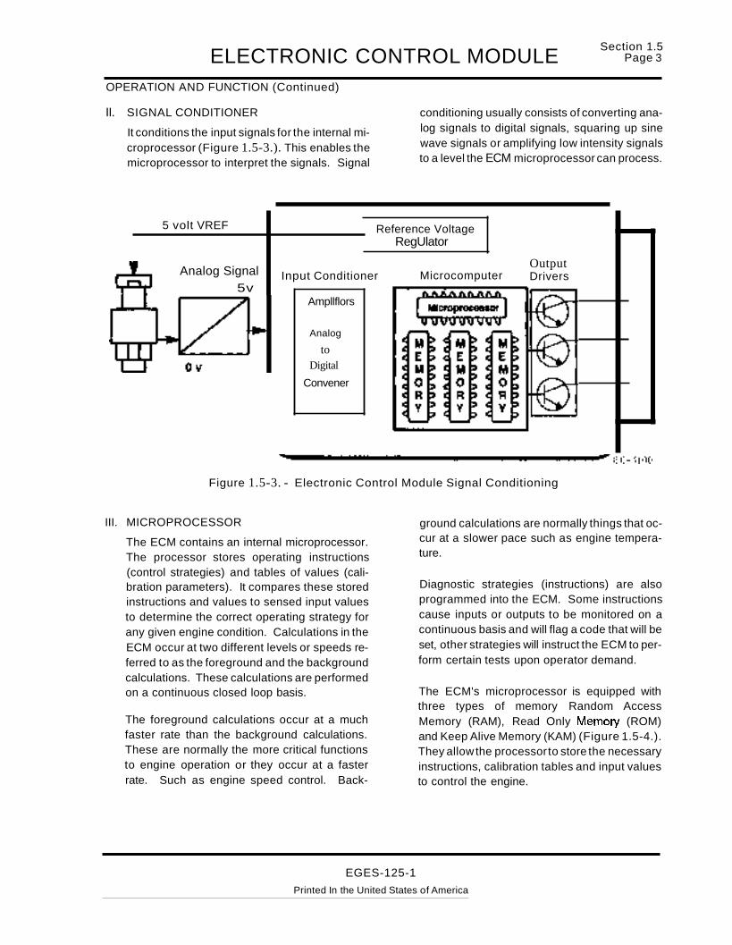
II. SIGNAL CONDITIONER
It conditions the input signals for the internal microprocessor (Figure 1.5-3.). This enables themicroprocessor to interpret the signals. Signal
5 volt VREF
conditioning usually consists of converting analog signals to digital signals, squaring up sinewave signals or amplifying low intensity signalsto a level the ECM microprocessor can process.
Reference VoltageRegUlator
Analog Signal5v
Input Conditioner
Ampllflors
Analog
toDigital
Convener
MicrocomputerOutputDrivers
~---------------------"EG-1100Figure 1.5-3. - Electronic Control Module Signal Conditioning
III. MICROPROCESSOR
The ECM contains an internal microprocessor.The processor stores operating instructions(control strategies) and tables of values (calibration parameters). It compares these storedinstructions and values to sensed input valuesto determine the correct operating strategy forany given engine condition. Calculations in theECM occur at two different levels or speeds referred to as the foreground and the backgroundcalculations. These calculations are performedon a continuous closed loop basis.
The foreground calculations occur at a muchfaster rate than the background calculations.These are normally the more critical functionsto engine operation or they occur at a fasterrate. Such as engine speed control. Back-
ground calculations are normally things that occur at a slower pace such as engine temperature.
Diagnostic strategies (instructions) are alsoprogrammed into the ECM. Some instructionscause inputs or outputs to be monitored on acontinuous basis and will flag a code that will beset, other strategies will instruct the ECM to perform certain tests upon operator demand.
The ECM's microprocessor is equipped withthree types of memory Random AccessMemory (RAM), Read Only Memory (ROM)and Keep Alive Memory (KAM) (Figure 1.5-4.).They allow the processorto store the necessaryinstructions, calibration tables and input valuesto control the engine.
EGES-125-1
Printed In the United States of America

Section 1.5Page 4 ELECTRONIC CONTROL MODULEOPERATION AND FUNCTION (Continued)
ROM:
Read Only Memory is the memory where calibrationtables and operating strategies are stored. Information in the ROM is permanent. It can not be changedor lost by turning the engine off or disconnecting thebatteries.
RAM:
Random Access Memory is a temporary storagememory for current events such as current enginetemperature or current speed, pedal position etc. Itis the memory to which information is temporarilystored so that it can be compared to the informationin the ROM. Unlike the Rom memory, the RAM islost every time the key is turned off or when poweris interrupted to the ECM.
KAM:
Keep Alive Memory is a permanent memory. It isused to store diagnostic faults (codes). Adaptivestrategies (temporary operating instructions) canalso be written to it in event of a system failure or asa compensation for component wear. Uninterruptedpower must be supplied from the battery to the ECMon a continuous basis to keep KAM memory alive.All information in KAM is lost if the ECM has a totalpower loss such as when the batteries are disconnected.
Reference VoltageRegulator
Input Conditioner MicrocomputerOutputDrivers
Amplifiers
Analog
to
Digital
Converter
EG-1101
Figure 1.5-4. - Electronic Control Module Microprocessor Memory
EGES-125-1Printed in the United States of America

ELECTRONIC CONTROL MODULEOPERATION AND FUNCTION (Continued)
ACTUATOR CONTROL
Section 1.5PageS
The ECM controls the actuators by applying a (lowlevel) signal to the base of the transistor output drivers (Figure 1.5-5.). These drivers, when switchedon, will complete the ground circuit of each actuator.
The actuators are controlled either thru a duty cycle(0/0 time on/off), or controlled thru a controlled pulsewidth or simply just switched on or off as determinedby the type of actuator being controlled.
Reference VoltageRegulator
Input Conditioner MicrocomputerOutputDrivers
Amplifiers
Analog
to
Digital
Converter
EG-1102
ECM (Low Level) Actuator Control (Signal In)
Figure 1.5-5. - Electronic Control Module Actuator Control
EGES-125-1Printed in the United States of America

INJECTOR DRIVER MODULESection 1.6
Page 1
INJECTION DRIVER MODULE FUNCTIONS
The Injection Driver Module (10M) is a device thatperforms four major functions.
I. Electronic Distributor for the injectors.The Electronic Control Module (ECM) sensesthe piston position of cylinder # 1 from the outputsignal of the Camshaft Position Sensor (CMP)which is located on the engine front cover. TheCMP sensor is a Hall effect sensor which looksfor a narrow vane on the timing sensor disk(Figure 1.6-1.). The disk is precisely mounted
and indexed on the camshaft gear in a relationship that identifies the position of #1 piston.
The ECM uses this signal to determine the correct injector firing sequence. The CylinderIdentification (CI) line carries the injector firingsequence information to the 10M.
The 10M receives a Fuel Demand CommandSignal (FOGS) signal from the ECM to controlinjector timing and the quantity of fuel that is delivered by each injector.
Timing Sensor Disk
IDM
,..-- NarrowWindow
ECM
CMPSensor
FDCS Fuel Demand Command Si
EG-1103
Cylinder Identification
Figure 1.6-1. -Injector Driver Module (Distributor)
EGES-125-1Printed In the United States of America

Section 1.6Page 2 INJECTOR DRIVER MODULEINJECTOR DRIVER MODULE FUNCTIONS - (Continued)
u. Power Source for the injectors.
The 10M supplies a constant 115 +volt d.c. supply to all injectors. The 115 volt d.c. supply iscreated in the 10M by making and breaking a 12volt source across acoil internaltothe IDM, the
IDM
Capacitors
same principle is used on automotive coils. Theresultant 115 + volts created by the collapsedfield is stored in capacitors until used by the injectors.
r---------Oscillator
Coil
---,
+12 V
Battery Voltage
L._________ ___ .J
EG-1104
Injector Power SupplyVoltage 115V
Figure 1.6-2. - Injector Driver Module (Power Source)
EGES-125-1Printed In the United States of America

INJECTOR DRIVER MODULESection 1.6
Page 3
INJECTOR DRIVER MODULE FUNCTIONS - (Continued)
III. Output Driver for the injectors
The 10M controls when the injector is turned onand how long the injector is turned on by closingthe circuit to ground by the use of output drivertransistors. Each injector has an individual out-
put driver in the 10M. The processor in the 10Mselects the correct firing sequence, the ECMthrough the FOCS signal controls the timing ofwhen the injection starts and the duration ofhow long the injector is open.
Capacitors
IDM
WHEN THE DRIVER IS ON,THE CIRCUIT IS GROUNDEDAND THE INJECTOR IS ON.
ToECM
EG-1105
FOCS Signal
End ofInjection
T12 volts
...-..-..t
Injection
Timin~Beginningof Injection
FOCS Pulsefrom ECM to 10M
Oriver
Injector PowerSupply Voltage
115V
Figure 1.6-3. - Injector Driver Module (Output Driver)
EGES-125-1
Printed In the United States of America

Section 1.6Page 4 INJECTOR DRIVER MODULEINJECTOR DRIVER MODULE FUNCTIONS - (Continued)
IV Performs diagnostics for itself and the injectors. The 10M is capable of identifying if aninjector is drawing too much current or too littlecurrent and sends a fault code to the ECM thatcan be accessed by the technician. This code
can be used to identify potential problems in eitherthe wiring harness or injector. The 10M alsoperforms self diagnostic checks that can set acode to indicate that the 10M has failed andneeds to be replaced.
,. ~,. .,
10M ECM
~ j ~ ~
I I I I1 10M Communication Line I
EG-11
Figure 1.6-4. - Injector Driver Module Diagnostic Communication
EGES-125-1Printed In the United States of America
06

SENSOR OPERATIONSection 1.7
Page 1
INPUT SIGNALS
Engine and vehicle sensors transmit input signals tothe Electronic Control Module (ECM) (Figure1.7-1.) by either:
+ Controlling a reference voltage to produce ananalog or digital signal.
+ Generating a signal voltage.
+ Switching a 12 volt signal.
REFERENCE VOLTAGE SENSORSReference voltage sensors are supplied with a con-
stant 5 volts regulated supplied by the ECM. A voltage regulator supplies the reference voltage (Vref)to these sensors. This voltage is changed by thesensor and the signal is relayed back to the ECM.The ECM, by comparing the Vrefto the returned signal can check it's internal programmed tables to determine the value of the variable being measured.
EG-1107
OutputDrivers
Reference VoltageRegulator
Microcomputer
REFERENCE VOLTAGE(5 VOLTS) FROM
VOLTAGE REGULATOR
Analogto
DigitalConverter
Input Conditioners
.....--... VoltageGenerator
Switch
Ch;ssls ~Ground ..... ...
Magnetic Pickup
SIGNAL LINES
-Signal Return Provided Through Processor
Figure 1.7-1. - Types of Input Signals
EGES-125-1
Printed In the United States of America

Section 1.7Page 2 SENSOR OPERATIONTYPES OF SENSORS
THERMISTOR
internal to the ECM. A thermistor sensor has twoelectrical connections, signal return and ground.The output of a thermistor sensor is not linear.
OutputDriversMicrocomputer
Reference VoltageRegulator
Examples:EaT Engine Oil TemperatureECT Engine Coolant Temperature Sensor(AT Intake Temperature Sensor
CurrentLimitingResistor
Analogto
DigitalConverter
Input Conditioners
ECT
A thermistor is a type of sensor which changes it'selectrical resistance with temperature. The electrical resistance of the thermistor decreases as temperature increases and increases as temperaturedecreases. The thermistor in conjunction with acurrent limiting resistor in the ECM (Figure 1.7-2.)forms a voltage divider network that provides a voltage signal that indicates temperature. The top halfof the voltage divider is the current limiting resistor
• VREF CONNECTION
• GROUND CONNECTION2 TERMINALS
o.n I-----'-_~-'---£-
0° 50° 100° 150° 200°
TEMPERATURE
1 Kn
100.n
EG-11 08
Signal Return Provided Through Processor10 Kn
R 100 KnESI
STANCE
The chart indicates resistance of a thermistor decreases astemperature increases. Output of thermistor is not linear.
Figure 1.7-2. - Thermistor Engine Coolant Temperature (ECT)
EGE5-125-1Printed in the United States of America

SENSOR OPERATIONTYPES OF SENSORS (Continued)
POTENTIOMETER
Section 1.7Page 3
A potentiometer (Figure 1.7-3.) is a variable voltage divider used to sense the position of a mechanical component. A reference voltage is applied toone end of the potentiometer. Mechanical motionconnected to the wiper causes it to move along theresistance material in a rotary fashion. The voltage
on the wiper changes at each point along the resistive material. This voltage is proportional to theamount of mechanical movement.
Example:APS Accelerator Position Sensor
Current
/
5 VR....E"F ~~~~~L~im~i~tin~g~~~~~~-- ....___r' Resistor
Reference VoltageRegulator
RESISTIVEMATERIAL
SIGNALVOLTAGE
MovableWiper
!
Input Conditioners
Analogto
DigitalConverter
Microcomputer
GND
OutputDrivers
EG-11 09
" !/'Id,r;.F'f
Figure 1.7-3. - Potentiometer (Variable Resistance Voltage Divider)
EGES-125-1
Printed In the United States of America

Section 1.7Page 4 SENSOR OPERATIONTYPES OF SENSORS (Continued)
VARIABLE CAPACITANCE SENSOR
Variable capacitance sensors are used to measurepressure. The pressure which is to be measured isapplied to a ceramic material. The pressure forcesthe ceramic to move closer to a thin metal disk. Thisaction causes the capacitance of the sensor tochange which creates a frequency that correspondsto a pressure. The internal circuitry of the sensorconverts that frequency into a linear analog voltagethat indicates pressure. The thicker the ceramic
SIGNALVOLTAGE
disk the more pressure that sensor can measure.A variable capacitance sensor has three connections: Vref, signal and ground. Refer to Figure1.7-4.
Examples:EOP Engine Oil Pressure SensorESP Exhaust Back Pressure SensorICP Injection Control Pressure Sensor
Reference VoltageRegulator
Input Conditioners
Analogto
DigitalConverter
EOP
Microcomputer
GND--
Output Drivers
EG-1110
Figure 1.7-4. - Variable Capacitance Sensor (Exhaust Back Pressure Sensor)
EGES-125-1Printed in the United States of America

SENSOR OPERATIONTYPES OF SENSORS (Continued)
HALL EFFECT SENSOR
Section 1.7PageS
The Hall Effect sensor is an electronic device whichgenerates a voltage signal controlled by the presence, absence or strength of a magnetic field.
The Camshaft Position sensor is an example of aHall Effect device. It contains a transducer, permanent magnet, signal conditioner and a switchingtransistor. The sensor's permanent magnet appliesa magnetic field around the transducer as shown inFigure 1.7-5. The sensor's transducer senses thestrength of the magnetic field which is controlled bythe vanes and windows (located on the rotating timing sensor disk) as they pass the sensor.
A voltage signal is generated by the Hall Effect device each time a window passes the device. The signal is filtered and conditioned by the signal condi-
tioner. The conditioned signal is applied to theswitching transistor's base which causes the transistor to switch on and ground the 12 volt line fromthe ECM. The ECM no longersenses the 12volt reference signal.
Each time a vane passes the Hall Effect device nosignal is generated. This action causes the transistor to shut off and causes the ECM to see its 12 voltreference signal.
This switching action allows the ECM to determinecrankshaft position and engine speed which is required by the ECM to control engine operating parameters such as injector timing and injection duration.
Power SupplyFor Sensor.
5 Volt
/
ReferenceFromECM
12 VoltsFromECM
CMP+- Grd.
.I::::=L.nternalPull UpResistor
ECM
Hall Effect Sensor(Camshaft Position Sensor)
PermanentMagnet
Transducer
--
Timing SensorDisk (Located onFace of CamshaftGear)
Vane
EG-1111
Figure 1.7-5. Hall Effect Sensor (Camshaft Position Sensor)
EGES-125-1Printed In the !J!'J_~~~_~!~!!~_~J_~~!~i_~~ ---------------------------------------------- --- ----------
---------~~-

Section 1.7Page 6 SENSOR OPERATIONTYPES OF SENSORS (Continued)
SWITCH SENSORS
Switch sensors are used to indicate position, levelsor pressures. The signal of a switch sensor is a digital signal created by either opening or closing aswitch. The on or off signal can indicate position asin the case of a clutch switch, level as in the case ofa coolant level switch or pressure as in the case ofa low oil pressure switch. A switch sensor can beeither a voltage input type switch or a groundingtype switch. A voltage input style switch will supplythe ECM with a voltage when closed. A groundingtype switch is wired in series with a current limitingresistor in the ECM and will cause a zero voltage
signal when closed (grounding the circuit). A switchsensor normally has two connectors signal return(Grd) and the signal. A switch sensor is considereda low speed digital input. Refer to Figure 1.7-6.
Examples:IVS Idle Validation SwitchBNO Brake Normally OpenBNC Brake Normally ClosedCLS Coolant Level SwitchDDS Driveline Disengagement Switch
SIgnal Return ProYlded Through Proc:Moor
CURREHT UIIITIIKlRESlSTOfI
Reterence VoltageRegulator
Input Condltlonera MicrocomputerOutputDrivers
~ ('?:i&:21
mmillA~1Og
D1glt8lConvener
CLUTCHPEDALRELEASED
EG·2607
SIgII8I Return Provlded Through Proc:Maor
CLUTCHPEDALDEPRESSED
EG·2608
LOW VOl.TAQE SIGNAL(LESS THAN 1 VOl.T) TOINPUT COlIOIT1ONERS
Input Conditioners
Analogto
Dlglt8lConvener
CURRENT UMIT1HQRESISTOR
Reference VoltegeRegulator
Microcomputer
EG-1112
Figure 1.7-6. - Driveline Disengagement Switch (DDS)
EGES-125-1Printed In the United States of America

SENSOR OPERATIONTYPES OF SENSORS (Continued)
MAGNETIC PICKUP
Section 1.7Page 7
A magnetic pickup is a sensor used to generate analternating frequency that indicates speed. Magnetic pickups normally have a two wire connectionfor signal return and ground. A magnetic pickup isconstructed with a permanent magnetic core surrounded by a wire coil. The signal frequency is gen-
erated by the rotation of gear teeth which make andbreakthe magnetic field created by the magnet. Refer to Figure 1.7-7.
ExamplesVSS Vehicle Speed Sensor
5 1 4 3
•EG·2606
Figure 1.7-7. - Magnetic Pickup (Vehicle Speed Sensor)
1. Magnetic Pickup Sensor 4. Permanent Magnet Field2. Transmission Case 5. Output Signal3. 16 Tooth Speedometer Gear
EGES-125-1
Printed In the United States of America

VEHICLE FEATURESSection 1.8
Page 1
STANDARD FEATURES
ELECTRONIC GOVERNOR CONTROLThe T 444E is fully electronically governed over alloperating ranges.
COLD IDLE ADVANCEThis feature provides an increase in engine cold idlespeed of up to 875 rpm (normal idle 700 rpm) for afaster warm up to nominal operating temperature.This is accomplished through the electronic controlmodule monitoring the engine coolant temperaturesensor input and adjusting injector operation as required. Low idle speed is increased proportionallywhen the engine's coolant temperature is below158°F (70°C) (700rpm) to 14°F (-10°C) (875 rpmmaximum).
COLD AMBIENT PROTECTION SYSTEM (CAP)This feature is built into the engine control systemsoftware to aid engine warm up and to maintain engine temperature during extended idle periods incold weather.
The CAP feature slowly ramps up engine idle speed(after 5 minutes of idle time) to a preset engine rpmwhen the intake air temperature is below 32° F (0°C) and coolant temperature is below 158 ° F (70 ° C).This system is programmed to return engine idlespeed backto normal idle when the vehicle operatordecides to operate the vehicle or engage the PTO.
GLOW PLUG ASSISTED STARTThis feature increases engine startability in coldweather. The glow plugs are controlled by the Electronic Control Module which monitors engine temperature. "A WAIT TO START' lamp is included toinform the operator when the engine is ready forcranking.
AMERICAN TRUCKING ASSOCIATION DATALINK PROVISIONSThe T 444E is equipped with an American TruckingAssociation (ATA) data link connector that allowscommunication between the electronic engine control system and the Pro-Link 9000 Electronic Service Tool (EST).
The data link provides communication capabilitiesfor:
• Engine parameter data transmission.
• Diagnostics and troubleshooting.
• Customer programming.
• Production line programming of vehicle features.
• Field programming.
SERVICE DIAGNOSTICSThe electronic service tool provides means for obtaining diagnostic information using the ATA datalink. The recommended electronic service tool isthe Pro-Link® 9000 with an International cartridge.Sensor, actuator, electronic component and enginesystem faults can be detected by the ECM and bediagnosed by the EST.
The engine control system also provides servicediagnostic information via flash codes emitted usingthe engine warning lamp. The service literature isindexed according to the flash codes.
ELECTRONIC SPEEDOMETER AND TACHOMETER PROVISIONSThe engine control system calibrates vehicle speedusing pulses/mile. Dip switches no longer need tobe changed when components affecting speed calibration are changed. The new speed calibration information can be programmed through the Electronic Service Tool.
ENGINE OVER TEMPERATURE PROTECTIONSYSTEM (COOLANT TEMPERATURE COMPENSATION)This system reduces fuel delivery when the enginecoolant temperature is above the cooling systemdesign target value. Fueling is reduced proportionally to the extent the design limit is exceeded. Thereduction is calibrated to a maximum of 200/0 beforestandard engine warning and/or option,al warning!shutdown systems engage. If this feature is activated, a fault code is stored in the Electronic ControlModule's memory to explain low power complaints.
This feature may be omitted on emergency vehicleapplications that require 1aOok power on demand.
EGES-125-1Printed In the United States of America

Section 1.8Page 2 VEHICLE FEATURESSTANDARD FEATURES (Continued)
EVENT LOGGING SYSTEM
This system records if the engine was operated beyond maximum rpm, over heated (coolant temperature), low on coolant and/or experienced low oilpressure. This information is stored in the ECMmemory and may be accessed through the use ofthe EST.
Power Take-Off (PTO) options with automatictransmissions. Engine Crank Inhibit is available asan optional feature with a manual transmission anda clutch switch.
ELECTRONIC ACCELERATOR PEDAL
ENGINE CRANK INHIBIT
This system will not allow the engine to crank unlessthe automatic transmission is in neutral and will notallow the starter to engage while the engine is running. It also facilitates the use of cruise control and
This feature eliminates the mechanical linkage usedwith conventional accelerator pedals. An accelerator position sensor within the accelerator pedal assembly provides the ECM with a signal representingthe driver's demand for power.
Input
Accelerator Position Sensor
Processing
Electronic Control Module
Fuel Injector
Outputs,...----_....._----...
Injection Pressure Regulator
Injector Drive Module
EG-1208
Figure 1.8-1. - Electronic Accelerator Pedal System Operation
EGES-125-1
Printed In the United States of America

VEHICLE FEATURESSection 1.8
Page 3
OPTIONAL FEATURES
CRUISE CONTROL
This feature provides vehicle speed using ~utomo
tive style set/coast, resume/accel, on, off switches.Speed control is disabled when the brake is applied,the clutch pedal is depressed or an automatic transmission is placed in neutral. The accelerator pedalcan be used to provide a speed increase from thecruise speed selected.
haust back pressure engine warm-up system is especially desirable in bus applications.
BODY EQUIPMENT MANUFACTURERS PROVISIONS
Additional circuits and connector junction blocks areprovided in the cab. The circuits include provisionsfor:
~_...... O, " F
F
CRUISE
l. j 0~-""N
SETICOAST
CRUISERESUME!ACCEL
EG-1209
• Remote engine speed control.
• Remote PTO (engine speed) control commands.
• Additional power and control (protection) circuits for after manufacture add-on equipment.
The standard electrical system will provide breakoutconnector access to the speed control circuits.
Cruise Control Switches.
THROTTLE CONTROL FOR PTO OPERATION
The T 444E is compatible with both stationary andmobile PTO applications. Remote and in-eabthrottle control locations are available. Also, thethrottle control feature can be used as an electronichand throttle.
ROAD SPEED LIMITING/GOVERNOR
This feature limits vehicle speed to an owner/operator programmable maximum speed.
EXHAUST BACK PRESSURE ENGINE WARMUP SYSTEM
With this feature, a butterfly valve is placed in the exhaust stream at the turbo exhaust outlet. When theambient and engine coolant temperatures are low,the valve restricts exhaust flow. The increased engine load increases the heat transferred to the cooling system. This, in turn, increases the amount ofheat available to warm the vehicle interior. The ex-
ENGINE WARNING SYSTEM
This system illuminates the red "Stop Engine" lampand actuates a buzzer when warning thresholds forcoolant temperature, engine coolant level and/orengine oil pressure (low) are exceeded.
ELECTRONIC IDLE SHUTDOWN TIMER
This is an optional feature which provides engineshutdown after a 5 minute idle time has been exceeded.
ENGINE SHUTDOWN SYSTEM (FIGURE 1.8-2.)
This system shuts down the engine after 30 seconds of operation beyond critical threshold valuesfor coolant temperature, oil pressure and/or enginecoolant level. The above mentioned warning system is included with this shutdown system. The engine may be restarted after shutdown, if it is mechanically capable of starting.
EGES-125-1
Printed In the United States of America

Section 1.8Page 4 VEHICLE FEATURESOPTIONAL FEATURES (Continued)
ENGINE SHUTDOWN SYSTEM-(Continued}
Inputs
CoolantTemperature
Outputs
EngineCoolantLevel
Processing
ElectronicControlModule
WARNINGBUZZER
WARNENGINELIGHT
Engine OilPressure
Figure 1.8-2. - Engine Shutdown System
EGES-125-1
Printed In the United States of America
10MPowerRelay
EG-1210

DIAGNOSTIC FAULT CODE DETECTION
DIAGNOSTIC CODeS
CONTINUOUS MONITOR
•
enCDg.
"tJ -mOu:a~CD .......... co
c):Ci)zoen-Ioeno."-I
~:c
~enCm _enm»rile;)~"'Z~-f0
menen-f-f-0°-c enmO::D::!I!t:e-»0::DZm
WIGGLETEST
•Helps detect intermittent problemsby monitoring inputcircuits and responding wnh anaudible beep whena faurt is detected•
•
ENGINE RUNNINGTESTS
STANDARD TESTPerforms "STEP" tests on
IPR and EPR system
INJECTOR TEST(Cylinder Contribution Test)Tests individual Cylinder/Injector perfon:nance
•
..
•
ENGINE OFFTESTS
STANDARD TESTTests output circuits
electrically
INJECTOR TEST(BUZZ TEST)
Activates injectorswithout engine running
OUTPUT STATE TESTActivates outputs
I DIAGNOSTIC TESTS I
..INACTIVE
CODES
Codes stored inmemory fromprior key on cycles
..EVENT LOG
Records engineoperation exceedingprogrammed parameters.
+Detects on a continuous basis:
Sensor circuit Out-of Range faultsSensor In-Range faults
Intermittent sensor and injector faultsEngine oil and cooling system fautts
..ACTIVE
CODES
Codes set duringcurrent key oncycle
m~.....~....
4'5-CDa.:;-~ mCDc C>= mi ena. Ien .....&r
I\)... Y'CDCI) .....0""'")It
3(I~crS»

Section 1M9Page 2
DIAGNOSTIC SOFTWARESELF TEST OPERATION
CONTINUOUS SELF TEST
CONTINUOUS MONITOR
Diagnostics are performed by the Electronic ControlModule (ECM) continuously to detect out of range,rationality and system faults.
During the time that the key is "ON", if an input signalis "Out of Range" meaning the signal is either greater or lesser than what the signal range should beduring normal operation, the ECM will record a"Fault". It will also monitor the operation of systemsand will determine if the system is working within anormal range. If the ECM detects that a system fallsoutside a predetermined range, it will record andflag a fault.
During normal engine operation, the ECM automatically performs several tests to detect faults. Whenit has detected a fault, the ECM often invokes a faultmanagement strategy to allow continued, thoughsometimes degraded, vehicle operation.
A "Fault" is an indication of a malfunction measuredor monitored electronically. Sometimes "Faults" arereferred to as "Codes."
"Codes" are three digit numbers assigned to Faultsto indicate the source of the malfunction. MostCodes will indicate the source and the "Mode" of failure. The "Failure Mode" will indicate the signalreading, IE.; "Out of Range High", "Out of RangeLow" or in Range fault.
During operation of the truck with the engine running, the Vehicle Personality Module (VPM)memory will record "EVENT ENGINE HOURS".This is the monitoring of engine operation exceeding programmed parameters. The standard EngineEvent is Overspeed of the engine, referred to asOver RPM and excess coolant temperature. To retrieve information on Engine Events, it will be necessary to access them with the Electronic ServiceTool.
If the engine is equipped with the optional enginewarning/shutdown system, low oil pressure, andlow coolant level operation, will also be monitoredand recorded as "EVENT ENGINE HOURS".
OPERATOR ON DEMAND TESTSENGINE OFF
STANDARD TEST (ENGINE OFF)
"Engine Off Tests" are "Standard Tests" performedby the ECM. These tests are commanded by theoperator using the Electronic Service Tool (EST) or
using the Self Test Input (STI) push-button switch.Since Injector Driver Module (10M) faults are notstored in the ECM, it will be necessary to perform aself test to transmit faults from the 10M to the ECM.
To use the EST access the Engine menu and selectDiagnostic Tests. Then select Engine Off Tests. Depressing the Enter key will initiate the test.
To use the STI diagnostic push-button switch, depress the switch and hold in, while turning the ignition switch to the "ON" position. Release the STIbutton after the key is in the "ON" position. Do notstart the engine.
When the operator signals the test to begin, theECM will perform internal tests of its processingcomponents and internal memory.
It will automatically proceed to Output Circuit Check(OCC). This will operate the ECM output circuits.It will measure each individual circuit's response.The following circuits are checked by the ECM during the test:
1. Cylinder identification
2. Exhaust Pressure Regulator
3. Engine Crank Inhibit (relay)
4. Glow Plug Control (relay)
5. Injector Driver Module (relay)
6 Glow Plug Light
7. Fuel Demand Command Signal
B. Injection Pressure Regulator
9. Engine to Transmission Data Line (EDL relay).
The ECM will monitor the outputs and test the operation of the output signals and actuators. If a circuit fails the test, a fault code will be logged.
When the test is complete, the EST will display anyfaults that were found during the test. If the STIdiagnostic switch was used, the faults will be transmitted as "Flash Codes," using the Oil Warning andEngine Warning lights.
The fault codes are read by counting the number oflight flashes. The following sequence occurs:
1. The "OillWater" light will flash one time. Thisindicates the beginning of Active fault codes.
2. The "WARN ENGINE" light will flash repeatedly signaling the active fault codes. All codes arethree digits. The number of flashes should becounted in sequence.
EGES-125-1
Printed in the United States of America

DIAGNOSTIC SOFTWARESELF TEST OPERATION
OPERATOR ON DEMAND TESTSENGINE OFF (Continued)
Section 1.9Page 3
STANDARD TEST (Continued)
3. At the end of each digit of the code there will bea short pause. Three flashes and a pause indicates the number 3. The code 232 will be sentas two flashes, (a pause), three flashes, (apause), and two flashes.
If there is more than one code being sent, the "OIUWATER" light will flash once indicating the beginning of another active fault code. The code 111 indicates "NO FAULTS".
If no further Active fault codes exist, the "OILlWATER" light will flash twice, indicating the beginningof "INACTIVE CODES". The "WARN ENGINE"light will then flash the "INACTIVE CODE"(s) present. If several "INACTIVE CODES" are present, the"OILlWATER" light will flash once between each ofthe fault codes.
When all of the stored fault codes have been sent,the "OILlWATER" light will flash three times indicating "END OF MESSAGE".
If it is necessary to repeat transmission of faultcodes, press the STI button and all stored codes willbe. retransmitted as described previously.
INJECTOR "BUZZ" TEST (ENGINE OFF)
The purpose of the Engine Off Injector "BUZZ" Testis to diagnose electrical problems with the fuel delivery components. This test can only be accessedwith the EST and only after an "Engine Off Test" orSelf Test has been performed.
NOTE: BEFORE RUNNING THIS TEST, FAULTCODES SHOULD BE ACCESSED, NOTED ANDERASED. THIS WILL ALLOW THE FAULTSFOUND IN THIS TEST TO BE DISPLAYED AS"ACTIVE CODES"
During the test, the ECM will signal the 10M to activate the injectors in numerical order 1 thru 8. TheIDM will monitor each injector's electrical circuit operation. The IDM will send feedback signals to theECM which indicate the status of injector performance and electrical circuit operation. If an electronic component in the fuel system fails the param-
eters of the test, an inactive fault code will be loggedand transmitted to the EST at the end of the test.
NOTE: THE TECHNICIAN CAN MONITOR INJECTOR OPERATION BY LISTENING TO THESOUND EACH INJECTOR PRODUCES AS IT ISACTIVATED BY THE 10M, HOWEVER, IN A HARDSTART/NO START CONDITION WHERE THE OILMAY BE VERY COLDITHICK INJECTORS MAYNOT BE AUDIBLE.
If the faults were not erased before this test, thefaults found during this test will be displayed as "INACTIVE CODES".
To read these fault codes, access the "DiagnosticCodes" menu and read both Active and Inactivecodes.
OUTPUT STATE TEST (ENGINE OFF)
The purpose of the Output State Test is to diagnosethe operation of the output signals and actuators.This test can only be performed by using the Electronic Service Tool.
To run this test, select the Output State Test fromthe EST Engine Off Test menu. The test consists oftwo modes of operation:
1. Toggling outputs from high to low.
2. Toggling outputs from low to high.
When in the "OUTPUTS ARE LOW" mode theECM will pull down the output voltage to their lowstate. This will actuate the output components thatare controlled by the ECM grounding the circuits.During this test "OUTPUTS ARE LOW" will be displayed on the screen.
When in the "OUTPUTS ARE HIGH" mode theECM will pull up the output voltage to their highstate. This will actuate the output components thatare controlled by the ECM energizing the control circuits. During this test "OUTPUTS ARE HIGH" willbe displayed on the screen.
During this test, the output of the circuit in questioncan be monitored with a DVOM. The DVOM willmeasure a "High or Low" voltage state condition asthe outputs are toggled. The actual voltage will varywith the circuit tested.
EGES-125-1
Printed in the United States of America

Section 1.9Page 4
DIAGNOSTIC SOFTWARESELF TEST OPERATION
OPERATOR ON DEMAND TESTSENGINE OFF TEST (Continued)
OUTPUT STATE TEST (ENGINE OFF)(Continued)
NOTE 1: THE EST WILL ONLY DISPLAY "OUTPUTS ARE HIGH" OR "OUTPUTS ARE LOW". ITWILL NOT DISPLAY ANY VOLTAGES ETC. ADVOM IS REQUIRED TO MONITOR THE SUSPECTED PROBLEM CIRCUIT OR ACTUATOR.
NOTE 2: FAULTS WILL NOT BE SET DURINGTHIS TEST.
This following actuators and signals are toggledhigh and low during the test:
a. Injector Driver Module Enable Relay
b. Cylinder Identification
c. Fuel Demand Command Signal (FDCS)
d. Exhaust Pressure Regulator
e. Injection Pressure Regulator
f. Engine Crank Inhibit Relay
g. Engine Data Link (EDL) Relay
h. Oil Warning Light
i. Warn Engine Light
j. Glow Plug Lamp
k. Glow Plug Relay
OPERATOR ON DEMAND TESTSENGINE RUNNING
STANDARD TEST (ENGINE RUNNING)
The Self Test (Engine Running) checks the operation of the following actuators:
1. Injection Pressure Regulator (IPR)
2. Exhaust Back Pressure Regulator (EPR)
During the test, the ECM commands the IPR andthe EPR actuators through a pre-programmed testing sequence to determine if the actuators are performing as expected. The ECM monitors the feedback signal values from the injection controlpressure and exhaust back pressure sensors andcompares those values to the expected values. Atthe end of the test, the ECM will return the engineto the normal operating mode and transmit any faultcodes which may have been set during the test.
This test can only be performed by using the Electronic Service Tool.
PROCEDURE
NOTE: ENGINE COOLANT TEMPERATUREMUST BE 1600 F ,BATTERY VOLTAGE MUST BEHIGHER THAN 12.5 VOLTS AND NO VEHICLESPEED SENSOR (VSS) SIGNAL SHOULD BEPRESENT DURING THIS TEST. IF ACTIVEFAULT CODES ARE PRESENT, THEY MUST BEREPAIRED AND CLEARED PRIOR TO RUNNINGTHIS TEST.
1. Select "Engine Running Test" from the "Diagnostic Test" menu in the EST.
2. Press "ENTER" to begin test. The ECM will begin to raise the engine idle speed to a predetermined value. It will then command the IPRvalve to set the injection control pressure torated speed pressure. If the performance of theIPR is acceptable,the ECM will control the IPRvalve to reduce the pressure in steps while continuing to monitor the performance of the injection control pressure system.
At the completion of the IPR test, the ECM will conduct a similar test on the EPR valve. When testingis completed, normal engine operation is restoredand fault codes will be transmitted as described previously.
INJECTOR TEST "CYLINDER CONTRIBUTION"(ENGINE RUNNING)
The Injector Test is designed to detect problemswith injection and combustion events. During thetest the ECM will control fuel delivery and determineeach cylinder's power contribution. If a cylinder isnot performing satisfactorily, a fault code will be set.
This test can only be performed by using the Electronic Service Tool.
PROCEDURE
NOTE: THE ENGINE RUNNING SELF TESTMUST BE PERFORMED FIRST IN ORDER TOGAIN ACCESS TO THE INJECTOR (ENGINERUNNING) TEST IN THE EST.
1. Select Injector Test from the Engine RunningTest menu.
EGES-125-1
Printed in the United States of America

DIAGNOSTIC SOFTWARESELF TEST OPERATION
Section 1.9PageS
c. Camshaft Position Sensor (CMP)
d. Data Communication Link
e. Exhaust Back Pressure (optional)
f. Engine Coolant Temperature
g. Engine Oil Pressure (optional)
h. Injection Control Pressure
i. Manifold Absolute Pressure
j. Remote Accelerator Pedal Sensor
k. Engine Oil Temperature
I. Barometric Pressure Sensor (BARD)
PROCEDURE
1. Select the Wiggle Test from the "DiagnosticTest" menu in the EST. Press the "ENTER" keyto begin test.
2. The technician should wiggle connectors andwires at all suspected problem points. The ESTwill "BEEP" if circuit continuity is broken. It willdisplay all faults found during the test.
OPERATOR ON DEMAND TESTS
WIGGLE TEST
OPERATOR ON DEMAND TESTS (ENGINE RUNNING)INJECTOR TEST (ENGINE RUNNING) (Continued)
PROCEDURE (Continued)
2. The ECM will increase the normal amount offuel delivery (overfuel) to the injector/cylinderbeing tested and monitor the reduction of fuelrequired to operate the remaining injectors tomaintain engine speed. If there is no reductionin fuel delivery to the other cylinders the ECMwill set a fault code identifying the non-eontributing cylinder.
When testing is completed, normal engine operation is restored and fault codes will be transmitted.
The purpose of the Wiggle Test is to troubleshoot intermittent connections at sensors and actuators. Itmay be performed with the engine off or running.The Electronic Service Tool is used to monitor thefollowing circuits during the Wiggle Test.
a. Accelerator Position Sensor (APS)
b. Intake Air Temperature Sensor (IAT)
EGES-125-1
Printed In the United States of America

SECTION 2 MECHANICAL DIAGNOSTICS
INDEX
PAGE
SECTION 2.1 DIAGNOSTIC FORMSINTRODUCTION 1INSTRUCTIONS . . . . . . . . . . . . . . . . . . . . .. . . . . . . . . . . . . . . . . . . . . . . . . . . . . . . . . . . . . . . . . . . . . . . .. 2ORDERING INFORMATION. . . . . . . . . . . . . . . . . . . . . . . . . . . . . . . . . . . . . . . . . .. . . .. . . . . . . . . . . . . .. 3
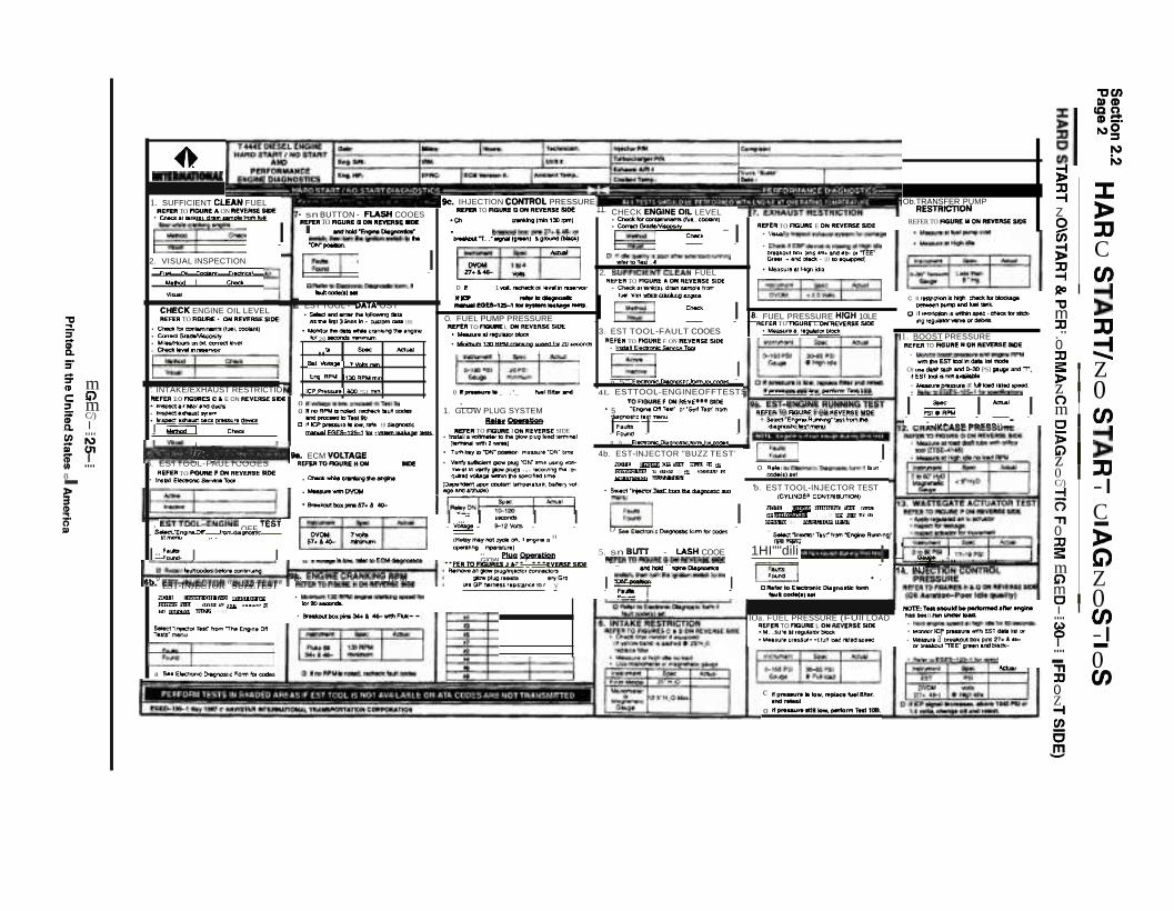
SECTION 2.2 HARD START I NO START DIAGNOSTICSINTRODUCTION 1HARD START NO\START & PERFORMANCE DIAGNOSTIC FORM EGED-130-1 (FRT. SIDE) 2HARD START NO\START&PERFORMANCE DIAGNOSTIC FORM EGED-13Q-1 (REAR SIDE) 3SUFFICIENT CLEAN FUEL 4VISUAL INSPECTION . . . . . . . . . . . . . . .. . . . . .. . . . .. . . . . . . . . .. 6CHECK ENGINE OIL LEVEL 7INTAKE/EXHAUST RESTRICTION. . . . . . . . . .. . . . . .. . . . .. . . . .. . .. . . . . . . . . . . . . . . .. .. . .. . . . . . . . . 8EST-TOOL FAULT CODES 9EST TOOL-ENGINE OFF TESTS 12EST-INJECTOR "BUZZ TEST' 13STI-BUTTON FLASH CODES 14EST TOOL-DATA LiST 16ECM VOLTAGE , 18ENGINE CRANKING RPM 20INJECTION CONTROL PRESSURE 21HIGH PRESSURE LEAKAGE TESTS:ISOLATE RIGHT CYLINDER HEAD 23ISOLATE LEFT CYLINDER HEAD 23INJECTION PRESSURE REGULATOR (IPR) AND HIGH PRESSURE PUMP TEST 24 ·ICP LEAKAGE TEST '" 25FUEL PUMP PRESSURE . . . . . . . . . . . . . . . . . . . . . . . . . . . . . . . .. . . .. . . .. . . . . . . . . . . . . . . .. . . . . . .. 27GLOW PLUG SYSTEM:GLOW PLUG "ON" TIME 29GLOW PLUG RESISTANCE TO GROUND (aATTERY - TERMINAL) 31GLOW PLUG HARNESS RESISTANCE TO RELAY 32
SECTION 2.3 PERFORMANCE DIAGNOSTICSCHECK ENGINE OIL LEVEL . . . . . . .. . . . .. . . . . . . . . . .. . . . . . . . . . . .. 1SUFFICIENT CLEAN FUEL 2EST-TOOL FAULT CODES 4EST TOOL-ENGINE OFF TESTS. . . . .. . .. . . . . . . . . . . . . . . . . . .. . . . . . . . . . . .. . . . . . . . . . . . .. . . . . .. 7EST-INJECTOR "BUZZ TEST' 8STI BUTTON-FLASH CODES 9INTAKE RESTRiCTION 11EXHAUST RESTRICTION 14FUEL PRESSURE HIGH IDLE 16EST-ENGINE RUNNING TEST 18EST TOOL-INJECTOR TEST 19FUEL PRESSURE FULL LOAD 20TRANSFER PUMP RESTRICTION . . .. . . .. . . . .. . .. .. . . . .. . . . . . . .. .. . . . . . . . . . . . . .. . . .. . . . . . .. . .. . 22FUEL REGULATOR VALVE REMOVAL AND INSPECTION 24BOOST PRESSURE 25
EGES-125-1Printed In The United Stat.s of America

II MECHANICAL DIAGNOSTICS,
INDEX
PAGESECTION 2.3 PERFORMANCE DIAGNOSTICS (Continued)
CRANKCASE PRESSURE . . . . . . . . . . . . . . . . . . . . . . . . . . . . . . . . . . . . . . . . . . . . . . . . . . . . . . . . . .. 27WASTEGATE ACTUATOR TEST 28INJECTION CONTROL PRESSURE (OIL AERATION-POOR QUALITY) 30ALTERNATE METHOD OF MEASURING (ICP) PRESSURE W/BREAKOUT BOX 32
SECTION 2.4 PERFORMANCE SPECIFICATIONS1994 MODEL YEAR . . . . . . . . . . . . . . . . . . . . . . . . . . . . . . . . . . . . . . . . . . . . . . . . . . . . . . . . . . . . . . . . .. 11994 1/2 MODEL YEAR 131995 MODEL YEAR . . . . . . . . . . . . . . . . . . . . . . . . . . . . . . . . . . . . . . . . . . . . . . . . . . . . . . . . . . . . . . . .. 211995 1/2 MODEL YEAR 331996 MODEL YEAR . . . . . . . . . . . . . . . . . . . . . . . . . . . . . . . . . . . . . . . . . . . . . . . . . . . . . . . . . . . . . . . .. 411997 MODEL YEAR . . . . . . . . . . . . . . . . . . . . . . . . . . . . . . . . . . . . . . . . . . . . . . . . . . . . . . . . . . . . . . . .. 61
EGES-125-1Printed In The United States of America

INTRODUCTION
DIAGNOSTIC FORMSSection 2.1
Page 1
No doubt almost any mechanical problem can be accurately diagnosed under ideal conditions. But what really matters is whether accurate diagnosis can become the norm under everyday conditions. Much of the longterm success and acceptance of an engine is actually determined by the efficiency of thousands of shop foremen and technicians.
The purpose of engine diagnostic forms are to provide the customer with satisfaction as well as assist thetechnician in troubleshooting the T 444E Diesel Engine. Diagnostic forms provide a guide to finding problemsquickly and easily and to avoid unnecessary repairs and expense. Engine diagnostic forms should not remainburied in a book in the shop foreman's service library. They should be taken right to the job and used to providea systematic and time saving method of diagnosing engine problems.
Engine diagnostic forms begin with the basics progressing to the tests that are more difficult. This leads thetechnician in a path of diagnosis to check the more common problems first and proceed to the less likely. Th.eform should be followed in sequence, starting at test number one (1) and continuing through to the final test.The order of the tests should be followed because some components depend on the function of other components for proper operation. Performing the tests out of order could cause an incorrect conclusion.
Two diagnostic forms are required to properly diagnose the T 444E engine. The first form, Hard Start/NoStart and Performance Engine Diagnostics, guides the technician through Hard Start or No Start conditions in which the engine does not start or is difficult to start. The Performance Engine Diagnostics portionguides the technician through conditions in which the engine is running with some type of petformance problem. An example would be a low power complaint. Illustrations when applicable, are located on the reverseside of the form. They show the location of test points and how to hook up test equipment at each point.
The second form, Electronic Control System Diagnostics, lists all engine and vehicle related fault codes onthe front side. A circuit index adjacent to each fault code is provided to assist the technician to quickly refer tothe appropriate section of the manual for each fault code. Fault code descriptions, comments and probablecauses are listed for each fault code listed. This information will allow the technician to understand what thefault code is and the problem associated with it.
The reverse side of this form contains a schematic wiring diagram of the T 444E engine and truck mountedelectronic controls. In addition, a chart is supplied which describes the Electronic Control Module's (60 pin)expected signal values under specified conditions. The chart will enable the experienced technician to quicklyidentify and repair the problem.
EGES-125-1
Printed In the United St~t!!~ ~f_~l1!e!I~~ _

Section 2.1Page 2
INSTRUCTIONS
DIAGNOSTIC FORMS
-IMPORTANT-
BEFORE ATTEMPTING TO PERFORM ANY OF THE DIAGNOSTIC PROCEDURES, IT IS IMPORTANTTO FILL IN THE INFORMATION REQUESTED AT THE TOP OF THE DIAGNOSTIC FORM(S). PROPERINFORMATION IS REQUIRED.
The DATE, MILES and HOURS are important information for warranty purposes.
The ENGINE SERIAL NUMBER AND VEHICLE IDENTIFICATION NUMBER (VIN) are important information for ordering parts and referencing service information. The ENGINE SERIAL NUMBER is located on amachined pad next to the rear of oil cooler on the engine block. The VIN is stamped on the manufacturer'sidentification plate located on the chassis.
The ENGINE HORSEPOWER/EMISSIONS INFORMATION and ENGINE FAMILY RATING CODE (EFRC)is important information to determine if the engine is the correct horsepower for the application and if the VPM(Vehicle Personality Module) is calibrated to the correct horsepower and emissions level. The ENGINEHORSEPOWERIEMISSIONS INFORMATION is located on the emission label located on the right valve cover. The ENGINE FAMILY RATING CODE can only be accessed with the EST (Electronic Service Tool).
To read the EFRC:
1. Select ENGINE MENU and press "ENTER".
2. Select CALIBRATION DATA MENU and press"ENTER".
3. Se~ect ENGrrRANS SELECT MENU and press"ENTER".
4. Scroll to the ENGINE RATING CODE and it willbe displayed on the EST. (Refer to DiagnosticTool Section for operating the EST.)
The MECHANIC and UNIT number is useful information for reference only.
Date: Miles: IHours: Mechanic: Complaint:
Eng. Sn. VIN Unit #
Eng. HP EFAC:. IAmbient Temp. Coolant Temp..
... H..d SW1JNo start Diagnostics ....' '.... Performance Diagnostics •I I
EGES-125-1
Printed In the United States of America
DIAGNOSTIC FORMSINSTRUCTIONS (Continued)
INSTRUCTIONS FOR ENGINE DIAGNOSTIC FORMS
Section 2.1Page 3
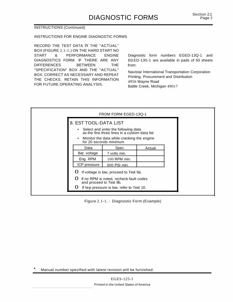
RECORD THE TEST DATA IN THE "ACTUAL"BOX (FIGURE 2.1-1.) ON THE HARD START NOSTART & PERFORMANCE ENGINEDIAGNOSTICS FORM. IF THERE ARE ANYDIFFERENCES BETWEEN THE"SPECIFICATION" BOX AND THE "ACTUAL"BOX, CORRECT AS NECESSARY AND REPEATTHE CHECKS. RETAIN THIS INFORMATIONFOR FUTURE OPERATING ANALYSIS.
Diagnostic form numbers EGED-13Q-1 andEGED-135-1 are available in pads of 50 sheetsfrom:
Navistar International Transportation CorporationPrinting, Procurement and Distribution4956 Wayne RoadBattle Creek, Michigan 49017
FROM FORM EGED-13Q-1
8. EST TOOL-DATA LIST• Select and enter the following data
as the first three lines in a custom data list
• Monitor the data while cranking the enginefor 20 seconds minimum
Data Spec. ActualBat. voltage 7 volts min.
Eng. RPM 100 RPM min.
ICP pressure 800 PSI min.
o If voltage is low, proceed to Test 9a.
o If no RPM is noted, recheck fault codesand proceed to Test 9b.
o If lep pressure is low, refer to Test 10.
Figure 2.1-1. - Diagnostic Form (Example)
at - Manual number specified with latest revision will be furnished.
EGES-125-1
Printed In the United States of America

HARD START/NO START DIAGNOSTICSINTRODUCTION
Section 2.2Page 1
The following pages have supporting information and instructions for the combined Hard Start/No Start andPerformance diagnostic form. Each section has detailed instructions on how to perform each test and howto use any specialized equipment.
EGES-125-1Printed In the United States of America
'tiC/)
!Il»CD
CC10CD::::!:NO~
N
;!j..)
JJ J:-tZ >~ :IJ~ C:xJ-t (J)AD i!'tIm:xJ :IJ."0 ::::!JJ3: ZJ>z 0nm (J)ci> i!"z0 :IJC/) -I-t(=; C'TI0 -JJ >3: G)m
" Zmc 0I.... (J)
Co)
? -I.... -- 0'TIJJ (J)0Z-trJ)
6.!!!
.......,
C II rtfttcttOl'lis 1Wgi'I. e:tllICkloft*lci&a;.bftWMn~ and fuel ......
C f ' ~l'lII'iI'inapee;.• ~lot"sIdr..~re~"""'Cltdlbril.
NOn:T"MOWid ..~arw...1Mft.....n nan lilNltf ......- ~tn9ft~al~_loreoMCOl'ldl"
• ""cMor K:P ptMIlJte "fI1h EST 01IIII NS! Of
• Mt&l\ltl a' tw..-olJt DOll~ 27... 46or twMAou1lEE- arM" &tid blaet-
Ob.TRANSFER PUMPRESTAlCT10N
REFER TO f'GUR! )I OfrilllllYVaSE SlOE
1. BOOST PRESSURE"EFER TO AGUlltr N OM ftEV!RSE.-of
- MonIttJrtloOtStpr.....".and~RMrI
wmfleEST1DOIItlCSMa •• !'fIOdtOr lIN dutl ad'I 8t'd~ PSI II. ard T .
IIESTD:;IliJnctI:.~
• Mlral;l.Q ptUlloQ at hA atl la., 1pMO.• Rtt.rpEG~S-l2S-'for~
I PS1~"" I '-' I-_ ...-.._----_-..._-
ro.Oll bU;j,np RUNNI~' r. T~~l ",,,,,':>E' j)!" ' o''''('CI ' ",I ,., 0 ClM IVll lin vCM"'O lh tr'J[CIOP Tr ':> T
c ,,~,. _Iv_.~p&ew"'" Met,.ftd,.....
o "".-.....,.Iow.,..to"'" 'TMt 1"
'1lfEA TO AOUftE E ON "IVERSE SIDE:• V......Uy inspect.w~l~rnlor oa""oe
• Chadl: ll EBPdeV'lCoe.sc:lOM'l5latHlgf'lidl.DlNllout beM DIIU 4i. ItlO 46- Of "TEE'"Gr"" .. ana~ - {IflO~l
·,",eas!Jr'.l~idIa
~~
~I Io R...IIOEIec'l1onio: tM9~klrTn~..1.'l
1;0'.h) 1&1
'b. EST TOOL-lNJECTOR TEST(CYLINDER CO'>lTRIBUTlON)
lOa. FUEL PRESSURE (FUll LOADREFflit TO noU"E L OM REVEIllJE SIDE·104..S'''....II~lflftliodl. .....Iur. ple5SlI••11vlt Ie:-tI ~lto 5Q..o
N O lt;. fn'l''' ~ 0'1 T1'<;,1 m",~l tl f' p,"
100m('(l I""" II' :'I"'''' 'D q.l ... .)cc('~!!o to' ''l' 'njrr lor I:HJll l[Sl
CHECK ENGlNEOIL LEVEL• er..t:Iltor~INI.. cooa.nl)• Cof.., Gr.dUVi;=.....='Y~,- _
~ CMC~ IOIt.~UTy '.~aft"ax1el'll2elllUl'l"lllg
rafettol"'l , ..
4b. EST-lNJECTOR "BUZZ TEST'
2. SUFFICIENT-CLEAN FUEL"En" TO F1GURE • OM REVERSE SID[
• Chedl a t \II"'II /. dl"Ul sample 'rorrfuel fille l wtWI. erWIn;.~
I~ Cho<. I rFUEL PRESSURE HIGH 10LEREFER TO FlGUIlE L ON AEV£fIll1E SlOE
3. EST TOOL-FAULT COOES . .........., ",..."""""'"REF£:.. TO nGUAE F ON REVE..SE SlOE
• 1~IE~OIit:SeI't'lCeTOOI
~ Io 5" E10Cl0t'ie OaIoranc Iotm lOr calK
O. FUEL PUMP PRESSURE"EFtft TO F10URE L ON REVERSE SlOE
·~."ftiOUlU:lfDko
•~ 130RPU~"9Wl"CIIOI ZO Ha)l"ds
i i
0 ........... _ .'_ ...",....... 4L ESTTOOL-ENGINEOFFTESTS .~-•••••• _• .~--,_••••.- TO R_.' ""REV'••• SlOE 91. EST-ENGINE RUNNING TEST
1. GLOW PLUG SYSTEM • 5 ·Eng~ O!I T.1t" 0""Se4f T.s," "om lIJfF'EA TO FiGURE F ON AEVatS! !IfOERillY OpwnUon tllagnotllc test~u • s.Ied' ·engw. Rlft"llnl( llSi tmm N
PIER" TO F'lUlM( I ON RfV!R'$£ SIDE I~= I I dl.lgrmm:: MS1 melWl• ~.~'l'Oltr.......nDIhI~plu9Je~ I'"",~1
(_mww,l .,." 2 ..roM) 0 S.. EIK'troll'lC D'-QI'lOSl>e: form tor ccdIIs
• Tum~.yto"'ON"~ rnlt&SlJ'.·O...· btne
• Vanry....." 0l0W plug "'ON'" In'It U$If'l9 'l'OftrN•., 10 \IIInf'y gDII plugs .,. ' Ke''IUlg~ / ...q"ed "'911 ..'un,.. apeoh~ to,.,.
(Oepe/"idttl1 \ClO"I tnlIanl '~.lVre. Mn.ry '..oi l-ave&flCa/Utl.Ol)
k. IHJECTlON CONTROL PRESSURE.,.TO AClURE QOfiIftEVE.ME SlOE 11.
·CtI ~1"*'131)tprI'I)
• bl'M~bDcpiolw27.'4&-0I
tlfMIIItlUI1'..·..-f9""") .. ~{'WD)
~- --OYOM 11)4n....... 'tIl:*
D If 1 ¥Oll. lWiCt'oIdfoIl te'l"lll in rut/'YOlr
.ICP ,...,.~.....leotl-U5-' fDr.,..,.. ....._ _
""'''"'--.."Eng ~PU 1130 RPW mill
BaI.¥llnI~1 .,VoIts"*,
aAl*1OE:Jec:tnwt~tonn, .
'-'ICXlIdti.)1iII
iCP Prnsura' aoo "51 ""'".
EST TOOL - OATA UST• SIiIIct WId.",., 1N loIIoMnO cII~
liS"" ,"I ) irwu Itl • CU5lom cs.- IISI
• "'klnI!of N dMa __c~~.ngine
lor 20 -=onds """"""'\lrft
@] . I
o lIwtt1g8blow.p/'OClNOlOTKtJlo "no RPU is NMd. rKNctl: . ull aadat1nCI~1DT~tb
C If 'CP pnuula. low, "'" 10 agnori;~ £SES-,2S-1 klr • ..",..-n....u9lt lIlStI.
• sn BUTTON - FLASH COOESMFEII TO MUM CI OW IIIEYER1E..._...._--
IWItI:h"lwrtun"lgriIiDnllWlEhto.."OH'_.
VI~1
IMflOd I CI'\edl
FuM 0tI CooIaI'II E.-c:tri",'
NQlt t'lll,n<'O"fl'''' m<J'I.'llt.~r,
I{"mrn 1",>1 " I I'''d..-' to !fJ'" It'''t>~ !!o IVIi'll l"I'C t l\t l;IVZI TF ST
CHECK ENGINE OIL LEVEL"~R TO FfGURE • OM IUVI!ASE SID(
• CIwdI b lXlnMll1W1a ("-I,~l
• CorrldGt~ry• "'lMMcufs at Oil. COIl'eet levelo Chedl"v"l"1 r-."Y(lI r
~r;;':"":-::-CNd----'1
'. INTAKE/EXHAUST RESTRICTIOM:f'ER 10 AG1JIIIES ell E ON R£V[M£ aIDE·~.J'Nlet.I"dCJ\C'll
• 1n5ped.~ 511....• Iraclect alltlal.st beClt ptMSUrt OIP'fEl8I _I c_
1. SUFFICIENT CLEAN FUEL'UNIt TO f'CURE A ON IIIEVEIISE MJ£
• O':-.t ....CS).d,..,...",.IIOf'll~
~--e-. I2. VISUAL INSPECTION
•~ 'lr,ctat Ttst" !'rom "The' e,....,. Of!Tu tS:menu
@]..-----"a S.. Electrtnc Ooagl"lQSbC 1=0fITl1or todes
~II1II11111GU1
'liiYlS''''''••''''!!!I!!!!III., tIL ECM VOLTAGE5. ESTTOOL-FAULTCOOES .E/'IlIro""""E."" _
"in" TO~, ON AEVEM£ SlOE• .,..... E~S.MoIToclt • Ct-*whI.. crMIlri9"-....
• ......... wmOYOU
• a.-lrmIl_ptntn., 40-
• Select ·I~or1.... lrem I'Ie lNlJ"OlRlc IK1
~~ I ...- I .- I I @J I'. E5TTooL=ENGINE OFF TEST ~- """'r ~,,- D __'''''_''''''''''_' . .-,'......"T"( ......_.",,,nl
· s.a "Enlll,.. or ,.. 'tOm dlllIiI"'OI1lo; DYON 7 \IItIftf IAI'tty lNyl\Ot~ on. II '"9"'. IS II ,., rntI'\lJ
.."....... 57...... -- ~"".."."".IU~J 5. sn BlITT - LASH COOE 1HI""dili i1i"""!IdI.QP,","iid'¥iM I' WI' I ! I II F•• I I GlOW PkIg Openttgn M:FEIlITDP'MIUPIEGOIf"E'YUIE1mE @] I .~ ....._ ._.. __ .. _........ D "_....... _IO.CM_ ••FE.lOFlGURESJA•• ' •••"'llSfSlOE • _ .... _ ..__• •.....
l~~~~~~~~~~b~~~~~~~~~~~~C'-1·~ .. Jl QllowPl ~e<:'Of~M:1Qf'S ~"'-"~".~..-::h'lo.... FCM.II'lO , ,0 ...." .."'...... _.""""'..... b. ENGIHECRANKING RPM _~""'_ ..,G'" ""'I!!!!!!!!:! c ........-..,,""....__ •lb. EST-INJECTOR "SUZZTEST" REnltTOF1l3lU1EHONIII!V!ME" ".GP/W."teUr••'J.lArC.tor Y I ~!.~ I fWloodII4alNt
• Mi~'30RPU""~",,b
"""'-• ~Ilo.pr-.)kl 46-WI'tIn...••
'lJ~
:i"[:i";. m"c ":J mif C/)Q. Ien ...... NQl cr=-
....0->:I"5-Ql

FUEL PUll, PRESSURE I TIlANSFER PUMP REST1llCTION
WASTEGATE ACTUATOR
:J:>:ucen~~:u
-f »z0 ~Ui C~:u en-fJ20~."m~:u
." :::!0:u Z~
> 0z0 enmC
~i>C)z ~0 -Ien-fn C." -0 »:u~ C)m ZC)m 0If' en....Co) -I? -.... 0-:u enm>
jlenCDa.,,_.
1»01O~CDNCo)N
Fig. K
Fig. F
EXHAUSTRES~nON
IICIOEL D-2OO PRES5UR£ 1UT lOT
0000 ._-t 2 J .::-to __ mu._ 3
Fig. E
BOOST PRESSURE
Fig. C
./
.. ;;.:; ·~ ·. A . ,. -'-"" :'. . ~\f'" --
'-: ,~~·-··i-C':·c.. ·C .'
Ag.BFig. A
Fig. P ,.,.__":~ ....,- .'~--'~ fl..~~r-------'~<" if')j'-:- i'i~ ~:.fi\ l~~
·"~t\ ·~>U\ .'~ ?,li';'~ ~~~,-.:~~;~~ _ .'. I./~\ I~·J' :' .
~3~~~• Aet\llt.toIJl 1_ ... .-
~:r[:r~ mCD
C)C:J m[ en
I....en I\)
~ crIII ....2->3CD:::!.
~

~:~~n2.2 HARD START/NO START DIAGNOSTICST 444E ENGINESUFFICIENT CLEAN FUEL
FROM FORM EGED-13Q-1
1. SUFFICIENT CLEAN FUEL
• Check at tank(s), drain sample from
fuel filter while cranking engine.
Method Check
Visual
PURPOSE
To determine if the fuel system is getting sufficientclean fuel to start and operate the engine.
TEST PROCEDURE
1. Route a hose from the fuel drain tube (Figure2.2-1.) to a clear container and open the drain.
2. Crank the engine and observe the fuel flowinginto the container. Stop cranking the enginewhen the container is half full.
Fuel flow out of the drain tube should be a steadystream. Insufficient flow could indicate fuel supplyor fuel system problem.
3. Inspect fuel in container. It must be clean andfree of air, contaminants, water, icing or clouding. The fuel should be straw colored. Fueldyed red or blue indicates an off-highway fuel.
4. Check fuel odor for the presence of other fuelssuch as gasoline or kerosene.
If engine oil is present in the fuel, it may indicate aninjector "0" ring leak and subsequent loss of injection control pressure. If that is suspected, checktheinjection control pressure during engine cranking.Use the Electronic Service Tool (EST) or follow theprocedure outlined in Test 9C on the Hard Start/NoStart diagnostic form.
NOTE: SOME SEDIMENT AND WATER MAY BEPRESENT IN THE FUEL SAMPLE IF THE FUELFILTER HAS NOT BEEN SERVICED ORDRAINED FOR A PROLONGED PERIOD OFTIME. A SECOND SAMPLE MAY BE REQUIREDTO DETERMINE FUEL QUALITY.
LOW OR NO FUELPOSSIBLE CAUSES
• No fuel in tank.
• If equipped with an in line fuel valve, it could be
shut off.
• Fuel supply line from tank(s) could be broken or
crimped.
• Fuel could be waxed or jelled (most likely in cold
weather with #2 fuel), the pickup tube in tankcould be clogged or cracked. If there is excessive water in the tank, it could freeze preventingthe fuel from being drawn to the engine.
• If the vehicle is equipped with supplemental fil
ters or water separators, check for plugged filters or leakage that could allow the fuel systemto draw air.
• Cloudy fuel indicates that the fuel may not be a
suitable grade for cold temperatures. Excessive water or contaminants in the fuel may indicate that the tank and fuel system may need tobe flushed and cleaned.
TOOLS REQUIREDClear container approximately 1 quart.
EGES-125-1Printed in the United States of America

HARD START/NO START DIAGNOSTICS
T 444E ENGINESUFFICIENT CLEAN FUEL (Continued)
Figure 2.2-1. - Fuel Drain
EGES-125-1Printed in the United States of America
Section 2.2'Page 5

~:~~~n 2.2 HARD START/NO START DIAGNOSTICST 444E ENGINEVISUAL INSPECTION
FROM FORM EGED-13Q-1
2. VISUAL INSPECTION
Fuel Oil Coolant Electrical Air
Method Check
Visual
PURPOSE
Visual inspection to check the general condition ofthe engine and to look for obvious causes of hard orno start conditions.
TEST PROCEDURE
1. Inspect entire fuel system for leaks includingtank and lines. Inspect fuel lines for damage(kinks and bends).
2. Check high pressure oil lines and high pressurepump in engine "V" for major oil leaks.
3. Inspect entire cooling system, (coolant level inreservoir, hoses, water pump and radiator) forcoolant leaks. Check for residue which mayhave been caused from prior leakage.
4. Inspect engine wiring harness for correct routing and insure that no rubbing or chaffing hasoccurred. Inspect the in-line Deutsch 31 wayconnector on the engine. Check connections tosensors, relays, actuators and control modules.Inspect battery cable connections for corrosion.Check the fuses at the battery. All connections should be seated and in good condition,free from damage and corrosion.
POSSIBLE CAUSES
• Loose or leaking fuel supply lines could causefuel system to lose prime.
• Kinked or blocked fuel supply lines will createrestriction to fuel flow.
• Massive fuel or oil leaks may contribute to nostart conditions.
• Coolant leaks could indicate serious engineproblems.
• Electronic connectors may be damaged or notinstalled properly causing a no start condition.
NOTE: THE CAMSHAFT POSITION (CMP) SENSOR AND THE INJECTION PRESSURE REGUlATOR (IPR) VALVE ARE THE TWO MOST CRIT1cAl ELECTRONIC COMPONENTS TO INSPECT WHEN THE ENGINE FAILS TO START.
TOOLS REQUIRED
Inspection light
EGES-125-1Printed in the United States of America

HARD START/NO START DIAGNOSTICST 444E ENGINECHECK ENGINE OIL LEVEL
FROM FORM EGED-13O-1
3. CHECK ENGINE OIL LEVEL• Check for contaminants (fuel, coolant)• Correct gradelViscosity• Miles/Hours on oil, correct level• Check level in reservoir
Section 2.2Page 7
Method
Visual
PURPOSE
To determine if the crankcase and oil reservoir contain engine oil of sufficient quantity and quality to enable the injection control pressure system to function properly.
TEST PROCEDURE
1. Park vehicle on level ground. Check oil levelwith oil level gauge. If there is no oil or very littleoil in the crankcase the fuel injectors will not operate.
If the oil level on the gauge is over full, it is possiblethe engine was incorrectly serviced or fuel is dilutingthe oil and filling the crankcase. If a substantialamount of fuel is in the oil , it will have a fuel odor.
2. Inspect oil for color. A milky white oil indicatespossible coolant contamination and will have anethylene glycol odor.
3. Check service records for correct oil type andviscosity for the temperature (environment) thevehicle is operating in. Single weight or 15W 40oil is not recommended for cold ambient temperatures. Oil that has had extended drain intervals will have increased viscosity (becomethicker) and will make engine cranking more difficult and starting less reliable at temperaturesbelow freezing. Refer to the lube oil chart in theoperator's or service manual for the correct oilselection for temperature conditions.
4. The oil level in the oil reservoir should bechecked. Remove the inspection plug in top ofreservoir(Figure 2.2-2.> to check oil level. Normal oil level is within 1/2 inch below the top ofthe reservoir. (If the engine has not been operated for some time, oil in the reservoir may draininto the crankcase. The engine may start hardor start and not continue to run.) Filling the res-
Check
ervoir will allow the system to prime faster facilitating starting.
If the oil level in the reservoir becomes low while thevehicle is parked for a short period of time, it is dueto a leaking check valve in the high pressure pump.
If oil level in the reservoir drops while cranking theengine, it indicates that no oil is being pumped to thereservoir.
POSSIBLE CAUSES
• Oil level low - Oil leak, oil consumption, incorrect servicing.
• Oil level high -Incorrect servicing, fuel dilutionfrom lift pump or defective injector "0" rings.
• Oil Contamination with Coolant - Oil Cooler,head gasket, porosity, (accessories i.e. watercooled air compressors.)
• Low reservoir level- Engine built dry (not pressured lubed), prolonged period of not running,leaking check valve in high pressure pump.
TOOLS REQUIRED1/4" drive ratchet or breaker bar to remove inspection plug.
Figure 2.2-2. - Checking Oil Level in Reservoir
EGES-125-1
Printed in the United States of America

~::~~n 2.2 HARD START/NO START DIAGNOSTICST 444E ENGINEINTAKE/EXHAUST RESTRICTION
FROM FORM EGED-13Q-1
4. INTAKE/EXHAUST RESTRICTION• Inspect air filter and ducts
• Inspect exhaust system
• Inspect exhaust back pressure device
Method
Visual
PURPOSE
Visual inspection to determine if an intake or exhaust restriction is contributing to a no start or hardstart condition.
NOTE: A HIGH INTAKE OR EXHAUST RESTRICTION MAY CAUSE A CONSIDERABLE AMOUNTOF BLACK OR BLUE SMOKE WHEN STARTINGTHE ENGINE.
VISUALLY INSPECT:
1. Air cleaner inlet and ducting to assure that it isnot restricted or collapsed.
2. Air cleaner housing, filter element and gasketsfor proper installation.
3. Filter minder to assure intake restriction is below the "RED" markings. When the filter element reaches maximum allowable restriction,the yellow indicator reaches the top of windowand automatically locks in this position.
NOTE: REFER TO PERFORMANCE DIAGNOSTICS SECTION 2.3 FOR DETAILED AIR CLEANER RESTRICTION INFORMATION.
Check
4. Exhaust system for damaged or restrictedpipes.
5. Exhaust back pressure device bell crank (Ifequipped) (Figure 2.2-3.) during cranking andassure it is not closing. If the tang is positionedas shown in Figure 2.2-3., the exhaust (butterfly) valve is closed.
POSSIBLE CAUSES
• Snow, plastic bags or other foreign materialmay restrict air flow at the air cleaner inlet. Onengines recently repaired, rags or cap plugsmay have been inadvertently left in the intakesystem.
• The exhaust back pressure device may be closing during cranking or stuck closed.
• The tailpipe or muffler may have been damagedor collapsed.
TOOLS REQUIREDNone
Figure 2.2-3. - Exhaust Back Pressure Valve Closed
EGES-125-1
Printed In the United States of America
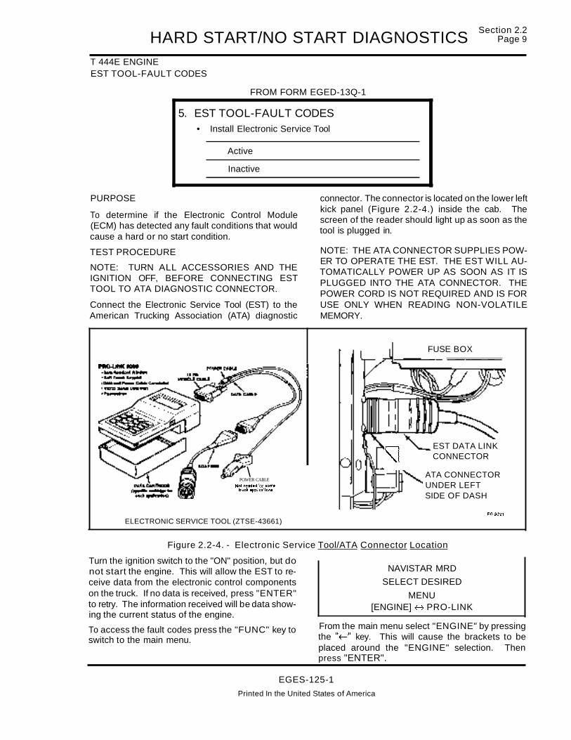
HARD START/NO START DIAGNOSTICST 444E ENGINEEST TOOL-FAULT CODES
FROM FORM EGED-13Q-1
5. EST TOOL-FAULT CODES• Install Electronic Service Tool
Active
Inactive
Section 2.2Page 9
PURPOSE
To determine if the Electronic Control Module(ECM) has detected any fault conditions that wouldcause a hard or no start condition.
TEST PROCEDURE
NOTE: TURN ALL ACCESSORIES AND THEIGNITION OFF, BEFORE CONNECTING ESTTOOL TO ATA DIAGNOSTIC CONNECTOR.
Connect the Electronic Service Tool (EST) to theAmerican Trucking Association (ATA) diagnostic
\POWER CABLE
Not nHdld 'or someIructc 8pPflcatlons
ELECTRONIC SERVICE TOOL (ZTSE-43661)
connector. The connector is located on the lower leftkick panel (Figure 2.2-4.) inside the cab. Thescreen of the reader should light up as soon as thetool is plugged in.
NOTE: THE ATA CONNECTOR SUPPLIES POWER TO OPERATE THE EST. THE EST WILL AUTOMATICALLY POWER UP AS SOON AS IT ISPLUGGED INTO THE ATA CONNECTOR. THEPOWER CORD IS NOT REQUIRED AND IS FORUSE ONLY WHEN READING NON-VOLATILEMEMORY.
FUSE BOX
~ '--EST DATA LINK"I CONNECTOR
ATA CONNECTORUNDER LEFTSIDE OF DASH
EG·3321
NAVISTAR MRD
SELECT DESIRED
MENU[ENGINE] H PRO-LINK
From the main menu select "ENGINE" by pressingthe "f-" key. This will cause the brackets to beplaced around the "ENGINE" selection. Thenpress "ENTER".
Figure 2.2-4. - Electronic Service Tool/ATA Connector Location
Turn the ignition switch to the "ON" position, but donot start the engine. This will allow the EST to receive data from the electronic control componentson the truck. If no data is received, press "ENTER"to retry. The information received will be data showing the current status of the engine.
To access the fault codes press the "FUNC" key toswitch to the main menu.
EGES-125-1
Printed In the United States of America

~:~:~~2.2 HARD START/NO START DIAGNOSTICST 444E ENGINEEST TOOL-FAULT CODES (Continued)
From the next menu select "DIAGNOSTICCODES". The selection will have the "I ~" symbolon the screen. This means there are other selections available. By pressing the ".J.." key the otherselections will display on the screen. Press"~" keyuntil "DIAGNOSTIC CODES" appears on thescreen.
The first option that will appear is "ACTIVECODES". By selecting this option, the fault codesthat are currently occurring or that have occurredsince the last key off cycle will be displayed.
NAVISTAR MRD
DIAGNOSTIC CODES
NAVISTAR MRD
ENGINE MENUt ACTIVE CODES
t DIAGNOSTIC CODES
Next press "ENTER". This causes the ESTto enterthe diagnostic codes section. From this point, diag...nostic codes can be accessed.
Press "ENTER". If there are any "Active Codes",the first one will appear on the screen along with adescription of the code. If there are any additionalcodes "Active" the "I.J.." symbol will appear on thescreen. Press" j,." key to access additional codes.If there are not any codes "Active", "NO ACTIVECODES" will appear on the screen.
MPSI PRO- LINK
I NAVISTAR DATA It
FUNCTION
~
Note: Refer to Sec. 5.2 for thecomplete Electronic Service ToolMenu Map.
PRO-LINK
EGES-125-1
Printed In the United States of America

HARD START/NO START DIAGNOSTICST 444E ENGINEEST TOOL-FAULT CODES (Continued)
Section 2.2Page 11
NOTE: ALLCURRENTFAULTCODESMUSTBEREPAIRED AND (CLEARED), BEFORE PRO-
To access "Inactive Codes" press the "FUNC" key.This will access the last prior menu selection. Thenpress the "J.." key to select "INACTIVE CODES".Press the "ENTER" key.
Inactive codes are faults that have occurred prior tothe last key off cycle and are now stored in memory.An "Active Code" will become an "Inactive" code ifthe key is shut off.
Record all fault codes that are found. If there areany fault codes found, refer to Electronic ControlSystem Diagnostics, Section 3.5.
t
NAVISTAR MRD
DIAGNOSTIC CODES
INACTIVE CODES
CEEDINGWITH FURTHER DIAGNOSTIC TESTING.
POSSIBLE CAUSES
Electronic Control Module (ECM) detectable faultswhich will cause a hard or no start condition are:
• Camshaft Position (CMP) sensor faults.
• Injection Pressure Regulator (IPR) output circuit check fault.
• Fuel Demand Command Signal (FDCS) andCylinder Identification (CI) output circuit checkfaults.
TOOLS REQUIREDPRO-LINK 9000 (ZTSE-43661)
SUPPLEMENTAL DIAGNOSTICSIf fault codes are set, refer to Electronic Diagnosticform EGED-135-1 and fault code diagnosis.
EGES-125-1
Printed in the United States of America

~:~:~~2.2 HARD START/NO START DIAGNOSTICST 444E ENGINEEST TOOL-ENGINE OFF TESTS
FROM FORM EGED-130-1
68. EST TOOL-ENGINE OFF TESTS• Select "Engine Off' test from diagnostic test menuI Faults
Found
o Repair fault codes before continuing
PURPOSE
To determine if there are any electrical malfunctionsthat can be detected by the Electronic Control Module (ECM) during an on demand self test.
TEST PROCEDURENOTE: ACCESS "DIAGNOSTIC CODES" MENUIN EST AND CLEAR ALL FAULT CODES BEFORE PERFORMING ENGINE OFF TESTS.
Access the "ENGINE OFF TESTS" in the "DIAGNOSTIC TESTS" section of the Electronic ServiceTool (EST).
Press the "FUNC" key repeatedly, until the mainmenu appears on the screen.
NAVISTAR MRD
SELECT DESIRED
MENU[ENGINE] H PRD-LINK
Move the brackets to engine selection by pressingthe "~" key, then press "ENTER"
Next select the "DIAGNOSTIC TESTS" menu bypressing the ".J.." key, until "DIAGNOSTIC TESTS"is shown on the screen. Press "ENTER" to makethis selection.
NAVISTAR MRD
ENGINE MENU
After the "ENTER" key is pressed, the EST willcommand the ECM to perform a [ (OCC) Output Circuit Check] self test. During this test, the ECM willtest the electrical continuity of the output circuits.
When the test is complete, the screen will displaythe number of faults found in the self test. If there areany additional faults found, press "ENTER" and thefaults will be displayed. If there is more than onefault that was found during the test, the "tj," symbolwill be shown on the screen. Press the".J.," key to access any additional faults.
NOTE 1: IF FAULT CODES WERE NOTCLEARED BEFORE RUNNING ENGINE OFFTESTS, ALL 10M FAULTS AND ASSOCIATEDCODES RECORDED DURING THE TEST WILLBE STORED AS "INACTIVE" CODES BY THEEST. TO READ THE CODES, ACCESS THE "INACTIVE" CODE MENU.
NOTE 2: THE PROGRAM IN THE EST WILLONLY ALLOW THE ENGINE OFF TESTS MENUTO BE ACCESSED ONCE. TO REPEAT ENGINEOFF TESTS, SELECT "STANDARD TEST" TORERUN THE ENGINE OFF TESTS.
POSSIBLE CAUSES
• Defective electrical components or circuitry.
• Injection Pressure Regulator (IPR) output circuit check fault.
DIAGNOSTIC TESTS
Press the ".J.," key, until the "ENGINE OFF TESTS"is shown on the screen. At this point, press "ENTER"
i
NAVISTAR MRDDIAGNOSTIC TESTS
ENGINE OFF TESTS
• Fuel Demand Command Signal (FOGS) andCylinder Identification (GI) output circuit checkfaults.
TOOLS REQUIREDPRO-LINK 9000 (ZTSE-43661)
SUPPLEMENTAL DIAGNOSTICS
If fault codes are set, refer to Electronic DiagnosticForm EGED-135-1 and fault code diagnosis.
EGES-125-1Printed in the United States of America

HARD START/NO START DIAGNOSTICST 444E ENGINEEST-INJECTOR "BUZZ TEST"
FROM FORM EGED-13Q-1
6b. EST-INJECTOR "BUZZ TEST"NOTE: "Engine Off Test" must beperformed first, in order to gain access tothe Injector "BUZZ TEST"
• Select "Injector Test" from "The Engine Off Tests" menu
I ~~~~~ I IC See Electronic Dia nostic Form for Codes
Section 2.2Page 13
PURPOSE
To determine if the injectors are electronically functioning correctly, by energizing each injector in aprogrammed sequence. The Electronic ControlModule (ECM) and Injector Drive Module (IDM) willmonitor th is test and transmit fault codes if any injector(s) or electrical circuitry are not functioning properly.
TEST PROCEDURE
NOTE 1: ACCESS "DIAGNOSTIC CODES"MENU IN EST AND CLEAR ALL FAULT CODES.
NOTE 2: ENGINE OFF TEST MUST BE PERFORMED FIRST IN ORDER TO ACCESS THE INJECTOR "BUZZ" TEST.
After the "Engine Off Test" has been completed,press the".!." key to access the "INJECTOR TEST".If the tool is not on a menu screen, Le. displaying offault codes etc., press the "FUNC" key. This will access the "DIAGNOSTIC TESTS" menu. Press"ENTER" to begin the test.
NAVISTAR MRD
DIAGNOSTIC TESTS
NOTE: IF FAULT CODES WERE CLEARED BEFORE THE INJECTOR "BUZZ" TEST, FAULTCODES DISPLAYED WILL BE ACTUAL FAULTSFOUND DURING THE TEST. IF CODES WERENOT CLEARED BEFORE TESTING, ACCESS"INACTIVE" FAULT CODES FROM DIAGNOSTICCODES MENU TO RETRIEVE FAULTS FOUNDDURING THIS TEST.
At the completion of the Injector Test, any faults thathave been detected will be displayed. If there ismore than one fault the "t.!." symbol will be displayed. These additional faults can be accessed bypressing the ".J.." key.
Record any faults found and refer to the ElectronicControl System Diagnostics, Section 3.5.
POSSIBLE CAUSES
• Bad wiring harness connection at injector sole
noid.
• Open or shorted engine wiring harness to injector(s).
• Defective injector solenoid(s).
• Defective IDM.
During this test, the injector solenoids will producean audible clicking sound when actuated. It is possible to detect a malfunctioning injector(s) by listening for the absence of the solenoid clicking sound.
t INJECTOR TESTTOOLS REQUIREDPRO-LINK 9000 (ZTSE-43661)
SUPPLEMENTAL DIAGNOSTICS
If fault codes are set, refer to Electronic DiagnosticForm EGED-135-1 and fault code diagnosis.
EGES-125-1
Printed In the United States of America

~=~~~2.2 HARD START/NO START DIAGNOSTICST 444E ENGINESTI-BUTTON FLASH CODES
FROM FORM EGED-13Q-1
7. STI-BUTTON FLASH CODES• Depress and hold "Engine Diagnostics" switch, then
turn the ignition switch to the "ON" position.
Refer to Electronic Diagnostic form,if fault code(s) set
PURPOSE
To read faults detected by the Electronic ControlModule (ECM), if the Electronic Service Tool (EST)is not available orthe EST cannot receive "Self TestInput" data due to communications or componentfailures.
The Self Test Input (STI) switch is located on the vehicle dashboard (Figure 2.2-5.) labeled "ENGINEDIAGNOSTICS". Depressing the STI switch on thedash while turning the ignition switch to the "ON"position, will signal the ECM to start the Self Test Input diagnostics to check output circuits. If any faultsare detected, the ECM will flash the "WARN EN...GINE" light to indicate which faults have been detected.
NOTE: SELF TEST INPUT DIAGNOSTICS WILLNOT FLASH VPM FAULT CODES.
TEST PROCEDURE
Depress and hold the STI switch (located on vehicledash). Turn the ignition switch to the "ON" position.Do Not Start The Engine. The ECM will begin toperform the self test to check the output circuits.
When the test is completed, the ECM will flash thered "OILlWATER" light and amber "WARN ENGINE" light to signal the fault codes.
NOTE: FAULT CODES CAN BE ACCESSED ATANYTIME BY TURNING THE IGNITION SWITCHTO THE "ON" POSITION (DO NOT START ENGINE) AND DEPRESSING THE STI SWITCH.
To read the fault codes it will be necessary to countthe number of times the "ENGINE WARN" lightflashes. The following sequence of events occureach time the STI switch is depressed to obtain thefault codes:
1. The "OILlWATER" light will flash one time to indicate the beginning of Active fault codes.
2. The "WARN ENGINE" light will flash repeatedly signaling the active fault codes.
NOTE: All FAULT CODES ARE THREE DIGITSAND CODE 111 INDICATES "NO FAULTS" HAVEBEEN DETECTED.
3. Count the number of flashes in sequence. Atthe end of each digit of the code there will be ashort pause. Three flashes and a pause wouldindicate the number 3. Therefore, two flashes,a pause, three flashes a pause, and two flashesa pause would indicate the code 232. If there ismore than one fault code, the "OILlWATER"light will flash once indicating the beginning ofanother active fault code.
After all the active codes have been flashed, the"OILlWATER" light will flash twice to indicate thebeginning of INACTIVE codes. Count the numberof flashes from the "WARN ENGINE" light. If thereis more than one inactive code, the "OILlWATER"light will flash once in-between each fault code.
After all codes have been sent, the "OILlWATER"light will flash three times indicating "END OF MESSAGE".
To repeat transmission of fault codes, depress the"ENGINE DIAGNOSTICS" switch which will signalthe ECM to resend all stored fault codes.
If fault codes are set, refer to Electronic DiagnosticForm EGED-135-1 and fault code diagnosis.
POSSIBLE CAUSES
• Electronic component or circuitry failures.
TOOLS REQUIREDNone.
EGES-125-1
Printed In the United States of America

HARD START/NO START DIAGNOSTICST 444E ENGINESTI BUTTON-FLASH CODES (Continued)
Section 2.2Page 15
o 1001
4)INTEIII1IONAL
ENGINE.DIAGNOSTICS
@STI~---
DIAGNOSTICSWITCH EG·3554
Figure 2.2-5. - Self Test Input (STI) Diagnostic Switch Location on Vehicle Dash
EGES-125-1Printed In the United States of America

~:~1~2.2 HARD START/NO START DIAGNOSTICST 444E ENGINEEST TOOL-DATA LIST
FROM FORM EGED-13Q-1
8. EST TOOL-DATA LIST• Select and enter the following data
as the first three lines in a custom data list• Monitor the data while cranking the engine
for 20 seconds minimum
Data Spec. Actual
Bat. voltage 7 volts min.
Eng. RPM 130 RPM min.
ICP pressure 800 PSI min.
o If voltage is low, proceed to Test 9a.
o If no RPM is noted, recheck fault codesand proceed to Test 9b.
o If ICP pressure is low, refer to diagnostic manualEGE~125-1 for system leakage tests
Continue to press the" J,." key until "INJ CNTL PSI" ison the third line. Then press the number "3" key tofreeze "INJ CNTL PSI" on line three.
This will "Freeze the "BATT VOLTS" on line one.Now press the".J," key until "ENGINE RPM" appears on the second line of the screen. Press thenumber "2" key to freeze "ENGINE RPM" on linetwo of the screen.
Press the "J,." key until "BAIT VOLTS" appears onthe screen. Continue to press the "-t" key until"SATT VOLTS", is at the top of the screen. Pressingthe number "1" key, a block dot will appear on line
number one.(I).
PURPOSETo determine if the components needed for startingare operating within specifications.
TEST PROCEDURE
IMPORTANT NOTETEST MUST BE PERFORMED WITH FULLYCHARGED BATTERIES.
To measure engine cranking speed, battery voltage, and Injection Control Pressure (ICP), it may bepossible to read the data on the Electronic ServiceTool (EST), "DATA LIST', while the engine is crank..ing. If the voltage drops below 7 volts while cranking, the EST tool will "RESET' back to start-up. Ifthis happens, the tool cannot be used to perform thistest. Refer to Test 9, "Testing Voltage, RPM andICP individually"
NOTE: TURN ALL ACCESSORIES AND THEIGNITION OFF, BEFORE CONNECTING ESTTOOL TO ATA DIAGNOSTIC CONNECTOR.
Connect the EST tool to the American TruckingAssociation (ATA) diagnostic connector. The connector is located on the lower left kick panel insidethe cab. The screen of the reader should light up assoon as the tool is plugged in.
Turn the ignition switch to the "ON" position. Do notstart the engine. This will allow the EST to receivedata from the electronic control components on thetruck. If no data is received press "ENTER" to retry.The information received will be data indicating thecurrent status of the engine.
RATED HP
RATED RPM
ACTIVE CODES
INACTIVE CODES
I BATIVOLTS
ENG. OIL TEMP
AMBIENT AIR
COOLANT TEMP
I BATTVOLTS
I ENGINE RPM
BOOST PSI
BARO IN Hg.
190
2300NO
NO
12.5
75 F
75 F75 F
12.5oo
14.4
EGES-125-1
Printed In the United States of America

HARD START/NO START DIAGNOSTICST 444E ENGINEEST TOOL-DATA LIST (Continued)
Section 2.2Page 17
I BATIVOLTS
I ENGINE RPM
I INJ CNTL PSI
FUELGAUHR
12.5
oo
0.3
• Blown 15A inline fuse (located in battery box)which supplies battery power (voltage) to ECM.
• Blown fuse F5 at ECM power relay control terminal86.
The EST is now ready to read the data needed.Crank the engine while observing the data on thescreen. If the EST recycles to the entry screen orshuts down, it will be necessary to measure the values separately. If this is required continue on tosteps 9A through 9C. Record the data on the diagnostic form.
The battery voltage must be 7 or more volts. If thevoltage to the Electronic Control Module (ECM)drops below 7 volts, the ECM will not remain powered up. If the ECM is not receiving power via theECM relay, the engine cannot be started.
Engine cranking RPM must be sufficient to generatethe required Injection Control Pressure to operatethe fuel injectors and to create enough compressionheat to ignite the fuel.
A "0" RPM indication on the Electronic Service Tool(EST) during engine cranking, indicates the ECMmay not be receiving a signal from the CamshaftPosition (CMP) sensor. Refer to CMP sensor diagnostics in Section 3.5 Electronic Control SystemDiagnostics.
If the CMP sensor is inoperative, it must be repairedbefore continuing. The ECM will not allow the Injector Pressure Regulator (IPR) valve to fully activatewithout a CMP signal.
If injection control pressure is low, remove the inspection plug in top of the oil reservoir and recheckthe oil level. (If the engine has not been operatedfor some time, the oil may have drained into thecrankcase.) If oil level is low, fill the reservoir. If theoil level in the reservoir continues to decline, the engine may not be pumping oil to the reservoir.
TEST MUST BE PERFORMED WITH FULLYCHARGED BATTERIES.
POSSIBLE CAUSES
• Low battery voltage. Due to "faulty" batteries,high resistance at battery cable connections orin the wiring to the ECM.
• Defective ECM power relay.
• Low cranking RPM. May be caused by electrical system malfunctions, incorrect oil or extended oil change intervals in cold ambient temperatures.
• No engine RPM indication on EST while cranking the engine. CMP sensor or faulty circuitry tothe ECM may cause this condition. Recheckforfault codes after cranking engine. (Refer to Test5 or 7).
• A defective high pressure oil pump or pumpdrive will prevent proper injection control pressure. A defective Injection Pressure Regulator(IPR), or electronic controls for the regulator willcause low injection control pressure.
TOOLS REQUIREDPRO-LINK 9000 (ZTSE-43661)
SUPPLEMENTAL DIAGNOSTICS
• Starting system diagnostics. Refer to Electricalsection CTS-511 0 of the Truck Service Manual.
• Low voltage at ECM. Refer to Electronic Control Module Power Supply (ECM PWR) in (Section 3.5) Electronic Control System Diagnostics.
• No Engine RPM indication during engine cranking. Refer to CMP sensor diagnostics in Electronic Control System Diagnostics Section 3.5.
• No Injection Control Pressure. Refer to Injection Control Pressure (ICP) sensor, IPR valvediagnostics in Electronic Control System Diagnostics Section 3.5.
• No injection control pressure and no electronicfaults. - Refer to Test 9C.
• If ICP pressure is low, refer to High PressureLeakage Tests on page NO TAG.
EGES-125-1
Printed in the United States of America

~:~~~~2.2 HARD START/NO START DIAGNOSTICST 444E ENGINEECM VOLTAGE
FROM FORM EGED-13Q-1
9a. ECM VOLTAGE• Check while cranking engine
• Measure with DVOM
• Breakout box pins 57+ &40-
Instrument Spec. Actual
DVOM 7 volts57+ & 40- minimum
D If voltage is low, refer to ECM diagnostics
PURPOSE
To determine if there is sufficient voltage and currentto operate the Electronic Control Module (ECM) andInjector Drive Module (IDM). The ECM and IDM require 7 volts minimum to operate and drive the injectors. This is an alternate method to be used if theElectronic Service Tool (EST) is unavailable or failsto function properly. Insufficient electrical powerfrom the batteries or an electronic failure may inhibitthe EST from receiving diagnostic data.
TEST PROCEDURE
TESTS MUST BE PERFORMED WITH FULLYCHARGED BATTERIES.
VOLTAGE MEASUREMENT AT BATTERY
1. Connect a DVOM (Digital Volt Ohm Meter)across the battery terminals.
2. Turn all accessories off and turn the ignitionswitch to the "ON" position.
3. Wait for the glow plug system to cycle, thencrank the engine.
Record the lowest voltage obtained during enginecranking .. If the voltage is below 7 volts, the 10M andECM power relays may be resetting due to the lackof voltage and current from the batteries or a problem exists in the starting system.
If voltage is within specification, perform VoltageMeasurement At The ECM Relay.
VOLTAGE MEASUREMENT AT THE ECMRELAY
The ECM power relay is located (Refer to Section7, Vehicle and Component Illustrations) on the
engine cowl and mounted on a bracket over theIDM.
1. Connect a DVOM (+ lead) to terminal 87{ wire97AR) of the ECM relay and the (-lead) to battery ground.
2. Turn all accessories off and turn the ignitionswitch to the "ON" position.
3. Wait for the glow plug system to cycle, thencrank the engine.
4. Observe and record voltage while engine iscranking.
If no voltage is present at terminal 87(wire 97AR),refer to Electronic Control Module Power Supply(ECM PWR) in (Section 3.5) Electronic Control System Diagnostics. If voltage is 7 or more volts, proceed with voltage check using the breakout box.
VOLTAGE MEASUREMENT AT ECMWITH BREAKOUT BOX (FIGURE 2.2-6.)
1. Remove the weather cover at the engine cowllocated on the upper driver's side of vehicle.
2. Remove the 60 way connector from the ECM.Attach the adapter of the breakout box to theECM and secure the bolt in the center of theadapter.
3. Reattach the 60 way connector to the adapterand secure the bolt in the center of the plug tothe adapter.
EGES-125-1
Printed in the United States of America

HARD START/NO START DIAGNOSTICST 444E ENGINEECM VOLTAGE (Continued)
VOLTAGE MEASUREMENT AT ECMWITH BREAKOUT BOX (Continued)
Section 2.2Page 19
BREAKOUT BOXCONNECTOR
€G·3S51
Figure 2.2-6. - Breakout Box (ZTSE-4346)
4. Connectthe positive lead ofthe voltmeterto terminal57 and the negative lead to terminal 40 onthe breakout box.
5. Turn the ignition switch to the "ON" position.Wait for the glow plug system to cycle, thencrank the engine. Record the lowest voltageobserved while cranking engine.
6. If voltage is lower than 7 volts, repair the ECMpower feed circuit. Refer to Electronic ControlModule Power Supply (ECM PWR) in (Section3.5) Electronic Control System Diagnostics.
POSSIBLE CAUSES
• Low battery voltage. Due to "faulty" batteries,
high resistance at battery cable connections ordefective starter.
• Low or no battery voltage to the ECM. - May be
due to high resistance or an open circuit in thepower feed circuit to the ECM or it's power relay.The ECM powercircuit fuse, F5, may be open orthe ECM power relay may be defective.
TOOLS REQUIREDDVOM and breakout box.
SUPPLEMENTAL DIAGNOSTICS
• Refer to Electronic Control Module Power Sup
ply (ECM PWR) in (Section 3.5) Electronic Control System Diagnostics.
EGES-125-1
Printed In the United States of America

~:~~~~2.2 HARD START/NO START DIAGNOSTICST 444E ENGINEENGINE CRANKING RPM
FROM FORM EGED-13Q-1
9b. ENGINE CRANKING RPM
• Minimum 130 RPM engine cranking speed for 20 seconds.
• Breakout box pins 34+ &46- with Fluke 88
Instrument Spec. Actual
Fluke 88 130 RPM34+ & 46- minimum
C If no RPM is noted, recheck fault codes
PURPOSE
To determine if engine cranking speed is highenough to start the engine. This is an alternatemethod to be used if the Electronic Service Tool(EST) is unavailable or fails to function properly. Insufficient electrical power from the batteries or anelectronic failure may inhibit the EST from receivingdiagnostic data.
TEST PROCEDURE
TEST MUST BE PERFORMED WITH FULLYCHARGED BATTERIES.
Engine cranking RPM must be sufficient to generatethe required Injection Control Pressure to operatethe fuel injectors and to create enough compressionheat to ignite the fuel.
A "0" RPM indication on the Electronic Service Tool(EST) during engine cranking, may indicate theECM is not receiving a signal from the CamshaftPosition (CMP) sensor. Refer to CMP sensor diagnostics, in Electronic Control System Diagnostics,Section 3.5.
If the CMP sensor is inoperative, it must be repairedbefore continuing. The ECM will not allow the Injector Pressure Regulator (IPR) valve to fully activatewithout a CMP signal.
CHECKING CRANKING RPMWITH BREAKOUT BOX
1. Remove the weather cover at the engine cowllocated on the upper driver's side of vehicle.
2. Remove the 60 way connector from the Electronic Control Module (ECM). Attach the adapter of the breakout box to the ECM and securethe bolt in the center of the adapter.
3. Reattach the 60 way connector to the adapterand secure the bolt in the center of the plug tothe adapter.
4. Connect the (+ lead) of the Fluke 88 to terminal34 and the (-lead) to terminal 46. Select the DCvoltage scale and press the "RPM" button.
5. Crank the engine while observing the Fluke 88.A minimum of 130 RPM is necessary to start theengine.
6. Record cranking engine RPM on diagnosticform.
NOTE: IF NO ENGINE RPM IS MEASURED WITHTHE FLUKE 88, CHECK FOR ADDITIONALFAULT CODES. REFER TO TESTS 5 & 7 ANDELECTRONIC CONTROL SYSTEM DIAGNOSTICS SECTION 3.5, FOR CAMSHAFT POSITION(CMP) SENSOR DIAGNOSTICS.
POSSIBLE CAUSES
• Low cranking RPM. Starting system electricalmalfunctions. Incorrect oil type or extended oilchange intervals in cold ambient temperatureconditions.
• No engine RPM. Poor connection at CMP sensor wiring harness connector, wiring harness tosensor open or shorted or CMP sensor is defective.
TOOLS REQUIREDFluke 88 DVOM (ZTSE-4357) and breakout box(ZTSE-4346).
SUPPLEMENTAL DIAGNOSTICS
• Refer to CMP sensor diagnostics, in ElectronicControl System Diagnostics, Section 3.5.
EGES-125-1
Printed in the United States of America

HARD START/NO START DIAGNOSTICST 444E ENGINEINJECTION CONTROL PRESSURE
FROM FORM EGED-13D-1
9c.INJECTION CONTROL PRESSURE• Check during engine cranking. (min. 130 RPM)
• Measure with w/breakout box pins 27+ and 46 - orbreakout "tee" signal (green) & ground (black)
Instrument Spec. Actual
DVOM 1 to 4
27+ & 46- volts
o If less than 1 volt, recheck oil level in reservoir.
If ICP pressure is low, refer to diagnosticmanual EGES-125-1 for system leakage tests.
Section 2.2Page 21
PURPOSE
To determine if the injection control pressure systemis supplying sufficient oil pressure to start and operate the engine. This is an alternate method to beused if the Electronic Service Tool (EST) is unavailable or fails to function properly. Insufficient electrical power from the batteries or an electronic failuremay inhibit the EST from receiving diagnostic data.
TEST PROCEDURE
MEASURING INJECTION CONTROL PRESSURE USING BREAKOUT BOX (FIGURE 2.2-7.)
1. Remove the weather cover at the engine cowllocated on the upper driver's side of vehicle.
2. Remove the 60 way connector from the ECM.
Attach the adapter of the breakout box to theECM and secure the bolt in the center of theadapter.
3. Reattach the 60 way connector to the adapterand secure the bolt in the center of the plug tothe adapter.
4. Connect the positive lead of the DVOM to terminal 27 and the negative lead to terminal 46.
5. Crank the engine while observing the DVOMand record the injection control pressure voltage signal on diagnostic fonn. If InjectionControl Pressure (ICP) pressure is low, referto High Pressure Leakage Tests.
Figure 2.2-7. - Breakout Box (ZTSE-4346)
EGES-125-1
Printed In the United States of America

~=~~2.2 HARD START/NO START DIAGNOSTICST 444E ENGINEINJECTION CONTROL PRESSURE - Continued
ALTERNATE METHOD OF MEASURING INJECTION CONTROL PRESSURE USING (BREAKOUT "TEE")
1. Remove engine harness connector at ICP sensor.
2. Connect the breakout "TEE" to the removedengine harness connector and the ICP sensor.
3. Connect DVOM leads (+Green, -Black) to the
breakout "TEE" as shown in Figure 2.2-8.
4. Crank engine and observe DVOM voltage reading. Record reading on diagnostic form. If voltage is low, recheck oil level in reservoir to confirm the reservoir contains a sufficient supply ofoil to enable the injection control system to function properly. Ifoil level is ok, proceed to HighPressure Leakage tests.
BLACKSIGNAL
GROUND/ / ~
BREAKOUT"TEE"
ZTSE-4347
Figure 2.2-8. - Injection Control Pressure.
EGES-125-1
Printed in the United States of America

HARD START/NO START DIAGNOSTICST 444E ENGINEHIGH PRESSURE LEAKAGE TESTS
Section 2.2Page 23
ISOLATE RIGHT CYLINDER HEAD ISOLATE LEFT CYLINDER HEAD
CAUTION THE ENGINE MAY START!
Remove high pressure hose from the right cylinderhead (Figure 2.2-9.). Use an Aero Equip size 6flare plug and install into the high pressure hose toblock it off. Crank the engine and monitor the Injection Control Pressure (ICP) signal.
If the engine fails to start, refer to procedure on Isolating Left Cylinder Head. If the engine starts or thercp pressure is now within specifications, the injection control pressure leak has been isolated to theright cylinder head.
1. Remove flare plug from the high pressure supply hose and reconnect hose to right cylinderhead.
2. Remove valve cover on right cylinder head.
3. Crank the engine and inspect the injector bodyand bore area for leakage. If no leakage is detected, perform ICP Leakage Test page 25.
A CAUTION!
Remove the plug (from previous step) in the rightcylinder head high pressure hose and reconnecthose to cylinder head. Remove the high pressurehose from the left cylinder head. Remove the ICPsensor and assemble it to the ICP adapter. Installthe ICP sensor/adapter onto the high pressure hose(Figure 2.2-1 O.). Crank the engine and monitor theICP signal.
NOTE: If the ICP pressure is not within specification proceed to IPR and High Pressure PumpTest page 24.
If the engine starts, or the ICP pressure is now withinspecifications, the injection control pressure leakhas been isolated to the left cylinder head. Reattachthe left side high pressure hose. Remove left valvecover and crank the engine. Inspect the injectorbody and bore area for oil leakage. If no leakage isdetected, perform ICP Leakage Test page 25.
OIL IS UNDER HIGH PRESSURE
RIGHT CYLINDER HEADHIGH PRESSURE LINE
PLUGGED
Figure 2.2-9. - Isolating Right Cylinder Head
GREEN-,CP BLACKRIGHT CYLINDER HEAD VOLTAGE SIGNALHIGH PRESSURE LINE SIGNAL GROUND
RECONNECTED
Figure 2.2-10. - Isolating Left Cylinder Head
EGES-125-1Printed In the UnIted States of America
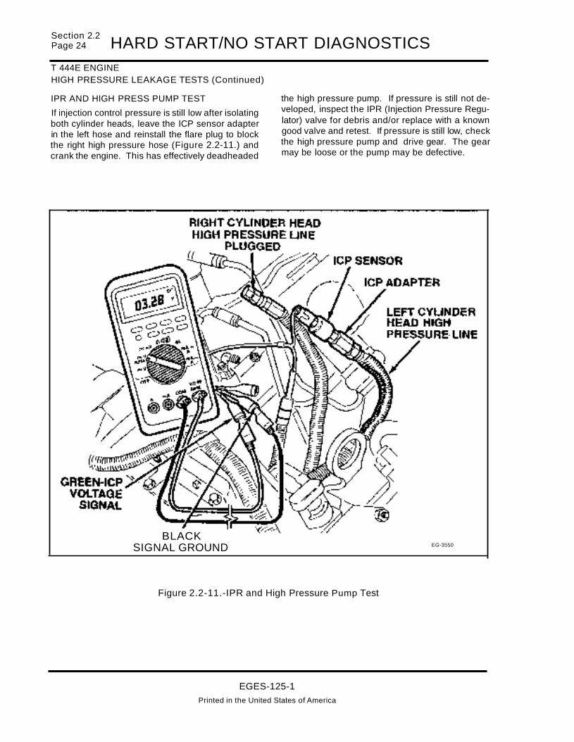
Section 2.2Page 24 HARD START/NO START DIAGNOSTICST 444E ENGINEHIGH PRESSURE LEAKAGE TESTS (Continued)
IPR AND HIGH PRESS PUMP TEST
If injection control pressure is still low after isolatingboth cylinder heads, leave the ICP sensor adapterin the left hose and reinstall the flare plug to blockthe right high pressure hose (Figure 2.2-11.) andcrank the engine. This has effectively deadheaded
BLACKSIGNAL GROUND
the high pressure pump. If pressure is still not developed, inspect the IPR (Injection Pressure Regulator) valve for debris and/or replace with a knowngood valve and retest. If pressure is still low, checkthe high pressure pump and drive gear. The gearmay be loose or the pump may be defective.
EG-3550
Figure 2.2-11.-IPR and High Pressure Pump Test
EGES-125-1Printed in the United States of America

HARD START/NO START DIAGNOSTICST 444E ENGINEICP LEAKAGE TEST
Section 2.2Page 25
1. Reconnect all high pressure oil lines disconnected in the process of isolating the cylinderhead which is causing a loss of ICP pressure.
2. Remove the high pressure supply line of thesuspect leaking cylinder head at the high pressure pump Figure 2.2-12..
3. Connect a regulated air supply Figure 2.2-13.to the high pressure supply oil line removed inthe previous step.
4. Apply 100 psi of pressure from the regulated airsource and inspect for leakage around the injectors.
5. With the fuel lines removed from the fuel regula..tor block, inspect for oil leakage out of each ofthe disconnected fuel lines. If oil is seeping outof the disconnected fuel lines remove all injectors in the cylinder head being tested and inspect injectors for worn "0" rings or obviousdamage.
If leakage is observed at an injector, remove and inspect injector for obvious damage or worn "O"rings.
If no leakage is present, perform Injector "Buzz" testwith air pressure still applied. Observe oil dischargefrom each of the injectors. Oil discharge should beequal from all injectors. If excess oil is discharged..from an injector(s), the injector(s) may be defective.
If it is difficult to determine which injector(s) are leaking remove air supply and regulator from the highpressure oil supply hose and:
A. Connect an automotive cylinder leak tester to the high pressure supply hose andapply air pressure via the cylinder leak tester.
B. Conduct an Injector "Buzz" test and observe the percent cylinder leakage whileeach injector is activated. Remove and inspect injectors which exhibit a greateramount of leakage compared to the others.
C. If none of the injectors indicate an excessive amount of leakage, remove all injectors. Inspect all "0" rings for wear and dam..age. All "0" rings should be replaced.
If oil was entering the fuel system, drain fuel tanksand dispose of the contaminated fuel properly.
~~ HIGH PRESSURE PUMP
OIL OUTLET/:? (LEFT BANK)~-....;
~)) r~-==---=:::--=:'-":=::-
EG·3736
Figure 2.2-12. - High Pressure Pump Oil Outlet Locations
EGES-125-1Printed In the United States of America

~=:~~2.2 HARD START/NO START DIAGNOSTICST 444E ENGINEICP LEAKAGE TEST (Continued)
Figure 2.2-13. -ICP Leakage Test
POSSIBLE CAUSES:Low injection pressure (voltage) indicates the injec..tors are not receiving sufficient oil pressure to prop"erly operate the fuel injectors. This may be causedby:
• No oil in engine.
• Oil reservoir leak down (possibly through highpressure pump check valve.
• Defective high pressure pump
• Injector "0" ring leak.
., Injector body leak.
• IPR valve stuck open.
• Pump drive gear loose or damaged.
TOOLS REQUIRED:DVOM, ICP sensor breakout "T' (ZTSE-4347), repadapter and an Aero Equip size 6 flare plug.
SUPPLEMENTAL DIAGNOSTICS
• Camshaft Position (CMP) sensor diagnostics,in Electronic Control System Diagnostics, Section 3.5.
EGES-125-1
Printed In the United States of America

HARD START/NO START DIAGNOSTICST 444E ENGINEFUEL PUMP PRESSURE
FROM FORM EGED-13O-1
10. FUEL PUMP PRESSURE
• Measure at regulator block
• Minimum 130 RPM cranking speed for 20 seconds
Instrument Spec. Actual
0-160 PSI 20 PSIGauge minimum
o If pressure is low, replace fuel filter and retest.
Section 2.2Page 27
PURPOSETo determine if fuel pressure is sufficient to start andoperate the engine.
NOTE: IF THE FUEL FILTER IS EQUIPPED WITHA WATER-IN-FUEL PROBE, CHECK WITH VEHICLE OPERATOR TO DETERMINE IF THE WATER-IN- FUEL LAMP HAS BEEN ILLUMINATEDDURING VEHICLE OPERATION.
TEST PROCEDURE
1. Remove 1/8" pipe plug located on the fuel regulator block (Figure 2.2-14.). Install 1/8 inch (3mm) pipe fitting in place of the pipe plug.
EQ.3311
2. Connect a line from the fitting to the 0-160 PSIgauge of the Model D-200 Pressure Test Kit.
3. Measure fuel pressure by cranking engine for20 seconds and observing maximum pressure.Record pressure on diagnostic form andcompare to specifications. If fuel pressure islow, change the fuel filter and retest.
NOTE: IT MAY TAKE A NUMBER OF CRANKCYCLES TO PURGE THE AIR OUT OF THE FUELSYSTEM.
Figure 2.2-14. - Fuel Transfer Pump Pressure Check
EGES-125-1Printed In the United States of America

~:~~~2.2 HARD START/NO START DIAGNOSTICST 444E ENGINEFUEL PUMP PRESSURE (Continued)
POSSIBLE CAUSES
• A fuel filter could cause high restriction and low
fuel pressure because of dirt or fuel jelling incold ambient temperatures. Change filter andretest.
• A kinked or severely bent fuel supply line or
blockage at the pickup tube could cause restriction and therefore low fuel pressure.
• A loose fuel line on the suction side of the fuel
system could cause air to be ingested into thesystem and cause low fuel pressure.
• The fuel pump could have internal damage, e.g.
ruptured diaphragm, seized plunger or leakingcheck valves.
TOOLS REQUIRED
Model D-200 Pressure Test Kit (ZTSE-2239) (0 to160 PSI fuel pressure gauge), appropriate line with1/8" NPT fitting.
EGES-125-1
Printed in the United States of America

HARD START/NO START DIAGNOSTICST 444E ENGINEGLOW PLUG SYSTEM
FROM FORM EGED-13Q-1
11. GLOW PLUG SYSTEMRelay Operation
• Install a voltmeter to the glow plug feedterminal (terminal w/2 wires)
• Turn key to "ON" position, measure "ON" time.
• Verify sufficient glow plug "ON" time using voltmeterto verify glow plugs are receiving the required voltagewithin the specified time.
(Degendent upon coolant temperature, battery voltagean altitude)
Spec. ActualRelay On
10 -120Timeseconds
Voltage 9 -12 Volts
(Relay may not cycle on, if engine isat operating temperature)
GLOW PLUG OPERATION
• Remove all glow plug/injector connectors.
• Measure glow plug resistance to Bat. Grd.
• Measure GP harness resistance to relay.
Plug to Harnessto
Glow Plug Ground RelayNumber .1 to 6 Ohms < 1 Ohm
#1
#3
#5
#7
#2
#4
#6
#8
Section 2.2Page 29
PURPOSE
To determine if the glow plug system is operatingsufficiently to start a cold engine.
TEST PROCEDURE:GLOW PLUG "ON" TIME
Connect a DVOM (Figure 2.2-15.) to the glow plugfeed terminal (terminal with 2 wires) on the glowplug relay. The DVOM will verify that the glow plugs
are receiving the required voltage (9-12v) for thespecified amount of time. Turn the ignition key to the"ON" position. DO NOT ATTEMPT TO START ENGINE. Note the time in seconds from when the ignition key is turned "ON" until the glow plug relay de-engergizes (0 volts indication on the DVOM).
NOTE: GLOW PLUG "ON" TIME WILL BE AFFECTED BY ENGINE COOLANT TEMPERATURE, BATTERY CONDITION AND VEHICLE ALTITUDE.
EGES-125-1
Printed In the United States of America

~:~:~2.2 HARD START/NO START DIAGNOSTICST 444E ENGINEGLOW PLUG SYSTEM (Continued)
Figure 2.2-15. - Measuring Glow Plug/Relay "ON" Time
If no voltage is present, check for voltage at the other large terminal of the glow plug relay. If no voltagepresent, refer to glow plug system diagnostics inElectronic Control System Diagnostics, Section 3.5.
POSSIBLE CAUSES
Insufficient glow plug on time will not allow enoughheat to accumulate in the combustion chamber toeasily facilitate starting. If the glow plug system"ON" time does not meet specifications the problemmay be:
• Faulty wire harness connection.
• Poor ground connection.
• Defective glow plug relay.
• ECM in default
• ECM defective.
EGES-125-1
Printed In the United States of America

HARD START/NO START DIAGNOSTICST 444E ENGINEGLOW PLUG SYSTEM (Continued)
Section 2.2Page 31
TEST PROCEDURE:
GLOW PLUG RESISTANCE TO GRD. (BATTERY (-) TERMINAL)
Disconnect the (4) glow plug/injector harness connectors from the valve cover gasket (harness).
NOTE: INCORRECT MEASUREMENTS WILLRESULT, IF ALL GLOW PLUG/INJECTOR HARNESS CONNECTORS ARE NOT DISCONNECTED.
Connect pigtail tool to each valve cover harnessconnector (Figure 2.2-16.) to measure glow plugresistance to (ground) battery negative terminal.Record resistance measurements on diagnosticform. A resistance measurement of .1 to 6 ohms indicates a good glow plug.
GLOW PLUGTEST POINTS
~~ GLOWPLUGI
~-tI--
INJECTORBREAKOUTTOOL(ZTSE-4345)
EG·3542
Figure 2.2-16. - Measuring Glow Plug Resistance to Gnd.
If the glow plug resistance to ground is high the mostlikely causes are:
• Open UVC (under valve cover) harness.
• Open glow plug.
EGES-125-1
Printed In the United States of America

~:~~~~2.2 HARD START/NO START DIAGNOSTICST 444E ENGINEGLOW PLUG SYSTEM (Continued)
TEST PROCEDURE:GLOW PLUG HARNESS RESISTANCE TORELAYMeasure resistance from the engine harness connector to the glow plug feed terminal (Figure2.2-17.) on the glow plug relay.
NOTE: INCORRECT MEASUREMENTS WILLRESULT, IF ALL GLOW PLUG/INJECTOR HARNESS CONNECTORS ARE NOT DISCONNECTED.
TOOLS REQUIRED
DVOM, Glow Plug/Injector Breakout Tool(ZTSE-4345) and Stop Watch or equivalent.
Figure 2.2-17. - Measuring Glow Plug Harness Resistance to Relay
EGES-125-1Printed in the United States of America
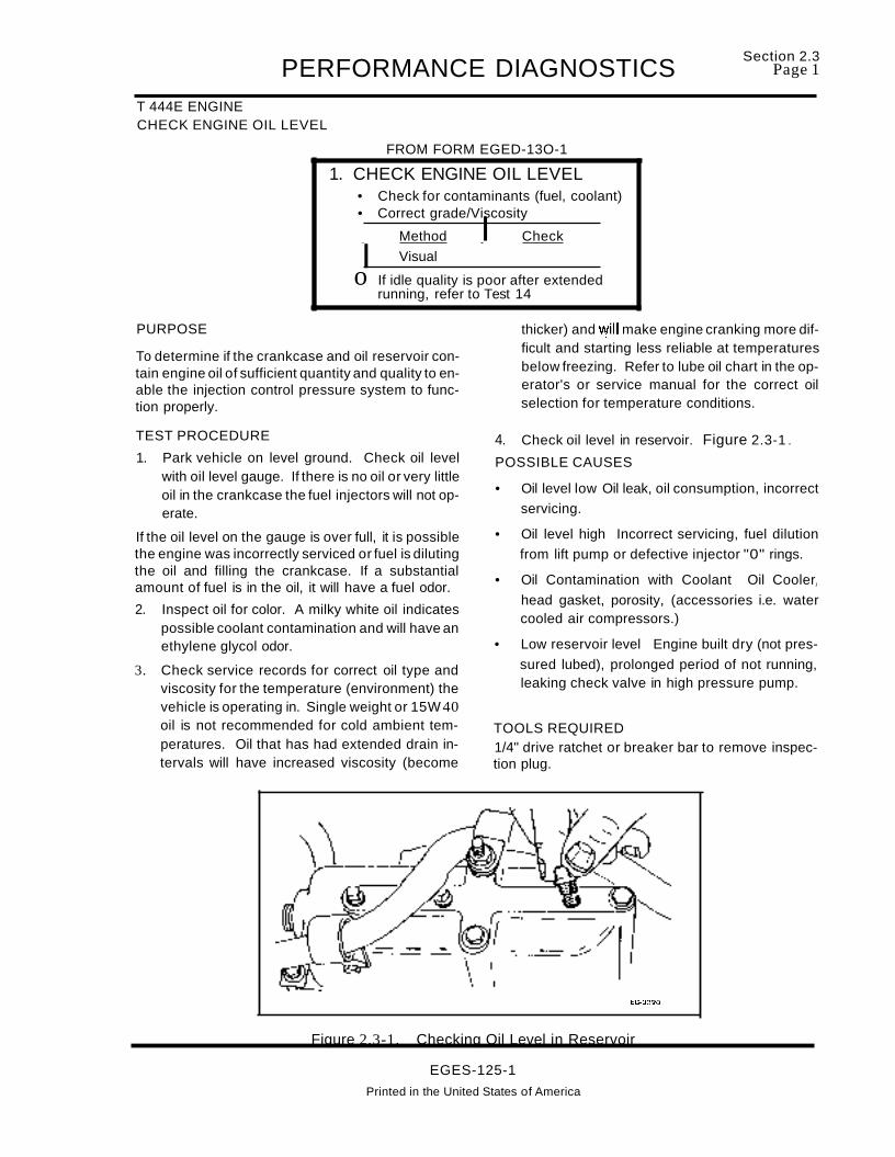
PERFORMANCE DIAGNOSTICST 444E ENGINECHECK ENGINE OIL LEVEL
FROM FORM EGED-13O-1
1. CHECK ENGINE OIL LEVEL• Check for contaminants (fuel, coolant)• Correct grade/Viscosity
IMethod I Check
Visual
o If idle quality is poor after extendedrunning, refer to Test 14
Section 2.3Page 1
PURPOSE
To determine if the crankcase and oil reservoir contain engine oil of sufficient quantity and quality to enable the injection control pressure system to function properly.
TEST PROCEDURE
1. Park vehicle on level ground. Check oil levelwith oil level gauge. If there is no oil or very littleoil in the crankcase the fuel injectors will not operate.
If the oil level on the gauge is over full, it is possiblethe engine was incorrectly serviced or fuel is dilutingthe oil and filling the crankcase. If a substantialamount of fuel is in the oil, it will have a fuel odor.
2. Inspect oil for color. A milky white oil indicatespossible coolant contamination and will have anethylene glycol odor.
3. Check service records for correct oil type andviscosity for the temperature (environment) thevehicle is operating in. Single weight or 15W 40oil is not recommended for cold ambient temperatures. Oil that has had extended drain intervals will have increased viscosity (become
thicker) and "'(ill make engine cranking more difficult and starting less reliable at temperaturesbelow freezing. Refer to lube oil chart in the operator's or service manual for the correct oilselection for temperature conditions.
4. Check oil level in reservoir. Figure 2.3-1 ..
POSSIBLE CAUSES
• Oil level low Oil leak, oil consumption, incorrect
servicing.
• Oil level high Incorrect servicing, fuel dilution
from lift pump or defective injector "0" rings.
• Oil Contamination with Coolant Oil CoolerJ
head gasket, porosity, (accessories i.e. watercooled air compressors.)
• Low reservoir level Engine built dry (not pres
sured lubed), prolonged period of not running,leaking check valve in high pressure pump.
TOOLS REQUIRED1/4" drive ratchet or breaker bar to remove inspection plug.
EG-3320
Figure 2.3-1. Checking Oil Level in Reservoir
EGES-125-1
Printed in the United States of America

Section 2.3Page 2 PERFORMANCE DIAGNOSTICST 444E ENGINESUFFICIENT CLEAN FUEL
FROM FORM EGED-13O-1
2. SUFFICIENT CLEAN FUEL• Check at tank(s), drain sample from
fuel filter while cranking engine.
Method Check
Visual
PURPOSE
To determine if the fuel system is getting sufficientclean fuel to start and operate the engine.
TEST PROCEDURE
1. Route a hose from the fuel drain tube (Figure2.3-2.) to a clear container and open the drain.
2. Crank the engine and observe the fuel flowinginto the container. Stop cranking the enginewhen the container is half full.
Fuel flow out of the drain tube should be a steadystream. Insufficient flow could indicate fuel supplyor fuel system problem.
3. Inspect fuel in container. It must be clean andfree of air, contaminants, water, icing or clouding. The fuel should be straw colored. Fueldyed red or blue indicates an off highway fuel.
4. Check fuel odor for the presence of other fuelssuch as gasoline or kerosene.
If engine oil is present in the fuel, it may indicate aninjector "0" ring leak and subsequent loss of injection control pressure. If that is suspected, check injection control pressure during engine cranking.Use the Electronic Service Tool (EST) or follow procedure outlined in Test 9C.
NOTE: SOME SEDIMENT AND WATER MAY BEPRESENT IN THE FUEL SAMPLE IF THE FUELFILTER HAS NOT BEEN SERVICED ORDRAINED FOR A PROLONGED PERIOD OFTIME. A SECOND SAMPLE MAY BE REQUIREDTO DETERMINE FUEL QUALITY.
LOW OR NO FUELPOSSIBLE CAUSES
• No fuel in tank.
• If equipped with a inline fuel valve, it could beshut off.
• Fuel supply line from tank(s) could be broken orcrimped.
• Fuel could be waxed or jelled (most likely in cold
weather with #2 fuel), the pickup tube in tankcould be clogged or cracked. If there is excessive water in the tank, it could freeze preventingthe fuel from being drawn to the engine.
If the vehicle is equipped with supplemental filtersor water separators, check for plugged filters orleakage that could allow the engine to draw air.
Cloudy fuel indicates that the fuel may not be a suitable grade for cold temperatures. Excessive wateror contaminants in fuel may indicate that the tankand fuel system may need to be flushed andcleaned.
TOOLS REQUIREDClear container approximately 1 quart.
EGES-125-1
Printed in the United States of America

PERFORMANCE DIAGNOSTICST 444E ENGINESUFFICIENT CLEAN FUEL (Continued)
Figure 2.3-2. - Fuel Drain
EGES-125-1Printed In the United States of America
Section 2.3Page 3

Section 2.3Page 4 PERFORMANCE DIAGNOSTICST 444E ENGINEEST-TOOL FAULT CODES
FROM FORM EGED-13O-1
3. EST-TOOL FAULT CODES• Install Electronic Service Tool
Active
Inactive
C See Electronic Diagnostic form for codes
PURPOSE
To determine if the Electronic Control Module(ECM) has detected any fault conditions that wouldcause an engine performance problem.
TEST PROCEDURE
NOTE: TURN ALL ACCESSORIES AND THEIGNITION OFF, BEFORE CONNECTING ESTTOOL TO ATA DIAGNOSTIC CONNECTOR.
Connect the Electronic Service Tool (EST) to theAmerican Trucking Association (ATA) diagnosticconnector. The connector is located on the lower leftkick panel (Figure 2.3-3.) inside the cab.
NOTE: THE ATA CONNECTOR SUPPLIES POWER TO OPERATE THE EST. THE EST WILL AUTOMATICALLY POWER UP AS SOON AS IT ISPLUGGED INTO THE ATA CONNECTOR. THEPOWER CORD IS NOT REQUIRED AND IS FORUSE ONLY WHEN READING NON-VOLATILEMEMORY.
Turn the ignition switch to the "ON" position, but donot start the engine. This will allow the EST to receive data from the electronic control componentson the truck. If no data is received, press "ENTER"to retry. The information received will be data showing the current status of the engine.
FUSE BOX
~ '--EST DATA LINK"'-., CONNECTOR
ATA CONNECTORUNDER LEFTSIDE OF DASH
EG-J32 I
ELECTRONIC SERVICE TOOL (ZTSE-43661)
Figure 2.3-3. - Electronic Service Tool - ATA Connector Location
EGES-125-1Printed In the United States of America

PERFORMANCE DIAGNOSTICS Section 2.3PageS
T 444E ENGINEEST TOOL-FAULT CODES (Continued)
To access the fault codes press the "FUNC" key toswitch to the main menu.
NAVISTAR MRD
SELECT DESIRED
MENU[ENGINE] H PRO-LINK
From the main menu select "ENGINE" by pressingthe "f-" key. This will cause the brackets to beplaced around the "ENGINE" selection. Then press"ENTER".
the diagnostic codes section. From this point, diagnostic codes can be accessed.
NAVISTAR MRD
ENGINE MENU
t DIAGNOSTIC CODES
The first option that will appear is "ACTIVECODES". By selecting this option, the fault codesthat have occurred during this key "ON" cycle will bedisplayed. Press "ENTER". If there are any"ActiveCodes", the first one will appear on the screen alongwith a description of the code. If there are any additional codes "Active" the"t..l." symbol will appear onthe screen. Press ".!." key to access additionalcodes. If there are not any codes "Active", "NO ACTIVE CODES" will appear on the screen.
From the next menu select "DIAGNOSTICCODES". The selection will have the "i~" symbolon the screen. This means there are other selections available. By pressing the "..l." key the otherselections will display on the screen. Press "..l." until"DIAGNOSTIC CODES" appears on the screen.Next press "ENTER". This causes the ESTto enter
i
NAVISTAR MRD
DIAGNOSTIC CODES
ACTIVE CODES
MPSI PRO- LINK
NAVISTAR DATA
tFUNCTION
+
EGES-125-1
Note: Refer to Sec. 5.2 p. 11 forthe complete Electronic ServiceTool Menu Map.
PRO-LINK
Printed in the United States of America

Section 2.3Page 6 PERFORMANCE DIAGNOSTICST 444E ENGINEEST TOOL-FAULT CODES (Continued)
To access "Inactive Codes" press the "FUNC" key.This will access the last prior selection. Then pressthe ".1." key to select "INACTIVE CODES" Pressthe "ENTER" key.
NAVISTAA MAD
DIAGNOSTIC CODES
Record all fault codes that are found. If there areany fault codes found, refer to "Electronic ControlSystem Diagnostics" section of the manual.
NOTE: ALL CURRENT FAULT CODES MUST BEREPAIRED (CLEARED), BEFORE PROCEEDINGWITH FURTHER DIAGNOSTIC TESTING.
POSSIBLE CAUSES
i INACTIVE CODES Electronic malfunctions which can be detected bythe ECM on a continuous monitor basis.
Inactive codes are faults that have occurred in thepast, and are now stored in memory. An "ActiveCode" will become an "Inactive" code if the key isshut off even if the malfunction no longer exists(such as an intermittent problem).
TOOLS REQUIREDPRO-LINK 9000 (ZTSE-43661)
SUPPLEMENTAL DIAGNOSTICSIf fault codes are set, refer to Electronic Diagnosticform EGED-135-1 and fault code diagnosis.
EGES-125-1
Printed In the United States of America
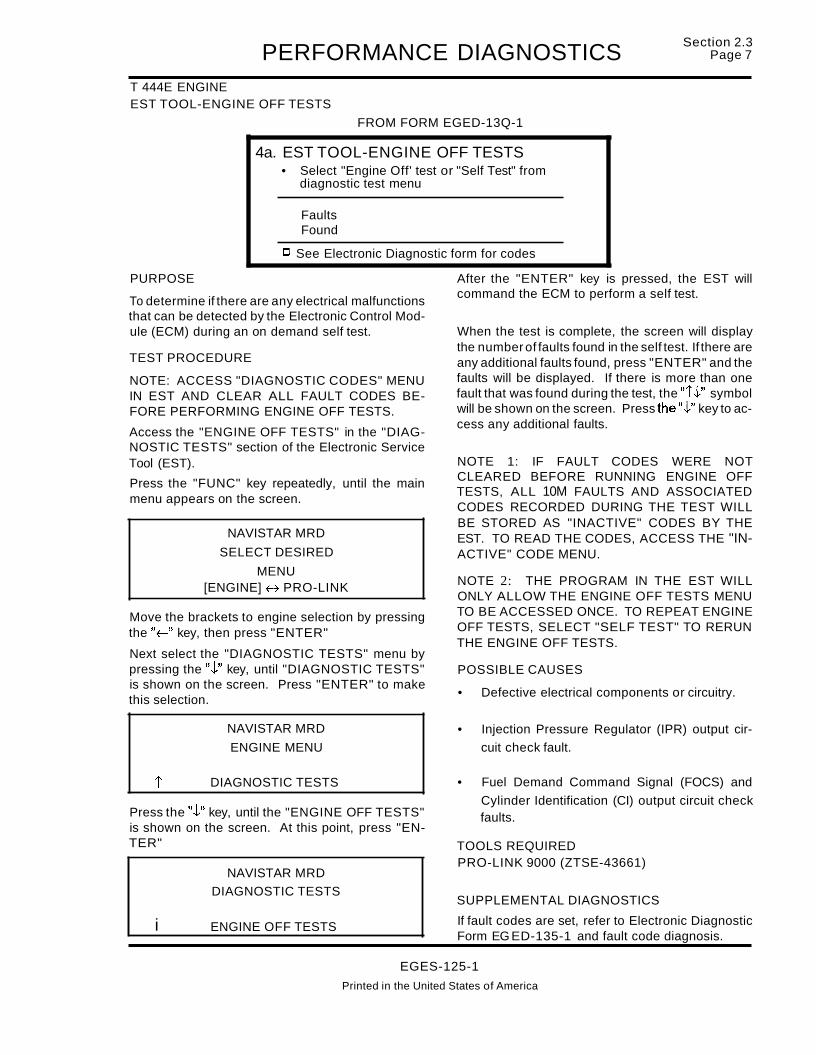
PERFORMANCE DIAGNOSTICST 444E ENGINEEST TOOL-ENGINE OFF TESTS
FROM FORM EGED-13Q-1
4a. EST TOOL-ENGINE OFF TESTS• Select "Engine Off' test or "Self Test" from
diagnostic test menu
FaultsFound
C See Electronic Diagnostic form for codes
Section 2.3Page 7
PURPOSE
To determine if there are any electrical malfunctionsthat can be detected by the Electronic Control Module (ECM) during an on demand self test.
TEST PROCEDURE
NOTE: ACCESS "DIAGNOSTIC CODES" MENUIN EST AND CLEAR ALL FAULT CODES BEFORE PERFORMING ENGINE OFF TESTS.
Access the "ENGINE OFF TESTS" in the "DIAGNOSTIC TESTS" section of the Electronic ServiceTool (EST).
Press the "FUNC" key repeatedly, until the mainmenu appears on the screen.
NAVISTAR MRD
SELECT DESIRED
MENU[ENGINE] H PRO-LINK
Move the brackets to engine selection by pressingthe "f-" key, then press "ENTER"
Next select the "DIAGNOSTIC TESTS" menu bypressing the ".t" key, until "DIAGNOSTIC TESTS"is shown on the screen. Press "ENTER" to makethis selection.
NAVISTAR MRD
ENGINE MENU
After the "ENTER" key is pressed, the EST willcommand the ECM to perform a self test.
When the test is complete, the screen will displaythe number of faults found in the self test. If there areany additional faults found, press "ENTER" and thefaults will be displayed. If there is more than onefault that was found during the test, the "i.t" symbolwill be shown on the screen. Press the".t" key to access any additional faults.
NOTE 1: IF FAULT CODES WERE NOTCLEARED BEFORE RUNNING ENGINE OFFTESTS, ALL 10M FAULTS AND ASSOCIATEDCODES RECORDED DURING THE TEST WILLBE STORED AS "INACTIVE" CODES BY THEEST. TO READ THE CODES, ACCESS THE "INACTIVE" CODE MENU.
NOTE 2: THE PROGRAM IN THE EST WILLONLY ALLOW THE ENGINE OFF TESTS MENUTO BE ACCESSED ONCE. TO REPEAT ENGINEOFF TESTS, SELECT "SELF TEST" TO RERUNTHE ENGINE OFF TESTS.
POSSIBLE CAUSES
• Defective electrical components or circuitry.
• Injection Pressure Regulator (IPR) output cir
cuit check fault.
Press the ".t" key, until the "ENGINE OFF TESTS"is shown on the screen. At this point, press "ENTER"
i
i
DIAGNOSTIC TESTS
NAVISTAR MRD
DIAGNOSTIC TESTS
ENGINE OFF TESTS
• Fuel Demand Command Signal (FOCS) and
Cylinder Identification (CI) output circuit checkfaults.
TOOLS REQUIREDPRO-LINK 9000 (ZTSE-43661)
SUPPLEMENTAL DIAGNOSTICS
If fault codes are set, refer to Electronic DiagnosticForm EG ED-135-1 and fault code diagnosis.
EGES-125-1
Printed in the United States of America

Section 2.3PageS PERFORMANCE DIAGNOSTICST 444E ENGINEEST-INJECTOR "BUZZ TEST"
FROM FORM EGED-13O-1
4b. EST-INJECTOR "BUZZ TEST"NOTE: Engine Off Test must be performedfirst in order to gain access to the Injector"Buzz Test"
• Select "Injector Test" from diagnostic test menu
I ~~~~~ IC See Electronic Diagnostic form for codes
PURPOSE
To determine if the injectors are electronically functioning correctly, by energizing each injector in aprogrammed sequence. The Electronic ControlModule (ECM) and Injector Drive Module (10M) willmonitor th is test and transmit fault codes if any injector(s) or electrical circuitry are not functioning properly.
TEST PROCEDURE
NOTE 1: ACCESS "DIAGNOSTIC CODES"MENU IN EST AND CLEAR ALL FAULT CODES.
NOTE 2: ENGINE OFF TEST MUST BE PERFORMED FIRST IN ORDER TO ACCESS THE INJECTOR "BUZZ" TEST.
After the "Engine Off Tests" have been completed,press the".t" key to access the "INJECTOR TEST".If the tool is not on a menu screen, Le. displaying offault codes etc., press the "FUNC" key. This will access the "DIAGNOSTIC TESTS" menu. Press"ENTER" to begin the test.
NAVISTAR MRD
DIAGNOSTIC TESTS
NOTE: IF FAULT CODES WERE CLEARED BEFORE THE INJECTOR "BUZZ" TEST, FAULTCODES DISPLAYED WILL BE ACTUAL FAULTSFOUND DURING THE TEST. IF CODES WERENOT CLEARED BEFORE TESTING, ACCESS"INACTIVE" FAULT CODES FROM EST MENUTO RETRIEVE FAULTS FOUND DURING THISTEST.
At the completion of the Injector Test, any faults thathave been detected will be displayed. If there ismore than one fault the "t.t" symbol will be displayed. These additional faults can be accessed bypressing the ".t" key.
Record any faults found and refer to the ElectronicControl System Diagnostics, Section 3.5.
POSSIBLE CAUSES
• Bad wiring harness connection at injector solenoid.
• Open or shorted engine wiring harness to injector(s).
• Defective injector solenoid(s).
• Defective IDM.
During this test, the injector solenoids will producean audible clicking sound when actuated. It is possible to detect a malfunctioning injector(s) by listening for the absence of the solenoid clicking sound.
t INJECTOR TESTTOOLS REQUIREDPRC-LINK 9000 (ZTSE-43661)
SUPPLEMENTAL DIAGNOSTICS
If fault codes are set, refer to Electronic DiagnosticForm EGED-135-1 and fault code diagnosis.
EGES-125-1

PERFORMANCE DIAGNOSTICST 444E ENGINESTI BUTTON-FLASH CODES
FROM FORM EGED-130-1
5. STI BUlTON-FLASH CODES• Depress and hold "Engine Diagnostics" switch, then
turn the ignition switch to the "ON" position.
Refer to Electronic Diagnostic formif fault code(s) set
Section 2.3Page 9
PURPOSE
To read faults detected by the Electronic ControlModule (ECM), if the Electronic Service Tool (EST)is not available or the EST cannot receive "Self TestInput" data due to communications or componentfailures.
The Self Test Input (STI) switch is located on the vehicle dashboard (Figure 2.3-4.) and is identified asthe "ENGINE DIAGNOSTICS" switch. Depressingthe STI switch on the vehicle dashboard while turningthe ignition switch to the "ON" position, will signalthe ECM to start the Self Test Input diagnostics tocheck output circuits. If any faults are detected, theECM will flash the "WARN ENGINE" light to indicatewhich faults have been detected.
NOTE: SELF TEST INPUT DIAGNOSTICS WILLNOT FLASH VPM FAULT CODES.TEST PROCEDURE
Depress and hold the STI switch (located on vehicledash). Turn the ignition switch to the "ON" position.Do Not Start The Engine. The ECM will begin toperform the self test to check the output circuits.
When the test is completed, the ECM will flash the"OILIWATER" and "WARN ENGINE" lights to signal the fault codes.
NOTE: FAULT CODES CAN BE ACCESSED ATANYTIME BY DEPRESSING AND HOLDING THESTI SWITCH WHILE TURNING THE IGNITIONSWITCH TO THE "ON" POSITION. (DO NOTSTART ENGINE.)
To read the fault codes it will be necessary to countthe number of times the "ENGINE WARN" lightflashes. The following sequence of events occureach time the STI switch is depressed to obtain thefault codes:
1. The "OILlWATER" light will flash onetimeto indicate the beginning of Active fault codes.
2. The "WARN ENGINE" light will flash repeatedly signaling the active fault codes.
NOTE: All FAULT CODES ARE THREE DIGITSAND CODE 111 INDICATES "NO FAULTS" HAVEBEEN DETECTED.
3. Count the number of flashes in sequence. Atthe end of each digit of the code there will be ashort pause. Three flashes and a pause wouldindicate the number 3. Therefore, two flashes,a pause, three flashes a pause, and two flashesa pause would indicate the code 232. If there ismore than one fault code, the "OILlWATER"light will flash once indicating the beginning ofanother active fault code.
After all the active codes have been flashed, the"OIUWATER" light will flash twice to indicate thebeginning of INACTIVE codes. Count the numberof flashes from the "WARN ENGINE" light. If thereis more than one inactive code, the "OILlWATER"light will flash once in-between each fault code.
After all codes have been sent, the "OIUWATER"light will flash three times indicating "END OF MESSAGE".
To repeat transmission of fault codes, depress the"ENGINE DIAGNOSTICS" switch which will signalthe ECM to resend all stored fault codes.
If fault codes are set, refer to Electronic DiagnosticForm EGED-135-1 and fault code diagnosis.
POSSIBLE CAUSES
• Electronic component or circuitry failures.
TOOLS REQUIREDNone.
EGES-125-1
Printed in the United States of America

Section 2.3Page 10 PERFORMANCE DIAGNOSTICST 444E ENGINESTI BUTTON-FLASH CODES (Continued)
o 100JL
ENGINE ..DIAGNOSTICS
QSTI~---
DIAGNOSTICSWITCH EG-3554
Figure 2.3-4. - Self Test Input (STI) Diagnostic Switch Location on Vehicle Dash
EGES-125-1Printed in the United States of America

PERFORMANCE DIAGNOSTICST 444E ENGINEINTAKE RESTRICTION
FROM FORM EGED-13Q-1
6. INTAKE RESTRICTION• Check filter minder if equipped
(If yellow band is latched @ 25"H20, replace filter)• Measure at High idle &no load
• Use manometer or magnehelic gaugeInstrument Spec. Actual
Filter Minder 25 " H20
Manometeror 12.5 " H20 Max..
MagnehelicGauQe
Section 2.3Page 11
PURPOSE
To determine if an intake/air cleaner restriction ex..ists. Often a low powerand poor fuel economy com..plaint is simply due to a dirty air cleaner element. Inthis test, the gauge is inserted in the air cleanerhousing. As the air cleaner element accumulatesdirt, restriction to airflow increases. If restriction exceeds specifications, replace the air cleaner ele..ment or elements.
NOTE: A HIGH INTAKE RESTRICTION MAYCAUSE A CONSIDERABLE AMOUNT OFBLACK OR BLUE SMOKE WHEN STARTINGTHE ENGINE.
INSPECT AIR INTAKERESTRICTION INDICATOR
1. Refer to appropriate "Operation and Mainte..nance Manual" "Air Cleaner Restriction Gaugeand Indicator", for detailed information.
NOTE: THE AIR CLEANER IS TO BE REPLACEDWHEN THE RESTRICTION REACHES THE MAXIMUM ALLOWABLE LIMIT. THE RESTRICTIONCAN BE MEASURED BY A SERVICE INDICATOR, WATER MANOMETER OR MAGNEHELICGAUGE.
2. Inspect the element(s) for damaged gaskets ordents. If they exhibit either they should be re..placed.
SINGLE ELEMENT AIR CLEANER
Measure air cleaner restriction as follows:
1. Attach the restriction test gauge (Figure2.3-5.) at air cleaner housing tap location.
2. Run engine at high idle RPM.
3. Replace the air cleaner element when the test..gauge shows a restriction greater than 12.5 in.H20 (3.13 kPa).
EG-33IS
Figure 2.3-5. - Restriction Test Location
EGES-125-1Printed In the United States of America
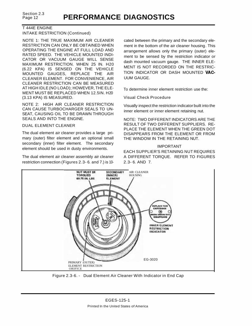
Section 2.3Page 12 PERFORMANCE DIAGNOSTICST 444E ENGINEINTAKE RESTRICTION (Continued)
NOTE 1: THE TRUE MAXIMUM AIR CLEANERRESTRICTION CAN ONLY BE OBTAINED WHENOPERATING THE ENGINE AT FULL LOAD ANDRATED SPEED. THE VEHICLE MOUNTED INDICATOR OR VACUUM GAUGE WILL SENSEMAXIMUM RESTRICTION. WHEN 25 IN. H20(6.22 KPA) IS SENSED ON THE VEHICLEMOUNTED GAUGES, REPLACE THE AIRCLEANER ELEMENT. FOR CONVENIENCE, AIRCLEANER RESTRICTION CAN BE MEASUREDAT HIGH IDLE (NO LOAD); HOWEVER, THE ELEMENT MUST BE REPLACED WHEN 12.5IN. H20(3.13 KPA) IS MEASURED.
NOTE 2: HIGH AIR CLEANER RESTRICTIONCAN CAUSE TURBOCHARGER SEALS TO UNSEAT, CAUSING OIL TO BE DRAWN THROUGHSEALS AND INTO THE ENGINE.
DUAL ELEMENT CLEANER
The dual element air cleaner provides a large primary (outer) filter element and an optional smallsecondary (inner) filter element. The secondaryelement should be used in dusty environments.
The dual element air cleaner assembly air cleanerrestriction connection (Figures 2.3- 6. and 7.) is 10-
PRIMARY (OUTER)ELEMENT RESTRICTIONORIFICE
cated between the primary and the secondary element in the bottom of the air cleaner housing. Thisarrangement allows only the primary (outer) element to be sensed by the restriction indicator ordash mounted vacuum gauge. THE INNER ELEMENT IS NOT RECORDED ON THE RESTRICTION INDICATOR OR DASH MOUNTED VACUUM GAUGE.
To determine inner element restriction use the:
Visual Check Procedure
Visually inspect the restriction indicator built into theinner element or inner element retaining nut.
NOTE: TWO DIFFERENT INDICATORS ARE THERESULT OF TWO DIFFERENT SUPPLIERS. REPLACE THE ELEMENT WHEN THE GREEN DOTDISAPPEARS FROM THE ELEMENT OR FROMTHE WINDOW IN THE RETAINING NUT.
IMPORTANTEACH SUPPLIER'S RETAINING NUT REQUIRESA DIFFERENT TORQUE. REFER TO FIGURES2.3- 6. AND 7.
AIR CLEANERHOUSING
EG-3020
Figure 2.3-6. - Dual Element Air Cleaner With Indicator in End Cap
EGES-125-1Printed In the United States of America

PERFORMANCE DIAGNOSTICST 444E ENGINEINTAKE RESTRICTION (Continued)
AIR CLEANERHOUSING
PRIMARY IOUTERIELEMENT RESTRICTIONORIFICE
Figure 2.3-7. - Dual Element Air Cleaner Retaining Nut Indicator
POSSIBLE CAUSES
• Dirty air cleaner element.
• Snow, plastic bags or other foreign materialmay restrict air flow at the air cleaner inlet. Onengines recently repaired, rags or cap plugsmay have been inadvertently left in the intakesystem.
TOOLS REQUIRED
Model 0-200 Pressure Test Kit (ZTSE-2239), magnehelic gauge or water manometer.
EGES-125-1Printed in the United States of America
Section 2.3Page 13

Section 2.3Page 14 PERFORMANCE DIAGNOSTICST 444E ENGINEEXHAUST RESTRICTION
FROM FORM EGED-13O-1
7. EXHAUST RESTRICTION• Visually inspect exhaust system for damage
• Check if EBP device is closing at High idleWith breakout box pins 49+ and 46 - or "TEE"Green + and Black - (If so equipped)
• Measure at High idle
Instrument Spec. Actual
DVOM < 2.0 Volts
PURPOSETo determine if a restriction exists in the exhaustsystem which would cause an engine performanceproblem.
VISUAL INSPECTION1. Visually inspect entire exhaust system for ob
vious physical damage.
2. If exhaust system damage is not present, startengine and warm to operating temperature.
3. Run engine at high idle with no
load.
4. The exhaust back pressure valve should beopen. {Figure 2.3-8.} illustrates position oftang on bellcrank of the back pressure devicewhen the exhaust back pressure (butterfly)valve is open. (If so equipped)
Figure 2.3-8. - Checking Position of Exhaust Back Pressure {butterfly} Valve At High Idle
EGES-125-1Printed In the United States of America

PERFORMANCE DIAGNOSTICSSection 2.3
Page 15
T 444E ENGINEEXHAUST RESTRICTION (Continued)
TEST PROCEDURE
1. If the suspected exhaust restriction is not visually evident, an exhaust back pressure measurement is necessary. Install the breakout boxor "T' (Figure 2.3-9.) in line with the ESP sensor which will allow access to the back pressurevoltage signal.
NOTE: APPLY PARKING BRAKE AND INSURETHE TRANSMISSION IS IN NEUTRAL.
2. Measure exhaust back pressure (voltage) athigh idle engine speed. Record voltage andcompare to voltage specification on diagnosticform.
POSSIBLE CAUSES
• Closed Exhaust Back Pressure device.
• Collapsed tailpipe
• Clogged catalytic converter. (If so equipped)
• Damaged muffler.
TOOLS REQUIREDDVOM and sensor breakout "T' (ZTSE-4347), orbreakout box (ZTSE-4346).
GREEN ESPSIGNAL
EG-3567
BLACKSIGNAL
GRD.
EXHAUSTBACK PRESSURE
SENSOR
Figure 2.3-9. - Measuring Exhaust Back Pressure (Voltage)
EGES-125-1
Printed In the United States of America
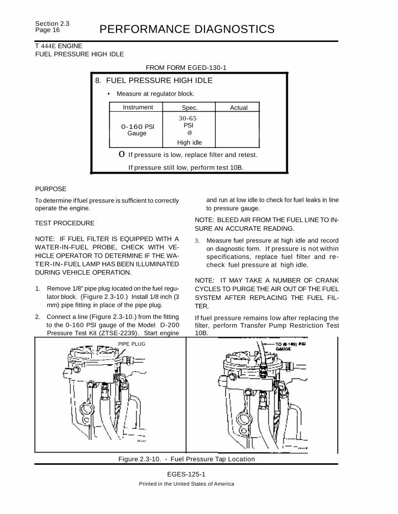
Section 2.3Page 16 PERFORMANCE DIAGNOSTICST 444E ENGINEFUEL PRESSURE HIGH IDLE
FROM FORM EGED-130-1
8. FUEL PRESSURE HIGH IDLE
• Measure at regulator block.
Instrument Spec. Actual
30-650-160 PSI PSI
Gauge @
High idle
o If pressure is low, replace filter and retest.
If pressure still low, perform test 10B.
PURPOSE
To determine if fuel pressure is sufficient to correctlyoperate the engine.
TEST PROCEDURE
NOTE: IF FUEL FILTER IS EQUIPPED WITH AWATER-IN-FUEL PROBE, CHECK WITH VEHICLE OPERATOR TO DETERMINE IF THE WATER-IN- FUEL LAMP HAS BEEN ILLUMINATEDDURING VEHICLE OPERATION.
1. Remove 1/8" pipe plug located on the fuel regulator block. (Figure 2.3-10.) Install 1/8 inch (3mm) pipe fitting in place of the pipe plug.
2. Connect a line (Figure 2.3-10.) from the fittingto the 0-160 PSI gauge of the Model D-200Pressure Test Kit (ZTSE-2239). Start engine
PIPE PLUG
~~~ __ )1,__ ----z ~
I--~I
0) ~
lG33f1
and run at low idle to check for fuel leaks in lineto pressure gauge.
NOTE: BLEED AIR FROM THE FUEL LINE TO INSURE AN ACCURATE READING.
3. Measure fuel pressure at high idle and recordon diagnostic form. If pressure is not withinspecifications, replace fuel filter and recheck fuel pressure at high idle.
NOTE: IT MAY TAKE A NUMBER OF CRANKCYCLES TO PURGE THE AIR OUT OF THE FUELSYSTEM AFTER REPLACING THE FUEL FILTER.
If fuel pressure remains low after replacing thefilter, perform Transfer Pump Restriction Test10B.
Figure 2.3-10. - Fuel Pressure Tap Location
EGES-125-1Printed in the United States of America

PERFORMANCE DIAGNOSTICSSection 2.3
Page 17
T 444E ENGINEFUEL PRESSURE HIGH IDLE (Continued)
POSSIBLE CAUSES
• A fuel filter could cause high restriction and lowfuel pressure because of dirt or fuel jelling incold ambient temperatures. Replace filter andretest.
• A kinked or severely bent fuel supply line or
blockage at the pickup tube could cause restriction and therefore low fuel pressure.
• A loose fuel line on the suction side of the fuel
system could cause air to be ingested into thesystem and cause low fuel pressure.
• The fuel pump could have internal damage, e.g.
ruptured diaphragm, seized plunger or leakingcheck valves.
TOOLS REQUIRED
Model 0-200 Pressure Test Kit (ZTSE-2239) (0 to160 PSI fuel pressure gauge), appropriate line with1/8" NPT fitting.
EGES-125-1
Printed In the United States of America

Section 2.3Page 18 PERFORMANCE DIAGNOSTICST 444E ENGINEEST-ENGINE RUNNING TEST
FROM FORM EGED-13O-1
9a. EST-ENGINE RUNNING TEST• Select "Engine Running" test from
the diagnostic test menu.
NOTE: Engine will run rough during this test.
Faults IFound
a Refer to Electronic Diagnostic form if faultcode(s) set
PURPOSE
To verify the engine's electronic sensors and actuators are operating properly within their specified operating ranges. The Electronic Service Tool (EST)is used to signal the Electronic Control Module(ECM) to perform the "Engine Running Test". TheECM will exercise the actuators and monitor sensorfeedback signals. If a sensor or actuator problemexists, the ECM will transmit fault code(s) to theEST.
TEST PROCEDURE
IMPORTANTAPPLY PARKING BRAKE AND INSURE THETRANSMISSION IS IN NEUTRAL BEFORE RUNNING TEST.
1. Start and run engine until it reaches 1600 F minimum.
NOTE: ENGINE MUST BE AT LEAST 1600 F TOALLOWTHE ECM TO PERFORM AN ACCURATETEST OF THE ENGINE SENSORS AND ACTUATORS. IF ENGINE COOLANT TEMPERATURE ISBELOW SELF TEST RANGE, THE EST TOOLWILL DISPLAY AN "ECT OUT OF SELF TESTRANGE" MESSAGE.
2. Access the "Engine Running Test" from the"DIAGNOSTIC TESTS" menu by pressing the".i" key, until "ENGINE RUNNING TEST" appears on the screen. Then press the "ENTER"key.
NAVISTAR MRD
DIAGNOSTIC TESTS
i ENGINE RUNNING TEST
The ECM will then conduct the "Engine RunningTest". It will command the engine to accelerate toa pre-determined engine RPM and operate t~e I~
jection Pressure Regulator (IPR) valve. If engine IS
equipped with the optional exhaust back pressuredevice, the ECM will also operate the Exhaust BackPressure Regulator (EPR) Valve during this test.
The ECM will measure the effects of actuator movement via the sensors. At the completion of the test,the EST screen will display "00 FAULTS", if nofaults were detected. If EST indicates faults havebeen detected, press the "ENTER" key to displaythe fault codes. Record fault codes and refer to theElectronic Diagnostic form EGED-135-1 forfault codes which were detected.
POSSIBLE CAUSES
• Defective or inoperative sensors or actuators.
• Open or shorted wiring harness to sensors oractuators.
• Loose or corroded engine wiring harness connections at sensor or actuators.
EGES-125-1Printed In the United States of America
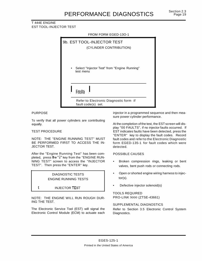
PERFORMANCE DIAGNOSTICST 444E ENGINEEST TOOL-INJECTOR TEST
FROM FORM EGED-13O-1
9b. EST TOOL-INJECTOR TEST(CYLINDER CONTRIBUTION)
NOTE: "Engine RUNNING Test" mustbe performed first, in order to gain access to the "INJECTOR TEST"
• Select "Injector Test" from "Engine Running"test menu
NOTE: Engine will run rough during this test.
I Faults IFound
Refer to Electronic Diagnostic form iffault code(s) set.
Section 2.3Page 19
PURPOSE
To verify that all power cylinders are contributingequally.
TEST PROCEDURE
NOTE: THE "ENGINE RUNNING TEST" MUSTBE PERFORMED FIRST TO ACCESS THE INJECTOR TEST.
After the "Engine Running Test" has been completed, press the".j," key from the "ENGINE RUNNING TEST" screen to access the "INJECTORTEST". Then press the "ENTER" key.
DIAGNOSTIC TESTS
ENGINE RUNNING TESTS
injector in a programmed sequence and then measure power cylinder performance.
At the completion of the test, the EST screen will display "00 FAULTS", if no injector faults occurred. IfEST indicates faults have been detected, press the"ENTER" key to display the fault codes. Recordfault codes and refer to the Electronic Diagnosticform EGED-135-1 for fault codes which weredetected.
POSSIBLE CAUSES
• Broken compression rings, leaking or bent
valves, bent push rods or connecting rods.
• Open or shorted engine wiring harness to injec
tor(s).
t INJECTOR TEST• Defective injector solenoid(s)
NOTE: THE ENGINE WILL RUN ROUGH DURING THE TEST.
The Electronic Service Tool (EST) will signal theElectronic Control Module (ECM) to actuate each
TOOLS REQUIREDPRO-LINK 9000 (ZTSE-43661)
SUPPLEMENTAL DIAGNOSTICSRefer to Section 3.5 Electronic Control SystemDiagnostics.
EGES-125-1
Printed in the United States of America

Section 2.3Page 20 PERFORMANCE DIAGNOSTICST 444E ENGINEFUEL PRESSURE (FULL LOAD)
FROM FORM EGED-13Q-1
10a. FUEL PRESSURE (FULL LOAD)
• Measure at regulator block.
• Measure at full load rated speed.
Instrument Spec. Actual
30-650-160 PSI PSI
Gauge @
Full load
o If pressure is low, replace fuel filter and retest.
If pressure still low, perform Test 10B.
NOTE: FUEL PRESSURE (FULL LOAt;» AND BOOST PRESSURE ARE"ROAD TESTS". THEY MAY BE PERFORMED AT THE SAME TIME.
PURPOSE
To determine if fuel pressure is sufficient to correctlyoperate the engine at full load operating condition.
NOTE: IF FUEL FILTER IS EQUIPPED WITH AWATER-IN-FUEL PROBE, CHECK WITH VEHICLE OPERATOR TO DETERMINE IF THE WATER-IN- FUEL LAMP HAS BEEN ILLUMINATEDDURING VEHICLE OPERATION.
TEST PROCEDURE
NOTE: FUEL PRESSURE MUST BE TAKEN ATFULL LOAD. FUEL PRESSURE MAY BE SUFFICIENT AT HIGH IDLE, BUT MAY BE UNSATISFACTORY AT FULL LOAD OPERATING CONDITIONS.
1. Remove 1/8" pipe plug located on the fuel regu..Jatar block. (Figure 2.3-11.) Install 1/8 inch (3mm) pipe fitting in place of the pipe plug.
2. Connect a line (Figure 2.3-11.) from the fittingto the 0-160 PSI gauge of the Model D-200Pressure Test Kit (ZTSE-2239). Start engine
and run at low idle to check for fuel leaks in lineto pressure gauge.
NOTE: BLEED AIR FROM THE FUEL LINE TO INSURE AN ACCURATE READING.
IMPORTANT
TO MEASURE FUEL PRESSURE AT FULLLOAD, VEHICLE MUST BE DRIVEN ON THEROAD IN THE HIGHEST GEAR (POSSIBLE) ANDACCELERATOR PEDAL DEPRESSED TO THEFLOOR (FULL DEPRESSION) OF THE CAB. IF AVEHICLE DYNAMOMETER IS AVAILABLE, OPERATE VEHICLE AT FULL RATED LOAD ANDSPEED.
3. Measure fuel pressure at full load and record ondiagnostic form. If pressure is not withinspecifications, replace fuel filter and recheck fuel pressure.
EGES-125-1Printed in the United States of America

PERFORMANCE DIAGNOSTICSSection 2.3
Page 21
T 444E ENGINEFUEL PRESSURE (FULL LOAD) (Continued)
NOTE: IT MAY TAKE A NUMBER OF CRANKCYCLES TO PURGE THE AIR OUT OF THE FUELSYSTEM AFTER REPLACING THE FUEL FILTER.
PIPE PLUG
If fuel pressure remains low after replacing thefilter, perform Transfer Pump Restriction Test10B.
Figure 2.3-11. - Fuel Pressure Tap Location
POSSIBLE CAUSES
• A fuel filter could cause high restriction and low
fuel pressure because of dirt or fuel jelling incold ambient temperatures. Replace filter andretest.
• A kinked or severely bent fuel supply line or
blockage at the pickup tube could cause restriction and therefore low fuel pressure.
• A loose fuel line on the suction side of the fuel
system could cause air to be ingested into thesystem and cause low fuel pressure.
• The fuel pump could have internal damage, e.g.
ruptured diaphragm, seized plunger or leakingcheck valves.
TOOLS REQUIRED
Model 0-200 Pressure Test Kit (ZTSE-2239) (0 to160 PSI fuel pressure gauge), appropriate line with1/8" NPT fitting.
EGES-125-1Printed In the United Slates of America

Section 2.3Page 22 PERFORMANCE DIAGNOSTICST 444E ENGINETRANSFER PUMP RESTRICTION
FROM FORM EGED-13O-1
10b. TRANSFER PUMP RESTRICTION
• Measure at fuel pump inlet
• Measure at High idle
Instrument Spec. Actual
0-30" Hg. <6" Hg.Vacuum Gauge
o If restriction is high, check for blockagebetween pump and fuel tank.
o If restriction is within spec., check for stickingregulator valve or debris.
TRANSFER PUMP RESTRICTION
PURPOSE
To determine if excessive restriction to fuel flow exists from the engine fuel inlet line to the fuel tank(s).
TEST PROCEDURE
1. Connect a tee between the fuel filter inlet andfuel supply line. (Figure 2.3-12.) Connect aline from the tee to the 0-30" Hg. vacuum gaugeof the D-200 Pressure Test Kit (ZTSE-2239).
2. Measure fuel inlet restriction at high idle and record reading on diagnostic form.
3. If restriction exceeds 6 in. Hg., locate the restriction on the suction side of the fuel systemand correct.
NOTE: IF FUEL INLET RESTRICTION IS WITHINSPECIFICATIONS, REFER TO FUEL REGULATOR VALVE REMOVAL AND INSPECTION ONPAGE 24.
Figure 2.3-12. - Transfer Pump Restriction
EGES-125-1Printed in the United States of America

PERFORMANCE DIAGNOSTICSSection 2.3
Page 23
T 444E ENGINETRANSFER PUMP RESTRICTION (Continued)
POSSIBLE CAUSES
• A fuel filter could cause high restriction and low
fuel pressure because of dirt or fuel jelling incold ambient temperatures. Replace filter andretest.
• A kinked or severely bent fuel supply line or
blockage at the pickup tube could cause restriction and therefore low fuel pressure.
• A loose fuel line on the suction side of the fuel
system could cause air to be ingested into thesystem and cause low fuel pressure.
• The fuel pump could have internal damage, e.g.
ruptured diaphragm, seized plunger or leakingcheck valves.
TOOLS REQUIRED
Model 0-200 Pressure Test Kit (ZTSE-2239) (0 to30" Hg. vacuum gauge), "T' fitting, and appropriatefuel lines.
EGES-125-1
Printed In the United States of America

Section 2.3Page 24 PERFORMANCE DIAGNOSTICST 444E ENGINEFUEL REGULATOR VALVE REMOVAL AND INSPECTION
FUEL REGULATOR VALVEREMOVAL AND INSPECTION.
1. Remove fuel return line from adapter fitting onfuel regulator block. (Figure 2.3-13.)
2. Remove the fuel line adapter fitting with "0"ring.
3. Use needle nose pliers to remove the fuel regulator spring and valve from the regulator.
4. Inspect fuel regulator valve seating surface fordamage and insure spring is not broken.
5. Inspect inside of regulator blockfor dirt ordebristhat could restrict the flow of fuel past the regulator valve.
Figure 2.3-13. - Fuel Regulator Valve Removal and Inspection
EGES-125-1Printed In the United States of America

PERFORMANCE DIAGNOSTICSSection 2.3
Page 25
T 444E ENGINEBOOST PRESSURE
FROM FORM EGED-130-1
11. BOOST PRESSURE• Monitor boost pressure and engine RPM
with the EST tool in data list mode,or use dash tach and 0-30 PSI gauge and"T" if EST tool is not available
• Measure pressure at full load rated speed
PSI @ RPM
Spec. I Actual
NOTE: BOOST PRESSURE AND FUEL PRESSURE (FULL LOAD) ARE"ROAD TESTS". THEY MAY BE PERFORMED AT THE SAME TIME.
PURPOSE
To determine if the engine can develop sufficientboost to obtain specific power.
TEST PROCEDURE
NOTE: TURN ALL ACCESSORIES AND THEIGNITION OFF, BEFORE CONNECTING ESTTOOL TO ATA DIAGNOSTIC CONNECTOR.
1. Connect EST to the ATA connector.
2. Turn the ignition switch to the "ON" position.
3. Access the data list and press the"..i" key until"BOOST PSI" is displayed on the screen.
BATT VOLTS
ENGINE RPM
BOOST PSI
BARO IN Hg.
12.5
oo
14.4
ALTERNATE TEST PROCEDURE
1. Install a tee into the MAP (Manifold AbsolutePressure) sensor line that comes from the intake manifold. (Figure 2.3-14.)
4. Drive vehicle on road till engine reaches operating temperature. Find an open section of roadand select a suitable gear. Depress the accelerator pedal (full depression) to the floor.
NOTE: DRIVING THE VEHICLE UP HILL ORFULLY LOADED WILL FACILITATE EFFORTSOF REACHING THE PROPER ENGINE LOADINGAT SPECIFIED ENGINE SPEEDS.
5. Record intake manifold boost at specified engine speeds.
Figure 2.3-14. - Boost Pressure Tap Location
NOTE: MAP SENSOR MUST NOT BE DISCONNECTED DURING TEST.
2. Temporarily install the 0-200 Pressure Test Kit(ZTSE-2239) inthecabofthevehicle. Connecta line to the 0 to 30 PSI gauge and route it to the"T' so it is not crimped or in contact with a hotengine suriace.
EGES-125-1Printed In the United States of America

Section 2.3Page 26 PERFORMANCE DIAGNOSTICST 444E ENGINEBOOST PRESSURE (Continued)
3. Drive vehicle on road until engine reaches operating temperature. Find an open section of roadand select a suitable gear. Depress the accelerator pedal (full depression) to the floor.
NOTE: DRIVING THE VEHICLE UP HILL ORFULLY LOADED WILL FACILITATE EFFORTSOF REACHING THE PROPER ENGINE LOADINGAT SPECIFIED ENGINE SPEEDS.
5. Record intake manifold boost at specified engine speeds.
NOTE: IF BOOST PRESSURE IS WITHIN SPECIFICATIONS, THE ENGINE IS FUNCTIONINGPROPERLY. THERE MAY BE CHASSIS OR APPLICATION CONCERNS.
POSSIBLE CAUSES:
• Restricted intake or exhaust.
• Low fuel pressure.
• Low injection control pressure.
• Control system faults
• Defective injectors.
• Defective tUrbocharger
• Base engine failure
EGES-125-1Printed In the United States of America

PERFORMANCE DIAGNOSTICSSection 2.3
Page 27
T 444E ENGINECRANKCASE PRESSURE
FROM FORM EGED-13O-1
12. CRANKCASE PRESSURE
• Measure at road draft tube with orifice restrictortool (ZTSE-4146)
• Measure at High idle no load RPM.
Instrument Spec. Actual
o to 60" H2O < 6" H2OMagnehelic
PURPOSE 7. Record crankcase pressure on diagnostic form.
IMPORTANT
POSSIBLE CAUSES:
• Dirt entering air induction system. (Check sys-tem for leaks.)
• Broken or worn compression rings
• Leaking or bent valves
• Turbocharger boost pressure entering crankcase.
• Air from air compressor leaking into crankcase.
DO NOT PLUG THE BREATHER TUBE DURINGTHE CRANKCASE PRESSURE TEST AS RESTRICTING THE TUBE CAN CAUSE CRANKSHAFT AND TURBOCHARGER SEALS TOLEAK.
TOOLS REQUIREDOrifice restriction tool (ZTSE-4146) and water manometer or 0-200 Pressure Test Kit (ZTSE-2239)r-----------------...,
To measure power cylinder condition.
TEST PROCEDURE
1. Park vehicle on level ground.
2. Insure breather tube is free of dirt.
3. Insure engine oil level is not above the full markand the dipstick is securely in place.
4. Connect a line from the restrictor tool (Figure2.3-15) to a water manometer or to the pressure side of the magnehelic gauge on the0-200 Pressure Test Kit (ZTSE-2239) . NOTE:Install a quick connect plug in the vacuumport of the gauge to vent it to atmosphere.(Make sure that the magnehelic gauge hasbeen zeroed)
5. Run engine to attain normal engine operatingtemperature before measuring crankcase pressure.
6. Perform engine crankcase pressure test withengine at high idle (no load) RPM. Allow thegauge reading to stabilize before taking thepressure reading.
Figure 2.3-15. - Crankcase Pressure Test
EGES-125-1Printed In the United States of America

Section 2.3Page 28 PERFORMANCE DIAGNOSTICS
T 444E ENGINEWASTEGATE ACTUATOR TEST
FROM FORM EGED-13Q-1
13. WASTEGATE ACTUATOR TEST• Apply regulated air to actuator
• Inspect for leakage
• Inspect actuator for movement
Instrument
o to 60 PSIGauge
Spec.
17-19 PSI
Actual
PURPOSETo determine operation of actuator in conjunctionwith turbocharger operation.
TEST PROCEDURE
1. Remove actuator boost line from turbo compressor housing and connect an air regulatorwith a 0-60 PSI gauge to the actuator boostline. Figure 2.3-16.
Figure 2.3-16. - Boost Pressure Tap Locationand Air Regulator Connection
2. Mark actuator (link) shaft with paint pen. Figure2.3-17.
3. Spray leak detector Figure 2.3-18. around theactuator housing and slowly apply air pressureto the actuator. Actuator (shaft) movement(indicated by position of paint mark) shouldbegin to occur between 17-19 psi.
Figure 2.3-17. - Paint Mark Location on Actuator Link
Figure 2.3-18. - Checking Actuator for Leaks
If a significant amount of actuator shaft movementoccurs and no air leaks are detected at actuatorhousing, actuator is OK. If little or no shaft movement occurs or air leaks are present at the actuatorhousing, the turbocharger must be removed from
EGES-125-1Printed in the United States of America

PERFORMANCE DIAGNOSTICSSection 2.3
Page 29
T 444E ENGINEWASTEGATE ACTUATOR TEST(Continued)
engine. Refer to engine service manual for furtherwastegate diagnosis.
POSSIBLE CAUSES
• Sticky flapper valve
• Ruptured actuator diaphragm
• Leaky canister
• Leaky hose to actuator
TOOLS REQUIREDAir pressure regulator, 0-60 psi gauge and paintmarker. (Alternative: Dial indicator)
EGES-125-1
Printed In the United States of America

Section 2.3Page 30 PERFORMANCE DIAGNOSTICST 444E ENGINEINJECTION CONTROL PRESSURE TEST (OIL AERATION-POOR IDLE QUALITY)
FROM FORM EGED-13O-1
14. INJECTION CONTROL PRESSURE
(Oil Aeration-Poor idle quality)NOTE: TEST SHOULD BE PERFORMEDAFTER ENGINE HAS BEEN RUN UNDERLOAD.
• Hold engine speed at high idle for 60 seconds.
• Monitor ICP pressure with EST data list or
• Measure at breakout box pins 27+ & 46or Breakout "Tee" green and black -
Instrument Spec. Actual
EST PSI
DVOM Volts(27+ ,46-) @ High Idle
o If ICP signal increases above 1040 PSI or 1.6 volts,
change oil and retest.
4. Operate engine at high idle and monitor (ICP)Injection Control Pressure for 60 seconds onthe EST.
Normal ICP pressure is 1000-1 040 PSI. If ICPpressure does not stabilize below 1100 PSI andcontinues to rise while high idle speed is maintained, engine lube oil may be aerated. If this condition occurs, change oil and filter, then repeat ICPtest.
PURPOSE
To determine if engine lube oil is being aerated andcausing poor idle quality.
TEST PROCEDURE
IMPORTANT
IF ENGINE OIL IS AERATING, IT MAY CAUSETHE ENGINE TO IDLE ERRATICALLY. TO DETERMINE IF OIL IS BEING AERATED, PERFORMTHIS TEST AFTER ENGINE HAS BEEN RUN UNCERA LOAD.
NOTE: TURN ALL ACCESSORIES AND THEIGNITION OFF, BEFORE CONNECTING ESTTOOL TO ATA DIAGNOSTIC CONNECTOR.
BATT VOLTS
ENGINE RPM
INJ CNTL PSI
FUEL GAL/HR
12.5
oo
0.3
1. Connect the Electronic Service Tool (EST) tothe American Trucking Association (ATA) datalink connector. (Figure 2.3-19.)
2. Start the engine and bring it to operating temperature.
NOTE: APPLY PARKING BRAKE AND INSURETHE TRANSMISSION IS IN NEUTRAL.
3. Press the"..j,." key on the EST until "INJ CNTLPSI" appears on the screen.
~~ EST DATA LINK'-.J CONNECTOR
ATA CONNECTORUNDER LEFTsloe OF DASH
Figure 2.3-19. - ATA Connector Location
EGES-125-1
Printed In the United States of America

PERFORMANCE DIAGNOSTICST 444E ENGINEINJECTION CONTROL PRESSURE (OIL AERATION-POOR IDLE QUALITY) (Continued)
Section 2.3Page 31
ALTERNATE METHOD OF MEASURING INJECTION CONTROL PRESSURE USING (BREAKOUT "TEE")
1. Remove engine harness connector at ICP sensor.
2. Connect the breakout "TEE" to the removedengine harness connector and the ICP sensor.
3. Connect DVOM leads (+Green, -Black) to thebreakout "TEE" as shown in (Figure 2.3-20.)
4. Start the engine and bring it to operating temperature.
5. Operate engine at high idle and monitor (ICP)voltage for 60 seconds. NormallCP voltage isbetween 1.2 to 1.6 volts. If the ICP signal voltage continues to rise as high idle speed is maintained, the engine lube oil may be aerated.Change oil and filter, then repeat ICP test athigh idle.
TOOLS REQUIREDDVOM and breakout sensor "T', (ZTSE-4347)
GREEN-ICP
Figure 2.3-20. - Measuring Injection Control Pressure Using "Breakout Tee"
EGES-125-1Printed In the United States of America

Section 2.3Page 32 PERFORMANCE DIAGNOSTICST 444E ENGINEINJECTION CONTROL PRESSURE (OIL AERATION-POOR IDLE QUALITY) (Continued)
ALTERNATE METHOD OF MEASURING INJECTION CONTROL PRESSURE USING BREAKOUT BOX
1. Connect breakout box at ECM. (Figure2.3-21.)
2. Connect DVOM to breakout box terminal #s(+27, -46).
3. Start the engine and bring it to operating temperature.
4. Operate engine at high idle and monitor (ICP)voltage for 60 seconds. NormallCP voltage isbetween 1.2 to 1.6 volts. If the ICP signal voltage continues to rise as high idle speed is maintained, the engine lube oil may be aerated.Change oil and filter, then repeat ICP test athigh idle.
TOOLS REQUIREDDVOM and breakout box (ZTSE-4346).
Figure 2.3-21. - Breakout Box (ZTSE-4346)
POSSIBLE CAUSES:
• Extended oil drain intervals. The anti-foam additives in the oil may be depleted from severeuse or extended oil drain intervals.
• Wrong oil type or grade of oil.
EGE5-125-1Printed In the United States of America

PERFORMANCE SPECIFICATIONST 444E1160 HP @ 2600 RPM[49 State 1994 Model Year]
PERFORMANCE SPECIFICATIONS
Section 2.4Page 1
Engine/Model T 444E/A160F
Engine rating 160 BHP @ 2600 RPM
Engine Family Rating Code (EFRC) 2141
Injector Part NumberOriginal Equipment 1 816 187 C2/C3
Turbocharger Part Number (With Exhaust Back Pressure Device) 1 824 703 C91AIR Ratio 84
Turbocharger Part Number (Without Exhaust Back Pressure Device) 1 824 704 C91AIR Ratio 84
Injection Timing Not-Adjustable
High Idle Speed - RPM with manual transmission 2600 + 50
High Idle Speed - RPM with automatic transmission . . . . . . . . . . . . . . . . . . . . . . .. 2600 + 200
Low Idle Speed - RPM 700 ±50
Injection Control PressureNoltage@ Low Idle No Load . . . . . . . . . . . . . . . . . . . . . . . . . . . . . .. 590 ± 50 psi (4.00 ± 0.3 MPa) (0.94 ± 0.1 Volts)
Injection Control PressureNoltage@ High Idle No Load 1020 ± 100 psi (7.10 ± 0.7 MPa) (1.40 ± 0.2 Volts)
Injection Control PressureNoltage@ Rated Speed and Full Load 2470 ± 150 psi (17.0 ± 1.0 MPa) (3.15 ± 0.3 Volts)
Intake and Exhaust Valve Clearance (Engine Off - Hot or Cold)Intake Not-AdjustableExhaust " " .. " ". ~ " . ~ ~ " " . " ~ . " " " . " " " " .. n •••••••••••••••••• " • Not-Adjustable
EGES-125-1
Printed In the United States of America

Section 2.4Page 2 PERFORMANCE SPECIFICATIONS
T 444E1160 HP @ 2600 RPM[49 State 1994 Model Year]
PERFORMANCE SPECIFICATIONSCONTINUED
The following data to be taken at high idle with [no load].
Air Cleaner Restriction* [Measured @ Air Cleaner Outlet](Check at High Idle [No Load]) - Max 12.5 in. H20 (3.13 kPa)(Check at Full Load, Rated Speed) - Max. . . . . . . . . . . . . . . . . . . . . . . . . . . . . . . .. 25 in. H20 (6.25 kPa)
Fuel Pressure [Minimum]* 20 psi (138 kPa)
Fuel Inlet Restriction Maximum* . . . . . . . . . . . . . . . . . . . . . . . . . . . . . . . . . . . .. 6 in. Hg. Vacuum (20.261 kPa)
(Requires StabilizedCrankcase Pressure [Maximum]* 6.0 in. H20** ( 2.0 kPa)
Operating Temperature)
The following data to be taken at full load, full throttle rated engine speed on chassis dynamometer oron highway.
15.0 psi ± 2.0 psi (103 kPa ± 14 kPa) @ 2600Intake Manifold Pressure* 6.0 psi ± 2.0 psi (42 kPa ± 14 kPa) @ 1500
Exhaust Back Pressure (After Turbocharger [Maximum])* 0-27 in.H20 (6.7 kPa)
Smoke Level Max* - Bosch Number . . . . . . . . . . . . . . . . . . . . . . . . . . . . . . . . . . . . . . . . . . . .. 1.3 @ 2600 RPM1.3 @ 1500 RPM
Measure water temperature differential across the radiator with engine on a chassis dynamometer, atfull load and ambient temperature of 80°F or above.
Water Temperature Differential Across Radiator 6-12°F (3.3-6.6°C)
The following data to be taken after engine reaches stabilized operating temperature.
Lube Oil Temperature (Oil Gallery) 23DoF (11 DOC) Max.
Lube Oil Pressure at Operating Temperature
Low Idle (Min.) 10-30 psi (137-344 kPa)Rated Speed (Min.lMax.) 40-70 psi (276-483 kPa)
*Engine must be at normal operating temperature.
**Crankcase pressure [maximum] as measured with Orificed Restrictor Tool ZTSE4146.
EGES-125-1
Printed In the Unltecl States of America

PERFORMANCE SPECIFICATIONST 444E1160 HP @ 2600 RPM[49 State 1994 Model Year]
PERFORMANCE SPECIFICATIONS
Section 2.4Page 3
Engine/Model T 444E/A160C
Engine rating 160 BHP @ 2600 RPM
Engine Family Rating Code (EFRC) 2111
Injector Part NumberOriginal Equipment 1 816 187 C2/C3
Turbocharger Part Number (With Exhaust Back Pressure Device) 1 824 703 C91AIR Ratio 84
Turbocharger Part Number (Without Exhaust Back Pressure Device) 1 824 704 C91AIR Ratio 84
Injection Timing Not-Adjustable
High Idle Speed - RPM with manual transmission 2600 + 50
High Idle Speed - RPM with automatic transmission . . . . . . . . . . . . . . . . . . . . . . .. 2600 + 200
Low Idle Speed - RPM 700 ±50
Injection Control PressureNoltage@ Low Idle No Load . . . . . . . . . . . . . . . . . . . . . . . . . . . . . .. 590 ± 50 psi (4.00 ± 0.3 MPa) (0.94 ± 0.1 Volts)
Injection Control PressureNoltage@ High Idle No Load 1020 ± 100 psi (7.10 ±0.7 MPa) (1.40 ± 0.2 Volts)
Injection Control PressureNoltage@ Rated Speed and Full Load 2470 ± 150 psi (17.0 ± 1.0 MPa) (3.15 ± 0.3 Volts)
Intake and Exhaust Valve Clearance (Engine Off - Hot or Cold)Intake Not-AdjustableExhaust ".......................................... Not-Adjustable
EGES-125-1
Printed In the United States of America

Section 2.4Page 4 PERFORMANCE SPECIFICATIONS
T 444E1160 HP @ 2600 RPM[California 1994 Model Year]
PERFORMANCE SPECIFICATIONSCONTINUED
The following data to be taken at high idle with [no load].
Air Cleaner Restriction* [Measured @ Air Cleaner Outlet](Check at High Idle [No Load)) - Max 12.5 in. H20 (3.13 kPa)(Check at Full Load, Rated Speed) - Max . . . . . . . . . . . . . . . . . . . . . . . . . . . . . . . .. 25 in. H20 (6.25 kPa)
Fuel Pressure [Minimum]* 4 ••••••••••••• 20 psi (138 kPa)
Fuel Inlet Restriction Maximum* . . . . . . . . . . . . . . . . . . . . . . . . . . . . . . . . . . . .. 6 in. Hg. Vacuum (20.261 kPa)
(Requires StabilizedCrankcase Pressure [Maximum]* 6.0 in. H20•• ( 2.0 kPa)
Operating Temperature)
The following data to be taken at full load, full throttle rated engine speed on chassis dynamometer oron highway.
15.0 psi ±2.0 psi (103 kPa ± 14 kPa) @ 2600Intake Manifold Pressure* 6.0 psi ± 2.0 psi (42 kPa ± 14 kPa) @ 1500
Exhaust Back Pressure (After Turbocharger [Maximum])* 0-27 in.H20 (6.7 kPa)
Smoke Level Max* - Bosch Number . . . . . . . . . . . . . . . . . . . . . . . . . . . . . . . . . . . . . . . . . . . .. 1.3 @ 2600 RPM1.3 @ 1500 RPM
Measure water temperature differential across the radiator with engine on a chassis dynamometer, atfull load and ambient temperature of 80°F or above.
Water Temperature Differential Across Radiator 6-12°F (3.3-6.6°C)
The following data to be taken after engine reaches stabilized operating temperature.
Lube Oil Temperature (Oil Gallery) 230°F (110°C) Max.
Lube Oil Pressure at Operating TemperatureLow Idle (Min.) 10-30 psi (137-344 kPa)Rated Speed (Min.lMax.) 40-70 psi (276-483 kPa)
*Engine must be at normal operating temperature.
··Crankcase pressure [maximum] as measured with Orificed Restrictor Tool ZTSE4146.
EGES-125-1Printed In the United States of America

PERFORMANCE SPECIFICATIONST 444E1175 HP @ 2600 RPM[49 State 1994 Model Year]
PERFORMANCE SPECIFICATIONS
Section 2.4PageS
Engine/Model . . . . . . . . . . . . . . . . . . . . . . . . . . . . . . . . . . . . . . . . . . . . . . . . . . . . . . . . . . . . . . . . . .. T 444E1A175F
Engine rating 175 BHP @ 2600 RPM
Engine Family Rating Code (EFRC) 2151
Injector Part NumberOriginal Equipment 1 816 187 C2/C3
Turbocharger Part Number (With Exhaust Back Pressure Device) 1 824 703 C91AIR Ratio 84
Turbocharger Part Number (Without Exhaust Back Pressure Device) 1 824 704 C91AIR Ratio 84
Injection Timing Not-Adjustable
High Idle Speed - RPM with manual transmission 2600 + 50
High Idle Speed - RPM with automatic transmission . . . . . . . . . . . . . . . . . . . . . . . .. 2600 + 200
Low Idle Speed - RPM 700 ± 50
Injection Control PressureNoltage@ Low Idle No Load . . . . . . . . . . . . . . . . . . . . . . . . . . . . . .. 590 ± 50 psi (4.00 ± 0.3 MPa) (0.94 ± 0.1 Volts)
Injection Control PressureNoltage@ High Idle No Load 1020 ± 100 psi (7.10 ± 0.7 MPa) (1.40 ±0.2 Volts)
Injection Control PressureNoltage
@ Rated Speed and Full Load 2470 ± 150 psi (17.0 ± 1.0 MPa) (3.15 ± 0.3 Volts)
Intake and Exhaust Valve Clearance (Engine Off - Hot or Cold)
Intake Not-AdjustableExhaust ""................ Not-Adjustable
EGES-125-1
Printed In the United States of America

Section 2.4Page 6 PERFORMANCE SPECIFICATIONS
T 444E1175 HP @ 2600 RPM[49 State 1994 Model Year]
PERFORMANCE SPECIFICATIONSCONTINUED
The following data to be taken at high idle with [no load].
Air Cleaner Restriction* [Measured @ Air Cleaner Outlet](Check at High Idle [No Load]) - Max 12.5 in. H20 (3.13 kPa)(Check at Full Load, Rated Speed) - Max ~ . . . . . . .. 25 in. H20 (6.25 kPa)
Fuel Pressure [Minimum]* ~ 20 psi (138 kPa)
Fuel Inlet Restriction Maximum* . . . . . . . . . . . . . . . . . . . . . . . . . . . . . . . . . . . .. 6 in. Hg. Vacuum (20.261 kPa)
{Requires StabilizedCrankcase Pressure [Maximum]* " 6.0 in. H20 ** ( 2.0 kPa)
Operating Temperature)
The following data to be taken at full load, full throttle rated engine speed on chassis dynamometer oron highway.
17.0 psi ±2.0 psi (117 kPa ± 14 kPa) @ 2600Intake Manifold Pressure* 6.0 psi ± 2.0 psi (42 kPa ±14 kPa) @ 1500
Exhaust Back pre:sure (After Turbocharger [Maximum])* 0-27 in.H20 (6.7 kPa) I
Smoke Level Max - Bosch Number . . . . . . . . . . . . . . . . . . . . . . . . . . . . . . . . . . . . . . . . . . . .. 1.3 @ 2600 RPM1.3 @ 1500 RPM
Measure water temperature differential across the radiator with engine on a chassis dynamometer, atfull load and ambient temperature of 80°F or above.
Water Temperature Differential Across Radiator ~ 6-12°F (3.3-6.6°C)
The following data to be taken after engine reaches stabilized operating temperature.
Lube Oil Temperature (Oil Gallery) 230°F (110°C) Max.
Lube Oil Pressure at Operating TemperatureLow Idle (Min.) 10-30 psi (137-344 kPa)Rated Speed (Min.lMax.) 40-70 psi (276-483 kPa)
*Engine must be at normal operating temperature.
1**Crankcase pressure [maximum] as measured with Orificed Restrictor Tool ZTSE4146.
EGES-125-1
Printed In the United States of America
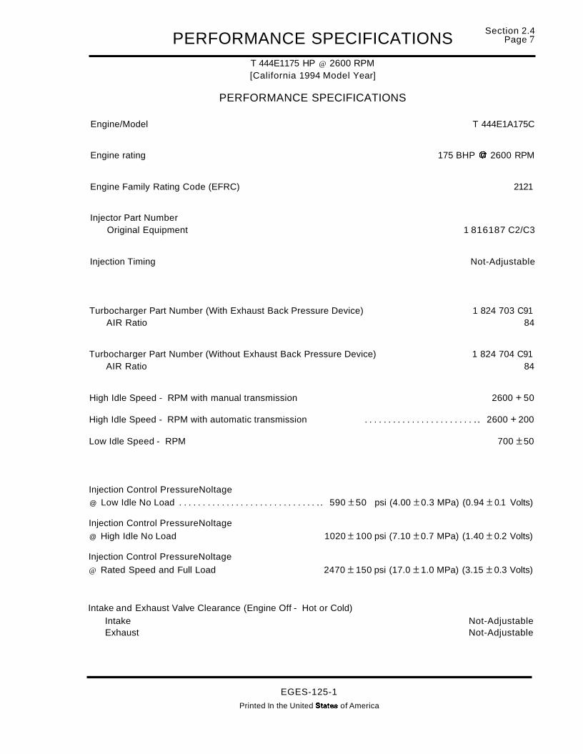
PERFORMANCE SPECIFICATIONST 444E1175 HP @ 2600 RPM[California 1994 Model Year]
PERFORMANCE SPECIFICATIONS
Section 2.4Page 7
Engine/Model T 444E1A175C
Engine rating 175 BHP @ 2600 RPM
Engine Family Rating Code (EFRC) 2121
Injector Part NumberOriginal Equipment 1 816187 C2/C3
Injection Timing Not-Adjustable
Turbocharger Part Number (With Exhaust Back Pressure Device) 1 824 703 C91AIR Ratio 84
Turbocharger Part Number (Without Exhaust Back Pressure Device) 1 824 704 C91AIR Ratio 84
High Idle Speed - RPM with manual transmission 2600 + 50
High Idle Speed - RPM with automatic transmission . . . . . . . . . . . . . . . . . . . . . . . .. 2600 + 200
Low Idle Speed - RPM 700 ±50
Injection Control PressureNoltage@ Low Idle No Load . . . . . . . . . . . . . . . . . . . . . . . . . . . . . .. 590 ±50 psi (4.00 ±0.3 MPa) (0.94 ± 0.1 Volts)
Injection Control PressureNoltage@ High Idle No Load 1020 ± 100 psi (7.10 ±0.7 MPa) (1.40 ± 0.2 Volts)
Injection Control PressureNoltage
@ Rated Speed and Full Load 2470 ± 150 psi (17.0 ±1.0 MPa) (3.15 ± 0.3 Volts)
Intake and Exhaust Valve Clearance (Engine Off - Hot or Cold)Intake Not-AdjustableExhaust Not-Adjustable
EGES-125-1
Printed In the United States of America

Section 2.4PageS PERFORMANCE SPECIFICATIONS
T 444E1175 HP @ 2600 RPM[California 1994 Model Year]
PERFORMANCE SPECIFICATIONSCONTINUED
The following data to be taken at high idle with [no load].
Air Cleaner Restriction* [Measured @ Air Cleaner Outlet](Check at High Idle [No Load]) - Max 12.5 in. H20 (3.13 kPa)(Check at Full Load, Rated Speed) - Max. . . . . . . . . . . . . . . . . . . . . . . . . . . . . . . .. 25 in. H20 (6.25 kPa)
Fuel Pressure [Minimum]* 20 psi (138 kPa)
Fuel Inlet Restriction Maximum* 6 in. Hg. Vacuum (20.261 kPa)
(Requires StabilizedCrankcase Pressure [Maximum]* 6.0 in. H20 "'''' ( 2.0 kPa)
Operating Temperature)
The following data to be taken at full load, full throttle rated engine speed on chassis dynamometer or
on highway.
17.0 psi ± 2.0 psi (117 kPa ± 14 kPa) @ 2600Intake Manifold Pressure* 6.0 psi ± 2.0 psi (42 kPa ± 14 kPa) @ 1500
Exhaust Back Pressure (After Turbocharger [Maximum])* 0-27 in.H20 (6.7 kPa)
Smoke Level Max* - Bosch Number . . . . . . . . . . . . . . . . . . . . . . . . . . . . . . . . . . . . . . . . . . . .. 1.3 @ 2600 RPM1.3 @ 1500 RPM
Measure water temperature differential across the radiator with engine on a chassis dynamometer, atfull load and ambient temperature of 80°F or above..
Water Temperature Differential Across Radiator . . . . . . . . . . . . . . . . . . . . . . . . . . . . . . . .. 6-12°F (3.3-6.6°C)
The following data to be taken after engine reaches stabilized operating temperature.
Lube Oil Temperature (Oil Gallery) 230°F (110°C) Max.
Lube Oit Pressure at Operating TemperatureLow Idle (Min.) 10-30 psi (137-344 kPa)Rated Speed (Min./Max.) 40-70 psi (276-483 kPa)
*Engine must be at normal operating temperature.
"''''Crankcase pressure [maximum] as measured with Orificed Restrictor Tool ZTSE4146.
EGES-125-1
Printed In the United States of America

PERFORMANCE SPECIFICATIONST 444E1190 HP @ 2600 RPM[49 State 1994 Model Year]
PERFORMANCE SPECIFICATIONS
Section 2.4Page 9
Engine/Model . . . . . . . . . . . . . . . . . . . . . . . . . . . . . . . . . . . . . . . . . . . . . . . . . . . . . . . . . . . . . . . . . .. T 444E/A190F
Engine rating 190 BHP @ 2600 RPM
Engine Family Rating Code (EFRC) 2161
Injector Part NumberOriginal Equipment 1 816 187 C2/C3
Injection Timing Not-Adjustable
Turbocharger Part Number (With Exhaust Back Pressure Device) 1 824 703 C91AIR Ratio 84
Turbocharger Part Number (Without Exhaust Back Pressure Device) 1 824 704 C91AIR Ratio 84
High Idle Speed - RPM with manual transmission 2600 + 50
High Idle Speed - RPM with automatic transmission . . . . . . . . . . . . . . . . . . . . . . . . . . . . . .. 2600 + 200
Low Idle Speed - RPM 700 ± 50
Injection Control PressureNoltage@ Low Idle No Load 590 ±50 psi (4.00 ±0.3 MPa) (0.94 ± 0.1 Volts)
Injection Control PressureNoltage@ High Idle No Load 1020 ± 100 psi (7.10 ± 0.7 MPa) (1.40 ± 0.2 Volts)
Injection Control PressureNoltage@ Rated Speed and Full Load 2470 ± 150 psi (17.0 ± 1.0 MPa) (3.15 ±0.3 Volts)
Intake and Exhaust Valve Clearance (Engine Off - Hot or Cold)Intake Not-AdjustableExhaust Not-Adjustable
EGES-125-1
Printed In the United States of America

Section 2.4Page 10 PERFORMANCE SPECIFICATIONS
T 444E1190 HP @ 2600 RPM[49 State 1994 Model Year]
PERFORMANCE SPECIFICATIONSCONTINUED
The following data to be taken at high idle with [no load].
Air Cleaner Restriction* [Measured @ Air Cleaner Outlet](Check at High Idle [No Load]) - Max 12.5 in. H20 (3.13 kPa)(Check at Full Load, Rated Speed) - Max . . . . . . . . . . . . . . . . . . . . . . . . . . . . . . . .. 25 in. H20 (6.25 kPa)
Fuel Pressure [Minimum]* 20 psi (138 kPa)
Fuel Inlet Restriction Maximum* . . . . . . . . . . . . . . . . . . . . . . . . . . . . . . . . . . . .. 6 in. Hg. Vacuum (20.261 kPa)
(Requires StabilizedCrankcase Pressure [Maximum]* 6.0 in. H20** ( 2.0 kPa)
Operating Temperature)
The following data to be taken at full load, full throttle rated engine speed on chassis dynamometer oron highway.
18.0 psi ± 2.0 psi (124 kPa ± 14 kPa) @ 2600Intake Manifold Pressure* 7.0 psi ± 2.0 psi (48 kPa ± 14 kPa) @ 1500
Exhaust Back Pressure (After Turbocharger [Maximum])* 0-27 in.H20 (6.7 kPa)
Smoke Level Max* - Bosch Number . . . . . . . . . . . . . . . . . . . . . . . . . . . . . . . . . . . . . . . . . . . .. 1.3 @ 2600 RPM1.3 @ 1500 RPM
Measure water temperature differential across the radiator with engine on a chassis dynamometer, atfull load and ambielr.~ 4gmperature of 80°F or above.
Water Temperature Differential Across Radiator 6-12°F (3.3-6.6°C)
The following data to be taken after engine reaches stabilized operating temperature.
Lube Oil Temperature (Oil Gallery) 230°F (110°C) Max.
Lube Oil Pressure at Operating TemperatureLow Idle (Min.) 10-30 psi (137-344 kPa)Rated Speed (Min.lMax.) 40-70 psi (276-483 kPa)
*Engine must be at normal operating temperature.
**Crankcase pressure [maximum] as measured with Orificed Restrictor Tool ZTSE4146.
EGES-125-1Printed In the United States of America

PERFORMANCE SPECIFICATIONST 444E1190 HP @ 2600 RPM[California 1994 Model Year]
PERFORMANCE SPECIFICATIONS
Section 2.4Page 11
Engine/Model T 444E/A190C
Engine rating 190 BHP @ 2600 RPM
Engine Family Rating Code (EFRC) 2131
Injector Part NumberOriginal Equipment 1816187C2/C3
Turbocharger Part Number (With Exhaust Back Pressure Device) 1 824 703 C91AIR Ratio 84
Turbocharger Part Number (Without Exhaust Back Pressure Device) 1 824 704 C91AIR Ratio 84
Injection Timing Not-Adjustable
High Idle Speed - RPM with manual transmission 2600 + 50
High Idle Speed - RPM with automatic transmission . . . . . . . . . . . . . . . . . . . . . . . . .. 2600 + 200
Low Idle Speed - RPM 700 ±50
Injection Control PressureNoltage@ Low Idle No Load . . . . . . . . . . . . . . . . . . . . . . . . . . . . . .. 590 ±50 psi (4.00 ±0.3 MPa) (0.94 ± 0.1 Volts)
Injection Control PressureNoltage@ High Idle No Load 1020 ± 100 psi (7.10 ± 0.7 MPa) (1.40 ± 0.2 Volts)
Injection Control PressureNoltage@ Rated Speed and Full Load 2470 ± 150 psi (17.0 ± 1.0 MPa) (3.15 ± 0.3 Volts)
Intake and Exhaust Valve Clearance (Engine Off - Hot or Cold)Intake Not-AdjustableExhaust Not-Adjustable
EGES-125-1Printed In the United States of America

Section 2.4Page 12 PERFORMANCE SPECIFICATIONS
T 444E1190 HP @ 2600 RPM[California 1994 Model Year]
PERFORMANCE SPECIFICATIONSCONTINUED
The following data to be taken at high idle with [no load].
Air Cleaner Restriction* [Measured @ Air Cleaner Outlet](Check at High Idle [No Load]) - Max 12.5 in. H20 (3.13 kPa)(Check at Full Load, Rated Speed) - Max . . . . . . . . . . . . . . . . . . . . . . . . . . . . . . . .. 25 in. H20 (6.25 kPa)
Fuel Pressure [Minimum]* 20 psi (138 kPa)
Fuel Inlet Restriction Maximum* . . . . . . . . . . . . . . . . . . . . . . . . . . . . . . . . . . . .. 6 in. Hg. Vacuum (20.261 kPa)
(Requires StabilizedCrankcase Pressure [Maximum]* 6.0 in. H20 ** (2.0 kPa)
Operating Temperature)
The following data to be taken at full load, full throttle rated engine speed on chassis dynamometer oron highway.
18.0 psi ±2.0 psi (124 kPa ± 14 kPa) @ 2600Intake Manifold Pressure* 7.0 psi ± 2.0 psi (48 kPa ±14 kPa) @ 1500
Exhaust Back Pressure (After Turbocharger [Maximum])* 0-27 in.H20 (6.7 kPa)
Smoke Level Max* - Bosch Number . . . . . . . . . . . . . . . . . . . . . . . . . . . . . . . . . . . . . . . . . . . .. 1.3 @ 2600 RPM1.3 @ 1500 RPM
Measure water temperature differential across the radiator with engine on a chassis dynamometer, atfull load and ambient temperature of 80°F or above.
Water Temperature Differential Across Radiator 6-12°F (3.3-6.6°C)
The following data to be taken after engine reaches stabilized operating temperature.
Lube Oil Temperature (Oil Gallery) 230°F (110°C) Max.
Lube Oil Pressure at Operating TemperatureLow Idle (Min.) 10-30 psi (137-344 kPa)Rated Speed (Min.lMax.) 40-70 psi (276-483 kPa)
*Engine must be at normal operating temperature.
**Crankcase pressure [maximum] as measured with Orificed Restrictor Tool ZTSE4146.
EGES-125-1
Printed In the United States of America

PERFORMANCE SPECIFICATIONST 444E1175 HP @ 2300 RPM
[49 State 1994 1/2 Model Year]
PERFORMANCE SPECIFICATIONS
Section 2.4 "Page 13
Engine/Model T 444E/A175F
Engine rating 175 BHP @ 2300 RPM
Engine Family Rating Code (EFRC) 2151
Injector Part NumberOriginal Equipment 1 816 187 C3
Turbocharger Part Number (With Exhaust Back Pressure Device) 1 823 554 C91AIR Ratio 1.0
Turbocharger Part Number (Without Exhaust Back Pressure Device) 1 823 553 C91AIR Ratio 1.0
Injection Timing Not-Adjustable
High Idle Speed - RPM with manual transmission 2500 + 50
High Idle Speed - RPM with automatic transmission 2500 + 200
Low Idle Speed - RPM 700 ± 50
Injection Control PressureNoltage@ Low Idle No Load . . . . . . . . . . . . . . . . . . . . . . . . . . . . . .. 590 ± 50 psi (4.00 ± 0.3 MPa) (0.94 ± 0.1 Volts)
Injection Control PressureNoltage@ High Idle No Load 1020 ± 100 psi (7.10 ±0.7 MPa) (1.40 ±0.2 Volts)
Injection Control PressureNoltage@ Rated Speed and Full Load 2470 ± 150 psi (17.0 ± 1.0 MPa) (3.15 ± 0.3 Volts)
Intake and Exhaust Valve Clearance (Engine Off - Hot or Cold)Intake Not-AdjustableExhaust "." "" .. " "........................................ Not-Adjustable
EGES-125-1Printed In the United States of America

Section 2.4Page 14 PERFORMANCE SPECIFICATIONS
T 444E1175 HP @ 2300 RPM[49 State 1994 1/2 Model Year]
PERFORMANCE SPECIFICATIONSCONTINUED
The following data to be taken at high idle with [no load].
Air Cleaner Restriction* [Measured @ Air Cleaner Outlet](Check at High Idle [No Load)) - Max 12.5 in. H20 (3.13 kPa)(Check at Full Load, Rated Speed) - Max . . . . . . . . . . . . . . . . . . . . . . . . . . . . . . . .. 25 in. H20 (6.25 kPa)
Fuel Pressure [Minimum]* 20 psi (138 kPa)
Fuel Inlet Restriction Maximum* . . . . . . . . . . . . . . . . . . . . . . . . . . . . . . . . . . . .. 6 in. Hg. Vacuum (20.261 kPa)
(Requires StabilizedCrankcase Pressure [Maximum]* 6.0 in. H20** (2.0 kPa)
Operating Temperature)
The following data to be taken at full load, full throttle rated engine speed on chassis dynamometer oron highway.
15.0 psi ± 2.0 psi (103 kPa ± 14 kPa) @ 2300Intake Manifold Pressure* 6.0 psi ± 2.0 psi (42 kPa ± 14 kPa) @ 1500
Exhaust Back Pressure (After Turbocharger [Maximum])* 0-27 in.H20 (6.7 kPa)
Smoke Level Max* - Bosch Number . . . . . . . . . . . . . . . . . . . . . . . . . . . . . . . . . . . . . . . . . . . .. 1.3 @ 2300 RPM1.3 @ 1500 RPM
Measure water temperature differential across the radiator with engine on a chassis dynamometer, atfull load and ambient temperature of 80°F or above.
Water Temperature Differential Across Radiator 6-12°F (3.3-6.6°C)
The following data to be taken after engine reaches stabilized operating temperature.
Lube Oil Temperature (Oil Gallery) 230°F (110°C) Max.
Lube Oil Pressure at Operating TemperatureLow Idle (Min.) 10-30 psi (137-344 kPa)Rated Speed (Min.lMax.) 40-70 psi (276-483 kPa)
*Engine must be at normal operating temperature.
**Crankcase pressure [maximum] as measured with Orificed Restrictor Tool ZTSE4146.
EGES-125-1Printed In the United States of America

PERFORMANCE SPECIFICATIONST 444E1175 HP @ 2300 RPM
[California 1994 1/2 Model Year]
PERFORMANCE SPECIFICATIONS
Section 2.4Page 15
Engine/Model . . . . . . . . . . . . . . . . . . . . . . . . . . . . . . . . . . . . . . . . . . . . . . . . . . . . . . . . . . . . . . . . . .. T 444E1A175C
Engine rating 175 BHP @ 2300 RPM
Engine Family Rating Code (EFRC) 2121
Injector Part NumberOriginal Equipment 1 816 187 C3
Turbocharger Part Number (With Exhaust Back Pressure Device) 1 823 554 C91AIR Ratio · .. 1.0
Turbocharger Part Number (Without Exhaust Back Pressure Device) 1 823 553 C91AIR Ratio 1.0
Injection Timing Not-Adjustable
High Idle Speed - RPM with manual transmission 2500 + 50
High Idle Speed - RPM with automatic transmission 2500 + 200
Low Idle Speed - RPM 700 ±50
Injection Control PressureNoltage@ Low Idle No Load . . . . . . . . . . . . . . . . . . . . . . . . . . . . . .. 590 ±50 psi (4.00 ±0.3 MPa) (0.94 ±0.1 Volts)
Injection Control PressureNoltage@ High Idle No Load 1020 ± 100 psi (7.10 ± 0.7 MPa) (1.40 ± 0.2 Volts)
Injection Control PressureNoltage@ Rated Speed and Full Load . . . . . . . . . . . . . .. 2470 ± 150 psi (17.0 ± 1.0 MPa) (3.15 ± 0.3 Volts)
Intake and Exhaust Valve Clearance (Engine Off - Hot or Cold)Intake Not-AdjustableExhaust Not-Adjustable
EGES-125-1
Printed In the United States of America
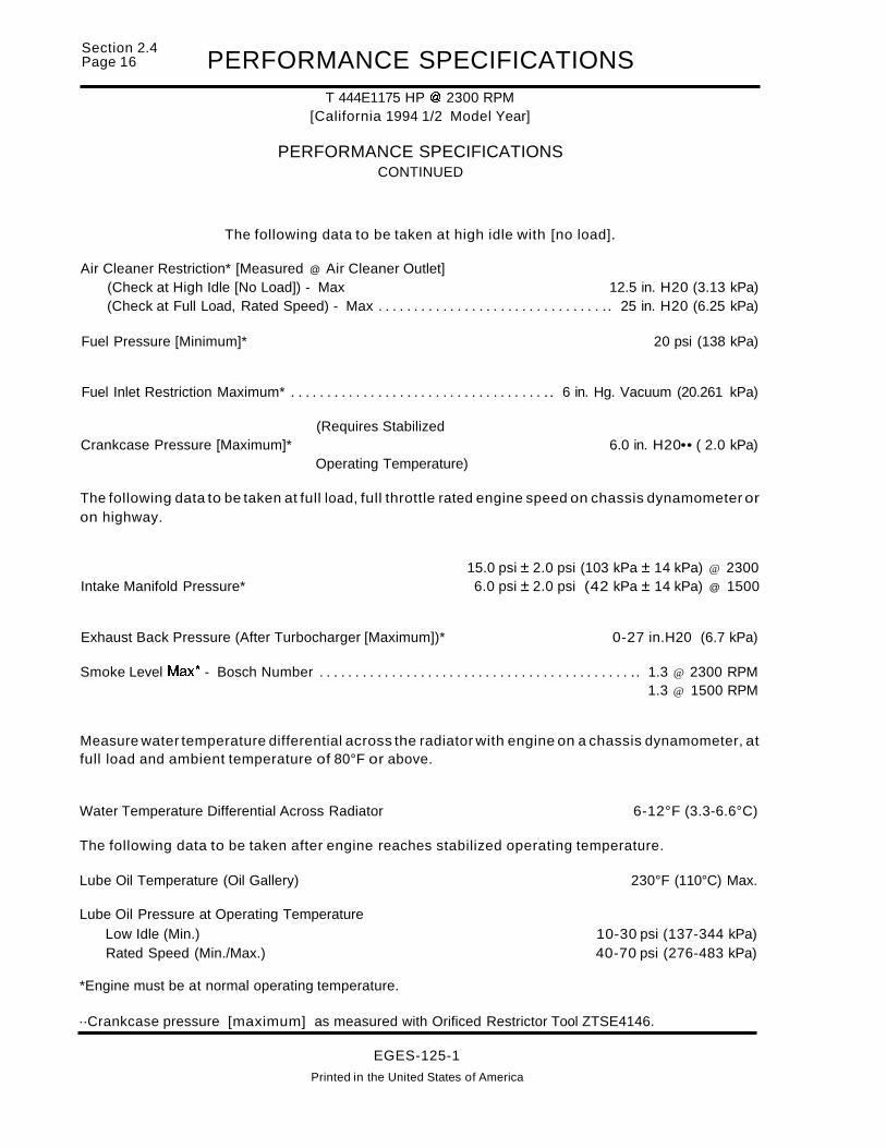
Section 2.4Page 16 PERFORMANCE SPECIFICATIONS
T 444E1175 HP @ 2300 RPM[California 1994 1/2 Model Year]
PERFORMANCE SPECIFICATIONSCONTINUED
The following data to be taken at high idle with [no load].
Air Cleaner Restriction* [Measured @ Air Cleaner Outlet](Check at High Idle [No Load]) - Max 12.5 in. H20 (3.13 kPa)(Check at Full Load, Rated Speed) - Max . . . . . . . . . . . . . . . . . . . . . . . . . . . . . . . .. 25 in. H20 (6.25 kPa)
Fuel Pressure [Minimum]* 20 psi (138 kPa)
Fuel Inlet Restriction Maximum* . . . . . . . . . . . . . . . . . . . . . . . . . . . . . . . . . . . .. 6 in. Hg. Vacuum (20.261 kPa)
(Requires StabilizedCrankcase Pressure [Maximum]* 6.0 in. H20•• ( 2.0 kPa)
Operating Temperature)
The following data to be taken at full load, full throttle rated engine speed on chassis dynamometer oron highway.
15.0 psi ± 2.0 psi (103 kPa ± 14 kPa) @ 2300Intake Manifold Pressure* 6.0 psi ± 2.0 psi (42 kPa ± 14 kPa) @ 1500
Exhaust Back Pressure (After Turbocharger [Maximum])* 0-27 in.H20 (6.7 kPa)
Smoke Level Max* - Bosch Number . . . . . . . . . . . . . . . . . . . . . . . . . . . . . . . . . . . . . . . . . . . .. 1.3 @ 2300 RPM1.3 @ 1500 RPM
Measure water temperature differential across the radiator with engine on a chassis dynamometer, atfull load and ambient temperature of 80°F or above.
Water Temperature Differential Across Radiator 6-12°F (3.3-6.6°C)
The following data to be taken after engine reaches stabilized operating temperature.
Lube Oil Temperature (Oil Gallery) 230°F (110°C) Max.
Lube Oil Pressure at Operating TemperatureLow Idle (Min.) 10-30 psi (137-344 kPa)Rated Speed (Min./Max.) 40-70 psi (276-483 kPa)
*Engine must be at normal operating temperature.
··Crankcase pressure [maximum] as measured with Orificed Restrictor Tool ZTSE4146.
EGES-125-1
Printed in the United States of America

PERFORMANCE SPECIFICATIONST 444E1190 HP @ 2300 RPM
[49 State 1994 1/2 Model Year]
PERFORMANCE SPECIFICATIONS
Section 2.4Page 17
Engine/Model . . . . . . . . . . . . . . . . . . . . . . . . . . . . . . . . . . . . . . . . . . . . . . . . . . . . . . . . . . . . . . . . . .. T 444E/A190F
Engine rating 190 BHP @ 2300 RPM
Engine Family Rating Code (EFRC) 2161
Injector Part NumberOriginal Equipment 1 816 187 C3
Turbocharger Part Number (With Exhaust Back Pressure Device) 1 823 554 C91AIR Ratio 1.0
Turbocharger Part Number (Without Exhaust Back Pressure Device) 1 823 553 C91AIR Ratio 1.0
Injection Timing Not-Adjustable
High Idle Speed - RPM with manual transmission 2500 + 50
High Idle Speed - RPM with automatic transmission . . . . . . . . . . . . . . . . . . . .. 2500 + 200
Low Idle Speed - RPM 700 ±50
Injection Control PressureNoltage@ Low Idle No Load . . . . . . . . . . . . . . . . . . . . . . . . . . . . . .. 590 ± 50 psi (4.00 ± 0.3 MPa) (0.94 ± 0.1 Volts)
Injection Control PressureNoltage@ High Idle No Load 1020 ± 100 psi (7.10 ±0.7 MPa) (1.40 ±0.2 Volts)
Injection Control PressureNoltage@ Rated Speed and Full Load 2470 ± 150 psi (17.0 ± 1.0 MPa) (3.15 ±0.3 Volts)
Intake and Exhaust Valve Clearance (Engine Off - Hot or Cold)Intake Not-AdjustableExhaust " " "".".......................... Not-Adjustable
EGES-125-1
Printed In the United States of America
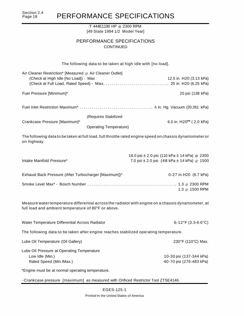
Section 2.4Page 18 PERFORMANCE SPECIFICATIONS
T 444E1190 HP @ 2300 RPM[49 State 1994 1/2 Model Year]
PERFORMANCE SPECIFICATIONSCONTINUED
The following data to be taken at high idle with [no load].
Air Cleaner Restriction* [Measured @ Air Cleaner Outlet](Check at High Idle [No Load]) - Max 12.5 in. H20 (3.13 kPa)(Check at Full Load, Rated Speed) - Max. . . . . . . . . . . . . . . . . . . . . . . . . . . . . . . .. 25 in. H20 (6.25 kPa)
Fuel Pressure [Minimum]* 20 psi (138 kPa)
Fuel Inlet Restriction Maximum* . . . . . . . . . . . . . . . . . . . . . . . . . . . . . . . . . . . .. 6 in. Hg. Vacuum (20.261 kPa)
(Requires StabilizedCrankcase Pressure [Maximum]* 6.0 in. H20•• ( 2.0 kPa)
Operating Temperature)
The following data to be taken at full load, full throttle rated engine speed on chassis dynamometer oron highway.
16.0 psi ± 2.0 psi (110 kPa ± 14 kPa) @ 2300Intake Manifold Pressure* 7.0 psi ± 2.0 psi (48 kPa ± 14 kPa) @ 1500
Exhaust Back Pressure (After Turbocharger [Maximum])* 0-27 in.H20 (6.7 kPa)
Smoke Level Max* - Bosch Number . . . . . . . . . . . . . . . . . . . . . . . . . . . . . . . . . . . . . . . . . . . .. 1.3 @ 2300 RPM1.3 @ 1500 RPM
Measure water temperature differential across the radiator with engine on a chassis dynamometer, atfull load and ambient temperature of 80°F or above.
Water Temperature Differential Across Radiator 6-12°F (3.3-6.6°C)
The following data to be taken after engine reaches stabilized operating temperature.
Lube Oil Temperature (Oil Gallery) 230°F (110°C) Max.
Lube Oil Pressure at Operating TemperatureLow Idle (Min.) 10-30 psi (137-344 kPa)Rated Speed (Min.lMax.) 40-70 psi (276-483 kPa)
*Engine must be at normal operating temperature.
··Crankcase pressure [maximum] as measured with Orificed Restrictor Tool ZTSE4146.
EGES-125-1
Printed In the United States of America
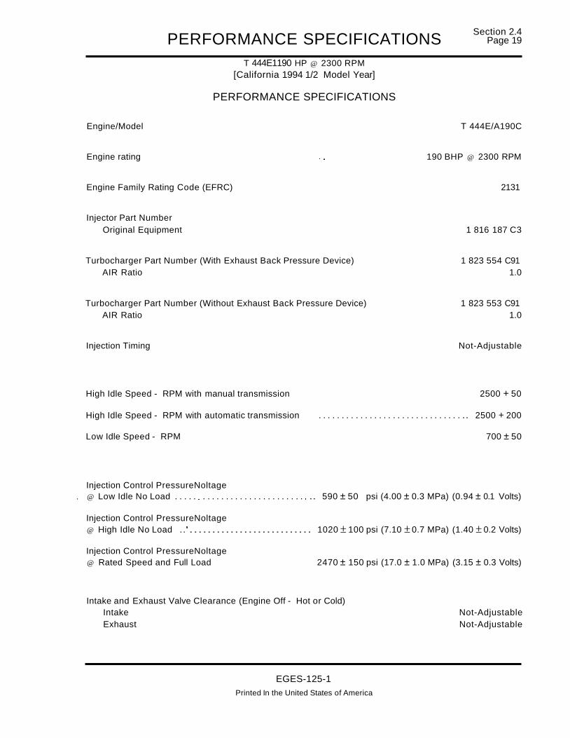
PERFORMANCE SPECIFICATIONST 444E1190 HP @ 2300 RPM
[California 1994 1/2 Model Year]
PERFORMANCE SPECIFICATIONS
Section 2.4Page 19
Engine/Model T 444E/A190C
Engine rating "" 190 BHP @ 2300 RPM
Engine Family Rating Code (EFRC) 2131
Injector Part NumberOriginal Equipment 1 816 187 C3
Turbocharger Part Number (With Exhaust Back Pressure Device) 1 823 554 C91AIR Ratio 1.0
Turbocharger Part Number (Without Exhaust Back Pressure Device) 1 823 553 C91AIR Ratio 1.0
Injection Timing Not-Adjustable
High Idle Speed - RPM with manual transmission 2500 + 50
High Idle Speed - RPM with automatic transmission . . . . . . . . . . . . . . . . . . . . . . . . . . . . . . . .. 2500 + 200
Low Idle Speed - RPM 700 ± 50
Injection Control PressureNoltage. @ Low Idle No Load . . . . . . . . . . . . . . . . . . . . . . . . . . . . . .. 590 ± 50 psi (4.00 ± 0.3 MPa) (0.94 ± 0.1 Volts)
Injection Control PressureNoltage@ High Idle No Load ..'........................... 1020 ± 100 psi (7.10 ±0.7 MPa) (1.40 ± 0.2 Volts)
Injection Control PressureNoltage@ Rated Speed and Full Load 2470 ± 150 psi (17.0 ± 1.0 MPa) (3.15 ± 0.3 Volts)
Intake and Exhaust Valve Clearance (Engine Off - Hot or Cold)Intake Not-AdjustableExhaust Not-Adjustable
EGES-125-1Printed In the United States of America

Section 2.4Page 20 PERFORMANCE SPECIFICATIONS
T 444E1190 HP @ 2300 RPM[California 1994 1/2 Model Year]
PERFORMANCE SPECIFICATIONSCONTINUED
The following data to be taken at high idle with [no load].
Air Cleaner Restriction* [Measured @ Air Cleaner Outlet](Check at High Idle [No Load]) - Max 12.5 in. H20 (3.13 kPa)(Check at Full Load, Rated Speed) - Max . . . . . . . . . . . . . . . . . . . . . . . . . . . . . . . .. 25 in. H20 (6.25 kPa)
Fuel Pressure [Minimum]* 20 psi (138 kPa)
Fuel Inlet Restriction Maximum* 6 in. Hg. Vacuum (20.261 kPa)
(Requires StabilizedCrankcase Pressure [Maximum]* 6.0 in. H20•• ( 2.0 kPa)
Operating Temperature)
The following data to be taken at full load, full throttle rated engine speed on chassis dynamometer oron highway.
16.0 psi ± 2.0 psi (110 kPa ± 14 kPa) @ 2300Intake Manifold Pressure* 7.0 psi ± 2.0 psi (48 kPa ± 14 kPa) @ 1500
Exhaust Back Pressure (After Turbocharger [Maximum])* 0-27 in.H20 (6.7 kPa)
Smoke Level Max* - Bosch Number . . . . . . . . . . . . . . . . . . . . . . . . . . . . . . . . . . . . . . . . . . . .. 1.3 @ 2300 RPM1.3 @ 1500 RPM
Measure water temperature differential across the radiator with engine on a chassis dynamometer, atfull load and ambient temperature of 80°F or above.
Water Temperature Differential Across Radiator 6-12°F (3.3-6.6°C)
The following data to be taken after engine reaches stabilized operating temperature.
Lube Oil Temperature (Oil Gallery) 230°F (110°C) Max.
Lube Oil Pressure at Operating Temperature
Low Idle (Min.) 10-30 psi (137-344 kPa)Rated Speed (Min.lMax.) 40-70 psi (276-483 kPa)
*Engine must be at normal operating temperature.
··Crankcase pressure [maximum] as measured with Orificed Restrictor Tool ZTSE4146.
EGES-125-1Printed in the United States of America

PERFORMANCE SPECIFICATIONST 444E1175 HP @ 2300 RPM[49 State 1995 Model Year]
PERFORMANCE SPECIFICATIONS
Section 2.4Page 21
Engine/Model . . . . . . . . . . . . . . . . . . . . . . . . . . . . . . . . . . . . . . . . . . . . . . . . . . . . . . . . . . . . . . . . . .. T 444E/A175F
Engine rating 175 BHP @ 2300 RPM
Engine Family Rating Code (EFRC) 2111
Injector Part NumberOriginal Equipment 1 816 187 C3
Turbocharger Part Number (With Exhaust Back Pressure Device) 1 823 554 C91AIR Ratio 1.0
Turbocharger Part Number (Without Exhaust Back Pressure Device) 1 823 553 C91AIR Ratio 1.0
Injection Timing Not-Adjustable
High Idle Speed - RPM with manual transmission 2500 + 50
High Idle Speed - RPM with automatic transmission .. . . . . . . . . . . . . . . . . . . . . . . . . . . . . . . . . .. 2500 + 200
Low Idle Speed - RPM 700 ±50
Injection Control PressureNoltage@ Low Idle No Load 590 ± 50 psi (4.00 ± 0.3 MPa) (0.94 ± 0.1 Volts)
Injection Control PressureNoltage@ High Idle No Load 1020 ± 100 psi (7.10 ±0.7 MPa) (1.40 ± 0.2 Volts)
Injection Control PressureNoltage@ Rated Speed and Full Load 2470 ± 150 psi (17.0 ± 1.0 MPa) (3.15 ± 0.3 Volts)
Intake and Exhaust Valve Clearance (Engine Off - Hot or Cold)Intake Not-AdjustableExhaust Not-Adjustable
EGES-125-1
Printed In the United States of America

Section 2.4Page 22 PERFORMANCE SPECIFICATIONS
T 444E1175 HP @ 2300 RPM[49 State 1995 Model Year]
PERFORMANCE SPECIFICATIONSCONTINUED
The following data to be taken at high idle with [no load].
Air Cleaner Restriction* [Measured @ Air Cleaner Outlet](Check at High Idle [No Load]) - Max 12.5 in. H20 (3.13kPa)(Check at Full Load, Rated Speed) - Max . . . . . . . . . . . . . . . . . . . . . . . . . . . . . . . .. 25 in. H20 (6.25 kPa)
Fuel Pressure [Minimum]* 20 psi (138 kPa)
Fuel Inlet Restriction Maximum* . . . . . . . . . . . . . . . . . . . . . . . . . . . . . . . . . . . .. 6 in. Hg. Vacuum (20.261 kPa)
(Requires StabilizedCrankcase Pressure [Maximum]* 6.0 in. H20** ( 2.0 kPa)
Operating Temperature)
The following data to be taken at full load, full throttle rated engine speed on chassis dynamometer oron highway.
15.0 psi ± 2.0 psi (103 kPa ± 14 kPa) @ 2300Intake Manifold Pressure* 6.0 psi ± 2.0 psi (42 kPa ± 14 kPa) @ 1500
Exhaust Back Pressure (After Turbocharger [Maximum])* 0-27 in.H20 (6.7 kPa)
Smoke Level Max* - Bosch Number . . . . . . . . . . . . . . . . . . . . . . . . . . . . . . . . . . . . . . . . . . . .. 1.3 @ 2300 RPM1.3 @ 1500 RPM
Measure water temperature differential across the radiator with engine on a chassis dynamometer, atfull load and ambient temperature of 80°F or above.
Water Temperature Differential Across Radiator 6-12°F (3.3-6.60 C)
The following data to be taken after engine reaches stabilized operating temperature.
Lube Oil Temperature (Oil Gallery) 230°F (110°C) Max.
Lube Oil Pressure at Operating Temperature
Low Idle (Min.) 10-30 psi (137-344 kPa)Rated Speed (Min./Max.) " 40-70 psi (276-483 kPa)
*Engine must be at normal operating temperature.
**Crankcase pressure [maximum] as measured with Orificed Restrictor Tool ZTSE4146.
EGES-125-1
Printed In the United States of America

PERFORMANCE SPECIFICATIONST 444E1175 HP @ 2300 RPM[California 1995 Model Year]
PERFORMANCE SPECIFICATIONS
Section 2.4Page 23
Engine/Model . . . . . . . . . . . . . . . . . . . . . . . . . . . . . . . . . . . . . . . . . . . . . . . . . . . . . . . . . . . . . . . . . .. T 444E/A175C
Engine rating 175 BHP @ 2300 RPM
Engine Family Rating Code (EFRC) 2112
Injector Part NumberOriginal Equipment 1 816 187 C3
Turbocharger Part Number (With Exhaust Back Pressure Device) 1 823554 C91AIR Ratio 1.0
Turbocharger Part Number (Without Exhaust Back Pressure Device) 1 823 553 C91AIR Ratio 1.0
Injection Timing Not-Adjustable
High Idle Speed - RPM with manual transmission 2500 + 50
High Idle Speed - RPM with automatic transmission " .. 2500 + 200
Low Idle Speed - RPM " 700 ±50
Injection Control PressureNoltage@ Low Idle No Load . . . . . . . . . . . . . . . . . . . . . . . . . . . . . .. 590 ± 50 psi (4.00 ± 0.3 MPa) (0.94 ± 0.1 Volts)
Injection Control PressureNoltage@ High Idle No Load 1020 ± 100 psi (7.10 ± 0.7 MPa) (1.40 ± 0.2 Volts)
Injection Control PressureNoltage@ Rated Speed and Full Load 2470 ± 150 psi (17.0 ± 1.0 MPa) (3.15 ± 0.3 Volts)
Intake and Exhaust Valve Clearance (Engine Off - Hot or Cold)Intake Not-AdjustableExhaust ~ ~ " " . " . ~ .. " " . " . ~ . . . . . . . . . . . . . . . . . . . . . . . Not-Adjustable
EGES-125-1Printed In the United States of America

Section 2.4Page 24 PERFORMANCE SP'ECIFICATIONS
T 444E1175 HP @ 2300 RPM[California 1995 Model Year]
PERFORMANCE SPECIFICATIONSCONTINUED
The following data to be taken at high idle with [no load].
Air Cleaner Restriction* [Measured @ Air Cleaner Outlet](Check at High Idle [No Load]) - Max .. ~ ~ . . . . . . . . .. 12.5 in. H20 (3.13 kPa)(Check at Full Load, Rated Speed) - Max . . . . . . . . . . . . . . . . . . . . . . . . . . . . . . . .. 25 in. H20 (6.25 kPa)
Fuel Pressure [Minimum]* 20 psi (138 kPa)
Fuel Inlet Restriction Maximum* . . . . . . . . . . . . . . . . . . . . . . . . . . . . . . . . . . . .. 6 in. Hg. Vacuum (20.261 kPa)
(Requires StabilizedCrankcase Pressure [Maximum]* ~ 6.0 in. H20** (2.0 kPa)
Operating Temperature)
The following data to be taken at full load, full throttle rated engine speed on chassis dynamometer oron highway.
15.0 psi ± 2.0 psi (103 kPa ± 14 kPa) @ 2300Intake Manifold Pressure* 6.0 psi ±2.0 psi (42 kPa ± 14 kPa) @ 1500
Exhaust Back Pressure (After Turbocharger [Maximum])* 0-27 in.H20 (6.7 kPa)
Smoke Level Max* - Bosch Number ... '.' . . . . . . . . . . . . . . . . . . . . . . . . . . . . . . . . . . . . . . .. 1.3 @ 2300 RPM1.3 @ 1500 RPM
Measure water temperature differential across the radiator with engine on a chassis dynamometer, atfull load and ambient temperature of 80°F or above.
Water Temperature Differential Across Radiator 6-12°F (3.3-6.6°C)
The following data to be taken after engine reaches stabilized operating temperature.
Lube Oil Temperature (Oil Gallery) 230°F (110°C) Max.
Lube Oil Pressure at Operating Temperature
Low Idle (Min.) 10-30 psi (137-344 kPa)Rated Speed (Min./Max.) 40-70 psi (276-483 kPa)
*Engine must be at normal operating temperature.
**Crankcase pressure [maximum] as measured with Orificed Restrictor Tool ZTSE4146.
EGES-125-1Printed In the United States of America

PERFORMANCE SPECIFICATIONST 444E1190 HP @ 2300 RPM[49 State 1995 Model Year]
PERFORMANCE SPECIFICATIONS
Section 2.4Page 25
Engine/Model . . . . . . . . . . . . . . . . . . . . . . . . . . . . . . . . . . . . . . . . . . . . . . . . . . . . . . . . . . . . . . . . . .. T 444E1A190F
Engine rating 190 BHP @ 2300 RPM
Engine Family Rating Code (EFRC) 2121
Injector Part NumberOriginal Equipment 1 816 187 C3
Turbocharger Part Number (With Exhaust Back Pressure Device) 1 823 554 C91AIR Ratio 1.0
Turbocharger Part Number (Without Exhaust Back Pressure Device) 1 823 553 C91AIR Ratio 1.0
Injection Timing Not-Adjustable
High Idle Speed - RPM with manual transmission 2500 + 50
High Idle Speed - RPM with automatic transmission . . . . . . . . . . . . . . . . . . . . . . .. 2500 + 200
Low Idle Speed - RPM 700 ±50
Injection Control PressureNoltage@ Low Idle No Load . . . . . . . . . . . . . . . . . . . . . . . . . . . . . .. 590 ±50 psi (4.00 ±0.3 MPa) (0.94 ± 0.1 Volts)
Injection Control PressureNoltage@ High Idle No Load 1020 ± 100 psi (7.10 ±0.7 MPa) (1.40 ±0.2 Volts)
Injection Control PressureNoltage@ Rated Speed and Full Load 2470 ± 150 psi (17.0 ±1.0 MPa) (3.15 ±0.3 Volts)
Intake and Exhaust Valve Clearance (Engine Off - Hot or Cold)Intake Not-AdjustableExhaust Not-Adjustable
EGES-125-1Printed In the United States of America
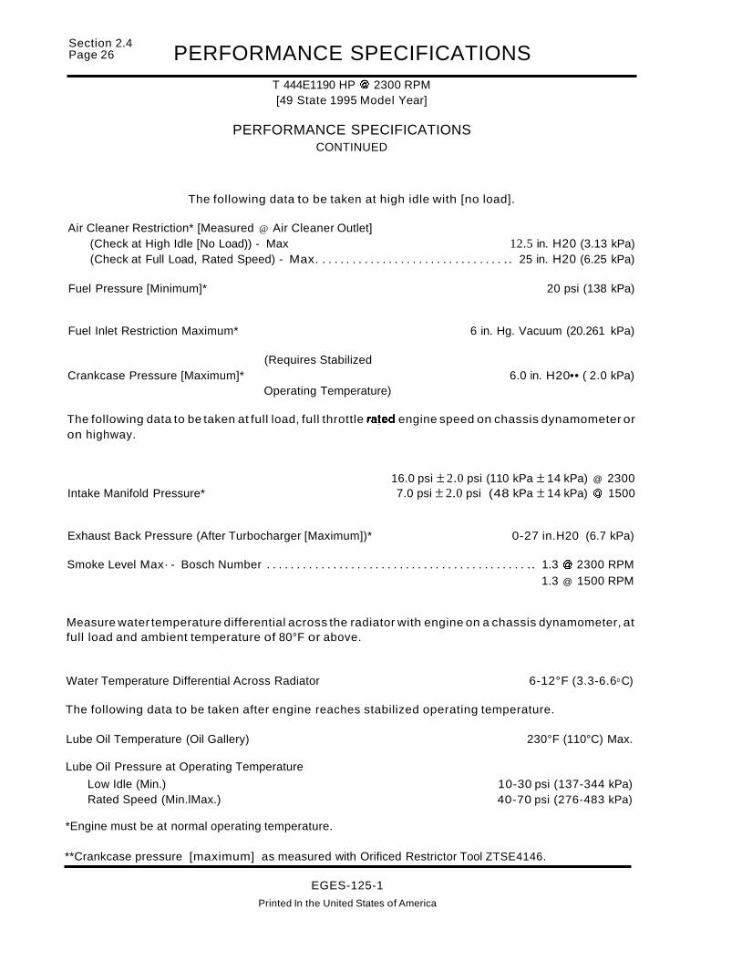
Section 2.4Page 26 PERFORMANCE SPECIFICATIONS
T 444E1190 HP @ 2300 RPM[49 State 1995 Model Year]
PERFORMANCE SPECIFICATIONSCONTINUED
The following data to be taken at high idle with [no load].
Air Cleaner Restriction* [Measured @ Air Cleaner Outlet](Check at High Idle [No Load)) - Max 12.5 in. H20 (3.13 kPa)(Check at Full Load, Rated Speed) - Max. . . . . . . . . . . . . . . . . . . . . . . . . . . . . . . .. 25 in. H20 (6.25 kPa)
Fuel Pressure [Minimum]* 20 psi (138 kPa)
Fuel Inlet Restriction Maximum* 6 in. Hg. Vacuum (20.261 kPa)
(Requires StabilizedCrankcase Pressure [Maximum]* 6.0 in. H20•• ( 2.0 kPa)
Operating Temperature)
The following data to be taken at full load, full throttle rated engine speed on chassis dynamometer oron highway.
16.0 psi ± 2.0 psi (110 kPa ± 14 kPa) @ 2300Intake Manifold Pressure* 7.0 psi ± 2.0 psi (48 kPa ± 14 kPa) @ 1500
Exhaust Back Pressure (After Turbocharger [Maximum])* 0-27 in.H20 (6.7 kPa)
Smoke Level Max· - Bosch Number . . . . . . . . . . . . . . . . . . . . . . . . . . . . . . . . . . . . . . . . . . . .. 1.3 @ 2300 RPM1.3 @ 1500 RPM
Measure water temperature differential across the radiator with engine on a chassis dynamometer, atfull load and ambient temperature of 80°F or above.
Water Temperature Differential Across Radiator 6-12°F (3.3-6.60 C)
The following data to be taken after engine reaches stabilized operating temperature.
Lube Oil Temperature (Oil Gallery) 230°F (110°C) Max.
Lube Oil Pressure at Operating Temperature
Low Idle (Min.) 10-30 psi (137-344 kPa)Rated Speed (Min.lMax.) 40-70 psi (276-483 kPa)
*Engine must be at normal operating temperature.
**Crankcase pressure [maximum] as measured with Orificed Restrictor Tool ZTSE4146.
EGES-125-1
Printed In the United States of America

PERFORMANCE SPECIFICATIONST 444E1190HP @ 2300 RPM[California 1995 Model Year]
PERFORMANCE SPECIFICATIONS
Section 2.4Page 27
Engine/Model . . . . . . . . . . . . . . . . . . . . . . . . . . . . . . . . . . . . . . . . . . . . . . . . . . . . . . . . . . . . . . . . . .. T 444E1A190C
Engine rating 190 BHP @ 2300 RPM
Engine Family Rating Code (EFRC) 2122
Injector Part NumberOriginal Equipment 1 816187 C3
Turbocharger Part Number (With Exhaust Back Pressure Device) 1 823 554 C91AIR Ratio 1.0
Turbocharger Part Number (Without Exhaust Back Pressure Device) 1 823 553 C91AIR Ratio · .. · 1.0
Injection Timing Not-Adjustable
High Idle Speed - RPM with manual transmission 2500 + 50
High Idle Speed - RPM with automatic transmission . . . . . . . . . . . . . . . . . . . . . . . . . . . . . . . .. 2500 + 200
Low Idle Speed - RPM · · .. 700 ±50
Injection Control PressureNoltage@ Low Idle No Load . . . . . . . . . . . . . . . . . . . . . . . . . . . . . .. 590 ± 50 psi (4.00 ± 0.3 MPa) (0.94 ± 0.1 Volts)
Injection Control PressureNoltage@ High Idle No Load 1020 ± 100 psi (7.10 ± 0.7 MPa) (1.40 ± 0.2 Volts)
Injection Control PressureNoltage@ Rated Speed and Full Load 2470 ± 150 psi (17.0 ± 1.0 MPa) (3.15 ± 0.3 Volts)
Intake and Exhaust Valve Clearance (Engine Off - Hot or Cold)Intake Not-AdjustableExhaust Not-Adjustable
EGES-125-1
____________Prlnted In the Unlted_S~t~Qf Ame~l~a

Section 2.4Page 28 PERFORMANCE SPECIFICATIONS
T 444E1190 HP @ 2300 RPM[California 1995 Model Year]
PERFORMANCE SPECIFICATIONSCONTINUED
The following data to be taken at high idle with [no load].
Air Cleaner Restriction* [Measured @ Air Cleaner Outlet](Check at High Idle [No Load]) - Max 12.5 in. H20 (3.13 kPa)(Check at Full Load, Rated Speed) - Max. . . . . . . . . . . . . . . . . . . . . . . . . . . . . . . .. 25 in. H20 (6.25 kPa)
Fuel Pressure [Minimum]* 20 psi (138 kPa)
Fuel Inlet Restriction Maximum* . . . . . . . . . . . . . . . . . . . . . . . . . . . . . . . . . . . .. 6 in. Hg. Vacuum (20.261 kPa)
(Requires StabilizedCrankcase Pressure [Maximum]* 6.0 in. H20** ( 2.0 kPa)
Operating Temperature)
The following data to be taken at full load, full throttle rated engine speed on chassis dynamometer oron highway.
16.0 psi ± 2.0 psi (110 kPa ± 14 kPa) @ 2300Intake M~nifold Pressure* 7.0 psi ± 2.0 psi (48 kPa ± 14 kPa) @ 1500
Exhaust Back Pressure (After Turbocharger [Maximum])* 0-27 in.H20 (6.7 kPa)
Smoke Level Max* - Bosch Number . . . . . . . . . . . . . . . . . . . . . . . . . . . . . . . . . . . . . . . . . . . .. 1.3 @ 2300 RPM1.3 @ 1500 RPM
Measure water temperature differential across the radiator with engine on a chassis dynamometer, atfull load and ambient temperature of 80°F or above.
Water Temperature Differential Across Radiator . . . . . . . . .. 6-12°F (3.3-6.6°C)
The following data to be taken after engine reaches stabilized operating temperature.
Lube Oil Temperature (Oil Gallery) 230°F (110°C) Max.
Lube Oil Pressure at Operating TemperatureLow Idle (Min.) 10-30 psi (137-344 kPa)Rated Speed (MiniMax.) 40-70 psi (276-483 kPa)
*Engine must be at normal operating temperature.
**Crankcase pressure [maximum] as measured with Orificed Restrictor Tool ZTSE4146.
EGES-125-1
Printed in the United States of America

PERFORMANCE SPECIFICATIONST 444E1210 HP @ 2400 RPM[49 State 1995 Model Year]
PERFORMANCE SPECIFICATIONS
Section 2.4Page 29
Engine/Model. . . . . . . . . . . . . . . . . . . . . . . . . . . . . . . . . . . . . . . . . . . . . . . . . . . . . . . . . . . . . . . . . .. T 444E/A21 OF
Engine rating 210 BHP @ 2400 RPM
Engine Family Rating Code (EFRC) 2231
Injector Part NumberOriginal Equipment 1 816 187 C3
Turbocharger Part Number (With Exhaust Back Pressure Device) 1 823 554 C91AIR Ratio " 1.0
Turbocharger Part Number (Without Exhaust Back Pressure Device) 1 823 553 C91AIR Ratio 1.0
Injection Timing Not-Adjustable
High Idle Speed - RPM with manual transmission 2500 + 50
High Idle Speed - RPM with automatic transmission . . . . . . . . . . . . . . . . . . . . . . .. 2500 + 200
Low Idle Speed - RPM " 700 ± 50
Injection Control PressureNoltage@ Low Idle No Load 590 ± 50 psi (4.00 ±0.3 MPa) (0.94 ± 0.1 Volts)
Injection Control PressureNoltage@ High Idle No Load 1020 ± 100 psi (7.10 ± 0.7 MPa) (1.40 ± 0.2 Volts)
Injection Control PressureNoltage@ Rated Speed and Full Load 2470 ± 150 psi (17.0 ± 1.0 MPa) (3.15 ± 0.3 Volts)
Intake and Exhaust Valve Clearance (Engine Off - Hot or Cold)Intake Not-AdjustableExhaust "" .. " .. " " "."........................ Not-Adjustable
EGES-125-1
Printed In the United States of America

Section 2.4Page 30 PERFORMANCE SPECIFICATIONS
T 444E121 0 HP @ 2400 RPM[49 State 1995 Model Year]
PERFORMANCE SPECIFICATIONSCONTINUED
The following data to be taken at high idle with [no load].
Air Cleaner Restriction* [Measured @ Air Cleaner Outlet](Check at High Idle [No Load]) - Max 12.5 in. H20 (3.13 kPa)(Check at Full Load, Rated Speed) - Max. . . . . . . . . . . . . . . . . . . . . . . . . . . . . . . .. 25 in. H20 (6.25 kPa)
Fuel Pressure [Minimum]* 20 psi (138 kPa)
Fuel Inlet Restriction Maximum* . . . . . . . . . . . . . . . . . . . . . . . . . . . . . . . . . . . .. 6 in. Hg. Vacuum (20.261 kPa)
(Requires StabilizedCrankcase Pressure [Maximum]* 6.0 in. H20 •• ( 2.0 kPa)
Operating Temperature)
The following data to be taken at full load, full throttle rated engine speed on chassis dynamometer oron highway.
17.0 psi ± 2.0 psi (117 kPa ± 14 kPa) @ 2400Intake Manifold Pressure* 7.0 psi ± 2.0 psi (48 kPa ± 14 kPa) @ 1500
Exhaust Back Pressure (After Turbocharger [Maximum])* 0-27 in.H20 (6.7 kPa)
Smoke Level Max* - Bosch Number . . . . . . . . . . . . . . . . . . . . . . . . . . . . . . . . . . . . . . . . . . . .. 1.3 @ 2400 RPM1.3 @ 1500 RPM
Measure water temperature differential across the radiator with engine on a chassis dynamometer, atfull load and ambient temperature of 80°F or above.
Water Temperature Differential Across Radiator 6-12°F (3.3-6.6°C)
The following data to be taken after engine reaches stabilized operating temperature.
Lube Oil Temperature (Oil Gallery) 230°F (110°C) Max.
Lube Oil Pressure at Operating TemperatureLow Idle (Min.) 10-30 psi (137-344 kPa)Rated Speed (Min.lMax.) 40-70 psi (276-483 kPa)
*Engine must be at normal operating temperature.
**Crankcase pressure [maximum] as measured with Orificed Restrictor Tool ZTSE4146.
EGES-125-1
Printed In the United States of America

PERFORMANCE SPECIFICATIONST 444E1210 HP @ 2400 RPM[California 1995 Model Year]
PERFORMANCE SPECIFICATIONS
Section 2.4Page 31
Engine/Model T 444E/A210C
Engine rating 210 BHP @ 2400 RPM
Engine Family Rating Code (EFRC) 2232
Injector Part NumberOriginal Equipment 1 816 187 C3
Turbocharger Part Number (With Exhaust Back Pressure Device) 1 823 554 C91AIR Ratio 1.0
Turbocharger Part Number (Without Exhaust Back Pressure Device) 1 823 553 C91AIR Ratio 1.0
Injection Timing Not-Adjustable
High Idle Speed - RPM with manual transmission 2500 + 50
High Idle Speed - RPM with automatic transmission . . . . . . . . . . . . . . .. 2500 + 200
Low Idle Speed - RPM 700 ±50
Injection Control PressureNoltage@ Low Idle No Load 590 ± 50 psi (4.00 ±0.3 MPa) (0.94 ± 0.1 Volts)
Injection Control PressureNoltage@ High Idle No Load 1020 ± 100 psi (7.10 ± 0.7 MPa) (1.40 ± 0.2 Volts)
Injection Control PressureNoltage@ Rated Speed and Full Load . . . . . . . . . . . . . .. 2470 ± 150 psi (17.0 ± 1.0 MPa) (3.15 ± 0.3 Volts)
Intake and Exhaust Valve Clearance (Engine Off - Hot or Cold)Intake Not-AdjustableExhaust Not-Adjustable
EGES-125-1
Printed In the United States of America

Section 2.4Page 32 PERFORMANCE SPECIFICATIONS
T 444E1210 HP @ 2400 RPM[California 1995 Model Year]
PERFORMANCE SPECIFICATIONSCONTINUED
The following data to be taken at high idle with [no load].
Air Cleaner Restriction* [Measured @ Air Cleaner Outlet](Check at High Idle [No Load]) - Max 12.5 in. H20 (3.13 kPa)(Check at Full Load, Rated Speed) - Max . . . . . . . . . . . . . . . . . . . . . . . . . . . . . . . .. 25 in. H20 (6.25 kPa)
Fuel Pressure [Minimum]* 20 psi (138 kPa)
Fuel Inlet Restriction Maximum* 6 in. Hg. Vacuum (20.261 kPa)
(Requires StabilizedCrankcase Pressure [Maximum]* 6.0 in. H20** ( 2.0 kPa)
Operating Temperature)
The following data to be taken at full load, full throttle rated engine speed on chassis dynamometer oron highway.
17.0 psi ± 2.0 psi (117 kPa ± 14 kPa) @ 2400Intake Manifold Pressure* 7.0 psi ± 2.0 psi (48 kPa ± 14 kPa) @ 1500
Exhaust Back Pressure (After Turbocharger [Maximum])* 0-27 in.H20 (6.7 kPa)
Smoke Level Max* - Bosch Number . . . . . . . . . . . . . . . . . . . . . . . . . . . . . . . . . . . . . . . . . . . . . 1.3 @ 2400 RPM1.3 @ 1500 RPM
Measure water temperature differential across the radiator with engine on a chassis dynamometer, atfull load and ambient temperature of 80°F or above.
Water Temperature Differential Across Radiator 6-12°F (3.3-6.6°C)
The following data to be taken after engine reaches stabilized operating temperature.
Lube Oil Temperature (Oil Gallery) 230°F (110°C) Max.
Lube Oil Pressure at Operating Temperature
Low Idle (Min.) 10-30 psi (137-344 kPa)Rated Speed (Min./Max.) 40-70 psi (276-483 kPa)
*Engine must be at normal operating temperature.
**Crankcase pressure [maximum] as measured with Orificed Restrictor Tool ZTSE4146.
EGES-125-1
Printed in the United States of America

PERFORMANCE SPECIFICATIONST 444E1210 HP @ 2300 RPM
[49 State 1995 1/2 Model Year]
PERFORMANCE SPECIFICATIONS
Section 2.4Page 33
Engine/Model . . . . . . . . . . . . . . . . . . . . . . . . . . . . . . . . . . . . . . . . . . . . . . . . . . . . . . . . . . . . . . . . . .. T 444E/A21 OF
Engine rating 210 BHP @ 2300 RPM
Engine Family Rating Code (EFRC) 2141
Injector Part NumberOriginal Equipment 1 822 890 C1
Turbocharger Part Number (With Wastegate) 1 823 560 C91AIR Ratio 1.11
Injection Timing Not-Adjustable
High Idle Speed - RPM with manual transmission e 2500 + 50
High Idle Speed - RPM with automatic transmission . . . . . . . . . . . . . . . . . . . . . . .. 2500 + 200
Low Idle Speed - RPM e •• 700 ±50
Injection Control PressureNoltage@ Low Idle No Load. . . . . . . . . . . . . . . . . . . . . . . . . . . . . .. 590 ±50 psi (4.00 ± 0.3 MPa) (0.94 ± 0.1 Volts)
Injection Control PressureNoltage@ High Idle No Load 1020 ± 100 psi (7.10 ±0.7 MPa) (1.40 ± 0.2 Volts)
Injection Control PressureNoltage@ Rated Speed and Full Load 2470 ± 150 psi (17.0 ± 1.0 MPa) (3.15 ± 0.3 Volts)
Intake and Exhaust Valve Clearance (Engine Off - Hot or Cold)Intake Not-AdjustableExhaust Not-Adjustable
EGES-125-1
Printed In the United States of America

Section 2.4Page 34 PERFORMANCE SPECIFICATIONS
T 444E1210 HP @ 2300 RPM[49 State 1995 1/2 Model Year]
PERFORMANCE SPECIFICATIONSCONTINUED
The following data to be taken at high idle with [no load].
Air Cleaner Restriction* [Measured @ Air Cleaner Outlet](Check at High Idle [No Load]) - Max 12.5 in. H20 (3.13kPa)(Check at Full Load, Rated Speed) - Max. . . . . . . . . . . . . . . . . . . . . . . . . . . . . . . .. 25 in. H20 (6.25 kPa)
Fuel Pressure [Minimum]* 20 psi (138 kPa)
Fuel Inlet Restriction Maximum* . . . . . . . . . . . . . . . . . . . . . . . . . . . . . . . . . . . .. 6 in. Hg. Vacuum (20.261 kPa)
(Requires StabilizedCrankcase Pressure [Maximum]* ~ 6.0 in. H20** ( 2.0 kPa)
Operating Temperature)
The following data to be taken at full load, full throttle rated engine speed on chassis dynamometer oron highway.
17.0 psi ± 2.0 psi (117 kPa ± 14 kPa) @ 2300Intake Manifold Pressure* 8.0 psi ± 2.0 psi (55 kPa ± 14 kPa) @ 1500
Exhaust Back Pressure (After Turbocharger [Maximum])* 0-27 in.H20 (6.7 kPa)
Smoke Level Max* - Bosch Number . . . . . . . . . . . . . . . . . . . . . . . . . . . . . . . . . . . . . . . . . . . .. 1.3 @ 2300 RPM1.3 @ 1500 RPM
Measure water temperature differential across the radiator with engine on a chassis dynamometer, atfull load and ambient temperature of 80°F or above.
Water Temperature Differential Across Radiator 6-12°F (3.3-6.60 C)
The following data to be taken after engine reaches stabilized operating temperature.
Lube Oil Temperature (Oil Gallery) 230°F (110°C) Max.
Lube Oil Pressure at Operating Temperature
Low Idle (Min.) 10-30 psi (137-344 kPa)Rated Speed (Min./Max.) 40-70 psi (276-483 kPa)
*Engine must be at normal operating 'temperature.
**Crankcase pressure [maximum] as measured with Orificed Restrictor Tool ZTSE4146.
EGES-125-1
Printed in the United States of America

PERFORMANCE SPECIFICATIONST 444E1210 HP @ 2300 RPM
[California 1995 1/2 Model Year]
PERFORMANCE SPECIFICATIONS
Section 2.4Page 35
Engine/Model T 444E/A210C
Engine rating 210 BHP @ 2300 RPM
Engine Family Rating Code (EFRC) 2142
Injector Part NumberOriginal Equipment 1 822 890 C1
Turbocharger Part Number (With Wastegate) 1 823 560 C91AIR Ratio 1.11
Injection Timing Not-Adjustable
High Idle Speed - RPM with manual transmission 2500 + 50
High Idle Speed - RPM with automatic transmission . . . . . . . . . . . . . . . . . . . . . . .. 2500 + 200
Low Idle Speed - RPM 700 ± 50
Injection Control PressureNoltage@ Low Idle No Load . . . . . . . . . . . . . . . . . . . . . . . . . . . . . .. 590 ±50 psi (4.00 ± 0.3 MPa) (0.94 ± 0.1 Volts)
Injection Control PressureNoltage@ High Idle No Load 1020 ± 100 psi (7.10 ±0.7 MPa) (1.40 ± 0.2 Volts)
Injection Control PressureNoltage@ Rated Speed and Full Load 2470 ± 150 psi (17.0 ± 1.0 MPa) (3.15 ±0.3 Volts)
Intake and Exhaust Valve Clearance (Engine Off - Hot or Cold)Intake Not-AdjustableExhaust Not-Adjustable
EGES-125-1
Printed In the United States of America

Section 2.4Page 36 PERFORMANCE SPECIFICATIONS
T 444E1210 HP @ 2300 RPM[California 1995 1/2 Model Year]
PERFORMANCE SPECIFICATIONSCONTINUED
The following data to be taken at high idle with [no load].
Air Cleaner Restriction* [Measured @ Air Cleaner Outlet](Check at High Idle [No Load]) - Max 12.5 in. H20 (3.13 kPa)(Check at Full Load, Rated Speed) - Max. . . . . . . . . . . . . . . . . . . . . . . . . . . . . . . .. 25 in. H20 (6.25 kPa)
Fuel Pressure [Minimum]* 20 psi (138 kPa)
Fuel Inlet Restriction Maximum* 6 in. Hg. Vacuum (20.261 kPa)
(Requires StabilizedCrankcase Pressure [Maximum]* 6.0 in. H20 ** ( 2.0 kPa)
Operating Temperature)
The following data to be taken at full load, full throttle rated engine speed on chassis dynamometer oron highway.
17.0 psi ±2.0 psi (117 kPa ± 14 kPa) @ 2300Intake Manifold Pressure* 8.0 psi ±2.0 psi (55 kPa ± 14 kPa) @ 1500
Exhaust Back Pressure (After Turbocharger [Maximum])* 0-27 in.H20 (6.7 kPa)
Smoke Level Max* - Bosch Number . . . . . . . . . . . . . . . . . . . . . . . . . . . . . . . . . . . . . . . . . . . .. 1.3 @ 2300 RPM1.3 @ 1500 RPM
Measure water temperature differential across the radiator with engine on a chassis dynamometer, atfull load and ambient temperature of 80°F or above.
Water Temperature Differential Across Radiator 6-12°F (3.3-6.6°C)
The following data to be taken after engine reaches stabilized operating temperature.
Lube Oil Temperature (Oil Gallery) 230°F (110°C) Max.
Lube Oil Pressure at Operating TemperatureLow Idle (Min.) 10-30 psi (137-344 kPa)Rated Speed (Min.lMax.) 40-70 psi (276-483 kPa)
*Engine must be at normal operating temperature.
**Crankcase pressure [maximum] as measured with Orificed Restrictor Tool ZTSE4146.
EGES-125-1
Printed In the United States of America

PERFORMANCE SPECIFICATIONST 444E1230 HP @ 2300 RPM
[49 State 1995 1/2 Model Year]
PERFORMANCE SPECIFICATIONS
Section 2.4Page 37
Engine/Model . . . . . . . . . . . . . . . . . . . . . . . . . . . . . . . . . . . . . . . . . . . . . . . . . . . . . . . . . . . . . . . . . .. T 444E1A230F
Engine rating 230 BHP @ 2300 RPM
Engine Family Rating Code (EFRC) 2151
Injector Part NumberOriginal Equipment 1 822 890 C1
Turbocharger Part Number (With Wastegate) 1 823 560 C91AIR Ratio 1.11
Injection Timing Not-Adjustable
High Idle Speed - RPM with manual transmission 2500 + 50
High Idle Speed - RPM with automatic transmission 2500 + 200
Low Idle Speed - RPM 700 ±50
Injection Control PressureNoltage@ Low Idle No Load . . . . . . . . . . . . . . . . . . . . . . . . . . . . . .. 590 ±50 psi (4.00 ± 0.3 MPa) (0.94 ± 0.1 Volts)
Injection Control PressureNoltage@ High Idle No Load 1020 ± 100 psi (7.10 ±0.7 MPa) (1.40 ± 0.2 Volts)
Injection Control PressureNoltage@ Rated Speed and Full Load 2470 ± 150 psi (17.0 ± 1.0 MPa) (3.15 ± 0.3 Volts)
Intake and Exhaust Valve Clearance (Engine Off - Hot or Cold)Intake '~ Not-AdjustableExhaust Not-Adjustable
EGES-125-1
Printed In the United States of America

Section 2.4Page 38 PERFORMANCE SPECIFICATIONS
T 444E1230 HP @ 2300 RPM[49 State 1995 1/2 Model Year]
PERFORMANCE SPECIFICATIONSCONTINUED
The following data to be taken at high idle with [no load].
Air Cleaner Restriction* [Measured @ Air Cleaner Outlet](Check at High Idle [No Load]) - Max 12.5 in. H20 (3.13 kPa)(Check at Full Load, Rated Speed) - Max. . . . . . . . . . . . . . . . . . . . . . . . . . . . . . . .. 25 in. H20 (6.25 kPa)
Fuel Pressure [Minimum]* 20 psi (138 kPa)
Fuel Inlet Restriction Maximum* . . . . . . . . . . . . . . . . . . . . . . . . . . . . . . . . . . . .. 6 in. Hg. Vacuum (20.261 kPa)
(Requires StabilizedCrankcase Pressure [Maximum]* 6.0 in. H20 ** ( 2.0 kPa)
Operating Temperature)
The following data to be taken at 'uliload, full throttle rated engine speed on chassis dynamometer or
on highway.
17.0 psi ±2.0 psi (117 kPa ±14 kPa) @ 2300Intake Manifold Pressure* 11.0 psi ± 2.0 psi (76 kPa ± 14 kPa) @ 1500
Exhaust Back Pressure (After Turbocharger [Maximum])* 0-27 in.H20 (6.7 kPa)
Smoke Level Max* - Bosch Number . . . . . . . . . . . . . . . . . . . . . . . . . . . . . . . . . . . . . . . . . . . .. 1.3 @ 2300 RPM1.3 @ 1500 RPM
Measure water temperature differential across the radiator with engine on a chassis dynamometer, atfull load and ambient temperature of 80°F or above.
Water Temperature Differential Across Radiator 6-12°F (3.3-6.6°C)
The following data to be taken after engine reaches stabilized operating temperature.
Lube Oil Temperature (Oil Gallery) 230°F (110°C) Max.
Lube Oil Pressure at Operating TemperatureLow Idle (Min.) 10-30 psi (137-344 kPa)Rated Speed (Min./Max.) 40-70 psi (276-483 kPa)
*Engine must be at normal operating temperature.
\**Crankca~~ pressure [maximum] as measured with Orificed Restrictor Tool ZTSE4146.
EGES-125-1
Printed In the United States of America

PERFORMANCE SPECIFICATIONST 444E1230 HP @ 2300 RPM
[California 1995 1/2 Model Year]
PERFORMANCE SPECIFICATIONS
Section 2.4Page 39
Engine/Model ~ . . . . . . . . . . . . . . . . . . . . . . . . . . . . . . . . . . . . . . . . . . . . .. T 444E/A230C
Engine rating 230 BHP @ 2300 RPM
Engine Family Rating Code (EFRC) 2152
Injector Part NumberOriginal Equipment 1 822 890 C1
Turbocharger Part Number (With Wastegate) ~ 1 823 560 C91AIR Ratio ~ 1.11
Injection Timing Not-Adjustable
High Idle Speed - RPM with manual transmission 2500 + 50
High Idle Speed - RPM with automatic transmission . . . . . . . . . . . . . . . . . . . . . . . . . . . . . .. 2500 + 200
Low Idle Speed - RPM 700 ± 50
Injection Control PressureNoltage@ Low Idle No Load . . . . . . . . . . . . . . . . . . . . . . . . . . . . . .. 590 ± 50 psi (4.00 ± 0.3 MPa) (0.94 ± 0.1 Volts)
Injection Control PressureNoltage@ High Idle No Load 1020 ± 100 psi (7.10 ± 0.7 MPa) (1.40 ± 0.2 Volts)
Injection Control PressureNoltage@ Rated Speed and Full Load 2470±150psi(17.0±1.0MPa) (3.15±0.,3Volts)
Intake and Exhaust Valve Clearance (Engine Off - Hot or Cold)Intake Not-AdjustableExhaust Not-Adjustable
EGES-125-1
Printed In the United States of America

Section 2.4Page 40 PERFORMANCE SPECIFICATIONS
T 444E1230 HP @ 2300 RPM[California 1995 1/2 Model Year]
PERFORMANCE SPECIFICATIONSCONTINUED
The following data to be taken at high idle with [no load].
Air Cleaner Restriction* [Measured @ Air Cleaner Outlet](Check at High Idle [No Load]) - Max 12.5 in. H20 (3.13 kPa)(Check at Full Load, Rated Speed) - Max. . . . . . . . . . . . . . . . . . . . . . . . . . . . . . . .. 25 in. H20 (6.25 kPa)
Fuel Pressure [Minimum]* 20 psi (138 kPa)
Fuel Inlet Restriction Maximum* 6 in. Hg. Vacuum (20.261 kPa)
(Requires StabilizedCrankcase Pressure [Maximum]* 6.0 in. H20** ( 2.0 kPa)
Operating Temperature)
The following data to be taken at full load, full throttle rated engine speed on chassis dynamometer oron highway.
17.0 psi ±2.0 psi (117 kPa ± 14 kPa) @ 2300Intake Manifold Pressure* 11.0 psi ± 2.0 psi (76 kPa ± 14 kPa) @ 1500
Exhaust Back Pressure (After Turbocharger [Maximum])* 0-27 in.H20 (6.7 kPa)
Smoke Level Max* - Bosch Number . . . . . . . . . . . . . . . . . . . . . . . . . . . . . . . . . . . . . . . . . . . .. 1.3 @ 2300 RPM1.3 @ 1500 RPM
Measure water. temperature differential across the radiator with engine on a chassis dynamometer, atfull load and ambient temperature of 80°F or above.
Water Temperature Differential Across Radiator 6-12°F (3.3-6.6°C)
The following data to be taken after engine reaches stabilized operating temperature.
Lube Oil Temperature (Oil Gallery) 230°F (110°C) Max.
Lube Oil Pressure at Operating Temperature
Low Idle (Min.) 10-30 psi (137-344 kPa)Rated Speed (Min.lMax.) 40-70 psi (276-483 kPa)
*Engine must be at normal operating temperature.
**Crankcase pressure [maximum] as measured with Orificed Restrictor Tool ZTSE4146.
EGES-125-1
Printed in the United States of America

PERFORMANCE SPECIFICATIONST 444E1175 HP @ 2300 RPM[49 State 1996 Model Year]
PERFORMANCE SPECIFICATIONS
Section 2.4Page 41
Engine/Model T 444E/A175F
Engine rating " 175 BHP @ 2300 RPM
Engine Family Rating Code (EFRC) 2111
Injector Part NumberOriginal Equipment 1 816 187 C3
Turbocharger Part Number (With Exhaust Back Pressure Device) 1 823 554 C91AIR Ratio 1.0
Turbocharger Part Number (Without Exhaust Back Pressure Device) 1 823 553 C91AIR Ratio 1.0
Injection Timing Not-Adjustable
High Idle Speed - RPM with manual transmission 2500 + 50
High Idle Speed - RPM with automatic transmission . . . . . . . . . . . . . . . . . . . . . . . . .. 2500 + 200
Low Idle Speed - RPM 700 ±50
Injection Control PressureNoltage@ Low Idle No Load 450 ±50 psi (3.10 ±0.3 MPa) (0.78 ± 0.1 Volts)
Injection Control PressureNoltage@ High Idle No Load 1020 ± 100 psi (7.10 ±0.7 MPa) (1.40 ± 0.2 Volts)
Injection Control PressureNoltage@ Rated Speed and Full Load 2470 ± 150 psi (17.0 ± 1.0 MPa) (3.15 ± 0.3 Volts)
Intake and Exhaust Valve Clearance (Engine Off - Hot or Cold)Intake Not-AdjustableExhaust Not-Adjustable
EGES-125-1
Printed in the United States of America

Section 2.4Page 42 PERFORMANCE SPECIFICATIONS
T 444E1175 HP @ 2300 RPM[49 State 1996 Model Year]
PERFORMANCE SPECIFICATIONSCONTINUED
The following data to be taken at high idle with [no load].
Air Cleaner Restriction* [Measured @ Air Cleaner Outlet](Check at High Idle [No Load]) - Max 12.5 in. H20 (3.13 kPa)(Check at Full Load, Rated Speed) - Max 25 in. H20 (6.25 kPa)
Fuel Pressure [Minimum]* 20 psi (138 kPa)
Fuel Inlet Restriction Maximum* . . . . . . . . . . . . . . . . . . . . . . . . . . . . . . . . . . . .. 6 in. Hg. Vacuum (20.261 kPa)
(Requires StabilizedCrankcase Pressure [Maximum]* 6.0 in. H20** ( 2.0 kPa)
Operating Temperature)
The following data to be taken at full load, full throttle rated engine speed on chassis dynamometer oron highway.
15.0 psi ± 2.0 psi (103 kPa ± 14 kPa) @ 2300Intake Manifold Pressure* 6.0 psi ± 2.0 psi (42 kPa ± 14 kPa) @ 1500
Exhaust Back Pressure (After Turbocharger [Maximum])* 0-27 in.H20 (6.7 kPa)
Smoke Level Max* - Bosch Number . . . . . . . . . . . . . . . . . . . . . . . . . . . . . . . . . . . . . . . . . . . .. 1.3 @ 2300 RPM1.3 @ 1500 RPM
Measure water temperature differential across the radiator with engine on a chassis dynamometer, atfull load and ambient temperature of 80°F or above.
Water Temperature Differential Across Radiator 6-12°F (3.3-6.6°C)
The following data to be taken after engine reaches stabilized operating temperature.
Lube Oil Temperature (Oil Gallery) 230°F (1'10°C) Max.
Lube Oil Pressure at Operating TemperatureLow Idle (Min.) 10-30 psi (137-344 kPa)Rated Speed (Min.lMax.) 40-70 psi (276-483 kPa)
*Engine must be at normal operating temperature.
**Crankcase pressure [maximum] as measured with Orificed Restrictor Tool ZTSE4146.
EGES-125-1
Printed In the United States of America

PERFORMANCE SPECIFICATIONST 444E1175 HP @ 2300 RPM[California 1996 Model Year]
PERFORMANCE SPECIFICATIONS
Section 2.4Page 43
Engine/Model T 444E1A175C
Engine rating " 175 BHP @ 2300 RPM
Engine Family Rating Code (EFRC) 2112
Injector Part NumberOriginal Equipment 1 816 187 C3
Turbocharger Part Number (With Exhaust Back Pressure Device) 1 823 554 C91AIR Ratio 1.0
Turbocharger Part Number (Without Exhaust Back Pressure Device) 1 823 553 C91AIR Ratio 1.0
Injection Timing " " Not-Adjustable
High Idle Speed - RPM with manual transmission "...... 2500 + 50
High Idle Speed - RPM with automatic transmission "...... . . . . .. 2500 + 200
Low Idle Speed - RPM " 700 ± 50
Injection Control PressureNoltage@ Low Idle No Load " 450 ± 50 psi (3.10 ±0.3 MPa) (0.78 ± 0.1 Volts)
Injection Control PressureNoltage@ High Idle No Load 1020 ± 100 psi (7.10 ± 0.7 MPa) (1.40 ± 0.2 Volts)
Injection Control PressureNoltage@ Rated Speed and Full Load 2470 ± 150 psi (17.0 ±1.0 MPa) (3.15 ± 0.3 Volts)
Intake and Exhaust Valve Clearance (Engine Off - Hot or Cold)Intake Not-AdjustableExhaust n •••••• n " •••••••••••••••••••••••••••••• n •••••••••••••••••••••••••••• Not-Adjustable
EGES-125-1
Printed In the United States of America

Section 2.4Page 44 PERFORMANCE SPECIFICATIONS
T 444E1175 HP @ 2300 RPM[California 1996 Model Year]
PERFORMANCE SPECIFICATIONSCONTINUED
The following data to be taken at high idle with [no load].
Air Cleaner Restriction* [Measured @ Air Cleaner Outlet](Check at High Idle [No Load]) - Max 12.5 in. H20 (3.13 kPa)(Check at Full Load, Rated Speed) - Max . . . . . . . . . . . . . . . . . . . . . . . . . . . . . . . .. 25 in. H20 (6.25 kPa)
Fuel Pressure [Minimum]* 20 psi (138 kPa)
Fuel Inlet Restriction Maximum* 6 in. Hg. Vacuum (20.261 kPa)
(Requires StabilizedCrankcase Pressure [Maximum]* 6.0 in. H20** ( 2.0 kPa)
Operating Temperature)
The following data to be taken at full load, full throttle rated engine speed on chassis dynamometer or
on highway.
15.0 psi ± 2.0 psi (103 kPa ± 14 kPa) @ 2300Intake Manifold Pressure* 6.0 psi ± 2.0 psi (42 kPa ± 14 kPa) @ 1500
Exhaust Back Pressure (After Turbocharger [Maximum])* 0-27 in.H20 (6.7 kPa)
Smoke Level Max* - Bosch Number . . . . . . . . . . . . . . . . . . . . . . . . . . . . . . . . . . . . . . . . . . . .. 1.3 @ 2300 RPM1.3 @ 1500 RPM
Measure water temperature differential across the radiator with engine on a chassis dynamometer, atfull load and ambient temperature of 80°F or above.
Water Temperature Differential Across Radiator . . . . . . . . . . . . . . . . . . . .. 6-12°F (3.3-6.6°C)
The following data to be taken after engine reaches stabilized operating temperature.
Lube Oil Temperature (Oil Gallery) 230°F (11 DOC) Max.
Lube Oil Pressure at Operating TemperatureLow Idle (Min.) 10-30 psi (137-344 kPa)Rated Speed (Min.lMax.) 40-70 psi (276-483 kPa)
*Engine must be at normal operating temperature.
**Crankcase pressure [maximum] as measured with Orificed Restrictor Tool ZTSE4146.
EGES-125-1
Printed In the United States of America

PERFORMANCE SPECIFICATIONST 444E1190 HP @ 2300 RPM[49 State 1996 Model Year]
PERFORMANCE SPECIFICATIONS
Section 2.4Pa~e.45
Engine/Model T 444E/A190F
Engine rating 190 BHP @ 2300 RPM
Engine Family Rating Code (EFRC) 2121
Injector Part NumberOriginal Equipment 1 816 187 C3
Turbocharger Part Number (With Exhaust Back Pressure Device) 1 823 554 C91AIR Ratio 1.0
Turbocharger Part Number (Without Exhaust Back Pressure Device) 1 823 553 C91AIR Ratio 1.0
Injection Timing Not-Adjustable
High Idle Speed - RPM with manual transmission 2500 + 50
High Idle Speed - RPM with automatic transmission 2500 + 200
Low Idle Speed - RPM 700 ±50
Injection Control PressureNoltage@ Low Idle No Load 450 ± 50 psi (3.10 ± 0.3 MPa) (0.78 ± 0.1 Volts)
Injection Control PressureNoltage@ High Idle No Load 1020 ± 100 psi (7.10 ±0.7 MPa) (1.40 ± 0.2 Volts)
Injection Control PressureNoltage@ Rated Speed and Full Load 2470 ± 150 psi (17.0 ±1.0 MPa) (3.15 ±0.3 Volts)
Intake and Exhaust Valve Clearance (Engine Off - Hot or Cold)Intake Not-AdjustableExhaust "...................................... Not-Adjustable
EGES-125-1Printed In the United States of America

Section 2.4Page 46 PERFORMANCE SPECIFICATIONS
T 444E1190 HP @ 2300 RPM[49 State 1996 Model Year]
PERFORMANCE SPECIFICATIONSCONTINUED
The following data to be taken at high idle with [no load].
Air Cleaner Restriction* [Measured @ Air Cleaner Outlet](Check at High Idle [No Load]) - Max 12.5 in. H20 (3.13 kPa)(Check at Full Load, Rated Speed) - Max . . . . . . . . . . . . . . . . . . . . . . . . . . . . . . . .. 25 in. H20 (6.25 kPa)
Fuel Pressure [Minimum]* 20 psi (138 kPa)
Fuel Inlet Restriction Maximum* . . . . . . . . . . . . . . . . . . . . . . . . . . . . . . . . . . . .. 6 in. Hg. Vacuum (20.261 kPa)
(Requires StabilizedCrankcase Pressure [Maximum]* 6.0 in. H20•• ( 2.0 kPa)
Operating Temperature)
The following data to be taken at full load, full throttle rated engine speed on chassis dynamometer oron highway.
16.0 psi ± 2.0 psi (110 kPa ± 14 kPa) @ 2300Intake Manifold Pressure* 7.0 psi ± 2.0 psi (48 kPa ± 14 kPa) @ 1500
Exhaust Back Pressure (After Turbocharger [Maximum])* 0-27 in.H20 (6.7 kPa)
Smoke Level Max* - Bosch Number . . . . . . . . . . . . . . . . . . . . . . . . . . . . . . . . . . . . . . . . . . . .. 1.3 @ 2300 RPM1.3 @ 1500 RPM
Measure water temperature differential across the radiator with engine on a chassis dynamometer, atfull load and ambient temperature of 80°F or above.
Water Temperature Differential Across Radiator 6-12°F (3.3-6.6°C)
The following data to be taken after engine reaches ~tabilizedoperating temperature.
Lube Oil Temperature (Oil Gallery) 230°F (110°C) Max.
Lube Oil Pressure at Operating TemperatureLow Idle (Min.) 10-30 psi (137-344 kPa)Rated Speed (Min./Max.) 40-70 psi (276-483 kPa)
*Engine must be at normal operating temperature.
**Crankcase pressure [maximum] as measured with Orificed Restrictor Tool ZTSE4146.
EGES-125-1
Printed In the United States of America

PERFORMANCE SPECIFICATIONST 444E1190 HP @ 2300 RPM[California 1996 Model Year]
PERFORMANCE SPECIFICATIONS
Section 2.4Page 47
Engine/Model T 444E1A190C
Engine rating 190 BHP @ 2300 RPM
Engine Family Rating Code (EFRC) 2122
Injector Part NumberOriginal Equipment 1 816 187 C3
Turbocharger Part Number (With Exhaust Back Pressure Device) 1 823 554 C91AIR Ratio 1.0
Turbocharger Part Number (Without Exhaust Back Pressure Device) 1 823 553 C91AIR Ratio 1.0
Injection Timing Not-Adjustable
High Idle Speed - RPM with manual transmission 2500 + 50
High Idle Speed - RPM with automatic transmission .. . . . . . . . . . . . . . . . . . . . . . . . . . . . . . . . . .. 2500 + 200
Low Idle Speed - RPM 700 ±50
Injection Control PressureNoltage@ Low Idle No Load . . . . . . . . . . . . . . . . . . . . . . . . . . . . . .. 450 ±50 psi (3.10 ±0.3 MPa) (0.78 ± 0.1 Volts)
Injection Control PressureNoltage@ High Idle No Load 1020 ± 100 psi (7.10 ±0.7 MPa) (1.40 ± 0.2 Volts)
Injection Control PressureNoltage@ Rated Speed and Full Load 2470 ± 150 psi (17.0 ± 1.0 MPa) (3.15 ± 0.3 Volts)
Intake and Exhaust Valve Clearance (Engine Off - Hot or Cold)Intake . . . . . . . . . . . . . . . . . . . . . . . . . . . . . . . . . . . . . . . . . . . . . . . . . . . . . . . . . . . . . . . . . . . . . . Not-AdjustableExhaust n ••• " • • • • • • • • • • • • • • • • • • • • • • • • • • • • • • • • • • • • • • • • • • • • • • • • • • • • • • • Not-Adjustable
EGES-125-1
Printed In the United States of America

Section 2.4Page 48 PERFORMANCE SPECIFICATIONS
T 444E1190 HP @ 2300 RPM[California 1996 Model Year]
PERFORMANCE SPECIFICATIONSCONTINUED
The following data to be taken at high idle with [no load].
Air Cleaner Restriction* [Measured @ Air Cleaner Outlet](Check at High Idle [No Load)) - Max 12.5 in. H20 (3.13 kPa)(Check at Full Load, Rated Speed) - Max . . . . . . . . . . . . . . . . . . . . . . . . . . . . . . . .. 25 in. H20 (6.25 kPa)
Fuel Pressure [Minimum]* 20 psi (138 kPa)
Fuel Inlet Restriction Maximum* 6 in. Hg. Vacuum (20.261 kPa)
(Requires StabilizedCrankcase Pressure [Maximum]* 6.0 in. H20** ( 2.0 kPa)
Operating Temperature)
The following data to be taken at full load, full throttle rated engine speed on chassis dynamometer oron highway.
16.0 psi ± 2.0 psi (110 kPa ± 14 kPa) @ 2300Intake Manifold Pressure* 7.0 psi ± 2.0 psi (48 kPa ± 14 kPa) @ 1500
Exhaust Back Pressure (After Turbocharger [Maximum])* 0-27 in.H20 (6.7 kPa)
Smoke Level Max* - Bosch Number . . . . . . . . . . . . . . . . . . . . . . . . . . . . . . . . . . . . . . . . . . . .. 1.3 @ 2300 RPM1.3 @ 1500 RPM
Measure water temperature differential across the radiator with engine on a chassis dynamometer, atfull load and ambient temperature of 80°F or above.
Water Temperature Differential Across Radiator 6-1,2°F (3.3-6.6°C)
The following data to be taken after engine reaches stabilized operating temperature.
Lube Oil Temperature (Oil Gallery) 230°F (110°C) Max.
Lube Oil Pressure at Operating TemperatureLow Idle (Min.) 10-30 psi (137-344 kPa)Rated Speed (Min.lMax.) 40-70 psi (276-483 kPa)
*Engine must be at normal operating temperature.
**Crankcase pressure [maximum] as measured with Orificed Restrictor Tool ZTSE4146.
EGES-125-1
Printed In the United States of America

PERFORMANCE SPECIFICATIONST 444E1210 HP @ 2400 RPM[49 State 1996 Model Year]
PERFORMANCE SPECIFICATIONS
Section 2.4Page 49
Engine/Model . . . . . . . . . . . . . . . . . . . . . . . . . . . . . . . . . . . . . . . . . . . . . . . . . . . . . . . . . . . . . . . . . .. T 444E/A21 OF
Engine rating 210 BHP @ 2400 RPM
Engine Family Rating Code (EFRC) 2231
Injector Part NumberOriginal Equipment 1 816 187 C3
Turbocharger Part Number (With Exhaust Back Pressure Device) 1 823 554 C91AIR Ratio 1.0
Turbocharger Part Number (Without Exhaust Back Pressure Device) 1 823 553 C91AIR Ratio 1.0
Injection Timing Not-Adjustable
High Idle Speed - RPM with manual transmission 2500 + 50
High Idle Speed - RPM with automatic transmission . . . . . . . . . . . . . . . . . . . . . . . . . . . . . . . . . . .. 2500 + 200
Low Idle Speed - RPM 700 ± 50
Injection Control PressureNoltage@ Low Idle No Load 450 ±50 psi (3.10 ±0.3 MPa) (0.78 ± 0.1 Volts)
Injection Control PressureNoltage@ High Idle No Load 1020 ± 100 psi (7.10 ± 0.7 MPa) (1.40 ±0.2 Volts)
Injection Control PressureNoltage@ Rated Speed and Full Load 2470 ± 150 psi (17.0 ± 1.0 MPa) (3.15 ±0.3 Volts)
Intake and Exhaust Valve Clearance (Engine Off - Hot or Cold)Intake Not-AdjustableExhaust Not-Adjustable
EGES-125-1
Printed In the United States of America

Section 2.4Page 50 PERFORMANCE SPECIFICATIONS
T 444E1210 HP @ 2400 RPM[49 State 1996 Model Year]
PERFORMANCE SPECIFICATIONSCONTINUED
The following data to be taken at high idle with [no load].
Air Cleaner Restriction* [Measured @ Air Cleaner Outlet](Check at High Idle [No Load]) - Max 12.5 in. H20 (3.13 kPa)(Check at Full Load, Rated Speed) - Max . . . . . . . . . . . . . . . . . . . . . . . . . . . . . . . .. 25 in. H20 (6.25 kPa)
Fuel Pressure [Minimum]* 20 psi (138 kPa)
Fuel Inlet Restriction Maximum* 6 in. Hg. Vacuum (20.261 kPa)
(Requires StabilizedCrankcase Pressure [Maximum]* 6.0 in. H20** ( 2.0 kPa)
Operating Temperature)
The following data to be taken at full load, full throttle rated engine speed on chassis dynamometeroron highway.
17.0 psi ± 2.0 psi (117 kPa ± 14 kPa) @ 2400Intake Manifold Pressure* 7.0 psi ±2.0 psi (48 kPa ± 14 kPa) @ 1500
Exhaust Back Pressure (After Turbocharger [Maximum))* 0-27 in.H20 (6.7 kPa)
Smoke Level Max* - Bosch Number . . . . . . . . . . . . . . . . . . . . . . . . . . . . . . . . . . . . . . . . . . . .. 1.3 @ 2400 RPM1.3 @ 1500 RPM
Measure water temperature differential across the radiator with engine on a chassis dynamometer, attuilioad and ambient temperature of 80°F or above.
Water Temperature Differential Across Radiator 6-12°F (3.3-6.6°C)
The following data to be taken after engine reaches stabilized operating temperature.
Lube Oil Temperature (Oil Gallery) 230°F (110°C) Max.
Lube Oil Pressure at Operating TemperatureLow Idle (Min.) 10-30 psi (137-344 kPa)Rated Speed (Min.lMax.) 40-70 psi (276-483 kPa)
*Engine must be at normal operating temperature.
**Crankcase pressure [maximum] as measured with Orificed Restrictor Tool ZTSE4146.
EGES-125-1Printed in the United States of America
----------------

PERFORMANCE SPECIFICATIONST 444E121 0 HP @ 2400 RPM[California 1996 Model Year]
PERFORMANCE SPECIFICATIONS
Section 2.4Page 51
Engine/Model T 444E1A210C
Engine rating n ••••••••••••••••••••••• 210 BHP @ 2400 RPM
Engine Family Rating Code (EFRC) 2232
Injector Part NumberOriginal Equipment 1 816 187 C3
Turbocharger Part Number (With Exhaust Back Pressure Device) 1 823 554 C91AIR Ratio 1.0
Turbocharger Part Number (Without Exhaust Back Pressure Device) 1 823 553 C91AIR Ratio 1.0
Injection Timing Not-Adjustable
High Idle Speed - RPM with manual transmission 2500 + 50
High Idle Speed - RPM with automatic transmission .. . . . . . . . . . . . . . . . . . . . . . . . . . . . . . . . . .. 2500 + 200
Low Idle Speed - RPM 700 ± 50
Injection Control PressureNoltage@ Low Idle No Load 450±50 psi (3.10±0.3 MPa) (0.78±'O.1 Volts)
Injection Control PressureNoltage@ High Idle No Load 1020 ± 100 psi (7.10 ±0.7 MPa) (1.40 ± 0.2 Volts)
Injection Control PressureNoltage@ Rated Speed and Full Load 2470 ± 150 psi (17.0 ± 1.0 MPa) (3.15 ± 0.3 Volts)
Intake and Exhaust Valve Clearance (Engine Off - Hot or Cold)Intake Not-AdjustableExhaust n ••••• " • ~ • • • • • • • • • • • • • • • • • • • • • • • • Not-Adjustable
EGES-125-1
Printed In the United States of America

Section 2.4Page 52 PERFORMANCE SPECIFICATIONS
T 444E1210 HP @ 2400 RPM[California 1996 Model Year]
PERFORMANCE SPECIFICATIONSCONTINUED
The following data to be taken at high idle with [no load].
Air Cleaner Restriction* [Measured @ Air Cleaner Outlet](Check at High Idle [No Load]) - Max 12.5 in. H20 (3.13 kPa)(Check at Full Load, Rated Speed) - Max. . . . . . . . . . . . . . . . . . . . . . . . . . . . . . . .. 25 in. H20 (6.25 kPa)
Fuel Pressure [Minimum]* 20 psi (138 kPa)
Fuel Inlet Restriction Maximum* . . . . . . . . . . . . . . . . . . . . . . . . . . . . . . . . . . . .. 6 in. Hg. Vacuum (20.261 kPa)
(Requires StabilizedCrankcase Pressure [Maximum]* 6.0 in. H20** ( 2.0 kPa)
Operating Temperature)
The following data to be taken at full load, full throttle rated engine speed on chassis dynamometer oron highway.
17.0 psi ±2.0 psi (117 kPa ± 14 kPa) @ 2400Intake Manifold Pressure* 7.0 psi ± 2.0 psi (48 kPa ± 14 kPa) @ 1500
Exhaust Back Pressure (After Turbocharger [Maximum])* 0-27 in.H20 (6.7 kPa)
Smoke Level Max* - Bosch Number . . . . . . . . . . . . . . . . . . . . . . . . . . . . . . . . . . . . . . . . . . . .. 1.3 @ 2400 RPM1.3 @ 1500 RPM
Measure water temperature differential across the radiator with engine on a chassis dynamometer, atfull load and ambient temperature of 80°F or above.
Water Temperature Differential Across Radiator 6-12°F (3.3-6.6°C)
The following data to be taken after engine reaches stabilized operating temperature.
Lube Oil Temperature (Oil Gallery) 230°F (110°C) Max.
Lube Oil Pressure at Operating TemperatureLow Idle (Min.) 10-30 psi (137-344 kPa)Rated Speed (Min.lMax.) 40-70 psi (276-483 kPa)
*Engine must be at normal operating temperature.
**Crankcase pressure [maximum] as measured with Orificed Restrictor Tool ZTSE4146.
EGES-125-1
Printed In the U~~~~t~t,-s~L~m~rlcB - - - - - - - - - - - - - - - - ---------------

PERFORMANCE SPECIFICATIONST 444E1210 HP @ 2300 RPM[49 State 1996 Model Year]
PERFORMANCE SPECIFICATIONS
Section 2.4Page 53
Engine/Model . . . . . . . . . . . . . . . . . . . . . . . . . . . . . . . . . . . . . . . . . . . . . . . . . . . . . . . . . . . . . . . . . .. T 444E1A21 OF
Engine rating 210 BHP @ 2300 RPM
Engine Family Rating Code (EFRC) 2141
Injector Part NumberOriginal Equipment 1 822 890 C1
Turbocharger Part Number (With Wastegate) 1 823 560 C91AIR Ratio 1.11
Injection Timing Not-Adjustable
High Idle Speed - RPM with manual transmission 2500 + 50
High Idle Speed - RPM with automatic transmission . . . . . . . . . . . . . . . . . . . . . . . .. 2500 + 200
Low Idle Speed - RPM 700 ±50
Injection Control PressureNoltage@ Low Idle No Load 450 ± 50 psi (3.10 ± 0.3 MPa) (0.78 ±0.1 Volts)
Injection Control PressureNoltage@ High Idle No Load 1020 ± 100 psi (7.10 ± 0.7 MPa) (1.40 ± 0.2 Volts)
Injection Control PressureNoltage@ Rated Speed and Full Load 2470 ± 150 psi (17.0 ± 1.0 MPa) (3.15 ± 0.3 Volts)
Intake and Exhaust Valve Clearance (Engine Off - Hot or Cold)Intake Not-AdjustableExhaust Not-Adjustable
EGES-125-1
Printed In the United States of America
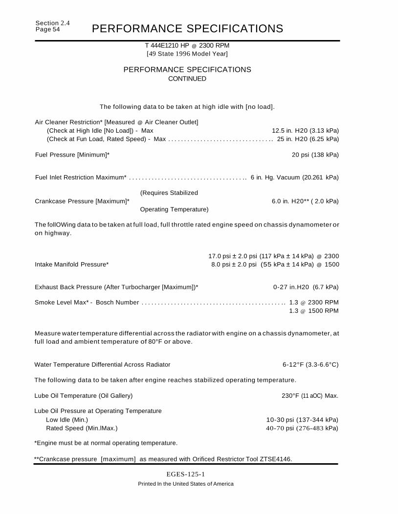
Section 2.4Page 54 PERFORMANCE SPECIFICATIONS
T 444E1210 HP @ 2300 RPM[49 State 1996 Model Year]
PERFORMANCE SPECIFICATIONSCONTINUED
The following data to be taken at high idle with [no load].
Air Cleaner Restriction* [Measured @ Air Cleaner Outlet](Check at High Idle [No Load]) - Max 12.5 in. H20 (3.13 kPa)(Check at Fun Load, Rated Speed) - Max . . . . . . . . . . . . . . . . . . . . . . . . . . . . . . . .. 25 in. H20 (6.25 kPa)
Fuel Pressure [Minimum]* 20 psi (138 kPa)
Fuel Inlet Restriction Maximum* . . . . . . . . . . . . . . . . . . . . . . . . . . . . . . . . . . . .. 6 in. Hg. Vacuum (20.261 kPa)
(Requires StabilizedCrankcase Pressure [Maximum]* 6.0 in. H20** ( 2.0 kPa)
Operating Temperature)
The follOWing data to be taken at full load, full throttle rated engine speed on chassis dynamometer oron highway.
17.0 psi ± 2.0 psi (117 kPa ± 14 kPa) @ 2300Intake Manifold Pressure* 8.0 psi ± 2.0 psi (55 kPa ± 14 kPa) @ 1500
Exhaust Back Pressure (After Turbocharger [Maximum])* 0-27 in.H20 (6.7 kPa)
Smoke Level Max* - Bosch Number . . . . . . . . . . . . . . . . . . . . . . . . . . . . . . . . . . . . . . . . . . . .. 1.3 @ 2300 RPM1.3 @ 1500 RPM
Measure water temperature differential across the radiator with engine on a chassis dynamometer, atfull load and ambient temperature of 80°F or above.
Water Temperature Differential Across Radiator 6-12°F (3.3-6.6°C)
The following data to be taken after engine reaches stabilized operating temperature.
Lube Oil Temperature (Oil Gallery) 230°F (11 aOC) Max.
Lube Oil Pressure at Operating TemperatureLow Idle (Min.) 10-30 psi (137-344 kPa)Rated Speed (Min.lMax.) 40-70 psi (276-483 kPa)
*Engine must be at normal operating temperature.
**Crankcase pressure [maximum] as measured with Orificed Restrictor Tool ZTSE4146.
EGES-125-1Printed In the United States of America

PERFORMANCE SPECIFICATIONST 444E1210 HP @ 2300 RPM[California 1996 Model Year]
PERFORMANCE SPECIFICATIONS
Section 2.4Page 55
Engine/Model T 444E/A210C
Engine rating 210 BHP @ 2300 RPM
Engine Family Rating Code (EFRC) 2142
Injector Part NumberOriginal Equipment 1 822 890 C1
Turbocharger Part Number (With Wastegate) 1 823 560 C91AIR Ratio 1.11
Injection Timing Not-Adjustable
High Idle Speed - RPM with manual transmission 2500 + 50
High Idle Speed - RPM with automatic transmission . . . . . . . . . . . . . . . . . . . . . . .. 2500 + 200
Low Idle Speed - RPM 700 ±50
Injection Control PressureNoltage@ Low Idle No Load 450 ±50 psi (3.1 0 ± 0.3 MPa) (0.78 ± 0.1 Volts)
Injection Control PressureNoltage@ High Idle No Load 1020 ± 100 psi (7.10 ±0.7 MPa) (1.40 ±0.2 Volts)
Injection Control PressureNoltage@ Rated Speed and Full Load 2470 ± 150 psi (17.0 ± 1.0 MPa) (3.15 ± 0.3 Volts)
Intake and Exhaust Valve Clearance (Engine Off - Hot or Cold)Intake Not-AdjustableExhaust Not-Adjustable
EGES-125-1Printed In the United States of America

Section 2.4Page 56 PERFORMANCE SPECIFICATIONS
T 444E1210 HP @ 2300 RPM[California 1996 Model Year]
PERFORMANCE SPECIFICATIONSCONTINUED
The following data to be taken at high idle with [no load].
Air Cleaner Restriction* [Measured @ Air Cleaner Outlet](Check at High Idle [No Load]) - Max 12.5 in. H20 (3.13 kPa)(Check at Full Load, Rated Speed) - Max. . . . . . . . . . . . . . . . . . . . . . . . . . . . . . . .. 25 in. H20 (6.25 kPa)
Fuel Pressure [Minimum]* 20 psi (138 kPa)
Fuel Inlet Restriction Maximum* 6 in. Hg. Vacuum (20.261 kPa)
(Requires StabilizedCrankcase Pressure [Maximum]* 6.0 in. H20** ( 2.0 kPa)
Operating Temperature)
The following data to be taken at full load, full throttle rated engine speed on chassis dynamometer oron highway.
17.0 psi ± 2.0 psi (117 kPa ± 14 kPa) @ 2300Intake Manifold Pressure* 8.0 psi ±2.0 psi (55 kPa ± 14 kPa) @ 1500
Exhaust Back Pressure (After Turbocharger [Maximum])* 0-27 in.H20 (6.7 kPa)
Smoke Level Max* - Bosch Number . . . . . . . . . . . . . . . . . . . . . . . . . . . . . . . . . . . . . . . . . . . .. 1.3 @ 2300 RPM1.3 @ 1500 RPM
Measure water temperature differential across the radiator with engine on a chassis dynamometer, atfull load and ambient temperature of 80°F or above.
Water Temperature Differential Across Radiator 6-12°F (3.3-6.6°C)
The following data to be taken after engine reaches stabilized operating temperature.
Lube Oil Temperature (Oil Gallery) 230°F (110°C) Max.
Lube Oil Pressure at Operating Temperature
Low Idle (Min.) 10-30 psi (137-344 kPa)Rated Speed (Min./Max.) ." 40-70 psi (276-483 kPa)
*Engine must be at normal operating temperature.
**Crankcase pressure [maximum] as measured with Orificed Restrictor Tool ZTSE4146.
EGES-125-1
Printed In the United States of America

PERFORMANCE SPECIFICATIONST 444E1230 HP @ 2300 RPM[49 State 1996 Model Year]
PERFORMANCE SPECIFICATIONS
Section 2.4Page 57
Engine/Model . . . . . . . . . . . . . . . . . . . . . . . . . . . . . . . . . . . . . . . . . . . . . . . . . . . . . . . . . . . . . . . . . .. T 444E1A230F
Engine rating 230 BHP @ 2300 RPM
Engine Family Rating Code (EFRC) 2151
Injector Part NumberOriginal Equipment 1 822 890 C1
Turbocharger Part Number (With Wastegate) 1 823 560 C91AIR Ratio 1.11
Injection Timing Not-Adjustable
High Idle Speed - RPM with manual transmission 2500 + 50
High Idle Speed - RPM with automatic transmission . . . . . . . . . . . . . . . . . . . . . . . . . . . . . . . . . . .. 2500 + 200
Low Idle Speed - RPM 700 ± 50
Injection Control PressureNoltage@ Low Idle No Load 450 ± 50 psi (3.10 ±0.3 MPa) (0.78 ± 0.1 Volts)
Injection Control PressureNoltage@ High Idle No Load 1020 ± 100 psi (7.10 ±0.7 MPa) (1.40 ±0.2 Volts)
Injection Control PressureNoltage@ Rated Speed and Full Load 2470 ± 150 psi (17.0 ± 1.0 MPa) (3.15 ± 0.3 Volts)
Intake and Exhaust Valve Clearance (Engine Off - Hot or Cold)Intake Not-AdjustableExhaust Not-Adjustable
EGES-125-1Printed In the United States of America

Section 2.4Page 58 PERFORMANCE SPECIFICATIONS
T 444E1230 HP @ 2300 RPM!49 State 1996 Model Year]
PERFORMANCE SPECIFICATIONSCONTINUED
The following data to be taken at high idle with [no load].
Air Cleaner Restriction* [Measured @ Air Cleaner Outlet](Check at High Idle [No Load]) - Max 12.5 in. H20 (3.13 kPa)(Check at Full Load, Rated Speed) - Max. . . . . . . . . . . . . . . . . . . . . . . . . . . . . . . .. 25 in. H20 (6.25 kPa)
Fuel Pressure [Minimum]* 20 psi (138 kPa)
Fuel Inlet Restriction Maximum* " 6 in. Hg. Vacuum (20.261 kPa)
(Requires StabilizedCrankcase Pressure [Maximum]* 6.0 in. H20•• ( 2.0 kPa)
Operating Temperature)
The following data to be taken at full load, full throttle rated engine speed on chassis dynamometer oron highway.
17.0 psi ± 2.0 psi (117 kPa ± 14 kPa) @ 2300Intake Manifold Pressure* 11.0 psi ± 2.0 psi (76 kPa ± 14 kPa) @ 1500
Exhaust Back Pressure (After Turbocharger [Maximum])* 0-27 in.H20 (6.7 kPa)
Smoke Level Max· - Bosch Number ... " . . . . . . . . . . . . . . . . . . . . . . . . . . . . . . . . . . . . . . . .. 1.3 @ 2300 RPM1.3 @ 1500 RPM
Measure water temperature differential across the radiator with engine on a chassis dynamometer, atfull load and ambient temperature of 80°F or above.
Water Temperature Differential Across Radiator 6-12°F (3.3-6.6°C)
The following data to be taken after engine reaches stabilized operating temperature.
Lube Oil Temperature (Oil Gallery) 230°F (110°C) Max.
Lube Oil Pressure at Operating TemperatureLow Idle (Min.) 10-30 psi (137-344 kPa)Rated Speed (Min./Max.) " " 40-70 psi (276-483 kPa)
*Engine must be at normal operating temperature.
··Crankcase pressure [maximum] as measured with Orificed Restrictor Tool ZTSE4146.
EGES-125-1Printed In the United States of America

Section 2.4Page 60 PERFORMANCE SPECIFICATIONS
T 444E1230 HP @ 2300 RPM[California 1996 Model Year]
PERFORMANCE SPECIFICATIONSCONTINUED
The following data to be taken at high idle with [no load].
Air Cleaner Restriction* [Measured @ Air Cleaner Outlet](Check at High Idle [No Load]) - Max 12.5 in. H20 (3.13 kPa)(Check at Full Load, Rated Speed) - Max. . . . . . . . . . . . . . . . . . . . . . . . . . . . . . . .. 25 in. H20 (6.25 kPa)
Fuel Pressure [Minimum]* 0' ••••••••••••••••••••• 20 psi (138 kPa)
Fuel Inlet Restriction Maximum* 6 in. Hg. Vacuum (20.261 kPa)
(Requires StabilizedCrankcase Pressure [Maximum]* '6.0 in. H20•• ( 2.0 kPa)
Operating Temperature)
The following data to be taken at full load, full throttle rated engine speed on chassis dynamometer oron highway.
17.0 psi ± 2.0 psi (117 kPa ± 14 kPa) @ 2300Intake Manifold Pressure* 11.0 psi ± 2.0 psi (76 kPa ± 14 kPa) @ 1500
Exhaust Back Pressure (After Turbocharger [Maximum])* ~ 0-27 in.H20 (6.7 kPa)
Smoke Level Max* - Bosch Number . . . . . . . . . . . . . . . . . . . . . . . . . . . . . . . . . . . . . . . . . . . .. 1.3 @ 2300 RPM1.3 @ 1500 RPM
Measure water temperature differential across the radiator with engine on a chassis dynamometer, atful' load and ambient temperature of 80°F or above.
Water Temperature Differential Across Radiator 6-12°F (3.3-6.6°C)
The following data to be taken after engine reaches stabilized operating temperature.
Lube Oil Temperature (Oil Gallery) 230°F (110°C) Max.
Lube Oil Pressure at Operating TemperatureLow Idle (Min.) 10-30 psi (137-344 kPa)Rated Speed (Min./Max.) 40-70 psi (276-483 kPa)
*Engine must be at normal operating temperature.
**Crankcase pressure [maximum] as measured with Orificed Restrictor Tool ZTSE4146.
EGES-125-1
Printed In the United Slates of America

PERFORMANCE SPECIFICATIONST 444EJ175 HP @ 2300 RPM[50 State 1997 Model Year]
PERFORMANCE SPECIFICATIONS
Section 2.4Page 61
Engine/Model T 444E18175
Engine rating 175 BHP @ 2300 RPM
Engine Family Rating Code (EFRC) 2111
Injector Part NumberOriginal Equipment 1 822 803 C1
Turbocharger Part Number (With Exhaust Back Pressure Device) 1 823 554 C91AIR Ratio 1.0
Turbocharger Part Number (Without Exhaust Back Pressure Device) 1 823 553 C91AIR Ratio 1.0
Injection Timing Not-Adjustable
High Idle Speed - RPM with manual transmission 2500 + 50
High Idle Speed - RPM with automatic transmission 2500 + 200
Low Idle Speed - RPM 700 ± 50
Injection Control PressureNoltage@ Low Idle No Load 440 ± 40 psi (3.00 ± 0.3 MPa) (0.76 ± 0.1 Volts)
Injection Control PressureNoltage@ High Idle No Load 1020±100psi(7.00±0.7MPa) (1.44±0.1 Volts)
Injection Control PressureNoltage@ Rated Speed and Full Load . . . . . . . . . . . . .. 2180 ± 150 psi (15.0 ± 1.0 MPa) (2.81 ± 0.2 Volts)
Intake and Exhaust Valve Clearance (Engine Off - Hot or Cold)Intake Not-AdjustableExhaust Not-Adjustable
EGES-125-1Printed In the United States of America

Section 2.4Page 62 PERFORMANCE SPECIFICATIONS
T 444E11'75HP @ 2300 RPM[50 State 1997 Model Year]
PERFORMANCE SPECIFICATIONSCONTINUED
The following data to be taken at high idle with [no load].
Air Cleaner Restriction* [Measured @ Air Cleaner Outlet](Check at High Idle [No Load]) - Max 12.5 in. H20 (3.13 kPa)(Check at Full ~oad, Rated Speed) - MdX 25 in. H20 (6.25 kPa)
Fuel Pressure [Minimum]* 20 psi (138 kPa)
Fuel Inlet Restriction Maximum* 6 in. Hg. Vacuum (20.261 kPa)
(Requires StabilizedCrankcase Pressure [Maximum]* 6.0 in. H20•• ( 2.0 kPa)
Operating Temperature)
The following data to be taken at full load, full throttle rated engine speed on chassis dynamometer oron highway.
15.1 psi ± 1.5 psi (104 kPa ± 10 kPa) @ 2300Intake Manifold Pressure* 4.7 psi ± 1.5 psi (32 kPa ± 10 kPa) @ 1500
Exhaust Back Pressure (After Turbocharger [Maximum])* 0-27 in.H20 (6.7 kPa)
Smoke Level Max* - Bosch Number 0.4 @ 2300 RPM0.6 @ 1500 RPM
Measure water temperature differential across the radiator with engine on a chassis dynamometer, atfull load and ambient temperature of 80°F or above.
Water Temperature Differential Across Radiator ,. 6-12°F (3.3-6.6°C)
The following data to be taken after engine reaches stabilized operating temperature.
Lube Oil Temperature (Oil Gallery) , 230°F (110°C) Max.
Lube Oil Pressure at Operating TemperatureLow Idle (Min.) 10-30 psi (137-344 kPa)Rated Speed (Min./Max.) 40-70 psi (276-483 kPa)
*Engine must be at normal operating temperature.
**Crankcase pressure [maximum] as measured with Orificed Restrictor Tool ZTSE4146.
EGES-125-1Printed In the United States of America

PERFORMANCE SPECIFICATIONST 444E1190 HP @ 2300 RPM[50 State 1997 Model Year]
PERFORMANCE SPECIFICATIONS
Section 2.4Page 63
Engine/Model T 444E18190
Engine rating 190 BHP @ 2300 RPM
Engine Family Rating Code (EFRC) 2121
Injector Part NumberOriginal Equipment 1 822 803 C1
Turbocharger Part Number (With Exhaust Back Pressure Device) 1 823 554 C91AIR Ratio 1.0
Turbocharger Part Number (Without Exhaust Back Pressure Device) 1 823 553 C91AIR Ratio · 1.0
Injection Timing Not-Adjustable
High Idle Speed - RPM with manual transmission 2500 + 50
High Idle Speed - RPM with automatic transmission . . . . . . . . . . . . . . . . . . . . . . . .. 2500 + 200
Low Idle Speed - RPM 700 ± 50
Injection Control PressureNoltage@ Low Idle No Load . . . . . . . . . . . . . . . . . . . . . . . . . . . . . .. 440 ± 40 psi (3.00 ±0.3 MPa) (0.76 ± 0.1 Volts)
Injection Control PressureNoltage@ High Idle No Load 1020 ± 100 psi (7.00 ± 0.7 MPa) (1.44 ± 0.1 Volts)
Injection Control PressureNoltage@ Rated Speed and Full Load 2320 ± 150 psi (16.0 ±1.0 MPa) (2.98 ±0.2 Volts)
Intake and Exhaust Valve Clearance (Engine Off - Hot or Cold)Intake Not-AdjustableExhaust "................................................................ Not-Adjustable
EGES-125-1
Printed In the United States of America

Section 2.4Page 64 PERFORMANCE SPECIFICATIONS
T 444E1190 HP @ 2300 RPM[50 State 1997 Model Year]
PERFORMANCE SPECIFICATIONSCONTINUED
The following data to be taken at high idle with [no load].
Air Cleaner Restriction* [Measured @ Air Cleaner Outlet](Check at High Idle [No Load]) - Max 12.5 in. H20 (3.13 kPa)(Check at Full Load, Rated Speed) - Max. . . . . . . . . . . . . . . . . . . . . . . . . . . . . . . .. 25 in. H20 (6.25 kPa)
Fuel Pressure [Minimum]* 20 psi (138 kPa)
Fuel Inlet Restriction Maximum* . . . . . . . . . . . . . . . . . . . . . . . . . . . . . . . . . . . .. 6 in. Hg. Vacuum (20.261 kPa)
(Requires StabilizedCrankcase Pressure [Maximum]* 6.0 in. H20** ( 2.0 kPa)
Operating Temperature)
The following data to be taken at full load, full throttle rated engine speed on chassis dynamometer oron highway.
15.5 psi ± 1.5 psi (107 kPa ± 10 kPa) @ 2300Intake Manifold Pressure* 7.0 psi ± 1.5 psi (48 kPa ± 10 kPa) @ 1500
Exhaust Back Pressure (After Turbocharger [Maximum])* 0-27 in.H20 (6.7 kPa)
Smoke Level Max* - Bosch Number 0.6 @ 2300 RPM1.3 @ 1500 RPM
Measure water temperature differential across the radiator with engine on a chassis dynamometer, atfull load and ambient temperature of 80°F or above.
Water Temperature Differential Across Radiator 6-12°F (3.3-6.6°C)
The following data to be taken after engine reaches stabilized operating temperature.
Lube Oil Temperature (Oil Gallery) 230°F (110°C) Max.
Lube Oil Pressure at Operating TemperatureLow Idle (Min.) 10-30 psi (137-344 kPa)Rated Speed (Min.lMax.) 40-70 psi (276-483 kPa)
*Engine must be at normal operating temperature.
**Crankcase pressure [maximum] as measured with Orificed Restrictor Tool ZTSE4146.
EGES-125-1
Printed In the United States of America

PERFORMANCE SPECIFICATIONST 444E1210 HP @ 2400 RPM[50 State 1997 Model Year]
PERFORMANCE SPECIFICATIONS
Section 2.4Page 65
Engine/Model T 444E1821 0
Engine rating 210 BHP @ 2400 RPM
Engine Family Rating Code (EFRC) 2231
Injector Part NumberOriginal Equipment 1 822 803 C1
Turbocharger Part Number (With Exhaust Back Pressure Device) 1 823 554 C91AIR Ratio 1.0
Turbocharger Part Number (Without Exhaust Back Pressure Device) 1 823 553 C91AIR Ratio 1.0
Injection Timing Not-Adjustable
High Idle Speed - RPM with manual transmission 2500 + 50
High Idle Speed - RPM with automatic transmission . . . . . . . . . . . . . . . . . . . . . . . . . . . . . . . . . . .. 2500 + 200
Low Idle Speed - RPM 700 ± 50
Injection Control PressureNoltage@ Low Idle No Load 440 ±40 psi (3.00 ±0.3 MPa) (0.76 ± 0.1 Volts)
Injection Control PressureNoltage@ High Idle No Load 1020 ± 100 psi (7.00 ± 0.7 MPa) (1.44 ± 0.1 Volts)
Injection Control PressureNoltage@ Rated Speed and Full Load 2470 ± 150 psi (17.0 ± 1.0 MPa) (3.15 ± 0.2 Volts)
Intake and Exhaust Valve Clearance (Engine Off - Hot or Cold)Intake Not-AdjustableExhaust " " " ".. Not-Adjustable
EGES-125-1Printed In the United States of America

Section 2.4Page 66 PERFORMANCE SPECIFICATIONS
T 444E1210 HP @ 2400 RPM[50 State 1997 Model Year]
PERFORMANCE SPECIFICATIONSCONTINUED
The following data to be taken at high idle with [no load].
Air Cleaner Restriction* [Measured @ Air Cleaner Outlet](Check at High Idle [No Load]) - Max 12.5 in. H20 (3.13 kPa)(Check at Full Load, Rated Speed) - Max . . . . . . . . . . . . . . . . . . . . . . . . . . . . . . . .. 25 in. H20 (6.25 kPa)
Fuel Pressure [Minimum]* 20 psi (138 kPa)
Fuel Inlet Restriction Maximum* . . . . . . . . . . . . . . . . . . . . . . . . . . . . . . . . . . . .. 6 in. Hg. Vacuum (20.261 kPa)
(Requires StabilizedCrankcase Pressure [Maximum]* 6.0 in. H20** ( 2.0 kPa)
Operating Temperature)
The following data to be taken at full load, full throttle rated engine speed on chassis dynamometer oron highway.
17.25 psi ± 1.5 psi (119 kPa ± 10 kPa) @ 2400Intake Manifold Pressure* " 7.00 psi ± 1.5 psi (48 kPa ± 10 kPa) @ 1500
Exhaust Back Pressure (After Turbocharger [Maximum])* 0-27 in.H20 (6.7 kPa)
Smoke Level Max* - Bosch Number 0.6 @ 2400 RPM1.9 @ 1500 RPM
Measure water temperature differential across the radiator with engine on a chassis dynamometer, atfull load and ambient temperature of 80°F or above.
Water Temperature Differential Across Radiator . . . . . . . . . . . . . . . . . . . . . .. 6-12°F (3.3-6.6°C)
The following data to be taken after engine reaches stabilized operating temperature.
Lube Oil Temperature (Oil Gallery) 230°F (11 DOC) Max.
Lube Oil Pressure at Operating Temperature
Low Idle (Min.) 10-30 psi (137-344 i<Pa)Rated Speed (Min./Max.) 40-70 psi (276-483 I<Pa)
*Engine must be at normal operating temperature.
**Crankcase pressure [maximum] as measured with Orificed Restrictor Tool ZTSE4146.
EGES-125-1
Printed In the United States of America

PERFORMANCE SPECIFICATIONST 444E1210 HP @ 2300 RPM[50 State 1997 Model Year]
PERFORMANCE SPECIFICATIONS
Section 2.4Page 67
Engine/Model . . . . . . . . . . . . . . . . . . . . . . . . . . . . . . . . . . . . . . . . . . . . . . . . . . . . . . . . . . . . . . . . . .. T 444E/BH21 0
Engine rating 210 BHP @ 2300 RPM
Engine Family Rating Code (EFRC) 2141
Injector Part NumberOriginal Equipment 1 822 803 C1
Turbocharger Part Number 1 823 560 C92AIR Ratio 1.11
Injection Timing Not-Adjustable
High Idle Speed - RPM with manual transmission 2500 + 50
High Idle Speed - RPM with automatic transmission . . . . . . . . . . . . . . . . . . . . . . .. 2500 + 200
Low Idle Speed - RPM 700 ± 50
Injection Control PressureNoltage@ Low Idle No Load 440 ± 40 psi (3.00 ± 0.3 MPa) (0.76 ± 0.1 Volts)
Injection Control PressureNoltage@ High Idle No Load 1020±100psi(7.10±0.7MPa) (1.44±0.1 Volts)
Injection Control PressureNoltage@ Rated Speed and Full Load 2470± 150 psi (17.0 ± 1.0 MPa) (3.15 ± 0.2 Volts)
Intake and Exhaust Valve Clearance (Engine Off - Hot or Cold)Intake Not-AdjustableExhaust Not-Adjustable
EGES-125-1Printed In the United States of America

Section 2.4Page 68 PERFORMANCE SPECIFICATIONS
T 444E1210 HP @ 2300 RPM[50 State "997 Model'Yeat]
PERFORMANCE SPECIFICATIONSCONTINUED
The following data to be taken at high idle with [no load].
Air Cleaner Restriction* [Measured @ Air Cleaner Outlet](Check at High Idle [No Load]) - Max 12.5 in. H20 (3.13 kPa)(Check at Full Load, Rated Speed) - Max . . . . . . . . . . . . . . . . . . . . . . . . . . . . . . . .. 25 in. H20 (6.25 kPa)
Fuel Pressure [Minimum]* 20 psi (138 kPa)
Fuel Inlet Restriction Maximum* . . . . . . . . . . . . . . . . . . . . . . . . . . . . . . . . . . . .. 6 in. Hg. Vacuum (20.261 kPa)
(Requires StabilizedCrankcase Pressure [Maximum]* 6.0 in. H20** ( 2.0 kPa)
Operating Temperature)
The following data to be taken at full load, full throttle rated engine speed on chassis dynamometer oron highway.
14.5 psi ± 1.5 psi (100 kPa ± 10 kPa) @ 2300Intake Manifold Pressure* 8.0 psi ± 1.5 psi (55 kPa ± 10 kPa) @ 1500
Exhaust Back Pressure (After Turbocharger [Maximum])* 0-27 in.H20 (6.7 kPa)
Smoke Level Max* - Bosch Number 0.8 @ 2300 RPM1.9 @ 1500 RPM
Measure water temperature differential across the radiator with engine on a chassis dynamometer, atfull load and ambient temperature of 80°F or above.
Water Temperature Differential Across Radiator 6-12°F (3.3-6.6°C)
The following data to be taken after engine reaches stabilized operating temperature.
Lube Oil Temperature (Oil Gallery) 230°F (11 DOC) Max.
Lube Oil Pressure at Operating TemperatureLow Idle (Min.) 10-30 psi (137-344 kPa)Rated Speed (Min.lMax.) 40-70 psi (276-483 kPa)
*Engine must be at normal operating temperature.
**Crankcase pressure [maximum] as measured with Orificed Restrictor Tool ZTSE4146.
EGES-125-1
Printed In the United States of America

PERFORMANCE SPECIFICATIONST 444E1230 HP @ 2300 RPM[50 State 1997 Model Year]
PERFORMANCE SPECIFICATIONS
Section 2.4Page 69
Engine/Model T 444E1B230
Engine rating 230 BHP @ 2300 RPM
Engine Family Rating Code (EFRC) 2151
Injector Part NumberOriginal Equipment 1 822 803 C1
Turbocharger Part Number (With Wastegate) 1 823 560 C92AIR Ratio 1.11
Injection Timing Not-Adjustable
High Idle Speed - RPM with manual transmission 2500 + 50
High Idle Speed - RPM with automatic transmission . . . . . . . . . . . . . . . . . . . . . . . . .. 2500 + 200
Low Idle Speed - RPM 700 ± 50
Injection Control PressureNoltage@ Low Idle No Load 440 ± 40 psi (3.00 ± 0.3 MPa) (0.76 ± 0.1 Volts)
Injection Control PressureNoltage@ High Idle No Load 1020 ± 100 psi (7.00 ± 0.7 MPa) (1.44 ±0.1 Volts)
Injection Control PressureNoltage@ Rated Speed and Full Load 2470 ± 150 psi (17.0 ± 1.0 MPa) (3.15 ± 0.2 Volts)
Intake and Exhaust Valve Clearance (Engine Off - Hot or Cold)Intake Not-AdjustableExhaust ~ . . . . . . . . . . . . . . . . . . . . . . . . . . . . . . . . . . . . . . . . . . . . Not-Adjustable
EGES-125-1
Printed In the United States of America
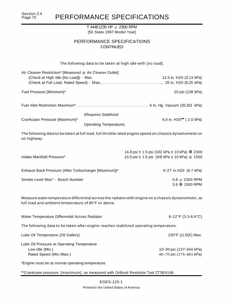
Section 2.4Page 70 PERFORMANCE SPECIFICATIONS
T 444E1230 HP @ 2300 RPM[50 State 1997 Model Year]
PERFORMANCE SPECIFICATIONSCONTINUED
The following data to be taken at high idle with [no load].
Air Cleaner Restriction* [Measured @ Air Cleaner Outlet](Check at High Idle [No Load]) - Max 12.5 in. H20 (3.13 kPa)(Check at Full Load, Rated Speed) - Max. . . . . . . . . . . . . . . . . . . . . . . . . . . . . . . .. 25 in. H20 (6.25 kPa)
Fuel Pressure [Minimum]* 20 psi (138 kPa)
Fuel Inlet Restriction Maximum* . . . . . . . . . . . . . . . . . . . . . . . . . . . . . . . . . . . .. 6 in. Hg. Vacuum (20.261 kPa)
(Requires StabilizedCrankcase Pressure [Maximum]* 6.0 in. H20•• ( 2.0 kPa)
Operating Temperature)
The following data to be taken at full load, full throttle rated engine speed on chassis dynamometer oron highway.
14.8 psi ± 1.5 psi (102 kPa ± 10 kPa) @ 2300Intake Manifold Pressure* 10.0 psi ± 1.5 psi (69 kPa ± 10 kPa) @ 1500
Exhaust Back Pressure (After Turbocharger [Maximum])* 0-27 in.H20 (6.7 kPa)
Smoke Level Max* - Bosch Number 0.8 @ 2300 RPM3.6 @ 1500 RPM
Measure water temperature differential across the radiator with engine on a chassis dynamometer, atfull load and ambient temperature of 80°F or above.
Water Temperature Differential Across Radiator 6-12°F (3.3-6.6°C)
The following data to be taken after engine reaches stabilized operating temperature.
Lube Oil Temperature (Oil Gallery) 230°F (11 DOC) Max.
Lube Oil Pressure at Operating TemperatureLow Idle (Min.) 10-30 psi (137-344 kPa)Rated Speed (Min./Max.) 40-70 psi (276-483 kPa)
*Engine must be at normal operating temperature.
**Crankcase pressure [maximum] as measured with Orificed Restrictor Tool ZTSE4146.
EGES-125-1
Printed In the United States of America

PERFORMANCE SPECIFICATIONST 444E1250 HP @ 2300 RPM[50 State 1997 Model Year]
PERFORMANCE SPECIFICATIONS
Section 2.4Page 71
Engine/Model T 444E1B250
Engine rating 250 BHP @ 2300 RPM
Engine Family Rating Code (EFRC) 2161
Injector Part NumberOriginal Equipment 1 822 803 C1
Turbocharger Part Number (With Wastegate) 1 823 560 C92AIR Ratio 1.11
Injection Timing " Not-Adjustable
High Idle Speed - RPM with manual transmission 2500 + 50
High Idle Speed - RPM with automatic transmission . . . . . . . . . . . . . . . . . . . . . . . . . . . . . . . . . . .. 2500 + 200
Low Idle Speed - RPM 700 ± 50
Injection Control PressureNoltage@ Low Idle No Load 440 ±40 psi (3.00 ±0.3 MPa) (0.76 ± 0.1 Volts)
Injection Control PressureNoltage@ High Idle No Load 1020 ± 100 psi (7.00 ±0.7 MPa) (1.44 ± 0.1 Volts)
Injection Control PressureNoltage@ Rated Speed and Full Load 2480± 150 psi (17.1 ± 1.0 MPa) (3.16± 0.2 Volts)
Intake and Exhaust Valve Clearance (Engine Off - Hot or Cold)Intake Not-AdjustableExhaust Not-Adjustable
EGES-125-1
Printed In the United States of America

Section 2.4Page 72 PERFORMANCE SPECIFICATIONS
T 444E1250 HP @ 2300 RPM[50 State 1997 Model Year]
PERFORMANCE SPECIFICATIONSCONTINUED
The following data to be taken at high idle with [no load].
Air Cleaner Restriction* [Measured @ Air Cleaner Outlet](Check at High Idle [No Load]) - Max 12.5 in. H20 (3.13 kPa)(Check at Full Load, Rated Speed) - Max. . . . . . . . . . . . . . . . . . . . . . . . . . . . . . . .. 25 in. H20 (6.25 kPa)
Fuel Pressure [Minimum]* 20 psi (138 kPa)
Fuel Inlet Restriction Maximum* . . . . . . . . . . . . . . . . . . . . . . . . . . . . . . . . . . . .. 6 in. Hg. Vacuum (20.261 kPa)
(Requires StabilizedCrankcase Pressure [Maximum]* 6.0 in. H20** ( 2.0 kPa)
Operating Temperature)
The following data to be taken at full load, full throttle rated engine speed on chassis dynamometer oron highway.
15.0 psi ± 1.5 psi (103 kPa ± 10 kPa) @ 2300Intake Manifold Pressure* 11.0 psi ± 1.5 psi (76 kPa ± 10 kPa) @ 1500
Exhaust Back Pressure (After Turbocharger [Maximum])* 0-27 in.H20 (6.7 kPa)
Smoke Level Max* - Bosch Number . . . . . . . . . . . . . . . . . . . . . . . . . . . . . . . . . . . . . . . . . . . .. 1.3 @ 2300 RPM4.6 @ 1500 RPM
Measure water temperature differential across the radiator with engine on a chassis dynamometer, atfull load and ambient temperature of 80°F or above.
Water Temperature Differential Across Radiator 6-12°F (3.3-6.6°C)
The following data to be taken after engine reaches stabilized operating temperature.
Lube Oil Temperature (Oil Gallery) 230°F (110°C) Max.
Lube Oil Pressure at Operating TemperatureLow Idle (Min.) 10-30 psi (137-344 kPa)Rated Speed (Min./Max.) 40-70 psi (276-483 kPa)
*Engine must be at normal operating temperature.
**Crankcase pressure [maximum] as measured with Orificed Restrictor Tool ZTSE4146.
EGES-125-1Printed in the United States of America

SECTION 3 ELECTRONIC CONTROL SYSTEMDIAGNOSTICS
INDEXPAGE
SECTION 3.1 ELECTRONIC CONTROL SYSTEM DIAGNOSTIC FORMINTRODUCTION 1GENERAL INSTRUCTIONS. . . . . . . . . . . . . . . . . . . . . . . . . . . . . . . . . . . . . . . . . . . . . . . . . . . . . . . . . .. 1ELECTRONIC CONTROL SYSTEM DIAGNOSTIC FORM EGED-135-1 (FRONT SIDE) 2ELECTRONIC CONTROL SYSTEM DIAGNOSTIC FORM EGED-135-1 (REAR SIDE) 4
SECTION 3.2 FLASH CODE CIRCUIT INDEX
SECTION 3.3 SENSOR AND ACTUATOR LOCATIONSSENSOR AND ACTUATOR LOCATIONS (ENGINE) 1ELECTRONIC CONTROL SYSTEM COMPONENT LOCATIONS (VEHICLE) 2
SECTION 3.4 SENSOR AND ACTUATOR DIAGNOSTIC PROCEDURES
SENSOR AND ACTUATOR DIAGNOSTIC PROCEDURES 1CONNECTOR CHECKS TO GROUND (8-) 1CONNECTOR VOLTAGE CHECKS 1HARNESS RESISTANCE TESTS . . . . . . . . . . . . . . . . . . . . . . . . . . .. 2OPERATIONAL SIGNAL CHECKS 2
SECTION 3.5 CIRCUIT FUNCTION AND DIAGNOSTICS
(APSnVS) ACCELERATOR PEDAL POSITION SENSOR / IDLE VALIDATION SWITCH 2(BARO) BAROMETRIC PRESSURE SENSOR 10(BRAKE) BRAKE SWITCH/RELAY CIRCUITS 16(CMP) CAMSHAFT POSITION SENSOR 30(OCUATA) DCUATA DATA COMMUNICATION LINKS 36(EBP) EXHAUST BACK PRESSURE SENSOR 50(ECI) ENGINE CRANK INHIBIT 54(ECl) ENGINE COOLANT LEVEL SYSTEM (ENGINE PROTECTION) 76(ECM) ELECTRONIC CONTROL MODULE SELF DIAGNOSTICS 86(ECM 10M) ECM/IDM COMMUNICATIONS 88(ECM PWR) ELECTRONIC CONTROL MODULE POWER SUPPLY 96(ECT) ENGINE COOLANT TEMPERATURE SENSOR 102(EDL) ENGINE DATA LINE CIRCUITS WITH ALLISON AT/MT TRANSMISSIONS 108(EOP) ENGINE OIL PRESSURE SENSOR 116(EOT) ENGINE OIL TEMPERATURE SENSOR 124(EPR) EXHAUST BACK PRESSURE REGULATOR 130(GPC) GLOW PLUG CONTROL 134(IAT) INTAKE AIR TEMPERATURE SENSOR 138(ICP) INJECTION CONTROL PRESSURE SENSOR " "." " 144(10M PWR) INJECTOR DRIVER MODULE POWER CIRCUITS 150(INJ) INJECTOR DRIVE CIRCUITS ". 158(IPR) INJECTION PRESSURE REGULATOR " 166(KAM PWR) KEEP ALIVE MEMORY POWER " 174(MAP) MANIFOLD ABSOLUTE PRESSURE SENSOR 180(SCCS) SPEED CONTROL COMMAND SWITCHES AND PTO CONTROLS " 186(STI/EWL) SELF TEST INPUT SWITCH AND ENGINE WARNING LIGHT 202(TACH) TACHOMETER INPUT CIRCUITS " " " 210(TSA) TWO SPEED AXLE CiRCUiT "" " 218(V REF) VOLTAGE REFERENCE CiRCUiTS " " 224
EGES--125-1Printed In The United States of America
II SECTION 3 ELECTRONIC CONTROL SYSTEMDIAGNOSTICS
INDEX
PAGE
SECTION 3.5 CIRCUIT FUNCTION AND DIAGNOSTICS (Continued)
(VPM) VEHICLE PERSONALITY MODULE FUEUHOUR METERS AND ODOMETER ..... 230(VSS) VEHICLE SPEED SIGNAL 0 0 •••• 0 0 0 0 0 0 ••••••••••••• 0 •••• 236
SECTION 3.6 CONNECTOR PINOUTS AND END VIEWS
AMBIENT AIR TEMPERATURE SENSOR CONNECTOR (398) o •••••••• 0 • • • • • • • • • • • • • • • • •• 1ATA DIAGNOSTIC & PROGRAMMING CONNECTOR (384) . 0 •• 0 0 0 ••••• 0 ••••• 0 • • • • • • • • • • •• 1ATA NEGATIVE BUS, BLUE CONNECTOR (428) ... 0 ••• 0 0 •••• 0 0 • 0 0 • 0 0 ••• 0 •••• 0 0 ••• 0 0 • 0 •• 1ATA POSITIVE BUS, RED CONNECTOR (427) 0 0 0 0 • 0 0 • 0 •••• 0 •••••• 0 0 0 •••••••• 0 0 0 0 • 0 ••• 0 0 112 WAY HARNESS CONNECTOR (435) 0 ••• 00000 •• 0 •••••• 0 ••• 0 ••••• 0 •• 0.00000 •••••••••• 1AUTOMATIC TRANSMISSION IN-LINE CONNECTOR (389) 0 •••••••••••••• 2AUTOMATIC TRANSMISSION IN-LINE CONNECTOR (402) . 0 0 0 •••••••••• 0 • o ••• 0 ••••••••• 2AUTOMATIC TRANSMISSION MODULATOR CONNECTOR (404) 0 •• 00.00 •• 0 00 •• 0.00. 0.000 2AUTOMATIC TRANSMISSION MODULATOR SHIFT RELAY CONNECTOR (403) 0 0 .0 ••••• o. 2BODY BUILDER REMOTE PTO CONNECTOR (429) 0 • 0 0 • 0 ••••••••••••••••••••••• 3BRAKE LIGHT SWITCH, HYDRAULIC CONNECTOR (51) 0 •• 0 0 0 0 •••••••••••• 0 •••••••• 0 • •• 4BRAKE LIGHT SWITCH CONNECTOR (46) 0 •••••• 0 • 0 • 0 ••• 0 0 0 0 0 0 0 • 0 0 • 0 •••• 0 0 •••••••• 0 ••• 4BRAKE LIGHT SWITCH AIR CONNECTOR (70) .0 ••••• 0 •• 0 •••• 0000 ••• 0 •• 0.000 ••• 0 ••••• 0. 4BRAKE LIGHT SWITCH AIR CONNECTOR (71) 0 ••••••••••••••••• 0.0 ••• 0 4BRAKE SWITCH RELAY CONNECTOR (393) .. 0 ••••••••••••••••••••••••••••••••••••••• 0 5BRAKE SWITCH HYDRAULIC CONNECTOR (50) 0 •••••••••••••••••••• 0 0 • • • • • • •• 5BRAKE WARNING MONITOR HYDRAULIC CONNECTOR (49) o. 0 0 •• 0 ••••••••• 0 0 •••• 0 • • •• 5BLOCKING DIODE ASSEMBLY (47) . 0 0 • 0 0 0 • 0 0 •••••• 0 • 0 0 0 •••••• 0 0 0 0 0 0 0 •• 0 • 0 • 0 •• 0 0 0 0 • 0 o. 5COOLANT HARNESS CONNECTOR (400) 0 ••• 0 ••••••••••••• 0 •••• 0 0 0 •••• 0 ••• 0 0 0 •• 6COOLANT LEVEL MODULE CONNECTOR (414) 0 •• 0 •••• 00 ••• 6CRANK/START RELAY CONNECTOR (387) 0.' .0 •••••• 00' 0 ••••••••• 6CRANK RELAY CONNECTOR (385) 0 •••• o •• 0 0 00 ••••• 0 ••• 0 •••••• 0 ••••••••• 6CRUISE RESISTOR BLOCK PRINTED CIRCUIT BOARD CONNECTOR (390) ..... 0 •• 0 0 • • •• 7CRUISE ON/OFF SWITCH (391) ... 0 0 0 0 • 0 • 0 •••• 0 ••• 0 • 0 0 0 •• 0 ••• 0 •• 0 0 0 •••••••••• 0 • • • • • •• 7CRUISE SET/RESUME SWITCH (392) . 0 0 ••••••• 0 •••••••••••• 0 0 ••••• 0 0 0 0 •••• 0 ••• 0 ••• 0 • 0 7CRUISElPTOrrHROTTLE CONNECTOR (394) 0 •• 0 •• 0 •• 0 0 •••••• 0 0 • 0 •• o. 7DASH CONNECTOR, 31 PIN (THRU DASH) (3 &3A) 0 ••••• 0 • 0 ••••••••••• 0 •• 0 •••••• 0 • 0 ••• 8DASH CONNECTOR (2) THRU DASH 4600/4600 LP TRUCK . 0 • 0 •••••• 0 • 0 ••••• 0 •••••••• o. 9DASH CONNECTOR (2) THRU DASH 3600, 4000 FBC TRUCK 0 0 0 0 •• 0 0 •••• o. 10DASH CONNECTOR (2) THRU DASH W/TRUCK .... 00 •• 000.000 •••• 0 •••••••• 0 •••••••••• 11DASH CONNECTOR (2) THRU DASH W/FBC 0 ••••••• 0 ••••••••• 0 ••••••• 000 •••••• 00 ••••• 12DASH CONNECTOR ENGINE (2A) ... 0 ••••••••••••••••••••••••••••••••••••••••••• 0 •• 0 13DASH CONNECTOR FRONT END (28) 0 • 0 • 0 0 0 • 0 0 0 •••••• 0 • 0 • • • • • • • • • • • • • • • • •• 13ECM &10M POWER RELAY FUSE IN-LINE CONNECTOR (412) .. 00 •• 0. 0 ••••• 00 •••• 0 ••• 14ECM CONNECTOR (379) .. 000 •• 00000 ••••••••• '.0"' • 0 ••••••••••••••• 0" 0 ••••••••••••• 14ECM DIODE ASSEMBLY CONNECTOR (415) 0000.00 •• 0 •• 00.0 ••• 0.000 •••••• 0 ••••••• 0 ••• 14ECM POWER RELAY CONNECTOR (395) .... 0 ••• 0 •• 0 ••••• 0 ••••••••••• 0 •••••••• 0 •• 0 •• 0 14ENGINE HARNESS POWER AND GROUND CONNECTOR (424) 0.0.00000. 000 •••••• 00.0. 15ENGINE HARNESS POWER AND GROUND CONNECTOR (426) 0 •••••• 15FUEL FILTER IN-LINE CONNECTOR (399) 0 ••• 00. 0.0.00 •••••• 0.0 •••• 0.0 •••• 0 ••••• 16FUEL FILTER IN-LINE CONNECTOR (401) 16
EGES-125-1Printed In The United States of America
SECTION 3 ELECTRONIC CONTROL SYSTEM IIIDIAGNOSTICS
INDEX
PAGESECTION 3.6 CONNECTOR PINOUTS AND END VIEWS (Continued),
INJECTOR DRIVE MODULE (IDM) CONNECTOR (380) 17INJECTOR DRIVE MODULE (10M) POWER RELAY CONNECTOR (396) 17INSTRUMENT CLUSTER YELLOW CONNECTOR (26) 18INSTRUMENT CLUSTER GREEN CONNECTOR (27) 18KEY SWITCH, TRUCK CONNECTOR (24) . . . . . . . . . . . . . . . . . . . . . . . . . . . . . . . . . . . . . . . . . . . .. 19KEY SWITCH, FBC CONNECTOR (63) . . . . . . . . . . . . . . . . . . . . . . . . . . . . . . . . . . . . . . . . . . . . . . .. 19MAP MODULE CONNECTOR (397) " . " . . . . . . . . . . . . . . . . . . . . . . . . . . . . . . . . .. 19SPEEDOMETER SENSOR CONNECTOR (303) 20TWO SPEED AXLE CONNECTOR (14) " 20VPM CONNECTOR (381) 20
EGES-125-1Printed In The United States of America

ELECTRONIC CONTROL SYSTEM
DIAGNOSTIC FORM
INTRODUCTION
GENERAL INSTRUCTIONS
Section 3.1Page 1
Thissection contains thesupporting information for the Electronic Control System Diagnostic form. It includesengine and vehicle recommended diagnostic procedures, a description of each control circuit's function and adetailed drawing with specifications for each circuit. The technician can be directed to the appropriate controlcircuit through the "Circuit Index" column on the Electronic Control System Diagnostic form EGED-135-1
Engine and Vehicle Electronic Diagnostics are indexed by circuit acronyms listed on the Electronic ControlSystem Diagnostic form. The Section Index lists the acronyms with the corresponding page numbers toquickly locate the circuit (s) requiring diagnostics. The diagnostic information is structured as described below.
• The function page(s) for each circuit is intended to give a technician a brief description of what that circuitdoes and what faults the control system can detect.
• The diagnostic page(s) for each circuit is intended to give the technician information required to test thatcircuit and determine if it is functioning correctly.
EGES-125-1
Printed In the United States of America

Section 3.1Page 2
ELECTRONIC CONTROL SYSTEM
DIAGNOSTIC FORM
ELECTRONIC CONTROL SYSTEM DIAGNOSTIC FORM EGED-135-1 (FRONT SIDE)
Technician Date
~.,. ICustomer NameINTERNATIONAL® Dealer Name
T 444E DIESEL IDealer LocationELECTRONIC CONTROL SYSTEM DIAGNOSTICS Unlt#
- CImlII CondIII... c- Pr_~
_.DMorIpIIan c..-
UI ECII Nolo"" _COCIoOnly No.....~bytN.CMOI...
112 ECII PWIl EIocl.SvL -.. .. 0.0'" "-II,, 1IeMry_'"ECM __ -.1,.au a-pno._-
I_~WR _.-eo I. OUt 01 ..... L.- ..."ftlIIttIge 10 ECM", IbM ... Yofta Lawlaaery 01 """'ftOII In ctRUIl
ECT E...... --p.Ipol....",-.,...... _M~plugoon 120_HoEI"_ ECT""'_or_'-
~ ' '. ECT E... _ ...............OI_.,.hIgIl Doto...~............... 120 _ No EIIP._ECT_or__
' 1:11 "...... MAP,,-....01_ _M_"A"~_,oIow_ .....~_._I.. __or
"AP MAP........ _ _._~--_... _ ...... Iow.'_...... ....,.-_._..-.... Doto-*_............ _ ...ow_ _10 III\~ _or pIuggod
p~ ICl' lCPoI........",_..... --"""'--..... ...... -_....._""--I
ICl' ICP ....._"' .._ .... --"""'-- ...... ~-hIgIl.--- _.-......-.._.... ,.,.-.go__ .IU-..g.Id....."
___or__
- _ . _ ...... _01_...... AP8 _ hlghOr_ 4055-0. .... onI, _ .._or12-'_"_
':!o.< • - _ ._oIgnoIllI__Al'MVll~lO""'AP8 -,.,.....'
' . . - _.~_.IdIo_~
UUVS~to",A" _APB.rva .............
if. _Vll ....v.I_ SWllc:fl CllaIIl_ Al'MVll~ ... _APB _1V8......
'" VIIS _ ......-....._",_Iow VP.._Vll8 ...."'~ro.._ vsa__.._I0'-112 \ISS -...-.................,.""" YP"_VSSOUl", ...~_
___IO_orI2_
113 ClIP w-.''''CII~oIg._por.... _ CII~oI_"""_ --.--'" ClIIPCIIp .....__
ECIl ..........-uw outakIIi l"puIa _...-,... ClIP
ClIIP ......__ICP__
Noc:w......_IC~oI.... ln_ .............. _or__
til .AIlO --........"'-""" .AIIO...... "...._ ...... or__
til BAllO__01_ ....", ....,._ IAJlO ...... _ --1M IAT _...............-"'-- IAT.........-Of'__ IAT ...... _ .... or___
1M....T _..................._..... lAT ...... h.... -E.p__ tATCIInlUIt .........
.. , lOP&gInoOlf"- 01__"__ EOPoI__ --" ' - EnII"01_............._...... _ ...... hlIIh -.........-
213 aces __010"'_"'_'" _ ...........__,12 .....0pIll-- aces --......-.._...... _APB_IIIgtw...n .... _ --J21 aces
ec:c:s_ ...__aces ...... _ ""'- _or_lnscca_
222 .- ---- T_2:SfMKl). u I.He)..... ,.....,_orNtoy123 DClJATA ---..-- bgIM ....__tIoId_
Da._.....or_- IWoIPWRKAM_ KAIII-, ..."",,__
No~_IOECII_1
m DCUATAATA__
AT" ...k_or ..._ATA___... _
:132 DCLJATA _IO_ECII_ .. ATADa. WIll_un_0 Uglll ON ATA_ ...c1"""'_hlIIhor_
23:1 TACH
T__.. _ ___OT.... _ --_..-:EM DCLJATA _ .._ATA_'OEeII __..m_noLJglltON ElT__"'OII.VP"~..
t3I DCLJATA YPMIEClloa._ No RCII ....-., lopIIooDa.__or_
211 ""Inf·QII._ .......... OCC ....__
IP~CInluIIC_HIlgInI 011 Toot _hlIIhor ....... _- E_ fDCI_'o 111M OCC__1oI1od fDCI 0Ulpul ClmllI Cllock-£.... 011_ _ ...... or_or_
113 _pWR 1IlIIl_....,OCC__1oI1od.... roIoy-OutpuI =ll:-..EngIna 011 Too. 1DM_....'_hlgMow
III IDl. IDLOCC_ EDL_~CIrcuI.~..OIlT'" 1IlL_.....or-......- II'tl
__..... occ___
EP~C......,~.. OIlT... _hlIIhor_or_HI ClPC
QIowp..._OCC....__01'~CtrcuII~OIlT...
_ ........_or_212 QPC
Dlow ......~OCC....__01'~ CIfCUII Cllack-£...... 011 TOot -1'IuI~ .._~-
W ECMIIllII _1nf.__OCCooll_tollod /¥. _ ....... 0vIput Cld a--eng. 011_ Opon C1_-NoIDM_1M ICII 0Ulpul__ 0Ul ....... HIgIl - ...................OCC_.' EClil o.....,Cl__Owl "'''-Low - Low_.......OCC_
/ . 1'.'", EDT &gino CHI T_. ........."'_....EOT ..... _ EOToI__..._._
<' .. . .,'." lOT 1!ftl1no1llIT_ ..........._hl.. EOT ...... hlgll EOT_orolrlllll'_313 EOI''' EftgInolll......... _WwNng L.- ECU ...... low 01 .....UN. Oll Ught ON Ho .......... _ ...-. ..... ploil.. _
311 EOP"" Engl.. go--",.........ECIoI__..~, --QlequIppodl -,-..-........-
.~~~~, - E.......pood(T_ ,,~}.'""_ECSI__........ _
T_I..""""",,_31t ECT Eno._ont."p.._I0___.... __ ....'_CllId__...I._ ..-no-.-..._..-.:l2t ICT-
Engl.._lT__WwNng_e-~_'_22U'FttOrcl e-,..,.....,,-
m EeT""E......e-llT__CrtI... _
~'-._....n 233.rF("UOCI323 Eet.
I_---~-
____1___"'_.___tor_
~~~SF , ...~~~~~..._,i;lt',,;,'" ::'1.',--..' .
EGES-125-1
Printed In the United States of America

ELECTRONIC CONTROL SYSTEM
DIAGNOSTIC FORMSection 3.1
Page 3
ELECTRONIC CONTROL SYSTEM DIAGNOSTIC FORM EGED-135-1 (FRONT SIDE)
Chassis Model Complaint
VIN Number Active CodesEngine Serial Number Inactive CodesVPM serial Number VPM version Standard Test CodesECM Serial Number ECM version Event Log Codes
.- Clrc.~ e-Jon """'-_.
~ ..... ....."'" -DC .... S'u_own nmer End'M £ngIM-..:town. .... el\UfdOwn ..... ,. on and Ide .......u.dltd ""'. .... I,.nl;lM4Md ......
IZI ECT _,_",_"c_nooyo~ Engl". P'OM' Nduoed due ,.onItortng I,... Low Coc*M." 01 coofent~p
~!'~~~~:: .; I~R "'I- CtlOr1 . ~..._.yot--.... ..."OO lep _ 3175 pol lH.1 Gtaundld tPIt dmIIt. ...ok.PA _1M
; .:;:::~..'~i: ICP..,. e-. ~__ .poc:__"
lC~ ..gnot__."hw llIon.--,"" _ Entl... 011 CItcvIIIIhonId 0( ....... .-.ot
1~~:,! '"'"'I-e-.~..._ .. _ ... _ _ ,...... _ not _ 0UIplII a.-Iof_.. ...telftg. T__
~""~:i', I~1CP_,._...poInlC_..........-, ICP__ not.\CP oIgnoI1_pooIDClol ~...)
~"O"flnoo. 1CP - .HIgIl_.....,
~!'I;~;_';:i 1M 1CP._ .....1Id __ <UIng c,"""",, .... _721pollCP .............. 1. _ .. ..-no ,...... 1.........._....-1--1141 EIlI' ~__.olgnol ....ot_'_ EBP__oct _Iow__
:lU EIl~
___............ _11I
0.
~--..on ....
:M3 EJ'ft
b _____
E8P llbOVII wortdng rangeCIuIOlrEB~ "",..~.__
:Me ~___- ........~olI
E1If' .... -. ......_·...-~.... .-no ChocIlIof"'~E8~ -... or__
:1&1 EPR ~_ ....04_..IgIIEIIgIno-" EIlP _....-.2300_ 1!Il~ ....._.UR-.:112 EPA
EI/I. ...__ or___"'-u,.... nat fMtdI output I,. KOE.ft ....
EPII ... .....-...__
421_ lHJ Low_ .. • ........_tCVI·-> toll diMectM.., DF*'IIn)eelClf drc:utt -lnJoeIot--_.431__
''''' Low--.. "'..·... ICVI·,-11ON_._.........d_ ............__•__.llIgh-
441_ ..... Low__.. YlIAT lCVI0_ ION _ n •• Injo«or drl..__ "'I-__... Iow(-.o) .... ,. ..
411_ lMJ'--__10" ICVl0-.... ION detected ................. to gn:lI .... C'Vt run "'1-__..._(_1.... • ..
a TC'jt.~- ....... ICVIO-1ECU_cyl____
_ 10__
_1_ ........... _......____1_--
.....----.-_2__",_ .....__...-._1__....~
....._---.-..HIgIl_._1_ Al.... _"'QI>_..__ O'O"oIll ......._I..--
• "!"i; INJ ..... _ .._2_ ..... _IIlglo_OUjlllIy_0,0.. ........ _ ......... _
. ',ill IMJ -...: 1 "ttl" ... Molt to ground Of VIIAT Rltht_ ..... _ ....- - .....................-. ~~. ....., _2ll1gh__....-.... VBAT .....-....-....- _ ....._ol ......._
~~.!Ji 10M I'WA 10M I.........................101I_ _lOlI
a2 .IIIII'WA
___.. low
~I._.- Cld I7QOMAG ..._1IlII.....,.,.I~~~ IMJ ----_.- -....._..............- ---3fIj
ECMIlDII ~_lal ...... __Iow-'.Cl"~_
Cl ...... _ ....._
ECIMO..".__tClI ...... llIgh llaIocODCllll........ a oIgnoO-&g._ C1 ..._ ......._IOIECII-ln1l>o._.
ECMIlDIIIDII__--IIyECU 1011 ..___ IDII-, ... Eng. otr. QI rFC#Ir/AG'" _ lOlI.....,.,.
;~J,~""~I'" KIIM* ----- IIopoIt _ 242. 20 _:IS> _ ._QI "'Ct'II7AG"" _IOM.....,_
1M INJ__"_2
NJM deW:ted ntON ttwn 1 ....... "'fecIor &ow WIll .........-_..-..... IMJ --..-, IIIII___' ...............-Iow_~_"'_IO'-"
ir.:r~ CII~
___Iore--._MtIlNltd'l bM-.n ECM Md CIIP-.or _EaI
l~lIw.,.I~ Vl'M _ ECU ........1'"'*10 wlVP1I_ VPIiK-CM.,. "OIl C'ClmpM&IIie ~__"'IlIO_"""~
I!'uo~· j · YPM _YP1I .... -...otblawlECtol_ VP"CM 1ft "OC ootf'''''''' ~-- ......--- ..............115 ECM
"'___1(AIl ..... _
KAM-.ry_ 1n1omIptocl1tAM,. ouppIr or__ECM
f;,J.~... " YPM Eng. ........g.-'""""~........ EIIglM__ • 2. Hp._1t _ft.."...-,...._ .....-~,.~,.:.'I - E""....... tIold _ ... rodftll Eng. M_lO 110 Hp. Opdono""__ IIP._~ECM.,*__
:. ·:!'!f/r t... · lIP. I_Eng. _1 ......; ... VP1I~noEng. to..IIy_""____ V~.
YP._--~
AI ECM_....--.-__-...
ECM_.....1Iy ---." ECIII-C-_~I""--
ECU ...... IlopIoooECtol
UI ECtol1WI ........,..c~U___
ECIt ....... ......-UI DCUATA _10-.0-.-. _ ECIol ECMIYr............. _ CIdI "'ATIr/AS. _____
134 YP1I_tuol_-v_In_ YPM..-orylor__....- FuoI_..., ...I_...._
IH - .""""0UItM*m...,.,~ k\..,.
YPM-..ory ....__... _ --...,...- .........,..141 YPIl ....". odafMIM IMmOfy IOcl.eIan In wrClf
YPM...-y ....__... _ -""._..,..--........-142 YP1I ........_- UpnImro-r---- f...__ lool; ......_10_
1M3 YP. ___1oull
EEpr....~----
_.___ IIopIooo YP1IIO_
M4 "". --- U""""-V____ ••____ .......... YPMlO_
MS Yr. _~..-rl_"""Upr... -.o.y__.., YI'tII ClMcIlIof__OIl
II' YPM
f_-...,__.....,,_YPIll dRIcIa Imw In.....,,. .. _ YPM .... pull'" f4__
au V,..Eft~-ewy__<WNpl*I VP. __I............... _YPM ........U_F4__
III lIP.. ~O-...,--....... A.....p1 .. _ . ........_.-... -... - -....--- -_....- YPM ........
EGED-1$-1 May 11197 Copyright NAVISTAR INTERNATIONAl TRANSPORTATION CORP.
EGES- 125-1Printed in the United States of America

m..m~:DoZ-oooz~:Do..en-<en-Ims:
"'CenS»(DU2S1CD _.
~o::J
~-I.
c):C)Zo(J)-I(=)."o:D3:
mrmn-I:cozoooZ-I::Dor-(J)
-<en-Im3:C);C)Zo(J)-I(;IIo:c3:mG)mcI
..A.,
..A.
~:cm»:cen6m
""'-"'"
~{F1)
BARD
(47) VSS·
(47A) VSS+(97AR) TACH OUT1(48) TACH 0UT2(97E) V SAl (E:.eM Fuse)
(93A) TSA(97E:!) V IGN (F4)
(41B) VSS 0UT2
(47C) VSS 0UT3
(97GE) FWR GRD
(97GF) CASE GRD
..- V IGN(F')
,2568910
18
20
15
23
14
13
4
12
11
VBAT~~
STOJWARN
BLUE =V REF CIRCUITS (5 v)
.F~~;;,;GRO I::
Cab Mounted ComponentsECM Connector
Pin NumbersIATIi
PURPLE =120 VOLTS
FOOPR r»MroI (I7CH)
...J~._.r- ..~' I !
... _ ..~~ ..?i1.•_.1 I CLS
.... _ J\7f11!) IDM
... _ M1,tD ~:~~:::: Connector...1~.._.
3
4
~ .. fI7AK)I_· ...~
__~__JI7GM) """ BRD II I_. ~- ~
...............l!,!~....... _ ..... _ ... l?7~)
-~""J
.~__ l.... (l18M)l....~....
~~QConnector(Valve Cover)
(Dotted R"" • Frequency or 8WtIch fUnctIon)
,. PMt~!~~~:-:y ~ ~..~ ~?!C).. .. • .. (CMftIy.~)
GREEN =SIGNAL CIRCUITS
T 444E Electronic Engine Controls • 1994 to 1997TRIck Mounted Components
Ale
ABeDEIt!.. .. Cl7IIVlI.__!'"''
, INJPWR (l7MY) 20115 .... ·· '. . ....-._•••
A I
(I1MM)1 21
I 'I I' '>;.-. ,INJPWR (81"8) 11~ ': I 115Vob~ !
EDCBA EDCBA
~~~~;~8_ .. _ .I.....!~.....J i L~;•.! .. _ .. _ .. _ . _~__: i: - ..nJ:!~ .. _ - •• _ - .... - .L..~"!·2 _ _ .. _ _ ... _ _ .. _ ...
EPR
BLACK. GROUND CIRCUIT
A I
ECT EDT
~-
Glow Plug
Retay
r-----------------------
(t7NC)
at starter)
n 'I I ~ , ~ , I ~~l~r I I -~- I '.
S ec. __.____ .~ --_,I -'1~-" ECT SigMa (Q18F)
····..13·.... v IGt-~ (F"2)
·····2if··· CMP Ground .70RI 1·..·"2'r..··
I 2'i _... _.... _.. _.... _.. _..
CUb,lllL u .~ ~~ • .. _ .• _ .. _ .. j :......
U!W : - . !. - .. - .. - •Inf~! .. _ . . . . _ ;§_I l r- I~.D.. _ _.......~ coS§)_.
CMP J?OO
cOIPR
RED =12 VOLTS
~s-Cic.;-
f mc: C)2. m... en[ I(J) .....Dr I\)
Ci Y'en ~
o....~CD..~

."..5·[5":It mCDc G'>::l m;: CJ)Q. Ien -0.
~I\,)
cr" -0.
0->3CIl..nIII
60 Pin Signal V.lue. T 444-E
Pin Acronym Clrcu" Clrcu" Key Kay Low Idle HIgh Idle Operating Comments
Number Heme Number on On Signal Da18 Ust Signal Da18 Usl Ranga
1 KAMPWR Keep Alive Memory Power 91J VaAT V BAT V BAT V BAT V BAT V BAT V BAT B+ for ECM KAM memory
5 BARe Barometric Pressure Sensor 97 CD Ov 4.5 - 4.6 v 4.5· 4.6v 15·14 PSI 4.5 ·4.6 v 15-14 PSI 4.9 · 2.0v 4.6v " Avg. BARO sea level
1 ECT EllQlne Coolant Temperature 97BF ()- .25v Temperature Dependent .6v" 195'F 4.53 v~ -40'F I .35Bv= 230'F
8 IVS Idle Validation Switch 91D OvlOv Ovl12v Ov 12v - 1lI12v APS Pedal Up/Down
9 DCL(-) Data Communication link 97 AT Ov 1 · 3v 1 · 3 v 1·3v Variable FreQ. OiQltal data stream from VPM 1 • 3 v
10 DOS (clutch) Oriveline Disengagement Switch 97 A Ov/Ov 12vIOv 12vlOv OffIOn 12vIOv OWOn 12vIOv Clu1I:h Pedal Up/Oown(CruiselPTO)
II EPR Exhaust Back Pressure Reaulator 91 BC Ov 1.5v 1.85v 1.91v 300/1195 Hz Exhaust Back Prossure
13 GPL Glow Plug Lamp lBG Ov OVl12v 12v 12v Ovll2v Ov-Llght On 12v=lighl Off
14 EOT EllQine Oil Temperature 97CE Ov Temperature Det endent .6v = 195'F 4.53 v= -40'F I .358v= 230'F
11 STOrWARN Self Test OU\j)utlWarn Lamp 97T Ov B+ B+ B + 12v Ov=L1ghl0n 12v=Light Off
18 CLS Coolant Level Switch 34B Ov B+ B+ B+ 12v Ov. Uaht On 12v- liaht Off
20 CASEGRO Case Ground 97GB Ov Ov Ov Ov Ov21 IPR(rea) Injection Pressure Regulator 97BH Ov 10·13v 10·13v 10-13v 10 ·13v Duly Cycle Current Controlled
22 FDCS Fuel Delivery Command SionaJ 97 BB Ov Ov 1·2v/46.5 Hz 2·3vl2oo Hz 491200 Hz 10()-3000 RPM
23 BOO Brake Normally Open Switch 91 N Ov/12v Ov/l2v Ov/12v Off/On Ov/12v OffIOn Ov/l2v Brake Pedal Up/Oown
24 EF 10M Feedback (Electronic feedback) 91 AZ. Ov 1 - 3v .3-1 v 1.52.5 v 46.51200 Hz 100 Hz with key on enaine off
25 IAT Intake Tempe<ature Sensor 97 AX Ov Temperature OBI: ndent 3.01V=68' F 4.53 v= -40'F I .358v= 230'F
26 V REF Voltage Reference 97AA Ov 5% .5v 5% .5v 5s .5v 5% .5v
27 ICP · sensor Ilnjaetlon Control Pressure Sensor 97BG Ov .2 - .3v .BB - 1.0v 54()- 640 PSI 1.4 ·1 .5 v 990 -1050 .9·3.25v 3.15 v = 2410 PSIIFull Load)
2B DCL 1+) Oala Communication link 91 AS Ov I - 3v 1 - 3 v 1·3v Variable Freo. O1a~al data stream from VPM 1 - 3 v
30 RAPS Remote Acceleralor Pedal Sensor 99 F
31 CMP GRO CMP Sensor Ground 97GR Ov Ov Ov Ov Ov
32 EDL Enaine Data line 97 F Ov Ov 0.1 B+ 0/12 Auto Trans. only (WOT Iransition)
33 10M EN 10M Enable Relay 97 AH Ov 12v -> Ov Ov Ov 12v/Ov 12v=IOM Off Ov=IOM On
34 CI Cylinder Identification 91BA Ov .5 v 6-7v 15·7 Hz 7.2v/24.9 Hz 5 Hz-600 Hz WiFluke BB in Tach mode reads RPM
35 ECI Enoine Crank Inhibit 97 H
36 TACH (out) Tachometer Output 970 Ov Ov 6.5v1140Hz 100 RPM 6.5v/540 Hz 2100 RPM 14()-600Hz Varies with eng. RPM (RPM/5)
37 VPWR lanition Power 97 AJ Ov VIGN VIGN VIGN VIGN VIGN VIGN lonldon source power
39 SCGRO Speed ContrOl Grd. 97CF Ov Ov Ov Ov Ov
40 PWR GRD Power Ground 97GC Ov OV Ov Ov ov
42 EOP Enoine 011 Pressure Sensor 97BK Ov .7 · .1 v 2 -4 .7v 10 ·38 PSI 4.6 -4.8 v 38 PSI .7· 4.B v I 0-38 PSI Sensor Hmited 10 3B PSI Maximun
43 BNC Brake Normally Closed 97M Ov 12v/Ov 12v/Ov Off/On 12v1Ov OfflOn 12vlOv Brake Pedal Up/Oown (CruisolPTO)
44 RVREF Remote Voltage Relerence 97 DO Ov 5% .5v 5% .5v 5s .5v 5 % .5v
45 MAP Manifold Absolute Pressure Sensor 97 AY Ov 2.5v 2.5v o PSI 2.5v .5 - 2.5 PSI 10B-186 Hz 10B/114Hz:Almosp. Pres.lsea level)
46 Sig. GRO Signal Ground 91X Ov Ov Ov Ov Ov Ground for all sensor . ianals
47 APS Acceleralor Pedal Sensor 99B Ov .25v· .5 v .25v· .5 v 0% 3.5·4.0 v 100"1• .25-4v I ()-l00"lo
48 STI Self Tesl Input 98 Ov 5v 5v 5v Ov when arounded for enoine oN tests
49 EBP- Sensor Exhaust BeCk Pressure Sansor 97BO Ov .B- l v .8·1 v 1.5 · 1.7 v .8 - 1.1 3.3v excessive pressure code se\
50 secs Cruise Controi 97 AC Ov 6.58v 6.58v 6.5Bv Varies with switch posilion
56 CMP Camshaft Position Sensor 97 BE Ov 120r2.5v 6· 7v 6 - 7v 140-600 Hz 10()-3000 RPM
57 VPWR lonlUon Power 97 AL Ov VIGN VIGN VIGN VIGN V IGN VIGN Ignition source power
58 GPR Glow P1ua Relav 97CH Ov OvI12v Ov/l2v 12v Ov"GPR On 12v=GPR Off
59 OWL OlllWater Lamp 97AF Ov 12v 12v 12v Ov=OWL On 12v=OWL Off
60 PWRGRO Power Ground 97 GO Ov Ov Ov Ov Ov
mrm0-t:00Z000 mz
r--tJJ m0
~r-CJ)
:D-<CJ)
C 0-t> Zms:: G) (=;C zi> 0 0G'> en 0z :::! z0
CJ) 0 ~-t-n :D0 0 0"T1 ::D r-0 s::0 ens::
-<m en{j)
~mc mI
3:-0.Co)
cr-0.-JJm:J>:0CJ)
~I CJ)
a.,,-'11)0l.Q:JCD~01-0.

ELECTRONIC CONTROL SYSTEM
FLASH CODE CIRCUIT INDEX
FLASH CODE CIRCUIT INDEX
Section 3.2Page 1
FLASH Sec.3.5CODE CIRCUIT INDEX Page No. FAULT DESCRIPTION
111 ECM 86 . . . . . .. No Fault Detected - Flash code only
112 ECM PWR 98 Electrical System Voltage B+ out of range HIGH
113 . . . . . .. ECM PWR 98 . . . . . .. Electrical System Voltage B+ out of range LOW
114* ECT 104 Engine Coolant Temperature signal out of range LOW
115* ECT 104. . . . .. Engine Coolant Temperature signal out of range HIGH
121* MAP 182 Manifold Absolute Pressure Frequency Out of Range
122* . . . . .. MAP 182 . . . . .. Manifold Absolute Pressure Signal is inactive
123 . . . . . .. MAP 182 . . . . .. Man Absolute Press (MAP) above spec. level at low idle
124* . . . . .. ICP 146 . . . . .. Injection Control Pressure Signal out of range LOW
125 . . . . . .. ICP 146 . . . . .. Injection Control Pressure Signal out of range HIGH
131* APS/JVS 4 Accelerator Position Signal out of range LOW
132* APSIIVS 4 Accelerator Position Signal out of range HIGH
133* . . . . . . APS/IVS 5 . . . . . . .. Accelerator Position Signal in-range fault
134* . . . . .. APS/IVS 5 . . . . . . .. Accelerator Position and Idle Validation disagree
135* . . . . . . APS/IVS 5 . . . . . . .. Idle Validation Switch circuit fault
141 . . . . . .. VSS 238 . . . . .. Vehicle Speed Signal out of range LOW
142 VSS 238 Vehicle Speed Signal out of range HIGH
143 CMP 32 Wrong number of CMP signal transitions per cam revolution
144 . . . . . .. CMP 32 . . . . . .. CMP Signal noise detected
145 CMP 33 CMP Signal inactive while ICP has increased
151 BARO 12 . . . . . .. Barometric Pressure Signal out of range HIGH
152 . . . . . .. BARO 12 . . . . . .. Barometric Pressure Signal out of range LOW
154 fAT 140 . . . . .. Intake Air Temperature Signal out of range LOW
155 IAT 140 . . . . .. Intake Air Temperature Signal out of range HIGH
211 * . .. EOP 118 . . . . .. Engine Oil Pressure Signal out of range LOW
212* EOP 118 Engine Oil Pressure Signal out of range HIGH
213 . . . . . .. SCCS 190 . . . . .. Remote Throttle Signal out of range LOW
214 " SCCS 190 Remote Throttle Signal out of range HIGH
221 SCCS 189 SCCS Switch or Circuit fault
222 . . . . . .. BRAKE 19 . . . . . .. Brake Switch Circuit Fault
223 DCUATA 39 . . . . . .. VPM not communicating with ECM
* - Indicates WARN ENGINE LAMP on when fault is set.
EGES-125-1Printed In the United States of America
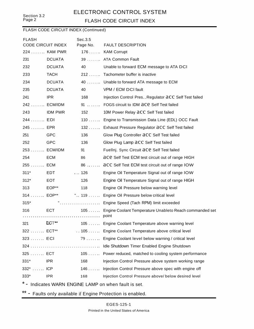
Section 3.2Page 2
ELECTRONIC CONTROL SYSTEM
FLASH CODE CIRCUIT INDEX
FLASH CODE CIRCUIT INDEX (Continued)
FLASH Sec.3.5CODE CIRCUIT INDEX Page No. FAULT DESCRIPTION
224 . . . . . .. KAM PWR 176 . . . . .. KAM Corrupt
231 DCUATA 39 . . . . . .. ATA Common Fault
232 DCUATA 40 Unable to forward ECM message to ATA DCl
233 TACH 212 . . . . .. Tachometer buffer is inactive
234 DCUATA 40 . . . . . .. Unable to forward ATA message to ECM
235 DCUATA 40 VPM / ECM DCl fault
241 IPR 168 Injection Control Pres..Regulator acc Self Test failed
242 . . . . . .. ECM/IDM 91 .. . . . .. FOGS circuit to IDM ace Self Test failed
243 IDM PWR 152 10M Power Relay acc Self Test failed
244 . . . . . .. EDl 110 . . . . .. Engine to Transmission Data Line (EDL) OCC Fault
245 . . . . . .. EPR 132 . . . . .. Exhaust Pressure Regulator acc Self Test failed
251 GPC 136 Glow Plug Controller acc Self Test failed
252 GPC 136 Glow Plug Lamp acc Self Test failed
253 . . . . . .. ECM/IDM 91 Fuellnj. Sync Circuit ace Self Test failed
254 ECM 86 ace Self Test ECM test circuit out of range HIGH
255 . . . . . .. ECM 86 . . . . . .. acc Self Test ECM test circuit out of range lOW
311* EDT " .. 126 Engine Oil Temperature Signal out of range lOW
312* EOT 126 Engine Oil Temperature Signal out of range HIGH
313 EOP** 118 Engine Oil Pressure below warning level
314 . . . . . .. EOP** " .. 119 . . . . .. Engine Oil Pressure below critical level
315* " . . . . . . . . . . . . . . . . . . .. Engine Speed (Tach RPM) limit exceeded
316 ECT 105 . . . . .. Engine Coolant Temperature Unableto Reach commanded set...................................... point
321 ECT*'" 105 . . . . .. Engine Coolant Temperature above warning level
322 . . . . . .. ECT** " . 105 . . . . .. Engine Coolant Temperature above critical level
323 . . . . . .. ECl 79 . . . . . .. Engine Coolant level below warning / critical level
324 . . . . . . . . . . . . . . . . . . . . . . . . . . . . . . . . .. Idle Shutdown Timer Enabled Engine Shutdown
325 . . . . . .. ECT 105 . . . . .. Power reduced, matched to cooling system performance
331* IPR 168 Injection Control Pressure above system working range
332* . . . . .. ICP 146 . . . . .. Injection Control Pressure above spec with engine off
333* IPR 168 Injection Control Pressure above/ below desired level
* - Indicates WARN ENGINE LAMP on when fault is set..
** - Faults only available if Engine Protection is enabled.
EGES-125-1
Printed in the United States of America

ELECTRONIC CONTROL SYSTEM
FLASH CODE CIRCUIT INDEXSection 3.2
Page 3
FLASH CODE CIRCUIT INDEX (Continued)
FLASH Sec.3.5CODE CIRCUIT INDEX Page No. FAULT DESCRIPTION
334* IPR 168 . . . . .. ICP unable to achieve setpoint (poor performance)
335* IPR 168 . . . . .. ICP unable to build pressure during cranking
341 . . . . . .. ESP Exhaust Back Pressure signal out of range LOW
342 ESP Exhaust Back Pressure signal out of range HIGH
343 . . . . . .. EPR 132 . . . . .. Excessive Exhaust Back Pressure
344 . . . . . .. ESP ,.. Exhaust Back Pressure above Spec. with Engine OFF
351 EPR 131 . . . . .. Exhaust Back Pressure below expected level at high enginespeeds
352 . . . . . .. EPR 131 . . . . .. Exhaust Back Pressure above or below desired level
421 INJ 160 LOW to HIGH Side Open - Cyl1
422 INJ 160 LOW to HIGH Side Open - Cyl2
423 INJ 160 LOW to HIGH Side Open - Cyl3
424 . . . . . .. INJ 160 . . . . .. LOW to HIGH Side Open - Cyl 4
425 INJ 160 . . . . .. LOW to HIGH Side Open - Cyl5
426 INJ 160 LOW to HIGH Side Open - Cyl 6
427 INJ 160 . . . . .. LOW to HIGH Side Open - Cyl 7
428 INJ 160 . . . . .. LOW to HIGH Side Open - Cyl 8
431 INJ 160 . . . . .. LOW to HIGH Side Short - Cyl1
432 INJ 160 LOW to HIGH Side Short - Cyl2
433 INJ 160 LOW to HIGH Side Short - Cyl3
434 INJ 160 LOW to HIGH Side Short - Cyl4
435 INJ 160 LOW to HIGH Side Short - Cyl5
436 INJ 160 . . . . .. LOW to HIGH Side Short - Cyl6
437 . . . . . .. INJ 160 . . . . .. LOW to HIGH Side Short - Cyl 7
438 INJ 160 LOW to HIGH Side Short - Cyl8
441 INJ 160 . . . . .. LOW side short to VBAT- Cyl 1
442 INJ 160 LOW side short to VBAT - Cyl2
443 INJ 160 LOW side short to VBAT - Cyl3
444 INJ 160 LOW side short to VBAT - Cyl4
445 INJ 160 LOW side short to VBAT - Cyl5
446 INJ 160 LOW side short to VBAT - Cyl6
447 INJ 160 LOW side short to VBAT - Cyl 7
448 INJ 160 LOW side short to VBAT - Cyl8
* - Indicates WARN ENGINE LAMP on when fault is set.
EGES-125-1
Printed In the United States of America

Section 3..2Page 4
ELECTRONIC CONTROL SYSTEM
FLASH CODE CIRCUIT INDEX
FLASH CODE CIRCUIT INDEX (Continued)
FLASH Sec..3 ..5CODE CIRCUIT INDEX Page No.. FAULT DESCRIPTION
451 INJ 161 . . . . .. LOW side short to ground - Cyl1
452 INJ 161 . . . . .. LOW side short to ground - Cyl2
453 . . . . . .. INJ 161 . . . . .. LOW side short to ground - Cyl 3
454 . . . . . .. INJ 161 . . . . .. LOW side short to ground - Cyl 4
455 INJ 161 . . . . .. LOW side short to ground - Cyl 5
456 . . . . . .. INJ 161 . . . . .. LOW side short to ground - Cyl 6
457 INJ .. " 161 . . . . .. LOW side short to ground - Cyl 7
458 INJ 161 ". LOW side short to ground - Cyl 8
461 Perf. Diag. CyL Contribution Test Failure - Cyl1
462 Perf. Diag. Cyl. Contribution Test Failure - Cyl2
463 Perf. Diag. Cyl. Contribution Test Failure - Cyl 3
464 Perf. Diag. Cyl. Contribution Test Failure - Cyl 4
465 Peri. Diag. Cyl. Contribution Test Failure - Cyl5
466 " .. Perl. Diag "........ Cyl. Contribution Test Failure - Cyl 6
467 Perf. Diag. Cyl. Contribution Test Failure - Cyl7
468 " Perl. Diag. Cyl. Contribution Test Failure - Cyl 8
511* .. " INJ 161 . . . . .. Bank 1 has multiple faults
512* . . . . .. INJ 161 . . . . .. Bank 2 has multiple faults
513* INJ 161 High Side to Bank 1 Open
5141r••••• " INJ 161 High Side to Bank 2 Open
5151r•••••• INJ 161 Bank 1 High Side Short to Ground or VBAT
521* INJ 161 . . . . .. Bank 2 High Side Short to Ground or VBAT
522* IDM PWR .. " 153 IDM Internal Failure
523 IDM PWR 153 . . . . .. 10M power voltage is LOW
524* INJ " 161 . . . . .. Both High Side Switches shorted together
531* .. " ECM/IDM 91 .. . . . .. Cylinder identification (CI) Signal Low
532* . . . . .. ECM/IDM 91 .. . . . .. Cylinder Identification (CI) Signal high
541 * . . . . .. ECM/IDM 92 . . . . . .. IDM Feedback TOGGLE not detected by ECM
543* . . . . .. ECM/IDM 92 . . . . . .. IDM faults not received
544 INJ 162 . . . . .. Injector Fault in Bank 2
545 INJ 162 " . . . .. Injector Fault in Bank 1
612* CMP 33 . . . . . .. Incorrect ECM installed for CMP (timing) wheel
* - Indicates WARN ENGINE LAMP on when fault is set..
EGES--125-1
Printed in the United States of America

ELECTRONIC CONTROL SYSTEM
FLASH CODE CIRCUIT INDEXSection 3.2
PageS
FLASH CODE CIRCUIT INDEX (Continued)
FLASH Sec.3.5CODE CIRCUIT INDEX Page No. FAULT DESCRIPTION
613* VPM 231 Installed ECM not compatible with VPM Software
614* . . . . . . VPM 231 . . . . .. Installed VPM not compatible with ECM software
615 . . . . . .. ECM 86, 231 .. Programmable Parameter KAM Corrupt fault
621* VPM 231 . . . . .. Engine using MFG. Default rating program engine
622* . . . . . . VPM 231 . . . . .. Engine using Field Default rating
623* VPM 232 . . . . .. Invalid Engine Rating Code; Check VPM programming
625 . . . . . .. ECM 86 . . . . . .. Module Software Background Process was inactive
631 ECM 86 ROM (Read Only Memory) Self Test fault
632 . . . . . .. ECM 86 . . . . . .. RAM Memory-CPU Self Test Fault
633 DCUATA 41 VPM is communicating incorrectly with ECM
634 . . . . . .. VPM 232 . . . . .. Internal Fuel meter memory location in error
635 . . . . . . . VPM 233 . . . . .. Interna~ Hourmeter memory location in error
641 VPM 233 . . . . .. Internal Odometer memory location in error
642 VPM 233 . . . . .. Internal Fuelmeter Fault
643 . . . . . . . VPM 233 . . . . .. Internal Hourmeter Fault
644 . . . . . . . VPM 233 . . . . .. Internal Odometer Fault
645 VPM 233 . . . . .. Internal EEPROM memory location error
651 . . . VPM 233 . . . . .. Feature memory data content corrupted
652 . . . . . . . VPM 234 . . . . .. Engine/Fuel memory data content corrupted
653 VPM 234 . . . . .. Engine/Rating memory data content corrupted
654 . . . . . . . VPM 234 . . . . .. Watchdog Timeout
* - Indicates WARN ENGINE LAMP on when fault is set.
EGES-125-1
Printed In the United States of America
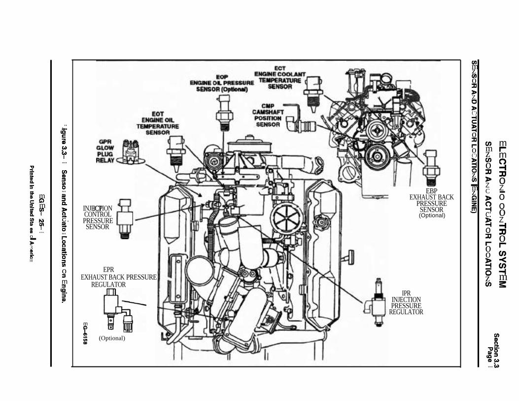
mrm~::JJoZ-oooZ-I::JJor-en<~m3:
en~a,,-'1»0
lQ::S~Co)
.... e.>
enmzenoJ:J»ZC»~c:!ioJ:JIoo!i6zen
enmzeno::D»ZC»(')
~~o::D,..o(')
~ozen-mzG)
Z!!J
EBPEXHAUST BACK
PRESSURESENSOR(Optional)
IPRINJECTIONPRESSURE
REGULATOR
m
~~ (Optional)C»
ICP §INJECTIONCONTROLPRESSURESENSOR
EPREXHAUST BACK PRESSURE
REGULATOR
."cE'ciCo)
f....en~::s~...I»::sQ.
»ac.g...r-8ao'::seno::sm::slQ:i'!D
'tI:!.~
S'Q,
3"
f mc G)=. m[ rren ....lD N- crI ....o-~3CD
5-III

Section 3.3Page 2
ELECTRONIC CONTROL SYSTEM
SENSOR AND ACTUATOR LOCATIONS
ELECTRONIC CONTROL SYSTEM COMPONENT LOCATIONS (VEHICLE)
ELECTRONIC CONTROL SYSTEM VEHICLE/ENGINE INTERFACE
----- ~~STI~
OtAGNOSncSWITCH
VEHICLEPERSONALITYMODULE (VPM)
ELECTJlONICCONTROL
MODULE (ECM)
DRIVEMODULE
(10M)
GINJECTORDRIVE
MODULERELAY
~ ':~y ~--_b..
EO-3584
Figure 3.3-2. Electronic Control System Component Locations (Vehicle)
EGES-125-1Printed In the United States of America

· ELECTRONIC CONTROL SYSTEM DIAGNOSTICSSection 3.5Page2 ACCELERATOR PEDAL POSITION SENSORlIVS SWITCH (APS/IVS)
APS/IVS PEDAL POSITION SENSOR /IDLE VALIDATION SWITCH
ECM
ELECTRONICCONTROLMODULE
10M
INJECTORDRIVERMODULE
FUEL QUANTITYAND
TIMING CONTROL
INJECTION CONTROLPRESSURE REGULATOR
(0 'Yo)oVolts
5 Volts(100 'Yo)
WARNLamp
EG-1114
SIGNAL FUNCTIONS
The Accelerator Pedal Position Sensor (APS) is apotentiometer type sensor which, when suppliedwith a 5 volt reference signal from the ElectronicControl Module (ECM), provides a linear analogvoltage signal that indicates the driver's demand forpower.
The Idle Validation Switch (IVS) is a 0/12 volt switchthat provides the ECM with a redundant signal toverify when the pedal is in the idle position.
Fuel Quantity and Timing Control - The APS signal is used in calculating desired fuel quantity andinjector timing.
Injection Control Pressure - Accelerator pedalposition is one of the controlling variables in the calculation of desired injection control pressure.
FAULT DETECTION/MANAGEMENT
Any detected malfunction of the APS or IVS sensorcircuit will illuminate the WARN ENGINE lamp.
An APS signal that is detected out of range high orlow by the ECM will cause the engine to ignore theAPS signal and will only allow the engine to operateat low idle.
If a disagreement in the state of IVS and APS is detected by the ECM and the ECM determines that itis an IVS fault , the ECM will only allow a maximumof 50% APS to be commanded.
If a disagreement in the state of IVS and APS is detected by the ECM and the ECM can not discern ifit is an APS or IVS fault or if it is an APS fault, theengine will be allowed to operate at low idle only.
EGES-125-1
Printed in the United States of America

ELECTRONIC CONTROL SYSTEM DIAGNOSTICSSection 3.5
ACCELERATOR PEDAL POSITION SENSORlIVS SWITCH (APS/IVS) Page 3
Fault Codes:131 APS signal out of range low132 APS signal out of range high133 APS signal in-range fault134 APS and IVS disagree135 Idle validation switch circuit faultDeutsch Connector
(On Cowl)
ECMConnector
Accelerator Pedal Sensor & Idle
Validation Switch
(APSIIVS)
I"Pin#472APS Signal ~ ...19 A (a)
Signal GroundB - I ~ (b)Pin # 46
V Ref21
roo-Pin # 26 12 C I ~ (c)
~in# 8IVS Signal 2 D I ~ (d)
~ E""--
IF4 (fuse) ~ (e)V IGN. - -
'-.!..J~EG-1115 F (f)
After removing connectors always check for damaged pins. corrosion. loose terminals etc.Connector Checks to Chassis Ground
(Check with Sensor Connector Disconnected and Ignition key off, all accessories off)
Test Points Spec. Comments
A to Grd. > 1000 ohms Resistance less than 1000 ohms indicates a short to ground.
B to Grd. < 5 ohms Resistance to chassis ground, check with key off, > than 5 ohms harness is open.
C to Grd. > 1000 ohms Resistance less than 1000 ohms indicates a short to ground.
o to Grd. > 1000 ohms Resistance less than 1000 ohms indicates a short to ground.
Connector Signal Checks (Check with Sensor Connector Disconnected and Ignition Key On)
Test Points Spec. Comments
A to Grd. 0- .25 volts If greater than .25 volts signal ground wire is shorted to V Ref or battery.
B to Grd. 0- .25 volts Signal ground no voltage expected.
Cto Grd. 5 ± .5 volts VRef check key on, if VRef not present check open/short to grd #26 to C, see VRef circuit.
o to Grd. 0- .25 volts If greater than .25 volts signal ground wire is shorted to V Ref or battery.
F to Grd. ~2 ± 1.5 volts < 10.5 v check for poor connection, 0 v check for open/short to grd circuit or blown fuse.
Harness Resistance Checks (Check with breakout box installed on engine harness only)Test Points Spec. Comments
#47 to A < 5 ohms Resistance from 60 pin connector to harness connector - APS Signal
#46 to B < 5 ohms Resistance from 60 pin connector to harness connector - Signal Ground
#26 to C < 5 ohms Resistance from 60 pin connector to harness connector - V Ref
#8 to 0 < 5 ohms Resistance from 60 pin connector to harness connector - IVS Signal
V IGN. to F < 5 ohms Resistance from V IGN. power to harness connector
APS Test Points IVS Test Points Operational Voltage Checks(+) #47 to H #46 (+) #8 to (-) #46 (Check with breakout box and the EST tool installed key "ON")
Position Voltage %APS Voltage %APS Comments
Low Idle .25 to.8 V 0% ovolts 0% IVS voltage should toggle just off low idle position.
High Idle 3 to 4.5 V 98-100% 12±1.5v 98-100%If APS measures only 50% and volt signal in spec.,IVS fault detected.
Fault Code Descriptions131 APS signal was less than 0.146 volts for more than 0.5 seconds *132 APS signal was greater than 4 .56 volts for more than 0.5 second *133 APS signal in-range fault *134 APS and IVS agree *135 Idle validation switch circuit fault - 50% APS only.
* -IF FAULT CODE IS SET. ENGINE OPERATION WILL DEFAULT TO RUN AT LOW IDLE SPEED ONLY.
EGES-125-1
Printed in the United States of America

Section 3.5 ELECTRONIC CONTROL SYSTEM DIAGNOSTICSPage 4 ACCELERATOR PEDAL POSITION SENSORlIVS SWITCH (APS/IVS)
APSIIVS EXTENDED SYSTEM DESCRIPTION
Navistar electronic engines use an electronicaccelerator pedal assembly that includes aAccelerator Position Sensor (APS) and IdleValidation Switch (IVS). These two functions areintegrated into one component mounted on thepedal. The accelerator pedal assembly isserviceable to the extent that the APS/IVS switchcan be replaced without replacing the completeassembly.
The engine Electronic Control Module (ECM)determines the position of the accelerator pedal byprocessing the input signals from the AcceleratorPosition Sensor (APS) and Idle Validation Switch(IVS).
ACCELERATOR POSITION SENSOR (APS)
Refer to circuit diagram on page 6 for the followingdiscussion.
The ECM sends a regulated 5 volt signal throughECM connector (379) terminal 26 to APS connector(382) terminal C. The APS then returns a variablevoltage signal (depending on pedal position) fromAPS connector (382) terminal A to the ECM atterminal 47. The APS is grounded from connector(382) terminal 8 to the ECM signal ground terminal46.
APS AUTO-CALIBRATION
The ECM learns the lowest and highest pedalpositions by reading and storing the minimum andmaximum voltage levels from the APS . In thismanner the ECM "auto- calibrates" the system toallow maximum pedal sensitivity. The ECMauto-calibrates as the key is ON, but when the keyis turned OFF, these values are lost. When the keyis turned on again, this process starts over. Whenthe pedal is disconnected (or new one installed), thepedal does not need to be calibrated, as thecalibration happens when the key is turned on.
IDLE VALIDATION SWITCH (IVS)
The ECM expects to receive one of two signalsthrough ECM connector (379) terminal 8 fromAPS/IVS connector (382) terminal D:
• 0 volts when the pedal is at the idle position.
• 12 volts when the pedal is depressed.
The Idle Validation Switch receives 12 volt ignitionvoltage from 10A fuse F4 (H1 with FBC). When the
pedal is NOT in the idle position (throttle applied),the IVS sends a 12 volt signal to the ECM.
The ECM compares the inputs it receives atterminals 47 and 8 from the APS/IVS to verify whenthe pedal is in the idle position. If the APS signal atterminal 47 indicates throttle is being applied, thenthe ECM expects to see 12 volts at IVS terminal 8.If the APS signal at terminal 47 indicates throttle isnot applied, then the ECM expects to see 0 volts atthe IVS terminal 8. The timing process is criticalbetween the APS and the IVS sensors. For thisreason, it is very difficult to determine if the APS/IVSassembly is working properly using avolt-ohmmeter.
ECM DIAGNOSTICS
When the key is ON, the ECM continuouslymonitors the APS/IVS circuits for expectedvoltages. It also compares the APS and IVS signalsfor conflict. If the signals are not what the ECMexpects to see, Fault codes will be set.
FLASH CODE 131ATA CODE PID 91 FMI 4 -ECM: APS OUT OF RANGE LOW
The ORL (out of range low) code 131 is set if theECM detects a voltage lower than 0.146 volts atterminal 47. Possible causes include: a short toground or an open in circuit 998. This code isdisplayed by either the Prolink EST or using theEngine Warn Light to flash codes.
When code 131 is active, the ECM restricts enginespeed to idle and turns the Engine Warning LightON. If the condition causing code 131 is intermittentand the condition is no longer present, the code willbecome inactive and normal engine operation willresume. If code 131 is active, perform Testing APSCircuits on page 8.
FLASH CODE 132ATA CODE PID 91 FMI 3 -ECM: APS OUT OF RANGE HIGH
The OF\i-' {out of range high) code 132 is set if theECM db ccts a voltage greater than 4.56 volts atterminal 47. Possible cause: short to VREF or 12volts in ~ircuit 99B. This code is displayed by eitherthe Prohnk EST or using the Engine Warn Light toflash codes.
EGES-125-1Printed In the United States of America

ELECTRONIC CONTROL SYSTEM DIAGNOSTICS Section 3.5
ACCELERATOR PEDAL POSITION SENSORlIVS SWITCH (APS/IVS) Page 5
APSIIVS EXTENDED SYSTEM DESCRIPTION (Continued)
FLASH CODE 132ATA CODE PID 91 FMI 3 -ECM: APS OUT OF RANGE HIGH (Continued)
When code 132 is active, the ECM restricts enginespeed to idle and turns the Engine Warn Light ON.If the condition causing code 132 is intermittent andthe condition is no longer present, the code willbecome inactive and normal engine operation willresume. If code 132 is active, perform Testing APSCircuits on page 8.
FLASH CODES 133, 134 AND 135APS IN-RANGE FAULTS
The ECM checks the voltage output of the APS bycomparing the APS signal with the IVS signal. APSand IVS signals can disagree in two cases:
• The APS signal indicates the pedal is presseddown to accelerate, but the IVS signal indicates idle position.
• The APS signal indicates the pedal has beenreleased to allow the engine to return to idle,but the IVS signal indicates off-idle position ofthe pedal.
If the ECM detects either of the above conditions,the ECM attempts to isolate the source of conflict.If code(s) 133, 134 and/or 135 are active, performTesting IVS Circuits on page 7 and Testing APSCircuits on page 8.
FLASH CODE 133ATA CODE PID 91 FMI 2 ECM: APS IN RANGE FAULT
If the IVS signal is changing and the APS signal isconstant, the ECM assumes APS is the conflictsource and sets code 133. Engine rpm is restrictedto idle and the Engine Warn Light is turned ON.
FLASH CODE 134ATA CODE PID 91 FMI 7ECM: APSRVS DISAGREE
If neither the APS or IVS is changing, or both arechanging or the ECM cannot determine the faultycode in specified time, then code 134 is set, enginerpm is restricted to idle and the Engine Warn Lightis turned ON.
FLASH CODE 135ATA CODE SID 230 FM111ECM: IVS CIRCUIT FAULT
If the APS is changing and IVS is constant, the ECMassumes IVS is the conflict source and sets flashcode 135. In this case the ECM limits the APS signalto a lower value, which provides less than full rpm,but does not limit engine rpm to idle. The EngineWarn Light is not turned ON.
Note that codes 133, 134 and 135 are caused by anintermittent condition, the codes remain ACTIVEuntil the vehicle has been shutdown and restarted.They do not recover without cycling the key switch.
TROUBLESHOOTING
The APS and IVS circuits operate with low currentlevels. When troubleshooting, pay special attentionto the connectors.
BEFORE P-ERFORMING ANY TEST
Inspect connectors for pushed back, damaged,corroded or dirty terminals, as well as making surethat the terminals and wires are properly crimped.Make sure the connectors are properly joinedtogether. Also check for any damage to the wiringand make sure system grounds are clean and tight.
TESTING APSnVS CIRCUITS• If flash codes 131 or 132 are present, perform
Testing APS Circuits on page 8. If flash codes133, 134 or 135 are present, perform TestingIVS Switch & Circuits on page 7.
These tests systematically check the APS and IVScircuits for:
A. Short circuits to ground.
B. Short circuits to unwanted voltagesources.
C. Open circuits or excessive circuit resistance.
D. Proper feeds and grounds.
Note: The tests performed on the accelerator pedalassembly check for shorts, opens and correctresistance values, but do not check for propertimingbetween the two functions. If all of the circuitsbetween the ECM and the accelerator pedalassembly check good (Testing IVS Circuits on page7) and APS Circuits on page 8, then the APSIIVSaccelerator switch should be replaced.
EGES-125-1
Printed In the United States of America

S t· 3 5 ELECTRONIC CONTROL SYSTEM DIAGNOSTICS
ec Ion .Page 6 ACCELERATOR PEDAL POSITION SENSORlIVS SWITCH (APS/IVS)
CIRCUIT DIAGRAM
ECM (379)
ECU(380)
SIGTRONu-_97_A_M__~
EOP c ..._9_7A_E__........
~---------e~ EOP
....- .....-----............_-1> ICP
CMP
H110A
II
Xlco.b).
IIIII
~c I---_-IWI FBC &S.C.
• W/CRUISE. PTO OR ENGINE BRAKE
NEUTRAL SAFETY SWITCH
12V IGN TO VPM
'-----~ BRAKE SWITCH RELAY (393)-
DASH C'ONN(3 & 3A)
LO
:>,......en
S11~7BX
~0-
m S- o Wa. e g C)
ca 0 en
i ~
:~ ~~~ ~~ ~c~~T~~~~~~r:
ACCEL POS SENSOR NO C NC
Idle ValidationAPS/IVS (382) Switch
(IVS)
TO BARO SENSOR
NOTE: IVS OPEN AT IDLE
OC) INDICATES TWISTED WIRE PAIR
Figure 3.5-1 APS/IVS System
EGES-125-1
Printed In the United States of America

ELECTRONIC CONTROL SYSTEM DIAGNOSTICS s · 3 5ectlon .
ACCELERATOR PEDAL POSITION SENSORlIVS SWITCH (APS/IVS) Page 7
Refer to Figure 3.5-1, on page 6 whileperforming this test.
TESTING (IVS) IDLE VALIDATION SWITCH AND CIRCUITS
( Begin)
Check 10A fuse F4 (or H1 w/FBC) for open condition.
Locate cause of overload condition,then correct. Re lace fuse.
Replace APS/IVSpedal assembly.
Perlorm TESTING APSSENSOR CIRCUITS on page B.
99E
KEY ON - Jumper breakout box terminal Bto ground (terminaI6D). At connector(382), measure voltage between terminalF and terminal D.
Replace theAPS/IVSassembly.
Locate open in circuit 99D betweenIVS connector (382) and ECMconnector (379), then correct.
Locate cause of NO orLOW voltage in feed circuit99E, then correct.
With key OFF, disconnect APS/IVSconnector (382) from cab harness.Turn key ON and at breakout box,measure voltage between terminals 8and 60.
KEY OFF - Install breakout box at ECM connector (379). Turn key ON and with APS/IVS pedalUP idle, measure volta e at breakout box between terminals 8 &60.
KEY OFF- Disconnect APS/IVS connector (382) from cab harness. KEON - Measure voltage to veh. ground at (382), terminal F.
Locate short tounwantedvoltage sourcein circuit 99D,then correct.
EGES-125-1Printed in the United States of America
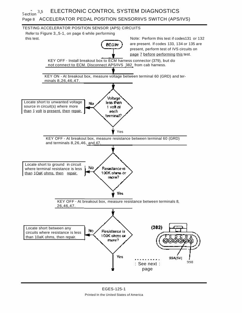
5 t" 3 5 ELECTRONIC CONTROL SYSTEM DIAGNOSTICS
ec Ion "Page 8 ACCELERATOR PEDAL POSITION SENSORlIVS SWITCH (APS/IVS)
TESTING ACCELERATOR POSITION SENSOR (APS) CIRCUITS
Refer to Figure 3,,5-1, on page 6 while performingthis test. Note: Perform this test if codes131 or 132
are present. If codes 133, 134 or 135 arepresent, perform test of IVS circuits onpage 7 before performing this test.
KEY OFF - Install breakout box to ECM harness connector (379), but donot connect to ECM. Disconnect APS/IVS 382 from cab harness.
KEY ON - At breakout box, measure voltage between terminal 60 (GRD) and terminals 8,26,46,47.
Locate short to unwanted voltagesource in circuit(s) where morethan 1 volt is present, then repair.
+Yes
KEY OFF - At breakout box, measure resistance between terminal 60 (GRD)and terminals 8,26,46, and 47.
Locate short to ground in circuitwhere terminal resistance is lessthan 1OaK ohms, then repair.
KEY OFF - At breakout box, measure resistance between terminals 8,26,46,47.
Locate short between anycircuits where resistance is lessthan 10aK ohms, then repair.
: See next :page
EGES-125-1Printed In the United States of America
998

ELECTRONIC CONTROL SYSTEM DIAGNOSTICS s II 3 5ectlon ..
ACCELERATOR PEDAL POSITION SENSORlIVS SWITCH (APS/IVS) Page 9
TESTING ACCELERATOR POSITION SENSOR (APS) CIRCUITS (Continued),KEY OFF - Install jumper between breakout box terminals 46 and 47. Atconnector 382 , measure resistance between terminals A and B.
Locate open in circuit(s)99A197W/ 97X or 99B betweenconnectors (379) and (382),then re air.
KEY OFF - At breakout box, install jumper between terminals 26 and 46. Atconnector 382 , measure resistance between terminals Band C.
Locate open in circuit(s)99C(5V) or 97AA(5V), thenrepair.
99C(5V) 99A
,Yes
KEY ON - At breakout box, install jumper between terminals 46 &8. Atconnector 382 measure resistance between terminals B &D.
Locate open in circuit(s)99C(5V) or 97AA(5V), thenrepair.
EGES-125-1
Printed in the United States of America

Section 3.5Page 10
ELECTRONIC CONTROL SYSTEM DIAGNOSTICS
BAROMETRIC PRESSURE SENSOR (BARD)
BAROMETRIC PRESSURE (BARO) SENSOR
ECM
ELECTRONICCONTROLMODULE
10M
INJECTORDRIVERMODULE
FUEL QUANTITYAND
TIMING CONTROL
BARO Signal (analog voltage)
5 Volts(High Pressure)(Low Altitude)
BARD
oVolts(Low Pressure)L:.---------'(High Altitude)
EG-1195
SIGNAL FUNCTIONS
The BARa (Barometric Pressure) sensor is a variable capacitance sensor that when supplied with a5 volt reference signal from the ECM produces a linear analog voltage signal that indicates pressure.
Timing Control - The BARa signal is used to determine altitude to adjust timing and fuel quantity tooptimize engine operation and control smokethroughout all altitude conditions.
FAULT DETECTION/MANAGEMENT
A BARa signal that is detected out of range high orlow by the ECM will cause the ECM to ignore theBARa signal and use the Manifold Absolute Pressure (MAP) signal generated at low idle as an indication of barometric pressure. If a MAP fault is detected, the BARa will default to 29.6 in. Hg. ofbarometric pressure.
EGES-125-1Printed in the United States of America

ELECTRONIC CONTROL SYSTEM DIAGNOSTICS
BAROMETRIC PRESSURE SENSOR (BARO)Section 3.5
Page 11
BarometricPressure Sensor
(BARD)
Fault Codes:
151 Out of Range High152 Out of Range Low
c
A
B
BARD SENSOR CONNECTOR (406)(INSIDE RH INST. PANEL) .--_-..DASH (3)
+-----__----...;...;,...---+-C:~_I----~ -..;~~ A
-t---..a..-~---""'+_C: t---+--~-...r. --....---""I B
J-+--------+-<~~------I C
ECM CONNECTOR(379)
(sensor mounted under dash)
After removing connectors always check for damaged pins, corrosion, loose terminals etc.Connector Checks to Chassis Ground
(Check with Sensor Connector (406) Disconnected and Ignition kevoff all accessories off)
Test Points Spec. Comments
Ato Grd. < 5 ohms Resistance to chassis grd, check with key off, > than 5 ohms the harness is open.
B to Grd. > 1000 ohms Resistance less than 1000 ohms indicates a short to ground.
C to Grd. > 1000 ohms Resistance less than 1000 ohms indicates a short to ground.
Connector Voltage Checks(Check with sensor Connector (406) Disconnected, Ignition Key On all accessories off)
Test Points Spec. Comments
B to Grd. 5 Volts + .5 V Ref, check with key ON, if voltage not is spec., see VRet circuit
C to Grd. 0- .25 v If voltage is greater than .25 v, signal wire is shorted to V ref or battery.
Harness Resistance Checks(Check with breakout box installed on engine harness only)
Test Points Spec. Comments
#46 to A < 5 ohms Aesistance from sensor connector to 60 pin connector - Signal ground
#26 to B < 5 ohms Resistance from sensor connector to 60 pin connector - VAef
#5 to C < 5 ohms Resistance from sensor connector to 60 pin connector - BARD signal
Test Points Operational Voltage Checks(+) #5 to (-) #46 (Check with breakout box installed in line with the ECM)
Voltage In. Hg. kPA Comments
4.89 31.0905 105 High atmospheric pressure
4.6 29.61 100 Normal atmospheric pressure at sea level.
2.6 17.766 60 Normal atmospheric pressure at 10,000 feet.
Fault Code Descriptions151 =Signal voltage was greater than 4.95 volts for more than 1.0 seconds.
152 = Signal voltage was less than 1.0 volts for more than 1.0 seconds.
EGES-125-1
Printed in the United States of America

Section 3.5Page 12
ELECTRONIC CONTROL SYSTEM DIAGNOSTICS
BAROMETRIC PRESSURE SENSOR (BARO)
EXTENDED DESCRIPTIONBAROMETRIC PRESSURE SENSORRefer to circuit diagram on page 13 for the followingdiscussion.
BAROMETRIC PRESSURE SENSOR (BARO)OPERATION
The ECM sends a regulated 5 volt signal from ECMconnector (379) terminal 26 to BARO connector(406) terminal 2. The BARD sensor returns avariable voltage signal (represents atmosphericpressure) from BARD connector (406) terminal 3 tothe ECM at terminal 5. The BARD sensor isgrounded from connector (406) terminal 1 to theECM signal ground terminal 46.
ECM DIAGNOSTICS
The ECM continuously monitors the signal from theBARO sensor to ECM terminal 5. If the signal is outof the expected range, a fault is logged (warninglight does NOT turn on) and the ECM uses theManifold Absolute Pressure (MAP) signalgenerated at low idle to Ndetermine barometricpressure.
Flash Code 151ATA Code PID 108 FMI3ECM: BAROS~NALOUTOFRANGEHmH
BARO signal greater than 4.95 volts for more than1 second.
Flash Code 152ATA Code PID 108 FMI4ECM: BARO SIGNAL OUT OF RANGE LOW
BARO signal less than 1.0 volt for more than 1 second.
TROUBLESHOOTING
The BARO circuits operate with low current levels.When troubleshooting, pay special attention to theconnectors.
BEFORE PERFORMING ANY TEST
Inspect connectors for pushed back, damaged,corroded or dirty terminals, as well as making surethat the terminals and wires are properly crimped.Make sure the connectors are properly joinedtogether. Also check for any damage to the wiringand make sure system grounds are clean and tight.
TESTING APSnVS CIRCUITS
NOTE: If fault codes indicate a problem is also present with the APS/IVS system, troubleshoot that system before performing the following test.
• If BARD flash code 151 or 152 is active, perform Testing Barometric Pressure Sensor Cir..cuits on page 14.
This test systematically checks the BARO circuitsfor:
A. Short circuits to ground.
B. Short circuits to unwanted voltagesources.
C. Open circuits or excessive circuit resistance.
D. Proper feeds and grounds.
EGES-125-1
Printed In the United States of America

ELECTRONIC CONTROL SYSTEM DIAGNOSTICS
BAROMETRIC PRESSURE SENSOR (BARO)Section 3.5
Page 13
CIRCUIT DIAGRAM
ACCELERATOR, BARO &MAP SYSTEMS
KEY SWITCHIGN (24)
Y<~(T)D...
-!
F4lOA B
With FBC & S.C.
," H1
lOAB
BAAOMETR1CPRESSURE
SENSOR(408)
97BX~18VT I
~~m!!!
LL t-W :J 0a: 0 Z> > (!)
MANIFOLDABSOLUTE
PRESS SENSOR(397)
:>:t-aJ>""'(0OJ-
97AY18VT
97W18VT
5497X16VT
ESP9782
MAP 97BVECM
(3791 IAT 97BU
EOP 97AE
IDM97AM
>~t..J>aJm,....-m
.....~-
(f) LL If) 0 0 Q..> W 0... Z a: <
a: < (!) « ~> (!) ell
If)
TOBATT(-)
3
99C(SVl__IBVT
B_"CCEL > - IPOSITION :>- "'_SENSOR <) ...... <
<> c_ O)...J
CD
... NO o_ldie r"'- ..... ...
ValidationI _ C F_
>t-'lIIl
1= NC-Switch E_ ~>um.,. - m-
OlACCELERATOR
-fPEDAL SWITCH -(382)97BTISVI__
J8VT
>
521I1'---97~C+5V ,__
MAP <J-_9_7_BT_(5_V_)_t 97-GB
EOP <) 97BY(5V)
ICP
CMP~
EGES-125-1
Printed in the United States of America

Section 3.5Page 14
ELECTRONIC CONTROL SYSTEM DIAGNOSTICS
BAROMETRIC PRESSURE SENSOR (BARO)
TESTING BAROMETRIC PRESSURE SENSOR CIRCUITS
Refer to circuit diagram on page 13, while performing this test.
KEY OFF- Disconnect the BARO sensor from connector(406). Turn key ON and measure voltage to ground atconnector (406) terminal 2.
Locate cause of NO or LOWvoltage in circuit 97BL(5V), thenrepair.
KEY ON- At connector (406) measure voltage betweenterminals 1 and 2.
Locate open in circuit 97Z, thenre air.
BARO SENSOR CONNECTOR (406)(INSIDE RH INSI PANEL)
CAB HARNESSB
97BL(SVlt------I++-I7> II)~~--I
c
KEY OFF- With connector (406) disconnected, remove connector (379) from ECM and connectbreakout box to harness side of (379). At breakout box measure resistance between terminal 5 and allother terminals in breakout box.
Locate short circuit between circuit97CD and any circuit whereresistance between terminals is lessthan 1OaK ohms, then re air.
EGES-125-1Printed In the United States of America

ELECTRONIC CONTROL SYSTEM DIAGNOSTICS
BAROMETRIC PRESSURE SENSOR (BARO)
TESTING BAROMETRIC PRESSURE SENSOR CIRCUITS (Continued)
YES
Section 3.5Page 15
KEY DFF- Use test lead to jumper breakout box terminal5 to terminal 46. At BARD connector measure resistancebetween terminals 1 and 3.
Locate open in circuit 97CDbetween connectors (406) and(379), then repair.
EGES-125-1
BARD SENSOR CONNECTOR (406)(INSIDE RH INST. PANEL)
CAB HARt£55B A
97BL (5V I t------++-+--II;> II~~---I
c
Printed in the United States of America

Section 3.5Page 16
ELECTRONIC CONTROL SYSTEM DIAGNOSTICS
BRAKE SWITCH/RELAY CIRCUITS (BRAKE)
BRAKE SWITCH/RELAY CIRCUITS
IGNITION BATTERY
BRAKERELAY
STOPLIGHTSWITCH
12V BRAKES ONOV BRAKES OFF
12V BRAKES OFFOV BRAKES ON
ELECTRONICCONTROLMODULE
SIGNAL FUNCTION
The service brake switch circuit function is tocommunicate to the ECM when the service brakesare applied and when the brakes are not applied.This information is used with cruise control and PTaoperation, which are controlled by the ECM.
SERVICE BRAKE SWITCH(ES)
There are three configurations of switches used.
1. With tractor air brakes (code 4092) a singlenormally open switch is used. Air pressurecloses the switch with brakes applied.
2. With truck air brakes (4091) two normally open,air operated switches are in parallel circuits.
3. With hydraulic brakes (04040) two mechanicalswitches are used, but only one of the switchesis linked to the ECM. The switches are actuatedby the brake pedal arm.
With the key ON and service brakes released,ignition voltage is applied to ECM terminal 43 andno voltage is applied to terminal 23.
When service brakes are applied, voltage is appliedto ECM terminal 23 and the voltage to ECM terminal43 is turned OFF.
FAULT DETECTION MANAGEMENT
The ECM continuously monitors ECM terminals 23(BNO) and 43 (BNC). The ECM expects to se~ 12Vat one terminal and 0 volts at the other. If the Signalsdisagree (12 volts at both or 0 volts at both), thenflash code 222 is set as an active fault.
When Flash code 222 is active, the Cruise and PTOsystems are disabled. If the fault is intermittent, thesystem does not reset until the vehicle has beenshut off and restarted.
This code does not turn ON the engine warninglight.
EGES-125-1
Printed In the United States of America

ELECTRONIC CONTROL SYSTEM DIAGNOSTICS
BRAKE SWITCH/RELAY CIRCUITS (BRAKE)Section 3.5
Page 17
Brake Switch I Relay Fault Codes:
(BRAKE)222 Brake Switch Circuit Fault
CRUISE/PTO/BRAKE SWITCHRELAY 13931
CAB HARNESS
Refer to page 27 forprocedure to test the relay.
ELECTRONICCONTROLMODULE
23 BND (Ov released12vapplied)
43 BNC (12v releasedOvapplied)
\2nd swonlyw/4091
After removing connectors always check for damaged pins. corrosion. loose terminals etc.
Connecter Voltage Checks(Connector (393) with relay removed, Ignition Key ON and Brakes Released)
Test Points Spec. Comments
Cir 97K to grd 12 ± 1.5 volts < 10.5v check connections, if 0 volts, check for open/short to grd or blown fuse
Cir 97Y to grd < 1.0 volt > 1.0v check for short to VREF or 12v circuit or defective switch (switch adjust-ment with hydraulic brakes)
Cir 97K to 97GH 12 ± 1.5 volts < 10.5v check connections, if 0 volts, check for open in ground circuit 97GH
(Connector (393) with relay removed, Ignition Key ON and Brakes Applied)Test Points Spec. Comments
Cir 97Y to 97GH 12 ± 1.5 volts< 10.5v check connections, if 0 volts check for open/short to grd or defectiveswitch (switch adjustment with hydraulic brakes) or blown fuse.
Cir 97M to grd < 1.0 volt > 1.0 volt, check for short to VREF or 12 volt circuit
(Connector (379) with breakout box installed, brake relay installed, Ignition Key ON, and Brakes Applied)Test Points Spec. Comments
#23 to grd 12 ± 1.5 volts < 10.5v check connections, if 0 volts check for open circuit 97N
#43 to grd < 1.0 volt > 1.0 volt short to BATT or VREF or defective relay
(Connector (379) with breakout box installed, brake relay installed, Ignition Key ON and Brakes Released)Test Points Spec. Comments
#23 to grd < 1.0 volt > 1.0 volt short to BATT or VREF or defective relay
#43 to grd 12 ± 1.5 volts < 1O.5v check connections, if 0 volts check for open circuit 97N or defective relay
Fault Code Descriptions
222 = Voltage at ECM pins #23 (BNO) and #43 (BNC) are the same
EGES-125-1Printed In the United States of America

Section 3.5Page 18
DESCRIPTION
ELECTRONIC CONTROL SYSTEM DIAGNOSTICS
BRAKE SWITCH/RELAY CIRCUITS (BRAKE)
All vehicles equipped with Cruise and PTO utilizethe Brake Switch Relay (393) to notify the ECM ofa brake ON or brake OFF condition.
WITH HYDRAULIC BRAKES
With hydraulic brakes the system includes (2) normally open brake switches (50) and (51) and theBrake Switch Relay (393).
Service Brakes NOT Applied
With the key ON and service brakes NOTAPPLIED,ignition power from 1OA fuse F4 (fuse H1 w/FBC)goes through the normally closed contacts (30 to87A) of the Brake Switch Relay (393) to the ECM atterminal 43. When the brakes are not applied, theECM sees 12 volts at terminal 43, the BNC (brakenormally closed) terminal.
When the brakes are not applied, note that no voltage is present on circuit 97N to ECM terminal 23,the Brake Normally Open terminal.
When the ECM sees 12 volts at terminal 43 and 0volts at terminal 23, it's programmed to interpret thiscondition as "service brakes are not applied."
Service Brakes Applied
Battery Power through 1OA fuse F33 (fuse E3w/FBC) is always present at the normally open(N.O.) brake switch (50). Applying the servicebrakes closes switch (50). With this switch closed,two things occur:
1. Power is applied to the Brake Switch Relay(393) causing it to energize, opening the N.C.contacts (30 to 87A). This turns OFF the powerto ECM terminal 43 (BNC). ECM terminal 43sees 0 volts.
2. Power is also applied (circuit 97N) to ECM terminal23, which is the Brake Normally Open terminal. ECM terminal 23 sees 12 volts.
When the ECM sees 0 volts at terminal 43 and 12volts at terminal 23, it's programmed to interpret thiscondition as "service brakes are applied."
WITH AIR BRAKES
With air brakes the system includes (2) normallyopen brake switches (70) and (71) and the BrakeSwitch Relay (393).
Service Brakes NOT Applied
With the key ON and service brakes NOT APPLI ED,Ignition power through 10A fuse F4 (fuse H1w/FBC) goes through the normally closed contacts(30 to 87A) of the Brake Switch Relay (393) to ECMterminal 43. When the brakes are not applied, theECM sees 12 vorts at terminal 43, the BNC (brakenormally closed) terminal.
When the brakes are not applied, note that no voltage is present on circuit 97N to ECM terminal 23,the Brake Normally Open terminal.
When the ECM sees 12 volts at terminal 43 and 0volts at terminal 23, it's programmed to interpret thiscondition as "service brakes are not applied."
EGES-125-1Printed In the United States of America

ELECTRONIC CONTROL SYSTEM DIAGNOSTICS
BRAKE SWITCH/RELAY CIRCUITS (BRAKE)
SERVICE BRAKES APPLIED
Section 3.5Page 19
Battery Power through 10A fuse F9 (30A fuse D3w/FBC) is always present at the normally open(N.O.) brake switches (70) and (71). Applying theservice brakes closes switches (70) and (71). Withswitches (70) and/or (71) closed, two things occur:
1. Power is applied to the Brake Switch Relay(393) causing it to energize, opening the N.C.contacts (30 to 87A). This turns OFF the powerto ECM terminal 43 (BNC). ECM terminal 43sees 0 volts.
2. Power is also applied (circuit 97N) to ECM terminal 23, which is the ECM Brake NormallyOpen terminal. ECM terminal 23 sees 12 volts.
When the ECM sees 0 volts at terminal 43 and 12volts at terminal 23, it's programmed to interpret thiscondition as "service brakes are applied."
The air brake stop light circuits work the same asNavistar vehicles without the electronic VB engine.Refer to the Circuit Diagram book for complete circuit information.
DIAGNOSTICS
FLASH CODE 222SID 247 FMI2ECM: BRAKE SWITCH CIRCUIT FAULT
The ECM continuously monitors ECM terminals 23(BNO) and 43 (BNC). The ECM expects to see 12Vat one terminal and 0 volts at the other. If the signalsdisagree (12 volts at both or 0 volts at both), thenflash code 222 is set as an active fault.
When Flash code 222 is active, the Cruise and PTOsystems are disabled. If the fault is intermittent, thesystem does not reset until the vehicle has beenshut off and restarted.
This code does not turn ON the engine warninglight.
WIRING CAUSES
A faulty brake switch, faulty brake switch relay, openfuses and/or open or short circuits (HIGH or LOW)can cause code 222 to set.
TROUBLESHOOTING
The Prolink EST can be used to monitor the brakeswitch operation. If the monitor indicates that thebrake switch is not operating properly, or code 222is active, perform the tests in this section.
BEFORE TROUBLESHOOTING
A. Before troubleshooting, make sure that the batteries are fully charged! Check battery cablesand grounds for clean, tight connections free ofdamage. Voltage tests will give misleadingreadings if the batteries are not fully charged.
B. Before troubleshooting, inspect circuit connectors for pushed back, loose or damaged(spread or bent) terminals, or wires with cutstrands, etc. Wires and connections must befree of damage or corrosion. When some connectors corrode, a light white residue will bepresent that must be removed.
C. Before troubleshooting, inspect the suspect circuit grounds for clean, tight connections, free ofany damage.
TESTING BNO/BNC BRAKE SWITCHSYSTEM
Air Brake Switch and Hydraulic Brake Switch circuittests must be performed before Brake Switch RelayCircuit test.
EGES-125-1
Printed in the United States of America

Section 3.5Page 20
ELECTRONIC CONTROL SYSTEM DIAGNOSTICS
BRAKE SWITCH/RELAY CIRCUITS (BRAKE)
CIRCUIT DIAGRAMAIR BRAKE BNOIBNC SWITCHIRELAY CIRCUITS
KEY SWITCHIGN
J1 BATTFEED
o
,W/FBC
H110A
WITRKF410A
,WIFBC
D330A
WITRKF9
20A
BRAKE SWITCHRELAY (393)
W/CRUISE, PTO,
...
86
97Y
N.O. BRAKE SWITCH RD(2 SHOWN)
..-oW'" (70) (71)
BN
TO TURNSIGNAL SWITCH
ORBODY BUILDERCONNWIFBC
(3 & 3A)
ECM (379)
BNO
EGES-125-1
Printed In the United States of America

ELECTRONIC CONTROL SYSTEM DIAGNOSTICS
BRAKE SWITCH/RELAY CIRCUITS (BRAKE)Section 3.5
Page 21
CIRCUIT DIAGRAMS (Continued)HYDRAULIC BRAKE BNO/BNC SWITCH/RELAY CIRCUITS
KEY SWITCHIGN
-B-TERMINAL
CRANK J1BAITSOLENOID FEED
0 -- 0 0
co c «0 .. ....(J) ..- .....
,W/FBC
H110A
WITRKF4
10A
W/FBCE310A
WITRKF3310A.
W"RK ,W/FBCF9 0310A 30A
><mI""'en
0 gg
N.D.STOPLIGHTSWITCH
(50) (51)
FE N.D.a- HYDRAULIC
BRAKE SWITCH(50)
97Y
BRAKE SWITCH 86RELAY (393)
WJCRUISE. PTO.
w0 a: 4(
~0) &1 ~
Q)
NOTE: REFER TO CTS-5000 FORCOMPLETE HYDRAULIC BRAKE CIRCUITDIAGRAM.
TO TURNSIGNAL SWITCH
HYDRAULIC BRAKEMONITOR
(49)
BNOBNe
(3 &3A)
ECM (379)
EGES-125-1
Printed in the United States of America

Section 3.5Page 22
ELECTRONIC CONTROL SYSTEM DIAGNOSTICS
BRAKE SWITCH/RELAY CIRCUITS (BRAKE)
AIR BRAKE SWITCH CIRCUIT TEST
NOTE: Refer to circuit diagram onpage 20 while performing this test.
NOTE: Vehicle air brakepressure mustbe at normaloperating pressure beforeperforming this test.
Check fuses F4 and F9 (03 and H1 with FBe) for open condition.
Locate cause ofoverload condition,then correct.Replace fuse(s).
Locate cause of NO or LOWvoltage in circuit 70 fromfuse, then correct.
STOP SWITCH (70)B
COf\NECTOR- "CAE"SLEEVEAM-B9000'27
TERMINAL- 879633R1
(Do not reconnectbrake switch yet)
With key OFF, remove connector (71) from other brake switch. Measure resistanceacross terminals of both brake switches without applying service brakes.
Replace switch(es)if resistance is lessthan 1OOK ohms.
With key OFF and service brakes applied, measure resistance across each brake switch (70 &71).
Replace switch ifresistance is not lessthan 2 ohms withservice brake applied.
Yes Connect harness to brake... switches and perform
TESTING BRAKE SWITCHRELAY CIRCUIT on page 24.
EGES-125-1Printed in the United States of America

ELECTRONIC CONTROL SYSTEM DIAGNOSTICS
BRAKE SWITCH/RELAY CIRCUITS (BRAKE)
HYDRAULIC BRAKE SWITCH CIRCUIT TEST
Section 3.5Page 23
NOTE: Refer to circuit diagram onpage 21 while performing this test.
Check fuses F4 and F33 (E3 and H1 with FBC) for open condition.
Locate cause ofoverload condition,then correct.Replace fuse(s).
Locate cause of NO or LOWvoltage in circuit 90C fromfuse, then correct.
HYDRAULIC BRAKE SWITC~MA1N CAB
(50)
CONNECTOR-~e2~'SCJTERMINAL"333733Cl
(Do not reconnectbrake switch yet)
With key OFF, remove connector (51) from other brake switch. Measure resistanceacross terminals of both brake switches without applying service brakes.
Refer to page 28and check brakeswitch adjustment.
With key OFF and service brakes applied, measure resistance across each brake switch (50 & 51).
Refer to page 28and check brakeswitch adjustment.
Yes Connect harness to brake.. switches and perform
TESTING BRAKE SWITCHRELAY CIRCUIT on page 24.
EGES-125-1Printed in the United States of America

Section 3.5Page 24
ELECTRONIC CONTROL SYSTEM DIAGNOSTICS
BRAKE SWITCH/RELAY CIRCUITS (BRAKE)
BRAKE SWITCH RELAY CIRCUIT TEST
CONNECTOR-16617~7CSJTERMINAL" J661627CJ
BRAKE SWITCH RELAY (393)Continued from Air or Hydraulic
BRAKE SWITCH Testing
Locate open incircuit 97Y/BN wire,then correct.
With key OFF, remove Brake Switch Relay from connector (393). Withbrakes applied, measure voltage at (393) terminal 5 (97Y) to gnd.
With key OFF, measure resistance to ground at connector (393) terminal 2 (97-GH).
Locate open inground circuit 97-GH,then correct.
With key ON, measure voltage at connector (393) between terminal 1 (97K) and terminal 2 (97-GH).
Locate cause of NO orLOW voltage in circuit97K, then correct.
Perform TESTING HELLA RELAY on page 27.
Replacerelay.
Yes(Do not install
relay yet), ..... __ .. _-- ..: See next :
page
EGES-125-1
Printed in the United States of America

ELECTRONIC CONTROL SYSTEM DIAGNOSTICS
BRAKE SWITCH/RELAY CIRCUITS (BRAKE)
BRAKE SWITCH RELAY CIRCUIT TEST (Continued)
Section 3.5Page 25
BRAKE SWITCH RELAY (393)
With key OFF, remove connector (379) from ECM, thenconnect breakout box to harness, but not to ECM. Measureresistance to ground terminals at breakout box terminals 23and 43.
Locate short circuit to groundin circuit where terminal (23OR 43) resistance is less than1OOK ohms, then correct.
CO'JNECTOR-t6617Af7C8JTEAM1NAL-J661627CJ
With key ON and SERVICE BRAKES RELEASED, measurevoltage to ground at breakout box terminals 23 and 43*
Locate short to "HOT' wirein circuit where terminal (23OR 43) voltage was morethan 1 volt, then correct.
Install relay inconnector (393).
With key ON and BRAKES RELEASED, measure voltage at breakout box terminal 43.
Locate openin circuit 97M,then correct.
With key ON and BRAKES RELEASED, measure voltage at breakout box terminal 23.
ReplaceECM.
r--.-------_ ....: See next :
pagea.. .. __ ,s
EGES-125-1Printed In the United States of America

Section 3.5Page 26
ELECTRONIC CONTROL SYSTEM DIAGNOSTICS
BRAKE SWITCH/RELAY CIRCUITS (BRAKE)
BRAKE SWITCH RELAY CIRCUIT TEST (Continued)
BRAKE SWITCH RELAY (393)
With key ON and SERVICE BRAKES APPLIED,measure voltage at breakout box terminal 23.
Locate openin circuit 97N,then correct.
CONNECTOR-16617~7C9JTEAMJNAL-1661627CJ
With key ON and BRAKES APPLIED, measure voltage at breakout box terminal 43.
ReplaceECM.
IThe brake switch circuits check good.
EGES-125-1Printed In the United States of America

ELECTRONIC CONTROL SYSTEM DIAGNOSTICS
BRAKE SWITCH/RELAY CIRCUITS (BRAKE)Section 3.5
Page 27
TESTING HELLA RELAYS
Refer to Figure 3.5-2 for this test.
RELAY DATARELAY SCHEMATIC
30~ mr6
-------~ 087 85
ENERGIZING COIL
NORMALLY CLOSEDCONTACT
~--- NORMALLY OPENCONTACT
COMMONCONTACT
FUNCTJON~~-- ENERGIZING COIL WHEN J2V 15 AFPL(EO TO THE
~------~ RELAY COIL, THE SWITCH WIPER ISPULLED FROM THE NORMALLY CLOSED~05T[]ON TO THE NORMALLY OPEN
TYPICAL RELAY([NSEATION END) POSITION.
Figure 3.5-2 Hella Relay
With relay removed from connector:
1. Measure resistance between terminals 30 and87A. If resistance is less than 2 ohms, go to step2.lf resistance is more than 2 ohms, replace therelay.
2. Measure resistance between terminals 30 and87. If resistance is 1OOK ohms or more go tostep 3. If resistance is less than 1OaK ohms replace the relay.
3. Connect (+) battery lead to terminal 85 and (-)lead to 86. The relay should energize with anaudible click. If the relay energizes, go to step4. If the relay does not energize, replace therelay.
4. With relay energized, measure resistance between terminals 30 and 87A. If the resistance is100K ohms or more, go to step 5. if resistanceis less than 1OOK ohms, replace the relay.
5. With relay energized, measure resistance between terminals 30 and 87. If resistance is lessthan 2 ohms the relay tests good. If resistanceis greater than 2 ohms, replace the relay.
EGES-125-1Printed In the United States of America

Section 3~5Page 28
ELECTRONIC CONTROL SYSTEM DIAGNOSTICS
BRAKE SWITCH/RELAY CIRCUITS (BRAKE)
PROCEDURE FOR ADJUSTING HYDRAULIC STOP LIGHT BRAKE
Disconnect cab harness from switches. See Figure3.5-3
1. With PAL nut on upper switch finger tight, connect #1 test light leads to switch. Adjust switchuntil light just comes ON. Note position of keyltab on connector body.
2. Hold PAL nut and rotate switch clockwise 1 fullturn. Key/tab should be in the same position asin step 1.
NOTE: The #1 test light should be off and theswitch set so that the brake pedal must bemoved 0.50 inches at point of contact to makethe light come on.
3. Tighten PAL nut on upper switch and watch key/tab so the switch is not turned when tighteningthe PAL nut.
4. With PAL nut on the lower switch finger tight,connect #2 test light leads to switch. Adjust thelower switch so that with the pedal depressed,both lights come on at the same time.
A. NOTE: If test light #2 (lower switch) comeson first, move lower switch closer to thepedal.
If test light #1 (upper switch) comes on first,move lower switch away from the pedal.
5. Tighten PAL nut on both switches and test onemore time.
6. Remove test lights and install connector withcircuits 70/70A and 70B/70C on the upperswitch and connector with circuits 90A and 90Bon the lower switch.
4
("\ \ 1
--\-~
~ 2
I~TOP LIGHT SWITCH AND~FaW. BRAKE SWITCH INSTAL-PaSITI~ LATION AND ADJUST
MENT IN SECTION I
VIEW IN DIFECTICN (F AFEOI E
NOTE: CONNECTOR NUMBERS g", ,',WSHOWN IN PARENTHESES. ~ ~ 11
, J liI~11. BRAKE SWITCH (50) ¥~ iJK.i.2. BRAKE SWITCH (51) ~~...:3. CLUTCH SWITCH CONNECTOR (386)', \
4. MAIN CAB HARNESS "" "
5. REF: STEERING COLUMN SUPPORT "BRACKET
6. REF: BLOCKING DIODE ASSY (47 & 48)
7. HYD. BRAKE BOOSTER MODULE (49)7
,, '
-U
\,\
Figure 3.5-3 - Truck BNO/BNC Hydraulic Brake Switches
EGES-125-1
Printed in the United States of America

Section 3.5Page 30
ELECTRONIC CONTROL SYSTEM DIAGNOSTICS
CAMSHAFT POSITION SENSOR (CMP)
CAMSHAFT POSITION (CMP) SENSOR
ECM
ELECTRONICCONTROLMODULE
10M
INJECTORDRIVERMODULE
FUEL QUANTITYAND
TIMING CONTROL
INJECTION CONTROLEXHAUST BACK PRESSURE REGULATOR
PRESSURE EXHAUST BACKREGULATOR PRESSURE VALVE
EG-1118
#4 12 Volt
CMP Signal(digital frequency)#1
# 4 .5-3 VoltsNARROW WINDOW
WIDEWINDOW
SIGNAL FUNCTIONS
The CMP (Camshaft Position) sensor is a Hall Effect type sensor that generates a digital frequencyas windows on the timing disk pass through its magnetic field. The frequency of the windows passingby the sensor as well as the width of selected windows allows the ECMto detect engine speed andposition.
Engine Speed - Is determined by counting 24 windows on the timing sensor disk each camshaft revolution.
Fuel Timing Control - The position of cylinder #1and #4 is determined by distinguishing a narrow orwide window on the camshaft timing sensor disk.
Engine Mode Selection - Allows the ECM to discern when the engine is in the off, crank or runmode.
Injection Control Pressure - Engine speed is oneof the controlling variables in the calculation of desired injection control pressure.
Exhaust Back Pressure - Exhaust back pressurecontrol is a function of engine speed and load.
Fuel Quantity ControllTorque Limiting - Enginetorque and fuel is controlled and is dependent onengine speed, Fuel quantity is determined by engine speed.
FAULT DETECTION/MP.NAGEMENT
An inactive CMP signal during cranking is detectable by the ECM. An inactive CMP signal will causea no start condition. Electrical noise can also be detected by the ECM~ if the level is sufficient to effectengine operation a corresponding fault code will beset. The engine will not operate Wllhout a functioning CMP signal.
EGES-125-1
Printed In the United States of AmericaL-_______________ --- ---

ELECTRONIC CONTROL SYSTEM DIAGNOSTICS
CAMSHAFT POSITION SENSOR (CMP)Section 3.5
Page 31
Camshaft PositionSensor(CMP)
Fault Codes:
143 CMP/SYNC Counts incorrect144 Noise Rejection145 Inactive CMP sensor612 Incorrect ECMrriming Wheel
Deutsch Connector(On Valve Cover)
CMP GroundSensor Connector
(c) EG-1119
(a)
........-(b)
SensorHarnessConnector
------ A------ 8------ C
26
24
27
VRef
CMP Signal
ECMConnector
After removing connector alwavs check for damaged pins. corrosion. loose terminals etc.Connector Checks to Chassis Ground
(Check with Sensor Connector Disconnected and Ignition key off, all accessories off)
Test Points Spec. Comments
A to Grd. < 5 ohms Resistance to chassis ground check with key off, if > than 5 ohms harness is open.
S to Grd. > 1000 ohms Resistance less than 1000 ohms indicates a short to ground.
C to Grd. > 1000 ohms Resistance less than 1000 ohms indicates a short to ground.
Connector Voltage Checks(Check with Sensor Connector Disconnected and Ignition Key On)
Test Points Spec. Comments
B to Grd. 5 ± .5 volts VAef check key on, VRef not present check open/short to grd #26 to B, see VAef circuit.
C to Grd. 12 ± 1.5 volts If < than 10.5 v check for poor connection, if 0 v check for open/short to grd circuit.
Harness Resistance Checks(Check with breakout box installed on engine harness only with ignition key Off)
Test Points Spec. Comments
#31 to A < 5 ohms Resistance from harness connector to 60 pin connector - Signal grd (CMP hasdedicated grd circuit)
#26 to 8 < 5 ohms Resistance from harness connector to 60 pin connector - V Ref.
#56 to C < 5 ohms Resistance from harness connector to 60 pin connector - CMP signal
Test Points Operational VOltafte Checks(+) #56 to (-) #31 (Check with breakout box installed in ine with the ECM and ignition key ON)Voltage Position Comments
12 ± 1.5 v Vane With the breakout box installed, the CMP sensor & ECM connected, bar engine by hand..5v to 3v Window The CMP signal voltage should change voltage state as timing wheel on cam is rotated.
Fault Code Descriptions143 =Incorrect number of sync to transition counts detected, possible intermittent CMP
sensor I circuit fault
144 = Electrical noise detected, check wire routing and grounds145 =Inactive CMP signal detected during engine cranking when ICP pressure was
sufficient for starting
612 = ECM/target disk mismatch detected (wrong ECM installed)
EGES-125-1Printed In the United States of America

Section 3.5Page 32
ELECTRONIC CONTROL SYSTEM DIAGNOSTICS
CAMSHAFT POSITION SENSOR (CMP)
CAMSHAFT POSITION SENSOR (CMP)EXTENDED SYSTEM DESCRIPTION
FUNCTION
The Navistar engine control system includes aCamshaft Position Sensor (CMP). This sensor provides the Electronic Control Module (ECM) with asignal that indicates camshaft position and enginespeed.
The CMP sensor signal is used by the ECM to synchronize piston position to injector firing sequence.The injector firing order sequence begins when theECM detects the narrow vane on the timing disk indicating #1 cylinder. Engine position for each cylinder is then continuously calculated as each vane onthe timing disk passes by the CMP sensor. This information is processed by the ECM and used for injection timing and fuel delivery control. The ECMcan then initiate the beginning of firing.
OPERATION
The Camshaft Position Sensor is a Hall Effect typesensor that generates a digital frequency as windows on the timing disk pass through the magneticfield. The frequency of the windows passing by thesensor as well as the width of selected windows allows the ECM to detect engine speed and position.When the narrow vane passes the CMP sensor thesignal on time is less than when the other vanespass the sensor. This produces a signal that theECM uses to indicate engine position.
Engine speed is detected by the ECM by countingthe frequency of the 24 signal pulses for each camshaft revolution.
ECM DIAGNOSTICS
Once the ECM has recognized the narrow vane(wide window) it will synchronize the engine firingorderto the timing of the CMP signal. Every 2 crankshaft revolutions it will verify that synchronization. Ifthe ECM receives too many ortoofew pulses forthenumber of engine revolutions, it will set a fault code.
The engine will not operate without a functioningCMP signal. However, the ECM will attempt to de-
termine the cause of an invalid signal and identify itwith a fault code.
CMP codes that are set will become inactive codesif the key is turned off. These codes can be retrievedusing the Self Test Input (STI) switch/(Engine Diagnostics switch) located on the vehicle dashboard orthe Electronic Service Tool.
FLASH CODE 143ATA CODE SID 21 FMI 2WRONG # OF CMP SIGNAL TRANSITIONSPER CAM REVOLUTION
Code 143 indicates the ECM has received CMP signals with the wrong number of transitions. This indicates that the ECM has counted the voltage transitions and found less than the specified number ofpulses from the sensor. When this problem is continuous, the engine will stop running and the ECMwill log an active code. If the key is shut off, the codewill become an inactive code. This code will not turnthe warning light on.
Possible causes for code 143: Intermittent CMPsignal caused by an intermittent circuit, defectiveCamshaft Position Sensor, or incorrect CMP sensorto timing disk clearance.
FLASH CODE 144ATA CODE SID 21 FMI 2CMP SIGNAL NOISE DETECTED
Code 144 indicates that the ECM has detected volt..age spikes or transitions other than the CMP signal.If this problem is continuous the engine could stoprunning and the ECM will log an active code. If thekey is shut off, the code will become an inactivecode. This code will not cause the warning light toilluminate.
Code 144 may be due to: Poor ground connectionsfor CMP or other electronic components. Wire harness shielding missing or incorrectly installed on theengine harness. Outside components that could induce voltage signals.
EGES-125-1
Printed In the United States of America

ELECTRONIC CONTROL SYSTEM DIAGNOSTICS
CAMSHAFT POSITION SENSOR (CMP)
CAMSHAFT POSITION SENSOR (CMP)EXTENDED SYSTEM DESCRIPTION (Continued)
Section 3.5Page 33
FLASH CODE 145ATA CODE SID 21 FMI12CMP SIGNAL INACTIVE WHILE ICP HAS INCREASED
Flash code 145 indicates that the ECM does not de...teet a CMP signal. This code would be set if the engine was rotating and the ECM detected a rise inICP pressure, but did not detect a CMP signal. Toset this code the engine must be rotated longenough for the ICP to increase. When this code isset the engine will not operate. This code will notcause the warning light to illuminate.
Possible causes for flash code 145: Defective CMPsensor, faulty sensor circuitry, or improper air gapbetween sensor and camshaft timing disk.
FLASH CODE 612ATA CODE SID 21 FMI7INCORRECT ECM INSTALLED FOR CMP TIMINGDISK
Flash code 612 indicates that the ECM has moni...
tared the CMP signal and the signal is incorrect forthe programming in the ECM. This means that theECM does not recognize the signal generated fromthe timing disk and CMP sensor.
When this condition exists, the ECM does not senda Fuel Demand Command Signal (FCDS) to the Injector Drive Module (10M). The engine cannot operate without a FDCS signal from the ECM.
Possible causes: ECM has been accidently replaced with an incorrect ECM for the particular engine application. (For example, the timing disk forthe V-8 (T444E) and the 1-6 are different and generate a different signal. An ECM from an 1-6 enginewill not run a V-8 (T444E) engine.) Incorrect signaldue to a defective CMP sensor or incorrect air gapbetween the CMP sensor and the timing disk.
EGES-125-1
Printed In the United States of America
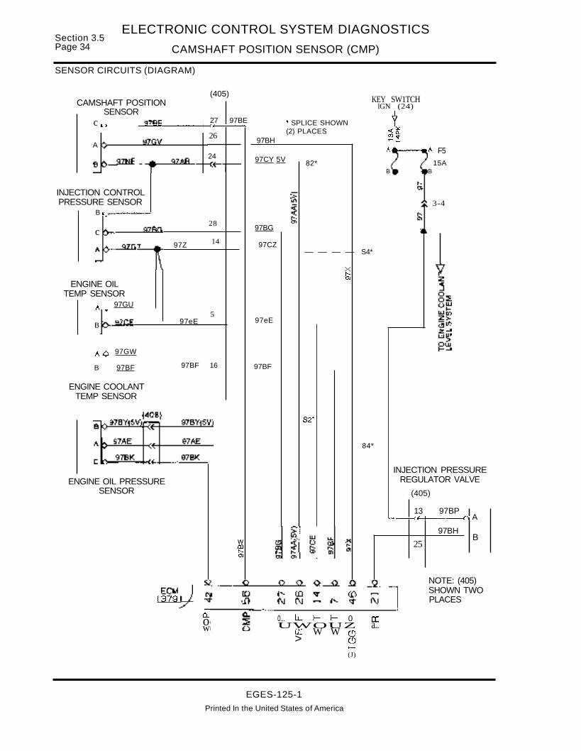
Section 3.5Page 34
ELECTRONIC CONTROL SYSTEM DIAGNOSTICS
CAMSHAFT POSITION SENSOR (CMP)
SENSOR CIRCUITS (DIAGRAM)
3-4
/\----../\ F5
15ABB
KEY SW1TCHlGN (24)
Y«~~~T-_
><r--..0>
---- S4*
82*
~ SPLICE SHOWN(2) PLACES
97BH
97eE
97CY 5V
97BG
97CZ
97BF
14
5
28
24
97BF 16
97eE
97Z
c
A
B
CAMSHAFT POSITIONSENSOR
27 97BEc I. ~ --w..&._--_-I--C4"'---1~;""';";;
26
(405)
A <> 97GW
B 97BF
ENGINE COOLANTTEMP SENSOR
ENGINE OILTEMP SENSOR
A 97GU
INJECTION CONTROLPRESSURE SENSOR
B K :>---w.&-......-...-!
ENGINE OIL PRESSURESENSOR
S2*
84*
INJECTION PRESSUREREGULATOR VALVE
(405)
13 97BP1...----1-<~-------llnlA
wmr--..(J)
25
97BHB
EC~J(379~
a.ow
NOTE: (405)SHOWN TWOPLACES
0... LL t- t- 0 a::UWOUZ a..cr W W (!)
> (!)..-(J)
EGES-125-1
Printed In the United States of America
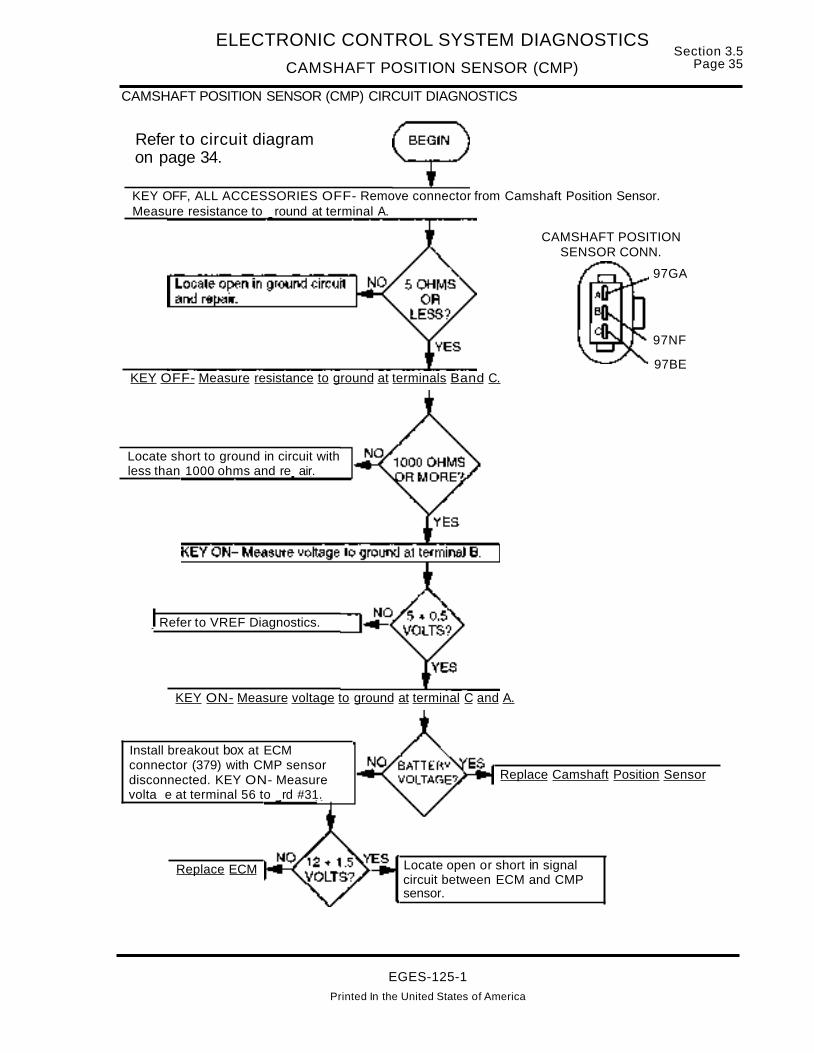
ELECTRONIC CONTROL SYSTEM DIAGNOSTICS
CAMSHAFT POSITION SENSOR (CMP)
CAMSHAFT POSITION SENSOR (CMP) CIRCUIT DIAGNOSTICS
Section 3.5Page 35
Refer to circuit diagramon page 34.
KEY OFF, ALL ACCESSORIES OFF- Remove connector from Camshaft Position Sensor.Measure resistance to round at terminal A.
CAMSHAFT POSITIONSENSOR CONN.
97GA
97NF
97BEKEY OFF- Measure resistance to ground at terminals Band C.
Locate short to ground in circuit withless than 1000 ohms and re air.
IRefer to VREF Diagnostics.
KEY ON- Measure voltage to ground at terminal C and A.
Install breakout box at ECMconnector (379) with CMP sensordisconnected. KEY ON- Measurevolta e at terminal 56 to rd #31.
Replace ECM
Replace Camshaft Position Sensor
Locate open or short in signalcircuit between ECM and CMPsensor.
EGES-125-1
Printed In the United States of America

Section 3.5Page 36
ELECTRONIC CONTROL SYSTEM DIAGNOSTICS
DCUATA COMMUNICATION LINKS (DCUATA)
VPM COMMUNICATIONS(Data Communications link, ATA Link)
,.ELECTRONIC SERVICE TOOL
ECM
ELECTRONICCONTROLMODULE
VPM
VEHICLEPERSONALITY
MODULE
•
WARNENGINElAMP
EG-1198
DCl• Data Communication Link +1- I1- _ _ _ _ _ _ _ _ _ _ _ _ _ _ _ _ _ _I
••••I
I
D
I
•AlA : _DiagnostiC/ProgramLink +/-
DDD~
DOD I!IDDDBOaB
SIGNAL FUNCTIONS
Data Communication link - the Data Communication Link signal is a 0 to 5 volt variable widthwave form signal that enables communication between the Vehicle Personality Module (VPM) andthe ECM. It is used for communication of diagnosticand calibration data.
ATA DiagnosticlProgramming link - The ATAsigna~ is a 0 to 5 volt width wave form signal that en..abies communication between the VPM and theElectronic Service Tool (EST). It is used forcommunication of calibration, programming and diagnosticinformation.
Tachometer Signal - The ECM provides the VPMwith a 0 to 12 volt tachometer signal. The frequencyof the signal is one-fifth (1/5th) the RPM.
FAULT DETECTION/MANAGEMENT
The VPM and ECM can detect on a continuous basis an open, short or intermittent connection on theDel and ATA lines.
EGES-125-1Printed In the United States of America

ELECTRONIC CONTROL SYSTEM DIAGNOSTICS
DCUATA COMMUNICATION LINKS {DCUATA}Section 3.5
Page 37
VPM CommunicationsDCl ± Data Communication LinkATA ± American Trucking Association
ESTConnector
Fault Codes:223 VPM Not Communicating with ECM231 ATA Common Fault232 Unable to Forward ECM Message to ATA DCl234 Unable to Forward ATA Message to ECM235 VPM/ECM DCl Fault633 ECM/VPM Common FaultNo Data Stream or Fault Codes displayed on EST
Electronic Service Tool does not power up.
ATA + (Red)
ATA - (Blue)VPM Connector
DCl-
DCl+
TACH (from ECM)
ECM Connector
After removing connector always check for damaged pins. corrosion, loose terminals etc.
Key ON Engine OFF - Voltage Checks at EST Connector+Test Points Spec. Signal Comments
Cto E B+ Power Should be power at C at all times.
Connector Checks to Ground at ECM(Check with breakout box installed, ignition key should be in the OFF position)
Test Points Spec. Signal Comments
#9 to #46 > 1000 ohm DCL- < 1000 ohms indicates a short to grd. either thru the harness or internal
#28 to #46 > 1000 ohm DCl+ in the ECM or VPM. Disconnect VPM and measure to grd again. If shortstill present, disconnect ECM and measure to grd. If short is still present,reoair harness.
Harn.ess Resista.nce Checks(Check with breakout box Installed, ignition key should be in the OFF position)
Test Points Spec. Signal Comments
#9 to 14 < 5 ohm DCl- Resistance from 60 pin connector to harness connector - DCl Signal#28 to 13 < 5 ohm DCL+ Resistance from 60 pin connector to harness connector - DCl Signal
12 to B < 5 ohm ATA- Resistance from VPM connector to EST connector - ATA S'ignal
11 to A < 5 ohm ATA+ Resistance from VPM connector to EST connector - ATA Signal
Cto B+ < 5 ohm PWR Resistance from EST connector to Fuse F28 - EST PowerE to Grd. < 5 ohm GAD Resistance from EST connector to grd (ECM pin #46 if breakout box installed)
Fault Code Descriptions223 VPM not communicating with ECM, DCl wiring faults, faulty VPM231 ATA Common Fault - ATA wiring faults, faulty VPM232 Unable to forward ECM message to ATA DCl - ATA wiring faults, faulty VPM234 Unable to forward ATA message to ECM-key is off wIEST installed, DCl wiring faults, faulty ECM235 VPM/ECM DCl Fault - DCl wiring faults, faulty ECM633 ECMNPM Common Fault - Del wiring fault, SW mismatch, faulty VPM
No Data Stream or Fault Codes displayed on Electronic Service ToolElectronic Service Tool does not power up.
EGES-125-1
Printed In the United States of America

Section 3.5Page 38
ELECTRONIC CONTROL SYSTEM DIAGNOSTICS
DCUATA COMMUNICATION LINKS (DCUATA)
EXTENDED DESCRIPTION
ECMNPM COMMUNICATION
The Navistar engine control system includes theElectronic Control Module (ECM), Vehicle Personality Module (VPM), and Injector Driver Module(10M). Refer to Figure 3.5-4. for the following discussion.
The engine control system "communicates" with theElectronic Service Tool through connector (384) asshown in Figure 3.5-4. The EST communicateswith the VPM using the American Trucking Associ..ation (ATA) data link Iines(1).
The ECM communicates with the VPM through aproprietary data link channel (DCl). The Data Communications link (DCl) channel connects the ECMand the VPM.
Both the ATA and DCl circuits use twisted wirepairs. All repairs to these pairs must maintain onecomplete twist per inch along the entire length of thecircuits. These circuits are polarized (one positiveand one negative) and reversing the polarity ofthese circuits will disrupt communications.
(1) - The ATA data link is defined by SAE recommended practices J1708 and J1587. This link andconnector (384) were adopted by the Recommended Practices 1201 and 1202.
ATA COMMUNICATIONS
Refer to the circuit diagram on page 42 for thefollowing discussion.
ATA DATA liNK CONNECTOR (384)
All communications between the EST (Prolink9000TM using the Navistar cartridge) and the enginecontrol system is done through the EST connector(384). This communications link supports:
• Displaying fault codes and operating conditions on the EST.
• Performing proprietary diagnostic testsprogrammed into the cartridge.
• Clearing fault codes.
• Programming performance parameter val-ues.
EST connector (384) has six pins, labeled A throughF, Figure 3.5-4. that provide the following:
A. Fused BATTERY power is provided to Pin "c"to provide battery power for electronic servicetools. Pin "E" provides a battery ground for theEST.
B. Connector (384) terminal A is connected by circuit 98B(+) to the positive RED ATA bus andEST connector (384) terminal B is connected bycircuit 980(-) to the negative BLUE (428) bus.These two connections allow communicationwith all components connected to the data linkat these same two busses.
ATA (+ and -)
<:J-----[>
VPM(381)
Del (+ and -)
<:J----~[>
ECM(279)
Figure 3.5-4. - ATA and DCl Communication
EGES-125-1
Printed in the United States of America

ELECTRONIC CONTROL SYSTEM DIAGNOSTICS
DCUATA COMMUNICATION LINKS (DCUATA)Section 3.5
Page 39
EXTENDED DESCRIPTION (Continued)
POSITIVE AND NEGATIVE ATA DATA LINKS
The RED Positive and BLUE Negative Data linkBusses connect the EST connector (384) and theVPM (381). They are also the connection point forother electronic components that require access tothe engine control system through the ATA communications link.
The RED positive bus (427) is connected by circuit98A(+) to the VPM at connector (381), terminal 11.The BLUE negative bus (428) is connected by circuit 98C(-) to the VPM at connector (381), terminal12.
DCl COMMUNICATION liNKS
The VPM is connected to the ECM through the DCl.The DCl connection between the ECM and theVPM serves as a conduit for data sent on the ATAto be shared with the ECM. Communications between the ECM and the EST connector go throughthe VPM.
VPM - ECM COMMUNICATIONS
The positive (+) DCl link is circuit 97AS, which connects ECM connector (379) terminal 28, to the VPMthrough connector (381), terminal 13. The negative(-) DCl link is circuit 97AT, which connects ECMconnector (379), terminal 9 to the VPM through connector (381), terminal 14. These two circuits (97ASand 97AT) are a twisted wire pair and pass throughdash connector (3) at terminals 8 and 1.
Both the ATA and DCl circuits use twisted wirepairs. All repairs to these wire pairs must maintainone complete twist per inch along the entire lengthof the circuits. Both circuits are polarized (one positive and one negative) and reversing the polarity ofthe circuit will disrupt communications.
ECM DIAGNOSTICS
Flash codes that can be caused by defects occurring in the ATA or DCl circuits are discussed in thissection. There are also Flash Codes related to orcaused by faulty communication (corrupt or invaliddata transmitted between the ECM and VPM), thatare discussed in this section.
EST CONNECTOR (384)
The engine control system does not detect faults inthe power or ground circuits to EST connector(384). If the service tool does not power up when
connected, try the service tool on another vehicle ifone is available to determine if the service tool isworking properly. If the service tool is OK, then perform Testing EST Connector (384) Power andGround Circuits on page 43.
EST DISPLAYS
Should the EST display NO DATA, theATA data linkcircuit from the EST connector to the VPM may bedisrupted. Verify that the key is ON and then performTesting The ATA Data link Circuits on page 44.
FAULT CODES
FLASH CODE 223ATA CODE SID 252 FMI 7VPM NOT COMMUNICATING WITH ECM
Symptom: Flash code 223 causes the engine tooperate in Field Defaults, which turns the EngineWarning Light ON. When Field Defaults are beingused by the ECM, Flash Code 622 also is set. If thecondition causing code 223 is intermittent, and thecondition is no longer present, the code will changeto an inactive code, and the engine will resumenormal operation.
Wiring Causes: DCl circuits 97AS and/or 97ATbetween the ECM and VPM: shorted low or High orOpen.
If code 223 is active:
1. Perform TESTING DCl CIRCUITS on page 47.
A. If defect is found in DCl circuit, correct defect.
B. If the DCl circuits (97AT and 97AS) checkgood, replace the VPM.
FLASH CODE 231ATA CODE SID 250 FMI 2VPM: ATA COMMON FAULT
SYMPTOM: Code 231 does not turn EngineWarning light ON. This code can occur when theVPM can't access the ATA data link. If this occurs,there will not be any ATA data available at theelectronic service tool (EST). The code can be''flashed'' using the STI switch located on theinstrument panel.
WIRING CAUSES: ATA positive or negative circuitsbetween EST and VPM and any other electronicdevices (transmissions, brakes etc.) using the ATAbus: Shorted (high or low), open, or busy (too manydevices).
EGES-125-1
Printed In the United States of America

Section 3.5Page 40
ELECTRONIC CONTROL SYSTEM DIAGNOSTICS
DCUATA COMMUNICATION LINKS (DCUATA)
DIAGNOSTICS (Continued)
FLASH CODE 231ATA CODE SID 250 FMI 2VPM: ATA COMMON FAULT (Continued)
If code 231 is active:
1. Perform Testing the ATA Data link Circuits onpage 44.
A. If defect is found in ATA circuits, correct defect.
B. If defect is not found in ATA circuits, investigate SYSTEM CAUSES.
SYSTEM CAUSES: System causes can include:
A. A defective ATA device (such astransmission controller or antilock brakecontroller) connected to the ATA bus is pulling the signal to ground.
B. Too many ATA devices, although this wouldbe rare.
C. If no system causes are present, replacethe VPM.
FLASH CODE 232ATA CODE SID 250 FMI 9VPM: UNABLE TO FORWARD ECM MESSAGETOATA DCL
SYMPTOM: There are no ECM replies to requestsfrom the EST or VPM. Flash Code 232 does notturn the Engine Warn light ON.
WIRING CAUSES: The positive and/or negativeATA data link circuits between the EST and VPM (orother devices installed using the ATA link): ShortedHigh or Low or Open.
If code 232 is active:
1. Perform Testing the ATA Data Link Circuits onpage 44.
A. If wiring defect is found, correct defect.
B. If no wiring defects are found, investigateSystem Causes.
SYSTEM CAUSES: Code 232 can occur when theECM is sending more messages than the VPM cantransmit on the ATA bus. This can be caused by:
A. A defective ATA device (such as transmission controller or antilock brake controller)connected to the ATA bus pulling the signalto ground.
B. Too many ATA devices or an incompatibleATA device has been connected to the ATAbus.
C. May be caused by code 231 occurring.
D. If none of the system causes are present,replace the VPM.
FLASH CODE 234ATA CODE SID 248 FMI 9VPM: UNABLE TO FORWARD ATA MESSAGETO ECM.
SYMPTOM: There are no ECM replies to requestsfrom the EST or VPM. There is NO Engine Warninglight. Code 223 may also be present.
NOTE: Code 234 can be set by connecting the ESTwhen the key is OFF. If the key was recently turnedoff, the VPM may still be powered. The VPM canstay on for up to 30 minutes after turning the key off.If the prolink is connected (key off), the VPM will unsuccessfully request data from the ECM, which isnot powered with the key off. If this occurs, turn thekey on and clear the codes.
WIRING CAUSES: DCl positive or negativecircuits (97AT and/or 97AS): Shorted High or low oropen between ECM and VPM.
If code 234 is active:
1. Verify that ignition key is ON.
2. Perform Testing DCl Data link Circuits onpage 47.
A. If defect is found in DCl, correct defect.
B. If no defects are in DCl, replace the ECM.
FLASH CODE 235ATA CODE SID 248 FMI 2VPM: VPMIECM DCL FAULT
SYMPTOM: There are no ECM diagnostic replies torequests from the EST or VPM. Engine Warninglight OFF. If the condition causing code 235 to setis intermittent and the condition is no longer present,the code will go to inactive status.
WIRING CAUSES: DCl circuits 97AT and/or 97ASare: shorted High or Low or Open between VPM andECM.
If code 235 is active, Perform Testing Del Data linkCircuits on page 47.
A. If wiring defect is found, correct defect.
B. If wiring defect is not found, replace theECM.
EGES-125-1
Printed In the United States of America

ELECTRONIC CONTROL SYSTEM DIAGNOSTICS
DCUATA COMMUNICATION LINKS (OCUATA)
DIAGNOSTICS (Continued)
Section 3.5Page 41
FLASH CODE 633AlA CODE SID 252 FMI 2ECM: ECMNPM COMMON FAULT
SYMPTOM: The engine operates on Field Defaultsturning the Engine Warning light ON and settingcode 622.
This code indicates that the ECM and VPM are communicating incorrectly. The message from the VPMcontains bad data, or the VPM takes too long to respond to ECM requests for data. If this code iscaused by an intermittent condition, and the condition is no longer present, the code will become inactive and normal engine operation will resume.
WIRING CAUSES: DCl circuits 97AT or 97ASbetween ECM and VPM are: shorted low, High orOpen.
If code 633 is active:
1. Perform Testing DCl Data Link Circuits onpage 47.
A. If defect is found in DCl, correct.
B. If there are no defects in the DCl, refer tocodes 613 and 614 and verify that the ECMand VPM have the correct software versions. If the software versions are correct,replace the VPM.
EGES-125-1
Printed In the United States of America

Section 3.5Page 42
ELECTRONIC CONTROL SYSTEM DIAGNOSTICS
DCUATA COMMUNICATION LINKS (OCUATA)
CIRCUIT DIAGRAM
J1BATIFEED
C210A
I
aJ-.,"'-t
I
•
2F2810A
F22
F
oC 97CB 9 -
E 97-GK
CAV CIRCUITA 988 +
r
W/TRUCK 0....-----D-A-r-A-L-IN-K-(3-S-4-)--o---a ~ ,..--------1 :
W/FBC :&SC~:
97-GK
G2'NCAaGRDSTUD
(435)
REDATABUS (+)(427)
,o.,.....0).
98B(+}
980(-)
BLUEATABUS (-)(428)
97C>1----_....... ---·--_.
97AT
9lAS
EST CONN.(384)
(3 &3A)DASHCONN8
ECM(379)
VPM(381)
Figure 3.5-5. - ATA and Del Communication links
EGES-125-1Printed In the United States of America

ELECTRONIC CONTROL SYSTEM DIAGNOSTICS
DCUATA COMMUNICATION LINKS (DCUATA)Section 3.5
Page 43
TROUBLESHOOTING
The DCl and ATA circuits operate with very low current levels. When troubleshooting the DCl or ATA,pay special attention to the connectors.
BEFORE PERFORMING ANY TEST
Inspect for pushed back, damaged, corroded or
dirty terminals as well as making sure that the terminal and wire are properly crimped. Make sure theconnectors are properly joined together. Also checkfor damage to wiring, and clean tight ground connections.
TESTING EST CONNECTOR (384) POWER AND GROUND CIRCUITS
DATA LINK(384)
(Connector TerminalsAre labeled)
FUSE CHART
F28 - WfTRUCK
C2 - W/FBC-W/S.C.
97-GK
97C980 -98B +
CIRCUIT
F
A.
oE
cB
c"v\
locate cause ofoverload condition,then correct.Replace 1OA fuse.
locate cause of NOor LOW voltage incircuit 97C fromfuse, then correct.
Refer to circuit diagramon page 42 to performthis test.
At connector (384), measure voltagebetween terminals C and E.
locate open inground circuit 97-GK,then correct.
EST connector (384) power and ground circuits check OK. I
EGES-125-1
Printed in the United States of America
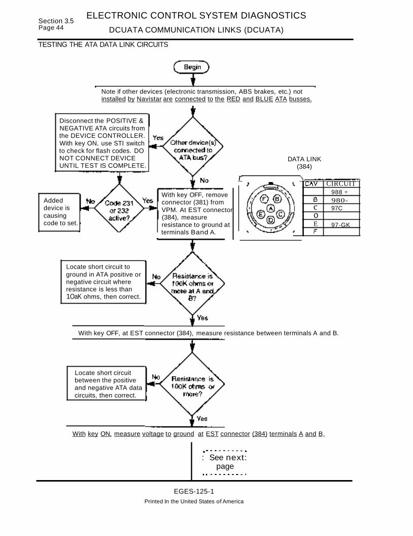
Section 3.5Page 44
ELECTRONIC CONTROL SYSTEM DIAGNOSTICS
DCUATA COMMUNICATION LINKS (DCUATA)
TESTING THE ATA DATA LINK CIRCUITS
Note if other devices (electronic transmission, ABS brakes, etc.) notinstalled by Navistar are connected to the RED and BLUE ATA busses.
980-988 +
97C
97-GK
CIRCUIT
FEocB
'\,..--..-------,CAV
DATA LINK(384)
r
With key OFF, removeconnector (381) fromVPM. At EST connector(384), measureresistance to ground atterminals Band A.
Disconnect the POSITIVE &NEGATIVE ATA circuits fromthe DEVICE CONTROLLER.With key ON, use STI switchto check for flash codes. DONOT CONNECT DEVICEUNTIL TEST IS COMPLETE.
Addeddevice iscausingcode to set.
Locate short circuit toground in ATA positive ornegative circuit whereresistance is less than1OaK ohms, then correct.
With key OFF, at EST connector (384), measure resistance between terminals A and B.
Locate short circuitbetween the positiveand negative ATA datacircuits, then correct.
With key ON, measure voltage to ground at EST connector (384) terminals A and B.
.--------- ....: See next:
page.. ,-.--_ .... _-"
EGES-125-1Printed In the United States of America

ELECTRONIC CONTROL SYSTEM DIAGNOSTICS
DCUATA COMMUNICATION LINKS (DCUATA)Section 3.5
Page 45
TESTING THE ATA DATA LINK CIRCUITS (Continued)
VPM(381)
8
16 9
23 15KEY OFF - RemoveECM Power Fuse. Atconnector (381) measureresistance between terminal11, cir 98A (+) andterminal 12, 98C (-) andall other terminals in(381)
Locate short circuitto unwanted voltagesource in ATApositive or negativecircuit where voltageis greater than 1.0volt, then correct.
Locate short circuit between any circuits,where resistance between terminals is lessthan 10aK ohms, thencorrect.
KEY OFF - Measure resistance between connector (381) terminal 11 ,cir 98A (+) and EST connector (384) terminal A.
Locate open or cause ofhigh resistance in circuit98A (+)/988(+) betweenconnectors (381) and(384), then correct.
KEY OFF - Measure resistance between connector (381) terminal 12,cir 98C(-) and EST connector (384)terminal B.
, ........... _-_ ..: See next:
page... .,. .... _ IfII!I, .......... IJ
EGES-125-1
Printed in the United States of America

Section 3.5Page 46
ELECTRONIC CONTROL SYSTEM DIAGNOSTICS
DCUATA COMMUNICATION LINKS (DCUATA)
TESTING THE ATA DATA LINK CIRCUITS (Continued)
Locate open or causeof high resistance incircuit 98C(-)/98D(-)between connectors(381) and (384), thencorrect.
988 +98D -
97-GK
97C
CIRCUITA.
E
co
B
\r----_--.-."C"V
DATA LINK(384)
r
KEY OFF - If an additional device is connected tothe ATA bus, measure resistance between connector (384) terminal Bandthe ATA (-) circuit in thedevice connector.
Locate open in ATA (-)circuit between connector (384) and device connector, then correct.
KEY OFF -If an additional device is connected to the ATA bus,measure resistance between connector (384) terminal A and theAlA (+) circuit in the device connector.
Locate open in ATA (+)circuit between connector(384) and device connector, then correct.
The ATA positive andnegative circuits arenot shorted high orlow and circuit resistance is within specifications.
EGES-125-1
Printed In the United States of America

ELECTRONIC CONTROL SYSTEM DIAGNOSTICS
DCUATA COMMUNICATION LINKS (DCUATA)
TESTING DCl DATA liNK CIRCUITS
With key OFF, remove connector (381) from VPM and (379) from ECM.Connect breakout box to ECM harness, but do not connect to ECM.
With key off, at breakout box,measure resistance betweenterminal 60 (GRD) AND terminals 9 (97AT) and 28 (97AS).
Section 3.5Page 47
Locate short circuit toground in circuit whereresistance to ground isless than 100K ohms,then correct.
With key OFF, measure resistance between breakout box terminals 9 and 28.
Locate short circuitbetween 97AT and97AS, then correct.
23 15 8
16 9 1
With key ON, at breakout box measure voltage atterminals 9 and 28. Use terminal 60 for ground.
Locate short circuit to"HOT" wire in circuit wherevoltage is greater than 1.0volt, then correct.
: See next:page
EGES-125-1Printed in the United States of America
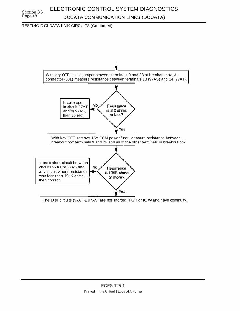
Section 3.5Page 48
ELECTRONIC CONTROL SYSTEM DIAGNOSTICS
DCUATA COMMUNICATION LINKS (DCUATA)
TESTING DCl DATA liNK CIRCUITS (Continued)
tWith key OFF, install jumper between terminals 9 and 28 at breakout box. Atconnector (381) measure resistance between terminals 13 (97AS) and 14 (97AT).
locate openin circuit 97ATand/or 97AS,then correct.
With key OFF, remove 15A ECM power fuse. Measure resistance betweenbreakout box terminals 9 and 28 and all of the other terminals in breakout box.
locate short circuit betweencircuits 97AT or 97AS andany circuit where resistancewas less than 10aK ohms,then correct.
The Del circuits (97AT & 97AS) are not shorted HIGH or lOW and have continuity.
EGES-125-1Printed In the United States of America

Section 3.5Page 50
ELECTRONIC CONTROL SYSTEM DIAGNOSTICS
EXHAUST BACK PRESSURE SENSOR (ESP)
EXHAUST BACK PRESSURE (EBP) SENSOR
ECM
ELECTRONICCONTROLMODULE
EBP Signal (analog voltage)
5 Volts(More Pressure)
oVolts(Less Pressure) ------...
EG-1120
EXHAUSTBACKPRESSUREVALVE
EXHAUSTBACKPRESSUREREGULATOR
EBPEXHAUST BACKPRESSURE SENSOR
SIGNAL FUNCTIONS
The ESP (Exhaust Back Pressure) sensor is a variable capacitance sensor that when supplied with a5 volt reference signal from the ECM produces a lin...ear analog voltage signal that indicates pressure.
The ESP sensor's primary function is to measureexhaust back pressure so that the ECM can controlthe exhaust back pressure regulator when needed.
FAULT DETECTION/MANAGEMENT
An ESP signal that is detected out of range high orlow by the ECM will cause the engine to ignore theESP signal and disable exhaust back pressure operation.
EGES-125-1
Printed in the United States of America

ELECTRONIC CONTROL SYSTEM DIAGNOSTICS
EXHAUST BACK PRESSlJRE SENSOR (ESP)Section 3R5
Page 51
EG-1121
(c)(b)
Sensor Connector(a)
Fault Codes:
341 Out of Range Low342 Out of Range High344 Signal Above SpecR w/EngR Off
Sensor HarnessConnector
Signal GroundJ-III--------~......-----__IA
Exhaust Back Pressure SignalJ-+---------------........ cV Ref>-+--------.....-.l....-------tB
Exhaust Back PressureSensor(EBP)
ECMConnector
After removing connector alwavs check for damaged pins, corrosion, loose terminals etc.
Connector Checks to Chassis Ground(Check with Sensor Connector Disconnected and Ignition key off, all accessories off)
Test Points Spec. Comments
A to Grd. < 5 ohms Resistance to chassis ground check with key off, if > than 5 ohms harness is open.
S to Grd. > 1000 ohms Resistance less than 1000 ohms indicates a short to ground.
eta Grd. > 1000 ohms Resistance less than 1000 ohms indicates a short to ground.
Connector Voltage Checks(Check with sensor Connector Disconnected and Ignition Key On)
Test Points Spec. Comments
B to Grd. 5 volts ± .5 V Ref. check with key ON, if voltage not in spec. , see V Ref circuit
C to Grd. < .25 volts If greater than 0.25 volts signal wire is shorted to V Ref of battery.
Harness Resistance Checks(Check with breakout box installed on engine harness only)
Test Points Spec. Comments
#46 to A < 5 ohms Resistance from sensor connector to 60 pin connector - Signal ground
#26 to B < 5 ohms Resistance from sensor connector to 60 pin connector - V Ref
#49 to C < 5 ohms Resistance from sensor connector to 60 pin connector - ESP signal
Test Points Operational Si~nal Checks(+) #49 to (-) #46 (Check with breakout box instal ed in line with the ECM)
Voltage PSIG KPAG Comments
.8 - 1.0 v 0 0 Signal with key "ON" and engine OFF (Value dependentupon atmospheric pressure and altitude.)
.8 -1.0 v 0 0 Normal warm idle signal.
1.19 v 14.8 10.0 Minimum back pressure signal expected at 2300 RPM (See EPR diagnostics)
Fault Code Descriptions341 =Signal voltage was less than .039 volts for more than 0.1 seconds.342 =Signal voltage was greater than 4.90 volts for more than 0.1 seconds.344 =Signal above 1.34 volts with engine off. 19 psi (130 kPa)
EGES-125-1
Printed in the United States of America

Section 3.5Page 52
ELECTRONIC CONTROL SYSTEM DIAGNOSTICS
EXHAUST BACK PRESSURE SENSOR (EBP)
EXHAUST BACK PRESSURE SENSOR (ESP)EXTENDED SYSTEM DESCRIPTION
FUNCTION
The exhaust back pressure (EPB) sensor is included in the Navistar engine control system onlywhen a vehicle is equipped with an exhaust backpressure valve.
The ECM monitors the ESP signal during engineoperation. The ESP's primary function is to measure exhaust back pressure so that the ECM cancontrol the exhaust back pressure regulator whenneeded to aid in maintaining and achieving normalengine operating temperature.
OPERATION
The exhaust back pressure sensor is a variable capacitance sensor. When pressure is applied to thesensor, the capacitance changes in relation to thepressure.
The ECM supplies a regulated 5 volt signal to terminal B of the E8P sensor from terminal 26 of theECM. The ESP sensor is supplied a signal return(ground) at terminal A to terminal 46 of the ECM.
During engine operation, exhaust back pressureacting on the sensor causes the sensor's capacitance to vary which changes the incoming 5 volt reference signal in relation to pressure. The sensor'spressure signal at terminal C is sent to terminal 49 ofthe ECM. This signal increases equally in proportion to an increase in pressure up to a maximum of38 PSI (262 kPa).
ECM DIAGNOSTICS
The ECM continuously monitors the signal from theE8P sensor to ensure the signal is within the correctoperating range. If the signal is lower or higher thanrequired, the ECM will set a fault code. This faultcode is retrieved using the Electronic Service Tool(EST) or by reading the flash code using the STIdiagnostic switch. If the ignition key is shut off, thecode will be stored as an inactive code.
FLASH CODE 341ATA CODE SID 34 FMI 20EXHAUST BACK PRESSURE SIGNAL OUT OFRANGE LOW
Code 341 indicates the ECM has detected a ESPsignal voltage less than .039 volts for more than 0.1seconds. If this fault code is set, the ECM will ignorethe E8P signal and continue to operate normally,however, if the fault isactive the ECM will disable exhaust back pressure valve operation
Possible causes for code 341: Open Vref signal circuit or a defective ESP sensor.
FLASH CODE 342ATA CODE SID 34 FMI19EXHAUST BACK PRESSURE SIGNAL OUT OFRANGE HIGH
An out of range high code will be set if the ECM detects a voltage more than 4.9 volts for more than 0.1seconds. If this fault code is set, the ECM will ignorethe ESP signal and continue to operate normally. Ifthis fault is active, the ECM will disable exhaustback pressure operation.
Code 342 may be caused by an open signal returncircuit, a short to a voltage source or a defectiveESP sensor.
FLASH CODE 344ATA CODE SID 34 FMI29EXHAUST SACK PRESSURE BELOW WARNING LEVEL
Code 344 indicates the exhaust back pressure wasgreater than 19 psi (130 Kpa) with the key "ON" andengine "OFF"
Code 344 may be caused by a defective or pluggedESP sensor or a restriction in the tube leading to thesensor. To confirm this, remove sensor and/or tubeand inspect for carbon deposits.
EGES-125-1
Printed In the United States of America

Section 3.5Page 54
ELECTRONIC CONTROL SYSTEM DIAGNOSTICS
ENGINE CRANK INHIBIT (ECI)
ENGINE CRANK INHIBIT SYSTEM (ECI)
KEY SWITCH
JUMPERWIREW/MANUAL
"X\i}
J/'
NEUTRALPOSITIONSWW/AUTOXMSN(CLOSED INNEUTRAL)
IGN
ENABLE CIRCUIT
STARTER'------+_--1 MAG SW
ov ENABLE12V DISABLE
12 NEUTRAL W/AUTO XMSN ONLYo N/NEUTRAL
B+ VOLTS
SIGNAL FUNCTION
The ECM uses the enable circuit to control enginecranking. The ECM prevents cranking motoroperation: whenever the engine is running orwhenever a vehicle with an automatic transmissionis not in neutral.
ELECTRONIC CONTROL MODULE (ECM)
AUTOMATIC TRANSMISSIONWith the key ON, the ECM enables the crank relayif the engine is not running and if 12 volts is presentat terminal 10 with an automatic transmission.
To enable the crank inhibit relay, the ECM setsterminal 35 LOW (ground state). To disable thecrank relay, terminal 35 is HIGH (12 volts).
CRANK INHIBIT RELAY
Turning the key to the start position applies powerto the crank inhibit relay at pin 2. If the relay isenabled by the ECM, the relay is energized andapplies ignition voltage to the cranking motormagnetic switch control coil.
CRANKING MOTOR MAGNETIC SWITCH
The crank motor magnetic switch is used to switchbattery power to the crank motor solenoid when thecrank inhibit relay is energized. With thermoovercrank protection installed the magnetic switchis grounded through the overcrank thermo couple.
MANUAL TRANSMISSIONWith a manual transmission, the ECM programmingdoesn't look at terminal 10 in enabling the crank inhibit relay.
FAULT DETECTION MANAGEMENT
The ECM does not monitor the cranking systemcircuits. There are no fault codes for this system.
EGES-125-1
Printed in the United States of America

ELECTRONIC CONTROL SYSTEM DIAGNOSTICS
ENGINE CRANK INHIBIT (ECI)Section 3.5
Page 55
Engine Crank Inhibit Refer to page 57 for complete Fault Codes:(ECI) I circuit diagram. No Codes Apply To This System
ECM (379)
KEYSWIGN
k,4NEUTRAL SAFETY SW (JUMPER INST. W/MANUAL
XMSN) /-"
__-01-{.---..-) 97AU
START RELAY(387)
CRANK RELAYCONNECTOR
~ (385)
97AU I97-GQ I
~
.-.--~I 97DE IL-~__...&.i
To bench test the CrankInhibit Relay refer topage 75.
17C
ECI Relay Connector Checks (Connector 385) Relay removed, ignition Key ON, Transmission in NeutralTest Points Spec. Possible Causes
1+ to Grd. 12v + 1.5vOpen F4 fuse or open 97AU circuit, defective neutral position switch, or not pluggedtogether with manual transmission.
1+ to 2- 12v + 1.5v Open Grd. 97GQ
1+ to 4- 12v + 1.5v Open 17A or 170. Defective start relay proceed to testing starter relay.
(Depress Clutch Pedal if equipped with Manual Xmsn or Place Auto Xmsn in Neutral)
1+ to 5- 12v + 1.5v Open 970E circuit or ECM control open. Proceed to testing at ECM.
(Turn ignition key to start or push start button with ignition key ON)
3+ to 2- 12v + 1.5v Open circuit 17, defective key or start switch.
With transmission in Neutral and Clutch Depressed.To jump ECI relay, connect a jumper wire between terminal 3 and 4. Turn ign. key to start or push starter button.
ECM (Connector 379) Checks w/Brkout. Box installed, key ON, Xmsn in Neutral, Clutch Pedal not depressedTest Points Spec. Possible Causes57+ to 60- 12v + 1.5v Open power or ground to ECM, refer to "ECM PWR".
10+ to 60- 12v + 1.5vOpen F4 fuse, 97AU or 97L. Defective neutral position switch, clutch switch or jumpersmissing.
(Depress clutch pedal if equipped with Manual Xmsn or Place Auto Xmsn in Neutral)57+ to 35- 12v + 1.5v Incorrect signal at terminal 1O. Incorrect VPM programming, or defective ECM.
(The following step should only be perlormed on vehicles with Manual Transmission)Depress clutch pedal
10+ to 60- < 1 volt Improperly mounted or defective clutch switch.
With transmission in Neutral and Clutch Depressed.To jump ECM relay, connect a jmpr. wire between term. 60&35 of b.o.b. Turn ign. key to start or push starter button.
Starter Relay Connector Checks (Connector 387) Key ON, Transmission in Neutral and Clutch DepressedTest Points Spec. Possible Causes
E+ to Grd. 12v + 1.5v Open fusible link 17L or circuit 178.E+ to D- 12v + 1.5v Thermo fuse open or open Grd. circuit 170 or 17G or 11 GJ.E+ to A- 12v + 1.5v Open 17C or defective starter solenoid.
(Turn ignition key to start or push start button with ignition key ON)F+ to D- 12v+ 1.5v Open 17Acircuit
With transmission in Neutral and Clutch Depressed.To jump starter relay, connect a jumper wire between terminal A and terminal E.NOTE: ENGINE SHOULD CRANK AS SOON AS JUMPER WIRE IS INSTALLED. TRANSMISSION MUST BE INNEUTRAL OR CLUTCH DEPRESSED.
EGES-125-1Printed in the United States of America
Section 3.5Page 56
DESCRIPTION
ELECTRONIC CONTROL SYSTEM DIAGNOSTICS
ENGINE CRANK INHIBIT (ECI)
The engine starting system is controlled by the Electronic Control Module (ECM). While cranking theengine, vehicle battery voltage may momentarilydrop below 6 volts, causing the ECM to shut down.When voltage comes back up, the ECM will resumeoperation. The Crank Inhibit Relay (385) has a 2-second delay feature that allows the engine to continue to crank (for up to 2 seconds) while the ECM isOFF, so the engine starts properly.
The cranking system is disabled by the ECM when:
A. The engine is running.
B. The automatic transmission is not in neutral.
C. The clutch is not depressed (only with optionalcustomer feature requiring clutch pedal to bedepressed to crank engine).
Components include:
• Start Switch (key or push button)
• Crank Inhibit Relay (385)
• Start Relay (387)
• Crank Motor and Solenoid
• Electronic Control Module (379)
• Neutral Position Switch with automatictransmission
• Clutch Switch (386) with optional "clutchdepressed starting feature" previously discussed.
OPERATION
Refer to the circuit diagram on page 57 for the following discussion.
Energizingthe engine starting system requires a series of events by the cranking system components.
The Engine Crank Inhibit Relay (385) receives inputs from several sources and if all conditions arepresent, the Start Relay (387) is energized.
CRANK INHIBIT RELAY (385)
The Crank Inhibit Relay has two major functions.
1. The ECM signal must "enable" the Crank InhibitRelay for the cranking system to operate.
2. The relay must keep the engine cranking if vehicle battery voltage drops below 6 volts duringcranking, causing the ECM to go off line momentarily.
The Crank Inhibit Relay has 5 terminals. To energize the Start Relay, the Engine Crank Inhibit relayinteracts with the other cranking system components.
1. Crank Inhibit Relay Terminal #5 is connectedby circuit 970E/97AH to ECM terminal #35. Forthe relay to enable the cranking system, voltageat ECM terminal #35 must be 0.1 - 0.6 volts.Note that the ECM switches terminal #35 between 0.1 - 0.6 volts and battery voltage, to either uenable" or "disable" the Crank InhibitRelay. The chart in the circuit diagram showsterminal voltages for various conditions and vehicle configurations.
Example 1: With the engine running, ECM terminal #35 will be at battery voltage, preventing the crank system from engaging.
Example 2: With the customer selected "ClutchMust Be Depressed To Start" feature, if theclutch pedal is not depressed when preparing to start the engine, 12V would be present at ECM terminal #35, and the crank system would not engage. Depressing theclutch would cause ECM terminal #35 toswitch to 0.1 - 0.6 volts.
EGES-125-1Printed In the United States of America

ELECTRONIC CONTROL SYSTEM DIAGNOSTICS
ENGINE CRANK INHIBIT (ECI)Section 3.5
Page 57
OPERATION (Continued)
WIFBCIGN
CONNECTTOGETHERW/MANUAL
XMSN
u..C')
F4 H1lOA lOA
-< LLC') C')
~ -
WfTRKIGN
~_-+--a (2 & 2A)
Neutral PositionSwitch (Closed withXMSN in Neutral)
1+--- TO KEY SW 'START"W/O PBS
TO KEYSW 'IGN" .......--..~WIPBS
CLOSEDWIPEDAL -----It--i'r-N
RELEASED
JUMPERINSTALLED
W/AUTOXMSN
STARTRELAY(387)
170
ENGINE CRANK INHIBIT CIRCUITIGN
178
l7G
llG
ECMKOEO = KEY ON ENGINE OFF (379) 35KOER =KEY ON ENGINE RUNNING ECI DDSVOLTAGE AT TERMINALS (35) •.•••••• (10)AUTOMATIC TRANSMISSIONKEY OFF ..... . . ... .. ...... . . . ...... .. ... ..••.... . ... OV OVKOEO (TRANS IN NEUTRAL) O.l--Q.6V l2VKOEO (TRANS NOT IN NEUTRAL) . . . . . . . . . . . . . . . . . . . . . 12V OVKOER 12V OVjMANUAL TRANSMISSION WITH CLUTCH SWITCHKEY OFF . . . . . . . . . . . . . . . . . . . . . . . . . . . . . . . . . . . . . . . . . . .. OV OVKOEO (Clutch Pedal Depressed) O.l--Q.6V OVKOEO (Clutch Pedal NOT depressed) 12V 12VKOER 12V 12VjMANUAL TRANSMISSION WITHOUT CLUTCH SWITCHKEY OFF OV OVKOEO CLUTCH PEDAL UP OR DOWN O.l--Q.6V 12VKOER 12V 12V
Figure 3.5-6. - Engine Crank Inhibit Circuit Diagram
EGES-125-1
Printed In the United States of America

Section 3.5Page 58
ELECTRONIC CONTROL SYSTEM DIAGNOSTICS
ENGINE CRANK INHIBIT (Eel)
OPERATION (Continued)
2. Crank Inhibit Relay Terminal #1 receivespower from the F4 fuse (H1 fuse w/FBC) whenthe key is ON. With an automatic transmission,the power must first pass through the NeutralSafety Switch (closed when in neutral). With amanual transmission, the power from F4 (or H1w/FBC) is present whenever the key is ON.
3. Crank Inhibit Relay Terminal #2 is groundedby circuit 97-GQ to G8 ground point.
4. Crank Inhibit Relay Terminal #3 receives ignition voltage when the start switch is engaged(push button or key switch). This energizes theCrank Inhibit Relay (if steps 1,2 and 3 occurred)causing voltage from terminal 4 to energize theStart Relay (387).
5. Crank Inhibit Relay Terminal #4 delivers output voltage on circuit 17A to the Start Relaywhen the Crank Inhibit Relay is energized.
START RELAY (387)
The Start Relay control coil is energized by voltagefrom the energized Crank Inhibit Relay on circuit17A. When energized, battery voltage from "B" terminal of cranking motor solenoid is applied throughthe Start Relay contacts (E to A) to the "S" terminalof crank motor to energize the cranking motor. TheStart Relay is a suppressed relay. The Start Relayhas an internal diode to prevent voltage spikes fromdamaging electronic components in the vehicle system.
THERMO OVERCRANK PROTECTION (OCP)
On vehicles equipped with Thermo OvercrankProtection cranking motors, the ground circuit forthe Start Relay is through the Thermo Overcrankthermocouple. If the cranking motor temperaturereache~ a certain level, the thermocouple opens,preventing further engine cranking until the cranking motor cools.
NEUTRAL POSITION SWITCH
With an Allison AT/MT automatic transmission anormally open (NO) Neutral Position Switch is us'edto turn power ON or OFF in circuit 97AU.
With the transmission in neutral, the switch is closedapplying power to Crank Inhibit Relay terminal #1and to ECM terminal 10. On the circuit diagrams,
ECM terminal 10 is labeled DDS (Driveline Disengagement Switch) . The 12 volts at ECM terminal 10tells the ECM that the Neutral Position switch isclosed and that the transmission is in neutral.
With an Allison WT (electronic transmission controls) , the neutral position switch is not used as theAllison WT Electronic Control Module determinesshifter position. With the transmission in neutral,ignition power from the transmission Vehicle Interface Module (VIM) Neutral Start Relay is deliveredon circuit 97AU to the Crank Inhibit Relay at terminal#1 . From terminal 1,circuit 97U97A applies the ignition voltage to ECM DDS terminal 1O.
When the vehicle has an automatic transmission(AT orWT), the clutch switch connector has ajumper connecting circuits 97L and 97A, completing thecircuit between Crank Inhibit Relay (385) terminal 1and ECM terminal 1O.
With an automatic transmission, ECM terminal 10 isprogrammed to expect 12 volts on circuit 97A whenthe shifter is in neutral and 0 volts when the shifteris not in neutral. The circuit diagram table shows terminal voltages for various conditions and vehicleconfigurations.
The Prolink 9000 can be used to monitor the NeutralPosition Switch. When the switch is closed (transmission in neutral), the Prolink (using PTa/ClutchSwitch Status) indicates clutch ON, meaning thedriveline is disengaged.
CLUTCH PEDAL SWITCH (386)
The clutch pedal switch determines driveline disengagement status for manual transmissions. Theclutch pedal switch is an active component in the"cranking" process ONLY if the customer selectedthe "clutch pedal must be depressed to start the engine" feature. If this feature has been selected, thecircuit operates as follows:
1. V\(it.h the key switch ON, voltage from Crank Inhibit Relay (385) terminal 1 is applied on circuit97L to the normally open (N.O.) clutch switch.The clutch switch is adjusted to be CLOSEDwhile the clutch pedal is RELEASED, andO~EN when the clutch pedal is DEPRESSED.With the clutch switch closed, 12 volts fromCrank Inhibit Relay terminal #1 is applied toECM terminal 10.
EGES-125-1
Printed in the United States of America

ELECTRONIC CONTROL SYSTEM DIAGNOSTICS
ENGINE CRANK INHIBIT (ECI)
OPERATION (Continued)
CLUTCH PEDAL SWITCH (386) (Continued)
Section 3.5Page 59
If the ECM sees 12 volts at DDS terminal 10, itdetermines that the pedal is not depressed,then the ECM applies 12 volts to ECM ECI terminal35, disabling the Crank Inhibit Relay (engine will not crank condition). If the clutch pedalis depressed (opening the clutch switch), thenovolts is present at ECM terminal 10, and theECM switches ECM terminal 35 voltage to 0.1- 0.6 volts, enabling the Crank Inhibit Relay (ifall other conditions are OK). The table in the circuit diagram shows terminal voltages for various conditions and vehicle configurations.
The Prolink 9000 EST can be used to monitor theClutch Switch position. When the clutch switch isopen (clutch depressed), the Prolink indicatesclutch ON, meaning the driveline is disengaged.
ELECTRONIC CONTROL MODULE
Electronic Control Module terminals 10 and 35 aredirectly involved with enabling the Crank InhibitRelay. The ECM and VPM (VPM stores informationfor the ECM) are programmed differently for automatic or manual transmissions.
ECM TERMINAL 10 (DDS)
ECM terminal 1a receives input (12 volts or 0 volts)from either the clutch switch with a manual transmission or neutral position indication with an automatic transmission. The ECM uses the input to determine the voltage signal on ECM terminal 35. Thevarious expected inputs are shown in the circuit diagram.
ECM TERMINAL 35 (ECI)
ECM terminal 35 is connected by circuit 97H toCrank Inhibit Relay terminal 5. Based on inputs toECM terminal 10 and engine operating conditions,the ECM either applies 0.1 - 0.6 volts or 12 volts toterminal 35. If the ECM applies 0.1 - 0.6 volts to terminal35, the Crank Inhibit Relay is "enabled." If theECM applies 12 volts to terminal #35, then theCrank Inhibit Relay is NOT "enabled."
ECM PROGRAMMING
The ECM "enables" the Crank Inhibit Relay if:
1. The engine is not running.
2. The transmission is in neutral (with automatictransmission).
3. The clutch pedal is depressed (with optionalsafety feature requiring clutch pedal to be depressed to crank engine).
If these conditions do not exist, the Crank InhibitRelay is not enabled and the engine will not crank.The table in the circuit diagram shows terminal volt..ages for various conditions and vehicle configurations.
TROUBLESHOOTING
The ECM "enables" or "disables" the engine cranking system with the Engine Crank Inhibit (ECI) relay.There are no ECM diagnostics available for thissystem. Perform the following tests to find thecause of a No Crank condition.
BEFORE TROUBLESHOOTING
A. Before troubleshooting, make sure that the batteries are fully charged! Check battery cablesand grounds for clean, tight connections free ofdamage. Voltage tests will give misleadingreadings if the batteries are not fully charged.
B. Before troubleshooting a particular circuit, inspect connectors for pushed back, loose ordamaged (spread or bent) terminals, or wireswith cut strands etc. The wires and connectionsmust be free of damage or corrosion. Whensome connectors corrode, a light white residuewill be present that must be removed.
EGES-125-1
Printed In the United States of America

Section 3.5Page 60
ELECTRONIC CONTROL SYSTEM DIAGNOSTICS
ENGINE CRANK INHIBIT (ECI)
TROUBLESHOOTING (Continued)ENGINE DOES NOT CRANK
The tests for Engine Does Not Crankare divided into two parts: Part 1, Engine Does Not Crank. Part 2, EngineDoes Not Crank with Manual XMSM and Clutch Switch. Refer to the Figure 3.5-7 while performing Part 1.
START RELAYCONNECTOR (387)
CJ c:=J c:=JFED
c:=J A
~ FROM CRANK~ ~ 17A <J INHIBIT RELAY
(2 &2A) - FIGU~~~5-8
STARTRELAY(387)
170
178
17G
17FL
CONNECTTOGETHER W/O .QQf.
11G-J
Figure 3.5-7 - Circuit Diagram Engine Cranking Circuit
EGES-125-1Printed In the United States of America

ELECTRONIC CONTROL SYSTEM DIAGNOSTICS
ENGINE CRANK INHIBIT (ECI)Section 3.5
Page 61
ENGINE DOES NOT CRANK TEST (PART 1)The Part 1 troubleshooting chart is to be used with either a manual transmission (with and without clutchswitch) or an Allison automatic transmission (AT, MT or WT).
For Part 2, select the appropriate troubleshooting chart for vehicle being tested: Manual Transmission WithA Clutch Switch, or Manual Transmission Without Clutch Switch or Automatic Transmission.
ICheck fuse F4 (H1 w/FBC) for open condition.
Locate cause of overloadcondition, then correct.Replace 10A fuse.
KEY OFF - Use suitable jumper wire and jump crank motor B+terminal to "S" terminal to see if crank motor 0 erates.
Refer to Service Manual Group08 for appropriate CrankingMotor section and diagnosecrankin motor s stem.
KEY OFF- At connector (387), measure volta e between circuits 17C and 17B.
Remove Start Relay from connector (387), then check for batteryvolta e at connector 387 , terminal "E" circuit 17B.
Locate open in feed circuit17FU17B, then correct.
Locate open in circuit 17Cbetween crank solenoid andstart relay, then repair.
EGES-125-1
Printed In the United States of America

Section 3.5Page 62
ELECTRONIC CONTROL SYSTEM DIAGNOSTICS
ENGINE CRANK INHIBIT (Eel)
ENGINE DOES NOT CRANK TEST (PART 1) (Continued)
KEY OFF- At connector (387), measurevolta e between circuits 178 and 17D.
Locate open in circuit17D/17G/11 G to ground,then repair. Note : If thermo overcrank is installed,check the thermocouple.
KEY ON- With start switch engaged, at connector (387),measure volta e between circuits 17A and 17D.
IReplace the start relay
Perform Start Relay Test procedure to determine relaycondition, then continue with Engine Does Not CrankPart 2. (A, B or C).
START RELAY TEST PROCEDURE
End View Of Start Relay
o
E
F
(N.C.)
/".....--0 C
E 01----...,,· b(N.O.) A
(COMMON)
F(..)
RELAY SCHEMATIC
o(+)
TEST STEPSWith Manual XMSN with Clutch Switch 1. Measure resistance between D and F.perlorm Engine Does Not Crank Part 2A p.63 A If . t . 60 t 70 h t
. resls ance IS 0 0 ms go 0With Automatic XMSN perform Part 28 p.66 step 2, otherwise replace the relay.
With Manual XMSN without Clutch Switch,~---- 2. Measure resistance between C and E,perlorm Part 2C p. 69 then C and A.
A. If continuity is present between Cand E but not between C and A, goto step 3.
B. If continuity is not present betweenC and E OR continuity is presentbetween C and A, replace the relay.
3. Using test leads, connect (+) batterylead to D and (-) lead to F. Measureresistance between E and A.
A. If relay makes audible click andthere is continuity between E and
A, the relay checks OK.
B. If resistance between A and E isgreater than 5 ohms, replace therelay.
EGES-125-1
Printed in the United States of America

ELECTRONIC CONTROL SYSTEM DIAGNOSTICS
ENGINE CRANK INHIBIT (ECI)Section 3.5
Page 63
ENGINE DOES NOT CRANK (PART 2A) WITH MANUAL XMSM AND CLUTCH SWITCHRefer to Figure 3.5-8 while using (PART 2A) test procedure.
With Manual XMSN And Clutch Switch
vvnRK VV/FBCIGN IGN
TO KEY SW ·STARrW/OPBS
~u-
5 3 2(f).. ...
ILOGIC I a~CJ) F4 H1
10A 10A
Ilr1 I,.....
~+)CD
::J ~~
~/
Q)
(2 & 2A)
:) 0-
~..-...0)
0)
(3 &3A)
~(J)
TO KEYSW -IGN-..---..W/PBS
&w/AIR BRK.
(sn) W/ABS
CRANKINHIBITRELAY(385)
CLOSEDW/PEDAL ---1----
RELEASED ::J:,....(J)
TO STARTRELAY <J~--e: "'--+-I~FIGURE ----.....--..3.5-7
Connector 385 - Relayinsertion end shown
ECM(379)
tNeutral Position Switch
--_.......__.......... Connection At Transmission
12V
I
I
I
{
W/CLUTCH RELEASED .12VWMOEO I
W/CLUTCH DEPRESSED : O.1-0.6V OV
Figure 3.5-8 - Circuit Diagram Engine Cranking Circuit
EGES-125-1Printed In the United States of America

Section 3.5Page 64
ELECTRONIC CONTROL SYSTEM DIAGNOSTICS
ENGINE CRANK INHIBIT (ECI)
ENGINE DOES NOT CRANK (PART 2A) (Continued)
Use this test with manual transmission equipped with a clutch switch. While performing this test, you may bedirected to perform the Clutch Switch Circuit Test on page 72.
Continued from ENGINE DOES NOT CRANK (Part 1)
Indicates driveline isDISENGAGED.
CLUTCH SWITCH =OFF
Indicates driveline is ENGAGED.
Perform ClutchSwitch CircuitTest page 72.
Perform ClutchSwitch CircuitTest page 72.
KEY ON - Use Prolink EST to check CLUTCH SWITCH position withedal released UP. Prolink should indicate CLUTCH SWITCH OFF.
KEY ON - Use Prolink EST to check CLUTCH SWITCH position withedal de ressed. Prolink should indicate CLUTCH SWITCH ON.
KEY ON- Remove Crank Inhibit Relay from connector (385). At (385),measure volta e between terminals 1 and 2.
Connector (385) Relay insertion end
shown
~7AU \97L
START RELAY~ CONNECTOR (387)
F
I97-GQ I
r----------,LContinued On Next Page...-----.-._----
Locate open in circuit 17Abetween connectors (385)and 387), then re air.
KEY ON- At (385), measure voltage between terminals 1 and 4.
EGES-125-1Printed in the United States of America

ELECTRONIC CONTROL SYSTEM DIAGNOSTICS
ENGINE CRANK INHIBIT (ECI)Section 3.5
Page 65
ENGINE DOES NOT CRANK (PART 2A) (Continued)
KEY ON- At connector (385) measure voltage betweencircuits 17 and 97-GQ while start switch is en a ed.
Locate cause of NO or LOW voltage in circuit 17 from start switch,then repair.
~7AU ,97L
I97-GQ I17
Connector (385) Relay insertion end
shown
KEY ON- With clutch pedal released, at connector (385), measurevolta e between circuit 97DE and 97-GQ.
KEY OFF- Remove connector (379) fromECM. At connector (385) measure resistance between circuits 97DE and 97-GQ.
Locate short circuit to unwanted voltage source incircuit 97DE/97H, then re..pair.
~ Replace crank inhibitrelay
KEY OFF- Remove connector (379) from ECM~ KEY ONAt connector (385) measure voltage between circuits97DE and 97-GQ.
KEY ON & Clutch Pedal depressed - At connector (385)measure volta e between circuits 97DE and 97-GQ.
Replacethe ECM
Locate shortto ground incircuit97DE/97H,then repair.
KEY OFF- Connect breakout box toconnector (379) and to ECM.KEY ON- With clutch pedal releasedmeasure voltage between breakout boxterminals 35 and 60.
EGES-125-1
Printed In the United States of America

Section 3.5Page 66
ELECTRONIC CONTROL SYSTEM DIAGNOSTICS
ENGINE CRANK INHIBIT (Eel)
ENGINE DOES NOT CRANK (PART 28) WITH ALLISON AT/MT TRANSMISSION
Refer to Figure 3.5-9 while performing test.
With Allison AT TransmissionWITRK VV/FBC
IGN IGN
TO KEY SW ·START"W/O PBS
~u.C')....
F4 H110A lOA
I
re Im ~+)
:J ~~
~ /(J)
(2 & 2A)::) 0-4( "" m(J)
(3 &3A)
J: ~I"-m OJ
ECM(379)
{
IN ANY GEAR 12V IW/KOEO
IN NEUTRAL o.1-o.6vlI
CRANKINHIBITRELAY(385)
TO START
F~b~1~~~ .......- ......~3.5-7
TO KEYSW"IGN·...--....W/PBS
JUMPER WIRE ATCLUTCH SW CONNECTOR
DDS Iovi
I
12V Neutral Position SwitchConnection At Transmission (closed in neutral)
Figure 3.5-9 - Circuit Diagram Engine Cranking Circuit
Connector 385 - Relayinsertion end shown
EGES-125-1Printed In the United States of America

ELECTRONIC CONTROL SYSTEM DIAGNOSTICS
ENGINE CRANK INHIBIT (ECI)Section 3.5
Page 67
ENGINE DOES NOT CRANK (PART 28) (Continued)
Use this test with automatic transmission. While performing this test, you may be directed to perform the Neutral Position Switch Circuit Test on page 73.
Continued from ENGINE DOES NOT CRANK (Part 1)
KEY OFF .. Use Prolink EST to check Neutral Position Switch with shifter infOlWard ear. EST should indicate clutch switch OFF.
EST display Indicates driveline isDISENGAGED.
Perform NeutralPosition Switch Teston page 73.
KEY ON - Use Prolink EST to check Neutral Switch position with shifter inneutral. The EST should indicate Clutch Switch ON.
End View of Connector(385)
97AU
'
97L
I97-GQ I
Yes
Perform NeutralPosition Switch Teston page 73.
Locate open or bad connection incircuit 97-GQ between connector(385) and ground, then repair.
KEY OFF- Remove Crank Inhibit relay from connector (385),KEY ON- At connector (385) measure voltage betweencircuit 97U97AU and 97-GQ.
,Vesr----------,LContinued On Next Page.J..-.----------
Locate open in circuit 17A betweenconnector (385) and Start Relay (387),then correct.
KEY ON- At connector (385), measure voltage between circuit97U97AU and circuit 17A.
EGES-125-1
Printed In the United States of America
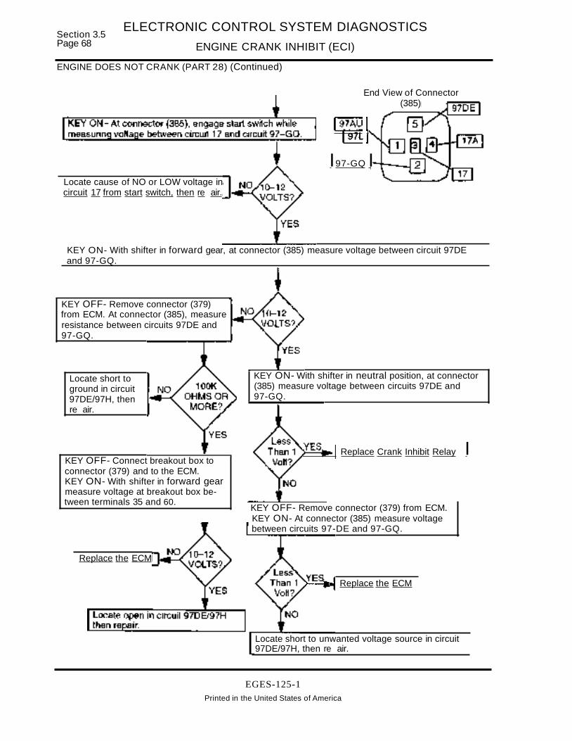
Section 3.5Page 68
ELECTRONIC CONTROL SYSTEM DIAGNOSTICS
ENGINE CRANK INHIBIT (ECI)
ENGINE DOES NOT CRANK (PART 28) (Continued)
Locate cause of NO or LOW voltage incircuit 17 from start switch, then re air.
End View of Connector(385)
~7AU ,97L
I97-GQ I
KEY ON- With shifter in forward gear, at connector (385) measure voltage between circuit 97DEand 97-GQ.
Locate short to unwanted voltage source in circuit97DE/97H, then re air.
~---.. Replace the ECM
~---~I Replace Crank Inhibit Relay I
KEY ON- With shifter in neutral position, at connector(385) measure voltage between circuits 97DE and97-GQ.
KEY OFF- Remove connector (379) from ECM.KEY ON- At connector (385) measure voltagebetween circuits 97-DE and 97-GQ.
Replace the ECM
Locate short toground in circuit97DE/97H, thenre air.
KEY OFF- Connect breakout box toconnector (379) and to the ECM.KEY ON- With shifter in forward gearmeasure voltage at breakout box between terminals 35 and 60.
KEY OFF- Remove connector (379)from ECM. At connector (385), measureresistance between circuits 97DE and97-GQ.
EGES-125-1Printed in the United States of America

ELECTRONIC CONTROL SYSTEM DIAGNOSTICS
ENGINE CRANK INHIBIT (ECI)Section 3.5
Page 69
ENGINE DOES NOT CRANK (PART 2C) WITH MANUAL TRANSMISSION WITHOUT CLUTCH SWITCHRefer to Figure 3.5-10 while performing test.
Manual Transmission Without Clutch Switch
...._ ......... (2 &2A)
F4 H110A 10A
::) a..~ ~(J)
(3 & 3A)
...--- TO KEY SW "START"W/OPBS
WITRK W/FBCIGN IGN
TO KEYSW ·,GN-W/PBS
~ LL.(W)
...... "...
TO STARTRELAY <3 17AFIGURE3.5-7
CRANKINHIBITRELAY(985)
JUMPER WIRE ATCLUTCH SW CONNECTOR
Connector 385 - Relayinsertion end shown
ECM(379) 35
Eel IW/KOEO {IN ANY GEAR O.1-D.6VI
IN NEUTRAL O.1--Q.6VII
tNeutral Position Switch
Connector At TransmissionIII
12V II
Figure 3.5-10 - Circuit Diagram Engine Cranking Circuit
EGES-125-1Printed In the United States of America

Section 3.5Page 70
ELECTRONIC CONTROL SYSTEM DIAGNOSTICS
ENGINE CRANK INHIBIT (ECI)
ENGINE DOES NOT CRANK (PART 2C) (Continued)
Use this test with manual transmission without a clutch switch.
Continued from ENGINE DOES NOT CRANK (Part 1)
Connector (385)Relay insertion end shown
(ClutCh Switch = ON)EST Indicates 12V is present
at ECM terminal 10
Locate open in circuit97-GQ, then re air.
KEY ON- With start switch engaged, at connector (385)measure volta e between circuit 17 and circuit 97-GQ.
KEY OFF- Remove Crank Inhibit Relay from connector(385). KEY ON- At (385) measure voltage between circuit97U97AU and circuit 97GQ.
KEY ON- At connector (385) measure voltage betweencircuit 97U97AU and circuit 17A.
KEY ON- Use Prolink EST to check clutch switch position with clutch pedal released andde ressed. Prolink should indicate Clutch Switch = ON, clutch edal u or down.
Locate open in circuit 17A betweenconnectors (385) and (387), then repair.
Locate open in circuit(s) 97A, 97L,97AU, 97P or 97BX, then repair.Note that a jumper wire should bepresent at the Clutch and NeutralPosition switch connectors.
Locate cause of NO or LOW voltagein circuit 17 from start switch, then repair.
EGES-125-1
Printed in the United States of America
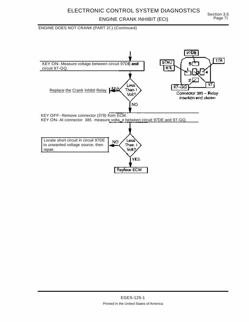
ELECTRONIC CONTROL SYSTEM DIAGNOSTICS
ENGINE CRANK INHIBIT (ECI)
ENGINE DOES NOT CRANK (PART 2C) (Continued)
Section 3.5Page 71
KEY ON- Measure voltage between circuit 97DE andcircuit 97-GQ.
Replace the Crank Inhibit Relay YES
KEY OFF- Remove connector (379) from ECM.KEY ON- At connector 385 measure volta e between circuit 97DE and 97-GQ.
Locate short circuit in circuit 97DEto unwanted voltage source, thenrepair.
EGES-125-1
Printed in the United States of America

Section 3.5Page 72
ELECTRONIC CONTROL SYSTEM DIAGNOSTICS
ENGINE CRANK INHIBIT (ECI)
CLUTCH SWITCH CIRCUIT TEST WITH CLUTCH SWITCH
Perform this test if directed by other test or if Prolink EST indicates the clutch switch is not functioning properly.
Continued from ENGINE DOES NOT CRANK (Part 2A)
Check 10A fuse F4 (H1 w/FBC) for open condition. (If electronic throttle pedal is working, the fuse is OK.)
Check clutch switch adjustment. With pedal released, clutch switch shouldbe closed and open with audible click when pedal is depressed.
Locate cause ofoverload condition,then correct.
Adjust switch.
NOTE: The clutch switchis a Normally Open switchthat is adjusted to beclosed when the clutchpedal is released (up).Depressing the clutchpedal causes the switchto open.
KEY OFF ... Disconnect circuits 97L and 97A from clutch switch. Useohmmeter to check switch operation in open and closed position.
Replace theclutch switch.
KEY ON - Measure voltage to ground at circuit 97L clutch switch connector.
Locate open in circuit 97L, 97AU,97P, 97BX between clutch switchand fuse F4 (H1 w/FBC). Check forjumper wire across thetransmission Neutral Safety switch.
Locate open incircuit 97A, thencorrect.
EGES-125-1
Connect clutch switch to harness andinstall breakout box at ECM connector(379). Turn key ON and measurevoltage at breakout box terminal 1O.
Clutch switch and circuit toECM checks good. If Prolinkdoes not indicate correctreading for clutch switchposition, replace the ECM.
Printed in the United States of America

ELECTRONIC CONTROL SYSTEM DIAGNOSTICSSection 3.5
ENGINE CRANK INHIBIT (Eel) Page 73
NEUTRAL POSITION SWITCH TEST WITH ALLISON ATIMT AUTOMATIC TRANSMISSION
Continued from ENGINE DOES NOT CRANK (Part 2B)
Check 10A fuse F4 (H1 w/FBC) for open condition. (If electronic throttle pedal is working, the fuse isOK.
Locate cause of overload condition,then correct. Re lace fuse.
Disconnect harness from neutral position switch. Turn key ON and measurevolta e to round at circuit 97P of neutral safe switch harness connector.
Locate open or bad connection incircuit 97BX or 97P, then correct.
Yes
KEY OFF - With transmission in neutral, measure resistance across neutral position switch terminals.
Replace theneutral switch.
KEY OFF - With transmission shifter in forward gear, measure resistance across neutral switch terminals
Replace theneutral switch.
: S"ee next page :
EGES-125-1Printed In the United States of America

Section 3.5Page 74
ELECTRONIC CONTROL SYSTEM DIAGNOSTICS
ENGINE CRANK INHIBIT (Eel)
NEUTRAL POSITION SWITCH TEST WITH ALLISON ATIMT AUTOMATIC TRANSMISSION (Continued)
+KEY ON - With neutral switch disconnected, measure voltageto ground at circuit 97AU of neutral switch harness connector.
In circuit 97AU, 97Lor 97A, locate shortcircuit to "HOT"wire, then correct.
Less than1 volt
Connect harness to neutral switch and install breakout boxat ECM connector (379). With shifter in neutral, turn key ONand measure voltage at breakout box terminal 1O.
Locate open in circuit 97A, 97L or 97AU between ECMconnector (379) and neutral switch, then correct.
EGES-125-1Printed in the United States of America

ELECTRONIC CONTROL SYSTEM DIAGNOSTICS
ENGINE CRANK INHIBIT (ECI)Section 3.5
Page 75
ENGINE CRANK INHIBIT (ECI) RELAY TEST
This procedure provides a method to bench test the Eel relay. The terminal numbers are marked on the relay.
Remove ECI relay for bench test. Measure resistance between ECI relay terminals 1 and 4.
IReplace the relay. I
Use test leads to jumper ECI relay terminals 2 and 5 to ground. Connect 12Vsu I to terminal 3, then check for continuit between terminals 1 and 4.
Replace the relay.
Remove ground from terminal 5 and note if continuityremains between terminals 1 and 4 for about 2 seconds.
Replace crankinhibit relay.
Crank inhibit relay tests OK.
EGES-125-1
Printed in the United States of America

Section 3.5Page 76
ELECTRONIC CONTROL SYSTEM DIAGNOSTICS
ENGINE COOLANT lEVEL SYSTEM (ECl)
ENGINE COOLANT LEVEL SYSTEM (ENGINE PROTECTION)
W/Metal Tank
COOLANT LEVELSWITCH MODULE
(4141
COOLANTLEVELPROBE
___-------()I A IGN
.......--....".r---------a B OUTPUT
......------...01 C I GN
.---00()1 0 PROBEOWL 59CLS 18D ...MiO~V=~LO;;;.;,W~CO;;,,;;;;O~LA~NT~ .....
12V= COOLANT OK
EOP 4210-----'""-1 ENGINEV AEF26 OILSIG GAD PRESS
46 ENGINEECT 7 COOLANT
TEMP
ECM
ALARMIi-Ai)
OJL/WATER
This Figure shows the 2500, 2600 or 8100 model vehicle ECl system.
SIGNAL FUNCTION
With the optional engine protection system, theECM monitors inputs from the Engine Oil Pressuresensor, Engine Coolant Temperature sensor andLow Coolant switch (or module). If any of thesesensors detect out of range conditions beyond thewarning level, ECM OWL terminal 59 goes LOW(grd) causing the alarm to sound and the oil/waterwarning light to turn ON. If the engine shutdownfeature has been selected, and the out of rangeconditions go beyond the critical level, the ECM willinitiate the shutdown process.
LOW COOLANT LEVEL SYSTEM
The 2500, 2600, 8100 models have a metal surgetank and use low coolant module and low coolantprobe. All other models with a plastic compositesurge tank utilize a magnetic low coolant switch inthe surge tank instead of the module and probe.
2500,2600,8100 Models - The low coolant moduleoutputs a 12V signal to ECM terminal when coolantlevels are at specified levels and OV when coolantis below the probe.
Models With Plastic Surge Tank - The low coolantswitch is open when coolant is OK and closed whencoolant is lOW. When this switch is OPEN, 12V ispresent at ECM terminal 18. When the switch isclosed, voltage is pulled to zero at ECM terminal 18.
ENGINE OIL PRESSURE SENSOR
The Engine Oil Pressure (EOP) sensor sends alinear analog signal to ECM terminal 42. If the ECMdetects oil pressure below the warning level theOWL is turned on. If oil pressure goes below thecritical level, engine shutdown is initiated. Refer toEngine Oil Pressure (EOP) Sensor diagnostics foradditional information and sensor circuittroubleshooting.
ENGINE COOLANT TEMPERATURE SENSOR
The Engine Coolant Temperature (ECT) sensorsends a 0-5 volt analog signal to ECM terminal 7.If the ECM detects coolant temperature above thewarning level the OWL is turned on. If coolanttemperature goes above the critical level, engineshutdown is initiated. Refer to Engine CoolantTemperature (ECT) Sensor diagnostics foradditional information and sensor circuittroubleshooting.
FAULT DETECTION MANANGEMENT
There are no ECM diagnostics for the EngineCoolant Level system. Flash Code 323 will be activewhen a low coolant situation is present and theProlink will indicate COOLANT LOW. After thecoolant has been restored to proper levels, Flashcode 323 will remain as an inactive code and theECM will log the engine hours of the occurrence.
EGES-125-1Printed In the United States of America

ELECTRONIC CONTROL SYSTEM DIAGNOSTICS
ENGINE COOLANT LEVEL SYSTEM (ECl)Section 3.5
Page 77
MODELS WITH METAL SURGE TANK
Engine Coolant level(ECl)
Fault Codes:
323 Engine Coolant Below Warning Critical Level
ENGINE COOLANT lEVEL MODULE
(414)DASH HARNESS
Module Outputw/Coolant =Output High (12v)
No Coolant =Output Low (Grd.)
Engine Coolant LevelSwitch Module
(414)ECM (379)
OWL 5997AF
TO ALARMIWARN LIGHT 34KEYSWIGN A IGN
CLS 18n-- 34_B --..;t B OUTPUT
KEY SW IGN C ] GN__3_4_A <)I 0 PROBE
COOLANTLEVELPROBE,..;;-;.---.....----
Connector Voltage ChecksConnector (414) with key ON, probe submerged in coolant and coolant module disconnected
Test Points Spec. Comments
A to grd 12 ± 1.5 volts < than 10.5 v check connections, if 0 volts check for open/short toground.
C to grd 12 ± 1.5 volts < than 10.5 v check connections, if 0 volts check for open/short toground.
eto D 5 to 10 volts min. Dvolts check for open in probe circuit < less than 5V checkconnections and check probe for clean condition.
Cto 8 12 ± 1.5 volts < than 10.5 volts check connections. 0 volts check for open circuit348.
Operational CheckECM Connector (379) with breakout box installed, probe submerged in coolant and key ON
Test Points Spec. Comments
#18 to grd 12 ± 1.5 volts < than 10.5 v check connections, if 0 volts check for open/short togrd in circuit 348.
Fault Code Descriptions323 = Indicates low coolant level. If coolant level full with code present, troubleshoot circuit.
EGES-125-1
Printed in the United States of America

Section 3.5Page 78
ELECTRONIC CONTROL SYSTEM DIAGNOSTICS
ENGINE COOLANT lEVEL SYSTEM (ECl)
MODELS WITH PLASTIC SURGE TANK
Engine Coolant level(ECl)
97
Fault Codes:
323 Engine Coolant Below Warning Critical Level
ECM (379)97AF
OWL 59 TO ALARMIWARN LIGHT
CLS 18n-- 3_4_B _
«.q-('t)
Magnetic 437CoolantLevelSwitch
(437)
1KOHMCOOLANT SWITCH
(437)(SURGE TANK)
Harness side of connector (437) - disconnected with key ON
Test Points Spec. Comments
A to grd. 6 ± 1.5 volts < than 10.5 v check connections, if 0 volts check for open/short toground or blown fuse
Ato B 6 ± 1.5 volts < than 10.5 v check connections, if 0 volts check for open inground path.
Switch side of connector (437) - disconnected with key OFF and coolant at proper level
Test Points Spec. Comments
Ato B >1000 ohms < than 1000 ohms replace the switch (sIb less than 5 ohms withlow coolant level)
Connector (379) with breakout box installed and key ON and coolant at proper level with (437)connected to ECl switch.
Test Points Spec. Comments
#18 to grd. 6 ± 1.5 volts < than 1O.5v check connections, if 0 volts check for open/short toground or blown fuse or defective resistor.
Fault Code Descriptions323 =Indicates low coolant level. If coolant level full with code present, troubleshoot circuit.
EGES-125-1Printed In the United States of America

DESCRIPTION
ELECTRONIC CONTROL SYSTEM DIAGNOSTICS
ENGINE COOLANT lEVEL SYSTEM (ECl)Section 3.5
,Page 79
The Engine Coolant level (ECl) System is part ofthe optional Engine Protection Package.
The purpose of the ECl system is to monitor the engine coolant level and alert the driver when a lowcoolant condition is present by turning on the OillWater Warning light and the alarm buzzer. If the vehicle is programmed for Engine Shutdown as part ofthe Engine Protection Package, a low coolant signalwill shut down the engine.
ENGINE COOLANT LEVEL (ECl)MODULE AND PROBE
Refer to the circuit diagram on page 80 for the fol ...lowing discussion.
The ECl module (414) receives 12V ignition powerfrom 15A fuse F4 (G1 fuse w/FBC) at terminals Aand C. ECl Module, TerminalB is connected (circuit34B) through connector (379) to ECM terminal 18(ECl).
ECl module (414) terminal D is connected to theCoolant Level Probe located in the surge tank. Avery low current signal from ECl module terminal Dgoes through the probe, then through the coolant(using coolant as a conductor) to ground (circuit34-G). When the coolant level is above the probe,ECl module terminalB will be HIGH (12V), and OillWater Warning light is OFF.
With coolant level below the probe for more than 7consecutive seconds (7 second delay prevents intermittent splashing signals), the ground paththrough the probe from ECl Module terminal 0 willbe open. This causes the ECl module terminal B togo lOW (0 volts). With ECl terminal B at a volts,ECM terminal 18 is at 0 volts causing the ECM toturn on the Engine Warning Light and Alarm.
DIAGNOSTIC CODES
The ECM does not check the ECl circuits. FlashCode 323 is set indicating that a "low coolant" condi ...tion was detected.
FLASH CODE 323PID 111 FMI1ECM: ENGINE COOLANT BELOW WARNING/
CRITICAL LEVEL
Flash Code 323 will be active when a low coolant situation is present and the Prolink will indicate COOLANT lOW. After the coolant has been restored toproper levels, Flash code 323 will remain as an inactive code and the ECM will log the engine hours ofthe occurrence.
TROUBLESHOOTING
Use the Prolink 9000 to monitor the ECl system operation. Prolink will indicate that the coolant level isFULL or LOW.
BEFORE TROUBLESHOOTING
A. Before troubleshooting, make sure that the batteries are fully charged! Check battery connections and grounds for clean, tight connectionsfree of damage. Voltage tests will give mis... leading readings if batteries are not fully charged.
B. Before troubleshooting a particular circuit, inspect connectors for pushed back, loose ordamaged (spread or bent) terminals, or wireswith cut strands, etc. The wires and connections must be free of damage or corrosion.When some connectors corrode, a light whiteresidue will be present that must be removed.
C. Before troubleshooting, inspect suspect circuitgrounds for clean, tight connections free ofdamage.
ENGINE COOLANT LEVEL MODULEAND PROBE TEST
Perform Testing For False low Coolant Signal onpage 81 , if Prolink indicates COOLANT lOW whencoolant level is above the probe.
Perform Testing For False Full Coolant Signal onpage 83, if Prolink indicates COOLANT FUll whencoolant level is below the probe.
EGES-125-1
Printed in the United States of America

Section 3.5Page 80
ELECTRONIC CONTROL SYSTEM DIAGNOSTICS
ENGINE COOLANT LEVEL SYSTEM (Eel)
ENGINE COOLANT LEVEL SYSTEM CIRCUIT DIAGRAM
WITRK
IGN
XMSN MODULATORSHIFT CONTROL
RELAY
W/FBC
IGN
LL(I)....
G115A
...... W/FBCm~
(3 & 3A)
EelMODULE
(414) NOTE: CIRCUIT34-G ATPROBE ENDCONNECTS TOSURGE TANKMOUNTINGBOLT.
LOCATED INSURGE TANK
EelPROBE
34..G
34
34C
TO TOeop & IPR RETARDER
RELAY
ECM(379)1-----..
Eelov.. LOW COOLANT12 V • COOLANT OK
(400)r--.34A SetA I I.......-.-.~:~--.....-.c:~ I
I I
I I.... _...
STARTERGND TANK
MTGBOLTGND
EGES-125-1
Printed In the United States of America

ELECTRONIC CONTROL SYSTEM DIAGNOSTICS
ENGINE COOLANT lEVEL SYSTEM (Eel)Section 3.5
Page 81
TESTING FOR FALSE LOW COOLANT SIGNAL
Perform this test if Prolink indicates LOW COOLANT when coolant level is above the probe.
Check F2 fuse (G1 w/FBC) for open condition.
Locate cause of overloadcondition, then correct.Replace 15A fuse.
CONNECTOR (414)
Locate open in circuit34A between (414) andprobe, then correct.Remove jumper andreinstall probe andretest operation.
: See next :page
LOW (do notremove jumper)
Remove connector (414)from Eel module. At (414),measure resistance toground at terminals 0,circuit 34A.
Disconnect circuit 34A from probe and jumper harness circuit 34A to engineround. With ke ON, note if Prolink indicates coolant level FULL or LOW.
Locate open or poor connection incircuit 34-G/11-G then repair.Remove ·um er and install robe.
With key OFF, measureresistance to ground at circuit34-G connection to surge tank.
Remove probe.Clean probe andretest. If it stilldoesn't work,replace the probe.
EGES-125-1Printed In the United States of America

Section 3.5Page 82
ELECTRONIC CONTROL SYSTEM DIAGNOSTICS
ENGINE COOLANT lEVEL SYSTEM (ECl)
TESTING FOR FALSE LOW COOLANT SIGNAL (Continued)
KEY ON- At connector (414) measure voltage to groundat circuits 34 and 34C.
locate open in circuit(s) 97 or 34or 34C, then correct.
Yes CONNECTOR (414)
With connector (414) disconnected from ECl module, install breakout box at ECM harnessconnector 379 , but do not connect to ECM. Jum er breakout box terminal 18 to 60 GRD .
KEY ON .. Measure voltage at connector (414) between terminals A (circuit 34) and B (circuit 34B).
locate open in circuit348, then correct.
KEY OFF .. With circuit 34A still jumpered to ground at surge tank, connect breakout box to ECM andconnect (414) to ECl module. Turn key ON and measure voltage between breakout box terminals 18and 60.
Replace the EngineCoolant level Module.
With 6.5 ± 2V at ECM terminal 18, coolant levelshould indicate OK on Prolink EST. If not, replace theECM.
EGES-125-1Printed In the United States of America
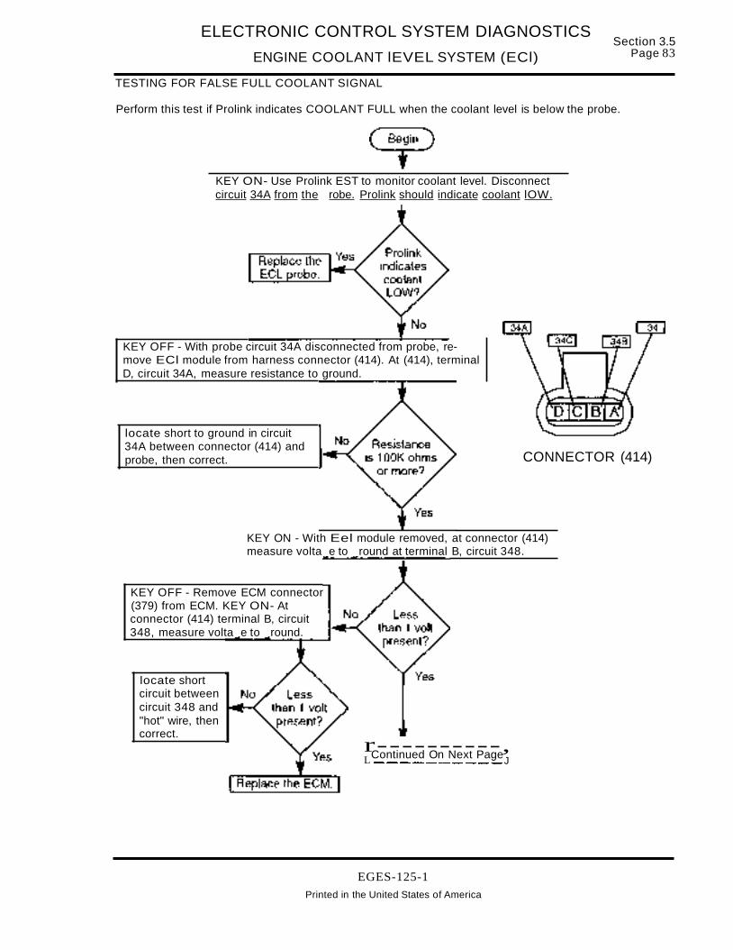
ELECTRONIC CONTROL SYSTEM DIAGNOSTICS
ENGINE COOLANT lEVEL SYSTEM (ECl)Section 3.5
Page 83
TESTING FOR FALSE FULL COOLANT SIGNAL
Perform this test if Prolink indicates COOLANT FULL when the coolant level is below the probe.
KEY ON- Use Prolink EST to monitor coolant level. Disconnectcircuit 34A from the robe. Prolink should indicate coolant lOW.
KEY OFF - With probe circuit 34A disconnected from probe, remove ECl module from harness connector (414). At (414), terminalD, circuit 34A, measure resistance to ground.
locate short to ground in circuit34A between connector (414) andprobe, then correct. CONNECTOR (414)
r----------,LContinued On Next PageJ---------------
locate shortcircuit betweencircuit 348 and"hot" wire, thencorrect.
KEY ON - With Eel module removed, at connector (414)measure volta e to round at terminal B, circuit 348.
KEY OFF - Remove ECM connector(379) from ECM. KEY ON- Atconnector (414) terminal B, circuit348, measure volta e to round.
EGES-125-1Printed in the United States of America

Section 3.5Page 84
ELECTRONIC CONTROL SYSTEM DIAGNOSTICS
ENGINE COOLANT LEVEL SYSTEM (ECl)
TESTING FOR FALSE FULL COOLANT SIGNAL (Continued)
KEY ON- At connector (414), measure voltageto ground at terminals A (cir 34) and C (cir34C).
CONNECTOR (414)
KEY OFF-Install ECl module in (414). Remove connector (379) from ECM and connect to breakoutbox. Do not connect breakout box to ECM. KEY ON- At breakout box measure voltage between terminals 18 (cir 348) and 60 (ground terminal).
Replace ECl module
EGES-125-1Printed in the United States of America

Section 3.5 ELECTRONIC CONTROL SYSTEM DIAGNOSTICSPage 86 ELECTRONIC CONTROL MODULE SELF DIAGNOSTICS (ECM)
ECM SELF DIAGNOSTICS
ECM(Electronic Control Module)
,."
,.",. .,
10M ECM VPM
INJECTOR ELECTRONICVEHICLEPERSONALITY
DRIVER CONTROL MODULEMODULE MODULE
j~
.... j...I I I I I I
I I I
SIGNAL FUNCTIONS
The Electronic Control Module (ECM) monitors andcontrols engine operation and performance, vehiclefeatures such as PTa and cruise control, communicates information to the Vehicle Personality Module(VPM) and Injector Drive Module (10M).
FAULT DETECTIONIMANAGEMENT
The ECM is capable of internal fault detection and
dependent upon the severity of the problem, canprovide fault management strategies to allow limited engine/vehicle operation.
FAULT DETECTION/MANAGEMENT
The ECM is capable of internal fault detection anddependent upon the severity of the problem, canprovide fault management strategies to allow limited engine/vehicle operation.
EGES-125-1

ELECTRONIC CONTROL SYSTEM DIAGNOSTICSSection 3.5
ELECTRONIC CONTROL MODULE SELF DIAGNOSTICS (ECM) Page 87
ECM SELF DIAGNOSTICS
NORMAL OPERATION DIAGNOSTICS
During normal engine operation, the ECM automatically performs several tests to detect faults. DuringNormal Operation, the ECM performs the Start-upKAM Test and Continuous Diagnostics.
START-UP KAM TEST
The Start-up KAM Test is used to validate the ECM'sKeep-Alive-Memory once each time the ECM resets (turns ON). If an error is detected, Flash codes224 or 615 can be set.
FLASH CODE 615ATA CODE SID 254 FMI13ECM: PROGRAMMABLE PARAMETER KAMCORRUPTFAULT
Flash Code 615 can be set when Flash code 224 isset. If 224 is present, refer to Keep Alive MemoryPower (KAM PWR) page 174 in this section to diagnose.
If code 224 IS NOT SET, code 615 indicates that theECM's RAM is defective. Replace the ECM.
CONTINUOUS DIAGNOSTICS
Continuous diagnostic checks are made by theECM during vehicle operation to detect out-ofrange, rationality and system faults. Flash codes112 and 113 can be set during this diagnostic process. Refer to (ECM PWR) in this section.
ON DEMAND DIAGNOSTICS (SERVICE DIAGNOSTICS)
The ECM will perform On-Demand Diagnostics(Service diagnostics) when requested by the service technician. The KOEO Standard Test Procedure includes:
• ECM Internal Self-Tests
• Output Circuit Checks (OCC).
ECMINTERNALSEL~TESTS
Use the Prolink EST to perform the self-tests. Thetest procedure checks the ECM's CPU, RAM, andROM. The test may set the following flash codes.
FLASH CODE 111ATA CODE PID 194 FMI 0ECM: NO ERRORS DETECTED
Flash Code 111 indicates that the ECM has not detected any errors.
FLASH CODE 625ATA CODE SID 254 FMI 9ECM: ECM INACTIVE BACKGROUND
Code 625 indicates that the ECM Software is Faulty.Replace the ECM.
FLASH CODE 631ATA CODE SID 240 FMI 2ECM: ROM TEST FAULT
If code 631 is present, replace the ECM.
FLASH CODE 632ATA CODE SID 254 FMI12ECM: RAM/CPU TEST FAULT
If code 632 is present, replace the ECM.
ECM OUTPUT CIRCUIT CHECKS (OCC)
During the OCC checks, the following ECM relatedcodes can occur:
FLASH CODE 254ATA CODE SID 254 FMI 3ECM: OCCORH
If code 254 is present, replace the ECM.
FLASH CODE 255ATA CODE SID 254 FMI 4ECM: OCCORL
If code 255 is present, replace the ECM.
EGES-125-1
Printed in the United States of America

Section 3.5Page 88
ELECTRONIC CONTROL SYSTEM DIAGNOSTICS
ECM/IDM COMMUNICATIONS (ECM/IDM)
ECM - 10M COMMUNICATIONSCYLINDER IDENTIFICATION - FUEL DEMAND COMMAND SIGNAL - IDM FEEDBACK
(CI) (FOeS) (EF)
C151g"11 12 Volts
~o.d~I 1ECM
Cylinder Foes Signal 12 VI ItNumber'1 '2 #7 #3 "4 #5 .6 '8'1 a S 10M
ELECTRONICCONTROLMODULE 0.6 VoUs
INJECTORDRIVERMODULE
EG-1122WARN
ENGINE LAMP
10M Feedback
112 17 tt3 M "5 #6 '8 1112 Volta
'1I: :
I I: :I aValts I: :1 Slgnll Ground I : :
I I
I Cylinder identification I : :I I - - - - -Fuel Oem.nd Con;mandSlgnal- - - - - : :• L. _ ... .., .......... - .... - - - - - ... - - - ......... - - .. - - .... - - - - - - .... ,. ........ - - - ........ - -I Ii
: Injection Driver Module FHdblck I. .. . - - - . - . - - -- . - - . - - ... .. ... .. Sign';' Gni';nd- .. - - • - - - - - - - •• - - ... - • .. .. .. ... ,
FUELQUANTITV~AND 0
TIMING CONTROL
I
~CMP
• CAMSHAFTPOSITIONSENSOR
SIGNAL FUNCTIONS
Cylinder Identification - Cylinder Identification(CI) signal is a 0 t012 volt wave form signal that communicates from the ECM to the IDM the position ofcylinder 1. This signal is used by the IDM to synchronize the injector firing sequence. This signal iscalculated from the signal generated from the Camshaft Position Sensor (CMP). The CI signal is generated by the ECM by "pulling down" (switching togrd.) a12 volt communication circuit in the 10M.Fuel Demand Command Signal - Fuel DemandCommand Signal is a 0 t012 volt wave form signalthat communicates from the ECM to the IDM the required engine timing and duration of injector firing.The timing and duration of the signal is determinedby ECM calibration and the signals of various sen..sor inputs. The FDCS signal is generated by theECM by "pulling down" (switching to ground) a 12volt communication circuit in the IDM.InjectorDriver Module Feedback -Injector DriverModule Feedback signal is a 0 t012 volt wave formsignal that communicates from the IDM to the ECMa mirror image of the FOCS signal. Extensions ofthe EF (Electronic Feedback) signal can indicate tothe ECM possible problems with the injectors by the10M asthe engine is running. An EFtoggle (100 hz.signal) generated when the key is first turned "ON"and before the engine starts, communicates to theECM that the IDM is powered up. In an engine off
or engine running diagnostic mode, the EF signal isalso used to communicate diagnostic informationfrom the IDM to the ECM. The EF signal is generated by the IDM by "pulling down" (switching to grd)a12 volt communications circuit in the ECM.
FAULT DETECTION/MANAGEMENT
Cylinder Identification - Intermittent open orshort to ground conditions can be detected by the10M through 10M stuck high or low codes (532 &531). Active faults can be detected by an on demand output circuit check performed during EngineOff Tests.NOTE: THE ENGINE WILL NOTOPERATE WITHOUT A FUNCTIONING CI CIRCUIT
Fuel Demand Command Signal - Active faultscan be detected by an on demand output circuitcheck performed during Engine Off Tests.
NOTE: THE ENGINE WILL NOTOPERATE WITHOUT A FUNCTIONING FDCS CIRCUIT
Injector Driver Module Feedback - Active faultscan be detected by a toggle sequence that the ECMlooks for on start up. The WARN lamp will be illuminated if this is detected.NOTE: 10M DIAGNOSTIC FAULT CODES WILLNOT BE TRANSMITTED IF THE EF LINE IS NOTFUNCTIONING, HOWEVER, THE ENGINE WILLOPERATE NORMALL1':
EGES-125-1
Printed in the United States of America

ELECTRONIC CONTROL SYSTEM DIAGNOSTICS
ECM/IDM COMMUNICATIONS (ECM/IDM)Section 3.5
Page 89
EG-1123
4
3
Signal Ground
EF Electronic Feedback
Fault Codes:
242 FOCS output circuit check253 CI output circuit check531 CI signal stuck low532 CI signal stuck high541 10M (EF) feedback not detected
CI C linder Identification 543 ECM - 10M communication error__(~llnre~nSy~ro..!!!.Zation_)_ __ __ _ 10M
Connector(Pin
Numbers)FDCS Fuel Demand Command Signal---------------------------22
ECMConnectorPin numbers
ECM - 10M COMMUNICATIONFOCS - Fuel Demand Command SignalCI - Cylinder IdentificationEF - 10M Feedback
Key On Engine Off - Voltage Checks(Check with breakout box installed with ignition key "ON" engine off)"
Test Points Spec. Signal Comments
#34 to #46 0.6±0.1 v CI signal Less than .5v indicates an open between the ECM and IDM.
#22 to #46 0.6 ± 0.1 v FOCS signal 12 volts indicates an open in the ECM or breakout box.
#24 to #46 1 to 4 volts EF feedback With the key on, EF has a 100 hz. digital signal that will measure 1-4 volts wi DVOM.
Connector Checks to Ground(Check with breakout box installed, ignition key should be in the OFF position.)
Test Points Spec. Signal Comments
#34 to #46 > 1000 ohms CI signal Less than 1000 ohms indicates a short to ground either thru the harness
> 1000 ohms FOCS signalor internal in the ECM or 10M. Disconnect the 10M and measure to
#22 to #46 ground. If short still present, disconnect the ECM and measure to#24 to #46 > 1000 ohms EF feedback ground. If short still present, repair harness.
Harness Resistance Checks(Check with breakout box installed, ignition key should be in the OFF position..)
Test Points Spec. Signal Comments
#34 to #16 < 5 ohms CI signal Resistance from ECM connector to 10M connector.#22 to #3 < 5 ohms FOCS signal Resistance from ECM connector to IDM connector.#24 to #4 < 5 ohms EF feedback Resistance from ECM connector to IDM connector.
#46 to #2 < 5 ohms SIG Grd Resistance from ECM connector to IDM connector.
Fault Code Descriptions242 =FOCS high or low resistance in the circuit detected during engine off test, OCC· test (REPAIR THIS FAULT FIRST).253 =CI high or low resistance in the circuit detected during engine off test. acc· test (REPAIR THIS FAULT FIRST).531 =CI signal stuck low, harness or internal circuits of IDM shorted to ground (intermittent problem, historical fault only)532 = CI signal stuck high, harness or internal circuits of IDM shorted to voltage source (intermittent problem, historical fault only)
541 =10M feedback (EF) (100 hz frequency transmitted during key ON, engine OFF) not detected.
543 =ECM-IDM communication error, no communication, detected on EF or wrong part number IDM.
* - oce =Output Circuit Check
EGES-125-1Printed In the United States of America

Section 3.5Page 90
ELECTRONIC CONTROL SYSTEM DIAGNOSTICS
ECM/IDM COMMUNICATIONS (ECM/IDM)
ECM 110M COMMUNICATIONS EXTENDEDEXTENDED SYSTEM DESCRIPTION
FUNCTION
The Navistar engine control system includes anElectronic Control Module (ECM) and an InjectorDrive Module (10M). The IDM's primary functionsare to supply high current and voltage to power theinjectors and to electrically "turn on" individual injectors upon command by the ECM. The ECM communicates and controls injector timing and fuel quantityand communicates engine position to the 10M to insure correct fueling timing, quantity and firing sequence. The 10M is also capable of feeding back orhandshaking information received from the ECMand of communicating diagnostic information perti ..nent to injector or 10M operation to the ECM. Information is transmitted between the 10M and ECMon three circuits; (CI) Cylinder Identification,(FDCS) Fuel Oemand Command Signal and (EF)Electronic Feedback.
Cylinder Identification (CI) is the signal from theECM to the 10M to indicate the beginning of the firing order. This signal is generated by the ECM toindicate to the 10M the position of #1 cylinder andsynchronize injector firing order to engine position.Engine position is detected by the Camshaft Position (CMP) sensor by identifying the sync window inthe timing disk. (Refer to CMP sensor for completefunction)
Fuel Demand Command Signal (FOCS) is the sig..oaf sent by the ECM to the 10M to indicate the beginning and ending of each injection cycle. This precise "On/Off" signal controls the fuel timing and rateby varying the beginning and ending of injection.
Electronic Feedback (EF) signal is sent from theIDM to the ECM to verify 10M operation and communicate diagnostic information.
• On initial power up, the IDM will signal the ECMwith a constant 100 Hz signal that it has successfully initialized.
• During engine operation, the EF signal mirrorsthe FDCS signal to the ECM to verify FDCS reception by the IDM and will modify the EF signalif certain injector faults are detected during engine operation.
• After an "Engine Off Standard Test" is per"formed, the EF signal will communicate diag..nostic information stored in the 10M pertainingto IDM function or injector operation to theECM.
OPERATION
CYLINDER IDENTIFICATION (CI)
When the 10M is powered up, 12 volts is suppliedfrom pin 16 of the 10M to pin 34 of the ECM. TheECM will "pull down" this 12 volts low to approximately .6 volts (the voltage drop across an internaltransistor in the ECM). After the ECM has receiveda sync signal from the CMP sensor and can identifythe position of cylinder #1 , it will toggle CI and allowit to go high (12 volts), 1800 of camshaft rotation later or 360 0 of crankshaft rotation the ECM will againpull the CI signal low (.6 volts). This indicates to the10M to initiate the firing sequence 1-2-7-3 when itreceives the high signal and 4-5-6-8 when it receives the low signal. This signal will be repeatedevery camshaft revolution.
FUEL DEMAND COMMAND SIGNAL (FOeS)
When the 10M is powered up, 12 volts is also supplied from pin 12 of the IDMto pin 22 of the ECM, theECM will "pull down" this 12 volts low to approximately .6 volts (the voltage drop across an internaltransistor in the ECM). After the 10M has receivedthe CI signal, the ECM will toggle the FDCS signalhigh and low to indicate to the 10M the beginningand ending of injector operation for each cylinder.
NOTE: THE ENGINE REQUIRES A FUNCTIONING CI AND FDeS SIGNAL TO OPERATE.
ELECTRONIC FEEDBACK (EF)
After the ignition key is turned "ON" and the ECMand 10M relays are enabled, the 10M is powered upand performs it's internal self checks. To signal thatthe 10M is initialized, a 100 Hz signal is transmittedon the EF circuit to the ECM.
Ouring engine operation, the EF signal mirrors theFDCS signal to the ECM to verify FOCS receptionby the IDM and will modify the EF signal if certain injector faults are detected during engine operation.
After an "Engine Off Standard Test" is performed,the EF signal will communicate diagnostic information stored in the 10M pertaining to IDM function orinjector operation to the ECM.
EGES-125-1Printed In the United States of America

ELECTRONIC CONTROL SYSTEM DIAGNOSTICS
ECM/IDM COMMUNICATIONS (ECM/IDM)
ECMnDM COMMUNICATIONS EXTENDEDSYSTEM DESCRIPTION (Continued)
Section 3.5Page 91
IDM DIAGNOSTICS
The 10M monitors operation of output circuits duringengine operation. Output circuits that are shorted oropen are detected by the 10M and are subsequentlydisabled if necessary to prevent damage to the out..put drivers. This will set a fault code. When a fault isdetected during operation an EF "extension", trans..fers fault information to the ECM. Not all faults canbe transferred during engine operation. However,faults are stored in the 10M when they are detected.These faults are transmitted during the "Engine OffTests", as inactive faults.
At start up, the 10M performs a Self Test of internalcomponents to determine if they are operating satisfactorily. The 10M compares the signal inputs to determine if the signal voltages are within specification, if not a fault code will be set. These faults arealso transferred to the ECM on command as inactive faults.
ECM DIAGNOSTICS
The ECM monitors the timing of the EF signal whilethe engine is running. When it detects a fault sentfrom the 10M, it will log the transfer. However, it willbe necessary to perform an Engine Off StandardTest to determine most fault codes stored in the10M. The Engine Off Test may be initiated by theElectronic Service Tool or the STI Self Test Inputswitch located on the vehicle dash.
The ECM continually measures the communicationsignal voltage levels. If the voltage levels are loweror higher than expected, a fault code will be set toidentify the circuit or component. The fault will beautomatically recorded as an active code. If theignition key is turned off, the fault will be stored as aninactive code.
FLASH CODE 242ATA CODE SID 154 FMI11FOCS CIRCUIT TO IDM OCC SELF TESTFAILED
During the Engine Off Standard Output CircuitCheck test, Code 242 will be set by the ECM, if theECM did not detect a voltage transition on the FDCScircuit. This code will not cause the Engine Warninglight to be illuminated.
Code 242 may be caused by a shorted high or low oropen FOCS circuit. If accompanied by other communication codes could indicate the IDM is not powered up. This fault must be repaired for the engineto operate.
FLASH CODE 253ATA CODE SID 153 FMI11FUEL INJ SYNC CIRCUIT OCC SELF TESTFAILED
Flash code 253 will be set during the Engine OffStandard Output Circuit Check test. This code is setby the ECM and indicates no voltage transition detected on the Cylinder Identification circuit. Thisfault will not cause the Engine Warning light to be illuminated.
Possible causes are a shorted (high or low) or openCI circuit. If accompanied by other communicationcodes could indicate the 10M is not powered up.This fault must be repaired for the engine to run.
FLASH CODE 531ATA CODE SID 153 FMI4FUEL INJ. SYNC SIGNAL LOW
Flash code 531 is set by the 10M and is transmittedto the ECM on command from the ECM during theEngine Off Standard Test. This code indicates thatthe 10M has detected that the FOCS signal and theCI signal have remained at 0 volts. This code willcause the Engine Warning light to be illuminated.
Possible cause may be a short to ground in the CIcircuit. This fault must be repaired for the engine torun.
FLASH CODE 532ATA CODE SID 153 FMI3FUEL INJ. SYNC SIGNAL HIGH
Flash code 532 is set by the 10M and is transmittedto the ECM on command from the ECM during theEngine Off Standard Test. This code indicates the10M has detected that the FDCS signal and CI signal have remained at 12 volts. This code will causethe Engine Warning light to be illuminated.
Possible causes are a short to a voltage source oran open CI circuit. This fau't must be repaired for theengine to run.
EGES-125-1
Printed In the United States of America

Section 3.5Page 92
ELECTRONIC CONTROL SYSTEM DIAGNOSTICS
ECM/IDM COMMUNICATIONS (ECM/IDM)
ECMIIDM COMMUNICATIONS EXTENDEDSYSTEM DESCRIPTION (Continued)
FLASH CODE 541AlA CODE SID 155 FMI1110M FEEDBACK TOGGLE NOT DETECTED BYECM
Flash code 541 is set by the ECM. The ECM monitors the CI, FOCS and EF signals for voltage levels.If the ECM detects that the CI or FOCS is open or ifthe EF signal is not sending a 100 Hz signal, thiscode will be set. This code will cause the EngineWarning light to be illuminated.
Possible causes are a short or open on the EF circuit if this code is the only code present. If accompanied by other 10M circuit faults the 10M may not bepowered or operational. If displayed during an Engine Off Standard Test it will be accompanied bycode 543. This code may be set due to other faultsin the ECM due to a reset condition. If other codesare present repair them first in the order of importance for engine operation. This code should notprevent engine operation by itself.
FLASH CODE 543ATA CODE SID 155 FMI 710M FAULTS NOT RECEIVED
Flash code 543 is set by the ECM during an EngineOff Standard Output Circuit Check test. This indicates that the ECM has commanded the transmission of fault codes from the 10M and has not received the codes. If this code occurs, first recordany active or inactive codes. Then clear the codesand rerun the Engine Off Standard Test. This codewill cause the Engine Warning light to be illuminated.
Possible causes for this code would be opens orshorts in the 10M I ECM communications circuits oran 10M not powered. If accompanied by other faultsrepair the other faults first in the order of importancefor engine operation. This code should not preventengine operation by itself.
EGES-125-1
Printed In the United States of America

ELECTRONIC CONTROL SYSTEM DIAGNOSTICS
ECMlIDM COMMUNICATIONS (ECM/IDM)Section 3.5
Page 93
INJECTOR DRIVE CIRCUIT
97M8
405
~ 11cx)C\I~(o
a: a: a: a:0000................0000wwww""") """) """) J~z~z
""10"'1'a: a: a: a:0000................0000wwww""") """) """) """)
~~~~
10M(380)
••......- 9_7A_Y__--I-<~:'+_~2_0+- 9.;..;.7M.;;.;;..Y~~....__--9..;..;,7A..;;..,K---<'¢}I24 ] NJPWR
A~~97MV " T (1,3,5,7)
t~ ....~~9~m~M~~~~~~9~7~M~M __~~~~B~M~~]23 ]N~~~ .Dr- "" 21 I (2,4,6,8)
~~~(o'-,~~~ ~~b CJ) 97MVo 0 0 0 0 0 0 0 ~ " 3
0>
mcoee<;} <;> <> <} ...,m~e~m~74o~__I-{~~=22=1-__~9~7A~D==---__.<~I 19
<> <1> y v 97ME :>0 97AP 0 7
, 9_7M......B_--I-<~~~1_0-l--- 97_8_N <<> 22
97MH ~~31 9788 A 9'"---------+<,',f---J----------Cv}l
'-- ----.;;9;..;;..7~AN~__I<~~f-l-9+----97.;;...A-N---'V<A.}I20'"-- 9_7_M_D----1H<~<,+--9-t-----9-7B-P------<<) 2 1
'--- 9.;;;...;.7..;.;.M;;.;;...F_~~~..~ ......8_+__---9-7B-R---_<~] 8
97MA ...... 2 97AB A 6'--------------+-C,~,'4.-,,--+--------·<v
_~----...;;.9..;;..,;;7B;;.;..A~---<>(}, 16
INJ (CYL 6)
INJ (CYL 4)
INJ (CYL 2)
INJ (CYL 8)
INJ (CYL 7)
INJ (CYL 3)
INJ (CYL 5)
INJ (CYL 1)
CI
__-----..;9;..;..7---BB-------(<):} I 3
_-9;;;..:.7~AZ -O 4
EAM-o 2
FDCS
EFSIGRTN
« m~
:Em m <Cr--.. r--.. r--.. S>0> 0> m
() (") () <> (') <) () <> ECM
) ~ C\I ~ coI
(379)('t) C\I C\I ~
)( en LL c0 w z0 C!Ju.
C!Jen
EGES-125-1Printed In the United States of America

Section 3.5Page 94
ELECTRONIC CONTROL SYSTEM DIAGNOSTICS
ECM/IDM COMMUNICATIONS (ECM/IDM)
ECM ¢::} 10M COMMUNICATIONS
ELECTRONICCONTROL
MOOULE (379)(DASH HARNESS)
204060
14 26 40
(10M) INJECTOR DRIVEMODULE (380)
DASH HARNESS
15 27
Locate open in groundcircuit and re air.
KEY OFF- At connector (380)measure resistance to ground atterminal 2.
r----------,L Continued On Next Page..J.-_-~--------
Locate open in circuit havingmore than 5 ohms and re air.
KEY OFF- Install breakout box at ECM to Dash Harness only (not to ECM).Measure resistance between:
1. ECM terminal 34 and (380) 10M terminal 16 (CI)
2. ECM terminal 22 and (380) 10M terminal 3 (FOCS)
3. ECM terminal 24 and (380) 10M terminal 4 (EF)
Refer to circuit diagramon page 93.
Remove connector (379) from the ECM. At(380) measure resistance to ground atterminals 3 (FOCS), 4 (EF) and 16 (CI).
Replace theECM
1 21 41
EGES-125-1Printed In the United States of America

ELECTRONIC CONTROL SYSTEM DIAGNOSTICS
ECM/IDM COMMUNICATIONS (ECM/IDM)Section 3.5
Page 95
ECM <=> 10M COMMUNICATIONS (Continued)
YES
KEY ON- With breakout box connected to dash harness only and 10M disconnected at380 , measure volta e to round at breakout box terminals 22, 24 and 34.
15 27
ELECTRONICCONTROL
MODULE (379)(Chassis Harness)
204060
(10M) INJECTOR DRIVEMODULE (380)
(Chassis Harness)
14 26 40
I Replace the10M.
KEY ON- Measure voltage at breakout box terminal 24 (EF).
Refer to 10M PowerSupply Oiagnostics inthis section.. If 10M ispowered and there isno voltage replace theIDM.
Locate short to unwantedvoltage source in any circuithaving .25 volts or more, thenre air.
KEY ON- At breakout box terminal 24 (EF) measure voltage frequency.
KEY OFF- Connect breakout box to ECM and Install connector (380) to10M. KEY ON- Measure voltage at breakout box terminals 34 (GI) and22 (FOGS).
Circuits are complete. Further malfunctions indicate component failure.
1 21 41
EGES-125-1Printed in the United States of America

S. ELECTRONIC CONTROL SYSTEM DIAGNOSTICS
eellon 3.5Page 96 ELECTRONIC CONTROL MODULE POWER SUPPLY (ECM PWR)
ELECTRONIC CONTROL MODULE (ECM) POWER SUPPLY
ECMELECTRONIC
CONTROLMODULE
oz::>~ BATTERYCJ
oz::>oa:CJ
KEEP ALIVE MEMORY
BATIERY
B7A
ECM RELAY
IGN SWITCHED BATTERY POWER
ECM POWER SUPPLY
CIRCUIT FUNCTIONS
The ECM receives 12 volt operating power with thekey ON from the ECM power relay. The ECM alsoreceives 12 volt battery power at all times for theKeep Alive Memory function.
ECM SWITCHED POWER
Turning the key ON energizes the ECM power relaycausing 12 volt battery power to be applied to ECMterminals 37 and 57.
ECM KEEP ALIVE MEMORY POWER
Battery power is applied at all times to support theECMs keep alive memory. Refer to KEEP ALIVE
MEMORY POWER CIRCUITS in this section foradditional information.
ECM POWER GROUND
ECM terminals 40 and 60 are grounded through thechassis harness to the negative battery terminal.
FAULT DETECTION MANAGEMENT
The ECM monitors voltage at terminals 37 and 57.If the ECM continuously receives less than 6.5 voltsor more that 18 volts a fault code will be set. The faultcodes do not cause the Warning light to be turnedON. If the condition is intermittent, the code will belogged as an inactive code.
EGES-125-1
Printed in the United States of America

ELECTRONIC CONTROL SYSTEM DIAGNOSTICS s · 3 5ectlon .
ELECTRONIC CONTROL MODULE POWER SUPPLY (ECM PWR) Page 97
Electronic Control ModulePower Supply(ECM-PWR)
Fault Codes:112 Internal power out of range high113 Internal power out of range low
224 KAM Corrupt
ECM POWER RELAY (395JChassis Harness
1
5
ECM PWRRELAY 395)
2
4
...L
15A ECM FUSE
5A FUSE-F5IGN
BATT
l
ECM CONNECTOR(379)
IGN f Pin #370PWR"\. Pin #57 0PWRf Pin #40GRD"\. Pin #60
After removing connector always check for damaged pins. corrosion, loose terminals etc.
Connector (395) - Check connector (395) with relay removed, ECM connector (379) disconnectedand key ON.
Test Points Spec. Comments
#30 to Grd. 12 ± 1.5 volts < than 10.5 v check connections, 0 v check for open/short toground or blown fuse
#86 to Grd. 12 ± 1.5 volts < than 10.5 v check connections, 0 v check for open/short toground or blown fuse
#86 to #85 12 ± 1.5 volts < than 10.5 v check grd circuit connections, 0 v check for openground circuit
#30 to #87 ovolts Any voltage indicates a short to ground in ECM feed circuit
Connector (379) - Check with breakout box installed on engine harness only and connector (395)with relay removed and key OFF.
Test Points Spec. Comments
#40 to Grd. < 5 ohms > 5 ohms indicates open or poor connection in ground circuits.#60 to Grd.
#37 to Grd. >1000 ohms < 1000 ohms indicates a short to ground#57 to Grd.
Connector (379) to (395) - Check with breakout box installed on engine harness only andconnector (395) with relay removed and key OFF
Test Points Spec. Comments
#87 to 37 <5 ohms > 5 ohms indicates an open or poor connection. If <5 ohms the#87 to 57 ECM power relay is suspect.
Fault Code Descriptions112 =Internal power was more than 18 volts.113 = Internal power was less than 6.5 volts.224 =Keep Alive Memory in ECM lost.
EGES-125-1Printed In the United States of America

ELECTRONIC CONTROL SYSTEM DIAGNOSTICSSection 3.5Page 98 ELECTRONIC CONTROL MODULE POWER SUPPLY (ECM PWR)
EXTENDED DESCRIPTION
Refer to the Electronic Control Module powersupply circuit diagram on page 99 for the followingdiscussion.
The Electronic Control Module (ECM) Power Relay(395) has battery power supplied directly from thebatteries to terminal 30. This circuit is protected bythe 15A ECM #1 PWR fuse that is part of the batterycable assembly.
When the key switch is turned ON, the ECM PowerRelay (395) is energized by ignition power from 5Afuse F5 (5A fuse C1 with FBC) at the relay controlcoil terminal 86. With the ECM Power Relay (395)energized, power flows through the normally open(N.D.) relay contacts (30 to 87) then on circuit 97ARto ECM connector (379), terminals 37 and 57.
The ground side of the ECM Power Relay controlcoil (terminal 85) is grounded by circuit 11-GK at theElectronic Ground Stud located at the cab. TheDiode Assy (415) prevents the electroniccomponents from voltage spikes created by therelay opening and closing.
The ECM power ground terminals 40 and 60 aregrounded through ECM connector (379) at thenegative battery terminal.
ECM DIAGNOSTICS
If the ECM continuously receives less than 6.5 voltsor more than 18 volts at terminals 37 and 57, it willcause Flash Code 112 or 113 to be set.
FLASH CODE 112ATA CODE PID 168 FMI3ECM: INTERNAL VOLTAGE POWER OUT OFRANGE HIGH
Code 112 can be caused by either of two conditions:
1. Vehicle voltage supply to the ECM iscontinuously more than 18 volts. Excessivevoltage can be caused by a defective alternator.
2. The ECM has an internal fault.
If the condition causing code 112 is intermittent, thecode will change from active to inactive status.
Code 112 does not cause the Engine Warning lightto turn ON.
FLASH CODE 113ATA CODE PID 168 FMI4ECM: INTERNAL VOLTAGE POWER OUT OFRANGE LOW
Code 113 can be caused by consistently less than6.5 volts being applied to ECM terminals 37 and 57.This can be caused by a defective alternator, lowbatteries, and/or increased resistance in the batteryfeed circuits. Code 113 does not turn the EngineWarning Light ON. If the condition causing Code113 to set is an intermittent condition, when thecondition is no longer present, the code status willchange from active to inactive.
FLASH CODE 224ATA CODE SID 254 FMI 2ECM: KAM CORRUPT
Flash code 224 can be caused by high or low batterypower supply to ECM terminal 1 OR an internalECM error.
TROUBLESHOOTING
If Flash Code 112 is active, refer to CTS- 5000Master Service Manual, GROUP 08ALTERNATORS and troubleshoot the chargingsystem.
If Flash Code 113 is active or NO voltage is presentto the ECM, perform TESTING ECM POWERSUPPLY CIRCUITS on page 100. If the powersupply to the ECM checks good, replace the ECM.
If a vehicle no-start condition is present and there isno power to the ECM, perform TESTING ECMPOWER SUPPLY CIRCUITS on page 100.
BEFORE PERFORMING ANY TESTS
Inspect ECM power relay circuit connectors forpushed back, damaged, corroded or dirty terminalsas well as making sure the terminals and wires areproperly crimped. Make sure connectors areproperly joined together. Also check for damagedwiring, and clean, tight battery and groundconnections.
EGES-125-1
Printed in the United States of America

ELECTRONIC CONTROL SYSTEM DIAGNOSTICS s .ectlon 3.5
ELECTRONIC CONTROL MODULE POWER SUPPLY (ECM PWR) Page 99
ELECTRONIC CONTROL MODULE POWER SUPPLY CIRCUIT DIAGRAM
VION
'1 ECM FUSE 15A
TOVPM 97E(381) lQ----............----.....
VBATT
(424)~oS;
TO ECM KAPWR Q- Dl_~_......._ ...~t7~C;.:.J....
81
§i~ TO 10M PWR 'I- 07_C_T .-........m RELAV (SQ6)
CONNECTOR 398(VIEWED FROM RELAY
INSERTION END)
ecM PWA RELAV HARNESS(385)
t7-QMC
EGES-125-1Printed In the United States of America

S. ELECTRONIC CONTROL SYSTEM DIAGNOSTICS
eetlon 3.5Page 100 ELECTRONIC CONTROL MODULE POWER SUPPLY (ECM PWR)
TESTING ECM POWER SUPPLY CIRCUITS
Check 15A in-line ECM fuse and 5A fuse F5 (fuse C1 w/FBC) for open condition.
Remove ECM relay from harness connector (395). KEY ON Measure voltage at connector (395), terminal 86. (97CS).
Locate cause of overload condition,then correct. Replace fuse.
Locate cause of NO or LOWvoltage from key switch incircuit 97CS to connector(395), then correct. Use Fluke88 DMM to check diode.
ECM POWER RELAY (395)
DASH HARNESS
CONNECTOR-lee1717C91TEAMINAL-J661627Ct
KEY OFF - Measure resistance to ground at connector (395) terminal 85 (circuit 11-GK).
Locate open or highresistance in circuit 11-GKbetween connector (395) andcab ground, then correct.
With key ON, check for voltage at connector (395) terminal 85 (circuit 11-GK).
Locate short circuit to"hot" wire in circuit11 ..GK, then correct.
At connector (395) measure voltage between terminals 30 (97CJ) and 85 (11-GK).
: See next:page
EGES-125-1Printed in the United States of America

ELECTRONIC CONTROL SYSTEM DIAGNOSTICS Section 3.5
ELECTRONIC CONTROL MODULE POWER SUPPLY (ECM PWR) Page 101
TESTING ECM POWER SUPPLV CIRCUITS (Continued)
Locate cause of NO orLOW voltage in circuit148, 14C, 97CM, or97CJ, then correct.
With key OFF, install breakout box to ECM harness connector (379), but do not connect breakout box to ECM.
ECM POWER RELAY (395)DASH HARNESS CONNECTOR
CONNECTOR-lee1717C91TERMJNAL-J661e27Cl
I
I
I
I
I
I
I
I
I
I 2.I
II
I
I
I
I
II
: 3.I
I
I
I
: A. If resistance is 1OOK ohms or more,:I the relay is good. Otherwise re-: place the relay. I1- - _ _ _ _ _ _ _ _ _ _ _ _ _ _ _ _ _ _ _ _ _ _ _ _ _ _ _ _ J
Replacethe relay.
Locate open or causeof high resistance inground circuit (97-GDor 97-GC or 97-GCAor 11-G), then correct.
Locate open or highresistance in circuitbetween relay (395) andECM connector (379),then correct.
KEY OFF - Measure resistance between connector (395),terminal 87 (97AR) and breakout box terminals 37 and 57.
r - - - - - - - - - - - - - - - - - - - - - - - - - - - - - -I
I Normally I
I Open Contact Normally :: Closed I
I Contact I
I Energizing :: Coil I
I I
I I
I I
I I
I I
: Common Energizing :I Coil II Contact I
I I
I I
& TESTING HELLA RELAY II I
: With relay removed: :I
: 1. Connect (+) battery lead to terminal 85 I
and (-) lead to terminal 86. :I
A. If relay energizes making an :audible click sound, go to step 2. I
Otherwise replace the relay. :o
With relay energized, measure resis- :tance between terminals 30 and 87. I
I
A. If resistance is less than 2 ohms, :go to step 3. Otherwise replace the:relay.
Disconnect battery leads from relayand measure resistance betweenterminals 30 and 87.
ECM PWR Supply circuits and relay check good. Ifthe ECM still does not power up, replace the ECM.
EGES-125-1Printed In the United States of America

Section 3.5Page 102
ELECTRONIC CONTROL SYSTEM DIAGNOSTICS
ENGINE COOLANT TEMPERATURE SENSOR (ECT)
ENGINE COOLANT TEMPERATURE (ECT) SENSOR
ECM
ELECTRONICCONTROLMODULE
10M
INJECTORDRIVERMODULE
FUEL QUANTITYAND
TIMING CONTROL
EXHAUSTBACKPRESSUREVALVE
EG-1124
WARNENGINELAMP
oVolts(Warmer)
GLOW PLUGLAMP
GLOWPLUGRELAY
ECT
ECT Signal (analog voltage)5 Volts
(Colder)
SIGNAL FUNCTIONSThe Engine Coolant Temperature (ECT) sensor isa thermistor type sensor that has a variable resistance that changes when exposed to different temperatures. When interfaced with the ECM it pro..duces a 0 to 5 volt analog signal that will measuretemperature.Coolant Temperature Compensation - At coolanttemperatures greater than 214°F (1 01 ° C) fuelquantity is reduced by 6% for each degree of temperature (OC), until engine temperature reaches218° F (103°C). Above 218° F (103°C) fuel is reduced by 3% for each °C increase in temperature.Idle Speed - At temperatures below 158° F, (70° C)low idle is incrementally increased to a maximum of875 RPM.
Glow Plug Control - Glow plug relay and lamp on
times are directly affected by engine coolant temperature.
Engine Warning and Protection - Optional feature when enabled will warn driver of overheatcondition and can be programmed to shut the engine down.
FAULT DETECTION/MANAGEMENT
An ECT signal that is detected out of range high orlow by the ECM will cause the ECM to ignore theECTsignal and assume an engine coolant temperature of -29°F (-20°C) for starting and a temperatureof 180° F (82 0 C) for engine running conditions. TheWARN lamp will also be illuminated as long as thefault condition exists.
EGES-125-1Printed in the United States of America

ELECTRONIC CONTROL SYSTEM DIAGNOSTICS
ENGINE COOLANT TEMPERATURE SENSOR (ECT)Section 3.5
Page 103
(a)
B16ECTSignal
Fault Codes:114 Out of Range Low115 Out of Range High316 Eng. Coolant Temp. unable to reach
commanded setpoint321 Eng. Coolant Temp. Above Warn322 Eng. Coolant Temp. Above Critical325 Coolant Tern . Com ensationDeutsch Connector --a.__.....- ____
(0 \1I) Sensorn va ve Cover Harness Connector
Signal Ground Connector14
A
Engine CoolantTemperature Sensor
(ECT)
EG-1125
ECMConnector
After removing connectors always check for damaged pins. corrosion. loose terminals etc.Connector Checks to Chassis Ground
(Check with Sensor Connector Disconnected and Ignition key off, all accessories off)
Test Points Spec. Comments
A to Grd. < 5 ohms Resistance to chassis ground, check with key OFF, if > 5 ohms the harness is open.
8 to Grd. > 1000 ohms Resistance less than 1000 ohms indicates a short to ground.
Connector Voltage Checks(Check with sensor Connector Disconnected and Ignition Key On)
Test Points Spec. Comments
B to Grd. 4.6 - 5.0 v Pull up voltage, if no or low voltage, circuit has open or high resistance or short to Grd.
A to Grd. 0- .25 v If greater than .25 volts, wire is shorted to V Ref. or battery
Harness Resistance Checks(Check with breakout box installed on engine harness only)
Test Points Spec. Comments
#46 to A < 5 ohms Resistance from harness connector to 60 pin connector - Signal ground
#7 to B < 5 ohms Resistance from harness connector to 60 pin connector - ECT Signal
Test Points Operational Signal Checks(+) #7 to (-) #46 (Check with breakout box installed in line with the ECM)Voltage Temp. ° F Temp. ° C Resistance Comments
0.53 v 248 120 1.19 K ohms
0.96 v 212 100 2 K ohms
'1.37v 176 80 3.84 K ohms
4.37 v 32 0 69.2 K ohms
4.60 v -5 -20 131.0 K ohms
Circuit Faults:Fault Code Descriptions
114 =Signal was less than .127 volts for more than 0.1 seconds. (Probable short to ground.)115 =Signal voltage was greater than 4.8 volts for more than 0.1 seconds. (Probable open circuit.)Cooling System Faults:316 = Coolant temp. has not reached 41 0 F321 = Engine Coolant Temperature above WARN level 225° F (107° C)322 =Engine Coolant Temperature above Critical level 2340 F (112.5°C)325 =Coolant Temperature Compensation enabled,
(Reduces fuel quantity 6% for each degree °C above 214° F (101°C)
EGES-125-1
Printed in the United States of America

Section 3.5Page 104
ELECTRONIC CONTROL SYSTEM DIAGNOSTICS
ENGINE COOLANT TEMPERATURE SENSOR (ECT)
ENGINE COOLANT TEMPERATURE SENSOREXTENDED SYSTEM DESCRIPTION
FUNCTION
The Navistar engine control system includes an Engine Coolant Temperature sensor. The ECM measures the Engine Coolant Temperature signal anduses this information for Coolant TemperatureCompensation and optional high temperature warning and shut down systems.
Coolant temperature Compensation is used to protect the engine if the coolant temperature is too high.The ECM monitors the ECT signal to determine thecoolant temperature. If the coolant reaches 214°F(1 01 °C ), the ECM will reduce the fuel delivery by6% for each Celsius degree of temperature increase. If the coolant temperature increases to218°F(1 04°C), fuel quantity will be reduced 3'1'0 foreach Celsius degree of temperature increase.Coolant Temperature Compensation can be programmed to be inoperative in certain applicationswhere full engine perlormance is required over theprotection of the engine.
On engines equipped with an engine warning system, the ECM will activate the audible warningalarm and illuminate the red Oil/Water warning lightwhen the engine coolant temperature reaches225°F (107°C).
On engines equipped with an engine shut down system, the ECM will shut the engine off when the coolant temperature reaches 235°F (112.5°C). The vehicle operator may restart the engine by turning theignition key "OFF" and then restarting it. Upon restart, the ECM will allow the engine to run for anadditional 30 seconds, before shutting off the engine again.
OPERATION
The Engine Coolant temperature sensor is a thermistor type sensor which changes resistance whenexposed to different temperatures.
When the temperature of the coolant is decreased,the resistance of the thermistor increases whichcauses the signal voltage to increase. As the temperature of the coolant is increased the resistanceof the thermistor decreases, which causes the signal voltage to decrease.
The ECT sensor is supplied a regulated 5 volt refer~ence voltage from ECM terminal 7. The sensor is
grounded at terminal A through the signal return,terminal 46, at the ECM. As the coolant temperature increases or decreases, the sensor changesresistance and provides the ECM with the coolanttemperature signal voltage at terminal 7 of theECM. This signal voltage is then read by the ECM todetermine the temperature of the coolant.
ECM DIAGNOSTICS
With the ignition key "ON", the ECM continuouslymonitors the ECT circuit for expected voltages. Ifthe signal voltage is less than or more than expected the ECM will set a fault code.
If the ECM detects a fault in the ECT signal, the ECMwill disregard the signal and default to a temperature of 180°F (82°C) for engine running operationand -4°F (-20°C) for starting the engine. If the faultis no longer present, the ECM will once again returnto normal operation using the ECT signal for processing.
Faults in the ECT signal can be retrieved using theSelf Test Input Switch (STI) orthe Electronic ServiceTool. If the fault is no longer present, it will be s10redas an Inactive Code.
FLASH CODE 114AlA CODE PID 110 FMI4Eel: OUT OF RANGE LOW
An out of range low code will be set if the ECM detects a voltage less than .127 volts for more than 0.1seconds. If this fault is Active, the ECM will use thedefault value of 180°F (82°C).
Code 114 may be caused by a short to ground or ashorted or biased sensor.
FLASH CODE 115ATA CODE PIO 110 FMI3ECl: OUT OF RANGE HIGH
An out of range high code will be set if the ECM detects a voltage greater than 4.6 volts for more than0.1 seconds. If this fault is Active, the ECM will usethe a default value of 180°F (82°C).
Code 115 may be caused by an open circuit, anopen sensor, or a short to another voltage source.
EGES-125-1
Printed In the United States of America

ELECTRONIC CONTROL SYSTEM DIAGNOSTICS
ENGINE COOLANT TEMPERATURE SENSOR (ECT)
ENGINE COOLANT TEMPERATURE SENSOREXTENDED SYSTEM DESCRIPTION (Continued)
Section 3.5Page 105
FLASH CODE 316ATA CODE PID 110 FMI1ENGINE COOLANT TEMPERATURE UNABLETO REACH COMMANDED SETPO/NT
Code 316 will only be set with engines that have theCold Ambient Protection (CAP) System enabled.This code will be set after the engine has run forgreater than 120 minutes and has not exceeded147°F (75°C) for vehicles with manual transmissions and 140°F (60°C) for vehicles with automatictransmissions.
NOTE: THIS CODE ONLY INDICATES THAT THEENGINE HAS NOT BEEN ABLE TO REACH OPERATING TEMPERATURE. IT DOES NOT INDICATE AN ELECTRONIC FAULT.
Possible causes of code 316: Extended idle time,cold ambient temperatures, (may require use ofwinter front), thermostat stuck open, mis-plumbedcooling system (thermostat bypass bypassed), auxiliary heater cores cooling off engine (school bus applications or fan clutch locked on.
FLASH CODE 321ATA CODE PID 110 FMI 0ENGINE COOLANT TEMPERATUREABOVE WARNING LEVEL
Code 321 will be set if the ECM detects engine coolant temperature above 225°F (107°C). When thisoccurs, the ECM illuminates the OIUWATER warn...ing light and sounds the audible alarm (if equipped),alerting the operator that a potential for engine dam...age exists.
If the temperature drops below 225°F(107°C), thecode will become inactive and the ECM will return tonormal operation.
FLASH CODE 322ATA CODE PIO 110 FMI 7ENGINE COOLANT TEMPERATURE ABOVECRITICAL LEVEL
Code 322 will be set if the ECM detects engine coolant temperature above 235°F (112.5°C). When thisoccurs, the OIUWATER warning light illuminatesand the audible alarm sounds (if equipped) will alertthe operator that the temperature is increasing(having set code 321) indicating a potential for engine damage. With code 322 active, the engine willshut down. At the same time the code and currentengine hours will be recorded in the VPM as an Engine Event.
If the temperature drops below 235°F (112.5°C), thecode will become inactive and the ECM will return tonormal operation. Should the engine shut down, itcan be restarted to move the vehicle to a safe place.
FLASH CODE 325ATA CODE PID 110 FMI14POWER REDUCED, MATCHED TO COOLINGSYSTEM PERFORMANCE
Code 325 will be set if the cooling system temperature exceeds 214°F (101°C). At this temperaturethe ECM will reduce the fuel delivered to the engineat or near the maximum demand level. For eachone Celsius degree of temperature the fuel will bereduced 6°k>. This reduces the heat produced by theengine thereby reducing the burden on the enginecooling system. It will also slow the vehicle speedencouraging the operator to downshift, thus increasing the efficiency of the cooling system.
As the temperature is reduced the compensationlevel is reduced until the temperature drops below214°F (1 01 °C ) at which normal operation is resumed.
EGES-125-1
Printed in the United States of America

Section 3.5Page 106
ELECTRONIC CONTROL SYSTEM DIAGNOSTICS
ENGINE COOLANT TEMPERATURE SENSOR (ECT)
SENSOR CIRCUIT DIAGRAM
A - ..
6
KEY SWITCHIBN (24)
~«x(f)Q..
T""!
><"(J)
---__.. 84*
82*
* SPLICESHOWN (2)PLACES97BH
97BG
97CZ
97CY 5V
97BF
5
28
24
97SF 16
A I( '>---W.LJlolLi - 9-7Z_--+-< <iE
1:--4-t---
A <> 97GW
B 97BF
ENGINE COOLANTTEMP SENSOR
B
A It >-------lC-f-..-...&----+--<4~-
(405)CAMSHAFT POSITION
SENSOR27 97SE
C k~---~----+-<4~---:
26
ENGINE OILTEMP SENSOR
A 97GU
INJECTION CONTROLPRESSURE SENSOR
B
A [>------...,;;~_+_<f-+-------
C I('l----+O-<'f-+------,
ENGINE OILPRESSURE SENSOR
(50 PSI SW WITH ENGINE WARNINGOR ENGINE PROTECTION SYSTEMONLY)
wCD
"0>
S2*
S4*
INJECTION PRESSUREREGULATOR VALVE
(405)
13 97BP'-----+-<~t___--<JI A
97BH___----+--<f-II------(. ~I 825
ECM. )1379;/ ~
a..ow
CDLn
f'.. CO "¢" CDNN f'.q- N
(Ll.L~~O a:UWOUZ 0
0:: W W (!)> (!)
.......en
NOTE: (405)SHOWNTWOPLACES
EGES-125-1Printed In the United States of America

ELECTRONIC CONTROL SYSTEM DIAGNOSTICS
ENGINE COOLANT TEMPERATURE SENSOR (ECT)Section 3.5
Page 107
ENGINE COOLANT TEMPERATURE (ECl) SENSOR DIAGNOSTICS
Refer to circuit diagramon page 106.
KEY OFF- Remove connector from ECT sensor. Measure resistance to ground at terminal A.
97GW
97F
ENGINE COOLANTTEMPERATURESENSOR CONN.
Replace Engine CoolantTern erature Sensor.
fil ~
~ lIUiJUlJUiJUUlJ 0 liiJiJUUUUUUlJi NN -
ELECTRONIC CONTROL MODULE (ECM) (379)OASH HARNESS
KEY OFF- Install breakout box at ECM connector(379). Measure resistance between breakout boxterminal 7 and ECT connector terminal B.
KEY OFF- Measure resistance to ground at terminal B.
Repair open signal circuit betweenconnector (379) terminal 7 and ECTconnector terminal B.
Locate short to ground insi nal circuit and re air.
KEY OFF- Install breakout box at ECMconnector (379). KEY ON- Measurevoltage to ground at terminal 7.
Repair cause of high resistance in signal circuit between connector379 terminal 7 and ECT connector terminal B.
EGES-125-1
Printed in the United States of America

Section 3.5 ELECTRONIC CONTROL SYSTEM DIAGNOSTICSPage 108 ENGINE DATA LINE WITH ALLISON AT/MT TRANSMISSIONS (EDL)
(EDL) ENGINE DATA LINE WITH ALLISON AT/MT TRANSMISSION
KEY SWITCH
IGN VOLTAGE
ECMELECTRONICCONTROLMODULE
CIRCUITENABLE
30
87A
r----I---............... MODULATORSOLENOIDRELAY
SHIFT CIRCUIT
TRANSMISSIONMODULATOR SHIFTSOLENOID
CIRCUIT FUNCTIONS
The Electronic Control Module is programmed withtwo shift schedules: The Closed Throttle Mode andthe Wide Open Throttle Mode.
1. The Closed Throttle Mode is for situations withmoderate engine load. ECM terminal 32 will beLow (0 volts). This energizes the relay, turningoff power to the solenoid, causing thetransmission to shift at approximately 65% ofengine load.
2. The Wide Open Throttle Mode is for heavy loadsituations. ECM terminal 32 will be High (12volts). This de-energizes the relay causing 12volts to be applied to the solenoid. In this mode,the ECM has shift schedules that occur at 80%of engine load.
When the engine is operating at less than the loadshift point, ignition voltage is not applied to the shiftsolenoid. When the ECM commands a shift, therelay coil ground is opened by the ECM, whichde-energizes the relay, turning ON the power to theshift solenoid, causing it to shift.
FAULT DETECTION
The Prolink EST is used to initiate the KOEO OutputCircuit Tests. This will test the enabling circuitbetween the key switch, through the relay coil andcircuit to ECM terminal 32. If an open or short (highor low) is found in this circuit, Flash Code 244 willbe set.
Note that the test does not check relay function orthe circuit to the shift solenoid.
EGES-125-1
Printed In the United States of America

ELECTRONIC CONTROL SYSTEM DIAGNOSTICS S til 3 5eClon .
ENGINE DATA LINE WITH ALLISON AT/MT TRANSMISSIONS (EDL) Page 109
Engine Data LineWith Allison Transmission
(EDL)KEY SWITCH (24)
Fault Codes:244 EDl acc FAULT
92C
AUTOMATIC XMSN MODULATORSHIFT RELAY(4031
XMSN HARNESS
92E
9281
2'-- --..;;...;97:...;...F --t 5
92C.-+-..-+----------------t3
ECM (379)
J
9.,.....,....
MODULATORSHIFT SOLENOID(404)
NOTE: Check fuse F2 and either test relay (refer to Bench Testing Relay on page 113) or substituteknown good relay and check vehicle shift operation before testing circuits.
(BATIERY MUST BE IN A FULL CHARGE CONDITION)Connector Checks To Chassis Ground
Connector (403) - Check connector with relay removed and key ON
Test Points Spec.. Comments
#30 to Grd. 12 ± 1.5 volts < than 10.5 v check connections, 0 v check for open/short toground or blown fuse
#86 to Grd. 12 ± 1.5 volts < than 10.5 v check connections, 0 v check for open/short toground or blown fuse
#86 to #87A >10.0 volts < than 10.0 v check circuit connections, 0 v check for open in cir-cuit 92C or 92-G or defective solenoid.
#30 to #85 12 ± 1.5 volts < than 10.5 v check connections, 0 v check for open in circuit 97F.
Connector (403) - Check with breakout box installed and relay removed from (403) and key ON.Use Prolink EST to initiate Output State Test and set outputs HIGH (refer to SECTION 5.2 forperforming Output State Test).
Test Points Spec. Comments
Breakout box 12 ± 1.5 volts < 12 ± 1.5 volts the ECM is defective#32 to Grd.
At (403) 12 ± 1.5 volts < than 10.5 v check connections, 0 v check for open/short toterminal 85 to ground in circuit 97F.Grd.
Fault Code Descriptions
244 =Output circuit check performed during Engine Off test detected high or low resistance in EDLrelay coil circuit.
EGES-125-1Printed in the United States of America

ELECTRONIC CONTROL SYSTEM DIAGNOSTICSSection 3.5Page 110 ENGINE DATA LINE WITH ALLISON AT/MT TRANSMISSIONS (EDL)
EXTENDED DESCRIPTION
Engine Data Line (EDL) output from the ECM controls the Transmission Modulator Shift SolenoidControl Relay (403), which in turn controls theTransmission Modulator Shift Solenoid (404).
The ECM is programmed with two shift schedules:Closed Throttle Mode and Wide Open ThrottleMode. The Closed Throttle Mode schedule for atransmission is for situations with a moderate engine load. The transmission will shift at approximately 65 percent of engine load. The Wide OpenThrottle Mode shift schedule has shift points that occur at 80 percent of engine load. This provides increased power in heavy load situations for passingor faster acceleration.
The ECM analyzes engine operating data and determines which mode is most appropriate for currentoperation. The physical Allison transmission usesEDL output from ECM connector (379) terminal 32to select the most appropriate shift schedule depending upon engine loads.
Refer to the circuit diagram on page 111 for the following discussion.
When ECM terminal 32 is LOW (0 volts), the transmission operates in the Closed Throttle Mode (normal shift schedule). When ECM terminal 32 is HIGH(12 volts), the transmission operates in the WideOpen Throttle Mode.
WIDE OPEN THROTTLEMODE OPERATION
In the Wide Open Throttle Mode, ECM terminal 32is HIGH (12 volts) and the XMSN Shift Modulator(404) is energized. The Transmission ModulatorShift Solenoid Control Relay (403) receives ignitionpower at common terminal 30 and control coil termina186. When ECM terminal 32 is HIGH (12 volts),circuits 97F and 92E have 12V so the relay (403)does not energize. The ignition power on circuit 928goes through the normally closed (N.C.) contacts
(30 to 87A) to the Transmission Modulator Shift Solenoid (404), causing the shift solenoid to energize.
CLOSED THROTTLE MODE OPERATION
In the Closed Throttle Mode, ECM terminal 32 isLOW (0 volts) and Transmission Shift Modulator(404) is not energized. When ECM terminal 32 isLOW (0 volts), circuit 97F grounds the ModulatorShift Control Relay control coil causing the relay toenergize, opening the normally closed (N.C.) contacts (30 to 87A) in relay (403), TURNING OFF thepower to the Transmission Modulator Shift Solenoid(404), which is de-energized.
ECM DIAGNOSTICS
The ECM does not continuously monitor the EDLcircuits. To check these circuits use the Prolink ESTto perform the KOEO - Output Circuit Checks(OCC).
FLASH CODE 244ATA CODE SID 248 FMI11ECM: EDL DCC FAULT
The OCC Test checks the Relay Control Coil circuits97F, 920, 92E and the relay control coil for opens orshorts (high or low). If a defect is noted, Flash Code244 will be set. The Engine Warning light does notturn ON.
Note that the ECM diagnostics DO NOT check theactual operation of the Modulator Shift SolenoidControl relay (403) or the Modulator Shift Solenoid(404). The ECM diagnostics also do not check circuits 928, 92C, 92-G or 11-GJ. For these reasons,it is possible for the Allison AT/MT transmissionModulator Shift Solenoid not to function, without afault code. Testing Modulator Shift Control Circuitslocated in TROUBLESHOOTING on page 112 include tests for these circuits.
If Flash code 244 is active or the transmission shiftmodulator does not operate properly perform Testing Modulator Shift Solenoid (404) Circuits on page112.
EGES-125-1Printed in the United States of America

ELECTRONIC CONTROL SYSTEM DIAGNOSTICSSection 3.5
ENGINE DATA LINE WITH ALLISON AT/MT TRANSMISSIONS (EDL) Page 111
CIRCUIT DIAGRAM
MODULATOR SHIFT SOLENOID W/ALLISON AT XMSN
XMSNSHIFT
MODULATOR(404)
WITRK
IGNKEYSW
W/FBC
IGNKEYSW
oNc»
WITRK
920
97F
92C
MODULATOR 30SHIFT CONTROL
RELAY -(403) 87A 087
oNm
" 0~
u-N N (W)
CJ) .....(J)
F2(389) 15A G1
15A
(3 & 3A)
CRKMOTOR
GRDSTUD
(3 & 3A)920
W/FBC7-
ECM (379) o VOLT8 (IDLE)12 VOLTS (HIGH IDLE)
EGES-125-1Printed in the United States of America

Section 3.5 ELECTRONIC CONTROL SYSTEM DIAGNOSTICSPage 112 ENGINE DATA LINE WITH ALLISON AT/MT TRANSMISSIONS (EDL)
TROUBLESHOOTING
BEFORE TROUBLESHOOTING
A. Before troubleshooting, make sure that the batteries are fully charged! Check battery cablesand grounds for clean, tight connections freefrom damage. The voltage tests will give misleading readings if the batteries are not fullycharged.
B. Before troubleshooting, inspect connectors forpushed back, loose or damaged (spread or
bent) terminals, or wires with cut strands etc.Wires and connections must be free of damageor corrosion. When some connectors corrode,a light white residue will be present that must beremoved.
C. Before troubleshooting, inspect the suspect cir...cuit grounds for clean, tight connections free ofany damage.
TESTING MODULATOR SHIFT SOLENOID (404) CIRCUITS
Check F2 fuse (G1 w/FBC) for open condition.
Locate cause of overload condition,then correct. Replace fuse.
Remove circuit 92C from shift modulator (404). With key ON (engine OFF), measurevoltage to ground at circuit 92C connection to shift solenoid (404). Less than 1 voltshould be present.
Perform TESTINGMODULATOR SHIFT RELAY(403) CIRCUITS on page 113.
Start engine. At HIGH IDLE, measurevoltage to ground at circuit 92C
connection to shift solenoid (404) ..
No
Locate open inground circuit 92-G,then correct.
EGES-125-1
With engine at high idle, measurevoltage between circuit 92C and92-G at shift solenoid.
The EDL circuit isperforming properly.Have Allison Dealercheck the XMSNSHIFT MODULATOR.
Printed in the United States of America

ELECTRONIC CONTROL SYSTEM DIAGNOSTICSSection 3.5
ENGINE DATA LINE WITH ALLISON AT/MT TRANSMISSIONS (EDL) Page 113
TESTING MODULATOR SHIFT CONTROL RELAY (403) CIRCUITS
EnergizingCoil
NormallyClosedContact
Typical Relay Insertion End
BENCH TESTING RELAY
: Normally: Open Contact
Continued fromTESTING POWER TOMODULATOR SHIFT
SOLENOID (404).
Replacethe relay.
With relay removed, bench test the relay.
MODULATOR SHIFTCONTROL RELAY (403)
HARNESS
Locate cause of NO orLOW voltage in circuit(s)928, 92E or 92D fromfuse I then correct.
CONNECTOR-le817~7C91TERM1NAL-J6S16Z7Cl
With key OFF, remove relay from connector (403).Remove connector (379) from ECM and installbreakout box to harness connector only (not to ECM).
r--------------.........-----_ I
•I Energizing: CoilI...... ........ ...... I
I
I
I,I Common: Contact,,,II
II
I 1. Connect (+) battery lead to terminal 86I
Yes (Do not : and (-) lead to terminal 85.
r--Il--.._in_s_ta_lI_re_l_ay_)...... : A. If relay energizes making an audi-With key ON, : ble "click" sound, go to step 2. :
measure voltage :2. With relay energized, measure resis- :to ground at I tance between terminals 30 and 87A. ', ,connector (403) , I
terminals 1 (928) I A. If resistance is 1OaK ohms or more, 'and 5 (92E). : go to step 3, otherwise replace :
r-- ....-_............ : the relay. :, ,: 3. Remove battery leads and measure re- I
sistance between terminals 30 and :87A. :,A If resistance is less than 2 ohms, I• I
the relay is good. Otherwise re- ,,place the relay. •,
With key ON, measure voltage to ground at (403) terminals 2 (97F) and 3 (92C).
Locate short circuit to"HOT' wire in circuit whereterminal voltage is morethan 1 volt, then correct. r---------- ..
: See next :page.. -_ .. .-_ ...... __ ..
EGES-125-1
Printed in the United States of America

Section 3.5 ELECTRONIC CONTROL SYSTEM DIAGNOSTICSPage 114 ENGINE DATA LINE WITH ALLISON AT/MT TRANSMISSIONS (EDL)
TESTING MODULATOR SHIFT CONTROL RELAY (403) CIRCUITS (Continued)
tWith key OFF, disconnect circuit 92C from solenoid (404). Measure resistance to ground at 92C.
Locate short toground in 92C,then correct.
CONNECTOR-lee17~7C91
TERMJNAL-leS1827CI
: See next :page :.. _--_.-_--_.
With key OFF, measure resistance to ground at 92-G.
MODULATOR SHIFTCONTROL RELAY (403)
HARNESS
Locate openin 92-G,then correct.
Locate openin 92C, thencorrect.
With key OFF, connect circuits 92-G and 92C together, then atconnector (403) measure resistance to ground at terminal 3 (92C).
EGES-125-1
Printed In the United States of America

ELECTRONIC CONTROL SYSTEM DIAGNOSTICSSection 3.5
ENGINE DATA liNE WITH ALLISON AT/MT TRANSMISSIONS (EDl) Page 115
TESTING MODULATOR SHIFT CONTROL RELAY (403) CIRCUITS (Continued)
Locate openin circuit 92F,then correct.
YesInstall relayin connector
(403)
Connect breakout box to ECM. With key ON, measurevoltage between breakout box terminals 32 and 60.
Replacethe ECM.
Start engine. With engine at HIGHIDLE, measure voltage betweenbreakout box terminals 32 and 60.
EDL control circuits are operating properly.
EGES-125-1Printed in the United States of America
MODULATOR SHIFTCONTROL RELAY (403)
HARNESS
CONNECTOR-le817~7C91TERMINAL-16S1627Cl

Section 3.5 ELECTRONIC CONTROL SYSTEM DIAGNOSTICSPage 116 ENGINE OIL PRESSURE SENSOR (EOP)
ENGINE OIL PRESSURE (EOP) SENSOR
EG-1126
WARNENGINELAMP
EOP Signal (analog voltage)
5 Volts(More Pressure)
oVolts(LessPressure) ------------------~
ECM
ELECTRONICCONTROLMODULE
EOPENGINE OIL
PRESSURE SENSOR
SIGNAL FUNCTIONS
The Engine Oil Pressure (EOP) sensor is a variablecapacitance sensor, that, when supplied with a 5volt reference signal from the ECM produces a lin..ear analog voltage signal that indicates engine oilpressure.
Engine Warning and Protection - An optional feature which, when enabled, will warn driver of low engine oil pressure condition and can be programmedto shut the engine down.
FAULT DETECTION/MANAGEMENT
An EOP signal that is detected out of range high orlow by the ECM will cause the engine to ignore theEOP signal and disable Engine Warning andProtection.
NOTE: The EOP sensor only reads 0-38 psi.
EGES-125-1
Printed In the United States of America

ELECTRONIC CONTROL SYSTEM DIAGNOSTICS
ENGINE OIL PRESSURE SENSOR (EOP)Section 3.5
Page 117
(e)(b)
Fault Codes:
211 Out of Range Low212 Out of Range High313 Eng. Oil Pres. Below Warn Level314 Eng. Oil Pres. Below Critical Level
Sensor Connector(a)
(Overlay Harness) Sensor HarnessSignal Ground Connector
J-I-E_n_g_in_e_V_oR_i~_~_re_s_s_u_re_S_ig_n_a_1-~ ~3-----1~ I
Engine Oil PressureSensor(EOP)
EG-1127
ECMConnector
After removing connector always check for damaged pins. corrosion. loose terminals etc.Connector Checks to Chassis Ground
(Check with Sensor Connector Disconnected and Ignition key off, all accessories off)
Test Points Spec. Comments
A to Grd. < 5 ohms Resistance to chassis ground check with key off, if > than 5 ohms harness is open.
8 to Grd. > 1000 ohms Resistance less than 1000 ohms indicates a short to ground.
C to Grd. > 1000 ohms Resistance less than 1000 ohms indicates a short to ground.
Connector Voltage Checks(Check with sensor Connector Disconnected and Ignition Key On)
Test Points Spec. Comments
B to Grd. 5 volts ±.5 V Ref. check with key ON, if voltage not in spec. , see V Ref circuit
C to Grd. 0-.25 volts If greater than 0.25 volts signal ground wire is shorted to V Ref of battery.
Harness Resistance Checks(Check with breakout box installed on engine harness only)
Test Points Spec. Comments
#46 to A < 5 ohms Resistance from sensor connector to 60 pin connector - Signal ground
#26 to B < 5 ohms Resistance from sensor connector to 60 pin connector - V Ref
#42 to C < 5 ohms Resistance from sensor connector to 60 pin connector - EOP signal
Test Points Operational Si~nal Checks(+) #42 to (-) #46 (Check with breakout box instal ed in line with the ECM)
Voltage PSJ kPA Comments
1.39 v 5 34
1.89 v 10 692.9 v 20 138
3.81 v 38 262 Maximum pressure sensor is capable of measuring
C· -t F It Fault Code DescriptionstfCUI au s:
211 = Signal was less than .039 volts for more than 0.1 seconds.212 = Signal voltage was greater than 4.9 volts for more than 0.1 seconds.
Oil Pressure Faults:313 =Engine oil pressure < 5 psi (34 kPa) @ 700 RPM or 10 psi (69 kPa) @ 1400 RPM or
20 psi (138 kPa) @2000 RPM314 =Engine oil pressure < 2 psi (14 kPa) @700 RPM or 5 psi (34 kPa) @1400 RPM or
12 psi (152 kPa) @ 2000 RPM
EGES-125-1Printed In the United States of America

Section 3.5Page 118
ELECTRONIC CONTROL SYSTEM DIAGNOSTICS
ENGINE OIL PRESSURE SENSOR (EOP)
ENGINE OIL PRESSURE SENSOREXTENDED SYSTEM DESCRIPTION
FUNCTION
The Engine Oil Pressure sensor (EOP) is includedin Navistar engine control system only when a vehicle is equipped with either the Engine Warning oroptional Engine Shutdown engine monitoring system.
The ECM measures the EOP signal to monitor theoil pressure during engine operation. If the oil pressure drops below 5.0 PSI (34kPa) @ 700 RPM or10.0 PSI (69 kPa) @ 1400 RPM or 20.0 PSI (138kPa) @ 2000 RPM, the ECM will illuminate the OIUWATER WARN light and sound the audible warningalarm. If the vehicle is equipped with the EngineShut down system and the oil pressure drops to 2.0PSI (14kPa) @ 700 RPM or 5.0 PSI (34 kPa) @
1400 RPM or 12.0 PSI (152 kPa) @ 2000 RPM, theECM will shut the engine off.
OPERATION
The Engine Oil Pressure sensor is a variable capacitance sensor. When pressure is applied to the sensor, the capacitance changes in relation to the pressure.
The ECM supplies a regulated 5 volt signal to terminal B of the EOP sensor from terminal 26 of theECM. The EOP sensor is supplied a signal return(ground) at terminal A to terminal 46 of the ECM.
During engine operation, oil pressure acting on thesensor causes the sensor's capacitance to varywhich changes the incoming 5 volt reference signalin relation to pressure. The sensor's oil pressuresignal at terminal C is sent to terminal 42 of theECM. This signal increases equally in proportion toan increase in pressure up to a maximum of 38 PSI(262 kPa).
ECM DIAGNOSTICS
The ECM continuously monitors the signal from theEOP sensor to ensure the signal is within the correct operating range. If the signal is lower or higherthan required, the ECM will set a fault code. Thisfault code is retrieved using the Electronic ServiceTool (EST) or by reading the flash code using theSTI diagnostic switch. If the ignition key is shut off,the code will be stored as an inactive code.
During engine operation, the ECM also monitors theengine speed signal. It compares the expected oilpressure specification versus engine speed. If theECM detects that the oil pressure is lowerfor a givenengine speed, the ECM will set a fault code. If thepressure is lower than the "critical" level, the ECM
will record a fault code. The VPM will automaticallyrecord this as a low oil pressure "Event" which isstored in the VPM memory and cannot be erasedusing the EST. This becomes a record of operationof the engine.
FLASH CODE 211ATA CODE PID 100 FMI 4ENGINE OIL PRESS SIGNAL OUT OF RANGELOW
An out of range low code will be set if the ECM detects a voltage less than .039 volts for more than 0.1seconds. If this fault code is set the ECM will ignorethe EOP signal and continue to operate normally.However, if the fault is Active, the ECM will turn onthe Engine Warning light.
Code 211 may be caused by an open Vref feed,open signal circuit or a defective sensor.
FLASH CODE 212ATA CODE PID 100 FMI3ENGINE OIL PRESSURE SIGNAL OUT OFRANGE HIGH
An out of range high code will be set if the ECM detects a voltage more than 4.9 volts for more than 0.1seconds. If this fault code is set, the ECM will ignorethe EOP signal and continue to operate normally. Ifthis fault is active, the ECM will illuminate the EngineWarning light.
Code 212 may be caused by an open signal returncircuit, a short to a voltage source or a defectivesensor.
FLASH CODE 313ATA CODE PID 100 FMI1ENGINE OIL PRESSURE BELOW WARNINGLEVEL
Code 313 indicates that the oil pressure hasdropped below the warning level. The specificationfor the warning level is 5.0 PSI (34kPa) @ 700 RPMor 10.0 PSI (69 kPa) @ 1400 RPM or 20.0 PSI (138kPa) @ 2000 RPM.
Code 313 may be caused by a defective sensorsending an incorrect signal. To confirm this,compare actual oil pressure to the reading on thedata list of the EST. Low oil pressure due to defective mechanical components will also set this code.
NOTE: IT MAY BE POSSIBLE TO SET THISCODE AT START-UP, ESPECIALLY IF THE OILWAS JUST CHANGED, OR AFTER A REBUILDUNTIL THE OIL SYSTEM IS PRIMED.
EGES-125-1
Printed in the United States of America

ELECTRONIC CONTROL SYSTEM DIAGNOSTICS
ENGINE OIL PRESSURE SENSOR (EOP)
ENGINE OIL PRESSURE SENSOREXTENDED SYSTEM DESCRIPTION(Continued)
FLASH CODE 314ATA CODE 100 FMI7ENGINE OIL PRESSURE BELOW CRITICALLEVEL
If flash code 314 is set, this indicates that the oilpressure has dropped below the critical level. Thespecification for the critical level is 2.0 PSI (14kPa)@ 700 RPM or 5.0 PSI (34 kPa) @ 1400 RPM or12.0 PSI (152 kPa) @ 2000 RPM.
Code 314 may be caused by a defective sensorsending an incorrect signal. To confirm this,compare actual oil pressure to the reading on thedata list of the EST. Low oil pressure due to defective mechanical components will also set this code.
EGES-125-1
Printed In the United States of America
Section 3.5Page 119

Section 3.5Page 120
ELECTRONIC CONTROL SYSTEM DIAGNOSTICS
ENGINE OIL PRESSURE SENSOR (EOP)
SENSOR CIRCUIT DIAGRAM
(405)CAMSHAFT POSITION
SENSOR27 97BE
C ~.,)----'-----+-<lf--+---"
26A l. >-----......~-----II--<.--+--
24B
INJECTION CONTROLPRESSURE SENSOR
B I( >---w.L..I..a.w-.-J
28C r >----~-------jl__<E--+--
97BH
97CY 5V
97BG
11 SPLICESHOWN (2)PLACES
82*
KEY SWITCHIGN (24)
Y«~O')~,....-
A - ..
B
" K >---w..I~ 97_Z_-+-<1jf-4--1--_ 97CZ ---- S4*
5B K>-~",,--- -.;;.9...:.....7C.;;;;..:;;E~<~-+
ENGINE OILTEMP SENSOR
" <> 97GU
97CE
97BF97BF 16
A 0 97GW
B 97BF
ENGINE COOLANTTEMP SENSOR
C K>O----+-("·lF-+-----..."
82*
S4"1l
ENGINE OILPRESSURE SENSOR
(50 PSI SW WITH ENGINE WARNINGOR ENGINE PROTECTION SYSTEMONLY)
INJECTION PRESSUREREGULATOR VALVE
(405)
13 97BP'----+-<~I___--C)lA
wmr---.0'>
25
97BHB
NOTE: (405)SHOWNTWOPLACES
a::a..0... LL I- I- 0
U W 0 U za:: w w (!)> (!)
~
(J)
a..ow
ECM. )I379y
""'""-------------------1
EGES-125-1
Printed In the United States of America

ELECTRONIC CONTROL SYSTEM DIAGNOSTICS
ENGINE OIL PRESSURE SENSOR (EOP)
ENGINE OIL PRESSURE (EOP) SENSOR DIAGNOSTICS
Section 3.5Page 121
Refer to circuit diagramon page 120.
KEY OFF- Remove connector from oil pressure sensor. At harness connector, measure resistanceto round at terminal A.
ENGINE OIL PRESSURESENSOR CONN.
97AE
97BK
KEY OFF- At oil pressure sensor connector, measure resistance to ground at terminals Band C.
Locate short to ground in circuitwith less than 1000 ohms, thenrepair.
Refer to VREFDia nostics
KEY ON- Measure voltage to ground at terminal C and A.
EGES-125-1
Printed in the United States of America
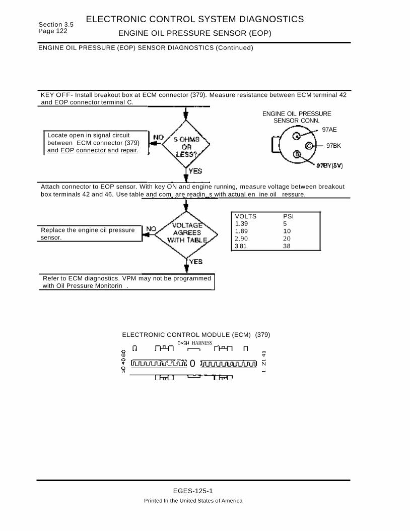
Section 3.5Page 122
ELECTRONIC CONTROL SYSTEM DIAGNOSTICS
ENGINE OIL PRESSURE SENSOR (EOP)
ENGINE OIL PRESSURE (EOP) SENSOR DIAGNOSTICS (Continued)
KEY OFF- Install breakout box at ECM connector (379). Measure resistance between ECM terminal 42and EOP connector terminal C.
Locate open in signal circuitbetween ECM connector (379)and EOP connector and repair.
ENGINE OIL PRESSURESENSOR CONN.
97AE
97BK
Attach connector to EOP sensor. With key ON and engine running, measure voltage between breakoutbox terminals 42 and 46. Use table and com are readin s with actual en ine oil ressure.
Replace the engine oil pressuresensor.
Refer to ECM diagnostics. VPM may not be programmedwith Oil Pressure Monitorin .
VOLTS PSI1.39 51.89 102.90 203.81 38
ELECTRONIC CONTROL MODULE (ECM) (379)DASH HARNESS
g ;
~ IiLfUiJiJULn:Ji 0 lJUUUUUiJUl1lil NN ~
EGES-125-1Printed In the United States of America
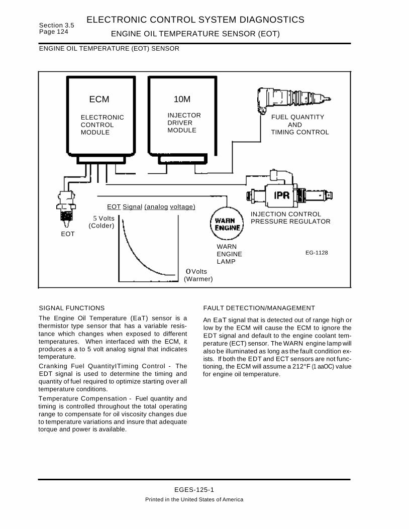
Section 3.5Page 124
ELECTRONIC CONTROL SYSTEM DIAGNOSTICS
ENGINE OIL TEMPERATURE SENSOR (EOT)
ENGINE OIL TEMPERATURE (EOT) SENSOR
ECM
ELECTRONICCONTROLMODULE
10M
INJECTORDRIVERMODULE
FUEL QUANTITYAND
TIMING CONTROL
EOT
EOT Signal (analog voltage)
5 Volts(Colder)
oVolts(Warmer)
WARNENGINELAMP
INJECTION CONTROLPRESSURE REGULATOR
EG-1128
SIGNAL FUNCTIONS
The Engine Oil Temperature (EaT) sensor is athermistor type sensor that has a variable resistance which changes when exposed to differenttemperatures. When interfaced with the ECM, itproduces a a to 5 volt analog signal that indicatestemperature.
Cranking Fuel QuantityITiming Control - TheEDT signal is used to determine the timing andquantity of fuel required to optimize starting over alltemperature conditions.
Temperature Compensation - Fuel quantity andtiming is controlled throughout the total operatingrange to compensate for oil viscosity changes dueto temperature variations and insure that adequatetorque and power is available.
FAULT DETECTION/MANAGEMENT
An EaT signal that is detected out of range high orlow by the ECM will cause the ECM to ignore theEDT signal and default to the engine coolant temperature (ECT) sensor. The WARN engine lamp willalso be illuminated as long as the fault condition exists. If both the EDT and ECT sensors are not functioning, the ECM will assume a 212°F (1 aaOC) valuefor engine oil temperature.
EGES-125-1
Printed in the United States of America

ELECTRONIC CONTROL SYSTEM DIAGNOSTICS
ENGINE OIL TEMPERATURE SENSOR (EOT)Section 3.5
Page 125
Engine OilTemperature Sensor
(EOT)
Fault Codes:
311 Out of Range Low
312 Out of Range High
(a)
SensorConnector
A
B
SensorHarnessConnector
5
14
EOTSignal
Deutsch Connector(On Valve Cover)
Signal Ground
EG-1129
ECMConnector
After removing connectors always check for damaged pins. corrosion. loose terminals etc.Connector Checks to Chassis Ground
(Check with Sensor Connector Disconnected and Ignition key off, all accessories off)
Test Points Spec. Comments
A to Grd. < 5 ohms Resistance 10 chassis ground, check with key OFF, if > 5 ohms the harness is open.
S to Grd. > 1000 ohms Resistance less than 1000 ohms indicates a short to ground.
Connector Voltage Checks(Check with sensor Connector Disconnected and Ignition Key On)
Test Points Spec. Comments
8 to Grd. 4.8 - 5.0v Pull up voltage, if no or low voltage, circuit has open or high resistance or short ground.
A to Grd. 0- .25v If greater than .25 volts, signal ground wire is shorted to V Ref. or battery
Harness Resistance Checks(Check with breakout box installed on engine harness only)
Test Points Spec. Comments
#46 to A < 5 ohms Resistance from harness connector to 60 pin connector - Signal ground
#14 to B < 5 ohms Resistance from harness connector to 60 pin connector - EDT Signal
Test Points Operational Voltage Checks(+) #14 to (-) #46 (Check with breakout box installed in line with the ECM)Voltage Temp. 0 F Temp. 0 C Resistance Comments
0.53 v 248 120 1.19 K ohms
0.96 v 205 96 2 K ohms1.37v 176 80 3.84 K ohms
4.37v 32 0 69.2 K ohms
4.60 v -5 -20 131.0 K ohms
Fault Code DescriptionsCircuit Faults:311 =Signal was less than 0.2 volts for more than 0.1 seconds.
312 =Signal voltage was greater than 4.8 volts for more than 0.1 seconds.
EGES-125-1
Printed In the United States of America

Section 3.5Page 126
ELECTRONIC CONTROL SYSTEM DIAGNOSTICS
ENGINE OIL TEMPERATURE SENSOR (EOT)
ENGINE OIL TEMPERATURE SENSOREXTENDED SYSTEM DESCRIPTION
FUNCTION
The Navistar engine control system includes an Engine Oil Temperature (EaT) sensor. The ECM monitors engine oil temperature via the EaT sensor signal to control fuel quantity and timing throughout theoperating range of the engine. The EOT signal allows the ECM to compensate for oil viscosity variations due to temperature changes in the operatingenvironment. This insures that adequate power andtorque are available under all operating conditions.
OPERATION
The Engine Oil Temperature Sensor is a thermistortype sensor which changes resistance when exposed to different oil temperatures.
When the temperature of the oil is decreased the resistance of the thermistor increases which causesthe signal voltage to increase. As the temperatureof the oil is increased, the resistance of the thermistor decreases, causing the signal voltage to decrease.
The EDT sensor is supplied a regulated 5 volt reference signal at terminal 8 from ECM terminal 14. Areturn circuit (ground) is supplied at terminal A fromECM terminal 46. As the oil temperature increasesor decreases, the sensor changes resistance andprovides the ECM with the oil temperature signalvoltage at terminal 14. This signal voltage is thenread by the ECM to determine the temperature ofthe oil.
ECM DIAGNOSTICS
With the ignition key "ON", the ECM continuouslymonitors the EOT signal to determine if it is withinexpected values. If the signal voltage is above orbelow the expected levels, the ECM will set a faultcode.
If the ECM detects a fault, it will use the value of theEngine Coolant Temperature signal, in place of theEDT signal. If the ECT sensor is not sending a cor-
rect signal, the ECM will default to -4°F (-20°C) forstarting or 212°F (100°C) for engine running operation.
EOT sensor faults can be retrieved using the Electronic Service Tool or by reading the flash codesfrom the warning light using the STI diagnosticswitch located on the vehicle dash. If the ignitionkey is shut off, the code will become an Inactivecode. EaT codes will cause the Engine Warninglight to be illuminated.
FLASH CODE 311ATA CODE PID 175 FMI 4ENGINE OIL TEMPERATURE SIGNAL OUT OFRANGE LOW
Code 311 out of range low, will be set if the signalvoltage was less than 0.2 volts for more than 0.1 seconds. If this code is set, the ECM will default toECTtemperature or a default value of-4°F (-20°C)for starting or 212°F (100°C) for engine running operation. This code will cause the ECM to illuminatethe Engine Warning light.
Code 311 may be set due to a short to ground in thesignal circuit or a defective sensor.
FLASH CODE 312ATA CODE PID 175 FMI 3ENGINE OIL TEMPERATURE SIGNAL OUT OFRANGE HIGH
Code 312 out of range high,will be set if the signalvoltage is more than 4.8 volts for more than 0.1 seconds. If this code is set, the ECM will default toECT temperature or a default value of -4°F (-20°C)for starting or 212°F (1 aaOC) for engine running operation. This code will cause the ECM to illuminatethe Engine Warning light.
Code 312 may be set due to an open signal circuitbetween the ECM and the sensorora short to a voltage source. A defective sensor may also causecode 312 to be set.
EGES-125-1Printed In the United States of America

ELECTRONIC CONTROL SYSTEM DIAGNOSTICS
ENGINE OIL TEMPERATURE SENSOR (EOT)Section 3.5
Page 127
SENSOR CIRCUIT DIAGRAM
3-4
A -.-A F5
15A8e
KEY SWITCHJGN (24)
~«:It:(t)o..,....!
---__ 84*
82*
* SPLICESHOWN (2)PLACES
97CZ
97BH
97CE
97BG
97CY 5V
97BF
5
28
24
97BF 16
A K>--a.I"jl...1lolll.L - 97-Z--t-<+-14_+_-
A <> 97GW
B 97BF
27 97BEC 1C.>------w.I.'"""""------I-<4~~~
26A 1:>-__--¥.&...-..z... +-<4~-
B
(405)CAMSHAFT POSITION
SENSOR
ENGINE OIL TEMPSENSOR
A 97GU
INJECTION CONTROLPRESSURE SENSOR
BI(>--~~--I
ENGINE COOLANTTEMP SENSOR
S2*
A ~>-9,;;;",,;,7..;..;A~E--+-<~+-----.;9;..;.7.;..;;.AE~ _
C 1(')-....9....;;7B;;...;..K.o....+.-<~01----.;;9...;;.,7~BK~
ENGINE OILPRESSURE SENSOR
(50 PSI SW WITH ENGINE WARNINGOR ENGINE PROTECTION SYSTEMONLY)
S4*
INJECTION PRESSUREREGULATOR VALVE
(405)
13 97BP-----+-~*-I--~rlllA
wmf'.en
97BH
25B
ECM(379)
a.ow
a.~o
0... LL ~ t-- 0 a::UWOUZ Q:
a: w w C)> (!)
........tf)
NOTE: (405)SHOWNTWOPLACES
EGES-125-1
PrInted In the United States of America

Section 3.5Page 128
ELECTRONIC CONTROL SYSTEM DIAGNOSTICS
ENGINE OIL TEMPERATURE SENSOR (EOT)
ENGINE OIL TEMPERATURE (EOT) SENSOR DIAGNOSTICS
Refer to circuit diagramon page 127.
97GU
97CE
KEY OFF- Remove connector from EOT Sensor. Measure resistance to ground at terminal A.
ENGINE OILTEMPERATURESENSOR CONN.
KEY OFF- At EOT connector measure resistance to ground at terminal B.
Locate short to ground in signalcircuit and re air.
KEY ON- At EOT connector measure voltage to ground at terminal B.
Locate cause of HIGH resistancein signal circuit betweenconnector (379) and EOTconnector, then re air.
KEY OFF-Install breakout box at ECM connector (379).Measure resistance between terminal 14 and EOTconnector terminal B.
!Replace the EDT sensor. I
Install breakout box at ECM connector(379). KEY ON- Measure voltage toground at terminal 14.
Locate open in signal circuit betweenconnector (379) and EOT connectorand repair.
EGES-125-1
Printed in the United States of America

Section 3.5 ELECTRONIC CONTROL SYSTEM DIAGNOSTICSPage 130 EXHAUST BACK PRESSURE REGULATOR (EPR)
EXHAUST BACK PRESSURE (EPR) REGULATOR
ECM
EPRExhaust Back Pressure Regulator
Output Signal
ELECTRONICCONTROLMODULE
12 Volts
Duty Cycle Controlled
EBPEXHAUST
BACK PRESSURESENSOR
IAT ECTINTAKE AIR ENGINE
TEMPERATURE COOLANTSENSOR TEMPERATURE
SENSOR
EXHAUST BACK PRESSUREREGULATOR
Ii APOWER IGROUND -L
EXHAUSTBACKPRESSUREVALVE
EG1130
OUTPUT FUNCTIONS
Exhaust Back Pressure Regulator -Is a variableposition valve that controls exhaust back pressureduring cold ambient temperatures to increase cabheat and decrease the amount of time needed to defrost the windshield. The ECM uses the measuredexhaust back pressure, (ambient) intake air temperature, engine coolant temperature and engine loadto determine the desired exhaust back pressure.Valve position is controlled by switching the outputsignal circuit to 12 volts inside the ECM. On/off timeis modulated from 0 to 99 % dependent upon the exhaust back pressure desired.
FAULT DETECTION/MANAGEMENT
An open or shorted to ground control circuit can bedetected by an on demand output circuit check performed during the engine off test.
Problems with either the Exhaust Back PressureDevice or the tube between the exhaust manifoldand the EBP sensor can be detected during the exhaust back pressure step test, in which the ECMcommands and then measures a specific preprogrammed pressure then measures time for pressure decay during the engine running test.
If the ECM detects an EBP or IAT sensor fault it willdisable the exhaust back pressure regulator.
EGES-125-1
Printed in the United States of America

ELECTRONIC CONTROL SYSTEM DIAGNOSTICS
EXHAUST BACK PRESSURE REGULATOR (EPR)Section 3.5
Page 131
EG-1131
(b)
Fault Codes:
245 Output Circuit Check343 Excessive Back Pressure351 EPR below expected352 EPR Step Test Fail
B
Regulator Harness RegulatorConnector Connector (a)
A
B A
EPR Control
(Overlay Harness)PWR Ground
<-----L-(-G-IO-W-PI-U-g-R-ellllllllli;;lay"'
-- Mounting Bolt)
l-I---------..-.c..~~----............
Exhaust Back PressureRegulator(EPR)
ECMConnector
After removing connector always check for damaged pins, corrosion, loose terminals etc.
Connector Checks to Chassis Ground(Check with Regulator Connector Disconnected, Ignition off, all accessories off~)
Test Points Spec. Comments
A to Grd. < 5 ohms Resistance greater than 5 ohms indicates an open circuit or bad ground.
S to Grd. > 1000 ohms Resistance less than 1000 ohms indicates a short to ground.
Harness Resistance Checks(Check with breakout box installed on engine harness only)
Test Points Spec. Comments
Pwr. Grd. to 2.5 to 20 Resistance through EPR circuit including regulator, check w/regulator connectorPin #11 ohms connected (unnecessarv to check next points if okay).A to Grd. < 5 ohms Resistance from regulator connector to Pwr. Ground.
S to #11 < 5 ohms Resistance from regulator connector to 60 pin connector.
Circuit Fault Code Descriptions245 = Output circuit check detected during Standard test, indicates high or low resistance in circuit.
Exhaust Back Pressure System Fault Code Descriptions343 = EPR pressure was greater than 77 in. Hg. (260 kpaG) for 3 seconds. (3.3 volts)351 = Exhaust backpressure is below 29.61 in. Hg. (20 kPaG) for 2.5 seconds (1.19 volts)
at engine speeds greater than 2300 RPM (possible plugged line)352 = Indicates that EPR pressure of 22 in. Hg. (75 kPa) commanded during ESP engine running
test was not obtained. (Plugged line or exhaust back pressure device failure.)
EGES-125-1Printed In the United States of America
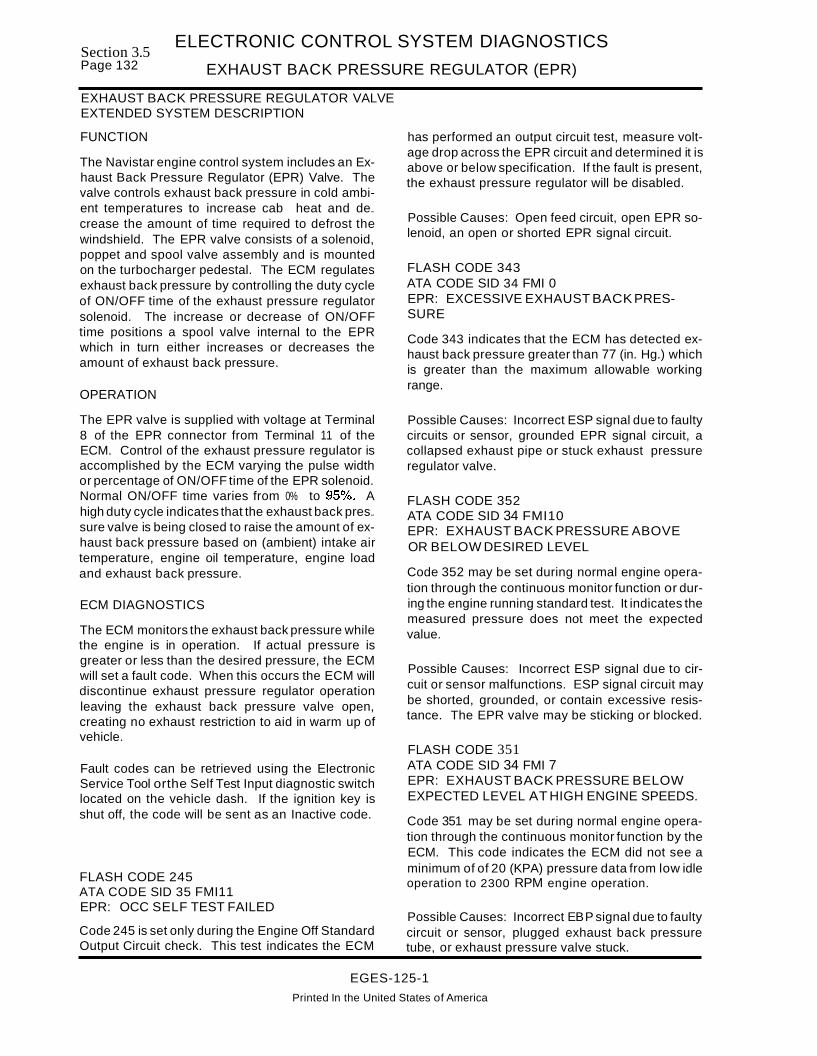
Section 3.5Page 132
ELECTRONIC CONTROL SYSTEM DIAGNOSTICS
EXHAUST BACK PRESSURE REGULATOR (EPR)
EXHAUST BACK PRESSURE REGULATOR VALVEEXTENDED SYSTEM DESCRIPTION
FUNCTION
The Navistar engine control system includes an Exhaust Back Pressure Regulator (EPR) Valve. Thevalve controls exhaust back pressure in cold ambient temperatures to increase cab heat and de...crease the amount of time required to defrost thewindshield. The EPR valve consists of a solenoid,poppet and spool valve assembly and is mountedon the turbocharger pedestal. The ECM regulatesexhaust back pressure by controlling the duty cycleof ON/OFF time of the exhaust pressure regulatorsolenoid. The increase or decrease of ON/OFFtime positions a spool valve internal to the EPRwhich in turn either increases or decreases theamount of exhaust back pressure.
OPERATION
The EPR valve is supplied with voltage at Terminal8 of the EPR connector from Terminal 11 of theECM. Control of the exhaust pressure regulator isaccomplished by the ECM varying the pulse widthor percentage of ON/OFF time of the EPR solenoid.Normal ON/OFF time varies from 0% to 95°.lc>. Ahigh duty cycle indicates that the exhaust back pres...sure valve is being closed to raise the amount of exhaust back pressure based on (ambient) intake airtemperature, engine oil temperature, engine loadand exhaust back pressure.
ECM DIAGNOSTICS
The ECM monitors the exhaust back pressure whilethe engine is in operation. If actual pressure isgreater or less than the desired pressure, the ECMwill set a fault code. When this occurs the ECM willdiscontinue exhaust pressure regulator operationleaving the exhaust back pressure valve open,creating no exhaust restriction to aid in warm up ofvehicle.
Fault codes can be retrieved using the ElectronicService Tool orthe Self Test Input diagnostic switchlocated on the vehicle dash. If the ignition key isshut off, the code will be sent as an Inactive code.
FLASH CODE 245ATA CODE SID 35 FMI11EPR: OCC SELF TEST FAILED
Code 245 is set only during the Engine Off StandardOutput Circuit check. This test indicates the ECM
has performed an output circuit test, measure voltage drop across the EPR circuit and determined it isabove or below specification. If the fault is present,the exhaust pressure regulator will be disabled.
Possible Causes: Open feed circuit, open EPR solenoid, an open or shorted EPR signal circuit.
FLASH CODE 343ATA CODE SID 34 FMI 0EPR: EXCESSIVE EXHAUST BACK PRESSURE
Code 343 indicates that the ECM has detected exhaust back pressure greater than 77 (in. Hg.) whichis greater than the maximum allowable workingrange.
Possible Causes: Incorrect ESP signal due to faultycircuits or sensor, grounded EPR signal circuit, acollapsed exhaust pipe or stuck exhaust pressureregulator valve.
FLASH CODE 352ATA CODE SID 34 FMI10EPR: EXHAUST BACK PRESSURE ABOVEOR BELOW DESIRED LEVEL
Code 352 may be set during normal engine operation through the continuous monitor function or during the engine running standard test. It indicates themeasured pressure does not meet the expectedvalue.
Possible Causes: Incorrect ESP signal due to circuit or sensor malfunctions. ESP signal circuit maybe shorted, grounded, or contain excessive resistance. The EPR valve may be sticking or blocked.
FLASH CODE 351ATA CODE SID 34 FMI 7EPR: EXHAUST BACK PRESSURE BELOWEXPECTED LEVEL AT HIGH ENGINE SPEEDS.
Code 351 may be set during normal engine operation through the continuous monitor function by theECM. This code indicates the ECM did not see aminimum of of 20 (KPA) pressure data from low idleoperation to 2300 RPM engine operation.
Possible Causes: Incorrect EBP signal due to faultycircuit or sensor, plugged exhaust back pressuretube, or exhaust pressure valve stuck.
EGES-125-1
Printed In the United States of America

Section 3.5Page 134
ELECTRONIC CONTROL SYSTEM DIAGNOSTICS
GLOW PLUG CONTROLLER (GPC)
GLOW PLUG CONTROL
ECM
GLOWPLUGRELAY
IGNITION----- SWITCH
BATTERY VOLTAGE(FROM STARTER SOLENOID)
1
WAITLAMP
BAROMETRICPRESSURESENSOR(BARO)
ENGINE COOLANTTEMPERATURE SENSOR
(ECT)
ELECTRONICCONTROLMODULE
EG·3138
BATTERYVOLTAGE EG-1132
OUTPUT FUNCTIONS
Glow Plug Relay - Controls the current flow to theglow plugs. Glow plug relay "ON" time is controlledby the ECM and is a function of engine coolant tem~perature, barometric pressure and battery voltage."ON" time normally varies between 10 to 120 seconds. The glow plugs are self limiting glow plugsanddo not require to be cycled on and off. (The glowplug relay will only cycle on and off repeatedly whenthere is a system voltage condition greater than13.0 volts.)
Glow Plug Wait Lamp - Lamp that indicates to theoperator when the glow plugs have been on longenough to crank the engine. It is controlled by the
ECM. Wait light on time is a function of engine coolant temperature, barometric pressure and batteryvoltage. "ON" time normally varies between 2 to 10seconds. (NOTE: Wait light on time is independent from glow plug relay on time).
FAULT DETECTION/MANAGEMENT
An open or shorted to ground glow plug relay or waitlamp circuit can be detected by an on demand output circuit check performed during the engine offtests.
Glow plug and glow plug harness problems can notbe detected by the ECM.
EGES-125-1
Printed in the United States of America

ELECTRONIC CONTROL SYSTEM DIAGNOSTICS
GLOW PLUG CONTROLLER (GPC)Section 3.5
Page 135
Pin #58-0
Fault Codes:251 GP Relay DCC Check252 GP Lamp DCC Check
DeutschConnector(On Cowl)
Pin#13 8f)- - - • - - 26 - - - - -Q
Glow Plug Lamp T(Control) KEYPWR
ECMConnector
DeutschConnector
(On Valve Cover)
Do
Glow Plug System
GLOW PLUG FEED
E D C B A E D C B A Engine~ ~"""'-+---Harness~ ~ Connector
Cyl. 2&4 Cyl. 6&8(e) (d)(c) (b)(a) (e) (d) (c) (b)(a) Valve
:A E---3 E---~.-...-.-cover: D D. Connector(s)_ ~12.w_pUlQ.(!c!1lc.2".1"~ ••1
CAUTION!DO NOT PERFORMVOLTAGE CHECKSWITH THE ENGINE
RUNNING
INJECTOR SOLENOIDOPERATING VOLTAGE115 V DC. @ 10 AMPSPRESENT ON INJECTORCIRCUITS.
EG-1133
Glow Plug Relay Operation (Voltage Checks)
Test Points Spec. Comments
B+ terminal B+ Relay switch power, B+ should be present at all times (terminal with single 6 gaugeto ground wire). Check connection at starter or fusible links if no power (voltage) present.
Glow Plug B+ Glow plug feed voltage should be present 10 to 120 sec. after key is cycled on, dependentFeed to Grd. upon battery voltage, barometric pressure (altitude) and engine coolant temperature.
B to Ground B+ Relay coil power. Voltage should be present when ign. key is ON - Check fuse if no voltage.
Pin # 58Ov / 12v Glow plug control, switched to (grd) by ECM during operation. Ov = relay ON, 12v =relay off.
to Ground
Glow Plug and Harness Operation(Measure glow plug resistance to ground with the pigtail connector installed at the valve cover connector:then measure resistance from the glow plug feed stud to the harness connector.
Test Points
Glow Plug Pigtail Connector to Relay to Harness CommentsNumber Ground (B-) Connector
Spec <.1 to 6 Ohm < 6 Ohms Relay to Harness Connector#1 NOTE: ALL ENGINE HARNESS CONNECTORS FOR GLOW
PLUG/INJECTORS SHOULD BE DISCONNECTED BEFORE#3 TAKING MEASUREMENTS
#5 High resistance could indicate an open circuit in the engine#7 harness between the glow plug connector and the relay.
#2 Pigtail Connector to Ground B-#4 High resistance could indicate an open circuit in the
#6UVC (under the valve cover) harness or in the glow plug.
Glow plug resistance should measure .1 to 6 ohms#8 dependent upon enqine temperature.
Fault Code Descriptions251 =OCC CHK periormed by ECM during engine off test. Indicates high or low resistance in GP coil circuit.252 =OCC CHK periormed by ECM during engine off test. Indicates high or low resistance in GP lamp circuit.
EGES-125-1
Printed in the United States of America

Section 3.5Page 136
ELECTRONIC CONTROL SYSTEM DIAGNOSTICS
GLOW PLUG CONTROLLER (GPC)
GLOW PLUG SYSTEMEXTENDED SYSTEM DESCRIPTION
FUNCTION
The Navistar engine control system includesa GlowPlug Control System that controls the current flow tothe glow plugs. Glow plug relay "ON" time is controlled by the ECM and is a function of Engine Coolant Temperature, Barometric Pressure, and BatteryVoltage. Glow plug "ON" time varies between10-120 seconds. Glow plugs are self limiting glowplugs and do not require to be cycled on and off. Theglow plug relay will cycle on and off repeatedly, ifbattery voltage is greater than 13.0 volts.
OPERATION
Refer to circuit diagram on page 135 for the following discussion.
Glow Plug System operation is dependent upon engine coolant temperature, barometric pressure andbattery voltage. When the ignition switch is placedin the "ON" position,Terminal B (coil side) of the glowplug relay is supplied with battery voltage. TerminalA (coil side) of the relay is connected to Terminal 58of the ECM. The ECM supplies battery ground tothe glow plug relay coil via an internal drivertransistor when coolant temperature, barometric pressureand battery voltage conditions require the glow plugsystem to warm the engine for starting.
Applying ground (8-) to terminal Acauses the relayto switch and apply battery voltage (present at thelarge terminal containing a single wire leading toand connected to the 8+ terminal of the starter solenoid) to the other large terminal which contains twowires. These wires now supply battery power to theglow plugs in the right and left cylinder heads.
The Glow Plug Wait Lamp is also turned on by theECM when the glow plug relay is enabled.
(NOTE: WAIT LIGHT ON TIME IS INDEPENDENTFROM GLOW PLUG RELAY ON TIME).
ECM DIAGNOSTICS
The ECM does not continuously monitor the glowplug control circuitry. An open or shorted to groundglow plug control relay on the control side (coil) circuit can be detected by an on demand output circuitcheck performed during the engine off test.
Fault codes can be retrieved using the electronicservice tool or the STI Self Test Input DiagnosticSwitch located on the vehicle dashboard. If the ignition key is shutoff, the code will be stored as an active code.
FLASH CODE 251ATA CODE SID 38 FMI11GPC: DCC SELF TEST FAILED
Code 251 is set only during the Engine Off StandardOutput Circuit check. This indicates that the ECMhas performed an output circuit test, measured thevoltage drop across the glow plug relay circuit anddetermined it is above or below specification. If thefault is present, the glow plug relay is not operatingand the glow plugs are not enabled.
Possible Causes: Open feed circuit, open glow plugrelay coil, an open or shorted GPC signal circuit.
FLASH CODE 252ATA CODE SID 36 FMI11GLOW PLUG LAMP: Dec SELF TEST FAILED
Code 252 is set only during the Engine Off StandardOutput Circuit check. This indicates that the ECMhas performed an output circuit test, measured thevoltage drop across the glow plug Wait Lamp circuitand determined it is above or below specification.
Possible Causes: Glow plug Wait Lamp burned out,open or shorted glow plug Wait Lamp circuit.
EGES-125-1
Printed In the United States of America

Section 3.5Page 138
ELECTRONIC CONTROL SYSTEM DIAGNOSTICS
INTAKE AIR TEMPERATURE SENSOR (IAT)
INTAKE AIR TEMPERATURE (IAT) SENSOR
ECM
ELECTRONICCONTROLMODULE
10M
INJECTORDRIVERMODULE
...
I I
IAT
IAT Signal (analog voltage)
5 Volts(Colder)
EXHAUSTBACKPRESSUREREGULATOR
EXHAUSTBACKPRESSUREVALVE
oVolts"'--------- (Warmer) EG-1134
SIGNAL FUNCTIONS
The Intake Air Temperature (IAT) sensor is a thermistor type sensor that has a variable resistance thatchanges when exposed to different temperatures.When interfaced with the ECM it produces a 0-5 voltanalog signal that will deduce temperature.
Exhaust Back Pressure Device - The IAT sensor's primary function is to measure intake air temperature in order to determine when the exhaustback pressure function is needed.
FAULT DETECTION/MANAGEMENT
An IAT signal that is detected out of range high orlow by the ECM will cause the engine to ignore the(AT signal, disable exhaust back pressure operationand assume an ambient temperature of 59° F (15 0
C).
EGES-125-1Printed in the United States of America

ELECTRONIC CONTROL SYSTEM DIAGNOSTICS
INTAKE AIR TEMPERATURE SENSOR (IAT)Section 3.5
Page 139
Intake AirTemperature Sensor
(IAT)
ECMConnector
Signal Ground
IAT Signal
EG-1135
SensorHarnessConnector
A
B
Fault Codes:
154 Out of Range Low155 Out of Range High
SensorConnector
(a)
After removing connectors always check for damaged pins, corrosion, loose terminals etc.Connector Checks to Chassis Ground
(Check with Sensor Connector Disconnected and Ignition key off, all accessories off)
Test Points Spec. Comments
A to Grd. < 5 ohms Resistance to chassis grd, check with key off, if > 5 ohms the harness is open.
8 to Grd. > 1000 ohms Resistance less than 1000 ohms indicates a short to ground.
Connector Voltage Checks(Check with sensor Connector Disconnected and Ignition Key On)
Test Points Spec. Comments
B to Grd. 4.8 - 5.0v Pull up voltage, if no or low voltage, circuit has open or high resistance or short to grd.
A to Grd. 0- .25v If greater than .25 volts, signal wire is shorted to V Ref. or battery
Harness Resistance Checks(Check with breakout box installed on engine harness only)
Test Points Spec. Comments
#46 to A < 5 ohms Resistance from harness connector to 60 pin connector - Signal ground
#25 to B < 5 ohms Resistance from harness connector to 60 pin connector - IAT Signal
Test Points Operational Voltage Checks(+) #25 to (-) #46 (Check with breakout box installed in line with the ECM)
Voltage Temp. 0 F Temp. 0 C Resistance Comments
1.72 v 122 50 10.9 K ohms
3.09 v 68 20 37.34 K ohms
3.897 v 32 0 68.75 K ohms
4.33 v 0 -18 120.9 K ohms
4.537 v -40 -40 194.3 K ohms
Circuit Fault Code DescriptionsCircuit Faults:154 = Signal voltage was less than .127 volts for more than 0.2 seconds.155 = Signal voltage was greater than 4.6 volts for more than 0.2 seconds.
EGES-125-1
Printed in the United States of America

Section 3.5Page 140
ELECTRONIC CONTROL SYSTEM DIAGNOSTICS
INTAKE AIR TEMPERATURE SENSOR (IAT)
INTAKE AIR TEMPERATURE SENSOREXTENDED SYSTEM DESCRIPTION
FUNCTION
The Navistar engine control system includes an Intake Air Temperature Sensor (IAT). The ECM measures the signal from the IAT sensor to determinethe temperature of the air entering the engine. TheECM uses this data to adjust timing and fuel rate forstarting in cold weather to limit smoke emissions.
OPERATION
The Intake Air Temperature Sensor is a thermistortype sensor which changes resistance when exposed to different air temperatures.
When the temperature of the intake air decreases,the resistance of thermistor increases which causesthe signal voltage to increase. When the air temperature increases, the resistance of the thermistor decreases causing the signal voltage to decrease.
The IAT sensor is supplied a regulated 5 volt reference signal at terminal B from ECM terminal 25. Areturn circuit (ground) is supplied at terminal A fromthe ECM terminal 46. As the air temperature increases or decreases, the sensor changes resis..tance and provides the ECM with the air temperature signal voltage reading at terminal 25.
ECM DIAGNOSTICS
With the ignition key "ON", the ECM continuouslymonitors the IAT signal to determine if it is within expected values. If the signal voltage is above or below the expected levels, the ECM will set a faultcode.
If the IAT sensor is not sending a correct signal, theECM will default to 77°F (25 0 C).
IAT faults can be retrieved using the Electronic Service Tool or by reading the flash codes from thewarning light using the STI diagnostic switch located on the vehicle dash. If the ignition key is shutoff, the code will become an Inactive code. IATcodes will cause the Engine Warning light to be illuminated.
FLASH CODE 154ATA CODE PID 171 FMI4AMBIENT AIR TEMP SIGNAL OUT OF RANGELOW
An out of range low code will be set if the ECM detects the signal voltage to be less than .127 volts formore than 0.2 seconds. If this fault is active, theECM will default to a value of 77°F (25° C) for starting.
Code 154 may be set due to a short to ground in thesignal circuit or a defective sensor.
FLASH CODE 155ATA CODE PID 171 FMI3AMBIENT AIR TEMP SIGNAL OUT OF RANGEHIGH
An out of range high code will be set if the ECM detects the signal voltage to be more than 4.6 volts formore than 0.2 seconds. If this fault is active, theECM will default to a value of 77°F (250 C) for starting.
Code 155 may be set due to an open signal circuitbetween the ECM and the sensor ora short to a voltage source. A defective sensor may also causecode 155 to be set.
EGES-125-1
Printed In the United States of America

ELECTRONIC CONTROL SYSTEM DIAGNOSTICS
INTAKE AIR TEMPERATURE SENSOR (IAT)Section 3.5
Page 141
SENSOR CIRCUIT DIAGRAM
3-4
A - ....A F5
15ABB
KEY SWJTCHIGN (24)
Y<elf«l'¢.,..--
* SPLICESHOWN (2)PLACES97BH
97BG
97CY 5V24
(405)
C f">----...lroU.-Wo.1Io&----...-.<~f__+-
28
27 97BEC ~~--_--w.&.'-'----f-<f~~--:.
26
B
A [:>------"-I-;¥I-I.----+--<4~-
CAMSHAFT POSITIONSENSOR
INJECTION CONTROLPRESSURE SENSOR
B Ie" >----w.a......-....---J
25
INJECTION PRESSUREREGULATOR VALVE
(405)
13 97BPA
INTAKE AIRTEMP
~ SENSOR~ 463 (398)
O)r------I-oCAE-+-[]
97BH~----f--< ~I--------ol( >1 B
><,.....0>
---~ S4*
S2*
97CZ
97CE
97BF
wco,.....0>
5
97BF 16
B 1(>-~.e..__ _..::9~7C=.:E=-+--<~_I_
A K >----w.--..... - 9-7Z--+-<1ifi;.-.4_+__-
c I(>----+-<,~---.....,
A <> 97GW
B 97BF
ENGINE COOLANTTEMP SENSOR
ENGINE OILPRESSURE SENSOR
(50 PSI SW WITH ENGINE WARNINGOR ENGINE PROTECTION SYSTEMONLY)
ENGINE OIL TEMPSENSOR
A 97GU
EC~(379~
a..owa..~()
0.... l.L I- I- 0U W 0 U Z
0::: W W (!)> (!)
.......<.n
EGES-125-1Printed In the United States of America

Section 3.5Page 142
ELECTRONIC CONTROL SYSTEM DIAGNOSTICS
INTAKE AIR TEMPERATURE SENSOR (IAT)
TESTING IAT (INTAKE AIR TEMPERATURE CIRCUITS)
Refer to circuit diagramon page 141.
KEY OFF- Remove connector from IAT sensor. Measure resistance to ground at terminal A.
Locate short to ground in signalcircuit and re air.
Install breakout box at ECM connector(379) and measure voltage at terminal25.
Repair open signal circuitbetween ECM and lAT.
Install breakout box at ECM connector (379).With KEY OFF, measure resistance betweenterminal 25 and IAT
Locate and repair high resistance insi nal circuit between ECM and lAT.
Replace the Intake Air Temperature Sensor.
EGES-125-1
Printed in the United States of America

Section 3.5Page 144
ELECTRONIC CONTROL SYSTEM DIAGNOSTICS
INJECTION CONTROL PRESSURE SENSOR (ICP)
INJECTION CONTROL PRESSURE (ICP) SENSOR
ECM
ELECTRONICCONTROLMODULE
IDM
INJECTORDRIVERMODULE
FUEL QUANTITYAND
TIMING CONTROL
EG-1136WARNENGINELAMP
INJECTION CONTROLPRESSURE REGULATOR
ICP Signal (analog voltage)
5 Volts(More Pressure)
ICP
oVolts(Less Pressure) t'o-------...
SIGNAL FUNCTIONS
The Injection Control Pressure (ICP) sensor is avariable capacitance sensor that when suppliedwith a 5 volt reference signal from the ECM produces a linear analog voltage signal that indicatespressure.
The ICP sensor's primary function is to provide afeedback signal to indicate injection control pressure to enable the ECM to command the correct injector timing and pulse width and the correct injection control pressure for proper fuel delivery at allspeed and load conditions.
FAULT DETECTION/MANAGEMENT
If the ECM detects a malfunctioning ICP sensor, theWARN lamp will illuminate. The ECM will go to openloop control of injection control pressure. (Operatefrom an estimated rcp pressure.)
EGES-125-1
Printed in the United States of America

ELECTRONIC CONTROL SYSTEM DIAGNOSTICS
INJECTION CONTROL PRESSURE SENSOR (ICP)Section 3.5
Page 145
Sensor Connector
~(a)
(b) (c)
Fault Codes:
124 Out of Range Low
125 Out of Range High
332 Signal Above Spec. wlEng. Off
Sensor Harness
Deutsch Connector
(On Valve Cover)
Injection Control Pressure
Sensor
(ICP)
EG-1137
ECMConnector
r"'" Signal_Ground Connector
Pin # 46 15 - - A
Pin#270ICP Signal
28 CV Ref _ - BPin#260 24
\.. ~
After removing connector always check for damaged pins. corrosion. loose terminals etc.
Connector Checks to Chassis Ground(Check with Sensor Connector Disconnected and Ignition key off, all accessories off)
Test Points Spec. Comments
A to Grd. < 5 ohms Resistance to chassis ground check with key off, if > than 5 ohms harness is open.
8 to Grd. > 1000 ohms Resistance less than 1000 ohms indicates a short to ground.
C to Grd. > 1000 ohms Resistance less than 1000 ohms indicates a short to ground.
Connector Voltage Checks(Check with sensor Connector Disconnected and Ignition Key On)
Test Points Spec. Comments
8 to Grd. 5 volts ± .5 V Ref. check with key ON, if voltage not in spec., see V Ref circuit.
C to Grd. 0-.25 v If greater than .25 volts, signal wire is shorted to V Ref. or battery
Harness Resistance Checks(Check with breakout box installed on engine harness only)
Test Points Spec. Comments
#46 to A < 5 ohms Resistance from sensor connector to 60 pin connector - Signal ground
#26 to 8 < 5 ohms Resistance from sensor connector to 60 pin connector - V Ref#27 to C < 5 ohms Resistance from sensor connector to 60 pin connector - ICP signal
Test Points I °eerational Voltage Checks(+) #27 to (-) #46 (Check with brea out box installed in line with the ECM)
Voltage PSI MPA Comments
.15 - .25 v 0 0 Atmospheric Pressure with Key ON and Engine OFF. (Altitude dependent)1.0 v 580 4 Minimum required at engine cranking speed 130 RPM
.66 - .86 v 400-480 2.7-3.3 Normal warm idle voltage signal
3.66 v 2520 17.4 Snap accel or full load pressure signal
Circuit Faults: Fault Code Descriptions
124 = Signal voltage was less than .039 volts for more than 1.0 seconds.125 = Signal voltage was greater than 4.90 volts for more than 1.0 seconds.332 = Signal above 1.625 volts with engine off. (1160 psi, 8 MPa)
EGES-125-1
Printed In the United States of America
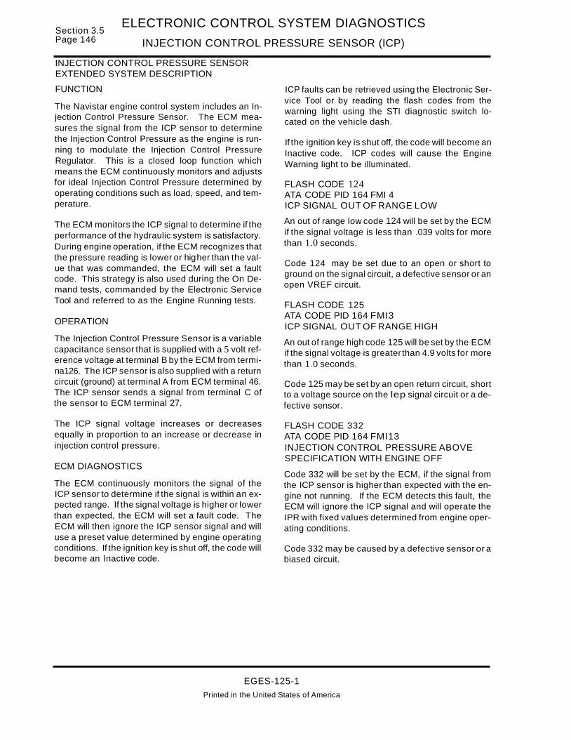
Section 3.5Page 146
ELECTRONIC CONTROL SYSTEM DIAGNOSTICS
INJECTION CONTROL PRESSURE SENSOR (ICP)
INJECTION CONTROL PRESSURE SENSOREXTENDED SYSTEM DESCRIPTION
FUNCTION
The Navistar engine control system includes an Injection Control Pressure Sensor. The ECM measures the signal from the ICP sensor to determinethe Injection Control Pressure as the engine is running to modulate the Injection Control PressureRegulator. This is a closed loop function whichmeans the ECM continuously monitors and adjustsfor ideal Injection Control Pressure determined byoperating conditions such as load, speed, and temperature.
The ECM monitors the ICP signal to determine if theperformance of the hydraulic system is satisfactory.During engine operation, if the ECM recognizes thatthe pressure reading is lower or higher than the value that was commanded, the ECM will set a faultcode. This strategy is also used during the On Demand tests, commanded by the Electronic ServiceTool and referred to as the Engine Running tests.
OPERATION
The Injection Control Pressure Sensor is a variablecapacitance sensor that is supplied with a 5 volt reference voltage at terminal B by the ECM from termina126. The ICP sensor is also supplied with a returncircuit (ground) at terminal A from ECM terminal 46.The ICP sensor sends a signal from terminal C ofthe sensor to ECM terminal 27.
The ICP signal voltage increases or decreasesequally in proportion to an increase or decrease ininjection control pressure.
ECM DIAGNOSTICS
The ECM continuously monitors the signal of theICP sensor to determine if the signal is within an expected range. If the signal voltage is higher or lowerthan expected, the ECM will set a fault code. TheECM will then ignore the ICP sensor signal and willuse a preset value determined by engine operatingconditions. If the ignition key is shut off, the code willbecome an Inactive code.
ICP faults can be retrieved using the Electronic Service Tool or by reading the flash codes from thewarning light using the STI diagnostic switch located on the vehicle dash.
If the ignition key is shut off, the code will become anInactive code. ICP codes will cause the EngineWarning light to be illuminated.
FLASH CODE 124ATA CODE PID 164 FMI 4ICP SIGNAL OUT OF RANGE LOW
An out of range low code 124 will be set by the ECMif the signal voltage is less than .039 volts for morethan 1.0 seconds.
Code 124 may be set due to an open or short toground on the signal circuit, a defective sensor or anopen VREF circuit.
FLASH CODE 125ATA CODE PID 164 FMI3ICP SIGNAL OUT OF RANGE HIGH
An out of range high code 125 will be set by the ECMif the signal voltage is greater than 4.9 volts for morethan 1.0 seconds.
Code 125 may be set by an open return circuit, shortto a voltage source on the lep signal circuit or a defective sensor.
FLASH CODE 332ATA CODE PID 164 FMI13INJECTION CONTROL PRESSURE ABOVESPECIFICATION WITH ENGINE OFF
Code 332 will be set by the ECM, if the signal fromthe ICP sensor is higher than expected with the engine not running. If the ECM detects this fault, theECM will ignore the ICP signal and will operate theIPR with fixed values determined from engine operating conditions.
Code 332 may be caused by a defective sensor or abiased circuit.
EGES-125-1
Printed in the United States of America

ELECTRONIC CONTROL SYSTEM DIAGNOSTICSINJECTION CONTROL PRESSURE SENSOR (ICP)
Section 3.5Page 147
SENSOR CIRCUIT DIAGRAM
B
KEY SW1TCHIGN (24)
Y«~(t)~,....-
><......0>
---- 84*
S2*
* SPLICESHOWN (2)PLACES97BH
97CZ
97CY 5V
97eE
97BG
97BF
14
5
24
97BF 16
97Z
(405)
B
A r:>-----"-'-~---01__<4~-
C f">----..w.I...Ioo~--_+__<+-_t__-
28
CAMSHAFT POSITIONSENSOR
27 97BEC ~"' --w...Io +-<.:"'-+ --:.
26
"0 97GW
B 97BF
ENGINE COOLANTTEMP SENSOR
ENGINE OILTEMP SENSOR
" 97GU
INJECTION CONTROLPRESSURE SENSOR
B Ie >----w..&-..............--l
S2*
S4*" [:>-9,;;",,;,7..;,..,;A=-E--+---<~+--_97AE~ _
c 1C'l-_9_7B_K--+-<~+--_9_7_BK--,
ENGINE OILPRESSURE SENSOR
(50 PSI SW WITH ENGINE WARNINGOR ENGINE PROTECTION SYSTEMONLY)
INJECTION PRESSUREREGULATOR VALVE
(405)
13 97BPa....----'-~E-I--~[)I, A
wen......0>
B
ECM_ J1379;/ ~
aow
coLn
c..~o
r'- CO V" CON N t' ~ N
a.. l.L t- t- 0 a::UWOUz c..
0::: W W (!)> (!)
~
(J)
NOTE: (405)SHOWNTWOPLACES
EGES-125-1Printed In the United States of America

Section 3.5Page 148
ELECTRONIC CONTROL SYSTEM DIAGNOSTICS
INJECTION CONTROL PRESSURE SENSOR (ICP)
INJECTION CONTROL PRESSURE (ICP) SENSOR DIAGNOSTICS
Refer to circuit diagramon page 147.
97BG
97ND
KEY OFF- Remove connector from ICP sensor. Measure resistance to ground at terminal A.
INJECTION CONTROLPRESSURE SENSOR
CONN. 97GT
KEY OFF- Measure resistance to ground at terminals Band C.
Locate short to ground in circuitwhere terminal resistance is lessthan 1000 ohms and repair.
KEY ON- At ICP connector measure voltage to ground at terminal B.
Refer to VREF Diagnostics
KEY ON- At ICP connector measure voltage to ground at terminal C and A.
Locate circuit 97BG or 97GTshort to unwanted voltagesource and repair.
r----------,L Conti~ed O~Ne~Page..J
EGES-125-1
Printed in the United States of America

ELECTRONIC CONTROL SYSTEM DIAGNOSTICS
INJECTION CONTROL PRESSURE SENSOR (ICP)
INJECTION CONTROL PRESSURE (ICP) SENSOR DIAGNOSTICS (Continued)
YES
Section 3.5Page 149
KEY OFF- Install breakout box at ECM connector (379). Measure resistance to ground betweenterminal 27 and ICP connector terminal C.
97GVRepair open in signal circuitbetween ECM connectorterminal 27 and ICP connectorterminal C.
INJECTION CONTROLPRESSURE SENSOR
CONN.
97BE
97NF
ELECTRONIC CONTROL MODULE (ECM) (379)DASH HARNESS
EGES-125-1
Printed In the United States of America

Section 3.5 ELECTRONIC CONTROL SYSTEM DIAGNOSTICSPage 150 INJECTOR DRIVER MODULE POWER CIRCUITS (10M PWR)
INJECTOR DRIVE MODULE (10M) POWER SUPPLY
ECM RELAY
a:s:-0-I-
~£Xl
~(f)
a:w~o0->0:W
~en
SW BATT POWER
ENABLE CIRCUITIDMRELAY
87A
SW BATT POWER
oz:::>oa:CJ
oz:::>aa:CJ
ECMELEC
TRONICCONTROLMODULE
CIRCUIT FUNCTIONS
The 10M receives switched 12 volt operating powerwith the key ON from the 10M power relay.
10M SWITCHED POWER
T~rning the key ON energizes the ECM power relaycausing 12 volt battery power to be applied to the10M relay coil. The IDM relay is enabled when thecoil is grounded through ECM terminal 33. With therelay energized (enabled), battery power is appliedto the IDM at terminal 14.
FAULT DETECTION MANAGEMENT
The 10M power circuits are not continuouslymonitored. If the circuit is not operating the enginewill not run. The ECM uses the Output Circuit Check(OCC) initiated during a Standard Test to test the10M relay control coil circuits for opens or shorts(high and low).
On each power up the 10M performs a self check.If internal faults are detected, a fault code will be setduring an Engine Standard Test.
EGES-125-1
Printed in the United States of America

ELECTRONIC CONTROL SYSTEM DIAGNOSTICS
INJECTOR DRIVER MODULE POWER CIRCUITS (10M PWR)Section 3.5
Page 151
Injector Drive Module Power Fault Codes:(10M PWR) 243 10M PWR Relay OCC Fault
522 10M Internal Fault523 10M PWR Voltage Low
NOTE: Verify the ECM is ON (warning light turns on duringself-test when key is turned on) . If the ECM is not receivingpower refer to ECM Power Supply Circuits before performingthis test.
IDM POWER RELAY (396)DASH HARNESS
5
97AG 10M PWR4
CUlT 15A 10M FUSE97CP
SA
IDM PWRRELAY 396)
IGN FROM ECM RELAY 97CT 2
97AH ENABLE CIR-
IDM CONN. (380)
VIGN 14
ECM CONN. (379)
Connector Checks To Chassis Ground
10M Relay removed from (396), 10M disconnected (380) and breakout box installed at ECMconnection (379)
Test Points Spec. Comments
KEVOFF At Connector (396) 10M PWR Relay
#1 to Grd. 12 ± 1.5 volts < less than 10.5 v check connections, if 0 volts check foropen/short to ground or blown fuse
#2 to Grd. ovolts avolts expected with ign. key "OFF".
#4 to Grd. > 1000 ohms < less than 1000 ohms, check for short to ground
#5 to Grd. > 1000 ohms < less than 1000 ohms, check for short to ground
KEVON At Connector (396) 10M PWR Relay
#2 to Grd. 12 ± 1.5 volts < less than 10.5 v check connections, if 0 volts check foropen/short to ground or blown fuse
KEVON At Connector (379) ECM Connector
#33 to 37 12 ± 1.5 volts < less than 10.5 v check connections. ECM is defective or othercondition is causing the ECM not to enable (ground) terminal 33.
KEVON At Connector (396) 10M PWR Relay
#1 to #5 12 ± 1.5 volts < less than 10.5 v check connections, if a volts repair open enablecircuit between connectors (379) and (396)
KEV OFF Test circuit Between Connectors (396) and (380) Relay & 10MConnector
(396) #4 to < 5 ohms Greater than 5 ohms, repair open in ignition circuit. Less than 5(380) #14 ohms, replace the IDM relay or connector (396)
Fault Code Descriptions243 =IDM relay circuit has high or low resistance detected by ECM during an Engine Off Test. {Output Circuit Test}522 =IDM has detected an intemal fault, if no other fault codes present replace 10M.523 =IDM power has been detected low by IDM.
EGES-125-1
Printed In the United States of America

Section 3.5Page 152
ELECTRONIC CONTROL SYSTEM DIAGNOSTICS
INJECTOR DRIVER MODULE POWER CIRCUITS (10M PWR)
INJECTOR DRIVER MODULE POWER CIRCUITSEXTENDED SYSTEM DESCRIPTION
The Injector Oriver Module (10M) Power Relay actsas an ON/OFF switch that the ECM uses to turn the10M on and off.
The ECM uses sensors to monitor Injection ControlPressure and Exhaust Back Pressure parameters.When starting the engine, if the ECM determinesthat any of these parameters are out of safe operating range, the ECM does not enable the 10M PowerRelay, which prevents the engine from starting.
If the engine is started, and parameters are detected out of the safe operating range, the enginewill derate, then disable the 10M Power Relay,which turns the 10M off, causing the engine to shutdown.
With the optional Engine Protection System, theECM also monitors Engine Oil Pressure, CoolantLevel and Temperature sensor information. If theseparameters are out of prescribed limits, the ECM willfirst derate the engine and then turn off the 10M,shutting down the engine.
Refer to the circuit diagram on page 154 for the following discussion.
The 10M PWR relay (396) controls battery power tothe Injector Driver Module (10M) through connector(380) terminal 14. Battery power is available at alltimes to relay connector (396) at terminal 30. Thefeed circuit is protected by 15A, #2 ECM PWR fuse.
When the key switch is turned ON, power from ECMPWR relay (395) is applied to the IDM PWR relaycontrol coil at terminal 85. The 10M relay control coilground circuit (97AH) is connected to ECM connec..tor (379) terminal 33. The ECM switches ECM ter..minal33 between 0 and 12 volts to enable or disable
the IDM relay. When terminal 33 is at 0 volts, the10M relay energizes.
When the 10M PWR relay is energized, battery power passes through the normally open relay contacts(30 to 87) and on circuit 97AG to connector (380)terminal 14 (IDM VIGN). The 10M power ground isfrom IDM terminal 26, through circuits97-GM/97-GMAI 97-GMC/97-GMD/11-G to thenegative battery terminal.
If the IDM is not powered, the engine will not run.
ECM DIAGNOSTICS
The ECM uses the Output Circuit Check (OCC) totest the IDM relay control coil circuit for short circuits(high or low) and opens in the circuit. Use the ProlinkEST to perform the OCC test. When the test is complete, the Prolink will indicate if there were faults detected and what the Flash Code number is.
FLASH CODE 243SID 37 FMI11ECM: IDM _ENABLE DCC FAULT
If the 10M detects a fault in the 10M circuit during theacc test, Flash Code 243 will be set. This indicatesthat circuit 97AH is shorted (high or low) open or nopower is present in circuit 97CT to energize the 10Mrelay.
When Flash Code 243 occurs, it can also causeFlash Codes 253, 523, 541 or 543 to be set. Flashcodes 253, 523, 541, and 543 can be caused byseveral conditions. This section only discusses the10M POWER RELAY circuits that could cause thecodes to set.
EGES-125-1
Printed In the United States of America

ELECTRONIC CONTROL SYSTEM DIAGNOSTICS
INJECTOR DRIVER MODULE POWER CIRCUITS {10M PWR}
ECM DIAGNOSTICS (Continued)
Section 3.5Page 153
FLASH CODE 522SID 233 FMI 12IDM: 10M INTERNAL FAILURE
FLASH CODE 523SID 233 FMI4IDM: 10M POWER VOLTAGE LOW
Code 523 can be caused by:
A. Faulty 10M PWR Relay control circuit (willcause code 243 to set when performing anacc test).
B. Excessive voltage drop in circuit 97AG.
C. Low voltage in 97CP to the 10M PWR Relayfrom #2 ECM fuse.
o. A defective 10M PWR Relay.
TROUBLESHOOTING
The test included in this section systematicallychecks the entire 10M Power Relay System.
If Flash Codes 243, 253, 523, 541 or 543 are active,perform the following test. Refer to the circuit diagram located in this section while using test procedure.
BEFORE TROUBLESHOOTING
Before Performing the test(s) included in this section:
A. Make sure batteries are fully charged! Checkbattery cables and grounds for clean, tightconnections free of damage and corrosion.Voltage tests will give inaccurate readings ifbatteries are not fully charged.
B. Inspect connectors for pushed back, loose ordamaged (spread or bent) terminals, or wireswith cut strands, etc. the wires and connections must be free of damage or corrosion.When some connectors corrode, a light whiteresidue is present that must be removed.
C. Inspect suspect circuit grounds for clean, tightconnections, free of damage.
EGES-125-1
Printed In the United States of America

Section 3.5Page 154
ELECTRONIC CONTROL SYSTEM DIAGNOSTICS
INJECTOR DRIVER MODULE POWER CIRCUITS (10M PWR)
INJECTOR DRIVER MODULE POWER SUPPLY CIRCUIT DIAGRAM
*IDM PWR RELAYTERMINAL NUMBERSREPRESENT THE RELAYNUMBERS NOT CONNECTOR NUMBERS
(426)
(424)
ECM CONN(379)
(412)
97CP
33
#2 ECMFUSE15A
POSITIVE BATTTERMINAL :t
10M-EN
10M PWRRELAY (396)
97AG
...---..-85
10M CONN(380)
Battery Voltage FromHARNESS ECM PWR Relay (395)
CONN(396)
(424)
(426)
NEG BATT TERMINAL
EGES-125-1
Printed in the United States of America

ELECTRONIC CONTROL SYSTEM DIAGNOSTICS
INJECTOR DRIVER MODULE POWER CIRCUITS (10M PWR)Section 3.5
Page 155
TESTING 10M PWR RELAY AND RELATED CIRCUITS
Verify that the ECM is powered. If the ECM is powered, the Engine WarningLight comes on during the Self-Test when the key is turned ON.
TYPICAL AELAYllNSEATlON ENOl
r----------------------------- ..ENERGIZlNG COIL
NORMALL Y CLOSEDCONTACT
NORMALLY OPENCONTACT
~~--- ENERGIZING COIL
I
I
I
I
I
•I
I COMMON.CONT"CT
Refer to (ECM PWR)Section and diagnosethe ECM PowerCircuits.
Connect (+) battery lead to terminal 85and (-) lead to terminal 86.
A. If relay energizes making anaudible click sound, go to step 2.Otherwise replace the relay.
With relay energized, measure resistance between terminals 30 and 87.
A. If resistance is less than 2 ohms,go to step 3. Otherwise replace the :relay. :
•Disconnect battery leads from relay •and measure resistance between :terminals 30 and 87. :
I
A. If resistance is 1OOK ohms or more, •the relay is good. Otherwise re- :place the relay. :
••••••I
•I
I.. J
TESTING HELLA RELAY
: With relay removed:I
I 1.••I
I
I
I,I
I
: 2.I
•II
I
I,I,13.
: See next:page
Remove relay from connector (396) andperform TESTING HELLA RELAY.
Check 15A, #2 ECM Power fuse foropen condition (located at batteries).
Locate cause of NO orLOW voltage in circuit97CP, then correct.
Locate cause of overloadcondition, then correct.Replace 15A fuse.
Yes (Do notinstall
With key OFF, measure voltage to ground relay)at connector (396) terminal 1 (97CP).
EGES-125-1Printed in the United States of America

Section 3.5Page 156
ELECTRONIC CONTROL SYSTEM DIAGNOSTICS
INJECTOR DRIVER MODULE POWER CIRCUITS (10M PWR)
TESTING 10M PWR RELAY AND RELATED CIRCUITS (Continued)
KEY OFF - Remove connectors (379) from ECM and(380) from 10M. Turn key ON and measure voltage toground at connector (396) terminals 4 and 5.
Locate short to "HOT" wire inany circuit with more than 1volt, then correct.
IDM POWER RELAY (396)
DASH HARNESS
KEY OFF- At connector (396) measureresistance to round at terminals 4 &5.
Locate short to ground incircuit where resistance is lessthan 1OOK ohms, then repair.
Locate cause of NO or LOWvoltage in circuit 97CT fromECM power relay, then repair.
Yes
KEY OFF- Measure resistance between connectors396 terminal 4 and 380 terminal 14.
CONNECTOR-leel747C91TERMJNAL- 16616Z7Cl
10M CONNECTOR (380)
I'" 26 40
1 15 27
Locate open or cause of highresistance in circuit 97AG,then re air.
KEY OFF- At 10M connector(380), measure resistance toground at terminal 26.
: See next:page
EGES-125-1Printed In the United States of America

ELECTRONIC CONTROL SYSTEM DIAGNOSTICS
INJECTOR DRIVER MODULE POWER CIRCUITS (10M PWR)Section 3.5
Page 157
TESTING IDM PWR RELAY AND RELATED CIRCUITS (Continued)
CONNECTOR-leel717C91TERMJNAL-J661627Cl
IDM CONNECTOR (380)
IDM POWER RELAY (396)
11 26 .040
I 15 27
ZOlSOI9C1 C~201B349C1 COVER
201 5979C 1 LOCK.50DY
Yes
With key OFF, install breakout box betweenharness connector (379) and ECM. Measureresistance between connector (396) terminal 5(97AH) and breakout box terminal 33.
ECM is not enablingthe 10M PWR relay.
Locate open orcause of highresistance in groundcircuit, then correct.
Locate open orcause of highresistance in circuit97AH, then correct.
Install relay in (396) and connect harness to 10M. With key ON,at breakout box measure volta e between terminals 33 and 60.
10M Power Relay Circuits are performing correctly.
EGES-125-1
Printed In the United States of America

Section 3.5Page 158
ELECTRONIC CONTROL SYSTEM DIAGNOSTICS
INJECTOR DRIVE CIRCUITS (INJ)
INJECTOR DRIVE CIRCUIT OPERATION
ECM
ELECTRONICCONTROLMODULE
10M
INJECTORDRIVERMODULE
WARNENGINELAMP
EG-1138
FUEL QUANTITYAND
TIMING CONTROL
7AMPS
INJECTOR DRIVE SIGNAL
SIGNAL FUNCTIONS
High Side Drive Outputs (Right and Left Bank)The high side drive output function is to supply to theinjectors a power supply of 115 volt DC at a maximum of 10 amps. This power supply is available tothe injectors on a continuous basis.
Low Side Drive Outputs - The low side drive outputs control the injector on time (fuel quantity), timing (in relation to TDC) and sequencing (firing order). The 10M controls (fires) each individualinjector by completing the ground circuit to each injector solenoid. A valid Cylinder Identification (CI)and Fuel Demand Command Signal (FOCS) mustbe sent from the ECM to the 10M before an injectorwill be allowed to fire.
FAULT DETECTION/MANAGEMENT
The Injector Driver Module (IDM) is capable of detecting, while the engine is running individual injector open and shorts to either ground or battery. It isalso capable of detecting right or left bank high sideopens or shorts to ground. A special On-DemandBuzz test will also allow the operator to enable all injector solenoids while the engine is off to verify circuit operation. IDM detected diagnostic faultcodes will not be transmitted if the EF line is notfunctioning, however, the engine will functionnormally.
Ifa short to ground condition is detected on anindividual injector, (low side), the 10M will discontinue the power to the bank with the shortedinjector, enable the WARN engine lamp and operate the engine on four cylinders.
EGES-125-1
Printed In the United States of America

ELECTRONIC CONTROL SYSTEM DIAGNOSTICS
INJECTOR DRIVE CIRCUITS (INJ)Section 3.5
Page 159
Fault Codes:
NOTE: (Last code digit refers to INJ or Bank #)
421-428 High to low side open inj. #1-#8431-438 High to low side short inj. #1-#8441-448 Low side short to B+ inj. #1-#8451-458 Low side short to grd. inj. #1-#8511 Multiple faults on bank #1 (right)512 Multiple faults on bank #2 (left)513 High side open right group514 High side open, left group515 High side #1 (right) short to grd.521 High side #2 (left) short to grd.524 High sides shorted together544 Injector Fault in Bank 2545 Injector Fault in Bank 1
24
oo
IDeutsch ConnectorInjectors (On Valve Cover)
1---------- 2 Low!i£le#1 6
- - -- - - 9 Low~i~e#3 21~arness Low side #5
I Connectors r- -- 8 Low ;ide #7 280Inj I I Inj. Inj I nJ. 19 --# # 7000A B ABO E (Right Side)
.....--.. 3
20 High Side #1
INJECTION DRIVERMODULE CONNECTOR EG-1139
23
a..-_.... 31 Low ~i~e #8 922 Low~~e#6 1930 Low~~e #4 710 Low!i~e#2 22
A CAUTION!
DO NOT PERFORMVOLTAGE CHECKSWITH THE ENGINE
RUNNING
INJECTOR SOLENOIDOPERATING VOLTAGE115 V DC. @ 10 AMPSPRESENT ON INJECTORCIRCUITS.
After removing connectors always check for damaged pins. corrosion. loose terminals etc.NOTE: Test all injector harness and valve cover connectors at Test Points indicated.
E · H C Ch k Ch · G dnglne arness onnector ec to assls rounTest Points Spec. Comments
B > 1000 ohms Injector low side - codes 451-458 may be set if shorted to grd.
C > 1000 ohms Injector power feed high side - codes 515 or 521 may be set if shorted to grd.
D > 1000 ohms Injector low side - codes 451-458 may be set if shorted to grd.
Valve Cover Gasket Connector to Chassis Ground(Check with pigtail connector installed on gasket connector)
Test Points Spec. Comments
B > 1000 ohms Injector low side - codes 451-458 may be set if shorted to grd.
C > 1000 ohms Injector power feed high side - codes 515 or 521 may be set if shorted to grd.
D > 1000 ohms Injector low side - codes 451-458 may be set if shorted to grd.
Under Valve Cover Harness and Injector Solenoid Resistance Checks(Check with pigtail connector Installed on gasket connector)
Test Points Spec. Comments
Bto C 3.4± 2 ohms Resistance thru injector solenoid and UVC harness - codes 421-428 may be pres-Cto D 3.4± 2 ohms ent if open, codes 431-438 may be present if injector or harness shorted together.
Engine Harness to 10M connector checks (measure to appropriate pin)Test Points Spec. Comments8 to IDM < 5 ohms Injector low side - code(s) 421-428 present if open present.
Cto IDM < 5 ohms Injector pwr. feed high side-code(s) 513 or 514 present if open, code 524 indicates sides shorted together.
Dto 10M < 5 ohms Injector low side - code(s) 421-428 present if open present.
EGES-125-1
Printed In the United States of America

Section 3.5Page 160
ELECTRONIC CONTROL SYSTEM DIAGNOSTICS
INJECTOR DRIVE CIRCUITS (INJ)
INJECTOR DRIVE CIRCUITEXTENDED SYSTEM DESCRIPTION
FUNCTION
SYSTEM DESCRIPTION
The Navistar engine control system includes anECM (Electronic Control Module) and an IDM (Injector Drive Module). The ECM provides the 10Mwith two important output signals which control fuelinjector operation. The ECM uses the fuel quantitycontrol strategy and input from the engine sensorsto determine how long each fuel injector is actuatedin order to provide the proper fuel quantity at anygiven engine operating condition. The ECM determines and provides a fuel output signal, FOCS (FuelDemand Command Signal), by combining the desired length of each injection with the result of the injection timing control strategy which determineswhen each injection will occur. The second outputsignal, (CI) Cylinder Identification, enables the 10Mto determine the correct injector firing order.
The 10M processes the FDCS and CI signals sentby the ECM to control injector operation. It amplifiesthe FDCS signal to make it powerful enough to operate the injectors and distributes it to each injectoraccording to the CI signal.
OPERATION
The IDM contains two solid state high side drivers.Each driver supplies a continuous 115 volts DC.Right bank high side driver supplies cylinders 1,3,5and 7 with 115 volts at terminal 24 of the 10M to terminals 3 and 20 of the valve cover connector. Leftbank high side driver supplies cylinders 2,4,6 and 8with 115 volts at terminal 23 of the IDM to terminals21 and 11 of the valve cover connector. The IDMturns each injector on by switching on a solid statedevice (Low Side Driver) to ground the injector solenoid return circuit. The 10M contains a low side driver for each of the injectors.
IDM DIAGNOSTICS
The 10M monitors the voltage on the driver circuitsand is capable of detecting an open or shorted circuit. If the IDM detects a short to ground or a multiple fault in a driver, the IDM will discontinue operation of that driver which would cause the engine tooperate on the remaining bank of 4 cylinders. TheIDM will transmit a message to the ECM that a faulthas been detected. The ECM will respond by illuminating the Engine Warning Light and compensatingfor inoperative cylinders to keep the engine runningif mechanically possible.
Faults detected by the 10M will be stored in the 10Mand transmitted to the ECM during an "Engine OffStandard Test". These faults will be transmitted asInactive faults. Faults can be retrieved using theElectronic Service Tool or the STI Self Test InputDiagnostic Switch located on the vehicle dash.
NOTE: THE LAST DIGIT OF THE FLASH CODEINDICATES THE AFFECTED CYLINDER NUMBER. FOR EXAMPLE, CODE 421 INDICATESCYLINDER NO. 1 HAS AN OPEN CIRCUIT BETWEEN THE IDM HIGH SIDE DRIVER AND THELOW SIDE (SIGNAL RETURN) TO THE IDM. THESID NO.S 1-8, INDICATE CYLINDER NO.S IN ASIMILAR MANNER.
FLASH CODE 421 THROUGH 428ATA CODE SID 1 THROUGH 8 FMI 5HIGH SIDE TO LOW SIDE OPEN
Flash Codes for High Side to Low Side Open indicate an open circuit between the IDM high side driver and the low side (Signal return) to the 10M.
The ECM will compensate for engine misfire to keepthe engine operating. The ECM will not illuminatethe Engine Warning light when this situation occurs.
Possible causes: Open wire in injector harness,open injector return circuit or injector solenoid.
FLASH CODE 431 THROUGH 438ATA CODE SID 1 THROUGH 8 FMI 4HIGH SIDE SHORTED TO LOW SIDE
Flash codes for High Side Shorted to Low Side indicate the return voltage is too high due to a short circuit between the high side driver and return circuit.
The ECM will compensate for engine misfire to keepthe engine operating. The ECM will not illuminatethe Engine Warning light when this situation occurs.
Possible causes: Shorted injector solenoid or wiringharness.
FLASH CODE 441 THROUGH 448ATA CODE SID 1 THROUGH 8 FMI 3LOW SIDE SHORTED TO 8+
Low Side Shorted to B+ indicates the IDM has detected continuous battery voltage on the signal return circuit.
The ECM will compensate for engine misfire to keepthe engine operating. The ECM will not illuminatethe Engine Warning light when this situation occurs.
A short circuit in the injector wiring harness will setthese codes.
EGES-125-1
Printed In the United States of America

ELECTRONIC CONTROL SYSTEM DIAGNOSTICS
INJECTOR DRIVE CIRCUITS (INJ)Section 3.5
Page 161
INJECTOR DRIVE CIRCUITEXTENDED SYSTEM DESCRIPTION (Continued)
FLASH CODE 451 THROUGH 458ATA CODE SID 1 THROUGH 8 FMI 6LOW SIDE SHORTED TO GROUND
Flash codes for Low Side Shorted to Ground indicate the return circuit shorted to ground.
If the 10M detects this fault, it will disable the entirebank of cylinders associated with the cylinder indicated.
Possible causes: Shorted injector solenoid or wiringharness to ground.
FLASH CODE 511ATA CODE SID 151 FMI11BANK 1 HAS MULTIPLE FAULTS
Multiple Faults indicates more than one fault wasdetected by the IDM, such as an open and a shortcircuit in cylinders 1,3,5, and 7.
With flash code 511 active, the 10M will disable thedrivers for cylinders 1,3,5 and 7. The ECM will compensate for misfire to keep the engine operating andwill illuminate the Engine Warning Light.
FLASH CODE 512ATA CODE SID 152 FMI11BANK2 HAS MULTIPLE FAULTS
Multiple Faults indicates more than one fault wasdetected by the 10M, such as an open and a shortcircuit in cylinders 2,4,6 and 8.
With flash code 512 active, the 10M will disable thedrivers for cylinders. 2,4,6 and 8. The ECM willcompensate for misfire to keep the engine operatingand will illuminate the Engine Warning Light.
FLASH CODE 513ATA CODE SID 151 FMI5HIGH SIDE OPEN, RIGHT GROUP
With High Side Open Right Group (Bank 1), the 10Mhas detected an open circuit to the injectors on cylinders 1,3, 5, or 7.
With flash code 513 active, the drivers for cylinders1, 3,5, and 7 are inoperative. The ECM will compensate for misfire to keep the engine operating andwill illuminate the Engine Warning light.
FLASH CODE 514ATA CODE SID 152 FMI5HIGH SIDE OPEN LEFT GROUP
With the High Side Open Left Group (Bank 2), the10M has detected an open circuit to the injectors oncylinders 2,4,6 and 8.
With flash code 513 active, the drivers for cylinders2,4,6 and 8 are inoperative. The ECM will compensate for misfire to keepthe engine operating and willilluminate the Engine Warning light.
FLASH CODE 515ATA CODE SID 151 FMI6HIGH SIDE BANK 1 SHORT TO GROUND ORB+
Flash code 515 indicates the IDM has detected thehigh side driver for cylinders 1,3, 5 and 7 has excessive current draw.
With flash code 515 active, the driver for cylinders 1,3, 5 and 7 will be disabled. The ECM will compensate for engine misfire to keep the engine running.This code will cause the Engine Warning light to beilluminated.
FLASH CODE 521ATA CODE SID 152 FMI 6HIGH SIDE BANK 2 SHORT TO GROUND ORB+
Flash code 521 indicates the 10M has detected excessive current draw on high side driver for cylinders 2, 4, 6 and 8.
With flash code 521 active, the driver for cylinders 2,4, 6 and 8 will be disabled. The ECM will compensate for engine misfire to keep the engine operatingand will illuminate the Engine Warning light.
FLASH CODE 524ATA CODE SID 151 FMI3BOTH HIGH SIDE SWITCHESSHORTED TOGETHER
Flash code 524 indicates a short circuit between thetwo high side drivers.
With this code active, the Engine Warning light willbe illuminated.
EGES-125-1
Printed In the United States of America

Section 3.5Page 162
ELECTRONIC CONTROL SYSTEM DIAGNOSTICS
INJECTOR DRIVE CIRCUITS (INJ)
INJECTOR DRIVE CIRCUITEXTENDED SYSTEM DESCRIPTION (Continued)
FLASH CODE 544ATA CODE SID 152 FMI14INJECTOR FAULT BANK #2
Flash code 544 indicates ECM has detected morethan one injector in Bank #2 (Left Bank) with lowvoltage.
FLASH CODE 545ATA CODE SID 151 FMI14INJECTOR FAULT BANK #1
Flash code 545 indicates ECM has detected morethan one injector in Bank #1 (Right Bank) with lowvoltage.
EGES-125-1Printed In the United States of America

ELECTRONIC CONTROL SYSTEM DIAGNOSTICS
INJECTOR DRIVE CIRCUITS (INJ)Section 3.5
Page 163
INJECTOR DRIVE CIRCUIT
97MS~ 11"
CX) C\J ~ COa: a:: a:: a::00001-1-1-1UUUOWWWWJ J J JZ~ZZ
~LO('I)"
a: a: a: a:00001-1-1-10000WWWWJ J J JZ~~~
IDM405 (380)
••1-------9-7A_Y__--I-("~2-0_+__.-;;..9..;...;;.7M..;.;...Y~__1..__-.-;;..9..;...;;.7A...;;.;..K~<>24 I N.JPWR
/f~../"97MV "" T (1,3,5,7)
~~ _~_97_M_M~~~~4~~~9_7M_M~~~~9_7_B_M~¢23 IN~PWR
"" .Dr '" 21 I (2,4,6,8)....---.....,~~(.-:-,~~~ ~ 6b en 97MV0000 0000 ~ ~3
m
mmooC;;) <;> <;> <> aloma 22 D
""~~~~_~~~'~~==I- ~9~7A~ A1¢ 19<) <r f v 97ME ~: 30 97AP <> 7
, 9_7M_B_--+-<~~1_0+-- 9_7B_N <() 22
97MH,~ 97B5'--------+<.~I---------.v(A.)I9
'"---------+<~~ 97AN <> 2097MD ~ 9 97BP <) 2 1
97MF ~ 8 97BR'-------------1-<:...,--+--------<<:)897MA ~~ 2 97AB /\ 6
'---------------t-<,:~-+---------<v
r----- 9..;...;;.7B;".,;",.A~__~Oc>, 16
INJ (CYL 6)
INJ (CYL 4)
INJ (CYL 2)
INJ (CYL 8)
INJ (CYL 7)
INJ (CYL 3)
INJ (CYL 5)
INJ (CYL 1)
CI
97BB,..----------e<>''>1 3__9;;;;..:..7..;.,,;;AZ~_<> 4
$MLo 2
FDCS
EF
SIGRTN
-
« m~
~m OJ «,...., I'- I'- I'-m m m m
0 <> 0 <> <> <> <> <> ECM
) oq- C\J oq- (0
I(379)(t) C\I C\J oq-
(3 en LL 0U w Z0 (!)u..
(!)
Ci5
EGES-125-1Printed In the United States of America

Section 3.5Page 164
ELECTRONIC CONTROL SYSTEM DIAGNOSTICS
INJECTOR DRIVE CIRCUITS (INJ)
INJECTOR DRIVE CIRCUITS
Refer to circuit diagramon page 163.
KEY OFF- Remove connector (380) from 10M. Measure resistance to ground at terminals 6,7, 8,9,19,20,21,22,23,24.
Disconnect positive battery terminal and measure resistance betweennegative battery terminal and connector (380) terminals 6,7,8,9,19,20, 21 , 22, 23, 24.
Locate short to ground in circuithaving less than 1000 ohms andrepair.
Locate short to ground in circuithaving less than 1000 ohms andrepair.
(10M) INJECTOR DRIVEMODULE (380)
DASH HARNESS
14 26 40
At 10M connector (380), measure resistance from terminal 24 (high side) to terminals 6,8,20 & 21,(low side). Then measure resistance from terminal 23 (high side) to terminals 7, 9, 19 and 22 (lowside)"
Measure resistance (at the injector)of any injector and circuit havingmore than 10.5 ohms.
IReplace the injector l~
Replace the 10M
Repair open in circuit betweenin"ector and connector 380 .
EGES-125-1
Printed In the United States of America
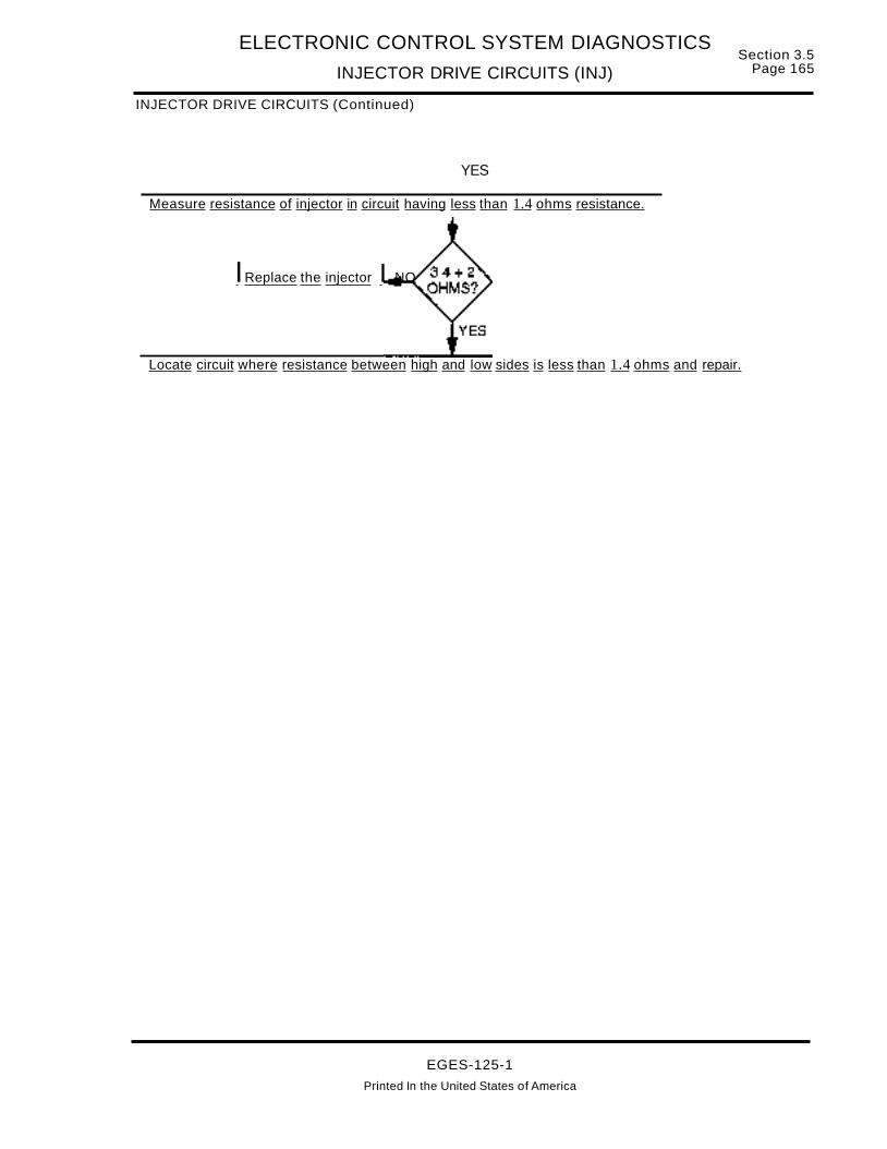
ELECTRONIC CONTROL SYSTEM DIAGNOSTICS
INJECTOR DRIVE CIRCUITS (INJ)
INJECTOR DRIVE CIRCUITS (Continued)
YES
Measure resistance of injector in circuit having less than 1.4 ohms resistance.
IReplace the injector I NO
Section 3.5Page 165
Locate circuit where resistance between high and low sides is less than 1.4 ohms and repair.
EGES-125-1
Printed In the United States of America

Section 3.5Page 166
ELECTRONIC CONTROL SYSTEM DIAGNOSTICS
INJECTION PRESSURE REGULATOR (IPR)
INJECTION PRESSURE REGULATOR (IPR)
EOT - Engine Oil Temperature
12 voltsIgnition Key Power
Duty Cycle Controlled
IPRInjection Pressure Regulator
Output Signal
12 Volts 400 Hz.
II INJECTION CONTROL
PRESSURE REGULATORL _
ECM
ELECTRONICCONTROLMODULE
ACCELERATOR POSITION IIDLE VALIDATIONEG-1140
ICP - Injection Control Pressure
MAP - Manifold Absolute Pressure
BARO - Barometric Pressure
CMP - Camshaft Position Sensor
OUTPUT FUNCTIONS
Injection Pressure Regulator -Is a variable posi",tion valve that controls injection control pressure.The ECM uses many input variables to determinethe desired injection control pressure.
Battery voltage is supplied to the IPR when the ignition key is in the on position. Valve position is controlled by switching the output signal circuit toground inside the Electronic Control Module (ECM).On off time is modulated from 0-50% dependentupon the desired injection control pressure.
FAULT DETECTIONIMANAGEMENT
An open or a short to ground control circuit can bedetected by an on demand output circuit check performed during the engine off test.
The ECM is capable of detecting, while the engineis running, if desired injection control pressure isequal to measured injection control pressure. If themeasured injection control pressure does not reasonably compare to the desired injection controlpressure, the ECM ignores the measured ICP signal and attempts to control the engine with the desired value. (If the problem was in the sensor circuit,this strategy causes little performance deterioration, if the problem is in the control circuit, engineperformance will probably still be unsatisfactory).
A faulty IPR or problem with the high pressure oilsystem can be detected by the engine running testduring the injection control pressure step test. During this test, the ECM commands and measures twospecific pre programmed pressures. A fault code isset, if the pressures can not be maintained.
NOTE: THE ENGINE WILL NOTOPERATE WITHAN IPR CIRCUIT THAT IS NOT FUNCTIONING.
EGES-125-1
Printed in the United States of America

ELECTRONIC CONTROL SYSTEM DIAGNOSTICS
INJECTION PRESSURE REGULATOR (IPR)Section 3.5
Page 167
25
Fault Codes:
241 Output Circuit Check331 Excessive ICP Pressure333 In-Range Fault334 Unable to reach setpoint335 Unable to build ICP during'
cranking
A
8
Regulator EG-1141
c~~:::ror RegulatorConnector13
DeutschDeutsch Connector
Connector(On Cowl) (On Valve Cover)
F5(15A)
KEVPWR
IPR Control
Injection PressureRegulator
(IPR)
ECMConnector
After removing connectors always check for damaged pins. corrosion, loose terminals etc..
Connector Checks to Ground (8-)(Check with IPR Connector Disconnected and Ignition key off, all accessories off)
Spec. Comments
> 1000 ohms A short to ground will command fulliPR pressure, code 331 may be set.
IPR Voltage Check(Check with regulator connector disconnected)
Test Points Spec. Comments
A to Grd. B+ Battery voltage from F2, check with key on (GP relay coil is supplied from same fuse).
8 to Grd. 0- .25v If greater than .25 volts, signal wire is shorted to V Ref. or battery.
Harness Resistance Checks(Check with breakout box installed) (IPR connector reconnected.)
Test Points Spec. Comments
#21 to F5 5 to 20 ohms Resistance through entire IPR circuit including regulator, check with regulatorconnector connected.
#21 to B < 5 ohms Resistance from 60 pin connector to regulator connector.
F2 to A < 5 ohms Resistance from power supply (F2) to regulator connector.
Fault Code Descriptions
241 = Output circuit check detected during Std. test, indicates high or low resistance in circuit.
331 =ICP pressure was greater than 3675 PSI (25 MPa) for 1.5 seconds. (possible grounded IPRcontrol circuit.) (Refer to injection control pressure diagnostics if not electronic fault.)
333/334 = (1) If set during normal engine operation indicates engine is operating in open loop controland ICP pressure is above or below desired pressure. (Refer to ICP control system diagnostics.)
(2) If set during engine running test, indicates ICP system failed step test andcould not maintain commanded pressure.
335 = ICP unable to build pressure during cranking.
EGES-125-1Printed in the United States of America

Section 3.5Page 168
ELECTRONIC CONTROL SYSTEM DIAGNOSTICS
INJECTION PRESSURE REGULATOR (IPR)
INJECTOR PRESSURE REGULATOREXTENDED SYSTEM DESCRIPTIONFUNCTIONThe Navistar engine control system includes a Injection Pressure Regulator (lPR) valve that controlsoil pressure in the high pressure injection controlsystem which is used to actuate the injectors. TheIPR valve consists of a solenoid, poppet and spoolvalve assembly and is mounted in the high pressureoil pump. The ECM regulates injection control pressure by controlling the duty cycle or (on/off time) ofthe injection control pressure solenoid. This increase or decrease of "on/off' time positions a poppet valve and spool valve internal to the IPR, whichin turn either maintains pressure in the injection control pressure system or vents pressure to the oilsump via the front cover. (Refer to manual Sec. 1.2,Injection Control Pressure System for a more complete description of the IPR operation and function.)
OPERATIONThe IPR valve is supplied with voltage at terminal Aof the IPR connector when the ignition key is turnedon thru fuse F5. Control of the injection control system is accomplished by the ECM grounding the IPRcircuit from terminal B of the IPR valve thru pin #21of the ECM. Precise control is accomplished by varying the pulse width or percentage of "on/off' timeof the IPR solenoid. The frequency of the pulsewidth to the IPR is 400 Hz, normal "on/off" times varies from 80/0 to 500/0. A high duty cycle indicates ahigh amount of injection control pressure beingcommanded, a low duty cycle is an indication of lesspressure being commanded.
ECM DIAGNOSTICSThe ECM monitors the Injection Control Pressurewhile the engine is in operation. If the actual pressure is greater or less than the desired pressure, theECM will set a fault code. When this occurs, theECM will ignore the ICP sensor and control the engine using pre programmed values for the IPR.
The Electronic Service Tool is used to Perform theEngine Running Standard Test which enables theECM to vary the command signal to the IPR andmonitor the performance of the Injection ControlPressure system. If the system does not respondwithin the specified parameters, the ECM will set afault code.
Fault codes can be retrieved using the ElectronicService Tool or the Self Test Input diagnostic switchlocated on the vehicle dash. If the ignition key isshut off, the code will be stored as an Inactive code.
FLASH CODE 241ATA CODE SID 42 FMI11INJECTION CONTROL PRESSURE REG. oec
SELF TEST FAILEDCode 241 is set only during the Engine Off StandardOutput Circuit Check. This test indicates the ECMhas performed an output circuit test, measured voltage drop across the IPR circuit and determined it isbelow or above specification.
If this fault is present, the engine will not run. TheECM will not illuminate the Engine Warning light ifthis code is active, however, this code will be transmitted at the completion of the Output Circuit Check,using the STI switch or the Electronic Service Tool.
Possible causes: Open feed circuit or fuse to theIPR, open IPR solenoid, or an open or shorted IPRsignal circuit.
FLASH CODE 331ATA CODE PID 164 FMI 0INJECTION 'CONTROL PRESSUREABOVE SYSTEM WORKING RANGECode 331 indicates the ECM has detected injectioncontrol pressure greater than 3675 PSI (25 MPA)which is greater than the maximum allowable working pressure.
When this code is active, the ECM will illuminate theEngine Warning light.
Possible causes: Incorrect ICP signal due to faultycircuits or sensor, grounded IPR signal circuit, amalfunction in the injection control pressure systemor a sticking or blocked IPR valve. Refer to InjectionControl Pressure system diagnostics in Section 2.
FLASH CODE 333ATA CODE PID 164 FMI10WJECnONCONTROLPRESSUREABOVEm~
LOW DESIRED LEVELCode 333 may be set during normal engine operation through the continuous monitor function or during the Engine Running Standard Test. It indicatesthe measured pressure does not match the expected value. The ECM will illuminate the EngineWarning light.
When this code is active, the ECM will ignore theICP sensor signal and will control the IPR from programmed values to keep the engine operating. Perform ICP sensor diagnostics to determine if theproblem exists in the ICP sensor/circuit. If diagnostic testing indicates the ICP sensor/circuit is functioning properly, perform additional diagnostic testson the injection control pressure system. Refer toInjection Control Pressure system diagnostics inSection 2.Possible causes: Incorrect ICP signal due to circuitor sensor malfunctions. IPR signal circuit may begrounded or contain excessive resistance. The IPRvalve may be sticking or blocked. Injection controlpressure system may not be functioning properly.
EGES-125-1
Printed In the United States of America

ELECTRONIC CONTROL SYSTEM DIAGNOSTICS
INJECTION PRESSURE REGULATOR (IPR)
ECM DIAGNOSTICS (Continued)
Section 3.5Page 169
FLASH CODE 334AlA CODE PID 164 FMI7INJECTION CONTROL PRESSURE UNABLETO REACH SETPOINT-POOR PERFORMANCECode 334 indicates an injection control system response time fault and may be set during normal engine operation through the continuous monitorfunction or during the Engine Running Standard Test.
While the driver of the vehicle rapidly presses hisfoot down on the accelerator pedal, the ECMcompares the actual vs the desired injection controlpressure and looks for a large pressure difference(1300 PSI/9MPA) for a short period of time (3 seconds). If the injection control system does not respond quick enough Code 334 will be set and theEngine Warning Lamp will be illuminated.
Possible Causes: Low oil level, contaminated engine oil or aerated oil. Trapped air in the injectioncontrol pressure system (particularly after an injector or high pressure pump replacement). Defectiveor stuck Injection Pressure Regulator (IPR). Intermittent IPR valve wiring connection-spread IPR
harness terminals at IPR valve, poorly crimped terminals or pulled back pin. Leaking injector"0" rings.Problem with ICP sensor and sensor circuit, systembiased high or low. Refer to Injection Control Pressure system diagnostics in Section 2.
FLASH CODE 335ATA CODE PID 164 FMI1INJECTION CONTROL PRESSURE UNABLETO BUILD PRESSURE DURING CRANKINGCode 335 indicates the ECM has determined thatthe injection control pressure system has failed tobuild a pressure of at least 725 PSI/5 MPA during aprogrammed period of engine cranking time whichwill vary with engine temperature.
NOTE: Engine cranking speed must be greaterthan 130 RPM before fault detection begins.
Possible Causes: No oil in engine. Air in the injection control pressure system (particularly after an injector or high pressure pump replacement). Defective or stuck IPR regulator. Leaking injector "0"rings. Loose high pressure pump gear. Defectivehigh pressure oil pump.
EGES-125-1Printed in the United States of America

Section 3.5Page 170
ELECTRONIC CONTROL SYSTEM DIAGNOSTICS
INJECTION PRESSURE REGULATOR (IPR)
SENSOR CIRCUIT DIAGRAM
5
B
KEY SWJTCHIGN (24)
Y«~(1)0-,...!
-----.. 84*
S2*
* SPLICESHOWN (2)PLACES
97CZ
97BH
97CY 5V
97CE
97BG
97BF
28
24
97BF 16
A <> 97GW
B 97BF
ENGINE COOLANTTEMP SENSOR
cA I( ~----W......-...... 9_7Z_--I-<E
1_4 -1--_
B
(405)
27 97BEC ~..J--_-w.I.------+-<'f--+-~
26A
B K >-...w..&-llI~ .-.;;;9..;;...7C=.:;E~< t---+-
CAMSHAFT POSITIONSENSOR
ENGINE OILTEMP SENSOR
A <> 97GU
INJECTION CONTROLPRESSURE SENSOR
B I( >----w.r..~--:.
ENG'INE OILPRESSURE SENSOR(50 PSI SW WITH ENGINE WARNINGOR ENGINE PROTECTION SYSTEMONLY)
S2*
84*
INJECTION PRESSUREREGULATOR VALVE
(405)
13 97BP""'----t-<~t-----<JI A
wCDf'.,0)
97BHr-----t-<~.-.-----e:>1 B
25
ECM(379)
COw
a.~()
NOTE: (405)SHOWNTWOPLACES
(L I..L t- t-- 0 a::UWOUZ 0..
0:: W W (!)> (!)-(J)
EGES-125-1
Printed in the United States of America

ELECTRONIC CONTROL SYSTEM DIAGNOSTICS
INJECTION PRESSURE REGULATOR (IPR)Section 3.5
Page 171
INJECTION CONTROL PRESSURE REG'ULATOR
Refer to circuit diagramon page 170
KEY OFF- Remove connector from IPR valve. Measureresistance to round at connector terminals A and B.
Locate short to ground in circuithaving less than 1000 ohms andrepair.
INJECTION CONTROLPRESSURE REGULATOR
IPR CONN.
97BP
KEY ON- At IPR connector measure voltage to ground at terminal A.
r----------,L Continued On Next Page..l---.-.~-----
1 21 41
ELECTRONICCONTROL
MODULE (379)(DASH HARNESS)
204060
Check fuse/locate cause of NOor LOW voltage in feed circuitand repair.
Locate short to unwantedvoltage source in circuit 97BHand repair.
ILocate open in circuit and repair. I NO
KEY ON- Measure voltage to ground at IPR connector terminal B.
KEY OFF-Install breakout box at ECM connector (379). Measure circuitresistance between breakout box terminal 21 and IPR connector terminal B
EGES-125-1Printed In the United States of America

Section 3.5Page 172
ELECTRONIC CONTROL SYSTEM DIAGNOSTICS
INJECTION PRESSURE REGULATOR (IPR)
INJECTION CONTROL PRESSURE REGULATOR (Continued)
Check for in range ICP failurerefer to ICP dia nosis.
Perform Hard Start/No Startdiagnostics to determine if ECMis not commanding the IPRpressure due to other faultsdetected by the ECM.
Check hydraulic system Noperation (refer to Low ICPPressure Test in MechanicalDia nostics.
EGES-125-1Printed In the United States of America

Section 3.5Page 174
ELECTRONIC CONTROL SYSTEM DIAGNOSTICS
KEEP ALIVE MEMORY POWER (KAM PWR)
KEEP ALIVE MEMORY POWER AND VPM BATTERY POWER CIRCUIT
VPM15A ECM PWR FUSE
+
ECM
1 KAPWR40 PWRGRD60 PWRGND20 CSEGND
CAB GND
CIRCUIT OPERATION
The Electronic Control Module (ECM) has information stored in volatile memory which is erased or lostwhen power is disconnected from the module. Thismemory is referred to as Keep Alive Memory (KAM).The ECM stores historical diagnostic informationfrom previous engine operating cycles, learned lim...its from certain engine and vehicle sensors and programmable parameters sent from the VPM.
The Vehicle Personality Module (VPM) utilizes theKAM power circuit to remain powered for at least 30minutes after each key off cycle to record accumulator values for vehicle miles, hours and fuel used.
FAULT DETECTION MANAGEMENT
On every power up KAM memory in the ECM ischecked by the processor to determine if any information in memory has been lost or can be storedcorrectly. A fault code will be set if power has beendisconnected, information sent from the VPM doesnot agree with the last power up or if the memory internal to the ECM is defective.
There is no fault detection for loss of KAM power tothe the VPM, however, the VPM will be unable tocommunicate with the Electronic Service Tool (EST)when the ignition key is in the OFF position.
EGES-125-1Printed in the United States of America

ELECTRONIC CONTROL SYSTEM DIAGNOSTICS
KEEP ALIVE MEMORY POWER (KAM PWR)Section 3.5
Page 175
Keep Alive Memory Power Fault Codes:
(KAM PWR) 224 KAM Corrupt615 Programmable Parameter KAM Corrupt
FROM + BATTTERMINAL
ELECTRONIC CONTROL MODULE (ECM)50-PIN HARNESS CONNECTOR (379)
8
15
23
VPM CONNECTOR(381 )
VPM HARNESS
1
9
16
97EKAM PWR 1 t-----.....l1iU-8-vT--------~18-f-':V=-T---t-1 8 VBAT
PWR GAD 40 f 15 PWRGRD
-= NEG.BATTTERMINAL
CAB GRD.
KAMPWR to ECM - Connector (379) with breakout box installed and key OFF
Test Points Spec. Comments
#1 to grd. 12 ± 1.5 volts < than 10.5 v check connections, if 0 volts check for open/short toground or blown fuse (If fuse is open the ECM will not be poweredwith key ON and Prolink will not read codes)
#1 to #40 12 ± 1.5 volts < than 10.5 v check connections, if 0 volts check for open inground path.
NOTE: If the KAM PWR to the ECM is good and ground circuits are good, and Flash code 224 or615 remains active, the ECM is defective.
KAMPWR to VPM - Connector (381)
Test Points Spec. Comments
#8 to grd. 12 ± 1.5 volts < than 10.5 v check connections, if 0 volts check for open/short toground or blown fuse (If fuse is open the ECM will not be poweredwith key ON and Prolink will not read codes)
#8 to #15 12 ± 1.5 volts < than 10.5 v check connections, if 0 volts check for open inground path.
Fault Code Descriptions
224 Kam Memory
615 Programmable Parameter KAM Corrupt Memory Information
EGES-125-1Printed in the United States of America

Section 3~5Page 176
ELECTRONIC CONTROL SYSTEM DIAGNOSTICS
KEEP ALIVE MEMORY POWER (KAM PWR)
ECM KAM AND VPM BATTERY POWEREXTENDED SYSTEM DESCRIPTION
Refer to circuit diagram on page 177 for the following discussion.
The ECM Keep Alive Memory (KAM) circuit 97J provides battery power from the Positive battery terminal through ECM connector 379 to ECM terminal 1at all times. The circuit is protected by 15 amp, #1ECM PWR Fuse, which also supplies power to theVPM, VBAT terminal (8). KAM stores fault codesand operating constants between engine starts.
ECM DIAGNOSTICS
During normal vehicle operation, the ECM performscertain tests. When the key is turned ON, the ECMperforms the Start-Up KAM Test to test its KeepAlive Memory. The test is performed once each timethe key is turned on or when the ECM resets.
The ECM performs a test to determine if thememory is working properly, but a lack of batterypower to ECM terminal 1 can cause fault code(s)224 and 653 to be set.
When power to KAM has been disrupted, there willbe no inactive faults.
FLASH CODE 224SID 254 FMI2ECM: KAM CORRUPTFlash Code 224 can be caused by:
A. Short oropen in KAM circuit. High or low voltageto ECM terminal 1 from the KAM battery supplycircuits will cause code 224.
Note that if the battery cable has been disconnected, on the next key ON cycle, code 224 willbe present, indicating that the KAM memoryhas lost power. The code will change to inactivestatus on the next key cycle.
B. Faulty KAM memory in the ECM.
Conditions causing Flash Code 224 can also causeFlash Code 615 to occur.
FLASH CODE 615SID 254 FMI 13ECM: PROGRAMMABLE PARAMETER KAMCORRUPT FAULT
If flash code 615 occurs when the KAM power supply to the ECM is good, then the KAM memory is defective. Refer to Electronic Control Module Diagnostics (ECM) in this manual section.
TROUBLESHOOTING
BEFORE TROUBLESHOOTING
A. Before troubleshooting, make sure that the batteries are fully charged! Check battery connections and grounds for clean, tight connectionsfree of damage. Voltage tests will give mis-leading readings if batteries are not fully charged.
B. Before troubleshooting a particular circuit, inspect connectors for pushed back, loose ordamaged (spread or bent) terminals, or wireswith cut strands, etc. The wires and connections must be free of damage or corrosion.When some connectors corrode, a light whiteresidue will be present that must be removed.
C. Before troubleshooting, inspect the suspect circuit grounds for clean, tight connections, free ofdamage or corrosion.
If Flash code 224 or 653 is active, perform KAMPower Circuit test on page 179.
EGES-125-1Printed in the United States of America

ELECTRONIC CONTROL SYSTEM DIAGNOSTICS
KEEP ALIVE MEMORY POWER (KAM PWR)
CIRCUIT DIAGRAM
KAM CIRCUIT WITH TRUCK OR FBC MODELS
+ pos BATT TERMINAL
Section 3.5Page 177
#1 ECMPWRFUSE
15A
(412)
(424)
(426)
(3 & 3A)~..-_97_E__......_9_7C_M_~ECM PWA
wi .... RELAY
:l (461)
VPM381
ECM379
EGES-125-1Printed In the United States of America

Section 3.5Page 178
ELECTRONIC CONTROL SYSTEM DIAGNOSTICS
KEEP ALIVE MEMORY POWER (KAM PWR)
CIRCUIT DIAGRAM
KAM CIRCUIT WITH 1652SC MODEL
J1o FEED
STUD
co"Ct.,...
02SA
97E
WI'-0'>
(3 &3A)
VPM381
EGES-125-1
ECM379
Printed in the United States of America

ELECTRONIC CONTROL SYSTEM DIAGNOSTICS
KEEP ALIVE MEMORY POWER (KAM PWR)
TROUBLESHOOTING (Continued)
KAM POWER CIRCUIT TEST
Section 3.5Page 179
If the ECM is powered, the fuse does not need to be checked as the same fuse feeds the ECM.
Check #1 ECM PWR Fuse for open condition.
Locate cause ofoverload condition,then correct.
KEY OFF - Remove connector (379) from ECM and install breakoutbox. At breakout box measure voltage between terminals 1 and 60.
Locate cause of NO or LOWvoltage in KAM circuit97J/97CM/14C from #1 ECMPWR Fuse, then correct.
Turn key switch OFF, then ON. Note if Flash Code 224 is still active.
EGES-125-1
Printed in the United States of America

Section 3.5Page 180
ELECTRONIC CONTROL SYSTEM DIAGNOSTICS
MANIFOLD ABSOLUTE PRESSURE SENSOR (MAP)
MANIFOLD ABSOLUTE PRESSURE (MAP) SENSOR
ECM
ELECTRONICCONTROLMODULE
10M
INJECTORDRIVERMODULE
FUEL QUANTITYAND
TIMING CONTROL
MAPManifold Absolute Pressure
Sensor
oVolts
5 Volts
EG-1142
SIGNAL FUNCTIONS
The Manifold Absolute Pressure (MAP) sensor is avariable capacitance sensor which operates on a 5volt reference signal from the ECM to produce a digital frequency signal that indicates pressure.
Smoke Control - The MAP signal is used to control smoke by limiting fuel quantity during acceleration until a specified boost pressure is obtained.
Dynamic Injection Timing - Optimizes injectiontiming for boost pressure measured.
FAULT DETECTION/MANAGEMENT
A MAP signal that is detected by the ECM to be outof range or at an incorrect value for specific conditions will cause the ECM to ignore the MAP signaland will operate the engine with the values from estimated MAP. (Operate from a calculated boost pressure signal)
EGES-125-1Printed in the United States of America

ELECTRONIC CONTROL SYSTEM DIAGNOSTICS
MANIFOLD ABSOLUTE PRESSURE SENSOR (MAP)Section 3.5
Page 181
(b)(c)(a)
Fault Codes:
121 Signal Freq. High/Low122 Signal Freq. Low/Inactive123 In range Fault
Sensor Connector
EG-1143
V Ref
SensorHarnessConnector
~------tlBMAP Signal:I-+-------------..c
Signal Ground ......-----...... A"---------
Manifold AbsolutePressure Sensor
(MAP)
ECM
After removing connectors always check for damaged pins. corrosion. loose terminals etc.
Connector Checks to Chassis Ground(Check with sensor Connector Disconnected and Ignition key off, all accessories off)
Test Points Spec. Comments
A to Grd8 < 5 ohms Resistance to chassis ground check with key off, if > than 5 ohms harness is open.
S to Grd. > 1000 ohms Resistance less than 1000 ohms indicates a short to ground.
eta Grd. > 1000 ohms Resistance less than 1000 ohms indicates a short to ground.
Connector Voltage Checks(Check with sensor Connector Disconnected and Ignition Key On)
Test Points Spec. Comments
B to Grd. 5 volts ± .5 V Ref. check with key ON, if voltage not in spec, see V REF circuit.
C to Grd. 4.8 - 5.0 v Pull up voltage, if no or low voltage circuit has open or high resistance or short to grd.
Harness Resistance Checks(Check with breakout box installed on engine harness only)
Test Points Spec. Comments
#46 to A < 5 ohms Resistance from sensor connector to 60 pin connector - Signal ground
#26 to B < 5 ohms Resistance from sensor connector to 60 pin connector - V Ref
#45 to C < 5 ohms Resistance from sensor connector to 60 pin connector - MAP signal
Test Points Operational Voltage Checks(+) #45 to (-) #46 (Check with breakout box installed in line with the ECM)
Frequency PSI kPAG Comments
90 Hz. N/A N/A Out of range low limit.108-114 Hz. 0 a Freq. with key on engine off, Atmospheric pressure dependent on altitude and BARO psi.
145 Hz. 25.4 175 Frequency expected at 25 psi.
256 Hz. 45 267 Out of range high limit
Fault Code DescriptionsCircuit Faylts:
121 =Signal frequency was greater than 256 Hz. for more than 0.1 seconds.
122 = Signal frequency was less than 90 Hz. or inactive for more than 0.25 seconds.
System Faults:
123 =Detected high boost signal at low idle. (Restricted MAP line.)
EGES-125-1
Printed in the United States of America

Section 3.5Page 182
ELECTRONIC CONTROL SYSTEM DIAGNOSTICS
MANIFOLD ABSOLUTE PRESSURE SENSOR (MAP)
MANIFOLD ABSOLUTE PRESSURE SENSOREXTENDED SYSTEM DESCRIPTION
FUNCTION
The Navistar engine control system includes a Manifold Absolute Pressure (MAP) sensor. The ECMmeasures the signal from the MAP sensor to determine intake manifold (Boost) pressure. From thisinformation, the ECM can optimize control of fuelrate and injection timing for all engine operatingconditions.
OPERATION
The Manifold Absolute Pressure sensor is a variable capacitance sensor that produces a digital frequency signal output. The MAP sensor is supplied 5volts from the ECM at terminal 26 to terminal 8 of thesensor. A return circuit (ground) is supplied fromECM terminal 46 to terminal A of the sensor. Thesensor receives intake manifold boost pressure viaa hose which connects to a tap on the intake manifold to the map sensor. Pressure applied to theMAP sensor changes the capacitance of the sensorwhich varies the digital frequency of the signal sentto the ECM. As boost pressure increases the frequency increases.
ECM DIAGNOSTICS
The ECM monitors the MAP sensor output signal forexpected values. If the ECM detects the MAP signalis greater than or less than the desired value, theECM will set a fault code.
If an active MAP sensor fault code is set, the ECMwill ignore the MAP signal. It will operate the engineusing programmed default values. Active faults forthe MAP sensor will cause the ECM to illuminate theEngine Warning light. These faults can be retrievedusing the Self Test Input diagnostic switch locatedon the vehicle dash orthe Electronic Service Tool. Ifthe ignition key is turned off, the fault code will bestored as an Inactive code.
FIGURE 7 FLASH CODE 121ATA CODE PID 102 FMI8MAPFREQUENCYOUTOFRANGEHmH
Code 121 will be set, if the ECM detects a frequencygreater than 256 Hz for more than 0.1 seconds inthe MAP signal.
If code 121 is active, the ECM will ignore the MAPsignal and operate the engine using programmeddefault values. The ECM will illuminate the EngineWarning light when this code is active.
Excessive high frequency noise in the MAP signalwill cause this code to be set.
FLASH CODE 122ATA CODE PID 102 FMI11MAP SIGNAL IS INACTIVE
Code 122 will be set, if the ECM detects a frequencyless than 90 Hz or an inactive MAP signal for morethan 0.25 seconds.
When code 122 is active, the ECM will ignore theMAP signal and operate the engine using programmed default values. The ECM will illuminatethe Engine Warning light when this code is set.
Possible causes: A defective MAP sensor or MAPsensor signal circuits may be open or shorted toground.
FLASH CODe 123ATA CODE PID 102 FMI2MAP SIGNAL ABOVE SPECIFIED LEVEL ATLOW/OLE
Code 123 is set when the MAP signal is greater than16.7 PSI (115 kPa) Absolute at low idle.
When code 123 is active, the ECM will ignore theMAP signal and operate the engine using programmed default values. The ECM will illuminatethe Engine Warning light when this code is set.
Possible causes: Restricted or plugged hose whichsupplies intake manifold boost pressure to the MAPsensor or a defective MAP sensor.
EGES-125-1
Printed In the United States of America

ELECTRONIC CONTROL SYSTEM DIAGNOSTICS
MANIFOLD ABSOLUTE PRESSURE SENSOR (MAP)Section 3.5
Page 183
ACCELERATOR, BARO & MAP CIRCUITS
ACCELERATOR, BARO & MAP SYSTEMS
KEY SWITCHIGN 124)
t<~(T)Q..
-!
F4lOA B
With FBC &S.C.
2A H1
10AB
BAROMETRICPRESSURE
SENSOR(406)
97BX~
IBVT IllJlm>m~
2 3
~----~~Oi----"
1-----19rIV\
c
A
B
.. NO 0
I~~
IO)~
MANIFOLDABSOLUTE
_ ~~ PRESS SENSOR>~ (397)~> l.L I-~~ W ::l 0m ~ 0 Z
ACCELERATOR f > > (!)PEDAL SWITCH
13821 --r---__9~~~~5VI_- I ~
- I>o~ ~~ ([)~ 3t~ 8~moo :Jm mm bim f'm
--,.....-- - - m--CD
ACCELPOSITION
SENSOR
r ..Idle C F
Validation ~I--_""'----"
Switch NC E
3
99C15VI__lBVT
S4
ESP < ......9-.;...7-.;...BZ~----I
MAP S7BV
IAT <l97BU
EOP 97AE
IDM 97AM
ECM(379)
TO U) lL. U) 0 D.. (l-BAn (-) > w a.. z OJ <
0:: < (!) ~> (!)
Ul
52~__9Y~O+5VJ_
97-GBMAP <1--9~7__B_T...5~---f
EOP 97BY(5V)
ICP~__..--97_C_Y~(5_V)~.-J
CMP
EGE5-125-1
Printed in the United States of America

Section 3.5Page 184
ELECTRONIC CONTROL SYSTEM DIAGNOSTICS
MANIFOLD ABSOLUTE PRESSURE SENSOR (MAP)
MAP MANIFOLD ABSOLUTE PRESSURE SENSOR
Refer to circuit diagramon page 183.
KEY OFF- Remove connector (397) from the sensor. Measure resistance to ground at terminal A.
KEY OFF- Measure resistance to ground at connector397 terminals Band C.
Locate short to ground in circuithaving less than 1000 ohms andrepair.
MAP MODULE CONN(397)DASH HARNESS
KEY ON- At connector (397) measure voltage between terminals B and A (grd).
Refer to VREF Diagnostics
KEY ON- Measure voltage between terminal C and A (grd).
EGES-125-1Printed in the United States of America

ELECTRONIC CONTROL SYSTEM DIAGNOSTICS
MANIFOLD ABSOLUTE PRESSURE SENSOR (MAP)Section 3.5
Page 185
MAP MANIFOLD ABSOLUTE PRESSURE SENSOR (Continued)
Perform PerformanceDiagnostics to determine if amechanical problem ispresent.
MAP MODULE CONN(397lDASH HARNESS
108-114 Hz = Atmospheric Pressure148 Hz = 10 PSI207 Hz = 25 PSI
Attach connector (397) to the MAP sensor. Install breakoutbox at ECM connector (379). KEY ON- Measure voltagefrequency with actual pressure (refer to table and note).
IReplace the MAP sensor
Locate open signal circuit andre air.
I I YESCorrect defects noted
Install breakout box at ECMterminal (379). KEY ONMeasure voltage at terminal 45.
Check to see ifECMispowered up, ifso replace theECM.
rNOTE: TheMAPsensorhosemust -,flow in a continuous incline to theIsensor without any dips or low spots, I
L that ~y c~~e wat~ pocket~ .J
EGES~125-1
Printed In the United States of America

Section 3.5Page 186
ELECTRONIC CONTROL SYSTEM DIAGNOSTICS
SPEED CONTROL COMMAND SWITCHES (Sces)
CRUISE CONTROL, PTO, HAND THROITLE SYSTEM
R PTO (PRESET SPEED)REMOTEPEDALSWITCHESR PTO ARIABLE SPEED
IGN VOLTAGE
r-------------------------
ECM ~w0 ~a:z lli 0..
en a: b: C/)a::O-u C!J 0..>1-0U U C!J ~ ICl..ten C/) en a: a:: a::0 0) in o ~ C\ILO ('t) ('t) ~ T"'"
: COMPONENTS CONNECTED TO REMOTE• PTO CONNECTOR ARE INSTALLED BY BODY: BUILDER
REMOTEPEDALSENSOR
REMOTESETRESUME
VREF
SIG RTN
REMOTE APS SIGNAL
SC GRD
oex:
C>-<>--<>---<l---<> - ,B I
rtJ I~ I~ I
F .,.. IL .J
RESISTOR BLOCK
....J<{zC!JenC/)uuC/)
SIGNAL FUNCTION
CRUISE CONTROL
ECM terminal 50 outputs a 6.58 volt signal to theresistor block. Activating the cruise commandswitches causes the signal to pass through differentresistance levels in the resistor block, altering thesignal which is grounded at ECM terminal 39.Thereare five expected signals to the ECM: OFF, ON,SET, RESUME and open (no switches have beenused). Refer to Extended Description on page 188for additional detail.
REMOTE PTO CONTROLS
To use the remote controls, cruise control must beturned on using the cab cruise ON/OFF switch. Theremote Set/Resume switch and disable switch arewired parallel to cab switches and operate in thesame manner.
With cruise control ON:
A. Placing the remote PTO Preset switch in the ONposition (closed) causes the PTO to operate ata preset engine speed (customer selected)programmed into the VPM.
B. Placing the remote PTO Variable switch in theON position (closed) causes the PTO to operateusing remote pedal.
NOTE: IF BOTH OF THE ABOVE SWITCHESARE ON, THE REMOTE PEDAL ISDEACTIVATED.
FAULT DETECTION MANAGEMENT
The ECM monitors the SCCS signal for the fiveexpected signals. If an incorrect signal is detected,Flash Code 221 is logged. The ECM also monitorsthe R-APS signal input at ECM terminal 30 from theremote pedal sensor for out-of-range signals, highor low.
EGES-125-1
Printed in the United States of America

ELECTRONIC CONTROL SYSTEM DIAGNOSTICS
SPEED CONTROL COMMAND SWITCHES (sees)Section 3.5
Page 187
BODY BUILDERCONN. 429
Fault Codes:
213 RPS Out of Range Low
214 RPS Out of Range High221 SCCS Switch or Circuit Fault
LL
ECM (379)0 z LL
wen a: .... en ex:(.) C) ex: Q. >() () C)
~ d:en en en0 en LO
0 vLO ('t) ('t) v
-,0-<>--<>---<>---<>6 I
en I~ I~ I
F ~ IL .J
RESISTOR BLOCK (390)
IGN VOLTAGE -.-9_7D_F_*_-+< 6 VPTO
.....--,------r---r--,---.-~---~9~7~C!:::..B*----------+_<8 ENABLE - PRE
L-- --=:9~7.=.CC=_* ___;_~ 7 ENABLE - VAR
97DD 5V * 12 R-VREF'--- 9;;;".;;;;9...:....F* --t--<;. 1 1 R-APS
97WA* 10 R-SIGGND,-.- 4~6~* -;-<;. 3 SCGND
_---46~A-*--_-------"'I_' 4 RESUME
_---46.;.,.-8-*-------------t-<;, 5 SET
46D* 1 DISABLE* CIRCUITS ONLY WITH REMOTE FEATURE
Speed Control Command Switches(SCCS)
Operational Voltage ChecksConnector (379) with breakout box installed and key ON
sces Sw. Posi- Breakout Spec. Commentstions Test Points
All switches in #50 to #39 6.2V-7.1V < than 6.2V check connections, battery condition.neutral position Greater than 7.1 V check for short to VBAT
Hold switch in #50 to #39 OV-100mV > than 1OOmV check connections, switch, resistorOFF position block and circuits for correct resistance or short to
VBAT or grd
Hold switch in #50 to #39 4.4V-5.0V <> than specified voltage drop, check connections,ON position switch, resistor block and related circuits for correct
resistance or short to VBAT or grd
Hold Set switch #50 to #39 2.2V-3.0V <> than specified voltage drop, check connections,in SET position switch, resistor block and related circuits for correct
resistance or short to VBAT or VREF or grd
Hold Res switch #50 to #39 700mV-800 <> than specified voltage drop, check connections,in RES position mV switch, resistor block and related circuits for correct
resistance or short to VREF or VBAT or grd
Fault Code Descriptions
213 = RPS signal was less than 0.146 volts for more than 0.5 seconds214 = RPS signal was greater than 4.56 volts for more than 0.5 seconds221 = sees voltage signal does not match expected levels (5 assigned levels for different conditions)
EGES-125-1Printed In the United States of America

Section 3.5Page 188
ELECTRONIC CONTROL SYSTEM DIAGNOSTICS
SPEED CONTROL COMMAND SWITCHES (SCCS)
EXTENDED DESCRIPTION
Cruise control and PTa operation (including remotePTa) share many circuits and components, so bothsystems are included in this section.
The Cruise/PTa system is controlled by the ECM inresponse to driver input on the Speed Control Command Switches (SCCS), which are the Cruise ON/OFF and SET/ RESUME switches. With a remotePTa operation, the body builder installed controlsinclude a remote SET/RESUME switch and a PTaDISABLE switch that are also SCCS switches.
The body builder also installs a Remote pedal sensor and switches to enable the remote PTa at a preset speed or enable in the variable mode, with engine speed controlled by the remote pedal sensor.These circuits will be discussed in Remote PedalSensor Circuits later in this section.
The Clutch Pedal Switch supplies the Driveline Disengaged Signal (DDS) to the ECM and the ServiceBrake Switches supply a Brake Normally Open(BNO) and Brake Normally Closed (BNC) signal tothe ECM. These signals indicate pedal positionsand are used by the ECM in operating the Cruise/PTa Control System.
The Vehicle Speed Signal (VSS) and CMP signalprovide vehicle speed and engine rpm informationthat the ECM uses in controlling the Cruise/PTasystem.
ECMCONTROL
Refer to the circuit diagram on page 191 for the following discussions on circuit operation.
SCCS CIRCUITS
The ECM sends a 6.58 volt signal from ECM terminal50 to the SCCS system. The signal goes throughthe SC Resistor Block Assembly to the SCCSswitches (see note 1) and returns to the ECM at terminal39. Depending on SCCS switch position (ON,OFF, SET, RESUME or when no switch is active),one of five different signals is expected when thesignal returns to ECM signal ground terminal 39.These five signals are discussed in the followingparagraphs.
NOTE 1: The SC Resistor Block is permanently attached to the cab harness and contains a printedcircuit board, that includes three resistors. Theprinted circuit board can be removed by opening the
end of the resistor block assembly and pulling theboard out.
NO SCCS SWITCHES ACTIVE
Note in circuit diagram that the ON/OFF, SET/RESUME (including the remote SET/RESUME) andthe remote DISABLE PTa switch are normallyopen, momentary switches. With the key switch ON,voltage is being applied from ECM terminal 50, butthe ECM expects to see an open circuit. With noswitch depressed, voltage measured between ECMterminals 39 and 50 is expected to be between 6.2and 7.1 volts. An OPEN circuit (6.2 to 7.1 Yolts between terminals 39 and 50) is the signal that theECM expects to see with no switch depressed.
CRUISE ON/OFF SWITCH IN ON POSITION
Momentarily placing this switch in the ON positioncauses the signal from ECM terminal 50 to gothrough the 2.2K ohm resistor located in the Resistor Block (390) through the ON terminal of the ON/OFF switch and returns to ECM terminal 39. Withthe ON switch depressed, the voltage drop in thiscircuit (measured between ECM terminals 39 and50) is expected to be between 4.4 and 5.0 volts. AYoltage between 4.4 and 5.0 volts is the signalthe ECM expects to see with the ON switch depressed.
CRUISE ON/OFF SWITCH IN OFF POSITION
Momentarily placing this switch in the OFF positioncauses the signal from ECM terminal 50 to gothrough the Resistor Block (390), terminals F to E,where there is no resistor, then through the OFF terminal of the ON/OFF switch returning to ECM terminal 39. With the OFF switch depressed, the expected voltage drop in this circuit (measuredbetween ECM terminals 39 and 50) is expected tobe between 0 and 100mV. A Yoltage between 0and 100mV is the signal the ECM expects to seewith the OFF switch depressed.
The Remote DISENGAGE PTa Switch is a normally open (NO) momentary switch that is wired parallelto the OFF side of the ON/ OFF switch. The PTa canonly be turned on from the cab switch, but can beturned OFF from the remote location. When thisswitch is closed, the ECM expects to see the samesignal as when the ON/OFF switch is in the OFFposition (0 to 1OOmV voltage drop).
EGES-125-1
Printed In the United States of America

ELECTRONIC CONTROL SYSTEM DIAGNOSTICS
SPEED CONTROL COMMAND SWITCHES (SCCS)
CRUISE SETIRESUME IN SET POSITION
Section 3.5Page 189
Momentarily placing this switch in the SET positioncauses the signal from ECM terminal 50 to gothrough the 680 ohm resistor located in the ResistorBlock (390) through the SET terminal of the SET/RESUME switch returning to ECM terminal 39. Withthe SET switch depressed, the voltage drop in thiscircuit (measured between ECM terminals 39 and50) is expected to be between 2.2 and 3.0 volts. Avoltage between 2.2 and 3.0 volts is the signalthe ECM expects to see with the SET switch depressed.
The Remote PTa SET/RESUME Switch is a normally open (NO) momentary switch that is wiredparallel to the cab SET/RESUME switch. When theremote SET switch is in the SET position, the ECMexpects to see the same signal as when the cabSET switch is in the SET position (2.2 to 3.0 volts).
CRUISE SET/RESUME IN RESUME POSITION
Momentarily placing this switch in the RESUMEposition causes the signal from ECM terminal 50 togo through the 121 ohm resistor located in the Resistor Block (390) through the RESUM E terminal ofthe SET/RESUME switch returning to ECM terminal39. With the RESUME switch depressed, the voltage drop in this circuit (measured between ECM terminals 39 and 50) is expected to be between 700mV and 810 mV. A voltage between 700mV and81 OmV is the signal the ECM expects to see withthe RESUME switch depressed.
The Remote PTa SET/RESUME Switch is a normally open (NO) momentary switch that is wiredparallel to the cab SET/RESUME switch. When theremote SET/RESUME switch is in the RESUMEposition, the ECM expects to see the same signal aswhen the cab SET/RESUME switch is in the RESUME position (700mV to 81 OmV).
REMOTE PEDAL SENSOR (RPS) SWITCHES
To enable the remote PTa, first the cab ON/OFFswitch must be set to the ON position. With PTa enabled, the Enable PRESET switch or Enable VARIABLE switch must be turned ON. These are toggleswitches, not momentary on switches.
REMOTE PRESET SWITCH
The remote Preset Switch receives ignition voltagefrom5A fuse, F6 through the body builder connector429, terminal 8. Closing this switch applies ignitionvoltage to ECM terminal 2. When ECM terminal 2sees 12 volts, it turns on the PTa to the presetspeed. Opening the switch turns off the remotePTa. If both the PRESET switch and the VARIABLE
switch are on, the ECM interprets this as an off signal.
REMOTE VARIABLE SWITCH
The remote Variable Switch receives ignition voltage from 5A fuse, F6 through the body builder connector 429, terminal 7. Closing this switch appliesignition voltage to ECM terminal 12. When ECM terminal 12 sees 12 volts, it turns on the PTa in thevariable mode, where engine speed is controlled bythe remote pedal. Opening the switch turns off theremote PTa. If both the PRESET switch and theVARIABLE switch are on, the ECM interprets this asan off signal.
REMOTE PEDAL SENSOR (RPS)
The RPS receives R-VREF (5V) from ECM terminal44, through body builder connector (429), terminal12. As the pedal position is changed, the wipersends the variable RPS signal through body builderconnector (429), terminal 11 to ECM terminal 30.The ECM expects to see a signal between 152 mVand 4.55 volts. This signal is interpreted by the ECMas percent of throttle, from 0 to 100 percent. TheRPS sensor is grounded through body builder connector (429), terminal 10 to ECM terminal 51 (SIGRTN).
ECM DIAGNOSTICS
sces DIAGNOSTICS
The ECM monitors the signal on SCCS circuit 97ACfor the expected five signals discussed earlier. If asignal is detected by the ECM that does not matchanyone of the five expected signals, then FlashCode 221 is set and the PTa or Cruise is disabled.
FLASH CODE 221ATA CODE SID 244 FMI 2ECM: sces SWITCH OR CIRCUIT FAULT
CAUSES: Open, short (HIGH or LOW), or bias highor low in SCCS circuits or components.
The ECM monitors the R..APS signal input at ECMterminal 30 from the remote pedal sensor for out-ofrange signals, high or low.
• Biased High Or Low ... A wiring or component defect that changes the circuit resistance (corroded switch contacts, poor connections, dirty or corroded terminals etc.)will alter the signal, causing the code to beset.
• A short to a 12V or 5V circuit will change theexpected signal.
EGES-125-1
Printed in the United States of America

Section 3.5Page 190
ELECTRONIC CONTROL SYSTEM DIAGNOSTICS
SPEED CONTROL COMMAND SWITCHES (SCCS)
SCCS DIAGNOSTICS (Continued)
• A short to ground changes the expectedsignal.
CORRECTIVE ACTION: Perform Testing SCCSCircuits on page 193.
RPS DIAGNOSTICS
The ECM monitors the R..APS signal input at ECMterminal 30 from the remote pedal sensor for out-of..range signals, high or low.
FLASH CODE 213ATA CODE SID 29 FMI 4ECM:RPSORL
If the ECM detects a RPS signal lower than 152 mV,this code is set and the remote pedal is disabled.
CORRECTIVE ACTION: Perform Testing RPS Circuits on page 200.
FLASH CODE 214ATA CODE SID 29 FMI 3ECM:RPSORH
If the ECM detects a RPS signal greater than 4.55volts, this code is set and the remote pedal is dis..abled.
CORRECTIVE ACTION: Perform Testing RPS Cir..cuits on page 200B
TROUBLESHOOTING
Before troubleshooting the Cruise/PTO control sys..tern, use the Prolink EST to:
1. Review any logged Flash Codes.
A. Code 221 relates directly to Cruise or Remote SCCS switches circuits. Codes 213and 214 relate to operation of the remotePTO pedal. First resolve any othercodes that may be present, becausethey may cause the ECM to disable thecruise controt Flash code 622 indicatesthe ECM is using Field Defaults that disable cruise and PTO operation. Thecause for code 622 must be corrected.
2. Usethe Prolink ESTto monitorclutchswitch op..eration. There is no diagnostic code for theDDS, Drive Line Disengagement Switch (clutchswitch) operation.
If the clutch switch circuit is open, indicating thatthe switch is depressed, then cruise and PTOcontrols won't operate. If the clutch switch circuit is defective (shorted high), depressing theclutch pedal may not disengage the cruise orPTO, causing the engine to go to rated rpmwhen the clutch pedal is depressed.
3. Flash code 222 is a Brake Switch fault which willdisable cruise and PTO operation. Use Prolinkto check brake switch operation. The BND andBNC switches must be working properly forcruise control to operate.
4. Flash codes 141 and 142 are Vehicle SpeedSensor faults which will disable the cruise andPTa controls. A speed sensor that is not properly adjusted will affect speedometer and cruisecontrol operation, and no codes will set. Correctany speedometer problems before troubleshooting the PTO system.
5. A severe INTERMITTENT connection orNOISE in the CMP SIGNAL can cause the en..gine to surge and the cruise control cannotproperly maintain vehicle speed or PTa enginerpm will fluctuate.
CRUISE/PTO CONTROLS DO NOT OPERATEPROPERLY
BEFORE TROUBLESHOOTING
A. Before troubleshooting, make sure that the bat..teries are fully charged! Check battery connections and grounds for clean, tight connectionsfree of damage. Voltage tests will give misleading results if the batteries are not fully charged.
B. Before troubleshooting, inspect circuit connec..tors for pushed back, loose, or damaged(spread or bent) terminals, or wires with cutstrands, etc. Wires and connections must befree of damage or corrosion. When some con..nectors corrode, a light white residue will bepresent that must be removed.
C. Before troubleshooting, inspect suspect circuitgrounds for clean, tight connections free ofdamage.
The Prolink EST can be used to monitor cruiseswitches, but if code 221 is active, the switches donot operate.
If Flash code 221 is active or if no flash code is present, perform Testing SCCS Circuits on page 193.
EGES-125-1Printed In the United States of America

ELECTRONIC CONTROL SYSTEM DIAGNOSTICS
SPEED CONTROL COMMAND SWITCHES (SCCS)
CIRCUIT DIAGRAM
Section 3.5Page 191
c ~a:~0
CJ z u..D: cc g
~z W I- U'J wC' c:: Q. ~3= " ~
a..IGN0 0 0 fjj
, I
(/) U) a: a::a.
ECM(379)
F6SA
12-WAYAMP(394)
mo:; ~ ENABLE ..PRE 8~ .....---0~ ~ 9700 ENABLE-PRE
970D (SV) R·VREF
99F R-APS
97WA R-SIGRTN
46·5C GND
46A .. RESUME ..
~..------_--.. 460 .. DISABLE 1
BODYBUILDER
CONN. (429)
SC RESISTOR BLOCK ASSY (390)
EGES-125-1Printed In the United States of America
BOTHENABLESW·ON·WHEN
CLOSED
RPS
REMOTESWITCHES
BODY BUILDERTYPICAL
INSTALLATION(THIS SIDE)

Section 3.5Page 192
ELECTRONIC CONTROL SYSTEM DIAGNOSTICS
SPEED CONTROL COMMAND SWITCHES (SCCS)
CIRCUIT DIAGRAM (WITHOUT REMOTE CONTROLS)
o~(.)(/)
ECM(379)
DASH(3 &3A)
2-WAVCONNECTOR (394)
SC RESISTOR BLOCK ASSY (390)
EGES-125-1Printed In the United State. of America

ELECTRONIC CONTROL SYSTEM DIAGNOSTICS
SPEED CONTROL COMMAND SWITCHES (SCCS)Section 3.5
Page 193
TESTING SPEED CONTROL COMMAND SWITCH (seCS) CIRCUITS
970E
97AC
97CE
97CD
'L---=O-.----- 97DH
CONN VIEWEDFROM TERMINALINSERTION END
(390)RESISTOR
BLOCKPRINTEDCIRCUIT
CONN
If remote PTO controls are installed, disconnect atconnector (429), then retest cruise control operation.
KEY OFF- Remove Cruise ON/OFF switch from connector (391).KEY ON- At (391) measure voltage to ground at circuit 97CE. Voltage shouldread 6.3 - 7.1 volts. Higher voltage indicates a short to 12V circuit.
Refer to Body Builder informationon the Remote PTO installation, tolocate defect in wiring or component, then repair.
KEY ON- Cut tie strap from Resistor Block(390) and test from backside of connector.Measure voltage to ground at (390) circuit97CE.
(391)CRUISE, ON/OFF
SWITCH97CDTERM 1661224CI
97CF, 97CATERM 1661226Cl
460, 97CETERM 1661224Cl
In circuit(s) 97CF or 97CA or 46-SC(w/remote PTO), locate short to unwanted voltage source, then repair.
KEY ON- At connector(391), measure voltage to
round at circuit 97CF/97CA.
Repair open incircuit 97CE.
Replace ResistorBlock circuit board.
EGES-125-1
Printed in the United States of America

Section 3.5Page 194
ELECTRONIC CONTROL SYSTEM DIAGNOSTICS
SPEED CONTROL COMMAND SWITCHES (Sces)
TESTING SPEED CONTROL COMMAND SWITCH (SCCS) CIRCUITS (Continued)
(391)CRUISE, ON/OFF
SWITCH97CDTERM 1661224C!
97CF, 97CATERM 1661226Cl
460, 97CETERM 1661224Cl
Locate open in circuit97CF between connectors (391) and(379), then repair.
KEY ON- At connector (391),measure voltage between circuit97CF/97CA and circuit 97CE.
; Coiitinu-ed-fro-ni previous page ~t.- Ift- .. __ .. __ ... __ ,..- ..
NO NO
KEY OFF- Remove connector (379) from ECM andSet/Resume Switch from connector (392).KEY ON- Measure voltage to ground at all circuits inconnectors (391) and (392).
KEY OFF- Install breakout boxat ECM connector (379).KEY ON- Measure voltage between breakout box terminals 50and 60.
Repair open incircuit 97AC.
97DE ll 46A
97CA. 46
97DH, 465
(392)CRUISE, SETI
RESUME SWITCH
Locate short to ground in anycircuit where resistance is lessthan 100K ohms, then repair.
Locate short to unwanted voltagesource in any circuit where voltageis more than 1 volt, then repair.
KEY OFF - At connector (391) measure resistance between circuits 97eD and 97CE. Note that thismeasures resistance through circuit 97CE, the 2.2K ohm resistor in the Resistor Block and circuit97CE.
Locate cause of out-of-specresistance in circuit g7eE, or97CD or the 2.2K resistor, thenrepair.
EGES-125-1
Printed in the United States of America

ELECTRONIC CONTROL SYSTEM DIAGNOSTICS
SPEED CONTROL COMMAND SWITCHES (sees)Section 3.5
Page 195
TESTING (SCCS) CIRCUITS (Continued)
(392)CRUISE, SET/
RESUME SWITCH97DE, 46A
(391)CRUISE, ON/OFF
SWITCH97CDTERM 166J224C!
97CF, 97CATERM L661226Cl
460, 97CETERM J661224CL
KEY OFF- Measure resistance between connector (391) circuit 97CEand connector (392) circuit 97DH. This measures resistance thoroughcircuit 97eE, the 680 Ohm resistor in the resistor block and circuit 97DH~
Locate cause of out-of-specresistance then re air.
97CA. 46
97DH, 46B
KEY OFF- Measure resistance between connector (391) circuit 97CE and connector (392) circuit97DE. This measures resistance throu h circuit 97eE, the 121 ohm resistor and circuit 97DE.
Locate cause of out-of-specresistance then re air.
Perform Testing SCCS ON/OFF and SET/RESUMESwitches to test SCCS Switches.
IReplace defective switch I NO
EGES-125-1Printed In the United States of America

Section 3.5Page 196
ELECTRONIC CONTROL SYSTEM DIAGNOSTICS
SPEED CONTROL COMMAND SWITCHES (SCCS)
TESTING (Sces) CIRCUITS (Continued)
r------------------------,I Remote PTO controls must be disconnected from Body ILBuild~connectou42~fo~efollowi~testst~~__ ~
e!54321
97CA II 46
97DH. 468
7Bsa
LO1112
1 - 4602-3 - 464 - 46A5 - 4686 - 97DF7 - 97CC8 - 97CB9-10 - 97WA11 - 99F12 - 97DD
(429)REAR CAB
BODY BUILDERCONN
(392)CRUISE, SETI
RESUME SWITCH97DE. 46A
(391 )CRUISE, ON/OFF
SWITCH97CDTERM 1661224CI
97CF, 97CATERM 1661226Cl
460, 97CETERM 1661224Cl
SCCS circuits check good.
Locate open in 46D, thenre air.
Locate open in 46B, thenre air.
Locate open in 46A, thenre air.
EGES-125-1
Printed in the United States of America
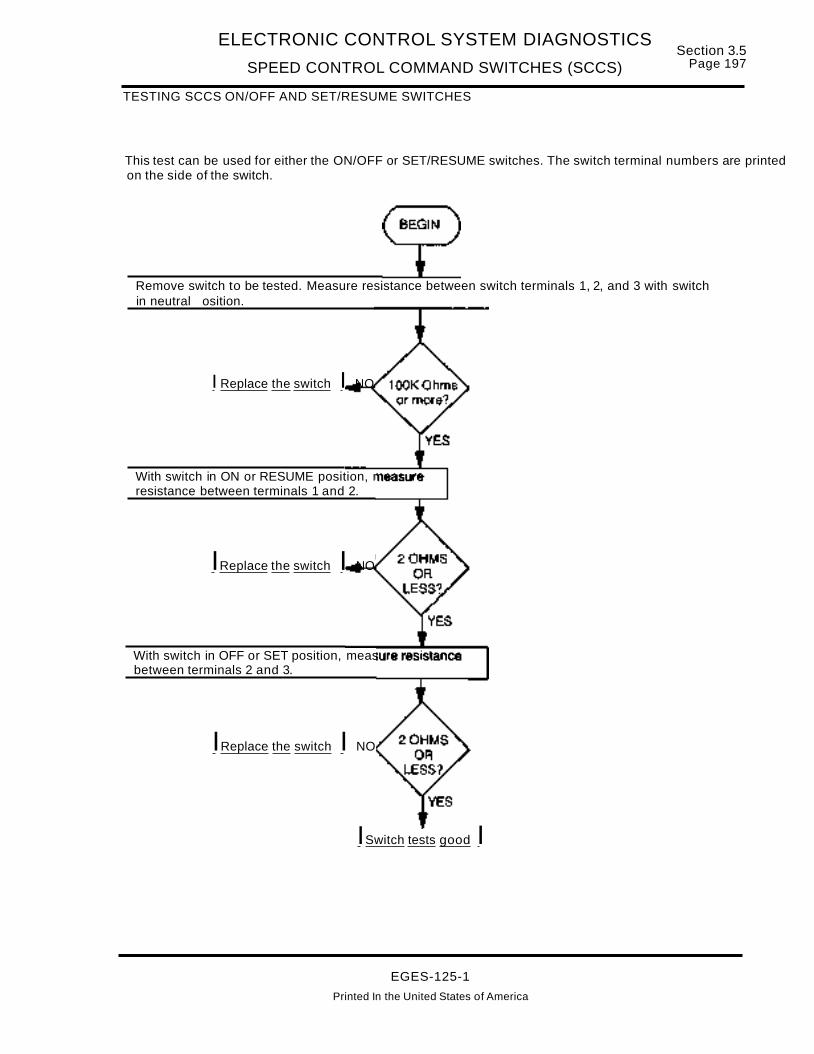
ELECTRONIC CONTROL SYSTEM DIAGNOSTICS
SPEED CONTROL COMMAND SWITCHES (SCCS)
TESTING SCCS ON/OFF AND SET/RESUME SWITCHES
Section 3.5Page 197
This test can be used for either the ON/OFF or SET/RESUME switches. The switch terminal numbers are printedon the side of the switch.
Remove switch to be tested. Measure resistance between switch terminals 1, 2, and 3 with switchin neutral osition.
I Replace the switch I NO
With switch in ON or RESUME position, measureresistance between terminals 1 and 2.
IReplace the switch I NO
With switch in OFF or SET position, measure resistancebetween terminals 2 and 3.
IReplace the switch I NO
ISwitch tests good I
EGES-125-1
Printed In the United States of America

Section 3.5Page 198
ELECTRONIC CONTROL SYSTEM DIAGNOSTICS
SPEED CONTROL COMMAND SWITCHES (SeeS)
REMOTE PTO ONLY DOES NOT OPERATE (OR OPERATES INCORRECTLY)
NOTE: BEFORE DIAGNOSING ANY PROBLEM WITH THE REMOTE PTO, BE SURE THAT THE VEHICLE CRUISE CONTROL SYSTEM OPERATES CORRECTLY.
Remote Preset PTO Mode Does Not Operate Properly
Turning the cruise control on using the cab Cruise ON/OFF switch, then turning the remote Enable Presetswitch ON will cause the PTa to operate at the customer selected preset rpm. The ECM does not diagnosethe Enable Preset switch circuit, therefore there are no fault codes to indicate the circuit is defective.
If the vehicle cruise control works properly, but the remote Enable Preset switch does not work, perform Testing Remote PTa Preset And Variable Enable Circuits.
Remote Variable PTO Mode Does Not Operate Properly
Flash codes 213 and 214 indicate the ECM detected an out-at-range signal (high or low) from the remote pedal sensor (RPS). Note that the ECM does not diagnose the Enable Variable switch circuit, therefore thereare no fault codes to indicate a defect in that circuit.
If the vehicle cruise control works properly, but the remote PTa does not work in the variable mode, checkfor flash codes. If Flash Code 213 or 214 is present or if no Flash Codes are present, perform Testing RemotePTa Preset And Variable Enable Circuits (below) and Testing Remote Pedal Sensor (RPS) Circuits on page200.
Testing Remote PTO Preset And Variable Enable Circuits
This test checks the Navistar installed circuits, but not the body builder switches and circuits. The circuit diagram in this section shows a typical installation of the body builder switches.
Check SA fuse Fa for open condition.
Locate cause of overloadcondition, then correct.Replace 5A fuse.
KEY ON - Disconnect remote PTa controls from Body Builder connector(429), then measure voltage to ground at connector (429) terminal 6 (97DF).
Locate cause of NO orLOW voltage at terminal 6from F6 fuse, then correct.
KEY OFF - Remove ECM connector (379) from ECM and connect breakoutbox to to (379) harness connector, but do not connect to ECM yet.
r---- -----,LContinued..9~Next PageJ
EGES-125-1
Printed in the United States of America

ELECTRONIC CONTROL SYSTEM DIAGNOSTICS
SPEED CONTROL COMMAND SWITCHES (SCCS)Section 3.5
Page 199
Locate short circuit tounwanted voltage source incircuit 97CB, then correct.
TESTING REMOTEPTO PRESET ANDVARIABLE ENABLECIRCUITS (Continued)
KEY ON - Measure voltage between breakout box terminals 2 and 40.
KEY ON - Measure voltage between breakout box terminals 12 and 40.
Locate short circuit tounwanted voltage source incircuit 97CC, then correct.
KEY OFF - Remove #1 ECM PWR fuse. At breakout box, measureresistance between terminal 2 and all other breakout box terminals.
KEY OFF - With #1 ECM PWR fuse removed, at breakout box measureresistance between terminal 12 and all other breakout box terminals.
Locate open or cause of high resistancein circuit 97CB and/or 97CC betweenconnector (429) and (379), then correct.
Locate short circuit between 97CB and anycircuit where terminal resistance is lessthan 1OOK ohms, then correct.NOTE: Less than tOOK ohms betweenterminal 2 and terminals 20, 31, 39, 40 or60 indicates a short to ground in circuit97GB.
Locate short circuit between97CC and any circuit whereterminal resistance is less than1OOK ohms, then correct.NOTE: Less than 100K ohmsbetween terminal 12 and terminals20, 31, 39, 40 or 60 indicates ashort to ground in circuit 97CC.
KEY OFF - At breakout boxinstall jumper betweenterminals 2 and 12. At bodyconnector (429), measureresistance between terminals 7and 8.
Circuits 97CC and97CB check good.Checkcorrespondingbody builderinstalled remoteswitches andwiring for open,short (high or low)and continuity.
EGES-125-1
Printed in the United States of America

Section 3.5Page 200
ELECTRONIC CONTROL SYSTEM DIAGNOSTICS
SPEED CONTROL COMMAND SWITCHES (SCCS)
TESTING REMOTE PEDAL SENSOR (RPS) CIRCUITS
This test checks the Navistar installed circuits, but not the body builder installed remote pedal sensor (RPS)or connecting circuits. The circuit diagram shows a typical installation of the body builder installed RPS.
KEY OFF- Remove connector (379) from ECM and install breakout boxto harness side only.KEY ON- Measure voltage between breakout box terminals 30 and 40.
7 8• I
18 ~11 2\2 ._....~ J
(429)REAR CAB
BODY BUILDERCONN
Locate short in circuit 99Fto unwanted voltagesource, then repair.
1 - 4602-3 - 464 - 46A5 - 46B6 - 970F7 - 97CC8 - 97CB9-10 - 97WA11 - 99F12 - 9700
KEY ON- At breakout box, measure voltage between terminals 51 and 40.
Locate short between 97G and anycircuit where resistance is less than100K ohms then re air.
KEY ON- At connector (429) measure voltage (VREF)to round at circuit 9700. VREF is about 5 volts.
KEY OFF- Install breakout box at ECM connector (379).KEY ON- Measure voltage between breakout box terminals 44 and 40.
Locate short circuit in circuit 97WA to unwanted volta e source then re air.
EGES-125-1
Printed In the United States of America

ELECTRONIC CONTROL SYSTEM DIAGNOSTICS
SPEED CONTROL COMMAND SWITCHES (SCCS)
TESTING REMOTE PEDAL SENSOR (RPS) CIRCUITS (Continued)
KEY OFF - At breakout box measure resistance betweenterminal 51 and all other terminals in breakout box.
Section 3.5Page 201
Locate short circuitbetween 97WA and anycircuit where terminalresistance is less than1OOK ohms, then correct.
KEY OFF - At breakout box install jumper between terminals 30 and 51.At connector 429 , measure resistance between terminals 10 and 11 .
Locate open or causeof high resistance incircuit 99F and/or97WA, then correct.
Navistar installed RPS circuits 97DD(5V), 99F and 97WA check good. Check correspondingbody builder installed circuits for shorts (high or low) and continuity. If circuits all check good,replace the Remote Pedal assembly.
EGES-125-1
PrInted in the United States of America

Section 3.5 ELECTRONIC CONTROL SYSTEM DIAGNOSTICSPage 202 SELF TEST INPUT SWITCH & ENGINE WARN LIGHT {STI/EWL}
SELF TEST INPUT SWITCH AND ENGINE WARNING LIGHT
ECMSTISW
STI48
WARN 17
5V
OV LAMP ON12V LAMP OFF ~---~
I ENGINEI WARNINGI
9IGNITIONVOLTAGE
SIGNAL FUNCTION
SELF TEST INPUT (STI) SWITCH
The STI switch (or Prolink EST) can be used to runthe Key On Engine Off (KOEO) Standard Tests.Faults detected during this test result in active faultcodes, which are transmitted as FLASH codes withthe Warning Light. If no faults are detected, the ECMwill FLASH code 111 (indicates no faults detected).
ECM terminal 48 has 5 volts with the key ON and engine OFF. Depressing the STI switch grounds termi ...nal 48, causing it to change from 5 volts to 0 volts,signaling the ECM to start the KOEO StandardTests.
ENGINE WARNING LIGHT
When the key switch is turned to ON, the amber En...gine Warning Light (EWL) turns ON and stays ON,while the ECM runs normal startup tests, and thenturns OFF. If the ECM detects a problem, the EWLremains on.
Ignition power from fuse F6 (fuse A2 w/FBC) is applied to the EWL. The ground side of the EWL iscan...nected to ECM terminal 17, which is a groundswitch. The ECM applies 12 volts to terminal 17(light OFF) or 0 volts (light ON), in response to engine conditions.
FAULT DETECTION MANAGEMENT
There are no ECM diagnostics for the STI orWarning light circuits.
EGES-125-1
Printed in the United States of America

ELECTRONIC CONTROL SYSTEM DIAGNOSTICS Section 3.5
SELF TEST INPUT SWITCH & ENGINE WARN LIG,HT (STI/EWL) Page 203
Self Test Input!Engine Warning Light
(STIIEWL)
....----------------.Fault Codes:
No Diagnostic Codes for these Systems
ECM (379)
STI48 5V 98
(3) DASH CONN.
6 98
STISW
98-G
97T
14
97T
OV LT: ON
12V LT: OFFINSTRUMENT
26 -12 CLUSTERf----~ ENGINE
I WARNING
IKEY SWITCH IIGNITION~ J- 26-4
'Y,--_~__1_3A_~~28__••I--- JSA F6 W/TRK 28K W/TRK5A A2 W/FBC 28E W/FBC
WARN 17
Test STI switch with ignition key "OFF"Test Points Spec. Comments
Across > 1000 ohmsSwitch < than 1000 ohms replace switch.Terminals open position
Across < 5 ohms> than 5 ohms replace switch.Switch
Terminals closed position
Spec.
> 1000 ohms
Test at STI switch connection with ignition key "OFF"
Comments
< than 1000 ohms locate short to ground
Test at STI switch connection with ignition key "ON"Test Points Spec. Comments
98 to grd 5 ±.5 volts < than 4.5v check connections, if 0 volts, check for open/short to ground in ckt. 98
98 to 98-G 5 ±.5 volts < than 4.5v check connections, if 0 volts, check for open in ground circuit
IF warning light does not turn on whenkey is turned ON1. Check fuse and bulb condition.2. Disconnect (379) from ECM and install
breakout box to harness. Jumperterminal 17 to ground and note if light isON.A. If light is ON, the ECM is defective.B. If light does not turn ON, check cir
cuit for open condition.
B. If light goes OFF, ECM is defective.
IF warning light STAYS ON after self test1. Check for active fault conditions (use Prolink or STI
flash codes).A. If active fault conditions are present correct
faults.B. If no fault conditions are present go to step 2.
2. Disconnect (379) from ECM and note if LIGHTremains ON.A. If light remains ON, check for short to ground
in circuit.
EGES-125-1Printed in the United States of America

Section 3.5 ELECTRONIC CONTROL SYSTEM DIAGNOSTICSPage 204 SELF TEST INPUT SWITCH & ENGINE WARN LIGHT (STI/EWL)
EXTENDED DESCRIPTION
Refer to circuit diagram on page 205 for the following discussion.
STISWITCH
The STI switch (or Prolink EST) can be used to runthe Key On Engine Off (KOEO) Standard Tests.Faults detected during this test result in active faultcodes, which are transmitted as FLASH codes withthe Warning Light. If no faults are detected, the ECMwill FLASH code 111 (indicates no faults detected).
Depressing the STI switch with the key ON and engine OFF starts the test cycle. The KOEO Standardtests include: (1) ECM Internal Tests and (2) OutputCircuit Check (OCC) tests.
The normally open (N.O.) switch has one pole connected through circuit 98 and ECM connector (379)to the ECM's STI terminal 48. The other switch poleis connected (circuit 98-G/11-GA) to the G2 groundstud.
ECM terminal 48 has5 volts with the key ON and engine OFF. Depressing the STI switch grounds terminal 48, causing it to change from 5 volts to 0 volts,signaling the ECM to start the KOEO StandardTests.
ENGINE WARNING LIGHT
When the key switch is turned to ON, the amber Engine Warning Light (EWL) turns ON and stays ON,while the ECM runs normal startup tests, and thenturns OFF8 If the ECM detects a problem, the EWLremains on.
Refer to circuit diagram on page 205 for the following discussion.
Ignition power from fuse F6 (fuse A2 w/FBC) is applied to the EWL. The ground side of the EWL is connected to ECM terminal 17, which is a ground
switch. The ECM applies 5 volts to terminal 17 (lightOFF) or 0 volts (light ON), in response to engineconditions.
ECM DIAGNOSTICS
There are no ECM diagnostics for the STI or Warning Light circuits.
TROUBLESHOOTING
SELF TEST INPUT (STI) SWITCH
If depressing the STI switch with key on and engineoff does not cause the OCC tests to run (if no faultsare detected code 111 should flash), perform Testing The STI Circuit on page 206.
ENGINE WARNING LIGHT (EWL)
If the EWL does not turn ON during the ECM startuptests, or stays ON after the engine is running withNO ACTIVE FLASH CODES, perform EngineWarning Light Does Not Turn ON test page 207 orEngine Warning Light Stays ON test page 208.
BEFORE TROUBLESHOOTING
A. Before troubleshooting, make sure that the bat..teries are fully charged! Check battery connections and grounds for clean, tight connectionsfree of damage. Voltage tests will give misleading results if the batteries are not fully charged.
B. Before troubleshooting, inspect circuit connectors for pushed back, loose, or damaged(spread or bent) terminals, or wires with cutstrands, etc. Wires and connections must befree of damage or corrosion. When some connectors corrode, a light white residue will bepresent that must be removed.
C. Before troubleshooting, inspect suspect circuitgrounds for clean, tight connections free ofdamage.
EGES-125-1
Printed In the United States of America
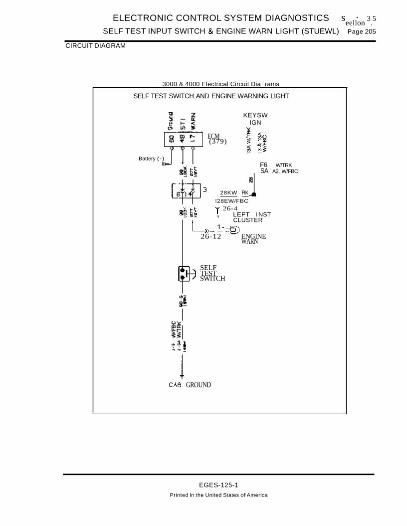
ELECTRONIC CONTROL SYSTEM DIAGNOSTICS s · 3 5eellon .
SELF TEST INPUT SWITCH & ENGINE WARN LIGHT (STUEWL) Page 205
CIRCUIT DIAGRAM
3000 & 4000 Electrical Circuit Dia rams
SELF TEST SWITCH AND ENGINE WARNING LIGHT
KEYSWIGN~a::~ ~u:> ""1:0
olSU-~ ~~,... ,...
ECM(379)
F6 W/TRKm~ ~~ SA A2, W/FBC
~3 28KW RK
~ !28EW/FBC~ t-!> r 26-4
m~ m! , LEFT I NST
LCLUSTER
1- --Fi'l>---t=-J26-12 ENGINE
WARN
Battery (-)II
SELFTESTSWITCH
1CAB GROUND
EGES-125-1
Printed In the United States of America

S t- 3 5 ELECTRONIC CONTROL SYSTEM DIAGNOSTICS
ec Ion .Page 206 SELF TEST INPUT SWITCH & ENGINE WARN LIGHT (STI/EWL)
TESTING THE SELF TEST INPUT (STI) CIRCUIT
Refer to circuit diagram on ~page 205. --.--
With key OFF, disconnect 98-G from STI switch. Measure resistance to ground.
Locate open in groundcircuit 98-G/11-GA,then correct.
With key OFF, disconnect 98 from STI switch. Use ohmmeter to test STI switch. Thereshould be less than 2 ohms when depressed and 100K ohms or more when released.
Replace STIswitch.
With key OFF, remove connector (379) from ECM and connect breakout box to harness,but not to ECM. Measure resistance between breakout box terminals 48 and 60.
Locate short toground in circuit98, then correct.
With key ON, measure voltage between breakout box terminals 48 and 60.
Locate circuit 98short circuit to "HOT"wire, then correct.
Locate open in circuit98, then correct.
With key OFF, at breakout box, installjumper between terminals 48 and 60.At STI switch, measure resistance toground at circuit 98.
YesI,....R-e-p-Ia-c-e-th-e-E-C-M-.-
EGES-125-1Printed in the United States of America

ELECTRONIC CONTROL SYSTEM DIAGNOSTICS S .eetlon 3.5
SELF TEST INPUT SWITCH & ENGINE WARN LIGHT (STI/EWL) Page 207
ENGINE WARNING LIGHT DOES NOT COME ON DURING START-UP
Check fuse F6 (or A2 with FBC) for open condition.
Locate cause of overloadcondition, then correct.Replace fuse.
Check condition of EWL bulb.
Replace#37 bulb.
Remove connector (379) from ECM. Install breakout box to harness, but not to ECM.Jumper breakout box termjnal17 to 60. Turn key ON and note if EWL is ON.
I Replace ECM. I
No - Leave jumper in place
Remove connector (26) from cluster. Turn key ON andmeasure voltage to ground at connector (26) terminal 4.
Locate cause of NO or LOWvoltage in feed circuit fromfuse and correct.
Locate open in circuit97T, then correct.
With key ON, measurevoltage between connector(26) terminals 4 and 12.
Replaceinstrumentcluster.
EGES-125-1Printed in the United States of America
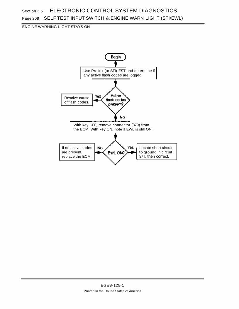
Section 3.5 ELECTRONIC CONTROL SYSTEM DIAGNOSTICSPage 208 SELF TEST INPUT SWITCH & ENGINE WARN LIGHT (STI/EWL)
ENGINE WARNING LIGHT STAYS ON
Use Prolink (or STI) EST and determine ifany active flash codes are logged.
Resolve causeof flash codes.
With key OFF, remove connector (379) fromthe ECM. With key ON, note if EWL is still ON.
If no active codesare present,replace the ECM.
Locate short circuitto ground in circuit97T, then correct.
EGES-125-1
Printed In the United States of America
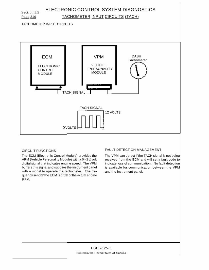
ELECTRONIC CONTROL SYSTEM DIAGNOSTICSSection 3.5Page 210 TACHOMETER INPUT CIRCUITS (TACH)
TACHOMETER INPUT CIRCUITS
ECM
ELECTRONICCONTROLMODULE
VPM
VEHICLEPERSONALITY
MODULE
DASHTachometer
• •I TACH SIGNAL
TACH SIGNAL
oVOLTS '--- _
CIRCUIT FUNCTIONS
The ECM (Electronic Control Module) provides theVPM (Vehicle Personality Module) with a 0 -12 voltdigital signal that indicates engine speed. The VPMbuffers this signal and supplies the instrument panelwith a signal to operate the tachometer. The frequency sent by the ECM is 1/5th of the actual engineRPM.
12 VOLTS
FAULT DETECTION MANAGEMENT
The VPM can detect if the TACH signal is not beingreceived from the ECM and will set a fault code toindicate loss of communication. No fault detectionis available for communication between the VPMand the instrument panel.
EGES-125-1Printed in the United States of America

ELECTRONIC CONTROL SYSTEM DIAGNOSTICS
TACHOMETER INPUT CIRCUITS (TACH)Section 3.5
Page 211
Tachometer Fault Codes:(TACH) 233 Tachometer Buffer Inoperative
ECMConnector
(Pin numbers)
VPMConnector
(Pin numbers)
TACH OUT (#1)
DASHTachometer
C VIGN
36TACH (from ECM)
4
6
Owner Operator Tachometer
TACH OUT (#2)
Key ON Engine Off - Voltage Checks at ECM(Check with breakout box installed and the Ignition Key ON, Engine OFF)
Spec. Signal Comments
12 ± 1.5 v TACH The signal is pulled up by the VPM with the key ON and engine OFF.
Connector Checks to Ground at ECM(Check with with breakout box installed, ignition key should be in the OFF position)
Test Points Spec. Signal Comments
> 1000 ohmsLess than 1000 ohms indicates a short to grd either thru the harness or internal
#36 to #46 TACH in the ECM. Disconnect the ECM from the breakout box and measure to grdagain, if short is still present repair harness.
Harness Resistance Checks From ECM to VPM(Check with breakout box installed, ignition key should be in the OFF position)
Test Points Spec. Signal Comments
#36 to 4 < 5 ohms TACH Resistance from 60 pin connector to harness connector - TACH Signal
#36 to 5 < 5 ohms TACH Resistance from VPM connector to TACH input at instrument panel- Dash Tach
#36 to 6 < 5 ohms TACH Resistance from VPM connector to TACH input - Optional Owner/Operator Tach
Key ON Engine Running - Signal Checks - TACH(Check with breakout box installed)
Specification Comments
5 to 7 volts/140 to 540 Hz TACH signal from the ECM is a frequency that is engine RPM + 5
Fault Code Descriptions223 = ECM TACH signal not communicating with VPM
EGES-125-1Printed in the United States of America

Section 3.5Page 212
DESCRIPTION
ELECTRONIC CONTROL SYSTEM DIAGNOSTICS
TACHOMETE~ INPUT CIRCUITS (TACH)
Refer to the circuit diagram on page 213 for this dis-cussion. ·
TACHOMETER INPUT SIGNAL
The ECM receives signals from the CMP sensorand calculates engine speed (rpm). The ECM sendsthe calculated engine speed as a digital TACH signal from ECM connector 36 (circuit 970) to the VPMat connector (381) terminal 4.
The VPM buffers the TACH signal received' fromECM and sends a pulse width modulated (PMW)signal to the Speedometer/ Tachometer unit at center liP connector (27).
ENGINE SPEED SIGNAL TO PROLINK EST
Engine rpm can be monitored using the ProlinkElectronic Service Tool (EST) connected to the ESTconnector (384). It is important to note that the signal comes through different circuits.
The engine speed signal read by the Prolink ESTcomes from the ECM, but is sent from ECM terminals 9 and 28, through the Data Communicationlink, DCl (+) and DCl (-) circuits, to the VPM', thenthrough the ATA Data Link, ATA (+) and ATA (-) cir-cuits, to the EST connector (384). '
ECM DIAGNOSTICS
If the CMP signal is not received and processed bythe ECM, the engine will not start. If the engine isrunning, but the tachometer does not operate (oroperates improperly), there are two tests to furtherisolate the problem.
TESTING SPEEDOMETERITACHOMETERCLUSTER
With the key ON and engine OFF, the SpeedometerlTachometer unit, located in the instrument panel,will perform a self-test, checking the tachometergauge and the speedometer/tachometer controlunit. Refer to Service Manual, Group 08, Instru-
ments for the appropriate section for information onperforming this test.
KOER TACH BUFFER TEST
The KOER Tach Buffer Test must be run when engine speed is greater than 1250 rpm. This testchecks the circuit (970) between the ECM and VPMfor open or short (high or low) circuit condition. Italso checks the internal VPM buffer circuit for openor short (high or low) conditions. If a defect is found,Flash Code 233 is set.
FLASH CODE 233PID 190 FMI2VPM: TACHOMETER BUFFER INOPERATIVE
This code is set during the KOER Tach Buffer Testif:
A. Engine speed is less than 1250 rpm.
B. Circuit 970 is open or shorted (high or low) between the ECM and VPM causing the VPM toreceive either no signal or an invalid signal.
C. The VPM internal buffering circuit is defective.
CORRECTIVE ACTION
If the tachometer doesn't work and:
A. The SpeedometerlTachometer Self-Test doesnot indicate a defect, perform Testing Circuit97AR on page 214. If the self-test revealed adefect, follow service manual recommendedcorrective action.
B. The Tach Buffer KOER test does not set a faultcode, then check circuit 97AR between VPMconnector (381 ) and liP connector (27) for openor short (high or low) circuit by performing Testing Circuit 97AR on page 214.
C. If the Tach Buffer KOER test does set Flashcode 233, perform Testing ECM/VPM Tachometer Circuit on page 215.
, EGES-125-1
Printed In the United States of America

ELECTRONIC CONTROL SYSTEM DIAGNOSTICS
TACHOMETER INPUT CIRCUITS (TACH)
CIRCUIT DIAGRAM
TACHOMETER INPUT CIRCUIT
ATA LINKTO EST CONN
(384)
CMPSGNTOECM
Section 3.5Page 213
VPM(381)
ECM(379)
CMP56
Del (-) 9
DCL(+) 28
TACS6
(3 &3A)
97AT
97AS
970
(435)
: N6iE~ Connecto; (43-S)is ~I not used with SC models. I.. _ .. _ .... ,.. .... ,f
97AT
97AS
970
8TWISTED
WIRE-PAIR
a:~CJ)
TACHOMETER INPUT
EGES-125-1Printed In the United States of America
lIP CONN( 27)

Section 3..5Page 214
ELECTRONIC CONTROL SYSTEM DIAGNOSTICS
TACHOMETER INPUT CIRCUITS (TACH)
TESTING TACHOMETER CIRCUIT 97AR
Perform SpeedometerfTachometer Self-Test before performing this test.
~KEY OFF - Remove green connector (27) from speedometer/tachometer module. TurnKEY ON - At connector (27), terminal 14 (circuit 97AR) , measure voltage to ground.
Locate defect in clusterconnector orspeedometer/tachometer unit,then correct. Refer to ServiceManual Group 08, Instrumentsfor the appropriate section.
Connector (27)@MAIN CAe
1;~8BBiBB8J~r~
KEY OFF - With connector (27) disconnected, remove connector (381) fromVPM. Turn key ON and measure voltage to ground at (27) terminal 14 (97AR).
In circuit 97AR, locateshort circuit to "HOT" wirebetween connectors (381)and (27), then correct.
KEY OFF - Me-asure resistance to ground at connector (27), terminal 14 (circuit 97AR).
Locate short circuit toground in circuit 97ARbetween connectors (27)and (381), then correct.
l6 9 1
(381)23 15 8
Locate open or cause of highresistance in circuit 97ARbetween connectors (27) and(381), then correct.
KEY OFF - Measure resistance between connector (27), terminal 14(circuit 97AR) and connector (381) terminal 5 (circuit 97AR).
Perform Testing ECMNPM Tachometer Circuit on page 215.
EGES-125-1Printed in the United States of America

ELECTRONIC CONTROL SYSTEM DIAGNOSTICS
TACHOMETER INPUT CIRCUITS (TACH)
TESTING ECMNPM TACHOMETER CIRCUIT
Perform this test when Flash Code 233 is ACTIVE.
~KEY OFF - Remove connector (379) from ECM and install breakout box toharness, but do not connect to ECM yet. Remove connector (381) from VPM.
KEY ON - Measure voltage between breakout box terminals 36 and 40.
Section 3.5Page 215
Locate short to"HOT" wire in circuit970, then correct.
KEY OFF - Measure resistance between breakout box terminals 36 and 40.
KEY OFF -Install jumper between breakout box terminals 36 and 40. Atconnector (381), measure resistance to ground at terminal 4 (circuit 970).
Locate short toground in circuit970, then correct.
Locate open or causeof high resistance incircuit 970 betweenconnectors (379) and(381), then correct.
(381)
23 15 8
°0°°0°°0°°0° I
°0°0 0 0
°0°o 0
16 9 1
KEY OFF - Remove jumper and connect breakout box to ECM. Turn KEYON and measure voltage between breakout box terminals 36 and 40.
Replacethe ECM.
.---_ .. _------- ..: See next page :...... _----------- ...
EGES-125-1
Printed In the United States of America

Section 3.5Page 216
ELECTRONIC CONTROL SYSTEM DIAGNOSTICS
TACHOMETER INPUT CIRCUITS (TACH)
TESTING ECMNPM TACHOMETER CIRCUIT (Continued)
tKEY OFF - With VPM disconnected, disconnect green cluster connector(27) from Speedometern-achometer cluster in instrument panel.
KEY ON - At harness connector (27), terminal 14 (circuit 97AR) , measure voltage to ground.
In circuit 97AR, locate shortto ··HOT" wire betweenconnectors (381) and (27),then correct.
Connector (27)@WAIN CAe
1;~BBBJLBBB]]I~
KEY OFF - At harness connector (27), terminal 14, measure resistance to ground.
In circuit 97AR, locateshort circuit to groundbetween connectors (381)and (27), then correct.
KEY OFF - Measure circuit 97AR resistance between connector (381) and connector (27).
KEY OFF - Connect (381) to VPM, then turn KEY ON andmeasure voltage to ground at connector (27), circuit 97AR.
Locate open or cause ofhigh resistance in circuit97AR, then correct.
Replace the VPM(Vehicle PersonalityModule).
(381)
23 15 8
16 9 1
Locate defect in connector (27) or speedometer cluster causing tachometer not towork properly, then correct. Refer to Service Manual Group 08, Instruments.
EGES-125-1Printed In the United States of America

Section 3.5Page 218
ELECTRONIC CONTROL SYSTEM DIAGNOSTICS
TWO SPEED AXLE INPUT CIRCUIT (TSA)
TWO SPEED AXLE SPEEDOMETER CIRCUIT
KEY SWITCH
TWO SPEED AXLE.....---l~ SHIFT SWITCH
TO SHIFTER
SIGNAL FUNCTIONS
The VPM is programmed with the high and low rearaxle ratios. The ratios are used to calculate thespeedometer signal, depending on which mode theswitch is in. The VPM uses the high ratio unlessvoltage is applied to VPM terminal 9 indicating thetwo speed selector switch is in the low range.
The two speed switch applies 12 volts to the VPMat terminal 9 ( and to the shifter) when 'the switch isin the LO position.
FAULT DETECTION MANAGEMENT
There are no ECM diagnostics for thE~ two speedcircuits.
EGES-125-1
Printed in the United States of America

ELECTRONIC CONTROL SYSTEM DIAGNOSTllCS
TWO SPEED AXLE INPUT CIRCUIT (TSA)Section 3.5
Page 219
Two Speed Axle SpeedometerFault Codes:
(TSA) There are no Diagnostic Codes for this application.
VPM CONNECTORVPM HARNESS (38 1 )
8
15
23
1
9
16
VPM (381)
12 volts in LOW range from 2 speedswitch.
USE PROLINK EST TO PERFORM THE FOLLOWING TEST
1. Use Prolink EST to verify correct VPM programming including correct rear axle ratios (high and low)
A. If programmed correctly go to step 2.
B. If programming is not correct, make necessary programming corrections.
2. Use EST to monitor two speed switch while changing switch position several times.
A. If switch does not function, go to step 3.
B. If switch functions properly go to step 4.
3. Disconnect connector (381) from VPM. With key ON and switch in LOW position, measure voltage toground at circuit 93A. Battery voltage (12 ± 1.5 volts) should be present.
A. If less than 10.5 v check connections, if a volts check for open/short to ground.
B. If battery voltage is present, replace the VPM.
4. Refer to Service Manual Group 08 Instruments, and perform Speedometer Self Diagnostic Test.
A. If the self test is not OK, follow the recommendations of the service manual.
B. If the self test is OK, road test the vehicle and have a passenger monitor vehicle speed using the Prolink. If the Prolink displays the correct speed replace the speedometer/tachometer unit. If the Prolinkdoes not display the correct speed, replace the VPM.
EGES-125-1Printed In the United States of America

Section 3.5Page 220
ELECTRONIC CONTROL SYSTEM DIAGNOSTICS
TWO SPEED AXLE INPUT CIRCUIT (TSA)
EXTENDED DESCRIPTION
NOTE: THE PURPOSE OF THIS SECTION ISTO DIAGNOSE THE TWO SPEED INTERFACEWITH THE SPEEDOMETER. THIS SECTIONDOES NOT DIAGNOSE TWO SPEED AXLE OPERATION.
The vehicle speed sensor reads the revolutions ofthe transmission speedometer gear and sends asignal to the VPM. VPM programming includes thehigh and low rear axle ratios. The VPM uses thesensor input and rear axle rations to calculate thespeedometer signal, depending on which range thevehicle is operating in. When voltage is applied toVPM terminal 9 from the two speed circuit, the VPMuses the low ratio.
The Two Speed Axle switch receives ACC powerfrom 10A fuse F14. This is a normally open switchwith "High" as the normal operating position. Withthe Two-Speed switch in the "Low" position, 12Vaccessory power is applied through VPM connector(381) at VPM terminal 9.
ECM DIAGNOSTICS
There are no ECMNPM diagnostics for this circuit.
TROUBLESHOOTING
If the speedometer/odometer does not correctlyshow vehicle speed when changing frorn the high tolow range, or low to high range, perform TestingTwo-Speed Speedometer Circuit on page 223.
BEFORE TROUBLESHOOTING
A. Before troubleshooting, make sure that the batteries are fully charged! Check battery connections and grounds for clean, tight connectionsfree of damage. Voltage tests will give misleading results if the batteries are not fully charged.
B. Before troubleshooting, inspect circuit connectors for pushed back, loose, or damaged(spread or bent) terminals, or wires with cutstrands etc. Wir~s and connections must befree of damage or corrosion. When some connectors corrode, a light white residue will bepresent that must be removed.
C. Before troubleshooting, inspect suspect circuitgrounds for clean, tight connections free ofdamage.
EGES-125-1
Printed In the United States of America

ELECTRONIC CONTROL SYSTEM DIAGNOSTICS
TWO SPEED AXLE INPUT CIRCUIT (TSA)Section 3.5
Page 221
CIRCUIT DIAGRAM TWO SPEED ELECTRIC (AIR)
3000 & 4000 Electrical Circuit Diagrams
AXLE. TWO SPEED ELECTRIC (AIR)
ACC (J2)
tII
< ....~~
F14 ~-15A. -
IS lOA
r J2D __--.....39----(1-3~-~4) TOAIR93 l'lLT IlL ~ 16GY DRYER
TRACTOR I~ONLY [
(14-A)",
(55) 2-SPD SWITCHW/MANUAL XMSNON SHIFT LEVER
M1 RED j (59-C)1r-14RO-
( (14-C)
M1 BLUE--14BL-~ (59-A)
(75) 2-SPD SWITCHW/AUTOXMSNON INST PANEL
TWO SPEEDAXLE SOLEN01D
(263)
(13-K2)(N/USED)
<tilt-
T(~~~)
m~t(436-4)
93A 59-BlBTN-------~>-----J--~-
EGES-125-1Printed In the United States of America

Section 3.5Page 222
ELECTRONIC CONTROL SYSTEM DIAGNOSTICS
TWO SPEED AXLE INPUT CIRCUIT (TSA)
TWO SPEED ELECTRIC (HYDRAULIC)
3000 & 4000 Electrical Circuit Diagrams
(55) 2 -SPD SWITCHW/MANUAL XMSNON SHIFT LEVER:
M1 - Blue- - -14B"[ - --:& (59-A)
(75) 2-SPD SWITCHW/AUTOXMSNINST PANEL
AXLE, TWO SPEED ELECTRIC (HYDRAULIC)Ace (J2)
tII
< ....~~
A F14 ~l;i
ft lOA ,
<(J).....
T[~~~l
~~OJ!!t(436-4)
~ir~-------~'>-------- ~;;~
(13- K2)1__----.zco'V......
_M.L---.BED j (59-C)/"- 14RD
Zf~14-c).-(\')'Va>
...... Q (13-K1)a:'V.....
TWO SPEEDAXLE MOTOR
(703)
14WH
FRAME GROUND'='
EGES-125-1
Printed In the United States of America

ELECTRONIC CONTROL SYSTEM DIAGNOSTICS
TWO SPEED AXLE INPUT CIRCUIT (TSA)Section 3.5
Page 223
TESTING TWO-SPEED SPEEDOMETER CIRCUIT
Refer to circuit diagramon page 221 or 222.
Use Prolink EST to verify that the VPM is programmed for 2-speed axle, including correct axle ratios.
Program for 2-speeda lication
Change 2-speed switch position several times while monitoring with Prolink. Note if switch isfunctionin .
1
9
16
Followrecommendationsof the servicemanual.
VPM CONNECTORVPM HARNESS (38 1 )
8
15
23
Refer to Service Manual Group 08,Instruments and performSpeedometer Self Diagnostic Test.
Locate cause of NOor LOW voltage incircuit 93A and repair.
KEY ON- Disconnect connector (381). With2-spd switch LO, measure voltage to ground atcircuit 93A (terminal 9)
Road test the vehicle and have passenger monitor vehicle speed using Prolink EST. IF EST displayscorrect speed replace the speedometer/tachometer unit. If the EST does not display correct speedreplace the VPM.
EGES-125-1Printed In the United States of America
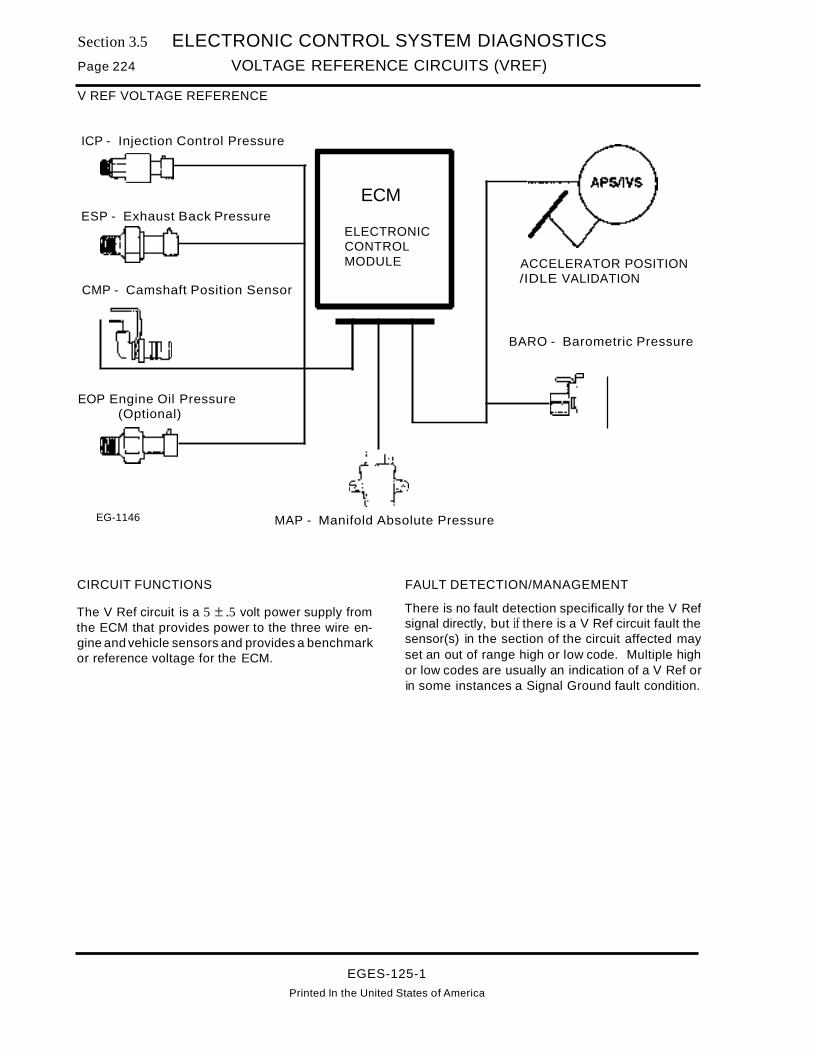
Section 3.5 ELECTRONIC CONTROL SYSTEM DIAGNOSTICSPage 224 VOLTAGE REFERENCE CIRCUITS (VREF)
V REF VOLTAGE REFERENCE
ICP - Injection Control Pressure
ECMESP - Exhaust Back Pressure
ELECTRONICCONTROLMODULE
CMP - Camshaft Position Sensor
EOP Engine Oil Pressure(Optional)
ACCELERATOR POSITION/IDLE VALIDATION
BARO - Barometric Pressure
EG-1146 MAP - Manifold Absolute Pressure
CIRCUIT FUNCTIONS
The V Ref circuit is a 5 ± .5 volt power supply fromthe ECM that provides power to the three wire engine and vehicle sensors and provides a benchmarkor reference voltage for the ECM.
FAULT DETECTION/MANAGEMENT
There is no fault detection specifically for the V Refsignal directly, but if there is a V Ref circuit fault thesensor(s) in the section of the circuit affected mayset an out of range high or low code. Multiple highor low codes are usually an indication of a V Ref orin some instances a Signal Ground fault condition.
EGES-125-1
Printed In the United States of America

ELECTRONIC CONTROL SYSTEM DIAGNOSTICS
VOLTAGE REFERENCE CIRCUITS (VREF)Section 3.5
Page 225
Voltage Reference Circuits(V Ref)
Engine Sensors(V Ref)
ICP Sensor
Deutsch Connector(On Valve Cover)
Fault Codes:Multiple out of range high/low faults set.
(Dependent upon where open or short is located.)
ECM Deutsch Connector Vehicle SensorsConnector (On Cowl) (V Ref)
APS/IVS Sensor
ABCDEF
ACB _ ..... 24 ...----.. 26 t_---.. 12 ....--...............---..
ESP Sensor
AcBL-L...... ..
CMP Sensor
Ac81.-......... ..
AC
B 1.-......,..---,.
8 C A
MAP Sensor(Mounted on Cowl) EG-1147
BARO Sensor
Connector V Ref Voltage Checks(If multiple faults set remove and measure V Ref at suspected sensor circuits)
Sensor Test Points Spec. Comments
ICP S to Grd 5 ±.5 v Check V Ref at suspected sensors one at a time. Identifying which sensors do
ESP S to Grd 5 ±.5 v not have V Ref and which ones share common V Ref feed will more quickly
CMP B to Grd 5±.5 vhelp isolate the area of a short or open circuit.
MAP B to Grd 5±.5 v If disconnecting a sensor causes V Ref to be present at a circuit that hadAPS/IVS C to Grd 5±.5 v previously lost V Ref it is likely that the disconnected sensor had shorted
BARD B to Grd 5± .5v V Ref to ground.
Sensor Test Points Spec. Comments
ICP B to Grd > 1000 ohms Resistance < 1000 ohms indicates a short to grd. If a short to grd condi-
ESP B to Grd > 1000 ohms tion is identified, remove all sensor connectors that are connected to V
CMP B to Grd > 1000 ohmsRef and ECM to determine if short is in a sensor, ECM or wire harness.
MAP B to Grd > 1000 ohmsIf the short is identified in the harness, remove the intermediate Deutsch
APS/IVS C to Grd > 1000 ohms connectors and measuring to grd will identify which part of the harnessBARD S to Grd > 1000 ohms the short is located in.
Connector Checks to Chassis Ground(Check with Sensor Connector(s). Disconnected and ignition key OFF, all accessories off)
Sensor Test Points Spec. Comments
ICP B to #26 < 5 ohms The measurement is taken form the sensor connector to the ECM 60 pin
ESP B to #26 < 5 ohms connector. Resistance greater than 5 ohms indicates high resistance or an
CMP B to #26 < 5 ohmsopen in the V Ref supply circuit
MAP B to #26 < 5 ohmsAPS/IVS C to #26 < 5 ohms
BARD B to #26 < 5 ohms
Harness Resistance Checks(Check with breakout box installed on harness only)
EGES-125-1Printed In the United States of America

Section 3.5Page 226
ELECTRONIC CONTROL SYSTEM DIAGNOSTICS
VOLTAGE REFERENCE CIRCUITS (VREF)
VOLTAGE REFERENCEEXTENDED SYSTEM DESCRIPTION
FUNCTION
The Electronic Control Module contains a regulated5 volt DC voltage reference source to power engineand vehicle control sensors. The sensor signals arecompared to the Voltage Reference to determineactual sensor output signal values. These valuesare processed by the ECM for engine operation.
OPERATION
The ECM is supplied with Battery Voltage when theignition key is ON at terminals 37 and 57. Ground
circuits are supplied at terminals 20, 40 and 60~ TheECM provides a constant regulated 5 volt referencesignal from terminal 26 to supply voltage to engineand vehicle sensors. A return circuit for sensors issupplied at terminal 46.
ECM VOLTAGE REFERENCE DIAGNOSTICS
If multiple sensor codes are set, it is possible thatthe V REF signal circuit is open or the return signalcircuit is open. Follow troubleshooting proceduresto determine if V REF circuits are at fault. The engine will not run without a valid V REF signal.
EGES-125-1
Printed In the United States of America
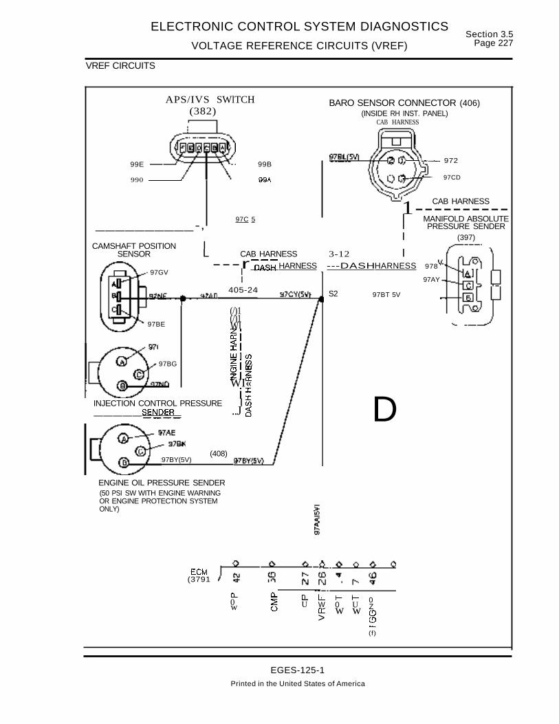
ELECTRONIC CONTROL SYSTEM DIAGNOSTICS
VOLTAGE REFERENCE CIRCUITS (VREF)Section 3.5
Page 227
VREF CIRCUITS
97AY
~l-4r--- 972
~-- 97CD
97BT 5V
D
BARO SENSOR CONNECTOR (406)(INSIDE RH INST. PANEL)
CAB HARNESS
S2
99A
99B
(408)97BY(5V)
97BG
97BE
APS/IVS SWlTCH(382)
990 -_-I
99E
(/)1(/)1WI~I~IwlcnZICf)- w(!)IzZ a:WI«II
INJECTION CONTROL PRESSURE I ~_____SENDE~ ..J c3
CAB HARNESS1----------97C 5 I MANIFOLD ABSOLUTE
__________-, I PRESSURE SENDERI (397)
CAMSHAFT POSITION ISENSOR L CAB HARNESS 3-12 I
---rl
DASHHARNESS ---DASHHARNESS 97897GV
I405-24
ENGINE OIL PRESSURE SENDER(50 PSI SW WITH ENGINE WARNINGOR ENGINE PROTECTION SYSTEMONLY)
ECM(3791
C- o.. 0.. l.L J- J- 00 ~ U W 0 U Zw 0 a: w w (.!)> C!)
--.(f)
EGES-125-1Printed in the United States of America

Section 3.5Page 228
ELECTRONIC CONTROL SYSTEM DIAGNOSTICS
VOLTAGE REFERENCE CIRCUITS (VREF)
VREF CIRCUITS (CONTINUED)
Refer to circuit diagramon page 227.
KEY OFF- Remove connector from suspect sensor. Measure resistance to ground at VREFconnector terminal.
Disconnect all sensors, one at a time andmeasure resistance to ground afterdisconnecting each sensor.
Locate groundedcircuit with less than1000 ohms resistanceto ground and repair.
Replace the shorted sensor that correctedresistance readin b disconnectin it.
KEY OFF- Install breakout box at ECM connector(379). Measure resistance between terminal 26and VREF terminal at the suspect sensorconnector.
Locate open in VREFcircuit between ECMconnector (379) andsuspect sensor connectorand repair.
KEY ON- At suspect sensor connector, measure voltage to ground at VREF terminal.
One at a time, disconnect all sensors andmeasure voltage at the VREF terminal afterdisconnecting each sensor.
IReplace the ECM i NOVREF circuit operating voltage is correct. If voltagedrops when sensor is connected, replace thesensor and retest.
EGES-125-1
Printed in the United States of America

Section 3.5Page 230
ELECTRONIC CONTROL SYSTEM DIAGNOSTICS
VEHICLE PERSONALITY MODULE (VPM)
VEHICLE PERSONALITY MODULE
ECM VPMDASH
TachometerDASH
Speedometer
ELECTRONICCONTROLMODULE
VEHICLEPERSONALITY
MODULE
][000 II]000 [!]0008otENTERI EJ
IFUNCI
T......~_......l 1 I .. ~ !~~~_~i~~~I : Speedometer Signal jI TACH Signal 1 : I : 1 _
'- - - - - - - - - - - _.& I .. _ _ _ _ _ _ _ _ _ _ _ _ _ _ _ _ _ _ _ _ _ _ _ ...
I Del Communications ~ I ATA Communications __...-.__........~-------------- ,
II
•VSS I
Signal:I
VSS :Vehicle Speed Sensor 1
0~--jEST
Electronic Service Tool
CIRCUIT FUNCTIONSThe VPM (Vehicle Personality Module serves fourmajor functions.Programming
• Provides th~ factory the ability to set EngineRatings and Horsepower.
• Accommodates field re-programming forchanges to tire size, rear axle, transmissionchanges etc.
• Enables and allows adjustment to "CustomerFeatures" such as cruise control set points,road speed limiting, PTa speeds.
Diagnostics fault retrievalandcommandofspecial operator on-demand tests.With the use of an EST (Electronic Service Tool) theVPM will allow for:
• Retrieval of continuous fault codes set in eitherthe IDM, ECM and VPM.
• Command of special diagnostic tests such asinjector tests, engine running tests, output stateand wiggle tests.
• Display of engine and vehicle PID's (parameters) on a real time basi~. (eg. coolant ~emper~ture, engine speed, cruise control sWitch pOSItion,etc.)
Stores accumulated values/logs engine events
• Vehicle Miles/Hours/Fuel used
• Logs engine events such as over heat, low oilpressure and over speed conditions.
Drives dash tachometer and speedometer
• Receives inputs from the ECM and TACH sensor.
• Buffers signals and drives instrument panelTACH and Speedometer gauges
• Communicates vehicle speed to the ECM.
FAULT DETECTION MANAGEMENTThe VPM has the ability to detect internal faultconditions such as incorrect programming, not everbeing programmed, wrong configuration of E~Mand VPM, corrupted memory and lost memory Situations.
External fault conditions, such as loss of DCUATAcommunication, VSS and KAM (Keep Alive Power)circuit faults are covered in previous sections of thismanual.
Management of a VPM detected fault will vary withthe severity of the fault. The more severe faults willonly allow the vehicle to operate in field defaultswhich will curtail horsepower (normally the lowesthorsepower rating available in that engine family)and disable customer features, less severe faultswill only log a code.
EGES-125-1
Printed in the United States of America

ELECTRONIC CONTROL SYSTEM DIAGNOSTICS
VEHICLE PERSONALITY MODULE (VPM)
PROGRAMMING AND SOFTWARE FAULTS
Section 3.5Page 231
FLASH CODE 613ATA CODE SID 252 FMI1VPM: VPMIECM SW MISMATCH
FLASH CODE 614ATA CODE SID 252 FMI13ECM: ECMNPM SW MISMATCH
Codes 613 and 614 will only occur when the VPMor ECM has been changed in the field. At start-up,the ECM compares software versions in the VPMand ECM. If the versions are not compatible, codes613 or 614 and 622 will be set. Code 622 indicatesField Defaults are being used and turns ON the Engine Warning Light.
If codes 613 and 614 are active:
1. The ECM and VPM must be software compatible. Whichever component (ECM or VPM) wasrecently replaced is not the correct part number(has software version that is not compatiblewith the component (ECM or VPM) that was notchanged). Determine correct part number andinstall.
The component having the most recent software configuration date sets the code (613 or614).
Example: If the VPM is replaced and the replacement VPM software version is of a laterdate than the ECM software in the vehicle, thefault code (613) will indicate that the ECM software is not compatible with the VPM.
Example: If the replacement VPM installed hada software date older than the ECM software,the fault code (614) would indicate that the VPMsoftware is not compatible with the ECM.
FLASH CODE 615ATA CODE SID 254 FMI13ECM: PROGRAMMABLE PARAMETER KAMCORRUPT MEMORY
At start-up, the ECM periorms tests on the KAMmemory, where programmable parameter information will be stored when retrieved from the VPM. Ifthe KAM memory test fails (bad memory or corruptdata), then Flash code 615 will be set. The engine
will operate on Field defaults turning ON the EngineWarning Light and setting code 622. If the conditioncausing code 615 to set is intermittent, and thecondition is no longer present, the code will changeto inactive status and the engine will operate normally.
Flash Code 615 can also be caused by no or lowpower to KAM memory at ECM terminal 1 whichcould cause code 224 to be set.
If code 615 is active:
1. Refer to SECTION 3: KEEP ALJVE MEMORYCIRCUIT.
A. If a defect is found in KAM Feed Circuit, correct defect.
B. If KAM power is present to ECM terminal 1,and code 615 is active, attempt to clearcode 615. If code 615 continues to be set,replace the ECM.
FLASH CODE 621ATA CODE SID 253 FMI 1ECM: ECM USING MANUFACTURINGDEFAULTS
SYMPTOM: Engine operates, but limited to 25 HPrating and Engine Warn Light is ON.
If the VPM is not programmed at the factory OR anunprogrammed VPM is installed in the field, then theECM will select parameter values from theManufacturing Default list. This list will provide onlylimited engine horsepower (25 HP). If the conditionthat caused code 621 to set is intermittent, and thecondition is no longer present, the code will changeto inactive status and the engine will operate normally.
If code 621 is active:
A. Program the VPM using established programming procedures included in the Prolink Manual.
FLASH CODE 622ATA CODE SID 253 FMI 0ECM: ECM USING FIELD DEFAULTS
SYMPTOM: Engine Warning Light ON, customeroptions disabled (cruise control etc.) and the engineis limited to 175 HP.
EGES-125-1
Printed in the United States of America
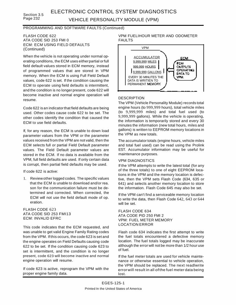
Section 3.5Page 232
ELECTRONIC CONTROL SYSTEM' DIAGNOSTICS
VEHICLE PERSONALITY MODULE (VPM)
VPM
ACCUMULATOR9,999,999 MILES
999,999 HOURS
I9,999,999 GALLONS IEVERY 30 MINUTES THEDATA IS WRITIEN TOPERMANENT MEMORY
DESCRIPTIONThe VPM (Vehicle Personality Module) records totalengine hours (to 999,999 hours), total vehicle miles(to 9,999,999 miles) and total fuel used (to9,999,999 gallons). While the vehicle is operating,the information is temporarily stored and every 30minutes the information (new total hours, miles andgallons) is written to EEPROM memory locations inthe VPM as new totals.
The accumulator totals (engine hours, vehicle milesand total fuel used) can be read using the ProlinkEST. Accumulator information may be useful formaintenance purposes.
VPM DIAGNOSTICSIf the VPM attempts to write the latest total (for anyof the three totals) to one of eight EEPROM locations in the VPM and the memory location is defective, then the VPM sets Flash Code (634, 635 or641) and selects another memory location to storethe information. Flash Code 645 may also be set.
If the VPM can't find a serviceable memory locationto write the data, then Flash Code 642, 643 or 644will be set.
PROGRAMMING AND SOFTWARE FAULTS (Continued)
FLASH CODE 622 VPM FUELIHOUR METER AND ODOMETERATA CODE SID 253 FMI 0 FAULTSECM: ECM USING FIELD DEFAULTS(Continued)
Code 622 is an indicator that field defaults are beingused. Other codes cause code 622 to be set. Theother codes identify the condition that caused theECM to use field defaults.
If, for any reason, the ECM is unable to down loadparameter values from the VPM or the parametervalues received from the VPM are not valid, then theECM selects full or partial Field Default parametervalues. The Field Default parameter values arestored in the ECM. If no data is available from theVPM, full field defaults are used. If only certain datais corrupt, then partial field defaults may be used.
If code 622 is active:
1. Reviewother logged codes. The specific valuesthat the ECM is unable to download and/or rea..son for the communication failure must be determined and corrected. When corrected, theECM will not use the field default mode of op..eration.
When the vehicle is not operating under normal operating conditions, the ECM uses eitherpartial or fullfield default values stored in ECM memory, insteadof programmed values that are stored in VPMmemory. When the ECM is using Full Field Defaultvalues, code 622 is set. If the condition causing theECM to operate using field defaults is intermittent,and the condition is no longer present, code 622 willbecome inactive and normal engine operation willresume.
FLASH CODE 623ATA CODE SID 253 FMI13ECM: INVALID EFRC
This code indicates that the ECM requested, andwas unable to get valid Engine Family Rating codesfrom the VPM. If this occurs, the code 623 is set andthe engine operates on Field Defaults causing code622 to be set. If the condition causing code 623 toset is intermittent, and the condition is no longerpresent, code 623 will become inactive and normalengine operation will resume.
If code 623 is active, reprogram the VPM with theproper engine family data.
FLASH CODE 634ATA CODE PID 250 FMI 2VPM: FUEL METER MEMORYLOCATION ERROR
Flash code 634 indicates the first attempt to writethe fuel totals encountered a defective memorylocation. The fuel totals logged may be inaccuratealthough the error will not be more than 1/2 hour useof fuel.
If the fuel meter totals are used for vehicle maintenance or otherwise essential to vehicle operation,the VPM should be replaced. The next readlwriteerrorwill result in all of the fuel meter data beinglost.
EGES-125-1
Printed In the United States of America

ELECTRONIC CONTROL SYSTEM DIAGNOSTICS
VEHICLE PERSONALITY MODULE (VPM)
VPM FUEUHOUR METER AND ODOMETER FAULTS (Continued)
Section 3.5Page 233
FLASH CODE 635AlA CODE PID 247 FMI 2VPM: HOUR METER MEMORY LOCATIONERROR
Flash code 635 indicates the first attempt to writethe engine hour totals encountered a defectivememory location. The engine totals logged may beinaccurate although the error will not be more thanone half an hour.
If the hour meter totals are used for vehicle mainte..nance or otherwise essential to vehicle operation,the VPM should be replaced. The next read/writeerrorwill result in the hour meter data being lost.
FLASH CODE 641ATA CODE PID 245 FMI 2VPM: ODOMETER MEMORY LOCATIONERROR
Flash code 641 indicates the first attempt to writethe vehicle total miles encountered a defectivememory location. The total vehicle miles loggedmay be inaccurate, although the error will not bemore than 30 miles.
If the odometer totals are used for vehicle maintenance or otherwise essential to vehicle operation,the VPM should be replaced. The next read/writeerror will result in the odometer data being lost.
FLASH CODE 642ATA CODE PID 250 FMI12VPM: FAULTY FUEL METER
Flash code 642 indicates the write cycle of the EEPROM memory locations in the VPM have been ex..ceeded. The fuel meter totals have been lost.
If the fuel meter totals are used for vehicle maintenance or otherwise essential to vehicle operation,the VPM should be replaced.
FLASH CODe 643AlA CODE PID 247 FMI12VPM: FAULTY HOUR METER
Flash code 643 indicates the write cycle of theEEPROM memory locations in the VPM have beenexceeded. The hour meter totals have been lost.
If the hour meter totals are used for vehicle mainte..nance or otherwise essential to vehicle operation,the VPM should be replaced.
FLASH CODE 644ATA CODE PID 245 FMI12VPM: FAULTY ODOMETER
Flash code 644 indicates the write cycle of theEEPROM memory locations in the VPM have beenexceeded. The Odometer totals have been lost.
If the odometer totals are used for vehicle maintenance or otherwise essential to vehicle operation,the VPM should be replaced.
VPM MEMORY FAULTS
FLASH CODE 645ATA CODE SID 253 FMI 7VPM: RAW EEPROM MEMORY LOCATIONERROR
Code 645 requires no action. Flash code 645 indicates an error was detected during a read or writeattempt at one of the EEPROM memory locations inthe VPM. The code is informational and will belogged as an inactive code. Code 645 will be loggedalong with another code which specifies what system or feature is affected.
If the error was in the VPM accumulators (totalmiles, fuel used or engine hour totals) a 634, 635,641,642,643 or 645 will be logged. Refer to VPMFuel Meter, Hour Meter and Odometer in thissection for a discussion of these codes.
If the EEPROM memory location failure was storinginformation from one of the data lists stored in theVPM (Short List, High Priority List or Low PriorityList), one of several fault codes (223, 235, 623, 624,633, 651, 652, or 653) discussed in this sectionwould be set because corrupt data would be read bythe ECM.lfforexample, the ECM attempted to readthe Short List and the data was bad, Flash Code 653would be set.
FLASH CODE 651ATA CODE SID 253 FMI10VPM: FEATURE MEMORY LIST CORRUPTED
If the VPM detects an error with the Feature List,code 651 wi II be set.
SYMPTOMS: Engine runs on partial defaults, butEngine Warning Light is not turned on. Vehiclefeatures such as cruise control, remote PTO andoptional engine protection system are disabled.
EGES-125-1Printed in the United States of America

Section 3.5Page 234
ELECTRONIC CONTROL SYSTEM DIAGNOSTICS
VEHICLE PERSONALITY MODULE (VPM)
VPM MEMORY FAULTS (Continued)
FLASH CODE 651ATA CODE SID 253 FMI10VPM: FEATURE MEMORY LIST CORRUPTED(Continued)
If code 651 is active:
1. Recycle the VPM. With the key ON, pull fuse F4(H1 with FBC) and then reinstall the fuse.
A. If code 651 is inactive, end the test.
B. If code 651 still is active after resetting theVPM, reprogram the VPM.
C. If code 651 still is active after reprogram-ming the VPM, replace the VPM.
FLASH CODE 652ATA CODE SID 253 FMI 2VPM: ENGINE/FUEL MEMORY LIST
CORRUPTED
SYMPTOMS: Engine runs on field defaults, settingcode 622 and Engine Warning Light is turned ON.
This code can be set if the VPM detects an error inthe engine-fuel list.
If code 652 is active:
1. Recycle the VPM. With the key ON, pull fuse F4(H1 with FBC) and then reinstall the fuse.
A. If code 652 is inactive, end test.
B. If code 652 is still active, replace the VPM.
FLASH CODE 653ATA CODE SID 253 FMI 12VPM: ENGINE RATING MEMORY LISTCORRUPTED
SYMPTOMS: Engine runs on field defaults, withEngine Warning Light turned ON.
This code can be set if the VPM detects an error inthe engine rating list.
If code 653 is active:
1. Recycle the VPM. With the key ON pull fuse F4(H1 with FBe) and then reinstall the fuse.
A. If code 653 is inactive, end test.
B. If code 653 is still active, replace the VPM.
FLASH CODE 654ATA CODE SID 252 FMI12VPM: WATCHDOG TIME-OUT FAULT
If a VPM software fault is detected, code 654 will beset, then the VPM will reset. The driver will likely notnotice the reset, but the code will be logged as aninactive code following the reset for informationalpurposes.
If code 621 is active:
A. Program the VPM using established programming procedures included in the Prolink Manual.
EGES-125-1
Printed in the United States of America

Section 3.5Page 236
ELECTRONIC CONTROL SYSTEM DIAGNOSTICS
VEHICLE SPEED SIGNAL (VSS)
SPEEDOMETER SIGNAL
ECM SPEEDOMETER
DCl (-)MICRO PROCESSOR
DCl (+)0000
I' 0000+ 0000::r 0000-J U 00000 0VPM 0
--10«0Zw
+ I~w
I' ~Del (+) OOQ..+ ~Del (-) en 00
~ ~ 00enenO~>1- « en« >VSS OUT
ATA(+)ATA (-)
VSS IN (+)VSS IN (-)
SIGNAL FUNCTION
The vehicle speed signal from the speed sensor isinput to the VPM. VPM programming includesnumber of teeth on the sensor wheel, tire size andaxle ratios. Using this information, the VPM createsa signal which is sent to the speedometer/tachometer cluster as input for the speedometerfunction.
The VPM also outputs a DCl formatted vehiclespeed signal over the DCl data link circuit to theECM. The ECM usesthe input for controlling vehiclefunctions including cruise control.
Additionally the VPM outputs an ATA formattedsignal over the ATA data link to the diagnosticconnector where vehicle speed can be read usingthe Prolink EST.
FAULT DETECTION MANAGEMENT
The vehicle speed sensor signal is monitoredcontinuously by the VPM to see that the signal is
within certain range. If the VSS signal isout..of-range, the VPM sends an out-of-range highsignal to the ECM, telling the ECM that the VPMdetected a fault in the VSS.
When the ECM sees the out-ot-range high signal,VPM Flash code 141 or 142 is set, but the EngineWarning light is NOT turned on. The ECM disablesoperation of the Cruise Control or ~T? .If R~ad
Speed Limiting is enabled, the EC~ w~1I hml~ enginespeed in all gears. Torque level tailoring will use aprescribed torque curve.
FAULT CODES
NOTE: IF THE VEHICLE SPEEDOMETER DOESNOT OPERATE PROPERLY, BUT NO FAULTCODES ARE PRESENT, USE THE PROLINK TOATTEMPT TO READ VEHICLE SPEED FROMTHE ATA DATA LINK CONNECTOR. IF VEHICLESPEED CAN BE READ USING THE PROLINK,TROUBLESHOOT CIRCUIT 478 AND THEINSTRUMENT CLUSTER.
EGES-125-1
Printed in the United States of America

ELECTRONIC CONTROL SYSTEM DIAGNOSTICS
VEHICLE SPEED SIGNAL (VSS)Section 3.5
Page 237
Vehicle Speed Sensor(VSS)
Fault Codes:141 Vehicle Speed Sensor Signal Out of Range Low142 Vehicle Speed Sensor Signal Out of Range High
(303)
INSTRUMENT CLUSTER CENTERGREEN(27)
197~BBB~B~B~~~~s, ,
I-----~---t-en
VPM CONNECTOR(381 )
VPM HARNESSVPM (381)
(27)
800000000
15 0000000 VSS OUT 1823 00000000 VSSIN(-) 1
VSS IN (+) 2
VPM Harness Connector Checks to Chassis GroundConnector (381) with VPM disconnected and connector (27) disconnected and key OFF
Test Points Spec. Comments
cir 47 to grd >100K ohms < less than 100K ohms check for short to grd or defective sensor.
cir 47A to grd > 100Kohms <less than 1OOK ohms check for short to grd or defective sensor.
cir 47 to 47A 600 - 800 ohms > than specified ohms, check for open circuit or sensor(manual xmsn) < than specified ohms, check for short between circuits or1200-1450 ohms defective sensor.(auto xmsn)
478 to grd >100 K ohms < less than 100K ohms check for short to ground
478 to (27) < 5 ohms > than 5 ohms check for open in circuit47B
VPM Harness Voltage ChecksVoltage check at Connector (381) with VPM disconnected and connector (27) disconnected andkey ON
Test Points Spec. Comments
47 to grd < 1.0 volt > than 1.0 volt check for short to VREF or Batt circuit
47A to grd < 1.0 volt > than 1.0 volt check for short to VREF or Batt circuit
478 to grd < 1.0 volt > than 1.0 volt check for short to VREF or Batt circuit
Operational Voltage ChecksConnect (381) to VPM and (27) to cluster. Disconnect sensor pigtail at (303). Place rear axles onstands (front wheels blocked) and with engine at idle and transmission in gear, measure ACvoltage from sensor.
Test Points Spec. Comments
white to black > 2.0 A.C. volts < less than 2.0 volts check sensor adjustment or defective sensor.
EGES-125-1
Printed In the United States of America

Section 3.5Page 238
ELECTRONIC CONTROL SYSTEM DIAGNOSTICS
VEHICLE SPEED SIGNAL (VSS)
EXTENDED DESCRIPTION
The Vehicle Speed Signal (VSS) from the VPM issent over the DCl data link to the ECM. The VSSinformation is used by the ECM to control featuressuch as: Cruise Control, PTa, Torque LevelTailoring and Road Speed limiting.
The VPM also provides VSS input to the vehiclespeedometer, tachometer and odometer unitlocated in the instrument panel.
Refer to the circuit diagram located in this section forthe following discussion.
VEHICLE SPEED SENSOR (303)
The Vehicle Speed Sensor (VSS) is located on thetransmission and sends an AC signal to the VPM.The VSS sensor contains a permanent magnetwhich creates a magnetic field. The AC signal iscreated when the 16-tooth transmissionspeedometer gear rotates breaking the magneticfield created by the sensor. The VSS signal is sentthrough the engine and cab harness to the VPM.
With a manual transmission, Navistar installs thespeed sensor at the rear of the transmission. Withan Allison AT/MT transmission, Allison installs thesensor at the lower right side of the transmission.
VPM (VEHICLE PERSONALITY MODULE)
The VPM (381) receives the AC signal from thevehicle speed sensor. The VPM programmingincludes the rear axle ratio and tire size. It uses thisprogrammed information and the speed sensorinput to create the vehicle speed signal sent to theSpeedometer Unit.
From VPM connector (381), terminal 1B, an analogAC signal is input on circuit 478 to the vehiclespeedometer unit through connector (27).Speedometer ground circuit 47-G from connector(27) is grounded at the cab ground stud.
The VSS signal is also formatted so that it can besent over the Digital Communications link (Del) tothe ECM (379).
ECM DIAGNOSTICS
FLASH CODES
During vehicle operation, the vehicle speed signal(VSS) is monitored continuously by the VPM to seethat the signal is within certain range. It the VSSsignal is out-of-range, the VPM sends anout-of-range high signal to the ECM, telling the ECMthat the VPM detected a tault in the VSS.
When the ECM sees the out-of-range high signal,VPM Flash code 141 or 142 is set, but the EngineWarning light is NOT turned on. The ECM disablesoperation of the Cruise Control or PTa. If RoadSpeed limiting is enabled, the ECM will limit enginespeed in all gears. Torque level tailoring will use aprescribed torque curve.
FLASH CODE 141ATA CODE PID 84 FMI 4VPM: VSSORL
This code is set when the VPM detects anout-of-range low (ORl) signal from the vehiclespeed sensor.
WIRING CAUSE: VSS Sensor circuit between theVPM and Sensor, shorted to ground or open.
If this code is active, perform Testing VPM to SensorCircuits on page 241 .
FLASH 142ATA CODE PID 84 FMI 3VPM: VSSORH
This code is set when the VPM detects anout-at-range high (ORH) signal from the vehiclespeed sensor.
WIRING CAUSE: VSS Sensor circuit shorted toVREF or VBAT circuit.
If this code is active, perform Testing VPM to SensorCircuits on page 241.
SPEEDOMETER DOES NOT FUNCTION PROPERLY
The ECMNPM diagnostics DO NOT check for VSSsensor adjustment, so it is possible with amiss-adjusted vehicle speed sensor to get a faultyvehicle speed signal without fault code 141 or142. The speedometer and/or odometer willoperate erratically or not at all. The odometer maynot function correctly.
If Flash code 141 or 142 IS NOT PRESENT, but thespeedometer and/or odometer does not functionproperly, perlorm Testing Speedometer on page245.
If Flash code 141 or 142 is present and thespeedometer does not function properly, correct thecause of the Flash Codes before troubleshootingthe speedometer.
If the speedometer/odometer does not functionproperly when the Two-Speed Axle is shifted (HIGHor LOW), refer to Two Speed Axle in this section.
EGES-125-1
Printed In the United States of America

ELECTRONIC CONTROL SYSTEM DIAGNOSTICS
VEHICLE SPEED SIGNAL (VSS)Section 3.5
Page 239
TROUBLESHOOTING
BEFORE TROUBLESHOOTING
A. Before troubleshooting, make sure that the batteries are fully charged! Check battery connections and grounds for clean, tight connectionsfree of damage. Voltage tests will give misleading results if the batteries are not fully charged.
B. Before troubleshooting, inspect circuit connectors for pushed back, loose, or damaged(spread or bent) terminals, or wires with cutstrands, etc. Wires and connections must befree of damage or corrosion. When some connectors corrode, a light white residue will bepresent that must be removed.
C. Before troubleshooting, inspect suspect circuitgrounds for clean, tight connections free ofdamage.
EGES-125-1Printed In the United States of America
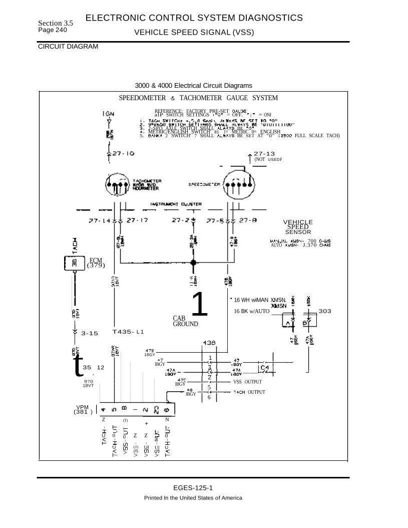
Section 3.5Page 240
ELECTRONIC CONTROL SYSTEM DIAGNOSTICS
VEHICLE SPEED SIGNAL (VSS)
CIRCUIT DIAGRAM
3000 & 4000 Electrical Circuit Diagrams
SPEEDOMETER & TACHOMETER GAUGE SYSTEM
REFERENCE: FACTORY PRE-SET GAUGEalP SWITCH SETTINGS ("0" = OFF. "I" = ONI
~: ~~~~D5w~~T~~H4~t~I~~~L§H~t~AXEw~ss~~ !gl~?~III00"3. 2-SPO AXLE SWITCH SHALL ALWAYS BE "0"4. METRIC/ENGLISH SWITCH' 81 1= METRIC 0= ENGLISH5. BA~' 2 SWITCH' 7 SHALL ALWAYS BE SET AT "0" (3500 FULL SCALE TACH)
27-13i (NOT USED I
VEHICLESPEED
SENSOR
MANUAL XMSN- 700 OHMSAUTO XMSN- J.370 OHMS
'" 16 WH wiMAN XMSN i ~
16 BK w/AUTO XMS~ sp 303
>- >-~f8 ~m- ....-
--+--<.-+--- TACH OUTPUT
SPEEDOMETER
------+-<·--+---1:Jv--+-<:4!E---1----'
----+-(+-+---11:J~~__+-C-c~4-+- -1
--t-<~I---VSS OUTPUT
@r'TACHOMETER
T W/OR W/OHDURMETER
ECM(379)
a:~ m:::t<> ••"m -CDm- --
ot- 1F'&;0>_ CABt3-15
GROUNDT435- L 1
436o~ ~t- 476,,~S! 0)- 18GY
1t35-
12-47
lBGY347A
18GY2
970 47C18VT lBGY
548lBGY
6
VPM(381 )
Z (T) N+
I ~ ~ t-I :::> :J t- =>U 0 0 Z Z :,) 0< I I a It- I lJ) I I I I
U lJ) (J) Ul Ul U< > (f) If) ill <t- > > > J-
EGES-125-1Printed In the United States of America
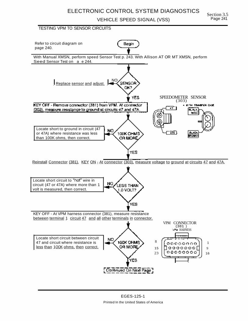
ELECTRONIC CONTROL SYSTEM DIAGNOSTICS
VEHICLE SPEED SIGNAL (VSS)
TESTING VPM TO SENSOR CIRCUITS
Section 3.5Page 241
Refer to circuit diagram onpage 240.
With Manual XMSN, perform speed Sensor Test p. 243. With Allison AT OR MT XMSN, performSeed Sensor Test on a e 244.
NOIReplace sensor and adjust. I
Locate short to ground in circuit (47or 47A) where resistance was lessthan 100K ohms, then correct.
SPEEDOMETER SENSOR(303)
Reinstall Connector (381). KEY ON - At connector (303), measure voltage to ground at circuits 47 and 47A.
Locate short circuit to "hot" wire incircuit (47 or 47A) where more than 1volt is measured, then correct.
KEY OFF - At VPM harness connector (381), measure resistancebetween terminal 1 circuit 47 and all other terminals in connector.
Locate short circuit between circuit47 and circuit where resistance isless than 1OOK ohms, then correct.
8
15
23
VPM CONNECTOR(381 )
VPM HARNESS
1
9
16
EGES-125-1Printed In the United States of America

Section 3.5Page 242
ELECTRONIC CONTROL SYSTEM DIAGNOSTICS
VEHICLE SPEED SIGNAL (VSS)
TESTING VPM TO SENSOR CIRCUITS (Continued)
KEY OFF - At VPM harness connector (381), measure resistancebetween terminal 2 circuit 47A and all other terminals in connector.
Locate short circuit between circuit47A and circuit where resistance wasless than 1OOK ohms, then correct.
VPM CONNECTOR(381 )
VPM HARNESS
800000000 1
15 0000000 9
23 00000000 L6
KEY OFF - At engine harness VSS connector (303), install jumper between circuit47 and 47A. At connector 381 ,measure resistance between circuit 47 and 47A.
Locate open in circuit 47 or 47Abetween connector (381) andconnector (303), then correct.
The VSS sensor and circuits 47 and 47A between the sensor and VPMcheck ood. If code 141 or 142 is still active, re lace the VPM.
SPEEDOMETER SENSOR(303)
• WITH TRANSFER CNSE
• II _ BK w/AUTO XMSNWH wlMANUAL XMSN
EGES-125-1
Printed in the United States of America

ELECTRONIC CONTROL SYSTEM DIAGNOSTICS
VEHICLE SPEED SIGNAL (VSS)
VEHICLE SPEED SENSOR TEST WITH MANUAL TRANSMISSION
Section 3.5Page 243
Refer to circuit diagram onpage 240.
Disconnect speed sensor from connector (303). On sensor side of (303), measure resistance toround at terminals A & B in sensor i tail.
SPEEDOMETER SENSOR(303)
• WI TH T'RN6'ER C,'8E
Install and adjust new sensor(turn sensor in until sensorcontacts speedometer gear, thenback out 1 turn).
Measure sensor resistance between terminals A (WH) & B (BK) in the sensor pigtail connector.
Install new sensor and adjust(turn sensor in until it contactsspeedometer gear, then back out1 turn).
1. Remove VSS sensor from transmission, then clean and check for damage. Then turn sensor in untilit contacts speedometer gear, back out 1 turn and tighten nut.
2. Use jack to place vehicle rear axles safely on floor stands. Block front wheels. Use meter leads longenough to safely clear rotating wheels. CAUTION: Be sure to disengage FRONT DRIVE AXLE ifvehicle is so equipped.
3. Set Fluke meter on AC position. Connect meter leads to the two VSS pigtail connector terminals. Startand run engine at idle with transmission in high gear. Note AC out ut from sensor.
Replacethe sensor.
I Sensor checks OK. Return to Testing VPM To Sensor Circuits on page 241. I
EGES-125-1Printed in the United States of America

Section 3.5Page 244
ELECTRONIC CONTROL SYSTEM DIAGNOSTICS
VEHICLE SPEED SIGNAL (VSS)
VEHICLE SPEED SENSOR TEST WITH ALLISON AT OR MT TRANSMISSION
Refer to circuit diagram onpage 240.
KEY OFF - Disconnect speed sensor pigtail from engine harness. Measure resistance to ground atboth circuits from the sensor.
Have Allison dealer replacethe seed sensor
KEY OFF - Measure resistance between the two sensor pigtail termials.
Have Allison dealer replacethe seed sensor
YES
1. Use jack to place vehicle rear axles safely on floor stands. Block front wheels. Use meter leads longenough to safely clear rotating wheels. CAUTION: Be sure to disengage FRONT DRIVE AXLE ifvehicle is so equipped.
2. Set Fluke meter to AC volts position. Connect meter leads to speed sensor terminals. Run engineat idle with transmission in hi h ear. Note AC out ut from sensor.
The vehicle speed sensor checks~--ol"'1
OK. Return to Testing VPM toSensor Circuits on page 241
EGES-125-1
Printed In the United States of America

ELECTRONIC CONTROL SYSTEM DIAGNOSTICS
VEHICLE SPEED SIGNAL (VSS)
TESTING SPEEDOMETER
Section 3.5Page 245
If Flash Codes are not present indicating that a VSSsignal problem has been detected by the VPM or
ECM, but the speedometer and/or odometer are notfunctioning properly, perform this test.
Refer to circuit diagram onpage 240.
Roadtest vehicle while passenger monitors vehicle speed using Prolink EST.Note if Prolink seed is accurate.
Check vehicle sensoradjustment. Remove sensor andcheck for damage and cleansensor. Turn sensor in until itcontacts speedo gear and backoff 1 turn.
Refer to CTS-5000, Instruments and perform SpeedometerlTachometer Self Diagnostics.
Follow recommended actionsin CTS-5000 to correct.
With key OFF, remove connector (27) from cluster and connector (381) from VPM. At (27), measureresistance to round at terminal 5 circuit 478 .
Locate short circuit to groundin circuit 478, then correct.
INSTRUMENT CLUSTER CENTERGREEN(27)
197~BB8~8~B~Et, ,
EGES-125-1
Printed in the United States of America

Section 3.5Page 246
ELECTRONIC CONTROL SYSTEM DIAGNOSTICS
VEHICLE SPEED SIGNAL (VSS)
TESTING SPEEDOMETER (Continued)
With key OFF, at connector (27) terminal 8 (circuit 47-G), measureresistance to round.
Locate open in ground path,then correct.
INSTRUMENT CLUSTER CENTERGREEN(27)
197~BBB~B~~~~~s, ;
9
]6
00000000000000000000000
8
15
23
With key ON, at connector (27) terminalS (cirCUit 478), measure voltage to ground.
VPM CONNECTOR(381 )
VPM H~RNES5
Locate short circuit to VREF or12 volt circuit, then correct.
With key OFF, measure resistance between connector (27) terminalS and connector (381) terminal 18.
Locate open in circuit478 between (27) and(381), then correct.
IReplace VPM.
EGES-125-1
Printed in the United States of America

SECTION 4SUPPLEMENTAL DIAGNOSTIC ANALYSIS
INDEX
PAGESUPPLEMENTAL DIAGNOSTIC ANALYSISCAMSHAFT TIMING 1COMBUSTION LEAKS 2COOLANT IN LUBE OIL 4COOLANT OVERTEMP . . . . . . . . . . . . . . . . . . . . . . . . . . . . . . . . . . . . . . . . . . . . . . . . . . . . . . . . . . . . . . . . . . . . .. 6EXCESSIVE FUEL CONSUMPTION . . . . . . . . . . . . . . . . . . . . . . . . . . . . . . . . . .. 7FUEUOIL DILUTION 8FUEL IN COOLANT "................................................. 9LOW OIL PRESSURE 10NO START - DRY RESERVOIR 13ECM RESET " .. " 16ROUGH IDLE DIAGNOSTICS .. "............................................................ 18SMOKE 21
EGES-125-1Printed In The United States of America
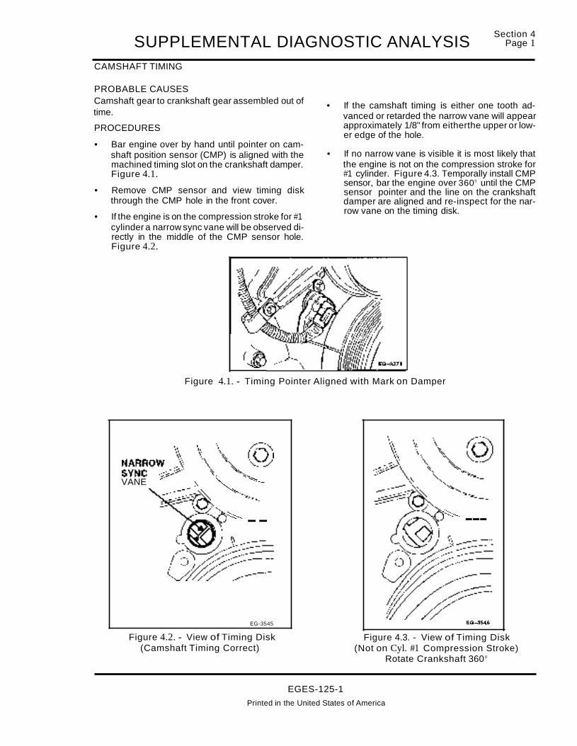
SUPPLEMENTAL DIAGNOSTIC ANALYSISCAMSHAFT TIMING
Section 4Page 1
PROBABLE CAUSESCamshaft gear to crankshaft gear assembled out oftime.
PROCEDURES
• Bar engine over by hand until pointer on camshaft position sensor (CMP) is aligned with themachined timing slot on the crankshaft damper.Figure 4.1.
• Remove CMP sensor and view timing diskthrough the CMP hole in the front cover.
• If the engine is on the compression stroke for #1cylinder a narrow sync vane will be observed directly in the middle of the CMP sensor hole.Figure 4.2.
(l®
• If the camshaft timing is either one tooth advanced or retarded the narrow vane will appearapproximately 1/8" from eitherthe upper or lower edge of the hole.
• If no narrow vane is visible it is most likely thatthe engine is not on the compression stroke for#1 cylinder. Figure 4.3. Temporally install CMPsensor, bar the engine over 3600 until the CMPsensor pointer and the line on the crankshaftdamper are aligned and re-inspect for the narrow vane on the timing disk.
Figure 4.1. - Timing Pointer Aligned with Mark on Damper
~~~~OV:) \\,\~@VANE __ ~ ~ ~
~~--~~ ~
~ --
EG-3545
Figure 4.2. - View of Timing Disk(Camshaft Timing Correct)
EGES-125-1
~ ---
EG-3546
Figure 4.3. - View of Timing Disk(Not on Cyl. #1 Compression Stroke)
Rotate Crankshaft 360 0
Printed in the United States of America

Section 4Page 2 SUPPLEMENTAL DIAGNOSTIC ANALYSISCOMBUSTION LEAKS
(COMBUSTION GAS OBSERVED IN ENGINE COOLANT IN OVERFLOW TANK OR SURGE TANK)
PROBABLE CAUSES
The most probable cause of combustion gas leakage to the cooling system is past the lower nozzlesleeve in the cylinder head. Figure 4.4. A blownhead gasket or porous cylinder wall is possible, butshould not be suspected unless special circumstances exist such as evidence of engine overheating or a very high mileage engine that has not hadproper coolant conditioning.
PROCEDURES
PROCEDURE #1
• Plug in block heater to warm coolant.
POSSIBLE LEAK PATHBETWEEN SLEEVE
AND CYLINDER HEAD
• Pressurize cooling system to 14 PSI.
• Remove valve covers and glow plugs.
• Observe glow plug holes while barring engineover by hand to see if coolant is flooding the topof the piston and escaping out of the glow pluqhole. (If the leak is a slight leak pressure mayhave to left on overnight and the engine in-·spected the next morning.)
• When the suspected nozzle sleeve is isolated,drain coolant and remove and replace thenozzle sleeve as per the service manual.
• Re-test after repair to confirm repair.
..................,.....a.....-COOLANT
Figure 4.4. - Injector Sleeve - Combustion Gas Leak Path
EGES-125-1
Printed In the United States of America

SUPPLEMENTAL DIAGNOSTIC ANALYSISSection 4
Page 3
COMBUSTION LEAKS (Continued)
PROCEDURES (Continued)
PROCEDURE #2
• Very slight leaks may require higher pressure tobe isolated.
• Plug in block heater to warm coolant.
• Remove valve cover and glow plugs.
• Remove cap from the surge tank.
• Rotate the crankshaft on the cylinder to betested so that the valves are shut. (Or removerocker arm pedestals to close valves.)
• Install the compression adapter. (ZTSE 4292)(Figure 4.5.) in the glow plug bore and adaptgauge end to accept shop air pressure (1 00 to160 PSI).
• With shop air applied (Figure 4.5.) observesurge tank for escaping air. If the nozzle sleeveis leaking, air will escape into the cooling system when shop air pressure is applied and beseen as bubbles in the surge/overflow tank.
• When suspected nozzle sleeve is isolated,drain coolant and remove and replace nozzlesleeve as per the service manual.
• Re-test after repair to confirm repair.
COMPRESSION TEST ADAPTERZTSE-4292~-----
L=~
Figure 4.5. - Pressure Check for Combustion Leaks
EGES-125-1
Printed in the United States of America

Section 4Page 4 SUPPLEMENTAL DIAGNOSTIC ANALYSISCOOLANT IN LUBE OIL
PROBABLE CAUSESOil cooler bundle or "0" ring failure, front cover "0"ring damage, front cover porosity, cylinder head porosity, crankcase porosity, nozzle sleeve leakage.
PROCEDURES
• Plug in block heater to warm coolant.
• Remove oil pan plug, oil filter and glow plugs.
• Pressurize cooling system to 14 PSI.
• Observe/inspect rear of oil cooler (where oil filter was mounted), (Figure 4.6.) oil pan plug forcoolant or air pressure escaping.
• If: Coolant/air leak is occurring from header atthe oil filter mounting header the oil cooler as..sembly should be removed and inspected orpressure tested.
• If the coolant is escaping out of the oil pan drainplug remove valve covers, inspect the cylinderhead area (Figure 4.7. page 5) under thevalve cover and welch plugs in cylinder headsfor coolant leakage.
• If no leaks are found remove engine and oil pan,block off coolant inlet, outlet and heater hoseconnections. Pressurize the cooling systemwith 14 PSI of regulated air pressure.
• Inspect bottom end of crankcase for pressureleaks.
• If no leaks found, remove front cover and inspect gaskets and sealing surfaces. Figure4.8. page 5.
• Re-test after repair to confirm repair.
Coolant
"0"Ring
FRONT OILCOOLER
"0"Ring Oil Cooler
Bundle
Oil
+- FILTER HEADER
Figure 4.6. - Oil Cooler Leak Paths
EGES-125-1
Printed in the United States of America
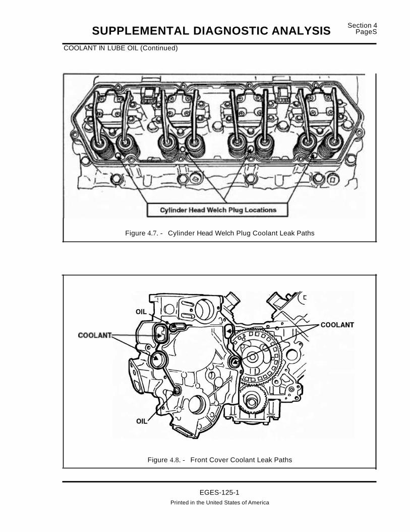
SUPPLEMENTAL DIAGNOSTIC ANALYSISCOOLANT IN LUBE OIL (Continued)
Section 4PageS
Figure 4.7. - Cylinder Head Welch Plug Coolant Leak Paths
COOLANT~-"",*---l."
Figure 4.8. - Front Cover Coolant Leak Paths
EGES-125-1Printed in the United States of America

Section 4Page 6 SUPPLEMENTAL DIAGNOSTIC ANALYSISCOOLANT OVERTEMP
PROBABLE CAUSESGauge error, low coolant level, plugged radiator,wrong radiator, stuck thermostat, no thermostat, defective water pump, broken belt, fan clutch slippage,wrong or damaged fan blade.
PROCEDURES
• Inspect radiator or surge tank for correct coolant level.
• Inspect fan blade, shroud, belt and radiator.(Verify correct part numbers.)
• Monitor ECT Engine Coolant Temperature withthe EST (Electronic Service Tool) and compare
to dash temperature reading of coolant temperature.
• Monitor engine coolant temperature with manual gauge or thermocouple installed in port infront cover for existing sender and confirm overtemperature.
• Remove and inspect thermostat, check foropening temperature.
• Remove radiator and have flow checked at radiator shop.
Figure 4.9. - Cooling System
EGES-125-1Printed in the United States of America

SUPPLEMENTAL DIAGNOSTIC ANALYSISEXCESSIVE FUEL CONSUMPTION
PROBABLE CAUSES
CUSTOMER EFFECTS:Inaccurate record keeping or tank filling, winterblend or #1 fuel, high expectations.
APPLICATION EFFECTS:Heavy loading (GVW) , low rear axle ratio, largefrontal area, prolonged idle times, accessory usage(PTO's etc.), tire size.
CHASSIS EFFECTS:Brake drag, Fan clutch engagement, transmissionslippage/shifting, fuel tank plumbing and venting, intake or exhaust restriction.
ENGINE EFFECTS:Incorrect or defective thermostat, faulty (ESP) Exhaust Back pressure operation, oil aeration, fuelsystem leaks, base engine performance loss.
PROCEDURES
• Review customer records and fueling procedures. Measurement errors are common. Fuelconsumption taken only from one tank of use issusceptible to significant error because of fillingprocedures and vehicle application differencesduring operation. Accurate fuel consumptionmust be measured over time, preferably overfour tanks of fuel with a record of what the vehicle was towing or doing during that time.
• Loss of fuel economy is normal if winter fuels,kerosene or #1 diesel is being used.
• Review vehicle specifications to determine iffuel consumption is normal for type of application and use of vehicle. (Compare consumptionwith similar vehicles in same application)
• Conduct all tests on the Performance Diagnostic Sheet. These tests will test the following engine/chassis systems and determine if the following systems are functioning or if particularconditions are present. Intake and exhaust system, fuel delivery and filtration system, highpressure fuel system and injector operation,turbocharger and exhaust back pressure operation, oil aeration, base engine condition andelectronic control system condition. If all testsare passed, the engine is operating normally.
EGES-125-1
Printed In the United States of America
Section 4Page 7
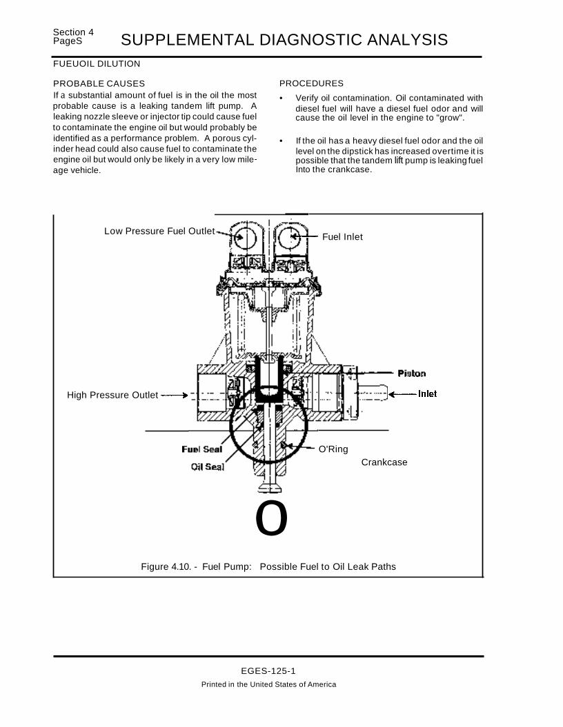
Section 4PageS SUPPLEMENTAL DIAGNOSTIC ANALYSISFUEUOIL DILUTION
PROBABLE CAUSESIf a substantial amount of fuel is in the oil the mostprobable cause is a leaking tandem lift pump. Aleaking nozzle sleeve or injector tip could cause fuelto contaminate the engine oil but would probably beidentified as a performance problem. A porous cylinder head could also cause fuel to contaminate theengine oil but would only be likely in a very low mile..age vehicle.
Low Pressure Fuel Outlet
High Pressure Outlet -----.
PROCEDURES
• Verify oil contamination. Oil contaminated withdiesel fuel will have a diesel fuel odor and willcause the oil level in the engine to "grow".
• If the oil has a heavy diesel fuel odor and the oillevel on the dipstick has increased overtime it ispossible that the tandem lift pump is leaking fuelInto the crankcase.
.............-- Fuel Inlet
+--Inlet
O'RingCrankcase
oFigure 4.10. - Fuel Pump: Possible Fuel to Oil Leak Paths
EGES-125-1
Printed in the United States of America

SUPPLEMENTAL DIAGNOSTIC ANALYSISSection 4
Page 9
FUEL IN COOLANT
PROBABLE CAUSESInjector sleeve (Upper section of sleeve to fuelgalley).
PROCEDURES
• Plug in block heater to warm coolant.
• Remove fuel return lines at regulator block.
• Pressurize cooling system to 14 PSI.
POSSIBLE LEAK PATHBETWEEN SLEEVE
AND CYLINDER HEAD
• Observe fuel return lines, injector bank with fuelto coolant leak will push fuel or air out of it's return line.
• Remove injectors on suspect bank.
• With cooling system pressurized, observe upper injector sleeve to head fit for leakage. (Figure 4.11.)
• After repair, pressurize cooling system to confirm repair.
.......~.............+--- COOLANT
Figure 4.11. - Injector Sleeve - Combustion Gas Leak Path
EGES-125-1Printed in the United States of America

Section 4Page 10 SUPPLEMENTAL DIAGNOSTIC ANALYSISLOW OIL PRESSURE
PROBABLE CAUSESInaccurate gauge reading, low oil level, oil dilution(fuel), Stuck oil pressure regulator, scored/damaged oil pump, rear main gallery plug, broken ormissing piston cooling jets, front cover "0" ringleaks, missing tappet galley plug, missing bearingshells, porous oil reservoir.
PROCEDURES
• Verify oil level, checkto see ifcontaminated withfuel.
• Verify oil pressure using a known good mechanical gauge and measuring at the oil reservoir and at the main oil galley. Oil pressure atboth points should be 10 PSI minimum @ lowidle and 40 PSI minimum @ wide open throttlewith the engine at operating temperature.
• If the difference between the reading on the reservoir and main galley vary more than 5 PSI,swap gauges and recheck, if the reservoir stillhas a lower reading reservoir is most likely porous, replace reservoir.
/
/j~
Oil PumpHousing
Rotors
• Remove and inspect oil cooler and regulator assembly. Oil regulator should be properly stakedin the oil header housing and the regulator piston should be free to move when pressure is applied.
• Remove, inspect and measure clearances inthe lube oil pump. (Figure 4.12.) Upon removalof the lube oil pump inspect the mating frontcover surface for gouging or deep scratching,inspect the oil pump for damage or wear. Measure the "G" rotor to oil pump housing clearance. Specification is 0.028" - 0.032" (0.72 0.81 mm). Measure from surface of housing to"G" rotor dimension. Specification is 0.001" 0.003" (0.,2 - 0.08 mm.)
• Remove the transmission and flywheel, inspectrear main plate for oil leaks. Massive oil leakcould indicate a missing main galley plug. Figure 4.13. If leak is indicated remove rear plateand inspect plugs.
• Remove oil pan and inspect for missing pistoncooling jets, bearing shells. Figure 4.14.
• Remove front cover, inspect for cut or damagedfront cover "0" rings, missing tappet galleyplugs. Figure 4.15.
Figure 4.12. - Lube Oil Pump Inspection and Measurement
EGES-125-1Printed In the United States of America
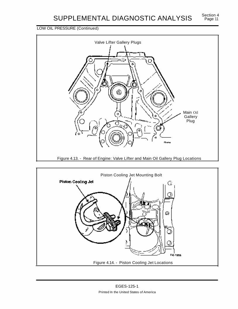
SUPPLEMENTAL DIAGNOSTIC ANALYSISLOW OIL PRESSURE (Continued)
Valve Lifter Gallery Plugs
Section 4Page 11
Main OilGallery
Plug
Figure 4.13. - Rear of Engine: Valve Lifter and Main Oil Gallery Plug Locations
Piston Cooling Jet Mounting Bolt
Figure 4.14. - Piston Cooling Jet Locations
EGES-125-1Printed In the United States of America

Section 4Page 12 SUPPLEMENTAL DIAGNOSTIC ANALYSISLOW OIL PRESSURE (Continued)
Valve Lifter Gallery Plugs
Figure 4.15. - Front of Engine: Valve lifter and Main Oil Gallery Plug Location
EGES-125-1Printed in the United States of America

SUPPLEMENTAL DIAGNOSTIC ANALYSISSection 4
Page 13
NO START - DRY RESERVOIR
PROBABLE CAUSESTo understand the cause of the no-start and identifythe most probable cause to this problem it is criticalto identify the failure mode.
If the engine:"STARTED RAN APPROXIMATELY 15 SECONDSAND STALLED"The most likely cause is the lack of oil supply by thelube system.
Or if the engine;"DID NOT START AND RESERVOIR WAS FOUNDDRY'
Possibilities include reservoir leak down: Causedby a leaking check valve in the high pressure oilpump, porous oil reservoir, or reservoir pump downwhich occurs during cranking and no start conditions caused by CMP circuit or other electronic control circuit failures.
PROCEDURES"STARTED RAN APPROXIMATELY 15 SECONDSAND STALLED"
This condition assumes that the reservoir was fullwhen the engine start was attempted, the enginestarted normally and would die after 15 seconds ofrunning .
• Refill the reservoir and verify the start and stallcondition .
• Remove, inspect and measure clearances inthe engine lube oil pump. (Figure 4.16.) Uponremoval of the lube oil pump inspect the matingfront cover surface for gouging or deep scratching, inspect the oil pump for damage or wear.Measure the "G" rotor to oil pump housingclearance. Specification is 0.028" - 0.032"(0.72 - 0.81 mm). Measure from surface ofhousing to "G"rotor dimension. Specification is0.001 " - 0.003" (0..2 - 0.08 mm.)
Straightedge /
/ jr
Rotor
Figure 4.16. - Lube Oil Pump Inspection and Measurement
EGES-125-1
Printed In the United States of America

Section 4Page 14 SUPPLEMENTAL DIAGNOSTIC ANALYSISNO START - DRY RESERVOIR (Continued)
"DID NOT START AND RESERVOIR WAS FOUND DRY'
• Refill the reservoir and attempt to start the engine.
• If the engine does not start, perform the procedures on the Hard Start/No Start Diagnosticform. The tests on this form will discern if the essential elements required to start are present.(e.g. CMP camshaft position signal, batteryvoltage, fuel & fuel pressure, lep injection control pressure, etc.)
• If the engine starts, the low reservoir problemmay be caused by reservoir leak down after aprolonged period of not running.
• Road test the vehicle for a minimum of 10 milesto assure that all air is purged from the injectioncontrol pressure system. Check oil level in res..ervoirto assure that it is full and let sit over night.
• Inspect oil level (Figure 4.17.) the next morning(prior to starting engine) to determine if leakdown has occurred.
• The only paths for leakage is past a check ballinternal to the high pressure oil pump or througha porous reservoir or front cover.
• Leakage past the check valve in the high pressure pump may be intermittent, the check valveinternal to the pump is not serviceable. If thehigh pressure pump is suspect, replace it. (Figure 4.18.) (Note: The IPR injection pressureregulator valve which is mounted in thepump will not cause a leak down problemand does not require replacement when ahigh pressure pump is replaced.)
• Porosity through a reservoir or front cover casting is highly unlikely and if it does occur willprobably be detected at very low miles. Leakage through a porous casting will also be diagnosed as a consistent problem and should notbe a case of intermittent leak down. If porosity issuspected it is recommended to replace thereservoir first since it is far easier to replace thana front cover.
Figure 4.17. - Checking Oil Level in Reservoir
EGES-125-1
Printed in the United States of America

SUPPLEMENTAL DIAGNOSTIC ANALYSISNO START - DRY RESERVOIR (Continued)
Section 4Page 15
RESERVOIR
BLEEDHOLE
FROMENGINE
TO
HIGH PRESSURE
HEUIINJECTOR
Figure 4.18. - High Pressure Oil System (600 to 3000 PSI)
EGES-125-1Printed In the United States of America

Section 4Page 16 SUPPLEMENTAL DIAGNOSTIC ANALYSISECM RESET
(GLOW PLUG LAMP CYCLES ON/GLOW PLUGS RECYCLE! ENGINE STUMBLE DIE/NO ACCELERATOR PEDAL AUTHORITY UNTIL RETURN TO IDLE POSITION)
A Electronic Control Module (ECM) reset occurswhen the ECM momentarily "reboots" or is turnedoff and on while the engine is operating. If the condition occurs a single time, the engine will momentarily stumble and the ECM will go through a normal keyon cycle, including turning the glow plug lamp andglow plugs on and will also attempt to validate theaccelerator pedal position. If the pedal is not at theidle position when this fault occurs, pedal authoritywill not be allowed by the ECM until the APS is released and the engine will idle only.
PROBABLE CAUSES
• Momentary loss of power to the ECM or 10M:Defective power relays, shorted or open harness, intermittent connectors, poor grounds.
• Momentary short to ground of V ref: Shortedharness or connector, defective sensor (sensors that use Vref include - EBP exhaust backpressure, ICP injection control pressure, CMPcamshaft position sensor, MAP manifold absolute pressure sensor, BARO barometric pressure sensor, APS accelerator pedal sensor.)
• Momentary short to ground of injector high sidevoltage: Under valve cover harness, valve cover gasket, engine harness, chassis harness areall possible sources of short to ground conditions.
PROCEDURES
• Complete tests #3, #4a and #4b on the Performance Diagnostic Form, this will determine ifthe ECM has detected any fault conditions thatcan cause a ECM reset. If the EST does not operate or is unavailable, perform Test 5 (STIFlash Codes).
NOTE: IF THE ECM IS UNABLE TO PERFORM AKOEO INJECTOR ELECTRICAL SELF TEST
(BUZZ TESn THIS WILL SOMETIMES INDICATEAN INJECTOR CIRCUIT HIGH SIDE SHORT TOGROUND CONDITION. DISCONNECT PAIRS OFINJECTORS BY REMOVING THE CONNECTORAT THE VALVE COVER AND ATTEMPT TO PERFORM THE BUZZ TEST. IF THE BUZZ TEST CANBE ACCOMPLISHED WITH AN INJECTOR PAIRDISCONNECTED, THE HIGH SIDE SHORT TOGROUND HAS MOST LIKELY BEEN ISOLATEDTO THE UNDER VALVE COVER HARNESS CORRESPONDING TO THE DISCONNECTED INJECTORS.
• Check all power and ground connections fortheECM and 10M.
• Monitor V ref (pin #26) and V Power (pins #37 9) with the breakout box installed when thefault occurs.
• Inspect the CMP sensor harness connector andthe harness (particularly around the idler pulley)for a V ref or signal short to ground condition.
• Remove and inspect the CMP camshaft position sensor for possible timing diskto CMP sensor contact
• If the ECM reset condition is repeatable, disconnect the following sensors one at a time andoperate the engine to determine if the reset willreoccur. ESP exhaust back pressure, ICP inl"ection control pressure, MAP manifold abso utepressure sensor, BARD barometric pressuresensor, APS accelerator pedal sensor, andEOP engine oil pressure sensor. Inspect eachharness and connector upon removal.
• Remove the valve covers and inspect the undervalve cover connectors (Figure 4.19.) for possible pinching under the valve cover gasket orrub through against the push tubes.
EGES-125-1Printed in the United States of America

SUPPLEMENTAL DIAGNOSTIC ANALYSISECM RESET (Continued)
Section 4Page 17
Injector WireCrimped Between UVCGasket & Cylinder Head
MisroutedInjector WireRubbing Push Tube
Figure 4.19. - Under Valve Cover Harness Inspection
EGES-125-1Printed In the United States of America

Section 4Page 18 SUPPLEMENTAL DIAGNOSTIC ANALYSISROUGH IDLE DIAGNOSTICS
PROBABLE CAUSESEngine oil (aerated, incorrect grade, low oil level,extended oil drain interval), defective injectors, injector shorts to ground, power cylinder problems,valve train problems, low fuel pressure, aeratedfuel, exhaust system to cab/chassis ground outs,loose/worn engine mounts, electronic control system faults, poor fuel quality, injection control pressure system problems.
PROCEDURES
• Verify ComplaintConfirm conditions when complaint is present,for example does the engine rough idle onlywhen hot, cold, after high speed operation,does it misfire over whole speed range, is therechassis vibration are there any other conditionsor observations present when the engine idlesrough.
• Inspect Exhaust System For Contact With CabOrBed
Many vehicles inspected have had contact between the flat exhaust pipe that comes off of theengine to the cab. This will transmit enginevibrations to the cab, especially on accelerationwhen the engine twists on it's mounts. It may beimproperly diagnosed as a rough idle complaint. The other exhaust ground out area observed has been in the center of the box area ifafifth wheel has been installed, the undersidebracket may sometimes rub on the driveline.
• Complete all tests on the Performance Diagnostic Sheet. Conditions are described belowthat can contribute to rough idle and why eachtest is being performed is listed below.
CHECK ENGINE OIL LEVEL
VERIFY CORRECT GRADEMust meet CG-4 / SH specification.
PERFORM EST TOOL - ENGINE OFF TESTSIntermittent CMP, 10M, ICP, Injector or wiring harness faults can affect engine idle conditions the
ECM may have detected and recorded these conditions.
PERFORM EST INJECTOR BUZZ TESTThis test will verify that the injectors are workingelectronically.
MEASURE TRANSFER PUMP PRESSURELow fuel pressure will cause the engine to misfireand will cause a loss of power.
• If pressure is low, remove canister mounted onfuel regulator and remove any debris on fuelscreen. Remove fuel regulator from side of fuelfilter and remove any material from screen protecting the fuel de-aeration orifice.
MEASURE TRANSFER PUMP INLET RESTRICTIONIf fuel pressure is low, this test will determine if thecause is a restricted fuel inlet from the fuel tank.
PERFORM AIR IN FUEL AND FUEL RETURNFLOW TESTThis test consists of installing a clear line on the return fuel line. Observing the clear line will indicateif return fuel is present and/or if air is present in thereturn fuel.
PERFORM EST - ENGINE RUNNING TESTThis test will test the functionality of the ICP controlsystem, the exhaust backpressure system. The engine must be up to operating temperature to performthis test.
PERFORM CYLINDER CONTRIBUTION TESTThis test will test the contributions of the individualpower cylinders. It will only detect a cylinder that iscontributing very little. It's primary function is to detect a bad injector, but it is possible it could detecta base engine problem such as broken rocker armbolts, bent push tube, broken rings or bent connecting rod.
EGES-125-1
Printed In the United States of America

SUPPLEMENTAL DIAGNOSTIC ANALYSISSection 4
Page 19
ROUGH IDLE DIAGNOSTICS (Continued)
PERFORMANCE DIAGNOSTICS (Continued)
PERFORM INJECTION CONTROL PRESSURETESTSOil Aeration Test with DVOM
Aerated oil will cause the engine to idle rough andpossibly die upon de-acceleration. The most likelycauses for aeration is insufficient oil level, incorrectoil grade, extended oil drain intervals and low pressure suction leaks.
Before performing oil aeration tests, verify that theICP sensor is reading correctly by monitoring theICP voltage signal with a DVOM or the injection control pressure using the EST with the key on and engine off. The value displayed wNI measure between.15 to .25 volts with a DVOMordisplayO PSI on theEST.
Oil QualityIf the oil is being aerated due to depletion of the antifoaming agents in the oil, the problem will be mostevident when the engine is hot and after prolongedoperation at high engine speeds. During this test, oilaeration caused by engine oil will probably start at alow ICP signal level (1.4 to 1.5 volts or 1024 to 1060PSI) and increase to a signal level above (1.75 voltsor 1270 PSI) after 60 seconds of WOT engine operation.
CHANGE OIL (CG-4) AND RE-TEST IF THISTEST IS FAILED
LOW PRESSURE SUCTION LEAKSIf a leak on the suction side is present, engine temperature will most likely have little effect on oil aeration. The ICP signal during this test will most likelyimmediately measure above 1.9 volts or 1400 PSIduring the WOT test and the engine may notachieve a engine speed above 2000 RPM duringthis test. (It is important that all KOER and cylindercontribution tests have been performed prior to thistest. A cylinder or injector not functioning will givesimilar test results.)
To confirm that a low side suction leak is occurring,overfill the engine crankcase with 3 quarts of engineoil, raise the rear wheels 10" off the ground and rerun this test, If a suction leak is present, (oil pickuptube or gasket leak) the added oil will seal the leakand the ICP signal should be in specification.
LOW IDLE STABILITY TEST
This test will help discern if erratic rail pressure andan associated low idle concern is caused by the ICPsensor or IPR valve. Disconnect engine harnessconnector at ICP sensor while engine is at idle. Ifengine rough idle smooths out, replace ICP sensor.If engine continues to idle rough with harness connector removed, refer to IPR and Injection ControlPressure system diagnostics.
PERFORM CRANKCASE PRESSURE TESTThe crankcase pressure test will determine thecondition of the power cylinders and base engine.
INJECTION CONTROL PRESSURE BALANCE
Compare ICP Pressure of Right and Left CylinderHead. Pressure differences between the right andleft cylinder head have been found to cause pooridle and performance complaints. Install an additionallCP sensor in the right cylinder head, connectthe ESP sensor connector (if vehicle is equippedwith) to the additional sensor, install a breakout boxand monitor the ICP signal on the left head and righthead. (Use ESP signal pin) with two DVOM'sinstalled. Compare the measured signal of the rightand left cylinder head at low idle, high idle and undera load. The difference between each head shouldnot exceed .2 volts.
To isolate if the pressure difference is caused by internal leakage in 'the cylinder head or by the highpressure pump, block the line feeding the right cylinder head and operate the on the left bankonly. Thenroute the line feeding the left cylinder head to theright cylinder head. (The left high pressure line willreach the right head).
EGES-125-1
Printed in the United States of America

Section 4Page 20 SUPPLEMENTAL DIAGNOSTIC ANALYSISROUGH IDLE DIAGNOSTICS (Continued)
PERFORMANCE DIAGNOSTICS (Continued)If there are pressure differences between the cylinder heads, leakage is occurring in the lower pressure head (e.g. loose or cross threaded oil gallerydrains, injector "0" rings, bad injector).
If the pressure is the same on each cylinder head,
the initial pressure difference is caused by the highpressure pump.
COMPRESSION TESTPerform compression test to verify base enginecondition. (Figure 4.20.)
Figure 4.20. - Compression Test
• If no other faults found replace injectors.
EGES-125-1
Printed in the United States of America

SUPPLEMEN1AL DIAGNOSTIC ANALYSISSection 4
Page 21
SMOKE
BLACK SMOKE
PROBABLE CAUSESAir intake or exhaust restriction, exhaust back pressure device closing, turbocharger failure, loose injector, altitude (very slight black smoke on hard acceleration is normal).
PROCEDURE:
• If engine has a fuel knock orthere is evidence offuel in the exhaust manifolds, remove exhaustmanifolds and inspect for fuel in the exhaustports. (Suspect loose injectors, missing ordamaged "0" ring and copper gasket on bottom.)
• Inspect air inlet system and exhaust system forpossible sources of restriction.
• Inspect exhaust back pressure (ESP) device atWOT to determine if closing.
• Monitor ESP signal (PID) with the EST toolwhile operating the engine to determine if exhaust back pressure is high.
WHITE SMOKEPROBABLE CAUSESNo glow plug operation, loose injectors, cold engine, bent connecting rods, low compression, wornrings, coolant leaking into combustion chamberpast injector steeves.
PROCEDURE:
• In cold ambient temperatures some whitesmoke is normal until the engine is up to operating temperature. Insure engine is up to operating temperature (190°F) prior to verifying asmoke complaint. If the engine is unable to obtain operating temperature during a road testverify thermostat opening temperature (190°F).
• On a cold engine the glow plug system may remain on for up to 2 minutes after the enginestarts to assist in cold smoke cleanup. Performglow plug diagnostic procedures (test #11) onHard Start / No Start diagnostic form to verifyglow plug operation.
• If engine has a fuel knock or evidence of fuel inthe exhaust, remove exhaust manifolds and inspect for fuel in the exhaust ports. (Suspectloose injectors, missing or damaged "a" ringand copper gasket on bottom.)
• If air induction system show evidence of waterinjection, that can cause hydraulic static lockand bend connecting rods or if the air inductionsystem shows evidence of dusting perform acompression test.
BLUE SMOKE/FUEL ODORPROBABLE CAUSES:
• Oil consumption
• Loose injectors.
PROCEDURE:
• If engine has a fuel knock or evidence of fuel inthe exhaust, remove exhaust manifolds and inspect for fuel in the exhaust ports. (Suspectloose injectors, missing or damaged "0" ringand copper gasket on bottom.)
EGES-125-1
Printed in the United States of America

SECTION 5 DIAGNOSTIC TOOL USE
INDEXPAGE
SECTION 5.1 DIAGNOSTIC TOOLSTOOL ILLUSTRATIONS 1BEYERS MODEL D-200 PRESSURE TEST KIT (ZTSE-2239) 6DWYER SLACK TUBE MANOMETER . . .. . . . . . . . . . . . . . . . . . . . . . . . . . . . . . . . .. . . . . . . . . . . . . . 7ORIFICIED RESTRICTOR TOOL (ZTSE-4146) AND ADAPTER (ZTSE-4284) BGLOW PLUG / INJECTOR BREAKOUT (ZTSE-4345) . . . . . . . . . . . . . . . . . . . . . . . . . . . . . . . . . . .. BICP / EBP BREAKOUT "T' (ZTSE-4347) . . .. . . . . . . . . . . . . . . .. . . . .. . . . . . .. . .. . . . . . . . . . . . . . . . . .. 9INJECTION CONTROL PRESSURE ADAPTER/PLUG KIT (ZTSE-4359) 9FLUKE 88 DIGITAL MULTIMETER (ZTSE-4357) 9BREAKOUT BOX (ZTSE-4346) 10
SECTION 5.2 PRO-LINK 9000 ELECTRONIC SERVICE TOOL OPERATIONDIAGNOSTIC CODE RETRIEVAL
DESCRiPTION 1ACTIVE CODES . . . . . . . . . . . . . . . . . . . . . . . . . . . . . .. . . .. . . . . . . . . . . .. . .. . . . .. .. . . .. .. .. .. . .. . . . .. . . . . .. 1REFRESH CODES . . . . . . . .. . . . . . . . . . . . . . . . . .. . . .. . . . . .. . . . . . . . . . . . . . . . . . . . . . . . . . . . . . . . . .. 2INACTIVE CODES . . . . . . . . . . . . . . . . . . . . . . . . . . . . . . . . . .. 2CLEAR CODES 2
DIAGNOSTIC TESTSDESCRIPTION 2STANDARD TEST (ENGINE OFF) 3INECTOR TEST ENGINE OFF 3OUTPUT STATE TEST 4VSS TEST 4ENGINE RUNNING TEST 4INJECTOR TEST 5TACH BUFFER TEST 5WIGGLE TEST 5
SERVICE TOOL / PROLINK FUNCTIONSCONTRAST ADJUST 6ENGLISH/METRIC DISPLAY 6CUSTOM DATA LiST 6RESTART 7RS-232 SERIAL PORT . . . .. . . . . . . . . . . . . . . . . . . . . . . . . . . . . . . . . . . . . . . . . . . . . . . . . .. . .. . .. .. . .. .. 7SNAPSHOT 8QUICK TRIGGER . . . . . . . . .. . . . . . . . . . . . . . . . . . . . . . . . . . . . . . . . . . . . . . . . . . . . . . . . .. . . . .. . . . . . .. BTRIGGER SETUP 9ELECTRONIC SERVICE TOOL MENU MAP 11
SECTION 5.3 MULTIMETER USEVOLTAGE 1OHMS LAW REVIEW. . . . . . . . . . . . . . . . . . . . . . . . . . . . . . . . . . . . . . . . . . . . . . . . . . . . .. .. . . .. . . . . . . .. 1USING THE VOLTMETER 2AMMETER 3OHMMETER 4MEASURING RESISTANCE 4CHECKING FOR OPEN CIRCUITS 6CHECKING FOR SHORT CIRCUITS 6VERIFY THE PROBLEM. . . . . . . . . . . . . . . . . . . . . . . . . . . . . .. . . . . . . .. . . .. .. .. . .. .. .. .. . . .. .. .. . .. . . . . . . .. 7
EGES-125-1Printed In The United States of America
II SECTION 5 DIAGNOSTIC TOOL USE
INDEX
PAGESECTION 5.3 MULTIMETER USE (Continued)
TROUBLESHOOTING: .READ "ELECTRICAL OPERATION" . . . . . . . . . . . . . . . . . . . . . . . . . . . . . . . . . . . . . . . . . . . . . . . . . . .. 7CHECK THE CIRCUIT DIAGRAM. . . . . . . . . . . . . . . . . . . . . . . . . . . . . . . . . . . . . . . . . . . . . . . . . . . . .. 7CHECK FOR THE CAUSE OF THE PROBLEM .. . . . . . . . . . . . . . . . . . . . . . . . . . . . . . .. . . . . . . . .. 7MAKE THE REPAIR. . . . . . . . . . . . . . . . . . . . . . . . . . . . . . . . . . . . . . . . . . . . . . . . . . . . . . . . . . . . . . . . .. 7VERIFY THE REPAIR IS COMPLETE 7ELECTRICAL TEST EQUIPMENT 7ELECTRONIC CIRCUIT TESTING 7JUMPER WIRES 812 VOLT TEST LIGHTS ~ 9
EGES-125-1Printed In Th. United Stat•• of America

DIAGNOSTIC TOOLSSection 5.1
Page 1
LISTED AND ILLUSTRATED IN THIS SECTION ARE THE NECESSARY DIAGNOSTIC TOOLSREQUIRED TO PERFORM ACCURATE DIAGNOSTICS
PRO-LINK 9000• Data Readout Window• Soft Touch Keypad• Data and Power Cable Connector-RS232 Serial Data Port• Pushbutton
\DATA CARTRIDGE
(specific cartridge foreach application)
PRO-LINK 9000{ZTSE-43661}
POWER CABLENot needed for some
truck applications
CG-12449
PRESSURE TEST KIT MODEL 0-200{ZTSE-2239}
EGES-125-1Printed In the United States of America

Section 5.1Page 2
TOOLS (Continued)
DIAGNOSTIC TOOLS
SLACK TUBE MANOMETERDWYER NO. 1211-48
CRANKCASERESTRICTORADAPTER(ZTSE-4284)
ORIFICEDRESTRICTOR TOOL(ZTSE-4146A
EGES-125-1
Printed in the United States of America

TOOLS (Continued)
DIAGNOSTIC TOOLS
GLOW PLUG I INJECTOR BREAKOUT(ZTSE-4345)
Section 5.1Page 3
ICP I EBP BREAKOUT "T"(ZTSE-4347)
EGES-125-1Printed in the United States of America

Section 5.1Page 4
TOOLS (Continued)
DIAGNOSTIC TOOLS
•ADAPTER PLUG
INJECTION CONTROL PRESSURE ADAPTERIPLUG KIT(ZTSE-4359)
( 000.0 0:]C) c::::> c::::> c::::>o C)C) c::>
;.-n
amv lllOIll) .... A
RPM mA""'
---v mA
~vn*
A mA COM RPM'" @)@)r!FLUKE 88 DIGITAL MULTIMETER
(ZTSE-4357)
EGES-125-1Printed In the United States of America

DIAGNOSTIC TOOLSTOOLS (Continued)
BREAKOUT BOXCONNECTOR
BREAKOUT BOX(ZTSE-4346)
EGES-125-1Printed In the United States of America
EG-J559
Section 5.1PageS

Section 5.1Page 6 DIAGNOSTIC TOOLS
The 0-160 psi gauge may be used to check fuelpressure.
THE QUICK DISCONNECTS HAVE SHUT-OFFVALVES IN THE PANEL CONNECTORS NOT INTHE PLUG. DO NOT CONNECT OR DISCONNECT LINES WHILE UNDER PRESSURE.
NOTE: When using the magnehelic gauge, besure to plug the test line into the proper ("Pressure" or "Vacuum") port. Use the "Pressure"port to read exhaust back pressure and crankcase pressure. Use "Vacuum" port to read aircleaner restriction. In both cases, THE OPPOSITE CONNECTOR MUST BE VENTED TO THEATMOSPHERE BY INSTALLING A QUICK CONNECTIVE PLUG IN THE PORT.
CAUTION!16BEYERS MODEL 200 PRESSURETEST KIT (ZTSE-2239)
DESCRIPTION
The Pressure Test Kit (Figure 5.1-1.) can be usedto measure intake manifold (Boost) pressure, fuelpressure, air cleaner restriction, fuel restriction , exhaust back pressure and crankcase pressure. Itmay also be used to test the accuracy ofthe gaugeswithin the kit.
Figure 5.1-1. - Pressure Test Kit Model 200
The 0-30 psi gauge may be used to measure fuelpressure or intake manifold (Boost) pressure.
The 0-30 in. Hg. vacuum gauge (0-14.7 psi), isused to measure fuel system inlet restriction.
The 0-60 inches of water (magnehelic) gauge(0-2.16 psi), may be used to measure air cleaner restriction or crankcase pressure.
The D-300 psi gauge is not normally used for anyengine diagnostic check.
OPERATING INSTRUCTIONS
Connect tubes between the test ports on the paneland the test points shown on the (REAR SIDE) ofHART START NO START AND PERFORMANCEDIAGNOSTIC FORM EGED-13D-1.
EGES-125-1Printed In the United States of America

DIAGNOSTIC TOOLSDWYER SLACK TUBE MANOMETER
Section 5.1Page 7
DESCRIPTION
The manometer (Figure 5.1-2.) is a "U" shapedtube with a scale mounted between the legs of the"U". Where the portability of the Model 200 Pressure Test Kit is not required, this manometer can beused to measure either low pressure or vacuum andmay be filled with water.
Figure 5.1-2. - Slack Tube manometer(Dwyer No. 1211-48)
"A" Dimension Indicates Total Fluid Column
Order from: Dwyer Instruments, Inc.Po. Box 373Michigan City, Indiana 46360Phone: (219) 872-9141
FILLING
The manometer may be filled with water, whenchecking very low pressures.
When filling with water, use only good drinkingwater without additives except for some coloredwater vegetable dye which enables the tester toread the scale easier. With both legs of the manometer open to the atmosphere, fill the tubeuntil the top of the fluid column is near the zeromark on the scale. Shake the tube to eliminateany air bubbles.
IMPORTANT
NEVER USE AN ANTIFREEZE SOLUTION,SODA POP, TONIC, ETC. THE INCREASE INDENSITY CAUSES FALSE READINGS.
INSTALLING AND READING
1. Support the manometer in a vertical position.Be sure the fluid is at the zero mark on the scale.
2. Connect one leg of the manometer to thesource of the pressure or vacuum. Be sure theother leg is open to atmosphere.
3. Start the engine and when the engine is in theproper operating condition as specified, observe the manometer.
4. After about two minutes, record the averageposition the fluid level is above and below thezero mark. Add the two figures together. Thesum of the two is the total column of fluid.
NOTE: At times both columns of the manometer will not travel the same distance.This is of no concern to the tester as long asthe leg not connected to the pressure orvacuum source is open to the atmosphere.
CLEANING
1. Wash the tube thoroughly with a little pure soapand water. Avoid liquid soaps and solvents.
EGES-125-1
Printed In the United States of America

Section 5.1Page 8 DIAGNOSTIC TOOLSORIFICED RESTRICTOR TOOL (ZTSE-4146A)and ADAPTER (ZTSE-4284)
DESCRIPTION
This Orificed Restrictor tool (ZTSE-4146A) inconjunction with the Restrictor Adapter(ZTSE-4284) (Figure 5.1-3.) are used to measurecombustion gas flow out of the engine.
NOTE: ENGINE MODELS WHICH AREEQUIPPED WITH A ROAD DRAFT TUBE DO NOTREQUIRE THE USE OF THE RESTRICTORADAPTER.
The Orificed Restrictor contains an integral oil fillcap which provides nearly effortless set-up whenperforming a crankcase pressure test on the T 444EDiesel Engine. The Model 0-200 Pressure Test Kitmay be used to perform the crankcase pressuretest.
IMPORTANTPRESSURE READINGS OBTAINED WITH THISRESTRICTOR MUST NOT BE USED AS THEMAIN SOURCE OF ENGINE CONDITION. OILCONSUMPTION TREND DATA MUST ALSO BEUSED IF THE PRESSURE READINGS AREBEYOND THE SPECIFIED LIMITS. NEITHERCHANGES IN OIL CONSUMPTION TRENDSNOR CRANKCASE DIAGNOSTIC PRESSURETRENDS CAN ESTABLISH A SPECIFICCOMPONENT PROBLEM BUT ARE ONLYINDICATORS THAT SOME PROBLEM EXISTS.
GLOW PLUG I INJECTOR BREAKOUT(ZTSE-4345)
DESCRIPTION
The Glow Plug/ Injectorbreakout tool (ZTSE-4345)(Figure 5.1-4.) is used to check injector solenoidcontinuity and glow plug resistance to ground.Refer to Mechanical Diagnostics Section, 2.2 (HardStart/No Start Diagnostics) for use of this tool.
Figure 5.1-4. - Glow Plug I Injector Breakout
o
CRANKCASERESTRICTORADAPTER(ZTSE-4284)
ORIFICEDRESTRICTOR TOOL(ZTSE-4146A)
Figure 5.1-3. - Crankcase PressureDiagnostic Tools
EGES-125-1Printed In the United States of America

DIAGNOSTIC TOOLSICP I EBP BREAKOUT "T" (ZTSE-4347)
DESCRIPTION
Section 5.1Page 9
Figure 5.1-6. -ICP AdapterlPlug Kit
ICP Injection Control Pressure / Exhaust BackPressure Sensor Breakout "T" (ZTSE-4347)(Figure 5.1-5.) is used to gain access to InjectionControl Pressure and Exhaust Back Pressuresignal voltages. The "T" enables the technician toquickly connect a voltmeter to read voltage(pressure) signals at each of the sensors. Use ofthe "T" to measure Injection Control Pressure isshown in Hard Start/No Start Diagnostics Section2.2. For use in measuring exhaust back pressure,refer to Performance Diagnostics Section 2.3.
ADAPTER
(ZTSE-4359)
PLUG
(ZTSE-4347)
Figure 5.1-5. -ICP I EBP Breakout "T"
INJECTION CONTROL PRESSURE ADAPTERIPLUG KIT (ZTSE-4359)
DESCRIPTION
Injection Control Pressure Adapter/Plug Kit (Figure5.1-6.) is used in performing High PressureLeakage Tests on the Injection Control Pressuresystem. The adapter allows the ICP sensor to beinstalled in either of the high pressure oil hosesduring the leakage tests. The plug is used to blockoff flow of oil in the high pressure hoses. Refer toHigh Pressure Leakage Tests in Hard Start/No StartDiagnostics Section 2.2 of this manual for properuse of this kit.
FLUKE 88 DIGITAL MULTIMETER (ZTSE-4357)
DESCRIPTION
The Fluke 88 multimeter (ZTSE-4357) (Figure5.1-7.) allows the technician to troubleshoot theelectrical components (sensors, injectorsolenoids,relays, wiring harnesses etc.) associated with the T444E Diesel Engine. In addition, it measuresengine RPM. This feature allows the technician tomeasure engine cranking RPM when the ElectronicService Tool (EST) is not available or is unable toreceive ATA data. This meter has a high inputimpedance which allows testing of sensors whilethe engine is running, without loading the circuitwhich is being tested. This ensures the signalvoltage measurement will not be affected by thevoltmeter.
r;-------.....~
[000.00:]C) c::::> C) c:::>a CJC::>c)n-:
D4mv .nrnJ!»)*
R'PMV
m~m'
~vn*
A rnA COM RPM
~~(@)@)r~
(ZTSE-4357)
Figure 5.1-7. - Fluke 88 Digital Multimeter
EGES-125-1
Printed In the United States of America

Section 5.1Page 10 DIAGNOSTIC TOOLSBREAKOUT BOX (ZTSE-4346)
Breakout Box (ZTSE-4346) (Figure 5~1-8.) wasdesigned to allow testing of the electronic controlsystem components without disturbing connectionsor the piercing of wire insulation to gain access tothe various signal voltages in the electronic controlsystem.
BREAKOUT BOX INSTALLATION
1. Remove the weather cover at the engine cowllocated on the upper driver's side of vehicle.
/BREAKOUT BOX
CONNECTOR
2. Remove the 60 way connector from the ECM.Attach the adapter of the breakout box to theECM and secure the bolt in the center of theadapter to the ECM.
3. Reattach the 60 way connector to the adapterand secure the bolt in the center of the plug tothe adapter.
Readings can now be taken at the test connectionsin the breakout box. The numbers at the testconnections correspond to the ECM terminalnumbers.
(ZTSE-4346)
EG·3S59
Figure 5.1-8. - Breakout Box
EGES-125-1Printed in the United States of America

PRO-LINK 9000 .ELECTRONIC SERVICE TOOL OPERATION sect~oa~~'~
DESCRIPTION
Fauh codes can be detected and stored in threecomponents. The IDM (Injector Driver Module), theECM (Electronic Control Module), and the VPM(Vehicle Personality Module).
The EST (Electronic Service Tool) (Figure 5.2-1.) isused to access stored fault codes by plugging it intothe American Trucking Association (ATA) data linkconnector located in the cab of the vehicle. Thisallows the tool to communicate with the VPM andgather fauhs from the ECM and IDM through theVPM.
DIAGNOSTIC CODE RETRIEVAL
Turn all accessories and the ignition off. Connectthe EST tool to the (ATA) diagnostic connectorlocated on the lower left kick panel inside the cab.The screen of the reader should light up as soon asthe tool is plugged in.
Figure 5.2-1. - Electronic Service ToolPro-Link 9000
Turn the ignition key to the "ON" position but do notstart the engine. This will allow the EST to receivedata from the electronic control components on thetruck. If no data is received press "ENTER" to retry.The information received will be data as to thecurrent status of the engine.
From the main menu select "ENGINE" by pressingthe "fo-" key. This will cause the brackets to beplaced around the "ENGINE" selection. Thenpress "ENTER".
From the next menu, select "DIAGNOSTICCODES". The selection will have the "i.t" symbolon the screen, which means there are otherselections available. By pressing the ".t" key theother selections will display on the screen. The firstscreen that will appear will be "DIAGNOSTICCODES". If another option was selected press ".t"key until "DIAGNOSTIC CODES" appears on thescreen. Next press "ENTER". At this pointdiagnostic codes can be accessed.
NAVISTAR MRD
ENGINE MENU
i DIAGNOSTIC CODES
ACTIVE CODES
The first option that will appear is "ACTIVECODES". By selecting this option, the fault codesthat are currently occurring or that have occurredduring the last key on cycle will be displayed. Press"ENTER". If there are any "Active Codes" the firstone will appear on the screen along with adescription of the code. If there are any additionalcodes "Active" the "i.t" symbol will appear on thescreen.
Press".t" key to access additional codes. If thereare not any codes "Active", "NO ACTIVE CODES"will appear on the screen.
To access the fault codes press the "FUNC" key toswitch to the main menu.
NAVISTAR MRDSELECT DESIRED
MENU[ENGINE] H PRC-L1NK
i
NAVISTAR MRD
DIAGNOSTIC CODES
ACTIVE CODES
EGES-125-1Printed in the United States of America

Section 5.2Page 2
PRO-LINK 9000ELECTRONIC SERVICE TOOL OPERATION
DIAGNOSTIC CODE RETRIEVAL Continued
REFRESH CODES
If the fault that caused the "Active Code" is no longermalfunctioning, it will still be displayed as an"ACTIVE CODE'~, until the key is cycled off. Toupdate the active codes in the EST, without turningthe key off, press the "FUNC" key to return to the"DIAGNOSTIC CODES" MENU".
Press the "~" key repeatedly until the "REFRESHCODES" selection appears on the screen. Press"ENTER" and the codes will update in the EST.
CLEAR CODES
To remove the codes from the memory, the EST isequipped with a "CLEAR CODES" option. Toaccess this option, press the "FUNC" key, this willrevert back to the "DIAGNOSTIC CODES" menu.Press the "J," key until "CLEAR CODES" appearson the screen. Press the "ENTER" key and thescreen will ask "ARE YOU SURE?" Press the"~"
key to select "YES". Press "ENTER" and thecodes will be deleted.
CLEAR CODES
NAVISTAR MRD
DIAGNOSTIC CODES
i REFRESH CODES
[YES]
ARE YOU SURE?
[NO]
INACTIVE CODES
To access "Inactive Codes" press the "FUNC" key.This will access the last prior selection. Then pressthe "~" key to select "INACTIVE CODES". Pressthe "ENTER" key.
Inactive codes are faults that have occurred in thepast, and are now stored in memory. An "ActiveCode" will become an "Inactive" code if the key isshut off or the malfunction no longer exists (such asan intermittent problem).
DIAGNOSTIC TESTS
Diagnostic tests are "Self Tests" performed by theelectronic components upon demand by theoperator. The "Self Tests" check various outputcircuits to determine if they are functioning properly.
There are two types of self tests.
1. "ENGINE OFP'2. "ENGINE RUNNING"
"ENGINE OFF" self tests check output circuitselectrically for open or short circuits with the enginenot running.
i
NAVISTAR MRDDIAGNOSTIC CODES
INACTIVE CODES
The "ENGINE RUNNING" test, checks the outputsof engine electronic controls with the enginerunning. The effect on engine operation ismeasured and compared to an expected level. Ifthe I~vel of operation is not within specification, afault IS recorded.
EGES-125-1Printed in the United States of America

PRO-LINK9000.ELECTRONIC SERVICE TOOL OPERATION sect:?a~:'~
DIAGNOSTIC TESTS - Continued
ENGINE OFF TEST
To perform "Engine Off" self tests, turn off allaccessories and ignition off. Connect the EST to theATA connector on the vehicle. Access the"ENGINE OFF TESTS" in the "DIAGNOSTICTESTS" section of the EST.
When the test is complete, the screen will displaythe number of new faults found in the self test. Ifthere are any additional faults found, press"ENTER" and the faults will be displayed. If there ismore than one fault found during the test, the "iJ,"symbol will be shown on the screen. Press the "~"
key to access any additional faults.
NAVISTAR MRD
SELECT DESIRED MENU
To access this test, press the "FUNC" key. This willallow access to the last prior selection. Or press the"FUNC" key repeated until the main menu appearson the screen.
[ENGINE] PROLINK
After the "ENGINE OFF TEST" has beenperformed several other tests are available.
At the completion of the "ENGINE OFF TEST"press the "FUNC" key to access the "ENGINE OFFTEST MENU".
The first option will be "ACTIVE CODES". Byseleoting this option, any aotive codes will bedisplayed.
Move the brackets to engine selection by pressingthe "~" key. Then press "ENTER".
Next select the "DIAGNOSTIC TESTS" menu bypressing the "~" key, until "DIAGNOSTIC TESTS"is shown on the screen. Press enter to make thisselection~
NAVISTAR MRD
ENGINE MENU
t DIAGNOSTIC TESTS
Press the "J," key until the "ENGINE OFF TESTS"is shown on the screen. At this point, press"ENTER".
NAVISTAR MRD
DIAGNOSTIC TESTS
t ENGINE OFF TESTS
After the "ENTER" key is pressed, the EST willcause the ECM to perform a self test.
STANDARD TEST (ENGINE OFF)
Press the "J," key to display other options. The nextoption will be "STANDARD TEST". By selectingthis option, the "ENGINE OFF TEST" will berepeated.
INJECTOR TEST (ENGINE OFF)
Press the "FUNC" key to continue. The next optionis "INJECTOR TEST". By selecting this test theECM will exercise (Buzz) the electronic injectors.During this test it will measure the circuits as wellactivate the injectors. This will allow the technicianto listen to the operation of the injector without theengine running. At the completion of the test, if theelectronic components detect any faults they will berecorded and displayed. Also by monitoring thenoise made by the injector the technician candetermine if an injector does not fire electronically.
Note: This test can only be done after theEngine Off test has been completed.
Select the "INJECTOR TEST" then press the"ENTER" key.
EGES-125-1
Printed In the United States of America
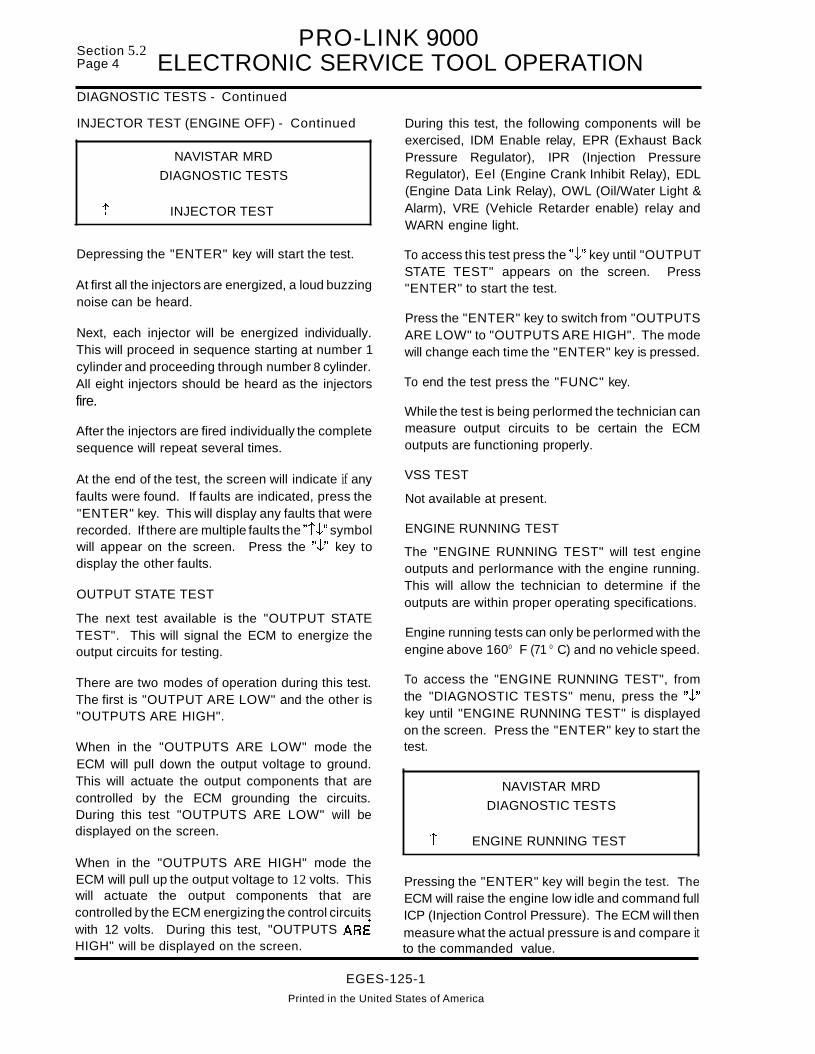
Section 5.2Page 4
PRO-LINK 9000ELECTRONIC SERVICE TOOL OPERATION
DIAGNOSTIC TESTS - Continued
INJECTOR TEST (ENGINE OFF) - Continued
NAVISTAR MRD
DIAGNOSTIC TESTS
t INJECTOR TEST
Depressing the "ENTER" key will start the test.
At first all the injectors are energized, a loud buzzingnoise can be heard.
Next, each injector will be energized individually.This will proceed in sequence starting at number 1cylinder and proceeding through number 8 cylinder.All eight injectors should be heard as the injectorsfire.
After the injectors are fired individually the completesequence will repeat several times.
At the end of the test, the screen will indicate if anyfaults were found. If faults are indicated, press the"ENTER" key. This will display any faults that wererecorded. If there are multiple faults the "tJ." symbolwill appear on the screen. Press the "J." key todisplay the other faults.
OUTPUT STATE TEST
The next test available is the "OUTPUT STATETEST". This will signal the ECM to energize theoutput circuits for testing.
During this test, the following components will beexercised, IDM Enable relay, EPR (Exhaust BackPressure Regulator), IPR (Injection PressureRegulator), Eel (Engine Crank Inhibit Relay), EDL(Engine Data Link Relay), OWL (Oil/Water Light &Alarm), VRE (Vehicle Retarder enable) relay andWARN engine light.
To access this test press the "J." key until "OUTPUTSTATE TEST" appears on the screen. Press"ENTER" to start the test.
Press the "ENTER" key to switch from "OUTPUTSARE LOW" to "OUTPUTS ARE HIGH". The modewill change each time the "ENTER" key is pressed.
To end the test press the "FUNC" key.
While the test is being perlormed the technician canmeasure output circuits to be certain the ECMoutputs are functioning properly.
VSS TEST
Not available at present.
ENGINE RUNNING TEST
The "ENGINE RUNNING TEST" will test engineoutputs and perlormance with the engine running.This will allow the technician to determine if theoutputs are within proper operating specifications.
Engine running tests can only be perlormed with theengine above 1600 F (71 0 C) and no vehicle speed.
To access the "ENGINE RUNNING TEST", fromthe "DIAGNOSTIC TESTS" menu, press the "J."key until "ENGINE RUNNING TEST" is displayedon the screen. Press the "ENTER" key to start thetest.
There are two modes of operation during this test.The first is "OUTPUT ARE LOW" and the other is"OUTPUTS ARE HIGH".
When in the "OUTPUTS ARE LOW" mode theECM will pull down the output voltage to ground.This will actuate the output components that arecontrolled by the ECM grounding the circuits.During this test "OUTPUTS ARE LOW" will bedisplayed on the screen. t
NAVISTAR MRD
DIAGNOSTIC TESTS
ENGINE RUNNING TEST
When in the "OUTPUTS ARE HIGH" mode theECM will pull up the output voltage to 12 volts. Thiswill actuate the output components that arecontrolled by the ECM energizing the control circuitswith 12 volts. During this test, "OUTPUTS AREHIGH" will be displayed on the screen.
Pressing the "ENTER" key will begin the test. TheECM will raise the engine low idle and command fullICP (Injection Control Pressure). The ECM will thenmeasure what the actual pressure is and compare itto the commanded value.
EGES-125-1
Printed in the United States of America

PRO-LINK 9000 .ELECTRONIC SERVICE TOOL OPERATION sect~oa~~·~
The test must be performed with the engine speedabove 1250 RPM.
When the test is complete, the number of faultsfound will be displayed. If there are any faults foundpress the "ENTER" key to display the faults. If thereis more than one fault, the "I~" symbol will bedisplayed. Press the "~" key to display other faults.
TACH BUFFER TEST
The Tach Buffer Test checks the circuit between theECM and VPM along with the internal buffer circuitin the VPM.
To perlorm this test select the "TACH BUFFERTEST' from the "ENGINE RUNNING TEST" menu.
DIAGNOSTIC TESTS - Continued
ENGINE RUNNING TEST - Continued
After testing Injection Control Pressure, the ECMwill activate the ESP (Exhaust Back Pressure) steptest. It will then command a specific back pressureand measure the EBP signal. The ECM will thencompare the expected value against thecommanded value to determine if the exhaust backpressure device is functioning correctly.
At the completion of the test the engine will return tonormal low idle and the screen will display thenumber of faults found.
If there are any faults found, press the "ENTER"key to display the faults. If the "IJ,." symbol is shown,more faults are accessible. Press the "~" key todisplay additional faults.
t
DIAGNOSTIC TESTS
ENGINE RUNNING TEST
INJECTOR TEST
After the "ENGINE RUNNING TEST" has beencompleted the injector test is accessible.
INJECTOR TEST
The injector test will test each cylinder'scontribution. This will measure how much work isbeing done by each cylinder as compared to theother cylinders.
The ECM will measure this by increasing theamount of fuel delivery to the injector being testedand monitoring the reduction in the other cylindersto maintain engine speed. If there is no reduction infuel delivery to the other cylinders, the ECM will seta fault code.
WIGGLE TEST
"WIGGLE TEST" is available under the DiagnosticTest Menu. The wiggle test is to assist thetechnician in finding an intermittent condition. Thewiggle test will monitor both signal outputs andinputs on a continuous basis. Any interruption in thecircuit will cause a fault.
To access "WIGGLE TEST" from the DiagnosticTest Menu, press the "~" key until "WIGGLE TEST"is displayed on the screen. Press the "ENTER" key,to start the test.
NAVISTAR MRD
DIAGNOSTIC TESTS
1 WIGGLE TESTTo access the "INJECTOR TEST" from theDiagnostic Tests menu press the "J,." key until the"INJECTOR TEST" is shown on the screen underthe "ENGINE RUNNING TESTS" menu. Thenpress the "ENTER" key.
At any time during the Wiggle Test if an open or shortis detected, the EST will beep and the word "BEEP"will display on the screen.
Note 1: "ENGINE RUNNING TEST" must beperformed first to access this test.
Note 2: While performing this test the enginewill run rough!
1
WIGGLE TEST
TEST IN PROGRESS
BEEP01 FAULTS FOUND
EGES-125-1
Printed In the United States of America
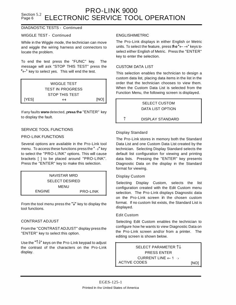
Section 5.2Page 6
PRO-LINK 9000ELECTRONIC SERVICE TOOL OPERATION
DIAGNOSTIC TESTS - Continued
WIGGLE TEST - Continued
While in the Wiggle mode, the technician can moveand wiggle the wiring harness and connectors tolocate the problem.
ENGLISHIMETRIC
The Pro-Link displays in either English or Metricunits. To select the feature, press the"~ -7" keys toselect either English of Metric. Press the "ENTER"key to enter the selection.
If any faults were detected, press the "ENTER" keyto display the fault.
To end the test press the "FUNC" key. Themessage will ask "STOP THIS TEST" press the"~" key to select yes. This will end the test.
CUSTOM DATA LIST
This selection enables the technician to design acustom data list, placing data items in the list in theorder that the technician chooses to view them.When the Custom Data List is selected from theFunction Menu, the following screen is displayed.
[YES]
WIGGLE TEST
TEST IN PROGRESS
STOP THIS TESTH [NO]
i
SELECT CUSTOM
DATA LIST OPTION
DISPLAY STANDARD
From the tool menu press the ".t" key to display thetool functions.
SERVICE TOOL FUNCTIONS
PRO-LINK FUNCTIONS
NAVISTAR MRD
SELECT DESIRED
MENU
Several options are available in the Pro-Link toolmenu. To access these functions press the "-7" keyto select the "PRO-LINK" options. This will causebrackets [ ] to be placed around "PRO-LINK".Press the "ENTER" key to make this selection.
[NO]
SELECT PARAMETER i .tPRESS ENTER
CURRENT LINE f-1 -7
ACTIVE CODES
Display Standard
The Pro-Link stores in memory both the StandardData List and one Custom Data List created by thetechnician. Selecting Display Standard selects thedefault list configuration for viewing and printingdata lists. Pressing the "ENTER" key presentsDiagnostic Data on the display in the Standardformat for viewing.
Display Custom
Selecting Display Custom, selects the listconfiguration created with the Edit Custom menuselection. The Pro-Link displays Diagnostic dataon the Pro-Link screen in the chosen customformat. If no custom list exists, the Standard List isdisplayed.
Edit Custom
Selecting Edit Custom enables the technician toconfigure how he wants to view Diagnostic Data onthe Pro-Link screen and/or from a printer. Theediting screen is shown below.
PRO-LINKENGINE
CONTRAST ADJUST
From the "CONTRAST ADJUST" display press the"ENTER" key to select this option.
Use the "i.t" keys on the Pro-Link keypad to adjustthe contrast of the characters on the Pro-Linkdisplay.
EGES-125-1Printed In the United States of America

PRO-LINK 9000 .ELECTRONIC SERVICE TOOL OPERATION sect:,oa~:'~
SERVICE TOOL FUNCTIONS - Continued
CUSTOM DATA LIST - Continued
The table below shows the keys used for creatingthe Custom Data List and the result of the key.
RESTART
Restart resets the Pro-Link to the beginning of theprogram. The contrast adjustment is not affected byRestart.
RS-232 SERIAL PORT
This selection allows the technician to configure thePro-Link RS-232 serial port for either printer orterminal (personal computer) output. The screenbelow appears when this item is selected.
FUNC Exits Edit Custom Mode
~ Scrolls up Current Line number andParameter
~ Scrolls down Current Line
t Scrolls up the Parameter only,Current Line Number unchanged
.t Scrolls down the Parameter only,Current line number unchanged
ENTER Accepts the Current Line number andParameter combination
i
RS-232 SERIAL PORT
FUNCTION MENU
PRINTER OUTPUT
To create a custom Data List:
• Select the desired data line as the Current Linenumber.
• Select the desired parameterto be displayed onthe line.
• Press the ENTER key. No change to the datalist occurs unless ENTER is pressed.
• Repeat for each Data Line.
Reset Custom
This selection resets the Custom Data list back tothe Standard List form. When selected, thefollowing screen is displayed.
This selection is used to print out diagnosticinformation.
The Pro-Link is set up to print to the Pro-LinkPrinter and no Port Setup is necessary for thatprinter. In order to print to a different printer, followthe instructions under Port Setup, in the ElectronicService Tool manual.
The following screen will be displayed if the"PRINTER OUTPUT" function is selected.
SELECT DATA TO PRINT
i DATA LIST
YES
RESET CUSTOM LIST
BACK TO STANDARD
ARE YOU SURE?f-~ [NO]
There are five types of data which can be printedout:
No is the default action. Reset the Custom Data Listto the Standard List by pressing the f- key to SelectYES, then press the "ENTER" key.
NOTE: If the Custom Data List is reset to theStandard List form, the Custom List is lost andmust be recreated.
DATA LISTDIAGNOSTIC CODESCALIBRATION DATASNAPSHOT DATAREPROG PARMS
Press the ".t" key to select other options. Press"ENTER" and the selection will be printed.
EGES-125-1Printed in the United States of America

Section 5.2Page 8
PRO-LINK 9000ELECTRONIC SERVICE TOOL OPERATION
SERVICE TOOL FUNCTIONS - Continued
Snapshot
Selecting the Snapshot option will display thefollowing screen.
DO YOU WISH TO PRINT
THE COMPLETE LIST
OR A CUSTOM LIST?[COMPLETE] ~ ~ CUSTOM
Complete
Choosing "COMPLETE" produces a screen asshown below.
SNAPSHOT PRINTOUTSELECT FRAMES
TRIG = ### FRAMES =###
START=###
TRIG = Frame number that contains thetrigger.
FRAME = Total number of frames in Snapshotmemory (a frame is one completeData List)
START = The first frame desired to print
Selecting "COMPLETE" will print all lines of thedata list. Enter the first frame desired to print at"START" and press "ENTER". Now line four willdisplay END = # # #. Enter the last frame desired toprint and press "ENTER". The tool will now print thecomplete data list for each of the frames that areselected.
Custom
Selecting Custom produces the following screen.
SELECT UP TO 6 DATA
PARAMETERS TO PRINTUSE FUNC TO QUIT
ENTER TO CONTINUE
Press the "ENTER" key and the following screenappears.
SELECT DATA TO PRINT
PRESS ENTERCOLUMN # =1
ACTIVE CODES
Use the "iJ,." keys to scroll the list on line four.Choose the item desired for column 1 of the customlist, press the "ENTER" key. Line three, "COLUMN#", advances to 2. Repeat this procedure for all sixcolumns of data to be printed. Press the "FUNC"key when finishedl The Select Frames screen appears. Select the desired frames to print and theCustom printout will begin.
SNAPSHOT
Snapshot allows the technician to record data fromthe Data List, for review. This can be helpful forcorrecting data while driving the truck or forsearching for an intermittent problem.
The following functions are available for Snapshot:
• Quick Trigger• Trigger Setup• Data Update Rate• Review Snapshot
Quick Trigger
The Quick Trigger function enables the technicianto take a second Snapshot quickly, using theprevious setting established during Trigger Setupforthefirst Snapshot. It is not necessary to reset thesetup values for each Snapshot. Press the"ENTER" key and the data is displayed on thePro-Link screen.
The Quick Trigger default trigger is Any NumericKey. Press any numeric key on the Pro-Link keypad to start recording data. Press any numeric keyagain to stop recording data.
EGES-125-1Printed in the United States of America

PRO-LINK 9000 .ELECTRONIC SERVICE TOOL OPERATION sect~a~:'~
SERVICE TOOL FUNCTIONS - Continued
Trigger Setup
Trigger Setup allows the technician to configurehow and when Snapshot triggers. Selecting thisoption displays the screen shown below.
SELECT SNAPSHOT
TRIGGER SOURCE
t ANY NUMERIC KEY
Four choices are available for Snapshot triggering.
• Any Numeric Key• Any Code• Specific PID• Specific SID
Any Numeric Key
Choosing this option requires the technician topress any numeric key on the Pro-Link keypad toactivate the trigger.
Specific Code, PID and SID
When selecting a Specific Code, PIO or SID ascreen is displayed which enables the technician tochoose the Code, PID or SID to trigger on from a listof those choices.
Setting Memory Trigger Point
Selecting any of the Trigger Setup options presentsthe display below.
DO YOU WISH TOADJUST THE MEMORY
TRIGG ER POINT
YES +- --7 [NO]
NO is the default.To adjust the trigger point, use the"f-" key to select YES, then press "ENTER".Selecting YES present the following screen.
T INDICATES LOCATIONOR TRIGGER IN MEMORY
BEG MID END
[ ••••••• 0 0 •• 0 • 0 0 • oT 0 0 ••••• 0 • 0 ••• 0 0 •• ]
Use the f- --7 keys on the Pro-Link keypad to adjustthe location of "T" along the line, then press"ENTER" to accept this position 0 When the triggeroccurs, all data to the right of "T" was received afterthe trigger occurred or towards the end of theSnapshot, Data to the left of "T' was receivedbefore the triggeroccurred or towards the beginningof the Snapshot.
Processing the Trigger
After defining all the setup functions, pressing the"ENTER" key presents the prompt on the screen,"WAITING FOR TRIGGER".
The Pro-Link is now storing data from the ECM andwaiting for the trigger condition to occur. When thetrigger occurs, the prompt is displayed"PROCESSING TRIGGER". The Pro-Link willrecord data in its memory buffer until full. Whencomplete refer to "Review Snapshot".
Review Snapshot
This function will only be displayed when there isSnapshot data in memory to view. The Snapshotshould have been triggered previously and the datastored in memory. The following screen isdisplayed.
DATADATADATA
T =# # # C =# # # GOTO
EGES-125-1
Printed in the United States of America
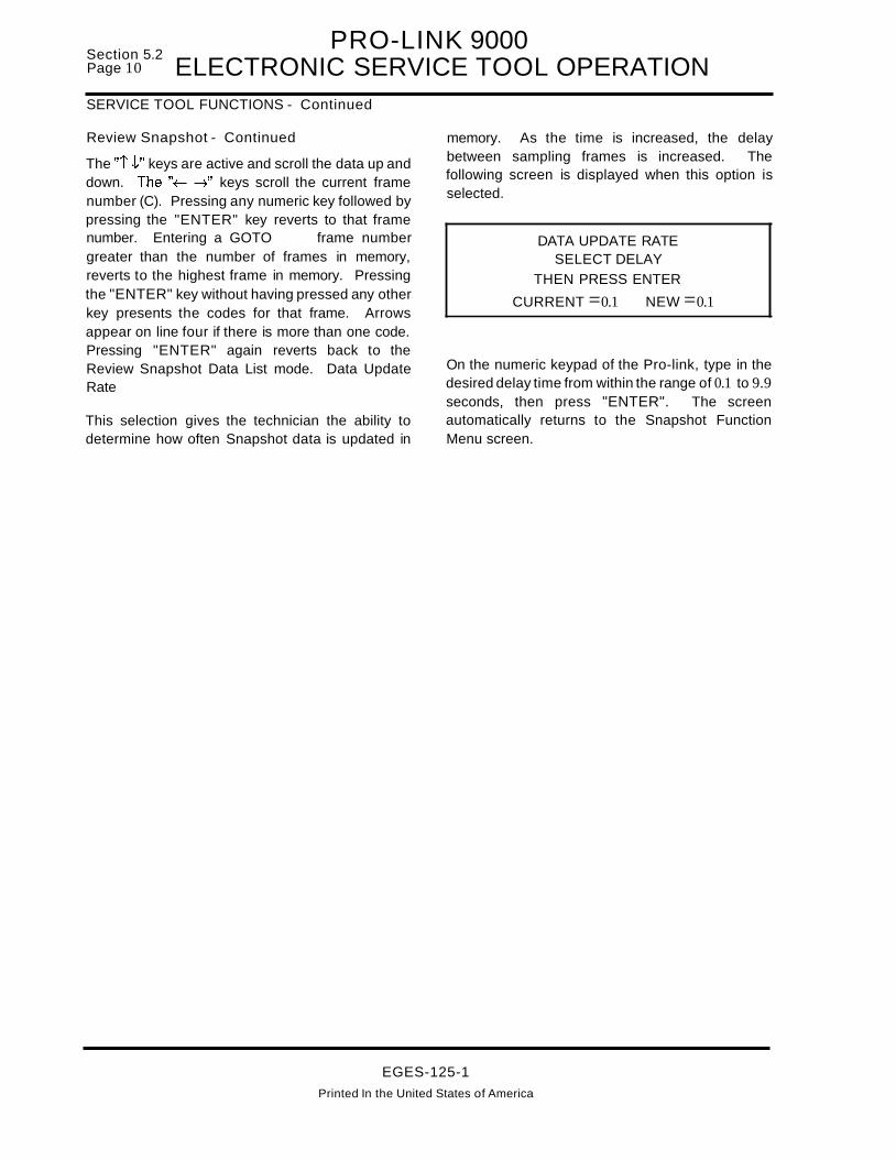
Section 5.2Page 10
PRO-LINK 9000ELECTRONIC SERVICE TOOL OPERATION
SERVICE TOOL FUNCTIONS - Continued
Review Snapshot - Continued
The "1 J," keys are active and scroll the data up anddown. The"~ -:;" keys scroll the current framenumber (C). Pressing any numeric key followed bypressing the "ENTER" key reverts to that framenumber. Entering a GOTO frame numbergreater than the number of frames in memory,reverts to the highest frame in memory. Pressingthe "ENTER" key without having pressed any otherkey presents the codes for that frame. Arrowsappear on line four if there is more than one code.Pressing "ENTER" again reverts back to theReview Snapshot Data List mode. Data UpdateRate
This selection gives the technician the ability todetermine how often Snapshot data is updated in
memory. As the time is increased, the delaybetween sampling frames is increased. Thefollowing screen is displayed when this option isselected.
DATA UPDATE RATESELECT DELAY
THEN PRESS ENTER
CURRENT =0.1 NEW =0.1
On the numeric keypad of the Pro-link, type in thedesired delay time from within the range of 0.1 to 9.9seconds, then press "ENTER". The screenautomatically returns to the Snapshot FunctionMenu screen.
EGES-125-1
Printed In the United States of America

'V..3"[3"
f mc C)2. m[ en
Ien ....it N.. rri ....2->3!t0'III
c~t:JC:f.J!'!~:J
~~~il~I _ .. I
•.l!'• ••••~ _r-:L-••..A••~
:::i:::'+~l"i~'~""r.:,:i~~:~
::j~:~::~::y.f!!'I:l:-,.Ji'"' .. ~ ..........,•.!!!!f!!lT-'.l..•..1•.-.,,--'tI". .1 1\-.-...-..": _..~
··BlGN....,.IlOWIICAHNOT.1\IIIIE)(IIj.-._
~i~.1:~ ceP.:~:C}!.,."t."f!tte_! r-t.•••-,..,.J----A.•1 L_=!I!!~.!..L.r;..!t--xe-, r-!-·..A;-;~..L•••••A_, .....tl.!'..!lJ_~·!!f~.!.'lf·' r··'·····......·j.~"" "j ••~tI..e'·~V.J_.._.'!.'l!P4... ...,_......,..,~• .%.••••••A..'I d~!!'t.,\\l.~.ret~e ... j j""..'1."--:ii~.x__.A••, ••!Jl'!!'!!!'r'.~.s'!!l!!!'!...J r••' ~
"'iCfi'~i"'"C!!:~~!9.f!
ELECTRONIC SERVICE TOOLMPSI PRO-LINK MAP
WITH 1678129C3 VPM
'-=,--:::1-
l--"--~", .......... ,:'!~lk'':I- .....-'1--....... ,, .... 2 I
::I:::l:~, .. ,'-- '"I~'",......j
L~..J,.1...1..,I _. I
L.~_J
r-"-iiiiC.iiii- -1, ,: MAD_' :I l'UIlCIIOll I"'_....... ...... .J
_'III1l__ TO_mlc:rlD__·~TOIEl\IIINTOL.UT_DIlllll'l'lTtl1_DAT&lll___ 'TA'lll _
_ ••• 'TOlUCT_
r~-"
~':r..ftIl:J[........."}
....."l."!W 1
....I :C:: 1,:r.!'!!':c:1f~i'-....!fI_"!......J
_".
mr-
~::aozoenm::a<om
dor-r:mzc:::,."
m1mo-I::DoZ-oen."m::D::DO<I-I0mZ-I"0<00°Igo"tJm::D
~-oZ
en(I)
,,2-I» _.CQO(1)::::1
.... 01
.... j,.)

MULTIMETER USESection 5.3
Page 1
Figure 5.3-2 - Simple Electrical Circuit
If any two of the values are known for a given circuit,the missing one can be found by substituting the values in amperes, volts, or ohms and solving for themissing value.
In a typical circuit, battery voltage is applied to a bulbthrough a 1a-amp fuse and a switch (Figure 5.3-2).Closing the switch turns on the bulb.
VOLTAGEVoltage is an electrical pressure or force thatpushes the current through a circuit. The pressureis measured in Volts and the symbol V (as in 12V)is used in the circuit diagrams. The letter "E" is alsoused for voltage and stands for ElectromotiveForce. Voltage can be compared to the pressurenecessary to push water through a metering valve.
Low voltage to a lamp will cause the lamp to glow
dimly. This can be caused by low source voltage(battery discharged or low alternator output), or byhigh circuit resistance in the circuit due to a poorconnection. The resistance of the poor connectionor poor ground acts as an additional load in the circuit, causing less voltage to be available to pushcurrent through the load device. Before making anymeter measurements, it is important to briefly review the relationship between voltage, current, andresistance (Ohms Law).
OHMS LAW REVIEWOhms Law describes the relationship of voltage,current and resistance, and provides us with a formula to make calculations as is shown in (Figure5.3-1).
OHMS LAW
BATIERY
GROUND
SWITCH
I~2 OHMSRESISTANCE
_ GROUND
1. 1= E/R
2. R =Ell
WHERE: I =CURRENT (AMPERES)E =VOLTAGE (VOLTS)R = RESISTANCE (OHMS)
THIS FORMULA STATES THAT CURRENTFLOW (I) =VOLTAGE (E) APPLIED TO ACIRCUIT DIVIDED BY TOTAL RESISTANCE(R) IN THE CIRCUIT. THIS SHOWS THAT ANINCREASE IN VOLTAGE OR A DECREASEIN RESISTANCE INCREASES THE CURRENT FLOW.
THIS FORMULA STATES THAT RESISTANCE (R) =VOLTAGE (E) APPLIED TO ACIRCUIT DIVIDED BY CURRENT FLOW (I)IN THE CIRCUIT. THIS ALLOWS US TOCALCULATE RESISTANCE NEEDED FOR ASPECIFIC CURRENT FLOW WITH A SPECIFIC VOLTAGE APPLIED (LIKE 12V).
To find the current flow use the formula:
1= E/ R
Filling in the numbers for the circuit in Figure 5.3-2,we have:
I = 12V/2 ohms or 1= 12 divided by 2 =6 amperes ofcurrent flow.
The bulb in this circuit operates at 6 amps and israted to operate at this level. With 12 volts applied,the bulb will glow at the rated output level (candlepower rating). However:
3. E =IR THIS GIVES THE VOLTAGE DROP(I MULTI- ACROSS A PARTICULAR LOAD DEVICEPLIED BY R) (RESISTANCE) THAT IS PART OF A SE-
RIES OF LOAD DEVICES.
MEMORIZE THE FORMULA IN THECIRCLE, THEN YOU ONLY HAVE TOCOVER THE IILETTER" THAT YOUWISH TO CALCULATE, WITH YOURFINGER, AND YOU HAVE THE FORMULA. FOR EXAMPLE: IF YOU COVER THE LETTER III". THE FORMULA IS1= E/R.
Figure 5.3-1 - Ohms Law
• If the voltage applied is low (low battery),
then (the value of E is lower) and currentflow will be less and the bulb will glow lessbrightly.
• Or if the connections are loose, or theswitch corroded, the circuit resistance willbe greater (value of Rwill be larger) and thecurrent flow will be reduced and the bulb willglow less brightly.
EGES-125-1
Printed in the United States of America

Section 5.3Page 2 MULTIMETER USEOHMS LAW REVIEW (Continued)
Figure 5.3-3 - Checking Power To A LoadDevice
RL = RESISTANCEOFTHE
LOAD DEVICE
12V
A:":":' A'"
OFF v....
12V
'rV'---~"..---.!L
When using a voltmeter to determine if voltage ispresent to power a device, connect the positive meter lead to input connection of the device (positiveside) and connect the negative meter lead to goodvehicle ground (Figure 5.3-3). This shows howmuch of the source voltage is available to the device. Note that the meter is connected in parallel tothe device.
Should we need to determine if voltage is availableat a connector where we can't readily connect to thedevice, we can connect the meter in parallel asshown in (Figure 5.3-4). The meter internal resistance is very high so little current will flow in the circuit, and the voltage can be read accurately.
To check the voltage drop across a load device (Figure 5.3-5), connect the positive lead of the voltmeter to the positive side of the device and the negativemeter lead to the negative side of the device.
• Is voltage present?
• What is the voltage reading?
• What is the voltage drop across a load device?
• Too high a voltage drop indicates excessiveresistance. If, for instance, a blower motorruns too slowly or a light glows too dimly,one can be sure that there is excessive resistance in the circuit. By taking voltagedrop readings in various parts of the circuit,the problem can be isolated (corroded orloose terminals for example).
• Too low of a voltage drop, likewise, indicates low resistance. If for instance, a blower motor ran too fast, the problem could beisolated to a low resistance in a resistorpack by taking voltage drop readings.
• Maximum allowable voltage drop underload is critical, especially if there is morethan one high resistance problem in a circuit. It is important because all voltagedrops in a circuit are cumulative. Corrodedterminals, loose connections, damagedwires or other similar conditions create undesirable voltage drops that decrease thevoltage available across the key circuitcomponents. Remember our earlier discussion, the increased resistance from theundesirable conditions will also decreasethe current flow in the circuit and all the affected components will operate at less thanpeak efficiency. A small drop across wires(conductors), connectors, switches, etc. isnormal. This is because all conductorshave some resistance, but the total shouldbe less than 10 percent of the total voltagedrop in the circuit.
USING THE VOLTMETER
In electrical diagnosis, the voltmeter is used to answer:
Being able to determine voltage drops is importantbecause it provides the following information:
EGES-125-1Printed in the United States of America

MULTIMETER USESection 5.3
Page 3
USING THE VOLTMETER (Continued)
NOTE: 34A IS ANIGNITION VOLTAGESOURCE
12V
OFF VIW
With the device operating, this will measure the voltage drop across the device. Notice in (Figure5.3-5) that since we only have one device, all of thevoltage should be dropped at the device. In any circuit, the voltage applied will equal the voltagedropped in the circuit. If in this circuit we onlydropped 9V across the load, that would indicate thatour wires, connections, etc. were dropping the other3V, which would indicate excessive circuit resistance.
AMMETER
An ammeter is used to measure current flow (amperage) in a circuit. Amperes are units of electronflow, which indicate how many electrons are passing through the circuit. Ohms Law indicates that current flow in a circuit is equal to the circuit voltage divided by total circuit resistance. Sinceamps (I) is thecurrent in the circuit, increasing voltage also increases the current level (amps)ft Also, any decrease in resistance (ohms) will increase currentflow (amps).
Figure 5.3-5 - Checking Voltage Loss
Figure 5.3-4 - Checking Power To AConnector At norJ11al operating voltage, most circuits have a
characteristic amount of current flow, referred to ascurrent draw. Current draw can be measured with aammeter. Referring to a specified current draw rating for a component (electrical device) J measuringthe current flow in the circuit, and comparing the two(the rating versus the actual measured) can providevaluable diagnostic information.
An ammeter is connected in series with the load,switches, resistors, etc. (Figure 5.3-6) so that all ofthe current flows through the meter. The meter willmeasure current flow only when the circuit is powered and operating. Before measuring current flow,we need to know approximately how much currentwill be present to properly connect the meter. TheDMM is fused to measure up 10 amps using the 10Aconnection point.
The estimate of current flow can easily be calculated. In (Figure 5.3-6), the resistance of the lightbulb is 2 ohms. Applying ohms law, we can calculatethat current flow will be 6 amps (6A =12V/2 ohms).If we remove the fuse, and install the ammeter asshown, with the switch closed we will measure 6amperes of current flowing in the circuit. Notice thatthe ammeter is installed so that all the current in thecircuit flows through it. The ammeter is installed inseries.
RL = RESISTANCEOF THE
LOAD DEVICE
12V
OFF v....
f'.---~~'".--...!.L
12V
EGES-125-1
Printed In the United States of America

Section 5.3Page 4 MULTIMETER USEUSING THE AMMETER (Continued)
12 VOLTS
BATTERY
GROUND
TI~LOAD
(LIGHT)_ GROUND
device. Loose or corroded connections can frequently cause this problem.
OHMMETER
The ohmmeter is used to ' measure resistance(ohms) in a circuit. Like the ammeter and voltmeter,there are both analog and digital meters available.It is recommended that the digital meter (Fluke 88DVOM) be used. See ELECTRONIC CIRCUITTESTING in this section.
CAUTION -The ohmmeter can only be usedon circuits where power has been removed.The meter contains its own low voltage power supply and the power from 12-volt systems may damage the meter.
Ohmmeters use a small battery to supply the voltage and current which flow through the circuit beingtested. The voltage of the meter battery and theamount of current flow in the circuit are used withOhms Law and the meter calculates the circuit resistance which is displayed by the meter. With theFluke 88 DVOM, range selection and meter adjustment are not necessary.
MEASURING RESISTANCE
1 - DMM SET TO MEASURE DC CURRENT
2 - FUSE SHOWN REMOVED
3 - LIGHT BULB (2 OHMS RESISTANCE)
4 - METER LEAD CONNECTED TO 10A METER JACK
Figure 5.3-6 - Installing The Ammeter
Excessive current draw means that more current isflowing in a circuit than the fuse and circuit were designed for. Excessive current will open fuses andcircuit breakers. Excessive current draw can alsoquickly dis-charge batteries. An ammeter is usefulto help diagnose these conditions. On the otherhand, there are times reduced current draw willcause a device (electric window motor for example)to operate poorly. Remember increased circuit resistance causes lower current to be available to the
Resistance measurements determine:
• Resistance of a load
• Resistance of conductors
• Value of resistors
• Operation of variable resistors
To measure the resistance of a component or a circuit, power must first be removed from the circuit.
The component or circuit that is to be measuredmust be isolated from all other components or circuits so that meter current (from probe to probe)only flows through the desired circuit or componentorthe reading will not be accurate. Notice in (Figure5.3-7) that if we wanted to measure the resistanceof the load, most of the current flow from the meterwould flow through the indicator lamp because ithas less resistance. To measure the load, one connector to the load should be removed. It is not always apparent when a component must be isolatedin such a manner, so it is usually a good practice toisolate the circuit or component by physically disconnecting one circuit.
EGES-125-1Printed In the United States of America

MULTIMETER USESection 5.3
PageS
USING THE OHMMETER (Continued)
The ohmmeter leads are then placed across the component or circuit and the resistance will be displayed inohms (Figure 5.3-8). When checking a sensor or variable resistor such as fuel level gauge, heating theelement or moving the arm should move the meter through a range of resistance that can be compared toa specification.
RELAY70-73
I •I ,
••, .
VERYLOW
~ VERY'HIGH, : BULB FILA-
~ ~, • MENT... • VERY
VARIABLERESISTANCE
r INDICATORLAMP
rA1~... ----."!.-:
OHMS
Figure 5.3-7- Improperly Isolating ComponentFor Resistance Check
Figure 5.3- 8- Measuring Resistance
EGES-125-1Printed In the United States of America
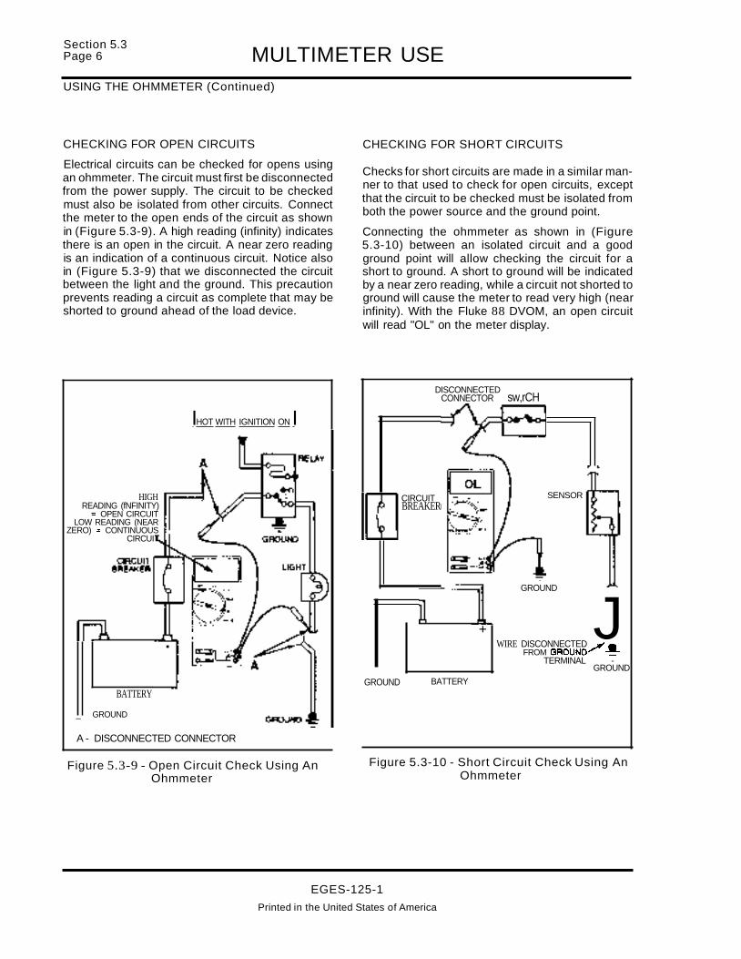
Section 5.3Page 6 MULTIMETER USEUSING THE OHMMETER (Continued)
CHECKING FOR OPEN CIRCUITS
Electrical circuits can be checked for opens usingan ohmmeter. The circuit must first be disconnectedfrom the power supply. The circuit to be checkedmust also be isolated from other circuits. Connectthe meter to the open ends of the circuit as shownin (Figure 5.3-9). A high reading (infinity) indicatesthere is an open in the circuit. A near zero readingis an indication of a continuous circuit. Notice alsoin (Figure 5.3-9) that we disconnected the circuitbetween the light and the ground. This precautionprevents reading a circuit as complete that may beshorted to ground ahead of the load device.
CHECKING FOR SHORT CIRCUITS
Checks for short circuits are made in a similar manner to that used to check for open circuits, exceptthat the circuit to be checked must be isolated fromboth the power source and the ground point.
Connecting the ohmmeter as shown in (Figure5.3-10) between an isolated circuit and a goodground point will allow checking the circuit for ashort to ground. A short to ground will be indicatedby a near zero reading, while a circuit not shorted toground will cause the meter to read very high (nearinfinity). With the Fluke 88 DVOM, an open circuitwill read "OL" on the meter display.
DISCONNECTEDCONNECTOR sw,rCH
IHOT WITH IGNITION ON I
HIGHREADING (fNFINITY)~ OPEN CIRCUIT
LOW READING (NEARZERO) = CONTINUOUS
CIRCUI
BATTERY
_ GROUND
A - DISCONNECTED CONNECTOR
GROUND
CIRCUITBREAKER
BATTERY
+
SENSOR
GROUND
JWIRE DISCONNECTED 1"_
FROM GROUND'---~TERMINAL -
GROUND
Figure 5.3-9 - Open Circuit Check Using AnOhmmeter
Figure 5.3-10 - Short Circuit Check Using AnOhmmeter
EGES-125-1
Printed in the United States of America

MULTIMETER USESection 5.3
Page 7
TROUBLESHOOTING
Before beginning any troubleshooting, there areseveral important steps to be taken:
VERIFY THE PROBLEM
Operate the complete system and list all symptomsin order to:
• Check the accuracy and completeness ofthe complaint.
• Learn more that might give a clue to the nature and location of the problem.
• Analyze what parts of the system are working.
READ "ELECTRICAL OPERATION"
Read the electrical operation for the problem circuit(while referring to the circuit diagram). By studyingthe circuit diagram and the electrical operation,enough information about circuit operation shouldbe learned to narrow the cause of the problem toone component or portion of the circuit.
CHECK THE CIRCUIT DIAGRAM
Refer to the circuit diagram for possible clues to theproblem. Location and identification of the components in the circuit may give some idea of where theproblem is.
The circuit diagrams are designed to make it easyto identify common points in circuits. This knowledge can help narrowthe problem to a specific area.For example, if several circuits fail at the same time,check for a common power source or commonground connection (see POWER DISTRIBUTIONAND GROUNDS). If part of a circuit fails, check theconnections between the part that works and thepart that doesn't work.
For example, if the low-beam headlights work, butboth high-beam lights and the high-beam indicatordo not work, then the power and ground paths mustbe good. Since the dimmer switch is the componentthat switches the power to the high-beam headlights, it is the most likely cause of failure.
CHECK FOR CAUSE OF THE PROBLEM
Diagnosis charts are provided for many of the common faults that may occur. Refer to these charts ineach section. Follow the procedures in the chart until the cause of the problem is located.
If the particular symptom found in the problem circuit is not covered by a diagnosis chart, refer to the
general electrical troubleshooting information provided under "Electrical Test Equipment" in this section.
MAKE THE REPAIR
Repair the problem circuit as directed in the diagnostic charts.
VERIFY THAT THE REPAIR IS COMPLETE
Operate the system and check that the repair hasremoved all symptoms, and also that the repair hasnot caused any new symptoms.
ELECTRICAL TEST EQUIPMENT
Various electrical testers have been developed overthe years. A few of these are basic but necessary topetform an electrical diagnosis. These include:
• Jumper Wires
• Test Lights
• Voltmeter
• Ohmmeter
• Ammeter
All of these testers come in a variety of models andany working model will be adequate for simple tests.However, when the value of a reading obtained using a meter is critical to the diagnostic procedure,accuracy becomes important. Make sure any electrical test meter used is of sufficient quality and accuracy to make the measurements required in theelectrical testing. The "Fluke 88 Digital Multimeter"(DMM) is the Navistar recommended meter and discussions of meter use in this manual will refer to thatmeter.
The Fluke aa Multimeter, a digital meter, isrecommended because it uses very little current todo its measuring. The digital meter has highimpedance (resistance): 10 megohms.
ELECTRONIC CIRCUIT TESTING
Some of the devices in an electronic control systemare not capable of carrying any appreciable amountof current. Therefore the test equipment used totroubleshoot an electronic system must be especially designed not to damage any part of it. Because most analog meters (Figure 5.3-11) use toomuch current to test an electronic control system, itis recommended that they not be used, unless specified.
EGES-125-1
Printed In the United States of America

Section 5.3Page 8 MULTIMETER USEELECTRONIC CIRCUIT TESTING (Continued)
ALLIGATORCLIP
ALLIGATORCLIP
SPADETERMINAL
PROBETIP
PINTERMINAL
ALLIGATORCLIP
Figure 5.3-13 - Jumper Wires
• A circuit without any opens or breaks hascontinuity (which means continuous) andneeds no further testing.
Jumper wires are fitted with several types of wiretips. It will be helpful to have several jumper wiresavailable with different tips (Figure 5.3-13).
In (Figure 5.3-12), if bypassing the switch with ajumper wire causes the light to illuminate, but closing the switch does not, it indicates the switch hasfailed. If, with the switch closed, the light does not illuminate, and "jumpering" the switch doesn't causethe light to operate, but "jumpering" the light toground causes the light to operate, then there is anopen in the ground circuit.
LIGHT
DIGITAL METER
+
JUMPERWIRE
ANALOG METER
BATTERY
GROUND
• If the circuit (Figure 5.3-12) works properlywith the jumper wire in place, but does not
work when the jumper wire is removed, thecircuit has an open spot.
JUMPER WIRES
Jumper wires (Figure 5.3-12) allow "jumping"across a suspected open or break in a circuit.
Figure 5.3-11 - Typical Meters, Digital AndAnalog
The use of any kind of battery-powered test light isnot recommended when troubleshooting an electronic circuit, since it, too, could damage an electronic control circuit.
Figure 5.3-12 - Troubleshooting Using JumperWires
EGES-125-1Printed in the United States of America

MULTIMETER USESection 5.3
Page 9
JUMPER WIRES (Continued)
The jumper wire can be used to check for open relaycontacts, wire breaks, poor ground connections,etc.
12-VOLTTEST LIGHTS
keep the probe tip sharp to minimize damage to wireinsulation. When the test is complete at a particularpoint, make sure to tape any holes made in wire insulation.
FUSE
BATTERY
12-VOLTTESTLIGHT
Figure 5.3-14 - Troubleshooting Using12-Volt Test Light
The 12-volt test light continuity tester depends onthe vehicle battery to power the circuit under test.Twelve-volt testers are available with a variety oftips to permit touching them to connectors, barewires, insulated wires or even wires within wiringharnesses (Figure 5.3-15). To check the tester before use, briefly touch the clip to one post of the battery and the other to the opposite post. Twelve-volttesters are not sensitive to polarity and can be connected either way_
The 12-volt test light generally has a sharp probe tipso it can be inserted into connector terminals orthrough wire insulation for testing. It is important to
The 12-volt test light tests for voltage in a circuit between the point being tested and ground (Figure5.3-14). If there is no glow in the bulb, the circuit isopen and no current is flowing.
Once a technician becomes familiar with the testlight and the brilliance of the bulb in a normal circuit,high-resistance circuits can be recognized by thedimming effect that they have on the test light bulb.As the current drops in a high-resistance circuit, thebulb will glow less brightly. Although using a 12-volttest light cannot be used as a fool-proof test for highresistance, a less than normal brilliance of the testlight is an indication of circuit high resistance. Further testing will verify the condition and locate thecause.
TYPICAL PROBE-TYPE TEST LIGHTS
LIGHTIN TIP
WRAP-AROUND TEST LIGHT
VEE NOTCH
Figure 5.3-15 - Typical 12-Volt Test Lights
EGES-125-1Printed in the United States of America

SECTION 6 CONNECTOR AND HARNESS REPAIR
INDEX
PAGE
CONNECTOR AND HARNESS REPAIR
CONNECTOR REPAIR 1DEUTSCH HEAVY-DUTY CONNECTORS 1CONTACT REMOVAL . . . . . . . . . . .. 2CONTACT AND WIRE ASSEMBLY. . . . . . . . . . . . . . . . . . . . . . . . . . . . . . . . . . . . . . . . . . . . . . . . . . . .. 3CONTACT INSERTION . . . . . . . . . . . . . . . . . . . . . . . . . . . . . . . . . . . . . . . . . . . . . . . . . . . . . . . . . . . . . .. 3INSPECTION. . . . . . . . . . . . . . . . . . . . . . . . . . . . . . . . . . . . . . . . . . . . . . . . . . . . . . . . . . . . . . . . . . . . . . .. 6STANDARD TERMINAL REPLACEMENT . . . . . . . . . . . . . . . . . . . . . . . . . . . . . . . . . . . . . . . . . . . . . .. 6TERMINAL REPLACEMENT - SEALED WEATHER PACK AND METRI-PACK 7SPLICE CLIP INSTALLATION 7CRIMP AND SEAL SPLICE SLEEVE INSTALLATION 8LOCKING WEDGE CONNECTORS 9TO REMOVE THE TERMINAL FROM THE CONNECTOR: . . . . . . . . . . . . . . . . . . . . . . . . . . . . . . .. 9TO REPLACE THE TERMINAL: 9TO INSTALL THE TERMINAL IN THE CONNECTOR: 10PACKARD CONNECTORS. . . . . . . . . . . . . . . . . . . . . . . . . . . . . . . . . . . . . . . . . . . . . . . . . . . . . . . . . .. 11TO REMOVE THE TERMINAL FROM THE PACKARD CONNECTOR: 11TO REPLACE THE TERMINAL IN THE CONNECTOR: 12TO INSTALL THE TERMINAL IN THE CONNECTOR: 12
EGES-125-1Printed in The United States of America

CONNECTOR AND HARNESS REPAIRSection 6
Page 1
CONNECTOR REPAIR
Several different types of connectors are used onthe subject vehicle. The Deutsch heavy-duty connector is used for the engine harness to instrumentharness connection and others to be discussed later are used in other applications.
Each type can be repaired by following these procedures.
DEUTSCH HEAVY-DUTY CONNECTORS
The Deutsch heavy-duty connectors used are designed to seal against moisture and contaminants.They also protect against damage from shock andvibration. The Deutsch part numbering system provides a complete description of the connector. Thepart number takes the form of HD 34-18-8 PartNumber -xxx. A complete explanation is providedin (Figure 6-1).
8 & KIt - individuallY PackaaedWith Contleta, Sealing PI~s,Mounting Hardware And Removal Tool
3 • New Commercbll
DEUTSCH PART NUMBERING SYSTEM
HD 34 • 18 • 8 P N - XXX
Peaian@_Deutaeh----I---T I Special MOdlftcalionsHeavy DutyCyNnartcal Connector Standard Clocking Position
Type Contact Style5 =: Standard Commercial P = Pin (Male) Type
S :: Socket (Female) Type
Shell Size And Insert Layout(See Facing Page ForAvailable Arrangements)
'------------- Style4. • Receptacle - Jam Nut TypeMounting6 == Plug
INSERT LAYOUTS MARKINGS SHOWN ARE FOR FRONT FACE OF PIN INSERT. (SOCKET INSERT REVERSE)
24·9PN
8 No. 12, 2 No.8, 1 No.4CONTACTS
24--19P
13 No. 16, 6 No. 12CONTACTS
24..16PN
18 No. 12CONTACTS
18-8PN
8 No. 12CONTACTS
iFigure 6-1 - Deutsch Connectors
EGES-125-1Printed in the United States of America

Section 6Page 2 CONNECTOR AND HARNESS REPAIRCONNECTOR REPAIR (Continued)
CONTACT REMOVAL1. To remove the damaged contact , snap an ap
propriate size plastic contact repair tool overthewire of the contact to be removed (Figure 6-2).
CONTACT REMOVAL TOOL
PART SIZE %.015 *.011 REI' MAX :*: .031NO. A • C D E
114008 8 .555 .875 .314 2.250 1.500
114009 .. .740 .875 .435 2.250 1.500
114010 12 .350 .825 .202 2.300 1.250
0411-2Q4.1805 18 .286 .500 .180 2.300 1.000
~·3 SIZE. CONFIGURATION
If the wire to the contact is broken off, insert thetool into the applicable cavity over the contact.Use a Deutsch tool or equivalent.
f:~:F =s-~Im~f-----D A~ ~E~SIZE " . 12 & 18 CONFIGURATION
(US! tHIS DEUTSCH TOOL, OR EQUIVALENT,
FOR CONTACT REMOVAL)
TOOL INSERTED TOUNLOCK CONTACT
LOCKING FINGERS
TOOL AND CONTACTR90VED
Figure 6-2 - Deutsch Connector Contact Removal
2. Slide the tool into the cavity overthe contact un- 3. Pull the contact/wire/tool assembly out of thetil resistance is felt (locking fingers released) as connector (Figure 6-5.).shown in (Figures 6-3 and 6-4.).
Figure 6-3 - Sliding Tool Into Cavity Figure 6-4. - Contact Locking Finger Releasedr-~----';-----~--""
Figure 6-5. - Contact Removal From Connector
EGES-125-1Printed in the United States of America

CONNECTOR AND HARNESS REPAIRCONTACT AND WIRE ASSEMBLY
Section 6Page 3
1. Strip 0.253 +/- 0.031 inch (approximately 1/4inch) of insulation from end of wire using suitable stripping tool.
Figure 6-6. - Insert Contact Into Tool
2. Position contact into Deutsch HDT-4800 handcrimping tool (or equivalent) so that the crimpbarrel is 1/32 inch above the tool indenters (Figure 6-6.). Hold contact in place by hand or bylightly squeezing the tool.
Figure 6-7. - Insert Wire Into Contact
3. Place the stripped end of the wire into the crimpbarrel of the contact. Insert wire into contact.(Figure 6-7.) Fully depress the tool handles.Release and remove wire/contact assembly.(Figure 6-8.)
4. Inspect the wire/contact terminal to make surethat all wire strands are in the crimp barrel andthat the crimp is secure.
Figure 6-8.- Contact Crimping
CONTACT INSERTION
1. Grasp the contact/wire assembly, between thethumb and forefinger, on the wire approximatelyone inch behind the contact crimp barrel.
2. Hold the connector with the grommet facing thecontact.
Figure 6-9. - Connector/Contacttion
3. Push the contact straight into the appropriatecavity in the connector grommet, until a positivestop is felt . The retaining fingers in the connector will snap behind the shoulder of the contactand lock it in place. (Figure 6-9.). A slight tugbackward on the wire will verify that the contactis properly seated. (Figure 6-10)
EGES-125-1Printed In the United States of America

Section 6Page 4 CONNECTOR AND HARNESS REPAIRCONNECTOR REPAIR (Continued)
Several different types of electrical connectors areused on the subject vehicles. Refer to Figures6-11. through 6-14. for additional connector illustrations.
Figure 6-10. - Verification of Contact Seating
LOCKING FINGERS CONTACT•,
tJ 1 __ I
.....
UNLOCKED POSITION CONTACT LOCKED IN POSITION
Figure 6-11. - Contact (Left) and Insertion (Right)
® 56/59 SERIES (FEMALE)
® 56 SERIES (MALE)
© PIN GRIP (FEMALE)
® PRINteD CIRCUIT (BOW)® PRINTED CIRCUIT lEDGE BOARDl
® PACK CON I AND II (FEMALE)
NOTE: ARROWS POINT TO TERMINAL LOCKTANG AND CONNECTOR CANAL
Figure 6-12. - Connector Details
EGES-125-1Printed in the United States of America

CONNECTOR AND HARNESS REPAIRCONNECTOR REPAIR (Continued)
Section 6PageS
@ PACK CON (FEMALE)HEAVY DUTYIIII SERIES
@PACKCON "HEAVY DUTY
CDWEATHER PACK (FEMALE) SLEEVE
CD WEATHER PACK (MALE) PIN NOTE: ARROWS POINT TO TERMINAL LOCK® MICRO-PACK (FEMALE) TANG AND CONNECTOR CANAL
Q) MICRO-PACK (FEMALE)
Figure 6-13. - Connector Details
®
@ METAl-PACK (FEMALE)150 SERIES
® METAl-PACK (FEMALE)150 SERIES - PULL TOSEAT
®
® METRI-PACK (MALE)160-280 SERIES150-280 SERIES SEALED
® METRI-PACK (FEMALE)280 SERIES280 SERIES SEALED
Figure 6-14. - Connector Details
EGES-125-1Printed in the United States of America
®
® METRI-PACK (FEMALE)480-630 SERIES480 SERIES SEALED
® METRI-PACK (MALEI480-630 SERIES

Section 6Page 6
INSPECTION
CONNECTOR AND HARNESS REPAIR
1-INSULATION CRIMP
2 - WIRE STRANDS VISIBLE IN THISAREA
3- CORE CRIMP
4 - GOOD SOLDER APPLICATION
5 - EVIDENCE OF GLUE
A - TERMINAL APPLICATION
B- SOLDER APPLICATION
C - CRIMP AND SEAL HEAT APPLICATION
Figure 6-15. -Inspecting Terminal, Solder, Crimp and Seal Heat Applications
STANDARD TERMINAL REPLACEMENT
Refer to Figure 6-16
1. Cut the cable just before the insulation wings onthe terminal.
2. Remove the insulation being careful not to cutany of the wire strands.
3. Position cable in the new terminal.
4. Hand crimp the core wings first, then the insulation wings.
NOTE: Always use the recommended crimp toolfor each terminal. A detailed crimp chart is included in the repair kit.
5. Solder all hand crimped terminals and electrically check for continuity.
1
1 - MATING END
2 - CORE WINGS
3 - INSULATION WINGS
4-CABLE
5-LOCKTANG
6 - INSULATION
7 - WIRE STRANDS
8 -SOLDER
Figure 6-16. - Standard Terminal Replacement
EGES-125-1Printed in the United States of America

CONNECTOR AND HARNESS REPAIRSection 6
Page 7
7. Replace the terminal in correct connectorcavity.
6. Solder all hand crimped terminals and electrically check for continuity.
NOTE: Always use the recommended crimp toolfor each terminal. A detailed crimp chart isincluded in the repair kit.2. Replace the seal and remove the insulation
being careful not to cut any of the wire strands.
3. Align the seal with the cable insulation.
4. Position the cable in the new terminal.
5. Hand crimp the core wings first, then theinsulation wings.
TERMINAL REPLACEMENT - SEALED WEATHER PACK AND METRI-PACK
Refer to Figure 6-17.1. Cut the cable just before the insulation wings on
the terminal.
l-CABLE
2 - CORE WINGS
3 - MAT1NG END
4-LOCKTANG
5 - INSULATIONWINGS
6-SEAL
7 - WIRE STRANDS
8-S0LDER
Figure 6-17. - Sealed Weather Pack and Metri-Pack Terminal Replacement
SPLICE CLIP INSTALLATIONRefer to Figure 6-18.
NOTE: A new clip must be located a minimum of1.5 inches (40 mm) from a connector, sleeve oranother clip.
1. Cut off the old clip or bad section of wire.
2. Remove the insulation being careful not to cutany of the wire strands.
3. Install the proper clip on the wire strands.
4. Hand crimp the clip until securely fastened.
5. Solder the clip and electrically check for continuity.
6. Cover the entire splice with splice tape. Extendthe tape onto the insulation on both sides of thesplice(s).
EGES-125-1Printed in the United States of America

Section 6Page 8 CONNECTOR AND HARNESS REPAIRSPLICE CLIP INSTALLATION (Continued)
1 - INSULATION
2 - WIRE STRANDS
3 - CLIP (POSITIONED CORRECTLY)
4 - CRIMPED CORRECTLY
5-S0LDER
6- TAPE
Figure 6-18. - Splice Clip Replacement
CRIMP AND SEAL SPLICE SLEEVE INSTALLATIONRefer to Figure 6-19.
NOTE: A new sleeve must be located a minimumof 1.5 inches (40 mm) from a connector, clip oranother sleeve.
1. Cut off the old sleeve or bad section of the wire.
2. Remove insulation being careful not to cut anyof the wire strands.
3. Install the proper sleeve on the wire strandsmaking sure the ends of the wire, hit the stop.
4. Hand crimp to the sleeve. Gently tug on the wireto make sure that they are secure.
NOTE: Always use the recommended crimp toolfor each sleeve. A detailed crimp chart is included in the Repair Kit.
CAUTION - Do not use a match or openflame to heat the sleeve seal.
5. Electrically check the sleeve and wire cable forcontinuity.
1 - WIRE STRANDS
2- WIRE STOP
3 - CRIMP CONNECTOR
4 - EVIDENCE OFGLUE
Figure 6-19. - Seal Splice Sleeve Replacement
EGES-125-1Printed In the United States of America

CONNECTOR AND HARNESS REPAIRSection 6
Page 9
LOCKING WEDGE CONNECTORSProcedure for removal of wire terminals from EeT,EOT, IAT and MAP.
The terminals are held in place by plastic retainingfingers which are part of the connector. The fingerssnap into the shoulder of the terminal and are heldin place by the locking wedge.
TO REMOVE THE TERMINAL FROM THE CONNECTOR:
1. Using the appropriate tool, pry the connectorlock out of the connector body from the matingend and remove the lock from the connector(Figure 6-20).
Figure 6-20. - Remove Lock Wedge
2. Insert a narrow blade into the connector to liftthe retaining finger away from the terminal (Figure 6-21.).
Figure 6-21. - Release Retaining Finger
3. Pull the wire and terminal out of the connectorbody (Figure 6-22.).
Figure 6-22. - Remove Terminal From Connector
TO REPLACE THE TERMINAL:
1. Remove the insulation, being careful not to cutany of the wire strands.
2. Position the wire in the new terminal (Figure6-23.).
Figure 6-23. - Place Terminal Over Wire
3. Hand crimp the core wings first and then the insulation wings (Figure 6-24.).
Figure 6-24. - Terminal Over Wire
EGES-125-1Printed In the United States of America

Section 6Page 10 CONNECTOR AND HARNESS REPAIRTO REPLACE THE TERMINAL: - Continued
EG-5475
Figure 6-25. - Contact Crimping Complete
TO INSTALL THE TERMINAL IN THE CONNECTOR:
1. Push the terminal into the connector body,deepenough so that the retaining finger snaps overthe terminal shoulder (Figure 6-26.).
Figure 6-26. - Insert Terminal
2. Push the insulator over the wires into the connector body (if equipped) (Figure 6-27.).
EG-5459
Figure 6-27. - Insert Insulation
3. Insert the locking wedge and push in until flushwith the face of the connector body (Figure6-28.).
Figure 6-28. - Insert Terminal Lock
EGES-125-1Printed in the United States of America

CONNECTOR AND HARNESS REPAIRSection 6
Page 11
PACKARD CONNECTORS
Procedure for removal of wire terminals from CMP,ICP, IPR J EOP and injector connectors.
The terminals are held in place by locking tabs thatare part of the terminal. To remove the terminal thelocking tab must be released from the wire side ofthe connector body and the terminal is removed toward the mating end of the connector body.
TO REMOVE THE TERMINAL FROM THE CONNECTOR:
1. Pry the insulator from the rear of the connectorbody (Figure 6-29.).
Figure 6-31. - Release Terminal Lock Tab
Figure 6-30. - Slide The Insulator Back
3. Insert the narrow blade tool into the rear of theconnector body on the locking tab side of thewire terminal (Figure 6-31.) .
Figure 6-29. - Move The Insulation Back
2. Slide the insulator down the wires away fromthe connector body (Figure 6-30.).
EGES-12S-1
Printed In the United States of America
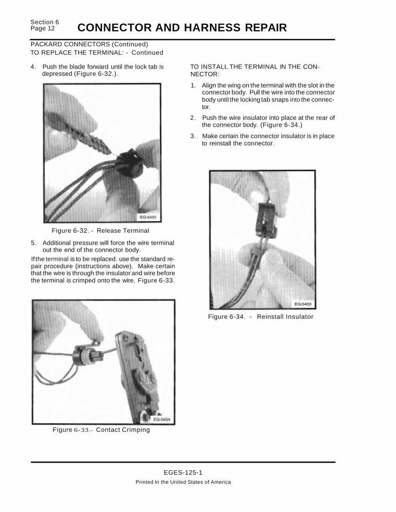
Section 6Page 12 CONNECTOR AND HARNESS REPAIRPACKARD CONNECTORS (Continued)TO REPLACE THE TERMINAL: - Continued
4. Push the blade forward until the lock tab isdepressed (Figure 6-32.).
Figure 6-32. - Release Terminal
5. Additional pressure will force the wire terminalout the end of the connector body.
If the terminal is to be replaced I use the standard repair procedure (instructions above). Make certainthat the wire is through the insulator and wire beforethe terminal is crimped onto the wire. Figure 6-33.
Figure 6-33.- Contact Crimping
TO INSTALL THE TERMINAL IN THE CONNECTOR:
1. Align the wing on the terminal with the slot in theconnector body. Pull the wire into the connectorbody until the locking tab snaps into the connector.
2. Push the wire insulator into place at the rear ofthe connector body. (Figure 6-34.)
3. Make certain the connector insulator is in placeto reinstall the connector.
Figure 6-34. - Reinstall Insulator
EGES-125-1Printed In the United States of America

SECTION 7VEHICLE AND COMPONENT ILLUSTRATIONS
INDEX
PAGE
VEHICLE AND COMPONENT ILLUSTRATIONSTRUCK LH CAB WIRING . w • • • • • • • • • • • • • • • • • • • • • • • • • • • • • • • • • •• 1RH TRUCK CAB WiRING 2CENTER TRUCK CAB WIRING 3TRUCK FUSE PANEL AND EST CONNECTOR (384) INSTALLATION 4TRUCK BNO/BNC AIR BRAKE PRESSURE SWITCHES 5TRUCK BNO/BNC HYDRAULIC BRAKE SWITCHES . . . . . . . . . . . . . . . . . . . . . . . . . . . . . . . . . . . .. 6ECMNPM MODULE LOCATION 7ECMNPM MODULE ASSEMBLY 8TRUCK CRUISE/PTO WIRING 9REAR CAB PTO WIRING (N/TRAVELCREW CAB) 10REAR TRAVEL CREW CAB PTO WIRING 11FBC LH CAB WIRING 12FBC CAB WIRING WITH AIR BRAKES 13FBC CAB WIRING WITH HYDRAULIC BRAKES 14FBC RH CAB WiRING 15FBC PARK BRAKE SWITCH 1617FBC FUSE PANEL . . . . . . . . . . . . . . . . . . . . . . . . . . . . . . . . . . . . . . . . . . . . . . . . . . . . . . . . . . . . . . . . . . . . . .. 17FBC LEFT KICK PANEL 18DASH HARNESS WIRING TRUCK AND FBC (LEFT SIDE) 19DASH HARNESS WIRING TRUCK AND FBC (CENTER) 20DASH HARNESS WIRING TRUCK AND FBC (LEFT SIDE) 21ENGINE WIRING - TRUCK AND FBC 22ENGINE WIRING AT TRANSMISSION .. TRUCK AND FBC 25ENGINE WIRING AT STARTER MOTOR - TRUCK AND FBC 26ENGINE WIRING ALTERNATORS - TRUCK AND FBC 27ENGINE WIRING AT AIR/FREON COMPRESSOR - TRUCK AND FBC 28ENGINE WIRING HYDRAULIC BRAKE/DASH/ENGINE HARNESS - TRUCK AND FBC 29ENGINE WIRING 105/160 AMP ALTERNATORS - TRUCK AND FBC 30ENG.-WRNG-(TRK.W/ LEECE-NEV. 2600JA 12V/160A ALTERNATOR W/4 GAUGE PROTECTION) 31ENGINE WIRING BATTERY CABLE/STARTING HARNESS - TRUCK AND FBC 32ENGINE WIRING EXHAUST BACK PRESSURE/GLOW PLUG RELAY - TRUCK AND FBC 33ENGINE WIRING COOLANT LEVEL SENSOR - TRUCK AND FBC 34ENGINE WIRING ALLISON AT TRANSMISSION WIRING - TRUCK AND FBC w •••••••••• 35ENGINE WIRING .. TRUCK AND FBC 36PLATFORM HARNESS WiRING 37EST (DATA LINK)/VPM CONNECTIONS/ACCELERATOR PEDAUSTOP LIGHT SWITCH WIRING 39PARK BRAKE SWITCH INSTALLATION & ADJUSTMENT , 40PLATFORM HARNESS WIRING - FUSE PANEUBRAKE SWITCH INSTALLATION & ADJUSTMENT 41PLATFORM HARNESS - CRUISE CONTROL WIRING 42DASH HARNESS WIRING - ECMNPM/IDM MODULE WITH 1652SC 43DASH HARNESS WIRING - VPM/ECM/IDM MODULE INSTALLATION WITH 1652SC .. ~ 44DASH HARNESS WIRING - LEFT SIDE WITH 1652SC PLATFORM ~ 45DASH HARNESS WIRING - RIGHT SIDE WITH 1652SC 46ENGINE HARNESS WIRING AT DASH PANEL WITH 1652SC 47LEFT SIDE ENGINE WIRE HARNESS " 48
EGES-125-1Printed in The United States of America

II
I
S~CTION 7VEHICLE AND COMPONENT ILLUSTRATIONS
PAGE
I
I INDEXI
IVEHICLE AND COMPONENT ILLUSTrRATIONSRIGHT SIDE ENGINE WIRING WITH 1652SC i.. .. ....... •. .. .. . .. .. . . .... ... . ......... .. ...... 49ENGINE HARNESS WIRING AT TRANSMISSIPN 50ENGINE HARNESS WIRING j • .. •• • •• .•• • •••••..•••••••••••.•.•.•••.••.••.•.•• 51ENGINE WIRING AT ALTERNATOR -1- 52BATTERY CONNECTOR (426) AND TOP VIE'f OF AC COMPRESSOR 53ALLISON "AT' TRANSMISSION WIRING '1' 54ENGINE WARM-UP DEVICE 1 55ENGINE SHUTDOWN WIRING AT DASH PAN!EL 56ENGINE SHUTDOWN WIRING AT DASH PANEL (CONTINUED) 57
I
IiII
iI
I
~GES-125-1Printed In ~ihe United States of America
I
I

VEHICLE AND COMPONENT ILLUSTRATIONSTRUCK LH CAB WIRING
Section 7Page 1
G08-38416.01.A
NOTE: CONNECTOR NUMBERS SHOWN INPARENTHESES
1. MAIN FUSE PANEL
2. MAIN CAB HARNESS
3. BREAKOUT FOR CIRCUITS TO VEHICLEPERSONALITY MODULE (VPM)
4. DASH CONNECTOR (2)
5. G2 GROUND STUD
6. CIRCUITS 11-G, 11-GA, 11-GD, 97-GK, 75-G
7. BREAKOUTS FOR HYD. BRAKE RECTIFIER,AND HYD. BRAKE MONITOR, KEY SWITCH,J2 ACC. FEED JUNCTION, CRUISE PTOCONNECTOR (394).
8. BARO SENSOR (406)
9. SEE FIGURE 7.2
10. APS/IVS (382)
Figure 7.1 - Truck LH Cab Wiring
EGES-125-1Printed In the United States of America

~:~~~n7 VEHICLE AND COMPONENT ILLUSTRATIONSRH TRUCK CAB WIRING
G08-38416.02
3
4
2
NOTE: CONNECTOR NUMBERS SHOWN INPARENTHESES
1. REF: POWER DIVIDER LOCKOUT SWITCH
2. MAIN CAB HARNESS
3. BRAKE RELAY (393)
4. CRANK RELAY (385)
5. G3 GROUND STUD
6. SEE FIGURE 7.1
7. REF: PANEL LIGHT FEED JUNCTION
Figure 7.2 - RH Truck Cab Wiring
EGES-125-1Printed in the United States of America

VEHICLE AND COMPONENT ILLUSTRATIONSSection 7
Page 3
CENTER TRUCK CAB WIRING
G08-38416.03.A2
c
2
A .0.B
...... ~........... D
-=-=.o:=.." ESWllOi .aHTIIIG
VIEW INDIAECTI~ CY NRJII B
NOTE: CONNECTOR NUMBERS SHOWN INPARENTHESES
1. MAIN CAB HARNESS
2. RH SWITCH PANEL (VIEW B)
A. WINDSHIELD WIPER (31)
B. HEADLIGHT (35)
C. WINDSHIELD WASHER (34)
D. PANEL LIGHT (33)
E. INTERRUPT (36)
3. CIRCUIT 43 TO POL SWITCH
4. DIAGNOSTIC SWITCH (CIRCUITS98/98A & 98-G)
5. YELLOW CLUSTER CONNECTOR (26)
6. GREEN CLUSTER CONNECTOR (27)
7. INSTRUMENT CLUSTER
8. NATURAL CLUSTER CONNECTOR (28)
9. REF: OIL PRESSURE LINE TO GAUGE
10. KEY SWITCH (24)
11. CIRCUIT 17 TO KEY SWITCH "S"TERMINAL W/O PUSH BUTTON
12. LH SWITCH CLUSTERLEFT CENTER - CRUISE ON/OFF (391)RIGHT CENTER - SET/RESUME (392)
13. REF: DASH LIGHT
Figure 7.3 - Center Truck Cab Wiring
EGES-125-1
Printed In the United States of America

~::~~n 7 VEHICLE AND COMPONENT ILLUSTRATIONS
TRUCK FUSE PANEL AND EST CONNECTOR (384) INSTALLATION
4G08-38416.04.A
NOTE: CONNECTOR NUMBERSSHOWN IN PARENTHESES
1. EST CONNECTOR (384)
2. MAIN CAB HARNESS
3. REF: LEFT KICK PANEL(PART OF WELDED CABASSY)
4. J1 FEED STUD
5 5. EST CONNECTOR DUSTCOVER
6. FUSE PANEL BRACKET
7. MAIN FUSE PANEL
Figure 7.4 - Truck Fuse Panel And EST Connector (384) Installation
EGES-125-1
Printed In the United States of America

VEHICLE AND COMPONENT ILLUSTRATIONSSection 7
PageS
TRUCK BNO/BNC AIR BRAKE PRESSURE SWITCHES
G08-38416.07
1 4
N/CHASSIS HAN) CONTROL
ROUTING W/4><24
5
ROUTING W/6X4
5
2
W/CHASS I5 HAil[) CONTRCL
1_.::::t~V"'-• .£\-' ......
NOTE: CONNECTOR NUMBERS SHOWN IN PARENTHESES
1.. BRAKE SWITCH (70)
2. STOP LIGHT SWITCH CONNECTOR (46)
3. MAIN CAB HARNESS
4. BRAKE SWITCH (71)
5. SWITCH HARNESS
Figure 7.5 - Truck BNOIBNC Air Brake Pressure Switches
EGES-125-1
Printed In the United States of America
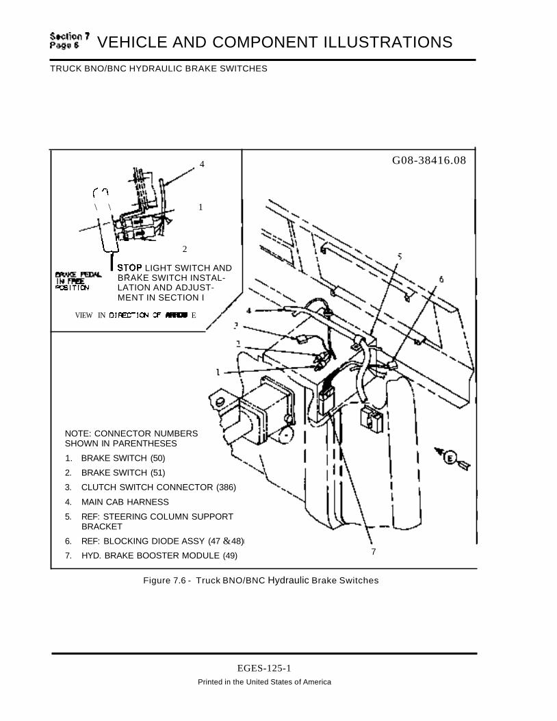
~~~~n7 VEHICLE AND COMPONENT ILLUSTRATIONS
TRUCK BNO/BNC HYDRAULIC BRAKE SWITCHES
4
("\ \ 1
--\-~J
LJ 2
I ~TOP LIGHT SWITCH AND~~ BRAKE SWITCH INSTAL-RSITI(».J LATION AND ADJUST
MENT IN SECTION I
VIEW IN DIFE:TI~ (F MR1II E
NOTE: CONNECTOR NUMBERSSHOWN IN PARENTHESES
1. BRAKE SWITCH (50)
2. BRAKE SWITCH (51)
3. CLUTCH SWITCH CONNECTOR (386)
4. MAIN CAB HARNESS
5. REF: STEERING COLUMN SUPPORTBRACKET
6. REF: BLOCKING DIODE ASSY (47 &48)
7. HYD. BRAKE BOOSTER MODULE (49) 7
G08-38416.08
Figure 7.6 - Truck BNO/BNC Hydraulic Brake Switches
EGES-125-1Printed in the United States of America
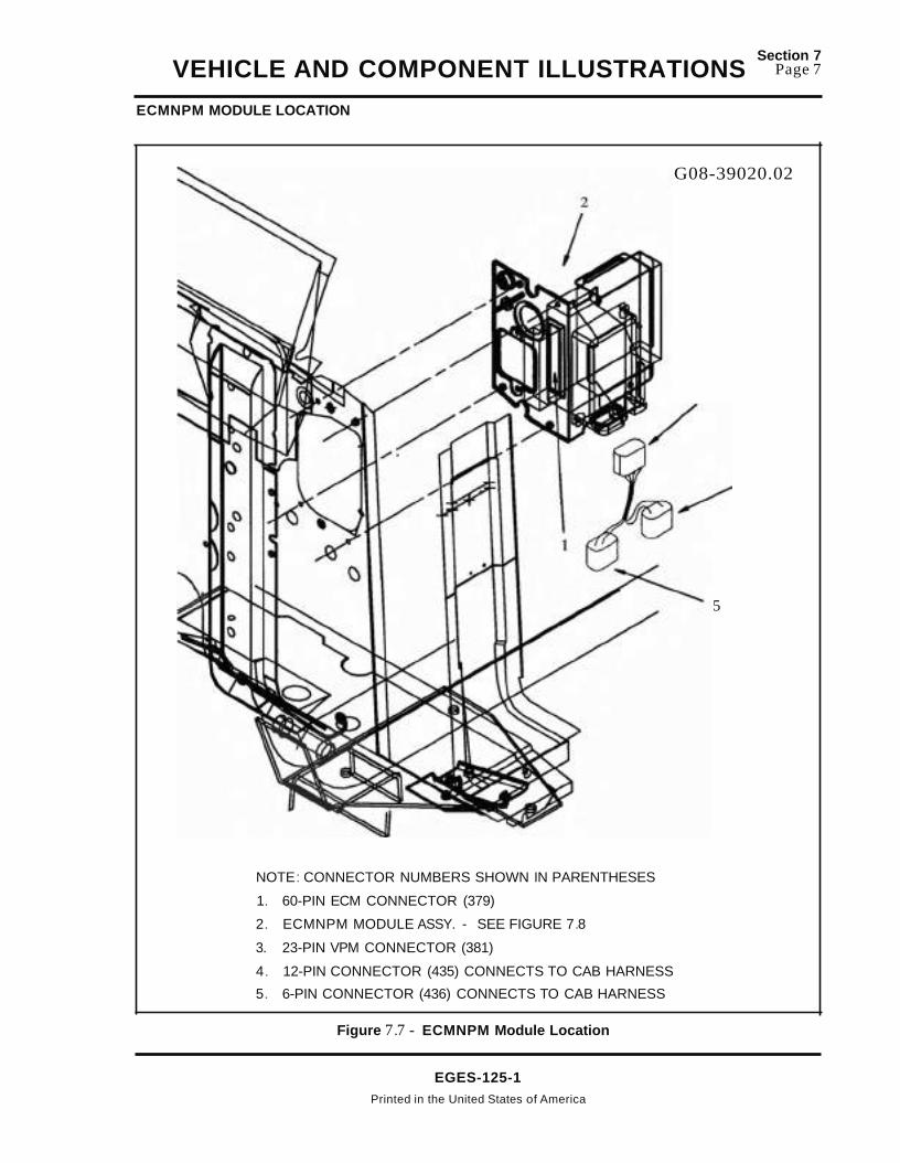
VEHICLE AND COMPONENT ILLUSTRATIONS
ECMNPM MODULE LOCATION
Section 7Page 7
G08-39020.02
5
NOTE: CONNECTOR NUMBERS SHOWN IN PARENTHESES
1. 60-PIN ECM CONNECTOR (379)
2. ECMNPM MODULE ASSY. - SEE FIGURE 7.8
3. 23-PIN VPM CONNECTOR (381)
4. 12-PIN CONNECTOR (435) CONNECTS TO CAB HARNESS
5. 6-PIN CONNECTOR (436) CONNECTS TO CAB HARNESS
Figure 7.7 - ECMNPM Module Location
EGES-125-1Printed in the United States of America

~:~~~n7 VEHICLE AND COMPONENT ILLUSTRATIONS
ECMNPM MODULE ASSEMBLY
G08-39020.01.A
rSEE. VIEW 0
4
/8
NOTE: CONNECTOR NUMBERS SHOWN INPARENTHESES
1. DETACHABLE ECM BRACKET
2. SEALING TAPE (1/4" THICK X 1" WIDE X5.5" LONG)
3. PAN HEAD SCREW (1/4-14 X 1/2)
4. ECM INFORMATION LABEL (SEE VIEW D)
5. ECM
6. GROUND STUD
FRONT
4
3
7. CONTROL MODULE BRACKET ASSY.
8. SEAL APPLIED TO FRONT OF ITEM 7
9. SEALING TAPE (1/4 THICK X 1" WIDE X3.5" LONG)
10. J-SPRING NUT -1/4-14.060 TO .087 PNLTHICKNESS
11 . VPM
12. DETACHABLE VPM BRACKET
Figure 7.8 - ECMNPM Module Assembly
EGES-125-1Printed in the United States of America

VEHICLE AND COMPONENT ILLUSTRATIONSSection 7
Page 9
TRUCK CRUISE/PTO WIRING
11
97
1l8
B
W/AUTO XMSN
CAB WIRING - LEFT FRONT VIEW BNOTE: CONNECTOR NUMBERS SHOWN IN 5. 12-WAY CONNECTOR (394)
PARENTHESES 6. BRAKE RELAY (393) (SEE FIGURE 7.2)1. HARNESS W/REMOTE PTO (SEE FIGURES 7 MAIN CAB HARNESS
7.10&7.11) .
2. SC RESISTOR BLOCK (PRINTED CIRCUIT) 8. CIRCUITS 97A AND 97LASSY (390) 9. CLUTCH SWITCH CONNECTOR (386)
3. CRUISE PTO JUMPER HARNESS SEE VIEW B
4. CRUISE SWITCHES (VIEW A) 10. CLUTCH SWITCHA. ON/OFF SWITCH (391) 11 . JUMPER INSTALLED IN ITEM 9 W/AUTOB. SET RESUME SWITCH (392) TRANSMISSION
5
A
1
~ VEHIa.E.
VIEW OF' LEfTSWITCH CLUSTER
VIEW "
Figure 7.9 - Truck CruiselPTO Wiring
EGES-125-1Printed In the United States of America

~::~1~7
VEHICLE AND COMPONENT ILLUSTRATIONS
REAR CAB PTO WIRING (NITRAVELCREW CAB)
VIEW A G08-38422.02
'" '"
3
4
SPEED CONTROL GROUND
RESUME PTO SPEED
SET PTO SPEED
VOLTAGE PTO
VARIABLE PTO ENABLE
PRESET PTO ENABLE
SIGNAL RETURN
ACCELERATOR CONTROL
VOLTAGE REFERENCE (5V)
/"',".
".
,/' ~'//
// ./
// //?//~//
/" pf:,f" ~/ 2
./" :::: ./" /~ STAtoDARD CAB
~-~/:::::'" NOTE: CONNECTOR NUMBERS SHOWN IN./" ~~~~ PARENTHESES
./"./"./" //~ 1. SEE FIGURE 7.9
/:::: /" 2. REMOTE PTO HARNESS
'" 3. BODY BUILDER CONNECTOR (429)
4. CONNECTOR INFORMATION (VIEW A)
97WA
99F
97DD(5V)
46
46A
46B
97DF
97CC
97CB
1
REMOTE PTO CIRCUIT IDENTIFICATION
CAVITY CIRCUIT DESCRIPTION
1 46D PTe DISABLE
2
3
4
5
6
7
8
9
10
11
12
Figure 7.10 - Rear Cab PTO Wiring (NITravelcrew Cab)
EGES-125-1
Printed In the United States of America

VEHICLE AND COMPONENT ILLUSTRATIONSSection 7
Page 11
REAR TRAVEL CREW CAB PTO WIRING
VIEW AG08-38422.03
SPEED CONTROL GROUND
RESUME PTO SPEED
SET PTO SPEED
VOLTAGE PTO
VARIABLE PTO ENABLE
PRESET PTO ENABLE
SIGNAL RETURN
ACCELERATOR CONTROL
VOLTAGE REFERENCE (5V)
46
46A
46B
97DF
97CC
97CB
97WA
99F
97DD(5V)
REMOTE PTO CIRCUIT IDENTIFICATION
CAVITY CIRCUIT DESCRIPTION
1 46D PTO DISABLE
2
3
4
5
6
7
8
9
10
11
12
TRAVELCREW CAB
1
~/'~
NOTE: CONNECTOR NUMBERS SHOWN INPARENTHESES
1. SEE FIGURE 7.9
2. REMOTE PTO HARNESS
3. BODY BUILDER CONNECTOR (429)
4. CONNECTOR INFORMATION (VIEW A)
Figure 7.11 - Rear Travel Crew Cab PTO Wiring
EGES-125-1Printed In the United States of America
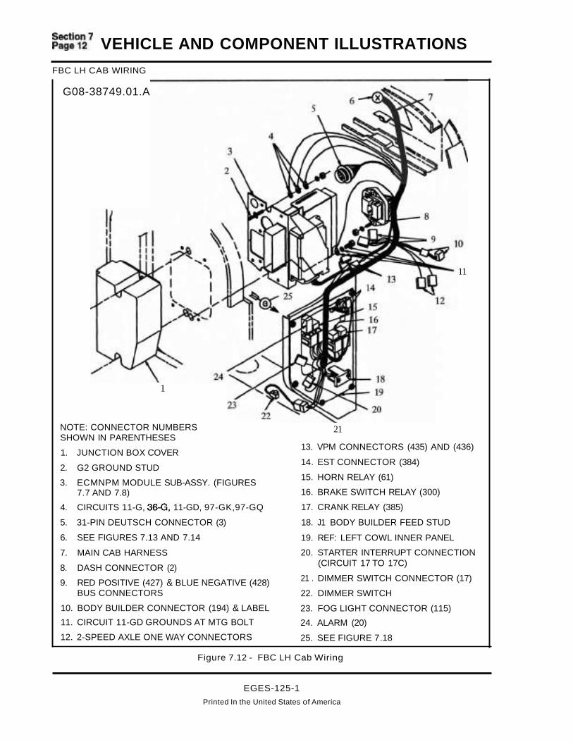
~~~~~7 VEHICLE AND COMPONENT ILLUSTRATIONS
FBC LH CAB WIRING
G08-38749.01.A
1
NOTE: CONNECTOR NUMBERSSHOWN IN PARENTHESES
1. JUNCTION BOX COVER
2. G2 GROUND STUD
3. ECMNPM MODULE SUB-ASSY. (FIGURES7.7 AND 7.8)
4. CIRCUITS 11-G, 36-G, 11-GD, 97-GK,97-GQ
5. 31-PIN DEUTSCH CONNECTOR (3)
6. SEE FIGURES 7.13 AND 7.14
7. MAIN CAB HARNESS
8. DASH CONNECTOR (2)
9. RED POSITIVE (427) & BLUE NEGATIVE (428)BUS CONNECTORS
10. BODY BUILDER CONNECTOR (194) & LABEL
11. CIRCUIT 11-GD GROUNDS AT MTG BOLT
12. 2-SPEED AXLE ONE WAY CONNECTORS
11
21
13. VPM CONNECTORS (435) AND (436)
14. EST CONNECTOR (384)
15. HORN RELAY (61)
16. BRAKE SWITCH RELAY (300)
17. CRANK RELAY (385)
18. J1 BODY BUILDER FEED STUD
19. REF: LEFT COWL INNER PANEL
20. STARTER INTERRUPT CONNECTION(CIRCUIT 17 TO 17C)
21 . DIMMER SWITCH CONNECTOR (17)
22. DIMMER SWITCH
23. FOG LIGHT CONNECTOR (115)
24. ALARM (20)
25. SEE FIGURE 7.18
Figure 7.12 - FBC LH Cab Wiring
EGES-125-1
Printed In the United States of America

VEHICLE AND COMPONENT ILLUSTRATIONSFBC CAB WIRING WITH AIR BRAKES
Section 7Page 13
G08-38749.02.A
W/AIR BRAKES
10 9
NOTE: CONNECTOR NUMBERS SHOWN IN PARENTHESES
1. CIRCUIT 140 TO J30 FEED STUD ON 10MBRACKET
2. REF: OIL PRESSURE GAUGE HOSE
3. TURN SIGNAL CONNECTOR (58)
4. HORN SWITCH ONE WAY CONNECTOR
5. SEE FIGURE 7.15
6. MAIN CAB HARNESS
7. INSTRUMENT CLUSTER
8. SEE FIGURE 7.12
9. CLUTCH SWITCH CONNECTOR (386)
10. APS/IVS CONNECTOR (382)
11 . STOP LIGHT SWITCH CONNECTOR (46)
12. AIR BRAKE SWITCHES (70 & 71)
13. REF: AIR BRAKE VALVE
Figure 7.13 - FBC Cab Wiring With Air Brakes
EGES-125-1Printed In the United States of America

~=~~~7 VEHICLE AND COMPONENT ILLUSTRATIONSFBC CAB WIRING WITH HYDRAULIC BRAKES
G08-38749.03.A
5
1
W/HYDRALL I C BRAKES
14
NOTE: CONNECTOR NUMBERS SHOWN IN PARENTHESES
1. CIRCUIT 140 TO J30 FEED STUD ON 10MBRACKET
2. REF: OIL PRESSURE GAUGE HOSE
3. HYDRAULIC BOOSTER MODULE (49)
4. BLOCKING DIODE ASSY (47)
5. TURN SIGNAL CONNECTOR (58)
6. HORN SWITCH (CIR 85A)
7. SEE FIGURE 7.15
8. INSTRUMENT CLUSTER
9. PARK BRAKE CONNECTOR (CIR 44B)
10. MAIN CAB HARNESS (SEE FIGURE 7.12)
11. CLUTCH SWITCH CONNECTOR (386)
12. BNO/BNC BRAKE SWITCHES (50 & 51)(SEE FIGURE 7.6)
13. APS/IVS CONNECTOR (382)
14. REF: HYDRAULIC BOOSTER
Figure 7.14 - FBC Cab Wiring With Air Brakes
EGES-125-1Printed in the United States of America

VEHICLE AND COMPONENT ILLUSTRATIONSFBC RH CAB WIRING
Section 7Page 15
G08-38749.04
1
NOTE: CONNECTOR NUMBERS SHOWN IN PARENTHESES
1. FUSE PANEL (SEE FIGURE 7.17)
2. BARO SENSOR (406)
3. FUSE BLOCK COVER
4. LIGHT SWITCH (60)
5. MAIN CAB HARNESS (SEE FIGURES 7.13OR 7.14)
6. ABS ALLISON INTERCONNECT (377)
7. J3 PANEL LIGHT FEED JUNCTION
8. KEY SWITCH (63)
9. AUTOMATIC XMSN LIGHT CONNECTOR(CIR 62E)
10. CIRCUIT 44/448 CONNECTS TO GROUNDTERMINAL OF KEY SWITCH
11. STI DIAGNOSTICS SWITCH (CIR 98 & 98-G)
Figure 7m15 - FBe RH Cab Wiring
EGES-125-1
Printed in the United States of America

~:~~~~7 VEHICLE AND COMPONENT ILLUSTRATIONSFBC PARK BRAKE SWITCH
G08-38749.07 & .08
VIEW 0
VIEW CPARKING BRAKE SWITCH MOUNTING
NOTE: CONNECTOR NUMBERS SHOWN IN PARENTHESES
1. PARK BRAKE GROUND CABLE (18WH)
2. SEE VIEW D FOR ADJUSTMENT
3. MOMENTARY SWITCH (NORMALLY OFF)
4. CIRCUIT 44B
Figure 7.16 - FBC Park Brake Switch
EGES-125-1Printed in the United States of America
.2Ei

VEHICLE AND COMPONENT ILLUSTRATIONS s~~~~~~
FBC FUSE PANEL
----,,0o
G08-38749.07
FUSE COLOR CHART
5A TAN
10A RED
15A LT BLUE
20A YELLOW
o 0 30A LT GREEN
FUSE AND FLASHER INSTALLATION
Figure 7.17 - FBC Fuse Panel
EGES-125-1
Printed In the United States of America

~:~~~~7 VEHICLE AND COMPONENT ILLUSTRATIONSFBC LEFT KICK PANEL
4
1
6 G08-38749.09
o
NOTE: CONNECTOR NUMBERS SHOWN INPARENTHESES
1. J1 BODY BUILDER FEED STUD
2. CRANK RELAY (385)
3. BRAKE SWITCH RELAY (300)
4. EST DATA LINK (384)
5. MAIN CAB HARNESS
6. HORN RELAY (61)
7. ALARM (20)
Figure 7.18 - FBC Left Kick Panel
EGES-125-1
Printed In the United States of America

VEHICLE AND COMPONENT ILLUSTRATIONSSection 7
Page 19
DASH HARNESS WIRING TRUCK AND FBC (LEFT SIDE)
G08-39035.0110
9 _----r....
1
2
3
IDM ASSEMBLY VIEW
--14NOTE: CONNECTOR NUMBERS 15SHOWN IN PARENTHESES 10. (4) SPRING NUTS
1. MAP SENSOR (397) 11. J-SPRING NUT, 1/4-14 (.060 TO .087 PNL THICKNESS)2. IDM POWER RELAY (396) PAN HD SCREW, 1/4-14 -1/2 LONG
3. ECM POWER RELAY (395) 12. ATIACH CONNECTOR TO IDM AND TIGHTEN SCREW
4. REF: IDM MOUNTING BRACKET 13. MAIN DASH HARNESS
5. IDM INFORMATION LABEL 14. DASH HARNESS CONNECTOR (424) TO ENGINE
6. HIGH VOLTAGE WARNING LABEL HARNESS
7. (4) PAN HD SCREWS 15. AUTO XMSN RELAY (402)10-24 - 2 1/4 LONG 16. CONNECT NEUTRAL SAFETY SWITCH CIRCUITS 97P
AND 97AU TO SAME CIRCUITS OF AUTO XMSN8. IDM HARNESS. (IF NEUTRAL SAFETY SWITCH IS NOT USED,9. REF: IDM MOUNTING BRACKET CONNECT 97P AND 97AU TOGETHER AS SHOWN).
Figure 7.19 - Dash Harness Wiring Truck And FBC (Left Side)
EGES-125-1Printed in the United States of America

~:~~~7
VEHICLE AND COMPONENT ILLUSTRATIONSDASH HARNESS WIRING TRUCK AND FBC (CENTER)
G08-39035.021
NOTE: CONNECTOR NUMBERS SHOWN IN PARENTHESES
1. SEE FIGURE 7.19 FOR 10M ASSY CONNECTIONS
2. MAIN DASH WIRING HARNESS
3. SEE FIGURE 7.21
4. MAIN ENGINE HARNESS
5. REF: LEFT VALVE COVER
6. DASH HARNESS 31-WAY CONNECTOR (405) CONNECTS TO ENGINE HARNESS
7. EXHAUST BACK PRESSURE CONNECTOR (410)
Figure 7.20 - Dash Harness Wiring Truck and FBC (Center)
EGES-125-1
Printed In the United States of America
4
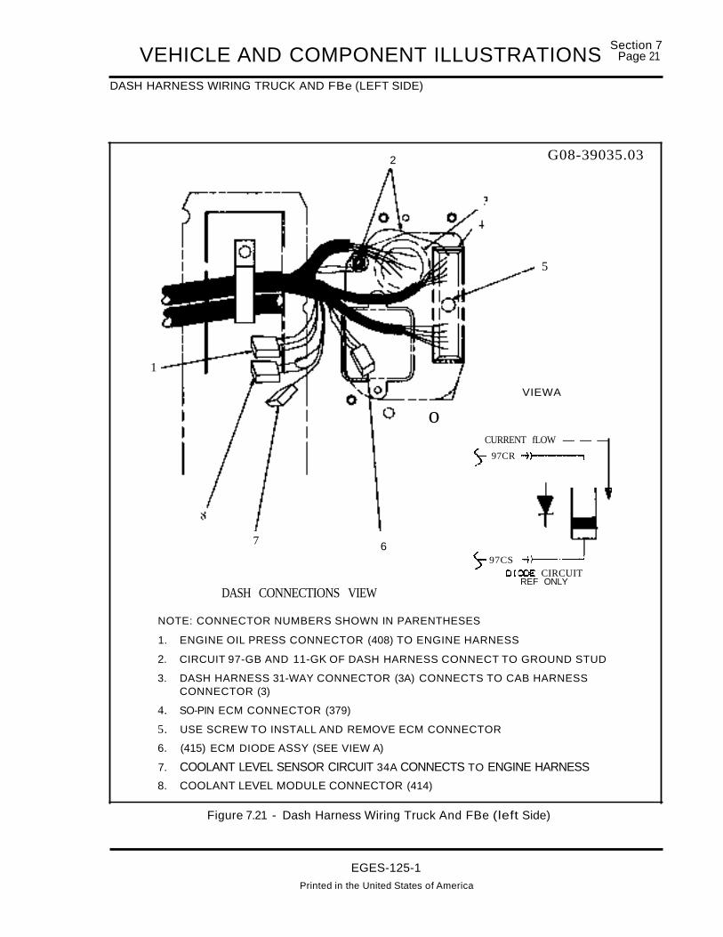
VEHICLE AND COMPONENT ILLUSTRATIONSDASH HARNESS WIRING TRUCK AND FBe (LEFT SIDE)
Section 7Page 21
1
7
DASH CONNECTIONS VIEW
6
2
o
G08-39035.03
5
VIEWA
CURRENT fLOW --
)- 97CR ;l------.
)- 97CS -+l---"'--'DIOOE CIRCUIT
REF ONLY
NOTE: CONNECTOR NUMBERS SHOWN IN PARENTHESES
1. ENGINE OIL PRESS CONNECTOR (408) TO ENGINE HARNESS
2. CIRCUIT 97-GB AND 11-GK OF DASH HARNESS CONNECT TO GROUND STUD
3. DASH HARNESS 31-WAY CONNECTOR (3A) CONNECTS TO CAB HARNESSCONNECTOR (3)
4. SO-PIN ECM CONNECTOR (379)
5. USE SCREW TO INSTALL AND REMOVE ECM CONNECTOR
6. (415) ECM DIODE ASSY (SEE VIEW A)
7. COOLANT LEVEL SENSOR CIRCUIT 34A CONNECTS TO ENGINE HARNESS
8. COOLANT LEVEL MODULE CONNECTOR (414)
Figure 7.21 - Dash Harness Wiring Truck And FBe (left Side)
EGES-125-1Printed in the United States of America

~:~~~~7 VEHICLE AND COMPONENT ILLUSTRATIONSENGINE WIRING - TRUCK AND FBC
1
1112
NOTE: CONNECTOR NUMBERS ARESHOWN IN PARENTHESES 9
1. MAP SENSOR (PART OF DASHHARNESS) MTD ON 10MMOUNTING BRACKET
2. HOSE CONNECTS MAP SENSORTO ENGINE (FIGURE 7.23)
3. DASH HARNESS
4. ENGINE HARNESS
5. CIRCUIT 11-GH OF ENGINEHARNESS TO GROUND STUD
6. ENGINE Oil PRESS SENSORCONNECTOR (408)
7. lOW COOLANT SENSOR CIRCUIT34A OF ENGINE HARNESS TOCIRCUIT 34A OF DASH HARNESS
8. CONNECTORS (2A & 2B)CONNECT TO CAB HARNESSCONNECTOR (2)
9. REF: HYDRAULIC BRAKE POWERCYLINDER
10. Oil PRESS GAUGE HOSE (SEEFIGURE 7.23)
~-14
(DASH PANEL)
VIEW IN DIRECTION OF ARROW GHYDRAULIC BRAKE WIRING
11. SEE FIGURE 7.23
12. CIRCUIT 90l TO FLOW SWITCH
13. BRAKE RELAY (300)
14. CIRCUITS 90P & 90N CONNECT TOHYDROMAX POWER STUD
15. DIFFERENTIAL PRESSURE SWITCH (301)
16. CIRCUIT 14 CONNECTS TO CAB HARNESSCIRCUIT 14
17. CONNECTOR (424) CONNECTS TO DASHHARNESS
Figure 7.22 - WlTruck va Electronic Engine Wiring (See Figure 7.29 For FBC)
EGES-125-1Printed in the United States of America

VEHICLE AND COMPONENT ILLUSTRATIONSENGINE WIRING - TRUCK AND FBe (Continued)
Section 7Page 23
G08-38419.02.A
6
11
NOTE: CONNECTOR NUMBERS ARE SHOWNIN PARENTHESES
1. GROUND CABLE
2. APPLY GRAPHO GREASE TO COMPLETEDCONNECTION
3. REF: HOOD HARNESS CONNECTORS(413 & 425)
4. DASH/ENGINE HARNESS CONNECTOR(405)
5. SEE OIL PRESSURE HOSE FIGURE 7.22
6. OIL PRESSURE HOSE
7. MAP SENSOR HOSE CONNECTOR BARB(SEE FIGURE 7.27 VIEW D AND E)
8. MAP SENSOR HOSE - HOSE MUST FLOWIN CONTINUOUS INCLINE TO MAP SENSORAS LOW SPOTS IN ROUTING MAY CAUSEWATER POCKETS. (SEE FIGURE 7.22)
9. SEE FIGURE 7.22
10. START MOTOR CRANK RELAY (387)
11. SEE FIGURE 7.25
12. CONNECTOR (426F) TO NEG BATIERYCABLE (SEE FIGURE 7.28 VIEW B)
13. SEE FIGURE 7.24
14. FUEL SENDER W/BUS & FBC COWL ONLYCIRCUITS 36 & 36-G
15. ENGINE HARNESS
16. ENGINE COOLANT CIRCUITS 29A & 29-G
Figure 7.23 - Electronic Engine Wiring (Truck & FBe)
EGES-125-1Printed In the United States of America

\
\
~:~~~~7 VEHICLE AND COMPONENT ILLUSTRATIONSENGINE WIRING - TRUCK AND FBC (Continued)
8
4 G08-38419.03.A
f:
7
NOTE: CONNECTOR NUMBERS SHOWN IN PARENTHESES
1. FUEL FILTER CIRCUITS 19A, 19B, 19C
2. ALTERNATOR WIRING - FIGURES 7.27 AND 7.30
3. OIL PRESSURE GAUGE HOSE
4. OIL PRESSURE SENSOR (408)
5. SEE GLOW PLUG RELAY IN FIGURE 7.26 VIEW M
6. GLOW PLUG CONTROLLER WIRING IN FIGURE 7.26 VIEW M
7. MAIN ENGINE HARNESS, STARTER MOTOR WIRING IN FIGURE 7.26 VIEW L
8. SEE FIGURE 7.23
Figure 7.24 - Electronic Engine Wiring (Truck & FBC)
EGES-125-1Printed In the United States of America

VEHICLE AND COMPONENT ILLUSTRATIONSSection 7
Page 25
ENGINE WIRING AT TRANSMISSION - TRUCK AND FBC
6AUTO XMSN a I L TEMP SENDER INSTL
VIEW F
G08-38419.043
f"o;':V9' /?....~!l\r---'r- 6CIR 31. 'I,
31-G......__~~
21
2--~
FULLER Xt.ASN
3
2 _---'11ft
~~~~~#'
7
SP ICER Xt.ENINTERNATIONAL XM5N
3
NOTE: CONNECTOR NUMBERS SHOWN IN PARENTHESES
1. TRANSMISSION TEMP CIRCUITS 31 & 31-G (SEE VIEW F)
2. BACK-UP LIGHT SWITCH
3. VEHICLE SPEED SENSOR (303)
4. AUTO XMSN MODULATOR SOLENOID (389)
5. NEUTRAL SAFETY SWITCH CIRCUITS 97AU AND 97AP
6. TRANSMISSION TEMP GAUGE SENDER
7. SEE FIGURE 7.23
Figure 7.25 - va Electronic Engine Wiring At Transmission (Truck & FBC)
EGES-125-1
Printed In the United States of America

~:~~~~7
VEHICLE AND COMPONENT ILLUSTRATIONSENGINE WIRING AT STARTER MOTOR - TRUCK AND FBC
G08-38419.05F'RONT
III ..
1
VJEW 1N 0 IFEeT I t»-I Of' ARROW L3
5
6
7
VIEW IN DIRECTION (F ARROW N VIEW IN DIRECTION C7 ARROW MGLOW PL..lI3 RELAY
NOTE: CONNECTOR NUMBERS SHOWN IN PARENTHESES
1. STARTER TO ENGINE GROUND CABLE (CIR 11-GS)
2. MAIN ENGINE HARNESS
3. BATTERY TERMINAL OF START MOTOR - CIRCUITS18-FL, 14-FL, 2-FL, 90-FL, & 17-FL OF ENGINEHARNESS. ENGINE HARNESS CIRCUITS MUST BEINSTALLED BEFORE POSITIVE BATTERY CABLE.TORQUE 20-25 FT-LBS (27-34 NeM). APPLYGRAPHO GREASE WHEN ASSY IS COMPLETE.
4. CIRCUIT 17C - TORQUE 16-30 IN-LBS (1.8-3.4 N-M)
5. STARTER GROUND - CIRCUITS 11-JG,11-GH, 2-G, 11-GS. TORQUE 20-25FT-LBS (27-34 NeM). APPLY GRAPHOGREASE WHEN ASSY IS COMPLETE.
6. CIRCUIT 40 WITH AIR BRAKES - SEEFIGURE 7.28 VIEW U
7. GLOW PLUG RELAY
8. CIRCUIT 18 (APPLY GRAPHO GREASETO RELAY CONNECTION)
9. SEE FIGURE 7.24
Figure 7.26 - va Electronic Engine Wiring (Truck & FBe)
EGES-125-1Printed in the United States of America

VEHICLE AND COMPONENT ILLUSTRATIONSENGINE WIRING ALTERNATORS - TRUCK AND FBC
Section 7Page 27
2
1
8
G08-38419.06.A4
1
12
4
5
90 AMP DELCO ICS- 130 JcaE oseBN
10 985,100, 115,130.145 AtAP DELCO 121-51 JCOOES OBeSE.oeaBA •oaaea.OBC3BC. OSSBD
15
16
VIEW ETCP VIEW
VIEW 0
14
eo NIP DELCO (20-51»caE OBBAR
5
2
NOTE: CONNECTOR NUMBERS SHOWN IN PARENTHESES
1. ENGINE HARNESS 9. OWNER OPERATOR HARNESS
2. CIRCUIT 1A 10. CIRCUITS 2-G AND 11-GZ - TORQUE 50-60 IN-LBS3. LOW COOLANT PROBE (6.2-8.0 N-M) APPLY GRAPHO GREASE TO
CONNECTOR (400) COMPLETED CONNECTION
4. SEE FIGURE 7.28 11. SEE FIGURE 7.31
5. CIRCUIT 77F TO AIC COMPRESSOR 12. CIRCUIT 2 AND 14Z - TORQUE 50-60IN-LBS
(FIGURE 7.28) ~gM8p~~~6 ~ciN~~~';;6~0 GREASE TO
6. CIRCUIT 2 - TORQUE 24-40 IN-LBS(2.8-4.5 N-M) APPLY GRAPHO GREASE 13. CIRCUIT 2-G - TORQUE 15-25 IN - LBS (1.6-2.8 N-M)TO COMPLETED CONNECTION APPLY GRAPHO GREASE TO COMPLETED CONNECTION
7. CIRCUIT 2-G - TORQUE 50-60 IN-LBS 14. CIRCUIT 2 - TORQUE 50-60 IN-LBS (6.2-8.0 N-M) APPLY(5.6-6.8 N-M) APPLY GRAPHO GREASE GRAPHO GREASE TO COMPLETED CONNECTIONTO COMPLETED CONNECTION 15. MAP SENSOR HOSE
8. SEE FIGURE 7.24 16. CLAMP
Figure 7.27 - VB Electronic Engine Wiring (Truck & FBe)
EGES-125-1Printed In the United States of America

~:=~~7
VEHICLE AND COMPONENT ILLUSTRATIONSENGINE WIRING AT AIRIFREON COMPRESSOR - TRUCK AND FBe
TO Co VEH ICLEB ...
G08-38419.079
13
2
VIEW BREAR VIEW
12
4
8
TOP VIEWFREON COMPRESSOR WI RIN3
12
13-0--
W/BENDIX 2150 AIR COMPAESSOR W/BENlIX 550 AIR COMPRESSOR
NOTE: CONNECTOR NUMBERS SHOWN IN PARENTHESES
1. POSITIVE BATIERY CABLE HARNESS
2. NEGATIVE BATTERY CABLE HARNESS
3. CONNECTOR (426) - CIR 97CPB, 97CM,97-GCM & 97-GCA
4. GROUND STRAP
5. BUS/FBC ONLY - FUEL SENDERCONNECTION CIR 36 & 36-G
6. LEFT TRANSMISSION MOUNTING FLANGE
7. ENGINE HARNESS
8. SEE FIGURE 7.27
9. ENGINE HARNESS CIRCUIT 77F
10. CONNECT DIODE JUMPER HARNESS TOENGINE HARNESS 77FA. CONNECT LT GREEN LEAD TO AC
COMPRESSOR CLUTCH LEADB. CONNECT WHITE LEAD CIRCUIT 77-G
TO GROUND.
11. AC COMPRESSOR CLUTCH LEAD
12. CIRCUIT 40 CONNECTS TO LOW AIRPRESSURE SWITCH
13. SEE FIGURE 7.26
Figure 7.28 - V8 Electronic Engine Wiring (Truck & FBe)
EGES-125-1Printed In the United States of America

VEHICLE AND COMPONENT ILLUSTRATIONSSection 7
Page 29
ENGINE WIRING HYDRAULIC BRAKEIDASH/ENGINE HARNESS - TRUCK AND FBC
G08-38419.09.A
9
10'\.
11
17
IDASH PANELI
876
13
18
VIEW IN OIRECTION OF ARROW GHYDRAULIC BRAKE WIRING
NOTE: CONNECTOR NUMBERSSHOWN IN PARENTHESES
1. MAP SENSOR AND HOSE - SEEFIGURES 7.23 AND 7.27
2. W/FBC BODY BUilDER FEEDSTUD ON 10M BRACKET
3. REF: IDM BRACKET
4. W/FBC CIRCUITS 14, 2, AND26A OF ENGINE HARNESS
5. CONNECTOR (426) ENGINE TODASH HARNESS CONNECTION
6. DASH HARNESS
7. ENGINE HARNESS
8. CIRCUIT 11-GH AT G2 GRD STUD
9. CONNECTOR (408)
10. CIRCUIT 34A lOW - COOLANT SENSOR CIRCUIT
11 . CONNECTOR (2A)
12. REF: HYD BRAKE POWER CYLINDER
13. SEE FIGURE 7.23
14. Oil PRESSURE GAUGE HOSE (SEE FIGURE 7.23)
15. CIRCUIT 90l TO FLOW SWITCH
16. HYDRAULIC BRAKE RELAY (300)
17. CIRCUITS 90P AND 90N TO HYDROMAX POWER STUD
18. DIFFERENTIAL PRESSURE SWITCH (301)
Figure 7.29 - va Electronic Engine Wiring (With FBC - For Truck See Figure 7.22)
EGES-125-1
Printed In the United States of America
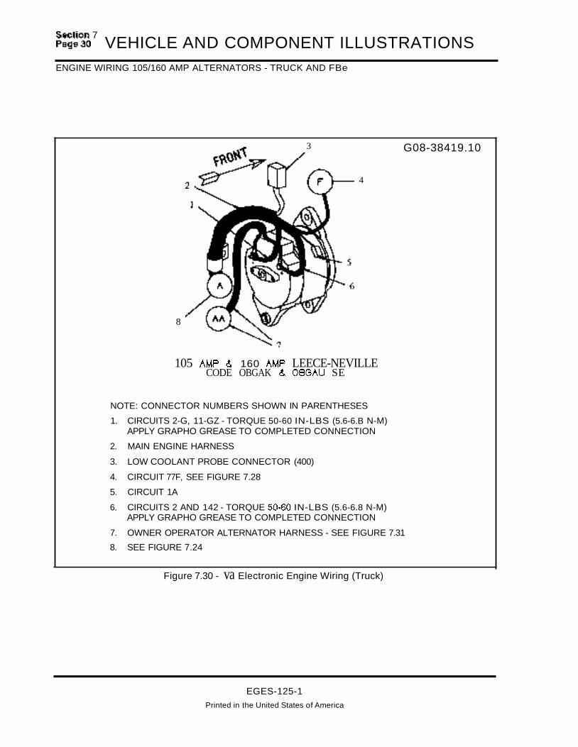
~:~:~~7
VEHICLE AND COMPONENT ILLUSTRATIONSENGINE WIRING 105/160 AMP ALTERNATORS - TRUCK AND FBe
8
2~3
4
G08-38419.10
105 AMP & 160 AMP LEECE-NEVILLECODE OBGAK & 08GAU SE
NOTE: CONNECTOR NUMBERS SHOWN IN PARENTHESES
1. CIRCUITS 2-G, 11-GZ - TORQUE 50-60 IN-LBS (5.6-6.B N-M)APPLY GRAPHO GREASE TO COMPLETED CONNECTION
2. MAIN ENGINE HARNESS
3. LOW COOLANT PROBE CONNECTOR (400)
4. CIRCUIT 77F, SEE FIGURE 7.28
5. CIRCUIT 1A
6. CIRCUITS 2 AND 142 - TORQUE 50:.60 IN-LBS (5.6-6.8 N-M)APPLY GRAPHO GREASE TO COMPLETED CONNECTION
7. OWNER OPERATOR ALTERNATOR HARNESS - SEE FIGURE 7.31
8. SEE FIGURE 7.24
Figure 7.30 - va Electronic Engine Wiring (Truck)
EGES-125-1Printed in the United States of America

VEHICLE AND COMPONENT ILLUSTRATIONS sp~~~n3~
ENGINE WIRING - (Truck WI Leece-Neville 2600JA 12V/160A Alternator W/4 Gauge Protection)
G08-38419.11
NOTE: CONNECTOR NUMBERS SHOWN IN PARENTHESES
1. LABEL - INFORMATION ON OWNER OPERATOR CONNECTIONS
2. FEED STUD
3. CIRCUIT 14Z CONNECTED
4. CIRCUIT 11-GZ GROUNDED TO DASH
5. OWNER OPERATOR ALTERNATOR HARNESS
6. SEE FIGURE 7.27 OR 7.30
Figure 7.31 - VB Electronic Engine Wiring (Truck WI Leece-Neville 2600JA 12V/160AAlternator W/4 Gauge Protection)
EGES-125-1Printed In the United States of America

~=~~~7
VEHICLE AND COMPONENT ILLUSTRATIONSENGINE WIRING BATTERY CABLE/STARTING HARNESS - TRUCK AND FBC
, a-tASSIS ·s
G08-38414.01
2
6
109
NOTE: CONNECTOR NUMBERS 8 ----.+-.......,
SHOWN IN PARENTHESES ~=a:~~t:r=;~==:
1. STARTER TO ENGINE BLOCKGROUND CABLE
2. POSITIVE BATIERY CABLE
3. CONNECTOR (412)
4. POSITIVE BATTERY CABLE ASSY
5. BATTERIES
6. (2) 15A ECM POWER FUSES
7. (+) JUMP START STUD AND CABLE
8. NEGATIVE BATIERY CABLE ASSY
9. CIRCUIT 11-G
10. STARTING HARNESS
11. CONNECTOR (426) CONNECTSTO ENGINE HARNESS
Figure 7.32 - Battery Cable Wiring (Truck And FBC)
EGES-125-1
Printed In the United States of America

VEHICLE AND COMPONENT ILLUSTRATIONSSection 7
Page 33
ENGINE WIRING EXHAUST BACKPRESSURE/GLOW PLUG RELAY - TRUCK AND FBC
1
VIEW CEXHAUST SOLENOID
CONNECTION
TURBOHOUSING
ENGINE WIRINGTO SOLENOID
6
EXiSTINGBLACK WIRE
V{EW EGROUND CONNECTION
5
G08-38425.01 & .024
3
7
VIEW 0W/AIR COMPA PIPING
2
1
AIR CLEANERPIPE iii
NOTE: CONNECTOR NUMBERS SHOWN IN PARENTHESES
1. EXHAUST BACK PRESSURE HARNESS
2. SEE VIEW E - CIRCUIT 2 OF ITEM 1 CONNECTS TO GLOW PLUG CONTROLLER GROUND STUD
3. CIRCUITS 97CA(5V), 97BC AND 9780 CONNECT TO EXHAUST BACK PRESSURE SENSOR
4. CIRCUITS 978U AND 97AX CONNECT TO AMBIENT AIR TEMP SENDER (VIEW D)
5. VIEW C - CIRCUITS 97BC AND 97-GP CONNECT TO EXHAUST SOLENOID CONNECTION
6. DASH HARNESS
7. 6-WAY CONNECTOR - 97BD, 9782, 97BC, 97BU, 97AX, AND 97CA(5V) BETWEEN ITEMS 1 AND 6
Figure 7.33 - Exhaust Back Pressure Device
EGES-125-1
Printed In the United States of America

~:~:~~7 VEHICLE AND COMPONENT ILLUSTRATIONSENGINE WIRING COOLANT LEVEL SENSOR - TRUCK AND FBC
NOTE: CONNECTOR NUMBERS SHOWN IN PARENTHESES
1. ENGINE HARNESS
2. CIRCUIT 34A ENGINE TO DASHHARNESS ONE WAY CONNECTOR
3. CLS MODULE CONNECTOR (414)
4. DASH HARNESS
5. SURGE TANK
6. CAUTION LABEL
7. CIRCUIT 34-G
8. CONNECTOR (400)
9. CLS HARNESS
10. CIRCUIT 34A CONNECTSTO PROBE
Figure 7.34 - Coolant Level Sensor (CLS) Wiring (Truck & FBC)
EGES-125-1Printed in the United States of America
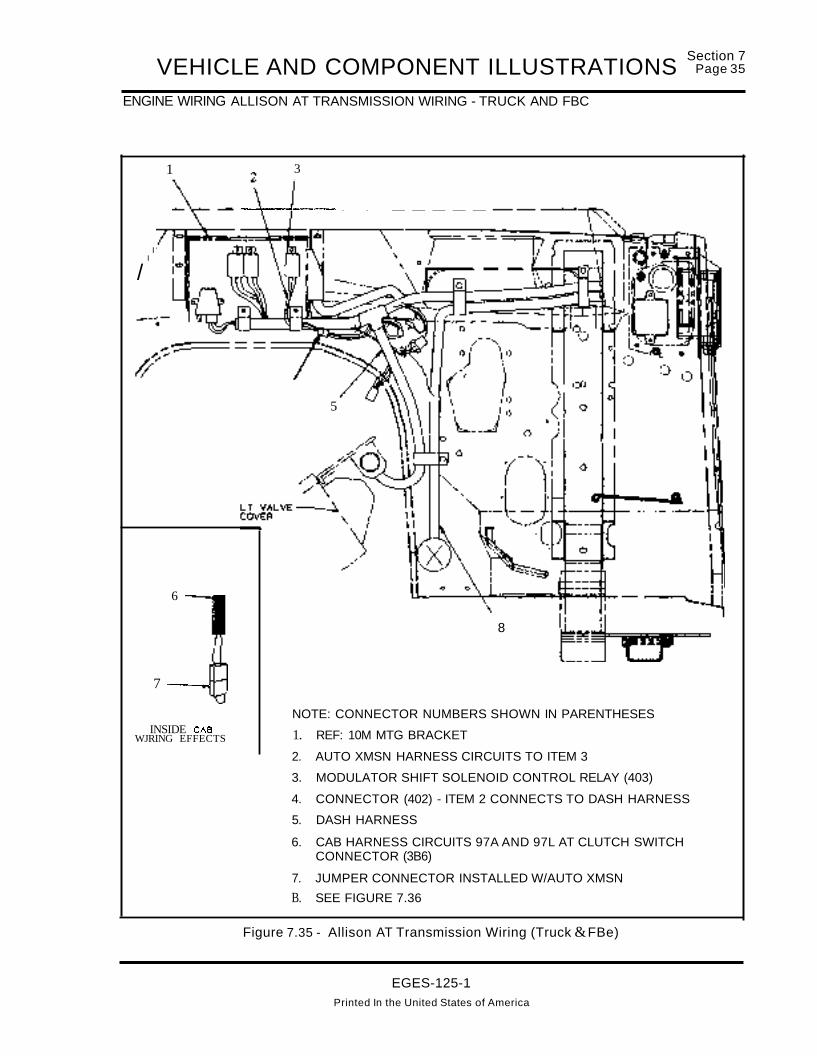
VEHICLE AND COMPONENT ILLUSTRATIONSENGINE WIRING ALLISON AT TRANSMISSION WIRING - TRUCK AND FBC
Section 7Page 35
1
II
/
6
7 ----...
INSIDE CABWJRING EFFECTS
3
---.ilr-----t--- - - -----
5
8
NOTE: CONNECTOR NUMBERS SHOWN IN PARENTHESES
1. REF: 10M MTG BRACKET
2. AUTO XMSN HARNESS CIRCUITS TO ITEM 3
3. MODULATOR SHIFT SOLENOID CONTROL RELAY (403)
4. CONNECTOR (402) - ITEM 2 CONNECTS TO DASH HARNESS
5. DASH HARNESS
6. CAB HARNESS CIRCUITS 97A AND 97L AT CLUTCH SWITCHCONNECTOR (3B6)
7. JUMPER CONNECTOR INSTALLED W/AUTO XMSN
B. SEE FIGURE 7.36
Figure 7.35 - Allison AT Transmission Wiring (Truck &FBe)
EGES-125-1Printed In the United States of America

~:~:~~7 VEHICLE AND COMPONENT ILLUSTRATIONSENGINE WIRING - TRUCK AND FBC
8
3
4
~~~/7
.................. 5
6
7
NOTE: CONNECTOR NUMBERS SHOWN IN PARENTHESES
1. CIRCUITS 97P AND 97AU NEUTRAL SAFETY SWITCH CIRCUITS
2. SEE FIGURE 7.35
3. REF: BACKUP LIGHT SWITCH CABLE
4. VEHICLE SPEED SENSOR
5. AUTO XMSN HARNESS
6. CIRCUIT 92C AND 92-G TO ALLISON TRANSMISSIONMODULATOR SOLENOID
7. NEUTRAL SAFETY SWITCH
8. ENGINE HARNESS
Figure 7.36 - Allison AT Transmission Wiring (Truck & FBC)
EGES-125-1Printed In the United States of America

VEHICLE AND COMPONENT ILLUSTRATIONS1652SC WIRING - PLATFORM WIRE HARNESS
Section 7Page 37
With the 1652SC, wiring is divided into three areas: Platform Harness Wiring, Dash Harness Wiring, andEngine Harness wiring. The location of many platform components is approximate as they are installed bythe various body builders.
PLATFORM HARNESS WIRING
G08-42425.01.A
8 k SEE FIGURE 7.39
13
SEE FIGURE 7.38
~14
36 -----t---........
35
34
33
32
25
Figure 7.37 - Platform Wire Harness (See next page for callouts)
EGES-125-1Printed in the United States of America
24

~:~~~~7 VEHICLE AND COMPONENT ILLUSTRATIONSPLATFORM HARNESS WIRING (Continued)
Platform Wire Harness (Callouts)
1. CIR 14, BATTERY FEED TO J1 FEEDSTUD, CONNECTS TO THE ENGINEHARNESS
2. (382) ACCELERATOR PEDAL SENSOR(APS/IVS) CONNECTS TO CABHARNESS
3. (49) HYDRAULIC BRAKE MONITOR
4. MAIN WIRING HARNESS
5. FUSE BLOCK - SEE FIGURE 7.42 (NOTSHOWN IN MOUNTED POSITION)
6. (406) BAROMETRIC AIR PRESSURESENSOR (BARO)
7. (60) LIGHT SWITCH (NOT SHOWN INMOUNTED POSITION)
8. (394) CRUISE CONTROL CONNECTOR(NOT SHOWN IN MOUNTED POSITION)- SEE FIGURE 7.43
9. (375) STI DIAGNOSTIC SWITCH (NOTSHOWN IN MOUNTED POSITION)
10. (47) HYD BRAKE BLOCKING DIODEASSY.
11. CIR 62E TO AUTOMATIC TRANSMISSIONLIGHT
12. CIR 44/44A CONNECTS TO GROUNDTERMINAL OF KEY SWITCH
13. INSTRUMENT CLUSTER CONNECTORS(26) YELLOW, (27) GREEN, (28) NATURAL
14. (20) ALARM WARNING BUZZER
15. (385) TIME DELAY CRANK RELAY
16. (61) HORN RELAY
17. ECM/IDMNPM ASSY - SEE FIGURES7.38, 7.44 AND 7.45
18. (384) EST (DATA) LINK CONNECTOR ISATTACHED TO MODULE BRACKET FIGURE 7.38
19. (393) BRAKE RELAY
20. (2) DASH CONNECTOR
21. J1 FEED STUD - CIR 14A, 14C, 15, 50
22. (381) CONNECTS PLATFORM HARNESSTO VPM - FIGURE 7.38
23. (194) BODY BUILDER CONNECTOR
24. (17) DIMMER SWITCH CONNECTOR
25. DIMMER SWITCH
26. STARTER INTERRUPT CONNECTOR (W/OAUTO TRANS CIR 17 CONNECTS TO 17A)
27. (427) RED AND (428) BLUE ATACONNECTORS
28. (3 & 3A) DASH CONNECTOR (DEUTSCH)
29. G2 GRD STUD - CIR 11-GD, 11-G,36-G, 97-GK, 97-GQ
30. CIR 44 TO PARK BRAKE SWITCH -FIGURE 7.40
31. CABLE TO TURN SIGNAL SWITCH
32. HYDRAULIC BRAKE BOOSTER
33. HORN CIR 85A
34. (58) TURN SIGNAL CONNECTOR
35. STOP LIGHT SWITCHES - FIGURE 7.40
36. REF: MECHANICAL OIL PRESSUREGAUGE HOSE CONNECTION
EGES-125-1
Printed in the United States of America

VEHICLE AND COMPONENT ILLUSTRATIONS sp~~~n3~
EST (DATA LINK)NPM CONNECTIONS/ACCELERATOR PEDAUSTOP LIGHT SWITCH WIRING
GOB-42425.02
3
VIEW IN DIRECTION rF~ C
'--__--'0
2
2 2
1. (381) CONNECTION PLATFORM HARNESS CONNECTION TO VPM
2. (384) EST CONNECTOR (PART OF PLATFORM HARNESS)
3. ALSO SEE FIGURES 7.37, 7.44 AND 7.45
IIII
VPM
1
vln IN DIFECTIDN or MPDI A
Figure 7.38 - EST (Data Link) and VPM Connections
GOB-42425.03.A
o
1
e:>
\,, 0
\ .' ~~~, ,~, ,~OO'_~',/' . ~.... ""-,,
L~/, ~~ »1. PLATFORM HARNESS ~ /' /,"
2. (50) AND (51) STOP LIGHTAND',,~ ,,"HYDRAULIC BRAKE SWITCHES ~ /'
3. (382) APS/IVS CONNECTION TO ~ ~~ ~",,,,ACCELERATOR PEDAL ~
VIEW IN DIRECTION CF ARROW BFigure 7.39 - Accelerator Pedal/Stop Light Switches
EGES-125-1Printed in the United States of America

~:~~c:.~7 VEHICLE AND COMPONENT ILLUSTRATIONSPARK BRAKE SWITCH INSTALLATION & ADJUSTMENT
(CIR:UITS 70 &~I
CIRCUITS soc &9OQ/97Y
(BRAKE F'EIW...IN FR:E 9fl(EiITICJI' )
STtP L1G-fT SW ITO-I & HYDW.J....I C EIRN<ESW ITO-I INSTAL.1.ATI CJI' /H):)AD..UmelT
VIEW G
PLATFORMHARNESS
VIEW .J
VIEW 0 7. (51) STOP LIGHT SWITCH (SEE FIGUREFR:5ET~ F'M PAR< BfW<E SW 7.41 FOR ADJUSTMENT PROCEDURE)
8. (50) HYDRAULIC BRAKE SWITCH (SEE1. MODULE MTG BRACKET FIGURE 5.04A FOR ADJUSTMENT2. SPEED CLIP PROCEDURE)
9. JAM NUT3. GROUND CABLE (MTG AREA ON ITEM 1 MUST BE
BRIGHT AND CLEAN TO ENSURE A GOOD GROUND) 10. CLUTCH SWITCH
4. PARK BRAKE SWITCH (NORMALLY OFF) SEE VIEW D 11. STOP LIGHT SWITCH BRACKET
5. INSULATING BOOT 12. (386) CLUTCH SWITCH CONNECTOR(HAS JUMPER INSTALLED WITH
6. CIRCUIT 44B OF PLATFORM HARNESS AUTOMATIC TRANSMISSION)
Figure 7.40 - Park Brake Switch Installation & Adjustment
EGES-125-1Printed in the United States of America

VEHICLE AND COMPONENT ILLUSTRATIONS sp~:~n4~
PLATFORM HARNESS WIRING - FUSE PANELIBRAKE SWITCH INSTALLATION & ADJUSTMENT
Battery PoweredTest Light
- IF Test Light #1 (upper switch) comes on first,move lower switch away from pedal.
Tighten PAL nut on lower switch and test onemore time to verify the adjustment.
7. Remove test lights, then connector (51) with circuits 70 & 70A/90R to upper switch and (50) withcircuits 90C & 90D/97Y to lower switch.
5. With PAL nut on lower switch finger tight, installTest light #2 to lower switch. Adjust the lowerswitch so that when pedal is depressed, bothtest lights come on at the same time.
- IF Test Light #2 (lower switch) comes on first,mover lower switch closer to the pedal.
MtgBrkt
NormallyClosedHydraulic BrakeSwitch
Brake Switch Adjustment Procedure
1. The PAL nut on upper switch (backside of bracket)should be finger tight.
2. Connect leads for test light #1 to upper switch, adjustthe switch until the light just comes on or goes off. Notethe position of the key tab on the switch body.
3. Hold PAL nut and rotate switch clockwise ONE full turn.The key tab should be in the same position as in step 2. 6.
NOTE: Test light should be off and switch set so pedalmust be moved 0.D50n at point of contact to make thelight come on.
4. Tighten PAL nut and watch that the key tab so the switchis not turned.
Figure 7.41 - Brake Switch Installation & Adjustment
VIEW HFUSE/C IRCU IT BREAKER AND
F'L..A9ER INSTALLAT ION
G08-42425.06
Figure 7.42 - Fuse Panel
EGES-125-1Printed In the United States of America

~:~~~7
VEHICLE AND COMPONENT ILLUSTRATIONSPLATFORM HARNESS - CRUISE CONTROL WIRING
5
4
8
.....__-- 1
2. (386) CLUTCH SW CONNECTOR - SEE VIEW B
3. (394) CONNECTS PLATFORM HARNESS CIRCUITS97AC & 97CF TO THE CRUISE CONTROL HARNESS
4. CRUISE CONTROL HARNESS
5. (392) SET/RESUME SW
6. (391) CRUISE ON/OFF SW
7. (390) SC RESISTOR BLOCK
8. CIRCUITS 97A &97L
9. CLUTCH SW ASSY
A. TO ADJUST CLUTCH SW - With clutch pedal depressed to bottom of Free Travel position, the actua
tor arm should touch the clutch pedal. The pedalshould activate with an audible click, when the clutch
pedal returns to the stop.
10. (393) BRAKE SWITCH RELAY MUST BE INSTALLED INVEHICLES WITH CRUISE CONTROL.
o
o
GOB-42427.01
\\
/~/). . ,--/
~
'L~-~ 10
1. PLATFORM HARNESS
;""
~~~\ C'I J
Figure 7.43 - Cruise Control Wiring
EGES-125-1Printed in the United States of America

VEHICLE AND COMPONENT ILLUSTRATIONSDASH HARNESS WIRING - ECMNPMlIDM Module With 1652SC
Section 7Page 43
2
1. VPM - (381) CONNECTS PLATFORM HARNESS TO VPM
2. BRACKET
3. ECM
4. 10M
5. (380) CONNECTS DASH HARNESS TO 10M
6. (379) CONNECTS DASH HARNESS TO ECM
7. ECM MUST BE INSTALLED WITH CONNECTOR KEYWAYSFACING IN DIRECTION SHOWN.
NOTE: ALSO SEE FIGURE 7.45
Figure 7.44 - ECMNPM/IDM Module With 1652SC
EGES-125-1
Printed In the United States of America
G08-42436.01.B
2

~:~~~~7 VEHICLE AND COMPONENT ILLUSTRATIONSDASH HARNESS WIRING - VPMIECMIIDM MODULE INSTALLATION WITH 1652SC
G08-42436.02.B
2
4
1. DASH HARNESS
2. VPM/ECM/IDM MODULE ASSY - SEE FIGURE 7.44AND 7.39
3. REF:SEAL
4. (380) 10M CONNECTOR
5. (379) ECM CONNECTOR
6. (395) ECM PWR RELAY & (396) 10M PWR RELAY SEE FIGURE 7.46
Figure 7.45 - VPM/ECMIIDM Module Installation With 1652SC
EGES-125-1
Printed In the United States of America

VEHICLE AND COMPONENT ILLUSTRATIONSDASH HARNESS WIRING - LEFT SIDE WITH 1652SC PLATFORM
Section 7Page 45
5
4-~..........
2 ---~'''''''''''''
1
6
•
7G08-42435.01.A
8 10
•
16 1
13
14
15
1. DASH HARNESS
2. (405) DASH/ENGINE HARNESS 31-WAYCONNECTOR
3. (410) ENGINE WARM-UP DEVICE
4. (424) CONNECTS TO ENGINE HARNESS
5. SEE FIGURE 7.47
6. ENGINE HARNESS - FIGURE 7.48
7. (408) ENGINE OIL PRESSURE SENSOR
8. (400) LOW COOLANT GROUNDCONNECTOR - CIR 34-G
9. (3A) 31 -WAY DASH CONNECTOR
10. DASH HARNESS CIR 11-GK ATTACHESTO GROUND STUD
11. CIR 97-GB ATTACHES TO TOP BOLT OFMODULE MTG BRACKET
12 (396) '10M PWR RELAY
13. (395) ECM PWR RELAY
14. (380) 10M CONNECTOR
15. (379) ECM CONNECTOR
16. (415) ECM PWR RELAY DIODE ASSY
17. (414) COOLANT LEVEL MODULECONNECTOR
Figure 7.46 - Dash Harness Wiring - Left Side With 1652SC Platform
EGES-125-1Printed In the United States of America

~:~~~7
VEHICLE AND COMPONENT ILLUSTRATIONSDASH HARNESS WIRING - RIGHT SIDE WITH 1652SC
G08-42435.03
2
4
o
1. COOLANT SURGE TANK (WITH ENGINE PROTECTION OPTION, THE LOWCOOLANT PROBE WOULD INSTALL IN SURGE TANK CONNECTED TO CIRCUIT34A AND 34-G. WHICH ARE SHOWN TAPED BACK IN THIS ILLUSTRATION)
2. (397) MANIFOLD ABSOLUTE PRESSURE SENSOR
3. DASH HARNESS
4. MAP SENSOR HOSE TO RT ENGINE INTAKE MANIFOLD
Figure 7.47 - Dash Harness Wiring - Right Side With 1652SC
EGES-125-1Printed in the United States of America

VEHICLE AND COMPONENT ILLUSTRATIONSSection 7
Page 47
ENGINE HARNESS WIRING AT DASH PANEL WITH 1652SC
11
10
1
1
14
(COWL PANELI
G08-42426.01 .A &8 G08-42426.09.A
12
7
u..t:=-_---;--9
461
SEE FIGURE 7.49
5
VIEW IN DIFECTIO" CI" NRJM CHVIJW1.IC IlfWCE WIRINJ
1. REF: DASH HARNESS - SEE 7.57 DASHHARNESS WIRING
2. (424) ENGINE/DASH HARNESS CONNECTOR
3. (387) START MOTOR CRANK RELAY PART OF THE ENGINE HARNESS
4. ENGINE HARNESS
5. REF: OIL PRESSURE GAUGE HOSE SEE FIGURE 7.49
6. CIR 14 OF ENGINE HARNESS CONNECTSTO CIR 14 OF DASH HARNESS
7. (408) OIL PRESSURE SENSOR CONNECTOR
8. CIR 34-G CONNECTION
9. (2A) DASH CONNECTOR
10. CIR 11-GH AITACHED TO GROUNDSTUD
11. SEE VIEW C
12. PRESSURE DIFFERENTIAL SWITCH
13. FLOW SWITCH
14. BRAKE BOOSTER RELAY
15. ENGINE HARNESS CIR SON & SOPCONNECT TO HYDROMAX POWER STUD
Figure 7.48 - Engine Harness Wiring At Dash Panel With 1652SC
EGES-125-1
Printed in the United States of America

~:~~~~7 VEHICLE AND COMPONENT ILLUSTRATIONSLEFT SIDE ENGINE WIRE HARNESS
G08-42426.02.A
1
3
SEE FIGURE 7.48
6
1. LEFT FRAME RAIL
2. GROUND CABLE
3. OIL PRESSURE GAUGE HOSE
4. (405) DASH/ENGINE HARNESS CONNECTOR
5. CIR 29 & 29-G TO ENGINE TEMP GAUGE SENDER
Figure 7.49 - Left Side Engine Wire Harness
EGES-125-1
Printed In the United States of America
SEEFIGURE7.50

~:~~~7 VEHICLE AND COMPONENT ILLUSTRATIONSENGINE HARNESS WIRING AT TRANSMISSION
2
8 Ie ~ •..a} ...r c:::::.
7
3 G08-42426.04
"AT" AUTOMATIC XMSNS
4
SPICER XMSNINTERNATIONAL XMSN
8
7
1. CIR 31 & 31-G
2. BACK-UP LIGHT SWITCH
3. SPEEDOMETER SENSOR
4. BACK-UP LIGHT HARNESSCONNECTS SWITCH TO 71 & 71 AOF ENGINE HARNESS
5. MODULATOR SOLENOID
6. NEUTRAL POSITION SWITCHCONNECTS TO 97P & 97AU
7. SEE FIGURE 7.49
8. ENGINE HARNESS
Figure 7.51 - Engine Harness Wiring At Transmission
EGES-125-1Printed In the United States of America

VEHICLE AND COMPONENT ILLUSTRATIONSRIGHT SIDE ENGINE WIRING WITH 1652SC
SEEFIGURE7.49
5
0' 5
~ SEE FIGURE 7.52
1. OIL PRESSURE GAUGE HOSE
2. (407) ENGINE OIL PRESSURE SENSOR
3. GLOW PLUG CONTROLLER WIRING SEE FIGURE 7.52 VIEW M
4. STARTER MOTOR WIRING
5. SEE FIGURE 7.54 VIEW B
Figure 7.50 - Right Side Engine Wiring With 1652SC
EGES-125-1
Printed in the United States of America
Section 7Page 49

VEHICLE AND COMPONENT ILLUSTRATIONSSection 7
Page 51
ENGINE HARNESS WIRING
5
2
1
.FRONT •
G08-42426.05
VIEW IN DIRECTION CF ARROW MGLOW PLUG CONTROLLER
~I2
VIEW IN DIRECTION (F ARROW L
--"--r-- 3
SEEVIEWBFIGURE7.54
7
8--4-.-"
9
4
VIEW IN DIRECTION (F ARROW N1. CIR 11 -GS ENGINE/START GROUND CABLE
2. ENGINE HARNESS
3. STARTING MOTOR
4. APPLY GRAPHO GREASE WHEN ASSY COMPLETE
5. GLOW PLUG CONTROLLER
6. CIR 17C ATIACHED THEN TORQUE 16-30 IN LBS (1.8-3.4 NM)
7. CIR 17-FL, 14-FL, 18-FL, 2-FL, 90-FL(W/HYD BRAKES)
8. TORQUE 20-25 FT LBS (27-34 NM)
9. CIR 11-GJ, 11-GH, 11-GS, 2-G
Figure 7.52 - Engine Harness Wiring
EGES-125-1Printed In the United States of America

~:~~~~7
VEHICLE AND COMPONENT ILLUSTRATIONSENGINE WIRING AT ALTERNATOR
G08-42426.06.A
SEEFIGURE7.50
1
SEEFIGURE7.50
90 AtIP DELCO (CS- 130 JCOOE OeBBN
SEEFIGURE7.54
SEE FIGURE7.54
5
4
85,100 AtIP DELCO 121-51)CODES OBGBE.OBGBA
2
1. CIR 1A
2. CIR 77F
3. CIR 2 - TORQUE 24-40 IN LBS (2.8-4.5 NM)
4. elR 2-G - TORQUE 50-60 IN LBS (5.6-6.8 NM)
5. CIR 2 - TORQUE 55-70 IN LBS (6.2-8.0 NM)
Figure 7.53 - Engine Wiring at Alternator
EGES-125-1Printed in the United States of America

VEHICLE AND COMPONENT ILLUSTRATIONSSection 7
Page 53
BATTERY CONNECTOR (426) AND TOP VIEW OF AC COMPRESSOR
6 G08-42426.07
8
TOP VIEWFREON CCWPRESSOR Wl RI~
CIR 97CPBJ.97CM.97-BMC.ST-9CA
3
VIEW BREAR VIEW4
FRONT OF VEH ICLEE9 ..
1. POSITIVE BATIERY CABLE
2. NEGATIVE BATTERY CABLE
3. (426) CONNECTS BATIERY CABLE/ENGINE HARNESS
4. REF: 36 &36-G FUEL GAUGE CIRCUITS
5. ENGINE HARNESS
6. ENGINE HARNESS AIR CONDITIONING CIR 77F
7. AIR CONDITIONING JUMPER DIODE HARNESS
8. CIR 77-GA
Figure 7.54 - Battery Connector (426) and Top View of AC Compressor
EGES-125-1Printed in the United States of America
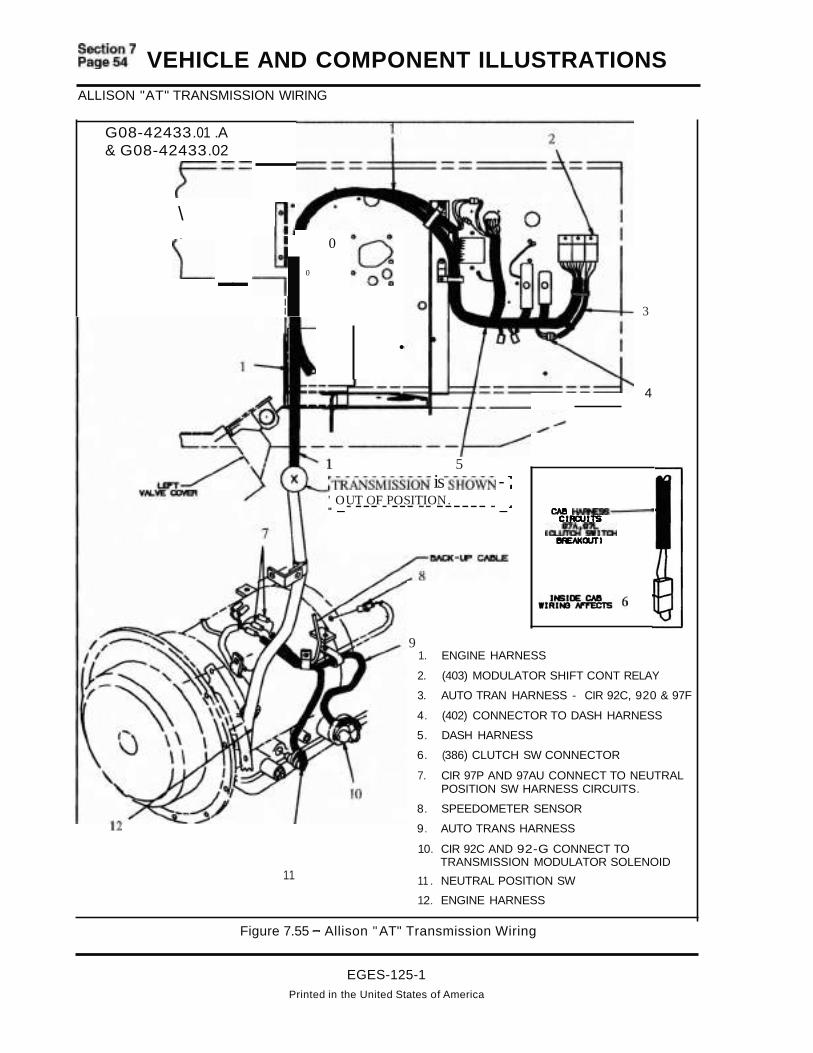
~:~~~~7 VEHICLE AND COMPONENT ILLUSTRATIONSALLISON "AT" TRANSMISSION WIRING
4
3
CAll HAArE!lS-CIACUI1S
,~'miTOlllAEAKourJ
91. ENGINE HARNESS
2. (403) MODULATOR SHIFT CONT RELAY
3. AUTO TRAN HARNESS - CIR 92C, 920 & 97F
4. (402) CONNECTOR TO DASH HARNESS
5. DASH HARNESS
6. (386) CLUTCH SW CONNECTOR
7. CIR 97P AND 97AU CONNECT TO NEUTRALPOSITION SW HARNESS CIRCUITS.
8. SPEEDOMETER SENSOR
9. AUTO TRANS HARNESS
10. CIR 92C AND 92-G CONNECT TOTRANSMISSION MODULATOR SOLENOID
11 . NEUTRAL POSITION SW
12. ENGINE HARNESS
•
11
1 5rTRANSrVii"ss{ol'i is-S-I-iOWN - ~
' OUT OF POSITION... _- --- - --- -- ------ - _ ..
G08-42433.01 .A& G08-42433.02
F==\ ~.
( ~ 0L __~ 0
II
Figure 7.55 - Allison "AT" Transmission Wiring
EGES-125-1Printed in the United States of America

VEHICLE AND COMPONENT ILLUSTRATIONSENGINE WARM-UP DEVICE
Section 7Page 55
1
4 G08-42428.01.A
1. (410) CONNECTS WARM -UP DEVICE HARNESS TO DASH HARNESS
2. CIR 97-GP GROUNDS AT GLOW PLUG RELAY BRACKET
3. WARM-UP DEVICE HARNESS
4. (409) EXHAUST BACK PRESSURE SENSOR
5. (398) IAT (INTAKE AIR TEMPERATURE SENSOR)
6. (411) HARNESS CONNECTION TO EXHAUST BACK PRESSURE REGULATOR
Figure 7.56 - Engine Warm-Up Device
EGES-125-1Printed in the United States of America

~:~~~~7
VEHICLE AND COMPONENT ILLUSTRATIONSENGINE SHUTDOWN WIRING AT DASH PANEL
2
5
G08-42430.01.A3
==,I
o 0 I
•
4
1. DASH HARNESS WIRING TO LOW COOLANT SENSORAND MAP SENSOR - FIGURE 7.58
2. REF: ENGINE HARNESS
3. CIR 34-G OF ENGINE HARNESS CONNECTS TO34-G OF DASH HARNESS
4. DASH HARNESS
5. (414) COOLANT LEVEL SENSOR MODULE
Figure 7..57 - Engine Shutdown Wiring At Dash Panel
EGES-125-1Printed in the United States of America

VEHICLE AND COMPONENT ILLUSTRATIONSENGINE SHUTDOWN WIRING AT DASH PANEL (Continued)
Section 7Page 57
1 2 G08-42430.02
1. LOW COOLANT PROBE
2. SURGE TANK
3. SEE FIGURE 7.57
4. (398) DASH HARNESS CONNECTIONTO LOW COOLANT SENSOR PIGTAIL
5. LOW COOLANT PIGTAIL
Figure 7.58 - Engine Shutdown Wiring At Dash Panel
EGES-125-1Printed In the United States of America
3
GLOSSARY OF TECHNICAL TERMSSection 8
Page 1
Actuator - A device which performs work in response to an electrical signal.
Address - A specific memory location in the RAM,ROM, or KAM of the ECM. The ECM can either readinformation from an address or send information(write) to an address (RAM or KAM only).
Analog - A continuously variable voltage.
Analog to Digital Converter (AID) - Acircuit within the processing section of the ECM that takes ananalog signal (either DC or AC) and converts it intoa usable digital signal for the microprocessor.
Analog Multimedia - A meter that uses a needleto point to a number on a scale of numbers to indicate a measured value (volts, ohms, amperes). Notrecommended for use on microprocessor systemsbecause of the possibility of excessive current dueto the low impedance of the meter.
APS, Accelerator Position Sensor - A potentiometer style sensor that indicates the operator's pedalposition.
ATA Data link - A serial data link specified by theAmerican Trucking Association and the SAE.
Background Manager - The portion of the computerthat performs "housekeeping duties". Typically the Background Manager controls low priorityitems or items that occur at a slower rate.
BARO Barometric Pressure Sensor - A variablecapacitance sensor which, when supplied with a 5volt reference signal from the ECM, produces a linear analog voltage signal indicating pressure.
BNC, Brake Normally Closed - An on/off switchstyle sensor used to indicate if the brake is applied.Normal primary function is to disengage cruise can..trol. (normally closed).
BNO, Brake Normally Open - An on/off switchstyle sensor used to indicate if the brake is applied.Normal primary function is to disengage cruise control. (normally open).
Calibration - The data values used by the strategyto solve equations and make decisions. Calibrationvalues are stored in the ROM as scalars, functionsand tables. Calibration values are input into the processor during programming to allow for the engineto operate within certain parameters.
CI, Cylinder Identification - A signal from the ECMto the IDM that identifies the position of the cylin..ders of the engine.
ClS, Coolant level Switch - A switch style sensorused to indicate low coolant level.
CMP, Camshaft Position Sensor - A Hall effectsensor used to indicate engine speed and camshaftposition. Speed is indicated by the numberofvanescounted per revolution. Camshaft position is indicated by a single narrow vane which indicates #1cylinder position or a wide vane in dual sync application that indicates #4 cylinder.
Continuous Test - A function of the ECM in whichthe inputs and outputs of the ECM are continuouslymonitored to assure that the readings are within setlimits.
DCl, Data Communication Link - A serial communication link between the ECM and the VPM.
DDS, Driveline Disengagement Switch - A switchindicating when the transmission is going out ofgear.
Disable - A type of computer decision which resultsin a system being deactivated and not allowed to operate.
Driver - A transistor in the output section of theECM that is used to turn on or off various actuatorsin the system.
Duty Cycle Signal- A type of wave signal that hasa controlled on/off time measure from 0% to 100ok.Normally used to control solenoids.
DVOM Digital Volt Ohm Meter - A meter that usesa digital display to indicate a measured value. Pre..ferred for use on microprocessor systems, becausea DVOM has a very high internal impedance and willnot load down the circuit being measured.
EBP, Exhaust Back Pressure Sensor - A variablecapacitance type sensor used to indicate exhaustback pressure.
ECI, Engine Crank Inhibit - An output on the ECMthat controls the ECI relay and controls when thestarter motor is allowed to operate and crank the engine over.
ECM, Electronic Control Module - The housingwhich contains the micro computer, Vref regulator,input conditioners and output drivers.
EGES-125-1Printed in the United States of America

Section 8Page 2 GLOSSARY OF TECHNICAL TERMS
ECM Power Relay - Relay which supplies or re··moves power to the ECM.
ECT, Engine Coolant Temperature Sensor - Athermistor type sensor which indicates engine tem..perature.
EF 10M Feedback - A communication line from theIDM to the ECM. In run mode, the signal on EF mirrors the FDCS signal received by the ECM from the10M. EF extensions will be used to identify detectedproblems with individual injectors.
EFRC, Engine Family Rating Code - A codereadable in the calibration list of the VPM with theEST service tool that identifies the horsepower andemission calibration of the engine.
Engine Off Test - A self test operation that is performed with the ignition switch in the "ON" positionwith the engine off.
Engine Running Test - Self test operation that isperformed with the engine running.
EOP, Engine Oil Pressure sensor - A variable capacitance type sensor used to indicate oil pressure.
EOT, Engine Oil Temperature sensor - Athermistor type sensor which senses engine oil temperature. This sensor is used to provide engine temperature signal to the ECM which uses the informationfor fuel rate and timing adjustment.
EPR, Exhaust Back Pressure Regulator - Apulse width modulated solenoid valve which allowspressurized lube oil to act upon a piston to open thebutterfly valve mounted on the exhaust side of theturbocharger. The regulator valve is controlled bythe ECM which determines how much the butterflyvalve is closed to control the exhaust back pressure.
EST Electronic Service Tool- The scan tool usedfor accessing diagnostics and programing theT 444E electronic control system.
EWL - Engine Warning Light Circuit
FOCS, Fuel Demand Command Signal - Command signal generated by the ECM and sent to the10M which controls when an injector is energized(opened) and how long the injector remains energized (open). This signal determines when and howmuch fuel the injector delivers to the combustionchamber.
FMEM, Failure Modes Effects Management - Analternate control strategy devised to reduce the adverse effects that can be caused by a system failure.Should a sensor fail, the ECM substitutes a goodsensor signal or assumed sensor value in its place.The WARN ENGINE LAMP is then lit to alert thedriver to take the vehicle in for service.
Foreground Manager - That portion of the computer that controls the primary engine control functions. The foreground manager responds to external events quickly to maintain correct engineperformance undera variety of conditions. Typicallythe foreground manager controls high priority items.
Function - An input value to a computer which thecomputer solves for an output.
Fusible Link - A wire designed to melt if more thana specified amount of electrical current flowsthrough it. Often used as a main fuse or backup fusefor large sections of the vehicle's wiring harness.
GPC, Glow Plug Control - Controls the currentflow to the glow plugs. Glow plug relay "ON" time iscontrolled by the ECM and is a function of enginecoolant temperature, barometric pressure and battery voltage. "ON" time normally varies between 10to 120 seconds. The glow plug relay will only cycleon and off repeatedly when there is a voltage condition greater than 13.0 volts.
GPL - Glow Plug Wait Lamp - On time is controlled by the ECM and is a function of ECT andBARO. On time will vary from 2 to 20 seceonds.
GPR, Glow Plug Relay - ECM controlled relaywhich supplies power to the glow plugs.
Hall Effect Sensor - A Hall Effect sensor generatesa digital on/off signal that indicates speed and alsoengine timing. The signal is created by a switchingaction caused by the passing of a vanes thru a positive and negative voltage potential. When the vaneis between this potential a signal is created. Whenthe gap is between this potential is open, no signalis generated. The widerthe vane the longerthe dutycycle of the signal, the narrower the vane the shorterthe duty cycle of the signal. A narrow vane is usedto indicate the position of #1 cylinder and a widevane to indicate the position of #4 cylinder. A HallEffect sensor has three connections ground, Vref,signal.
EGES-125-1
Printed in the United States of America

GLOSSARY OF TECHNICAL TERMSSection 8
Page 3
HEUI Hydraulically Actuated, ElectronicallyControlled, Unit Injectors - Engine description forInternational T 444E Diesel Engine.
High Speed Digitallnputs-Inputstothe ECMthatare from a sensor that generates varying frequencies. Examples of high speed digital input sensorsare engine speed, vehicle speed and Manifold Absolute Pressure (MAP) sensors.
IAT, Intake Air Temperature sensor - A thermistorstyle sensor used to indicate intake air temperature.
ICP, Injector Control Pressure Sensor - A transducer style sensor used to indicate Injection ControlPressure.
10M, Injector Driver Module- Is an electronic unitwhich has the primary function of an electronic distributor for the injectors. It also is the power supplyfor the injectors. It supplies 115 volts de @ 10 ampsto the injectors.
Impedance - A form of opposition to AC currentflow measured in Ohms.
Injection Control Pressure - High lube oil pressure generated by a high pressure pump/pressureregulator used to hydraulically actuate the fuel injectors.
Input Conditioner - A device or circuit that conditions or prepares an input signal for use by the microprocessor.
IPR, Injection Control Pressure Regulator - AnECM controlled pulse width modulated regulatorvalve which regulates injection control oil pressure.
IVS, Idle Validation Switch - An on/off switch sensor that indicates when the accelerator pedal is inthe idle position.
KAM, Keep Alive Memory - Is a memory locationin the microprocessor which allows the ECM tostore information on input failures, identified in normal operations for use in diagnostic routines. KeepAlive Memory can also store alternate calibrationparameters generated by the FMEM strategy inevent of sensor failure or wear. KAM memory is volatile and will be lost if power is disconnected.
KAMPWR - The circuit that continuously suppliesKAM memory with 12 volts to prevent the loss ofKAM memory.
Low Speed Digital Inputs - Are switched sensorinputs that generate an on/off (high/low) signal tothe ECM. The input supplied to the ECM from thesensor could be from a high input source switch(usually 12 or 5 volts) or could be from a groundingtype switch which grounds the signal from a currentlimiting resistor internal to the ECM and creates alow signal. (0 volts)
MAP, Manifold Absolute Pressure - A MAP sensor is a sensor that generates a digital frequencythat indicates manifold boost pressure or vacuum.The signal is created by switching action caused bymanifold pressure on a diaphragm connected to acapacitor circuit in the sensor. The digital frequencyincreases as pressure increases. A MAP sensorhas three connections, signal return (grd) , MAP signal and Vref.
Microprocessor - An integrated circuit within a micro computer which controls information flow withinthe computer.
Normally Closed - Refers to a switch or a solenoidthat is closed when no control force is acting on it.
Normally Open - Refers to a switch orsolenoid thatis open when no control force is acting on it.
On Demand Test - A self test which the technicianinitiates, and is run from a program in the processor.
acc, Output Circuit Check - An "On Demand"test performed during an "Engine Off' self test thattests the continuity of selected actuators.
Output State Check - An "On Demand" test selected by the technician which forces the processorto activate actuators "High or Low" for additionaldiagnostics.
OWL - OillWater Light and Alarm
Potentiometer - Is an electro-mechanical device(variable voltage divider) which senses the positionof a mechanical component. Mechanical motionconnected to the wiper causes it to move along theresistance material in a rotary fashion. The voltageon the wiper changes at each point along the resistive material and is proportional to the amount ofmechanical movement. Potentiometers have threeconnections. Vref, Signal out (wiper) and ground.
PROM - Programmable Read Only Memory
PTO, PowerTakeoff Unit- Accessory output, usually from the transmission that is used to powera hydraulic pump for garbage packing, lift equipment,etc.
EGES-125-1
Printed In the United States of America

Section 8Page 4 GLOSSARY OF TECHNICAL TERMS
Pulse Width - The length of time an actuator. suchas an injector remains energized.
RAM, Random Access Memory - A type ofmemory that is used to store information. Information can be written to and read from the RAM. Inputinformation such as current engine speed or temperature would be stored here to be compared tovalues stored in the ROM. All memory in the RAMis lost when the ignition switch is turned off.
Read - A computer operation where information isretrieved from the memory.
RFI - Radio Frequency Interlerence
ROM, Read Only Memory - A type of memory thatis used to store information permanently. Information can not be written to the ROM memory. Operating strategies and calibration tables are the type ofinformation most commonly stored in the ROM.
Sampling - The act of periodically collecting information, as from a sensor. A microprocessor samples inputs from various sensors in the process ofcontrolling a system.
Scalar - A single numerical value that is assigneda label and is used as a calibration parameter. Thisvalue can be multiplied, divided, added or subtracted to a given input.
sces, Speed Control Command Switches - Aset of switches used for cruise control, PTa and remote hand throttle system.
SIG GRD, Signal Ground - The common groundwire to the ECM in wire harness for the sensor inputs.
Sll, Self Test Input "Engine Diagnostics"Switch - Diagnostic switch located on vehicle dashused to activate Self Test Input engine diagnostics.
Strategy - A plan or set of operating instructionsthat the microprocessor follows in order to achievea desired goal. Strategy is the computer programitself, including all equations and decision makinglogic. Strategy is always stored in the RAM an thuscannot be changed during calibration.
SlOP - Stop Engine Lamp
Switch Sensors - Switch sensors are used to indicate position, levels or pressures. The signal of aswitch sensor is a digital signal created by either theopening or closing a switch. The on or off signal canindicate position as in the case of a clutch switch,level as in the case of a coolant level switch, or pressure as in the case of a low oil pressure switch. Aswitch sensor normally has two connectors signalreturn (Grd) and the signal. A switch sensor is considered a low speed digital signal input.
TAC, Tachometer Output Signal - Engine speedsignal from the ECM to the VPM.
Table - Devices that a computer uses to take twodifferent inputs and solve for an output.
Thermistor - Sensor used to determine temperature. A thermistor changes it's resistance value inrelation to temperature change. Increasing temperature results in decreasing resistance, decreasingtemperature results in increasing resistance. Thethermistor in conjunction with a current limiting resistor in the ECM forms a voltage divider that provides a voltage signal that indicates temperature.Since the top half of the voltage divider is the currentlimiting resistor and is internal to the ECM a thermistor sensor only has two connections, signal returnand ground.
Threshold Value - A value stored in the ROM portion of the ECM. This value is compared to the valueof a particular sensor provided to the ECM duringthe continuous self-test. If the value is not within theparameters of the threshold value, a service code isentered into the KAM.
Transducers (load cells) - Transducers are usedto sense pressure. Their function is very similar topotentiometers. The 5 volt reference signal ischanged by the internal circuitry of the sensor intoan analog voltage that indicates pressure. A transducer sensor has three connections Vref, signal andground.
Transition - Changing from one value or conditionto another, such as from positive to negative in anelectronic circuit.
TTS - Transmission Tailshaft Speed
UVC, Under Valve Cover - A combination valvecover gasket and harness containing fuel injectorand glow plug wiring.
EGES-125-1Printed in the United States of America

GLOSSARY OF TECHNICAL TERMSSection 8
PageS
VEPS Vehicle Electronic System ProgrammingSystem - The computer system used to programelectronically controlled vehicles.
VIGN, Voltage Ignition - Voltage supplied by theignition switch when the key is in the "ON" position.
VIT, Vendor Interface Tool - A vendor (enginesupplier) tool used to translate programming information between Navistar's truck VEPS system format to the vehicle.
VPM, Vehicle Personality Module - A modulewhich identifies to the ECM the individual vehicleparameters forthe system being used. This moduleallows for resetting of road speed, PTO set points,cruise control set points, speedometer calibrationsand other vehicle features.
VRE Vehicle Retarder Enable - Output from ECMto a vehicle retarder.
V Ref Reference Voltage - A five volt referencesupplied by the ECM to operate the engine sensors.
VBAT - Battery voltage.
VPWR - Battery voltage.
VSS Vehicle Speed Sensor - Normally a magneticpickup style sensor that is mounted on the tailshaftof the transmission to indicate ground speed.
WARN ENGINE Lamp - Lamp in the dash thatcomes on when selected fault codes are set or whenthe ECM is utilizing FMEM strategy. Fault codes insome vehicles can be read as flash codes throughthe WARN ENGINE lamp. To access the flashcodes, the STI (Self Test Input "Engine Diagnostics") switch is depressed and held momentarilywhile the ignition switch is placed in the "ON" position. This will cause the WARN ENGINE lamp toflash any fault codes which were stored while operating the vehicle.
Write - A computer operation where information issent to and stored in memory.
EGES-125-1
Printed In the United States of America