CHE Agenda 1/97 - NFPA
167
Page 1 of 6 Technical Committee on Standpipes (SPI-AAA) M E M O R A N D U M DATE: May 4, 2017 TO: Principal and Alternate Members of the Technical Committee on Standpipes (SPI-AAA) FROM: Chad Duffy, NFPA Staff Liaison Office: (617) 984-7562 Email: [email protected] SUBJECT: AGENDA – NFPA 14 First Draft Meeting (Fall 2018) Enclosed is the agenda for the First Draft meeting for NFPA 14, Standard for the Installation of Standpipe and Hose Systems, which will be at the Doubletree by Hilton Hotel & Suites Charleston, 8:00am to 5:00pm ET on Monday May 22, 2017, Tuesday May 23, 2017, and Wednesday May 24, 2017. Please submit requests for additional agenda items to the chair at least seven days prior to the meeting, and notify the chair and staff liaison as soon as possible if you plan to introduce any First revisions at the meeting. All NFPA Technical Committee meetings are open to the public. Please contact me for information on attending a meeting as a guest. Read NFPA's Regulations Governing the Development of NFPA Standards (Section 3.3.3.2) for further information. Additional Meeting Information: See the Meeting Notice on the Document Information Page (www.nfpa.org/14next) for meeting location details. If you have any questions, please feel free to contact Elena Carroll, Project Administrator at 617-984-7952 or by email [email protected]. C. Standards Administration
-
Upload
khangminh22 -
Category
Documents
-
view
1 -
download
0
Transcript of CHE Agenda 1/97 - NFPA

Page 1 of 6
Technical Committee on Standpipes (SPI-AAA)
M E M O R A N D U M
DATE: May 4, 2017
TO: Principal and Alternate Members of the Technical Committee on Standpipes
(SPI-AAA)
FROM: Chad Duffy, NFPA Staff Liaison
Office: (617) 984-7562 Email: [email protected]
SUBJECT: AGENDA – NFPA 14 First Draft Meeting (Fall 2018)
Enclosed is the agenda for the First Draft meeting for NFPA 14, Standard for the Installation of
Standpipe and Hose Systems, which will be at the Doubletree by Hilton Hotel & Suites Charleston,
8:00am to 5:00pm ET on Monday May 22, 2017, Tuesday May 23, 2017, and Wednesday May 24, 2017.
Please submit requests for additional agenda items to the chair at least seven days prior to the
meeting, and notify the chair and staff liaison as soon as possible if you plan to introduce any
First revisions at the meeting.
All NFPA Technical Committee meetings are open to the public. Please contact me for
information on attending a meeting as a guest. Read NFPA's Regulations Governing the
Development of NFPA Standards (Section 3.3.3.2) for further information.
Additional Meeting Information: See the Meeting Notice on the Document Information Page (www.nfpa.org/14next) for meeting
location details. If you have any questions, please feel free to contact Elena Carroll, Project
Administrator at 617-984-7952 or by email [email protected]. C. Standards Administration

Technical Committee on Standpipes (SPI-AAA) NFPA 14 Second Draft Meeting (Fall 2018) Monday, May 22, 2017, 8:00am – 5:00pm ET,
Tuesday, May 23, 2017, 8:00am – 5:00pm ET, &
Wednesday, May 24, 2017, 8:00am – 5:00pm ET
Doubletree by Hilton Hotel & Suites
Page 2 of 6
AGENDA
Monday, May 22, 2017
1. Call to Order – 8:00 AM
2. Introductions and Attendance
3. Review Agenda
4. NFPA Staff Liaison Presentation and Review of Key Dates in Current Cycle
5. Chairman Comments
6. Approval of Previous Meeting Minutes
7. Presentations
8. Adjourn – 5:00 PM
Tuesday, May 23, 2017
1. Call to Order – 8:00 AM
2. Continue Presentations if needed
3. Act on Task Group reports (See Task Group Assignments Below)
TG1 - Maritime TG2 – Pressure Reducing
Valves
TG3 – ASTM Standards for
Pipe and Fitting Pressures
Brad Cronin (Chair) Cecil Bilbo (Chair) Tom Wellen (Chair)
Terry Victor Jim Widmer Don Casey
Pete Schwab John Norman Rich Kozel
Terry Manning Ron Webb Michael McDaniel
Rich Richardson Jeff Hebenstreit
Joe Versteeg Andrew Henning
Phil Gunning
4. Act on Public Input for NFPA 14 and Committee First Revisions
5. Adjourn – 5:00 PM

Technical Committee on Standpipes (SPI-AAA) NFPA 14 Second Draft Meeting (Fall 2018) Monday, May 22, 2017, 8:00am – 5:00pm ET,
Tuesday, May 23, 2017, 8:00am – 5:00pm ET, &
Wednesday, May 24, 2017, 8:00am – 5:00pm ET
Doubletree by Hilton Hotel & Suites
Page 3 of 6
Wednesday, May 24, 2017
1. Call to Order – 8:00 AM
2. Act on Public Input for NFPA 14 and Committee First Revisions
3. New Business
4. Adjourn – 5:00 PM
Please submit requests for additional agenda items to the chair at least seven days prior to the meeting. Please notify the chair and staff liaison as soon as possible if you plan to introduce any committee input at the meeting. Key Dates for the Fall 2018 Revision Cycle
Proposal Closing Date January 5, 2017
Final Date for First Draft Meeting June 15, 2017 Posting of First Draft and TC Ballot August 3, 2017
Ballots Returned By August 24, 2017 Post Final First Draft September 7, 2017
Comment Closing Date November 16, 2017
Final Date for Second Draft Meeting May 17, 2018 Posting of Second Draft and TC Ballot June 28, 2018
Ballots Returned By July 19, 2018 Posting Final Second Draft August 2, 2018
Closing Date for Notice of Intent to Make a Motion (NITMAM) August 30, 2018
Issuance of Consent Document (No NITMAMs) November 5, 2018
NFPA Annual Meeting June 20, 2019
Issuance of Document with NITMAM August 7, 2019
Technical Committee deadlines are in bold.

Technical Committee on Standpipes (SPI-AAA) NFPA 14 Second Draft Meeting (Fall 2018) Monday, May 22, 2017, 8:00am – 5:00pm ET,
Tuesday, May 23, 2017, 8:00am – 5:00pm ET, &
Wednesday, May 24, 2017, 8:00am – 5:00pm ET
Doubletree by Hilton Hotel & Suites
Page 4 of 6
Meeting Preparation Committee members are strongly encouraged to review the published input prior to the meeting
and to be prepared to act on each item.
Handout materials should be submitted to the chair at least seven days prior to the meeting.
Only one posting of the inputs will be made; it will be arranged in section/order and will be pre-
numbered. This will be posted to the NFPA Document information pages located at
www.nfpa.org/14. If you have trouble accessing the website please contact Elena Carroll at
Mandatory Materials: Last edition of the standard
Meeting agenda
Public input/comments
Committee Officers' Guide (Chairs)
Roberts’ Rules of Order (Chairs; An abbreviated version may be found in the
Committee Officer’s Guide)
Optional Materials: NFPA Annual Directory
NFPA Manual of Style
Prepared committee input/comments (If applicable)
Regulations and Guiding Documents All committee members are expected to behave in accordance with the Guide for the Conduct of
Participants in the NFPA Codes and Standards Development Process.
All actions during and following the committee meetings will be governed in accordance with the
Regulations Governing the Development of NFPA Standards. Failure to comply with these
regulations could result in challenges to the standards-making process. A successful challenge on
procedural grounds could prevent or delay publication of the document.
The style of the document must comply with the Manual of Style for NFPA Technical Committee
Documents.

Technical Committee on Standpipes (SPI-AAA) NFPA 14 Second Draft Meeting (Fall 2018) Monday, May 22, 2017, 8:00am – 5:00pm ET,
Tuesday, May 23, 2017, 8:00am – 5:00pm ET, &
Wednesday, May 24, 2017, 8:00am – 5:00pm ET
Doubletree by Hilton Hotel & Suites
Page 5 of 6
General Procedures for Meetings Use of tape recorders or other means capable of producing verbatim transcriptions of any
NFPA Committee Meeting is not permitted.
Attendance at all NFPA Committee Meetings is open. All guests must sign in and identify
their affiliation.
Participation in NFPA Committee Meetings is generally limited to committee members
and NFPA staff. Participation by guests is limited to individuals, who have received prior
approval from the chair to address the committee on a particular item, or who wish to speak
regarding public input or comments that they submitted.
The chairman reserves the right to limit the amount of time available for any presentation.
No interviews will be allowed in the meeting room at any time, including breaks.
All attendees are reminded that formal votes of committee members will be secured by
letter ballot. Voting at this meeting is used to establish a sense of agreement, but only the
results of the formal letter ballot will determine the official action of the committee.
Note to Special Experts: Particular attention is called to Section 3.3(e) of the NFPA Guide
for the Conduct of Participants in the NFPA Codes and Standards Development Process in
the NFPA Directory. This section requires committee members to declare any interest they
may represent, other than their official designation as shown on the committee roster. This
typically occurs when a special expert is retained by and represents another interest
category on a particular subject. If such a situation exists on a specific issue or issues, the
committee member shall declare those interests to the committee and refrain from voting
on any action relating to those issues.

Technical Committee on Standpipes (SPI-AAA) NFPA 14 Second Draft Meeting (Fall 2018) Monday, May 22, 2017, 8:00am – 5:00pm ET,
Tuesday, May 23, 2017, 8:00am – 5:00pm ET, &
Wednesday, May 24, 2017, 8:00am – 5:00pm ET
Doubletree by Hilton Hotel & Suites
Page 6 of 6
ACTIONS AND MOTIONS
Possible Action #1: Resolve PI (no change to section)
Action Required Sample motion
Make a statement to resolve a PI
I move to resolve PI # with the following
statement . . .
Possible action #2: Create First Revision (make a change to a section)
Action Required Sample motion
Step 1 Create a First revision based one or more
PIs I move to create a First Revision based on PI #
Step 2
If the revision is related to multiple PIs,
generate a statement to respond to all of
them together
Step 1 Create a First Revision I move to create a First Revision as follows . . .
Step 2 Generate a statement (substantiation)
Possible Action 3: Create Committee input
Step 1 Create proposed revision for solicitation
of public comments
I move to create CI with a proposed revision to X
as follows . . .
Step 2
Generate a statement to explain the intent
and why the Committee is seeking public
comment

Attachment #1:
Previous Meeting Minutes

MINUTES of the NFPA 14 – 2nd Draft meeting
Adobe Connect/Conference Call – April 7, 2015 Tuesday; April 7
1. Chairman David Hague called the meeting to order at 11:05 AM.
2. Attendance was taken by Staff Liaison Chad Duffy.
3. Staff Liaison Chad Duffy reviewed the meeting agenda.
4. Staff Liaison Chad Duffy reviewed the new process motions for a 2nd draft meeting.
5. Staff Liaison Chad Duffy provided the Second Draft presentation including key dates in the current cycle.
6. The Technical Committee on Standpipes recognized a moment of silence for the passing of former
Technical Committee Chairman Thomas Brown.
7. Chairman Hague provided standard meeting instructions and advised the committee on a research
foundation project that is reviewing the intake capabilities of a 2-1/2” fire department connection.
8. Chairman Hague called for a motion to accept the minutes of March 4 & 5 First Draft meeting of the
Technical Committee in Tempe, AZ. Motion passed unanimously.
9. Technical Committee completed the review and action process on public comments.
10. Chairman Hague thanked both the Task Group on Horizontal Exits and Protection of Aboveground Piping;
the task groups where then disbanded.
11. Chairman Hague assigned a task group to review standpipe flow testing for the next revision cycle. The
task group consists of the following members:
a. Peter Schwab – Chairman b. Terence Manning c. Edward Prendergast d. Terry Victor e. Steve Leyton
12. Chairman Hague assigned a task group to review dock standpipe piping materials for the next revision
cycle. The task group consists of the following members:
a. Steve Leyton – Chairman b. Peter Schwab c. Rich Richardson d. Marinus Both e. Terry Victor
13. Chairman Hague called for a motion to adjourn at 3:30 PM. Motion passed unanimously.
Respectfully submitted; Chad Duffy, NFPA

Attendance:
David Hague, Chairman Chad Duffy, Staff Liaison Principals Cecil Bilbo Marinus Both Randal Brown Brian Conway James Dockrill Jeff Hebenstreit Thomas Jutras Eric Lee Stephen Leyton Terence Manning David Mettauer Bob Morgan Rita Neiderheiser John Norman III James Peterkin Maurice Pilette Edward Prendergast Rich Richardson Peter Schwab Ronald Webb Jim Widmer Alternates Don Casey Terry Victor Guest Jason Gamache

Attachment #2: Public Input

Public Input No. 71-NFPA 14-2017 [ Global Input ]
In the following sections change the terms “outlet(s)” and “hose outlet(s)” to “hose connection(s)”:
3.3.22, 7.2.2.1, 7.10.1.1.1, 7.10.1.1.6, 7.10.1.2.1, 7.10.1.2.2, 8.1.2(16), 11.5.1.2, A.5.4.1.1, A.5.4.2.1, A.7.3.2.2, A.7.3.2.7, A.7.3.2.10, A.7.3.2.11, Figure A.7.3.2.7, A.7.8.1.2, Figure A.7.10.1.1.6, and A.7.10.1.1.6
Statement of Problem and Substantiation for Public Input
The terms outlet and hose outlet are used throughout the document when the term hose connection is more appropriate. By substituting hose connection for these terms will clarify the intent of the requirement.
Related Public Inputs for This Document
Related Input Relationship
Public Input No. 68-NFPA 14-2017 [Section No. 3.3.3.2]
The revised definition compliments this global change.
Submitter Information Verification
Submitter Full Name: Terry Victor
Organization: Tyco/SimplexGrinnell
Street Address:
City:
State:
Zip:
Submittal Date: Wed Jan 04 11:36:32 EST 2017
Public Input No. 52-NFPA 14-2016 [ New Section after 1.4.2 ]
1.4.3 Compliance with Subsequent Editions of this Standard. Compliance with
subsequent editions of this standard shall be considered evidence of compliance with the AHJ's adopted edition of this standard.
A.1.4.3 More recent editions of this standard incorporate advances in knowledge, best practices and technology. Therefore, if an owner or contractor provides evidence of compliance with a more recent edition of this standard, than has been adopted by the AHJ,

the AHJ should accept compliance wiht the newer edition as evidence of full compliance with the edition of the standard specified in the AHJ's adoped fire or building code.
Statement of Problem and Substantiation for Public Input
If a contractor chooses to comply with the most current published edition of NFPA 14, even though it is not adopted by the AHJ, there is no reason that the most current edition of NFPA 14 should not be accepted as clear evidence of compliance to an adopted previous edition of NFPA 14. This issue is becoming more of a problem as AHJ's delay code adoptions beyond the 3 year traditional code adoption cycle going 6+ years in some circumstances. Having a code 6+ years out of date may create a situation where the code is specifying an edition of the standard that is 8, 9, 10 or ever 12+ years behind the most current edition. Although some progressive AHJS may be willing to approve a newer edition of the standard based on the equivalency language in NFPA 14, this is not always the case as many may be unwilling to stretch their comfort zones without specific guidance in the standard or code. This change memorializes this concept in the standard to provide liability protection to the contractor and specific guidance to the AHJ, along with comfort, that this practice is allowed.
Submitter Information Verification
Submitter Full Name: Anthony Apfelbeck
Organization: Altamonte Springs Building/Fire Safety Division
Street Address:
City:
State:
Zip:
Submittal Date: Mon Dec 19 13:35:12 EST 2016
Public Input No. 5-NFPA 14-2016 [ Chapter 2 ]
Chapter 2 Referenced Publications
2.1 General.
The documents or portions thereof listed in this chapter are referenced within this standard and shall be considered part of the requirements of this document.
2.2 NFPA Publications.
National Fire Protection Association, 1 Batterymarch Park, Quincy, MA 02169-7471.
NFPA 13, Standard for the Installation of Sprinkler Systems, 2016 edition.
NFPA 13R, Standard for the Installation of Sprinkler Systems in Low-Rise Residential Occupancies, 2016 edition.
NFPA 20, Standard for the Installation of Stationary Pumps for Fire Protection, 2016 edition.
NFPA 22, Standard for Water Tanks for Private Fire Protection, 2013 edition.
NFPA 24, Standard for the Installation of Private Fire Service Mains and Their Appurtenances, 2016 edition.

NFPA 25, Standard for the Inspection, Testing, and Maintenance of Water-Based Fire Protection Systems, 2014 edition.
NFPA 51B, Standard for Fire Prevention During Welding, Cutting, and Other Hot Work, 2014 edition.
NFPA 72® , National Fire Alarm and Signaling Code, 2016 edition.
NFPA 101 ®, Life Safety Code®, 2015 edition.
NFPA 170, Standard for Fire Safety and Emergency Symbols, 2015 edition.
NFPA 1963, Standard for Fire Hose Connections, 2014 edition.
2.3 Other Publications.
2.3.1 ANSI Publications.
American National Standards Institute, Inc., 25 West 43rd Street, 4th Floor, New York, NY 10036.
ANSI Z97.1, Safety Glazing Materials Used in Buildings — Safety Performance Specifications and Methods of Test, 2009.
2.3.2 ASME Publications.
ASME Internatioanl, Two Park Avenue, New York, NY 10016-5990.
ASME B1.20.1, Pipe Threads, General Purpose (Inch), 2013.
ASME B16.1, Gray Iron Pipe Flanges and Flanged Fittings Classes 25, 125, and 250,
2015.
ASME B16.3, Malleable Iron Threaded Fittings Classes 150 and 300, 2011.
ASME B16.4, Gray Iron Threaded Fittings Classes 125 and 250, 2011.
ASME B16.5, Pipe Flanges and Flanged Fittings , NPS 1/2 Through NPS 24 Metric/Inch Standard, 2013.
ASME B16.9, Factory-Made Wrought Steel Buttwelding Fittings, 2012.
ASME B16.11, Forged Fittings, Socket-Welding and Threaded, 2011.
ASME B16.25, Buttwelding Ends, 2012.
ASME B36.10M, Welded and Seamless Wrought Steel Pipe, 2015.
Boiler and Pressure Vessel Code, 2017.
2.3.3 ASTM Publications.
ASTM International, 100 Barr Harbor Drive, P.O. Box C700, West Conshohocken, PA 19428-2959.
ASTM A53/A53M, Standard Specification for Pipe, Steel, Black and Hot-Dipped, Zinc-Coated, Welded and Seamless, 2012.
ASTM A135/A135M, Standard Specification for Electric-Resistance–Welded Steel Pipe, 2009, reapproved 2014.
ASTM A234/A234M, Standard Specification for Piping Fittings of Wrought Carbon Steel and Alloy Steel for Moderate and High Temperature Service, 2015.
ASTM A795/A795M, Standard Specification for Black and Hot-Dipped Zinc-Coated (Galvanized) Welded and Seamless Steel Pipe for Fire Protection Use, 2013.
ASTM B75/B75M, Standard Specification for Seamless Copper Tube, 2011.

ASTM B88, Standard Specification for Seamless Copper Water Tube, 2014.
ASTM B251, Standard Specification for General Requirements for Wrought Seamless Copper and Copper-Alloy Tube, 2010.
ASTM SI10, Standard for Use of the International System of Units (SI): The Modern Metric System, 2010.
2.3.4 AWS Publications.
American Welding Society, 8869 NW 36 Street, # 130, Miami, FL 33166-6672.
AWS A5.8M/A5.8, Specification for Filler Metals for Brazing and Braze Welding, 2011, Amendment 1, 2012.
AWS B2.1/B2.1M, Specification for Welding Procedure and Performance Qualification,
2014, Amendment 1, 2015.
2.3.5 AWWA Publications.
American Water Works Association, 6666 West Quincy Avenue, Denver, CO 80235.
AWWA C104/A21.4, Cement-Mortar Lining for Ductile-Iron Pipe and Fittings, 2013.
AWWA C110/A21.10, Ductile-Iron and Gray-Iron Fittings, 2012.
AWWA C115/A21.15, Flanged Ductile-Iron Pipe with Ductile-Iron or Gray-Iron Threaded
Flanges, 2011.
AWWA C151/A21.51, Ductile-Iron Pipe, Centrifugally Cast,2009.
AWWA C153/A21.53, Ductile-Iron Compact Fittings, 2011.
2.3.6
Other Publications.
Merriam-Webster's Collegiate Dictionary, 11th edition, Merriam-Webster, Inc., Springfield, MA, 2003.
2.4 References for Extracts in Mandatory Sections.
NFPA 13, Standard for the Installation of Sprinkler Systems, 2016 edition.
NFPA 24, Standard for the Installation of Private Fire Service Mains and Their Appurtenances, 2016 edition.
NFPA 101® , Life Safety Code®, 2015 edition.
NFPA 241, Standard for Safeguarding Construction, Alteration, and Demolition Operations, 2013 edition.
NFPA 1002, Standard for Fire Apparatus Driver/Operator Professional Qualifications, 2014 edition.
NFPA 5000® , Building Construction and Safety Code®, 2015 edition.
Statement of Problem and Substantiation for Public Input
Referenced current SDO names, addresses, standard names, numbers, and editions.
Submitter Information Verification
Submitter Full Name: Aaron Adamczyk

Organization: [ Not Specified ]
Street Address:
City:
State:
Zip:
Submittal Date: Mon May 30 16:12:39 EDT 2016
Public Input No. 77-NFPA 14-2017 [ Section No. 2.3.3 ]
2.3.3 ASTM Publications.
ASTM International, 100 Barr Harbor Drive, P.O. Box C700, West Conshohocken, PA 19428-2959.
ASTM A53/A53M, Standard Specification for Pipe, Steel, Black and Hot-Dipped, Zinc-Coated, Welded and Seamless, 2012.
ASTM A135/A135M, Standard Specification for Electric-Resistance–Welded Steel Pipe, 2009 (2014).
ASTM A234/A234M, Standard Specification for Piping Fittings of Wrought Carbon Steel and Alloy Steel for Moderate and High Temperature Service, 2016.
ASTM A795/A795M, Standard Specification for Black and Hot-Dipped Zinc-Coated (Galvanized) Welded and Seamless Steel Pipe for Fire Protection Use, 2013.
ASTM B75/B75M, Standard Specification for Seamless Copper Tube, 2011.
ASTM B88, Standard Specification for Seamless Copper Water Tube, 2016.
ASTM B251, Standard Specification for General Requirements for Wrought Seamless Copper and Copper-Alloy Tube, 2010.
Statement of Problem and Substantiation for Public Input
updates
Submitter Information Verification
Submitter Full Name: Marcelo Hirschler
Organization: GBH International
Street Address:
City:
State:
Zip:
Submittal Date: Thu Jan 05 17:41:32 EST 2017

Public Input No. 53-NFPA 14-2017 [ New Section after 3.3 ]
TITLE OF NEW CONTENT
3.3.1 Automated Inspection and Testing. The performance of inspections and tests at a
distant location from the system or component being inspected or tested through the use of electronic devices or equipment installed for the purpose.
Statement of Problem and Substantiation for Public Input
Technology now allows for inspecting and testing a standpipe system from a distant location. New text has been added to NFPA 14 allowing for the installation and requirements for the devices and equipment used for this purpose. A definition is needed to describe the intent of the new requirements and allowances.
Related Public Inputs for This Document
Related Input Relationship
Public Input No. 54-NFPA 14-2017 [New Section after 3.3.4] Similar concepts
Public Input No. 55-NFPA 14-2017 [New Section after 4.1.3]
Public Input No. 61-NFPA 14-2017 [New Section after 11.6]
Submitter Information Verification
Submitter Full Name: Terry Victor
Organization: Tyco/SimplexGrinnell
Street Address:
City:
State:
Zip:
Submittal Date: Tue Jan 03 09:33:05 EST 2017
Public Input No. 68-NFPA 14-2017 [ Section No. 3.3.3.2 ]
3.3.3.2 Hose Connection.
The threaded outlet of a hose valve installed on a standpipe system for the connection of fire hose.
Statement of Problem and Substantiation for Public Input
The current definition is confusing when trying to apply the requirements of NFPA 14. By having the phrase “A combination of equipment provided …” leads the user to believe there is more than one component included in a hose connection. In reality, as the term “hose

connection” is primarily used throughout the document it is meant to apply to the point where the fire hose is attached to the hose valve. This revised definition clarifies what is meant by the term “hose connection” throughout the document. This revised definition will also help clarify the location where there are supposed to be pressure limitations and where hydraulic calculations begin.
Related Public Inputs for This Document
Related Input Relationship
Public Input No. 69-NFPA 14-2017 [Section No. 3.3.23.2]
Public Input No. 70-NFPA 14-2017 [Section No. 3.3.8]
Public Input No. 71-NFPA 14-2017 [Global Input]
Public Input No. 72-NFPA 14-2017 [Section No. 7.2.3.1 [Excluding any Sub-Sections]]
Public Input No. 73-NFPA 14-2017 [Section No. 7.2.3.2 [Excluding any Sub-Sections]]
Public Input No. 74-NFPA 14-2017 [Section No. 8.3.1.2]
Public Input No. 75-NFPA 14-2017 [Section No. A.7.8]
Submitter Information Verification
Submitter Full Name: Terry Victor
Organization: Tyco/SimplexGrinnell
Street Address:
City:
State:
Zip:
Submittal Date: Wed Jan 04 11:27:37 EST 2017
Public Input No. 54-NFPA 14-2017 [ New Section after 3.3.4 ]
TITLE OF NEW CONTENT
3.3.5 Distance Monitoring. The monitoring of various conditions of a system or component
from a location distant from the system or component through the use of electronic devices, meters, or equipment installed for the purpose.
Statement of Problem and Substantiation for Public Input
Technology now allows for monitoring certain conditions of a standpipe system or component from a distant location. New text has been added to NFPA 14 allowing for the installation and requirements for the devices, meters and equipment used for this purpose. A definition is

needed to describe the intent of the new requirements and allowances. This term has also been added to NFPA 13 and 20.
Related Public Inputs for This Document
Related Input Relationship
Public Input No. 53-NFPA 14-2017 [New Section after 3.3]
Public Input No. 55-NFPA 14-2017 [New Section after 4.1.3]
Public Input No. 61-NFPA 14-2017 [New Section after 11.6]
Submitter Information Verification
Submitter Full Name: Terry Victor
Organization: Tyco/SimplexGrinnell
Street Address:
City:
State:
Zip:
Submittal Date: Tue Jan 03 09:35:25 EST 2017
Public Input No. 78-NFPA 14-2017 [ Section No. 3.3.4.1 ]
3.3.4.1* Type I and Type II Construction.
Those types in which the fire walls, structural elements, walls, arches, floors, and roofs are of approved noncombustible or limited-combustible materials.
Statement of Problem and Substantiation for Public Input
Add an annex note explaining the differences.
Related Public Inputs for This Document
Related Input Relationship
Public Input No. 79-NFPA 14-2017 [New Section after A.3.3.1]
Submitter Information Verification
Submitter Full Name: Marcelo Hirschler
Organization: GBH International
Street Address:
City:

State:
Zip:
Submittal Date: Thu Jan 05 17:45:59 EST 2017
Public Input No. 70-NFPA 14-2017 [ Section No. 3.3.8 ]
3.3.8 Hose Station.
A combination of a hose rack or reel, hose nozzle, and hose, that is attached to a hose connection.
Statement of Problem and Substantiation for Public Input
The revised definition makes it clear that the additional equipment listed when attached to the hose connection creates the hose station.
Related Public Inputs for This Document
Related Input Relationship
Public Input No. 68-NFPA 14-2017 [Section No. 3.3.3.2] Definitions compliment each other.
Submitter Information Verification
Submitter Full Name: Terry Victor
Organization: Tyco/SimplexGrinnell
Street Address:
City:
State:
Zip:
Submittal Date: Wed Jan 04 11:33:06 EST 2017
Public Input No. 39-NFPA 14-2016 [ New Section after 3.3.10 ]
3.3.11 Open Parking Garage
A structure or portion of a structure with the openings as prescribed by the local building code on two
or more sides that is used for the parking or storage of private motor vehicles.
Statement of Problem and Substantiation for Public Input

Adding this definition if PI-38 is accepted.
Related Public Inputs for This Document
Related Input Relationship
Public Input No. 38-NFPA 14-2016 [New Section after 5.4.1.2]
Submitter Information Verification
Submitter Full Name: Peter Schwab
Organization: Wayne Automatic Fire Sprinkler
Street Address:
City:
State:
Zip:
Submittal Date: Fri Nov 18 11:03:09 EST 2016
Public Input No. 32-NFPA 14-2016 [ Section No. 3.3.16.1 ]
3.3.16.1 Horizontal Standpipe.
The system piping that delivers the water supply for two or more hose connections, and for sprinklers on combined systems, on a single level.
Statement of Problem and Substantiation for Public Input
There will be vertical piping on a horizontal standpipe. What makes it a horizontal standpipe is that the hose connections are on a single level. The definition more mirrors the definition of a standpipe.
Submitter Information Verification
Submitter Full Name: Peter Schwab
Organization: Wayne Automatic Fire Sprinkler
Street Address:
City:
State:
Zip:
Submittal Date: Fri Nov 18 08:37:53 EST 2016

Public Input No. 28-NFPA 14-2016 [ Section No. 3.3.23.1 ]
3.3.23.1 Control Valve.
A valve controlling flow to water-based fire protection systems.
A.3.3.23.1 Control Valve.
Control valves do not include hose valves, inspector's test valves, drain valves, trim valves for dry pipe, preaction and deluge valves, check valves, or relief valves.
Statement of Problem and Substantiation for Public Input
This is explanatory language and belons in the annex. This change will correlate with NFPA 13.
Submitter Information Verification
Submitter Full Name: Peter Schwab
Organization: Wayne Automatic Fire Sprinkler
Street Address:
City:
State:
Zip:
Submittal Date: Thu Nov 17 13:09:02 EST 2016
Public Input No. 69-NFPA 14-2017 [ Section No. 3.3.23.2 ]
3.3.23.2 Hose Valve.
The valve to an individual hose connection with a threaded outlet for attaching a fire hose.
Statement of Problem and Substantiation for Public Input
The terms hose valve, hose outlet, and outlet are used interchangeably and in some cases incorrectly throughout the document. The revised definition will make it clear that the threaded outlet of the hose valve is the hose connection.
Related Public Inputs for This Document
Related Input Relationship
Public Input No. 68-NFPA 14-2017 [Section No. 3.3.3.2] Definitions compliment each other.
Submitter Information Verification

Submitter Full Name: Terry Victor
Organization: Tyco/SimplexGrinnell
Street Address:
City:
State:
Zip:
Submittal Date: Wed Jan 04 11:30:13 EST 2017
Public Input No. 55-NFPA 14-2017 [ New Section after 4.1.3 ]
4.1.4 Automated Inspection and Testing and Distance Monitoring Devices, Meters, and Equipment
4.1.4.1* Devices, meters, and equipment utilized to perform automated inspection and testing procedures that are not subjected to system pressure shall not be required to be listed.
4.1.4.2* Devices, meters, and equipment utilized to perform distance monitoring of system or component status that are not subjected to system pressure shall not be required to be listed.
Statement of Problem and Substantiation for Public Input
Technology now allows for monitoring certain conditions of a standpipe system from a distance as well as for automated inspection and testing procedures. When the device is external to the standpipe system, doesn’t enter the system piping and is not subject to system pressure there isn’t a need to have it listed.
Related Public Inputs for This Document
Related Input Relationship
Public Input No. 54-NFPA 14-2017 [New Section after 3.3.4] Definition of terms in the proposal
Public Input No. 53-NFPA 14-2017 [New Section after 3.3] Definition of terms in the proposal
Public Input No. 61-NFPA 14-2017 [New Section after 11.6]
Public Input No. 62-NFPA 14-2017 [New Section after A.4.1.3]
Submitter Information Verification
Submitter Full Name: Terry Victor
Organization: Tyco/SimplexGrinnell
Street Address:
City:

State:
Zip:
Submittal Date: Tue Jan 03 09:37:25 EST 2017
Public Input No. 43-NFPA 14-2016 [ Section No. 4.2.1 ]
4.2.1
Pipe or tube used in standpipe systems shall meet or exceed one of the standards in Table 4.2.1 or shall be in accordance with 4.2.2 through 4.2.6.
Table 4.2.1 Pipe or Tube Materials and Dimensions
Materials and Dimensions (Specifications) Standard
Ductile Iron
Ductile-Iron Pipe, Centrifugally Cast
for Water AWWA C151
Flanged Ductile
Iron Pipe with Ductile
Iron or Gray
Iron Threaded Flanges AWWA C115
Ferrous piping (Welded and Seamless)
Specification for Electric-Resistance–Welded Steel Pipe ASTM A135
Specification for Black and Hot-Dipped Zinc-Coated (Galvanized) Welded and Seamless Steel Pipe for Fire Protection Use
ASTM A795
Specification for Pipe, Steel, Black and Hot-Dipped, Zinc-Coated, Welded and Seamless ANSI/ASTM A53
Welded and Seamless Wrought Steel Pipe ANSI/ASME B36.10M
Copper tube (drawn, seamless)
Specification for Seamless Copper Tube ASTM B75
Specification for Seamless Copper Water Tube ASTM B88
Specification for General Requirements for Wrought Seamless Copper and Copper-Alloy Tube ASTM B251
Brazing filler metal (classifications BCuP-3 or BCuP-4)
Brazing Filler Metal AWS A5.8
Statement of Problem and Substantiation for Public Input
Updated references (Based on NFPA 13). Terraview makes it difficult to read (See NFPA 13 Table 6.3.1.1)

Submitter Information Verification
Submitter Full Name: Peter Schwab
Organization: Wayne Automatic Fire Sprinkler
Street Address:
City:
State:
Zip:
Submittal Date: Fri Nov 18 14:30:34 EST 2016
Public Input No. 41-NFPA 14-2016 [ New Section after 4.2.7.2 ]
4.2.8 Pipe and Fittings for Standpipe Systems for Piers and Bulkheads
4.2.8.1 Pipe or tube and fittings used in standpipe systems for piers and bulkheads shall be
permitted to be in accordance with section 4.2.8.
4.2.8.2 Piping shall be permitted to be in accordance with Table 4.2.8.2
Table 4.2.8.2 Pipe or Tube Materials and Dimensions
Materials and Dimensions Standard
(Specifications)
Plastic
Polyvinyl Chloride (PVC) Pressure Pipe, 4 in. Through 12 in., for Water Distribution AWWA C900
Polyvinyl Chloride (PVC) Pressure Pipe, 14 in. Through 48 in., for Water Distribution AWWA C905
Polyethylene (PE) Pressure Pipe and Fittings, 4 in. (100 mm) Through 63 in. (1575 mm) for Water
Distribution AWWA C906
Molecularly Oriented Polyvinyl Chloride (PVCO) 4 in. Through 12 in. (100 mm Through 600 mm) for
Water Distribution AWWA C909
Brass
Specification for Seamless Red Brass Pipe ASTM B43 ASTM B 43
Ductile Iron

Cement Mortar Lining for Ductile Iron Pipe and Fittings for Water AWWA C104
Polyethylene Encasement for Ductile Iron Pipe Systems AWWA C105
Rubber-Gasket Joints for Ductile Iron Pressure Pipe and Fittings AWWA C111
Flanged Ductile Iron Pipe with Ductile Iron or Gray Iron Threaded Flanges AWWA C115
Thickness Design of Ductile Iron Pipe AWWA C150
Ductile Iron Pipe, Centrifugally Cast for Water AWWA C151
Standard for the Installation of Ductile Iron Water Mains and Their Appurtenances AWWA C60
Stainless Steel
Specification for Seamless, Welded, and Heavily Cold Worked Austenitic Stainless Steel Pipes ASTM A312/312M
4.2.8.3 Non-metallic piping shall be evaluated for exposure to direct ultra violet rays of sunlight.
4.2.8.3.1 Where required to be protected from ultra violet rays of sunlight, the method shall be approved.
4.2.8.4 Fittings shall be permitted to be in accordance with Table 4.2.8.4.
Table 4.2.8.4 Fittings Materials and Dimensions
Materials and Dimensions Standard
CPVC
Chlorinated Polyvinyl Chloride (CPVC) Specification for Schedule 80 CPVC Threaded Fittings ASTM F 437
Specification for Schedule 40 CPVC Socket-Type Fittings ASTM F 438
Specification for Schedule 80 CPVC Socket-Type Fittings ASTM F 439
Bronze Fittings
Cast Bronze Threaded Fitting ASTM B16.15
Ductile Iron
Cement Mortar Lining for Ductile Iron Pipe and Fittings for Water AWWA C104
Ductile Iron and Gray Iron Fittings, 3 in. Through 48 in., for Water and Other Liquids AWWA C110

Rubber-Gasket Joints for Ductile Iron Pressure Pipe and Fittings AWWA C111
Flanged Ductile Iron Pipe with Ductile Iron or Gray Iron Threaded Flanges AWWA C115
Protective Fusion-Bonded Epoxy Coatings for the Interior and Exterior Surfaces of Ductile-Iron
and Gray-Iron Fittings for Water Supply Service AWWA C116
Ductile-Iron Compact Fittings for Water Service AWWA C153
Stainless Steel
Specification for Wrought Austenitic Stainless Steel Pipe Fittings ASTM A403/A403M
4.2.8.5 Pipe and fittings shall be rated for the maximum system working pressure to which they are exposed but shall not be rated at less than 150 PSI (10 bar).
4.2.8.6 Joining of Pipe and Fittings
4.2.8.6.1 Joints shall be approved.
4.2.8.6.2 Flexible connections shall be permitted on floating piers where acceptable to the authority having jurisdiction. [303:6.3.5]
4.2.8.6.3 Except as permitted by 4.2.8.6.2.1, all joints shall be mechanically restrained.
4.2.8.6.3.1 The following joining methods shall not be required to be mechanically restrained at every joint:
(1) Locking mechanical push on joints
(2) Mechanical joints utilizing setscrew retainer glands
(2) Bolted flange joints
(3) Heat fused joints
(4) Welded joints
(5) CPVC welded joints
(6) Threaded joints
(7) Grooved joints
Additional Proposed Changes
File Name Description Approved
303_A2015_MAR-AAA_SD_PCResponses.pdf
303_A2015_MAR-AAA_FD_PIResponses.pdf
303_A2015_MAR-AAA_FD_CIStatements.pdf
Statement of Problem and Substantiation for Public Input
NFPA 303 is the Fire Protection Standard for Marinas and Boatyards. Section 6.3.1 requires Class I standpipe systems in piers, bulkheads and buildings where the hose lay distance from

the fire apparatus exceeds 150 ft (45m). Section 6.3.3 then tells the user to install the system in accordance with NFPA 14. During the last cycle, I submitted language to allow other types of pipe including non metallic piping allowed for underground service to be added to NFPA 303. The Committee floated a Committee Input asking for comments as well as rejecting the Public Input. I submitted comments and that was rejected based on the fact that NFPA 14 should be the place that dictates materials to be used in standpipe systems. Marinas and boatyards are of course located on or adjacent to water. This could be fresh or salt water. These environments can be harsh. The current Table 4.2.1 and 4.3.1 provide galvanized or copper as the only real option for corrosion resistance. Installing a copper system is generally not an option as it will turn green and probably be stolen for scrap. Galvanized piping is an option but we have seen these installations corrode within 2 years in marine installations. This public input proposes to add additional materials to new tables specifically for Marinas and Boatyards. The non-metallic piping materials are specifically listed for use in fire protection systems but for undergound or overhead (CPVC) service. We have successfully installed non-metallic systems in Marinas in Florida. NFPA 14 should add language to address this need for alternative materials in Marina and Boatyard standpipe systems
Related Public Inputs for This Document
Related Input Relationship
Public Input No. 31-NFPA 14-2016 [New Section after 7.10.4]
Submitter Information Verification
Submitter Full Name: Peter Schwab
Organization: Wayne Automatic Fire Sprinkler
Street Address:
City:
State:
Zip:
Submittal Date: Fri Nov 18 13:42:19 EST 2016
Public Input No. 42-NFPA 14-2016 [ Section No. 4.3.1 ]
4.3.1
Fittings used in standpipe systems shall meet or exceed the standards in Table 4.3.1 or shall be in accordance with 4.3.2.
Table 4.3.1 Fittings Materials and Dimensions
Materials and Dimensions Standard
Cast-iron
Cast Iron Threaded Fittings Class 125 and 250
ASME B16.4
Cast Iron Pipe Flanges and Flanged Fittings ASME B16.1

Malleable-iron
Malleable Iron Threaded Fittings, Class 150 and 300 ASME B16.3
Ductile-iron
Ductile-Iron and Gray-Iron Fittings AWWA C110
Ductile-Iron Compact Fittings for Water Service AWWA C153
Steel
Factory-Made Wrought Steel Buttwelding Fittings
ASME B16.9
Buttwelding Ends for Pipe, Valves, Flanges, and Fittings ASME B16.25
Standard Specification for Piping Fittings of Wrought Carbon Steel and Alloy Steel for Moderate and
Elevated Temperatures ASTM A234
Steel Pipe Flanges and Flanged Fittings ASME B16.5
Forged
Steel Fittings, Socket
Welded and Threaded
Copper
Wrought Copper and Copper Alloy Solder Joint Pressure Fittings
Cast Copper Alloy Solder Joint Pressure Fittings
ASME B16.11
ASME B16.22
ASME B16.18
Statement of Problem and Substantiation for Public Input
Updated titles and standards. Added copper since it is in pipe, there should be references for fittings. Terraview makes it difficult to see the changes. See NFPA 13 Table 6.4.1.
Submitter Information Verification
Submitter Full Name: Peter Schwab
Organization: Wayne Automatic Fire Sprinkler
Street Address:
City:
State:
Zip:
Submittal Date: Fri Nov 18 14:20:15 EST 2016
Public Input No. 56-NFPA 14-2017 [ New Section after 4.5.2 ]
TITLE OF NEW CONTENT

4.5.2.1 Valves with an automatic means to operate the valve shall not close in less than 5 seconds when operated at maximum possible speed from the fully open position.
Statement of Problem and Substantiation for Public Input
Technology now allows for automated valves to be used in systems. These valves must have the same restrictions on closing time to avoid water hammer and damage to the system.
Related Public Inputs for This Document
Related Input Relationship
Public Input No. 57-NFPA 14-2017 [New Section after 4.5.2]
Submitter Information Verification
Submitter Full Name: Terry Victor
Organization: Tyco/SimplexGrinnell
Street Address:
City:
State:
Zip:
Submittal Date: Tue Jan 03 09:39:45 EST 2017
Public Input No. 57-NFPA 14-2017 [ New Section after 4.5.2 ]
4.5.3 Automated Valves.
4.5.3.1 A listed indicating valve with an automatic means to operate the valve shall be permitted.
4.5.3.1.1 A listed water control valve assembly with an automatic means to operate the valve shall be connected to a remote supervisory station.
4.5.3.1.2 A listed water control valve assembly with an automatic means to operate the valve shall include a visual position indicator.
4.5.3.1.3 A listed water control valve assembly with an automatic means to operate the valve shall be able to be operated manually as well as automatically.
Statement of Problem and Substantiation for Public Input
Technology now allows for automated valves to be used in systems. These valves must have the same restrictions on closing time to avoid water hammer and damage to the system. The valve must indicate whether it’s open or closed, or a means of supervision that indicates its position must be provided just like a standard control valve. If an automated valve is provided it still needs to be able to be opened and closed manually.

Related Public Inputs for This Document
Related Input Relationship
Public Input No. 56-NFPA 14-2017 [New Section after 4.5.2]
Characteristics of these valves are linked
Public Input No. 61-NFPA 14-2017 [New Section after 11.6]
Submitter Information Verification
Submitter Full Name: Terry Victor
Organization: Tyco/SimplexGrinnell
Street Address:
City:
State:
Zip:
Submittal Date: Tue Jan 03 09:41:02 EST 2017
Public Input No. 49-NFPA 14-2016 [ New Section after 4.6.1.1.1 ]
4.6.1.1.2
Hose connestions within the cabinet, shall be positioned so that fire department hose cannot kink or require the use of elbow fittings.
Statement of Problem and Substantiation for Public Input
Hose connections within cabinets often are installed so that the fire department can either not make the connection, the fire department hose will kink, or the connection requires the use of an elbow fitting because the threads are facing downward toward the bottom of the cabinet. This proposal would resolve the problem by requiring the hose connection readily available.
Submitter Information Verification
Submitter Full Name: Robert Trotter
Organization: Codes Based Solutions Llc
Street Address:
City:
State:
Zip:
Submittal Date: Thu Dec 01 16:47:35 EST 2016

Public Input No. 38-NFPA 14-2016 [ New Section after 5.4.1.2 ]
5.4.1.2.1
Manual standpipes shall be permitted in open parking garages where the highest floor is located not more than 150 ft (45720 mm) above the lowest level of fire department vehicle access.
Statement of Problem and Substantiation for Public Input
This is language found in the IBC. NFPA 14 should coordinate. Renumber current 5.4.1.2.1 to 5.4.1.2.2
Related Public Inputs for This Document
Related Input Relationship
Public Input No. 39-NFPA 14-2016 [New Section after 3.3.10]
Submitter Information Verification
Submitter Full Name: Peter Schwab
Organization: Wayne Automatic Fire Sprinkler
Street Address:
City:
State:
Zip:
Submittal Date: Fri Nov 18 10:57:16 EST 2016
Public Input No. 26-NFPA 14-2016 [ Section No. 5.6.1 ]
5.6.1
Except for manual dry and manual wet standpipe systems, listed waterflow devices shall be provided for each standpipe system.
Statement of Problem and Substantiation for Public Input
There is no need for a waterflow alarm on a manual wet standpipe system. If it is part of a combined system, then the sprinkler system will have a waterflow alarm device. Manual wet standpipe systems can have a water supply as small as a 1/2" connection that may not even activate a waterflow alarm.

Related Public Inputs for This Document
Related Input Relationship
Public Input No. 27-NFPA 14-2016 [Section No. 5.6.3]
Submitter Information Verification
Submitter Full Name: Peter Schwab
Organization: Wayne Automatic Fire Sprinkler
Street Address:
City:
State:
Zip:
Submittal Date: Thu Nov 17 13:00:39 EST 2016
Public Input No. 27-NFPA 14-2016 [ Section No. 5.6.3 ]
5.6.3
Paddle-type waterflow alarms shall be used on automatic wet standpipe systems only.
Statement of Problem and Substantiation for Public Input
See PI #26
Related Public Inputs for This Document
Related Input Relationship
Public Input No. 26-NFPA 14-2016 [Section No. 5.6.1]
Submitter Information Verification
Submitter Full Name: Peter Schwab
Organization: Wayne Automatic Fire Sprinkler
Street Address:
City:
State:
Zip:
Submittal Date: Thu Nov 17 13:04:40 EST 2016

Public Input No. 29-NFPA 14-2016 [ Section No. 6.1.2.2.5 ]
Statement of Problem and Substantiation for Public Input
This language is found in section 6.1.2.5 which is a more appropriate location than this section.
Submitter Information Verification
Submitter Full Name: Peter Schwab
Organization: Wayne Automatic Fire Sprinkler
Street Address:
City:
State:
Zip:
Submittal Date: Thu Nov 17 14:23:47 EST 2016
Public Input No. 30-NFPA 14-2016 [ New Section after 6.1.2.3.2.3 ]
6.1.2.3.3
Water-filled piping shall be permitted to be installed in areas where the temperature is less than 40°F (4°C) when heat loss calculations performed by a professional engineer verify that the system will not freeze.
Statement of Problem and Substantiation for Public Input
This language is also found in NFPA 13 and NFPA 13R. There are many regions in the country where the temperature will drop below 40° F but never long and cold enough to freeze the water.
Submitter Information Verification
Submitter Full Name: Peter Schwab
Organization: Wayne Automatic Fire Sprinkler
Street Address:
City:
State:
Zip:
Submittal Date: Thu Nov 17 14:30:46 EST 2016

Public Input No. 76-NFPA 14-2017 [ Section No. 6.3.2 ]
6.3.2
Valves shall be provided on all standpipes, including manual-dry standpipes and horizontal standpipes, to allow isolation of a standpipe without interrupting the supply to other standpipes from the same source of supply.
Statement of Problem and Substantiation for Public Input
Section 6.3.2 does not cover Horizontal Standpipes which supplies two or more hose connections, Section 6.3.3 would be required for one hose valve only
Submitter Information Verification
Submitter Full Name: James Dockrill
Organization: J&S Fire Sprinkler Design & Co
Affilliation: Canadian Automatic Sprinkler Association
Street Address:
City:
State:
Zip:
Submittal Date: Wed Jan 04 19:52:39 EST 2017
Public Input No. 83-NFPA 14-2017 [ Section No. 6.4.1 ]
6.4.1
Unless the requirements of 6.3.6.1.2 are met, isolation valves shall not be permitted between the fire department connection and where the fire department connection piping connects to the system piping.
Statement of Problem and Substantiation for Public Input
6.3.6.1.2 and 6.4.1 seem to conflict. 6.3.6.1.2 allows control valves downstream of the fire department connection. 6.4.1 says no valves from the FDC to the standpipe system. Building complexes are becoming common where a water distribution system is installed for several high-rises located on a single parking deck.
Submitter Information Verification
Submitter Full Name: Thomas Wellen

Organization: American Fire Sprinkler Association
Street Address:
City:
State:
Zip:
Submittal Date: Thu Jan 05 22:59:38 EST 2017
Public Input No. 65-NFPA 14-2017 [ Section No. 6.4.5 ]
6.4.5 Number, Location and Identification.
6.4.5.1
A minimum of one fire department connection shall be required for any standpipe system.
6.4.5.2* For large buildings or where a standpipe connection serves multiple buildings, two
or more fire department connectinos shall be provided as follows:
A) Where multiple buildings are served, a minimum of one standpipe connection for each building over 50,000 sq. ft. shall be provided.
B) For buildings exceeding 500,000 sq. ft. in size, a minimum of two standpipe connections shall be provided.
C) For buildings exceeding 5 stories in height, a minimum of two standpipe connections shall be provided.
D) The authority having jurisdiction is authorized to require additional standpipe connections.
Fire department connections shall be visible and recognizable from the street or nearest point of fire department apparatus accessibility or on the street side of buildings.
6.4.5.2.1
Fire department connections shall be located and arranged so that hose lines can be attached to the inlets without interference from nearby objects, including buildings, fences, posts, landscaping, vehicles, or other fire department connections.
6.4.5.3
Each fire department connection shall be designated by a sign, with letters at least 1 in. (25.4 mm) in height, that reads “STANDPIPE.” For manual systems, the sign shall also indicate that the system is manual and that it is either wet or dry.
6.4.5.3.1
If automatic sprinklers are also supplied by the fire department connection, the sign or combination of signs shall indicate both designated services (e.g., “STANDPIPE AND AUTOSPKR” or “AUTOSPKR AND STANDPIPE”).
6.4.5.3.2
A sign also shall indicate the pressure required at the inlets to deliver the standpipe system demand.

6.4.5.4
Where a fire department connection services multiple buildings, structures, or locations, a sign shall be provided indicating the buildings, structures, or locations served.
6.4.5.5*
Fire department connections shall be located not more than 100 ft (30.5 m) from the nearest fire hydrant connected to an approved water supply.
6.4.5.5.1
The location of the fire department connection shall be permitted to exceed 100 ft (30.5 m) subject to the approval of the authority having jurisdiction.
Statement of Problem and Substantiation for Public Input
While the current standard clearly requires one 2 ½” inlet for each 250 gpm of required flow, it is silent on the requirements for the number of fire department connections needed. Many jurisdictions have found additional FDC’s necessary due to the ease with which a single connection can be compromised. Parking, construction, temporary storage, street closures, and mechanical damage are a few reasons that a connection may be unavailable to the fire department. According to the NFPA Research Foundation study recently conducted, “While the current NFPA requirements do not include the number and the length of the building exposure sides as a factor to determine the number of required FDCs, it is recognized that certain jurisdictions highlight the need for redundancy of FDCs by taking the building exposures into consideration. Based on this information, redundancy appears to be an important factor for overall system reliability.” The report also includes a small survey of jurisdictions, and found the following cities had requirements in addition those in NFPA 14 requiring a single FDC: New York City, NY, Chicago, IL, Georgia, and Orlando, FL. It’s likely that there are other jurisdictions in addition to those surveyed that require redundant FDC’s, and we have found multiple FDC’s on large buildings to be commonplace. The risk associated with a catastrophe resulting from an FDC being unavailable during a fire far outweighs the minimal cost of installing an additional connection.
Related Public Inputs for This Document
Related Input Relationship
Public Input No. 67-NFPA 14-2017 [New Section after A.6.4.5.4]
Submitter Information Verification
Submitter Full Name: J. L. Tidwell
Organization: Tidwell Code Consulting
Affilliation: Fire Equipment Manufacturers' Association
Street Address:
City:
State:
Zip:
Submittal Date: Tue Jan 03 12:28:44 EST 2017

Public Input No. 23-NFPA 14-2016 [ New Section after 6.4.5.2.2 ]
6.4.5.2.2.1
The pressure required sign shall not be required when the pressure required is 150 PSI or less.
Statement of Problem and Substantiation for Public Input
NFPA 13E indicates a standard pressure of 150 PSI unless a sign indicates otherwise. NFPA 13 also allows the ommission of this sign when 150 PSI or less
Submitter Information Verification
Submitter Full Name: Peter Schwab
Organization: Wayne Automatic Fire Sprinkler
Street Address:
City:
State:
Zip:
Submittal Date: Tue Nov 15 15:59:28 EST 2016
Public Input No. 1-NFPA 14-2016 [ Section No. 7.2.1 ]
7.2.1
The maximum pressure at any point in the system at any time shall not exceed 400 psi (27.6 bar).
Statement of Problem and Substantiation for Public Input
The materials used for standpipes, (i.e. PRV valves) are UL Listed and FM Approved for 400psi. The 350psi limitation is antiquated. It might be better revised that the standpipe system pressure limitation be limited by the material data sheets that make up the system components.
Submitter Information Verification
Submitter Full Name: Brian Callahan
Organization: Xl Fire Protection
Street Address:

City:
State:
Zip:
Submittal Date: Wed Apr 06 11:53:33 EDT 2016
Public Input No. 21-NFPA 14-2016 [ Section No. 7.2.1 ]
7.2.1
The maximum pressure at any point in the system at any time shall not exceed 400 psi (27.6 bar).
Additional Proposed Changes
File Name Description Approved
NFPA_14_PC_2.pdf NFPA 14 PC 2
Statement of Problem and Substantiation for Public Input
NOTE: This Public Input appeared as “Reject but Hold” in Public Comment No. 2 of the (F2015) Second Draft Report for NFPA 14 and per the Regs. at 4.4.8.3.1. Most PRV's for standpipe use are UL/FM listed to 400psi.
Submitter Information Verification
Submitter Full Name: TC ON SPI-AAA
Organization: NFPA TC ON STANDPIPES
Street Address:
City:
State:
Zip:
Submittal Date: Wed Oct 26 13:57:56 EDT 2016
Public Input No. 2-NFPA 14-2016 [ Section No. 7.2.2.1 ]
7.2.2.1
Where express mains supply higher standpipe zones, there shall be no hose outlets on any portion of the system where the pressure exceeds 400 psi (27.6 bar).
Statement of Problem and Substantiation for Public Input

PRV hose valves, for the most part, are UL Listed &/or FM Approved to 400psi. 350psi is antiquated text, and should be updated accordingly.
Submitter Information Verification
Submitter Full Name: Brian Callahan
Organization: Xl Fire Protection
Street Address:
City:
State:
Zip:
Submittal Date: Wed Apr 06 11:59:21 EDT 2016
Public Input No. 20-NFPA 14-2016 [ Section No. 7.2.2.1 ]
7.2.2.1
Where express mains supply higher standpipe zones, there shall be no hose outlets on any portion of the system where the pressure exceeds 400 psi (27.6 bar).
Additional Proposed Changes
File Name Description Approved
NFPA_14_PC_1.pdf NFPA 14 PC 1
Statement of Problem and Substantiation for Public Input
NOTE: This Public Input appeared as “Reject but Hold” in Public Comment No. 1 of the (F2015) Second Draft Report for NFPA 14 and per the Regs. at 4.4.8.3.1. I make this suggestion based on the fact that most PRV valves for fire protection standpipe use are UL/FM listed to 400psi., i.e. Zurn, Elkhart, Potter Roemer, etc.
Submitter Information Verification
Submitter Full Name: TC ON SPI-AAA
Organization: NFPA TC ON STANDPIPES
Street Address:
City:
State:
Zip:
Submittal Date: Wed Oct 26 13:54:51 EDT 2016

Public Input No. 72-NFPA 14-2017 [ Section No. 7.2.3.1 [Excluding any Sub-Sections] ]
Where the residual pressure at a 1 1⁄2 in. (40 mm) hose connection available for trained personnel use exceeds 100 psi (6.9 bar), an approved pressure-regulating device shall be provided to limit the residual pressure at the flow required by Section 7.10 to 100 psi (6.9 bar).
Statement of Problem and Substantiation for Public Input
The hose connection is the outlet to the valve and is included in the definition. Having these additional words in this requirement causes confusion.
Related Public Inputs for This Document
Related Input Relationship
Public Input No. 68-NFPA 14-2017 [Section No. 3.3.3.2]
This change compliments the revised definition.
Submitter Information Verification
Submitter Full Name: Terry Victor
Organization: Tyco/SimplexGrinnell
Street Address:
City:
State:
Zip:
Submittal Date: Wed Jan 04 11:40:13 EST 2017
Public Input No. 3-NFPA 14-2016 [ Section No. 7.2.3.2 [Excluding any Sub-Sections] ]
Where the static pressure at a 2 1⁄2 in. (65 mm) hose connection exceeds 175 psi (12.1 bar), a listed pressure-regulating device shall be provided to limit static and residual pressures at the outlet of the hose connection to no more than 175 psi (12.1 bar), or as approved by the local fire official.
Statement of Problem and Substantiation for Public Input
Current 175 psi stiffens firefighting hose, hard for firefighters to maneuver in small space of stairwell, with many 180 degree turns, and through maze of building walls and contents. Local

fire official should be consulted for approving hose discharge pressure appropriate for their equipment, crew abilities, and building firefighting plans.
Submitter Information Verification
Submitter Full Name: William Andrews
Organization: City of Richmond VA
Affilliation: City of Richmond Virginia's Fire Marshal's office
Street Address:
City:
State:
Zip:
Submittal Date: Wed Apr 06 16:37:11 EDT 2016
Public Input No. 73-NFPA 14-2017 [ Section No. 7.2.3.2 [Excluding any Sub-Sections] ]
Where the static pressure at a 2 1⁄2 in. (65 mm) hose connection exceeds 175 psi (12.1 bar), a listed pressure-regulating device shall be provided to limit static and residual pressures at the hose connection to no more than 175 psi (12.1 bar).
Statement of Problem and Substantiation for Public Input
The hose connection is the outlet to the valve and is included in the definition. Having these additional words in this requirement causes confusion.
Related Public Inputs for This Document
Related Input Relationship
Public Input No. 68-NFPA 14-2017 [Section No. 3.3.3.2]
This change compliments the revised definition.
Submitter Information Verification
Submitter Full Name: Terry Victor
Organization: Tyco/SimplexGrinnell
Street Address:
City:
State:
Zip:
Submittal Date: Wed Jan 04 11:42:06 EST 2017

Public Input No. 59-NFPA 14-2017 [ New Section after 7.2.4 ]
TITLE OF NEW CONTENT
7.2.4.1 The redundant pressure regulating device required by 7.2.4(3) shall be allowed to be
omitted where all of the following provisions are provided:
(1) Failure of the pressure regulating device to maintain the desired maximum pressure downstream of the device shall result in an audible and visual trouble signal in accordance with NFPA 72.
(2) A replacement pressure regulating device can be installed within 24 hours of the initiation of the audible and visual trouble signal.
(3) When failure of the pressure regulating device to maintain the desired maximum pressure downstream occurs and the downstream hose connections have non-pressure regulating hose valves, the fire department shall be notified of the excess pressure at the hose connections.
Statement of Problem and Substantiation for Public Input
The requirement for redundant master PRVs is very costly and isn’t necessary when certain conditions are met. The proposed new language allows for the omission of the redundant PRV but only when the downstream pressure is monitored, a signal is sent upon failure of the device to regulate the downstream pressure, and a replacement PRV can be installed with 24 hours. A replacement valve could be obtained and stored on site, or arrangements can be made with a local supply house to have one in inventory at all times in case a replacement is needed. If the downstream hose valves are the pressure reducing type they are required to be tested with the main PRV bypassed per section 11.5.5.1.1 and therefore should provide the desired outlet pressure without any problem until the master PRV is replaced. If they are not the pressure reducing type, the fire department must be notified so they can be prepared in case a fire event occurs during the 24 hour period.
Related Public Inputs for This Document
Related Input Relationship
Public Input No. 58-NFPA 14-2017 [Section No. 7.2.4] PI 59 is an exception to 7.2.4(3).
Submitter Information Verification
Submitter Full Name: Terry Victor
Organization: Tyco/SimplexGrinnell
Street Address:
City:
State:
Zip:
Submittal Date: Tue Jan 03 09:45:35 EST 2017

Public Input No. 58-NFPA 14-2017 [ Section No. 7.2.4 ]
7.2.4*
Where more than two hose connections are used downstream of a pressure-regulating device, the following conditions shall apply:
(1) In systems with multiple zones, pressure-regulating device(s) shall be permitted to be used in lieu of providing separate pumps to control pressure in the lower zone(s) as long as the devices comply with all requirements in 7.2.4.
(2) A method to isolate the pressure-regulating device(s) shall be provided for maintenance and repair.
(3) To provide redundancy, pressure regulating devices shall be arranged in series so that the failure of any single device does not allow pressure in excess of 175 psi (12.1 bar) to any of the multiple hose connections downstream.
(4) An equally sized bypass around the pressure-regulating device(s), with a normally closed control valve, shall be installed.
(5) Pressure-regulating device(s) shall be installed not more than 7 ft 6 in. (2.31 m) above the floor.
(6) The pressure-regulating device shall be provided with inlet and outlet pressure gauges.
(7) The fire department connection(s) shall be connected to the system side of the outlet isolation valve.
(8) The pressure-regulating device shall be provided with a pressure relief valve in accordance with the manufacturer's recommendations.
(9) Remote monitoring and supervision for detecting high pressure failure of the pressure-regulating device shall be provided in accordance with NFPA 72.
Statement of Problem and Substantiation for Public Input
The requirement for redundant master PRVs isn’t clear as the text is currently written. Changing section 7.2.4(3) as shown makes it clear that redundant PRVs are required.
Related Public Inputs for This Document
Related Input Relationship
Public Input No. 59-NFPA 14-2017 [New Section after 7.2.4]
Public Input No. 63-NFPA 14-2017 [Section No. A.7.2.4]
Submitter Information Verification
Submitter Full Name: Terry Victor

Organization: Tyco/SimplexGrinnell
Street Address:
City:
State:
Zip:
Submittal Date: Tue Jan 03 09:42:40 EST 2017
Public Input No. 35-NFPA 14-2016 [ Section No. 7.3.2.5 ]
7.3.2.5*
A single hose connection shall be permitted to be installed in the open corridor between open stairs that are not greater than 75 ft (23 m) apart.
Statement of Problem and Substantiation for Public Input
The proper term is a corridor. The term breezeway is not defined in the IBC.
Submitter Information Verification
Submitter Full Name: Peter Schwab
Organization: Wayne Automatic Fire Sprinkler
Street Address:
City:
State:
Zip:
Submittal Date: Fri Nov 18 10:33:42 EST 2016
Public Input No. 44-NFPA 14-2016 [ Section No. 7.3.2.12 ]
7.3.2.12
The distances in 7.3.2.10 and 7.3.2.11 shall be reduced to 130 ft (39.7 m) in open parking garages when manual dry standpipes are installed in open parking garages.
Statement of Problem and Substantiation for Public Input
This change clarifies that only the standpipes in the garage need to be spaced at 130 ft (39.7 m). This would not apply to other standpipes located alsewhere in the building.
Submitter Information Verification

Submitter Full Name: Peter Schwab
Organization: Wayne Automatic Fire Sprinkler
Street Address:
City:
State:
Zip:
Submittal Date: Mon Nov 21 15:21:25 EST 2016
Public Input No. 22-NFPA 14-2016 [ New Section after 7.5.1 ]
7.5.1.1
Standpipes shall be permitted to not be interconnected where acceptable to the AHJ.
Additional Proposed Changes
File Name Description Approved
NFPA_14_PC_8.pdf NFPA 14 PC 8
Statement of Problem and Substantiation for Public Input
NOTE: This Public Input appeared as “Reject but Hold” in Public Comment No. 8 of the (F2015) Second Draft Report for NFPA 14 and per the Regs. at 4.4.8.3.1. The Committee statement said that section 7.5.1 gave the AHJ the ability to specify how standpipes are interconnected. The statement is in contrast to the point raised by the Public Input. Many AHJ's are under a Min/Max system so since 7.5.1 states they shall be interconnected, they have no choice. By adding this section, the AHJ can now have the legal ability to allow standpipes to not be interconnected based on their fire fighting SOP's.
Submitter Information Verification
Submitter Full Name: TC ON SPI-AAA
Organization: NFPA TC ON STANDPIPES
Street Address:
City:
State:
Zip:
Submittal Date: Wed Oct 26 13:59:45 EDT 2016

Public Input No. 84-NFPA 14-2017 [ Section No. 7.6.2 ]
7.6.2
Standpipes that are part of a combined system in a building that is partially sprinklered shall be at least 6 in. (150 mm) in size.
7.6.3 (renumber the remaining section)
Where the building is protected throughout by an approved automatic sprinkler system in accordance with NFPA 13 or NFPA 13R, the minimum standpipe size shall be 4 in. (100 mm) for systems hydraulically designed in accordance with 7.8.1.
Statement of Problem and Substantiation for Public Input
AHJ's still don't believe that a standpipe can be 4 in. when the building is sprinklered throughout. Since this falls under 6.2.1, AHJ's are not allowing the standpipe to be 4 in. even though the building is sprinklered throughout. Perhaps renumbering the paragraphs can help the AHJ's to correctly interpret the standard.
Submitter Information Verification
Submitter Full Name: Thomas Wellen
Organization: American Fire Sprinkler Association
Street Address:
City:
State:
Zip:
Submittal Date: Thu Jan 05 23:14:51 EST 2017
Public Input No. 60-NFPA 14-2017 [ Section No. 7.8.1 ]
7.8.1 Minimum Design Pressure for Hydraulically Designed Systems.
Hydraulically designed standpipe systems shall be designed to provide the waterflow rate required by Section 7.10 at a minimum residual pressure of 100 psi (6.9 bar) at the outlet of the hydraulically most remote 2 1⁄2 in. (65 mm) hose connection valveand 65 psi (4.5 bar) at the outlet of the hydraulically most remote 1 1⁄2 in. (40 mm) hose station valve.
7.8.1.1
The pressure loss through the hose valve shall be determined using the valve manufacturer's most up-to-date friction loss data.
7.8.1.1.1
The values in Table 8.3.1.3 shall be permitted to be used for non-pressure reducing valves when the valve manufacturer’s most up-to-date friction loss data is unavailable.

7.8.1.2*
Manual standpipe systems shall be designed to provide 100 psi (6.9 bar) at the outlet of the hydraulically most remote 2 1/2 in. (65 mm) hose connection valve with the calculations terminating at the fire department connection.
Statement of Problem and Substantiation for Public Input
There has been confusion interpreting these requirements when trying to determine where the required pressure is to be calculated, at the outlet of the hose valve, or at the fitting connection to the standpipe. These changes will make it clear that the pressure is required at the outlet of the hose valve.
Submitter Information Verification
Submitter Full Name: Terry Victor
Organization: Tyco/SimplexGrinnell
Street Address:
City:
State:
Zip:
Submittal Date: Tue Jan 03 09:52:21 EST 2017
Public Input No. 34-NFPA 14-2016 [ New Section after 7.8.1.2 ]
7.8.1.2.1
The pressure required at the fire department connection for manual standpipes shall not exceed the working pressure of the system components of the standpipe system or sprinkler system when a combined system.
Statement of Problem and Substantiation for Public Input
Some contractors have been calculating all 4" standpipe systems and bulk to the FDC and indicating that the PSI required at the FDC is IE: 245 PSI. (Report from Denver). This is on non high rise combined systems. The PSI required at the FDC should not exceed the pressure ratings of the system components for manual standpipes.
Submitter Information Verification
Submitter Full Name: Peter Schwab
Organization: Wayne Automatic Fire Sprinkler
Street Address:
City:

State:
Zip:
Submittal Date: Fri Nov 18 08:53:11 EST 2016
Public Input No. 80-NFPA 14-2017 [ Section No. 7.10.1.2.1 [Excluding any Sub-Sections] ]
Hydraulic calculations and pipe sizes for each standpipe shall be based on providing 250 gpm (946 L/min) at the two hydraulically most remote hose connections on the standpipe and at the point of connection of each of the other standpipes at the minimum residual pressure required by Section 7.8.
Statement of Problem and Substantiation for Public Input
The calculation procedure is to add 250 gpm at the point of connection and not at the topmost outlet of the other standpipes.
Submitter Information Verification
Submitter Full Name: Thomas Wellen
Organization: American Fire Sprinkler Association
Street Address:
City:
State:
Zip:
Submittal Date: Thu Jan 05 21:48:48 EST 2017
Public Input No. 81-NFPA 14-2017 [ Section No. 7.10.1.2.2 ]
7.10.1.2.2
Where a horizontal standpipe on a Class I and Class III system supplies three or more hose connections on any floor, hydraulic calculations and pipe sizes for each standpipe shall be based on providing 250 gpm (946 L/min) at the three hydraulically most remote hose connections on the standpipe and at the point of connection of each of the other standpipes at the minimum residual pressure required by Section 7.8.
Statement of Problem and Substantiation for Public Input
The calculation procedure is to add 250 gpm at the point of connection and not at the topmost outlet of the other standpipes.
Submitter Information Verification
Submitter Full Name: Thomas Wellen
Organization: American Fire Sprinkler Association
Street Address:
City:
State:
Zip:
Submittal Date: Thu Jan 05 21:54:17 EST 2017
Public Input No. 31-NFPA 14-2016 [ New Section after 7.10.4 ]
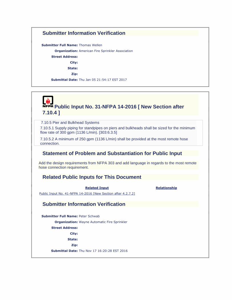
7.10.5 Pier and Bulkhead Systems
7.10.5.1 Supply piping for standpipes on piers and bulkheads shall be sized for the minimum flow rate of 300 gpm (1136 L/min). [303:6.3.5]
7.10.5.2 A minimum of 250 gpm (1136 L/min) shall be provided at the most remote hose connection.
Statement of Problem and Substantiation for Public Input
Add the design requirements from NFPA 303 and add language in regards to the most remote hose connection requirement.
Related Public Inputs for This Document
Related Input Relationship
Public Input No. 41-NFPA 14-2016 [New Section after 4.2.7.2]
Submitter Information Verification
Submitter Full Name: Peter Schwab
Organization: Wayne Automatic Fire Sprinkler
Street Address:
City:
State:
Zip:
Submittal Date: Thu Nov 17 16:20:28 EST 2016

Public Input No. 25-NFPA 14-2016 [ Section No. 7.11.2 ]
7.11.2 Drains.
All standpipe systems shall be equipped with drain connections in accordance with this section.
7.11.2.1
A main drain shall be provided on the standpipe system side of the system control valve in accordance with Figure 7.11.2.1.
Figure 7.11.2.1 Drain Connection for System Riser.
7.11.2.2
Where acceptable to the AHJ, the lowest hose connection shall be permitted to be used as the main drain.
7.11.2.3
The main drain connection shall be sized in accordance with Table 7.11.2.3.
Table 7.11.2.3 Sizing for Standpipe Drains
Standpipe Size Size of Drain Connection
Up to 2 in. (50 mm) 3⁄4 in. (20 mm) or larger
2 1⁄2 in. (65 mm), 3 in. (80 mm), or 3 1⁄2 in. (90 mm) 1 1⁄4 in. (32 mm) or larger
4 in. (100 mm) or larger 2 in. (50 mm) or larger
7.11.2.4
The main drain connection shall discharge at a location that permits the valve to be opened wide without causing water damage.
7.11.2.5
Portions of the standpipe system that are trapped such that they cannot be drained through the main drain connection shall have an auxiliary method of draining in accordance with one of the following:
(1) An auxiliary drain in accordance with NFPA 13
(2) An auxiliary drain connection in accordance with Table 7.11.2.3

(3) A hose connection at a low point that has been approved for use with a hose to drain water out of the trapped portion of the system to a location that will not cause water damage
Additional Proposed Changes
File Name Description Approved
7.11.2.docx Changes to 7.11.2
Statement of Problem and Substantiation for Public Input
Please see the attached word document for changes proposed to section 7.11.2. This method is easier than Terraview to show accurately. This input attempts to deliniate between a standpipe "system" main drain valve and a standpipe drain valve. The current text refers to a main drain on the standpipe. This then requires a gauge on each standpipe drain per 5.5.1 and requires a main drain flow test at each standpipe per 11.5.6.
Submitter Information Verification
Submitter Full Name: Peter Schwab
Organization: Wayne Automatic Fire Sprinkler
Street Address:
City:
State:
Zip:
Submittal Date: Thu Nov 17 11:06:09 EST 2016
Public Input No. 7-NFPA 14-2016 [ Section No. 7.12.2 ]
7.12.2
High-rise buildings shall have
a fire department connection for each zone
.
Statement of Problem and Substantiation for Public Input
Section 7.12.2.1 provides no guidance to the AHJ as to when a single connection would be acceptable. One AHJ may say “Yes” to a 420 foot high-rise building, the next door AHJ may say “No” to an 85 foot high-rise building. If it is technically acceptable for any high-rise building to have a single FDC for each zone, as indicated in 7.12.2.1, then the standard should reflect the minimum language necessary to satisfy the system design. The standard is a minimum standard and if the minimum is a single FDC under 7.12.2.1, then that should clearly be called out as the minimum standard required under NFPA 14. In addition, current language is also inconsistent with the Manual of Style in two separate locations: 1. Section 2.2.3.1 states that

“Codes and standards shall state specific criteria that minimize the judgment required by the users.” With no guidance provided to the AHJ, section 7.12.2. and 7.12.2.1 is currently 100% enforced based on judgment. 2. Section 2.2.3.2 states “Multiple levels of safety shall not be used in any code or standard.” The code language in sections 7.12.2 and 7.12.2.1 create two separate levels of safety for the issue of the number of FDCs per zone in high-rise buildings. This is a direct conflict with the 2.2.3.2 MOS direction. If there is technical justification for a threshold or protection conditions for multiple FDCs per zone in high-rise buildings, as opposed to a single FDC per zone in high-rise buildings, then the TC should quantify those specific thresholds in 7.12.2.1 and not leave the choice to an AHJ without any direction as to what should guide the AHJ’s decision.
Submitter Information Verification
Submitter Full Name: Anthony Apfelbeck
Organization: Altamonte Springs Building/Fire Safety Division
Street Address:
City:
State:
Zip:
Submittal Date: Sat Jun 04 11:12:01 EDT 2016
Public Input No. 40-NFPA 14-2016 [ Section No. 7.12.3 ]
7.12.3
Fire department connection sizes shall be based on the standpipe system demand and shall be sized as follows:
(1) up to 750 gpm (2840 L/min) demand provide two 2 1⁄2 in. (65 mm) inlets
(2) greater than 750 gpm (2840 L/min) provide three 2 1⁄2 in. (65 mm) inlets
7.12.3.1
An approved large diameter hose connection of a size to accommodate the required flow shall be permitted.
Additional Proposed Changes
File Name Description Approved
1505254.000_7849_Final.pdf FPRF FDC Inlet Report
Statement of Problem and Substantiation for Public Input
This input is being submitted based on the FPRF report.
Submitter Information Verification

Submitter Full Name: Peter Schwab
Organization: Wayne Automatic Fire Sprinkler
Street Address:
City:
State:
Zip:
Submittal Date: Fri Nov 18 11:16:09 EST 2016
Public Input No. 8-NFPA 14-2016 [ Section No. 7.12.3 [Excluding any Sub-Sections] ]
Fire department connection sizes shall be based on the standpipe system demand and shall include one 2 1⁄2 in. (65 mm) inlet per every 500 gpm (946 L/min) or fraction thereof.
Statement of Problem and Substantiation for Public Input
The Fire Protection Research Foundation report "Fire Department Connection (FDC) Inlet Flow Assessment" indicates that an expected flow of 500 GPM through each 2 1/2" inlet is reasonable based on the testing conducted by Exponent. The condition of a an FDC flowing 1,000 GPM total at 500 GPM per port created a friction loss of 15 psi. This is very reasonable and does not adversely impact the FD's ability to support a standpipe.
Submitter Information Verification
Submitter Full Name: Anthony Apfelbeck
Organization: Altamonte Springs Building/Fire Safety Division
Street Address:
City:
State:
Zip:
Submittal Date: Mon Jun 06 13:23:51 EDT 2016
Public Input No. 14-NFPA 14-2016 [ Chapter 8 ]
Chapter 8 Plans and Calculations
8.1* Plans and Specifications.
8.1.1
Plans accurately showing the details and arrangement of the standpipe system shall be submitted for approval to the authority having jurisdiction (AHJ) prior to the installation of the system.

8.1.2
Working plans shall be drawn to an indicated scale, on sheets of uniform size, and shall show those items from the following list that pertain to the design of the system:
(1) Name of owner(s) and occupant(s)
(2) Location, including street address
(3) Point of compass
(4) Name and address of installing contractor
(5) For automatic and semiautomatic standpipe systems, the following:
(a) Size of city main in street and whether dead end or circulating; if dead end, direction and distance to nearest circulating main
(b) City main test results and system elevation relative to test hydrant
(6) For automatic and semiautomatic standpipe systems, other sources of supply, with pressure and elevation
(7) Approximate capacity of each dry pipe system
(8) For automatic and semiautomatic standpipe systems, water supply capacity information, including the following:
(a) Location and elevation of static and residual test gauge with relation to the riser reference point
(b) Flow location
(c) Static pressure [psi (bar)]
(d) Residual pressure [psi (bar)]
(e) Flow [gpm (L/min)]
(f) Date
(g) Time
(h) Name of person who conducted the test or supplied the information
(i) Other sources of water supply, with pressure or elevation
(9) Pipe type and schedule of wall thickness
(10) Nominal pipe size and cutting lengths of pipe (or center-to-center dimensions)
(11) Type of fittings and joints and locations of all welds and bends
(12) Type and location of hangers, sleeves, braces, and methods of securing piping
(13) All control valves, check valves, drain pipes, and test connections
(14) Make, type, model and size of alarm, dry pipe, or deluge valve
(15) Type and location of alarms

(16) Size and location of standpipes, hose outlets, hand hose, nozzles, cabinets, and related equipment
(17) Information on the hydraulic data nameplate
(18) Hydraulic reference points shown on plan that correspond with comparable reference points on the hydraulic calculation sheets
(19) The setting for pressure-reducing and pressure-restricting valves
(20) The size and location of hydrant(s) and the relation to fire department connections
(21) Size, location, and piping arrangement of fire department connections
(22) Scale and graphical representation of the scale
(23) Hose valve manufacturer and model
(24) Pressure-reducing valve(s) manufacturer and model
(25) Required pressure at hose valve outlet
(26) Location of hose valves used in the hydraulic calculations
(27) Standpipe system demand (flow and pressure) at the following locations:
(a) Fire department connection (FDC) inlet
(b) Fire pump discharge flange
(c) Water supply tank discharge
(d) Water supply source if different from (a) through (c)
(d) (28) Fire Department hose supply to be calculated in the hydraulic
calculations where a manual system is designed.
8.1(28) The AHJ shall provide the worse case scenario of hose length and size for connection to the FDC for the specific location. This information is needed to determine friction loss from the supply for the manual wet and/or dry standpipe/hose connection.
8.1.3
The drawings shall show the location, arrangement, water supply, equipment, and all other details necessary to establish compliance with this standard.
8.1.4*
The plans shall include specifications covering the character of materials used and shall describe all system components.
8.1.5
The plans shall include an elevation diagram, and the vertical elevation of each floor shall be indicated.
8.2 Hydraulic Calculations.
8.2.1
Standpipe system piping shall be sized by hydraulic calculations.
8.2.2
A complete set of calculations shall be submitted with the plans.

8.2.3*
Hydraulic calculations shall be prepared on form sheets that include a summary sheet, detailed worksheets, and a graph sheet. [13:23.3.1]
8.2.4 Summary Sheet.
The summary sheet shall contain the following information, where applicable:
(1) Date
(2) Location
(3) Name of owner and occupant
(4) Building number or other identification
(5) Description of hazard
(6) Name and address of contractor or designer
(7) Name of approving agency
(8) System design requirements, as follows:
(a) Number of standpipes flowing
(b) Minimum rate of water application gpm (L/min)
(9) Total water requirements as calculated, including individual standpipe and partial sprinkler demand
(9) 8.2.4 (10) The AHJ shall provide the worse case scenario for the amount of
hose to be used for the supply from the fire apparatus to the FDC for the purpose of determining the pressures to be provided by the fire department pumper when hooked to the FDC for a manual standpipe and/or hose connection. This information is needed to ensure that the addition of fire department supply line to the FDC does not adversely affect the pressures to be supplied at the most remote/demanding location.
8.2.4 (11) The manual wet system signage at the FDC shall include the pressure loss from the fire apparatus to the hose valve.
8.2.5 Detailed Worksheets.
Detailed worksheets or computer printout sheets shall contain the following information:
(1) Sheet number
(2) Hose connection description and discharge constant (K)
(3) Hydraulic reference points
(4) Flow in gpm (L/min)
(5) Pipe size
(6) Pipe lengths, center-to-center of fittings
(7) Equivalent pipe lengths for fittings and devices
(8) Friction loss in psi/ft (bar/m) of pipe

(9) Total friction loss between reference points
(10) Devices per 8.3.1.5
(11) Elevation head in psi (bar) between reference points
(12) Required pressure in psi (bar) at each reference point
(13) Velocity pressure and normal pressure if included in calculations
(14) Notes to indicate starting points or reference to other sheets or to clarify data shown
8.2.6 Graph Sheet.
A graphic representation of the complete hydraulic calculation shall be plotted on semiexponential graph paper (Q 1.85) and shall include the following:
(1) Water supply curve
(2) Standpipe system demand
(3) Hose demand (where applicable)
(4) Partial sprinkler demand where applicable (see 7.10.1.3.2)
8.3 Hydraulic Calculation Procedures.
8.3.1 General.
8.3.1.1
For all systems, the hydraulic calculations shall be the most demanding based on the criteria of Chapter 7.
8.3.1.2
Calculations shall begin at the outlet of each hose connection and shall include the friction loss for the hose valve and any connecting piping from the hose valve to the standpipe.
Sec.8.3.1.2.1
Calculations shall begin at the outlet of each hose connection and shall include the friction loss for the hose valve and any connection piping from the hose valve to the fire apparatus supply for manual systems.
8.3.1.3
Table 8.3.1.3 shall be used to determine the equivalent length of pipe for fittings and devices unless the manufacturer's published data indicate that other factors are more accurate.
Table 8.3.1.3 Equivalent Pipe Length Chart
Fittings and Valves Expressed in Equivalent Feet of Pipe
Fittings and Valves 3⁄4 in. 1 in.
1 1⁄4 in.
1 1⁄2 in. 2 in.
2 1⁄2 in. 3 in.
3 1⁄2 in. 4 in. 5 in. 6 in. 8 in. 10 in. 12 in.
45 degree elbow 1 1 1 2 2 3 3 3 4 5 7 9 11 13
90 degree standard elbow 2 2 3 4 5 6 7 8 10 12 14 18 22 27
90 degree long-turn elbow 1 2 2 2 3 4 5 5 6 8 9 13 16 18
Tee or cross (flow turned 90 degrees)
3 5 6 8 10 12 15 17 20 25 30 35 50 60
Butterfly valve 6 7 10 12 9 10 12 19 21

Fittings and Valves Expressed in Equivalent Feet of Pipe
Fittings and Valves 3⁄4 in. 1 in.
1 1⁄4 in.
1 1⁄2 in. 2 in.
2 1⁄2 in. 3 in.
3 1⁄2 in. 4 in. 5 in. 6 in. 8 in. 10 in. 12 in.
Gate valve 1 1 1 1 2 2 3 4 5 6
Swing check* 5 7 9 11 14 16 19 22 27 32 45 55 65
Globe (straight) hose valve 46 70
Angle or hose valve 20 31
For SI units, 1 in. = 25.4 mm.
*Due to the variations in design of swing check valves, the pipe equivalents indicated in this table are considered to be average.
8.3.1.4
For saddle-type fittings having friction loss greater than that shown in Table 8.3.1.3, the increased friction loss shall be included in the hydraulic calculations.
8.3.1.5 Valves.
Specific friction loss values or equivalent pipe lengths for alarm valves, dry pipe valves, deluge valves, strainers, and other devices shall be made available to the authority having jurisdiction. [13:23.4.3.3]
8.3.1.6 Differing Values.
Specific friction loss values or equivalent pipe lengths for listed fittings not in Table 4.3.1 shall be used in hydraulic calculations where these losses or equivalent pipe lengths are different from those shown in Table 8.3.1.3. [13:23.4.3.4]
8.3.2 Adjustments.
8.3.2.1
Table 8.3.1.3 shall be used only where the Hazen-Williams C factor is 120.
8.3.2.2
For other values of C, the values in Table 8.3.1.3 shall be multiplied by the factors indicated in Table 8.3.2.2.
Table 8.3.2.2 Adjustment Factors for C Values
Multiplying Factor C Value
0.713 100
1.16 130
1.33 140
1.51 150
8.3.2.3
Table 8.3.2.3 indicates typical C factors that shall be used for commonly used piping materials.
Table 8.3.2.3 Hazen-Williams C Values
Pipe or Tube C Value
Unlined cast or ductile iron 100
Black steel (dry) 100
Black steel (wet) 120
Galvanized (wet) 120
Galvanized (dry) 100

Pipe or Tube C Value
Plastic (listed all) 150
Cement-lined cast or ductile iron 140
Copper tube or stainless steel 150
8.3.2.4
The AHJ shall be permitted to require other C values.
8.3.2.5
For internal pipe diameters different from Schedule 40 steel pipe [Schedule 30 for pipe diameters 8 in. (200 mm) and larger], the equivalent length shown in Table 8.3.1.3 shall be multiplied by a factor derived from the following equation:
[8.3.2.5]
8.3.2.5.1
The factor thus obtained shall be further modified as required by Table 8.3.2.2. This table shall apply to other types of pipe listed in Table 8.3.2.3 only where modified by factors from 8.3.2.3 and 8.3.2.5.
8.3.3 Formulas.
8.3.3.1 Friction Loss Formula.
8.3.3.1.1
Pipe friction losses shall be determined on the basis of the Hazen-Williams formula, as follows:
[8.3.3.1.1]
where:
p = frictional resistance (psi/ft of pipe)
Q = flow (gpm)
C = friction loss coefficient
d = actual internal diameter of pipe in inches
.
[13:23.4.2.1.1]
8.3.3.1.2
For SI units, the following equation shall be used:
[8.3.3.1.2]
where:
pm = frictional resistance (bar/m of pipe)
Qm = flow (L/min)
C = friction loss coefficient
dm = actual internal diameter (mm)
.
[13:23.4.2.1.2]
Additional Proposed Changes

File Name Description Approved
INSP_II_-_NFPA_14_code_changes.docx
manual systems - hydraulic calculations to include the friction loss fo the fire apparatus supply line to the FDC and signage to include this pressure requirements
Statement of Problem and Substantiation for Public Input
The hydraulic calculations for the manual system would reflect the loss of pressure from the fire department pumper, this is important because the systems are designed to such a small safety margin if any that this additional loss of pressure that you know will be there because it is a manual system could affect the system requirements. This information if not put on the signage at the FDC would leave even more question as to the actual pressure at the hose connection or most demanding point of the manual system.
Submitter Information Verification
Submitter Full Name: angela dayfield
Organization: Fire Safety Consutants Inc.
Street Address:
City:
State:
Zip:
Submittal Date: Mon Oct 03 12:19:03 EDT 2016
Public Input No. 74-NFPA 14-2017 [ Section No. 8.3.1.2 ]
8.3.1.2
Calculations shall begin at each hose connection and shall include the friction loss for the hose valve and any connecting piping from the hose valve to the standpipe.
Statement of Problem and Substantiation for Public Input
The hose connection is the outlet to the valve and is included in the definition. Having these additional words in this requirement causes confusion.
Related Public Inputs for This Document
Related Input Relationship
Public Input No. 68-NFPA 14-2017 [Section No. 3.3.3.2]
This change compliments the revised definition.
Submitter Information Verification

Submitter Full Name: Terry Victor
Organization: Tyco/SimplexGrinnell
Street Address:
City:
State:
Zip:
Submittal Date: Wed Jan 04 11:44:12 EST 2017
Public Input No. 33-NFPA 14-2016 [ Section No. 11.1.3 ]
11.1.3
The installing contractor shall complete and sign the appropriate contractor's material and test certificate(s) as shown in Figure 11.1.3(a) and Figure 11.1.3(b).
Figure 11.1.3(a) Sample Contractor's Material and Test Certificate for Aboveground Piping.


Figure 11.1.3(b) Sample of Contractor's Material and Test Certificate for Underground Piping. [24:Figure 10.10.1]


Statement of Problem and Substantiation for Public Input
Change the language from "Have Copies of the Following Been Left on the Premises" to "Have Copies of the Following Been Provided to the Owner or Owner's Representative". NFPA 13R, 13 and 24 have made similar changes.
Submitter Information Verification
Submitter Full Name: Peter Schwab
Organization: Wayne Automatic Fire Sprinkler
Street Address:
City:
State:
Zip:
Submittal Date: Fri Nov 18 08:44:44 EST 2016
Public Input No. 61-NFPA 14-2017 [ New Section after 11.6 ]
11.7 Automated Inspection and Testing Devices and Equipment
11.7.1 Automated inspection and testing devices and equipment installed on the standpipe system shall be tested to ensure the desired result of the automated inspection or test is realized.
11.7.1.1 Automated inspection devices and equipment shall prove to be as effective as a visual examination.
11.7.1.2 Automated testing devices and equipment shall produce the same action required by this standard to test a device.
11.7.1.2.1 The testing shall discharge water where required by this standard and NFPA 25.
11.7.2 Failure of automated inspection and testing devices and equipment shall not impair the operation of the standpipe system unless indicated by an audible and visual trouble signal in accordance with NFPA 72.
11.7.3 Failure of a system or component to pass automated inspection and testing devices and equipment shall result in an audible and visual trouble signal in accordance with NFPA 72.
11.7.4 Failure of automated inspection and testing devices and equipment shall result in an audible and visual trouble signal in accordance with NFPA 72.
Statement of Problem and Substantiation for Public Input
Technology now allows for automated inspection and testing of systems and components. When the devices and equipment are installed for that purpose, they need to be tested to make sure they provide the desired result for future inspections and tests. NFPA 25 has language describing how the device or equipment can be used and their limitations as they

apply to the periodic testing of systems and components. NFPA 14 needs to provide the original acceptance test criteria for these devices and equipment. This language is also being added to NFPA 13 and 20.
Related Public Inputs for This Document
Related Input Relationship
Public Input No. 53-NFPA 14-2017 [New Section after 3.3] Defines trems used in proposal
Public Input No. 54-NFPA 14-2017 [New Section after 3.3.4]
Defines terms used in proposal
Public Input No. 55-NFPA 14-2017 [New Section after 4.1.3]
Describes devices used for the purpose
Public Input No. 57-NFPA 14-2017 [New Section after 4.5.2]
Describes valves used for the purpose
Submitter Information Verification
Submitter Full Name: Terry Victor
Organization: Tyco/SimplexGrinnell
Street Address:
City:
State:
Zip:
Submittal Date: Tue Jan 03 09:58:24 EST 2017
Public Input No. 47-NFPA 14-2016 [ Section No. 12.5.2 ]
12.5.2
Hose valves shall be kept closed at all times and guarded against mechanical injury. [241
8.7.4.2.5]
Additional Proposed Changes
File Name Description Approved
241_COD_AAA_FD_FRReport.pdf
Statement of Problem and Substantiation for Public Input
The rest of this section is extraced from NFPA 241. See the action taken by the 241 committee. NFPA 14 should now extraxt this language.
Submitter Information Verification

Submitter Full Name: Peter Schwab
Organization: Wayne Automatic Fire Sprinkler
Street Address:
City:
State:
Zip:
Submittal Date: Thu Dec 01 13:35:28 EST 2016
Public Input No. 79-NFPA 14-2017 [ New Section after A.3.3.1 ]
A.3.3.4.1 The differences between Types I and II construction are mainly based on the fire resistance rating requirements for the various building elements.
Statement of Problem and Substantiation for Public Input
explanation
Related Public Inputs for This Document
Related Input Relationship
Public Input No. 78-NFPA 14-2017 [Section No. 3.3.4.1]
Submitter Information Verification
Submitter Full Name: Marcelo Hirschler
Organization: GBH International
Street Address:
City:
State:
Zip:
Submittal Date: Thu Jan 05 17:46:55 EST 2017
Public Input No. 62-NFPA 14-2017 [ New Section after A.4.1.3 ]
TITLE OF NEW CONTENT
A.4.1.4.1 Certain devices, meters, and equipment that may be used to perform inspection
and testing procedures from a distant location are not integral to the system and don’t affect

system performance. Automated inspection and testing devices and equipment, such as a digital camera, may be in the riser room or attached to the system externally but are not an integral part of the system. Such devices do not need to be listed.
A.4.1.4.2 Certain devices and equipment that may be used to monitor system or component
status from a distance are not integral to the system and don’t affect system performance. Distance monitoring devices, such as an external thermometer, may be attached to the system externally and therefore are not subjected to system pressure. Such devices do not need to be listed.
Statement of Problem and Substantiation for Public Input
Technology now allows for monitoring certain conditions of a standpipe system from a distance as well as for automated inspection and testing procedures. When the device is external to the standpipe system, doesn’t enter the system piping and is not subject to system pressure there isn’t a need to have it listed. These annex sections are explanatory for proposed new sections 4.1.4.1 and 4.1.4.2.
Related Public Inputs for This Document
Related Input Relationship
Public Input No. 55-NFPA 14-2017 [New Section after 4.1.3]
Text in the body this annex text is linked to.
Submitter Information Verification
Submitter Full Name: Terry Victor
Organization: Tyco/SimplexGrinnell
Street Address:
City:
State:
Zip:
Submittal Date: Tue Jan 03 10:01:09 EST 2017
Public Input No. 67-NFPA 14-2017 [ New Section after A.6.4.5.4 ]
TITLE OF NEW CONTENT
Type your content here .
A6.4.5.2t fThere is a need for redundant fire department connections where a single
connection may be compromised. Connections may be compromised by parked vehicles, damaged hose threads, debris in the intake piping and other conditions. If a compromised FDC will r sult in a significant barrier to responding personnel, additional connections should be provided.
When a large campus style facility is served by private fire service mains which feed the standpipe systems, and the campus covers a large area, additional FDC's should be

provided at strategic locations to enhance the fire department's ability to pump to the system.
Statement of Problem and Substantiation for Public Input
see reason for changes to Sec. 6.4.5.
Related Public Inputs for This Document
Related Input Relationship
Public Input No. 65-NFPA 14-2017 [Section No. 6.4.5] Annex Material to add further explanation.
Submitter Information Verification
Submitter Full Name: J. L. Tidwell
Organization: Tidwell Code Consulting
Affilliation: Fire Equipment Manufacturers' Association
Street Address:
City:
State:
Zip:
Submittal Date: Tue Jan 03 12:41:53 EST 2017
Public Input No. 63-NFPA 14-2017 [ Section No. A.7.2.4 ]
A.7.2.4
A small diameter pressure-reducing device can be required due to the minimum listed flow for large diameter pressure-reducing devices typically exceeding low flow conditions, to accommodate low flow conditions such as those created by the flow of a 1 1⁄2 in. (40 mm) hose connection or a single sprinkler on a combined system. These should also be arranged such that the failure of a single device does not allow pressure in excess of 175 psi (12.1 bar) to more than two hose connections.
See Figure A.7.2.4 for one method to comply with 7.2.4. Alternate methods are acceptable as long as they comply with all the requirements of 7.2.4.
Figure A.7.2.4 Dual Pressure-Regulating Device Arrangement.
Statement of Problem and Substantiation for Public Input
Figure A.7.2.4 only shows one method of compliance. The addition text makes it clear that other methods are possible and acceptable.

Related Public Inputs for This Document
Related Input Relationship
Public Input No. 58-NFPA 14-2017 [Section No. 7.2.4]
Describe redundant requirement linked to the figure
Submitter Information Verification
Submitter Full Name: Terry Victor
Organization: Tyco/SimplexGrinnell
Street Address:
City:
State:
Zip:
Submittal Date: Tue Jan 03 10:02:46 EST 2017
Public Input No. 36-NFPA 14-2016 [ Section No. A.7.3.2.5 ]
A.7.3.2.5
Paragraph 7.3.2.1 requires that a standpipe be provided in each required exit stairwell. One arrangement that might be found in certain residential buildings is that two remotely located exit stairs provide the occupants two distinct means of egress. This section allows a single hose connection to be located anywhere between the exit stairs, provided the exit stairs are open and are located within 75 ft (23 m) of each other. (See Figure A.7.3.2.5).
Figure A.7.3.2.5 Single Hose Valve in Open Stairs/Corridors.
Statement of Problem and Substantiation for Public Input
The proper term is a corridor. The term breezeway is not defined in the IBC. In addition, add the word maximum underneath the 75 ft (23 m). Change the text to say a single hose connection instead of hose valve.
Submitter Information Verification
Submitter Full Name: Peter Schwab
Organization: Wayne Automatic Fire Sprinkler
Street Address:
City:

State:
Zip:
Submittal Date: Fri Nov 18 10:35:09 EST 2016
Public Input No. 37-NFPA 14-2016 [ Section No. A.7.3.2.7 ]
A.7.3.2.7
Access to the roof can be via a stairwell that terminates at the roof level. Access could also be a permanent ladder, permanent ladder rungs, or a pull-down stair with a roof hatch. See Figure A.7.3.2.7 for an example of a roof outlet in areas subject to freezing. The isolation valve will be in the normally closed position.
Figure A.7.3.2.7 Roof Outlet Piping Arrangement.
Statement of Problem and Substantiation for Public Input
Added language to clarify that this valve is only needed when subject to freezing.
Submitter Information Verification
Submitter Full Name: Peter Schwab
Organization: Wayne Automatic Fire Sprinkler
Street Address:
City:
State:
Zip:
Submittal Date: Fri Nov 18 10:39:47 EST 2016
Public Input No. 82-NFPA 14-2017 [ New Section after A.7.3.2.8 ]
New annex A.7.3.2.9
A control valve and ball drip can be added to the pipe when the pipe above the roof to the roof hose outlet is subject to freezing. The control valve can be a listed indicating control valve or capped wrench head control valve. See Figure A.7.3.2.7 for an example of a roof outlet.
Statement of Problem and Substantiation for Public Input

A listed indicating type control valve can be used in lieu of a post-indicating, wall-type indicating, or capped wrench head control valve.
Submitter Information Verification
Submitter Full Name: Thomas Wellen
Organization: American Fire Sprinkler Association
Street Address:
City:
State:
Zip:
Submittal Date: Thu Jan 05 22:34:55 EST 2017
Public Input No. 75-NFPA 14-2017 [ Section No. A.7.8 ]
A.7.8
Where determining the pressure at the remote hose connection, the pressure loss in the hose valve should be considered.
It is very important that fire departments choose an appropriate nozzle type for their standpipe fire-fighting operations. Constant pressure- (automatic-) type spray nozzles (see NFPA 1964) should not be used for standpipe operations because many of these types require a minimum of 100 psi (6.9 bar) of pressure at the nozzle inlet to produce a reasonably effective fire stream. In standpipe operations, hose friction loss could prevent the delivery of 100 psi (6.9 bar) or 75 psi (5.2 ?bar) to the nozzle.
In high-rise standpipe systems with pressure-reducing hose valves, the fire department has little or no control over hose valve outlet pressure.
Many fire departments use combination (fog and straight stream) nozzles requiring 100 psi (6.9 bar) residual pressure at the nozzle inlet with 1 1⁄2 in., 1 3⁄4 in., or 2 in. (40 mm, 44 mm, or 50 mm) hose in lengths of up to 150 ft (45.7 m). Some use 2 1⁄2? in. (65 mm) hose with a smooth bore nozzle or a combination nozzle.
Some departments use 50 ft (15.2 m) of 2 1⁄2 in. (65 mm) hose to a gated wye, supplying two 100 ft (30.5 m) lengths of 1 1⁄2 –2 in. (40–50 mm) hose with combination nozzles, requiring 120–149 psi (8.3–0.3 bar) at the valve outlet. (See Table A.7.8.)
See also NFPA 1901.
Table A.7.8 Hose Stream Friction Losses Summary
Calculation No. Nozzle/Hose
Valve Outlet
Flow
gpm L/min psi bar
1 2 1⁄2 in. (65 mm) combination nozzle, with 150 ft (45.7 m) of 2 1⁄2 in. (65 mm) hose
250 946 123 8.5

Calculation No. Nozzle/Hose
Valve Outlet
Flow
gpm L/min psi bar
2 Two 1 1⁄2 in. (40 mm) combination nozzles with 100 ft (30.5 m) of 1 1⁄2 in. (40 mm) hose per nozzle, 2 1⁄2 in. (65 mm) gated wye, and 50 ft (15.2 m) of 2 1⁄2 in. (65 mm) hose
250 946 149 10.3
3 Same as calculation no. 2 with two 100 ft (30.5 m) lengths of 1 1⁄2 in. (40 mm) hose
250 946 139 9.6
4 Same as calculation no. 3 with two 100 ft (30.5 m) lengths of 2 in. (50 mm) hose
250 946 120 8.3
5 1 1⁄2 in. (40 mm) combination nozzle with 150 ft (45.7 m) of 2 in. (50 mm) hose
200 757 136 9.4
6 Same as calculation no. 5 with 1 1⁄2 in. (40 mm) hose 200 757 168 11.6
Note: For a discussion of use by the fire department of fire department connections, see NFPA 13E.
Statement of Problem and Substantiation for Public Input
The hose connection is the outlet to the valve and is included in the definition. Having these additional words in this requirement causes confusion.
Related Public Inputs for This Document
Related Input Relationship
Public Input No. 68-NFPA 14-2017 [Section No. 3.3.3.2]
This change compliments the revised definition.
Submitter Information Verification
Submitter Full Name: Terry Victor
Organization: Tyco/SimplexGrinnell
Street Address:
City:
State:
Zip:
Submittal Date: Wed Jan 04 11:46:40 EST 2017
Public Input No. 46-NFPA 14-2016 [ New Section after A.7.10.1.2.3 ]
A.7.10.1.2.3.1
In some types of construction there will be a multiple buildings separated by fire walls creating separate buildings. There will be horizontal exits between each of the buildings. The common supply piping will generally be installed on the bottom floor. The standpipes that

should be calculated will be the most demanding group of standpipes located within each fire area. See Figure A.7.10.1.2.3.1.
Additional Proposed Changes
File Name Description Approved
NFPA_14_Common_Supply_Piping-Model.pdf Common Supply Piping
Statement of Problem and Substantiation for Public Input
This input helps clarify section 7.10.1.2.3.1 indicating that when construction uses a fire wall thus creating separate buildings, the calculations only need to be for that fire area. Generally (ICC) the fire wall would need to be a 2 hour fire wall to consider it separate. This separation should be more than adequate as NFPA 14 only requires a 30 minute supply per 9.2.
Submitter Information Verification
Submitter Full Name: Peter Schwab
Organization: Wayne Automatic Fire Sprinkler
Street Address:
City:
State:
Zip:
Submittal Date: Thu Dec 01 12:49:34 EST 2016
Public Input No. 51-NFPA 14-2016 [ Section No. A.7.12 ]
A.7.12
The fire department connection should be located not less than 18 in. (500 mm) and not more than 4 ft (1.2 m) above the level of the adjacent grade or access level.
See NFPA 13E.
The number of 2 1⁄2 in. (65 mm) inlets to supply the required water volume and pressure at the fire department connection is dependent on several variables, such as the performance of the water supply at the source, the distance from the source to the location of the inlets, the diameter of the hose used, the size of the fire department pumper, and the required water volume and pressure at the base of the standpipe riser(s).
Statement of Problem and Substantiation for Public Input
The proposed language is from annex 8.17.2 of NFPA 13 2016 edition. Since both NFPA 13 and NFPA 14 provide specifications for fire department connections, the language addressing the minimum and maximum height should be the same in both documents. There is no justification for one document to contain different language addressing height than the other document since the function of an FDC is similar for both NFPA 13 and NFPA 14 systems.

Differences between the two documents on this issue only serve to create confusion with the AHJ and potential conflicts regarding system installations due to differing standard guidance and AHJ expectations.
Submitter Information Verification
Submitter Full Name: Anthony Apfelbeck
Organization: Altamonte Springs Building/Fire Safety Division
Street Address:
City:
State:
Zip:
Submittal Date: Mon Dec 19 13:19:01 EST 2016
Public Input No. 50-NFPA 14-2016 [ New Section after A.9.1 ]
A-9.1.4
Additional information on how to design water supplies for standpipe systems in tall buildings can be found in the SFPE Engineering Guide: Fire Safety for Very Tall Buildings.
Statement of Problem and Substantiation for Public Input
The SFPE Guide for Fire Safety for Very Tall Buildings can provide the designer with additional information on how to design a water supply for buildings where fire department pumpers cannot supply the required system demand through a fire department connection.
Submitter Information Verification
Submitter Full Name: Chris Jelenewicz
Organization: SFPE
Street Address:
City:
State:
Zip:
Submittal Date: Tue Dec 06 16:33:52 EST 2016
Public Input No. 64-NFPA 14-2017 [ Section No. A.11.5.5.1 ]

A.11.5.5.1
It is important to test pressure-regulating devices at the maximum and minimum anticipated flow rates. Minimum flow can be from a single sprinkler for combined systems or flow from a 1 1⁄2 in. (40 mm) hose connection on standpipe systems that do not supply sprinklers. This can require a sustained flow to demonstrate the continued performance of the pressure-regulating device at the minimum flow rate.
The design documents should indicate the model and type of each pressure-regulating device as well as the inlet and outlet pressure based on the water supply data and hydraulic calculations. Many of these devices are custom built based on these pressures and must be installed in the proper location in the standpipe system.
Statement of Problem and Substantiation for Public Input
It’s important that the pressure reducing devices installed on the standpipe system be the correct one in the correct location. Most hose valves and floor control assembly valves are manufactured with limited pressure variations and these valves cannot be interchanged in the system. The only way to make sure the right valve is installed in the right location is during the acceptance test, and to perform this test successfully the information described must be provided.
Submitter Information Verification
Submitter Full Name: Terry Victor
Organization: Tyco/SimplexGrinnell
Street Address:
City:
State:
Zip:
Submittal Date: Tue Jan 03 10:05:18 EST 2017

Angela Dayfield 22750 Beech Daly, Brownstown, MI 48134 734-231-2353 Code Change proposal for NFPA 14. Standard for the installation of Standpipe and Hose Systems 2016 edition. Where Manual standpipe and/or hose connections are installed, the hydraulic calculations shall include the friction loss of the fire departments supply line from the fire apparatus to the FDC. This information shall be accounted for in the hydraulic calculations and the signage at the FDC shall reflect this additional friction loss in the pressure to be delivered from the fire apparatus to meet the required standpipe pressures. This information is needed to ensure that the fire department supply line does not adversely affect the pressures required at the most demanding point of the standpipe and/or hose connection. This should also include the addition to the following sections of NFPA 14. Chapter 8, Plans and Calculations: Sec .8.1 Plans and specifications, Sec. 8.2.4 Summary Sheet and Sec 8.2.5 Detailed Worksheets should include: 8.1(25) The AHJ shall provide the worse case scenario of hose length and size for connection to the FDC for the specific location. This information is needed to determine friction loss from the supply for the manual wet and/or dry standpipe/hose connection. 8.2.4 (10) The AHJ shall provide the worse case scenario for the amount of hose to be used for the supply from the fire apparatus to the FDC for the purpose of determining the pressures to be provided by the fire department pumper when hooked to the FDC for a manual standpipe and/or hose connection. This information is needed to ensure that the addition of fire department supply line to the FDC does not adversely affect the pressures to be supplied at the most remote/demanding location. 8.2.4 (11) The manual wet system signage at the FDC shall include the pressure loss from the fire apparatus to the hose valve.
Sec.8.3.1.2.1
Calculations shall begin at the outlet of each hose connection and shall include the friction loss for the hose valve and any connection piping from the hose valve to the fire apparatus supply for manual systems.
(28) Fire Department hose supply to be calculated in the hydraulic calculations where a manual system is designed.
ecarroll
Typewritten Text
PI 14
ecarroll
Typewritten Text
ecarroll
Typewritten Text
ecarroll
Typewritten Text

Public Comment No. 1-NFPA 14-2014 [ Section No. 7.2.2.1 ]
7.2.2.1
Where express mains supply higher standpipe zones, there shall be no hose outlets on any portionof the system where the pressure exceeds 350 400 psi (24 27.6 bar).
Statement of Problem and Substantiation for Public Comment
I make this suggestion based on the fact that most PRV valves for fire protection standpipe use are UL/FM listed to 400psi., i.e. Zurn, Elkhart, Potter Roemer, etc.
Related Item
Public Input No. 1-NFPA 14-2013 [New Section after 6.1.1]
Submitter Information Verification
Submitter Full Name: BRIAN CALLAHAN
Organization: XL FIRE PROTECTION
Street Address:
City:
State:
Zip:
Submittal Date: Wed Aug 06 09:52:09 EDT 2014
Committee Statement
Committee Action: Rejected but held
Resolution: This is new material.
Copyright Assignment
I, BRIAN CALLAHAN, hereby irrevocably grant and assign to the National Fire Protection Association (NFPA) all and full rights incopyright in this Public Comment (including both the Proposed Change and the Statement of Problem and Substantiation). Iunderstand and intend that I acquire no rights, including rights as a joint author, in any publication of the NFPA in which thisPublic Comment in this or another similar or derivative form is used. I hereby warrant that I am the author of this Public Commentand that I have full power and authority to enter into this copyright assignment.
By checking this box I affirm that I am BRIAN CALLAHAN, and I agree to be legally bound by the above CopyrightAssignment and the terms and conditions contained therein. I understand and intend that, by checking this box, I am creating anelectronic signature that will, upon my submission of this form, have the same legal force and effect as a handwritten signature
National Fire Protection Association Report http://submittalsarchive.nfpa.org/TerraViewWeb/FormLaunch?id=/Terra...
1 of 1 10/26/2016 11:23 AM
ecarroll
Typewritten Text
PI 20
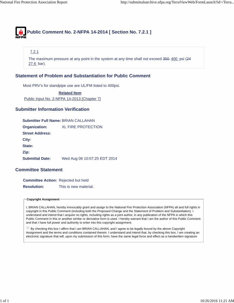
Public Comment No. 2-NFPA 14-2014 [ Section No. 7.2.1 ]
7.2.1
The maximum pressure at any point in the system at any time shall not exceed 350 400 psi (2427.6 bar).
Statement of Problem and Substantiation for Public Comment
Most PRV's for standpipe use are UL/FM listed to 400psi.
Related Item
Public Input No. 2-NFPA 14-2013 [Chapter 7]
Submitter Information Verification
Submitter Full Name: BRIAN CALLAHAN
Organization: XL FIRE PROTECTION
Street Address:
City:
State:
Zip:
Submittal Date: Wed Aug 06 10:07:25 EDT 2014
Committee Statement
Committee Action: Rejected but held
Resolution: This is new material.
Copyright Assignment
I, BRIAN CALLAHAN, hereby irrevocably grant and assign to the National Fire Protection Association (NFPA) all and full rights incopyright in this Public Comment (including both the Proposed Change and the Statement of Problem and Substantiation). Iunderstand and intend that I acquire no rights, including rights as a joint author, in any publication of the NFPA in which thisPublic Comment in this or another similar or derivative form is used. I hereby warrant that I am the author of this Public Commentand that I have full power and authority to enter into this copyright assignment.
By checking this box I affirm that I am BRIAN CALLAHAN, and I agree to be legally bound by the above CopyrightAssignment and the terms and conditions contained therein. I understand and intend that, by checking this box, I am creating anelectronic signature that will, upon my submission of this form, have the same legal force and effect as a handwritten signature
National Fire Protection Association Report http://submittalsarchive.nfpa.org/TerraViewWeb/FormLaunch?id=/Terra...
1 of 1 10/26/2016 11:21 AM
ecarroll
Typewritten Text
PI 21

Public Comment No. 8-NFPA 14-2014 [ New Section after 7.5.1 ]
7.5.1.1
Standpipes shall be permitted to not be interconnected where acceptable to the AHJ.
Statement of Problem and Substantiation for Public Comment
The Committee statement said that section 7.5.1 gave the AHJ the ability to specify how standpipes are interconnected. The statement is in contrast to the point raised by the Public Input. Many AHJ's are under a Min/Max system so since 7.5.1 states they shall be interconnected, they have no choice. By adding this section, the AHJ can now have the legal ability to allow standpipes to not be interconnected based on their fire fighting SOP's.
Related Item
Public Input No. 95-NFPA 14-2013 [New Section after 7.5.1]
Submitter Information Verification
Submitter Full Name: Peter Schwab
Organization: Wayne Automatic Fire Sprinkler
Street Address:
City:
State:
Zip:
Submittal Date: Tue Sep 23 12:53:51 EDT 2014
Committee Statement
CommitteeAction:
Rejected but held
Resolution: More clarification is need when different types of systems are located within the samebuilding, however further study is required.
Copyright Assignment
I, Peter Schwab, hereby irrevocably grant and assign to the National Fire Protection Association (NFPA) all and full rights incopyright in this Public Comment (including both the Proposed Change and the Statement of Problem and Substantiation). Iunderstand and intend that I acquire no rights, including rights as a joint author, in any publication of the NFPA in which thisPublic Comment in this or another similar or derivative form is used. I hereby warrant that I am the author of this Public Commentand that I have full power and authority to enter into this copyright assignment.
By checking this box I affirm that I am Peter Schwab, and I agree to be legally bound by the above Copyright Assignment andthe terms and conditions contained therein. I understand and intend that, by checking this box, I am creating an electronicsignature that will, upon my submission of this form, have the same legal force and effect as a handwritten signature
National Fire Protection Association Report http://submittalsarchive.nfpa.org/TerraViewWeb/FormLaunch?id=/Terra...
1 of 1 10/26/2016 11:22 AM
ecarroll
Typewritten Text
PI 22

7.11.2 Drains. All standpipe systems shall be equipped with drain connections in accordance with this section.
7.11.2.1 A main drain shall be provided on the standpipe system side of the system control valve in accordance with Figure 7.11.2.1.
Figure 7.11.2.1 Drain Connection for System Riser.
7.11.2.1.1 The main drain connection shall be sized in accordance with Table 7.11.2.1.1.
Table 7.11.2.1.1 Sizing for Standpipe Riser Drains
Standpipe Riser Size Size of Drain Connection
Up to 2 in. (50 mm) 3⁄4 in. (20 mm) or larger
2 1⁄2 in. (65 mm), 3 in. (80 mm), or 3 1⁄2 in. (90 mm) 1 1⁄4 in. (32 mm) or larger
4 in. (100 mm) or larger 2 in. (50 mm) or larger
7.11.2.1.2 The main drain connection shall discharge at a location that permits the valve to be opened wide without causing water damage. 7.11.2.1.3 A main drain connection shall not be required on manual wet and manual dry standpipe systems.
ecarroll
Typewritten Text
PI 25

7.11.2.2 A drain connection shall be provided on the standpipe side of the standpipe isolation valve. 7.11.2.2.1 Where acceptable to the AHJ, the lowest hose connection shall be permitted to be used as the main standpipe drain.
A.7.11.2.2.1
Where approved, it is acceptable to attach a hose to the lowest hose valve and run to a location that will not cause water damage.
7.11.2.3.2.2 The main drain connection shall be sized in accordance with Table 7.11.2.3.2.2.
Table 7.11.2.3.2.2 Sizing for Standpipe Drains
Standpipe Size Size of Drain Connection
Up to 2 in. (50 mm) 3⁄4 in. (20 mm) or larger
2 1⁄2 in. (65 mm), 3 in. (80 mm), or 3 1⁄2 in. (90 mm) 1 1⁄4 in. (32 mm) or larger
4 in. (100 mm) or larger 2 in. (50 mm) or larger
7.11.2.4.2.3 The main standpipe drain connection shall discharge at a location that permits the valve to be opened wide without causing water damage except as.
7.11.2.2.3.1
Where allowed by 7.11.2.2.1, the standpipe drain shall not be required to be piped to a drain location.
7.11.2.5.3 Portions of the standpipe system that are trapped such that they cannot be drained through the main drain connection or a standpipe drain connection shall have an auxiliary method of draining in accordance with one of the following:
1. An auxiliary drain in accordance with NFPA 13
2. An auxiliary drain connection in accordance with Table 7.11.2.3.2.2.
3. A hose connection at a low point that has been approved for use with a hose to drain water out of the trapped portion of the system to a location that will not cause water damage

© January 2016 Fire Protection Research Foundation FIRE PROTECTION RESEARCH FOUNDATION ONE BATTERMARCH PARK | QUINCY, MASSACHUSETTS, USA 02169-7471 E-MAIL: [email protected] | WEB: WWW.NFPA.ORG/FOUNDATION
Fire Department Connection (FDC) Inlet Flow Assessment
FINAL REPORT
PREPARED BY:
Y. Pock Utiskul, Ph.D., Neil P. Wu, P.E., and Elizabeth KellerExponent, Inc.
Bowie, MD, USA
ecarroll
Typewritten Text
PI 40

FOREWORD A Fire Department Connection (FDC) is “A connection through which the fire department can pump supplemental water into the sprinkler system, standpipe, or other system, furnishing water for fire extinguishment to supplement existing water supplies.” FDCs are required on all standpipe systems per NFPA 14, Standard for the Installation of Standpipe and Hose Systems, and sprinkler systems per NFPA 13, Standard for the Installation of Sprinkler Systems. In 2007, the Technical Committee for NFPA 14 added the requirement for one 2 ½ inch inlet per every 250 gallons per minute (gpm), but this requirement lacks supporting scientific documentation, so there was a need to conduct flow testing to determine the amount of water that is possible to flow into an FDC inlet.
The Fire Protection Research Foundation initiated this project to determine the actual flow that can be achieved for each 2 ½ inch inlet on an FDC to provide technical basis to the NFPA 14 Technical Committee for a possible change to the standard. The Fire Protection Research Foundation expresses gratitude to the report authors Y. Pock Utiskul, Ph.D., Neil P. Wu, P.E., and Elizabeth Keller who are with Exponent, Inc. The Foundation also expresses gratitude to the Maryland Fire and Rescue Institute (MFRI) where the tests were conducted. The Research Foundation appreciates the guidance provided by the Project Technical Panelists and all others that contributed to this research effort. Thanks are also expressed to the National Fire Protection Association (NFPA) for providing the project funding through the NFPA Research Fund. The content, opinions and conclusions contained in this report are solely those of the authors and do not necessarily represent the views of the Fire Protection Research Foundation, NFPA, Technical Panel or Sponsors. The Foundation makes no guaranty or warranty as to the accuracy or completeness of any information published herein.

About the Fire Protection Research Foundation
The Fire Protection Research Foundation plans, manages, and communicates research on a broad range of fire safety issues in collaboration with scientists and laboratories around the world. The Foundation is an affiliate of NFPA.
About the National Fire Protection Association (NFPA)
Founded in 1896, NFPA is a global, nonprofit organization devoted to eliminating death, injury, property and economic loss due to fire, electrical and related hazards. The association delivers information and knowledge through more than 300 consensus codes and standards, research, training, education, outreach and advocacy; and by partnering with others who share an interest in furthering the NFPA mission. All NFPA codes and standards can be viewed online for free. NFPA's membership totals more than 65,000 individuals around the world. Keywords: fire department connection, FDC, FDC inlet, flow testing, standpipe systems, NFPA 14

PROJECT TECHNICAL PANEL
Scott Futrell, Futrell Fire Consult & Design, Inc.
Dave Hague, Liberty Mutual
Jeff Hebenstreit, UL LLC
Steve Leyton, Protection Design & Consulting (AFSA representative)
Bob Morgan, Fort Worth Fire Department
Maurice Pilette, Mechanical Designs Ltd
Pete Schwab, Wayne Automatic Fire Sprinklers
Kyle Smith, Cobb County Fire and Emergency Services
Ronald Webb, S.A. Comunale Company, Inc. (NFSA representative)
Chad Duffy, NFPA Staff Liaison
PROJECT SPONSOR
National Fire Protection Association

Thermal Sciences
Fire Department Connection Inlet Flow Requirements: A Report on Full-scale Testing Results

1505254.000 7849
Fire Department Connection Inlet Flow Requirements: A Report on Full-scale Testing Results Prepared for Fire Protection Research Foundation One Batterymarch Park Quincy, MA 02169 Prepared by Y. Pock Utiskul, Ph.D., P.E., CFEI Neil P. Wu, P.E., IAAI-CFI, CBO Elizabeth Keller Exponent, Inc. 17000 Science Drive, Suite 200 Bowie, MD 20715 January 8, 2016 Exponent, Inc.

January 8, 2016
1505254.000 7849 ii
Contents
Page
List of Figures iv
List of Tables vi
Acronyms and Abbreviations vii
Limitations viii
Executive Summary ix
1 Background 1
1.1 Project History 1
1.2 Research Objectives and Project Scope 1
1.2.1 Review of Source Material for the Traditional Flow Requirement 2
1.2.2 Development of Full-Scale Flow Test Plan 2
1.2.3 Full-scale Flow Testing 3
1.2.4 Report and Summary of Best Practices 3
1.3 Project Assumptions 3
2 Literature Review 4
2.1 Current FDC Requirements 4
2.2 History of the NFPA 14 Requirement 5
2.3 Jurisdictional Adoptions and Procedures 6
2.3.1 Code Adoptions 7
2.3.2 Standpipe Firefighting Operations 10
2.4 Existing FDC Flow Test Data 11
2.5 Summary 12
3 Testing Program Summary 14
4 FDC Descriptions 16
4.1 Single FDCs 16
4.2 Siamese FDCs 17

January 8, 2016
1505254.000 7849 iii
4.3 Triamese FDC 17
5 Test Setup 23
5.1 Test Apparatus 24
5.1.1 Water Flow Activities 24
5.1.2 Supply Hose Line 28
5.1.3 Flow Test Assembly 28
5.1.4 Flow Rate Measurements 31
5.1.5 Pressure Loss Measurements 32
5.1.6 DAQ System 33
5.1.7 Still Photography and High Definition Video 33
5.2 Flow Test Protocols 33
6 Test Results 35
7 Analysis and Discussion 40
7.1 Single FDC 40
7.2 Siamese FDC 41
7.3 Triamese FDC 43
7.4 FDCs Pressure Loss Characteristics 44
7.5 Section Summary 47
8 Key Findings 48
9 Acknowledgements 50
Appendix A 51

January 8, 2016
1505254.000 7849 iv
List of Figures
Page
Figure 1 Map of municipalities included in survey 6
Figure 2 Single FDCs 17
Figure 3 Single flush FDC (FDC-1) 18
Figure 4 Single flush FDC (FDC-2) 18
Figure 5 Single flush FDC (FDC-3) 19
Figure 6 Siamese freestanding FDC (FDC-4) 19
Figure 7 Siamese freestanding FDC (FDC-4); view from bottom showing single clapper 20
Figure 8 Siamese projecting FDC (FDC-5) 20
Figure 9 Siamese projecting FDC (FDC-5); view through outlet showing double inlet clappers 21
Figure 10 Triamese flush FDC (FDC-6) 21
Figure 11 Triamese flush FDC (FDC-6); view through inlet showing clappers 22
Figure 12 Fire department pumper apparatus 25
Figure 13 Test facility and drafting basin at MFRI 26
Figure 14 Test platform with single FDC and test apparatus secured to test platform 26
Figure 15 Test platform with siamese FDC and test apparatus secured to test platform 27
Figure 16 Test platform with triamese FDC and test apparatus secured to test platform 27
Figure 17 Flow test schematic for single FDC 29
Figure 18 Flow test schematic for siamese FDC 29
Figure 19 Flow test schematic for triamese FDC 30
Figure 20 Flow rate measurement with in-line averaging pitot tube 31
Figure 21 Single FDC flow test 36
Figure 22 Siamese FDC flow test 36
Figure 23 Triamese FDC flow test 37
Figure 24 Measurement layout 37

January 8, 2016
1505254.000 7849 v
Figure 25 Single FDC pressure loss data 40
Figure 26 Siamese FDC pressure loss data 42
Figure 27 Triamese FDC pressure loss data 44
Figure 28 FDC pressure loss characteristics 46
Figure 29 Pumper control and pressure gauges 53

January 8, 2016
1505254.000 7849 vi
List of Tables
Page
Table 1 Test Matrix 15
Table 2 FDC Descriptions 16
Table 3 Test Measurement Results 38
Table 4 FDC Pressure Loss Coefficients 45
Table 5 Pressure Data 51

January 8, 2016
1505254.000 7849 vii
Acronyms and Abbreviations
CFC California Fire Code
DAQ data acquisition system
FDC fire department connection
FM FM Global
FPRF Fire Protection Research Foundation
ft feet
gpm gallons per minute
hz hertz
in inch
IBC International Building Code
ICC International Code Council
IFC International Fire Code
lb pound
MFRI Maryland Fire and Rescue Institute
NFPA National Fire Protection Association
NH American National Fire Hose Screw Threads
NPT National Pipe Threads
SCH schedule
SOP standard operating procedures
UL Underwriters Laboratories

January 8, 2016
1505254.000 7849 viii
Limitations
At the request of the Fire Protection Research Foundation (FPRF), Exponent assessed fire
department connection (FDC) inlet flow requirements. This report summarizes a literature
review and full-scale flow testing of multiple types of FDCs. The scope of services performed
during this literature review and testing program may not adequately address the needs of other
users of this report, and any re-use of this report or its findings, conclusions, or
recommendations presented herein are at the sole risk of the user.
The full-scale flow test strategy and any recommendations made are strictly limited to the test
conditions included and detailed in this report. The combined effects (including, but not limited
to) of different environmental conditions, equipment, and scenarios are yet to be fully
understood and may not be inferred from these test results alone.
The findings formulated in this review are based on observations and information available at
the time of writing. The findings presented herein are made to a reasonable degree of scientific
and engineering certainty. If new data becomes available or there are perceived omissions or
misstatements in this report, we ask that they be brought to our attention as soon as possible so
that we have the opportunity to fully address them.

January 8, 2016
1505254.000 7849 ix
Executive Summary
This report summarizes full-scale flow testing of multiple types of FDCs. For an automatic
standpipe, an FDC is defined as, “A connection through which the fire department can pump the
secondary water supply to an automatic standpipe system at the required system demand.
Supplemental water can also be provided into the sprinkler system or other system furnishing
water for fire extinguishment to supplement existing water supplies.”1 In the case of a manual
standpipe, the FDC is defined as, “A connection through which the fire department can pump
the primary water supply to a manual standpipe system at the required system demand.”2
Industry standards, such as National Fire Protection Association (NFPA) 14, Standard for the
Installation of Standpipe and Hose Systems, and NFPA 13, Standard for the Installation of
Sprinkler Systems, require FDCs be installed on standpipe systems and automatic sprinkler
systems, respectively.
Since 2007, NFPA 14 has required one (1) 2.5-inch diameter FDC inlet for every 250 gallons
per minute (gpm) of water flow to satisfy the standpipe system demand; however, there is
currently a lack of supporting scientific documentation to substantiate this flow limitation per
inlet. Flow testing to characterize the maximum actual flow rate that can be achieved for each
2.5-inch FDC inlet is required to support the current 250 gpm requirement or recommend a
change to the standard.
In summary, this project involved full-scale flow testing of multiple FDCs to determine actual
flow characteristics and pressure loss associated with various FDC assemblies. The tests
utilized suppression equipment consistent with real-world installations in structures and typical
procedures for emergency response to a structure fire, including the use of a fire department
pumper apparatus and hose to connect and flow water through the FDC assemblies.
1 NFPA 14-2013, Section 3.3.3.1.1. 2 NFPA 14-2013, Section 3.3.3.1.2.

January 8, 2016
1505254.000 7849 x
The overriding goal of this research project was to provide a technical basis to the NFPA 14
Technical Committee for a possible change to the standard. A full listing of project
observations as they relate to the current NFPA guidance is provided in Section 8 of this report.

January 8, 2016
1505254.000 7849 1
1 Background
1.1 Project History
For an automatic standpipe, a fire department connection (FDC) is defined as, “A connection
through which the fire department can pump the secondary water supply to an automatic
standpipe system at the required system demand. Supplemental water can also be provided into
the sprinkler system or other system furnishing water for fire extinguishment to supplement
existing water supplies.”3 In the case of a manual standpipe, the FDC is defined as, “A
connection through which the fire department can pump the primary water supply to a manual
standpipe system at the required system demand.”4 Industry standards, such as National Fire
Protection Association (NFPA) 14, Standard for the Installation of Standpipe and Hose
Systems, and NFPA 13, Standard for the Installation of Sprinkler Systems, require FDCs be
installed on standpipe systems and automatic sprinkler systems.
Since 2007, NFPA 14 has required one (1) 2.5-inch diameter FDC inlet for every 250 gallons
per minute (gpm) of water flow to satisfy the standpipe system demand; however, there is
currently a lack of supporting scientific documentation to substantiate this flow limitation per
inlet. Flow testing to characterize the maximum actual flow rate that can be achieved for each
2.5-inch FDC inlet is required to support the current 250 gpm requirement or recommend a
change to the standard.
1.2 Research Objectives and Project Scope
The overall project research objective was to provide a technical basis to the NFPA 14
Technical Committee for a possible change to the standard.
The scope of work included, but was not limited to, the following primary tasks:
1. A review of any source material for the traditional 250 gpm flow limitation for each 2.5-
inch diameter FDC inlet (see Section 2);
3 NFPA 14-2013, Section 3.3.3.1.1. 4 NFPA 14-2013, Section 3.3.3.1.2.
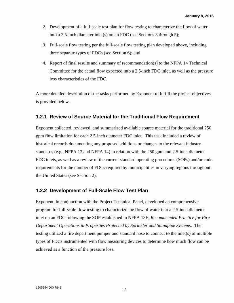
January 8, 2016
1505254.000 7849 2
2. Development of a full-scale test plan for flow testing to characterize the flow of water
into a 2.5-inch diameter inlet(s) on an FDC (see Sections 3 through 5);
3. Full-scale flow testing per the full-scale flow testing plan developed above, including
three separate types of FDCs (see Section 6); and
4. Report of final results and summary of recommendation(s) to the NFPA 14 Technical
Committee for the actual flow expected into a 2.5-inch FDC inlet, as well as the pressure
loss characteristics of the FDC.
A more detailed description of the tasks performed by Exponent to fulfill the project objectives
is provided below.
1.2.1 Review of Source Material for the Traditional Flow Requirement
Exponent collected, reviewed, and summarized available source material for the traditional 250
gpm flow limitation for each 2.5-inch diameter FDC inlet. This task included a review of
historical records documenting any proposed additions or changes to the relevant industry
standards (e.g., NFPA 13 and NFPA 14) in relation with the 250 gpm and 2.5-inch diameter
FDC inlets, as well as a review of the current standard operating procedures (SOPs) and/or code
requirements for the number of FDCs required by municipalities in varying regions throughout
the United States (see Section 2).
1.2.2 Development of Full-Scale Flow Test Plan
Exponent, in conjunction with the Project Technical Panel, developed an comprehensive
program for full-scale flow testing to characterize the flow of water into a 2.5-inch diameter
inlet on an FDC following the SOP established in NFPA 13E, Recommended Practice for Fire
Department Operations in Properties Protected by Sprinkler and Standpipe Systems. The
testing utilized a fire department pumper and standard hose to connect to the inlet(s) of multiple
types of FDCs instrumented with flow measuring devices to determine how much flow can be
achieved as a function of the pressure loss.

January 8, 2016
1505254.000 7849 3
1.2.3 Full-scale Flow Testing
The full-scale flow testing involved testing of multiple FDCs installed on a test manifold. All
tests utilized actual suppression equipment and procedures, including a fire department pumper
apparatus and hose. All water flow activities were conducted by qualified active duty
firefighters. Exponent collaborated with the Maryland Fire and Rescue Institute (MFRI), who
provided their facilities and expertise. Their training staff was utilized to provide technical
insight on standard FDC connection procedures and to facilitate the tests. Active duty
firefighters from MFRI performed all water flow activities.
1.2.4 Report and Summary of Best Practices
Exponent collected and processed the test data from the full-scale testing program in this formal
research engineering report. This report provides:
1. An overview of the project work to date;
2. A summary of the full-scale test data;
3. Comparison with current NFPA guidance; and
4. Identification of future potential research.
1.3 Project Assumptions
The following are key assumptions and limitations related to the test program:
The FDCs procured for this test program are only a small set of samples intended to
provide a preliminary understanding of FDC hydraulic characteristics (i.e., flow and
pressure loss) in a broad range of FDC configurations. The test results from this study
are not intended to be representative of all FDCs available or used in systems.
FDC flow rate data obtained from this test is specific to the upstream supply line
configuration and components used in this test program (i.e., hoses and fittings).
These upstream supply components, including the fire department pumper, are typical
equipment used during fire department operations. Friction losses associated with the
upstream equipment are well documented.
January 8, 2016
1505254.000 7849 4
2 Literature Review
2.1 Current FDC Requirements
FDC requirements are currently defined by NFPA 14 for standpipe systems and NFPA 13 for
sprinkler systems. The purpose of a standpipe system is to eliminate the need for excessively
long runs of hose for manual firefighting inside a structure. Standpipes allow firefighters to
connect a hose to a permanently installed valve on the standpipe system inside a building and
fight a fire with a shortened amount of hose. FDCs allow firefighters to supplement, or fully
supply, the standpipe water flow from an external water source, such as a hydrant or pond,
through a pumper apparatus to the structure. The current (2013) edition of NFPA 14 requires
that the full standpipe system demand be available from FDCs, and states in Section 7.12.3:
Fire department connection sizes shall be based on the standpipe system demand and
shall include one 2 1⁄2 in. (65 mm) inlet per every 250 gpm (946 L/min).
In contrast, for sprinkler systems, the current (2013) edition of NFPA 13 states in Section 6.8.1,
that FDC(s) shall consist of two (2) 2.5-inch inlets, unless otherwise designated by the Authority
Having Jurisdiction (AHJ), or where piped to a 3-inch or smaller riser.5 Further clarification is
provided in the annex, which states that the purpose of the FDC is to supplement the water
supply, but not necessarily provide the entire sprinkler system demand. NFPA 13-2013 further
states that FDCs are not intended to deliver a specific volume of water.6
The FDC requirements in NFPA 14 are more explicit than the requirements in NFPA 13 and
specifically call for FDCs to have one (1) 2.5-inch diameter hose connection for each 250 gpm
of system demand. A typical standpipe system in a fully sprinkler protected facility may need
up to four (4) FDC inlets to satisfy the system demand. Where adopted, the requirements of
both standards must be met, including those requiring the more restrictive FDC capacity of 250
gpm for every 2.5-inch diameter inlet in a combined sprinkler/standpipe system.
5 NFPA 13-2013 Section 6.8.1 6 NFPA 13-2013 Section A.6.8.1

January 8, 2016
1505254.000 7849 5
NFPA 14 also requires manual standpipe systems be designed to provide 100 psi at the topmost
outlet, with hydraulic calculations terminating at the FDC.7 The intent of the standard is for a
fire department pump to be the source of flow and pressure8, however, pressure loss values for
the FDC itself are not provided in the standard and data from the manufacturers is currently
unavailable (see Section 2.4).
Although not directly related to FDC inlet flow, the 2016 edition of NFPA 20, Installation of
Stationary Pumps for Fire Protection, offers an interesting correlation of flow (pump rating in
gpm) to the number of hose valve outlets required. For pumps rated from 100 to 1,000 gpm, the
number of outlets required approximately follows a similar 250 gpm per 2.5-inch valve ratio as
prescribed in NFPA 14, however, there is more variability at certain higher flows (above 1,250
gpm), where greater than 250 gpm is allowed per each 2.5-inch diameter valve.9
2.2 History of the NFPA 14 Requirement
The current FDC requirement in Section 7.12.3 of NFPA 14 first appeared in the Report on
Proposals for the 2007 edition of the standard. The substantiation of the request states that the
proposal is the result of the Standpipe Task Group, which met in June 2004 and forwarded its
recommendations to the Technical Committee on Standpipes for action.10,11 Since it first
appeared in the 2007 edition of NFPA 14, Section 7.12.3 has resulted in proposals to remove the
restriction based on manual standpipe pumper tests that indicate 2.5-inch diameter inlets on an
FDC are capable of significantly more flow.12 One response to a proposal to modify the section
states that the restriction is intended to simplify and assist contractors in understanding how
many inlets to provide for firefighting operations, not just for testing.13 The 2.5-inch inlet flow
requirement of 250 gpm is understood to be a conservative value under ideal delivery conditions
and allows for redundancy for firefighting operations in the event that an FDC is lost.14 Other
7 NFPA 14-2013 Section 7.8.1.2. 8 NFPA 14-2013 Section A.7.8.1.2. 9 NFPA 20-2016 Table 4.27(a). 10 NFPA 14 Report on Proposals 2005, 14-58 Log #47. 11 Minutes have been requested for the June 2004 meeting of the Standpipe Task Group. 12 NFPA 14 Report on Proposals 2012, 14-70 Log #16. 13 NFPA 14 Report on Comments 2012, 14-35 Log #38. 14 NFPA 14 Report on Proposals 2012, 14-70 Log #16.

January 8, 2016
1505254.000 7849 6
reasons for the fixed inlet flow requirement include the anticipation of pressure loss possible
due to the location of fire hydrants and arrangement of supply hose from the hydrant to a
pumper and from the pumper to the FDC, including the distance traveled and elevation
changes.15
2.3 Jurisdictional Adoptions and Procedures
A survey of several major municipalities in varying regions throughout the United States was
conducted to determine their current code adoptions relative to standpipe systems and specific
requirements for number of FDC inlets serving standpipe systems, as shown in Figure 1. In
addition, literature was reviewed to determine the most common arrangement for equipment
supplying an FDC.
Figure 1 Map of municipalities included in survey
15 NFPA 14 Report on Comments 2012, 14-34 Log #9.

January 8, 2016
1505254.000 7849 7
2.3.1 Code Adoptions
2.3.1.1 Los Angeles, California
The 2014 City of Los Angeles Fire Code adopts portions of the California Fire Code (CFC) and
the 2012 edition of the International Code Council (ICC) International Fire Code (IFC).16
Section 905.2 states that standpipe systems shall be installed according to an amended version
of NFPA 14-2013. The amended portion does not affect the requirements of Section 7.12.3.17
The current Los Angeles Municipal Code (6th edition) outlines the amendments to NFPA 14 and
the amended portion does not affect the requirements of Section 7.12.3.18 In addition to Section
7.12.3, the previous edition of the Los Angeles Municipal Code also mandated the number of
FDCs based on the height of the highest outlet above the FDC and the number of the standpipe
risers.19 This requirement no longer applies to new construction after January 2014.
2.3.1.2 New York, New York
The 2014 New York City Fire Code, Section 905.2, states that standpipe systems shall be
installed in accordance with the construction codes, including the Building Code.20 The 2014
New York City Building Code, Section 905.2, states that standpipe systems shall be installed
according to an amended version of NFPA 14-2007. The amended portion deletes Section
7.12.3.21 Instead, the New York City Administrative Code, Section 27-940, requires at least one
siamese connection, an FDC with two-way inlets, for each 300 feet of exterior building wall.
2.3.1.3 Chicago, Illinois
The Municipal Code of Chicago, Title 15, Fire Prevention, Section 15-16-1020, requires at least
one siamese connection on each street exposure, to a limit of two street exposures. If any
16 http://www.ecodes.biz/ecodes_support/free_resources/2014LACityFire/14Fire_main.html, Section 101, as of
September 21, 2015. 17 2014 Los Angeles Fire Code Chapter 80, Referenced Standards. 18 City of Los Angeles Municipal Code, 6th Edition, Ordinance No. 182847, Section 94.2020.0, NFPA 14. 19 City of Los Angeles Municipal Code, 5th Edition, Ordinance No. 179324, Section 94.2020.8, Table 4.8.2 20 http://www.nyc.gov/html/fdny/apps/pdf_viewer/viewer.html?file=firecode_chap_09.pdf§ion=firecode_2014,
as of September 21, 2015 21 2014 New York City Building Code Appendix Q, Modified National Standard for Automatic Sprinkler,
Standpipe, Fire Pump and Fire Alarm Systems.

January 8, 2016
1505254.000 7849 8
exposure is more than 250 feet long, two siamese connections are required, spaced at least 200
feet apart.22
2.3.1.4 Atlanta, Georgia
The state of Georgia adopts State Minimum Fire Safety Standards, based on the 2012 edition of
the IFC, with modifications. Section 905.1 states that standpipe systems shall be installed in
accordance with NFPA 14-2013, as amended. The amended portion does not affect the
requirements of Section 7.12.3, however, a new section (7.12.4) is added that states that the
location of FDCs shall be approved by the Fire Chief.23
2.3.1.5 Orlando, Florida
The Orlando Building Code incorporates the 2014 Florida Building Code24, which is based on
the 2012 edition of the ICC International Building Code (IBC). Section 905.2 states that
standpipe systems shall be installed in accordance with the Florida Building Code and NFPA
14-2010.25 In addition, the City of Orlando Fire Prevention Code adopts NFPA 1, Uniform Fire
Code, Chapter 13, Fire Protection Systems, and amends Section 13.2.2.1 to state that two (2)
siamese connections shall be provided in the path of fire department access, one at each end of
the building or as remotely located as possible.26
2.3.1.6 Kansas City, Missouri
The Kansas City, Missouri Code of Ordinances adopts the 2012 edition of the IBC, with
amendments.27,28 Section 905.2 of the 2012 IBC states that standpipe systems shall be installed
in accordance with NFPA 14-2010. The amended portion does not affect the requirements of
NFPA 14 Section 7.12.3.
22 http://www.amlegal.com/nxt/gateway.dll/Illinois/chicagobuilding/buildingcodeandrelatedexcerptsofthemunic?
f=templates$fn=default.htm$3.0$vid=amlegal:chicagobuilding_il; Current through March 18, 2015. 23 Georgia Minimum Fire Safety Standards (Chapter 120-3-3), effective January 1, 2015. 24 Orlando, Florida Code of Ordinances, Supplement 57, Update 2, Chapter 13, Building Code. 25 Florida Building Code, Building, 5th Edition (2014), Chapter 35, Referenced Standards. 26 Orlando, Florida Code of Ordinances, Supplement 57, Update 2, Chapter 24, Fire Prevention Code, Section
24.27. 27 Kansas City, Missouri Code of Ordinances, Article II, Sec. 18-40. 28 The Kansas City, Missouri Code of Ordinances further adopts the 2000 edition of the IFC, with amendments, in
Sec. 26-100, however, the 2012 edition of the IBC is the more recent and restrictive adoption of NFPA 14, and therefore prevails.

January 8, 2016
1505254.000 7849 9
2.3.1.7 Fort Worth, Texas
The Fire Code of the City of Forth Worth adopts the 2009 edition of the IFC, with
amendments.29 Section 905.2 of the 2009 IFC states that standpipe systems shall be installed in
accordance with NFPA 14-2007. The amended portion does not affect the requirements of
NFPA 14 Section 7.12.3.
2.3.1.8 Seattle, Washington
The Seattle Building Code adopts the 2012 edition of the IBC, with amendments.30 Section
905.2 of the 2012 IBC states that standpipe systems shall be installed in accordance with NFPA
14-2010.
2.3.1.9 District of Columbia
The 2013 District of Columbia Fire Code is based on the 2012 edition of the IFC.31 Section
905.2 states that standpipe systems shall be installed according to NFPA 14-2010, with
exceptions. The exceptions do not affect the requirements of Section 7.12.3.32
2.3.1.10 Las Vegas, Nevada
The Municipal Code of the City of Las Vegas adopts the 2012 edition of the IFC, along with the
Southern Nevada Fire Code Amendments.33 Section 905.2 of the 2012 IFC states that standpipe
systems shall be installed according to NFPA 14-2010. The Southern Nevada Fire Code
Amendments change the requirements of Section 7.12.3 to address the sprinkler system demand
(if a combined system); however, they do not affect the inlet flow requirement of 250 gpm. The
requirements of 7.8.1.1 are changed to require manual standpipe systems be designed to provide
125 psi (instead of 100 psi) at the topmost outlet.34
29 Fort Worth Ordinance Number 19607-03-2011. 30 Seattle Municipal Code, Supplement 2, Update 2, Title 22, Subtitle I, Building Code. 31 http://www.ecodes.biz/ecodes_support/Free_Resources/2013DistrictofColumbia/13Fire/13DCFire_main.html, ,
as of September 21, 2015 32 2013 District of Columbia Fire Code, Chapter 80, Referenced Standards. 33 Municipal Code of the City of Las Vegas, Supplement 23, Title 16, Chapter 16.16, International Fire Code. 34 2014 Southern Nevada Fire Code Amendments.

January 8, 2016
1505254.000 7849 10
2.3.2 Standpipe Firefighting Operations
A review of the literature revealed that there is scarce information currently published regarding
the arrangement and connection of hose from the water source, through a fire department
pumper apparatus, to an FDC. A research study by the U.S. Fire Administration recommends
that fire departments have water supply SOPs that establish which units are responsible for
supplying FDCs, possibly including special pumping procedures. The study cites one SOP that
includes details for water supply operations: Dallas, Texas specifies that two pumpers supply
the standpipe system for redundancy or in case higher pressure is required. Dallas also does not
allow the use of “large diameter hose” to connect the pumper to the standpipe.35
There are many studies detailing standpipe operations, however, they focus on the building
interior connections and the attack hose and nozzle configurations. A research study by the
Oakland Fire Department aimed at updating their high-rise firefighting procedures surveyed ten
(10) major municipalities and determined that a majority of the fire departments surveyed use a
2.5-inch hose with a 1 1/8-inch smooth bore nozzle for standpipe operations, however, some use
a 1 ¾-inch hose with a 7/8-inch smooth bore nozzle. The research study further determined that
a high-rise building standpipe system must be augmented by fire apparatus for effective
firefighting practices.36 A similar research study performed by the New Orleans Fire
Department surveyed 12 major municipalities and found that most departments surveyed only
have a casual reference to water supply operations in their SOPs, which instructs the first due
engine to connect to the FDC and supply the system with “appropriate pressure.” Field tests
conducted during the same research study determined that a 1,250 gpm dual stage pump in a
pumper apparatus could develop outlet pressures of 200 to 600 psi.37
The 2015 edition of NFPA 13E provides basic procedures and information for use in fire
department operations involved with automatic sprinkler and standpipe systems. Figure 4.3.4(b)
specifies a minimum 2.5-inch hose to supply the FDC from the pumper for supplementing an
35 U.S. Fire Administration/Technical Report Series, “Special Report: Operational Considerations for Highrise
Firefighting.” USFA-TR-082/April 1996. 36 Edwards, J. “High-Rise Firefighting: An Analysis of Procedures for Operational Effectiveness.” Oakland Fire
Department, Oakland, CA. 37 Savelle, G. “Fire Department High Pressure Pumping Operations at High-Rise Fires.” New Orleans Fire
Department, New Orleans, LA.

January 8, 2016
1505254.000 7849 11
automatic sprinkler system; however, a minimum hose diameter is not specified for standpipe
operations. Instead, Section 6.3.3 states that lines from a pumper should be connected and
charged to the pressure required to give the desired working pressure on the standpipe outlets
being used. In addition, Section 6.3.4.1 states that the pump operator should consider the
following factors in calculating the pump discharge pressure:
Friction loss in the hose supplying the FDC;
Friction loss in the standpipe system itself;
Pressure loss due to the elevation of the nozzles;
The number and details of the attack lines operating from the standpipe; and
The pressure desired at the nozzles.
Pressure losses for fire hoses of various lengths and diameters are well characterized and
documented38, allowing the supply hose diameter to be chosen based on the needs of the fire
department.
2.4 Existing FDC Flow Test Data
Data sheets from six (6) FDC manufacturers were reviewed for existing flow test data or friction
loss information. Of the approximately 30 models reviewed (most with multiple configurations,
i.e., clappers, inlet arrangement, etc.), none currently provide any flow test data or friction loss
information. Most provide (minimum) inlet flow capacities in line with the NFPA 14
requirement for one (1) 2.5-inch diameter inlet per 250 gpm of flow. Three manufacturers
provided pressure ratings on at least one FDC, ranging from 175 to 500 psi.
FDC data sheets generally referenced listings from Underwriters Laboratories (UL) and/or
approval by FM Global (FM). UL 405, Standard for Fire Department Connection Devices, was
reviewed and references NFPA 14 for the installation of FDCs for standpipe systems. UL 405
does not provide flow test data; however, it does specify that FDCs are tested to 300 psig for
38 Scheffey, J.L., et al., Determination of Fire Hose Friction Loss Characteristics, The Fire Protection Research
Foundation, October 2013.

January 8, 2016
1505254.000 7849 12
leakage and strength of body. 39 In addition, FM 1530, Approval Standard for Fire Department
Connections, was reviewed and also does not provide flow test data; however, it specifies that
the minimum rated working pressure shall be 175 psig.40
2.5 Summary
FDCs allow firefighters to supplement, or fully supply, the standpipe water flow from an
external water source, such as a hydrant or pond, through a pumper apparatus to a structure.
NFPA 14 requires that the full standpipe system demand be available from FDCs and requires
one (1) 2.5-inch diameter inlet for every 250 gpm of standpipe demand. The FDC requirements
in NFPA 14 are more prescriptive than those in NFPA 13. In a combined sprinkler/standpipe
system, the more restrictive requirements of NFPA 14 generally apply. In addition, NFPA 14
requires manual standpipe systems be designed to provide 100 psi at the topmost outlet, with
hydraulic calculations terminating at the FDC, however, pressure loss values for the FDC itself
are not provided in the standards and data from the manufacturers is currently unavailable.
Several major municipalities in varying regions throughout the United States were surveyed to
determine their current code adoptions relative to standpipe systems and specific requirements
for number of FDC inlets serving standpipe systems. Of the 10 municipalities surveyed, the
majority adopt NFPA 14 with no modification of the default NFPA 14 FDC inlet flow
requirements. Municipalities that do not adopt NFPA 14 requirements generally use the number
of exposures and length of the building exposure side to determine the number of FDCs
required.
While the current NFPA requirements do not include the number and the length of the building
exposure sides as a factor to determine the number of required FDCs, it is recognized that
certain jurisdictions highlight the need for redundancy of FDCs by taking the building exposures
into consideration. Based on this information, redundancy appears to be an important factor for
overall system reliability.
39 UL 405, 6th Edition, August 23, 2013. 40 FM 1530, August 1970.

January 8, 2016
1505254.000 7849 13
In addition, literature was reviewed to determine the most common arrangement for equipment
supplying an FDC. Although there is a lack of information specific to water supply operations
at high-rise structure fires, it was determined that pressure losses for fire hoses of various
lengths and diameters are well characterized and documented, allowing pressure loss of the
FDC component to be calculated independent of the upstream supply components.

January 8, 2016
1505254.000 7849 14
3 Testing Program Summary
Exponent, with guidance from the Project Technical Panel, conducted a series of flow tests on
common FDCs with the following goals: 1) to determine the maximum flow rate that can be
achieved for each 2.5 inch diameter inlet and 2) to measure the pressure losses associated with
the FDCs as a function of flow rate. Three common types of FDCs were acquired for this test
program, including single, siamese (two-way inlets), and triamese (three-way inlets). A more
detailed description of each acquired FDC is provided in Section 4.
A fire department pumper, Model 2011 Pierce Arrow XT, rated at 2,000 gpm capacity with a
minimum net pressure of 150 psi was utilized to supply water flow from a municipal fire
hydrant. Each FDC inlet was connected via a standard 2.5-inch diameter hose with a 100-foot
length (two 50-foot sections). A pressure transducer was instrumented upstream of each FDC
inlet. Downstream of the FDC outlet, an in-line averaging pitot tube was instrumented to obtain
the total flow rate as well as the pressure loss across the FDC assembly. With the exception of
pressure readings on the supply hoses from the fire department pumper and the differential
pressure on the in-line averaging pitot tube, all pressure measurements were recorded via a data
acquisition system to allow for real-time monitoring of the flow condition to ensure pressure
data during the steady state flow conditions were captured at a target flow rate.
For each flow test, water was charged to the FDC inlet(s) starting from a low flow condition to
develop bulk flow (no greater than 150 gpm), then gradually increased to a target flow rate for
the FDC assembly as outlined in the test matrix (see Table 1). Where multiple FDC inlets were
tested simultaneously, the flow was equally distributed to each inlet. At the respective target
flow rate, a minimum of 2 minutes was allowed for a steady state condition to develop. After a
maximum flow was reached, the flow was gradually decreased to a lower target flow rate and
the measurements were repeated. The achievement of the maximum flow was determined based
on the flow capacity available of from the hydrant, as well as the general safety observations
during the test. As a safety precaution, due to a potential for high velocity flow, it was

January 8, 2016
1505254.000 7849 15
determined that the theoretical maximum flow was approximately 750 gpm per each 2.5-inch
diameter FDC inlet (three times the current prescriptive requirement of 250 gpm).41
A detailed description of the test apparatus setup, measurements, and the test protocols is
provided in Section 5.
Table 1 Test Matrix
Test No.
FDC ID FDC Type Test ID* Flow to Inlet
Number Target Flow [gpm]
1 FDC-1 Single FDC-1-1 1 250, 500, Max
2 FDC-2 Single FDC-2-1 1 250, 500, Max
3 FDC-3 Single FDC-3-1 1 250, 500, Max
4 FDC-4 Siamese
FDC-4-1 1 250, 500, Max
5 FDC-4-2 1 and 2 500, 1000, Max
6 FDC-5 Siamese
FDC-5-1 1 250, 500, Max
7 FDC-5-2 1 and 2 500, 1000, Max
8
FDC-6 Triamese
FDC-6-1A 1 250, 500, Max
9 FDC-6-1B 2 (center inlet) 250, 500, Max
10 FDC-6-2 1 and 2 500, 1000, Max
11 FDC-6-3 1, 2, and 3 750, 1200, Max
* Test ID nomenclature used in this test program follows the format: XXX-X-Y, where “XXX-X” is FDC ID and “-Y” represents the number of charged inlet(s).
41 Water flow at 750 gpm through a 2.5-inch diameter conduit will result in a flow velocity of approximately 49
ft/s.

January 8, 2016
1505254.000 7849 16
4 FDC Descriptions
In conjunction with FPRF, Exponent procured a total of six (6) FDCs for testing. A description
of each FDC procured is provided in Table 2, below.
Table 2 FDC Descriptions
FDC ID FDC Type Description Figure Manufacturer
FDC-1 Single
Flush single inlet
Material: Brass
Size: 2.5-in x 2.5-in
Figure 3 A
FDC-2 Single
Flush single inlet
Material: Brass
Size: 2.5-in x 2.5-in
Figure 4 B
FDC-3 Single
Flush single inlet
Material: Brass
Size: 2.5-in x 2.5-in
Figure 5 C
FDC-4 Siamese
Freestanding siamese with single clapper two-way inlet
Material: Brass
Size: 4-in x 2.5-in x 2.5-in
Figure 6
Figure 7 B
FDC-5 Siamese
Projecting siamese with double clappers two-way inlets
Material: Brass
Size: 4-in x 2.5-in x 2.5-in
Figure 8
Figure 9 D
FDC-6 Triamese
Flush triamese with triple clappers three-way inlets
Material: Brass
Size: 6-in x 2.5-in x2.5-in x 2.5-in
Figure 10 B
4.1 Single FDCs
Three (3) single FDCs (FDC-1, FDC-2, and FDC-3) from three different manufacturers were
procured for testing. All three FDCs procured were flush type with a 2.5-inch American
National Fire Hose Screw Threads (NH) swivel female inlet and a 2.5-inch National Pipe
Thread (NPT) female outlet. The appearances and dimensions of all three single FDCs were
very similar, but FDC-1 was slightly longer, while FDC-2 and FDC-3 were almost identical.
All three single FDCs were equipped with rubber gaskets on the inlet side, although there were

January 8, 2016
1505254.000 7849 17
slight variations in gasket thickness and width among the three single FDCs. A comparison of
the single FDCs is provided in Figure 2. None of the single FDCs were equipped with clappers.
4.2 Siamese FDCs
Two (2) siamese FDCs (FDC-4 and FDC-5) from different manufacturers were obtained for
testing. Both siamese FDCs contained two (2) 2.5-inch NH swivel female inlets equipped with
rubber gaskets and a 4-inch NPT female outlet. FDC-4 was a freestanding type (integral 90°
orientation) with a single inlet clapper, as shown in Figure 6 and Figure 7. FDC-5 was a
projecting type with dual inlet clappers, as shown in Figure 8 and Figure 9. The clappers in
both siamese FDCs (FDC-4 and FDC-5) were not equipped with a spring-loaded closing
mechanism (snoot type clappers).
4.3 Triamese FDC
One triamese FDC (FDC-6) was procured for testing, as shown in Figure 10 and Figure 11. The
triamese FDC was a flush wall-mount type with three (3) 2.5-inch female NPT inlets with triple
inlet clappers and a 6-inch NPT female outlet. No rubber gasket was provided with the triamese
FDC and the clappers were not equipped with a spring-loaded closing mechanism.
Figure 2 Single FDCs
FDC-1 FDC-2 FDC-3

January 8, 2016
1505254.000 7849 18
Figure 3 Single flush FDC (FDC-1)
Figure 4 Single flush FDC (FDC-2)

January 8, 2016
1505254.000 7849 19
Figure 5 Single flush FDC (FDC-3)
Figure 6 Siamese freestanding FDC (FDC-4)

January 8, 2016
1505254.000 7849 20
Figure 7 Siamese freestanding FDC (FDC-4); view from bottom showing single clapper
Figure 8 Siamese projecting FDC (FDC-5)

January 8, 2016
1505254.000 7849 21
Figure 9 Siamese projecting FDC (FDC-5); view through outlet showing double inlet clappers
Figure 10 Triamese flush FDC (FDC-6)

January 8, 2016
1505254.000 7849 22
Figure 11 Triamese flush FDC (FDC-6); view through inlet showing clappers

January 8, 2016
1505254.000 7849 23
5 Test Setup
The FDC flow testing was performed at MFRI in College Park, Maryland.42 The overall intent
of the testing was to provide a repeatable scientific experiment that characterizes the flow
characteristics at the maximum actual flow rate for each 2.5-inch FDC inlet. The data generated
was then used to support the current 250 gpm requirement or recommend a change to the
standard. The following are key assumptions related to the testing:
The FDCs procured for this test program are only a small set of samples intended to
provide a preliminary understanding of FDC hydraulic characteristics (i.e., flow rate and
pressure loss). The test results from this study are not representative of all available
FDCs of similar types.
FDC flow rate data obtained from this test program is specific to the upstream supply
line configuration and components used in this test program (i.e., hoses and fittings).
These upstream supply components are commonly used during fire department
operations and their friction loss characteristics are well documented.
A series of flow tests were conducted on common FDCs with the following objectives: 1) to
determine the maximum flow rate that can be achieved for each 2.5 inch inlet and 2) to measure
the pressure losses associated with each type of FDC as a function of the flow rate. Data
collected during these tests included:
Total FDC discharge flow rates;
Pressure losses;
Test observations;
Still photography; and
High definition video.
42 MFRI provides a world class test facility for research, development, and testing of fire protection systems and
fire service technologies in live-fire conditions.

January 8, 2016
1505254.000 7849 24
MFRI provided the facility for the flow tests, the fire department apparatus and water supply,
and qualified personnel to conduct the actual water flow.
Exponent performed the following tasks:
Test observations and data monitoring;
Providing and installing the flow rate and pressure measurement devices and data
acquisition system (DAQ);
Still photography; and
High definition video recording;
5.1 Test Apparatus
The test apparatus setup is described herein as follows.
5.1.1 Water Flow Activities
Water flow activities were handled by MFRI. All tests were conducted by three active duty
firefighters utilizing a fire department pumper43, Model 2011 Pierce Arrow XT, rated at 2,000
gpm capacity and capable of charging water through up to six (6) 2.5-inch hose lines with a
minimum net pressure of 150 psi per NFPA 1901, Standard for Automotive Fire Apparatus.
The fire department pumper used in this test program is shown in Figure 12.
The test apparatus utilized water from a municipal hydrant producing a static pressure of 100 psi
and a residual pressure of 50 psi at a 3,757 gpm flow rate.44 Water was discharged into a
collection funnel, allowing the water to flow into a drafting basin with its drainage open during
testing (see Figure 13 and Figure 14).
43 Engine 122, College Park Volunteer Fire Department, Maryland. 44 Hydrant Test – Hydrant 62, dated 6/1/2013

January 8, 2016
1505254.000 7849 25
Figure 12 Fire department pumper apparatus

January 8, 2016
1505254.000 7849 26
Figure 13 Test facility and drafting basin at MFRI
Figure 14 Test platform with single FDC and test apparatus secured to test platform

January 8, 2016
1505254.000 7849 27
Figure 15 Test platform with siamese FDC and test apparatus secured to test platform
Figure 16 Test platform with triamese FDC and test apparatus secured to test platform

January 8, 2016
1505254.000 7849 28
5.1.2 Supply Hose Line
In all flow tests, 2.5-inch diameter double-jacket rubber-lined standard fire hoses with a total
length of 100 feet (two 50-foot length sections) were used to supply water to the FDC inlets.
The use of a 2.5-inch diameter hose eliminated the need for any hose adapters before connecting
to the FDC inlets and the 100-foot length was required given the location of the fire department
pumper and the test apparatus during the test.
While the total flow rate obtained from this test program is specific to the selected hose size and
configuration, the pressure loss for each FDC is a function of the flow rate and is independent of
the hose configuration or pressure losses from the upstream components. Pressure losses for
fire hoses with different lengths and diameters are well characterized and documented.45
5.1.3 Flow Test Assembly
During each flow test, the FDC assembly was secured to the test platform to allow for safely
discharging water into the drafting basin. A pressure transducer was instrumented upstream of
each FDC inlet. Downstream of the FDC outlet, an in-line averaging pitot tube was
instrumented to obtain the total flow rate, as well as the pressure drop across the FDC. The
inlets and outlet of the FDC were connected with steel pipes with appropriate lengths to allow
for accurate pressure measurements at approximately five times the pipe diameter (5D) length
upstream and up to ten times the pipe diameter (10D) length downstream of the FDC. With the
exception of pressure readings on the supply hoses from the fire department pumper and the
differential pressure on the in-line averaging pitot tube, all pressure measurements were
recorded via a data acquisition system to allow for real-time monitoring of the flow condition to
ensure pressure data during the steady state flow conditions were captured at a target flow rate.
Calibrated pressure transducers (Omega PX309) were used for the pressure measurements in
this test program. Figure 17 through Figure 19 provide the schematics for the flow test
assembly.
45 Scheffey, J.L., et al., Determination of Fire Hose Friction Loss Characteristics, The Fire Protection Research
Foundation, October 2013.

January 8, 2016
1505254.000 7849
29
Figure 17 Flow test schematic for single FDC
Figure 18 Flow test schematic for siamese FDC
Supply from Street
Hydrant
Single FDC
PU1,n
In-line Pitot
Manometer for Flow Rate Measurement
PD, t
Pressure Transducer
Pumper
Pp1
Discharge to Drafting
Basin 2.5” Hose Line 100 ft 1 ft (~5D)
2.5” Steel Pipe 2 ft (~10D)
2.5” Steel Pipe
NTS
Supply from Street
Hydrant
Siamese FDC
PU1, n
In-line Pitot
PD, t
Pressure Transducer
Pumper
Pp1
Discharge to Drafting
Basin
2.5” Hose Line
2.5” Steel Pipes 3 ft (~10D)
4” Steel Pipe
PU2, n
2.5” Hose Line
100 ft
Pp2
1 ft (~5D)
NTS
Manometer for Flow Rate Measurement

January 8, 2016
1505254.000 7849
30
Figure 19 Flow test schematic for triamese FDC
Supply from Street
Hydrant
Triamese FDC PU1, n
In-line Pitot
PD, t
Pressure Transducer
Pumper
Pp1
Discharge to Drafting
Basin
2.5” Hose Line
2.5” Steel Pipes
3 ft (~6D)6” Steel Pipe
PU2, n
2.5” Hose Line
100 ftPp2
1 ft (~5D)
PU3, n
Pp3
NTS
Manometer for Flow Rate Measurement

January 8, 2016
1505254.000 7849 31
5.1.4 Flow Rate Measurements
During the flow testing, the FDC flow rate was determined based on the measurements of the
differential pressure between the total pressure (stagnation pressure) and the normal pressure
using an in-line averaging pitot tube instrumented downstream of the FDC. Three different
models of in-line averaging pitot tubes (Dwyer DS-300-2-1/2, DS-300-4, and D-S400-6) were
used depending upon the type and outlet size of the FDC. A schematic for the in-line pitot tube
is shown in Figure 20.
Figure 20 Flow rate measurement with in-line averaging pitot tube
A calibrated digital manometer (Dwyer 477-7-FM) was used to measure the differential
pressures at the in-line pitot tube, which were then used to calculate the total discharge flow rate
based on the following expression46:
46 Dwyer Instruments, Inc. DS Flow Sensors – Installation and Operating Instructions Flow Calculations, FR72-
440451-01 Rev. 2, July 2004
Flow Direction
Connecting to digital manometer and
pressure transducer
Connecting to digital manometer

January 8, 2016
1505254.000 7849 32
5.668 ∙ ∆ / (1)
where Q is the flow rate expressed in gpm; K is the flow coefficient (0.62 for a 2.5-inch pipe,
0.67 for a 4-inch pipe, and 0.71 for a 6-inch pipe); D is the inside pipe diameter in inches; P is
the differential pressure in inches-of-water-column; and Sf is specific gravity of water at the
flowing condition.47
5.1.5 Pressure Loss Measurements
In general, pressure losses through the FDC can be theoretically estimated based on the
difference between the total pressures measured upstream and downstream of a hydraulic
component when the change in elevation is negligible. The total pressure (Pt) is given as a sum
of the normal pressure (Pn) and the velocity pressure (Pv):
(2)
The normal pressure is the pressure acting against, or perpendicular to the hydraulic component
wall. The velocity pressure is a measure of the energy required to keep the water in motion.
The velocity pressure always acts in the direction of water flow, while the normal pressure acts
perpendicular to the velocity pressure.48
For this test program, the pressure loss associated with each FDC was determined based on the
difference between the total pressure obtained from upstream and downstream of the FDC and
the pressure losses associated with the steel pipes upstream and downstream of the FDC. The
downstream total pressure was directly measured using the in-line averaging pitot tube, whereas
the upstream total pressure was estimated from the summation of the measured upstream
normal pressure and the calculated velocity pressure, which is given as49:
0.001123 / (3)
47 At the time of the test, water temperature was approximately 60°F corresponding to the specific gravity of 1. 48 NFPA, Automatic Sprinkler Systems Handbook, 10th Edition, p. 800 49 NFPA 13-2013, Section 23.4.2.2

January 8, 2016
1505254.000 7849 33
where Q is inlet flow rate in gpm and D is the inside pipe diameter in inches. For single FDCs,
the inlet flow rate is equal to the measured discharge flow rate. For the siamese and triamese
FDCs, the inlet flow rate is determined based on the assumption that the inlet flows are equally
divided and conservation of mass applies (i.e., the sum of the inlet flows equals the discharge
flow).
5.1.6 DAQ System
With the exception of pressure readings on the supply hoses from the fire department pumper
and the differential pressure on the in-line averaging pitot tube, all pressure measurements were
recorded via a Fluke 2638A Hydra Series III DAQ system to allow for real-time monitoring of
the pressures and flow conditions at one second intervals (1 Hz). The DAQ system was used to
capture the pressure data during steady state flow conditions, as well as to post process the
pressure data to minimize the potential effect of vibration and other measurement noise during
the flow testing.
5.1.7 Still Photography and High Definition Video
Still photography and high definition video were recorded during the flow testing. Still
photography was captured using a Nikon D3300 digital camera and high definition video was
captured using multiple Canon Vixia high definition camcorders.
5.2 Flow Test Protocols
The operation of the fire department apparatus and water flow activities were conducted by
MFRI and qualified personnel (i.e., active duty firefighters) in accordance with NFPA 13E.
Exponent instrumented the measurement devices, recorded observations, and monitored the data
collected during testing.
The test preparation protocol was as follows:
1. Connect the FDC inlet(s) and outlet to the upstream and downstream steel pipe sections
that were pre-instrumented with appropriate pressure transducers and an in-line pitot
tube.

January 8, 2016
1505254.000 7849 34
2. Secure the FDC and test apparatus to the test platform.
3. Connect the 2.5-inch supply hose lines to the inlet steel pipe sections and to the fire
department pumper.
4. Straighten the supply hose line as much as possible to minimize the pressure loss.
5. Ensure the drainage to the drafting basin and the general test assembly are in proper
operating condition.
6. Initialize and ensure proper operation of the fire department pumper (conducted by
MFRI) in accordance with NFPA 1901, NFPA 13E, and SOPs, as approved by MFRI
and the qualified operator(s).
The test protocol was as follows:
1. Start the DAQ system and allow for background data to be collected for a minimum of 1
minute.
2. Start high definition video recording simultaneously with data collection.
3. Charge water to the FDC inlet(s) with low flow condition (no greater than 150 gpm) and
ensure no or minimal leaks on the test assembly and proper discharge of water to the
drafting basin.
4. Monitor the flow rate on DAQ system and gradually increase the flow to the target flow
rates as outlined in the test matrix.
5. Record the pressure readings at the pumper for the upstream supply hose.
6. When the target flow rate is reached, allow a minimum of 2 minutes for steady state flow
conditions to develop.
7. Repeat Steps 4 and 5 to collect data at the next target flow rate.
8. After the maximum flow is reached and the data collected, gradually decrease to a lower
target flow rate and repeat the measurements.
9. Still photographs were recorded throughout the test as necessary.
10. After the completion of all data collection for all target flow rates, stop the fire
department pumper, and turn of all data collection equipment.

January 8, 2016
1505254.000 7849 35
6 Test Results
The following section is a presentation of the data collected during the flow tests along with a
brief discussion of the data processing to determine the flow rate achieved during the test and
ultimately the pressure losses associated with the FDCs.
The FDC flow testing was performed at the MFRI facility located at 4500 Paint Brach Parkway,
College Park, Maryland 20742 on October 26, 2015. A total of eleven (11) tests were
conducted; three (3) tests using three single FDCs (FDC-1 through FDC-3), four (4) tests using
two siamese FDCs (FDC-4 and FDC-5), and four (4) tests using one triamese FDCs (FDC-6).
Figure 21 through Figure 23 provide representative views of the flow testing for each FDC type.
As shown in Figure 24, the differential pressures were measured using a digital manometer at
the in-line pitot tube. Using Eq. (1) the differential pressures were then used to calculate the
total discharge flow rates presented in Table 3.
The pressure measurements in this test program included the total pressure measured
downstream of the discharge pipe ( , ) and the normal pressure(s) measured upstream of the
respective inlet pipe(s) ( , , , and , ). At their respective flow rates, the pressures
were recorded for a minimum of two minutes to ensure that steady state flow conditions were
established. The average pressure data over the steady state period are reported in Table 3.
Additionally, detailed pressure data recorded at the pumper for each test is provided in
Appendix A, for reference. The pressure losses associated with the FDCs were determined
directly based on the pressure measurement downstream of the hose lines, as discussed in this
section, independently from the pumper pressure data.

January 8, 2016
1505254.000 7849 36
Figure 21 Single FDC flow test
Figure 22 Siamese FDC flow test

January 8, 2016
1505254.000 7849 37
Figure 23 Triamese FDC flow test
Figure 24 Measurement layout
From Pumper
NTS
FDC
PU1, n
In-line Pitot
Manometer for Flow Rate Measurement
PD, t
Pressure Transducer
Discharge 2.5” Hose Inlet pipe Discharge pipe
Discharge pipe pressure loss
∆ , )
Inlet pipe pressure loss
∆ , )
FDC Pressure Loss
(∆ )

January 8, 2016
1505254.000 7849 38
Table 3 Test Measurement Results
Test ID FDC Type
Flow to
Inlet(s)
Manometer [inch-H2O]
Total Discharge Flow [gpm]
Average Pressure [psi]50 FDC Pressure Loss [psi] PD,t PU1,n PU2,n PU3,n
FDC‐1‐1
Single 1
160 271 3.4 2.0 ‐ ‐ 0.2
551 503 12.2 7.6 ‐ ‐ 1.2
1047 693 23.6 14.0 ‐ ‐ 1.3
FDC‐2‐1
Single 1
172 281 3.7 2.0 ‐ ‐ 0.0
495 478 10.3 5.7 ‐ ‐ 0.6
503 481 11.0 6.1 ‐ ‐ 0.4
926 652 24.7 15.6 ‐ ‐ 0.6
FDC‐3‐1
Single 1
118 233 3.5 2.3 ‐ ‐ 0.0
551 503 11.4 6.6 ‐ ‐ 0.9
962 664 20.7 13.9 ‐ ‐ 3.3
1167 732 26.4 17.6 ‐ ‐ 3.5
FDC‐4‐1
Siamese 1
53 448 1.2 1.1 ‐ ‐ 5.5
101 642 2.4 8.5 ‐ ‐ 14.6
109 618 2.7 5.8 ‐ ‐ 16.7
153 761 3.2 12.0 ‐ ‐ 24.9
FDC‐4‐2
Siamese 2
216 906 5.8 8.5 8.3 ‐ 8.1
304 1073 7.7 9.3 10.5 ‐ 9.2
401 1232 10.1 12.5 14.2 ‐ 12.5
478 1345 11.9 17.5 16.3 ‐ 17.5
588 1492 13.7 19.3 19.1 ‐ 20.3
FDC‐5‐1
Siamese 1
80 552 1.4 1.3 ‐ ‐ 8.3
129 700 3.1 6.5 ‐ ‐ 17.1
159 777 4.1 8.2 ‐ ‐ 20.9
FDC‐5‐2
Siamese 2
198 865 5.1 8.6 8.1* ‐ 8.4
255 982 6.9 19.4 19.7* ‐ 18.8
445 1298 10.5 22.2 23.8* ‐ 22.8
551 1445 12.8 27.8 24.4* ‐ 28.9
FDC‐6‐1A
Triamese 1
14 554 0.28 7.4 ‐ ‐ 15.8
15 566 0.35 11.4 ‐ ‐ 20.1
FDC‐6‐1B
Triamese 1
44 979 0.9 10.6 ‐ ‐ 36.9
46 1006 0.9 10.4 ‐ ‐ 38.3
53 1076 1.8 5.9 ‐ ‐ 36.9
FDC‐6‐2
Triamese 2
47 1012 1.1 2.3 0.2* ‐ 8.4
63 1171 1.2 6.0 2.0* ‐ 14.4
98 1467 1.8 10.4 10.4* ‐ 23.7
135 1717 2.6 16.8 13.8* ‐ 35.0
FDC‐6‐3
Triamese 3
92 1420 2.3 7.5 5.1 7.4* 11.5
98 1462 1.9 5.6 5.6 4.5* 10.4
139 1748 3.5 12.6 9.2 8.3* 18.6
141 1755 3.5 10.7 9.2 9.1* 16.7
151 1818 3.7 12.4 9.6 8.1* 18.9
50 Note (*) Supplemental technique is used to determine certain upstream pressure due to cavitation created by hose orientations
during testing.

January 8, 2016
1505254.000 7849 39
The maximum flow for each test was based on the available flow capacity at the hydrant and
additional safety considerations. For this test program, the maximum flows were measured at
732 gpm for single FDCs. For the siamese and the triamese FDCs, the maximum flow rates
achieved were 1,492 gpm and 1,818 gpm, respectively, when all inlets were simultaneously
charged.
As presented in Table 3, the normal pressure(s) measured upstream of the inlet pipe(s) ( , ,
, ,and , ) for siamese and triamese FDCs are relatively similar at their respective flow
rates, with a variation of up to ±3 psi. This observation is supportive of the fact that the inlet
flows to the siamese and triamese FDCs are equally split. As such, only , was used to
further calculate the upstream normal pressure ( , ) based on Eq. (3) as follows:
, , 0.001123 / (4)
where is inlet flow (gpm), and is inside diameter of the inlet pipe (in). In addition, the
pressure loss associated with the FDC is given as:
∆ , ∆ , , ∆ , (5)
where ∆ , and ∆ , are the pressure losses associated with the inlet and outlet pipes
respectively. The pressure loss attributed to the fully developed, steady state, incompressible
flow through a pipe section is estimated based on the Darcy-Weisbach equation as follows:
∆ 0.000216 / , (6)
where is friction loss factor as provided by a Moody diagram, is length of pipe (ft), is water
density (lb/ft3), is flow in pipe (gpm), and is inside diameter of pipe (in). Following Eq. (4),
(5), and (6), the pressure losses that occur between the inlet and the outlet of the FDCs at a
given flow rate are estimated and summarized in the last column of Table 3.

January 8, 2016
1505254.000 7849 40
7 Analysis and Discussion
The following section is a discussion of the data and observations collected during the flow tests
and serves to supplement the presentation of the data in Section 6.
7.1 Single FDC
A total of three single FDCs (FDC-1, FDC-2, and FDC-3) were tested and their pressure losses
as a function of flow rates are presented in Figure 25. The error bars represent a single standard
deviation for the data collected during the steady state flow condition. Also included in Figure
25 are solid lines representing a fitted trend line for the pressure losses as a function of flow rate
based on the following expression:
∆ / , (7)
where is the average pressure loss coefficient for the FDC, is the total discharge flow,
and is the inside diameter of the FDC discharge outlet.
Figure 25 Single FDC pressure loss data
0
1
2
3
4
5
6
0 200 400 600 800
Pressure Loss [psi]
Flow Rate [gpm]
FDC‐1‐1
FDC‐2‐1
FDC‐3‐1
CFDC = 0.0041
CFDC = 0.0032
CFDC = 0.0014

January 8, 2016
1505254.000 7849 41
Based on the test results, the maximum flow rate for the single FDCs during testing was
approximately 730 gpm, 2.8 times the prescriptive requirement of 250 gpm per inlet provided in
NFPA 14. In addition, it is possible that a higher flow rate could have been achieved during the
single FDC testing given the capacity of the water supply and the pumper. However, a limit for
flow of no greater than 750 gpm per inlet was selected due to a safety consideration based on a
high velocity flow (approximately 49 ft/s).
Based on the test results, FDC-2 produced the lowest pressure losses, while FDC-3 provided the
greatest pressure loss among the three single FDCs. While slight differences in the pressure
losses were observed among the three single FDCs, especially at a higher flow rates, the
variation was small (within ±2 psi). The rubber gaskets used in each manufacturer’s FDC are
slightly different in size and thickness, which could account for the variation observed at higher
flow rates.
For the range of the tested flow rates, the pressure losses associated with all tested single FDCs
were generally small. While the error bars suggest a greater variability of the data taken at a
higher flow rate, the maximum pressure loss is expected to be low even at values approximately
three times that of the prescriptive flow rate.
7.2 Siamese FDC
Two siamese FDCs (FDC-4 and FDC-5) were tested, each with only one inlet charged and with
both inlets simultaneously charged. The pressure losses are presented in Figure 26. The error
bars represent a single standard deviation for the data collected during the steady state flow
condition. Also included in Figure 26 are solid lines representing a fitted trend line for the
pressure losses as a function of flow rate based on Eq. (7).
The total flow rate data provided in Figure 26 is the total discharge flow rate measured within
the discharge pipe. Based on the test results, the maximum flow that was achieved during
testing was 777 gpm when only one inlet was charged with water and 1,492 gpm when both
inlets were charged. Similar to the single FDC flow testing, the flow tests for the siamese FDCs
were concluded at the selected maximum flows based on safety considerations.

January 8, 2016
1505254.000 7849 42
As observed in this test program, the greatest pressure loss associated with the siamese FDC
was approximately 25 psi when only one inlet was charged at 761 gpm and 29 psi when both
inlets were charged with a total flow of 1,445 gpm. In general, at a respective total discharge
flow rate, the pressure losses associated with the siamese FDC is optimized (i.e., minimized)
when both inlets are charged.
Figure 26 Siamese FDC pressure loss data
Models of siamese FDCs with varying clapper designs were included in the testing. FDC-4 was
a freestanding type (integral 90° orientation) FDC with a single inlet clapper and FDC-5 was a
wall-mount type FDC with dual inlet clappers (see Figure 6 through Figure 9). When only one
inlet was charged (FDC-4-1 and FDC-5-1 tests), both FDC-4 and FDC-5 produced similar
pressure loss characteristics, with FDC-4 producing slightly higher pressure loss values at a
given flow rate. When both inlets were simultaneously charged (FDC-4-2 and FDC-5-2 tests),
FDC-4 hydraulically performed better, with lower pressure losses compared to FDC-5. Based
on these test results, the presence of an internal clapper can influence the pressure loss
characteristics of the FDC.51 The results also indicated that when only one inlet was charged,
there was no noticeable difference in the pressure losses experienced between FDCs with one or
51 The orientation of the freestanding siamese FDC (FDC-4) during testing may have had some impact on clapper
behavior, but such impact is expected to be minimal.
0
5
10
15
20
25
30
35
40
0 200 400 600 800 1000 1200 1400 1600
Pressure Loss [psi]
Total Flow Rate [gpm]
FDC‐4‐1
FDC‐4‐2
FDC‐5‐1
FDC‐5‐2CFDC = 0.0341
CFDC = 0.0397
CFDC = 0.0095
CFDC = 0.0154

January 8, 2016
1505254.000 7849 43
two inlet clappers. The difference in pressure loss was noticeable in the two-clapper model
when both inlets were charged, as both clappers likely interfered with the flow, creating higher
pressure losses. None of the clappers in the FDCs tested utilized a spring-loaded closing
mechanism.
Further, the results also suggest that the difference in the geometry and shape of FDC-4 and
FDC-5 (i.e., freestanding versus projecting) is less influential to the pressure loss performance
than the presence of the clappers. The geometry of the freestanding model is expected to
inherently contain a greater flow restriction compared to that of the projecting model (i.e., a
convergence plus a sharp, 90° turn versus a convergence alone). However, the fact that the
freestanding model with one clapper (FDC-4) showed better hydraulic performance than the
projecting model with two clappers (FDC-5) indicates that the clappers have a greater impact to
the pressure losses than the geometry of the FDC.52
7.3 Triamese FDC
One triamese FDC (FDC-6) equipped with non-spring-loaded inlet clappers was tested and the
pressure loss data is presented in Figure 27 below, along with error bars for the standard
deviation and the trend lines following Eq. (7). Four separate tests were performed on the
triamese FDC, including two tests with only one inlet charged (FDC-6-1A and FDC-6-1B); one
test with two inlets charged (FDC-6-2) and one test with all three inlets charged (FDC-6-3).
52 This observation is specific to the FDCs tested and may not be universally applicable to all FDCs.

January 8, 2016
1505254.000 7849 44
Figure 27 Triamese FDC pressure loss data
Based on the test results, the maximum flow rate that was achieved was 1,076 gpm when only
one inlet was charged (FDC-6-1B), with the corresponding pressure loss at approximately 40
psi. A maximum flow rate of 1,717 gpm was achieved when two inlets were charged (FDC-6-
2) with a corresponding pressure loss of 35 psi and a maximum flow rate of 1,818 gpm was
achieved when all three inlets were charged (FDC-6-3) with a corresponding pressure loss of 19
psi. For tests FDC-6-2 and FDC-6-3, the tests concluded with their maximum flow rate when
the water supply reached its maximum capacity, i.e. when the hydrant residual pressure reduced
below 20 psi.53 In general, at a respective total discharge flow rate, the pressure loss associated
with the triamese FDC reduced with more inlets connected, similar to the observations made for
the siamese FDCs.
7.4 FDCs Pressure Loss Characteristics
The pressure loss associated with water flow through FDCs can be expressed as a direct
function of a squared flow rate, , a characteristic length (i.e., pipe diameter) to the fifth
power, , and a pressure loss coefficient, , as previously shown in Eq. (7), which follows
53 NFPA, Fire Protection Handbook, 20th Edition, Section 15, Chapter 2, p. 15-24.
0
5
10
15
20
25
30
35
40
0 200 400 600 800 1000 1200 1400 1600 1800 2000
Pressure Loss [psi]
Total Flow Rate [psi]
FDC‐6‐1A
FDC‐6‐1B
FDC‐6‐2
FDC‐6‐3
CFDC = 0.0815
CFDC = 0.0456
CFDC = 0.3496

January 8, 2016
1505254.000 7849 45
the form of the Darcy-Weisbach equation. In general, the pressure loss coefficient is strongly
dependent on the geometry of the component considered and the greater the coefficient, the
greater the pressure loss.54 The FDC pressure loss coefficient, , based on the test results
from this test program are as provided in Table 4.
Table 4 FDC Pressure Loss Coefficients
FDC ID Test ID Flow to Inlets FDC Pressure Loss Coef.
( )
FDC-1 FDC-1-1 1 0.00032
FDC-2 FDC-2-1 1 0.00014
FDC-3 FDC-3-1 1 0.00041
FDC-4 FDC-4-1
FDC-4-2
1
2
0.0396
0.0095
FDC-5 FDC-5-1
FDC-5-2
1
2
0.0341
0.0154
FDC-6
FDC-6-1 (A&B)
FDC-6-2
FDC-6-3
1
2
3
0.3496
0.0815
0.0456
Given that the pressure losses obtained from this test program track reasonably well with the
pressure loss expression in Eq. (7), using the FDC pressure loss coefficient, extrapolated data
based on the pressure loss coefficients for all tested FDCs are presented in Figure 28.
54 Munson et al, Fundamentals of Fluid Mechanics, 5th Edition, 2006, p.437

January 8, 2016
1505254.000 7849 46
Figure 28 FDC pressure loss characteristics
The pressure losses across single FDCs are the lowest in comparison to that of siamese and
triamese FDCs. This observation is consistent with the geometry of the single FDCs that is
typically smooth, clapper-less, and contains very little resistance in comparison to that of the
siamese or the triamese FDCs, where inherent flow restrictions including turns, bends, and
clappers are incorporated as part of their designs.
Based on the pressure loss characteristics of the FDCs obtained in this study, when only one
inlet is charged with a flow rate of 500 gpm, two times that of the current NFPA 14
requirement, a resultant pressure loss of approximately 10 psi or less is expected. This level of
pressure loss is equivalent to a pipe pressure loss created by flowing 500 gpm of water through
an approximately 14-foot length of 2.5-inch schedule (SCH) 40 steel pipe.55 In addition, when
multiple inlets are charged with a flow rate of 500 gpm per inlet, substantial flow rates can be
achieved for siamese and triamese FDCs, while the pressure loss across the FDC is only 55 Based on the Darcy-Weisbach formula for friction loss
0
5
10
15
20
25
30
35
40
45
0 200 400 600 800 1000 1200 1400 1600 1800 2000
Pressure Loss [psi]
Total Flow Rate [gpm]
FDC-3-1 CFDC = 0.0041
FDC-1-1 CFDC = 0.0032
FDC-2-1 CFDC = 0.0014
FDC-6-3 CFDC = 0.0456
FDC-6-2 CFDC = 0.0815
FDC-6-1 CFDC = 0.3496
FDC-4-2 CFDC = 0.0095
FDC-4-1 CFDC = 0.0397
FDC-5-2 CFDC = 0.0154
FDC-5-1 CFDC = 0.0341
250 gpm
NFPA 14 500 gpm

January 8, 2016
1505254.000 7849 47
expected to increase to approximately 15 psi, which is equivalent to flowing 500 gpm through a
21-foot length of 2.5-inch SCH 40 steel pipe.
For a flow rate of 800 gpm per inlet, approximately 3.2 times that of the current NFPA 14
requirement, the pressure loss associated with the FDC is expected to be up to 27 psi when one
inlet is charged and 37 psi when multiple inlets are simultaneously charged. This level of
pressure loss can have a potential impact to the hydraulic performance of the automatic fire
suppression and/or standpipe when relying on the FDC for the water supply.
7.5 Section Summary
Three single FDCs were tested at a maximum flow rate of approximately 730 gpm and resulted
in a corresponding pressure loss of less than 5 psi. Two siamese FDCs were tested at a
maximum flow rate of 777 gpm with one inlet charged and 1,492 gpm with both inlets charged
and resulted in a corresponding pressure loss of less than 30 psi for both configurations. One
triamese FDC was tested at a maximum flow rate of 1,076 gpm with one inlet charged, 1,717
gpm with two inlets charged, and 1,818 gpm with all three inlets charged and resulted in
corresponding pressure losses of 40 psi, 35 psi, and 19 psi, respectively. The tested siamese and
triamese FDCs were provided with clappers, but none were equipped with a spring-loaded
closing mechanism.
The pressure losses across single FDCs were the lowest in comparison to that of siamese and
triamese FDCs.
For a flow rate of 250 gpm per inlet, the pressure loss associated with the FDC was found to be
insignificant (i.e., less than 5 psi). At a flow rate of 500 gpm per inlet (two times current NFPA
14 requirement), the pressure loss was found to be up to approximately 10 psi when only one
inlet was charged and up to 15 psi when multiple inlets were each flowing 500 gpm (i.e. a total
of 1,000 gpm for the siamese and a total of 1500 gpm for the triamese). At a flow rate of 800
gpm per inlet (3.2 times the current NFPA 14 requirement), the pressure loss up to 27 psi when
one inlet was charged and up to 37 psi when multiple inlets were each flowing 800 gpm,
potentially impacting the hydraulic performance of the systems.

January 8, 2016
1505254.000 7849 48
8 Key Findings
Based on the literature review and the full-scale FDC flow testing conducted in this test
program, the key findings are presented as follows.
NFPA 14 currently requires that the full standpipe system demand be available from FDCs and
requires one (1) 2.5-inch diameter inlet for every 250 gpm of standpipe demand. The majority
of surveyed municipalities adopt NFPA 14 with no modification of the default NFPA 14 FDC
inlet flow requirements. Municipalities that deviate from the NFPA 14 requirements generally
use the number of exposures and length of the building exposure side to determine the number
of FDCs required. In addition, NFPA 14 requires manual standpipe systems be designed to
provide 100 psi at the topmost outlet, with hydraulic calculations terminating at the FDC,
however, pressure loss characteristic for the FDC itself are not provided in the standard, and
data from the manufacturers is currently unavailable. The lack of the scientific basis for the
required flow rate and the unavailability for the FDC pressure loss information are the main
driving forces of this study.
FDC full-scale flow testing indicates that a flow rate of approximately 730 gpm, nearly three
times that of the prescriptive requirement in the current edition of NFPA 14, can be achieved
through a single FDC with a 2.5-inch inlet with a pressure loss of less than 5 psi. For siamese
and triamese FDCs, flowing through one 2.5-inch inlet with a comparable flow rate yields a
pressure loss up to approximately 25 psi, five times that of the single FDC. When more than
one 2.5-inch inlet is charged with water simultaneously, a greater flow rate can be achieved with
a lower pressure loss through the FDCs. For siamese FDCs, the maximum flow rate achieved
was 1,492 gpm when both inlets were charged, which resulted in a pressure loss of less than 30
psi. For the triamese FDC, the maximum flow rate achieved was 1,818 gpm when all three
inlets were charged, which resulted in a pressure loss of 19 psi pressure loss.

January 8, 2016
1505254.000 7849 49
Based on the pressure loss characteristics of the FDCs obtained in this study, the following
conclusions are made:
For a flow rate of 250 gpm per 2.5-inch diameter inlet (current NFPA 14 requirement),
the pressure loss associated with the FDC is insignificant (i.e., less than 5 psi).
For a flow rate of 500 gpm per 2.5-inch diameter inlet (two times the NFPA 14
requirement), the FDC pressure loss is expected to be up to 10 psi when one inlet is
charged and up to 15 psi when multiple inlets are each flowing 500 gpm.
For a flow rate of 800 gpm per 2.5-inch diameter inlet (3.2 times the NFPA 14
requirement), the FDC pressure loss is expected to be up to 27 psi when one inlet is
charged and up to 37 psi when multiple inlets are each flowing 800 gpm, potentially
creating an impact on system hydraulic performance.
The current NFPA 14 prescriptive requirement of 250 gpm per 2.5-inch diameter inlet is
very conservative, and a flow rate of 500 gpm per 2.5-inch diameter inlet is expected to
have a minimal impact on the hydraulic performance of the system.
If the current flow per FDC inlet is increased so as to allow for reduction in the required
number of FDC inlets for standpipe systems, consideration for the total number of FDC
inlets, each capable of supplying the hydraulic demand, should be given to structures
where redundancy in FDC locations and/or access may be critical. The allowable
number of inlets should also be subject to approval by the local authorities due to site
and access specific conditions.

January 8, 2016
1505254.000 7849 50
9 Acknowledgements
The authors would like to thank the MFRI crews for their significant efforts in setting up,
instrumenting, and conducting the full-scale flow tests.
The authors further thank:
Casey Grant, Research Director of the FPRF
Kathleen Almand, Executive Director of the FPRF
Amanda Kimball, Research Project Manager of the FPRF
Peter Schwab, Wayne Automatic Fire Sprinklers Inc.
Jim Widmer, Morris Group International, Potter Roemer
College Park Volunteer Fire Department
The Project Technical Panel
We would also like to thank a number of our colleagues at Exponent who provided assistance,
input, and advice.

January 8, 2016
1505254.000 7849
51
Appendix A
Table 5 Pressure Data
Test ID FDC Type
Flow to Inlet(s)
Total Discharge
Flow [gpm]
Pumper Pressure Data [psi] Average Pressure [psi] (b) FDC
Pressure Loss [psi]
Intake Pressure
Set Pressure (a)
Pump Pressure
Discharge Pressure
Pp1
Discharge Pressure
Pp2
Discharge Pressure
Pp3 PD,t PU1,n PU2,n PU3,n
FDC‐1‐1 Single
1
271 80 Idle 130 30 ‐ ‐ 3.4 2.0 ‐ ‐ 0.2
503 70 Idle 140 90 ‐ ‐ 12.2 7.6 ‐ ‐ 1.2
693 60 147 150 140 ‐ ‐ 23.6 14.0 ‐ ‐ 1.3
FDC‐2‐1 Single
1
281 75 Idle 130 50 ‐ ‐ 3.7 2.0 ‐ ‐ 0.0
478 70 Idle 120 80 ‐ ‐ 10.3 5.7 ‐ ‐ 0.6
481 70 90 120 80 ‐ ‐ 11.0 6.1 ‐ ‐ 0.4
652 75 155 165 145 ‐ ‐ 24.7 15.6 ‐ ‐ 0.6
FDC‐3‐1 Single
1
233 80 Idle 130 40 ‐ ‐ 3.5 2.3 ‐ ‐ 0.0
503 70 Idle 120 90 ‐ ‐ 11.4 6.6 ‐ ‐ 0.9
664 60 130 135 125 ‐ ‐ 20.7 13.9 ‐ ‐ 3.3
732 75 165 180 155 ‐ ‐ 26.4 17.6 ‐ ‐ 3.5
FDC‐4‐1 Siamese
1
448 75 Idle 125 60 ‐ ‐ 1.2 1.1 ‐ ‐ 5.5
642 60 110 120 105 ‐ ‐ 2.4 8.5 ‐ ‐ 14.6
618 60 130 130 120 ‐ ‐ 2.7 5.8 ‐ ‐ 16.7
761 70 180 180 165 ‐ ‐ 3.2 12.0 ‐ ‐ 24.9
FDC‐4‐2 Siamese
2
906 65 90 90 90 70 ‐ 5.8 8.5 8.3 ‐ 8.1
1073 60 120 120 110 95 ‐ 7.7 9.3 10.5 ‐ 9.2
1232 50 150 150 138 115 ‐ 10.1 12.5 14.2 ‐ 12.5
1345 40 170 170 155 135 ‐ 11.9 17.5 16.3 ‐ 17.5
1492 20 200 200 178 160 ‐ 13.7 19.3 19.1 ‐ 20.3
FDC‐5‐1 Siamese
1
552 65 Idle 120 85 ‐ ‐ 1.4 1.3 ‐ ‐ 8.3
700 75 140 145 134 ‐ ‐ 3.1 6.5 ‐ ‐ 17.1
777 70 180 180 164 ‐ ‐ 4.1 8.2 ‐ ‐ 20.9

January 8, 2016
1505254.000 7849
52
Test ID FDC Type
Flow to Inlet(s)
Total Discharge
Flow [gpm]
Pumper Pressure Data [psi] Average Pressure [psi] (b) FDC
Pressure Loss [psi]
Intake Pressure
Set Pressure (a)
Pump Pressure
Discharge Pressure
Pp1
Discharge Pressure
Pp2
Discharge Pressure
Pp3 PD,t PU1,n PU2,n PU3,n
FDC‐5‐2 Siamese
2
865 66 90 80 85 65 ‐ 5.1 8.6 8.1* ‐ 8.4
982 68 120 120 110 95 ‐ 6.9 19.4 19.7* ‐ 18.8
1298 50 170 170 154 135 ‐ 10.5 22.2 23.8* ‐ 22.8
1445 45 200 200 180 160 ‐ 12.8 27.8 24.4* ‐ 28.9
FDC‐6‐1A Triamese
1 554 N/A N/A N/A N/A ‐ ‐ 0.28 7.4 ‐ ‐ 15.8
566 N/A N/A N/A N/A ‐ ‐ 0.35 11.4 ‐ ‐ 20.1
FDC‐6‐1B Triamese
1
979 N/A N/A N/A N/A ‐ ‐ 0.9 10.6 ‐ ‐ 36.9
1006 N/A N/A N/A N/A ‐ ‐ 0.9 10.4 ‐ ‐ 38.3
1076 N/A N/A N/A N/A ‐ ‐ 1.8 5.9 ‐ ‐ 36.9
FDC‐6‐2 Triamese
2
1012 70 90 90 85 80 ‐ 1.1 2.3 0.2* ‐ 8.4
1171 50 120 125 114 110 ‐ 1.2 6.0 2.0* ‐ 14.4
1467 40 170 170 155 155 ‐ 1.8 10.4 10.4* ‐ 23.7
1717 30 200 195 180 177 ‐ 2.6 16.8 13.8* ‐ 35.0
FDC‐6‐3 Triamese
3
1420 45 80 85 80 80 90 2.3 7.5 5.1 7.4* 11.5
1462 40 90 80 80 85 85 1.9 5.6 5.6 4.5* 10.4
1748 28 100 102 95 80 95 3.5 12.6 9.2 8.3* 18.6
1755 20 120 120 109 80 110 3.5 10.7 9.2 9.1* 16.7
1818 10 127 125 118 100 118 3.7 12.4 9.6 8.1* 18.9
Note: (a) For certain tests, the flow was throttled to achieve a low flow condition (approximately < 90 gpm). (b) A supplemental technique was used to determine certain upstream pressure due to cavitation created by hose orientations during testing (noted by “*”). (c) “N/A” indicates that pumper data was not recorded. (d) “Idle” denotes the idle engine (approximately 700 rpm) as indicated on the pressure set at the pumper control.

January 8, 2016
1505254.000 7849 53
Figure 29 Pumper control and pressure gauges
Intake Pump
Pp1 Pp3 Pp2 Set

Public Comment No. 4-NFPA 303-2014 [ New Section after 6.3.7 ]
ADD New SectionsSee attached Word Document
Additional Proposed Changes
File Name Description ApprovedNFPA_303.docx New sections
Statement of Problem and Substantiation for Public Comment
NFPA 303 needs to provide guidance for materials used for standpipes on docks. This submittal will allow the used of materials that are acceptable for underground installations. These materials are more corrosion resistant.
Related ItemPublic Input No. 15-NFPA 303-2013 [New Section after 6.4]
Submitter Information Verification
Submitter Full Name: Peter SchwabOrganization: Wayne Automatic Fire SprinklerStreet Address:City: State: Zip:Submittal Date: Wed May 14 10:07:31 EDT 2014
Committee Statement
CommitteeAction:
Rejected
Resolution: The Standard requires standpipe systems where installed shall be in accordance with NFPA 14, Standard for the Installation of Standpipe and Hose Systems except for provisions specifically addressed in NFPA 303. The requirements for piping, fittings and joining of pipe material found in NFPA 14 are established requirements and do not need to be duplicated or amended within NFPA 303.
Page 9 of 9National Fire Protection Association Report
9/11/2014http://submittals.nfpa.org/TerraViewWeb/ContentFetcher?commentParams=%28Comment...
ecarroll
Typewritten Text
PI 41
ecarroll
Typewritten Text

6.3.8 Piping
6.3.8.1 Piping Materials. Piping shall be listed for fire protection or shall comply with the standards inTable 6.3.8.1
Table 6.3.8.1
Ferrous Piping (Welded and Seamless) Specification for Black and Hot-Dipped Zinc-Coated (Galvanized) Welded and Seamless Steel Pipe for Fire Protection Use
Specification for Pipe, Steel, Black and Hot-Dipped, Zinc-Coated, Welded and Seamless
Wrought Steel Pipe Specification for Electric-Resistance-Welded Steel Pipe
ASTM A 795
ANSI/ASTM A 53
ANSI/ASME B36.10M ASTM A 135
Copper Tube (Drawn, Seamless) Specification for Seamless Copper Tube
Specification for Seamless Copper Water Tube
Specification for General Requirements for Wrought Seamless Copper and Copper-Alloy Tube
Specification for Liquid and Paste Fluxes for Soldering Applications of Copper and Copper-Alloy Tube
Brazing Filler Metal (Classification BCuP-3 or BCuP-4)
Solder Metal, Section 1: Solder Alloys Containing Less Than 0.2% Lead and Having Solidus Temperatures Greater than 400°F
Alloy Materials
ASTM B 75
ASTM B 88
ASTM B 251
ASTM B 813
AWS A5.8
ASTM B 32
ASTM B 446PLASTICNonmetallic Piping Specification for Special Listed Chlorinated Polyvinyl chloride (CPVC) Pipe
Polyvinyl Chloride (PVC) Pressure Pipe, 4 in. Through 12 in., for Water Distribution
Polyvinyl Chloride (PVC) Pressure Pipe, 14 in. Through 48 in., for Water Distribution
Polyethylene (PE) Pressure Pipe and Fittings, 4 in. (100 mm) Through 63 in. (1575 mm) for Water Distribution
ASTM F 442
AWWA C900
AWWA C905
AWWA C906

Brass Pipe Specification for Seamless Red Brass Pipe
ASTM B 43
Ductile Iron Cement Mortar Lining for Ductile Iron Pipe and Fittings for Water
Polyethylene Encasement for Ductile Iron Pipe Systems
Rubber-Gasket Joints for Ductile Iron Pressure Pipe and Fittings
Flanged Ductile Iron Pipe with Ductile Iron or Gray Iron Threaded Flanges
Thickness Design of Ductile Iron Pipe
Ductile Iron Pipe, Centrifugally Cast for Water
Standard for the Installation of Ductile Iron Water Mains and Their Appurtenances
AWWA C104
AWWA C105
AWWA C111
AWWA C115
AWWA C150
AWWA C151
AWWA C600
6.3.8.2 Piping shall be rated for the maximum system working pressure to which they are exposed butshall not be rated at less than 150 psi (10 bar).
6.3.8.3 Non metallic piping shall be evaluated for exposure to direct ultra violet rays of sunlight.
6.3.8.3.1Where required to be protected from ultra violet rays of sunlight, the method shall beapproved.
6.3.9 Fittings
6.3.9.1 Fittings shall be listed for fire protection or shall be in accordance with Table 6.3.9.1.
Table 6.3.9.1
Cast Iron Gray Iron Threaded Fittings, Classes 125 and 250
Gray Iron Pipe Flanges and Flanged Fittings, Classes 12, 125, and 250
ASME B16.4
ASME B16.1
Malleable Iron Malleable Iron Threaded Fittings, Class 150 and 300
ASME B16.3
Steel Factory-Made Wrought Steel Buttweld Fittings
Buttwelding Ends
ASME B16.9
ASME B16.25

Specification for Piping Fittings of Wrought Carbon Steel and Alloy Steel for Moderate and Elevated Temperatures
Pipe Flanges and Flanged Fittings, NPS 1⁄2 Through 24
Forged Steel Fittings, Socket Welded and Threaded
ASTM A 234
ASME B16.5
ASME B16.11
Copper Wrought Copper and Bronze Solder Joint Pressure Fittings
Cast Bronze Solder Joint Pressure Fittings
ASME B16.22
ASME B16.18
CPVCChlorinated Polyvinyl Chloride (CPVC) Specification for Schedule 80 CPVC Threaded Fittings
Specification for Schedule 40 CPVC Socket-Type Fittings
Specification for Schedule 80 CPVC Socket-Type Fittings
ASTM F 437
ASTM F 438
ASTM F 439
Bronze Fittings Cast Bronze Threaded Fittings ASTM B16.15Ductile Iron Cement Mortar Lining for Ductile Iron Pipe and Fittings for Water
Ductile Iron and Gray Iron Fittings, 3 in. Through 48 in., for Water and Other Liquids
Rubber-Gasket Joints for Ductile Iron Pressure Pipe and Fittings
Flanged Ductile Iron Pipe with Ductile Iron or Gray Iron Threaded Flanges
Protective Fusion-Bonded Epoxy Coatings for the Interior and Exterior Surfaces of Ductile-Iron and Gray-Iron Fittings for Water Supply Service
Ductile-Iron Compact Fittings for Water Service
AWWA C104
AWWA C110
AWWA C111
AWWA C115
AWWA C116
AWWA C153
6.3.9.2 Fittings shall be rated for the maximum system working pressure to which they are exposed butshall not be rated at less than 150 psi (10 bar).
6.3.10 Joining of Pipe and Fittings
6.3.10.1 Joints shall be approved.
6.3.10.2 All threaded steel pipe and fittings shall have threads cut in accordance with B1.20.1.

6.3.10.3 Pipes joined with grooved fittings shall be joined by a listed combination of fittings, gaskets,and grooves.
6.3.10.4 Joints for the connection of copper tube shall be brazed or joined using pressure fittings asspecified in Table 6.3.9.1.
6.3.10.5 Except as permitted by 6.3.10.5.1, all joints shall be mechanically restrained.
6.3.10.5.1 The following joining methods shall not be required to be mechanically restrained at everyjoint:
(1) Locking mechanical push on joints(2) Mechanical joints utilizing setscrew retainer glands(2) Bolted flange joints(3) Heat fused joints(4) Welded joints(5) CPVC welded joints(6) Threaded joints(7) Grooved joints
6.3.11 Hanging of Pipe and Fittings
6.3.11.1 All piping shall be supported in accordance with NFPA 13.

Public Input No. 15-NFPA 303-2013 [ New Section after 6.4 ]
6.4.8 PipingWhere approved by the AHJ, listed underground pipe shall be permitted to be installed underneath piers.6.4.8.1Where plastic underground piping is installed underneath piers as allowed by 6.4.8, consideration shall be taken in regards to protecting the piping from UV light.6.4.8.2Where underground piping is installed underneath piers, all joints shall bemechanically restrained.
Statement of Problem and Substantiation for Public Input
Many piers are located along cosats with a salt water environment. When standpipe systems are installed, the piping requirements must adhere to NFPA 14. I do not believe the NFPA 14 committee has taken into account this type of environment when determining acceptable pipe types. In a corrosive salt water environment, galvanized piping will last a few years if that. There is some concern about the susceptibility of plastic piping in regards to fire. However, there may be more reliability with plastic pipe than steel pipe as the corrosion factor and/or how well the system is maintained and inspected comes into play.
Submitter Information Verification
Submitter Full Name: Peter SchwabOrganization: Wayne Automatic Fire SprinklerStreet Address:City: State:Zip:Submittal Date: Thu Apr 25 13:27:44 EDT 2013
Committee Statement
Resolution: The proposed change lacks requirements for restraint of the piping system and its fittings. Annex A.6.4 allows for the use of corrosion-resistant types of pipe, fittings, and hangers or protective corrosion-resistant coatings to be used where corrosive conditions exist. The Committee has developed a Committee Input (See CI-9) using the proposed requirement. The Technical Committee on Marinas and Boatyards is requesting public comments on the proposed new text. In particular the Committee would like recommendations for restraining methods for plastic or synthetic pipes and fittings.
Copyright Assignment
Page 22 of 46National Fire Protection Association Report
1/9/2014http://submittals.nfpa.org/TerraViewWeb/ContentFetcher?commentParams=%28Comment...

Committee Input No. 13-NFPA 303-2013 [ New Section after 4.6.2 ]
4.6.3
Recreational swimming shall be prohibited at all times within the confines of the marina/boatyard area.
Submitter Information Verification
Submitter Full Name: [ Not Specified ]
Organization: [ Not Specified ]
Street Address:
City:
State:
Zip:
Submittal Date: Tue Nov 12 14:17:52 EST 2013
Committee Statement
CommitteeStatement:
The Technical Committee on Marinas and Boatyards is aware of the electric shock drowning (ESD) hazard associated with the swimming around docks and boats that are connected to or using electrical power. Fatal electric shock drowning incidents are caused by AC faults aboard boats. Electric current leaking from a boat can paralyze swimmers causing them to drown even though the current may not cause electrocution. Equipment Leakage Circuit Interrupter (ELCI) or Residual Current Device (RCD) properly installed on boats can reduce the ESD hazards. The Committee has made revisions in this First Draft to address installation and testing of ground fault detection devices. The purpose of NFPA 303 is to provide a minimum acceptable level of safety to life from fire and electrical hazards at marinas and related facilities. ESD can be avoided if people do not swim within the confines of the marinas/boatyard area. NFPA 303, Fire Protection Standard for Marinas and Boatyards, currently does not have a swimming prohibition. The Committee requests the public to comment on whether or not the proposed requirement should be included in the standard. NOTE: If this proposed new text is added to NFPA 303, then a signage requirement will be added in 8.2.6 as, "8.2.6(8) A prohibition against recreational swimming within the confines of the marina/boatyard area."
ResponseMessage:
Page 1 of 2National Fire Protection Association Report
1/9/2014http://submittals.nfpa.org/TerraViewWeb/ContentFetcher?commentParams=%28Comment...

Committee Input No. 9-NFPA 303-2013 [ New Section after 6.4.7 ]
6.4.8* Piping
Where approved by the authority having jurisdiction, piping listed for use underground shall be permitted to be installed underneath piers.
6.4.8.1 Plastic underground piping installed underneath piers as permitted by 6.4.8 shall be protected from ultra-violet (UV) light exposure.
6.4.8.2 Where underground piping is installed underneath piers as permitted by 6.4.8, all joints shall be mechanically restrained.
6.4.8.3 Where underground piping is installed underneath piers as permitted by 6.4.8 an engineering evaluation of the piping system shall be conducted.
Add the following guidance note in Annex A.
A.6.4.8 Where the term underground piping is used it is intended to refer to thematerial used in the construction of the pipe.
Submitter Information Verification
Submitter Full Name: [ Not Specified ]
Organization: [ Not Specified ]
Street Address:
City:
State:
Zip:
Submittal Date: Tue Nov 12 12:26:56 EST 2013
Committee Statement
Committee Statement:
Annex A.6.4 allows for the use of corrosion-resistant types of pipe, fittings, and hangers or protective corrosion-resistant coatings to be used where corrosive conditions exist. This proposed new requirement specifically addresses non-corrosive type piping used in fire standpipe systems. The Technical Committee on Marinas and Boatyards is requesting public comments on the proposed new text. In particular the Committee would like recommendations for restraining methods for plastic or synthetic pipes andfittings.
ResponseMessage:
Page 2 of 2National Fire Protection Association Report
1/9/2014http://submittals.nfpa.org/TerraViewWeb/ContentFetcher?commentParams=%28Comment...

ecarroll
Typewritten Text
PI 46
ecarroll
Typewritten Text

ecarroll
Typewritten Text
PI 47

Attachment #3: Committee Roster

Address List No PhoneStandpipes SPI-AAA
Janna E. Shapiro05/02/2017
SPI-AAA
Stephen M. Leyton
ChairProtection Design & Consulting2851 Camino Del Rio South, #210San Diego, CA 92108-3843American Fire Sprinkler AssociationAlternate: Thomas G. Wellen
IM 7/12/2001SPI-AAA
Cecil Bilbo, Jr.
PrincipalAcademy of Fire Sprinkler Technology, Inc.301 North Neil Street, Suite 423Champaign, IL 61820-3170Alternate: Michael Wade McDaniel
SE 3/1/2011
SPI-AAA
Chad Binette
PrincipalLiberty Mutual Insurance3 GemaSan Clemente, CA 92672Alternate: Matthew Witt
I 08/03/2016SPI-AAA
Marinus Both
PrincipalWestern States Fire Protection Companyd.b.a. Statewide Fire Protection3130 Westwood DriveLas Vegas, NV 89109Alternate: John L. Hulett
IM 7/28/2006
SPI-AAA
Don Casey
PrincipalCity Of Mississauga Fire & Emergency Services300 City Centre Drive, 2nd FloorMississauga, ON L5B 3C1 Canada
E 10/18/2011SPI-AAA
Brian G. Conway
PrincipalGreat Lakes Plumbing & Heating Company4521 West Diversey AvenueChicago, IL 60639Illinois Fire Prevention AssociationAlternate: Jerry Graupman
IM 4/14/2005
SPI-AAA
James Dockrill
PrincipalJ&S Fire Sprinkler Design & Consulting55 Woodrow StreetSt. Catharines, ON L2P 2A4 CanadaCanadian Automatic Sprinkler AssociationAlternate: Jason W. Ryckman
IM 8/2/2010SPI-AAA
Jeff Hebenstreit
PrincipalUL LLC484 Tamarach DriveEdwardsville, IL 62025-5246Alternate: Daniel R. Weaver
RT 08/11/2014
SPI-AAA
Andrew M. Henning
PrincipalCAL FIRE, Office of the State Fire Marshal1131 “S” StreetSacramento, CA 95811-6524Alternate: Bradley J. Goodrich
E 04/08/2015SPI-AAA
Thomas H. Jutras
PrincipalEngineering Planning & Management, Inc.959 Concord StreetFramingham, MA 01701New England Association of Fire Protection SystemDesigners
IM 7/19/2002
SPI-AAA
Edwin A. Kotak, Jr.
PrincipalRobert W. Sullivan, Inc.529 Main Street, Suite 203Boston, MA 02129Alternate: Donald E. Contois
SE 1/17/1997SPI-AAA
Richard W. Kozel
PrincipalLivingston Fire Protection, Inc.5150 Lawrence PlaceHyattsville, MD 20781
IM 10/3/2002
1

Address List No PhoneStandpipes SPI-AAA
Janna E. Shapiro05/02/2017
SPI-AAA
Eric Lee
PrincipalEnvironmental Systems Design, Inc.175 West Jackson Blvd., Suite 1400Chicago, IL 60604
SE 1/10/2002SPI-AAA
Terence A. Manning
PrincipalJENSEN HUGHES668 North 44th Street, Suite 240WPhoenix, AZ 85008
SE 1/1/1989
SPI-AAA
Scott T. Martorano
PrincipalThe Viking Corporation210 North Industrial Park RoadHastings, MI 49058
M 8/5/2009SPI-AAA
David R. Mettauer
PrincipalEast Texas Fire Protection, Ltd.12440 Highway 155 S, Unit 1ATyler, TX 75703National Association of Fire Equipment Distributors
IM 3/4/2009
SPI-AAA
Bob D. Morgan
PrincipalFort Worth Fire Department200 Texas StreetFort Worth, TX 76102
E 8/2/2010SPI-AAA
Rita L. Neiderheiser
PrincipalUA Sprinkler Fitters LU 669PO Box 280648Lakewood, CO 80228United Assn. of Journeymen & Apprentices of thePlumbing & Pipe Fitting IndustryAlternate: Charles W. Ketner
L 8/2/2010
SPI-AAA
John W. Norman III
Principal264 Hewlett AvenueMerrick, NY 11566
SE 3/1/2011SPI-AAA
James S. Peterkin
PrincipalTLC EngineeringSenior Fire Protection Engineer18 Kline DriveThornton, PA 19373
SE 08/02/2010
SPI-AAA
Maurice M. Pilette
PrincipalMechanical Designs Ltd.67 Chouteau AvenueFramingham, MA 01701-4259
SE 1/1/1990SPI-AAA
Edward J. Prendergast
PrincipalWolf Technical Services10344 South LeavittChicago, IL 60643
SE 8/5/2009
SPI-AAA
Rich Richardson
PrincipalSeattle Fire Department220 Third Avenue South, 2nd FloorSeattle, WA 98104Alternate: Gary L. English
E 1/14/2005SPI-AAA
Daniel Sanchez
PrincipalCity of Los AngelesBuilding & Safety201 North Figueroa Street, Suite 400Los Angeles, CA 90012
E 10/18/2011
SPI-AAA
Peter T. Schwab
PrincipalWayne Automatic Fire Sprinklers, Inc.222 Capitol CourtOcoee, FL 34761-3033
IM 7/29/2005SPI-AAA
Kyle J. Smith
PrincipalCobb County Fire & Emergency Services575 Ripplewater DriveMarietta, GA 30064Alternate: Christopher Sobieski
E 10/20/2010
2

Address List No PhoneStandpipes SPI-AAA
Janna E. Shapiro05/02/2017
SPI-AAA
Mark Summers
PrincipalLos Alamos National Laboratory3272 Zubin LaneKaty, TX 77493-1395
U 03/07/2013SPI-AAA
Ronald N. Webb
PrincipalS.A. Comunale Company, Inc.2900 Newpark DriveBarberton, OH 44203National Fire Sprinkler AssociationAlternate: John B. Corso
M 10/23/2003
SPI-AAA
Jim Widmer
PrincipalPotter Roemer FIRE PROPO Box 3237Montgomery, AL 36109-1405Fire Equipment Manufacturers' AssociationAlternate: Jeff Saunders
M 10/23/2003SPI-AAA
Terry L. Victor
Voting AlternateTyco/SimplexGrinnell3621 Carrollton RoadUpperco, MD 21155
M 03/07/2013
SPI-AAA
Donald E. Contois
AlternateRobert W. Sullivan, Inc.529 Main Street, Suite 203Boston, MA 02129-1121Principal: Edwin A. Kotak, Jr.
SE 08/17/2015SPI-AAA
John B. Corso
AlternateNational Fire Sprinkler Association, Inc.2400 Tyler LaneLouisville, KY 40205Principal: Ronald N. Webb
M 1/10/2008
SPI-AAA
Gary L. English
AlternateSeattle Fire Department220 Third Avenue SouthSeattle, WA 98104Principal: Rich Richardson
E 1/14/2005SPI-AAA
Bradley J. Goodrich
AlternateCAL FIRE, Office of the State Fire Marshal1131 “S” StreetSacramento, CA 95811-6524Principal: Andrew M. Henning
E 04/08/2015
SPI-AAA
Jerry Graupman
AlternateGreat Lakes Plumbing & Heating Company4521 West Diversey AvenueChicago, IL 60639Illinois Fire Prevention AssociationPrincipal: Brian G. Conway
IM 8/9/2011SPI-AAA
John L. Hulett
AlternateWestern States Fire Protection Company7020 South Tucson WayCentennial, CO 80112-6791Principal: Marinus Both
IM 1/10/2008
SPI-AAA
Charles W. Ketner
AlternateNational Automatic Sprinkler Fitters LU 669Joint Apprenticeship & Training Committee7050 Oakland Mills RoadColumbia, MD 20732United Assn. of Journeymen & Apprentices of thePlumbing & Pipe Fitting IndustryPrincipal: Rita L. Neiderheiser
L 8/2/2010SPI-AAA
Michael Wade McDaniel
AlternateF TechVolcan Momotombo2714, Col. El Colli UrbanoZapopan, Jalisco, 45070 MexicoPrincipal: Cecil Bilbo, Jr.
SE 03/07/2013
3

Address List No PhoneStandpipes SPI-AAA
Janna E. Shapiro05/02/2017
SPI-AAA
Jason W. Ryckman
AlternateCanadian Automatic Sprinkler Association335 Renfrew Drive, Suite 302Markham, ON L3R 9S9 CanadaPrincipal: James Dockrill
IM 10/28/2014SPI-AAA
Jeff Saunders
AlternateWilson & Cousins Interior Fire Protection4390 Paletta Court, Unit MBurlington, ON L7L 5R2 CanadaFire Equipment Manufacturers' AssociationPrincipal: Jim Widmer
M 07/29/2013
SPI-AAA
Christopher Sobieski
AlternateCobb County Fire & Emergency Services1500 Powers Ferry RoadMarietta, GA 30067-5414Principal: Kyle J. Smith
E 10/29/2012SPI-AAA
Daniel R. Weaver
AlternateUL LLC333 Pfingsten RoadNorthbrook, IL 60062-2096Principal: Jeff Hebenstreit
RT 10/20/2010
SPI-AAA
Thomas G. Wellen
AlternateAmerican Fire Sprinkler Association, Inc.12750 Merit Drive, Suite 350Dallas, TX 75251American Fire Sprinkler AssociationPrincipal: Stephen M. Leyton
IM 03/05/2012SPI-AAA
Matthew Witt
AlternateLiberty Mutual Insurance1839 South State Street, Unit 2SChicago, IL 60616Principal: Chad Binette
I 08/03/2016
SPI-AAA
James W. Nolan
Member EmeritusJames W. Nolan Company633 Florence DrivePark Ridge, IL 60068-2101
SE 1/1/1965SPI-AAA
Janna E. Shapiro
Staff LiaisonNational Fire Protection Association1 Batterymarch ParkQuincy, MA 02169-7471
4/20/2017
4


![Second Revision No. 3-NFPA 53-2020 [ Detail ]](https://static.fdokumen.com/doc/165x107/631ed16a1aedb9cd850fee3c/second-revision-no-3-nfpa-53-2020-detail-.jpg)