MEMORANDUM - NFPA
88
National Fire Protection Association 1 Batterymarch Park, Quincy, MA 02169-7471 Phone: 617-770-3000 • Fax: 617-770-0700 • www.nfpa.org MEMORANDUM TO: Technical Committee on Water Tanks FROM: Elena Carroll, Project Administrator DATE: July 21, 2017 SUBJECT: NFPA 22 Second Draft Technical Committee FINAL Ballot Results (F2017) According to the final ballot results, all ballot items received the necessary affirmative votes to pass ballot. 26 Members Eligible to Vote 5 Members Not Returned (Curran, Hochhauser, Legatos, Patrick, Sanchez) The attached report shows the number of affirmative, negative, and abstaining votes as well as the explanation of the vote for each revision. To pass ballot, each revision requires: (1) a simple majority of those eligible to vote and (2) an affirmative vote of 2 /3 of ballots returned. See Sections 3.3.4.3.(c) and 4.3.10.1 of the Regulations Governing the Development of NFPA Standards.
-
Upload
khangminh22 -
Category
Documents
-
view
1 -
download
0
Transcript of MEMORANDUM - NFPA
National Fire Protection Association
1 Batterymarch Park, Quincy, MA 02169-7471
Phone: 617-770-3000 • Fax: 617-770-0700 • www.nfpa.org
M E M O R A N D U M
TO: Technical Committee on Water Tanks
FROM: Elena Carroll, Project Administrator
DATE: July 21, 2017
SUBJECT: NFPA 22 Second Draft Technical Committee FINAL Ballot Results (F2017)
According to the final ballot results, all ballot items received the necessary affirmative votes to pass
ballot.
26 Members Eligible to Vote
5 Members Not Returned (Curran, Hochhauser, Legatos, Patrick, Sanchez)
The attached report shows the number of affirmative, negative, and abstaining votes as well as the
explanation of the vote for each revision.
To pass ballot, each revision requires: (1) a simple majority of those eligible to vote and (2) an
affirmative vote of 2/3 of ballots returned. See Sections 3.3.4.3.(c) and 4.3.10.1 of the Regulations
Governing the Development of NFPA Standards.
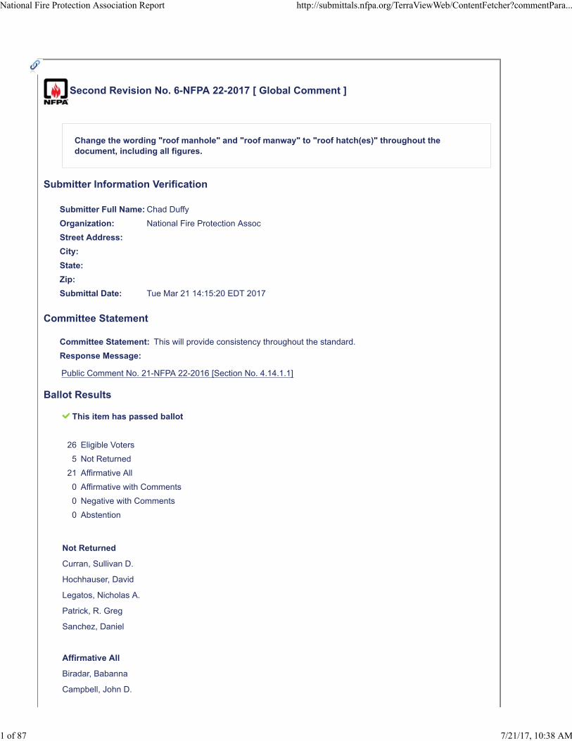
Second Revision No. 6-NFPA 22-2017 [ Global Comment ]
Change the wording "roof manhole" and "roof manway" to "roof hatch(es)" throughout thedocument, including all figures.
Submitter Information Verification
Submitter Full Name: Chad Duffy
Organization: National Fire Protection Assoc
Street Address:
City:
State:
Zip:
Submittal Date: Tue Mar 21 14:15:20 EDT 2017
Committee Statement
Committee Statement: This will provide consistency throughout the standard.
Response Message:
Public Comment No. 21-NFPA 22-2016 [Section No. 4.14.1.1]
Ballot Results
This item has passed ballot
26 Eligible Voters
5 Not Returned
21 Affirmative All
0 Affirmative with Comments
0 Negative with Comments
0 Abstention
Not Returned
Curran, Sullivan D.
Hochhauser, David
Legatos, Nicholas A.
Patrick, R. Greg
Sanchez, Daniel
Affirmative All
Biradar, Babanna
Campbell, John D.
National Fire Protection Association Report http://submittals.nfpa.org/TerraViewWeb/ContentFetcher?commentPara...
1 of 87 7/21/17, 10:38 AM

Culp, Christopher
Fisher, Douglas W.
Fowler, Joseph R.
Gagnon, Robert M.
Garber, Greg
Henning, Andrew M.
Hillman, Jack
Kelly, Kevin J.
Kidd, Todd M.
Koenig, Gary
McGuire, Keith
Mitchard, John M.
Morgan, Bob D.
Noble, Thomas William
Ramo, Leonard J.
Rosenwach, Andrew
Sornsin, Mark A.
Stein, Gregory R.
Stevens, Owen
National Fire Protection Association Report http://submittals.nfpa.org/TerraViewWeb/ContentFetcher?commentPara...
2 of 87 7/21/17, 10:38 AM
Second Revision No. 17-NFPA 22-2017 [ New Section after 2.3.1 ]
2.3.2 AISC Publications.
American Institute of Steel Construction, 103 East Randolph Street, Suite 2000, Chicago, IL 60601.
ANSI/AISC 360, Specification for Structural Steel Buildings , 2016.
Submitter Information Verification
Submitter Full Name: Chad Duffy
Organization: National Fire Protection Assoc
Street Address:
City:
State:
Zip:
Submittal Date: Tue Apr 11 10:56:07 EDT 2017
Committee Statement
Committee Statement: New reference. Renumber sections accordingly.
Response Message:
Ballot Results
This item has passed ballot
26 Eligible Voters
5 Not Returned
21 Affirmative All
0 Affirmative with Comments
0 Negative with Comments
0 Abstention
Not Returned
Curran, Sullivan D.
Hochhauser, David
Legatos, Nicholas A.
Patrick, R. Greg
Sanchez, Daniel
Affirmative All
Biradar, Babanna
Campbell, John D.
Culp, Christopher
National Fire Protection Association Report http://submittals.nfpa.org/TerraViewWeb/ContentFetcher?commentPara...
3 of 87 7/21/17, 10:38 AM
Fisher, Douglas W.
Fowler, Joseph R.
Gagnon, Robert M.
Garber, Greg
Henning, Andrew M.
Hillman, Jack
Kelly, Kevin J.
Kidd, Todd M.
Koenig, Gary
McGuire, Keith
Mitchard, John M.
Morgan, Bob D.
Noble, Thomas William
Ramo, Leonard J.
Rosenwach, Andrew
Sornsin, Mark A.
Stein, Gregory R.
Stevens, Owen
National Fire Protection Association Report http://submittals.nfpa.org/TerraViewWeb/ContentFetcher?commentPara...
4 of 87 7/21/17, 10:38 AM
Second Revision No. 2-NFPA 22-2017 [ Section No. 2.3.8 ]
2.3.9 AWWA Publications.
American Water Works Association, 6666 West Quincy Avenue, Denver, CO 80235.
AWWA C652, Disinfection of Water-Storage Facilities , 2011.
AWWA D100, Welded Carbon Steel Tanks for Water Storage, 2011.
AWWA D102, Coating Steel Water-Storage Tanks, 2014.
AWWA D103, Factory-Coated Bolted Carbon Steel Tanks for Water Storage, 2009 including AddendumD103a-14, 2014 .
AWWA D104, Automatically Controlled, Impressed-Current Cathodic Protection for the InteriorSubmerged Surfaces of Steel Water Storage Tanks , 2011.
AWWA D106, Sacrificial Anode Cathodic Protection Systems for the Interior Submerged Surfaces ofSteel Water Storage Tanks , 2016.
AWWA D107, Composite Elevated Tanks for Water Storage , 2016.
AWWA D108, Aluminum Dome Roofs for Water Storage Facilities , 2010.
AWWA D110, Wire- and Strand-Wound, Circular, Prestressed Concrete Water Tanks, 2013.
AWWA D115, Circular Tendon -Prestressed Concrete Water Tanks with Circumferential Tendons , 2006.
AWWA D120, Standard for Thermosetting Fiberglass-Reinforced Plastic Tanks, 2009.
AWWA D121, Bolted Aboveground Thermosetting Fiberglass-Reinforced Plastic Panel-Type Tanks forWater Storage, 2012.
Submitter Information Verification
Submitter Full Name: Chad Duffy
Organization: National Fire Protection Assoc
Street Address:
City:
State:
Zip:
Submittal Date: Tue Mar 21 13:36:51 EDT 2017
Committee Statement
CommitteeStatement:
AWWA D103 - AWWA issued an addendum to D103 incorporating important changes to thestandard. The reference should incorporate the addendum.
AWWA D108. This reference is needed for a new reference proposed for Sec. 6.2.3.2.
ResponseMessage:
Public Comment No. 13-NFPA 22-2016 [Section No. 2.3.8]
Ballot Results
This item has passed ballot
National Fire Protection Association Report http://submittals.nfpa.org/TerraViewWeb/ContentFetcher?commentPara...
5 of 87 7/21/17, 10:38 AM
26 Eligible Voters
5 Not Returned
21 Affirmative All
0 Affirmative with Comments
0 Negative with Comments
0 Abstention
Not Returned
Curran, Sullivan D.
Hochhauser, David
Legatos, Nicholas A.
Patrick, R. Greg
Sanchez, Daniel
Affirmative All
Biradar, Babanna
Campbell, John D.
Culp, Christopher
Fisher, Douglas W.
Fowler, Joseph R.
Gagnon, Robert M.
Garber, Greg
Henning, Andrew M.
Hillman, Jack
Kelly, Kevin J.
Kidd, Todd M.
Koenig, Gary
McGuire, Keith
Mitchard, John M.
Morgan, Bob D.
Noble, Thomas William
Ramo, Leonard J.
Rosenwach, Andrew
Sornsin, Mark A.
Stein, Gregory R.
Stevens, Owen
National Fire Protection Association Report http://submittals.nfpa.org/TerraViewWeb/ContentFetcher?commentPara...
6 of 87 7/21/17, 10:38 AM
Second Revision No. 3-NFPA 22-2017 [ Sections 4.10.2, 4.10.3 ]
4.10.2
The workmanship shall be of such quality that defects or injuries are not produced during manufacture orerection that cause the specified allowable stresses to be exceeded under any specified design loads .
4.10.3
Specified unit stresses shall not be exceeded.
Submitter Information Verification
Submitter Full Name: Chad Duffy
Organization: National Fire Protection Assoc
Street Address:
City:
State:
Zip:
Submittal Date: Tue Mar 21 13:54:42 EDT 2017
Committee Statement
CommitteeStatement:
It is unreasonable to state that defects or injuries to material may not produced during erectionwithout strict definition of 'defects or injuries'. Instead, any defects should be repaired or remediatedto meet the requirements of the standard. AWWA D100, for instance, has allowable tolerances forshape and for specific loading conditions requires the manufacture to confirm that the as-builtstructure conforms to the shape tolerances in order to validate the basis of design. This changealigns the requirements to a reasonable requirement in line with the requirements of tank standards.
ResponseMessage:
Public Comment No. 5-NFPA 22-2016 [Sections 4.10.2, 4.10.3]
Ballot Results
This item has passed ballot
26 Eligible Voters
5 Not Returned
21 Affirmative All
0 Affirmative with Comments
0 Negative with Comments
0 Abstention
Not Returned
Curran, Sullivan D.
Hochhauser, David
Legatos, Nicholas A.
Patrick, R. Greg
National Fire Protection Association Report http://submittals.nfpa.org/TerraViewWeb/ContentFetcher?commentPara...
7 of 87 7/21/17, 10:38 AM
Sanchez, Daniel
Affirmative All
Biradar, Babanna
Campbell, John D.
Culp, Christopher
Fisher, Douglas W.
Fowler, Joseph R.
Gagnon, Robert M.
Garber, Greg
Henning, Andrew M.
Hillman, Jack
Kelly, Kevin J.
Kidd, Todd M.
Koenig, Gary
McGuire, Keith
Mitchard, John M.
Morgan, Bob D.
Noble, Thomas William
Ramo, Leonard J.
Rosenwach, Andrew
Sornsin, Mark A.
Stein, Gregory R.
Stevens, Owen
National Fire Protection Association Report http://submittals.nfpa.org/TerraViewWeb/ContentFetcher?commentPara...
8 of 87 7/21/17, 10:38 AM
Second Revision No. 19-NFPA 22-2017 [ Section No. 4.12.6.1 ]
4.12.6.1
All steel columns and struts shall be designed in accordance with AWWA D100. the applicable AWWAtank design standard for the type of tank being constructed.
4.12.6.2
Where no AWWA design standard exists for the type of tank being constructed, steel columns and strutsshall be designed in accordance with ANSI/AISC 360.
Submitter Information Verification
Submitter Full Name: Chad Duffy
Organization: National Fire Protection Assoc
Street Address:
City:
State:
Zip:
Submittal Date: Wed May 03 16:44:33 EDT 2017
Committee Statement
CommitteeStatement:
As written, this sections requires steel columns and struts to be designed in accordance withAWWA D100 even if the tank design would generally follow AWWA D103, AWWA D110, AWWAD115, AWWA D120 or AWWA D121. This revision provides clarity to the supposed intent.
ResponseMessage:
Public Comment No. 24-NFPA 22-2016 [Section No. 4.12.6.1]
Ballot Results
This item has passed ballot
26 Eligible Voters
5 Not Returned
21 Affirmative All
0 Affirmative with Comments
0 Negative with Comments
0 Abstention
Not Returned
Curran, Sullivan D.
Hochhauser, David
Legatos, Nicholas A.
Patrick, R. Greg
National Fire Protection Association Report http://submittals.nfpa.org/TerraViewWeb/ContentFetcher?commentPara...
9 of 87 7/21/17, 10:38 AM

Sanchez, Daniel
Affirmative All
Biradar, Babanna
Campbell, John D.
Culp, Christopher
Fisher, Douglas W.
Fowler, Joseph R.
Gagnon, Robert M.
Garber, Greg
Henning, Andrew M.
Hillman, Jack
Kelly, Kevin J.
Kidd, Todd M.
Koenig, Gary
McGuire, Keith
Mitchard, John M.
Morgan, Bob D.
Noble, Thomas William
Ramo, Leonard J.
Rosenwach, Andrew
Sornsin, Mark A.
Stein, Gregory R.
Stevens, Owen
National Fire Protection Association Report http://submittals.nfpa.org/TerraViewWeb/ContentFetcher?commentPara...
10 of 87 7/21/17, 10:38 AM
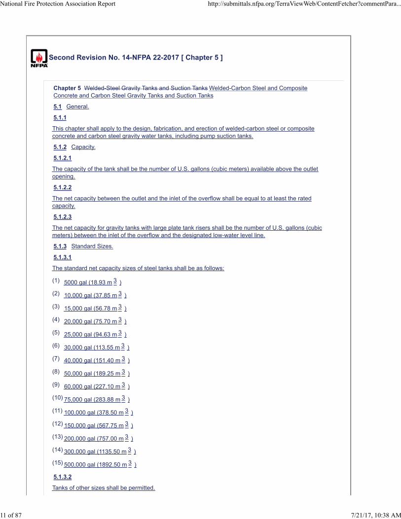
Second Revision No. 14-NFPA 22-2017 [ Chapter 5 ]
Chapter 5 Welded-Steel Gravity Tanks and Suction Tanks Welded-Carbon Steel and CompositeConcrete and Carbon Steel Gravity Tanks and Suction Tanks
5.1 General.
5.1.1
This chapter shall apply to the design, fabrication, and erection of welded-carbon steel or compositeconcrete and carbon steel gravity water tanks, including pump suction tanks.
5.1.2 Capacity.
5.1.2.1
The capacity of the tank shall be the number of U.S. gallons (cubic meters) available above the outletopening.
5.1.2.2
The net capacity between the outlet and the inlet of the overflow shall be equal to at least the ratedcapacity.
5.1.2.3
The net capacity for gravity tanks with large plate tank risers shall be the number of U.S. gallons (cubicmeters) between the inlet of the overflow and the designated low-water level line.
5.1.3 Standard Sizes.
5.1.3.1
The standard net capacity sizes of steel tanks shall be as follows:
(1) 5000 gal (18.93 m 3 )
(2) 10,000 gal (37.85 m 3 )
(3) 15,000 gal (56.78 m 3 )
(4) 20,000 gal (75.70 m 3 )
(5) 25,000 gal (94.63 m 3 )
(6) 30,000 gal (113.55 m 3 )
(7) 40,000 gal (151.40 m 3 )
(8) 50,000 gal (189.25 m 3 )
(9) 60,000 gal (227.10 m 3 )
(10) 75,000 gal (283.88 m 3 )
(11) 100,000 gal (378.50 m 3 )
(12) 150,000 gal (567.75 m 3 )
(13) 200,000 gal (757.00 m 3 )
(14) 300,000 gal (1135.50 m 3 )
(15) 500,000 gal (1892.50 m 3 )
5.1.3.2
Tanks of other sizes shall be permitted.
National Fire Protection Association Report http://submittals.nfpa.org/TerraViewWeb/ContentFetcher?commentPara...
11 of 87 7/21/17, 10:38 AM
5.1.4 Form.
Steel tanks shall be permitted to be of any form desired, provided they conform to all requirements ofthis standard.
5.2 Materials.
5.2.1
All tank foundations, materials, accessories, fabrication, construction, and welding shall be inaccordance with AWWA D100 or AWWA D107.
5.2.2
All tank and tower foundations, steel tank towers, pipe connections and fittings, valve enclosures andfrost protection, tank heating and acceptance test requirements shall be in accordance with thisstandard.
5.3 Preventing Ice Damage.
During construction, the contractor shall keep the tank, structure, and building roofs free of ice causedby leakage until the tank equipment is made watertight.
5.4 Corrosion Protection for Bottom Plates on Soil or Concrete.
5.4.1*
The underside of all bottom plates shall be protected against corrosion by one of the methods requiredby 5.4.1.1 or 5.4.1.2 .
5.4.1.1
The sand pad, including pH range of the lime sand mix, sulfate content, and chloride content, shall meetthe requirements of AWWA D100 or AWWA D107.
5.4.1.2
Where permitted by environmental authorities, an oiled sand cushion shall be permitted to be used inaccordance with AWWA D100.
5.5 Painting Inaccessible Areas.
5.5.1
Except for the underside of the floor on ground-supported flat-bottom tanks, faying surfaces of boltedconnections that prohibit coatings, and overlapping surfaces of single-welded lap joints above the highwaterline, parts that are inaccessible after fabrication, but that are subject to corrosion, shall beprotected by paint before assembly.
5.5.1.1
This requirement shall not apply to the overlapping surfaces of single-welded lap joints above the highwaterline.
5.6 Painting and Corrosion Protection.
5.6.1
Except where exempted by 5.5.1 , all interior surfaces of steel tanks that are exposed to waterimmersion or the vapor phase zone above the high water level shall be cleaned by near-white blastingin accordance with SSPC SP 10 and shall be painted in accordance with the requirements of AWWAD102 and the project specifications. If cathodic protection is used to supplement corrosion protection onthe immersed surfaces then it shall be done in accordance with AWWA D104 or AWWA D106.
5.6.2
All exterior surfaces and inside dry surfaces (pedestal tanks) shall be cleaned by commercial blasting inaccordance with SSPC SP 6 and shall be coated in accordance with the requirements of AWWA D102.
5.6.3
Other interior or exterior paint systems shall be permitted to be used, provided permission is firstobtained from the authority having jurisdiction.
National Fire Protection Association Report http://submittals.nfpa.org/TerraViewWeb/ContentFetcher?commentPara...
12 of 87 7/21/17, 10:38 AM
5.6.4
After construction, all weld seams, unprimed surfaces, or any areas where the primer (if preprimed) hasbeen damaged shall be blast-cleaned and primed with the specified coating system primer.
5.7 Painting Application.
All painting shall be applied in accordance with the appropriate requirements of SSPC Systems andSpecifications Steel Structures Painting Manual , Chapter 5.
5.8 Heavy Metals.
The coating systems described in this section shall not exceed state and local limits of regulated heavymetals.
5.1 General.
5.1.1
This chapter shall apply to the design, fabrication, and erection of welded-steel gravity water tanks,including pump suction tanks.
5.1.2 Capacity.
5.1.2.1
The capacity of the tank shall be the number of U.S. gallons (cubic meters) available above the outletopening.
5.1.2.2
The net capacity between the outlet opening of the discharge pipe and the inlet of the overflow shall beequal to at least the rated capacity.
5.1.2.3
The net capacity for gravity tanks with large plate tank risers shall be the number of U.S. gallons (cubicmeters) between the inlet of the overflow and the designated low-water level line.
5.1.3 Standard Sizes.
5.1.3.1
The standard net capacity sizes of steel tanks shall be as follows:
5000 gal (18.93 m 3 )
10,000 gal (37.85 m 3 )
15,000 gal (56.78 m 3 )
20,000 gal (75.70 m 3 )
25,000 gal (94.63 m 3 )
30,000 gal (113.55 m 3 )
40,000 gal (151.40 m 3 )
50,000 gal (189.25 m 3 )
60,000 gal (227.10 m 3 )
75,000 gal (283.88 m 3 )
100,000 gal (378.50 m 3 )
150,000 gal (567.75 m 3 )
200,000 gal (757.00 m 3 )
300,000 gal (1135.50 m 3 )
500,000 gal (1892.50 m 3 )
National Fire Protection Association Report http://submittals.nfpa.org/TerraViewWeb/ContentFetcher?commentPara...
13 of 87 7/21/17, 10:38 AM
5.1.3.2
Tanks of other sizes shall be permitted.
5.1.4 Form.
Steel tanks shall be permitted to be of any form desired, provided they conform to all requirements ofthis standard.
5.2 Materials.
5.2.1 Plates, Shapes, and Tubular Columns.
5.2.1.1 Plates.
Plate materials shall be of open-hearth, electric furnace, or basic oxygen process steel that conforms toAWWA D100 and one of the following ASTM specifications:
ASTM A36/A36M
ASTM A283/A283M, Grades A, B, C, and D
5.2.1.2
Where plates of thicknesses greater than 3 ⁄4 in. (19.1 mm) are used, ASTM A283/A283M, Grade D,shall not be used. ASTM A131/A131M, Grades A, B, and C; or ASTM A516/A516M, Grades 55 and 60,shall be used as alternatives.
5.2.1.3 Basis of Furnishing Plates.
Plates shall be furnished, based on weight, with permissible underrun and overrun in accordance withthe tolerance table for plates ordered to weight in ASTM A20.
5.2.1.4 Shapes.
Structural materials shall be open-hearth, electric furnace, or basic oxygen process steel that conformsto ASTM A36/A36M, or ASTM A131/A131M, Grades A, B, and D, or ASTM A992/A992M.
5.2.1.5
Copper-bearing steel that contains approximately 0.20 percent copper shall be permitted to be used. Inall other respects, steel shall conform to the specifications of 5.2.1.1 , 5.2.1.3 , and 5.2.1.4 .
5.2.2 Bolts, Anchor Bolts, and Rods.
5.2.2.1
Bolts and anchor bolts shall conform to AWWA D100.
5.2.2.2
ASTM A36/A36M shall be considered an acceptable alternative material for anchor bolts. Rods shall beopen-hearth, electric furnace, or basic oxygen process steel that conforms to ASTM A36/A36M.
5.2.3 Forgings.
5.2.3.1
Steel used for forgings shall be made only by the open-hearth process.
5.2.3.2
Forgings shall conform to the following ASTM specifications:
ASTM A105/A105M
ASTM A668/A668M Class D
ASTM A181/A181M, Class 70
5.2.4 Castings.
Castings shall conform to ASTM A27/A27M, Grade 60-30 full annealed.
5.2.5 Reinforcing Steel.
Reinforcing steel shall comply with ASTM A615/A615M, Grade 40 or Grade 60.
5.2.6 Filler Metal Electrodes.
National Fire Protection Association Report http://submittals.nfpa.org/TerraViewWeb/ContentFetcher?commentPara...
14 of 87 7/21/17, 10:38 AM
5.2.6.1
Manual, shielded metal arc welding electrodes shall conform to the requirements of AWS A5.1/A5.1M.
5.2.6.2
Electrodes shall be of any E60XX or E70XX classification that is suitable for the electric currentcharacteristics, the position of welding, and other conditions of intended use.
5.2.6.3
Electrodes for other welding processes shall be in accordance with applicable AWS specifications forfiller metal.
5.3 Earthquake Load.
5.3.1
Tanks shall meet the requirements for resistance to earthquake damage in accordance with theearthquake design provisions of AWWA D100.
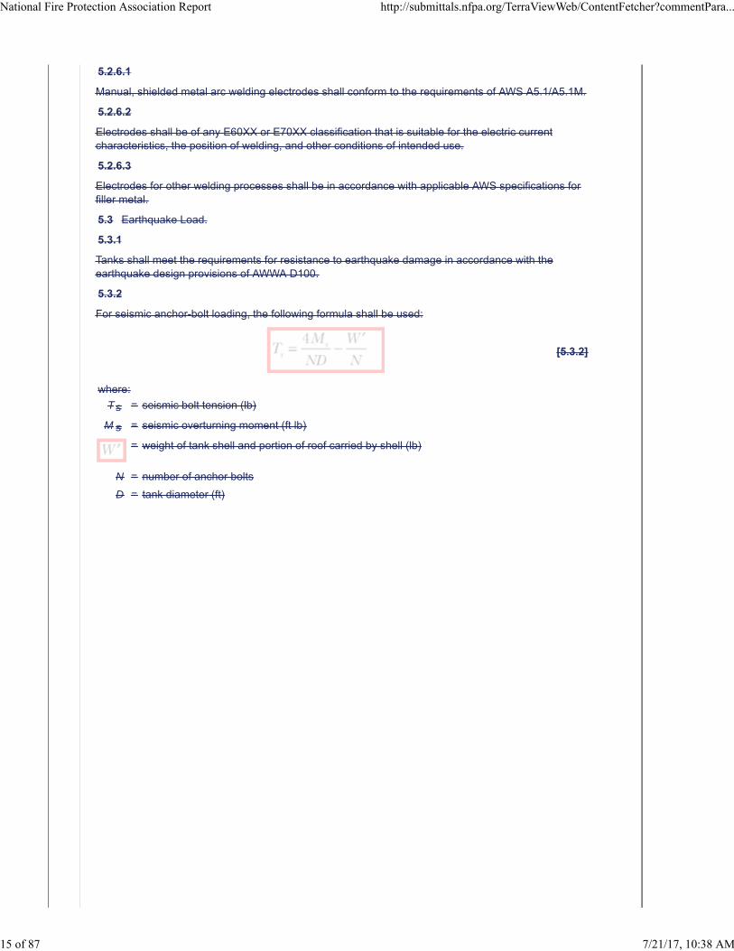
5.3.2
For seismic anchor-bolt loading, the following formula shall be used:
[5.3.2]
where:
Ts = seismic bolt tension (lb)
M s = seismic overturning moment (ft lb)
= weight of tank shell and portion of roof carried by shell (lb)
N = number of anchor bolts
D = tank diameter (ft)
National Fire Protection Association Report http://submittals.nfpa.org/TerraViewWeb/ContentFetcher?commentPara...
15 of 87 7/21/17, 10:38 AM
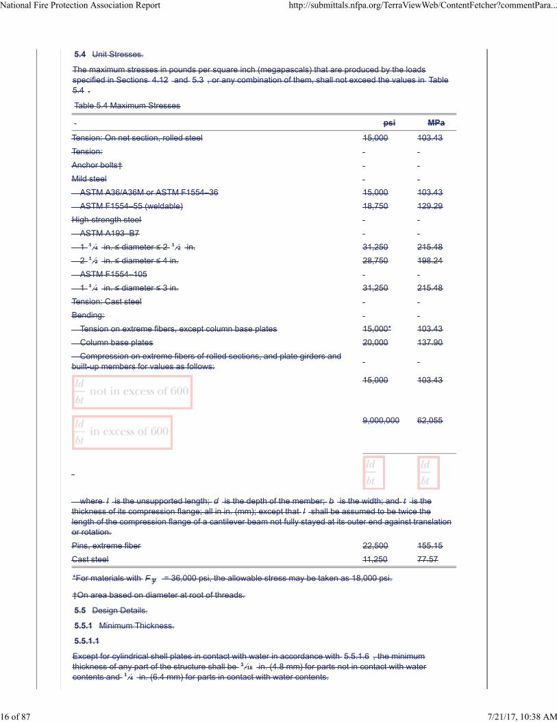
5.4 Unit Stresses.
The maximum stresses in pounds per square inch (megapascals) that are produced by the loadsspecified in Sections 4.12 and 5.3 , or any combination of them, shall not exceed the values in Table5.4 .
Table 5.4 Maximum Stresses
psi MPa
Tension: On net section, rolled steel 15,000 103.43
Tension:
Anchor bolts†
Mild steel
ASTM A36/A36M or ASTM F1554–36 15,000 103.43
ASTM F1554–55 (weldable) 18,750 129.29
High-strength steel
ASTM A193–B7
1 1 ⁄4 in. ≤ diameter ≤ 2 1 ⁄2 in. 31,250 215.48
2 1 ⁄2 in. ≤ diameter ≤ 4 in. 28,750 198.24
ASTM F1554–105
1 1 ⁄4 in. ≤ diameter ≤ 3 in. 31,250 215.48
Tension: Cast steel
Bending:
Tension on extreme fibers, except column base plates 15,000* 103.43
Column base plates 20,000 137.90
Compression on extreme fibers of rolled sections, and plate girders andbuilt-up members for values as follows:
15,000 103.43
9,000,000 62,055
where l is the unsupported length; d is the depth of the member; b is the width; and t is thethickness of its compression flange; all in in. (mm); except that l shall be assumed to be twice thelength of the compression flange of a cantilever beam not fully stayed at its outer end against translationor rotation.
Pins, extreme fiber 22,500 155.15
Cast steel 11,250 77.57
*For materials with F y = 36,000 psi, the allowable stress may be taken as 18,000 psi.
†On area based on diameter at root of threads.
5.5 Design Details.
5.5.1 Minimum Thickness.
5.5.1.1
Except for cylindrical shell plates in contact with water in accordance with 5.5.1.6 , the minimumthickness of any part of the structure shall be 3 ⁄16 in. (4.8 mm) for parts not in contact with watercontents and 1 ⁄4 in. (6.4 mm) for parts in contact with water contents.
National Fire Protection Association Report http://submittals.nfpa.org/TerraViewWeb/ContentFetcher?commentPara...
16 of 87 7/21/17, 10:38 AM
5.5.1.2
The controlling thickness of rolled shapes for the purposes of the foregoing stipulations shall be takenas the mean thickness of the flanges, regardless of web thickness.
5.5.1.3
The minimum thickness of tubular columns and struts shall be 1 ⁄4 in. (6.4 mm).
5.5.1.4
Round or square bars used for wind bracing shall have a minimum diameter or width of 3 ⁄4 in.(19.1 mm).
5.5.1.5
Bars of other shapes, if used, shall have a total area at least equal to a 3 ⁄4 in. (19.1 mm) round bar.
5.5.1.5.1
Roof plates for suction tanks with cone roofs shall be permitted to be 0.1792 in. (7 gauge) sheet.
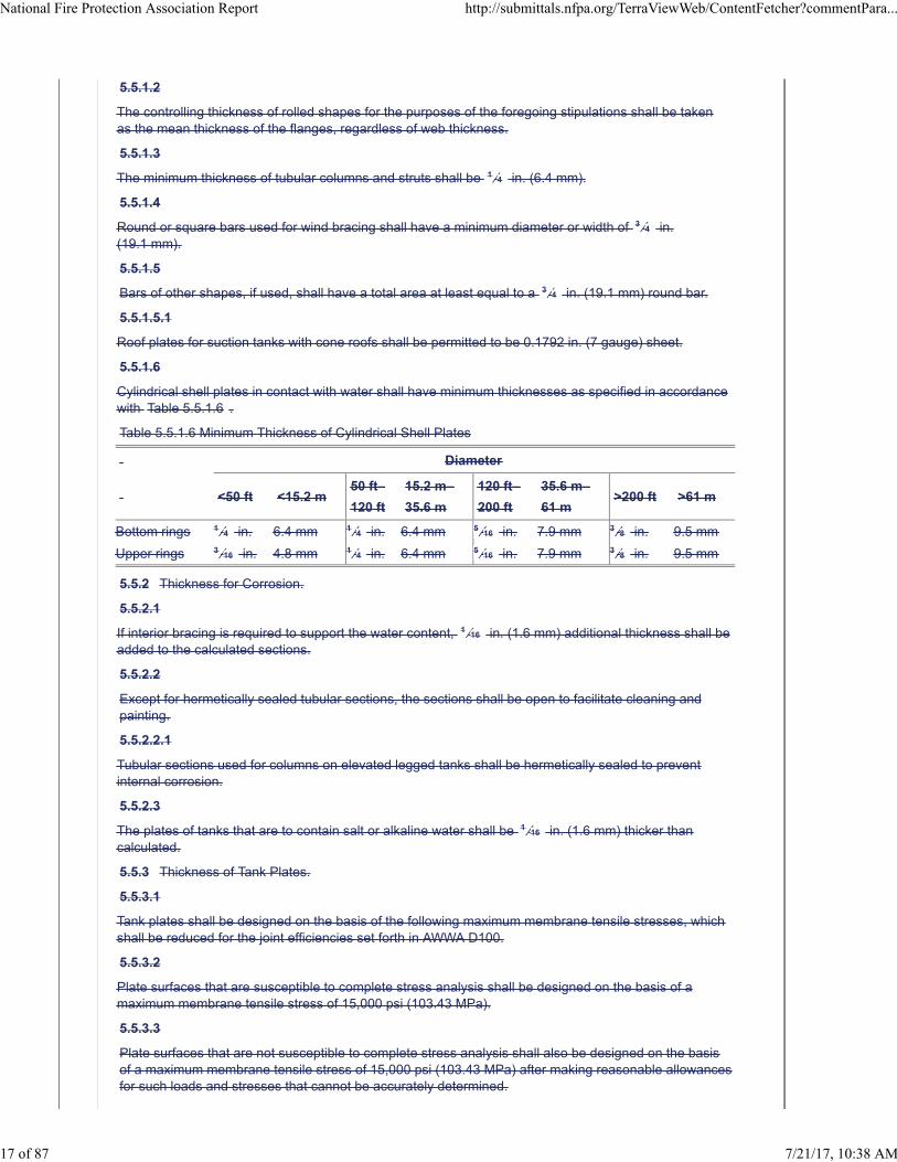
5.5.1.6
Cylindrical shell plates in contact with water shall have minimum thicknesses as specified in accordancewith Table 5.5.1.6 .
Table 5.5.1.6 Minimum Thickness of Cylindrical Shell Plates
Diameter
<50 ft <15.2 m50 ft–
120 ft
15.2 m–
35.6 m
120 ft–
200 ft
35.6 m–
61 m>200 ft >61 m
Bottom rings 1 ⁄4 in. 6.4 mm 1 ⁄4 in. 6.4 mm 5 ⁄16 in. 7.9 mm 3 ⁄8 in. 9.5 mm
Upper rings 3 ⁄16 in. 4.8 mm 1 ⁄4 in. 6.4 mm 5 ⁄16 in. 7.9 mm 3 ⁄8 in. 9.5 mm
5.5.2 Thickness for Corrosion.
5.5.2.1
If interior bracing is required to support the water content, 1 ⁄16 in. (1.6 mm) additional thickness shall beadded to the calculated sections.
5.5.2.2
Except for hermetically sealed tubular sections, the sections shall be open to facilitate cleaning andpainting.
5.5.2.2.1
Tubular sections used for columns on elevated legged tanks shall be hermetically sealed to preventinternal corrosion.
5.5.2.3
The plates of tanks that are to contain salt or alkaline water shall be 1 ⁄16 in. (1.6 mm) thicker thancalculated.
5.5.3 Thickness of Tank Plates.
5.5.3.1
Tank plates shall be designed on the basis of the following maximum membrane tensile stresses, whichshall be reduced for the joint efficiencies set forth in AWWA D100.
5.5.3.2
Plate surfaces that are susceptible to complete stress analysis shall be designed on the basis of amaximum membrane tensile stress of 15,000 psi (103.43 MPa).
5.5.3.3
Plate surfaces that are not susceptible to complete stress analysis shall also be designed on the basisof a maximum membrane tensile stress of 15,000 psi (103.43 MPa) after making reasonable allowancesfor such loads and stresses that cannot be accurately determined.
National Fire Protection Association Report http://submittals.nfpa.org/TerraViewWeb/ContentFetcher?commentPara...
17 of 87 7/21/17, 10:38 AM
5.5.3.3.1
The maximum membrane tensile stress shall in no case exceed 11,000 psi (75.85 MPa) whencalculated, assuming that the concentrated reactions of supporting members are uniformly distributedbetween such reactions.
5.5.3.3.2
Therefore, the lowest cylindrical courses of tanks with suspended bottoms and the suspended bottomsthemselves shall be designed for a maximum membrane tensile stress of 11,000 psi (75.85 MPa),reduced for the joint efficiencies.
5.5.3.4
As an alternative to 5.5.3.1 and 5.5.3.2 , tank shell plates for suction tanks shall be permitted to bedesigned on the basis of the stresses, material selection, and inspection set forth in Section 14 ofAWWA D100, provided all requirements of Section 14 of the standard are met.
5.5.3.5
Where compressive stresses exist, the selected plate thickness shall comply with the allowable localbuckling stresses in accordance with AWWA D100.
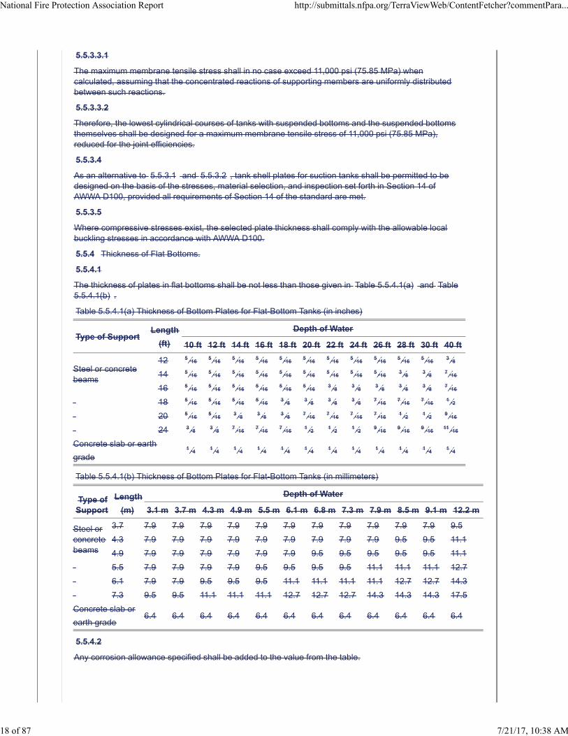
5.5.4 Thickness of Flat Bottoms.
5.5.4.1
The thickness of plates in flat bottoms shall be not less than those given in Table 5.5.4.1(a) and Table5.5.4.1(b) .
Table 5.5.4.1(a) Thickness of Bottom Plates for Flat-Bottom Tanks (in inches)
Type of SupportLength
(ft)
Depth of Water
10 ft 12 ft 14 ft 16 ft 18 ft 20 ft 22 ft 24 ft 26 ft 28 ft 30 ft 40 ft
Steel or concretebeams
12 5 ⁄165 ⁄16
5 ⁄165 ⁄16
5 ⁄165 ⁄16
5 ⁄165 ⁄16
5 ⁄165 ⁄16
5 ⁄163 ⁄8
14 5 ⁄165 ⁄16
5 ⁄165 ⁄16
5 ⁄165 ⁄16
5 ⁄165 ⁄16
5 ⁄163 ⁄8 3 ⁄8 7 ⁄16
16 5 ⁄165 ⁄16
5 ⁄165 ⁄16
5 ⁄165 ⁄16
3 ⁄8 3 ⁄8 3 ⁄8 3 ⁄8 3 ⁄8 7 ⁄16
18 5 ⁄165 ⁄16
5 ⁄165 ⁄16
3 ⁄8 3 ⁄8 3 ⁄8 3 ⁄8 7 ⁄167 ⁄16
7 ⁄161 ⁄2
20 5 ⁄165 ⁄16
3 ⁄8 3 ⁄8 3 ⁄8 7 ⁄167 ⁄16
7 ⁄167 ⁄16
1 ⁄2 1 ⁄2 9 ⁄16
24 3 ⁄8 3 ⁄8 7 ⁄167 ⁄16
7 ⁄161 ⁄2 1 ⁄2 1 ⁄2 9 ⁄16
9 ⁄169 ⁄16
11 ⁄16
Concrete slab or earth
grade1 ⁄4 1 ⁄4 1 ⁄4 1 ⁄4 1 ⁄4 1 ⁄4 1 ⁄4 1 ⁄4 1 ⁄4 1 ⁄4 1 ⁄4 1 ⁄4
Table 5.5.4.1(b) Thickness of Bottom Plates for Flat-Bottom Tanks (in millimeters)
Type ofSupport
Length
(m)
Depth of Water
3.1 m 3.7 m 4.3 m 4.9 m 5.5 m 6.1 m 6.8 m 7.3 m 7.9 m 8.5 m 9.1 m 12.2 m
Steel orconcretebeams
3.7 7.9 7.9 7.9 7.9 7.9 7.9 7.9 7.9 7.9 7.9 7.9 9.5
4.3 7.9 7.9 7.9 7.9 7.9 7.9 7.9 7.9 7.9 9.5 9.5 11.1
4.9 7.9 7.9 7.9 7.9 7.9 7.9 9.5 9.5 9.5 9.5 9.5 11.1
5.5 7.9 7.9 7.9 7.9 9.5 9.5 9.5 9.5 11.1 11.1 11.1 12.7
6.1 7.9 7.9 9.5 9.5 9.5 11.1 11.1 11.1 11.1 12.7 12.7 14.3
7.3 9.5 9.5 11.1 11.1 11.1 12.7 12.7 12.7 14.3 14.3 14.3 17.5
Concrete slab or
earth grade6.4 6.4 6.4 6.4 6.4 6.4 6.4 6.4 6.4 6.4 6.4 6.4
5.5.4.2
Any corrosion allowance specified shall be added to the value from the table.
National Fire Protection Association Report http://submittals.nfpa.org/TerraViewWeb/ContentFetcher?commentPara...
18 of 87 7/21/17, 10:38 AM
5.5.5 Accessibility of Bottoms.
Grillages shall be designed so that the tank bottom and beams are accessible for inspection andpainting.
5.5.6 Net Sections.
Net sections shall be used in calculating the tensile stress in plates and members.
5.5.7 Load Location.
5.5.7.1
When calculating the thickness of plates that are stressed by the weight or pressure of the tankcontents, the pressure at the lower edge of each ring shall be assumed to act undiminished on theentire area of the ring.
5.5.8 Opening Reinforcement.
5.5.8.1
All openings of more than 4 in. (102 mm) in diameter that are located in the shell, suspended bottom,larger steel plate tank riser, or tubular support shall be reinforced.
5.5.8.2
The reinforcement shall be either the flange of a fitting, an additional ring of metal, excess plate metalabove that actually required, or a combination of these methods.
5.5.8.3
The opening diameter shall be considered to be the maximum dimension of the hole cut in the plateperpendicular to the direction of maximum stress.
5.5.8.3.1
Excess plate metal used for joint efficiency shall not meet the requirements for opening reinforcement ifthe center of the opening is within one opening diameter of any plate seam or point of supportattachment.
5.5.8.4
Welding shall be provided to transmit the full net strength of the reinforcing ring or flange to the plate.
5.5.8.4.1
In computing the net reinforcing area of a fitting, such as a boilermaker's flange or a manhole saddlethat has a neck, the material in the neck shall be considered as part of the reinforcement for a distance,measured from the surface of the parent plate or from the surface of an intervening reinforcement plate,that is equal to four times the thickness of the material in the neck.
5.5.9 Roof Supports.
The supports for tank roofs that do not contain water shall be designed in accordance with the steelconstruction specifications of the American Institute of Steel Construction.
5.5.9.1
Rafters that are in contact with a steel roof, have a slope of less than 2 in. in 12 in. (51 mm in 305 mm),and consist of beam or channel shapes less than 15 in. (381 mm) deep shall be considered to beadequately braced in the lateral position by friction between the roof plate and the top flange.
5.5.9.2
The maximum slenderness ratio, L / r , for columns that support the roof shall be 175. The spacingbetween rafters, as measured along the tank circumference, shall not exceed 2π ft (0.61π m).
5.5.10 Welded Joints.
The types of joints used and their design shall conform to AWWA D100.
5.6 Workmanship.
5.6.1 Plate Edges.
National Fire Protection Association Report http://submittals.nfpa.org/TerraViewWeb/ContentFetcher?commentPara...
19 of 87 7/21/17, 10:38 AM
The plate edges to be welded shall be universal mill edges or shall be prepared by shearing, machining,chipping, or mechanically guided oxygen cutting. Where the edges of plates are oxygen cut, the surfaceobtained shall be uniform and smooth and shall be cleaned of slag accumulations before welding.
5.6.1.1
Edges of irregular contour shall be permitted to be prepared by manually guided oxygen cutting.
5.6.2 Rolling.
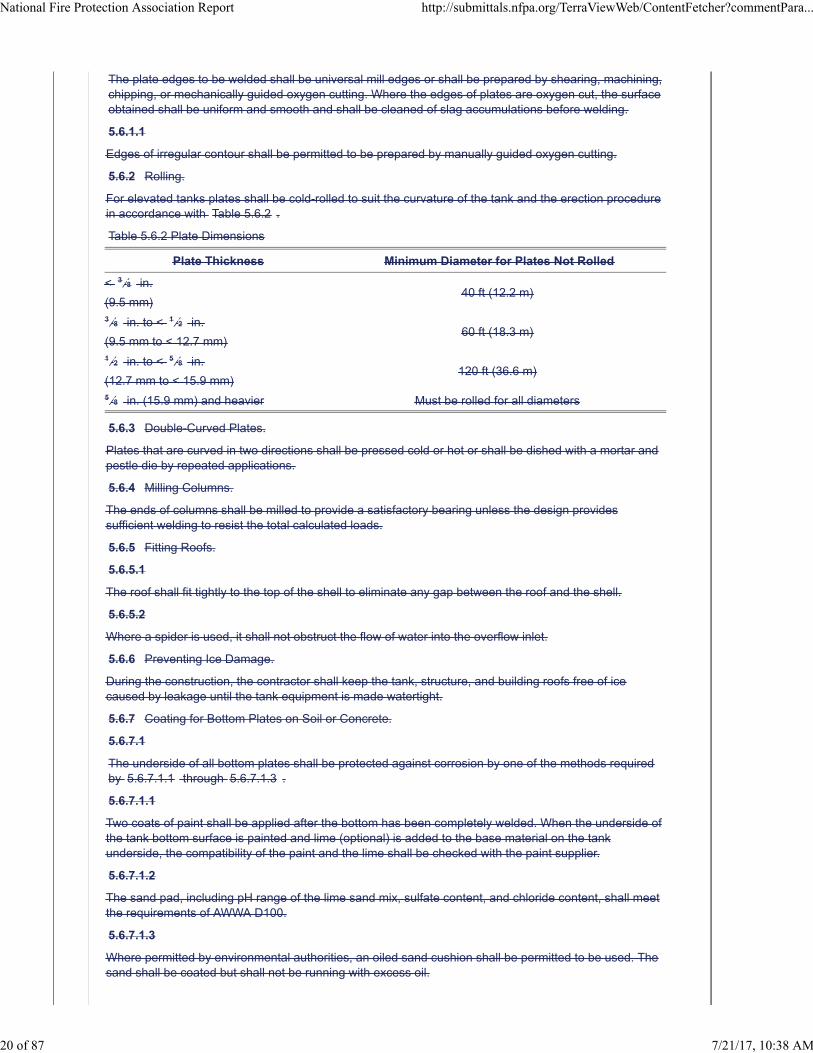
For elevated tanks plates shall be cold-rolled to suit the curvature of the tank and the erection procedurein accordance with Table 5.6.2 .
Table 5.6.2 Plate Dimensions
Plate Thickness Minimum Diameter for Plates Not Rolled
< 3 ⁄8 in.
(9.5 mm)40 ft (12.2 m)
3 ⁄8 in. to < 1 ⁄2 in.
(9.5 mm to < 12.7 mm)60 ft (18.3 m)
1 ⁄2 in. to < 5 ⁄8 in.
(12.7 mm to < 15.9 mm)120 ft (36.6 m)
5 ⁄8 in. (15.9 mm) and heavier Must be rolled for all diameters
5.6.3 Double-Curved Plates.
Plates that are curved in two directions shall be pressed cold or hot or shall be dished with a mortar andpestle die by repeated applications.
5.6.4 Milling Columns.
The ends of columns shall be milled to provide a satisfactory bearing unless the design providessufficient welding to resist the total calculated loads.
5.6.5 Fitting Roofs.
5.6.5.1
The roof shall fit tightly to the top of the shell to eliminate any gap between the roof and the shell.
5.6.5.2
Where a spider is used, it shall not obstruct the flow of water into the overflow inlet.
5.6.6 Preventing Ice Damage.
During the construction, the contractor shall keep the tank, structure, and building roofs free of icecaused by leakage until the tank equipment is made watertight.
5.6.7 Coating for Bottom Plates on Soil or Concrete.
5.6.7.1
The underside of all bottom plates shall be protected against corrosion by one of the methods requiredby 5.6.7.1.1 through 5.6.7.1.3 .
5.6.7.1.1
Two coats of paint shall be applied after the bottom has been completely welded. When the underside ofthe tank bottom surface is painted and lime (optional) is added to the base material on the tankunderside, the compatibility of the paint and the lime shall be checked with the paint supplier.
5.6.7.1.2
The sand pad, including pH range of the lime sand mix, sulfate content, and chloride content, shall meetthe requirements of AWWA D100.
5.6.7.1.3
Where permitted by environmental authorities, an oiled sand cushion shall be permitted to be used. Thesand shall be coated but shall not be running with excess oil.
National Fire Protection Association Report http://submittals.nfpa.org/TerraViewWeb/ContentFetcher?commentPara...
20 of 87 7/21/17, 10:38 AM
5.6.7.2
Where the tank bottom is placed on oiled sand, the sand shall be saturated to a depth of 4 in. (102 mm)with a suitable petroleum-base oil.
5.6.8
Tanks shall meet the erection tolerance requirements of AWWA D100.
5.7 Accessories.
5.7.1 Connections.
Connections shall be provided on the tank for the necessary pipes, braces, frost-casting, and walkwaysupports.
5.7.2 Roof Anchorage.
Each roof plate shall be securely fastened to the top of the tank.
5.7.3 Roof Hatch.
5.7.3.1
An easily accessible roof hatch or roof door having a minimum opening dimension of 24 in. (610 mm)shall be provided in the roof.
5.7.3.2
The hatch cover shall be built of steel plate with a minimum thickness of 3 ⁄16 in. (4.8 mm).
5.7.3.3
The hatch opening shall have a curb that is a minimum of 4 in. (102 mm) high, and the cover shall havea minimum downward overlap of 2 in. (51 mm).
5.7.3.4
A catch shall be provided to keep the cover closed.
5.7.3.5
A second roof hatch shall be placed 180 degrees from the primary roof hatch.
5.7.4 Ladders — General.
5.7.4.1
Outside and inside steel ladders that are arranged for convenient passage from one to the other andthrough the primary roof hatch shall be provided.
5.7.4.2
Ladders shall not interfere with the opening of the hatch cover and shall not incline outward from thevertical at any point.
5.7.4.3
For pedestal-supported tanks, the ladder shall be placed inside an access tube that extends through thecenter of the tank.
5.7.5 Outside Fixed Shell and Roof Ladder.
5.7.5.1
The outside tank ladder of suction tanks and multiple-column-supported gravity tanks shall be fixed aminimum of 7 in. (178 mm) between the tank side and the centerline of rungs and shall be rigidly boltedor welded to brackets that are spaced a maximum of 12 ft (3.7 m) apart and that are welded to the tankplates.
5.7.5.2
The bottom bracket shall be located a maximum of 6 ft (1.8 m) above the base of the tank cylinder, andthe ladder shall extend up the tank shell and radially along the roof, with the top bracket located withinapproximately 2 ft (0.61 m) of the roof hatch.
5.7.5.3
There shall be a minimum 1 ft (0.3 m) clearance at the sides and front of the ladder at the balcony.
National Fire Protection Association Report http://submittals.nfpa.org/TerraViewWeb/ContentFetcher?commentPara...
21 of 87 7/21/17, 10:38 AM
5.7.5.4
All ladders shall be equipped with a cage, a rigid notched rail, or other listed ladder safety device.
5.7.6 Inside Ladder.
5.7.6.1
The inside fixed ladder provided for passage between the roof hatch and tank bottom shall not be rigidlyconnected to the bottom plates.
5.7.6.2
A ladder shall extend from the top to the bottom of the inside of the large steel tank riser pipes and shallbe secured to the shell plates by brackets that are spaced a maximum of 12 ft (3.7 m) apart.
5.7.6.2.1
The upper bracket shall be located at the top of the tank riser.
5.7.6.3
All ladders over 20 ft (6.1 m) high shall be equipped with a cage, a rigid notched rail, or other listedladder safety device.
5.7.7 Ladder Bars and Rungs.
5.7.7.1
Ladder side bars shall be not less than 2 in. × 1 ⁄2 in. (51 mm × 12.7 mm) or 2 1 ⁄2 in. × 3 ⁄8 in. (64 mm× 9.5 mm).
5.7.7.2
Side bars shall be spaced at least 16 in. (406 mm) apart. Rungs shall be of at least 3 ⁄4 in. (19.1 mm)round or square steel and shall be spaced 12 in. (305 mm) on their centers.
5.7.7.3
The rungs shall be firmly welded to the side bars.
5.7.7.4
Ladders and connections shall be designed to support a concentrated load of 350 lb (159 kg).
5.7.8 Painting Inaccessible Parts.
5.7.8.1
Except for the underside of the floor on ground-supported flat-bottom tanks, faying surfaces of boltedconnections that prohibit coatings, and contact surfaces of unsealed roof lap joints, parts that areinaccessible after fabrication, but that are subject to corrosion, shall be protected by paint beforeassembly.
5.7.8.1.1
This requirement shall not apply to the overlapping surfaces of single-welded lap joints above the highwaterline.
5.7.9 Painting.
5.7.9.1
All interior surfaces of steel tanks that are exposed to water immersion or the vapor phase zone abovethe high water level shall be cleaned by near-white blasting in accordance with SSPC SP 10 and shallbe primed in accordance with the requirements for “Inside Paint System No. 1” in AWWA D102.
5.7.9.2
All exterior surfaces and inside dry surfaces (pedestal tanks) shall be cleaned by commercial blasting inaccordance with SSPC SP 6 and shall be coated in accordance with the requirements of AWWA D102.
5.7.9.3
The appropriate primers for other interior and exterior paint systems shall be permitted to be used,provided permission is first obtained from the authority having jurisdiction.
National Fire Protection Association Report http://submittals.nfpa.org/TerraViewWeb/ContentFetcher?commentPara...
22 of 87 7/21/17, 10:38 AM
5.7.9.4
After construction, all weld seams, unprimed surfaces, or any areas where the primer (if preprimed) hasbeen damaged shall be blast-cleaned and patch-primed with the coating system primer.
5.7.9.5
All finish coat painting for interior surfaces shall be in accordance with the requirements of AWWA D102.
5.7.9.5.1
Wax coating systems shall not be permitted.
5.7.9.6
Finish coat painting for all exterior surfaces shall be in accordance with the requirements of AWWAD102.
5.7.10 Painting Application.
All painting shall be applied in accordance with the appropriate requirements of SSPC Systems andSpecifications Steel Structures Painting Manual , Chapter 5.
5.7.11
The painting and priming systems described in 5.7.9 through 5.7.10 shall be lead free.
Supplemental Information
File Name Description Approved
NFPA_22_Chapter_5_-_CD.docx New Chapter 5. For staff use.
Submitter Information Verification
Submitter Full Name: Chad Duffy
Organization: National Fire Protection Assoc
Street Address:
City:
State:
Zip:
Submittal Date: Tue Apr 11 09:13:52 EDT 2017
Committee Statement
CommitteeStatement:
Deleted requirements that are redundant to AWWA D100and referenced AWWA D100 as theconstruction document. Items particular to fire water storage tanks remains in the this chapter.Clarifies construction requirements for tanks in one document.
Delete annex sections that correlate with deleted sections.
ResponseMessage:
Ballot Results
This item has passed ballot
26 Eligible Voters
5 Not Returned
20 Affirmative All
1 Affirmative with Comments
0 Negative with Comments
National Fire Protection Association Report http://submittals.nfpa.org/TerraViewWeb/ContentFetcher?commentPara...
23 of 87 7/21/17, 10:38 AM
0 Abstention
Not Returned
Curran, Sullivan D.
Hochhauser, David
Legatos, Nicholas A.
Patrick, R. Greg
Sanchez, Daniel
Affirmative All
Biradar, Babanna
Campbell, John D.
Culp, Christopher
Fowler, Joseph R.
Gagnon, Robert M.
Garber, Greg
Henning, Andrew M.
Hillman, Jack
Kelly, Kevin J.
Kidd, Todd M.
Koenig, Gary
McGuire, Keith
Mitchard, John M.
Morgan, Bob D.
Noble, Thomas William
Ramo, Leonard J.
Rosenwach, Andrew
Sornsin, Mark A.
Stein, Gregory R.
Stevens, Owen
Affirmative with Comment
Fisher, Douglas W.
Editorial - Shouldn't Chapter 5 be labelled "Welded-Carbon Steel or Composite Concrete and Carbon SteelGravity Tanks and Suction Tanks". Change "and" to "or" before Composite Concrete
National Fire Protection Association Report http://submittals.nfpa.org/TerraViewWeb/ContentFetcher?commentPara...
24 of 87 7/21/17, 10:38 AM
Second Revision No. 15-NFPA 22-2017 [ Chapter 6 ]
Chapter 6 Factory-Coated, Bolted Steel Tanks Factory-Coated, Bolted Carbon Steel Tanks
6.1 General.
6.1.1*
This chapter shall apply to the design, fabrication, and erection of bolted carbon steel water tanks,including pump suction tanks with factory-applied coatings.
6.1.2 Standard Capacity.
The standard capacity of bolted tanks varies with the number of panels added to the diameter and
ranges from 4000 gal to approximately 500,000 gal (15.1 m 3 to approximately 1900 m 3 ) net capacity.
6.1.2.1
Tanks of other capacities shall be permitted.
6.1.3 Form.
6.1.3.1
Bolted tanks shall be cylindrical.
6.1.3.2
All joints, including vertical, horizontal, shell-to-roof, and shell-to-bottom plates or sheets, shall be fieldbolted.
6.1.3.3
Coatings shall be factory applied in accordance with AWWA D103.
6.1.3.4
Bolt holes shall be shop-punched or drilled for field assembly.
6.1.3.5
Joints that are in contact with water and weathertight joints shall be sealed.
6.2 Materials, Fabrication, and Installation.
6.2.1
All design materials, fabrication, and installation shall be in accordance with AWWA D103.
6.2.2
All tank and tower foundations, accessories, steel tank towers, pipe connections and fittings, valveenclosures and frost protection, tank heating and acceptance test requirements shall be in accordancewith this standard.
6.3 Corrosion Protection.
Where cathodic protection is used to supplement corrosion protection on the immersed surfaces orunderside of floor plates, it shall be done in accordance with AWWA D104 or AWWA D106.
6.4 Structural Shapes.
Aluminum shapes shall be permitted to be used for portions of the tank that are not in contact with waterand shall follow the design criteria in AWWA D108.
6.1 General.
6.1.1
This chapter shall apply to the design, fabrication, and erection of bolted steel water tanks, includingpump suction tanks with factory-applied coatings.
6.1.2 Standard Capacity.
National Fire Protection Association Report http://submittals.nfpa.org/TerraViewWeb/ContentFetcher?commentPara...
25 of 87 7/21/17, 10:38 AM
The standard capacity of bolted tanks varies with the number of panels added to the diameter and
ranges from 4000 gal to approximately 500,000 gal (15.1 m 3 to approximately 1900 m 3 ) net capacity.
6.1.2.1
Tanks of other capacities shall be permitted.
6.1.3 Form.
6.1.3.1
Bolted tanks shall be cylindrical.
6.1.3.2
All joints, including vertical, horizontal, shell-to-roof, and shell-to-bottom plates or sheets, shall be fieldbolted.
6.1.3.3
Coatings shall be factory applied.
6.1.3.4
Bolt holes shall be shop-punched or drilled for field assembly.
6.1.3.5
Joints that are in contact with water and weather-tight joints shall be sealed.
6.2 Plate and Sheet Materials.
6.2.1
Plate and sheet materials shall be of open-hearth, electric furnace, or basic oxygen process steel thatconforms to any of the following:
ASTM A36/A36M
ASTM A283/A283M, Grade C or Grade D
ASTM A1011/A1011M
ASTM A572/A572M, Grade 42 or Grade 50
6.2.2
Plates and sheets shall be furnished on the basis of weight, with permissible underrun and overrun inaccordance with the tolerance table for plates ordered to weight in ASTM A6/A6M.
6.2.3 Structural Shapes.
6.2.3.1
Hot-rolled structural shapes shall conform to ASTM A36/A36M or ASTM A992/A992M.
6.2.3.2
Aluminum shapes shall be permitted to be used for portions of the tank that are not in contact with waterand shall follow the design criteria in Appendix A of AWWA D103.
6.2.4 Tubular Columns.
6.2.4.1
Steel pipe shall be permitted to be used for tubular columns or other structural members, provided itcomplies with ASTM A53/A53M, Type E or Type S, Grade B; ASTM A139/A139M, Grade B; and APISPEC 5L, Grade B; and provided the minimum wall thickness of any such material complies with thedesign requirements and the minimum thickness requirement of this standard.
6.2.4.2
The allowable underrun shall be subtracted from the nominal wall thickness when calculating theminimum pipe wall thickness.
6.2.4.3
Tubular sections shall not be flattened to form end connections.
National Fire Protection Association Report http://submittals.nfpa.org/TerraViewWeb/ContentFetcher?commentPara...
26 of 87 7/21/17, 10:38 AM
6.2.5 Bolts, Anchor Bolts, and Nuts.
Bolts, anchor bolts, and nuts shall conform to AWWA D103 and Section 12.4 .
6.2.6 Forgings.
Steel used for forging shall be made only by the open-hearth process. Forgings shall conform to thefollowing ASTM specifications:
ASTM A105/A105M
ASTM A668/A668M
6.2.7 Filler Metal Electrodes.
6.2.7.1
Manual, shielded metal arc welding electrodes shall conform to the requirements of AWS A5.1/A5.1M.
6.2.7.2
Electrodes shall be of any E60XX or E70XX classification suitable for the electric current characteristics,the position of welding, and other conditions of intended use.
6.2.7.3
Electrodes for other welding processes shall be in accordance with applicable AWS specifications forfiller metal.
6.2.8 Gasket.
6.2.8.1
Gasket material shall be of adequate tensile strength and resilience to obtain a leakproof seal at allseams and joints.
6.2.8.2
Gasket material shall be resistant to weather and ozone exposure and shall be in accordance withASTM D1171. Physical requirements shall conform to AWWA D103.
6.2.8.3
Gasket material shall be capable of resisting chlorination exposure in accordance with AWWA C652.
6.2.9 Sealant.
6.2.9.1
Sealants shall be supplied by the tank manufacturer. Sealants shall remain flexible over a temperaturerange of −40°F to 170°F (−40°C to 76.7°C).
6.2.9.2
Resistance to hardening and cracking shall be required. The sealant shall be solid with no plasticizers orextenders to cause shrinkage.
6.2.9.3
The sealant shall resist ozone and ultraviolet light and shall not swell or degrade under normal waterstorage conditions. In addition, the sealant shall be capable of resisting chlorination exposure inaccordance with AWWA C652.
6.3 Earthquake Load.
National Fire Protection Association Report http://submittals.nfpa.org/TerraViewWeb/ContentFetcher?commentPara...
27 of 87 7/21/17, 10:38 AM
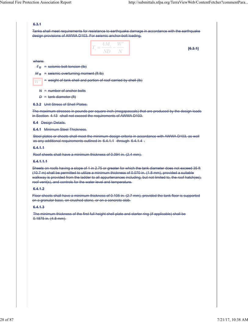
6.3.1
Tanks shall meet requirements for resistance to earthquake damage in accordance with the earthquakedesign provisions of AWWA D103. For seismic anchor-bolt loading,
[6.3.1]
where:
Ts = seismic bolt tension (lb)
M s = seismic overturning moment (ft lb)
= weight of tank shell and portion of roof carried by shell (lb)
N = number of anchor bolts
D = tank diameter (ft)
6.3.2 Unit Stress of Shell Plates.
The maximum stresses in pounds per square inch (megapascals) that are produced by the design loadsin Section 4.13 shall not exceed the requirements of AWWA D103.
6.4 Design Details.
6.4.1 Minimum Steel Thickness.
Steel plates or sheets shall meet the minimum design criteria in accordance with AWWA D103, as wellas any additional requirements outlined in 6.4.1.1 through 6.4.1.4 .
6.4.1.1
Roof sheets shall have a minimum thickness of 0.094 in. (2.4 mm).
6.4.1.1.1
Sheets on roofs having a slope of 1 in 2.75 or greater for which the tank diameter does not exceed 35 ft(10.7 m) shall be permitted to utilize a minimum thickness of 0.070 in. (1.8 mm), provided a suitablewalkway is provided from the ladder to all appurtenances including, but not limited to, the roof hatch(es),roof vent(s), and controls for the water level and temperature.
6.4.1.2
Floor sheets shall have a minimum thickness of 0.105 in. (2.7 mm), provided the tank floor is supportedon a granular base, on crushed stone, or on a concrete slab.
6.4.1.3
The minimum thickness of the first full height shell plate and starter ring (if applicable) shall be0.1875 in. (4.8 mm).
National Fire Protection Association Report http://submittals.nfpa.org/TerraViewWeb/ContentFetcher?commentPara...
28 of 87 7/21/17, 10:38 AM
6.4.1.3.1
This minimum thickness shall be permitted to be reduced, provided the design meets the followingcriteria:
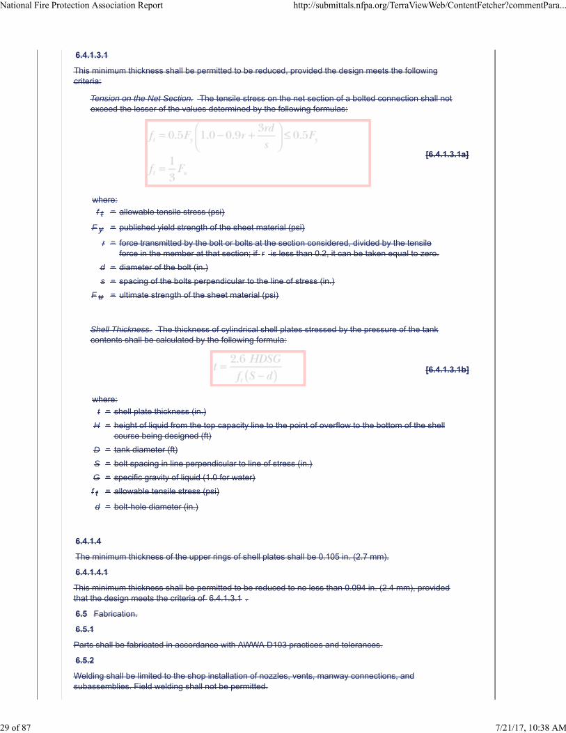
Tension on the Net Section. The tensile stress on the net section of a bolted connection shall notexceed the lesser of the values determined by the following formulas:
[6.4.1.3.1a]
where:
f t = allowable tensile stress (psi)
F y = published yield strength of the sheet material (psi)
r = force transmitted by the bolt or bolts at the section considered, divided by the tensileforce in the member at that section; if r is less than 0.2, it can be taken equal to zero.
d = diameter of the bolt (in.)
s = spacing of the bolts perpendicular to the line of stress (in.)
F u = ultimate strength of the sheet material (psi)
Shell Thickness. The thickness of cylindrical shell plates stressed by the pressure of the tankcontents shall be calculated by the following formula:
[6.4.1.3.1b]
where:
t = shell plate thickness (in.)
H = height of liquid from the top capacity line to the point of overflow to the bottom of the shellcourse being designed (ft)
D = tank diameter (ft)
S = bolt spacing in line perpendicular to line of stress (in.)
G = specific gravity of liquid (1.0 for water)
f t = allowable tensile stress (psi)
d = bolt-hole diameter (in.)
6.4.1.4
The minimum thickness of the upper rings of shell plates shall be 0.105 in. (2.7 mm).
6.4.1.4.1
This minimum thickness shall be permitted to be reduced to no less than 0.094 in. (2.4 mm), providedthat the design meets the criteria of 6.4.1.3.1 .
6.5 Fabrication.
6.5.1
Parts shall be fabricated in accordance with AWWA D103 practices and tolerances.
6.5.2
Welding shall be limited to the shop installation of nozzles, vents, manway connections, andsubassemblies. Field welding shall not be permitted.
National Fire Protection Association Report http://submittals.nfpa.org/TerraViewWeb/ContentFetcher?commentPara...
29 of 87 7/21/17, 10:38 AM
6.5.3
Coatings shall be applied in accordance with AWWA D103.
6.5.4
All tank components shall be given a mark number for ease of assembly.
6.5.5*
All coated parts shall be protected from damage during shipment.
6.6 Erection.
6.6.1
Bolted tanks shall be erected in accordance with the manufacturers' drawings, instructions, and AWWAD103 procedures to facilitate inspection for leaks.
6.6.1.1
Bolted steel floor plates shall be positioned directly on a minimum 4 mil (102 μm) polyethylene base thatis arranged to allow waterflow from the center of the tank to the perimeter of the tank.
6.6.1.2
The polyethylene sheets shall be placed over the sloped base and shall be lapped a minimum of 18 in.(457 mm) on top of one another (the higher sheet overlapping the adjacent sheet) to allow drainagefrom the underside of the tank.
6.6.1.3
Polyethylene sheeting shall not be required for tanks with concrete slabs that also serve as the tankfloor, provided the provisions of Section 17.1 have been met.
6.6.2
The erector shall exercise care to properly install all parts of the tank including, but not limited to,gaskets and sealants.
6.6.3
Care in handling coated parts shall be exercised.
6.6.3.1
Any sections that experience damage to the factory-applied coatings shall be repaired or replaced inaccordance with the manufacturers' instructions.
6.6.3.2
Damaged parts shall be replaced.
Supplemental Information
File Name Description Approved
NFPA_22_Chapter_6_-_CD.docx New Chapter 6. For staff use.
Submitter Information Verification
Submitter Full Name: Chad Duffy
Organization: National Fire Protection Assoc
Street Address:
City:
State:
Zip:
Submittal Date: Tue Apr 11 09:20:53 EDT 2017
Committee Statement
National Fire Protection Association Report http://submittals.nfpa.org/TerraViewWeb/ContentFetcher?commentPara...
30 of 87 7/21/17, 10:38 AM
CommitteeStatement:
Deleted requirements that are redundant to AWWA D-103 and referenced AWWA D-103 as theconstruction document. Items particular to fire water storage tanks remains in this chapter.Clarifies construction requirements for tanks in one document.
Delete annex sections that correlate with deleted sections.
ResponseMessage:
Ballot Results
This item has passed ballot
26 Eligible Voters
5 Not Returned
21 Affirmative All
0 Affirmative with Comments
0 Negative with Comments
0 Abstention
Not Returned
Curran, Sullivan D.
Hochhauser, David
Legatos, Nicholas A.
Patrick, R. Greg
Sanchez, Daniel
Affirmative All
Biradar, Babanna
Campbell, John D.
Culp, Christopher
Fisher, Douglas W.
Fowler, Joseph R.
Gagnon, Robert M.
Garber, Greg
Henning, Andrew M.
Hillman, Jack
Kelly, Kevin J.
Kidd, Todd M.
Koenig, Gary
McGuire, Keith
Mitchard, John M.
Morgan, Bob D.
Noble, Thomas William
Ramo, Leonard J.
Rosenwach, Andrew
National Fire Protection Association Report http://submittals.nfpa.org/TerraViewWeb/ContentFetcher?commentPara...
31 of 87 7/21/17, 10:38 AM

Sornsin, Mark A.
Stein, Gregory R.
Stevens, Owen
National Fire Protection Association Report http://submittals.nfpa.org/TerraViewWeb/ContentFetcher?commentPara...
32 of 87 7/21/17, 10:38 AM
Second Revision No. 10-NFPA 22-2017 [ Section No. 9.1 ]
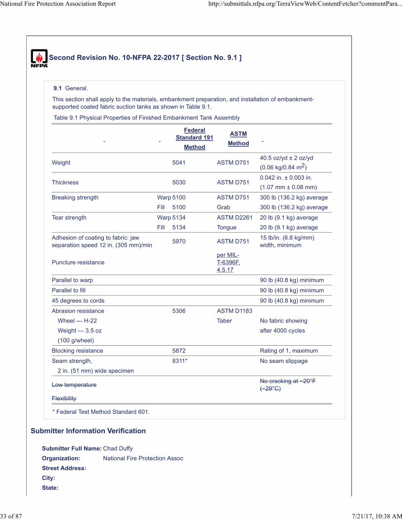
9.1 General.
This section shall apply to the materials, embankment preparation, and installation of embankment-supported coated fabric suction tanks as shown in Table 9.1.
Table 9.1 Physical Properties of Finished Embankment Tank Assembly
FederalStandard 191
Method
ASTM
Method
Weight 5041 ASTM D75140.5 oz/yd ± 2 oz/yd
(0.06 kg/0.84 m2)
Thickness 5030 ASTM D7510.042 in. ± 0.003 in.
(1.07 mm ± 0.08 mm)
Breaking strength Warp 5100 ASTM D751 300 lb (136.2 kg) average
Fill 5100 Grab 300 lb (136.2 kg) average
Tear strength Warp 5134 ASTM D2261 20 lb (9.1 kg) average
Fill 5134 Tongue 20 lb (9.1 kg) average
Adhesion of coating to fabric: jawseparation speed 12 in. (305 mm)/min
5970 ASTM D75115 lb/in. (6.8 kg/mm)width, minimum
Puncture resistanceper MIL-T-6396F,4.5.17
Parallel to warp 90 lb (40.8 kg) minimum
Parallel to fill 90 lb (40.8 kg) minimum
45 degrees to cords 90 lb (40.8 kg) minimum
Abrasion resistance 5306 ASTM D1183
Wheel — H-22 Taber No fabric showing
Weight — 3.5 oz after 4000 cycles
(100 g/wheel)
Blocking resistance 5872 Rating of 1, maximum
Seam strength, 8311* No seam slippage
2 in. (51 mm) wide specimen
Low temperatureNo cracking at −20°F(−29°C)
Flexibility
* Federal Test Method Standard 601.
Submitter Information Verification
Submitter Full Name: Chad Duffy
Organization: National Fire Protection Assoc
Street Address:
City:
State:
National Fire Protection Association Report http://submittals.nfpa.org/TerraViewWeb/ContentFetcher?commentPara...
33 of 87 7/21/17, 10:38 AM
Zip:
Submittal Date: Wed Mar 22 09:50:50 EDT 2017
Committee Statement
CommitteeStatement:
The puncture resistance MIL spec has been revised to the appropriate reference. LowTemperature Flexibility has been removed as there are no applicable MIL spec's available and thetask group was unable to find any other low temperature flexibility specifications for this type oftank application.
ResponseMessage:
Ballot Results
This item has passed ballot
26 Eligible Voters
5 Not Returned
21 Affirmative All
0 Affirmative with Comments
0 Negative with Comments
0 Abstention
Not Returned
Curran, Sullivan D.
Hochhauser, David
Legatos, Nicholas A.
Patrick, R. Greg
Sanchez, Daniel
Affirmative All
Biradar, Babanna
Campbell, John D.
Culp, Christopher
Fisher, Douglas W.
Fowler, Joseph R.
Gagnon, Robert M.
Garber, Greg
Henning, Andrew M.
Hillman, Jack
Kelly, Kevin J.
Kidd, Todd M.
Koenig, Gary
McGuire, Keith
Mitchard, John M.
Morgan, Bob D.
National Fire Protection Association Report http://submittals.nfpa.org/TerraViewWeb/ContentFetcher?commentPara...
34 of 87 7/21/17, 10:38 AM

Noble, Thomas William
Ramo, Leonard J.
Rosenwach, Andrew
Sornsin, Mark A.
Stein, Gregory R.
Stevens, Owen
National Fire Protection Association Report http://submittals.nfpa.org/TerraViewWeb/ContentFetcher?commentPara...
35 of 87 7/21/17, 10:38 AM
Second Revision No. 7-NFPA 22-2017 [ Section No. 12.2.2 ]
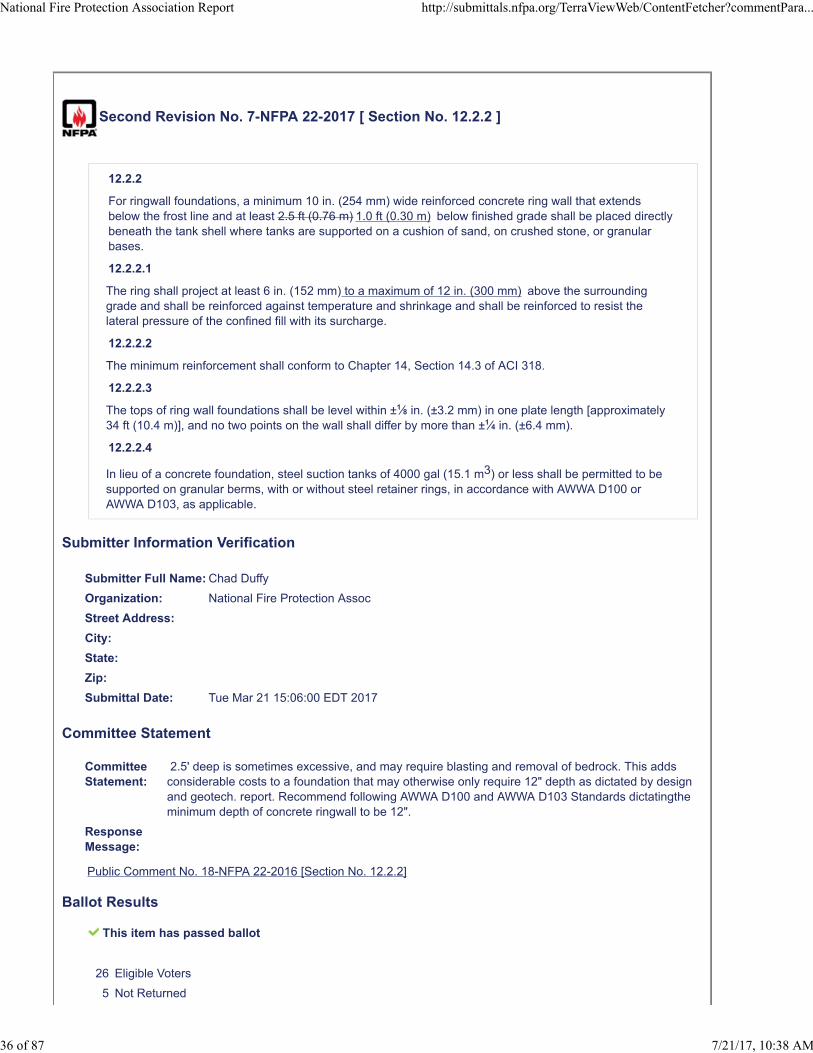
12.2.2
For ringwall foundations, a minimum 10 in. (254 mm) wide reinforced concrete ring wall that extendsbelow the frost line and at least 2.5 ft (0.76 m) 1.0 ft (0.30 m) below finished grade shall be placed directlybeneath the tank shell where tanks are supported on a cushion of sand, on crushed stone, or granularbases.
12.2.2.1
The ring shall project at least 6 in. (152 mm) to a maximum of 12 in. (300 mm) above the surroundinggrade and shall be reinforced against temperature and shrinkage and shall be reinforced to resist thelateral pressure of the confined fill with its surcharge.
12.2.2.2
The minimum reinforcement shall conform to Chapter 14, Section 14.3 of ACI 318.
12.2.2.3
The tops of ring wall foundations shall be level within ±1⁄8 in. (±3.2 mm) in one plate length [approximately34 ft (10.4 m)], and no two points on the wall shall differ by more than ±1⁄4 in. (±6.4 mm).
12.2.2.4
In lieu of a concrete foundation, steel suction tanks of 4000 gal (15.1 m3) or less shall be permitted to besupported on granular berms, with or without steel retainer rings, in accordance with AWWA D100 orAWWA D103, as applicable.
Submitter Information Verification
Submitter Full Name: Chad Duffy
Organization: National Fire Protection Assoc
Street Address:
City:
State:
Zip:
Submittal Date: Tue Mar 21 15:06:00 EDT 2017
Committee Statement
CommitteeStatement:
2.5' deep is sometimes excessive, and may require blasting and removal of bedrock. This addsconsiderable costs to a foundation that may otherwise only require 12" depth as dictated by designand geotech. report. Recommend following AWWA D100 and AWWA D103 Standards dictatingtheminimum depth of concrete ringwall to be 12".
ResponseMessage:
Public Comment No. 18-NFPA 22-2016 [Section No. 12.2.2]
Ballot Results
This item has passed ballot
26 Eligible Voters
5 Not Returned
National Fire Protection Association Report http://submittals.nfpa.org/TerraViewWeb/ContentFetcher?commentPara...
36 of 87 7/21/17, 10:38 AM
21 Affirmative All
0 Affirmative with Comments
0 Negative with Comments
0 Abstention
Not Returned
Curran, Sullivan D.
Hochhauser, David
Legatos, Nicholas A.
Patrick, R. Greg
Sanchez, Daniel
Affirmative All
Biradar, Babanna
Campbell, John D.
Culp, Christopher
Fisher, Douglas W.
Fowler, Joseph R.
Gagnon, Robert M.
Garber, Greg
Henning, Andrew M.
Hillman, Jack
Kelly, Kevin J.
Kidd, Todd M.
Koenig, Gary
McGuire, Keith
Mitchard, John M.
Morgan, Bob D.
Noble, Thomas William
Ramo, Leonard J.
Rosenwach, Andrew
Sornsin, Mark A.
Stein, Gregory R.
Stevens, Owen
National Fire Protection Association Report http://submittals.nfpa.org/TerraViewWeb/ContentFetcher?commentPara...
37 of 87 7/21/17, 10:38 AM
Second Revision No. 9-NFPA 22-2017 [ Sections 14.1.7.1, 14.1.7.2 ]
14.1.7.1
Connections for use other than fire protection shall not be made.
14.1.7.1
Connections for other than fire protection shall be approved.
14.1.7.1.1*
Pipe used for other than fire protection purposes shall be entirely separate from fire-service pipes andshall extend to an elevation inside the tank above that required for fire protection.
Submitter Information Verification
Submitter Full Name: Chad Duffy
Organization: National Fire Protection Assoc
Street Address:
City:
State:
Zip:
Submittal Date: Tue Mar 21 16:55:32 EDT 2017
Committee Statement
CommitteeStatement:
Section 14.1.7.1 was deleted because it was contradictory to section 14.1.7.2. Renumber theremainder of the sections.
ResponseMessage:
Ballot Results
This item has passed ballot
26 Eligible Voters
5 Not Returned
21 Affirmative All
0 Affirmative with Comments
0 Negative with Comments
0 Abstention
Not Returned
Curran, Sullivan D.
Hochhauser, David
Legatos, Nicholas A.
Patrick, R. Greg
Sanchez, Daniel
National Fire Protection Association Report http://submittals.nfpa.org/TerraViewWeb/ContentFetcher?commentPara...
38 of 87 7/21/17, 10:38 AM
Affirmative All
Biradar, Babanna
Campbell, John D.
Culp, Christopher
Fisher, Douglas W.
Fowler, Joseph R.
Gagnon, Robert M.
Garber, Greg
Henning, Andrew M.
Hillman, Jack
Kelly, Kevin J.
Kidd, Todd M.
Koenig, Gary
McGuire, Keith
Mitchard, John M.
Morgan, Bob D.
Noble, Thomas William
Ramo, Leonard J.
Rosenwach, Andrew
Sornsin, Mark A.
Stein, Gregory R.
Stevens, Owen
National Fire Protection Association Report http://submittals.nfpa.org/TerraViewWeb/ContentFetcher?commentPara...
39 of 87 7/21/17, 10:38 AM
Second Revision No. 8-NFPA 22-2017 [ Section No. 14.7.2.1 [Excluding any Sub-
Sections] ]
Two A minimum of two manholes shall be provided in the first ring of the steel suction tank shell atlocations to be designated by the purchaser.
Submitter Information Verification
Submitter Full Name: Chad Duffy
Organization: National Fire Protection Assoc
Street Address:
City:
State:
Zip:
Submittal Date: Tue Mar 21 16:25:28 EDT 2017
Committee Statement
Committee Statement: The added text provides clarification aligning with AWWA D100.
Response Message:
Ballot Results
This item has passed ballot
26 Eligible Voters
5 Not Returned
20 Affirmative All
0 Affirmative with Comments
1 Negative with Comments
0 Abstention
Not Returned
Curran, Sullivan D.
Hochhauser, David
Legatos, Nicholas A.
Patrick, R. Greg
Sanchez, Daniel
Affirmative All
Biradar, Babanna
Campbell, John D.
Culp, Christopher
Fisher, Douglas W.
National Fire Protection Association Report http://submittals.nfpa.org/TerraViewWeb/ContentFetcher?commentPara...
40 of 87 7/21/17, 10:38 AM
Fowler, Joseph R.
Gagnon, Robert M.
Garber, Greg
Henning, Andrew M.
Hillman, Jack
Kelly, Kevin J.
Kidd, Todd M.
Koenig, Gary
Mitchard, John M.
Morgan, Bob D.
Noble, Thomas William
Ramo, Leonard J.
Rosenwach, Andrew
Sornsin, Mark A.
Stein, Gregory R.
Stevens, Owen
Negative with Comment
McGuire, Keith
This contradicts AWWA D103-09 for bolted tanks where only (1) shell manhole is required. A shell sheet may beremoved opposite the manhole if necessary. See AWWA D103-09 Sec. 7.1.
National Fire Protection Association Report http://submittals.nfpa.org/TerraViewWeb/ContentFetcher?commentPara...
41 of 87 7/21/17, 10:38 AM
Second Revision No. 11-NFPA 22-2017 [ Section No. 16.1.4 ]
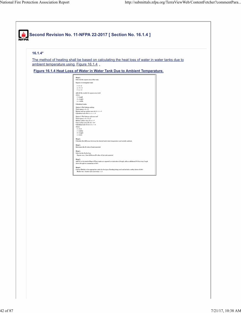
16.1.4*
The method of heating shall be based on calculating the heat loss of water in water tanks due toambient temperature using Figure 16.1.4 .
Figure 16.1.4 Heat Loss of Water in Water Tank Due to Ambient Temperature.
National Fire Protection Association Report http://submittals.nfpa.org/TerraViewWeb/ContentFetcher?commentPara...
42 of 87 7/21/17, 10:38 AM
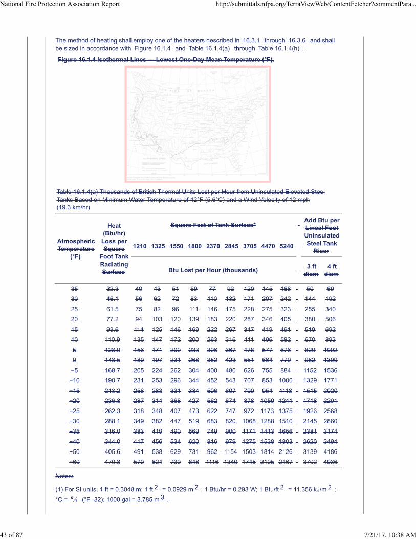
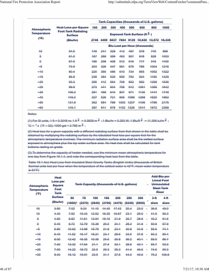
The method of heating shall employ one of the heaters described in 16.3.1 through 16.3.6 and shallbe sized in accordance with Figure 16.1.4 and Table 16.1.4(a) through Table 16.1.4(h) .
Figure 16.1.4 Isothermal Lines — Lowest One-Day Mean Temperature (°F).
Table 16.1.4(a) Thousands of British Thermal Units Lost per Hour from Uninsulated Elevated SteelTanks Based on Minimum Water Temperature of 42°F (5.6°C) and a Wind Velocity of 12 mph(19.3 km/hr)
AtmosphericTemperature
(°F)
Heat(Btu/hr)
Loss perSquare
Foot TankRadiatingSurface
Square Feet of Tank Surface* Add Btu perLineal FootUninsulatedSteel Tank
Riser1210 1325 1550 1800 2370 2845 3705 4470 5240
Btu Lost per Hour (thousands) 3 ft
diam4 ft
diam
35 32.3 40 43 51 59 77 92 120 145 168 50 69
30 46.1 56 62 72 83 110 132 171 207 242 144 192
25 61.5 75 82 96 111 146 175 228 275 323 255 340
20 77.2 94 103 120 139 183 220 287 346 405 380 506
15 93.6 114 125 146 169 222 267 347 419 491 519 692
10 110.9 135 147 172 200 263 316 411 496 582 670 893
5 128.9 156 171 200 233 306 367 478 577 676 820 1092
0 148.5 180 197 231 268 352 423 551 664 779 982 1309
−5 168.7 205 224 262 304 400 480 626 755 884 1152 1536
−10 190.7 231 253 296 344 452 543 707 853 1000 1329 1771
−15 213.2 258 283 331 384 506 607 790 954 1118 1515 2020
−20 236.8 287 314 368 427 562 674 878 1059 1241 1718 2291
−25 262.3 318 348 407 473 622 747 972 1173 1375 1926 2568
−30 288.1 349 382 447 519 683 820 1068 1288 1510 2145 2860
−35 316.0 383 419 490 569 749 900 1171 1413 1656 2381 3174
−40 344.0 417 456 534 620 816 979 1275 1538 1803 2620 3494
−50 405.6 491 538 629 731 962 1154 1503 1814 2126 3139 4186
−60 470.8 570 624 730 848 1116 1340 1745 2105 2467 3702 4936
Notes:
(1) For SI units, 1 ft = 0.3048 m; 1 ft 2 = 0.0929 m 2 ; 1 Btu/hr = 0.293 W; 1 Btu/ft 2 = 11.356 kJ/m 2 ;
°C = 5 ⁄9 (°F -32); 1000 gal = 3.785 m 3 .
National Fire Protection Association Report http://submittals.nfpa.org/TerraViewWeb/ContentFetcher?commentPara...
43 of 87 7/21/17, 10:38 AM
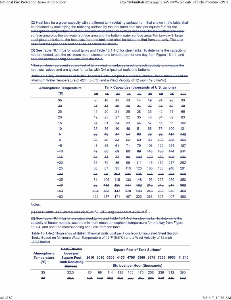
(2) Heat loss for a given capacity with a different tank radiating surface from that shown in the table shallbe obtained by multiplying the radiating surface by the tabulated heat loss per square foot for theatmospheric temperature involved. The minimum radiation surface area shall be the wetted tank steelsurface area plus the top water surface area and the bottom water surface area. For tanks with largesteel-plate tank risers, the heat loss from the tank riser shall be added to that from the tank. The tankriser heat loss per linear foot shall be as tabulated above.
(3) See Table 16.1.4(b) for wood tanks and Table 16.1.4(c) for steel tanks. To determine the capacity ofheater needed, use the minimum mean atmospheric temperature for one day from Figure 16.1.4, andnote the corresponding heat loss from the table.
*These values represent square feet of tank radiating surfaces used for each capacity to compute theheat loss values and are typical for tanks with D/4 ellipsoidal roofs and bottoms.
Table 16.1.4(b) Thousands of British Thermal Units Lost per Hour from Elevated Wood Tanks Based onMinimum Water Temperature of 42°F (5.6°C) and a Wind Velocity of 12 mph (19.3 km/hr)
Atmospheric Temperature
(°F)
Tank Capacities (thousands of U.S. gallons)
10 15 20 25 30 40 50 75 100
35 8 10 11 13 14 19 21 28 33
30 11 14 16 19 21 27 31 40 49
25 15 20 21 25 28 36 42 54 65
20 19 25 27 32 35 46 54 69 83
15 24 31 34 39 44 57 66 85 102
10 28 36 40 46 51 68 78 100 121
5 33 43 47 54 60 78 92 117 142
0 38 49 53 62 69 90 106 135 164
−5 43 56 61 71 79 103 120 154 187
−10 49 63 69 80 89 116 136 174 211
−15 54 71 77 89 100 130 153 195 236
−20 61 79 86 99 111 145 169 217 262
−25 68 87 95 110 123 160 188 240 291
−30 74 96 104 121 135 176 206 264 319
−35 81 105 115 133 148 193 226 289 350
−40 88 114 125 144 162 210 246 317 382
−50 104 135 147 170 190 246 290 372 450
−60 122 157 171 197 222 266 307 407 490
Notes:
(1) For SI units, 1 Btu/hr = 0.293 W; °C = 5 ⁄9 (°F −32); 1000 gal = 3.785 m 3 .
(2) See Table 16.1.4(a) for elevated steel tanks and Table 16.1.4(c) for steel tanks. To determine thecapacity of heater needed, use the minimum mean atmospheric temperature for one day from Figure16.1.4, and note the corresponding heat loss from the table.
Table 16.1.4(c) Thousands of British Thermal Units Lost per Hour from Uninsulated Steel SuctionTanks Based on Minimum Water Temperature of 42°F (5.6°C) and a Wind Velocity of 12 mph(19.3 km/hr)
AtmosphericTemperature
(°F)
Heat (Btu/hr)Loss per
Square FootTank Radiating
Surface
Square Feet of Tank Surface*
2610 3030 3505 4175 4795 5360 6375 7355 9650 11,740
Btu Lost per Hour (thousands)
35 32.3 85 98 114 135 155 175 206 238 312 380
30 46.1 121 140 162 193 222 248 294 340 445 542
National Fire Protection Association Report http://submittals.nfpa.org/TerraViewWeb/ContentFetcher?commentPara...
44 of 87 7/21/17, 10:38 AM
AtmosphericTemperature
(°F)
Heat (Btu/hr)Loss per
Square FootTank Radiating
Surface
Square Feet of Tank Surface*
2610 3030 3505 4175 4795 5360 6375 7355 9650 11,740
Btu Lost per Hour (thousands)
25 61.5 161 187 216 257 295 330 393 453 594 722
20 77.2 202 234 271 323 371 414 493 568 745 907
15 93.6 245 284 329 391 449 502 597 689 904 1099
10 110.9 290 337 389 463 532 595 707 816 1071 1302
5 128.9 337 391 452 539 619 691 822 949 1244 1514
0 148.5 388 450 521 620 713 796 947 1093 1434 1744
−5 168.7 441 512 592 705 809 905 1076 1241 1628 1981
−10 190.7 498 578 669 797 915 1023 1216 1403 1841 2239
−15 213.2 557 646 748 891 1023 1143 1360 1569 2058 2503
−20 236.8 619 718 830 989 1136 1270 1510 1742 2286 2781
−25 262.3 685 795 920 1096 1258 1406 1673 1930 2532 3080
−30 288.1 752 873 1010 1203 1382 1545 1837 2119 2781 3383
−35 316.0 825 958 1108 1320 1516 1694 2015 2325 3050 3710
−40 344.0 898 1043 1206 1437 1650 1844 2193 2531 3320 4039
−50 405.6 1059 1229 1422 1694 1945 2175 2586 2984 3915 4762
−60 470.8 1229 1427 1651 1966 2258 2524 3002 3463 4544 5528
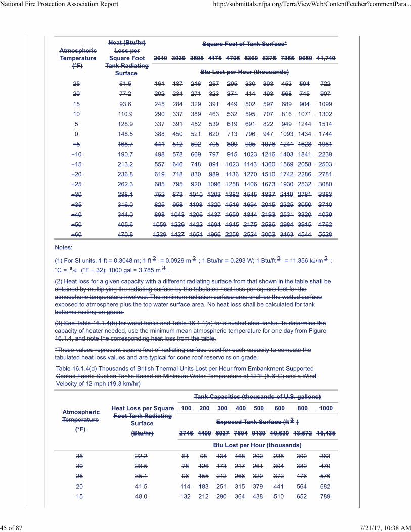
Notes:
(1) For SI units, 1 ft = 0.3048 m; 1 ft 2 = 0.0929 m 2 ; 1 Btu/hr = 0.293 W; 1 Btu/ft 2 = 11.356 kJ/m 2 ;
°C = 5 ⁄9 (°F − 32); 1000 gal = 3.785 m 3 .
(2) Heat loss for a given capacity with a different radiating surface from that shown in the table shall beobtained by multiplying the radiating surface by the tabulated heat loss per square feet for theatmospheric temperature involved. The minimum radiation surface area shall be the wetted surfaceexposed to atmosphere plus the top water surface area. No heat loss shall be calculated for tankbottoms resting on grade.
(3) See Table 16.1.4(b) for wood tanks and Table 16.1.4(a) for elevated steel tanks. To determine thecapacity of heater needed, use the minimum mean atmospheric temperature for one day from Figure16.1.4, and note the corresponding heat loss from the table.
*These values represent square feet of radiating surface used for each capacity to compute thetabulated heat loss values and are typical for cone roof reservoirs on grade.
Table 16.1.4(d) Thousands of British Thermal Units Lost per Hour from Embankment-SupportedCoated Fabric Suction Tanks Based on Minimum Water Temperature of 42°F (5.6°C) and a WindVelocity of 12 mph (19.3 km/hr)
AtmosphericTemperature
(°F)
Heat Loss per SquareFoot Tank Radiating
Surface
(Btu/hr)
Tank Capacities (thousands of U.S. gallons)
100 200 300 400 500 600 800 1000
Exposed Tank Surface (ft 3 )
2746 4409 6037 7604 9139 10,630 13,572 16,435
Btu Lost per Hour (thousands)
35 22.2 61 98 134 168 202 235 300 363
30 28.5 78 126 173 217 261 304 389 470
25 35.1 96 155 212 266 320 372 476 576
20 41.5 114 183 251 315 379 441 564 682
15 48.0 132 212 290 364 438 510 652 789
National Fire Protection Association Report http://submittals.nfpa.org/TerraViewWeb/ContentFetcher?commentPara...
45 of 87 7/21/17, 10:38 AM
AtmosphericTemperature
(°F)
Heat Loss per SquareFoot Tank Radiating
Surface
(Btu/hr)
Tank Capacities (thousands of U.S. gallons)
100 200 300 400 500 600 800 1000
Exposed Tank Surface (ft 3 )
2746 4409 6037 7604 9139 10,630 13,572 16,435
Btu Lost per Hour (thousands)
10 54.5 149 241 329 413 497 579 740 896
5 61.0 167 269 369 463 557 648 828 1003
0 67.5 185 298 408 512 616 717 916 1109
−5 73.9 203 326 447 561 675 786 1004 1216
−10 80.4 220 355 486 610 734 855 1092 1322
−15 86.8 238 384 525 659 793 924 1180 1429
−20 93.3 256 412 564 708 852 992 1268 1536
−25 99.9 273 441 604 758 912 1061 1356 1642
−30 106.2 291 469 643 807 971 1130 1444 1749
−40 119.3 327 526 721 905 1089 1268 1620 1962
−50 131.9 362 584 799 1003 1207 1406 1796 2175
−60 145.1 397 641 878 1102 1326 1544 1972 2389
Notes:
(1) For SI units, 1 ft = 0.3048 m; 1 ft 2 = 0.0929 m 2 ; 1 Btu/hr = 0.293 W; 1 Btu/ft 2 = 11.356 kJ/m 2 ;
°C = 5 ⁄9 (°F − 32); 1000 gal = 3.785 m 3 .
(2) Heat loss for a given capacity with a different radiating surface from that shown in the table shall beobtained by multiplying the radiating surface by the tabulated heat loss per square feet for theatmospheric temperature involved. The minimum radiation surface area shall be the wetted surfaceexposed to atmosphere plus the top water surface area. No heat loss shall be calculated for tankbottoms resting on grade.
(3) To determine the capacity of heater needed, use the minimum mean atmospheric temperature forone day from Figure 16.1.4, and note the corresponding heat loss from the table.
Table 16.1.4(e) Heat Loss from Insulated Steel Gravity Tanks (English Units) (thousands of Britishthermal units lost per hour when the temperature of the coldest water is 42°F; mean water temperatureis 54°F)
AtmosphericTemperature
(°F)
HeatLoss perSquare
FootTank
Surface
(Btu/hr)
Tank Capacity (thousands of U.S. gallons)
Add Btu perLineal FootUninsulatedSteel Tank
Riser
50
(1800)*
75
(2370)
100
(2845)
150
(3705)
200
(4470)
250
(5240)
300
(5905)
3 ft
diam
4 ft
diam
15 3.90 7.02 9.24 11.10 14.45 17.43 20.4 23.0 36.8 49.0
10 4.40 7.92 10.43 12.52 16.30 19.67 23.1 26.0 41.5 55.3
5 4.90 8.82 11.61 13.94 18.15 21.9 25.7 28.9 40.2 61.6
0 5.40 9.72 12.79 15.36 20.0 24.1 28.3 31.9 50.9 67.9
−5 5.90 10.62 13.98 16.79 21.9 23.4 30.9 34.8 55.6 74.1
−10 6.40 11.52 15.17 18.21 23.1 28.6 33.5 37.8 60.3 80.4
−15 6.90 12.42 16.35 19.36 25.6 30.8 36.2 40.1 65.0 86.7
−20 7.40 13.32 17.54 21.1 27.4 33.1 38.8 43.1 69.7 93.0
−25 7.90 14.22 18.72 22.5 29.3 35.3 41.4 46.6 74.5 99.3
−30 8.40 15.12 19.91 23.9 31.1 37.5 44.0 49.6 79.2 105.6
National Fire Protection Association Report http://submittals.nfpa.org/TerraViewWeb/ContentFetcher?commentPara...
46 of 87 7/21/17, 10:38 AM
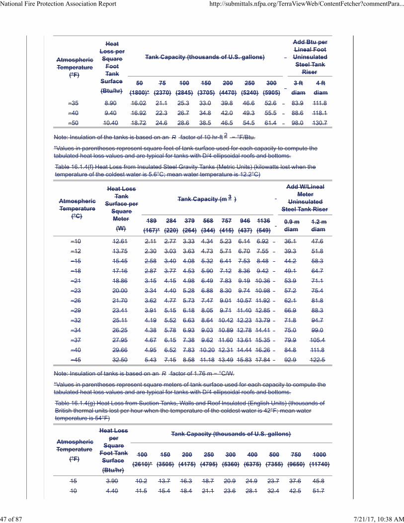
AtmosphericTemperature
(°F)
HeatLoss perSquare
FootTank
Surface
(Btu/hr)
Tank Capacity (thousands of U.S. gallons)
Add Btu perLineal FootUninsulatedSteel Tank
Riser
50
(1800)*
75
(2370)
100
(2845)
150
(3705)
200
(4470)
250
(5240)
300
(5905)
3 ft
diam
4 ft
diam
−35 8.90 16.02 21.1 25.3 33.0 39.8 46.6 52.6 83.9 111.8
−40 9.40 16.92 22.3 26.7 34.8 42.0 49.3 55.5 88.6 118.1
−50 10.40 18.72 24.6 28.6 38.5 46.5 54.5 61.4 98.0 130.7
Note: Insulation of the tanks is based on an R factor of 10 hr-ft 2 − °F/Btu.
*Values in parentheses represent square feet of tank surface used for each capacity to compute thetabulated heat loss values and are typical for tanks with D/4 ellipsoidal roofs and bottoms.
Table 16.1.4(f) Heat Loss from Insulated Steel Gravity Tanks (Metric Units) (kilowatts lost when thetemperature of the coldest water is 5.6°C; mean water temperature is 12.2°C)
AtmosphericTemperature
(°C)
Heat LossTank
Surface perSquareMeter
(W)
Tank Capacity (m 3 )
Add W/LinealMeter
UninsulatedSteel Tank Riser
189
(167)*
284
(220)
379
(264)
568
(344)
757
(415)
946
(437)
1136
(549)
0.9 mdiam
1.2 mdiam
−10 12.61 2.11 2.77 3.33 4.34 5.23 6.14 6.92 36.1 47.6
−12 13.75 2.30 3.03 3.63 4.73 5.71 6.70 7.55 39.3 51.8
−15 15.45 2.58 3.40 4.08 5.32 6.41 7.53 8.48 44.2 58.3
−18 17.16 2.87 3.77 4.53 5.90 7.12 8.36 9.42 49.1 64.7
−21 18.86 3.15 4.15 4.98 6.49 7.83 9.19 10.36 53.9 71.1
−23 20.00 3.34 4.40 5.28 6.88 8.30 9.74 10.98 57.2 75.4
−26 21.70 3.62 4.77 5.73 7.47 9.01 10.57 11.92 62.1 81.8
−29 23.41 3.91 5.15 6.18 8.05 9.71 11.40 12.85 66.9 88.3
−32 25.11 4.19 5.52 6.63 8.64 10.42 12.23 13.79 71.8 94.7
−34 26.25 4.38 5.78 6.93 9.03 10.89 12.78 14.41 75.0 99.0
−37 27.95 4.67 6.15 7.38 9.62 11.60 13.61 15.35 79.9 105.4
−40 29.66 4.95 6.52 7.83 10.20 12.31 14.44 16.26 84.8 111.8
−45 32.50 5.43 7.15 8.58 11.18 13.49 15.83 17.84 92.9 122.5
Note: Insulation of tanks is based on an R factor of 1.76 m − °C/W.
*Values in parentheses represent square meters of tank surface used for each capacity to compute thetabulated heat loss values and are typical for tanks with D/4 ellipsoidal roofs and bottoms.
Table 16.1.4(g) Heat Loss from Suction Tanks, Walls and Roof Insulated (English Units) (thousands ofBritish thermal units lost per hour when the temperature of the coldest water is 42°F; mean watertemperature is 54°F)
AtmosphericTemperature
(°F)
Heat Lossper
SquareFoot TankSurface
(Btu/hr)
Tank Capacity (thousands of U.S. gallons)
100
(2610)*
150
(3505)
200
(4175)
250
(4795)
300
(5360)
400
(6375)
500
(7355)
750
(9650)
1000
(11740)
15 3.90 10.2 13.7 16.3 18.7 20.9 24.9 23.7 37.6 45.8
10 4.40 11.5 15.4 18.4 21.1 23.6 28.1 32.4 42.5 51.7
National Fire Protection Association Report http://submittals.nfpa.org/TerraViewWeb/ContentFetcher?commentPara...
47 of 87 7/21/17, 10:38 AM
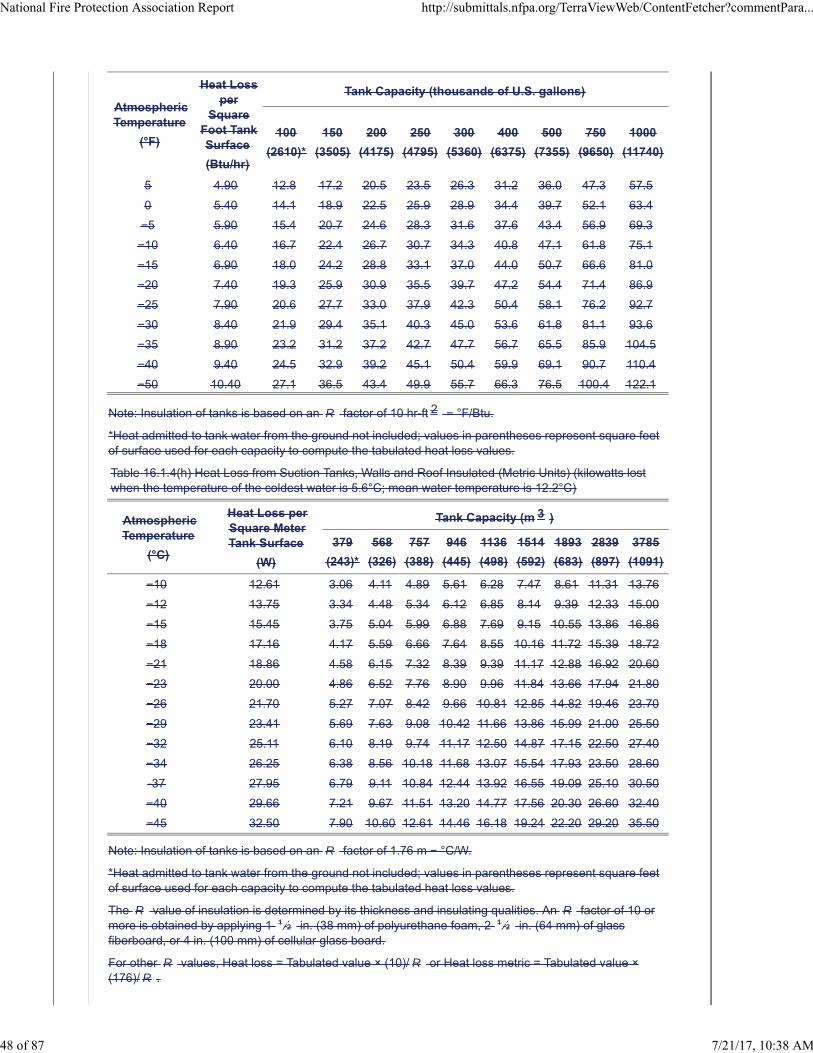
AtmosphericTemperature
(°F)
Heat Lossper
SquareFoot TankSurface
(Btu/hr)
Tank Capacity (thousands of U.S. gallons)
100
(2610)*
150
(3505)
200
(4175)
250
(4795)
300
(5360)
400
(6375)
500
(7355)
750
(9650)
1000
(11740)
5 4.90 12.8 17.2 20.5 23.5 26.3 31.2 36.0 47.3 57.5
0 5.40 14.1 18.9 22.5 25.9 28.9 34.4 39.7 52.1 63.4
−5 5.90 15.4 20.7 24.6 28.3 31.6 37.6 43.4 56.9 69.3
−10 6.40 16.7 22.4 26.7 30.7 34.3 40.8 47.1 61.8 75.1
−15 6.90 18.0 24.2 28.8 33.1 37.0 44.0 50.7 66.6 81.0
−20 7.40 19.3 25.9 30.9 35.5 39.7 47.2 54.4 71.4 86.9
−25 7.90 20.6 27.7 33.0 37.9 42.3 50.4 58.1 76.2 92.7
−30 8.40 21.9 29.4 35.1 40.3 45.0 53.6 61.8 81.1 93.6
−35 8.90 23.2 31.2 37.2 42.7 47.7 56.7 65.5 85.9 104.5
−40 9.40 24.5 32.9 39.2 45.1 50.4 59.9 69.1 90.7 110.4
−50 10.40 27.1 36.5 43.4 49.9 55.7 66.3 76.5 100.4 122.1
Note: Insulation of tanks is based on an R factor of 10 hr-ft 2 − °F/Btu.
*Heat admitted to tank water from the ground not included; values in parentheses represent square feetof surface used for each capacity to compute the tabulated heat loss values.
Table 16.1.4(h) Heat Loss from Suction Tanks, Walls and Roof Insulated (Metric Units) (kilowatts lostwhen the temperature of the coldest water is 5.6°C; mean water temperature is 12.2°C)
AtmosphericTemperature
(°C)
Heat Loss perSquare MeterTank Surface
(W)
Tank Capacity (m 3 )
379
(243)*
568
(326)
757
(388)
946
(445)
1136
(498)
1514
(592)
1893
(683)
2839
(897)
3785
(1091)
−10 12.61 3.06 4.11 4.89 5.61 6.28 7.47 8.61 11.31 13.76
−12 13.75 3.34 4.48 5.34 6.12 6.85 8.14 9.39 12.33 15.00
−15 15.45 3.75 5.04 5.99 6.88 7.69 9.15 10.55 13.86 16.86
−18 17.16 4.17 5.59 6.66 7.64 8.55 10.16 11.72 15.39 18.72
−21 18.86 4.58 6.15 7.32 8.39 9.39 11.17 12.88 16.92 20.60
−23 20.00 4.86 6.52 7.76 8.90 9.96 11.84 13.66 17.94 21.80
−26 21.70 5.27 7.07 8.42 9.66 10.81 12.85 14.82 19.46 23.70
−29 23.41 5.69 7.63 9.08 10.42 11.66 13.86 15.99 21.00 25.50
−32 25.11 6.10 8.19 9.74 11.17 12.50 14.87 17.15 22.50 27.40
−34 26.25 6.38 8.56 10.18 11.68 13.07 15.54 17.93 23.50 28.60
-37 27.95 6.79 9.11 10.84 12.44 13.92 16.55 19.09 25.10 30.50
−40 29.66 7.21 9.67 11.51 13.20 14.77 17.56 20.30 26.60 32.40
−45 32.50 7.90 10.60 12.61 14.46 16.18 19.24 22.20 29.20 35.50
Note: Insulation of tanks is based on an R factor of 1.76 m − °C/W.
*Heat admitted to tank water from the ground not included; values in parentheses represent square feetof surface used for each capacity to compute the tabulated heat loss values.
The R value of insulation is determined by its thickness and insulating qualities. An R factor of 10 ormore is obtained by applying 1 1 ⁄2 in. (38 mm) of polyurethane foam, 2 1 ⁄2 in. (64 mm) of glassfiberboard, or 4 in. (100 mm) of cellular glass board.
For other R values, Heat loss = Tabulated value × (10)/ R or Heat loss metric = Tabulated value ×(176)/ R .
National Fire Protection Association Report http://submittals.nfpa.org/TerraViewWeb/ContentFetcher?commentPara...
48 of 87 7/21/17, 10:38 AM
16.1.4.1
The heater shall be plainly marked with a plate or cast lettering that indicates the kilowatt (British thermalunit) per hour input, type of heater, and the manufacturer’s name.
16.1.4.2
The allowable working pressure of the heater shall not be less than the maximum filling pressuresustained when the tank is being filled.
Supplemental Information
File Name Description Approved
Heat_Loss_of_Water_in_Water_Tank_Due_to_Ambient_Temperature_-_CD.docx
Heat Loss Calculation Method - For Staff Use
Submitter Information Verification
Submitter Full Name: Chad Duffy
Organization: National Fire Protection Assoc
Street Address:
City:
State:
Zip:
Submittal Date: Wed Mar 22 10:52:31 EDT 2017
Committee Statement
CommitteeStatement:
NFPA 22 is an international standard and the geographical map and table were restricted to theUnited States. The chart and tables have been deleted and replaced with heat loss method that iscommonly used throughout the industry. When determining heat loss the ambient meantemperature of a geographical area must be determined and applied to the appropriate formula.
ResponseMessage:
Ballot Results
This item has passed ballot
26 Eligible Voters
5 Not Returned
21 Affirmative All
0 Affirmative with Comments
0 Negative with Comments
0 Abstention
Not Returned
Curran, Sullivan D.
Hochhauser, David
Legatos, Nicholas A.
Patrick, R. Greg
Sanchez, Daniel
National Fire Protection Association Report http://submittals.nfpa.org/TerraViewWeb/ContentFetcher?commentPara...
49 of 87 7/21/17, 10:38 AM

Affirmative All
Biradar, Babanna
Campbell, John D.
Culp, Christopher
Fisher, Douglas W.
Fowler, Joseph R.
Gagnon, Robert M.
Garber, Greg
Henning, Andrew M.
Hillman, Jack
Kelly, Kevin J.
Kidd, Todd M.
Koenig, Gary
McGuire, Keith
Mitchard, John M.
Morgan, Bob D.
Noble, Thomas William
Ramo, Leonard J.
Rosenwach, Andrew
Sornsin, Mark A.
Stein, Gregory R.
Stevens, Owen
National Fire Protection Association Report http://submittals.nfpa.org/TerraViewWeb/ContentFetcher?commentPara...
50 of 87 7/21/17, 10:38 AM
Second Revision No. 12-NFPA 22-2017 [ Section No. 16.2 ]
16.2* Heating Requirements.
16.2.1*
National Fire Protection Association Report http://submittals.nfpa.org/TerraViewWeb/ContentFetcher?commentPara...
51 of 87 7/21/17, 10:38 AM
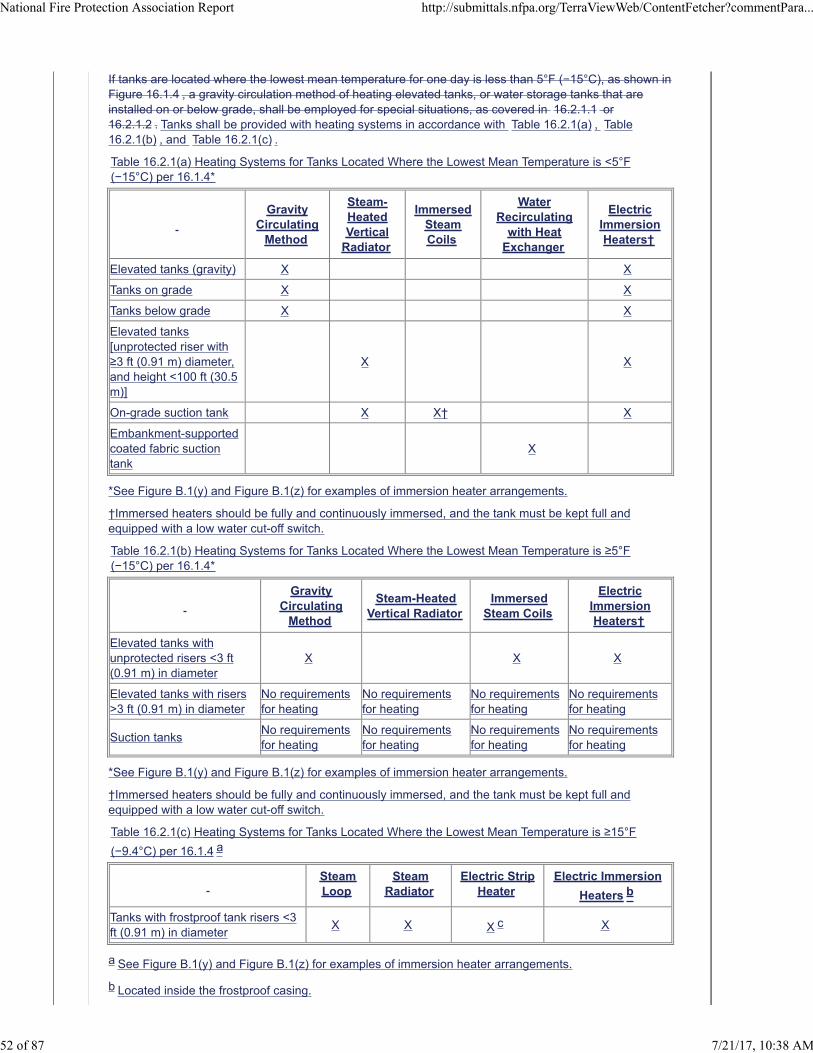
If tanks are located where the lowest mean temperature for one day is less than 5°F (−15°C), as shown inFigure 16.1.4 , a gravity circulation method of heating elevated tanks, or water storage tanks that areinstalled on or below grade, shall be employed for special situations, as covered in 16.2.1.1 or16.2.1.2 . Tanks shall be provided with heating systems in accordance with Table 16.2.1(a) , Table16.2.1(b) , and Table 16.2.1(c) .
Table 16.2.1(a) Heating Systems for Tanks Located Where the Lowest Mean Temperature is <5°F(−15°C) per 16.1.4*
Gravity
CirculatingMethod
Steam-HeatedVertical
Radiator
ImmersedSteamCoils
WaterRecirculating
with HeatExchanger
ElectricImmersionHeaters†
Elevated tanks (gravity) X X
Tanks on grade X X
Tanks below grade X X
Elevated tanks[unprotected riser with≥3 ft (0.91 m) diameter,and height <100 ft (30.5m)]
X X
On-grade suction tank X X† X
Embankment-supportedcoated fabric suctiontank
X
*See Figure B.1(y) and Figure B.1(z) for examples of immersion heater arrangements.
†Immersed heaters should be fully and continuously immersed, and the tank must be kept full andequipped with a low water cut-off switch.
Table 16.2.1(b) Heating Systems for Tanks Located Where the Lowest Mean Temperature is ≥5°F(−15°C) per 16.1.4*
Gravity
CirculatingMethod
Steam-HeatedVertical Radiator
ImmersedSteam Coils
ElectricImmersionHeaters†
Elevated tanks withunprotected risers <3 ft(0.91 m) in diameter
X X X
Elevated tanks with risers>3 ft (0.91 m) in diameter
No requirementsfor heating
No requirementsfor heating
No requirementsfor heating
No requirementsfor heating
Suction tanksNo requirementsfor heating
No requirementsfor heating
No requirementsfor heating
No requirementsfor heating
*See Figure B.1(y) and Figure B.1(z) for examples of immersion heater arrangements.
†Immersed heaters should be fully and continuously immersed, and the tank must be kept full andequipped with a low water cut-off switch.
Table 16.2.1(c) Heating Systems for Tanks Located Where the Lowest Mean Temperature is ≥15°F
(−9.4°C) per 16.1.4 a
SteamLoop
SteamRadiator
Electric StripHeater
Electric Immersion
Heaters b
Tanks with frostproof tank risers <3ft (0.91 m) in diameter
X X X c X
a See Figure B.1(y) and Figure B.1(z) for examples of immersion heater arrangements.
b Located inside the frostproof casing.
National Fire Protection Association Report http://submittals.nfpa.org/TerraViewWeb/ContentFetcher?commentPara...
52 of 87 7/21/17, 10:38 AM
c Immersed heaters should be fully and continuously immersed, and the tank must be kept full andequipped with a low water cut-off switch.
16.2.1.1
A steam-heated vertical radiator system shall be used for elevated tanks with unprotected tank risers of3 ft (0.91 m) or more in diameter that have tower heights under 100 ft (30.5 m) (see 13.1.2 ) , gravitytanks, and on-grade suction tanks.
16.2.1.2
A steam-heated vertical radiator system also shall be used for tower heights over 100 ft (30.5 m).
16.2.1.2.1
An open-ended pipe sleeve similar to that shown in Figure B.1(u) shall be used.
16.2.1.3
Immersed steam coils shall be used for suction tanks and gravity tanks that have flat bottoms supportednear ground level in situations where the tank is kept filled so that the steam coils are continuouslysubmerged.
16.2.2
Where the lowest mean temperature for one day is 5°F (−15°C) or above, as shown in Figure 16.1.4 ,and only intermittent heating is required for elevated tanks with unprotected tank risers of less than 3 ft(0.91 m) in diameter, heating shall be by means of water circulation or immersed steam coils, or byblowing steam from a supply that is directed into the water.
16.2.2.1
Suction tanks and gravity tanks that have tank risers of 3 ft (0.91 m) or more in diameter shall not berequired to have provision for heat.
16.2.3
Where the lowest mean temperature for one day is above 15°F (−9.4°C), as shown in Figure 16.1.4 ,the method of heating tanks with frostproof tank risers of less than 3 ft (0.91 m) in diameter shall be asteam loop or steam radiator, or thermostatically controlled electric strip heaters shall be placed insidethe frostproof casing.
Supplemental Information
File Name Description Approved
NFPA_22_Table_16.2._Red_Letter_Removed_8-18-16.xlsxNew Heat Method Tables - For Staff Use
Submitter Information Verification
Submitter Full Name: Chad Duffy
Organization: National Fire Protection Assoc
Street Address:
City:
State:
Zip:
Submittal Date: Wed Mar 22 11:07:40 EDT 2017
Committee Statement
CommitteeStatement:
Heating requirements for tanks have been placed in a table format for ease of use andimmersion heaters have been acknowledged.
ResponseMessage:
National Fire Protection Association Report http://submittals.nfpa.org/TerraViewWeb/ContentFetcher?commentPara...
53 of 87 7/21/17, 10:38 AM
Ballot Results
This item has passed ballot
26 Eligible Voters
5 Not Returned
21 Affirmative All
0 Affirmative with Comments
0 Negative with Comments
0 Abstention
Not Returned
Curran, Sullivan D.
Hochhauser, David
Legatos, Nicholas A.
Patrick, R. Greg
Sanchez, Daniel
Affirmative All
Biradar, Babanna
Campbell, John D.
Culp, Christopher
Fisher, Douglas W.
Fowler, Joseph R.
Gagnon, Robert M.
Garber, Greg
Henning, Andrew M.
Hillman, Jack
Kelly, Kevin J.
Kidd, Todd M.
Koenig, Gary
McGuire, Keith
Mitchard, John M.
Morgan, Bob D.
Noble, Thomas William
Ramo, Leonard J.
Rosenwach, Andrew
Sornsin, Mark A.
Stein, Gregory R.
Stevens, Owen
National Fire Protection Association Report http://submittals.nfpa.org/TerraViewWeb/ContentFetcher?commentPara...
54 of 87 7/21/17, 10:38 AM
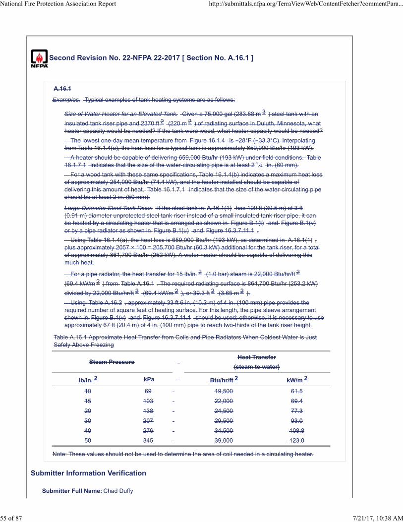
Second Revision No. 22-NFPA 22-2017 [ Section No. A.16.1 ]
A.16.1
Examples. Typical examples of tank heating systems are as follows:
Size of Water Heater for an Elevated Tank. Given a 75,000 gal (283.88 m 3 ) steel tank with an
insulated tank riser pipe and 2370 ft 2 (220 m 2 ) of radiating surface in Duluth, Minnesota, whatheater capacity would be needed? If the tank were wood, what heater capacity would be needed?
The lowest one-day mean temperature from Figure 16.1.4 is −28°F (−33.3°C). Interpolatingfrom Table 16.1.4(a), the heat loss for a typical tank is approximately 659,000 Btu/hr (193 kW).
A heater should be capable of delivering 659,000 Btu/hr (193 kW) under field conditions. Table16.1.7.1 indicates that the size of the water-circulating pipe is at least 2 1 ⁄2 in. (60 mm).
For a wood tank with these same specifications, Table 16.1.4(b) indicates a maximum heat lossof approximately 254,000 Btu/hr (74.4 kW), and the heater installed should be capable ofdelivering this amount of heat. Table 16.1.7.1 indicates that the size of the water-circulating pipeshould be at least 2 in. (50 mm).
Large-Diameter Steel Tank Riser. If the steel tank in A.16.1(1) has 100 ft (30.5 m) of 3 ft(0.91 m) diameter unprotected steel tank riser instead of a small insulated tank riser pipe, it canbe heated by a circulating heater that is arranged as shown in Figure B.1(t) and Figure B.1(v)or by a pipe radiator as shown in Figure B.1(u) and Figure 16.3.7.11.1 .
Using Table 16.1.4(a), the heat loss is 659,000 Btu/hr (193 kW), as determined in A.16.1(1) ,plus approximately 2057 × 100 = 205,700 Btu/hr (60.3 kW) additional for the tank riser, for a totalof approximately 861,700 Btu/hr (252 kW). A water heater should be capable of delivering thismuch heat.
For a pipe radiator, the heat transfer for 15 lb/in. 2 (1.0 bar) steam is 22,000 Btu/hr/ft 2
(69.4 kW/m 2 ) from Table A.16.1 . The required radiating surface is 864,700 Btu/hr (253.2 kW)
divided by 22,000 Btu/hr/ft 2 (69.4 kW/m 2 ), or 39.3 ft 2 (3.65 m 2 ).
Using Table A.16.2 , approximately 33 ft 6 in. (10.2 m) of 4 in. (100 mm) pipe provides therequired number of square feet of heating surface. For this length, the pipe sleeve arrangementshown in Figure B.1(v) and Figure 16.3.7.11.1 should be used; otherwise, it is necessary to useapproximately 67 ft (20.4 m) of 4 in. (100 mm) pipe to reach two-thirds of the tank riser height.
Table A.16.1 Approximate Heat Transfer from Coils and Pipe Radiators When Coldest Water Is JustSafely Above Freezing
Steam Pressure Heat Transfer
(steam to water)
lb/in. 2 kPa Btu/hr/ft 2 kW/m 2
10 69 19,500 61.5
15 103 22,000 69.4
20 138 24,500 77.3
30 207 29,500 93.0
40 276 34,500 108.8
50 345 39,000 123.0
Note: These values should not be used to determine the area of coil needed in a circulating heater.
Submitter Information Verification
Submitter Full Name: Chad Duffy
National Fire Protection Association Report http://submittals.nfpa.org/TerraViewWeb/ContentFetcher?commentPara...
55 of 87 7/21/17, 10:38 AM
Organization: National Fire Protection Assoc
Street Address:
City:
State:
Zip:
Submittal Date: Fri Jun 02 07:31:00 EDT 2017
Committee Statement
CommitteeStatement:
The examples have been deleted because Figure 16.1.4 and accompanying Tables havebeen removed from the standard.
ResponseMessage:
Ballot Results
This item has passed ballot
26 Eligible Voters
5 Not Returned
21 Affirmative All
0 Affirmative with Comments
0 Negative with Comments
0 Abstention
Not Returned
Curran, Sullivan D.
Hochhauser, David
Legatos, Nicholas A.
Patrick, R. Greg
Sanchez, Daniel
Affirmative All
Biradar, Babanna
Campbell, John D.
Culp, Christopher
Fisher, Douglas W.
Fowler, Joseph R.
Gagnon, Robert M.
Garber, Greg
Henning, Andrew M.
Hillman, Jack
Kelly, Kevin J.
Kidd, Todd M.
Koenig, Gary
National Fire Protection Association Report http://submittals.nfpa.org/TerraViewWeb/ContentFetcher?commentPara...
56 of 87 7/21/17, 10:38 AM
McGuire, Keith
Mitchard, John M.
Morgan, Bob D.
Noble, Thomas William
Ramo, Leonard J.
Rosenwach, Andrew
Sornsin, Mark A.
Stein, Gregory R.
Stevens, Owen
National Fire Protection Association Report http://submittals.nfpa.org/TerraViewWeb/ContentFetcher?commentPara...
57 of 87 7/21/17, 10:38 AM
Second Revision No. 21-NFPA 22-2017 [ Section No. A.16.1.2.1 ]
A.16.1.2.1
Atmospheric Temperature. Figure 16.1.4 shows isothermal lines that indicate the lowest meantemperature for one day that has ever been officially recorded at any point in the United States orsouthern Canada. This map has been compiled from official records and can be used with reasonableaccuracy to determine the lowest mean temperature for one day that can be expected to occur.
Submitter Information Verification
Submitter Full Name: Chad Duffy
Organization: National Fire Protection Assoc
Street Address:
City:
State:
Zip:
Submittal Date: Fri Jun 02 07:24:40 EDT 2017
Committee Statement
Committee Statement: Figure 16.1.4 has been deleted from the standard.
Response Message:
Ballot Results
This item has passed ballot
26 Eligible Voters
5 Not Returned
21 Affirmative All
0 Affirmative with Comments
0 Negative with Comments
0 Abstention
Not Returned
Curran, Sullivan D.
Hochhauser, David
Legatos, Nicholas A.
Patrick, R. Greg
Sanchez, Daniel
Affirmative All
Biradar, Babanna
Campbell, John D.
National Fire Protection Association Report http://submittals.nfpa.org/TerraViewWeb/ContentFetcher?commentPara...
58 of 87 7/21/17, 10:38 AM
Culp, Christopher
Fisher, Douglas W.
Fowler, Joseph R.
Gagnon, Robert M.
Garber, Greg
Henning, Andrew M.
Hillman, Jack
Kelly, Kevin J.
Kidd, Todd M.
Koenig, Gary
McGuire, Keith
Mitchard, John M.
Morgan, Bob D.
Noble, Thomas William
Ramo, Leonard J.
Rosenwach, Andrew
Sornsin, Mark A.
Stein, Gregory R.
Stevens, Owen
National Fire Protection Association Report http://submittals.nfpa.org/TerraViewWeb/ContentFetcher?commentPara...
59 of 87 7/21/17, 10:38 AM
Second Revision No. 23-NFPA 22-2017 [ Section No. A.16.1.3 ]
A.16.1.3
Choice of Circulating Heaters. To select a suitable circulating heater, first obtain from Figure 16.1.4the lowest mean atmospheric temperature for one day that may occur at the locality in question; thendetermine the total heat loss from the tank equipment in British thermal units (kilowatts) per hour fromTable 16.1.4(a) for an gravity steel tank, from Table 16.1.4(b) for an elevated wood tank, from Table16.1.4(c) for a steel suction tank, or from Table 16.1.4(d) for an embankment-supported coated fabricsuction tank. The heater installed should have sufficient capacity to deliver, under actual field conditions,an amount of heat that is equivalent to that lost from the tank equipment. A steam water heater shouldbe planned with due consideration of the steam pressure available. Other heaters should be planned forthe particular kind of fuel to be used.
Submitter Information Verification
Submitter Full Name: Chad Duffy
Organization: National Fire Protection Assoc
Street Address:
City:
State:
Zip:
Submittal Date: Fri Jun 02 07:51:24 EDT 2017
Committee Statement
CommitteeStatement:
The annex has been deleted because Figure 16.1.4 and accompanying Tables have beenremoved from the standard.
ResponseMessage:
Ballot Results
This item has passed ballot
26 Eligible Voters
5 Not Returned
21 Affirmative All
0 Affirmative with Comments
0 Negative with Comments
0 Abstention
Not Returned
Curran, Sullivan D.
Hochhauser, David
Legatos, Nicholas A.
Patrick, R. Greg
Sanchez, Daniel
National Fire Protection Association Report http://submittals.nfpa.org/TerraViewWeb/ContentFetcher?commentPara...
60 of 87 7/21/17, 10:38 AM

Affirmative All
Biradar, Babanna
Campbell, John D.
Culp, Christopher
Fisher, Douglas W.
Fowler, Joseph R.
Gagnon, Robert M.
Garber, Greg
Henning, Andrew M.
Hillman, Jack
Kelly, Kevin J.
Kidd, Todd M.
Koenig, Gary
McGuire, Keith
Mitchard, John M.
Morgan, Bob D.
Noble, Thomas William
Ramo, Leonard J.
Rosenwach, Andrew
Sornsin, Mark A.
Stein, Gregory R.
Stevens, Owen
National Fire Protection Association Report http://submittals.nfpa.org/TerraViewWeb/ContentFetcher?commentPara...
61 of 87 7/21/17, 10:38 AM
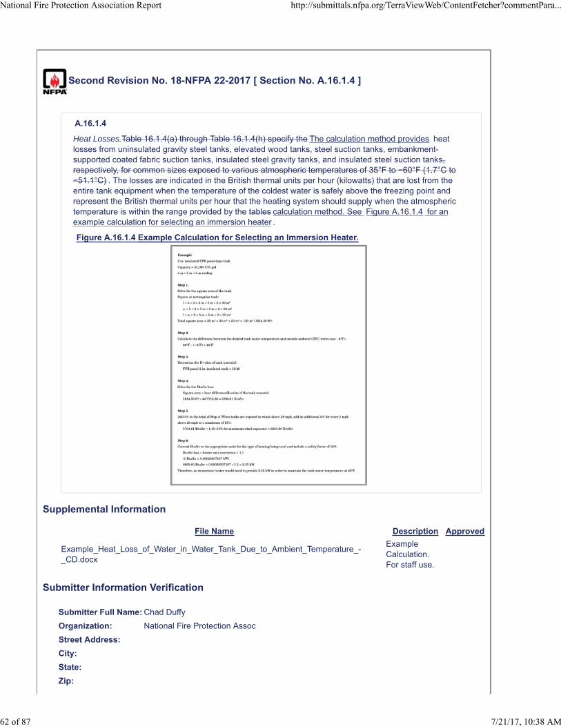
Second Revision No. 18-NFPA 22-2017 [ Section No. A.16.1.4 ]
A.16.1.4
Heat Losses.Table 16.1.4(a) through Table 16.1.4(h) specify the The calculation method provides heatlosses from uninsulated gravity steel tanks, elevated wood tanks, steel suction tanks, embankment-supported coated fabric suction tanks, insulated steel gravity tanks, and insulated steel suction tanks,respectively, for common sizes exposed to various atmospheric temperatures of 35°F to −60°F (1.7°C to−51.1°C) . The losses are indicated in the British thermal units per hour (kilowatts) that are lost from theentire tank equipment when the temperature of the coldest water is safely above the freezing point andrepresent the British thermal units per hour that the heating system should supply when the atmospherictemperature is within the range provided by the tables calculation method. See Figure A.16.1.4 for anexample calculation for selecting an immersion heater .
Figure A.16.1.4 Example Calculation for Selecting an Immersion Heater.
Supplemental Information
File Name Description Approved
Example_Heat_Loss_of_Water_in_Water_Tank_Due_to_Ambient_Temperature_-_CD.docx
Example Calculation. For staff use.
Submitter Information Verification
Submitter Full Name: Chad Duffy
Organization: National Fire Protection Assoc
Street Address:
City:
State:
Zip:
National Fire Protection Association Report http://submittals.nfpa.org/TerraViewWeb/ContentFetcher?commentPara...
62 of 87 7/21/17, 10:38 AM
Submittal Date: Fri Apr 14 13:40:08 EDT 2017
Committee Statement
CommitteeStatement:
Revised annex to align with action taken in standard. Added example calculation forimmersion heater.
Response Message:
Ballot Results
This item has passed ballot
26 Eligible Voters
5 Not Returned
21 Affirmative All
0 Affirmative with Comments
0 Negative with Comments
0 Abstention
Not Returned
Curran, Sullivan D.
Hochhauser, David
Legatos, Nicholas A.
Patrick, R. Greg
Sanchez, Daniel
Affirmative All
Biradar, Babanna
Campbell, John D.
Culp, Christopher
Fisher, Douglas W.
Fowler, Joseph R.
Gagnon, Robert M.
Garber, Greg
Henning, Andrew M.
Hillman, Jack
Kelly, Kevin J.
Kidd, Todd M.
Koenig, Gary
McGuire, Keith
Mitchard, John M.
Morgan, Bob D.
Noble, Thomas William
Ramo, Leonard J.
Rosenwach, Andrew
National Fire Protection Association Report http://submittals.nfpa.org/TerraViewWeb/ContentFetcher?commentPara...
63 of 87 7/21/17, 10:38 AM

Sornsin, Mark A.
Stein, Gregory R.
Stevens, Owen
National Fire Protection Association Report http://submittals.nfpa.org/TerraViewWeb/ContentFetcher?commentPara...
64 of 87 7/21/17, 10:38 AM
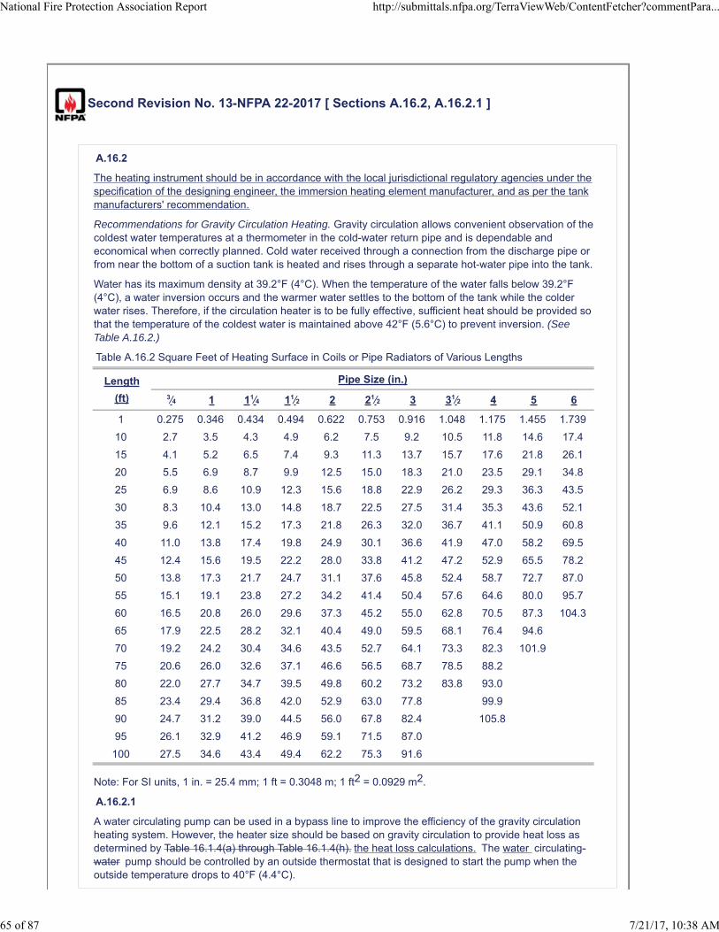
Second Revision No. 13-NFPA 22-2017 [ Sections A.16.2, A.16.2.1 ]
A.16.2
The heating instrument should be in accordance with the local jurisdictional regulatory agencies under thespecification of the designing engineer, the immersion heating element manufacturer, and as per the tankmanufacturers' recommendation.
Recommendations for Gravity Circulation Heating. Gravity circulation allows convenient observation of thecoldest water temperatures at a thermometer in the cold-water return pipe and is dependable andeconomical when correctly planned. Cold water received through a connection from the discharge pipe orfrom near the bottom of a suction tank is heated and rises through a separate hot-water pipe into the tank.
Water has its maximum density at 39.2°F (4°C). When the temperature of the water falls below 39.2°F(4°C), a water inversion occurs and the warmer water settles to the bottom of the tank while the colderwater rises. Therefore, if the circulation heater is to be fully effective, sufficient heat should be provided sothat the temperature of the coldest water is maintained above 42°F (5.6°C) to prevent inversion. (SeeTable A.16.2.)
Table A.16.2 Square Feet of Heating Surface in Coils or Pipe Radiators of Various Lengths
Length
(ft)
Pipe Size (in.)
3⁄4 1 11⁄4 11⁄2 2 21⁄2 3 31⁄2 4 5 6
1 0.275 0.346 0.434 0.494 0.622 0.753 0.916 1.048 1.175 1.455 1.739
10 2.7 3.5 4.3 4.9 6.2 7.5 9.2 10.5 11.8 14.6 17.4
15 4.1 5.2 6.5 7.4 9.3 11.3 13.7 15.7 17.6 21.8 26.1
20 5.5 6.9 8.7 9.9 12.5 15.0 18.3 21.0 23.5 29.1 34.8
25 6.9 8.6 10.9 12.3 15.6 18.8 22.9 26.2 29.3 36.3 43.5
30 8.3 10.4 13.0 14.8 18.7 22.5 27.5 31.4 35.3 43.6 52.1
35 9.6 12.1 15.2 17.3 21.8 26.3 32.0 36.7 41.1 50.9 60.8
40 11.0 13.8 17.4 19.8 24.9 30.1 36.6 41.9 47.0 58.2 69.5
45 12.4 15.6 19.5 22.2 28.0 33.8 41.2 47.2 52.9 65.5 78.2
50 13.8 17.3 21.7 24.7 31.1 37.6 45.8 52.4 58.7 72.7 87.0
55 15.1 19.1 23.8 27.2 34.2 41.4 50.4 57.6 64.6 80.0 95.7
60 16.5 20.8 26.0 29.6 37.3 45.2 55.0 62.8 70.5 87.3 104.3
65 17.9 22.5 28.2 32.1 40.4 49.0 59.5 68.1 76.4 94.6
70 19.2 24.2 30.4 34.6 43.5 52.7 64.1 73.3 82.3 101.9
75 20.6 26.0 32.6 37.1 46.6 56.5 68.7 78.5 88.2
80 22.0 27.7 34.7 39.5 49.8 60.2 73.2 83.8 93.0
85 23.4 29.4 36.8 42.0 52.9 63.0 77.8 99.9
90 24.7 31.2 39.0 44.5 56.0 67.8 82.4 105.8
95 26.1 32.9 41.2 46.9 59.1 71.5 87.0
100 27.5 34.6 43.4 49.4 62.2 75.3 91.6
Note: For SI units, 1 in. = 25.4 mm; 1 ft = 0.3048 m; 1 ft2 = 0.0929 m2.
A.16.2.1
A water circulating pump can be used in a bypass line to improve the efficiency of the gravity circulationheating system. However, the heater size should be based on gravity circulation to provide heat loss asdetermined by Table 16.1.4(a) through Table 16.1.4(h). the heat loss calculations. The water circulating-water pump should be controlled by an outside thermostat that is designed to start the pump when theoutside temperature drops to 40°F (4.4°C).
National Fire Protection Association Report http://submittals.nfpa.org/TerraViewWeb/ContentFetcher?commentPara...
65 of 87 7/21/17, 10:38 AM
Submitter Information Verification
Submitter Full Name: Chad Duffy
Organization: National Fire Protection Assoc
Street Address:
City:
State:
Zip:
Submittal Date: Wed Mar 22 11:29:06 EDT 2017
Committee Statement
Committee Statement: Correlate with revised section 16.2 and 16.2.1.
Response Message:
Ballot Results
This item has passed ballot
26 Eligible Voters
5 Not Returned
21 Affirmative All
0 Affirmative with Comments
0 Negative with Comments
0 Abstention
Not Returned
Curran, Sullivan D.
Hochhauser, David
Legatos, Nicholas A.
Patrick, R. Greg
Sanchez, Daniel
Affirmative All
Biradar, Babanna
Campbell, John D.
Culp, Christopher
Fisher, Douglas W.
Fowler, Joseph R.
Gagnon, Robert M.
Garber, Greg
Henning, Andrew M.
Hillman, Jack
Kelly, Kevin J.
Kidd, Todd M.
National Fire Protection Association Report http://submittals.nfpa.org/TerraViewWeb/ContentFetcher?commentPara...
66 of 87 7/21/17, 10:38 AM
Koenig, Gary
McGuire, Keith
Mitchard, John M.
Morgan, Bob D.
Noble, Thomas William
Ramo, Leonard J.
Rosenwach, Andrew
Sornsin, Mark A.
Stein, Gregory R.
Stevens, Owen
National Fire Protection Association Report http://submittals.nfpa.org/TerraViewWeb/ContentFetcher?commentPara...
67 of 87 7/21/17, 10:38 AM
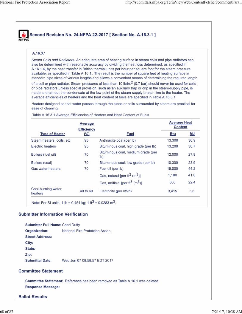
Second Revision No. 24-NFPA 22-2017 [ Section No. A.16.3.1 ]
A.16.3.1
Steam Coils and Radiators. An adequate area of heating surface in steam coils and pipe radiators canalso be determined with reasonable accuracy by dividing the heat loss determined, as specified inA.16.1.4, by the heat transfer in British thermal units per hour per square foot for the steam pressureavailable, as specified in Table A.16.1 . The result is the number of square feet of heating surface instandard pipe sizes of various lengths and allows a convenient means of determining the required length
of a coil or pipe radiator. Steam pressures of less than 10 lb/in.2 (0.7 bar) should never be used for coilsor pipe radiators unless special provision, such as an auxiliary trap or drip in the steam-supply pipe, ismade to drain out the condensate at the low point of the steam-supply branch line to the heater. Theaverage efficiencies of heaters and the heat content of fuels are specified in Table A.16.3.1.
Heaters designed so that water passes through the tubes or coils surrounded by steam are practical forease of cleaning.
Table A.16.3.1 Average Efficiencies of Heaters and Heat Content of Fuels
Type of Heater
Average
Efficiency(%) Fuel
Average HeatContent
Btu MJ
Steam heaters, coils, etc. 95 Anthracite coal (per lb) 13,300 30.9
Electric heaters 95 Bituminous coal, high grade (per lb) 13,200 30.7
Boilers (fuel oil) 70Bituminous coal, medium grade (perlb)
12,000 27.9
Boilers (coal) 70 Bituminous coal, low grade (per lb) 10,300 23.9
Gas water heaters 70 Fuel oil (per lb) 19,000 44.2
Gas, natural [per ft3 (m3)] 1,100 41.0
Gas, artificial [per ft3 (m3)] 600 22.4
Coal-burning waterheaters
40 to 60 Electricity (per kWh) 3,415 3.6
Note: For SI units, 1 lb = 0.454 kg; 1 ft3 = 0.0283 m3.
Submitter Information Verification
Submitter Full Name: Chad Duffy
Organization: National Fire Protection Assoc
Street Address:
City:
State:
Zip:
Submittal Date: Wed Jun 07 08:58:57 EDT 2017
Committee Statement
Committee Statement: Reference has been removed as Table A.16.1 was deleted.
Response Message:
Ballot Results
National Fire Protection Association Report http://submittals.nfpa.org/TerraViewWeb/ContentFetcher?commentPara...
68 of 87 7/21/17, 10:38 AM
This item has passed ballot
26 Eligible Voters
5 Not Returned
21 Affirmative All
0 Affirmative with Comments
0 Negative with Comments
0 Abstention
Not Returned
Curran, Sullivan D.
Hochhauser, David
Legatos, Nicholas A.
Patrick, R. Greg
Sanchez, Daniel
Affirmative All
Biradar, Babanna
Campbell, John D.
Culp, Christopher
Fisher, Douglas W.
Fowler, Joseph R.
Gagnon, Robert M.
Garber, Greg
Henning, Andrew M.
Hillman, Jack
Kelly, Kevin J.
Kidd, Todd M.
Koenig, Gary
McGuire, Keith
Mitchard, John M.
Morgan, Bob D.
Noble, Thomas William
Ramo, Leonard J.
Rosenwach, Andrew
Sornsin, Mark A.
Stein, Gregory R.
Stevens, Owen
National Fire Protection Association Report http://submittals.nfpa.org/TerraViewWeb/ContentFetcher?commentPara...
69 of 87 7/21/17, 10:38 AM

Second Revision No. 20-NFPA 22-2017 [ Section No. B.1 ]
National Fire Protection Association Report http://submittals.nfpa.org/TerraViewWeb/ContentFetcher?commentPara...
70 of 87 7/21/17, 10:38 AM

B.1 General.
National Fire Protection Association Report http://submittals.nfpa.org/TerraViewWeb/ContentFetcher?commentPara...
71 of 87 7/21/17, 10:38 AM
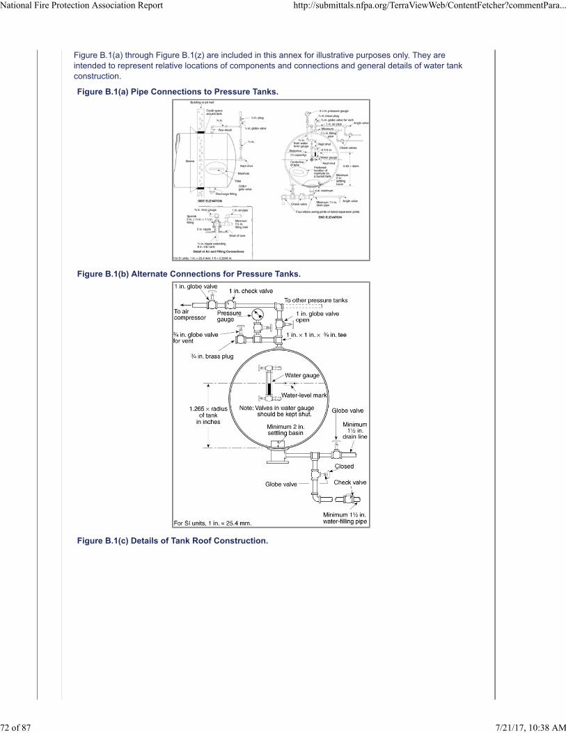
Figure B.1(a) through Figure B.1(z) are included in this annex for illustrative purposes only. They areintended to represent relative locations of components and connections and general details of water tankconstruction.
Figure B.1(a) Pipe Connections to Pressure Tanks.
Figure B.1(b) Alternate Connections for Pressure Tanks.
Figure B.1(c) Details of Tank Roof Construction.
National Fire Protection Association Report http://submittals.nfpa.org/TerraViewWeb/ContentFetcher?commentPara...
72 of 87 7/21/17, 10:38 AM
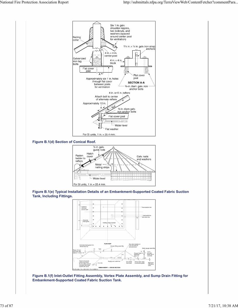
Figure B.1(d) Section of Conical Roof.
Figure B.1(e) Typical Installation Details of an Embankment-Supported Coated Fabric SuctionTank, Including Fittings.
Figure B.1(f) Inlet-Outlet Fitting Assembly, Vortex Plate Assembly, and Sump Drain Fitting forEmbankment-Supported Coated Fabric Suction Tank.
National Fire Protection Association Report http://submittals.nfpa.org/TerraViewWeb/ContentFetcher?commentPara...
73 of 87 7/21/17, 10:38 AM
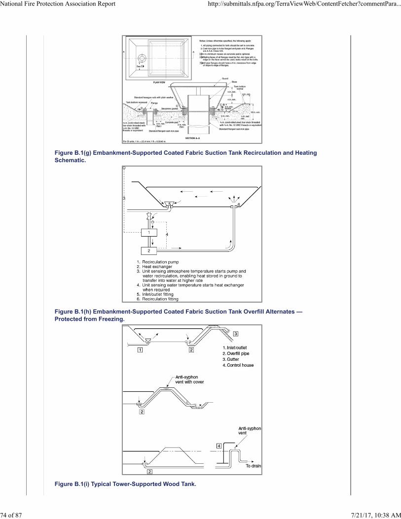
Figure B.1(g) Embankment-Supported Coated Fabric Suction Tank Recirculation and HeatingSchematic.
Figure B.1(h) Embankment-Supported Coated Fabric Suction Tank Overfill Alternates —Protected from Freezing.
Figure B.1(i) Typical Tower-Supported Wood Tank.
National Fire Protection Association Report http://submittals.nfpa.org/TerraViewWeb/ContentFetcher?commentPara...
74 of 87 7/21/17, 10:38 AM
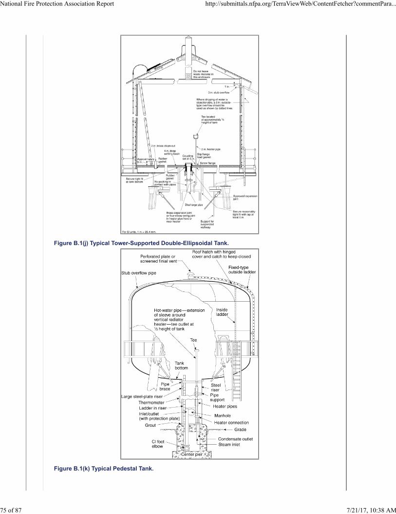
Figure B.1(j) Typical Tower-Supported Double-Ellipsoidal Tank.
Figure B.1(k) Typical Pedestal Tank.
National Fire Protection Association Report http://submittals.nfpa.org/TerraViewWeb/ContentFetcher?commentPara...
75 of 87 7/21/17, 10:38 AM
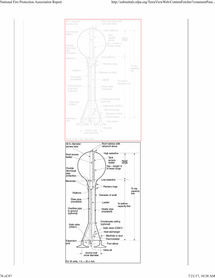
National Fire Protection Association Report http://submittals.nfpa.org/TerraViewWeb/ContentFetcher?commentPara...
76 of 87 7/21/17, 10:38 AM
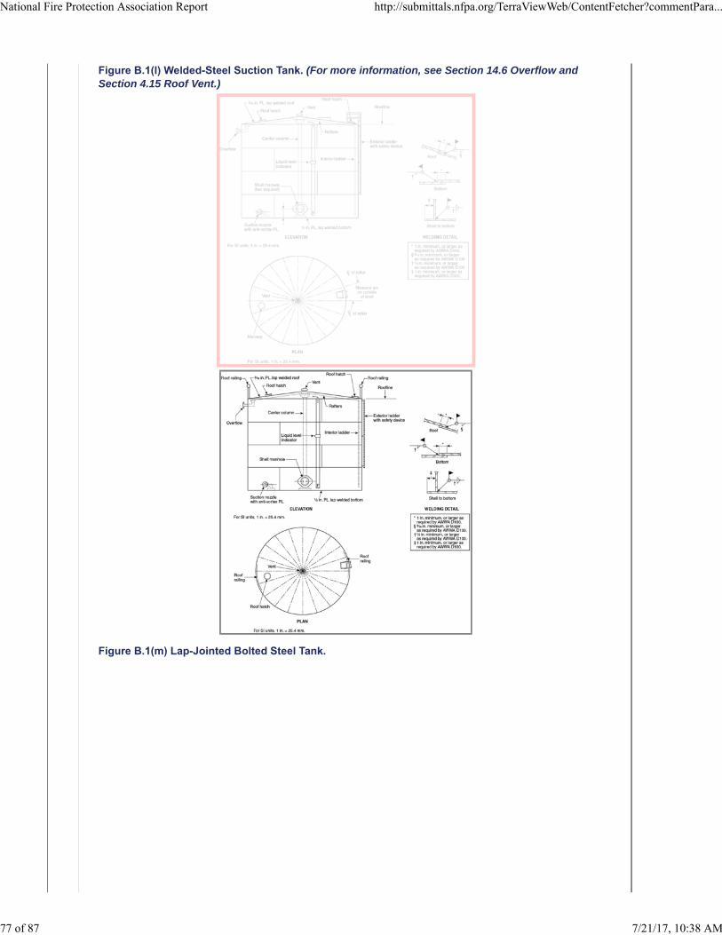
Figure B.1(l) Welded-Steel Suction Tank. (For more information, see Section 14.6 Overflow andSection 4.15 Roof Vent.)
Figure B.1(m) Lap-Jointed Bolted Steel Tank.
National Fire Protection Association Report http://submittals.nfpa.org/TerraViewWeb/ContentFetcher?commentPara...
77 of 87 7/21/17, 10:38 AM
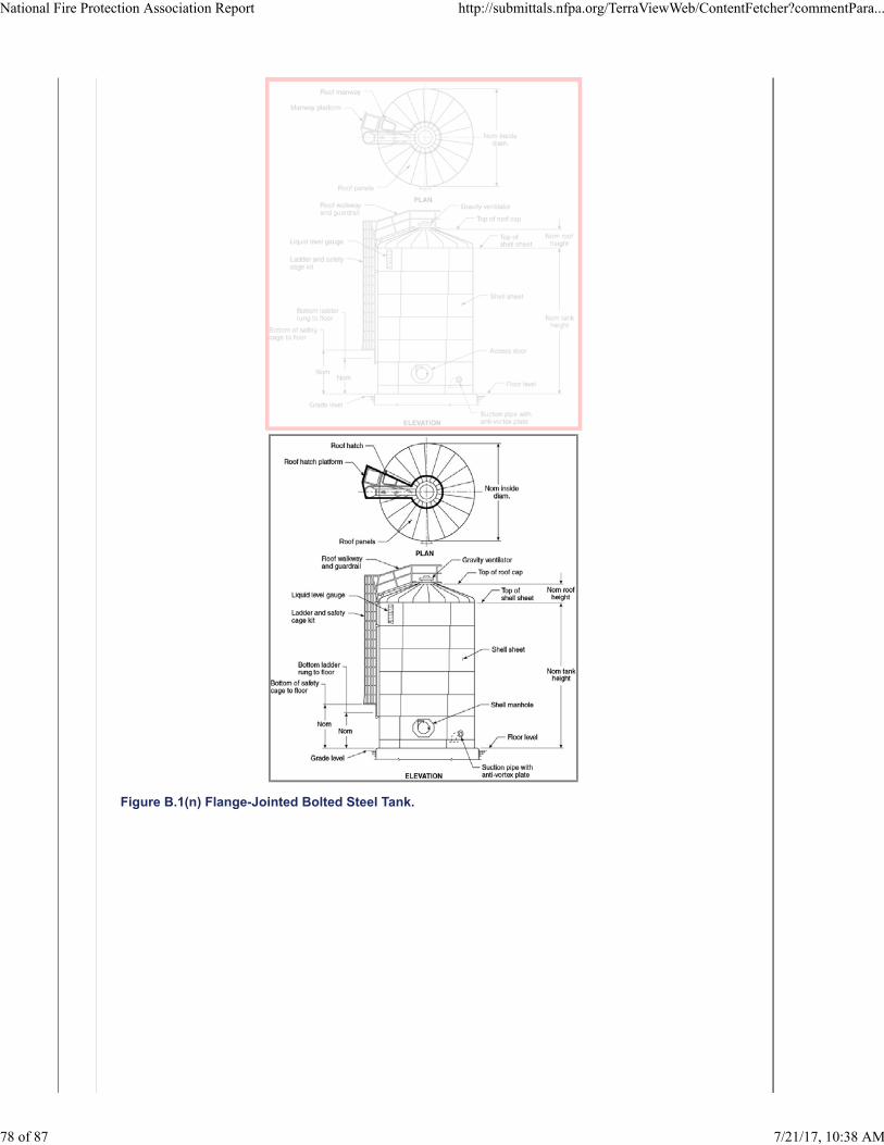
Figure B.1(n) Flange-Jointed Bolted Steel Tank.
National Fire Protection Association Report http://submittals.nfpa.org/TerraViewWeb/ContentFetcher?commentPara...
78 of 87 7/21/17, 10:38 AM
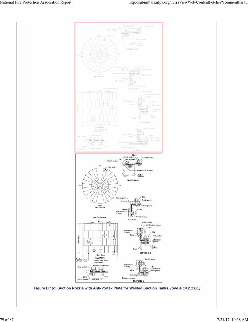
Figure B.1(o) Suction Nozzle with Anti-Vortex Plate for Welded Suction Tanks. (See A.14.2.13.2.)
National Fire Protection Association Report http://submittals.nfpa.org/TerraViewWeb/ContentFetcher?commentPara...
79 of 87 7/21/17, 10:38 AM
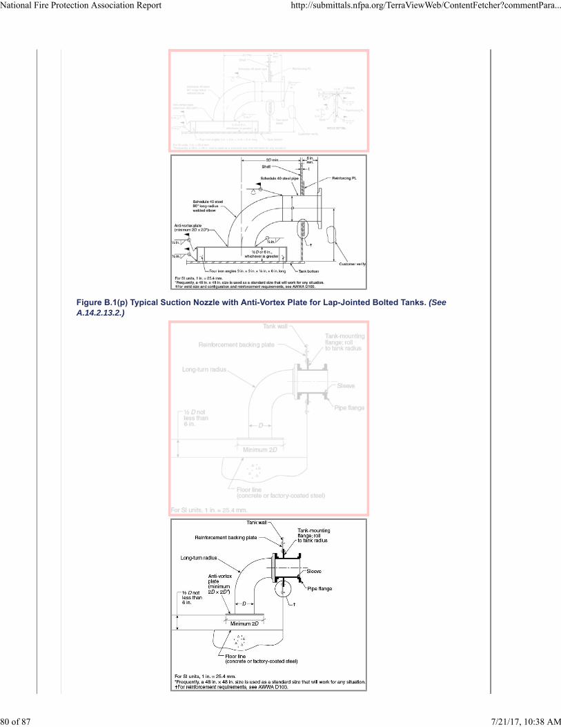
Figure B.1(p) Typical Suction Nozzle with Anti-Vortex Plate for Lap-Jointed Bolted Tanks. (SeeA.14.2.13.2.)
National Fire Protection Association Report http://submittals.nfpa.org/TerraViewWeb/ContentFetcher?commentPara...
80 of 87 7/21/17, 10:38 AM
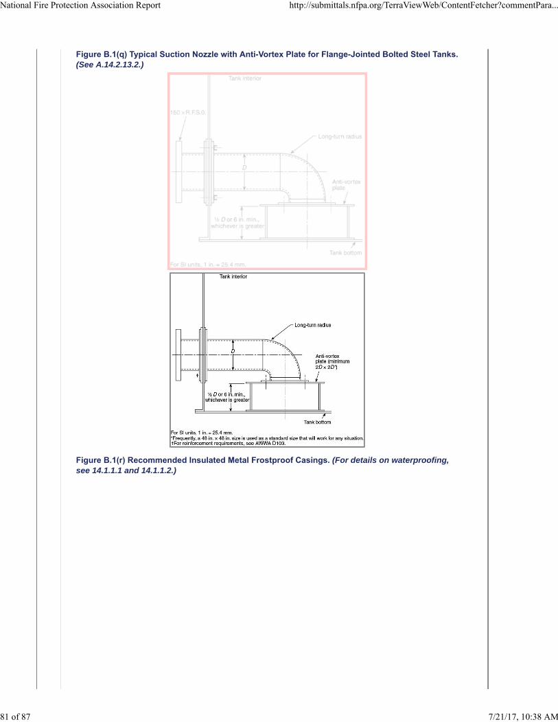
Figure B.1(q) Typical Suction Nozzle with Anti-Vortex Plate for Flange-Jointed Bolted Steel Tanks.(See A.14.2.13.2.)
Figure B.1(r) Recommended Insulated Metal Frostproof Casings. (For details on waterproofing,see 14.1.1.1 and 14.1.1.2.)
National Fire Protection Association Report http://submittals.nfpa.org/TerraViewWeb/ContentFetcher?commentPara...
81 of 87 7/21/17, 10:38 AM
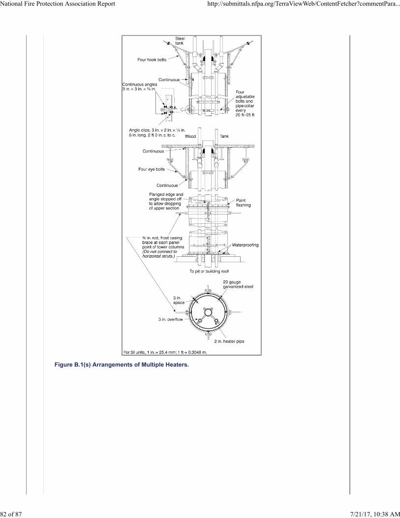
Figure B.1(s) Arrangements of Multiple Heaters.
National Fire Protection Association Report http://submittals.nfpa.org/TerraViewWeb/ContentFetcher?commentPara...
82 of 87 7/21/17, 10:38 AM
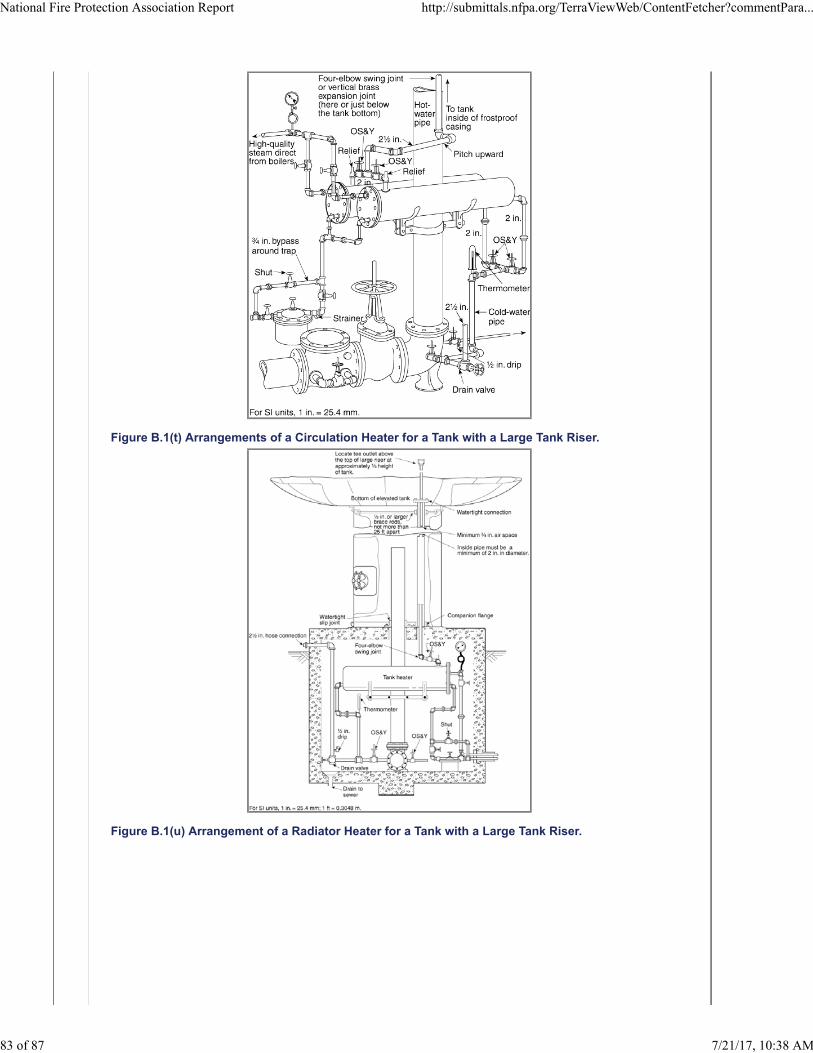
Figure B.1(t) Arrangements of a Circulation Heater for a Tank with a Large Tank Riser.
Figure B.1(u) Arrangement of a Radiator Heater for a Tank with a Large Tank Riser.
National Fire Protection Association Report http://submittals.nfpa.org/TerraViewWeb/ContentFetcher?commentPara...
83 of 87 7/21/17, 10:38 AM
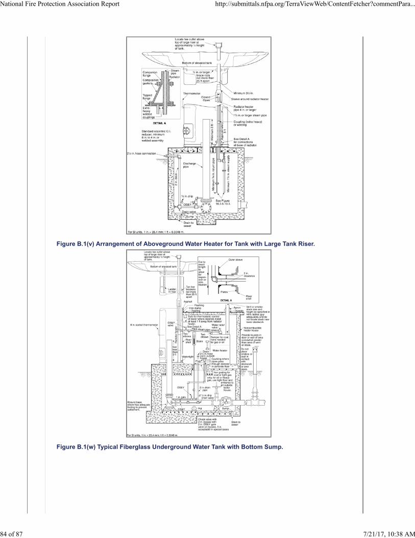
Figure B.1(v) Arrangement of Aboveground Water Heater for Tank with Large Tank Riser.
Figure B.1(w) Typical Fiberglass Underground Water Tank with Bottom Sump.
National Fire Protection Association Report http://submittals.nfpa.org/TerraViewWeb/ContentFetcher?commentPara...
84 of 87 7/21/17, 10:38 AM
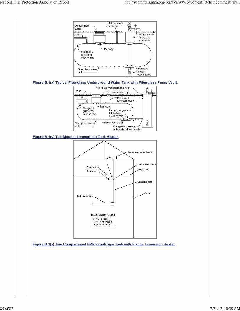
Figure B.1(x) Typical Fiberglass Underground Water Tank with Fiberglass Pump Vault.
Figure B.1(y) Top-Mounted Immersion Tank Heater.
Figure B.1(z) Two Compartment FPR Panel-Type Tank with Flange Immersion Heater.
National Fire Protection Association Report http://submittals.nfpa.org/TerraViewWeb/ContentFetcher?commentPara...
85 of 87 7/21/17, 10:38 AM
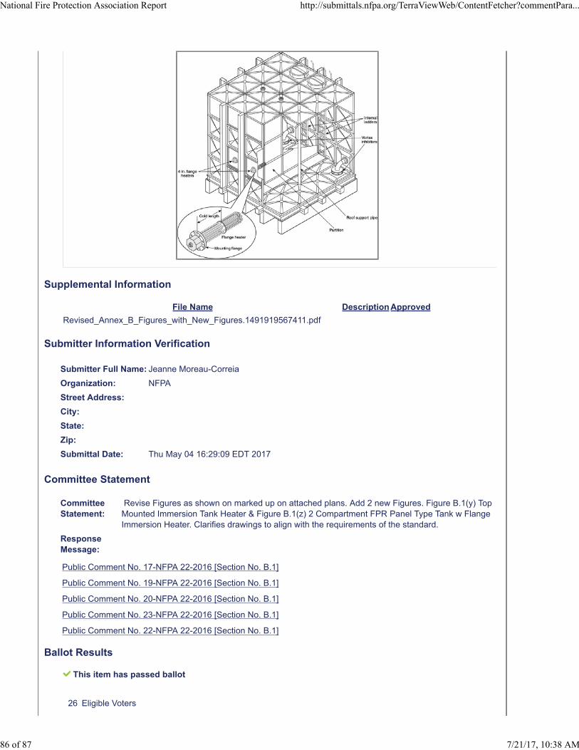
Supplemental Information
File Name Description Approved
Revised_Annex_B_Figures_with_New_Figures.1491919567411.pdf
Submitter Information Verification
Submitter Full Name: Jeanne Moreau-Correia
Organization: NFPA
Street Address:
City:
State:
Zip:
Submittal Date: Thu May 04 16:29:09 EDT 2017
Committee Statement
CommitteeStatement:
Revise Figures as shown on marked up on attached plans. Add 2 new Figures. Figure B.1(y) TopMounted Immersion Tank Heater & Figure B.1(z) 2 Compartment FPR Panel Type Tank w FlangeImmersion Heater. Clarifies drawings to align with the requirements of the standard.
ResponseMessage:
Public Comment No. 17-NFPA 22-2016 [Section No. B.1]
Public Comment No. 19-NFPA 22-2016 [Section No. B.1]
Public Comment No. 20-NFPA 22-2016 [Section No. B.1]
Public Comment No. 23-NFPA 22-2016 [Section No. B.1]
Public Comment No. 22-NFPA 22-2016 [Section No. B.1]
Ballot Results
This item has passed ballot
26 Eligible Voters
National Fire Protection Association Report http://submittals.nfpa.org/TerraViewWeb/ContentFetcher?commentPara...
86 of 87 7/21/17, 10:38 AM
5 Not Returned
21 Affirmative All
0 Affirmative with Comments
0 Negative with Comments
0 Abstention
Not Returned
Curran, Sullivan D.
Hochhauser, David
Legatos, Nicholas A.
Patrick, R. Greg
Sanchez, Daniel
Affirmative All
Biradar, Babanna
Campbell, John D.
Culp, Christopher
Fisher, Douglas W.
Fowler, Joseph R.
Gagnon, Robert M.
Garber, Greg
Henning, Andrew M.
Hillman, Jack
Kelly, Kevin J.
Kidd, Todd M.
Koenig, Gary
McGuire, Keith
Mitchard, John M.
Morgan, Bob D.
Noble, Thomas William
Ramo, Leonard J.
Rosenwach, Andrew
Sornsin, Mark A.
Stein, Gregory R.
Stevens, Owen
National Fire Protection Association Report http://submittals.nfpa.org/TerraViewWeb/ContentFetcher?commentPara...
87 of 87 7/21/17, 10:38 AM