
1962 NFPA ADVANCE REPORTS
763
~DVANCING I'~CHNICAL PROGRESS "IN FIRE 'ROTECTION J~GINEERING 1962 NFPA ADVANCE REPORTS Prepared for the SIXTY-SIXTH NFPA ANNUAL MEETING SHERATON HOTEL PHILADELPHIA, PA. MAY 21-25, 1962 NATIONAL FIRE PROTECTION ASSOCIATION International 60 Batterymarch St. Boston 10, Mass. 4.5-4-6Z-SM 9 PRINTEO IN U.S.A. I
-
Upload
khangminh22 -
Category
Documents
-
view
0 -
download
0
Transcript of 1962 NFPA ADVANCE REPORTS

~DVANCING
I'~CHNICAL
PROGRESS
"IN FIRE
'ROTECTION
J~GINEERING
1962 NFPA
ADVANCE
REPORTS
Prepared for t h e
S I X T Y - S I X T H N F P A
A N N U A L M E E T I N G
SHERATON HOTEL
PHILADELPHIA, PA.
MAY 21-25, 1962
NATIONAL F I R E PROTECTION ASSOCIATION
I n t e r n a t i o n a l
60 B a t t e r y m a r c h St. Bos ton 10, Mass.
4 . 5 - 4 - 6 Z - S M �9 P R I N T E O I N U . S . A . I

1962 NFPA ADVANCE R E P O R T S
The 1962 NFPA Advance Reports contain committee re- ports pre-printed for consideration at the Sixty-Sixth Annual Meeting of the National Fire Protection Association in Phila- delphia, Pennsylvania, May 21-25, 1962. Publication of these reports is in conformance with Article 52 of the NFPA Regula- tions Governing Technical Comnaittee Procedure and is done so that all intcrested may have advance notice of the proposed action to be taken at the A/muM Meeting.
All mcmbers and others interested are urged to read these reports and be prepared to 13articipate in the discussions incident to action on the reports at the Annual Meeting. Written com- ments may bc filed with the responsible Committee Chairman and the Association prior to the meeting. After action by the Association, there will not be opportunity for amendment of any standard adopted tmtil it is next brought up for revision.
The proposals made in these reports are not official until acted upon by the Annual Meeting. The reports are subject to amendment at the Annual Meeting. They may be adopted as pre-printed, amended in minor or major detail before adop- tion, referred back to the committees for further consideration or otherwise disposed of. Such reports as are designated as tentative are not intended for final action this year; under normal procedure, they will be considered further by the com- mittees and presented in final form at a subsequent meeting.
The reports will be presented and acted upon during the various sessions of the meeting as indicated on the separately published program. While it is expected that the reports will be presented in the order indicated in the program, the order may be changed by action of the meeting.
Reports which are finally adopted by the Association at the Annual Meeting will be printed by the Association following the meeting, normally in separate pamphlet form and in one of the seven annual volumes of the National Fire Codes. Those in- terested should watch for announcements in the issues of Fire News (sent automatically to all members) and the periodically issued List of NFPA Publications, available free from the Association.
For Procedure for Action on Committee Reports, see inside back cover.
Copyright (~ I962 National Fire Protection Associaiion

Table of Contents
Committees Reporting
Alphabet i ca l Lis t ing of C o m m i t t e e s Page
/~lr C o n d i t i o n i n g . . . . . . . . . . . . . . . . . . . . . . . . 1
~%viation . . . . . . . . . . . . . . . . . . . . . . . . . . . . 5
C a r b o n D i o x i d e . . . . . . . . . . . . . . . . . . . . . . . . 169
( ' h c m i c a l s a n d E ~ p l e s i ~ c s . . . . . . . . . . . . . . . . . . . . 173
( * u t t i n g a n d W e l d i n g P r a c t i c e s . . . . . . . . . . . . . . . . . . 5 0 7
I ) u a t E x p ! o s i o n H a i a r d s . . . . . . . . . . . . . . . . . . . . . . 2 1 5
I ]c~ ; t ron ic C o m p u t e r ~ y s t e m s . . . . . . . . . . . . . . . . . . 2 2 2
Iqro I:)oors a n d W i n d o w s . . . . . . . . . . . . . . . . . . . . 250
| I r e P u m p s . . . . . . . . . . . . . . . . . . . . . . . . . . 2 5 8
l, h u l , n a b l e L i q u i d s . . . . . . . . . . . . . . . . . . . . . . . 271
Iv'to, i n - W a t e r S p r i n k l e r s . . . . . . . . . . . . . . . . . . . . . ; 8 2
~ t . . . . . . . . . . . . . . . . . . . . . . . . . . . . . 3 1 8
elat(hgcs . . . . . . . . . . . . . . . . . . . . . . . . . . . . 3 4 6
~ .. -a *n . . . . . . . . . . . . . . . . . . . . . . . . . . . . . 3 5 3
B0:~ldlads . . . . . . . . . . . . . . . . . . . . . . . . . . . 401
~ h i n e T o o l E l e c t r i c a l S t a n d a i d s . . . . . . . . . . . . . . . 4 4 0
1~4~*lllc F i r e P r o l e c t i o n . . . . . . . . . . . . . . . . . . . . . 4 8 6
*, ,~.hilull E l e c t r i c a l C o d e . . . . . . . . . . . . . . . . . . . . 6 0 0
b t ~iahle F i r e E x t i n g u i s h e r s . . . . . . . . " . . . . . . . . . . . G02
~'~:ly to L i fe . . . . . . . . . . . . . . . . . . . . ~ . . . . G20
.t, :Min t S y s t e m s a n d T h e r m o s t a t s . . . . . . . . . . . . . . . ~55
~ ~.r S p r a y . . . . . . . . . . . . . . . . . . . . . . . . . . ~ 6 8
t : ,~.vr ' r a n k s . . . . . . . . . . . . . . . . . . . . . . . . . . 5 ] 0
i~ "~tlilg A p p a r e l . . . . . . . . . . . . . . . . . . . . . . . . ~83

T a b l e o f C o n t e n , t s ( C o n t i n u e d )
Standards Being Revised or Submitted
N F P A No. T i t l e ( A b b r e v i a t e d ) Page
10 12
15 16
I0 Series: h'zlln~ui4hing A ppliances
Portable Fire li,'xtinguishers . . . . . . . . . . . . . . . 503 Carbon Dioxide Extinguishing Sys tems . . . . . . . . . . 169 Water Sl)ray Sys tems . . . . . . . . . . . . . . . . . . 569 l~oam-Water Sprinkler and Spray Sys tems . . . . . . . . . 283
20 22
s Series: Eztin#uiahing AuxtTiarles
Centrifugal Fire P u m p s . . . . . . . . . . . . . . . . . 258 Water Tanks . . . . . . . . . . . . . . . . . . . . . . 570
80 Series: Flammable Liquids
321M-T Basic Classification of F lammable Liquids by Flash Poin t . . 273 327 Cleaning or Safeguarding Small Tanks and Containers . . . 276 328M Manholes, Sewers, and Similar Underground Structures . . . 277
36 Solvent Extract ion P lan ts . . . . . . . . . . . . . . . . 278
40 42 43 49M
495
~0 Series: Combustible Solids
Cellulose Ni t ra te Motion Picture Fihn . . . . . . . . . . 178 Pyroxylin Plastics in Factories . . . . . . . . . . . . . . 179 Pyroxylin Plastics in Warehouses and Retmil Stores . . . . . 180 Hazardous Chemicals Data . . . . . . . . . . . . . . . 181 Explosives and Blasting Agents . . . . . . . . . . . . . . 175
5 IB 56
565 566
59
50 8cries: Gases
Cutt ing and Welding Processes . . . . . . . . . . . . . . 208 Fhmunahle Anesthetics Code . . . . . . . . . . . . . . . 403 , Nonflamnmblc Medical Gas Sys tems . . . . . . . . . . . 430 Bulk Oxygen Sys tems a t Consumer Sites . . . . . . . . . 355 Liquefied Petroleum Gas a t Utility Gas Plants . . . . . . . 357
4
61A 61C
664
60 ,Series: Ezplosive Dusts
Starch Factories . . . . . . . . . . . . . . . . . . . . 216 Flour and Feed Mills and Allied Grain Storage Elevators . . 219 Woodworking and Wood Flour Manufac tur ing Plants . . . . 221
I I

S t a n d a r d s B e i n g R e v i s e d ( C o n t i n u e d )
N F P A No. T i t l e ( A b b r e v i a t e d ) P a g e
70 8cries: Electrical
70 Na t iona l Electrical Code . . . . . . . . . . . . . . . . 600 71 Cen t ra l S ta t ion Pro tec t ive Signal ing S y s t e m s . : . . . . . . 557 72 Propr ie t a ry Pro tec t ive Signal ing S y s t e m s . . . . . . . . . 558 72C R e m o t e S ta t ion Pro tec t ive Signal ing S y s t e m s . . . . . . . 559 73 Munic ipa l Fire Ala rm S y s t e m s . . . . . . . . . . . . . . 560 74M H o m e Fire Ala rm S y s t e m s . . . . . . . . . . . . . . . . 567 75 Electronic C o m p u t e r S y s t e m s . . . . . . . . . . . . . . 223 76 Essent ia l Hospi ta l Electrical Service . . . . . . . . . . . 409 79 Meta l Work ing Mach i ne Tools . . . . . . . . . . . . . . 441
80-90 Series: Construction
80 Fire Doors and Windows . . . . . . . . . . . . . . . . 251 88 Garages . . . . . . . . . . . . . . . . . . . . . . . . 346 90A Air Cond i t ion ing S y s t e m s for O t he r T h a n Res idences . . . . 2
I01
224
306
403
404M 407 409
�9 410C
414
416 417-T 420M
702
I00 ~ i e s : 8aJety to Life
Bui ld ing Exi ts Code . . . . . . . . . . . . . . . . . . 522
s Series: BuIMing Construction
H o m e s and C a m p s in Fores t Areas . . . . . . . . . . . . . 319
800 Series: Marine
Gas Haza rds on Vessels to be Repai red . . . . . . . . . . 488
400 Series: Aviation
Aircraf t Rescue and Fire F igh t ing Services for Ai rpor t s and Hel ipor ts . . . . . . . . . . . . . . . . . . . . . . 77
Sta t ic Electr ic i ty in Aircraf t Opera t ions and M a i n t e n a n c e . . 14 Ai rc ra f t Fuel ing on the Ground . . . . . . . . . . . . . 8 Aircraf t H a n g a r s . . . . . . . . . . . . . . . . . . . . 32 Aircraf t Fuel S y s t e m M a i n t e n a n c e . . . . . . . . . . . . 36 Vehicular Pe r fo rmance R e c o m m e n d a t i o n s , Aircraf t Rescue
Vehicles . . . . . . . . . . . . . . . . . . . . . . . 131 Airpor t T e r m i n a l Bui ldings . . . . . . . . . . . . . . . 19 Aircraf t Loading W a l k w a y s . . . . . . . . . . . . . . . . 30 F o a m i n g R u n w a y s for Crash Protec t ion . . . . . . . . . . 166
700 Seriea: Classification, Trtatment, Materials
F l a m m a b i l i t y of Wear ing Appare l . . . . . . . . . . . . 584
I I I

Table of Contents (Continued)
S u b j e c t T a b l e o f C o n t e n t s
A A i r C o n d i t i o n e r s , E l e c t r i c a l . . . . . . . . . . 6 9 5 Air C o n d i t i o n i n g S y s t e m s
A i r p o r t T e r m i n a l 13ui ld ings . . . . . . . . . . 22 C o m p u t e r s . . . . . . . . . . . . . . . . . . . . . . . . 2,t2 I n l e t s a n d O u t l e t s . . . . . . . . . . . . . . . . . . 3 . 2 2 Li fe S a f e t y R e q u i r e m c n t ~ . . . . . . . . . . . 551 O t h e r T h a n R e s i d e n c e s . . . . . . . . . . . . . I
A i r F o a m Liquid ConceutrtHes f o r F o a m - W a t e r S p r i n k l e r s . . . . . . . . . 292
A i r V e n t l l u H o n d u r l n p . A i r c r a f t F u e l S y s t e m M a i n t e n a n c e . . . . . . . . . . . 36
A i r c r a f t F o a m i n g R u n w a y s for P r o t e c t i o n o f . . . 166 F u e l S e r v i c i n g of . . . . . . . . . . . . . . . . . . . 8 F u e l S y s t e m M a i n t e n a n c e of . . . . . . . . . 3 6 H a n g a r s . . . . . . . . . . . . . . . . . . . . . . . . . . 32, 713 L o a d i n g W a l k w a y s fo r . . . . . . . . . . . . . . 3 0 R e s c u e a n d F i r e F i g h t i n g S e r v i c e s f o r . 77 R e s c u e a n d F i r s l : i g h t i n g V e h i c l e s fo r 131 S t a t i c H a z a r d s d u r i n g O p e r a t i o n s a n d
M a i n t e n a n c e . . . . . . . . . . . . . . . . . . . . . 1.t A i r p o r t s
A i r c r a f t L o a d i n g W a l k w a y s a t . . . . . . . 3 0 F o a m i n g R u n w a y s a t . . . . . . . . . . . . . . . 166 F u e l i n g A i r c r a f t a t . . . . . . . . . . . . . . . . . 8 H a n g a r s a t . . . . . . . . . . . . . . . . . . . . . . . 3 3 , 7 1 3 R e s c u e a n d F i r e F i g h t i n g S e r v i c e s a t . . 77 R e s c u e a n d F i r e F i g h t i n g V e h i c l e s a t . . 131 T e r m i n a l B u i l d i n g s a t . . . . . . . . . . . . . . . 19
A i s l e s , H o s p i t a l s a n d N u r s i n g I l o m e s 526 , 537
A l a r m s , F i r e A u x i l i a r y . . . . . . . . . . . . . . . . . . . . . . . . . . 5 5 8 C e n t r a l S t a t i o n . . . . . . . . . . . . . . . . . . . . 557 C o m p u t e r s , fo r . . . . . . . . . . . . . . . . . . . . . 233 E l e c t r i c a l S y s t e m s . . . . . . . . . . . . . . . . . . 7 4 2 F o a m - W a t e r S p r i n k l e r S y s t e m s . . . . . . 2 9 5 F o r e s t P r o p e r t i e s . . . . . . . . . . . . . . . . . . . 323 H o m e . . . . . . . . . . . . . . . . . . . . . . . . . . . . . 567 H o s p i t a l s a n d N u r s i n g I l o m e s . . . . . . 5 2 9 , 5 4 1 Lo ca l . . . . . . . . . . . . . . . . . . . . . . . . . . . . . 5 5 8 M u n i c i p a l . . . . . . . . . . . . . . . . . . . . . . . . . 5 6 0 P r o p r i e t a r y . . . . . . . . . . . . . . . . . . . . . . . . 5 5 8 R e m o t e S t a t i o n . . . . . . . . . . . . . . . . . . . . 5 5 9 T e l e p h o n e . . . . . . . . . . . . . . . . . . . . . . . 5 6 1 , 5 6 5
A l u m i n u m S h e a t h e d C a b l e ......... 6 5 8 A n e s t h e t i c s , F l a m m a b l e . . . . . . . . . . . 1 0 3 .7 1 8 A n t i - F r e e z e E x t l n R u l s h e r s , M a i n t e -
n a n c e . . . . . . . . . . . . . . . . . . . . . . . . . . . 504 A p p a r a t u s . M o t o r , A i r c r a f t R e s c u e
a n d F i r e F i l ~ h t l n g . . . . . . . . . . . . . . . 131 A p p l i a n c e s , E l e c t r i c a l . . . . . . . . . . . . . . . 691 A t t a c h m e n t P l u g s , G r o u n d i n g T y p e ,
E l e c t r i c a l . . . . . . . . . . . . . . . . . . . . . . . . 6 9 0 A u t o m a t i c S p r i n k l e r s (see Sprinklers)
B I l a l c o n l e s
G u a r d s a n d H a n d r a i l s . . . . . . . . . . . . . . 547 W a t e r T a n k s . . . . . . . . . . . . . . . . . . . . . . 573
B a r b e c u e s , O u t d o o r . . . . . . . . . . . . . . . . . 333 l l l a s t l n ~ A g e n t s . . . . . . . . . . . . . . . . . . . . 175 B e a r d s , Fa l s e , F l a m m a b i l i t y of . . . . . . . . 586 l l o l l l n p . P o i n t , I ) c f i n i t i o n . . . . . . . . . . . . . 274 B r a n c h C i r c u i t s , E l e c t r i c a l . . . . . . . . . 618, 622 Building Construction
A i r p o r t T e r m i n a l B u i l d i n g s . . . . . . . . . . 19 C o l n p a t e r S y s t e m s , F e a t u r e s fo r . . . . . . 227. ] l o m e s a n d C a m p s in F o r e s t A r e a s . . . . 324
Buildings (see also Occupancies) B u l k S t o r a g e P l a n t s . . . . . . . . . . . . . . . . 716
C C a b l e , E l e c t r i c a l
A h m l i n u m S h e a t h e d . . . . . . . . . . . . . . . . 658 A r m o r e d . . . . . . . . . . . . . . . . . . . . . . . . . . 6 6 0 M e t a l - C l a d . . . . . . . . . . . . . . . . . . . . . . . . 660 N o n - m e t a l l i c S h e a t h e d . . . . . . . . . . . . . . 664 S u l ) p o r t s fo r C o n t i n u o u s , R i g i d . . . . . . 6 5 5
C a r b o n D i o x i d e A i r c r a f t R e s c u e a n d F i r e F i g h t i n g . . . . 86 C o m p u t e r S y s t e m s . . . . . . . . . . . . . . . . . 235 E x t i n g u i s h i n g S y s t e m s . . . . . . . . . . . . . . lf19 I n e r t i n g , A i r c r a f t F u e l S y s t e m s . . . . . . . 38 I n e r t i n g , S h i p T a n k s . . . . . . . . . . . . . . ~. 492
C a t h o d i c P r o t e c t i o n , fo r W a t e r T a n k s . 572 C a u t e r y E q u i p m e n t . . . . . . . . . . . . . . . . 406 C e l l u l o s e N i t r a t e M o t i o n P i c t u r e F i l m 178 C h a s s i s , V e h i c l e , A i r c r a f t R e s c u e a n d
F i r e F i g h t i n g . . . . . . . . . . . . . . . . . . . . 134, 146 C h e m i c a l s , B u l k S h i l ) m e n t o n V e s s e l s . . 4 9 9 C h e m i c a l s , D a t a o n . . . . . . . . . . . . . . . . . 181 C h e m i s t , M a r i n e ( ;ms . . . . . . . . . . . . . . . . 4 9 0 C h i m n e y s a n d F l u e s , H o m e s a n d
C a m p s in F o r e s t A r e a s . . . . . . . . . . . . 332 C i r c u i t B r e a k e r s , E l e c t r i c a l . . . . . . . . . . 627 C l a s s i f i c a t i o n o f F l a m m a b l e L i q u i d s
b y F l a s h P o i n t . . . . . . . . . . . . . . . . . . 273 C l a s s i f i c a t i o n o f F i r e s , P o r t a b l e F i r e
E x t i n g u i s h e r s . . . . . . . . . . . . . . . . . . . . 503 C l e a r a n c e s , E l e c t r i c a l A p p a r a t u s a n d
S p r a y ] l e a d s . . . . . . . . . . . . . . . . . . . . . 569 C o m m u n i c a t i o n C i r c u i t s , Electric . . . . 745 C o m m u n i c a t i o n s , A i r c r a f t R e s c u e a n d
F i r s F i g h t i n g a t A i r p o r t s . . . . . . . . . . 103 C o m m u n i t y F i r e P r o t e c t i o n , F o r e s t
A r e a s . . . . . . . . . . . . . . . . . . . . . . . . . . . 342 C o m p u t e r
E q u i p m e n t , C o n s t r u c t i o n of . . . . . . . . . . 231 S y s t e m s . . . . . . . . . . . . . . . . . . . . . . . . . . . 223 S y s t e m R o o m s , C o n s t r u c t i o n . . . . . . . . 22~ S y s t e m R o o m s , P r o t e c t i o n . . . . . . . . . . . 233
IV

fable of Contents (Continued) C o n d u c t i v e F l o o r i n g , Anesthetizing
Areas . . . . . . . . . . . . . . . . . . . . . . . . . . . 407 C o n d u c t i v e R u b b e r , A n e s t h e t i z i n g
Areas . . . . . . . . . . . . . . . . . . . . . . . . . . . 405 C o n d u c t o r s , Electrical
General Wiring . . . . . . . . . . . . . . . . . . . . 644 Grounded, Use and Identification: . . . . 617
" .Machine Tools . . . . . . . . . . . . . . . . . . . . . 467 C o n d u i t , Electrical " Flexible Metal . . . . . . . . . . . . . . . . . . . . . 674
Liquid-Tight . . . . . . . . . . . . . . . . . . . . . . . 675 Rigid Metal . . . . . . . . . . . . . . . . . . . . . . 668 Rigid Non-Metallic . . . . . . . . . . . . . . . . . 669
(~onta ine ta Carbon Dioxide, H y d r o s t a t i e T e s t i n g . . 169 Flammable Liquid, Cleaning or Safe-
guarding . . . . . . . . . . . . . . . . . . . . . . . . 276 Liquefied Petroleum Gases,
Nonrsfrigsrated . . . . . . . . . . . . . . . . . . 361 Refrigerated . . . . . . . . . . . . . . . . . . . . . 369
C o n t r o l C i r c u i t s , Machine Tools . . 458 ~kwds, Flexible, Electrical . . . . . . . . . . . 405.683 Cor r idors , H o o p i t a l s a n d N u r s i n g
H o m e s . . . . . . . . . . . . . . . . . . . . . . . . 526 .537 C r a n e s a n d Ho i s t s , Electrical . . . . . . . . . 725 ~ r l t i c a l ElecJtTIcal Services , Hosp i ta l , . 411 (~u t t i ng a n d W e l d i n g
(;arsges . . . . . . . . . . . . . . . . . . . . . . . . . . . 347 Processes, Use of . . . . . . . . . . . . . . . . . . . 208
( ~ l i n d e t a Carbon Dioxide, Test ing . . . . . . . . . . . . 169 Oxygen Supply Systems . . . . . . . . . . . . . 431
D ~ h m p e r s , Fi re , for Air Condit ioning
Systems . . . . . . . . . . . . . . . . . . . . . . . . . 3 1~etectors, F i re (see Alarm~, Fire) Detec tnrs , S m o k e (see Smoke Detection) Doors
Exit . . . . . . . . . . . . . . . . . . . . . . . . . . . . . . 545 ~trs . . . . . . . . . . . . . . . . . . . . . . . . . . . . . . 520 Hospitals and Nursing Homes . . . . . . . 526 Power Operated . . . . . . . . . . . . . . . . . . . . 546
D r a i n a g e , Airport Ramps and Hangar Doors . . . . . . . . . . . . . . . . . . . . . . . . . . . 32
| ~ y Chemical E x t i n g u i s h e e s Wheeled. Class B and C . . . . . . . . . . . . . 508 Wheeled, Muiti-Purpose . . . . . . . . . . . . . 500
Dry C h e m i c a l S y s t e m s Aircraft Hangars . . . . . . . . . . . . . . . . . . . 33 Aircraft Rescue and Fire ]Fighting . . . . 87
Dry Cleaning, Textile Flammability Test Samples . . . . . . . . . . . . . . . . . . . . . . . . . 595
Dgyers, Grain . . . . . . . . . . . . . . . . . . . . . . . 220 Duc t s , Air C o n d i t i o n i n g
Computer Systems . . . . . . . . . . . . . . . . . 242 Connectors for . . . . . . . . . . . . . . . . . . . . . 2
Duets Flour and Feed . . . . . . . . . . . . . . . . . . . . 210 Grain Elevators . . . . . . . . . . . . . . . . . . . . 219 ~tareh . . . . . . . . . . . . . . . . . . . . . . . . . . . . 216 Woodworking and Wood Flour . . . . . . 221
Dwelling Fire Alarms (tee Atarm~, Fire)
E d u c a t i o n a l B u i l d i n g s , Definition for Exi t Code . . . . . . . . . . . . . . . . . . . . . . . 522
E lec t r i c S i g n s . . . . . . . . . . . . . . . . . . . . . . . 723 E lec t r i c We lde r s . . . . . . . . . . . . . . . . . . . . 732 Electric Wir ing and Equ ipment
Clearance from Water Spray Nozzles.. 569 Computer Systems . . . . . . . . .. . . . . . . 234,242 General, National Code for . . . . . . . . . . 600 Homes in Forest Areas . . . . . . . . . . . . . . 329 Hospital , Essential Services . . . . . . . . . . 409 Machine Tools, Metalworking . . . . . . . 444 Signaling Systems . . . . . . . . . . . . . . . . . . 555 Solvent Extract ion Plants . . . . . . . . . . . 280 Starch Factories . . . . . . . . . . . . . . . . . . . . 217 Vehicles, Aircraft Rescue and Fire
Fight ing . . . . . . . . . . . . . . . . . . . . . . 140, 149 E l e c t r i c i t y , S t a t i c (ate Ftatic Electricity) E l e c t r o n i c C o m p u t e r S y s t e m s . . . . . . . 223 E l e c t r o n i c E q u i p m e n t , Anesthetizing
Locations . . . . . . . . . . . . . . . . . . . . . . . 407 E l e v a t o r S h a f t s , Hospitals and Nursing
Homes . . . . . . . . . . . . . . . . . . . . . . . . 529, 540 E leva to r s , Electrical Requirements for 725 E m e r g e n c y E l e c t r i c a l S y s t e m s . . . . . 409,739 E m e r g e n c y L ~ h t i n g , Computers . . . . . 243 EmerAency S h e l t e r s . . . . . . . . . . . . . . . . . 545 E n d o t h e r m y E q u i p m e n t , Anesthetizing
Locations . . . . . . . . . . . . . . . . . . . . . . . 406 E n t i n e s , Aircraft Rescue and 1tire Fight-
ing Vehicles . . . . . . . . . . . . . . . . . . . 130, 147 E v a c u a t i o n P l a n s a n d R o u t e s fo r
F o r e s t Areas . . . . . . . . . . . . . . . . . . . . 339 E x h a u s t P ip inA for F i re P u m p E n g i n e s 268 Exi t Dr i l l s , Hospitals and Nursing
Homes . . . . . . . . . . . . . . . . . . . . . . . 533,543 Exi t L i g h t i n g a n d S i g n s , Hospitals and
Nursing Homes . . . . . . . . . . . . . . . . . . 534 Exi t s
Airport Terminal Buildings . . . . . . . . . . 23 Code for . . . . . . . . . . . . . . . . . . . . . . . . . . 522 Distance of Travel to . . . . . . . . . . . . . . . 545 Homes and Camps in Forest Areas . . . . 325 Hospitals and Nursing Homes . .522 ,524 ,536
Exploelves, M a g a z i n e s a n d H a n d l i n g . 175 E x t e n s i o n s , Non-Metaille. E lec t r i ca l . . . 666 E x t i n g u i s h e r s
Computer Rooms and Equipment . . . . 234 Hospitals . . . . . . . . . . . . . . . . . . . . . . . . 532,542 Hydrostat ic Testing . . . . . . . . . . . . . . . . 516 Loaded Stream . . . . . . . . . . . . . . . . . . . 506, 507 Markings . . . . . . . . . . . . . . . . . . . . . . . . . . 517 Metal Fires . . . . . . . . . . . . . . . . . . . . . . riO3, 513 Nursing Homes . . . . . . . . . . . . . . . . . . 532,542 Shelters, Emergency . . . . . . . . . . . . . . . . 545 Standard for, Revisions . . . . . . . . . . . . . 503 Water . . . . . . . . . . . . . . . . . . . . . . . . . . . . 503 Wet t ing Agent . . . . . . . . . . . . . . . . . . . . . 505
F Fabr i c s , PymxyUn-eoated, F lammabi l i ty 586 Paceplates, Receptacles, Electrical . . . . 689
V

Table of Contents (Continued) F e e d M i l l s . . . . . . . . . . . . . . . . . . . . . . . . . . 219 F e e d e r s , Elec t r ica l Conductors . . . . . . . . 622 F i l m , Cellulose N i t r a t e Mot ion P ic tu re . 178 F i n i s h i n g Procemues, Elect r ica l Wir ing
and Equ ipmen t in . . . . . . . . . . . . . . . . 717 F i r e A l a r m s (see Alarn~) F i r e D e p a r t m e n t s , Ai rpor t . . . . . . . . . . . 77 F i r e D o o r s
Hardware for . . . . . . . . . . . . . . . . . . . . . . 254 Sectional Uni t s for . . . . . j . . . . . . . . . . . 255 S tandard for . . . . . . . . . . . . . . . . . . . . . . . 250
F i r e E s c a p e S t a i r s Hospi ta ls and Nurs ing Homes . . . . . . . . 539 Guards and Handra i l s . . . . . . . . . . . . . . 550
F i r e E x t i n g u i s h e r s (see Extinguishers) . . F i r e F i g h t i n g E q u i p m e n t
Ai rc ra l t Rescue and Fire F igh t ing . . . . 131 Homes and Camps . . . . . . . . . . . . . . . . . 338
F i r e P u m p s , Ins ta l la t ion of . . . . . . . . . . . 258 F i r e s t o p p l n g , Hospi ta ls and Nurs ing
Homes . . . . . . . . . . . . . . . . . . . . . . . . 529 ,540 F i r e W a t c h e r s , for Cu t t ing and Welding �9 213 F l a m m a b l e L i q u i d s
Aircraf t Fuel Servicing . . . . . . . . . . . . . . 8 Aircraf t Fuel System Main tenance . . . . 36 Basic Classification of . . . . . . . . . . . . . . . 273 Boiling Point , Definit ion . . . . . . . . . . . . 274 Flash Point , Definit ion . . . . . . . . . . . . . . 274 Garages . . . . . . . . . . . . . . . . . . . . . 3 4 7 , 3 4 9 , 3 5 0 Manholes, Sewers, etc . . . . . . . . . . . . . . . 277 Vapor Pressure, Definit ion . . . . . . . . . . . 273
F l a m m a b i l i t y , Wear ing Apparel . . . . . . 584 F l a s h F a i n t , Defined . . . . . . . . . . . . . . . . 274 F l e x i b l e C o r d , Elect r ica l . . . . . . . . . . . 405 ,683 F l o o r s , R a i s e d , in Compute r R o o m s . . . 228 F l o u r a n d F e e d M U l s . . . . . . . . . . . . . . . 219 F o a m
Aircraf t Rescue and Fire F igh t ing . . . . 84 Runways for C r ~ h Protect ion . . . . . . . 166 Under Ai rc ra f t Loading Walkways . . . . 31
F o a m - W a t e r S p r i n k l e r S y s t e m s Aircraf t Hangars . . . . . . . . . . . . . . . . . . . 33 S tanda rd for . . . . . . . . . . . . . . . . . . . . . . . 285
F o o t S w i t c h e s , E l e c t r i c a l , Anesthet iz- ing Locations . . . . . . . . . . . . . . . . . . . . 405
F o r e s t , Homes and C a m l ~ in . . . . . . . . . . 319 F u e l S u p p l y fo r F i r e P u m p s . . . . . . . . . 266 F u e l S y s t e m s
Aircraf t Rescue and Fire F igh t ing Vehicles . . . . . . . . . . . . . . . . . . . . . . . 139, 149
Main tenance , Ai rc ra f t . . . . . . . . . . . . . . 36 F u e l i n g A i r c r a f t . . . . . . . . . . . . . . . . . . . . 8 F u s e s , Elect r ica l . . . . . . . . . . . . . . . . . . . . . 627
- - G - - Garages . . . . . . . . . . . . . . . . . . . . . . . . . . 346, 7 ! 2 G a s
Anesthet iz ing Locations. Hazards o f . . 403 Cu t t ing and Welding, Processes Us ing . 208 LP, a t Ut i l i ty Gas Plants . . . . . . . . . . . 357 Manholes , Sewers, etc. , Haza rds in . . . . 277 Mar ine Haza rds . . . . . . . . . . . . . . . . . . . . 487
G a s ( c o n t i n u e d ) Nonf lammable Medical . . . . . . . . . . . . . 430 Oxygen Systems a t Consumers S i to s . . 355" Piping, Used as Elect r ica l Ground . . . . . 636 Ve~ela, Mar ine . . . . . . . . . . . . . . . . . . . . 487
G a s o l i n e S e r v i c e S t a t i o n s , Electr ical Equ ipmen t for . . . . . . . . . . . . . . . . . . . 714
G h u g l n g Devices , LPG Containers . . . . . 378" G e n e r a t o r s
Hospi ta l Essential Electr ical Services . 4244 Shelters, Emergency . . . . . . . . . . . . . . . . 545
G r o i n E l e v a t o r s . . . . . . . . . . . . . . . . . . . . . 219 G r i n d i n g E q u i p m e n t i n G r o i n E l e -
v a t o r s . . . . . . . . . . . . . . . . . . . . . . . . . . 219 G r o u n d I n d i c a t o r , E l e c t r i c a l , Anos-
thet iz ing Loca u~ns . . . . . . . . . . . . . . . 404 G r o u n d i n g
Elect r ica l Wir ing and Equ ipmen t . . . . . 631 Elec t ros ta t ic Vacuum Sweeping Ap-
pa ra tus in S tarch Factor ies . . . . . . . . 2174 Machine Tools . . . . . . . . . . . . . . . . . . . . . 477
G u a r d s , S t a i r , Exi t . . . . . . . . . . . . . . . . . . 546 G u t t e r s , A u x i l i a r y , Electr ical . . . . . . . . . 680 4
~ H ~
H a n d r o i l s , S t a i r s , Exi t . . . . . . . . . . . . . . 547 H a z a r d o u s C h e m i c a l s D a t a . . . . . . . . . 181 H a z a r d o u s L o c a t i o n s , Electr ical . . . . . . 704 * H e a t i n g E q u i p m e n t
Ai rpor t Te rmina l Buildings . . . . . . . . . . 22 Homes and Camps in Fores t Areas . . . . 333 Wate r T a n k s . . . . . . . . . . . . . . . . . . . . . . 5741
H e l i p o r t s , Ai rc ra f t Rescue and Fire Fight ing Services . . . . . . . . . . . . . . . . . 77
H o g s , Wood Waste . . . . . . . . . . . . . . . . . . . 221 H o m e F i r e A l a r m s (see Alarn~, Fire) Hose , LPG . . . . . . . . . . . . . . . . . . . . . . . . . . 379 H o s p l t a l a
Anesthet iz ing Locations in . . . . . . . . . . . 403 Elect r ica l Services in . . . . . . . . . . . . . . 409 ,739 Exi ts for . . . . . . . . . . . . . . . . . . . . . . . . 523, 5351 Nonflamnmble Gas Systems in . . . . . . . 430
H u l a S k i r t s , F lamnmbi l i ty of . . . . . . . . . 5864 H y d r a n t s , Airpor t Fuel . . . . . . . . . . . . . . 12 H y d r o s t a t i c T e s t i n g , Ext inguishers . . . . 516
I n c i n e r a t o r s Flue Fed . . . . . . . . . . . . . . . . . . . . . . . . . . 553 Homes and Camps in Fores t A r e a s . . : . 337
I n e r t i n g , Aircraf t Fuel System . . . . . . . . 36 I n s t i t u t i o n a l B u i l d i n g s , Definit ion . . . . 522 I n s t r u m e n t s , Combust ib le Gas . . . . . . . 56 I n t e r i o r F i n i s h
Homes and Camps in Fores t Areas . . . . 327 Hospi ta ls and Nurs ing Homes . . . . . . 529 ,540
I n t e r p r e t a U o n s , Elec t r ica l Code Com- mi t t ec Rules for . . . . . . . . . . . . . . . . . . 752
J J o c k e y P u m p s , Ins ta l la t ion of . . . . . 260, 261 J u n c t i o n Boxes , Elec t r ica l . . . . . . . . . . . 677
V!
Table of Contents (Continued)
L L a d d e r s , Roof , for Wate r T a n k s . . . . . . 572 L a n d i n g s , S t a i r , Guards and Handra i l s 547 L i g h t i n g , Machine Tools . . . . . . . . . . . . . 466 L i g h t i n g F i x t u r e s . Electr ical . . . . . . . . . 689 L i n e n C h u t e s . . . . . . . . . . . . . . . . . . . . . . . 553 L i q u e f i e d P e t r o l e u m G a s '
Garages . . . . . . . . . . . . . . . . . . . . . 350, 351, 352 Ut i l i ty Gas Plants . a t . . . . . . . . . . . . . . . 357
L l g h t n l n ~ P r o t e c t i o n Compute r Systems . . . . . . . . . . . . . . . . . 243 Homes and Camps in Forest Areas . . . . 330 LPG Storage Conta iners . . . . . . . . . . . . 360
L i q u i d s , F l a m m a b l e (see Flammable Liquids) L o a d e d S t r e a m E x t i n g u i s h e r s . . . . . . 506 .507 Low V o l t a g e C i r c u i t s , ElectricM . . . . . . 742
M M a c h i n e T o o l s , ,~.|etalworking . . . . . . 444. 734 M a g n e s i u m , Ai rc ra f t Rescue and Fire
Fight ing. Problems with . . . . . . . . . . . 89 M a r i n e F i r e P r o t e c t i o n . . . . . . . . . . . . . 486 M a r k i n g s
Extinguishers. Por tab le . . . . . . . . . . . . . 517 Liquefied Petroleum Gas Conta ine r s . 363. 370
M e t a l s , Fire Ext inguishers for . . . . . . . . . 513 . M e t a l w o r k i n g M a c h i n e T o o l s . . . . . . 444. 734
�9 M o t i o n P i c t u r e S t u d i o * , Elec t r ica l Re- quirsments for . . . . . . . . . . . . . . . . . . . 722
M o t o r s , Mach ine Tool . . . . . . . . . . . . . 476.734 M o t o r s , M o t o r C i r c u i t s , Electr ical . . . . 694 M o v i n g W a l k w a y s , Electr ical . . . . . . . . . 725
�9 M u n i c i p a l F i r e A l a r m s (see Alarms, Fire)
- - N - -
�9 N i t r o g e n , Iner t ing Aircraf t Fuel Systems 39 N u r s i n g H o m e s , Exi ts for . . . . . . . . . . 523 ,535
- - 0 - -
, O d o r l z l n g , LP-Gas . . . . . . . . . . . . . . . . . . 359 O p e r a t i n g P r o c e d u r e s , E m e r g e n c y ,
Computers . . . . . . . . . . . . . . . . . . . . . . 244 O u t d o o r F i r e P r o t e c t i o n . . . . . . . . . . . . 341 O u t l e t Boxes , Electr ical . . . . . . . . . . . . . . 677 O u t s i d e B r a n c h C i r c u i t s a n d F e e d e r s 744
' O v e r c u r r e n t P r o t e c t i o n , Elec t r ica l Essential Hospi ta l Services . . . . . . . . . . 627 Fire Pumps . . . . . . . . . . . . . . . . . . . . . . . . 265 Machine Tools . . . . . . . . . . . . . . . . . . . . . 452 Wiring, Genera l . . . . . . . . . . . . . . . . . . . . 627
~Oxygen Bulk Systems . . . . . . . . . . . . . . . . 355, 430, 432
�9 Ten t s . . . . . . . . . . . . . . . . . . . . . . . . . . . . . 439
P " ~ n l c H a r d w a r e . . . . . . . . . . . . . . . . . . . . 545 P h o t o g r a p h i c L i g h t i n g , Anesthet iz ing
Locations . . . . . . . . . . . . . . . . . . . . . . . 408 P i p ing
Foam Wate r Spr ink le r Systems . . . . . . 300 Liquefied Pet ro leum Gas . . . . . . . . . . . . 375
P l u g s , E l e c t r i c a l , Anesthet iz ing Loca- tions . . . . . . . . . . . . . . . . . . . . . . . . . . . . 403
P o w d e r - O p e r a t e d T o o l s , Starch Fac- tories . . . . . . . . . . . . . . . . . . . . . . . . . . . 218
P o w e r S u p p l i e s , EssentiM Hosp i ta l Electr ical Services . . . . . . . . . . . . . . . . 413
P o w e r T o o l s , M e t a l w o r k i n g , Elec t r ica l S tandard for . . . . . . . . . . . . . . . . . . . . . 444
P r e s s u r e I n e r t i n g , Ai rc ra f t Fuel System Main tenance . . . . . . . . . . . . . . . . . . . . . 36
P r o j e c t o r s , M o t i o n P i c t u r e , Conduc- tors . . . . . . . . . . . . . . . . . . . . . . . . . . . . . 723
P u m p s Fire . . . . . . . . . . . . . . . . . . . . . . . . . . . . . . 259 Fire. Supervision of . . . . . . . . . . . 557 ,558 , 560 Foam Liquid Concent ra tes . . . . . . . . . . 293 Liquefied Petroleum Gas . . . . . . . . . . . . 379
P y r o z y l l n P l a s t i c s , Storage. Handl ing . Use . . . . . . . . . . . . . . . . . . . . . . . . . . . 179. 180
R R a c e w a y s , C e l l u l a r C o n c r e t e
Floor. Electr ical . . . . . . . . . . . . . . . . . . . . 676 R a d a r , I g n i t i o n H a z a r d , Ai rc ra f t Fuel-
ing . . . . . . . . . . . . . . . . . . . . . . . . . . . . . 8 R a d i o , Ai rc ra f t Rescue and Fire F igh t ing
Veldcles. for . . . . . . . . . . . . . . . . . . . . . 103 R a d i o a n d T e l e v i s i o n E q u i p m e n t . . . . 746 R a m p s
Hospi ta ls and Nurs ing H o m e s . . 5 2 7 . 5 2 9 . 5 3 8 Rail ings for . . . . . . . . . . . . . . . . . . . . . . . . 550
R e c e p t a c l e s , G r o u n d i n g T y p e , Elec- t r ical . . . . . . . . . . . . . . . . . . . . . . . . . . . 689
R e c o r d s , Protect ion of. Computers . . . . . 237 R e l i e f Dev ices , L P G C o n t a i n e r s
Aboveground Conta iners . . . . . . . . . . . . 385 Tes t ing . . . . . . . . . . . . . . . . . . . . . . . . . . . 384 Underground Conta iners . . . . . . . . . . . . 386 Vaporizers . . . . . . . . . . . . . . . . . . . . . . . . . 386
R e l i e f Va lves fo r F i r e P u m p s . . . . . . . . 259 R e s c u e V e h i c l e s , Ai rc ra f t Services a t
Airpor ts . . . . . . . . . . . . . . . . . . . . . . . . . 100 R o o f C o v e r i n g s , H o m e s , Forest Areas . 327 R o t a r y , A i r c r aT t , Rescue. Fire F igh t ing 77 R u b b i s h C h u t e s . . . . . . . . . . . . . . . . . . . . 553 R u b b i s h Dlspotml , Homes, Fores t Areas 337 R u n w a y s , Foaming for Crash Protect ion 160
S S e r v i c e s , Electr ical . . . . . . . . . . . . . . . . . . . 624 S h e l t e r s , Emergency . . . . . . . . . . . . . . . . . 545 S h i p s , Gas-Freeing . . . . . . . . . . . . . . . . . . . 487 S i g n a l i n g C i r c u i t s , Elect r ica l . . . . . . . . . 742 S i g n a l i n g S y s t e m s . . . . . . . . . . . . . . . . . . 557 S i g n s , Electr ic . . . . . . . . . . . . . . . . . . . . . . . 723 S i l l s fo r F i r e D o o r s . . . . . . . . . . . . . . . . . . 251 S i p h o n l n e r t i n g , Ai rc ra f t Fuel System
Main tenance . . . . . . . . . . . . . . . . . . . . . 36 S m o k e B a r r i e r s , Exis t ing Hospi ta ls and
Nurs ing Homes . . . . . . . . . . . . . . . . . . 539
VII

T.ble of Cr,,i tcu, ts ( Co,i rh,i,erl)
S m o k e I ) e t e c t o r a Air Cmldi t ioning SystetllS . . . . . . . . . . . ~1 Unde r Fhmr Spae,m. Glnll|ln[er l i l~ l l ln l ~;|:l
S n l o k e p r o o f T o w e r s . . . . . . . . . . . . . . . . . /~*1 I) S n l o k e V e n l h l g , Safcty tO 1,[[4) l l eqnho .
mcnt~ of . . . . . . . . . . . . . . . . . . . . . . . . fi52 S m o k i n g
H os piuda a ml N urai ng I I omes . . . . . . 5:1,1./~,l,I S o l v e n t E x I r a c l l o l l P h i l l i s . . . . . . . . . . . ~71J S p r i n k l e r s
Aircraf t I l angars . . . . . . . . . . . . . . . . . . . ,'l:l Aircraf t l,ov.ding Wldkways . . . . . . . . . . 31 Airpor t Te rmina l Iluihlhlgn . . . . . . . . . . 2.1 C o m l m t c r System Rooms . . . . . . . . . . . 2:1:| F0alU-~Vtt tcr . . . . . . . . . . . . . . . . . . . . . . . ')g5 l losp i ta l s . . . . . . . . . . . . . . . . . . . . . . . . 529.5,10 Lodges, Ih~tels. etc. , in Forest A r e a s . . 339 Nurs ing II~nne5 . . . . . . . . . . . . . . . . . . 529, 540 Pressure T a n k Systcms . . . . . . . . . . . . . ;~39
S t a i r s , IIospitals all++/ NurBing l lolm:s 527. 529. 538, 539
S t a r c h F a c t o r i e s . . . . . . . . . . . . . . . . . . . . 216 S t a t i c E l e c t r l e H y
Aircraf t Operat ions and Main tenance 14 LP Gas Piping Systems . . . . . . . . . . . . . 361
S t o r a g e Blas t ing Agents . . . . . . . . . . . . . . . . . . . . 175 Cellulose N i t r a t e Mot ion Pic ture Fihn 178 Compute r Supplies and Tapes . . . . . . . 230 Explosives . . . . . . . . . . . . . . . . . . . . . . . . . 175 Liquefied Pet ro leum Gases . . . . . . . . . . 357 Oxygen Systems. Bulk . . . . . . . . . . . . . . 355 Pyroxyl in Plast ics . . . . . . . . . . . . . . . . 179. 180
S t o r a g e B a t t e r i e s . . . . . . . . . . . . . . . . . . . 703 S u r f a c e E x t e n s i o n s , Non-Meta l l i c ,
Electr ical . . . . . . . . . . . . . . . . . . . . . . . . 666 S w i m m i n g P o o l s . . . . . . . . . . . . . . . . . . . . 736 S w i t c h Boxes , Electr ical . . . . . . . . . . . . . 677 S w i t c h b o a r d s a n d P a n e l b o a r d s , Elec-
t r ical . . . . . . . . . . . . . . . . . . . . . . . . . . . 682 S w i t c h e s , Elect r ica l . . . . . . . . . . . . . . . . . . 681
- - T - - T a n k C a r s . L P G , Unloading of . . . . . . . . 388 T a n k S h i p s , Gas Freeing . . . . . . . . . . . . . 488 T a n k T r n ( : k s
Ai rc ra f t Fuel Servicing . . . . . . . . . . . . . . 9 Water . for Aircraf t Rescue and Fire
F igh t ing . . . . . . . . . . . . . . . . . . . . . . . . 100 T a n k s
Aircraf t Fuel Main tenance . . . . . . . . . . 36 Cleaning or Safeguarding Small . . . . . . 276 Foam Liquid Concent ra te . . . . . . . . . . . 294 Water . . . . . . . . . . . . . . . . . . . . . . . . . . . . 570
T e l e p h o n e F i r e A l a r m s (see Alarms. Fire) T e l e v i s i o n E q u i p m e n t , Electr ical . . . . . 746 T e r m i n a l B u i l d i n g s , Ai rpor t . . . . . . . . . 19 T e s t A p p a r a t u s , Textile Flammabil i ty 590 T e s t s , A c c e p t a n c e
Foam-Wate r Spr inkler Systems . . . . . . 304 T e x t i l e s , Anesthet iz ing Locations . . . . . . . 408 T e x t i l e s , F lammabi l i ty of . . . . . . . . . . . . . 5S7 T h e a t r e s , Elec t r ica l Requi rements f o r . . 720
T i r e s , Aircraf t Rescue and Fire Fight ing Vehicles . . . . . . . . . . . . . . . . . . . . . . . 143, 152
"l'tmla, M a c h i n e , M e t a l w o r k i n g . . . . . . 4.t4 T o w e r s , SnuJkeproof . . . . . . . . . . . . . . . . . 549 " l ' ru ln lnf l , Aircraf t Rescue and Fire
Fight ing Personnel . . . . . . . . . . . . . . . 100 T r m ~ s f o r m e r s . . . . . . . . . . . . . . . . . . . . . . . 702 T r u c k s (see also Vehicles)
I':x plosive Car ry ing . . . . . . . . . . . . . . . . . 176 T u b l n g
Eh:ctrieal Meta l l ic . . . . . . . . . . . . . . . . . . 673 Oxygen Systems . . . . . . . . . . . . . . . . . . . . 437
V Valves
Foam Water Sprinklers . . . . . . . . . . . . . ~0O Liquefied Petrolemn Gas C o n t a i n e r . . . 376 Oxygen Systems . . . . . . . . . . . . . . . . . . 433 ,437
V a p o r P r e s s u r e , Definition . . . . . . . . . . . 274 V a p o r i z e r s , LP Gas . . . . . . . . . . . . . . . . . . 380 V e h i c l e s , Ai rc ra f t Rescue, Fire Fight ing 131 " V e n t i l a t i o n , Airpor t Te rmina l Buildings 22 V e n t i n g (see also Relief Devices)
Aircraf t Fuel Servicing T a n k Vehicles. 9
W W a l k w a y s , Aircraf t Loading . . . . . . . . . . 30 W a l k w a y s , M o v i n g , Electr ical . . . . . . . . 7 2 5 . W a t e r , for Aircraf t Rescue and Fire
Fight ing . . . . . . . . . . . . . . . . . . . . . . . . 83 W a t e r E x t i n g u i s h e r s , Ma in tenance . . . . 503 W a t e r F i l l i n g S u p p l y , for Water T a n k s 582 W a t e r P i p e , Use as Electr ical (] round 635 ,638" W a t e r S p r a y S y s t e m s . . . . . . . . . . . . . . . 569 W a t e r S u p p l i e s
Fire Pumps . . . . . . . . . . . . . . . . . . . . . . . . 262 Foam-Wate r Sprinkler , Spray Systems 297 Homes and Camps in Forest Areas . . . . 321
W a t e r T a n k s . . . . . . . . . . . . . . . . . . . . . . . 570 W e a r i n g A p p a r e l , F l ammabi l i t y Classi-
fication . . . . . . . . . . . . . . . . . . . . . . . . . 584~ W e i g h i n g E x t i n g u i s h e r C a r t r i d g e s
5 0 3 , 5 0 4 , 505. 506. 507-~ W e l d e r s , Electr ic . . . . . . . . . . . . . . . . . . . . 732 W e l d i n g a n d C u t t i n g
Flour and Feed Mills . in . . . . . . . . . . . . 217~ Processes . . . . . . . . . . . . . . . . . . . . . . . . . . 208 Water T a n k s . . . . . . . . . . . . . . . . . . . . . . 571
We l l s , for Fire Pumps . . . . . . . . . . . . . . 262,265 W e t t i n g A g e n t , E x t i n g u i s h e r s , Main-
tenance . . . . . . . . . . . . . . . . . . . . . . . . . 505, W h e e l e d Dry C h e m i c a l E x t i n g u i s h e r s 508 W i g s , Fa l s e , F lammabi l i ty of . . . . . . . . . 586~ W i n d o w s , A i r p o r t T e r m i n a l B u i l d i n g s ,
Pro tec t on for . . . . . . . . . . . . . . . . . . . . 26 W l r e w a y s , Electr ical . . . . . . . . . . . . . . . . . 676 W i r i n g , E l e c t r i c a l
l tosp i ta l Essent ia l Services . . . . . . . . . . 421 Machine Tool . . . . . . . . . . . . . . . . . . . . 4fi9, 484 Methods. General . . . . . . . . . . . . . . . . . . 640
W o o d w o r k i n g a n d Wood F l o u r M a n u - f a c t u r i n g P l a n t s . . . . . . . . . . . . . . . . 221'
VI I I

REPORT OF C O M M I T T E E ON AIR C O N D I T I O N I N G
1 AC-1
Report of Committee on Air Conditioning. F. H. Faust, Chairman,
General Electric Co., Air Conditioning Dept., Tyler, Texas. (rex). National Electrical Manulacturers Assn.)
Martin M. Brown, Secretary, American Reciprocal Insurers, 2 Park Ave., New York 16, N. Y.
Morgan Abel, Air-Conditioning and Re- frigeration Institute.
Morris Bengal, New York Bureau of Slate Building Codes.
John F. Briggs, Mechanical Contractors Assn. of America, Inc.
John E. Clougherty, Fire *larshals Ass. . of North America.
Dee Cramer, Sheet Metal and Air-Con- ditioning Contractors' National Assn., i n c .
Charles B. Droba,'j" Federal IIousing Ad- ministration.
Richard G. Gewain, National Board of Fire Underwriters.
Robert N. Greene, The Travelers In- demnity Co. (Personal)
L. B. Hansen, Factory Insurance Assn.
W. M. Horn, Kentucky hlspectlo. Bureau.
W. G. Kirkland, American Iron and Steel I =tstitute.
R J, Loofley, Air Filter Institute.
A. I. McFarlan, American Society of Ileating, Refrigerating & Air-Condi- ti,,,,iatg I'-]tL gin ee r s.
W. M. Myler. Jr., National Warm Air I-[eatil]g & Air Conditioning Assn.
Robert K. Raisler, National Automatic Sprinkler and Fire Control Assn.
William Robertson, Jr., American In- stitute of Architects.
F. E Robinson, Fire Marshals Assn. of North America.
Stanley Z, 'Seago, Stale of North Carolilla, IJepartmettt O1" Adluil l istra- i .m. ( l 'ersonal)
C. George Segeler, Alllel'ieall Gas As:.ill.
Raymond C. Seifert. "Association of Casualty & Surety C~,s.
Charles J. Shukes, Cook County Inspec- ti .n Ih~reau.
George V. Stafford, I ml)roved Risk Mutuals.
J. A. Wilson, F'aelory Mutual Engineer- i,,g Divisio..
J H. Witte, Underwriters ' I.aboratories, tic.
Alternates.
H. T. Gilkey, Nat i .nal VVarIn A i r Ileat. ing & Air Cnnditionillg Assn. (Alter- hate to Vd. M. Myler, Jr .)
Frederick J. Reed, A i r - C i ) n l l l l l o l i l l l g alld" ae / l ' i ~e ra [ [ it l l I i tS t i l t l le , (/% ]lel'l lalr [o
tNou-vot ing member.
This report has been submitted to letter ballot of the Com- mittee which consists of 25 votincj members, of whom 23 have voted affirmatively, Mr. Gewain voted negatively and Mr. Mc- Farlan has not voted.
The Committee on Air Conditioning presents for final adop- tion the following proposed revisions to N I?I:'A Standard No. 90A, Air Conditioning and Ventilating Systems of Other Than. Resi- dence Type, edition dated May 1961.
Standard No. 90A is published in the National Fire Codes, Volume III, and in pamphlet form by the NFPA and the NBFU.

2 AC-2 AIR C O N D I T I O N I N G
Proposed Revisions to Standard for the Instal la t ion of
Air Condit ioning and Venti lat ing Systems of Other Than Residence Type
1. Revise Note after paragraph 101. to read as follows: NoxE: For systems in residences, see No. 90B; for Blower and Exhaust Systems, see No. 91; [or systems in hospitals, in addition to this standard, see provisions for specific locations, as specified in the NFPA Code for Use of Flammable Anesthetics (No. 56).
2. Revise paragraph l13(a) as follows: l13.(a) Flexible duct connectors for use between ducts and
air outlets or air outlet units need not conform to the requirements for ducts if they conform to the following provisions and are ap- proved for this use:
1. They shall be made from a base material of metal or mineral.
2. They shall not be subject to deterioration from mildew or moisture.
3. They shall not exceed 20 square inches in cross sec- tional area when penetrating a floor. They shall not pass through any floor unless they possess a flame spread rating of not over 25 without evidence of continued progressive combustion and with a smoke developed rating not higher than 50 or designated "Light" or "Negligible".
�9 4. Except as provided in paragraph 3., connectors not exceeding 8 inches in diameter shall possess a flame spread rating of not over 50 without evidence of continued pro- gressive combustion.
5. Connectors exceeding 8 inches in diameter shall possess a flame spread rating not over 25 without evidence of continued progressive combustion and with a smoke developed rating not higher than 50.
6. They shall not exceed 12 feet in length�9 7. They shall not pass through any fire wall or fire
partition. 8. They shall be encased with not less than one-half inch
of noncombustible insulating material or shall be located in an enclosure of noncombustible construction.
9. They shall be constructed to resist damage during installation, and deformation or collapie in use.

3 REPORT OF COMMITTEE ON AIR CONDITIONING A C r
3. Revise paragraph 125.(a) to read:
125.(a) No attic, basement or concealed space in a buildh)Ft shall be used as an integral part of a duct system unless it confo,'m!* to all the requirements for ducts, except that noncombustibh' plenum chambers formed above perforated ceilings used flw distributing air need not conform to all the requirements for ducts. Such arrangements shall be subject to the approval of the authority having jurisdiction. Approved plenum chambers may be located in any such portion of the building, but such chambers shall not be used for storage or occupational purposes, and any electrical wiring
'contained therein shall conform with Section 300-22 of NFI:'A National Electrical Code (No. 70).
4. Change the second sentence of paragraph 132 to:
Louvered fire dampers as shown in Figure 4 shall be limited in width to 48 inches using No. 16 Std. Gauge steel or 36 inches using No. 18 Std. Gauge steel.
5. Add new paragraph 145. as follows:
145. Air inlet and outlet ceiling openings with combustible grilles may be permitted provided the installation of such grilles conforms to the following provisions:
1. They shall be of such materials and installed in such a manner as will assure their falling from ,'osition before they ignite.
2. They shall be installed not less than 7 feet above the floor.
3. They shall be installed so as not to permit propagation of flame from one grille o r unit to another.
4. They shall not be installed in fire-resisting ceilings unless paragraph 126(b) is complied with.
NoTr: Where applicable, provisions on interior finish, NITPA Build- ing Exits Code (No. 101), and obstructions to sprinklers, NFPA Standard for the Installation of Sprinkler Systems, (No. 13), shall also apply.
6. Change the second paragraph o[ 201 to read: Heat actuated devices are not effective for this purpose under
the usual conditions of air conditioning operation. Smoke detection equipment is available which can be arranged to sound alarms, shut down fans, close dampers, actuate fire extinguishing efiuipment or perform other functions.

4 AC-4 AIR C O N D I T I O N I N G
7. Revise paragraph 201(d) to read: (d) Smoke detection equip'ment should be adjusted so that
its operation in response to smoke intensity is equivalent to thnt of photoelectric equipnaent which operates as follows:
1. A reduction of less than four per cent in light beam intensity will not result in operation.
2. Operation will result from a reduction in the clear beam light intensity of two per cent per foot of length of the light beam.
3. Operation wiil result from a total reduction in the clear be:tin light intensity of thirty-six per cent.
8. Revise paragraph 201([) to read:
( f ) Smoke detection equipment should incorporate suitable visual or audible signals to indicate any condition which would interfere with proper operation of the equipment.

I t E P O R T OF A V I A T I O N C O M M I T T E E
5 AV-I
Repor t of C o m m i t t e e on Aviat ion. J e r o m e Ledere r , t Chairman,
Fligiit Safety Foundation, 408 Park Avenue, South, New York 10, N. Y.
Harvey "L. Hansber ry . Vice-Chairman, Fenwal, Inc., A~hland, Mass.
George H. T r y o n , t SccrelarF National Fire Protection Association, 60 Batterymarch St,, Boston I0, Mass.
J. C, Abbot t , British Overseus Airways Corp. (Personal)
D. W. Bedell, American Petroleum Institute. 
6 AV-2 EXPLANATION OF AVIATION COMMITTEE REPORT
LiaisOn Representa t ives . Col. Edwin E. Aldrln, Institute o[ Aerospace Sciences, Inc. W. W. Bat t l lana , National Aviation Trades Association C. E. A. Brown, National Association of State Aviation Officials M. T. Charak, National Aeronautics and Space Administration Allen W. Dallas, Air Transport Association J. B. n u r t r a n f t , Jr., Aircraft Owners & PiJot~ Association S. Krzyczkowskl , International Air Trarmport Association Dr, L. G. Lederer, Airlines Medical Directors Association Dr, A. F. Robertson , National Bureau of Standards E. J. C. Wil l iams, Air Ministry, United Kingdom Chief , Aerudromes, Air Routes and Ground Aids Section, International Civil Aviation Or-
saniaation
Explanation of Aviation Committee Report The report of the Coinmittec on Aviation this year is divided
into nine parts. Parts 1 and I I are the result of the work of the Sectional Committee on Aircraft Fuel Servicing. Parts III , IV, and V arc the result of the work of the Sectional Committee on Aircraft Hangars and Airport Facilities. Par t VI is the result of the work of the Sectional Commit tee on Aircraft Maintenance and Servicing. Par ts VII, VIII and IX are the result of the work of the Sectional Commit tee on Aircraft Rescue and Fire Fighting. The rosters of these Sectional Committees are published with the reports of each preceding Parts I, III , VI and VII.
�9 T ) T i art I contains Proposed Revisions of NFI A No. 407 and is the result of a eommittee meeting held September 26, 1961 in Boston plus the work of a Sub- committee appointed at that time to develop recommendations on Article 670 covering Tank Vehicle Loading. These revisions arc heing submitted for final adoption.
Part II is a revision of the 1960 edition of NFPA No. 404 being submitted for final adoption. In essence, this revision deletes from the 1960 edition the previous Part IV of No. 404 since it w:ts a duplication of material already appearing in NFPA Nos. 407 and 409. In addition, l�9 V of the 1960 edition has been deleted inasmuch as this section was mainly ~ list of references and the recommendations in all the references were not consistent, one with the other. This caused some confusion, leading to the recommendation for deletion of these references. In addition, the Com,nittee recommended that the num- ber of the pamphlet be redesignated No. ,104M to indicate that it is a manual and not a standard.
Part III submits for fimtl adoption a revision of the material tentatively adopted in 1960 on the Constrtwtion and Protection of Airport Terminal Bnildings (No. ,ll6). The tentative version has been revised to take into con- sideration terminals used for general aviation and feeder airlines having a rated occupancy of under 200 pet'sol)s and the recommendations on windows facing ramps has been colnpleted.
Par t IV is a proposed tentative standard for the Construction and Protec- tion of Aireraft Loading Walkways (No, 417-T). The submission of this text for tentative adoption is a result of several years of effort to secure reasonable construction and protection requirements for these loading walkways cur- rently found at a numher of the major airline terminals.
Par t V includes sonm proposed revisions of NFPA No. 409, largely to bring this standard in line with the recommendations contained ill the NFPA Standard on Aircraft Fueling Ramp Drainage ~No. 415) adopted last ),ear plus some revisions to Chapters 15~ 16 and 17 which are largely of an editorial

7 I ,~X| ' I ,ANATI()N OF A V I A T I O N C O M M I T T E E R E P O R T AV-3
i.':stur~ r~r bring these chal)t.ers in line with the 1961 edition of NFPA No. 13 o .d lira lU'opot4ed 1962 NFPA No. 16 (published herein).
Par t VI combines in one text, the 1957 Suggested Procedures for Safe- |l~l.~lrdlng Aircraft Fuel Tank Atmospheres tGround Handling) designated ,N';,'I'A No. ,1115 and the tentat ive recommendations for Safeguttrding Aircraft Fuel 'l 'a,lk Iiel)air Operations, tentat ively adopted in 1961 and designated NI,'PA No. ,IIOC-T2. In making this single panq)hlet, covering the whole c~'.lm nf aircraft fuel system maintenance, the Committee is following a master Otlll[l|e for it.s proposed Standard on Aircraft M'fintenance and Storage, as
I mhlitdmd in the 1955 Adwtnce Reports. Two other s tandards in this series mw~, been completed, one on Aircraft Electrical System Maintenance (410A)
ttnd the other on Aircraft Breathing Oxygen System Maintenance (410B). The eom,nittee has underway additional texts in this overall project. The sub- mlttsim, of No. 410C is for final adoption.
Part VII is a complete revision of NFPA No. ,10:3 except for Articles 400, ttlMJ and 600 in which only minor editorial changes from the previous 1961 ~,.lition have been made. Included in this major overhaul is a new method for rvcmumending minimum amounts of extinguishing agents for airports for the protection of aircraft operations. Tahle 1 and Section 317 contain the signifi- clmt revised criteria in capsule form. I t is being submit ted for final adoption ttl, this meeting.
I 'art VIII recommends final adoption of the Vehicular Performance Recom- mendations for Aircraft Rescue and Fire Fighting Vehicles tNo. 41-I)~ A full oxphtnation of the background of this report is pul)lished as an introductory otatement to Par t VIII .
I 'ar t IX zecommends adol)tion of some proposed revisions for NFPA No. ,120M adopted in May 19111. In essence, the revisions are intended to clarify certain existing paragraphs in this text and emphasizes where runway fo.tming for crash protection is to be accomplished, vehicles designed to meet the recommendations of NFPA No. -103 should not be used for this purpose to assure tha t such vehicles will always be in full operating condition. These revisions are being suhlnit ted for final adoption.
V o t e S t a t e m e n t of t h e A v i a t i o n C o m m i t t e e The materml presented has been mtbm.~tted to the Sectwnal Commd~ees and to
Ihe ma~n CommTttee for ballot and the jollowzng table presents the voting record to date. A final ~ote statement will be f/~t, en at the" Annual Meetzng utcludmg the tntmes oj those voting negati~,ely and thetr reasons.
MmN COMMITTEE COMMITTEE SECTIONAl, COMMITTEES (SIIoRT TITLE)
TITLE NO. VOTING Aviation Fueling Hangars Maintenance Rescue 1~'1E M B ERS ;3-1 * 9 25 31 36
Aft. Neg. Aff. Neg. Aff. Neg. Aft. Neg. Aft. Neg.
Part I Part ] I Par t I I I Part IV Part V I 'art VI I 'ar t VII Par t VIII Par t IX
15 0 15 0 21 0 21 0 20 1 15 0 21 2 23 0 22 1
7 0 7 0
16 1 16 1 15 2
12 0 26 I 28 0 25 2
*Includes votes of menfl)ers serving on both tile main Committee and one or more of the Sectional Committees,

8 AV-4 REPORT OF AVIATION COMMITTEE
Report of Sectional Committee on Aircraft Fuel Servicing
J . A. O ' D o n n e l l , Chairman, A m e r i c a n Ai r l ines , L a G u a r ( l l a A i r p o r t , F l u s h | n g 71, N e w York .
J . C, A b h o t t , B r i t i s h O v e r s e a s All '- w a y s Corp. ( P e r s o n a l )
D. W. Bedel l , A m e r i c a n P e t r o l e u m I n s t i t u t e .
H e n r y O. Bone , J r . , B o e i n g A i r p l a n e Co. (Personal}
J o h n W. B r i d g e s , F e d o r a l Av ia t i on A g e n c y . A i r p o r t O p e r a t i o n s B r a n c h .
J . M. Chase , Fl lgl~t S a f e t y F o u n d a - t ion.
N. L. Chr l s to f fe l , U n i t e d Ai r L ines . ( P e r s o n a l )
R. Dan M a h a n e y , t F e d e r a l A v i a t i o n A g e n c y , B u r e a u of N a t i o n a l Capi to l Ah'ports.
Roy C. Petersen, Airport Operators Counci l .
It. H . To l son , A m e r i c a n P e t r o l e u m I n s t i t u t e .
A l t e r n a t e s .
J . J . B r e n n e m a n , Uni t ed Ai r L ines . C . F . R e i n h a r d t , A m e r i c a n P e t r o l e u m ( A l t e r n a t e to N. L. Chr l s to f fe l ) I n s t i t u t e . ( A l t e r n a t e to Mess r s .
D. W. Bede l l a n d R. H . To l son )
t N o n - v o t i n g m e m b e r .
Part I of Aviation Committee Report The Commit tee recommends adoption of the fol lowing revisions to the N F P A Standard for Aircraf t Fueling on the Ground (No. 407) as p~eblishc,i by the N F P A in pamphle t form, dated May 1961, and a,~ pteblished in the 1961-6~ edition of Volume VI of th, e Nat ional Fire Codes. For e,~,7~lanation of this report and for vote s ta tement , see pages AV-s and AV-3.
Proposed Revision of Standard for
AIRCRAFT FUELING ON THE GROUND N F P A N o , 4 0 7 ~ M a y 1 9 6 1
1. R e v i s e P a r a g r a p h 273 to r e a d :
273. Ai rpo~ surface detection radar operates under a peak power output of 50 kilowatts. It is fixed equipment ra ther than airborne. Antennas for airport surface detec- tion radar equipment shall be located so tha t the beam will not be directed toward any fuel storage or loading racks located within 100 feet. No a i rc ra f t fueling operations or any operations involving flammable liquids or vapors shall be conducted within this 100 foot distance.

9 PART I - REVISIONS ON AIRCRAFT FUELING AV-5
i7o Revise Paragraph 275 to read (changed only in fifth ~.rpatence) :
275. Aircraf t warn ing radar installations are the most
t ubwcrful. Most of these installations are, however, remotely ~'ated from the hazards indicated in Paragraph 271 and
t~i'~) thus not covered herein. Ground radar for approach r o,ltrol or traffic pat tern surveillance is considered the most ih'c hazardous type of radar normally operat ing on an air- port. The lat ter equipment has a peak power output of 5 mcgawatts. Antennas shall be located so tha t the beam will nbt be directed toward any fuel storage or loading cacks within 300 feet. No a i rc raf t fueling operations or troy operations involving flammable liquids or vapors shall he conducted within this 300 foot distance. Where pos- oJble, new installations of this type equipment should be h)cated at least 500 feet f rom any of the hazards described ~t, Paragraph 271.
I. Revise Paragraph 616.b. to change the figure of 50 per ~'ent to 75 per cent so that it will read:
b. If the emergency venting facili ty operates in re- I~l)onse to pressure, the required vent area is to be estab- h~hed by an internal pressure not in excess of 75 per cent ,,f the hydrostat ic test pressure to which the vessel was ralbjected in accordance with Paragraph 613.a.
L Add to Paragraph 616 a new Subparagraph "c" to read:
c. If the tank is to be bottom-filled either during nor- real filling or a i rc raf t defueling, it shall have sufficient ,mrmal vapor venting capacity so tha t the compartment pressure cannot exceed 75 per cent of the hydrostat ic test I,'essure at maximum filling rates. Emergency venting ~hall be sized such tha t liquid can be released at the maxi- emJm filling rate without the compartment pressure exceed- mg 75 per cent of the hydrostat ic test pressure. I f so de- r it is not necessary or desirable to open top tank Omtches during bottom filling or a i rc ra f t defueling opera- ~ions. Vents can either be mechanically opened prior to or ~mtomatically actuated by tank pressure; the latter is pre- r f rom a contamination viewpoint.
CAUTION: Emergency venting, should be located to minimize the possibility of ignition of any liquid overflow.

10 AV-6 REPORT OF AVIATION COMMITTEE
5. A d d to P a r a g r a p h 618 a n e w S u b p a r a g r a p h " g " to read:
g. Where a deadman valve is used to monitor a i rc ra f t fueling, the time of closure shall assure a minimum "over- shoot" while minimizing surge pressure upstream of the deadman valve. "Overshoot" is defined as the quanti ty of fuel passing through the valve a f te r the deadman control is released. Where the valve closure may be affected by low downstream pressure, "overshoot" shall be determined with a reduction of downstream pressure such as would result f rom a major line break.
6. A d d to P a r a g r a p h 655 a n e w S u b p a r a g r a p h " d " to read:
d. Minimize exposure to damage f rom out-of-control aircraf t .
7. A d d a n e w Sec t ion 670 to read:
670. Tank Vehicle Loading:
671. Top loading or overhead loading of tank trucks will be done by:
a. Drop tubes at tached to loading assemblies extend- ing into the vehicle tank to within six inches of the bottom of the tank and maintained in tha t position until the tank is loaded to provide submerged loading and avoid splashing or free fall through atmosphere of the fuel, or
b. Fixed drop pipes permanently mounted in the ve- hicle tank and te rmina t ing within six inches of the tank bottom or inside a sump to mainta in submerged loading and avoid overshot or splash loading of the fuel.
672. Bottom loading of the tank vehicle will be pro- vided by :
a. Loading hose suitable for the service in accordance with Paragraph 510 equipped with swivel connections at each end as necessary to avoid kinks or sharp bends in the hose, or
b. Loading swing arms of metal supported by counter- balancing and having adequate flexibility by swivel joints to allow free movement for the changing level of the fuel vehicle connection in loading.

11 PART I - REVISIONS ON AIRCRAFT FUELING AV=7
c. The hose or swing arm will terminate at the tank vehicle connection with a self-sealing, leak-proof dry-break coupler which cannot be opened until it is securely engaged to the vehicle tank companion adapter. It shall not be pos- 0ible to disconnect the coupler f rom the tank vehicle unless the internal valving is fully closed.
d. The supply piping terminat ing at the loading hose or swing arm shall be supported in a manner to car ry the load imposed by the hose or arm.
e. A shutoff valve, self-closing by manual or heat ac- tuated release, shall be provided in the piping immediately I,pstream of the loading hose or swing arm connection.
f. Curbs or guards should be provided, if necessary, to prevent collision with and damage to the piping and fixed equipment by moving vehicles.
g. The bottom loading adapter of the tank vehicle ~filall be of self-sealing spring-loaded check valve type which will remain in closed position until opened by use of the companion coupler. The coupler and adapter , where fea- !fible (usually not feasible for motor fuel over-the-road l ransports) , shall be equipped with coded lugs or mechani- ral device to prevent connection between equipment having different fuel assignments. The product selection position ,mmber shall be as follows: (1) AVGAS Grade 100/130; {2) Spare ; (3) AVGAS Grade 115/145; (4) J E T A or A-I Aviation Turbine Fuel ; (5) J E T B Aviation Turbine I,'uel or JP-4 ; (6) Spare.
h. Control of the maximum fill condition in the ve- hicle tank shall be provided by preset metered liquid con- ~rol, float actuated shutoff, sensing 02" other automatic ~,leviee to prevent overfilling of the tank.
i. Where maximum fill condition control is provided lily liquid level device, a means of preehecking the level ontrol system shall be incorporated using a manual valve.
Preeheeking shall check both the level sensing and shutoff ~4,viee as an integral system operation. A visible means, nuch as a pressure gauge, shall be provided so that the , ,pcrator will have a positive signal that the precheck works.

12 AV-8 REPOIIT 01" ^VIA'I'ION C O M M I T T E E
8. Revise Parag~'aph 701.c,. to ~'ead:
c. Each bmtal lat io, shall be studied indi.vidually to determine whether ad(lltlo,al firc safety measures are nec- essary. The a~tbor l ty bavblg jurisdict ion may require ap- proval of j)la.s a . d spccif icat io.s before work on the con- s t ruc t io , or a l tc ra t io , of a fixed fueling system starts.
9. Re.vi~es Parag'rr 70g.d. to read:
d. Fi• Fueling System. An ar rangement of aviation fuel s torage tankage, piping, dispensing hydrants , cabinets, or pits at an a i rpor t designed to service a i rc ra f t f rom loca- tions established by the installation of the equipment.
10. Revise Paragraph 732.b. to read:
b. Except in systems having not over 3 outlets and a flow rate of not over 60 gallons per minute per outlet, each hydran t shall have a hand-opera.ted or foot-operated, fail- safe, deadman type, shutoff valve. The location of the deadman control shall correspond to the position of the fuel serviceman during normal a i rc ra f t fueling procedures. Where a deadman valve is used, the time of closure shall assure a minimum "overshoot" while minimizing surge pressure ups t ream of the deadman valve. "Overshoot" is defined as the quant i ty of fuel passing through the valve a f t e r the deadman control is released, Where the valve closure may be affected by low downst ream pressure, "over- shoot" shall be determined with a reduction of downst ream pressure such as would result from a major line break. The shutoff valves, which may be an integral par t of the hydrant valve, should be located as close as possible to each fuel hydran t on the supply side thereof, but shall not be posi- tioned so the valves could be rendered inoperative by a sur- face accident, spill or malfunction which could necessitate shutdown of the system by the remote control devices. A screen should be provided on the supply side of these valves to t rap foreign material that could lodge in the valves and prevent complete closure.
11. Revise Parag~'aph 733.a. to read:
a. Emergency remote control s ta t ion(s) shall be pro- vided. It shall be the purpose of such s ta t ion(s) to shut down, by any appropr ia te means, the flow of fuel in the

13 PART I I - REVISED MANUAL ON STATIC AV-9
~,ntlre system or in sections thereof as may be considered dc~irable from a fire safety viewpoint.
I~,. Revise Paragraph 762 to read:
762. Fueling hydrants, cabinets and pits having a flow rate in excess of 60 gallons per minute shall be located at least 50 feet from any terminal building, hangar, service building or enclosed finger (other than movable aircraft loading walkways).
t3. Revise Paragraph 764 as follow~:
764. Fueling hydrant boxes or fueling pits which are connected to a ramp drainage system shall be fitted with vapor sealing traps.
P a r t II of Aviation Committee R e p o r t
The Commit tee recommends adoption of the following revised text for the Manual on Static Electricity in Aircraft Operations and Maintenance (No. 404) last revised in May 1960. The 1960 text is published in pamphlet form and in the 1961-65 editi~t of Volume VI of the National Fire Codes. For explanation of this report and for vote statement, see pages AV-$ and AV-3.

14 S T A T I C E L E C T R I C I T Y - - A I R C R A F T 404M-3
Proposed Revised Manual on
S T A T I C E L E C T R I C I T Y I N A I R C R A F T O P E R A T I O N S A N D M A I N T E N A N C E .
No~ 404M
Part I - Definition and Scope
110. Static electricity is the set of phenomena associated with the appearance of an electric charge on the surface of an insulator or insulated conductive body. The develop- ment of such electrical charges is not, in itself, a potential fire or explosion hazard. In order for static electricity to be a source of ignition, four conditions must be fulfilled:
a. There must be an effective means of static generation, b. There must be a means of accumulat ing the separate
charges and maintaining a suitable difference of electrical potential,
c. There must be a spark discharge of adequate energy, and
d. The spark must occur in an ignitible mixture.
120. These recommendations present a digest of infor- mation on how stat ic electricity is generated on a i rcraf t in flight and on the ground.
130. The basic methods of controlling the accumulation of stat ic electrical charges, their dissipation and control are covered in the N F P A manual on Static Electr ici ty (No. 77M) .t
140. Detailed N F P A recommendations on controlling the hazards of electrostat ic charges during a i rcraf t fueling on the ground are given in N F P A No. 407* and recommended methods of installing stat ic grounding facilities in aircraft hangars are covered in N F P A No. 409.*
~fPublished in National Fire Codes, Vol. V and in separate pamphlel form.
*Published in National Fire Codes, Vol. VI and in separate pamphle~ form.
404M-4 STATIC E L E C T R I C I T Y - AIRCRAFT OPERATIONS
15
Part I I - Generation of Static Electricity on Airborne Aircraft
210. Static charges may be developed on airborne air- craft by: (a) the physical contact made by the aircraft with atmospheric water particles (liquid or solid), particularly by dry snow and ice crystals; (b) the physical contact made by the aircraft with other airborne particles, such as dust or smoke, and, (c) by the proximity of aircraft to electri- cally charged Clouds. Charges generated by physical con- tact [see (a) and (b) above] are classified as "precipita- tion" static while the electrification of airborne aircraft by charged clouds [see (c) above] is called "electrostatic induc- tion." Electrification of aircraft in flight caused by precipi- tation static increases about as the cube of the speed of the aircraft (doubling rate of speed, increases static gener- ation eight fold). Precipitation static may be generated by the microscopic foreign ingredients in the air forced or flow- ing over aircraft surfaces. The metallic air foils are normal- ly charged negatively by this form of static generation with opposite charges being carried into the slip stream. The relative position of the charges produced by electrostatic in- duction from charged clouds on the aircraft 's surfaces will change with changes in the orientation of the aircraft with respect to the charged clouds. These changes will be ac- companied by compensating current movements and changes of voltage across possible insulating barriers.
220. Precipitation static charges are usually so-called "free" charges. (A "free" charge is a charge that seeks neutralization by losing or gaining electrons to or from some other body.) Electrostatic induction normally sets up a "bound" charge which varies in magnitude according to the distance from the cloud, the degree of cloud electrifi- cation and the possible interception by the aircraft of ion- ized leaders from the cloud to earth or to other clouds just prior to a stroke of lightning. (Only a small percentage of all lightning strokes are believed to pass from clouds to earth, the remainder occurring within sections of the same cloud or between adjacent clouds.)
230. Bonding of aircraft parts to provide equalization of the potential between various metallic structures of the aircraft is desirable. While such bonding is common, por- tions of aircraft may be insulated, either because of ira-

16 STATIC G E N E R A T I O N - AIRBORNE AIRCRAFT 4 0 4 M - 5
perfect bonding or because they are incapable of being elec- trically bonded (i.e., antenna lead-ins might be a source of static spark inside the ai rcraf t s t ructure when the antenna lead-in is connected to its receiver through a capacitor). Unbonded portions might consti tute a static fire hazard where flammable vapors are present and an explosion hazard where such flammable vapors exist within confined areas or s t ructures of an aircraft .
240. High humidity conditions do not aid in the dissipa- tion of static electrical charges on airborne a i rc ra f t as is occasioned on objects rest ing on the ground simply because of the absence of any continuous solid surface between the ai rcraf t and the ground on which a moist film can be de- posited. In fact, when humidi ty reaches the saturat ion point, an increase in precipitation static results. Small traces of water vapor in a film on an insulator (as might be imparted by condensation) do, however, render the insula- tor conducting.
250. Static dissipators can only a t t empt to approach the theoretical ideal which would be to discharge instant ly the electrostatic charges generated on the a i rc ra f t so that there would be no difference of potential with the surrounding atmosphere. This is t rue since ionization cannot s ta r t until the impressed potential gradients of the a i rcraf t at tain their ionizing threshold intensities. Static dissipators will safely discharge dangerous potentials f rom aircraf t if of proper design and installed in adequate number at electri- cally strategic locations.
260. It should be s tated explicitly tha t the development of static charges on airborne a i rcraf t offers a fire or explo- sion hazard only where flammable vapor-air mixtures exist and every effort should be made to eliminate all construc- tions and procedures which could produce accumulations of such flammable vapor mixtures.

17 40,IM-G STATIC E L E C T R I C I T Y - - A I R C R A F T OPERATIONS
I'art III m Genera t ion of S t a t i c E l e c t r i c i t y on A i r c r a f t on the Ground
310. An aircraf t is similar to any other rubber- t i red vehicle, such as an automobile or truck, with regard to its ~,l)ility to build up a s tat ic charge when in movement on the ground or at res t (see Section 550 of Chapter 5 of NFI?A No. 77M). The difference is principally one of mag- odtude because of the grea te r "plate area" of the aircraft . Charges may be generated by movement of air currents over a i rcraf t surfaces where such currents carry particles of dust, snow or water .
320. The movement of air over the metallic surface of aa aircraf t insulated from ground is akin to the generation of precipitation stat ic under flight conditions. The air movement is natural ly not so rapid and the charges gen- crated are not usually as great as when airborne. Some ground maintenance operations, however, provide sources of flammable vapors which increase the fire hazard. Gen- eration of s tat ic charges in hangars heated by blower sys- terns will usually be found to be grea te r during cold weather clue to the lower humidi ty and increased circulation of dust particles in the air.
330. The sudden discharge of a highly electrified cloud by a relatively distant lightning s troke might suddenly re- lease any "bound" charges which might have been present on an aircraft . If the a i rcraf t is not connected metallically to the ground, the charge thus freed might spark over the tires or elsewhere with possible disastrous results in the presence of flammable vapors. This phenomena is, in effect, similar to tha t described as "electrostat ic induction" when the a i rcraf t is airborne.
340. Certain maintenance operations may also produce stat ic charges which consti tute a fire hazard in the presence of flammable vapors. Fueling and replenishing of flammable liquid tanks, spraying, buffing, cleaning and str ipping of fabric coverings are examples.
18 AV-10 C O M M I T T E E ON A I R C R A F T H A N G A R S
Report of Sect ional C o m m i t t e e on Aircraft Hangars and Airport Facil i t ies
If. F. Blumel0 Jr . , Chairman, American Airlines, 633,3rd Ave., New Yoi'k 17, N. Y.
J. W. BrldP.es,t trice-Chairman. Federal Aviation A~cuey, Facilities aml Material, FM-463,
Airport Operatmns Branch, Washington 25, D. C.
J. C. Abbot t , British Overseae Airways Corp. Rober t Malln, Military Air Transport (Personal) Service.
D. W. Bedell, American Petrolemo Institute. L, D. McKenna , Canadian Department of Andrew T. BoRP.s, I l l , American Society of Notional Dcfence.
fleeting, Refrigerating aml Air-Condition- E, J. R. Moul ton , Chubb & Son. (Personal) ing Engineers, Inc. R . C . Petersen, Airport Operators Council.
J. J. B r e o n e m a n , United Air Lines. (Per- E.B. Rumble , National Automatic SprinklEr sonal) and Fire Control Association.
Joseph M. Chase, Flight Safety Founda- R . M . L . Russell, Factory Insurance As- tion. soeiation.
Glflord T. Cook, Dept. of the Air Force. George Schrank , Fire Equipment Manufae- Donald L. I ) r u m m , National Board of Fire turcrs Association.
Underwriters. J. tl . Sellers, North AmErica Companies. L. A. Eflt~lestou, Gage-Babcock Associates, (Personal)
Ins, (l'ersonal) John T, S tephan , American Association of S t u a r t C. I l and , J. S, Frclinghuysen Corp. Airport Executives.
(Personal) R . H . Tolson, American Petroleum Institute. I lnrvey L. I l ansbe r ry (ex-oflieio), Fenwal,
Inc. W . L . Walls, Factory Mutual Engineering R. E. I I I tebeoek, Eastern Air Lines. (Per- Division.
nonal) C.V. Whal ln , Department of the Navy. J e r o m e Lederer,'~ (ex-ofl~cio), Flight Safety Douglas C. Wolfe, American Association of
Foundation. Airport ExEcutives.
JfNon-voting member.
Al ternates .
A l t e rna te to Messrs. Bedell and Tolson Al te rna te to Mr. I I I teheock C. F. RIClNH^RDT (Aumriean Petrolemu GhE,~,~ E. ROOF (Eastern Air Lines).
Institute). A l t e rna t e to Mr. R u m b l e A l t e rna t e to Mr. Cook T .S . 1)ugh: (National Automatic Sprinkl~er
I~.OSCOI~ L. B~:LL (Dept. of the Air Force). and Fire Control Association).
Liaison Representa t ives .
Daniel Farb, American Institute of Steel A. Roger Kelly, Fred S. nubia Associates. Construction (Alternate to T. It. Iliggins) Rober t Schempf , Tippetts-Abbett-Me-
II. l lalevl, Kahn and Jacobs. Carthy-Stratton. Frank J. I l a n r a h n n , American Institute of J o h n G. Shope, National Lumber Manu-
Timber Construction. lecturers Association. T. R. t l lgglns, American Institute of Steel J . L . S t a u n t o n , Consulting Engineer.
Construction. Ralph M. Weaver, Portland Cement Asso- R. M. I luber , Anmmnn & Whitney. eiation.
Par t III of Aviat ion C o m m i t t e e Repor t TILe Committee recommends .for Final Adoption the Revised Tentative Standard
on Constr.ction and Protection of Airport Terminal Buildings (No. ]t16). The Tentotive text adopted last gear (May 1961) has been revised as a result of a series of Sectional Committee Meetings during the past year. For an explanation of this report and for vote statement see pages A V-2 and A V-$.

~ 1 6 ~I A I R P O R T T E R M I N A L B U I L D I N G S
Proposed Standard on
Construct ion and Protect ion of
AIRPORT TERMINAL BUILDINGS
NFPA No. 416
Part I. Scope, Purpose and Definit ions
i00. Scope and Purpose.
101. These recommendations apply to the special fire protec- lion problems which are encountered in the construction of Air- Imrt Terminal Buildings and the extensions thereto. Due to the ~,sposure of these structures by operations on adjacent airport t'nmps and the large number of people who may, on occasion, o~mupy these buildings, special consideration is indicated to a.<sure adequate fire safety.
102. Par t II of this s tandard gives the basic recommenda- fimlS generally applicable to all airport terminal buildings. Par t I l l modifies certain of the recommendations in Par t I I for the r.~maller airport terminals serving exclusively general aviation ibusiness, executive and private operators) and certain feeder cfirline operations (see also Paragraph 112).
110. Definit ions.
111. An AIRPORT TERMINAL BUILDING is a s t ructure used primarily for air passenger enplaning or deplaning, including ticket sales, flight information, baggage handling and other necessa, ry functions in connection with air t ransport operations. The term AIRPORT TERMINAL BUILDING includes any fully en- closed extension functioning as FINGERS or any SATELLITE buildings used for passenger handling or aircraft flight service fimctions. Aircraft loading walkways* and "mobile lounges" (~rc excluded.
*The NFPA Committee sponsoring this standard is also proposing in 1962 a Tentative Standard on Construction and Protection of Aircraft Loading Walkways, NFPA No. 417-T.

20 DEFINITIONS 416-5
112. Airport terminal buildings falling under the provisions of Par t I I [ are defined as those used essentially to provide serv- ices for handling single- and twin-engined aircraft used exclu- sively for gelier~fl aviat ion (business, executive and prixrate operators) and for certain feeder airline operat ions and where the rated occupancy of the terminal building is under 200 persons. These terminals may bc separate s t ructures (referred to as Type 1 Terminals in Pa r t l I [ ) , pa r t of or a t tached to an aircraft hangar used for the storage of aircnfft (referred to as T y p e 2 Terminals in Pa r t I I l ) , or part of or a t tachcd to aircraft hangars or other s t ructures uscd for the maintcnancc of aircraft or for any indus- trial purpose (referred to as T y p e 3 Terminals in Pa r t I I I ) .
NOTE[ Routine aircraft nmintenancc work may occasionally be done in a hangar used for the storage of aircraft, but no hazardous maintenance (e.g., transfer of fuel, welding, cutting or soldering, doping or spraying) should be permitted.
113. h Fl,uc, m~ is a roofed s t ructure with or without additional weather protection, extending from the main building and pro- vided for passenger enplaning or deplaning (excluding aircraft loading waikways*), with provisions for parking aircraft on one or more sides.
114. A SATELLrrE is a s t ructure which m a y be adjacent to b u t separatcd from the AIRPORT TERMINAL BUILDING accessible aboveground or through subway passages and used to provide flight service operations, i.e., passenger check-in, waiting rooms, food service, enplaning or deplaning, etc.
115. An AmPORT RAMP is defined as any outdoor area, includ- ing aprons and hardstands, on which aircraft m a y be positioned, stored, serviced, or maintained, irrespective of the nature of the surface of the area.
*See footnote on previous page.

,116 6 A I I t P O I t T " I 'E I IMINAL I : IUILDINGS
21
Part 1I. R e c o m m e n d a t i o n s General ly Applicable t o
All Airport Te rmina l Buildings
(See a l so Part I l l for E x c e p t i o n s Appl i cab le to S m a l l T e r m i n a l B u i l d i n g s )
200. General .
201. Airport termim~l buildings should be of fire-resistive, tmncombustible or heavy timber construction its defined ill NFPA ,qtand~rd Types of Building Construction (No. 220). Com- bustible interior finish shall be limited to that permitted ill Ulass A places of assembly as spccified in the NFPA Building Exits Code (No. 101).
202. Airport terminal buildings, including totally enclosed fingers and any enclosed aircraft or ground equipment servicing itreas, shall conform to the area limits of the N~tional Building Code.t
203. The hazards associated with operations on adjacent air-
~ rt ramps constitute an exposure to airport terminal buildings. indows, doors and o~her openings shall be located with these
hazards in mind (see Sections 220, 230 and 290).
2 0 4 . Airport ramps shall slope away from airport terminal buildings with a gradient of at least one per cent for a distance of 50 feet.** Aircraft fueling and defueling, the operation of air- craft fuel servicing tank vehicles, and the installation and opera- tion of airport fixed fueling systems on airport ramps shall be in ~,ccordance with the NFPA Standard on Ai§ Fueling on the Ground (No. 407).
205. Airport terminal buildings should preferably be con- structed without below-grade areas or blind spaces where flam- mable vapors might collect. Where such areas are included in the airport terminal building design, and where access or other openings to them are within 100 feet from a normal aircraft position, these areas shall be anechanically ventilated providing four complete air changes per hour or shall be protected against flammable vapor penetration. (See NFPA Standard on Blower and Exhaust Systems, No. 91.)
tPublished by and available from the National Board of Fire Underwriters, 85 John St., New York, N. Y.
**For further information, see NFPA Standard on Aircraft Fueling Ramp Drainage (No. 415).

22 P A R T I I MAJOR AlP, P O R T T E R M I N A L S 416-7
210. Limitations of Occupancy .
211. Enclosed fingers of ordinary or wood frame construction [as defined in NFPA Standard Types of Building Construction (No. 220)]~attached to a main airport terminal building of fire- resistive, fi~ncombustible or heavy timber construction [as also defiaed in NFPA Standard Types of Building Construction (No. 220)] shall not be occupied for offices, ticket sales, restaurants, shops, cargo storage and handling, or servicing areas for equip- ment, unless separated from the main terminal building by a wall or partition fitted with self-closing doors.
212. Any occupancy rated as "high hazard" by the National Building Code* (including storage and handling of flares, jato units, etc.) shall be prohibited in an airport terminal building.
220. Heating, Ventilation, Air Conditioning.
221. Heating, ventilating and air conditioning systems shall be installed in accordance with the applicable national standards such as the NFPA Standard for the Installation of Oil Burning Equipment (No. 31), the NFPA Standard for the Installation of Gas Appliances and Gas Piping in Buildings (No. 54), or the NFPA Standard for the Installation of Air Conditioning and Ventilating Systems of Other Than Residence Type (.No. 90A). Article XI and Appendix I of the National Building Code* give additional information on the safe installation of heating equip- ment. Special recommendations applicable to airport terminal buildings are given ill Paragraphs 222-224 following.
222. Air supply intake and exhaust openings for air condi- tioning or ventilating equipment should not be located on the ramp side of an airport terminal building. If located on the ramp side, they shall be not less than 10 feet above the grade level of the ramp and at least 50 feet from any point of flammable vapor release (e.g., fuel tank vent openings, fueling hydrant pits, etc.). Air intake openings shall be fitted with approved auto- matic heat actuated fire shutters or louvers. Exhaust openings shall be fitted with approved, gravity operated, fire louvers. Openings on the street side or on the roof away from possible fire, smoke, or flammable vapor exposure from the ramp need not be provided with the above equipment.
*Published by and available from the ~National Board of Fire Underwriters, 85 John St., New York, N. Y.

416-8 A I R P O R T T E R M I N A L B U I L D I N G S
23
223. Boiler, heater, or incinerator rooms containing coal, gas or nil-fired equipment, or any room containing any other open flame device should not have openings on the ramp side of the building. Access should be arranged from the building interior or street ,idc exterior. Any access from the building interior shall be from a nonhazardous area. Combustion and ventilation air should be supplied from the street side or roof of the building or through a ~ravity louver from a nonhazardous area in the building. Open- rags to such rooms, including ventilating openings tha t do face tile ramp side of the terminal or finger, shall be at least 10 feet above ramp grade and 50 feet from any point of flammable vapor release. If it is necessary to locate doors at grade level on the ramp side, they shall be not less than 100 feet from any point of flammable vapor release and the gradient of the ramp shall be as specified in Paragraph 204.
224. Stacks or chimneys from a boiler, heater or incinerator, xhall terminate at least 20 feet above ramp grade, and above the roof of the building. Stacks or chimneys from boilers or heaters using solid fuel or any incinerator shall be fitted with double screening to control fly ash and sparks. Such stacks or chimneys shall be located so the outlet is a t least 100 feet horizontally from any aircraft position or point of flammable vapor release.
225. Incinerators shall conform to the applicable portions of the N F P A Standard on Incinerators (No. 82).
230. Exits.
231. Airport terminal building exits shall conform to the re- quirements in Section 21 of the N F P A Building Exits Code (No. 101).
NOTE: Since there is a hazard to persons from jet intakes and blast, noise, propellers, etc., on the ramp, these factors should be taken into consideration in locating emergency exit points for the structures.
232. If emergency exits discharge directly onto an airport ramp, the doors shall be clearly placarded " E M E R G E N C Y E X I T O N L Y " in letters a t least 2 inches high and these exits shall never be locked.
NOTE: A means of notification of unauthorized usage (such as an alarm system) of these emergency exits may be desirable.
240. Elevators and Escalators. 241. Elevator shaftways and machinery rooms of elevators,
escalators and dumbwaiters shall be enclosed in accordance with Chapter 38 of the N F P A Building Exits Code (No. 101).

24 PART II MAJOR AIRPORT TERMINALS 416-9
250. Vertical Openings.
251. Unprotected vertical openings and. large unprotected light wells should be avoided whenever possible in airport terminal buildings. Permissible unprotected vertical openings shall be in accordance with Section 43 of the NFPA Building Exits Code (No. 101).
260. Electrical .
261. All electrical installations shall be in accordance with the applicable portions of the National Electrical Code (NFPA No. 70).
262. Ventilation and access openings, for transformer or elec- trical service rooms or vaults, located on the ramp side of an air- port terminal building shall be located as outlined in Paragraphs 222 and 223.
270. Fire Protection. 271. In airport terminal buildings of fire-resistive or non-
combustible construction [as defined in NFPA Standard Types of Building Construction (No. 220)], automatic sprinkler pro- tection should be installed in rooms having a combustible oc- cupancy or combustible interior finish with flame-spread ratings in excess of those applying to Class A as defined by the NFPA Building Exits Code (No. 101). Typical examples of com- bustible occupancies in airport terminal buildings include: air freight storage and handling, restaurant and flight kitchens, automotive or ramp equipment storage or servicing areas, etc.
NOTE: Where automatic sprinklers are installed only in areas contain- ing combustible occupancies,it should be redognized that the partial pro- tection in the sprinklered areas may be inadequate in the event of a fire originating in an unsprinklered area. I t should also be noted that changes or rearrangements in occupancy within these buildings may be anticipated and frequently it is more satisfactory and logical to provide complete sprinkler protection.
Airport terminal buildings of combustible construction should be provided with automatic sprinkler protection throughout. Sprinkler installations shall be in accordance with the NFPA Standard for Installation of Sprinkler Systems (No. 13).
272. Automatic sprinkler systems should be equipped with ' tm approved automatic waterflow alarm designed to transmit itlt ithtrm-to the public fire department, central station, or the airport fire station. Installation shall be in accordance with the provisions outlined in the NFPA Standards for Central Station

416-10 A I R P O R T T E R M I N A L B U I L D I N G S
25
Protective Signaling Systems (No. 71), Proprietary, Auxiliary and Local Protective Signaling Systems (No. 72), or Remote Station Protective Signaling Systems (No. 72C).
273. Special attention is drawn to the protection needed for record-keeping rooms and for accounting and computing equip- ment rooms. [See NFPA Manual on Protection of Records (No. 232) and the NFPA Standard on Electronic Computer Systems (No. 75)]. These areas should be cut off in a standard manner from other occupancies in the terminal building.
274. Automatic fire detection systems should be installed in those portions of airport terminal buildings occupied as the con- trol tower or used for navigational aid~ or communications equipment, unless the areas containing this equipment are con- tinuously occupied. These systems shall be instalred in accord- ance with the standards listed in Paragraph 272. -
275. Fire hydrants shall be provided on both the ramp and street sides of airport terminal buildings in accordance with local good practice. Such hydrants should not be spaced more than 500 feet apart.
276. Standpipe and hose systems shall be provided for all air- port terminal buildings in excess of 2 stories (35 feet) high or 100 feet in shortest dimension. Such standpipe and hose systems shall be installed in accordance with the NFPA Standard for Installation pf Standpipe and Hose Systems (No. 14). Any in- stalled system shall be designed for full 2~-inch fire department use. Outlets shall be fitted with a standard 2~-inch to ll~-inch fire department reducing fitting to which 1 ~-inch approved hose is attached for occupants' use, unless both sized outlets are provided.
277. A manual fire alarm system should be installed in ac- cordance with the requirements outlined in Section 21 of the NFPA Building Exits ~Code (No. 101).
278. Water supply from public and/or private sources shall be adequate to supply maximum calculated sprinkler demand plus a minimum of 500 gallons per minute at 20 pounds per square inch residual pressure as a supply for fire department pumpers for hose streams. Where sprinklers are not provided, a minimum of 1,000 gallons per minute at 20 pounds per square inch residual pressure shall be provided for hose streams. The supply shall be available at the rate specified for a period of at least one hour.
26 PART II MAJOR AIRPORT TERMINALS 416--11
279. Hand fire extinguishers shall be provided throughout an airport terminal building in accordance with the requirements outlined in the N F P A Standard for Installation, Maintenance, and Use of Portable Fire Extinguishers (No. 10).
280. Covered Plane Loading Positions.
281. Airport terminal buildings having large canopy areas over the aircr-fft loading positions which, in effect, place the aircraft totally or substantially under such canopies should have such canopies provided with autom-~tic sprinkler protection in accordance with the N F P A Standard on Aircraft Hangars (No. 409).
NOTE: The lire protection and fire control problems introduced by terminal buildin~ ct, lmtruction using canopies to subst~mtially cover air- craft loading positions must bc considered in terminal building design.
The use of automatic sprinkh~rs to protect the canopy structure may be necessary. When walls of limited tire rcsist,'mee separate the public area from the aircraft loading position, the use of high density water spray curtains at the separating walls or automatic sprinkler protection through- out the structure may bc necessary.
290. Windows Facing the Ramp.
291. The use of large expanses of glass in airport terminal building wails facing the ramp should be avoided where the ele- vation of the top of the glass is more than 20 feet above grade, if aircraft arc to be parked so that probable .points of fuel spillage, e.g., fuel tank vent opcnizJgs, fueling hydrants, fuel tank fill con- nections, etc., arc to bc within 100 feet of such walls or if fueling ramp drainage inlets are to be less than 100 feet from such walls.
NOTE l: The NFPA Standard on Airport Fueling Ramp Drainage (No. 415) prohibits locating such inlets less than 50 feet from ordinary walls not having such large expanses of glass.
NOT~. 2: This recommendation is made because of the radiant heat release from a serious fuel spill fire can be expected to break high glass windows up to 75 feet away and cause ignition of combustible materials within the building.
292. If such large windows are installed and the probable spill points are within 100 feet of the airport terminal building wall, the minimum distance between the building and the fueling ramp drainage inlets shall be at least 100 feet from the exposed wall.

,116-12 c
A I R P O R T T E R M I N A L B U I L D I N G S
27
293. When such clearances, including location of fueling ramp d,'ainage inlets are impractical, the large expanses of glass shall be protected by properly designed, automatically operated out- tlhle sprinklers or spray nozzles capable of thoroughly wetting the glass surface in accordance with NFPA Standard for the Installation of Sprinkler Systems (No. 13).
NOTE: Other suitable methods of obtaining the desired protection may be devised.

28 P A R T I I I S M A L L A I R P O R T T E R M I N A L S 416--13
Part III. Exceptions Applicable to Small Airport Terminals
(Terminals Used for General Aviatl~)n and Feeder Airlines Having a Rated Occupancy of Under 200 Persons)
300. General.
301. For definition of these small airport terminals, see Part I, Paragraph 112.
302. The fire protection problems for these terminals are basically the same as those discussed for the larger terminals in Part II, but vary in degree and severity.
303. These terminals may be located remote from other activities and thus have less exposure fire hazard (Type 1 terminal as defined in Paragraph 112), may be part of or attached to an aircraft storage hangar (Type 2 terminal as defined in Paragraph 112), or may be part of or attached to an aircraft hangar or other structures used for the maintenance of aircraft or for any in- dustrial purpose (Type 3 terminal as defined in Paragraph 112).
304. Aircraft hangars attached to Type 2 and 3 terminals should be constructed and protected in accordance with the NFPA Standard on Aircraft Hangars (No. 409) including the provisions therein on internal subdivisions, Paragraph 502. There shall be no openings between any area used for operations more hazardous than aircraft maintenance and repair and a Type 3 terminal.
305. In no aircraft hangar or other structure attached to a Type 2 or 3 terminal shall fueling or the operation of aircraft engines be permitted. Aircraft maintenance shall follow the recommendations for safeguarding these operations given in the series of NFPA Standards identified by the basic designation No. 410.
310. Fire Protection.
311. While desirable and recommended wherever feasible, it will not normally be practical to require the degree of protection specified in Paragraphs 271 through 278 of Part II for these terminals. However, the provisions for fire extinguishers given in Paragraph 279 shall be followed and the following recom- mendations apply.

4 1 6 - 1 4 AIRPORT TERMINAL BUILDINGS
29
312. If a public or private water main exists adjacent to a Type 1, 2 or 3 terminal, at least one fire hydrant supplied from such main should be provided on both the ramp and street sides of these terminal buildings in accordance with good practice. At least 500 gallons per minute at 20 pounds per square inch residual pressure should be available for 30 minutes as a supply to fire department pumpers for hose streams.
313. If no water main exists as described in Paragraph 312, permanent ground storage of at least 30~000 gallons of water, suitable for use by the local fire department, should be provided. [See NFPA Standard on Outside Protection (No. 24) for guid- ance on this subject.]
Part IV of Aviation C o m m i t t e e Report The Committee recommends Tentative Adoption of the Proposed Tentative
Standard on Constrt~ction and Protection of Aircraft Lotuling Walkways (No. MT-T).
This text has been ~nder development for a number of years but is being sub- mitted at this time only for Tentative Adoption to secure farther industr!t reaction to the proposals and to afford time to permit additional study of the various pro- tective means suggested.
For an explaaation of this report and for vote statement, see pages A V-~ and A V..8.

30 417-5
Proposed Tentat ive Standard on Construct ion and Protect ion of
AIRCRAFT LOADING WALKWAYS NFPA No. 417-T
10. Definit ion.
11. An AmCitAFT LOADING WALKWAY, aS used herein, shall mean an elevated device to convey passengers between a point in a finger or an airport terminal building and an aircraft.
12. Included in this category are walkways which may be essentially fixed and permanent ly placed; walkways which are essentially mobile in nature and which fold, telescope or pivot to a fixed point at the finger or the airport terminal building; or walkways which are entirely mobile and usable at any aircraft loading position. So-called "nmbile lounges" are excluded.
20. Purpose.
21. This s tandard is primarily intended to assure the integri ty of awl aircraft loading walkway to permit its use as a means of safe emergency egress for passengers from an aircraft should a fire occur in or around such aircraft positioned for walkway load- ing or unloading. The recommended features of construction and fire protection are particularly applicable to a flammable liquid spill fire on the airport ramp exposing the walkway and the aircraft.
22. While primarily employed for convenience of passenger handling, the use of these walkways or other types of equipment offering an e(luivalent or greater degree of fire safety is urged as contr ibuting to aircraft passenger fire safety.
30. General Arrangement . 31. An v:ircraft loading walkway should be fully enclosed with
a top, sides and a solid bottom. There should be no windows other than those essential for operator vision and the number of openings should be minimized.
40. Construct ion and Fire Protect ion.
41. Each loading walkway installation should be designed to provide a safe exit route from the aircraft for a t least five minutes under severe fire exposure conditions. This may be accomplished by construction features, by provision of a fixed sprinkler or a water spray protection system affixed to the walkway, a fixed

417-6 AIRCRAFT LOADING WALKWAYS
31
foam system installed in the ramp, or a combination of these approaches.
42. Exterior surfaces of floors, roofs and walls shall be con- structed entirely of noncombustible materials. Primary load bearing structural elements should be of steel.
NOT~:: Exterior coatings are available which will increase the fire re- sistance of unprotected metals.
43. Flexible closures, diaphragms, etc., shall be noncom- bustible or treated in an al)proved manni~r to be rel~dered fire' retardant and to not exceed the flame spread rating recom- mended for fabrics and textiles as outline(] in NFPA Standard on Flameproofed Textiles (No. 701). Interior finishes of walk- ways sh:dl not have a flame spread rating in excess of those ap- plying to Class "A" as defined by the NFPA Building Exits Code (No. 101).
44. Where [ixcd sprinklcr or water spray protection is pro- vided (as mentioned in paragraph 41), it shall be of the open head deluge type, actuated automatica0y.
NOT~: The extent and nature of such protection may vary considerably due to the wtried configurations of the walkways. Such protection may I)e partial, protecting only flexible closures and telescoping joints, or complete, protecting exposed load hearing structural elements of the walkway, the entire area of the flexible closure, the h'ottom and sides of the walkway and other areas us indicated by local conditions.
45. Where a fixed foam system is installed, the protection shall be adequate to blanket the area under the walkway(s) when positioned at the aircraft exit door(s) and for a distance of ap- proximately 20 feet on each side thereof. The system shall be automatically actuated.
NOTE: Caution should be taken in designing the automatic actuat ing equipment recommended in paragraphs 44 and 45 to prevent accidental operation because of heat or pressure factors which could exist in the areas where these systems are installed (e.g., operation o.f turbine engines in the vicinity, heat creating equipment on the ramp, hot air curtains a t terminal openings, etc.).
50. Misce l laneous .
51. When in loading or unloading position, it is desirable to maintain walkway interiors under positive pressure, with source of pressurizing air from the interior of the terminal building or finger or other smoke-free location, to keep out smoke and fumes.
52. The door at the airport terminal building leading from the loading walkway shall be equipped with panic hardware on the aircraft side.

32 AV-12 R E V I S I O N S OF S T A N D A R D O N A I R C R A I ' T l l A N G A R S
Part V of Aviation Committee Report The Committee recommends adoption of ihe following revisions to
the NFPA Standard on ,4ircraft Hangars (No. 409) as pu61ished by the NFPA in pamphlet form dated May 1960 and as published in the 1961-62 Edition of l/olume I/l of the National Fire Codes. For explanation of this report and for vote statements, see pages Al/-2 and /tV-3.
Proposed Revisions of S tandard on AIR, CRAFT H A N G A R S
NFPA No. 409---May 1960
1. Revise Paragraph 901 to change the last sentence and to make re]erence to NFPA No. 415, the revised text to read:
901. APRON DRAINAGE. The apron or approach at the en- trance to the hangar shall slope away from the hangar with a mini- mum grade of one per cent (1:100) for the first 50 feet. Ramps used for aircraft fueling adjacent to hangar structures shall comply with the NFPA Standard on Aircraft Fueling Ramp Drainage (No. 415). In establishing locations for nearby aircraft parking, considera- tion should be given to the drainage pattern of the apron.
2. Revise Paragraph 902.c. by revising the next to the last sentence o] the present text and deleting the present last sentence so that, as revised, the text will read:
c. Drains at Doors Accommodating Aircraft. Drains should be provided at these doors to dispose of as much as possible of the water flow resulting from the operation of interior water sprinklers and the use in the hangar of fire hose streams. They should consist of grated drainage trenches at each such door extending approxi- mately the full width of the opening but should not pass fire walls. Each trench should be an independent unit to prevent the flow of liquids from one hangar door trench to another and should discharge to a safe location where pollution is not a factor. Grating over such trenches should be at least 8 inches in width and openings or voids in the grating should be designed to trap the maximum practicable amount of water flowing from the hangar floor. Door trenches may be located inside or outside the door but if outside special precautions will be necessary in cold climates to keep them clear of ice and snow. Where the door trenches are outside, bottom door seals and tracks shall not interfere with efficient drainage.
3. As an editorial correction, change the re]erence to NFPA No. 13 in Paragraph 1505.a. ]rom "Paragraph 102" to "Chapter 1, Section 1200".

REPORT OF A V I A T I O N C O M M I T T E E
33 AV-13
4. As an'editorial correction, change the re]erences to NlfPA No. 13 in Paragraph 1507.a~ ]rom "Paragraphs 4230 Schedule /or Extra Hazard Occupancies and 1043 Pipe Schedule ]or Deluge Systems" to "Sections 3050 Schedule ]or Extra Hazard Occupancies and 5370 Pipe Schedule ]or Deluge Systems".
5. Add new Paragraph 1601.]. to read: f. When consideration is given to converting a system in-
stalled in accordance with Chapter 15 to the type of system described in this Chapter, all portions of this Chapter shall be applied in accomplishing the conversion. The .hydraulic design of the original system must be careftilly considered when planning the details of the conversion work.
6. Revise Paragraph 1606. to read:
1606. PIPE
a. The applicable parts of Chapter 3 of the NFPA Standard for the Installation of Sprinkler Systems (No. 13) shall be consulted for requirements applicable to piping, valves, pipe fittings, and hangers, including corrosion-protection coatings (galvanizing or other means). In these open-head systems, gal'vanized pipe and fittings shall be used for normal occupancies. Corrosive atmospheres may require other coatings. Since the systems herein covered are required to .be hydraulically designed, the pipe-size tables of the NFPA Standard for the Installation of Sprifikler Systems (No. 13) are not applicable.
b. Piping carrying,air-foam liquid concentrate shall be black steel or cast iron.
7. Revise Paragraph 1608.a. to read: a. Strainers shall 'be capable of remo~ng from the water
all solids of sufficient size to obstruct ~the discharge devices. In addition, the strainers shall be capable of continued operation with- out serious increase in head loss for. a: perig'd estimated to be ample when considering the type of protection provided, the condition of the water, and similar local circumstances. Strainers should be in- stalled so as to be accessible for cleaning during an emergency. Dual- type strainers, or equivalent, may be necessary if water supplies are badly contaminated.
8. Insert a Note ]ollowing Paragraph 1701 to read: No'rE: D r y chemical, other than approved foam compatible types, used in conjunction with foam poses some problems of compatibility which vary with the quantities involved and the techniques used.

34 AV-14 R E P O R T OF A V I A T I O N C O M M I T T E E
Report of Sect ional C o m m i t t e e on Aircraft M a i n t e n a n c e and Servicing
Joseph M. Chase, Chairman, Flight Safety Foundation, .168 l'ark Avenue, South, New York 16, N. Y.
N. L. Chrlstoffel, I"ice-Chairman, United Air lanes, Stapleton Airfield, Denver 7, Colorado.
J. C. Abbot t , British Overseas Airways Curl). (Personal)
N, W. Andrews, Rcpuhlic Aviation Corpor- ation. (Personal)
W. D. Bedell, American Petroleum Institute. Wi l l i am A. Belrne, Jr . , Alexander &
Alexander. (l'ersonal) I l en ry G. Bone, Jr . , Boeing Airplane Co.
(Personal) G. A. Brelle, Annul Chcntical Co. (Personal) J. W. Ilrldp.ea, Federal Aviation Agency. S /L A. M. Conley, Canadian Department
o f National Defenee. Glfford T. Cook, Dept. of the Air Force. Carl Etz, McDonnell Aircraft Corp. (Per-
sonal) F /L A. E. Graham, Canadian Department
of National Dcfcnce. S t u a r t C. I l and , J. S. Frelinghuysen Corp.
(Personal) Harvey L. I l a n s b e r r y (ex-offieio), Fcnwal
Inc. J e r o m e Ledere r t (ex-offieio), Flight Safety
Foundation, Inc. R. Dan Mahaney, l" Federal Aviation
Agency. Rober t Mal in , Military Air Transport
Service.
C. M. Midd le swor th , t Federal Aviati~ Agency.
R. S. Moore, Grumman Aircraft Enginecrinj Corp. (Personal)
II. L. Morris, Eastern Air Lines. (Personal E. J. R, i o u l t o n , Chubb & Son. (Personal Roy C. Petersen, Airport Operators Council R. L. Pot ter . American Airlines. (Personal D. T. Rounds , Air Line Pilots Association, R. M. L. Russell, Factory Insurance At
sociation. II. W. Schil l ing, Trans World Airlino
(Personal) J. |1. Sellers, North America Companlo
(Personal) J o h n T. S tephan , American Association ~
Airport Executives. R. It . Tolson, American Petroleum I nstitut~ W. L. Walls, Factory Mutual Engineerlr~
Division. R. M. WIiklns. National Safety Council. G. A. Winte r , Association of Casualty
Surety Companies. Douglas C. Wolfe, American Association (,
Airport Executives. K e n n e t h Zuber , Compressed Gas Aes~
elation.
INns-voting member.
A l t e r n a t e s .
Al t e r na t e to Messrs. Bedell and Tolaon C. F. REINHAttDT (American Petroleum
Institute)
A l te rna te to Mr . Chr lstof fe! J. J. BRENNEIUAN (United Air Lines)
Alternate to Mr" Cook Roscoz L. BZLL (Department of the Air
Force)
A l t e rna t e to Mr. Morris C. H. BUCKLAND (Eastern Air Lines)
A l t e rna t e to Mr . Sehilllnp. R. M. WEAVER (Truss World Airlines)
A l te rno te to Mr . W in te r W. K. DOUghTY (Association of Cazusll~
and Surety Companies)

PART IV - - REVISED NFPA N O . 4 1 0 C
35 AV-I 5
P a r t VI o f A v i a t i o n Committee Report The Committee recommends adoption of the foUowing Proposed N F P A Recom-
mendations on Safeguarding Aircraft Fuel System Maintenance (No. 410C). This text combines the N F P A suggested Procedures for Safeguarding Aircraft Fuel Tank Atmospheres (No. 405) which was adopted by the Association in May 1967 and the N F P A Tentative Recommendations on Safeguarding Aircraft Fuel Tank Repair Operations (No. 410C-T9) which was lasl acted upon by the Asso- r in May 1961. This has been done in conformance with the overall ob- jective of lhe Sectional CommiUee on Aircraft Maintenance and Servicing to de- ,'elop, progressively, a Standard on Aircraft Maintenance and Storage. (Refer- ettce: N F P A 1955 Advance Reports, pages ~-34.)
The last previous printing of N F P A No. 405 was in the National Fire Codes, Vol. VI and in separate pamphlet form under date of May 1957. N F P A No. 410C-T9 was printed in separate pamphlet form under dale of May 1961 for corn- ,tent and criticism by all interested. It has been modified in accordance with the Sectional Committee wishes as reported its Aviation BMletin No. ~81. N F P A A~o. 405 has been renumbered and edited by the CommiUce Secretary in accordance with instructions by the Sectional Committee to combine the two texts into the [ormal of the proposed overall Standard on A ircrafl Maintenance and Storage.
SPECIAL NOTE: Efforts are being made to bring ~p to dale the text of Para- graph 428 and Table 3 of this text but this work has not been completed to dale. I f possible, the latest available data on instruments wiU be included prior to publication, assuming favorable action on this report.
For information, the Association has now available two other texts which have been Finally Adopted on Aircraft Maintenance Fire Problems. They are:
N F P A No. 410A. Recommendations on Safeguarding Aircraft Electrical System Maintenance Operations, June 1959
N F P A No. 4lOB. Reeomn~eTulations on Safeguarding Aircrafl Breathing Oxygen System Maintenance Operations, May 1961
In process but not ready for adoption at this lime are two other texts, one on "Recomnmndations o~ Safeguarding Aircraft Painting, Cleaning mul Paint Removal" ( N F P A No. 410D) and a second on "Fire Safely Features for Op- rtational and Design Requirements for Portable Equipment on Airport Ramps (no number designated as yet). Drafts of these two proposed lexts are published in elvialion BuUetin No. ~81, December 1961. One other study underway by this &ctional Committee is a Proposed Fire Hazard Classification of Airport Ramp Areas [reference shmdd be made to Aviation Bulletin No. ~41 (February 1960) a,d No. ~81.1

36 410C-4 AIRCRAFT FUEL SYSTEM MAINTENANCE
Proposed Recommendat ions on Safeguarding
AIRCRAFT FUEL SYSTEM MAINTENANCE NFPA No. 410C
PART B. AIRCRAFT MAINTENANCE
Section 410. Routine Handl ing Fuel in Tanks and Systems
411. General. a. Aircraft fueling and defueling shall be accomplished in ac-
cordance with the NFPA Standard on Aircraft Fueling on the Ground (No. 407).*
Section 420. Safeguarding Tank Atmospheres
421. General Procedures and Definitions. a. These recommendations outline three possible methods
which may be followed during aircraft ground handling in the interest of fire and explosion prevention when it is desired to re- duce the flammable vapor hazard of aircraft fuel tank atmos- pheres when such tanks contain or did contain a volatile fuel. The circumstances under which any one procedure may be followed are variable and subject to the discretion of the operator (see Paragraphs 421.e., f. and g.). Airborne fuel tank inerting is not included.
b. Establishing the need for treating aircraft fuel tank at- mospheres by one of the methods outlined should be the respon- sibility of a properly qualified person. Normally, preventive measures are taken where flammable vapors in air e.raft fuel tanks present a hazard during the handling of aircraft under conditions and in locations where the release of such flammable vapors pre- sents.an unacceptable risk, either because of the life hazard in- volved or the potential magnitude of the property damage which might result from the ignition of such vapors.
c. The three basic procedures suggested herein are:
(1). Siphon inerting covered in Paragraph 423.
(2). Pressure inerting covered in Paragraph 424.
*Published in National Fire Codes, Volume VI and in separate pamphlet form.

SAFEGUARDING TANK ATMOSPHERES
37 410C-5
421. (Continued)
(3). Air venti lat ion covered in Paragraphs 425-427.
d. Paragraph 428 covers instrumentat ion.
e. Generally, siphon inerting is suitable in cases where it is not necessary to open the tanks to conduct inspection or work therein and has been found particularly desirable for a series of tanks (metal, integral or b l adde r )moun ted in an aircraft. Siphon inerting requires the draining of the fuel within the tanks to be inerted. There may be cases where siphon inerting would be desirable for safeguarding a tank or tanks adjacent to (but not adjoining) another tank which is to undergo inspection or work. Under such conditions, a combination of procedures might be employed on a single aircraft at the same time.
f. Pressure inerting is also used in cases where it is not neces- sary to open tanks to conduct inspection or work therein. Pres- sure inerting does not necessarily require the draining of the fuel within the tanks to be inerted. The effectiveness of the method can only be assured when it is possible to sample the fuel t ank atmosphere in all void portions of each tank to be treated to de- termine tha t a satisfactory concentrat ion of inert gas is secured. Siphon inerting (see Paragraph 421.e.) is considered the most efficient procedure for inerting interconnected tanks in tha t this method assures even distribution of the inert gases throughout such a fuel tank system. Pressure inerting will find its greatest usefulness for inerting individual tanks but where interconnected tanks are inerted by this method it is impor tant tha t each indi- vidual interconnected tank be probed to determine tha t efficient distribution of the inert gas has been secured in all portions of such a fuel t ank system.
g. Generally, air ventilation is suitable in cases where the tank or an interconnected tank must be opened to conduct inspec- tion or work therein. Air ventilation requires the draining of the fuel within the tanks to be venti lated prior to s tar t of the ventila- tion. In many cases, the health hazards resulting from the pres- ence of fuel vapors, part icularly leaded grades of aviation fuel, determine the extent of ventilation required when human occu- pancy is necessary for the inspection or work, and fresh air breath- mg masks are not available or are impractical. An atmosphere safe from the health viewpoint will automatical ly result in an atmosphere containing a " too lean" mixture of fuel vapors to present a fire or explosion hazard. [See Paragraphs 425.b. (1) and (2).]

38 410C-6 A I R C R A F ' r F U E L S Y S T E M M A I N T E N A N C E
421. (Contin~ed)
h. I n e r t i n R . Inerting,* as used herein, means the usa of an inert gas to rcndcr the atmosphere of an enclosure nonexplosive or nonflammable, lnerting, in effcct, reduces the oxygen content [see Paragraph 421.n.(I) and Table No. 1] of the air in the tank vapor space below thc lowest point at which combustion ca1, occur by replacing the oxygen in air with an inert gas.
i. I n e r t Gas . Iner t gas is any gas which is nonflammable, chemically inactive a,ld noncontaminat ing for the use intended and oxygen-deficient to thc extcnt required.
j. I n e r t A t m o s p h e r e . An inert atmosphere is an atmos- phere where combustion cammt occur.
k. Air V e n t i l a t i o n . Air ventilation, as used herein, means to pass undiluted air (air not containing flammable vapors or inert gases) through tm aircraft tank to render the atmosphere of the tank more suitable for human occupancy and to reduce the amount of flammable vapors in the tank to below the lower ex- plosive limit of the fuel vapors involved. I t is recognized that , at sometime during and, possibly, after, air ventilation, the tank may contain a flammable vapor-air mixture. During such periods, a fire and explosion hazard exists which requires the elimination of ignition sources within the vapor-hazardous areas.
I. P u r g i n g . Procedures to accomplish purging~ are not cov- ered herein but it is impor tant to establish the technical differ- ence between inerting (as used herein) and purging to avoid con- fusion of terminologies, procedures and results. For the above purposes, purging a,i aircraft fuel iank means to remove the flam- mable vapor atmosphercs, or any residue capable of producing flammable vapors, in the tank and connected distribution lines so tha t subsequent natural ventilation will not result in the rein- s ta tement of a flammable atmosphere unless or until a flammable liquid is again introduced into the tank or its connected distribu- tion lines.
m , I n e r t G a s e s . (1) CARBON mOXmX.~ vapors (as distinguished from carbon
dioxide liquid or solid carbon dioxide, dry ice) is a satisfactory
*The term "inerting" is used to avoid the more awkward use of the adjective "inert" throughout the text. "Inerting" is identical in meaning to the phrase: "to render inert."
tDictionary definition: to cleanse or purify by separating and carrying off whatever is impure, heterogeneous, or superfluous.

S A F E G U A R D I N G T A N K A T M O S P H E R E S
39 410C-7
421. (Continued)
merting medium and is readily available a t most locations where work of this type is conducted. The use of solid carbon dioxide ((.dry ice) is not desirable for inerting aircraft fuel tanks. Carbon dioxide does have a tendency to escape from a tank which has been inerted and sealed. Periodic checks (not to exceed 48 hours) dmuld be conducted to assure the maintenance of an inert at- mosphere, particularly in nonmetallic fuel cells, or, in lieu of this, a positive pressure (within the safe working pressure of the tank) ahould be maintained on the inerted tank from the inert gas mq)ply.
(2). NITROGEN is a satisfactory medium and is also normally available at locations where work of this type is conducted. (h'eater quantit ies of nitrogen are required than of carbon di- oxide to secure the desired inerting effect !see Paragraph 42 l.n. (l) . and Table No. 11, but, generally, nitrogen can be retained more easily in a sealed tank than can carbon dioxide because of its lighter weight. .Per iodic checks (not to exceed 48 hours) should be conducted to assure the maintenance of an inert atmosphere, particularly in nonmetallic fuel ceils, or in lieu of this, a positive pressure (within the safe working pressure of the tank) should be maintained on the inerted tank from the inert gas supply.
n. Iner t Gas C o n c e n t r a t i o n s .
(1). Table No. 1 is included as a guide to the maximum permissible oxygen percentages in atmospheres containing vari- ous typical aviation fuel vapors with carbon dioxide and nitrogen ~m the inert gas, both of which are acceptable for inerting of air- craft fuel tanks. The quant i ty of inert gas provided should re- duce oxygen concentrations to at least the 20 per cent factor of ~afety (20 per cent below the lower explosive limit at which com- bustion can occur). (For exceptions, see Paragraphs 423.a.(3). and 424.a.(3).
(2). Prior to certifying tha t a tank has been inerted, a check should be made to determine tha t the maximum permis- sible oxygen content of the tank with the inert gas used does not exceed tha t specified in Table No. 1 with the 20 per cent factor of safety [see Paragraph 421.n.(1).], assuming tha t the fuel in- volved is one of those listed in the Table as typical. (For other fuels, consult the appropriate Laboratory. ) The instrummat used to secure this measurement must be of a type specifically designed to measure the oxygen content of the inerted atmosphere or the inert gas concentration. (See Paragraph 428. and note part icu-

40 4 1 0 C - 8 AIRCRAFT FUEL SYSTEM MAINTENANCE
T a b l e N o . 1
Maximum Permissible Oxygen Percentages an d M i n i m u m Inert Gas Concentra t ions
With Various Factors of Safety for lner t ing of Aircraft Fuel Tanks Containing Various Typical Aviation Fuelst
T y p i c a l Fue l s and F ac tors of S a f e t y
Aviation Gasoline I 0% Fa,~tor of Sa!,~ty
10% 20% . . . . . .
Aviation Gasoline 2 0% Factor of Sa!ety
10% . . . .
20% . . . . . .
Type B Turbine Fuel (Je-4) a
0% Factor of Safety 10% . . . . . .
20% . . . . . .
Using Carbon Dioxide
as lner t ing Medium Using Nitrogen
as lner t ing Medium
Maximum 02%
Maximum M i n i m u m 03% CO2%
14.6 13.1 11.6
14.8 13.3 11.8
14.3 12.8 11.4
27.9 11.9 30.7 10.7 33.5 9.5
27.0 11.9 29.7 10.7 32.4 9.5
29.0 11.5 31.9 10.3 34.8 9.1
Minimum N2%
41.2 45.:3 49.4
40.6 44.7 48.7
4:3.0 47.3 51.6
Footnotes to Table No. 1
t Figures based oil Aviation Gasoline grade 115/145 at atmospheric pressure and 80 ~ =I:2*F.
2 Figures based oll Aviation Gasoline grade 100/130 at atmospheric pressure and 80 ~
3 Figures at atmospheric pressure and about 75~
Data on other aviation fuels are not currently available. See Paragraph 421.o.(3).
421 .n . (2 ) ( C o n t i n u e d )
lar ly t h a t a s t a n d a r d c o m b u s t i b l e gas ind ica to r c a n n o t be relied upon to g ive an accura te , eas i ly i n t e rp re t ed r ead ing in an at- mosphe re heav i l y charged wi th an ine r t gas.)
tBased on information supplied by the Bureau of Mines, U. S. Department of the Interior, Report No. 3460 (July 7, 1955) "Research on the Flammability Characteristics of Aircraft Fuels."
INERTING PROCEDURES - - GENERAL
41 410C-9
421. (Conlinued)
o. Personnel Skills and Procedures. (1). Personnel selected to supervise inerting work should
have considerable knowledge and experience in handling flam- mable liquids and inert gases. They should be fully informed on the chemistry of combustion and be trained in the handling of explosion hazards.
(2). Special caution is required to avoid asphyxiation in concentrations of inert gases and to avoid the toxic effects of gasoline vapors. Air supply breathing masks will be required where tank ent'ry must be made in an inerted tank.
.(3). Warning! The inerting of aircraft fuel tanks contain- ing other fuels than those listed in Table No. 1 may involve haz- ards not yet fully understood. Consult a qualified Laboratory for data on fuels not listed.
422. Inerting Procedures, General
a. Location of Work. (1). The aircraft, wing section or tank to be inerted should
be located out of doors in an established area clearly segregated and indicated as a hazardous area.
b. Precautions Against Exterior Ignition Sources. (1). All open flame and spark producing equipment" or de-
vices within the vapor hazard area should be shut down and not operated during the inerting procedures.
(2). Procedures to guard against the accumulation of static electrical charges on the aircraft, wing section or tank should be taken in accordance with NFPA Manual on Static Electricity in Aircraft Operations and Maintenance (No. 404M).*
(3). Wherever possible the aircraft on which the inerting is being accomplished should have its electrical system de-energized and batteries removed.
(4). Electrical equipment used in the vapor hazard areas should be approved for use in Class I, Group D, Division 1 haz- ardous locations as defined by the National Electrical Code (No. 70).t
(5i. All mechanics and other persons, except those engaged in the inerting procedures, should remain clear of the aircraft and
*Published in National Fire Codes, Vol. VI and in separate pamphlet form. tPublished in National Fire Codes, Vol. V and in separate pamphlet form.

42 410C-10 A I R C R A F T F U E L S Y S T E M M A I N T E N A N C E
422. (Continued) no other maintenance activit ies should be conducted on the air- craft, the wing section, or tank until af ter the inerting has becn accomplished.
(6). Fuel handling should follow the N F P A Standard on Aircraft Fueling on the Ground (No. 407).* Airport and aircraft radar equipment operatiol~s should bc controlled as recommended in Scction 270 of N F P A No. 407.
(7). Warning*. These procedures are designed to a c - ! complish sat isfactory incrting of aircraft fuel tank~ under the con- ditions discussed in Paragr~Lphs 421.c. and 421.f. When aircraft wing or fuselage section,s (other than fuel t ank areas) contain f lammable vapors (as a result of spillage of fuel, leakage in the fuel sys tem or penetrat ion and e n t r a p m e n t of f lammable vapors during fueling or defuclil~g), it is impor tan t t ha t such flammable vapors be cleared from su(:h areas out of doors by either natural or forced venti lat ion of such. spaces.
(8). A suitable warning sign should be placed in a conspicu- ous location oa aircraf t to indicate t ha t the fuel sys tem has been inerted.
c. Fire P r o t e c t i o n . (1). Aircraft hangars, in which work of this type is con-
ducted, should be provided with au tomat ic fire protect ion equip- ment in accordance with the recommendat ions contained in the N F P A Standard on Aircraft Hangars (No. 409).*
(2). Adequate portable fire extinguishing equipment should be provided for the hazards involved. Por table or naobile equip- ment should include a quick smother ing type extinguishing agent (such as carbon dioxide or dry chemical) plus a permanent smoth- ering type extinguishing agent (such as foam). The amoun t and nature of such equ ipment depends on the size of the t ank being inerted, the size of the aircraft and the life and exposure hazards involved.
*Published in National Fire Codes, Vol. Vl and in separate l)aml)hlet form. tSee NFPA Suggestions for Aircraft Rescue and Fire Fighting Services for
Airports and Heliports (No. 403) for airport mobile fire equipment, tile NFPA Standard oll Aircraft Fueling on the Ground (No. 407) for fire extinguisher recommendations during fueling and dcfueling, and the NFPA Standard on Aircraft Hangars (No. 409) for hangar and adjacent ramp protection. Thes(; standards pul)lished in National Fire Codes, Vol. VI and in separate pamphlet form. The NFPA Standard for the Installation, Maintenance, and Use of Portable Fire Extinguishers (NFPA No. 10) imblished in Vol. VII of the Na- tional Fire Codes and in separate pamphlet form is also a useful reference.

43 SIPHON INERTING 4 1 0 C - 1 1
423. S iphon Inerting.
a. Evaluation of Method, General. (1). This is a recommended method of inerting an aircraft
htcl tank or tanks; it is part icularly desirable for a series of tanks 0netal, integral or bladder) mounted in an aircraft.
(2). The aircraft fuel tank should first be filled to capacity t~'ith fuel (less outage space) and then this fuel drained while the mort gas is siphoned into the tank void spaces through the tank vent line(s). This involves, in some cases, the handling of con- &dcrable quantit ies of fuel.
(3). If "hot work" is to bc performed on a tank which has been inerted by this method, the oxygen content in the t ank vapor space shall be maintaincd at substanti 'dly zero during the e,t ire period when tim work is in progress. (Processes included in the category of "hot work" are welding, cutting, soldering, ex- plosive riveting or any similar process involving an open flame, the application of heat or a spark-producing tool.)
twoid liquid ~). If
or regulator of inert gas.
c. A of inert gas.
b. Apparatus Required. (1). The following equipment is required to accomplish tile
,~iphon inerting of an aircraft fuel tank: a. An inert gas supply. The gas must be delivered to tile
[uel tank atmosphere in the gaseous slate, if the gas is stored in cylinders at high pressure, special precautions must be taken to
discharge [see Paragraph 423.b.(I).d.]. a pressurized gas supply is used, a pressure reducing valve to accommodate the cylinder or other source This valve must be suitable for the gas being used. needle type flow control valve to regulate the flow
d. If a pressurized gas supply is used, a surge tank (this may be an air-tight oil drum) equipped with adequate pressure and vacuum relief devices should bc used.
e. A calibrated differential pressure gage. f. Tubing to t ransmit the inert gas to the aircraft tank
vent, the tubing equipped wi.th ~ r - t igh t connectors. g. Equipment to dcfuel the aircraft in a safe manner
~normally an aircraft fuel servicing vehicle).
(2). An oxygen or an appropriate inert gas analyzer or a combustibles detector will be needed for subsequent testing for ehe maintenance of an inerted atmosphere in a tank (see Para- graph 428.).

44 410C-12 AIRCRAI~ FUEL SYSTEM MAINTENANCE
423. ~( Continued)
Example Flow Diagram of Siphon Inerting Method
c. Example Procedure*, S i p h o n Method .
(1) Fill the aircraft fuel tanks to capacity with fuel (less outage space). (This renders the fuel tanks substantially free of air and thereby avoids any possibility of a fuel vapor-air mixture within the flammable range of the fuel vapor.)
(2). Crack the pressure reducing valve on the gas pressure cylinder (if used) setting it at one to one-and-a-half pounds pres- sure per square inch.
(3). Open gas needle valve allowing the inert gas to purge the surge tank and connecting lines. Close the needle valve.
(4). Conduct a static pressure test on the aircraft vent line system to determine that this system is tight. If the system is not tight it may permit air to enter through the vent lines thereby diluting the inert gas mixture
(5). Connect the inert gas line to the fuel tank vent opening making the connection air tight. (This connection can often be made with a one-hole rubber, laboratory type, stopper.)
(6). Defuel the aircraft fuel tanks into an aircraft fuel serv- icing truck (or equivalent) while opening the needle valve in the inert gas line, to provide a continuo.us supply of the inert gas, sufficient to permit continuous siphoning and inerting of the mr space created by the defueling operation.
*The example procedure detailed herein may have to be altered under cer- tain conditions depending upon aircraft design'factors and the inerting equip- ment used.

PRESSURE INERTING
45 410C-13
423. (Continued) (7). Positive pressure must be maintained throughout the
fuel system to prevent collapse of the tank (particularly bladder type tanks) but this pressure should not exceed the safe working pressure of the tank (one and one-half pounds per square inch maximum is recommended). The calibrated differential pressure gage should be installed in the inert gas supply line as close to the aircraft intake vent as possible.
(8). When aircraft fuel tanks have been drained, close the fuel tank drain cocks, disconnect the inert gas supply line at the fuel tank vent opening, insert and secure a solid plug in vent open- ing .and cover with sealing tape. In lieu of sealing the vent intake, a positive pressure (within the safe working pressure of the tank) may be maintained on the inerted tank from the inert gas supply with a pressure gage inserted in the line to indicate the pressure and the maintenance thereof.
(9). Warn ing! The maintenance of an inert atmosphere within the tank depends upon retaining the inert gas which has been thus siphoned into the tank [see also comments in Para- graphs 421.m.(1).'and (2).]. If at any time any part of the fuel system connected to the inerted tank is opened to the atmosphere, the tank can no longer be considered inerted, and the vapor con- tent Of the tank must then be tested with an oxygen or an appro- priate inert gas analyzer or a combustibles detector (see Para- graph 428.). If the oxygen content of the . tank is above the minimums specified in Paragraphs 421.n.(1). or 423.a.(3)., addi- tional inert gas should be added to reinstate the safe tank at- mosphere. In some rubberized fabric bladder type tanks or integral type tanks where sealants are used the tank fabric or sealant deteriorates if the tank is allowed to remain dry for 10 days or longer after defueling. The inside of such tanks should be sprayed with SAE 10 oil or equivalent if they are to remain in- erted for 10 days or longer as recommended by the manufacturer. Any loss of inert gas which may be occasioned by this treatment should be replaced to maintain the safe tank atmosphere.
424. Pressure Inerting.
a. Evaluation of Method, General. (1). This method of inerting the vapor space of an aircraft
fuel tank or tanks requires careful analysis to assure that all vapor portions of the tank or tanks are reached by the inert gas in sufficient volume to render the nonliquid portions of the tank inert. To assure that such tank atmosphere is inert, it is neces-

46 410C-14 AIRCRAI~ FUEL SYSTEM MAINTENANCE
424. (Continued) sary to thoroughly probe the vapor spaces of the tank with an appropriate instrument (an oxygen analyzer, the appropriate inert gas analyzer, or a combustibles d e t e c t o r - see Paragraph 428.). This method may be used with greatest satisfaction on single tanks, whether mounted in aircraft or not. Interconnected tanks tend 'to dissipate the inert gas unevenly when introduced by this rather than the siphon method and accordingly a larger volume of gas is needed (see Paragraphs 421.e. and f. of these suggested procedures).
(2). An advantage of this method is that the tank vapor space can be inerted without a change of level of fuel in the tank assuming that drainage of the fuel is not necessary or desirable for other purposes or that work is not to be performed in the tank.
(3). If "hot work" is to be performed on a tank which has been inerted by this method, the oxygen content in the tank vapor space shall be maintained at substantially zero during the entire period when the work is in progress. (P~ocesse~ included in the category of "hot work" are welding, cutting, soldering, ex- plosive riveting or any similar process involving an open flame, the application of heat or a spark-producing tool.)
b. Appara tus Required. (1). The following equipment is required to accomplish
pressure inerting of an aircraft fuel tank. a. An inert gas supply. The gas must be delivered to the
fuel tank atmosphere in the gaseous state. If the gas is stored in cylinders at high pressure, special precautions must be taken to avoid liquid discharge. The supplier of the gas may be consulted as to the proper manner of avoiding liquid discharge from cyl- inder supplies.
NOTE: Care should be exercised to prevent the inadvertent use of un- modified carbon dioxide fire extinguishers for inerting purposes. Modified cylinders for inerting should be clearly placarded and stored separately from fire extinguisher spares.
b. A pressure reducing or regulating valve to accommo- date the cylinders or other source of iner t gas. This valve must be suitable for the gas being used.
c. A needle-type flow control valve to regulate the flow of inert gas.
d. A length of flexible steel, equivalent metallic or con- ductive rubber tubing with an electrostatic bonding wire at each end. This tubing should be of sufficient length to situate the

P R E S S U R E I N E R T I N G
47 410C-15
424. (Continued) inert ing equ ipment a t a distance from the aircraf t being inerted to permit observat ion of the entire operat ion f rom the pressure regulator position.
e." A pressure relief valve set to operate at the m a x i m u m safe working pressure of the tanks being inerted. The exhaust ' f rom this valve shall be directed away from the aircraft . [See Note following Paragraph 424.b.(I).f .]
f. A fitting to accommoda te the filler neck of the t ank being inerted, arranged as to form a gas t ight seal between the fuel t ank opening and the inert gas delivery tube. This fitting must be made of conduct ing material to form a bond between the t ank filler line and the inert gas delivery line. This is in addit ion to the electrostat ic bonding wire and clip on the end of the inert gas delivery line.
NOTE: Since the safe working pressure may vary with each aircraft, it is recommended that a separate fuel tank fitting be made for eaeh different type of aircraft and that the fitting be constructed in such a manner that it will not fit any type of aircraft other than the one for which it is in- tended. This fitting should contain the pressure relief valve as an integral part thus making it unnecessary to adjust the setting of this valve for the different types of aircraft.
In addition, the fitting shall have a length of copper tubing not less than one inch in d iamete r and twelve inches in length, closed a t its far end and containing many holes or discharge ports along the last three inches of its length to discharge the inert gas.
g. An oxygen or an appropr ia te inert gas analyzer or a combust ibles detector (see Pa rag raph 428.).
C. E x a m p l e P r o c e d u r e , * P r e s s u r e M e t h o d .
(1). Obta in and install on the end of the flexible inert gas delivery tube, the proper fuel t ank fitting for the aircraf t t a n k to be inerted.
(2). Check the electrostat ic bond for cont inui ty f rom the inert gas source to the t ank fitting. There should be no discon- t inui ty .
(3). Ground the pressure inert ing equ ipment and the air- craf t wing section or fuel t a n k to an identical electrostat ic ground [see Pa rag raph 422.b.(2).]
*The example procedure detailed herein may have to be altered under cer- tain cbnditions depending upon aircraft design factors and the inerting equip- ment used.

48 410C-16 AIRCRAFT FUEL SYSTEM MAINTENANCE
424. (Continued)
Schematic D i a W r a m o f Pressure Inerting Procedure
(4). Before attaching the fuel tank fitting or opening the fuel tank filler cap, clean possible-moisture and dust from the inert gas delivery and its associated equipment and fittings by dis- charging a small quantity of inert gas through the system.
(5). Connect the electrostatic bond wire at the delivery end of the inert gas delivery tube to the aircraft or fuel tank prior to removing the fuel tank filler cap.
(6). Connect the inert gas delivery fitting to the fuel tank filler assembly so as to obtain the gas tight seal between the inert gas delivery fitting and the fuel tank."
(7). Close the needle valve in the inert gas delivery line.
(8). Adjust, if necessary, the inert gas pressure regulator to the pressure prescribed for the specific aircraft to be inerted. Open the needle valve in the inert gas delivery line. Check the adjustment of the inert gas pressure regulator to be certain that the proper gas pressure is maintained. Check the pressure relief valve at the fuel tank fitting. If inert gas is discharging from this valve, reduce the opening of the needle valve in the inert gas de- livery line until the relief valve discharge stops.
(9). The flow of inert gas should be continued until a safe tank atmosphere is secured [see Paragraphs 421.n.(1) and 424.a. (3).]. To assure that a safe atmosphere does exist, it is necessary to thoroughly probe the vapor spaces of each tank with an appro-

A I R V E N T I L A T I O N
49 410C-17
424. (Continued)
priate instrument through access panels. After the desired con- centration has been secured, close off the vent line openings with a gas tight seal or plug. Then either remove the inert.gas delivery fitting from the fuel tank cap and cover with a safety seal or leave the equipment as is, maintaining, as required, an inert gas pres- sure on the inerted tank within the safe working pressure of the tank.
425. Air V e n t i l a t i o n - - G e n e r a l .
a. Bas i c C o n s i d e r a t i o n s .
(1). Under these procedures, air ventilation of aircraft fuel tanks is recommended for the sole purpose Of rendering the at- mosphere in an aircraft fuel tank more suitable for personnel to enter t he tank area for inspection or work purposes. This re- quires, basically, reducing the fuel tank vapors to below a pre- determined toxic threshold (unless respiratory protection is pro~ vided) and below the predetermined lower flammability limits of the flammable vapors and, then, maintaining this condition throughout the period of inspection or work. Air ventilation is not a method of inerting an aircraft fuel tank and this distinction must be clearly understood (see Paragraph 421.e. through 421.g.).
(2). Air ventilation may be accomplished by exhausting the fuel tank atmosphere of toxic and flammable concentrations of fuel vapors through a specified vapor exhaust system with or without a blower designed to augment the "sweeping" of the fuel vapors from the tank. As explained later, the design of the air ventilation system used on any particular aircraft must be "tailor- engineered" to satisfy the requirements of the aircraft in question and detailed specifications will be required for each fuel tank con- figuration to achieve properly the objectives sought.
(3). Under some conditions (particularly in integral type fuel tanks having sealing compounds at tank joints and in baffled tanks where drainage through baffles may not be efficient) it is possible to reinstate a flammable fuel vapor-air concentration after initial ventilation has secured a satisfactory condition. Where flammable solvents are used to remove or replace sealant or where fuel vapors are released by the breaking of sealing com- pound blisters, a localized toxic and/or flammable vapor at- mosphore will most likely be created. When such conditions exist, extreme' caution must be exercised to eliminate all possible igni- tion sources. To minimize this type of hazard, nonflammable

50 410C-18 AIRCRAb"I ' F U E L S Y S T E M M A I N T E N A N C E
425. (Continued)
solvents should be used wherever possible and air ventilation should be continued during all work periods. Periodic cheeks should be made with a combust ibles detec tor or other appropr ia te ins t rument (see Pa ragraph 428.) in the area of work to assure the main tenance of a safe t ank a tmosphere .
NOTE: Strict control over the usage of any flammable solvents including limitations on the quantities of such solvents used and the type of con- tainer in which they are handled is important in this connection. Non- flammable solvents are recommended where found suitable for the pur- pose. The periodic checks suggested are for checking an), unusual condi- tions that may develop and for the purpose of maintaining a fire safety consciousness among the employees involved in fuel tank maintenance work.
(4). Unless tests show tha t air venti lat ion in a part icular t ank keeps the t ank a tmosphere below the m ax i mum allowable concentrat ions of the toxic vapors in use, respirators should be used to protec t workers f rom the vapors. Use of respirators is par t icular ly recommended during any " m o p p i n g - u p " operations.
(5). Air mover equ ipment used to secure air venti lat ion should not create fire hazards. Air movers designed to operate by expansion of compressed air or steam" are recommended. Where electrical eCluipment is used, the appliances should con- form to the types recommended by Article 513 of the Nat ional Electrical Code ( N F P A No. 70).* Compressed air should not be introduced direct ly into aircraf t fuel t ahks for air venti lat ion purposes.
b. Lower Flammabi l i ty Limits. (1). The following Table is included as a g u l d e t o the lower
f lammabi l i ty limits of the various aircraf t fuels in current usage based on technical informat ion present ly available. [See N F P A Manua l on Fire Hazard Propert ies of Aviat ion Fuels (No. 413M) t]
(2). The determining factor of allowable concentrat ions m a y be influenced predominant ly , as ment ioned previously, by the m a x i m u m allowable concentrat ion of vapors permi t ted f rom an industrial hygiene viewpoint where respira tory p~otection for workers is not provided. For leaded gasoline of all grades the limit establi,:hed is 500 par ts per million based on exposures for an eight-hour work day. For gas turbine fuels (such as Type A and B), the limits are 400 to 500 par ts per million. Solvent
*Published in National Fire Codes, Vol. V and in separate pamphlet form. ~Published in National Fire Codes, Vol. VI and in separate pamphlet form.

51 AIR VENTILATION 4 1 0 C - 1 9
425. (Continued)
Table No. 2
Lower F l a m m a b i l i t y L i m i t s of Aviation Fuels
Lower F l a m m a b i l i t y L imi t
Fuel Per C e n t by Par t s per Volume Mil l ion
Aviation Gasoline (all grades) 1.4 14,000 Type A (kerosene) Turbine Fuel 0.6 6,000 Type B (gasoline-kerosene blend) 0.8 8,000
vapors may be even lower (e.g., methyl ethyl ketone has a limit of 250 parts per million).
(3). It is recommended that a factor of safety be included where the lower flammability limit is the criterion and that 20 per cent of the limits shown in Table No. 2 be considered the maximum allowable concentration of fuel vapor.
(4). Instruments used to measure the lower flammability limit (or maximum allowable toxic limit) should be calibrated accurately for the type of vapors present and checked periodically against standard samples to assure maintenance of calibration. (See also Paragraph 427.b.(1).c. and Paragraph 428 of these recommendations.) Sampling tubes should be of a type which will be impervious to absorption of the vapors. Instruments de- pending upon electrical power, if not designed for use in Class I, Group D atmospheres (as defined in the National Electrical Code*) or certified intrinsically safe because of their low energy design, should be operated only in nonhazardous locations.
c. Personne l Skil ls and Procedures .
(1). Personnel selected to conduct air ventilation work should have considerable knowledge and experience in handling flammable liquids and should be fully informed on the chemistry of combustion. Since a health hazard is also involved in many cases, knowledge of the importance of industrial hygiene require- ments is likewise desirable.
(2). Thorough knowledge of the fuel system of the aircraft being treated is essential.
*NFPA No. 70 published in National Fire Codes, Vol. V and in separate pamphlet form.

52 410C-20 AIRCRA~r FUEL SYSTEM MAINTENANCE
426. Preparations for Air Vent i lat ion.
a. Location of Work. (1). Prior to conducting work on tanks, it is necessary to
defuel the tank or tanks to be inspected or maintained. Such defueling operations should be done outdoors in accordance with the recommendations contained in NFPA Standard on Fueling Aircraft on the Ground (No. 407).* Residual fuel which cannot be withdrawn by normal defueling procedures must, most fre- quently, be drained from the tanks by removal of bottom tank plates. With the opening of the tank, air ventilation procedures should be immediately instituted. Preferably, this operation should be done outdoors when weather conditions permit. This operation is inherently very hazardous as there can be little control over the vapors released and frequently liquid fuel escapes as bottom plates are removed. Such fuel must be retrieved in the safest possible manner and the fuel prevented from excessively wetting the underside of th~ wing or dripping to the ground or ramp to form pools. Furthermore, some of the residual fuel must be siphoned out of the tank or be manually sponged or "mopped- up" from tank low points or where trapped by baffles. Prior to entry into the tank to conduct any manual operation therein, tests should be conducted to determine that a flammable vapor air mixture does not'exist o~ that toxic quantities of vapors are not present (unless adequate respiratory protection is provided and worn). Obviously, as much of this operation as is possible should be conducted outdoors to gain the maximum advantages of free air circulation and the elimination of ignition sources.
(2). Hangar docks (open faced structures) are preferable to enclosed hangars for the balance of the air ventilation procedure where such facilities are available and practical. Under all con- ditions, aircraft undergoing fuel tank ventilation procedures should be segregated or isolated from other aircraft.
(3). When air ventilation is done in an enclosed hangar and where a closed ventilating system to discharge vapors from tanks to outside the hangar is not used and tank vapors are discharged into the hangar, tests should be conducted to determine that the presence of such fuel vapor laden air in the enclosed hangar does not constitute a hazard under the worst conditions that can normally be anticipated. Any flammable vapor concentration over 20 per cent of the lower flammability limit within or beyond a distance of five feet downwind from any discharge point of a tank shall result in emergency revisions of procedures.
*Published in National Fire Codes, Vol. VI and in separate pamphlet form.

AIR VENTILATION
53 "410C-21
426. (Continued)
b. Precautions Against Exterior Ignit ion Sources. (1). All open flame and spark producing equipment or de-
vices within the vapor hazard area should be shut down and not operated during the ventilation procedures.
(2). Electrical equipment used in the vapor hazard areas should be approved for use in Class I, Group D, Division 1 hazardous locations as defined by the National Electrical Code. t
(3). Procedures to guard against the accumulation of static electrical charges on the aircraft, wing section or tank should be taken in accordance with the recommendations contained in NFPA Manual on Static Electricity in Aircraft Operations and Maintenance (No. 404M).*
(4). Aircraft electrical circuits which are in vapor hazardous areas should be de-energized.
(5). Airport and aircraft radar equipment operations should be controlled as recommended in Section 270 of NFPA No. 407.*
(6). Suitable warning signs should'be placed in conspicuous locations around the aircraft to indicate that tank ventilation is in progress.
c. Fire Protection. (1). Aircraft hangars, in which work of this type is con-
ducted, should be provided with automatic fire protection.equip- ment in accordance with the recommendations contained in the NFPA Standard on Aircraft Hangars (No. 409).*
(2). Adequate portable fire extinguishing equipment should be provided for the hazards involved. Portable or mobile equip- ment should include a quick smothering type extinguishing agent (such as carbon dioxide or dry chemical) plus a permanent smoth- ering type extinguishing agent (such as foam). The amount and nature of such equipment depends on the size of the tank being ventilated, the size of the aircraft and the life and exposure haz- ards involved.**
*Published in National Fire Codes, Vol. VI and in separate pamphlet form. tNFPA No. 70 published in National Fire Codes, Vol. V and in separate
pamphlet form. **See footnote to Paragraph 422.c.(2).

54 410C-22 AIRCRAFT FUEL SYSTEM MAINTENANCE
427. Air Vent i la t ion Procedures .
a. Eva luat ion of Method , General .
(1). It must be recognized that in using air ventilation pro- cedures there will be times when the fuel-vapor air mixture in the tank will be within the'flammability range. (See also Paragraph 421.k.) During such periods a fire and explosion hazard exists. It is thus vitally important that there are no ignition sources within the tank or within reach of the vapors being discharged from the tank.
(2). Successful use of air ventilation depends heavily on three basic factors:
a. Complete drainage of the fuel tank to be treated, in- cluding siphoning, sponging or "mopping up" of fuel residues which may be trapped in the tank. During the latter operations eztreme caution is necessary to prevent accidefital ignition of the vapors which will be present.
b. Establishment of adequate air circulation through the tank to be treated to assure that the air movement provided rids the entire tank volume of h'azardous quantities of fuel vapors. This requires exhaustive tests on each tank configuration to es- tablish the correct tank openings required, the rate of air. move- ment and the time needed to accomplish the objective. Such tests must include combustible vapor measurements of all the tank volume to assure that no vapor hazardous pockets remain, espe- cially in tank corners which may not be properly air ventilated if the air currents established by the exhaust and/or blower systems are ineffective.
c. Continuation of air ventilation during the entire period that the tanks are opened and any work is being done. If additional quantities of flammable vapors are introduced into the tank volume (as during internal cleaning of tank surfaces or re- sealing of tank seams) adjustments may be needed to maintain the proper amount of ventilation required.
(3). Air ventilation should not be relied upon to safeguard fuel tank atmospheres if "hot work" is to be performed on the tank. (Processes included in the category of "hot work" are welding, cutting, soldering, explosive riveting or any similar process involving an open flame, the application of heat or a spark-producing tool.)

55 AIR VENTILATION 4 1 0 C - 2 3
427. (Continued) (4). Where air exhaust only is used, precautions should be
taken to prevent building up a negative pressure which might result in tank collapse. Where a blower is used, the volume and pressure of air introduced and discharged should be so balanced that no pressure differential arises which might have an adverse effect on the tank structure.
b. Apparatus Required. (1). The following equipment is required to accomplish air
ventilation of aircraft fuel tanks: a. An air mover (exhaust) and, if circumstances dictate,
a blower [see Paragraph 425.a.(5).]. b. If air ventilation is conducted in an enclosed hangar
and conditions warrant, an exhaust system designed to discharge the vapors to the outside of the hangar.
c. A properly calibrated combustibles detector designed to take readings of fuel and solvent vapor concentrations within the tank volume being treated and appropriate gas sampling tubing.
WARNING! The reliance placed on combustibles detectors requires great care in the selection of the proper instrument and thorough knowl- edge of its capahilities and limitations. Expert maintenance is normally required. 0nly persons specially trained in the use of the instruments selected and in interpreting the measurements secured should be relied upon to perform the required tests. (See Paragiaph 428 of these recom- mendations.)
c. Example Procedure,* Air Ventilation (Enclosed Air- c ra f t Hangar).
(1). Flace the aircraft in the proper position in the hangar with fuel tanks drained, residual fuel "mopped-up" and the proper underwing tank plates removed; where possible, air venti- lation should have been started outdoors and a satisfactory read- ing secured indicating a nonhazardous tank atmosphere.
(2). Guard against static spark hazards by electrically bonding and grounding exhaust equipment and the aircraft to be ventilated. If ducting is used, connect a static bonding wire from each exhaust hose nozzle to the aircraft wing before opening the fuel tank(s).
*The example procedure is illustrative of one method only and may be altered as required for different situations and conditions following the principles enumerated above.

56 4 1 0 C - 2 4 AIRCRAFT FUEL SYSTEM MAINTENANCE
427. (Continued)
(3). If a closed ventilating system [see Paragraph 426.a.(3).] is used, connect the prearranged exhaust system connected to an explosion-proof exhaust fan designed to extract air at a specific rate (air flow must be calibrated for each tank volume and con- figuration to assure effective fuel vapor removal).
NOTE: I t cannot be assumed tha t a high rate of air flow through a tank will be more efficient than a moderate rate. Complete sweeping of the tank volume is desired without by-passing of comers or creating excessive turbulence.
(4). If portable air movers and/or blowers are used, place this equipment in position, secure the equipment and, for exhaust systems, seal around tank attachment. If ducting is used, insert the exhaust hose nozzle(s) making a tight seal connection all around the opening(s) leaving no air gap. Start the fan to ex- haust the vapor to outside thehangar or to a safe location.
NOTE: Where blowers are used, assure t ha t a i r introduced into the tank is clean and does not have entrained dust, moisture or flammable vapors.
(5). Maintain the" ventilation for the time prescribed to achieve a safe atmosphere within the tank [see Paragraph 425.b. (3).] and during all tank maintenance work. Check the actual conditions periodically with the combustibles detector.
(6). Halt tank maintenance operations when any unsafe condition develops and do not resume operations until a safe condition is restored [see Paragraph 426.a.(3).]
(7). When work has been completed, remove ventilating equipment. If ducts are used, remove the exhaust nozzles from the tank(s) leaving the exhaust fan operating and static bonding wire(s) attached. Replace tank caps. Allow exhaust fan to run for three or four minutes to permit removal of any Vapors from the ducts. Disconnect the static bond wires from the aircraft and turn off the exhaust fan.
428. I n s t r u m e n t a t i o n .
a. I n s t r u m e n t a t i o n to D e t e r m i n e Fuel T a n k Atrnos- pheres .
(1)i To assist in the selection of the proper or most desirable instrument for determination of the fuel tank atmosphere, a list- ing of the various instruments available has been compiled and is submitted as Table No. 3. This table is furnished as a con-

INSTRUMENTATION
57 410C-25
428. (Continued)
venience only. I t has been prepared based primarily on informs- tion furnished by the manufacturer of each instrument listed.
Nc~r~: The National Fire Protection Association accepts no responsibility for the accuracy of the information, for any interpretations which may be made of the information or for effectiveness of the instruments for the purposes indicated.
(2). The information shown is for standard instruments as produced by the manufacturer. In many cases minor changes or additions can make an instrument more accurate or more versa- tile. Wherever possible, these data have been footnoted but it is suggested that the manufacturer be contacted directly to de- termine the technical suitability of the instrument for any specific requirement before usage.
(3). Personnel charged with the responsibility of handling, calibrating and reading instruments should have full knowledge of the capabilities and limitations of the instruments.
(4). The gas to be measured may be part of a mixture of one or more of th~ other gases or vapors. I t is necessary to know whether or not the readings will be accurate in the presence of the contaminants.
(5). I t is 'intended to extend the scope of Table No. 3 to include as many suitable instruments as possible. If the name of an instrument does not appear in the Table and its manufacturer is not listed below, it is requested that any information available be submitted to the Association for future possible inclusion in the Table.
(6). The following manufacturers have stated that the in- struments they mknufacture are not suitable for inclusion in Table No. 3:
a. Belco Industrial Equipment Division, Bogue Electric Manufacturing Co., Paters(~n, New Jersey.
"b. Cambridge Instrument Co., Inc., New York, N. Y.
c. Fischer and Porter Co., Hatboro, Pa.

,e, 1 ,n
3
4
S
$
5
5,6
S
S
c
5.
TABLE NO. | I N S ' I ' R U ~ ' ~ 17OR D ~ U ~ A T I O N 0 u F U ~ b TANX A ' I ' M O S P I ~ 8
O ~ G ~ F Y R I T E
I~I~ORMA'I~ON ~ I ~ I A B D BY THB I ~ / ~ m
CARBON DIOXIDE FYRITE
OXYGEN ANALYZER PORTABLE I)2
OXYGEN ANALYZER RECORDING 1:3
CARBON DIOXIDE ANALYZER
COMBUSTION TESTER NO. I Io~K~-- SPEC1AL VAPOTESTER NO. M-I T Y P E - - L COMBUSTION GAS ALARM
MODEL SM SNIFFER COMBUSTIBLE GAS INDICATOR - - MODEL G EXPLOSIMETER
MODEL 2
EXPLOSIM~I1F.R MODEL S
COMBUSTIBLE GAS INDICATOR MODELS
20. 2t & 40 LOR-ANN COMBUSTIBLE
*GAS INDICATOR MODEL EP-~0 COMBUSTIBLR GAS ALARM. ~ ~ - S M
I f f f IT
i,g ~g g ,1
I,It,I:JlL ]!!li l !lli
/~BORA'r~oRY DATA
'*!lJ |~z,' :--, ]
I I I I I I I I I I I I INBBBBN I N N B B B i I N B N B B i INFIBBBII lpapaBmomm lnnnoom I N N B N N I lnnn, nNnl Imnuuum INNNNNN luunuuu INUUUNnn I l I l N H H H I H
X m
X _
m
m
m
m
[ ] ..
X m
t ,~
Z
O0

INSTRU MENTATION
59 4 1 0 C - 2 7
N o t e s to T a b l e No . 3
(1) A combustibles detector can detect and measure the quanti ty of a com- bustible gas ill a mixture regardless of thepresence or absence of oxygen in the mixture as in the case of a mixture of leaded gasoline vapors in CO~.
(2) A combustible gas indicator (sometimes called "explosimeter") is used to indicate the degree of combustibility of a mixttlre. Such an instrument when sampling gasoline w~pors ill CO2 or N2 may indicate a full or nearly full scale reading momentarily and then stabilize on or near zero in a very short time.
(3) The presence of high and variable concentrations of CO2 in the unknown gas sample will affect the accuracy of the reading. The manufacturer does not recommend its use for this purpose.
(4) Combustibles scale must be calibrated against a petroleum vapor.
(5) Can be equipped with an air dilution valve and recalibrated b$ manu- facturer. When so equipped and recalibrated this instrument may be satis- factory for use in the column indicated. Check exact usage contemplated with the manufacturer and /or the approval laboratory.
(6) This instrument can be used on leaded fuels if equipped with a special inhibitor filter available from the manufacturer.
(7) See Paragraph 425.b.(4), last sentence.

6O 410C-28 AIRCRAFT FUEL SYSTEM MAINTENANCE
Section 430. Tank Repairs
431. General and Definitions.
a. The fire record shows mishandling of fuel as the main contributor of the three principal factors responsible for air- craft ground fires.
b. These suggested procedures outline safeguards for the re- pair of the three basic types of aircraft fuel tanks presently in use:
( | ) . INTEGRAL. The designation INTEGRAL FUEL TANK should be confined to fuel containers whose boundaries are made up of as nearly 100 per cent primary structure as possible, PRXMARY STRUCTURE being the elements of the aircraft which carry the major stresses of flight, such as, stressed skin, spar caps, spar webs, etc. The integral fuel tank may be either a part of the wing or the fuselage. Integral fuel tanks discussed herein shall be confined to the types which are basically without gasket materials installed.in the seams; the structural cavities being made fueltight by the installation of a sealing material after the completion of fabrication of the unit in which the tank is located.
(2). BLADDER. The designation BLADDER TANK includes both collapsible and self-sealing..The bladders themselves are of a special synthetic rubber and fabric material:. Normally these cells have a fairly low melting point and change pliability with relative small changes in temperature. Pliability is a critical quality in the fuel cell material. A plasticizing agent is com- pounded into the synthetic rubber to keep it pliable. Fuel tends to extract the plasticizing agent, however, this is not detri- mental since fuel itself keeps the material pliable.
(3). METAL TANKS. The te rm METAL TANKS shall apply to all types of metal fuel containers including surge and vent tanks that may be removed from the aircraft for shop or bench repair, but does not include metal fuel containers that are an integral part of the aircraft, that may, under certain major overhaul conditions, be removed from the primary portion of the airframe.
432. Repair of Integral Fuel Tanks.
a. Procedure for Repairing.
(I). Prior to conducting work on tanks, it is necessary to defuel the tank or tanks to be repaired or inspected. Such de-

REPAIR OF INTEGRAL TANKS
61 410C-29
432. (Continued) fueling operation should be done outdoors in accordance with the recommendations contained in the NFPA Standard on Air- craft Fueling on the Ground (No. 407).*
(2). Residual fuel which cannot be withdrawn by normal defueling procedures must, most frequently, be drained from the tanks by removal of tank access plates. With the opening of the tanks, air ventilation procedures as outlined should be im- mediately instituted. Preferably this operation should be done outdoors when weather conditions permit. This operation is inherently very hazardous as there can be little control over the vapors released and frequently liquid fuel escapes as bottom plates are removed. Such fuel must be retrieved in the safest possible manner and the fuel prevented f~om excessively wetting the under-surface of the wing or dripping to the ground or ramp to form pools. Furthermore, some of the residual fuel must be siphoned out of the tank or be manually sponged or "mopped up" from tank low points or where trapped by baffles or other internal structural members.
(3). Prior to entry into the tank to conduct ally manual operation therein, tests should be conducted to determine that a flammable vapor air mixture does not exist, or that toxic quanti- ties of vapors are not present (unless adequate respiratory protec- tion is provided and worn). Obviously, as much of this operation as .is possible should be conducted outdoors to gain the maximum advantages of free air circulation and the elimination of-ignition sources.
b. Safeguarding Fuel Tank Atmospheres . (1). Prior to the start of any repairs to integral tanks, it is
necessary to rid the entire tank volume of hazardous quantities of fuel vapors. This operation should be conducted in accordance with .the recommendations contained in Section 420 of these recommendations.
c. Personnel Skills and Procedures. (1). Personnel selected to perform fuel tank repair should
have considerable knowledge and experience in handling flam- mable liquids and should be familiar with the operation and limitations of the extinguishers available.
*Published in National Fire Codes, Volume VI and in separate pamphlet form.

62 410C-30 A I R C R A F T F U E L S Y S T E M M A I N T E N A N C E
432. (Continued) (2). The supervisor in charge of the operation should have a
thorough knowledge of the operation.
d. Locat ion of Work.
(1). Hangar Docks (open faced structures) are preferable to enclosed hangars for tank maintenance work, where such facilities are availkble and practical.
(2). When tank repair work is done in an enclosed hangar, and tank vapors are discharged into the hangar, tests should be conducted to determine that the presence of such fuel vapor- laden air does not constitute a hazard under the worst conditions that can normally be anticipated. Any flammable vapor con- centration over 20 per cent of the lower flammability limit within or beyond a distance of five feet downwind from any dis- charge point of a tank shall result in emergency revision of procedures.
(3). Consideration should be given to the toxic character- istics of the material being used.
e. Precaut ions Against Exterior Igni t ion Sources.
(1). All open flame and spark producing equipment or devices within the vapor hazard area should be shut down and not operated during the ventilation procedure.
(2). Electrical equipment used in the vapor hazard area should be approved for use in Class I, Group D, Division 1, hazardous locations as defined by the National Electrical Code, (NFPA No. 70).*
(3). Procedures to guard against the accumulation of static electrical charges on the aircraft, wing section or tank, should be taken in accordance with the recommendations con- tained in the NFPA Manual on Static Electricity in Aircraft Operations and Maintenance (No. 404M).t Personnel wearing apparel shall be made of material which will not accumulate static charges. (Cotton is presently the material most commonly used.)
*Published in National Fire Codes, Volume V and in separate pamphlet form.
tPublished in National Fire Codes, Volume VI and in separate pamphlet form.

REPAIR OF INTEGRAL TANKS
63 410C-31
432. (Continued) (4). Aircraft electrical circuits shall be de-energized while
initial fuel tank ventilation is in progress.
f. Fire Pro tec t ion . (1). Aircraft hangars and docks in which tank repair work
is being conducted, should be provided with automatic fire pro- tection equipment in accordance with the recommendations con- tained in the NFPA Standard for Aircraft Hangars (No. 409).*
(2). Adequate portable fire extinguishing equipment should be provided for the hazards involved. Portable or mobile equip- ment should include a quick smothering type extinguishing agent (such as carbon dioxide or dry chemical) plus a permanent smothering type extinguishing agent (such as foam). The amount and nature of such equipment depends upon the size and type of aircraft undergoing tank repairs. In no event, however, shall an extinguisher having a rating of less than 20B-C be used and such a unit shall be located not over 50 feet from any opening in a fuel cell.
g. Example Procedure. t (1). Place the aircraft in the proper position in the hangar
dock or hangar building with fuel tanks, fuel lines and cross- feed system drained. Crossfeed and selector valves should be in the "open" or "on" position to prevent fuel being trapped within the 'lines.
(2). Suitable warning signs should be placed in conspicuous locations around the aircraft to indicate tank repairs and air ventilation are in progress.
(3). Guard against static spark hazards by electrically grounding the aircraft to be repaired.
(4). Attach air movers or blowers, for exhaust system, seal around tank attachments and electrically bond to aircraft. For blower system, remove necessary tank door and insert the ex- haust hose nozzle, bond and ground as necessary to guard against static spark hazards.
*Published in National Fire Codes, Volume VI and in separate pamphlet form.
tThe example procedure detailed herein may have to be altered under certain conditions depending upon aircraft design factors and the fuel tank configuration.

64 410C-32 AIRCRAFT F UE L SYSTEM MAINTENANCE
432. (Continued)
(5). Maintain ventilation for the time prescribed to achieve a safe atmosphere withiff the tank, and during all tank rbpair work. Cheek the actual conditions periodically with the com- bustible gas detector and maintain frequent verbal contact with personnel within tanks. For further details, see Section 420 of these recommendations, particularly Paragraphs 425-427.
(6). Remove additional tank access doors shoul.d it be necessary to effect repairs. Such removal may expose additional quantities of trapped or residual fuel. When such is the ease applicable precautions as outlined in Paragraphs 432. a. through f. should be followed.
(7). Aircraft docks and/or workstands shall conform with the recommendation contained in NFPA 410A, Recommenda- tions on Safeguarding Aircraft Electrical Systems Maintenance Operations. *
(8). Portable electrical lights used in tank repair operations shall be approved for use in Class I, Group D, Division 1, haz- ardous locations as defined by the National Electrical Code, NFPA No. 70.t
(9). If flashlights are used within integral fuel cells, they shall be approved for use in Class I, Group D, Division 1, haz- ardous locations as defined by the National Electrical Code, NFPA No. 70.t
(10). Containers used to transport flammable solvents used in effecting compound removal within the fuel tanks should be equipped with positive closing or antispill lids to prevent spill while entering the fuel tank.
(11). Removal of sealant and clean-up of area to be re- sealed often requires considerable agitation of the solvent or stripper. When flammable solvents or strippers are used for this operation it becomes imperative that extreme caution be .exercised to eliminate all possible ignition sources. To minimize this type of hazard, nonflammable solvents should be used when- ever possible, recognizing however, that nonflammable sol- vents may be more toxic.
*Published in National Fire Codes, Volume VI and in separate pamphlet form.
tPublished in National Fire Codes, Volume V and in separate pamphlet form.

R E P A I R O F I N T E G R A L T A N K S
65 410C-33
432. (Continued)
�9 (12). Removal of existing sealant should be aceomolished with nonsparking metallic, or hardwood scrapers. Plastic scrap- ers which tend to accumulate a static electric charge should not be used.
(13). Repairs necessitating structural rework should be accomplished with compressed air driven tools, i.e., drill motors, rivet gun, etc.
(14). No hot work should be permitted within the boundaries of integral fuel tanks. (Processes included in the category of hot work are welding, cutting, soldering, explosive riveting or any similar process involving an open flame, the application of heat or a spark producing tool.)
(15). Blowers having electrical components used to acceler- ate cure time of sealant or to warm tank interiors shall be ap- proved for use in Class I, Group D, Division l, hazardous loca- tions as defined by the National Electrical Code, NFPA No. 70.*
(16). Top coating of fuel tank sealant base materials is normally accomplished by brushing one or more coats of sealer over the base material. This operation is inherently very haz- ardous.as these sealers generally have a flash point in the 25 ~ to 50 ~ F. range. During such operation extreme caution should be taken to eliminate all possible ignition sources. Adequate respiratory equipment should be provided and worn. Applica- tion of top coating by spray method is not recommended.
(17). Air ventilation should be continued during tank closing operations, and discontinued only after all tank doors are installed.
i
h. N0nroutine Tank Repairs.
(1). Precautions as outlined in Section 432. g. should be observed. Additionally, when individual tanks are to be re- paired, sufficient access doors must be removed to insure ade- quate ventilation during such repair work.
(2). When repairs are to be made to integral tanks which are interconnected to other integral or bladder tanks which do not require rework, steps shouJd be taken to prevent fumes from
*Published in National Fire Codes, Volume V and in separate pamphlet f o r m .
66 410C-34 AIRCRAI~r FUEL SYSTEM M'AINTENANCE
432. (Continued) entering the tank, or section undergoing repairs, e.g., plugging or taping intereonneetor openings, vent openings, or vent mani- folds.
(3). When repairs are necessary at other than regular re- pair stations, portable fire extinguishers (capacity to be de- termilled by exposure hazard) and standby personnel shall be provided. [See Paragraph 432.f.(2). for additional guidance.]
(4). Whenever tank repairs are in progress, steps shall be taken to prevent all electrical and manual controls to the affected tank from being activated or energized.
433. Repair of Bladder Tanks. p
a. Procedure for Repairing.
(1). Prior to conducting work 6n bladder type fuel cells, it is necessary to defuel the cell or cells to be repaired or inspected.
(2). Because of the necessity of working inside of cells which may contain fuel, extreme caution must be taken to prevent an ignition source inside the cell. The defueling operation should be done outdoors in accordance with the recommendations con- tained in the NFPA Standard on Aircraft Fueling oil the Ground (No. 407).*
(3). Tank removal is inherently very hazardous as there can be little control over the vapors released and frequent fuel spillage. Such fuel must be retrieved in the safest possible man- ner as quickly as possible. Preferably this operation should be done outdoors when weather conditions permit.
b. Safeguarding Fuel Tank Atmospheres.
(1). With the opening of the cell, air ventilation procedures should be immediately instituted. Residual fuel, where .possible, should be removed from the cells to prevent unnecessary fuel spills.
(2). Prior to entry into the cell to conduct any manual op- eration, tests should be conducted to determine that a flammable vapor-air mixture does not exist or that toxic quantities of vapors
*Published in National Fire Codes, Volume VI and in separate pamphlet form.

REPAIR OF BLADDER TANKS
67 410C-35
433. (Continued)
are not present (unless adequate respiratory protection is pro- vided and worn).
(3). When repairs are to be made to a cell which is inter- connected with other fuel tanks, steps should be taken to com- pletely seal the adjacent sections of the system to prevent addi- tional fumes from entering the working section. Obviously as much of this operation as is possible should be conducted out- doors to gain the maximum advantage of free air circulation and the elimination of ignition sources.
c. Personne l Skills and Procedures . [See Paragraphs 432. c. (1) and (2).]
d. L o c a t i o n o f W o r k .
(1). Hangar Docks (open faced structures) are preferable to enclosed hangars for fuel system maintenance work where such facilities are available and practical. I t is recommended that aircraft be segregated or isolated during the time fuel cells are being removed.
(2). Fuel cell repair areas should be well ventilated and segregated from other maintenance or assembly areas.
e. P r e c a u t i o n s A g a i n s t E x t e r n a l I g n i t i o n S o u r c e s . [See Paragraphs 432. e. (1) through (4).]
f. Fire Pro tec t ion . [See Paragraphs 432. f. (1) and (2).]
g. E x a m p l e P r o c e d u r e . *
(1). Place the aircraft in the proper position in the hangar dock or hangar building with fuel tanks, fuel lines and erossfeed system drained. Crossfeed and selector valves should be in the "open" or "on" position to prevent fuel being trapped within the lines.
(2). Suitable warning signs should be placed in conspicuous locations around the aircraft to indicate fuel system repairs and air ventilation are in progress.
*The example procedure detailed herein may have to be altered under certain conditions depending upon aircraft design factors and the type of bladde~ being repaired.
58 410C-36 AIRCEAFT F U E L SYSTEM M A I N T E N A N C E
433. (Continued) (3). Guard against static spark hazards by grounding tl(~
aircraft.
(4). Remove the access doors and open the fuel cell.
(5). Attach ventilation system and maintain for the ti,~ prescribed to achieve a safe atmosphere within the tank a,( until the cell is ready for removal. Check the actual conditi01 periodically with a combustible gas detector. (See Section 4'~ of these recommendations, particularly Par~graphs 425-427.)
NOTE: Turbine powered aircraft arc most frequently fueled with Type h (kerosene) fuel. The use of a combustible gas analyzer can be recom. mended to detect the possible mixtures of only lower flash point Type B turbine fuels or aviation gasoline.
(6). Remove all of the equipment, lines, etc., and deta(" the cell from the fuel cell cavity. Prior to the removal of tl; cell all equipment, pumps, lines, etc., must be removed and atr residual fuel remaining in the cell must be siphoned out or maqt, ally sponged or "mopped up" from cell low points.
(7). Collapse the cell and remove from the aircraft.
(8). After removal of the cell, the cell cavi ty should I, checked with a combustible gas detector to be certain tha t a sic condition exists.
(9). Transpor t the cell to the repair area and preserve l accordance with the manufacturer ' s recommendations.
(10). Portable electrical lights used in cell repair operati0~ must be approved for use in Class I, Group D, Division ~. hazardous locations, as defined by the National Electrical Cod" N F P A No. 70.*
(11). If flashlights are used in the cells they shall bc l the type approved for use in Class I, Group D, Division I hazardous locations, as defined by the National Electrical Cod: N F P A No. 70.*
(12). Containers used to t ransport flammable solvcn! should be equipped with positive closing or antispill lids to pl~ vent spilling.
*Published in National Fire Codes, Volume V and in separate pamph} form.

R E P A I R OF B L A D D E R T A N K S
69 410C-37
OiL (Continued)
(13). Electrical heating units used in tank repair operations i' fll be approved for use in Class I, Group D, Division 1, haz- , Aous locations, as defined by the National Electrical Code.
(14). Blowers having electrical components used to ac- '~,rate the cure time of sealants shall be approved for use in '~s I, Group D, Division 1, hazardous locations, as defined r the National Electrical Code, N F P A No. 70.
05) . Fuel cell repairs are normally accomplished by al- inately applying several coats of so!vent and sealer over and
, ~lcr the patch. This o'peration is inherently very hazardous the sealers generally have a flash point in the 25 ~ to 50 ~ F.
:'lgc. During such operation, extreme caution must be taken eliminate all possible ignition sources. Adequate respiratory
.'llpment should be provided and worn if necessary.
(16). Upon reinstallation of the cell, air venti lat ion pro- h,res should be s tar ted again and maintained until the fuel ]is closed.
I~L Repair of Metal Tanks.
~. Scope.
(l). Prior to conducting work on metal tanks, recommenda- ~l.q as outlined in Section 432. a. through f. shall apply.
(2). Procedures for the safe removal of flammable vapors Jl metal tanks are given in the N F P A Standard Proccdures
, r or Safeguarding Small Tanks and Containers (No. /J), published in National Fire Codes, Vol. 1.
b. Special Precautions.
(I). In addition to the precautions contained in N F P A No. / [~cc Paragraph 434. a. (2) above], the following special pre- ~tons are recommended:
a. Trea t each compar tment in a container having two ~Jiore compar tments in the same manner regardless of which ~partment is to be repaired.
b. Stencil or tag all tanks tha t have been cleaned and "t"d. The stencil or tag should include a phrase such as "Safe , Welding or Cut t ing ," the signature of the person so certifying
. 'I tho date.

7O 410C-38 A I R C R A F T F U E L S Y S T E M M A I N T E N A N C E
Section 460. F u e l Transfer Equipment and Operations and Pressure Test ing of Aircraft Fuel Sys tems
461. Scope.
a. The general fire safety recommendat ions outlined in th: Section are applicable for aircraft fuel transfer operations an testing aircraft fuel systems during aircraft maintenance a,, overhaul operations, not for routine fueling and defuel ing. t Tit type of operation considered here may be one of the following
(1). Transferring fuel from one tank to another within a, aircraft while on the ground prepara tory to maintenance;
(2). Transferr ing fuel from a t ank in an aircraft to a tanl in ground equipment;
(3). Transferr ing fuel for the purpose of performing tanl repairs, replacement of tank accessories or for balancing of fu( loads; and
(4). Pressure testing of an aircraft fuel system with a te~ fluid or fuel to assure the integri ty of the system.
462. General.
a. Due to the variations in aircraft configurations, no specifi procedures can be given for aircraft fuel transfer operations an ~, for pressure testing of aircraft fuel systems. The maintenantv procedure manuals for each aircraft must be consulted to d( termine the exact procedures to be followed in each case. Thesl recommendations provide only the basic fire safety precautioJz: to be followed.
b. Aircraft fuel transfer operations involving gasoline c' Type B turbine fuels* should be done outdoors. Pressure test ing of aircraft fuel systems shall be conducted outdoors exccp', where high flash point or Type A turbine fuels* are used.
]'See N FPA Standard on Aircraft Fueling on the Ground (No. 407).
*See NFPA Manual on Fire Hazard Properties of Aviation Fuels (N~ 413M),published in National Fire Codes, Volume VI and in separate pamphl( form. Type A turbine fuels are kerosene grades and Type B are blends r gasoline and kerosene grades.

FUEL TRANSFER OPERATIONS
71 4 1 0 C - 3 9
NOTE: ~Vhen it is absolutely necessary to conduct such operations under cover because of weather factors or for some other unusual condition, adequate precautions shall he taken to assure as satisfactory a degree of fire safety as possible. Open-sided, dock-type hangars are preferable for such work as compared with conventional hangars because of the more adequate natural ventilation normally ,tvailable in the former type structure to dispel any flamnlable vapors which might be released dur- ing the operations.
To safeguard such operations, the following general recommendations are advanced in addition to those applicable for similar outdoor work (see Paragraphs 464 through 467 of this Section).
1. Each operation of this tyl)e shall be done only with the expressed permission of management.
2. Each operation shall be conducted only in a structure equipped with automatic sprinkler protection, preferably deluge water sprinkler systems or foam-water sprinkler systems.
3. An aircraft being worked on should be parked and maintained during each operation so tha t it could be rapidly withdrawn from the hangar in an emergency.
4. Maximum possible natural ventilation shall be provided during each operation.
5. The amount of fuel transferred or test fit, id used shall be the mini- mum considered essential for each operation.
6. Wherever possible, high flash point tluids or Type A turbine fuel* shall be used in lieu of more hazardous fluids or fuels where the purpose is merely to test the aircraft fuel system's integrity.
7. The area used for such operations shouhl be amply placarded to indicate the nature of the operations being conducted, such as "TRANS-
F E R R I N G FUEl , . "
8. Adequate special fire and safety supervisors shall be assigned to safeguard the operation.
9. External fuel system piping, where used, shall be approved by the authori ty having jurisdiction.
10. Any other simultaneous m.tintcmmce operation which can con- st i tute a source of ignition of any vapors which may he released during an operation shall not be permitted.
11. ]-Iangars used for these operations shall meet the construction and protection recommendations given in I,he NFPA Standard on Air- craft Hangars (No. 409).*
*Published in National Fire Codes, Volume VI and in separate pamphlet |0rm.

72 410C-40 A I R C R A F T F U E L S Y S T E M M A I N T E N A N C E
463. Personnel Skills. a. Personnel selccted for fuel transfer operations shall have
thorough knowledge of the fuel system of the aircraft involv~ the handling of flammablc liquids and shall be familiar with F operation and limitations of the fire extinguishing equipm4 available.
464. Fire Protection. a. Adequate portable or mobile fire extinguishing equipm(
shall be provided to safeguard the hazards involved during a craft fuel transfer operations "rod pressure testing of aircraft fi, systems. This equipment should include a quick smothcfi' type extinguishing agent for Class B fires (such as carbon dioxi or dry chcmical) plus a permanent smothering type extingui,' ing agent for Class B fires (sucil as foam). The amount a' nature of such equipment depend on the size and type of F aircraft undergoing service and the fire exposure hazards i volved. In no event, however, shall an exti,~guisher having rating of less than 20B-C be used and such a unit shall be local, not over 50 feet from both sides of the aircraft undergoing ma! tenanee.
465. Precautions Against Exterior Ignition Sources. a. Precautions against exterior ignition sources shall be tak~
in accordance with Paragraphs 432.e.(1) through (3) of •( tion 430.
b. Internal coml)ustion engine powered equipment shall [ removed or otherwise immobilized from the vapor hazard al~ prior to the star t of aircraft fuel transfer operations or pressu' testing of aircraft fuel systems and the area posted to prevr the entrance of such equipment into the hazard area.
c. Ground power generators that are essential when empl0 ~ ing the aircraft fuel booster pump for the transfer or presstt' testing work shall be locatcd outside the vapor hazard area.
466. Personnel Requirements . a. When transferring fuel from one aircraft tank to anoth~
by means of the aircraft fuel booster pump, sufficient persom shall be assigned to accomplish the operation, to prevent ov~ filling, overpressurizing and to detect possible leakage. Wh( such fuel transfer operations cannot be done utilizing the i~

F U E L T R A N S F E R O P E R A T I O N S
73 410C-41
tVO. (Continued)
~,al aircraft fuel system plumbing, there shall be sufficient .,:~onnel to perform the functions outlined in the previous ! t cnce with particular at tent ion given to the integrity of the ~h'rnal plumbing arrangement.
b. When transferring fuel from an aircraft tank by suction ,:rag an external pump or tank truck, sufficient personnel shall :) assigned to accomplish the operation, to prevent overfilling
I ll to guard against hose slippage and any flammable liquid ,~, ~llage.
C. When removing fuel from an aircraft tank by gravi ty ~c fall of the fuel should be avoided and a positive electrical nd shall be provided between the fuel tank and the receiving atainer.
ti7. O t h e r P r e c a u t i o n s .
|l. During fuel transfer operations, signs reading " T R A N S - , F, RRING F U E L " shall be placed either on or under each wing
the aircraft and at the fuel selector panel in the cockpit.
b. Aircraft radio and electronic t ransmit t ing equipnlent shall ' ,t be operated during aircraft fucl transfer operations or pres-
r~ testing of aircraft fuel systems. (See Section 270 of N F P A .~t. 407t for further guidance on this subject.)
c. Any fuel transfer hose nozzle used during these operations ~.~dl be electrically bonded as may be required to prevent :~ dif- ~mce of electrostatic potential developing between any of the mponent equipment being used and to equalize over adjacent ,ductive surfaces any electrostatic charges developed by the
t',w of fuel. These bonding connections shall be made prior to ~,0 start of operations and maintained until after" the operations ~t'e been completed.*
d. Any spillage of fuel shall be handled in accordance with '0 recommendations given in Section 210 of the NFPA Standard
Aircraft Fueling on the Ground (NFPA No. 407).t
'See NFPA Manual on "Static Electricity in AircnLft Operations and 'llntenance" (No. 404M), published in National Fire Codes Volume V[ and ~.separate pamphlet form. jPublished in National Fire Codes Volume VI and in sep'~rate pamphlet
gill.

74 410G--42 AIRCRAFT FUEL SYSTEM MAINTENANCE
467. (Continued) e. When transferring aircraft fuels or flammable fluids b) ~
hose into a tank or drum, the hose should be extended and fixed below the liquid level of the receiving tank to reduce the hazard of liquid surface electrostatic generation.
f. When transferring fuel from an aircraft tank by any of the means described herein, it is normally not possible to completely defuel or drain a tank. This means that residual fuel will remain in the tank creating fuel wtpor hazards therein which must be reckoned with in the event subsequent tank maintenance or re. pair operations are to bc conducted. The recommendations givc. in Section 420 of these reeommcndations should be followed i. this subsequent work.
g. Be sure tha t in transferring fuel from one tank to another a t tent ion is given to the relative capacities of the tanks to pre. vent accidental overfilling.
h . Caution shall be exercised to prevent intermixing 0I test fluids or different grades of fuel which could consti tute a flight operational hazard.

AV-16 R E P O R T OF A V I A T I O N C O M M I T T E E
75
Report of Sect ional C o m m i t t e e on Aircraft Rescue and Fire F ight ing .
Rober t C. Byrus, Chairman, Fire Service Extension, University of Maryland, College Park, Md.
J. C. Abbot t , British Overseas Airways Corp. (Personal)
J. R. W. Barre t te , Parker & Co. (Personal)
J. W. Bridp~es, Federal Aviation Agency.
Mart in P. Caaey, ]'idqrs. Air Force Systems Command, USAF.
N. L. Chrlstoffel, United Air Lines. (Pers.)
William L. Collier, Air Line Pilots Assn.
Clfford T. Cook, Ildqrs. USAF, Fire Pro- tection Group, Deputy Director for Civil Engineer Operations.
Chief J o h n F. Dowd, Westover Air Force Base Fire Dept. (Personal)
(~lrl Dreeaen, Bureau of Naval Weapons, Department of the Navy.
II. A. Earsy, United Aircraft Corp. (Pets.)
Chief Mil ton M. Fischer. (Personal)
Ilertil F io rman , Stockhohn Arlanda Air- port. (Personal)
Chief A. M. Grunwel l , The Tumpane Co. (Personal)
ilarvey L. I l ansbe r ry (ex-otlicio), Fenwal.
VIc Ilewes, Air Line Pilots Association.
W. S. Jacobsen , North American Aviation Fire Dept. (Personal)
Chief Paul Kowall, Nassau County Voca- tional Education and Extension Board. (Personal)
llervey F. Law, Airport Operators Coancil.
Jerome Lederer,$ (ex-oificio), Flight Safety Foundation.
R. Dan M a h a n e y , t Federal Aviation Agency.
James E. Malco lm, Engineer Research and Development Laboratories, Department of the Army.
|Non-voting n~embers.
Alternate to Mr. Chrlstoffel J. J. BnENNE.~tAS
Alternate to Mr. Cook Roscoz L. BI:~LL
Rober t Mal ls , Military Air Transport Service.
Chief Claude J. M c G l a m e r y , Chance Vought Aircraft, Inc., (Personal)
Chief Edward D. Nasa, Andrews Air Force Base Fire Dept. (Personal)
J. A. O'Donnel l , American Airlines. (Pers.)
Chief Jesse O. Parka, Sail Francisco Inter- national AirpDrt Fire Dept. (Personal)
J o h n Peloubet , Magnesium Association.
II. B. Peteraon, U. S. Naval Research Laboratory.
S /L B. C. O u l n n , Canadian Department of National Defence.
D . B . R e e s , Canadian Department of Trans- port (Civil Aviation).
W . D . Rober taon, Seattle-Tacoma Airport. (Personal)
J. K. S c h m i d t , Air Proving Ciround Center, USAF. (Personal)
George Sehrank , Fire Equipment Manu- facturers Association.
W. E. Seal, Boeing Airplane Coml~any. (Personal)
W. R. S m i t h , t Dayton, Ohio. (Personal)
John T. S tephan , American Association of Airport Executives.
E. F. Tahisz , Underwriters' Laboratories of Canada.
Eric R. Thorse l l , Fire Apparatus Manu- facturers Association.
C. van Messel, KLM Royal Dutch Airlines.
Douglas C. Wolfe, American Association of Airport Executives.
AI r e r a n te s .
A l t e r n a t e re M r . K o w a l l J^Mzs Roozns
Alternate to S/L Oulnn F/L A. E. Gn^u^M
Alternate to Mr. Tablsz O. L. TOPPIN

76 PART V I I OF A V I A T I O N C O M M I T T E E R E P O R T AV-17
Liaison Representatives. G. A. Brelie, Ansul Ctmmieal Company George R. Cooper, Jr . , Wal.ter Motor Truck Company J. P. Dunne , Chicago-O'llare International Airport A. D. Kulper , National Foam System, Inc. (Alternate to D. N. Meldrum) l t enry W. Mar r ya t t , Wormald Brothers (Victoria) Pty., Ltd. D. N. M e l d r u m , National Foam System, Inc. J a m e s O'Rep, an , Rockwood Sprinkler Company L. E. Rivkind, Mearl Corporation GeorRe Scharbach, Willys Motors Inc. M. S. S tua r t , Chrysler Corporation l l u b e r t Walker, American LaFrance, Div. of Sterling Precision Corp. il. V. Wil l lamson, Cardox Corporation, Division of Chemetron J. H. Yankle, Yankee Motor Bodies Corp.
Par t VII of Aviation C o m m i t t e e Repor t
The CommiUee recommends culoption of the foUowing revised N F P A Sug- gestions for Aircraft Rescue and Fire Fighting Services for Airports and Heli: ports (No. 403). The previo~s edition, dated May 1961, was p~blished in the 1961-6S2 Edition of Volume VI of the Nettional Fire Codes at~d in'separate pamphlet form. For explanation of this report and for vote slatement, see pages A V-~ and A V-3.

ArRCIIAI , ' I ' I{I'-:SCUE AND FII~.E F I G I I T I N G S E R V I C E S
77
Proposed Revised 1962
Suggestions for
A ircra f t R e s c u e a n d F ire F i g h t i n g S e r v i c e s
for A i r p o r t s a n d H e l i p o r t s *
NFPA No. 403
Article 100. Introduction
i 10. Application
111. This material pertains solely to aircraft rescue and fire lighting services for airports and heliports. This material does not include fire protection facilities for airport structures (i.e., hangars, 'shops,' terminals, other airport buildings, etc.) although the services suggested herein might constitute valuable fire pro- tection for such structures and their contents ira many instances. Vehicles designed for aircraft rescue and firc fighting services at airports arc specialized pieces of cquipmcnt; consideration giyen to the structural fire fighting capability of these vehicles may be only to the extent that auy design features or equipmcnt added do not detract from their primary purpose.
112. Heliports designed exclusively for" the handling of rotary aircr,'fft operations are generally limited in ,'u'c~L a,rd are sepa- rately evaluated as regards rotary aircraft rcscue and fire fight- ing services. Heliports nvty bc Ioc:Lted :tl, ground level, on platforms constructed specili(-ally for" the purpose, or on the roofs of buildings. The degree of life protection suggested de- pends on the type of rotary aircraft using the heliport, the potential life hazards involved and the nature of the operations conducted at tim heliport. Heliport aircraft rescue 'tnd fire fighting services and information on rotary aircraft rescue and fire fighting problems are contained ira Paragraphs 215, 252, 318, and Table No. 2.
*See Appendix for a bibliography of other helpful hlformation o11 aircraft rescue and fire fighting and airport fire safety.

78 ARTICLE 1 0 0 - - INTRODUCTION 403-7
120. Type of Aircraft Operations Safeguarded
121. The threat of fire is ever present and may occur at any time when an aircraft is involved in either operational or serv- icing accidents. Experience has shown tha t severe problems of rescue are encountered when fire occurs incident to operational accidents. Fire is especially apt to occur immediately following ground impact in operational accidents (but may occur at any time during rescue operations) because of the nature of the air- craft fuel and lubricants used, the latent heat of operating air- craft engines, exhaust flames and hot gases, the possibility of sparks being created through disturbance of electrical circuits or from friction, or the discharge of accumulated electrostatic charges at t ime of ground contact. The outstanding character- istic of aircraft fires is thcir tendency to reach lethal intensity within a very short t ime after outbreak. This not only handi- caps rescue efforts but also prcsents a severe hazard to the lives of those involved in the accident and anyone a t tempt ing their rescue.
130. Location of Accidents
131. The possibility of aircraft accidents is constantly present throughout the extent of air routes. The accident potential is greatest, however, o n the movement areas of airports or heli- ports or in their immediate vicinity due to the concentration of air traffic, letdown, landing, taxiing, take-off, fueling, and maintenance operations. For this reason, the provision of special means to deal with incidents on and in the immediate vicinity of such movement areas is of pr imary importance. I t is within such limits tha t there are the greatest opportunit ies of saving life and property.
140. Nature of Suggestions
141. These suggestions are designed to give guidance on the amount and type of services considered helpful to provide aircraft rescue and fire fighting protect ion at civil airports and heliports. Some of the terminology used is defined in Appendix A.
150. Administrative Control
151. Aircraft rescue and fire fighting on the movement area of an airport should be under the administrat ive control of airport management except where the aircraft rescue and fire fighting

403-8 A I R C R A F T R E S C U E AND F I R E F I G H T I N G S E R V I C E S
79
~crvices at airports are organized as a part of a municipal (or ~hnilar regional) fire service and are thus under the direct admin- it, trative jurisdiction of the Chief of the municipal (or similar regional) Fire Depar tment . Under the lat ter conditions close Ihfison with airport management is essential to integrate fire de- partment and aircraft operations to assure effective and safe re- ~l)onse of emergency equipment on the nmvement area of the air- port.
152. Where aircraft rescue and fire fighting services are not under the direct administrat ive jurisdiction of the Chief of a municipal (or similar regional) fire service, airport management ~hould exercise administrat ive control whether such management iS a governmental agency, a private corporation or an individual, and irrespective of how the aircraft rescue and fire fighting serv- ices are financed and /o r organized. Airport management should also have administrat ive duties in connection with aircraft rescue and fire fighting scrviccs within tim reasonably accessible en- virons of the airport movement area where there is no contlict with the administrat ive jurisdiction of suitably organized and equipped municipal (or similar regional) fire services.
153. Regardless of the administrat ive control of aircraft rescue and fire fighting services on the airport, a prearranged high degree of mutual aid ( jo i , t defense measures) is desirable between such services on airports and any mmficipal (or sinlilar regional) fire or rescue agencies serving the environs of tim air- port. An "area emergency plan" is desirable aml airport nian- agemcnt should encourage and offer instruction to cooperating agencies on the special l)roblcms and techniques associated with aircraft rescue and fire lighting.
154. The scrvit-es of other :~v:tilablc airl)ort I)crso.lml m)t used for aircraft rescue aml fire fighting should be utilized to I)crform specific duties d t l r i l | g a l l c l n f . w g e l l ( : y ~ 8u('h a s : aircraft eva('uation; scene security; first aid assistan(-c; escort duty; trallsportation; etc. These spc(-ial crews should operate tlurillg an emergency under the direction of the o|lJ(-er i . charge of the rescue and fire fighting services. Tr 'dning should be utl(Icr the direction of air- port management. Insurance coverage for such persomml while assisting in cnlcrgcncies should bc considered in the planning.

80 Awr[CLE 200 - - BASIS FOB, SUGGESTIONS 403~
Article 200. Basis for Sugges t ions
210. Airport Indexes
211. To provide a generally applicable index useful in de termining the suggested minimum anmunts of extinguishil~: agents for protection to airport operations, airports are grouw into two basic classes. Airports serving exclusively "Genen Aviat ion" aircraft (snIall personal and executive type aircrafl are classified into Index A or index B depending on the numl~ of annual aircr.'fft movcnients at the airport (see Note for e~ ception). Airports serving. "Air Carrier" aircraft (commercit aviation) arc grouped into five Indexes based on the total all( c i ted points derived by the application of the chart in Section 31;
NOTE: Airports serving exclusively "General Avi'ttion" (:md private airports serving industri~d or commercial interests) should provide pro- tection compand:)lc to at least Index 4 in Table 1 if they accommo(hLtc ex- ecutive or ch:trter ztircraft of the four engine (reciprocating) or twill engine (turbine) types operating at a frequency of 150 monthly move- ments or nmrc. (gcc also Paragraph 317.d.)
212. These Indexes are used in Table 1 (sec Article 300) l establish the suggested minimum quantities of extinguishiJ~ agents for airports. Heliports are separately trcated (sce Tab! 2). The minimum tLmounts of extinguishing ~Lgents in Table indicate amounts suggested for the "survivable" type of ace, dent and to provide a reasonable degree of mobile fire protecti0' for airport ramp and movement areas ra ther than for maximtH protection. Basically, these amounts of extinguishing agents at, provided for fire control or extinguishment to afford opportunit~ for rescue operations in fire accidents or incidents.
213. All aircraft do not have identical crash impacL fit, dangers. For example, aircraft with fuel cells well segregaW from ignition sources and with properly designcd plulnbing gel: erally have less impact fire dangers than other aircraft whid lack thcsc design features. Rescue opportunities in aircraft me, vary with the nature and adequacy of the exit facilities providctl In addition, crash rescue problems at each airport will diff( somewhat due to the various types of aircraft operations, th' local airport conditions, and the scope of operations. Specit, conditions affecting any individual airport thus should be cot: sidered in the application of Table 1 and increases made in 1,k scale of protection where a fire protection engineeri,lg analy~: justifies. The application of these hidexes to airports is thu subject to discriminating use, although experience has indicatr

403-10 A I R C R A . F T R E S C U E A N D F I R E F I G H T I N G S E R V I C E S
81
that ' the suggestions contained herein will provide a minimum degree of protection in most situations.
NOTE: Such special conditions may be air traffic exceeding 200,000 annual movements; airports accumulating more than 200 points (see Section 317); experimental aircraft operations; special airport operational hazards; extreme high density seating in aircraft using the airport; aircraft fuel loads exceeding those normally employed; parallel runways; or run- ways exceeding 10,000 feet in length. (See also Section 317.c.)
214. The application of the factors used in the Airport Classification Chart (see Section 317) should be checked by an analysis of information obtainable locally on the number of movements, the aircraft in use, and the projected route segments flown (which affects directly the imposed aircraft fuel loads). At airports where figures reflecting the annual air carrier move- ments are not readily available, reference may be made to publications of governmental agencies (such as the Federal Aviation Agency in the U.S.) which normally publish such figures and offer projections of future movements to permit advance planning.
215. As indicated in Paragraph 212, the Airport Classification Chart (Section 317) floes not apply to heliports. It is suggested that heliports subjected to an average of 50 or more helicopter movements monthly provide the protection capabilities outlined in Table 2 of this publication. This suggestion is based on the fact that severe life hazards from fire may exist in rotary aircraft accidents because the fuel supply is normally located in par- tieularly close proximity to the occupied portions of the aircraft and their compact design may result in direct impact shocks causing damage to fuel tankage in event of unintended ground collisiort or severe malfunctioning of operating rotors. The mitigating circumstances from the life safety viewpoint in rotary Ifircraft fire incidents are that the carrying capacities of current commercial helicopters are not large and fuel loads are similarly moderate. Current rotary aircraft in civilian service may be divided into three categories for the purposes of these suggestions (m indicated in Table No. 2 (see Paragraph 318).
220. Applicability of Index
221 . It is not anticipated that the total fuel load of each aircraft.will be involved in fire following each and every accident. The amounts of fuel shown in the Airport Classification Chart
I sce Section 317) merely indicates the relative fire danger from ucl exposure which might be involved in an accident during

82 ARTICLE 200 - - B A S I S ' F O R SUGGESTIONS 4 0 3 - 1 1
take-off or on the ramp. While the fuel load aboard an aircraft generally governs the. potential magnitude of the fire risk, it should also be clearly understood that lubricating oils,, flammable hydraulic fluids, alcohol; combustible fabrics or cargoes, mag- nesium parts, etc., may provide the initial fuel or contribute significantly to fire spread. Conversely," installed fire protection devices designed to operate on impact may eliminate or lessen the magnitude of the potential fire hazard.
222. Personnel provided to man the aircraft rescue and fire fighting equipment will vary not only with the desig,1 of the equipment, the number of units and similar factors, but also with the distribution of the traffic over each 24-hour period and the duty hours of the personnel assigned. For personnel suggestions refer to Section 390.
223. The suggested minimum amounts of extinguishing agents in Tables 1 and 2 (Section 300) should be provided on the airport or heliport regardless of the availability of other fire fighting equipment off the airport or heliport.
230. Basis for Equipment
231. In view of the lack of uniformity in the size and type of rescue and fire fighting equipment in use throughout the world, an attempt has been made to standardize on vehicles in Table 1. This equipment should meet the NFPA Vehicular Performance Recommendations for Aircraft Rescue and Fire Fighting Vehicles (No. 414). (See also Sections 320, 330 and 340 herein.) Table 1 suggests the number of vehicles as well as the total amounts and discharge rates of extinguishing agents to be available. The former suggestions give the minimum number of vehicles to be provided in each of the Indexes. As a study of Table 1, Indexes 1-5 will indicate, three basic fire fighting vehicles are proposed. This does not preclude the use of other vehicles, but is a guide in purchasing future equipment. By standardizing on vehicles, a readily recognized advantage is that an airport m a y add to existing equipment as increased operations may require without creating obsolescence.
232. A number of commercially available vehicles with a gross weight of 7,999 pounds or less are available which will meet the performance recommendations of Part III of NFPA No. 414 and be suitable for the service ir~dicated in Table 1, lines 3, 4 and 5 (all Indexes) and lines 6, 7 and 8 (Indexes A and B).

403-12 A I R C R A F T R E S C U E AND F I R E F I G H T I N G S E R V I C E S
83
, 233. Generally, special duty vehicles designed specifically to meet Part II of NFPA No. 414 will be required to serve ade- quately for the fire fighting and tank vehicles indicated in Table I, lines 6, 7 and 8 (Indexes 1 through 5) and lines 9, 10 and 11 (Indexes 2 through 5). Vehicles having greater load carrying capacity meeting Part II of NFPA No. 414 are also available and may be used where larger mobile water carrying capacities ~are desired and where multiple units are available to assure that "out-of-service" time of any one vehicle will not adversely affect the protection on the airport.
240. Types of Ext inguishing Agents
241. in order to establish the types of extinguishing agents nuggested for aircraft rescue and fire fighting, it is desirable to consider certain basic principles concerning the various agents available for the purpose. These are summarized in Paragraphs 242 through 246.
242. Water
a. Water is recognized as the best cooling agent universally 'available for the control of fire and for personnel protection from heat but the ability of water to effect extinguishment is limited on large flammable liquid based fires of the type usually en- countered in accidents involving aircraft. Therefore, it is not o,ggested as the sole agent available for this type of fire fighting on airports.
NOTE: See the NFPA Guide for Aircraft Rescue and Fire Fighting Techniques for Fire Departments Using Conventional Fire Apparatus and Equipment (No. 406M) where specialized equipment is not available.
b. Water spray may be used effectively for the protection of trapped personnel in aircraft accidents involving fire and for Ihe protection of rescue and fire fighting personnel from severe radiant heat conditions and its availability is therefore con- aldered desirable. This is usually entirely practical through the tlsc of adjustable valves and nozzles on equipment designed es- ~ntial.ly to dispense foam.
c. The use of straight water streams discharged at high ve- e0city is not considered desirable for aircraft rescue and fire f ight- ~,g except where it is desired to "sweep" fuel spills from haz- crdous areas.

84 A R T I C L E 200 - - B A S I S F O R S U G G E S T I O N S 403-1~
d. Wetting agents added to water improve its extinguishing efficiency on flammable liquid based fires but care must be exercised to assure compatibility if foam is a supplementary agent.
7.43. F o a m
a. Foam used for aircraft rescue and fire fighting consists an aggregation of bubbles of lower specific gravity than oil or water possessing tenacious qualities for covering and clinging to vertical or horizontal surfaces. I t should be able to cool hoi surfaces, flow over a burning liquid surface and form a long lasting, air-excluding blanket that seals off volatile flammable vapors from access to air or oxygen. Good quality foam should be homogeneous, resisting disruption due to wind and draft or, heat and flame attack. I t should be capable of resealing in event of mechanical rupture of an established blanket. Foam, when applied to the fuselage of an aircraft, insulates, cools and reflects radiant heat, providing protection to occupants. There are two kinds of foam:
(1). Chemical F o a m - A foam which is produced by the reaction of an alkaline salt solution (usually bicarbonate of soda) and an acid salt solution (usually-aluminum sulphate) to form a gas (carbon dioxide) in the presence of a foaming agent which i ~ causes the gas to be trapped in bubbles to form a foam.
(2). Mechanical Foam (Air Foam) - - A foam which is pro- duced by the physical agitation of a mixture of water, air and a foam liquid concentrate. The concentrates are produced in two approved strengths: one is for use in a nominal proportion of 3 per cent in water and a second for use in a nominal 6 per cent ' proportion. Both types can be used to produce a suitable me- chanical foam but the manufacturer of the foam-making equip- ment should be consulted as to the correct concentrate to be used in any particular system (the proportionerg installed must be properly designed and/or set for the concentrate being used). Mixing foam liquids of different types or different manufacture should not be done unless it is established that they are corn-. pletely compatible. "
b. Mechanical. foam (air foam) is particularly suited for air- craft rescue and fire fighting because the basic ingredients, water and foam compound, can be carried in bulk to the scene of the accident and brought into operation with the minimum of delay. The most serious limitation of foam for aircraft rescue and fire

405-14 A I R C R A F T R E S C U E AND F I R E F I G H T I N G S E R V I C E S
85
~ghting is the problem of quickly supplying large quantities of eoam to the fire in a gentle manner so as to form an impervious fire-resistant blanket on large flammable liquid spills. The hazards of disrtrpting established foam blankets by turbulence, water precipitation and heat baking can be ovhrcome by fire- men's training and the purchase of a good quality of the basic foam ingredient.
c. Mechanical foam (air foam) may be produced in a number of ways. The methods of foam production selected should be carefully weighed considering the techniques of employment best suited to the equipment concerned, the rates and patterns of discharge desired and the manpower needed to properly dis- pense the foam capabilities of the vehicles. The principal methods of foam production in use are:
(1). NOZZLE ASPIRATING SYSTEMS. Foam is produced by pumping a proportioned solution of water and foam compound" under high pressure into a specialized discharge appliance or nozzle which draws in atmospheric air and mixes it mechanically ~ith the solution. Various devices are used to shape the dis- charge pattern between a straight stream and a spray.
(2). IN-LINE FOAM PUMP SYSTEMS. A proportioned solu- , tion of water and foam compound is injected at atmospheric or
higher pressure into a positive displacement type pump which ~c.ks in atmospheric air and mixes it with the solution to gen- erate foam. The foam is formed in the discharge piping or hose as in the in-line aspirating and in-line compressed air systems. Nozzles serve only to distribute the foam in various patterns.
(3). IN-LINE ASPIRATING SYSTEMS. An inductor in the pump discharge line receives a proportional solution of water and foam compound under pressure, or watdr only if the inductor is designed also to draft the correct amount of foam compound. The liquid in p~ssing through the inductor draws in atmospheric air which is mixed with the solution to form foam in the discharge fines. Nozzles serve only to distribute the foam in various patterns.
(4). IN-LINE COMPRESSED AIR SYSTEMS. These are similar to in-line aspirating systems except that air under pressure is injected into the solution. The air is supplied by a compressor on the vehicle.
d. Foam is currently applied in two principal pattern con- figurations, solid stream and dispersed patterns. Normally both

86 A R T I C L E 200 - - BASIS FOR S U G G E S T I O N S 4 0 3 - 1 ~ ,
methods of application are available using variable nozzle& Training and experience will determine the best method of ap-~ ~ pLcation under a given set of circumstances. Foam when dis- persed in wide, uniformly dispersed patterns (sometimes called "fog-foam" or "snow-foam") is used principally for direct ap- plication to a large area of burning fuel or while securing the rescue area. I t falls very gently on the surface, giving radiation protection to the fire fighter and coohng and smothering the fire in a short time. SoLd streams of foam are used principally for fire situations requiring long distance reach or where the foam may be deflected from a sohd barrier to facilitate gentle ap- phcation. SoLd stream foam is not recommended for close-in rescue operations.
e. The quaLty of water to be used in making foam may affect foam performance. N o corrosion inhibitors, freezing point de- pressants or any other additives should be used in the water supply without prior consultation and approval of the foam compound manufacturer.
244. Carbon Dioxide
a. Carbon dioxide provides a means of quickly "knocking down" flammable Lquid fires when applied at 'a proper rate and in sufficient quantity. It has excellent flooding characteristics and penetrates to otherwise inaccessible areas. I t leaves no residue. As atmospheric conditions (particularly wind direction and ve- locity) may interfere with the smothering effect of carbon.dioxide and as the cooling effect may not always be sufficient to prevent reignition of flammable vapors by hot or burning materials, a supplementary cooling and blanketing agent (foam or water) i is normally necessary. Fireman's training has a great influence ~ on the effective use of carbon dioxide. When liquid carbon dioxide is discharged to the atmosphere a portion is converted to "dry ice" at minus 110 ~ F.
b. The following subparagraphs define "high pressure" and "low pressure" carbon dioxide:
(1). "High pressure" carbon dioxide is carbon dioxide ~ stored in pressure containers at atmospheric temperatures. At 70 ~ F. the pressure in this type of storage is 850 pounds per square inch. On airports, "high pressure" carbon dioxide is preferably limited to portable extinguishers and small cylinder systems used for standby protection on ramps and flight lines.

403-16 A I R C R A F T R E S C U E A N D F I R E F I G H T I N G S E R V I C E S
87
The use of "high pressure" carbon dioxide cylinders manifolded together has not proved to be as effective for aircraft rescue and fire fighting work as "low pressure" equipment.
(2). "Low pressure" carbon dioxide is carbon dioxide stored in an insulated pressure container at controlled low temperatures, usually at 0 ~ F. At this temperature the pressure in this type of ~orage is 300 pounds per square inch. Low pressure is used where large storage capacity and high discharge rates are re- quired, as in aircraft rescue and fire fighting operations. The lower liquid temperature and higher discharge rate combine to produce greater cooling effect and longer reach.
C. Carbon dioxide is normally used in aircraft rescue and fire fighting service in one of the following ways:
(1). When foam is the principal agent, carbon dioxide, preferably "low pressure," is employed as a supplementary agent, either initially (before foam is applied) when the fires are in their incipient stages, or, subsequently to control or extinguish fires in concealed or inaccessible locations or to check "running" fires.
(2). As a combined agent with foam, "low pressure" carbon dioxide is applied in large quantities (l,000 lbs. or more) at a minimum discharge rate of 1,000 lbs. per minute. Table 1 in- dicates that "low pressure" carbon dioxide may be used in lieu of foam compatible dry chemical to effect the quickest fire control or extinguishment with foam as the principal agent. Quantitatively, two pounds of "low pressure" carbon dioxide should be provided for every one pound of foam compatible dry chemical recommended in the Table.
245. Dry Chemicals a. There are a number of chemical compounds offered on a
proprietary basis which are referred to as "dry chemical" fire extinguishing agents. Historically, sodium bicarbonate based compounds were initially so described, but in recent years a number of other chemicals have been tested and found as, or more effective (e.g., potassium bicarbonate base, monoammonlum phosphate base, etc.). Such chemicals have proven effective as a means of quickly "knocking-down" flammable liquid fires when applied with the proper technique at an adequate rate and in sufficient quantity. They have good "flooding" characteristics and can penetrate to otherwise inaccessible areas. They have

88 ARTICLE 200 - - BASIS FOR SUGGESTIONS 403-17
good shielding effects against radiant heat and good range under normal outdoor conditions. However, particularly during rescue operations, it is necessary to" guard against the reignition of flammable vapors. The permanency of extinguishment with dr)' chemical may also be affected by atmospheric conditions, par- ticularly where air currents or wind conditions are adverse, but firemen's training has a great influence on this contingency.
b. Dry chemicals as currently used in aircraft rescue and fire fighting service may be employed in one of the following ways:
(1). When foam is the principal agent utilized, regular (not necessarily foam-compatible) dry chemicals are employed as a supplementary medium (usually in relatively small quantities) before the foam is applied and when the fires are in their incipient stages. Regular dry chemical may also be used subsequently to control or extinguish fires in concealed or inaccessible locations, or to check "running" fires where foam is not being used simultane- ously. Care must be taken when using regular dry chemical in conjunction with foam to avoid deleterious effects on the foam and somewhat greater quantities of foam may be needed to over- come the tendency of the foam to breakdown due to the ad- mixture. Foam-compatible dr3, chemicals are now available and have been "listed" by nationally recognized fire testing labora- tories; it is anticipated that within a short time most dry chemi- cals (regardless of their base composition) will be of the foam- compatible type. New foam liquid concentrates "listed" by these same laboratories will also be tested to assure they will meet these compatibility features. It is thus important that where foam is used and dry chemical is to be employed as a companion agent simultaneously, only "listed" foam-compatible dry chemi- cal be used.
(2). Some limited use has been made of large quantities of dry chemicals (quantities of over 1,000 lbs.) discharging the agent through turrets at rates of 1,000 pounds per minute or more, but experience to date has not established this technique or the equipment requirements. Present day usage is thus limited to handline applications and, with proper training, good resfilts can be achieved as indicated in Paragraph 245.a.
246. O t h e r A g e n t s
a. Several vaporizing liquid extinguishing agents effective on flammable liquid fires under proper conditions have been

403-18 A I R C R A F T R E S C U E AND F I R E F I G H T I N G S E R V I C E S
89
used and others have been proposed for aircraft rescue and fire fighting but inadequate technical data prevents making any positive recommendations on their use up to this time. Where it is deemed advisable to use vaporizing liquid extinguishing agents care should be taken to assure that any toxic vapors produced will not constitute a hazard during rescue operations.
247. Summary on Agents
a. The information given in Paragraphs 242-246 indicates that no single agent has all the qualities needed to accomplish speedy and permanent extinguishment of all aircraft fires. Foam, applied as discussed in Paragraph 243.d. is, however, the most effective medium found to date and is therefore the principal ex- tinguishing agent upon which reliance is placed for this service. For further suggestions, see Article 300.
b. The types and quantities of extinguishing media suggested in Tables No. 1 and 2 are based on the conclusions indicated in Paragraph 247.a.
250. Magnesium Fire Control
251. The presence of magnesium alloys in aircraft structures introduces an additional problem to fire extinguishment in cases where this metal becomes involved in an aircraft fire. None of the agents available for this application (see Paragraphs 242- 246) is capable of securing positive extinguishment of burning magnesium under all conditions and experience proves that a definite reignition hazard to flammable liquid vapors exists from burning magnesium following almost complete control over other ignited materials. The only practical methods of overcoming this difficulty are: (1) by the removal of the magnesium from the fire area where accessible and identifiable; (2) by the localized application of special magnesium extinguishing agents or cover- ing with sand or dirt; (3) by cooling with water or foam (this process liable to temporarily intensify flame spread until the application is sufficient to produce the degree of cooling required) ; or (4) by blanketing the exposed flammable liquids with foam and allowing the magnesium to burn itself out.
252. The form and mass of magnesium in normal airframe components of conventional aircraft is such that ignition does not normally occur until it has been subjected to considerable

90 A R T I C L E 2 0 0 - - B A S I S F O R S U G G E S T I O N S 403-19
flame exposure (as from a fire involving aviation fuels or ordinary combustibles). This fact indicates that the problems with mag- nesium fire control on such aircraft normally occur following, rather than preceding, rescue opportunities. Exceptions include thin forms of magnesium frequently employed in rotary air- craft airframes, powerplant magnesium components which may be ignited by powcrplant fires and magnesium wheels or landing gear components which may be ignited following friction heating or brake fires.
253. Magnesium fires attacked ill their incipient stages may be controlled under some conditions by the application of special magnesium fire extinguishing agents as indicated in Paragraph 251 but generally where a mass of magnesium becomes involved the application of large volumes of coarse water streams provides the best ultimate control method. Attacking magnesium fires this way, however, is undesirable where the primary fire control technique is with foam as the coarse water streams would have the effect of breaking down foam blankets in the area. Thus volume application of foam is indicated during the critical period when flammable liquid spills present the primary hazard with the aim to so cover exposed flammable liquid spills to prevent or eliminate their vapor hazard. Following completion of rescue and all possible salvage, it is, however, frequcntly advisable to apply coarse water streams to still-burning magnesium com- ponents even if the immediate result might be a localized in- tensification of flame and considerable sparking. In this con- nection it is sometimes feasible to segregate burning magnesium components from the main fuel spill area with shovels or cranes to permit separate fire control treatment of this matcrial.

403-20 A I R C R A F T R E S C U E A N D F I R E F I G H T I N G S E R V I C E S
91
Article 300. Suggestions
310. Extinguishing Agent Suggestions
311. Table 1 indicates the quantities of water (for foam production) and the quantity of approved foam-compatible dry chemical that are suggested for minimum protection on airports
~classified according to the Airport Classification Chart (see ~ections 211, 213, 214 and 317). The amount of dry chemical suggested may be replaced with "low pressure" carbon dioxide at a ratio of two pounds of carbon dioxide to one pound of dry chemical (see Section 244).
312. The rates of discharge suggested in Line 5 of Table 1 indicate the desired minimum rates in pounds per minute of dry chemical discharged from handline nozzles�9 [see Paragraph 245.b.(2) ]. Where dry chemical is replaced with carbon dioxide, - the rates of discharge should be approximately two times that suggested for dry chemical. The rates of discharge suggested in Line 8 of Table 1 indicate the total desired minimum rates of water and foam liquid concentrate (not "expanded" foam) for foam production in U. S. gallons for the number of vehicles recommended. It is suggested that equipment be so designed
�9 that it is possible to discharge 75 per cent of the amount of water- foam liquid solution specified from elevated turret nozzles. The rates of discharge suggested in Line l l of Table 1 for tank vehi- cles indicate the desired minimum rates of discharge in U.S. gallons for transfer of water to fire fighting vehicles.
313. The amounts of water (for foam production) and of sup- plemental agents (foam compatible dry chemical or "low pres- sure" carbon dioxide) suggested in Lines 4, 7, and 10 of Table l, are based on their being immediately available for application from properly designed and equipped mobile aircraft rescue and fire fighting vehicles, stationed on the airport (see Sections 320- 350) and manned by thoroughly trained and equipped aircraft rescue and fire fighting crews (see Section 390 and Article 600). it is suggested that the dry chemical indicated in Line 4 of Table ! be carried on the light rescue vehicle(s) described in Section 330. The agent quantities suggested in Table 1 are designed to pro- vide for a mobile rescue and fire fighting striking force which offers the minimum practicable capability for achieving the rescue and fire control functions. Where water tank trucks (Section 340) are relied upon to supply the water suggested in Line 10 of Table l, they should be so designed and operated that

92 A R T I C L E 3 0 0 - - S U G G E S T I O N S 403-21
they can reach accident sites in time to supply the fire fighting vehicles with the additional water specified and discharge it at rates specified in Line l l to permit uninterrupted rescue and fire fighting operations. It is also suggested that water hydrants, strategically located on the airport, be provided to refill tank and fire fighting vehicles readily.
314. The amounts of approved foam liquid concentrates sug- gested in Table 1 indicate the minimum desired amounts in U. S. gallons to be provided at the airport. It issuggcsted that two-thirds of this amount be carried on the vehicles to support a major fire fighting operation with the remaining one-third to be carricd in stock for recharging the vehicles to assure prompt return to full service condition. For example, sufficient foam liquid concentrate should be carried on the fire fighting vehicle(s) to satisfy the total water capacity of the fire fighting vehicle(s) and the tank vehicle(s). An equal amount of foam liquid con- centrate should be carried on th'e tank vehicle(s) (in tanks or in
�9 cans) to permit rapid in-service refilling of the foam tanks on the fire fighting vehicle(s). This will allow for two complete applica- tions of the water suggestcd in Table 1 in the event of a major fire suppression operation. Additional foam liquid concentrates should be carried in stock in accordance with Section :315 fol- lowing.
315. Extinguishing agents (foam liquid concentrate, dry chemical and/or carbon dioxide) should be carried in stock to resupply vehicles in sufficient amounts commensurate with re- supply times from suppliers. A minimum of one additional charge for all vehicles should be maintained, and where delivery time from suppliers exceeds 24 hours, supplies should be increased accordingly. This condition will vary at different airports, and no definitive quantities c'm thus be recommended. C'u'e should be exercised in stocking agents to assure that stocks are rotated on a "first in, first out" basis.
316. Consideration should also be given to quantities of agents (foam liquid concentrate, dr 3 , chemical and/or carbon dioxide) for the l:)urpose of training in addition to that reserved for fire suppression. Where it is anticipated that runwa'ys will be foamed for aircraft emergency landings, additional foam liquid concentrate should be carried in stock to assure that the supplies reserved for fire fighting are not reduced below the amounts suggested in Sections 314 and 315. (See NFPA Guide for Foaming Runways for Crash Protection, No. 420M.)

T a b l e 1
Suggested M i n i m u m Amounts of Extinguishing Agents for Airports for the Protection of Aircraft Operations
1. Ai rpor t Indexes
2. T o t a l Allocated Po in t s Based on Ai rpor t Classif icat ion for C o l u m n s 1-5 (See Sec- t ions 211 and 317)
3. No . of V e h i c l e s
RESCUE VEHICLES
Suggested 4. T o t a l A p p r o v e d
Foam-Compat ib le Dr), Chemiea| in Pounds (**)
5. Minimum lLates of Discharge in Pounds per Minute
F I R E F I G H T I N G VEHICLES
0. No. of V e h i c l e s Suggested
7. Total Water for M e c h a n i c a l (***) Foam Production in U. S. Gals.
8. T o t a l M i n i m u m Rates of Discharge in Gals. per Minute
G E N E R A L AVIATION(*)
A B
Under Over 50,000 50,000 Move- Move- ments ments
1 1
AIR CARRIER A I R P O R T S (See Sec. 211-214)
1 2 3 4 5( t )
Under 40 40-60 70-90 100-140 150-220
Points Points Points Points Points (See Sec. (See Sec. (See Sec. (See Sec. (See Sec.
317) 317) 317) 317) 317)
1 1 1 1 l o r 2
500 300 300
500 300 300 O r - -
1 1 1
300 300 750
150 150 400
300
300
750
400
500
500
1,500
750
500
500
3,000
1,500
1,000
500
3,000
1,500
I t~ bo
C~
5o

Table 1 (Continued
GENERAL AVIATION(*)
1. Airport Indexes A
Tota l Allocated Poin ts Based Under Over on Ai rpor t Classif icat ion 50,000 50,000 for C o l u m n s 1-5 (See Sec- Move- Move- t ions 211 and 317) ments ments
2.
9. No . of V e h i c l e s Suggested 0 0
10. Total Water in U.S. Gals. (***) 0 0
11. Total Min. Rates of Discharge for Transfer into Fire Fighting Vehicle(s) 0 0
TANK VEHICLES
AIR CARRIER AIRPORTS (See Sec. 211-214)
1 4 5(t)
Under 40 100-140 150-220
Points Points Points (See Sec. (See Sec. (See Sec.
317) 317) 317)
l o r 2
2,000
Amounts of Approved Foam Liquid Concentrate for fire fight- ing, 2/3rds to be Carried on 3% 35 35 Vehicles. (Quantities for Train- - - ing and Runway Foaming Not Included.) Sec. 31-t-316. 6% 65 65
2 3
40-60 70-90 Points Points
(See See. (See Sec. 317) 317)
1 l o r 2
1,000 2,000
400 750
210 420
370 735
2
4,000
0 750 1,500
90 600 840
160 1,050 1,470
(*) General Aviation Airports classified on Annual Aircraft Movements only (see also Sections 211 and 317.d.).
(**) See Paragraphs 244.c.(2) and 311 regarding use of "low pressure" carbon dioxide in place of dry chemical.
(***) Excess of water provided on fire fighting vehicles may be credited to that suggested on tank vehicles at the ratio of 3 gallons on fire fighting vehicles to 4 gallons on tank vehicles (see also Section 340).
( t ) See P a x u g r a p h 317.c. for i nc r e a s e d p r o t e c t i o n needs in s o m e spec ia l cruses.
[-
5O O
50
O Z

403-24 AIRCRAFT RESCUE AND FIRE FIGHTING SERVICES
95
3 1 7 . A i r p o r t C l a s s i f i c a t i o n C h a r t
a . T h e basic sugges t ions g iven in this t e x t can be expressed s imply by the fo l lowing " f o r m u l a " :
Potential Life Hazard Fire Risk (Annual No. (Maximum (Maximum of Aircraft -t- Single Aircraft -~ Single Aircraft
Suggested Movements) Capacity) Fuel Load) Fire Protection Rescue and Fire Con- Rescue and Fire Con-
for Aircraft = trol Facilities trol Proficiency Operations (No. of Vehicles, Ade-@(Equipment Suitabil i ty
quacy of Agents, Rates and Availability, Corn- of Discharge, etc.) municat ions , Personnel
Skills)
b. For a i rpor t s se rv ing "fir carr ier a i rc ra f t ( commerc ia l avi- at ion) , the fol lowing " p o i n t s y s t e m " should bc used for d e t e r m i n - ing the m i n i m u m pro tec t ion ,me(Is r e c o m m e n d e d in Tab l e 1 :
FOR FIGURING FACTORS POINTS YOUR AIRPORT
NEEDS
of Air Total Annual Number Carrier Movements*
150,000 or more 100,000 to 150,000 50,000 to 100,000 25,000 to 50,000 7,500 to 25,000 2,500 to 7,500 Under 2,500
Maximum Single paclty ~
150 or more 125 to 150 100 to 125 75 to lO0 40 to 75 Under ,10
Aircraft Ca-
Maximum Single Aircraft Fuel Load ***
25,000 U.S. Gallons or more 15,000 to 25,000 7,500 to 15,000 4,000 to 7,500 1,500 to ,t,000 Under 1,500
Total Allocated Points (See Table 1)
100 80 60 5O ,I0 20 I0
60 50 ,t0 30 20 10
60 50 40 30 20 10
~e footnotes next page.

96 A R T I C L E 3 0 0 ~ S U G G E S T I O N S 403-25
Footnote s to Chart in Paragraph 317.b.
*Based on figures available from airport management, the control tower, or a n'~tional regul,'ttory agent-y. It is desirable to project the number of move. ments a 3'ear or more in adwmce to keep ahead of airport fire safety needs. A "movement" is a take-off or a landing.
**Based on maximum seating capacity of largest aircraft operating a t tho airport a t a frequency of 150 monthly movements or more.
***Based on maximum imposed fuel loads (not maxinmm capacity) of aircraft operating at the ttirport at a frequency of 150 monthly movements or more .
c. While this "point" system has general application, air- ports should consider their overall problems in applying these minimum protection suggestions as indicated in Section 213. Airports having over 200,000 movements or airports accumulat- ing over 200 points and /o r having such problems as excessive response times to reach various locations on large airports, parallel runways, special airport approach or departure hazards, operation of experilnental aircraft; extreme high density seating in aircraft using the airpcrt, or multiple daily frequency of heavily loaded overseas flights, should consi.der increasing these st(ggested minimums as may be necessary.
d. As indicated in Section 211, airports serving general avi- ation (small personal and executive aircraft), the minimunl pro- tection suggested in Table 1 is based on tile number of annual movements only; one (hldex "A") being for airports having under 50,000 aircraft annual movements, thc second (index "B" ) for airports having a greater number of annual moveme,~ts. At some of the smaller general aviation airports, the provision of 30 pound dry chemical fire extinguishers on each airport mainte- nance vehicle and 150 pound dry chemical wheeled extinguishers at each fueling area may bc preferable to mounting all the fire fighting equipment on one vehicle for which a driver might not be available or which might have to be garaged at a location not readily accessible to operati,lg personnel at the time of the acci- dent. At general aviation airports and at private airports serving -industrial or commercial interests where executive or charter aircraft of the four engine (reciprocating) or twin engine (turbine) types are accommodated with a frequency of 150 monthly movements or more, the minimum protection provided should be at least to the scale of Index 4 of Table 1, or greater, if indi- cated by the basic formula in Paragraph 317.a.

T a b l e No . 2 Suggested Amounts for Companion Extinguishing Agents
Rotary Aircraft Rescue and Fire Fighting at Heliports
Hel ipo r t Index
H-1
H-2
Rota ry Ai rc ra f t Take-off
Weight Ranges
Under 3,000 lbs.
3,000-15,000 lbs.
Typica l R o t a r y Ai rc ra f t in
W e i g h t Ca tegor ies
Bell 47G Sikorsky S-52
Sikorsky S-51, S-55, S-58
Vertol H-21
4 I I 6 Selection of Extinguishing Agents* Water for Foam
P r o d u c t i o n F o a m -
Compatible Dry C h e m i c a l t
A m o u n t Rate of of
Water Discharge U.S. Gals . U.S. GPM
150"* 60**
300 150
750 400
Lbs.
75**
300
Additional Water for Foam to Assure Con- t inuous Application
U.S. Gals.
150"*
300
H-3 15,000-30,000 lbs. Sikorsky S-56 300 600
*The method of providing the protection suggested will depend, in part, .upon the physical features of the heliport. Fixed extinguishing systems may be employed ~ i th sufficient hose line coverage on roof-top or platform facilities if the areas of coverage make this practical. At ground level heliports, motor vehicles may be considered more desirable {,han fixed equipment especially if an "off-the-heliport" incident is to be adequately covered. At elevated platfornm, .fixed or whee!ed equipment should be provided due to the limited operating area and lack of access by motor vehicles, lqxea or wneema equipment located at individual rotary aircraft landing pads may be credited ~ i th meeting these recommendations.
**As an al ternate for Index H-l, tile criteria under General Aviation Airport Index A of Table 1 may be used. #,Vhere "high pressure" carbon dioxide is used, the amount suggested should be approximately three times tha t suggested
. . . . ,, - ~ " . " ." " preferred on a two-to-one for dry chemmal. Where quantRles equal or exceed 500 lbs., lo~ pressure carbon tnoxme m ratio with the dry chemical.
>
>
t~ r
> X r
=:

98 A R T I C L E 3 0 0 - - S U G G E S T I O N S 403-27
318. Heliport Protection
a. Table No. 2 indicates the quantities of water (for foam pro. duction) and the quant i ty of dry chemical or carbon dioxide that are suggested for heliports (see Paragraph 112), categorized ac- cording to rotary aircraft weight groupings (see Paragraph 215).
b. As indicated in Paragraph 215, the severe life hazard~ from fire tha t are inherent in the design of rotary aircraft, make it imperative tha t extinguishing equipment for heliports be capable of discharging their agents in an absolute minimum of time. The amounts of agcnts and the discharge rates suggested in Table No. 2 are designed primarily to effect instant knock- down to permit rescues which may be needed.
c. Where unlimited water supplies are available for foam pro: duction, it is recommended tha t sufficient foam liquid be ade- quate for 5 minutes of continuous operation at the recommended rates of discharge indicated in Table No. 2.
d. Attent ion is called to the first footnote to Table No. 2 for al ternate methods of providing the scale of protection recomo mended. Even though the area of hcliports is normally relatively small (as compared with airports), mobility of fire protectio,~ equipment is desirable to permit personnel to rapidly employ the equipment. Fire extinguishers designed to meet these re: quirements should thus be of the wheeled type and fixed stand~ pipe and hose facilities should be so designed, and hose should be of sufficient length (consistent with performa,lcc rcquirr ments) to permit rapid employment over the entire area.
320. Fire Fighting Vehicle Suggestions
321. These vehicles should be constructed to comply with the provisions of Par t II of the N F P A Vehicular Performance Recom mendations for Aircraft Rescue and Fire Fighting Vehicl('~ (NFPA No. 414).
322. I t is desirable to have more than one such vehicle avail able to facilitate at tacking aircraft fires from more than oI1~ point or quarter as an aid to expedite rescue.
NOTE: This is particularly important when dealing with air carrier air- craft because: (l) of the need to insulate the fuselage with foam to main- tain its integrity as a shield for the occupants against flame impingement and radiated heat from fuel spill fires during the evacuation and reseu~

99 405-28. AIRCRAFT RESCUE AND FIRE FIGHTING SERVICES
period, and (2) the need to make and maintain a rescue path or paths from aircraft exit point(s) to permit the safe evacuation and rescue of the occupants. Each airport should make an analysis of the aircraft being served to determine procedural policies for rescue, .fire control and extinguishment prior to making a decision on the number of vehicles required, being realistic, at the same time, as to how the number of vehicles will influence manpower requirements and vehicle maintenance. (See also Article 600.)
323. The "payload" capacity (fire fighting and rescue equip- ment and manpower) of the vehicles used in this service should be compatible with the desired performance characteristics established for vehicles in the various weight classes specified in NFPA No. 414. It is particularly important that the vehicle not be overloaded to reduce the required acceleration, speed, or vehicle flotation (as measured by weight distribution on the tires) below the acceptable minimums set forth in the referenced document.
324. The off-pavement (runway or taxiway) performance o.f each specialized vehicle should be established by test at each airport during the variable weather and terrain conditions ex- perienced at each airport to establish, prior to an actual emer- gency, the capabilities and limitations of the vehicle for off- pavement response to accident sites. In addition, periodic tests should be run to determine the maintenance of the other per- formance requirements of the vehicle as originally designed.
325. All essential vehicles (those designed to reach the scene first and the major units should be provided with two-way radio facilities to assure communication opportunities with Airport Control. (See Section 370.)
326. Overall vehicle dimensions should be within practical limits having regard to local standard highway practices, width of gates and height and weight limitations of bridges, and other local considerations.
327. Simplicity of vehicle operation (particularly operation of extinguishing agent discharge facilities) is highly important be- cause of the time restrictions imposed upon successful aircraft rescue and fire fighting operations and the need to keep to the minimum the crew required. I t must be remembered that fast blanketing of the fire area is essential. Hand hose lines are thus usually not enough for fires involving larger types of aircraft (over 30,000 lbs.); elevated turrets or similar devices having large discharge capacities are needed to quickly blanket the fire and knock down the bulk of the flames (see Section 312). Hand

100 A R T I C L E 3 0 0 - - S U G G E S T I O N S 403-29
lines are used primarily for covering rescue parties, for controlling the fire in t, he rescue area, and for spot cooling of the fuselage to avoid heat suffocation to t rapped occupants.
328. See also Section 350.
330. Light Rescue Vehicle Suggestions
331. The rescue vehicle(s) suggested in Table 1 should coml~ly with Par t I I I of NFPA No. 414. Operationally, the rescue vehi- cle should be the first unit to reach an accident site. I t is con- sidered extremely impor tant tha t this vehicle be so designed tha t it can be operated and h a n d l e d b y one man and tha t this one man can place in operational readiness the extinguishing equipment while en route so tha t there will be no delay in placing the vehicle in service.upon arrival. Experience has proven that the availability of such a vehicle has been most valuable in at tacking fires in their incipient stages; in many cases, ex- t inguishment or contr61 has been achieved by this single unit prior to the arrival of the la,'ger fire fighting vehicles and in other cases, a successful holding action has been accomplished. The anlouFit of agent carried on this light vehicle (normally foam-compatible dry chemical) will depend on its load capacity, but extreme care should be exercised to prevent overloading the vehicle and thus detract ing from its accclcn~tion, speed, flotation and traction capabilities. (See Paragraph 325 and Section 370 with regard to communications equipment.)
332. Rescue tools (see Section 360) should be c~u'ried by this vehicle. Caution should be exercised in connection with this recommendation, however, tha t the addition of the resct, e tools does not overload the vehicle or interfere with the vehicle's performance. In cases where it is not possible to carry the de- sired rescue tools on this vehicle without overloading the unit, it is suggested tha t a separate vehicle having the s~m~e per- formance capability be provided, equipped with the rescue tools and equipment designed to aid in the evacuation of crews and passengers from aircraft in distress.
340. Water Tank Vehicle Suggestions
341. Water tank trucks (sometimes referred to as "Nurse Trucks") , as suggested in Table l, arc designed 1,o augment the quant i ty of water available on the fire fighting vehicles. Where airports elect to have multiple fire fighting vehicles to carry the total minimum water (for foam production) suggested in lieu of

,103-30 A I R C R A F T R E S C U E AND F I R E F I G H T I N G S E R V I C E S
101
tank vehicles, three gallons of water carried on such vehicles e,tn be considered the equivalent of fore" gallons carried on water tltnk vehicles. Since the function of water tank vehicles is to ,'eplenish the water supplies of the fire fighting vehicles, t ank vehicles should also be designed in accordance with Par t II of N FPA Vehicular Performance Recommendat ions for Aircraft Hcscue and Fire Fighting Vchiclcs (NFPA No. 414). The op- erational purpose of thcse vehicles will dictate their performance needs in each instance with the overall concept of their being able to maintain the fire fighting capability of the fire fighting refit(s) without interruption at the dischargc rates of the latter e.quipment as long as the water supply permits.
342. Water tank trucks should be equil)pcd with a pump or pumps ~uid hose for relaying water to the fire fighting equip- ment or for direct application on thc fire. It is desirable tha t pumps have sufficient capacity to replenish the fire fighting vehicle having the largest rate of disclmrgc when theft vehicle is Ol)crati,lg at maximum capacity. Proper type and sufficient quanti ty of hose should be providcd to transfer thc watcr con- tent of the t~u~k vehicle to thc major rescue and fire fighting vehicle.
343. Auxiliary supplies of foam compounds, combi,lation straight and disperscd pat tern foam uozzlcs, "rod water spray ,mzzles might tdso be carried on the tank truck.
344. Scc also Sect ion 350.
350. S u g g e s t i o n s fo r F i re F i g h t i n g E q u i p m e n t on Vehic les
351. No at teml)t is made here to det-ul w:rter puml) capaeitics, pump inlet and outlet plumbing, foam proportioners and con- trois, the location of elevated nozzles .u~d their operation, hose reel locatiolls, or other design details of foatu or supplementary agent equipment mounted on the cquipmcnt provided. I t is recognized tlmt ~dl these itcms rc(luirc carcft, l cnginccring and that the details of the fire control cquipmcnl, must be com- patible with the discharge rates rc( 'ommendcd in the Tables, the manpower available in each insttm(-c, and the objective of providing maximum capability for the vehicles in their pr imary function of rescue.t
tThe NFPA Sectional Committee on Aircraft Res~-ue an(l Fire Fighting Initiated in November 1961 "m additional project to dr~ft perform'race recom- ,ucndations for [ire fighting equipment to be mounted on aircraft rescue and fire fighting vehicles.

102 ARTICLE 300--SUGGESTIONS 403-31
352. Vehicles provided for this service should be designed to permit uninterrupted pump discharge even when maneuvering the vehicle during the rescue operation. This may be accom- plished by providing an independent pumping engine(s), or, if the vehicle engine(s) is (arc) also used for pumping, by providing a specially designed transmission or engine-powered take-off. Use of such a transmission or power take-off should not result in more than a slight decrease in pump pressure, as well as not interrupt ing extinguishing agent discharge while vehicle move- ment is being accomplished.
353. Wherevcr possible, opt imum benefits are normally achieved with mobile equipment by approaching civil aircraft fires from the windw~Lrd position but this is not always possible. This dictates tha t turrets and hand lines should be so located and operable to be efficient ill any position (or any angle of vehicle approach) to avoid any waste of time (turrets operable 360 ~ and hand lines on reels or hose bed). Ground sweep nozzles (discharging foam under the front bumper of the vehicle) are desirable.
354. At airports adjacent to water or swampy areas or where snow, ice or unusual terrain may affect fire and rescue activities, special consideration should be given to these factors.
360. Accessory Equipment Suggested
361. MANUAL CUTTING, OPENING AND ACCESS TOOLS:
a. Large and small axes specially designed for piercing metallic fuselages (non-wedging).
b. Bolt, bar, metal cutters. c. Metal and wood crosscut and hack saws. d. Rounded tip knives for cutt ing safety belts, parachute
straps. e. Vise and electrical wire cutt ing pliers. f. Access ladders (length depending on types of aircraft). g. Screwdrivers and fastener tool. h . Keys to aircraft compartments .
362. MANUAL SHIFTING TOOLS: a. Crowbar and claw tool.

103 403-32 AIRCRAFT RESCUE AND FIRE FIGHTING SERVICES
b. Steel center cable ( ~ inch recommended) with a safety lock-eye hook on each end.
c. Long handled shovels. d. Pike pole. e. Sledge hammer. f. Plugs and crimping tools for fuel lines and tanks. g. Lifting jacks.
363. ELECTRICAL OR MECHANICAL TooLs: a. Electrical or pneumatic, circular metal cutting saw. b. Electrical lighting plant. c. Portable public address system with batteries. d. Power winch or crane.
3(}4. FIRST AID EQUIPMENT: a. First aid medical kit. b. Asbestos and wool blankets. c. Stretchers. d. Resuscitator.
365. Aircraft Emergency Evacuation Stairs. I t is suggested that at least One set of aircraft emergency escape stairs be pro- vided and carried on either the rescue vehicle or one of the fire fighting vehicles as covered in Sections 330 and 320 re- spectively.
370. Communications and Alarms Suggested
371. The provision of two-way radio communication, special telephone and general alarm systems is desirable between Airport Control and the Airport Fire Station. Dependable transmission of essential emergency signals is a vital necessity. Mobile ve- hicles considered essential for the effective rescue and fire fighting service should be provided with two-way radio equipment (see Paragraph 325). Consistent with the individual situations at each airport, communication and alarm equipment should serve the following purposes:
a. Provide for direct communication between Airport Con- trol and the Airport Fire Station to ensure the prompt alerting and despatch of rescue and fire fighting vehicles and personnel in event of an alert or incident.

104 A R T I C L E 300 - - S U G G E S T I O N S 403-33
b. Provide for emergency signals to ensure the immediate summoning of auxiliary personnel not on stand-by du ty at the Airport Fire Station (see Paragraph 154).
c. As necessary, provide for the summoning of cooperating public protective agencies (public' fire departments, ambulance and medical services, police or security personnel) and others located on or off the airpo,'t.
d. Provide for com,nunication by means of two-way radio with all radio-equipped aircraft rescue and fire fighting vehicles.
380. Related Airport Features
381. The installation of underground water service mains with flush type hydra,its along aprons and in front of administra- tion and service areas is suggested. Underground water service mains for the movement area are also desirable wherever eco- nomically feasible. The col,struction of ramps, cisterns, docks, etc., to permit utilization and access to natural water sources available should not be overlooked.
382. Consideration should be given at all airports, depending on local conditions, to provide for ready access to such natural water supplies (lakes, ponds, streams, etc.) as may be available in the immediate vicinity and provision should be made on at least one unit of the fire fighting equipment available for drafting and pumping from such water supplies to augment the capabil- ities of the aircraft rescue and fire fighting vehicles.
383. Depending on the location of the airport and local topography, consideration should be given to tile provision of suitable quick exits around the perimeter of the airport for air- craft rescue and fire fighting vehicles and to provide good ap- proaches to access roads beyond the airport boundary for as far a distance as is necessary or practical. Particular at tention should be given to the provision of ready access to the undershoot and overrun areas.
384. Aircraft rescue and fire fighting vehicles normally should be garaged at a central station. This station should be heated (where necessary) to assure immediate starting of garaged vehicles and should be located so:
a. Tha t access to the movement area is unobstructed.

,103-3,l A I R C R A I ~ R E S C U E AND F I R E F I G I I T I N G S E R V I C E S
105
b. T h a t vehicle running distance to active runways is the ohortest possible consistent with local regulations regardiqg clearances of structures from landing areas.
c. T h a t visibility of flight activity is normally obtainable.
d. Tha t auxiliary personnel, trained for aircraft rescue and fire fighting, will be able to reach their stations without un- necessary delay.
e. Tha t direct communication with Airport Control be available.
390. Personnel Suggestions
391. All personnel provided for aircraft rescue aqd fire fighting duties should be fully schooled in the performance of their duties under the direction of a designated Chief of Emergency Crew.
392. Personnel: Men recruited for aircraft rescue and fire fighting services should be of a high physical standard, resolute, possess initiative, competent to form an intelligent assessment of a fire situ'Ltion and, above all, must be well trained and fully qualified. Ideally, every man should be capable of sizing up changing circumstances at an aircraft accident and to take the necessary action without detailed supervision. Where, of neces- sity, the available manpower displays limited c.'q)acity to use initiative, the deficiency must be made good by the provision of additional supervisory staff of a superior grade who will be re- sponsible for exercising control of their ~;rcws. The officer re- sponsible for the organization and trtdning of the fire service should be an experienced, qualified and competent leader.
393. Fully traillcd perso,mel, whether fifll-l, ime o," ~uxiliary, should be available to oper:rte t,he rescue :~,,(1 fire lighting equip- ,nent supplied or to perfoz:m other duties during the emergency as suggested in Parag, 'aph 15,t. Training recommendations for aircraft rescue and fire fighting are given in Article 600 herein. During flight operations, sufficient personnel should be available t,o bring into i m m e d i a t e 'use the rescue vehicle available as recom- mended in Sectio,~ :3:30 and at least one-third of the total ex- tinguishing media indicated for the airport or heliport in Tables No. 1 or 2 or a minimum of one fire fighting vehicle described in Section 320, whichever is the greater. Each additional unit of equipment available should be in the charge of a qualified

106 A R T I C L E 300 - - S U G G E S T I O N S 403-35
driver-operator to ensure its operational readiness. Other trained personnel should be readily available to complete the manning requirements for all vehicles.
394. Movement and utilization of aircraft rescue and fire fighting equipment and of other emergency equipment at the time of cmcrgency should be governed by the principles set forth in "Standard Operating Procedures, Aircraft Rescue and Fire Fighting" (NFPA No. 402).
395. It is suggested that equipment be manned and placed at predetermined emergency stations on the movement area prior to any landing or take-off attempted under any abnormal flight or weather conditions which might increase the accident potential during such operations.
396. All authorized personnel should be given suitable identi- fying insignia to prevent any misunderstanding as to their right to be in the fire area or on the movement area of an airport during an emergency.
397. The following fire fighters' personal equipment is sug- gested:
a. Bunker suit with heat insulative interliners for coat and trousers to afford full arm, body and leg protection, outer gar- ment to be water repellent and flame resistant.
b. Protective gloves of chrome leather with heat insulative interliner and gauntlet wrist protection.
c. Standard fireman boots with wool lining.
d. Fireman helmet with plastic full vision face shield and front and neck protective aprons.
398. Full-time aircraft rescue and fire fighting personnel, where available, may profitably be assigned airport fire preven- tion duties (inspections and fire-guard functions) and be re- sponsible for the routine maintenance of all airport fire equip- ment if suitable arrangements are provided to alert them for instant duties when away from the ceiltral firc station and if suitable transportation is available, when needed, to assure timely response to alarms.
,103-36 A I R C R A F T R E S C U E AND F I R E F I G H T I N G S E R V I C E S
107
Article 4 0 0 . - Ambulance and Medical Facilities
410. Suggested Provision for Ambulances
411. The availability of ambulance and medical facilities for the removal and after-care of casualties arising from an aircraft ewcident should receive the careful consideration of airport managements and should form part of the overall emergency I)lan established to deal with such emergencies.
412. The extent of the facilities to be provided should be de- termined by the type of trttffic and the maximum number of pas- ecngers likely to be involved ira the largest aircraft normally rising the airport.
4113. Any decision regarding the provision of ambulances on the airport proper should consider the ambulance facilities avail- able in the proximity of the airport and the possibility of as- t:c,nbling this equipment to meet within a reasonable period of tlmc a sudden demand for assistance of the scale envisaged. I t is tdso impor tant to consider the suitability of such ambulances for movement on the terrain in the vicinity of the airport. Where it is decided tha t the provision of an -mabulance or amhuhmces on the airport is necessary, then consideration should be given to the following :
a. The vehicle to be provided should bc of a type suitable for movement on the terrain over which it may rcasonahly be ex- pected to operate and should provide adcquate protection for the casualties.
b. As a measure of economy, the vehicle may bc one which is ltscd for other purposes, provided such other uses will not inter- fore with its availability ira the event of an accident. Any dual purpose vehicle should bc easily modified to permit the carriage of stretchers and other medictd equipmenL, in ~L case where auxiliary personnel arc relied on for fire fighti,lg and rescue pur- poses the ambulance vehicle could be used for the t ransport of 0ueh personnel to the scene of the accident and then assume its role as an anabulance.
420. Suggest ions for Organization of Medical Assistance Program
421. The provision of a first aid room on the airport for the reception and treatment of casualties may be desirable. Such

108 A R T I C L E S 4 0 0 - - 5 0 0 - - A M B U L A N C E S - - R E P O R T S 4 0 3 - - 3 7
a room should be equipped t o the standard considered necessary to meet the local requirement wbich will of course take into ac- count the availability and proximity o f hospital services with whom predetermined arrangements should exist for the re- ception and handling of casualties arising from an aircraft accident.
422. The emergency plan should provide for the summoning of doctors in the event of an accident and for the recruitment and training in first aid of as many people as possible from airport staffs who may be prepared to undertake such duties either on a voluntary basis or on such other basis as may be determined locally. It is especially desirable that personnel manning am- bulances should be trained in medical first aid (see Section 154).
423. The usefulness and efficiency of any ambulance and first aid organization to be provided on an airport may be greatly assisted if it is used to deal with incidents whether of a minor or major character arising during the normal routine working of the airport. By so doing a situation is avoided whereby trained personnel and a useful organization may be left untried and unused over very long periods.
A r t i c l e 5 0 0 . - - R e p o r t s
510. NFPA Repor t s
511. Each operation of aircraft rescue and fire fighting equip- ment should be carefully reported and analyzed and one copy of each such report should be sent to the National Fire Protec- tion Association, 60 Batterymarch St., Boston 10, Mass. The form reproduced in Appendix C is the Official Report of the Association and full size co'pies are available from the NFPA.

,103-38 A I R C R A F T R E S C U E A N D F I R E F I G H T I N G S E R V I C E S
109
Article 600. Training Procedures Aircraft Rescue and Fire Fighting Personnel at Airports
610. Introduct ion
611. Ins tances when personnel whose protection dutics consist aolely of the rescue and fire fighting services for aircraft move- merits are actually called upon to face a serious si tuation involv- ing major rescue and fire fighting operations are relatively in- frequent. Normally , they will experience numerous s tandbys to cover r amp and other aircraft movements and scrvicing opera- tions (under circumstances where the possibility of a serious accident may reasonably bc anticipated) plus a fcw actual minor incidents. Under such conditions they are seldom called upon to put their full knowledge and experience to a supreme test. I t fol- lows, therefore, tha t only by means of a most carefully planned, and rigorously followed program of training can there be any assurance tha t both ilion and equipnmnt will be able to deal with a major aircraft fire should the necessity arise.
612. Training of aircraft rcscuc alid fire fighting personnel falls into two broad categories: (I) basic training in 1,he use and mainte- nance of cquipmcilt (see Section 030); and (2) latticed training which covers the deployment of men and equipment to -tccomplish con.trol of a tire to permit rescue ol)erations to proceed (see Sec- tion 640).
620. The Training Program
621. The officer resl)onsible for the training progr ' tm must en- deavor to maintain the interest and enl, husiasm of his crews a t all times. In certain respects this will not be too difficult. There are so many factors affecting aircraft rescue and tire lighting pro- cedures which, as f.tr as possible, Intlst b c anticil)ated, st.tged and practiccd, tha t the officcr 'has an ol)portunity of sustaining the interest of his s tudents indefinitely. Each new type of aircraft using the airport brings with it new problems which must be assessed and incorporated into thc training program. 0 thc r more routine aspects of training become less intcrcsting over a long period and here it is essential tha t the officer should ensure tha t each man realizcs to the full the need of such training. For ex- ample, it is a fundamental practicc in the rescue and fire fighting service tha t each man satisfies himself, when on duty, tha t the equipment he may be called upon to use is serviceable. This par-

110 A R T I C L E 6 0 0 ~ T R A I N I N G 403-39
ticular aspect of a man's duty could deteriorate after a long period of comparative inaction unless the man is really convinced of the importance of this task. The entire training program must be designed to ensure that both men and equipment are at all times fully efficient. This represents a very high standard to achieve but anything less than full efficiency is not only not good enough but may be dangerous both to those in need of aid and those who are seeking to give such aid.
630. Basic Tra in ing
631. Fire and Fire E x t i n g u i s h m e n t : All rescue and fire fighting personnel should have a general knowledge of the causes of fire, the factors contributing to spread of fire and the principles of fire extinguishment. Only when armed with such simple knowledge can they be expected to take intelligent action when confronted with a serious fire situation. It must be known, for instance, that certain types of fire require a cooling agent while others need blanketing or smothering action, and equally, that certain of the media used extinguish by cooling, while others blanket or smother a fire (see Section 240). The scope of instruc- tion will vary with the intelligence of the trainees. In most cases, the simpler this instruction is kept, the more successful it is likely to be. In no case should enthusiasm, engendered by the interest value of the subject, be allowed to carry the instruction beyond its practical application.
632. Types of Extinguishing Agent Employed : It is essen- tial that the agents employed shall be thoroughly understood. In particular, every opportunity should be given to use the agents on actual fires to understand by experience not only the virtues but also the limitations of each agent. Each routine equipment test should be used as a training exercise in the proper handling of the equipment and the correct application of the particular agents involved.
633. Hand l ing of Equipment: All rescue and fire fighting personnel must be capable of handling their equipment, not only under drill ground condition, but also in rapidly changing circum- stances. The aim must always be to ensure that every man is so well versed in the handling of all types of equipment that, under stress conditions, he is able to operate it in an automatic manner. This can be accomplished in the initial state of training by em- ploying the "change-round" technique during standard drills, and later by training involving the use of two or more pieces of

403-40 A I R C R A F T R E S C U E A N D F. I R E F I G H T I N G S E R V I C E S
111
equipment simultaneously. Part icular a t tent ion should be paid to actual operation. This form of training is, of course, a con- tinuing commitment.
634. Care of E q u i p m e n t : A thorough knowledge of all equipment is essential in order to insure its intelligent handling and to insure thorough maintenance which is essential to guar- antee operational efficiency under all circumstances. I t is im- portant tha t every fire fighter shall satisfy himself tha t any pieces of equipment which he may be called upon to use will work satis- factorily and, in the case of auxiliary equipment, that it is in its correct storage position. The importance of correct storage of mnall equipment to insure that it car) be instantly located cannot be overstressed. Officers responsible for training are advised to hold periodic compar tment drills when individual crew members are required to produce immediately a particular item. All rescue and fire service equipment must be regularly tested or in- spected and careful records m u s t b e maintained of thc circum- stances and results of each test. Some items of equipment car) be repaired locally and training in such subjects should be provided.
635. Loca l T e r r a i n : A thorough knowledge of the airport and its immediate vicinity is essential. Training should include instruction in the use of al tcrnative routes where obstacles, natural or artificial, may be encountered. The existence in any [)art of the area of ground which may from timc to time become ,mpassable should be known to all crew mcml)crs and, where these features are not permanent, arrangements should be made for the current circumstam-cs to be made widely known. Each man must have a complete knowledge of the availability of local water supplies.
636. Aircraft Famil iar izat ion Training: The importance of this aspect of training cannot be overemphasized. Rescue and [ire fighting personnel may be called upon to c f fcc ta rescue from a,i aircraft interior under adverse conditions, worki,lg in a,i at- mosphere heavily laden with smoke and fumes. (I f self-contained breathing apparatus is supplied careful training in its use is essen- tiM.) I t is also essential that every man should have an int imate knowledge of all types of aircraft normally using the airport. This knowledge cannot be acquired solely from a s tudy of dia- grams which are issued by ninny operators. There is no sub- ntitute for a periodic inspection of the aircraft, paying particular at tention to position and locking mechanism of all exits, both

112 A R T I C L E 0 0 0 - - T R A I N I N G 403-41
normal and emergency, and to the internal layout and seating a~- rangements. So far as is practicable, fire fighters should be al- lowed to operate the emergency exits and certainly should be fully conversant with film method of opening all the main doors. An elementary knowledge of aircraft construction is highly desirable since such knowledge is invaluable if, as a last resort, forcible entry is necessary. The cooperation of the engineering staff of the aircraft operators should be sought on this aspect of training.
637. F i r s t Aid: Every member of the rescue team should, if at all possible, be trained and periodically requalified in first aid. The prime reason for this qualification is to ensure that casualties are intelligently handled so tha t injuries are not needlessly aggravated.
638. Search and Rescue
a. The training program should provide instruction in search procedures, not only in enclosed spaces of ,~n aircraft, but also for procedures for systematic searching of the area in the im- mediate vicinity of an aircraft accident and also in the path of the aircraft.
b. As a broad principle, i t should be taught tha t the p_ersons involved in a fire are most frequently found near an exit, i.e., doors and windows, or in lavatories and compartments , etc.
c. Rescue is always best effectcd by way of a normal channel, if available. For example, it is easier to carry a person through a doorway than to manipulate him through a window. The mai~ cabin door of an aircraft should always be a t tempted first. Should the door be jammed it will usually be found quicker to force it by applying leverage at the right spot than to achieve entry and rescue through another form of opening. Success in this form of operation requires a full knowledge of the locking mechanism and direction of travel of the door concerned. Forcible ca t ty through other than nornml chammls should only be -~ttempt, ed when it is obvious tha t regular means cannot be employed. Pressurized cabins offer tough resistance to penetration by an axe or even power-operated saws. Properly designed axes and power saws are of value in making forcible entry, in some cases, but expert knowledge in handling such tools is a prime requisite to successful use in an actual emergency.
d. All fire fighters should be trained in rescue procedures. The working space inside a cabin is necessarily somewhat restricted and it will generally be found advisable to restrict the number of

403-42 A I R C R A F T R E S C U E A N D F I R E F I G H T I N G S E R V I C E S
113
rescuers working inside the aircraft and work on a chain or "buddy" principle.
e. Where possible, the airport emergency organization should provide for the availability of personnel other than rescue and fire fighting personnel, for the handling of casualties from the mo- ment they are removed from the aircraft (see Section 154).
f. All rescue personnel should be trained in fireman's lift and other forms of rescue.
640. Tactical Training
641. When personnel are well versed in the handling of fire fighting equipment they should receive training in tactics to be adopted at aircraft fires. Teamwork is a primary essential.
642. This training is a continuing commitment and must be" absorbed to the point where compliance with the initial action called for is automatic, in the same sense that hose-laying to a well-trained fire fighter is automatic and will, therefore, follow even when working under stress. Only when this is achieved, will the officer-in-charge be in a position to assume complete con- trol of the situation.
643. Tactical training is designed to deploy men and equip- ment to advantage in order to establish conditions in which people may be rescued from an aircraft which is involved in, or liable to become involved in, fire. The object is to isolate the fuselage from the fire, cool the fuselage, establish and maintain an escape route and achieve the degree of fire control necessary to permit rescue operations to proceed. This is fundamental and must be stressed in the training program. The service to be provided is primarily life saving but the personnel must be trained in fire fighting because aircraft involved in a serious accident frequently are involved in fire simultaneously. Until all the occupants of the aircraft are accounted for, fire fighting operations must be directed to those measures which are necessary to permit rescue to be carried out. This includes fire precautionary measures at those incidents where no fire has broken out. When the life saving commitment has been met it is necessary, of course, to utilize all available resources to secure protection of property.
644. The main attack on the fire will normally be by means of mass application of foam or, alternately, by the combined use of foam-compatible dry chemical or carbon dioxide and foam.

114 AltTICLE 6 0 0 - - T R A I N I N G 403--,I.~
Where foam alone is used as the principal agent a suitabl(, back-up agent must be available to deal with pockets of firv which may bc inaccessible to dircct foam applicatioa. This will generally bc provided in the form of dry chemical or carbol, dioxide extinguishing agents to be used on running liquid fuel fires or in enclosed spaces, such as wing voids, in an engine nacelle, or wheel well. (See Section 240 and Article 300.)
645. The following points should be covered in the tactical training program :
a. The Approach: Eqtfipmcnt should approach the incident by way of the fastest route in order to reach the incident in the, shortest possible t~ime. This is tluitc frequently not the shortest route as, speaking generally, it is preferable where possible to travel on a paved surface than to approach over rough grouad 0r grassland. Equipment recommended for this service is basically designed for on- and off-pavement service* but speed is vital and the quickest route, rather than necessarily the most direct route, is the one to be selected. When nearing the scene of the incident a careful watch must bc maintained for occupants who may be dashing away from the aircraft or who may have been flung clear and are lying injured in the approaches. This applie~ particularly at night, of course, and calls for intelligent use 01 spot or floodlights.
b. Positioninl~ of Equipment : The positioniag of equip. ment, both airport and assisting equipmeat , is important in ma,ff respects and regard should be had to the following factors: Th0 equipment operator must be i,a a position to view the fire ground; the equipment must not bc placed in a position of hazard duc to spillage of fuel or due to slope of ground or wind dirccl, ion; ,m one unit should deny approach to the scene for other emergency vehicles, such as ambulances; equipment must be positioned to operate effectively Oil the fire, particularly as regards rescue operations, but not be so positioned that it might be trapped by fire.
c. Posi t ioning of Lil~ht Fire Fighting~ and Rescue Vehicle(s) :
( l) . Normally, the light rescue vehicle (sec Section 330) reaches the accident ~ite first arid is used to ilfitiate rescue and
*See NFPA Vehicular Performance Reconmmndations.for Aircraft, Rescue and Fire Fighting Vehicles (No. 414).

403-44 A I R C R A F T R E S C U E A N D F I R E F I G H T I N G S E R V I C E S
115
fire fighting at the earliest possible moment. Hopefully, the mis- sion of its crew is to prevent fire outbreak and initiate rescue operations, to control or extinguish the fire in its incipient stage to permit rescue, or, alternately, to try to secure a rescue path, to size up the rescue and fire fighting problem and to be in a position to direct the positioning of the major appliances upon arrival.
(2). The light rescue vehicle should be positioned to permit the most rapid access to the principal egress route from the air- craft in distress except when it is obvious that occupants are evacuating safely without assistance and the fire or threat of fire is otherwise located.
(3). Since the light rescue vehicle has limited extinguishing capability, caution must be taken to avoid placing the vehicle in untenable locations in event of sudden extension of the flame front or all explosion. After the vehicle's extinguishing ca- pacity has been exhausted and assuming incomplete control; the vehicle should be withdrawn from a position which might be subsequently occupied to advantage by later-arriving fire fight- ing equipment.
d. Position of Major Fire Fighting Vehicles: (1). Major units equipped with turrets for the mass appli-
cation of the extinguishing media should be positioned as to make effective use of the turret streams. It is vitally important to avoid wastage of the limited amounts of agent available so that turrets should be used only when they are being effective. Normally, hand lines control the rescue paths so it is equally important to locate equipment to permit the effective employ- ment of these lines. Proper positioning of apparatus is, in fact, often the key to successful operations.
(2). The main initial object is to insulate and cool the fuse- [age and to safeguard the escape routes. The type and number of nozzles available will vary with the type and the scope of the equipment provided. NFPA Charts 403-2A and 403-2B on the Principles of Fire Fighting for Civil Aircraft (copies available at 15 cents each) illustrate some useful techniques.
(3). The initial discharge of foam should cover and be along the line of the fuselage and then directed to drive the fire out- wards. When selecting the best position to accomplish this pur- pose, always remember that the wind has considerable influence

116 A R T I C L E 600 - - T R A I N I N G 40~-45
i' upon the rate of fire and heat travel. The position should be chosen with this in mind, thus utilizing the wind, whenever pos- sible, to assist in the main objective. Except in unusual circum- stances hose streams should not be directed towards the fuselage at right angles as this may tend to drive burning fuel toward the occupied areas handicapping survival of trapped occupants. Similarly, care must be exercised to avoid the possibility of dis- turbing a foam blanket by the careless application of additional foam or any other agent. Foam should always be laid on a liquid fuel fire so that it gently forms a blanket with the least possible turbulence to the fuel surface.
(4). There are two basic methods of applying foam. One involves the use of a straight stream which can be applied di- rectly or indirectly on a surface at some distance. The second is to use a spray or diffused stream at close range. Often, foam can be applied to a fire area by deflecting from another surface, such as against the contour of the fuselage. This has the ad- vantage of simultaneously insulating the fuselage by building up a foam cover. Whenever foam equipment is'being subjected to a periodic routine check the opportunity should be taken to train crew members in these methods of application. It is important that such training be carried out on actual fires so that personnel will obtain an assessment of the value, as well as the limitations, of the agent so applied and familiarize himself with the heat con- ditions he will experience. These drills should be carried out at intervals of not more than one month.
(5). Officers responsible for training should decide on the optimum positioning of equipment best suited to their available resources under each simulated condition and then take steps to train their crews accordingly. At a fire there is little time for in- dividual briefing of crew members and while the initial layout may have to be adjusted to cope with the existing circumstances, it is very important for the crews to know exactly what their first action should be well in advance. I t should always be re- membered that this layout of equipment should be standard practice at an aircraft incident even when fire has not broken out and under these conditions, at least one nozzle should be manned and in readiness to go into instant action should the occasion arise.
650. Addit ional C o m m e n t s
651. Conservat ion of Ext ingu i sh ing Media: The quantities of extinguishing agents available at an aircraft accident are

117 403-46 AIRCRAFT RESCUE AND FIRE F I G H T I N G SERVICES
normally very limited. Accordingly it is essential that the mini- mum of wastage is permitted. This calls for complete coordina- lion between pump and nozzle operators. The.personnel engaged in fire fighting should cease using extinguishing media as soon as it is certain beyond doubt that equipment is not serving a useful purpose. Simple hand signals can be employed to achieve the necessary liaison. Such signals would not be required, however, where the design of the equipment permits remote control.

118 A P P E N D I X A - - D E F I N I T I O N S 403-47
A p p e n d i x A - - D e f i n i t i o n s
Article A-100. ICAO Definitions
A-II0. The following definitions of terms are extracted from t h e "Lexicon" issued by the International Civil Aviation 0r-
ganization:
A-111. AERODROME: A defined area on land or water-(including any buildings, installations and equipment) intended to be used either wholly or in part for the arrival, departure and movement of aircraft.
A-112. AIRCRAFT: Any machine that can derive support in the atmosphere from the reactions of the air.
A-II3. AIRPORT: An aerodrome at which facilities have, in the opinion of the State authorities, been sufficiently developed to be of importance to civil aviation.
A-114. AIR TRAFFIC: All aircraft in flight or operating on the maneuvering area of an aerodrome.
A-II5. LANDING AREA: The part of the movement area in- tended for landing and take-off run of aircraft.
A-II6. MOVEMENT AREA: That part of an aerodrome intended for the surface movement of aircraft.
Article A-200. NFPA Definitions
A-210. The following definitions are added to clarify the foregoing text:
A-211. AIRCRAFT FIRE FIGHTING: The control or extinguish- ment of aircraft fires following ground accidents incident to air- craft rescue and thereafter. Aircraft fire fighting, as used in this paper, does not include the control or extinguishment of airborne fires in aircraft.
A-212. AiRCRAFT RESCUE: The removal of personnel from an aircraft which has sustained a ground accident. Rescue, as used in this paper, does not include search operations or medical services other than first aid treatments.
A-213. AIRPORT CONTROL*: A service established to provide air traffic control for airports.

i
im-4s A I R C R A F T R E S C U E AND F I R E F I G H T I N G S E R V I C E S
119
A-214. AIRPORT I~(ANAGER: The individual having managerial .~sponsibility for the operation and safety of the airport whether ~e represents a governmental agency, a private corporation, or m individual. The airport manager may have administrative mntrol over aircraft rescue and fire fighting services operating zn the movement area of the airport (see Section 150 for details). •qe should not normally be required to exercise authority over ~erational matters at the time of emergency, said responsibility :ormally being that of a duly appointed Chief.
A-215. CHIEF OF EMERGENCY CREW: As used in this text, �9 e individual normally h.aving operational control over aircraft ~cue and fire fighting equipment and manpower (Emergency Crew) specifically made available for aircraft rescue and fire ~ghting activity on the airport, or his designated assistant. He Las both the authority and responsibility for decisions affecting ~-escue and fire fighting activity and is normally in sole command
such operations at time of emergency.
A-216. EMERGENCY CREW: Personnel under the operational ~risdiction of the Chief of Emergency Crew assigned on a full- time or part-time basis to aircraft rescue and fire fighting ac- :ivities.
A-217. MOVEMENT: AS used herein, a movement means a land- ~g or a take-off of an aircraft at an airport.
A-218. MUTUAL AID: Prearranged exchanges of aid and as- ~tance between various fire defense organizations within a given area, as, for instance, the mutual aid which might be provided ~etween aircraft rescue and fire fighting organizations and local ~ublic fire departments for an "area" defense of the community, ~he airport, and surrounding territories.

APPENDIX B - - REFERENCES 403-49
A p p e n d i x B - - R e f e r e n c e s *
Other Typical NFPA Publications Relating Particularly to
Airport Fire Safety
Available from the National Fire Protection Association 60 Batterymarch St., Boston 10, Mass., U.S.A.
402
404M
406M
407
408
409
410A
410B
410C
412
413M
414
415
416
420M
Standards Standard Operating Procedures, Aircraft Rescue and Fire
Fighting, 1954 . . . . . . . . . . . . . . . . . . . . . $ .35
Static Electricity in Aircraft Operations and Maintenance, 1962 .40
Guide for Aircraft Rescue and Fire Fighting Techniques for Fire Departments Using Conventional Fire Apparatus and Equipment, 1961 . . . . . . . . . . . . . . . . . . . . 75
Standard for Aircraft Fueling on the Ground, 1962 . . . . . . 75
Aircraft Hand Fire Extinguishers, 1956 . . . . . . . . . . . 25
Standard on Aircraft Hangars, 1962 . . . . . . . . . . . . . 75
Recommendations on Safeguarding Aircraft Electrical System Maintenance Operations, 1959 . . . . . . . . . . . . . . 40
Recommendations on Safeguarding Aircraft Breathing Oxygen System Maintenance Operations, 1961 . . . . . . . . . . 50
Recommendations on Safeguarding Aircraft Fuel System Maintenance, 1962 . . . . . . . . . . . . . . . . . . . 75
Suggested Standard Test Procedures for Aircraft Rescue and Fire Fighting Vehicles Utilizing Foam, 1960 . . . . . . . . 50
Fire Hazard Properties of Aviation Fuels ((:;round Handling), 1960 .50
Vehicular Performance Recommendations for Aircraft Rescue and Fire Fighting Vehicles, 1962 . . . . . . . . . . . . . . 75
Standard on Aircraft Fueling Ramp Drainage, 1961 . . . . . . 50
Standard on Construction and Protection of Airport Terminal Buildings, 1962 . . . . . . . . . . . . . . . . . . . . . 50
Guide for Foaming Runways for Crash Protection, 1962 . . . . 50
*Lists corrected to May 1, 1962.

403-50 AIRCRAI~P RESCUE AND FIRE FIGHTING SERVICES
121
Aviation Bulletins (AB)* AB 43. "The Effectiveness of Existing Aircraft Rescue and Fire Fighting
Equipment," Chief Milton M. Fischer, Mitchel Air Force Base Fire Depart- ment, Price: $.50.
AB g3. "Tower-Emergency Crew Coordination" by Charles W. Carmody, Chief, Operations Division, Civil Aeronautics Administration, Price: $.50.
AB 85. "USAF Crash Rescue Training" by Captain Albert C. Peterson: Director, Department of Firefighting and Crash Rescue Training, United States Air Force, Price: 8.50.
AB 96. "Aircraft Crash Rescue and Fire Protection in the United States Air Force" by Gifford T. Cook, Chief, Fire and Crash Rescue Section, Di- rectorate of Installations, Headquarters USAF, Price: 8.50.
AB 99. "TailoroMade Foam for Crash Firefighting" by Richard L. Tuve, Head, Engineering Research Branch, Chemistry Division, Naval Research Laboratory, Price: $.50.
AB 101. Recent Developments in Airplane Crash Fire Fighting and Rescue by Alfred W. Krulee, Fire Prevention Engineer, Bureau of Aeronautics, United States Navy, Price: $.50.
AB 102. "Protecting Civil Aircraft" by R. Dan Mahaney, Safety Engineer, Washington National Airport, Price: $.50.
AB 106. "Human Survival in Aircraft Crash Fires" by Gerard J. Pesman, National Advisory Committee for Aeronautics, Flight Propulsion Research Laboratory, Price: 81.00.
AB 107. "Aircraft Evacuation Under Fire Conditions" by Barry G. King, Medical Division, Office of Aviation Safety, Civil Aeronautics Administration, Price: $1.00.
AB ll3. "Britain's Airport Fi~e Protection Programme" by J. A. Brooker, Chief u Service Officer, Ministry of Transport and Civil Aviation, Price: $1.00.
AB 124. Aircraft Fire Fighting, Extmgumhment and Crash Rescue by W. R. Smith, Chief, Fire Fighting Equipment Section, Wright Air Develop- ment Center, Wright-Patterson Air Force Base, Ohio, Price: $1.00.
AB 125. "New Navy Aircraft Crash Fire and Rescue Equipment" by Carl Dreesen, Fire Protection and Crash Fire Engineer, Bureau of Aeronautics, Dept. of the Navy, Price: $.50.
AB 126. "Crash Resistant Fuel Tanks, One Answer to the Crash Fire Problem" by Robert J. Schroers, Chief, Structures Branch, Aircraft Division, CAA Technical Development and Evaluation Center, Price: 8.50.
AB 127. "Air Line Pilots Appraisal of the Crash Fire Problem" by Theo. G. Linnert, Head, Engineering and Air Safety Department, Air Line Pilots Association, Price: 8.25.
AB 128. "Airport Management's Interest in Fire ,Safety" by Douglas C. Wolfe, Manager, Broome Count)' Airport (Binghamton, N. Y.), Price: 8.50.
*This listing is partial and includes only those Aviation Bulletins related particularly to aircraft rescue and fire fighting. For complete bibliography of available Bulletins, write to NFPA. Copies available only as supply lasts.

122 A P P E N D I X B - - R E F E R E N C E S 403-51
AB 135. "U.S.A.F. Aircraft Fire Fighting and Rescue Experience, 1951- 1953, with Reports on 10 Typical Incidents," Price: $1.50.
AB 142. "Large Loss Aircraft Fire Accidents of 1955," Price: $2.00. AB 144. "Comments and Recommendations on Aerodrome Fire Fighting
Equipment Presented by International Federation of Air Line Pilots Associ- ations," Price: 8.75.
AB 149. "United States Air Force Aircraft Rescue and Fire Fighting Vehicle, Type O-11A," Price: 8.25.
AB 150. "Royal Air Force Airfield Crash and Fire Tender, Mark 5 A," Price: $.25.
AB 151. "Aircraft Rescue and Fire Fighting Vehicle Built for Boeing Airplane Company, 'The Fire Queen'," Price: $.25.
AB 152. "United States Air Force Aircraft Rescue and Fire Fighting Vehicle, Type O-6," Price: $.25.
AB 159. "Fuels for "Iurbine Engines from the Fire Safety Viewpoint" by A R. Ogston, Esso Expert Corporation, Price: $.75.
AB 160. "Human Factors in Aircraft Safety" by Dr. Ross .A. McFarland, Harvard University School of Public Health, Price: $1.50.
AB 161. "Fire Safety in the Design and Operation of the Boeing 707 Commercial Jet Transport" by Otto E. Kirchner, 707 Project, Boeing Air- plane Company, Price: $2.00.
AB 163. "Crash Injuries in Aircraft Accidents" by A. Howard Hasbrook, Director, Aviation Crash Injury Research, Cornell University, Price: $2.00.
AB 164. "Combined Ansul-Navy Tests on Foam Compatible Dry Chemi- cal" by George A. Brelie, Manager, Special Equipment Dept., Ansul Chemical Company, Price: $1.00.
AB 165. "Crash and Rescue Factors in Naval Aviation Safety" by A. L. Rasmussen, United States Naval Aviation Safety Center, Price:~$1.50.
AB 166. "Crash Fire Prevention - - Research to Flight Test" by E. R. Zeek and I. J. Hammill, Walter Kidde & Co., Inc., .Price:.$.25.
AB 167. "Drills, Dummy-Runs, Dividends," Naval Aviation News, Sep- tember 1956, Price: $.10.
AB 189. "The Goals, Gains and Groans of the NFPA's Aviation Fire Safety Program" by M. M. Fischer, Fire Chief, Mitchel Air Force Base Fire Department, Price: $.75.
AB 190. "Large Loss Aircraft Fire Accidents of 1956," Price: $3.00.
AB 191. "1956 NFPA Airport Survey (U.S.A.) Aircraft Rescue and Fire Fighting Equipment," Price: $1.00.
AB 193. "Trimethoxvboroxine (TMB) - - A New Magnesium Fire Ex- tinguishing Agent for Aircraft Crash Fire Fighting," Price: $.50.
AB 194. "The Fire Safety Program at Boeing-Wichita" by Willis Seal, Fire Marshal, Boeing Airplane Company, Price: $1.00.
AB 199. "The Military Air Transport Services' World-Wide Crash Pro- tection Program" by John W. Bridges, Chief, Fire and Crash Rescue Branch, Price: 8.75.

123 403-52 AIRCRAFT RESCUE AND FIRE FIGHTING SERVICES
AB 200. "CAB Statistical Analysis of U. S. Air Carrier Accidents Involving Fire After Impact by Airport Proximity 1947-1957," Price: $.10.
AB 201. "United States Navy Aircraft Rescueand Fire Fighting Vehicle (Foam) Type MB-I," Price: 8.50.
AB 202. "United States Navy Aircraft Rescue and Fire Fighting Vehicle, Type MB-2 With Data on Commercial Version of Same Basic Vehicle," Price: 8.25.
AB 207. "Foaming Runways for Crash Protection," Price: 8.50. AB 215. "Fire Hazards Associated with the Transportation of Cargo by
Air" by Capt. Edward A. Tappe, Air Line Pilots Association, Price: $.50.
AB 216. "New DeveloEments in Crash Fire Fighting and Rescue in the Navy" by Carl Dreesen, Bureau of Aeronautics, Department of the Navy, Price: 8.50.
AB 217. "Design Considerations for Crash Trucks" by A. G. Sheppard, American LaFrance Corporation, Price: 8.50.
AB 221. United Kingdom Aerodrome Fire Service Aircraft Rescue and Fire Fighting Vehicle (Ministry of Transport and Civil Aviation), Price: .$.50.
AB 230. "Operation: Aviation Fire Research" by H. L. Hausberry and G. H. Tryon (June 1959), Price: 8.50.
AB 235. "Air Line Pilots Guide to Airport Fire Fighting Services and Procedures" by Captain J. D. Gallagher, Canadian Air Line Pilots Associ- ation (Nov. 1959), Price: 8.75.
AB 236. "Attention - - All Pilots: For the Survivable Airport Crash - - Five Minutes of Protection" by George H. Tryon (November 1959), Price: $.75.
AB 249. "There's Protection on England's Aerodromes" by J. A. Brooker, Chief Fire Service Officer, Ministry of Aviation (August 1960), Price: $.75.
AB 251. "RCAF Fire-Fighter Training" by S/L B. C. Quinn, Fire Marshal, RCAF (October 1960), Price: $.25.
AB 254. Informational Bulletin on the Use of Special Types of Protective Clothing by Aircraft Rescue and Fire Fighting Personnel, October 1960, Price: $.25.
AB 257. New Aircraft Rescue and Fire Fighting Problems with Jet and Turbo-Prop Aircraft, October 1960, Price: $.25.
AB 264. Status of Aviation Fire Research, January 1961, Price: $.25. AB 272. "Fire Lessons from LaGuardia Airport Electra Crash" by M. G.
Beard, American Airlines, July 1961, Price: $1.50. AB 273. "Safeguarding Operations at New York's Airports" by Hervey F.
Law, Port of New York Authority, July 1961, Price: $.75. AB 274. "Crash Truck Pump and Vehicle Drives," by George R. Cooper,
Jr., Walter Motor Truck Company, July 1961, Price: $I.00. AB 275. "CAB's Views on Fire After Crash," by Melvin Gough, Director,
Bureau of Safety, Civil Aeronautics Board, July 1961, Price: $.50.

124 APPENDIX B - - REFERENCES 403-53
Typical ICAO Publications
Available from International Civil Aviation Organization 1080 University St., Montreal, Canada*
Dec. 7192-AN/857, Pa r t 16 "Training Mtmual, Aerodrome Fire Servic0 Personnel," Price: $.25.
"Internat ional Standards and Recommended Practices, Aerodromes, Annex 14," Third Edition - - Sept. 1958, Price: $1.50. (Including Amend. ment lb (2/12/60)).
"Lexicon of Terms Used in Connection witn Internat ional Civil Aviation, Document 7200," Price: $1.00.
"Repor t of the Sixth Session, Aerodromes, Air Routes and Ground Aids Division, Montreal, 12 March-15 April 1957," Volume I, Dec. 7791 - - A G A / 592-1 and Vol. II, Dec. 7791 - - AGA/592-2, Price: $5.00 for both volumes.
"Aircraft Accident Digests"
No. 1 (1951) Circular 18-AN/15 $".15 No. 6 (1956) Circular 47-AN/,12 $2.50 No. 2 (1952) Circular 24-AN/21 $ .85 No, 7 (1951) Circular 50-AN/,15 $2.50 No. 3 (1953) Circular 31-AN/26 $1.00 No, 8 (1958) Circular 5,I-AN/,19 $2.25 No. 4 (1954) Circular 38-AN/33 $2.00 No, 9 (1959) Circular 56-AN/51 $3.00 No. 5 (1955) Circular 39-AN/34 $2.00 No, 10 (1961) Circular 59-AN/54 $3.00
No. 11 (1961) Circular fi2-AN/57 $2.75
Appendix C Aircraft Fire Report F o r m
On tile following four pages are reproductions of the official N FP A "Aircraft Fire Repor t " form. This form should be used to report aircraft fire experience to the Association. Full size (81/~ x I I inchcs) copies are available from l,hc National Fire Protection Association, 60 Bat te rymarch St., Bosl, on 10, Mass., U.S.A. upon request. Authorization is hereby given to l, cl)roduce the form locally as desired.
*And other offices in Paris, France; Lima, Peru; London, Enghmd; Cairo, Egypt; Bangkok, Thai land and New Delhi, India.

125 ,103-54 A I R C R A F T R E S C U E A N D F I R E F I G i [ T I N G S E R V I C E S
N A T I O N A L F I R E P R O T E C T I O N A S S O C I A T I O N
R e p o r t N o . A i r c r o f t F i r e R e p o r t C l a s s : 8 4 0 , 0 0
l a i ~ I i l l i l l + . A + I 1 + A l l l + P l . ~ i ~ l l i ~ P l i l i ~ A m . 1O h l ' r l l ' I m + k if.. i 10. I i
+ ~ l m + m y i { ~ v . l i ' n l o | c,~, oimi"l ' ~Of l i ! i:1~. r e m i t o 1 ~ 1 . l lOt ,~ d,itOml fm,o,l, col 'n~o, d lmi tm{ ~ l , . ~ h m { t J
i l l FI~=~I:
~ i l O { ~ + . l ; t l ~ of A m l m l _ _ + l ~ Oi F, O, A I t I ~ i I +
HO~' i R I ~ ~ m i r a 1 o{ ~ + + ~ l l : _ _ I J i l l + i r a tire; - -
w ~ F,,r C W R + i F R
G+m.~l w ~ , ~ , O,,,d,,~m,: +*+ l~m. ,~ , * C*,l,mm I+**,
+ m . , m l * v,l+b,h vl m,l l l
A~mllmll w , ~ Vllmll. m P. H,
+ i r a WlOlhlr ~ I ~ u + Cl ~ r ( l l l i l ot WlOl~l ~ i l i ~ l
+W+',~m W.o,l+, o C~,.,I~*,+..0 r~,o, ~ ~ l,,* .~,~+pr Ar
T ~ b ~ i i l W l { 1~.1 ~ , + i e e l ,ItrOi+, i . f l + m l ~ 11i1+1 Oi o i f l l o i l { ~ o + . +{flCi ~ ml~ lb i l l ,+ l ~ 11i1 + , + ~ 1 , . i l l
T p ICommo~ ~ o, i v + i ; I m o{ ( ~ , . I i , _ _ ; m ~ l l i , v , l , {
{l*l+il,., N ~ , , ' ~ , A,,(,oi~ l~,ml u,,,<+ 1~
~ l m l d ~ A i ~ m f f l : . ~ 1 ~ m + 41 T i m :
Cloui l icot Iota (Chl( IJ
Co~,c+ol . . . . I - - I N o ~ el ~ , o l o +
M l h l l ~ . . . . . . ( ' - -1 ~ m , i l O*4~h
~ . . . . . . . ( - - - I N ~ o+ ~ , o . , , ,
p+mi*l N l m l
l l ~ l * i i I l l l l ~ i : l m m
Glhl~ i~ t~ml l l l<m I
T~p4 ~ Ar (Ch*,li ~ ~d,)
A i ~ m h C,al~, l ~ d ~ + . l , i~ili.+ll b . h , . : . . . . .
AIIIOIi C,O+ l i l +* l+ ~i l . l m l D~le r
A l ~ m { i l i r i i~ me AI,, l , , l l - * , + , ~ l d ,n 11,~I . 1-- I
IrIIIWI {,.,,,~. r162 o, ~1.,.,,r
C ~ o, ?ab* O . . . . . . . . . . . . . . . . . ["--"]
r .,,,,,~ .+,l,,,v~,i; * l ~ i . . . . . . . . ^*,.~tt *. H.OI',, l'o.., i,i** ...... [ - - ' )
A*,<,~#, I~ l h ~ , , , h , , *. ~ A+, . . . . . . . . . . r _ . J
r o , , o , m )
l.i*d{.,ll All+ *.ell*Idol I{'o ~.. r .+++,* +~ ,,~, *,. �9 r
w e , ~,r i q , , , ~ d - ,~ , 0,,.,,~^ P.+,.~+.' _ _ _ _
Wol ~ , o i , l.q..,,l~*'d . , m v H ; Rod.* r i
A,,r h,* m ,t.* .",,, W0J~.*d In C~U+ ~ h,* . . . . . [ ~
A,,c,a,, f , , * (No C,oa, I ~ ,+,* ~ . . . . . . . . . . [ " ~ ]
A . t , o l l h , o - 0th+, l ~ l h f l . .
Po - , , 0 , , O , l h + , ~ .,,1, $ . ~ 1 . , . . .
tO* +,~,,m * . * * ~ , I P h * , 0. , r . , m . . , ~ . . . . . . . . [ - - 1
r i ,~ l ,~ , . I
C , o ~ w,+.,,, s.~0h,,, o m<N~,l L4~I,A o . . . . . . . . .
0,~* , I * ~ t , , , t . . . . . . . . . . . . . . . . . . I ~ I
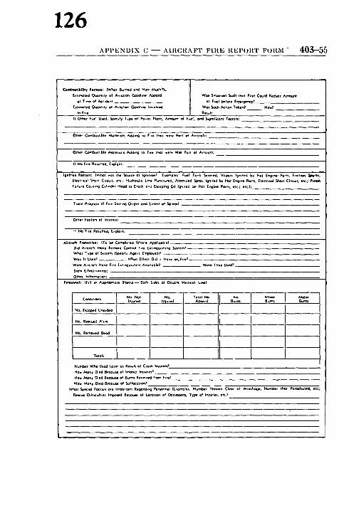
126 APPENDIX C -- AIRCRAFT FIRE REPORT FORM - 403-55
( t f i ~ t ed ~ . l , t y ~( Avmt~ C-=tOh~ Aboard Wet $ ; t ~ .T~ch ,hot P*l=t Could Reduce At~=~m! at T ,~ of Ar162 of F~ I b l f~e Er~r~ecyp
[ t f l ~ t ed ~nh l y Ot Av ;= l= GomhN Involved wo$ ~ As Told, n? H~ in Fire Re . I t
I f Other F~ ] U~ , ~ l f y T~ OI POwfft Plonl, ~ f o~ F~t , or~ ~g-~,f;cont roctort:
O t~ f ~S f i b~e ~ l e rm l t ~ ,~ ~D r*f . I ~ I we,t N~ PO,I Ot AirCf=~t;
If NO F,,e Re~tfCd, E~aloln;
I|~i~;e~ Facten; {Whet .os the ~ou,Ce of I g~ , t ~ I ( .om=l .$ F~ T0nk ~e~e~d, V=~o~ Ig~;ted by HOl IE~*~. Ports, F r l c f ~ (r~trlCOl S~r f Cite=if. lee ; HvdPomh( L~ PuP<furred, A t~ * l l d ~ roy +g~;fed by Hot E~ tN Ports. (rectr,~l ~ , t Cr l ie.; P lS~ Fo,l~,* Co=~,-g C~l,~o, Heed m C,~c~ o.d (moa ;~ 0+1 I~nl=.d ~ Hot (~g;m* Po~ . .~c , : et~,):
Ttocr Prog,e.s of F,,I ~,al,r~Q Or,g,~ o~d ( . tent of ~ ,eod
Other FoCtO~* of Inleleu:
i f NO Fire Re~hcd. [.=Dla,n:
&;~tgh P*otectlo*: (To b~ Cod i f i ed Where .a~phc4bae) D.d A ,~mh HO.e Re t i e Co~tm~ F;r. [.fi~guld~,r~g S~tem) What Type el S~tmm [~ r Agent Em~Wyed)?
Wot h U~d ) - - Whal If@co! D*d ~1 Hove on.F~te) Were A;~r~fl HO~ F,rf ~ . l l , ~u ,~ f t A.n,l�9 Weee l~ev U~d~
Pe~me l : (Fdl m Al~propr*ote Breaks ~ Bo;h $,des of Double Yerl,col L ,~ )
NO. al~u4~d Ahve
No, Reded 0cod
No Nol n~ Total No No M i~ A~=i~ l~ured f Cd Ab~ord B~ B~s Ournl
"rotors
Nut.be, Who O,:d ~ . , os R.~h o~ Cro~ troutS.s? H~ M~n v O,ed Be~ og Irr~ac~ I n i u r , ~
H~ IV~y O,ed Bec=~ of ,~.f f l~.of~? VVhat ~ ,Q I Fac~o~t a~e ImD~r~onl Regard,r,g P e ~ (E~mgle~. Number Th r~ Cleqr of Wreckoge. N ~ r Pomdl~ ld , ~C;
R~ Odficulhlt In'm~sed B~u~ of Loct=tl~ Of Or Type of inJuries, eft,)

403-56 A I R C R A ~ I ' R E S C U E AND F I R E F I G H T I N G S E R V I C E S
127
l e~+l , Jill l i lkl+. I lind Mldicul ~l~;cls: III N ~ e . ~o $1otl m ~propr l~ie 5~ce+, II Revue Work Plrfolmed bY Fi~ Flohlo~0 Fra i l Inchcctl
b+ StQt,n m " ~ m e " in m l ~ Column )
Factor+ RIK+I ro,ces J F+re F,ght,ng r~c r Med,~l S I . . r
mm~ ol Orgomlot+n rand SOO~+O, ol Se,~,C.
~n~wc t A~oalobll
P,eces at ~q.+~,rn+
Ty~l o m mo+u,l ol H+nd [qu,prP4nt Ut,l, i ed
Ho. ~ ^ I i . , Acc,~m Wo. I~ D,~ , , I+ .+)
I~O. WOt the F*.I Alorm t,on~,lt.dP ~o.. [+--] : l.,os~o,~. ~ : ~o+,o. I ~ 0~ , , . ,+ . ~ ]
wo+ S,t+ ol ~c , ,+ .m Co,,++., G , . . n +n II~. ^l+,m?
Ii Ngl+ 5lOfl ~ t o ~ Lt t~+ ol ~ n . ~ m n l ~ i o t i . R i m + , Jill, m MI+<QI ~+.,CIS,
HO. ~ O,d It to~l r l ~ r Fl,l ond m+r ~ l , . , c l l to R m h it++ ~ r o ~ ~it++l An r fm~o+s In .m. .+ . , l h CJm'm~m m (tllr ol t . ~ In,er.al.
l l f in lv i lh 'n l * I ' " ' 1 Ulld IRd Tlct~+ill.ll Lmldlv+ll:
II o . . . . . . . . . . ^+++nrb u~d ^ l ~ m . + ~ 1 . ~ o m , l y t ~ . . a tec+m,,~e U~d ,n ~ t , c o , , ~ ond r . ~ I t l
r 0 ,0 . ,d '
C++~n IJmo,d*
(Hlgh PFllmll I
Ory Cmm,col
Prr+t++l. P$1
FNm lPtlm+.t~)
FO,O~ (P+cK,Up) WoT., F ~ _ _ _ _
W ~ t W+,+ w m . , ~i~:+l, ~++.,r
I'+o. l~+~+m w+, C++~+t ~,o+,r ~ , . , c . o, H1dmmP
Wol L , ,O~ w o t . , A.+.lmbt.+ [+o l~ t+~ Ol tlChmque tm0lo+d

128 A P P E N D I X C - A I R C R A F T F I R E R E P O R T F O R M 403-57
VeJ~l era4 L e ~ - volu~s Lm~s
So,.md vo f~ ot Almmh: l I.nu m Aircraft: S
Tc~ml S Total $ ,%~lly l+r of ~ P l Im,~h,id ~ $~ib-d~Ide Vlll~,ii ~ l , if ~ l l r
Olmjml. I ~ ~ A l ~ ( ~ ~ /~ony of ~he F~I~[nI~ m Pals~bll: RJ la f~ of Crosk m Cify ~ AIrpar Watvt ~ ~r Pklcl= mint of At,~.mfl end Fire Equ~rmml, IDImcllcm of Wind. Unu~,~ Te~b~ C.cndJtt~l. L~catbon oi Fml ~ ] k l g l ~ ~ ~ PIftlnem Fc~'tc,~|
I H
S
IndlcOlll ~ ~ I l l ,ear l Wind Ol~ l l l ,~
Nm~m'~r l ~ z (U~ f,~omte Sheet l! O.~m~O
/ v ~ m Oay Ylmr T,He O,~mt l~b~

AV-18 R E P O R T OF A V I A T I O N C O M M I T T E E
129
Part VIII of Aviation C o m m i t t e e Report,
The Committee recommends, for final adoption, the following revised N F P A Tentative Veh&ular Performance Reconoaeadatioas for Aircraft Rescue and Fire Fighting Vehicles (No. ]~1~).
Historically, a Tentative edition of these Recommendations was approved by the Association in 1960. In 1961, a revised Tentative edition was subntitted for final adoption, but at the 1961 Annual Meeting this edition was returned to the Sponsoring ComntiUce for farther study as a result of criticisms submitted on the text. When the report was referred back to the sponsoring Aviation Committee, a recommendation was made that prior to resubmittol at a future meeting, these proposed reeootmendations be coordinated with the NI,'PA Committee on Fire Department Equipmenl.
On June $9, 1961, a special meeting wos held in Des Plaines, Illinois to discuss the problems involved wilh these proposed reeontmeadatioas. Aviation Bulletin No. g77 reported this spec&l meeting attd the Subcommittee otel to discuss l lte revisions suggested. I,'ollowing this act&n, a meeting was hehl with the Steering Committee of the N F P A Committee on Fire Department Equipment oa October 10, 1961. A revised draft of the proposals incorporating both the Subcommittee's recommendations and those of the Steering Commitl~'e of the NI,'PA Committee on Fire Department Equipment ~mts circulated prior to a meeting of the foU Sec- tional Comotittee on A irb.rafl Rescue and Fire Fighting hebl November 15-17, 19?;I. At this h,tter meeting, some further revisions were made attd the material, as re- vised, was p,blishdd in A. B. No. ~8~.
When the NI,'P.A Committee on Fire Department Equipment ,tel in .laauary 196~, this revised text was discussed and endorsed by that Committee. On page A V--3 of this p,blication there appears a vote statement to date of the Committee on A viotion.
Part V I I of this year's Aviation Committee Report proposes a rather extensive revision of the N I" P A's Suggestions for zl ircra f t Rescue and Fire Fighting Services for Airports and Ilcliparts (No. /~03) and changes have been m~ule in this text to reference NI,'PA No. ~ !]~ (see parlicMarly paragraphs ~31, P.3,51 aud 8,r of NI"PA 408 as published herein).

130 P A R T V l l l OF A V I A T I O N C O M M I T T E E R E P O R T AV-l.q
The Subcommittee responsible for this document, as presently published, is as follows:
R. Dan M a h a n e y , Chairman Federal Aviation Agency, Bureau of N.~tional Capital Airports
Washington 25, D. C.
J. J. Brenneman, United Air lanes (Personal)
John W. Bridges, Fedcr.d Aviation Agency
George R. Cooper, Jr., Walter Motor Truck Company (Persomd)
Hervey F. Law, Airport Operators Council
George Scharback, Willys Motorn Inc. (Personal)
J. K. S c h m i d t , U. S. Air Force, Air Proving Ground Center
M. S. Stuart, Chrysler Corporation (Personal)
Eric R. Thorsell, Fire Apparatua Manufacturers Assn.
J. H. Yank ie Yankee Motor Bodies Corp. (Personal)
The Sul)cmmnittee dealing with this Standard IlLs .tgreed to take on the additional responsibility of dr-tiring fire fighting equipment recommendations for these vehicles. A preliminary meeting of this Subcommittee was held on January 23, 1962 in New York City to initiate this action. The folh)wing personnel (all serving in a personal capacity) have been added to the presenl Subcommittee as given above to assist in the preparation 0f this new material:
G. A. Brelie, Ansul Chemical Co. D. N. Meidrum, National Foam System, Inc. J. F. O'Regan, Rockwood Sprinkler Co. H. B. Peterson, U. S. Nawd Research Lab. Leo Rivklnd, Me:u.I Corporation Hubert Walker, American LaFrancc H. V. Williamson, Cardox, Div. of Chemctron Corp.

131 414-4 AIRCRAFT RESCUE VEHICLE PERFORMANCE
Proposed 1962 Revision of the Tentative
Vehicular Performance Recommendations for
A i r c r a f t R e s c u e a n d Fire F i g h t i n g V e h i c l e s N F P A No . 414
PART I - SCOPE AND PURPOSE
I1. Scope. I l l . These vehicular performance" recommendations apply to
aircraft rescue and fire fighting vehicles intended to carry rescue and fire fighting equipment for rescuing occupants and combat- ing aircraft fires in disabled or burning aircraft on, or in the vi- cinity of, an airport. For the purpose of simplification, these vehicles will hereinafter be referred to simply as "vehicles." The basic NFPA recommendations on the use and provision of t, his equipment are contained in "Suggested Standard Operating Procedures, Aircraft Rescue and Fire Fighting" (NFPA No. 402), and "Suggestions for Aircraft Rescue and Fire Fighting Services for Airports and Heliports" (NFPA No. 403).
12. Purpose. 121. These performance recommendations on the desired ve-
hicular capabilities of aircraft rescue and fire fighting vehicles are proposed as a guide to airport operators intending to pur- chase such equipment. These recommendations do not cover the design and operating capabilities of the fire fighting equipment mounted thereon. Reference is made to the design and op- erating capabilities of the fire fighting equipment only to the extent that this equipment affects essential vehicle performance.
122. These performance recommendations are intended to out- fine features and components which, when assembled, will pro- duce an efficient and capable vehicle for both on-and-off pave- ment performance. The features outlined herein affecting the vehicular capabilities of these vehicles are considered advisable for their proper operation on and off paved surfaces with par- r emphasis on their off-pavement capability. This latter feature is particularly important to assure timely and effective ,~sponse of these vehicles to aircraft accident sites across terrain

132 PURPOSE - - RESPONSIBILITY OF CONTRACTORS 414--5
which might halt or delay standard highway equipment. The omission of any of the features outlified should be done only with complete knowledge of how it or they will affect the vehicle's performance capabilities.
123. The essential elements of vehicle construction and per- formance for this service are included herein. Drafting of com- plete specifications for bidding purposes is the responsibility of the user, who should take into consideration local problems, ex- ercising care against inclusion of provisions which may conflict with the recommendations set forth herein.
124. Two categories of vehicles are described in these recom- mendations in accordance with the NFPA Suggestions for Air- craft Rescue and Fire Fighting Services for Airports and Heli- ports (NFPA No. 403).
1241. MAJOR FInE FIGHTING VEHICLES with a gross weight of four (4) tons or more.
1242. LIGIIT RESCUE VEHICLES with a gross weight of under four (4) tons.
1243. Because of the broad range covered by the category MAJ0a FIRE FIGHTING VEHICLES, this category is divided into classes according to gross vehicle weight (see Part II, Paragraph 212). Certain recommendations, such as acceleration and tire size are adjusted in recognition of differing needs of the vehicles in the various classes.
13. Responsibility of Contractors (Suppliers).
131. The emergency nature of aircraft rescue and fire fighting services requires that a high level of competence, reliability, and experience be demanded of contractors building equipment for such service. Materia|s used in fabrication must be of superior character.
132. The contractor must assume complete responsibility for all component parts of the complete vehicle, even though major portions may be sub-contracted. This responsibility shall iuclude design, construction, inspection, performance test, and servicing. The purchaser should ascertain that the contractor is capable of furnishing parts and technical assistance to the purchaser for the normal life of the vehicle (10 years).
NOTE: Responsibility for servicing shall not include those eomponent~ supplied to the contractor by the customer, unless so specified in th0 contract.

414-6 A I R C R A b " r R E S C U E V E H I C L E P E R F O R M A N C E
133
133. The contractor shall also be responsible for assuring that I,he vehicular performance of the vehicle meets these recom- mendations (as they may be modified) and thus qualify as a well- designed aircraft rescue and fire fighting vehicle.
134. All major components shall have the manufacturer's rating for this type service and these ratings shall not be exceeded by actual imposed loads.
135. A one-year warranty shall bc supplied by the contractor.
136. Bidders should be require.d to furnish with the bids a detailed description of the vehicles offered, and drawings showing general arrangement, weights, and dimensions. Data similar to that provided for in the Questionnaire contained in Part V should also be required.
14. Design Principles.
141. The vehicle design shall provide for rapid acceleration and high speed; nmximum mobility on and off pavements in all seasons and under all we-tther conditions; ease of ol)eration; safety; reliability; and -Lccessibility for repairs and maintenance.
142. All-wheel drive for off-pavement operation is essential lind shall be achieved without sacrificing any of the attributes [ff high performance, high speed vehicles. Weight shall be distyibuted substalttially equal over all wheels with maximum tire loads limited to provide the highest practic:d)le level of performat~ce on soft, slippery or rottgh terr:~.in.
143. Special design consideration sh-dl be given to the sttving of iveight wherever possible, insofar as it cats be accomplislmd while retaining :~ large factor of sttfety on wearing and stressed members. This can be -Lccomplished through tim use of light- weight construction wherever possihlc.
144. Performance requirements out,lined in these I{.ecom- mendations shall be met with the vehicle in an in-service con- dition.

134 MAJOR FIRE FIGHTING VEHICLES 414-7
PART I I - MAJOR FIRE F I G H T I N G VEHICLES
21. Genera l .
211. The category of major vehicles encompasses a gross vehicle .weight range commencing at 4 tons (8,000 lbs.) and ex- tending to over 45,000 lbs., and in some cases to over 60,000 lbs. Because the same performance cannot be expected of all vehicles within this range, it is necessary to classify vehicles into lesser weight ranges within which an equal level of performance is practicable.
212. Accordingly, the following weight ranges (lbs.) have been established in classes for the purposes of this specification:
Class Vehicle Weight Range (Pounds) 1 8,000-15,000 2 15,000--20,000 3 20,000-25,000 4 25,000-30,000 5 30,000-35,000 6 35,000-40,000 7 40,000-45,000 8 45,000 and over
213. The weight of a vehicle for purposes of this classification is its gross weight, with all fire fighting and rescue equipment, full load of extinguishing agents, full load of fuel, and complete personnel complement, ready for service.
214. Because of the fact that definite differences in per- formance exist between classes, it is essential that specifications for purposes of bidding be drawn to limit the maximum gross weight.
NoT~: Variations in gross weight should be permitted because of dif. ferences in design and construction, provided the original l)erformancc recommendations as contracted for have been met.
22. Weights and Dimensions .
221. Weights.
2211. The gross vehicle weight rating of the chassis as furnished shall equal or exceed the actual gross weight of the fully loaded and equipped vehicle.
2212. Weight should be distributed as equally as possible

414-8 AIRCRAFT RESCUE VEHICLE PERFORMANCE
135
over the axles and tires under all conditions of loading. The variation in weight between any two tires or any one axle shall not exceed 5 per cent right and left, or 10 per cent between any two axles.
NOTE: Weight on individual tire shall be determined by weight scale measurement at the ground.
Weight variations between axles shall be based on the average loading of the axles and, between tires, shall be the average loading of the two tires of a given axle.
These recommendations favor the use of single tires and a drive to all wheels. The tires are tdso required to be of uniform size. Therefore, best perforumnce and traction are possible only by equalizing the weight on individual tires.
Maintaining equalization of weight over t h e tires under conditions of light lo'td is also essential for best performance, particularly since the load natty be lightened so th ' t t the vehicle can traverse extremely soft ground.
The conditions of l(vLtling considered are those due to addition or dis- charge of the life extinguishing medit,m such 'ts water or chemicals.
2213. Center.of gravity of the vehicle slmll be kept as low as possible under all conditions of loading. The vehicle shall be capable of resting on a side slope equivalent to a 30 per cent grade without danger of capsizing.
NOTE: The maximum side slope on which a vehicle can rest without capsizing is an indication of its stability anti location of center of gravity. Because of the combined effects of spring motion, tire deflection, speed and surface conditions, the ability to rest on a 30 per cent side slope should indicate the ability to operate on a side slope, up to 20 per cent, a t slow speed.
A factor tha t cannot be me:tsured by this test is the effect of movement of water in vehi(:le tanks while the truck is in motion on rough ground. Baffling of the water tank should mitigate the effect of such ,novement.
222. Dimensions .
2221. Under-clcar,'tnces of the ch,tssis shall be sufficient to permit the maximum mobility in soft ground and rough terrain which tire size, weight, and power m,'Lkc the vehicle potentially capable of traversing. The following ,trc the minimum .tcccptable clearance dimensions and angles:
Angle of Approach Angle of I)eparture Intera.xle Clearance Angle Under-Chassis-Clearance l)imensions:
Under 30,000 lbs. Gross Weight 30,000 lbs. and over Gross Weight
30 degrees 30 degrees 12 degrees
12 inches 14 inches

136 MAJOR F I R E F I G H T I N G V E H I C L E S 414-9
Under-chassis-clearance dimensions shall apply to all portions of the chassis except for tires and wheel-mounted brake drums pro- vided that the drums shall not extend more than three inches from the tire line.
NOTE: Certain projections may extend below the minimum clearance provided they are hinged or otherwise constructed so that they will swing clear when striking an object. Gener, dly, however, such projections should be avoided because, in spite of careful design, they are likely to be knocked off in service.
2222. Over-all height, length, and width of the vehicle shall be held to a minimum so as to provide greater maneuverability due to compactness and to facilitate movement on public high- ways.
NOTE: Over-all width should be checked with local jurisdiction.
2223. Chassis shall be so constructed and body and equip- ment so mounted that a driver of average height shall be able to see the ground 20 feet ahead when the driver is in his normal driving position without leaving or rising in his seat. He shall be able to see the ground immediately adjacent to the driver's side of the vehicle. I t is recommended that mirrors, or other provisions, be made for visioo on the opposite side of the vehicle.
NOTE: Best, design dictates either a cab forward or cab-over-engin0 arrangement to insure that the driver is placed sufficiently far forward so that he can see the ground a short distance ahead of the vehicle.
23. Engine .
231. General Performance R e c o m m e n d a t i o n s and Ar- r a n g e m e n t s :
2311. The vehicle shall be powered by means of an internal combtlstion engine(s), with a minimum cubic inch piston dis- placemeat as indicated in Paragraph 2313, capable of developing sufficient power under operating conditions to achieve the re- quired rate of acceleration as specified in Paragraph 2312.
NOTE: Turbine-powered vehicles and "air-cushion" vehicles may be used when experience has been accumulated to permit ewduating the ca. pabilities and limitations of vehicles of these types for this specialized service.
2312. The vehicle shall be consistently able, when fully

414-10 AIRCRAlOl ~ RESCUE VEHICLE PERFOP, MANCE
137
loaded, of acce le ra t ing f rom 0 to 50 nfiles per hour on d r y level concrete p a v e m e n t wi th in the fol lowing m a x i m u m t imes :
Class Gross Vehicle Weight (Pounds) Time (Seconds) 1 8,000-15,000 30 2 15,000-20,000 30 3 20,000-25,000 35 4 25,000-30,000 40 5 30,000-35,000 45 6 35,000-40,000 50 7 40,000-45,000 55 8 45,000 and over 60
The a b o v e acce l e ra t ion t imes shal l be ach ieved in a m b i e n t t e m p e r a t u r e s v a r y i n g f rom 0 degrces F to 100 degrees F and a t e l eva t ions up to 2,000 feet a b o v e sea level unless a h igher ele- va t ion is specified.
NOTE: The above acceleration requirements at clev.ttions up to 2,000 feet strove sea level are intended In ensure accep~dfle performance at the great majority of airports.
Airports above 2,000 feet should state the elevation at which the vehicle will operate in order to ensure the required performance.
2313. In a d d i t i o n to be ing c a p a b l e of mee t i ng the a b o v e acce le ra t ion r equ i r emen t s , t he engine(s) shal l also have the fol- lowing m i n i m u m cubic inch p i s ton d i s p l a c e m e n t :
Gross Vehicle Weight (Pounds) Displacement (Cu. In..) Class 1 8,000-15,000 300 2 15,000-20,000 400 3 20,000-25,000 475 4 25,000-30,000 525 5 30,000-35,000 590 6 35,000--40,000 700 7 40,000-45,000 800 8 45,000 and over 900
2314. I t is r e c o m m e n d e d t h a t gasol ine engines be used for a i rc raf t rescue and fire f ight ing serv ice due to the i r h igher horse- power - to -we igh t r a t io a n d g r ea t e r acce l e ra t ion c a p a b i l i t y .
NOTE: In some cases the acceleration time required can be met with engines with less displacement than specified above. Nevertheless, the minimum displaeenmnt is specified because of greater over-all performance obtained from larger displacement engines.
On the other hand, it may be that with certain types of engine design the required acceleration cannot be obtained even though engines meeting

138 MAJOR FIRE FIGIITING VEHICLES 414-1l
the specified minimum displacement are used. In such cases, the accelera- tion time still stands as a mi,fimum requirement.
The use of high compression or specially modified engines which require high octane or specially blended fuel, and requiring special maintenance, shall be avoided.
See Note following Paragraph 2311.
2:315. Where the engine(s) is (are) used to power both the chassis and the [ire lighting pumps, provision shall be made to ensure that the operation of the pump will riot, under any cir- cumstances, cause either:
a. the engine(s) to stall, or
b. more than a slight, and momentary reduction ira engine speed and consequent drop in pump pressure.
The vehicle shall also be capable of full rated capacity while con- ducting a stipulated mud and sand test.
2316. The engine shall be equipped with a governor which shall be set at not more than the maximum permissible revolu- tions-per-minute recommended by the engine manufacturer under no-load condition.
2317. The provisions appearing in Sections 232,233 and 234 contain recommendations for the engine and its accessories and systems which have proven desirable in vehicles for this type service.
232. Engine Cooling Systems.
2321. LIQUID COOLED ENGINES.
a. The cooling system should be of the closed, forced-feed type using a circulating pump. Tile radiator, cylinder block, cylinder head, fan and water pump shall be of ample capacity to permit continuous flow with full load operation of the engine at both stationary and maximum vehicle speed without boiling the coolant under ambient temperature conditions up to l l0 de- grees F. The cooling system shall be provided with an automatic thermostat for prompt engine warming.
b. Radiator shutters, when furnished for cold climates, shall be of the automatic type, and be designed to open auto- matically upon failure.

139 414-12 A I R C R A F T R E S C U E V E H I C L E P E R F O R M A N C E
2322. AIR-COOLED ENGINES. a. Air-cooled engines shall be so designed and installed
as to permit the vehicle to stand still and pump for indefinite periods without overheating.
b. Air-cooled engine design and installation shall provide for sufficient rate of flow and distribution of air to hold cylinder head and oil temperatures within manufacturer 's prescribed limits under all operating conditions. This shall include full power operation for prolonged periods with ambient temperatures up to 110 degrees F, at both s tat ionary aud maximum vehicle speed.
c. Cylinder head and oil temperature gages that clearly indicate maximum permissible operating temperature shall be mounted in the cab and elsewhere, as required, to be plainly visible to the driver.
233. Fuel System.
2331. For gasoline engines, a complete fuel system should in- clude a mech-mically driven fuel pump, auxiliary electric fuel pump, fuel strainer and necessary piping, including a flexible fuel line from the fuel punip to the tank line. All fuel lines shall be protected from damage, exhaust heat, and exposure to ground fire.
2332. An accessible strainer shall be provided for each fuel line and a drain shall be provided at the bot tom of the fuel tank.
2333. Fuel tanks shall not be installed in such a manner as to permit gravi ty feed to the carburetor.
233,1. Fuel i, allks shall I)c I)rovidcd with a,i U,iderwriters' Laboratories, Inc., Uudc,'writcrs' I,aboratorics of Canada, or Factory Mutual li:ugiueering Division "tpproved flame arrester relief fitting o,1 the filler opening.
2335. Fucl tank capacity shall be sufficient to provide for two (2) hours pumping at rated capacity.
234. Exhaust System.
2341. The exhaust system shall be of such size as to avoid undue back pressure and shall be located and constructed in such a man,ler that e,ltrance of exhaust gases into the cab will be minimized under all conditions of operation. Exhaust pipe, muffler and tailpipe shall bc of high-grade, rust-resistant materials.

140 MAJOR FII(E FIGIITING VEHICLES 414-13
2342. The tailpipe and muflter shall be protecte d from dam. age due to traversing rough terrain. Tailpipe shall be designed to discharge to the rear and shall not be directed toward the ground.
24. Vehicle Electrical System.
241. Each gasoline engine shall be equipped with a com- plete and separate battery starting system. Where greater en- gine reliability is desired, -t complete dual ignition may be re- quired.
242. The vehicle shall be provided with a complete electrical system of either the 12 or 24 volt type.
243. An alternator and rectifier, capable of delivering a minimum of 100 amperes, 12 volts or 50 amperes, 24 volts, shall be provided.
244. Two independent battery systems shall be provided, with a selector switch located in the cab. For 12 volt systems, there shall be two (2) 12 volt batteries, 150 ampere hour capacity each, at 20 hour rate. For 24 volt systems, there shall be two (2) 24 volt batteries, 100 ampere hour capacity each, or four (4) 12 volt batteries, 100 ampere hour capacity each, at 20 hour rate.
245. Provisions shall be provided to permit plugging into local electric power supplies to maintain battery charging.
246. An engine coohmt preheating device shall be provided as an aid to rapid starting and high initial engine performance.
247. The electrical system shall be insulated, waterproofed and protected against exposure from ground fires.
NOTE: Radio suppression of the electrical system, sufficient to assure positive operation of radio equipment without interference to "my other communications on the airport, shall be furnished when specified.
25. Vehicle Drive.
251. The drive shall provide for the transmission of power from the engine flywheel to the wheels of the vehicle with such multiplication of torque that the vehicle is capable of traveling at all speeds necessary for effective aircraft rescue and fire fighting service. With respect to Classes 3 through 8, the driv0 shall provide for the continuous transmission of power from the engine through a torque converter or fluid coupling and trans- mission. The transmission shall have the ability to shift from

~14-14 AIRCRAFT RESCUE VEHICLE PERFORMANCE
141
airy selected ratio to another in sequence, either forward or re- ~'c,'se, without interruption of power transmission.
NOTE: See Note under Paragraph 2311.
252. The entire drive train shall be designed with sufficient torque capacity to slip the wheels of the fully loaded and bal- atlced vehicle on pavement having a coefficient of friction of 0.6. The following drive line components shall be certified by the rmnponent manufacturer to be suitable for use in the drive line , f the complete vehicle considered as a complete vehicle: clutch (rod/or torque converter, transmission, transfer case, propeller draft, differentials and axles~
253. The transmission shall have sufficient range of gears to provide a top speed in highest gear of 50 mph and enough re- duction ira lowest gear to produce the t ract ive effort needed to ascend a 50 per cent grade. Spacing of intermediate gears tfimll provide an adequate number of speeds for all operating conditions without excessive overlap.
254. Positive drive to each wheel is required to negotiate colt ground, unimproved surfaces, snow or ice. Positive wheel drive may be achieved by the use of torque proportioning or no- 0pin differentials, or by means of other automatic devices which will ensure tha t each wheel of the vehicle is driven independently of the other wheels.
255. The t~ansfer case may be either separate or integral with the transmission. ] t shall incorporate a drive to the front lind rear axles which is engaged at all times during the intended airport service and which will not allow the vehicle to stall as long as the tires of any axle have-traction.
256. Fron t and rear axles shall have adequate capacity to q'arry the maximum imposed load under all intended operating conditions. The variations in axle tread shall not exceed 20 per cent of the tire sectional width at rated load. Fron t and rear axles shall be provided with automat ic locking or no-spin dif- ferentials or other automat ic devices which will lock out dif- ferential action whenever any one tire loses traction. When hlteraxle differentials are furnished with bogie axles, they shall be either automat ic locking or no-spin type or be locked out at all times during the intended airport service.
257. ] t is recommended tha t f ront axles be equipped with ~teering drive ends of the constant velocity type or other pro- vision be made to eliminate objectionable cyclical fluctuations

142 MAJOR FII].E FIGIITING VEHICLES 414-1~
in angular velocity of the whccls when they are cramped in th(, steering position.
26. Other Chassis Components.
261. Clu tch . When a clutch is used, the actuation pedld pressure to obtain release shall not exceed 50 pounds with ade- quate displacement for wear prior to normal adjustment.
262. Transmiss ion . Where a fire fighting pump is drive, from the chassis engine, provision shall be made in design of the power take-off to allow uninterrupted transmission of power to the pump even though the transmission gears are being shifted, chltch is released, or the transmission is placed in any of its speed ranges.
263. Suspension.
2631. The suspension system shall be designed to allow the vehicles, loaded or unloaded, to travel at high speeds over im- proved road surfaces, and at moderate speeds over rough, un- improved terrain. Special consideration shall be given to tim need for cushioning road shocks, providing adequate wheel motion, and reducing unsprung weight.
2632. Design of the axles and suspension system shall be such that the total unsprung weight of the vehicle will not I)e greater than 20 per cent of the gross weight of the vehicle when fully loaded.
NOTE: Unsprung weight is that portion of the vehicle weight not carried by the chassis springs.
2633. Design of axles and suspension system shall also pro. vide for an individual wheel motion above level ground of not less than 10 inches for vehicles under 30,000 lbs. gross weight, and 12 inches for vehicles 30,000 lbs. and overgross weight without raising any other wheel off the ground.
2634. Suspension design shall be such that at least two inches of deflection remain before bottoming of suspension on the axle stops or bumpers when the vehicle is fully loaded and on level ground.
2635. Double acting hydraulic shock absorbers shall be fur- nished on front axles. Front and rear axles shall be furnished with stops for bottoming to prevent damage to axles, propeller shafts, engine oil pan, or any other portions of the chassis which may be damaged by wheel motibn beyond allowable amounts.

414--16 AIRCRAFT RESCUE VEHICLE PERFORMANCE
143
2 6 4 . W h e e l s , T i r e s a n d R i m s .
2641. Wheels shall be single rim type with tires of identical size and same tread design.
2642. Tires and inflation pressures shall be selected to pro- vide effective performance on the terrain encountered in the intended airport service. For normal terrain conditions, a maxi: mum inflation pressure of 45 pounds per square inch is recom- mended. For more extreme terrain conditions, lower inflation pressure down to 30 pounds per square inch may be desirable for greater off-pavement mobility. The following Table sets forth recommended maximum loads per tire for s tandard tire sizes at inflation pressures of 30 pounds per square inch and 45 pounds per square inch.
TIRE LOAD RATINGS
R e c o m m e n d e d Load a t 30 lb. a t 45 lb. B a s e d o n
Tire S i z e I n f l a t i o n I n f l a t i o n T & R A T a b l e
9.00-16 1,950 2,475 LT-1B 8.25-20 2,390 3,030 EM--3D 9.00-20' 2,840 3,590 "
10.00-20 3,200 4,050 " 11.00-20 3,540 4,480 " 12.00-20 4,020 5,080 " 12.00-24 4,520 5,720 " 14.00-20 5,620 7,100 " 14.00-24 6,270 7,920 " 16.00-25 8,200 10,400 " 18.00-25 10,670 13,520 "
18.00-33 12,640 16,000 "
21.00-25 13,640 17,280 "
21.0{}-29 14,820 18,770 "
24.00-25 16,860 21,340 " 20.5-25 9,590 12,170 WEM-I 23.5-25 12,440 15,760 "
26.5-25 15,530 19,700 " 26.5-29 1 7 , 0 9 0 21,650 "
29.5-25 19,160 24,210 "

144 M A J O R F I R E F I G H T I N G V E H I C L E S 414-17
NOTE: Adequate ply ra t ing mus t be selected as determined by load and inflation to be used (refer T & R A Yearbook) . T & R A refers to the Tire and R im Association.
NOTE: For t ire sizes not shown, cur ren t ra t ings m a y be obta ined f rom the Ti re and R i m Association, Inc. (2001 Firs t Nat ional Tower , Akron 8, Ohio). The m a x i m u m loadt in the Table are based on cur ren t T i re and R im Association, Inc. ra t ings as shown it, Tables LT-1B, E M - 3 D and W E M - I of their 1961 Year Book.
2643. Actual inflation pressures of the tires with the vehi- cles in an in-service condition sh,'fil be as specified in the Table.
2644. If the vehicle is required to operate on the highway five or more miles beyond the immediate vicinity of the 'airport a t sustained speeds above 30 miles per hour, inflation pressure should be increased to those levels recommended for highway service.
2645. An aggressive tire tread is recommended for general service. Tire manufacturers should be consulted for tread de- signs to meet special terrain conditions.
2646. Rim contours and sizes shall also be based on current practices of the Tire and Rim Association, Inc.
27. Controlling Mechanisms.
271. Brakes.
2711. Service brakes shall be .of the all-wheel type. On vehicles less than 25,000 lbs. gross weight, service brakes may be of the hydraulic type with power booster or the air-nmchanical type. On vehicles 25,000 lbs. or more gross weight, service brakes shall be of the air-over-hydraulic or air-mechanical type.
2712. If air-mechanical brake~ are furnished, a brake chamber shall be provided for each wheel and shall be mounted so that no par t of the brake chamber projects below the axle.
2713. Air brake systems shall include a compressor, release valve, brake control valve, t readle-type actuating pedal, air pres- sure gage, enclosed-type brake adjusters, low pressure warning, and all necessary connections.
2714. On vehicles less than 25,000 lbs. gross weight, and when supplied with air brakes, the air compressor shall be at least 7 cu. ft. capacity; on vehicles 25,000 lbs. or more gross Weight, the air compressor shall be at least 12 cu. ft. capacity. Air compressors shall be lubricated and cooled by the engine lubrication and cooling system.

145 114--18 AIRCRAFT RESCUE VEHICLE PERFORMANCE
2715. Compressed air reservoirs will have a minimum rapacity of 2,000 cu. in. and shall be equipped with drain and ~afety valves. Provision for quick build-up of pressure shall be furnished. Quick build-up of tank pressure from 5 lbs. to the pressure regulating valve setting shall be accomplished within 12 seconds.
2716. The service brakes shall be capable of holding the fully loaded vehicle on a 50 per cent grade, and capable of bring- ~ng the fully loaded vehicle to five (5) complete successive stops within 30 feet from a speed of 20 mph on dry, hard, approxi- mately level road, free from loose material.
2717. The parking or emergency brake system shall be an entirely independent mechanical system or may be connected to &e same brake shoes as the service brakes but through entirely ~eparate mechanical means.
2718. The parking brakes shall be hand lever operated and -'.hall be capable of holding the fully loaded vehicle on a 20 per ~ent grade.
272. Steering.
2721. All chassis shall be equipped with power assisted ~teering. The steering mechanism shall be so designed to permit manual steering sufficient to bring the vehicle to a safe stop in the event of failure of power assist.
2722. The power-assisted steering shall have sufficient ca- pacity so that no more than 15 lbs. pull is required on the steering wheel in order to turn the steering wheel from lock to lock with ~e engine running.
28. Turning Diameter. 281. Wall-to-wall turning diameter of the fully loaded vehicle
~all not be greater than three times its over-all length. In the event an 8 x 8 chassis is provided, the turning diameter shall aot be greater than three-and-a-half times the over-all length.

146 L I G I I T R E S C U E V E H I C L E S 414-10
PART I I I - LIGHT RESCUE VEHICLES
31. General .
311. T h e c a t e g o r y of " l i g h t rescue veh ic les" covers a vehicle wi th a gross we igh t of 7,999 p o u n d s or less as i n d i c a t e d in Para- g r a p h 1242 of P a r t I of thesc r e c o m m e n d a t i o n s .
312. T h e we igh t of a vehic le for pu rposes of th is classification is i ts gross weight , wi th all fire f ight ing and rescue equipment , full load of ex t ingu i sh ing agen t s , full load of fuel, complete personne l c o m p l e m e n t , r e a d y for service.
32. Weight s and D i m e n s i o n s .
321. Weights .
3211. T h e gross vehic le we igh t r a t ing of the chassis a~ fu rn i shed shall equa l or exceed the ac tua l gross we igh t of th0 fu l ly loaded a n d e q u i p p e d vehicle .
3212. T h e a c t u a l we igh t of the ful ly loaded and equipped vehic le should be d i s t r i b u t e d as equa l l y as poss ib le over th0 axles and tires. T h e v a r i a t i o n in we igh t be tween a n y two tire~ of any one axle shal l no t exceed 10 per cen t r ight and left nor shal l a n y axle c a r r y less t han 40 per cen t or more than 00 per cent.
NOTE: Weight on individual tire sh~ll be dcternfined by weight scale measurement at the ground.
This specification requires the use of single tires .tnd a drive to all wheels. The tires are also required to be of uniform size. Therefore, besl performance and traction are possil~le only by equalizing the weight olt individual tires.
3213. C e n t e r of g r a v i t y of the vehic le shall be k e p t as low as poss ib le unde r all cond i t ions of loading. T h e vehicle shall be c apab l e of res t ing on a side s lope e q u i v a l e n t to a 30 per cen t grade w i t h o u t d a n g e r of caps iz ing.
NOTE: The maximum side slope on which a vchic:le can rest without capsizing is an indication of its stability and location of center of gravity.
Because of the combined effects of spring motion, tire deflection, speed and surface conditions, the ability to rest on a 30 per cent side slol~ should h~dicate the ability to operate on a side slope, up to 20 per cenl at slow speed.

414-20 AIRCRAY'r RESCUE VEHICLE PERFORMANCE
147
322. Dimensions.
3221. Under clearances of the chassis shall be sufficient to permit the maximum mobility in soft ground and rough terrain which tire sizes, weight, and power make the vehicle potentially capable of traversing. The following are the minimum ac- ceptable clearance dimensions and angles:
Angle of Approach 30 degrees Angle of Departure 30 degrees Interaxle Clearance Angle 12 degrees Minimum Ground Clearance 8 inches
Under-chassis-clearance dimensions shall apply to all portions of the chassis except for tires and brake drums.
3222. Over-all height, length, and width of the vehicle shall be held to an absolute minimum so as to provide maximum ma- neuverability due to compactness and to facilitate rapid move- ment on public highways.
3223. Chassis shall be so constructed and body and equip- ment so mounted that the vehicle driver shall be able to see the ground 20 feet ahead when a driver of average height is in his normal driving position without leaving or rising in his seat. He shall be able to see the ground immediately adjacent to the driver's side of the vehicle. It is recommended that truck-type mirrors, or other provisions, be made for vision to the opposite side of the vehicle.
33. Engine.
331. General Pe r fo rmance R e c o m m e n d a t i o n s and Ar- rangements .
3311. The vehicle shall be powered by means of an internal combustion engine capable of developing sufficient power under operating conditions to achieve the required performance char- acteristics.
NOTE: Turbine-powered vehicles and "air-cushion" vehicles may be used when experience has been accumulated to permit evaluating the capabilities and limitations of vehicles of these types for this specialized service.
3312. The vehicle shall be consistently able, when fully [0aded, of accelerating from 0 to 50 mile~ per hour on dry level concrete pavement within 25 seconds. The above acceleration time shall be achieved in ambient temperatures varying from 0 degrees F to 100 degrees F and at elevations up to 2,000 feet above sea level, unless a higher elevation is specified.

148 LIGHT RESCUE VEHICLES 414-21
N(YrE: I t is recommended that gasoline engines be used for aircraft rescue and fire fighting service due to their higher horsepower-to-weight ratio and greater acceleration capability. See Note under Paragraph 3311.
The requirement that the vehicle be capable of accelerating from 0 to 50 miles per hour within 25 seconds at elevations up to 2,000 feet above sea level is intended to ensure acceptable performance a t the great ma- jority of airports. Airports above 2,000 feet should state the elevation at which the vehicle will operate in order to ensure the same performance.
The use of high compression or specially modified engines which require high octane or specially blended fuel, and requiring special maintenance, shall be avoided.
3313. Where the engine is used to power both the chassis and the fire fighting pumps, provision shall be made to ensure that the operation of the pump will not, under any circum- stances, cause either:
a. the engine to stall, or b. more than a slight, and momentary reduction, in engine
speed and consequent drop in pump pressure.
3314. The provisions appearing in Sections 332, 333 and 334 contain recommendations for the engine and its accessories and systems which have proven desirable in crash fire fighting vehicles.
332. Engine Cooling Systems.
3321. LIQUID" COOLED ENGINES. a. The cooling system should be of the closed, forced-feed
type using a circulating pump. The radiator, cylinder block, cylinder head, fan and water pump shall be of ample capacity to permit continuous full load operation of the engine at both stationary and maximum vehicle speed without boiling the cool- ant under ambient temperature conditions up to 110 degrees F. The cooling system shall be provided with an automatic thermo- stat for prompt engine warming.
3322. AIR-CooLED ENGINES. a. Air-cooled engines shall be so designed and installed as
to permit the vehicle to stand still and pump for indefinite periods without overheating.
b. Air-cooled engine design and installation shall provide for sufficient rate of flow and distribution of air to hold cylinder head and oil temperature within manufacturer's prescribed limits under all operating conditions. This shall include full

414-22 AIRCRAI~ ' r R E S C U E V E H I C L E P E R F O R M A N C E
149
power operation for prolonged periods with ambient tempera- tures up to l l0 degrees F, at both stationary and maximum vehicle speed.
c. Cylinder head and oil temperature gages or warning 'lights that clearly indicate maximum permissible operating tem- perature shall be mounted in the cab and elsewhere, as required, to be plainly visible to the driver.
333. Fuel System. 3331. For gasoline engines, a complete fuel system should
include an electric fuel pump located near the fuel tank to pre- 'vent vapor-lock, fuel strainer and necessary piping, including a flexible fuel line from the fuel pump to the tank line. All fuel lines shall be protected from damage, exhaust heat, and exposure to ground fire.
3332. A strainer shall be provided for each fuel line and a drain shall be provided at the bottom of the fuel tank.
3333. Fuel tanks shall not be installed in such a manner as to permit gravity feed to the carburetor.
3334. Fuel tanks shall be provided with an Underwriters' Laboratories, Inc., Underwriters' Laboratories of Canada, or Factory Mutual Engineering Division approved flame arrester relief fitting on the filler opening.
3335. Fuel tank capacity shall be sufficient for two hours' operation.
334. Exhaust System. 3341. The vehicle shall be furnished with an exhaust system,
tailpipe, and muffler of such size as to avoid undue back pressure and shall be located and constructed in such a manner that entrance of exhaust gases into the cab will be minimized under all conditions of operation. Exhaust pipe, muffler and tailpipe shall be of high-grade, rust-resistant materials.
3342. The tailpipe and muffler shall be protected from damage due to traversing rough terrain. Tailpipe shall be de- signed to discharge to the rear and shall not be directed toward the ground.
34. Vehicle Electrical System. 341. The vehicle shall be provided with battery starting and
a complete electrical system of the 12- or 24-volt type.

150 L I G l l T R E S C U E V E I I I C L E S 414-23
342. An al ternator and ,'ectifier, capable of delivering a mini- mum of 60 anaps, 12 volts or equivalent power at 24 volts, shall be provided.
NOTE: Alternator capacity should be specified by the electrical load experienced aL each airport.
343. A 70 ampere-hour, 12 volt I)attcry or an equivalent iq 24 volts shall be provided.
344. Provisions shall be provided to permit plugging into local electric power supplies to ,naintain bat tery charging.
345. The electrical system shall be insulated, splashproofc~l and protectc~d against exposure from ground fires.
NOTE: Radio SUl)pression of the electrical system, suftlcient to ensun~ positive operation of radio cquip,nent without interference to any othe! communications on the :drport, shall be furnished when specified.
35. V e h i c l e Dr ive .
351. The drive shall provide for the transmission of power from the engine flywheel to all wheels of tile vehicle with such multiplication of torque that the vehicle is capable of traveling at all speeds necessary for effective aircraft rescue and fire fighting service.
NOTE: See Note following P-tragraph 3311 regarding turbine-powered and "air-cushion" vehicles.
352. The entire drive train shall be designed with sufficient torque capacity to slip the wheels of the fully loaded and balanced vehicle on pavement havi,lg a coefficient of friction of 0.6. The following drive litm componcnts shall bc certified by the com. ponent malmfacturcr to be suitable for use in the d,'ive line 01 the complete vehicle considered as a complete vchicle: (.lutch and/or torque co,lvertcr, transmission, tra,lsfer casc, propellel shaft, diffcrcntials and axles.
353. The transmission shall have sufficient range of gears to provide a top speed in highest gear of 50 miles per hour and enough reduction il~ lowest gear to produce the t ract ive effort needed to ascend .~ 50 per cent grade. Spacing of intermediate gears shall provide an adequ:Lte number of speeds for all operatin~ conditions without exccssive overlap.
354. I t is recommended that front axles bc equipped with steering drive ends of the constant velocity type or other pr0. vision be made to eliminate objectionable cyclical fluctuatio,~l
I I

414-24 AIRCRAI~r RESCUE VEHICLE PERFORMANCE
151
in angular velocity of the wheels when they are cramped in the steering position.
355. Rear axles shall be provided with automatic locking or no-spin differentials or other automatic locking devices which will lock out differential action whenever any one tire loses traction. It is recommended that the front axles be similarly equipped.
356. Trans fe r Case. The transfer case may be either gear or chain operated. If chain is employed, adequate provision shall be made for adjustment of the chain due to wear.
36. Other Chassis Components .
361. Suspension.
3611. The suspension system shall be designed to allow the vehicle, loaded or unloaded, to travel at high speeds over im- proved road surfaces, and at moderate speeds over rough, un- improved terrain. Special consideration shall be given to the need for cushioning road shocks, providing adequate wheel motion, and reducing unsprung weight.
3612. Design of the axles and suspension system shall be such that the total unsprung weight of the vehicle will not be greater than 15 per cent of the gross weight of the vehicle when fully loaded.
NOa'E: Unsprung weight is that portion of the vehicle weight n o t carried by the eha~is springs.
3613. Design of axles and suspension system shall provide for an individual wheel motion above level ground or not less than S inches without raising any other wheel off the ground.
3614. Spring design shall be such that at least one inch of spring deflection remains before bottoming of springs on the axle stops when the vehicle is fully loaded and on level ground.
3615. Double acting hydraulic shock absorbers shall be furnished on all axles. Front and rear axles shall be furnished with stops for bottoming to prevent damage to axles, propeller shafts, engine oil pan, or any other portions of the chassis which may be damaged by wheel motion beyond allowable amounts.
362. Wheels, Tires, and Rims.
3621. Wheels sJmll be single rim type with tires of identical size and same tread design.

152 L I G H T R E S C U E V E I t I C L E S 414-25
3622. Tires and inflation pressures shall be selected to pro- vide effective performance on the terrain encountered in tim intended airport service. For normal terrain conditions, a maxi- mum inflation pressure of 45 pounds per square inch is recom- mended. For more extreme terrain conditions, lower inflation pressure down to 30 pounds per square inch may be desirable for greater off-pavement mobility. The following Table sets forth recommended nm.xilnum loads pet" tire for s tandard tire sizes at inflation pressurcs of 30 pounds per square inch and 45 pounds per square inch.
T I R E L O A D R A T I N G S
Tire Size
7.00-16 7.50-16 9:00-16
R e c o m m e n d e d Load at 30 lb. a t 45 lb. Based on
Inf la t ion Inf la t ion T & R A Tabl0
1,250 1,580 L T - 1B 1,430 1,815 " 1,950 2,475 "
NOTE: Adequate ply ra t ing m u s t be selected as de te rmined by load and inflation to b* used (refer T & R A Yearbook) . T & R A refers to the Tire anti R im Association.
NOTE: For t ire sizes no t shown, cur ren t ra t ings m a y be obtained f rom the Tire and R i m A~oeia t ion , Inc. (2001 Firs t Nat ional Tower, Akron 8, Ohio). The nmximuln load~ in this table are based on current Tire and Rim Association, Inc. rat ings as shown in Tabh L T - I B of their 1961 Year Book.
3623. Actual inflation pressures of the tires with the vehicles in a,i in-service condition shall be as specified in the Table.
3624. If the vehicle is required to operate on the highway five or more miles beyond the immediate vicinity of the airport at sustained speeds above 30 miles per hour, inflation pressul, should be incrcased to those levels recommended for highway service.
3625. An aggressive tire tread is recommended for generd service. Tire manufacturers should be consulted for tread de signs to meet special terrain conditions.
3626. Rim contours and sizes shall also be based on currenl practices of the Tire and Rim Association, lnc.

414-26 AIRCRAF'V R E S C U E V E H I C L E P E R F O R M A N C E
153
37. Controlling Mechanisms.
371. Brakes.
3711. Service brakes shall be of the all-wheel hydraulic 'type. Power booster shall be furnished when specified.
3712. The service brakes shall be capable of holding the fully loaded vehicle on a 50 per cent grade, and shall be capable of consistently bringing the fully loaded vehicle to a complete stop within 30 feet from a speed of 20 miles per hour on dry, hard, approximately level road, free from loose material.
' 3713. The parking or emergency brake system shall be an entirely independent mechanical system or may be connected to the same brake shoes as the service brakes but through entirely separate mechanical means.
3714. The parking brakes shall be hand lever operated and ~all be capable of holding the fully loaded vehicle on a 20 per cent grade.
372. Steering.
3721. Power steering, if furnished, shall not prevent normal :-teering in the event of failure of power assist system.
373. T u r n i n g Clearance Diameter .
3731. Wall-to-wall turning clearance diameter of the fully [aaded vehicle shall not be greater than 3 ~ times its over-all ~n~h.

154 DEFINITIONS 414-27
PART IV - - DEFINITIONS
Aggressive Tire Tread: AGGRESSIVE TIRE TREAD is designed to provide a maximum of traction for all types of service. This would include sand~ mud, snow, ice and hard surface, wet or dry.
Air-Cooled Eng ine : AIR-COOLED ENGINE is one in which the heat given off from the' cylinder walls is directly absorbed by the atmosphere rather; than the heat being absorbed by a liquid coolant which acts only as a vehicle for transferring the heat from the engine to a radiator.
" A i r - C u s h i o n " Vehicle: "AIR-CusHION" VEHICLE is supported by the thrust reaction of a forced air stream acting oil the earth's surface (land or water). It is intended to operate close to the surface and may travel over water and all types of level terrain.
Air-Mechanical Brakes: AIR-~/[ECHANICAL BRAKES are brakes in which the force from ant individual air chamber is directly applied to the friction surfaces through a mechanical linkage.
Air Over Hydraulic Brakes: AIR OVER HYDRAULIC BRAKES are brakes in which the force of a master air cylinder is applied to the friction surfaces through an intervening hydraulic system.
All Wheel Drive: ALL WHEEL DRIVE is used to describe a vehicle which drives on all wheels such as b, d and e under the defilfition "Vehicle Types."
A m b i e n t T e m p e r a t u r e : AMBIENT TEMPERATURE is the average temperature of the en- vironment surrounding a vehicle.
Angle of Approach: ANGLE OF APPROACH is intended to measure the steepest ramp that a fully-loaded vehicle can approach. It is determined by the horizontal ground line and the line tangent to the loaded radius of the front tire extended forward to that fixed point on the vehicle, which will form the smallest angle.

414-28 AIRCRAFT RESCUE VEIIICLE PERFORMANCE
155
Angle of D e p a r t u r e : ANGLE OF DEPARTURE is intended to measure the steepest ramp irom which the fully-loaded vehicle can depart. I t is determined
!by the horizontal ground line and the line tangent to the loaded ~tadius of the rear tire extended rearward to tha t fixed point on the vehicle which will form the smallest angle.
Automatic Locking Differential: AUTOMATIC LOCKING DIFFERENTIAL is a type of non-slip dif- ferential tha t automatical ly operates, usually by a clutch action
'h~ the differential to prevent slippage or loss of traction.
~Axle T r e a d : AXLE TREAD is the distance between the center of two tires or wheels on one axle. Where dual tires and wheels are used at each end of an axle, the tread is measured as the distance between
~eenters of the pairs of tires or wheels.
,~ Bogie: BOGIE refers to a combination of two axles used to support the end of a vehicle; therefore, in a 6 x 6 vehicle we have two axles
~at the rear of the vehicle to support the weight on the rear. This lwo-axle combination is called a "rear bogie." With an 8 x 8 vehicle, we have two axles in the front and two axles in the rear; ~herefore, we have a front bogie and a rear bogie. ,
Cen te r of G r a v i t y : )CENTER OF GRAVITY is the point within a vehicle a t which all of ~its weight may be considered to be concentrated. When a vehicle is t ipped to a degree tha t a vertical line passing through ~he center of gravi ty falls on the ground outside the tire track, it is unstable and will turn over.
J
Chassis: �9 CHAsSlS is the assembled frame, engine, drive train, and tires of' a vehicle.
C o n s t a n t Veloc i ty T y p e : CONSTANT V'ELOCITY TYPE identifies a type of universal joint ~hat is free from cyclical variation in speed of the driven shaft for all angles of operation in relation to the speed of the driving
"~aft. Non-constant velocity universal joints may have a vari- ation of 25% in speed a t an angle of 28 ~ which represents the cramp angle for driving front axles.

156 DEFINITIONS 414-~
Cooling Preheater Device: COOLING PREHEATER DEVICE is a device for heating the engim coolant so tha t the engine is maintained at a constant tempera- ture. I t usually consists of a coolant jacket and an electr~ heating element. The engine coolant flows through the preheate~ .- jacket and is heated by the heating element which obtains i~ power from an outside source, thereby holding the engine coola~ at a constant temperature for fast starting.
Cubic Inch Piston Displacement: CUBIC INCII PISTON DISPLACEMENT is intended to measure tl~ total volume displaced by one complete stroke of all the pisto~ in an engine. I t is defined by the following equation:
Disp. = 0.785 B 'SN Where B = Engine Bore, Inches
S = Engine Stroke, Inches N = Number of Cylinders
Dual Ignit ion: DUAL IGNITION (complete) may best be defined as an ignitio~ system which has two spark plugs in each cylinder, two distribu- tors, two coils, two sets of batteries and two ignition swi t ch~ Each system operates entirely independent of the other.
Fluid Coupling: FLUID COUPLING is a turbine-like d.evice which transmits powe~ solely through the action of a fluid in a closed circuit withou: direct mechanical COlmection between input and ou tpu t shaft.% and without resulting in torque nmltiplication.
Individual Wheel Motion: INDIVIDUAL WHEEL MOTION is the. vertical motion or move- ment of one wheel on a vehicle without producing movement any other wheel.
I n - S e r v i c e C o n d i t i o n : IN-SERVICE CONDITION is a state or condit ion of readiness fo: intended duty. Usually an emergency vehicle properly serviced with all equipment properly loaded and ready for immediate response.
Intended Airport Service: INTENDED AIRPORT SERVICE includes all aspects of aircraft rescue and fire fighting services, as set forth in N F P A No. 403 and iL

157 414-30 AIRCRAFT RESCUE VEHICLE PERFORMANCE
NFPA No. 414, Paragraph 111. I t is continuous and extends ~eographically to the areas defined in Paragraphs 131,382, 383, ~ d 384 of N F P A No. 403.
�9 ~ateraxle Clearance Angle ( R a m p Angle ) : ~NTERAXLE CLEARANCE ANGLE, or RAMP ANGLE, is intended to ~easure the ability of a fully-loaded vehicle to negotiate a ramp ~ t h o u t encountering interference between the vehicle and the ~mp between ally two axles. I t shall be determined by the 5orizontal ground line and whichever of the following lines forms ~he smaller angle:
a. The lille tangent to the loaded radius of the front tire, ex- ~ended rearward to tha t fixed point on the vehicle, ahead of a certical line midway between the two axles, which will determine �9 e smallest angle.
b. The lille tangent to the loaded radius of the rear tire ex- :ended forward to tha t fixed point on the vehicle, behind a verti- ~ l line midway between the two axles, which will determine the
~mallest angle.
|nteraxle D i f f e r e n t i a l : bTrERAXLE DIFFERENTIAL is a differential in the line of drive ef any two axles. Its purpose is to eliminate tire slippage and excessive tire wear. Also to proportion the driving power in proportion to available traction.
Light Weight Construction: ~,IGHT WEIGHT CONSTRUCTION is intended to indicate the use of son-ferrous metals or plasters or a reduction ill weight by the use cf advanced engineering practices resulting in a weight saving ~ t h o u t sacrificing strength or efficiency.
No-Load Condition: No-LoAD CONDITION is all engine with s tandard accessories op- erating without an imposed load, with the vehicle drive clutches ~nd any special accessory clutches in a disengaged or neutral zondition.
"'No-Spin" DiiIerential: "No-SPIN" DIFFERENTIAL is a registered t rade-mark for a non- ~ p differential manufactured by Detroi t Automotive Products Corporation. The name is generally used to describe or indicate a specific type of non-slip differential. The "No-Spin" dif- ferential is automatic in operation, providing equal power to

158 DEFINITIONS 414--31
each wheel in an ax le when equal traction is obtained. When traction on one wheel decreases in mud or snow or on a slippery~ surface, the differential automatical ly transfers driving power to the wheel having traction. Such power transfer can be as much as 100~o of driving power or to the limit of traction.
Off Pavement Performance: OFF PAVEMENT PERFORMANCE may best be defined its the vehi- cle's ability to perform or operate on other than paved surfaces. This other than paved surfaces includes dirt roads and trails, open cross country of all kinds. This ability factor is sometimes referred to as oil road mobility or cross country mobility. All of these terms are synonymous.
Over-All Height, Length and Width: OVER-ALL dimensions shall be determined with the vehicle fully loaded and equipped uplcss otherwise specified, 'u~d shall include all fixed protrusions which couh;l in any way himler the passage of the vehicle. Dimensions ovcr mov'd)le protrusions shall be determined with the protrusion in its normally stored position.
Per Cent Grade: PER CENT C;R,~,DE iS the ratio of the change in elevati~m to the horizontal distance traveled multiplied by 100. A clmngc ill elevation of 50 feet o~;cr :t horizontal distance of 50 fcct is the equivalent of a 100% grade.
Power Assist Steering: POWER ASSmT STEEP, ING is "~ system using hydr,tulie ~}r all power to aid in the steering "tssist. This system is SUpl)lcmcntar 3 to the mechanical system to preserve steering ability in c roa t o: power failure.
Radio Suppression : RADIO SUPPRESSION consists of suppressing the ignitio,~ noise which normally interfere with radio tr'ulsmissi~}n and reception There are three common types of radio suppression, namely SAE-RMA, MILITARY "rod HALLE~r.
(a) SAE-RMA shielding consists only of resistors for sparl plugs and distributor.
(b) MILITARY suppression inchldcs metal shicldi,,g for spar] plugs, metal box housing for coils and distributors an, metal covered ignition wiring.

414-32 AIRCRAFT RESCUE VEIIICLE PERFORMANCE
(C) HALLETT supprcssion includes a metal plated d is t r ibu tor cap, metal snap o11 cover for spark plugs, a metal cover for coal a n d m e t a l c o v c r for s p a r k p l u g w i r ing .
S t e e r i n g Dr ive E n d s : STEERING DI(IVE ENDS or stul) shaf ts are in the f ront wheel tq)indlc in a dr iving-s teer ing axle as used :tt tile f ront of an Ml-whccl d, 'ivc vehicle. The tmivcrsal jo ints which permits ~tcering while tr 'tnsmil, t ing power is suppor ted by the s teering drive end ,'tt its imler cml, alld the oute r cml is cotmected to the wheel hub th rough a tlriviJlg tlallgc.
T o r q u e C o n v e r t e r : TORQUE CONVnlt'rvlt is .'~ [levite similar t,~ thc thfid [;(~ul)litlg bu t which, by recalls (ff athliti(m:tl t u r b i . c bht(Ics, results in v,triable torque multil)licatimL
U n d e r - C h a s s i s C l e a r a n c e I ) h n e n s l o n s : UNDER.-CIIASSIS CI,EAItANCE DIMENSIONS ,qh:tH bo tlctcr,ni~tcd with the vehicle fully hmdcd aml fully cquipl)Cd unless o thcrwisc ~peeificd, and shall i t . : h . l c all CmlH)(mc~ll,s ~)f tim vehicle which d~) not rot.'ttc with the tires or which could hitltle," the I)assagc of the vehicle.
U n s p r u n g . W e i g h t : UNSPRUNG ~,VEI(~III~ is t hc t o t a l weight ~)f all vehicle CmIH)[mcnl,s which arc m:t c~ml)lctcly SUlq.):'t,cd I)y the suspe::sio:: sysl,cm.
Vehicle T y p e s : VEHICIA,: 'rvl,t,:s arc dcsigm.tl Its .I x 2, ,I x d, (; x ,I, (; x I'~, a l . I 8 x 8. These -tl'C used t,~) i,.lical,c the I l l l l l lbcr (if wheels 4),1 the vehit:le and tile mllt~hcr ~f wheels whic i l I),'()1.:1 . r d, ' ivc the vci l ich:. The fi,'st Iiillll]|(:r is l,hc iiillllhcr ()f wheels, [,hc SI.'IJIHI(,I I i I l l l lbcr iS the n u m b c , " - f d, ' ivi.K whccl~, thcrq:f.. 'e:
(a) A .I x 2 vchi~;Ic is . , ic I . , v i . g ,I wheels :tml drives ~,l 2 wheels. Ib) A 't x ,I vehicle is ~)m.' I . lv ing ,I wheels ,t, .I dr ives . l l all .I
wheels. (c) A (i x ,I vc i l ichv is one ] lav i l IK 1; wheels am] d. ' ivcs o,l ,I wheels. {{I) A (J x (J vc]li(:lc is ()Ill. I }lltVillg 13 wl lccls ll.ll(.I d r i v e s oil all 13
wheels. ir An 8 x 8 vehicle is ore.' I,avi,,g S wheels aml drives ut~ all 8
wheels. No'm.:: The term "wheel" in tiffs doHignat,ion i~ interpreted to mean
either a single tire or a net of dual tirea operating a8 one tire.

160 DEFINITIONS 414--33
Wall-to-Wall Turning Diameter: WALL-TO-WALL TURNING I)IAMETER is in tended to measure the space which will comple te ly conta in a vehicle as it is being turned. I t is, therefore, the d iamete r of tim smallest circle which can bc descr ibed by tile o u t e r m o s t point on the vehicle as it negotiates a 360 ~ r ight or lcft turn .
Weight Scale Measurement: WEIGI-IT SCALE ]Vh~AsUREMENT is the accura te m e a s u r e m e a t of vehicle weight by mcaas of a settle to verify or check a s ta ted or es t imated weight.
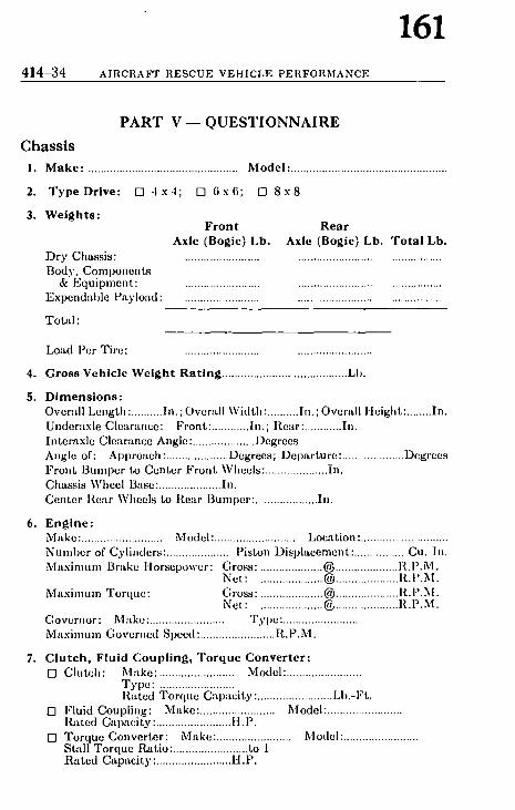
4 1 4 - 3 4 A I R C R A F T R E S C U E V E H I C L E P E R F O R M A N C E
161
P A R T V - - Q U E S T I O N N A I R E
C h a s s i s
I. Make: ................................................
2. T y p e Drive: [] 4 x 4 ; U] 6 x 6 ;
3. We igh t s : Front
Axle (Bogie) Lb. D r y Chas s i s : ........................
B o d y , C o m p o n e n t s & E q u i p n m n t : ........................
E x p e n d a b l e P a y l o a d : ........................
T o t , d :
Model : ..................................................
[] 8 x 8
Rear Axle (Bogie) Lb, Tota l Lb,
L o a d P e r T i r e : . . . . . . . . . . . . . . . . . . . . . . . . . . . . . . . . . . . . . . . . . . . . . . . .
4. Gross Vehic le We ight Rat ing ........................................ Lb .
5. D i m e n s i o n s : O v e r a l l L e n g t h : .......... In . ; O v e r a l l W i d t h : .......... h i . ; O v e r a l l H e i g h t : ........ I n .
Unde r t t x l e C lea r lu i ee : F r o n t : ............ I n . ; R e a r : ............ I n .
I n t e r a x l e C le : i r .mce A n g l e : .................... D e g r e e s
A n g l e of: A p p r o a c h : .................... D e g r e e s ; D e p a r t u r e : .................... D e g r e e s
F r o n t 13umper to C e n t e r F r o n t W h e e l s : .................... i n .
Chas s i s W h e e l Base : .................... I n .
C e n t e r R e a r W h e e l s to R e a r B u m p e r : .................... In .
6. Eng ine : M a k e : .......................... M o d e l : .......................... L o c a t i o n : ............................
N u m b e r of C y l i m l e r s : .................... P i s ton D i s p l a c e m e n t : ................ Cu . h i .
M a x i m u m B r a k e H o r s e l ) o w e r : G r o s s : .................... ~ .................... R . P . M . N e t : .................... (~ .................... I t . P . M .
M a x i m u m T o r q u e : G r o s s : .................... (~ .................... R . P . M . N e t : .................... (~ .................... R . P . M .
G o v e r n o r : M a k e : ........................ T y p e : ........................
M a x i m u m G o v e r n e d S p e e d : ........................ R . P . M .
7. C l u t c h , F lu id Coupl ing , Torque Converter: [ ] C l u t c h : M a k e : ........................ M o d e l : ........................
T y p e : ........................ R a t e d T o r q u e C ' q ) a c i t y : ........................ LI ) . -F t .
[ ] F lu id Coup l i , l g : M a k e : ........................ M o d e l : ........................ l ~ t t e d C a p a c i t y : ........................ H. P.
[] T o r q u e C o n v e r t e r : M a k e : ........................ M o d e l : ........................ S ta l l T o r q u e IL~tio: ........................ to 1 R a t e d C a p a c i t y : ........................ H . P .

" I I I I
F L ~-~
I I I I I
. I l l I1 I IJ
A- ANGLE OF APPROACH C - INTERAXLE CLEARANCE
ANGLE D- ANGLE OF DEPARTURE H- OVERALL HEIGHT L - OVERALL LENGTH U- UNDERCHASSIS CLEARANCE W-OVERALL WIDTH
--- W : -
T o a s s i s t In i n t e r p r e t i n g t h e v a r i o u s m e a s u r e m e n t s , t h i s d i a g r a m s h o w s t h e r e c o m m e n d e d m e t h o d s for f i g u r i n g t h e a n g l e s , l e n g t h , w i d t h , h e i g h t , a n d u n d e r c h a s s l s c l e a r a n c e for a i r c r a f t r e s c u e a n d fire f i g h t i n g v e h i c l e s .
z
r t~
oo

4 1 4 - 3 6 AIRCRAFT RESCUE VEHICLE PERFORMANCE
163
8. T r a n s m i s s i o n : Make: .................................... Model : ....................... Type: .......................... Max imum Rated I n p u t Torque Capaci ty: ................................ Lb.-Ft . N u m b e r of Speeds: Forward : ........................ ; Reverse: ........................
M.P.H.* Speed Gear Rat io {~ Eng ine Governed RPM
1 . . . . . . . . . . . . . . . . . . . . . . . . . . . . . . . . . . . . . . . . . . . . . . . . . . . . . . . .
2 . . . . . . . . . . . . . . . . . . . . . . . . . . . . . . . . . . . . . . . . . . . . . . . . . . . . . . . .
3 . . . . . . . . . . . . . . . . . . . . . . . . . . . . . . . . . . . . . . . . . . . . . . . . . . . . . . . .
4 . . . . . . . . . . . . . . . . . . . . . . . . . . . . . . . . . . . . . . . . . . . . . . . . . . . . . . . .
5 . . . . . . . . . . . . . . . . . . . . . . . . . . . . . . . . . . . . . . . . . . . . . . . . . . . . . . . . 6 . . . . . . . . . . . . . . . . . . . . . . . . . . . . . . . . . . . . . . . . . . . . . . . . . . . . . . . .
a e v . . . . . . . . . . . . . . . . . . . . . . . . . . . . . . . . . . . . . . . . . . . . . . . . . . . . . . . . . R e v . . . . . . . . . . . . . . . . . . . . . . . . . . . . . . . . . . . . . . . . . . . . . . . . . . . . . . . . .
* N O T E : If a u x i l i a r y t r a n s m i s s i o n o r m u l t i p l e r a n g e t r a n s f e r c a s e s p r o v i d e d . M . P . I I . t o b e m e a s u r e d w i t h t h e e c o m p o n e n t s in h i g h r a n g e .
9. Auxi l iary T r a n s m i s s i o n : Make: .............................. Model: ............................ Type : ............................ Max imum Rated I n p u t Torque Capaci ty: ............................ Lb.-Ft . Gear Ratio: High Range: ............................ ; Low Range: ............................
10. Transfer Case: [] Transfer Case: Make: ............................ ; Model: ....................................
Max imum Rated I n p u t Torque Capaci ty: .................................... Lb.-Ft . Gear Ratio: High Range: ........................ ; Low Range: ........................ Type Drive to F ron t and Rear Axles (Bogies): ......................................
[-'] Center Differential or Compensa t ing Device: Make: ............................ Model: ............................ Type : [ ] Autonmtic Locking
[ ] Driver Selective Locking [ ] Direct Drive:
Type : [ ] Coanected at All Times [ ] Driver Selective Disconnect
11. Front Drive: [ ] Axle; [ ] Bogie Make: ........................ Model: ........................ Gear Ratio: ........................ to 1 Type Drive: [ ] Single Reduction; [ ] l )ouble Reduction I f l )ouble Reduction, type final reduction:
[ ] Spur Gears at Differential [ ] In terna l Gears a t Hubs
Steering Drive Ends: Make: ............................ Model: ............................ Type : [ ] Const~tnt Velocity
[] Cardan
Differential or Compensating Device: Make: ............................ Model: . . . . . . . . . . . . . . . . . . . . . . . . . . . .
Type: [] Automatic Locking [] Non-Locking
Maximum Rated Input Torque Capacity: ............................ Lb.-Ft. Maximum Rated Load on Tires at Ground: ............................ Lb. Axle Tread: ............................ In. Bogie Wheel Base: ............................ In.

164 QUESTIONNAIRE 414-37
12. R e a r D r i v e : [] Axle; [] Bogie Make: ...................... Model: ........................ Gear Ratio: ........................ to l Tyl)e Drive: [] Single Reduction; [] Double Reduction If Double Retluction, Type I0'imd Reduction:
[] Spur Gears at l)itlerential [] In ternal Gears at Itul)s
Differential or Compensa t ing Device: Make: ............................ Model: ............................ Type : [] Autotnativ Locking
[] Non-Locking Max imum Rated I n p u t Torque Cal).tcity: ............................ Lb.-Ft . Max imum llJtte(I Load on Tires :tt Ground: ............................ Lb. Axle Tread: ............................ In. Bogie Wheel Base: ............................ In.
13. O v e r a l l G e a r R e d u c t i o n : In Lowest Forward Gear: ............................ to 1
14. S u s p e n s i o n : F r o n t R e a r
Type Suspension: Leaf Spring: [] [] Coil SI)ring: [] [] Torsion Bar: [] [] Air Cushion: [] []
Wheel Travel to Full Jounce: C'Lrrying Full Load (In.) : . . . . . . . . . . . . . . . .
Wheel Rate at Full: Load (Lb. per In.): . . . . . . . . . . . . . . . .
Wheel Motion a t Full Lo'td (In.) : Shock Absorbers: [] []
Upsprung Weight a t Full Load: .................... %
15. W h e e l s , T i r e s a n d R i m s : F r o n t R e a r
Wheels, Type: Disc: [-1 D Spoke: [] []
Wheels, Construct ion: Steel: [] [] Aluminum : [] []
Rims, Type : Single : [] [] Dual : [] []
Rim Size (In.) . . . . . . . . . . . . . . . . Tire Size
Ply Rat ing: . . . . . . . . . . . . . . . . Inflation Pressure (P.S.I .) : . . . . . . . . . . . . . . . .
Max imum Load @ .......................... Above Pressure (Lb.) . . . . . . . . . . . . . . . .
Tire Tread Design: ..............................

165 ~ | ~ ~18 A I H C R A F T R E S C U E V E H I C L E PEI~.FOf(MANCE
15. Electr ical S y s t e m : V o l t a g e : L i g h t i n g : ............................ ; S t a r t i n g : ............................ A l t e r n a t o r : M a k e : ............................ M o d e l : ............................
C a p a c i t y : ............................ A m p . @ ............................ Vo l t s
I | n t t c r i e s : M-Lkc: .................... M o d e l : .................... N u m b e r : .................... C a p a c i t y , h~ach: .................... A m p . H r . @ 2 0 Hr . R a t e
B a t t e r y S y s t e m : [] S ing l e ; [ ] D u a l St~tr ter : M a k e : ............................ M o d e l : ............................ ['1 E x t e r n a l B a t t e r y C h a r g i n g C o n n e c t i o n : .................... Vo l t s ['1 E n g i n e C o o l a n t P r e h e a t i n g C o n n e c t i o n : .................... Vo l t s
I-I E l e c t r i c a l S y s t e m R a d i o S u p p r e s s e d
| ? . F u e l S y s t e m : I,'nel P u m p s : [] M e c h a n i c a l , N u m b e r : ....................
[] E l e c t r i c a l , N u m b e r : ....................
I 'ue l T a n k C a p a c i t y : .................... G a l . ; L o c a t i o n : ........................................ [ ] F l a m e A r r e s t e r R e l i e f F i t t i n g on F i l l e r O p e n i n g
18. E x h a u s t S y s t e m : C o n s t r u c t i o n of Muf f l e r : ....................................................................................
T a i l P i p e : ...................................................................................................... L o c a t i o n of E x h a u s t D i s c h a r g e : ........................................................................
!9. Service Brakes: M a k e : ................ ~ ........... N u m b e r : ............................
F ron t , T y p e : [ ] I n t e r n a l Shoe [] Dis(;
B r a k i n g A r e a : .................... Sq. I n .
R e a r , Tyf )e : [ ] I n t e r n a l S h o e [] D i s k
B r a k i n g A r e a : .................... Sq. In .
B r a k e Appl ic .Lt ion S y s t e m : M a k e : ............................ T y p e : [] A i r - M e c h a n i c a l
[ ] H y d r a u l i c , w i t h : [ ] A i r B o o s t e r [] V , m u u m B o o s t e r [] N o B o o s t e r
If Ai r B r a k e A p l ) l i c a t i o n S y s t e m : C o m p r e s s o r C . q ) a c i t y : ............................ C. F. M. A i r R e s e r v o i r s C a p a c i t y : ............................ Cu . In .
v1 Q u i c k B u i l d - U p T a n k
~0. E m e r g e n c y Brakes: M a k e : .................................... : ....... L o c a t i o n : ................................................ B r a k i n g A r e a : ............................. Sq. In. T y p e : [ ] E n t i r e l y I n d e p e n d e n t of S e r v i c e B r a k e s
[] C o n n e c t e d to S e r v i c e B r a k e s
21. S t e e r i n g : S t e e r i n g Ge-~r: M a k e : ........................................ M o d e l : .............................. [ ] P o w e r Ass i s t , M a k e : ...................................... M o d e l : ..............................
W a l l - t o - W a l l T u r n i n g D i a m e t e r : ............................ F t .

166 AV-20 REPORT OF AVIATION COMMITTEE
Part IX of Aviation Committee Report The Committee recommends the Iollewing revisions of the NFPA Guide on Foaming Runways for Crash Protection (No. 420M) as published by the NFPA in pamphlet form, dated May 1961 and as published in the 1961-65 Edition o! Volume VI of the National Fifo Codes. For explanation of this report and ]or vote statement, seo pages AV-$ and AV-3.
Proposed Revisions of Guide on FOAMING RUNWAYS FOR CRASH
PROTECTION NFPA No. 420M- May 1961
1. Rev i s ed P a r a g r a p h 31.d. to read:
d. REDUCTION OF FUEL SPILL FIRE HAZARD. From all tha t is known of the fire suppression qualities of foam and the scale research tests, it is clear tha t a foam coated runway would have no appreciable effect on the fire hazard of fuel vapors in the a tmosphere over the foam. These vapors could still be ignited above the foam blanket by an engine fire, electrical arcs or sparks, static discharges or other ignition sources. Should liquid fuel be released over the foam blanket, it will fall through and spread under the foam, reducing the release of flammable vapors. In case of ignition, the burning area may be reduced, de- pending on the age and condition of the foam blanket. Fire crews should be prepared to fight such a fire.
2. Rev i se No te 1 to P a r a g r a p h 41.b. to read:
NOTE 1: Airports not having adequate equipment should not attempt to lay a foam blanket.
3. Rev i se P a r a g r a p h 41.d. to read as foUows, leaving the " N o t e " fo l lowing the paragraph as is:
d. The foam making capability of the equipment available on the a i rport for runway foaming (not including pr imary fire fighting vehicles which should not be used for this purpose) plotted against the prudent holding
�9 time of the a i rc ra f t involved in the emergency.
4. A d d to P a r a g r a p h 43 so tha t the ent ire Paragraph , as revised, wi l l read:

REVISIONS OF NFPA NO. 420M
167 AV-21
,13. Determination as to the feasibility of applying foam to a runway is a decision which the airport manager or his representative (the Chief of the Airport Fire Department) must make after receipt of the official request for such serv- Iccs from the pilot or operator and an evaluation of the fire })rotection and other airport operational problems involved.
uc to the fact that aircraft operations are continuing elsewhere on the airport and the existing danger that cir- cumstances beyond the control of the pilot of the disabled aircraft may require an emergency landing before the foam blanket is ready, or before the foam making units have been replenished, it is essential that the primary air-
~ ort fire fighting vehicles as recommended in the NFPA uggestions for Aircraft Rescue and Fire Fighting Serv-
ices for Airports and Heliports (No. 403) should never be used to foam a runway. These vehicles must always be maintained in fully operational condition. Tank vehicles or specially designed equipment should be used for runway foaming.
5. Revise Paragraph 51.b. to read:
b. Primary aircraft rescue and fire fighting vehicles as recommended in the NFPA Suggestions for Aircraft Rcscue and Fire Fighting Services for Airports and Heli- ports (No. 403) should never be used to foam a runway. Auxiliary tank trucks equipped to dispense foam through ground sweep nozzles or special boom nozzles or other addi- tional specialized foaming equipment should be used for runway foaming.
6. Delete present Paragraph 51.d.
7. Relet ter present Paragraphs 51.e. to 51.1. to 51.d. to 51 .k.
8. Revise present Paragraph 51.e. (to be relettered 51.d.) to read:
d. Previous experience has shown that, when making a gear-up landing, the aircraft contacts the runway much further from tKe threshold than normal. This is due to the reduced stalling speed of the aircraft with the gear up. The point of aircraft touchdown can be 500 to 2000 feet further down the runway than normal, depending on the size and speed of the aircraft involved.

168 AV-22 I:EPORT OF AVIATION COMMITTEE
9. Revise Paragraph 57.h. (to be relettered 51.g.) to read:
g. The length, width and depth of the foam pattern will vary with the type of emergency, the type of aircraft , the length of the runway, the quantit ies of agent available, and the time factors involved. The following Table 1 may be used for est imating the approximate water and foam liquid requirements for foaming a runway strip 1000 feet long. The needed supplies for longer or wider strips may be readily calculated from the figures in the Table by using an appropriate mult iplying factor.
T a b l e I
Water and Foam Liquid Requirements for Runway Foaming*
*These f igures are based on applying w a t e r as foam at a m in imum ra te of 0.1 gallons per square foot of runway surface. The app rox ima te equiva len t foam b lanke t thick- ness is 2 inches for Expans ion 12 and l~/fi inches for Expans ion 8.
Wid th of F o a m 20 ft. 75 ft. Leng th of P a t t e r n 1,000 ft. 1,000 ft. R u n w a y Area Covered 20,000 sq. ft. 75,000 sq. ft. W a t e r 2,000 gallons 7,500 gallons F o a m Liquid Concen t ra t e
6% Type 120 gallons 450 gallons 3% Type 60 gallons 225 gallons
For a malfunct ioning main gear or wheels-up landing, the runway foam pattern should be at least as wide as the distance between the outboard engines of the a i rcraf t involved p l u s a safety factor of 10 feet on each side. For this type emergency the foam pattern should be laid down the center line of the runway beginning at a point agreed to by the pilot and should be so calculated to run con- tinuously the full length of the projected slide. For a defective or "cocked" nose wheel with main gear fully operational, it is recommended tha t the runway foam pat tern should be at least 1/.2 the width of the main gear tread, laid down the center of the runway, beginning at a point agreed to by the pilot (usually fu r the r down from the threshold than for a main gear or wheels-up landing) and calculated to run continuously the full length of the projected landing.
10. It is plan~zed to add so'me photogra?)hic material.

169 REPORT OF C O M M I T T E E ON CARBON DIOXIDE CO2-1
J
Repor t of Commit tee on Carbon Dioxide. H. Tw Johnson, Chairman.
Illinois Iuspect ion and Rat ing Bureau, 175 XV. Jackson Blvd.,=Chicago ,I, III.
Douglas R. Abbey, Drm Mills, Ont . , Canada. (Personal )
{~. V. Batley, Bethlehenl Steel Co. I Personal )
], A. Bono, Underwri te rs ' Laborator ies , l l l c .
Walter Boon, American Petroleum In- l l t t t t l te .
Donald A. Diehl, Compressed Gas Assn. W. G. Goodwin, Fire Equipment Manu-
lactu; 'crs ' Ins t i tu te of Canada.
P,hE.~g Johnson,l)ivision. Factory Mutual Engineer-
Professor Willis I& Labes, l l l inols ln- stltute of Technology. (Personal )
r H. Lindsay, American LaFrance , Div. o[ Ster l ing l ' recision Corp. (Personal )
~, A. McGuckin, Edison Electric )n- atltute.
E J. Melters, National Paint, Varnish & L a c q u e r ASSII.
Robert Roos, Fire Equipment Mfrs. Assn. Inc.
Gilbert L. Toppin, Underwri te rs ' Lab- oratories of Canada.
E. E. Williams, Factory Insurance Assn. H. V. Will iamson, Cardox Division,
Chemetron Cnrp. (Personal )
Alternates.
Stewart Boal, Fire Equipment Mfrs. Assn. (Aherna te to Robert Roos.)
George Schi'ank, Compressed Gas Assn. (Aherna te to Donald A. Diehl.)
L. W. Vincent, American LaFrance Div. of Sterl ing Precision Corp. (Aherna le to C. II. l . indsay.)
This report has been submitted to the Committee for letter hollot. Of the 16 mem.bers of the Committee all voted affirmatively.
At the 1961 Annual Meeting an extensive revision of the gtandard for Carbon Dioxide Extinguishing Systems (NF 'PA No. 12) was adopted with an effective date of November 1, 1961. :'unendments adopted in 1961 introduced a new method of system I.tesig-n based upon the rate of carbon dioxide application and upon Uozzle characteristics. The report being submitted this year con- qists principally of additions to facilitate the use of the new design ,icthod.
Proposed Amendments to S T ANDARD FOR
CARBON DI OX I DE E X T I N G U I S H I N G SYSTEMS
NFPA No. 12~1961
I. Add sentence on hydrostatic retestin 9 of cylinders to 1551, the am.ended paragraph to read:
1551. High pressure containers or cylinders shall be con- ~tt'ucted, tested and marked in accordance with the Interstate Commerce Commission specifications'[ (in current effect upon (late ~if manufacture and test) for ICC-3A, 3AA-1800, or higher, ;careless steel cylinders. Charged cylinders shall be tested for

170 C02-2 A M E N D M E N T S TO N F P A NO. 12
tightness before shipme.nt in accordance with an approved pro- cedure. Cylinders in service shall be hydrostatically retested for continuing service at least every 12 years in accordance with the test procedure and apparatus set forth in the regulations of the Interstate Commerce Commission.
2. Substitute more accurate orifice flow data for low pressure carbon dioxide in Table 2, the amended Table 2 to read:
Table 2. Discharge Rate Per Square Inch of Equivalent Orifice Area for Low Pressure Storage (300 Psia).
Orifice Pressure Discharge Rate psia Lbs./Min./Sq. In.
300 4220 290 2900 280 2375 270 2050 260 1825 250 1655 240 1525 230 1410 220 1305 210 1210 200 1125 190 1048 180 977 170 912 160 852 150 795 140 741 130 689 120 638 110 589 100 542
3. In 262 change "'Record vaults" (line 5) to "Record storage rooms," the amended section to read:
282. Pressure Relief Vent ing. Poros i ty and leakages such as at doors, windows, and dampers, though not readily ap- parent or easily calculated have been found to provide sufficient relief for the normal carbon dioxide flooding systems without need for additional venting. Record storage rooms, refrigerated spaces, and duct work have also been found to need no additional venting when tested under their average system conditions.
4. Add the following two paragraphs and four tables at the end of/1-165 in Appendix/1.
Tables A-5 and A-6 list the equivalent lengths of pipe fittings for determining the equivalent length of piping systems. Table

171 REPORT OF COMMITTEE ON CARBON DIOXIDE C O 2 - 3
A-5 is for threaded jo ints and Table A-6 is for welded joints . Both tables were computed for schedule 40 pipe s izes ; however , /or all pract ical purposes the same figures can also be used for schedule 80 pipe sizes.
Table A-5. Equivalent Length of Threaded Pipe Fittings.
Elbow 90* Union Long Rad. Coupling
Pipe Elbow Elbow & Tee Tee or Size Std. 45* Std. 90* Thru Flow Side Gate Valve
0.6 1.3 0.8 2.7 0.3 0.8 1.7 1.0 . 3.4 0.4 1.0 2.2 1.4 4.5 0.5
1 1.3 2.8 1.8 5.7 0.6 1~ 1.7 3.7 2.3 7.5 0.8 1~ 2.0 4.3 2.7 8.7 0.9 2 2.6 5.5 3.5 11.2 1.2 2 ~ 3.1 6.6 4.1 13.4 1.4 3 3.8 8.2 5.1 16.6 1.8 4 5.0 10.7 6.7 21.8 2.4 5 6.3 13.4 8.4 27.4 3.0 6 7.6 16.2 10.1 32.8 3.5
Table A-6. Equivalent Lerngt~h of Welded Pipe Fittings.
Elbow 90* Long Rad.
Pipe Elbow Elbow & Tee Tee Gate Size Std. 45* Std. 90* Thru Flow Side Valve
0.2 0.7 0.5 1.6 0.3 �89 0.3 0.8 0.7 2.1 0.4
0.4 1.1 0.9 2.8 0.5 1 0.5 1.4 1.I 3.5 0.6 1~ 0.7 1.8 1.5 4.6 0.8 1~ 0.8 2.1 1.7 5.4 0.9 2 1.0 2.8 2.2 6.9 1.2 2 ~ 1.2 3.3 2.7 8.2 1.4 3 1.5 4.1 3.3 10.2 1.8 4 2.0 5.4 4.4 13.4 2.4 5 2.5 6.7 5.5 16.8 3.0 6 3.0 8.1 6.6 20.2 3.5
F o r nominal changes in elevation of p ip ing the change in head pressure is negligible. However , if there is a substant ia l change in elevation this factor should be taken into account. The head pressure correct ion per foot of elevation depends on the average line p ressure where the elevation takes place since the densi ty

172 CO~-4 AMENDMENTS TO NFPA NO. 12
changes with pressure . Correc t ion factors are given in Tables A-7 and A-8 for low pressure and high pressure systems respectively. The correct ion is subtracted f rom the terminal p ressure when the' flow is upward and added to the terminal p ressure when the flow is downward .
Table A-7.
Average Line Pressure psia
300 280 260 240 220 200 180 160 140 120 100
Elevation Correction Factors for Low Pressure Systems.
Elevation Correction ,~si/fl.
0.443 0.343 0.265 0.207 0.167 0.134 0.107 0.085 0.067 0.052 0.039
Table A-8. Elevation Correction Factors High Pressure Systems.
Average Line Pressure psia
750 0.352 700 0.300 650 0.255 600 0.215 550 0.177 500 0.150 450 0.125 400 0.105 350 0.085 3OO 0.070 250 0.055 200 0.040
for
Elevation Correction osi/ft.
5. Renumber present Table A-5 to read A-9 and change reference in A-2534 from Table A-5 to Table A-9.

173 C O M M I T T E E ON C H E M I C A L S A N D E X P L O S I V E S CE1
Report of C o m m i t t e e on Chemica l s and Explosives
Dr. Rober t W. Van Dolah, Chairman, Explosives Research Laboratory. Bureau of Mines, U. S. Department of the Interior,
4800 Forbes Ave., Pittsburgh 13, Pa.
Ches t e r l. Babcock,~ ,~"ecretary, National Fire Protection Assn., 60 Batterynmrch St., Boston 10, Mass.
|L R. Abbey, Don Mills, Ont., Canada. (l'crsonal)
i~hurles W. B a h m e , Northridge, Calif. (l'ersonal)
.~r G. Baker , Mutual Fire Inspection Bureau of New England.
W, J. Baker, Conference of Special P, isk Un- derwriters.
Mat|hew M. Braldech, American Chemical Society and National Board of Fire Under- writers.
t,q, J. Burns , M unitions Carriers Conference. Iohn D. Cook, National Automatic Sprin-
kler and Fire Control Assn. Dr. Glenn If. D a m o n , U. S. Dept. of the
I nterior. Ihmald A. Diehl, Compressed Gas Assn. W. II. Doyle, Factory Insurance Assn. ~, E. Dufour , Underwriters' Laboratories,
Ioc. f b o m a s E. Duke , Fire Prevention & Engi-
neering Bureau of Texas. lh~ward II. Fawcet t , General Electric Co.
(Personal) ~eynold J . Green , Manufacturing Chem-
ists' Assn., Inc. ~,t'eo. E. G r u b e r t , Conference of Special Risk
Underwriters. Win. G. Hayne , New York Board of Fire
Underwriters. | )cpu(y Chief R a y m o n d M. Hill, Fire
Marshals Assn. of North America. 8ohn H o m m e s , Western Actuarial Bureau. t(meph A. Houp.hton, Liberty Mutual Fire
Iss. Co. (Personal) Ihtrret t B. J a m e s , St. , W. II. Markham &
Go. (Personal) P, F., J o h n s o n , Factory Mutual Engineering
I)ivi~iun. it. W. Klefer, Union Carbide Chemicals Co.
(Personal)
Win. B. Lark in , San Diego 6, Calif. (Per- sonal)
Dr. R ichard Y. LeVine, Olin Mathieson Chemical Corp. (Personal)
M. W. Marx, Manufacturing Chemists' Assn., Inc.
Char les I I. Mayhood, Manufacturing Chem- ists' Assn., Inc.
F. J . McCialn , Factory Insurance Assn. W. G. McKenna , Bureau of Explosives. Asst. Chief N o r m a n Nordwiek, Fire
Marshals Assn. of North America. Russell P. Nor thup , National Electrical
Manufacturers Assn. Capt . Har ry J . Parker , National Cargo
Bureau. Roy Petersen , American Assn. of Port
A uthorities. S. J. Por ter , Spencer Chmnical Co. (Per-
sonal) II. T. R l t t m a n , Institute of Makers of
Explosives. Rudo lph S c h m l d t , J r . , Assn. of Casualty
& Surety Cos. R. I[. Scot t , General Electric Co. (Personal) Eric Shack le ton , Underwriters' I~abora-
tories of Canada. Major Carroll E. Shaw, Fire Marshals
Assn. of North America. Char les J. Shukes , Co.k County Inspection
Bureau. Char les B. S m i t h , U. S. Coast Guard. I l e r m a n II. Spae th , Pacific Firs Rating
Bureau. A. W. S t r a h o r n , Institute of Makers of
Explosives. Paul T. T r u i t t , National Plant Food Insti-
tute. F. W. Wlschmeye r , Eastman Kodak Co.
(Personal)
ALTERNATE. Char l e s An thony , Compressed Gas Assn. (Alternate to Donald A. Diehl.)

L74 C1/2 E X P L A N A T I O N AND S E C T I O N A L C O M M I P T E E S
The report of the Committee on Chemicals and Explosives this year is divided into" five parts. Parts I, II, III, and IV were pre- pared by the Sectional Committee on Explosives. Part V was prepared by the Sectional Committee oil Properties of Hazardous Chemicals.
Part I proposes amendments of the Code for the Manufacture, Transportation, Storage, and Use of Explosives and Blasting Agents, NFPA No. 495.
Part II proposes reconfirmation of the Standard for the Storage and Handling of Cellulose Nitrate Motion Picture Film, NFPA No. 40.
Part III proposes reconfirmation of the Standard for the Stor- age, Handling, and Use of Pyroxylin Plastics in Factories Making Articles Therefrom, NFPA No. 42.
Part IV proposes reconfirmation of the Standard for the Stor- age and Sale of Pyroxylin Plastic ill Warehouses and Wholesale, Jobbing and Retail Stores, NFPA No. 43.
Part V proposes amendments of Hazardous Chemicals Data, NFPA No. 49M.
The Sectional Committee on Explosives and the Sectional Committee on Properties of Hazardous Chemicals report to the Association through the Committee on Chemicals and Explosives.
W. J. Burns G. H. D a m o n W m . G. Hayne
SECTIONAL COM M ITTEE ON EXPLOSIVES.
H. T. R l t t m a n . Chairman.
R a y m o n d M. Hill Carroll E. Shaw Win. B. Larkln A . W . S t r aho rn W. G. M c Ke nna Robert W. Van Dolah S. J. Por ter
SECTIONAL COMMITTEE ON PROPERTIES OF HAZARDOUS CIIEMICALS.
T h o m a s E. Duke. Chairman.
D. R. Abbey R . E . Dufour R . H . Scott Char les W. Bahrne Win. E. G r u b e r t Charles J. Shukes A r t h u r G. Baker R . W . Klefer Charles B. S m i t h M a t h e w M. Braldech Rudolph Schrnldt . J r . Robert W. Van Dolah

175 COMMITTEE ON CHEMICALS AND EXPLOSIVES CE3
PART I
Proposed Amendments of Code for the
MANUFACTURE, TRANSPORTATION, STORAGE, AND
USE OF EXPLOSIVES AND BLASTING AGENTS
N F P A No. 4 9 5 - 1959
Part I of the report received letter ballot approval by the Sectional Committee on Explosives and has been submitted for ballot to the Committee on Chemicals and Explosives which consists of 45 mem- bers, 40 of whom have voted a.~rmatively. Mr. Nordwiek voted negatively; Messrs. Hoaghton and Northup are recorded "not vot- ing"; Messrs. Cook and Spaeth have not returned ballots.
I. Revise Paragraph 311 to clarify exclusions from magazine stor- age requirements and to add fuse lighters, fuse igniters, and safety fuses to the exclusions. Revised Paragraph 311 will read:
311. All Class A, Class B, Class C explosives, and special in- dustrial high explosives, and any newly developed and unclassi- fied explosives, shall be kept in magazines which meet the require- ments of this chapter. This shall not be construed as applying to the following:
1. Wholesa le and retail s tocks of smal l a r m s a m m u n i t i o n . 2. Special industrial explosive devices when in quantities of less than 500
pounds. 3. Fuse lighters and fuse igniters. 4. Safety fuse (safety fuse does not include, cordeau detonant fuse).
~. Revise Paragraph 315 to make it clear that authorization must be obtained from the authority having jurisdiction to store more than 50 pounds of explosives in a Class II magazine at a blasting site. Revised Paragraph 315 will read:
315. Class I magazines shall be required where the quantity of explosives stored is more than 50 pounds. Class II magazines may be used where the quantity of explosives stored is 50 pounds or less, except that the authority having jurisdiction may au- thorize the use of Class II magaz.ines for the temporary storage at blasting sites of larger quantities of explosives.

176 CE4 A M E N D M E N T S TO N F P A NO. 495
3. Revise Paragraph 318 to make it clear that the temporary storage distances apply only at blasting sites. Revised Paragraph 318 will read:
318. When used for temporary storage at a site for blasting operations, Class II magazines shall be located away from neigh- boring inhabited buildings, railways, .highways, and other maga- zines. A distance of at least one hundred and fifty (150) feet shall be maintained between Class II magazinr and the work in progress when the quantity of explosives kept therein is in excess of 25 pounds, and at least 50 feet when the quantity of explosives is 25 pounds, or less. The authority having jurisdiction may re- quire a greater separation between Class II magazines and the work in progress where conditions warrant.
2~. Revise Paragraph 415 so that the road vehicles in which ex- plosives may be transported agree with recently revised vehicle re- quirements of the ICC. Revised Paragraph 415 will read:
415. Explosives may be loaded into and transported in the following:
I. Truck 2. Truck with semitrailer 3. Truck with full trailer 4. Truck tractor with semitrailer 5. Truck tractor with semitrailer and full trailer
5. Revise Paragraph 511 to clarify who may handle explosives. Revised Paragraph 511 will read:
511. The handling of explosives may be performed by the person holding a permit to use explosives or by other employees under his direct supervision provided that such employees are at least 21 years of age.
6. Delete the first sentence of Paragraph 533, because ihe stemming procedure required is not followed except in coal mines, where it is required by Federal regulation. Revised Paragraph 533 will read:
533. No holes shall be loaded except those to be fired in the next round of blasting. After loading, all remaining explosives shall be immediately returned to an authorized magazine.
7. Change the first "or" in Paragraph 54~ to "of", the revised Paragraph 5 ~ to read:
544. No blasting cap shall be inserted in the explosives with- out first making a hole in the cartridge f~r the cap with a wooden punch of proper size or standard cap crimper.

i77 COMMITTEE ON CHEMICALS AND EXPLOSIVES C]~5
8. Amend Paragraph 721 to include mobile equipment among the blasting agent mixing facilities that must comply with the American Table of Distances. Revised Paragraph 721 will road:
721. Buildings or other facilities used for mixing blasting agents, including mobile equipment, shall be located, with re- spect to inhabited buildings, passenger railroads and public high- ways, in accordance with the American ,Table of Distances.*
9. Delete the parentheses characters from Paragraph 721b, revised 7~Ib to read:
b. Minimum intra-plant separation distances between mixing units and the oxidizer storage areas and blasting agent storage areas shall be determined by competent persons, and these dis- tances shall be approved by the authority having jurisdiction.
lO. Delete the last sentence of Paragraph 723 since the prohibition against mixing blasting agents while in transit on public highways properly belongs in Paragraph 721, which contains restrictions on locations of all blasting agent mixing facilities. (See amendment 8.) Revised Paragraph 728 will read:
723. The design of the mixer should minimize the possibility of frictional heating," compaction, and especially, confinement. Open mixers are preferable to enclosed mixers. Bearings and gears should be protected against the accumulation of oxidizer dust. All surfaces should be accessible for cleaning. Mixing and packaging equipment should be constructed of materials com- patible with the fuel-oxidizer composition.
11. Add "or packaging" to the last sentence of Paragraph 72~ to require retesting of blasting agent sensitivity i f the packaging method is changed.. Revised Paragraph 72~ will read:
724. The provisions of this Section shall be considered when determining blasting agent compositions. The sensitivity of the blasting agent shall be determined by means of a No. 8 test blasting cap at regular inter~'als and after every change in ingredients, compo- sition or packaging, or as mmf be requested by the authority having jurisdiction.
12. Revise editorially Paragraph 72~b to clarify the intent that no liquid fuel with flash point less than that of No. 2Diesel fuel oil may be used to make a blasting agent. Revised Paragraph 72~b will read:

CE6 RECONFIRMATION OF NFPA NO. 40
b. No liquid fuel with flash point lower than that of No. 2 Diesel fuel oil (125 ~ F. minimum or legal) shall be used.
18. Add the foUowing reference to the list in the Appendix:
A46. "Tentative Safety Recomme.ndations for Field-Mixed Ammonifim Nitrate Blasting Agents," Bureau of Mines, U. S. Department of Interior, Information Circular 7988, 1960.
P A R T I I
Proposed Reconfirmation of
STANDARD FOR THE STORAGE AND HANDLING OF CELLULOSE NITRATE MOTION PICTURE FILM
NFPA No. 4 0 - 1953
Part 1I of the report received letter ballot approval by the Sectional Committee on Explosives and has been submitted for ballot to the Committee on Chemicals and Explosives which consists of 45 mem- bers, 38 of whom have voted affirmatively. Mr. Larkin voted nega- tively; Messrs. Houghton, Kiefer, Northup, and Truitt are recorded "not voting"; Messrs. Cook and Spaeth have not returned ballots.
This standard, which was last revised in 1953, was reviewed by the Sectional Committee on Explosives to determine whether it should be maintained as an active NFPA standard in the light of the fact that for several years nitrate motion picture film has not been produced in the United States and Canada. The Committee felt that No. 40 should be kept available for those who might have occasion to store or handle old cellulose nitrate film. Al- though the Committee did not feel that changes in technical parts of the standard were needed, it agreed to submit the stand- ard for reconfirmation so that the user would know that the standard reflected the current thinking of the Committee. If the standard is reconfirmed, the 1962 edition will incorporate minor editorial revisions, primarily to bring up to date references to other NFPA standards. A free copy of the 1953 edition of NFPA No. 40 will be sent on request to anyone interested for review.

COMMITTEE ON CHEMICALS AND EXPLOSIVES
179 CE7
P A R T I I I
Proposed Reconfirmation of
STANDARD FOR THE STORAGE, HANDLING, AND USE OF PYROXYLIN PLASTICS IN FACTORIES
MAKING ARTICLES THEREFROM
N F P A No. 4 2 - 1936
Part I I I of the report received letter ballot approval by the Sec- tional Committee oTt Explosives and has been submitted for ballot to the Committee on Chemicals and Explosives which consists of ~5 members, 39 of whom have voted a.~rmatively. Mr. Houghton ~'oted negalively; Messrs. Kiefer, Northup, and Truitt are recorded "not toting"; Messrs. Cook and Spaeth have not returned ballots.
This standard, which was last amended in 1936, was reviewed by the Sectional Committee on Explosives to determine whether amendments were needed to bring its fire prevention and protec- tion recommendations into agreement with present-day practices. No changes of this nature appeared to be necessary, but it was agreed to submit the standard for reconfirmation so that the user would know that the standard reflected the current thinking of the Committee. If the standard is reconfirmed, the 1962 edition will incorporate minor editorial revisions, primarily to bring up to date references to other NFPA standards. A free copy of the 1936 edition of NFPA No. 42 will be sent on request to anyone interested for review.

180 CE8 R E V I S I O N S TO NFPA NO. 43
P A R T IV
Proposed Reconf irmat ion of
STANDARD FOR THE STORAGE AND SALE OF P Y R O X Y L I N PLASTIC IN WAREHOUSES AND WHOLESALE, JOBBING AND RETAIL STORES
N F P A No. 4 3 - 1940
Parl IV of the reporl received letter baUol approval by the Set: tional Committee on Explosives and has been submitted for ballot to the Committee on Chef,deals and Explosives which consisls of ]~ members, 39 of whom have voled aj~rmatively. Mr. Houghto~t voled negalively; Messrs Kiefer, Northup, and Truill are recorded "n0I voting"; ll'Iessrs. Cook and Spaeth have not returned ballots.
This standard, which was last amended in 1940, was reviewed by the Sectional Committee on Explosivcs to determine whether amendments were needed to bring its fire prevention and protec. tion recommendations into agreement with present-day practices No changes of this nature appeared to be necessary, but it wan agreed to submit the standard for reconfirmation so that the usew would know that the standard reflected the current thinking ol the Committee. If the standard is r~confirmed, the 1962 editioz, will incorporate minor editorial revisions, primarily to bring up to date references to other NFPA standards. Free copies of the 1940 edition Of NFPA No. 43 will be sent on request to anyone interested for review.

181 C O M M r F r E E O N C H E M I C A L S A N D E X P L O S I V E S CE9
P A R T V
Proposed Amendments of
HAZARDOUS CHEMICALS DATA
N F P A N o . 4 9 M - - 1961
Part V of the report received letter ballot approval by the Sectional Committee on Properties of Hazardous Chemicals and has been submitted for ballot to the Committee on Chemicals and Explosives whic~ consists of It5 members, ~0 of whom have voted affirmativdy. Messrs. Doyle and Honghton voted negativelyn Messrs. Marc and Em/th are recorded "not voting," and Mr. Burns has not returned his ballot.
Amendments being submitted for adoption include addition of information on 20 chemicals not included in the 1961 edition, as well as amendments of statements on electrical equipment for hazardous atmospheres of certain chemicals in the 1961 edition.
1. Add the following paragraph to the "Ezplanatory" material:
Polymer iza t ion . Certain of the materials covered are noted as presenting a hazard due to their ability to undergo polymeriza- tion. �9 This reaction is nsuall3f prevented by inhibitors but in- hibition may be nullified by heat or certain chemicals, as noted in individual cases. In addition, once initiated, this exothermic polymerization reaction is accelerated by its owx~ heat. Also, the increased temperature may cause an increase m pressure which requires provision of adequate venting to prevent destructive explosive failure of containers.
~. Revise "Fire Fighting Phases" for "Acetic Acid (Glacial)" to read:
FIRE FIGHTING PHASES: Use water spray, dry chemical, carbon dioxide, or "alcohol" foam on acetic acid fires. Wear self- contained breathing apparatus.
8. Revise "Remarks" for "Acetic Acid (Glacial)" to read:
REMAmm: Electrical installations in Class I hazardous locations, as defined in Article 500 of the National Electrical Code, should be in accordance with Article 501 of the Code; and electrical

CE10 A M E N D M E N T S TO N F P A NO. 4 9 M
equipment should be. suitable for use in atmospheres contain. ing acetic acid vapors. See Fire Hazard Properties of li'lam. mable Liquids, Gases and Volatile Solids (NFPA No. 325), and Chemical Safety Data Sheet SD-41 (Manufacturing Chemists' Association, Inc.)
~. Revise "Storage" for "Acetone (Dimelhyl Ketone)" to read:
STORAGE: Protect containers agail~st physical damage. Separate from oxidizing materials. Electrical installations in inside storage areas should coliform to the National Electrical Code requirements for Class 1 hazardous locations.
5. Revise "Fire Fighting Phases" for "A cetone (Dimethyl Ketone)" to read:
FIRE FIGIITING PHASES: Lighter than water, sohlble in it in aJJ proportions. Use water spray, dry chemical, carbon dioxide, or "alcohol" foam on acetone fires.
6. Revise "Remarks" for "Aluminum (Dust or Powder)" to recal:
REMARKS: Electrical installations in Class II hazardous locations, as defined in Article 500 of the National Electrical Code, should be in accordance with Article 502 of the Code; Class II, Group E electrical equipment should be used in atmospherea containing aluminum dust. This hazardous powder may be produced by some rectal spraying operations. See Code for the Processing and Finishing of Aluminum (NFPA No. 65), Code for the Prevention of Dust Explosions in the Manufacture of Aluminum Bronze Powder (NFPA No. 651) and National Electrical Code (NFPA No. 70).
7. Revise "Fire Fighting Phases" for "Ammonia (Anhydrous)" to read:
FIRE FIGHTING PHASES: Stop flow of gas. Use water to keep con- tainers cool. Do not extinguish unless necessary to effect an immediate shutoff of flow. Dry chemical, carbon dioxide, and water spray can be used to extinguish ammonia fires. Wear self-contained breathing apparatus.
8. Revise "Remarks" for "Ammonia (Anhydrous)" lo read:
REMARKS: Electrical installations in Class I hazardous locations~ as defined in Article 500 of the National Electrical Code,

183 C O M M F I T E E ON C H E M I C A I ~ A N D E X P L O S I V E S CEl l
should be in accordance with Article 501 of the Code; and electrical equipment should be suitable for use in atmospheres containing ammonia gas. See Fire-Hazard Properties of Flam- mable Liquids, Gases and Volatile Solids (NFPA No. 325), Chemical Safety Data Sheet SD-8 (Manufacturing Chemists' Association, Inc.), and CGA Pamphlet G-2, Anhydrous Am- monia (Compressed Gas Association).
9. Remse "Remarks" for "Bronze (Dust or Powder)" to read:
REMARKS: Electrical installations in Class II hazardous locations, as defined in Article 500 of the National Electrical Code, should be in accordance with Article 502 of the Code; and electrical equipment should be suitable for use in atmospheres containing bronze dust or powder. See ALUMINtm rUST; also see Code for the Processing and Finishing of Aluminum (NFPA No. 65), and Code for the Prevention of Dust Explosions in the Manu- facture of Aluminum Bronze Powder (NFPA No. 651).
I0. Revise "Fire Fighting Phases" for "Butane" to read:
FIRE FIGHTING PHASES: Stop flow of gas. Use water to keep con- tainers cool. Do not extinguish unless necessary to effect an immediate shutoff of flow. Dry chemical and carbon dioxide can be used to extinguish butane fires.
11. Revise "Fire Fighting Phases" for "Carbon Disulfide (Carbon Bisulfide)" to read:.
FIRE FIGHTING PHASES: Foam is ineffective. Use dry chemical, carbon dioxide or other inert gas. Cooling and blanketing with water spray is effective in case of fires in metal containers or tanks to help prevent ~eignition by hot surfaces. Wear self- contained breathing apparatus.
12. Revise "Remarks" for "Carbon Disulfide (Carbon Bisulfide)" to read:
REMARKS: Electrical installations in Class I hazardous locations, as defined in Article 500 of the National Electrical Code, should be in accordance with Article 501 of the Code; and electrical equipment should be suitable for use in atmospheres contain- ing carbon disulfide vapors. Carbon disulfide should never be transferred by means of air; use pump, water, or inert gas. Do not use spark-producing tools or devices where stored, handled or used. Use wood measuring stick for measuring con-

184 CEI2 A M E N D M E N T S TO NFPA NO. 49M
tents of containers and tanks. Do not dispose of carbon di sulfide by pouring it on the ground; provide a safe place for burning it.
See the Standard for Carbon Dioxide Extinguishing Systcm~ (NFPA No. 12), Flammable Liqt, ids Code (NFPA No. 30), National Elect,'ical Code (NFPA No. 70), Static Electricity (NFPA No. 77M), l'rotcctio,i Against Lightning (NFPA No 78), Fire-Hazard Properties of l;'lammal31e Liquids, Gases aml Volatile Solids (NFPA No. 325), Chemical Safety Data Sheel SD-12 (Manufacturing Chemists' Association, Inc.), and Hand~ book of Industrial Loss Prevention, Chapter 52 (Factory Mr,~ tual Engineering Division).
13. Revise "Fire Fighting "Phases" for "Cyclopropane" to read:
FIRE ];'mHTING PHASES: Stop flow of gas. Use water to keep co,t. taincrs cool. Do not extinguish unless necessary to effect an immediate shutoff of flow. If a bur,ring cylinder is mounted oJ, an anesthetic machine or truck, move the cylinder to a safe place. D,'y chemical and carbon dioxide can be used to ex- tinguish cyclopropane fires. Wear self-contained breathing apparatus.
14. Revise "Storage" for "Dioxane" to read:
STORAGE" Protect against physical damage. Store in cool area, well ventilated at floor level, of noncombt, stible, or better, construction. Isolate f,'om com])ustible or oxidizing materials and all possible sources of ignition. Electrical installations in inside storage areas should conform to the National Electrical Code requirements for Class I hazardous locations.
15. Revise "Remarks" for "Dioxane" to read:
REMARKS: Elcct,'ical installations ill Class I hazardous locations. as defined in Article 500 .of the National Electrical Code, should be in accordance with Article 50l of the Code; and electrical equipment should be suitable for use in atmospheres contain- ing dioxane vapors. See Flammable Liquids Code (NFPA No. 30) and Fire-Hazard Properties of Flammable Liquids, Gases and Volatile Solids (NFPA No. 325).
16. Revise "Fire Fighting Phases" for "Ethylene" to read:
FIRE FIGHTING PHASES: Stop flow of gas. Use water to keel) containers cool. Do not extinguish unless necessary to effect

185 C O M M I T r E E ON C H E M I C A L S AND E X P L O S I V E S CE13
an immediate shutoff of flow. If a burning cylinder is mounted on an anesthetic machine or truck, move the cylinder to a safe place. Dry chemical and carbon dioxide can be used to ex- tinguish ethylene fires. Wear serf-contained breathing ap- paratus.
17. Revise "Storage" for "Hydrogen Cyanide (Hydrocyanic Acid)" b read:
~rORAGE: Protect against physical damage. Store in cool, well- ventilated area, of noncombustible construction. Isolate from other storage and all possible sources of ignition. Individual containers should not remain in storage for more than 90 days or not longer than recommended by supplier. Electrical in- stallations in inside storage areas should conform to the Na- tional Electrical Code requirements for Class I hazardous lo- cations.
18. Revise "Remarks ' for "Hydrogen Cyanide (Hydrocyanic Add)" to read:
I[m~ARKS: Electrical installations in Class I hazardous locations, as defined in Article 500 of the National Electrical Code, should be in accordance with Article 501 of the Code; and electrical equipment should be suitable for use in amospheres containing hydrogen cyanide vapors. See Flammable Liquids Code (NFPA No. 30), Fire-Hazard Properties of Flammable Liquids, .Gases and Volatile Solids (NFPA No. 325), and Chemical Safety Data Sheet SD-67 (Manufacturing Chemists' Association, Inc.).
19. Revise "Fire Fighting Phases" for "Hydrogen Sulfide" to read:
[IRE FIGHTING PHASES: Stop flow of gas. Use water to keep con- tainers cool. Do not extinguish unless necessary to effect an immediate shutoff of flow. Dry chemical and carbon dioxide can be used to extinguish hydrogen sulfide fires. Wear self- contained breathing apparatus.
~g~. Revise "Remarks'for "Hydrogen Sulfide" to read:
~ R K S : Electrical installations in Class I hazardous locations, as defined in Article 500 of the National Electrical Code' should be in accordance with Article 501 of the Code; and electrical equipment should be suitable for use in atmospheres containing hydrogen sulfide gas. See Static Electricity (NFPA No. 77M), Fire-Hazard Properties of Flammable Liquids, Gases

1 8 6 CEI4 A M E N D M E N T S TO NFPA NO. 49M
and Volatile Solids (NI"i'A No. :325), and Chemical Sail Data Shcct SD-36 (Manufacturing Chemists' Association, 1 uc
21. Revise "Fire Fighting Phases" for "Magnesium" to read:
FIRE FIGHTING PI1ASES: Smother with dry graphite or ol}~: suitable dry powders. Do not use foam, carbon tetrachlori~' or carbon dioxide. Matmal application of water should be e0' ducted with care to prevent contact with burning or moll~ magnesium. Protect eyes and skin against flying partieh Avoid direct vicwing of magnesium fires as eye injury mt result.
22. Revise "Remarks" for "Naphthalene" to read:
REMARKS: Electrical installations in Class I hazardous locatioz. as defined in Article 500 of the National Electrical Code, shou be in accordance with Article 501 of the Code; and electri( equipment should be suitable for use in atmospheres contai' ing naphthalene vapors. See Fire-Hazard Properties of Fla,. mable Liquids, Gases and Volatile Solids (NFPA No. 325), al Chemical Safety Data Sheet SD-58 (Manufacturing Chemist Association, Inc.).
23. Revise "Remarks" for "Nitroaniline" to read:
REMARKS: Electrical installations in Class I hazardous locatiol, as defined in Article 500 of the National Electrical Code, shou be in accordance with Article 501 of the Code; and electric: equipment should be suitable for use in atmospheres containi,, nitroaniline vapors. See Fire-Hazard Properties of Flaxnmal~, Liquids, Gases and Volatile Solids (NFPA No. 325).
24. Revise "Remarks" for "Nitrochlorobenzene" to read:
REMAnKS: Electrical installations in Class I hazardous locatiolr as defined in Article 500 of the National Electrical Code, shoul be in accordance with Article 501 of the Code; and electric4 equipment should be suitable for use in atmospheres containi,~ nitrochlorobenzene vapors. See Fire-Hazard Properties ( Flammable Liquids, Gases and Volatile Solids (NFPA No. 325
25. Revise "Remarks" for "Phenol (Carbolic Acid)" to read: f
REMARKS: Electrical installations in Class I hazardous locatiol(: as defined in Article 500 of the National Electrical Code, shoul~
f

187 COMMITTEE ON CllEMICALS AND EXPLOSIVES CE*.5
be in accordance with Article 501 of the Code; and clcct,rical equipment should be suitable for use in atlnosphcrcs contai,fi,~g phenol vapors. See Hrc-Hazard Properties of l,'lammablc Liquids, Gases and Volatile Solids (NFPA No. 325), and Chemical Safety Dat~ Sheet SD-4 (Manufacturing Chemists' Association, Inc.).
?.6. Revise "Fire Fighting Phases" for "Phosphorus, Red" to read:
I,'tttE FIGHTING I)HASES: Flood with water and when fire is ex- tinguished, cover with wet sand or dirt. Extreme caution should bc used during cleanup since rcignition may occur. Under certain conditions at high temperatures, red phosphorus reverts to the more hazardous white phosphorus. Wear self- contained breathing apparatus.
07. Revise "Remarks" for "Sulfur" to read:
!{EMARKS.: Electrical installations in Class I hazardous locations, as defined in Article 500 of the National Electrical Code, should be in accordance with Article 501 of the Code; and electrical equipment should bc suitable for use in atmospheres containing sulfur vapors. Electrical installations in Class II hazardous locations, as defined in Article 500 of the National Electrical Code, should be in acco:'dancc with Article 502 of the Code; and electrical ectuipment should be suitable for use in atmos- pheres containing sulfur dust. See Fire-Hazard Properties of Vlammable Liquids, Gases and Volatile Solids (NFPA No. 325), Standard for the Prevention of Sulfur Fires and Explosions (NFPA No. (i55), and Chemical Safety Data Shcct SD-74 (Manufacturing Chemists' Association, Inc.).
~8. Revise "Storage" for "Vinyl Ether (Divinyl Ether)" to read:
I~rORAGE: Protect against physical damage. Store in unheated area of noncombustible construction, isolated from other com- bustible materials and possible sources of ignition. Provide ade- quate floor level ventilation. Protect against static electricity and lightning. For large quantity storage rooms, protect with automatic sprinklers, total flooding carbon dioxide or dry chemical systems. Only Class I, Group C electrical equipment permitted in inside storage rooms. Electrical installations should conform to the National Electrical Code requirements for Class I, Division 2 hazardous locations.

188 CE16 AMENDMENTS TO NFPA NO. 49M
~9. Revise "Remarks" for "Vinyl Ether (Divinyl Ether)" to read:
RE~RKS: Electrical installations in Class I hazardous locations, as defined in Article 500 of the National Electrical Code, should be in accordance with Article 501 of the Code; Class I, Group C electrical equipment should be used in atmospheres containing vinyl ether vapors. See Flammable Liquids Code (NFPA No. 30), Code for the Use of Flammable Anesthetics (NFPA No. 56), National Electrical Code (NFPA No. 70), Static Electricity (NFPA No. 77M), Code for Protection Against Lightning (NFPA No. 78), and Fire-Hazard Properties of Flammable Liquids, Gases and Volatile Solids (NFPA No. 325.).
30. Add the following data and synonyms:
ACETALDEHYDE DESCRIPTION: Colorless, flammable liquid at temperatures below
69 ~ F. but rapidly volatilizes at this temperature; pene- trating fruity odor.
USUAL SHIPPING CONTAINERS: One-quart glass pressure bottles, 5- to 55-gallon metal drums, insulated tank cars and insulated tank trucks.
Free AND EXPLOSION HAZARDS: Highly reactive and flammable liquid which rapidly volatilizes at 69 ~ F. Vapor forms ex- plosive mixtures with air over a wide range. Flammable limits, 4% and 57%. Flash point is very low, -36 ~ F. Ig- nition temperature is relatively low, 365 ~ F. Liquid is lighter than water (specific gravity, 0.8). Vapor is heavier than air (vapor density 1.5). Very reactive and can be oxidized or reduced readily. Combines with halogens and amines, and forms a great number of condensation products with alcohols, ketones, acid anhydrides, phenols and similar compounds. Hydrogen cyanide, hydrogen sulfide and anhydrous ammonia react with acetaldehyde readily. Easily undergoes polymeri- zation which is accompanied by evolution of heat. All of these reactions can be violent. Vapor oxidizes readily with air and may form highly explosive and unstable peroxides.
LIFE HAZARD: Eye, skin and respiratory irritant. Capable of producing serious eye burns. Prolonged inhalation may have a narcotic effect, resulting in drowsiness. Maximum accept- able concentration, 200 parts per million. Wear protective clothing, goggles and respiratory protection.
STORAGE: Protect against physical damage. Store bulk quantities outside in detached tanks provided with refrigeration and

C O M M r F r E E O N C H E M I C A L S A N D E X P L O S I V E S
189 CE17
inert gas blanket, such as nitrogen, in void space above liquid level. Smaller container storage should be in a detached noncombustible building, provided with cooling facilities, adequate ventilation and free of sources of ignition; no alkaline materials (such as caustics, ammonia, amines), halogens, alcohols, ketones, acid anhydrides, phenols, nor oxidizing ma- terials, permitted in storage room. Electrical installations in inside storage areas should conform to the requirements of the National Electrical Code requirements for Class I hazardous locations. Isolate from other storage.
FIRE FIGHTING PHASES: Acetaldehyde is soluble in water in all proportions. Flooding with water can dilute to point where combustion will not be supported. Water spray, carbon di- oxide, dry chemical, and "alcohol" foam can be used to ex- tinguish acetaldehyde fires.
REMARKS: Electrical installations in Class I hazardous locations, as defined in Article 500 of the National Electrical Code, should be in accordance with Article 501 of the Code; and electrical equipment should be suitable for use in atmospheres containing acetaldehyde vapors. See Flammable Liquids Code (NFPA No. 30), National Electrical Code (NFPA No. 70), Static Electricity (NFPA No. 77M), Protection Against Lightning (NFPA No. "78), Fire Hazard Properties of Flammable Liquids, Gases and Volatile Solids (NFPA No. 325), and Chemical Safety Data Sheet SD-43 (Manufacturing Chemists' Asso- ciation, Inc.).
ACETIC ANHYDRIDE DESCRIPTION: Clear, colorless flammable liquid with very strong
pungent, acetic odor.
USUAL SHIPPING CONTAINERS: One-gallon glass jugs with alumi- num screw cap; boxed cRrboys, to 13-gallon capacity; alumi- n u m or stainless steel drums, to 55 gallons; alunnnum tank cars.
FIRE AND EXPLOSION HAZARDS: Flammable liquid. Vapor forms explosive mixtures with air. Flammable limits, 2.7% and 10%. Flash point, 129 ~ F. Ignition temperature, 600 ~ F. Liquid is slightly heavier than water (specific gravity 1.08). Vapor is much heavier than air (vapor density 3.5).
LIFE HAZARD: Eye, skin and respiratory irritant. Maximum ac- ceptable concentration, 5 parts per million.

190 CE18 A M E N D M E N T S TO N F P A NO. 49M
STORAGE: Protect against physical damage. Store in cool, well ventilated place, away from sources of ignition or heat. Avoid pits, depressions and basements. Separate from other storage.
FIRE FIGHTING PHASES: Use water spray, carbon dioxide, dry chemical, or "alcohol" foam.
REMARKS: See Flammable Liquids Code (NFPA No. 30), Na- tional Electrical Code (NFPA No. 70), Fire Hazard Properties of Flammable Liquids, Gases and Volatile Solids (NFPA No. 325) and Chemical Safety Data Sheet SD-15 (Manufacturing Chemists' Association, Inc.).
ACETYLENE
DESCRIPTION: Colorless gas with slight garlic-like odor.
USUAL SHIPPING CONTAINERS: Steel cylinders, 10 to 300 standard cubic feet capacity, containing a porous material and acetone.
FIRE AND ~,XPLOSION HAZARDS: Highly flammable gas. Forms explosive mixtures with air over a very wide range. Flam- mable limits, 2.5% and 82%. Ignition temperature is com- paratively low and varies according to mixture composition, pressure, water vapor content and initial temperature; mini- mum ignition temperature is about 581 ~ F. Slightly lighter than air (vapor density 0.9). Acetylene not dissolved in acetone is unstable at high pressures and may decompose into hydrogen and carbon with explosive violence. Genera- tion, distribution through hose or piping, or utilization of acetylene should be maintained at a pressure less than 15 psi gage. Under certain conditions, acetylene forms explosive compounds with copper, silver and mercury. Also forms spontaneously explosive acetylene chloride with chlorine.
LIFE HAZARD: Nontoxic but can cause asphyxiation by exclusion of oxygen.
STORAGE: Protect against physical damage. Isolate from oxi- dizing gases, especially chlorine. Store in cool, well-ventilated, noncombustible place, away from all possible sources of ig- nition and combustible materials. Protect against lightning and static electricity.
FIRE FIGHTING PHASES: Stop flow of gas. Use water to keep con- tainers cool. Do not extinguiw unless necessary to effect an immediate shutoff of flow. Dry chemical and carbon dioxide can be used to extinguish acetylene fires.

191 CoMMrrrEE ON CHEMICALS AND EXPLO6IVF~ CEI9
bREMARRS: Only Class I, Group A electrical equipment permitted in atmospheres containing acetylene. See Standard for the Installation and Operatios of Gas Systems for Welding and Cutting (NFPA No. 51), National Electrical Code (NFPA No. 70), Static Electricity (NFPA No. 77M), Code for Protec- tion Against Lightning (NFPA No. 78), Fire Hazard Prop- erties of Flammable Liquids, Gases and Volatile Solids (NFPA No. 325) and Chemical Safety Data Sheet SD-7 (Manufactur- ing Chemists' Association, Inc.).
s PEROXIDE (25% solut ion) DESCRIPTION: Colorless liquid with strong pungent odor; used,
shipped and stored as a 25% solution in dimethyl phthalate as the pure material is extremely shock sensitive and not ac- cepted for shipment.
USUAL SHIPPING CONTAINERS : One- and ten-pound amber bottles and 65-pound carboys, all with special venting caps.
FIRE AND EXPLOSION HAZARDS" A n o x i d i z i n g material. Sensi- tive to heat and should not be subjected to temperatures above 90 ~ F. ; violent decomposition may occur above 122 ~ F. Shock sensitive crystals may form below 17 ~ F. Flash point, 113 ~ F. Liquid is slightly heavier than water (specific gravity 1.18) and vapor is much heavier than air (vapor density 4.07).
LIFE HAZARD: Poisonous. Eye and skin irritant. Avoid in- halation of vapor. Wear eye, skin and respiratory protection. In case of accidental contamination of eyes, skin or clothing, flush with copious quantities of water. If contaminated clothing ignites, use water to extinguish; smothering fire with blanket is ineffective.
~TORAGE: Protect against physical damage. Store only in de- tached, isolated noncombustible building erected for this pur- pose and used exclusively for this material. Do not store solid or paste peroxides in same building with this material. No electrical installation, open flames or other sources of ig- nition permitted in storage building. Storage building temper- ature must be maintained in the range of 17 ~ F. to 90 ~ F. Store only in original containers with special venting caps. Do not open containers in storage building. Provide a supply of noncombustible absorbent material such as vermiculite or perlite to soak up any accidental spillage and remove to a safe place for burning.
]~RE FIOHTINO PHASES: Apply water spray or dry chemical from as far a distance as possible or from an explosion-pro-

192 CE20 AMENDMEN'I'S TO NFPA NO. 49M
tected location if other than small quantities involved. If a fire occurs in the vicinity of this material, maintain a cooling water spray over containers to prevent overheating. Clean-up and salvage operations should not be attempted until all of the peroxide has cooled completely.
REMARKS: See Fire Hazard Properties of Flammable Liquids, Gases and Volatile Solids (NFPA No. 325), and Fire and Explosion Hazards of Organic Peroxides (National Board of Fire Underwriters, Research Report No. 11).
ACROLEIN DESCRIPTION: A d e a r , colorless, volatile, flammable liquid with
piercing disagreeable odor. USUAL SHIPPING CONTAINERS" Five- and 55-gallon drums.
FIRE AND EXPLOSION HAZARDS: Highly flammable volatile liquid. Vapor forms explosive mixtures with air over a wide range. Flammable limits, 2.8% and 31%. Flash point is very low, -15 ~ F. Ignition temperature, 453 ~ F. Liquid is lighter than water (specific gravity 0.84). Vapor is heavier than air (vapor density 1.94). Must have an inhibitor added to prevent self-polymerization which is accompanied by evolution of heat. Readily converted by oxygen to hazardous peroxides and acids. Extremely violent polymerization reaction results when in contact with alkaline materials such as caustics, ammonia or amines.
LIFE HAZARD: Small amount is highly poisonous. Highly ir- ritating to eyes, skin and respiratory tract and may result in serious burns. Wear complete protective clothing, goggles and breathing apparatus. If accidental contamination occurs, flush with copious quantities of water. Maximum acceptable concentration of vapor, 0.5 parts per million.
STORAGE: Protect against physical damage. Outside or detached storage is preferable. Inside storage should be in a standard fire-resistive flammable liquids storage room, provided with adequate ventilation and free of sources of ignition; no alkaline materials, such as caustics, ammonia or amines, or oxidizing materials permitted in storage room. Do not store uninhibited acrolein under any circumstances. Electrical installations in inside storage areas should conform to the National Electrical Code requirements for Class I hazardous locations.
FIRE FIGHTING PHASES; Use water spray, carbon dioxide, dry chemical, or "alcohol" foam. Wear complete protective cloth- ing and self-contained breathing apparatus.

193 CoMMrrrEE ON ~ . m C A ~ A~D ~XP~rVES CF~I
REMarKS: Electrical installations in Class I hasardous locations, as defined in Article 500 of the National Electrical Code, should be i~ accordance with Article 501 of the Code; and electrical equipment should be suitable for use in atmospheres containing acmlein vapors. See Flammable Liquids Code (NFPA No. 30), National Electrical Code (NFPA No. 70), Static Elec- tricity (NFPA No. 77M), Protection Against Lightning (NFPA No. 78), and Fire Hasard Properties of Flammable Liquids, Gases and Volatile Solids (NFPA No. 325).
ACRYLIC ACID
DEscmpTms: A colorless liquid with an acrid odor. USUAL SHIPPING CONTAINERS" One gallon glass bottles; 5-
gallon carboys; 55-gallon stainless steel drums. FIRE AND EXPLOSION HAZARDS: Flammable liquid. Flash point
130 ~ F. Shipped with an inhibitor as this material at ordinary temperatures in large containers without inhibitor will self- polymerize at an accelerated rate with explosive violence.
LIFE HAZARD: Poisonous. One of the most serious eye injury chemicals. A skin and respiratory irritant.
STORAGE: Store in cool, well-ventilated noncombustible place. The acid, with or without inhibitor, may be stored safely for extended periods if kept below its melting point of 54o F.
FIRE FIGHTING PHASES: Soluble in all proportions in water. Water spray, dry chemical, carbon dioxide, and "alcohol" foam can be used to extinguish acrylic acid fires. Wear eye, skin and respiratory protection.
ACRYLONITRILE DESCRIPTION: A colorless liquid with faintly pungent odor. USUAL SHIPPING CONTAINERS: Lined pails, drums, tank cars and
tank trucks. FIRE AND EXPLOSION HAZARDS: Highly flammable liquid. Vapor
forms explosive mixtures with air. Flammable limits, 3% and 17%. Flash point, 32 ~ F. Dilute solutions also are haz- ardous: Flash point of 2% in water, 70 ~ F. ; 3% in water, 54 ~ F.; 5% in water, less than 48 ~ F. Ignition temperature, 898 ~ F. Liquid is lighter than water (specific gravity 0.8). Vapor is heavier than air (vapor density, 1.83). Violent poly- merization occurs in presence of concentrated caustic alkali.

194 CE22 AMENDMENTS TO NFPA NO. 49M
In very pure state, may polymerize spontaneously with evolu- tion of heat, especially on exposure to light, but is usually ir/- hibited against this.
LIFE HAZARD: Poisonous by inhalation, ingestion, or skin ab- sorption. Maximum acceptable concentration, 20 parts per million. Wear complete protective clothing, goggles and breathing apparatus. If accidental contamination occurs, flush with copious quantities of water.
STOI~.AGE: Protect against physical damage. Outside or detached storage is preferable. Inside storage should be in a standard fire-resistive flammable liquids storage room, provided with adequate ventilation and free of sources of ignition; no .~lkaline materials such as c'mstics, ammoni-~ or amines, or oxidizing materi-tls permitted in storage room. Do not store uninhibited acrylonitrile under any conditions. Store drums on end with bungs up, no more than two high. Outside tanks should be ~tboveground and surrounded with dikes of sufficient e.~paeity to hold entire tank contents. Electrical installations in inside storage areas should coliform to the National Electrical Code requirements for Class I hazardous locations.
FIaE FIGHTING PHASES: Use dry chemical, "alcohol" foam, or carbon dioxide. Wear complete protective clothing and self- contained breathing apparatus.
REMAaKS: Electrical installations in Class I hazardous locations, as defined in Article .500 of the National Elcctrical Code, should be in accordance with Article 50l of the Code; and electrical equipment should be suitable for use in a.tmosphercs containing acrylonitrile vapors. See Flammable Liquids Code (NFPA No. 30), National Electrical Code (NFPA No. 70),Stat ic Elec- tricity (NFPA No. 77M), Protection Against Lightning (NFPA No. 78), Fire Hazard Properties of Flammable Liquids, Gases and Volatile Solids (Nli'PA No. 325) and Chemical Safety Data Sheet SD-31 (Manufacturing Chemists' Association, Inc.).
ALLYLAMINE
DESCRIPTION: Colorless to light yellow liquid with strong am- monia-like odor.
USUAL SHteeIN~ CONTA1NEI~S: One-, 5-, and 10-pound bottles; 5-, 30- and 55-gallon drums.
FIRE AND EXPLOSION HAZAaDS: Highly flammable liquid. Vapor forms explosive mixtures with air over a wide range. Flam- mable limits, 2.2% to 22%. Flash point, --20 ~ F. Ignition

195 COMMITTEE ON CHEMICALS AND EXPLOSIVES CE23
temperature, 705 ~ F. Liquid is lighter than water (specific gravity 0.76). Vapor is twice as heavy as air (vapor density, 2.0).
!,WE HAZAaD: Poisonous. Eye, skin and respiratory irritant. Wear eye, skin and respiratory protection.
~'rOlthGE: Protect against physical damage. Outside or detached storage is preferable. Inside storage should be in a standard fire-resistive flammable liquids storage room, provided with adequate ventilation and free of sources of ignition. Do not store with oxidizing or combustible materials. Keep con- tainers closed. Electrical equipment in inside storage areas should colfl'orm to the National Electrical Code requirements for Class I hazardous locations.
~'mE FmHTI~G PIb~SES: Use water spray, "alcohol" foam, carbon dioxide, or dry chemical. Wear protective clothing and self- contained breathing apparatus.
Ifl~MARKS: Electrical installations in Class I hazardous locations, as defined in Article 500 of the National Electrical Code, should be in accordance with Article 501 of the Code; and electrical equipment should be suitable for use in atmospheres containing allylamine vapors. See Flammable Liquids Code (NFPA No. 30), National Electrical Code (NFPA No. 70), Static Elec- tricity (NFPA No. 77M), Protection Against .Lighttfing (NFPA No. 78) and Fire Hazard Properties of Flammable Liquids, Gases and Volatile Solids (NFPA No. 325).
{IENZENE
(I}b]SCRIPTION: Colorless fl:umnable liquid with aromatic odor. ,i'SUAL SHIPPING CONTAINERS: Small glass bottles, one-gallon
cans, 5- to 55-gallon met-fl drums, tank ct~rs t~nd tank trucks.
I~:IItE A N D EXPLOSION I'[,~.ZAItDS: Flanmmble liquid. Vapor forms explosive mixtures with air. l,'lammable limits, 1.3~o and 7.1~o. Flash point, 12 ~ F. Ignition temperature, 1044 ~ F. Liquid is slightly lighter than water (specific gravity, 0.9). Vapor is heavier than air (vapor density, 2.8) and may travel considerable distance to a source of ignition and flash back. IFl~ HazaltD: Breathing of high concentrations of benzene may cause acute poisoning and death. Repeated inhalation of low concentrations often results in severe or fatal anemia. Also a skin and eye irritant. Maximum acceptable concentration, 25 parts per million.

196 CE24 AMENDMENTS TO NFPA NO. 49M
STOIC.AGE: Protect -~gainst physical damage. Outside or detach+', storage is preferable. Inside storage should be in a stantl~,+ fire-resistive Ilammable liquids storage room, provided w~,l adequ-tte ventilatioa and free of sources of ignition.
FXaE FmHTINC, PHASES: Use water spray, carbon dioxide, (h chemic:d or foam. We'tr self-contained breathing app-Lr,~t~'
REMARKS: Only Class I, (;roul) D electrical equipment pernaitt+ in atmospheres containing benzene vapors. See 1;lammM Liquids Code (NFPA No. 30), National Electrical C(,I" (NFPA No. 70), Stt~tie Electricity (NFPA No. 77M), l'I, tection Against Lightning (Nl;PA No. 78), Fire Hazard Pr.; erties of Flammable Liquids, Gases and Volatile Solids (N FI' No, 325), and Chemical Safety Data Sheet SD-2 (Man facturing Chemists' Association, INC.).
BERYLLIUM (Dust or powder)
DESCRIPTION: Silvery maJ;erial, resembling aluminum powder.
USUAL SIIIPPINO CONTAINERS; Steel and fiber drums.
FIRE AND EXPLOSION HAZAIiDS: Forms explosive mixtures in at' Hazard greater as fineness increases. Reacts readily with son strottg acids, producing hydrogcn.
LtFE HAZAIr Extremely toxic respiratory poison and eyc i ~, ritant. If introduced under skin through cuts or punetur4" may develop slow-healing ulcers. Maximum acceptable co: centration, 0.002 milligrams per cubic meter.
STORAGE: Keel) dry :tnd isolate from acids, caustics and chlorir ated hydroc'trbons. Sep-tratc from oxidizing materials.
FI~tE FIGHTING I)IIASES: l )o IIot rise water. Smother with sui'. able dry powder. Wear COml)lete protective clothing -tnd sel cot,rained brcathiag apparatus. After exposure to berylliu! fire, personnel should bathe carcfully; all e(luipnmnt at, clothing should be washed down and clothing should I, laundered separately from other Imncontaminated matcr[" and clothing.
REMARKS: Electrical installations in Class II hazardous locatioa' as defined in Article 500 of the National Electrical Code, shoul be in accordance with Article 502 of the Code; and electric: equipment should be suitable for use in atmospheres containil( beryllium dust.

COMMI'I'I'EE ON CIIEM1CALS AND EXI'LOSIVES CE25
: ~ i ~ ' I ' A D I E N E
"C40|ttP'rlON: A colorless, mildly aromatic ftanunable gas.
trial SIHPPING CONTAiNEItS: Liquefied in steel pressure cylin- :let's and tank cars.
,0:|| ,/ AND EXPLOSION HAZARDS: Flammable gas. Forms ex-
! flosive mixtures with air. Flammable limits, 2% and 11.5%. gnition tenaperature, 804 ~ F. Heavier than air (vapor den-
,,il,y, 1.9). Usually contains an i~dfibitor to prevent self- polymerization, which is accompanied by evolution of heat.
'vJ,: l-I:~zAao: Slightly toxic but m-~y cause asphyxiation by |,xclt|sion of oxygen. Slight respiratory irritant. Direct ex- pansion on skin may cause frecze burns. Mt~ximum acceptable (.'oncentratiol b 1,000 parts per million.
,,mAGE: Protec t against physical damage. Detached outside ~Lorage is preferable. Inside storage should be confined to a llt'e-resistive room, properly cut off from remainder of build- rag, provided with adequ-tte ventilation and free of sources of Ignition. Store cylinders vertically and do not stack. Do not 4ore with oxidizing material.
, , , i l l , : FIGHTING PIIASES: Stop flow of gas. Use water spray to kccp CO|ltaincrs cool. Do ~ot extinguish unless necess%ry to tqTcct an immediate slautot'f of flow. Dry chemical and carbon dioxide can be used to extinguish butadiene fires.
~Xta|tKS: Electrical installations in Class I hazardous locations, (is defined in Article 500 of the 'National Electrical Code, should be in accordance with Article 501 of the Code; and electrical eqt|ipment should be suitable for use in atmospheres containing hutadicnc gas. See Nat, ional Electrical Code (NFI 'A No. 70), Ntatic Electricity (NI,'I)A No. 77M), Protection Against I,ightning (NFPA No. 78), 1,'ire Hazard Properties of Flam- umble Liquids, Gases and Volatile Solids ( N H ' A No. 325), mad 13|emical Safety Data Sheet SD-55 (Manufacturing Chemists' :Association, Inc.).
I'HYL A C E T A T E
'~'~ClIIPTION: A colorless flammable liquid with fragrant, pleasant, f rui ty odor.
5|IAL S H I P P I N G C O N T A I N E R S : Olle gallon cans, 5 to 55-gallon metal drums, tank cars and tank trucks.
,~411,: AND EXPLOSION HazaRDs:High ly flammable liquid. Vapor h~rnls explosive mixtures with air. Flammable limits, 2.2%

198 C E 2 6 AMENDMENTS TO NFPA NO. 49M
and 11.4~o. Flash point is low, 24 ~ F. Ignition temperatu,v 800 ~ F. Liquid is slightly lighter than water (specific gravit) 0.9). Vapor is three times heavier than air (vapor densit) 3.0), and may travel considerable distance to a source of igniti0y and flash back.
LIFE HAZARD: Slight, temporary, eye and respiratory irritaut Maximum acceptable concentration, 400 parts per million.
STO,tAaE: Protect against physical damage. Outside or detacht~ storage is preferable. Inside storage should be in a standm~ flammable li(luids storage room, provided with adequat~ ventilatioa and free of sources of ignition and heat.
FIRE FIGIITING [)IIASES: U s e w a t e r s p r a y , c a r b o n dioxide, do chemical or "alcohol" foam.
REMAItKS: Only Class I, Group D electrical equiplucnt permitte( in ;Ltmospheres containing ethyl acetate vapors. See Flare mable Li(luids Code (NFPA No. 30), National Electrical Cod~ (NFPA No. 70), Static Electricity (NFPA No. 77M), Pro tection Against Lightning (NFPA No. 78), Fire Hazar(' Properties of Fl-tmmable Liquids, Gases and Vol-ttile Solid' (NFPA No. 325) az,d Chemical S'ffety Data Sheet SD-5I (Manufacturing Chemists' Association, inc.).
ETHYL C H L O R I D E
DESCRtPTION: A colorless, pungent flammable liquid which boil~ at 54 ~ F.
USUAL SIIIPPING CONTAINERS." Small glass or met-fl container~ pressure cylinders, metal drums, tank cars and tank trucks.
FIRE AND EXPLOSXON HAZAttDS: Highly flammable volatile liqui( which rapidly volatilizes at room temperature�9 Vapor form, explosive mixtures with air. Flammable limits, 3.8% an( 15.4%. Flash point is very low, -58 ~ F. Ignition temperature 966 ~ F. Liquid is slightly lighter th:m water (specific gravit) 0.9)�9 Vapor is heavier than air (vapor density 2.2) and ma~ travel considerable distance to "~ source of ignition and flas] back. t
LIFIg HAZAI'~D: Slight. eye, skin aad respiratory irritant. In halation produces narcotic and anesthetic effects. Concen- trations of 4~o or over may produce deep or even fatal anes �9 ~l thesia. Direct liquid contact with skin can cause frostbite du( I to rapid cooling by evaporation. Maximum'acceptable con centration, 1,000 parts per million, i l
'1

199 COMMITTEE ON CIIEMICALS AND EXPLOSIVES CE27
STORAGE: Protect ag:finst physical damage. Outside or d~.,tached storage is preferable. Inside storage should be in a stamlard fire-resistive fl:tmnaal)le liquids storage room, provided with adequate ventilation and free of sources of ignition and heat. Only Class 1, Group C electrical equipment permitted in inside storage rooms. Electrical installations should conform to the National Electrical Code requirements for Class 1, l)ivision 2 hazardous locations.
FIRE FIGIITING PHASES: US~ w a t e r spray, carbon dioxide or dry chemical. Wear self-contained breathing apparatus.
REMAItKS: Electrical installations in Class I hazardous locations, as defined in Article 500 of the National Electrical Code, should be in accorda,lce with Article 501 of the Code; Cla~s l, Group C electrical equipmeat should be used in atmosl)heres coataining ethyl chloride vapors. Sec l"lamnmblc Liquids Code (N I"PA No. 30), National Electrical Code (Nl,'l'A No. 70), Static Elec- tricity (NFPA No. 77M), Protectiol~ Against Lightning (NFPA No. 78), l"ire Hazard Properties of Hammable Li(luids, Gases and Volatile Solids (NI:i'A No. 325), and Chemical Safety Data Sheet SD-50 (Malmfacturing Chemists' Association, Inc.).
ETHYLENE DICHLORIDE
DESCRIPTION: Clear flammable liquid with chloroforna-like odor and sweet taste.
USUAL SlltPPt.,','G CON'rAINEItS: Onc-galloa c-mS, 5-to 55-gallon metal drums and t'mks cars.
FIRE AND EXPLOSION ]-[AZAI(DS: Flammable liquid. Vapor forms explosive mixtures with air. Flanmml)le limits, 6.2% and 16~ . Flash point, 56 ~ F. Igaition temperature, 775 ~ F. Liquid is he-tyler than water (specific gravity 1.3). Vapor is much heavier than "fir (wq)or density 3.4) and inay travel considerable distance to ~ source of iglfition aad flash back.
LIFE ]-[AZAItD: Toxic by inhalatiolb skin contact or oral intake. Prolonged, excessive or repeated exposures in any form are httzardous. Also all eye irritant and can cause serious damage. Maximum acceptable concentr'ttion, 100 parts per million. Wear complete protective clothing, goggles and respiratory protection.
STORAGE: Protect against physical damage. Outside or detached storage is preferahle. Inside storage should be in a standard fire-resistive flammal)le liquids storage room, provided with adequate ventilation and free of sources of ignition and heat.
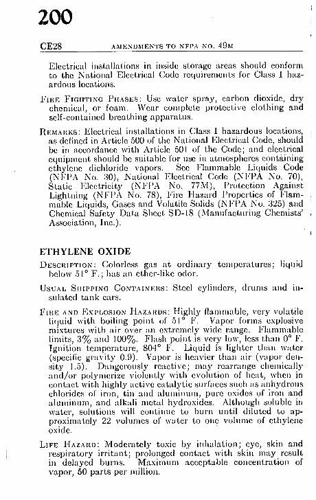
200 CE28 AMENDMENTS TO NFPA NO. 49M
Electrical installations in inside storage areas should conform to the National Electrical Code requirements for Class I haz- ardous locations.
FIRE FIGHTING PIIASES: Usc w a t e r spray, carbon dioxide, dry chemical, or foam. Wear complete protective clothing and self-contained breathing al)paratus.
REMaI~KS: Electrical installations in Class I hazardous locations, as defined in Article 500 of the National Electrical Code, should be in accordance with Article 501 of the Code; and electrical equipment should be suitable for use in atmosl)heres cont~tining ethylene dichloride vapors. See Flammable Li(luids Code (Nl,'l)A No. 30), National Electrical Code (NI:I)A No. 70), Static Electricity (NI,'PA No. 77M), I'rotcction Against Lightning (NFI'A No. 78), l,'irc Hazard l)ropcrtics of Flam- mable Liquids, Gases and Volatile Solids (NI,'I'A No. 325) and Chemical Safety Data Sheet SD-18 (Manufacturitlg Chemists' Association, Inc.).
ETHYLENE OXIDE DESCRIPTION: Colorless gas at ordinary temperatures; liquid
below 51 ~ F.; has an ether-like odor.
USUAL SIIIPPING CONTAINI'~Ir Steel cylinders, drums and in- sulated tank cars.
FIItE AND EXPLOSION ]-IAzAI'~DS: Highly flammable, very volatile liquid with boiling point of 51 ~ F. Vapor forms explosive mixtures with :dr over :Ln extremely wide range. Flanamable limits, 3~'o and 100%. Flash point is very low, less th-m 0 ~ F. Ignition temper'tture, 804 ~ F. Liquid is lighter than water (specific gr-tvity 0.9). Vapor is heavier than air (vapor den- sity 1.5). Dangerously reactive; may re:u'range chemically �9 tnd/or polymerize violently with evolution of heat, when in contract with highly ;~ctivc cat~dytic surfaces such as anhydrous chlorides of iron, tin and -dumilmm, pure oxides of iron and �9 aluminum, and alk-tli metal hydroxides. Although soluble in water, solutions will continue to burn until diluted to ap- proximately 22 vohunes of water to one volume of ethylene oxide.
LIFE HAZilY.D: Moderately toxic by inhalation; eye, skin and respiratory irrit~mt; prolonged contact with skin may result in delayed burns. Maximum acceptable concentration of vapor, 50 parts per million.

COMMITTEE ON CIIEMICALS AND EXPLOSIVES
201l CE29
STOI~,AGE: Protect against physical damage. Should be kept cool, below 86 ~ F. Should be stored outside, away from buildings �9 u~d other materials, in insul-~ted tanks or containers, shielded from sun-he-tt, provided with cooling facilities and protected by a properly designed water-spray system. Adequate diking and drainage should be provided in tank area to confine -rod dispose of liquid in case of tank rupture. Avoid pits and de- pressions, inside storage should be held to a minimffm and confined to a s tandard fire-resistive fl-tmna-tble liquids storage room, provided with co'ntinuous ventih~tion and free of sources of igniti~m. Do not permit chlorides, oxides, "tcids, organic bases, alkali metal hydroxides, metallic potassium or other combustible materials in storagc room.
I"IRE FIGHTING })IIASES: Shut off flow of liquid or gas. Keep con- taincrs cool with water spray. Do not extinguish unless neces- sary to effect an immediate shutoff of flow. Dry chemical or carbon dioxide can be used to extinguish cthylcuc oxide lircs.
I(I';MAI~,KS: Elcctri(~al installations in Class i hazardous locations, as defined in Art.iclc 500 of the National Electrical Code, should be in accordance with Articlc 501 of the Code; and electrical equipment should bc suitable for usc i,l atmospheres containing ethylene oxide gas. Sce Flammable Liquids Code (NI:I)A No. 30), National Elcctrical Code (NI,'I'A No. 70), Static Elec- tricity (NFI'A No. 77M), l)rotcction Against Lightni,tg (NI"I)A No. 78) and Fire Hazard I'ropcrtics of Flammable Liquids, Gases and Volatile Solids (NFPA No. 325).
FLUORINE I)I,;8CRIPTION: Pale yellow gas with pungent odor.
~'SUAL SI I IPPING CO N T A IN ERS : Special steel cylinders.
~?II{E AND EXPLOSION l'l,XZAlr Dangerously reactive gas. Re- ,~cts vigorously with m o ~ oxidiz-Lblc subst'LI,ces at room tem- )erature, frequently with ig,dtion, l Ceacts with water to form Lydrogen fluoride (see) and oxygen. Reacts with nitric acid
to form explosive gas, ttuorinc nitr-Ltc.
~,/I,'E HAZAH.D: Poisonous gas. C.Luscs severe irritation or hurns to eyes, ski,~ -rod respiratory tract . Maximum acceptable [:oncentr~Ltion, 0.1 l)arts per millio,~. Wear complete protective ~:lothing, gogglcs and self-contained breathing apparatus.
~FOI~.AGE: Protec t against physical dam:Lge. Isolate from other ~torage, especially materials with which fluorine is known to react. Keep aw~Ly from sources of heat and ignition.

202 CE30 AMENDMENTS TO NFPA NO. 49M
FIRE FIGHTING PIIASES: Although fluorine reacts with water, sometimes vigorously, to form hydrogen fluoride, use wat(,~ spray to cool containers until flow can be shut off or is cos~ sumed. Wear complete protective clothing and self-cos1 tained breathing '.tpparatus.
METHYL ACETATE DESCRIPTION: Colorless fl-umnablc liquid with fragrant odor.
USUAL SIIIPPING CONTAINERS: G lass bottles, steel cylinders, mcta'l drums, tank cars and tank trucks.
FIRE AND EXPLOSION HAZARDS: Highly flammable volatile liqui(I Vapor forms explosive mixturcs with -~ir. Flammable limiW 3.l~o and 16%. Flash point is low, 14 ~ F. Ignition tempe! attire, 935 ~ F. Liquid is lighter than water (specific gravit) 0.9)�9 Vapor is heavier than air (vapor density 2.8).
LIFE HAZARD: Eye, skin and respiratory irritant. Has anesthcti' effect in high concentrations. Maximum acceptable coa: centration, 200 parts per million.
STORAGE: Protect against physical damage. Outside or detachC storage is preferable. Inside storage should be in ~ standatl, fire-resistive flammable liquids storage room, provided wil ~ adequate ventilation and free of sources of ignition. Do n('~ store with oxidizing or combustible m-tterials.
FIRE FIGHTING PHASES: Use water spray, "alcohol" foam, dl~' chemicM or carbon dioxide. Wear respiratory protection.
REMARKS: Only Class I, Group D electrical equipment permitt~ in atmospheres containing methyl acetate vapors. See Flair. mable Liquids Code. (NFPA No. 30), National Electrff Code (NFPA No. 70), Static Electricity (NFPA No. 77M Protection Against Lightning (NFPA No. 78), and l",:. Hazard Properties of Flammable Liquids, Gases and Volal!i Solids (NFPA No. 325).
METHYL AMINES (Mono-, di-, and trimethylamine) DI~SCRIPTION: Flammable gases at 9rdinary temperatures wif'
fish-like odor in low concentrations and ammonia-like odor~ high concentrations. May be in water solutions (25%~ 40%) all of which are classed as flammable liquids.
USUAL SHIPPING CONTAINERS : .For gases: Steel cylinders, tll.r cars and tank trucks.
Foa SOLUTIONS: Steel drums, tank cars and tank trucks.

203 COMMII~rEE ON CIIEMICALS AND EXPLOSIVES CE3I
i?1111,; AND EXPLOSION ]-IAZARDS: Methylamine g a s e s a r e flam- mable. Flanun-tble limits: mononaethylamine, 4.9% and 20.7%; dimethylanfine, 2.8~0 and 14.4~0; trimethylamine, 2.0% arid 11.6%. Ignition temperatures: monomethylamine, 806 ~ F.; dimethylamine, 755 ~ F. and trimethylamine, 374 ~ F. All are heavier than air (vapor densities: mono-, 1.1; di-, 1.6; tri-, 2.0). Liquid solutions a,'e flammable; flash points vary f,'om 4 ~ F. to less than 80 ~ F. Contact with mercury can pro- duce an explosive reaction.
I,II,'E l-liZARD" Eye, skin and respiratory irritant. Direct or pro- longed contact can cause burns and serious injury. Wear protective clothing, goggles and respiratory protection.
:';roaaos: Protect against physical damage. Outside or detached storage is prefer-~ble. Inside storage should be in a standard lire-resistive flammable liquids storage room, provided with ,tdequate ventilation and free of sources of ignition and excess he:~t. Insure against accidental contact with mercury.
|?IRE FIGHTING PHASES: Stop flow of gas. Use water to keep con- tainers cool. Do not extinguish unless necessary to effect an immediate shutoff of flow. D,'y chemical or carbon dioxide can be used to extinguish methyl amine fires. Water spray, carbon dioxide, dry chemical and "alcohol" foam can be used on fires involving water solutions of the methyl anaines.
01*':,~tARKS: Electrical installations in Class I hazardous locations, as defined in Article 500 of the National Electrical Code, should be in accordance with Article 501 of the Code; arid electrical equipment should be suitable for use in atmospheres containing methyl amine gas. See Flammable Liquids Code (N I,'PA No. 30), National Electrical Code (NFPA No. 70), Static Electricity (NFPA No. 77M), Protection Against Lightning (NFPA No. 78), Fire Hazard P,'opertics of Flammable Liquids, Gases and Volatile Solids (NFPA No. 325) and Chemical Safety Data Sheet SD-57 (Manufacturing Chemists' Association, Inc.).
fOLUENE
[Ih:SCRIPTION: Colorless flammable liquid with aromatic ben- zene-like odor.
II 'illJAh SHIPPING C O N T A I N E R S : (:;lass bottles, cans, drums, tank ,!ars and tank trucks.
li iltI,~ AND EXPLOSION HAZARDS: Flammable liquid. Vapors form e• mixtures with air. Flammable limits, 1.2~o and 7.1~o. Flash point, 40 ~ F. Ignition temperature, 997 ~ F.

204 CE32 AMENDMENTS TO NFPA NO. 49M
Liquid is slightly lighter thazl water (specific gravity, 0.9). V:tpor is thrcc times hcavicr titan air (vapor density, 3.1) arid may travel considerable distance to a source of ignition and flash back.
LIFE HAZARD: Eye and respiratory irritant. Extreme inhalation of vapors m.'~y cause dc-Lth by paralysis of the respiratory center. Maximum :Lcvcpt'd:de concentration, 200 parts per million.
STORAGE: Protect ag~finst physical damage. Outside or detached storage is prcfer'fl)le, lnside storage should be in as tandard fire-resistive flamnlable liquids storage room, provided with adequate ventilation and free of source./of ignition.
FIRE FIGHTING PHASES: Use water spray, carbon dioxide, dry chemical or foam. Wear self-contained breathing apparatus.
REMA liES: Only Class I, Group D electrical equipment permitted in atmospheres containing toluene vapors. See l~lanamabl0 Liquids Code (NFPA No. 30), N.ttion.fl Electrical Code (NFPA No. 70), Static Electricity (NFPA No. 77M), Pro- tcction Against Lightning (NFPA No. 78), Fire Hazard Prop. erties of Flamnmble Liquids, Gases arrd Volatile Solids (NFPA No. 325) and Chemical Safety Data Sheet SD-63 (Manu- facturing Chemists' Association, Inc.).
VINYL C H L O R I D E
DESCRIPTION: Colorless, sweet smelling, flamm-tble gas at or- din-~ry temperatures; liquid below 7 ~ F.
USUAL SH1PPINO CONTAINERS: Presstire cylinders and tank cars. FInE AND EXPLOSION HAZAltDS: Flammable gas at ordinary
temperatures; liquid below 7 ~ F. Forms explosive mixtures with air. Flammable limits, 4% and 22%. Ignition temper- ature, 882 ~ F. Gas is heavier than air (vapor density, 2.2). Liquid is slightly lighter than water (specific gravity, 0.9). Polymerizes, accompanied by evolution of heat, in presence of air, oxygen, sunlight or heat; usually inhibited with phenol.
LIFE HAZARD: Acts as a general anesthetic and may be fatal in high concentrations. Skin irritant and prolonged contact results in freezing due t o r a p i d evaporation. Maximum ac- ceptable concentration, 500 parts per million. Fires involving this material result in production of highly toxic combustion products such as hydrogen chloride, phosgene and carbon monoxide.

COMMI'VrEE ON CIIEMICALS AND EXPLOSIVES
205 CE33
.~TOItAGE: Protect against physical damage. Outside oz" detached storage is preferable. /qside storage should be in a standard llre-resistive flammable liquids storage room, provided with adequate ventilation and free of sources of ;gait;on and heat.
I,'Jm.: I"IGHTIN(~ PHASI~S: Stop flow of gas. U~c wirer to kcep con- tainers cool. Do not extinguish unless ncccssary to etTeet an immediate shutoff of flow. Dry chemical and carbon dioxide can be uscd to extinguish vinyl chloride fires.
R t;:MARKS: Electrical installations ia Class I hazardous locations, as defined in Article 500 of the National Electrical Code, should be in accordance with Article 50I of the Code; and electrical equipment should be suitable for use in atmospheres containing vinyl chloride gas. Sce Hammable Liquids Code (NFPA No. 30), National Elcctrical Code (NI,'PA .No. 70), Static Elec- tricity (NFPA No. 77M), I'rotection Against Lightning (NFPA No. 78), Firc Hazard Propcrtics of l"lammabie Liquids, Gases and Volatile Solids (NFI'A No. :325) a,ld Chemical Safety Data Sheet SD-5(i (Manufacturing Chemists' Association, Inc.).
ACETIC ACID ANHYDRIDE ACETIC ACID METHYL ESTER ACETIC ETHER ACETYL OXIDE ACRYLIC ALDEHYDE ALI~EHYDE ALLYL ALDEHYDE
BENZOL BIETHYLENE
{:;HLOROErI'HANE CHLOROETHENE CHLOROETHYLENE
I)IACETYL PEROXIDE DICHLORO ETHANE DIMETHYLAMINE DIMETHYLENE OXIDE DI VINYL
See ACETIC ANIIYDRIDE
See METIIYL ACETATE
See ETIIY1, ACETATE
See ACETIC ANIIYDRIDE
See ACROI,EIN
See ACETA LDEll YDE
See ACROLEIN
See BENZENE
See BUTADIENE
See ETIIYL CIILORIDE
See VINYL CIiLORIDE
See VI'NYL CIILOR1DE
See ACETYL PEROXIDE
See ETIIYLENE DICHLORIDE
Scc METIIYL AMINES
See ETIIYLENE OXIDE
See BUTADIENE
ETHANAL See ACETALDEHYDE

206 CE34 AMENDMENTS TO NFPA NO. 49M
E T H A N O I C A N H Y D R I D E E P O X Y E T H A N E E T H Y L E N E ALDEHYDE E T H Y L E N E C H L O R I D E
M E T H Y L ACETIC ESTER. M E T H Y L BENZENE M O N O M E T H Y L A M 1 N E
O X I R A N E
PROPENAL P ROPE NE N I T R I L E
T OL UOL T R I M E T H Y L A M I N E
S e e ACETIC ANIIYDRIDE
See ETHYLENE OXIDE
See ACROLEIN See ETHYLENE DICHLORIDI~
S e e METItYL ACETATE
S e e TOLUENE
S e e METHYL AMINES
S e e ETIIYLENE OXIDE
See ACROLEIN See ACRYLONITRILE
S e e TOLUENE
See METltYL AMINES
VINYL CYANIDE See ACIIYLONITRILE

207 COMMITTEE ON CUTTING AND WELDING PRACTICES CWI
Report of Commit tee on Cutt ing and Welding Practices
F. C. S a a c k e , Chairman, Air Reduct ion Co., Inc., 150 E. 42nd St., New York 17, N. "f.
L. G . M a t t h e w s , Secretary, In terna t ional Acetylene Assn., 270 Park Ave. , New York 17, N. Y.
(' C. Axtel l , Nat ional Welding Supply Assn. ~l~'tlcenr B a m f o r d , Liber ty Mutua l Fire ln-
�9 Co. (Personal.) t ~4,mar E. Ber l~ lund , Ford Motor Co.
r i 'ersonal.) r A. C o n r e y , Nat ional Association of
�9 Mutual Ins. Cos. r A. F e n t o n , Amer ican Welding
~hJciety. ~'~dan G . F o r d , Amer ican Petrolctun Inst i -
Care. t~r J. I l a r t n e t t , New York Fire l )ept .
| 'cmonal.) ~' 0~, J o h n s o n , Fac tory Mutua l Engineer ing
Division. r E. M a l o n e y , Mechanical Con-
qfflctors Association of A nler ica , I no,
E. A. O l s e n , Compressed Gas Associat ion.
] l . E m e r s o n T h o m a s , Liquefied Pet ro leum (:~a8 Associat ion, lnc .
W. II . V a n A r n u m , Nat ional [{oard of Fire Underwri ters .
G. N. W a d e , Fac to ry Insurance Associat ion.
A l t e r n a t e s .
C. R. I ) i e t r l c k , Liquefied I 'e t ro lcum Gas Associat ion. (Al ternate to II . IBmerson Thomas . )
J . F. M c K e n n a , Anmrican Pet ro leum hmti - tutc . (Alternate to Adrian (;. ]:ord.)
T . B a r r e t t Oulnn, National Wehling Supply Associat ion. (Alternate to A. C. Axtcll.)
This report has been submitted to ballot of the Committee which nsists of 15 members of whom 13 have voted a~rmatively, one
, Tatively; Mr. Hartnelt has not voted.
Ill 1958, the NF P A Board of Directors attthorizcd the creation the Commit tee oil Cut t ing and Welding Practices ill an effort
, provide guidance ill safe practices ill the usage of cutt ing and eh l i ng equipment. One of the first objectives of this new com-
,,ttee was "~ccomplished ill tile issuance of the educational folder qparks Ast ray ." The following good practice rc(;onanmndations
'w e been developed as a s tandard to guide all persons when cut- ~lg and welding equipment is used. Tiffs material was tenta- ~ely adopted at the 1960 Annual meeting. Since that time the /[!lnmendations have bccn circulated for comlneut. The fol- ,,ring is tile revised text for final adoption.

208 51B-2 C U T T I N G AND W E L D I N G P R O C E S S E S
Standard for Fire Prevention in
USE OF CUTTING, AND WELDING PROCESSES
N F P A N o . 5 1 B - - 1962
Foreword Cutting and welding processcs using electric arcs or oxy-fu(
gas flames are a necess,'~ry part of our industrial world. Too of tea however, the persons who use, hire, or supervise the use of the.~ processes do z~()t, fully appreciate tha t their improper use ca,J result in loss of life and property by fire and explosion.
Approximately 6 per' cent of fires in industrial properties hat,( been caused by cutt ing and welding, primarily with portabl~ equipment in areas not specifically designed or approved for" sucl work. Cuttirrg arrcl welding operations produce literally thou, sands of ignition sources in the form of sparks and hot slag. Th~ ele(ztric arc or the oxy-fucl gas flame and the hot work pieces ar~ also inherent ignition sources.
A majori ty of industrial fires ira which cutt ing and welding i~ a factor have been caused by sparks. These globules 6f moltel) metal have scatt,ered :ts far "ts 35 feet, setting fire to-all kinds 0J corn!;ustible materials. They have also fallen through cracks pipe h01cs or other small opcrfings in floors and partitio~rs startin~ fires which have reached serious proportions before being noticed
Electric arcs or oxy-fuel gas flames, in themselves, have rareb caused fire except where they have overheated combustibles i,~ the vicinity of the work or where they have been used on con. taiuers tha t had not been purged of flammable materials. In the lat ter case, an explosion generally resulted.
The heat of the metal being welded oz" (;ut has caused fire~ where the hot pieces were permit ted to rest or fall upon com. bustible materials. Fires and explosions have also been caused where this heat was transmit ted, as ira the case of a container, through thc metal to a flammable atmosphere or to combustibles within the container.
Anything which is combustible or flammablc is susceptible to ignition by the cutt ing and welding. The most common materials

209 R E S P O N S I B I L I T Y FOR CUTTING AND W E L D I N G 51B-3
~ikcly to become involved in fire are combustible building con- ,:it'uction such as floors, partit ions, and roofs; combustible con- ~4mts such as wood, paper, textiles, chemicals, and flammable liquids and gases; and combustible ground cover such as grass (rod brush.
I ' , 'cventing cutting and welding fires can best be achieved by q,parating tile combustibles f,'om ignition sources or by shielding
the combustibles.
I. Purpose . This stand'ard has been prepared for the guidance ,,f cutters aud welders, their supervisors (including outside con- I r a c t o r s ) , and those in management on whose proper ty cutt ing and welding is to bc performed.
5~. Scope . This stal~clard covers recommendatiol~s for the safe ttsc of gas and arc (-utting and weldi,~g equipnaent to prevent loss of life and prol)erty from fire.
NOTE: Det, fils on lnst.tllation and Operation of (~;~m Systems for Weld- ing and Cuttin~ are covered in NFPA Standard No. 51.* l)etails on installation aml olJer:Ltion of arc cuttiug ll, l ld welding equil)nlent ~tre cov- ered ia American Standard Safety in Welding and Cutt{ng (ASA-Z,19.1). *
3. Respons ib i l i ty for C u t t i n g and Welding . Although tile cutter or welder has the best oppor tun i ty to avoid fire or i . j u ry hy proper (-ord, rol of tile hot work equipment he is using, there Itre many (-ircunlstances where fires, explosions, or severe i , jur ies would be itmvitable if the oxy-fuel gas torch or the electrode were to be used. Such cirrumstan(-es ca~ arise where the (:utter or welder may 1lot, be ~Lw~Lre of (I) the proximity or the fl:unmable mLture of nearby combustible solids, liquids, or dusts; (2) the presence or developme~fl, of possibly explosive mixtures of flam- mable g~Lses a~ld air; or (3) the prese ,ce or m~ture of high oxygell c(mcentratiolIs ill t,he loc:~tioll where hot work is to be performed. The precautions tal(ell by a critter oli welder will often be gov- erned by the desire of others for speed or e c o . o m y in his work or by the failure of mallagemerlt to emphasize the possible ex- tent or seriousness of a fire i~l the work -trea. Therefore, all three, the cut ter or welder, his supervisor, aml managetnetd, share full responsibility for the safe use of ruttil~g or Welding equil)ment. The following paragraphs outliue the specific responsibilities of each.
*No. 51 is awtihd~le from National Fire Protevtion Associ~d,ion, 60 Battery- march St., Boston 10, Mass. ASA-Z.19.1 availal~le from American Welding Society, 345 E. ,17th St., New York 17, N. Y.

210 51B-4 CUTTING AND WELDING PROCESSES
31. M a n a g e m e n t shall recognize its responsibility for the saf~ usage of cutting and welding equipment on its property and:
311. Based on fire potentials of phmt facilities, establish ap. proved areas for cutting and welding, and establish procedure8 for approving cutting and welding in other areas.
312. Desigmtte an individual responsible for authorizing cut- ting and welding operations in areas not specifically designed or approved for such processes.
NOTE: [-[e may be ~t welding supervisor, foreman, contr'mtor, persoa responsible for fire protection, or other qualified individual aware of th0 fire hazards involved.
313. Insist tha t cutters or welders and their supervisors are suitably trained in the safe operation of their equipment and the safe use of the process.
314. Select contractors to perform hot work involving cutting or welding who have suitably trained personnel and who have an awareness of l~he magnitude of the risks inv.olved.
315. Advise.all contractors about flammable materials or haz- ardous conditions of which they may not be aware.
32. The S u p e r v i s o r of cutt ing or welding operations in areas not designed or approved for such processes may bc a foreman ia a large plant or a plant manager or owner in a small one.
321. He shall be responsible for the safe handling of the cut. ring or welding equipment and the safe use of the cutting or welding process.
322. He shall determine the combustible materials and haz. ardous areas present or likely to be present in the work location,
323. He shall protect combustibles from ignition by the fob lowing:
3231. Have the work moved to a location free from danger. ous combustibles.
3232. If the work cannot be moved, have the combustibles moved to a safe distance from the work or have the combustible~ properly shielded against ignition.
3233. See that cutting and welding arc so scheduled that plant operations tha t might expose combustibles to ignition arc not started during cutt ing or welding, i

F I R E P R E V E N T I O N P R E C A U T I O N S
211 51B-5
32,1. He shall determine tha t the cut ter or welder secures his t.~,proval that conditions are safe before going ahead.
325. He shall determine tha t fire protect ion and extinguishing ~ulpment are properly located at the site.
326. Where fire watchers arc required (see 43), he shall see ",!~t they are available at the site.
~i, The C u t t e r o r W e l d e r shall handle his equipment safely and ~ it so as not to endanger lives and property .
il31. He shall have approval by his supervisor before he s tar ts *rut or weld.
:132. He shall not cut or weld where conditions are not safe.
333. He shall continue to cut or weld only so long as condi- ' fibs are unchanged from those under which approval was
, ,anted.
Fire P r e v e n t i o n P r e c a u t i o n s . Cutti,~g or welding shall ~ permitted only in areas tha t are or have been made fire safe.
,~Qlhin the confines of an operat ing plant or building, cut t ing r ~1 welding should preferably be done ill a specific area designed
, ~tpl)roved for such work, such as a maintenance shop or a ~ached outside location. Such areas shall bc of noncombus- "~o or fire-resistive construction, essentially free of combustible ,I flammable contents, and sui tably segregated from adjacent as. When work cannot bc moved practically, as in most con-
r, nc, tion work, thc arca shall bc made lirc safe by removing :l;bustiblcs or protect ing combustibles from ignition sources.
Jt, Cutt ing or welding shall not be permit ted ill the following !,~lations :
I I I. In areas not authorized by management .
12. Ill sprinklcred buildings while such protection is impaired.
tl:l. Ill the presence of explosive a tmospheres (mixtures of ~ , m a b l e gases, vapors, liquids, or dusts with air), or explosive ,a~sphcrcs that may develop inside uncleaned or improperly
pared tanks or equipment which have previously contained h materials, or tha t may develop in areas with an accumula- ~ of combustible dusts. (See N F P A No. 327, Cleaning or
~t,guarding Small Tanks and Containers.)*

212 51B-0 C U T T I N G AND W E L D I N G P R O C E S S E S
414. In areas near the storage of large quantities of cxp(r readily ignitible materials such as bulk sulfur, baled pal)('! cotton.
42. Beforc cutt ing or welding is permitted, the area shall inspected hy the individual responsil)le for authorizing cul~ and welding operations. He shall designate precautions t . followed in granting atithorization to proceed, preferably ill( form of a writtcn permit. (A suggested form of written pelqll, shown in the Appendix. I t may be modified to suit local c~: tions.) fie shall sign the permit or otherwise authorize the ~ and shall assure himself of the following:
421. Where eomhustible materials such as paper clippi, wood shavings or textile fibers are on the floor, the floor shtd swept clean for a radius of 35 feet. Combustible floors slull kept wet, covered with damp sand, or protected by fire-rcsii,~ shields. Where floors have been wet down, personnel opertr arc welding or cutt ing equipment shall be protected from pc'." shock.
422. Where practicable, all combustibles shall be relo(': at least 35 feet from the work site. Where relocation is iml, ticable, combustibles shall be protected with flame-proofed l ers or otherwise shi.elded with metal or asbestos guards or+ tains. Edges of covers at the floor should be tight to pr(~ sparks from going under them. This precaution is also impo,~ al, overlaps where several covers are used to protect a larg0 L
423. Wall or floor openings or cracks within 35 fect of tht shall be t i gh t l y covered to prevent the passage of sparks I,#, jacent areas.
424. Ducts and conveyor systems tha t might carry spll i l distant combustibles shall be suitably protected or shut dot~
425. Where cutt ing or weldit~g is done near walls, parlll ceiling or roof of combustible construction, fire-resistant sl or guards shall be provided to prevent ignition.
426. If welding is to be done on a metal wall, partition, cl or roof, precautions shall be taken to prevent ignition off bustibles on the other side, due to conduction or radiation, I erably by relocating combustibles. Where combustibles ae~ relocated, a fire watch oil the opposite side from the worli ~ be provided.

F I I t E P R E V E N T I O N P R E C A U T I O N S
213 51B-7
W(.,Iding shall not be attemptecl on ~.t metal p~rtition, r or roof h~Lvi,lg a combustible covering nor on walls ,~,ti~ms of combustible sandwich-type-panel construction.
, (hi t t ing or welding on pipes or other metal in contact ,,mbustiblc walls, partitions, ceilings or roofs shall nof~ be
~:dw.n if the work is close enough to cause ignition by :. llon.
t I 'ortable fire extinguishers, appropriate for the type of n4, fire, shall be concentrated at the work area. Where hose ~,q, available, they shall be connected and ready for service.
Ice W a t c h e r s shall be required by the individual respon- II,,r authorizing cutt ing and welding whenever cutt ing or .~ is performed in locations whcre other than a minor fire develop, or any of Om following conditions exist:
~l~preciable combustible material in building construction ,," contents closer than 35 feet to the point of operation.
Al~preciable combustibles are more than 35 feet away but are easily ignited by sparks.
Wall or floor openings within a 35-foot radius expose com- bustible mate'rial in adjacent areas including concealed ~,lmCCS in walls or floors.
I 'umbustible materials are adjacent to thc opposite side ,d ,,mt~d partitions, walls, ceilings, or roofs and are likely Io be ignited by conduction or radiation.
I"h'c watchers shall have fire extinguishing cquipment ,, available and he trained in its use.
I"ire watchers shall be familiar with facilities for sounding ,'~m in the event of a fire.
I,'irc watchers shall watch for fires in all exposed areas, ,,, I o extinguish them first only when obviously within the ~ of the equipment available, or otherwise sound the
A fire watch shall be maintained for at least a half hour ,repletion of cutt ing or welding operations to detect and ):'~h possible smoldering fires.
~ tapping" or other cutt ing or welding o,l a flammable O~quid transmission or distribution util i ty pipe line, safe
: le~,n should be established.

214 5 1 B - 8 CUTTING AND WELDING PROCESSES
A P P E N D I X
A S u g g e s t e d F o r m of W r i t t e n C u t t i n g a n d W e l d i n g P e r m i t ( M a y b e m o d i f i e d . t o s u i t l oca l c o n d i t i o n s )
PERM IT
FOR C U T T I N G AND W E L D I N G W I T H POltTABLI~ GAS OR ARC E Q U I P M E N T
Date ....................................................................................................................
Building ..............................................................................................................
Dept ................................................................. Floor ........................................
Work to be done ................................................................................................
Special Precautions ..........................................................................................
Is fire watch required? ......................................................................................
Tile location where this work is to be done has been examined, necessary prec'mtious taken,* and permission is granted for this work.
Permit expires ....................................................................................................
Signed .............................................................................. (Individual responsible for
authorizing welding and cutt ing)
Time star ted .............................................. Completed ....................................
FINAL C H E C K - U P (Where fire watch is required)
Work area and all adjacent areas to which sparks and heat might have spread (including floors above and below and on opposite sides of walls) were inspected for a t least 30 minutes af ter the work was completed and were found fire safe.
Signed ................................................................................ (Fire watcher)
*The back of this permi t may be used to list precautions applicable to l, specific industry or p lant involved.

215 REI:'ORT OF C O M M I T T E E ON DUST EXPLOSION HAZARDS D E - I
Roport of Committee on Dust, Explosion Hazards. C. G. Gibson, Chairman,
Ontario De)a r tmen t of Labour, 8 York St., Toronto 1, Ont. Canada. (rep. Canadian Assn. of Adm u strators of Labour Leg s at on)
~:r W. Andrews, Jr., American Society of ~:lrchauical Engineers.
I '~ Marion Barnes, The Sulphur lu- 4klllUle.
M, Blaesi, N F P A Committee on |}l,wer Systems.
[ s~0~,~ M. Clark, Grain Elevator and V*ocessing Superintendents.
[(~ P, Congdon, Factory Insurance Assn. r W, Cousins, Factory Mutual Engineer-
trill Division. ll I t. Crass, Jr., Manufacturing Chemists'
~ ~n. , ]nc. L ~bcrt F. Dilly, National Board of Fire
|hulerwriters. 0, IL Dufour, Underwri ters ' Laboratories,
hie. Cfcd G. Ely, The American Boiler and
AIIIliated Industries. ~' W. Gordon, Combustion Engineering,
Inc. (Personal) . William G. Grill~n, U. S. Department of
I,abor. li)0telllas L. Hail, Millers' National Feder-
1||1OII. '~6rren Hallen, \Vest Coast Lumbermen 's
AlSSn, .0 I!. Hanson, American Foundrymen's
Assn. q~ E. Harbin, Underwriters Grain Assn. 0 F. Henderson, National Electrical
Mlulufacturers Assu. 01qr Isenberg, Manufacturing Chemisfs
Assn., Inc.
H. C. Lee, Assn. of Mill & Elevator Mutual Ins. Cos.
William C. Lund, Society of the Plastics Industry.
Dr, Edward G. Melter, American In- dustrial Hygiene Assn.
John Nagy, U. S. Bureau of Mines. Don O. Noel, Metal Powder Producers
Assn. of the Metal l 'owder Industries Federation.
Thomas A. Oravecz, International Assn. of Governmental Labor Olllcials.
J. A. Peloubet, The Maguesium Assn. J. M. Robinson, Assn. of Casualty &
Surety Cos. W. H. Russell, Assn. of Casualty &
Surety Cos. Arthur C. Schrier, National Confectioners'
l~.ssn.
Lincoln D. Scott, Corn industries Re- search Foundation.
E. J. Sestak, Factory Insurance Assn. T. T. Singer, Western Actuarial Bureau. Lester C. Smith, The Spencer Turbine
Co. (Personal) . Pete Stallcop, Grain & Feed De:ders Na.
tional Assn., Terminal Elevator Grain Merchauts Assn.
George H. Steel, American Society of Saiety Engineers.
Paul J. Turner, Great Northern Railway. (Persooal) .
H. L. Walker, Edison Electric Institute.
Alternates.
| , H. Gretzer (Alternate to George H. Steel).
10hn F. Hennessey, National Confec- liuHers' Assn. (Alternate to Arthur C. Schrier).
flheldon W. Homan, U. S. Dept. of I,abor. (Alternate to Win. G. Griffht).
|, M. Jensen, Corn Industries Research Foundation. (Alternate to Lincoln D. Scott).
Frank Jun, Millers' National Federation. (Alternate to Douglas L. Hail).
G. Koth, Factory Mutual F.ngineering Division. (Alternate to E, W. Cousins).
J. P. Markey, Edison Electric Institute. (Alternate to H. L. Walker) .
A. J. Stabb, Underwriters ' Laboratories, Inc. (Alternate to R. E. Dufour).
G. D. Perkins, Assn. of Mill & Elevator Mutual Ins. Cos. (Alternate to H. C. Lee).
The report of the Committee on Dust Explosion Hazards is divided into three parts. Parts I and II are the work of the Sec- qlonal Committee on Grain and Food Processing Dusts. Part I l l t,~ the work of the Sectional Committee on Wood and Solid Fuel I)usts.

2t6 DE-2 R E V I S I O N S TO N F P A NO. 61A
Part 1 contains proposed revisions of the Standard for tli" Prevention of Dust Explosions in Starch Factories, N F P A N~ 61A.
Part I I contMns proposed revisions of the Code for the Pl'~" vention of Dust ExPlosions in Flour and Feed Mills, and Alli~,' Grain Storage Flevators, N F P A No. 61C.
Part 111 contains proposed revisions of the Code for the Pl'~ vention of Dust Fxplosions in \,Voodworking and \u Flora Manufacturing F'lants, N FPA No. 664.
The following sectional COlnmittces arc responsible for tll~ revisions being submitted.
S E C T I O N A L C O M M I T T E E O N G R A I N A N D P 0 0 D P R O C E S S I N G D U S T O Thomas T . .S inge r , Chairman,
Dean M. Clark J . M . Jensen Edward G. Melter E. W. Cousins (ahernate to J . M . R o b i n s o n Robert F. Dilly Lincoln D. Scott) Arthur C, Schrier R. E. Dufour Frank Jun Lincoln De Scot t L. H. Gretzer (ahernate to E . J . Sestak
(ahertt;tte t . Douglas L, Hail) A . J . Stabb George II. Slec[) G. Koth (ahernate to
Douzlas L. Hail (al ternate to R . E . Dufour) C. E , Harbin E . W . Cousins) Pete Stallcop John F. Hennessey H . C . Lee George H. Steel
(alternate to G . D . Perkins Paul J. Turner Arthur C. Schrler) (ahernate to
H. C. Lee)
S E C T I O N A L C O M M I T T E E O N W O O D A N D S O L I D F U E L D U S T S . Fred G. Ely, Chairman,
C. M. BIaesi S. Fe Henderson W . H . Russell C. W. Gordon J. Po Markey Lester C. Smith Warren Hallen (ahernate to H . L . Walker S. B. Hansen H . L . Walker)
P A R T I
Proposed Rev i s ions of Standard for the
P R E V E N T I O N O F D U S T E X P L O S I O N S
I N S T A R C H F A C T O R I E S
NFPA No. 51A--1959
This part of the report has been submitted to ballot of tile Committee on Dust Explosion Hazards which consists of 37 mere bers, 31 of whom have voted affirmatively. Mr. Nagy voted negatively, Mr. Walker and Mr. Meiter are recorded as "'nor voting", and Messrs. Hansen, Schrier, and Stallcop have not re turned ballots.

217 IIF, I'ORT OF COMMITTEE ON DUST EXPLOSION I'IAZAI,H.)S D E - 3
I:he fol lowing proposed amendments of N F P A No. 61A, h r d for the P reven t ion of Dust Exp los ions in Starch lZac -
. , ~. were p r e p a r e d by the Secti .onal C o m m i t t e e oH Gr:til~ ;tt~d i I ' roccss ing Dusts and then submit ted for review and ballot
I,~, C onmaittee on Dust Exp los ion Hazards .
Revise Sect ion 211 to read: BI1. Bui ldings shall be of f i re-resis t ive or noncombust ible
,l, t,ction.
Delete third sentence o f Sect ion 422, the rcT'ised section to
422. The cleaning of sur faces shall be by vacuum sweeping tl'atus, if it can be feasibly applied. I f vacuum or portablc
msm appara tus is used, the hoses shall be p roper ly grounded ~ regular ly checked fox electrical cont inui ty f rom pick-up nozzle
, pqHng system. I f vacuum apl)aratus is not ugcd, sur faces shall cleaned by soft brushes, wipers , or mops of loose fabric.
Revise last sc~ttence o f No tc at end of Section 422, revised ~te to read:
No'rt.:: Unenclosed motors in use in some starch factories gather dust , |he windings which can be blown out with compressed air with reason- ":' pressure. Such cleaning operations create a possible dust explosion
irtl and motors should not be blown while rutming or while the plant m operation. Electric blowers and other portable electric equlpmellt shall florin with the requirements of Sectio,1 513.
'~ ' Delete Sect ions 423 and 425 and remtmber present Section, 424 be Section. 423.
' / Imend Section 513 to read: 513. Electr ical equipment shall be installed according to the
,} tu la t ions of the Nat ional Electr ical Code. In locations containing mdJust ible dusts the regula t ions of Ar t ic les 500 and 502 shall ~qlly.
, / ldd a new Sect ion 515 to read: 515. Internal combust ion engines should not be used in loca-
r xms conta in ing combust ible dusts.
Add n e w / l r t i c l e 54 to read:
~4, Welding and Cutting. 541. W e l d i n g and cut t ing opera t ions arc potent ial ly one of
'he most hazardous opera t ions that may be conducted in starch '.i.tctories. This is par t i cu la r ly truc because of the combustil)lc dust ,lid o ther re fuse which might be found in the immediate vicinity
,~ hc,'e welding or cut t ing is carr ied out.

218 DE-4 REVISIONS TO NFPA NO. 61A
542. Written permission must be given by the manager q~ superintendent, or other recognized officer, before each wcldh~ oi cutting job is undertaken.
543. All machinery and dust producing operations fr0 which dust may reach the area or within range of welding spar| must be shut down prior to the start of the welding or cutting jq" and remain inoperative until the job has been completed and fil~ inspection is made.
5t4. Sweep clean and wet down floors and surrounding including time floor immediately below, before welding and cutfiL job is commenced.
545. All floors or wall openings within 35 feet must tightly sealed to prevent passage of sparks and all combustil. material which cannot be removed from the area nmst be proteel~ by suitable flameproof covers or guards.
546. Assign a responsible man equipped with adequ;. portable extinguishers in the area and in time floor above and bek, when there is a possibility of sparks reaching these areas.
547. If a major welding or cutting job is to be undertak~ and the plant cannot be shut down, special requirements will l' outlined by the authority having jurisdiction.
548. [NSI'ECTION ON COMPLETION OF JOB. Flying spare from welding arc frequently thrown or fall into places where I' material smoldcrs for hours before bursting into flame. A card inspection of all areas near the welding scene, including the fl(M above and below, should be made when the job is finished, i' such areas should be patrolled for a period long enough to m: certain that no smoldering fires have developed.
8. .ddd a ~tczo Art icle 55 to read:
55. Powder-Operated Tools. 551. Gun-type tools using powder or cartridges for drip,
pegs or pins into concrete, brick, steel, etc., shall not be used wlv flammable dust or dust clouds are present. When the use of I' type of equipment becomes necessary all dust producing machit~' in the area shall be shut down, all equipment, floors and walls ~! be carefully cleaned, and all dust accumulations rcmoved. A car~' check shall be made to be sure that no cartridges or chargeS. left on the premises where they could crater equipment or be t cidentally discharged after operation of the dust producinl~ handling machinery is resumed.

219 REPORT OF C O M M I T T E E ON DUST E X P L O S I O N HAZARDS DE-5
P A R T I I , Proposed Revisions of ~Code for the
P R E V E N T I O N OF D U S T E X P L O S I O N S IN F L O U R A N D F E E D MILLS A N D
A L L I E D GRAIN STORAGE E L E V A T O R S NFPA No. 61C--1959
"/'his part of the report has been submitted to ballot of the ~mittee on Dust Explosion Hazards which consists of 37 mem-
o. 29 of whom have voted affirmatively. Messrs. Nagy and ~h voted negatively, Messrs. Crass, Melter and Walker are cdcd as "not voting", and Messrs. Hansen, Schrier, and Stall- b,~lvc not returned ballots.
I'he following proposed amendments of N F P A No. 61C, ' fo." the Prevention of Dust Explosions in Flour and Feed ~. were prepared by the Sectional Committee on Grain and
I'rocessing Dusts and then submitted for review and ballot ~":q, Committee on Dust Explosion Hazards.
|dd sentence to Section 3011, the revised section to read: !01 I. Elevator leg belts shall be enclosed in separate casings
I'~,lh up and down legs, except where running through beltway ,,rn bins. (See Article 107.) Elevator legs, heads and boots ',i be of noncombustible construction. ~dd a new Section 3015 to read: ~,1)15. Where possible, legs not equipped with dust control '1 he vented to the outside through a noncombustible vent.
!,',r Section 3042 to read: ~,~H2. Electrical equipment shall conform with the require-
,d Chapter 7. ' ',j,ise title of Article 319 to read: 3i0, Grinding and Pulverizing Equipment. ~'~4se the first sentence of Section 3191 so that the revised
,~ ~tttill read: '~P~I. In addition to the magnetic or pneumatic separators ,,~i in Article 309, attrition mills, hammer mills and other '~:,~! and pulverizing equipment shall be equipped with all-
I (l,Omld stock handling systems. When a pneumatic system ,rod stock handling is used, all spouting, air trunking, fans l!,'r shall be entirely of metal. The collector shall be
'1 a,~ the outside of the building. When the elevator system ,~ htmdling is used, all spouting, elevator legs, and other l~mls shall be of all-lnetal construction. The elevator head

220 D E - 6 REVISIONS TO N F P A NO. 61c
should be vented to the outside of the building or positive ~ aspiration should be provided.
6. Delete Article 320. Manufactured Stock Driers, and Chaplel : Grain Driers, and substitute the following:
' C H A P T E R 4. D R Y E R S .
401. Grain and Manufactured S t o c k Dryers . 4011. The construction, installation and operation of gr;
dryers and manufactured stock dryers shall conform with all~ quiremeuts of N F P A No. 93, Standard for Dehydrators w Dryers for Agricultural Products.
7. Add sen.fence to Section 6016, the revised section, to read', 6016. The develops{lent and installation of satisfacW
permanent vacuum sweeping apparatus is recommended, l f vacm~ or portable vacuum apparatus is used, the hoses shall be propel grouuded and regularly checked for electrical continuity frq, pick-up nozzle to piping system.
�9 8. Revise Section 7022 to rcad: 7022. Motors (including electric blowers and other porlal
equipment) shall conform with tile requirements of Section 70~
9. Delete the last sentence of the Note which follows Section 70, the rcv;scd Note to read:
NOTE: Uneuclosed motors in use in some mills and elevators, ga[~' dust iu the windings, which can be blown out by compressed air with rear able pressure. Such cleaning operations create a possible dust explo., hazard and motors should not be blown while running or while house i~ operation.
10. Revise Section 8102 to read: 8102. Since animal, vegetable and fish oils are combuslll
materials and may be subject to spontaneous heating under ce,'h. conditions, they should be stored and handled in a manner apprm~ by tile authority having jurisdiction.
11. Delete Article 905 and renumber Articles 906 and 907 to i 905 and 906 respectively.
.12. Delete Sections 907.1, 9072, 9073 and 9074 and substin'ae t> following:
9061. Fire protection should be provided for dryers as I, quired in N F P A No. 93, Standard for l)ehydrators and Dry~ for Agricultural Products.

221 I t E P O R T O F C O M M I T T E E O N D U S T E X P L O S I O N HAZARI)S DE-7
PART l l !
Proposed Revisions of Code for the
~,~i~VENTION OF DUST EXPLOSIONS IN WOODWORKING
AND WOOD FLOUR MANUFACTURING PLANTS
NFPA No. 664--1960
This part o / t h e report has been submitted to ballot o] the mdttee oll Dust Explosion Hazards which consists of 37 ~Jbers, of whom 31 have voted afirmatively. Messrs. Crass, ffer, and Walker are recorded as "not voting", and Messrs. ,~en, Schrier, and Stallcop have not returned ballots.
The following proposed revisions of N F P A No. 664, Code |he Prevent ion of Dust Explosions in \ ,Voodworking and ,~d Flour Manufac tur ing Plants were prepared by tile Sec- ,,d Commit tee on Wood and Solid Fuel Dusts and then sub-
~t'd for review and ballot by the Commit tee on Dus t Ex- ,ion Hazards .
R e v i s e Section 1341 to read :
1341. If the scrap wood is to be processed by hogs de- dug small chips and shredded product for use as fuel or other purposes, the material shall be t ransfer red to stor- vaults~ conforming to Article 133. This material should
~erablv he t ransferred through a closed chokefeed con- .,.w to a separate storage vault used only for this material.
Revise Section 1342 to read: IS42. If an air t ransfer system is used for the hog wood,
~ hog shall discharge through a separate fan to a separate 'eetor. Each collector shall discharge to the hog wood ~agc vault.
Revise Section 1343 to read:
1343. If the scrap wood is to be processed by mills de- ~hlg a pulverized product , the requi rements of Pa r t B - - ,,I Flour Manufac tur ing shall be ohserved.
Delete Sections 1344 and 1345. I

222 COMMITTEE ON ELECTRONIC COMPUTER SYSTEMS E(~
R e p o r t o f C o m m i t t e e on E l e c t r o n i c
C o m p u t e r S y s t e m s .
J o h n J . Ahern , Chairman, Genera l Motors Corp.. De t ro i t 2. Mleil.
Ma thew M. Bra idech , Na t iona l Board of F i re U n d e r w r i t e r s .
W. L. H a n h u r y , Fede ra l F i re Council. Donald J . K e i g h e r , U. S. Atomic
E n e r g y Commiss ion . Orr in J . Moses, F a c t o r y :Mutual
E n g r g . Division. Ha ro ld E. Nelson, Genera l Services
A dm i n i s t r a t i on . R. B. P e t e r m e i e r , R e m i n g t o n P.and
Univac. (Pe r sona l )
l l a r v e y Ross ing , A m e r i c a n Telel~l:' & T e l e g r a p h Co. (Pe r sona l )
George E. Sehall, J r . , Nat iona l F_' t r ica l Code Commit tee .
George H . Simpson, I n t e r n a l h : Bus iness Machines Corp. (J~ sonal)
A. J . Ste iner , N F P A Committeo Record Pro tec t ion .
F r a n k S t e tka , t Na t iona l Wire Pr~' t i on A s s n .
Fred J . Zeleny, F a c t o r y Insure" Assn.
A l t e rna t e . P. V. Ti lden. Ve t e r ans Admin i s t r a t i on . (A l t e rna t e to ~V. L. Han b u r )
t N o n - v o t i n g m e m b e r .
This report has been submit ted to ballot of the Co'~ mittee, which consists of 12 voting members, of whom have voted affirmatively. Mr. O. J. Moses and Mr. R. i ~ Petermeier have voted negatively.
The Committee on Electronic Computer Systems ~ formed by the action of the NFPA Board of Director~ January 1960 following a request for standardization by I computer industry. The committee's first report to the sociation was tile submission of its Tentative Standard- the Protection of Electronic Computer Systems, (No. 75? to the 1961 NFPA Annual Meeting in Detroit. The c~, mittee has found the interest in this tentative stanck most helpful in its deliberations this year, and wishes express its appreciation to those who sent in comments c constructive criticism. The report that fol lows is a cal'(' revision of the tentative standard and is submitted for fit adoption.

ELECTRONIC COMPUTER SYSTEMS
223
S t a n d a r d f o r t h e P r o t e c t i o n o f
E L E C T R O N I C C O M P U T E R S Y S T E M S
N F P A N o . 7 5 - 1 9 6 2
C O N T E N T S
.~0ction Page
F o r e w o r d . . . . . . . . . . . . . . . . . . . . . . . . . . . . . . 75-3
~00. P u r p o s e a n d S c o p e . . . . . . . . . . . . . . . . . . . . . . 75-5
~l). B u i l d i n g C o n s t r u c t i o n R e q u i r e m e n t s . . . . . . . 75-6
~'~}0. Gene ra l C o m p u t e r R o o m R e q u i r e m e n t s . . . . . 75-8
a~}0. C o n s t r u c t i o n o f C o m p u t e r E q u i p m e n t . . . . . . 75-10
,~0. P r o t e c t i o n o f C o m p u t e r R o o m s a n d E q u i p m e n t 75-12
~90. P r o t e c t i o n o f R e c o r d s . . . . . . . . . . . . . . . . . . . 75-16
,;00. U t i l i t i e s . . . . . . . . . . . . . . . . . . . . . . . . . . . . . . . . 75-20
':90. F i r e E m e r g e n c y P r o c e d u r e s . . . . . . . . . . . . . . 75-22
' :1}0. G l o s s a r y . . . . . . . . . . . . . . . . . . . . . . . . . . . . . . . 75-25
A p p e n d i x . . . . . . . . . . . . . . . . . . . . . . . . . . . . . . . 75-27

224 FOREWORD 75-~
FOREWORD
Electronic computer systems have made such enormou~ strides in recent years that they are becoming common. place. Indeed, the transit ion to increased usage of elcr tronic computer systems is assured, due to increased business competition and the general over-all growth and complexity of technological changes in our present da)' society coupled with improvements in the equipment itself There is an increasing number of variables which must b~' taken into consideration in our everyday lives - - overlook~ ing any one item may spell the difference between profit and loss, success or failure. To do this task of analysis, w~, look to electronic computer systems - - one might say tht' only practical answer to date.
These machines increasingly are being used not only t~ process large amounts of statistical, problematical, or experl mental information, but also to print out answers or infor: mation - - all in very short periods of time. More and mor4. reliance is being placed on these machines to perform t11~ repetitive, the experimental, and indeed the whole pra gramming operations for business and other activities.
Much has been wri t ten on the steps required befol~ installing electronic computer systems. The requiremenl~ embrace selection of proper equipment, checking and plan ning for areas to receive the equipment, utility requii'c ments, orientation and t ra ining of personnel to operate thl equipment, and consideration for expansion of the initin~ facility. One other factor should be included in these im portant p o i n t s - - n a m e l y , fire protection.
Oftentimes the strategic importance or dependenr upon the equipment by the business or activity is vitally, tied to uninterrupted operation of the electronic comput~ system equipment. Consequently, by the partial or entiJ~ loss of this equipment, the company's entire operati0;, could be temporar i ly paralyzed.
Not to be overlooked are the "one-of-a-kind" electrom computer systems. These are the "custom-made" mo@b that are designed and constructed to per form specific taslc~

2 2 _ 5 .i,
~.5-4 ELECTRONIC COMPUTER S Y S T E M S
[Ieplacement units for this type of system are not available ,~lld the probability of the existence of a duplicate system, ,'hich could be used to perform vital operations in the event
:~,m system is partially or totally impaired by a fire, is ,,~,mote.
Planning for fire protection is vital due to the organiza- ~ :on's dependence upon the electronic computer system in- :~allation. Once management commits itself to a program f dependence on electronic computer systems, simple eco- .,talcs dictates doing away with former methods and pro- ,'dures. The personnel, equipment, and facilities are no roger available to back up the load assumed by the com- ~lter equipment if it is put out of operation by fire or other ,fforeseen occurrences. Often, the major cost involved to mnagement by disruption of the computer operation is
'corn business interruption ra ther than from the actual mnetary loss represented by the equipment itself, although 'm latter may run into millions of dollars.
Present information indicates tha t sustained tempera- ~rcs in excess of about 140~ will cause malfunct ioning of ,nponent parts within electronic computer system units
,~(I temperatures of between 300~ to 500~ will cause ,tensive damage to computer system units and will usually ,'quire their replacement. Smoke and particles which may :~ generated by fire also can adversely affect computer �9 ,~tem operations.
While this s tandard does not propose to cover all con- e~gencies with hard and fas t rules and criteria, it does give
�9 ~l indication of the major areas of consideration and will fovide a basis for an intelligent evaluation of fire protec- .m requirements. There is no substitute for informed ,sideration of common sense 1)rinciples.

226 SECTION 1 0 0 - PURPOSE AND SCOPE 75-5
SECTION 100. PURPOSE AND SCOPE
1100. Purpose
1101. The purpose of this s tandard is to set for th the minimum requirements for the protection of electronic com- puter systems from damage by fire or its associated effects.
1200. Scope
1201. This s tandard covers the fire protection require- ments for installations of electronic computer systems where special building construction, rooms, areas, operating environment or protection of systems are required.
1202. This standard presently does not cover systems which can be installed without this special construction.
1203. This standard, however, may be used as a manage- ment guide for the protection of electromechanical process- ing equipment, small table top or desk type units and elec. tronic computer systems tha t do not require specifically constructed rooms or areas.

75-6 ELECTRONIC COMPUTER SYSTEMS
227
SECTION 200. BUILDING CONSTRUCTION REQUIREMENTS
2100. Building Construction
2101. The computer area shall be housed in a fire- resistive, noncombustible or sprinklered building, except as noted in Paragraph 2102.
2102. When the portion of a nonfire-resistive s t ructure housing a computer area is a separate fire division, only tha t portion of the s t ructure housing the computer area is re- quired to comply with Paragraph 2101.
2200. Location of Computer Area
2201. The electronic computer area shall be located to minimize fire, water, and smoke exposure f rom adjoining areas and activities.
2202. The computer room shall not be located above, below or adjacent to areas or other s t ructures where hazard- ous processes are located unless adequate protective features are provided.
2300. Computer Room Construction
2301. The computer system shall be housed in a room of noncombustible construction or as permitted in Para- graph 5101. All materials including walls, floors, partitions, finish, acoustical t reatment , raised floors, raised floor sup- ports, suspended ceilings, and other construction involved in the computer room, shall have a flame-spread ra t ing of 25 or less (see NFPA Standard Method of Test of Surface Burning Characterist ics of Building Materials, No. 255).
(a) Floor covering materials, such as asphalt, rubber or vinyl floor tiles, linoleum or carpeting may be used to cover any exposed floors.
(b) All metal floors should be grounded.
2302. In multistoried buildings, the floor above the com- puter room shall be made reasonably water t igh t to prevent unnecessary water damage to equipment. Any openings at beams, pipes, etc. shall be sealed to watert ightness.
2400. Computer Room Fire Cutoffs
2401. Where exposure to the building housing the com- puter is unfavorable, good protection against exposure

228 SECTION 2 0 0 - BUILDING CONSTRUCTION 75-7
shall be provided. This protection should consist of blank masonry walls, or other suitable exposure protection, de- pending upon local conditions (see NFPA Suggested Prac- tice for Protection Against Fire Exposure of Openings in Fire Resistive Walls, No. 80A).
2402. Tile coml)uter room shall be cut off f rom other occupancies within the building by noncombustible, fire-re- sistance-rated walls, floor and ceiling. Tlle fire-resistance rat ing shall be commensurate with the exposure, but not less than one hour.
2403. The fire-resistant walls or parti t ions enclosing the computer room shall extend from the structural floor to the s tructural floor above, or the roof.
2500. Raised Floors (Where Required)
2501. Raised floors including the structural SUl)porting members shall be of concrete, steel, aluminum or other non- combustible material. Pressure impregnated, fire-retardant t reated lumber having a flame-spread rat ing of 25 or less may be used (see NFPA Method of Test of Surface Burning Characteristics of Building Materials, No. 255). Other types of wood construction shall not be used for raised floors (see Paragraphs 5105 and 5106 for existing installations).
2502. Exist ing combustible, s tructural floors shall be covered with an insulating noncombustible material before installing a raised floor.
2503. Access sections or panels shall be provided in raised floors so tha t all the space beneath is readily acces- sible.
2504. Openings in raised floors for electric cables o1' other uses shall be protected to minimize the entrance of debris or other combustibles beneath the floor. This may be accomplished by covers, grilles, screens, or by locating equipment directly over the openings.
2600. Cable Openings
2601. Electric cable openings in floors shall be made smooth or shall be otherwise protected to preclude the possi- bility of damage to the cables.

75-8 ELECTRONIC COI~IPUTER SYSTEMS
229
SECTION 300. GENERAL COMPUTER ROOM REQUIREMENTS
3100. Materials and Equipment Permitted in the Com- puter Room
3101. Except as noted below, only tlle actual electronic computer equipment and such input-output or other aux- Iliary electronic equipment electronically interconnected with the computer, or which must be located in close prox- fruity to the electronic computer equil)nlent, shall be per- mitted within the computer room itself.
3102. All office furni ture in tile computer room shall be metal.
3103. Small supervisory offices and similar light hazard occupancies directly related to the electronic equipment operations may be located within the computer room if all furnishings are metal and adequate facilities are provided for containing tile necessary combustible material. Supplies of paper or other combustible material shall be strictly limited to the minimum needed for efficient operations.
3104. Records may be kept in the COml)uter room to the extent allowed in Section 600.
3105. The following shall not be permitted within the computer room :
(a) Any activity or occupancy not directly associated with the electronic computer system (s) involved.
(b) Supplies of paper or other combustible material in excess of tha t necessary for efficient operation.
(c) Service and repair shops and operations cxcept for tha t servicing and repairing performed directly on machines which are impractical to remove from the computer room.
(d) Bulk storage of records (see Section 600).
(e) Any other combustible material, equipment or oper- ation which consti tutes a hazard and which can be removed.
3200. Combination of Systems
3201. Separate electronic con~puter systems should not be combined in a single computer room unless the systems

230 SECTION 3 0 0 - COMPUTER ROOMS 75-9
are interconnected electronically, use the same input-output equipment or must be located in the same room for other operational reasons. Computers may be located in adjacent rooms with properly protected communicating openings in separat ing walls (see Section 200).
3300. General Storage
3301. The operation of an electronic computer system frequent ly requires considerable quantit ies of stationery supplies and other combustible support materials. This material can present a serious fire exposure within the com- puter room capable of causing serious damage to vital equip- ment or records.
3302. Paper stock, unused recording media, and other combustibles within the computer room shall be restricted to the absolute minimum necessary for efficient operation. Any such materials in the computer room shall be kept in totally enclosed metal file cases or cabinets.
3303. One or more storage rooms outside of the com- puter room shall be provided for reserve stocks of paper, unused recording media and other combustibles (see sketch, Appendix A).

75-10 ELECTRONIC COMPUTER SYSTEMS
231
SECTION 400. CONSTRUCTION OF COMPUTER EQUIPMENT
,ll00. Types of Computer Equipment 4101. TYPE I . - So designed that, when any component
o1" par t is ignited, the fire will be confined to the immediate area where the source of ignition is located, to the extent that the affected parts can be readily replaced; or so de- tfigned, by the use of special construction and material, to be inherently f ree f rom the possibility of ignition of any component or material. The equipment shall include auto- matic means to de-energize the circuits before components or units are caused to operate at, or to be subjected to, hazardous tempera ture conditions.
4102. TYPE II. - - So designed that when de-energized fire is not likely to spread beyond the external housing of the unit in which the source of ignition is located.
4103. TYPE III. - - Includes all equipment not defined in Types I and II above.
4104. Classification of all equipment into the three Types described above is being developed by the test ing laboratories. Unt i l this information is available, Under- writers ' Laborator ies listed equipment may be considered as meeting at least the Type II rating.
4200. Use of Approved or Listed Equipment 4201. Wherever possible, each installed electronic corn-
tinter sys tem or individual computer unit shall be a recog- Jdzed Type I or Type II construction (as defined in Para- {~raphs 4101 and 4102).
,1202. "Recognized" equipment is that equipment which has been accepted by the author i ty having jurisdiction as meeting the requirements for Type 1 and Type lI. Approval ~a' listing as Type I and Type lI by Underwri ters ' Labora- tories, Inc., Fac tory Mutual Engineer ing Division or other ~mtionally recognized independent fire test ing laboratories ~hall be considered as proof that the equipment has met such ~|andards.
,1203. Any equipment not of a recognized construction chall be considered to be of a Type III construction in deter- fahfing the applicable installation requirements pertaining qo that part icular equipment.

232 SECTION 400--COMPUTER EQUIPMENT 75-i~
4300. Design Features
4301. Approved flexible cord and plug assemblies, m~ to exceed 15 feet in length, may be used for connecting tl~ computer to building wir ing to facili tate interchange.
4302. Interconnecting. cables and wiring between uni,~ should be of a type approved for the purpose by a nationall:t recognized test ing laboratory. Such cables shall be con sidered as a part of the computer system and suitable fo, installation on the floor or under a raised floor as describ0~ in Section 2500. If cables or other interconnecting wirint~ is of any other type, the equipment shall be so designed thai the cables or wiring can be installed in accordance with the, NFPA National Electrical Code (No. 70).
4303. Individual units of a system should be housed in metal or noncombustible enclosures with suitable sub~ divisions to minimize the likelihood of fire spreading from one section to another within a single unit structure. Enclo. sures shall be designed to permit easy access to all interior sections in the event of an emergency.
4304. Air filters for use in individual units of a com- puter system shall be of approved types tha t will not burn freely or emit a large volume of smoke or other objectionable products of combustion when attacked by flames, so ar- ranged tha t they can be readily removed, inspected, cleaned or replaced when necessary.
4305. Each electronic computer system shall be so de- signed that, in the event of an emergency, the system can be de-energized by the operation of a suitably marked con- trol at one location (see Section 700).
4306. Except as noted below, oil shall not be used as a component of a unit of an electronic computer system. If the design of the unit is such tha t oil or equivalent fluid is required for cooling or other purposes, it shall have a flash point of 300~ or higher, and the container shall be of a sealed construction, incorporat ing automatic pressure relief devices.
4307. All sound deadening material used inside of com- puter equipment shall be noncombustible.

3.12 ELECTRONIC COMPUTER SYSTEMS
233
SECTION 500. PROTECTION OF COMPUTER ROOMS AND EQUIPMENT
IIllll. Protection of Computer Rooms
5101. If tile construction of the computer room contains ,~y combustible material other than tha t permitted in Para-
[~allh 2301, or if the computer housing or s t ructure is built ,~I or in part of combustible material, then the computer .... .iln shall be protected by an automatic sprinkler system.
5102. If the operation in the computer room involves a ~ffnificant quant i ty of combustible materials (exclusive of
~hlit contained within electronics equipment and protected ~<l* accordance with Paragral)h 5400), the computer room ~hllll be protected by an automatic sl)rinlder system (see Ihn'agraph 3105).
5103. Automatic sprinkler systems protecting computer i'ooms or computer areas shall conform to N F P A Standard for the Installation of Sprinkler Systems (No. 13). Sprin- lllcr systems protecting computer rooms should preferably lie valved separately from other sl)rinlder systems.
5104. 'I'o minimize water damage to the electronic com- puter equil)ment located in sprinlder protected areas, it is important tha t power be oft prior to the application of water on the fire. In facilities which are under the super- vision of an operator or other person famil iar with the equipment (during all periods that equipment is energized), the normal delay between the initial outbreak of a fire and the operation of a sprinkler system will provide adequate time for operators to .shut down the power by use of the cmergency shutdown switches as prescribed in Paragraph 7301. In other instances wl!ere a fire may operate sprinlder heads before discovery by personnel, a method of automatic detection should be provided to automatically de-energize the electronic equipment as quickly as possible.
5105. Smoke or fire detectors shall be provided in the air space below existing combustible raised floors to sound an audible as well as visual alarm and to shut down all elec- tric power passing through the air space.
5106. Air spaces below existing combustible raised floors shall be subdivided by tight, noneombustible bulkheads into

234 SECTION 5 0 0 - - P R O T E C T I O N RECOMMENDATIONS 75-13
areas not exceeding that required for one system or, in any case, not more than 10,000 sq. ft.
5107. The air space below a raised floor or above a suspended ceiling may be used as a plenum chamber for air conditioning if construction is noncombustible and all wir- ing is of an approved type. Interconnecting cables and wiring between units should be of a type approved for the purpose by a nationally recognized test ing laboratory. Such cables shall be considered as a par t of the computer system. If cables or other interconnecting wiring is of any other type, the equipment shall be so designed that the cables o1" wiring can be installed in accordance with the N F P A Na- tional Electrical Code (No. 70).
5200. Portable Fire Extinguishers
5201. Approved portable carbon dioxide extinguishers shall be provided and maintained for electrical fires. See N F P A Standard for the Installation, Maintenance and Use of Portable Fire Ext inguishers (No. 10).
5202. Approved Class A type extinguishers shall be pro. vided and maintained for ordinary combustible material8 such as paper.
5203. If it is desired to provide other types of extin- guishers, advice should be obtained f rom the computer equipment manufac tu re r and the author i ty having jurisdir tion as to their acceptability.
5204. In installations where conditions may require the provision of inside hose, it shall be ll/2-inch rubber lined with shutoff combination solid stream, water-spray nozzleAJ
5300. Training
5301. Designated persons working in the computer arc~ shall be thoroughly t rained in how to use each of the avail: able types of manually operated fire fighting equipmeni This training should show the capabilities and the limita ~ tions of the extinguishing equipment.
5302. All hand-type extinguishing equipment shall b{~ plainly marked to indicate the type of fire for which it is i,,: tended, and installed and maintained in accordance with N F P A Standard for Portable Fire Ext inguishers (No. 10)
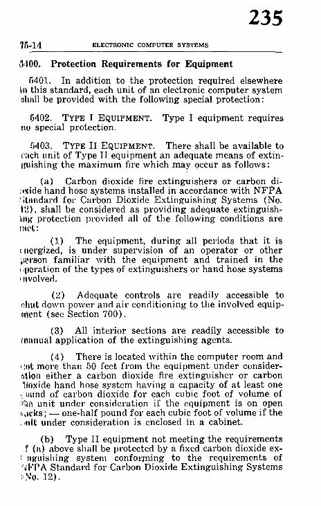
75-14 ELECTRONIC COMPUTER S Y S T E M S
235
5:100. Protection Requirements for Equipment
5401. In addition to the protection required elsewhere m this standard, each unit of an electronic computer system ~hall be provided with the following special protection:
5402. TYPE I EQUIPMENT. Type I equipment requires ~lo special protection.
5,103. TYPE II EQUIPMENT. There shall be available to ~'ach unit of Type II equipment an adequate means of extin- t~Lfishing the maximum fire which may occur as follows:
(a) Carbon dioxide fire extinguishers or carbon di- (,xide hand hose systems installed in accordance with N F P A (~iandard for Carbon Dioxide Extinguishing Systems (No. i2), shall be considered as providing adequate extinguish- ~t~g protection provided all of the following conditions are f '~tet :
(1) The equipment, during all periods that it is c,~crgized, is under supervision of an operator or other ~ r s o n famil iar with the equipment and t rained in the (;pcration of the types of extinguishers or hand hose systems L~tvolved.
(2) Adequate controls are readily accessible to ehut down power and air conditioning to the involved equip- meat (see Section 700).
(3) All interior sections are readily accessible to r application of the extinguishing agents.
(4) There is located within the computer room and r more than 50 feet f rom the equipment under consider- ~floa either a carbon dioxide fire extinguisher or carbon .~toxide hand hose system having a capacity of at least one I, mmd of carbon dioxide for each cubic foot of volume of t~le unit under consideration if the equipment is on open ~,,~el(s ; - - one-half pound for each cubic foot of volume if the ~0,1t under consideration is enclosed in a cabinet.
(b) Type II equipment not meet ing the requirements (a) above shall be protected by a fixed carbon dioxide ex-
~' ~lgtfishing system confor~ning to the requirements of "~'I"I"A Standard for Carbon Dioxide Extinguishing Systems I~No. 12).

236 SECTION 5 0 0 - - P R O T E C T I O N RECOMI~,IENDATIONS 75-15
5404. TYPE III EQUIPMENT. Because of the hazard ln'~" sented by the possibility of communication of fire to othf!~ equipment outside of Type III units, hand applied exth,' guishing agents shall be considered inadequate except if~ the ease of small (table top or desk size) units. Except fi,'~ the previously mentioned small units, all Type III equ!!.', ment shall be protected with a fixed carbon dioxide extra guishing system as described in Paragraph 5403 (b) ahoy'4
5405. Fixed carbon dioxide extinguishing systems 1,~ stalled to meet the requirements of Paragraphs 5403 (b) 4,', 5:104 above may be manually actuated when the equil)mo,~ ~ is. during all periods when it is energized, under the supe| vision of an operator or other persons familiar with tl~r equipment. In all other instances, the extinguishing s.w terns shall be provided with both manual and automalt: actuation means. The automatic actuation should be by ~t, approved method of detection meeting the requirements ,~ NFPA Standard for Propr ie tary Protect ive Signaling Sy~ terns (No. 72). Part icular attention shall be given in th~ choice of actuation means, to insure detection, eonsideril~I, the air flows usually involved in such systems, and thl small heat release under fire conditions.
5406. When called upon to operate, each fixed carbo: dioxide extinguishing or carbon dioxide hand hose instlfl lation shall be arranged to automatically sound an alarm and shut down power and air conditioning supplied to tl~: equipment involved.

ELECTRONIC COMPUTER SYSTEMS
237
SECTION 600. PROTECTION OF RECORDS
I:O00. General
ill Of. The operation of most electronic computer systems ~. lvcs obtaining, using, creat ing and s tor ing large
' ;,)unts of records. In many operations these records are ,~ important to the cont inui ty of the operation and its
~':~fion as the computer itself.
~,:~00. Record Media
t;201. Records may be the commonly encountered paper ..... m'ds, punch cards, plastic or metal base electronic tapes ; n metal or plastic reels and in metal, plastic or cardboard
~btainers), paper, control panels, magnetic discs, memory %i,ms, memory cores or various o ther means of maintaining
a' future use informat ion in plain or machine language, ',fide or outside of electronic equipment. Some of these
,,,'~'m'ds such as magnetic discs, memory drums and memory ~,'es are usually found as an integral portion of electronic
~ OUll)ment and as such the protection of these records is ~'ered in Section 500.
i1202. It is ex t remely impor tant to note tha t the degree resistance of magnetic tape to fire exposure is not corn-
: !etcly known. It is known, however, tha t fire exposures I[[~wat and /o r steam) tha t would not damage records on
~l)cr media may damage, records on magnetic tape. The ~ ,otection of records or magnetic tape by storage methods , rcscntly available must be considered limited.
c)~00. Types of Records
6301. Records involved in computer operations fall into ~lvc basic types which must be safeguarded according to J(heir importance and the difficulty involved in their replace- r as follows:
6302. INPUT DATA - - Raw or part ial ly refined informa- tion to be entered into the computer system, ei ther as mem- r y for later use or for immediate use in the solution of a ~roblem, development of a statist ic or production of some ,Lher product.
6303. :MEMORY - - In format ion previously converted to ~.mguage or symbols immediately recognizable to the corn-

238 SECTION 6 0 0 - PROTECTION OF RECORDS 75-1~
puter equipment and held for fu ture use. Memory may Ig" on any media which can be directly read by the compute! system.
6304. PROGRAM - - Data, which may be on paper, punc3~ cards, photographic, magnetic or electronic media, used IJ~ direct the computer as to which input or memory data 1t~ use, how to use it and the type of results to obtain. Also tv be considered are any diagrams or other records which cat) be used to reproduce programs.
6305. OUTPUT DATA - - The final product of the computcP system. This may consist of printed material or electronic data.
6306. ENGINEERING RECORDS - - Those plans, specificn tions, and other records which provide the engineerin~ record of the construction, wiring, and a r rangement of the computer system and its housing area. Of part icular im portance are records of modification made following the original installation.
6400. Value of Records
6401. The evaluation of records should be a joint effor~ of all parties concerned with the safeguarding of computel operations. The amount of protection provided for record~ shall be directly related to the importance of the records I~ measured by evaluation of what the loss of a particuh~t record would mean in terms of the mission of the computel system and the re-establishment of operations af ter a fire In order to maintain a reasonable sense of consistency, it i~ assumed tha t computer equipment capable of properly usini~ the records will be available. The following classification~ of records are based on the recommendations of NFP/~ Standard on the Protection of Records (No. 232). All r~' ords shall be evaluated and assigned to one of these cat{" gories to ensure tha t adequate protection is provided whcl~ necessary and tha t unimportant records are not overl)l~ tected.
6402. CLASS I (VITAL) RECORDS I Records tha t al~ essential to the mission of the equipment, are irreplaceabh" or would be needed immediately af ter the fire and cord not be quickly reproduced. Examples might include k(' programs, master records, equipment wir ing diagrams, aW certain input-output and memory data.

~3~t8 ELECTRONIC COMPUTER S Y S T E M S
239
0~|03. CLASS I I (IMPORTANT) RECORDS - - Reco rds t h a t ,~o essential o1" important but which, with difficulty or ex- I~c~a expense, could be reproduced without a critical delay ot" ,)0,)' essential missions. Some programs, wir ing diagrams, ~,wmory and input-output data have this level of im- 1, . , , l ' t l tnce.
6'10,1. CLASS III (USEFUL) RECORDS - - Records whose L' '~.,~ might occasion much inconvenience but which could ,,~'adily b~ replaced and which would not be an insurmounta- ~,~,'. obstacle to prompt restoration of operations. Programs ,rod procedures saved as examples of special problems are I~!,,pical of records in this category.
(M05. CLASS IV. (NONESSENTIAL) R E C O R D S - Those ~,vcords which on examination are found to be no longer r:,'t'essary.
~l,~O0. Protection Required 6501. RECORDS KEPT WITHIN THE COMPUTER ROOM. (a )
The amount of records kept within the computer room shall he kept to the absolute minimum required for efficient oper- ation. Nonessential records shall not be kept in the computer !'~ I0 rn.
(b) Any records regularly kept or stored in the com- Q,utcr room shall be provided with the following protection:
( l ) Class I (V i t a l ) ' o r Class II ( Important) rec- ~,rds shall be stored in Class C or better records protection cqui pment.
(2) Class III (Useful) records on paper based or 6,lastic materials shall be stored in metal files or cabinets.
(3) Class III (Useful) records on metal based ma- norial require no special protection.
6502. RECORDS STORED OUTSIDE OF THE COMPUTER ROOM. (a) To the maximum extent consistent with efficient opera- flon, all record storage shall be outside of the computer loom.
(b) Record storage room.
(1) Class I (Vital) and Class II ( Impor tant ) rec- ords shall be stored in fire-resistive rooms. The degree of ~h'c resistance shall be commensurate with the fire expo- ,m,'e to the records, but not less than two hours (see Para- ilt'aph 6601).

240 SECTION 6 0 0 - PROTECTION OF RECORDS 75-19
(2) Unless the records are contained in metal files, cabinets or other noncombustible containers, records storage rooms shall also be provided with an automatic sprinkler system.
(3) Class III (Useful) and Class IV (Nonessen- tial) records do not require any special fire protection un- less these records are stored with vital or important rec- ords. In such ease the requirements for the most valuable records apply to all records.
(4) The records storage room shall be used only for the storage of records. Spare tapes, however, may be stored in this room if they are unpacked and stored in the same manner as the tapes containing records. All ogher opera- tions including splicing, repairing, reproducing, etc. shall be prohibited in this room.
6503. When records are kept in cases, boxes or other containers, protection shall be that required for the highest level of damageable media in the total assembly of records and containers.
6504. It is recommended that the following be con- sidered as limitations in the design of record storage rooms :
(a) Rooms containing only paper records shall not exceed 50,000 cubic feet.
(b) Rooms containing plastic based records in non- combustible containers shall not exceed 10,000 cubic feet.
(c) Rooms containing plastic based records in com- bustible containers shall not exceed 5,000 cubic feet.
6600. Duplication of Records
6601. The best protection for records consists of stor- ing duplicate records in separate areas not subject to the same fire. In some electronic computer operations the du- plication of records on the same or different media is a common practice. The keeping of duplicate records is par- t icularly important when records on magnletic tape are in- volved.
(a) All Class I (Vital) records shall be duplicated on the same or different media and the duplicates stored in an area which is not subject to a fire t h a t may involve the originals, preferably in a separate building.

241 75-20 ELECTRONIC COMPUTER SYSTEMS
(b) Whenever practical, Class II (Important) rec- ords shall be similarly duplicated and stored.
(c) Class I (Vital) records not duplicated shall be protected in accordance with NFPA Standard on the Pro- tection of Records (No. 232).
6700. Protection Against Building Collapse
6701. In any building where a fire may result in a build- ing collapse which could either drop the records storage equipment or drop structural members on the records stor- age equipment, the records storage equipment shall be of types designed to protect the records against damage from the impact involved.

242 S E C T I O N 7 0 0 - - U T I L I T I E S 75-21
SECTION 700. UTILITIES
7100. Air Conditioning Systems
7101. Air conditioning equipment shall conform to the requirements of N F P A Standard for the Installation of Air Conditioning and Venti lat ing Systems of other than Resi- dence Type (No. 90A), and to the additional requirements set for th below.
7102. A separate air conditioning system should be pro- vided for the computer area.
7103. Air ducts serving other areas should not pass through the electronic equipment area. When it is imprac- tical to reroute such ducts, they shall be encased in a fire- resistive duct, equivalent to the fire resistance of the enclo- sure for the electronic equipment area.
7104. Air ducts serving other areas shall not pass through any computer records storage room.
7105. All duct insulation and linings shall be noncom- bustible, including vapor barr iers and coatings.
7106. Air filters for use in air conditioning systems shall be of approved types that will not burn freely or emit a large volume of smoke or other objectionable products of combustion when at tacked by flames and shall be so ar- ranged that they can be readily inspected, cleaned and /o r replaced when necessary.
7107. If the computer area is within an area which is air conditioned and additional air conditioning capacity is not required, the ducts serving the computer area should have suitable fire dampers, as outlined in N F P A Standard No. 90A.
7200. Electrical Service
7201. The requirements in this section apply to all power and service wir ing supplying the electronic computer equip- ment. They do not apply to wir ing and components within the actual equipment or to wir ing connecting various units of equipment. The equipment and interconnected wiring requirements are set for th in Section 400.

75-22 ELECTRONIC COMPUTER S Y S T E M S
243
7202. Service equipment supplying the main power re- quirements of the computer room area should be of a type arranged for remote control or located to fulfill the require- ments of Paragraph 7301.
7203. All wir ing shall conform to the N F P A National Electrical Code (No. 70).
720,1. Service t ransformers should not be permitted in the electronic computer area. However, if such a trans- former must be installed in this area, it shall be of the dry type or the type filled with a nonflammable dielectric medium. Such t ransformers shall be installed in accordance with the requirements of the NFPA National Electrical Code (No. 70).
7205. Protection against l ightning surges shall be pro- vided where needed in accordance with the requirements of the NFPA National Electrical Code (No. 70).
7206. The number of junction boxes in underfioor areas should be kept to a minimum. If they must be used, they shall be metal, completely enclosed, readily accessible, prop- erly grounded and in compliance with the N F P A National Electrical Code (No. 70), requirements as to construction. They shall be securely fastened to the floor. No splices or connections shall be made in the underfloor area except within, junction boxes or approved type receptacles or con- nectors.
7300. Emergency Power Controls
7301. In addition to any emergency shut-down switches for individual components or other units of equipment, con- trois for the disconnecting means provided as a part of the main service wiring supplying the electronic computer equipment shall be located near the operator 's console and next to the main exit door to readily disconnect power to all electronic equipment in the electronic computer area and to the air conditioning system (see Paragraph 8200).
7302. Provision should be made for emergency lighting.

244 SECTION 8 0 0 - FIRE EMERGENCY PROCEDURES 75-23
SECTION 800. FIRE EMERGENCY PROCEDURES
8100. Preplanning for Continued Operation in a Fire Emergency
8101. The continued operation of an electronic computer system is dependent on information stored on cards, tape, discs, drums, etc. Therefore, the preplanning for continued operation should include:
(a) A program to protect records in accordance with their importance as set for th by the section on protection of records.
(b) Arrangements for emergency use of other in- stalled computer equipment to cover:
(1) Plans for t ranspor ta t ion of personnel, data and supplies to emergency computer locations.
(2) Agreements and procedures for the emergency use of the computer equipment.
(c) Programs designed with adequate number of checkpoints and res tar t s to ensure rapid recovery to normal operations.
8102. Personnel should receive continuing instructions in:
(a) Method required for turning off all electrical power to the computer.
Turning off the air conditioning to the area.
Alert ing the Fi re Depar tment or company fire
(b)
(c) brigade.
(d) (e)
Evacuat ion of personnel.
The location of and proper operation and appli- cation of all available fire extinguishing and damage control equipment. Because of the noise and of the need for skillful operation of carbon dioxide extinguishing equipment, com- puter room personnel should be fully trained in carbon dioxide usage through actual operat ing of the equipment on a practice fire.
(f) The importance of records and their s torage re- quirements.

75-24 ELECTRONIC COMPUTER SYSTEMS
245
8200. Emergency Fire Procedure
8201. A wri t ten emergency fire plan should be prepared for each installation which assigns specific responsibilities to designated personnel. The following major items are suggested as minimum features of this plan.
8202. Remove all power to the computer system.
(a) ~IEANS Main line circuit breaker or equivalent for turning off all power.
(b ) LOCATION OF CONTROL FOR DISCONNECTING MEANS Remote controls for operat ing the disconnect located near the operator 's console and next to the main exit door.
8203. Shut down air conditioning system.
(a) IN CASES OF COMPLETELY SEPARATE SYSTEMS ONLY Emergency means similar to that described in Pa rag raph 8202 provided to turn off the computer room air conditioning. They should also be located near the emergency power shut- off device.
(b ) IN CASES OF REGULAR BUILDING SYSTEMS ONLY Emergency means similar to that described in Pa rag raph 8202 provided to close off all duct dampers leading to and from the computer room. They should be located near the emer- gency power shut-off device.
(C) IN CASES OF COMBINING THE REGULAR BUILDING SYSTEM WITH A SUPI~LEMENTARY SYSTEM
Emergency means provided to simultaneously accomplish the similar action as described in the preceding (a) and (b) items.
8204. Notification of proper authori ty.
( a ) BUILDING FIRE BRIGADE Fire brigades shall be called immediately.
(b) OUTSIDE FIRE-FIGHTING COMPANY Outside fire depar tments shall be called in accordance with the emergency fire plan (see Pa ragraph 8201).

246 SZCTmN 900-- GLOSSARY 75-25
8300. Damage Control
8301. Means should be provided to preven~ water dam- age to electronic equipment. The proper method of doing this will vary according to individual equipment design. Consideration should be given to the provision of water- proof covers.
3302. Whenever electronic equipment or any type of record is wet down, smoked up or otherwise affected by the results of a fire or other emergency, it is vital tha t im- mediate action be taken to clean and dry the electronic equipment. If the water, smoke or other contaminations are permitted to remain in . the equipment longer than ab- solutely necessary, the damage may be grossly increased.

75-26 ELECTRONIC COMPUTER S Y S T E M S
247
SECTION 900. GLOSSARY
ASSOCIATED EFFECTS. Smoke, wind, heat, water.
|}USINESS INTERRUPTION. Loss of use of the equipment and restoration to the former level of operation.
(;IIECK POINT (RESTARTS). A predetermined point in the programming of information where the operator can re- h, rn to continue that portion which was accidentally inter- ,'upted. These points are spaced to minimize lengthy reruns.
(~0NSOLE. Unit containing main operative controls of the ~ystem.
~0NTROL PANEL (PLUG BOARD). A removable wir ing panel for manually changing the operation of a component of an electronic computer system.
I']LECTRO M~ECHANICAL PROCESSING EQUIPMENT. Individual I, nits which are not electronic in nature and do not con- otitute a system or complete a total function.
I?,LECTRONIC COMPUTER SYSTEM. Any electronic digital or analog computer, along with all peripheral, support, mem- ol'y, programming or other directly associated equipment, records, s torage and activities. The most common types of electronic computer systems are of the digital computer type and are usually classed as Electronic Data Processing Machines ( E D P M ) , Automatic Data Processing Machines (ADPM), a n d / o r Integrated Data Processing systems.
ELECTRONICALLY INTERCONNECTED. Units that must be con- ,Iccted by a signal wire to complete a system or per form an operation.
iNPUT-OUTPUT ( I /O) . That equipment electronically asso- ciated with the computer which feeds information into the computer for computat ion or receives information which has been computed and displayed in a form famil iar to the operator.
INTERCONNECTING CABLES. Signal and power cables for op- oration and control of system (usually supplied by computer manufac turer ) .

248 APPENDIX 75-27
MASTER RECORD. A record of informat ion on a medium which can be r e fe r r ed to whenever there is a need to rebuild a. program.
PROGRAM. Inst ruct ions to direct systems operation.
RAISED FLOOR. P la t fo rm on which machines are installed for housing interconnect ing cables, and at t imes as a means of supplying conditioned air to various units. Sometimes re fe r red to as a false floor or secondary floor.
READILY ACCESSIBLE. When the covers, panels, doors or other enclosure for the electronic components within the equipment or the flooring can be removed by quick, simple operat ions to expose any area which might be involved in fire and permi t the application of an ext inguishing media. Prefe rab ly no special tool m" other removable device should be required to per form this operation. Where safety from electrical shock requires the extra security for electronic components, a simple tool may be required provided the tool is kept in a convenient tanll)erproof location on or near the machilm. Quick removal of the machine enclosure means that any component can be exposed by the average male employee in not over one minute. Where a special tool or device is required to assist in faci l i ta t ing accessibility to underfloor areas, the number and a r rangements of the de- vices shall be such tha t any space beneath the floor can be exposed to application of the ext inguishing media by the average male eml)loyee in not over one and one-half minutes.
~EPARATE FIRE DIVISION. A port ion of a building cut off from all o ther portions of the building by fire walls, fire doors and other approved means adequate to prevent damage f rom any fire which may occur in the building f rom involv- ing more than one such separate fire area. In nonfire-re- sistive buildings, this includes protection against building collapse as the result of a fire outside the separate fire area.

75-28 ELECTRONIC COMPUTER SYSTEMS
249
Appendix
Mec~nicol [ [
ee [] Rm Resist~
It Bose I ] Tope 1,1 Records H Records
L.,-L._~L.---,I u
<o.,,,.,, ,,oo. ~ r I~L,,,on, . . . . . . Q3 ~M'~ntfmnc~lStotionery I I . . . . . . "]', I ~ H Room II StoraQe I ! ~,,,,i,,,l]. _ 17"~.............~ ,<-: II / /
Office I ~ I~ H I]" I"-IXl " " /
ELECTRONIC COMPUTER AREA

250 REPORT OF COMMITTEE ON FIRE DOORS AND %VINDOXVS FD!
Report of Committee on F i r e D o o r s a n d Windows. %V. K. Es tep , Chai , m a , .
Midd le D e p a r t m e n t Assn. of F i r e Unds . . 316 4th Ave.. P i t t s b u r g h 22, Pa.
George F. Allebaeh, I n s u r a n c e R a t i n g B u r e a u of the D. C.
31. A. B r i d g h a m , I m p r o v e d R i s k Mu- tuals .
Ba t t . Chief J o h n G. Degenko lb , F i r e M a r s h a l s Assn. of Nor th Amer ica .
J . F. D u r k i n , Assn. of C a s u a l t y and S u r e t y Cos.
Leon F. D u s i n g , Steel Door I n s t i t u t e . Malcolm E. F i s c h e r , N a t i o n a l Steel
Door and F r a m e Assn. C h r i s t i a n H a n s e n , Paci f ic F i r e R a t i n g
Btlreatl . E. P. H a n s o n , Na t iona l A u t o m a t i c
S p r i n k l e r & F i r e Contro l Assn.
W i l l i a m S. H a s w e l l , N a t i o n a l Build. ers" H a r d w a r e Assn.
J . E. N o r d e n g , Confe rence of Special R i s k U n d e r w r i t e r s .
S tephen E. P a r k e r . Confe rence of Spe. eial R i s k U n d e r w r i t e r s .
Clifford A. S t e v e n s , N n t i o n a l %Vood, work l%Iantlfacttlrers Assn.. Inc.
E. K. S toehr , U n d e r w r i t e r s ' Labora . tor ies . Inc.
L e w i s W. V a u g h a n . Unde rwr i t e rn ' L a b o r a t o r i e s of Canada .
G. W a t s o n . N a t i o n a l E l e v a t o r Manu- f a c t u r i n g I n d u s t r y , Inc.
A l t e r n a t e s . J o s e p h N. Saino, N a t i o n a l Steel Door and F r a m e Assn.
( A l t e r n a t e to Malcolm E. F i s c h e r . ) Allen P. %Vherry, Steel Door I n s t i t u t e
( A l t e r n a t e to L. F. D u s i n g . )
This .report. has been submi t t ed t,o b(tllot, o/ t,h,e Co,mmlitt,ee .which. consists of 16 m e m b e r s o/ w h o m 15 have voted af. fi,rmatively, and M~'. War,son 'is reco~'ded as not vot ing.
The Committee on Fi re Doors and Windows presents for final adoption the following revisions to N F P A No. 80, S tandard for the Installation of Fi re Doors and \Vindows. N F P A No. 80 is published by the N F P A in the National Fire Codes, Volume III and in separate paml)hlet form. It is also published by the National ]3oard of Fi re Underwrit . ers with the same identifying number.

251 FD2 FIRE DOORS AND ~,VINDO~VS
Proposed Revisions to STANDARD FOR THE INSTALLATION OF
FIRE DOORS AND WINDOWS. N F P A N o . 8 0 - - 1 9 6 1
I. Add the word "steel" to 50 as [ollo~vs:
50. Flush Mounted. Flush mounted doors are hung on a steel f rame set in the wall. 2. Revise entire 500 as follows:
500. Sills. a. Buildings with noncombustible floors require no spe-
cial sill construction, if the floor s t ruc ture is extended through the door opening.
b. Buildings with combustible floors require special sill construction at door opening, as combustible floor struc- tures must not extend through the door opening.
c. Sills shall be made of noncombustible mater ia ls ex- tending at least the width of the door f r ame but not less than 4 inches wide. See Figure 2 for recommended construe- tion.
d. If sills are flush concrete construction, they shall be of a good grade and shall be at least 4 inches thick, extend- ing to the masonry opening on ei ther side.
e. Raised noncombustible thresholds are acceptable and are recommended whenever combustible floor coverings are contemplated or are in use on one or more sides of the door opening. See F igure 2.
COMBUSTIBLE FLOOR COVERING SHALL NOT BE PERMITTED TO EX T END THROUG]-I DOOR OPENINGS. 3. Revise the last sentence of 505 b. to read as follows:
The device may be provided with deadbolts in addition to the active latchbolt except when the doors are to be used as a required means of egress. See Section 20a. ~. Revise the last sentence of 505 b. (2) to read as follows:
A keeper shall be secured in the sill to receive the bot- tom bolt of the s ta t ionary door. Open back strikes shall not be installed in the inactive leaf of pairs of fire doors. 5. Revise Table II (see page FD3) . 6. Revise Table I I I (see page FD4) . Revision involves composite steel and Hollo~v-Metal Doors.

TABLE II
Builders Hardware Mortise and Surface Hinges for Swinging Doors
Doors up to 60 in. in height shall be provid, d with two hinges and an additional hinge for each additional 30 in. of he ight or fract ion thereof.
Fox" 1~.~ Inch or T h i c k e r Doors Maximum
Size Door Hinge Size Width Height Height Thickness
Door Rat ing, Hr . Feet Feet In. In. Type Hinge
3, 1~ , 1, ~ 4 10 4 �89 0.180 Steel, Mort ise or Surface
3, 11/.2, 1, a[~ 4 8 4 �89 0.134 Steel, Mort ise or Surface
1 ~ , ~ 4 8 6 0.225
3, 1~, ~ 4 8 4 0.225
1�89 ~/ 4 ~0 4�89 0.180
1 ~ , 1, ~ 3 5 4 0.130
1~ , 1, ~ 2 3 3 0.092
Fo r 1% Inch Doors
1 ~/,, ~ 3 7 3 �89 0.092
Steel-Olive Knuckle
Steel Pivots ( Inc lud ing Top. Bot tom and In te rmedia te )
B ronze - ( I ron or Steel Stud and Sockets Provided Adjacen~ To Each Hinge)
Steel, Mort ise or Surface
Steel, Mort ise or Surface
Steel. Mort ise or Surface
bJ LII t,a
C~
O ,-q
O
�9 x
O
> z
�9

Compos i te Wood or P las t ic (f lush) Composi te A l u m i n u m (flush)
Composi te Steel (f lush)
Hol low-Meta l (Pane l l ed or f lush)
Meta l -Clad (Pane l l ed or f lush)
Shee t -Me ta l (Pane l l ed or f lush)
Door R a t i n g Hours
1
1
3
.3
1% or
3 3 3 1�89 or
t�89 or
11~ or
1�89 or
T A B L E I I I B u i l d e r s H a r d w a r e
L a t c h i n g D e v i c e s f o r S w i n g i n g D o o r s
M a x i m u m L a t c h e s (See Notes ) Open ing Single Doors in Pa i r s H e i g h t Swing Act ive Leaf
F e e t Doors
7 �89 in . _
7 �89 in. __
8 �9 3 Pt . Su r f ace - -
8 ~ in. % in.
I nac t i ve Leaf
Top & B o t t o m Bol ts
8 �89 in. ~f~ in.
10 3 Pt . Concealed 3 Pt . Concealed 8 �89 in. __ 7 �89 �89 in. ~ in.
8 to 10 3 Pt . Concealed 3 Pt . Concealed
Top & B o t t o m Bol ts
2 Pt. Concealed
Top & B o t t o m Bol ts
Top & B o t t o m Bol ts
8 �89 in. "~ in. Top & B o t t o m Bol ts
8 �89 in. ~ in. Top & Bottom Bolts
8 �89 in. ~ in.
Note 1: La t ch d i m e n s i o n s shown ind i ca t e m i n i m u m th row. N,Jte 2: F o r a l t e r n a t e a s s e m h l i e s , s e e p a r a g r a p h 21.
Top & B o t t o m Bol ts
I-
I
'7.
z
0
5~
t,n taa

254 REPORT OF C O M M I T T E E ON FIRE DOORS AND ~.V1NDO~A'S FD5
7. Delete the expression "Horizontal sliding" f rom 601 as follows: 601. Wall mounted doors are hung on the surface of the wall. Doors of the tin-clad and sheet-metal (flush, cor- rugated, and composite) types shall be wall mounted.
8. Add reference to center parting doors to 608 a. (2) as follows:
(2). Fire door hardware includes tracks, hangers, t rack brackets, binders, bumpers, pull handles, stay rolls, and center latch assembly for center par t ing doors.
9. Change heading of 608 b as follows: b. Track B inders
10. Following 608 b insert ne'w head C. Track, and reletter existing c, d, e, f, g, h, i and j as d, e, f, g, h, i. j and k respec- tively.
11. Revise 608 b. (4) , new 608 c(4) , as follows: (4). M o u n t i n g B o x Type Track. When box type
track is used the number of track brackets provided shall be such tha t a bracket is located directly over each hanger when the door is closed, on each end, and such intermediate brack- ets so that bracket centers shall not exceed 39'/.2 in. Wall bolts securing brackets in position shall not be less than % in. in diameter and shall be installed through the wall, ex- cept as provided in 605 (b). 12. Revise 608 c. (new 608 d) as follows:
d. Hangers. Doors for openings six feet and less in width shall be provided with two hangers. Doors for open- ings in excess of six feet shall have an additional hanger (see Table VII) . Two hangers shall be provided on each section of vertically spliced sheet metal or tin clad doors. (See Paragraph 609.)
13. Revise 608 d. (1) and (4) , ne,w 608 e. (1) and (4) , as follows:
e. B inders . (1). At least two f ront binders are required. The
upper binder shall be placed approximately 24 in. f rom the top of the door, and the lower binder approximately 24 in. above the sill.
(4). Composite doors shall have one base binder and one or more f ront and rear latches. See Figure 25a.

I,'1)6 FIRE DOORS AND WINDOVr
255
14. Revise 608 e. (new 608 [.) as follows: f. S tay Rolls. Figures 27, 28, 29 and 30, Section 16
t)how acceptable methods of a t taching Stay Roll Brackets. I,'or concealed type Stay Roll, see Figure 30. 15. Revise 608 .i. (new 608 k.) as follows:
k. Handles. The flush pull on the back of the door nhall be countersunk flush with the surface of the door. Ihmdle oll f ront of door shall be bolted to flush pull by through bolts or otherwise securely attached. (See Figure 25, Section 16.)
16. Revise 609 as follows: 609. Sec t iona l D o o r Uni t s .
a. Tin-Clad and Sheet-Metal. May be furnished in not more than two sections and shall be provided with cover plates for the joint between the sections and reinforcing angles or channels running horizontally across the door. When shipped, both cover plates shall be at tached to one
i t~cction of the door, being bolted together through the door. The edge of the adjacent section shall be inserted in the groove formed by these cover plates and secured in a like manner by through bolts. Reinforcing angles or channels tfimll be secured by through bolts.
b. Composite Sliding Doors. Composite doors sha!l (,.onsist of not less than two or more than five panels con- 0tructed for either field or factory assembly. P a n e l s a r e interconnected with flush mounted channel members secured to each panel. t7. Change the title o[ Section 10 to read:
Installation of Doors for Chutes and Manually Operated Duml)-Waiiers
18. Change vefe~'ence in the last sentence of 1104 a. (2) (b.). as follows:
For exceptions see 1103 a . (2) .
19. Revise 1312 as follows: 1:)12. The area of individual glass lights, subject to light fire exposure (Class F ) , shall not exceed 1296 square inches (,xposed area, with neither the width nor height exceeding 5,1 inches.

256 REPORT OF COMMITTEE ON FIRE DOORS AND WINDOWS FD7
20. Delete existing Figure 2 and insert the fol lowing new Figure 2.
1-] . . . . .
FLOOR LINE
7 7 ; - . . �9 - ~ ;.. - / .
COMBUS~SLE FLOOR ErPUETUA[
i . . . . . :
F i g u r e 2. Noncombus t ib l e sill used wi th combus t ib l e floors fo r doors swing ing in to s teel f rame.
Combus t ib le floor cover ing shall not be p e r m i t t e d to ex tend through the door openings.
21. Delete existing Figure 28 and insert the following new figure:
, f i
I 1 / I
!. \
/ / F ~ A M E ~ . . .
F i g u r e 28 . S t a y ro l l .
22. Delete existing Figure 30 and insert the following new figure:
Figu re 30. Concealed type s t ay roll.
. ~ I ST R U r. T UP, A L
I I tl
fl
, .,%.
h
!-l-" ~-L
Li_
. : :..: .= ....

5/8 IN.DIAMETER (MIN.)
PENDANT HANGERS
5/8 IN.DIAMETER ~ , (MIN.)
INTERMEDIATE LATCH (REAR) CLOSED POSITION
BOX TYPE TRACK /
~ _ r ~II
,I
CEILING LINE
~- FUSIBLE LINK_S
_.d_
Ii ' l
I
I,
INTERMEDIATELATCH ~ - c~,
/ " CONCEALED 5/8 IN, DIAMETER WALL BOLT STAY ROLL
(MIN.)
Figure 25a. Horizontal sliding composite door.
- - i . . . .
~APPROVED SLIDING DOOR CLOSER
BINDER /
~ \ 5/8 IN.D,~ETER (MIN.)
DO
o~
r o
f~
",,3

258 REPORT OF COMMITTEE ON FIRE PUl%.IPS FPUI
R e p o r t o f C o m m i t t e e on F ire P u m p s .
E. W. Fowle r , Chairman, Nat iona l Board of F i r e U n d e r w r i t e r s . 85 J o h n St., N e w Y o r k 38. N. Y.
, James E. l l lowers . Secretary. I n t e r - R e g i o n a l I n s u r a n c e Conference . 125 Maiden Lane . N e w Y o r k 38. N. Y.
J o h n R. A n d e r s o n , N e w E n g l a n d F i r e I n s u r a n c e R a t i n g Assn.
Donald M. B r y a n , U n d e r w r i t e r s ' L a b o r a t o r i e s of Canada .
S. P. Croshy , I n g e r s o l l - R a n d Co. ( P e r s o n a l )
Carl Ell is . F a c t o r y Mutua l E n g i n e e r - i ng Div i s ion .
N o r m a n E. Gatseh , Ohio I n s p e c t i o n Bin-can.
S. K. Goodwin , F a c t o r y I n s u r a n c e Assn.
R. 1t. J e n s e n , U n d e r w r i t e r s ' L a b o r a - �9 to r ies . Inc. R. E. K u m m e r , H y d r a u l i c In s t i t t i t e . 1. L. L a m e r , S o u t h - E a s t e r n U n d e r -
w r i t e r s Assn. O. C. L e w i s , L a y n e N e w York Co.
( P e r s o n a l ) H. Wi l l i am M a r s c h n e r , Confe rence of
Special R i s k U n d e r w r i t e r s . C. B. Mil ler , J r . . Na t iona l A u t o m a t i c
S p r i n k l e r & F i r e Control Assn. D, %V. N o r d b e c k , S tone & W e b s t e r
E n g i n e e r i n g Corp. ( P e r s o n a l )
It. J . O s t r u m , O r e g o n I n s u r a n c e R a t - i n g Bureau .
Chas . J . S hukes , Cook County Inspec - t ion Bureau .
C. I . T a g g a r t , I n t e r n a l Combus t ion E n g i n e I n s t i t u t e .
E m i l W a g n e r , N e b r a s k a In spe c t i on Bureau .
F. M. W i n t e r h a l t e r , N a t i o n a l E lec t r i - cal M a n u f a c t u r e r s Assn.
J o h n M. ~,Vrenn, P o r t of N e w York Au tho r i t y . ( P e r s o n a l )
Alternates. R o b e r t B u r n s , Na t iona l E lec t r ica l
M a n u f a c t u r e r s Assn. ( A l t e r n a t e to F. M. ~,Vinterhalter .)
E. U, L a s s e n , Na t iona l E lec t r ica l M a n u f a c t u r e r s Assn. ( A l t e r n a t e to F. IV[. ~,Vinterhalter .)
R. W. Seelbaeh, U n d e r w r i t e r s ' Labo- r a to r i e s , Inc. ( A l t e r n a t e to R. H. J e n s e n . )
C. G. Spice, I n t e r n a l C o m b u s t i o n En- g i n e I n s t i t u t e . ( A l t e r n a t e to C. 1. T a g g a r t . )
This report has been submit ted to letter ballot of the Committee which, consists of 21 members, of whom 20 have voted affirmatively and Mr. Nordbeck h, as not returned his ballot as of th, e date of this writ ing.
The following revisions to Standard No. 20, Centrifugal Fire Pumps, have been prepared by the NFPA Committee on Fire Pumps and are submitted for final adoption.
Centrifugal Fire Pumps, NFPA No. 20, is published in the National Fire Codes, Volume IV, and in pamphlet form by the NFPA and the NBFU.
Proposed Revisions to
STANDARD FOR THE INSTALLATION OF CENTRIFUGAL FIRE PUMPS
N F P A N O . 2 0 - - 1 9 6 1

I,'I'U2 CENTRIFUGAL FIRE P U M P S
259
t. Change the last sentence of Paragraph 4 in "General" rO read:
Certified shop test characterist ic curves showing head- delivery, efficiency and brake horsepower shall be furnished by the manufacturer .
~. Add the following referencd to end of paragraph 32d: (See Figs. 100 a-1 and 143 e)
t. In paragraph 43c add a new sentence before the last ,;~'t~tence. Entire paragraph to read:
c. The relief valve should discharge into an open pipe in plain sight near the pump or into a cone or funnel accured to the outlet of the valve. This cone should be so constructed tha t the pump operator can easily see any water ~'asting through the relief valve, and it should be so made as Io avoid splashing water into the pump room. If a closed |ype cone is used, it should be provided with means for visually detecting motion of water through the cone. The ~'one should be piped to a point where water can be freely wasted, preferably outside the building.
t. Renumber 43h as 43i and add new 43h to read: h. The relief valve waste pipe from a closed cone shall
be sized to prevent back pressure in excess of 8 psi.
.'h In paragraph 46 add a new second sentence. Entire ~aragraph to read:
,|6. CIRCULATION RELIEF VALVE TO PREVENT OVERHEAT- !NG. Pumps which are automatical ly controlled shall be i,rovided with a :y~-inch relief valve set slightly, below the ~hut-off pressure and ar ranged to permit circulation of suf- ficient water to prevent the pump from overheating when r with no discharge. This is not needed for sub- ,|lcrged type pumps nor for engine driven pumps for which t,,Igine cooling water is taken from the pump discharge. Pumps which are manually controlled shall be equipped ~,ith either such a relief valve or with a test valve as speci- fied in Section 133. Provision should be made for discharge ~o a drain.
~. Add a new valve attached to the outlet flange of the ~tored water supply in Figure lOOa and identi fy it as valve (h Identi fy existing valve 6 as 6A (Al ternate) and add ~'eference to paragraph 143k and Notes to nomenclature Cot number 6 as follows:

260 REPORT OF COMMITTEE ON FIRE PUMPS, FPU3
Fig. 100 ~ Centrifugal F i re Pump Inst~llation where Pump T~c~ Water Always U n d e r a Head
1. Above Ground Suction Tank. 10. Umbrella Cock or Automatic 2. Entrance Elbow and 4 x 4 ft., Air Release.
square vortex plate, 4 in. above 11. Discharge Gauge. bottom of tank. 12. Reducing Tee.
3. Suction Pipe. 13. Discharge Check Valve. 4. Frostproof Casing. 14. Relief Valve (if required). 5. Flexible Couplings. 15. Discharge Pipe. 6. O. S. & Y. Gate Valves (See 16. Drain Valve or Ball Drip.
143k and Notes). 17. Hose Valve Manifold with 7, Eccentric Reducer. Hose Valves. 8. Suction Gauge. 18. Pipe Supports. 9. Horizontal Fire Pump.
7. A d d ne w F igure 100a,-1 and notes as fo l lows:
Fire Pump Outside Screw
Check and Yoke Volve
--- '- .--~Outs i d e S crew i._.\__iV~ve , Out side Screw Heod~ / ~ Y~176 j ~x'~" ~oo-.....H o s e [~Oj~d Yoke Volve
~ j I ^ I ~ J C;eck ~ I v~lvef~ v I . . . . �9 v I~1
FromTonkor-r'~ (~'~utsl'~'e Screw jL~koc ey Q"~s ide Screw Tonk Fill Line ond Yoke Volve Pump ond YoKe volve
Fig. 100aol. Jockey Pump Ins t~la t ion with Fi re Pump.

$;1'1}'1 CENTRIFUGAL FIRE P U M P S
261
'.ffrt: 1: Jockey pump usual ly requi red wi th au tomat i ca l ly con- ~ ~;~,=llc'(I pumps.
%~|V 2: Jockey pump suct ion may come from tank filling supply ~X*, This al lows high p ressu re to be ma in t a ined on fire p ro tec t ion ,,~letn even when supply t ank may be e m p t y for repairs .
lee'vise sketches " A " and "B" in Figure 1~3e and add
"A"
Check Outside Screw Valve) (and Yoke Valve H~s= , r
""L X - ~ P . o ~ H ~ ~. Ouls=de ScrewJ Fire ~" Outs ide~crew eooer and Yoke Volvel Pump"~,~j '~ '~ and Yoke Valve :.;.. ~ I j j ~ I ~ .~ -" -----P- IO Yard System
r, ~ . Public I Jockey ~ _ J Che'~'ck "~ (with Gravity Tank ~'-)'"' I Pump ~ Volve~ supply)~ other water
Outside Screw Outside Screw and Yoke Valve and Yoke Valve
II I~ II
Check Outside Screw Valve) ~ond Yoke Valve H >t ' ~ ,~ .~ _ ~ p _ ~ ose
Outside Screw [Outside Screw Fire ln~.~, ,~ , , r~r .~ Header and Yoke Valve and Yoke} ~ P u m p JSo n d" ~To'k e" ~/o~ v" "e . . . . . .
-: , '~ JValve ..~ I j'~. . . ~ r I . . f . ~ t o Taro :~ystem ~, Jt~Public / X "~ ' l I_ '~ . ~ "~" I (No other wo'ter Jockey ~ C h e c k I sunni v) r Pump
Outs=de~':'XScrew L_I ~ O(~uts,de Screw and Yoke Valve and Yoke Valve
F i g . 143 e. Schemat i c Dhtg ram of the
Sugges ted A r r a n g e m e n t for a Boos te r P u m p in a By-Pass
NOTE: Jockey P u m p usual ly requi red wi th au toma t i ca l ly con- , . l ied pumps.
: Revise .pa~'a,qraph l~3k and add new notes as follows:
k. Provide an approved O.S. & Y. or approved indi- ctor type gate valve in the suction pipe if the pump is ever
:.,q)plied under a head.
~OTE 1: If suct ion p ressu re comes f rom city or service w a t e r mains, the ga te valve should normal ly be located at the suct ion Ihmgc on the pump. NOTE 2: If suct ion p ressu re comes f rom a s to red w a t e r con- l{flner, the ga te valve should normal ly be located at the ou t le t of the conta iner .

262 REPORT OF C O M M I T T E E ON FIRE P U M P S FPU5
10. Revise enti~'e section 220 to read as follows:
220. Wate r Supply. 221. SOURCE.
a. The water supply shall be acceptable to the authori. ty having jurisdiction. Stored water supplies f rom reser. voirs or tanks supplying wet pits are preferable. Lakes. s t reams and ground water supply may be acceptable wher0 investigation shows that they can be expected to provide a suitable and reliable supply.
b. The acceptance of a well as a source of wa te r sup. ply shall be dependent upon sa t is factory development of the well and the making of a prel iminary test to determine hydraulic conditions. The history of the water table should be carefully investigated. The number of wells already in use in the area and the probable number that may be iu use should be considered in relation to the total amount of water available.
222. PUMP SUBMERGENCE. a. Proper submergence of the pump must be provided
for reliability of operation of the fire pump unit. b. WET PIT INSTALLATIONS. The minimum submer-
gence should be such that the second impeller f rom the bot- tom of the pump bowl assembly will be below the lowest s tanding water level in the open body of water supplying the pit (Fig. 200b, Appendix C). The minimum submergenc~ shall be increased by one foot for each 1000 feet of elevation above sea level.
C. WELL INSTALLATIONS. Submergence of the second impeller f rom the bot tom of the pump bowl assembly should be 10 feet below the pumping wate r level at 150 per cenl of ra ted capacity. (See Figure 200 a, Appendix C.)
223. WELL CONSTRUCTION. a. It shall be the ground wate r supply contractor 's
responsibil i ty to make one or more test holes, if necessary, in search of water -bear ing formation, develop a well to meet the required water production necessary for a specific pump, to per form all work and install all equipment in a thorough and workmanlike manner.
b. Each well completed must be of ample diameter and depth and sufficiently s t ra ight to receive the pump. The turbine-type pump is designed to operate in a vertical posi.

I"l'U6 CENTRIFUGAL FIRE PUMPS
263
tion with all parts in correct a l ignment ; it cannot operate in a crooked well unless the turbine unit hangs freely without being cramped.
224. UNCONSOLIDATED FORMATIONS.
a. All casings shall be steel of such diameter and in- t~talled to such depths as the formation may jus t i fy and in the contractor 's opinion best meet the conditions. Both immr and outer casing shall conform to the thickness and wcight in Table 224.
T A B L E 224
Nomina l Wall We igh t per Foot Size (ID) Th ickness (P la in Ends )
Inches Inches Pounds 8 0.277 24.70
10 0.307 34.24 12 0.330 43.77 16 and l a rge r 0.375 - -
b. Outer casing shall extend down to approximately the top of the water-bearing formation. The inner casing of lesser diameter and well screen shall extend into the water-bearing formation as the water-bearing s t ra tum en- countered may jus t i fy and, in the contractor 's opinion, best meet the conditions.
c. It should be emphasized tha t the well screen is a vital part of the well construction and careful at tention t~hould be given to its selection. It shall be the same nominal diameter as the inner casing and of the proper length to i)rovide for the quanti ty of water to be developed. The ~creen shall be made of stainless steel material (18-8). The ~creen shall have adequate s trength to resist the external forces tha t will be applied af ter it is installed and to mini- mize the likelihood of damage during the installation.
d. The bottom of the well should be sealed properly with a cement plug or a plate of the same material as the acreen. The sides of the outer casing should be sealed by the iatroduction of neat cement placed under pressure from the bottom to the top.
e. The immediate area surrounding the well screen ~hould be properly prepared with clean and well-rounded gravel of such size and quant i ty as will create a gravel filter to insure a low velocity and friction loss of water leaving the water-bearing formation arid enter ing the well.

264 REPORT OF COMMITTEE ON FIRE PUMPS FPU7
225. CONSOLIDATED FORMATIONS. Where wells take their supply f rom consolidated formations, such as rock, the specifications should be decided upon by the author i ty having jurisdiction upon consultation with a recognized ground water consultant in the area. In instances where the drilling penetrates unconsolidated formations above the rock, surface casing shall be installed, seated in solid rock and cemented in place.
226. DEVELOPING A WELL. Developing a new well and cleaning it of sand (not to exceed five parts per million) shall be the ground water supply contractor 's responsibility and should be done with a test pump and not the new fire pump which could be ruined before it is placed in service. Freedom from sand shall be determined when the test pump is operating at 150 per cent of rated capacity of the fire pump for which the well is being prepared.
227. T E S T AND I N S P E C T I O N OF W E L L .
a. A test to determine the water production of the well shall be made with an acceptable type of water measur- ing device such as an orifice, a venturi meter or a calibrated pitot tube, and shall be witnessed by a representative of the customer, contractor and author i ty having jurisdiction, as required. The test shall be continuous for a period of at least eight hours at 150 per cent of the rated capacity of the fire pump, with averaged hourly readings over the test period. The tests should be evaluated in the light of the effect of other wells in the vicinity and any possible seasonal variation in the water table at the well site. Test data shall describe the static water level and the pumping water level at 100 and 150 per cent of the rated capacity of the fire pump for which the well is being prepared.
b. The well work completed by the ground water supply contractor should be carefully examined and if there is some doubt about s t raightness of well, gaging and plot- t ing is recommended before acceptance of the well.
c. Before the permanent pump is ordered, the water in the well should be analyzed for corrosiveness including such items as pH, salts such as chlorides, harmful gases such as carbon dioxide (CO..) or hydrogen sulfide (H...S).

FI'U8 CENTRIFUGAL FIRE P U M P S
265
If the wate r is corrosive, the pumps should be constructed of a suitable corrosion-resis t ing mater ia l such as bronze or red brass in accordance with chemical analysis and ex- perience in the area.
! I. In paragraph 251a add th, e ' w o r d s "or dual dr ive" to the first sentence:
a. The pump may be driven by a vertical hollow shaf t electric motor o1" r ight angle gear drive o1" dual drive with internal combustion engine or steam turbine.
12. Revise paragraph 433 to ,read:
433. OVERCURRENT PROTECTIVE DEVICES (Fuses or cir- cuit b reakers ) .
a. Such devices installed in the powe]" supply circuits at utility plants or substat ions ahead of the plant distribu- tion circuit breakers shall be rated and, in the case of cir- cult breakers, set so as not to ol)en these circuits under stalled rotor cur ren t or other motor s ta r t ing conditions of the fire ptlml) motor under maximum plant load.
b. Such devices installed in the fire pump feeder cir- cuit (fuses are not recommended in the fire pump feeder circuit at plant bus) should have overcur ren t set t ing for short circuit protection only.
12. Revise tithe of "pa.rag'r~'ph 451 to ,read: " T y p e s - - 600 Volts o;r Less ."
14. T~'ansfer the fi'rst sentc.ncc o]" pa.ru,!l'ra'lHi 451C and num ber it 432c as fol lows:
c. Where squirrel-cage motors are used, the capacity of the genera t ing station, the co,meeting lines and the trans- formers should be ample and such as not to cause the voltage to drop sufficiently to prevent the motor s ta r t ing (not more than 10 per cent below normal voltage).
15. Revise title of 'pa.rag~'a'p]~, ]~52 to read " T y p e s ~ In Ex - cess of 600 Volts ."
16. Revise title of 550 to read " L i m i t e d Service Con- trollers."
17. Revise pa'rag.ra?Jh 551a to ,read: a. APPLICATION. This section is applicable to auto-
matic controllers for across-the-line type squirrel cage m o - tors of 30 horsepower or Jess, 600 volts or less, where such use is acceptable to the au thor i ty having jurisdiction.

266 REPORT OF C O M M I T T E E ON FIRE P U M P S FPU9
18. In paragraph 551b, for the words "auxil iary booster and special fire service pumps" mebstitute "fire pump serv- ice" as follows:
b. GENERAL. Motor control equipment shall be com- pletely assembled, wired and tested at the fac tory before shipment, and the assembly shall be specifically approved for fire pump service. All equipment shall be suitable for use in a damp location, that is, it shall be of a type such that reliability of operation will not be adversely affected by installation in a location subject to a moderate degree of moisture, as some basements.
19. In the first sentence of paragraph 552b, change the words "Controller for Auxi l iary Booster or Special Fire Service P u m p " to "Limi ted Service Controller" as follo~vs:
b. MARKING. Each motor control panel shall be marked "Limited Service Controller" and marked to indi- cate plainly the name of the manufac ture r and his desig- nated catalogue number or equivalent designation, and the electrical ra t ing in volts, horsepower, frequency, phase, etc., as may be appropriate . These markings shall be so located as to be visible a f te r installation.
20. Revise paragraph 627e to read as [ollo~vs: e. A water jacketed (cooled) exhaust manifold shall
be used since no fan is available to dissipate heat and to avoid hazard to operators or flammable material adjacent to the engine. This exhaust manifold should be cooled by raw wate r discharging f rom the heat exchanger.
21. Replace sections 640, 650 and 660 wi th new sections 640 and 650 which follow. Renumber existing section 670 as 660.
640. Fuel Supply Arrangement
641. REVIEW OF PLAN. Before any system is installed the author i ty having jurisdiction should be consulted as to the system proposed to the end that the suitabili ty of the system for conditions be determined.
642. GUARDS. There shall be provided a guard or pro- tecting pipe at all pipes exposed above the floor.
643. CAPACITY GASOLINE SUPPLY. The capacity of the main gasoline supply tank shall be determined by conditions and subject to special consideration in each case by the au thor i ty having jur isdict ion; minimum storage capacity

FPUIO CENTRIFUGAL FIRE PUMPS
267
shall be sufficient to operate the engine for at least 8 hours and a grea ter capacity should be provided in places where prompt replenishment of supply is unlikely.
NOTE: Allow one pint of gasoline per horsepower per hour.
644. LOCATION GASOLINE SUPPLY. The tank shall be lo- cated outside the pump room and in accordance with mu- nicipal ordinances, and requirements of the author i ty hav- ing jurisdiction. The tank should be so located with respect to pumps drawing gasoline therefrom that the maximum lift will not exceed 6 feet, The fuel tank for an automotive type engine should preferably be installed so that the top of the tank is about on a level with the carburetor . Means shall be provided for determining the amount of gasoline in the storage tank. The tank should have suitable filling and vent connections.
645. GASOLINE FEED. The gasoline shall be fed to the carbure tor by a method which will be dependable and safe. The following suggested a r rangement may be modified to suit the conditions, subject to approval by the author i ty having jurisdiction.
A pumping system utilizing a gasoline pump, furnished as a par t of the engine, which draws gasoline from the s torage tank and delivers it to the carburetor . The gasoline pump should be capable of pumping gasoline at a rate of at least 1V.., t imes the amount needed for the engine while running at rated speed and load. As a supplementary sup- ply there shall also be provided a hand gasoline pump con- nected to draw gasoline from the storage tank and deliver it to a two-quar t tank from which the carbure tor may be supplied by grav.ity. (See Fig. 645.)
646. GASOLINE PIPING. All gasoline piping between tanks and between tanks and engines shall be approved seamless copper tubing with flared joints. Fuel pump suction lines shall be at least "~ inch in size. A suitable flexi- ble connection of approved metallic type shall be provided in the fuel line where it connects to the engine fuel piping.
647. CAPACITY DIESEL FUEL SUPPLY. The capacity of the main diesel fuel supply tank shall be determined by con- ditions and subject to special consideration in each case by the author i ty having jur isdict ion; minimum storage ca- pacity shall be sufficient to operate the engine for at least

268 REPORT OF COMMITTEE ON FIRE P U M P S F P U l l
8 hours, and a greater capacity should be provided in places where prompt replenishment of supply is unlikely.
NOTE: Allow one pint of diesel fuel per horsepower per hour.
648. LOCATION DIESEL FUEL SUPPLY. The tank shall be located in accordance with municipal ordinances, and re- quirements of the author i ty having jurisdiction. Means shall be provided for determining the amount of fuel in the storage tank. The tank should have suitable filling and vent connections.
649. DIESEL FUEL PIPING. N F P A Standard for the Installation of Oil Burning Equipment (No. 31) may be used as a guide. A suitable flexible connection of approved metallic type shall be provided in the fuel line where it connects to the engine fuel piping. No shutoff valve shall be installed in the fuel re turn lille to the tank. (See Fig. 649 for a suggested ar rangement . )
650. Exhaust Piping
651. EXHAUST PIPING. Exhaus t from the engine shall be piped to a safe point outside the pump room and ar- ranged to exclude water. A flexible connection should be made between the exhaust manifold and the exhaust pipe. The exhaust pipe shall be as short as possible and not over 15 feet unless the size of exhaust pipe is increased at least one pipe size, and shall be properly insulated f rom com- bustible material. Muffler, receiving vessel or other attach- ments which may accumulate unburned gases are not recommended, but if used shall not be located in the pump room. Exhaust gases should not be discharged where they will affect persons or endanger buildings, flues o1" stacks. A free and independent exhaust is essential to the relia- bility of the equipment.
22. Designate Figure 651 as Figure 645 and change refer- ences in note after figure caption from Article 651 and Sec- lion 660 to Article 645. Words "and Section 660" to be deleted.
23. Revise paragraph 736 as follows:
736. COOLING CONTROL. An electric solenoid valve, when required, shall be installed in accordance with Section 627.
24. Delete Figure 652 and insert new Figures 649a and 649b as follows:

l [-Flash Arrester
IO' Min.
12 | -.,---~- Pitch Gravity Fuel Return,t Flexiblet-~.t/.l" I [ Fuel Level ...... ([ I I II ; , ~(To be---e-~e-cified~gine M---~-~-.) - - - - ~ 1 " ~ - - - - I~ ~JL ' I STORAGE TANK [ / I II ~ " ~-Injector I I j(Preferabylnside Pump | tll II •Filte#.l
Room) | Manual Cock Valve,Locked Open I It ~Condensote Drain ; ; | j 'o r Central Station Supervised J J IJ - ~
', ' 5 ~ - - - . . . .
~f~"~ ,,, Dr oin V~o~r e~et~ ~ t P;:~: c f [ ~u e IL i n e Pr ate c t i on (Whe re : l e e : ; : ' ; ~ ~ el Supply Pump
I"Orain Plug When Subject to "~-~ondensote Drain Freezing
�9 Secondory Filter Behind or Before Engine Fuel Pump According to Engine Manufacturer's Specifications
tt Size of Fuel Piping Accord ng to Engine Manufacturer's Specifications
t Excess Fuel May be Returned to Fuel Supply Pump Suction,if Recommeded by Engine Mfr. Fig. 649a~ F u e l S y s t e m for Diesel E n g i n e D r i v e n F i r e P u m p .
W h e r e a fuel head on in jec to r s is ob jec t ionable .
p~
t~
s
Z .= C ;> t "
[R
"o C

IO'Min.
4- 12"
Flash Arrester
tnstolled ~ Mounted on Engine by Fill Cop,Outside (l/16"Mesh Removable Locally ~ Manufacturer
T Wire Screen)
Fuel Return ~t Fuel Return Pump May beNecessary I
~0 for Some Engines) : STORAGE TANK / ,(Preferably Inside Pum Check ~ t , ' Room) Valve/- ~r//t Jl I~-1 : Flexible/~" ~ N
i t JJ ~i:O~eyrr~ [ d Injector
Manual Cock Valve.Locked Open II ~J~Condensate Or-in ; f o rCen t ra l Station Supervised II . . . . . . . . ~. .~r_~_- ' i -~ - - F I . . . . C . . . . . " i n - II II I Engine
, ,5 Yo Volume for Sump ~ - - " Flexible-~#// Fuel Supply Pump " ~ - P i t c h I/4 perft t . . . . . . . . . . . . . . . ". I ~IuelLineProfect,on(WhereNeeded)/ I ~:;i,m .m3~ !___~
~ 1 uraln Valvewnennol :~uojecl ~ " I L' " " ; ' ) ,, to Freezing 1 ~ . _ I Drain Plug When Subject to " ~-Condensate Drain
Freezing Secondary Filter Behind or Before Engine Fuel Pump According to Engine Manufacturer's Specifications
1-tSize of Fuel Piping According to Engine Manufacturer's Specifications
T Excess Fuel May be Returned to Fuel Supply Pump Suction,if Recommended by Engine Mfr. Fig. 649b. Fue l S y s t e m for Diesel E n g i n e D r i v e n F i r e P u m p .
W h e r e a fuel head on in j ec to r s is no t ob jec t ionab le .
t,J - , . 1 0

271 R E P O R T O F C O M M I T T E E O N F L A M M A I 3 L E L I Q U I I ) S FLI
Report of C o m m i t t e e on F l a m m a b l e Liquids. P a u l C. L a m b , Chairman,
Lever Brothers Conlpany, 390 Park Ave. , New Tork 22, N. Y.
M i l e s E. Woodwor th ,~ f Seeretriry, Nat ional Fire Pruteetion Assn., l;O Ba t t e rynmrch St., Boston 10, Mass .
il EOihert A d a m s , hl,l,rtlved Risk M u t . a l s . I~. IE. A lb i s se r , M a n u f a c t u r i n g Chemis t s
~lilLsoi'.hl t io n |no. W, J , B a k e r , Conference ~)f Speeia | Risk
i Ilnh:rwriters. i ' V. Ba r l ey , Bethlehcnl Steel Co. (Personal) !&', (L I l l u h m , A merieaul I 'etroleuni Ins t i tu te . l l c l l l e r t R . B o g a r d u s , Fire lnsuolnee
l is t ing Organizat ion of New Jersey. lltathl I l u g h B o t t r l l l , Nat ional Oil Fuel
E IlSti tute. ill', S. B ro o k s , Oklahonui Insl)ecti~m lhlreiilt. i tsroEd C r o u c h , nasl.i l ian K . d a k CiJ.
( l 'eraonal ) ~'. I.. C r u s E n b e r r y , ln ternathJnal Association
. f Fire Chiefs. W. IE. DoyEe, Fac tory Insi i ranee Associa-
l ion. INllu:s J. I ) u g ~ a o , Union Carbi i le Cheniicals
1".. (Persoaal) I I , M . D y m o n d , "resting I.ahllratories, l i i v i -
ilhin of Canadi i in St l in lh i r l ls Ae~qoeinlion. i:, El. FaEl lo, Nat iona l l letr l lh; l l ln IGdlners
Association. IE, I ) . FEncher , Nati~mal Clit tonseed I)rlid-
lie Idl Association. i~. G. | r l e m l o R , Al i i l i i t f i i l : t l l r lng Chl.,i i i ists'
i t sllociation, lnc. IPlirker C. Poise, Alner iean I'q:trolelUii lnst i -
Itite. ~oger D. Fre r l ks , Fedeoi t i i in Ill" Societies
f . r Paint Technology. l l i l le F. G I I m u o , I"ire Marshals Asslw.iathin
i l l Nori.h Anierh:a. I, E. G o o l d , Nat iona l I)aint, Varnish ll~
laietluer 1%.8soeia ti till. i~fell Elap.ue, Al i ler iean ll(.,tr(lleiilii lnst i t l i te . El, C. I laEer, Anler iean Petrlih.,ilnl Ins t i l i l le . r E.. I laEac, Nat iona l ~ll),hcll l l |iroeesslJr8
Association. !larl P. I l a n c o c k , %ll*estl+,rn Oil & (ills Assll-
elation. flll~'niond /%1. Il l l l , I:irl:. Marshals Ass~.:ia-
Ilan of North Alnerica. #:tulrles I I . I l o w e , J r . , Fire Marsha ls Ass . -
elation of N(,rth Anil.,ril:a. i l l l l i l~er a . J a c k s o o , IAl i in l l ry ~r Chriuit.'rs
All ied Trades Alasllcialhm. ih W. J o h o s o o , Pal - A i r . , Cal l f . (Permlnal) IJ~ I.. Jones , Nathan i l I~llilit, Varnish d~
I.ac(luer Association. B . g h V. K e e p e r s , Fire P r e w m t i . n nml
I,;ngineering Bateau of Texas . II~eorge F. K e n n e d y , Fire Marsha ls Asso-
ciation of Nor th America .
L o u i s F. I .anl~.hurst , Vegetable Oil Ext rac- t ion. (Personal)
F red Lolbl , Nat ional Ins t i tu te of | ) ryc lean- ing.
W. S, /%larsh, Fac tory Mutua l Engineerln K I)ivision.
C. I I . M u y h o o d , Manufac tu r ing Cimmis ts ' Association.
J . F. M c K e n o u , Amer ican Pet ro leum In- s t i tute .
W. G. M c K e o n a , Bureau of Explosives. (Personal)
L. S. Mi l l e r , Oil Insurance Association. J . W. /%lorrls, J r . , South-Eas te rn Under-
writers Aas.c ia t ion. J . I I . M y e r s , American Pt:Lroletim Inst i tute . I ) e a n OIds , Ins t i tu te of Appliance Manu-
factHrcrs. R. ~,|. P a t t o n , Joseph E. Seagri).nl tog Sons,
Inc. (Personal) W. R, P o w e r s , NI"PA C o m m i t t e e on Fur
Cleaning and Sit)rage (ex- . l l ie i . ) G e o r g e P r u s s l o g , Washington 7, D. C.
( l ' e r s .na l ) Georl~e A. O u a n d e e , Swif t & C . . (Personal) J . S h a r p O u e e o e r . Na t i . na l I 'aint , Varnish
.~ I.a(:,lucr Assq.:iiith)n. R u d o l p h S c h m l d i , J r . , Asm)eiation of
Casua l ty & ~ure ty Cos. E. J . S e s l a k , I, 'aetory lnsuranl.'c Association. P a u l R. She l l e r , The Anierh:an Oil Chem-
ists ' Society. T . "r. S i n g e r , Western Actuar ia l Bureau. A l l an R. S m i t h , Na t i . lml Truck T a n k and
Tra ih : r T a s k Inst i tute , Steel T a n k In- s t i tu te .
I~. C. SOl l lOler . An. : r i can Petr,d|euln In- s t i tu te .
S. F. S p e n c e , ~hlllUfaet|lrillg ChemistB' Assu~:istion, Inc.
G. I I . Stee l , I la lst ,m I 'ur ina Co. ( l 'ermmal) C. AustEo S u t h e r l a o d , National T a n k
Truck Carriers . Inc. R. A. W. S w l t z e r . L)onfini.ul Fire Colmnis-
8iOller. E. F. T a b l s z , Underwr i te rs ' l .aborator ies of
Canada . W i n . I I . V a n A r o u m , Nat ional Board of
I"ire Underwritq:rs. W m C. W h i l i n g . New I':ngland Fire Insur-
ance I (a t ing Association. J . IE. W l t t e , Underwr i te rs ' Laboratories,
Inc. J . M i l t o n W r i g h t , Amer ican Reciprocal
l nstl ruts. T. I I . W r l g l H , O h i . Inspect ion Bureau. Dr . /%1. G. Z a b e t a k l s , U.S. Bureau of Mines.

272 FL2 C L A S S I F I C A T I O N O F F L A M M A B L E L I Q U I D S
A l t e r n a t e s .
B, II. Ba t t ag l ln , Western Actuarial Bureau. (Alternate to T. T. Singer.)
C. E, Blome, National Oil Fuel institute. (Alternate to I)avid Ilugh Bottriil.)
R ichard G. Brown, American Itccil~rocal Insurers. (Alternate to J. hl. Wright.)
Paul R. Deschere, Laundry & Cleaners Allied Trades Aamttciation. (Alternate to Rodger R. Jackson.)
B. II . Lord, J r . . American Petroleum Iaetb tare. (Alternate to Fred Hague.)
J . B. Ma th l s , Institute of Ai,Dliance Menu, faeturers. (Alternate to Dean Olds.)
F. J . McClaln , Factory Insurance Associa, tion. (Alternate to W. H. Doyle.)
J . N. Pryce, Canadian Underwriters Ass0, ciation. (Alternate to E. F. Tabisz.)
II, S. Robinson , Oil Insurance Aseociati0e (Alternate to L. S. Miller.)
Clay B. Wade , South-Eastern Underwriters Association. (Alternate to J. W. Morris, Jr.)
C o r r e s p o n d i n g M embers.~"
Dr. InS. C e r t M a g n u s , Branddirektor, l n g v a r S t r o m d a h l , Statens Brandinspektion Brueckenstr. 2, llauptfeuerwache, Mann- Box 7097, Stockholm 7, Sweden. helm, Gernmny.
)'Non-voting.
P A R T I SECTIONAL C O M M I T T E E ON CLASSIFICATION, LABELING AND
P R O P E R T I E S OF FLAMMABLE L I Q U I D S
J . S h a r p Queener , Chairman,
J. R o b e r t A d a m s R a y m o n d M . hi l l II . s . R o b i n s o n R. H. Albisser George F. Kennedy (Alternate to L. S. Miller) W. S. Brooks C. II. Mayhood Rudo lph S c h m l d t , J r . I i a ro ld C r o u c h W . G . M e K e n n a E . C . S o m m e r W. II. Doyle L . S . Mil ler W. II. Van A r n u m J a m e s J . D u g g a n R . M . P a t t o n Miles E. Woodwor th E. II. Fallln M . G . Z a b e t a k i s
This Part of the report has been prepared by the Sectional Conl. millee on Classiflcalion, Labeling and Properties of Flammable Liquids, approved by the Sectional Committee and submitted for letter ballot to the enlire Committee on Flammable Liquids. Tire Committee on Flammable Liquid~ consists of 6~ voting members o] whom 42 have voted afftrmalively on the report as a whole. Other votes are recorded as follows:
Negative: Messrs. Bl'uh;7~-~ Duggan, Folse, Hague, Haier, Hancock, Johnson, J. F. McKenna, Myers, Prus. sing, Sommer, Sutherland and l"an Arnum.
Not Voting: Messrs. Sheffer and Smith.
No ballot returned up to date of this publicalion: Messrs~ BoUriU, Crusinberry, Dymond, Keepers, Langhurst, Mayhood and W, G. McKenna.
This Basic Classification of Flammable Liquids by Flash Point has been under study for over nine years by the Sectional Committee on Classification, Labeling and Properties of Flanl. mable Liquids. At present there are a wide variety of classifies.

273 I(EPORT OF COMMITTEE ON FLAMMABLE LIQUIDS FL3
qlml~S for flammable liquids even within NFPA stalad:trds. I t is uhq; hope of the Commit tee tha t a greater degree of ilififorlnity btr classifyilag flammable liquids will be accomplished by this a;0w classification. I t is recognized tha t complete uniformity ~,ill , o t be achieved because of the federal laws based upon open ~,p flash point tests. However, eve ry effort was made to utilize c~ist,ing division points aim the closed cup divisions selected are aoughly comparable in results to those divisions based upon open iql test methods.
The tenta t ive adoption of this Basic Classification does not im,zm that all applic-tble s tandaMs must include all these classes cd liquids. Instead it is the ilitent tha t the dividing lines be fol- [',Pwed where applicable. For example, a s tandard ola flammable hqlli(ls because of its specific applicability may cover only Class I ,roll Class II liquids as defined (liqtlids with a flash point below i 10 ~ F. CC). Another st-md-u'd may wish to Inailat-tin the exist- ui,g 200 ~ F. CC division and, therefore, could inchlde this in its :,,ope s ta tement by including Class I, CI.tss II and Class I I IA [',luids. Other stand-trds for specific l)urposes in-Ly wish to in- ~ Ii,de provisions for all liquids having a flash point where in the ~,*:~st they have been limited to those having a flash point below :000 F. CC.
This menaol'aiMuln is being submit ted for tentat ive adoption.
TENTATIVE BASIC CLASSIFICATION OF FLAMMABLE LIOUIDS BY FLASH P O I N T
N F P A No. 321M-T
F l a m m a b l e L i q u i d shall mean any liquid having a flash ;;~,int and having a vapor I)i'essui'e not cxceediug 40 pounds per :,lUlU'e inch absolute at 100 ~ F. Liquids having flash points at
, t above 140 ~ F. are ~omctilncs known as comblzstible liquids.
Flammable liquids shall be divided into three classes based ~llOl~ flash point determinations as defined below:
Class I shall inchlde those having flash points bclow 100 ~ F. ,~ul shall be subdivided as follows:
Class IA shall inchldc those having flash points below 73 ~ F. aim having a boiling point below 100 ~ F.
Class IB shall inchlde those having flash points below 73 ~ F. and having a boiling point at or above 100 ~ F.
Class IC shall include those having flash points at or above 73 ~ F. and below 100 ~ F.

274 FL4 CLASSIFICATION OF FLAMMABLE LIQUIDS
Class II shall include those having flash points at or above 100 ~ F. and below 140 ~ F.
Class I l I shall include those having flash points at or above 140 ~ F. and shall be subdivided as follows:
Class I l iA shall include those having flash points at or above 140 ~ F. and below 200 ~ F.
Class Ili13 shall include those having flash points at or above 200 ~ F.
Flash Po in t shall mean the minimum temperature in de- grees Fahrenheit at which a flammable liquid will give off flam- mable vapor as determined by appropriate test procedure and r apparatus as specified below.
The flash point of flammable liquids having a flash point at or below 175 ~ F. (79 ~ C.), except for fuel oils and certain viscous materials, shall be determined in accordance with the standard method of test for Flash Point by the Tag Closed Tester, ASTM D-56-56.
The flash point of flammable liquids having a flash point above 175 ~ F., except for fuel oils, shall be determined in ac- cordance with thc standard method of test for Flash Point by the, Cleveland Open Cup Tester, ASTM D-92-57.
The flash point of fuel oil, and certain viscous materials hav- ing a flash point at or bciow 175 ~ F., shall be determined in ac- cordance with the standard method of test for Flash Point b y the Pensky-Martens Closed Tester, ASTM D-93-58T.
Vapor Pressure shall mean the pressure, measured i, pounds per square inch absolute exerted by a volatile liquid, as determined by the standard method of test "for Vapor Pressure of Petroleum Products (Reid Method), ASTM D-323-58.
Boiling Point shall mean the initial boiling point of any flammable liquid, when determined in accordance with the appro. priate standard method of test listed below:
(1) for Distillation of Gasoline, Naphtha, Kerosene and Similar Fetroleum Products, ASTM D-86-56.
(2) for Distillation of Crude Petroleum, ASTM D-285-54T, (3) for Distillation of Natural Gasoline, ASTM D-216-54. (4) for Distillation Range of Lacquer Solvents and Diluents,
ASTM D-1078-58. (5) for Distillation of Other Flammable Liquids, ASTM
D-86-56.

R E P O R T O F C O M M I T T E E O N F L A M M A B L E L I Q U I D S
275 FL5
P A R T II
S E C T I O N A L C O M M I T T E E O N M A I N T E N A N C E A N D R E P A I R
T . I1. W r i g h t , Chairman,
r V. B a r l e y G . C . F l e m l n g G e o r g e F, P r u s s l n ~ I ~ , , b e r i R. B o g a r d u s P a r k e r C. Fo l se A l l a n R. S m i t h I~,*~hl I luRh B o t t r i l l O . C . I l a le r W. l i . Van A r n u m
E. Blome Earl P. I l ancock J. 71. W l t t e Id t e rna t e to Dav id l l ugh G e o . F. K e n n e d y M i l e s E. W o o d w o r t h Shtttril|) J . F . M c K e n n a
r i l . Fal l ln
This Part of the report has been prcpared by the ,Sectional Com- ,;ittee on Mainlenan'ce and Repair, approved by the Sectional , onlmzllee and submiUed for leUer baUol to the entire Committee on I, hlm'mable Liquids and the CommiUee on Gases. The Committee f~ Flammable Liquids consists of 6]/ voting me:tubers of whom 51
't',rc voted afftrmativelg on the report as a whole. Other votes are ,corded as follows:
Not Voting: Messrs. Langhurst, Loibl, Sheffer, Smith, Steel and Sutherland.
No ballot returned 'up to date of this publication: Messrs. Bluhm, Bollrill, Crouch, Cru~qnberry, Dymond, Jackson and Mayhood.
The Committee on Gases consists of 30 voting members of 'whom have voted aJfirmalively on the report as a whole. Other votes are
eorded as follows:
Not Voting: Mr. Curtis.
No ballot rcturned up to (late of this publication: Messrs. Cline, Doyle, Hansen., Herron, Hill, Keepers, Morris, Poethig, Segeler, Va'ughan, and Vaughn.
The changes made to this s tandard are editorial in nature or r clarity of intent. The reln'tining text of this s tandard adopted 11957 was reviewed and reaffirmed.

276 FL6 AMENDMENT,q_ TO NFPA NO. 327
A m e n d m e n t s to
STANDARD PROCEDURES FOR CLEANING OR SAFEGUARDING SMALL TANKS AND CONTAINERS
N F P A No. 327
1. Section 2, Paragraph a., line 3 - - Change to read:
A: Crude Oil and Unfinished Products ; Bulletin 2016, Cleani,~ Tanks Used for Gasoline or Similar Low Flash Products, puk lished by . . .
2. S e c t i o n 11 - - Revise to read:
II . The several purposes for which a small tank or contaim may require cleaning arc listed in the following:
3. Paragraph 1 1 I - Delete the word "Containers" in the title.
It. Paragraph 1 1 3 - - C h a n g e lille to read: "Cleaning for Othr Purposes."
5. Section 27 - - Add a new hole to read as follows:
NOTE: For fur ther information sec Static Electricity, No. 77M.
NFP/~
6. Paragraph 322, Line 3 - Change the words "continued vent, laling" to "continu.ing the ventilation."
7. P a r a g r a p h 8 2 8 - - Change last two lines to read:
gas, and then continuing to ventilate with air, tim hazards inciden: to passing through the flammable range are minimized.
8. Section 34, line 2 - - Revise to read as follows:
i t may be impossible to remove all potential ly hazardous liq~d ~. or solid residues, tha t is residues of the type tha t will produ~ flammable vapors when heated. Such residues may be trappc( behind heavy scale or rust and may not easily be detected.

277 REPORT OF COMMII'TEE ON FLAMMABLE LIQUIDS FL7
P A R T III This Part of the report has been prepared by the Sectional Com-
~. ~OItcc on Maintenance and Repair, approved by the Sectional Com- ,: .~tlcc and submitted for letter ballot to the entire Committee on ', ::,tamable Liquids and the Committee on Gases. The Committee
I,'lammable Liquids consists of 6~ voting members of whom 50 '; ::'e voted affirmatively on the report as a whole. Other votes are , ,:ordcd as follows:
Negative: Mr. Haler.
Not Voting: Messrs. Langhursl, Loibl, Sheffer, Smith, Steel and Sutherland.
No baUol returned up to date of this publication: Messrs. Bluhm, BoUriU, Crouch, Crusinberry, Dym, ond, Jackson, and Mayhood.
The CommiUce on Gases consists of 30 voting members of whom ii/r have voted a~rmatively on the report as a whole. Other votes are ~,,eorded as follows:
Not Voting: Mr. Curtis.
No ballot returned up lo date of this publication: Messrs. Cline, Doyle, Hansen, Herron, Hill, Keepers, Morris, Poethig, Segeler, l' aughan and Vaughn.
The Committee reviewed the text of this informative report ,,d~pted in 1956 and only the two following changes were pro- ~,~sc(l.
Amendments to ~',ONTROL OF FLAMMABLE LIQUIDS AND GASES IN
MANHOLES, SEWERS AND SIMILAR UNDERGROUND STRUCTURES
NFPA No. 328M
', ~ Page 6, R, efrigerant Gases, line ~: htsert the words "have varying ,j ~c~rees of flammability" in place of the words "are flammable."
? Page 9, Add a new paragraph before heading "Unsafe Prac- :re, s" to read as follows:
Fire Damage: Fires in underground structures can result in
i 'palling of concrete, destruction of protective linings and de- '~,rioration of other interior surfaces. Such damage, if extensive, .my result in weakening the structure.

278 FL8 A M E N D M E N T S TO N F P A NO. 36
P A R T IV
SECTIONAL C O M M I T T E E ON SOLVENT E X T R A C T I O N
Paul C. L a m b , Chairman,
It . D. F lncher George A. O u a n d e e W. II. Van A r n u m S. L. I la lac E . J . Ses tak Miles E. Woodwor th H u g h V. Keepers Paul R. Sheffer T. tl . W r i g h t Louis F. L a n ~ h u r s t G. II. Stee l
This Part of the report has been prepared by the Sectional Corn mittee on Solvent Extraction, approved by the Sectional Commil~J and submitted for letter ballot to the entire Commiltee on Flammabb Liquids. The Committee on Flammable Liquids consists of 63 rot ing members of whom ~8 have voted affirmatively on the report as whole. Other votes are recorded as follows:
Negative: Messrs. Doyle on the whole report and Hancock or:
Sec. 5~0.
Not Voting: Messrs. Bluhm, Freriks, Haier, Jackson, Johnson Loibl, J. F. McKenna, Smith and Sutherland.
No ballot returned up to date of this publicatiSn: Messrs Bottrill, Mayhood, W. G. MeKenna, Sommer arl~ Tabisz.
The principal changes being proposed cover the sections ot classification of hazardous areas. Other changes -~re primarily i, clarify the intent of the pert inent sections.
A m e n d m e n t s to t h e
S T A N D A R D FOR SOLVENT E X T R A C T I O N PLANTS
N F P A N o . 36 - - 1959
1. Add a new Section 1170 to read:
1170. Processes employing oxygen active compounds whicl~ are heat or shock sensitive are prohibited within the area de scribed in Section 1120.
2. Definitions:
CONTROLLED AREA - - The area between 50 feet and I00 fee: of the extraction process.

279 REPORT OF COMMITTEE ON FLAMMABLE LIQUIDS FL9
I:[ESTRICTED AREA - - The area within 50 feet of the extrac- llon process.
TOASTERS- Equipment capable of producing the desired cooking, toasting and modification of protein by means of heat and moisture.
3, Paragraph 2053 - - A mend as follows:
2053. There shall be no smoking or other sources of ignition within the restricted and controlled areas. Lighters and matches ,hall not be carried into the extraction process.
~. Paragraph 2064 - - Change the first line to read:
2064. The space within the restricted and controlled areas .hall be k e p t . . .
6. Article 22 - - Revise title to read:
22. Repairs in Restricted and Cont ro l led P l a n t Is in Opera t ion or Unpurged .
Areas When
6. Article 23 - - Revise to read:
23. Repairs in Restricted and Cont ro l led P l a n t Is S h u t Down and Purged .
Areas When
7. Section 2320 - - Delete the word "the" before "purging" and the word "procedures" after "purging" in line one.
8. Paragraph 2331 - - A d d a new sentence to be inserted after the first sentence 'lo read:
The equipment shall be adequately vented to prevent build up of excessive pressure.
9. Section 2570 - - Change title to read:
2570. Identification of Piping and Equipment:
I0. Paragraph 3021 - - In line 8 .change the first word "fenced" to JJrestricted."
I/ . Section 3]HO - - Revise to read:
3410. Adequate precautions shall be taken to relieve ex- cessive pressure in transport tanks before unloading.

280 FLIO A M E N D M E N T S TO N F P A NO. 36
12. Sec t ion 4340 - - Revise to read:
4340. Dust shall not be allowed to accumulate on ledges, pipes, girders and machinery.
13. Sec t ion 5020 - - Revise to read:
5020. An industrial type fence shall be placed at a minimum of 50 feet from the extraction process. A controlled area shall extend from 50 feet to at least 100 feet from the extractio,l process. The restricted and controlled areas shall be posted with signs warning of ~he possible flammable vapor hazard around the perimeter. All entrances and exits into the fenced area shall be under continuous supervision and provision shall be made for emergency egress.
14. Sec t ion 5040 - - Revise f irs t sentence to read:
5040. Except as permitted in Paragraph 5050, the extraction process shall bc 100 feet from any public thoroughfaz'e, any building or line of adjoining property that may be built upon. . .
15. Ar t ic le 53 - - Revise to read:
53. Open Flames and Heating.
16. Sect ion 5310 - - Move f irs t sentence and m a k e it a new SectioTJ 5320 as foUows:
5320. Heat, if required, shall be provided by indirect means.
17. Sec t ion 5410 - - Revise to read:
5410. Electrical wiring and electrical equipment of the ex- traction process, outward 15 feet into the restricted area and vertically at least five feet above the highest vent, vessel or equip- ment containing solvent shall be installed in accordance with the requirements for Class I, Group C or D, Division I locations. See Figure 1.
18. Sec t ion 5420 ~ Revise to read:
5420. Electrical wiring and electrical equipment within the restricted area to a height of eight feet above the extraction process grade level shall be installed in accordance with the re- quirements of Class I, Group C or D, Division 1 locations. See Figure 1.

281 REPORT OF COMMITTEE ON FLAMMABLE LIQUIDS F L l l
~ F ~.C-~_~--~ ~ ~-C D-1
GRADE LEVEL " - 1 5 ' - " ~ 35' - ~
LEGEND OF CLASS, GROUP 8 DIVISION
I-CD-I CLASS I, GROUP C OR D, DIVISION I I-CD-2 CLASS I, GROUP C OR D, OIVISION 2
Fig . I. T y p e a n d E x t e n t o f H a z a r d o u s A r e a s
,,VENT rco-l]-~-3
r I I I I EXTRACIIO~ I
PROCESS 7' I
o 1-CO-I ~ I / . . . .
I R E STI,RICTEO AREA I
50"---'-.---'-4
19. Section 5480 - - Add a new section to read:
5430. Electrical wiring and electricM equipment within the roatrolled area and within four fcct of the extraction process grade level, except the preparation process, shall be installed in accordance with the requirements of Class I, Group C or D, I)ivision 2 locations. See Figure 1.
80. Sectiou 5440 - - Move f rom present Section 5430 and revise to read:
5440. Permanent lights shall be inst~lled where needed. I,'lashlights approved for Class 1, Group C or D locations shall be provided.
81. Section 5740 - - Change lit'le and revise to read:
5740. Grinders: Grinding opcrat io .s sh.'dl not be located in the restricted area. Such operations may be permitted in the controlled area only when conforming to the provisions of Sec- tion 5050.
~ . Section 5820 - - Add the following Iv the Note:
It is impor~mt to maintain sampling lines free of deposits. The back blowing of these lines has been found to be effective.

282 COMMITTEE ON FOAM-WATER SPRINKLERS FWSI
R e p o r t o f t he C o m m i t t e e on F o a m - W a t e r Sprinkler~
O. L. Robinson, Ch,~irmdn
1354 Scott Ave.. W inne tka . Ill.
C. F. Averi l l , Nat iona l Au toma t i c Sp r ink l e r & F i r e Control Associa- t ion
H . F. Blumel , J r . , N F P A Sectional Commi t t ee on A i r c r a f t H a n g a r s and A i rpo r t Faci l i t ies
J o h n D. Cook, Nat iona l Au toma t i c Spr ink le r and F i r e Control Assn.
J . R. Coreoran, Edison Elec t r ic I n s t i - tu te
Thos . L. Culber t son , NlVPA Commi t - tee on F o a m
W. IV[. H orn , N F P A Commi t t e e on W a t e r Sp ray
R. H. $ensen , U n d e r w r i t e r s ' L a b o r a - tories. Inc.
C. H. L i n d s a y , A m e r i c a n L a F r a n c e , Div. of S te r l ing Prec i s ion Corp. (Pe r sona l )
Donald I . MeGtl l ivrau Underwrl tc~# L a b o r a t o r i e s of Canada
J a m e s O ' R e g a n , N F P A Commit tee (~ F o a m
R o b e r t Roos, Th e F y r - F Y t e r Co., Ro search & D e v e l o p m e n t CenicJ (Pe r sona l )
W. E. S t e w a r t , N F P A Commit te0 (~ Au toma t i c Sp r ink le r s
W a l t e r J . Swingler , F a c t o r y Insuranf# Associat ion
R. L. Tuve , NY'PA Commi t t ee F o a m
T. A. Ventrone , A m e r i c a n Cyanaml~ Co. (Pe r sona l )
J a c k Wood, T h e Viking Corp. ( P e r sonal)
This proposed Standard has been submitted for letter ballot to the Committee consisting of 17 voting members, of whom all have voted affirmatively.
The Committee submits for Adoption the followin$~ new proposed NFPA Standard for Foam-Water Sprinklcr Systems and Foam-Water Spray Systems (NFPA No. 16). This standard was tentatively adopted in 1961.

283 F O A M - W A T E R S P R I N K L E R S Y S T E M S
S t a n d a r d for F O A M - W A T E R S P R I N K L E R S Y S T E M S
a n d
F O A M - W A T E R S P R A Y S Y S T E M S
N F P A N o . 16
TABLE OF CONTENTS PAGE NO.
~, ~WORO ................................................ 16-3
1010. tO20. 1030. 1040. 1050. 1060.
~ ~!~.?rl0N 2 2010. 2020. 2030. 2040. 2050. 2060. 2070. 2080. 2090. 2100. 2110. 2120.
r~JICTION 3
3010. 3020. 3030. 3040.
~IKCTION 4 4010. 4020. 4030. 4040. 4050. 4060.
- - G E N E R A L I N F O R M A T I O N . . . . . . . . . . . . . . . . . . . . . . . . 1 6 - 4
D e f i n i t i o n s . . . . . . . . . . . . . . . . . . . . . . . . . . . . . . . . . . . . 16-4 S c o p e . . . . . . . . . . . . . . . . . . . . . . . . . . . . . . . . . . . . . . . . . 16-6 S y s t e m D e s c r i p t i o n . . . . . . . . . . . . . . . . . . . . . . . . . . . . 16-7 S y s t e m D e s i g n P l a n . . . . . . . . . . . . . . . . . . . . . . . . . . . 16-7 A p p l i c a b i l i t y . . . . . . . . . . . . . . . . . . . . . . . . . . . . . . . . . . 16-7 A p p r o v a l s . . . . . . . . . . . . . . . . . . . . . . . . . . . . . . . . . . . . . 16-9
- - S Y S T E M C O M P O N E N T S . . . . . . . . . . . . . . . . . . . . . . . . . 16-10 A p p r o v e d D e v i c e s a n d M a t e r i a l s . . . . . . . . . . . . . . . . "16-10 C o m p o n e n t P a r t s . . . . . . . . . . . . . . . . . . . . . . . . . . . . . . 16-10 F o a m - W a t e r S p r i n k l e r s . . . . . . . . . . . . . . . . . . . . . . . . 16-10 F o a m - W a t e r S p r a y N o z z l e s . . . . . . . . . . . . . . . . . . . . 16-10 A i r - F o a m L i q u i d C o n c e n t r a t e s . . . . . . . . . . . . . . . . . . 16-11 A i r - F o a m L i q u i d - C o n c e n t r a t e P r o p o r t i o n i n g M e a n s 16-11 P u m p s . . . . . . . . . . . . . . . . . . . . . . . . . . . . . . . . . . . . . . . . 16-12 P o w e r S u p p l y . . . . . . . . . . . . . . . . . . . . . . . . . . . . . . . . . 16-12 A i r - F o a m L i q u i d - C o n c e n t r a t e S t o r a g e T a n k s . . . . 16-13 P r e s s u r e on A i r - F o a m L i q u i d - C o n c e n t r a t e L i n e s . . 16-14 L o c a t i o n o f S y s t e m - C o n t r o l E q u i p m e n t . . . . . . . . . . 16-14 A l a r m s . . . . . . . . . . . . . . . . . . . . . . . . . . . . . . . . . . . . . . . 16-14
- - W A T E R S U P P L I E S . . . . . . . . . . . . . . . . . . . . . . . . . . . . . . 16-16 T y p e s o f W a t e r . . . . . . . . . . . . . . . . . . . . . . . . . . . . . . . . 16-16 W a t e r - S u p p l y C a p a c i t y a n d P r e s s u r e . . . . . . . . . . . 16-16 W a t e r T e m p e r a t u r e . . . . . . . . . . . . . . . . . . . . . . . . . . . 16-16 S t r a i n e r s . . . . . . . . . . . . . . . . . . . . . . . . . . . . . . . . . . . . . . 16-17
- - S Y S T E M D E S I G N A N D I N S T A L L A T I O N . . . . . . . . . . . . . . 16-18 P l a n s a n d S p e c i f i c a t i o n s . . . . . . . . . . . . . . . . . . . . . . . . 16-18 D e s i g n G u i d e s . . . . . . . . . . . . . . . . . . . . . . . . . . . . . . . . . 16-18 P i p i n g , V a l v e s , P i p e F i t t i n g s , a n d H a n g e r s . . . . . . . 16-19 O p e r a t i n g - M e a n s D e s i g n . . . . . . . . . . . . . . . . . . . . . . . 16-20 D e s i g n P r o v i s i o n s fo r F l o o r D r a i n a g e . . . . . . . . . . . . 16-21 H y d r a u l i c C a l c u l a t i o n s . . . . . . . . . . . . . . . . . . . . . . . . . 16-21

284 TABLE OF CONTENTS |6~ I.
SECTION 5 - - ACCEPTANCE TESTS . . . . . . . . . . . . . . . . . . . . . . . . . . . . 16~ ~ 5010. F l u s h i n g of S u p p l y P i p i n g . . . . . . . . . . . . . . . . . . . . . . lfl:~ 5020. S y s t e m T e s t - - D i s c h a r g i n g W a t e r . . . . . . . . . . . . . . 10:~ 5030. H y d r o s t a t i c P r e s s u r e T e s t s . . . . . . . . . . . . . . . . . . . . . 16~.'0 5040. S y s t e m T e s t s D i s c h a r g i n g F o a m '" . . . . . . . . . . . . . . . . 10=, ,~ 5050. A c c e p t a n c e T e s t S u g g e s t i o n s . . . . . . . . . . . . . . . . . . . 10:', ~
SECTION 6 - - PERIODIC TESTING . . . . . . . . . . . . . . . . . . . . . . . . . . . . . I6o~ ~" 6010. T e s t i n g and I n s p e c t i o n of A i r - F o a m Liqu id -Con-
c e n t r a t e I n j e c t i o n S y s t e m s . . . . . . . . . . . . . . . . . . . 10 . " 6020. I n s p e c t i o n of A i r - F o a m Liquid C o n c e n t r a t e s . . . . . 16.~', 6030. T r i p p i n g of W a t e r - C o n t r o l Va lves . . . . . . . . . . . . . . 16.~"
SECTION 7 - - MAINTENANCE . . . . . . . . . . . . . . . . . . . . . . . . . . . . . . . . 16o~,~,f 7010. F o a m - W a t e r S p r i n k l e r and F o a m - W a t e r S p r a y
S y s t e m s . . . . . . . . . . . . . . . . . . . . . . . . . . . . . . . . . . . . 16.~, 7020. O p e r a t i n g and M a i n t e n a n c e I n s t r u c t i o n s and L a y -
o u t s . . . . . . . . . . . . . . . . . . . . . . . . . . . . . . . . . . . . . . . . 16.~.~ '
APPENDIX . . . . . . . . . . . . . . . . . . . . . . . . . . . . . . . . . . . . . . . . . . . . . . . . ] 6 - ~ Foam-Water Sprinklers ............................... 16-2 Foam-Water Spray Nozzles ........................... 16.2~I Air-Foam Liquid-Concentrate Pump System ............ 16-~) Balanced-Pressure Proportioning System ............... 16-3| Pressure-Proportioning Tank Arrangement; Pressure-
Proportioning Tank With Diaphragm ........ 16-3~ Pressure-Proportioning Tank Arrangement; Pressure-
Proportioning Tank Without Diaphragm ..... 16-3s ~ Friction Factors for Steel Pipe and Cast-lron Pipe ..... 16-3,r
Foreword
This Standard is a minimum standard for the desig,0 installation, and use of special Foam-Water Sprinkler and Foam-Water Spray Systems in fire protection service where discharge alternately of air foam in spray form and water in like form from piped systems is indicated. In some in. stances, the application of foam may be the pr imary desig, purpose, with discharge of water as a secondary considera. tion. In others, water discharge may be the controlling consideration, with discharge of air foam as the secondary object.

285 FOAM-WATER SPRINKLER SYSTEMS
FOAM-WATER S P R I N K L E R SYSTEMS a n d
FOAM-WATER SPRAY SYSTEMS N F P A N o . 1 6
Section 1. General Information
~0. Definitions.
|0! I. AIR FOAM (MECHANICAL FOAM). Air foam (me- ' ,mical foam) is an aggregation of air-filled bubbles of
,~,r specific gravi ty than oil or water. This foam is a ~'hanically made fire-fighting foam produced in the cases
'r the special systems covered by this Standard, by dis- ',~r((ing a solution consisting of f resh or salt water to :'~lcll a foaming agent has been added through specially
~tgned discharge outlets ( foam-water sprinklers or foam- ,,~t4~r spray nozzles) with which the systems are equipped.
~':o foam produced by these devices generally has greater lldlty and more rapid wa te r dropout than foam produced
L / equipment presently covered in the N F P A Standard for IJ'~am Extinguishing Systems (No. 11).
|0L2. AIR-FOAM FOAMING AGENTS. These are hydro- ,~,~,r protein-base, "low-expansion" compounds. They are ,oduced in two concentrations, one for use in a nominal
~ ~0portion of 3 per cent in water and a second for use in a <minal 6 per cent proportion. Foaming agents are fre- w, t ly referred to as "air- foam liquids"; .sometimes as ~tabilizers"; sometimes as " foam compounds"; sometimes ~ "air-foam-forming concentrates" and sometimes as "air- :ml liquid concentrates." In the interest of uniformity
�9 ,vth other s tandards of the National Fi re Protect ion Asso- L~tion, the name "air-foam liquid concentrates" will be used ,,rein.
1013. AIR-FOAM SOLUTION. A mixture consisting oI an ~,jr.foam liquid concentrate in suitable proport ions in either r"~csh or salt water.
1014. DISCHARGE DEVICES. Discharge devices are the ~,]tccially designed, open-type heads installed at the dis- *Imrge outlets of the protective systems covered by this :tandard. They consist of a body which (1) encloses an
~r-foam maker and (2) carries a deflector to shape the air

286 SECTION 1 --GENERAL INFORMATION
foam or water issuing from the assembly. These devku: are made in two patterns identified by the names "foal :' water sprinklers" and "foam-water spray nozzles," resp(" tively. The two patterns differ importantly only in l) design of their deflectors with resulting differences in tl: patterns of extinguishing-agent discharge (air foam water).
NOTE: The t e r m " d i s c h a r g e devices," w h e r e used herein, will r e f e r col lect ively to bo th f o a m - w a t e r s p r i n k l e r s and foam. w a t e r s p r a y nozzles. T he indiv idual n a m e s will be used whel~ specific r e fe rence is requi red .
�9 1015. FOAM-WATER SPRINKLERS. Foam-water sprit, klers have deflectors designed to produce water-discharg, patterns closely comparable to those of "standard" spril: klers (nomenclature from the NFPA Standard for the Is: stallation of Sprinkler Systems, No. 13) when dischargini at the same rates of flow. They will generate air foam wh(" supplied with air-foam solution under pressure and wi: distribute the foam in a pattern essentially similar to the, of water discharging therefrom. Minor contraction of th pattern occurs when discharging foam in comparison wit;~ the pattern when discharging water.
�9 1016. FOAM-WATER SPRAY NOZZLES. Foam-water spr• nozzles will generate air foam in the same manner as d~" scribed for foam-water sprinklers when supplied with air foam solution under pressure and will distribute the resull ing foam, or water in the absence of foam solution, in r special directional pattern peculiar to the particular nozzh
1017. FOAM-WATER SPRINKLER SYSTEM. A foam-wat( sprinkler system is a special system, pipe-connected tot source of air-foam liquid concentrates and to a water suppl: and is equipped with foam-water sprinklers for extinguish ing-agent discharge and for distribution over the area I be protected. The piping system is connected to the war( supply through an automatic valve which is actuated b~ operation of a heat-responsive system installed in the sam, areas as the sprinklers. When this valve opens, water flo~ into the piping system; air-foam liquid concentrate is il~ jected into the water; and the resulting air-foam soluti0: discharging through the foam-water sprinklers generat(
*Aster i sks ind ica te t h a t add i t iona l i n f o r m a t i o n is publ ished [: the Appendix.

287 10:8 FOAM-WATER SPRINKLER SYSTEMS
n~l~! distributes air foam. Upon exhaustion of the air-foam I",illld concentrate supply, water, discharge will follow the ~ r foam and continue until shut off manually. Systems may r:, used for discharge of water first, followed by discharge
~ air foam for a definite period and this followed by water , J,til manually shut off.
1018. FOAM-WATER SPRAY SYSTEM. A foam-water spray ~,otem is a special system, pipe-connected to a source of r~w-foam liquid concentrate and to a water suppl~" and is ~,,juipped with foam-water spray nozzles for extinguishing- ~gent discharge (air foam or water sequentially in that ,~rder or in reverse order) and distribution over the area C0 be protected. System-operation a r rangements parallel ~hose for foam-water sprinkler systems as described in the ~oregoing paragraph.
1019. DENSITY. This te rm refers to the unit rate of ~:quid application to an area and is expressed in gallons per r~l nute per square foot. The term "densi ty" is used in this ' :Lmdard with reference to application of water in some ~:1~'2 :.-:-? iT, ct:~ers to application of air-foam solution.
1020. Scope.
1021. This Standard covers the minimum requirements for foam-water sprinkler systems and foam-water spray ~,stems, ei ther of which combine, in a single system, pro- vision for the al ternate discharge of air foam and water Crom discharge devices specially designed to produce deft- elite discharge patterns.
1022. Accordingly, systems may be designed with the ~'equired density for either foam or water application as the t ontrolling factor, depending on the design purpose of the ~rotection.
1023. The devices covered herein are intended primari ly ~or use in combined foam-water sprinkler or foam-water ~pray systems and may not be applicable where separate r water-sprinkler , or water-spray systems are to be ~,stalled. This Standard is not applicable for these separate r and reference should be made to either the N F P A l;tandard for Foam Ext inguishing Systems (No. 11), the NFPA Standard for the Installation of Sprinkler Systems (No. 13) or the N F P A Standard on Water Spray Systems Sot Fire Protection (No. 15).

288 SECTION 1 - GENERAL INFORMATION 16-7
1030. System Description.
1031. These fire protection systems are equipped with special-design, open-pattern discharge devices which may
�9 be either foam-water sprinklers or foam-water spray noz- zles, or both, depending upon the hazard and the desigll intent.
1032. System-piping connections are made to (1) a sup- ply of fresh or salt water under pressure; (2) a supply of air-foam liquid concentrate; and (3) suitable proportioning equipment serving as a means of delivery of the required amount of liquid concentrate into the water flowing to the protective system.
1040. System Design Plan.
1041. These special systems shall be designed primarily for automatic operation, supplemented by auxiliary manual tripping means.
1042. Systems shall deliver air foam for a definite period at given densities (gallons per minute of air-foam solution per square foot) to the hazards which they protect, either prior to water discharge or following water discharge, de- pending upon system-design purpose.
1043. Following completion of discharge of air foam to the hazards protected, these special systems shall discharge water until manually shut off.
1044. Authorities having jurisdiction shall be consulted as to the means by which a reserve supply of air-foam liquid concentrate shall be made available. The purpose of a re- serve supply of concentrate is to have available the means for returning systems to service-ready condition following system operation.
1050. Applicability.
1051. Systems of this type will discharge foam or water from the same discharge devices with which the systems are equipped and, in view of this dual extinguishing-agent discharge characteristic, foam-water sprinkler and spray systems are selectively applicable in combination Class A and Class B hazards.*
*As defined in the N F P A S tanda rd on Por tab le F i re Ex t ingu ishers (No. 10).

16-8 FOAlXl-XVATER S P R I N K L E R SYSTEI~IS
289
NOTE: Any auxiliary extinguishing equipment shall have ex- tinguishing-agent discharge compatible with air foam. Certain wetting agents are incompatible with some foams. Dry-chemical powder extinguishing agents may, in general, exhibit the same reaction.
1052. Foam-wate r sprinkler and foam-water spray sys- tems are especially applicable to the protection of flam- mable-liquid hazards. They may be used for any of the following purposes or combinations thereof :
a. EXTINGUISHMENT. The p r imary purpose of such 0ystems is the ext inguishment of fire in the protected haz- ard. For this purpose, suitable foam-solution discharge densities (gallons per minute per square foot) shall be pro- vided by system design and use of selected discharge de- vices; by provision of adequate supplies of air-foam liquid concentrate; and by provision of adequate water supplies at suitable pressures to accomplish the system-design, foam- discharge rates for the design period and following deple- tion of air-foam liquid concentrate supplies, to provide similar rates of water discharge f rom the system until shut off.
b. PREVENTION. Prevention of fire in the protected hazard is a supplemental fea ture of such systems. Manual operation of a system to selectively discharge foam or water from the discharge devices in case of accumulations of haz- ardous materials f rom spills in such occupancies as garages, a i rcraf t hangars, petro-chemical plants, paint and varnish plants, or f rom other causes in the protected area will af- ford protection against ignition pending clean-up measures. In such cases, manual system operation can provide for foam coverage in the area with water discharge manually available.
c. CONTROL AND EXPOSURE PROTECTION. Control of fire, to permit controlled burning of combustible materials where ext inguishment is not practicable, and exposure pro- tection to reduce heat t ransfer from an exposure fire may be accomplished by water spray a n d / o r foam from these special systems, the degree of accomplishment being related largely to the fixed discharge densities provided by the system design.

290 SECTION 1- GENERAL INFORMATION 16-9
1053. Foam is not considered a suitable extinguishing agent on fires involving liquefied or compressed gases, e.g., butane, butadiene, propane, etc., nor on materials which will react violently with water (e.g., metallic sodium) or which produce hazardous materials by reacting with water, nor on fires involving electrical equipment where the elec- trical nonconductivity of the extinguishing agent is of first importance.
1054. Air foam produced from solutions of standard types of liquid concentrate in water are not recommended for use on fires in water-soluble solvents. Special "alcohol- type" liquid concentrates are available for production of air foams for protection of such hazards but these foams are generally not considered acceptable for this method of application.
i060. Approvals.
1061. Prior to designing a system under consideration, the authority having jurisdiction shall be consulted. All plans and specifications pertinent to the installation shall be approved by the authority having jurisdiction prior to in- stallation and such authority shall be consulted as to devices and materials used in system construction and in selection of the air-foam liquid concentrate to be provided for system use. All equipment shall be approved for the particular application intended. Before asking final system approval, the installing company shall comply with the requirements of Paragraph 5050.

Ifi-10 FOAM-VrA'I;ER SPRINKLER SYSTEMS
291
Section 2. System Components
2010. Approved Devices and Materials.
2011. The author i ty having jurisdict ion shall be con- ~mlted as to approved devices, materials, and air-foam liquid concentrates.
2020. Component Parts .
2021. All component par ts (including air-foam liquid concentrates) of foam-water sprinkler and foam-water spray systems shall be coordinated to provide complete sys- tcms capable of discharging either foam or wa te r and pri- marily operable by automatic means with supplementary auxiliary manual t r ipping means.
2030. Foam-Water Sprinklers.
2031. Shall be of approved makes and types having water passages not less than 1/.I. inch in an), cross-section dimension.
2032. Table 1 shows the range of tim water ~lischarge rates of approved foam-water sprinklers.
T A B L E 1
F O A M - W A T E R S P R I N K L E R W A T E R D I S C H A R G E R A T E S
P r e s s u r e a t Sprinkler I n l e t
( P o u n d s pe r S q u a r e I n c h )
R a n g e of D i s c h a r g e Rates
(Ga l lons p e r 3 I inu te )
20 12-16 30 14-18 40 16-20 50 18-22 75 22-26
100 25-30
2040. Foam-Water Spray Nozzles.
2041. Shall be approved makes and types having water passages not less than I/~ inch in any cross-section dimen- sion.
2042. These discharge devices in approved forms are available in a number of pat terns with variat ions in dis- charge capacity.

292 S E C T I O N 2 - - S Y S T E M C O M P O N E N T S 16-1.1
2050. A i r - F o a m Liquid C o n c e n t r a t e s .
2051. Air-foam liquid concentrates shall be of types found acceptable for use with the concentrate-proportioning equipment and with the discharge devices with which a g i v e n system is equipped. Original supplies of liquid con- centrates and rel)lacement supplies shall be checked by appropriate tests o!" otherwise to determine acceptability.
2052. Air-foam liquid concentrates meeting the require- ments of Paragraph 2051 are available in 3 per cent and 6 per cent enncentrations and for ordinary o1" low tempera- tures.
2053. The quantities of air-foam liquid concentrates to be provided for foam-water sprinkler and spray systems shall be sufficient to mainta in the discharge densities for the'application time period used as a base in system design. (See Paragraphs 1044, 4022 and 4023.) Additional quan- tities of liquid concentrate shall be provided as specified by the author i ty having jurisdiction.
NOTE: See Paragraph 1054 concerning "alcohol-type" con- centrates.
2060. A i r - F o a m Liqu id -Concentra te P r o p o r t i o n i n g Means.
2061. Positive pressure-injection methods are recom- mended for introduction of air-foam liquid concentrates into the water flowing through the supply piping to the systems, except tha t where water-supply conditions require pumps, around-the-pump proportioners may be used.
2062. Positive pressure-injection methods include the use of: *(a) air-foam liquid-concentrate punlp discharging through a metering orifice into the protection-system riser with the foam-liquid pressure at the upstream side of the orifice exceeding the water pressure in the system riser by a specific design value ; * (b) a balanced-pressure proportion- ing system (demand type proportioner) utilizing an air- foam concentrate pump discharging through a metering ori- fice into a proportioning controller (venturi) or orifice in the protection system riser with the foam liquid and water pressures automatically maintained equal by the usc of a pressure-control valve; * (c) pressure-proportioning tanks
*Asterisks indicate that additional information is published in the Appendix.

FOA1M-'~VATER SPRINKLER SYSTEMS
293
,,.llh or without a diaphragm to separate the water and ~.~;,m-liquid concentrate.
2063. Propor t ioning equipment described in preceding ] 'a, 'agraphs 2061 and 2062 shall be of approved types.
2064. Orifice plates should have "tell-tale" indicators tItving orifice diameters and indicating flow direction if flow ~ haracterist ics vary with flow direction.
NOTE: See Append ix A-2062(a) for f o r m u l a for ca l cu la t ion of size of orif ices used in m e t e r i n g a i r - f o a m liquid concen t r a t e s .
I~070. Pumps.
2071. Air-foam liquid-concentrate pumps and water pumps shall be of types acceptable to the author i ty having ~urisdiction. They shall have adequate capacities to meet lhc maximum needs of the systems on which they are used. iSee Paragraph 3020 for water-supply requirements.) To ,,,sure positive injection of concentrates, the discharge iwcssure rat ings of pumps at the design discharge capacity t~hall be suitably in excess of the maximum water pressure available under any condition at the point of concentrate rejection.
2072. Air-foam liquid-concentrate pumps shall be of the centrifugal type and have adequate capacity for the service.
2073. Air-foam liquid-concentrate pumps shall have re- liability equivalent to that of approved fire pumps. Pumps ~fimll be suitable for use with the air-foam liquid concen- trates to be used where pump installation is to be made.
2080. Power Supply.
2081. Power supply for the drivers of air-foam liquid- concentrate pumps and water pumps shall be of maximum reliability and the supply should be supervised by a power- availability supervisory from a separate source. Compliance with the applicable requirements of the N F P A Standard for the Installation of Centrifugal Fi re Pumps (No. 20), cover- ing the reliability of power supply for fire-pump drivers, is considered as meeting the intent of this Section.
2082. Controllers governing the s tar t ing of electric- driven concentrate pumps shall be of approved types. Where control equipment listed by a nationally recognized test ing

294 SECTION 2 - SYSTEM COMPONENTS 16-13
laboratory for fire-protection service is not available, suit- able listed industrial-control equipment with adequate in- terrupting capacity in accordance with the N F P A Stand- ard for the Installation of Centrifugal Fire Pumps (No. 20) may be used.
2083. Authorities having jurisdiction shall be supplied with details of pumps, power supplies, controllers, etc., and shall be consulted regarding the foregoing.
2090. Air-Foam Liquid-Concentrate Storage Tanks.
2091. Storage tanks for air-foam liquid concentrates shall be of construction suitable for the liquid, solidly mounted, and pe~'manently located.
NOTE: A i r - f o a m liquid c o n c e n t r a t e s a re h e a v i e r t h a n w a t e r w i th specific g rav i t i e s r a n g i n g f rom 1.1 to 1.2.
2092. Minimum storage temperatures of air-foam liquid concentrates shall be considered in locating storage tanks.
2093. Storage tanks shall have capacities to just ac- commodate the needed quantities of air-foam liquid con- centrate plus adequate space for outage, the latter to preferably be accomplished by means of a vertical riser. Tanks meeting this requirement will have minimum surface areas in contact with air and liquid 'concentrates at the liquid level and thus minimize the possibility of interior corrosion of tanks. Air-foam liquid concentrate outlets from tanks should be raised above the bottoms of the tanks to provide adequate sediment pockets.
2094. The capacities of tank sediment pockets shall be taken into consideration in determining needed quantities of air-foam liquid concentrates to completely fill tanks and a portion of the riser pipe.
2095. Tanks shall be equipped with suitable conserva- tion-type vents of adequate capacity; access handholes o1' manholes located to provide for visual inspection of interiol tank surfaces, connections for pump suction; relief and testing lines; protected sight gages or other liquid-level devices; and adequate filling and draining connections.
2096. Tanks shall be located to furnish a positive hea( on the pump suction.

295 16-14 FOAM-~,VATER SPRINKLER SYSTEMS
2097. Pressure proportioning tanks shall have means for filling, for gaging the level of liquid concentrates and for drainage, cleaning and inspection of interior surfaces. and of the concentrate holding bag, if provided.
2100. Pressure on Air-Foam Liquid-Concentrate Lines.
2101. Where air-foam concentrate lines to the protec- tive-system injection points are run underground or where they run aboveground for more than 50 feet, air-foam liquid concentrate in these lines shall be maintained under pressure to assure prompt foam application and to provide a means of checking on the t ightness of the system. Pres- sure may be maintained by a small auxil iary pump; or by other suitable means.
2110. Location of System-Control Equipment.
2111. Equipment items, such as storage tanks and pro- portioners for air-foam liquid concentrates; l)umps for water and air-foam liquid concentrates; and control valves for water, liquid concentrates, and air-foam solution shall be installed where they will be accessible, especially duril)g a fire emergency in the protected area and where there will be no expzzure f rom the protected hazard.
2112. Automatically controlled valves shall be as close to the hazard protected as accessibility permits so tha t a minimum of piping is required between the automatic-con- trol valve and the discharge devices. Consideration should be given to 1)rovisions of remotely located post-indicator or other shutoff valves to l)ermit system water-supply con- trol under abnormal conditions.
2120. Alarms.
2121. The author i ty lmving jurisdiction shall be con- stilted regarding the alarm service to be provided and re- garding the need for electrical fittings designed for use in hazardous locations in electric-alarm installations (see Na- tional Electrical Code (NFPA No. 70), Article 500 and other Articles in Chapter 5 thereof) .
2122. A local alarm, actuated independently of water flow, to indicate operation of the heat-responsive system shall be 1)rovided on each system. Central station or pro- prietary station water-flow alarm service is desirable but

296 SECTION 2 -- SYSTEM COMPONENTS 16-15
provision of this service does not necessarily waive the local- alarm requirement.
2123. Outdoor water -motor or electric-alarm gongs, re- sponsive to system water flow, may" be required by the in- spection au thor i ty having jurisdiction.
2124. Under conditions where central station or pro- pr ie ta ry station water-flow alarm service* is not available, it may be advisable to connect electrical alarm units to public Fire Depar tment Headquar ters or neares t Fire De- par tment Station or ()ther suitable place where aid may be readily secured.
2125. A suitable trouble alarm shall be provided for each system to indicate failure of heat-resl)onsive equipment (including electric Sul)ervisory circuits) or o ther such de- vices or equipment upon which the sy'stem operation is dependent.
*See lhe NFPA Standards on Central Station Protective Signaling Systems (No. 71~, on Proprietary, Auxiliary and Local Protective Signaling Systems (No. 72~ and on Remote Station Protective Sig- naling Systems r 72C~.

16 -'16 FOAM-WATER S P R I N K L E R S Y S T E M S
297
Section 3. Water Supplies
3010. Types of Water.
3011. Authori t ies having jurisdiction shall be consulted concerning water supplies.
3012. Water supplied to Foam-Water Sprinkler Systems aud Foam-Water Spray Systems may be fresh or salt, hard or soft, without affecting the quality or volume of foam produced. The water should be clean and free of constit- uents not compatible with air-foam liquid concentrates.
3013. There may be unusual circumstances where the only available water is (1) discolored but free of solids or (2) contains minerals, silt, organic matter, or trade or process wastes which may affect foam quality. These waters shall be proven acceptable by test of foam-making capabilities.
3014. Water containing solids of size likely to clog ori- rices in discharge devices but otherwise acceptable from the foam-making standpoint, may be supplied to systems af ter passing through line strainers.
3020. Water-Supply Capacity and Pressure.
3021. Water supplies for foam-water sprinkler systems and foam-water spray systems shall be of capacity and pressure capable of maintaining foam discharge and/or water discharge at the design rate for the required period of discharge over the entire area protected by systems ex- pected to operate simultaneously.
WARNING: If water supply is dependent on public water sources, attention must be given to the pollution hazard intro- duced by the use of air-foam liquid concentrate and any cross connections cleared with Public Health Agencies concerned.
3022. Water supplies shall be capable of operating the entire system at rated capacity for at least 60 minutes and, if there are exposures or other unfavorable conditions, an increase in supply may be required.
11030. Water Temperature.
3031. Air-foam production is not sensitive to variations hi water temperature between 40~ and 100~ Elevated water temperatures may resdlt in production of foam which is susceptible to earl), breakdown.

298 SECTION 3 - WATER SUPPLIES 16-17
3040. Strainers. (For Water and Air-Foam Liquid Con- centrates.)
3041. Stra iners shall be capable of removing from tile water all solids of sufficient size to obstruct the discharge devices. In addition, the s t ra iners shall be capable of con- tinued operation without serious increase in head loss for a period estimated to be ample when considering the type of protection provided, the condition of the water, and similar local circumstances. Stra iners should be installed so as to be accessible for cleaning during an emergency. Dual-type strainers, or equivalent, may be necessary if water supplies are badly contaminated.
3042. Stra iner designs preferably should incorporate flushout connections of sufficient size to permit flushing at velocities of 10 feet per second through the strainer basket.
3043. Stra iners shall be installed in the main water- supply lines feeding orifices (or water passages) smaller than 3/8 inch. Strainers shall be installed on sys tems having larger orifices where water-supply conditions warrant . The largest dimension of the screen opening shall be 1/16 inch less than the diameter of the smallest orifice to be protected
3044. Stra iners shall be installed in air-foam liquic concentrate lines at the entrance to meter ing orifices or pro. portioning devices.

16-18 FOAM-WATER SPRINKLER' SYSTEMS
)
Section 4. System Design and Installation
t010. Plans and Specifications.
,1011. The designing and installation of foam-water ~prinkler and spray systems should be entrusted to none but fully experienced and responsible persons. Before such twstems are installed, complete working plans and specifi- ~'ations shall be submitted for approval to the authority having jurisdiction. Working plans shall be drawn to scale, ~fimw all essential details, and be so made that they can be easily reproduced to provide the necessary copies. Infor- ,nation required includes the design purpose of the system; discharge densities and period of discharge; hydraulic cal- culations; details of tests of available water supply; detailed layout of the piping and of the heat-responsive operating equipment; type of discharge devices to be installed; loca- tion and spacing of discharge devices; pipe-hanger installa- tion details; location of draft curtains; an accurate and complete layout of the buildings or hazards to be protected; and other pertinent data to puovide a clear explanation of the proposed design.
,1012. In addition to the items listed in Paragraph 4011, I)lans and specifications shall indicate the quantity of air- foam liquid concentrate to be stored, including the quantity h, reserve; and the concentration designation, either 3 per cent or 6 per cent.
,1013. The specifications should include the specific sys- tem and other tests that may be required to meet the ap- proval of the authority having jurisdiction and indicate how cost of testing is to be borne.
,1014. Complete plans and detailed data describing pumps, drivers, controllers, power supply, fittings, suction and discharge connections, and suction conditions shall be ~ubmitted by the engineer or contractor to the authority having jurisdiction for approval before installation.
,1015. Charts showing head delivery, efficiency and brake horsepower curves of pumps shall be furnished by the con- t,'actor.
,1020. Design Guides. ,1021. Foam-water sprinkler and foam-water spray sys-
tem designs shall conform to all the applicable requirements

300 SECTION 4--SYSTEM DESIGN, INSTALLATION 16-19
of the following standards of the National Fire Protection Association except where otherwise specified herein:
T i t l e N F P A S t a n d a r d N u m b e r s
No. 20 No. 11 No. 13 No. 14
4024. SIZE OF SYSTEM - - The size os a single system should be kept as small as practicable, giving consideration to water supplies and other factors affecting reliability of the protection. Segregated hazards (those so separated from other hazards as not to be subject to the spread of fire from such other hazards) should be protected by sepa- rate systems.
4030. Piping, Valves, Pipe Fittings, and Hangers.
4031. Applicable parts of Chapter 3 of the NFPA Stalld- ard for the Installation of Sprinkler Systems (No. 13) shall be consulted for requirements apl)licable to piping, valves, pipe fittings, and hangers, including corrosion-protection
Cen t r i f uga l F i r e P u m p s F o a m E x t i n g u i s h i n g S y s t e m s S p r i n k l e r S y s t e m s S t a n d p i p e and Hnse S y s t e m s Supe rv i s ion and Care of Va lves Con t ro l l i ng
W a t e r Suppl ies for F i r e P r o t e c t i o n No. 26 W a t e r T a n k s for P r i v a t e F i r e P r o t e c t i o n Serv ice No. 22 W a t e r - S p r a y S y s t e m s for F i r e P r o t e c t i o n No. 15 Ou t s ide P r o t e c t i o n No. 24 N a t i o n a l E l ec t r i ca l Code No. 70 C e n t r a l S t a t i o n P r o t e c t i v e S igna l ing S y s t e m s No. 71 P r o p r i e t a r y , Auxi l ia ry , and Local P r o t e c t i v e
S igna l ing S y s t e m s No. 72 R e m o t e S t a t i o n P r o t e c t i v e S igna l ing S y s t e m s No. 72C
NOTE: C o m p o n e n t s of the e lec t r i ca l por t ions of these protec- t ive sys tems , w h e r e ins ta l led in loca t ions s ub j ec t to h a z a r d o u s vapor s or dus t s sha l l be of types app roved for use there in .
4022. The design discharge rates for water or air-foam solution shall provide densities of not less than 0.16 gallons per minute per square foot of protected area.
4023. The foam discharge shall continue for a period of 10 minutes. Where the system has been designed to have delivery rate higher than that specified in the foregoing, proportionate reduction in the discharge period may be made, except that in aircraft hangars the discharge period shall not be less than 7 minutes.

16-20 FOAM-WATER SPRINKLER SYSTEMS
301
~'0atings (galvanizing or other means) . In these open-head 0ystems, galvanized pipe and fittings shall be used for nor- real occupancies. Corrosive atmospheres may require other coatings. Since the systems herein covered are required to bc hydraulically designed, the pipe-size tables of the N F P A Standard for the Installation of Sprinkler Systems (No. 13) are not applicable.
,1032. Piping carrying air-foam liquid concentrate shall Im black steel or cast iron.
4033. Authori t ies having jurisdiction shall be consulted regarding pipe fittings to be used in system assembly in fire areas. Where protection is being designed for areas having a large space factor and high ceilings (aircraft hangars and tfimilar areas) , cast-iron fittings may be considered accept- able. With more severe exposures of fittings and in situa- tions where potentially hot, rapid-spreading fires are con- templated, malleable- or ductile-iron fittings may be required.
,10,10. Operating-Means Design. 4041, Automatic operation of these special sys tems shall
be provided for by heat detectors of pneumatic or electric type, installed in the protected areas and connected to and circuited with means for tr ipping water-supply valves and other system-control equipment. Supplemental manual means for accomplishment of this purpose shall also be provided.
4042. Air-foam liquid-concentrate injection shall be acti- vated automatically by, or concurrently with, activation of tim main water-supply control valve. Manual operating means shall be designed to accomplish this same purpose.
,1043. Heat-responsive operating means, whether pneu- matic or electric, shall be provided w i t h complete super- vision so arranged that failure of equipment or loss of aupervising air pressure or loss of electric energy will result hi positive notification of the abnormal condition.
4044. The spacing of heat-responsive devices (heat de- tectors) for systems installed for protection against fire exposure requires more careful engineering and may call for a different arrangement from that required for other types of systems. Where used in a corrosive atmosphere, the de- vices should be of materials not subject to corrosion or be protected to resist corrosion.

302 SECTION 4 - - S Y S T E M DESIGN, INSTALLATION 16-21
4045. Manually-operated t r ipping devices may actuate the automatic control valve by mechanical, pneumatic, elec- tric, or other approved means. The manual device shall be amply s t rong to prevent breakage. Manual controls shall not require a pull of more than 40 pounds (force) nor a movement of more than 14 inches to secure operation.
NOTE: H e a t - r e s p o n s i v e devices ( h e a t de t ec to r s ) of e lec t r ic type and any aux i l i a ry e q u i p m e n t of e lec t r ic type, if in haza rd - ous areas*, sha l l be express ly des igned for use in such areas .
4046. Where a hazard protected by an automatic air- foam sys tem is in a sprinklered area, the air-foam system should be designed to operate before the sprinkler system.
4050. Design Provisions for Floor Drainage.
4051. Where practical, floor drainage design should in- clude adequate facilities for removal of the largest antici- pated flammable-liquid spill plus the free water reaching the floor f rom the fixed fire protection system, as well as the discharge from the hose streams.
4052. Means should be provided to assure that an effec- tive foam blanket will be retained in the protected areas. In aircraft-s torage areas and other spaces where curbs are not feasible, floor design should be arranged to retain the foam blanket.
4060. Hydraulic Calculations.
4061. System piping shall be hydraulically calculated and sized in order to obtain reasonably uniform foam and water distribution and to allow for loss-of-head in water-supply piping. Adjus tment in pipe sizes to provide uniform dis- charge should be based on a maximum variation of 15 per cent from the assumed average discharge per sprinkler or nozzle.
4062. Pipe sizes shouid be adjusted according to detailed friction-loss calculations. These calculations should show the relation between the water supply and demand. These calculations shall be submitted to the author i ty having juris- diction.
*See N a t i o n a l E lec t r i ca l Code ( N F P A No. 70), Ar t i c le 500 and o t h e r Ar t i c les in C h a p t e r 5 thereof .

16-22 FOAM-WATER SPRINKLER SYSTEMS
303
4063. It is recommended that hydraulic calculations for determining the air-foam solution and water-flow character- istics of systems covered by this Standard be made in ac- cordance with the recommendations appearing in the NFPA Standard for Water-Spray Systems (No. 15).
NOTE: P ip ing ca r ry ing a i r - foam solut ion (a i r - foam liquid concen t r a t e mixed wi th wa te r ) should be sized on the same basis as if it were ca r ry ing plain water .
*4064. The friction losses in piping carrying air-foam liquid concentrate shall be calculated using the Darcy formula (also known as the Fanning formula). Friction factors for use with this formula shall be selected from the charts, Friction Factors for Commercial Steel and Cast-Iron Pipe (see Appendix for formula and charts). In calculat- ing Reynolds Number for selecting friction factors from the charts, the actual density (or specific gravity) of the air- foam liquid concentrate to be used in the system shall be used. The viscosity used shall be the actual viscosity of the air-foam liquid concentrate at the lowest anticipated stor- age temperature.
4065. For purposes of computing friction loss in piping, the following "C" Factors shall be used for Williams and Hazens formula:
Black or Galvanized-Steel Pipe 120 Unlined Cast-Iron Pipe 100 Asbestos-Cement or Cement-Lined Cast Iron 140
*Aster isk indicates tha t addi t ional in format ion is published in the Appendix.

304 SECTION 5 - ACCEPq't~,NCE TESTS 16-23
Section 5. Acceptance Tests
5010. Flushing of Supply Piping.
5011. Mains supplying water for systems shall be flushed out thoroughly before the system risers are connected to the mains. Water should be flowed through these mains with a velocity of at least 10 feet per second for a sufficient time to give at least two changes of water or until there is no continuing evidence of discharge of foreign materials.
5012. Where the supply will not produce the stipulated flow rate, at least the maximum flow available should be obtained by employing adequate discharge means.
5013. In connection with flushing operations, considera- tion shall be given to means for disposal of the water dis- charged. The following Table indicates the flows required in pipe sizes 4 to 12 inches to produce a velocity of 10 feet per second.
T A B L E 2
F L O W S R E Q U I R E D T O P R O D U C E A V E L O C I T Y O F T E N F E E T P E R S E C O N D I N P I P E S
]Pipe Size Flow (Inches) qGallons per Minuie~
4 390 6 880 8 1560
10 2440 12 3520
5020. System T e s t - - D i s c h a r g i n g Water.
5021. When practicable, full flow tests with water should be made of system piping as a means of checking the head layout, discharge pattern, any obstructions and de- termination of relation between design criteria and actual performance, and to insure against clogging of the smaller piping and the discharge devices by foreign mat te r carried by the water.
5022. The maximum number of systems tha t may be ex- pected to operate in case of fire should be in full operation simultaneously to give a check as to adequacy and condition of the water supply.

16-24 FOAM-WATER S P R I N K L E R S Y S T E M S
305
5030. Hydrostatic Pressure Tests.
5031. All piping, including yard piping, air-foam liquid concentrate lines and the system piping, shall be tested hydrostatically at not less than 200-pound per square inch pressure for two hours, or at 50-pound per square inch in excess of the maximum static pressure when the maximum static pressure is in excess of 150 pounds.
5032. The amount of leakage in underground piping should be measured at the specified test pressure by pump- ing from a calibrated container. Leakage should not exceed 21/2 , 3t/~, 4, 5, and 6~/2 quarts of water pet" 10 joints per hour for 6-, 8-, 10-, 12-, and 16-inch pipe, respectively.
5033. Brine or other corrosive chemicals shall not be used for test ing systems.
5034. To prevent the possibility of serious water dam- age in case of a break, pressure should be maintained during the two-hour test period by a small capacity pump, the main controlling gate being closed t ight during this period.
5040. Sysiem Tests Discharging Foam.
50,11. Acceptance Tests should include: a. Foam discharge from a single system. b. Simultaneous discharge (with foam) of the maxi-
mum number of systems expected to operate with the single system tested.
Now~:: Where discharge of entire system is not practical. adequate tests of system components shall be performed.
5042. During the tests, the pressure at the discharge devices should be at least equal to the minimum design operating pressure of the system or systems tested. Per- centage of air-foam liqtlid concentrates injected into the water should be within the following limits: :~; per cent to 4 per cent for nominal 3 per cent concentrates and 5 per cent to 7 per cent for nominal 6 per cent concentrates.
5043. These tests shall be made to demonstrate the ability of the protective system to deliver acceptable foam (at design rates of discharge of air-foam solution) to the protected hazard. The discharge shall be continued for a sufficient time period to obtain stabilized discharge (3 min- utes minimum) and preferably for a period of 5 minutes.

306 SECTION 5 - - A C C E P T A N C E TESTS 16-2[~
5044. During foam discharge tests, foam sampling and foam analysis tests should becarr ied out in accordance with the procedure described in the Appendix of the NFPA Standard on Foam Extinguishing Systems (No. 11).
5045. Foam delivered from foam-water-sprinkler aml foam-water-spray systems shall quickly form a cohesive foam blanket and spread rapidly around obstruction[~ Foams discharged from such systems, and meeting thes(~ requirements, have exhibited "expansions". ranging from 4 to 8 ; and "25 per cent drainage-time" values, ranging from 0.30 minute to 1 minute.
5046. Systems shall be thoroughly flushed with watcr after operation with foam, except those portions normally containing air-foam liquid concentrate when the system if~ not operating. Particular attention should be given to strainers or other small openings.
5050. Acceptance Test Suggestions.
5051. All tests should be made by the contractor in the presence of the inspector for the authority having juris. diction.
5052. Before asking final approval of the protective equipment by the authority having jurisdiction, installin~ companies should furnish a written statement to the effecl that the work covered by its contract has been completed and all specified flushing of underground, lead-in, and system piping has been successfully completed, together with speci. fled hydrostatic pressure tests and system-foam discharge tests.
5053. A form appearing in the NFPA Standard for the Installation of Sprinkler Systems (No. 13), Chapter 1, hay. ing the Title "Sprinkler-Contractors Certificate Covering Materials and Tests" will be useful to the contractor a.~ guide in filing written statements as called for in the fore. going.

307 i6-26 FOAM-~VATER S P R I N K L E R S Y S T E M S
Section 6. Periodic Testing
6010. Testing and Inspection of Air-Foam Liquid-Concen- trate Injection Systems.
6011. Air-foam liquid-concentrate injection sys tems 0hall be so arranged tha t periodic tes ts and inspections may be made without discharging air-foam solution to the system piping in order to check operation of all mechanical and elec- trical components of the systems. Proport ioning devices and strainers shall be checked and cleaned at the t ime of the inspection. The sys tem should be so arranged tha t tes ts can be performed with as little loss of air-foam liquid con- centrate as practical.
6020. Inspection of Air-Foam Liquid Concentrates.
6021. Periodic inspection should be made of air-foam liquid concentrates and their containers for evidence of ex- cessive sludging or deterioration. Samples of liquid con- centrates should be referred to their manufac turer for check of condition. Presence of specified quanti t ies of concen- trates in sys tem-s torage equipment in service-ready posi- tion and the quanti t ies of reserve concentrates on hand should be checked with requirements for same.
6030. Tripping of Water-Control Valves.
6031. Water-supply control valves and their automatic and manual tr ipping means shall be arranged so that peri- odic maintenance checks and tes ts of the tr ipping means for response, and of the thermostat ical ly operated water-supply control valves for readiness to open, may be made. These checks and tes ts shall be arranged so that they may be ac- complished without discharging air-foam from sys tem dis- charge devices or diminishing or diluting the air-foam liquid-concentrate supply.

308 S E C T I O N 7 - - M A I N T E N A N C E 16-27
Section 7. Maintenance
7010. Foam-Water Sprinkler and Foam-Water Spr~ky Systems.
7011. These sys tems require competent and effective care and maintenance to assure tha t they will perform theh' purpose effectively at the time of fire. Systems should be serviced and tested periodically (not less than semiannually) by men experienced in this work. These tes ts should in. clude a qualitative test of the air-foam liquid concentrate, An inspection contract with the installer of the equipment for service, test, and operation at regular intervals is recom- mended and may be required by the author i ty having juris- diction.
7012. STRAINERS - - Stra iners should be thoroughly iw spected and cleaned af ter each operation or flow test. In. spection and cleaning should be performed at intervals of not more than six months.
7020. Operating and Maintenance Instructions and Lay. outs.
7021. Operating and maintenance instructions and lay. outs shall be posted at control equipment and at Fire Head. quarters. Selected plant personnel should be trained and assigned the task of operating and maintaining the equip. ment.

309 16-28 FOAM-WATER SPRINKLER S Y ~
A p p e n d i x
Upright Mount ing P e n d e n t Mount ing
Figure A-1015.
Foam-water sprinklers are open-type sprinklers designed: (1) to receive air-foam solution (water plus liquid concentrate); (2) to direct the "solution" through an integral foam maker, the nozzle action of which breaks the "solution" into spray and discharges it into a mixing tube where it combines with air drawn in through openings in the housing: (3) to provide mixing-chamber capacity for development of the air foam: (4) to direct the formed foam dis- charging from the open end of the mixing tube against a deflector, fltaped to distribute the foam in a pat tern essentially comparable to the water-distribution pattern of present-day "standard" sprink~'ers nomenclature from current edition of NFPA Standard for the In- ~tall:tion of Sprinkler Systems (No. 13)) and to do this with essen- tially no impingement of the foam on the ceiling; and, (5) in the case of discharge of water only. that is in absence of foam, to de- , l o p a water-distribution pattern directly comparable to that of "standard" sprinklers.
The normal direction of discharge from foam-water sprinklers �9 downward. To provide a choice in installation design, foam-water ~prinklers are produced for installation in the upright position and
the pendent, with the pattern of discharge in ei ther case being that stated in the foregoing. Sprinkler deflectors shall be .formed to produce the required discharge pattern which may meant di.~ering drapes of deflectors lor each ol the two positions ol installation. ,-he variation in shape of deflectors is illustrated in the Figure.

310 APPENDIX 16-29
F igu re A-1016.
F o a m - w a t e r spray nozzles combine a f o a m - m a k e r wi th a bod) and a d i s t r i bu t ing deflector. They will gene ra t e air foam in the same m a n n e r as descr ibed for f o a m - w a t e r spr inklers , w h e n supplied with a i r - foam solut ion unde r pressure , and will d i s t r i bu te t h e resulting foam, or w a t e r in the absence of foam solution, in a special pat tern pecul iar to t he pa r t i cu l a r h e a d
These nozzles a re avai lable in a n u m b e r of p a t t e r n s wi th varia- t ions in d i scha rge capaci ty .
Darcy Formula
AP = 0.000216 d'
Reynolds N u m b e r
Re - 50.6Qp d~
AP = Fr i c t ion loss in p.s.i. L = Leng th of pipe in feet f = Fr ic t ion f ac to r p = Weight dens i ty of fluid, pounds per cubic foot
Q = Flow in GPM d = Pipe d i a m e t e r in inches # = Absolute (dynamic~ viscosi ty in eent ipoise
Re = Reynolds N u m b e r

~0:30 FOAM-WATER SPRINKLER SYSTEMS
311
Figu re s A-2062 (a) (b) (c) (d) - - a re s c h e m a t i c a r r a n g e m e n t s of :~,'|l]}ment to i l l u s t r a t e the pr inc ip le of o p e r a t i o n of va r ious pro- :, 7 t loning me thods . O t h e r a r r a n g e m e n t s or c o m p o n e n t s m a y also 'o treed to accompl i sh t he s a m e purpose .
~, I~FSERVE SUPPLY 'I \--S,GHT GLASS
~':~-~--] ~[ ,--FOAM LIQUID STORAGE TANK I! I] fTO SYSTEM il --TEST LINE [I ~ - i--ORIFICE PLATES---7 T
~------~. . . . . . ~ ~ DELUGE iI "" ' I I " - W , ~ V A L V E i I
~.,a__~] P ,,L COIvlF~ION D~ELUGE .~ ~ l ~ .~-~ ~', I ~ I ~ IVALVE--~
"' I I . . . . . ....,,: 4ZZ: - ': I I ~ \ \ "? FOAM LIQUID PUMPJ'cHEC K VALVE__ ~ ~-STRAINER -T
Figure A-2062.(a)
S c h e m a t i c a r r a n g e m e n t of a i r - f o a m l i q u i d - c o n c e n t r a t e s t o r a g e r l i q u i d - c o n c e n t r a t e p u m p ; m e t e r i n g p r o p o r t i o n e r : and i n t e r con - r~ct ing piping.
NOTE: T h e a i r - f o a m l i q u i d - c o n c e n t r a t e m e t e r i n g orif ice nhould be c a l c u l a t e d by us ing t he f o r m u l a :
Q : 19.6C d ' k / h Q : ga l lons pe r m i n u t e of F o a m Liquid C : Orif ice Coefficient d : Orif ice D i a m e t e r in I n c h e s h : H e a d in F e e t of F o a m Liquid
~he coefficient "C" is a f fec ted by seve ra l f a c t o r s w h i c h inc lude orif ice Chape, v iscos i ty of F o a m Liquid, veloci ty , r a t i o of orif ice d i a m e t e r r pipe d i a m e t e r , etc.

312 A P P E N D I X 1 6 - 3 1
%
/ / / . . ~ z - / / /
PI~OT LIN[
.~ ,o u~o --vALve 0 , A P . A . C , .
- . . ~,o~,o ~ \ / ' l i t M //-,~,~-H / / / /~ ~ J II I IAa
F i g u r e A-2062.(b)
B a l a n c e d - P r e s s u r e P r o p o r t i o n i n g S y s t e m
TO FOAM SYST[M t
PROPORTIONING CONTROLLER ~ ~ - - R ECOV[fIu $1[CTION
FOAM LIQUtD M[T[gING ORIFIC[
Ft.[ XISLE J ,
F i g u r e A-2062.(c) P r e s s u r e -
Propor t ion l ,8 T a n k With D i a p h r a g m

WATER BY-PASS LINE
STRAINER
WATER \ INLET \
DELUGE VALVE
NORMALLY CLOSED
~PROPORTIONIN/ ,~D__
NORMALLY OPEN
/ /
WATER INLET
PICK UP T U B E ~ ] I
CHECK VALVE TO FOAM MAKERS~
~" NORMAL LY OPEN
DRAIN, LIQUID "" PROPORTIONING TANK
CONCENTRATE
F i g u r e A-2062.(d) P r e s s u r e - P r o p o r t i o n i n g T a n k M e t h o d ( P r e s s u r e - P r o p o r t i o n i n g T a n k ~ q t h o u t D i a p h r a g n l ) . T h e a r r a n g e -
m e n t of t h e s e d e v i c e s nif ty t a k e a v a r i e t y of f o r m s . A s i n g l e t a n k o r a b a t t e r y of t a n k s m a n i f o l d e d t o g e t h e r n l a y be u sed .
&,
0

314 APPENDIX 16-~
G: o
U
I0 ~ 2 3 4, 5 6 8 tO 4 2 3 4 S 6
REYNOLOS NUMBER. R
FOR CAST IRON PIPE
8 1Or
See Page 16-29 for formula for Reynolds Number

t6-84 F O A M - W A T E R S P R I N K L E R S Y S T E M S
315
I - -
I.L
.10
.09
.OO
.07
.06
.OS
.03
.OIS
*\.i
i n B ! I I I I I I I I n i i g l l l l l l i l l i l l i | l l l l i H~d, , , , , - ' I _~ ! imi l ~ _ m E i m i m m l i l i i m ~ l i Z L m _ m l i l i l i I G Z w . m _ W l l l N i l l i l i i l l l i i m i i n l l l i l l i i m D i l i l l i l l i i l i G U l i l i l i i I I I ~ ; E I I i l �9 �9 i i l l~, l ~.ql ~l_li
2 IO s 2 3 4 5 6 8 tO 6
E"
3 m
4 "
6" 8"
3 4 5 6 8 I0 T
REYNOLDS NUMBF.R. R FOR CAST IRON PIPE
See Page 16-29 for formula for Reynolds Number

316 APPENDIX 16-3!
I-- U
Z _o I-- U
.Io
.o9
o8
.07
.06
D5
.04
.03
.O2
.015
.01 I03
- - j -
~176 :V
J
3 4 5 6 8 IOq
REYNOLDS NUMBER. R
FOR STEEL PIpF"
--l-
--.-t-
-L
2 .~ 4 5 ~ 8 I05
See Page 16-29 for formula for Reynolds Number

|0~ FOAM-WATER SPRINKLER SYSTEMS
317
d 0 i-
.i0
D9
.08
~07
.05
.04
\
.0! 10 5
\
i
% ,
I i
I !
\
m
m
2 3 4 5 6 8 IO G 2 3 4 5'--6 8 I0 7
REYNOLDS NUMBER.R FOR STEEL PiPE
See P a g e 16-29 for fo rmula for Reynolds N u m b e r

318 REPORT OF FOREST COMMITTEE FORI
Report of Forest C o m m i t t e e .
Fred L. Mat tson, Jr . , Chairman, West Coast Lumbermen's Assn., Portland 5, Ore.
Paul R. Lyons, t Secretary, National Fire Protection Assn., 60 Batterymarch St., Boston 10, Mass.
A. A. Brown, Forest Service, U. S. Dept. of Agriculture
J. W. Churchman , (rep. Saskat(;he- wan Dept. of Natural Resources)
James Diehi, Forest Service,. U. S. Department of Agriculture
Ar thur S. Hopkins, Northeastern Forest Fire Protection Commission
H. Kieffer, Department of Lands �9 rod Forests, Quebec
�9 K. E. Klinger, Los Angeles County Fire Dept. (Persomd)
Wm. H. Larson, Washington Forest Protection Assn.
Nell LeMay, Wisconsin Oonscrva- tion Dept.
Merle S. Lowden, Forest Service, U. S. Department of Agriculture
T. E. Mackey, Department of Lands and Forests, Ontario
J. C. Macleod, Department of For- estry, Ontario
S tua r t S. Peters, Dept. of Mines & Resources, St. John's, Nfld.
John F. Shankl in , U. S. Depart- ment of the Interior
J. G. Somers, Dept. of Mines, Agri- culture & Natural Resources, Man- itoba.
Henry G. Thomas , Hartford, Conn. (Personal)
C. A. Thomson, Montreal (Per- sonal)
tNon-voting.
This report has been submitted to ballot of the Committee which consists of 17 members of which 15 have voted a~irmatively. Messrs. Larson and Thomson have not voted.
This p a m p h l e t was p r e p a r e d b y the N F P A F o r e s t C o m m i t t e e to r ep lace N F P A No. 224 - - " F i r e P r e v e n t i o n S t a n d a r d s for H o m e s and C a m p s in F o r e s t e d A r e a s . "
T h e tex t , a c o m p l e t e r ev i s ion of t he p rev ious tex t , i n c o rpo ra t e s changes r e c o m m e n d e d b y t h e C o m m i t t e e and is p r e sen t ed in t h e fo rm of r e c o m m e n d e d p rac t i ce s r a t h e r t h a n as a t echn ica l s t a n d a r d .

$~4-2 H O M E S AND C A M P S IN F O R E S T AI~.EAS
319
Contents
Payfl
Q'~reword . . . . . . . . . . . . . . . . . . . . . . . . . . 224-3
r~cllon !. Area Fire P r o t e c t i o n . . . . . . . . . . . . . . 224-- I
100. B u i h l i n g L o c a t i o n . . . . . . . . . . . . . . . . . 224-- I I I10. W a t e r S u p p l y . . . . . . . . . . . . . . . . . . . 224- , I
120. A c c e s s R o a d s a n d A r e a s . . . . . . . . . . . . . . 2 2 4 - 5 130. A l a r m S y s t e m s . . . . . . . . . . . . . . . . . . 2 2 4 - 6
~zct lon 2. S t r u c t u r a l S t a n d a r d s . . . . . . . . . . . . . . 2 2 4 - 7
200 . B u i l d i n g a n d F i r e S a f e t y C o d e s a n d S t a n d a r d s . . . . . 2 2 4 - 7 210 . B u i l d i n g C o n s t r u c t i o n F e a t u r e s . . . . . . . . . . . 2 2 4 - 7 220 . C o n s t r u c t i o n . . . . . . . . . . . . . . . . . . . 2 2 4 - 7 230 . E x i t s . . . . . . . . . . . . . . . . . . . . . . . 2 2 4 - 8 2,10. I n t e r i o r F i n i s h . . . . . . . . . . . . . . . . . . . 2 2 4 - 1 0 250. R o o f C o v e r i n g s . . . . . . . . . . . . . . . . . . . 2 2 4 - 1 0 260. Sp 'Lrk A r r e s t e r s . . . . . . . . . . . . . . . . . . 2 2 4 - 1 1
'~-ctlon 3. E lec tr i ca l E q u i p m e n t . . . . . . . . . . . . . . 2 2 4 - 1 2
300 . I n s t a l l a t i o n . rod S a f e t y P r e c a u t i o n s . . . . . . . . . . 2 2 4 - 1 2 310 . R a d i o a n d T e l e v i s i o n E q u i p m e n t . . . . . . . . . . . 2 2 4 - 1 3 320 . P r o t e c t i o n A g a i n s t L i g h t n i n g . . . . . . . . . . . . 2 2 4 - 1 3
'."r 4. l t e a t i n g a n d C o o k i n g E q u i p m e n t . . . . . . . . 2 2 4 - 1 5
,100. C h i m n e y s a n d F l u e s . . . . . . . . . . . . . . . . 2 2 4 - 1 5 , l l0 . E q u i l ) m e n t B u r n i n g S o l i d F u e l . . . . . . . . . . . . 2 2 4 - 1 6 ,120. O u t d o o r B a r b e c u e s . . . . . . . . . . . . . . . . . 2 2 4 - 1 6 ,130. E q u i p n m n t B u r n i n g F l a m m a b l e L i q u i d s . . . . . . . 2 2 4 - 1 7 ,I.10. E q u i p m e n t B u r n i n g G a s . . . . . . . . . . . . . . . 2 2 4 - 1 8 ,150. O p e n F l a m e - t y p e L i g h t i n g E q u i p m e n t . . . . . . . . 2 2 4 - 1 9 ,Ill0. S t o r a g e o f C o m b u s t i b l e s a n d F l a m m a b l e s . . . . . . . 2 2 4 - 1 9
e : c t l o n 5. G e n e r a l Fire P r o t e c t i o n . . . . . . . . . . . . . 2 2 4 - 2 0
500 . R c m o w d of V e g e t a t i v e H a z a r d s . . . . . . . . . . . 2 2 4 - 2 0 510 . R u b b i s h D i s p o s a l a n d I n c i n e r a t o r s . . . . . . . . . . 2 2 4 - 2 0 520 . B r u s h B u r n i n g . . . . . . . . . . . . . . . . . . . 2 2 4 - 2 1 530 . F u n d a m e n t a l F i r e F i g h t i n g E q u i p m e n t . . . . . . . . 2 2 4 - 2 1 5,10. Po r t tLb le F i r e E x t i n g u i s h e r s . . . . . . . . . . . . . 2 2 4 - 2 1 550. A u t o m a t i c S p r i n k l e r s . . . . . . . . . . . . . . . . 2 2 4 - 2 2 560. E w L c u a t i o n P l a n s a n d R o u t e s . . . . . . . . . . . . . 2 2 4 - 2 2
~ r 1 6 2 6 . O u t d o o r F i r e P r o t e c t i o n . . . . . . . . . . . . . 2 2 4 - 2 4
600. F o r e s t L a n d O w n e r s a n d M a n a g e r s . . . . . . . . . . 2 2 4 - 2 4 |H0 . F o r e s t L . m d U s e r s . . . . . . . . . . . . . . . . . 2 2 4 - 2 4 620 . C o m n m n i t y F i r e P r o t e c t i o n . . . . . . . . . . . . . 2 2 4 - 2 5 630 . R e g u l a t i o n . . . . . . . . . . . . . . . . . . . . . 2 2 4 - 2 5
-~-;~:r 7. C a m p e r s ' R u l e s . . . . . . . . . . . . . . . . 2 2 4 - 2 7
700. R e p o r t i n g F i r e s o r V i o l a t i o n s . . . . . . . . . . . . 2 2 4 - 2 7 710. M a k i n g C a m p . . . . . . . . . . . . . . . . . . . 2 2 4 - 2 7 720 . B r e a k i n g C a m p . . . . . . . . . . . . . . . . . . 2 2 4 - 2 7
, t~fcrence Lis t of P u b l i c a t i o n s . . . . . . . . . . . . . . . 2 2 4 - 2 8

320 FOREWORD 224
RECOMMENDED GOOD PRACTICE FOR HOMES AND CAMPS IN FOREST AREAS
NFPA No. 224M
Foreword This publication has been prepared as a guide for officers I,
fire agencies for the enactment of necessary regulations. It wi also serve to acquaint home owners, resort owners and othe~v with certain good practices to prevent structural fires in fore: areas and damage to valuable t imberland and watershed area,
Throughout the United States and Canada, in forest area~ permanent homes, cabins, SUlnmer camps and resorts are beil~ built in increasing numbers. The crowding of cities has increas~ the desire for country living and each 3'ear more people are et: joying the beauty and natural variety of forest lands.
This migration to the forests and watershed areas brings r year-round fire prevention problem. During the summer seasot~ particularly, fuel and weather conditions unite to produce th~ most hazardous fire situation.
When a fire does get s tarted in forest areas it is quite dif ferent from the city fire, where discovery and response at~ usually prompt. Urban fire depar tments can reach the scen~ of a fire quickly with adequate equipment, manpower, an! ~ water supplies so that they can, in most instances, extinguish blaze promptly. Such is seldom the case in forest areas. Thl light construction of many homes, the flammable cover growt) adjacent to the site, thc rclative inaccessibility to fire fightin~ apparatus, and lack of water supplies create a difficult conditioll Once a building fire gains headway, total destruction usuall) results, with the added danger tha t flying brands may start t fast spreading forest fire or ignite other nearby structures.
Since the danger also cxists th,~t a forest fire may invade thq residential area, certain precautions are necessary to protect these structures. Therefore, it is essential tha t uniform standard~ and prevention measures be adopted.
The National Fire Codes and other publications of the Nationa~ Fire Protection Association are applicable to the constructior and safeguarding of forest properties and should be followed f0~ detailed fire control and fire safety information. This pamphlet contains many references to N F P A standards which are corn. piled in a reference list on page 224-28.

]24~I HOMES AND CAMPS IN F O R E S T AREAS
321
Section 1
AREA FIRE PROTECTION
I00. Building Location
Buildings should be at least 40 feet apart and located to gain ,naximum advantage of firebreaks created by streams or roads. Where cabins and structures are under organized fire protection, !he at t thori ty having jurisdiction may alter these distance pro- visions.
A space of 100 feet or more, cleared of hazardous vegetative tffowth and other flammable materials, should be maintained be- tween a building and surrounding brush or heavily wooded area. If a home or cottage is on a brush or wood-covered slope, a larger cleared space of 200 to 400 feet or more may be needed. Not all green vegetation is hazardoug and some ground cover may hell) to control growth of more hazardous weeds and brush. (~onsult a local forester for advice on desirable species. Fire can spread rapidly uphill and the potential threa t to the build- ing would depend upon the type and density of the vegetation, as well as the steepness of the slope.
ilO. Water Supply
When planning the water supply for an individual cottage or for a group of buildings, consideration should be given to the use of water for fire protection as well as for domestic purposes. A dependable water supply should be available before con- ~mmtion starts to l)rovidc adequate protection against fire.
For homes and cottages, pipe supply mains should be at least I-inch diameter. Garden hose outlets should be on the exterior of buildings to permit hose stream protection for all sides of the building and the roof. I t is desirable to have some outlets at least 50 feet from the building for fire fighting use. Where practical, hose should be racked near and kept connected to at least one outside outlet. Exterior outlets should have adequate protection from freezing.

322 AREA F I R E P R O T E C T I O N 224-5
When tracts or subdivisions are developed where numerous structures might be built, a water system should be provided for the entire development. Construction and installation of
w a t e r storage facilities, distribution lines, and fire hydrants of sufficient capacity should be included. (NFPA Standard No. 24 - - "Outside Protec t ion" gives recommendations on the in- stallations of water mains.)
Because power supply for electrically operated pumps might not be completely reliable, it is desirable to provide s tandby water supply for fire emergencies. Where terrain permits, an elevated tank or reservoir is the most reliable water supply. In some areas this can be gravi ty filled. Other arrangements for a dependable water supply may include a reserve water supply of 2,500 gallons minimum in a tank or reservoir, and an al ternate method of pumping water, such as a properly housed engine-driven pumping .unit. Sufficient pressure and volume should be provided to deliver an effective stream of water to the highest point of the roof. Where engine-driven pumps are used as s tandby units only, the engine should be started at least weekly to assure reliable response in an emergency. Where piped water supplies are not available, several back pack pump cans or similar units maintained full of water should be pro- vided in convenient locations. (Recommendat ions for portable pumps are included in N F P A Standard No. 19l - - "Portable Pumping Units.")
120. A c c e s s R o a d s or A r e a s
If fire apparatus is expected to respond to the home, cottage or camp area, a good roadway is needed. This roadway should~be at least 15 feet wide with tree branches and brush trimmed.albng the road to facilitate vehicle movement and to minimize th0 danger of injury to persons riding on trucks. Curves and grades should be designed to accommodate the fire apparatus which may respond.
If a pond or pool of water is in the vicinity, an approach to the edge should be cleared so tl~at a pumping unit can move to this point to draft water. This pumper location or landing should be within 10 feet of the water level, with adequate clear- ance for fire apparatus to turn around. Permanent signs should be posted around the proper ty which indicate this emergency water source.

224-6 HOMES AND CAMPS IN F O R E S T AREAS
323
130. Alarm Systems
The local fire warden should be contacted to explain the most effective means of communicat ing a fire alarm. On Federal, State and Provincial forest properties, instructions for sending fire alarms are normally prominent ly posted and this is good prac-
i(ice in any area used for homes and camps.
For isolated cottage or camp properties, instructions should he sought from the local fire chief, fire warden or forest ranger, e0ncerning the steps to be t~ken in a fire emergency. In the absence of telephone communications, it may be necessary to drive for miles to give notification of fire, so it is important to
!~now the nearest place where such notification might be given ~o a responsible person.
In a communi ty of dwellings, cottages or camp sites, a signal eo alert other proper ty owners immediately on discovery of a Ixc is desirable so that the fire may be at tacked by all neighbors t the early stagcs, i t is best to have a distinctive signal (siren, ur horn, etc.) centrally available for this purpose. This does no l ,:,-place the need to notify the nearest professionally organized
~e depar tment immediately by telephone or other prearranged ~":~rnl methods.

324 S T R U C T U R A L S T A N D A R D S 224-7
Section 2
STRUCTURAL STANDARDS
200. Building and Fire Safety Codes and Standards
National and regional building codes will be helpful to persons who want to build new structures in forested areas. In addition, a number of NFPA codes and standards concerning fire protec- tion should be followed in constructing such properties includ- ing the following: "~
No. 30- -Flammable Liquids Code No. 54--Instal la t ion of Gas Piping and Appliances No. 5 8 - Storage and Use of Liquefied Petroleum Gas No. 70- -Nat iona l Electrical Code No. 101 --Building Exits Code
210. Building Construct ion Features
If the building rests oil supports with an open space beneath, all such open spaces or areas under floors should be screened to prevent the accumulation of leaves, litter and other materials subject to fire. Do not store combustibles in these spaces. At least four inches should be maintained between wood and the ground to provide adequate ventilation and prevent rotting of the wood (unless it is treated) which could result in a fire haz. ardous condition.
If the building has a basement or ccllar, there should be suf. ficient headroom for the safe installation of heating equipment. Noncombustible or fire resistant materials are recommended fol ceilings and walls near heating equipment to minimizc the pos. sibility of fire spread. Roof and gable vents should have screem to prevent sparks from entering the building.
220. Construct ion
Some general fire safety recommendations applicable to hom~ of this type are:
i
Install firestopping in the studding of all coml)ustible wall an~ ceiling concealed spaces to prevent the unhampered spread 01

224-8 H O ME S AND CAMPS IN F O R E S T A R E A S
325
fire in such areas. Firestopping consists of using wooden blocks, or noncombustible material supported on metal strips to block off all openings or passages in walls and floors t ightly so as to effectively prevent the passage of smoke and hot gases. This may be done at moderate cost in new buildings and makes 0m building much safer for the occupants. In old buildings it may be costly and impractical to provide complete firestopping. Blocking, however, should at least be installed at the walls between the first floor joists.
If insulation is needed, use noncombustible or fire resistant treated materials for this purpose.
Enclose stairways and othcr vertical openings to retard vertical spread of fire. (See page 224-9)
Build a trap door or scuttle hole and provide a ladder for access to at t ic spaces.
There should be a door or other means of access to the space beneath the building.
Clean gutters and the roof of ncedle and leaf accumulations. (See section on Roof Coverings, pagc 224-[0)
Combustible materials used on the interior of the building may be treatcd with a fire-rctardant coating o1" impregnation to improve the fire resistance of such materials. To be adequate, such t rea tment must have a degree of permanency and be applied properly to produce the required resist.Lnce to fire. (NFPA Standard No. 703 discusses ih'c-rctardant t rea tment of I)uilding materials.)
230. Exits
Every cottage or resort used as a dwelling should have adequate c, xits so that people can escape if fire occurs.
At least one exit should be a door or s tairway providing un- 0bstructcd travcl to the outside of the building at street or Iffade level. No room or space shoukl be occupied which is accessible only by a ladder, folding stairs or through a t rap door.
All locking devices which would impede or prohibit escape from fire, such as chain type bolts, limited opening sliding type

326 STRUCTURAL STANDARDS 224-0
locks and burglar locks which (/armor be easily disengaged by quick-releasing catches should be prohibited.
All closet door latches should be such that children can open the doors from inside the closet.
All bathroom door locks shot,ld be designed to permit the open- ing of the locked door from the outside in an emergency with- out the use of a special key.
No required path of travel to the outside from any room should be through another room o," apar tment not under the immediat~ control of the occupant of the first room or his family, nor through a bath, 'oom or other space subject to locking.
No passage from sleeping rooms to outside should be less than three feet wide~
Ali doors providing exit should be at least 24 inches wide, Thir ty- inch or wider doors are preferable. Every area containing a sleeping room should have a door between it and the remaind0t of the building.
All stairways should comply at least with the minimum require: ments for Class C stairs in existing buildings, as described il~ Section 33 of the N F P A Building Exits Code, tha t is, the stair way should be at least 30 inches wide, with maximum height 0I risers being 8 inches, and minimum width of tread 8 inche~ Inside stairways should be enclosed or protected to safeguard th~, stairway as an exit.
Every sleeping room, unless it has two doors providing sepa rate ways of escape, or has a door leading outside of the buikli,~ directly, should have at least one outside window which can Ig~ opened from the inside without the use of tools to provide a clem opening of not less than 16 inches in least dimension and 43'2 square inches in area, with the bot tom of the opening not mow than 3 ft. 6 in. above the floor.
No stove or combustion heater should be located dicectl) under or immediately at the foot of stairs or otherwise so Io cared as to block escape in case of malfunctioning of the stov~ or heater.
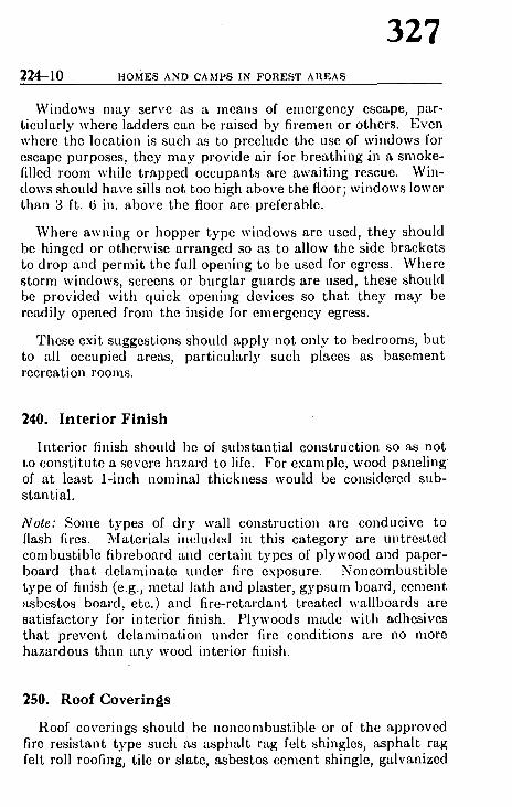
224-10 HoMEs AND CAMPS IN FOREST AREAS
327
Windows may serve as a means of emergency escape, par- tieularly where ladders can be raised by firemen or others. Even where the location is such as to preclude the use of windows for escape purposes, they may provide air for breathing in a smoke- filled room while t rapped occupants are await ing rescue. Win- dows should have sills not too high above the floor; windows lower than 3 ft. 6 in. above the floor are preferable.
Where awning or hopper type windows are used, they should be hinged or otherwise arranged so as to allow the side brackets to drop and permit the full opening to be used for egress. Where s torm windows, screens or burglar guards are used, these should be provided with quick opening devices so tha t they m a y be readily opened from the inside for emergency egress.
These exit suggestions should apply not only to bedrooms, but to all occupied areas, part icularly such places as basement recreation rooms.
240. Interior Finish
Inter ior finish should be of substant ia l construction so as not to const i tute a severe hazard to life. For example, wood panel ing of at least 1-inch nominal thickness would be considered sub- stantial .
Note: Some types of dry wall construction are conducive to flash fires. Materials included in this category are untreated combustible fibreboard and certain types of plywood and paper- board tha t delaminate under fire exposure. Noncombust ib le type of finish (e.g., metal lath and plaster, gypsum board, cement asbestos board, etc.) and f i re-retardant t reated wallboards are sat isfactory fox" interior finish. Plywoods made with adhesives that prevent delaminat ion under fire conditions are no more hazardous than any wood interior finish.
250. Roof Coverings
Roof coverings should be noncombust ible or of the approved fire resistant type such as asphal t rag felt shingles, asphal t rag felt roll roofing, tile or slate, asbestos cement shingle, galvanized

328 S T R U C T U R A L S T A N D A R D S 224--11
sheet iron or aluminum. 'Underwriters' Laboratories, Inc., Chi- cago, Illinois, publishes a listing of roofing materials which have passed the Laboratories' fire tests.
260. Spark Arresters
Spark arresters should be provided oll all chimneys and titles. An additional benefit of such arresters is that they prevent birds, rodents and insects from cntcring the building.
Spark arresters used o,I chimneys should be made of corrosion resistant materi~d such as copper bearing steel (0.25 of 1% copper) or of metal equivalent thereto in strength, corrosion resistance and quality.
Openings in the wire mesh should not exceed 5/~-inch in diameter, nor be less than ~G-inch in diameter. Spark arrcsters should be maintained in good condition to perform their intended service. (See NFPA Standard No. 213 - - " S p a r k Arresters.")

224-12 HOMES AND CAMPS IN FOREST AREAS
329
S e c t i o n 3
E L E C T R I C A L E Q U I P M E N T
300. I n s t a l l a t i o n a n d S a f e t y P r e c a u t i o n s
All electr ical i n s t a l l a t ions should be made by a qualified elec- I, rician in confo rmance with the N a t i o n a l Elec t r ica l Code ( N F P A No. 70) in the Un i t ed Sta tes and the C a n a d i a n Elect r ical Code in Canada .
Here are some th ings to check to assure t h a t ins t a l l a t ions are completed p roper ly :
(1) Make ccrt-tin th'tt fuses of tile correct capacity are used for the electrical circuits. If the fuse is of tile incorrect capacity, then electrical overload of tile circuit may cause overheating of the wiring and break- down of the insulation, with fire resulting.
(2) All wiring should be f'tstened securely to recel)taclcs and fixtures. Frayed or loosely connected wiring can result in arcing, or shock to persons.
(3) Be particularly cautious about touching any electrical fixture in a wet location. Fuse panel boxes should be located in a dry area so that the danger from moisture will bc minimized. In wet or moist .treas, the shock h.tzard can })e severe and m'ty even le'td to clcctro('ution, since the moisture provides a better path for' the electricity to tr~Lvel through the body to ground.
(4) Modern 3-wire circuit c.drle should be grounded properly on in- st'tlhttion. Only grounding type outlets should be installed.
(5) Since .t great deal of the older type 2-wire, ungrounded electrical circuits arc still in use, I)arti('uhtr attention must be given to the proper grounding of modern electrical :tl)l)liances on su(.h ci,'cuits.
(6) If electric lights dim when an clectric:d appliance such as a w-mhing machine, toaster, iron, or heater is turned on, this is an indication of overloading and tire circuit should be checked 'rod corrected.
Lampshades , cur ta ins , draper ies and s imilar f l ammable fabrics, plast ics or. paper p roduc t s should never be al lowed close to electric bulhs.
Ex tens ion cords should be res t r ic ted to the i r proper use, such cords should no t be run th rough walls or u n d e r carpets .

330 ELECTRICAL EQUIPMENT 224-13
Frayed and worn lamp or extension cords should be replaced immediately.
3i0. Radio and Television Equipment
All radio and television equipment should be installed accord- ing to the requirements of the National Electrical Code (NFPA No. 70) and the Code for Protection Against Lightning (NFPA No. 78). These requirements have been summarized in the NFPA pamphlet "Television and FM Antennas."
For safety against lightning, all metal structures, including masts and poles supporting an'tenna members should be grounded in a specific manner. If the building has an approved lightning protection system, metallic masts, when installed outside the building, should be bonded properly to the lightning protection system, with standard lightning conductors or the equivalent.
Antennas should not be installed where they can fall against power lines or, on large buildings, hamper or fall on fire fighters who may have to respond to a fire in the building.
If the building has modern 3-wire electrical circuits, ordinarily one side of the 110-volt supply circuit will be grounded, and lightning will have an alternative path to the ground through the radio or television receiver. In areas where lightning occurs frequently, the building owner should get advice from qualified electricians concerning the modern, safe installation of all such electrical equipment.
320. Protection Against Lightning
Homes in exposed positions in areas having frequent thunder- storm activity should be protected by a properly installed and maintained lightning rod system in accordance with the Code for Protection Against Lightning (NFPA No. 78).
Substantial personal protection against lightning can be ob- tained by following these safety recommendations:
Do not go out of doors or remain out during thunderstorms unless it is necessary. Stay inside of a building where it is dry, preferably away from fireplaces, stoves and other metal objects.

331 224-14 HOMES AND CAMPS IN F O R E S T AREAS
If there is any choice of shelter, choose in the following order:
I. Large metal or metal-frame buildings.
2. Dwellings or other buildings which are protected against lightning by a properly installed and maintained lightning rod system.
3. Large unprotected buildings.
4. Small unprotected buildings.
If remaining out of doors is unavoidable, keep away from:
1. Small sheds and shcltcrs if in an exposed location.
2. Isolated trees.
3. Wire fences.
4. Hilltops and wide-open spaces.
Seek shelter in an automobile, a cave, a depression in the ground, a deep valley or canyon, the foot of a steep or overhang- ing cliff, dense woods, or a grove of trees.

332 HEATING AND COOKING EQUIPMENT 224-15
Section 4
HEATING AND COOKING EQUIPMENT
400. Chimneys and Flues
Stoves and furnaces should be connected to a standard masonry chimney of 33~-inch millin~um wall thickness, with fire clay fluc lining, built on concrete or solid masonry foundation, or to an approved properly supported "patented chimney" installed in accordance with the listing of the testing laboratory. (Under- writers' Laboratorics, Inc., Chicago, Illinois, publishes lists of types of patentcd chimney considered suitable under this section.)
Any wood construction used in the building should not be in contact with the chimney and should be kept a minimum of two inches away.
Chimneys should extend at least 3 feet above the highest point where they pass through the roof of the building and at least 2 feet higher than any ridge within l0 feet of such chimney.
Periodically, flues and chimneys should be checked for accumu- lation of soot and cleaned when dangerous amounts are noted. (The period will vary depending upon the fuel used and the frequency of usagc.) Dampers and chimney connectors should be kept in good rcpair. (NFPA Standard No. 211 contains recommendations on chimney and flue construction.)
Fireplaces should be constructed of solid masonry or reinforced concrete. If a lining of fire brick at least 2 inches thick or other appropriate lining is used, the total thickness of back and sides should be 8 inches. Stone, concrete-block and cinder-block walls should be at least 12 inches thick�9 All chimneys should havc smooth flue linings of fire clay or vitrified clay not less than a/@inch thick with properly cemented joints to minimize the ac- cumulation of soot and thereby lessen the danger of chimney fires.
A solid hearth should extend a minimum of 20 inches from the flue or fireplace to protect flooring and rugs.
Fireplace openings should be equipped with small-mesh screen to cover the full width of the openings.
Fires in fireplaces should be put out before leaving the premises.

224--16 HOMES AND CAMPS IN F O R E S T AREAS
333
410. Equipment Burning Solid Fuel
Wood and coal stoves should rest on a solid base with 18-inch clearance from unprotected combustible walls and ceiling; 12- inch minimum clearance from noncombustible or fire-resistivo walls and ceilings.
A sheet metal floor covering should be used under wood stoves, where the flooring or floor covering is combustible, to catch fall- ing sparks; extend this covering at least 6 inches beyond all sides of stove and 12 inches in front.
Sheet metal or asbestos-covered metal should cover exposed combustible walls or parti t ions where the above clearances can- not be obtained. A l-inch air space should be provided between this protect ive covering and the wall, using porcelain knobs or small blocks for spacers.
Woodboxes should bc located at least 3 feet from a wood burn- ing stove.
Ashes should be deposited in covered metal containers only, storing out of doors until safe disposal can be made.
To dispose of ashes, dump them only when thoroughly welled in a pit dug in mineral soil where all vegetat ive hazard has been cleared away for l0 feet.
Kerosene or other flammable liquids should not be used for starting or quickening fires.
420. Outdoor Barbecues
The use of outdoor b~rbecues is cow~tiuuing to increase r:q)ictly, and portable and s ta t ionary b-trbequcs c'Luse many serious fires. Persons who use such barbecues should be certai~ tha t an ~trea of at least five feet around the b-trbecue is cleared of flammable materitd. Ashes and unburned nmterial from barbecues should be confined and disposed of in the same m-Lnner -Ls ashes from stoves.
430. Equipment Burning F lammable Liquids
All equipment which burns flammable liquid for cooking or supplying heat to a room or building should be installed in ac-

334 H E A T I N G A N D C O O K I N G E Q U I P M E N T 224-17
e o r d a n c e wi th the N F P A S t a n d a r d on Oil B u r n i n g E q u i p m e n t ( N F P A No. 31) b y qual i f ied mechan ic s expe r i enced in m a k i n g such ins ta l l a t ions . Only a p p l i a n c e s and e q u i p m e n t which have been t e s t ed and l i s ted b y a n a t i o n a l l y recognized t e s t i ng lab- o r a t o r y should be used and i ts use should be r e s t r i c t e d to i ts de s i gna t ed purpose .
Spec ia l care should bc t a k e n in the p lac ing of ke rosene s toves and p o r t a b l e ke rosene h e a t c r s to avo id c o n t a c t w i th c o m b u s t i b l e ma te r i a l s , i nc lud ing d rape r i e s , to avo id a c c i d e n t a l ove r tu rn ing , and to avo id b lock ing of ex i t rou te s in e v e n t of ma l func t ion . F a b r i c s m u s t no t be p laced on s toves for d ry in g .
T h e fo l lowing r e q u i r e m e n t s a re t a k e n f rom N F P A No. 3 l - - " I n s t a l l a t i o n of Oil B u r n i n g E q u i p m e n t . "
"Clearances and mounting.
Stoves shall be installed to provide clearances to combustible material not less than as shown in Table 6.
Stoves which .Lre listed for inst'tllation with lesser clearances than specified in Table 6 may be installed in accordance with their listing.
Table 6
M i n i m u m Clearance, Inches
Heat ing and Cooking Appl iances Sides Rear
Ch imney Con-
nector
Ranges . . . . . . . . . . . . . . . . 24 * 9 18 Room Heater, circulating type . . . . . . 12 12 18 Room Iteater, radiant type . . . . . . . . 36 36 18
*For other than tile oil burner side of a range tile clearance a t the side may be 18 inebes.
Stoves may be installed with lesser clearances to combustible material provided the combustible material is protected by plaster, sheet metal or other noncombustible material. In no case shall the horizontal distance be less than six inches from a range to that portion of adjacent unpro- tected combustible walls or cabinets extending above the cooking top of tim range."
Kerosene and fuel oil should be stored and handled in conformance with the provisions of the Flammable Liquids Code (NFPA No. 30) and the Standard for Oil Burning Equipment (NFPA No. 31).

335 224-18 HOMES AND CAMPS IN F O R E S T AREAS
440. Equipment Burning Gas
All e q u i p m e n t which burns gas should be installed ill accord- ance with the N F P A S tanda rd on Gas Appl iances and Gas Pip- i,lg ( N F P A No. 54). Liquefied pe t ro leum gas containers should hc installed in accordance with the N F P A S tanda rd for the Storage and Hand l ing of Liquefied Pe t ro leum Gas ( N F P A No. 58). Instal lat ion should be made only by a qualified installer.
General safe ty precaut ions to be observed for gas instal lat ions i . c lude the following:
(l) When work is to be ~)erformed on any gas installation or piping, the gas must be turned off to eliminate h.Lz,trd of leakage. All burners shouhl be turned off before the gas supply is stopped.
(2) When checking for Icakt~ge, so'q) and water, or other material accept-tblc for the purpose shall be used. M.~tches, candles, [lame or other sources of ignition shouhl never be used in locating g'ts leakage. Hand flashlights, IJref~r~d~ly of the safety type, or al)l)roved safety lamps should be used when sc:trching for gas leakage. Electric switches should not be oper'ttcd; if electric lights are ah'cady turned on when the search is being made, they should not be turned off. In other words, if there is any pos- sibility of g.~s lea[age in the room or area, every precaution must be taken to 'tvoid introducing a source of ignition.
(3) It is always best to call the gas installer or gas service company whenever g~s burning equipment does not function properly, or when- ever there is evidence of g'Ls lcak.'~ge.
Liquefied pe t ro leum gas, somet imes called "bo t t l ed gas ," is ~Jtorcd u,~dcr pressure in containers for domes t ic use. A s t rong qKIorant is added to this gas and to na tura l gas so t h a t leakage will be noticed p rompt ly .
For domes t ic use, conta iners should be set on a firm foundat ion , above ground. The out le t piping should bc protec ted agains t breakage by set t l ing by a flexible connect ion or special fitting. The containers are required to have safe ty deviccs spec i fed by In tcrs ta tc C o m m e r c e Commiss ion regulations.
The same sa fe ty pract ices should be followed for L P - G a s in- ritallations as are r ecommended for instal lat ions using na tu ra l or l '0mmercial gas. Always call the gas installer or gas service com- pany if the e q u i p m e n t does not funct ion proper ly or if there is l, vidence of leakage. T a k e precau t ions . to avoid a source of igni- llon if gas leakage is suspected.

336 IIEATING AND COOKING EQUIPMENT 224-19
450. Open Flame-type Lighting Equipment
Open flame-type lamps should be securely positioned on a substantial table or stand and kept af, le~st IS inches from com- bustible walls and ceilings.
Hanging lamps or lanterns shoukt be provided with catches or locks to prevent them from being accidentally knocked from their hooks. Above any hanging lantern or lamp, plate a metal shiekl with a minimum of I-inch air space between the shield and any combustible ceiling.
All open flame-type hmq)s , i,icluding candles, should have glass ctfimneys.
Open flame-type lamps should be cleaned after each use and refilled outdoors during daylight hours.
460. Storage of Combustibles and Flammables
Attics, cellars, garages, woodsheds and the premises in general, should he kept clear of accumulations of cast-off items and rub- bish. ("A clean house seldom burns.")
Casoline should he kept only in 'metal containers of the approved safety type. All dispensing of gasoline should be done outdoors.
Certain oils (vcgctable and animal oils) are subject to spon- taneous het,.ting in contact with combustibles. Oil-soaked rags, waste, or paper should not be allowed to accumuhtte. Temporary storage should bc fil a separate metal container.
Safety inatches should be used in preference to the "strike anywhere" type of match. All matches should be stored out of reach of small children and in protective containers.
Clothes or other fabrics should not be hung or placed over or close to heating appliances to dry.

224-20 ] IOMES AND CAMPS IN F O R E S T AREAS
337
Sect ion 5
GENERAL FIRE PROTECTION
500. Removal of Vegetat ive Hazards
Remove hazardous vegetative material 100 feet or more from all structures, outside fireplaces and incinerators. Lawns, gardens and green shrubs can be planted in this area to prevent erosion and to preserve ground moisture trod humus for larger tress. (See Section l, "Buikling Loc~tion," for additional clear- ance requirements.)
Trim tree limbs -rod boughs back 10 feet from all chimney outlets, outside firel)laccs and incinerators.
Thin and prune trees surrounding the structure to lessen danger of a fire crowning; in the event of a fire, this will decrease the amount of heat. Seek advice of ~ forester or fire w~rden regarding the proper removal and disposal of brush ~md other vegetation.
Keep structures and chimneys free of vines and other close growing vegetation that will become dry and hazardous during periods of drought.
510. Rubbi sh Disposal and Incinerators
Get rid of non-burmtble rubl)ish promptly before large amounts accumulate. Dispose of it at designated dumping grounds or burn combustible rul)bish in an approved type incinerator during damp, less hazardous weather.
Before doing any burning outdoors obtain a permit issued by local fire authority or forest officer trod follow his instructions as to clearance, time ~,~(1 nccessary tools to have available. (See NFPA Standard No. 82A, Rul)bish Handling and Incinerators.)
Inspect spark arrcsters regularly to make sure they are not clogged or burned out.

338 G E N E R A L F I R E P R O T E C T I O N 224-21
520. Brush Burning
Obtain burning permit and follow the permit instructions; do not burn during windy or dry wet~ther. After the brush is burned, patrol the area constantly, until you are certain that the fire is out.
530. Fundamenta l Fire Fight ing Equipment
Where water hose outlets are available, have sufficient garden hose or s/~-inch hose or other types to reach any part of the structure from garden hose outlets and equip the hosc with an adjustable garden-type nozzle; 100 fcet of hose is the desired minimum which should be stored where readily available. Where practical, hose should be racked near or kept connected to at least one outside outlet.
Keep a substantial ladder readily accessible. It should be of sufficient length to reach the roof ridge:
Keep a shovel, axe and rake and two or more pails filled with water available at all times and in good condition.
540. Portable Fire Extinguishers
Portable fire extinguishers are good emergency fire fighting equipment when used properly on the type and size of fire for which they are designed. Use only those extinguishers which have passed the tests of nationally recognized laboratories, such as the Underwriters' Laboratories, Inc., Factory Mutual Engineer- ing Division and Underwriters' Laboratories of Canada. In recent years, "multi-purpose" type extinguishers have been ap- proved for the major classes of fire. If a specific' kind of ex- tinguisher is wanted for a certain area of the building, here is a guide for selection:
For fires involving trash, paper, cloth, wood or other ordinary combustibles, use a pressurized water, pump tank or chemical extinguisher.
For fires in flammable liquids such as gasoline, oil, grease, tar and paint, use a carbon dioxide, dry chemical or foam extinguisher.

224-22 HOMES AND CAMPS IN FOREST AREAS
339
I;'or fires in electrical equipment such as lalnps, nloto,'s, fuse panels and switchboards, use a nonconducting cxtinguishing ~gcnt such as carbon dioxide or dry chemical. Do not use soda acid, foam or other water- type extinguishers until the electric power has been shut off.
I;'or detailed information on portable fire extinguishers, see ~I;'PA Standard No. 10.
~50. Automat ic Sprinklers
Wherever a reli'~ble water supply of ~dequate flow is avail- t~hlc, automatic sprinkle,'s can provide excellent fire protection.
For lodges, hotels, motels and other multiple-occupancy build- ~.gs in forested areas, substantial protection against interior fires ~a. be obtained through automatic sprinkler systems. Since ~hi!se buildings are not likely to have the benefit of public water mains, their sprinkler systems could be supplied by pressure ~:mks.
Detailed recommendations on all types of sprinkler systems for I~re, protection are contained in NFPA Standard No. 1 3 - - ~l,stallation of Sprinkler Systems." All such work should be
~,rformed by a qualified sprinkler contractor.
~60. Evacuation Plans and Routes
(:ommunities located in forested areas with limited means of ~;,~rcss should be constantly alert to the danger that regular ~,..utes of travel may be cut off by a forcst firc. This danger ~,ald exist for a single building, a group of cottages, or a well
: ,lal)lished community. Even though the means of exit may be , ut affected, adjacent fircs can move in quickly, necessitating , ~,ry rapid partial or complete evacuation of the location.
To assure a safe and orderly evacuation, detailed plans laid -,ell in advance are necessary.
I,'ormulation of the plan is essentially a community effort.
The organization heading the project might consist of a Chair- [ !,m or Director, and under his direction would be several corn-

340 G E N E R A L F I R E P R O T E C T I O N 224--23
mittees, each being responsible for such items as communica- tions, transportation, accomm6dation aud supply, medical and police work.
Plans would be developed for each of the above topics with complete details as to the various steps to be takea in the event of an emergency.
Communications would involve a complete warning system by means of a siren or other signal audible throughout the com- munity. The particular signal employed would signify the type and degree of plan to be put in operation.
Transportat ion would involve air, rail, road, boat, or other means of exit. A detailed and complete plan involving all possible means of moving peiople from the area would be con. sidered in the plan.
The accommodation and. supply group is responsible for the establishment of control centers and arrangements for the housing, feeding, warmth and general welfare of the people being evacuated as well as their return after the emergency is over.
The :'.,.edical committee arra,lgcs for first aid and medical supplies essential to the welfare of evacuees during the period of travel.
The police orgatfization having jurisdiction in the area is re. sponsible for law and order and traffic control throughout the emergency.
Many details must be worked out by the various committee and formulated into a complcte plan which should be provideg to each householder in the commuai ty il~ pamphlet form f01 s tudy and for ready referet{ce.
Two main responsibilities rest with the State, Provincial Federal or other agency responsible for forest fire control in tl, area, namely, fighting the fire and keeping the municipalit) full), advised of the fire situation at all times.
The complete plan should be worked out in detail during th~ off-season and reviewed regularly, in order that everyone con cerned may be fully informed as to responsibilities and procedure:

224-24 I1OMES A N D C A M P S I N F O R E S T A R E A S
341
Sect ion 6
OUTDOOR FIRE PROTECTION
600. Forest Land Owners and Managers
If they provide public campsites, owners and managers of forest lands should:
1. Restrict camping to prepared camp grounds where fire- places or stoves are provided or to sites designated by land own- ers, forest or park officials.
2. Make frequent personal contacts with forest users advising them of precautions necessary to prevent fires and also inspect 4'amp sites.
3. Keep campers currently informed of critical fire danger l:ituations and tell them what to do in case of danger.
4. Provide a cachc of fire fighting tools and inform campers of its location and use of tools.
5. When selecting locations to be developed into camp sites ~ttempt to pick the less hazardous areas.
(i. Employ fire prevention educational measures in camping qrcas such as posters, camp fire talks, demonstrations, movies, ~'t(~,
7. Through newspapers, radio and television keep the public ~.~fformed of closures, bans and postponement of hunting or fish- L :,lg s e a s o I I S .
8. Invoke camping, travel, or smoking bans during periods ~ high fire hazard.
9. As an extreme measure enact complete closures of areas.
~10. Forest Land Users
I. When required, register with proper forest or fire official lmn entering forested areas.

342 OUTDOOR FIRE PROTECTION 224~T,
2. Secure camp fire perinits where required.
3. Have car equipped with the fire fighting tools which ,nm) be required by State law or local regulations.
4. Be familiar with and observe regulations on smoking at") camp fire building.
5. Camp and house-trailer occupants should conform to Ih~ safety regulations for dwellings with respect to clearance ~.~ hazardous material, use of flammable liquids and gases and il~ stallation of approved .types of fire extinguishers.
6. Get acquainted with the local fire warden and find out ho~ to get in touch with him quickly in case of fire trouble.
7. Extinguish all open fires upon retiring or before leaving camp site.
8. Be an alert, good "housekeeper" in the woods. Praetir162 fire prevention at all times.
9. Do not discharge fireworks in forested areas; they awe generally prohibited.
620. Community Fire Protection
if possible, pool the resources of the community to provido 0 tanker fire truck, slip-on tanker pump unit, or portable punl i and forestry hose plus necessary manpower to ol)e'rate the eqt, ip inent. (See detailed specifications ill NFPA pamphlet No. 295M entitled, "Communi ty Forest Fire Fighting Equipnmnt." F~,l volunteer fire department equipment and organization, see NFI'~ Standard No. 192, "Volunteer Fire Departments for Rural an(i Small Community ~ervice.")
Know where and how to report fires to the local public fire pro tection agency.
630. Regulation
To at tain a degree of protection against fire, a communit) must establish certain laws and regulations and enforce thor:

343 224-26 HOMES AND CAMPS IN FOREST AREAS
for the sa fe ty of people wi th in the c o m m u n i t y . Basical ly , the following is nccessa ry :
I. Proper regulation of building construction.
2. Establishing necessary fire prevention measures.
3. Regulating use of fire and establishing the necessary precautions to Im l~tken.
,I. Setting up fire permit regulations.
5. Empowering fire officials with proper authority for enforcement.
6. Regulating disposal of burning material from any vehicle.

344 CAMPERS' RULES 224-27
Section 7
CAMPERS' RULES
700. Reporting Fires or Violations
Upon entering a forcstcd arca, lcarn how and where to report fires. If one is discovered, rcport it immediately.
Careless campers arc a major cause of fires in forested areas. Fires result in great loss to recreation areas, valuable timber and watershed lands. I t is therefore of the utmost importanco that campers recognize and appreciate their responsibility in pro. venting fires.
"710. Making Camp
Use a prep[~rcd camp site, preferably whcre fireplaccs or stovca are provided and veget~tivc hazard has been cleared away.
(Eee ~ection 420 for use of barbecues.)
Where it is permissible to prepare a camp site, follow thc~ rules:
Before bu i ld ing an open fire, scrape away all f l ammable mater ia l down Io mhmra l soil for a t least, five feet on all sides. D o n ' t confuse duff ( decay~ vege tab le m a t t e r ) with minera l soil - - duff is combust ib le .
Dig a small pit and keep the fire small. Never build it against trct~ logs or near brush.
Be sure pipe ashes, cigars or cigarette stubs are "dead oul," then dio pose of them in ash trays, mineral soil or water.
720. Breaking Camp
Never break camp until your open fire is "dead out." Satural~ ashes and coals with water, stir thoroughly until ashes are coFi to the touch. If you do not have sufficient water, stir or ch0; mineral soil into ashes and coals. Continue this until coals ,~ "dead out." Check by feeling them with bare hands.

224-28 IIOMES AND CAMPS IN FOREST AREAS
345
R E F E R E N C E LIST OF P U B L I C A T I O N S
The fol lowing pub l i c a t i ons con ta in de ta i l ed reference m~Lterial which s u p p l e m e n t s the i n fo rma t ion in this p a m p h l e t . T h e y m a y he o b t a i n e d by wr i t ing to the N a t i o n a l F i re F r o t e c t i o n Associa- tion, G0 B a t t e r y m a r c h S t ree t , Bos ton 10, M a s s a c h u s e t t s . A (~mq)lete l ist of the Assoc i a t i on ' s pub l i c a t i ons is ava i l ab l e free Olb request .
-'.'t~utdard No.
10
13
24
"~0
31
5,!
f,8
70
78
g2A
l t l l
IUI
i112
JII
2~!5M
~t.I
Title
Portable Fire Extinguishers
Installation of Sprinkler Systems
Outside Protection
Flammable Liquids Code
Installation of Oil Burning Equipment
Installation of Gas Appliances and Gas Piping in Buildings
Storage and Handling of Liquefied Petroleum Gases
National Electrical Code
Protection against Lightning
Incinerators, Rubbish Handling
Building Exits Code
Specifications for Portable Pumps
Volunteer Fire Departments
Chimneys, Flues and Vents
Spark Arresters for Chimneys ~tnd Stacks
Community Organization and Equil)ment for Fighting Forest, Grass and Brush Fires
Fire Retardant Treatments of Building MateriMs
NFPA Quarlery Reprint - - Television and FM Antennas

: 46 R E P O R T OF C O M M I T T E E ON GARAGES GARJ
Report of C o m m i t t e e on Garages
Elmer F. Reske, Chairman, Cook County Inspection Bureau, 175 W. Jackson Blvd., Chicago 4, Ill.
B. n . BattaP, lin~ NFPA Co,nmittee on Fin- istfing Proeesse~.
Andrew T. Bogfis, I l l , (pro tern), American Society of Heating, Refrigerating & Air- Conditioning Engineers, Inc.
J. R. De l | aven , Federation of Mutual Fire Insurance Cos.
P. W. Engels, American Pctrolculn I nstitute. H. E. Goranson , Tennessee Inspection
Bureau. Rober t N. Greene , Jr . , Travelers Fire In-
surance Co. (Personal) Casaa t t Griffin, International Conference of
Building Officials. Van Court Lucas, NFPA Committee on
Transit Operations. Mrs. Norene Dann Mar t in , National Park-
ing Association. David Miller, Meclmnical Contractors Asso-
ciation of America, Inc. J . L. Reardon, American Automobile Assn.
W. !1. Rodda, NFPA Committee on True, Transportation.
Elwood tl . Ru the r fo rd , Fire Marahab Association of North America.
E. N. Seari, NFPA Committee on Buildhli Construction.
J . P. Stokes, Association of Casualty 4 Surety Cos.
Wayne E. Swanson, International Aaao clarion of Fire Chiefs.
Jack Wood, National Automatic Sprinklrl and Fire Control Association.
Al te rna tes . Rober t Hat~,oplan, Association of Casaah)
& Surety Cos. (Alternate to J. P. Stokel,) Jack F. McKenna . American Petrolcm~
Institute. (Alternate to P. W. Engels.) J o h n G. Sk ldmore , American Society c~
Heating. Refrigerating & Air-Conditionin# Engineers. (Alternate to Andrew T. Bogg~ HI.)
This report has been submitted to letter ballot of the Commitlet which consists of 18 members, of whom all have vo~ed a~rmatively
The Committee prepared relatively extensive revisions t() NFPA No. 88, Standard for Garages, at its meeting on Janua D 23, 1962. They are presented for final adoption. The significance of the changes is stated briefly in the introduction of each itellt of the report.
P r o p o s e d R e v i s i o n s to
S T A N D A R D FOR G A R A G E S
NFPA No. 8 8 - 1957
1. In Paragraph 1310 change wording to include reference to th~ current title of Standard No. 80. Revised paragraph to read:
1310. Openings in fire walls shall be protected in accordan(~ with the Standard for the Installation of Fire Doors and Windo~ (NFPA No. 80).

#;. i l l2 REVISIONS TO NFPA NO. 88
347
Revise Paragraph 2011 (renumbering to 2020) to read:
$020. Section 65 of the Flammable Liquids. Code (NFPA * 30) shall be used to determine the extent of the hazardous
,,,'a where flammable liquids are stored or handled. Article 51 I 'l Hm National Electrical Code (NFPA No. 70) shall be used to
, ~,,rn the installation of wiring and equipment within the ",'~:lrdous a r e a s .
In Paragraph 211~ change wording to include reference to the ,cent titles of Standards Nos. 90A, 90B and 5~. Revised para- )ph to read:
,?1 I,I. Heating equipment shall be installed to conform with :~,,~wlcs X and XI of the Nati.onal Building Code published by '~ National Board of Fire Underwriters, the Standards of the ~io,lai Fire Protection Association on Air-Conditioning and
,, ~ililating Systems of Other Than Residence T)ipe (NFPA 90A), on Residence Type Warm Air Heating and Air-
mlitioning Systems (NFPA No. 90B), on Installation of Oil Jofing Equipment (NFPA No. 31), and on Installation of Gas
<,'A~llances and Gas Pipin.g (NFPA No. 54) except as hereinafter -~'ilioally provided.
In Paragraph 2210 change wording to include reference to the ~rcnl lille of Standard No. 90A. Revised paragraph to read:
4)110. General . Mechanical ventilating systems employed illlrages shall be installed in accordance with the Standard for
!,stallation of Air-Conditioning and Ventilating Systems of '~:,,r Than Residence Type (NFPA No. 90A) and in accordance ~h the provisions of Section 2100. When blower and exhaust
. h,ms are installed for vapor removal, the systems shall be in- ~lcd in accordance witJl the Standard for Blower and Exhaust ,=Ictus (NFPA No. 91).
Iteuise Paragraph 2265 to include reference to an additional , ~fllc, able NFPA Standard, No. 97. Revised paragraph to read:
u Ducts T h r o u g h Fire Walls. The passing of ducts ~,ugh fire wails should he avoided. Where ducts must pass i,,iilgli fire walls they shall be installed in accordance with the r of NFPA Standards Nos. 90A and 91. �9
Revise Paragraph 2320 to include reference to a designated area Io Standard for Fire Protection in Use of Cutting and Welding
~csses (NFPA No. 51B). Revised paragraph to read:

348 R E P O R T OF C O M M I T T E E ON GARAGES GAR~
2320. Welding or Open Flame Operations. All operation' involving open flame or electric arcs, including fusion gas an( electric welding, shall be restricted to the areas tha t are fire safe This provision includes, but is not limited to, fuel tank an( radiator repairs. Responsibility for cutt ing and ~elding, and re lated fire prevention precautions shall be in accordance wit[ requirements of the Standard for Fire Protection in Use of Cut ting and Welding Processes (No. 51B).
During preparation of N FPA Fire Record Bulletin HS-I, Welding apd Cutting in Garages, a s t u d y of 890 fires revealed that 139 (16~o) were started by welding or cutting torches�9
7. Revise Paragraph 2350 lo include refere.nce to correct .4rticle ( National Electrical Code. Last two lines of paragraph to read:
�9 . . accordance with Articlc 511 of the National Electrical Cod' (NFPA No. 70).
8. In Paragraph 2372 change wording to include reference to tl; current title of Standard No. 5~ and delete reference to form( Standard No. 52, contents of which are now in No. 5~. Revis( paragraph to read:
2372. Devices which are used to heat nonflammable solvel, shall conform to the requirement of one or more of the followinr ( l) Standard for the Installation of Oil Burning Equipmct' (NFPA No. 31); (2) Standard for the Installation of Gas App'. ances and Gas Piping (NFPA No. 54). The heating devices sh~ be so constructed tha t t l~ cleaning solvent cannot enter t}, coml)ustion chamber, the bot tom of which shall be more than I inches abovc the floor and shall contain no openings which w~ permit glowing particles or hot objects to fall to the floor.
9. In Paragraph 2382 change wording to include reference to t current title of Standard No. 5~ and delete reference to for~s�9 Standard No. 52, contents of which are now in No. 5~. Revill paragraph to read:
2382. Steam cleaning devices should be listed by a nationa!. recognized laboratory and shall conform to the requirenlcnts,' the Standard for Oil Burning Equipment (NFPA No. 31)I. oil consuming units and to Standard for the Installation of 61 Appliances and Gas Piping (NFPA No. 54) for gas burni: appliances.

GAR4 REVISIONS TO NFPA NO. 8 8
349
tO. Revise title of Article 2~00 to reflect new contents. Revised title ~,~ read:
~400. Storage and Handling of Flammable Liquids and Liquefied Petroleum Gases
n I. Revise wording of Paragraph 2~10 to delete listing of certain ~mnmable liquids and include reference to the current title of Stand- ~lrd No. 58. Revised paragraph to read:
2410. The storage and handling of flammable liquids shall be , il accordance with the Flammable Liquids Code (NFPA No. 30). ~hc storage and handling of liquefied petroleum gas shall be in , onipiiance with the Standard for the Storage and Handling of {l.iquefied Petroleum Gases (NFPA No. 58).
~. Eliminate Article 2500; and revise and renumber Paragraph !~tO to include reference to fueling vehicles wilh flammable liquids
,lud to include current number of applicable Section in Standard ~o. 30. Revised paragraph to read:
2420. Fueling Vehicles with Flammable Liquids. The de- -,gn and installation of equipment used for the dispensing of I!l,mmable liquids shall be in accordance with Section 63 of \ ' i :PA No. 30, Flammable Liquids Code.
L Delete Paragraphs 2511, 2512 and 2513, replacing with word- c ~ff/ consistent w~th related sectwns of I lammable Lzqu~ds Code VFPA No. 30). Revised and renumbered paragraphs to read:
2,121. Manual Nozzle: The dispensing of Class I flammable :quid into a fuel tank or into a cdntainer shall be under the con-
(:~ol of a competent a t t endant at all timcs. No device shall be "~cd which permits the dispensing of Class 1 flammable liquid
,Amn the operator 's hand is removed from the nozzle control ,vcr except as provided in Paragraph 2,t22.
A Class I flammable liquid includes those having flash points at or below 20 ~ F.
2,122. Automatic Nozzles with Latch-Open Devices: In lieu of '~,ing held open by hand, only an approved ~utomatic nozzle my be used for dispensing Class I flammable l iquid into the fuel
m k of a vehicle. Such a nozzle shall have the latch-open device ~ an integral part of the assembly and shall shut off the l iquid Aiab]y and posit ively when the gasoline tank is filled, when i t "~lls from the filling neck of an automobile tank, when it is sub-

350 R E P O R T OF C O M M I T T E E ON G A R A G E S GARf,
ject to rough usage such as dropping or lack of proper lubricatiotL or when an automobile is driven away while the nozzle is still h~ the tank. A competent attendant shall be in the immedial( vicinity of the vehicle being filled by such an approved nozzle.
2423. Inside L.ocation including Open Air Parking Garage,'~ Approved dispensing units may be located inside garages upo:, specific approval of the authority having jurisdiction. The di~: pensing area shall bc separated from motor vehicle repair area' in a manner approved by the authority having jurisdiction. Th,' dispensing unit and its piping shall be protected against physic~ damage by vehicles either by inountingon a concrete island or bb equivalent means and shall be located in a position where it can not be struck by a vehicle descending a ramp or other slope oL: of control. The dispensing area shall he provided with an ap proved mechanical or gravity ventilation system. A clearl)
' *identified switch, readily accessible in case of fire or physief~ damage to any dispensing unit, shall be provided to shut off th~ power to dispensing units. When dispensing units are locate(1 below grade only approved mechanical ventilation shall be user, and the entire dispensing area shall be protected by an approvc(l automatic sprinkler system. The ventilating systems shall lu electrically interlocked with the gasoline dispensing units so tha~ the dispensing units cannot be operated unless the ventilatiag fan motors arc energized.
1~. Renumber Paragraph 2514 to 2~24 to follow preceding re visions.
15. Revise and renumber Paragraph. 2530 to include reference t fueling vehicles with liquefied petroleum gas. Revised paragreqJ' to read:
2430. F u e l i n g V e h i c l e s w i t h L i q u e f i e d P e t r o l e u m Ga~ Facilities for filling liquefied petroleum gas fuel tanks shall I,: located outside of any building not used exclusively for dispensiu~ and storing of liquefied petroleum gas.
16. Delete Paragraph 2531 and replace with wording consistet, with related sections of Standard for the Storage and Handling Liquefied Petroleum Gases (NFPA No. 58). Revised paragrapt. to read:
2431. Meters, vapor separators, valves, and fittings in th~ dispenser shah be suitable for LP-Gas service and shall be dr signed for a minimum working pressure of 250 psig.

(;AR(.I REVISIONS TO NFPA NO. 88
351
2'132. Provisions shall be made for venting LI)-GtLs contained in IL dispensing device to a safe location.
One way of '~ccomplishing this is to vent the LP-Gas at the point of disHmrge of the storage tank safety relief valve.
2,133. Pumps used to t ransfer LP-Gas shall be equipped to allow control of the flow and to prevent leakage or accidental disvharge. Means shall be provided outside the dispensing device to readily shut off the power in the event of fire or accident.
2434. A manual shut-off valve and an excess flow check valve ~,hall be installed downs t ream of the pump and ahead of the dis- Imnser inlet.
2,t35. Dispensing hose shall be resistant to the action of LP- (;as in the liquid phase and designed for a min imum burst ing pressure of 1,250 psig. An excess flow check valve or au tomat ic ~!hut-off valve shall be installed at the terminus of the liquid line at the point of a t t a chmen t of the dispensing hose.
2,136. LP-Gas dispensing devices shall not be located less than 10 feet from aboveground storage containers greater than 2,000-gallon watcr capaci ty nor closer than 20 feet to the nearest hlLsement or cellar, pit, building, sidewalk, s t reet or thoroughfare, or proper ty line. LP-Gas dispensing devices shall not be in- t~talled within a building except tha t they may be located under a weather shclter or canopy provided this area is not enclosed on more than two sides. I f the enclosing sides are adjacent to each ol, hcr, the area shall be properly ventilated. No drains or blow- off lines shall bc directed into or in proximity to the sewer sys- tems used for other purposes.
2437. LP-Gas dispensing devices shall be installed on a con- crete foundation or as par t of a complete storage and dispensing assembly mounted on a conlnlon base, and shall be adequate ly pt'otected from physical damage.
2438. The dispensing of LP-Gas into the fuel container of a vehicle shall be performed by a competent a t t endan t who shall remain at the LP-Gas dispenser during the entire t ransfer opera- tion. The motors of all vehicles being fueled shall be shut off during the fueling operations.
17. Renumber Paragraphs 2532 to 2~39 to follow preceding re- visions.

35Z R E P O R T OF C O M M I T T E E ON G A R A G E S GAR7
18. Insert new Article 2500 to read:
2500. Compressed Gas Cylinder Storage
19. Delete Paragraph 2533 and replace with newly numbered and reworded paragraph referring to requirements of NFPA No. 51. Revised paragraph to read:
2501. Compressed gases shall be stored in accordance with the Standard for the Installation and Operation of Gas Systems for Welding and Cutting (NFPA No. 51).
20. Revise Paragraph 3015 to include sprinkler requirement for Underground Garages over 5,000 square feet. Revised paragraph to read:
3015. Basement and Underground Garages excecding an area of 5,000 squarc fcct.
21. Delete Paragraph 3025 in view of requirement for sprinklers in Underground Garages being included in Paragraph 3015.
22. Revise Paragraph 3420 to include reference to NFPA No. 72C, formerly a part of NFPA No.-72. Last sentence to read:
3420 . . . . Details of facilities for approved watchman, fire alarm and supervisory service are contained in the Standards for Central Station Protective Signaling Systems (NFPA No. 71), Proprietary, Auxiliary and Local Protective Signaling Systems (NFPA No. 72) and Remote Station Protective Signaling Sys- tems (NFPA No. 72C).

R E P O R T OF C O M M I T T E E ON GAS ES
353 GA1
R e p o r t o f C o m m i t t e e o n G a s e s . Frankl in R. Fe the rs ton , Chairman,
Compressed Gas Assn., Inc., 500 Fifth Ave., New York 36, N. Y.
Clark F. J o n e s , t Secretory, National Fire Protection Assn., 60 Batterymarch St., Boston 10, Mass.
Orville L. Baubl i tz , IIoueing & Home Finance Agency.
Morris Bengal , New York Bureau of State Building Codes.
W. M. Cline, American Iron & Steel In- stitute.
John J. Crowe, Compressed Gas Association, Inc.
E. C. Curt is , Industrial Truck Association. II. L. DeCamp, Conference of Special Risk
Underwriters. W. H. Doyle, Factory Insurance Associ-
ation. A. F. Dyer, American Petroleum Institute. L. H. Flanders , Factory Mutual Engineer-
ing Division. L. H. Hansen , Factory Insurance Associ-
ation. F~d. J. Herron, Fire Marshals Association of
North America. Raymond M. Ii111, Fire Marshals Associ-
ation of North America. Kenne th E. Kamho lz , Federation of Mu-
tual Fire Insurance Cos. II. V. Keepers, Fire Prevention and Engi-
neering Bureau of Texas. L. G. Ma t thews , International Acetylene
Association.
J. W. Morris, Jr . , South-Eastern Under- writers Association.
Rober t T. Pa lmer . Fire MiLrshals Associ- ation of North America.
Rober t E. Poethlg, Liquefied l'etroleum Gas Association., Inc.
George II. Pope, Underwriters' Laboratoriee, [nc,
W m . I!. Richardson, National Park Service. C. C. Segeler, American Gas Association. Myron Snell, Association of Casualty &
Surety Cos. E. C. S o m m e r , American Petroleum In-
stitute. II. Emerson T h o m a s , Wsstfield, N. J.
(Personal) J o h n L. T h o m p s o n , Kentucky Inspection
Bureau. Win. II. Van A r n u m , National Board of
Fire Underwriters. Lewis W. Vaughan , Underwriters' Lab-
oratories of Canada. Lucius E. Vaughn, Fire Marshals Associ-
ation of North America. C. C. W e s tmore l a nd , American Gas Ae-
eocintion.
Al te rna tes .
Dale K. Auck, Federation of Mutual Fire L . E . I l enry , American Gas Association. Insurance Cos. (Alternate to Kenneth E. (Alternate to C. C. Westmoreland.) Kamholz.) E . O . Mat tocks , American Petroleum In-
Russell Has t ings , Industrial Truck Associ- etitute. (Alternate to A. F. Dyer and E. C. ation. (Alternate to E. C. Curtis.) Summer.)
Clay B. Wade, South-Eastern Underwriters Assn. (Alternate to J. W. Morris, Jr.)
|Non-voting.
The report of the Committee on Gases this year is divided into three parts. Part I is the work of the Sectional Committee Oil Industrial Gases, ])art II is the work of the Sectional Com- mittee on Gas Utilization, and Part III is the work of the Sectional Committee on Utility Gases.
Part I contains proposed revision of NFPA No. 566. Part II reports extensive proppsed revisions of NFPA No. 565
and is shown as Part III of the Committee on Hospitals Report tin page 430.
Part I I I is a proposed complete revision of NFPA No. 59.

354 GA-2 R E P O I t T O F C O M M I T T E E ON G A S E S
The following scclAonal committees respoi~siblc for the initial development and revision of st~uldards on their respective sub- jects report to the Association through the general Committee on C;ascs. Thcre is also an Exccutivc Committee, consisting of the Gcncral Chairman, Sccrctary, and the Chairmci~ of the Sectional Committccs, cx officio.
S E C T I O N A l . C O M M r I ' T E E ON I N D U S T R I A l . G A S E S . M y r o n Sne l l , Chairman,
W . M. C l l n e F .d . J . I l e r r o n R o b e r t E. P o e t h l g J. J . Crowe R a y m o n d M. I n l l G e o r g e II. Pope W. II. Doyle L . G . M a t t h e w s E . C . S o m m e r A. F. l )yer E . O . M a t t o c k s II. E. T h o m a s F. R. F e t h e r s l o n (alternate to A. F, Dyer W. II. Van A r n u m L. II. F l a n d e r s and E. C. Summer) L . W . V a u g h a n
SEC 'F IONAL C O M M r I - I ' E E ON U T I L I T Y GAS. C. C. W e s t m o r e l a n d , Chairman,
Orv i l l e L. B a u b l l t z M o r r i s Benga l A. F. Dyer F. R. F e t h e r s t o n L. II. F l a n d e r s L. 13. I l a n s e n L. E. I l e n r y
(altcrnatt~ ,~u C. C. ~tVeStlll,)reltt nd)
Ed. J . I l e r r o n C . G . Sege le r R a y m o n d M. I l i i l M y r o n S n e l l II . V. Keepers II. E. T h o m a s E. O . M a t t o c k s W . II. Van A r n u m
(alternate to A. F, Dyer) L . W . V a u g h a n W. G. Meade L u c i u s E. V a u g h n
(alternate tu Myron Snell) C lay B. W a d e J . W. Morr i s , J r . (altermtte to J. W. R o b e r t T. P a l m e r Morris, Jr.)
S E C T I O N A L C O M M I T T E E ON G A S U T I L I Z A T I O N . J o h n L. T h o m p s o n , Chairman,
J . J . Crowe Ed. J. I l e r r o n C . G . Sege le r W. II. Doyle L . G . M a t t h e w a II. E. T h o m a s A. F. Dyer E . O . M a t t o c k s W. II. Van A r n u m F. R. F e t h e r s t o n (alternate to A. F. Dyer)

REPORT OF COMMITTEE ON GASES
355 GA3
Part I
Proposed Revision
STANDARD FOR THE INSTALLATION OF BULK OXYGEN SYSTEMS AT CONSUMER SITES
( N F P A No. 5 6 6 - 1957)
This section of the report has been submitted to ballot of the Com- mittee on Gases which consists of 30 voting members, 26 of whom have voted o~rmativelg, Mr. Curtis not voting; Messrs. Hill, Kamholz and Vaughn have not returned ballols.
Refer to the 1957 edition as published in pamphlet form and in Vol. I, National Fire Codes, 1960-4~1.
The following proposed revision in NFPA No. 566, S tandard for Bulk Oxygen Systems at Consumer Sites was prepared by the Sectional Committee on Industrial Gases and then submit ted for review and ballot by the Committee on Gases.
Revise Paragraph 3-1 to read:
3-1. Bulk Oxygen System. A bulk oxygen system is an assembly of equipment, such as oxygen storage containers, pres- sure regulators, safety devices, vt~porizers, nmnifolds and inter- connecting piping, which has storage capacity of (a) more than 13,000 cubic feet of oxygen (NTP) connected in service or ready for service, or (b) more than 25,000 ctfl)ic feet of oxygen (NTP) including unconnected reserves on hand at the site. The bulk oxygen system terminates at the point where oxygen at service pressure first enters the supply line. The oxygen containers may be s tat ionary or movable, "rod the oxygen may be stored as gas or liquid.

356 GA4 R E V I S I O N S TO N F P A NO. 59
P a r t II
Proposed Revision
Standard for
NONFLAMMABLE MEDICAL GAS SYSTEMS No. 5 6 5 - - M a y 1958
This section of the report has been submitted to ballot of the Com- mittee on Gases, which consists of 30 voting members, 24 of whom have voted a Oirmativelg. Messrs. Doyleand Hansen voted negatively. Mr. Curtis not voting. Messrs. Hill, Kamholz and Vaughn have not returned their ballots.
Proposed revisions are shown as Part I I I of the Committee on Hospitals Report..
P a r t III
This section of the report has been submitted to ballot of the Com- mittee on Gases, which consists of 30 voting members, 24 of whom have voted a~irmatively. Messrs. Doyle and Hansen voted negatively. Mr. Curtis not voting. Messrs. Hill, Kamholz and Vaughn have not returned their ballots.

GENERAL REQUIREMENTS
357 59-3
Proposed Changes in
S t a n d a r d for the Storage and Hand l i ng of
L i q u e f i e d P e t r o l e u m G a s e s a t U t i l i t y G a s P l a n t s
No. 59--May 1958
SECTION 1. GENERAL REQUIREMENTS
11. Introduction.
110. This standard recommends basic requirements. The principal purpose of this standard is to outline methods for pro- tection of persons and property by providing in a condensed form a standard of reference to serve as a guide to all persons con- cerned with the construction and operation of liquefied petroleum gas equipment at utility gas plants.
111. The term "liquefied petroleum gases" as used in this standard shall mean and include any .material which is com- posed predominantly of any of the following hydrocarbons, or mixtures of them; propane, propylene, butanes (normal butane or isobutane), and butylenes.
112. In the interest of safety, it is important that persons engaged in handling liquefied petroleum gases understand the properties of these gases and that they be thoroughly trained in safe practices for the handling and distribution of these products.
113. Under moderate pressure the gases liquefy, but upon relief of the pressure are readily converted into the gaseous phase. Under moderately low temperature the gases liquefy. Advan- tage of this characteristic is taken by the industry. Generally the gases are shipped and stored under pressure as liquids. The escape of liquid into the atmosphere normally results in instan- taneous vaporization, with the volume of gases being between 200 and 300 times the volume of escaping liquid. When in the gaseous state these gases are heavier than air and have a nar- rower range of flamnmbility than natural or manufactured gas.
114. In the case of pure product at atmospheric pressure and below 31 F., normal butane is a liquid. Propane is a liquid at atmospheric pressure at temperatures below minus 44 F. and

358 59-4 LP GASES AT U'rlLITY GAS PLANTS
normally does not present ,~ flammable liquid hazard except when stored at or below its boiling point.
115. Commercially available butane and propane may have different liquefying points from those given above because they normally contain various percentages of other hydrocarbon products.
116. Rapid vaporization takcs place at temperatures above the boiling points (normal butane about 31 F.; propane about minus 44 F.). Normally these gases are stored as a liquid under pressure; however, in refrigcrated storage these gases are fre- quently stored at or below the boiling point at practically at- mospheric pressure.
12. Appl icat ion of Rules.
120. The following standard is intended to apply to utility gas companies for tile design, construction, location, installation, and operation of refrigerated and nonrefrigerated liquefied petroleum gas systems.
121. When operations involving container charging or trans- portation of liquefied petroleum gas in liquid form are carried out on the same property, these operations shall conform to Standard for the Storage and Handling of Liquefied Petroleum Gases (No. 5S).*
122. Installations having -tn aggregate water capacity not exceeding 2,000 gallons shall conform to Standard for the Storage and Handling of Liquefied Petroleum Gases (No. 58).*
13. Definit ions.
130. The term "gas" in this standard shall refer to liquefied petrolcum gases in either the liquid or gaseous state.
131. The term "containers" includes all vessels such as tanks, cylinders or drums used for storing liquefied petroleum gases.
132. The term "systems" as used in this standard refers to an assembly of equipment consisting essentially of liquefied petroleum gas unloading equipment, container or containers, major devices such as vaporizers, relief valves, excess flow
*See Appendix G, page 59-46, for availability.

G E N E R A L REQU I Ir E N T S
359 59-5
valves, regulators, and interconnecting piping. In the case of refrigerated storage, it would also ' include compressors, con- dcnsers, and other related equipment and controls. Such systems shall include any unloading equipment , storage equipment or in- terconnecting piping up to the outlet of the first s tage regulator, vaporizer or mixing device, whichever is the last unit before the liquefied petroleum gas enters other plant equipment or distribu- tion lines.
133. Tim designation of containers used for storing any of the liquefied petroleum gases defined in this s tandard shall de- pend on the type of construction employed during its fabrication.
(a) Containers completely fabricated within a plant under shop controlled conditions shall be known as "shop fabricated containers."
(b) Containers fabricated in whole or in par t at or near their final location shall be known as "field erected con- tainers."
134. The term "bur ied" refers to installations in which the top of tim container (excluding the manway) is below the sur- rounding grade. The term "par t ia l ly buried" (or mounded) refers to installations in which the top of the container is above the surrounding grade and is covered with earth.
135. The abbreviat ions "psig" and "psia" as uscd in this s tandard refer to pounds per square inch gauge and pounds per square inch absolute, respcctivcly.
14. Odorizing Gases.
140. All liquefied petroleum gases slmll be effectively odor- ized by an approved agent of such character as to indicate positively, by a distinctive odor, the presence of gas down to concentration in air of not over one-fifth the lower limit of flam- mabil i ty; provided, however, tha t odorization is not required if harmful in the use or further processing of the liquefied pe- troleum gas, or if odorization will serve no useful purpose as a warning agent in such use or further processing.
NOTE: The lower limits of flammability of the more commonly used liquefied petroleum gases are: Propane, al)proximately 2 per cent; Butane, approximately l ~ per cent. These figures represent volumetric per- centages of gas in a gas-air mixture in each case.
141. The odorization requirement of 140 shall be considered to be met by the use of 3 1.0 pounds of e thyl inercaptan, 1.0

360 59-6 LP G A SES AT U T I L I T Y GAS P L A N T S
pounds of thiophane, or 1.4 pounds of amyl mercaptan per 10,000 gallons of LP-Gas. However, this listing of odorants and quantities shall not exclude the use of other odorants that meet the odorization requirement of 140.
15. Approval of Equipment.
150. In systems utilizing containers of over 2,000 "gallons water capacity, each container valve, excess flow valve, gauging device, relief device directly connected on the liquefied petroleum gas container and direct fired vaporizer shall have its correctness as to design, construction, and performance determined by:
�9 (a) Listing by Underwriters' Laboratories, Inc., or
(b) Listing by a nationally recognizcd agency for liquefied petroleum gas use, or
(c) The authority having jurisdiction.
16. Damage from Vehicles�9
160. Where damage to liquefied petroleum gas systems from vehicular traffic is a possibility, precautions against such damage shall be taken.
17. Electrical Equipment.
170. Electrical installations and equipment shall conform to the provisions of the National Elcctrical Code (No. 70)* or be such as may be required and approved by the authority having jurisdiction.
171". Adequate lighting shall be provided to illuminate operat- ing facilities such as walkways and essential control valves.
18. Sources of Ignition.
180. Open flames and other sources of ignition shall not be permitted in vaporizer rooms, gas mixing rooms, and silnilar locations. Direct-fired vaporizers shall be located outside or ill a separate room or building.
181. Liquefied petroleum gas storage containers do nob re- quire lightning protection. (See Paragraph 326, Code for Pro- tection Against Lightning, NFPA No. 78.)*
*See Appendix G, page 5946, for availability.

N O N R E F R I G E I t A T E D C O N T A I N E R S
361 59-7
182. Since liquefied petroleum gas is containccl i~l a closed system of piping and equipment, the system need not be elec- trically conductive or electrically bonded for protection agai , s t Htatic electricity. (See Paragraph 6130, Static Electricity, NFPA No. 77M.)*
183. If the presence of s tray electric currents is indicated as a cause of corrosion due to electrolysis, proper provision shall be made for suitable protection.
SECTION 2. NONREFRIGERATED CONTAINERS.
21. Requirement for Construction and Original Test of Nonrefrigerated Containers.
210. Shop fabric~ted containers shall be designed, constructed m~d tested in accordance with the Unfired Pressure Vessel Code ~ponsored by either the America~l Society of Mechanical Engi- lleers (ASME)* or the American Petroleum Inst i tu te and the American Society of Mecha, ical Engineers (API-ASM E) ** or in accordance with the rules of the author i ty under which the containcrs are installed, provided such rules substantially con- form with the rules of tim ASME Code or the API -ASME Code.
(a) Containers constructed according to the 1949 and earlier editions of the ASME Code need not comply with the paragraphs U-2 to U-10 inclusive and U-19. Containers constructed according to paragraph U-70 are not authorized.
(b) Containers constructed according to API-ASME Code need not comply with the Section l or with appendix to Section I of said Code. Paragraphs W-601 to W-606 in- clusive in the 1943 and earlier editions of said Code do not apply.
21 l. The provisions of 210 sball not be construed as prohibit- i.g tile colJtinued use or reinstallati(m of containers constructed ~.d maintained in accord'thee with tim Code in effect at the time ~f fabrication.
'See Aplmndix G, page 59-t6, for av,'dlability of standards.
'~ of eontufiners under Om API-ASME Code is not authorized after July 1, 1962.

362 59-8 LP G A S E S AT U T I L I T Y GAS P L A N T S
22. D e s i g n P r e s s u r e a n d C l a s s i f i c a t i o n o f N o n r e f r i g e r - a t e d C o n t a i n e r s .
220. Shop f ab r i c a t ed s t o r age con ta ine r s for non re f r i ge r a t ed s t o r age shal l be des igned and classif ied as fol lows:
Minimum Design Pressure of Container lb. per sq. in. gauge
1949 edition of ASME Code (Par. U-200, U-201);
For Gases with Vapor 1950, 1952, 195~i and 1959 Press. Not to Exceed 1949 and earlier editions of ASME Code;
Container lb. per sq. in. gauge editions of ASM E All editions of Type at 100 F. (37.8 C.) Code (Par. U-68, U-69) API-ASME Coder
80* 80* 80* 100" 100 10.0 100 125 125 125 125 156 150 150 150 187 175 175 175 219 200'* 215 200 250
*New storage containers of the 80 type have not been authorized since Dec. 31, 1947.
**Container type may be increased by increments of 25. The minimum design pressure of containers shall be 100~o of the container type designation when constructed under 1949 or earlier editions of the ASME Code (Par. U-68
u he and U-69). The mininmm design pressure of containers shall be 125 To of t container type desigmttion when constructed under: (l) the 1949 ASME Code (Par. U-200 and U-201), (2) 1950, 1952, 1956 and 1959 editions of the ASME Code, and (3) all editions of the API-ASME Code.
tConstruction of containers under the API-ASME Code is not authorized after July 1, 1962.
NOTE: Because of low soil temperature usually encountered, and the insulating effect of the earth, the average vapor pressure of products stored in underground containers will he materially lower than when stored aboveground. This reduction in actual operating pressure there- fore provides a substantial corrosion allowance for these containers when installed underground.
221. F i e l d - e r e c t e d n o n r e f r i g e r a t e d con ta ine r s shal l be bu i l t in a cco rdance wi th app l i c ab l e p rov i s ions of the 1959 ed i t i on of the A S M E Boi le r and Pressure Vessel Code Sec t ion V I I I , Unfired Pressure Vessels, excep t t h a t c o n s t r u c t i o n us ing j o i n t efficiencies in T a b l e s U W I 2 , C o l u m n C is no t p e r m i t t e d .
222. F i e l d - e r e c t e d con ta ine r s for non re f r i ge r a t ed s to rage sha l l be des igned for a p ressu re no t less t h a n 125C7o of t he maxi- m u m v a p o r p ressure of t h e p r o d u c t a t 100 F. to be s to red in the con ta iners , b u t in no case shal l t he con t a ine r be des igned for a p ressu re of 25 psig or less.

N O N R E F R I G E R A T E D C O N T A I N E R S
363 59-9
223. The shell or head thickness of any nonrefrigerated con- tainer shall not be less than ~6 inch.
23. Markings on Nonrefrigerated Containers.
230. Each container for nonrefrigerated storage shall marked as specified in the following:
be
(a) With a marking identifying compliance with, and other markings required by the rules of the code under which the container is constructed; or with the s t amp and other markings required by the Nat ional Board of Boiler & Pressure Vessel Inspectors.
Underground : Container and an accessible name plate. Aboveground : Container.
(b) With notat ion as to whether sys tem is designed for underground or aboveground installation.
Underground : Container and an accessible name plate. Aboveground: Container.
(C) With the U. S. Standard.
Underground : Aboveground :
water capaci ty of the container in gallons,
Container and all accessible name plate. Container.
(d) With the pressure in pounds per square inch for which the container is designed.
Underground: Container and an accessible name plate. Aboveground : Container.
(e) With the wording "This container shall not contain a product having a vapor pressure in excess of -----: lbs. per sq. in. gauge at 100 F . " (See 220 and 222.)
Underground and aboveground: A name plate or tag on filler connection.
(f) With the outside surface area in square feet. Underground: Container and'an accessible name plate. Aboveground: Container.

3 6 4
59-10 LP GASES AT UTILITY GAS PLANTS
(g) With marking indicating the maximum level to which the container may be filled with liquid at temperatures between 20 F. and 1:30 F. except on containers provided with fixed maxilnum level indicators. Markings shall be in increments of 20 F.
Aboveground and underground: System name plate or on liquid level gauging device.
24. Location of Nonrefrigerated Containers.
240. Nonrefrigerated Aboveground Containers
(a) Containers shall be located outside of buildings.
(b) Contailmrs shall be located in accordance with the following table:
Water capacity of each container in gallons
2,001 to 30,000 30,001 to 70,000
70,001 to 125,000 125,001 to 200,000 200,001 to 1,000,000 1,000,001 or more
Minimum Distances
Between containerst i n feet
5 ofl 1/4 of sum of diameters adjacent containers
~t
cc
F r o m c o n t a i n e r to n e a r e s t in t . ~ o r t a n t b u i l d i n g or g r o u p ol u i l d i n g s , o r a p r o p e r t y lin0
w h i c h m a y b e b u i l t u p o n in feet
50 75
100 200 300 400
~rhe minimum distance requirement for spacing between containers wlm~l the water capacity of a container is 180,000 gallons or more shall be at least 25 feet. Tile minimum distance requirement for spacing betweell groups of containers when a group of two or more containers has an aggr(~ gate water capacity of 180,000 gallons or more shall be at least 25 feet
(c) A container or containers with an aggregate watel capacity in excess of 180,000 gallons, and their loadinl~ stations should be located 100 feet or more from buildin~ occupied for generation, compression or purification 0~ manufactured gas, or from natural gas compressor build: ings, or from outdoor installations essential to the maintc nance of operation in such buildings. Such container ol containers and their loading stations should be 100 feet or more from aboveground storage of flammable liquids and

365 N O N R E F B . I G E R A T E D C O N T A I N E R S 59-11
from any buildings of such construction or occupancy which constitutes a material hazard of exposure to the containers in the event of fire or explosion in .said buildings, if the container or containers are located closer than 50 feet to any such buildings or installations, then thc latter shall be protected by walls adjacent to such storage containers or by other appropriate means against thc ent ry of escaped liquefied petroleum gas, or of drainage from the storage container area and its loading points - - all in such a manner as may be required and approved by the au- thori ty having jurisdiction.
(d) Nonrefrigerated liquefied petroleum gas containers shall not be located within dikes enclosing flammable liquid tanks, and shall not be located within dikes en- closing refrigerated liquefied petroleum gas tanks.
241. Nonrefrigerated Underground Containers
(a) Underground containers shall include both buried and partially buried (or mounded) containers.
(b) Containers shall be located outside of any buildings. Buildings or roadways shall not be constructed over any underground containers. Sides of adjacent containers shall be separated by not less than 3' feet.
(c) When containers are installed parallel with ends in line, any number of containers may be in one group. When more than one row is installed, the adjacent ends of the tanks in each row shall be separated by not less than 10 feet.
(d) Containers and their loading stations shall be lo- cated not less than 50 feet from the nearest important build- ing or group of buildings or line of adjacent property which may be built upon.
(e) The containers and their loading stations should be located not less than 50 feet from buildings occupied for generation, compression or purification of gas, or from out- door installations essential to the maintenance of operation in such buildings. They should be located not less than 50 feet from aboveground storage of flammable liquids and from any buildings of such construction or occupancy which con- sti tutes a severe exposure to any aboveground appurtenances of the underground installation in the event of fire or ex- plosion in said buildings. If the underground installations

366 59-12 LP GASES AT U T I L I T Y GAS P L A N T S
by necessity are located closer than 50 feet to any such buildings or installations, then the latter shall be protected against the entry of escaping liquefied petroleum gas, in such a manner as may be required and approved by the authori ty having jurisdiction.
242. Nonrefrigeratcd containers shall not be stacked one above the other.
243. The ground within 25 feet of any aboveground nonre- frigeratcd container shall bc kept clear of readily ignitible ma- terial such as weeds and long dry grass.
244. In cases where nonrefrigerated containers are to be in- stalled in heavily populatcd or congested' areas, the authority having jurisdiction shall determine restrictions of individual tank capacity, total storage, distance to lille of adj'oining property which may be built on or other reasonable protective methods,
25. Installation of Nonrefrigerated Storage Containers.
250. Nonrefrigerated Aboveground Containers
(a) Every container shall be supported to prevent th~ concentration of excessive loads oil the supporting portion of the shell or heads.
(b) Supports for containers shall be of solid masonry, concrete or steel. Structural metal supports may be em- ployed when they are protected against fire in all approved manner. Steel supports shall be protected against fire with a material having a fire resistance rating of at least two hours. Steel skirts having only one opening shall be pro- tected as above but fireproofing need only be applied to the outside of the skirt.
(e) Horizontal containers shall be mounted on saddles in such a manner as to permit expansion and contraction, not only of the container but also of the connected piping. 0nly two saddles shall be used.
(d) Suitable means to prevent corrosion shall be provided on that portion of the container in contact with the founda- tions or saddles.
(e) Containers should be kept properly painted or other- wise protected from the elements.

N O N R E F R I G E I t A T E D CONTA IN EItS
367 59-13
251. Nonrefrigerated Underground Containers
(a) Buried containers shall be placed so that the top of the container is not less than 6 inches below tile grade of the surrounding area. Partially buried (or mounded) con- tainers shall have not less than 12 inches of cover, sufficient to provide surface drainage without erosion or other de- terioration.
(b) The container manway shall not be covered with the backfill or mounding material. Under conditions where the container manway cover is below the ground level, a manway providing sufficient access shall be installed. No other part of the container shall be exposed.
(c) The containers shall be set on a firm foundation or firm undisturbed earth and surrounded with soft earth or sand well tamped into place. Provision shall be made to take care of settling and rotation.
(d) Containers shall be adequately protected against corrosion.
(e) Bot tom connections to the container shall be pro- hibited. All cmmections shall be in the container manway or at openings along the top length of the container.
252. Field welding where necessary shall be made only on saddle plates or brackets which were applied by manufacturer of container, except as provided by the code under which the con- tainer was fabricatcd.
253. Secure anchorage or adequate pier height shall be pro- vided to protect against container flotation wherever sufficiently high water might occur.
254. When flamnmblc liquid storage tanks are in the same general area as liquefied petroleum gas cont,%iners, the flammable liquid storage tanks shall be diked or diversion curbs or grading used to prevent accidentally escaping flammable liquids from flowing into liquefied petroleum gas container areas.
255. The container storage area shall be fenced or otherwise protected where necessary and at least two points of access through the fencing, if used, shall be provided.
26. Reinstallation of Nonrefrigerated Containers.
200. Containers once installed underground or aboveground

368 59-14 LP GASES AT UTLLITY GAS PLANTS
which have been out of service for more than one year, shall not be reinstalled aboveground or underground, unless they suc- cessfully withstand without distortion hydrosta t ic pressure re- tests a t the pressure specifed for the original hydrostat ic test as required by the code under which constructed, and show no evi- dence of serious corrosion. Reinstallat ion of containers in all other respects shall bc in accordance with all the provisions listed in this standard. (See 25. See also Section 6 for relief valve requiremcnts.)
27. Gaskets.
270. The gaskets for use on storage containers shall be re- sistant to the action of liquefied petroleum gas in the liquid phase. Gaskets shall be made of metal having a melting point of over 1500 F. or shall be confined within an assembly having a melting point of over 1500 F. Aluminum " 0 " rings and spiral wound metal gaskets are also acceptable. When a flange is opened, the gasket shall be replaced.
28. Fil l ing Densit ies .
280. The "filling densi ty" is defined as the per cent ratio of the weight of the gas in a container to the weight of water a t 60 F. tha t the container will hold. l~xccpt as noted in 282, nonrefrigerated containers shall be filled according to the follow- ing filling densi.ties:
M A X I M U M P E R M I T T E D FILLIN( : ; I ) E N S I T Y
Aboveground Containers 0 to 1200 U.S. Gals. Over 1200 U.S. Gals. Underground
(1000 hap. gal., (1000 h,lp. gal., COll~i|lerS Specific Gravity 4550 liters) 4550 liters) All
at 60 F. (15.6 C.) Total Water Cap. Total Water Cap. Capacities
.496-- .503 4 1 % 4 4 % 4 5 %
.504-- .510 42 45 46
.511-- .519 43 46 47
.520-- .527 44 47 48
.528-- .536 45 48 49
.537-- .544 46 49 50
.545-- .552 47 50 51
.553--.560 48 51 52
.561--.568 49 52 53
.569--.576 50 53 54
.577--.584 51 54 55
.585--.592 52 55 56 .593--.600 53 56 57

H . E F R I G E R A T E D C O N T A I N E R S
369 59-15
281. The maximum liquid volume in per cent of the total container capacity may be determined for nonrefrigerated liqtm- fled petroleum gases at any liquid temperature by usillg the formula shown in Appendix C.
282. For individual underground nonrefrigerated installa- tions, the author i ty having jurisdiction may authorize the use of increased filling densities where the maximum ground tempera- tures do not exceed 60 F. These filling densities shall be based upon sound engineering practices for the operating conditions involved.
SECTION 3. REFRIGERATED CONTAINERS.
31. Requirements for Construction, Design and Original Test of Refrigerated.Containers.
310. Refrigerated containers shall be built ill accordance with applicable provisions of onc of tile following codes as appropriate for conditions of maximum allowable working pressure, design temperature, and hydrostat ic testing:
(a) For pressures of-15 psig or more use the 1959 .edition of the ASME Boiler and Pressure Vessel Code Section VIII, Unfired Pressure Vessels, except tha t construction using joint eflicicncies in Table UWI 2, Columll C is not permitted.
(b) For pressures of I/~ psig up to 15 psig use API Stand- ard 620, Recommended Rules for the Design and Construc- tion of Large, Welded, Low Pressure Storage Tanks.* (Tentat ive) First Editioll 1956 and Addenda 1958.
(c) For pressures below I/~ psig use API Standard 650, Welded Steel Tanks for Oil Storage.* First Edition Dec. 1961.
311. Field-erected containers for refrigerated storage shall be designed as an integral p~rt of the storage system iw~cluding tank insulation, compre.~sors, condensers, controls, ~md piping. Proper allowance shall be made for the service temperature limits of the particular process aml the products to be stored when determin- ing material specifications and the design pressure. Welded con- struction shall be usc<l. All main shell seams shall receive com- plete acceptable radiographic examination.
*The thickne~ of the ~tnk may be determined using the maximum expected density of the product to be stored instead of the density used in API Stand- ard 620 and 650.

370 59-16 LP GASES AT U T I L I T Y GAS P L A N T S
312. Materials having ductility and impact resistance at the design temperature equal to or supcrior to those listed in Ap- pendix F shall be used in the fabrication of containers for re- frigerated storage of liquefied petroleum gas.
313. When austcnitic steels or nonferrous materials arc used, thc ASME Code sh-~ll be used as a guide in the selection of ma- terials for use at the design temperature.
314. Materials. for nozzles, attached flanges, structural mem- bers which arc in tension, and other such critical elements shall be selected for the design temperature based on impact test re- quirements. Materials which arc certified by impact testing shall absorb 15 ft.-lb. Charpy keyhole at a temperature 20 F. lower than the design temperature.
315. The design temperature shall be the lower of the fol- lowing :
(a) The minimum temperature to which the tank con- tents will be refrigerated.
(b) The minimum anticipated tank shell temperature due to atmospheric temperature considering the effective- ness of the insulation in keeping shell temperature above expected minimum atmospheric temperature where at- mospheric temperature below the refrigerated temperature may be expected.
316. The provisions of 310 shall not be construed as prohibit- ing the continued use or reinstallation of containers constructed and maintained in accordance with the Code in effect at the time of fabrication.
32. Markings on Refrigerated Containers.
320. Each refrigerated container shall be identified by the attachment of a nameplate on the outer covering in an accessible place marked as specified in the following:
(a) Manufacturer's name and date built.
(b) With liquid volume of the container in gallons U. S. Standard.
(c) With the maximum allowable working pressure in pounds per square inch.
(d) With the minimum temperature in degrees Fahrenheit for which the container was designed.

R E F R I G E R A T E D CONTA INERS
371 59-17
(e) The maximum allowable water level to which the container may be filled for test purposes.
(f) With the density of the product to be stored in pounds per cubic ft. for which the container was designed.
(g) With the maximum level to which the container may be filled with the liquefied petroleum gas for which it was designed.
33. Location of Refrigerated Containers.
330. Refrigerated Aboveground Containers.
(a) Containers shall be located outside of buildings.
(b) Containers shall be located in accordance with the following table:
Minimum Distances From conta iner to nearest iln-
I Iportant building or group of Water capacity of each container Between containers buildings, or a property line
in gallons in feet w|fieh may be built upon . . . . in feet
200,001 to 1 ,000,000 Iz~ of s u m of d i anae te r s of 300 fee t 1,000,001 o r m o r e a d j a c e n t c o n t a i n e r s 400 f ee t
(c) A container or containers with an aggregate water capacity in excess of 180,000 gallons, and their loading sta- tions should be located 100 feet or more from buildings oc- cupied for generation, compression or purification of manu- factured gas, or from natural gas compressor buildings, or from outdoor installations essential to the maintenance of operation in such buildings. Such container or containers and their loading stations should bc 100 feet or more from aboveground storage of flammable liquids and from any buildings of such construction or occupancy which consti- tute a material hazard of exposure to the containers in the event of fire or explosion in said buildings. If the container or containers are located closer than 50 feet to any such buildings or installations, then the lat ter shall be protected by walls adjacent to such storage containers or by other appropriate means against the entry of escaped liquefied petroleum gas, or of drainage from the storage container area and its loading points - - all in such a manner as may be required and approved by the au thor i ty having juris- diction.
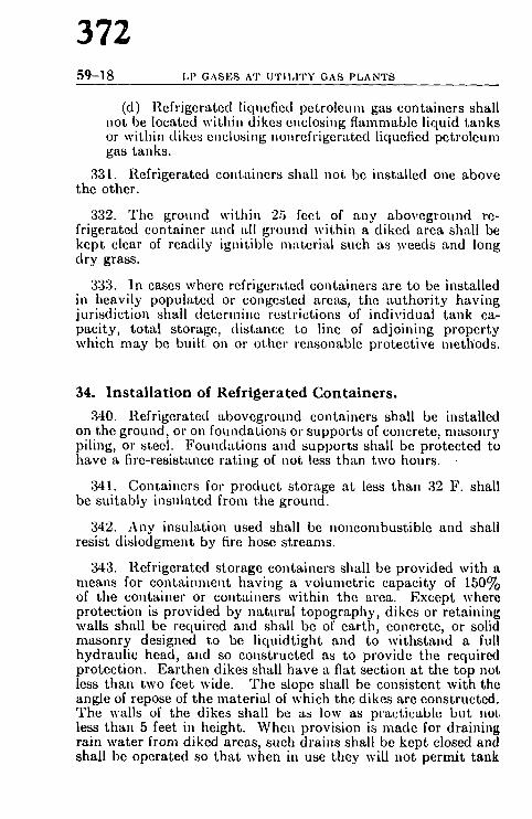
372 59-18 LP GAS ES AT U T I L I T Y GAS P L A N T S
(d) Refrigerated liquefied petroleum gas containers shall not be located within dikes enclosing flammable liquid tanks or within dikes c,mlosi,tg nonrefrigerated liquefied petroleum gas tanks.
331. Refrigerated containers shall not be installed one above the other.
332. The ground within 25 feet of any aboveground re- frigerated container and ~dl grovnd within a diked area shall be kept clear of readily ignitible material such as weeds and long dry grass.
333. In cases where rcf,'igerated containers are to be installed in heavily populated o," congested areas, the authority having jurisdiction shall determine restrictions of individual tank ca- pacity, total storage, distance to line of adjoining property which may be built on or other reasonable protective meth'ods.
34. Installation of Refrigerated Containers.
340. Refrigerated ,.fi)oveground containers shall be installed on the ground, or on foundations or supports of concrete, masonry piling, or steel. Foundations and supports shall be protected to have a fire-resistance rating of not less than two hours.
341. Containers for product storage at less than 32 F. shall be suitably insulated from the ground.
342. Any insulation used shall be noncombustible and shall resist dislodgment by fire hose streams.
343. Refrigerated storage containers shall be provided with a means for containment having a volumetric capacity of 150% of the container or containers within the area. Except where protection is provided by natural topography, dikes or retaining walls shall be required and shall be of earth, concrete, or solid masonry designed to be liquidtight and to withstand a full hydraulic head, and so constructed as to provide the required protection. Earthen dikes shall have a flat section at the top not less than two feet wide. The slope shall be consistent with the angle of repose of the material of which the dikes are constructed. The walls of the dikes shall be as low as practicable but not less than 5 feet in height. When provision is made for draining rain water from diked areas, such drains shall be kept closed and shall be operated so that when in use they will not permit tank

R E F | ( I G E R A T E D C O N T A I N E R S 59-19
contents to enter natural water courses, public sewers, or 1)ublic drains. When pumps control drainage from the diked area, they shall not be self-starting.
344. Field welding on container where necessary shall be made only on saddle plates or brackets which were applied by manufacturer of container, except as provided by the code under which the container was fabricated.
345. Secure anchorage or adequate pier height shall be pro- vided to protect against container flotation wherever sulliciently high water might occur.
346. When flammable liquid storage tanks are in the same general area as liquefied petroleum gas containers, the flammable liquid storage tanks shall be diked or diversion curbs or grading used to prevent accidentally escal)ing flammable liquids from flowing into liquefied petroleum gas container areas.
347. The container storage area shall be fenced or otherwise protectc<l where necessary and at least two points of access through the fencing, if used, shall be provided.
35. Reinstal lat ion of Refrigerated Containers.
350. Containers once installed, which have been out of service for more than one year, shall not be put back in service, unless they successfully withstand without distortion hydrostat ic pres- t~urc rctcsts at the pressure specified for the original hydrostatic test as required by the code under which con~t.ructcd, arid show ,m evidence of serious corrosion. Reinstallation of containers i . all other respects shall be in accordance with all the pro- visions listed in this standard. (See 34. See also Section 6 for relief valve requirements.)
36. Gaskets.
360. The gaskets for use on storage containers shall be re- ~listant to the action of liquefic<l petroleum gas in the liquid phase. Gaskets shall be made of metal having a melting point of over 1500 F. or shall be confined within an assembly having a Inciting point of over 1500 F. Aluminum "O" rings and spiral- wound metal gaskets are also acceptable. When a flange is ~qmned, the gasket shall be replaced.

374 59-20 LP GASES AT U T I L I T Y GAS P L A N T S
37. Filling Densities.
370. The filling lbnits for refrigerated storage containers shall be based upon sound engineering practice for the individual de- sign and operating conditioas involved. Since negligible expan- sion of the liquid can take place within the possible range of operating pressure and tempcr-~.ture of a refrigerated tank, the maximum liquid volume ill percent of the total container capacity may be greater for a refrigerated tank than normally employed for a nonrefrigerated tank.

PIPING, VALVES, GAUGING DEVICES
375 59-21
SECTION 4. P I P I N G , VALVES, G A U G I N G DEVICES.
41. Piping Materials.
,ll0. Seamless copper, brass, or steel pipe or tubing may be ~l::e(I for sizes ]/~ in. or under. All piping and pipe fittings over a~j in. size, connected to a storage container, shall be made of ~;leel. All piping or tubing shall be tested after installation at |1~ times the maximum working pressures to which it may be ~ul)jected.
,11 I. Piping connections to the container for sizes over 2 ~lwhcs nominal pipe diameter shall be welded flanges or straight ~eldcd, with the possible exception of piping connections for c'*ccss flow valves and for relief valve risers.
,112. The use of cast iron valves, pipe and fittings shall be ~,rohil)ited in piping carrying liquefied petroleum gas in the hquid phase. This does not prohibit the use of container valves ,,r llttings made of malleable or nodular iron.*
,tl3. Valve seat material, packing, gaskets, etc., shall be re- ~-i.ltant to the action of liquefied petroleum gas in the liquid phase.
,114. All piping, tubing, fittings and the valves shall be leak ~e.,~tcd after assembly and proved free from leaks at not less than r operating pressures. Test shall not be made with a flame.
,115. Provision shall be made for expansion, contraction, jar- f i ,g and vibration, and for Settling.
,116. Piping outside buildings may be buried aboveground, (,r both, but shall be well supported and protected against physi- (al damage and corrosion.
,II7. Piping, valves, fittings and gauging devices for the re- aelgcrated portion of the liquefied petroleum gas fittings system chaJl be based on sound engineering practices for the individual ~h~ign and operating conditions involved.
*t.~nr information as to the suitability of'malleable or nodular iron for this use, #~'fi,r to Standards of the American Society for Testing Materials (A47-52 or 5339-51T). See Appendix G, page 59-46, for availability.

376 59-22 LP GASES AT UTILITY GAS PLANTS
42. Conta iner Valves and Accessories.
420. All shutoff valves and accessory equipment (liquid or gas) shall be suitable for use with liquefied petroleum gas, and designed for not less than the max inmm extreme pressure and t empera tu re to which they may be subjected. Valves for use with nonrefrigerated containers which may be subjected to con- tainer pressure shall have a rated working pressure of a t least 250 psig. Cast iron wdves, piping, and fittings shall be pro- hibited on liquefied petroleum gas containers and their connec- tions. This does not I)rohibit the use of container valves or fittings made of malleable or nodular iron.*
421. All commotions to containers, except safety relief con- nections, liquid level gauging devices, and plugged openings, shall have shutott valves located as close to the container as practicable.
422. Excess flow vah, es where required by this standard shall close automat ica l ly at those rated flows of vapor or liquid as specified by the m-mufacturer . The connections or line includ- ing valves, fittings, etc., downs t ream of an excess flow valve shall have a greater capaci ty than the rated flow of the excess flow valve.
423. Except as provided in 424 and 442, all liquid and vapor connections on containers except ~afety relief connections shall be equipped with approved au tomat ic excess flow valves, or with back pressure check valves, or a remotely controlled au tomat ic quick-closing valve which shall remain closed ex- cept during operat ing periods. The mechanism for remotely controlled, quick-closing valves shall be provided with a sec- ondary control equipped with a fusible release (not over 220 F. melting point) which will cause the quick-closing valve to close automat ica l ly in case of fire.
424. Openings from a container or through fittings at tached directly on the container to which pressure gauge connection is made, need not be equipped with an excess flow valve if such openings are not larger than No. 54 drill size.
425. Excess flow and back pressure check valves where re- quired by this s tandard shall be located inside of the container or a t a point outside where the line enters the container; in the lat ter case, installation shall be made in such a manner tha t any undue stress beyond the excess flow or back pressure check valve will not cause breakage between the container and such valve.
*See footnote, page 59-21.

PIPING, VALVES~ GAUGING DEVICES
377 59-23
d26. Excess flow valves shall be designed with a by-pass, not ~o e• a No. 60 drill size opening to allow equalization of |t re~tl res.
,t27. All inlet and outlet connections except safety valves, hquid level gauging devices and pressure gauges on any container clmll be labeled or color coded to designate whether they are con- ~w~cted to vapor or liquid space. Labels may be on valves.
,128. Each storage container shall be provided with a suitable pressure gauge.
43. Filler and Discharge Pipes, Manifolds.
,130. Piping connections between container and manifold o.hould be designed to provide adequate allowances for contrac- tit,I, expansion, vibration, and settlement. Compression type rouplings shall not be considered suitable for this purpose.
,131. It is desirable that liquid manifold connections be located at non-adjacent ends of parallel rows of containers.
,132. The use of non-metallic hose is prohibited for intercon- ,ceting stationary containers.
,t33. A good test for determination of piping stresses con- ~ists of unbolting piping at a flange and noting whether the flange remains in proper alignment.
,134. The filling pipe inlet terminal shall not be located inside a building. Such terminals shall be located not less than 10 feet from any building, and preferably not'less than 5 feet from any dfivcway, and shall be properly supported and protected from physical damage.
435. A shutoff valve shall be provided in liquid piping for ~'a0~ section of pipe containing 500 gallons capacity when the pipe is within 300 feet of storage containers or other important Mmveground structures.
436. When the liquid line manifold connecting containers in a group has a volumetric capacity of more than 100 gallons, such container manifolds shall be located not less than 100 feet from the nearest adjacent property owned by others which may be built upon. The manifold piping terminates at the first line valve which may be used to isolate the manifolded containers [rom any other part of the liquid line system.

378 59-24 LP GAS ES AT U T I L I T Y GAS P L A N T S
437. If more than three storage containers discharge liquh~ into a manifold whose nominal diameter is greater than 2 inch(~ and if the flow capacity of such manifold is less than the total di ~. charge capacity of the discharge lines from the containers, one i~ the following for each container sllall be provided:
(a) A remotely controlled external shutoff valve in corn bination with an excess flow valve.
(b) A remotely controlled quick-closing valve which shall remain closed except during operating periods. Tim mechanism for such valves may be provided with a second_ ary control equipped with a fusible release (not over 220 I" melting point) which will cause the quick-closing valve t4.~ close automatically in case of fire.
44. Liquid Level Gauging Device.
440. Each nonrefrigerated storage system shall be equipp~l with a liquid level gauging device of approved design, such as a pressure differential type, a float guage, a rotary gauge, slip tub0, magnetic or fixed tube device. If the liquid level gauging devi(,4~ is a float type or a pressure differential type and the container i~ a nonrefrigerated type, the container shall also be provided with an auxiliary gauging device such as: a fixed dip tube, slip tubej rotary gauge, or similar device.
441. Refrigerated containers shall be equipped with a liqui~g level gauging device. An auxiliary gauging device is not re~ quired for refrigerated containers. However, in lieu of an auxo iliary gauge, refrigerated containers, if subject to overfilling, shall bc equipped with an automatic device to interrupt fillini~ of the tank when the maximum filling level is reached.
442. All gauging devices shall be arranged so tha t the maxio mum liquid level for butane, for a 50-50 mixture of butane an(I propane, and for propane, to which the container may be filled is readily determinable.
443. Gauging devices tha t require bleeding of the product to the atmosphere, such as the rotary tube, fixed tube and slilj tube, shall be so designed tha t the bleed valve maximum opening is not larger than a No. 54 drill size, unless provided with an ex- cess flow valve.
444. Gauging devices for containers shall have a maximum allowable working pressure at least equal to tha t of the container0 to which they are at tached.

PIPING~ VALVES~ GAUGING DEVICES
379 59-25
,I,15. Length of a fixed tube device shall be designed to indicate the maximum level to which the container may be filled for tile product contained. This level shall be based on tile volulnc of tile i)roduct at 40 F. at its maximum permitted filling density for aboveground containers and at 50 F. for buried containers. Itefer to Appendix D for calculating filling point for which tube ~hall be designed.
,146. Gauge glasses of the columnar type shall not be per- ,,litted.
45. Hose Specifications. ,150. Hose shall be fabricated of materials tha t are resistant
to the action of liquefied petroleum gas.
451. Hose subject to container pressure shall be designed for a bursting pressure of not less than five times the pressure for which the container was designed. Hose connections when made |filal] be capable of withstanding a test pressure of twice the pres- ~lure for which the container is designed.
452. Hose and hose connections located on the low pressure aide of regulators or reducing valves shall be designed for a burst- ing pressure of not less than 125 pounds per square inch but not less than five times the pressure setting of the safety relief devices )rotecting tha t portion of the system. There shall be no leakage tom assembled hose connections.
46. Drips, Pits and Drains. 460. Where vaporized gas may condense, suitable means shall
be provided for re-vaporization or disposal of the condensate.
461. Every effort should be made to avoid the use of pits. If pits are used they shall be fitted with continuous automatic Ilammable vapor detecting devices equipped with an alarm. No drains or blow-off lines shall be directed into or in proximity to sewer systems used for other purposes.
47. Pumps and ,Compressors. 470, Each pump and compressor shall be suitable for the
liquefied petroleum gas service intended. Each pump and com- pressor shall be marked with its maximum working pressure.
471. Refrigerated storage systems shall be provided with sufficient capacity to maintain all containers at a pressure not in

380 59-26 LP GASES AT U T I L I T Y GAS P L A N T S
excess of the operating pressure under summer weatimr condi- tions and shall be provided with additional capacity for filling or s tand-by service. When cotnpressors and condensers are used, each system shall have at least 2 compressors. Compressor capacity provided for s tand-by service shall equal or exceed the capacity of the compressors provided to nmintain operating pres- sure. Auxiliary equipmet~t such as fans, circulating water pumps, and instrument air compressors shMl be provided with spare or s tand-by facilities sufficiellt to insure that prolonged failure of refrigeration may be prevented.
472. Adequate ,nea,ls shall be available for operating eqfiip- inent in event of failure of normal facilities.
48. Protection of Container Accessories.
480. Valves, regulating, gauging, and other container acces- sory equipment shall be protected against tampering and physical damage.
No','E: The use of other than fr-mgible type locks is not desirable because it prevents access to gas controls in case of emergency.
481. All connections on underground containers shall be lo- cated within a substantial dome, housing, or manhole and pro- tected by a substantial round cover. (See 64f.)
SECTION 5. VAPORIZERS.
51. General.
510. Liquefied petroleum gas storage containers shall not be directly heated with open flames.
511. Heating or cooling coils shall not be installed inside of a storage container.
5121 Vaporizers shall not be equipped with fusible plugs for pressure relief.
513. Vaporizer houses shall not have drains to sewers or sump pits.
52. Vaporizers Not Directly Heated With Open Flames.
520. Vaporizers constructed in accordance with the require- ments of the ASME Unfired Pressure Vessel Code shall be per-

381 VAPORIZERS 59--27
manently marked as follows: (a) With the code marking signifying the specifi-
cations to which vaporizer is constructed. (b) With the allowable working pressure and
temperature for which the vaporizer is designed. (c) With the sum of the outside surface area and
the inside heat exchange surface area expressed in square feet.
(d) With the name or symbol of the manufacturer, date of manufacture, an.d serial number.
521. Vaporizers having an inside diameter of 6 inches or less exempted by the ASME Unfired Pressure Vessel Code shall have a design working pressure not less than 250 pounds per square inch gauge and need not be permanently marked.
522. Vaporizers shall not be installed in the same room with units furnishing air other than for a liquefied petroleum gas mix- ing device. Vaporizers may be installed in buildings, rooms, sheds, or lean-tos, other than those in which open flames or fires mayexist . Such structures shall be of light fire resistive con- struction or equivalent, well ventilated near the floor line and at the highest point in the roof.
523. A shutoff, valve shall be installed on the liquid line to the liquefied petroleum gas vaporizer unit at least 50 feet away from the vaporizer building.
524. The heating medium lines into and leaving the vaporizer shall be provided with suitable means for preventing the flow of gas into the heat systems in the event of tube rupture in the vaporizer. Vaporizers shall be provided with suitable automatic means to prevent liquid passing from the vaporizers to the gas discharge piping.
525. The device that supplies the necessary heat for pro- ducing steam, hot water, or other heating medium shall be separated from all compartments or rooms containing liquefied
I )etroleum gas vaporizers, pumps, and central gas mixing devices )y a wall of substantially fire resistive material and vaportight construction.
53. Direct Fired Vaporizers. 530. Each vaporizer shall be marked to show the name of
tile manufacturer; rated British Thermal Unit input to burners;

382 59-28 LP GAS ES AT U T I L I T Y GAS P L A N T S
the area of the heat exchange surface in square feet; and the maximum vaporizing capacity in gallons per hour, and date and serial number.
53I. No direct fired vaporizers shall be located closer than 50 feet to line of adjoining property upon which structures may be built. They shall also be located a minimum distance of 50 feet away from any liquefied petroleum gas storage container.
532. No direct fired vaporizer shall be connected to a con- tainer that has a storage capacity in gallons, less than 10 times the hourly capacity of the wLporizer in gallons. Vaporizers may be connected to the liquid section or the gas section of the storage container, or both; but in any case there shall be at the container a manually operated valve in each connection to permit complete shutting off, when desired, all flow of gas or liquid from container to vaporizer.
533. Vaporizers may be installed in buildings, rooms, hous- ings, sheds, or lean-tos used exclusively for vaporizing or mixing of liquefied petroleum gas. All vaporizer housing structures shall be of light fire resistive construction, well ventilated near the floor line and the highest point of the roof.
534. When vaporizers and mixing equipment are in.stalled in structures that house other facilities, the vaporizers and mixing equipment room shall be separated from the other parts of the building with fire resistive, vaportight walls.
535. Vaporizers shall be provided with suitable automatic means to prevent liquid passing from the vaporizer to the glm discharge piping of the vaporizer.
536. V.aporizers shall be provided with a means for turning off the gas to the main burner and pilot from a remote location,
537. Vaporizers shall be equipped with automatic safety devices to shut off the flow of fuel to main burners and pilot, ti the ignition device should fail.
538. Pressure control equipment which is a pertinent parl of the vaporizer, if located within 10 feet of the vaporizer, shall be separated from the open flame by a substantial vaportighL fire resistive partition or partitions.
539. No direct fired vaporizer shall raise the product pressuw over the designed working pressure of the vaporizer equipment

383 REL1EF DEVICE8 59 - -29
SECTION 6. RELIEF DEVICES.
61. General.
Ol0. Relief devices on containers shall be so arranged that tim possibility of tampering will be minimized; if the pressure ,~,l, ting or adjus tment is external, the relief devices shall be provided with all approved means for sealing the adjustment.
611. Each nonrefrigerated shop fabricated container relief th,vicc shall be plainly and permanent ly marked with the "Con- 0alncr Type , " of the presstlre vessel on which the device is de- ::gacd to be installed, with the pressure in pounds per square t*ich gauge at which the device is set to s tar t to discharge, with ol,~ actual rate of discharge of the device at its full open position q0* ~'ubic feet per minute of air at 60 F. and atmospheric pressure, <~el~l with the manufacturer ' s name and catalogue number; for ~ ~ample, T-200--250-15,000 A I R - - i n d i c a t i n g that the device , ~ mfitable for use on a Type 200 container, tha t it is set to s tar t ~oi discharge at 250 pounds per square inch gauge, and tha t its r of discharge at full open position is 15,000 cubic feet per
)mute of air. Each field erected nonrcfrigerated and refrigerated ,,*J,tainer relief device shall be similarly marked except "Con- ~'~mcr T y p e " indication is not required.
012. The rate of discharge of container relief valves shall be i ,ccordance with the provisions of Appendix A for nonre-
I tr containers and Appendix E for refrigerated containers.
ill3. Connections to which relief devices are attached, suct~ as ,,qflings, flanges, nozzles, and discharge lines for venting, shall
;' ~ 'c internal dimensions tha t will not restrict the net relief area.
Gl,1. The size of the relief device outlet connection shall not be lldlcr in diameter than the nominal size of the relief outlet ~m(;ction and shall not appreciably restrict flow through the
~II5. All container relief devices shall be located on the con- :wrs and shall be connected with the vapor space of the con-
I,~lO. No shutoff valve shall be installed between the relief : ,.il'o and the container, equipment, or piping to which the : f device is connected except tha t a shutoff valve may be used ';'ro the arrangement of this valve is such tha t full required

384 59-30 LP GASES AT UTILITY GAS PLANTS
capacity flow through the relief device is always afforded.
NOTE: T h e above except ion is made to cover such cases as a thruo* way va lve instal led unde r two relief devices, each of which has the required rate of d ischarge. T h e ins ta l la t ion will allow ei ther of the reliefs to Im closed b u t does not allow bo th reliefs to be closed a t the s ame t ime. Anothq,t exception to th is m a y be where two separa te reliefs are instal led with indl, v idua l shu tof f valves. I n ' t h i s case the two shutoff va lve s t e m s shall I)o mechanica l ly in te r -connec ted in a m a n n e r which will allow full requirtxl flow of one relief a t all t imes.
617. Relief device discharge vents shall be installed in a manner which will provide protection against physical damag0 and such discharge pipes shall be fitted with loose fitting rain caps. Return bends and rcstrictive pipe fittings shall not I)[~ permitted.
618. If desired, discharge lines from two or more relief devices located on the same unit, or similar lines from two or more different units, except those located on storage containers, may be run into a common discharge header, provided that the cross sectional area of such header be at least equal to the sum of the cross sectional area of the individual discharge lines, and that the setting of relief devices is the same.
619. Discharge from a relief device shall not terminate in any building, beneath any building, or in any other kind of con. fined area. The discharge from all ~clief devices, except thos~ installed between shutoff valves, shall be piped to a point not less than three feet above the highest point of any building within 50 feet.
62. Testing Relief Devices. 620. Frequent testing of relief devices, as would be required
where there is a probable increase or decrease in t h e releasing pressure of the dcvicc due to clogging, sticking, corrosion or exposure to elevated temperatures, is not necessary for such devices on liquefied petroleum gas containers for the following reasons:
(a) The gases are so-called "sweet gases," i.e., they hav0 no corrosive effect on metals; the devices are constructed of materials not readily subject to corrosion and are pro. tected against the weather when installed in pressure vessels, Further, the tempera ture variations are not sufficient to bring about any permanent set of spring mechanisms.
(b) Therefore the testing and inspecting of relief device~ to check relief pressure settings is required only at about five-year intervals.

385 RELIEF DEVICES 59-31
63. On Aboveground Containers.
(i30. Every container shall be provided with spring loaded relief valves or their equivalent.
631. T h e discharge from the relief devices shall be vented away from the container, and unobstructed to the open air in a manner to prevent any impingement of escaping gas upon the con- tainer, adjacent containers, piping and other equipment. The vents shall be fitted with loose fitting rain caps. Suitable pro- vision shall be made to prevent any liquid or condensate tha t may accumulate inside the relief device or its vent from rendering the relief device inoperative. If a bo t tom drain is used, a means shall be provided to protect the container, adjacent containers, piping of equipment against impingement of flame resulting from ig- nition of product escaping from the drain. The vent piping shall extend upward a t least 7 feet above the top of the container.
632. Container relief devices shall be set to sturt to discharge tm follows with relation to the design pressure or maximum allow- able working pressure of the container as appropr ia te for the applicable code:
C o n t a i n e r s M i n i m u m M a x i m u m *
ASME Code; Par. U-68, U-69--1949 and earlier editions . . . . . . . . . . . . . . . . . 110% 125%
ASME Code; Par. U-200, U-201--1949 edition . . . . . . . . . . . . . . . . . . . . . . . . . . . . 88 100
ASME Code--1950, 1952, 1956 and 1959 editions . . . . . . . . . . . . . . . . . . . . . . . . . . . 88 106
API-ASME Code--All editions . . . . . . . . . . 88 1O0 API Standard 620 (First Edition) . . . . . . . . 100 API Standard 650 (First Edition) . . . . . . . . 100
*Note: A plus tolerance of 10% is permitted.
633. Relief devices oil containers shall be constructed to discharge at not less than the rates shown in Appendix A or E, before the pressure is in excess of 120 per cent of the max imum permit ted s ta r t to discharge pressure set t ing of the devices.
634. In certain locations sufficiently sustained sun tem- Imratures prevail which will require the use of a lower vapor pressure product to be stored or the use of a higher designed pres~ f~ure vessel in order to prevent the container relief device from opening as a result of these temperatures . As an al ternat ive the containers m a y be protected by cooling devices such as water f~l)rays, by shading, or other effective means.

386 59-32 L P G A S E S AT U T I L I T Y GAS P L A N T S
635. For refrigerated storage, consideration shall be "given to making proper provisions for vacuum conditions.
64. On Underground Containers.
640. Relief devices shall meet all the conditions outlined for Aboveground Containers except the rate of discharge for relief devices installed thereon may be reduced to a minimum of 30 per cent of the specified rate of discharge shown in Appendix A. The discharge pipe from safety relief devices shall extend di- rectly, vertically upward at least 7 feet above the ground. If liquid product is placed in containers while they are not buried, these containers should be considered as aboveground containers.
641. Where there is a probability of the manhole or hous- ing becoming flooded, the discharge from regulator vent lines should be above such water level. All manholes or housings shall be provided with ventilated louvers or their equivalent.
65. On Vaporizers.
650. Each vaporizer shall be provided with a relief device providing an effective rate of discharge in accordance with Appendix B.
651. Relief valves on direct fired vaporizers shall be located so that they shall not be subjected to temperatures in excess of 140 F. (See 61 for other requirements on relief devices.)
66. Between Shutoff Valves.
660. A relief device shall be installed between each pair of shutoff valves on liquefied petroleum gas liquid piping so as to relieve into a safe atmosphere. I t is recommended that the start to discharge pressure of such relief devices be not in excess of 500 psig.
67. At Discharge of Final Stage Regulators.
670. When the discharge pressure from the final stage regu- lator is not more than 5 pounds, the low pressure side shall be equipped with a relief device, set to relieve at not less than two

387 HANDLING 59-33
tl,ncs, and not more than three times the discharge pressure but !mr more than 5 lbs. in excess of the discharge pressure. Whcn the discharge pressure is more than 5 pounds, the relief shall be set to not less than 11/~ times and not more than two times the dis- charging pressure. Regulator breather vents shall be piped out- 0ldc the building and equipped with insect-proof terminal screens.
S E C T I O N 7. H A N D L I N G .
71. Transfer of Liquids Within a Util ity Plant.
710. Liquefied petroleum gas in liquid form may be trans- ferred from tank cars, or tank trucks, or storage within a utility plant either by liquid pump or by pressure differential.
(a) Pumps and compressors used for transferring liquefied petroleum gas shall be designed for the product handled.
(b) Pressure differential for transferring liquid should be developed by a vapor compressor which takes suction from the vapor space of the liquefied petroleum gas container being filled and discharges into the vapor space of the con- tainer being emptied.
711. Under certain conditions, it may be necessary to create a pressure differential by using fuel gas, air, or inert gas, which is at a pressure higher than the pressure of the liquefied petroleum
aS in the container being filled. This may be done under the llowing conditions:
(a) Adequate precautions must be taken to prevent liquefied petroleum gas from flowing back into the fuel gas, air, or inert gas line or system by installing two back flow check valves in series in these lines at the point where they connect into the liquefied petroleum gas system. In addi- tion, a manually operated positive shutoff valve shall be installed at this point.
(b) Any fuel gas, air, or inert gas used to obtain a pressure differential to move liquid liquefied petroleum gas shall be noncorrosive and dried to avoid stoppage by freezing.
(c) ]f a fuel gas, air, or inert gas is used to obtain a pres- sure differential to move liquid liquefied petroleum gas, consideration should be given, after the operation is dis-

388 59-34 LP GASES AT UTILITY GAS PLANTS
continued, to remowng the fuel gas, air, or inert gas from the container into which it was placed, such as by venting. This should be done only if thc vented gas can be conducted to a proper vent, prefcrably tt distance from the plant and then properly disposed of.
(d) Before any fuel gas, air, or inert gas is placed in a t ank car for unloading liquefied petroleum gas by pressure differential, permission should be obtained from the vendor of the liquefied petroleum gas to introduce such vapors into the t ank car or a tank truck.
712. At least one a t t endan t shall remain close to the transfer connection from the time the connections are first made until they are finally disconnected, during the transfer of product.
713. The maximum vapbr pressure of the product a t 100 F. which may be transferred into a container shall be in accordance with 220 or 221 and 222.
714. Where needed unloading piping or hoses shall be pro- vided with suitable bleeder valves for relieving pressure before disconnection.
715. Precaution shall be exercised to assure tha t only those gases for which the system is.designed, examined, and listed, are employed in its opcration, particularly with regard to pressuves.
72. Tank Car Loading and Unloading Point.
720. The track of tank car siding shall be relatively level.
721. A T A N K CAP~ C O N N E C T E D sign, as covered by I.C.C. ( In ters ta te Commerce Commission)* rules, shall be in- stalled a t the active end or ends of the siding while the tank car is connected for unloading.
722. While cars are on side-track for unloading, the wheels a t both ends shall be blocked on the rail.
723. A man shall be in a t tendance a t all t imes while the tank car or cars are being unloaded.
724. The pipe line to which the t ank car unloading hoses are connected shall be equipped with a back flow check valve to pre- vent discharge of the liquefied petroleum gas from the receiving container and line in case of rup ture of line hose or fittings.
*See Appendix G, page 59-46, for availability.

389 F I R E P R O T E C T I O N 59-35
725. The tank car unloading point should be located with due cmfety consideration to the following;
(a) Proximity to railroad and highway traffic. (b) The distance of such unloading point from adjacent
property. (c) With respect to buildings on installer's property. (d) Nature of occupancy. (e) Topography. (f) Type of construction of buildings. (g) Number of tank cars that may be safely unloaded at one
time. (h) Frequency of unloading.
726. Where practical, the distance of the tank car unloading point should conform to the distance in 240 except that lesser distances may be used, keeping in mind the above items and upon approval of the authority having jurisdiction.
SECTION 8. FIRE PROTECTION.
81. Fire Protection.
810. Tile wide range in the size, design, and location of utility plant liquefied petroleum gas installations makes the recommendations of any specific kind or method of fire protection impractical. The planning of effective fire protection should initially be coordinated with the protection practices followed in other sections of the particular utility company and should give due consideration to the requirements of the authority having jurisdiction.
811. Gas fires should not be extinguished until the source of the burning gas can be shut off. Remotely operated or re- motely located pipe line valves may be advantageously used for fire control under many circumstances (see 435, 437 and 523).
812. Hand or wheeled fire extinguishers designed for gas fires, preferably of the dry chemical type, should be available at each strategic location within a liquefied ~)etroleum gas plant.

390 59-36 LP GASI'-~S AT U T I L I T Y GAS P L A N T S
813. Supplies of water may be utilized through hose lines prefer- ably equipped with combination (spray and straight stream) nozzles to permit widest ad~ptability in fire control. If sufficient quantities of water can be made available, complete water spray protection can be given consideration. The water is used for the sole purpose of cooling equipment, foundations, and piping. I t shall not be relied upon for extinguishing gas fires.
814. Fire-resistive insulation may be utilized for protecting metal against heat. Care in selecting and applying such insula- tion is necessary since effectiveness is dependent on its ability to stay in place on a container during a fire.
815. Where standard watchman service is provided it shall be extended to the liquefied petroleum gas installation; such per- sonnel shall bc properly trained.
816. Suitable roadways or means of access shall be provided for extinguishing equipment such as wheeled extinguishers o,' other fire department apparatus.
817. Routine fire drills and inspections should be scheduled and operating personnel thoroughly trained in the use of available. fire-fighting equipment and the location and use of all gas and liquid piping and valves.
Interpre ta t ion Procedure of the C o m m i t t e e on Gases
Those desiring an interpretation shall supply the Chairman with fiv~ identical copies of a statement in which shall appear specific reference to a aingle problem, p,~ragraph, or section. Such a statement shall be on the businc~ stationery of the inquirer and shall be duly signed.
When applications involve actual field situations they shall so state an~ all parties involved shall be named.
The Interpretations Committee will reserve the prerogative to refuse c0a sideration of any application that refers specifically to proprietary items (2 equipment or devices. Generally inquiries should be confined to interpret~ tion of the literal text or the intent thereof.
Requests for interpretations should be addressed to the National l;'b; Protection Association, 60 Batterymarch Street, Boston. 10, Massachuset~

391 APPENDIX A 5 9 - 3 7
APPENDIX A.
M i n i m u m Requi red Rate of Discharge in cubic feet per m i n u t e of nit a t 120% of t h e m a x i m u m p e r m i t t e d s t a r t to d i scharge pressure for ~afety rel ief devices to be used on n o n r e f r i g e r a t e d c o n t a i n e r s o t h e r t h a n those c o n s t r u c t e d in acco rdance wi th I n t e r s t a t e C o m m e r c e Corn- miss ion specif ica t ions .
Surface Flow Rate Surface Flow Rate Surface Flow Rate Area CFM Area CFM Area CFM
8q. let. Air Sq. Ft. Air Sq. Ft. Air
20 or le~ 62,i 170 3620 600 10170 25 751 175 3700 650 10860 30 872 180 3790 700 11550 35 990 185 3880 750 12220 40 I lO0 190 3960 800 12880 45 1220 195 4050 850 13540 50 13:r 200 4130 900 14190 55 1-130 210 4:r 950 14830 60 1540 220 4-170 I000 15470 65 16-10 230 4630 1050 16100 70 1750 2-10 4800 1100 16720 75 1850 250 49';0 1150 17350 80 1950 260 5130 1200 17960 85 2050 270 5290 1250 18570 90 2150 280 5450 1300 19180 95 22-I0 290 5610 1350 19780
100 2340 300 5760 1400 20380 105 2-140 310 5920 1450 20980 110 2530 320 6080 | 500 21570 115 2630 330 6230 1550 22160 120 2720 340 6390 1600 22740 125 2810 350 65 I0 1650 23320 130 2900 360 6690 1700 23900 135 2990 370 6840 1750 24470 140 3080 380 7000 1800 25050 145 3170 390 7150 1850 25620 150 3260 400 7300 1900 26180 155 3350 450 8040 1950 26750 160 3440 500 8760 2000 27310 165 3530 550 9470
Surface Area =Total outside surface area of container in square feet. When the surface are-t is not st,tmped on the name plate or when the mark-
Ing is not legible, the area can be calculated by using one of the following formulas:
(1) Cylindrical container with hemispherical heads Area =Overall length Xoutside diameterX3.1416
(2) Cylindrical container with semi-cltipsoidal heads Area = (Overall lengthh-.3 outside diameter)Xoutside diameterX 3.1.t16
(3) Spherical container Area =Outside diameter squared X3.1416

392 59-38 LP GASES AT UTILITY GAS PLANTS
Flow R a t e - C F M A i r =R equ i r ed flow capacity in cubic feet per minute of air a t s tandard conditions, 60 F. and atmospheric pressure (14.7 psia).
The rate of discharge may be interpolated for intermediate values of surface area. For containers with total outside surface area greater than 2000 square feet, the required flow rttte can be calculated using the formula, Flow Rate-CFM Air =53.632 A0 .8-~-
Where A = total outside surface area of the container in square feet.
Valves not marked "Air" h:tve flow rate marking in cubic feet per minute of liquefied petroleum gas. These can be converted to ratings in cubic feet per minute of air by multiplying tim liquefied petroleum gas ri~tings by the factors listed below. Air flow ratings can be converted to ratings in cubic feet per minute of liquefied petroleum gas by dividing the air ratings by the factors listed below.
Air Conversion Factors. Container Type 100 125 150 175 200
Air Conversion Factor 1.162 1.142 1.113 1.078 1.010
A P P E N D I X B.
M i n i m u m Required Rate of Discharge for Safety Relief Valves for Liquefied Petroleum Gas Vaporizers (Steam Heated, Water Heated, and Direct Fired.)
The minimum required rate of discharge for relief valves shall be de- termined as follows:
1. Obtain the total surface area by adding the surface area of vaporizer shell in square feet directly in contact with liquefied petroleum gas and the heat exchange surface area in square feet directly in contact with liquefied petroleum gas.
2. Obtain the minimum required rate of discharge in cubic feet of air per minute, a t 60 F. and 14.7 psia from Appendix A for this total surface area.
A P P E N D I X C.
Method of Calculating M a x i m u m Liquid Volume Which Can Be Placed in a Container at Any Liquid Temperature.
The quant i ty of liquefied petroleum gas which may be placed in a container is dependent upon the temperature of the liquid and the maximum permitted filling density in addition to the size of the container.
The filling density depends on: The size of tank, whether i t is installed aboveground or underground, and the specific gravity of the liquid liquefied petroleum gas a t 60 F. placed in the container. Filling density values are given in Paragraph 280. The liquid temperature should be obtained by measur- ing the temperature of the liquid liquefied petroleum gas in the container with a thermometer placed in a thermometer well installed jn the tank.

393 APPENDIX C 5 9 - 3 9
L I Q U I D V O L U M E C O R R E C T I O N F A C T O R S S P E C I F I C GRAVITIES A T 00 ~ P . /00 o P,
0`~00 2 0,910 0.$?0 0.530 0.540 0`S,~ 0.560 0.,5631 0.S/0 0,580 0.M44 I.,~99
V O L U M E CORRECTION FACTORS
O t , m . , *d V e ~
. . . . . . . . . . 1.160 1.1~5.5 1.153 1.146 I 1.140 1,133 1.127 1.122 1.120 I . I I0 1.111 1,100 1.100 ~ 6 J . . . . . . . . . . 1,153 1.149 1.146 1.140 I 1.134 1.128 1.122 I.I17 I . I I6 I .II1 1,100 1.199 1,101 o m . . . . . . . . . . 1.147 1,143 1.140 1.134 I, LI28 1.1~1 1.11T 1.111 l . l lO 1.106 1.101 1,099 L099
. . . . . . . . . . 1.140 1.1~ 1.134 1.128 1.123 1.110 j . l l I 1.106 1.10,?. 1.101 1.990 1.094 1.099
. . . . . . . . . . 1.134 1.12'0 1.12S 1.123 I. I I6 L I I I 1.100 1.101 1,100 1.050 I ,~J 1.000 1,0811 _ I t . . . . . . . . . . 1.13'/ 1.122 .I.121 I . |16 1.II0 1.105 1.100 1.099 I.O94 L991 I . ~ 1.08.5 1.083 I I O . . . . . . . . . . 1.120 1.111 I.I14 1.199 1.104 1.009 1.09-5 1.990 1.990 1 .0~ 1.0~3 1.990 1~70
e . i J . . . . . . . . . . 3.113 1.100 1.107 1.102 L09T 1.0~3 1 .0~ 1994 1.993 1,080 1.077 1J075 1.074 ~ 1 0 . . . . . . . . . . 1.105 1.10~ 1.100 1.995 1.091 1.087 1.083 1,070 1.076 1.075 I.OTI 1.071 1.0m m 0 . . . . . . . . . . 1.008 1.004 1.994 1.999 1.995 1.031 1.077 1.074 1.0T3 1.070 1997 1.994 I.OM
0 . . . . . . . . . . 1.99"J I . ~ 1.0~ 1.084 1.080 1.070 I O~ 1.069 1.0~ 1.0~ 1.0~ 1,996 IJ04I 6 . . . . . . . . . . 1.089 1.990 , 1.085 1.991 1.077 1.07r 1.070 1.057 1.056 1.----'~-- 1,041 I . ~ 1"--'~" 4 . . . . . . . . . . 1990 1 . ~ i I.C82 1.990 1.070 1.071 1.099 1.0~5 1.994 I.(M3 1.069 1.0..58 1.0~? 0 . . . . . . . . . . 1.084 1.080 1.990 1.076 1.0TJ 1.069 1.0~5 1.063 1991 1.050 1.057 I ~ 1.994 0 . . . . . . . . . . 1.991 1.070 I 1.077 1.074 1.070 1 .0~ 1.0~3 1.000 1.050 1.997 1.995 1.05.1 1.053
I0 . . . . . . . . . . 1.078 1.995 1.074 1.071 1.057 1.054 1.f~1 1.058 1.057 L035 1.053 1.991 1.060 16 . . . . . . . . . . 1.075 1.07~ 1.071 1.998 1.064 1.031 10.59 1.060 1.055 1.053 1.051 1.049 i N I | . . . . . . . . . . 1.07~ 1.990 1.0~9 1.990 1.992 1.0~2 1 .0~ 1.053 1.053 L051 1.049 1.04? I.~q0 16 . . . . . . . . . . 1.990 1997 1.0f~5 1993 1.990 1.C.;6 1.054 1.0,51 1 .0~ 1.048 1.046 1.041 1.994
. . . . . . . . . . 1.997 1.0r 1.004 1.0~1 1.0,~7 1,0~ 1.031 1.040 1.046 k046 1,04r 1 .00 I . ~ | IO . . . . . . . . . . 1.064 1.0~ ~t 1.991 1.058 1.994 1.051 1.040 1.040 1.040 1.04r 1.041 1.041 1.040 113 . . . . . . . . . . i.0~1 1.0~9 1.999 1.05.5 1.053 1.049 1.046 1.044 1.044 L043 L040 1.049 1.0~J IM . . . . . . . . . . 1.058 1990 1.0,~5 1.052 1.042 1.040 1.04r 1.042 1.049 1.040 I.O30 |.997 1 ~ 0
. . . . . . . . . . 1~1~5 1.0~ 1,0,52 1.040 1,04 7" 1,04r 1.0~2 I,G39 1.030 1.997 |.000 1.006 1 . ~ Jl] . . . . . . . . . . 1.060 1.990 1.040 1.047 1.044 1.041 1.039 1.997 1.037 1,99.5 1.994 1.991 IJO~l 00 . . . . . . . . . . 1.040 ' 1.047 1.046 1.0~4 I.~41 I~0~0 1,997 1.(~15 1.035 1 ,0~ 1993 1J~9 1,990 . . . . . . . . . . . 1 . 0 , I 1.046 1.04J 1.041 1.008 1.0.~6 1.0~S 1.993 1.993 L991 I.(130 1.990 1.998 J4 . . . . . . . . . . 1.04.1 1.041 | .040 1.008 1.030 1.03r 1.039 1.991 1.030 1.020 1.028 1 .0~ 1 .0~ J0 . . . . . . . . . . 1.030 1.008 1.997 1.005 1.033 1.991 1.990 1.029 1.028 1.997 1.995 1.025 1.024 60 . . . . . . . . . . I r a 0 I ~ . ~ 1.994 1992 1.991 1.020 L027 1.026 1.025 1.025 1.0~ 1.023 1 .0~ 410 . . . . . . . . . . 1.033 1 . ~ 1.001 1.99~ 1 .0~ 1.990 1.99.5 1.024 1.023 1.993 1991 1.991 1.099
u 60 . . . . . . . . . . 1.(130 1.029 1.028 1.997 1.025 1.02r 1 .--~-~--- 1.022 1,02.I L021 1.0 l " ~ - - "~ 1.010 1.018 414 . . . . . . . . . . ' 1.027 1.990 1.025 1.993 1.0'~ 1.991 1.990 1.019 1.010 1.010 1.017 1.017 LOll
I 1.0~ 1.99~ 1 .0~ 1.001 1.990 1.018 1.010 1.017 1.010 L010 1.015 1.015 1.014 ~::: : : : : : : : : ~.o~o ,.o,~ ~.01o 1.OLO 1.017 i.o16 1.OLO 1,oir 1 .o . 1.on 1oi., 1.0n t,on M . . . . . . . . . . 1.017 1.010 1,010 1.015 1.01r 1.013 1.013 1.012 1.011 L011 L011 LOll 1.010 ~ ! ! i i i ! i ! ! i 1.014 1.013 1.012 1.013 1.011 1.010 1.010 1.~09 1.099 1.00~ 1 .0~ 1~0~ 1.00~
1.010. 1.010 1.099 1.999 1.008 1.008 1.007 1.007 1.007 1.099 1.099 1.099 I.flM 1.007 1.007 1.008 I.~)e 1.005 1.005 1.005 1.00.5 1.099 I . ~ 5 1.004 1.004 1.004
51 .......... 1.099 1.003 1.99@ 1.003 1.099 1.002 I.~2 1.002 ~ ~ 1.00~ 1.099 1.099 1.990 1.990 1.000 1.990 1.000 1.000 1.000 1.099 1.000 1.990 1.0~0 1.000 1.099
: : : : : : : : : : : 0.997 0.997 0.097 0.997 0.997 0`097 0.997 0.~9 0.990 0,990 0.990 0.999 0.18111 M . . . . . . . . . . 0.993 0 . ~ 0.~4 0.09,1 0 `001 0.994 0.905 0.~5 0`005 0,995 0.996 0 , ~ 0`099 M . . . . . . . . . . I 0.990 0.900 0.000 0 . ~ 0 0391 0.092 0,0~2 0.093 0.903 0.993 0.~03 0,~13 0.gV3 60 . . . . . . . . . . 0.996 0.99~ 0.987 0.997 0.~99 0.999 0.0.~0 0`000 0.990 0`010 0`991 0.991 O.P01 70 . . . . . . . . . . 0.083 0 , 0 0 0 0.984 0 . 9 8 4 0.085 0.980 0,067 0.038 0 , 0 ~ 1 0 `99S 0,080 0 ` 0 8 9 0,t~19 ~1 . . . . . . . . . . 0.979 0.980 0.981 0.931 0 . ~ .0.983 0.084 0.0~15 0 ,0~ 0,988 0`997 0,997 0.997
�9 71 . . . . . . . . . . 0,070 0,976 0.077 0,976 0,080 0.990 0.982 0,0~3 0.983 0,064 0.986 O, �M, 0 . ~ 0.972 0,OTJ 0.974 0.075 0.077 0.978 O .OT0 0.980 0.991 0`991 0*992 0.993 0.999
~8~iii!iii ! ! i 0 . " 9 0.990 0`070 0`679 0,074 0`075 0`077 0.978 0.976 0,996 0.990 0`099 0 ` , 1 0 .0~ 0.067 0.057 0,202 0.971 0.072 0.974 0.075 0.078 0.O~ 0.976 0.976 0.6711
" . . . . . . . . . . . o.991 0o~ 0,9. 0.0. 0 .9. 0.o. 0,o~'--T o . , . , ; , - - - T ~ : ~ - r - ~ ~ - B ~ - 0 , - : i ~ - ; - B - ~ - . . . . . . . . . . 0`o57 0.~59 0 . ~ 0 0.062 07.~5 0.060 0,9~q 0`070 0.~71 I 0 . o ~ 0.971 0`974 0.171
IM . . . . . . . . . . 0`994 0.650 0.0.56 - 0.059 0 .~1 0.0~4 0.9~6 0,057 09~9 0969 0.071 0.071 0.07~ 18 . . . . . . . . . . 0.950 0.0.53 0.9,53 0,065 0.956 O.OGI 0,963 O.O~,~ O.gG~ 0,997 0 ` ~ 0.99~ 0`070 60 . . . . . . . . . . 0.046 0,040 0.949 0.052 0,0.~ 0 05S 0,050 0 ,~G2 0 , ~ 0.~04 0,901 0.997 0 .~8 ~PJ . . . . . . . . . . 0.943 0.945 0.946 0`0(9 0055 0.055 O.O,W 0.9,59 0,0~0 0.~.2 O,S~r 0`995 0`660 94 . . . . . . . . . . OJ~8 0`041 0.042 0.940 0.949 0.9.52 0 ,~4 0 . ~ 7 0.956 0,0.50 0.9~2 0`992 0 . ~ 4
. . . . . . . . . 0 ,~ O.~S 01030 0.~3 0 .046 0.~9 0 .~ 0 .054 0.0~ 0,~7 O*~O 0 .~ 0.~1 99 . . . . . . . . . . O.g31 O,9~Pl 0.935 0.039 0 , $ 4 3 0.940 0.940 O.g.S2 0.0--%1 O.gM 0.957 0,957 O.~MI
160 . . . . . . . . . . 0,007 0 .930 0.992 0.9341 0,940 0,040 0.945 0.049 0.050 0.$52 0.q54 0.055 0.0~7 N6 . . . . . . . . . . 0.g17 0.020 0.923 0.027 0,,'~ I 0,f.35 0 ,~2 0,943 0,943 0,946 0.g4Y 0 ,045} 0.0,51 I10 . . . . . . . . . . 0.99T 0.011 0.913 0.019 0.~'~ 0.027 0.932 0.036 0.037 0.0.19 0. '143 0.044 0`040 I i i . . . . . . . . . . 0,897 0.99~1 0.~04 0 . ~ 0.215 0.9- '20 0,995 0.$20 0.930 0.0~3 0.997 0.038 0`240 130 . . . . . . . . . . 0 .S87 0.892 0 . 8 9 4 0.900 0.907 0.012 0.915 0 ,9 : ;~ 00'24 0.5"~7 0,991 0.932 0`S04 L ~ . . . . . . . . . . 0.870 0.991 0.884 0:890 0.B~8 0,G~ 0,909 0.010 0.016 0.020 0,025 0.~1 OJ'J8 130 . . . . . . . . . . ~ 0 , 5 7 1 0.873 0.850 O J ~ 0`~5 0,901 0.~99 0 ` ~ 0.013 0,g18 0.~1 1~5 . . . . . . . . . . 0.854 0.J~l 0JI99 0 - 8 7 1 0.870 0.~7 0.806 0 m l 0.90] 0 . ~ 0 7 0.g1| 0.g1r 0.010 1~0 . . . . . . . . . . ~ O,Jl~ 0,8,52 0`~1 0.870 0.879 0 ~ O J ~ 0JJ~5 0300 0.005 0.099 OJHO

394 5 9 - 4 0 LP GASES AT UTILITY GAS PLANTS
Knowing the liquid temperature and the filling density, the maximum vol- ume of liquid liquefied petroleum gas which may be placed in a container can be determined as follows:
D V ~ - -
G X F Where
V = m a x i m u m liquid volume (in per cent of total container capacity) which shall be placed in a container when the liquid temperature i8 T.
D =filling density from Paragraph 280 in per cent.
G =specific gravity of liqueficd petroleum gas at 60 F. placed in con- tainer.
F=cor ree t ion factor from following table for correcting liquid volume from 60 F. to volume at temperature T. The correction factor is obtained by finding the specific gravity at 60 F. (G) in the column a t the top of the table and coming down this column till the actual liquid temperature T is found. The correction factor corresponding to this specific gravity and temperature is then read. Interpolation is permitted.
T = temperature of liquid liquefied petroleum gas in container in degrees Fahrenheit .
After obtaining V from the above formula the actual maximum gallons of liquefied petroleum gas which may be placed in a container is obtained by multiplying the water capacity of the container by V
100
Example:
Assume an aboveground container with 10,000 gallons water capacity
Propane with a specific gravity of 0.508 at 60 F. to be placed in container
Filling density from Paragraph 280 for aboveground container in which a product having a specific gravity a t 60 F. of 0.508 is to be placed is 45%
To determine maximum quant i ty t ha t may be placed in container when the liquid temperature is 60 F.
45 X 10,000 V = - - 8,850 gallons
0.508 X 100
When liquid temperature is 82 F. find correction factor in the table on next page for specific gravity at 60 F. of 0.508 and a liquid temperature of 82 F. which is 0.963
45 X I'0,000 V = 9,200 gallons
0.508 X0.963 X 100

395 APPENDIX D 59--41
A P P E N D I X D.
M e t h o d of Ca lcu la t ing M a x i m u m Volume of Liquefied P e t r o l e u m (;us w h i c h can be placed in a c o n t a i n e r for wh ich l eng t h of fixed dip tuhe is set .
I. I t is impossible to set out in a table the length of a fixed dip tube for various capacity tanks because of the varying tank diameters and lengths and because the tank may be installed either in a vertical or horizontal position. K01owing the maximum permitted filling volume in gallons, however the h,ngth of the fixed tube can be determined by the use of a strapping table obtained from the container manufacturer. The length of the fixed tube should be such that wlmn its lower end touches the surface of the liquid in the con- Izdner, the contents of tim container will be the maximum permitted volunm tu~ determined by the following formula:
2. Formula for determining maximum volume of liquefied petroleum gas for which a fixed length of dip tube shall be set.
Water Cap. (Gals.) of Container* X Filling Density** Maximum Volume of
Sp.Gr. of liquefied petroleum gas*• liquefied petroleum gas Correction Faetor t X 100
Example: Assume a 30,000-gallon total water capacity tank for above- ground storage of propane llaving a specific gravity of 0.510 at 60 F.
30,000 )<45 1,350,000
0.510 X 1.031 )< 100 52.58
1,350,000
52.58 25,675 gallons propane, the maximum amount permitted to be placed in a 30,000-gallon total water capacity aboveground container equipped with a fixed dip tube.
*Meusured at 60 F. **From Paragraph 280 "Filling Densities." tFor aboveground containers the liquid temperature is assumed to b~ 40 F. and for under- ground container8 the liquid temperature is aesumed to be 50 F. To correct the liquid vol. umes at tilese temperatures to 60 F. the following factors shall be used : (See Paragraph 444.)
V o l u m e C o r r e c t i o n F a c t o r s
Specific Gravity 0.500
.510
.520
.530 .540 .550 .560 .570 .580 .590
Aboveground 1.033 1.031 1.029 1.028 1.026 1.025 1.024 1.023 1.021 1.020
Underground 1.017 1.016 1.015 1.014 1.013 1.013 1.012 1.011 1.011 1.010

396 59-42 LP GASES AT UTILITY GAS PLANTS
3. The maximum volume of liquefied petroleum gas which can be placed in a container when determining the length of the dip tube expressed as a per- centage of total water content of the container is calculated by the following formula:
Maximum" Vol. of liquefied petroleum gas (From Maxhnum Formula in Par. 2 above) X 100 Per Cent
- of Total water content of container liquefied petroleum gas
in gallons
4. The maximum weight of liquefied petroleum gas which may be placed in a container for determg~ing the length of a fixed dip tube is determined by multiplying the maximum volume of liquefied petroleum gas obtained by the formula in Par. 2 above by the pounds of liquefied petroleum gas in a gallon of ,t0 F. for abovcground and at 50 F. for underground containers. For example typical pounds per gallon are specified below:
Aboveground Underground pounds per gallon pounds per gallon
Propane . . . . . . 4.37 4.31 Butane . . . . . . 4.97 4.92
APPENDIX E. NOTE: The safety relief valve caoacity in addition to preventing excessive pressure in the event of fire exposure also protects the container from excessive pressure in event the refrigera- tion system does not function.
M i n i m u m r equ i red ra te of d i scha rge in cubic feet per m i n u t e of a ir a t 120 per c e n t of t h e m a x i m u m pe rmis s ib l e s t a r t - t o - d i s c h a r g e p ressure as specified in P a r a g r a p h 6:32 for s a f e t y re l i e f d e v i c e s t o be u s e d on r e f r i g e r a t e d c o n t a i n e r s s h a l l be c o m p u t e d by t h e f o l l o w i n g f o r m u l a :
Qa-633 '000 FA0.S2 _ [ ZT LC ~ / ~ -
Where Qa=Min imum required flow capacity of air, in cubic feet per
minute, a t 60 F. and 14.7 psia. F = A composite enviromnental factor, as tabulated in Table E-1. A = Total exposed wetted surface, in the case of spheres or spheroids,
to the elevation of maxinmm horizontal diameter of the tank, in sq. ft.
L = Latent heat of gas at flowing conditions in Btu/pound. C = C o n s t a n t for gas which is a function of the ratio of specific
heats at standard conditions.
= ~ (value for C is then taken from graph of k versus k C
as shown in Figure E-2). Z = Compressibility factor at flowing conditions. T = Absolute temperature at flowing conditions. M = Molecular weight of gas.

397 APPENDIX E 59-43
T A B L E E- I - - E N V I R O N M E N T A L F A C T O R S E n v i r o n m e n t F i l e f o r F
B a r e vessel 1.0 Insuhi ted vessels, with the following typical conduc t ance vnhles, in Btu per hour per squa re foot per degree Fahrenhe i t , hlised on 1600 degrees F a h r e n h e i t t e m p e r a t u r e difference:
~. 4.0 0.3 b. 2.0 0.15 e. 1.0 0.075
7
t=k GURE E - I :RMINING VALUE OF A0.82 WITH SURFACE AREA=A SQ.I
-! i.-!-ITi-~-!-H r ; - F ~ , [-~-~Vr-l-r~-r-;-r- I i ' < 1 , ' ~ i
,00 500 600 VALUES OF AO.8?-

398 59-44 L P G A S E S A T U T I L I T Y G A S P L A N T S
40C
39C
38C
37C
36C
$ 35c
z 0 u
34G
:530
F l r l I T
FLOW FORMULA CALCULATIONS
C = 5 2 0 ~
i.o 1.2 1.4 k
F i g u r e E-2
1.6 1,8 2.0
] .00 1.02 1.04 1 .O6 1.08 1.10 1.12 1.14 1.16 1.18 1.20 1.22 1.24
ConstaI i t c
:]15 318 320 322 324 327 329 331 333 335 337 339 341
1.26 1.28 1.30 1.32 1 .:34 1.36 1.38 1.40 1.42 1.44 ] .46 1.48 1.50
Coilstal~t c
:]4',3 345 :347 :]49 :35 L
:352 354 :356 358 359 361 363 364
1.52 1.54 1.56 1.58 1.60 1.62 1.64 1.66 1.68 1.70 2.OO 2.20
Cons t an t c
366 :368 369 371 372 374 376 377 379 380 400 412

A P P E N D I X F
399 59-45
A P P E N D I X F
M i n i m u m M a t e r i a l R e q u i r e m e n t s for S h e l l s a n d B o t t o m s o f R e f r i g e r a t e d S t o r a g e T a n k s for V a r i o u s T e m p e r a t u r e s
a n d T h i c k n e s s e s C o n s t r u c t e d o f F e r r i t i c S t e e l s
:s ign T e m p e r a t u r e
f~') I:, to 25 1:. incl.
low 25 F. to --5 F. hmcl.
low --5 F, to --30 F. See Note 3)
C~,low --5 F. to --30 F. (See Note 3)
luw --30 F.
T h i c k n e s s
Up to Jaj in., incl.
Over J,~ in. to 1 in., incl.
Over 1 in. to l t~ in., incl.
Over 1 ~ in.
Up to ~,~ in., incl.
Over J~j in. to lt/fi in., incl.
Over 1 ~ in.
Up to Mi in., incl.
Over J,~ in. to I ~ in., incl.
All thicknesses
Over la/~ in.
Material Spec.
Any Approved Steel with specified rain. T.S. not exceeding 60,000 psi (See Note 1)
A-131 B (or C) Case 1256 A-2Ol A & B
A-131 C Case 1256 A-201 A & B
A-131 C Case 1256 A-201 A & B
Case 1256 A-2Ol A & B
A-131 C Case 1256 A-201 A & B
A-131 C Case 1256 A-201 A & B
Case 1256 A-201 A & B
A-131 C Case 1256 A-201 A & B
A-300
A-300 Class 1
Q u a l i f i c a t i o n s to I~ A d d e d to t h e Bas ic
S p e c i f i c a t i o n
None
None None F G P (Fine grain
practice)
None None F G P
Normalized Normal ized FGP, Normal ized
None None
FG P FG P F G P , High Mang .
(See Note 2)
Normalized Normalized I,'GP, I l igh Mang. ,
Normalized
FG P I"GP, High Mang .
Normalized F C P , Normalized F G P , l l igit Mang. ,
Normalized
Tes t Tempera tu re t be 20 F. lower tha~ denign t cmpera tu r
A-201 A & B only
,. ~$r, I : For this t h i ckne~- t empera tu re category approved steels inehnle all those listed in API t150 and A P I 620. Mater ia ls for A S M E Code Vessels m u s t comply with requirelnent8
I that Code and an:,, addit ional re~ uirenmnts of this table A-I31 steel is not apl)roved by 4t'lME; sol e Code cases have not )een approved by sonm local jurisdict ions AI spec [iv t;mterials listed in taMe are sa t i s fac tory for all designs based on API 650 or API 620.
,to 2: Manganese content of 0 .70% to 1 . 0 ~ is preferred in lieu of usual content of 0 .80% r ~211d I n t l H i .
I~t; :l: For ASM E Code Vessels wi th a design t empera tu re below - - 2 0 F., the impac t require- r :cola shall comply wi th A-300. Tes t t empera tu re shall be 20 F. lower titan design tem- t~rnture.

400 59-46 LP GASES AT UTILITY GAS PLANTS
A P P E N D I X G . R E F E R E N C E
The following standards are specifically mentioned in the foregoing text, or deal with rel.Lted subjects ,Lnd are useful for reference. Tile number desig. nations are those used I)y the National Fire Protection Associ'Ltion, th0 National Board of Fire Underwriters, and the Canadian Underwriters Asso. ciation. The abbrevialions after the titles indicate tile pt, blication sources, Where two or more sources arc indicated, the texts arc identical from each source, except for cover and introductory matter.
No. 58~STORAGE AND I§ OF LIQUEFIED PETROLEUM GASF~ (NFPA, NBFU, CUA, NFC I).
No. 70. N^TIONAh ELECTRICAL CODE (NFPA, NBFU, NFC V).
No 77M. STATIC ELECTRICITY (NFPA, NFC V).
No. 78. COI)E FOR PROTECTION AGAINST LIGIITNING (NFPA, NFC V)
N F P A - Published in pamphlet form by the Nation.d Fire Protectiotl Association, 60 Batterymarch Street, Boston 10, Mass.
N B F U - Published in palnt)hlet form by the National Board of Firv Underwritcrs at 85 John St., New York; 222 West Adams St., Chicago; ot 465 California St., San Francisco.
C U A - Published in pamptfiet form by the Canadian Underwriten Association, 460 St. John St., Montre.d, Quebec.
NFC I, II, II], IV, V, VI or VII - - Published by the Nation'Ll Fire Pro, tection Association in the National Fire Codes volume indicated. Th(,.~ codes, rel)ublished annu-Llly, are available from the National Fire Protectiot Association, 60 Batterymarch Street, Boston 10, Mass.
API-ASMF~ Code for Unfired Pressure Vessels for Petroleum Liquid~ and Gases (1951 edition with 1954 Addenda) Price $3.00, or Rules for C(m struction of Un[ircd Pressure Vessels, Section VIII, ASME Boiler Constru( tion Code (195!) edition) Price $5.00. Available from the American Sociel) of Mechanical Engineers, 2[.) West 39th St., New York 18, New York.
Regulations of the U. S. Interstate Commerce Commission outlil~, specifications for transl)ortation of explosives and dangcrous articles (Fedem Code of Regulations - - Title 49 - - Parts 71-90) Price $3.00. Avail-d)le frua: Government Printing Ottice, Washington, D. C., or from the Bureau (,' Explosives, 63 Vescy St., New York, N. Y. Pric~: $:{.50. In C-~nada, tl~ regulations of the Board of Transport Commissioners for Canada apl)l) Available from BTC, Union Station, Ottawa, Ontario.
American Society for Testing Materials standards are available fr01~ ASTM otfice, 1916 Arch St., Philadelphia, P.a.

R E P O R T O F C O M M I T T E E O N H O S P I T A L S
401 HO1
Report of Committee on Hospitals Roy Hudenburg. Chairman
Community Heal th Assn., 6533 E. Jefferson Ave., Detroit 7, Mich. (rep. American Hospital Assn.)
Noyce L. Griffin, Secretary Dept. of Health, Education, and Welfare, U. S. Public Health Service,
I)iv. of Hospital & Medical Facilities, Archi tectural & Engineer ing Branch Washing ton 25, D. C.
l l~ tvh t L. Aberg, American Assn. of **'tl I'Ve Anesthetists .
~:r oB'u Babcock, M.D., Jo in t Com- ~al0nion Accreditat ion o f Hospitals .
(~,eJnee Boyd, Assn. of Casual ty & ' .nlety Cos.
( *~1 F. Brooks, Air Conditioning & ]~!rh'igera tins lust i tute.
nr E. DeForest , M.D., American tfrdlcal Assn.
,Or*hard P. C~ulin, American Society of It~,llting Refr igerat ing & Air-Condi- i6,n ng Engineers, inc.
~t!*Jor George E. Cdlber t . .USAF (MSC), l'~tiled States Air Force.
0 1 Ralph T. Goerner, Jr . , MSC, USN, S. Dept. of the Navy.
tr L. Hermach, National Bureau of ' .iltndards.
I,, Lloyd, National Bureau of Stand- ,.d~.
l~,ink Mar l in, Manufacturers Surgical Oade Assn.
~ m a a Morss, American Inst i tute of ~tehltects.
0.~.tsrd Negus, U. S. Public Heal th r vice.
Bat t . Chief Chas. J . Pierce, Chicago Fire Department (Personal)
Eugene R. Ross, C.W.O., U, S. Depart- ment of the Army.
John F. Schnaiber, Rubber Manufacturers Assn.
Paul Sheppard, National Safety Council. Earle P." Shoub, U. S. Bureau of Mines. H. R. Stevenson, Edison Electric Insti-
tnte. Kent P. Stiner, Internat ional Assn. of
Electrical Ins )eetors and National Electrical Code Cmnm tree.
George J. Thomas, M.D., The St. Francis General Hospital & Rehabili tation Insti tute. (Personal)
Ralph M. Tovell, M.D., American Society of Anesthesiologists.
F. A. Van Arts , Internat ional Union, U.A.~N. (Personal)
Carl W. Wal ter , M.D., American College of Surgeons.
John P. Watson , Veterans Adminis t ra- tion.
W. C. Westerberg, Underwri ters ' Labora- tories, Inc.
Pauline Young, American Hospital Assn.
Alternates.
~611hur G. Billin, Manufac turers Surgical Nathaniel Glickman, American Society Vfade Assn. (Alternate to F rank of Heat ing, Refr igerat ing & Air-Con- t tart in.) di t ioniog Engineers. (Alternate to
I' C, Cannon, Edison Electric Inst i tute. R . P . Gaulin.) ~,,L, Iternate to H. R. Stevenson.)
I *~1, Thomas C. Dens, M.C., U. S. Or of the Navy. (Alternate Paul Guest, U. S. Bureau of Mines. e) I,t. Ralph T. Goerner, Jr .) (Alternate to Earle P. Shoub.)

4O2 HO2 R E P O R T OF C O M M I T T E E ON H O S P I T A L S
The
I.
Comnaittee report consists of three parts:
Proposed amendments of the Code for Use of Flam- mable Anesthetics (No. 56) submitted for adoption; and
11.
II1.
Proposed Revised Standard for Essential Hospital Electrical Service tentatively adopted in 1960 under the title Standard for Hospital Emergency Electrical Systems (No. 76) submitted for adoption.
Proposed revisions of the Standard for Nonflammable Medical Gas Systems (No. 565) submitted for adoption.
This report has been submitted to ballot by the Committee, which consists o] 29 voting members. One member, Mr. Boyd, has not returned the ballot. The respective votes on the various parts o] this report are as ]ollows :
Part 1. 27 members have voted affirmatively with onr vote qualified by a negative vote on Section 2542~ and one member (Babcock) recorded as not voting
Part II. 23 members have voted afirmatively and fiv~ members (Pierce, Tovell, Hudenburg, Brooks an~ Young) recorded as not voting.
Part 111. 24 members have voted afirmatively and lou~ (Walter, A berg, DeForest and Schreiber) recorde~ as not voting.
The proposed changes (Part I l I ) which pertain to gase (NFPA No. 565) have been submitted to the Committee o~ Gases which has voted concurrence.

R E P O R T O F C O M M I T T E E O N l t O S P I T A L S
4O3 HO3
P A R T I Proposed Revisions to Code for the Use of
FLAMMABLE 'AN ESTH ETICS ~Recommended Safe Practice for Hospital Operating Rooms)
NFPA No. 5 6 - - M A Y , 1960
t. Change the re]erence to the National Electrical Code in the A]th line o] Section 2431 ]tom Article 500 to Article 501 to read:
l",lectrical Code,* Article 501, Class I, Division 1. Equipment ullstalled therein shall be approved for use in Class I, Group t, '~tmospheres.
2. Revise Subsection 2438(d) to read:
(d) Plugs and receptacles for use in anesthetizing I,~cations for services of prescribed voltage, frequency rating, ruld number of conductors, shall be designed for interchange- ~fl)ility, for direct connection without the use of adaptors with Class 1, Group C receptacles in hazardous locations and with C~)ck-in type general purpose receptacles in nonhazardous ~pcations. This requirement shall apply only to plugs and tcccpt.acles for two-wire, single phase, 125-volt alternating current service; three-wire, single phase, 250-volt alternating ~urrent service; and to two-wire, 125-volt direct current ~)'stems.
3. Delete present Subsection 2438(e) and replace with the ]ol- ~,Jwing :
(e) Exception: Receptacles provided for services hay- mg different voltages, frequencies or types on the same prem- ~!~es shall be of snch design that attachment plugs and caps ~lsed in such receptacles cannot be connected to circuits of a different voltage, frequency, or type, but will be interchange- ahle within each such classification.
4. Revise Subsection 2438(]) to read:
([) The required basic dimensions for the conforming members of plugs required for two-wire, 12fi-volt, single phase

404 HO4 REVISIONS TO NFPA NO. OG
a l t e r n a t i n g c u r r e n t se rv ice ; for th ree-wire , s ingle phase 25( volt a l t e r n a t i n g c u r r e n t service ; and for 125-volt direct currel: l i g h t i n g service are d i a g r a m e d in A p p e n d i x A 2438.
5. Indicate title corrections on drawing Fig..4 2438, to appear i, revised standard. Revised cut o] typical plug shown below.
6. The note ]ollo-aqng Section 2442(d) is amended by the addi- tion o] the ]oliou,ing :
It is desirable to limit the size of the tran,former to I0 KVA t." less. to limit the secondary s.vstem to two-wire -ingle phase wit~ reasonably short runs to distribution panel.,, anti to u_-e a r insulation with low leakage current in order ',o meet thc,e require ments.
7. Revise Section 2444 to read:
2444. T h e u n g r o u n d e d sys t em shall he l , r , ,vided with : g r o u n d - c o n t a c t ind ica to r (see A p p e n d i x A 24-4~ s,, arrange, tha t a g reen s ignal l amp c o n s p i c u o u s l y vi , i t , le t,, pe r sons it the a n e s t h e t i z i n g loca t ion r ema ins li,..,hted whi le the svsten is isolated from g r o u n d . . . \ n ad j acen t red d,..,nal l amp and at aud ib le w a r n i n g s ignal shall t,e ene rg ized x~hen any ,,ne con duc to r of the sys t em becomes g r o u n d e d t h r . u ~ h a res i s tance or a capac i t ive r eac tance (,f any value u I, t,, :it lea- t r ohm, T h e c u r r e n t t h r o u g h the g r o n n d ind ica to r t,, .~r,,und shall no: exceed two mi l l i ampe re s u n d e r any fault c t ,nd i t ion ex te rna l t~

R E P O R T OF C O M M I ' I ' r E E ON I I O S P I T A L S
4O5 HO5
~lhe ground indicator. The inclicator and associated signals '~lmll not be installed in a hazarclous location (see Articles 212 ~ml214). This system shall b e i n addition to the usual contro I mid protect ive devices.
,~. Add the ]ollowing to Subsection 2484(a):
~,,e used ancl the a t t achment plug shall be inserted only in a Omxccl, approved receptacle.
O. Add a n e w Subsection 2484(b) to read:
(b) Exception: Foot trcadle operatecl controllers are permitted if appendecl to portable electrical appliances in an approved manner or if integral with the supply cord and equippecl with a connector containing an anesthet iz ing loca- llon receptacle approved for use in Class I, Group C atmos- pheres into which the equipment plug (see Section 2438) may be inserted.
tO. Former Subsection 2484(b) is renumbered 2484(c) and revised to read :
(c) Flexible cord of No. 14 A W G anti smaller shall Consist of two insulated concluctors, shieldecl by a peripheral metallic braid which is jacketed an'el connected to the ground terminal of the polarized plug to assure adequatc ground for monitoring purposes.
II. Former Subsection 2484(c) is renumbered 2484(d):
(d) Por table equipnlent shail be proviclecl with a stor- age device for its ttexible cord, so clesignecl that the shortest radius to which the cord can be subjectecl is not Icss than three inches.
12. Revise Section 2542 to read:
2542. RUBBER TUBING AND PARTS: All rubber or equiva- lent parts of anesthesia machines, resusci tators and assistors shall be of conduct ive rubber or equivalent material and shall be so labelecl. The resistance between two electrodes of the type specified in Section 2522(b), with one electrode placed

4O6 HO6 REVISIONS TO NFPA NO. 56
on a metal par t of the machine and the other electrode p~ace~ on a rubl~er part , shall not exceed one m egohm when measure~ with an ins t rumen t of the type specified in Section 2522(cl Each part shall he tested in this manner at least once a month It shall be the responsibi l i ty of the anes the t i s t to make thest tests or ascertain that these tests are made by others.
13. Revise Section 3175 to read:
3175. Cautery and e n d o t h e r m y equ ipment shall not I)~ used dur ing procedures involving flammal)le anesthet ic agent unless the equ ipment complies with the requ i rements Article 249. (See Article 343.)
14. Revise title o] Article 343 and Sections 3431, 3432 and 343, to read :
343. Use of Cautery, Endothermy and Electrical Equi~ ment.
3431. This Code for use of f lammable anes thet ics h~ heen devised to al low the surgeon and anesthes iologis t wig choice of anes thes ia agents , and refrains from prohibitin categorical ly the use of cautery and endo thermy, high fn quency equipnlent, and low vol tage , ins t ruments . Hospil~ admin is t ra t ive author i t ies shall take such steps as are necet sary to impress upon personnel the addit ional risk involvt in the use of cau te ry and e n d o t h e r m y dur ing opera t ions t which flamnaahle anes the t ics are used.
3432. l f cautery or endo the rmy mus t be used in an opew~ tion, hospital regula t ions shall require that the surgeon pt' forming the opera t ion and the anesthes iologis t responsili for the adminis t ra t ion of the anesthet ic shall seledt a no', f lammable anesthet ic , except that cautery or cndo the rmy ml he used in the presence of flamnmable anes the t ics if, in ti combined j udg m en t of the surgeon and the anesthesiolo[~i, failure to do so would jeopardize the pa t ien t ' s life, and tlu joint ly accept the responsibi l i ty for the deviation.
3433. The pat ient shall he so draped when cauteryr e n d o t h e r m y is used tha t a barr ier will be provided agail; any escape of f lammable mix tu res to the area in which f cautery or e n d o t h e r m y is be ing applied.

REPORT OF COMMITTEE ON HOSPITALS
4O7 HO7
NOTE: Switches and control devices for cautery, endothermy or other portable electrical equipment or instruments sliould be operated at a distance of at least two feet from any portion of any :mesthesia system containing mixtures of flammable gases. (See also Sections 2452 and 2487, and Article 249.)
I$. Revise title o /Ar t ic le 344 and Section 3441 to read:
344. Electrical and Electronic Equipment.
3441. Hospi ta l regula t ions shall be es tabl ished and r~Jorced to control the use of electrical equ ipment such as ~clcvision equipment , d i a the rmy equipment , public address ~ystems, and similar electronic and high f requency appara tus m the presence of f lammable anesthet ic agents.
i6. Revise Article A 214(d) to read:
(d) The area of the anes the t iz ing locations below five ~cct above the floor defined in Art ic le 214 cons t i tu tes a "haz- ~rtlous locat ion" as defined by Article 500 of the Nat ional Electrical Code. Because persons en te r ing such anes the t iz ing hPcations may have accumula ted electrostat ic charges, the ~h~or of corr idors and rooms cont iguous to the anes the t iz ing I~Jcation must be conduct ive and at the same potent ia l as the I, Ioor in the anes the t iz ing location. Pa t ien ts should not b e 8ransported while f lammable anes thet ics are being adminis- !trod. Steri l izing rooms direct ly com m un i ca t i ng with anesthe- aizing locations are required by Article 251 to lye provided ~,ith conduct ive floors to equalize static charges. Such rooms, LJ not used as anes the t iz ing locations, are not required to lye =erred by ungrounded electrical dis t r ibut ion sys t ems specified ,,ll Article 244 or explos ion-proof wir ing specified in Article :~:12. W h e r e anes the t iz ing locations open direct ly on a passage- ~av not a par t of an opera t ing room or delivery" room suite, ohe conduct ive fl'oor should extend ten feet ei ther side of the ~,*)or frame. I t is desirable to demarca te the hazardous loca- or of such a corr idor by a physical barr ier (doors) and :lutionary signs to check smoking, use of open flame, wear ing
improper c lothing and shoes, and the appl icat ion of insu- i'.~thtg floor wax.

408 HO8 REVISIONS TO NFPA NO. 56
17. Revise Article A 356 to read:
-~ 356. T e x t i l e s .
M a n y s y n t h e t i c t e x t i l e s have ve ry h igh e l ec t r i ca l res i s t iv- i ty and a re e x c e l l e n t c h a r g e g e n e r a t o r s . In case of d o u b t re- g a r d i n g any fabr ic used in a n e s t h e t i z i n g l oca t i ons , the sur face r e s i s t i v i t y of the fabr ic s h o u l d be m e a s u r e d a t an a m b i e n t rela- t ive h u m i d i t y of 50 pe r c en t and t e m p e r a t u r e of 23 C. by m e t h o d 76-54 of the A m e r i c a n A s s o c i a t i o n of T e x t i l e C h e m i s t s and Colo r i s t s .* T h e m e a s u r e d v a l u e s s h o u l d be less than 5 x 10 I1 o h m s (pe r un i t s q u a r e of the m a t e r i a l ) .
18. Revise Subsection 2(]) o] Appendix B to read:
(f) Only approved photographic lighting equipment shall be used in anesthetizing locations. Because of occasional bursting of bulbs suit. able enclosures shall I)e used to prevent sparks and hot particles fallintl into the hazardous area. Photoflood lamps which are not suitably enclosed shall not be used.
19. Revise Subsection 4(d) o] Appendix B to read:
(d) If cautery, endothermy or other electrical equipment employ. ing an open spark is to be used during an operation, flammable anes. thetics shall not be used unless the patient's life would be jeopardized b~ the surgeon performing the operation and the anesthesiologist respon. sible for administration of the anesthetic.

R E P O R T OF C O M M I T T E E ON H O S P I T A L S
409 H 0 9
P A R T II .
Standard for
ESSENTIAL H O S P I T A L E L E C T R I C A L SERVICE
NFPA No. 76 ~ 1962
Foreword
Medical and nursing sciences are becoming progressively more dependent upon electrical apparatus for the preserva- llon of life of hospitalized patients. For example, year by )'car, more surgeons in more hospitals perform cardiac opera 7 lions, in some of which the l)atient's life depends upon arti- iiclal circulation of the blood; in other patients, life is sus- tained by means of electrical impulses that s t imulate and regulate heart act ion; in still others, suction developed by electrical means is rout inely relied upon to remove body thli(ls and mucus that might otherwise cause suffocation. In auother sense, l ighting is .needed in strategic areas in order that precise procedures may be carried out, and power is ,ceded to safeguard such ritual services as refr igerated stores held in tissue, bone, and blood banks.
In ter rupt ion of normal electrical service to hospitals may he caused by catastrophes such as storms, floods, fires, earth- quakes, or explosions; by l)yramiding failures of substat ions t ransmit t ing electrical power ; or by incidents within the hospital. For all such situations, electrical systems should be idt, nned to limit internal disruption and I)rovide vital services with ex t r a features to assure continuity. Outages may be {orrecte'd in seconds or may require hours for correction. 'l'his implies that the system of protect ion must be designed Io cope with the longest probal)le outage which experience indicates is infrequent ly as long as six to eight hours, but in extreme cases may persist for many days.
Selecting electrical services considered to be essential, designing safeguards to assure cont inui ty in these services, ,rod maintaining the electrical components of such essentia1 ~.ervices so that they will work when called on, are complex problems that war ran t s tandardized guidance for regulat ing ,~gcncies, govern ing boards and adminis t ra t ion of hospitals, ~md archi tects and engineers concerned with hospital con- ~lruction. Such guidance is offered in this standard.

410 GENEH.AL 76-~
CHAPTER I. GENERAL
II. Purpose
111. The purl)ose of this s tandard is to delineate mini- mum factors govern ing the design, operation, and maintenance of those portions of hospital electrical systems whose inter- ruption in any degree would jeopardize tim effective and safe care of hospitalized patients.
12. Scope
121. This s tandard applies to hospitals serving patients who are unable to provide for their own safety. It does not apply to nursing homes, convalescent homes, old age homes, and facilities providing care only for ambula tory patients.
122. No requi rement of this s tandard shall supersede any specific requi rement of N F P A No. 101*--Building Exits Code- -o r N F P A No. 70*--Nat ional Electrical Code--excepl that this s tandard limits the type of the al ternate source of electrical i)ower allowable for use in sys tems designed to assure cont inui ty of electric power in hospitals.
123. This s tandard does not cover the requi rements for fire puml)S. Refer to N F P A No. 20,* Standard for the In. stallation of Centr ifugal Fire Pumps.
13. Systems
131. Essential hospital electrical service is technically referred to herein as the Protec ted Cont inui ty System. Thi~ has three l )ar ts - - the Enlergency Electrical System, Critical Electrical System I, and Critical Electrical System II.
132. The Emergency Electrical System embodies cir. cuits customari ly required in hospitals 1)y local codes or regu< lations to conform with the provisions of Article 700 of the National Electrical Code that wir ing be run in separate race ways and boxes. This s tandard specifies those circuits thai are manda tory in this classification and prohibits others from being added.
*Available from the NFPA Publications Service,

?b ~i E S S E N T I A L H O S P I T A L ELI,~C'rRICAL S E R V I C E
411
133. Critical .Electrical Systems 1 and I1 embody other c'!.,lcntial circuits, whose wiring may be rnn in raceways and t'llxcs with other wiring. These circuits are either recom- r or optional. Some circuits will be chosen according ~,~ the predicted reliability of the local util i ty services.
~4. Design Considerations
141. The design of Pro tec ted Cont inui ty Systems for ILt~npitals should give considerat ion to the possible interrup- Ib~ill of normal electrical service to hospitals which may be ,il,sed by such catas t rophes as storms, floods, fires, earth-
,luakes, and similar cataclysms to which the hospital locality ~;i)' be subject, usually local in nature.
142. Electrical design should take into consideration , mdi t ions that may exist inside a hospital, and be planned to l,iure cont inui ty of essential electrical service by providing ~efinite limits of internal disruption.
0.~, Reliabili ty of Two Separate Central Station-Fed Services
151. This s tandard gives recognit ion to systems sup- i llcd by two separate stat ion-fed services which may with r safety reduce the scope of a Protec ted Cont inui ty Sys-
, 'in. It is recognized that a var ie ty of operat ing considera- i ins, including the need for providing care to disaster vic- L ~ll.q, may prompt hospital officials to consult with their ~whitects and engineers, utility planning services, and other ~ieucies with respect to the desirabili ty of increasing the
0,~pital functions that are to be served by the Protec ted Con- ,!uity System for improved effectiveness of patient care and ~fety.
152. Guidance in de termining the reliabili ty of electric ~vice cont inui ty may be obtained from the electric util i ty ~vlce records. When a hospital is to be served by two tllral station feeders, the record of s imultaneous failure of ,Ill feeders, over the preceding five-year period, should in- ,lie the reliability of the central station services. Records hcating such s imultaneous interrupt ions limited to two ,~irs or less, fol- any single occurrence, should be considered ~ln acceptable record.

412 GENERAL 76-~
16. Loca t ion of Au tomat i c T rans fe r E q u i p m e n t and E m e r g e n c y P r ime Mover
161. T h e physical location of l~)oth the au tomat ic trans, fer equ ipment and emergency pr ime mover becomes of utmosl importance. The integr i ty of the sys t em will be no bet ter thav the in tegr i ty of this emergency equipment . P lans for the loca tion of equ ipment should provide protect ion agains t externa or internal hazardous condit ions that might cause complet~ failure of the equipnaent, such as floods and fires.
17. S e l e c t i o n of E q u i p m e n t
171. The emergency t ransfer equ ipment and primq mover should 'be of sufficient capaci ty and ra t ing to serve thq essential services safely. Th is size will va ry depending upol the type and size of facility and the considerat ion as to whethel long ou tages may lye ant ic ipated due to local conditions. Thq es t imated m a x i m u m length of such possible ou tage is a prin cipal factor in de te rmin ing whe ther addit ional functionl should be supplied by the Pro tec ted Cont inui ty Sys tem.
172. I t is essential that p lanning of the emergency equip ment be comprehens ive in order to main ta in the in tegr i ty an( reliabili ty of the sys t em and to insure that the equipmenl itself is of a design compat ib le with the entire electrica system.
18. M a i n t e n a n c e of E q u i p m e n t
181. Main tenance of the au tomat ic t ransfer and thq pr ime mover equ ipment is fundamenta l ly essential to anl considerat ion of s e rv i cecon t inu i ty . W h e n hospital authoritie, place reliance on auxi l iary equ ipment for assur ing the con t inui ty of essential electrical services, it is vital that auto matic equ ipment opera te wi thout exception or delay. Sur assurance is dependent upon alert and unaba ted maintenancq of this type of equipment . Organ ized periodic tes t ing undel actual condit ions with a full under s t and ing as to the propel test procedures , is absolu te ly essential, both as to operati0: and to personnel.
NOTE: Recent surveys indicate a 5 per cent failure of auto- matic operation in hospitals: a poor record, calling for substantial improvement in maintenance attention.

% 8 E S S E N T I A L H O S P I T A L E L E C T R I C A L S E R V I C E
413
C H A P T E R 2. S O U R C E OF P O W E R
,!I. Required Power Sources
211. T h e P ro t ec t ed C o n t i n u i t y Sys tem, compr i sed of :~tems d e s i g n a t e d here in as E m e r g e n c y Elec t r i ca l Sys t em, 9' , .
(, t lt,cal S y s t e m I and Cri t ical S y s t e m II , as descr ibed in hapter 3, shall have a m i n i m u n a of two i n d e p e n d e n t sources f power.
212. R e q u i r e d sources of power for E n l e r g e n c y and I ritical E lec t r i ca l S y s t e m s shall he the n o r m a l service and a I,e,lerator set located on the p remises and d r iven by some form [ pr ime mover . All services shall comply wi th Ar t i c le 230 [ the N a t i o n a l Elec t r ica l Code.
213. EXCEPTtON: H o s p i t a l s wi th e lect r ical s y s t e m s nor - ~,mlly powered by g e n e r a t i n g un i t s on the p r emi se s shal l have ~,'r C o n t i n u i t y Elec t r ica l S y s t e m s as o u t l i n e d here in ,ith the source of a l t e r n a t e power p rov ided e i ther by an
e'hlit ional g e n e r a t o r set as descr ibed here in , of adequa t e ~pacity to serve the P ro t ec t ed C o n t i n u i t y E lec t r i ca l Sys t ems , r by an ex t e rna l service in acco rdance with A r t i c l e 2 3 0 of
he Na t iona l E lec t r i ca l Code.
NOTr: For the greatest assurance of improved continuity of electrical service it is recommended that, wherever feasible, hospitals ~hould be served by two separate full capacity central station serv- Ices (Section 700-9, National Electrical Code), connected in such a manner as to pick up the load automaticafly and so arranged that file load of the Protected Continuity Electrical System will not be Iransferred to the generator set if either of the central station-fed nervices is energized. It is recotnme,aded that such services he se- lected and installed with full recognition of local hazards of inter- ruption, such as icing and floods. Battery and trickle charger sets located outside the anesthetizing location may be used to augment provisions for the lighting of operating rooms and delivery rooms.

414 EMERGENCY AND CRITICAL CLASSIFICATIONS ~6-,~
CHAPTER 3. EMERGENCY AND CRITICAL
CLASSIFICATIONS
31. General
311. \ u a hospital is served by two central s tat ion feeders, the functions to be served by the Pro tec ted Cont inui ty Sys tem may be reduced in relation to the reliabil i ty of the combined services, as de te rmined by the author i ty" having jurisdict ion on evidence of such reliability, including number of ou tage incidents, t ime durat ion of each ou tage incident and cause, produced by the electric utility. (See Section 152.)
No-r~: A n y m i n i m u m so d e t e r m i n e d s h o u h l be r e v i e w e d by ap- p rop r i a t e representatives of the hospital with the planning s.ervices available from the utility and other appropriate agencies to de- termine whether special considerations call for additional functions to be included in the design of the Protected Continuity System.
32. Emergency Electrical System
321. GENERAL:
a. Those areas or funct ions in hospitals, which are re- quired to be connected to the E m e r g e n c y Electrical Sys tem, are listed herein (Art icle 32). No lighting, receptacles or equ ipment other than those listed herein, arc to be connected to the E m e r g e n c y Electrical S3,stem.
b. The E m e r g e n c y Electrical Sys tem shall be so in- stalled and connected to a l t e rna te sources of power , as specified in Chapte r 2. in such a manner that all l ight ing and e(luipment specified herein will be auto ,na t ica l ly res tored to operat ion in not more thaq 10 secouds.
322. Exit ways i l luminat ion, as required in the 13uilding Exits Code, NFF'A No. 101,* Section 52, such ,as l ight ing re- quired for corridors, passageways , s t a i rways and landings at exit doors.
323. Exit signs and exit directional s igns required in Building Exits Code, NFI"A No. 101,* Section 53.
324. Alarm sys tems, including fi,'c a l a rms ac tua ted at manual stat ions, by electric wate," flow alarm devices in con- nection with spr inkler s y s t em s and by au toma t i c fire detect ion
*Availal)le from the N I;'I'A I'uhlications Service.

7#-10 ESSENTIAL HOSPITAL ELECTRICAI~ SEItVICE
.415
systems (see Building. Exits Code, paragraph 2231), alarms required for systems used for the piping of nonflanm~able medical gases as specified in Standard for Nonflammable Medical Gas Systems, N F P A No. 565,* and generator unit de- rangement signals.
325. Fire alerting systems, including hospital paging sys- tems when these are intended for alerting or issuing instruc- tions during emergency conditions, as specified in Sections 2336(a) and (b) of the Building Exits Code, N F P A No. 101.*
326. Surgical suite electrical circuits required by the Code for Use of Flammable Anesthetics, N F P A No. 56,* to be un- grounded circuits fed through isolating transformers.
327. Obstetrical delivery suite circuits required by the Code for Use of Flammable Anesthetics to be served by un- grounded circuits fed through isolating transformers.
NOTE: Permanently installed overhead surgical lights and re- ceptacles in anesthetizing locations are required to be supplied by ungrounded electrical circuits. It is not the intention of the above requirement that circuits other than those in the anesthetizing lo- cations will he connected to the Emergency Electrical System, nor is it intended that anesthetizing locations other than those located in the surgical and obstetrical suites will be served from the Emer- gency Electrical System.
328. Generator Set Locat ion: Lighting.
33. Critical Electrical Sys tem I ( A u t o m a t i c Res tora t ion)
331, GENERAL :
a. Those areas or functions in hospitals which are rec- ommended or l)ermitted to be connected to Critical Sys tem I are listed herein (Article 33). No lighting, receptacles or equipment, other than listed herein, are to be connected to Critical Electrical System I.
b. Critical System I shall be so installed and connec ted to alternate sources of power, as specified in Chapter 2, tha t all lighting and equipment specified herein will be au toma t - ically restored to operation in not more than 10 seconds. (See Note following Section 341(b).)
*Available from the NFPA Publications Set.vice.

416 EMERGENCY AND CRITICAL CLASSIFICATIONS 76-11
332. RECOMMENDED AREAS AND FUNCTIONS:
a. Surgical and obstetr ical recovery rooms : and receptacles.
b. tacles.
C.
d.
e.
Light ing
In tens ive nurs ing care uni ts : L igh t ing and recep-
In fan t nurser ies : L igh t ing and receptacles.
Medicat ion prepara t ion a reas : Light ing.
Nurses ' s ta t ions : L igh t ing for nurs ing work area, unless emergency corr idor l ight ing is located so as to provide emergency il lumination.
f. Dispens ing pharmac ies : Light ing.
g. E m e r g e n c y t r ea tmen t rooms and similar areas, such as f rac ture rooms, and associated service areas involving func- tions direct ly related to e m e r g e n c y t r e a t m e n t ! L igh t ing and receptacles.
h. Blood bank areas : L igh t ing and receptacles in areas used by hlood bank personnel for such activit ies as typ ing and cross-matching, including service to blood bank refr igerators .
i. Central suction sys t ems serving critical medical and surgical funct ions: pump m o t o r ; l ight ing and receptacles at the pump location for main tenance and repair activities. P u m p motors for central suction sys t ems shall be so connected that operat ion will be au tomat ica l ly restored.
NOTE: To provide for improved cont inui ty of operat ion, it is advisable to provide suct ion sys tems serving critical medical and surgical funct ions with dual motor and pump combinat ions , elec- trically interconnected.
j. Communica t ion services : Te lephone swi tchboard : L.ighting.
333. OPTIONAL AREAS AND FUNCTION:
a. I t is highly desirable to connect l ight ing and recep- tacles in some rooms or wards conta in ing acute general care beds toCr i t i ca l Sys tem I. De te rmina t ion of the nunlbers and locations of such wards or rooms des ignated for inclusion in Critical Sys tem I should take into considerat ion the number of beds avai lable e lsewhere in the huilding for intensive care nursing.

76-12 ESSENTIAL HOSPITAL ELECTRICAL SERVICE
417
NOTE: In planning for bedside receptacles.to be connected to the Protected Continuity System, it is important to consider the dependence of many patients on such electrical equipment as port- able suction pumps: diagnostic equipment, such as electrocardio- graphs: heart pacers; and oxygen tents.
b. Surg ica l and obs te t r i ca l su i te areas, o the r t han those served by the e m e r g e n c y e!ectr ical s y s t e m : L i g h t i n g and i 'cceptacles vi tal to p a t i e n t care.
c. D i s p e n s i n g pharnaacies" L i g h t i n g and receptacles .
d. Cen t ra l s ter i le supp ly d e p a r t m e n t s , i n c l u d i n g areas in tended for iss t tance of s ter i le supp l i e s : L i g h t i n g and re- ceptacles.
e. P s y c h i a t r i c pa t i en t bed a r ea s : L i g h t i n g only .
f. Main electr ical cont ro l cen te r s and t r a n s f o r m e r r o o m s : I . i gh t ing and receptac les ins ta l l ed for the pu rpose of power- i n g t r o u b l e l ights and electr ical hand tools. G e n e r a t o r r o o m s : Receptacles .
g. Te leplaone swi tc la ing e q u i p m e n t and i n t r a d e l ) a r t m e n t comnaun ica t ion svstetns: . O u t l e t s s e r v i n g such s w i t c h i n g and te lephone s i g n a l i n g ecluipment .
NOTE: l)epartme,ltal installations, known as digital dialing sys- lems and used for intradepartmental conamunications may become relatively useless during a failure of electrical service to the area. In the event of such failure those systems which have lighted se- lector buttons in the hase of the telephone i,astrument or in the desk units known as "Director Sets" will be out of service to the extent thfft the lights will not function and that the buzzer used to indicate incoming calls will be silenced. The lack of electrical energy will not prevent the use of telephones for outgoing calls, but incoming calls will not be signaled, nor will intercommuni- cating calls be signaled. This communication failure should be taken into consideration in planning Protected Continuity Systems to serve such areas as emergcqcy departments, and X-ray depart- ments in the larger hospitals.
11. Nurse call s y s t e m s in i n p a t i e n t areas, a n e s t h e t i z i n g locat ions and e m e r g e n c y d e p a r t m e n t s .
34. Critical Electrical System II (Delayed Restoration)
341. GENERAL:
a. T h i s Ar t i c le l is ts a reas and func t i ons which ma y be connec ted to Cri t ical S y s t e m II .

418 EMERGENCY AND CRITICAL CLASSIFICATIONS 76-13
b. All areas and functions served by Critical Electrical Sys tem I I shall be subject to delayed restorat ion. This de- layed res tora t ion nlay be achieved by manual res tora t ion or th rough autonlat ic res torat ion with a t ime lag of at least 20 seconds fol lowing the energiz ing of the sys tem. Ex t r eme caution shall be observed to protec t the sys tem and its asso- ciated a l te rna te power source from overloading.
NotE: It may become advisable when addi:ional heavy power loads are to be served by the Critical Systems to subdivide the sys- tem, with each subdivision to be individually served by a separate transfer switch, which will usually be selected with a rat ing in ex- cess of the proposed total connected load. The system should be so designed that the total load that it may carry at any one time will never interfere with the safe operation of the generator set supplying it.
Equipment served by Critical System II may be restored to service either automatically or manually. (See Section 532.) Auto- matic restoration should be considered according to the need for relatively uninterrupted service. Time delay equipment may be needed to prevent heavy starting surges in connection with the automatic restoration of heavy current-consuming equipment to op- eration.
342. RECOMMENDED AREAS AND FUNCTIONS:
a. A p p a r a t u s : W a t e r pressure, hot wa te r circulation, sump pumps and equ ipment required to opera te for the safety of major appara tus , including associated control and alarm systems.
13. Rooms conta ining above a p p a r a t u s : L igh t ing and receptacles for t rouble l ights and electrical hand tools at loca- t ions of above appara tus .
343. Recommended areas and functions for hospitals which are not supplied with electrical energy by two sepa- rated central s ta t ion-fed services considered by local authori- ties to have sufficient reliabili ty to limit any s imul taneous outage to a m a x i m u m durat ion of two hours :
a. H e a t i n g systems, including control sys t ems and ven- t i la t ing sys t ems required for heat distr ibution, in climates where in the j udgm en t of local author i t ies the sever i ty of winter t empera tu re s is capable of reducing indoor tempera- tures in pat ient areas below a safe level when the heating sys tem is inoperat ive for more than two hours.
b. In huildings of more than four stories an elevator service that will reach every pat ient floor, g round floor, and

76-14 ESSENTIAL IIOSPITAL I~LECTItlCAL SERVICE
419
f loors on w h i c h a re l oca t ed s u r g i c a l su i t e s and o b s t e t r i c a l de- l i ve ry su i tes . T h i s sha l l i nc lude c o n n e c t i o n s for cab and m a c h i n e r o o m l i g h t i n g and c o n t r o l and s igna l s y s t e m s . In i n s t a n c e s w h e r e i n t e r r u p t i o n of p o w e r will r e s u l t in e l e v a t o r s t o p p i n g b e t w e e n floors, it m a y be d e s i r a b l e to p r o v i d e t h r o w - ove r f ac i l i t i e s to a l l o w the t e m p o r a r y o p e r a t i o n of a n y e l e v a t o r for t he r e l ea se of p a t i e n t s o r o t h e r p e r s o n s w h o m a y be conf ined .
344. OPTIONAL AREAS AND FUNCTIONS:
NOTE: Suggested items listed in this section include those that may be needed to sustain operation during protracted current inter- ruptions of the kind frequently associated with natural catastro- phes, which are likely to resuh in increased loads of emergency and surgical patients.
a. C e n t r a l s t e r i l e s u p p l y : A t l eas t one a u t o c l a v e .
b. H o t w a t e r g e n e r a t i o n .
c. X - r a y rooms , m i n i m a l d e v e l o p i n g fac i l i t i es and asso - c i a t ed s e r v i c e a reas .
d. L a b o r a t o r i e s : L i g h t i n g and r e c e p t a c l e s .
e. K i t c h e n : L i g h t i n g , c o o k i n g fac i l i t i e s a n d a p p l i a n c e s , r e f r i g e r a t e d food s to r age .
f. L a u n d r y : M i n i m a l fac i l i t i es for w a s h i n g , e x t r a c t i n g and t u m b l i n g .
NOTE: Service facilities such as those listed in items c, d, and e above may be operated only periodically during outages of elec- trical service. It ,nay be feasible to program the use of such facili- ties in such a way that only one of the service facilities will be required for operation at any one time. While this may be ac- complished by manual restoration of such service to the various pieces of equipment, it is strongly urged that extreme caution should be observed in the selection of generator and transfer switch ca- pacity in order that the system will not be overloaded by the prob- able combinations of equipment that may be operated at any. one time.
g] R e f r i g e r a t e d m e d i c a l s t o r a g e : P o w e r for r e f r i g e r - a to r s o r c e n t r a l r e f r i g e r a t o r s y s t e m s s u p p l y i n g bone banks , t i s sue banks , and the s t o r a g e of b io log i ca l p r e p a r a t i o n s . Such r e f r i g e r a t o r s m a y i nc lude those i n s t a l l ed in n u r s e s ' s t a t i o n s and o t h e r s i m i l a r l o c a t i o n s for m e d i c i n a l s t o r age . ( F o r b lood banks s e e S e c t i o n 3 3 2 ( h ) . )

420 ELECTRICAL CIIARACTERISTICS 76--15
h. Any other hospital areas or f tmct ions may be con- nected to Critical Electrical Sys tem I I with due caution for proper sizing of ove rcur ren t protect ion devices, t ransfer swi tches and genera tor . se t s .
C H A P T E R 4. E L E C T R I C A L C H A R A C T E R I S T I C S
41. Capac i ty of Sys t em
411. Tile E m e r g e n c y and Critical Electr ical Sys tems shall each have adequate capaci ty and ra t ing for the opera- tion of all l ight ing and eqt l ipment to be served by each sys tem.
412. Hosp i ta l s which install app rox i m a t e ly 100 per cent genera tor set capaci ty, based on peak opera t ing load, and suit- able switch gear for t r ans fe r r ing the hospital electrical load from the normal source of power to the gene ra to r . s e t power supply, will comply with the requ i rements of this s tandard if the E m e r g e n c y Electrical Sys tem as specified in this s tandard is installed. (See Art icle 32.) The E m e r g e n c y Electrical Sys- tem as required herein shall have a separa te au tomat ic t rans- fer switch connect ing it to the alterna.te power supply.
42. Electr ical Character is t ics
421. Electrical character is t ics of the genera to r set and t ransfer switches shall be sui table for tile operat ion of all l ight ing and equ ipment they are intended to supply.
NOT~: The capacity of transfer switches should be adequate to carry full load current continuously, to handle surge currents, and to withstand the thermal and electromagnetic effects of short cir- cuit currents.

76-16 E S 8 E N T I A L H O S P I T A L E L E C T R I C A L S E R V I C E
421
C H A P T E R 5. A R R A N G E M E N T OF W I R I N G
51. Automatic Operation
511. The E m e r g e n c y Sys tem and Critical Sys tem I shall he so a r ranged that in the event of in ter rupt ion of the normal supply, the a l ternate sys tem shall be au tomat ica l ly placed in operat ion.
512. Automat ic swi tching equ ipment shall be approved for emergency service and shall be designed and installed with in ter locking provis ions that will p reven t the intercon- nection of normal and a l ternate sources of power in any op- eration of the au tomat ic swi tching equipment . The operat ion of time equ ipment shall be so a r ranged that the load will be served by the normal power sutgply except when normal serv- ice is interrupted. Controls and swi tch ing equ ipment shall be so a r ranged that in ter rupt ion of the normal service will au tomat ica l ly disconnect the Emergency , Critical I and Criti- cal ] I Sys tems from the normal power source, s ta r t the gen- erator and au tomat ica l ly connect the E m e r g e n c y and Critical I Sys tems to the genera to r when the genera to r has a t ta ined its rated speed. Critical 1I Sys tems may be connected manua l ly or au tomat ica l ly by means of t ime delay switches in such a sequential manner as not to overload the generator . The re shall be a delay of not less than 20 seconds af ter electrical service is establ ished for the Emergency Electrical Sys tem and Critical Sys tem I before electrical service shall be re- stored to Critical Electrical Sys tem I I. \,Vhen normal power is restored while the a l te rna te sourcc of power is connected, a switch may be operated au tomat ica l ly or nonau tomat ica l ly to disconnect the a l ternate source of power and to reconnect the normal service. If operat ion is :mtomatic0 a t ime delay feature should be provided to avoid short t ime re-establ ish- ment of norfilal service. (See Note following Section 721 for precautions relative to shor t t ime operat ion of genera tor set.)
52. Overcurrent Protection
521. The wir ing sys tem supp ly ing the E m e r g e n c y Sys- tem shall be connected to a t ransfer switch supp ly ing no other part of the system. It shall be protected by overcur ren t pro- lective devices in such a manner that time in ter rupt ion of serv- ice in the balance of the sys tem due to internal failure will not disrupt service to the E m e r g e n c y System.

422 ARRANGEMENT OF WIRING "76-17
522. Critical System I and Critical System I I shall be connected to one or more transfer switches and each system shall be protected by overcurrent protective devices of proper design and capacity, not common to the other, arranged in such a manner that the interruption of service in either wir- ing system due to internal failure will not disrupt service to the other system.
NOTE: I t iS r e c o m m e n d e d t ha t in t h o s e i n s t a n c e s w h e r e h a r d - sh ip will not be encountered Critical System I and Critical Sys- tem II should be connected individually to separate transfer switches with proper overcurrent protection, so as better to insure continuity of service to Critical System I. In developing engineer- ing design intended to insure continuity of electrical service to vital hospital functions, primary consideration should he given to the prevention of overloading wiring devices by limiting the pos- sibilities of power surges due to instantaneous re-establishment of connections to heavy loads.
53. Equ ipment (See also Section 512.)
531. Controls of all equipment served by Emergency and Critical System I shall be of the type that will automatical ly restore operation after interruption of current supply.
532. Equipment served by Critical System I I may be either of a type that after a power interruption will restore itself automatical ly to service with appropriate time delay sequencing, or that will require manual restoration to opera- tion.
54. Wi r ing Requirements
541. The Emergency Electrical System wiring shall lye kept entirely independent of all other wir ing and equipment and shall not enter the same raceways, boxes or cabinets with other wiring, except as permitted in Section 700-17 of the National Electrical Code. Except ions are (a) transfer switches, and (b) exit l ighting fixtures which are supplied from two SOUrCeS.
542. Critical System I and Critical System II are not sub- ject to the provisions of Section 700-17, National Electrical Code, and the wir ing of these systems may occupy the same raceways, boxes or cabinets with other wiring, except that such wir ing may not occupy the same raceways, boxes or cabinets as wir ing for E m e r g e n c y Electrical Systems.

76-18 E S S E N T I A L H O S P I T A L E L E C T R I C A L S E R V I C E
423
543. Provisions of Section 700-18 of the National Elec- trical Code with respect to switches installed in emergency lighting circuits shall apply to lighting requirements for exit lighting required under the Building Exits Code, except that as provided in Section 700-20(b) of the National Electrical Code, switching arrangements to transfer corridor lighting in patient areas of hospitals from overhead fixtures to fixtures designed to provide night lighting may be permitted, provided the switching system is so designed that switches can only select between two sets of fixtures and cannot extinguish both sets at the same time.
544. Provisions of Section 700-18 of the National Elec- trical Code with respect to the location and installation of switches in lighting circuits other than those controlling exit way lighting and exit directional signs, shall be applied in the light of the interpretation that personnel ordinarily assigned to work in an area illuminated by fixtures connected to the Emergency Electrical System shall be considered as author- ized personnel. (This provision applies particularly to un- grounded circuits in anesthetizing locations connected to Emergency Systems.)

424 GENERATOR ,~ETS AND PRIME MOVERS 76-19
C H A P T E R 6. G E N E R A T O R S E T S A N D
P R I M E M O V E R S
61. I n s t a l l a t i o n
611. G e n e r a t o r se t s and p r i m e m o v e r s i n s t a l l e d as a sou rce of p o w e r for h o s p i t a l P r o t e c t e d C o n t i n u i t y S y s t e m s sha l l be spec i f i ca l ly d e s i g n e d for such s e rv i ce and to o p e r a t e in c o n j u n c t i o n w i th eacla o the r . G e n e r a t o r un i t s , i n c l u d i n g fuel t a n k s , e x h a u s t l ines and all a p p u r t e n a n t pa r t s , sha l l be i n s t a l l e d in a c c o r d a n c e w i t h Sec t ion 20 of S t a n d a r d for the I n s t a l l a t i o n and U s e of C o m b u s t i o n E n g i n e s and Gas T u r - b ines ( N F P A No. 37) . A d e q u a t e space sha l l be p r o v i d e d for h o u s i n g and s e r v i c i n g the g e n e r a t o r un i t and a s s o c i a t e d equ ip - m e n t for i t s s t a r t i n g and con t ro l . S e r v i c e t r a n s f o r m e r s shal l no t be i n s t a l l e d in th i s a rea .
NOTZ: It is desirable that some latitude of excess capacity should be provided in the selection of equipment for the alternate source of power and that provisions in panel boards should fa- cilitate addition of future feeders or branch circuits to the Critical Systems as development of hospital needs progresses.
Norz: In areas where hospital grounds may be subject to flood under extraordinary abnormal conditions, it is desirable to place the generator set and all associated equipment above any anticipated flood level, and to provide means for facilitating the disconnecting of circuits which feed Emergency and Critical services in areas which under flood conditions may be submerged.
62. G e n e r a t o r Set
621. T h e g e n e r a t o r se t sha l l be of suff ic ient c a p a c i t y and p r o p e r r a t i n g to s u p p l y a d e q u a t e l y c i r c u i t s of t he E m e r g e n c y and Cr i t i ca l E l e c t r i c a l S y s t e m s .
622. T h e g e n e r a t o r set c a p a c i t y for the E m e r g e n c y Elec- t r i ca l S y s t e m and Cr i t i ca l S y s t e m I sha l l be suf f ic ient for p ick- i ng up the load and s u p p l y i n g the full c u r r e n t d e m a n d s of t h e s e s y s t e m s , s t a b i l i z e d w i t h i n p lu s or m i n u s five pe r cent f r e q u e n c y s t a b i l i t y , w i t h i n ten s econds . T h i s p r o v i s i o n shall be d e e m e d to m e e t r e q u i r e m e n t s for i m m e d i a t e r e s t o r a t i o n of se rv ice .
NotE: In very large hospitals where the load of Emergency and Critical Electrical Systems may be so substantial that a single gen- erator will not be able to energize the system within the minimum

76-20 E S S E N T I A L H O S P I T A L E L E C T R I C A L S E R V I C E
425
time allocated, it may be necessary to install more than one gener- ator. Consideration should be given to the possibility in such in- stances of powering the Emergency Electrical System or the Emergency Electrical and the Critical System I from a separate generator. It will be noted that the minimum time factor specified in Section 321(b) and 331(b) does not apply to the alternate power source for the Critical System II.
623. Maintenance o[ Tempera tu res :
a. Diesel engines: Provision shall be made for maintain- ing a temperature of not less than 70 degrees Fahrenhei t in the generator room and for maintaining a water jacket tem- perature of not less than 90 degrees Fahrenheit .
b. Gasoline, naturai gas and liquefied petroleum gas en- gines: Provision shall be made for maintaining a temperature of not less than 50 degrees Fahrenhei t in the generator room and for maintaining a water jacket temperature of not less than 90 degrees Fahrenheit .
624. Provision shall be made for adequate replenishment of air required for engine combustion and for the cooling of engines cooled by the recirculation of water through engine radiators.
625. Bat te ry-s ta r t ing systems for internal combustion engines shall be provided with a hat tery providing a minimum of 60 seconds continuous cranking time.
NOTg: Starting equipment should he arranged to provide for a starting cycle of short cranking times, set to terminate with enough battery reserve to permit additional cranking after the cause of the nonfunction has been discovered.
63. Fue l Tanks
631. Fuel tanks shall be installed in accordance with provisions of Chapters 4 and 5 of the Standard for Installa- tion and Use of Combust ion Engines and Gas Turbines ( N F P A No. 37).* Gasoline engines used as prime movers shall be equipped with a tank integral with the engine and con- forming to requirements of Article 51 of N F P A Standard No. 37.*
*Available from tile NFPA Publications Service.

426 G E N E R A T O R SETS AND P R I M E MOVERS 76-21
64. Safety Devices
641. All prime movers serving genera tor sets shall be equipped with a:l automat ic engine shutdown device for en- gine overspeed.
642. Gas-fueled engines installed as a part of a genera tor set shall be provided with an auxil iary valve that will stop the flow of gas whenever the engine stops opera t ing for any cause. (See Section 442, N F P A Standard No. 37.)*
55. Derangement Signals
651. Audible and visual signal devices, powered by an electric s torage ba t te ry (see Section 700-12, National Elec- trical Code), shall be provided for the fol lowing purposes :
a. To give warning of the derangement of the al ternate power source, including excessive water temperature , water jacket tempera tures below those required in Section 512, low lubricat ing oil pressure and high lubricat ing oil t empera tu res ;
b. To indicate that the genera tor set is carrying the load ;
c. To indicate when the main fuel s torage tank contains less than a three-hour opera t ing supply.
652. A visual signal device shall be provided when prac- tical to indicate when the ba t te ry charger is proper ly func- tioning.
653. Audible warning signals, except for ba t te ry charg- ing malfunction, shall be so ar ranged that they will operate outside of the genera tor room in a location readily observed by opera t ing personnel at a regular work station.
NOTE: In the planning of the location1 of required derangement signals and other indicating instruments of the Emergeqcy Sys- tem, consideration should be given to locating then) in such a way as to permit closed-circuit television monitoring.
*Available from the NFPA Publications Service.

76-22 ESSENTIAL IIOSPITAL ELECTRICAL SI'3RVICE
427
CHAPTER 7. MAINTENANCE
71. Maintenance Requirements
711. The genera to r set or o ther a l te rna te power source and associated equ ipment for emergency connect ion to Pro- tected Cont inui ty Sys tems, including all appur t enan t parts , ~flmll be so mainta ined at all t imes as to be capable of supply- lug service within the shor tes t t ime pract icable and, when in- tended to serve the E m e r g e n c y Electr ical Sys tem or Critical
~ ,stem I, not g rea te r than the interval specified in Sections l (b ) and 331(b).
72. Inspection and Test
721. Genera tor sets serving Pro tec ted Cont inui ty Sys- Ictus shall be inspected daily and shall be exercised for at least 30 minutes under load condit ions at intervals of not more than aeven days.
NotE: When indications such as the issuance of storm warnings indicate that power outages may be likely, good practice recom- mends the warming up of generator sets by a regular 30-minute exercise period. Operation of generator sets for short intervals should be avoided, particularly with compression ignition engines, since if condensation vapors formed before the engine becomes properly warmed'up are not dissipated, they will form varnish in the cylinders and acid in the oil crankcase which is harmful to the engine.
73. Ba t t e ry Maintenance
731. S torage bat ter ies used in connect ion with hospital Protected Cont inui ty Electrical Sys t ems shall he inspected at intervals of not more than seven days and shall be mainta ined tn full compl iance with manufac tu re r s ' specifications. Defec- tlve bat ter ies shall be repaired or replaced immedia te ly upon discovery of defects. (See Section 700-4, Nat ional Electrical Code.)
74. W r i t t e n Record
741. A wri t ten record of inspection, per formance , exer- t lsi,~g periods and repairs shall be - regu la r ly main ta ined and ttvailable for inspection by the au thor i ty hav ing jurisdiction.

428 DEFINITIONS 76"-23
A P P E N D I X - - DEFI N ITIONS
ALTERNATE POWER SOURCE. One or. more generator s~ts intended to provide power during the interruption of the normal electrical service, or the public utility electrical service intended to provide power during iuterruption of service normally provided by the generat ing facilities on the premises.
AUTOMATIC. Self-acting, operat ing by its own mecbanisn* when ac- tuated by some inlpersonal influence, as for example, a change in cur- rent s t rength, pressure, temperature, or mechanical configuration. (This definition is the same as that in the 1959 edition of the National Elec- trical Code and in ASA C42, "Definitions of Electrical Terms.")
CRITICAL SYSTEM I. A system of feeders and branch circuits con- nected to alternate power sources by a transfer switch and supplying energy to critical .hospital functions with automatic restoration of op- eration with power interruptions of no more than ten' seconds; except as specifically provided the system is not intended to supply current to equipment of greater rat ing than that suitable for connect ing to 15 or 20 ampere receptacles.
CRXTmAL SYSTEM II. A system of feeders and branch circuits con- nected to alternate power sources by a t ransfer switch and supplying energy to critical bospital functions with automatic, time sequence or manual restoration of operation: the system, with adequate overcurrent protection, may be connected to alternate power sources by the same transfer switch that serves the Critical I System or, as added protection against internal disruption of the electrical system, may be connected by one or more individual t ransfer switches to the alternate sources of power.
EMERCENCV ELECTRICAL SYSTEM. A system of feeders and branch cir- cuits meet ing the requirements of Article 700 of the National Electrical Code, connected to alternate power sources by a transfer switch and supplying energy to an extremely limited number of prescribed func- tions vital to the protection of life and patient safety, with automatic restoration of operation with power interruptions of not more than ten seconds; only circuits serving those areas or functions specifically listed in Article 33 may be connected to this system.
IM~MCEDIATE RESTORATION OF SERVICE. Automatic restoration of operation with an interruption of not more than ten seconds (as applied to those areas and functions served by the Enlergency Electrical System and Critical System I). except for areas and functions for which the Build- ing Exits Code, NF'PA No. 101, or the National Electrical Code, N F P A No. 70, otherwise make specific provisions.
Ir,rrENslvg ~r CARE UNITS. Groups of beds. rooms, or wards, spe- cifically designated by the hospital to provide intensive nursing care for critically ill patients and intended to be specifically staffed and organized for such service, distinct from a surgical or obstetrical recovery unit forming a part of a surgical or obstetrical suite.

"/b ~24 ESSENTIAL HOSPITAL ELECTRICAL SERVICE
429
NURSES' STATIONS. Areas intended to provide a center of nursing ac- livity for a g roup of nurses work ing under one nurse superv isor and ,crying bed patients , where the patient calls are received, nurses are dispatched to the bedside, nurses notes are writ ten, inpatieqt char ts
~ repared, and medica t ions are prepared for dis t r ibut ion to patients. Vhcre such activities are carried on in more than one location within
~t tnlrsiug unit, all such separate areas are considered a part of the nurses ' s tat ion.
PROTECTED CONTINUITY SYSTEM. A sys t em compr i s ing al ternate sources of power, t r ans fe r switches , overcur ren t protect ion devices, distr ibu- lion cabinets , feeders, branch circuits, motor controls , and all con- nected electrical equipment , des igned to assure des ignated areas and hmct ions of a hospital cont inui ty of electrical service dur ing disrupt ion of normal power sources, and also des igned to minimize the interrup- tive effects of d isrupt ion within the internal wir ing systeni .
PSYCHIATRIC PATIENT BED AREAS. Areas specifically set aside for active inpatient care of psychiat r ic patients , exc lud ing bed areas not specifi- cally ass igned to psychiat r ic care and general care uni t beds tha t ma y occasionally be ass igned to psychiat r ic patients.
References to the National Electrical Code, N F P A No. 70, are to the applicable r equ i r emen t s contained in the 1959 edition. Require- nlents in this code are intended as m i n i m u m s .

430 HOI0 REVISIONS TO NFPA NO. 565
P A R T III
Proposed Revis ions
STANDARD FOR NONFLAMMABLE MEDICAL GAS SYSTEMS
No. 5 6 5 - 1958
1. Revise paragraph references in note under Section 11, Scope, so that it reads as follows:
NOTE: Wherever the term "oxygen" occurs in this standard, the require- ments shall be interpreted to include systems for nitrous oxide except as specifically provided in 212, 213, 222 and 233.
2. Revise Paragraph 12. Definitions. Designate present para- graph as 121 and add four new definitions as follows:
12. Def init ion
121. A piped distribution system consists of a central supply system with control equipment, and a system of piping extend- ing to the points in the hospital where nonflammable medical gases may be required, and suitable station outlet valves at each use point.
122. A BULK OXYGEN SYSTEM is all assembly of equipment, such as oxygen storage containers, pressure regulators, safety de- vices, vaporizers, manifolds, and interconnecting piping, which has storage capacity of (a) inore than 13,000 cubic feet of oxygen connected in service or ready for service, or (b) more than 25,000 cubic feet of oxygen including unconnected reserves on hand at the site. The bulk oxygen system terminates at the point where oxygen at service pressure first enters the supply line. The oxygc, containers may be stat ionary or movable, and the oxygen may be stored as gas or liquid.
123. OPERATING SUPPLY i8 the portion of the supply system which normally supplies the piping systems. The operating sup. ply consists of a pr imary supply or a pr imary and secondary supply.
124. The PRIMARY SUPPLY is tha t portion of the equipment which is actually supplying the system.
125. The SECONDARY SUPPLY, when one exists, automaticall), supplies the system when the pr imary supply becomes exhausted This is a normal operating procedure of the equipment.

431 REPORT OF COMMITTEE ON HOSPITALS HOI 1
126. The RESERVE SUPPLY, when one exists, refers to that portion of the supply equipment which automatically supplies the system in the event of failure of the operating supply. The reserve supply only functions in an emergency and not as a normal operating procedure.
8. Revise entire Chapter 2 to read:
Chapter 2. Source of Supply
21. Central Supply Systems The central supply system sball be a system of cylindcrs
and necessary supply eqtlipment assembled as described in either 211 or 212, or a bulk supply system (213) which may be of the permanently installed type or the trailer type.
211. CYLINDER SYSTEM WITIIOUT RESERVE SUPPLY: (See Figure ] .)
21ll. A cylinder manifold system shall have two banks (or units) of cylinders which alternately supply the pipeline, each bank having a pressure regulating valve and cylinders connected to a common header. I t is recommended that each bank con- tain a minimum of two cylinders or at least an average day's mlpply unless normal delivery schedules require a greater supply. When the content of the primary bank becomes exhausted, the t;econdary bank shall automatically operate to supply the pipe- line.
2112. A check valve shall be installed between each cylinder lead and the manifold header.
NOTE: The purpose of this check wtlve is to prevent the loss of gas from the manifolded cylinders in the event the affety relief device on an individual cylinder should function or a cylinder lead (pigtail) should fail.
212. CYLINDER SUPPLY SYSTEMS WITII RESERVE SUPPLY: (See Figure 2.)
[Paragraphs 212 through 2126 are new]
2121. A cylinder supply system with reserve supply shall consist of:
(a) A primary supply which supplies the pipeline. (b) A secondary supply which shall operate automatically
hi supply the pipeline as the primary supply becomes exhausted.

432 HO12 REVISIONS TO NFPA NO. 565
(c) A reserve supply which shall operate automatically in the event both the primary and secondary supplies are unable to supply the pipeline.
2122. The reserve supply shall consist of three or more manifolded high pressure cylinders connected as required under 222 and (a) shall be equipped with check valves as required in 2112 or (b) shall be provided with an alarm switch which fihall operate the emergency alarm signal when the reserve supply drops to 75 per cent of capacity.
2123. A liquid oxygen cylinder supply system shall be in- stalled either (a) as indicated in Figure 2, or (b) as indicated in Figure 1 with the addition of a reserve supply connected as shown in Figure 2.
2124. When liquid oxygen cylinder supply systems are designed to prevent the loss of gaseous oxygen produced by the evaporation of liquid oxygen in the secondary supply, they shall be designed so that the gaseous oxygen produced shall pass through the line regulating valve before entering the oxygen piping.
2125. Liquid oxygen cylinder supply systems shall be con- structed to withstand high pressure (2200 psig) or shall be pro- vided with suitable pressure relief devices upstream of the con- trol unit.
2126. Cylinder supply systems designed in accordance with 212, do not require check valves between each cylinder lead and the manifold header on the primary and secondary supply.
213. BULK OXYGEN SYSTEMS: (See Figure 3.)
2131. The bulk oxygen system shall consist of at least two sources of supply at all times. There are two common types of bulk supply systems:
(a) The alternating type with two or more units alter- nately supplying the pipeline. When the primary supply is ex- hausted, the secondary supply automatically becomes the pri- mary supply and a new secondary supply is connected when or before this change-over takes place.
(b) The continuous type with one or more units continu- ously supplying the pipeline while another unit remains as the reserve supply and operates only in case of an emergency.
2132. The secondary supply referred to in 2131 (a), and the

433 R E P O R T O F C O M M I T T E E ON H O S P I T A L S HO13
rcscrve supply referred to in 2131 .(b), shall contain at least an average day ' s supply and shall consist of:
(a) three or more manifolded cylinders connected as re- quired under 2112 and 222, or
(b) one or more containers provided an alarm switch is ,,,stalled which shall operate the emergency alarm signal when (he primary source is in operation and the reserve supply is down lo 75 per cent of capacity or one day 's average supply.
J2. General Requirements for Central Supply Systems
221. Cylinders shall be designed, constructed, tested and maintained ill accordance, with Inters ta te Commerce Commis- :'t~m's Specifications and Regulations.
222. M~mifolds shall bc of substantial construction and of a ,h,sign and materials suitable for the service pressures involved. M~:chanical means shall be provided to assure tile connection of r containing the proper gas to tile manifold. Cylinder ,,.,tlcts for oxygen shall havc a .903 inch - - 14NGO-RH-EXT ,:,tside diameter for oxygen, industrial and medical (Connection %~n. 540, St-mdard for Compressed Gas Cylinder Valve Outlet ,ll,I Inlet Connections, ASA 1357. I-1957),* and for nitrous" oxide q25 inch - - 14NG0-1~H-EXT standard cylinder valve outlet
r ~mnec~mn for nitrous oxide (Co,mcction No. 320, Standard for I~'.mpressed Gas Cylinder Valve Outlet and Inlet Commctions, *,SA B57.I-1957).* When other nonflammable gases or gas r iixtures arc to be piped, care should be taken to assure non- , 'iterchangeability with other medical gases.
NOTE: ]b is advisable to obtain manifolds from, and lutve them in- stalled under the supervision of, a manufacturer familiar with proper practices for their construction and use.
223. Pressure regulating wdves c:q)ablc of m-Lintaining a con- :1<rot dynamic delivery pressure of 50 to 100 psi at the maximum !',w rate of the system shall be inst-fllcd in the lines leading from "~It~ primary, secondary and reserve supplies.
NOTE: Pressure compensated metering devices are being used in hos- Idtals and, therefore, it is necessary to have const:mt line pressure. Most metering devices are calibrated for 50 psi line pressure and, therefore, this value is recommended.
224. A manually operated shutoff valve shall be installed up- !~vam of each pressure regulating valve and a shutoff valve or
r162 Imck valve shall be installed downstream.
~Peo Appendix, page 00, for availability.

434 HO14 REVISIONS TO'NFPA NO. 565
225. A pressure relief valve set at 50 per cent above normal pipeline pressure shall be installed downstream of the pressure regulatii~g valve, ahead of any shutoff valve. This pressure re- lief valve may be set at a higher pressure provided another pres- sure relief valve set at 50 per cent above normal pipeline pressure is installed in the main supply line. All pressure relief valves shall close automatical ly when excess pressure has been released. Pressure relief wflves set ut 50 per cent above normal pipeline pressure shall be vented to the outside if the total capacity of the manifolded cylinders is in excess of 1500 cubic feet of gas. Pres- sure relief v'~lves shall be of brass or bronze and especially de- signed for oxygen service.
2261. Enclosures for supply systems shrill be provided with doors or gates which m-~y be locked. Rooms for supply systems shall not be used for storage purposes other them for cylinders containing the nonflammable g~ses which are to be distributed through the pipeline. Storage of empty cylinders disconnected from the supply e~luipment pending their removal is permissible.
2262. Ordinary electric,tl wall fixtures in supply rooms shall be installed in fixed locations not less than 5 feet above the floor to avoid physical damage.
2263. When enclosures (interior or exterior) for supply systems are located near sources of he~Lt such ~Ls furm~ces, in. cinerators or boiler rooms, they shall be of construction so a~ to protect cylin'ders from overheati,~g. Open electrical con. ductors and tr 'msformers shall Ilot be located in close proximit) to enclosures. Such enclosures shall not bc located adjacent t( oil storage tanks.
2264. Smoking shall be prohibited in supply system eu- closures.
227. Supply systems complying with 212 or 213 (see Figure2 2 and 3) shall have a cheek valve in the pr imary supply main upstream of the point of intersection with the secondary 03 reserve supply main.
23. Locat ion
231. Oxygen supply systems or stor~Lge locations of a tot~) capaci ty in excess of 1500 cubic feet, but not exceeding tit. quantit ies specified in 223, when located within a hospital (, similar occupancy, shall be enclosed in a separate room or c~ closure within a room with a fire resistance rating of at least o,,

435 REPORT OF COMMITTEE ON HOSPITALS H O ] 5
hour. Enclosures shall not communicate directly with anesthetiz- ing locations or storage locations for combustible anesthetic agents. The manifold enclosure shall be vented to the outside.
232. Oxygen supply systems of a total capacity of less than 1500 cubic feet may be enclosed in rooms not vented to the out- side. Doors to such rooms shall be provided with louvres at top and bottom. Such room shall not communicate directly with anesthetizing locations or storage locations for combustible anesthetic agents.
233. Oxygen supply systems or storage locations of a total capacity of (a) more th-~n 13,000 cubic feet connected in service or ready for service, or (b) more than 25,000 cubic feet of oxygen including unconnected reserves on hand at the site shall comply with the Standard for Bulk Oxygen Systems at Consumer Sites (NFPA No. 566).
/j. Revise Figure / and caplio~ as follows:
SO TO IOO PSI L PIPING SYSTEM CONTINUED ON
FIG. 4
TO OUTSIDE OF BUILDING
HIGH PRE HEADER
r? /rfi ~ '''GYLINDERVALVE/ ,~ , , , , , , II \_SA'ETYREL,E, I I
CYLINDERS CYLINDERS 8ANal t=Z OAN#)
f lu. ! . Typica l O x y g e n or Ni t rous Ox ide Cy l inder Supp ly System w i t h o u t Reserve Supply (Schemat ic)
t upp l y sys tems w i th different arrangements of. va l ves and regu la tors are permissible i f t hey p rov ide equ i va len t sa feguards.

436 HO16 R E V I S I O N S T O N F P A N O . 5 6 5
5. Change Figure 2 to Figure 3 and revise the caption. Add new Figure 2 - - Typical Oxygen Cylinder Supply System with Reserve Supply as shown.
TO OUTS, DE OF GU,LD,NGREL'CF,~-~ LyE SUPPLY P,P,NG SYSTEM - ~ ' CONTINUED ON FIG. 4
OPERATING ~ CHECK V A L V E S ~ CONTROL UNIT I.
L,NE RRESSURE RESERVE PRESSURE PRE~ r u = v c ~ ) I I ~ REGULATING VALVE REGULATING VALVE"~ J " - ~ ' = ~ '1 "~F~--=."='~ ~[~-------~-CHANGE OVER ALARM
P RATING : ~ . . . . SWITCH. SEE PAR.321 o oLD ~ . N ~ ~ . - C ' T - - - ~ G L E E D E R VALVE
. . . . . . . . " ' ~ _ _ _Y~--~__ _~ SEE PAR. 2124 , ' T--,..:~:J- - L ~ ~ CHECK VALVES---,-~
PRIMARY SUPPLY SECONDARY SUPPLY RESERVE SUPPLY (LIQUID CYLINDERS ;=SO PSIG) (HtGH PRESSURE CYLINDERS)
2200 PSIG OPERATING SUPPLY MAY CONSIST OF ONE OR MORE SUPPLY UNITS ON EACH SANK
Fig. 2. T y p i c a l O x y g e n C y l i n d e r Supp ly Sys tem w i t h Reserve Supp ly
Supp ly sys tems w i t h d i f f e ren t a r r a n g e m e n t s o f v a l v e s and r e g u l a t o r s are pe rm iss i b l e i f t h e y p r a v i d e e q u i v a l e n t s a f e g u a r d s .
TO OUTSIDE OF BUILDING [~J=p__.__.._. PIPING
RELIEF VALVE SYSTEM CONTINUED ON F~G.4 ,,
I SO TO I00 PS.I.. i ~ l . . ~ . . ~ CH EC K VA LV E " - ~ - . ~ . %
ALARM SWITCH (SEE PAR. J 3 3/
PRESSURE ~ f t . ~ , ~ - / ~ R E G U L ATiNG VALVE ~...~,~ ( : ,
ALARM i SWITCH ALARM SWITCH I All/SEE PAR.
r-r~P'~"~'~-(SEE P~4R.3 2 2) ~__=.[ J 3 4/ --"L J
SHUT-OFF CYLINDER ' VALVE ,w.-"- VALVE = ~ T- I"--I
GAS/sINGLEOR LIQUIDoR I I - - J - J-J---" MULTIPLE UNITS/J SAFETY RELIEF = ONE OR I
i MORE OPERATING SUPPLY DEVICE CO NTAINERS=q
I J
~- RESERVE SUPPLY ' - ~ . . . . . .
Fig. 3. T y p i c a l O x y g e n Bulk Supp ly Sys tem (Schemat i c )
Bulk s u p p l y sys tems w i t h d i f f e ren t a r r a n g e m e n t s of v a l v e s , r egu la to rs , and gas s u p p l y un i ts are p e r m i s s i b l e i f t h e y p r o v i d e e q u i v a l e n t sa feguard l , Equ ipmen t s h o w n in d o t t e d l ines i nd i ca tes a rese rve s u p p l y a r rangement o u t l i n e d in p a r a g r a p h 2 1 3 2 ( b ) .

437 R E P O R T OF C O M M I T T E E ON H O S P I T A L S HO17
6. In Paragraph ~12 delete "or cast" in the second line. Revised text to read:
412. All fittings used for connecting copper tubing shall be wrought copper, brass, or bronze fittings made especially for solder or brazed connection, except as provided in 413. Brass pipe shall be assembled with screw type brass fittings or with bronze or copper brazing type fittings. (See also 512.)
7. Revise Paragraph/t l3 to read:
413. Approved gas tubing fittings may be used on gas dis- tribution lines when pipe sizes are one-half inch nominal or less if the fitting is so installed as to be visible in the room. Such littings may also be used in connecting copper tubing of three~ quarter inch nomin-H or less to shutoff valves described in Sec- tion 42 providing the fittings are readily "tccessible.
8. Revise Paragraph/~15 to reaxl:
415. Oxygen pipelincs inst-tlled in combustible parti t ion shall bc protcctcd against physical danmge by installation within pipe or conduit. Openings for pipelines installed in concealed spaces t~hall be fire-stopped with construction having a fire resistance t'qual to or greater than the original construction. Oxygea risers may be installed in pipe sh'ffts if suitable protection against physical d.tnmgc, effects of excessivc hc.Lt, corrosion, or contact with oil is provided. Oxygen risers shall not be located in elevator /jhafts.
tt. Change Figure 3 to Figure ~ and correct drawing by enclosing #~e valves on the second and third floors marked "Room Zone Valve ,u Wall Box at each Anesthetizing Room" in a wall box as illus- Iraled for the similar ilem o'a the first floor.
I0. Revise Paragraph 2t32 to read:
432. Manual ly operated valves shall be equipped with non- interchangeable connections complying with Diameter-Index qafety System (A Standard for Noninterch~mgeable Low Pres- sure Contractions for Medical Gascs, Air and Suction) CGA Pamphlet V-5.* Threadcd outlets shall be provided with a cap md chain to protect the outlet when not in use or shall be in- C tailed in a recessed valve box equipped with a door.

piPE S~eST - -~ i �9
I I I ~ . ~3 RECOVERY
STATION 0 ~JTLET ~ I I STATION U~-JLL L I L.#.~-~I." / I I ROOMS (WALL O~ CEU,,.ING) WALL OR CI~IL INbl I I I I I 410 ~ ~A~.. %
wALL Box At EACH ~ ~ LL ~ r I I I t~ ~LVE ~ W~LL BOX
I I I I I I 1 I I , I I I 1 1 1 1
I~ELI~ERY ROOM OELr~ OO I i i i ISOLAT ION 5US I~CT S t A t ' O " ~ U t U e ' - j I I ..... oN=,~F.~ , , l : i l , ' / , - -
{WALL OR CEIL,NG) I'II/,~-LL O~ ELI~.I;'~,~] I ~ I t
CORRIDOR ZONE VALVE Z 0 E &L s , - '
ANESTHETIZtNG ROOM ANESTklETIZING ROOM . ~ ~ l , I I I ~V ( IN WALL ~OX NURSERY
' I
t i I STATION
':'N: f . . . . . .
CORrmOR SEttiNg1 ~ , , /_CO~RIOOr SECT,On J / ,,~.~,,,,,.~o~ . . . ~ - ~ o ~ ; 1 ' , , v~E~L~o, g p
: ', : P~t,ENT RO0.S
, , - , , - - - - j ~ i f . - ~ c 0 R ~ p o R ' " "-: - . ~ ' . - ' : - ' : - - : " . . ~ - ' : . . . . . . . - , - , s ~,?- . .G-. : -~: - . - ~ : _ ~ - ~ , - * : . ~ > ~ . ,a ,s v v ~, ' 1- " - " " " " . '- - - ' . ". "~- - , : . "
I .J,~:, EA~'~%~~ "E L~PL? MAI,~J . ~ TO OTHER
RISERS
xxx.j/~_.=~ E.rR=NCE ',~L~E I ~ P,PE S.A.T TO (INSIDE ~ O~jTSIO[ ~k.DGJ : . ~ ! J /~FLOORS ABOVE
C/}

439 R E P O R T O F C Q M M I T T E E ON H O S P I T A L S He19
Itcvise References to Other Standards in the Appendix to include:
I)iameter-Index Safety S y s t e m - Noninterchangcable Low Prltssure Connections for Medical Gases, Air and Suction, avail- ~blc from Compressed Gas Associ-ttion, Inc., 500 Fifth Avenue, ~:cw York 36, New York. (CGA Pamphlet V-5.)
81. Revise Paragraph 613 to read:
613. No open flame or other source of ignition shall be per- iaitted within the tent. Matches or smoking materials therein ~hall be prohibited. "No Smoking" signs shall be posted in the 0~lOm and "No Smoking" labels in red lcttcrs shall be perma- camt, ly attached on three sides of tent c~mopics. When the tent ~ in position over the bed, only water, powder or other approved tm,mombustible substances shall be used "~s a rul)bing medium. I'he use of alcohol within the tent canopy shall be prohibited.
Su~l~ested Word laR for T e n t C a n o p i e s
OXYGEN IN USE KEEP FIRE AWAY
A n y mater ia l that can burn is more easi ly set
on fire and burns faster in the presence of
oxygen.
BE CAREFUL NO SMOKING

440 REPORT 0F C0hiMITTEE ON MACHINE TOOLS MTEI
Report of Committee on Machine Tool Electrical Standards
Swaflleld Cowan, Chairman Factory Insurance Association. 1216 Johnston Bldg.. Clmrlotte. N. C.
E. J. LoefHer, Secretary Warner & Swasey Research Center, 28999 Aurora Road, Cleveland 39. Ohio
Nelson P. Bashor, %V. F. & John Barnes Company
E. E. Carlton, California Division of Industrial Safety
Joe I. Ehrhardt, Excello Corporation
Frank L. Fisher," Allen-Bradley Com- pany
It. L. Lloyd, National Bureau of Standards
t N o n v o t i n g m e m b e r
Edmonds Love, Square D Company
II. B. Love, Detroit Department o! Buildings and Safety
G e o r g e B. Newbold, Middle Depart- ment Association of Fire Under- writers
It. E. L. Shirley. Georgia Power Com- pany
Frank Stetka,t National Fire Protec. tion Association
A l t e r n a t e
W. F . H u e t t e , A l i e n - B r a d l e y C o m p a n y ( A l t e r n a t e to F r a n k L. F i s h e r )
T h i s C o m m i t t e e r e p o r t s t h r o u g h tile C o r r e l a t i n g Commit , tee of the N a t i o n a l E l e c t r i c a l Code C o m m i t t e e and tile n~embers of the C o r r e l a t i n g C o m m i t t e e a r e be ing ba l lo t ed on the r e p o r t p resen ted h e r e i n a t the t ime of the p u b l i c a t i o n of t he se A d v a n c e Repor t s . g r e p o r t of t h e i r b a l l o t i n g will be m a d e to the N F P A A n m m l Meeting a t t he t ime th i s r e p o r t is p r e s e n t e d . C o r r e l a t i o n b e t w e e n th is report a n d Ar t i c l e 670 of t he N a t i o n a l E lec t r i ca l Code has been achieved t h r o u g h the c o o p e r a t i o n of Pane l No. 12 of the N a t i o n a l Electrical Code C o m m i t t e e so t h a t if th i s report , is adop ted , t h e r e will be c o l r e s p o n d i n g r e v i s i o n s in A r t i c l e 670 and t he se r ev i s ions a r e published in th i s v o l u m e u n d e r the r e p o r t of the N a t i o n a l E lec t r i ca l Code Com. mi t t ee .
Th e C o m m i t t e e on Mach ine Tool E lec t r ica l Sta'nda'rds, consisti~lO of 11 vo t ing m e m b e r s , has s lebmi t ted the repor t to th, e Correlati,ng C o m m i t t e e of the N a t i o n a l E lec t r ica l Code C o m m i t t e e w i t h a ballol indicat ing tha t 9 m e m b e r s are vot ing affi'r~natively. Messrs . F r a n k L F i sh e r and E d m o n d s L o v e have r eques t ed to be recorded r "~0! vo t i n g " and there are no nega t i v e ballots.

441 79-2 ELECTRICAL STANDARD FOR M E T A L W O R K I N G M A C H I N E TOOLS
Proposed
Electrical Standard for Metal Working Machine Tools
N F P A No. 79
T A B L E O F C O N T E N T S Section Page No.
,N'O.*
100-1 100-3 100-5 100-7
I10-1 110-3 110-5 110-7 110-9 110-11 110-13
120-1 120-3 t20-5 120-7 120-9 120-11 120-13 120-15 120-17
130-1 130-3 !30-5 130-7 130-9
P R E F A C E
C H A P T E R 10O. G E N E R A L
P u r p o s e . . . . . . . . . . . . . . . . . . . . . . . . . . . . . . . . . . . . . . . . . . 79-7 Scope . . . . . . . . . . . . . . . . . . . . . . . . . . . . . . . . . . . . . . . . . . . . 79-7 Def in i t ion of Me ta l W o r k i n g M a c h i n e Too l s . . . . . . . . . 79-7 M a n d a t o r y and A d v i s o r y Ru le s . . . . . . . . . . . . . . . . . . . . . 79-8
C H A P T E R 110. D I A G R A M S , I N S T R U C T I O N S , A N D N A M E P L A T E S
D i a g r a m s . . . . . . . . . . . . . . . . . . . . . . . . . . . . . . . . . . . . . . . . 79-9 I n s t r u c t i o n s . . . . . . . . . . . . . . . . . . . . . . . . . . . . . . . . . . . . . . 79-9 E q u i p m e n t N a m e P l a t e s . . . . . . . . . . . . . . . . . . . . . . . . . . . 79-9 M a c h i n e M a r k i n g . . . . . . . . . . . . . . . . . . . . . . . . . . . . . . . . . 79-9 C o m p o n e n t M a r k i n g . . . . . . . . . . . . . . . . . . . . . . . . . . . . . . . 79-9 Device I d e n t i f i c a t i o n . . . . . . . . . . . . . . . . . . . . . . . . . . . . . . 79-10 F u n c t i o n I d e n t i f i c a t i o n . . . . . . . . . . . . . . . . . . . . . . . . . . . . 79-10
C H A P T E R 120. S U P P L Y C I R C U I T D I S C O N N E C T I N G M E A N S
" type . . . . . . . . . . . . . . . . . . . . . . . . . . . . . . . . . . . . . . . . . . . . . 79-11 R a t i n g . . . . . . . . . . . . . . . . . . . . . . . . . . . . . . . . . . . . . . . . . . . . 79-11 P o s i t i o n I n d i c a t i o n . . . . . . . . . . . . . . . . . . . . . . . . . . . . . . . . 79-11 S u p p l y C o n d u c t o r s to be D i s c o n n e c t e d . . . . . . . . . . . . . 79-11 C o n n e c t i o n s to S u p p l y L ines . . . . . . . . . . . . . . . . . . . . . . 79-11 E x p o s e d Live P a r t s . . . . . . . . . . . . . . . . . . . . . . . . . . . . . . . 79-11 M o u n t i n g . . . . . . . . . . . . . . . . . . . . . . . . . . . . . . . . . . . . . . . . . 79-12 I n t e r l o c k i n g . . . . . . . . . . . . . . . . . . . . . . . . . . . . . . . . . . . . . . 79-12 O p e r a t i n g H a n d l e . . . . . . . . . . . . . . . . . . . . . . . . . . . . . . . . . 79-12
C H A P T E R 130. P R O T E C T I O N
M a c h i n e Tool C i r cu i t s . . . . . . . . . . . . . . . . . . . . . . . . . . . . . 79-13 S u p p l y C o n d u c t o r and l ~ach i ne O v e r c u r r e n t P r o t e c t i o n 79-13 Add i t iona l O v e r c u r r e n t P r o t e c t i o n . . . . . . . . . . . . . . . . . . 79-13 L o c a t i o n of P r o t e c t i v e Dev ices . . . . . . . . . . . . . . . . . . . . . . 79-13 M o t o r B r a n c h C i r cu i t s . . . . . . . . . . . . . . . . . . . . . . . . . . . . . 79-15
*The u n u s u a l n u m b e r i n g s y s t e m is de s igned to f ac i l i t a t e m a k i n g add i t ions o r c h a n g e s in th i s t e x t in r e c o g n i t i o n of t h e e v e r c h a n g i n g advancements in the industry. -

442 TABLE OF C O N T E N T S 79-3
130-11 130-13 130-15 130-17 130-19 130-21
140-1 140-3 140-5 140-7 140-9
M o t o r O v e r l o a d . . . . . . . . . . . . . . . . . . . . . . . . . . . . . . . . . . . . 79-16 Spec ia l M o t o r O v e r l o a d . . . . . . . . . . . . . . . . . . . . . . . . . . . . 79-18 C o n t r o l C i r cu i t C o n d u c t o r s . . . . . . . . . . . . . . . . . . . . . . . . . 79-18 L i g h t i n g B r a n c h C i r cu i t s . . . . . . . . . . . . . . . . . . . . . . . . . . . 79-18 C o n t r o l C i r cu i t T r a n s f o r m e r . . . . . . . . . . . . . . . . . . . . . . . 79-18 U n d e r v o l t a g e . . . . . . . . . . . . . . . . . . . . . . . . . . . . . . . . . . . . . . 79-1S
C H A P T E R 140. C O N T R O L C I R C U I T S
S o u r c e of C o n t r o l P o w e r . . . . . . . . . . . . . . . . . . . . . . . . . . 79-19 C o n t r o l C i r cu i t V o l t a g e s . . . . . . . . . . . . . . . . . . . . . . . . . . . 79-19 C o n n e c t i o n of C o n t r o l Dev ices . . . . . . . . . . . . . . . . . . . . . 79-19 I n t e r l o c k i n g . . . . . . . . . . . . . . . . . . . . . . . . . . . . . . . . . . . . . . 79-19 S e q u e n c i n g . . . . . . . . . . . . . . . . . . . . . . . . . . . . . . . . . . . . . . . 79-20
CHAPTER 150. CONTROL COMPONENTS AND EQUIPMENT
150-1 Panel Mounted Devices ............................ 79-21
150-3 Connections ...................................... 79-21
150-5 Subpanels ........................................ 79-21
150-7 Manual and Electro-Mechanical Motor Controllers ... 79-2l
C H A P T E R 160. C O N T R O L E N C L O S U R E S A N D C O M P A R T M E N T , ~
160-1 T y p e . . . . . . . . . . . . . . . . . . . . . . . . . . . . . . . . . . . . . . . . . . . . . 79-2~ 160-3 C o m p a r t m e n t L o c a t i o n . . . . . . . . . . . . . . . . . . . . . . . . . . . . 79-2~ 160-5 Wa] l T h i c k n e s s . . . . . . . . . . . . . . . . . . . . . . . . . . . . . . . . . . . 79-2~ 160-7 D i m e n s i o n s . . . . . . . . . . . . . . . . . . . . . . . . . . . . . . . . . . . . . . . 79-2: 160-9 D o o r s . . . . . . . . . . . . . . . . . . . . . . . . . . . . . . . . . . . . . . . . . . . . 79-2." 160-11 G a s k e t s . . . . . . . . . . . . . . . . . . . . . . . . . . . . . . . . . . . . . . . . . . 79-2:
C H A P T E R 170. L O C A q [ I O N A N D M O U N T I N G O F C O N T R O L E Q U I P M E N T
170-1 G e n e r a l R e q u i r e m e n t s . . . . . . . . . . . . . . . . . . . . . . . . . . . . . 79-2, 170-3 C o n t r o l P a n e l s . . . . . . . . . . . . . . . . . . . . . . . . . . . . . . . . . . . . 79-2 [ 170-5 Control Panel Enclosure .......................... 79-2'
170-7 Clearance in Enclosures ........................... 79-2'
170-9 Machine Mounted Components ..................... 79-7
C H A P T E R 180. O P E R A T O R ' S C O N T R O L S T A T I O N S A N D E Q U I P M E N T
180-1 P u s h b u t t o n s , S e l e c t o r S w i t c h e s , I n d i c a t i n g L i g h t s . . . . 79-2 180-3 F i x e d S t a t i o n s . . . . . . . . . . . . . . . . . . . . . . . . . . . . . . . . . . . . 79-, ~ 180-5 A r r a n g e m e n t of C o n t r o l S t a t i o n C o m p o n e n t s . . . . . . . . 79-~ 180-7 L e g e n d P l a t e s . . . . . . . . . . . . . . . . . . . . . . . . . . . . . . . . . . . . . 79-2 180-9 L o c a t i o n of C o n t r o l S t a t i o n s . . . . . . . . . . . . . . . . . . . . . . . 79-~ 180-11 P e n d e n t S t a t i o n s . . . . . . . . . . . . . . . . . . . . . . . . . . . . . . . . . . 79-~

443 79-4 ELECTRICAL STANDARD FOR METAL ~,VORKING I~'IACI.IINE TOOLS
190-1
190-3
200-1 200-3
C H A P T E R 190. A C C E S S O R I E S A N D L I G H T I N G
A t t a c h m e n t P l u g s and R e c e p t a c l e s ( E x t e r n a l to C o n t r o l P a n e l ) . . . . . . . . . . . . . . . . . . . . . . . . . . . . . . . . . . . . . . . . . 79-27
C o n t r o l P a n e l and M a c h i n e W o r k L i g h t s . . . . . . . . . . . 79-27
C H A P T E R 200. C O N D U C T O R S
P o w e r and C o n t r o l . . . . . . . . . . . . . . . . . . . . . . . . . . . . . . . . 79-28 E lec t ron ic , P rec i s ion , and S t a t i c C o n t r o l . . . . . . . . . . . . 79-28
210-1 210-3 210-5
220-1 220-3 220-5 220-7 220-9
C H A P T E R 210. ~VIR IN G M E T H O D S A N D P R A C T I C E S
G e n e r a l R e q u i r e m e n t s . . . . . . . . . . . . . . . . . . . . . . . . . . . . . 79-30 P a n e l W i r i n g . . . . . . . . . . . . . . . . . . . . . . . . . . . . . . . . . . . . . 79-31 M a c h i n e W i r i n g . . . . . . . . . . . . . . . . . . . . . . . . . . . . . . . . . . . . 79-31
C H A P T E R 220. R A C E W A Y S A N D J U N C T I O N B O X E S
G e n e r a l R e q u i r e m e n t s . . . . . . . . . . . . . . . . . . . . . . . . . . . . . 79-33 P e r C e n t Fi l l of R a c e w a y s . . . . . . . . . . . . . . . . . . . . . . . . . 79-33 Rigid M e t a l C o n d u i t and F i t t i n g s . . . . . . . . . . . . . . . . . . . 79-33 L i q u i d t i g h t F l ex ib l e Me ta l C o n d u i t and F i t t i n g s . . . . . . 79-34 L i q u i d t i g h t F lex ib le N o n m e t a l l i c C o n d u i t and F i t t i n g s 79-35
220-11 W i r e w a y s . . . . . . . . . . . . . . . . . . . . . . . . . . . . . . . . . . . . . . . . . 79-35 220-13 M a c h i n e C o m p a r t m e n t s and R a c e w a y s . . . . . . . . . . . . . . 79-36 220-15 J u n c t i o n B o x e s . . . . . . . . . . . . . . . . . . . . . . . . . . . . . . . . . . . . 79-36 220-17 M7*.or T e r m i n a l Boxes . . . . . . . . . . . . . . . . . . . . . . . . . . . . . 79-36
C H A P T E R 230. M O T O R S A N D M O T O R C O M P A R T I ~ I E N T S
230-1 Acces s ib i l i t y . . . . . . . . . . . . . . . . . . . . . . . . . . . . . . . . . . . . . . 79-37 230-3 M o u n t i n g A r r a n g e m e n t . . . . . . . . . . . . . . . . . . . . . . . . . . . . 79-37 2,30-5 D i r e c t i o n A r r o w . . . . . . . . . . . . . . . . . . . . . . . . . . . . . . . . . . 79-37 230-7 M o t o r C o m p a r t m e n t s . . . . . . . . . . . . . . . . . . . . . . . . . . . . . . 79-37
c H A P T E R 240. G R O U N D E D C I R C U I T S A N D E Q U I P M E N T G R O U N D I N G
2,10-1 E x p o s e d C o n t r o l C i r c u i t s . . . . . . . . . . . . . . . . . . . . . . . . . . . 79-38 240-3 L i g h t i n g C i r cu i t s . . . . : . . . . . . . . . . . . . . . . . . . . . . . . . . . . . 79-38 240-5 S t a t i o n a r y E q u i p m e n t . . . . . . . . . . . . . . . . . . . . . . . . . . . . . 79-38 240-7 P o r t a b l e and P e n d e n t E q u i p m e n t . . . . . . . . . . . . . . . . . . 79-38 240-9 M e t h o d s of G r o u n d i n g . . . . . . . . . . . . . . . . . . . . . . . . . . . . 79-38 2,10-11 E q u i p m e n t G r o u n d i n g C o n d u c t o r s . . . . . . . . . . . . . . . . . . 79-39
A P P E N D I X
Appendix A G l o s s a r y of T e r m s . . . . . . . . . . . . . . . . . . . . . . . . . . . 79-40 Append ix B R e f e r e n c c s to O t h e r Codes a n d S t a n d a r d s . . . . . . 79-44 Appendix C Mach ine Tool W i r e ( t y p e M T W ) . . . . . . . . . . . . . 79-45

444 PREVACZ 79-5
ELECTRICAL STANDARD FOR METAL WORKING MACHINE TOOLS
N F P A N o . 79
PREFACE
A Metal Working Machine Tool, as covered by this stand- ard, is defined herein as follows:
A metal cut t ing machine tool is a power-driven ma- chine, not portable by hand, used for the purpose of removing metal.
A metal forming machine tool is a power-driven ma- chine, not portable by hand, used to press, forge, em- boss, hammer, blank, or shear metal.
Other types of electrically powered production and proc- essing equipment are excluded, and their electrical equip- ment and installations should be judged under the general provisions of the National Electrical Code ( N F P A No. 70, ASA-C1), ra ther than this standard.
In September 1941, the machine tool industry wrote its first Electrical Standard to make machine tools safer to operate, more productive, less costly to maintain and to improve the quality and performance of their electrical components. That part icular s tandard served as an Ameri- can "War Standard."
To s tudy the special electrical problems involved with machine tools, the Electrical Section of the National Fire Protect ion Association in 1941 sanctioned a Special Sub- committee on Wiring, Overcurrent Protect ion and Control of Motor Operated Machine Tools. This Subcommittee, co- operat ing with machine tool builders, manufac ture rs of control equipment, and Underwr i te rs ' Laboratories, Inc., conducted tests and investigated the peculiar conditions in- volved with machine tools which might war ran t exception to certain specific National Electrical Code requirements. This investigation resulted on August 4, 1942, in an Interim Amendment and first appeared in a 1.943 Supplement to the 1940 Edit ion of the National Electrical Code ( N F P A No. 70) as Article 670, Machine Tools. It remained essentially unchanged through the 1959 edition.
Meanwhile, manufac ture rs of other types of industrial equipment erroneously began to follow the specialized prac- tices permit ted by Article 670. Late in 1952 a Technical Subcommittee on Fundamenta ls of Electrically Operated

445 79-6 ELECTRICAL STANDARD FOR METAL WORKING I~IACHINE TOOLS
Machinery and Material Handl ing and Process ing Equip- ment for Fixed Locations was organized to a t t empt to group in one article the special requirements of this broad field. The extremely broad scope introduced so many problems, that in December 1956, this Technical Subcommittee was reorganized into an N F P A Committee whose scope was limited to Machine Tools and whose objective was the prepa- ration of this N F P A Standard with corresponding revisions in Article 670 in the National Electrical Code ( N F P A No. 70).
The electrical equipment of a modern, industrial machine tool, may vary f rom that found on a single motor machine such as a drill press which per forms a simple, repetitive operation, to tha t of the very large, mult imotored automatic machines which involve highly complex electrical control systems and equipment. Generally these machines are espe- cially designed, fac tory wired and tested by the builder, and then erected in the plant in which they will be used. Be- cause of their importance to the production of the plant, and their usual high cost, they are customari ly provided with many safeguards and other devices, not often incor- porated in the usual motor and control application as con- templatcd by the National Electrical Code ( N F P A No. 70).
Although these machines may be completely automatic, they are constantly attended, when operating, by a highly skilled operator. The machine tool usually incorporates many special devices to protect the operator, protect the machine and building against fires of electrical origin, pro- tect the machine and work in process against damage due to electrical failures, and protect against loss of production due to failure of a machine component. To provide these safeguards, it may be preferable to sacritice deliberately a motor or some other component, ra ther than to chance injury to the operator, the work, or the machine. It is because of such considerations that this s tandard varies from the basic concepts of motor protection as contained in the National Electrical Code (NFI?A No. 70).
It is the intent of this s tandard to provide for the pro- tection of both persons and property against in jury or damage, by fires or accidents of electrical origin. Because certain practices in this industry provide bet ter than a bare minimum of safety, it was deemed advisable to include some of these desirable practices in this Standard as "Recommendat ions" rather than as minimum "Require- ments."

446 C H A P T E R 1 0 0 - - GENERAL 79-7
CHAPTER 100. GENERAL
100-1. Purpose. (a) The purpose of this Electrical S tandard is to pro-
vide detailed information for the application to machine tools of electrical appara tus which will promote safety to life and proper ty .
(b) This S tandard is a minimum Standard and is not intended to limit or inhibit the advancement of the ar t of Electrical or Mechanical Engineering.
100-3. Scope. (a) The provisions of this S tandard apply to all elec-
trical equipment, apparatus , and wir ing furnished as a par t of an industrial machine tool, commencing at the place of connection of the supply to the machine tool clectrical equipment.
(b) The provisions of this Standard apply to electrical equipment for use on circuits which operate f rom a supply voltage of 600 volts or less.
(c) This Standard shall not be considered adequate for machine tools intended for use in areas defined as haz- ardous locations by the National Electrical Code ( N F P A No. 70).
(d) This Standard is not intended to apply to: (1) Fixed or portable tools judged under the require-
ments of a test ing laboratory acceptable to the author i ty having jurisdiction.
(2) Tools on which the electrical equipment consists only of a single motor, motor-controller, pushbutton sta- tions, and work lights.
(e) The installation of the machine tool is covered by Article 670 of the National Electrical Code ( N F P A No. 70).
100-5. Definition of Metal Working Machine Tools. For the purpose of this Standard, machine tools are defined as fol- lows :
(a) A metal cut t ing fnachine tool is a power-driven machine, not portable by hand, used for the purpose oI removing metal.

9-8
447 ELECTRICAL STANDARD FOR METAL Vr MACHINE TOOLS
(b) A metal forming machine tool is a power-driven aachine, not portable by hand, used to press, forge, emboss, Lammer, blank, or shear metal.
00-7. Mandatory and Advisory Rules. Mandatory rules f this Standard are characterized by the use of the word shall." Advisory rules are characterized by the use of the ~,ord "should," o1' are stated as recommendations of tha t ~,hich is advised but not required.

448 DIAGRAMS, INSTRUCTIONS, NAME PLATES 79-9
CHAPTER 110. DIAGRAMS, INSTRUCTIONS, AND NAME PLATES
l l 0 - 1 . D i a g r a m s . Comple te d i a g r a m s s h o w i n g all of the e lec t r ica l c i rcu i t s on the m a c h i n e tool shall be p rov ided .
110-3. I n s t r u c t i o n s . I n f o r m a t i o n r e f e r r i n g to the ins ta l la - t ion, ope ra t ion , and m a i n t e n a n c e of the e q u i p m e n t shall be f u r n i s h e d .
110-5. Equipment Name Plates. (a ) A p e r m a n e n t n a m e p la te l i s t ing supp ly vol tage ,
phase , f r equency , ful l- load c u r r e n t (see Note 1), a m p e r e r a t i n g of l a r g e s t m o t o r , s h o r t c i rcu i t i n t e r r u p t i n g capac i ty of the m a c h i n e o v e r c u r r e n t p r o t e c t i v e device if f u rn i shed , and d i a g r a m n u m b e r shal l be a t t a c h e d to the cont ro l equip- m e n t enc losure or m a c h i n e w h e r e p la in ly vis ible a f t e r in- s ta l la t ion .
NOTE 1. The full load current shall be not less than the sum of the full load currents required for all motors and other equip- ment which may be in operation at the same time under normal conditions of use. Where unusual type loads, duty cycles, etc., require oversized conductors, the required capacity shall be in- cluded in the marked "full load current." NOTE 2. Where more than one incoming supply circuit is to be provided, the name plate shall state the above information for each circuit. (b ) W h e r e o v e r c u r r e n t p ro t ec t i on is p rov ided in ac-
co rdance w i th Sect ion 130-3, the m a c h i n e tool shall be p e r m a n e n t l y m a r k e d " O v e r c u r r e n t p ro t ec t ion p rov ided a t m a c h i n e supp ly t e r m i n a l s . "
110-7. Mach ine Mark i ng . The m a c h i n e tool shall be m a r k e d w i t h the bu i lde r ' s name , t r a d e m a r k , or o the r iden- t i f icat ion symbol .
110-9. Component Marking. (a ) W h e r e e lec t r ica l e q u i p m e n t is r e m o v e d f r o m its
o r ig ina l enc losure or w h e r e e q u i p m e n t is so placed t h a t the m a n u f a c t u r e r ' s ident i f ica t ion p la te is not r ead i ly visible, an add i t iona l ident i f ica t ion p la te shall be p e r m a n e n t l y a t t a c h e d to the m a c h i n e tool or enclosure .

449 79-10 ELECTRICAL STANDARD FOR I~,IETAL WORKING MACHINE TOOLS
(b) Where the motor name plate or the connection dia- gram plate is not visible, an additional plate shall be pro- vided where it can be easily read.
(c) Name plates or identification plates shall not be re- moved f rom electrical equipment.
110-11. Device Identification. (a) All control panel devices shall be plainly and perma-
nently identified with the same.designation as shown on the diagrams.
Exception: Where the size or location of the devices make individual identification impractical, group identification shall be used.
(b) All devices external to the control panel shall be identified by a name plate with the same designation as shown on the diagrams, and mounted adjacent to (not on) the device.
Exception: Devices covered by Section 110-13.
110-13. Function Identification. Each control station de- vice (pushbutton, pilot light, selector switch, etc.) shall be identified as to its function by a legend plate.

450 CHAPTER 1 2 0 - - S U P P L Y CIRCUIT DISCONNECTS 79-11
CHAPTER 120. SUPPLY CIRCUIT DISCONNECTING MEANS
120-1. Type. A manually operated disconnecting means shall be provided for each incoming supply circuit and shall be of the following types: A fusible or nonfusible motor circuit switch, or a circuit breaker, or a circuit i n t e r r u p t e r (circuit breaker without tr ip elements).
120-3. Rating.
(a) The current car ry ing capacity of the disconnecting means shall be not less than 115 per cent of the sum of the full load currents required for all equipment which may be in operation at the same time under normal conditions of u s e .
(b) The in ter rupt ing capacity of the disconnecting means shall be not less than the sum of the locked rotor current of the largest motor plus the full load current of all other connected operating equipment.
(c) Fusible motor circuit switches or circuit breakers shall be applied in accordance with Chapter 130.
120-5. Position Indication. The disconnecting means shall plainly indicate whether it is in the open or closed position.
120-7. Supply Conductors To Be Disconnected. Each dis- connecting means shall disconnect all ungrounded conduc- tors of a single supply circuit simultaneously. Where there is more than one source, additional individual disconnecting means shall be provided for each supply circuit, so tha t all supply to the machine may be interrupted.
120-9. Connections To Supply Lines. I t is recommended tha t the incoming supply line conductors terminate at the disconnecting means with no connection to terminal blocks or other devices ahead of the disconnecting means.
120-11. Exposed Live Parts . With the disconnecting means open, there shall be no exposed live parts.

451 7.%12 ELECTRICAL STANDAP, D FOR IX'iETAL WORKING I~IACHINE TOOLS
120-13. Mounting.
(a) The disconnecting means shall be mounted within the control enclosure, or adjacent thereto. I t is recom- mended that it be mounted at the top of the control panel with no other equipment mounted directly above it.
(b) Where more than one disconnecting means is pro- vided for multiple supply circuits, they shall be grouped in .he location.
120-15. Interlocking. The disconnecting means shall be mechanically or electrically interlocked, or both, with the control enclosure doors.
120-17. Operating Handle.
(a) The operating handle of the disconnecting means shall be readily accessible.
(b) The center of the grip of the operat ing handle of the disconnecting means, when in its highest position, shall not be more than 6~, feet above the floor and it is recom- mended tha t it be at least 3 feet above the floor.
(c) The operating handle shall be so ar ranged tha t it may be locked in the "Off" position.
(d) When the control enclosure door is closed, the oper- ating handle shall positively indicate whether the discon- necting means is in the open or closed position.

45Z C H A P T E R 130 - - P R O T E C T I O N 79:1
CHAPTER 130. PROTECTION
130-1. Machine Tool Circuits. F igures I, II, III, and D1 show typical circuits which are acceptable for protection machine tool motors and controls. Protect ive interlocks ~,, not shown. (See page 79-14.)
130-3. Supply Conductor and Machine Overcurrent Prolr tion. The overcurrent protection as shown in line C of iJ' Typical Diagrams, Figures I through IV inclusive, may may not be furnished as par t of the machine tool. Wh~ furnished as a par t of the machine tool it shall consist ot single circuit breaker or set of fuses and the machine sh~ bear the marking required in Section 110-5.
130-5. Additional Overcurrent Protection. The additio~ overcurrent protection shown in line D of the Typical D, grams, Figures III and IV, shall be provided as par t of i1' machine control. Such overcurrent protection (fuse or ow current tr ip unit of a circuit breaker) shall be p l aced each ungrounded branch circuit conductor. A circu breaker shall open all ungrounded conductors of the brm~ circuit.
130-7. Location of Protect ive Devices. Overcurrent I~|' tective devices shall be located at the point where the c~ ductor to be protected receives its supply, except as follo~'
Exception No. 1. Wheq'e all of the following conditions e complied with, (1) the conductor" has a cuq'rent carrll~. capacity of at least one-tMrd that of the conductor" f~ . ,which it is supplied, and (2) it is suitably protected ft~ ; physical damage, and (3) is not over 25 ]'cet long, a': (4) terminates in a single circuit breal,:er or set of fusee
Exception No. 2. Wheq'e all of the following conditt( : a~'e complied with, (1) the conductor" h, as a current ca~, ing capacity of not less than the sum of the maximum r ~ tinuous load cue"rents supplied, and (2) is not over ~ feet long, and (3) does not extend beyond the control pae ~ enclosure.

A S u ~ Y N. E. CODL ARI~'tE 67O
DISCONNECTING MEANS g CHAPTER 120
OVERCURRENT PROTECTION
c (WHEN SUPPLIED)
SECTION 130-3
ADDITIONAL OVERCURRENT PROTECTION
D (AS REQUIRED)
SECTION 130-3
CONTROL CIRCUITS CONDUCTORS SECT. 130-15
E TRANSFORM, ER SECT. 130-19 UNDERVOLTAGE SECT. 130-21
MOTOR CONTROLLERS F
SECTION |50.7
MOTOR OVERLOAD G
.~*CTI ON 130-11
MOTORS
CHAPTER 230 H SPECIAL MOTOR OVERLOAD
SECEION 130.;3
ALL CONDUCTORS CHAPTER 200
- ii [] [] [ ]
_ _ _ C _
[
[
c FIG I FIG It FIG III FIG IV
m
q
t " u3
0 ~o
t~ ,.-1
t "
O
8

454 C H A P T E R 130 - - P R O T E C T I O N 79
130-9. Moto r B r a n c h Circui ts . ( a ) The o v e r c u r r e n t p r o t e c t i v e device f o r a b ranch
cui t s u p p l y i n g a s ingle m o t o r shal l be capab le of cart}, the s t a r t i n g c u r r e n t of the m o t o r . O v e r c u i ' r e n t protcr shall be cons idered as be ing ob t a ined w h e n the o v e r c t m , device has a r a t i n g or s e t t i n g not exceed ing the val g iven in Tab le 130-A. W h e r e the o v e r c u r r e n t protcr specified in the tab le is not sufficient f o r the s t a r t i n g cur,, of the mo to r , it m a y be inc reased to a m a x i m u m of 400 L cen t of the m o t o r ful l load c u r r e n t f o r i ;hermal-magw t r i p c i rcui t b r e a k e r s and n o n t i m e delay fuses , and a nl~ m u m of 200 pe r cent f o r t i m e delay or dual e l emen t rio'
Tab le 130-A M a x i m u m R a t i n g or S e t t i ng
of Moto r B r a n c h Circui t P r o t e c t i v e Devices fo r Va r i ous T y p e s of Moto r s
P e r Cent of Full-Load Current
T Y P E OF M O T O R F u s e R a t i n g
Time Delay or I Nontime Dual E l e m e n t ] DelaY
ThermaI-Mn|, netic Circtr
B r e a k e r Raltk,
MOTORS MARKED WITH CODE LETTER INDICATING LOCKED-ROTOR KVA
All A.C. Single-Phase and Polyphase Squirrel- Cage and Synchronous Motors.
Code Letter A Code Letter B to E Code Letter F to V
125 125 125
150 150' 250 200 300 250
MOTORS NOT MARKED WITH CODE LETTER INDICATING LOCKED-ROTOR KVA
Single-Phase, All Types Squirrel-Cage and Syn- chronous High Reactance Squirrel- Cage:
Not more than 30 Amp. Full-Load Current
More than 30 Amp. i Full-Load Current
Wound Rotor Direct Current
125
125
125
125 125 125
300
300
250
200 150 150
250
250
250
20O 150 150

455 ;~J6 ELECTRICAL ST,~dNDARD FOR METAL Vt'ORKING I~IACHINE TOOLS
(b) Two or more motors and thei r control equipment W be connected to a single branch circuit provided all of
':, following conditions are complied wi th:
( l ) The maximum size of a conductor (selected f rom ir,~l)lc 200-A) connected to a motor controller shall not ex-
.,'d the values given in Table 130-B.
(2) The ra t ing or set t ing of the overcur ren t protec- ~,~ device shall be as low as practicable, and shall not ex- "d the values in Table 130-C for the smallest conductor in
"~ circuit.
(3) The motor and controller circuits shall be so ; ,r tha t a minimum number of branch circuit over-
, r cn t protect ive devices are used.
~',0.11. Motor Overload.
{a) Overload dew, ices shall be provided to protect each ,tor, motor controller, and branch-circui t conductors
,.i.dast excessive heat ing due to motor overloads or fail- ,~ to start .
(b) Reset t ing of the overload device shall not r e s t a r t '~ motor if tha t r e s ta r t ing can cause in jury to the opera tor , damage to proper ty .
{r The minimum number and location of overcur ren t ' ~/ccs shall be determined f rom Table 130-D.
TABLE 130-B
Maximum Conductor Size for Given
Motor Controller Size*
M o t o r Con- t ro l le r Size
Ma~ximunl Conductor Size, A W G or M C M
10 8 4 0
000 500
*See ASA-C 19.1

456 CHAPTER 1 3 0 - - PROTECTION 79-17
T A B L E 130-C
R e l a t i o n s h i p B e t w e e n C o n d u c t o r S i ze a n d
O v e r c u r r e n t P r o t e c t i o n R a t i n g
Marx. Rating of Overcurrcnt Conductor Size, AWG Protective Device, Amp.
22 20 18 16 14 12 10
8 6 4 3 2 1 0
00
8 15 25 40 60 80
100 150 200 250 300 350 400 500 600
T a b l e 130-D
N u m b e r a n d L o c a t i o n of O v e r c u r r e n t D e v i c e s
Kind of Motor
1-phase A.C. or D.C.
1-phase A.C. or D.C.
1-phase A.C. or D.C.
3-phase A.C.
3-phase A.C.
3-phase A.C.
3-phase A.C.
Supply System
2-wire, 1-phase A.C'. or D.C. ungrounded
2-wire, 1-phase A.C. or D.C., ol~e conductor grounded
3-wire, 1-phase A.C. or D.C., grounded-neutral
3-wire, 3-phase A.C., ungrounded
3-wire, 3-phase A.C., one conductor grounded
3-wire, 3-phase A.C. grounded-neutral
4-wire, 3-phase A.C. grounded-neutral or ungrounded
Number and Locat ion of Overcurrent Uni t s (such as trip coils, relays, etc.)
1 in either conductor
1 in ungrounded conductor
1 in either ungrounded conductor
2 in any 2 conductors
2 in ungrounded conductors
2 in any 2 conductors
2 in any 2 conductors except thc neutral
NOTE: For 2-phase power supply systems refer to National Elec- trical Code, Section 430-37.

457 ~) - l . 8 ELECTRICAL STANDARD FOR METAL ~VORKING MACHINE TOOLS
130-13. Special Motor Overload. Short-t ime rated motors or high revers ing duty motors which cannot be adequately i)rotected by external overload devices shall be protected by a thermal device mounted in the motor and sensitive to the temperature of the motor, or to botl) motor tempera ture and current. In addition, such motors should be protected against stalled conditions.
130-15. Control Circuit Conductors. The conductors in the control t r ans fo rmer secondary circuit shall be protected against overloads and short circuits. A branch circuit over- current device (fuse or circuit breaker) shall be connected in series with each branch control circuit. Where the cir- cuit is grounded, the protective device shall be located only in the ungrounded side.
130-17. Lighting Branch Circuits. Overcurrent protection for lighting branch circuits shall not exceed 15 amperes.
130-19. Control Circuit Transformer. The control circuit t ransformer shall be protected against secondary short cir- cuits. Where the circuit is grounded, the protective device shall be located only in the ungrounded side.
NOTE: T h e s a m e o v e r c u r r e n t device m a y be used to p rov ide the p r o t e c t i o n cal led fo r in S e c t i o n s 130-15, 130-17, and 130-19.
130-21. Undervoltage. Undervol tage protect ion shall be provided for all equipment which can cause injury to the operator or damage to proper ty should a motion be in- itiated upon the re turn of power a f te r an undervoltage condition.

458 CHAPTER 1 4 0 - CONTROL CIRCUITS 79-19
CHAPTER 140. CONTROL CIRCUITS
140-1. Source of Control Power. The source of supply for.al l control circuits shall be taken f rom the load side of the main disconnecting means.
140-3. Control Circuit Voltages. (a) Al ternat ing Current (A.C.) control voltage shall be
115 volts, single phase, obtained f rom a t r ans fo rmer with an isolated secondary winding, except as follows:
Except ion No. 1. Other voltages may be used, where nec- essary, for the operation of electronic, precision, static, or similar devices used in the control circuit.
Except ion No. 2. Exposed, grounded control circuits may be used when supplied by a t rans former having a primary rating of not more than 115 volts, a secondary rating of not more than 25 volts and a capacity of not more than 50 volt-amperes. (See Section 240-1)
Except ion No. 3. A n y electro-mechanical magnetic de- vice having an in~'ush current exceeding 20 amperes at 115 volts may be energized at line voltage through relay con- tacts. The relay coil shall be connected to the control circuit.
(b) Direct Current (D.C.) control voltage shall not exceed 250 volts.
Exception. Other voltages may be used, where necessary, for the operation of electronic, precision, static, or similar devices used in the control circuit.
140-5. Connection of Control Devices. It is recommended that all operat ing coils of electro-mechanical magnetic de- vices be connected to the same side of the control circuit, and all contacts should be connected to the other side of the control circuit.
140-7. Interlocking. Where there is more than one elec- trically controlled or operated device on a machine tool, and where possible damage may be caused by the fai lure of any

459 79-20 ELECTRICAL STANDARD FOR METAL V~'ORKING MACHINE TOOLS
one device to function properly, the circuits shall be ar- ranged with protective interlocks. Wherepract icable , these Interlocks shall in terrupt all operations, provided such in- terruption will not cause in jury to the operator or damage to property.
1,10-9. Sequencing. Where operation of control devices in improper sequence can cause injury to the operator or dam- age to property, circuits shall be so interlocked as to insure I)roper sequence of operation.

460 C H A P T E R 1 5 0 - - C O N T R O L E Q U I P M E N T 79-2!
CHAPTER 150. CONTROL COMPONENTS AND EQUIPMENT
150-1. Panel Mounted Devices. I t is recommended tha t all panel mounted control devices be f ront connected and front wired.
150-3. Connections. I t is recommended tha t convenient means for making conductor connections be provided on or adjacent to all control devices mounted in the control en- closure.
150-5. Subpanels. It is recommended tha t subpanels with concealed or inaccessible internal wir ing or components be mounted and wired so as to be easily removable.
150-7. Manual and Electro-Mechanical Motor Controllers.
(a) Each controller shall be capable of s tar t ing and stopping the motor or motors which it controls, and for al- tez'nating current motors shall be capable of interrupting the stalled rotor current of the motor or motors.
(b) Al ternat ing current motor controllers shall open all of the supply conductors leading to associated motors.
Table 150-A
Horsepower Ratings for Special Duty Motor Controller Applications*
Size of M o t o r C o n t r o l l e r
H o r s e } o w e r a t
220 VOLTS
1 3
10 20 30 75
150
440/550 VOLTS
1 5
15 30 60
150 300
*See ASA-C19.1

461 ?9-22 ELECTRICAL STANDARD FOR METAL Vr MACHINE TOOLS
(c) Where machine operation requires a motor control- lt'r to repeatedly open high motor current, such as in plug- ~top, plug-reverse, or jogging (inching) duty, requiring continuous operation with more than five openings per ~tfinute, the controller shall be derated in accordance with Table 150-A.
(d) Several motors may be operated from one motor controller if separate overload protection is provided for each motor, and the horsepower rating of the controller is elot exceeded.

462 C H A P T E R 1 6 0 - - C O N T R O L E N C L O S U R E S 79-23
CHAPTER 160. CONTROL ENCLOSURES AND COMPARTMENTS
160-1. Type. Enclosures and compar tments shall be non- ventilated and constructed to exclude such materials as dust, flyings, oil and coolant.
Exception: Equipment normaUy requiring ventilation may be housed in ventilated enclosures or compartments provided they are so located that the enclosed equipment is capable of operating satisfactorily and without hazard.
160-3. Compartment Location. Compartments for built-in control shall be completely isolated f rom coolant and oil reservoirs. The compar tment shall be readily accessible and completely enclosed; it shall not be considered enclosed where it is open to the floor, the foundation upon which the machine tool rests, or to other compar tments of the machine tool which are not clean and d r y .
160-5. Wall Thickness.
(a) The walls of compar tments shall be not less than the following: No. 14 USS gage for sheet steel; 1/8 inch for cast metal ; or 3/32 inch for malleable iron.
(b) Enclosures shall conform with the applicable re. quirements of S tandards for Industrial Control Apparatua (ASA-C19.1).
160-7. Dimensions. The depth of the enclosure or com. par tment including doors shall be not less than the maxi. mum depth of the enclosed equipment plus the required electrical clearances.
160-9. Doors. All enclosures or compar tments shall have hinged doors which swing about a vertical axis and shall be held closed with captive fas teners or vault- type hard. ware. The thickness of the door shall be not less than that indicated in Section 160-5 and it is recommended that the width not exceed 36 inches.
160-11. Gaskets. Where gaskets are used they shall bc of an oil-resistant material and shall be securely attached to the door or enclosure.

463 g9-24 ELECTRICAL STANDARD FOR METAL ~VORKING I~,IACHINE TOOLS
CHAPTER 170. LOCATION AND MOUNTING OF CONTROL EQUIPMENT
QT0-l. General Requirements. (a) Control equipment shall be so mounted and located
f~at it will not interfere with machine adjus tments or main- r'~,nance.
(b) It is recommended tha t control equipment and ter- ~ llnals be located above the operat ing floor line of the ma- hhm to provide safe and ready access.
(c) Pipe lines, tubing, or devices for handling air, gases, I' liquids shall not be located in enclosures or compartments ,,retaining electrical control equipment.
070-3. Control Panels.
(a) I t is recommended tha t all control devices normally ~,.lvlel mounted for any one machine be mounted in one en- h~sure or compartment and where more than one enclosure
required, tha t they be grouped together.
(b) All devices mounted on the control panel and con- ,,cted to supply circuit voltage, or to both supply and con- ~ol circuit voltages, shall be grouped above or to the side I devices connected only to control voltages.
!,'xception: Where supply circuit voltage is 150 volts or
(c) The panel shall not be set to such depth f rom door ~r or other projecting portion of machine as to inter- r~,n.e with inspection and servicing.
tl?0-5. Control Panel Enclosure. (a) The enclosure silall be mounted in such a manner
,~t(I position as to guard it against oil, dirt, coolant, and "~tt~t, and to minimize the possibility of damage f rom floor ~ucks or other moving equipment.
(b) It is recommended tha t no portion of the machine ,mlediately above the door opening and less than 6 feet
~om the floor project more than 6 inches beyond the door ' ~ / l l n e .

464 CHAPTER 1 7 0 - -L OCAT ION & MOUNTING---CONTROL EQUIPMENT 79.2!,
170-7. Clearance in Enclosures.
(a) Enclosures or compar tments for mounting contJ~ panels shall provide ample room between panel and case ft, j proper wir ing and maintenance.
(b) Exposed, nonarcing, bare, live par ts within an el~' closure or cor~partment shall have an air space betwc(.!~ them and the uninsulated walls of the enclosure or corn partment, including conduit fittings, of not less than 1/2 inch Where barr iers between metal enclosures or compartment~ and arcing par ts are required, they shall be of flame-r~' t a rdan t insulating materials which will not readily carbo,r ize.
170-9. Machine Mounted Components. (a) Control equipment such as limit switches, bral<e~.
solenoids, position sensors, etc., shall be mounted rigidly IJ/ a readily accessible and reasonably dry and clean locatio~t and shall be free f rom possibility of accidental operation b~ ~ normal movement of machine components or operator Such equipment shall be mounted with sufficient clearanct f rom surrounding surfaces to make its removal and re placement easy.
(b) All limit switches or position sensors shall be s(~ installed that accidental overtravel by the machine will n0~ damage the limit switch or sensor.
(c) Solenoids shall be accessible and shall not be sub merged in oil.
Exception: Where the solenoid is sealed in an individual oil-filled container.

465 ,I j:~(~ ELECTRICAL STANDARD FOR METAL WORKING iNIACHINE TOOLS
{'IIAPTER 180. OPERATOR'S CONTROL STATIONS AND EQUIPMENT
0q0-1. Pushbuttons, Selector Switches, Indicating Lights.
(a) All pushbutton and selector switch operators and :dicating lights shall be of the oiltight type. E:~:ccption: Pendent stations, Pa~'agraph 180-11 (a) . (b) It is recommended that individually mounted drum
;~vpe switches and toggle switches be oiltight. (c) Emergency pushbut ton operators shall be of the
aim or mushroom type. (d) "Stop" pushbut ton operators shall be red in color,
~,,tl tile red color shall not be used to identify pushbut ton perators having other functions.
a80-3. Fixed Stations. Fixed control stations shall be l,lst, moisture, and oiltight,
1~10-5. Arrangement of Control Station Components. All :l~wt pushbut tons shall be mounted above or to the left of F(heir associated stop buttons.
Exception: Sta~'t pushbut tons in se~'ies, suck as ope~'ating 5eltlons on punch presses. 180-7. Legend Plates. Legend plates shall be so located ~hat the~: can be easily read by the machine operator.
t,~0-9. Location of Control Stations. (a) All stations shall be mounted in a reasonably clean
~,,d dry location. (b) Controls shall be within easy reach of the machine
q~crator, and shall be so placed that he does not have to coach past spindles or other moving parts which might ause injury.
(c) Controls shall be free f rom possibility of accidental :q)cration by normal movement of the machine, operator or work.
i80-11. Pendent Stations. (a) It is recommended that oiltight controls and enclo-
,~ures be used for pendent stations. (b) A wobble stick or rod operator at the bottom of the
~tation may be used for "Emergency Stop" controls. (c) For grounding and bonding provisions, see Section
;,10-7, and Paragraph 240-9(c) .

466 C H A P T E R 190 - - A C C E S S O R I E S A N D L I G H T I N G 79-27
CHAPTER 190. ACCESSORIES AND LIGHTING
I90-1. Attachment Plugs and Receptacles (External to Control Panel).
(a) At tachment plugs and receptacles shall be of a locking type to prevent accidental "disconnections," and ap. proved for the voltage applied. Where used on 300 volts or over they shall be skirted and constructed to contain any arc generated when a connection is made or broken.
(b) The construction of a t tachment plugs and recep. tacles shall be such that if a grounding connection is pro. vided, it will be automatically made before any live conner tions are made and will not be broken until all current- car ry ing parts of the a t tachment plug are dead. A ground. ing prong shall not be used as a current -carrying part.
( c ) They shall be provided with gaskets to prevent en. t rance of oil or moisture when in operat ing position, and it is recommended tha t means be provided to seal effectively the receptacle when the plug is removed.
190-3. Control Panel and Machine Work Lights. (a) The lighting circuit voltage shall not exceed 150
volts between conductors.
(b) Lights shall be supplied from one of the followinfi S O l . l r c e s :
i l ) A separate isolating t rans former connected t( the load side of the machine tool disconnecting means.
(2) The l l5-vol t machine tool control circuit.
(3) The plant lighting circuit.
(c) The conductors to s ta t ionary or built-in lights shal be type MTW, and the conductors within the fixtures shal be not smaller than No. 18 AWG.
(d) Flexible cords shall be all thermoplastic, Type ST
(e) For grounding provisions, see Section 240-3.
(f) Incandescent lampholders shall be of the medium base screwshell type and shall be switchless. The fixtmx shall not incorporate an a t tachment plug receptacle.
(g) Stroboscopic effects from lights shall be avoided.

467 }~ ELECTRICAL STANDARD FOR METAL V~'ORKING I~IACI-IINE TOOLS
CHAPTER 200. CONDUCTORS
']0-l. Power and Control.
(a) Conductors (o ther than those in Section 200-3) on :,,, machine and in raceways shall conform to one of the ,llowing :
(1) Machine tool wire, type MTW, as described in ,ppendix C.
(2) Multiconductor, all thermoplast ic cord, Type ST.
(3) Special mult iconductor control cables, having in- Jvidual conductors of type MTW construct ion and a jacket pproved for the purpose.
(4) Mineral insulated metal sheathed cable, Type MI.
(b) Conductors shall be not smaller than : AWG
(1) Power Circuits . . . . . . . . . . . . . . . . . . . . . . No. 14
(2) Light ing and control circuits on the ma- chine and in raceways . . . . . . . . . . . . . . . . No. 16
Exception: No. 18 A W G may be used in a jacketed, multi- ,nductor cable assembly.
(3) Control circuits on panels . . . . . . . . . . . . No. 18
(e) The cu r ren t carr ied by conductors shall not exceed '~,~ values given in Table 200-A.
(d) Motor circuit conductors shall have a cu r ren t carry- g capacity not less than 125 per cent of the full load cur- nt ra t ing of the highest ra ted motor in the group, plus
'~. sum of the full load cur ren t ra t ings of all o ther con- v ted motors and appara tus in the group which may be , operation at the same time.
~0-3. Electronic, Precision, and Static Control.
(a) Conductors used to connect electronic, precision, '~tic, or similar devices or panels shall conform to the llowing :

468 C H A P T E R 2 0 0 - - C O N D U C T O R S 79-29
Tab le 200-A
C o n d u c t o r C u r r e n t C a r r y i n g C apac i t y
A m p e r e R a t i n g In A m p e r e R a t i n g 1. C o n d u c t o r C o n d u c t o r Size
Size C o n d u i t A W G o r
R a c e w a y
22 3 2O 5 18 7 16 10 14 15 12 20 10 30 8 40 6 55 4 70 3 80 2 95 1 110 o 125
Cont ro l E n c l o s u r e
105 120 140 165 195
A W G or MCM
3 00 5 000 7 0000
10 250 20 300 25 350 40 400 55 500 80 600
7OO 75O 8OO 9OO
1000
Condu i t Control or Enclosure
R a c e w a y
145 225 165 260 195 300 215 340 240 375 260 420 280 455 320 515 355 575 385 630 400 655 410 680 435 730 455 780
(1) C o n d u c t o r insu la t ion shall be su i t ab le fo r the pur pose and adequa t e f o r the vo l t age on t h a t conductor . Wher~ the conduc to r s a r e r u n wi th , or a d j a c e n t to, o the r conduc- tors , all conduc to r s shall be insu la ted f o r the max imum vo l t age involved.
(2) I t is r e c o m m e n d e d t h a t s t r anded , t inned copl~c~ c o n d u c t o r s be used.
(3) P r i n t e d c i rcu i t b o a r d s of f l a m e - r e t a r d a n t mate r ia l m a y be used in place of conven t iona l conduc to r as semblies .
(b) Size of c o n d u c t o r s :
(1) Conduc to r s in r a c e w a y s shall be not sma l l e r tha,~ No. 18 AWG.
Exception. In a "jaclceted, multi-conductor" cable assembly No. 22 A W G o~" larger conductors may be used.
(2) Conduc to r s not in r a c e w a y s shall be no t smallc~ t h a n No. 22 AWG.
(c) The c u r r e n t c a r r i e d by conduc to r s shall no t excec(l the va lues g iven in Tab le 200-A.

469 ~-~0 ELECTRICAL STANDARD FOR METAL WORKING MACHINE TOOLS
HIAPTER 210. WIRING METHODS AND PRACTICES
~'10-1. General Requirements.
(a) Conductors shall be identified at each te rmina t ion l'4y marking with a number to correspond with the diagrams .rod shall be color coded as follows:
Black - - Line, load, and control circuits at line voltage.
Red - - A.C. control circuits.
Blue - - D.C. control circuits.
Green - - Equipment grounding conductor.
White - - Grounded circuit conductor.
Exceptions to the above may be made only as follows:
Exception No. 1 Internal wir ing on individual devices ~mrchased completely wired.
Exception No. 2 Where insulation is used that is not tavailable in the colors required.
Exception No. 3 Where mult iconductor cable is used.
Exception No. 4 Conductors used to connect electronic, precision, static, or similar devices or panels.
(b) Conductors and cables shall be run wi thout splices from terminal to terminal .
Exception: S p l i c e s m a y be made to leads attached to eq~dpment, and shall be insulated wi th oil resistant electri- cal tape.
(c) Terminals on terminal blocks shall be plainly marked to correspond with the markings on the diagrams.
(d) It is recommended tha t electrical connections be made with pressure connectors (e.g., cr imped lug or pin, etc.), or screw or bolt connections where the wire is re- tained (e.g., saddle, cup washer, etc.) .
(e) Shielded conductors shall be careful ly te rmina ted to i)revent f r ay ing of s t rands and to permi t easy disconnection.

470 C I . I A P T E R 210 - - W I R I N G M E T H O D S 79-31
210-3. Panel Wiring.
(a) Panel conductors shall be supported where nece~ sary to keep them in place. Wir ing channels may be use. where made of a f lame-retardant insulating material.
(b) It is recommended that control panels be froli~ connected. Where back connected panels are used, accc~' doors or swingout panels which swing about a vertical axt~ shall be provided.
(e) It is recommended tha t multiple-device contr~ panels be equipped with. terminal blocks or with attachment" plugs and receptacles for all outgoing control conductors.
210-5. Machine Wiring.
(a) Conductors and their connections external to tll: control panel enclosure shall be totally enclosed in suitabI: raceways or enclosures as described in Chapter 220, unlcr~ otherwise permitted in this Section.
(b) Fi t t ing~ used with raceways or multiconductor cabI: shall be liquidtight.
(c) Liquidt ight flexible metal conduit or multiconduct(,~ cable shall be used where necessary to employ flexible co~; nections to pendent pushbut ton stations. The weight q:r pendent stations shall be supported by chains or wire rol~ external to the flexible conduit or multiconductor cable.
(d) Liquidtight flexible metal conduit and fittings shnl be used for connections involving small or infrequent movd" ments. They shall also be used to complete the connecti0 ~ to normally s ta t ionary motors, limit switches, and oth(~ externally mounted devices. The conduit length shall be ,~ longer than necessary, but shall not exceed 5 feet.
(e) Connections to continuously moving parts shall I,: made with extra flexible conductors encased in liquidtigl. flexible metallic or nonmetallic conduit or with extra flexib!: multiconductor cable. Flexible cable and conduit shall ha~. vertical connections and shall have sufficient slack to av01 ~ sharp flexing and straining, except as follows:
Exception: Horizontal connections may be used i f lk,~ flexible cable or conduit is azlequately supported.

471 71~-32 ELECTRICAL STANDARD FOR I~,IETAL WORKING MACHINE TOOLS
(f) Where flexible conduit or cable is adjacent to mov- ,,Ig parts, the construction and the support ing means shall ~wcvent damage to the flexible conduit or cable under all Ionditions of operation.
(g) All conductors of any circuit shall be contained in Ohc same raceway, except as follows:
Exception: Where it is not practicable, all conductors of (:a individual cont~'ol ci.rcuit need not be contained in the ,:ame ?'aceway.
(h) Conductors connected in A.C. circuits and conduc- tors connected in D.C. circuits may occupy the same race- ~ay regardless of voltage, provided they are all insulated 1or the maximum voltage of any conductor in the raceway.
.(i) Where electrical equipment is removable, it may be ~'onnected through a polarized, grounding type a t tachment phlg and receptacle. The male plug shall be connected to ~he load circuit.
(j) Where construction is such that wir ing must be dis- r for shipment, terminal blocks in an accessible en- ~'losure or a t tachment plugs and receptacles shall be pro- ~'ided at the sectional points.

472 CHAPTEI~. 220 - - RACE~,VAYS, J U N C T I O N B O X E S 79-3!
CHAPTER 220. RACEWAYS AND JUNCTION BOXES
( N O T E : Raceways and junction boxes are provided fcr mechanical protection only. See Chapter 240 for acceptable means of equipment grounding.)
220-1. General Requirements.
(a) All sharp edges, flash, burrs, rough surfaces 0~ threads with which the insulation of the conductors ma~ come in contact shall be removed from raceways and fl! tings. Where necessary, additional protection consisting 0" a flame-retardant, oil-resistant insulat ing material, shall b: provided to protect conductor insulation.
(b) Raceways shall be a r ranged to drain oil or moisttm to convenient points where t/~-inch openings shall be pr(~ vided.
(c) It is recommended tha t entrances for raceways an' multiconductor cables be located in the sides, back or bott0~: of enclosures or compartments.
220-3. Per Cent Fill of Raceways. The combined cros~ sectional area of all conductors shall not exceed 50 per col, of the interior cross-sectional area of the raceway.
220-5. Rigid Metal Conduit and Fittings.
(a) Rigid metal conduit and fittings shall be of galval: ized steel, meeting the requirements of ASA Standard,' C80.1" and C80.4,* or of a corrosion-resistant material sull able for the conditions. It is recommended tha t the use ~ dissimilar metals in contact anywhere in the system I, avoided to eliminate the possibility of galvanic action.
(b) Conduit smaller than //2 inch, electrical t rade si~. shall not be used.
(c) Fi t t ings shall be threaded unless s t ructural difficL*i ties prevent assembly.
(d) Running threads shall not be used.
(e) Conduit shall be securely held in place and sul ported at each end.
*See Appendix B for information on availability.

473 ,19o34 ELECTRICAL STANDARD FOR I~,IETAL WORKING MACHINE TOOLS
(f) Where conduit enters a sheet metal box or enclosure, bushing providing a smoothly rounded insulating surface
:hall be installed to protect the conductors f rom abrasion, J,less the design of the box or enclosure is such as to afford ,luivalent protection. Where conduit bushings are con-
:Iructed wholly of insulating material, a locknut shall be j 'ovided both inside and outside the enclosure to which the ~mduit is attached.
(g) Bends of rigid conduit shall be so made tha t the ,,mduit will not be injured, and tha t the internal diameter f the conduit will not be effectively reduced. The radius f the curve of the inner edge of any field bend shall not be 'as than shown in Table 220-A.
Table 220-A
Minimum Radii of Conduit Bends
Size of Conduit, Inches
�89
1 1Yt 11/,/_, 2 2F_, 3 3F_, 4 5 6
M i n i m u m Radius of Conduit Bends, Inches
4 41~ 5% 7�88 8�88 91/_o
10W 13 15 16 24 30
(h) A run of conduit shall not contain more than the iuivalent of 4 quarter bends (360 degrees, total) .
J0-7. Liquidt ight Flexible Metal Conduit and Fi t t ings .
(a) Liquidt ight flexible metal conduit shall consist of an d-resistant, liquidtight jacket or lining in combination with
',xible metal reinforcing tubing.
(b) Fi t t ings shall be of metal and shall be designed for ~-e with liquidtight flexible metal conduit.
(c) Liquidtight flexible metal conduit smaller than 1/. 2 :oh, electrical t rade size, shall not be used.

474 C H A P T E R 220 - - RACEV~'AYS, J U N C T I O N B O X E S 79-35
220-9. Liquidtight Flexible Nonmetallic Conduit and Fit- tings.
(a) Liquidt ight flexible nofimetallic conduit shall consist of a water- and oil-resistant and f lame-retardant material. I t shall be constructed of a seamless liner and cover, bonded together with one or more layers of flexible, braided, rein- forcing cords.
(b) The conduit shall be resis tant to kinking and shall have physical chai'acteristics comparable to the jacket of multiconductor cable.
(c) The conduit shall be suitable for use at temperatures of 80 ~ C in air, and 60 ~ C in the presence of water, oil, or coolant.
(d) The conduit shall have a minimum wall thickness of l/h inch and diameters shall be as near as practicable to the limits given in Table 220-B.
Table 220-B
Liquidtight Flexible Nonmetallic Conduit Dimensions
I Inside D i a m . - - Inches
M i n i m u m
lk
1
llk
I Outside D i a m . ~ Inches M a x i m u m
27/~.,
1~,~ lt.~,% 1,-,.~( " 1 3 2
2~,~
(e) Fi t t ings shall be of metal and shall be designed for use with liquidtight flexible, nonmetallic conduit.
(f) Liquidtight flexible nonmetallic conduit smaller than 1/, inch inside diameter shall not be used.
220-11. Wireways.
(a) Exter ior wireways may be used where rigidly sup- ported above and clear of all moving or contaminat ing por- tions of the machine tool.

475 ,~J~I~6 ELECTRICAL STANDARD FOR METAL ~WORKING M A C H I N E TOOLS
(b) Metal thickness shall be not less than No. 14 USS i.lge.
(c) Covers shall be gasketed and shaped to overlap ides. Covers shall be at tached to wireway by hinges or hains and held closed by means of captive screws or other uitable fasteners. On horizontal wireways the cover shall ~I on the top.
(d) Where wireway is furnished in sections, the joints ~ctween sections shall fit t ightly, but need not be gasketed.
(e) 0n ly openings required for wir ing or for drainage hall be provided. Wireways shall not have unused knock- +tits.
120-13. Machine Compartments and Raceways. Compart- ilents or raceways within the column or base of a machine ool may be used to enclose conductors provided the com- mrtment or raceway is isolated f rom coolant and oil reser- 'oirs and is entirely enclosed. Conductors run in enclosed 'ompartments and raceways shall be secured and so ar- 'anged tha t they will not be subject to physical damage.
120-15. Junction Boxes. Junction boxes shall not have mused knockouts and shall be provided with gasketed cov- ,rs. It is recommended that external mount ing means be ~rovided.
120-17. Motor Terminal Boxes. Motor terminal boxes ~hall not be used as general purpose junction boxes for wir- ng to solenoid valves, limit switches, etc. Terminals for notor mounted devices such as brakes, thermostats , plug- cing switches, or tachometer generators, may be connected n the motor terminal box.

47O CHAPTER 230--MOTORS & MOTOR COiMPARTMENTS 7~)*~,
CHAPTER 230. MOTORS AND MOTOR COMPARTMENTS
230-1. Accessibility. Each motor shall be mounted who~ it is accessible for maintenance and is not subject to damage,
230-3. Mounting Arrangement . The motor mounting a~ rangement shall be such that all motor hold-down bolts car be easily removed and replaced and terminal boxes easJb reached. Unless bearings are permanent ly sealed, provisiol) shall be made for easily lubricat ing both bearings. Th~ motor name plate shall indicate where permanent ly sealed bearings are used.
230-5. Direction Arrow. Where reverse rotation can caune in jury to the operator or damage to property, a directiot~ a r row shall be installed.
230-7. Motor Compartments . Motor compar tments shall be clean and dry and adequately vented directly to the exo terior of the equipment. Unless other compar tments meet the requirements of the motor compartment , there shall b0 no openings of any kind between the motor compartment and any other compar tment of the equipment. Where n conduit or pipe is run into the motor compar tment from another compar tment not meeting the motor compartment requirements, any clearance around the conduit or pipe shall be sealed.

477 ) ~ 8 ELECTIIlCAL STANDARD FOR METAL WORKING MACI.IINE TOOLS
CHAPTER 240. GROUNDED CIRCUITS AND EQUIPMENT GROUNDING
'10-1. Exposed Control Circuits. Exposed control circuits ~,rating at 25 volts or less shall be grounded. (See Para- ~aph 140-3(a) Exception No. 2.)
~1()-3. Lighting Circuits. (a) One conductor of a machine l ighting circuit fed
~'om a separate machine-mounted l ighting isolating trans- .briner shall be grounded only at the t rans former by bond- ~0g to a clean metal surface of the machine, with a screw ~u(I nonferrous spring washer.
(b) Where the machine l ighting circuit is fed f rom the dant l ighting circuit, the grounded conductor shall be iden- dicd by a white or natural gray colored insulation.
:10-5. Sta t ionary Equipment. The machine and all ex- posed noncurrent -carrying metal parts of control enclo- ures, motors, conduits, control stations, resilient mounted ,quipment, and other devices and accessories shall be wounded.
H0-7. Portable and Pendent Equipment. The metal en- 'losures of all portable accessories or pendent stations shall ~c bonded to the machine frame.
!.10-9. Methods of Grounding. (a) A copper or other corrosion-resistant conductor
dlall be used for grounding ancl bonding purposes. Where a :onductor other than copper is used, its electrical resistance )or linear foot shall not exceed, and its tensile s t rength shall )e not less than tha t of the allowable copper conductor.
(b) Bonding by a t taching the equipment to the machine vith bolts or other approved means shall be considered ~atisfactory where all paint and dirt are removed from ioint surfaces. Moving machine parts, other than remov- able accessories or at tachments, having metal-to-metal bear- ng surfaces shall be considered as adequately bonded.
(c) Portable, pendent, and resilient mounted equipment ~hall be bonded by separate conductors. Where multicon- :luctor cable is used, the bonding conductor shall be included is one conductor of the cable.

478 CHAI'TER 240 - - G R O U N D I N G 79::
(d) Raceways shall not be used in lieu of a groundlci or bonding conductor.
240-11. Equipment Grounding Conductors.
(a) Grounding conductors may be insulated, covered, bare and shall be protected against physical damage. Equ~,,, ment grounding conductors shall be green in color, tmli bare.
(b) The size of the equipment grounding conduci, shall be as shown in Table 240-A. Column "A" indical, maximum capacity in amperes of the overcurrent protecti~ device in the circuit ahead of the equipment.
Table 240-A
Size o f E q u i p m e n t G r o u n d i n g C o n d u c t o r s
Copper Conductor Column "A", Amperes Size, AWG
20 30 40 60
100 200 400 600 800
1000 1200
14 or 16" 14 12 10
8 6 4 2 0
00 000
*No. 16 conductors are permitted only in multiconductor cable.

4d ~0~i|0 ELECTRICAL STANDARD FOR METAL WORKING MACI.HNE TOOLS
APPENDIX A. GLOSSARY OF TERMS
~!i~ANCH CIRCUIT. A branci~ circuit~ is tha t portion of a ~'+.i,'ing system extending beyond the final overcurrent device ~,,'otecting the circuit. (A device not approved for branch r n'cuit protection, such as a thermal cutout or motor over- b,ad protective device, is not considered as the overcurrent <h,vice protecting the circuit.) (NEC-NFPA No. 70)
(~ BREAKER. A circuit breaker is an automatic device designed to open (under abnormal conditions) a current- cnrrying circuit without in jury to itself. (NEC-NFPA No. 'to) {~IRCUIT INTERRUPTER. A circuit in ter rupter is a nonauto- matic operated device designed to open (under abnormal conditions) a current -carrying circuit without in jury to itself.
CONDUIT.
RIGID METAL CONDUIT. A rigid metal conduit is a race- way specially constructed for the purpose of the pulling in or the withdrawing of wires or cables after the conduit is ill place and made of metal pipes of standard weight and thickness permitting the cutting of standard threads. (ASA C,12.95)
FLEXIBLE METAL CONDUIT. A flexible metal conduit is a flexible raceway of circular cross section specially con- structed for the purpose of the pulling in or the withdraw- ing of wires or cables after the conduit and its fittings are in place. (ASA C42.95)
CONTROL CIRCUIT. The control circuit of a control ap- paratus or system is the circuit which carries the electric signals directing the performance of the controller, but does not carry the main power circuit (NEC-NFPA No. 70).
CONTROL CIRCUIT TRANSFORMER. A control circuit trans- former is a voltage transformer utilized to supply a voltage suitable for the operation of control devices. (ASA C42.25)
CONTROL CIRCUIT VOLTAGE. The control circuit voltage is the voltage provided for the operation of shunt coil mag- netic devices. (NMTBA)

48O A P P E N D I X A - - G L O S S A R Y 79-411
CONTROL COMPARTMENT. A control compartment is a spa( within the base, frame, or column of the machine used fl,~ mount ing the control panel. (NMTBA)
CONTROL ENCLOSURE. The control enclosure is the mete, housing for the control panel, whether mounted on the mn chine tool or separately mounted. (NMTBA)
DEVICE. A device is a unit of an electrical system which t~ intended to carry but not consume electrical energy. (NE{" N F P A No. 70)
DISCONNECTING MEANS. A disconnecting means is a devir or group of devices, o r other means whereby the conductol: of a circuit can be disconnected f rom their source of pow('~ (NEC-NFPA No. 70)
ELECTRICAL EQUIPMENT. In this Standard, the term "EIc~ trical Equipment" includes electro-magnetic, electronic, air static apparatus, as well as the more common electrie;~ devices. (NMTBA)
ELECTRIC CONTROLLER. An electric controller is a devicc (,~ group of devices which serves to govern, in some predct(,) mined manner, the electric power delivered to the apparatq,: to which it is connected. (ASA C42.25)
ELECTRO-MECHANICAL. Electro-mechanical is the term al~ plied to any device in which electrical energy is used to ma~ netically cause mechanical movement. (NMTBA)
FEEDER. A feeder is the circuit conductors between tl~: service equipment, or the generator switchboard of ~' isolated plant, and the branch circuit overcurrent devic~ (NEC-NFPA No. 70)
INRUSH CURRENT (SOLENOID). The inrush current of t solenoid is the steady-state current taken from the line ~i rated voltage and frequency with the plunger blocked in tic rated maximum open position.
INTERMITTENT DUTY. In te rmi t ten t duty is a requirement 4 service that demands operation for al ternate intervals (1) load and no-load; or (2) load and rest ; or (3) loa(t no-load and rest ; such al ternate intervals being definit(,~ specified. (NEMA IC1)
INTERRUPTING CAPACITY, In ter rupt ing capacity is the hilt~ est current at rated voltage tha t the device can interrul;3 (NMTBA)

481 ~):~2 ELECTRICAL STANDARD FOR METAL ~,VORKING MACHINE TOOLS
:,I(IGING ( I N C H I N G ) . Jogging is the quickly repeated clo- ore of the circuit to s tar t a motor f rom rest for the purpose
accomplishing small movements of the driven machine. ASA C42.25)
~,K;KED-ROTOR CURRENT. The locked-rotor current of a ;0tot is the steady-state current taken f rom the line with ';e rotor locked and with rated voltage (and rated fre- ,~tcncy in the case of a l ternat ing-current motors) applied
the motor. (ASA C42.10)
'IIIIBTURE-RESISTANT. Moisture-resistant means so con- ~ructed or t reated tha t exposure to a moist atmosphere ,ill not readily cause injury. (ASA C42.95)
~II)TOR-CIRCUIT SWITCH. A motor-circuit switch is a switch ltcnded for use in a motor branch circuit. The switch is
,atcd in horsepower and is capable of in te r rupt ing the taximum operat ing overload current of a motor of the
'~mc ra t ing at the rated voltage. (ASA C42.25)
~II'~;RATING OVERLOAD. Operating overload is the overcur- ,,,,t to which electric appara tus is subjected in the course
the normal operating conditions tha t it may encounter. r ASA C42.25)
NOTE 1: The m a x i m u m ope ra t ing over load is cons idered to be ulx t imes no rm a l full- load c u r r e n t for a l t e r n a t i n g c u r r e n t indus- It'lal mo to r s and contro l appa ra tu s ; four t imes normal full- load ~'urrent for d i r e c t - c u r r e n t indust r ia l mo to r s and control appa- fi~tus used for r educed-vo l t age s t a r t i ng ; and ten t imes no rma l hill-load c u r r e n t for d i r e c t - c u r r e n t indus t r ia l mo to r s and con- I~x)l a p p a r a t u s used for fu l l -vol tage s ta r t ing .
NOTE 2: I t should be under s tood tha t these over loads are cur- I:cnts t h a t may pers i s t for a very shor t t ime only, usually a mnl.ter of seconds.
'.($VgRCURRENT. Overcurrent in an electric circuit is tha t ~wrent which will cause an excessive or dangerous temper-
)Awe in the conductor or conductor insulation. (NMTBA)
I;IANEL. A panel is an element of an electric controller con- ,t~ting of a slab or plate on which various component parts
the controller are mounted and wired. (ASA C42.25)
I~fll.;CISION DEVICE. A precision device is a device tha t will I~crate within prescribed limits and will consistently repeat llo'ations within those limits. (NMTBA)

48Z APPENDIX A - - GLOSSARY 79,~
RACEWAY. A raceway is any channel for enclosing con(hi' tors which is designed expressly and used solely for IIr purpose. (ASA C42.95)
RELAY. A relay is a device which is operative by a vami~ tion in the conditions of one electric circuit to effect I! operation of other devices in the same or another elect,, circuit. (NEMA IC1)
NOTE: W h e r e re lays o p e r a t e in r e sponse to c h a n g e s in more t h a n one condi t ion, all func t ions should be men t ioned .
SHORT-TIME RATING. Tt~e short-time ra t ing is the ratii~ which defines the load which can be carried for a short ;m'1 definitely specified time, the machine, apparatus, or devh being at approximately room temperature at the time th~ load is applied. (NEMA IC1)
SPLASHPROOF (AS APPLIED TO CONTROL). Splashproof mea,~ so constructed and protected tha t external splashing wit; not interfere with successful operation. (ASA C42.95)
STATIC DEVICE. As associated with electronic and otheo control or information handling circuits, the term "static' refers to devices with switching functions that have n' moving parts. (NMTBA)
SUBPANEL. A subpanel is an assembly of electrical device.~ connected together which forms a simple functional unit i,l itself. (NMTBA)
T I G H T (USED AS h S U F F I X ) . Apparatus is designated ao water t ight , dust-tight, etc. when so constructed tha t the en closing case will exclude the specified material. (ASA C42.95)
UNDERVOLTAGE PROTECTION. Undervoltage or low-voltag(, protection is the effect of a device, operative on the reduc tion or fai lure of voltage, to cause and mainta in the inter- ruption of power to the main circuit. (ASA C42.25)
WIREWAY. Wireways are sheet-metal troughs with hinged or removable covers for housing and protecting electrical wires and cable and in which conductors are laid in plar a f te r the wireway has been installed as a complete system, (NEC-NFPA No. 70)

483 ~}=44 ELECTRICAL STANDARD FOR METAL WORKING MACHINE TOOLS
APPENDIX B. REFERENCES TO OTHER CODES AND STANDARDS
NOTE: The following sources of refer- ence are included solely as a conven- ient guide for the users of this Standard, and are not considered as a part of or amendatory thereto.
National Fire Protect ion Association, 60 Ba t t e rymarch St., Boston 10, Mass. (Sponsors: National Electrical Code, NFPA No. 70)
Underwri te rs ' Laboratories , Inc., 207 E. Ohio St., Chicago I t, Ill., and 161 Sixth Ave., New York 13, N . Y., and 1655 Scott Blvd., Santa Clara, Calif., and 2550 Dundee Road, Box 247, Northbrook, Ill.
American Standards Association, 10 Eas t 40th Street , New York 17, N. Y.
American Society for Test ing Materials, 260 South Broad St., Philadelphia 2, Pa.
Electronic Industr ies Association, 11 West 42nd St., New York 36, N. Y.
National Electrical Manufac turers Association, 155 Eas t ,l,lth St., New York 17, N. Y.
National Machine Tool Builders Association, 2139 Wiscon- sin Ave., N.W., Washington 7, D. C.
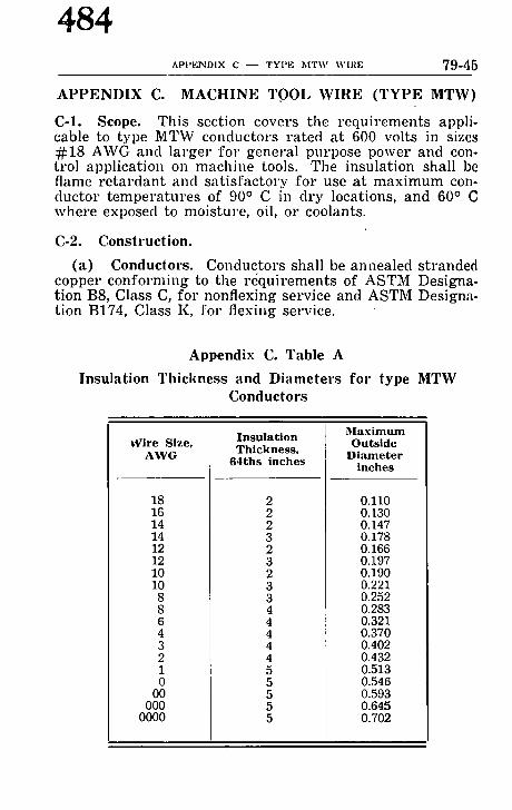
484 A P P E N D I X C - - T Y P E M T V r X V I R E 79-45
APPENDIX C. MACHINE TOOL WIRE (TYPE MTW)
C-1. Scope. This section covers the requirements appli- cable to type MTW conductors rated at 600 volts in sizes #18 AWG and larger for general purpose power and con- trol application on machine tools. Tile insulation shall be flame re ta rdant and sat isfactory for use at maximum con- ductor temperatures of 90 ~ C in dry locations, and 60 ~ C where exposed to moisture, oil, or coolants.
C-2. Construction.
(a) Conductors. Conductors shall be annealed stranded copper conforming to the requirements of ASTM Designa- tion B8, Class C, for nonflexing service and ASTM Designa- tion B174, Class K, for flexing service.
Appendix C. Table A
Insulation Thickness and Diameters for type MTW Conductors
Wire S i ze , AWG
18 16 14 14 12 12 10 10
8 8 6 4 3 2 1 0
00 000
0000
I n s u l a t i o n T h i c k n e s s .
6 4 t h s i n c h e s
Maximum O u t s i d e
D i a m e t e r i n c h e s
0.110 0.130 0.147 0.178 0.166 0.197 0.190 0.221 0.252 0.283 0.321 0.370 0.402 0.432 0.513 0.546 0.593 0.645 0.702

485 79-46 ELECTRICAL STANDARD FOR METAL WORKING MACI[INE TOOLS
(b) Insulation. Insulation shall be a material approved for use on type MTW conductors with thicknesses and diameters as specified in Appendix C, Table A.
(c) Finish. There shall be no additional covering pro- vided over the insulation except tha t if a lubricant is applied it shall be such tha t it will not flake off nor have any dele- terious effect on the equipment.
(d) Identification. The conductor shall have a readily identifiable continuous permanent marking to indicate MTW or Machine Tool Wire, voltage, size, and manufacturer . In no case shall any par t of identification be obtained by the use of fibrous material. Each coil or reel shall be tagged or marked to indicate MTW or Machine Tool Wire, voltage, size, manufacturer , temperature ratings, and any additional designations for which the material is approved.

486 REPORT OF COMMITTEE ON MARINE FIRE PROTEGTION MFPI
R e p o r t of t h e C o m m i t t e e o n M a r i n e Fire P r o t e c t i o n
T h o m a e M. Torrey , Chairman, Insurance Co. of North America, 79 John St., New York 38, N. Y. (Personal)
Char les S. M o r g a n , t ,SecretarT/, National Fire Protection Assn., 60 Batteryraarch St., Boston 10, Mass.
Braz ton B. Carr , The American Waterways Operators, Inc.
Jo seph E. Choate , National Assn. of Engine & Boat Mfrs.
R . Cox, Fire Equipment Manufacturer8 Assn.
Alan C u m y o , Canada Department of Trans- port.
F r a n k W. D u n h a m , J r . , American Assn. of Port Authorities.
F. J . Fee, J r . , National Autonmtic Sprinkler & Fire Control Assn.
H. A. Gi lber t , Inland Waters Petroleum Carriers Assn.
Rear A d mi r a l F r a n k D. n igbee , USCG (ret.) (ex-oflieio), Chairman, Committee on Harbor Emergency Organization.
Lewis C. Hos t (ex-oflicio), Chairman, Com- mittee on Gas Hazards.
George W. Mo r g an , Assn. of American Ship Owners.
Capt . Ha r ry J . Pa rker , National Cargo Bureau, Inc.
Roy C. Pe te r sen (ex-oflieio), Chairman, Committee on Operation of Marine Ter- minals.
Rear A d m i r a l H. C. Sh ephea rd , USCG (ret.), ~Vashington 113, D . C . (Personal)
Earl S. Shul te rs , U. S. Department of Corn, merce.
Robe r t J . Snyder , Pacific American Steam, ship Assn.
Vice Admi ra l Lyndon Spencer , USCll (ret.), Lake Carriers' Assn,
Rear Admi ra l !. J . S t ephens , United Statm Coast Guard.
J o h n M. Tech ton , Marine Chemists' A~an,
E. S. Terwl l l lger (ex-officio), Chairman, Committee on Motor Craft.
J . Pau l T h o m p s o n , U. S, Salvage Aaan,. Inc.
P ie r re R. Vallet (ex-officio), Chairmen. Committee on Marina~ and Boatyards.
T. T. Wi lk inson , American Petroleum In. stitute.
A l t e r n a t e s .
Stanley Beeket t , Canada Dept. of Trsna. port. (Alternate to A. Cumyn.)
B. H. Lord, J r . , American Petroleum Im stitute. (Alternate to T. T. Wilkinson.)
Bur r Wll l lamsOn, Fire Equipment Menu. lecturers Assn. (Alternate to R. Cox.)
This report has been submitted to letter ballot of this Committee which consists of 23 members, all of whom have voted a.l~rmatively.
This Committee concurs ill the presentation for adoption of the following report of the Sectional Committee on Gas Hazards. The Sectional Committee, since 1947, has been under joint administration with the American Bureau of Shipping.

M FP2 A M E N D M E N T S TO NFPA NO. 306
487
R e p o r t of S e c t i o n a l C o m m i t t e e o n Gas H a z a r d s . (Under joint sponsorship with the A merican B ureau of Shippintl)
Lewis C. Host , Chairman, American Bureau of Shipping, 45 Broad St., New York, N. Y.
0t-alton B. Cart , The American Waterways Operators, Inc.
~tlttes C. Clarke, Marine Transport Lines, the, (Personal)
~,Odney n . Elden, Pacific American Tank- ahl I) Assn.
atqlel Gara te , ,V~ld Shipyards Corp. (Per- tmnsl)
I lenry A. Gi lber t , Inland Waters Petroleum Carriers Assn.
|~apt, S a m u e l G. Gulll , U. S. Coast Guard. Win, B. Jupp , Annapolis, Md. (Personal) !tmeph J. LaRocca, U. S. I)ept. of Labor, t lw V. Phelps, Warren Petroleum Corp,
(l'ersonal)
Dr. H. G. Schneider . Esso Standard Oil Co. (Personal)
Rear Admira l t l . C. Shephea rd , USCG (ret.), Washington 16, D . C . (Personal)
J o h n M. T e c h t o n , Marine Chemists' Assn.
J. Paul T h o m p s o n , U. S. Salvage Assn., |as .
Charles J. T l e d e m a n , Betidehem Steel Co. (Personal)
T. T. Wilkinson, American Petroleum In- stitute.
J. Lyell Wilson, Norfolk, Nebraska. (Per- sonal)
Alternates . n. II. Lord. Jr . , American Petrolemn In- Ralph W. N e t t e r s t r o m , U. S, Dept. of
.tltute. (Alternate to T. T. Wilkinson.) Labor. (Alternate to Joseph J. LaRocca.)
This report has been submitted to letter ballot of the Sectioaal Committee which consists of 16 members, all of whom have voted aJfirmatively.
The Commit tee submits for adoption certain amendments to Ihe Standard for the Control of Gas Hazards on Vessels to be Repaired (NFPA No. 306). The amendments are intended both Io clarify and to broaden certain aspects of the s tandard . The proposed reviscd text of paragraphs 312 and. 313 serves to era- . !lhasize the necessity for maintenance of safe conditions through- out the t ime repairs ar t to be carried on and the responsibility i)f t, he Gas Chemist for so qualifying hiscertificate as to assure this.
The proposed addition of an entirely new Section 5 broadens Ihe scope of the Standard to take cognizance of the possible hazard to health occasioned by chemicals which are t ransported ill bulk in vessels and which may or may not have character- I~tics of flammability or combustibility. This extension of the ~tandard into an area which is not ncccssarily directly related to th'e safety has been undertaken to mect a very practical need (uld is done with the knowledge and cooperation of the hy- giellists' profession. No needless duplication of effort is con- templated as may be seen by the refcrences in Section 5 to the determination of permissible concentratiolls by the American Conference of Governmental Industrial Hygienists.
Other than the changes mentioned above, the only modifi- cations are editorial in character and serve merely to make the whole consistent.

488 CONTROL OF GAS IIAZARDS ON VESSELS 306 ,'l
S t a n d a r d for t h e C o n t r o l o f G a s H a z a r d s o n V e s s e l s t o be R e p a i r e d
SECTION 1.
110. Scope. This s tandard describes the conditions requirC} before making repairs on an3, vessel carrying or burning corn bustible or flamnmble liquids, or carrying flammable co,, pressed gases. I t is applicable to both cold work and to repait~ involving riveting, welding, burning or like fire producing op erations on vessels while in ports in the continental United ,States, both within and outside ship repair yards. I t is applicabh ~ specifically to those spaces in such vessels which are subject tq~ concentrations of combustible or flammable liquids or gases a.~ hereinafter dcscribcd. Note: See also Section 5, paragraph 510.
111. Tank Vessels Entering a Repair Yard. Tank vesseh shall not be allowed to enter a repair yard, except as provided in Section 4 of these standards, unless cleaned or cleaned and inerted in accordance with the provisions in Section 3, para- graphs 320- or 330- respectively, and so certified by a Certificated Gas Chemist. Repairs or alterations shall not be under take, until a Gas Chemist 's certificate is obtained.
112. Tank Vessels Not Entering a Repair Yard. Repairs or alterations shall not be made, unless the compartments or sp'aces involved and the adjacent compar tments or spaces hay0 been cleaned, in accordance with the provisions in Section 3. paragraphs 340- or unless the compar tment or spaces involve(i have been cleaned and the adjacent compar tments or spaces have been inerted in accordance with paragraphs 350- and so certified by a Certificated Gas Chemist. Repairs or alterations shall not be under taken until a Gas Chemist 's certificate is ob- tained.
113. Vessels Other Than Tank Vessels Anywhere. On any vessels which have carried flammable or combustible liquid in bulk as fuel or cargo, whether in a repair yard or elsewhere, no repairs involving hot work shall be made in and on the ex- ternal boundaries (shell, tank top or deck) of cargo tanks, fuel tanks, oil pipe lines and heating coils, unless such compartments and pipe lines, deemed necessary by the Certificated Gas Chemist, have been cleaned or inerted to meet the appropriate designation requirements of Section 2, paragraphs 220- except tha t the ap-

C O N T R O L O F G A S H A Z A R D S ON V E S S E L S
489
lwat ion of 224(b) may be used only in the case of repairs not wnlving the tank top or decks of tank boundaries. In such ~cs paragraph 224(b) may be modified by partially flooding
,,tl,h water provided that any hot work is performed at least Ilhrcc feet below the water level; provided further that the gas ~mtent of the atmosphere above water does not exceed one half ~f one per cent by volume in air. In no case shall internal hot ,~t,rk be pernfitted within any compartment or space unless the ~ ompartnmnt in which the work is to be performed is in such a ~ondition as will meet the requirements of Section 2, paragraph ,!21. Repairs or alterations shall not be undertaken until a Gas *'hcmist's certificate is obtained.
114. Vessels Carrying Flammable Compressed Gas. On Imy vessels which have carried flammable compressed gas in bulk, no repairs or alterations involving hot work shall be made mdcss the applicable provisions of paragraphs i I I and 112 are ~'omplied with; provided, however, individual pressure tanks, mcrted in accordance with paragraph 225, are considered in a t~afc condition for such work not directly involving these tanks or their pipe lines or the spaces in which these tanks are located.
120. E m e r g e n c y Except ion . Nothing in this standard shall be construed as prohibiting the immediate dry-docking of a vessel whose safety is imperiled, as by being in a sinking condition or by having been seriously damaged, making it impracticable to clean and gas-free in advance. In such cases however all necessary precautionary measures should bc taken as soon as practicable to provide safe conditions satisfactory to the Certificated Gas Chemist.
130. G o v e r n m e n t a l Regu la t ions . Attention of owners, re- pairers and chemists is directed to the general regulations of the government covering repairs to vessels. Nothing in this standard shall be construed as superseding existing require- mcnts of any governmental or local authority.
The "Rules and Regulations for Tank Vessels" and other rules and regulations for vessel inspection of the United States Coast Guard prescribe an inspection prior tomaking repairs involving riveting, welding, burning or like fire producing operations. These regulations provide, under the conditions stated therein, for inspection by a gas chemist certificated by the American Bureau of Shipping or alternately another person. For par- ticulars, these regulations should be consulted.

490 CONTROL OF GAS IIAZARDS ON VESSELS ~06-5
S E C T I O N 2.
210. S t a n d a r d D e f i n i t i o n s . (See also Section 5, paragraph 520.)
For the purpose of this s tandard the following definitions are to be recognized:
211. CERTIFICATED GAS CHEMIST: The holder of a valid certificate issued by the American Bureau of Shipping in ac- cordance with its "Rulcs for Certification of Chemis ts" estab- lishing him as a person qualified to determine whether repairs and al terat ions to vessels, which may involve gas hazards, can be under taken with safety..
212. GAs.CItEMIST'S CERTIFICATE: A written s t a tement pre- pared and issued by a Certificated Gas Chemist in form and manner prescribed by the American Bureau of Shipping. . (See page 306-16.)
213. FLAMMABLE AND COMBUSTIBLE LIQUIDS: a. FLAMMABLE LIQUIDt: For the purpose of these require-
ments, a f lammable liquid is any liquid which gives off f lammable vapors (as determined by flash point from an open cup tester, as used for test of burning oils) a t or be- low a t empera ture of 80~
b. COMBUSTIBLE LIQUID: For the purpose of these require- ments a combustible liquid is any liquid having a flash point above 80~ (as determined by means of an open-cup tester as used for test of burning oils).
C. EQUIVALENT FLASH POINTS: "Tag" Closed
Open Cup Cup T e s t e r Pensky-Martens Tester (A.S.T.M.) Closed Tester
~ ~ ~
80 75 - - 150 - - 140
d. FLAMMABLE COMPRESSED GAS: For the purpose of these requirements, f lammable compressed gas is defined as any f lammable gas which bas bee,l compressed and liquefied for the purpose of t ranspor ta t ion and has a Reid vapor pressure exceeding 40 pounds.
INote: "Flammable" and "Inflammable" have the same meaning.

491 J06-6 CONTROL OF GAS IIAZARDS ON VESSELS
21,1. TANKER ]~)ESIGNATIONS: It. TANK VESSEL: A tank vessel is auy vessel especially con-
structed or converted to carry liquid bulk cargo in tanks. h. TANK SHIP: A tank ship is any tank vessel propelled by
power or sail. C, TANK BARGE: A tank barge is any tank vessel not equip-
ped with means of self-propulsion.
215. REPAIR CLASSIFICATIONS: a. HOT WORK: Any repair or al teration involving riveting,
welding, burning or similar fire-producing operatioi~s. Grinding, drilling or similar spark-producing operations shall be considered hot work except when in the judgment of the Certificated Gas Chemist, circumstances do not necessitate such classification.
b. COLD WORK: A n y - r e p a i r or al terat ion which does not involve heat, fire and spark-producing oper-ttions.
220. S t a n d a r d Sa fe ty D e s i g n a t i o n s : (See also Secl. 5, para. 530.)
The following s tandard safety designatio,ls shall be used where applicable in preparing Gas Chemists ' certificates, cargo tank labels and other references:
221. SAFE FOR h ' [ E N - SAFE FOR ]?IRE: ~Ieans t h a t in the compar tmen t or space so designated and in the adjacent 2 com- par tments or spaces:
a. The gas content of the a tmosphere by volume is within a permi.~sihle concentrationfl and tha t ;
b. In the judgment of the Certificated Gas Chemist , the resi- dues arc not capable of producing dangerous gases under a tmospheric conditions and in the presence of fire.
222. SAFE FOR I~ / |EN- NOT SAFE FOR FIRE: Means tha t in the c o m p a r t m e n t or space so designated:
a. s gas content of the a tmosphere by volume is within a permissible concen t ra t ion) and tha t ;
2Note: Except th'Lt adjacent compartnmnts may be inerted and, in the ease of fuel tanks, may be treated :is deemed necessary by the Certificated (:;its Chemist.
aNote: As a guide to pcrmissil)le concentration limits, refer to current table nf "Threshold Limit V:dues" of the American Conference of Governmental Industrial Hygienists, 1014 Broadway, Cincinnati 2, Ohio; 25c per cop3'.

492 CONTROL OF GAS HAZARDS ON VESSELS ~00-7
b. In the judgment of the Certificated Gas Chemist, the resi- dues are not capable of producing d~mgerous gases under atmospheric conditions and in the absence of fire.
223. NOT SAFE FOlt A ' [EN--NOT SAFE FOR FIRE: Means tha t in the compar tmen t or space so designated, either:
a. The gas content of the a tmosphere by volume is not withi , a permissible concentration, 3 or tha t ;
b. I n ' t h e judgment of the Certificated Gas Chemist, the resi- dues are capable of producing dangerous gases under at- mospheric conditions, or tha t ;
e. The c o m p a r t m e n t was not tested because it contained bal- last, slops, bunkers, etc. In such cases this safety designa- tion slmll I.)c followed by ~ s t a tement of the condition of the c o m p a r t m e n t which prevented it from being tested.
224. INERTED: M e a n s t h a t in the compar tmen t or space so designated, either:
a. Carbon dioxide or other nonf lammable gas, approved by the American Bureau of Shipping, has been introduced into the space in sufficient volume to mainta in the oxyge, content of the a tmosphere of the space a t or below l0 per cent during the whole of the inerting period, and to insure tha t the volume of the inerting gas shall never be less tha , 50 per cent of tha t of the void space; or tha t
b. The space has been filled to the top with water.
c. The kind of gas and the safe disposal or securing of gas inerting media shall be noted on the Gas Chemist ' s certifi- cate by the Certificated Gas Chemist upon the completion of repairs. Closing and securing of hatches and other openings, except vents, may be considered as "safe dis- posal" of the gas by the Certificated Gas Chemist .
225. INERTED, FOR _~'LAMMABLE COMPRESSED GAS: 3,'Iean8 tha t individual pressure tanks with a working pressure of 50 pounds per square inch or over m a y be considered inerted when a positive pressure is maintained on the tanks by the flammabl0 vapors remaining af ter the cargo has been discharged.
SSee footnote on page 306--6.

,906-8 C O N T R O L OF GAS HAZARDS ON V E S S E L S
493
S E C T I O N 3.
,910. M i n i m u m R e q u i r e m e n t s P r e c e d e n t to t h e I s s u a n c e of a G a s C h e m i s t ' s C e r t i f i c a t e - - A p p l i c a b l e in All C ases .
311. Before a Certificated Gas Chemist shall issue a certificate ,:etting forth in writing tha t the contemplated repairs and al- It'rations to a vessel can, in his judgment, be undertaken with cafety he shall personally determine that the applicable mini- mum requirements have been complied with to his satisfaction.
312. When the Certificated Gas Chemist has satisfied himself that these minimum requirements and any other requirements, dec,ned by him to I)e necessary in order tha t the repairs and al- terations can be nndertaken with safety have been carried out, t~ Gas Chemist 's certificate shall be issucd by him setting forth m writing those facts. Such certificate shall be qualified as may bc necessary and shall be prepared in form and manner pre- i;cribed by the Americ-tn 13ureau of Shipl)ing. (See page 306-16.) It shall include such requirements as may be deemed necessary by the Certificated Gas Chemist, to maintain insofar as can rea- ~.o,mbly be done, the safe conditions in the spaces certified throughout the operation and shall include such additional tests and certifications as the (;as Chemist considers required. Such qualifications and requirements shall include precautions neces- m~ry to eliminate or minimize hazards that may bc present from protective coatings or residues from cargoes.
313. I t shall be the responsibility of the vessel repairer to retain the services of the Certificated (;as Chemist and to secure topics of his inspection ccrtificate, and to provide the Master of the vessel and the representatives of the vessel owner with copies of such ccrtificatc. I t shall bc the responsibility of the vessel repairer to maintain a safe condition on the vessel during Ihc course of repairs or alterations by full observance of all qvalifications and rcquircmer~ts listed by the Gas Chemist in the ~:c,'tificate.
320. M i n i m u m R e q u i r e m e n t s W h i c h S h a l l Preva i l Pr ior to t h e I s s u a n c e of a G a s C h e m i s t ' s C e r t i f i c a t e , W h e r e a Sa fe C o n d i t i o n Is to Be O b t a i n e d E n t i r e l y by C l e a n i n g .
321. All cargo heater coils shall have been steamed and blown. All cargo pumps, cargo lines, cargo smothering and vent lines 0hall have been flushed with water or blown with s team or air.

494 CONTROL OF GAS IIAZARDS ON VESSELS 306- t ]
322. Compar tmen t s shall be so cleaned tha t the gas content by volume of the atmosl)hcre in all cargo compar tments and other spaces subject to gas accumulat ion (with the exception of bunker tanks containing fuel oil') shall be within a permissible co,o centrat ion 3.
323. The residues ia all cargo compar tments and other spac(,,~ (with the exception of bunker tanks containing fuel oil 4) shall not be capable, izl the opinion of the Certificated Gas Chemist~ of releasing gas which will raise the concentrat ioa in any such space above a permissible concentrat ion2
324. Satisfactory compliance with all the foregoing require- ments shall be noted on the Gas Chemist ' s certificate.
330. M i n i m u m R e q u i r e m e n t s Which Shall Prevail Prior to the Issuance of a Gas Chemis t ' s Certificate Where a Safe Cond i t i on Is to Be Obta ined by Bo th Cleanin~ and ln e r t ing or Entirely by lner t ing .
331. A Certificated Gas Chemist shall approve the use of th0 inerting procedure. Except where water is the inerting nmdium he shall be present continuously and actual ly supervise the con- trol of ttle inerting medium and the hazards from the t ime the inerting medium is first takez~ aboard until the repairs and tim safe disposal or securing of the inerting medium are. complete. (Where gas incrting is being performed, a subst i tute for the Certif- icated Gas Chemist shall not be permit ted as provided under other conditions in U. S. Coast Guard regulations.)
332. Only authorized persons and those actually necessary i. connection with the repairs should be permit ted on board the vessel from the t ime the inerting gas is taken aboard until th0 repairs and the safe disposal or securing of the inerting gas arc completed.
333. All cargo heater coils, except those in the inerted spaces shall have been steamed and blown. All cargo slnothering and vent lines, except those in the inerted spaces, shall have been flushed with water, or blown with s team or air, or inerted. All valves to the inerted spaces shall have been closed and secured.
~See footnote on page 306-6. ~Note: If, however, the work involved is within or on the cargo compart-
ment adjacent to fuel oil bunker bound-Lries, then the bunker tanks should bu treated as deemed necessary by the Certificated Gas Chemist.

306-10 C O N T R O L OF GAS I IAZARDS ON VES S ELS
495
All cargo pumps and cargo lines shall have been flushed with water, or blown with s team or air, or inertcd.
334. All spaces to be inerted shall be sufficiently intact to re- tain the inerting medium. All valves, hatches and other openings to the inerted spaces, except those controlling the inerting ,ncdium, are to be closed and secured.
335. Compar tmen t s or spaces in which internal repairs or alterations are to be under taken shall be cleaned to comply with the requirements of paragraphs 320- and all other spaces (with the exception of I)unker tanks containing fuel oil") shall be in- erred in accordance with the requirements of Section 2, para- graph 224.
336. Compar tmen t s or spaces on which external repairs or alterations are to be undcrtaken on the external boundaries (deck or shell) may be inertcd by gas instead of being cleaned as described in paragraph 335, and all othcr spaces (with the exception of bunker tanks containi,lg fuel oil 'l) shall be inerted, such inerting to be in accordance with the requirements of Sec- tion 2, paragraph 224.
337. Satisfactory compliance with all the forcgoing require- ments sh~ll be noted on thc Gas Chemist ' s certificate.
340. M i n i m u m R e q u i r e m e n t s Which Shall Prevail Prior to the Issuance of a Gas Chemis t ' s Certificate Where a Safe Condi t ion Is to Be Obta ined Entirely by Clean- ing Certain C o m p a r t m e n t s and by Securing the Other C o m p a r t m e n t s .
341. All cargo heater coils to the spaces involved shall have been steamed and blown; all cargo smothering and vent lines to the spaces involved shall have been flushed with water or blown with s team or air; and the valves to all other compar t - ments closed and sccured. All cargo pumps and cargo lines shall have been flushed with water or blown with s team or air and the valves closed and secured.
342. Compar tmen t s or spaces in which internal repairs or al terations are to be under taken and all adjacent compar tments ,
4See footnote on p~ge 306-9.

496 C O N T I t O L O F G A S I I A Z A R D S ON V E S S E L S 306- I I
including those diagonally adjacent thereto, shall be eleancd to comply with thc applicablc recluirements of paragraphs 320- and all other compartments slmll be closed and secured.
343. S~tisfactory compliance with all the foregoing requirc- ments shall be noted on the Gas Chemist's certificate.
. . . . . I 77'~?~i t t ~ t t i
I ~ ~ , f / / / , ~ / / w / / / / ~ P a r a g r a p h s 320 - - Safe C o n d i t i o n O b t a i n e d E n t i r e l y by C l e a n - '
inR i n a R e p a i r Yard.
P a r a g r a p h s 330 - - Safe C o n d i t i o n O b t a i n e d by C l e a n i n g a n d i n e r t l n g In a R e p a i r Yard .
___I _ V//~//~f///.J/,~i
I ~ . . . .
P a r a g r a p h s 340 - - Safe C o n d i t i o n O b t a i n e d by C l e a n i n g a n d S e c u r i n g N o t i n a R e p a i r Yard .
P a r a g r a p h s 350 - - Safe C o n d i t i o n O b t a i n e d by C l e a n i n g , I n e r t - i n~ a n d S e c u r i n g No t i n a R e p a i r Yard.
K e y : / / / / / / - Clean; \\\ \\\ - Ine r t ; W - W o r k .

~Oh-12 C O N T R O L OF GAS ] IAZARDS ON VI']SSELS
497
i50. M i n i m u m Requirements Which Shall Prevail Prior to the Issuance of a Gas Chemist 's Certificate Where a Safe Condit ion Is to Be Obtained by Both Cleaning and Inerting or Entirely by Inerting Certain Com- partments and by Securing the Other Compart- ments .
;151. All cargo heater coils to the spaces involved, except those I!,,~ the inerted spaces, shall have. been s teamed and blown; cQI cargo smothering and vent lines to the spaces involved, ex- r ~'pt those to the inerted spaces, shall have heen flushed with ~ater or I)lown with s team or air or inerted; and the valves to nil other compar tmen t s closed and secured, All cargo pumps :~ad cargo lines shall have been flushed with water, or blown ,~il, h s team or air or inerted and the valves closed and secured.
352. Compar tmen t s or spaces in which internal repairs or ~lt~rations are to he undertaken shall be clenched to comply with t~ilc , 'equirements of paragraphs 320- and all adjacent compar t - ,~w,lts, including those diagonally adjacent thereto, shall be ~wrtcd to comply with the applicable requirements of paragraphs )iI()- and all other compar tments shall be closed and secured.
:t53. Compar tmen t s or spaces on which external repairs or ~ltcrations are to be undertaken on the external boundaries , lock or shell) may be inertcd by gas instead of being cleaned as ,Q~'scribed in paragraph 352, and all adjacent compar tments , ,m:luding those diagonally adj-tccnt thereto, shall be inerted to ,mnply with the applicable requirements of paragraphs 330- ,~,l(I all other spaces shall be closed and secured. Flooding with ~atcr may be used in lieu of gas incrting provided tha t the work ~-~ confined to the exterior shell at least three (3) feet below the ~atcr level and further provided tha t the gas content of the ~lmosphere above the water does not exceed one half of one
~t,r cent by volume in air, and if approved by a Certificated Gas It'hemist.
354. Sat isfactory compliance with all the foregoing require- iJicl~ts shall be noted on the Gas Chemist ' s certificate.

498 CONTROL OF GAS HAZARDS ON VESSELS 306-I!
SECTION 4.
410. Exempt ions from the R e q u i r e m e n t s of Sect ion 1 fff, Vessels Entering a Repair Yard.
411. Vessels which enter the repair yard for examinatiol either afloat or ill drydock, provided, tha t all bulk cargo col,. par tments and cofferdams are kept closed.
412. Vessels which enter the repair yard for scraping, washin[ down and painting afloat or in drydock, provided, tha t all bul! cargo compartments and cofferdams are kept closed.
413. Vessels which enter the repair yard for work (hot (, cold) to be performed outside of the vessel, either afloat or i drydock, on the propeller, tailshaft or rudder (except hollm rudders in which case a Gas Chemist 's certificate shall be rr quired for the rudder) or for work to be performed off the vest ' such as oll the anchors or chains, provided, that all bulk carg compartments and cofferdams are kept closed.
414. Vessels which enter the repair yard for work, either afioa ~ or in drydock, within boiler and machinery spaces, and at otht locations remote from the cargo compartments but not less tht~ twenty-five (25) feet from the nearest cargo compartment whi( has not been cleaned or inerted to meet the appropriate designa lion ~equirements of Section 2, paragraphs 220-; provided, tht, where hot work is to be undertaken a Gas Chemist 's certifica! shall be required and this certificate shall set forth each speci[ location for which such work is approved, and further provide( that all bulk cargo compartments and cofferdams are kept close(
415. Vessels which proceed to a special berth selected and ss apart in the repair yard for a degassing, clearing and inerti,( berth with due regard to the hazards of the location and I hazards to adjacent property.
416. The degassing, cleani,~g and inerting of vessels at stt( special berths shall be carried out in accordance with the I~ quirements of Section 3, paragraphs 320- or 330- before th~ are shifted to other berths. No repairs involving hot w01, shall be undertaken on any vessel in such special berth until ~ has been degassed and cleaned or inerted in accordance with l}, requirements of Section 3, paragraphs 320- or 330- nor shall su( repairs be then undertaken if another vessel or vessels, whi( have not complied with these requirements, are in the speeil berth at the same time.

499 306-14 CONTROL OF GAS IIAZARDS ON VESSELS
,117. A Gas Chemist 's certificate shall be obtaincd before Mfifting a vessel to another berth from the special berth, or before undertaking the repair work at the special berth.
,118. \;essels which proceed to a drydock or special I)erth r;elcct, ed and set apar t with due regard to the hazards of the hmation and to h a z a r d s t o adjacent property may undergo spe- cific limited repair of a local nature when the compartments or t!paccs involved and the adjacent compar tments or spaces are prepared in accordance with the provisions in Section 3, para- graphs 340- or paragraphs 350-. Not more than one vessel ,hall be located at each special berth. A Gas Chemist 's certifi- cate shall be obtained before undertaking such repairs.
SECTION 5.
500. Standard for Certifying Cargo Tanks Which Have Been Used for Carrying Chemica l s in Bulk.
510. Scope . The s tandard set forth in this Section describes the conditions required I)efore making repairs in spaces used for 4.arrying chemicals ill bulk, it being understood tha t the re- m:dning spaces ill the vessel comply, with the applicable pro- visions of paragraphs I 11, 112 -rod 113.
520 . S'rANDAItD D E F I N I T I O N S - CIIEMICAL. For the purpose of these requirements a chemical is any compound, mixture or solution in the form of ~ solid, liquid or g:rs, which may be hazardous by virtuc of its properties or by virtuc of the prop- crties of compounds which might b6 evolved from hot work or cold work.
530 . STANDARD SAFETY I)ESIGNATIONS:
a. The stand'u'd safety dcsign-ttions set forth in paragraph 221 and 222 may be used, provided tha t in the judgment of the Certificated (;as Chemist, the gas or vapor content in the compar tments or spaces is within a permissible conccntratiolt for exposures not exceeding a total of 8 hours per day. 3
b. Where applicable, s tandard safety designations of para- graph 223 may be used.
3See footnote on page 306--6.

500 C O N T R O L OF GAS HAZARDS ON V E S S E L S 306-1~',
c. h~ additiolb for spaces tha t Imve contained noncom~ bustible or nonflammable chemicals, the following s'ffels' designation shall be used where applicable in preparing the Gas Chemist 's certificate:
NOT SAFE FOIl ME,',' - - SAFE FOR Flies: Means t ha i ' i n the judgment of the Certific~tcd Gas Chemist, the residuc~ i,~ the compartmetl t or space so designated are not com- bustible or flammable, but are considered hazardous to person nel.
(1) In such cases this designation shall be followed by a s ta tement explaining tim condition of this space.
540. Minimum requireme~ts precedent to the issuance of a ([as Chemist 's certificate for spaces tha t have contained chemi- cals in bulk in all cases shall be as set forth in paragraphs 311 through 313.
550. Minimum requirements which shall prevail prior to the issuance of a Gas Chemist 's cerlMicate for sp-~ces tha t have con- tained chemicals in bulk shall be as set forth in paragraphs 320, 330, 340 and 350 insofar as they are applicable, with the following additions:
a. All pipe lines, together with the cargo pumps and cargo lines serving the chemical-carrying spaces shall be initially dealt with to the satisfaction of the Certificated Gas Chemist.
b. Compar tments having carried chemicals-in bulk and which are to be cleaned shall be so cleaned tha t the gas content by volume of the atmosphere in those compar tments shall be within the permissible limits set forth in paragraph 530a.
c. The residues in the comp'~rtments shall not be capable, in the judgment of the Certificated Gas Chemist, of re- leasing vapors or gases which would raise the concentra- tion above the limits set forth in paragraph 530a.
d. The residues in compar tments shall not be of sufficient concentration, in the judgment of the Certificated Gas Chemist, to cause corrosive actiol~ tha t would endanger the life or health of personnel.
e. The residues in compar tments shall not be capable, in the judgment of the Certificated Gas Chemist, of releasing vapors or gases which would raise the concentration above a permissible concentrat ion during the perfornmnce of hot work.

t06~l(~ CONTIC.OL O F GAS I I A Z A R D S O N V E S S E L S
501
G A S
lteading (Chemist or Laboratory)
C H E M I S T ' S C E R T I F I C A T E
Survey Requested By:
VESSEL: O W N E R OR A G E N T : DATE: Type of Vessel: Test Method : Time of Completion : Location : Last Cargo : Certificate No. :
I - - A . - - B h m k F o r m Alternatit~es - - B . - - R u l e d F o r m - - T a n k e r w / ( : e n t e r & w i n g s for this space - - C . - - R u l e d F o r m - - T a n k e r w / p & s & s u m m e r s
- - D . - - R u l e d F o r m - - C a r g o Vesse l
S t a n d a r d D e s i g n a t i o n s 1. SA:*'E FOR ~'IEN - - SAFE r,'Oa FIRE: Means tha t in the compar tment so desig-
nated tile gas content is witilin the permissible limits of the Standard and tha t in my judgment the residues are not capable of producing dangerous gases under atmospheric conditions and in the i)r(mence of fire.
2, SAFE FOP- I~IEN - - NOT SAFE FOa FIRE: Means that in tile compartment so designated the gas content is within the permisMble limits of tile Standard and tha t in my judgment the residues are not capable of producing dangerous gases under atmospheric conditions and in tile absence of fire.
3. NOT SAFE FOR ~IEN - - NOT SAFE I~'OR FLEE: M e a n s that in the compartment so designated the gas content is not within the permissible limits of the Stand- ard or tha t in my iudgment tim residues are capable of producing dangerous gases under atnmspherie conditions or timt tile conlpartnient wt~ not tested by me.
4. NOT SAFE FOR ~IEN - - SAFE FOIl FIRE.' Means that in the compartment or spaces so designated, the residues are not combustible or fiamnmble but are considered hazardous to personnel.
C h e m i s t ' s E n d o r s e m e n t :
T h i s is to c e r t i f y t h a t , in t h e c o n ] p a r t m e n t s n o t e d in t h e f o r e g o i n g l ist , I h a v e e x a n f i n e d t h e s e s p a c e s f o r c l e a n l i n e s s a n d h ' t v e t e s t e d t h e a t m o s p h e r e in e a c h fo r g a s c o n t e n t . m d a t t h e t i m e of i n s p e c t i o n n o t e d f o u n d t h e m to b e a s i n d i c a t e d in a c c o r d a n c e w i t h t h e Standard for the Control of Gas Hazards on Vessels to Be Repaired, a d o p t e d b y t h e A m e r i - c a n B u r e a u of S h i p p i n g a n d N a t i o n a l F i r e P r o t e c t i o n A s s o c i a t i o n .
T h i s c e r t i f i c ' t t e is b a s e d o n c o n d i t i o n s e x i s t i n g a t t h e t i m e t h e i n s p e c t i o n h e r e i n s e t f o r t h w a s c o m p l e t e d . T r a n s f e r of b a l l a s t o r m a n i p u l a t i o n of v a l v e s o r c l o s u r e e q u i p m e n t t e n d i n g to a l t e r c o n d i - t i o n s in p i p e l ines , t ' t n k s o r c o m p a r t m e n t s s u b j e c t to g a s a c c u m u l a t i o n , u n l e s s s p e c i f i c a l l y a p p r o v e d in t h i s c e r t i f i c a t e , r e q u i r e s i n s p e c t i o n a n d e n d o r s e m e n t o r r e i s s u e of c e r t i f i c a t e fo r t h e s p a c e s so a f f e c t e d .
S i g n e d .. . . . . . . . . . . . . . . . . . . . . . . . . . . . . . . . . . . . . . . . . . . . . . . . . . . . . . . . . . .
C e r t i f i c a t e d C h e m i s t N o . . . . . . . . . . . . . . . . . . . . . . . . . . . . .
Form of Gas Chemist's certificate prescribed by the American Bureau of Shlppinl~.

502 COMMITTEE ON PORTABLE FIRI~ EXTINGUISHERS PFEd
R e p o r t o f C o m m i t t e e on P o r t a b l e F i r e
Extinguishers. Deputy Chief R a y m o n d M. Hil l , Chairman,
Fi re P r e v e n t i o n Bureau . D e p a r t m e n t of Fire , 217 So. Hill St.. Los Ange les 12, Calif.
( rep. F i r e Mar sha l s Assn. of Nor th Amer i ca )
Douglas R. Abbey . (Pe r sona l ) Dale K. Auck, F e d e r a t i o n of Mutua l
F i r e I n s u r a n c e Companies . J . A. Bona, U n d e r w r i t e r s ' L a b o r a -
tories, Inc. F. L. B r a n n i g a n , U. S. Atomic En -
e r g y Commiss ion . Tbos . L. Culber t son , A m e r i c a n P e t r o -
l eum Ins t i t u t e . E d w a r d Gould, New E n g l a n d F i r e I n -
su r ance R a t i n g Associat ion. S. K. Goodwin, F a c t o r y I n s u r a n c e As-
sociat ion. A. B. Guise, Ansul Chemical Com-
pany. (Pe r sona l ) A. Clifford H udson , New H a m p s h i r e
Board of U n d e r w r i t e r s . Arnold O. Jef f r ies . P h i l a d e l p h i a Board
of Pub l i c Educa t ion . (Pe r sona l ) P. E. Johnson , F a c t o r y Mutua l En-
g i n e e r i n g Division. Tho re J o h n s o n , I l l inois In spec t ion Bu-
reau .
K. It. La id l ey . F i re E q u i p m e n t Ms. : u f a c t u r e r s ' I n s t i t u t e of Canada.
C. H. ]Lindsay, Amer i can LaFrancr Div. of S te r l ing Prec i s ion Carp (Pe r sona l )
E. J . Meyers , Na t iona l Pa in t , Varnish & L a c q u e r Assn,
E d w a r d N. ~ [ o n t g o m e r y , E a s t Bostoa Mass. (Pe r sona l )
R a y m o n d B. Oliver, F i re MarshalJ Assn. of Nor th Amer ica .
F. E. Robinson , F i r e M a r s h a l s Asan of Nor th Amer ica .
Rober t Roos, F i re E q u i p m e n t ]VIanuo f a c tu r e r s Associat ion, Inc.
H e r m a n u P. Sch lander , A m e r i c a n R(~. c iprocal I n s u r e r s .
A. L. S te i lhorn , Compressed Oaa Assn. . Inc.
G i lbe r t L. Tapp in . U n d e r w r i t e r s ' Lab, o ra to r i e s of Canada .
This report has been submitted to letter ballot of tho Co,vmittee which consists o / 2 3 members of whom 21 have voted affirmatively on all items. A final vote s tatement will be given at the Annual Meeting.
The Committee recommends adoption of the follow- ing revisions to the NFPA Standard for the Installation, Maintenance and Use of Portable Fire Extinguishers (No. 10), as published by the NFPA in pamphlet form, dated May 1961, and as published in the 1961-62 National Fire Codes, Volume VII. The National Board of Fire Under- writers has also published the same text in NBFU No. 10, dated August 1961.

E-2 REVISIONS TO NFPA NO. ] 0
503
1962 Proposed Revisions to STANDARD FOR THE INSTALLATION,
MAINTENANCE AND USE OF PORTABLE FIRE EXTINGUISHERS
N F P A N o . 10
Inse~'t a new sub-parag.raph (d) to Pa~'ag~'aph 221, tend b'tte~" existing (d) to new (e) . Addit ional sub-pa~'ag~'aph rcad:
(d) Class D Fires, defined as fires in combustible :,tals, such as t i tanium, zirconium, sodium, potassium, etc.
Revise sub-paragraph 15~3(b) and add a note, the )tire Pa~'ag,raph to ~'ead:
1543. Ext inguishers shall be examined periodically 1 accordance with the provisions of this Section.
(a) At least once yearly the extinguishers and all ~:eir parts (including gasket and hose) shall be examined ,r deterioration or injuries due to misuse, and the orifices of '~c hose nozzles examined to see tha t they are not clogged. "~tinguishers or parts which are not in good condition shall ~ replaced, or if of the cartridge-operated type, returned
the manufac turer for examination or subjected to a ,ydrostatic pressure test in accordance with Section 71. At :,ese inspections all pumps (of pump-operated extinguish- rs) shall be tested by operating them several strokes, dis- barging the solution back into the tank, then put t ing a drop f thin lubricating oil on the piston rod packing.
(b) At least semi-annually, all cartr idges shall be vmoved and weighed on an accurate scale to detect loss of m~tents by leakage. A replacement cartr idge shall be pro- ided if the loss of weight is in excess of that permitted by he instructions on the extinguisher name plate. The artridges which are provided with a gauge shall be ex- mined to determine whether the pressure indication on he gauge is within the operable range.
(c) At least semi-annually extinguishers of the tored-pressure type shall be examined to determine tha t the ressure as indicated on the extinguisher gauge is in the perable range.

504 C O M M I T T E E ON PORTABLE FIRE E X T I N G U I S H E R S PFE,~
(d) At these inspections and when extinguisheb are recharged, date of inspection or recharging and sign~ ture of person who performed it are to be put on the t~ at tached to each extinguisher. This work shall be doli~ under capable supervision. On these occasions several of tht ext inguishers should be discharged as if at a fire and befm~ an assembly of the occupants of the building. These exhib~ lions are valuable for the reasons given in paragraph 105 When recharged, each ext inguisher should, where practic~ be emptied by discharging it.
N O T E : I t is not the in ten t of this p a r a g r a p h to requi re deprc: sur iza t ion of s t o r e d - p r e s s u r e type ex t ingu i she r s unless an extern: examina t i on indica tes t h a t an in te rna l examina t i on should be m~,d~
3. Revise Paragraph 1643 and add a note, the entire Paro graph to read:
1643. Ext inguishers shall be examined periodicalJ:' in accordance with the provisions of this Section.
(a) At least once yearly the extinguishers and a! their par ts (including gasket and hose) shall be examinff for deterioration or injuries due to misuse, and the orifices ~' the hose nozzles examined to see that they are not clogged Ext inguishers or par ts which are not in good condition sha[ be replaced, or if of the car t r idge-operated type, returnc: to the manufac tu re r for examination or subjected to~ hydrostat ic pressure test in accordance with Section 71.
(b) At least semi-annually, all car t r idges shall I1: removed and weighed on an accurate scale to detect lo~' of contents by leakage. A replacement car t r idge shall I~, provided if the loss of weight is in excess of that permitt~, by the instructions on the extinguisher name plate. T]I~ car t r idges which are provided with a gauge shall be e~ amined to determine whether the pressure indication on th~ gauge is within the operable range.
(c) At least semi-annually extinguishers of th, s tored-pressure type shall be examined to determine that th, pressure as indicated on the extinguisher gauge is in th~ operable range.
(d) At these inspections and when extinguishm~ are recharged, date of inspection or recharging and siam ture of person who performed it are to be put on the ta| at tached to each extinguisher. This work shall be don,

E-d REVISIONS TO NFF'A NO. J.0
505
:~ter capable supervision. On these occasions several of the ,~ulguishers should be discharged as if at a fire and before
assembly of the occupants of the building. These exhibi- ns are valuable for the reasons given in paragraph 105. lien recharged, each extinguisher should, where practical, empt ied by discharging it.
N O T E : I t is n o t t h e i n t e n t of t h i s p a r a g r a p h to r e q u i r e d e p r e s - ,l~atio.n o f s t o r e d - p r e s s u r e t y p e e x t i n g u i s h e r s u n l e s s a n e x t e r n a l unination indicates that an internal examination should be made.
Revise Paragraph 1843 and add tt note, the entire Para- ,~4ph to read:
1843. Ext inguishers shall be examined periodically ~ accordance with the provisions of this Section.
(a) At least once yearly the extinguishers and all ;,,iv parts (including gasket and hose) shall be examined ~,' deterioration or injuries due to misuse, and the orifices of ~e hose nozzles examined to see that they are not clogged. '~tinguishers or parts which are not in good condition shall ~ replaced, or if of the cartridge-operated type, returned
the manufac tu re r for examination or subjected to a ~,drostatic pressure test in accordance with Section 71.
(b) At least semi-annually, all cartr idges shall be moved and weighed on an accurate scale to detect loss contents by leakage. A replacement cartr idge shall be
rovided if the loss of weight is in excess of tha t permitted ~, the instructions on the extinguisher name plate. The wtridges which are provided with a gauge shall be ex- mined to determine whether-the pressure indication on the auge is within the operable range.
(c) At least semi-annually extinguishers of the loved-pressure type shall be examined to determine tha t the rcssure as indicated on the extinguisher gauge is in the I)erable range.
(d) At these inspections and when extinguishers ,'c recharged, date of inspection or recharging and signa- !n'e of person who performed it are to be put on the tag ttached to each extinguisher. This work shall be done nder capable supervision. On these occasions several of the ~tinguishers should be discharged as if at a fire and before n assembly of the occupants of the building. These exhibi- ,ons are valuable for the reasons given in paragraph 105.

506 COMMITTEE ON PORTABLE FIRE EXTINGUISHERS PFE-5
When recharged, each extinguisher should, where practical, be emptied by discharging it.
NOTE: It is not the intent of this paragraph to require depres- surization of stored-pressure type extinguishers unless an external examination indicates that an internal examination should be made.
5. Revise Paragraph 2443 and add a note, the entire Para- graph to read:
2443. Ext inguishers shall be examined periodically in accordance with the provisions of this Section.
(a) At least once yearly the extinguishers and all their parts (including gasket and hose) shall be examined for deterioration or injuries due to misuse, and the orifices of the hose nozzles examined to see tha t they are not clogged. Ext inguishers or parts which are not in good condition shall be replaced, or if of the cartr idge-operated type, returned to the manufac tu re r for examination or subjected to a hydrostat ic pressure test in accordance with Section 71.
(b) At least semi-annually, all cartr idges shall be removed and weighed on an accurate scale to detect loss of contents by leakage. A replacement cartr idge shall be provided if the loss of weight is in excess of that permitted by the instructions on the extinguisher name plate. The cartr idges which are provided with a gauge shall be ex- amined to determine whether the pressure indication on the gauge is within the operable range.
(c) At least semi-annually extinguishers of the stored-pressure type shall be examined to determine tha t the pressure as indicated on the extinguisher gauge is in the operable range.
(d) At these inspections and when extinguishers are recharged, date of inspection or recharging and signa- ture of person who performed it are to be put on the tag at tached to each extinguisher. This work shall be done under capable supervision. On these occasions several of the extingulshers should be discharged as if at a fire and before an assembly of the occupants of the building. These exhibi- tions are valuable for the reasons given in paragraph 105. When recharged, each extinguisher should, where practical, be emptied by discharging it.

PFE-6 REVISIONS TO NFPA NO. 10
507
NOTE: It is not the intent of this paragraph to require depres- surization of stored-pressure type extinguishers unless an external examination indicates that an internal examination should be made.
6. Revise Paragraph 2543 and add a note, the entire Para- graph to read:
2543. Ext inguishers shall be examined periodically in accordance with the provisions of this Section.
(a) At least once year ly the ext inguishers and all their par ts ( including gasket and hose) shall be examined for deter iora t ion or injuries due to misuse, and the orifices of the hose nozzles examined to see tha t they are not clogged. Ext inguishers or par ts which are not in good condition shall be replaced, or if of the car t r idge-operated type, re turned to the ma nu fa c tu r e r for examinat ion or subjected to a hydros ta t ic pressure test in accordance with Section 71.
(b) At least semi-annually, all car t r idges shall be removed and weighed on an accurate scale to detect loss of contents by leakage. A replacement car t r idge shall be provided if the loss of weight is in excess of tha t permit ted by the instruct ions on the ext inguisher name plate. The car t r idges which are provided with a gauge shall be ex- amined to determine whether the pressure indication on the gauge, is within the operable range.
(c) At least semi-annually ext inguishers of the s tored-pressure type shall be examined to determine tha t the pressure as indicated on the ext inguisher gauge is in the operable range.
(d) At these inspections and when ext inguishers are recharged, (late of inspection or recharging and signa- ture of person who performed it are to be put on the tag at tached to each extinguisher. This work shall be done under capable supervision. On these occasions several of the ext inguishers should be discharged as if at a fire and before an assembly of the occupants of the building. These exhibi- t ions are valuable for the reasons given in paragraph 105. When recharged, each ext inguisher should, where practical, be emptied by discharging it.
NOTE: It is not the intent of this paragraph to require depres- surization of stored-pressure type extinguishers unless an external examination indicates that an internal examination should be made.

508 C O M M I T T E E ON PORTABLE FIRE E X T I N G U I S H E R S PFE.'~
7. Add the following note to Paragraphs 4343, 4443, and 4543.
NOTE: It is not the intent of this paragraph to require deprcr. surization of stored-pressure type extinguishers unless an extern~ ~) examination indicates that an internal examination should be mmh,
8. Revise the last sentence of Paragraph 4411, so that the, entire Paragraph will read:
4411. Ext inguishers are designed to be wheeled to the fire and, to be used, must be operated in accordance with instructions which are prominent on the extinguisher, la the case of nitrogen cylinder operated extinguishers, release of the gas in the cylinder pressurizes the dry chemical chamber and expels the dry chemical. The discharge ia controlled by a shutoff valve. With a pressurized dry chemi. cal extinguisher, both the dry chemical and expellant are stored in a single chamber, and the dry chemical may be expelled by opening a valve on the cylinder head and then controlling the discharge by a shutoff valve on the hose. Ill either case, operation expels a cloud of dry chemical from the nozzle. Single stream nozzles have an effective range of approximately 20 feet to 35 feet, two-stream nozzles have a range of approximately :10 feet to 20 feet in one position and 35 feet to 45 feet in the s t ra ight s tream position, de- pending upon the size and design of the extinguishers.
9. Revise Paragraph 4424, the new Paragraph to read:
4424. When the extinguisher is furnished with a single stream type of nozzle, with the nozzle open and the extinguisher in operation, the force and range of the stream are not dependent upon the operator.
When the extinguisher is furnished with a two position nozzle, the operator may control the type of s tream to be either a long-range s t ra ight s tream or a shorter-range broader stream.
The effective discharge periods for the extinguishers are 20 seconds to I:Yl. minutes.
In using extinguishers of this type, consideration should be given to any possible hazard which may be created by reduction in visibility due to the cloud of dry chemical.
10. Add new Section 46 to read:

,'I~'E.8 REVISIONS TO NFPA NO, ] 0
509
Section 46
WHEELED DRY CHEMICAL EXTINGUISHERS FOR CLASS A, B, AND C FIRES
(MULTI-PURPOSE TYPE)
Approved wheeled fire extinguishers suitable for use on {:;lass A, B, and C fires are made in sizes having capacities from 125 to 300 pounds of dry chemical. The fire extin- guishing agents used are specially treated materials in dry powder form with components for producing free flow and water-repellency. The agents used in extinguishers de- scribed in this section differ f rom those described in See- tions 43 and 44.
Method of Operation.
4611. Ext inguishers are designed to be wheeled to the fire, and to be used, must be operated in accordance with instructions which are prominent on the extinguisher. In the case of nitrogen cylinder operated extinguishers, release of the gas in the cylinder pressurizes the dry chemical chamber and expels the dry chemical. The discharge is con- trolled by a shutoff valve. With a pressurized dry chemical extinguisher, both the dry chemical and expellant are stored in a single chamber, and the dry chemical may be expelled by opening a valve on the cylinder head and then control- ling the discharge by a shutoff valve on the hose. In either case, operation expels a cloud of dry chemical f rom the nozzle.
Single stream nozzles have an effective range of ap- proximately 20 feet to 35 feet, two-stream nozzles have a range of approximately 10 feet to 20 feet in one position and 35 feet to 45 feet in the s t ra ight s tream position, de- pending upon the size and design of the extinguishers.
4612. On fires in ordinary (Class A) combustibles, the discharge should be directed at the burning surfaces so as to cover them with chemical. When the flames have been extinguished, the chemical discharge should be directed on any glowing areas. Careful watch should be maintained for any hot spots that may develop and additional agent ap- plied to those surfaces as required to coat them thoroughly with the extinguishing medium.

510 C O M M I T T E E ON PORTABLE FIRE E X T I N G U I S H E R S PFE-.q
4613. On fires in flammable liquids and electrical equipment, the discharge should be directed at the base of the flames. Best results are obtained by a t tacking the near edge of the fire and gradually progressing forward moving the nozzle rapidly with a side-to-side sweeping motion.
Some extinguishers have relatively high-velocity nozo zles and to prevent splashing when used on depths of flare. mable liquid, care should be taken to direct the initial dis. charge f rom a distance not closer than 10 feet.
Suitability. 4620. These extinguishers are suitable for use inside
factory and warehouse buildings in which doorways are wide enough to permit passage of extinguishers f rom one room or section to another, or in which the extinguisher will not be required to pass f rom one room to another. They are also suitable for use in outdoor applications where rel, atively solid runways are provided.
4621. These extinguishers are effective on incipienl fires in ordinary combustible materials (such as wood, paper, textiles, rubbish, etc.), i.e., on Class A fires. The ex- t inguishing agents adhere to heated surfaces and thus coal the combustible materials. Ext inguishment results from agent retained on the surface of the combustible material ra ther than by quenching as with water type extinguishers,
4622. These extinguishers are effective on fires in con~ siderable quantit ies of flammable liquids, greases, etc., il~ open vessels or on floors, etc., i.e., on Class "B" fires, whet0 the cloud of chemical may be employed to separate the flame f rom the burning surface.
4623. They are effective on incipient fires in electrical equipment, i.e., on Class "C" fires, where a nonconductinl~ extinguishing agent is of importance.
4624. When the extinguisher is furnished with a single s tream type of nozzle, with the nozzle open a n d thi' ext inguisher in operation, the force and range of the stream are not dependent upon the operator.
When the extinguisher is furnished with a two poslo tion nozzle, the Operator may control the type of stream to be either a long-range s t ra ight s t ream or a shorter-rang(, broader stream.

I'I"E-IO REVISIONS TO NFPA NO. 10
511
The effective discharge periods for the exthlguishers ~rc I/.2 minute to I minute.
In using extinguishers of this type, consideration should be given to any possible hazard which may be created by ,:eduction in visibility due to the cloud of dry chemical.
4625. These extinguishers do not need to be protected from freezing.
I}istribution.
4632. Arrangement . Ext inguishers shall be conspicu- ,msly located where they will a lways be readily accessible Cmd so distr ibuted as to be immediately available in event of fire.
blaintenance. 4641. Ext inguishers shall be kept full with the speci-
Ilecl weight of dry chemical at all times. In the case of cylinder operated extinguishers, cylinders shall be kept fully charged at all times. Checking the pressure is the primary method of determining whether or not the cylinder in fully charged ; the pressure shall be not less than 1500 psi. In the case of pressurized extinguishers, proper expelling pressure must be maintained at all times. Examinat ion of the pressure gauge indicates whether or not the extin-
g uisher is properly pressurized. Ext inguishers shall be re- lied immediately a f te r use, even though only part ly dis-
charged. Before recharging, hose shall be cleaned of all dry chemical by discharging gas through it in accordance with instructions on the name plate.
4642. Ext inguishers shall be examined at regular in- tervals - - several t imes a year - - to make sure that they have not been tampered with, or removed from their desig- ,rated places, to detect any injuries, to make sure the nitro- gcn cylinder is properly charged, and to see that the orifice of the hose nozzle is not clogged.
N O T E : I f an e x t i n g u i s h e r s h o w s ev idence of cor ros ion or me - chanical in jury , it m a y be u n s a f e for f u r t h e r use and shou ld be , e t u r n e d to the m a n u f a c t u r e r for e x a m i n a t i o n , or s u b j e c t e d to a hyd ros t a t i c p r e s s u r e t e s t in a c c o r d a n c e wi th Sec t ion 71.
4643. At least once yearly, the ext inguishers and all Iheir par ts (including gasket and hose) shall be examined to determine any deteriorat ion or injuries due to misuse,

512 C O M M I T T E E ON PORTABLE FIRE E X T I N G U I S H E R S PFE-11
tha t the orifices of the nozzles are not clogged, tha t the hose has not been cut or otherwise deteriorated, and tha t thread- ed connections are tight. The hose must be free f rom dry chemical or other obstruction. In the case of cylinder- operated extinguishers, these examinations should make sure tha t the dry chemical is in freely running powdery condition. Ext inguishers or parts which are not in good condition shall be replaced or retm'ned to the manufac ture r for examination.
At least semi-annually, all cylinders shall be checked to detect loss of contents by leakage. A replacement cylinder shall be provided if the loss is in excess of that permitted by the instructions on the extinguisher name plate. The pressurized extinguishers shall be examined to determine whether the pressure indication on the gauge is within the operable range.
N O T E : I t is not the i n t en t of this p a r a g r a p h to require depres- sur iza t ion of s t o r e d - p r e s s u r e type ex t i ngu i she r s unless an ex te rna l examina t i on indica tes t h a t an in ternal e x a m i n a t i o n should be made.
4644. Recharging work shall be done under capable supervision and date of recharging and signature of the person who performed it put on the tag attached to each extinguisher. CARE SHOULD BE T A K E N TO AVOID CONTAMINATION OF MULTI-PURPOSE DRY CHEMI- CALS WITH ANY OTHER TYPE OF DRY CHEMICALS. At each annual inspection, one or more of' the extinguishers should be discharged as if at a fire and before an assembly of the occupants of the building. These exhibitions are valuable for the reasons given in paragraph 105.
4645. On every property where extinguishers of this type are employed, there .shal l be kept on hand nitrogen cylinders and dry chemical charges supplied by the manu- fac turer so tha t the extinguishers may be promptly re- charged af te r use.
4646. Ext inguishers of this type do not need to be protected against freezing.
Ext inguishers of this type should not be located where the ambient temperature will exceed 120~ unless other- wise noted on the name plate of the extinguisher.
4647. Chemicals or cylinders other than those fur- nished by the manufac tu re r shall not be used in these ex-

PFE-12 REVISIONS TO NFPA NO. 10
513
t inguishers, and the manufac turer ' s recharging instructions should be carefully followed.
4648. Aisles at least one foot wider than the extin- guisher shall be maintained at all times and floors of aisles must be kept clear of any th ing which would interfere with the rapid movement of the extinguisher to a fire.
4649. Hydrostat ic Tests.
(a) Every ten years extinguishers which have been in service shall be subjected to a hydrostat ic pressure test of the shell and the hose, in accordance with Section 71, to determine tha t they are still capable of safely wi ths tanding the pressures which might be generated during operation.
ALL TRACES OF WATER MUST BE REMOVED BEFORE RECHARGING.
(b) Nitrogen cylinders (or other cylinders used for inert gas storage) shall be hydrostatically retested at least once every twelve years to determine if they are satis- factory for continued use. Such hydrostat ic tests shall be made in accordance with test procedures and apparatus set f o r t h in the regulations of the Interstatc Commerce Com- mission.
11. A d d n e w Sect, ion 62 t,o ~'ead:
Section 62
EXTINGUISHERS AND POWI)EI~ EXTINGUISHING AGENTS FOR METAL i~'IItES
General.
6211. Fire of high intensity may occur ill certain metals. Ignition is generally tile result of" frictional heat- i n g , e x p o s u l ' c o1" s t t n l c t o I l l o i s t t l l 'C , o1" c x p o s u l ' e t o a l ' ll 'e in other combustible matcrials. The greatest hazard exists when these metals are in thc molten statc or in finely di- vided forms o f dust, tu rn ings ol" shavings. \V hile reasonable precautions in handling and storage will prcvent ignition of these metals, there are occasional fires which must be controlled or exti nguislled.
N O T E : T h e f i re p r o p e r t i e s of a g iven m e t a l ,l~ay n o t b e c o m e e v i d e n t u n l e s s e n c o u n t e , ' e d in a sul l~cienl ly th in or f inely d iv ided fo rm.

514 C O M M I T T E E ON PORTABLE FIRE E X T I N G U I S H E R S PFE-13
For example, ignition and self-sustaining combustion of zirconium specimens over one inch in thickness are difficult or iml)ossible to achieve; specimens l/1,000-inch thick can be ignited with a match. zirconium powders with parl.icles 1/1,000,000th of an inch thick will ignite spontaneously on exposure to air and will explode sponlllo neously if dispersed in air. Even copper and steel will burn in air II in an extremely finely divided state. The metal fire extinguishinl: agents and devices discussed below are best suited for control of fiJ'e.~ involving slow to moderate rates of combustion.
6212. Norma l ex t i ngu i sh ing agen t s genera l ly should not be used on metal fires (Class D) as the re is dange r in mos t cases of inc reas ing tile in tens i ty of the fire because of a chemical react ion between some ex t ingu i sh ing agen t s and the b u r n i n g metal.*
6213. Specialized techniques and ex t ingu i sh ing agents have been developed to control and ex t inguish fires of this type. However , a given a g e n t does not necessar i ly control or ex t inguish all metal fires. Some agen t s are valuable in w o r k i n g wi th several metals, o thers are useful in combat t ing only one type of metal fire. The au thor i t i e s hav ing jurisdic- t ion should be consul ted in each case to de te rmine the de- sired pro tec t ion fo r the pa r t i cu l a r haza rd involved.
Approved Agents and Extinguishers.
6221. Approved ex t i ngu i sh ing agen t s are avai lable in d ry powder form. Cer ta in of the agen t s a re in tended to be appl ied by m e a n s of a hand shovel or scoop, o thers by means of por tab le fire ex t ingu i she r s designed fo r use wi th dry powders , and some are approved for appl ica t ion by either method. The agen t s in tended fo r appl ica t ion by shovel ov scoop are avai lable in 40-lb. and 50-lb. pails and 350-1b. drums. A p p r o v e d ex t ingu i she r s are made in sizes having capaci t ies up to 30 lb. in the hand type and 350 lb. in the wheeled type. The agen t s descr ibed in this section may differ f r o m those descr ibed in Sect ions 43, 44, 45, and 46.
*Water is a good coolant and can be used on some combustible metals under proper conditions and applications to reduce the tem- perature of burning metals below the ignition point, extinguishing the fire. The advantages and limitations of a wide variety of com- mercially available metal fire extinguishing agents are discussed in Section 15, Chapter VII of the NFPA Fire Protection Handbook (12th Edition).

G'FE-1.4 REVISIONS TO NFPA NO. 1 0
515
tlcthod of Operation.
6231. The ext inguishing agent may be applied :from ~tl extinguisher and/or by scoop and shovel. The extin- ~i~llshers are of the cartridge-operated or stored-pressure I~,pcs. The method of operation is accomplished in a similar ,~mnner as described for these types of extinguishers in h.ctions 43, 44, 45, and 46. The technique of applying the ~gcnt to the fire may vary with the type and form of the qgcnt and the metal.
6232. The application of the agent should be of suffi- cient depth to adequately cover the fire area and provide ~ smothering blanket. Additional applications may be ~lccessary to cover any hot spots which may develop. The ~m~terial should be left u'ndisturbed until the mass has ~ooled before disposal is attempted. Care should be taken h) avoid scattering the burning metal.
6233. Fires in small or large quantities of finely di- ~,lded combustible metal or combustible metal alloy scrap ~,hich are moist or wet with water or water-soluble ma- chining lubricants are likely to burn so rapidly and develop e.o much heat (may be of explosive nature) that they cannot he approached closely enough to permit proper application , f the extinguishing medium. Fires in combustible metals (.m water-,vetted surfaces may also burn so rapidly and violently that they cannot be approached closely enough lo permit proper application of the extinguishing medium.
6234. Where the burning metal is on a combustible 0urface, the fire should first be covered with powder, then a one- or two-inch layer of powder spread out nearby and the burning metal shovelled onto this layer, with more powder added as needed.
6235. Reference should be made to the manufac turer ' s recommendations for use and special technique for extin- guishing fires in various combustible metals,
,quitability.
6241. Each extinguisher and extinguishing agent is al)proved for use on the specific combustible metal fires for which it has been found acceptable as determined by in- dividual investigations. Such information, together with the recommended method of application and limitations of

516 COMMI'r'I'}2E ON I'ORTAI+LE FIRE E X T I N G U I S t l E R S PFE-1
each ex t ingu i she r and agent , ave given in tile individual al provals or listings.
Distribution. 6251. The ex t ingu i she r s ov ex t ingu i sh ing agent
should be conspicuously m a r k e d and loeated w h e re th~ will a lways be read i ly accessible and so d i s t r ibu ted as ir be immedia te ly avai lable in even t of fire. An ample suppl! should be provided to cont ro l a p robable fire s i tuat ion.
Maintenance. 6261. E x t i n g u i s h e r s shall be kept fu l ly cha rged at al
t imes and ma in t a ined in acco rdance wi th the maintenan~. r e q u i r e m e n t s given u n d e r Sect ions 43, 44, 45, and 46.
6262. Pai ls or d r u m s shall be kept full a t all time~ P a r t i c u l a r cave should be t aken to keep the powder dry.
NOTE: Damp and wet extinguishing powder will not be fr( flowing and if it contains sufiicien! moisture will result in hazardot reaction if applied to a metal fire.
6263. Pai ls or d rums shall be examined at r egu la r ir t e rva l s - - at least severa l t imes a y e a r - - to make su,~ t ha t they have not been t a m p e r e d wi th or r emoved fr0r t he i r des igna ted places and t ha t the powder is f r ee flowin~ Covers shall be kept on conta iners .
6264. At least once yea r l y con t a ine r s shall be e~ amined fo r de t e r io ra t i on or damage due to misuse. Cot: t a i ne r s which a re not in good condi t ion shall be replaced.
12. Replace Pa~'agraphs 7141 and 7142 "with. the followhl' new Pa,rag,raph 7141, renu,mbering Pa,ragraph 7143 a~;: 7144 as Paq'ag~'aphs 7142 and 7143.
7141. The hyd ros t a t i c tes t shall be conducted on th shell only. Remove the head assembly con ta in ing valve,~ p res su re gauges, etc., be fore tes t ing. I t is not necessary t r emove hose f r o m the ex t i ngu i she r when it is a t t ached d, rec t ly to the e x t i n g u i s h e r shell.
13. Replace the second sentence of Pa~'ag'raph 7151 a~; ~ delete sub-pa~'ag~'aphs (a) and (b). the entb'e.Pa~'ag~'aT~ to q'ead:
7151. P r e s s u r e shall be appl ied a t a r a t e of rise I' r each the tes t p re s su re in a p p r o x i m a t e l y one minute , a!,'

FE-16 REVISIONS TO NFPA NO. 1 0
517
ic pressure shall be held for one minute, a f te r which ressure shall be released. The test pressure shall be 75% f the fac tory test pressure (as noted on the ext inguisher ame plate) but in no case less than 300 pounds per square 1oh.
I,. A d d new A p p e n d i x I I I to ~'ead:
APPENDIX III
Recommended Markings to Indicate Extinguisher Suitability
The following recommendations are given as a guide in imrking extinguishers, and/or ext inguisher locations, to ndicate the suitability of the ext inguisher for a part icular 'lass of fire (see Paragraph 220).
Markings should be applied by decalcomanias, painting, pr similar methods having at least equivalent legibility and hlrability.
Where markings are applied to the extinguisher, they ~hould be located on the f roa t of the shell above or below the ext inguisher name plate. Markings should be of a size ;rod form to give easy legibility at a distance of 3 feet.
Where markings are applied to wall panels, etc., in the ~,icinity of extinguishers, they should be ol" a size and form to give easy legibility at a distance of 25 feet.
1. Ext inguishers suit- able for "Class A" fires
zN should be identified by a tr iangle containing the letter "A". If colored, the t r iangle shall be colored green.*
/,-RED 2. Ext inguishers suit- ~/f / ~, able for "Class B" fires / ~ ~ / f ~ t should be identified by a
square containing the letter V / ~ / / ~ t "B". If colored, the square
shall be colored red.*

518 COMMITTEE ON PORTABLE FIRE EXTINGUISHERS P F E - I ~
~ ~ 3. Extinguishers suit - able for "Class C" fireb
should be identified by a cir. cle containing the letter "C", If colored, the circle shall bc colored blue.*
4. Extinguishers suit- able for fires involving met- als should be identified by a five-pointed star containing the letter "D". If colored, the star shall be colored yel- l o w . *
�9 N O T E : R e c o m m e n d e d col. o r s as de sc r ibed in t he Federa l Color S t a n d a r d N u m b e r 595~ a r e :
Green - - No. 14260
Red - - No. 11105
Blue - - No. 15102
Y e l l o w - No. 13655
t A v a i l a b l e f r o m the S u p e r i n t e n d e n t of D o c u m e n t s , U.S. Govern . mer i t P r i n t i n g Office, W a s h i n g t o n 25, D.C.. P r i c e : $2.25 pe r copy.

FE-18 REVISIONS TO NFPA NO. 10
519
Extinguishers suitable for more than one class of fire lay be identified by multiple symbols as described pre- iously.
Typical Markings
1. Soda-Acid Extinguisher
2. Carbon Diox ide E x t i n g u i s h e r
3. Multi-Purpose Dry Chemical Extinguisher
. E x t i n g u i s h e r for Metal F i r e s

520 R E P O R T OF C O M M I T T E E ON S A F E T Y TO L I F E SLI
Repor t of Commi. t tee on Safe ty to Life. Francis R. Scherer , Chairman,
13 So. Fitzhugh St., Rochester, N. Y. (National Council on Schoolhouse Construction)
Rober t S. M o u h o n , Secretary, National Fire Protection Assn., 60 Batterymarch St., Boston I0, Mass.
A r t h u r J. Benllne, Departlnent of Air Pollution Control (New York), Eastern States Building Officials Federation and New York State Bldg. Officials Confer- ence, Inc.
Kern E. Church, North Carolina Insurance Dept., Fire Marshals Association of North America.
Allen L. Cobh, Eastman Kodak Co., American Society of Safety Engineers.
J o h n C_.o~geshall, New York State Depart- ment of Labor. International Association of Governmental Labor Officials.
Rober t H. Collins, Improved Risk Mu- tuals.
Henry B. Cross,* Providence, R. I. H. E. D 'Andrade , llhaninating Engineering
Society. Bat t . Chief John G. De~enkolb, Los
Angeles Dept. of Fire, Fire Marshals As- sociation of North America.
Leslie A. Du t ton , Divisiop Chief, Los Angeles County Fire Dept., Fire Marshals Association of North America.
R. Ster l ing Ferguson, National Research Council.
Win. D. Gulon, Commissioner of Buildings & Housing, Cleveland, Ohio, Building Officials Conference of America.
Edward Grey | l a l s tead ,* ,leneen & llal- stead, Chicago.
H. J. lloeffer, National Safety Council. Sheldon W. I l o m a n , U. S. Department of
Labor. Roy I ludenburg,*(Chairman, NFPA Com-
mittee on llospitals), Community flealth Assn.
Geo. S. ldell, American Institute of Archi- tects.
S tephen F. Kimbal l , Liberty Mutual In- surance Co., National Association of Mu- tual Casualty Cos.
J a m e s H. L a m b , National Touring Bureau, American Automobile Association.
W. N. Lawton , Grinnell Co., Inc., National Automatic Sprinkler and F'ire Control As* sociation.
T h o m a s F. Lee, Hartford Fire Depart~ meat, International Association of Fire Chiefs.
F rank J. Lehner , Automatic Fire Alarm Co., Central Station Fire Protection As- sociation.
J a m e s K. McElroy,* llingham, Mass.
*Serving in a personal capacity tCorresp6nding Member, not voting.
Roger C. Mellem, American Hospital At, sociation.
N. D. Mitchell ,* Arlington I, Va. J o h n Morris,* University of Illinois. C. S. Mullen, Jr . , Citief Fire Marshal. Firs
Marshals Association of North America. W. W. Prhsky , National Bgard of Fire Us.
derwriters. J a m e s M. Reardon, Cllief of Police, Man.
chester, Conn., International Association o! CbieIs of Police.
l l a r ry C. Robert , Jr . ,* Atlanta, Ga: Charles Rust , Aetna Casualty & Surety Co.,
Association of Casualty & Surety Cos. Elwood II. Ru ther fo rd , Fire MarMtal
Flint, Mieb., Fire Marshals Association o~ North Alncrica.
Seward Scharff, Automatic Fire Alarm As- sociation.
Carroll E. Shaw,* Major, Connecticut State Police.
N o r m a n C. S t ro the r S m l t h , t Fire Offices' Committee Fire Protection Association.
Edward F. Tablsz, Underwritem' Labora- tories of Canada.
George N. T h o m p s o n , * Washington, D. C. J o h n C. T h o r n t o n , American Institute of
Architects. P. 'V. Ti lden, Veterans Administration. Nelson T. Walker,* Erie, Pa. Building CodQ
Committee. J. A. Wilson, Factory Mutual Engineering
Division. George II. Wright , Underwriters' Labora-
tories, Inc.
Alternates.
C. L. Crouch, Illuminating Engineering So- ciety. (Alternate to H, E. D'Andrade.)
W. I l un t e r , Aetna Casualty & Surety Co., Association of Casualty & Surety Cos., (Alternate to Charles P, ust.)
Samue l J. Pope, (Alternate representative of American Hotel Assn.)
W. Oarl S impson , ADT Co. of Arkansas, Central Station Fire Protection Associa- tion, (Alternate to Frank J. Lehner.)
l la ro ld S. S m i t h , Automatic Fire Alarm Assn.
Joseph S t enne t t , National Assn. of Mutual Casualty Cos. (Alternate to S. F. Kimball.)
Wllls B. Tabler , American institute of ArchitectS. (Alternate to Geo. S. Idell.)
G. Watson, National Board of Fire Under- writers. (Alternate to W. W. Pritaky.)

,i~1,2 A M E N D M E N T S T O N F P A NO. 101
521
This report, prepared in accordance with the action of the com-
mittee at two mectirngs, has been submitted to the commiltee for letter
tp(dlot, which has not been completed as of the date of publication of
&:s report. The res'ults of lhe baUot will be reported at lhe N F P A
;lnuual Meeling. The commiltee regrets lhat because of conditions
beyol~d its control il has not complied wilh the Regulations on Tech-
,ical Comm.iUee Procedure in respecl lo the date of submission of
r millec reporls, and is requesling the Board of Direclors lo
(Julhorize the submission of this reporl to the N F P A Annual Meeling.
The committee presents for adoption the following amend-
mcnts of the Building Exits Code for Life Safety from Fire,
NIepA No. 101, Edition of 1961. Thcse amendments are based
ill)on consideration of recent fire experience, particularly the
I lartford Hospital fire which resulted in the death of 16 persons,
and also include revisions in certain other scctions of the Build-
ing Exits Code such as changes in the material on guards and hand-
rails, air conditio,nng, cmcrgcncy shcltcrs and othcr features.
Only changes are shown; items not mentioned here will con-
ti,me unchanged from the 1901 Edition, except for editorial
changes necessitated by the amendments. The material on Hos-
pitals and Nursing Homes is intended to replace, in its entirety,
thc simila," nmterial in the 1961 Edition.

522 R E P O R T OF C O M M I T T E E ON S A F E T Y TO L I F E SL3
Proposed Revisions to
BUILDING EXITS CODE FOR LIFE SAFETY FROM FIRE
S E C T I O N 20. O C C U P A N C Y C L A S S I F I C A T I O N
1. Revise 2002 as foUows:
2002. E d u c a t i o n a l (for exit requirements see Section 22)
Educational buildings are those used for the gathering of groups of persons for purposes of instruction such as schools, colleges, universities, academies.
Educational occupancy is distinguished from assembly in that the same occupants are regularly present and they are subject to discipline and control.
Education't l occupancy includes part-day, nursery schools, kindergarteas and other schools whose purpose is prilm~rily ed- ucational even though the children are of pre-sehool age.
Other occupancies associated with educational institutions shall be in accordance with the appropriate parts of the Code.
In cases where instruction is incidental to some other occu- pancy, as, for example, instruction to new employees in a store or factory, the section of this Code governing such other occu- pancy shall apply.
2. Revise 2003 as follows:
2003. I n s t i t u t i o n a l (for exit requirements see Section 23)
Insti tutional buildings are those used for purposes such as medical or other t rea tment or care of persons suffering from physical or mental illness, disease or infirmity, for the care of in- fants, convalescents or aged persons, and for penal or corrective purposes. Insti tutional buildings ordinarily provide sleeping facilities for the occupants.
Insti tutional buildings are t reated in the following groups (see Section 23 for more det.~iled definitions) :
a. Hospitals and Nursing Homes, including homes for the aged and convalescent homes
b. Nurseries for children under three years of ~ge c. Prisons, including jails, houses of correction, reformatories
3. Substitute the following new text on new and existing hospitals and nursing homes for existing text on the same subject:

101-52 B U I L D I N G E X I T S CODE
523
NEW H O S P I T A L S AND NEW N U R S I N G H O M E S
See also preceding general provisions, 2300-2302
Definition and Application
2:$10. This part of the Building Exits Code covers both new hospitals and new nursing homes, the requirements for exits and related features of life safety from fire being similar in both oc- cupancies. Where there are differences, the word Hospital, or Nursing Home, at the beginning of the paragraph, indicates tha t the particular paragraph applies only to the indicated occupancy, as defined in paragraph 2311.
2311a. A I'[OSPITAL means -~ building used for the medical, ob- stetrical or surgical c-u'c, on a 24-hour basis, of four or more p~ttients. HOSPITAL, wherever used in this Code, shall include general hospitals, mental hospitals, tuberctflosis hospitals, children's hospitals, and any such fi~cilities providing inpat ient care.
b. A NUIISING HOME nlet~llS a building used for the lodging, boarding or nursing clare, on ~ 2,I-hour b~sis, of four or more per- sons who because of mental or physical incapacity may bc unable to provide for their own needs and safety without the assistance of another person. NUItSL','G HOME, wherever used in this Code, sh,~ll include nursing, :rod convalcsccnt or homes for the aged.
c. A PATIENT includes any occupant for whom care is provided.
2312a. Buildings hereafter erected and additions thereto shall comply with all requirements for new buildings.
b. Each addition to a new hospital or nursing home, and each addition, other than bathrooms, toilets oz" exits, to an existing hospital or nursing home, or to any existing building converted to hospital or nursing home use, shall be such that tile entire result- ing building conforms to .'all requirements for new buildings, or the addition shall be separated from the older s t ructure by a noncombustible fire partit ion having at least a 2-hottr fire re- sistance rating. Each communicating opening in such fire par- tition shall bc protected by an approved, singlc-swinging, self-

524 SECTION 23. INSTITUTIONAL OCCUPANCIES 101-53
closing fire door kept closed, except where open for passage of perso,ls through it, or kept normally open under the conditiotls specified in paragr~ph 3209. The fire doors arc not required to swing with exit travel as specified izl paragraph 3202.
Occupancy
2313a. Occupallcies IIot ul~der the control of, or not incidental to, the administration of a hospital or nursing home are pro- hibited thcrcin', with the exception of residence facilities for per- sonnel required by the administr.~tion go live i,a the building.
b. Beds for l)aticllt sleeping occupancy shall not be located in basements or ccllars.
This is ,mr intended to prohibit operating and recovery or similar rooms in b.tsements.
c. Auditoriums, chapels, residential areas, garages or other oc- cupancies in connection with hospitals or nursing homes shall have exits provided in accordance with the other applicable sec- tions of this Code.
Exit Details
Number and Types, Exit Measurement
2314a. Exits shall be restricted to the following permissible types:
1. Doors (see paragraph 2318). 2. Stairs and Smokeproof Towers (see paragraph 2322). 3. Ramps (see paragraph 2323). 4. Horizontal Exits (see paragraph 2324a).
Ramps are undesirable in hosl)itals and uursing homes bee:ruse of tile accident hazard in both ,lormal and emergency traffic except in the case of ramps of extremely gradual slope, which require so much space as to be impracticable in most situations. They are, however, the only practicable method of moving l)atients in beds from one story to a,aother, except by elevators which may not be available under fire conditions. The best phm is to provide for horizontal egress to another section of the building, minimizing the need for complete evacuation.
Ramps may be the best means for providing egress from doors two or three steps above or below the grade level, and also to compensate for minor differences in floor levels betweeu adjoining sections of buildings. Such ramps should be in accordance with Section 2323.

525 101-54 B U I L D I N G E X I T S CODE
b. At least two exits of the above types, remote from each other, sh-fll be provided for each . f loor or fire section of the building. At least one exit in each f leer 'o r fire section shall be of T y p e 1" or 2 as listed above.
C. Every pa t ien t sleeping room in nursing homes only, unless it Ires a door leading direct ly outs ide of the building, shall have at least one outside window which can be opened from the inside wi thout the use of tools to provide a (-lear opening of size atlc- q u i t e to be usable in an emergency, with the bo t t om of the open- ing not more than 3 feet above the floor.
Twenty-four inch width is the minimum considered necessary for use by firemen wearing breathing apparatus.
See t)aragraph 2320 for rc~strictions on use of locks on such openings.
2315a. The cal~acity for any floor o," space in number of persons for w h o m exits shall be provided, shall be the m a x i m u m n u m b e r of persons occupying t h a t floor or space, bu t no t less than 1 person for each 150 sq. ft. gross floor area of the building (entire area wittfin outside walls with no deduct ions) , nor less than the following for pa t ien t sleeping rooms and dormitor ies :
Adul t s 1 for each 75 sq. ft. net floor area
Children 1 for each 50 sq. ft. net floor area
h f fan t s 1 for each 25 sq. ft. ne t floor area (Fract ional areas not counted)
The above arc:~s arc based on the use of hospital or single beds, cribs or bassinets, for adults, children and inf-Lnt'; respectively.
b. The capac i ty of cach permissiblc t ype of exit shall be based on its width in units of 22 inches as dclincd in pa rag raph 3011: The capaci ty of exits providing travel wi thou t steps, such as doors and horizontal exits, shall be 30 persons per exit unit. Where tra(:cl is over stairs, the exit capac i ty shall be 15 persons per exit unit.
These exit capacities, which arc subst'tnti:tlly less th.m for other parts of this Code dealing with exits for occupants in norm.d health, are based on the "tssuml)tion that some of the o(-cul)ants cannot leave without physic.d assistauce, and some m.ty have to be carried or moved ila beds.
2316. Revo lv ing doors and o ther types of exits not specifically covered by pa ragraph 2314a shall not be counted as required exits, and shall no t be installed except in s i tua t ions such as re- volving doors a t a main en t rance where DOt subject to emergency

526 SECTION 23. INSTITUTIONAL OCCUPANCIES 101--55
exit use by patients. Elevators in accordance with Section 38 const i tute a desirable supplementa ry facility, but are not counted as required exits.
Access, Aisles and Corridors 2317a. Aisles, passageways and corridors and exit location and access shall be in accordance with Section 31, except as modified in b, c, and d below.
b. Exits shall be so placed tha t the entrance door of every pr ivate room and every point in open wards, day rooms, dormitories, dining rooms -rod other sp~(-cs shall be not more than 100 feet, (along the line of travel) from the nearest exit; in buildings com- pletely protected by a s tandard automilt ic sprinkler sys tem the distance may be 150 feet.
c. Required aisles alld corridors shall be not less than 7 feet in clear width in all areas occupied by pat ients or serving as egress from pat ient areas. ' Buildings shall bc so designed tha t all pat ient beds can bc rolled to exits.
d. Exits shall be so arranged tha t there are no pockets or dead ends exceeding 30 feet in which occupants might be t rapped.
HOSPITALS: Many hospital authorities advise against the placing of an exit at the extreme end of a hospital wing occupied by operating or deliver)" rooms for the reason th-tt this arrangement can be a source of contamination from airborne bacteria, but with proper control over the normal use of exit facilities it should be possible to provide exits at appro- priate locations without introducing danger of contamination. Operating rooms and delivery rooms should be so located that through traffic cannot normally pass.
The enforcing authority may, under his discretionary power, permfg the use of an interior stairway in a wing containing operating rooms or delivery rooms in such a maturer that there will be no normal traffic past the doors of operating rooms or delivery rooms located in the area, but which will provide adequate exits for patient bedrooms adjoining.
Doors 2318. Doors shall be in accordance" with Section 32, except as modified below.
2319. Outside landings to which exit doors discharge shall be located a t points where the finish grade is not more than 5 risers higher or lower than the exit door sill.

101-56 BUILDING EXITS CODE
527
2320a. Patient rooms shall be provided with substantial doors, mmh as a 13/~ in. solid Wood door, with openings therein, if any, limited to 144 sq. in. and glazed with wired glass, except as other- wise permitted I)3' the enforcing authority.
Doors, if closed in c'me of fire, nmy under some circumst.mccs cont r ibute materFdly to the safe ty of p:Lticnts in roolus. However , there arc situ- ations, such ,'ts in r o o m s for p:Lraplcgics, where doors linty be undesirable, ~md in such c-tscs it is approl)ri:tte for the enforcing :mthor i ty to waive this provision.
b. All patient room doors sh-dl be provided with latches.
L:~tches ~tre of v.due in hohling doors closed ag.tinst the pressure of fire gases, bu t m.'ty I m of friction type so t, lud, t, hey m~ty be opened with- out the necessity of turning .L knob.
c. No locks shall be installed on patient room doors except by permission of tim eaforcing authority. Such locks, except those i,lstalled in accordance with Paragraph 2302, shall be such as to be readily opened from tim patient room without the use of any key, and of such type that thcy can bc locked only fi'om the cor- ridor side, provided that doors of patient rooms leading dircctly to tim exterior of the building may bc subject to locking from the room side. In any case, where patient room doors are locked, attendants shall carry keys.
2321. All doorways to patient occupied spaces, all doorways he- tween the patient occupied spaces and the required exits and all exit doorways shall be at least 44 inches in clear width, except that exit doors so located as not to be subject to use by patients may be not less than 28 inches in clear width.
Stairs , S m o k e p r o o f Towers , R a m p s
2322. Stairs and smokeproof towers shall be ill accordance with Section 33, and shall be Class A.
2323. Ramps shall be in accordance with Section 34, and shall be Class A, except that Class 13 ramps may be used where the height of the r-unp is 1 foot or less.
H o r i z o n t a l Exi ts - - S u b d i v i s i o n of F loor Areas
2324a. Horizontal exits shall be ill accordance with Sections 30 and 39, except as modified below and shall be at least 44 inches in clear width.

' q
i 528 SECTION 23. INSTFru'rIONAL OCCUPANCIES 101-57
b . Each floor used for p a t i e u t s leeping rooms shal l be divided in to a t leas t two fire sect.ions by a f i r c wall, or I)y ~ partitioz~ have ing a t leas t a I -hour firc rcs is tance ra t ing . A t leas t 30 sq. ft. I)Or pat ienl t shal l be p rov ided on each sidc for t he t o t a l n u m b e r o| p a t i e ~ t s on bot,h sides. P~u'titions shall ex tend 1,o the roof in a t t i c s where the ceil ing below has less t h a n a 2-hour fire resistam,~, ra t i , lg . Such pa r t i t io , l s shal l bc con t i tmous t h r o u g h any con~ cealed space such as bei, ween the cei l ing and the floor abovq, Such p a r t i t i o n s shall have open ings on ly in publ ic rooms ur corr idors .
C. Openings shall bc p ro t ec t ed by a p p r o v e d self-closing fire doora wi th fire rcsistan~;e r a t ing of -~t least one hour in fire walls, aml wi th a r~),t,itlg of ~d, le~sl, 45 miml t e s in p~rtitio,~s, so ins ta l led tha t t h e y m a y bc kep t in open pos i t ion b u t will 6lose ~Lutomatically in case of fire by a r r -u lgcmcn t s in acco rdance with pari~graph :3209 or by Ileal, sens i t ive releases and m a y be relca.,ied m a n u a l l y to self-closing ',~ctiom Such doors are riot requi.red to swing with exi t t r ave l as Sl)CCified in p~Lragraph 3202 whcl~ sc rv ing less than f i f ty persons in any d i r cc t ion of exi t t r ave l .
The w'tiver of swinging of doors in the direction of Exit travel is based on the assumption th:tt in this occupancy there will be no possibility of
p:tnic rush which might prevent opening of doors swinging against exit tr.~vel. While the closing arrangements described in paragraph 3209 arc p,'eferred, it is judged that heat sensitive releases of the fusible link t~,pe m.ty I)e used with reasonable safety in horizontal exits and sub* dividing partitions provided the el)crating personnel h'ts been properly trained to close the doors upon receipt of an .darm.
d . N o more t han 150 feet of co r r ido r w i t h o u t ho r i zon ta l exits as def ined in p a r a g r a p h a., shal l bc p e r m i t t e d . T h e enforcing a u t h o r i t y m a y requ i re a d d i t i o n a l p a r t i t i o n s where he finds them neces sa ry for the s a f e ty of t he occupan t s .
]n pl:mning Exits, arrangements should be made to transfer patients from one section of a floor to another section of the same floor sep'~ratcd by a fire partition in such a manner that p~Ltients confined to their beds may bc transferrcd in their beds. Where the building design will permit, the section of the corridor containing :m entrance or elevator lobby should be separated from corridors leading from it by fire pttrtitions. Such an arrangement, where the lobby is centrally located will, in effect, produc~ a smoke lock, placing a double barrier between the area to which patient~ may be t'tken and the arca from which they must be evacu.ttcd because of threatening smoke and firE.

i01-58 BUILDING EXITS CODE,
529
PROTECTION
Protection of Vertical Openings and Fire Stopping :~328. Stairways, ramps, elevator shafts, light and ventilation 0rafts, chutes and other opcniags between stories shall be cn- dosed with noncombustible materials and in accordance with Imragraphs 4301, 4303 and 4304. Doors in stairway enclosurcs nhall be self-closing and shall normally be kept in closed position 0xeept as otherwise permitted by paragraph 3209 and shall be marked in accordance with paragraph 3207. 2329. Firestopping shall be provided in accordance with para- graphs 4371 and 4372.
Interior Finish 2330. Interior finish shall be Class A in, accordancc with Section ,I,I except that Class B materials may be, used in individual rooms of not over 4 persons capacity.
Automatic Sprinklers, Fire Detection and Alarm Systems 2331a. Except for buildings of fire-resistive construction, auto- matic protection shall be provided throughout in accordance with the following table:
Type of I]eight With lleighl With Conslruclion Automatic Fire A utomalic
(see Section ]~1) Detection S!/stcm Sprinkler System
Protcctcd Noncombustible 2 stories No limit
Noncombustible, Heavy 1 story* 2 stories Timber, Protected Ordinary, Protected Wood Frame
Ordinary, Wood Frame Not permitted 2 stories
An)" occupied attic o1" -tttic used for storage should be considered as a story in determining building heights.
All p-~rtitions, except in sprinklercd buildings, should be of noncom- bustible or of one hour or bet ter construction.
*Buildings of these tyl)es with .mtomatic fire detection bu t without automatic sprinkler protection should be erected with no basement, or with a basement used only for .L heating plant and other nonpat ient oc- cupancy. Such basement shoukt have no access except from outside the building and should be separated from the first story by unpierced, non- combust ib le construction hav ing a 2-hour fire resistance rating.

530 S E C T I O N 23. I N S T I T U T I O N A L O C C U P A N C I E S 101-59
b. In addition t0 the protection specified by Paragraph a for nonfire-resistive constructions, in buildings of fire-resistive con- struction all areas not subject to continuous 24-hour supervision shall be protected, and all hazardous areas shall bc protected in accordance with Paragraph 2338.
2332. Required automatic fire detection systems shall be in ac- cordance with ~ectio~J 45, trod shall bc electrically supervised.
2333. Required automatic sprinkler systems shall be in ac- cordance with Section 46, for systems in light hazard occupancies, and shall be electrically interconnected with the fire alarm system. The main sprinkler control valve sh~tll be electrically supervised so that a local alarm will sound when the wdve is closed.
2334. The spri,lkler piping for any isolated hazardous area which can be adequately protected by a single sprinkler may be connected directly to a domestic water supply system having a flow of at least 22 gallons per minute at 15 pounds per square inch residual pressure at the sprinklcr. An approved shutoff valve shall be installed between the sprinkler head and the connection to the domestic water supply.
2335. Every building shall have an electrically supervised, nmnually operated fire alarm system, in accordance with Section 45, except tha t visible alarm devi'ccs may be used in patient areas.
Alarm sending stations should be so loe-tted as to be readily available in all portions of tim premises, to the end that when a fire is discovered by anyone who is qualified to send an alarm, he may reach a station from which aid may be summoned without being required to leave tim zone of his ordinary activities or to pass out of the sight and hearing of those immediately exposed by or in direct view of the fire. The operation of an alarm sending station slmuld automatically act to summon aid of attend- ants for the purpose of assisting in the remowd of physically Imlpless oc- cupants and in controlling ment.dly incompetent occupants. The aid so summoned should also include an adequ'ttely re.tuned and equipped public fire departnmnt, if such a department is so situated as to azsure prompt arrival. Otherwise, there should be an adequate local or private fire brigade, which will be summoned.
The system required by this paragraph may be incorporated with an automatic fire detection system if so equipped as to perform both func- tions.
2336a. In addition to the fire alarm system required by paragraph 2335, every hospital and nursing home with capacity of 30 or more patients shall be equipped with a system suitable for alerting all persons charged with duties for patient care and all

531 101-60 BUILDING EXITS CODE
('mployees of the hospital who are within the building, in the r of emergency.
In small institutions with less than 30 patients, it may be tmstmmd that the premises are so small that all personnel would know of the ex- istence of fire without any alerting system.
b. The alerting system shall be capable of being operated froth ~llc telephone switchboard and the administrat ive office.
The .alerting system here specified h~ts a separate function from that of the manual fire alarm system required by paragraph 2335. Unlike the alarm system, the alerting system may be used for paging or other op- erating functions.
Air Conditioning, Ventilating, Heating, Cooking and Other Service Equipment ~1337a. Air conditioning, ventilating, healing, cooking and other r.ervice equipment shall be in accordance with Section 47, except as modified i,1 b. ;u~d c. below.
b. Fuel burning space heaters and portable electric space heaters Chall not be used.
~c. Combustion and ventilation air for boiler or heater rooms droll be taken directly from and discharged directly to the out- aide air.
,t
I lazardous Areas 2338. Haz~rdot, s areas such as tliose listed below and other areas with contc,,ts which may be easily ignited, burn with an wtense fl-une, or result in the productio,I of de,ise smoke and [u,nes, shall be sep:~rated from other parts of the building by
iconstruction having :~ fire-resistance rating of at least 1 hour, with any commu,Iicati,Ig ope,iings protected by approved auto- marie or self-closing fire doors, hi sprinklered buildings self-
]dosing, l~,~-inch solid core, wood, flush do.ors may be used in lieu of fi,'e doors. All such areas shall be p,'ovided with approved automatic fire detection Or approved auto,nat ic sprinkler pro- tcction.
Boiler and heater rooms Rooms or sp'~ces used for storage, ' Laundries in quantit ies deemed hazardous
Kitchens by the enforcing authori ty , of Repair shops combustible supplies and equip- Handicraf t shops tnent Laboratories where quantities of flammable solvents are used
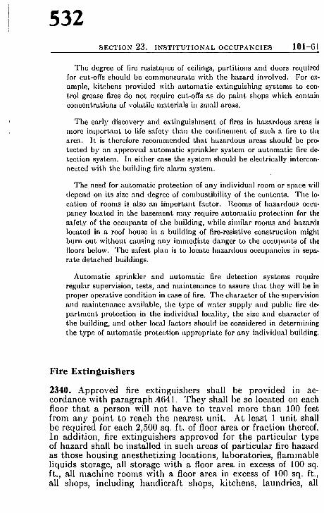
532 SECTION 23. INSTITUTIONAL OCCUPANCIES 101-61
The degree of fire resistance of ceilings, partitions and doors required for cut-offs should be commensurate with the hazard involved. For ex- ample, kitchens provided with automatic extinguishing systems to con- trol grease fires do not require cut-offs as do paint shops which contain concentrations of volatile materials in small areas.
The early discovery and extinguishment of fires in hazardous areas is nmre important to life safety than the confi,mnmnt of such a fire to th~ area. It is therefore recommended that hazardous areas should be pro- tected by an approved "mtomatic sprinkler system or autonmtic fire de- tection system. In either case the system should be electrically intercon- nected with the building flee alarm system.
The need for autom.ttic protection of any individual room or sp'tce will depend on its size and degree of combustibility of the contents. The lo- cation of rooms is also an important factor. Rooms of hazardous occu- pancy located in the basement may require "mtomatic protection for the safety of the occupants of the building, while similar rooms and hazards located in a roof house in a building of fire-resistive construction might burn out without c.msing any immediate danger to the occut)ants of the floors below. The safest plan is to locate hazardous occupancies in sepa- rate detached buildings.
Automatic sprinkler and automatic fire detection systems require regular supervision, tests, and mainten:mce to assure that they will be in proper operative condition in case of fire. The character of the supervision and maintenance available, the type of water supply and public fire de- partment protection in the individual locality, the size and character of the building, and other local factors should be considered in determining the type of automatic protection appropriate for any individual building.
Fire Extinguishers
2340. Approved fire ext inguishers shall be provided in ac- cordance wi th paragraph-4641. T h e y shall be so located on each floor t h a t a person will no t have to t ravel more t han 100 feet f rom a n y po in t to reach the neares t uni t . A t least 1 u n i t shall be required for each 2,500 sq. ft. of floor area or fract ion thereof. In addi t ion , fire ext inguishers approved for the par t i cu la r type of hazard shall bc instal led in such areas of par t i cu la r fire hazard as those hous ing anes the t i z ing locations, laborator ies , f lam,nable l iquids storage, all s torage wi th a floor area in excess of 100 sq. ft., all mach ine rooms wi th a floor area in excess of 100 sq. ft., all shops, i nc lud ing hand ic ra f t shops, ki tchens, laundries , all

533 101-62 B U I L D I N G E X I T S CODE
rooms into which laundry chutes and trash chutes discharge. Such equipment shall be nmintained in proper operat ing con- dition at all t imes and employees or a t t endants shall be regularly trained in its use.
In the selection of fire extinguishers for use on flammable liquid and electrical fires, care should be given to the type of extinguishing a g e n t - particularly when the extinguishers are to be used in confined spaces. Highly toxic fumes are produced by the vaporizing action of carbon tetrachloride and similar agents that are used in some types of extinguish- ers 'tpprovcd for Clams B "rod Cl'Lss C fires. Such types of extinguishers should not be selected.
Operating Features
Attendants, Evacuation Plan, Fire Exit Drills
2343a. Min imum staffing shall a t all t imes provide one on-duty a t tendant and one s tand-by a t t endan t for' each 30 pat ients or fractio,I thcreof. When the building is equipped with a,~ approved autoniatic sprinkler system, the s tand-by a t t endan t is not re- quired. There shall be a t lcast one a t tend-mr on du ty at all timcs on each floor" occupied by patients. Mininium staffing requirenicnts for any building housing more than 30 pat ients shall include in addition one person capable of handling duties at the hospital or nursing home comniunicat ions center and assigned to such duties.
b. The adminis t ra t ion of every hospital "rod nursing home shall have in effect "tnd available to all supervisory personnel writ ten copies of :L plan for" the protection of all persons in the event of fire and for" their evacuat ion to arcas of refuge and from the build- ing when neccssary. All employees shall be instructed and kept informed respccting their duties under the pl-m. The provisions of paragraphs 5121 to 5126 inclusive shall apply.
c. All beds intended for use by pat ients shall be equipped with casters at least 31/~ inches iu diameter with tires of rubber or similar resilient material . Tile enforcing au thor i ty m a y make exceptions in the equipping of beds intended for use in areas limited to pat ients such as convalescent, self-care or psychiatr ic patients.

534 SECTION 23. INSTITUTIONAL OCCUPANCIES 101-63
Smoking 2344. Smoking regulations shall be adopted and shall include the following minimal provisions:
(a) Smoking shall be prohil)ited in any room, ward, or compart- ment where flammable liquids, combustible gases, or oxygen are used or stored and in any other hazardous location. Such areas shall be posted with "NO SMOKING" signs.
(b) Smoking by patients classified as not responsible shall be prohibited.
(c) Ash trays of nonconlbustible material and safe design shall be provided in all areas where smoking is pcrinitted. (d) Metal containcrs with self-closi,ng cover devices shall be pro= vided for the disposal of the contents of ash trays.
The most rigkl discipline with regard to prohibition of smoking may not be nearly so effective in reducing incipient fires from surrel)titious smoking as the opcn recognition of smoking, with provision of suitable f,'~ciliLies for smoking. Proper education and training of the staff and attendants in the ordinary fire hazards and their .tbatcmcnt is unquestionably essential. The problem is a broad one, variable with different types and arr 'mgement of buildings, and the effectiveness of rules of procedure, necessarily flexible, depends in large part upon the management.
Exit Lighting and Signs 2345a. Exit lighting and exit signs shall be in accordance with Sections 52 and 53, except�9 as modified below.
b. Paragraph 5202 shall apply.
c. HOSPITALS. Type 1 emergency lighting shall be provided in accordance with Section 52 for all hospitals.
d. NURSING HOMES shall have Types 1 or 2 emergelacy lighting in accordance with Section 52, except for buildings converted to nursing home use in which Type 3 may be accepted by the enforcing authority.
Draperies 2346a. All combustible draperies and curtains for decorative and acoustical purposes shall be rendered and maintained flameproof.
The use of draperies of inherently noncombustible material is recom- mended.
Acoustical material applied as interior finish is covered by paragraph 2330.
101-64 B U I L D I N G E X I T S CODI'~
535
EXISTING HOSPITALS AND EXISTING NURSING HOMES
See also preceding general provisions, 2300-2302
Definition and Application
2350. This part of the Building Exits Code covers hoth existing hospitals and existing nursing homes, the requirements for exits and related features of life safety from fire being similar in both occupancies. Where there are differences, the word Hospital, or Nursing Home, indicates that the particular paragraph applies only to the indicated occupancy, as defined below.
2351a. A HOSPITAL means a building used for the medical, ob- stetrical or surgical care, on a 24-hour basis, of four or more patients. HOSPITAL, wherever used in this Code, shtdl include general hospitals, mental hospitals, tuberculosis hospitals, chil- dren's hospitals, and any such facilities providing inpatient care.
b. A NUltSINr HOME means a building used for the lodging, boarding, or nursing c:~re, on a 24-hour basis, of four or more persons who because of mental or physical inc'tpacity may he unable to provide for their own needs ~uad safety without the assistance of anothcr person. Nursing home, wherever used in this Code, shall include nursing and conv-dcscent homes, and homes for tim aged.
c. A PATIENT includes any occupant for ~hom care is provided.
2352a. The requirements for existing hospitals ,'uad existing nursing homes ~tpl)ly only to cxisting occupancics. Existing occu- pancies conforming to -ill requirements for new buildings need not meet the requirements for existing hospitals and nursing homes.
b. Each building heretofore erected and not now used as a hospit'd or nursing home shall comply with all requirements for new hospitals and new nursing homes before being converted to such use.
c. Additions to existing hospitals and nursing homes shall comply with all requirements for additions to new occupancies as required by paragraph 2312b.

536 I N S T I T U T I O N A L O C C U P A N C I E S 101-65
Occupancy
2353a. Rooms allocated to pat ients shall not be occupied by any greater number of persons than their capaci ty as determined by the table in paragraph 2355a.
b. Occupancies not under the control of, or not incidental to, the adminis t ra t ion of a hospital or nursing home are prohibited therein, with the exception of residence facilities for persomml required by the adminis t ra t ion to live in the building.
c. Auditoriums, chapels, residential areas, garages or other oc- cupancies in connection with hospitals or nursing homes shall have exits provided in accordance with the other applicable sec- tions of this Code.
d. Beds for pat ient sleeping occupancy shall not be located in basements in unsprinklcred buildings.
Exit Details
Number and Types, Exit Measurement
2354a. Exits shall be restricted to the following permissible types :
1. Doors (see pa ragraph 2357). 2. Stairs and Smokeproof Towers (see paragraph 2358). 3. Horizontal Exits (see paragraph 2359). 4. R a m p s (see paragraph 2358). 5. Fire Escape Stairs (see paragraph 2360).
b. At least two exits of the above types, remote from each other, shall be provided for each floor or fire section of the building. At least one exit in each floor or fire section shall be of T y p e 1 or T y p e 2, as listed above. The enforcing au thor i ty may accept as a second means of egress an existing Class A or B, or a new Class A, fire escape stair constructed in accordance with Sec- tions 30 and 35.
Ramps arc undesirable within hospitals because of their accident hazard in both normal and emergency traffic. However, r-mlps of ex- tremely gradual slope may prove to be the best means of providing egress from doors not more than three feet above grade and for compcn~tting for differences in floor levels of not more than two feet between adjoining sections of buildings.
C. Basement exits for pat ients shall discharge directly out- doors wi thout the necessity for use of interior stairs connecting with the s tory above.

101-66 BUILDING EXITS CODE
537
d. Revolving doors and other types of exits not specifically cov- crcd by paragraph 2354a shal l 'not be counted as required exits," and shall not be installed except in situations where not subject to emergency exit use by patients. Elevators in accordance with Section 38 const i tute a desirable supplementa ry facility, but are not counted as required exits.
2355a. The capaci ty for any floor or space in number of persons for whom exits shall be provided, shall be the m ax i m u m number of perso,~s occupying tha t floor or space, but not less than 1 per- son for each 150 sq. ft. gross floor area of the building (entire area within outside walls with no deductions), nor less than the following for pat ient sleeping rooms and dormitories:
Adults l for each 75 sq. ft. net floor area Children 1 for each 50 sq. ft. net floor area Infan ts 1 for"e-Lch 25 sq. ft. net floor area
(Fractional areas not counted) The above arc'm arc based on the use of hospit:d or single beds, cribs
or b-tssincts, for adults, chikh'en ,'tnd infants respectively.
b. The capaci ty of cach perniissible type of exit shall be based on its width in units of 22 inches as defined in paragraph .3011, each such unit having a capaci ty of 15 persons.
Access, Aisles and Corridors 2356a. Aisles, pass~lgeways aud corridors, exit discharge and exit loc-~tion ~t,d access shall be in aeeor(h, lce with Section 31, except as modified below:
b. Exits sh-dl be so placed tha t the eu t r a , c e door of every pr ivate r0onI and every point in open wards, day rooms, dornIitories, dining rooms and other spaces shah be , o r more than 75 feet (along the liue of tr-tvcl) from the ,e~trcst exit; in buildings com- pletely protected by ~tl approved au tomat ic sprinkler sys tem the distance m a y be 100 feet.
c. Exits shall be of such width and so '~rranged as to avoid any obstructions to the convenient renaoval of non-anabulatory per- sons by carrying them on stretchers or on mat t resses serving as stretchers.
d. Each occupied room shall have a t least one doorway opening directly to the outside, or to a corridor leadiug directly or by a s tairway to the outside, or to an adjacent room which has such access to the outside.

538 INSTITUTIONAL OCCUPANCIES 101-67
e. At least one required exit from each floor shall lead directly., or through an enclosed passtLgeway, to tim outside in accordance with paragraph 3131. A second or third required exit, where a more direct exit is impractical, m a y lead to a first floor lobby hav- ing ample and direct exits to the outside.
f. Corridors and passageways to be used as a means 'o f exit, or par t of a means of exit, shrill be at least 40 inches wide.
A person on a 39-inch wide m a t t r e s s m a y be carried th rough a 40-inch doorway. W h e r e perso,m "tre to be carried on ma t t r e s s e s or stretcher~, ex t ra space m a y be needed to m a k e t u rn s a t s ta i r landings .
~,. Corridors and passageways to be used as a means of exit, o,' pa r t of a means of exit, shall be unobst ructed and shall not lead through any room or space used for a purpose tha t m a y obstruct free passage.
Dead-end corr idors are undesir '~ble and should be avoided wherever possible so t h a t exits will be accessible in a t leas t two different direetionn from all po in t s in aisles, pa s sageways and corridors.
Doors
2357a. Doors shall be in accordance with Section 32 except modified below.
b. Doorways serving as exits, or par t of a meaus of exit, shall be at least 40 inches wide, except tha t doors so located as not to be subject to use by p~tticnts may be not less than 28 inches clear width and th ' t t doors at least 28 inches wide, previously installed, may be accepted by the enforcing authori ty .
c. There shall be no locks on pat ient room doors except by per- mission of the enforcing authori ty . Such locks, except those in accordance with Paragraph 2302, shall be such as to he readily opened from the pat ient room without the use of any key, and of such type tha t thcy can be locked only from the corridor side, provided tha t doors of pat ient rooms leadi~g directly to the ex- terior of the building may be subject to locking from the room side. In any case, where pat ient room doors are locked, attend- ants shall carry keys.
Stairs, Smokeproof Towers, Ramps 2358a. Stairs and smokeproof towers shall be in accordance with Section 33 and shall be Class A, B or C except tha t modificatio,~ of Class C requirements is permitt.ed under the provisions of paragraph 3371.

101-68 BUILDING EXITS CODE
539
b. Ramps shall be in accordance with Section 34, and shall be Glass A or Class B.
Horizontal Exits
2359a. Horizontal exits shall be in accordance with Sections 30 and 39 except as modified below, and shall be at least ,14 i,mhes in clear width.
b. Doors in horizontal exits are not required to swing with exit travel as specified in paragraphs 3923, 3925 and 3933.
c. Required fire doors in horizontal exits shall be self-closing or may be so installed that they may he kept in open position but will close automatical ly in case of fire by arrangements in ac- cot'dance with paragraph 3209 or by heat sensitive releases and may be released manually to self-closing action. Walls or parti- tions having a I-hour fire resistance rating shall be accepted in applying paragraph 3931.
Fire Escape Stairs
2360. Fire escape stairs shall be in accordance with Section 35. Existing fire escape stairs shall be Class A' or B. Fire escape stairs hereafter erected shall be Class A.
Division of Floor Areas
2361a. All floors above the first floor having a maximum occu- pancy exceeding 30 p-~tients shall be divided into two sections by a fire wall, firc parti t ion or smoke barrier so loc-~ted as to provide ample space on each side for the total number of patients on the floor. Doors provided in such fire walls or fire partit ions sh,411 be fire doors trod, in such smoke I)arriers, shall be fire doors or smoke stop doors, COlfforming to paragraph 3231. Such doors shall be self-closing or m~ty be so installed tha t the3, will close automatical ly and may be released m~mually to self-closing action. Such doors are not required to swing with exit travel.
See paragral)h 2359 for further requirements applying to such division walls if they arc intended for use as Horizontal Exits.
b. Smoke barriers shall be not less fire-resistive than ~/~-inch gypsum board on both sides of wood studs. Openings therein shall be protected with fixed wired glass panels or by doors as described in the preceding paragraph.

540 I N S T I T U T I O N A L O C C U P A N C I E S 101-69
Protection
Protection of Vertical Openings and Firestopping
2362a. Stairways between stories shall be enclosed in accordance with paragraphs 4303 and 4304 with part i t ions h-~ving a 1-hour fire resist-race rating, except tha t where a full enclosure is im- practical the required enclosure may be limited to tha t necessary to prevent a fire origiwttiug in any s tory from spreading to any other story. Fire doors protecting exit doorways therein shall be self-closing or m a y be so installed t ha t they m a y be kept in the open position, under the conditions specified in paragraph 3209. Exit doors shall norm-~lly be kept in closed position and shall be marked in accordance with paragraph 3207.
b. Elevator shafts, light and venti lat ion shafts, chutes and other vertical openings between stories shall be protected as required above for stait 'ways, except tha t such protection shall not be re- quired in ally building equipped with an approved "mtomatic sprinkler system. Where chutes and other vertical openings con- nect only three successive stories in unsprinklercd buildings, smoke-t ight enclosures constructed of sheet metal or tongue and groove wood boards or enclosures of similar fire , 'esistance may be accepted by the enforcing au thor i ty when the shaft is protected by au tomat ic sprinklers in accordance with paragraph 2365b and c.
c. Exterior walls of f rame construction and interior stud parti- tiofis shall be firestopped so as to cut off all concealed draft openings, both horizontal and vertical, bctwecn any ccllar or base- men t and the first floor. Such firestopping shall consist of suit- able noncombust ible materi 'fl or of wood at least 2 inches (nomi- nal) thick.
Interior Finish 2363. hl ter ior finish shall be Class A or Class B in accordance with Section 44 except tha t interior finish in individual rooms with a capaci ty of not more than 4 persons may be Class C.
Section 44 provides for tile application of approved fiame-retardant coatings to correct excessive flame spread characteristics of certain tyl)es of existing interior finish. It also makes certain modifications in require- ments where automatic sprinklers are installed.
Automat ic Sprinklers, Fire Detection and Alarm Systems 2364a. Except for buildings of fire-resistive construction, auto-
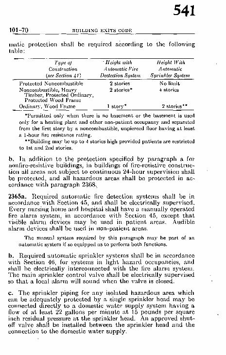
101-70 B U I L D I N G E X I T S CODE
541
matic protection shall be required according to the following table :
Type oJ " Height with Ileighl Wi th Colistrnction - Automatic Fire A ntomatic
(see Section. ~1 ) Dectection Sys tem Sprinkler Sys tem
Protected Noncombustible Noncoml)ustiblc, Heavy
Timber, Protected Ordinary, Protected Wood Frame
Ordin.try, Wood Frame
2 stories No limit 2 stories* 4 stories
1 story* 2 stories**
*Permitted only when there is no basement or the basement is used only for a heating plant and other non-patient occupancy and sep'mtted from the first story by a noncombustible, unpierced floor having at least a 1-hour fire resistance rating.
**Building may be up to 4 stories high provided patients are restrietetl to 1st and 2nd stories.
b. II1 addition to tim protection specified by paragraph a for ,onfire-resistive buildings, in buildings of fire-resistive construc- tioa all areas not subject to continuous 24-hour supervision shall be protected, and all hazardous areas shall be protected in ac- cordance with paragraph 2368..
2355a. Required au tomat ic fire detection systems shall be in accordance with Section 45, and shall be electrically supervised. Every nursi,~g home and hospital shall have a manual ly operated fire a larm system, in accordance with Section 45, except tha t visible a larm devices may be used in pa t ien t areas. Audible alarm devices shall be used in ,ran-patient areas.
The manual system required by this paragral)h may be part of an automatic system if so equipped as to perform both functions.
b. Required au tomat ic sprinkler systems shall be in accordance with Section 46, for systems in light hazard occupancies, and shall be electrically interco,mected with the fire a larm system. The main sprinkler control valve shall be electrically supervised so tha t a local a larm will sound when the valve is closed.
c. The sprinkler piping for any isolated hazardous area which can be adequate ly protected by a single sprinkler head m a y be connected directly to a domestic water supply sys tem having a flow of a t least 22 gallons per minute a t 15 pounds per square i,mh residual pressure a t the sprinkler head. An approved shut- off valve shall be installed between the sprinkler head and the connection to the domestic water supply.

542 I N S T I T U T I O N A L O C C U P A N C I E S 101-71
Fire Extinguishers 2366. Approved fire extinguishers shall be provided in accord. ance with paragraph 4641. They shall be so located on each floor tha t -~ person will not have to travel more than 75 feet from any poi,~t to reach the ne-~rest unit. At le.'lst 1 unit shall be required for each 2500 sq. ft. of floor area or fraction thereof. Ill additioll, an approved fire extinguisher shall be installed a t each kitchen, workshop and handic, 'aft shop and in cellar and basement store- rooms.
In the selection of fire extinguishers for use on flammable liquid and electrical fires, c~Lre should be given to the type of extinguishing agent -- particularly if the extinguishers are to be used in confined spaces. Highly ! toxic fumes are produced by the v-q)orizing action of carbon tetrachloride and similar .~gent,s that are used in some types of extinguishers approved for Class 13 and Class C fires.
Air Conditioning, Ventilating, Heating, Cooking and Other Service Equipment 2367a. Air conditioning, ventilating, heating, cooking and other service equipment shall be in accord~tnce with Section 47, except as modified in b. and c. below. b. Fuel burning space heaters and portable electric space heat- ers are prohibited. c. Combust ion and venti lat ion air for boiler o," heater rooms shall be taken directly from and discharged directly to the out- side air.
Hazardous Areas 2368. Hazardous areas such as those listed below and other areas with contents which m a y be easily ignited, burn with an intense flame, or result in the production of dense smoke and fumes, shall be separa ted from other par ts of the building by construction having a fire-resistance rating of -~t least 1 hour, with any communicat ing openings protected by approved auto- mat ic or self-closing fire doors, or separated from other par ts of the building by existing substant ial enclosures acceptable to the enforcing au thor i ty h-tving jurisdiction where the building is protected by a complete, approved, au tomat ic sprinkler system. All such areas shall be provided with approved au tomat ic fire detection or approved au tomat ic sprinkler protection.
Boiler and heater rooms Rooms or spaces used for storage, Laundries in quanti t ies deemed hazardous Kitchens by the enforcing author i ty , of Repair shops combust ible supplies and equip- Handicraf t shops ment Laboratories where quanti t ies of f lammable solvents are used

101-72 B U I L D I N G E X I T S CODE
543
The degree of fire resist'race of ceilings, partitions and doors required for cut-offs should be commensurate with the hazard involved. For ex- ample, kitchens provided with automatic extinguishing systems to con- trol grease fires do not require eut-offs as do paint shops which contain concentrations of volatile materials in small areas.
The earl)" discovery and extinguishment of fires in hazardous areas is more important to life safety than the confinement of such a fire to the area. It is therefore recommended that hazardous are'~s should be pro- tected by an approved automatic sprinkler system or automatic fire de- tection system. In either case the system should b.e electrically inter- connected with the building fire alarm system.
The need for automatic protection of any individual room or space will depend on its size and degree of combustibility of the contents. The lo- cation of rooms is also an important factor. Rooms of hazardous occu- pancy located in the basement may require automatic protection for the safety of the occupants of the building, while similar rooms and hazards located in a roof house in a building of fire-resistive construction might burn out without causing any immediate danger to the occupants of the floors below. The safest plan is to locate lmzardous occupancies in sepa- rate detached buildings.
Automatic sprinkler and automatic fire detection systems require regular supervision, tests, and maintenance to assure that they will be in proper operative condition in case of fire. The character of tim supervision and maintenance available, the type of water supply and public fire de- partlnent protection in the individual locality, the size and character of the building, and other local factors should be considered in determining the type of automatic protection appropriate for any individual building.
Operating Features
Attendants, Evacuation Plan, Fire Exit D r i l l s 2369a. M i n i m u m staff ing shal l a t all t imes p r o v i d e one o n - d u t y a t t e n d a n t and one s t a n d - b y a t t e n d a n t for each 30 p a t i e n t s or f r ac t ion thereof . W h e n the bu i ld ing is e q u i p p e d wi th an a p p r o v e d a u t o m a t i c sp r ink le r sys t em, t he s t a n d - b y a t t e n d a n t is no t re- qu i red . T h e r e shal l be a t leas t one a t t e n d a n t on d u t y a t all t i m e s on each floor occup ied b y pa t i en t s . M i l f i m u m staff ing requ i re - m e n t s a t all t imes for a n y bu i ld ing hous ing more t h a n 30 p a t i e n t s shal l i nc lude in a d d i t i o n one person c a p a b l e of h a n d l i n g du t i e s a t t he hosp i t a ! or nurs ing home c o m m u n i c a t i o n s cen te r a n d ass igned to such dut ies . b . T h e a d m i n i s t r a t i o n of eve ry hosp i t a l ai~d nurs ing home shal l have in effect a n d awf i l ab le to all s u p e r v i s o r y pe r sonne l w r i t t e n copies of a p l an for t he p r o t e c t i o n of al l persons in t he e v e n t of fire a n d for the i r e v a c u a t i o n to a reas of refuge and f rom the bu i ld - ing when necessary . All e m p l o y e e s shall be i n s t r u c t e d a n d k e p t i n f o r m e d r e spec t ing the i r du t i e s under the plan. T h e p rov i s ions of p a r a g r a p h s 5121 to 5126 inc lus ive shah a p p l y a n d fire ex i t dr i l l s shal l be he ld a t reasonal~le in t e rva l s . c. All beds i n t e n d e d for use b y p a t i e n t s shal l be e q u i p p e d w i t h

544 INSTITUTIONAL OCCUPANCIES 101-73
casters at legist 3 ~ inchcs in diameter with tires of rubber o1' similar resilient material.. The enforcing author i ty may make exceptions in the equipping of beds intended for use in areas limited to patients such as convalescent, self-care or psychiatric patients. In hospitals ira which the nlovement of patients ira their beds is not feasible, every mattress shall be provided with ,handles so secured as to permit the mattress to serve as a stretcher when necessary for" ewmu-Ltion.
Smoking 2370. Smoking regulations shall be adopted and shall include the following minimal pro.visions: (a) Snioking sh-tll be prohibited in any room, ward, or compart- nIent where flammable liquids, combustible gases, or oxygen are used or stored and in any other hazardous locati6n. Such areas shall be posted with "NO S M O K I N G " signs. (b) Sin~ by patients classified as not responsible shall be prohibited. (c) / Ash trays of noncombustible material and safe design shall be' provided ira all areas where smoking is permitted. (d) Metal containers with self-closing cover devices sh,'dl be provided ira all ar~as where smoking is permitted.
The most rigid discipline with regard to prohibition of smoking may not be nearly so effective in reducing incipient fires from surreptitious smoking as the open recognition of smoking, with provision of suitable facilities for smoking. Proper education and training of the staff and at- tendants in the ordinary fire hazards and their abatement is unquestion- ably essential. The problem is a broad one, variable with different types and arrangement of buildings, and the effectiveness of rules of procedure, hecessarily flexible, depends in large part upon the management.
Exit Lighting and Signs 2371a. Exit ligh.ting and exit signs shall be in accordance with Sections 52 and 53, except as modified below. b. Paragraph 5202 shall apply. c. Type l, 2 or 3 emergel3cy lighting shall be provided in build- ings with a patient capacity of 30 or more persons. d. Exit signs are not required ira 1-story buildings with a pat ient capacity of less than 30 persons.
Draperies 2372. All combustible curtains and draperies for decorative or acoustical purposes shall be rendered and maintained flame- proof.

SL,I A M E N D M E N T S TO NFPA NO. 10l
545
EMERGENCY SHELTERS
4. Revise 29~3 and add new 2 9 ~ as.follows:
2943a. Shelters shall be provided with lighting facilities inde- 0endcnt of all public util i ty services, designed for coqtinuotm operation during the entire period for which the shelter is planned.
h. Electric generators and their prime movers, and fuc lsuppl ies to operate the prime movers, shall be located outside of the areas designed for human occupancy, in such a manner tha t fire therein will not endanger occupants.
2944. Suitable fire extinguishing facilities shall be provided, of self-contained types, suitable for the kind of fire likely to be encountered, and not requiring any outside service for recharging or replenishing.
An automatic sprinkler system, with ample self-cont-uned water supply suiticient for repeated operation, not depending upon any outside water supply or power source, is the best form of protection. ][and hose is desirable if it has adequate self-contained water supply. Extinguishers of the pump tank type, or water barrels with buckets, can also meet the requirements of this paragraph. Autom'~tic sprinkler protection is par- ticularly desirable for all large shelters.
SECTION 30. EXITS AND EXIT MEASUREMENTS
5. A d d new 3026 as follows:
3026. Distances of t ravel to outside stairs shall be measured in the same manner as to inside stairs, except tha t where outside stairs arc wiflfin 15 ft. horizontal dist, ance of any unprotected building opening, as permit ted by paragraph 3:383, the distance to the exit shall be measured down the stairs to the ground level, in accordance with pa ragraph 3025.
SECTION 32. DOORS
6. Add new 3216 as follows:
3216. No single swinging door, or single leaf of any multiple leaf doorway, shall exceed 48 inches ill width.
7. A d d new 3223, 322/j and 3225 to Panic Hardware as follows:
3223. Where panic hardware as defined ill pa ragraph 322l is requ.ired, it shall be of a type approved by a nationally recognized testing laboratory or the local enforcing authori ty .

R E P O R T O F C O M M I T T E E O N S A F E T Y T O L I F E S L
3224. Required panic hardware shall not be equipped with an locking or dogging devicc, set screw, or other arrangement whic can be used to prevent thc release of the latch when presstH is applied to the bar.
3225. No lock, padlock, hasp, bar, chain, or other device, c combination thereof, shall be installed or~maintained at an time on, or in connection with any door oh ~b_jch panic hard ware is required by this Code if such device.,:~.revents, or i intended to prevent, the free use of the door fb~'dxit purpose.'.
8. Revise 323s as foll.ows: .~j~
3232. Fire doors, where installed in ac; J; quirements of this Code shall be of ap shall provide fire resistance of at least one" specified by the applicable provisions of C"' in no casc shall a door bc required to have- greater than tha t of the required wall
"*r . ~ f
.~firs which reverse ,~ horizontal dis-
" one foot. .:~.~ance ratin~
part i t ion in whicl installed (sce paragraph 4304, Protectio~ ,i Openings).
Longer ratings may be required where doo~s are provided for propert) protection as well as life safety.
NFPA Standard for Fire Doors an(i Windows (NFISA.No. 80) ma~ be consulted for standard practice in the selection ~and installation ol fire doors.
9. Add 3242 and 3~3 to Power Operated Doors as follows:
3242. Where power operated entrance doors , whether or not they consti tute required means of egress, are ,mec)~anically ac- tuated to open only against exit travel, they shall be so arranged tha t they can be opened from the side from which exit is made by normal means without any special knowledge or effort. Such doors shall be so arranged Lhat they can be opened manually to swing with the exit travel in Class A, Class B, or Class C places of assembly and in Class A, Class B, or Class C mer- cantile establishments, arid in any occupancy where there is no door swinging with the exit travel within 20 ft.
3243. No power operated door shall bc counted as a required exit unless it swings with the exit t ravel by mechanical or manual means.
10. The following text, revising material in Section 33, Stairs aTul Smokeproof Towers, Section 34, Ramps, and Section 35, Fire Escape Stairs, provides uniform requirements on guards and hand-

SL6 AMENDMENTS TO NFPA NO. | 0 [
_547
rails. No other change is proposed, though certain existing text pertaining to related subjects is i~tcluded to provide conlinuily.
SECTIONS 33, 34 AND 35 /f:GUARDS AND HANDRAILS
3360. All staii,.6, stair landings and balconies appur tenant thereto shall be gu's against falls over tile open edge (except where waivcd by. l)hragraph 3365) and shall have handrails on both sides, except tha t h:u~drails shall not be required on level land- :~ - - . . . . . . ,1 tha t for existing class C stairs a handrail
vqualiy spaced l., y be permitted. apaced rails for 36 ~. not more than 6 it,:: s tairs . ; '~'i rds and handrails shall continue for the full ing . . . . . class.~+ee~ ;q~,C, . . . . . of stairs.
'/'ll~ " ' ' t :ard may serve as the handr.dI in m'uLy cases, bu t guards and h~m, have separa te functions.
F
3362. Handrails oI, lairs shall be not less than 30 in. nor more than 42 m.'" "above he upper surface of the tread, measured vertically to thc top of the rail, from a point on the tread one inch back fi~0m the leading edge, except tha t on stairways de- signed for usa I~y children an additional handrail may be pro- vided lower thafi the main handrail.
Tim op t i nm m height of handrai l v:Lries depending upon the s teepness of the st .drs .rod the character of occupancy. The most convenien t height of rail for persons "Lscending stairs is lower th:m for descending. The aver- age o p t j n m m height is abou t 33 in.; 27 in. for schools a t t ended by small chihlren.
3363. Hand,'ails sh'~ll provide a clearance of at least 11~ in. be- tween handr:fil and wall to which fastened. Handrails shall be of such design and so supl)ortcd as to withstand a load of 200 pounds applied at any I)oint, downward or horizo,~tally.
l [andrai ls which projec t not more than 3V2 in. from a wall do not re- duce the ra ted effective width of the stairwtLy nm:rsured in units as per par. 3012.
The o p t i m u m diameter of handrai l for use by adul t s is abou t ll/'~ in.
3364. Any stairway 88 in. or more in width shall be provided with one or more intermcdiate handrails substantially supported; the numbcr and positions of intermediate handrails to be such that thcre will be not more than 06 in. between adjacent hand- rails, except tha t on monumental outside stairs) such as often

R E P O R T O F C O M M I T T E E O N S A F E T Y T O L I F E S L ~
found on churches and public buildings, two handrails may b( permitted.
3365. a The height of guards required by paragraph 3360 shall he measured vertically to the top of the guard from a point on the tread one inch back from the leading edge or from the floor of landings or bMconies.
b. For new construction guards shall be not less than 42 in. high except tha t stairs scrving not more than three successive floor levels, or not more than 25 ft. vertical distance, in buiklings of other than assembly or educational occupancy, may he not less than 36 in. high.
c. No guards shall he required for inside s~drs which reverse direction at intermediate landings, where th~ horizontal dis- tance between successive flights is not more than qnc foot.
. 4 .
STAIR- GALUSTRADI':"" :. " CLASS A :~ 7IN RISER
IO IN. TREAD 42 IN. GUARD AND HANDRAIL A=61N MAX. D: I0 JN.
6 FOOT FIGURE

SL8 AMENDMENTS TO NFPA NO. 101
549
d. No guard shall be required for stairs, or their landings or Imlconies, inside or outside, in any s tructure where the total maximum vertical fall is six feet or less.
c. Guards to protect the front of theatre balconies may be waived by the enforcing author i ty in cases where a guard would interfere with vision of the stage and the design of the balcony is such as to minimize danger of falls over the edge.
3366. Guards, where required, shall be of substantial solid con- ~truction such as walls, or may be rails, parallel to the slope of the stairs or horizontal on landings or balconies, with four equally spaced rails for 42 in. high guards, and with 3 equally ~paced rails for 36 in. high guards, or vertical balusters, spaced not more than (i in. apart, or not more than 10 in. apart for exist- ing class C stairs, or wire mesh or other designs to provide equiv- iLlcnt protection.
The bottom of the guard shall be not more than l0 in. above ,tair, landing or balcony surface, in the case of stairs, measured vertically from a point one inch back from the leading edge of the tread.
An intermediate rail of a iequircd gu'~rd may also serve as the required handrail when of proper size and shape, assuming tha t the rail run~ parallel to :~he slope of the cxitway and is within the permissihle height limits.
When the guard is of wire mesh, or vertical balusters, or solid con- struction, or designs other th-m rails running parallel to the slope of the stair, a separate handrail shouhl be required unless the top of the guard is designed as a handr:fil and is within the I)ermissiblc height limits.
Add a fine print note offer paragraph 3382: Tile guards tha t 'Lre required for the unenclosed sides of outside stairs
by par. 3365 will usually meet this requirement when the stair is not more th,m 3 stories high. SI)ecial architectural t reatment , including applica- tion of such devices as nmtal or nr~sonry screens and grilles, or higher guards, or solid guards , etc., will usually be necessary for stairs over 3 stories in height.
SMOKEPROOF TOWERS 3394. Access to the stairway shall be provided from every story through vestibules open to the outside on an exterior wall or from balconies overhanging an exterior wall, but not subject to severe fire exposure hazard. Every such vestibule, balcony or landing shall have an unobstructed length t~nd width not less than the required width of exit doors serving same, and shall be di- t'ectly open to a street or alley or yard or to an enclosed court

550 R E P O R T OF C O M M I T T E E ON S A F E T Y TO L I F E SL!
open at the top not less than 20 ft. in width and 10O0 sq. ft. iz area. Balconies or vestibules for new smokeproof towers shal have solid balustrades not less than four ft. high. Existing smoke. proof towers shall have solid guards not less than four feet higl or shall have guards not less than 4 ft. high in gcneral conformit) with paragraph 3366. Wall openings exposil~g balconies oJ vestibules shall be protected in accordance with paragraph 3512
RAMPS Railings.
3461. All ramps shall have walls or guards on both sides, it accordance with paragraphs 3360, 3365 and 3366, with the ex. ception therein specified for existing class C stairs applying t~ existing class C ramps.
3362. Handrails, not lcss than 30 in. or more than 42 in. high in general accordance with the requi remcnts of paragraph: 3360-3364 for stair handrails, shall be provided on all Class l! and Class C ramps.
3363. and 3364. Delete
FIRE ESCAPE STAIRS
Guards and Handrails.
3541. All fire escttl)es shall have walls or gu.u'ds on both sides in accordance with paragraphs 3360, 33(i5 and 33(i0, except fol height, which shall be 42 in. for Class A and Class 13 fire escapes and 36 in. for Class C fire escapes, tile ficight being measure( vertically from a point on the stair tread one inch b~ck fron the leading edge, or vertically above any .landing or balcon 3 floor level.
3542. All fire escapes shall have handrails on both sides, no less than 30 in. nor more than 42 in. high, measured verticall3 from a point on the stair tread one inch back from the leadint edge, all in general conformity to the requirements for stai; handrails, paragraphs 3360-3364.
3543. Handrails and guards shall be so constructed as to with stand a force of 200 pounds applied downward or horizontally a~ any point. Handrails and guards shall not be considered a~ structural members for the purposes of paragraph 3533.
3544. and 3545. Delete.

SLIO A M E N D M E N T S TO N F P A NO. 10l
551
SECTION 47. AIR CONDITIONING, VENTILATING, HEATING, COOKING
AND OTHER SERVICE EQUIPMENT
! I. Replace present ~701 to/t731 by the following:
4701. No air conditioning, ventilating, heating, cooking or other service equipmcnt shall be so installed or opcratcd as to cn- danger ways of exit, sprcad fire or smoke through buildings, or otherwise create an abnormt~l hazard to occupants such ,~s to endanger their safety before thcy have oppor tuni ty to utilize available exit facilities.
Air Condit ioning and Venti lating
4710. No system in which air is recirculated shali serve both any required enclosed exit s ta i rway or ramp, or encloscd passage- w.~y providing exit froln the enclosed stairway or ramp to the outside of the building, and any other space in the building.
4711. Air conditioning and ventilating systems (including forced air heating systcms) shall be so installed and maintained as to minimize the danger of spread of fire or smoke therefrom from one floor or fire are~ to another, or from outside into any occupied building or structurc.
NFPA St:mdard No. 90A, Air Conditioning, gives dct:dls of s:~fe in- stallation ~nd (:omt)li'mce therewith should be construed as providing compliance with the ubovc t)aragmph.
4712. Any recirculating system which scrves inore than one floor, where floors are required by other scctions of this Code to be separatcd by the enclosure of vertical openings, or serves both sides of a rcquired horizontal exit or required smoke stop parti t ion, shall be arranged:
(1) To stop fans automat ical ly in case of tire, by the operation of an approved smoke detection sys tem or dcvice within the duct, or
(2) To stop fans automat ica l ly in case of fire by an approved conncction to a complctc au tomat ic sprinkler or fire de- tection system protccting the entire building including the air filters, and
(3) except where air filters arc above all interior inlets and outlets of the system, close dampers on both the up- s t ream and downst ream sides of the air filters, or

552 I~.EPORT OF COMMITTEE ON SAFETY TO LIFE SL11
(4) in lieu of the above, in case of fire to conver~ the system automat ica l ly to a smoke rclnoval sys tem in accord- ance with pars. 4721-4731.
Unit air comlitioners and fans, including local air circulating unila with he.tting or cooling supplied through closed pipes from a central point, are not considered as systems for the purposes of this paragraph and do not ordin'trily inw)lve any danger of spread of fire from ono room or area to another.
4713. Air conditioning systems serving any single floor or fire area in any Class A or B place of assembly or in any Class A u,' B mercanti le es tabl ishment shall be provided with effectiv(, means for prevent ing recireulation of smoke through the system in case of fire in air filters or from other sources drawn into the system.
In Class A or Class B places of assembly or mercantile estab- lishments, manual shut-off may be permit ted by the cnforcing au thor i ty if competent , properly trained persons are continuously on duty, instructed in procedures in case of fire. Otherwise the. equipment shall be automat ic , consisting of approved photo- electric or other smoke-sensit ive controls.
NFPA Standard on Air Conditioning, No. 90A, provides information on installation and maintenance of smoke-sensitive controls. Heat sensitive, elements such as fusible links may not operate l)romptly enough to stop smoke.
Smoke Venting
4721. Slnoke venting facilities where required for safe use of exits in windowless buildings, underground structures, large area factories shall be au tomat ic ill operation.
For theatre stages see par. 2153. For theatre auditoriums see par. 2156. For large area f'~ctories see par. 2713.
4722. Na tura l draf t smoke venting shMl utilize roof vents or vents in walls at or near the ceiling level, such vents to be nor- mally open or if closed shall be designed for au tomat ic opening in case of fire by approved means.
Automatic means for opening smoke vents may include smoke-actuated release equipment, connection to a complete automatic sprinlder or auto- marie fire detection system. Oper-Ltion by the meltirig of fusible links, the breakage of glass, or the melting of plastic, depending upon cir- cumstances, may or may not be sufficiently rapid to prevent d.mgerous smoke accumulation.

SLI2 AMENDMENTS TO NFPA NO. 101
553
4723. Where smoke vent ing facilities are installed for purposes ~*f exit safety in accordance with the requirements of this Code Ihey shall be adequate to prevent dangerous accumulations of omoke during the period of t ime necessary to evacuate the area ~,(!rvcd, using available exit facilities with a margin of safety to allow for unforeseen contingencies.
In the absence of exac t daL~ as to the m i n i m u m v e n t areas nece~ar.v to provide adequate smoke venting for life safety, the design of venting facilities for any individual area can only be established on a judgment basis, taking into consideration the hazard of occupancy, the conditions of use, ceiling height, drdft conditions and other pertinent factors. As ~l guide, reference may be made to the Guide for Smoke and Heat Venting, NFPA No. 204.
4724. The discharge aper tures of all natural draf t smoke vents ' nhall be so arranged as to be readily susceptible to opening by fire dcpar tments working from the exterior.
4731. Power operated smoke exhausting systems may be sub- ~tituted for required natural draf t vents only by specific per- mission of the efiforcing authori ty .
Where power operated smoke removal is one of the functions of the regular air conditioning system and is installed in accordance with NFPA Standard No. 90A, Air Conditioning and Ventilating Systems of Other Than Residence Type, and where so arranged and inst~tlled as to have adequate .reliability, it may appropriately be accepted.
12. Add the fol lowing new text on Chutes and Incinerators:
Rubbish Chutes , Linen Chutes and Flue Fed Incinerators 4771. All chtg;es and incinerator flues which might serve to spread fire shall be enclosed in accordance with paragraph 4301, and the openings therein shall be protected in accordance with paragraph 4303. No such chutes or incinerator flues shall, in new cdnstruction, open directly on any exit, or corridor to an exit, but shall be in a separate room or closet separated from the exit (or from the corridor) by an approved self-closing fire door, except tha t this requirement shall not apply to pr ivate dwellings and tha t in apa r tmen t houses, au tomat ic sprinkler protection laay be provided in lieu of the self-closing fire door.
4772a. All incinerator flues shall comply with N F P A Standard No. 82, Incinerators.

554 REPORT OF COMMITTEE ON SAFET't: TO LIFE S L I 3
b. Al l r ubb i sh chutes , and l inen or l a u n d r y chutes shall comply wi th N F P A S t a n d a r d No. 82A, R u b b i s h H a n d l i n g .
Linen or laundry chutes are not specifically mentioned in Standard No. 82, but the hazard is similar to that of rubbish chutes, and the same safeguards are indicated.
4773. In new cons t ruc t ion , all chu tes o the r t h a n inc inera tor chu tes shal l be p r o v i d e d wi th a u t o m a t i c sp r ink le r p ro tec t ion .
See NFPA Standard No. 13, Sprinkler Systems, for details.

555 COMMITTEE ON SIGNALING SYSTEMS AND THERI~IOSTATS S S ' l
Report of Committee on Signaling Systems and Thermostats
Boyd A. H a r t l e y , Chairman, National Board of F i re U n d e r w r i t e r s , 222 W e s t Ada ms St., Chicago 6, Ill.
Donald L. D r u m m , t Secretary, National Board of F i r e U n d e r w r i t e r s , 85 John St., New York 38. N. Y.
:t. T . A n d e r s o n , J r . , Dist r ic t Publ ic Works Office, 12th Nava l Distr ict .
:lr B. Ayeock, S o u t h - E a s t e r n U n d e r w r i t e r s Associat ion.
P, R. Bcchtol t , W e s t e r n Ac tua r i a l Ihtrcau.
I, A. Bona, U n d e r w r i t e r s ' L a b o r a - |ar ies . Inc.
| ' rank R. Br idges , Couch Ord inance Inc. (Pe r sona l )
g, ?,1. Dix, U n d e r w r i t e r s ' L a b o r a t o r i e s of Canada.
~, I )abeau , Omce of Dominion F i re I~O111111 i~s[oncl'.
1, W. F lo t ron , J r . , A u t om a t i c F i re Alarm Associat ion.
~t, K. Goodwin, Fac t o ry I n s u r a n c e As- sociation.
J~rank E. Goiber t . Nat iona l B u r g l a r & F'ire A la rm Associat ion, Inc.
I'y I l a r r i m a n , F i re Devices, Inc. (New York). (Pc r sonaD
W. G. l l o lmes , P r a t c c t o w i r e Co. (Pe r sona l )
John J o r d a n . I n t e r n a t i o n a l Municipal Signal Associat ion.
ii, V. ]Keepers. F i re P r e v e n t i o n and E n g i n e e r i n g B u r e a u of Texas .
31, l l . h . L i n d s a y , A D T Co. (P e r - sonal)
?Non-vo t ing m e m b e r .
A s s t . C h i e f W m . C. ) I c D a d e , F i r e Marsha l s Associat ion of Nor th Amer ica .
J a m e s H. McDowell , Cent ra l Sta t ion Elec t r ica l P ro t ec t ion Associat ion,
F. R. M idda ugh , N F P A Commi t t ee on F i re B r i g a d e s and VCatchmen.
Wal lace Moll, Lou i s i a na R a t i n g & F i re P r e v e n t i o n Bureau .
O. J . Moses, F a c t o r y Mutua l :Engl.- nee r ing Division.
J . N. ]Pryce, Canad ian U n d e r w r i t e r s Associat ion.
E. S. Ruth , Na t iona l Elec t r ica l Mfrs. Associat ion.
George A. Smith , A m e r i c a n I n s t i t u t e of Elec t r ica l Eng inee r s .
L e o n a r d D. Schrnidt, Amer i can Tele- phone & T e l e g r a p h Co.
J . J . S tephens , Cent ra l S ta t ion F i r e P ro tec t ion Associat ion.
George L. Swan, J ackson , Ga. (Pe r - sonal )
S. B. Swift , U n d e r w r i t e r s ' L a b o r a - tories. Inc.
J . C. Thomson , J r . , No r th Carol ina F i re I n s u r a n c e R a t i n g Bureau .
L loyd A. Wal l ing , Pacific F i r e R a t i n g ~ u r e a u .
A l t e rna t e s .
Norman Carlson, Cent ra l Sta t ion F i r e Pro tec t ion Associat ion. (A l t e rna t e to J. J. S tcphcns . )
Thomas P. Devine, I n t e r n a t i o n a l Mu- nicipal Signal Associat ion. (Al ter - nate to J o h n J o r d a n . )
I,. B. Hansen , F a c t o r y I n s u r a n c e As- sociation. IAI t c rna t e to S. K. Good- win.)
L. I I . Ho rn , U n d e r w r i t e r s ' L a b o r a - tories. Inc. (A l t e rna t e to J . A. Boll o. )
~V. F. Schucharf l , Na t iona l Elec t r ica l l~Ianufacturers Associat ion. (Al ter - na te to E. S. Ru th . )

556 8 8 - 2 COMMITTEE ON SIGNALING SYSTEMS AND THER1MOSTATS
S E C T I O N A L C O M M I T T E E ON D E T E C T I O N D E V I C E S .
B o y d A. H a r t l e y , Chairman,
B e n j a m i n B. Ayeoek S . K . Goodwin ~Vm. C. M c D a d e J . A. Bono Cy H a r r i m a n J . H . McDowel l F . R. B r i d g e s ~V. G. H o l m e s O . J . M o s e s K. M. D i x P . E . l l u b b y G . L . S w a n S. D u b e a u H . V . K e e p e r s J . C . T h o m s o n . J r .
3I. H. A. L i n d s a y L . A . W a l l i n g
S E C T I O N A L C O M M I T T E E ON M U N I C I P A L F I R E A L A R M S Y S T E M S .
Dona ld L. D r u m m , Chairman
F. R. B r i d g e s ~Vm. C. M c D a d e L e o n a r d D. S c h m i d t J o h n J o r d a n J . N . P r y e e G . L . Swan H . V. K e e p e r s E . S . R u t h
S E C T I O N A L C O M M I T T E E ON ] P R I V A T E F I R E A L A R M S Y S T E M S .
B o y d A. H a r t l e y , Chairman
B e n j a m i n B. Ayeock W . G . H o l m e s E . S . R u t h H. T. A n d e r s o n , J r . J . J o r d a n G . A . Smi th P . R. Bech to l t H . V . K e e p e r s L e o n a r d D. S c h m i d t F. R. B r i d g e s M . H . A . L i n d s a y J . J . S t e p h e n s K. M. Dix ~Vm. C. 3 I cDade G . L . Swan S. D u b e a u J . H . MeDowel l S . B . Swi f t J . W. F lo t ron F . R . M i d d u u g h J . C . T h o m s o n , J r . S. K. G o o d w i n ~V. Mol l L . A . W a l l i n g F r a n k E. G u i h e r t O . J . Moses
The Committee presents its report in five parts:
I. Revisions to Standard on Central Station Protective Signaling Systems (NFPA No. 71) II. Revisions to Standard on Proprietary, Auxiliary and Local Protective Signaling Systems (NFPA No. 72) III. Revisions to Standard on Remote Station Protective Signaling Systems (NFPA No. 72C) IV. Revisions to Standard oll Municipal Fire Alarm Sys- tems (NFPA No. 73) V. Revisions to Guide for Home Fire Alarm Systems (NFPA No. 74M)

REVISIONS TO N F P A NO. 71
557 SS-3
P A R T I
Proposed Revis ion of S T A N D A R D ON ,CENTRAL STATION P R O T E C T I V E SIGNALING SYSTEMS
(NFPA No. 71--1961)
This part of the Report has been submitted to letter ballot of the Committee which, at the time of votin 9, consisted of 30 voting members, of whom 28 have voted affirmatively on all items. There are no negative votes. Mr. Bono wished to be recorded as not voting. Mr. Guibert has not returned the ballot.
I. Revise Section 2240 to read: 22n.-0. Electric Light or Power Service.
2241. Where experience with conamercial light or power service continuity is satisfactory, such sources may be used to supply signal initiating circuits at the protected premises, subject to the acceptance of the authority having jurisdiction and provided that failure of the service source results in the transmission of a trouble signal to the central station.
2242. Connection to the commercial light or power service shall be made on the house side of the main meter but ahead of all control switches so located. A circuit disconnecting means shall be so installed that it will be accessible only by authorized personnel. Transformers and other devices used in such an application shall be expressly approved for the purpose.
2243. An overcurrent protective device of suitable current- carrying capacity and capable of interrupting the maximum short- circuit current to which it may be subjected shall be provided in each ungrounded conductor. The overcurrent protective device shall be enclosed in a locked or sealed cabinet located immediately adjacent to the point of connection to the light and power con- ductors.
2. Add a second sentence to Paragraph 3346 so the paragraph reads as follows:
3346. PUMP SUPERVISION. Automatic fire pumps, auxiliary booster and special service pumps shall be supervised as required by the authority having jurisdiction. Where supervision is applied to the electric power supplying the pump, connection of the super- visory device shall be made on the line side of the motor starter so that open fuses or open circuit breakers in the supply line to the pump will be detected at once.

558 SS-4 REVISIONS TO NFPA NO. 72
P A R T II
Proposed Revision of
STANDARD ON PROPRIETARY, AUXILIARY, AND LOCAL PROTECTIVE SIGNALING SYSTEMS
( N I F P A N o . 72 - - 1961 )
This part of the Report has been submit ted to letter ballot of the Committee which, at the time of voting, con- sisted of 30 voting members, of whom 28 have voted affirmatively on all items. There are no negative votes. Mr. Bono wished to be recorded as not voting. Mr. G~dbert has not returned the ballot.
1. Revise the second sentence of Paragraph 2045 so that the paragraph reads as follows:
2045. Use Restriction. Fi re alarm systems shall be used for no other than fire-protective signaling purposes, except that local control functions, necessary to make the premises safer in the event of fire, or to make it possible t6 hear fire alarm signals, may be automatically performed. The per- formance of automatic control functions shall not inter- fere with power for lighting or for operat ing elevators. This does not preclude the combination of fire protective signaling services with other services requiring monitoring of operations.
2. Revise Paragraph 2223 to read as follows:
2223. An overcurrent protective device of suitable cur- rent -carrying capacity and capable of in terrupt ing the maximum short-circuit current to which it may be sub- jected shall be provided in each ungrounded conductor. The overcurrent protective device shall be enclosed in a locked or sealed cabinet located immediately adjacent to the point of connection to the light and power conductors.
3. Add a second sentence to Paragraph 3446 so the para- graph wiU read as follows:
3446. Pump Supervision. Automatic fire pumps, auxil- iary booster and special service pumps shall be supervised as prescribed by the author i ty having jurisdiction. Where supervision is applied to the electric power supplying the

559 COMMITTEE ON SI(.]NALING SYSTEMS AND T H E R M O S T A T S S 8 " 5
Jmnl), connection of the supervisory device shall be made on he line side of the motor s tar ter so tha t open fuses or *l)Cn circuit breakers in the supply line to the pump will be Ictected at once.
P A R T III
Proposed Revision of
STANDARD ON REMOTE STATION PROTECTIVE SIGNALING SYSTEMS
( N T P A No. 7 2 C - - 1 9 6 1 )
This pa,rt of the Report has been submitted to lette~" ~allot of the Committee which, at the time of voting, con- dsted of 30 voting member's, of whom 28 have voted af- !]rmatively on all items. There are no negative votes. Mr. Itouo wished to be ~'eco~'ded as not voting. M~'. G~dbert has ~ot ~'eturned the ballot.
r. Renumber" present Pa~'agrapk 2037 to be Parag~'aph ~0,18 and add new Paragrapk 2037 as follows:
2037. Uniformity of Signal Indication.
a. In the remote station, when audible signals are t r ans - fem'ed to a lamp, as permit{ed by Paragraphs 2047 and 2'112, a red lamp shall be used for alarm signals, and an amber lamp for trouble signals. Also, when a power on indication is provided, a white or a clear lamp shall be used.
b. Signal sounding appliances shall be distinctive for Iflarm and trouble signals, and shall be uniform in the oame area.
2038. Rewinding or Resetting. Apparatus shall be com-
5'. Add a new Pa~'ag~'apk 2222 to read as follo~vs:
2222. An overcurrent protective device of suitable cur- rent-carrying capacity and capable of in ter rupt ing the maxi- mtlm short-circuit current to which it may be subjected ~hall be provided in each ungrounded conductor. The over- current protective device shall be enclosed in a locked or t, ealed cabinet located immediately adjacent to the point of connection to the light and power conductors.

560 SS-6 REVISIONS TO NFPA NO. 73
3. Add new Paragraph 2513 as follows:
2513. The number of waterfiow switches which may by connected to actuate a single t ransmi t te r shall not exceed five, and the number of supervisory switches which may be connected to actuate a single t ransmi t te r shall not exceed twenty.
4. Add a second sentence to Paragraph 3146 so the par~. graph will read as follows:
3146. Pumping Supervision. Automatic fire pumps, aux- iliary booster and special service pumps shall be supervised as prescribed by the author i ty having jurisdiction. Where supervision is applied to the electric power supplying the pump, connection of the supervisory device shall be made on the line side of the motor s tar ter so tha t open fuses or open circuit breakers in the supply line to the pump will be detected at once.
PART IV Proposed Revision of
STANDARD ON MUNICIPAL FIRE ALARM SYSTEMS
( N T P A No. 73, 1960)
This part of the Report has been submitted to letter ballot of the Committee which, at the time of voting, consisted o] 30 voting members, of whom 27 have voted affirmatively on all items. Mr. Bridges has voted negatively on Ite~hs 6, 14 15, 16, 17, and 18 and has voted affirmatively on all othe~ items. Mr. Bono wishes to be recorded as not voting. Mr Guibert has not returned the ballot.
1. Revise the last few words of the f i r s t paragraph an~ the last few words of the second paragraph of Section 101( so the Section reads as follows:
1010. A municipal fire alarm system is an electricall3 operated means of not i fy ing a fire depar tment tha t a fir~ has occurred. A complete municipal fire alarm system ful fills two functions, that of receiving alarms from the publi~ through fire alarm boxes located on the street and tha t oJ t ransmi t t ing the a larm to those fire companies which shoul( respond to the emergency.

561 COMMITTEE ON SIGNALING SYSTEMS AND TI-IERMOSTATS 88-7
Municipal fire alarm facilities also include the provisions ',, ' receipt of alarms f rom persons using commercial tele- 'Imnes and the provisions necessary to alert other inter- ~ted parties and organizations, such as the police and water
"~,~!artments, tha t a fire or other emergency exists. Ihis Standard covers the installation, maintenance, and
,.t, of all municipal fire alarm facilities. Radio systems are ~,~clucled if so used as to perform one or more of the above
#~lnctions.
', Revise the title of N F P A No. 72, appea,ring ,in the ~eond pa,rag~'aph of Sect ion 1020, to read:
hdned in the Standard for Proprie tary, Auxiliary, and Local 0h'otective Signaling Systems ( N F P A No. 72).
1, Revise the fi~'st sentence o[ Paragraph 1135 so the pa~'a- Itrr reads:
1135. A separate tie line shall be provided from a Type A fire alarm headquarters to each Tyl)e A or Type B sub- r so tha t signals can be t ransmit ted f rom each sub- t~tation simultaneously. The circuit between headquarters lind the sub-station shall not be used as part of a required alarm circuit f rom headquarters to a fire station when the mtmber of alarms per year t ransmit ted over such circuits tLpproximates 1500. When the number of alarms from mu- ,dcipal fire alarm boxes to a Type B sub-station approxi- mates ] 500 per year, the Tyt)e B sub-station shall become a Type A sub-station with at least one operator on duty at all times, or shall be divided into two or more Type B sub- ~tations.
4. Add new Pa~'agvaph 1136 as foUo,ws:
1136. In a completely Type B s3~'stem, all sub-stations may be connected to each other and to fire alarm headquar- ters by a single tie line.
5. Add new Paq'agraph 11,~7 as fol..to,ws:
1137. In a non-coded system ~where a concentrator- identifier is employed as sub-station equipment, at least one tie circuit shall be provided for each 40 non-coded boxes, with at least two such tie circuits, betwcen the sub-station and fire alarm headquarters. An additional circui t(s) shall be provided when such is needed to identify the location of boxes when t ransmi t t ing their signals.

562 SS-8 REVISIONS TO NFI 'A NO. 73
6. Add a Note to Pa~'agraph 1226 so tl~e pa~'ag~'aph readt; as follows:
1226. To assure reliability, circuits upon which trans: mission and receipt of alarms depend shall be under elec. trical supervision or have equivalent provisions to give prompt warn ing of conditions adversely affecting reliability.
NOTE: For c i rcui ts not under cons t an t e lect r ical supervision, n periodic tes t for con t inu i ty a t in te rva ls of not more than sl;~ minu tes will be acceptable .
7. Revise Pa~'ag~'aph 2012 to ~'ead as follows:
2012. Except as otherwise permit ted in this Standard, all circuits shall be electrically supervised and isolated so as to insure continuity of operation. Any method used to comply with the intent of this paragraph will be deemed satisfactory, provided that other applicable requirements of this Standard are observed.
Open local circuits within single buildings are permitted for the operation of alert ing devices and alarm equipment additional to that required by this Standard.
8. Add new Pe~rag~'aph 2025 as foUo'ws:
2025. Fire alarm boxes shall not be connected to cir. cuits connecting sub-stations to fire alarm headquarters.
9. Revise Pa~'agraph 2032 by eliminating th.e ~'equi~'emen~ for supe,rvision of the second ~'equb'ed alarm circ~dt and b~ inserting a new sentence, the parag~'aph to ~'ead as follows.
2032. Two separate and distinct alarm circuit facilitie., shall be provided for t ransmi t t ing alarms to fire station, except as permitted elsewhere in this Standard. One alarn circuit facility shall consist of supervised metallic circuitt for transmission of coded signals or signals for graphi( recording, such as the print ing telegraph or teletype sys tems. The other alarm circuit facili ty may consist o: metallic circuits for t ransmission of coded signals, signal~ for graphic recording, or voice signals, such as voice-ampli fication system, or may consist of a radio system for t rans mission of voice signals. When radio is employed as one o the required alarm circuits, a separate frequency shall b, provided for this purpose in cities of over 500,000 popula tion. Alarm circuit facilities shall conform to the appli cable requirements of this Standard.

563 COMMITTEE ON SIGNALING SYSTEI~,IS AND THERMOSTATS SS-9
'), Add new Paragraph 2035 by relocating present Para- ~ l p k 2042.
2035. W h e n rece iv ing uni t s in fire s ta t ions a re depend- ~t for opera t ion upon a local power supply, the local power
:!l~l)ly shall be visual ly supervised by a no rma l ly illumi- ~ted light.
'~. Revise Paragraph 2042 by renumbering present Para- j~tph 2043 and by adding a sentence, the paragraph to read '~ follows:
20,12. Means of a c k n o w l e d g i n g receipt of the a l a r m shall '2, provided f r o m the fire s ta t ion to the a l a r m - t r a n s m i t t i n g perator. A c k n o w l e d g m e n t m a y be by radio ( inc lud ing tha t a a p p a r a t u s when r e spond ing ) or by wired electrical cir- ,,tits ( inc lud ing d e p a r t m e n t te lephone faci l i t ies) .
~3. Renumber present Paragraph 2044 to be Paragraph ;tP,3.
20,13. W i r i n g shall be installed in accordance wi th the >r of Ar t ic le 210.
~,'t. Add new Paragraph 2114 to read as follows:
2114. E x c e p t as o therwise provided herein, cable and :Are shall c o n f o r m to In t e rna t i ona l Municipal Signal Asso- lation specif icat ions or equal.
~4. Delete present Paragraph 2121 and renumber Para- )r~phs 2122 through 2125.
2121. The insula t ion and cove r ing or shea th of cabled 2122. Wires shall be of solid copper cons t ruc t i on ; 2123. Othe r munic ipa l ly control led signal wi res m a y be 2124. All cables, when installed, wi th all t aps and splices
tS, Revise Note 2 of present Paragraph 2122 (renum- Ppered as Paragra.ph 2121), the Note to read as follows:
NOTE (2): Paper or pressed pulp insulation is not considered satisfactory for emergency service such as a fire alarm system, except that cables containing conductors with such insulation may be acceptable if pressurized with dry air or nitrogen. Natu- ral rubber-sheathed cable shall not be used where it may be exposed to oil, grease, or other substances or conditions which may tend to deteriorate the cable sheath. Braided-sheathed cables shall be used only inside of buildings when run in conduit or metal raceways and used in lieu of individual conductors.

554 SS-10 REVISIONS TO NFPA NO. 73
16. Revise Paragraph 2141 to read as follows:
2141. Fire alarm system wires shall be run under alQ other wires except communication wires. Suitable precaur tions shall be provided where passing through trees, undo," bridges, over raih'oads and other places where in jury oJ' deterioration is possible. Wires and cables shall not be at, tached to a cross-arm carrying electric light and powcl" wires, except tha t circuits car ry ing up to 220 volts for mE. nicipal communication use are permitted. Such 220-voll circuits shall be tagged o1" otherwise identified.
17. Delete the Note to Paragraph 2142 and revise to read as follows:
2142. Aerial cables shall be supported by messenger wire of adequate tensile s t rength, except two-conductor cable may be used for distribution from cable terminals to nearby fire alarm boxes without messenger support, thereby minimizing the number of cable terminal boxes. Conductors in a messenger-supported two-conductor cable shall be of No. 19 gage or larger size.
18. Revise Paragraph 2356 to read as follows:
2356. A storage ba t te ry shall be installed floating on the normal power Supply on the system and arranged to pro. vide current for operating the system until the generator unit reaches ope~'ating speed, and shall have not less than four hours operating capacity. A separate storage batter), and automatic float charge1: shall be provided for starting the generator unit.
NOTE: Where duplicate generator units are provided, with facili- ties to get,one generator on the line within ten seconds, the 4-hour system battery may be omitted.
19. Revise the title of Section 2420 to read as follows: 2420. Design of Signal Boxes.
20. Add new Paragraphs 2425 and 2426 as follows:
2425. All signals f rom boxes should be received at fire alarm headquarters except where selective switching has been provided for use by the police or other authorized per- s o n s .
2426. Only succession boxes shall be connected to cir- cuits served by sub-stations.

565 COMMITTEE ON SIGNALING SYSTEMS AND TI'IERMOSTATS SS-II
:'1. Revise Paragraph 2521 to read as follows:
2521. A t e l ephone n u m b e r shall be a s s igned f o r fire a la rm e m e r g e n c y se rv ice only, and a n o t h e r f o r n o r m a l fire d e p a r t m e n t bus iness . Te lephone d i r e c t o r y l i s t ing shall be ~.,t fol lows :
ON THE INTRODUCTORY PAGES:
" T o r e p o r t a fire, dial (o r call) . . . . . (fi~:e n u m b e r ) "
IN THE ALPHABETICAL SECTION:
" F I R E D E P A R T M E N T To r e p o r t a fire . . . . . . . . (fire n u m b e r ) F o r o the r p u r p o s e s . . . . . . . . ( bus ines s n u m b e r ) "
The F i r e D e p a r t m e n t l i s t ing shall also a p p e a r in t he iLIphabetical sec t ion unde r t he n a m e of t he c o m m u n i t y .
I f t he d i r e c t o r y covers an a r e a which is p r o t e c t e d by more t h a n one fire d e p a r t m e n t or p r o t e c t i o n d is t r ic t , each ~uch d e p a r t m e n t or d i s t r i c t shall be l is ted as out l ined above.
P r e f e r a b l y full knowledge of the e m e r g e n c y n u m b e r should be f u r t h e r a s s u r e d t h r o u g h the d i s t r i bu t i on by the (ire d e p a r t m e n t of su i t ab le ca rds to all r es idences and places of business .
22. Revise Pa,ragraph 2534 to read as follows:
2534. Rece ip t and t r a n s m i s s i o n of fire a l a r m s and o t h e r e m e r g e n c y calls by t e l ephone shall be recorded a u t o m a t i c a l l y .
23. Revise Paragraph 2722, for clarification, as follows:
2722. Both a r ecorded visual and an audible s ignal a re required to ind ica te the r ece ip t of an a l a rm. T h e recorded visual s ignal shall ind ica te t he exac t locat ion f r o m which tile a l a r m is be ing t r a n s m i t t e d . T h e audible s ignal m a y be common to severa l box c i rcui t s and m a y be a r r a n g e d so t h a t the fire a l a r m o p e r a t o r m a y m a n u a l l y si lence the s ignal t e m p o r a r i l y b y a s e l f - r e s t o r i n g swi tch .
24. Revise Note (2) of Paragraph 2723 as foUows:
NOTE (2): A reserve recorder shall be provided when systems have more than four box circuits, except that when boxes are on individual circuits a spare recorder need be provided only when the number of boxes exceeds 100.

566 SS-12 REVISIONS TO NFPA NO. 73
25. Revise Pa~'ag~'aph 2761 to ~'ead as follows:
2761. Every box circuit shall extend to a location-where alarm t ransmi t t ing equipment is installed, an operator i~ constantly on duty, and automatic recording and soundin• facilities, t ransferable between box circuits, are provided.
When mechanical or rotat ing drum-repeat ing facilities ar( installed on the system, automatic recording and soundin~ facilities are required on each box circuit either at the lo. cation above described or at some fire station.
26. Revise the fi~'st sentence of Pa~'agraph 2762, the pa~'~b graph to ~'ead as follows:
2762. A box circuit entering a fire station and ther~ connected to automatic recording and sound facilities ma! be considered as one of the two alarm circuits required b~ Section 2032.
When a city receives less than 600 alarms per year o where all stations have recording and sounding devices re sponsive to each box circuit, the alarm circuit may b omitted.
27. Add new Pa~'agraphs 3022, 3023, and 3024 as follows
3022. Operators shall be in good health and free fror disabling physical and mental defects tha t would affer their ability to efficiently handle the duties assigned. The shall be temperamental ly suited to the position, includin being able to remain calm and take decisive action durin emergencies, to remain alert during periods of inactivit and when carrying out normal repeti t ive operations, and t work harmoniously with other persons.
3023. Operators shall be familiar with general fire d, par tment operations, with the location of streets, importar s t ructures including schools, hospitals, and other buildin~ with a high life hazard, and congested and/or hazardou areas.
3024. Operators shall have a working knowledge of tt fire alarm sys tem and be capable of making the prescrib~ tests . They shall be familiar with rules and regulations r lating to equipment in use, including those of the Feder Comr0unications Commission pertaining to radio.

567 COMMITTEE ON SIGNALING SYSTEMS AND THERMOSTATS SS-13
?8. Rev i s e P a r a g r a p h 3115 to read as follo~vs:
3115. Batter ies shall be tested by operation at least once ~r bat ter ies shall supply the entire power supply to lhe fire alarm system for a continuous period of one-eighth Lhe rated hour capacity. At least monthly, bat ter ies shall ~upply the entire power supply for a continuous period of ram-third the rated hour capacity. During the period of this lest, a qualified operator shall be on duty in order to de- lermine immediately if the system is in danger of interrup- Lion through failure of the ba t te ry or any of its components.
P A R T V
Proposed Revision of GUIDE FOR HOME FIRE ALARM SYSTEMS
N F P A N o . 7 4 M ~ 1960
This part of the Report has been submitted to Icttcr ballot of the ('on~mitlee which, at tbe time of voting, consisted of 30 voting mem- bers, of whom 28 have vole.d a.[firmalively. There arc no negative rotes. Mr. Bono wishes to be recorded as not voting. Mr. Guibert has not returned the ballot.
I. Revise the next to last paragraph of Section 9 to read as follows:
Underwriters' Laboratories, Inc., lists single-station units, utilizing various power sources, such as compressed gas, wound ~prhlgs, etc., which when releascd by a heat sensit.ive device will ~:,mnd a distinctive alarm.

568 REPORT OF C O M M I T T E E ON ~,VATER SPRAY W S - ]
Repor t of Commit tee on Wate r Spray. Carl J. Setzer, Chairman,
Ohio Inspection Bureau, 431 E. Broad St., Columbus, Ohio
George G. Blair, Edison Electric Institute. F. H. Burton, Pacific Fire Rating Bureau. A. C. Fisher, Jr., National Automatic
Sprinkler & Fire Control Assn. E , W~ Fowler, National Board o[ Fire
Underwriters. W. M. Horn, Kentucky Inspection Bu-
reau. R. H. Jensen, Underwriters ' Laboratories,
Inc. Benjamin E. Lingo, Department of the
Navy. N. R. Lockwood, American Petroleum
Institute.
L~ So Miller, Oil Insurance Assn. M. H. Nickerson, Lexsuco, Inc. (Pet
sonal) Ja, mes O'Regan National Automatlt �9 j
Spr akler & 1" re Control Assn. H. N. Rider, National Automatic Sprin
kler & Fire Control Assn. R. M. L. Russell, Factory lnsuranceAssa A. El. .Sheppard, Factor)' Mutual En
gineermg Division. J. J. Walker, Union Carbide Chemlcah
Co. (Personal) Stearns H. Whitney, Iml)roved Ris~
Mutuals.
Alternates.
H. D Bradley, Kentucky Inspection Bu- H. S. Robinson, Oil ' Insurance Assn, reau. (Ahernate to W. M. Horn.) (Aheruate to L. S. Miller.)
This report has been submitted to ballot o]: the Committee which consists o] c 17 members, o]: whom 15 have votcd affirmatively and Messrs. R. H. Jensen and J. J. Walker have not voted at the time o[ this writing.
The Committee on Water Spray presents for final adoption the following revision to NFPA No. 15, Standard for Water Spray Systems for Fire Protection.
The subject of the proposed revision, which involves clear- ances between water spray devices and live electrical equipment has been under study by a subcommittee for several years. It has been only recently that sufficient information has been developed that could be given final consideration.
NFPA No. 15 is published in the National Fire Codes, Volume IV, and in pamphlet form by NFPA. It is also published by the National Board of Fire Underwriters with the same identifying number.

WS-2 R E V I S I O N TO N F P A NO. 15
569
P r o p o s e d R e v i s i o n t o
S T A N D A R D F O R W A T E R S P R A Y S Y S T E M S F O R F I R E P R O T E C T I O N
NFPA No. 15--1957
I. Rcvise 21.21 and rite accompanybtg table and add a ne'w qraph as follows:
21.21 Clearance between any portion of the equipment and any portion . f live electrical apparatus should not be less than that given in the ~wcompanying table and chart.
Line Distance Line Distance Voltage (l,ches) Voltage (Inches) 15.000 or less 6 115,000 37 25,000 8 138,000 44 34,500 12 161,000 52 46,000 15 196,000 63 69,000 23 230,000 76 92,000 30 287,500 98
345,000 120
The cle:tr:mces given are h)r transformers operating at altiludes of 3300 feet or less. For operathn~ at :altitudes in excess of 3`300 feel, the clearance qlall bc i.creased at the rate of one per cent (0.01) per ,330 feet increase in ahhude in excess of .3300 feet.
In order to prevent possible damage to energized llghtning arresters f,'om the water spray, the manufacturer of the arresters or his literature ,,hould be consulted for installation and operating instructions.
-345
-297,5
-Z30
-196
-161
- l i5 92
" 69 J
15 3 0 4 5
J J
. J
6 0 75 9 0
CLEARANCE , INCHES
s s
j "
I 0 5 120

570 REPORT OF COMMITTEE ON ~A'ATER TANKS W r r . ~
Report of Committee on Water Tanks R o b e r t ][ . Merz , Chairman,
Midd le D e p a r t m e n t A s s o c i a t i o n of F i r e U n d e r w r i t e r s . 401 W a l n u t St. , P i d l a d e l p h i a 6. Pa .
K e n n e t h J . Car l . Secretary, N a t i o n a l B o a r d of F i r e U n d e r w r i t e r s , 85 J o h n St., N e w Y o r k 38, N. Y.
J . R o b e r t A d a m s , I m p r o v e d R i s k Mu- tua l s .
A. V. B a l d w i n , U. S. V e t e r a n s A d m i n - i s t r a t i on .
I . E. B o b e r g , Steel T a n k I n d u s t r y . W . J . D a h l g r e n , T e n n e s s e e I n s p e c t i o n
B u r e a u . L. B. H a n s e n , F a c t o r y I n s u r a n c e As-
soc ia t ion . JV. N. L a w t n n , N a t i o n a l A u t o m a t i c
S p r i n k l e r & F i r e Con t ro l A s s o c i a - . t ion.
F r e d L . P l u m m e r , A m e r i c a n Weldln$ Soc ie ty .
S u m n e r R o b e r t s , N a t i o n a l W o o d Tnn t I n s t i t u t e .
J o h n A. S h a n n o n , A s s o c i a t i o n of Caa~ u a l t y a n d S u r e t y Compan ie s .
R i c h a r d T a y l o r , S tone & W e b s t e r ( P e r s o n a l )
J . A. W i l s o n , F a c t o r y M u t u a l Engl~ n e e r i n g Div is ion .
This report has been submit ted to ballot of the Commit. tee, of w h o m all have voted affirmatively, except Mr. Joh~ A. Shannon, who has not replied to Committee communica. tion up to the date of publication of this report.
The Committee recommends for final adoption the fol- lowing revisions to N F P A Standard No. 22, Standard for the Construction and Installation of Water Tanks for Pri- vate Fire Prote.ction Service, 1958 edition.
If this {eport is adopted at the Annual Meeting, the entire s tandard will be 'set in larger type with the revisions indicated in the body of the text. When the s tandard is re- set, references will be brought up to date and minor edi- torial changes will be made.
Proposed Revisions to
STANDARD FOR THE CONSTRUCTION AND INSTALLATION OF WATER TANKS FOR PRIVATE
FIRE PROTECTION SERVICE
1. Revise title to read:
STANDARD FOR WATER TANKS FOR PRIVATE FIRE PROTECTION
2. Revise 1. Tank Material, to read:
1. Tank Material. Tanks are usually built of wood or steel and are often supported on towers, ordinari ly of steel although reinforced concrete towers are sometimes used.

WT-2 REVISIONS TO NFPA NO. 22
571
{~oncrete has also been employed for tanks in a few cases, where special conditions make it economical or otherwise desirable. In all such cases, however, the work should be handled only by experienced contractors who are able to g!ve assurance that careful workmanship and expert super- vtslon will be employed, and who will also furnish a bond guaranteeing the water- t ightness o f the tank for a period of years.
:1. Revise 4. Mill Use Connections, to read: 4. Connections For Use Other Than Fire Protection.
Tanks for fire protection should preferably not be used for other purposes.
The f requent filling of the tank, which is necessary when the wa te r is used for purposes other than fire pro- tection, is highly objectionable since the tank then becomes a settling basin result ing in a large accumulation of sedi- ment in the bottom. When water is drawn from the tank this sediment is drawn into the yard and sprinkler systems and may cause the obstruct ion of the pipes and sprinklers.
In the case of a wooden tank the constantly varying water level, with consequent drying out and wet t ing of the lumber, may appreciably shorten the life of the tank. With a steel tank the constant refilling usually requires more fre- quent painting, which means not only grea ter expense, but more time out of service.
4. Revise 11. Welding, to inchtde reference to joint design as follows:
11. Welding. Where acceptable to the author i ty hav- ing jurisdiction, steel gravi ty a n d suction tanks and steel plate r isers may be of welded construction provided that the joint design and the welding fully conforms to the cur- rent edition of the Rules for Field Welding of Steel Storage Tanks of the American Welding Society, and that the tank builder presents to the author i ty having jurisdict ion evi- dence fully sa t i s fac tory to the author i ty tha t said rules have been complied with. The author i ty may accept a wri t- ten certificate f rom the builder as evidence that said rules have been complied with or may require a certificate f rom a qualified consulting engineer or commercial test ing labora- tory. In either case the certificate shall be supplemented with evidence sat isfactory to the author i ty tha t the said rules have been complied with in the following four part iculars:

572 REPORT OF COMMITTEE ON WATER TANKS WT-,q
5. Rev i se 102 to read:
102. Capacity. The capacity of the tank is the number of U. S. gallons available above the outlet opening. The net capacity between the outlet opening of the discharge pipe and the inlet of the overflow shall be at least equal to the rated capacity.
6. Rev i se 517 to read:
517. Welded Joints. The types of joints used and their design shall conform to the current Rules for Field Welding of Steel Storage Tanks of the American Welding Society. (See Section 11.)
7. A d d mater ia l on revolv ing ladders to 707 as follo~vs:
707. Roof Ladder. A revolving roof ladder attached to the roof finial with a swivel connection and equipped with rollers so that it will rotate around the roof shall be pro- vided on elevated tanks. Provision shall be made for locking the ladder in its normal position in line with the tower ladder and jus t to the left of the roof hatch. Revolving ladders with more than 12 feet between finial and base lock- ing device shall be provided with intermediate locking de- vices not more than 12 feet apart . Other a r rangements of revolving ladders may be permit ted if approval is obtained from the author i ty having jurisdiction.
8. A d d mater ia l on anodes to 715 as fo l lows:
715. Cathodic Protection. In lieu of fu ture repainting, an approved cathodic system of corrosion protection, de- signed to protect all wetted surfaces, including that of the riser, may be used. Anodes shall be of suitable material and construction, approved by the author i ty having juris- diction. Aluminum alloy 2107-T4, and high silicon cast iron with a maximum of 14.35 per cent silicon are considered suitable materials. All anodes shall be provided with ap- proved- containment devices to prevent any portions there- of f rom separat ing and falling. All such containment de- vices shall be securely fastened to pin insulators hung from the roof of the tank. To insure continued reliable operation of such cathodic protection equipment, the owner shall make ar rangements with the supplieq" for annual inspections and maintenance of the equipment.
w'r-4 REVISIONS TO NFPA NO. 2~ )
573
:h Add to the last sentence of th.e last paragraph, of 1003 '~,~ follows:
If the hemispherical or ellipsoidal shape is continuous tO the shell of the large riser without fiat horizontal dia-
~ hragm plate and the riser is supported by a separate solid oundation or is suspended from the tower, the riser plates
~hall be designed to carry the water load of a hollow cylin- der extending f rom the bottom of the tank to the top of |he tank. The outside radius of this hollow cylinder shall l)e taken as two feet greater than, and the inside radius equal to, the radius of the riser shell at the tank bottom. This load shall not be deducted from the tank water load when designing the tank and tower except that it may be deducted for the tower design of tanks with ellipsoidal bottoms of a fiat shape at the connection to risers supported I)y a separate solid foundation.
tO. In 1108 delete reference to welded 'joints in shell plates ~a~ follows:
1108. Fillet and Groove Welds. Welded joints shall be proportioned so that the loads specified in Section 10 0hall not cause stresses therein in excess of design stresses ,,brained by applying to the allowable working stresses in the base material, the effieiencies in the current Rules for Field Welding of Steel Storage Tanks of the American Welding Society.
t l . Add two new sentences to 1405 as follows:
1405. Balcony. Towers over 20 feet high, and having a horizontal circular girder at the top of the inclined col- umns, Article 1223, to resist the inward thrust f rom the columns, shall be provided with a balcony at least 24 inches wide around the base of the cylindrical portion of the tank. A rigid railing at least 36 inches high shall be provided around the outside of the balcony. The top rail and posts shall be not lighter than 1.~/,. x I'~A. x 3/16 inch angles or their equivalent. An intermediate rail or latticing shall be provided.
A balcony shall not be required for pedestal or tripod supported tanks. For inclined column tower supported tanks without a cylindrical shell, a balcony shall not be omitted without the approval of the author i ty having jurisdiction.

5"I'
REPORT OF COMMITTEE ON WATER TANKS WWr ~"
12. Rev i s e 2005 to read:
2005. Splices. Splices should not be made in stav~, or bottom planks. However, where staves or bottom planh*~ exceeding 16 feet in length are required and where cond~ tions war ran t special consideration, one approved fingq~ joint splice may be used in a stave or bottom plank if I)el mitted by the author i ty having jurisdiction. Such joints il~ adjacent staves 02" bottom planks shall be staggered a mira mum of 4 feet.
13. To 3502 add a sen tence per ta in ing to a tow tempera ture a larm as foUows:
3502. General Requirements. Except as specified i,l Article 3521, tanks located where the water may freczr shall be adequately heated even if the tank water is cir culated by being used, in part, for purposes other than fir~, protection. The heating system shall be of such capacity that the temperature of the coldest water can be maintained during coldest weather at 42 ~ F. There shall be a low water temperature alarm connected to an approved central station supervisory service or adequate local proprietary alarm set at 40 ~ F.
14. Dele te the last two sen tences of 3503 as foUows:
3503. Gravity-Circulating Systems. The heating sys- tern shall be of the gravity-circulat ing type except as noted in Articles 3520, 3521 and 3522. Gravity circulation permits convenient observation of coldest water temperatures at a thermometer in the cold-water return-pipe and is depend. able and economical if correctly planned. Cold water re- ceived through a connection from the discharge pipe or from near the bottom of a suction tank or standpipe is heated and rises through a separate hot-water pipe into the tank.
15. Rev i se the th ird paragraph of 3507 to read:
Thermostatic control of the burner with temperature response element shall be located in the coldest water affected by atmospheric temperature, maintaining a mini- mum water temperature of at least 42 ~ F.
16. S u b s t i t u t e n e w F i gur e 20 o~ pages 576 and 577 for ex i s t ing F i g u r e 20.

w'r.6 REVISIONS TO NFPA NO. 22
575
tT. Delete Figures 21, 22, 23 and 24.
$8. Revise 3528 to ~'ead:
3528. Choice of Circulating-Heaters. To select a suit- ~l)lc circulating-heater, first obtain the lowest mean atmos-
l )heric temperature for one day tha t may occur at the ocality in question f rom the Isothermal Map, Fig. 20, and
lhen determine the total heat-loss f rom the tank equipment ia Btu per hour f rom Table 4 for an elevated steel tank, Table 5 for an elevated wooden tank or Table 6 for a steel auction tank or standpipe. The heater installed shall have mlfficient capacity to deliver, under actual field conditions, an amount of heat equivalent to that lost f rom the tank equipment. A steam heater shall be planned with due con- oideration of the steam pressure available. Other heaters 011all be planned for the particular kind of fuel to be used. In any case the heater shall have an allowable working pres- aure at least as great as the maximum pressure to which it ,nay be subjected either by the static head from the tank or the pressure used when filling the tank.
!9. Delete 3530.
~0. Revise 3531 to q'ead:
Typical Examples. I. Size of Steam Heater or Coal, Gas or Oil Fired Water Heater For An Elevated Tank. Given a 75,000-gallon steel tank with an insulated riser pipe and 2,370 sq. ft. of radiat- ing surface at Duluth, Minnesota. With 15 pounds per square inch steam pressure, what heater capacity would be needed? If the tank were wooden, what heater capacity would be needed ?
From Figure 20 the lowest one-day mean temperature is - 2 8 ~ Interpolat ing from Table 4 the heat loss for a typical tank is approximately 659,000 Btu per hour.
A steam heater as shown in Figure 8 should be capable of delivering 659,000 Btu per hour under field conditions with 15 pounds steam pressure. Article 3514 shows that the size of the water-circulating pipe will be at least 21/. 2 inches.
For a wooden tank, other conditions as above, Table 5 shows a maximum heat loss of about 254,000 Btu per hour and the steam heater installed should be capable of deliver-

576 REPORT OF COMMITTEE ON XVATER TANKS WT-7
Fig. 20. I so thermal L ines
Compiled f rom Uni ted S t a t e s

,VT-8 REVISIONS TO NFPA NO. 22
577
Lowes t One - D ay M e a n T e m p e r a t u r e ~
W e a t h e r B u r e a u Records .

578 REPORT OF C O M M I T T E E ON WATER T A N K S WT-9
ing that amount of heat. Article 3514 shows that the size of the water-circulating pipe will be at least 2 inches.
Direct fired water heaters, if used, should be capabl0 of delivering the required heat with due consideration to the kind of fuel to be used, especially the kind ofcoa l when it is used.
2. Large Diameter Steel Riser. If the tank in Example ! has 100 feet of 3 foot diameter unprotected steel riser in- stead of a small insulated riser pipe it may be heated by a circulating heater arranged as shown in Figures 16 and 18A or by a pipe radiator as indicated in Figures 17 and 18.
From Table 4 the heat loss is 659,000 Btu per hour aa determined in Example 1 plus approximately 2057 x 100 : 205,700 additional for the riser for a total of approximately 864,700 Btu per hour. A steam heater or direct fired water heater shall be capable of delivering this much heat.
For a pipe radiator the heat t ransfer for 15 pounds per square inch steam is 22,000 Btu per hour from Table 1. The required radia t ing surface is 864,700 divided by 22,000 or 39.3 sq. ft.
F rom Table 2, approximately 33 ft. 6 in. of 4 in. pipe will give the required number of square feet of heating surface. For this length the pipe sleeve a r rangement shown in Fig. ures 17 and 18 should be used or it will be necessary to use approximately 67 ft. of 4 in. pipe to reach two-thirds of the riser height.
21. Rev i se 3601 to read:
3601. Service. Pressure tanks may be used for lira. ited private fire protection services, such as those covered by the following N F P A s tandards :
No. 13 - - Sprinkler Systems
No. 1 4 - - S t a n d p i p e and Hose Systems
No. 1 5 - Water Spray Systems for Fire Protection
Pressure tanks shall not be used for any other purpose unless approved by the author i ty having jurisdiction.
22. Rev i se Tables 4 and 6 as foUows: see No te s to Tables 4 and 6 on page WT-12.

T A B L E 4
T H O U S A N D S OF B RITISH T H E R M A L U N I T S LOST P E R H O U R F R O M E L E V A T E D S T E E L T A N K S
W h e n the t e m p e r a t u r e of the coldes t w a t e r is 42~
(See Table 5 for wooden t anks and Table 6 for s teel s t andp ipes )
To determine capacity of heater needed, find the min imum mean atmospheric temperature /or one day /ro'rn the Isothermal Map, Figzere 20, and note the corresponding heat loss below.
T A N K C A P A C I T I E S - - T H O U S A N D S U. S. G A L L O N S 25 30 40 50 75 100 150 200 250
A t m o s - H e a t ( B t u ) Stee l R i ser p h e r i c L o s s P e r S q u a r e f e e t of t a n k su r face*
T e m p e r a - Sq. F t . t u r e T a n k R a d i - 1210 1325 1550 1800 2370 2845 3705 4470 5240
Deg . F a t i n g 3 f t . 4 f t . S u r f a c e B t u L o s t pe r h o u r , T h o u s a n d s alia. d i a .
35 32.3 40 43 51 59 77 92 120 145 168" 50 69 30 46.1 56 62 72 83 110 132 171 207 242 144 192 25 61.5 75 82 96 111 146 175 228 275 323 255 340
20 77.2 94 103 120 139 183 220 287 346 405 380 506 15 93.6 114 125 146 169 222 267 347 419 491 519 692 10 110.9 135 147 172 200 263 316 411 496 582 670 893
5 128.9 156 171 200 233 306 367 478 577 676 820 1092 0 148.5 180 197 23l 268 352 423 551 664 779 982 1309
- 5 168.7 205 224 262 304 400 480 626 755 884 1152 1536
- 10 190.7 23l 253 296 344 452 543 707 853 1000 1329 1771 - 15 213.2 2,58 283 331 384 506 607 790 954 1118 1515 2020 - 2 0 236.8 287 314 368 427 562 674 878 1059 1241 1718 2291
- 25 262.3 318 348 407 473 622 747 972 1173 1375 1926 2 5 ~ - 30 288.1 349 382 447 519 683 820 1068 1288 1510 2145 2860 - ~ 5 316.0 383 419 490 569 749 900 1171 1413 1656 2381 3174
- 4 0 344.0 417 456 534 620 816 979 1275 1538 1803 2620 3494 - 5 0 405.6 491 538 629 731 962 1154 1503 1814 2126 3139 4186 - 6 0 470.8 570 624 730 848 1116 1340 1745 2105 2467 3702 4936
Add B t u P e r L i n e a l F t .
U n i n s u l a t e d
* T h e s e n u m b e r s a r e s q u a r e fee t of t a n k r a d i a t i n g s u r f a c e s u s e d for each c a p a c i t y t o c o m p u t e t h e t a b u l a t e d h e a t loss v a l - u e s a n d a r e t y p i c a l f o r t a n k s w i t h D/4 e l l i p s o i d a l r o o f s a n d b o t t o m s .
z
o
z
2 P t~ t~

T A B L E 6
T H O U S A N D S O F B R I T I S H T H E R M A L U N I T S L O S T P E R H O U R F R O M S T E E L S U C T I O N T A N K S A N D S T A N D P I P E S
W h e n t h e t e m p e r a t u r e of t h e c o l d e s t w a t e r is 4 2 ~
( S e e T a b l e s 4 and 5 fo r e l eva ted s teel o r w o o d e n t a n k s . )
To d e t e r m i n e capac i ty of h e a t e r needed, f ind the m i n i m u m m e a n a tmospher i c t e m p e r a t u r e /or one d a y / r o m the I s o t h e r m a l Map, Fig~t?'e ZO, and no t e rite corresponding hea t loss below.
T A N K C A P A C I T I E S - - T H O U S A N D S U. S. G A L L O N S A t m o s - H e a t (B tu ) 100 125 150 200 250 300 400 500 750 1000 p h e r i e L o s s P e r
T e m p e r a - Sq. F t . S q u a r e fee t of t a n k su r face* t u r e T a n k R a d i - 2610 3030 3505 4175 4795 5360 6375 7~55 9650 11740
Deg. F a t i n g S u r f a c e B tu L o s t pe r h o u r , T h o u s a n d s
~5 32.3 85 98 114 ! 35 15,~ 175 206 238 312 380 30 46.1 121 140 162 193 222 248 294 340 445 542 25 61.5 161 187 216 257 295 3311 393 453 594 722
20 77.2 202 234 271 323 371 414 493 5C~ 745 907 15 93.6 245 284 329 391 449 502 597 689 904 1099 10 110.9 290 337 389 463 532 595 707 816 1071 1302
5 128.9 337 391 452 539 619 691 822 949 1244 1514 0 148.5 388 4.50 521 620 713 796 947 1093 1434 1744
- 5 168.7 441 512 592 705 809 905 1076 1241 1628 1981
- 10 190.7 4!)8 578 669 797 915 1023 1216 1403 1841 2239 - 15 213~2 ~'~57 646 748 891 1023 1143 1360 1569 2058 2503 - 2 0 236.8 619 718 830 989 1136 1270 1510 1742 2286 2781
- 25 262.3 (;85 795 920 1096 1258 1406 1673 1930 2532 3080 - 30 288.1 752 873 1010 1203 1382 1.%15 1837 2119 2781 3383 - &~ 316.0 825 958 1108 1320 1516 1694 2015 2325 3050 3710
- 4 0 344.0 898 1043 1206 1437 1650 1844 2193 2531 3320 4039 - 50 405.6 1059 1229 1422 1694 1945 2175 2586 2984 3915 4762 - 60 470.8 1229 1427 1651 1966 2258 2524 3002 3463 4544 5528
* T h e s e n u m b e r s a r e s q u a r e fee t of r a d i a t i n g s u r f a c e used fo r each c a p a c i t y to c o m p u t e t h e L~bu la ted h e a t loss v a l u e s a n d a r e t y p i c a l fo r cone roo f r e s e r v o i r s on g r a d e .
O
.q r~
O Z
Z
I

W T - 1 2 REVISIONS TO NFPA NO. 22
581
23.
NOTE TO TABLE 4: H e a t loss for a g iven capac i ty w i th a d i f fe ren t t a n k r a d i a t i n g su r f ace t h a n shown above shal l be ob ta ined by mu l t i p ly ing the r a d i a t i n g su r f ace by the t a b u l a t e d h e a t loss per s q u a r e foot for the a t m o s p h e r i c t e m p e r a t u r e involveci. T h e mini- m u m r a d i a t i o n su r f ace a r ea sha l l be the w e t t e d t a n k steel su r f ace a r e a plus the top w a t e r su r f ace area . F o r t a n k s wi th la rge s teel p l a t e r i se r s the h e a t loss f rom the r i se r shal l be added to t h a t f rom the tank . T h e r i se r loss pe r l ineal foot shal l be as t a b u l a t e d above.
NOTE TO TABLE 6: H e a t loss for a g iven capac i ty w i th a d i f f e ren t r a d i a t i n g su r f ace t h a n s h o w n above shal l be ob ta ined by mul - t ip ly ing t he r a d i a t i n g s u r f ace by the t a b u l a t e d hea t loss per s q u a r e foot for the a t m o s p h e r i c t e m p e r a t u r e involved. The mini- m u m r a d i a t i o n su r f ace a r ea sha l l be the w e t t e d su r f ace exposed to a t m o s p h e r e plus t h e top w a t e r su r f ace area . No hea t loss shal l be f igured for t a n k b o t t o m s r e s t i n g on grade.
Rev i s e Table 8 as fo l lows:
T A B L E 8 V O L U M E S A N D S U R F A C E A R E A S
of CYLINDRICAL TANKS, HEMISPHERICAL, D/3 and D/4
ELLIPSOIDAL BOTTOMS . V~_ ~ l e in Gall______ons_ S~rfa~e Areas
[ ,~o~, ~ ~ ~ -~ / [--~ ~--~ ~ Ellipsoidal r
/ v , ~ . I ~ / I o / D ~ v I ~ [EIHpsoid. l B o t t o m I ~ ~ ~ e~ B o t t o m [ I / ~ D/4-- i D/3 D/4
I0 i i 12 13 14 15 16 17 18 19 20 21 22 23 24 25 26 27 28 29 30
58.8 1958 1306 979 31 157 124 108 711 2607 1738 1303 35 190 150 131 846 3384 2256 1692 38 226 179 156 993 4303 2868 2151 41 265 210 183
1152 5374 3583 2687 44 308 243 212 1322 6610 4406 3305 47 353 279 244
,1504 8022 5348 4011 50 402 317 278 1698 9622 6414 4811 53 454 358 313 1904 11421 7614 5711 57 509 402 351 2121 13433 8955 6716 60 567 448 391 2350 15667 10445 7834 63 628 496 434 2591 18137 12091 9068 66 693 547 478 2844 20853 13902 10427 69 760 600 525 3108 23828 15885 11914 72 831 656 573 3384 27073 18049 13536 75 905 714 624 3672 30600 20400 15300 79 982 775 678 3972 34421 22947 17210 82 1061 838 733 4283 38547 25698 19274 85 1145 904 790 4606 42991 28660 21495 88 1232 972 850 4941 47763 31487 23881 91 1321 1047 912 5288 52877 35251 26438 94 1414 1116 976

5t 2
REPORT OF COMMITTEE ON WATER TANKS WTo18
24. Delete the word "angle" from 3703 as follows:
3703. Filling Pipe. The water-filling pipe shall 1)(~ at least 11/2-inch in diameter, run separately f rom the fillin~ pump or other acceptable source of supply, and shall be adequately supported and protected f rom mechanical in. jury. It may be connected to the top or bottom of the tanlc as required by the author i ty having jurisdiction (Figs. 2r~ and 26). A horizontal bronze-seat, swing check valve, and a renewable-disc globe valve, both of reliable make, shall be provided in the pipe near the tank, the globe valve being placed between the check valve and the tank.
25. Delete the ~vord "angle" from 3704 as follows:
3704. Air Pipe. The air supply pipe shall be at least 1 inch in size, well supported and protected from breakage. It shall be connected to the tank above the water level as shown in Figs. 25 and 26. A horizontal bronze-seat swing check valve and a renewable-disc globe valve, both of reliable make, shall be provided in the pipe near the tank, the globe valve being placed between the tank and the check valve.
26. Delete the word "angle" from 3708 as follows:
3708. Emergency Drain. (Figs. 25 and 26.) Provi- sion shall be made to drain each tank independently of all other tanks and the sprinkler system by a pipe not less than 11/2 inch in diameter. The drain valve shall be a globe valve with renewable disc, and shall be located near the tank.
Use of a drain other than shown in Figs. 25 and 26, below the pressure tank, a f te r shut t ing off of other water supplies, is not permit ted under any condition as collapse of the pressure tank may result.
27. Revise 3709 to read:
3709. Water-Fill ing Supply. The filling supply or pump shall be reliable and capable of replenishing the water required to be maintained in the tank against the normal tank pressure in not more than 4 hours. A properly de- signed relief valve shall be provided at the pump as speci- fled in Article 3707.

REPORT OF COMMITTEE ON WEARING APPAREL WA-1
Report of Committee on Wearing Apparel. Louis Segal , Chairman,
{~ctllfornla S ta t e F i r e M a r s h a l ' s Office, 107 South B r o a d w a y . "Room 9035, Los A n g e l e s 12, Calif.
0 e o r g e S. Buck, J r . , Na t iona l Cotton Council of Amer ica .
t'. H. C a r m a n , M a n u f a c t u r i n g Ch e m - ists' Assoc ia t ion , Inc.
J~tmes M. Church , Co lumbia U n i v e r - si ty. (Pe r sona l )
i lharles L. Condlt , T h e Soc ie ty of the f ' las t ics I n d u s t r y , Inc.
John G. Degenko lb , F i r e M a r s h a l s Assn. of N o r t h Amer ica .
J . R. D e H a v e n , F e d e r a t i o n of Mutua l Fire I n s u r a n c e Cos.
Dorothy D o w n s , F i r e m e n ' s Mutua l I n - su rance Co. (Pe r sona l )
'| '. A. Fel ld , J r . , Union Carb ide Ch e m - icals Co. (Pe r sona l )
Chief Russel l ~I. H u n t , In ternat iona l Assn. of F i r e Chiefs .
Vincent D. K e n n e d y , Cal i fornia Re- ta i le rs Assn.
Dr. Carl A. Moyer , Dept . of S u r g e r y , W a s h i n g t o n Un ive r s i ty . (Pe r sona l )
Gordon O'Neil l , Na t iona l Safe ty Coun- cil.
Char les S. Rust , Ae tna Casua l ty & S u r e t y Co. (Pe r sona l )
Dr. l~Iarjorie W. Sandholzer , Na t iona l B u r e a u of S t a n d a r d s .
Ross A. W. Swi tzer , Domin ion F i r e C o m m i s s i o n e r , Canada.
Dr. Robe r t T r i m b y , C o m m i t t e e on Acc ident Pr e ve n t ion , A m e r i c a n A c a d e m y of Pedia tr i c s .
This report has been submitted to the Committee on Wearing Apparel for letter ballot. Of the 17 members of the Committee, 13 have voted affirmatively. Messrs. Buck, Carman and DeHaven have voted negatively, and Mr. Condit wished to be recorded as "not voting." Mr. DeHaven voted affirmatively for the revised standard, but negatively /or final adoption.
The Committee on Wearing Apparel was organized in March, 1952 to study the combustibility of clothing and its component materials, with particular reference to personal safety. An informative report was presented at the 1952 Annual Meeting. The Standard for Classification of the Flammability of Wearing Apparel ( N F P A No. 702-T) was tentatively adopted at the 1953 Annual Meeting. Minor revisions were adopted in 1955 and 1957, and a complete revision was tentatively adopted in 1959.
The Committee now proposes an extensive revision for final adoption. Amendments made since the last revision minimize or eliminate test procedures which do not provide necessary information such as the present requirement that fabrics with inherent qualities of flame resistance be dry cleaned and washed before testing. An important amend- ment would permit the use of presently available test ap- paratus without major modifications. The proposed revision eliminates presently included recommendations for end uses of fabrics of different flammability classification.

584 702-2 FLAMMABILITY OF WEARING APPAREL
STANDARD FOR CLASSIFICATION OF THE
FLAMMABILITY OF WEARING APPAREL
( N F P A N o . 702 D 1 9 6 2 )
Introduction
The flammability of wearing apparel is dependent on the following pr imary factors :
1. Basic fiber or fibers 2. Weight and weave of material 3. Surface characterist ics of fabric 4. Design of the garment.
All fabrics of natural or regenerated cellulose as well as most types of finished and unfinished fabrics made from other natural or synthetic fibers are combustible, and many are relatively flammable.
In addition to the characterist ics of the clothing in- volved, the age and mental and physical alertness and ability of the person involved are very important factors in de- termining the consequences of a fire accident. The studies of this Committee and other groups have demonstrated that a large percentage of the serious burn cases occurs with children who are too young to avoid the fire or to react wisely and promptly in the fire emergency, and with older people, and patients in hospitals and insti tutions who for physical or mental reason do not react promptly and ef- fectively. Another group tha t needs special consideration includes workers whose occupations are hazardous because of abnormal exposure to flammable materials or sources of ignition.
I t is most important to realize tha t the great major i ty of wearing apparel fire accidents involve fabrics which are and have been in common everyday use. Most such acci- dents are caused by ignorance or carelessness on the part of the wearer, since in every case the clothing must be exposed to a source of ignition. Only those materials which exhibit abno~'mal flammability can be considered "danger- ously flammable."
585 INTRODUCTION 7 0 2 - 3
Furthermore , the design of a garment, the mixing of fibers within the same fabric or the wearing of separate l~arments containing different fibers, and the effect of heat IIpon certain synthetic fibers, can all be important factors m determining the consequences of a fire accident ; yet none . f these factors can be considered in establishing flamma- bility standards.
Because of these limitations, s tandards in this field can have only limited value. Prevention Is the Only Effective Cure!
Chapter 1. Purpose
l l . The purpose is to reduce danger of in jury and loss of life by providing s tandard methods for test ing and classify- ing the flammability of textile and other products for cloth- ing use.

586 702-4 F L A M M A B I L I T Y OF WEARING APPAREL
Chapter 2. Scope
21. This s tandard provides methods for test ing the flam- mabil i ty of textiles used or intended for use in wear ing ap- parel, establishes classes of flammability, and sets forth the requirements which textiles shall meet to be so classified. It also provides means for classifying the flammability of nontextile clothing and costume articles such as hula skirts. false wigs and beards, imitation leis, etc., whose form pre- vents accurate measurement of their rate of burning by any recognized tes t method.
211. A hula skir t is defined as a skir t made of sepa- rate vertical s t rands of such mater ia ls as dry grass or leaves, na r row str ips of paper or cellophane, or threads of various fibers.
212. False wigs and beards shall include such articles made of cotton, hemp, jute and similar flammable fibers, but shall not include those of wool or other animal or human hair.
22. Specific Exceptions. This s tandard shall not apply to:
221. Hats (of conventional type) , gloves and foot- wear.
NOTE: H a t s of t he " p a r t y f avo r" t ype a r e be ing m a d e w i t h t r i m of e x t r e m e l y f l a m m a b l e m a t e r i a l s such as s h r e d d e d paper , and can be d a n g e r o u s becaus e of t h e i r use in l a rge n u m b e r s a t p a r t i e s and publ ic g a t h e r i n g s . Such ha t s , w i t h specia l r e fe r - ence to t he t r im, sha l l be cons ide red c o s t u m e a r t i c l e s and classif ied in a c c o r d a n c e w i t h Ar t i c l e 32.
222. Interl ining fabrics.
NOTE: I n t e r l i n i n g f ab r i c s a re no t cons ide red d a n g e r o u s l y f lam- m a b l e w h e n used as in t e r l in ings . W h e n used for o t h e r purposes , t h e y sha l l be t e s t ed a n d classif ied in t he n o r m a l m a n n e r .
23. The standard, wi thout requiring tes t ing of any sort, classifies as "dangerously flammable" pyroxylin-coated fab- rics for wearing apparel.
NOTE: W h e n a t e s t m e t h o d is deve loped w h i c h can a d e q u a t e l y e v a l u a t e t he special h a z a r d s of th i s type of m a t e r i a l , t h e C o m m i t t e e c an cons ide r i ts adop t ion as p a r t of th i s S t a n d a r d .

587 REQUIREMENTS 702-5
Chapter 3. Requirements
~lt. Flammability, Textiles
311. NORMAL FLAMMABILITY. This general class shall ~i~clude textiles which meet the minimum requirements set g0t'th in Subsections 31101, 31102 and 31103. These are
~ enerally accepted as having no unusual burning charac- eristics.
31101. CLASS 1. This class shall include all textiles which show a time of flame spread of 20 seconds or more ~0hen tested as described in Chapter 4, and may be con- oldered relatively slow burning.
31102. CLASS 2. This class shall include all textiles which show a time of flame spread of 8 to 19 seconds in- elusive when tested as described in Chapter 4, and may be considered moderately flammable.
31103. CLASS 3. This class shall include all textiles ~which show a time of flame spread of 3 to 7 seconds in- clusive when tested as described in Chapter 4, and may be considered relatively flammable.
312. RAPID BURNING. This general class shall include ~tll textiles which are considered dangerously flammable and recog,,ized as being unsuitable for clothing because of their rapid burning.
31201. CLASS 4. This class shall include all textiles which show a time of flame spread of less than 3 seconds when tested as described in Chapter 4.
31202. Pyroxylin-coated fabrics are considered dan- gerously flammable and recognized as being unsuitable for clothing because of their ease of ignition, rapid and intense burning, and generation of toxic products of combustion. (See note under Article 23.)
32. Flammabili ty, Nontextiles
321. NORMAL FLAMMABILITY. This class shall include uontextiles which meet the minimum requircments set forth in Subsection 32101. Nontextiles meeting these re- quirements are generally accepted as having no unusual burning characteristics.

588 702-6 F L A M M A B I L I T Y OF ~,VEARING APPAREL
32101. NONTEXT1LES. Such non tex t i l e s in t he i r or ig. inal s ta te ,* when tes ted as descr ibed in C h a p t e r 5, shall be classified N o r m a l F l a m m a b i l i t y , when the spec imens do not b u r n or flash t he i r full l ength d u r i n g the ten-second f lame exposure .
322. RAPID BURNING. Th i s c lass shall include non- tex t i les wh ich h a v e b u r n i n g c h a r a c t e r i s t i c s as descr ibed ill Subsec t ion 32201. Such non tex t i l e s a r e cons idered danger - ously f l a m m a b l e and recognized as be ing unsu i t ab l e for c lo th ing because of t h e i r r ap id bu rn ing .
32201. NONTEXTILES. Stlch non tex t i l e s in t he i r o r i - g inal s ta te , when tes ted as descr ibed in C h a p t e r 5, shall be classified as Rap id B u r n i n g , when the s p e c i m e n s b u r n or flash t he i r full length d u r i n g the t en-second f lame exposure .
*When such articles are washable, and are treated for flame resist- ance with water soluble chemicals, they shall bear a permanently affixed label stating "Do not wash or wet this article! Water will remove flameproofing agents and make it unsafe to wear."

METHOD OF TEST--TEXTILES
589 702-7
Chapter 4. Method of Test m Text i les
II. Test Spec imens
411. NUMBER AND SIZE OF SPECIMENS REQUIRED. Five ~pecimens, each measuring 2 inches by 6 inches, are re- quired for each test.
412. For textiles without a raised fiber surface, the long dimension shall be that in which they burn most rap- idly and the more rapidly burning surface shall be tested. To establish the long dimension and the surface, prelimi- nary tests are made as described in Article 47 with speci- mens cut in different directions.
413. For textiles having a raised fiber surface, the direction of the lay of the surface fibers shall be parallel with the long dimensions of the specimens. For this type of textiles with varying depths of pile, tuft ing, etc., the opecimens are taken f rom that par t and tested on that t}urface which has the fas tes t rate of burning.
414. When the prel iminary test indicates t rea tment with a fire re tarding finish, a swatch large enough to pro- vide the specimens required for the test, with allowance for ~hrinkage in dry cleaning and washing, is subjected to the dry cleaning and washing procedures described in Articles 4,t and 45. The specimens for the flammability test are then taken f rom it. This procedure is not required for fabrics which are nonflammable due to inherent propert ies of their Itbers.
~ ' - - D I I :2 .ECTION IN W H I C H FA I~P . lC B U R N S
M 0 5"1" R AP~DLY
Figure 1. Specimen showing staple

590 702-8 F L A M M A B I L I T Y OF WEARING APPAREL
415. The specimens required for testing, each 2 inches by 6 inches, are marked out on the back (or under side) of each sample with the long dimension in the direction in which burning is most rapid, as established in the prelimi- nary trials. A staple is at tached for identification to the end of the specimen toward which burning is most rapid, the staple being applied to the face of the material which shows most rapid flame spread (Fig. 1). The specimens are then cut out.
42. Flammabil i ty Tester
421. The flammability tester* consists of a draft- proof ventilated chamber enclosing a standardized ignition medium, sample rack, and automatic t iming device.
42101. DRAFT-PR00F CHAMBER WITH VENTED TOP (A, Fig. 2). This metal chamber prevents air circulation around the specimen rack and flame, but permits free ven- tilation for rapid oxidation. The chamber is 141/. 2 inches wide by 81/2 inches deep and 14 inches in height. There are 12 half-inch holes equidistant along the rear of the top closure. A venti lat ing str ip is provided at the base of the sliding glass door in the front, of the apparatus .
42102. SPECIMEN RACK (C, Fig. 2). The specimen rack provides support for the f rames in which the speci- mens are mounted. The angle of inclination is 45 degrees. Two guide pins project ing downward from the center of the base of the rack travel in slots provided in the floor of the chamber so that ad jus tment can be made for the thickness of the specimen in relation to the flame front. A stop is provided in the base of the chamber to assist in adjust ing the position of the rack.
42103. SPECIMEN HOLDER (B, Fig. 2). The speci- men holder consists of two 1/16-inch matched metal plates with clamps mounted along the sides, between which the specimen is fixed. The plates are slotted and loosely pinned for alignment. The two plates of the holder cover all but the central 11/.2 inches of the width of the specimen for its
*Blueprints of working plans for the manufacture of this apparatus are available at a nominal charge from the United States Testing Company, 1415 Park Avenue, Hoboken, New Jersey.

591 METHOD OF TEST--TEXTILES 702-9
I
Figure 2. Flammabil i ty tester
full length. The specimen holder is supported in the draft- proof chamber on the rack at an angle of 45 degrees.
42104. CONTROL KNOBS (not shown). There are two of these knobs which hold the rack in test position. The knobs can be reached under the stage of the cabinet and permit forward and back ad jus tments of the rack when loosened.

592 702-10 FLAMMABILITY OF WEARING APPAREL
42105. IGNITION MEDIUM (F, Fig. 2). The ignitioa medium consists of a spring loaded gas jet formed around a 26 gage hypodermic needle. The gas jet is protected by a copper shield.
42106. STOP CORD (G, Fig. 2). This cord, stretched from the spool (P, Fig. 2) through suitable thread guides provided on the specimen frame and chamber walls, permitl the lacing of the cord in the proper position exactly 5 inches from the point where the center of the ignition flame impinges on the test specimen.
42107. PULLEY OR EYE (H, Fig. 2). Support and guide for stop cord.
42108. STOP WEIGHT ( I , Fig. 2). The weight, at- tached by means of a clip to the stop cord, in dropping actuates the stop motion.
F l g u r e & Photo of flammabfll~- t e ~ t e r

593 MFTI{I)D ~'1" Tb, t4T TEXI'ILES 702"11
12109. SLIDE D()I)R CONTR()I, (. | , Fig. 2) . This kl~,d~ , y e s the catch mechan i sm used t~ h(,hl the sliding" d,,,,r
, ;ill o p e n posi t ion fo r i n s e r t i . n of tes t S p e c i m c l l l 'acl,:s.
12110. SLIDE I)OOR (K. Fig. 2) . A glass d-~v slides the grooves at the f r o n t of the cabinet .
I2111. FUEL CONTR,~L VALVE (L. Fig. 2). ( ' , resists a sens i t ive c<mtvol device for r egu l a t i ng the ftwl supply
' tilt, tank. The valve ends ill a ! -,-illc}l male c,mm~cti,m l'~w , , t achment to the s t a nda rd bu tane t ank of 2 pounds ca- .~city.
42112. FL(W~" METFR (V. Fig. 2). A Inall(mleter is ~,.,.d to b r i ng the fuel supply t,~ test level 1)3" IlleallS of the ,,ntrol valve. The m a n o m e t e r consists of a I ' - shaped glass ~ll)e cut into the gas line in a m a n n e r to r eg i s t e r the gas q'essure del ivered to the microt>urnev. At tached to the case *.all behind the ttow m e t e r is a m~,valde meta l plate wi th wo p a r a l M hor izonta l lines p roper ly spaced for the desired }rune length. When the p ressure is off. tile plate is so regu- ated t ha t the liquid level in h~th sides of the U-shaped tube m,ets the lower line. When the test is made, the p res su re s so ad jus t ed tha t the h ighe r liqui<l level in the l : - shaped ~ube meets the uppe r line.
4211:1. C . P . BUTANE C,~NTMNER (M. Filx. 2) . This t'mq supply is a No. 1 cy l inder ~1" C. P. Imtam,.
-1211.1. ST~H' \VAT( ' I ! AND T1MINt ; ~ I E t ' I I A N I S M ( N , Fig. 2) . This watch, I~y nice.illS t,l' special a t t achmen t s , is , ' t u a t ed to s t a r t by connecti~m wilh the gas je t (F, Fig. 2). t'he gas je t is m,,ved t - its most f,~rward Imsiti,m I)y a tviving mechan i sm ( lever (k Fig. 2) ,w manual ly ( lever I', Fig. 2) and au tomat ica l ly s t a r t s the t in t ing at t he 'noment of flame impact . The fal l ing weight (I. Fig. 2) . v h e n c a u s e d to m(~ve I/y s t , ve l ' a l lCe (~f c l l l 'd ((~, Fig. 2) stops the watch . T iming is read di rec tb ' .
-12115. STMtT1N(; I,EVEI~, M~:C}~ANWAL (O, Fig. 2) . Fhis lever is opera ted f rom left to r ight in one s t roke and released. This actuat , ,s a d r iv ing mechanisnl on the r e a r ,f the cabinet which nmves the gas je t to its most f o r w a r d
position fo r exact ly one second. This p rocedure is used only for fabr ics hav ing a ra ised liber surface (see Subsect ion 17501 ).

594 702-12 FL.'O.I,MABILITY OF WEARING APPAREL
42116. STARTING I,EVER, 5IANUAL (T. Fig. 2). This lever controls the manual application of the gas jet to the lower edge of the specimen. The jet is held in position until ignition occurs. This procedure is used for all fabrics ex- cept those subiect to surface flash with base ignition {see Subsection 47502).
42117. CORD SUPPLY (P, Fig. 2). This supply, con- sisting of a spool of No. 50 mercerized cotton sewing thread, is fastened to the side of the cilamber and can be withdraw~ by releasing the thumb screw holding same in position.
42118. CORD LOOP (Q, Fig. 2). At a point behind the stop cord (Go Fig. 2) on tile rear panel, ti]ere is installed another loop to draw the cord away from directly over the flame. " "
42119. DRAFT VENTILATOR STRIP (R, Fig. 2). A dra f t ventilator strip is placed across the front opening. sealing the space between the sliding door when in lowered position and the base on which the grid rack is attached.
43. Brushing Device
431. This device consists of a base board over which a smaller carriage is drawn. This carriage runs on parallel tracks attached to the edges of the upper surface of the baseboard. The brush is hinged with pin hinges at the rear edge of the base board and rests on the carriage verticalh- with a pressure of 150 grams.
�9 4 '
Figure 4. Brushing device

METHOD OF T E S T - TEXTILES
595 702-13
Figure 5. Photo of brushing device
432. The brush consists of two rows of stiff nylon bristles mounted with the tufts in a staggered position. The bristles are 0.016 inch in diameter and 0.75 inch in length. There are 20 bristles per tuft and 4 tufts per inch. A clamp is attached to the forward edge of the movable carriage to permit holding the specimen on the carriage during the brushing operation.
433. After the specimen has been put in place on the carriage and fastened by means of the clamp, the brush is raised, the carriage pushed to the rear, and the brush low- ered to the face of the specimen. The carriage is then drawn forward by hand at a uniform rate.
i t . Dry Cleaning
441. A swatch from each sample as mentioned in Sec- tion 414 shall be subjected to the following dry cleaning procedure.
442. APPARATUS. The apparatus is a cylinder, prefer- ably metal, approximately 13 inches high and about 83/~ inches in diameter (capacity 3 gallons). The cylinder is mounted in a vertical position on an axis which is inclined 50 ~ to the axis of the cylinder and is rotated about this axis at a speed of 45 to 50 revolutions per minute.

596 702-14 F L A M M A B I L I T Y OF WEARING APPAREL
~ / / / / / / / / / / / / / / / / / / / / / / / / / / /
W I T H N A P AGAIN~ ,T N A ~
Figure 6. Lay of nap
443. CLEANING PROCEDURE. The appara tus is filled approximately one-third with perchlorethylene to which is added 270 milliliters of dry cleaning soap.* The swatches and sufficient suitable worsted cloth in pieces approximately 12 by 12 inches to make a total dry load of 1 pound are placed in the apparatus . It is operated for 25 minutes. The solution is poured out, the appara tus refilled to approxi. mately one-third with f resh perchlorethylene wi thout soap, and the appara tus is operated for an additional 5 minutes. This last operation is repeated 3 times. The swatches are then removed and the excess solvent removed f rom the swatches by any convenient means, such as rolling them between two layers of Turkish toweling or between two layers of absorbent paper. They are then permit ted to dry at room temperature.
45. Washing Procedure
451. The swatches, a f te r being subjected to the dry cleaning procedure (Article 44) shall then be immersed and worked gently for 5 minutes in a bath of soft wa te r in which 0.5 percent neutral chip soap has been dissolved. The vol. ume of the bath shall be 20 times the weight of the swatche~ and the tempera ture shall be between 95 ~ and 100~ The swatches shall then be rinsed twice in water at 80~ ex. tracted and dried. The individual specimens, each 2 by 0 inches, are then cut out as described in Section 415 and tested as described in Articles 46 and 47.
*The soap shall .be made by dissolving 56 grams of caustic potash (KOH) in 100 milliliters of water. The potassium hydroxide solution shall be poured slowly with constant st irring into a mixture of 340 grams of oleic acid, 400 milliliters of Stoddard Solvent (Commercial Standard CS 3-40 grade), and 100 milliliters of ter t iary butyl alcoh0] or an equal quanti ty of butyl cellosolve.

METHOD OF T E S T - TEXTILES
597 702-15
46. Brushing, Drying and Mounting Specimens
461. Each specimen having a raised fiber surface, in its original condition or a f te r dry cleaning and washing, is placed on the brushing device carr iage (Article 43) and drawn under the brush once against the lay of the raised fiber surface (see Fig. 6). Other specimens do not require brushing. All specimens are clamped individually in the specimen holders, with the staple on top and the stapled end at the closed end of the holder. They are then dried in a horizontal position in an oven for 30 minutes at 221~ removed f rom the oven and placed over anhydrous calcium chloride in a desiccator until cool, but for not less than 15 minutes.
46101. Specimens of fabrics having a raised fiber surface are mounted in the holder so that the ignition flame will impinge on the surface (bottom edge positioned ap- proximately 5V2 inches below the line of the stop cord).
46102. All other specimens are mounted so that the ignition flame will impinge on the bottom edge (positioned exactly 5 inches below the line of the stop cord).
,17. Procedure for Testing
471. Adjus t the position of the rack of the flamma- bility tes ter (Article 42), with a holder and trial specimen in position, so that the tip of the indicator finger touches the face of the specimen.
472. Open the control valve in the fuel supply. Allow approximately 5 minutes for the air to be forced f rom the fuel line, ignite the gas and adjus t the flame to a length of ~x inch measured f rom its tip to the opening in the gas nozzle.
473. Remove the mounted specimen f rom the desic- cator and insert it in position on the rack in the chamber of the apparatus .

598 702-16 FLAMMABILITY OF WEARING APPAREL
474. See that the stop cord (No. 50 cotton sewini, thread) is s t rung through the guides in the upper place 0f the specimen holder across the top of the specimen an(~ through the guides at the rear of the chamber over th~ guide ring, and the weight is hooked in place close to and jus t below the guide ring. Set the stop watch at zero. Close' the door of the apparatus . Conduct the test in a d ra f t - f r~ room with the appara tus at room temperature .
475. Actuate the appropr ia te s tar t ing lever (see Sub: sections 47501 and 47502). This s tar ts the t iming mecha nism and applies the flame to the specimen. This should I~' done within 45 seconds of the time the specimen is removc#] from the desiccator. Timing is automatic, s tar t ing upoli application of the flame and ending when the weight 10 released by the burning of the stop cord.
47501. For fabrics having a raised fiber surface, us~ the mechanical s tar t ing lever (0, Fig. 2). Record the timq of flame spread (reading of stop watch) and note whethe, the base is ignited or fused to a point where the damage it apparent from the back or reverse side, for ea'ch specimen If base ignition or fusing does not occur on any of thq 5 specimens, or if no flame reaches the stop cord, the sam, specimens shall be retested and classified in accordance wifll the procedure for textiles without a raised fiber surface.
NOTE: Valid eva lua t ion of su r face flash haza rd p re sen t s com- plex and difficult problems. The in t en t and purpose of this subsec t ion is first to tes t for su r face flash charac te r i s t i c s . If these prove to be nonhaza rdous (i.e., very low intensi ty , or se l f -ex t ingu ish ing before reach ing the s top cord) the same spec imens are r e m o u n t e d in the f r ames for tes t by edge igni- tion. This p rocedure is made necessa ry because some texti les wi th a l ight su r face nap, pa r t i cu la r ly co t ton flannels and suedes, can be subjec t to two en t i re ly s ep a ra t e and dist incl types of burning, which can take place s imul t aneous ly or in- dependent ly .
47502. For fabrics without a raised fiber surface~ use the manual s tar t ing lever (T, Fig. 2), holding the flanw in its lowered position until the specimen is ignited. Record the time of flame spread (reading of stop watch) for eacll specimen.

METHOD OF T E S T - TEXTILES
599 702-17
8. Results
481. TIME OF FLAME SPREAD. The time of flame pread of the textile is taken as an average t ime for 5 speci- ~lens. Results of tests of-specimens before and a f t e r dry leaning and washing shall be recorded and reported sepa- ately.
482. BASE FABRIC IGNITION OR FUSING. For fabrics roving a raised fiber surface, the time of surface flame pread is taken as the average time for 5 specimens or ~,hatever number burns, when the intensi ty of the flame is ,uch as to cause ignition or fusing of the back or reverse ,ide of one or more specimens.
483. REPORTING RESULTS. The repor ted results shall ,e the average time of flame spread before or a f t e r dry leaning and washing, whichever is the lower, and based on his result, the textile shall be placed in the proper classifi- ation as given in Article 31.
Chapter 5. Method of Test B N o n t e x t i l e s
il. Five specimens are taken for test, f r o m different ~ortions of the same art icle or f rom different articles. The ,pecimens shall consist of a mass of the mater ia l approxi- hating as nearly as possible 2 in. x 12 in. in size.
12. Tests are per formed in a d ra f t - f ree enclosure. The ~pecimen is supported in a vertical position, and its bot- ,ore edge exposed for ten seconds to a luminous Bunsen :)urner flame approximate ly 1/2 in. in d iameter and 11/2 in. long, the bottom of the specimen being held 3/1. in. above Lhe top of the burner .
~3. Note if any of the specimens burn o1" flash thei r full lengths, and if so, record the t ime for any flaming to reach Lhe top of the specimen.
5,1. REPORTING RESULTS. The repor ted results shall be the average t ime of flame spread, and based on this result, the nontexti les shall be placed in the proper classification fLs given in Article 32.
NOTE: When articles are adeauately treated for flame resist- ance. flames will not reach the top of the test specimens, in which case the results should be reported as Normal Flare- inability.

600 EXPLANATION OF ELECTRICAL COMMITTEE REPORT E-I
R e p o r t o f E l e c t r i c a l C o r r e l a t i n g C o m m i t t e e o f
N A T I O N A L E L E C T R I C A L C O D E C O M M I T T E E
BARON WHITAKER, Chairma~ U n d e r w r i t e r s ' Labora to r i e s , Inc., 161 Six th Ave., New York 13
FRANK STETKA,* Secretary 612 N o r t h Mich igan Ave., Chicago 11
E. A. BRAND RICHARD L. LLOYD Alternate: O. K. COLEMAN RICHARD W. OSRORN
C. F. HEDLUND H.H. WATSON L. S. INSKIP Alternate: W. A. McADAMS LOUIS E. LAFEHR JOSEPH WHITNER
* NoN-VOTING
This repor t is s u b m i t t e d in accordance w i t h the act ion o f the Com. mi t t ee at a mee t ing on Feb. 26-28, 1962. A f u r t h e r repor t o f balloti~g wil l be s u b m i t t e d at the N F P A A n n u a l Meet ing .
Fol lowing the es tab l i shed p rocedures fo r r ev i s ing the Nat ional E lec t r ica l Code, the C o r r e l a t i n g .Commit tee me t on F e b r u a r y 26, 27 and 28, 1962, and considered the final r epo r t s of the Code Making Pane l s of the Na t iona l EleCtrical Code Commi t t ee which were sub- mi t t ed in accordance wi th the ca l enda r p rev ious ly announced .
Th~ Cor r e l a t i ng Commi t t ee now p re sen t s th i s Repor t for a general revis ion to the 1959 Edi t ion of the Na t iona l Elec t r ica l Code and ex- pects t h a t a helpful discussion will t ake place a t the t ime of the Elec- t r i ca l Section mee t ing on May 22, 1962.
The procedure for h a n d l i n g Code rev is ions calls for a r e p o r t by th0 C h a i r m a n of the Na t iona l Electric 'al Code Commi t t ee to the Associa. t ion r e c o m m e n d i n g official N F P A adopt ion of the f inally ag reed t ex t of the new Code. A f t e r N F P A adopt ion, the new Code will have official N F P A s ta tus . In accordance wi th prev ious policy, i t is an t ic ipa ted t h a t the Code will be publ i shed by the N F P A for gene ra l d is t r ibut ion as p rompt ly as possible, in any case not l a t e r t h a n S e p t e m b e r 1, 1962, and will concur ren t ly be made ava i l ab le fo r publ ica t ion by the Na t iona l Board of F i re U n d e r w r i t e r s and submi t t ed to the Amer ican S t a n d a r d s Associa t ion f o r app rova l as an A m e r i c a n s t anda rd .
This r e p o r t of the Cor r e l a t i ng Commi t t ee con ta ins only those i tems which were proposed by the Code Mak ing Pane l s as revis ions to the Na t iona l Elec t r ica l Code. I t does not r e f e r to i t ems r e m a i n i n g on the docket of Code M a k i n g Pane l s nor to i tems t h a t were re jec ted . For de ta i l s conce rn ing the l a t t e r i t ems see N F P A No. 70-PR, "Proposed A m e n d m e n t s of the 1959 Ed i t ion Na t iona l E lec t r ica l Code".
In the course of i n c o r p o r a t i n g the Code Mak ing Pane l s ' recom- menda t ions in the p r e s en t repor t , the Sec re t a ry found it necessary to make ce r t a in edi tor ia l c h a n g e s in o rder to proper ly p r e s e n t the i n t e n t of the Pane l s and avoid conflict.
March 19, 1962 FRANK STETKA, S e c r e t a r y

E -2 REPORT OF ELECTRICAL CODE COMMITTEE
OUI
NFPA NATIONAL ELECTRICAL CODE COMMITTEE
CORRELATING COMMITTEE
BARON WH1TAKER, Chairman Underwriters' Laboratories, Inc., 161 Sixth Ave., New York 13, N. u
FRANK STETKA,* Secretary 612 North Michigan Ave., Chicago 11, 111.
E. A. BRAND (Alternate: O. K. COLEMAN), JA~.IES B. HAYS,* C. F. HEDLUND, L. S. INSKIP, LOUIS E. LAFEIIR, RICHARD L. LLOYD, RICIIARD W. OSRORN, WALTER E. STEWART,* H. H. WATSON (Alternate:-W. A. MCADAMS), JOSEPH W I rrrN ER
CODE MAKING P A N E L S
Panel on I n t r o d u c t i o n - - A r t i c l e 90 E. L. Jom'~SON, Chairman
Room 309, City Hall, Atlanta 3, Ga.
HENDLEY BLACKMON, E. A. BRAND, E, R. CORNISl L W. A. FARQUIIAR
Panel No. 1 - -Ar t i c l e s 100-110 KENT P. STINER, Chairman
Bulldog Electric Products Division, I-T-E Circuit Breaker Co., Box 177, Detroit 32, Mich.
I{. A. BRAND, E. R. CORNISH, W. A. FARQUHAR, D. L. JOHNSON, R. L. LLOYD, H. P. MICHENER
Panel No. 2 - - A r t i c l e s 200, 210, 215, 220, 700 H. H. WATSON, Chairman
General Electric Co., 1285 Boston Ave., Bridgeport 2, Conn.
A. S. ANDERSON, DUNCAN B. ANDERSON, T. P. BRANCH, P. J. HICKS, JR., R. L. LLOYD, FRANCIS R. SCIIERER, G. S. SHOEIVIAKER, GORDON A'. A. SI~,s KENT I'. STINER (Alternate: RoY HUDENBURG), JOSEPH WIIITNER
Panel No. 3 - - A r t i c l e s 230, 600, 730 O. K. COLE1L,[AN, Chairman
P. O. Box 705, Lafayette, Ind.
FRANK G. CA~,tUS, H. A. JABERG, D. L. JOHNSON, H. W. KELLEY, R. L. LLOYD, (~. L. LUCAL, A. E. PRINGLE, If, W. R. RXLLING (Alternate: A. D. LUTCENS), ii. Z. SEGALLs G. E. SHOEi~[AKER
Panel No. 4 - -Ar t i c l e 240 R. L. LLOYD, Chairman
National Bureau of Standards, Rm. 4042, Industrial Bldg., Washington 25, D. C.
CHARLES BANGERT, JR., JOHN C. BOLF~, SWAFFIELD COWAN, C. F. HEDLUND, P. J. HICKS, JR., J. C. INGRAM) E. U. LASSEN, FRED MAYGLOTHLING, GEORGE E. SClIALL, GEORGE J, YANDA
�9 Non-voting.

OUk PERSONNEL OF ELECTRICAL CODE COMMITTEE E-3
Pane l No. 5 - - A r t i c l e s 250, 280 L. S. INSK1P, Chairman
Bell Telephone Laboratories, Inc., Mountain Ave., Murray Hill, N. J.
W. A. FAR~UHAR, LELAND J. HALL, C. F. HEDLUND, R. H. KAUFMANN, H. W= KELLEY, R. L. LLOYD, C. L. LUCAL (Alternate: H. H. KocH), KENNET, PRIESTLY, R. E. WARD I
Panel No. 6---Art icles 300, 310, ,I00 H. R. STEVENSON, Chairman
Detroit Edison Company, 2000 Second Ave., Detroit 26, Mich.
WARREN APGAR, S. F. HILL (Alternate: V. C. HOLLOWAV), WM. P. HOGAN, JB, R. L. LLOYD, H. B. LOVE, W. R. MtLBY, S. J. ROSCH, C. H. SEABERC (Alternate: L. H. SELDEN), B. Z. SEGALL, C. W. ZIMI~IERER
Pane l No. 7 - - A r t i c l e s 320, 324, 328, 330, 334, 336, 338, 339, 342, 344, 390
JOSEPH WHITNER, Chairman South-Eastern Underwriters Assn., Box 5048, Atlanta 2, Ga.
T. P. BRaNC,, GEORC.E J. BRUNNER (Alternate: W. R. MILBY), G. J. CROWDr'~ C. J. HART, W. J. RICHARD, W. R. R~LLING (Alternate: A. D. LUTGENSh WALTER E. STEV,'ART, ROBERT L. THOMPSON
Pane l No. 8 - - A r t i c l e s 346, 348, 350, 351, 352, 353, 351, 35;3, 358, 362, 364 ARTIIUR C. VmT, Chairman
Chief Electrical Inspector, 108 W. Second St., Los Angeles 12, Calif.
J. L. AnA~lS, P. J. HmKs, JR., G. E. MANNING, MrLTON MINTO (AIternate: KENNETH PRIESTLEY), ROBERT H. MURPHY, WALTER R. STONE, H. H. WATSON, WALTER O. ZERVAS
Pane l No. 9 - - A r t i c l e s 370, 373, 374, 380, 38-1 Wtt.UtAM P. HOGAN, JR., Chairman
Chief Electrical Inspector, Bureau of Electrical Inspection, 321 North LaSalIe St., 4th Floor, Chicago 10, Ill.
WARREN APGaR, R. J. ARTUUR, SR., R. H. FRIES, A. E. PRINGLE, II, NATHAN II RUDOLPH, W/~I. SEUBERT, W. P. ~/~ITII
Pane l No. 1 0 - - A r t i c l e s 402, 410, 422 BUFORD H. MARTIN, Chairman
Electrical Demonstration Branch, Tennessee Valley Authority 417 Edney Bldg., Chattanooga, Tenn.
CLIFF ATKINS, WM. R. JOHZ'rSON, W. P. LOWELL, JR. (Alternate: H. H. W^T~ SON), F. NEU~[ER, A. B. NEWTON, B. Z. SEGALL, G. E. SHOEMAKER, J. M TURNBU~ (Alternate: ROBERT A. JUTSTROM)
Panel No. l l - - A r t i e l e s 430, 445 RICHARD W. OSBORN, Chairman
Oshorn Electrical Co., 5516 So. Kingshighway, St. Louis 9, Mo.
N. ELLIS CANNADY, JR. (Alternate to RICHARD W. OSBORN), KARL M. GERTKI8, J. C. INGRAM, Loins E. LAFEHR, R. L. LLOYD, H. B. LOVE, BUFORD H. MARTIN, G. B. M. ROBERTSON (Alternate: R. E. L. SHIRLEY), C. E. SC~AAD, MAR~N I, SCH~QDT (Alternate: JAMES W. COOKE), R. W. SEELBACH, V. G. VAUCHAN

1",-4 REPORT OF ELECTRICAL CODE COMMITTEE
DU.
Pane l No. 1 2 - - A r t i c l e s 610, 620, 630, 670 E. E. CARLTON, Chairmat,
I)ept. of Industrial Relations, Div. of Industrial Safety, 455 Golden Gate Ave., San Francisco 2, Calif.
C. S. ALGER, C. BRONGERS~tA, N. ELLIS CA,~NADY, JR., C. G. D~ t t r r , C. F. |II,:DLUND, G. W. HEU~.a_ANN, WILLIAM J. MZESE, G. H. REPPERT
P a n e l No. 1 3 - - A r t i c l e s 450, 460, 470, 710 C. F. HEDLUND, Chairman
Factory Mutual Engineering Division, 1151 Boston-Providence Turnpike, Norwood, Mass.
WALTER R. ALLEN, E. E. CARLTON, R. H. KAUFMANN, KARL KRUMMEL, |[ENRY E. LOKAY, JR., GORDON R. M ~ S ~ R , G. B. NEWBOLO
Pane l No. 1 4 - - A r t i c l e s 480, 500-503, 510-517 FRED J. ZELENY, Chairman
Factory Insurance Association, 175 W. Jackson Blvd., Chicago 4, Ill.
|lEal~,tAN F. BLUM.EL, JR., WM:. C. CAUTLIEN, JOHN J. CROWE, L. J. HALL, ROBERT P. HOXt, W-,LL, E. R. HOYaE, G. B. JAI~tES, SR., R. L. LgOYD, A. H. MC- KtNNEY, M. W. McRAvEN, O. J. MosEs, RUSSELL P. b~ORTitUP, S. M. SA~FORO, C. E. SCltAAD, KENT P. STI~ER, W. C. WESTERaERG, OTTO F. ZEnLZa, JR
P a n e l No, 1 5 - - A r t i c l e s 520, 530, 540, 640, 650, 810 K. S. GEmES, Chairman
Underwriters' Laboratories, Inc., 1655 Scott Blvd., Santa Clara, Calif.
Jott~ E. BALDWIN, H. E. COREr, JR. (Assistant: E. J. BONNZSEN), LEON D. DAME (Alternate: KENNETH J. Goss), BART. CIIIEF JOHN G. DEGENKOLB, V. M. GRAHAM, V. C. HOLLOWAY (Alternate: S. F. HILl.), H. A. KLIEGL, J. W. I,L'WIS, W. A. SUNTER, A. C. VEIT (Alternate: E. V. MULLER)
Pane l No. 1 6 - - A r t i c l e s 720, 725, 800 F. T. WRIGItT, Chairman
Underwriters' Laboratories, Inc., 161 Sixth Ave., New York 13, N. Y.
JOHN C. BOLEN (Alternate: KESNETH PRIESTLEY), RICHARD B. BOYO, JR., J^~tES B. EPEES, JR., WALTER S. FLOWERS, BOYD A. HARTLEV, L. S. INSKIP, FRED MAYGLOTHLING, J. A. RODGERS, E. S. RUTH, S. B. SWIFT (Alternate to F. T. WRIGHT)
Pane l No. 1 7 - - A r t i c l e s 660, 665 W. A. MCADAMS, Chairman
General Electric Co., Rm. 624, Bldg. 23, 1 River Road, Schenectady 5, N. u
J. F. CACHAT, F. F. DICK~.tANN, M. G. FOLKES, L. H. HORN, CHRIS A. KLAWA, G. E. MAXIM, SCOTT W. S~UTIt (Dr.), G. A. WINTZ

U1~J"r
ARTICLE 90 E.
ARTICLE 9 0 - - INTRODUCTION
Section 90-1.(I))
Revise:
( b ) T h i s code c o n t a i n s b a s i c m i n i m u m p r o v i s i o n s co , s i d e r e d n e c e s s a r y f o r s a f e t y . C o m p l i a n c e t h e r e w i t h an, p r o p e r m a i n t e n a n c e wil l r e s u l t in an i n s t a l l a t i o n e s sen t i a l l : f r e e f r o m h a z a r d , b u t n o t n e c e s s a r i l y ef f ic ient , c o n v e n i e n l o r a d e q u a t e f o r g o o d s e r v i c e o r f u t u r e e x p a n s i o n o f eler t r i c a l use .
Hazards often occur because of overloading of wiring systems b methods or usage not in conformity with the Code. This occurs becat, s in'itial wiring, did not provide for increases in use of electricity. Fo this reason it is recommended that the initial installation be adequat and that reasonable provisions for system changes be made as nml be required for future increase in the use of electricity.
S e c t i o n 9 0 - 2 . ( b )
Revise:
( b ) N o t C o v e r e d . I t does n o t c o v e r i n s t a l l a t i o n s i~ m i n e s , s h i p s , r a i l w a y c a r s , a i r c r a f t , a u t o m o t i v e e q u i p m e n ! o r t h e i n s t a l l a t i o n s o r e q u i p m e n t e m p l o y e d b y a r a i l w a y e l e c t r i c o r c o m m u n i c a t i o n u t i l i t y in t h e e x e r c i s e o f i t s rune. t i on a s a u t i l i t y , a n d l o c a t e d o u t d o o r s o r in b u i l d i n g s used e x c l u s i v e l y f o r t h a t p u r p o s e .

1",-6 REPORT OF ELECTRICAL CODE COMMITTEE
Article 100- -DEFINITIONS
I~cvise entire Article incorporati~Tg new definitio,tts in alpha-" bctical order:
Chapter 1. General
ARTICLE 100 ~ DEFINITIONS
General g'uides for th i s Ar t ic le on Defini t ions include: (1) for s im- Idicitv, only defini t ions e s sen t i a l to the proper use of th is Code are nclu('led; (2) only those t e r m s used in two or more Ar t ic les arc defined
m full in Art ic le 100, o ther def ini t ions be ing defined in the individual Article where they apply ; (3) in genera l , NEC defini t ions will be the ~,mm as defini t ions in the l a t es t revisioq of ASA C42, "Def in i t ions of Electrical T e r m s , " and are so identified by an a s t e r i sk*
*Accessible: (As applied to wiring methods.) Not perma- nently closed in by the s t ruc ture or finish of the building; capable of being removed without disturbing the building ~tructure or finish. (See "Concealed" and "Exposed.")
:::Accessible: (As applied to equipment.) Admit t ing close approach because not guarded by locked doors, elevation or other effective means. (See "Readily Accessible.")
Anesthetizing Location: See Section 517-1(b).
Appliance: An appliance is utilization equipment, gener- ally o ther than industrial, normally built in standardized sizes or types, which is installed or connected as a unit to perform one or more functions such as clothes washing, air conditioning, food mixing, deep frying, etc.
Appliance--Fixed: An appliance which is fas tened or otherwise secured at a specific location.
Appliance--Portable: An appliance which is actually moved or can easily be moved from one ])lace to another in aormal use.
Appliance--Stationary: An appliance which is not eas- ily moved f rom one place to another in normal use.
Approved: Acceptable to the au thor i ty enforcing this Code.
*Askarel: A synthet ic nonflammable insulating liquid

OU'O ARTICLE 100 E-7
which, when decomposed by the electric arc, evolves only nonflammable gaseous mixtures.
At tachment Plug (Plug Cap) (Cap): An attachmcnl plug is a device which, by insertion in a receptacle, estab. lishes connection between the conductors of the attached flexible cord and the conductors connected permanently to the receptacle.
*Automatic: Automatic means self-acting, operating by its own mechanism when actuated by some impersonal in. fluence, as for example, a change in current s trength, pres. sure, temperature, or mechanical configuration. (See :'Non. automatic.")
Block (City, Town, or Village): See Section 800-2.
*Branch Circuit: A branch circuit is tha t portion of a wiring system extending beyond the final overcurrent de. vice protecting the circuit.
A dev ice n o t a p p r o v e d f o r b r a n c h c i r c u i t p r o t e c t i o n s u c h as a t he r . real c u t o u t o r m o t o r o v e r l o a d p r o t e c t i v e dev ice is no t c o n s i d e r e d as t h e o v e r c u r r e n t dev ice p r o t e c t i n g t h e c i r cu i t .
*Branch C i rcu i t - -App l i ance : An appliance branch cir. cuit is a circuit supplying energy to one or more outlets to which appliances are to be connected; such circuits to have no permanently connected lighting fixtures not a part of an appliance.
Branch C i r c u i t - - G e n e r a l Purpose: A branch circuit tha t supplies a number of outlets for l ighting and appliances.
Branch C i r c u i t - - Individual: A branch circuit tha t sup- plies only one utilization equipment.
Branch Circuit, Multi-Wire: A multi-wire branch circuit is a circuit consisting of two or more ungrounded conductors having a potential difference between them, and an identified grounded conductor having equal potential difference be- tween it and each ungrounded conductor of the circuit and which is connected to the neutral conductor of the system.
Building: A structure which stands alone or which is cut off from adjoining s t ructures by fire walls with all open- ings therein protected by approved fire doors.
*Cabinet: An enclosure designed either for surface or flush mounting, and provided with a frame, mat or tr im in which swinging doors are hung.

E-8 REPORT OF ELECTRICAL CODE COMMITTEE
OU i
Cell (As Applied to R a c e w a y s ) : See Sect ion 356-1 and 358-1.
Circui t B r e a k e r : A device des igned to open and close a c ircui t by n o n - a u t o m a t i c means , and to open the c i rcui t au to - tact ical ly on a p r e d e t e r m i n e d over load of cu r ren t , w i t h o u t in ju ry to i t se l f when p rope r l y appl ied wi th in i ts ratin 'g.
Communication Circuit: A ci rcui t which is p a r t of a so- called cen t ra l s t a t ion sy s t em .
Such circuits include telephone, telegraph, fire and burglar alarms, watchman, and sprinkler supervisory circuits.
*Concealed: Rendered inaccess ible by the s t r u c t u r e or Iinish of the building. Wi res in concealed r a c e w a y s a re con- s idered concealed, even t h o u g h they m a y become access ib le by w i t h d r a w i n g t hem.
Conductor: BARE: A ba re conduc to r is one h a v i n g no cove r ing or
insula t ion w h a t s o e v e r . (See "Conduc to r , Cove red . " )
COVERED: A covered conduc to r is one h a v i n g one or more l aye r s of non-conduc t ing m a t e r i a l s t h a t a re not recog- nized as insu la t ion unde r the Code. (See "Conduc to r , Bare . " )
*Connector, P r e s s u r e (Soider less ) : A p r e s s u r e wire con- nector is a device which e s t ab l i shes the connect ion be tween two or more conduc to r s or be tween one or m o r e conduc to r s and a t e rmina l by m e a n s of mechan ica l p r e s s u r e and w i t h o u t the use of solder.
Control Circuit: See Sect ion 430-71.
Controller: A device, or g roup of devices, which se rves to govern , in some p r e d e t e r m i n e d m a n n e r , the electr ic power del ivered to the a p p a r a t u s to which it is connected. See also Sect ion 430-81 (a) .
Cooking Unit, Counter Mounted: An a s s e m b l y of one or m o r e domes t i c su r f ace h e a t i n g e l emen t s fo r cooking pu r - poses des igned fo r flush m o u n t i n g in, or s u p p o r t e d by, a counter , and which a s s e m b l y is comple te wi th i nhe ren t or s e p a r a t e l y m o u n t a b l e cont ro ls and in te rna l wir ing. (See "Oven, Wal l -Mounted . " )
Current Limiting Overcurrent Protective Device: (See Sect ion 240-27.)

ARTICLE 100 E-9
'::Cutout Box: An enclosure designed for surface mount. ing and having swinging doors or covers secured directly to and telescoping with the walls of the box proper. (See "Cabinet .")
*Demand Fac tor : The demand factor of any system, or par t of a system, is the ratio of the maximum demand of the system, or par t of a system, to the total connected load of the system, or of the par t of the system under consideration,
Device: A unit of an electrical system which is intended to ca r ry but not utilize electric energy.
Disconnecting Means: A device, or group of devices, or o ther means whereby the conductors of a circuit can be dis. connected from thei r source of supply.
Dry: (See " L o c a t i o n - - Dry.")
Dust-Ignition-Proof: See Section 502-1.
* l )ustproof : So constructed or protected tha t dust will not in ter fere with its successful operation.
*Dust-Tight: So constructed tha t dust will not enter the enclosing case.
Duty:
*CONTINUOUS: Continuous duty is a requi rement of service that demands operat ion at a substantial ly constant load for an indefinitely long time.
*INTERMITTENT: In te rmi t t en t .duty is a requirement of service that demands operat ion for a l ternate intervals of (1) load and no load; or (2) load and res t ; or (3) load, no load and rest.
*PERIODIC: Periodic duty is a type of in termi t tent duty in which the load conditions are regular ly recurrent .
*SHORT TIME: Shor t t ime duty is a requi rement of service tha t demands operation at a substantial ly constant load for a short and definitely specified time.
*VARYING: Vary ing duty is a requi rement of service tha t demands operat ions at loads, and for intervals of time, both of which may be subject to wide variat ion.
See Table 430-22 (a--Exception) for illustrations of various types of duty.
Duty Cycle (Welding) : See Section 630-31(c).

E-IO REPORT OF ELECTRICAL CODE C0511~IVI'TEE
O4oY
*Electric Sign: A fixed or por table , se l f -conta ined elec- Irically i l luminated appl iance wi th words or symbols de- ~dgned to convey in fo rma t ion or a t t r a c t a t ten t ion .
': 'Enclosed: Su r rounded by a case which will p r even t a person f r o m accidenta l ly con tac t ing live par ts .
E q u i p m e n t : A genera l t e rm including mater ia l , f i t t ings, devices, appliances, f ixtures , a p p a r a t u s and the like used as l* par t of, or in connect ion with, an electr ical instal lat ion.
:: :Explosionproof A p p a r a t u s : Exp los ionproof a p p a r a t u s ts appa ra tu s enclosed in a case which is capable of wi th- tltanding an explosion of a specified gas or vapor which m a y occur wi th in it and of p r even t i ng the igni t ion of a specified gas or vapor su r r ound ing the enclosure by sparks , flashes, i~r explosion of the gas or vapor within, and it m u s t opera te at such an ex te rna l t e m p e r a t u r e t h a t a su r round in g flam- ,nable a t m o s p h e r e will not be igni ted t he reby .
Exposed : (As applied to live par t s . ) Exposed means t h a t it live pa r t can be i n a d v e r t e n t l y touched or approached nearer t h a n a safe d i s t a n c e by a person. I t is applied to parts not su i tab ly guarded , isolated or insulated. (See "Accessible" and "Concealed ." )
:::Exposed: (As applied to wi r ing m e t h o d . ) E x p o s e d means not concealed.
:: :Externally Operable : E x t e r n a l l y operable means capa- ble of being opera ted w i thou t expos ing the ope ra to r to con- tact wi th live par ts .
This term is applied to equipment, such as a switch, that is enclosed hi a case or cabinet.
Feeder: A feeder is the c i rcui t conduc tors be tween the service equipment , or the g e n e r a t o r swi tchboard of an Isolated plant , and the b ranch c i rcui t o v e r c u r r e n t device.
::=Fitting: An accessory such as a locknut , bush ing or o ther pa r t of a wi r ing sys t em which is in tended p r imar i ly to p e r f o r m a mechanica l r a t h e r t han an electr ical funct ion .
Garage: A bui lding or por t ion of a bui lding in which one or more self-propel led vehicles c a r r y i n g volatile, f lammable liquid fo r fuel or power are kep t fo r use, sale, s torage , rental , repair , exhib i t ion or d e m o n s t r a t i n g purposes , and all t h a t port ion of a bui lding which is on or below the floor or floors

0 LU
ARTICLE 100 E-11
in which such vehicles a re kep t and which is not sepa ra ted t h e r e f r o m by su i tab le cutoffs .
Ground : A g round is a conduc t ing connect ion, whe the r in ten t iona l or accideutal , be tween an electr ical c i rcui t or e q u i p m e n t and ea r th , or to some conduc t ing body which se rves in place of the ea r th .
G r o u n d e d : Grounded m e a n s connec ted to e a r t h or to some conduc t ing body which se rves in place of the ear th .
Grounded (Ef fec t ive ly Grounded C o m m u n i c a t i o n Sys- t e m ) : See Sect ion 800-2(d) .
Grounded Conduc to r : A conduc to r which is in tent ional ly g rounded , e i t he r solidly or t h r o u g h a c u r r e n t l imi t ing device.
G r o u n d i n g Conduc to r : A conduc to r used to connect an equ ipmen t , device or w i r ing s y s t e m wi th a g r o u n d i n g elec- t rode or e lect rodes .
G u a r d e d : Covered, shielded, fenced, enclosed or o ther- wise p ro tec ted , by m e a n s of su i t ab le covers or cas ings , bar- r iers , ra i ls or screens , m a t s or p l a t f o r m s , to r e m o v e the l iabi l i ty of d a n g e r o u s con tac t or a p p r o a c h by pe r sons or ob jec t s to a point of danger .
H a z a r d o u s Loca t ions : See Ar t ic le 500.
H e a d e r : See Sect ion 356-1.
H e a d e r D u c t s : - See Sect ion 358-1.
H o i s t w a y : A n y s h a f t w a y , h a t c h w a y , wall hole, or o the r ve r t i ca l open ing or space in which an e l eva to r or dumb- w a i t e r is des igned to opera te .
Ident i f ied: Ident if ied, as used in th i s Code in r e f e r e n c e to a conduc to r or i ts t e rmina l , m e a n s t h a t such conduc to r or t e r m i n a l is to be recognized as g rounded . See Ar t ic le 200.
:::Isolated: I so la ted m e a n s t h a t an ob jec t is not readi ly access ib le to pe r sons unless special m e a n s fo r access are used.
*Light.ing Out le t : An out, let in tended fo r t he d i rec t con- nect ion of a l ampholder , a l i gh t ing f ix ture or a p e n d e n t cord t e r m i n a t i n g in a l ampholder .

I",.12 REPORT OF ELECTRICAL CODE COMMITTEE
O i l
Loca t ion : DAMP LOCATION : A locat ion s ub j ec t to a m o d e r a t e de-
gree of mois tu re , such as some b a s e m e n t s , some ba rn s , some ~'c)ld s t o r a g e w a r e h o u s e s , and the like.
DRY LOCATION: A iocat ion not n o r m a l l y sub jec t to d a m p n e s s or wetness . A locat ion classified as d ry m a y be t e m p o r a r i l y sub j ec t to d a m p n e s s or we tness , as in the case of a bu i ld ing u n d e r cons t ruc t ion .
WET LOCATION : A locat ion sub jec t to s a t u r a t i o n wi th wa te r or o t h e r liquids, such as locat ions exposed to wea the r , w a s h r o o m s in g a r a g e s , and like locat ions. I n s t a l l a t i o n s u n d e r g r o u n d or in concre te s labs or m a s o n r y in d i rec t con- tact wi th the e a r t h shall be cons ide red as w e t locat ions.
L o w - E n e r g y P o w e r Ci rcu i t : A c i rcu i t which is not a , ' emote-cont ro l or signa'l c i rcu i t bu t which has the power supply l imi ted in accordance wi th the r e q u i r e m e n t s of Class 2 r e m o t e contro l c i rcui ts . See Ar t ic le 725.
Such circuits include electric door openers and circuits used in the operat ion of coin opera ted phonographs .
Mult i -Out le t A s s e m b l y : A t y p e of s u r f a c e or flush race- way des igned to hold conduc to r s and a t t a c h m e n t p lug re- ceptacles , a s s e m b l e d in the field or a t t he factor) , .
: : 'Non-automat ic : N o n - a u t o m a t i c m e a n s t h a t the impl ied act ion r equ i r e s pe rsona l i n t e r v e n t i o n fo r i ts control . (See " A u t o m a t i c . " )
As apnlicd to an electric control ler , non-au tomat ic control does not necessari ly imply a manual controlle, ' , but only tha t personal in ter- vention is necessary.
' : :Outlet: A point on the w i r i ng s y s t e m a t which c u r r e n t is t a k e n to supp ly u t i l iza t ion equ ipmen t .
".'Outline L i g h t i n g : An a r r a n g e m e n t of i ncandescen t l amps or gaseous tubes to out l ine and call a t t e n t i o n to cer- ta in f e a t u r e s such as the shape of a bui ld ing or the decora- t ion of a window.
Oven, Wa l l -Moun ted : A dom es t i c oven fo r cooking pur - poses des igned fo r m o u n t i n g in or on a wall or o t h e r su r face .
P a n e l b o a r d : A single panel or g r o u p of pane l un i t s de- s igned fo r a s s e m b l y in the f o r m of a s ingle panel ; inc luding buses , and wi th or w i t h o u t sw i t ches a n d / o r a u t o m a t i c over - c u r r e n t p r o t e c t i v e devices fo r t he contro l of l ight , h e a t or power c i rcu i t s of smal l indiv idual as well as a g g r e g a t e ca-

ARTICLE 100 E-13
paci ty; designed to be placed in a cabinet or cutout box placed in or against a wall or par t i t ion and accessible only f rom the front . (See "Switchboard.")
Projector, Non-Professional: See Section 540-30.
Projector, Professional: See Section 540-10.
Qualified Person: One famil iar with the construction and operation of the appara tus and the hazards involved.
Raceway: Any channel for holding wires, cables or bus- bars, which is designed expressly for, and used solely for, this purpose.
Raceways may be of metal or insulat ing mater ia l and the term in. cludes rigid metal conduit, flexible metal conduit, electrical metallic tubing, underfloor raceways, cellular metal floor raceways, surfacQ metal raceways, wireways and busways.
*Raintight: So constructed or protected tha t exposure to a beating r a i n will not result in the entrance of water.
*Readily Accessible: Capable of being reached quickly, for operation, renewal, or inspections, without requiring those to whom ready access is requisi te to climb over or remove obstacles or to resor t to portable ladders, chairs, etc. (See "Accessible.")
Receptacle (Convenience Outle t ) : A receptacle is a con- tact device installed at an outlet for the connection of an a t t achment plug and flexible cord.
*Receptacle Outlet: An outlet where one or more recep- tacles are installed.
Refrigeration Compressor, Sealed (Hermetic Type ) : See Section 430-3.
Remote-Control Circuit: Any electrical circuit which controls any other circuit th rough a relay or an equivalent device.
Sealable Equipment : Equipment enclosed in a case or cabinet tha t is provided with means of sealing or locking so tha t live par ts cannot be made accessible wi thout opening the enclosure. The equipment may or may not be operable wi thout opening the enclosure.
Sealed (Hermetic Type) Refrigeration Compressor: A mechanical compressor consisting of a compressor and a motor, both of which are enclosed in the same sealed hous-

F,-14 REPORT OF ELECTRICAL CODE COMMITTEE
013
ing, with no external shaf t nor shaf t seals, the motor operat- ing in the refr igerant atmosphere.
Service: The conductors and equipment for delivering energy from the electricity supplx system to the wiring system of the premises served.
*Service Cable: The service cable is the service conduc- tors made up in the form of a cable.
Service Conductors: The supply conductors which extend from the street main, or from t ransformers to the service equipment of the premises supplied.
Service Drop: The overhead service conductors between the last pole or other aerial support and the first point of a t tachment to the building.
Service-Entrance Conductors, Overhead System:. The service conductors between the terminals of the service equipment and a point usually outside the building, clear of building walls, where joined by tap or splice to the service drop.
Service-Entrance Conductors, Underground System: The service conductors between the terminals of the service equipment and the point of connection to the service lateral.
Where service equi!)ment is located outside the building walls, there . m y be no serv ice-en t rance conductors , or they may be ent i re ly outside the building.
Service Equipment: The necessary equipment, usually consisting of circuit-breaker or switch and fuses, and their accessories, located near point of entrance of supply conduc- tors to a building and intended to constitute the main control nnd means of cutoff for the supply to tha t building.
Service Lateral : The underground service conductors between the street main. ineluding any risers at a pole or other s t ructure or from transformers, and the first point of connection to the service entrance conductors in a terminal box inside or outside the building wall. Where there is no terminal box, the point of connection shall be considered to be the point of entrance of the service conductors into the building, m C
Service Raceway: The rigid 1 conduit, electrical metallic tubing, or other raceway, tha t encloses the service entrance conductors. //

ol r ARTICLE 100 E-15
Setting: (Of circuit-breaker.) The value of the current at which it is set to trip.
Show-Window: A show-window is any window used or designed to be used for the display of goods or advertising material, whether it is fully or part ly enclosed or entirely open at the rear, and whether or not it has a platform raised higher than the street floor level.
Sign: See "Electric Sign."
Signal Circuit: Any electrical circuit which supplies energy to an appliance which gives a recognizable signal.
Such circuits include circuits for door bells, buzzers, code. calling systems, signal lights, and the like.
Special Permission: The writ ten consent of the author- ity enforcing this Code.
Switches:
GENERAL USE SWITCH: A general-use switch is a switch intended .for use in general distribution and branch circuits. It is rated in amperes, and it is capable of inter- rupt ing its rated current at its rated voltage.
GENERAL USE SNAP SWITCH: A form of general use switch so constructed that it can be installed in flush device boxes, or on outlet box covers, or otherwise used in con- junction with wiring systems recognized by this Code.
A C GENERAL USE SNAP SWITCH: A form of general use snap switch suitable only for use on al ternat ing current circuits for controlling the following:
(a) Resisti~re and inductive loads (including electric dis- charge lamps) not exceeding the ampere ra t ing at the vo~t- age involved.
(b) Tungsten filament lamp loads not exceeding the ampere rat ing at 120 volts.
(c) Motor loads not exceeding 80 per cent of the ampere ra t ing of the switches at the rated voltage.
All AC general use snap switches are marked "AC" in addition to their electrical rating.
AC-DC GENERAL USE SNAP SWITCH : A form of general use snap switch suitable for use on either direct or alternat- ing current circuits for controlling the fQllowing:

1~.16 REPORT OF ELECTRICAL CODE COMMITTEE
(a) Resistive loads not exceeding the ampere rat ing at ~hc voltage involved.
*ISOLATING SWITCH: An isolating switch is a switch intended for isolating an electric circuit f rom the source of power. It has no in te r rup t ing rat ing, and it is intended to ~w, operated only af te r the circuit has been opened by some other means.
MOTOR CIRCUIT SWITCH: A switch, rated in horse- power, capable of in ter rupt ing the maximum operat ing overload cur ren t of a motor of the same horsepower ra t ing (is the switch at the rated voltage.
Switchboard: A large single panel, f rame, or assembly of panels, on which are mounted, on the face or back or both, switches, overcur ren t and other protect ive devices, buses and usually instruments. Switchboards are generally accessible f rom the rear as well as f rom the f r o n t a n d are not intended to be installed in cabinets. (See "Panelboard.")
Thermal Cutout : An overcur ren t protect ive device which contains a hea ter element in addition to and affecting a renewable fusible member which opens the circuit. It is not designed to in ter rupt short circuit currents .
Thermal Protect ion: (As applied to motors.) The words, ~ Protect ion," appearing on the name plate of a motor indicate tha t the motor is provided with a thermal protector.
Thermal Pro tec tor : (As applied to motors.) An inherent overheating protective device which is responsive to motor current and tempera ture and which, when properly applied to a motor, protects the motor against dangerous overheat- Ing due to overload or failure to start .
*Utilization Equipment: Utilization equipment is equip- ment which utilizes electric energy for mechanical, chemical, heating, lighting, or similar useful purposes.
*Ventilated: Provided with a means to permit circula- tion of air sufficient to remove an excess of heat, fumes or vapors.
*Voltage (of a c i rcui t ) : Voltage is the grea tes t root- mean-square difference of potential between any two con- ductors of the circuit concerned.

616 ARTICLES I 0 0 AND I i 0 I~-I
On various systems such as 3-phase 4 wire, single phase 3 wire n,V: 3 wire direct current, there may be various circuits of various voltag(', ~
Vollage lo Ground: In grounded circuits the volt~qv between the given conductor and tha t point or conductq,9 of the circuit which is grounded; in ungrounded circuit,, the greatest voltage between the given conductor and an!, other conductor of the circuit.
Waier i igh l : So constructed tha t moisture will not ent(,~ the enclosing case.
*Weatherproof: Weatherproof means so constructed (,t protected that exposure to the weather will not interfel', with successful operation.
Raintight or watert ight equipment may fulfill the requirements f~ "weatherproof". However, weather conditions vary and considerat[0,,~ should be given to conditions resulting from snow, ice, dust, or ten: peraturc extremes.
Welder, Electric :
RATED PRIMARY CURRENT: Section 630-31(c). ACTUAL PRIMARY CURRENT: Section 630-31(c).
Wet : (See "Location - - Wet.")
X-Ray:
CONTINUOUS RATING: Section 660-4. LONG TIME RATING: S e c t i o n 660-4. MOMENTARY RATING: S e c t i o n 660-4.
A R T I C L E 1 1 0 - - G E N E R A L
S e c t i o n 110-21.
Add: Seclion 110-21. Circuit Marking. Marking shall be pro:
vided on or immediately adjacent to motor control, feeder, and branch circuit disconnecting means located in switch. boards, panelboards, and.s imi lar locations to indicate the circuit or equipment controlled by them unless what they control is readily apparent.

REPORT OF ELECTRICAL CODE COMMITTEE
617
ARTICLE 2 0 0 - - U S E AND IDENTIFICATION OF GROUNDED CONDUCTORS
'.'ccl ion 200-5.(a)
/,?coise :
(a) Two wire branch circuits and AC circuits of two or ~no,'e conductors may be tapped from the ungrounded con- :~ueton's of circuits having identified grounded neutrals. r i~vitching devices in each tapped circuit shall have a pole ~, each ungrounded conductor. These poles shall operate ~imultaneously.
Exception No. 1. For Motor Controllers see Section $30-85, r**nd for heating equipment see Section 422-29.
~h.'ct ion 200-6.(e)
Ohwise :
(c) Where, on a 4-wire delta-connected secondary, the midpoint of one phase is grounded to supply l ighting and ,)lmilar loads, tha t phase conductor having the higher volt- ~ltc to ground shall be indicated by tagging or other effec- ~lvc means at any point where a connection is to be made if ~hc neutral conductor is present.
~ection 200-10.(b) . Exception No. 2.
Revise:
Exception No. 2. Three-wire and Four-wire Receptacles ~ud At tachment Plugs. Three-wire and four-wire recep- tacles and attachment plugs, other than those of the ground- htg type which are rated within the limits outlined and rcq'tdred under Section 210-21(b), but on which one termi- ,al may be used for the connection of a grounded circuit ronductor, shall have such a terminal marked to show other than a white or green finish.

618 ARTICLE 210 E-19
ARTICLE 2 1 0 - - B R A N C H CIRCUITS
Section 210-4.
Revise:
210-4. Mul t i -Wire Branch Circuits . Branch ci rcui ts recog- nized by this Art ic le m a y be instal led as mul t i -wire circuits.
See Article 100 for Definition.
Section 210-5.
Revise:
210-5. Color Code. Where installed in raceways , as alumi- num shea thed cable, as open work, or as concealed knob- and- tube work, the conduc to r s of mul t i -wire b ranch circui ts and two-wire b ranch ci rcui ts connected to the same sys t em shall con fo rm to the fol lowing color code. Three -wi re c ircui ts - - o n e black, one white, one red ; four -wi re c i r c u i t s - - o n e black, one white, one red, one blue; five-wire c i r c u i t s - one black, one white, one red, one blue, one yellow. Where more than one mul t i -wire b ranch ci rcui t is carr ied t h r o u g h a single r aceway the ungrounded conduc to r s of the addit ional c i rcui t m a y be of colors o the r than those specified. All cir- cuit conduc tors of the same color shall be connected to the same ungrounded feeder conduc to r t h r o u g h o u t the installa- tion.
A n y conduc to r in tended solely for g r o u n d i n g purposes shall be identified by a g reen color unless it be bare. Branch c i rcui t conduc tors and equ ipment lead wires to which branch ci rcui t conduc tors a t t a ch hav ing a green cover ing shall not be used for o the r t h a n g r o u n d i n g purposes .
The above is not intended to prohibit the use of green colored in- ternal wiring of equipment, except where such wiring serves as the lead wires to which the branch circuit conductors attach.
See Section 200-7 for use of white or natural gray for grounded or neutral conductors.
Section 210-6.(a). Exception No. 1.
Revise:
Exception No. 1. In industrial establishments or in stores where the conditions of maintenance and supervision assure that only competent individuals will service the lighting fix- tures the voltage of branch circuits which supply only light- ing fixtures that are equipped w i th mogul-base screw-shell lampholders or wi th lampholders of other types approved

E-20 REPORT OF ELECTRICAL CODE COMMITTEE
619
for the application, mounted not less than eight feet f rom the floor, which do not have switch control as an integral part of the fixture shall not exceed 300 volts to ground;
Section 210-6.(a). Exception No. 2.
Revise:
Exception No. 2. In industrial establishments, ol~ce buildings, schools, stores, and public and commercial areas of other b~dldings, such as hotels or transportation termi- nals, the voltage of branch circuits which supply only the ballasts for electric discharge lamps mounted in perma- nently instaUed fixtures, by other than screw-sheU type lampholders, which do not leave manual switch control as an integral part of the fixture shaU not exceed 300 volts to ground. Where screw-shell type la,moholders are used for elect~'ic discharge lamps the fixtures shall be installed not less than eight feet f rom the floor.
Section 210-7.
Revise:
210-7. Grounding Receptacles: Receptacles and cord con- nectors equipped with grounding contacts shall have those contacts effectively grounded. The branch circuit or branch circuit raceway shall include or provide a grounding con- ductor to which the grounding contacts of the receptacle or cord connector shall be connected. The metal armor of armored cable, the sheath of aluminum sheathed cable, or a metallic raceway is acceptable as a grounding conductor. See Sections 210-22(b), 250-45 and 250-59.
Exception No. 1. For extensions only in existing installa- tions which do not have a grounding conductor in the branch circ~dt, the grounding conductor of a grounding type recep- tacle outlet may be grounded to a grounded cold water pipe near the equipment.
Section 210-9. (New)
Add:
210-9. Branch circuits supplying fixed, movable or portable equipment and lighting in or on swimming pools shall in- clude a grounding conductor for the purpose of grounding the non-current carrying metal par ts of such equipment or

620 ARTICLE 210 E-21
lighting. The metal a rmor of armored cable or a metallic raceway is not acceptable as the required grounding con- ductor in this application. See Article 680
Section 210-19.(c). Exception No. 2 (d).
Delcte
Section 210-19.(c). Exception No. 5 (new).
Add:
Exception No. 5. Where tap conductors supply eleOtric ranges, waU-mow~tted electric ovens and connter-mou'nted electric cooking '~tnits from 50 ampere b.ra~ch circuits they s/tall be of suitable capelcity for the load to be served, not less tha~ 20 am, pe'res in ,ratting and n o lo~ger than necessary for servici~g the applia~tce.
Section 210-20.(a)
Revise:
(a) Rating. Shall not be in excess of the value specified in Section 240-5.
Section 210-21.(b)
Re vise:
(b) Receptacles. Receptacles installed on 15 ampere and 20 ampere branch-circuits shall be of the grounding type and they shall be installed in accordance with Section 210-7. The installation of grounding type outlets shall not be used as a requi rement tha t all portable equipment be of the grounded type. See Article 250 for requi rements for the grounding of portables.
When connected to circuits having two or more outlets, receptacles shall conform to the following:
15-amp. circuits . . . . . . . . . . . . . . Not over 15-amp. rat ing 20-amp. circuits . . . . . . . . . . . . . . . . . . 15 or 20-amp. rat ing 30-amp. circuits . . . . . . . . . . . . . . . . . . . . . . . 30-amp. rat ing 50-amp. circuits . . . . " . . . . . . . . . . . . . . . . . . . 50-amp. ra t ing Receptacles connected to circuits having different volt-
ages, frequencies or types of cur ren t (AC or DC) on the same premises shall be of such design tha t a t t achment plugs used on such circuits are not interchangeable.

621 E-22 REPORT OF ELECTRICAL CODE COMMITTEE
Grounding receptacles ra ted at 15 or 20 amperes and installed in circuits of less than 150 volts between con- ductors shall be approved for use only on potentials less than 150 volts. Grounding receptacles ra ted at 15 amperes and installed in circuits of 151 to 300 volts between con- ductors shall be approved for use only on potentials not less than 151 volts.
Receptacles rated at 15 amperes connected to 15 or 20 ampere branch circuits serving two or more outlets shall ,lot supply a total load in excess of 12 amperes for portable appliances. Receptacles ra ted at 20 amperes connected to 20 ampere branch circuits serving two or more outlets shall not supply a total load in excess of 16 amperes for portable appliances.
Section 210-22.(b)
Delete present second and third paragraphs and revise first paragraph to read:
(b) Dwelling Type Occupancies. In every kitchen, din- ing room, breakfas t room, living room, parlor, l ibrary, den, sun room, recreat ion room and bedroom, receptacle outlets shall be installed so tha t no point along the floor line in any wall space is more than six feet, measured horizontally, f rom an outlet in tha t space including any wall space two feet wide or grea ter and the wall space occupied by sliding panels in exter ior walls. The receptacle outlets shall, insofar as practicable, be spaced equal distances apart . Receptacle outlets in floor shall not be counted as par t of the required number bf receptacle outlets unless located close to the wall.
Section 210-23.(b) and (c)
Change existing (b) to (c) and add new paragraph (b) as foUows:
(b) Combination Motor and Heater Loads. Branch-cir- cuit conductors and overcur ren t devices for individual branch-circuits supplying motor-operated appliances in which the cur ren t drawn by resistance loads exceeds the motor cur ren t ratings, as in clothes dryers and similar appliances, shall have a capacity of 125 per cent of appliance nameplate rat ings.

622 ARTICLES 215 AND 220 E-23
ARTICLE 215 - - F E E D E R S
Section 215-2.
Revise first paragraph:
215-2. Conductor Size. Feeder conductors shall have a current rat ing not smaller than the feeder load as deter- mined by Section 220-4. A 2-wire feeder supplying two or more 2-wire branch circuits, or a 3-wire feeder supplying more than two 2-wire branch circui'ts, or two or more 3-wire branch circuits, shall be not smaller than No. 10. Where a feeder carries the total current supplied by the service- entrance conductors, such feeder, for services of No. 6 and smaller, shall be of the same size as the service-entrance conductors.
ARTICLE 2 2 0 - - B R A N C H CIRCUIT AND FEEDER CALCULATIONS
S e c t i o n 2 2 0 - 2 . ( b )
Revise fine print note to become mandatory provision:
This provision shall not be applicable to receptacle out- lets connected to the circuit specified in paragraph 220-3 (b) nor to receptacle outlets provided for the connection of fixed equipment as provided for in Section 400-3.
Section 220-3.(b)
Revise:
(b) Receptacle Circuits, Dwelling Occupancies. For the small appliance load in kitchen, laundry, pantry, dining- room and breakfast-room of dwelling occupancies, two or more 20 ampere branch circuits in addition to the branch circuits specified in Paragraph 220-3(a) shall be provided for all receptacle outlets in these rooms, and such circuits shall have no other outlets.
Receptacle outlets supplied by at least two appliance receptacle branch circuits shall be installed in the kitchen.

623 E-24 REPORT OF ELECTRICAL CODE COMMITTEE
R e c e p t a c l e o u t l e t s i n s t a l l e d so l e ly f o r t h e s u p p o r t of a n d thc p o w e r s u p p l y f o r e l e c t r i c c locks m a y be i n s t a l l e d on l i g h t i n g b r a n c h c i r c u i t s .
A three wire 115/230 volt branch circuit is the equivalent of two 115 volt receptacle branch circuits.
S e c t i o n 2 2 0 - 4 . ( h )
Revise:
(h) S m a l l A p p l i a n c e s - - D w e l l i n g O c c u p a n c i e s . In s i n g l e - f a m i l y d w e l l i n g s , in i n d i v i d u a l a p a r t m e n t s o f m u l t i - f a m i l y d w e l l i n g s h a v i n g p r o v i s i o n s f o r c o o k i n g b y t e n a n t s , a n d in each h o t e l s u i t e h a v i n g a s e r v i n g p a n t r y , a f e e d e r load o f no t less t h a n 1500 w a t t s f o r e ach t w o - w i r e c i r c u i t i n s t a l l e d as r e q u i r e d b y S e c t i o n 2 2 0 - 3 ( b ) s h a l l be i n c l u d e d f o r s m a l l a p p l i a n c e s ( p o r t a b l e a p p l i a n c e s s u p p l i e d f r o m r e c e p t a c l e s of 15 o r 20 a m p e r e r a t i n g ) in p a n t r y a n d b r e a k f a s t - r o o m , d i n i n g r o o m , k i t c h e n a n d l a u f i d r y . W h e r e t h e load is s u b - d i v i d e d t h r o u g h t w o o r m o r e f e e d e r s , t h e c o m p u t e d l oad for e ach s h a l l i n c l u d e n o t l e ss t h a n 1500 w a t t s f o r e ach t w o - w i r e c i r c u i t f o r s m a l l a p p l i a n c e s . T h e s e l o a d s m a y be i n c l u d e d w i t h t h e g e n e r a l l i g h t i n g load a n d s u b j e c t to t h e d e m a n d f a c t o r s in P a r a g r a p h 2 2 0 - 4 ( a ) .
T a b l e 220-5. ( N o t e s 1, 2 a n d 3 ) .
Revise:
Note l. Over 12 kw to.27 kw ranges all of same kw rating. For ranges, individually rated more than 12 kw but not more than 27 kw, the maximum demand in Column A shall be increased 5 per cent for each additional kw of rat ing or major fraction thereof by which the rating of individual ranges exceeds 12 kw.
Note 2. Over 12 kw to 27 kw ranges of unequal ratings. For ranges individually rated more than 12 kw and of different rat ings but none exceeding 27 kw an average value of rat ing shall be calculated by adding together the ratings of all ranges to obtain the total connected load {using 12 kw for any range rated less than 12 kw) and dividing by the total number of ranges; and then the maximum demand i n . Column A shall be increased 5 per cent for each kw or major fraction thereof by which this average value exceeds 12 kw.
Note 3. This table does not apply to commercial ranges. The branch circuit load for a commercial range shall be the nameplate rat ing of the range.

624 ARTICLE 230 E-25
A R T I C L E 230 - - S E R V I C E S
S ec t ion 230-2. E x c e p t i o n No . 2.
Revise:
Exception No. 2. Emergency Lighting. Where a separato service is req~dred for emergency lighting and power pur. poses.
Sect ion 230-3.
Revise:
230-3. Supply to a Bui ld ing f r o m A n o t h e r . No overhead service, no underground service and no service f rom an isolated plant shall supply one building from another, unless such buildings are under single occupancy or management . See Sections 230-45 and 230-76.
Sec t ion 230-23.
Revise:
230-23. Minimum Size of Service Drop Conductors. Con- ductors shall be of sufficient size to cari-y the load and shall not be smaller than No. 8 copper or equivalent except for limited load as in Section 230-41, Exception No. 4, where they may be not smaller than No. 12 and shall then be of hard drawn copper or equivalent.
Conductors to a building from a pole on which a meter or service switch is installed shall be considered as a service drop and installed accordingly.
Sec t ion 230-26.
Revise:
230-26. Point of A t t a c h m e n t to Buildings. The point of a t t achment of a service drop to a building shall be not less than 10 feet above finished grade and shall be at a he ight to permit a minimum clearance for service 'drop conductors of 10 feet above sidewalks and 18 fee t above driveways, alleys and public roads. The a t t achment should not be more than 30 fee t above ground unless a g rea te r height is neces- sary for proper clearance. Where it is impractical to get the point of a t t achment high enough to obtain the above clearances, the clearance over residential dr iveways may be reduced, provided a clearance of 10 feet over sidewalks,

E-26 REPORT OF ELECTRICAL CODE COMMITTEE
625
18 feet over alleys and public roads, and a minimum of 12 fcct over residential driveways is obtained.
In the event a mast type riser is required to at tain the I'Ctluired height, it shall be of such construction and so ~u,pported tha t it will wi thstand the strain imposed by the t~crvice drop. Raceway fittings shall be of a type approved for the purpose.
Section 230-32.(a)
Revise:
(a) In the Ground. Underground service conductors shall be protected against physical damage by being installed in duct, conduit, in cable of one or more conductors approved for the purpose, or by other approved means. See Paragraph 310-1(b), 310-5 and 310-6.
Section 230-44.
Revise:
230-44. Wiring Methods. Service-entrance conductors ex- tending along the exterior, or enter ing buildings, may be installed as separate conductors, in cables approved for the purpose, or enclosed in rigid conduit, or, for circuits not exceeding 600 volts, in electrical metallic tubing, wireways, auxiliary gut ters , o1" as busways.
Service-entrance conductors should not be run within the hollow spaces of frame buildings unless provided with overcurrent protection at their outer end.
Section 230-90.(a). Exception No. 2.
Revise:
Exception No. 2. Circuit-breakers may have a rating or setting in conformity wi th Section 240-5, Exceptio~s No. 1 and 2, also Section 240-7; fuses shall conform to require.- merits of Section 240-6.
Section 230-101.(h)
Revise:
(h) Over 15,000 Volts. Where the voltage exceeds 15,000 volts between conductors they shall enter ei ther metal clad switchgear or a t r ans fo rmer vault conforming to the re- quirements of Section 450-41 to 450-48.

626 ARTICLE 230 E-27
Section 230-101.(i)
Revise:
(i) Enclosed by Concrete or Brick. Conductors within a building in conduit or duct and enclosed by concrete or brick not less than 2 inches thick shall be considered outside the building.
Section 230-106.(a) (1).
Revise:
(1) On circuits of 15,000 volts or less, oil-filled or other fuses of suitable rat ing and type and complying with Sec- tion 230-70(h) may be used without switch or circuit. breaker provided they may be operated as a disconnecting means.

E-28 REPORT OF ELECTRICAL CODE COMMITTEE
627
ARTICLE 240 ~ OVERCURRENT PROTECTION
Section 240-4.
Revise:
~40-4. Time-Delay Overcurrent Devices. Circuit-breakers and plug fuses installed in residential occupancies on circuits of 20 amperes or less shall be of the time-delay type.
Section 240-5. Exception No. 1.
IC evise :
Exception No. 1. Rat ing of Non-Adjustable Overcurrent Protection of 800 Amperes or Less. When the standard am- pere rat ings of fuses and non-adjustable circ~dt-breakers do ,ot correspond wi th the aUowable current-carrying capac- tties of conductors, the next higher standard rating may be used.
Section 240-6.(a)
Revise:
(a) If the allowable current-carrying capacity of a con- ductor does not correspond to the ra t ing of a standard-size fuse, the next larger size or rat ing of fuse may be used only where the rat ing is 800 amperes or less.
Section 240-7.(a)
Revise:
(a) Non-adjustable-trip circuit-breakers, except as other- wise permit ted in Note 10 to Tables 310-12 through 310-15 ,hall be rated in accordance with the current-carrying capac- ity of the conductor. When the allowable current-carrying capacity of a conductor does not correspond to the ra t ing ' of a standard-size circuit-breaker, the next larger size or rating of circuit-breaker may be used only where the rat ing Is 800 amperes or less.
Section 240-15. Exceptions 4, 5 and 6.
Revise:
Exception No. 4. Feeder Taps. A conductor tapped f rom rt, feeder shall be considered as properly protected f rom over-

628 ARTICLE 240 E-29
cu.rrent when installed in accordance with Sections 210-25, 364-8 and 430-58.
Exception No. 5. Feeder Taps Not Over 10 Feet Long. Where (1) the smaller conductor has a current-carrying capacity of not less than the sum of the allowable current. ca~'rying capacities for the conductors of the one or more circuits or loads supplied, crnd (2) the tap is not over 10 feet long and does not extend beyond the switchboard, panel. board, or control devices which it supplies, and (3) except at the point of connection to the feeder, the tcvp is enclosed in conduit, electrical metaUic tubing, or in metal gutters ~ohen not a part of the switchboard or panelboard.
Exception No. 6. Feeder Taps Not Over 25 Feet Long. Where the smaUer conductor has a current-carrying capac- ity at least one-third that of the conductor from which it is supplied, and provided the tap is suitably protected from physical damage, is not over 25 feet long, and terminates in a single circuit-breaker or set of fuses which will limit the load on the tap to that aUowed by Tables 310-12 through 310-15. Beyond this point the conductor's may supply any number of circuit-breakers or sets of fuses.
Section 240-16.(a)
Revise:
(a) Readily accessible, except as provided in Sections 230- 91 and 230-92 for service equipment and Section 364-11 for busways.
Section 240-20. (fine print note)
Add:
Plug fuses of the Edison base type are recognized in this code only as a r ep lacement i tem in ex is t ing instal la t ions.
Section 240-21. (fine print note)
Delete
Section 240-22.(a)
Revise:
(a) Classification. Plug fuses and fuseholders of Type S shall be classified at not over 125 volts; 0 to 15 amperes, 16 to 20 amperes, and 21 to 30 amperes.

E-30 REPORT OF ELECTRICAL CODE COMMITTEE
629
Section 240-22.(b)
Revise:
(b) Fuses Usable Only in Fuseho lde r s of the S a m e Classi- lication. Fuses o f the 16 to 20 a m p e r e and the 21 to 30 ampere classification shall not be usable wi th fu seho lde r s or adap te r s of a lower ampere classif icat ion.
Section 240-23.(a) (2)
Revise:
(2) 601-6000 ampere ca r t r i dge fuses and fu seho lde r s shall be classified at 600 volts as fo l lows:
601 - 800 801 - 1200
1201 - 1600 1601 - 2000 2001 - 3000 3001 - 4000 4001 - 5000 5001 - 6000
There are no 250 volt ra t ings over 600 ampe re s , bu t 600 volt f u s e s may be used for lower voltages.
Section 240-23.(b)
Revise:
(b) Fuses Usable Only in Fuseho lde r s of the S a m e Classi- and fuseholders shall be so designed t h a t i t will be difficult to put a fuse of any given class into a f u s e h o l d e r which is designed for a current lower, or vo l t age h igher , t h a n t h a t of the class to which it belongs. Fuseho lde r s fo r c u r r e n t l imit ing fuses shall not permit inse r t ion of fuses which a re not cu r r en t limiting.
Section 240-25.(f)
Add:
Note : The mark ing r equ i r emen t fo r the i n t e r r u p t i n g r a t - ing shall become effective on J a n u a r y 1, 1965.
Section 240-25.(g) (3) (Note)
Delete

630 ARTICLE 240 E-31
Section 240-30. ( N e w )
Add:
240-30. S u p p l e m e n t a r y O v e r c u r r e n t P ro t ec t ion . Where s u p p l e m e n t a r y o v e r c u r r e n t p ro t ec t ion is ut i l ized in connec. t ion wi th app l iances or o t h e r u t i l iza t ion e q u i p m e n t to pro. vide individual p ro tec t ion fo r specific c o m p o n e n t s or internal c i rcui t s wi th in the e q u i p m e n t i tself , th i s does not ab roga te a n y of the r e q u i r e m e n t s appl icable to b ranch c i rcui t s and is not to be used as a s u b s t i t u t e fo r b r anch -c i r cu i t pro. tect ion.
It is not the intent of the above requirement that supplementary overcurrcnt protection be subject to the accessibility requirements as given elsewhere in this code for branch circuit overcurrent protective devices.

E-32 REPORT OF ELECTRICAL CODE COMMITTEE
631
ARTICLE 2 5 0 - - GROUNDING
S e c t i o n 250-2.
Revise:
250-2. O t h e r A r t i c l e s . I n o t h e r A r t i c l e s , a p p l y i n g to p a r - t i c u l a r c a s e s o f i n s t a l l a t i o n o f c o n d u c t o r s a n d e q u i p m e n t , t h e r e a r e r e q u i r e m e n t s t h a t a r e in a d d i t i o n to t h o s e o f t h i s A r t i c l e o r a r e m o d i f i c a t i o n s o f t h e m :
A r t i c l e A p p l i a n c e s . . . . . . . . . . . . . . . . . . . . . . . . 422 B r a n c h C i r c u i t s . . . . . . . . . . . . . . . . . . . 210
C o m m u n i c a t i o n s C i r c u i t s . . . . . . . . . . . C o n d u c t o r s . . . . . . . . . . . . . . . . . . . . . . .
C r a n e s a n d H o i s t s . . . . . . . . . . . . . . . . E l e v a t o r s . . . . . . . . . . . . . . . . . . . . . . . . . F i x t u r e s & L i g h t i n g E q u i p m e n t . . . .
800 200 310 610 620 410
F l e x i b l e C o r d s . . . . . . . . . . . . . . . . . . . . . 400
G e n e r a t o r s . . . . . . . . . . . . . . . . . . . . . . . 445 G r o u n d i n g R e c e p t a c l e s ( O u t l e t s ) . . . . 210
H a z a r d o u s L o c a t i o n s . . . . . . . . . . . . . . . 500-517 I n d u c t i v e a n d D i e l e c t r i c H e a t
G e n e r a t i n g E q u i p m e n t . . . . . . . 665 L e s s T h a n 50 V . . . . . . . . . . . . . . . . . . . . 720 L i g h t i n g F i x t u r e s . . . . . . . . . . . . . . . . . 410 M a c h i n e Too l s . . . . . . . . . . . . . . . . . . . . . 670 M o t i o n P i c t u r e S t u d i o s . . . . . . . . . . . . . 530
M o t o r s a n d C o n t r o l l e r s . . . . . . . . . . . . . 430 O r g a n s . . . . . . . . . . . . . . . . . . . . . . . . . . 650 O u t l e t , S w i t c h a n d J u n c t i o n B o x e s ,
a n d F i t t i n g s . . . . . . . . . . . . . . . . 370
R a d i o a n d T e l e v i s i o n . . . . . . . . . . . . . . 810
S e c t i o n 422-12 210-5 210-6
310-2
410-91 410-92 410-93 410-94 410-95 410-96 400-13 400-14 445-8 210-7 210-21 210-22
530-19 530-66
370-4 370-15

632 ARTICLE 250 E-33
Recep tac les & A t t a c h m e n t P lugs . . . .
R e m o t e Control Ci rcui t s . . . . . . . . . . . Room Ai r Condi t ioners . . . . . . . . . . . . . Serv ices . . . . . . . . . . . . . . . . . . . . . . . . . . Service E q u i p m e n t . . . . . . . . . . . . . . . . S igns and Out l ine L i g h t i n g . . . . . . . . . Sound Record ing E q u i p m e n t . . . . . . . . S w i m m i n g Pools . . . . . . . . . . . . . . . . . . S w i t c h b o a r d s . . . . . . . . . . . . . . . . . . . . . Swi tches . . . . . . . . . . . . . . . . . . . . . . . . .
T h e a t e r s & A s s e m b l y Hal ls . . . . . . . . T r a n s f o r m e r s . . . . . . . . . . . . . . . . . . . . . X - r a y E q u i p m e n t . . . . . . . . . . . . . . . . . .
Sect ion 250-23.
Revise:
250-23. Grounding Connect ions for S y s t e m s .
410 410-55 410-56
725 725-2 I 422 422-,10 230 230 230-63 600 640 640-,1 680 384 384-1 I 380 380-1
380-12 520 520-81 45O 450-8 66O
Alternat ing-Currenl
(a ) Seconda ry a l t e r n a t i n g - c u r r e n t c i rcui t s which are to be g rounded shall h a v e a c o n n e c t i o n to a g r o u n d i n g elec. t rode a t each individual service , excep t as p rov ided for in Sect ion 250-21. The connec t ion shall be m a d e on the supply side of the se rv ice d i sconnec t ing means . Each sec. ondai 'y d i s t r ibu t ion s y s t e m which is g rounded shall have :d leas t one addi t ional connect ion to a g r o u n d i n g e lec t rode al the t r a n s f o r m e r or e lsewhere . No connect ion to a grounding e lec t rode shall be made to the g rounded c i rcu i t conductor on the load side of the se rv ice d i sconnec t ing means , excep, as p rov ided fo r in Sect ion 250-24.
(b) W h e r e the s e c o n d a r y s y s t e m is g rounded a t any point, the g rounded conduc to r shall be run to each individual serv. ice. Th i s conduc to r shall be not sma l l e r t h a n the required g r o u n d i n g conduc to r specified in Table 250-94 (a) .
The requirement for running a grounded conductor to each indi- vidual service specified in Paragraph (b) will become effective January I, 1964.
Sec t ion 250 -43 . ( i )
Add new paragraph:
( i ) E q u i p m e n t suppl ied by Class 1 and Class 2 remote contro l and s igna l ing c i rcu i t s whe re P a r t B of th i s article r equ i r e s those c i rcui t s to be g rounded .

633 1']-34 REPORT OF ELECTRICAL CODE COMMITTEE
Section 250-44. (d) (Fine print note)
Add:
Extensive metal in or on buildings, which may become energized and which is subject to personal contact, if adequately bonded to- gether and grounded, will provide additional safety.
Section 250-45. (First paragraph)
ir cvise :
250-45. P o r t a b l e E q u i p m e n t . U n d e r any of the fo l lowing condit ions, exposed n o n - c u r r e n t - c a r r y i n g m e t a l p a r t s of I)ortable equ ipmen t , which a re l iable to become energized, ~dlall be g r o u n d e d :
Section 250-45.(c)
IC evise :
(c) In res iden t i a l occupancies , (1) c lo thes -wash ing , c lo thes-dry ing , and d i s h - w a s h i n g mach ines , and (2) po r t - able, hand held, m o t o r ope ra t ed tools and appl iances of the following t y p e s : drills, hedge cl ippers , lawn mowers , we t ~crubbers , s a n d e r s and saws.
Exception: Such tools and a.ppliances protected by an approved syste,~ of double insulation, or its equivalent, need ~tot be grounded. Where such an approved system is em- ployed the eq~dpment shall be distinctively marked.
Portable tools or appliances not provided with special insulating or grounding protection are not intended to be used in damp, wet or con- ductive locations.
Section 250-45.(d) (fine print note, first paragraph)
Revise fine print note (first paragraph to become mandatory provision) :
This p a r a g r a p h shall not be cons t rued to p roh ib i t the use of an insu la t ing t r a n s f o r m e r wi th a s econda ry vo l t age g r e a t e r t h a n 50 volts , w h e r e the exposed me ta l p a r t s of the appl iance connec ted to such a t r a n s f o r m e r a re g rounded , and p rov ided o t h e r condi t ions of th i s Ar t ic le a r e fulfilled.
Section 250-52.
Add fine print note.
It is recommended that high capacity services have the grounding conductor connected to the grounded circuit conductor Within the ser- vice entrance equipment enclosure.

O J 4 ARTICLE 250 E-35
Section 250-53.
Revise:
250-53. Common Grounding Conductor. The grounding con. ductor for circuits shall also be used for grounding equip. ment, conduit and other metal raceways or enclosures fo,' conductors, including service conduit or cable sheath and service equipment.
See Section 250-112.
Section 250-57.(b), (3) and (4)
Revise:
(3) By a grounding conductor in the supply cord, whe, cord connected as permitted in Section 400-3;
(4) By special permission, other means for grounding fixed equipment may be used.
Section 250-59.(a) and (b)
Revise:
(a) By means of the metal enclosure of the conductors feeding such equipment, provided an approved grounding. type a t tachment plug is used, one fixed contacting member being for the purpose of grounding the metal enclosure, and provided, fur ther , tha t the metal enclosure of the con. ductors is at tached to the a t tachment plug and to the equip. ment by connectors approved for the purpose;
Exception: The grounding contacting ~,ember of ground. ing type attachment plugs on the power supply cord of hand-held tools or hand-held appliances may be of the movable self-restoring type.
(b) By means of a grounding conductor run with the power supply conductors in a cable assembly or flexible cord tha t is properly terminated in an approved grounding-type a t tachment plug having a fixed grounding contacting mem- ber. The grounding conductor in a cable assembly may be uninsulated; but where an individual covering is provided for such conductors it shall be finished to show a green color.
Exception: The grounding contacting member of ground. ing type attachment plugs on the power supply cord o/ hand-held tools or hand-held appliances may be of the mov. able self-restoring type.

E-36 REPORT OF ELECTRICAL CODE COMMITTEE
635
Section 250-72.(b)
i~evise :
(b) Threaded couplings and threaded bosses on enclo- sures with joints shall be made up wrench t ight where rigid conduit is involved.
Section 250-74. (new)
Add, renumbering present Sections 250-74 to 250-78 to 250- 75 to 250-79.
250-74. Bonding at Grounding-type Receptacles. Where there is likelihood tha t grounding continuity, especially at flush-type boxes, will not be maintained between a grounded outlet box and the grounding circuit of the receptacle through the mounting yoke, a bonding jumper shall connect the grounding terminal of the receptacle to the grounded box.
Section 250-79.(a) (Present Section 250-78.(a)
Revise:
(a) Material and Size. Bonding jumpers shall be of copper or other corrosion-resistant material and shall be of sufficient size to have current-carrying capacity not less than is required in Table 250-94(a).
Section 250-81.
Revise:
250-81. Water Pipe. A metallic underground water piping system, either local or supplying a community, shall always be used as the grounding electrode where such a piping system is available. Where the buried portion of the metallic piping system is less than ten feet (including well casings bonded to the piping system) or there is some likelihood of the piping system being disconnected or isolated through the use of non-metallic piping or insulated couplings, the piping system shall be supplemented by one or more of the grounding electrodes recognized in Sections 250-82 and 250- 83.
Expand ing use of nonmetal l ic p iping for wa te r sys tems and insu- la t ing couplings on metallic water systems makes it more important

535 ARTICLE 250 E-37
t h a t wa te r p ip ing wi th in a bui ld ing be adequa te ly grounded without depend ing on connec t ions to an outs ide p ip ing sys tem. The interior p ip ing sys tem should be e lec t r ica l ly cont inuous. Bonding to gas, sewer, hot wa te r p ip ing and metal l ic a i r ducts wi th in the p remises will pro. vide addi t iona l safe ty .
Section 250-82.(b)
Revise:
(b) Where permit ted, a continuous metallic underground gas piping system. Unc!erground gas service piping shall not be used as a grounding electrode except when it i,~ electrically continuous uncoated metallic piping and its use as a grounding electrode is acceptable both to the servinl~ gas supplier and to the at l thori ty having jurisdiction, since gas piping systems are often constructed with insulating bushings or joints, or are of coated or nonmetallic piping.
Section 250-91.(a)
Revise:
(a) For System or Common Grounding Conductor. The grounding conductor of a wiring system shall be of copper or o ther corrosion-resis tant material. The conductor may be solid or stranded, insulated or bare. Except in cases of bus-bars, the grounding conductor shall be without joint or splice th roughout its length. Where the grounding conductor is not of copper, its electrical resistance per linear fool shall not exceed tha t of the allowable copper conductor for such a purpose.
Section 250-91.(b)
Revise:
(b) For Conductor Enclosures and Equipment Only. The grounding conductor for equipment and for conduit and other metal raceways or enclosures for eonductors, may be a conductor of copper or o ther corrosion-resistant material, s t randed or solid, insulated or bare, a bus-bar or a rigid conduit, steel pipe, electrical metallic tubing or the armor of armored cable, except tha t under conditions favorable to corrosion, a suitable corrosion-resis tant material shall be used. Where conduit is used as a grounding conductor, all joints and fittings shall be made wrench tight.
Section 250-92.(a)
Revise:

1':-38 REPORT OF ELECTRICAL CODE COMMITTEE
637
(a) System or Common Grounding Conductor. A ground- ~ug conductor, No. 4 or larger, may be at tached to the sur- 6,ce on which it is carried without the use of knobs, tubes ,,' insulators. It need not have protection unless exposed I , severe physical damage. A No. 6 grounding 'conductor , which is free f rom exposure to physical damage, may be ,'tin along the surface of the building construction without metal covering or protection, where it is rigidly stapled to the construct ion; otherwise, it shall be in conduit, electrical metallic tubing or cable armor. Grounding conductors mnaller than No. 6 shall be in conduit, electrical metallic tubing or cable armor. Metallic enclosures for grounding c .nductors shall be electrically continuous from the point of a t tachment to cabinets or equipmel~t to the grounding elec- trode, and shall be securely fastened to the ground clamp or fitting. Where rigid metallic conduit or steel pipe is used us protection for a grounding conductor, the installation tdmll comply with the requi rement of Article 346; where electrical metallic tubing is used, the installation shall com-
[ fly with the requirements of Article 348. Aluminum ground- ng conductors shall not be used where in direct ' contact
with masonry or the ear th or where subject to corrosive conditions. Where used outside, aluminum grounding con- ductors shall not be installed within 18 inches of the earth.
Tal)le 250-94.(b)
Revise:
Table 250-94(b). Sizes of Grounding Conductors
Size of G r o u n d i n g C o n d u c t o r
Size of L a r g e s t S e r v i c e C o p p e r C . n d u c t o r or E q u i v a l e n t W i r e for M u l t i p l e C o n d u c t o r s A W G . No.
E l e c t r i c a l Condui t or M e t a l l i c
P i p e T u b i n g T r a d e S ize T r a d e S ize
( I n c h ) ( I n c h )
2 or sma l l e r . . . . . . . . . . . . . . . . . . . . 8 I orO . . . . . . . . . . . . . . . . . . . . . . . . . 6 00 or 000 . . . . . . . . . . . . . . . . . . . . . . 4 Over 000 to 350,000 c.m . . . . . . . . . . 2 Over 350,000 c.m. to
600,000 e.m . . . . . . . . . . . . . . . . . 0 Over 600,000 c.m. to
1,100,000 c.m . . . . . . . . . . . . . . . 00 Over 1,100,000 e.m . . . . . . . . . . . . . . 000
�89 �89 ~/~ 1
1 2
1 2 1 2

05 t ARTICLE 250 E-39
Aluminum Service Conductor *Aluminum Grounding Conduchlt
0 or smaller 6 2/0 or 3/0 4 4/0 or 250 MCM 2 Over 250 MCM to 500 MCM 0 Over 500 MCM to 900 MCM 3/0 Over 900 MCM to 1750 MCM 4/0 Over 1750 MCM 250 MCM
* See installation restrictions in Section 250-92(a).
T a b l e 250-95.
Revise:
T a b l e 250-95. S izes of G r o u n d i n g C o n d u c t o r s
Rat ing or Se t t ing of Automat i c Over- Size of Grounding Conductor current Device in Circuit Ahead of Equipment . Con- Copper Aluminum* Conduit
duit, etc., Not Ex- Wire Wire or Pipe ceeding ( A m p e r e s ) No. No. ( Inch)
Electrical Metallic Tubing (Inch)
20 16"* 12 ~ ]/~ 30 14 12 ]/~ 40 12 10 ~ 60 10 S �89 �89
100 8 6 ~/~ 200 6 4 :/~ 1 400 4 2 ~ 1~ 600 2 0 ~ 1 8O0 0 000 1 2
1000 00 0000 1 2 1200 000 250 MCM 1 2
* See installation restrictions in Section 250-92(a). ** Permissible only when part of an approved cable assembly.
S e c t i o n 2 5 0 - 1 1 2 . ( a )
Revise:
( a ) To W a t e r P ipes . S y s t e m or c o m m o n g r o u n d i n g con- d u c t o r s sha l l be a t t a c h e d to a w a t e r p i p i n g s y s t e m on the s t r e e t s ide of t h e w a t e r m e t e r or on a cold w a t e r p ipe of a d e q u a t e c u r r e n t - c a r r y i n g c a p a c i t y as n e a r as p r a c t i c a b l e to t h e w a t e r s e rv i ce e n t r a n c e to t h e b u i l d i n g . W h e r e the s o u r c e of t h e w a t e r s u p p l y is f r o m a d r i v e n well in the b a s e m e n t of t h e p r e m i s e s , t h e c o n n e c t i o n sha l l be m a d e as n e a r as p r a c t i c a b l e to t h e well. W h e r e p r a c t i c a b l e , t h e po in t

E-40 REPORT OF ELECTRICAL CODE C O M M I T T E E
r
of a t t a c h m e n t shall be accessible. W h e r e the point of a t t a c h - ment is not on the s t r e e t side of the w a t e r m e t e r , t he w a t e r
i )iping s y s t e m shall be m a d e e lec t r ica l ly con t inuous b y )onding t o g e t h e r all p a r t s be t ween the a t t a c h m e n t and the ~treet side of t he w a t e r m e t e r or the pipe en t r an ce which contain i n su l a t i ng sec t ions or a re l iable to become discon- nected, as a t m e t e r s , va lves and serv ice unions. E q u i p m e n t may be g rounded to a g rounded cold w a t e r pipe nea r the equipment .
Section 250-114. ( new)
Add:
250-114. C o n t i n u i t y and A t t a c h m e n t of B ranch Circui t Grounding Conductors to Boxes. W h e r e m o r e t h a n one g round ing conduc to r of a b r anch c i rcui t en t e r s a box, all such conduc to r s shall be in good electr ical con tac t wi th each o ther and the a r r a n g e m e n t shall be such t h a t the discon- nection or r e m o v a l of a receptac le , f ix ture , or o t h e r device fed f r o m the box will no t i n t e r f e r e wi th or i n t e r r u p t the g round ing con t inu i ty .
( a ) Metal l ic Boxes . A connec t ion shall be m a d e be tween the one or m o r e g r o u n d i n g conduc to r s and a meta l l i c box by m e a n s of a g r o u n d i n g sc rew which shall be used fo r no o the r purpose , or an a p p r o v e d g r o u n d i n g device.
(b ) Nonmeta l l i c Boxes . One or m o r e g r o u n d i n g con- duc tors b r o u g h t into a nonmeta l l i c ou t le t box shall be so a r r a n g e d t h a t a connec t ion can be m a d e to a n y f i t t ing or device in t h a t box which r equ i r e s g round ing .
Renumber present Sections 250-114 to 250-117 inclusive.
Section 250-115. (F ine p r in t note)
Revise:
Ground clamps for use on copper water tubing and copper, brass, or lead pipe should preferably be of copper, and those for use on gal- vanized or iron pipe should preferably be of galvanized iron and so designed as to avoid physical damage to pipe. Ground clamps used with aluminum grounding conductors" should be approved for the purpose.

64O ARTICLE 300 E-4]
A R T I C L E 300 - - W I R I N G M E T H O D S - - G E N E R A L R E Q U I R E M E N T S
Sect ion 3 0 0 - 3 . ( c )
Revise:
(c) Secondary wir ing to electr ic d i scharge lamps of 1,000 volts or less, insulated fo r the secondary vol tage involved, m ay occupy the same f ix ture enclosure as the b ranch circuit conductors .
Sect ion 300-3,(d)
Add ~ew Paragraph, "d" to read as follows ,redesignati~(.i p~'ese~t Paragraphs "d" and "e" as Para.graphs "e" and "f".
(d) P r i m a r y leads of electr ic d i scharge lamp ballasts, insulated for the p r i m a r y vol tage of the ballast , when con- ta ined wi thin the individual wi r ing enclosure m ay occupy the same f ix ture enclosure as the b ranch c i rcui t conductors .
Sect ion 300-5.
Revise:
300-5. P ro tec t ion Agains t Corrosion. Metal raceways , cable a rmor , boxes, cabinets and all metal l ic elbows, couplings, and fit t ings, unless made of co r ros ion- res i s t an t mater ia l , shall be su i tab ly p ro tec ted aga ins t corros ion inside and outs ide (except t h r eads at jo in t s ) by a coa t ing of approved co r ros ion- res i s t an t ma te r i a l s such as zinc, cadmium, or enamel. F e r r o u s raceways , f i t t ings and boxes p ro tec ted from corros ion solely by enamel may be used only indoors and in occupancies not sub jec t to severe cor ros ive influences.
In por t ions of dairies, laundries , canner ies , and other wet locations, and in locations where walls are f requen t ly washed or where the re are su r faces of abso rben t mater ia l s , such as damp p~q)er or wood, the en t i re wi r ing system. including all boxes, f i t t ings, condui t s and cable used there . with, shall be moun ted so t h a t t he r e is a t least one-quar te r inch a i r space be tween it and the wall or suppor t ing surface.
Meat-packing plants, tanneries, hide cellars, casing rooms, glue houses, fertilizer, rooms, salt storage, some chemical works, metal refineries, l)ulp mills, sugar mills, round houses, some stables, and similar locations are judged to be occupancies where severe cor- rosive conditions are likely to be present.

E-42 REPORT OF ELECTRICAL CODE COMMITTEE
641
Section 300-8.(b)
Revise:
(b) Where there is no objection because of weakening the building s t ructure , armored or non-metallic sheathed c,tble, aluminum sheathed cable and Type MI cable may be laid in notches in the studding or joists when the cable at those points is protected against the driving of nails into it by having the notch covered with a steel plate at least 1/16 Inch in thickness before building finish is applied.
Section 300-15.
Revise:
300-15. Boxes. Except as p e r m i t t e d in Section 336-11 and 410-60 a box or fitting shall be installed at each outlet, switch point, or conductor splice connection joining sections of conduit, electrical metallic tubing or surface metal race- way. A box shall be installed at each outlet, switch point, or conductor splice connection joining sections of armored cable, aluminum sheathed cable, non-metallic sheathed cable or Type MI cable, and at each outlet and switch point of conceale:! knob-and-tube work.
Section 300-16.(a)
Revise:
(a) A box or terminal fitting having a separately bushed hole for each conductor shall be used wherever a change is made from conduit, electrical metallic tubing, non-metallic sheathed cable, armored cable, aluminum sheathed cable, or Type MI cable and surface metal raceway wiring to open wiring or to concealed knob-and-tube work. A fitting used for this purpose shall contain no taps or splices and shall not be used at fixture outlets.
Section 300-19.(a)
Revise the table in this paragraph:
300-19. Supporting Conductors in Vertical Raceways. (a) Conductors in vertical raceways shall be supported at
intervals not grea ter than those specified in the following table :

ARTICLE 300 E-43
Conductors A l u m i n u m Copper
No. 18 to No. 8 . . . . . . . . . . N o t G r e a t e r t h a n . . . . 100 feet 100 feel No. 6 to No. 0 . . . . . . . . . . ' . . . . . . . . . 2 0 0 feet 100 feel No. 00 to No. 0000 . . . . . . . ' . . . . . . . . . 1 8 0 feet 80 feel 211,601 C M to 350,000 C M . . . . ' . . . . . . . . . 1 3 5 feet 60 feel 350,001 C M to 500,000 C M . . . . ' . . . . . . . . . 120 fee t 50 feel 500,001 C M to 750,000 C M . . . . ' . . . . . . . . . 95 feet - 40 feel
A b o v e 750,000 C M . . . . ' . . . . . . . . . 85 fee t 35 feel
Section 300-20.
Revise:
300-20. Induced Currents in Metal Enclosures. When con- d.uctors carrying 50 amperes or more of a l ternat ing current are installed in metal enclosures having magnetic properties they shall be so arranged as to avoid heat ing the surround. ing metal by induction. To accomplish this all phase con- ductors and the neutral, where one is used, shall be grouped together.
When a single conductor of a circuit passes through metal with magnetic properties the inductive effect shall be mini- mized by :
(1) Cutt ing slots in the metal between the individual holes through which the individual conductors pass, or
(2) Passing all the conductors in the circuit through an insulating wall sufficiently large for all of the conductors of the circuit.
Exception: In the case of circuits supplying vacuum or electric discharge lighting systems or signs on X-ray appa- ratus, and under plaster extensions permit ted by Sections 344-1 to 344-4 inclusive, the currents carried by the con. ductors are so small that the inductive heating effect may be ignored where these conductors are placed in metal en. closures or pass through metal.
A l u m i n u m b e i n g a n o n - m a g n e t i c m e t a l , t h e r e w i l l be no h e a t i n g duo to e d d y c u r r e n t s , h o w e v e r , i n d u c e d c u r r e n t s w i l l be p r e s e n t . T h e s e ar0 n o t c o n s i d e r e d of su f f i c i en t m a g n i t u d e to r e q u i r e g r o u p i n g of con- d u c t o r s in a l u m i n u m c o n d u i t o r s p e c i a l t r e a t m e n t in p a s s i n g conduc- t o r s t h r o u g h a l u m i n u m w a l l s e c t i o n s .
Section 300-21.
Revise:

1':-44 REPORT OF ELECTRICAL CODE COMMITTEE
543
:100-21. Prevention of Spread of Fire. Electrical installa- tions shall be so made tha t the possible spread of fire through fire-stopped partitions, hollow spaces, fire walls or fire partitions, vertical shafts , venti lat ing or air handling ducts is reduced to a minimum.
Section 300-22.(a) IC evise :
(a) Where it is necessary to run a wiring system through ail" handling ducts or plenum chambers, the wiring method t~hall be rigid conduit, electrical metallic tubing, flexible ~tteel conduit with lead-covered conductors, Type ACL ar- mored cable with fittings suitable for the location, Type MI mineral insulated-metal sheathed cable, or Type ALS aluminum sheathed cable. The terminals of circuits of such wiring systems shall be so located tha t it will not be neces- sary to install motors or control equipment in the ducts, except for temperature and humidi ty control. Raceways shall not interfere with the operation of automatic fire dampers in ducts.
Exception No. 1. The above provisions shall not apply to iutegral fan sys tems specifically approved for the purpose.
Except ion No. 2. It is not the intent of this section to in- clude habitable rooms or areas of a building, the prime pur- $)ose of which is not air handling. I t ~ay , however, include false ceiling space, hollow spaces in the wall, and the like i f used for air handling purposes.
Except ion No. 3. In venti lating sys tems used solely for data processing sys tems the wir ing method shall be rigid conduit, electrical metallic tubing, flexible steel conduit w i th lead covered conductors, Type A C L armored cable w i th fit- tings approved for the purpose, Type MI mineral insulated- metal sheathed cable, Type A L S a luminum.sheathed cable, or flexible cords or cables specifically approved as a part of the data processing system, when such cords or cables may be used in conformance w i th other sections of this code.

644 ARTICLE 310 E-45
ARTICLE 310--CONDUCTORS FOR GENERAl , WlRIN(;
Table 310-2.(a)
Revise to include Type T H W N to foUow Type T H W on Page 70-120 of the N F P A Edit ion:
Table 310-2(a). Conductor Application
Max. Trade Type Opera t - Appl ica t ion N a m e Le t te r ing Prov is ions
Tem p.
Moisture and T H W N 75~ Dr), and wet locations. Heat -Res is tant 167~ Thermoplast ic
Table 310-2.(I))
Revise the Table to read as shown on pages E-$6 to E-50.
Section 310-2.(d), (2) and (3)
Revise:
(2) The let ter "D" used as a suffix indicates a twin wire with two insulated conductors laid parallel under an outer non-metallic covering.
(3) The let ter "M" used as a suffix indicates an assem- bly of two or more insulated conductors twisted together under an outer non-metallic covering.
Section 310-5.
Revise:
310-5. Wet Locations. Insulated conductors used under- ground, in concrete slabs o1" other masonry in direct contact with earth, in wet locations, or where condensation or ac- cumulation of moisture within the raceway is likely to occur, shall be moisture-resis tant , rubber-covered (Type RW); moisture-and heat - res is tant (Type RH-RW) ; moisture-and heat-resis tant , rubber-covered (Type R H W ) ; moisture-re- s is tant latex rubber (Type RUW) ; moisture-resis tant , thermoplast ic-covered (Type T W ) ; moisture- and heat-
Continued on Page E-51.

T r a d e N a m e
H e a t R e s i s t a n t L a t e x R u b b e r
T h e r m o p l a s t i c
Mois tu re - R e s i s t a n t T h e r m o p l a s t i c
Moi s tu re and H e a t - R e s i s t a n t T h e r m o p l a s t i c
T h e r m o p l a s t i c and Asbes tos
T y p e L e t t e r
RUH
T
T W
T H W
TA
Table 310-2(b) . Conductor Insulations
In su l a t i on Th ickness of I n su l a t i on Outer Cover ing
9 0 % Unmi l led , 14-10 . . . . . . . . . . . . . . . . . . 18 Mils Moi s tu re - r e s i s t an t , Gra in less R u b b e r 8-2 . . . . . . . . . . . . . . . . . . . . 25 Mils t l ame- r e t a rdan t ,
non-meta l l i c cover ing
F]ame- R e t a r d a n t , T h e r m o p l a s t i c C o m p o u n d
F l a m e - R e t a r d a n t , M o i s t u r e - R e s i s t a n t T h e r m o p l a s t i c
F l a m e - R e t a r d a n t , Moi s tu re and H e a t - R e s i s t a n t T h e r m o p l a s t i c
T h e r m o p l a s t i c and Asbes tos
14-10 . . . . . . . . . . . . . . . . 2 /64 Inch 8 . . . . . . . . . . . . . . . . . . . . 3 /64 Inch 6-2 . . . . . . . . . . . . . . . . . . 4 /64 Inch 1 - 4 / 0 . . . . . . . . . . . . . . . . 5 /64 Inch 213-500 . . . . . . . . . . . . . . 6 /64 I rich 501-1000 . . . . . . . . . . . . . 7 /64 Inch 1001-2000 . . . . . . . . . . . . 8 /64 Inch
14-10 . . . . . . . . . . . . . . . . 2 /64 Inch 8 . . . . . . . . . . . . . . . . . . . . 3 /64 Inch 6-2 . . . . . . . . . . . . . . . . . . 4 /64 Inch 1 - 4 / 0 . . . . . . . . . . . . . . . . 5 /64 Inch 213-500 . . . . . . . . . . . . . . 6 /64 Inch 501-1000 . . . . . . . . . . . . . 7 /64 Inch 1001-2000 . . . . . . . . . . . . 8 /64 Inch
14-10 . . . . . . . . . . . . . . . . 3 /64 Inch 8-2 . . . . . . . . . . . . . . . . . . 4 /64 I rich 1-4/0 . . . . . . . . . . . . . . . . 5 /64 Inch 213-500 . . . . . . . . . . . . . . 6 /64 Inch 501-1000 . . . . . . . . . . . . . 7 /64 Inch 1001-2000 . . . . . . . . . . . . 8 /64 Inch
Th 'p l ' . Asb. 14-8 . . . . . . . . . . . 20 Mils 20 Mils 6-2 . . . . . . . . . . . 30 Mils 25 Mils 1 - 4 / 0 . . . . . . . . . 40 Mils 30 Mils
None
None
None
F l a m e - r e t a r d a n t , co t ton bra id
0
D'l
0 CJ
0
D1

Silicone- Asbestos
Thermoplas t ic and F ib rous Braid
Minera l - Insula ted Metal -Sheathed
Varnished Cambric
Asbestos and Varnished Cambr ic
SA
TBS
MI
V
AVA and AVL
Silicone R u b b e r
14-10 . . . . . . . . . . . . . . . . 3/64 Inch 8-2 . . . . . . . . . . . . . . . . . . 4/64 Inch 1-4/0 . . . . . . . . . . . . . . . . 5/64 Inch 213-500 . . . . . . . . . . . . . . 6/64 Inch 501-1000 . . . . . . . . . . . . . 7/64 Inch 1001-2000 . . . . . . . . . . . . 8/64 Inch
Asbestos or glass
Thermoplas t ic 14-10 . . . . . . . . . . . . . . . . 2/64 Inch F lame-re ta rdant , 8 . . . . . . . . . . . . . . . . . . . . 3/64 Inch non-metall ic covering 6-2 . . . . . . . . . . . . . . . . . . 4/64 Inch 1-4 /0 . . . . . . . . . . . . . . . . 5/64 Inch
Magnes ium 16-4 . . . . . . . . . . . . . . . . . . . 50 Mils Copper Oxide 3 -4 /0 . . . . . . . . . . . . . . . . . . . 55 Mils
Varnished Cambric
14-8 . . . . . . . . . . . . . . . . . 3/64 Inch 6-2 . . . . . . . . . . . . . . . . . . 4/64 Inch 1-4 /0 . . . . . . . . . . . . . . . . 5/64 Inch 213-500 . . . . . . . . . . . . . . 6/64 Inch 501-1000 . . . . . . . . . . . . . 7 /64 Inch 1001-2000 . . . . . . . . . . . . 8/64 Inch (Dimen. in Mils) AVA AVL
VC Asb. Asb. 14-8 (solid only) 30 20 25
AVA AVL 1st 2nd 2nd
Asb. VC Asb. Asb. 14-8 . . . . . . . . . l0 30 15 25 6-2 . . . . . . . . . . 15 30 20 25 1-4 /0 . . . . . . . . 20 30 30 30 213-500 . . . . . . 25 40 40 40 501-1000 . . . . . 30 40 40 40 1001-2000 . . . . 30 50 50 50
Impregna ted Asbestos and Varnished Cambric
Non-metal l ic covering or lead shea th
AVA-asbestos braid or glass
AVL-lead shea th
>
.-]
i
L~

T a b l e 3 1 0 - 2 ( b ) - - - C o n t i n u e d
T r a d e N a m e
Asbes tos and Varn i shed C a m b r i c
Asbestos
Asbestos
Code
AVB
A
AA
R
I m p r e g n a t e d Asbes tos and Varn i shed C a m b r i c
Asbes tos
I n s u l a t i o n Th icknes s of I n s u l a t i o n
Asbes tos
VC Asb. 18-8 . . . . . . . . . . . . . . . . . 30 20 6-2 . . . . . . . . . . . . . . . . . . 40 30 1 - 4 / 0 . . . . . . . . . . . . . . . . 40 40
Asb. VC 2nd Asb. 14-8 . . . . . . . . l0 30 15 6-2 . . . . . . . . . 15 30 20 1 - 4 / 0 . . . . . . . 20 30 30 213-500 . . . . . 25 40 40 501-1000 . . . . 30 40 40 1 0 0 1 - 2 0 0 0 . . . 3 0 50 50
14 . . . . . . . . . . . . . . . . . . . . . 30 Mils 12-8 . . . . . . . . . . . . . . . . . . . 40 Mils
14 . . . . . . . . . . . . . . . . . . . . . 30 Mils 12-8 . . . . . . . . . . . . . . . . . . . 30 Mils 6-2 . . . . . . . . . . . . . . . . . . . . 40 Mils 1 - 4 / 0 . . . . . . . . . . . . . . . . . . 60 Mils
14-12 . . . . . . . . . . . . . . . . 2 /64 Inch Code R u b b e r 10 . . . . . . . . . . . . . . . . . . . 3 /64
8-2 . . . . . . . . . . . . . . . . . . 4 /64 1 - 4 / 0 . . . . . . . . . . . . . . . 5 /64 213-500 . . . . . . . . . . . . . . 6 / 6 4
501-1000 . . . . . . . . . . . . . 7 /64 1001-2000 . . . . . . . . . . . . 8 /64
Inch Inch Inch Inch Inch Inch
Oute r Cover ing
F l a m e - r e t a r d a n t , co t ton bra id ( swi tchboard wir ing)
F l a m e - r e t a r d a n t , co t ton bra id
W i t h o u t asbes tos bra id or glass
*Mois tu re - r e s i s t an t , f l ame- re t a rdan t , non-meta l l i c cover ing
5
0 ;0
0
M
M (3
[..,
0
0
N
.-1
* O u t e r c o v e r i n g is no t r e q u i r e d o v e r r u b b e r i n s u l a t i o n s wt i i ch h a v e been s p e c i f i c a l l y a p p r o v e d f o r t he p u r p o s e . ~ , ~

Heat -Res i s tan t RH R H H
Hea t -Res i s t an t Rubber . . . . . . . . . . . . . . . .
Mois ture- R W Moisture- Res is tan t Resis tant
Rubber
Mois ture and R H - R W Moisture Hea t -Res i s tan t and Heat
Resis tant R ubbe r
Mois ture and R H W Moisture Hea t -Res i s tan t and Heat
Resis tant Rubber
Latex Rubber R U 90% Unmilled, Grainless Rubber
* '14-12 . . . . . . . . . . . . . . 2/64 Inch 10 . . . . . . . . . . . . . . . . . . . 3/64 Inch 8-2 . . . . . . . . . . . . . . . . . . 4/64 Inch 1-4/0 . . . . . . . . . . . . . . . . 5/64 Inch 213-500 . . . . . . . . . . . . . . 6/64 Inch 501/1000 . . . . . . . . . . . . . 7/64 Inch 1001-2000 . . . . . . . . . . . . 8/64 Inch
14-10 . . . . . . . . . . . . . . . . 3/64 Inch 8-2 . . . . . . . . . . . . . . . . . . 4/64 Inch 1-4/0 . . . . . . . . . . . . . . . . 5/64 Inch 213-500 . . . . . . . . . . . . . . 6/64 Inch 501-1000 . . . . . : . . . . . . . 7/64 Inch 1001-2000 . . . . . . . . . . . . 8/64 inch
14-10 . . . . . . . . . . . . . . . . 3/64 Inch 8-2 . . . . . . . . . . . . . . . . . . 4/64 Inch 1-4/0 . . . . . . . . . . . . . . . . 5/64 Inch 213-500 . . . . . . . . . . . . . . 6/64 Inch 501-1000 . . . . . . . . . . . . . 7/64 Inch 1001-2000 . . . . . . . . . . . . 8/64 Inch
14-10 . . . . . . . . . . . . . . . . 3/64 Inch 8-2 . . . . . . . . . . . . . . . . . 4/64 Inch 1-4/0 . . . . . . . . . . . . . . . . 5/64 Inch 213-500 . . . . . . . . . . . . . . 6/64 Inch 501-1000 . . . . . . . . . . . . . 7/64 Inch 1001-2000 . . . . . . . . . . . . 8/64 Inch
14-10 . . . . . . . . . . . . . . . . . . 18 Mils 8-2 . . . . . . . . . . . . . . . . . . . . 25 Mils
*Moisture resistant , f lame-retardant , non-metallic covering
*Moisture-resis tant , f lame-retardant , non-metallic covering
* M oisture-resis tant , f lame-retardant , non-metall ic covering
*Moisture-resis tant , flame re ta rdant , non-metallic covering
Moisture-resis tant , f lame-retardant , non-metallic covering
*Outer covering is not required over rubber insulat ions which have been specifically approved for the purpose. **For 14-12 sizes R H H shall be 3/64 inch thickness insulation.

T a b l e 3 1 0 - 2 ( b ) - - C o n t i n u e d
0 T r a d e N a m e
La t ex R u b b e r
Asbes tos
Asbes tos
T y p e Le t t e r
RUW
AI
Pape r
AIA
Insu la t ion
9 0 % Unmil led , Gra in less R u b b e r
T h i c k n e s s of In su l a t i on
14-10 . . . . . . . . . . . . . . . . . . 18 Mils 8-2 . . . . . . . . . . . . . . . . . . . . 25 Mils
Ou te r Cove r ing
Mois tu re - r e s i s t an t , l l ame- re t a rdan t , non-meta l l i c cover ing
I m p r e g n a t e d 14 . . . . . . . . . . . . . . . . . . . . . 30 Mils W i t h o u t a sbes tos braid Asbes tos 12-8 . . . . . . . . . . . . . . . . . . . 40 Mils
Sol. Str . 14 . . . . . . . . . . . . . 30 Mils 30 Mils 12-8 . . . . . . . . . . 30 Mils 40 Mils 6-2 . . . . . . . . . . . 40 Mils 60 Mils 1"-4/0 . . . . . . . . . 60 Mils 75 Mils 213-500 . . . . . . . . . . . . . . . . 90 Mils 501-1000 . . . . . . . . . . . . . . 105 Mils
I m p r e g n a t e d Asbes tos
Pape r
Wi th a sbes to s braid or glass
Lead s h e a t h
T h e n o n - m e t a l l i c c o v e r i n g ove r i n d i v i d u a l r u b b e r - c o v e r e d c o n d u c t o r s o f a l u m i n u m s h e a t h e d cah le a n d o f l e ad - s h e a t h e d o1" m u l t i p l e - c o n d u c t o r cable is no t r e q u i r e d to be f l ame r e t a r d a n t . F o r a r m o r e d cable , see Sec t ion 334-2. F o r n o n - m e t a l l i c - s h e a t h e d cable , see Sec t ion 336-2. F o r T y p e U F cable , see Sec t ion 339-1. F o r a l u m i n u m s h e a t h e d cab le see Sec t ion 331-9.
O
O
>
0
t'1 0
..]
.-]

650 ARTICLE 310 E-51
r e s i s t a n t , t h e r m o p l a s t i c - c o v e r e d (Type T H W ) ; m o i s t u r e r e s i s t a n t t h e r m o p l a s t i c ( T y p e T H W N ) ; lead covered ; a lumi num s h e a t h e d cable (Type A L S ) ; m i n e r a l i n s u l a t e d - m e t a s h e a t h e d (Type MI) ; or of a t y p e a p p r o v e d fo r the purpose
Such conductors are not suitable for' direct burial in the earth unlesl of a type specifically approved for the purpose.
Sec t ion 310-6.
R c c i s e :
310-6. Bur ied Conduc to r s . Cables of one or 'more conduc. t o r s fo r d i r ec t bu r i a l in t he e a r t h sha l l be T y p e A L S o~ T y p e USE, excep t t h a t b r anch c i r cu i t and f e e d e r cable ma.~ be T y p e UF. W h e r e s ing le c o n d u c t o r cab les a r e ins ta l l ed , al c o n d u c t o r s of each serv ice , f eeder , s u b - f e e d e r or brancl ~ c i rcu i t , i nc lud ing the n e u t r a l conduc to r , shal l be run con. t i n u o u s l y in the s ame t r ench or r a c e w a y . Supp lemen ta rx mechan i ca l p ro t ec t ion , such as a c o v e r i n g board , concrete pad, r a c e w a y , etc., m a y be r e q u i r e d by the a u t h o r i t y en. f o r c ing the Code.
Section 310-11.
R c c i s c :
310-11. C u r r e n t - C a r r y i n g C a p a c i t y Reduction Factors. W h e r e more t h a n t h r e e c o n d u c t o r s a re in s t a l l ed in a racewa.~ o1" a s s e m b l e d into one or more cab les the c u r r e n t - c a r r y i n ~ c a p a c i t y of each c o n d u c t o r sha l l be r educed in accordance wi th No te 8 to Tab les 310-12 t h r o u g h 310-15.
Notes to Tah les 310-12 t h r o u g h 310-15
R e c ise:
Notes To Tab les 310-12 t h r o u g h 310-15.
Currenl-Carrying Capacity. The maxinmm, continuous, current. carrying capacities of copper conductors are given in Tables 310-12 and 310-13. The current-carrying capacities of aluminum conductor1 are given in Tables 310-14 and 310-15.
1. Explanation of Tables. For 310-7, and the various Artielet explanation of Type Letters, and of this Code. For flexible cordt for recognized size of conductors see Tables 400-9 and 400-11. for the various conductor" insula- tions, see Sections 310-2 and 2. Application of Tables. Fol 310-3. For installation require- open wiring on insulators and ments, see Section 310-1 through for concealed knob-and-tubt

651. E-52 REPORT OF ELECTRICAL CODE COMMITTEE
work, the a l lowable c u r r e n t - ca r ry ing capac i t ies of Tab les 310-13 and 310-15 shal l be used. For all o the r recognized w i r i n g methods, the a l lowable c u r r e n t - ca r ry ing capac i t i es of Tab les ~}10-12 and 310-14 shal l be used, unless o the rwise provided in th i s ~ode.
3. A luminum Conductors. For a luminum conductors , t he al low- able c u r r e n t - c a r r y i n g capac i t i es oball be in accordance wi th Tables 310-14 and 310-15.
4. Ba re Conductors . W h e r e bare conduc tors a re used wi th Insulated conductors , t h e i r al- lowable c u r r e n t - c a r r y i n g capac- ity shal l be l imi ted to t h a t per- mitted fo r the insu la ted conduc- tors of the same size.
5. Type MI Cable. The t em- pera ture l im i t a t i on on which the c u r r e n t - c a r r y i n g capac i t i es of Type MI cable a re based, is de te rmined by the i n s u l a t i n g mater ia l s used in the end seal. Te rmina t ion f i t t ings inco rpora t - Ing u n i m p r e g n a t e d o rgan ic in- aulat ing m a t e r i a l s a re l imi ted to 85~ opera t ion .
6. U l t i m a t e Insulat ion Tem- perature. In no case shal l con- ductors be assoc ia ted t o g e t h e r In such a way wi th r e spec t to the kind of circuit , the w i r ing method employed, or the n u m b e r of conductors , t h a t the l imi t ing t empe ra tu r e of the conduc tors will be exceeded.
7. Use of Conductors With I l igher O p e r a t i n g T e m p e r a t u r e s . Where the room t e m p e r a t u r e is within 10 degrees C of the max i - mum a l lowable o p e r a t i n g tem- pera tu re of the insu la t ion , i t is desirable to use an in su la t ion with a h i g h e r m a x i m u m al low- able o p e r a t i n g temlSera ture ; al- though insu la t ion can be used in a room t e m p e r a t u r e app roach - Ing i t s m a x i m u m al lowable op-
e r a t i n g t e m p e r a t u r e l imi t if the c u r r e n t is reduced in accordance wi th the Correc t ion Fac to r s for d i f fe rent room t e m p e r a t u r e s .
8. More T h a n Three Conduc- to r s in a Raceway or Cubic. Tab les 310-12 and 310-1.4 give the a l lowable c u r r e n t - c a r r y i n g capac i t i es fo r no t more t h a n t h r e e conduc tors in a r aceway or cable. W h e r e the n u m b e r of conduc tors in a r aceway or cable exceeds th ree , the a l lowable cur- r e n t - c a r r y i n g capac i ty of each conductor shal l be reduced as shown in the fo l lowing Table :
N u m b e r of P e r Cen t of Va lues in Conductors Tab le s 310-12 and
310-14
4 t o 6 80 7 to 24 70
25 to 42 60 43 and above 50
E x c e p t i o n - - When conductors of dil~erent systems, as provided in Section 300-3, are installed in a common raceway the derating factors shown above apply to the number of Power and L ight ing (Art ic les 210, 215, 220 and 230) conductors only.
Where single conductor or multi-conductor cables are stacked or bundled wi thou t maintain ing spacing and are not installed in raceways, the individudal current-carrying ca- pacity of each conductor shall be reduced as shown in the above table.
9. W h e r e Type R H - R W rub- ber i n su la t ed wire is used in wet locat ions the a l lowable cur- r e n t - c a r r y i n g capac i t ies shal l be t h a t of Column 2 in Tab les 310- 12 t h r o u g h 310-15. W h e r e used in d r y locat ions the a l lowable c u r r e n t - c a r r y i n g capac i t i es shal l be t h a t of Column 3 in Tab les 310-12 t h r o u g h 310-15.
10. O v e r c u r r e n t Protect ion. W h e r e the s t a n d a r d r a t i n g s and

652 ARTICLE 310 E-5~
s e t t i n g s of o v e r c u r r e n t devices do not cor respond wi th the r a t - ings and s e t t i n g s al lowed fo r conductors , t he nex t h i g h e r s t a n d a r d r a t i n g and s e t t i n g m ay be used.
Exccpt as limited in Section ~0-5.
11. N e u t r a l Conductor . A neu- t r a l conductor which ca r r i e s only the unba lanced c u r r e n t Srom o the r conductors , as in the case of n o r m a l l y ba lanced c i rcui t s of t h r ee or more conductors , shal l no t be counted in d e t e r m i n i n g c u r r e n t - c a r r y i n g capac i t i es as p rovided for in Note 8.
In a 3-wire c i rcui t cons i s t ing of 2- phase wires and the neut ra l of a 4-wire. 3-phase W Y E connected system, a com- mon conductor carr ies approx ima te ly the same cu r r en t as the other conductors and is not therefore considered as a neu t ra l conductor.
12. Vol t age Drop. The allow able c u r r e n t - c a r r y i n g capaci t ic in Tab les 310-12 t h r o u g h 310-1 a re based on t e m p e r a t u r e alon and do no t t ake vo l t age drop in to cons idera t ion .
13. Deterioration of Insulatio, I t should be noted t h a t even th bes t g r a d e s of r u b b e r insulatiol will d e t e r i o r a t e in t ime, so even tua l ly will need to be replaced.
14. A l u m i n u m Shea thed Cabh The c u r r e n t - c a r r y i n g capaci t ic of Type ALS cable are deter mined by the t e m p e r a t u r e limi t a t i on of the insu la ted conduc to r s incorpora ted wi th in th, cable. Hence the c u r r e n t - c a r r y ing capac i t ies of a luminun
. s h e a t h e d cable may be deter mined f rom the co lunms iJ Tab les 310-12 and 310-14 appli cable to the type of insulate( conduc tors employed wi th in th~ cable. See Note 9.
T a b l e 3 1 0 - 1 2 .
Rev i se the heading of the f o u r t h colu~m as s h o w n :
T a b l e 3 1 0 - 1 2 . Allowable Current-Carrying C a p a c i t i e s of Insulated Copper Conductors in A m p e r e s
Not More than Three Conductors in Raceway or Cable or Direct Burial (Based on Room Tempera tu re of 30 ~ C. 86 ~ F.)
Size AWG MCM
Rubber Type R
Type RW
Type RU Type RUW
(14-2)
Type RH-RW
See Note 9
Thermo- plastic
Type T Type TW
Rubber Type RH
R U H (14-2)
Type RH-RW
See Note 9
Type R H W
Thermo- plastic
Type T H W
Paper
Thermo- plastic
Asbestos Type TA
Thermo- plastic
Type TBS
Silicone Type SA
Var-Cam Type V
Ashestos Vat-Cam Type AVB
MI Cable
RHH
Asbestos Var-Cam Type AVA Type AVL
Impreg- nated
Asbestos Type AI
(14-8) Type AIA
Asbestom Type A (14-8)
Type A^

E-54 REPORT OF ELECTRICAL CODE COMMITTEE
653
Table 310-13 .
Revise the heading of the fourth and eighth columns as shown and remove the second footnote to Table on weather- proof-covered conductors:
T a b l e 310 .13 . A l l o w a b l e Current -Carry ing Capac i t i e s of I n s u l a t e d Copper C o n d u c t o r s in A m p e r e s
Single Conductor in Free Air (Based on Room Temperature of 30 ~ C. 86 ~ F )
S i z e AWG MCM
Rubber Type R Type RW
Type R U TYPe R U W
04-2)
Type RH-RW See Note 9
Thermo- plastic
Type T Type T W
Paner I - - r
Thermo- I "Rubber plastic ] Type Asbestos I RH Type TA l
RUH Thermo- I (14-2) plastic l
- - Type TBS[ Type - - ,
R H - R W Silicone I See Type SA [
Note 9 - - , - - Vat-Cam I
Type [ Type V l R H W - - ,
Thermo- Asbestos [ plastic Vat-Cam ] Type .Type AVB[ T H W - - ,
MI Cable I - - i
RHH I
Asbestos Var-Cam
Type AVA Type AVL
Impreg- nated
Asbestos Type AI
O 4 - 8 ) Type AIA
Asbestos Type A (14-8)
Type AA
B a r e a r l d
Cover- ed
Con- due- tots
Table 310 -14 .
Revise the heading of the fourth column as shown on the following page:

654 ARTICLE 3 1 0 E-55
T a b l e 310-14 . A l l o w a b l e C u r r e n t - C a r r y i n g C a p a c i t i e s of I n s u l a t e d A l u m i n u m Conductors in A m p e r e s
Not More than Three Conductors in Raceway or Cable or Direct Burial (Based on Room Temperature of 30 ~ C. 86 ~ F.)
Size AWG MCM
Rubber Type R, RW, RU. RIJ'W (12-2)
Type RH-RW N ote 9
Thermo- plastic Type T. TW
Rubber Type RH
RUH (14-2)
Type RH-RW Note 9
Type RHW
Thermo- plastic
Type THW
Paper
Thermo- plastic
Asbestos Type TA
Thermo- plastic
Type TBS
Silicone Type SA
Var-Cam Type V
Asbestos Var-Cam
Type AVB
MI Cable
R H H
Asbestos Var2Cam Type AVA Type AVL
Impreg- nated
Asbestos Type AI
(14-8~ Type AIA
Asbestoo Type A (14-8)
Type AA
T a b l e 310-15 .
Revise the heading of the four th and eighth columns as shown and remove the second footnote to Table on weather. proof-covered conductors:
T a b l e 310-15 . A l l o w a b l e Current -Carry ing Capac i t i e s of I n s u l a t e d A l u m i n u m Conductors in A m p e r e s
Single Conductor in Free Air (Based on Room Temperature of 30 ~ C. 86 ~ F.)
Size AWG MCM
Rubber Type R, RW, RU, RUW (12-2)
Note 9
Thermo- plastic
Type T, TW
Paper
Thermo- Rubber plastic Type Asbestos RH Type TA
RUH Thermo- (14-2) plastic
TypeTBS Type
RH-RW Silicone Note 9 Type SA
Type Var-Cam R H W Type V
Tbermo- Asbestos plastic Var-Cam Type Type AVB THW - -
MI Cable
RHH
Asbestos Var-Cam Type AVA Type AVL
Impreg- nated
Asbestos Type AI
(14-8) Type AIA
Asbestos Type A (14-8)
Type AA
Bare and
Cover- ed
Con- duc- tots

~:.56 REPORT OF ELECTRICAL CODE COMMITTEE
655
ARTICLE 318 ( N E W ) - CONTINUOUS RIGID CABLE SUPPORTS
~idd ent ire n e w Art ic le :
A !('rlCLE 318--CONTINUOUS RIGID CABLE SUPPORTS
~18-1. Scope. Continuous rigid cable supports, ventilated ~,,' non-ventilated, shall be of noncombustible materials and r~my be used for the support of the conductor assemblies described herein.
It is not the intent of this Article to require tha t cables he supported by continuous rigid cable supports or to recog- ~,ize the use of conductors for general wiring, described ill Article 310 in Continuous Rigid Cable Supports.
318-2. Construction. Continuous rigid cable supports shall he approved for the purpose and (1) shall have suitable a|rength and rigidity to provide a reliable support for the cables. (2) shall not present sharp edges, burrs, or projec- lions to the cables, and (3) if of metal, they shall be ade- quately protected against corrosion or shall be of corrosion- cesistant material.
318-3. Use. Continuous rigid cable supports may be used for exposed work in wet or dry locations, only in areas of fire-resistive or non-combustible construction or other con- ,~lvuction acceptable to the inspection authori ty. They shall m)t be used (1) in hoistways, (2) in hazardous locations Ci) where subject to severe physical damage, (4) in areas having readily combustible contents as determined by the inspection authori ty.
318-4. Inslallalion.
(a) Continuous rigid cable supports, (1) shall be installed ll.~ a complete system, including boxes and fittings if used, (2) each run shall be completely installed before the in- ~tallation of cables. (3) in portions of runs where additional physical protection is advisable, non-combustible covers or ~,nclosul'es may be used.
(b) When approved cables as listed in Section 318-7(a) are installed in the same continuous rigid cable support with other cable assemblies covered by Section 318-8, they .fdmll be separated from such other cable assemblies by a ,~olid non-combustible barrier.

656 ARTICLE 318 (NEW) E-5
318-5. Extension Through Walls. Continuous rigid cabl supports shall not extend trimsversely through a fire wal: They may extend transversely through a partition or w,,,I (other than a fire wall) provided the section within the will is unbroken, non-ventilated, and constructed as an approvc~ wireway.
318-6. Grounding. If of metal, all elements of continuou rigid cable supports shall be bonded together and grounde{I Continuous rigid cable supports shall not be used either a grounded (neutral) conductors or as equipment groundinl conductors.
318-7. Wiring Methods.
(a) Continuous rigid cable supports shall contain only th, following listed cables when installed in compliance with th, requirements of 318-1 through 318-6 and the provisions o this section: (l) mineral-insulated metal-sheathed cables (Article 330), (2) metal-clad cable, (Article 33'4), (3) non metallic sheathed cable, (Article 336), (4) service entranm cables, (Article 338), (5) underground feeder and brancl circuit cable, (Article 339), (6) any approved conduit o raceway with its contained conductors.
(b) There shall be no more than two layers of cable ol raceway in a continuous rigid cable support. If a second layel is installed, there shall be a continuous, ventilated non combustible separator between layers, so located tha t then is at least one inch clear space between the bottom of th, separator and the closest cable or raceway below.
(e) The vertical spacing between continuous rigid cabh supports shall be not less than 18 inches center to center
318-8. Other Cable Assemblies.
(a) Factory-assembled multiple conductor control or sig nal circuit and power cables specifically approved for use il continuous rigid cable supports, may be used in industrial commercial, or similar occupancies where installed in com pliance with the requirements of this section and section, 318-1 through 318-6.
(b) Continuous rigid cable supports, if of metal, shall b( mechanically and electrically connected to the enclosure ir which the cables terminate. Cables shall pass through bush. ings where entering a raceway or other metal enclosure

t~:1;8 REPORT OF ELECTRICAL CODE COMMITTEE
657
(c) Splices and taps shall be made only in junction boxes fittings approved for the purpose.
(d) The sum of the cross-sectional area of all contained i ~iwer and control cables shall not exceed 40 per cent of the ,~ttcrior cross-sectional area of the continuous rigid cable ,,~lpport. Where the continuous rigid cable support employs ~hle rails, the interior area is tha t contained within the ovctangle using the top of the rail as the dimension of the ~ilurth side. Where no side rails are employed, the interior ~rea is calculated by multiplying the continuous rigid cable ~upport width by an assumed height of 4 inches.
(e) The current-carrying capacity for power and control cables installed in continuous rigid cable supports shall be r in accordance with the following:
(1) Where cables containing not more than 3 conduc- tors are installed in ventilated continuous rigid cable sup- ports and spacing between cables is maintained at from olie-quarter to one cable diameter, apply the following factors to the appropriate current-carrying capacity tables in Article 310.
Table 318-8. (e-l)
Factors for Cables with Maintained Spacing
Number of Cables Horizontally I 2 3 4 5 6
Vertically 1 1.00 0.93 0.87 0.84 0.83 0.82 2 0.89 0.83 0.79 0.76 0.75 0.74
(2) Where spacing is maintained using cables contain- ing more than 3 conductors or when no spacing is main- tained, the current-carrying capacity shall be calculated in accordance with the provisions of Section 310-11.

658 ARTICLE 331 (NEW) E-5~
A R T I C L E 331 ( N E W ) - - A L U M I N U M S H E A T H E D C A B L E
A d d ent ire n e w Ar t i c l e :
A R T I C L E 331 - - A L U M I N U M S H E A T H E D C A B L E
Type ALS
A. General
331-1. Definition and Construction. Aluminum sheathe(~ type ALS cable is a factory assembled cable consisting oi one or more insulated conductors enclosed in an imperviotm~ continuous, closely fitting, seamless tube of aluminum. II shall be used with approved fittings for te rminat ing and connecting to boxes, outlets and other equipment.
331-2. Use. Aluminum sheathed cable may be used in both exposed and concealed work, in dry or wet locations. The sheath of aluminum sheathed cable exposed to destructivr corrosive conditions such as environments containing stronR chlorides or caustic alkalis, or where vapors of chlorine or hydrochloric acid are present or where the cable is installed underground, shall be protected by materials suitable for those conditions. See Section 300-5.
331-3. Other Articles. In addition to the provisions of thia Article, the installation of aluminum sheathed cable shall comply with the other applicable provisions of this Code. See especially Article 300.
B. I n s ta l l a t i on s
331-4. Supports. Aluminum sheathed cable shall be securely supported by staples, straps, hangers, or similar fittings so designed and installed as not to injure the cable. Cable shall be secured at intervals not exceeding 6 feet except wher0 the cable is fished.
331-5. Through Studs, Joists and Rafters. See Section 300-8.
331-6. Wet Locations. See Section 300-5.
331-7. Bends. All bends shall be so made tha t the cable will not be damaged and the radius of the curve on the inner edge of any bend shall be not less than:

~ ~;0 REPORT OF ELECTRICAL CODE COMMITTEE
659
(~,) Ten t imes the ex te rna l d i a m e t e r of the sheat l l fo r 'Me not more t ha n "y,. inch in ex te rna l d iamete r .
{h) Twelve t imes the ex te rna l d i a m e t e r of the shea th fo r ~l,ie more t ha n :Yl. inch bu t not more t han 1' / , inches in z~e,'nal d i a m e t e r ; and
{c) F i f t e e n t imes the ex t e rna l d i ame te r of the shea th fo r ,!pie more t ha n l',Z., inches in ex te rna l d iamete r .
'11-8. F i t t ings . When a luminum shea thed cable is con- vl.cd to boxes or equ ipment , the f i t t ings shall be approved r the condi t ions of service. When single conduc to r a lumi- ml s hea t he d cables e n t e r meta l boxes t h r o u g h sel)arate
z:enings r e f e r to Sect ion 300-20.
C. Construction
i l .9. Genera l . Type ALS cable shall confo rm to the fol- ,wing :
(~,) Conductors . The conduc to rs shall be copper or elec- deal conduc to r (EC) g rade a luminum, solid or s t randed .
(b) Insu la t iom The insulat ion shall be a type l isted in ~'able 310-2 (b) of Ar t ic le 310.
(c) Insu la t ion Cover ing. The cover ing over the insula- ~'mn shall be the same as p e r m i t t e d fo r lead shea thed cable , r mult iple conduc to r cable.
(d) Ou te r Shea th . The ou te r shea th shall be of a cont in- ~ous, closely f i t t ing seamless tube of a luminum to prov ide raechanical pro tec t ion , a mo i s tu r e seal and an adequa te pa th ~,r e qu i pm e n t g r ound ing purposes and shall con fo rm with ~,'ovisions of Sect ion 331-2. The shea th shall not be used as r c u r r e n t - c a r r y i n g conductor .

660 ARTICLE 334 (NEW) E-(
ARTICLE 3 3 4 - - A R M O R E D CABLE
Revise entire Article:
ARTICLE 3 3 4 - METAL-CLAD CABLE Type MC and AC Series
334-1. Definition. A metal-clad cable is a fabricated assen' bly of insulated conductors in a flexible metallic enclostm See Section 334-4.
334-2. Voltage. See Section 300-2. For systems in excc! of 600 volts see Article 710.
334-3. Marking. The provisions of Sections 310-2 sh~ apply, except that AC cable shall have ready identificati0" of the maker by distinctive external markers in the cab',, sheath throughout its entire length.
334-4. Construction. Metal-clad cable shall be an approve cable of Type MC or AC Series, with acceptable metal co~ ering. The insulated conductors shall conform with Secti0! 334-5.
(a) Type MC. Type MC cables are power cables limitc in size. for the voltages of this article, to conductors of No. AWG and larger for copper and No. 2 AWG and larger f(,~ aluminum. The metal enclosures shall be either a coverint of interlocking metal tape, or an impervious, close fittint, corrugated tube. Supplemental 'protection of an outer co~ ering of corrosion-resistant material shall be required whet~ such protection is needed. See Section 300-5. The cables shl~! provide adequate path for grounding purposes.
(h) Type AC. Type AC cables are branch circuit anl feeder cables with armor of flexible metal tape. Cables 0~ the AC type. except ACL. shall have an internal bondini' strip of copper or aluminum, in intimate contact with tht armor for its entire length.
334-5. Conductors. Conductors for metal-clad cable sha[ conform with the following:
(a) Type MC. For cables of Type MC, insulated condur tors shall be of a type listed in Table 310-2(b) for ru*ober thermoplastic, varnished cloth, asbestos-varnished cloth, 0~ of a type especially approved for the purpose.

661 ~L62 REPORT OF ELECTRICAL CODE COMMITTEE
(b) Type AC. For cables of Type AC, insulated conduc- I~'..rs shall be of a type listed in Table 310-2 (b). In addition, ~hc conductors shall have an ovei'all mois ture-res is tant and I:l 'c-retardant fibrous covering; for Type ACT, a moisture- ~,~,.~istant fibrous covering is required only on the individu.~,l ~ ~ l l | d u c t o r s .
'~14-6. Use. Except where otherwise specified elsewhere in t~his Code, and where not subject to physical damage, metal- , lad cable may be installed for branch circuits and feeders ~tl both exposed and concealed work as follows:
(a) Type MC. This type of power cable may be used in ~*artially protected areas, such as in cable t rays and the like, ~ll dry locations and when any of the following conditions ewe met it may be used in wet locations:
(1) The metallic covering is impervious to moisture.
(2) A lead sheath or mois ture impervious jacket is pro- vlded under the metal covering.
(3) The insulated conductors under the metallic cov- q,ring are approved for use in wet locations.
See S e c t i o n 300-5 .
(b) Type AC. Armored cable of the AC type may be used ill dry locations; for under plaster extensions as pro- vided in Article 344; and embedded in plaster finish on brick , r other masonry, except in damp or wet locations. Armored cnble may be run or fished in the air voids of masonry block . r tile walls; where such walls are exposed or subject to excessive mois ture or dampness or are below grade line, Type ACL cable shall be used. Armored cable shall contain lead-covered conductors (Type ACL). if used where exposed to the weather or to continuous moistare, for underground runs and embedded in masonry, concrete or fill in buildings In course of construction, or where exposed to oil, or o ther conditions having a deter iora t ing effect on the insulation. Type AC armored cable shall not be used where prohibi ted elsewhere in this Code, including (1) in theatres , except as provided in Section 520-4; (2) in motion-picture studios; (3) in any hazardous locations; (4) where exposed to cor- rosive fumes or vapors; (5) on cranes or hoists, except as provided in Section 610-11 Exception No. 3; (6) in s torage bat tery rooms; (7) in hois tways or on elevators, except as

662 ARTICLE 334 (NEW) E-63
provided in Section 620-21; or (8) commercial garage.~ where prohibi ted in Article 511.
334-7. Other Articles. In addition to the provision of thi~ Article, metal-clad cable shall conform to other applicable provisions of this Code. See especially Article 300.
334-8. Supports. Metal-clad cable shall be secured by ap. proved staples, straps, hangers or similar fittings so de. signed and installed as not to injure the cable.
(a) Type MC cable shall be secured at intervals not ex. ceeding six feet, and within two feet f rom every box ol fitting, except where cable is fished. Cable may be installed on metal racks, trays, t roughs, or venti lated cableways grounded as required by Article 250. The cables shall be separated f rom each other by a distance of not less than one. quar te r of a cable diameter. There shall be no more than one layer of cables on a rack or o ther support member. Each cable shall be supported at intervals not exceeding six feet and within two feet f rom every box or fitting, and each cable shall be a t tached to the support at intervals of not more than ten feet horizontally and two feet vertically.
(b) Type AC cable shall be secured at intervals of noi exceeding 4V., feet and within 12 inches from every outle! box or fitting, except where cable is fished and except lengths of not over 24 inches at terminals where flexibility is neces. sary.
334-9. Bends. All bends shall be so made tha t the cable will not be injured, and the radius of the curve of the inner edge of any bend shall not be less than 7 times the diameter of MC, nor 5 times the diameter of AC cable.
334-10. B o x e s and F i t t i n g s .
(a) At all points where type MC metal-clad cable termi. nates, suitable fittings designed for use with the particular wiring cable and the conditions of service, shall be used.
(b) At all points where the a rmor of AC cable terminates~ a fitt ing shall be provided to protect wires f rom abrasion, unless the design of the outlet boxes or fittings is such a~ to afford equivalent protection, and in addition, an approved insulating bushing or its equivalent approved protection shall be provided between the conductors and the armor. The connector or clamp by which the armored cable is

663 1';-6'1 REPORT OF ELECTRICAL CODE COMMITTEE
fi,stened to boxes or cabinets shall be of such design tha t ~hc insulating bushing or its equivalent will be visible for ~nspection. This bushing is not required with lead-covered cables whch shall be so installed tha t the lead sheath will be visible for inspection. Where change is made from ar- mored cable to o ther cable or raceway wiring methods, a box shall be installed at junct ion point as required in Section 300-15.
33,1-11. Through Studs, Joists and Rafters. See Section ~t00-8.
33,1-12. Exposed Work. Exposed runs of cable shall closely I'011ow the surface of the building finish or of running boards, except :
(a) Lengths of not more than 24 inches at terminals where flexibility is necessary.
(b) Where suitably supported in accordance with Section 334-8 (a).
(c) On the underside of floor joists in basements where tmpported at each joist and so located as not to be subject to physical damage.
334-13. In Accessible Attics. Type AC cables in accessible attics or roof spaces shall be installed as follows:
(a) Where run across the top of floor joists, or within 7 fcet of floor or floor joists across the face of r a f t e r s or stud- (ling, in at t ics and roof spaces which are accessible, the cable shall be protected by substantial guard strips which are at least as high as the cable. Where this space is not accessible by permanent stairs or ladders, protection will only be required within 6 feet of the neares t edge of scuttle hole or at t ic entrance.
(b) Where cable is carried along the sides of raf ters , studs or floor joists, nei ther guard strips nor running boards shall be required.

664 ARTICLES 336 AND 338 E-65
A R T I C L E 3 3 6 ~ N O N - M E T A L L I C S H E A T H E D C A B L E
Sect ion 336.2.
Revise:
336-2. Cons t ruc t ion . Non-me ta l l i c s h e a t h e d cable shall b0 an a p p r o v e d T y p e NM or NMC in sizes No. 14 to 2 AW(] inclusive. In addi t ion to the insu la ted conductors , the cable m a y h a v e an a p p r o v e d size of un insu la t ed or ba re conductor fo r g r o u n d i n g pu rpos e s ot~ly.
A R T I C L E 338 - - S E R V I C E - E N T R A N C E C A B L E
Sect ion 338-1.
Revise first part, graph (subparagraphs to remain u'~o changed) :
338-1. Def ini t ion. S e r v i c e - e n t r a n c e cable is a conductor a s s e m b l y p rov ided wi th a su i t ab le overal l cover ing , pr imar i ly used fo r se rv ices and of the fo l lowing types . W h e n consist. ing of two or m o r e conduc tors , one m a y be w i t h o u t in(ft. v idual insulat ion.
Sec t ion 338 -3 . (b )
Re vise:
(b ) Service e n t r a n c e cables w i t h o u t individual insulation on the g rounded c i rcu i t conduc to r shall not be used as a b r anch c i rcu i t or as a f e ede r wi th in a bui lding, except a cable which has a final non-meta l l i c ou t e r cove r ing and whe,i suppl ied by a l t e r n a t i n g c u r r e n t a t not exceed ing 150 volt~ to g round , m a y be used: (1) As a b r anch c i rcui t to suppl)' only a range , wa l l -moun ted oven, c o u n t e r - m o u n t e d cookin~ unit , or c lo thes dr ier , or (2) as a f eede r to supp ly only o t h e r bu i ld ings on the s a m e p remises . I t shall no t be use~ as a f eede r t e r m i n a t i n g wi th in the s a m e bui ld ing in which it o r ig ina tes .

665 I*',.(i6 REPORT OF ELECTRICAL CODE COMMITTEE
ARTICLE 3 3 9 - - U N D E R G R O U N D FEEDER AND BRANCH CIRCUIT CABLE
,~ection 339-3.(a)
Ir
(a) Underground feeder and branch circuit cable may be used underground, including direct burial in the earth, as feeder or branch circuit cable when provided with over- current protection of the rated current-carrying capacity ~Js required in Section 339-4.
Section 339-3.(c)
ie evise :
(e) A minimum depth of 18 inches shall be maintained for conductors and cables buried directly in the earth, when aupplementary protection from physical injury such as a covering board, concrete pad, raceway, etc., is not provided.
Sect ion 339-3. (d)
Revise :
(d) Type UF cable may be used for interior wiring in wet, dry, or corrosive locations under the recognized wiring methods of this Code, and when installed as non-metallic sheathed cable it shall conform with the inst~Jllation pro- visions of Article 336 and shall be of the multiple conductor type, except where recognized under the provisions of Sec- tion 422-27.
Section 339-3.(e)
Rev ise :
(e) This type of cable shall not be used: (1) as service- entrance cable, (2) in commercial garages, (3) in theatres except as provided in Section 520-4; (4) in motion picture studios, (5) in storage bat tery rooms; (6) in hoistways, (7) in any hazardous location, (8) embedded in poured cement, concrete or aggregate, (9) when exposed to direct rays of the sun, unless approved for the purpose.

666 ARTICLE 342 E-67
ARTICLE 3 4 2 - - N O N - M E T A L L I C SURFACE EXTENSIONS
Revise entire Article to read:
ARTICLE 3 4 2 - - N O N - M E T A L L I C EXTENSIONS
342-1. Description. Non-metallic extensions are an assem- bly of two insulated conductors within a non-metallic jacket or an extruded thermoplast ic covering. The classification includes both surface extensions, intended for mounting directly on the surface of walls or ceilings, and aerial cable, containing a support ing messenger cable as an integral part of the cable assembly.
342-2. Other Articles. In addition to the provisions of this Article, non-metallic extensions shall conform to other appli- cable provisions of this Code.
342-3. Use Permit ted. Non-metallic extensions may be used only where all of the following conditions are met :
(a) The extension is installed as a separate 15 or 20 ampere branch circuit or is from an exist ing outlet on such a branch circuit in conformi ty with the requirements of Article 210.
( b ) - T h e extension is run exposed and in a dry location.
(c) For non-metallic surface extensions, the building is occupied for residential or office purposes.
(d) For aerial cable, the building is occupied for indus. trial purposes, and the na ture of the occupancy requires a highly flexible means for connecting equipment.
342-4. Use Prohibited. Non-metallic extensions shall not be installed :
(a) As a subst i tu te where the general wiring method~ specified by this Code can be employed.
(b) In unfinished basements, attics, or roof spaces.
(c) Where voltage between conductors exceeds 150 volts for non-metallic surface extension and 300 volts for aerial cable.
(d) Where subject to corrosive vapors.
(e) Where run through a floor or parti t ion, or outside the room in which it originates.

E-68 REPORT OF ELECTRICAL CODE COMMITTEE
667
:|,12-5. Splices and Taps. Extensions shall consist of a con- ,.inuous unbroken length of the assembly, wi thout splices, and without exposed conductors between fittings. Taps may bc made where approved fittings completely covering the tap connections are used. Aerial cable and its tap connectors shall be provided with an approved means for polarization. Receptacle type tap connectors shall be of the twist-lock type.
3,12-6. Fi l l ings. Each run shall te rminate in a fitting which covers the end of the assembly. All fittings and devices shall be of a type approved for the purpose.
"bl2-7. |nstal lal ion. Non-metallic extensions shall be in- stalled in conformi ty with the following requirements :
(a) Non-melallic Surface Exlensions.
(1) One or more extensions may be run in any direc- tion from an exist ing outlet, but not on the floor or within 2 inches from the floor.
(2) Non-metallic surface extensions shall be secured in place by approved means at interwds not exceedil!g 8 inches, except tha t where connection to the supplying out- let is m;,,-te by means of an a t t~chment plug the first fasten- ing may be placed 12 inches or less f rom the plug. There shall be at least one fas tening between each two adjacent outlets supplied. An extension shall be at tached only to woodwork or plaster finish, and shall not be in contact with any metal work or other conductive material except with metal plates on receptacles.
(3) A bend which reduces the normal spacing between the conductors shall be covered with a cap to protect the asseml)ly from physical damage.
(b) Aerial Cable.
(1) Aerial cable shall be supported by its messenger cable, securely a t tached at each end with approved clamps and turnbuckles. In termediate supports shall be provided at not more than 20 foot intervals. Cable tension shall be adjusted to eliminate excessive sag. The cable shall have a clearance of not less than 2 inches f rom steel s t ructura l members or other conductive material.
(2) Aerial cable shall have a clearance of not less than 10 feet above floor areas accessible to pedestr ian traffic, and

668 ARTICLES 342 AND 346 E-69
not less t h a n 14 f ee t above floor a r ea s access ible to veh icu la r traffic.
(3) Cable suspended over work benches , not accessible to p e d e s t r i a n traffic, shall have a c lea rance of not less than 8 f ee t above the floor.
(4) Aeria l cable m a y se rve to s u p p o r t l i gh t ing f ix tures when the to ta l load on the s u p p o r t i n g m e s s e n g e r cable does not exceed t h a t fo r which the a s s e m b l y is in tended.
(5) The s u p p o r t i n g m e s s e n g e r cable, when c o n f o r m i n g to the appl icable p rov i s ions of Ar t ic le 250 and when proper ly identified as a g r o u n d i n g conductor , m a y be used fo r the g r o u n d i n g of equ ipmen t . The m e s s e n g e r cable shall not be used as a b ranch c i rcui t conductor .
A R T I C L E 346 m R I G I D M E T A L C O N D U I T
S e c t i o n 346-1 .
Revise:
346-1. Use. Rigid me ta l condui t m a y be used under all a t m o s p h e r i c condi t ions and occupancies , excep t t h a t f e r rous r a c e w a y s and f i t t ings p r o t e c t e d f r o m cor ros ion solely by enamel m a y be used only indoors and in occupancies not s u b j e c t to s eve re co r ros ive influences. W h e r e prac t icable d i s s imi l a r me t a l s in con t ac t a n y w h e r e in the s y s t e m shall be avoided to e l imina te the poss ib i l i ty of ga lvan ic action.
Meat-packing plants, tanneries, hide cellars, casing rooms, glue houses, fertilizer rooms, salt storage, some chemical works, metal refineries, pulp and paper mills, sugar mills, round houses, textile bleacheries, plants producing synthetic staples, some stables, and similar locations are judged to be occupancies where severe corrosive conditions are likely to be present.
See Section 300-5 for limitation in the use of ferrous raceways and fittings protected from corrosion solely by enamel.

E-70 REPORT OF ELECTRICAL CODE COMMITTEE
669
ARTICLE 347 (NEW) - - R I G I D NON-METALLIC CONDUIT
Add ent ire ~ew Ar t ic le :
ARTICLE 347--RIGID NON-METALLIC CONDUIT
3,17-1. Description. The provision of this Article shall apply to a type of conduit and fittings of suitable non- metallic material which is res is tant to moisture and chem- Ical atmospheres. For use above ground, it shall also be flame retardant, res is tant to impact and crushing, shall resist distortion due to heat under conditions likely to be encoun- tered in service and shall be resis tant to low tempera ture and sunlight effects. For use underground, the material t~llall be acceptably res is tant to moisture and corrosive agents and shall be of sufficient s t rength to withstand abuse, tmch as by impact and crushing, in handling and during installation. Where intended for direct burial, wi thout en- casement in concrete, the material shall also be capable of withstanding continued loading which is likely to be en- countered a f t e r installation.
Materials which have been recognized as having suitable physical characteristics when properly formed and treated include fiber, as- bestos cement, soapstone, and rigid polyvinyl chloride for under- ground use and rigid polyvinyl chloride for use above ground.
3,17-2. Use Permit ted . Rigid non-metallic conduit and fit- tings approved for the purpose may be used only under the following conditions and where the voltage is 600 volts or less except as noted for direct 5urial:
(a) Direct ear th burial. Rigid non-metallic conduit shall he not less than 24 inches below grade and where the voltage exceeds 600, shall be encased in two inches of concrete.
(b) In concrete walls and floors.
(c) In locations subject to severe corrosive influences as act fo r th in Section 300-5 and where subject to chemicals for which the materials are specifically approved.
(d) Cinder fill.
(e) Wet Locations. In portions of dairies, laundries, can- neries or o ther wet locations and in locations where wa l l s are f requent ly washed, the entire conduit system including boxes and fittings used therewi th shall be so installed and equipped as to prevent water f rom enter ing the conduit.

670 ARTICLE 347 (NEW) EoT:!
All supports, bolts, straps, screws, etc., shall be of corrosiol', res is tant mater ials or protected against corrosion by al~ proved corrosion-resis tant materials.
347-3. not be
(a)
(b) (r
(d)
347-4. Other Articles. Installation of rigid non-metalll[ conduit shall comply with provisions of the applicable sec tions of Article 300.
Use Prohibited. Rigid non-metallic conduit sha! used :
Above ground outdoors.
In hazardous locations.
In the concealed spaces of combustible constructioa
For the support of fixtures or o ther equipment.
A . I n s t a l l a t i o n s
347-5. Trimming. All cut ends shall be t r immed inside anl] outside to remove rough edges.
347-6. Joints. All joints between conduit and couplings, fittings and boxes shall be made by a method specifically approved for the purpose.
347-7. Physical Damage. Rigid non-metallic conduit shall not be used where subject to physical damage.
347-8. Supports. Rigid non-metallic conduit shall be ade. quately supported as required in Table 347-8. In addition,
�9 there shall be a support within 4 feet of each box, cabinet or o ther conduit termination.
Table 347-8
Conduit Size Maximum Spac ing be tween Supports Inches Fee t
4 aA 4
1 5 1N 5 1~ 5 2 5 2~ 6 3 6 3�89 7 4 7 5 7 6 8

I,:o72 REPORT OF ELECTRICAL CODE COMMITTEE
671
:117-9. Expansion Joints. Expansion joints for rigid non- ~oletallic conduit shall be provided where required to com- fi,.nsate for thermal expansion and contraction.
317-10. Minimum Size. No conduit smaller than I/, inch cicctrical t rade size shall be used.
3i7-11. Number of Conductors. The number of conductors permitted in a single conduit shall be as follows:
(a) New Work:
(1) Where conductors are all of the same size, Tables I and 2 of Chapter 9.
(2) Where conductors are of various sizes to be used In combination, use Tables 3 and 4 of Chapter 9 and the dimensions of rubber-covered conductors f rom Table 5 of Chapter 9.
(3) When equipment grounding is required by Article 250, a separate grounding conductor shall be installed in the conduit.
(b) Rewiring: Same as specified for new work.
3,17-12. Bushings. Where a conduit enters a box or other titting, a bushing or adapter shall be provided to protect the wire f rom abrasion unless the design of the box or fitting is such as to provide equivalent protection. See Paragraph 373-6(b) for the protection of conductors at bushings.
3,17-13. Bends, How Made. Bends of rigid non-metallic conduit shall be so made tha t the conduit will not be injured and tha t the internal d iameter of the conduit will not be effectively reduced. Field bends shall be made only with bending equipment specifically approved for the purpose, and the radius of the curve of the inner edge of such bends shall be not less than shown in Table 346-10.
347-14. Bends, Number in One Run. A run of conduit be- tween outlet and outlet, between fitting and fitting or be- tween outlet and fitting shall not contain more than the equivalent of four quar te r bends (360 ~ ) total including those bends located immediately at the outlet or fitting.
347-15. Boxes and Fitt ings. See Article 370.

672 ARTICLE 347 (NE:W) E-73
B. Construction Specifications
347-16. General. Rigid non-metallic conduit shall conform to the following:
(a) Rigid non-metallic polyvinyl chloride conduit as shipped shall be in s tandard lengths of 10 feet including coupling, one coupling to be furnished with each length.
(b) Each length of conduit shall be clearly and perma. nently marked with the manufacturer ' s name or trademark, nominal conduit size and type of material used.

E-74 REPORT OF ELECTRICAL CODE C O M M I T T E E
6 7 3 '
ARTICLE 348---ELECTRICAL METALLIC TUBING
Section 348-1.
Revise:
348-1. Use. Electrical metallic tubing may be used for both exposed and concealed work. Electrical metgllic tubing protected from corrosion solely by enamel shall not be used. Electrical metallic tubing shall not be used (1) where dur- ing installation or af terwards, it will be subject to severe physical damage; (2) in cinder concrete or fill where subject to permanent moisture unless protected on all sides by a layer of non-cinder concrete at least 2 inches thick or unless the tubing is at least 18 inches under the fill.
See Section 300-5 for limitation in the use of ferrous raceways and fittings protected from corrosion solely by enamel.
Section 348-3.
Revise:
348-3. Use of Dissimilar Metals. Where practicable, the use of dissimilar metals throughout the system shall be avoided to eliminate the possibility of galvanic action.
Section 348-8.
Revise:
348-8. Couplings and Connectors. Threadless couplings and connectors used with tubing shall be made up t ight. Where buried in masonry or concrete, they shall be con- crete-t ight type, or where installed in wet locations, shall be of the rain-t ight type.
Section 348-13.(b)
Revise:
(b) Finish. Tubing shall have such a finish or t rea tment of outer surfaces as will provide an approved durable means of readily dist inguishing it, af ter installation, f rom rigid conduit.

674 ARTICLE 350 E-7I~
A R T I C L E 3 5 0 - - F L E X I B L E M E T A L CONDUIT
Section 350-2.
Revise:
350-2. Use. Flexible metal condui t shall not be used (1) ill wet locations, unless conductors are of the lead-covered type or of o ther type specially approved for the condit ions ; (2) i, ho is tways , except as provided in Section 620-21; (3) ill s t o r age -ba t t e ry rooms; (4) in any hazardous location excepl as pe rmi t t ed in Sections 501-4(b), 502-4 and 503-3; nor (5) where rubber-covered conductors are exposed to oil, gaso. line, or o ther mater ia ls hav ing a de te r io ra t ing effect o~1 rubber .

14.76 REPORT OF ELECTRICAL CODE COMMITTEE
675
A R T I C L E 3 5 1 - - L I Q U I D - T I G H T F L E X I B L E M E T A L C O N D U I T
S e c t i o n 351-3.
Revise:
351-3. M a x i m u m Size. T h e m a x i m u m size of l iqu id - t igh t flexible m e t a l condui t shall no t exceed 3 inch e lect r ical t r a d e t~ize.
S e c t i o n 351-4.
Revise:
351-4. Conduc to r Size. The m a x i m u m size of conduc to r in- s tal led in l i qu id - t igh t flexible m e t a l condui t shall no t exceed tile fo l lowing va lues :
Trade Size of Conduit Size of Conductor
'~ inch 16 Awg Y'2 inch 12 Awg
inch 8 Awg 1 inch 6 Awg 1 ~ inch 2 Awg 1 i/~ inch 1 Awg 2 inch 00 Awg 21/j.) inch 0000 Awg 3 inch 350 MCM
Liquid t i g h t flexible meta l l i c condui t in sizes 1V-_~ inch and l a rge r shall be bonded in accordance wi th Sect ion 250-78 or m a y be a p p r o v e d ill accordance wi th Sect ion 90-8 to be used w i thou t a s e p a r a t e bond.

676 ARTICLES 358 AND 362 E-77
ARTICLE 3 5 8 - - C E L L U L A R CONCRETE FLOOR RACEWAYS
Section 358-1.
Revise:
358-1. Scope. Approved precast cellular concrete floor race. ways shall comply with the applicable requirements of Arti. cle 300, and shall also comply with the provisions of Sec. tions 358-2 to 358-11 inclusive. For the purpose of this Article, "precast cellular concrete floor raceways" shall be defined as the hollow spaces in floors constructed of precast cellular concrete slabs, toge ther with suitable metal fittings designed to provide access to the floor cells in an approved manner. A "cell" shall be defined as a single, enclosed tubu- lar space in a floor made of precast cellular concrete slabs, the direction of the cell being parallel to the direction of the floor member. "Header ducts" shall be defined as t ransverse metal raceways for electrical conductors, furnishing access to predetermined cells of a precast cellular concrete floor, th'us providing for the installation of electrical conductors f rom a distr ibution center to the floor cells.
ARTICLE 362- -WIREWAYS
Section 362-5.
Revise:
362-5. Number of Conductors. Wireways shall not contain more than 30 conductors at any cross section, unless the conductors are for signaling circuits or are controller con- ductors between a motor and its s t a r t e r and used only ,for s ta r t ing duty. The sum of the cross-sectional areas of all contained conductors at any cross-section of a wireway shall not exceed 20 per cent of the inter ior cross-sectional area of the wireway.
The correction factors specified in Note 8 of Tables 310-12 and 310-14 are not applicable to the foregoing.

*;o78 R E P O R T O F E L E C T R I C A L C O D E C O M M I T T E E
677
A R T I C L E 3 7 0 - - O U T L E T , S W I T C H A N D J U N C T I O N BOXE S , A N D F I T T I N G S
~ection 370-3.
Revise:
:170-3. Non-Meta l l ic Boxes. Non-me ta l l i c boxes app roved for the p u r p o s e m a y be used only wi th open wi r ing on insu- h to r s , concealed k n o b - a n d - t u b e work , non-meta l l i c s h e a t h e d cable, non-meta l l i c w a t e r p r o o f wir ing, and wi th a p p r o v e d son-meta l l i c conduit .
Section 370-5.
Revise:
It is r e c o m m e n d e d t h a t approved boxes c;f non-conduct ive ma te r i a l he used with non-meta l l i c sbea thed cable or approved non-meta l l ic conduit when such cable or condui t is used in locat ions where the re is likely to be occasional m o i s t u r e p r e s e n t such as in da i ry barns .
Table 370-6 (a-l). Revise :
Tab le 3 7 0 - 6 ( a - 1 ) - - D e e p Boxes
M a x i m u m N u m b e r of Conduc to rs Box Dimens ions , Inches
T rade Size No. 1.1 No. 12 No. 10 No. 8 No. 6
I X x 3 ~ oc tagona l . . 5 5 4 0 0 1 ~ x 4 octagonal . . . . 8 7 6 5 0 11/~ x 4 square . . . . . . . 11 9 7 5 0 l X x 4 11/16 square. 16 12 10 8 0 2 ~ x 4 11/16 square. 20 16 12 10 6 2 x 1 ~ x 2 ~ . . . . . . 5 4 4 2 ~ x 1 ~ x 2 ~ . . . . . . 6 6 5 3 x 1 ~ x 2 ~ . . . . . . 7 7 6
W h e r e t h e r e is n o t s u f f i c i e n t s p a c e f o r a d e e p e r b o x , f o u r N o . 14 A W G c o n d u c t o r s m a y e n t e r a box o r o v i d e d w i t h c a b l e c l a m p s a n d c o n t a i n i n g o n e o r m o r e d e v i c e s o n a s i n g l e m o u n t i n g s t r a p .
Table 370-6(a-2)
Rev i s e as s h o w n on the foUowing page:

678 ARTICLE 370 n-7~ 1
Tab le 3 7 0 - 6 ( a - 2 ) - - S h a l l o w Boxes
M a x i m u m N u m b e r of Conductor~ Box Dimens ions , I n c h e s
T r a d e Size No. 14 No. 12 No. 10
3 ~ . . . . . . . . . . . . . . . . . . . . . . . . . 4 4 3 4 . . . . . . . . . . . . . . . . . . . . . . . . . . . 6 6 4 ll/~ x 4 square . . . . . . . . . . . . . . . 9 7 6 4 11/16 . . . . . . . . . . . . . . . . . . . . . 8 6 6
Any box less than 1 i/.. inch deep is considered to be a shallow box.
Tab le 370-6(b)
Revise:
Table 370-6 (b )
Size of F ree Space W i th in !|o~ ~i C o n d u c t o r fo r Each Conductor
No. 14 . . . . . . . . . . . . . . . . . . . . . . . . . . . . . . . . 2. cubic inches No. 12 . . . . . . . . . . . . . . . . . . . . . . . . . . . . . . . . 2.25 cubic inches No. 10 . . . . . . . . . . . . . . . . . . . . . . . . . . . . . . . . 2.5 cubic inches No. 8 . . . . . . . . . . . . . . . . . . . . . . . . . . . . . . . . 3. cubic inches No. 6.. . . . . . . . . . . . . . �9 . . . . . . . . . . . . . . . . . . 5. cubic inches
Sect ion 370-7.(c)
Revise:
(c) Non-Meta l l ic Boxes . W h e r e non-meta l l i c boxes are used wi th open wi r ing or concealed k n o b - a n d - t u b e work, the conduc to r s shall en t e r t h r o u g h individual holes. W h e r e flex. ible t u b i n g is used to encase the conductor , the t ub ing shall ex t end f r o m the las t i n su la t ing s u p p o r t and m a y be run into the box or t e r m i n a t e a t the wall of the box. I f non-metal l ic s h e a t h e d cable is used, the cable a s s e m b l y shal l en t e r the box t h r o u g h a knockou t opening. C l a m p i n g of individual conduc to r s or cables to the box is not r equ i r ed whe re sup. po r t ed wi th in 8 inches of the box. W h e r e non-meta l l i c con. dui t is ins ta l led wi th non-meta l l i c boxes or f i t t ings , the con. dui t shal l be secured to such boxes and f i t t ings in an a p p r o v e d m a n n e r .
Sec t ion 370-15 . (a )
Revise:
( a ) Non-me ta l l i c covers and p la t e s or meta l l ic covers and p la t e s m a y be used wi th non-meta l l i c ou t le t boxes. When

F'..80 REPORT OF ELECTRICAL CODE COMMITTEE
679
metallic covers or plates are used, they shall comply with the ~l'Ounding requirements of Section 250-42.
Sce Section 410-95.
Section 370-18.(a)
Rcvise:
(a) Minimum Size. For raceways of 1 inch trade size and larger, containing conductors of No. 6 or larger, the minimum dimensions of a pull box or a junction box in- stalled in a raceway shall conform to the following:
Section 370-18.(c)
Add new paragraph:
(c) Covers. All pull boxes, junction boxes and fittings shall be provided with covers approved for the purpose. Where metallic covers are used, they shall comply with the grounding requirements of 250-42.
Section 370-19.
Revise:
370-19. Junction, Pull and Outlet Boxes Be Accessible. Junction, pull and outlet boxes shall be so installed tha t the wiring contained in them may be rendered accessible with- out removing any part of the building, sidewalks or paving.

680 ARTICLE 374 E-81
A R T I C L E 3 7 4 - - A U X I L I A R Y G U T T E R S
Sect ion 374-5.
Revise:
374-5. N u m b e r of Conduc tors . A u x i l i a r y g u t t e r s shall nol con ta in m o r e t han 30 conduc to r s a t a n y cross sec t ion unles.~ the conduc to r s a re fo r s igna l ing c i rcu i t s or a re contro l con~ duc to r s be tween a m o t o r and i ts s t a r t e r and used only for s t a r t i n g du ty . The sum of the c ross -sec t iona l a r e a s of ~tll con ta ined conduc to r s a t a n y c ross sect ion of an auxi l iary g u t t e r shall not exceed 20 per cent os the in te r io r cross. sec t ional a r ea of the g u t t e r .
For elevators see Section 620-35.
Sect ion 374-6.
Revise:
374-6. C a r r y i n g Capac i ty of Conduc tors . The c u r r e n t - c a r r y - ing capac i t i e s of insu la ted copper and a l u m i n u m conductors a re g iven in Tables 310-12 and 310-14 respec t ive ly . The cor- rec t ion f a c t o r s specified in No te 8 of t hese t ab les shall not app ly to conduc to r s in a u x i l i a r y g u t t e r s . The c u r r e n t carr ied con t inuous ly in ba re copper ba r s in a u x i l i a r y g u t t e r s shall not exceed 1000 a m p e r e s per s qua re inch of cross section of the conductor . F o r a l u m i n u m ba r s the c u r r e n t car r ied con t inuous ly shall not exceed 700 a m p e r e s per s q u a r e inch of cross sect ion of the conductor .

t~-82 REPORT OF ELECTRICAL CODE C O M M I T T E E
681
ARTICLE 380- -SWITCHES
gection 380-9.
!I c v i s e :
380-9. Covers of Flush Snap Switches. Flush snap switches, ihat are mounted in ungrounded metal boxes and located within reach of conducting floors or o ther conducting sur- faces, shall be provided with covers of non-conducting, non- combustible material . Metallic faceplates shall be of fer rous metal not less than 0.030 inch in thickness or of non-ferrous metal not less than 0.040 inch in thickness. Faceplates of Insulating mater ia l shall be non-combustible and not less than 0.10 inch in thickness but may be less than 0.10 inch In thickness if formed or reinforced to provide adequate mechanical s t rength.

08 2 ARTICLE 384 E-83
ARTICLE 384- -SWITCHBOARDS A N D PANELBOARDS
Section 384-9.
Revise:
384-9. Conductor Covering. Insulated conductors wher0 closely grouped, as on the rear of switchboards, shall each have a f lame-retardant outer covering. The conductor cover. ing shall be stripped back a sufficient distance from thu terminals so as to not make contact with them. Insulated conductors used for ins t rument and control wiring on th0 back of switchboards shall be f lame-retardant , e i ther inher. ently or by means of an outer covering, such as one of the following types: R, RH, RW, RHH, RHW, V, ALS, AVA, AVB, T, TA, TBS, TW, THW, MI, or o ther types specificall)~ approved for the purpose.
Section 384-15.
Recise:
384-15. Number of Overcurrent Devices on One Panelboard. Not more than 42 overcur ren t devices of a lightirig and ap- pliance branch circuit panelboard shall be installed in any one cabinet or cutout box.
For the purposes of this Article a two-pole circuit breaker shall be considered two overcur ren t devices; a three-pole breaker shall be considered three overcurrent devices.

r REPORT OF ELECTRICAL CODE COMMITTEE
683
A R T I C L E 4 0 0 ~ F L E X I B L E C O R D S
l*able 400-11.
t2evise Table to read as s h o w n on pages E-85 to E-88.
Notes to Table 400-11.
Revise note to read:
7. Traveling cables for oper- r control and signal circuits Caay have one or more non- o~etallic fillers or may have a oupporting filler of stranded ateel wires having its own pro- t,~ctive braid or cover. Cables 0xcccding 100 feet in length ~hall have steel supporting fillers, except in locations sub- ~cct to excessive moisture or r vapors or gases. Where steel supporting fillers arc used, they shall run straight fll,'ough the center of the cable a~sembly and shall not be cabled
with the copper strands of any conductor.
TylJe E and EO Cables may incorporate in the construction #20 Gauge Conductors formed as a pair, and covered with suit- able metallic braided shielding for telephone circuits. The in- sulation of the conductors may be rubber or thermoplastic of thickness specified for Type E and EO Cables. The shield shall have its own protective cover- ing. This component may be in- corporated in any layer of the cable assembly, and shall not run straight through the center.
Section 400-14.
Revise:
,100-14. Grounding Conductor Identification. A conduc to r " I n t e n d e d to be u sed as a g r o u n d i n g c o n d u c t o r sha l l h a v e a c o n t i n u o u s i d e n t i f y i n g m a r k e r r e a d i l y d i s t i n g u i s h i n g i t f rom t h e o t h e r c o n d u c t o r or c o n d u c t o r s . C o n d u c t o r s h a v i n g a g r e e n c o v e r i n g sha l l n o t be u sed fo r o t h e r t h a n g r o u n d i n g purposes . T h e i d e n t i f y i n g m a r k e r sha l l c o n s i s t of one of t h e fo l lowing :
( a ) Colored B r a i d . A b r a i d f i n i s h e d to s h o w a g r e e n color.
( b ) Colored I n s u l a t i o n or C o v e r i n g . F o r co r d s h a v i n g no b r a i d s on t h e i n d i v i d u a l c o n d u c t o r s a g r e e n i n s u l a t i o n or a g r e e n c o v e r i n g on one c o n d u c t o r .

Table 400-11. Flexible Cord. (See Section 400-2)
Trade Name
Parallel Tinsel Cord
Type Let ter
TP See Note 3
T P T See Note 3
Size AWG
27
27
27
27
lacketed Tinsel Cord
Asbestos- Covered Heat - Resistant Cord
Cotton-Cov- ered Heat- Resistant Cord
TS See Note 3
TST See Note 3
AFC
AFPO
A F P D
CFC
CFPO
C F P D
18-10
18-10
No. of Conductors
2
2
2 o r 3
2 o r 3
2or3
2
2 o r 3
2 o r 3
2
2or3
Insulat ion
Rubber
Thermo- plastic
Rubber
Thermo- plastic
Impreg- nated
Asbestos
Impreg- nated Cotton
Braid on Each
Conductor
None
None
None
None
Cotton or Rayon
None
Cotton or Rayon
None
Outer Covering
Rubber
Thermo- plastic
Rubber
Thermo- plastic
None
Cotton, Rayon or Saturated Asbestos
None
Cotton or Rayon
Attached to an
Appliance
Attached to an
Appliance
Attached to an
Appliance
Attached to an
Appliance
Pendant
Pendant
Use
Damp Places
Damp Places
Damp Places
Damp Places
Dry Places
Dry Places
Not Hard Usage
Not Hard Usage
Not Hard Usage
Not Hard Usage
Not Hard Usage
Not Hard Usage
t -
& See N o t c s %~

Trade Name
Parallel Cord
A_ll Rubber Parallel Cord
a, ll Plastic ?arallel Cord
a, ll Plastic ?arallel Cord
See Notes
Type Size Letter AWG
PO-1 18
PO-2 18, 16
PO 18-10
SP-1 18
SP-2 18, 16 See Note 8
SP-3 18-12 Note 8
SPT-1
SPT-2 See Note 8
SPT-3
Note 8
18, 16
18-12
No. of Conductors
Insulat ion
Rubber
Rubber
Rubber
Thermo- plastic
Thermo- plastic
Braid on Each
Conductor
Cot ton
None
None
None
None
Outer Covering
Cotton or Rayon
Rubber
Rubber
Thermoplast ic
Thermoplast ic
See Note2
Pendan t or Port.
Pendan t or
Portable
Refriger- tors or
Room Air Condi- tioners
Pendan t o r
Portable
Refriger- ators or
Room Air Condi- tioners
Use
Dry Places
Damp Places
Damp Places
Damp Places
Damp Places
Not Hard Usage
Not Hard Usage
Not Hard Usage
Not Hard Usage
Not Hard Usage
QO

Lamp Cord C 18-10
Twisted Port- PD able Cord
P-1 Reinforced
Cord
Moisture- Proof Rein- forced Cord
Braided Heavy Duty Cord
Vacuum Cleaner Cord
Junior Hard Service Cord
18-10
18
P-2 18, 16
P 18-10
PW-1 18
PW-2 18, 16
PW 18-10
K See Note 4 18-10
SV
SVT See Note 8
SJ
SJO
SJT
18
18, 16
2 or more
2 or more
2 or more
2 or more
2 or more
2, 3, or 4
Rubber
Rubber
Rubber
Rubber
Rubber
Rubber
Thermopl '
Rubber
Thermopl ' or Rubber
Cotton
Cotton
Cotton
Cotton
Cotton
None
None
None Pendant or Port.
Cotton or Rayon Pendant or Port.
Pendant Cotton over or
Rubber Filler Portable
Dry NotHard Places Use
Dry NotHard Places Usage
NotHard Dry Use
Places - - Hard Usage
Cotton, Moisture- Pendant NotHard Resistant Finish or Damp Use over Rubber Port. Places - - Filler Hard
Usage
Two Cotton, Mois- Pendant Damp Hard ture-Resistant or Places Usage Finish SeeNote 5 Portable
Rubber Pendant Damp NotHard or Places Use
Thermoplastic Portable
Rubber Pendant
Oil Resist. or Compound Portable
Thermoplastic
Damp Hard Places Usage
0'
I
S e e N o t e s

s
Trade Name Type Let ter
AVPO
AVPD
SRD
SRDT
N o . of Conductors
Insulat ion Braid
on Each Conductor
Heat & Mois- ture-Resist- an t Cord
Range, Dryer Cable
Elevator Cable
Size AWG
18-10
10-4
I0-4
E See Note 7
18-14
18-14
EO See Note 7
ET See Note 7
2 o r 3
3 o r 4
3or4
2 or more
Asbestos & Var. C a m .
Rubber
Thermo- plastic
Rubber
Thermo- plastic
None
None
None
Cotton
Rayon
Outer Covering
Asbestos, Flame- Ret. Moisture Resist.
Rubber or Neoprene
Thermoplast ic
Three Cotton, Outer one Flame- Re ta rdan t & Moisture-Resist . See Note 5
One Cotton and a Neoprene Jacket See Note 5
Three cotton, Outer one Flame-Re- t a rdan t & Mois- ture-Resis tant . See Note 5
Use
Pendan t or
Portable
Portable
Portable
Elevator Lighting
and Control
Damp Not Places Hard
Usage
Damp Ranges, Places Dryers
Damp Ranges, Places Dryers
Non-Hazardous Locations
Hazardous Locations
Non-Hazardous Locations
See Notes

688 ARTICLE 4 0 0 E c,~L '
Section 400-15.
R e cise:
400-15. Insulation Thickness. The nominal thickness t' rubber or thermoplastic conductor insulation in Types 'l'~ TST, PO-1, P-l, PW-1, SV, and SVT shall be not less thw 1/64 inch. The nominal thickness of rubber insulation [, Types HC, HPD, HSJ, and HS shall be not less than 1./6! inch for the Nos. 18-16 AWG sizes, and not less than 2/6~ inch for the Nos. 14-12 AWG sizes. The nominal thicknez,- of the thermoplastic insulation in Type ET elevator cab[~ shall be not less than 20 mils for the No. 18 and No. 16 AW(~ size and not less than 1/32 inch for the No. 14 AWG size The nominal thickness of the rubber insulation in Types I and EO elevator cables shall be not less than 20 mils for thq No. 18 and 16 AWG sizes and not less than 2/64 inch f01 the No. 14 AWG size for ratings not exceeding 300 volt~ The nominal thickness of latex-rubber insulation, when era, ployed, in Types S J, SJO, S and SO shall be not less than I5 mils for the Nos. 18-16 AWG sizes and not less than 18 mih~ for the No. 14 AWG and larger sizes. The nominal thicknesI~ of conductor insulation in Types PO, P, PW, SP-2, SPT-2, HPN, SR, and SRT shall be not less than 3/64 inch. The nominal thickness of thermoplastic insulation in Type SPT-3 shall be not less than 4/64 inch for sizes 18-16 and 5/64 inch for No. 14 and 6/64 inch for No. 12 AWG. For other types, the minimum nominal thickness of rubber or thermoplastic conductor insulation shall be as follows: size AWG 27, and 18 to 16--2/64 inch; 14 to 10--3/64 inch; 8--4/64 inch.

~ 90 REPORT OF ELECTRICAL CODE COMMITTEE
689
~I~'I'ICLE 410~LIGHTING FIXTURES, LAMPHOLDERS, LAMPS, RECEPTACLES AND ROSETTES
c.ction 410-4.(b)
; h'vise:
(b) F i x t u r e s instal led in cor ros ive locat ions shall be of a ~vpe approved for such locations.
See Section 210-21.(b) for receptacles in fixtures.
gection 410-26.
|dd a n e w sen tence a f t e r " E x c e p t i o n No. 2."
Branch c i rcui t conduc to rs wi th in 3 inches of a bal las t ~hall be type R H H or o the r types of conduc to rs recognized got use a t t e m p e r a t u r e s not lower t han 90 ~ C. (194 ~ F. ) .
gection 410-52.(b)
ilc vise:
(b) Metallic f acep la tes shall be of f e r r o u s meta l not less Ihan 0.030 inch in th ickness or of non- fe r rous meta l not less Ihan 0.040 inch in th ickness . Facep la te s of insu la t ing mate - ,'lal shall be non-combust ib le and not less t han 0.10 inch in th ickness bu t m a y be less t han 0.10 inch in th ickness if fo rmed or r e in fo rced to provide adequa te mechanica l t~trength.
Section 410-55.
Re vise:
410-55. Recep tac les - - -Grounding Type . Receptac les which are instal led to p rov ide for an equ ipmen t g round ing connec- tion fo r cord-connec ted equ ipmen t fo r a 2-wire power supply from a receptac le r a t ed 15 amperes m a x i m u m at a po ten t ia l between 151 and 300 vol t s ; or e i t he r 15 or 20 amp e re s a t a potent ia l of not more t han 150 volts ; shall have one sepa ra t e fixed g roun d ing member . The te rmina l fo r connect ion to the g round ing m e m b e r shall be des igna ted by a green-colored finish.

090 ARTICLE 410 E-91
Section 410-56.
Revise:
410-56. At tachment Plugs (Caps)- -Grounding Type. At a t tachment plug (cap) for use with a grounding-type recep tacle shall, when for use with a grounding type receptacll as described in Section 410-55, have one separate fixei! grounding member which shall be so designed as to prevenl it from being capable of touching any current-carrying col1: tact of the receptacle. The terminal connection for thi~ grounding member shall be designated by a green-coloreO finish.
Exception: The g~'ounding contacting member of g rou~zd~ ing type attachment plugs on the po~ve~" supply co~'d of hand-held tool or hand-held appliance may be of the movable self ~'esto~'ing type.
Section 410-67.
Revise:
410-67. Enclosure. Sheet metal enclosures shall be pro. tected against corrosion by galvanizing, plating, or other equivalent heat-resist ing coating, and shall not be less than No. 22 USS gauge.

REPORT OF ELECTRICAL CODE COMMITTEE
691
A R T I C L E 422--APPLIANCES
:~-lhm 422-15 . (a )
~'.15. Disconnection of Portable Appliances.
{a) Fo r po r t ab l e app l i ances a s e p a r a b l e connec to r or an . ! a chmen t p lug and recep tac le m a y se rve as the d i sconnec t - d means.
~rlh)n 422-16. (a)
{a) Fo r cord-connec ted appl iances , such as househo ld )nges and c lo thes d rye r s , a s epa rab l e connec to r or an a t - : rhment p lug and receptficle m a y se rve as the d isconnect - 'l[ means.
:rrlion 422-20 . (b)
I ,'~ v i s e :
(b) A household t y p e appl iance wi th s u r f a c e h e a t i n g ele- ;v . ts and which have a m a x i n m m d e m a n d of more t h a n 60 ml)ero:: as ca lcu la ted in aco rdance wi th Tab le 220-5 shall
,"ave its power supply subd iv ided into two or m o r e c i rcu i t s aeh of which is p rovided wi th o v e r e u r r e n t p ro t ec t i on r a t e d ~ not m o r e t h a n 50 a m p e r e s .
qeclion 422-20. (d) ( new)
bid ~ e w para .qraph " d " :
(d) Open coil or exposed shea thed-co i l t y p e s of s u r f a c e he . t i ng e l emen t s in c o m m e r c i a l t ype h e a t i n g app l iances ,~hall be p ro t ec t ed by o v e r c u r r e n t p ro t ec t ion devices which (~rc ra ted a t not m o r e t h a n 50 a m p e r e s .
Neclion 422-21.
Rev i se :
t22-21. N a m e p l a t e . Each e lect r ic app l iance shall be pro- ~'ided wi th a namep la t e , g iv ing the m a k e r ' s n a m e and the m~rmal r a t i n g in vol ts and a m p e r e s , or in vol t s and wa t t s .
As appl ied to appl iances , such m a r k i n g s shal l be so located as to be c lear ly visible a f t e r ins ta l la t ion , w i t h o u t h a v i n g to

692 ARTICLE 422 E-
remove any par t of the enclosure or hav ing to move larl appliances.
Pa r t E. (head ing) .
Revise:
E. Special Provis ions For Fixed Indoor Electr ical Space Heating
Section 422-29.(a)
Re vise:
422-29. Controllers and Disconnecting Means. (a) T h e r m o s t a t s and the rmos ta t i ca l ly controlled switch
"ing devices which indicate an "off" position and which iJl t e r rup t line cur ren t shall open all ungrounded conductors ir the "off" position.
Section 422-37.(b) !
Revise." 1 (b) Cables shall be secured in place by non metalli
f r a me s or spreaders or o ther approved means w-hile tht concrete or o ther finish is applied.
Section 422-39. (new)
Add ne,w Section 422-39 " " renumbemng exzst~nq Sectzo~ltl 422-39, 422-40 and 422-41 to 422-49, "422-50 and 422-5~ (as revised, see next entry) .
422-39. Installation of Resistance Heaters in Air Ducts. ~i hea te r which is to be instal led in an air duct or plenum shalll be approved for the purpose and shall be installed in thll ma nne r approved for the equipment . Each such hea te r sha[, be provided wi th approved controls which disconnect th( power supply to the hea ters in the case of fa i lure of a norma ~ air flow across the hea te r s for any reason, such as blocke~ filters, motor fai lure, broken belts, s ha f t s or o ther drivinf equipment , etc.. and shall be provided wi th an approve~ t empera tu re - l imi t ing control.
Renumber existing Sections 422-39, 422-40 and 422-41 t~ 422-49, 422-50 and 422-51.

E-94 REPORT OF ELECTRICAL CODE COMMITTEE
693
Section 422-51.
t? e, v i s e :
122-51. Branch Circuit Requirements.
(a) The total load of motor operated air-conditioning equipment shall not exceed 80 per cent of the ra t ing of a branch circuit which does not supply l ighting units or other appliances.
(b) The total load of air-conditioning equipment shall not e• 50 per cent of the ra t ing of a branch circuit where lighting units or o ther appliances are also supplied.
(c) For air-conditioning units employing two or more motors, see Section 430-53(c).
Section 422-52. (new)
A d d a n e w S e c t i o n :
,122-52. Disconnecting Means. A separable connector or an a t tachment plug and receptacle may serve as the disconnect- Ing means.

694 ARTICLE 430 E-95
ARTICLE 4 3 0 - MOTORS, MOTOR CIRCUITS AND CONTROLLERS
Sec[ion 430-7.(b)
A d d )'ollo,'i'~g the Tclble's f i , e p r in t ~otes:
(1) Multi-speed motors shall be marked with the cod~ le t ter designating the locked-rotor KVA per horsepower fo)' the highest speed, except constant horsepower motors which shall be marked with the code le t ter giving the highest locked-rotor KVA per horsepower.
(2) Single-speed motors s ta r t ing on Y connection and running on delta connections shall be marked with a code let ter corresponding to the locked-rotor KVA per horse. power for the Y connection.
(3) Dtml-voltage motors which have a different locked- ro tor KVA per horsepower on the two voltages shall be markcd with the code let ter for the voltage giving the high. est locked-rotor KVA per horsepower.
(4) Motors with 60- and 50-cycle rat ings shall be marked with a code let ter designating the locked rotor KVA per horsepower on 60 cycles.
(5) Par t -winding-s tar t motors shall be marked with a code let ter designating the locked-rotor KVA per horse- power that is based upon the locked-rotor cur ren t for the full winding of the motor.
Section 430-10.
Ree ise :
430-10. Wiring Space in Enclosures. Enclosures for con- trollers and disconnecting means for motors shall not be used as junct ion boxes, auxi l iary gut ters , or raceways for conductors feeding through or tapping off to the other appa- ra tus unless designs are employed which provide adequate space for this purpose.
Section 430-21.
Add a )~ew subparc~graph:
(a) The provisions of Articles 250 and 310 are not in- tended to apply to conductors which form an integral par t of equipment, such as motors, motor controllers, and the like. See Sections 300-1(d) and 310(c).

| : 9{~ REPORT OF ELECTRICAL CODE COMMITTEE
695
~ b l c ,130-37. (fine print note)
~'~~dsc the presen t "fine p r in t no te" to be a m a n d a t o r y pro-
ONote: Three running overcur ren t units shall be used ~hcre three-phase motors are installed in isolated, inacces-
:~ble, or unat tended locations, unless the motor is protected I'~ i, other approved means.
~cction 430-41.
Dclcte this Sec t ion
~4cction 430-52.
Revise:
,1:{0-52. Rat ing or Set t ing for Individual Motor Circuit. The motor-branch-circuit overcur ren t device shall be capable of ~nrrying the s ta r t ing cur ren t of the motor. Overcurrent pro- lection shall be considered as being obtained when this overcurrent device has a ra t ing or set t ing not exceeding the values given in Table 430-152 or 430-153; provided tha t where the overcur ren t protect ion specified in the Table is wlot sufficient for the s ta r t ing cur ren t of the motor, it may be incyeased, but shall in no case exceed 225 per cent of the motor full load cur rent for sealed hermet ic compressor motors of 400 KVA locked rotor or less, nor more than 400 I)er cent for o ther motors.
B r a n c h c i rcu i t p ro tec t ive device r a t i n g s ca lcu la ted on th i s bas is a re given in Columns 4, 5, 6, and 7, Tab le 430-146.
See E x a m p l e No. 8, C h a p t e r 9, and D i a g r a m in Section 430-1.
Section 430-53.
Ad d a new subparagraph "c" :
(c) The nameplate marking of a room air conditioner unit shall be used in determining the branch circuit require- ments, and each unit shall be considered as a single-motor unit unless the nameplate is otherwise marked. For the purpose of this paragraph a room air conditioner is an a l te rna t ing-current hermet ic type air cooled window, con- sole, or in-wall room air conditioner which is installed in the conditioned room. It covers equipment ra ted not g rea te r

696 ARTICLE 430 E-97
t h a n 250 vol ts , s ing le phase . I t a l so app l i e s to such a room a i r cond i t ione r , i f i t h a s p r o v i s i o n s fo r h e a t i n g .
NOTE: The provisions of paragraph 430-53,(c) shall become effective on January 1, 1964.
Section 430-71.
Revise the fine print note to read:
CONTROL CIRCUIT (Definition): The control circuit of a control apparatus or system is the circuit which carries the electric signals directing the performance of the controller, but does not carry the main power circuit.
Section 430-86.
Revise el iminating subparagraph " c" :
430-86. Motor Not in Sight F r o m Con t ro l l e r . W h e r e a m o t o r and the d r i v e n m a c h i n e r y a r e no t in s i g h t f r o m the con t ro l l e r loca t ion , t h e i n s t a l l a t i o n shal l c o m p l y w i th one of t h e fo l lowing c o n d i t i o n s :
( a ) The con t ro l l e r d i s c o n n e c t i n g m e a n s is capab le of being locked in t h e open pos i t ion .
( b ) A m a n u a l l y o p e r a b l e s w i t c h which will d i s connec t the m o t o r f r o m i t s source of s u p p l y is p laced w i t h i n s i g h t f rom the m o t o r locat ion .
Tab le 430-147.
Revise:
Tab le 430-147. F u l l - L o a d C u r r e n t s in A m p e r e s D i r e c t - C u r r e n t M o t o r s
The following values of full-load currents are for motors running at base speed.
HP 120V 240V
~/~ 2.9 1.5 3.6 1.8
1/~ 5.2 2.6 7.4 3.7
1 9.4 4.7 lJ/~ 13.2 6.6 2 17 8.5 3 25 12.2

E-98 REPORT OF ELECTRICAL CODE COMMITTEE
Table 430-147 (Continued) r
HP 120V 2,10V
697
5 40 20 71/'2 58 29
10 76 38
15 55 20 72 25 89 30 106
40 140 50 173 60 206 75 255
100 341 125 425 150 5O6 200 675
T a b l e 430-148.
Revise by inserting new (third) explanatory introductory paragraph under heading:
T a b l e 4 3 0 - 1 4 8 . F u l l L o a d C u r r e n t s in Amperes S i n g l e P h a s e A l t e r n a t i n g C u r r e n t M o t o r s
The fo l lowing values of full- load c u r r e n t s a r e for motors r u n n i n g a t usual speeds and motors wi th no rma l torque c h a r a c t e r i s t i c s . Motors bui l t for especial ly low speeds or h igh torques may have h ighe r full- load cu r r en t s , in which case the n a m e p l a t e c u r r e n t r a t i n g s should be used.
To obta in full-load eurrenLq of 20g- and 200-volt mc,t,u's, inc rease co r r e spond ing 230-volt motor full- load c u r r e n t s by 10 and 15 pe r cent , respec t ive ly .
The vol tages l isted a re ra ted motor vol tages . C o r r e s p o n d i n g nominal system vol tages a re 110 to 120, 220 to 240, ,140 to 480 and 550 to 600 volts.
H P 115V 230V 440V
is 4.4 2.2 . . i~ 5.8 2.9 .. Va 7.2 3.6 .. 1/. 9.8 4.9 .. aA 13.8 6.9 . .
I 16 8 . . 1 '/.- 20 10 .. 2 24 12 .. 3 34 17 ..
5 56 28 71~ 80 40 ~i
10 100 50 26

698 ARTICLE 430 E-99
T a b l e 4 3 0 - 1 4 9 .
Revise by inserting new (second) e.~:.planatory i~lt'roductorl! paragraph u~zder heading:
Table 430-149. Full-Load Current T w o - P h a s e A . C . M o t o r s (4-wire)
The following values of full-load current are for motors running at speeds usual for belted motors and motors with normal torque characteristics. Motors built for espe, eially low speeds or high torques may require more running current, in which case tho nameplate current rat ing should be used. Current in common conductor of 2-phase, 3-wire system will be 1.41 times value given.
The voltages listed are rated motor voltages. Corresponding nominal system voltages are ll0 to 120, 220 to 240, ,t40 to 480 and 550 to 600 volts.
HP �89
1
1�89 2 3
5 . 7t,~
10
15 20 25 30 40 50 60 75
100
125 150 200
Induction Type Squirrel-Cage and Wound Rotor
A m peres
llOV
4 4.8 6.,1
8.8 II.2
220V
2 2.4 3.2
4.4 5.6 8
13 19 24
34 45 55 87 88
108 129 158 212
268 311 415
440V
1 1.2 1.6
2.2 2.8 4
7 9
12
17 23 28
34 44 54 65 79
106
134 155 208
550V
.8 1.0 1.3
1.8 2.2 3.2
6 8 I0
14 18 22
27 35 43
52 63 85
108 124 166
2300V
6
7.5 9
11
13 16 21
26 31 41
Synchronous Type tUni ty Power Factor
A m ~eres
220V 440V
47 24
56 29 75 37 94 47
i i i 56 140 70 182 93
228 114 137 182
550V 2300V
19 4.7
23 5.7 31 7 38 9
44 I I 57 13 74 17
93 22 110 26 145 35
"]'For 90 and 80 per cent P. F. the above figures should be multiplied by 1.I and 1.25 respectively.
T a b l e 4 3 0 - 1 5 0 .
Revise by inserting new (fourth) explanatory footnote paragraph as shown on the following page:

E - I O 0 REPORT OF ELECTRICAL CODE COMMITTEE
Table 430-150. Full-Load Current* Three-Phase A.C. Motors
699
HP
�89 �90
1
1�89 2
3
5
7�89 10
15
20
25
30
40
50
60
75
100
125
150
200
Induction Type Squirrel-Cage and Wound Rotor
Amperes
l l0V
4
5.6
7
10
13
Synchronous Type tUni ty Power Factor
Amperes
220V 440V 550V 2300V 220V 440V 550V 2300V
2 1 .8
2.8 1.4 1.1
3.5 1.8 1.4
5 2.5 2.0
6.5 3.3 2.6
9 4.5 4
15 7.5 6
22 l l 9
27 14 11
40 20 16
52 26 21
64 32 26 7 54 27 22 5.4
78 39 31 8.5 65 33 26 6.5
104 52 41 10.5 86 43 35 8
125 63 50 13 108 54 44 10
150 75 60 16 128 64 51 12
185 93 74 19 161 81 65 15
246 123 98 25 211 106 85 20
310 155 124 31 264 132 106 25
360 180 144 37 158 127 30
480 240 192 48 210 168 40
F o r ful l - load c u r r e n t s of 208- and 200-vol t motors , i nc rease the co r r e spond ing 220- volt motor full-load c u r r e n t by 6 and 10 per cent . respect ively .
*These values of full- load c u r r e n t a r e for motors r u n n i n g a t speeds usual for belted motors aml motors wi th no rma l to rque c h a r a c t e r i s t i c s . Motors bui l t for especial ly low speeds or h igh torques may r equ i r e more r u n n i n g c u r r e n t , in which case the n a m e p l a t e c u r r e n t r a t i n g shouhl bc usc~i.
1"For 90 lind 80 per cen t P. F. the above f igures should I~e mul t ip l i ed I)y 1.1 and 1.25 respect ive ly .
The vol tages listed a re r a t ed motor vol tages . Co r r e spond ing nomina l system vol tages a r e 110 to 120o 220 to 240. 440 to 480 and 550 to 600 volts.

700 ARTICLE 430 E-101
Table 430-151.
Revise:
Table 430-151 Locked-Rotor Current Conversion TalJle
A s D e t e r m i n e d f r o m H o r s e p o w e r a n d V o l t a g e R a t i n g F o r U s e O n l y W i t h S e c t i o n s 430-83, E x c e p t i o n No . 3, a n d 4 3 0 - 1 1 0 ( b )
Conversion Table
M a x i m u m M o t o r L o c k e d - - R o t o r - A m p e r e s M a x H P R a t i n g Single P h a s e T w o or T h r e e P h a s e
115 V 230 V 110 V 220 V 440 V 550 V
�89 �90
1 1�89 2 3 5 7 � 8 9
10 15 20 25 30 40 5O 60 75
100 125 150 200
58.8 29.4 82.8 41.4 96 48
120 60 144 72 204 102 336 168 480 240 600 300
�9 24 12 6 4.8 33.6 16.8 8.4 6.6 42 21 10.8 8.4 60 30 15 12 78 39 19.8 15.6 - - 54 27 24 - - 9 0 4 5 3 6
- - 1 3 2 6 6 5 4
- - 162 84 66 - - 240 120 96 - - 312 156 126 - - 384 192 156 - - 468 234 186 - - 624 312 246 - - 750 378 300 - - 900 450 360 - - 1110 558 444 - - 1476 738 588 - - 1860 930 744 - - 2160 1080 864 - - 2880 1440 1152

E - 1 0 2 REPORT OF ELECTRICAL CODE COMMITTEE
701
T a b l e 4 3 0 - 1 5 3 .
Rev i se
T a b l e 4 3 0 - 1 5 3 . M a x i m u m R a t i n g o r S e t t i n g o f M o t o r - B r a n c h - C i r c u i t P r o t e c t i v e D e v i c e s f o r M o t o r s n o t M a r k e d
w i t h a C o d e L e t t e r I n d i c a t i n g L o c k e d R o t o r K V A
Type of Motor
P e r Cent of Full-.Load C u r r e n t F u s e R a t i n g . C i r c u i t - B r e a k e r ~ e t t i ng
(See also Table I h s J a n - "Time 430-146, Columns t aneous L i m i t
4, 5. 6, 7 "Pype T y p e
Single-phase, all types . . . . . . 300 Squirrel-cage find syn-
chronous (full-voltage, resistor and reactor starting) . . . . . . . . . . . . . . . . 300
Squirrel-cage and syn- chronous (auto-trans- former starting) Not more than 30 am-
peres . . . . . . . . . . . . . . . . . 250
More than 30 a m p e r e s . . . 200
High-reactance squirrel-cage Not more than 30 am-
peres . . . . . . . . . . . . . . . . . 250
More than 30 a m p e r e s . . . 200
Wound-rotor . . . . . . . . . . . . . . 150
Direct-current Not more than 50 H . P . . . 150
More than 50 H.P . . . . . . . 150
Sealed Hermetic Compressor *. 400 KVA locked ro tor or less ** 175
250
250
200
200
. . . . 250
. . . . 200
. . . . 150
250 150
175 150
. . . . *'175
F o r cer ta in except ions to the values specified see Sect ions 430-52 and 430-59. The values given in the las t column also cover the r a t i ngs of non-ad jus tab le , t ime- l imi t types of c i rcu i t -breakers which may also be modified as in Section 430-52.
Synchronous motors of the low-torque low-speed type (usual ly 450 R.P.M. or lower} such as are used to drive rec iproca t ing compressors , pumps , etc., which s t a r t up unloaded, do not require a fuse r a t i n g or c i rcu i t -b reaker s e t t i ng in excess of 200 per cent of ful l- load current .
F o r motor s marked wi th a Code Le t te r , see Table 430-152.
*The locked ro tor K V A is the p roduc t of the motor vol tage and the motor locked ro tor cu r r en t (LRA) given on the motor namep la t e di- vided by 1,000.
**This value may be increased to 225 per cent if necessa ry to pe rmi t s t a r t i ng .

702 ARTICLE 450 E-103
A R T I C L E 450 - - T R A N S F O R M E R S A N D T R A N S - F O R M E R V A U L T S
Sec t ion 450-3.
Revise:
450-3. Overcurrent Protec t ion . Overcur ren t protect ion shall conform to the following. As used in this Section. the word " t r a n s f o r m e r " means a t r a n s f o r m e r or polyphase bank of two or three single phase t r a n s f o r m e r s opera t ing as a unit.
Sect ion 450-9.
Revise to correct ~'eference to A S A Sta,da~'d:
450-9. Marking. Each t r a n s f o r m e r shall be provided with a nameplate giving the name of the m a n u f a c t u r e r ; rated kilovolt-amperes, f requency, p r imary and secondary voltage; and the amount and kind of insuhlting liquid where used and the t r a n s f o r m e r ra t ing exceeds 25 kva. Where Class B insu- lation as defined in ASA C 57:12-58 is used in the construc- tion of d ry- type t r a n s f o r m e r s of more than 100 kva, the namepla te shall so indicate.
Sect ion 450-21.
Revise the last paragraph:
Trans fo rmer s rated more (han 35,000 volts shall be in- stalled in a vault. See P a r t C of this Article.
Sect ion :150-23.
Revise:
450-23. Askarel - Insula led T r a n s f o r m e r s Inslalled Indoors. Askarel- insulated t r ans for lne rs rated in excess of 25 kva shall be furnished with a pressure-re l ief vent. Where in- stalled in a poorly venti lated place they shall be furnished with a means for absorbing any gases genera ted by arcing inside the case, or the i)ressure relief vent shall be connected to a chimney or flue which will ca r ry such gases outside the building. Askavel-insulated t r a n s f o r m e r s rated more than 35,000 volts shall be installed in a vault.
Sect ion 450-,12.
Revise:
Seclion 450--12. Walls, Roof, and Fhmr. The walls and roofs of vaults shall be constructed of reinforced concrete, brick,

703 E-104 REPORT OF ELECTRICAL CODE COMMITTEE
load bear ing tile, concre te block, or o the r fire resis t ive con- s t ruc t ions which have adequa te s t ruc tu ra l s t r eng th for the condit ions, and a min imum fire res i s tance of 21/., hours ac- cording to Amer ican S tandard A2.1---Methods of Fire Tests of Bui lding Cons t ruc t ion and Mater ia ls (ASTM Standard E l19 -58 ; N F P A No. 251). The floors of vaul ts in contac t with the ear th shall be of concre te not less than 4 inches thick bu t when the vaul t is cons t ruc ted wi th a vacant space or o the r s tor ies below it, the floor shall have adequate s t ruc tu ra l s t r e ng th for the load imposed thereon and a min imum fire res is tance of 2'/.2 hours.
Section 450-,13.(a) Rev i se to covrcct refere'~ce' to N F P A St,(tudard:
"(a) Type of Door. Each doorway shall be provided with a t igh t - f i t t ing (loot" of a t~,pe approved for openings in Class A s i tua t ions as defined in the N F P A Standard for the Instal lat ion of Fire Doors and Windows, No. 80 (National Fi re Codes, Vol. l I l) . The a u t h o r i t y enforc ing this Code m ay requ i re such a door on each side of the wall where condi- t ions war ran t .
Sect ion ,150-44.
Rcvi.~c t~, ~orrect re ference to A S A S t a , d ( t r d :
450-4-'1. Venti la t ion. The vent i la t ion shall be adequate to p r e v e n t .'t t r a n s f o r m e r t e m p e r a t u r e in excess of the values prescr ibed in ASA C57.12-58.
ARTICI ,E 480 - - STORAGE B A T T E R I E S
Seclion ,180-7.(c) Rev i s e :
(c) Wir ing Method. Ill s to rage b a t t e r y rooms, bare con- ductors , open wiring, Type MI cable, type ALS cable, or conduc tors in rigid condui t or electrical metall ic tubing shall be used as the wir ing method. Rigid metal conduit, or elec- tr ical metall ic tubing, where used, shall be of" corrosion- r e s i s t an t mater ia l or shall be sui tably pro tec ted f rom cor- rosion.

704 ARTICLE 500 E-105
ARTICLE 5 0 0 - HAZARDOUS LOCATIONS
Section 500 -1 .
Ad d a fine pr int note to the existing text:
Where rigid conduit is used in hazardous locations, it is necessary to have all th readed jo ints made up wrench t igh t to minimize spark ing when fau l t cu r r en t flows th rough the conduit system. I f it is imprac- tical to make a th readed jo in t t ight , a bonding j u m p e r should be utilized.
Section 500-4.(a)
Revise fine print note (only change is to eliminate the pres- ent third word "would" and to change the tense of the verb "include" in the first l ine):
This classification usually includes locations where flammable vola- tile liquids or liquefied f lammable gases are t r a n s f e r r e d f rom one con- t a ine r to ano the r ; in ter iors of sp ray booths and a reas in the vicini ty of sp r ay ing and pa in t ing opera t ions where volatile f lammable solvents are used; locations conta in ing open tanks or vats of volatile f lammable l iquids; d ry ing rooms or c o m p a r t m e n t s for the evapora t ion of flam- mable solvents ; locations conta in ing fa t and oil ex t rac t ion a p p a r a t u s using volatile flammable solvents ; por t ions of c leaning and dyeing p lan ts where hazardous liquids are used; gas gene ra to r rooms and o ther por t ions of gas m a n u f a c t u r i n g plants where f lammable gas may escape; inadequate ly vent i la ted pump rooms for f lammable gas or for volatile f lammable l iquids; and all o ther locations where hazardous concen t ra t ions of flammable vapors or gases are likely to occur in the course of normal operat ions .
Section 500-4.(b)
Revise fine print note (only change is to eliminate the pres- ent third word "would" and to change the tense of the verb "include" in the first line) :
This classification usually includes locations where flammable vola- tile liquids or f lammable gases or vapors are used, but which, in the j u d g m e n t of the Code enforc ing author i ty , would become hazardous only in case of an accident or of some unusual ope ra t ing condition. The quan t i ty of hazardous mater ia l t ha t migh t escape in case of accident, the adequacy of ven t i l a t ing equipment , the total a rea involved, and the record of the indus t ry or business with respec t to explosions or fires are all fac tors t h a t should receive considera t ion in de te rmin ing the classification and ex ten t of each hazardous area.

E-106 REPORT OF ELECTRICAL CODE COMMITTEE
705
S e c t i o n 5 0 0 - 5 . ( a )
Revise fine print notes (only changes are to eliminate the words "would" and "will" and to change the tense of the verb "include" in the first line) :
This classification usually includes the working areas of grain han- dling and storage plants; rooms containing grinders or pulverizers, cleaners, graders, scalpers, open conveyors or spouts, open bins or hoppers, mixers or blenders, automatic or hopper scales, packing ma- chinery, elevator heads and boots, stock distributors, dust and stock collectors (except all-metal collectors vented to the outside), and all similar dust producing machinery and equipment in grain processing plants, starch plants, sugar pulverizing plants, malting plants, hay grinding plants, and other occupancies of similar nature; coal pulver- izing plants (except where the pulverizing equipment is essentially dust- t ight) ; all working areas where metal dusts and powders are produced, processed, handled, packed or stored (except in tight con- tainers) ; and all other similar locations where combustible dust may, "under normal operating conditions, be present in the air in quantities sufficient to produce explosive or ignitible mixtures.
Combustible dusts which are electrically non-conducting include dusts produced in the. handling and processing of grain and grain products, pulverized sugar and cocoa, dried egg and milk powders, pulverized spices, starch and pastes, potato and woodflour, oil meal from beans and seed, dried hay, and other organic materials which may produce combustible dusts when processed or handled. Elec- trically conducting non-metallic dusts include (lusts from pulverized coal, coke and charcoal. Metallic dusts from magnesium, aluminum and aluminum bronze are particularly hazardous and every precaution must be taken to avoid ignition and explosiun.
S e c t i o n 5 0 0 - 6 . ( a )
Revise fine print notes (only changes are to eliminate the words "would" and "will" in the first lines of each para- graph and to insert the word "usually" as the third "word in the first paragra~h) :
Such locations usually include some parts of rayon, cotton and other textile mills; combustible fiber manufacturing and processing plants; cotton gins and cotton-seed mills; flax processing plants; clothing manufacturing plants; woodworking plants; and establishments and industries involving similar hazardous processes or conditions.
Easily ignitible fibers and flyings include rayon, cotton (including cotton linters and cotton waste), sisal or henequen, istle, jute, hemp, tow, cocoa fiber, oakum, baled waste kapok, Spanish moss, excelsior and other materials of similar nature.

706 ARTICLE 501 E-107
ARTICLE 5 0 1 - CLASS I I N S T A L L A T I O N S - HAZARDOUS LOCATIONS
Section 501-3.(a)
Omit fine print note.
Section 501-6.(b). (1)
Revise fine print note (only change is to eliminate the seco~Td word "wil l" and to change the tense of the verb "include"):
This includes service and b r a n c h c i rcui t swi tches and circuit . b r eake r s ; mo to r cont ro l lers , inc luding push -bu t tons , pi lot switches, re lays and motor -over load pro tec t ive devices; and swi tches and circuit- b r e a k e r s for the .control of l i g h t i n g and appl iance circui ts . Oil- immersed c i r cu i t -b reake r s and cont ro l le r s of o rd ina ry gene ra l use type may not confine comple te ly the arc produced in the in t e r rup t ion of heavy overloads, and specific approva l :for locat ions of th i s class and division is t h e r e f o r e necessary .
Section 501-6.(b). (4)
Revise fine print note (only change is to eliminate the words "shall be" in the first lines subst i tut ing the word "is") :
A set of fuses is cons t rued to mean a g roup con ta in ing as many fuses as are required to p e r f o r m a s ingle p ro tec t ive :function in a circuit . For example , a g roup of 3 :fuses p r o t e c t i n g an ungroundcd t h r e e - p h a s e circuit , and a s ingle :fuse p r o t e c t i n g the u n g r o u n d e d con- duc tor of an identified two-wire s ing le -phase circuit , would each be considered as a se t of :fuses. Fuses con fo rming to P a r a g r a p h 501-6(b-3) need not be included in coun t ing the 10 sets of :fuses pe rmi t t ed in gene ra l pu rpose enclosures .
Section 501-8.(a)
Revise:
(a) Class I, Division 1. In Class I, Division 1 locations, motors, generators and other rotat ing electrical machinery shall be (1) approved for Class I locations (explosion-proof), or (2) of the totally enclosed type supplied with positive- pressure ventilation from a source of clean air with dis- charge to a safe area, so arranged to prevent energizing of the machine until ventilation has been established and the enclosure has been purged with at least ten (10) volumes of air, and also arranged to automatically de-energize the equipment when the air supply fails, or (3) of the totally enclosed inert-gas-filled type supplied with a suitable reliable

E- 108 REPORT OF ELECTRICAL CODE C O M M I T T E E
707
source of inert gas for pressuring the enclosure, with devices provided to insure a positive pressure in the enclosure and arranged to automatically de-energize the equipment when the gas supply fails. Totally enclosed motors of types (2) or (3) shall have no external surface with an operating temperature in degrees Centigrade in excess of eighty per cent (80%) of the ignition temperature of the gas or vapor involved, as determined by ASTM test procedure (Desig- nation: D-286-30). Appropriate devices shall also be pro- vided to detect any increase in temperature of the motor beyond design limits and automatically de-energize the equipment. Auxiliary equipment shall be of a type approved for the location in which it is installed.
Section 501-10.(a) and (b), (1) and (2)
Revise:
501-10. Utilization Equipment, Fixed and Portable. Utiliza- tion equipment, fixed and portable, shall conform to the following:
(a) Class I, Division 1. In Class I, Division 1 locations, utilization equipment, including electrically-heated and motor-driven equipment shall be approved for Class I loca- tions.
(b) Class I, Division 2. In Class I, Division 2 locations, utilization equipment, fixed and portable, shall conform to the following :
(1) Heaters. Electrically-heated utilization equip- ment shall be approved for Class l locations.
(2) Motors. Motors of motor-driven utilization equip- ment shall conform to Paragraph 501-8(b).
Section 501-11.
Revise:
501-11. Flexible Cords, Class I, Divisions 1 and 2. A flex- ible cord may be used only for connection between a portable lamp or other portable utilization equipment and the fixed portion of its supply circuit and where used shall (1) be of a type approved for extra hard usage, (2) contain, in addi- tion to the conductors of the circuit, a grounding conductor conforming to Section 400-13, (3) be connected to terminals or to supply conductors in an approved manner, (4) be sup-

708 ARTICLE 501 E-109
po r t ed b y c l amps or by o the r su i t ab le m e a n s in such a m a n n e r t h a t t h e r e will be no tens ion on the t e rmina l con. nect ions , and (5) su i t ab le seals shall be p rov ided where thc flexible cord en t e r s boxes, f i t t ings or enclosures of explosion. p roof type .
Section 501-11.
Revise fi~e print note:
Refer to Section 501-13 when flexible cords are exposed to liquids having a deleterious effect on tile conductor insulation.
Section 501-16.(a)
Revise:
(a ) Exposed P a r t s . The exposed non=cur ren t - ca r ry ing me ta l p a r t s of e q u i p m e n t such as the f r a m e s or meta l e x t e r i o r s of moto r s , fixed or po r t ab l e l amps or Other uti l iza- t ion equ ipmen t , l igh t ing f ix tures , cab ine ts , cases , and con- duit , shall be g ro unded as specified in Ar t ic le 250 of this Code.

I . ' . I 10 REPORT OF ELECTRICAL CODE COMMITTEE
709
ARTICLE 5 0 2 - - C L A S S II INSTALLATIONS HAZARDOUS LOCATIONS
Section 502-1.
Revise present first paragraph of the fine pri~t note to now become a mandatory rule:
Equipment installed in Class II locations shall be able to function at full rat ing without developing surface tempera- tures high enough to cause excessive dehydrat ion or gradual carbonization of any organic dust deposits tha t may occur. Dust which is carbonized or is excessively dry is highly susceptible to spontaneous ignition. In general, maximum surface temperatures under actual operating conditions shall not exceed 165~ (329~ for equipment which is not sub- ject to overloading, and 120~ (248~ for equipment such as motors, power t ransformers , etc., which may be over- loaded.
Section 502-3.
Revise fi~e print notes to become 'n.~andatory rules:
Suitable l ightning protective devices shall include primary devices, and also secondary devices where overhead sec- ondary lines exceed 300 feet in length or where secondary is ungrounded.
Interconnection of all grounds shall incklde grounds for pr imary and secondary l ightning protective devices, sec- ondary system grounds if any, and grounds of conduit and equipment of the interior wiring system. For ungrounded secondary systems, secondary l ightning protective devices may be provided both at the service and at the point where the secondary system receives its supply, and the interven- ing secondary conductors may be accepted as the metallic connection between the secondary protective devices, pro- vided grounds for the pr imary and secondary devices are metallically interconnected at the supply end of the sec- ondary system and the secondary devices are grounded to the raceway system at the load end of the secondary system.

710 ARTICLE 502 E-1 I i
Surge protective capacitors shall be of a type especially designed for the duty, shall be connected to each ungrounded service conductor, and shall be grounded to the interior con~ duit system. Capacitors shall be protected by 30-ampere, fuses of suitable type and voltage rating, or by automatic circuit-breakers of suitable type and rat ing and shall be connected to the supply conductors on the supply side of the service disconnecting means.
Section 502-6.(a). (1)
Revise fine print note (only eha~ge is to eliminate the seco~d word "will" and change the tense of the verb "include"):
This includes service and bra'nch circuit fuses, switches and circuit. breakers, motor controllers (including push buttons, pilot switches. relays, and motor overload protective devices), and switches, fusca and circuit-breakcrs for the control and protection of lighting and appliance circuits.
Section 502-10. (a ). and (b) . (1) and (2)
Revise:
502-10. Utilization Equipment, Fixed and Portable. Utiliza- tion eqtiipment, fixed and portable, shall conform to the following :
(a) Class II, Division 1. In Class II, Division 1 locations, utilization equipment, - including electrically-heated and motor-driven equipment, shall be dust- ignit ion-proof ap- proved for Class ll locations. Where dust from magnesium, aluminum', aluminum bronze powders, or o ther metals of similarly hazardotls character is t ics may be present, such appliances shall be specifically approved for such locations.
(b) Class I[, Division 2. In Class II, Division 2. locations, utilization equipment, fixed and portable, shall conform to the following:
(1) Heaters . Electr ical ly-heated utilization equipment shall be dust-ignit ion-proof approved for Class II locations.
(2) Motors. Motors of motor-driven utilization equip- ment shall conform to Paragraph 502-8(b).
Section 502-10.(b). (4)
Omit the fine pri~zt note/oUowing this paragraph.

E.112 REPORT OF ELECTRICAL CODE C O M M I T T E E
711
Section 502-16.(a)
Ir cvise :
(a) Exposed Parts. The exposed non-current-carrying metal parts of equipment such as the frames or metal exteriors of motors, fixed or portable lamps or other utili- zation equipment, l ighting fixtures, cabinets, cases, and conduit, shall be grounded as specified in Article 250 of this Code.
ARTICLE 5 0 3 - - C L A S S III I N S T A L L A T I O N S - - HAZARDOUS LOCATIONS
Section 503-1.
Revise p~'esent fine print note to become mc~ndato~'y rule:
Equipment installed in Class III locations shall be able to function at full rat ing without developing surface tempera- tures high enough to cause excessive dehydration or gradual carbonization of accumulated fibers or flyings. Organic ma- terial which is carbonized or is excessively dry is highly susceptible to spontaneous ignition. In general, maximum surface temperatures under actual operating conditions shall not exceed 165~ (329~ for equipment which is not subject to overloading, and 120~ (248~ for equip- ment such as motors, power t ransformers, etc., which may be overloaded.
Section 503-8.(a) and (b)
Revise:
503-8. Utilization Equipment, Fixed and Portable, Class III, Divisions 1 and 2. Utilization equipment shall conform to the following :
(a) Heaters. Electrically heated utilization equipment shall be approved for Class III locations.
(b) Motors. Motors of motor-driven utilization equip- ment shall conform to Paragraph 503-6 (b). Utilization equip- ment which may be readily moved from one location to another should conform to requirements for the most haz- ardous location.

712 ARTICLE 511 E-113
ARTICLE 5 1 1 - - C O M M E R C I A L GARAGES, REPAIR AND STORAGE
Section 511-5.(a-e)
Revise:
511-5. Wiring in Spaces Above Hazardous Areas. (a) All fixed wiring shall be in metallic raceways or shall
be Type MI or Type ALS cable. Cellular metal floor raceway.~ may be used only for supplying ceiling outlets or extensions to the area below the floor, but such raceways shall have no connections leading into or through any hazardous area above the floor. No electrical conductor shall be installed ill any cell, header or duct which contains a pipe for steam. water, air, gas, drainage, or other service except electrical.
(b) For pendants, flexible cord suitable for the type of service and approved for hard usage shall be used.
(c) For connection of portable lamps, motors or other utilization equipment, flexible cord suitable for the type of service and approved for extra hard usage shall be used.
(d) When a circuit which supplies portables or pendants includes an identified grounded conductor as provided in Article 200, receptacles, a t tachment plugs, connectors, and similar devices shall be of polarized type, and the identified conductor of the flexible cord shall be connected to the screw shell of any lampholder or to the identified terminal of an), utilization equipment supplied.
(e) When a pend,mt is used to supply a portable lamp or utilization equipment, the female portion of a polarized pin- plug connector or equivalent shall be at tached to the lower end of the pendant, and the male portion shall be attached to the cord for the portable. The connector shall be designed to break apart readily in any position, and shall be suspended at a level not less than tha t specified in Section 511-2. At tachment plug receptacles in fixed position shall be located above the level specified in Section 511-2.

!"o- 1 14 REPORT OF ELECTRICAL CODE COMMITTEE
713
ARTICLE 5 1 3 - AIRCRAFT HANGARS
Section 513-4.(a-d)
IC e v i s e :
513-4. Wiring Not Within Hazardous Areas. (a) All fixed wiring in a hangar, but not within a hazard-
ous area as defined in Section 513-2, shall be installed in metallic raceways or shall be Type MI or Type ALS cable, except tha t wiring in non-hazardous locations as defined in I:'aragraph 513-2(d) may be of any type recognized in Chapter 3 of this Code.
(b) For pendants, flexible cord suitable for the type of service and approved for hard usage shall be used. Each such cord shall include a separate grounding conductor.
(c) For portable utilization equipment and lamps, fex- ible cord suitable for the type of service and approved for extra hard usage shall be used. Each such cord shall include a separate groundi}lg conductor.
(d) Where a circuit which supplies portables or pendants includes an identified grounded conductor as provided in Article 200, receptacles, a t tachment plugs, connectors, and similar devices shall be of polarized type, and the identified conductor of the flexible cord shall be connected to the screw shell of any lampholder or to the identified terminal of any utilization equipment supplied. Acceptable means shall be provided for maintaining continuity of the grounding con- ductor between the fixed raceway system and the non- current-carrying metallic portions of pendent fixtures, port- able lamps, and portable utilization equipment.
Section 513-5.(d)
R e v i s e :
(d) Portable utilization equipment which is or may be used within a hangar shall be of a type suitable for use in Class I, Division 2 locations.
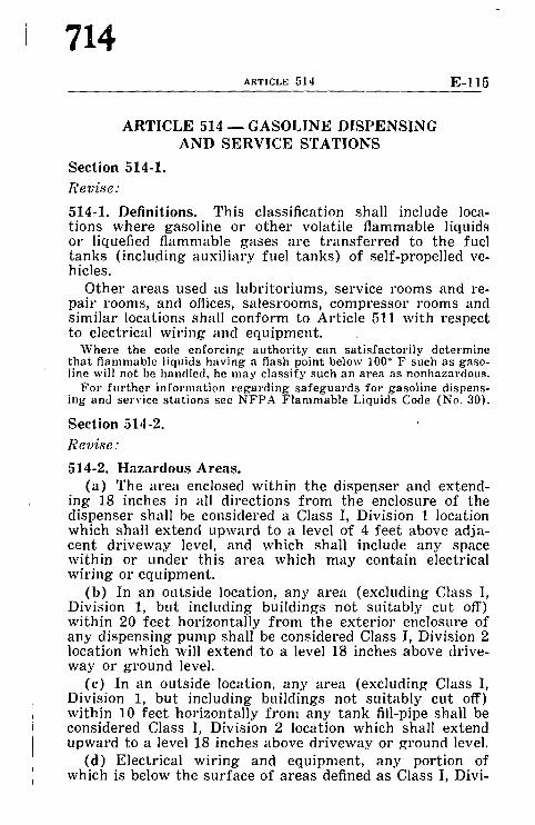
714 ARTICLE 514 E-115
A R T I C L E 5 1 4 - G A S O L I N E D I S P E N S I N G A N D S E R V I C E S T A T I O N S
Section 514-1.
Revise:
514-1. Defini t ions. Th i s c lass i f icat ion shall include loca- t ions whe re gasol ine or o t h e r volat i le f l ammable liquids or liquefied f l ammab le gases a re t r a n s f e r r e d to the fucl t a n k s ( including a u x i l i a r y fuel t a n k s ) of se l f -propel led ve- hicles.
O t h e r a r e a s used as l u b r i t o r i u m s , serv ice rooms and re- pa i r rooms , and offices, sa les rooms , c o m p r e s s o r rooms and s im i l a r locat ions shall c o n f o r m to Ar t ic le 511 wi th respec t to e lectr ical w i r ing and equ ipmen t .
Where the code enforcing authority can satisfactorily determine that flammable liquids having a flash point below 100 ~ F such as gaso- line will not be handled, he may classify such an area as nonhazardous.
For further information regarding safeguards for gasoline dispens- ing and service stations see NFPA Flammable Liquids Code (No. 30).
Sect ion 51,1-2.
Revise:
514-2. H a z a r d o u s Areas . ( a ) The a r ea enclosed wi th in the d i spense r and ex tend-
ing 18 inches in all d i rec t ions f r o m the enclosure of the d i spense r shall be cons idered a Class I, Divis ion 1 location which shall ex t end u p w a r d to a level of 4 f e e t above ad ja - cent d r i v e w a y level, and which shall include a n y space wi th in or unde r th is a r e a which m a y conta in electr ical w i r i ng or equ ipmen t .
(b ) In an outs ide location, a n y a r ea (exc lud ing Class I, Divis ion 1, bu t including bui ld ings not su i t ab ly cut off) wi th in 20 f ee t ho r i zon ta l ly f r o m the e x t e r i o r enclosure of a n y d i spens ing p u m p shall be cons idered Class I, Divis ion 2 locat ion which will ex tend to a level 18 inches above dr ive- way or g r o u n d level.
(c) In an outs ide location, a n y a r e a (exc luding Class I, Divis ion 1, bu t including bui ld ings not su i t ab ly cu t off) wi th in 10 f ee t ho r i zon ta l ly f r o m a n y t a n k fill-pipe shall be cons idered Class I, Divis ion 2 locat ion which shall ex tend u p w a r d to a level 18 inches above d r i v e w a y or g round level.
(d) E lec t r ica l w i r i ng and equ ipmen t , a n y por t ion of which is below the s u r f a c e of a r e a s defined as Class I, Divi-

E, II6 REPORT OF ELECTRICAL CODE COMMITTEE
715
~,hm I or Division 2 in 514-2(a), (b), (c) above shall be ~'onsidered to be a Class I, Division 1 location which shall v,~tend at least to the point of emergence.
(e) The spherical volume within a 3 foot radius f rom point of discharge of any tank vent-pipe shall be considered ~ Class I, Division 1 location and for any vent t ha t does not discharge upward the cylindrical volume below the Division I location extending to ground shall be considered Class I, Division 2 location. The volume between a 3 feet to 5 fee t radius f rom point of discharge of a vent shall be considered a Class I, Division 2 location. The hazardous area shall not ,)xtend beyond an unpierced wall.
Section 514-4.
Revise:
514-4. Wiring and Equipment Above Hazardous Areas. Wiring and equipment above hazardous areas defined in Section 514-2 shall conform to Sections 511-5 and 511-6.
Section 514-5.
Revise:
514-5. Circuit Disconnects. Each circuit leading to or through a dispensing pump shall be provided with a switch or o ther acceptable means to disconnect simultaneously from the source of supply all conductors of the circuit in- cluding the grounded neutral , if any.
Section 514-6.
Revise:
514-6. Sealing. (a) An approved seal shall be provided in each conduit
run enter ing or leaving a dispensing pump or o ther en- closure located in Class I, Division 1 or Division 2 location when the connecting conduit originates in a nonhazardous location. There shall be no union, coupling, box or fitt ing in the conduit between the sealing fitting and the point at which the conduit emerges into the pump or o ther equip- ment, or into any cavities or enclosures in direct communi- cation therewith .
This p a r a g r a p h s ta tes t h a t the first f i t t ing a f t e r the conduit emerges f rom the slab or f rom the concrete mus t be the seal ing fitting. Above the fi t t ing, the r ema inde r of the wi r ing and equ ipment is required to conform to the rules fo r the area classification involved.

716 ARTICLE 515 E-117
A R T I C L E 5 1 5 - - B U L K - S T O R A G E P L A N T S Secretary's Note
Proposals for revision of Article 515 are being considered by a subcommittee composed of members of C.M.P. No. 14 and mem- bers of the NFPA Flammable Liquids Committee and it is expected that a report of the subcommittee will have been proc- essed through C.M.P. No. 14 and presented ~or consideration at the NFPA Annual Meeting'.
Section 515-4.
Revise:
515-4. Wi r ing and Equipment A b o v e H a z a r d o u s Areas . All fixed w i r i ng above h a z a r d o u s a r e a s shall be in meta l l i c race- w a y s or shall be T y p e A L S cable. F ixed e q u i p m e n t which m a y produce arcs , s p a r k s or pa r t i c les of hot meta l , such as l a m p s and l ampho lde r s fo r fixed l ight ing, cu tou t s , swi tches , receptac les , moto r s , or o t h e r e q u i p m e n t h a v i n g m a k e and b r e a k or s l id ing con tac t s , shall be of to ta l ly enclosed t ype or shall be p rov ided wi th su i t ab le g u a r d s or sc reens to p r even t escape of s p a r k s or hot m e t a l par t ic les . P o r t a b l e l amps or
' app l iances , and t he i r flexible cords shall c o n f o r m to the p rov i s ions of Ar t ic le 501 fo r the class of locat ion above which t h e y a re connec ted or used.
Section 515-5 . (a)
Revise:
( a ) U n d e r g r o u n d wi r ing shall be ins ta l led in r igid meta l condui t , or, whe re bur ied unde r not less t h a n 2 fee t of ea r th , m a y be insta l led in non-meta l l i c condui t or duct, as Type A L S cable, or in the f o r m of cable a p p r o v e d fo r the purpose . W h e r e cable is used, i t shall be enclosed in r ig id m e t a l con- dui t f r o m the point of lowes t bur ied cable level to the point of connec t ion to the a b o v e g r o u n d r a c e w a y .

E. II 8 REPORT OF ELECTRICAL CODE COMMITTEE
717
ARTICLE 516 - - FINISHING PROCESSES
Section 516-3.(d)
licrise:
(d) Portable electric lamps or o ther utilization equip- ment shall not be used within a hazardous area during operation of the finishing process. When such lamps or utilization equipment are used during cleaning or repair ing operations, they shall be of a type approved for Glass I locations, and all exposed metal par ts shall be effectively grounded.
Sction 516-5.(a)
Revise:
516-5. Wiring and Equipment Above Hazardous Areas. (a) All fixed wiring above hazardous areas shall be in
metallic raceways or shall be Type MI cable or Type ALS cable. Cellular metal floor raceways may be used only for supplying ceiling outlets or extensions to the area below the floor of a hazardous area, but such raceways shall have no connections leading into or through the hazardous area above the floor unless suit~ible seals are provided. No elec- trical conductor shall be installed in any cell, header or duct which contains a pipe for steam, water, air, gas, drainage, or for o ther service except electrical.

718 ARTICLE 517 E-119
ARTICLE 5 1 7 ~ FLAMMABLE ANESTHETICS
Section 517-3.(a)
Rev i se :
(a) In hazardous areas as defined in Section 517-2, all fixed wiring and equipment, and all portable equipment, including lamps and other utilization equipment, operating at more than 8 volts between conductors, shall conform to the requirements of Sections 501-1 to 501-15 inclusive and of Paragraphs 501-16(a and b) for Class I, Division 1 loca- tions, and all such equipment shall be specifically approved for the hazardous atmospheres involved.
Section 517-3.(d)
Rev i se :
(d) Flexible cords which are or may be used in hazard- ous areas for connection to portable utilization equipment, including lamps operating at more than 8 volts between conductors shall be of a type approved for extra hard usage, shall be of ample length, and shall include an additional condv::tor for grounding. A storage device for the flexible cord shall be provided, and shall not subject the cord to bending at a radius of less than 3 inches.
Section 517-3.(e) new
A d d a .~Tew s~tbpavagrcr
(e) Receptacles and a t tachment plugs shall be of the type with provision for connection of the grounding conductor, and where located within a hazardous area, shall be ap- proved for Class I location. Single phase, 125 volt receptacles and a t tachment plugs shall be of the type recognized in Section 2438 of NFPA Code for the Use of Flammable Anesthetics (No. 56).
Section 517-4.(a)
Rev ise :
(a) Wiring above a hazardous area as defined in Para- graph 517-2 (b) shall be installed in metal raceways or shall be Type MI cable or Type ALS cable.

b: 120 REPORT OF ELECTRICAL CODE COMMITTEE
719
~'~Vctlcm 517-4.(c)
/,?~' e~ise:
(c) Surgical and other lighting fixtures shall conform to 0',~ragraph 501-9 (b), except tha t surface tempera ture limi- ~ t lons set forth in Paragraph 501-9(b-2) shall not apply, ~)t~(I except tha t integral or pendent switches which are C,~,eated above and cannot be lowered into the hazardous r need not be explosion-proof.
Section 517-6.(d)
Revise the fine print ~7ote: I','or ma in tenance tes t s of the ground indicator, see Section 3422 of
the N F P A Code for the Use of F lammable Anes the t i c s (No. 56).
Section 517-6.(e)
Revise:
(e) Branch circuits supplying only fixed lighting fixtures above the hazardous location other than surgical lighting fixtures or supplying only approved permanently installed X-ray equipment which complies with Section 2434 of the NFPA Code for the Use of Flammable Anesthetics (No. 56) may be supplied by a conventional grounded system, pro- vided: (a) wiring for grounded and ungrounded circuits does not- occupy the same raceways; (b) the lighting fix- tures and the X-ray equipment (except the enclosed X-ray tube and the metal-enclosed high voltage leads to the tube) are located at least eight feet above the floor or outside the anesthetizing location; and (c) switches for the grounded circuits are located outside of the anesthetizing location.
NOTE: Remote control s ta t ions for remote control swi tches may be installed in the anes the t i z ing location if the remote control circuit is energized f rom the ungrounded dis t r ibut ion sys tem.

720 ARTICLE 520 E-121
ARTICLE 5 2 0 - - T H E A T E R S AND ASSEMBLY HALLS
Section 520-4.
Revise:
520-4. Wiring Method. The wiring method shall be metal raceways, Type ALS cable or Type MI cable except as fol- lows :
Exception No. 1. As p~'ovided in Article. 650, Sound Re, productions, in Article 800, Communication Circuits, and in A.rticle 725 for Class 2 Remote Control and Signal Circuits.
Exception No. 2. Where the area intended for public ~sse,~bly has a c(o~acity of less than 200 persons, arm.o~'ed cable as provided in Article 334 may be used, or for con- cealed work. coucealed k~wb-a~Td-tube work or non-metallic sheathed coddle as provided in Articles 324 and 326 may also be 'used.
For recommendations for determination of population capacity, refer to NFPA Building Exits Code (No. 101).
Exception No. 3. The wi.ri~Tg for stage set lighting and stage e]fccts and other wi.ri~g ,which is not fixed as to loca- tion shall be doue with approved portable cables and ap- .proved flexible cords.
Section 520-,13.(b)
R ev ise:
(b) Where the metal t rough construction specified in Paragraph 520-43(a) is not used, footlights shall consist of individual outlets with lampholders, wired witfi rigid o1" flexible metal conduit, Type ALS cable or Type MI cable. The circuit conductors shall be soldered to the lampholder terminals. Disappearing footlights shall be so arranged tha t the current supply shall be automatically disconnected when the footlights are replaced in the recess designed therefor.
Section 520-45.
Revise:
520-45. Receptacles. Receptacles intended for the supply of arc lamps shall have not less than 50 amperes capacity

721 E-122 REPORT OF ELECTRICAL CODE COMMITTEE
and shall be supplied by conductors not smaller than No. 6. Receptacles intended for the supply of incandescent lamps shall have not less than 20 amperes capacity and shall be supplied by conductors not smaller than No. 12. Plugs for arc and incandescent receptacles shall not be interchange- able.
Section 520-61.
R e v i s e :
520-61. Arc Lamps. The construction of arc lamps shall be approved by the authorit ies having jurisdiction.
Section 520-63.(a)
R c v i.s'e :
520-63. Lights on Scenery. (a) Brackets oil scenery shall be wired internally and the
fixture stem shall be carried through to the back of the scenery where a bushing shall be placed oil the end of the stem. except tha t externally wired brackets or other fixtures may be used when wired with Type P or other cords de- signed for hard usage which shall extend through scenery and without joint or splice in canopy of fixture back and terminate in an approved type stage connector located within 18 inches of the fixture, unless such location is im- practical.

722 ARTICLE 530 E-] 23
ARTICLE 530 ~ MOTION PICTURE STUDIOS AND SIMILAR LOCATIONS
Section 530-1.
Revise:
530-1. Scope. The requirements of this Article shall apply to television studios (except as covered in Section 520-1), motion picture studios, exchange, factory, labo~'atory, stage, or a portion of the building in which motion picture filmA more than 7/a inch in width are manufactured, exposed, developed, printed, cut, edited, rewound, repaired or stored.
For recommendations for protection against cellulose nitrate film hazards refer to NFPA Standard for the Storage and Handling of Cellulose Nitrate Motion Pictm'e Film (No. 40).
Section 530-11.
Revise:
530-11. Permanent Wiring. The permanent wiring shall be in approved metal raceways Type ALS cable or Type MI cable.
Exception. Communication circuits, and sound recording and reproducing equipment may be wired as permitted by the articles covering those installations. (See Articles 640 and 800.)
Section 530-16.
Revise the exception under this Section:
Exception. The requirements of this Section shall not apply to portable lamps used as properties in a motion pic- ture set, or television stage set on a studio stage or lot, or on location.
Section 530-51.
Revise:
530-51. Lamps in Cellulose Nitrate Film Storage Vaults. Lamps in cellulose n i t ra te film storage vaults shall be rigid fixtures of the glass enclosed and gasketed type. Lamps shall be controlled by a switch having a pole in each ungrounded conductor. This switch shall be located outside of the vault

REPORT OF ELECTRICAL CODE COMMITTEE
723
~,ul provided with a pilot light to indicate whether the ~wltch is on or off. This switch shall disconnect f rom all ~"~mrces of supply all ungrounded conductors te rminat ing . m any outlet in the vault.
ARTICLE 5 4 0 - - M O T I O N PICTURE PROJECTORS
~cl ion 540-13.
ir vise:
~i10-13. Conductor Size. Conductors supplying outlets for l~rc projectors of the professional type shall not be smaller lhan No. 8 and shall be of sufficient size for the projec tor ,,mployed. Conductors for incandescent type projectors shall ronform to normal wiring s tandards as provided in Section 210-25.
ARTICLE 6 0 0 - ELECTRIC SIGNS AND OUTLINE LIGHTING
Section 600-6.
Revise:
600-6. Load of Branch Circuit. Circuits shall be so ar- ranged tha t the load imposed by outlets, lamps, and t rans- formers connected to them, shall in no case exceed the rating of the branch circuit.
Circuits which supply lamps, ballasts, and t r ans fo rmers or combinations thereof may be rated not to exceed 20 L m peres.

724 ARTICLE 600 E-I~
Circuits containing electric discharge l ighting tram formers exclusively shall not be rated in excess of ,~: amperes.
Section 600-21.(a)
Revise:
(a) Wiring Method. Conductors shall be installed ~" open conductors on insulators, in rigid metal conduit, flexibb metal conduit, electrical metallic tubing, armored cabh' metal troughing, Type ALS cable or Type MI cable.
Section 600-21.(b)
Revise:
(b) Insulation and Size. Conductors shall be of" a tyl)~' approved for general use and shall be no smaller than No. 1,1
Exception No. 1. Conductors in portable signs and lead~ in wiring channels which are pe~'manently attached to elec: tric discharge lampholders or electric discharge ballasts a~d which are not longer than 8 feet may be smaller than No. 14 but shall not be smaller than No. 18 and shall be of a ty'p~' approved for the purpose.
Section 600-31.(b)
Revise:
(b) Insulation and Size. Conductors shall be of a type approved for the purpose and for the voltage of the circuit and shall be not smaller than No. 14.
Exception No. 1. Leads in wiring channels which are per. �9 manently attached to electric discharge lampholders or elec.
tric discharge ballasts and which are not longer than 8 feet may be smaller than No. 14 but shall not be smaller than No. 18 and shall be of a type approved for the purpose.

1r REPORT OF ELECTRICAL CODE COMMITTEE
725
ARTICLE 6 1 0 - CRANES AND HOISTS
Section 610-1.
Ir cvise :
(;10-1. Scope. The provisions of this Article shall apply to the installation of cranes, crane runways, hoists, and mono- ,'ails, and shall be additional to, or amendatory of, the requirements prescribed in Articles 100 to 480, inclusive, of this Code.
For defini t ion of var ious k inds of c r anes and ho i s t s see A m e r i c a n S t anda rd Sa fe ty Code for Cranes , Derr icks , and Hois t s , A SA B30 .2 - - ! 9,!3.
Section 610-11. (first sentence)
Revise:
610-11. Wiring Method. Conductors shall be enclosed in raceways or be Type ALS cable or Type MI cable.
Section 610-14.(d) and (e) (new)
A d d n e w paragraphs "d" and "e" :
(d) Calculation of Motor Load. The current-carrying capacity of the power supply conductors on the crane shall be not less than the combined short time full load ampere rating of the largest motor or group of motors for any single crane motion plus 50 percent of the combined short time full load ampere rat ing of the next largest motor or group of motors.
(e) Other Loads. Additional loads, such as heating, lighting, and air conditioning, shall be provided for by appli- cation of the appropriate sections of this Code.
Section 610-21.(d)
Rev i se :
(d) Supports for Rigid Conductors. Conductors along runways and crane bridges, which are of the rigid type specified in Section 610-13 Exception No. 1, shall be carried on insulating supports spaced at intervals of not more than 80 times the vertical dimel~sion of the conductor, but in no case greater than 15 feet, and spaced apart sufficiently to give a clear electrical separation of conductors or adja- cent collectors of not less than 1 inch. Hardwood supports

726 ARTICLE 610 E-127
covered with, or impregnated with, insulating paint shall be acceptable insulators.
Section 610-21.(h)
Revise:
(h) Locating or Guarding Contact Conductors. Contact conductors shall be located or guarded in s u c h a manner tha t unqualified persons cannot inadver tent ly touch ener- gized cur ren t -car ry ing parts.
Section 610-32.
Revise:
610-32. Disconnecting Means for Crane. A motor-circuit switch or circuit breaker shall be provided in the leads from the runway contact conductors on all bridge cranes. If cranes are operated from cages or cabs, the switch or circuit breaker shall be in the cage or cab or mounted on the bridge and operable f rom the cage or cab when the trolley is at one end of the bridge.
Section 610-42.
Revise:
610-42. Crane Motors. Where more than one motor is em- ployed on a crane, each motor shall have individual over- cur ren t protection as provided in Article 430, except tha t where two motors operate a single hoist, carriage, truck, or bridge, and are controlled as a unit by one controller, the pair of motors with their leads may be protected by a single overcurrent device.
Section 610-51.
Revise:
610-51. Grounding. All exposed metal par ts of cranes, hoists, and accessories, including pendant controls, shall be metallically joined toge ther into a continuous electrical con- ductor so tha t the ent ire crane or hoist will be grounded on installation in accordance with Article 250. Moving parts, other than removable accessories or a t t achments having metal-to-metal bearing surfaces, i.e., such as bridge wheels running on a track, shall be considered to be electrically connected to each other through the bearing surfaces for grounding purposes.

Ho 128 REPORT OF ELECTRICAL CODE COMMITTEE
727
ARTICLE 6 2 0 - - E L E V A T O R S , DUMBWAITERS, ESCALATORS, AND MOVING WALKS
Ncction 620-1.
Ite vise:
020-1. Scope. This Article shall apply to electrical equip- ment and wiring used in connection with elevators, dumb- waiters, escalators, and moving walks.
Section 620-2.
Ir the first paragraph as follows (bahtnce of Section to remain unchanged):
{;20-2. Voltage Limitations. The nominal voltage used for elevator, dumbwaiter, escalator, and moving walk operating control and signal circuits, operating equipment, driving machine motors, machine brakes, and motor-generator sets Ifimll not exceed the following:
Section 620-3.
Revise:
620-3. Live Par ts Enclosed. All live parts of electrical apparatus in the hoistways, at the landings, or in or on the cars of elevators and dumbwaiters or in the wellways or the landings of escalators or moving walks shall be enclosed to protect against accidental contact.
Section 620-11.
Revise first paragraph as follows (balance of Section to remain unchanged) :
620-11. Insulation of Conductors. The insulation of conduc- tors installed in connection with elevators, dumbwaiters, escalators and moving walks, shall comply with the fol- lowing:
Section 620-11.(c)
Revise:
(c) Other Wiring. All conductors in the raceways and in or on the cars of elevators and dumbwaiters and in the well- ways of escalators and moving walks and in the machine

728 ARTICLE 620 E-I~'~
room of elevators, dumbwaiters , escalators and movi~j walks shall have flame-retardant and moisture-resista,~'~ insulation.
Sect ion 620-12.
Revise f i r s t paragraph to read as follows (balance of See tion to remain unchanged):
620-12. Minimum Size of Conductors. The minimum size o| conductors used for elewLtor, dumbwaiter , escalator, am~ moving walk wiring, except for conductors which form a,~ integral par t of control equipment, shall be as follows:
I
il'
I
Sect ion 620-13. (New)
Add new Section:
620-13. Motor Circuit Conductors. Conductors supplying elevator, dumbwaiter , escalator, or moving walk motors shall have a carrying capacity conforming to sub-sections (a). (b) and (c) below based on the nameplate current rat ing of the motors. With generator field control, the carrying capac, ity shall be based on the nameplate current rat ing of tho driving motor of the motor-generator set which supplies power to the elevator motor.
The h e a t i n g of conduc tors depends on root m e a n square cur ren t va lues which, with g e n e r a t o r field control , are reflected by the name- p la te c u r r e n t r a t i n g of the m o t o r - g e n e r a t o r se t d r iv ing motor r a t h e r t h a n by the r a t i n g of the e l eva to r m o t o r which r e p r e s e n t s ac tua l but s h o r t t ime and i n t e r m i t t e n t ful l - load c u r r e n t values.
(a) Conductors Supplying a Single Motor. Conductors supplying a single motor shall have a carrying capacity in conformance with Section 430-22, Table 430-22 (a-Excep- tion).
(b) Conductors Supplying Several Motors. Conductors supplying several motors shall have a current carrying ca- paci ty of not less than 125 per cent of the nameplate current rat ing of the highest rated motor in the group plus the sum of the nameplate current rat ings of the remainder of the motors in the group.
(c) Feeder Demand Factor. Feeder conductors of less capacity than required by sub-section (b) above may be furnished subject to the requirements of Section 430-26.

t~ !30 REPORT OF ELECTRICAL CODE COMMITTEE
729
~r ion 620-21.
C~vise first paragraph to read as follows ("Exceptions" to ,~cmain unchanged except as noted for No. 1 below) :
620-21. Wiring Methods. Conductors located in hoistways ~md escalators and moving walk wellways, in or on cars and machine and control rooms, not including the traveling t'ables connecting the car and hoistway wiring, shall be ~,stalled in rigid conduit, electrical metallic tubing, metal wh'eways, Type ALS cable or Type MI cable subject to the following exceptions :
Section 620-21.
Ir vise Exception No. 1 :
Exception No. 1. Flexible conduit or armored cable may br used in hoistways and in escalator and moving walk welhvays between risers and limit switches, interlocks, op- erating buttons, and similar devices.
Section 620-34.
Revise:
620-34. Supports. Supports for Type ALS cable or con- ductor raceways in the hoistway or escalator or moving walk wellway shall be securely fastened to the guide rail or to the hoistway or wellway construction.
Section 620-52.
Revise:
620-52. Electrical Equipment in Garages and Similar Occu- pancies. Electrical equipment and wiring used for eleva- tors, dumbwaiters, escalators, and moving walks in garages shall conform to the requirements of Article 511. Wiring and equipment located under the car platform shall be con- sidered as being located in the hazardous area.
Section 620-61.(b)
Revise:
(b) Motors. (1) Duty on elevator and dumbwaiter driving machine
motors and driving motors of motor generators used with

730 ARTICLE 620 E-131
generator field control shall be classed as intermit tent . Such motors shall be protected against overcurrent in accordance with Section 430-33.
(2) Duty on escalator and moving walk driving machine motors shall be classed as continuous. Such motors shall be protected against overcurrent in accordance with Section 430-32.
(3) Elevator, dumbwaiter, escalator, and moving walk driving machine motors and driving motors of motor gen. erator sets shall be protected against running overcurrent as provided in Table 430-37, except tha t no more than two overcurrent protective units shall be required.
Section 620-71.
Revise:
620-71. Guarding Equipment. Elevator, dumbwaiter, esca- lator, and moving walk driving machines, motor generator sets, controllers and auxiliary control equipment shall be installed in a space secured against unauthorized access.
Such equipment may be located in rooms or spaces con- taining other equipment essential to the operation of the building provided it is separated therefrom by a substantial metal grill enclosure of a design which will ' reject a ball two inches in diameter and is at least six feet high equipped with a self-closing and self-locking door.
I t- is not intended to prohibit the installation of dumb- waiter, escalator, or moving walk controllers outside the spaces herein specified, provided they are enclosed in cabi- nets with doors or removable panels capable of being locked in the closed position; nor is it intended to prevent the in- stallation of dumbwaiter controllers within the hoistway without cabinets, provided removable or hinged panels capa- ble of being locked in the closed position are installed in the hoistway enclosures to provide access to the controllers.
Section 620-72.(b)
Revise:
(b) Escalator and Moving Walk Control Panels. The minimum working clearance for escalator and moving walk control panels shall be as specified in Paragraph 620-72 (a) provided tha t where the control panel is mounted in the

1'1-132 REPORT OF ELECTRICAL CODE COMMITTEE
"/51
same space as the escalator or moving walk drive machine 'rod the clearances specified cannot be provided, they may be waived where the entire panel is ar ranged so tha t it can be readily removed from the machine space and is provided with flexible leads to all external connections.
Where control panels are not located in the same space as the drive machine they shall be so located in cabinets with doors or removable panels capable of being locked in the closed position. Such cabinets may be mounted in the balustrading on the side away f rom the .moving steps or moving treadway.
Section 620-81.
Revise:
620-81. Metal Raceways Attached lo Cars. Conduit, Type ALS cable or armored cable a t tached to elevator cars shall be bonded to grounded metal par ts of the car with which they come in contact.

732 ARTICLE 030 E-133
ARTICLE 6 3 0 - ELECTRIC WELDERS
Section 630-1.
Revise:
630-1. Scope. This Article covers electric arc welding, re. sistance welding apparatus, and other similar welding equip- ment tha t is connected to an electrical supply system.
Part B. (Title)
Revise title of Part to read:
B. AC Transformer and DC Rectifier Arc Welders
Section 630-11.
Revise:
630-11. Capacity of Supply Conductors. The current-carry- ing capacity of conductors shall be as follows:
(a) Individual Welders. The rated current-carrying ca- pacity of the supply conductors shall be not less than the current values determined by multiplying the rated pr imary current in anaperes, given on the welder nameplate, and the following factor based upon the duty cycle or time rat ing of the welders :
Rated Percent Duty C y c l e o f W e l d e r s M u l t i p l y i n g F a c t o r
20 or less 0.45 30 0.55 40 0.63 50 0.71 60 0.78 70 0.84 80 0.89 90 0.95
100 1.00
For a welder having a time rating of one hour. the multiplying factor shall be 0.75.
(b) Group of Welders. The rated current-carrying ca- pacity of conductors which supply a group of welders may be less than the sum of the currents, as determined in ac- cordance with Section 630-11.(a) of the welders supplied. The conductor rat ing shall be determined in each case accord- ing to the welder loading based on the use to be made of each

0 I:ld REPORT OF ELECTRICAL CODE COMMITTEE
t 3 3
,,~,ldc," and the al lowance permissible in the event t h a t all ~111~,~ wclders supplied by the conduc tors will not be in use at 1111~,,~ ramie time. The load value used for each welder shall take ~1o account both the m a g n i t u d e and the duril t ion of the I ~ ,:td while the welder is in use.
Conductor ratings based on 100 per cent of the current, as detcrmined . ~ accordance with 630-11(a), of the two largest weldcrs, 85 per cent 0,.~r the third largest welder, 70 per cent for the fourth largest welder, ~t~d 60 pcr cent for all the remaining welders, should provide an ample (.ms'gin of safety under high production conditions with respect to ~h~ maximum permissible temperature of the conductors. Percentage ~Mucs lower than those given are permissible in cases where the work ~ t, uch that a high operating duty cycle for individual welders is ~mpossible.
Section 630-13.
Rcvise :
630-13. Disconnect Means. A disconnect means shall be provided in the supply connect ion of each welder which is not equipped with a disconnect moun ted as an in tegra l pa r t of the welder.
The disconnect means shall be a switch or c ircui t b reaker and its r a t i ng shall be not less t han t h a t necessa ry to ac- commoda te ove r cu r r en t pro tec t ion as specified under 630-12.
Secti~)n 630-14.
Revise:
630-14. Marking . A namepla te g iv ing the fol lowing infor- mat ion shall be provided : name of m a n u f a c t u r e r ; f r equency ; p r i ma ry vo l t age ; ra ted p r i m a r y c u r r e n t ; m a x i m u m open- circuit secondary vo l t age ; ra ted secondary c u r r e n t ; basis of ra t ing , i.e., the du ty cycle, n u m b e r of phases, 60-minute ra t ing.
ARTICLE 6 6 0 - X-RAY EQUIPMENT
Section 660-1.
Omit the third paragraph of the fine print note appearing under this Section.

734 ARTICLE 670 E-13~,
ARTICLE 670--MACHINE TOOLS
Title
Revise title of article to read:
ARTICLE 670--METAL WORKING MACHINE TOOLS
For further information see NFPP, Standard on Metal Working Machine Tools (No. 79).
Section 670-1.
Revise:
670-1. Scope. The provisions of this Article apply to the size and overcurrent protection of supply conductors to metal working machine tools and to the nameplate data re. quired on each such tool.
Section 670-2.
Revise:
670-2. Definition of Metal Working Machine Tools. For the purpose of this Article, metal working machine tools are defined as follows:
(a) A metal cut t ing machine tool is a power driven ma- chine, not portable by hand, used for the purpose of remov- ing metal.
(b) A metal forming machine tool is a power driven machine, not portable by hand, used to press, forge, emboss. hammer, blank, or shear metal.
Section 670-3.
Revise:
670-3. Machine Tool Nameplate Data. A permanent name- plate listing supply voltage, phase, frequency, full load cur- rents (see note), ampere rat ing of largest motor, short circuit interrupt ing capacity of the machine overcurrent protective device if furnished, and diagram number shall be at tached to the control equipment enclosure or machine where plainly visible a f te r installation.

I",o 136 REPORT OF ELECTRICAL CODE COMMITTEE
735
NOTE 1. The full load cur ren t shall be not less than the i~lml of the full load currents required for all motors and othcr equipment which may be in operation at the same time ~l,~(ler normal conditions of use. Where unusual type loads, duty-cycles, etc., require oversized conductors, the required capacity shall be included in the marked "full load cur ren t . "
NOTE 2. Where more than one incoming supply circuit Is to be provided, the nameplate shall state the above in- formation for each circuit.
Section 670-4.
Revise:
670-4. Conductors Supplying a Machine Tool.
(a) The supp!y circuit conductors shall have a current- carrying capacity of not less than the marked full load cur- rent ra t ing plus 25 per cent of the full load cur rent ra t ing of the highest ra ted motor as indicated on the nameplate. For the protect ion of supply conductors to the machine tool, refer to Section 240-5.
(b) A machine tool conforming with NFPA No. 79 shall be considered individual unit equipment. It is provided with a disconnecting means and may be supplied by branch cir- cuits protected by ei ther fuses or circuit breakers.
(c) The disconnecting means may or may not incorporate overcurrent protection. Where the machine tool nameplate is marked "Overcur ren t protect ion provided at machine sup- ply terminals ," the supply conductors are to be ei ther feeders or taps as covered by Section 240-15.
"Overcurrent protection provided at machine supply terminals" means that provision has been made in the machine tool for each set of supply conductors to terminate in a single circuit breaker or set of fuses.

736 ARTICLE 680 E-137
ARTICLE 680~SWIMMING POOLS
Article 680. (New)
I n s e r t n e w A r t i c l e :
ARTICLE 680--SWIMMING POOLS
680-1. Scope. The provisions of this Article apply to the construction and installation of electric wiring for equip. ment in or adjacent to swimming pools, to metallic appur- tenances in or within 5 feet of the pool, and to the auxiliary equipment such as pumps, filters and similar equipment. No electric appliances or wiring shall be installed in the water or in the enclosing wails of a swimming pool, except as pro- vided for in this Article.
680-2. Approval of Equipment. All equipment shall be approved for the purpose.
680-3. Application of Other Articles. Except as modified by this Article, wiring and equipment in or adjacent to swimming pools shall comply with the applicable require- ments of Chapters 1 to 4, inclusive, of this Code.
680-4. Lighting.
(a) The provisions of this Section apply to lighting fix- tures installed below the pool surface.
(b) Approved metal fixture housings (forming shells) shall be installed for the mounting of all underwater fixtures and shall be equipped with provisions for conduit entries. Metal parts of the fixture, fixture housing, and the supply conduit below grade level shall be of brass or other suitable copper alloy. The conduit shall extend from the fixture hous- ing (forming shell) to a suitable junction box located as provided in Section 680-5 of this Article.
All noncurrent carrying metal parts of l ighting fixtures shall be grounded whether exposed or enclosed in noncon- ducting materials.
(c) All circuits supplying underwater fixtures should be isolated. If the circuit voltage is greater than 30 volts, an approved fail-safe ground detector device which automat-

F..138 REPORT OF ELECTRICAL CODE COMMITTEE
75"I
tcally de-energizes the circuit or an approved grid struc- lure or similar safeguard should be used.
(d) Transformers used for the supply of fixtures, to- gether with the t ransformer enclosure, shall be approved for the purpose. The t ransformers shall be of an isolating type having a grounded metal barrier between the high and low voltage windings.
(e) No lighting fixture shall be installed for operation at more than 150 volts.
(f) A nonmetallic fixture shall not be used with a grounded power supply.
680-5. Junction Boxes and Transformer Enclosures.
(a) Junction boxes installed on the supply side of con- duits extending to under~yater pool lights shall be construc- ted of brass or suitable copper alloy unless located:
(1) Not less than 4 feet from the pool perimeter, and
(2) Not less than 12 inches above the ground or con- crete surface.
(b) Transformer enclosures shall be located:
(1) Not less than 4 feet from the pool perimeter, and
(2) Not less than 12 inches above the ground or con- crete surface, and
(3) In no case less than 12 inches above the maximum water level.
(c) Boxes shall be provided with means for independently terminat ing not less than two grounding conductors.
680-6. At tachment Plug Receptacles. No a t tachment plug receptacles shall be installed within 10 feet of the inside walls of the swimming pool.
680-7. Grounding. (a) All metallic conduit, piping systems, pool reinforcing
steel, l ighting fixtures, and the like, shall be bonded together and grounded to a common ground. The metal parts of lad- ders, diving boards, and their supports, shall be grounded.
(b) No pool equipment shall be grounded to an external grounding electrode tha t is not common to the pool ground (deck 'box or t ransformer enclosure).

738 ARTICLE 680 E-]:I9
(c) An unbroken No. 14 AWG, or larger, insulated coppet' wire shall be provided for a grounding conductor from the deck box to the distribution l)anel ground.
(d) Metallic raceways shall not be depended upon for grounding. Where exposed to pool water and in o ther cot. rosive areas such as in puml) houses or adjacent to water t rea t ing and other equipnlent, the grounding of. the non~ cur rent car ry ing parts shall be by means of an insulated copper conductor sized in accordance with Section 250-95.
680-8. Methods of Grounding and Bonding.
(a) Metal wiring enclosures shall be grounded in accord. ance with Article 250, in addition to other requirements of this Article.
(b) In addition to o ther requirements of this Article, l ighting fixtures tha t are supplied by flexible cord or cable shall have all metal parts grounded by means of an insulated grounding conductor tha t is an integral par t of the cord. This conductor shall be No. 14 AWG or larger.
(c) Nonelectrical equipment required to be grounded to a common ground in accordance with Section 680-7 shall be grounded in accordance with Article 250.
St ru c tu r a l r e in fo rc ing s teel m a y be used as a common bonding con- duc tor for nonelectr ical pa r t s where connect ions can be re l iably made in accordance with the provis ions of Art ic le 250.
680-9. Clearances. Service drop conductors shall not be in- stalled above the swimming p.ool or surrounding area ex- tending 10 feet horizontally f rom the pool edge. or diving s t ructure , observation stands, towers or platforms.
680-10. Overhead Wiring. No open overhead wiring shall be installed in the pool area as described in Section 680-9.
See Section 90-2(b) .

I",- 1,10 REPORT OF ELECTRICAL CODE COMMITTEE
739
ARTICLE 700--EMERGENCY SYSTEMS
Section 700-8.
Revise:
700-8. G e n e r a t o r Set . One service , in accordance wi th Ar - ticle 230, and a g e n e r a t o r se t d r iven by some f o r m of p r i m e move r and of sufficient c apac i t y and p rope r r a t i n g to supply c i rcui ts c a r r y i n g e m e r g e n c y l i gh t ing or l i gh t ing and power , with su i t ab le m e a n s fo r a u t o m a t i c a l l y s t a r t i n g the p r i m e move r on f a i l u re of the n o r m a l service . F o r hospi ta ls , the t r ans i t ion t i m e f r o m i n s t a n t of f a i l u r e of the n o r m a l power source to the e m e r g e n c y g e n e r a t o r source shall no t exceed ten seconds.
See Section 700-4.
Section 700-14.
Revise:
700-14. E m e r g e n c y Illumination. E m e r g e n c y i l lumina t ion shall include all r equ i r ed exi t l igh ts and all o t h e r l igh t s specified as n e c e s s a r y to p rov ide sufficient i l luminat ion. W h e r e a f ix ture wi th two l a m p h o l d e r s is used to comply with the r e q u i r e m e n t s of th i s sect ion and the e m e r g e n c y l igh t ing c i rcu i t o p e r a t e s a t less t h a n 50 volts , these two h tmpholde r s m a y be coun ted as a s ingle l a m p h o l d e r in app ly- ing the l imi ta t ion of 8 l a m p h o l d e r s in Sect ion 720-5 pro- vided the to ta l load does not exceed 320 volts .
Emergency lighting systems should be so designed and installed that the failure of any individual lighting element, such as the burning out of a light bull), cannot leave any space in total darkness.

740 ARTICLE 710 E-I41
ARTICLE 710--OVER 600 VOLTS--GENERAL
Section 710-10.(a)
Revise:
(a) In Public Places. In places which are regularly open to the public, electrical installations shall conform with Sections 710-31 to 710-36 inclusive. Metal enclosed switch. gear, unit substations, t ransformers , pull boxes, connection boxes, and other similar associated equipment shall be marked with appropriate caution signs. Openings in venti- lated dry-type t ransformers or similar openings in other equipment shall be designed so tha t foreign objects inserted through these openings will be deflected from energized parts.
Section 710-10.(b)
Revise:
(b) In Places Frequented Only By Persons Employed on the Premises. In places where access is normally restricted to persons employed on the premises, enclosure of electrical installations is not mandatory provided tha t : (1) No live parts are exposed or readily accessible; (2) The associated conduits or armored cables terminate in, and are securely fastened to, the terminal chamber, casing or enclosure of the equipment; (3) Openings in ventilated dry-type trans- formers or similar openings in other equipment are designed so tha t foreign objects inserted through these openings will be deflected from energized parts.
Section 710.22.
Revise:
710-22. Isolating Means. Means shall be provided to com- pletely isolate an item of equipment. The use of isolating switches is not necessary where there are other ways of de- energizing the equipment for inspection and repairs such as metal-enclosed switchgear units, and removable truck panels. Isolating switches s]aould be interlocked with the associated circuit interrupt ing device to prevent their being opened under load, otherwise signs warning against opening them under load shall be provided. Barriers should be pro-

~42 REPORT OF ELECTRICAL CODE COMMITTEE
741
, , b*d on bo th sides of each pole of indoor o p e n - t y p e isolat- 'L! t~witches. A fuse holder and fuse , des igned fo r the pur -
l.: "~, m a y be used as an i so la t ing swi tch .
:r hm 710-31.
th J~isc:
,]liD.31. Enclosure for Electrical Installations. Elec t r ica l , w~tallations in a vaul t , room, c loset or in an a r e a s u r r o u n d e d L',~> a wall, sc reen or fence, access to which is cont ro l led by I'~(g~k and key or o the r a p p r o v e d means , a r e cons idered to be ,:~'ccssible to qualified p e r s o n s only. T h e h e i g h t of the wall, ~ ' rccn or f ence should not be less t h a n e igh t f e e t overal l , ~mlcss des igned to p rov ide an equ iva l en t deg ree of isolat ion. I'hc type of enc losure used in a g iven case shall be des igned cm(I c o n s t r u c t e d accord ing to the n a t u r e and deg ree of the h a z a r d ( s ) a s soc ia t ed wi th the ins ta l la t ion . Ar t ic le 450 ~'~wcrs m i n i m u m c o n s t r u c t i o n r e q u i r e m e n t s fo r oil-filled I , ' a n s f o r m e r vau l t s .
I so l a t i on b y e l e v a t i o n is c o v e r e d in S e c t i o n s 710-11 a n d 710-36.
A R T I C L E 7 2 0 - - C I R C U I T S A N D E Q U I P M E N T O P E R A T I N G A T L E S S T H A N 50 V O L T S
Section 720-5.
Revise:
720-5. B r a n c h Circui t . N o t m o r e t h a n 8 l a m p h o l d e r s or receptac les , nor a to ta l load of m o r e t h a n 320 wa t t s , shall
~ %e suppl ied by a b r a n c h circui t . Moto r s or app l iances of r a t i n g m o r e t h a n 320 w a t t s shall h a v e a s e p a r a t e b r a n c h circui t .
Exception: See Section 700-14. i

742 ARTICLE 725 E-143
ARTICLE 725--REMOTE-CONTROL, LOW- ENERGY POWER, LOW-VOLTAGE POWER AND
SIGNAL CIRCUITS
Section 725-15.
R e v i s e :
725-15. Number of Conductors in Raceways. The number of conductors of remote-control or signal circuits in a race. way may be determined according to Section 300-17 and Note 8 of Tables 310-12 through 310-15 need not be ob- served. Where there are four or more conductors in a race. way, some of which are remote-control, as permit ted by Section 300-3, the provisions of Note 8 of Tables 310-12 through 310-1.5 shall apply, as determined by the number of power and lighting circuit conductors only.
Section 725-21.
R e v i s e :
725-21. Grounding. Class 1 remote-control and signal cir- cuits and equipment shall be grounded in accordance with Article 250.
Section 725-42.(b)
R e v i s e f ine p r i n t n o t e :
W h e r e 3 or m o r e c o n d u c t o r s a r e u sed , i t is r e c o m m e n d e d t h a t such c o n d u c t o r s be g r o u p e d u n d e r a c o m m o n b r a i d o r c o v e r i n g .
Section 725-42.(c)
A d d n e w t, e x t t,o ~'ead:
(c) Conductor Insulation. Conductor insulation shall comply with the following:
(1) 30 Volts or Less. The insulation shall be suitable for the particular' application.
T h e k ind o f i n s u l a t i o n f o r t h e c o n d u c t o r s is n o t spec i f i ed in f u r t h e r de t a i l a s r e l i a n c e is p l aced on c u r r e n t l i m i t a t i o n to s t o p d a n g e r o u s c u r r e n t s .
(2) 30 to 150 Volts. Conductors of a cable shall be of solid or s tranded copper not smaller than No. 22 Awg, and

E-144 REPORT OF ELECTRICAL CODE COMMITTEE
743
shall have thermoplast ic insulation of not less than 0.012 inch nominal (0.010 inch minimum) thickness. The cable conductors shall have a thermoplast ic jacket overall having a nominal thickness of not less than 0.035 inch (0.030 inch minimum). Where the number of conductors in a cable ex- ceeds 4, the thickness of the thermoplast ic jacket overall shall be increased so as to provide equivalent performance characterist ics. Similarly, where the size of conductors in a cable exceeds No. 16 gauge, the thickness of the conductor insulation shall be increased so as to provide equivalent l)erfol'mance .characteristics.
Two-conductor assemblies of No. 16 gauge or smaller, may be in flat 1)arallel construction with 1 '32 inch nominal integral-insulation jacket and an 0.047 inch minimuna web. Approved low-energy circuit cable may be used.
Other insulation having equivalent performance charac- teristics may be acceptable.
Where single conductors are used they shall be not smaller than No. 18 Awg and shall be insulated in conformity with Section 725-14.
Section 725-44. (New)
A d d n e w S e c t i o n :
725-44. Grounding. Class 2 remote control and signal cir- cuits and equipment shall be grounded in accordance with Article 250.

744 ARTICLE 730 E-145
ARTICLE 730- -OUTSIDE BRANCH CIRCUITS AND F E E D E R S
Section 730-10.
R e v i s e :
730-10. Wiring on Buildings. Outside wiring on surfaces of buildings may be installed, for circuits of less than 600 volts, as open conductors on insulating supports, as multiple- conductor cable approved for the purpose, as aluminum sheathed cable, in rigid metal conduit, in busways as pro- vided in Article 364, or in electrical metallic tubing. For cir- cuits of more than 600 volts as provided for services in Section 230-101, and for sign and outline l ighting as pro- vided in Article 600.
Section 730-19.(a)
R e v i s e :
(a) Over Roofs. Open conductors shall not be less than 8 feet f rom the highest point of roofs. Conductors at tached to roof s t ruc tures shall be substant ial ly supported. Wher- ever practicable, conductors crossing over buildings shall be supported on s t ruc tures which are independent of the building.
For Service Drop Conductors see Section 230-24(a).
Section 730-19.(c)
R e v i s e :
(c) Final Spans. Final spans of feeders or branch cir- cuits to buildings which they supply or from which they are fed may be a t tached to the building but they shall be kept 3 feet f rom windows, doors, porches, fire escapes or similar locations.

E-146 REPORT OF ELECTRICAL CODE COMMITTEE
745
ARTICLE 800--COMMUNICATION CIRCUITS
Section 800-2.(d)
Revise:
(d) Omission of fuses. A protec tor wi thout fuses may be used under any of the following conditions:
(1) Where circuits enter a building through metal- sheathed cable, provided the metal sheath of the cable is cffectively grounded and the conductors in the cable shall safely fuse at currents less than the cur ren t -ca r ry ing ca- pacity of the protector, the associated insulated conductors, and the protector grounding conductor.
(2) Where insulated conductors in accordance with Section 800-11(c-1 and -2) are used to extend circuits to a building from a metal-sheathed cable or f rom a non- metallic-sheathed cable having a metal grounding shield between the sheath and the conductor assembly provided the metal sheath or ' shie ld is effectively grounded and the conductors in the cable or cable stub shall safely fuse at currents less than the cur ren t -ca r ry ing capacity of the pro- rector, the associated insulated conductors, and the protec- tor grounding conductor.
(3) Where insulated conductors, in accordance with Section 800-11(c-1 and -2) are used to extend circuits to a building from other than grounded metal -sheathed cable, provided (a) the protec tor is approved for this purpose and (b) the protector grounding conductor is connected to a water pipe electrode or the grounding conductor or ground- ing electrode of a rriulti-grounded neutral power system and (c) the connections of the insulated conductors to the ex- posed plant or the conductors of the exposed plant shall safely fuse at currents less than the cur ren t -car ry ing ca- pacity of the protector, the associated insulated conductors, and the protec tor grounding conductor.
(4) Where insulated conductors in accordance with Section 800-11(c-1 and -2) are used to extend circuits aeri- ally to a building from an unexposed buried or underground circuit.
Effectively grounded means permanently connected to earth through a ground connection of sufficiently low impedance and having sufficient current-carrying capacity to prevent the building up of voltages which may result in undue hazard to connected equipment or to persons.

746 ARTICLE 81 0 E-1,17
A R T I C L E 8 1 0 - - R A D I O AND T E L E V I S I O N E Q U I P M E N T
Section 810-1.
Revise fine print note:
It is recommended that the authority enforcing this Code be freely consulted as to the specific methods to be followed in any case of doubt relative to installation of antenna conductors and that the National Electrical Safety Code, Part 5, be followed.
Section 810-11.
Revise:
810-11. Material . An t enna and lead-in conduc tors shall be of h a r d - d r a w n copper, bronze, a luminum alloy, copper-clad steel or o the r h i g h - s t r e n g t h , co r ros ion- res i s t an t mater ia l . So f t -d rawn or m e d i u m - d r a w n copper m ay be used for lead-in conduc tors where the m a x i m u m span between points of sup- por t is less than 35 feet.
Section 810-12.
Revise:
810-12. Suppor ts . Outdoor an tenna and lead-in conductors shall be securely suppor ted . They shall not be a t t ached to poles or s imilar s t r u c t u r e s c a r r y i n g electric l ight or power wires or t rol ley wires of more than 250 volts be tween con- ductors . Insu la to r s suppor t ing the an t enna conduc tors shall have sufficient mechanica l s t r e n g t h to safe ly suppor t the conductors . Lead-in conduc tors shall be securely a t t ached to the an tenna .
Section 810-13.
Revise:
810-13. Avoidance of Con tac t s with Conduc tors of Other Sys tems . Outdoor an t enna and lead-in conduc tors f r o m an a n t enna to a building shall not cross over electric l ight or power circui ts and shall be kept well away f r o m all such cir- cui ts so as to avoid the possibi l i ty of accidental contact .

I.:o I ,I 8 REPORT OF ELECTRICAL CODE COMMITTEE
747
Where p r o x i m i t y to electr ic l igh t and power serv ice con- duct, ors of less t h a n 250 vol ts be tween conduc to r s canno t be t~voided, the ins ta l la t ion shall be such as to p rov ide a c lear- ~mce of a t leas t two feet . I t is r e c o m m e n d e d t h a t a n t e n n a ~'~mductors be so insta l led as not to cross under e iect r ic l igh t , r power conductors .
Section 810-14.
Revise:
~10-14. Splices. Splices and jo in t s in a n t e n n a spans shall hc made wi th a p p r o v e d spl ic ing devices or by such o the r means as will not app rec i ab ly weaken the conductors .
Soldering may ordinarily be expected to weaken the conductor. Therefore, the joint should be mechanically secure before soldering.
Section 810-16.
Revise:
810-16. Size of Wire-Strung Antenna.
(a ) Ou tdoor a n t e n n a conduc to r s fo r r ece iv ing s t a t i ons shall be of a size not less t h a n g iven in Tab le 810-16 (a) .
Section 810-17.
Revise:
810-17. Size of Lead- In . Lead- in conduc to r s f r o m outs ide : ,~tenna fo r r ece iv ing s ta t ions , shall, f o r va r ious m a x i m u m open span lengths , be of such size as to h a v e a tensi le s t r e n g t h a t l eas t as g r e a t as t h a t of the conduc to r s fo r an- t enna as specified in Sect ion 810-16. W h e r e the lead-in con- s i s t s of two or m o r e conduc to r s which a re tw i s t ed t o g e t h e r or a re enclosed in the s a m e cove r ing or a re concentr ic , t he conduc to r size shall, f o r va r ious m a x i m u m open span lengths , be such t h a t the tens i le s t r e n g t h of the combina - t ion will be a t l eas t as g r e a t as t h a t of the conduc to r s fo r a n t e n n a as specified in Sect ion 810-16.
Section 810-52.
Revise:
810-52. Size of An tenn a . A n t e n n a conduc to r s fo r a m a t e u r t r a n s m i t t i n g and rece iv ing s t a t i ons shall be of a size not less t h a n g iven in Tab le 810-52.

748 ARTICLE 810 E-],19
Section 810-54.
Revise:
810-54. Clearance on Building. Antenna conductors fol' t r ansmi t t ing stations, a t tached to buildings, shall be firmly mounted at least 3 inches clear of the surface of the build~ ing on nonabsorptive insulating supports, such as treated pins or brackets, equipped with insulators having not lesa than 3-inch creepage and airgap distances. Lead-in conduco tors a t tached to buildings shall also conform to these reo quirements, except when they are enclosed in a continuotm metallic shield which is permanent ly and effectively grounded. In this la t ter case the metallic shield may also be used as a conductor.

E-150 REPORT OF ELECTRICAL CODE COMMITTEE
749
CHAPTER 9--TABLES AND EXAMPLES
Table 2. (head ings )
Revise headings to Table as follows (balance of Table to remain the same) :
Table 2. T rade Sizes of Condui t or Tub ing for N u m b e r of Conduc to r s
Lead-Covered Types RL and RHL---600 V.
(See Sections 346-6 and 348-6)
Number of Number of Number of Size Single Conductor 2-Conductor 3-Conductor
A WG Cables Cables Cables MCM
, 1 2 1 3 1 4 1213 4 , 1 2 1 3 1 4
Table 4.
Revise title of Table (balance of Table to remain the same) :
Table 4. Dimens ions and Pe r Cent A r e a of Condui t and of T u b i n g m " N e w W o r k "

750 CHAPTER 9 - - TABLES E-151
Table 4A. (new)
A d d a n e w T a b l e $ A :
Table 4A. Dimensions and Per Cent Area of Conduit and of Tubing--Rewir ing
Areas of Conduit or Tubing for the Combinat ions of Wires Pe rmi t t ed in Table 3, Chapte r 9.
Not Lead Covered
Area - - Square Inches
Trade 1 Cond. 2 Cond. 3 Cond. and Size 60 ~ 40',;~ Over 50%
.18 .12 .15
.32 .21 .27 1 .52 .34 .43 11/.~ .90 .60 .75 1 l/~ 1 . 2 2 .82 1 . 0 2
2 2.02 1.34 1.68 21/~ 2.87 1.92 2.40 3 4.43 2.95 3.69 31/~, 5.94 3.96 4.95
4 7.63 5.09 6.36 4 ~ 9.57 6.38 7.98 5 12.00 8.00 10.00 6 17.33 11.56 14.45

I; .152 REPORT OF ELECTRICAL CODE C O M M I T T E E
751
T a b l e 5. D i m e n s i o n s o f R u b b e r - C o v e r e d a n d
T h e r m o p l a s t i c - C o v e r e d C o n d u c t o r s
Size A WG
Types RF-2 , RFH-2 , Types R, RH, R H H , T F , T, THW*** , T W ,
R H W , R H - R W , RW RU**, RUH** , R U W
Approx. Approx. Approx. Area Diam. Area
Sq. In . Inches Sq. In.
Column 3 Column 4 Column 5
.0167. .106 .0088
.0196 .118 .0109
.0230 .131 .0135
.0327* .i6~*** .6~6d***
.0278 .148 .0172
.0384* .i§ .6~i***
.6460 .168 .0224 .199"** .0311"**
.6~6 .228 .0408 . . . . . 259*** .0526***
.1238 .323 .0819
.1605 .372 .1087
.1817 .401 .1263
.2067 .433 .1473
.2715 .508 .2027
.3107 .549 .2367
.3578 .595 .2781
.4151 .647 .3288
.4840 .705 .3904
.5917 .788 .4877
.6837 .843 .5581
.7620 .895 .6291
.8365 .942 .6969
.9834 1.029 .8316
1.1940 1.143 1.0261 1.3355 1.214 1.1575 1.4082 1.249 1.2252 1.4784 1.282 1.2908 1.6173 1.345 1.4208
1.7531 1.404 1.5482 2.2062 1.577 1.9532 2.5475 1.702 2.2748 2.8895 1.817 2.5930 3.2079 1.922 2.9013
M C M Approx. Diam. Inches
Column 1 Column 2
18 .146 10 .158
14 -',(, in. .171 14 s~, in. .204* 14 12 ~ in. .188 12 ~(~ in. .221" 12 10 . . . . . 242 10 8 . . . . . 311 8 . . . . . . .
6 .397 4 .452 3 .481 2 .513 1 .588
0 .629 00 .675
000 .727 0000 .785
250 .868 300 .933 350 .985 400 1.032 500 I . l l 9
600 1.233 700 1.304 750 1.339 800 1.372 900 1.435
lO00 1.494 1250 1.676 1500 1.801 1750 1.916 2000 2.021
T y p e T I t W N
Approx. Approx. Diam. Area Inches Sq. In.
Column 6 Column 7
.105 .0087
.i22 .6i i~
.i~a .6is4
.2oi .63i~
.257 .0519
.328 .0845
.356 .0995
.388 .1182
.450 .1590
.491 .1893
.537 .2265
.588 .2715
.646 .3278
.716 .4026
.771 .4009
.822 .5307
.869 .5931
.955 .7163
*The d imens ions of Types RW, R H H and T H W wire . Also, these d imens ions to be used for new work in c o m p u t i n g size of condui t or t ub ing for combina t ions of wi res not shown in Tab le 1, C h a p t e r 9.
**No. 14 to No. 2.
***Dimens ions of T H W w i r e in sizes 14 to 8. No. 6 T H W wi re and l a r g e r is the name d imension as T wi re .
No. 18 to No. 8, so l id ; No. 6 and l a rge r , s t r anded .
The d imens ions of rubber -covered conductors in Column 3 of th is T a b l e a re to be treed in c o m p u t i n g the size of condui t or t ub ing for new work for combina t ions not shown in Tab le 1. For r e w i r i n g ex i s t i ng raceways , the a reas in columns 5 or 7 a re to I~ used.

752 APPENDIX E- 15~
A P P E N D I X
R u l e s o f P r o c e d u r e
Interpretation Procedure of the
National Electrical Code Committee
Revise the first paragraph of the right hand column on pa{l~ 70-528 (NFPA Printings) to read:
The findings of the I n t e r p r e t a - t ions Commit tee will be in its name and for the Nat ional Elec- t r ical Code Commit tee as a whole. In any case where the re is more than one nega t ive vote on any proposed in te rp re ta t ion , the i n t e rp re t a t i on shall be re- fe r red to the Cor re la t ing Com- mit tee . The Cor re la t ing Com- mi t tee shall then e i ther make a j u d g m e n t on the consensus of vot ing in the Commit tee or r e fe r the r eques t for i n t e rp re t a t i on to the proper Code-Making Panel or Panels .

i~r for Act ion on C o m m i t t e e Reports
Adopted by NFPA Board of Directors, June 26, I96~
II~) Technical commit tee reports proposing new or revised ~ m,i;u'ds to be acted upon by the Association in annual meeting
;ot~l have received the affirmatively recorded votes of a major- ~,,. ~d the committee and must have been received by the N F P A
I ~ecutive Office by March 1 preceding the meeting and pre- rolled in the Advance Reports for general circulation to all aerested members so that everyone interested will have had qmrtunity to secure advance notice of proposed action before
'.~i' ~illllUaJ meeting.
I':XCEPTION: Reports may be presented without such advance publication by specific authorizat ion of the Board of Direc- lots or by the unanimous consent of the annual meeting. Such unanimous consent pertains only to the presentation of the report; the consent having been granted, it is not necessary Ihat the action in adopting the report itself need be unani- IIIOUS.
{l~) Amendments to reports may be presented by the commit- ~re or from the floor of the meeting and acted on without ~dvnnce notice, provided that no new subject is thereby ul l t roduced.
((I) Minori ty reports may be presented by one or more dis- ~,nl.ing commit tee members. Notice of intention to present ~,iwh minority reports must be filed in advance of the meeting whh the chairman of the committee concerned and with the N FPA office.
t'l) Informative or progress reports not proposing action on .flicial s tandards of the Association may be presented without ~,lvance notice, subject to availability of provision for their IW(:sentation on the program of the annual meeting.
(.~) The Association in annual meeting may adopt reports as iwcsented, adopt amendments , refer back to committees, reject tw table reports as it may desire, but shall not delegate its .mthority for action on official s tandards of the Association except to the Board of Directors.