
TECHNICAL COMMITTEE ON EMERGENCY POWER ... - NFPA
497
TECHNICAL COMMITTEE ON EMERGENCY POWER SUPPLIES Second Draft Meeting Agenda for NFPA 110 and NFPA 111 June 16 and 18, 2020 Telephone/Web Conference 06-20-01 Call to Order & Welcome 06-20-02 Introduction of Committee Members (Attachment A) 06-20-03 Approval of Previous Meeting Minutes (Attachment B) 06-20-04 Chairs Remarks 06-20-05 Staff Presentation 06-20-06 Task Group Reports and Review of Public Comments (Attachment C) 06-20-07 Old Business 06-20-08 New Business 06-20-09 Adjournment
-
Upload
khangminh22 -
Category
Documents
-
view
0 -
download
0
Transcript of TECHNICAL COMMITTEE ON EMERGENCY POWER ... - NFPA

TECHNICAL COMMITTEE ON EMERGENCY POWER SUPPLIES
Second Draft Meeting Agenda for NFPA 110 and NFPA 111
June 16 and 18, 2020
Telephone/Web Conference
06-20-01 Call to Order & Welcome
06-20-02 Introduction of Committee Members (Attachment A)
06-20-03 Approval of Previous Meeting Minutes (Attachment B)
06-20-04 Chairs Remarks
06-20-05 Staff Presentation
06-20-06 Task Group Reports and Review of Public Comments (Attachment C)
06-20-07 Old Business
06-20-08 New Business
06-20-09 Adjournment

Attachment A: Technical Committee Roster

Address List No PhoneEmergency Power Supplies EPS-AAA
National Electrical Code®
Christopher Coache06/10/2020
EPS-AAA
Dan Chisholm, Sr.
ChairMGI Systems, Inc.PO Box 2474Winter Park, FL 32790-2474Alternate: Dan Chisholm, Jr.
IM 10/1/1993EPS-AAA
Ernest E. Allen
PrincipalThe Doctors Company5001 Mayfield Road, Suite L55Lyndhurst, OH 44124NFPA Health Care Section
I 7/1/1990
EPS-AAA
Kenneth A. Cotton
PrincipalUS Energy/Donlee CropNetwork Operation Center140 East Stetson AveSuite 309Hemet, CA 92543Alternate: Joshua Dugger
M 10/1/1999EPS-AAA
David A. Dagenais
PrincipalPartners/Wentworth-Douglass Hospital789 Central AvenueDover, NH 03820
U 08/09/2012
EPS-AAA
Richard L. Day
PrincipalMichigan State Fire Marshal's Office207 Jackson StreetAllegan, MI 49010-9156
E 03/03/2014EPS-AAA
Thomas A. Domitrovich
PrincipalEaton Corporation114 Old State RoadEllisville, MO 63021Alternate: Bruce Gordon Campbell
M 04/02/2020
EPS-AAA
Timothy Evans
PrincipalUL, LLC Canada7 Underwriters RoadToronto, ON M1R 3A9 CanadaAlternate: Robert D. Osborne
RT 12/06/2019EPS-AAA
Louis J. Feller
PrincipalUS Army Corps of EngineersMedical Facilities Center4735 E. Marginal Way SSeattle, WA 98134-2329
U 03/03/2014
EPS-AAA
Jason M. Fisher
PrincipalSolar Technical Consulting LLC344 Key West DriveCharlottesville, VA 22911-8426
SE 04/02/2020EPS-AAA
James R. (Skip) Gregory
PrincipalHealth Facility Consulting4128 Zermatt DriveTallahassee, FL 32303-2252Florida Agency for Health Care Administration
E 3/21/2006
EPS-AAA
Ross M. Hardy
PrincipalOrlando Health Dr. P. Phillips HospitalFacilities Mgr Engineering Dr. Phillips Hospital9400 Turkey Lake RoadOrlando, FL 32819
U 07/14/2004EPS-AAA
Jonathan Hartsell
PrincipalRodgers5701 North Sharon Amity RoadCharlotte, NC 28215
IM 07/29/2013
EPS-AAA
Timothy Hurd
PrincipalNEC Energy Solutions155 Flanders RoadWestborough, MA 01581
M 04/02/2020
1

Address List No PhoneEmergency Power Supplies EPS-AAA
National Electrical Code®
Christopher Coache06/10/2020
EPS-AAA
Oleh Kowalskyj
PrincipalU.S. Department of Veterans AffairsVeterans Health Administration (10NAS)810 Vermont Avenue, NWWashingston, DC 20420US Department of Veterans AffairsAlternate: Gary Krauch
U 04/04/2017EPS-AAA
Pouyan Layegh
PrincipalUniversity of Texas MD Anderson Cancer Center3126 Barrons WaySugar Land, TX 77479
U 11/30/2016
EPS-AAA
Chad E. Loomis
PrincipalCornell University2336 South Balch HallIthaca, NY 14853
U 3/2/2010EPS-AAA
Alan Manche
PrincipalSchneider Electric1601 Mercer RoadLexington, KY 40511-1025Alternate: Ronald A. Schroeder
M 10/23/2003
EPS-AAA
Daniel J. O'Connor
PrincipalJENSEN HUGHES4 Overlook PointLincolnshire, IL 60069-4302Alternate: Eric Camiel
SE 1/1/1984EPS-AAA
Gary L. Olson
PrincipalkW Rx, LLC12979 Killdeer Street NWMinneapolis, MN 55448-7018
SE 08/09/2011
EPS-AAA
Chris Paxton
PrincipalBloom Energy Corporation4353 North First StreetSan Jose, CA 95134
M 04/02/2020EPS-AAA
Steve R. Sappington
PrincipalCaterpillar Inc.175 Cutstone CourtFayetteville, GA 30215-6206
M 08/11/2014
EPS-AAA
Michael L. Savage, Sr.
PrincipalMarion County Building Safety2710 E. Silver Springs Blvd.Ocala, FL 34470
E 08/08/2019EPS-AAA
Randy H. Schubert
PrincipalEricsson444 Hoes LanePiscataway, NJ 08854-4104Alliance for Telecommunications Industry SolutionsAlternate: Richard G. Kluge
U 12/08/2015
EPS-AAA
Ronald M. Smidt
PrincipalAtrium HealthPO Box 901Troutman, NC 28166American Society for Healthcare EngineeringAlternate: Joshua Brackett
U 7/24/1997EPS-AAA
David Stymiest
PrincipalSmith Seckman Reid, Inc.2995 Sidco DriveNashville, TN 37204
SE 1/12/2000
2

Address List No PhoneEmergency Power Supplies EPS-AAA
National Electrical Code®
Christopher Coache06/10/2020
EPS-AAA
Timothy P. Windey
PrincipalCummins Power Generation1400 73rd Avenue NEMinneapolis, MN 55432-3702Alternate: Rich Scroggins
M 08/03/2016EPS-AAA
Stephen Works
PrincipalBlanchard Machinery3151 Charleston HighwayWest Columbia, SC 29172
IM 12/06/2017
EPS-AAA
James Hunt
Voting AlternateHostrat Inc.5723 East AlkiSpokane, WA 99212Electrical Generating Systems Association
M 08/03/2016EPS-AAA
David C. Skiba
Voting AlternateSargent & Lundy LLC55 East Monroe StreetSuite 2710Chicago, IL 60603-5821
SE 10/28/2014
EPS-AAA
Joshua Brackett
AlternateBaptist Health5525 Studer RoadLittle Rock, AR 72223American Society for Healthcare EngineeringPrincipal: Ronald M. Smidt
U 12/06/2019EPS-AAA
Eric Camiel
AlternateJENSEN HUGHES117 Metro Center BoulevardSuite 1002Warwick, RI 02886JENSEN HUGHESPrincipal: Daniel J. O'Connor
SE 12/07/2018
EPS-AAA
Bruce Gordon Campbell
AlternateEaton Corporation130 Commonwealth DriveWarrendale, PA 15086Principal: Thomas A. Domitrovich
M 04/02/2020EPS-AAA
Dan Chisholm, Jr.
AlternateMGI Systems, Inc.412 Page StreetOrlando, FL 32806Principal: Dan Chisholm, Sr.
IM 7/14/2004
EPS-AAA
Joshua Dugger
AlternateFacility Shield International14419 Veterans WayMoreno Valley, CA 92553-9059Principal: Kenneth A. Cotton
M 10/29/2012EPS-AAA
Richard G. Kluge
AlternateEricsson1 Ericsson DrivePiscataway, NJ 08854Alliance for Telecommunications Industry SolutionsPrincipal: Randy H. Schubert
U 12/08/2015
EPS-AAA
Gary Krauch
AlternateVirginia New England Healthcare System2000 Springs RoadBuilding 61Bedford, MA 01730US Department of Veterans AffairsPrincipal: Oleh Kowalskyj
U 04/04/2017EPS-AAA
Robert D. Osborne
AlternateUL LLC12 Laboratory DriveResearch Triangle Park, NC 27709-3995Principal: Timothy Evans
RT 12/06/2019
3

Address List No PhoneEmergency Power Supplies EPS-AAA
National Electrical Code®
Christopher Coache06/10/2020
EPS-AAA
Ronald A. Schroeder
AlternateASCO Power Technologies, LP160 Park AvenueFlorham Park, NJ 07932Principal: Alan Manche
M 1/10/2008EPS-AAA
Rich Scroggins
AlternateCummins Power Generation3850 North Victoria StreetShoreview, MN 55126-2907Principal: Timothy P. Windey
M 10/28/2014
EPS-AAA
William H. Everard
Member EmeritusEverard Mid Atlantic Inc.8743 Center RoadSpringfield, VA 22152-2234
SE 1/1/1979EPS-AAA
Christopher Coache
Staff LiaisonNational Fire Protection AssociationOne Batterymarch ParkQuincy, MA 02169-7471
8/7/2011
4

Attachment B: Previous Meeting Minutes

- 1 -
8/14/2019
To: Christopher Coache
re: 2022 Edition of NFPA 110 and NFPA 111
First Draft Meeting / Session Minutes
8/13/19
19-8-1: Call to Order @ 0800 / Dan Chisholm, Chairman / Secretary (Steve Works / Blanchard)
19-8-2: Introduction of Members and Guests (reference Members sign-in)
Guest Log: Steve Burris and Craig Huling (Petroleum Recovery Services, Inc.), John
Sharpe (Generac Power Systems, Inc.), Robert Osbourne (UL)
19-8-3: Approval of Previous Meeting Minutes – accepted @ 0810
19-8-4: NFPA Staff Presentation / Christopher Coates (NFPA) 0810-0830
19-8-5: Task Group Reports – Steve Sappington (Caterpillar) delivers fuel testing synopsis for
committee review and record.
19-8-6: Review of Public Inputs
1) Order of review as presented in Meeting Agenda.
2) PI Task Groups were formed @ 1130 (lunch) to facilitate sub-topics and present
recommendations to the Committee as follows:
a. Fuel Cells – Ron Smidt (chair), David Stymiest, Jonathan Hartsell, Alan Manche
b. Battery Concerns – Ross Hardy (chair), Randy Schubert, Steve Works, Steve
Sappington
c. Continuation of Agenda – Pouyan Layegh (chair), Ronald Schroeder, Ernest
Allen, Skip Gregory
3) Meeting re-convened @ 1300 to review the PI task group’s findings and process PI’s
accordingly.
4) Meeting paused @ 1830; special task group was formed to review PI’s relating to
Standards for Testing (8.4) as follows: Ron Smidt (chair), Oleh Kowalskvi, Jonathan
Hartsell, Randy Schubert, Ross Hardy, Alan Manche, Pouyan Layegh. This meeting
ended @ 2145.
8/14/19
5) Meeting re-convened @ 0800. Opening session reviews the 8.4 task group’s work.

- 2 -
6) Remaining PI’s for NFPA 110 & 111 were addressed (ended @ 1200)
19-8-7: Old Business – N/A
19-8-8: New Business – Alan Manche: NFPA 110 committee should consider how to address
usability of NFPA 110 (follow-up from upcoming public comments).
19-8-9: Meeting Adjourned @ 1215.
Respectfully Submitted,
Steve Works
Blanchard Machinery / Power Systems

Attachment C: NFPA 110 Public
Comment Report

Public Comment No. 33-NFPA 110-2020 [ Section No. 5.1.1 [Excluding any Sub-
Sections] ]
The following energy sources shall be permitted to be used for the emergency power supply (EPS):
(1)
(2)
(3)
(4)
Statement of Problem and Substantiation for Public Comment
Allows use of a energy source that is highly utilized in Fuel cells.
Related Item
• CI 9
Submitter Information Verification
Submitter Full Name: Ronald Smidt
Organization: Atrium Health
Affiliation: ASHE
Street Address:
City:
State:
Zip:
Submittal Date: Wed May 06 11:30:07 EDT 2020
Committee: EPS-AAA
* Liquid petroleum products at atmospheric pressure as specified in the appropriate ASTM standardsand as recommended by the engine manufacturer
* Liquefied petroleum gas (liquid or vapor withdrawal) as specified in the appropriate ASTM standardsand as recommended by the engine manufacturer
* Natural or synthetic gas
Hydrogen gas
National Fire Protection Association Report https://submittals.nfpa.org/TerraViewWeb/ContentFetcher?commentPar...
1 of 120 5/7/2020, 4:56 PM

Public Comment No. 34-NFPA 110-2020 [ Section No. 5.2.1 [Excluding any Sub-
Sections] ]
Energy converters shall consist only of rotating equipment as indicated in 5.2.4.
Statement of Problem and Substantiation for Public Comment
As requested in Committee Input 9, this allows other technology other than reciprocating engines to be utilized.
Related Public Comments for This Document
Related Comment Relationship
Public Comment No. 35-NFPA 110-2020 [New Section after 5.2.1.1]
Public Comment No. 37-NFPA 110-2020 [New Section after 5.2.5]
Related Item
• CI-9
Submitter Information Verification
Submitter Full Name: Ronald Smidt
Organization: Atrium Health
Street Address:
City:
State:
Zip:
Submittal Date: Wed May 06 11:45:23 EDT 2020
Committee: EPS-AAA
National Fire Protection Association Report https://submittals.nfpa.org/TerraViewWeb/ContentFetcher?commentPar...
2 of 120 5/7/2020, 4:56 PM

Public Comment No. 35-NFPA 110-2020 [ New Section after 5.2.1.1 ]
TITLE OF NEW CONTENT 5.2.1.1.1
Fuel Cells systems utilized as Level 1 energy converters shall be listed or field labeled to ANSI/CSA FC1
Additional Proposed Changes
File Name Description Approved
NFPA_110_Section_5_Draft_for_submition_w_comments_05-06-2020.docx
Statement of Problem and Substantiation for Public Comment
Task group response to CI 9
Related Public Comments for This Document
Related Comment Relationship
Public Comment No. 33-NFPA 110-2020 [Section No. 5.1.1 [Excluding any Sub-Sections]]
Public Comment No. 34-NFPA 110-2020 [Section No. 5.2.1 [Excluding any Sub-Sections]]
Public Comment No. 36-NFPA 110-2020 [Section No. 5.2.4]
Public Comment No. 37-NFPA 110-2020 [New Section after 5.2.5]
Related Item
• CI 9
Submitter Information Verification
Submitter Full Name: Ronald Smidt
Organization: Atrium Health
Street Address:
City:
State:
Zip:
Submittal Date: Wed May 06 11:48:26 EDT 2020
Committee: EPS-AAA
National Fire Protection Association Report https://submittals.nfpa.org/TerraViewWeb/ContentFetcher?commentPar...
3 of 120 5/7/2020, 4:56 PM

Note the following was produced by a Task group in response to Chair request on CI-9 Change are highlighted and total text will be up loaded with each submission. This is only CH 5 changes 5.2 Energy Converters — General.
5.2.1 Energy converters shall consist only of rotating equipment as indicated in 5.2.4.
5.2.1.1 Level 1 energy converters shall be representative products built from components that have proven
compatibility and reliability and are coordinated to operate as a unit.
5.2.1.1.1 Fuel Cell systems utilized as Level 1 energy converters shall be listed or field labeled to ANSI / CSA
FC1 .
5.2.1.2 The capability of the energy converter, with its controls and accessories, to survive without damage from
common and abnormal disturbances in actual load circuits shall be demonstrable demonstrated by tests on
separate prototype models, or by acceptable tests on the system components as performed by the component
suppliers, or by tests performed in the listing process for the assembly.
5.2.1.3 A separate prototype unit for a rotating type EPS shall be permitted to be utilized in a Level 1 or Level 2
installation, provided that all prototype tests produce no deleterious effects on the unit, and the authority having
jurisdiction, the owner, and the user are informed that the unit is the prototype test unit.
5.2.2* The A rotating equipment prototype unit shall be tested with all typical prime mover accessories that
affect its power output in place and operating, including, but not limited to, the following:
(1) Battery-charging alternator
(2) Water pump
(3) Radiator fan for unit-mounted radiators or oil coolers (or comparable load)
(4) Fuel pump and fuel filter(s)
(5) Air filter(s)
(6) Exhaust mufflers or restriction simulating the maximum backpressure recommended by the prime mover
manufacturer
5.2.3 The energy converter for Level 1 systems shall be specifically designed, assembled, and tested to ensure
system operation under the following conditions:
(1) Short circuits
(2) Load surges due to motor starting
(3) Elevator operations
(4) Silicon controlled rectifier (SCR) controllers
(5) X-ray Imaging equipment
(6) Overspeed, overtemperature, or overload
(7) Adverse environmental conditions
5.2.4 EPS
5.2.4.1 EPS utilizing Rrotating equipment shall consist of a generator driven by one of the following prime mover
types:
(1) Otto cycle (spark ignited)
(2) Diesel cycle
(3) Gas turbine cycle
5.2.4.2 EPS utilizing fuel cell systems shall consist of one or more of the following types:
(1) Proton exchange membrane (PEMFC)
(2) Solid oxide (SOFC)
(3) Molten carbonate (MCFC)

(4) Phosphoric acid (PAFC)
(5) Alkaline (AFC)
5.2.4.2.3 For EPS utilizing rotating equipment, Oother types of prime movers and their associated equipment
meeting the applicable performance requirements of this standard shall be permitted, if acceptable to the
authority having jurisdiction.
5.2.4. 2.3 Where used for Level 1 applications, the a prime mover shall not mechanically drive any equipment
other than its operating accessories and its generator. A fuel cell system shall not energize any other equipment
other than its operating accessories necessary to provide power for the Level 1 application.
5.2.5 The EPS shall be installed in accordance with NFPA 70, National Electrical Code.
5.2.5.1A fuel cell system EPS shall also be installed in accordance with NFPA 853, Installation Standard for
Stationary Fuel Cell Power Systems.
5.3 Energy Converters — Temperature Maintenance.
5.3.1 The EPS shall be heated as necessary to maintain the water jacket and battery temperature determined by
the EPS manufacturer for cold start and load acceptance for the type of EPSS.
5.3.1.1 A fuel cell system type EPS shall be provided with a thermal management system determined sufficient
in accordance with its listing and intended installation location for cold start, if applicable, and load acceptance
for the type of EPSS.
5.3.2 All prime mover heaters shall be automatically deactivated while the prime mover is running. (For
combustion turbines, see 5.3.5.)
5.3.2.1 Air-cooled prime movers shall be permitted to employ a heater to maintain lubricating oil temperature as
recommended by the prime mover manufacturer.
5.3.3 Antifreeze protection shall be provided according to the manufacturer's recommendations.
5.3.4 Ether-type starting aids shall not be permitted.
5.3.5 The ambient air temperature in the EPS equipment room or outdoor housing containing Level I rotating
equipment shall be not less than 4.5°C (40°F).
5.3.6 Fuel cell systems EPS shall be provided with a thermal management system in accordance with its listing.
Fuel cell system EPS shall be installed in accordance with their its listing and manufacturer’s recommended
installation instructions and specifications.
*A5.3.6 The type of thermal management system utilized by a fuel cell system will will be permitted to vary
depending upon the type of fuel cell system and the limitations of its intended installation (e.g. outdoors or
indoors in a controlled environment). Therefore, the fuel cell system is to be installed in accordance with the
manufacturer’s recommended installation instructions and system specifications, and in accordance with its
listing. The ability of the thermal management system to maintain the fuel cell system within its operating
parameters in accordance with its intended installation environment are evaluated as part of its listing.
5.4* Energy Converters — Capacity. The energy converters shall have the required capacity and response to
pick up and carry the load within the time specified in Table 4.1(b) after loss of primary power.
5.5 Energy Converters — Fuel Supply.
5.5.1 The fuel supplies specified in 5.1.1(1) and 5.1.1(2) for energy converters intended for Level 1 use shall not
be used for any other purpose. (For fuel system requirements, see Section 7.9.)
5.5.1.1 Enclosed fuel tanks shall be permitted to be used for supplying fuel for other equipment, provided that
the drawdown level or other passive features are designed into the fuel system to guarantee that the required
quantity of fuel is available for the EPSS.
Commented [CP1]: Do we need to separate rotating equipment vs. fuel cells for clarification between the two?
Commented [RS2R1]: Yes iI think we do.
Commented [RS3]: This section is specific to rotating equipment. I am struggling with how to seprate out the rotation from the fuel cell.
Commented [CP4]: Some EPS fuel cell systems are not intended to be cold started due to long ramp times to full power.

5.5.1.2 Vapor-withdrawal LP-Gas systems shall have a dedicated fuel supply.
5.5.2* A low-fuel sensing switch shall be provided for the main fuel supply tank(s) using the energy sources
listed in 5.1.1(1) and 5.1.1(2) to indicate when less than the minimum fuel necessary for full load running, as
required by the specified class in Table 4.1(a), remains in the main fuel tank.
5.5.3* The main fuel tank shall have a minimum capacity of at least 133 percent of either the low-fuel sensor
quantity specified in 5.5.2 or the quantity required to support the duration of run specified in Table 4.1(a).
5.6 Rotating Equipment.
5.6.1 General. Prime movers and accessories shall comply with NFPA 37, Standard for the Installation and Use
of Stationary Combustion Engines and Gas Turbines, except as modified in this standard.
5.6.2 Prime Mover Ratings. Proper derating factors, such as altitudes, ambient temperature, fuel energy
content, accessory losses, and site conditions as recommended by the manufacturer of the generator set shall
be used in determining whether or not brake power meets the connected load requirements.
5.6.3 Prime Mover Accessories.
5.6.3.1 Governors shall maintain a bandwidth of rated frequency for any constant load (steady-state condition)
that is compatible with the load.
5.6.3.1.1 The frequency droop between no load and full load shall be within the range for the load.
5.6.3.1.2 The frequency dip upon one-step application of the full load shall not be outside the range for the load,
with a return to steady-state conditions occurring within the requirements of the load.
5.6.3.2 Solenoid valves, where used, both in the fuel line from the supply or day tank closest to the generator set
and in the water-cooling lines, shall operate from battery voltage.
5.6.3.2.1 Solenoid valves shall have a manual (nonelectric) operation, or a manual bypass valve shall be
provided.
5.6.3.2.1.1 The manual bypass valve shall be visible and accessible and its purpose identified.
5.6.3.2.1.2 The fuel bypass valve shall not be the valve used for malfunction or emergency shutdown.
5.6.3.3 The prime mover shall be provided with the following instruments:
(1) Oil pressure gauge to indicate lubricating oil pressure when a pressurized lubricating system is provided
(2) Temperature gauge to indicate cooling medium temperature when a liquid medium cooling system is used
(3) Hour meter to indicate actual total running time
(4) Battery-charging meter indicating performance of prime mover–driven battery charging means
(5) Other instruments as recommended or provided by the prime mover manufacturer where required for
maintenance
5.6.3.4 The instruments required in 5.6.3.3(1) through
5.6.3.3(4) shall be placed on an enclosed panel, located in proximity to or on the energy converter, in a location
that allows maintenance personnel to observe them readily. The enclosed panel shall be mounted by means of
antishock vibration mountings if mounted on the energy converter.
5.6.3.5 All wiring for connection to the control panel shall be harnessed or flexibly enclosed, shall be securely
mounted on the prime mover to prevent chafing and vibration damage, and shall terminate at the control panel
in an enclosed box or panel. (For control panel requirements, see 5.6.5.)
5.6.3.6 The generator set shall be fitted with an integral accessory battery charger, driven by the prime mover
and automatic voltage regulator, and capable of charging and maintaining the starting battery unit (and control
battery, where used) in a fully charged condition during a running condition.

5.6.3.6.1 A battery charger driven by the prime mover shall not be required, provided the automatic battery
charger has a highlow rate capable of fully charging the starting battery during running conditions as specified in
5.6.3.6.
5.6.4 Prime Mover Starting Equipment.
5.6.4.1 Starting Systems. Starting shall be accomplished using either an electric starter or a stored energy
starting system.
5.6.4.1.1 Electric starter systems shall start using a positive shift solenoid to engage the starter motor and to
crank the prime mover for the period specified in 5.6.4.2 without overheating, at a speed at least equal to that
recommended by the manufacturer of the prime mover and at the lowest ambient temperature anticipated at the
installation site.
5.6.4.1.2 Other types of stored energy starting systems (except pyrotechnic) shall be permitted to be used where
recommended by the manufacturer of the prime mover and subject to approval of the authority having
jurisdiction, under the following conditions:
(1) Where two complete periods of cranking cycles are completed without replacement of the stored energy
(2) Where a means for automatic restoration from the emergency source of the stored energy is provided
(3) Where the stored energy system has the cranking capacity specified in 5.6.4.2.1
(4) Where the stored energy system has a “black start” capability in addition to normal discharge capability
5.6.4.2* Otto or Diesel Cycle Prime Movers. For otto or diesel cycle prime movers, the type and duration of the
cranking cycle shall be as specified in Table 5.6.4.2.
5.6.4.2.1 A complete cranking cycle shall consist of an automatic crank period of approximately 15 seconds
followed by a rest period of approximately 15 seconds. Upon starting and running the prime mover, further
cranking shall cease.
5.6.4.2.2 Two means of cranking termination shall be utilized so that one serves as backup to prevent
inadvertent starter engagement.
5.6.4.2.3 Otto cycle prime movers of 15 kW and lower and all diesel prime movers shall be permitted to use
continuous cranking methods.
5.6.4.3* Number of Batteries. Each prime mover shall be provided with both of the following:
(1) Storage battery units as specified in Table 5.6.4.2
(2) A storage rack for each battery or battery unit
Table 5.6.4.2 Starting Equipment Requirements
Starting Equipment Requirements
_________________________________________________________________________________________
Level 1 Level 2
(a) Battery unit X X
(b) Battery certification X NA
(c) Cycle cranking X or O O
(d) Cranking limiter time-outs
Cycle crank (3 cycles) 75 sec 75 sec
Continuous crank 45 sec 45 sec
(e) Float-type battery charger X X
dc ammeter X X
dc voltmeter X X
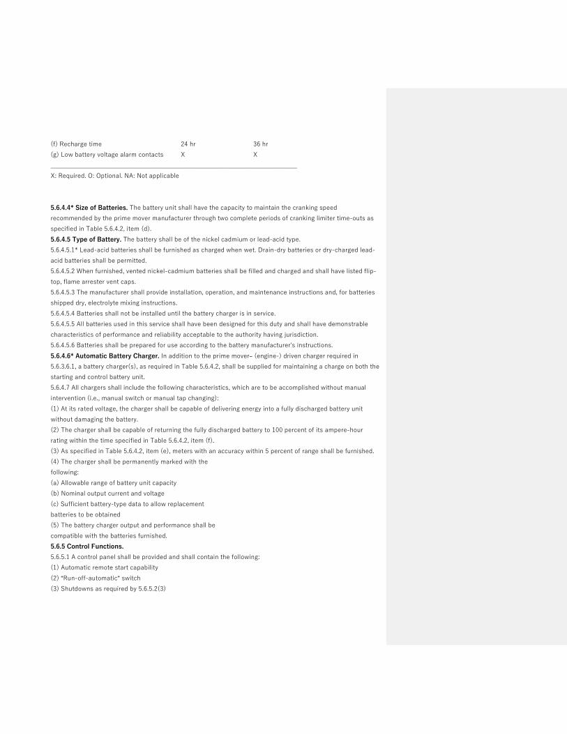
(f) Recharge time 24 hr 36 hr
(g) Low battery voltage alarm contacts X X
______________________________________________________________________________
X: Required. O: Optional. NA: Not applicable
5.6.4.4* Size of Batteries. The battery unit shall have the capacity to maintain the cranking speed
recommended by the prime mover manufacturer through two complete periods of cranking limiter time-outs as
specified in Table 5.6.4.2, item (d).
5.6.4.5 Type of Battery. The battery shall be of the nickel cadmium or lead-acid type.
5.6.4.5.1* Lead-acid batteries shall be furnished as charged when wet. Drain-dry batteries or dry-charged lead-
acid batteries shall be permitted.
5.6.4.5.2 When furnished, vented nickel-cadmium batteries shall be filled and charged and shall have listed flip-
top, flame arrester vent caps.
5.6.4.5.3 The manufacturer shall provide installation, operation, and maintenance instructions and, for batteries
shipped dry, electrolyte mixing instructions.
5.6.4.5.4 Batteries shall not be installed until the battery charger is in service.
5.6.4.5.5 All batteries used in this service shall have been designed for this duty and shall have demonstrable
characteristics of performance and reliability acceptable to the authority having jurisdiction.
5.6.4.5.6 Batteries shall be prepared for use according to the battery manufacturer's instructions.
5.6.4.6* Automatic Battery Charger. In addition to the prime mover– (engine-) driven charger required in
5.6.3.6.1, a battery charger(s), as required in Table 5.6.4.2, shall be supplied for maintaining a charge on both the
starting and control battery unit.
5.6.4.7 All chargers shall include the following characteristics, which are to be accomplished without manual
intervention (i.e., manual switch or manual tap changing):
(1) At its rated voltage, the charger shall be capable of delivering energy into a fully discharged battery unit
without damaging the battery.
(2) The charger shall be capable of returning the fully discharged battery to 100 percent of its ampere-hour
rating within the time specified in Table 5.6.4.2, item (f).
(3) As specified in Table 5.6.4.2, item (e), meters with an accuracy within 5 percent of range shall be furnished.
(4) The charger shall be permanently marked with the
following:
(a) Allowable range of battery unit capacity
(b) Nominal output current and voltage
(c) Sufficient battery-type data to allow replacement
batteries to be obtained
(5) The battery charger output and performance shall be
compatible with the batteries furnished.
5.6.5 Control Functions.
5.6.5.1 A control panel shall be provided and shall contain the following:
(1) Automatic remote start capability
(2) “Run-off-automatic” switch
(3) Shutdowns as required by 5.6.5.2(3)

(4) Alarms as required by 5.6.5.2(4)
(5) Controls as required by 5.6.5.2(5)
5.6.5.2 Where a control panel is mounted on the energy converter, it shall be mounted by means of antivibration
shock mounts, if required, to maximize reliability. An automatic control and safety panel shall be a part of the
EPS containing the following equipment or possess the following characteristics, or both:
(1) Cranking control equipment to provide the complete cranking cycle described in 5.6.4.2 and required by Table
5.6.4.2
(2) Panel-mounted control switch(es) marked “run–off–automatic” to perform the following functions:
(a) Run: Manually initiate, start, and run prime mover
(b) Off: Stop prime mover or reset safeties, or both
(c) Automatic: Allow prime mover to start by closing a remote contact and stop by opening the remote contact
(3) Controls to shut down and lock out the prime mover under any of the following conditions:
(a) Failing to start after specified cranking time
(b) Overspeed
(c) Low lubricating-oil pressure
(d) High engine temperature (An automatic engine shutdown device for high lubricating-oil temperature shall
not be required.)
(e) Operation of remote manual stop station
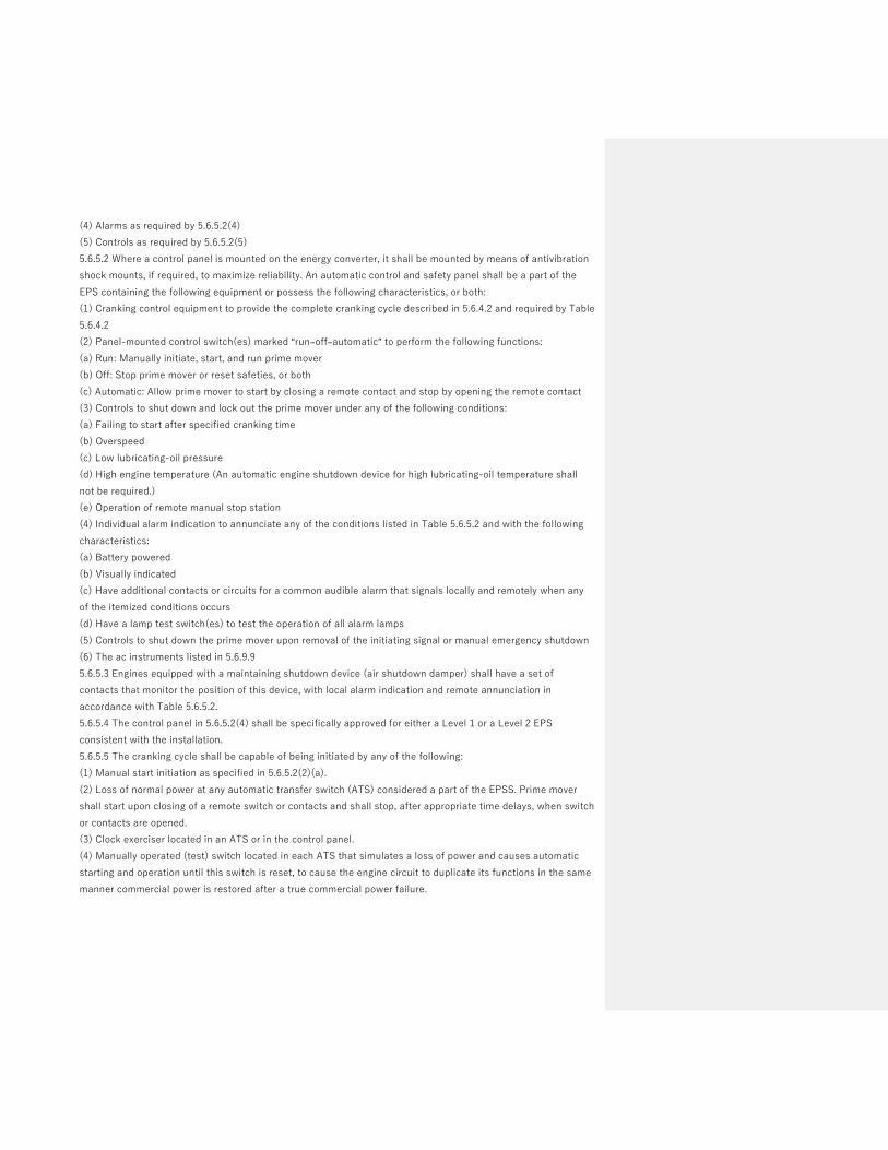
(4) Individual alarm indication to annunciate any of the conditions listed in Table 5.6.5.2 and with the following
characteristics:
(a) Battery powered
(b) Visually indicated
(c) Have additional contacts or circuits for a common audible alarm that signals locally and remotely when any
of the itemized conditions occurs
(d) Have a lamp test switch(es) to test the operation of all alarm lamps
(5) Controls to shut down the prime mover upon removal of the initiating signal or manual emergency shutdown
(6) The ac instruments listed in 5.6.9.9
5.6.5.3 Engines equipped with a maintaining shutdown device (air shutdown damper) shall have a set of
contacts that monitor the position of this device, with local alarm indication and remote annunciation in
accordance with Table 5.6.5.2.
5.6.5.4 The control panel in 5.6.5.2(4) shall be specifically approved for either a Level 1 or a Level 2 EPS
consistent with the installation.
5.6.5.5 The cranking cycle shall be capable of being initiated by any of the following:
(1) Manual start initiation as specified in 5.6.5.2(2)(a).
(2) Loss of normal power at any automatic transfer switch (ATS) considered a part of the EPSS. Prime mover
shall start upon closing of a remote switch or contacts and shall stop, after appropriate time delays, when switch
or contacts are opened.
(3) Clock exerciser located in an ATS or in the control panel.
(4) Manually operated (test) switch located in each ATS that simulates a loss of power and causes automatic
starting and operation until this switch is reset, to cause the engine circuit to duplicate its functions in the same
manner commercial power is restored after a true commercial power failure.

5.6.5.6* All installations shall have a remote manual stop station of a type to prevent inadvertent or unintentional
operation located outside the room housing the prime mover, where so installed, or elsewhere on the premises
where the prime mover is located outside the building.
5.6.5.6.1 The remote manual stop station shall be labeled.
5.6.6* Remote Controls and Alarms. A remote, common audible
alarm shall be provided as specified in 5.6.5.2(4).
5.6.6.1 Alarms and annunciation shall be powered by the prime mover starting battery unless operational
constraints make this impracticable. In that circumstance an alternate source from the EPS, such as a storage
battery, UPS, or branch circuit supplied by the EPSS, shall be permitted.
5.6.6.2 The following annunciation shall be provided at a minimum:
(1) For Level 1 EPS, local annunciation and facility remote annunciation, or local annunciation and network
remote annunciation
(2) For Level 2 EPS, local annunciation
5.6.6.3 For the purposes of defining the types of annunciation in 5.6.6.2, the following shall apply:
(1) Local annunciation is located on the equipment itself or within the same equipment room.
(2) Facility remote annunciation is located on site but not within the room where the equipment is located.
(3) Network remote annunciation is located off site.
5.6.6.4 An alarm-silencing means shall be provided, and the panel shall include repetitive alarm circuitry so that,
after the audible alarm has been silenced, it reactivates after the fault condition has been cleared and has to be
restored to its normal position to be silenced again.
5.6.6.5 In lieu of the requirement in 5.6.6.4, a manual alarm silencing means shall be permitted that silences the
audible alarm after the occurrence of the alarm condition, provided such means do not inhibit any subsequent
alarms from sounding the audible alarm again without further manual action.
5.6.7 Prime Mover Cooling Systems. Cooling systems for prime movers shall be either forced-air or natural
convection, liquid-cooled, or a combination thereof.
Table 5.6.5.2 Safety Indications and Shutdowns
5.6.7.1 Forced-air-cooled diesel or otto cycle engines shall have an integral fan selected to cool the prime mover
under full load conditions.
5.6.7.2 Liquid-cooled prime movers for Level 1 applications shall be arranged for closed-loop cooling and consist
of one of the following types:
(1) Unit-mounted radiator and fan
(2) Remote radiator
(3) Heat exchanger (liquid-to-liquid)
5.6.7.3 Cooling systems shall prevent overheating of prime movers under conditions of highest anticipated
ambient temperature at the installed elevation (above sea level) when fully loaded.
5.6.7.4* Power for fans and pumps on remote radiators and heat exchangers shall be supplied from a tap at the
EPS output terminals or ahead of the first load circuit overcurrent protective device.
5.6.7.5 The secondary side of heat exchangers shall be a closed-loop cycle, that is, one that recycles the cooling
agent

5.6.7.1 Forced-air-cooled diesel or otto cycle engines shall have an integral fan selected to cool the prime mover
under full load conditions.
5.6.7.2 Liquid-cooled prime movers for Level 1 applications shall be arranged for closed-loop cooling and consist
of one of the following types:
(1) Unit-mounted radiator and fan
(2) Remote radiator
(3) Heat exchanger (liquid-to-liquid)
5.6.7.3 Cooling systems shall prevent overheating of prime movers under conditions of highest anticipated
ambient temperature at the installed elevation (above sea level) when fully loaded.
5.6.7.4* Power for fans and pumps on remote radiators and heat exchangers shall be supplied from a tap at the
EPS output terminals or ahead of the first load circuit overcurrent protective device.
5.6.7.5 The secondary side of heat exchangers shall be a closed-loop cycle, that is, one that recycles the cooling
agent.
5.6.7.6 The installed EPS cooling system shall be designed to cool the prime mover at full-rated load while
operating in the particular installation circumstances of each EPS.
5.6.7.7 A full-load on-site test shall not result in activation of high-temperature pre-alarm or high-temperature
shutdown.
5.6.7.8 For EPSS cooling systems requiring intermittent or continuous waterflow or pressure, or both, a utility,
city, or other water supply service shall not be used.
5.6.7.9 The EPSS cooling system shall be permitted to use utility or city water for filling or makeup water.
5.6.7.10 Design of the EPS cooling system shall consider the following factors:
(1) Remote radiator or heat exchanger sizing
(2) Pipe sizing
(3) Pump sizing
(4) Sufficient shutoffs to isolate equipment to facilitate maintenance
(5) The need for and sizing of de-aeration and surge
(6) Drain valves for cleaning and flushing the cooling system
(7) Type of flexible hoses between the prime mover and the cooling system piping
5.6.8 Prime Mover Exhaust Piping. Where applicable, the exhaust system shall include a muffler or silencer sized
for the unit and a flexible exhaust section.
5.6.9 Generators, Exciters, and Voltage Regulators. Generators shall comply with Article 445 of NFPA 70,
National Electrical Code, and with the requirements of 5.6.9.1 through 5.6.9.9.
5.6.9.1* The generator shall be of drip-proof construction and have amortisseur windings.
5.6.9.2 The generator shall be suitable for the environmental conditions at the installation location.
5.6.9.3 The generator systems shall be factory tested as a unit to ensure operational integrity of all of the
following:
(1) Generator
(2) Exciter
(3) Voltage regulator
5.6.9.4 EPS voltage output, or the output of the transformer immediately down-line from the EPS, at full load
shall match the nominal voltage of the normal source at the transfer switch(es).
5.6.9.5 Exciters, where furnished, shall be of either the rotating type or the static type.

5.6.9.6 Voltage regulators shall be capable of responding to load changes to meet the system stability
requirements of 5.6.9.8.
5.6.9.7 If the system stability requirements of 5.6.9.8 cannot be accomplished, anti-hunt provisions shall be
included.
5.6.9.8 Generator system performance (i.e., prime mover, generator, exciter, and voltage regulator, as applicable
when prototype tested as specified in 5.2.1.2) shall be as follows:
(1) Stable voltage and frequency at all loads shall be provided to full-rated loads.
(2) Values consistent with the user's needs for frequency droop and voltage droop shall be maintained.
(3) Voltage dip at the generator terminals for the maximum anticipated load change shall not cause disruption or
relay dropout in the load.
(4) Frequency dip and restoration to steady state for any sudden load change shall not exceed the user's
specified need.
5.6.9.9 The generator instrument panel for Level 1 applications shall contain the following:
(1) An ac voltmeter(s) for each phase or a phase selector switch
(2) An ac ammeter(s) for each phase or a phase selector switch
(3) A frequency meter
(4) A voltage-adjusting feature to allow ± 5 percent voltage adjustment
5.6.10 Miscellaneous Requirements.
5.6.10.1 Where applicable, the prime mover and generator shall be factory mounted on a common base, rigid
enough to maintain the dynamic alignment of the rotating element of the system prior to shipment to the
installation site.
5.6.10.2 A certification shall be supplied with the unit that verifies the torsional vibration compatibility of the
rotating element of the prime mover and generator for the intended use of the energy converter.
5.6.10.3* Vibration isolators shall be furnished where necessary to minimize vibration transmission to the
permanent structure.
5.6.10.4 The manufacturer of the EPS shall submit complete schematic, wiring, and interconnection diagrams
showing all terminal and destination markings for all EPS equipment, as well as the functional relationship
between all electrical components.
5.6.10.5 The energy converter supplier shall stipulate compliance and performance with this standard for the
entire unit when installed.
5.6.10.6 Where requested, the short circuit current capability at the generator output terminals shall be
furnished.
5.7 Fuel Cell System Equipment
5.7.1 General. Fuel cell systems and accessories shall comply with NFPA 853, Standard for the Installation of
Stationary Fuel Cell Power Systems, except as modified in this standard.
5.7.1.1* Fuel cells are classified by the type of electrolyte used (see 5.2.4). A5.7.1.1 There is a difference in start-up ramp time to full power based on the fuel cell type ranging from seconds to hours. During start-up, fuel cells have an average power output until they reach full power. If needed, additional power supplied from another source, such as a battery or ultra-capacitor, assists with powering the intended load during this time. Fuel cell systems that require high operating temperatures ramp slowly until they

reach full power and an additional start-up power source is not necessary. For these types of fuel cells, they are typically run continuously in order to provide emergency power in the required time period.
5.7.2 Fuel Cell System Ratings. Proper derating factors, such as altitudes, ambient temperature, fuel energy
content, accessory losses, and site conditions as recommended by the manufacturer of the fuel cell system shall
be used in determining whether or not the fuel cell system meets the connected load requirements.
5.7.3 Fuel Cell System Accessories.
5.7.3.1 Fuel Cell System controls/power conditioning systems shall maintain a bandwidth of rated frequency for
any constant load (steady-state condition) that is compatible with the load.
5.7.3.1.1 The frequency droop between no load and full load shall be within the range for the load.
5.7.3.1.2 The frequency dip upon one-step application of the full load shall not be outside the range for the load,
with a return to steady-state conditions occurring within the requirements of the load.
5.7.3.2 Solenoid valves, where used in the fuel line from the supply closest to the fuel cell system and in water-
cooling lines, shall operate from battery voltage.
5.7.3.2.1 Solenoid valves shall have a manual (nonelectric) operation, or a manual bypass valve shall be
provided.
5.7.3.2.1.1 The manual bypass valve shall be visible and accessible and its purpose identified.
5.7.3.2.1.2 The fuel bypass valve shall not be the valve used for malfunction or emergency shutdown.
5.7.3.3 The fuel cell system shall be provided with the following instruments when necessary:
(1) Temperature gauge to indicate cooling medium temperature when a liquid medium cooling system is used
(2) Hour meter to indicate actual total running time
(3) Battery-charging meter indicating performance of fuel cell system powered battery charging means
(4) Other instruments as recommended or provided by the fuel cell system manufacturer where required for
maintenance
5.7.3.4 The instruments required in 5.7.3.3(1) through 5.7.3.3(4) shall be placed on an enclosed panel, located in
proximity to or on the fuel cell system, in a location that allows maintenance personnel to observe them readily.
5.7.3.5 All external wiring for connections to the fuel cell system and its parts, if applicable, shall be in
accordance with Article 692 of NFPA 70.
5.7.3.6 Where applicable, the fuel cell system set shall be fitted with an integral accessory battery charger,
powered by the fuel cell system and automatic controls for charging and maintaining the starting battery unit
(and control battery, where used) in a fully charged condition during a running condition.
Commented [CP5]: Should this be part of Annex A?
Commented [CP6]: Need clarification on the intent of this requirement. Why does the valve need to operate from battery voltage?
Commented [CP7]: Need clarification on intent of this requirement. Is it that a manual bypass valve is required if an electric valve is the primary one?
Commented [CP8]: Can this be the main fuel line valve to the overall fuel cell system?
Commented [CP9]: Not sure of the intent of this valve. It is not requiring a fuel bypass valve for fuel cell systems, correct? Fuel cell systems that are continuously running normally only have one source of fuel, so they primarily have a fuel shutoff valve, not a fuel bypass valve. Also, emergency shutdown of the system, not just fuel?
Formatted: Highlight
Commented [CP10]: Some fuel cell systems are monitored remotely 24/7 and run time data is collected off-site. SOFC are run 24/7 from pipeline natural gas, so not sure if hour meter is needed.
Commented [CP11]: Could be monitored off-site.
Formatted: Highlight
Commented [CP12]: If this information is monitored off-site, this panel would not be necessary. In the case of the Bloom Energy system, maintenance personnel are BE field service staff and they monitor the system from a laptop. Customers also have limited access viewing capability of their system’s operation.
Formatted: Highlight

5.7.4 Fuel Cell System Starting Equipment.
5.7.4.1* Starting Systems. Where applicable, starting shall be accomplished using a stored energy starting
system.
A5.7.4.1 Some fuel cell systems use power from the utility grid for start-up until the fuel cell system is up to
operational status, then it disconnects from grid power and runs independently of the grid.
5.7.4.1.1 Other types of stored energy starting systems (except pyrotechnic) shall be permitted to be used where
recommended by the manufacturer of the fuel cell system and subject to approval of the authority having
jurisdiction, under the following conditions:
(1) Where a means for automatic restoration from the emergency source of the stored energy is provided
(3) Where the stored energy system has the capacity to handle the intended loads until the fuel cell system is
operating
(4) Where the stored energy system has a “black start” capability in addition to normal discharge capability.
5.7.4.3.1 Number of Batteries. Where applicable, a fuel cell system shall be provided with batteries for startup
until the fuel cell system is operating to provide the necessary power to the loads. The fuel cell system shall be
provided with one of the following:
(1) Storage battery units as specified in Table 5.7.4.2, or
(2) Battery or capacitor storage systems that are either incorporated as part of the fuel cell system or installed
as a separate accessory such as a battery rack or storage system.
Table 5.7.4.2 Fuel Cell Starting Equipment Requirements
Fuel Cell Starting Equipment Requirements
____________________________________________________________________________________________________
Level 1 Level 2
(a) Battery Units X X
(b) Battery Certification X X (for other than LA and Nickel)
(c) Power to load 45 sec 45 sec
(d) Automatic battery charger (BMS control) X X
(e) Maximum Recharge time 24 H 36 H
(f) Low battery voltage alarm contacts X X
X: Required. O: Optional
5.7.4.4* Size of Batteries. A battery unit or other storage system provided for startup power for a fuel cell
system shall be sized to provide power to the necessary loads until the fuel cell power system is operating.
5.7.4.5 Type of Battery. The battery shall be of the nickel cadmium, lead-acid type or as noted in 5.7.4.5.3.
Commented [CP13]: Some FC systems use power from the grid for start-up until the FC is up to Balance of Plant status, then it disconnects from grid power and runs independently on NG.
Commented [FLB14R13]: I added Chris explanation above with a few tweaks as annex material.
Commented [FLB15]: Get rid of old technology specific criteria. BMS control that is evaluated per

5.7.4.5.1 Lead-acid batteries shall be furnished as charged when wet. Drain-dry batteries or dry-charged lead-
acid batteries shall be permitted.
5.7.4.5.2 When furnished, vented nickel-cadmium batteries shall be filled and charged and shall have listed flip-
top, flame arrester vent caps.
5.7.4.5.3 In addition to nickel cadmium and lead acid batteries, fuel cell systems may utilize other technology
batteries (e.g. lithium ion) or storage capacitor technology for starting applications. These other storage system
technologies shall be listed to UL 1973.
5.7.4.5.4The manufacturer shall provide installation, operation, and maintenance instructions for the batteries in
accordance with their listing.
5.7.4.5.5 Batteries or capacitor units shall not be installed until their charging mechanism is installed if separate
from the battery or capacitor unit.
5.7.4.5.6 All start up storage systems used in this service shall have been designed for this duty and shall have
demonstrable characteristics of performance and reliability acceptable to the authority having jurisdiction.
5.7.4.5.7 Batteries or capacitors shall be prepared for use according to the battery/capacitor manufacturer's
instructions.
5.7.4.6 Automatic Battery Charger. A battery charger(s), as required in Table 5.7.4.2, shall be supplied for
maintaining a charge on both starting and control battery units as applicable to the fuel cell system.
5.7.4.7 All chargers shall include the following characteristics, which are to be accomplished without manual
intervention (i.e., manual switch or manual tap changing):
(1) At its rated voltage, the charger shall be capable of delivering energy into a fully discharged battery unit
without damaging the battery.
(2) The charger shall be capable of returning the fully discharged battery to 100 percent of its ampere-hour
rating within the time specified in Table 5.7.4.2, item (e).
(3) For float type chargers, meters with an accuracy within 5 percent of range shall be furnished.
(4) The charger, if a separate accessory for charging lead acid or Ni-cad batteries, shall be permanently marked
with the following:
(a) Allowable range of battery unit capacity
(b) Nominal output current and voltage
(c) Sufficient battery-type data to allow replacement batteries to be obtained
(5) The battery charger output and performance shall be compatible with the batteries furnished.
5.7.5 Control Functions.
5.7.5.1 An on-site control panel or remote monitoring control system shall be provided and shall contain the
following:
Commented [CP16]: A remote monitoring control system may be offsite and a panel may not be a required part of the fuel cell system. Items 3-5 apply to FC systems that run continuously.

(1) Automatic remote start capability
(2) “Run-off-automatic” switch function
(3) Shutdowns as required by 5.7.5.2(2)
(4) Alarms as required by 5.7.5.2(3)
(5) Controls as required by 5.7.5.2(4)
5.7.5.2 An automatic control and safety panel or remote monitoring control system shall be a part of the EPS
containing the following equipment or possess the following characteristics, or both:
(1) Panel-mounted control switch(es) marked “run–off–automatic” to perform the following functions for quick-
start fuel cell power systems:
(a) Run: Manually initiate, start of fuel cell system
(b) Off: Stop fuel cell system or reset safeties, or both
(c) Automatic: Allow fuel cell system to start by closing a remote contact and stop by opening the remote
contact
(2) Controls to shut down and lock out the fuel cell system under any of the following conditions:
(a) Failing to start after specified time
(b) Abnormal conditions including high temperatures
(c) Operation of remote manual stop station
(3) Individual alarm indication on a control panel to annunciate any of the conditions listed in Table 5.7.5.2 and
with the following
characteristics:
(a) Battery powered
(b) Visually indicated
(c) Have additional contacts or circuits for a common audible alarm that signals locally and remotely
when any of the itemized conditions occurs
(d) Have a lamp test switch(es) to test the operation of all alarm lamps
(54) Controls to shut down the fuel cell system upon removal of the initiating signal or manual emergency
shutdown
5.7.5.3 (reserved)
5.7.5.4 The control panel or remote monitoring control system in 5.7.5.2(4) shall be specifically approved for
either a Level 1 or a Level 2 EPS consistent with the installation.
5.7.5.5 The startup operation shall be capable of being initiated by any of the following:
(1) Manual start initiation as specified in 5.7.5.2(2)(a) for quick start-up fuel cell systems.
(2) Loss of normal power at any automatic transfer switch (ATS) considered a part of the EPSS. The fuel cell
system shall start-up or switch power to the load upon closing of a remote switch or contacts and shall stop,
after appropriate time delays, when switch or contacts are opened.
(3) Clock exerciser located in an ATS or in the control panel.
(4) Manually operated (test) switch located in each ATS that simulates a loss of power and causes automatic
starting and operation until this switch is reset, to cause the fuel cell system circuit to duplicate its functions in
the same manner commercial power is restored after a true commercial power failure.
Commented [CP17]: For FC systems that are running continuously in order to pick up the load when needed, this function should not be required. Maybe add a comment “for quick start-up fuel cell systems”.
Commented [CP18]: The word “function” is included for gen-sets. In the case of FC systems that are running continuously, this should not be necessary.
Commented [CP19]: This is a FC 1 requirement
Commented [CP20]: Need to add some separate requirements for remote monitoring control system
Commented [CP21]: Is “approved” equivalent to listed, or is it an AHJ’s decision?
Commented [CP22]: Not sure what this is.
Commented [CP23]: Need clarification on this.

5.7.5.6* All installations shall have a remote manual stop station of a type to prevent inadvertent or
unintentional operation located outside the room housing the fuel cell system, where so installed, or elsewhere
on the premises where the fuel cell system is located outside the building.
5.7.5.6.1 The remote manual stop station shall be labeled.
5.7.6* Remote Controls and Alarms. A remote, common audible alarm shall be provided as specified in
5.7.5.2(4). Remote controls and alarms for fuel cell systems shall be in accordance with 5.6.6.1 through 5.6.6.5
except as noted below.
5.7.6.1 Alarms and annunciation need not be powered by a starter battery if the fuel cell system does not rely
upon one (i.e. is under continuous operation).
5.7.7 Fuel Cell Cooling Systems. Cooling systems for fuel cell systems shall be either forced-air or natural
convection, liquid-cooled, or a combination thereof.
Commented [CP24]: If remote monitored, the alarm is for the monitoring station, correct?
Commented [CP25]: Should not be a requirement if a fuel cell system is run continuously and doesn’t use a starting battery.
Commented [FLB26R25]: Revised wording, as 5.6.6.1 allows options other than starting batteries. Changed statement to address continuously running fuel cell systems that do not employ a starting battery.

Public Comment No. 36-NFPA 110-2020 [ Section No. 5.2.4 ]
5.2.4
Rotating
EPS
5.2.4.1 EPS utilizing R r otating equipment shall consist of a generator driven by one of the following prime movertypes:
(1) Otto cycle (spark ignited)
(2) Diesel cycle
(3) Gas turbine cycle
5.2.4.
1
Other
2 EPS utilizing fuel cell systems shall consist of one or more of the following types:
(1) Proton exchange membrane (PEMFC)
(2) Solid oxide (SOFC)
(3) Molten carbonate (MCFC)
(4) Phosphoric acid (PAFC )
(5) Alkaline (AFC)
5.2.4. 2 . 3 For EPS utilizing rotating equipment, O o ther types of prime movers and their associated equipmentmeeting the applicable performance requirements of this standard shall be permitted, if acceptable to the authorityhaving jurisdiction.
5.2.4. 2
. 3 Where used for Level 1 applications, the a prime mover shall not mechanically drive any equipment otherthan its operating accessories and its generator . A fuel cell system shall not energize any other equipment other thanits operating accessories necessary to provide power for the Level 1 application .
Additional Proposed Changes
File Name Description Approved
NFPA_110_Section_5_Draft_for_submition_w_comments_05-06-2020.docx
Statement of Problem and Substantiation for Public Comment
Task group response to CI 9
Related Public Comments for This Document
Related Comment Relationship
Public Comment No. 35-NFPA 110-2020 [New Section after 5.2.1.1]
Related Item
• CI 9
Submitter Information Verification
National Fire Protection Association Report https://submittals.nfpa.org/TerraViewWeb/ContentFetcher?commentPar...
4 of 120 5/7/2020, 4:56 PM

Submitter Full Name: Ronald Smidt
Organization: Atrium Health
Street Address:
City:
State:
Zip:
Submittal Date: Wed May 06 12:00:58 EDT 2020
Committee: EPS-AAA
National Fire Protection Association Report https://submittals.nfpa.org/TerraViewWeb/ContentFetcher?commentPar...
5 of 120 5/7/2020, 4:56 PM

Note the following was produced by a Task group in response to Chair request on CI-9 Change are highlighted and total text will be up loaded with each submission. This is only CH 5 changes 5.2 Energy Converters — General.
5.2.1 Energy converters shall consist only of rotating equipment as indicated in 5.2.4.
5.2.1.1 Level 1 energy converters shall be representative products built from components that have proven
compatibility and reliability and are coordinated to operate as a unit.
5.2.1.1.1 Fuel Cell systems utilized as Level 1 energy converters shall be listed or field labeled to ANSI / CSA
FC1 .
5.2.1.2 The capability of the energy converter, with its controls and accessories, to survive without damage from
common and abnormal disturbances in actual load circuits shall be demonstrable demonstrated by tests on
separate prototype models, or by acceptable tests on the system components as performed by the component
suppliers, or by tests performed in the listing process for the assembly.
5.2.1.3 A separate prototype unit for a rotating type EPS shall be permitted to be utilized in a Level 1 or Level 2
installation, provided that all prototype tests produce no deleterious effects on the unit, and the authority having
jurisdiction, the owner, and the user are informed that the unit is the prototype test unit.
5.2.2* The A rotating equipment prototype unit shall be tested with all typical prime mover accessories that
affect its power output in place and operating, including, but not limited to, the following:
(1) Battery-charging alternator
(2) Water pump
(3) Radiator fan for unit-mounted radiators or oil coolers (or comparable load)
(4) Fuel pump and fuel filter(s)
(5) Air filter(s)
(6) Exhaust mufflers or restriction simulating the maximum backpressure recommended by the prime mover
manufacturer
5.2.3 The energy converter for Level 1 systems shall be specifically designed, assembled, and tested to ensure
system operation under the following conditions:
(1) Short circuits
(2) Load surges due to motor starting
(3) Elevator operations
(4) Silicon controlled rectifier (SCR) controllers
(5) X-ray Imaging equipment
(6) Overspeed, overtemperature, or overload
(7) Adverse environmental conditions
5.2.4 EPS
5.2.4.1 EPS utilizing Rrotating equipment shall consist of a generator driven by one of the following prime mover
types:
(1) Otto cycle (spark ignited)
(2) Diesel cycle
(3) Gas turbine cycle
5.2.4.2 EPS utilizing fuel cell systems shall consist of one or more of the following types:
(1) Proton exchange membrane (PEMFC)
(2) Solid oxide (SOFC)
(3) Molten carbonate (MCFC)

(4) Phosphoric acid (PAFC)
(5) Alkaline (AFC)
5.2.4.2.3 For EPS utilizing rotating equipment, Oother types of prime movers and their associated equipment
meeting the applicable performance requirements of this standard shall be permitted, if acceptable to the
authority having jurisdiction.
5.2.4. 2.3 Where used for Level 1 applications, the a prime mover shall not mechanically drive any equipment
other than its operating accessories and its generator. A fuel cell system shall not energize any other equipment
other than its operating accessories necessary to provide power for the Level 1 application.
5.2.5 The EPS shall be installed in accordance with NFPA 70, National Electrical Code.
5.2.5.1A fuel cell system EPS shall also be installed in accordance with NFPA 853, Installation Standard for
Stationary Fuel Cell Power Systems.
5.3 Energy Converters — Temperature Maintenance.
5.3.1 The EPS shall be heated as necessary to maintain the water jacket and battery temperature determined by
the EPS manufacturer for cold start and load acceptance for the type of EPSS.
5.3.1.1 A fuel cell system type EPS shall be provided with a thermal management system determined sufficient
in accordance with its listing and intended installation location for cold start, if applicable, and load acceptance
for the type of EPSS.
5.3.2 All prime mover heaters shall be automatically deactivated while the prime mover is running. (For
combustion turbines, see 5.3.5.)
5.3.2.1 Air-cooled prime movers shall be permitted to employ a heater to maintain lubricating oil temperature as
recommended by the prime mover manufacturer.
5.3.3 Antifreeze protection shall be provided according to the manufacturer's recommendations.
5.3.4 Ether-type starting aids shall not be permitted.
5.3.5 The ambient air temperature in the EPS equipment room or outdoor housing containing Level I rotating
equipment shall be not less than 4.5°C (40°F).
5.3.6 Fuel cell systems EPS shall be provided with a thermal management system in accordance with its listing.
Fuel cell system EPS shall be installed in accordance with their its listing and manufacturer’s recommended
installation instructions and specifications.
*A5.3.6 The type of thermal management system utilized by a fuel cell system will will be permitted to vary
depending upon the type of fuel cell system and the limitations of its intended installation (e.g. outdoors or
indoors in a controlled environment). Therefore, the fuel cell system is to be installed in accordance with the
manufacturer’s recommended installation instructions and system specifications, and in accordance with its
listing. The ability of the thermal management system to maintain the fuel cell system within its operating
parameters in accordance with its intended installation environment are evaluated as part of its listing.
5.4* Energy Converters — Capacity. The energy converters shall have the required capacity and response to
pick up and carry the load within the time specified in Table 4.1(b) after loss of primary power.
5.5 Energy Converters — Fuel Supply.
5.5.1 The fuel supplies specified in 5.1.1(1) and 5.1.1(2) for energy converters intended for Level 1 use shall not
be used for any other purpose. (For fuel system requirements, see Section 7.9.)
5.5.1.1 Enclosed fuel tanks shall be permitted to be used for supplying fuel for other equipment, provided that
the drawdown level or other passive features are designed into the fuel system to guarantee that the required
quantity of fuel is available for the EPSS.
Commented [CP1]: Do we need to separate rotating equipment vs. fuel cells for clarification between the two?
Commented [RS2R1]: Yes iI think we do.
Commented [RS3]: This section is specific to rotating equipment. I am struggling with how to seprate out the rotation from the fuel cell.
Commented [CP4]: Some EPS fuel cell systems are not intended to be cold started due to long ramp times to full power.

5.5.1.2 Vapor-withdrawal LP-Gas systems shall have a dedicated fuel supply.
5.5.2* A low-fuel sensing switch shall be provided for the main fuel supply tank(s) using the energy sources
listed in 5.1.1(1) and 5.1.1(2) to indicate when less than the minimum fuel necessary for full load running, as
required by the specified class in Table 4.1(a), remains in the main fuel tank.
5.5.3* The main fuel tank shall have a minimum capacity of at least 133 percent of either the low-fuel sensor
quantity specified in 5.5.2 or the quantity required to support the duration of run specified in Table 4.1(a).
5.6 Rotating Equipment.
5.6.1 General. Prime movers and accessories shall comply with NFPA 37, Standard for the Installation and Use
of Stationary Combustion Engines and Gas Turbines, except as modified in this standard.
5.6.2 Prime Mover Ratings. Proper derating factors, such as altitudes, ambient temperature, fuel energy
content, accessory losses, and site conditions as recommended by the manufacturer of the generator set shall
be used in determining whether or not brake power meets the connected load requirements.
5.6.3 Prime Mover Accessories.
5.6.3.1 Governors shall maintain a bandwidth of rated frequency for any constant load (steady-state condition)
that is compatible with the load.
5.6.3.1.1 The frequency droop between no load and full load shall be within the range for the load.
5.6.3.1.2 The frequency dip upon one-step application of the full load shall not be outside the range for the load,
with a return to steady-state conditions occurring within the requirements of the load.
5.6.3.2 Solenoid valves, where used, both in the fuel line from the supply or day tank closest to the generator set
and in the water-cooling lines, shall operate from battery voltage.
5.6.3.2.1 Solenoid valves shall have a manual (nonelectric) operation, or a manual bypass valve shall be
provided.
5.6.3.2.1.1 The manual bypass valve shall be visible and accessible and its purpose identified.
5.6.3.2.1.2 The fuel bypass valve shall not be the valve used for malfunction or emergency shutdown.
5.6.3.3 The prime mover shall be provided with the following instruments:
(1) Oil pressure gauge to indicate lubricating oil pressure when a pressurized lubricating system is provided
(2) Temperature gauge to indicate cooling medium temperature when a liquid medium cooling system is used
(3) Hour meter to indicate actual total running time
(4) Battery-charging meter indicating performance of prime mover–driven battery charging means
(5) Other instruments as recommended or provided by the prime mover manufacturer where required for
maintenance
5.6.3.4 The instruments required in 5.6.3.3(1) through
5.6.3.3(4) shall be placed on an enclosed panel, located in proximity to or on the energy converter, in a location
that allows maintenance personnel to observe them readily. The enclosed panel shall be mounted by means of
antishock vibration mountings if mounted on the energy converter.
5.6.3.5 All wiring for connection to the control panel shall be harnessed or flexibly enclosed, shall be securely
mounted on the prime mover to prevent chafing and vibration damage, and shall terminate at the control panel
in an enclosed box or panel. (For control panel requirements, see 5.6.5.)
5.6.3.6 The generator set shall be fitted with an integral accessory battery charger, driven by the prime mover
and automatic voltage regulator, and capable of charging and maintaining the starting battery unit (and control
battery, where used) in a fully charged condition during a running condition.

5.6.3.6.1 A battery charger driven by the prime mover shall not be required, provided the automatic battery
charger has a highlow rate capable of fully charging the starting battery during running conditions as specified in
5.6.3.6.
5.6.4 Prime Mover Starting Equipment.
5.6.4.1 Starting Systems. Starting shall be accomplished using either an electric starter or a stored energy
starting system.
5.6.4.1.1 Electric starter systems shall start using a positive shift solenoid to engage the starter motor and to
crank the prime mover for the period specified in 5.6.4.2 without overheating, at a speed at least equal to that
recommended by the manufacturer of the prime mover and at the lowest ambient temperature anticipated at the
installation site.
5.6.4.1.2 Other types of stored energy starting systems (except pyrotechnic) shall be permitted to be used where
recommended by the manufacturer of the prime mover and subject to approval of the authority having
jurisdiction, under the following conditions:
(1) Where two complete periods of cranking cycles are completed without replacement of the stored energy
(2) Where a means for automatic restoration from the emergency source of the stored energy is provided
(3) Where the stored energy system has the cranking capacity specified in 5.6.4.2.1
(4) Where the stored energy system has a “black start” capability in addition to normal discharge capability
5.6.4.2* Otto or Diesel Cycle Prime Movers. For otto or diesel cycle prime movers, the type and duration of the
cranking cycle shall be as specified in Table 5.6.4.2.
5.6.4.2.1 A complete cranking cycle shall consist of an automatic crank period of approximately 15 seconds
followed by a rest period of approximately 15 seconds. Upon starting and running the prime mover, further
cranking shall cease.
5.6.4.2.2 Two means of cranking termination shall be utilized so that one serves as backup to prevent
inadvertent starter engagement.
5.6.4.2.3 Otto cycle prime movers of 15 kW and lower and all diesel prime movers shall be permitted to use
continuous cranking methods.
5.6.4.3* Number of Batteries. Each prime mover shall be provided with both of the following:
(1) Storage battery units as specified in Table 5.6.4.2
(2) A storage rack for each battery or battery unit
Table 5.6.4.2 Starting Equipment Requirements
Starting Equipment Requirements
_________________________________________________________________________________________
Level 1 Level 2
(a) Battery unit X X
(b) Battery certification X NA
(c) Cycle cranking X or O O
(d) Cranking limiter time-outs
Cycle crank (3 cycles) 75 sec 75 sec
Continuous crank 45 sec 45 sec
(e) Float-type battery charger X X
dc ammeter X X
dc voltmeter X X

(f) Recharge time 24 hr 36 hr
(g) Low battery voltage alarm contacts X X
______________________________________________________________________________
X: Required. O: Optional. NA: Not applicable
5.6.4.4* Size of Batteries. The battery unit shall have the capacity to maintain the cranking speed
recommended by the prime mover manufacturer through two complete periods of cranking limiter time-outs as
specified in Table 5.6.4.2, item (d).
5.6.4.5 Type of Battery. The battery shall be of the nickel cadmium or lead-acid type.
5.6.4.5.1* Lead-acid batteries shall be furnished as charged when wet. Drain-dry batteries or dry-charged lead-
acid batteries shall be permitted.
5.6.4.5.2 When furnished, vented nickel-cadmium batteries shall be filled and charged and shall have listed flip-
top, flame arrester vent caps.
5.6.4.5.3 The manufacturer shall provide installation, operation, and maintenance instructions and, for batteries
shipped dry, electrolyte mixing instructions.
5.6.4.5.4 Batteries shall not be installed until the battery charger is in service.
5.6.4.5.5 All batteries used in this service shall have been designed for this duty and shall have demonstrable
characteristics of performance and reliability acceptable to the authority having jurisdiction.
5.6.4.5.6 Batteries shall be prepared for use according to the battery manufacturer's instructions.
5.6.4.6* Automatic Battery Charger. In addition to the prime mover– (engine-) driven charger required in
5.6.3.6.1, a battery charger(s), as required in Table 5.6.4.2, shall be supplied for maintaining a charge on both the
starting and control battery unit.
5.6.4.7 All chargers shall include the following characteristics, which are to be accomplished without manual
intervention (i.e., manual switch or manual tap changing):
(1) At its rated voltage, the charger shall be capable of delivering energy into a fully discharged battery unit
without damaging the battery.
(2) The charger shall be capable of returning the fully discharged battery to 100 percent of its ampere-hour
rating within the time specified in Table 5.6.4.2, item (f).
(3) As specified in Table 5.6.4.2, item (e), meters with an accuracy within 5 percent of range shall be furnished.
(4) The charger shall be permanently marked with the
following:
(a) Allowable range of battery unit capacity
(b) Nominal output current and voltage
(c) Sufficient battery-type data to allow replacement
batteries to be obtained
(5) The battery charger output and performance shall be
compatible with the batteries furnished.
5.6.5 Control Functions.
5.6.5.1 A control panel shall be provided and shall contain the following:
(1) Automatic remote start capability
(2) “Run-off-automatic” switch
(3) Shutdowns as required by 5.6.5.2(3)
(4) Alarms as required by 5.6.5.2(4)
(5) Controls as required by 5.6.5.2(5)
5.6.5.2 Where a control panel is mounted on the energy converter, it shall be mounted by means of antivibration
shock mounts, if required, to maximize reliability. An automatic control and safety panel shall be a part of the
EPS containing the following equipment or possess the following characteristics, or both:
(1) Cranking control equipment to provide the complete cranking cycle described in 5.6.4.2 and required by Table
5.6.4.2
(2) Panel-mounted control switch(es) marked “run–off–automatic” to perform the following functions:
(a) Run: Manually initiate, start, and run prime mover
(b) Off: Stop prime mover or reset safeties, or both
(c) Automatic: Allow prime mover to start by closing a remote contact and stop by opening the remote contact
(3) Controls to shut down and lock out the prime mover under any of the following conditions:
(a) Failing to start after specified cranking time
(b) Overspeed
(c) Low lubricating-oil pressure
(d) High engine temperature (An automatic engine shutdown device for high lubricating-oil temperature shall
not be required.)
(e) Operation of remote manual stop station
(4) Individual alarm indication to annunciate any of the conditions listed in Table 5.6.5.2 and with the following
characteristics:
(a) Battery powered
(b) Visually indicated
(c) Have additional contacts or circuits for a common audible alarm that signals locally and remotely when any
of the itemized conditions occurs
(d) Have a lamp test switch(es) to test the operation of all alarm lamps
(5) Controls to shut down the prime mover upon removal of the initiating signal or manual emergency shutdown
(6) The ac instruments listed in 5.6.9.9
5.6.5.3 Engines equipped with a maintaining shutdown device (air shutdown damper) shall have a set of
contacts that monitor the position of this device, with local alarm indication and remote annunciation in
accordance with Table 5.6.5.2.
5.6.5.4 The control panel in 5.6.5.2(4) shall be specifically approved for either a Level 1 or a Level 2 EPS
consistent with the installation.
5.6.5.5 The cranking cycle shall be capable of being initiated by any of the following:
(1) Manual start initiation as specified in 5.6.5.2(2)(a).
(2) Loss of normal power at any automatic transfer switch (ATS) considered a part of the EPSS. Prime mover
shall start upon closing of a remote switch or contacts and shall stop, after appropriate time delays, when switch
or contacts are opened.
(3) Clock exerciser located in an ATS or in the control panel.
(4) Manually operated (test) switch located in each ATS that simulates a loss of power and causes automatic
starting and operation until this switch is reset, to cause the engine circuit to duplicate its functions in the same
manner commercial power is restored after a true commercial power failure.

5.6.5.6* All installations shall have a remote manual stop station of a type to prevent inadvertent or unintentional
operation located outside the room housing the prime mover, where so installed, or elsewhere on the premises
where the prime mover is located outside the building.
5.6.5.6.1 The remote manual stop station shall be labeled.
5.6.6* Remote Controls and Alarms. A remote, common audible
alarm shall be provided as specified in 5.6.5.2(4).
5.6.6.1 Alarms and annunciation shall be powered by the prime mover starting battery unless operational
constraints make this impracticable. In that circumstance an alternate source from the EPS, such as a storage
battery, UPS, or branch circuit supplied by the EPSS, shall be permitted.
5.6.6.2 The following annunciation shall be provided at a minimum:
(1) For Level 1 EPS, local annunciation and facility remote annunciation, or local annunciation and network
remote annunciation
(2) For Level 2 EPS, local annunciation
5.6.6.3 For the purposes of defining the types of annunciation in 5.6.6.2, the following shall apply:
(1) Local annunciation is located on the equipment itself or within the same equipment room.
(2) Facility remote annunciation is located on site but not within the room where the equipment is located.
(3) Network remote annunciation is located off site.
5.6.6.4 An alarm-silencing means shall be provided, and the panel shall include repetitive alarm circuitry so that,
after the audible alarm has been silenced, it reactivates after the fault condition has been cleared and has to be
restored to its normal position to be silenced again.
5.6.6.5 In lieu of the requirement in 5.6.6.4, a manual alarm silencing means shall be permitted that silences the
audible alarm after the occurrence of the alarm condition, provided such means do not inhibit any subsequent
alarms from sounding the audible alarm again without further manual action.
5.6.7 Prime Mover Cooling Systems. Cooling systems for prime movers shall be either forced-air or natural
convection, liquid-cooled, or a combination thereof.
Table 5.6.5.2 Safety Indications and Shutdowns
5.6.7.1 Forced-air-cooled diesel or otto cycle engines shall have an integral fan selected to cool the prime mover
under full load conditions.
5.6.7.2 Liquid-cooled prime movers for Level 1 applications shall be arranged for closed-loop cooling and consist
of one of the following types:
(1) Unit-mounted radiator and fan
(2) Remote radiator
(3) Heat exchanger (liquid-to-liquid)
5.6.7.3 Cooling systems shall prevent overheating of prime movers under conditions of highest anticipated
ambient temperature at the installed elevation (above sea level) when fully loaded.
5.6.7.4* Power for fans and pumps on remote radiators and heat exchangers shall be supplied from a tap at the
EPS output terminals or ahead of the first load circuit overcurrent protective device.
5.6.7.5 The secondary side of heat exchangers shall be a closed-loop cycle, that is, one that recycles the cooling
agent

5.6.7.1 Forced-air-cooled diesel or otto cycle engines shall have an integral fan selected to cool the prime mover
under full load conditions.
5.6.7.2 Liquid-cooled prime movers for Level 1 applications shall be arranged for closed-loop cooling and consist
of one of the following types:
(1) Unit-mounted radiator and fan
(2) Remote radiator
(3) Heat exchanger (liquid-to-liquid)
5.6.7.3 Cooling systems shall prevent overheating of prime movers under conditions of highest anticipated
ambient temperature at the installed elevation (above sea level) when fully loaded.
5.6.7.4* Power for fans and pumps on remote radiators and heat exchangers shall be supplied from a tap at the
EPS output terminals or ahead of the first load circuit overcurrent protective device.
5.6.7.5 The secondary side of heat exchangers shall be a closed-loop cycle, that is, one that recycles the cooling
agent.
5.6.7.6 The installed EPS cooling system shall be designed to cool the prime mover at full-rated load while
operating in the particular installation circumstances of each EPS.
5.6.7.7 A full-load on-site test shall not result in activation of high-temperature pre-alarm or high-temperature
shutdown.
5.6.7.8 For EPSS cooling systems requiring intermittent or continuous waterflow or pressure, or both, a utility,
city, or other water supply service shall not be used.
5.6.7.9 The EPSS cooling system shall be permitted to use utility or city water for filling or makeup water.
5.6.7.10 Design of the EPS cooling system shall consider the following factors:
(1) Remote radiator or heat exchanger sizing
(2) Pipe sizing
(3) Pump sizing
(4) Sufficient shutoffs to isolate equipment to facilitate maintenance
(5) The need for and sizing of de-aeration and surge
(6) Drain valves for cleaning and flushing the cooling system
(7) Type of flexible hoses between the prime mover and the cooling system piping
5.6.8 Prime Mover Exhaust Piping. Where applicable, the exhaust system shall include a muffler or silencer sized
for the unit and a flexible exhaust section.
5.6.9 Generators, Exciters, and Voltage Regulators. Generators shall comply with Article 445 of NFPA 70,
National Electrical Code, and with the requirements of 5.6.9.1 through 5.6.9.9.
5.6.9.1* The generator shall be of drip-proof construction and have amortisseur windings.
5.6.9.2 The generator shall be suitable for the environmental conditions at the installation location.
5.6.9.3 The generator systems shall be factory tested as a unit to ensure operational integrity of all of the
following:
(1) Generator
(2) Exciter
(3) Voltage regulator
5.6.9.4 EPS voltage output, or the output of the transformer immediately down-line from the EPS, at full load
shall match the nominal voltage of the normal source at the transfer switch(es).
5.6.9.5 Exciters, where furnished, shall be of either the rotating type or the static type.

5.6.9.6 Voltage regulators shall be capable of responding to load changes to meet the system stability
requirements of 5.6.9.8.
5.6.9.7 If the system stability requirements of 5.6.9.8 cannot be accomplished, anti-hunt provisions shall be
included.
5.6.9.8 Generator system performance (i.e., prime mover, generator, exciter, and voltage regulator, as applicable
when prototype tested as specified in 5.2.1.2) shall be as follows:
(1) Stable voltage and frequency at all loads shall be provided to full-rated loads.
(2) Values consistent with the user's needs for frequency droop and voltage droop shall be maintained.
(3) Voltage dip at the generator terminals for the maximum anticipated load change shall not cause disruption or
relay dropout in the load.
(4) Frequency dip and restoration to steady state for any sudden load change shall not exceed the user's
specified need.
5.6.9.9 The generator instrument panel for Level 1 applications shall contain the following:
(1) An ac voltmeter(s) for each phase or a phase selector switch
(2) An ac ammeter(s) for each phase or a phase selector switch
(3) A frequency meter
(4) A voltage-adjusting feature to allow ± 5 percent voltage adjustment
5.6.10 Miscellaneous Requirements.
5.6.10.1 Where applicable, the prime mover and generator shall be factory mounted on a common base, rigid
enough to maintain the dynamic alignment of the rotating element of the system prior to shipment to the
installation site.
5.6.10.2 A certification shall be supplied with the unit that verifies the torsional vibration compatibility of the
rotating element of the prime mover and generator for the intended use of the energy converter.
5.6.10.3* Vibration isolators shall be furnished where necessary to minimize vibration transmission to the
permanent structure.
5.6.10.4 The manufacturer of the EPS shall submit complete schematic, wiring, and interconnection diagrams
showing all terminal and destination markings for all EPS equipment, as well as the functional relationship
between all electrical components.
5.6.10.5 The energy converter supplier shall stipulate compliance and performance with this standard for the
entire unit when installed.
5.6.10.6 Where requested, the short circuit current capability at the generator output terminals shall be
furnished.
5.7 Fuel Cell System Equipment
5.7.1 General. Fuel cell systems and accessories shall comply with NFPA 853, Standard for the Installation of
Stationary Fuel Cell Power Systems, except as modified in this standard.
5.7.1.1* Fuel cells are classified by the type of electrolyte used (see 5.2.4). A5.7.1.1 There is a difference in start-up ramp time to full power based on the fuel cell type ranging from seconds to hours. During start-up, fuel cells have an average power output until they reach full power. If needed, additional power supplied from another source, such as a battery or ultra-capacitor, assists with powering the intended load during this time. Fuel cell systems that require high operating temperatures ramp slowly until they

reach full power and an additional start-up power source is not necessary. For these types of fuel cells, they are typically run continuously in order to provide emergency power in the required time period.
5.7.2 Fuel Cell System Ratings. Proper derating factors, such as altitudes, ambient temperature, fuel energy
content, accessory losses, and site conditions as recommended by the manufacturer of the fuel cell system shall
be used in determining whether or not the fuel cell system meets the connected load requirements.
5.7.3 Fuel Cell System Accessories.
5.7.3.1 Fuel Cell System controls/power conditioning systems shall maintain a bandwidth of rated frequency for
any constant load (steady-state condition) that is compatible with the load.
5.7.3.1.1 The frequency droop between no load and full load shall be within the range for the load.
5.7.3.1.2 The frequency dip upon one-step application of the full load shall not be outside the range for the load,
with a return to steady-state conditions occurring within the requirements of the load.
5.7.3.2 Solenoid valves, where used in the fuel line from the supply closest to the fuel cell system and in water-
cooling lines, shall operate from battery voltage.
5.7.3.2.1 Solenoid valves shall have a manual (nonelectric) operation, or a manual bypass valve shall be
provided.
5.7.3.2.1.1 The manual bypass valve shall be visible and accessible and its purpose identified.
5.7.3.2.1.2 The fuel bypass valve shall not be the valve used for malfunction or emergency shutdown.
5.7.3.3 The fuel cell system shall be provided with the following instruments when necessary:
(1) Temperature gauge to indicate cooling medium temperature when a liquid medium cooling system is used
(2) Hour meter to indicate actual total running time
(3) Battery-charging meter indicating performance of fuel cell system powered battery charging means
(4) Other instruments as recommended or provided by the fuel cell system manufacturer where required for
maintenance
5.7.3.4 The instruments required in 5.7.3.3(1) through 5.7.3.3(4) shall be placed on an enclosed panel, located in
proximity to or on the fuel cell system, in a location that allows maintenance personnel to observe them readily.
5.7.3.5 All external wiring for connections to the fuel cell system and its parts, if applicable, shall be in
accordance with Article 692 of NFPA 70.
5.7.3.6 Where applicable, the fuel cell system set shall be fitted with an integral accessory battery charger,
powered by the fuel cell system and automatic controls for charging and maintaining the starting battery unit
(and control battery, where used) in a fully charged condition during a running condition.
Commented [CP5]: Should this be part of Annex A?
Commented [CP6]: Need clarification on the intent of this requirement. Why does the valve need to operate from battery voltage?
Commented [CP7]: Need clarification on intent of this requirement. Is it that a manual bypass valve is required if an electric valve is the primary one?
Commented [CP8]: Can this be the main fuel line valve to the overall fuel cell system?
Commented [CP9]: Not sure of the intent of this valve. It is not requiring a fuel bypass valve for fuel cell systems, correct? Fuel cell systems that are continuously running normally only have one source of fuel, so they primarily have a fuel shutoff valve, not a fuel bypass valve. Also, emergency shutdown of the system, not just fuel?
Formatted: Highlight
Commented [CP10]: Some fuel cell systems are monitored remotely 24/7 and run time data is collected off-site. SOFC are run 24/7 from pipeline natural gas, so not sure if hour meter is needed.
Commented [CP11]: Could be monitored off-site.
Formatted: Highlight
Commented [CP12]: If this information is monitored off-site, this panel would not be necessary. In the case of the Bloom Energy system, maintenance personnel are BE field service staff and they monitor the system from a laptop. Customers also have limited access viewing capability of their system’s operation.
Formatted: Highlight

5.7.4 Fuel Cell System Starting Equipment.
5.7.4.1* Starting Systems. Where applicable, starting shall be accomplished using a stored energy starting
system.
A5.7.4.1 Some fuel cell systems use power from the utility grid for start-up until the fuel cell system is up to
operational status, then it disconnects from grid power and runs independently of the grid.
5.7.4.1.1 Other types of stored energy starting systems (except pyrotechnic) shall be permitted to be used where
recommended by the manufacturer of the fuel cell system and subject to approval of the authority having
jurisdiction, under the following conditions:
(1) Where a means for automatic restoration from the emergency source of the stored energy is provided
(3) Where the stored energy system has the capacity to handle the intended loads until the fuel cell system is
operating
(4) Where the stored energy system has a “black start” capability in addition to normal discharge capability.
5.7.4.3.1 Number of Batteries. Where applicable, a fuel cell system shall be provided with batteries for startup
until the fuel cell system is operating to provide the necessary power to the loads. The fuel cell system shall be
provided with one of the following:
(1) Storage battery units as specified in Table 5.7.4.2, or
(2) Battery or capacitor storage systems that are either incorporated as part of the fuel cell system or installed
as a separate accessory such as a battery rack or storage system.
Table 5.7.4.2 Fuel Cell Starting Equipment Requirements
Fuel Cell Starting Equipment Requirements
____________________________________________________________________________________________________
Level 1 Level 2
(a) Battery Units X X
(b) Battery Certification X X (for other than LA and Nickel)
(c) Power to load 45 sec 45 sec
(d) Automatic battery charger (BMS control) X X
(e) Maximum Recharge time 24 H 36 H
(f) Low battery voltage alarm contacts X X
X: Required. O: Optional
5.7.4.4* Size of Batteries. A battery unit or other storage system provided for startup power for a fuel cell
system shall be sized to provide power to the necessary loads until the fuel cell power system is operating.
5.7.4.5 Type of Battery. The battery shall be of the nickel cadmium, lead-acid type or as noted in 5.7.4.5.3.
Commented [CP13]: Some FC systems use power from the grid for start-up until the FC is up to Balance of Plant status, then it disconnects from grid power and runs independently on NG.
Commented [FLB14R13]: I added Chris explanation above with a few tweaks as annex material.
Commented [FLB15]: Get rid of old technology specific criteria. BMS control that is evaluated per

5.7.4.5.1 Lead-acid batteries shall be furnished as charged when wet. Drain-dry batteries or dry-charged lead-
acid batteries shall be permitted.
5.7.4.5.2 When furnished, vented nickel-cadmium batteries shall be filled and charged and shall have listed flip-
top, flame arrester vent caps.
5.7.4.5.3 In addition to nickel cadmium and lead acid batteries, fuel cell systems may utilize other technology
batteries (e.g. lithium ion) or storage capacitor technology for starting applications. These other storage system
technologies shall be listed to UL 1973.
5.7.4.5.4The manufacturer shall provide installation, operation, and maintenance instructions for the batteries in
accordance with their listing.
5.7.4.5.5 Batteries or capacitor units shall not be installed until their charging mechanism is installed if separate
from the battery or capacitor unit.
5.7.4.5.6 All start up storage systems used in this service shall have been designed for this duty and shall have
demonstrable characteristics of performance and reliability acceptable to the authority having jurisdiction.
5.7.4.5.7 Batteries or capacitors shall be prepared for use according to the battery/capacitor manufacturer's
instructions.
5.7.4.6 Automatic Battery Charger. A battery charger(s), as required in Table 5.7.4.2, shall be supplied for
maintaining a charge on both starting and control battery units as applicable to the fuel cell system.
5.7.4.7 All chargers shall include the following characteristics, which are to be accomplished without manual
intervention (i.e., manual switch or manual tap changing):
(1) At its rated voltage, the charger shall be capable of delivering energy into a fully discharged battery unit
without damaging the battery.
(2) The charger shall be capable of returning the fully discharged battery to 100 percent of its ampere-hour
rating within the time specified in Table 5.7.4.2, item (e).
(3) For float type chargers, meters with an accuracy within 5 percent of range shall be furnished.
(4) The charger, if a separate accessory for charging lead acid or Ni-cad batteries, shall be permanently marked
with the following:
(a) Allowable range of battery unit capacity
(b) Nominal output current and voltage
(c) Sufficient battery-type data to allow replacement batteries to be obtained
(5) The battery charger output and performance shall be compatible with the batteries furnished.
5.7.5 Control Functions.
5.7.5.1 An on-site control panel or remote monitoring control system shall be provided and shall contain the
following:
Commented [CP16]: A remote monitoring control system may be offsite and a panel may not be a required part of the fuel cell system. Items 3-5 apply to FC systems that run continuously.

(1) Automatic remote start capability
(2) “Run-off-automatic” switch function
(3) Shutdowns as required by 5.7.5.2(2)
(4) Alarms as required by 5.7.5.2(3)
(5) Controls as required by 5.7.5.2(4)
5.7.5.2 An automatic control and safety panel or remote monitoring control system shall be a part of the EPS
containing the following equipment or possess the following characteristics, or both:
(1) Panel-mounted control switch(es) marked “run–off–automatic” to perform the following functions for quick-
start fuel cell power systems:
(a) Run: Manually initiate, start of fuel cell system
(b) Off: Stop fuel cell system or reset safeties, or both
(c) Automatic: Allow fuel cell system to start by closing a remote contact and stop by opening the remote
contact
(2) Controls to shut down and lock out the fuel cell system under any of the following conditions:
(a) Failing to start after specified time
(b) Abnormal conditions including high temperatures
(c) Operation of remote manual stop station
(3) Individual alarm indication on a control panel to annunciate any of the conditions listed in Table 5.7.5.2 and
with the following
characteristics:
(a) Battery powered
(b) Visually indicated
(c) Have additional contacts or circuits for a common audible alarm that signals locally and remotely
when any of the itemized conditions occurs
(d) Have a lamp test switch(es) to test the operation of all alarm lamps
(54) Controls to shut down the fuel cell system upon removal of the initiating signal or manual emergency
shutdown
5.7.5.3 (reserved)
5.7.5.4 The control panel or remote monitoring control system in 5.7.5.2(4) shall be specifically approved for
either a Level 1 or a Level 2 EPS consistent with the installation.
5.7.5.5 The startup operation shall be capable of being initiated by any of the following:
(1) Manual start initiation as specified in 5.7.5.2(2)(a) for quick start-up fuel cell systems.
(2) Loss of normal power at any automatic transfer switch (ATS) considered a part of the EPSS. The fuel cell
system shall start-up or switch power to the load upon closing of a remote switch or contacts and shall stop,
after appropriate time delays, when switch or contacts are opened.
(3) Clock exerciser located in an ATS or in the control panel.
(4) Manually operated (test) switch located in each ATS that simulates a loss of power and causes automatic
starting and operation until this switch is reset, to cause the fuel cell system circuit to duplicate its functions in
the same manner commercial power is restored after a true commercial power failure.
Commented [CP17]: For FC systems that are running continuously in order to pick up the load when needed, this function should not be required. Maybe add a comment “for quick start-up fuel cell systems”.
Commented [CP18]: The word “function” is included for gen-sets. In the case of FC systems that are running continuously, this should not be necessary.
Commented [CP19]: This is a FC 1 requirement
Commented [CP20]: Need to add some separate requirements for remote monitoring control system
Commented [CP21]: Is “approved” equivalent to listed, or is it an AHJ’s decision?
Commented [CP22]: Not sure what this is.
Commented [CP23]: Need clarification on this.

5.7.5.6* All installations shall have a remote manual stop station of a type to prevent inadvertent or
unintentional operation located outside the room housing the fuel cell system, where so installed, or elsewhere
on the premises where the fuel cell system is located outside the building.
5.7.5.6.1 The remote manual stop station shall be labeled.
5.7.6* Remote Controls and Alarms. A remote, common audible alarm shall be provided as specified in
5.7.5.2(4). Remote controls and alarms for fuel cell systems shall be in accordance with 5.6.6.1 through 5.6.6.5
except as noted below.
5.7.6.1 Alarms and annunciation need not be powered by a starter battery if the fuel cell system does not rely
upon one (i.e. is under continuous operation).
5.7.7 Fuel Cell Cooling Systems. Cooling systems for fuel cell systems shall be either forced-air or natural
convection, liquid-cooled, or a combination thereof.
Commented [CP24]: If remote monitored, the alarm is for the monitoring station, correct?
Commented [CP25]: Should not be a requirement if a fuel cell system is run continuously and doesn’t use a starting battery.
Commented [FLB26R25]: Revised wording, as 5.6.6.1 allows options other than starting batteries. Changed statement to address continuously running fuel cell systems that do not employ a starting battery.

Public Comment No. 37-NFPA 110-2020 [ New Section after 5.2.5 ]
TITLE OF NEW CONTENT 5.2.5.1
5.2.5.1 A fuel cell system EPS shall also be installed in accordance with NFPA 853, Installation Standard forStationary Fuel Cell Power Systems .
Renumber exiting 5.2.5.1 to 5.2.5.2
Additional Proposed Changes
File Name Description Approved
NFPA_110_Section_5_Draft_for_submition_w_comments_05-06-2020.docx
Statement of Problem and Substantiation for Public Comment
Task group response to CI 9
Related Public Comments for This Document
Related Comment Relationship
Public Comment No. 33-NFPA 110-2020 [Section No. 5.1.1 [Excluding any Sub-Sections]]
Public Comment No. 34-NFPA 110-2020 [Section No. 5.2.1 [Excluding any Sub-Sections]]
Public Comment No. 35-NFPA 110-2020 [New Section after 5.2.1.1]
Related Item
• CI 9 •
Submitter Information Verification
Submitter Full Name: Ronald Smidt
Organization: Atrium Health
Street Address:
City:
State:
Zip:
Submittal Date: Wed May 06 12:09:02 EDT 2020
Committee: EPS-AAA
National Fire Protection Association Report https://submittals.nfpa.org/TerraViewWeb/ContentFetcher?commentPar...
6 of 120 5/7/2020, 4:56 PM

Public Comment No. 38-NFPA 110-2020 [ New Section after 5.3.1 ]
TITLE OF NEW CONTENT 5.3.1.1
5.3.1.1 A fuel cell system type EPS shall be provided with a thermal management system determined sufficient inaccordance with its listing and intended installation location for cold start , if applicable CP1] and load acceptance forthe type of EPSS.
Additional Proposed Changes
File Name Description Approved
NFPA_110_Section_5_Draft_for_submition_w_comments_05-06-2020.docx
Statement of Problem and Substantiation for Public Comment
Related Item
• CI 9
Submitter Information Verification
This PC has not been submitted yet
National Fire Protection Association Report https://submittals.nfpa.org/TerraViewWeb/ContentFetcher?commentPar...
7 of 120 5/7/2020, 4:56 PM

Note the following was produced by a Task group in response to Chair request on CI-9 Change are highlighted and total text will be up loaded with each submission. This is only CH 5 changes 5.2 Energy Converters — General.
5.2.1 Energy converters shall consist only of rotating equipment as indicated in 5.2.4.
5.2.1.1 Level 1 energy converters shall be representative products built from components that have proven
compatibility and reliability and are coordinated to operate as a unit.
5.2.1.1.1 Fuel Cell systems utilized as Level 1 energy converters shall be listed or field labeled to ANSI / CSA
FC1 .
5.2.1.2 The capability of the energy converter, with its controls and accessories, to survive without damage from
common and abnormal disturbances in actual load circuits shall be demonstrable demonstrated by tests on
separate prototype models, or by acceptable tests on the system components as performed by the component
suppliers, or by tests performed in the listing process for the assembly.
5.2.1.3 A separate prototype unit for a rotating type EPS shall be permitted to be utilized in a Level 1 or Level 2
installation, provided that all prototype tests produce no deleterious effects on the unit, and the authority having
jurisdiction, the owner, and the user are informed that the unit is the prototype test unit.
5.2.2* The A rotating equipment prototype unit shall be tested with all typical prime mover accessories that
affect its power output in place and operating, including, but not limited to, the following:
(1) Battery-charging alternator
(2) Water pump
(3) Radiator fan for unit-mounted radiators or oil coolers (or comparable load)
(4) Fuel pump and fuel filter(s)
(5) Air filter(s)
(6) Exhaust mufflers or restriction simulating the maximum backpressure recommended by the prime mover
manufacturer
5.2.3 The energy converter for Level 1 systems shall be specifically designed, assembled, and tested to ensure
system operation under the following conditions:
(1) Short circuits
(2) Load surges due to motor starting
(3) Elevator operations
(4) Silicon controlled rectifier (SCR) controllers
(5) X-ray Imaging equipment
(6) Overspeed, overtemperature, or overload
(7) Adverse environmental conditions
5.2.4 EPS
5.2.4.1 EPS utilizing Rrotating equipment shall consist of a generator driven by one of the following prime mover
types:
(1) Otto cycle (spark ignited)
(2) Diesel cycle
(3) Gas turbine cycle
5.2.4.2 EPS utilizing fuel cell systems shall consist of one or more of the following types:
(1) Proton exchange membrane (PEMFC)
(2) Solid oxide (SOFC)
(3) Molten carbonate (MCFC)
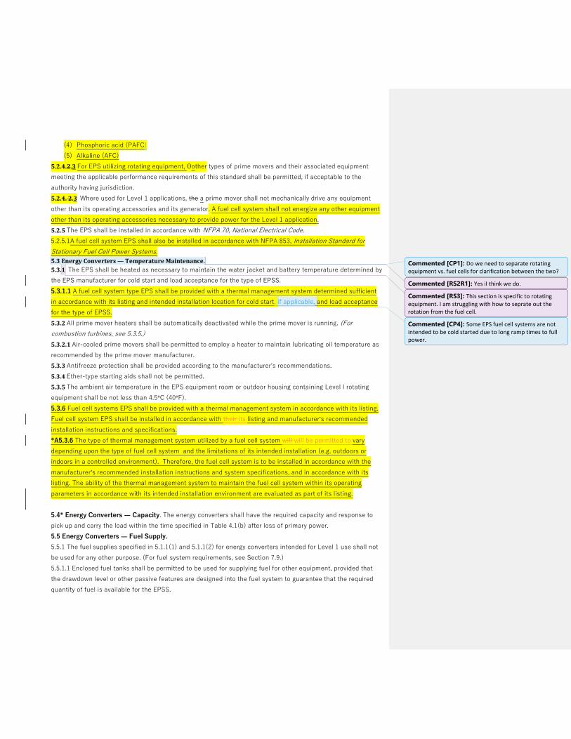
(4) Phosphoric acid (PAFC)
(5) Alkaline (AFC)
5.2.4.2.3 For EPS utilizing rotating equipment, Oother types of prime movers and their associated equipment
meeting the applicable performance requirements of this standard shall be permitted, if acceptable to the
authority having jurisdiction.
5.2.4. 2.3 Where used for Level 1 applications, the a prime mover shall not mechanically drive any equipment
other than its operating accessories and its generator. A fuel cell system shall not energize any other equipment
other than its operating accessories necessary to provide power for the Level 1 application.
5.2.5 The EPS shall be installed in accordance with NFPA 70, National Electrical Code.
5.2.5.1A fuel cell system EPS shall also be installed in accordance with NFPA 853, Installation Standard for
Stationary Fuel Cell Power Systems.
5.3 Energy Converters — Temperature Maintenance.
5.3.1 The EPS shall be heated as necessary to maintain the water jacket and battery temperature determined by
the EPS manufacturer for cold start and load acceptance for the type of EPSS.
5.3.1.1 A fuel cell system type EPS shall be provided with a thermal management system determined sufficient
in accordance with its listing and intended installation location for cold start, if applicable, and load acceptance
for the type of EPSS.
5.3.2 All prime mover heaters shall be automatically deactivated while the prime mover is running. (For
combustion turbines, see 5.3.5.)
5.3.2.1 Air-cooled prime movers shall be permitted to employ a heater to maintain lubricating oil temperature as
recommended by the prime mover manufacturer.
5.3.3 Antifreeze protection shall be provided according to the manufacturer's recommendations.
5.3.4 Ether-type starting aids shall not be permitted.
5.3.5 The ambient air temperature in the EPS equipment room or outdoor housing containing Level I rotating
equipment shall be not less than 4.5°C (40°F).
5.3.6 Fuel cell systems EPS shall be provided with a thermal management system in accordance with its listing.
Fuel cell system EPS shall be installed in accordance with their its listing and manufacturer’s recommended
installation instructions and specifications.
*A5.3.6 The type of thermal management system utilized by a fuel cell system will will be permitted to vary
depending upon the type of fuel cell system and the limitations of its intended installation (e.g. outdoors or
indoors in a controlled environment). Therefore, the fuel cell system is to be installed in accordance with the
manufacturer’s recommended installation instructions and system specifications, and in accordance with its
listing. The ability of the thermal management system to maintain the fuel cell system within its operating
parameters in accordance with its intended installation environment are evaluated as part of its listing.
5.4* Energy Converters — Capacity. The energy converters shall have the required capacity and response to
pick up and carry the load within the time specified in Table 4.1(b) after loss of primary power.
5.5 Energy Converters — Fuel Supply.
5.5.1 The fuel supplies specified in 5.1.1(1) and 5.1.1(2) for energy converters intended for Level 1 use shall not
be used for any other purpose. (For fuel system requirements, see Section 7.9.)
5.5.1.1 Enclosed fuel tanks shall be permitted to be used for supplying fuel for other equipment, provided that
the drawdown level or other passive features are designed into the fuel system to guarantee that the required
quantity of fuel is available for the EPSS.
Commented [CP1]: Do we need to separate rotating equipment vs. fuel cells for clarification between the two?
Commented [RS2R1]: Yes iI think we do.
Commented [RS3]: This section is specific to rotating equipment. I am struggling with how to seprate out the rotation from the fuel cell.
Commented [CP4]: Some EPS fuel cell systems are not intended to be cold started due to long ramp times to full power.

5.5.1.2 Vapor-withdrawal LP-Gas systems shall have a dedicated fuel supply.
5.5.2* A low-fuel sensing switch shall be provided for the main fuel supply tank(s) using the energy sources
listed in 5.1.1(1) and 5.1.1(2) to indicate when less than the minimum fuel necessary for full load running, as
required by the specified class in Table 4.1(a), remains in the main fuel tank.
5.5.3* The main fuel tank shall have a minimum capacity of at least 133 percent of either the low-fuel sensor
quantity specified in 5.5.2 or the quantity required to support the duration of run specified in Table 4.1(a).
5.6 Rotating Equipment.
5.6.1 General. Prime movers and accessories shall comply with NFPA 37, Standard for the Installation and Use
of Stationary Combustion Engines and Gas Turbines, except as modified in this standard.
5.6.2 Prime Mover Ratings. Proper derating factors, such as altitudes, ambient temperature, fuel energy
content, accessory losses, and site conditions as recommended by the manufacturer of the generator set shall
be used in determining whether or not brake power meets the connected load requirements.
5.6.3 Prime Mover Accessories.
5.6.3.1 Governors shall maintain a bandwidth of rated frequency for any constant load (steady-state condition)
that is compatible with the load.
5.6.3.1.1 The frequency droop between no load and full load shall be within the range for the load.
5.6.3.1.2 The frequency dip upon one-step application of the full load shall not be outside the range for the load,
with a return to steady-state conditions occurring within the requirements of the load.
5.6.3.2 Solenoid valves, where used, both in the fuel line from the supply or day tank closest to the generator set
and in the water-cooling lines, shall operate from battery voltage.
5.6.3.2.1 Solenoid valves shall have a manual (nonelectric) operation, or a manual bypass valve shall be
provided.
5.6.3.2.1.1 The manual bypass valve shall be visible and accessible and its purpose identified.
5.6.3.2.1.2 The fuel bypass valve shall not be the valve used for malfunction or emergency shutdown.
5.6.3.3 The prime mover shall be provided with the following instruments:
(1) Oil pressure gauge to indicate lubricating oil pressure when a pressurized lubricating system is provided
(2) Temperature gauge to indicate cooling medium temperature when a liquid medium cooling system is used
(3) Hour meter to indicate actual total running time
(4) Battery-charging meter indicating performance of prime mover–driven battery charging means
(5) Other instruments as recommended or provided by the prime mover manufacturer where required for
maintenance
5.6.3.4 The instruments required in 5.6.3.3(1) through
5.6.3.3(4) shall be placed on an enclosed panel, located in proximity to or on the energy converter, in a location
that allows maintenance personnel to observe them readily. The enclosed panel shall be mounted by means of
antishock vibration mountings if mounted on the energy converter.
5.6.3.5 All wiring for connection to the control panel shall be harnessed or flexibly enclosed, shall be securely
mounted on the prime mover to prevent chafing and vibration damage, and shall terminate at the control panel
in an enclosed box or panel. (For control panel requirements, see 5.6.5.)
5.6.3.6 The generator set shall be fitted with an integral accessory battery charger, driven by the prime mover
and automatic voltage regulator, and capable of charging and maintaining the starting battery unit (and control
battery, where used) in a fully charged condition during a running condition.

5.6.3.6.1 A battery charger driven by the prime mover shall not be required, provided the automatic battery
charger has a highlow rate capable of fully charging the starting battery during running conditions as specified in
5.6.3.6.
5.6.4 Prime Mover Starting Equipment.
5.6.4.1 Starting Systems. Starting shall be accomplished using either an electric starter or a stored energy
starting system.
5.6.4.1.1 Electric starter systems shall start using a positive shift solenoid to engage the starter motor and to
crank the prime mover for the period specified in 5.6.4.2 without overheating, at a speed at least equal to that
recommended by the manufacturer of the prime mover and at the lowest ambient temperature anticipated at the
installation site.
5.6.4.1.2 Other types of stored energy starting systems (except pyrotechnic) shall be permitted to be used where
recommended by the manufacturer of the prime mover and subject to approval of the authority having
jurisdiction, under the following conditions:
(1) Where two complete periods of cranking cycles are completed without replacement of the stored energy
(2) Where a means for automatic restoration from the emergency source of the stored energy is provided
(3) Where the stored energy system has the cranking capacity specified in 5.6.4.2.1
(4) Where the stored energy system has a “black start” capability in addition to normal discharge capability
5.6.4.2* Otto or Diesel Cycle Prime Movers. For otto or diesel cycle prime movers, the type and duration of the
cranking cycle shall be as specified in Table 5.6.4.2.
5.6.4.2.1 A complete cranking cycle shall consist of an automatic crank period of approximately 15 seconds
followed by a rest period of approximately 15 seconds. Upon starting and running the prime mover, further
cranking shall cease.
5.6.4.2.2 Two means of cranking termination shall be utilized so that one serves as backup to prevent
inadvertent starter engagement.
5.6.4.2.3 Otto cycle prime movers of 15 kW and lower and all diesel prime movers shall be permitted to use
continuous cranking methods.
5.6.4.3* Number of Batteries. Each prime mover shall be provided with both of the following:
(1) Storage battery units as specified in Table 5.6.4.2
(2) A storage rack for each battery or battery unit
Table 5.6.4.2 Starting Equipment Requirements
Starting Equipment Requirements
_________________________________________________________________________________________
Level 1 Level 2
(a) Battery unit X X
(b) Battery certification X NA
(c) Cycle cranking X or O O
(d) Cranking limiter time-outs
Cycle crank (3 cycles) 75 sec 75 sec
Continuous crank 45 sec 45 sec
(e) Float-type battery charger X X
dc ammeter X X
dc voltmeter X X

(f) Recharge time 24 hr 36 hr
(g) Low battery voltage alarm contacts X X
______________________________________________________________________________
X: Required. O: Optional. NA: Not applicable
5.6.4.4* Size of Batteries. The battery unit shall have the capacity to maintain the cranking speed
recommended by the prime mover manufacturer through two complete periods of cranking limiter time-outs as
specified in Table 5.6.4.2, item (d).
5.6.4.5 Type of Battery. The battery shall be of the nickel cadmium or lead-acid type.
5.6.4.5.1* Lead-acid batteries shall be furnished as charged when wet. Drain-dry batteries or dry-charged lead-
acid batteries shall be permitted.
5.6.4.5.2 When furnished, vented nickel-cadmium batteries shall be filled and charged and shall have listed flip-
top, flame arrester vent caps.
5.6.4.5.3 The manufacturer shall provide installation, operation, and maintenance instructions and, for batteries
shipped dry, electrolyte mixing instructions.
5.6.4.5.4 Batteries shall not be installed until the battery charger is in service.
5.6.4.5.5 All batteries used in this service shall have been designed for this duty and shall have demonstrable
characteristics of performance and reliability acceptable to the authority having jurisdiction.
5.6.4.5.6 Batteries shall be prepared for use according to the battery manufacturer's instructions.
5.6.4.6* Automatic Battery Charger. In addition to the prime mover– (engine-) driven charger required in
5.6.3.6.1, a battery charger(s), as required in Table 5.6.4.2, shall be supplied for maintaining a charge on both the
starting and control battery unit.
5.6.4.7 All chargers shall include the following characteristics, which are to be accomplished without manual
intervention (i.e., manual switch or manual tap changing):
(1) At its rated voltage, the charger shall be capable of delivering energy into a fully discharged battery unit
without damaging the battery.
(2) The charger shall be capable of returning the fully discharged battery to 100 percent of its ampere-hour
rating within the time specified in Table 5.6.4.2, item (f).
(3) As specified in Table 5.6.4.2, item (e), meters with an accuracy within 5 percent of range shall be furnished.
(4) The charger shall be permanently marked with the
following:
(a) Allowable range of battery unit capacity
(b) Nominal output current and voltage
(c) Sufficient battery-type data to allow replacement
batteries to be obtained
(5) The battery charger output and performance shall be
compatible with the batteries furnished.
5.6.5 Control Functions.
5.6.5.1 A control panel shall be provided and shall contain the following:
(1) Automatic remote start capability
(2) “Run-off-automatic” switch
(3) Shutdowns as required by 5.6.5.2(3)

(4) Alarms as required by 5.6.5.2(4)
(5) Controls as required by 5.6.5.2(5)
5.6.5.2 Where a control panel is mounted on the energy converter, it shall be mounted by means of antivibration
shock mounts, if required, to maximize reliability. An automatic control and safety panel shall be a part of the
EPS containing the following equipment or possess the following characteristics, or both:
(1) Cranking control equipment to provide the complete cranking cycle described in 5.6.4.2 and required by Table
5.6.4.2
(2) Panel-mounted control switch(es) marked “run–off–automatic” to perform the following functions:
(a) Run: Manually initiate, start, and run prime mover
(b) Off: Stop prime mover or reset safeties, or both
(c) Automatic: Allow prime mover to start by closing a remote contact and stop by opening the remote contact
(3) Controls to shut down and lock out the prime mover under any of the following conditions:
(a) Failing to start after specified cranking time
(b) Overspeed
(c) Low lubricating-oil pressure
(d) High engine temperature (An automatic engine shutdown device for high lubricating-oil temperature shall
not be required.)
(e) Operation of remote manual stop station
(4) Individual alarm indication to annunciate any of the conditions listed in Table 5.6.5.2 and with the following
characteristics:
(a) Battery powered
(b) Visually indicated
(c) Have additional contacts or circuits for a common audible alarm that signals locally and remotely when any
of the itemized conditions occurs
(d) Have a lamp test switch(es) to test the operation of all alarm lamps
(5) Controls to shut down the prime mover upon removal of the initiating signal or manual emergency shutdown
(6) The ac instruments listed in 5.6.9.9
5.6.5.3 Engines equipped with a maintaining shutdown device (air shutdown damper) shall have a set of
contacts that monitor the position of this device, with local alarm indication and remote annunciation in
accordance with Table 5.6.5.2.
5.6.5.4 The control panel in 5.6.5.2(4) shall be specifically approved for either a Level 1 or a Level 2 EPS
consistent with the installation.
5.6.5.5 The cranking cycle shall be capable of being initiated by any of the following:
(1) Manual start initiation as specified in 5.6.5.2(2)(a).
(2) Loss of normal power at any automatic transfer switch (ATS) considered a part of the EPSS. Prime mover
shall start upon closing of a remote switch or contacts and shall stop, after appropriate time delays, when switch
or contacts are opened.
(3) Clock exerciser located in an ATS or in the control panel.
(4) Manually operated (test) switch located in each ATS that simulates a loss of power and causes automatic
starting and operation until this switch is reset, to cause the engine circuit to duplicate its functions in the same
manner commercial power is restored after a true commercial power failure.
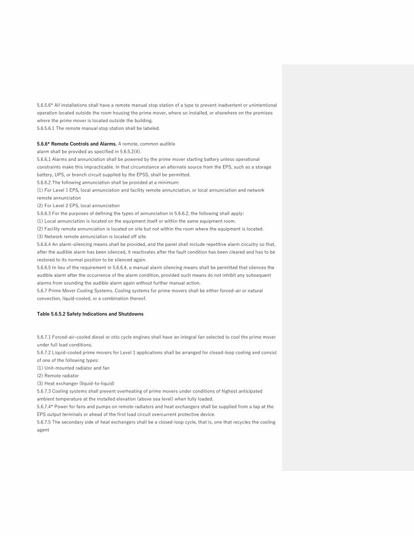
5.6.5.6* All installations shall have a remote manual stop station of a type to prevent inadvertent or unintentional
operation located outside the room housing the prime mover, where so installed, or elsewhere on the premises
where the prime mover is located outside the building.
5.6.5.6.1 The remote manual stop station shall be labeled.
5.6.6* Remote Controls and Alarms. A remote, common audible
alarm shall be provided as specified in 5.6.5.2(4).
5.6.6.1 Alarms and annunciation shall be powered by the prime mover starting battery unless operational
constraints make this impracticable. In that circumstance an alternate source from the EPS, such as a storage
battery, UPS, or branch circuit supplied by the EPSS, shall be permitted.
5.6.6.2 The following annunciation shall be provided at a minimum:
(1) For Level 1 EPS, local annunciation and facility remote annunciation, or local annunciation and network
remote annunciation
(2) For Level 2 EPS, local annunciation
5.6.6.3 For the purposes of defining the types of annunciation in 5.6.6.2, the following shall apply:
(1) Local annunciation is located on the equipment itself or within the same equipment room.
(2) Facility remote annunciation is located on site but not within the room where the equipment is located.
(3) Network remote annunciation is located off site.
5.6.6.4 An alarm-silencing means shall be provided, and the panel shall include repetitive alarm circuitry so that,
after the audible alarm has been silenced, it reactivates after the fault condition has been cleared and has to be
restored to its normal position to be silenced again.
5.6.6.5 In lieu of the requirement in 5.6.6.4, a manual alarm silencing means shall be permitted that silences the
audible alarm after the occurrence of the alarm condition, provided such means do not inhibit any subsequent
alarms from sounding the audible alarm again without further manual action.
5.6.7 Prime Mover Cooling Systems. Cooling systems for prime movers shall be either forced-air or natural
convection, liquid-cooled, or a combination thereof.
Table 5.6.5.2 Safety Indications and Shutdowns
5.6.7.1 Forced-air-cooled diesel or otto cycle engines shall have an integral fan selected to cool the prime mover
under full load conditions.
5.6.7.2 Liquid-cooled prime movers for Level 1 applications shall be arranged for closed-loop cooling and consist
of one of the following types:
(1) Unit-mounted radiator and fan
(2) Remote radiator
(3) Heat exchanger (liquid-to-liquid)
5.6.7.3 Cooling systems shall prevent overheating of prime movers under conditions of highest anticipated
ambient temperature at the installed elevation (above sea level) when fully loaded.
5.6.7.4* Power for fans and pumps on remote radiators and heat exchangers shall be supplied from a tap at the
EPS output terminals or ahead of the first load circuit overcurrent protective device.
5.6.7.5 The secondary side of heat exchangers shall be a closed-loop cycle, that is, one that recycles the cooling
agent

5.6.7.1 Forced-air-cooled diesel or otto cycle engines shall have an integral fan selected to cool the prime mover
under full load conditions.
5.6.7.2 Liquid-cooled prime movers for Level 1 applications shall be arranged for closed-loop cooling and consist
of one of the following types:
(1) Unit-mounted radiator and fan
(2) Remote radiator
(3) Heat exchanger (liquid-to-liquid)
5.6.7.3 Cooling systems shall prevent overheating of prime movers under conditions of highest anticipated
ambient temperature at the installed elevation (above sea level) when fully loaded.
5.6.7.4* Power for fans and pumps on remote radiators and heat exchangers shall be supplied from a tap at the
EPS output terminals or ahead of the first load circuit overcurrent protective device.
5.6.7.5 The secondary side of heat exchangers shall be a closed-loop cycle, that is, one that recycles the cooling
agent.
5.6.7.6 The installed EPS cooling system shall be designed to cool the prime mover at full-rated load while
operating in the particular installation circumstances of each EPS.
5.6.7.7 A full-load on-site test shall not result in activation of high-temperature pre-alarm or high-temperature
shutdown.
5.6.7.8 For EPSS cooling systems requiring intermittent or continuous waterflow or pressure, or both, a utility,
city, or other water supply service shall not be used.
5.6.7.9 The EPSS cooling system shall be permitted to use utility or city water for filling or makeup water.
5.6.7.10 Design of the EPS cooling system shall consider the following factors:
(1) Remote radiator or heat exchanger sizing
(2) Pipe sizing
(3) Pump sizing
(4) Sufficient shutoffs to isolate equipment to facilitate maintenance
(5) The need for and sizing of de-aeration and surge
(6) Drain valves for cleaning and flushing the cooling system
(7) Type of flexible hoses between the prime mover and the cooling system piping
5.6.8 Prime Mover Exhaust Piping. Where applicable, the exhaust system shall include a muffler or silencer sized
for the unit and a flexible exhaust section.
5.6.9 Generators, Exciters, and Voltage Regulators. Generators shall comply with Article 445 of NFPA 70,
National Electrical Code, and with the requirements of 5.6.9.1 through 5.6.9.9.
5.6.9.1* The generator shall be of drip-proof construction and have amortisseur windings.
5.6.9.2 The generator shall be suitable for the environmental conditions at the installation location.
5.6.9.3 The generator systems shall be factory tested as a unit to ensure operational integrity of all of the
following:
(1) Generator
(2) Exciter
(3) Voltage regulator
5.6.9.4 EPS voltage output, or the output of the transformer immediately down-line from the EPS, at full load
shall match the nominal voltage of the normal source at the transfer switch(es).
5.6.9.5 Exciters, where furnished, shall be of either the rotating type or the static type.

5.6.9.6 Voltage regulators shall be capable of responding to load changes to meet the system stability
requirements of 5.6.9.8.
5.6.9.7 If the system stability requirements of 5.6.9.8 cannot be accomplished, anti-hunt provisions shall be
included.
5.6.9.8 Generator system performance (i.e., prime mover, generator, exciter, and voltage regulator, as applicable
when prototype tested as specified in 5.2.1.2) shall be as follows:
(1) Stable voltage and frequency at all loads shall be provided to full-rated loads.
(2) Values consistent with the user's needs for frequency droop and voltage droop shall be maintained.
(3) Voltage dip at the generator terminals for the maximum anticipated load change shall not cause disruption or
relay dropout in the load.
(4) Frequency dip and restoration to steady state for any sudden load change shall not exceed the user's
specified need.
5.6.9.9 The generator instrument panel for Level 1 applications shall contain the following:
(1) An ac voltmeter(s) for each phase or a phase selector switch
(2) An ac ammeter(s) for each phase or a phase selector switch
(3) A frequency meter
(4) A voltage-adjusting feature to allow ± 5 percent voltage adjustment
5.6.10 Miscellaneous Requirements.
5.6.10.1 Where applicable, the prime mover and generator shall be factory mounted on a common base, rigid
enough to maintain the dynamic alignment of the rotating element of the system prior to shipment to the
installation site.
5.6.10.2 A certification shall be supplied with the unit that verifies the torsional vibration compatibility of the
rotating element of the prime mover and generator for the intended use of the energy converter.
5.6.10.3* Vibration isolators shall be furnished where necessary to minimize vibration transmission to the
permanent structure.
5.6.10.4 The manufacturer of the EPS shall submit complete schematic, wiring, and interconnection diagrams
showing all terminal and destination markings for all EPS equipment, as well as the functional relationship
between all electrical components.
5.6.10.5 The energy converter supplier shall stipulate compliance and performance with this standard for the
entire unit when installed.
5.6.10.6 Where requested, the short circuit current capability at the generator output terminals shall be
furnished.
5.7 Fuel Cell System Equipment
5.7.1 General. Fuel cell systems and accessories shall comply with NFPA 853, Standard for the Installation of
Stationary Fuel Cell Power Systems, except as modified in this standard.
5.7.1.1* Fuel cells are classified by the type of electrolyte used (see 5.2.4). A5.7.1.1 There is a difference in start-up ramp time to full power based on the fuel cell type ranging from seconds to hours. During start-up, fuel cells have an average power output until they reach full power. If needed, additional power supplied from another source, such as a battery or ultra-capacitor, assists with powering the intended load during this time. Fuel cell systems that require high operating temperatures ramp slowly until they
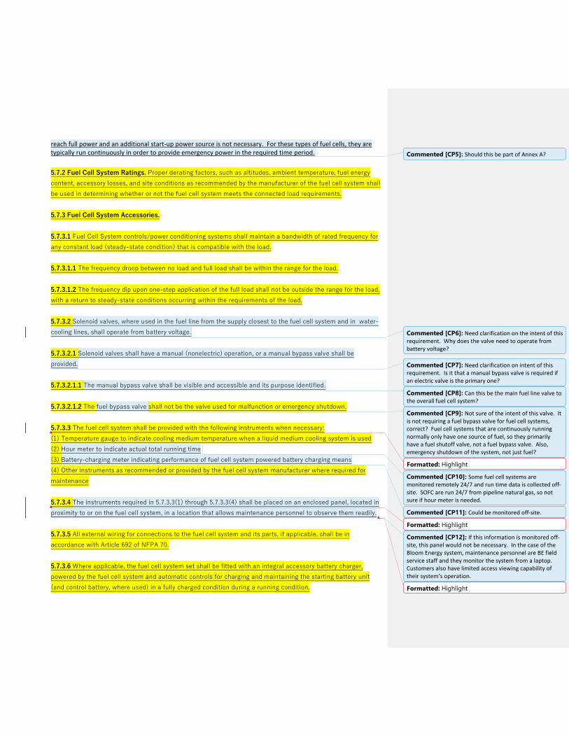
reach full power and an additional start-up power source is not necessary. For these types of fuel cells, they are typically run continuously in order to provide emergency power in the required time period.
5.7.2 Fuel Cell System Ratings. Proper derating factors, such as altitudes, ambient temperature, fuel energy
content, accessory losses, and site conditions as recommended by the manufacturer of the fuel cell system shall
be used in determining whether or not the fuel cell system meets the connected load requirements.
5.7.3 Fuel Cell System Accessories.
5.7.3.1 Fuel Cell System controls/power conditioning systems shall maintain a bandwidth of rated frequency for
any constant load (steady-state condition) that is compatible with the load.
5.7.3.1.1 The frequency droop between no load and full load shall be within the range for the load.
5.7.3.1.2 The frequency dip upon one-step application of the full load shall not be outside the range for the load,
with a return to steady-state conditions occurring within the requirements of the load.
5.7.3.2 Solenoid valves, where used in the fuel line from the supply closest to the fuel cell system and in water-
cooling lines, shall operate from battery voltage.
5.7.3.2.1 Solenoid valves shall have a manual (nonelectric) operation, or a manual bypass valve shall be
provided.
5.7.3.2.1.1 The manual bypass valve shall be visible and accessible and its purpose identified.
5.7.3.2.1.2 The fuel bypass valve shall not be the valve used for malfunction or emergency shutdown.
5.7.3.3 The fuel cell system shall be provided with the following instruments when necessary:
(1) Temperature gauge to indicate cooling medium temperature when a liquid medium cooling system is used
(2) Hour meter to indicate actual total running time
(3) Battery-charging meter indicating performance of fuel cell system powered battery charging means
(4) Other instruments as recommended or provided by the fuel cell system manufacturer where required for
maintenance
5.7.3.4 The instruments required in 5.7.3.3(1) through 5.7.3.3(4) shall be placed on an enclosed panel, located in
proximity to or on the fuel cell system, in a location that allows maintenance personnel to observe them readily.
5.7.3.5 All external wiring for connections to the fuel cell system and its parts, if applicable, shall be in
accordance with Article 692 of NFPA 70.
5.7.3.6 Where applicable, the fuel cell system set shall be fitted with an integral accessory battery charger,
powered by the fuel cell system and automatic controls for charging and maintaining the starting battery unit
(and control battery, where used) in a fully charged condition during a running condition.
Commented [CP5]: Should this be part of Annex A?
Commented [CP6]: Need clarification on the intent of this requirement. Why does the valve need to operate from battery voltage?
Commented [CP7]: Need clarification on intent of this requirement. Is it that a manual bypass valve is required if an electric valve is the primary one?
Commented [CP8]: Can this be the main fuel line valve to the overall fuel cell system?
Commented [CP9]: Not sure of the intent of this valve. It is not requiring a fuel bypass valve for fuel cell systems, correct? Fuel cell systems that are continuously running normally only have one source of fuel, so they primarily have a fuel shutoff valve, not a fuel bypass valve. Also, emergency shutdown of the system, not just fuel?
Formatted: Highlight
Commented [CP10]: Some fuel cell systems are monitored remotely 24/7 and run time data is collected off-site. SOFC are run 24/7 from pipeline natural gas, so not sure if hour meter is needed.
Commented [CP11]: Could be monitored off-site.
Formatted: Highlight
Commented [CP12]: If this information is monitored off-site, this panel would not be necessary. In the case of the Bloom Energy system, maintenance personnel are BE field service staff and they monitor the system from a laptop. Customers also have limited access viewing capability of their system’s operation.
Formatted: Highlight

5.7.4 Fuel Cell System Starting Equipment.
5.7.4.1* Starting Systems. Where applicable, starting shall be accomplished using a stored energy starting
system.
A5.7.4.1 Some fuel cell systems use power from the utility grid for start-up until the fuel cell system is up to
operational status, then it disconnects from grid power and runs independently of the grid.
5.7.4.1.1 Other types of stored energy starting systems (except pyrotechnic) shall be permitted to be used where
recommended by the manufacturer of the fuel cell system and subject to approval of the authority having
jurisdiction, under the following conditions:
(1) Where a means for automatic restoration from the emergency source of the stored energy is provided
(3) Where the stored energy system has the capacity to handle the intended loads until the fuel cell system is
operating
(4) Where the stored energy system has a “black start” capability in addition to normal discharge capability.
5.7.4.3.1 Number of Batteries. Where applicable, a fuel cell system shall be provided with batteries for startup
until the fuel cell system is operating to provide the necessary power to the loads. The fuel cell system shall be
provided with one of the following:
(1) Storage battery units as specified in Table 5.7.4.2, or
(2) Battery or capacitor storage systems that are either incorporated as part of the fuel cell system or installed
as a separate accessory such as a battery rack or storage system.
Table 5.7.4.2 Fuel Cell Starting Equipment Requirements
Fuel Cell Starting Equipment Requirements
____________________________________________________________________________________________________
Level 1 Level 2
(a) Battery Units X X
(b) Battery Certification X X (for other than LA and Nickel)
(c) Power to load 45 sec 45 sec
(d) Automatic battery charger (BMS control) X X
(e) Maximum Recharge time 24 H 36 H
(f) Low battery voltage alarm contacts X X
X: Required. O: Optional
5.7.4.4* Size of Batteries. A battery unit or other storage system provided for startup power for a fuel cell
system shall be sized to provide power to the necessary loads until the fuel cell power system is operating.
5.7.4.5 Type of Battery. The battery shall be of the nickel cadmium, lead-acid type or as noted in 5.7.4.5.3.
Commented [CP13]: Some FC systems use power from the grid for start-up until the FC is up to Balance of Plant status, then it disconnects from grid power and runs independently on NG.
Commented [FLB14R13]: I added Chris explanation above with a few tweaks as annex material.
Commented [FLB15]: Get rid of old technology specific criteria. BMS control that is evaluated per

5.7.4.5.1 Lead-acid batteries shall be furnished as charged when wet. Drain-dry batteries or dry-charged lead-
acid batteries shall be permitted.
5.7.4.5.2 When furnished, vented nickel-cadmium batteries shall be filled and charged and shall have listed flip-
top, flame arrester vent caps.
5.7.4.5.3 In addition to nickel cadmium and lead acid batteries, fuel cell systems may utilize other technology
batteries (e.g. lithium ion) or storage capacitor technology for starting applications. These other storage system
technologies shall be listed to UL 1973.
5.7.4.5.4The manufacturer shall provide installation, operation, and maintenance instructions for the batteries in
accordance with their listing.
5.7.4.5.5 Batteries or capacitor units shall not be installed until their charging mechanism is installed if separate
from the battery or capacitor unit.
5.7.4.5.6 All start up storage systems used in this service shall have been designed for this duty and shall have
demonstrable characteristics of performance and reliability acceptable to the authority having jurisdiction.
5.7.4.5.7 Batteries or capacitors shall be prepared for use according to the battery/capacitor manufacturer's
instructions.
5.7.4.6 Automatic Battery Charger. A battery charger(s), as required in Table 5.7.4.2, shall be supplied for
maintaining a charge on both starting and control battery units as applicable to the fuel cell system.
5.7.4.7 All chargers shall include the following characteristics, which are to be accomplished without manual
intervention (i.e., manual switch or manual tap changing):
(1) At its rated voltage, the charger shall be capable of delivering energy into a fully discharged battery unit
without damaging the battery.
(2) The charger shall be capable of returning the fully discharged battery to 100 percent of its ampere-hour
rating within the time specified in Table 5.7.4.2, item (e).
(3) For float type chargers, meters with an accuracy within 5 percent of range shall be furnished.
(4) The charger, if a separate accessory for charging lead acid or Ni-cad batteries, shall be permanently marked
with the following:
(a) Allowable range of battery unit capacity
(b) Nominal output current and voltage
(c) Sufficient battery-type data to allow replacement batteries to be obtained
(5) The battery charger output and performance shall be compatible with the batteries furnished.
5.7.5 Control Functions.
5.7.5.1 An on-site control panel or remote monitoring control system shall be provided and shall contain the
following:
Commented [CP16]: A remote monitoring control system may be offsite and a panel may not be a required part of the fuel cell system. Items 3-5 apply to FC systems that run continuously.

(1) Automatic remote start capability
(2) “Run-off-automatic” switch function
(3) Shutdowns as required by 5.7.5.2(2)
(4) Alarms as required by 5.7.5.2(3)
(5) Controls as required by 5.7.5.2(4)
5.7.5.2 An automatic control and safety panel or remote monitoring control system shall be a part of the EPS
containing the following equipment or possess the following characteristics, or both:
(1) Panel-mounted control switch(es) marked “run–off–automatic” to perform the following functions for quick-
start fuel cell power systems:
(a) Run: Manually initiate, start of fuel cell system
(b) Off: Stop fuel cell system or reset safeties, or both
(c) Automatic: Allow fuel cell system to start by closing a remote contact and stop by opening the remote
contact
(2) Controls to shut down and lock out the fuel cell system under any of the following conditions:
(a) Failing to start after specified time
(b) Abnormal conditions including high temperatures
(c) Operation of remote manual stop station
(3) Individual alarm indication on a control panel to annunciate any of the conditions listed in Table 5.7.5.2 and
with the following
characteristics:
(a) Battery powered
(b) Visually indicated
(c) Have additional contacts or circuits for a common audible alarm that signals locally and remotely
when any of the itemized conditions occurs
(d) Have a lamp test switch(es) to test the operation of all alarm lamps
(54) Controls to shut down the fuel cell system upon removal of the initiating signal or manual emergency
shutdown
5.7.5.3 (reserved)
5.7.5.4 The control panel or remote monitoring control system in 5.7.5.2(4) shall be specifically approved for
either a Level 1 or a Level 2 EPS consistent with the installation.
5.7.5.5 The startup operation shall be capable of being initiated by any of the following:
(1) Manual start initiation as specified in 5.7.5.2(2)(a) for quick start-up fuel cell systems.
(2) Loss of normal power at any automatic transfer switch (ATS) considered a part of the EPSS. The fuel cell
system shall start-up or switch power to the load upon closing of a remote switch or contacts and shall stop,
after appropriate time delays, when switch or contacts are opened.
(3) Clock exerciser located in an ATS or in the control panel.
(4) Manually operated (test) switch located in each ATS that simulates a loss of power and causes automatic
starting and operation until this switch is reset, to cause the fuel cell system circuit to duplicate its functions in
the same manner commercial power is restored after a true commercial power failure.
Commented [CP17]: For FC systems that are running continuously in order to pick up the load when needed, this function should not be required. Maybe add a comment “for quick start-up fuel cell systems”.
Commented [CP18]: The word “function” is included for gen-sets. In the case of FC systems that are running continuously, this should not be necessary.
Commented [CP19]: This is a FC 1 requirement
Commented [CP20]: Need to add some separate requirements for remote monitoring control system
Commented [CP21]: Is “approved” equivalent to listed, or is it an AHJ’s decision?
Commented [CP22]: Not sure what this is.
Commented [CP23]: Need clarification on this.

5.7.5.6* All installations shall have a remote manual stop station of a type to prevent inadvertent or
unintentional operation located outside the room housing the fuel cell system, where so installed, or elsewhere
on the premises where the fuel cell system is located outside the building.
5.7.5.6.1 The remote manual stop station shall be labeled.
5.7.6* Remote Controls and Alarms. A remote, common audible alarm shall be provided as specified in
5.7.5.2(4). Remote controls and alarms for fuel cell systems shall be in accordance with 5.6.6.1 through 5.6.6.5
except as noted below.
5.7.6.1 Alarms and annunciation need not be powered by a starter battery if the fuel cell system does not rely
upon one (i.e. is under continuous operation).
5.7.7 Fuel Cell Cooling Systems. Cooling systems for fuel cell systems shall be either forced-air or natural
convection, liquid-cooled, or a combination thereof.
Commented [CP24]: If remote monitored, the alarm is for the monitoring station, correct?
Commented [CP25]: Should not be a requirement if a fuel cell system is run continuously and doesn’t use a starting battery.
Commented [FLB26R25]: Revised wording, as 5.6.6.1 allows options other than starting batteries. Changed statement to address continuously running fuel cell systems that do not employ a starting battery.
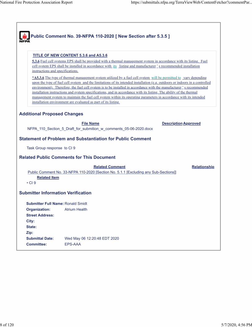
Public Comment No. 39-NFPA 110-2020 [ New Section after 5.3.5 ]
TITLE OF NEW CONTENT 5.3.6 and A5.3.6
5.3.6 Fuel cell systems EPS shall be provided with a thermal management system in accordance with its listing. Fuelcell system EPS shall be installed in accordance with its listing and manufacturer ’ s recommended installationinstructions and specifications.
*A5.3.6 The type of thermal management system utilized by a fuel cell system will be permitted to vary dependingupon the type of fuel cell system and the limitations of its intended installation (e.g. outdoors or indoors in a controlledenvironment). Therefore, the fuel cell system is to be installed in accordance with the manufacturer ’ s recommendedinstallation instructions and system specifications, and in accordance with its listing. The ability of the thermalmanagement system to maintain the fuel cell system within its operating parameters in accordance with its intendedinstallation environment are evaluated as part of its listing.
Additional Proposed Changes
File Name Description Approved
NFPA_110_Section_5_Draft_for_submition_w_comments_05-06-2020.docx
Statement of Problem and Substantiation for Public Comment
Task Group response to CI 9
Related Public Comments for This Document
Related Comment Relationship
Public Comment No. 33-NFPA 110-2020 [Section No. 5.1.1 [Excluding any Sub-Sections]]
Related Item
• CI 9
Submitter Information Verification
Submitter Full Name: Ronald Smidt
Organization: Atrium Health
Street Address:
City:
State:
Zip:
Submittal Date: Wed May 06 12:20:48 EDT 2020
Committee: EPS-AAA
National Fire Protection Association Report https://submittals.nfpa.org/TerraViewWeb/ContentFetcher?commentPar...
8 of 120 5/7/2020, 4:56 PM

Note the following was produced by a Task group in response to Chair request on CI-9 Change are highlighted and total text will be up loaded with each submission. This is only CH 5 changes 5.2 Energy Converters — General.
5.2.1 Energy converters shall consist only of rotating equipment as indicated in 5.2.4.
5.2.1.1 Level 1 energy converters shall be representative products built from components that have proven
compatibility and reliability and are coordinated to operate as a unit.
5.2.1.1.1 Fuel Cell systems utilized as Level 1 energy converters shall be listed or field labeled to ANSI / CSA
FC1 .
5.2.1.2 The capability of the energy converter, with its controls and accessories, to survive without damage from
common and abnormal disturbances in actual load circuits shall be demonstrable demonstrated by tests on
separate prototype models, or by acceptable tests on the system components as performed by the component
suppliers, or by tests performed in the listing process for the assembly.
5.2.1.3 A separate prototype unit for a rotating type EPS shall be permitted to be utilized in a Level 1 or Level 2
installation, provided that all prototype tests produce no deleterious effects on the unit, and the authority having
jurisdiction, the owner, and the user are informed that the unit is the prototype test unit.
5.2.2* The A rotating equipment prototype unit shall be tested with all typical prime mover accessories that
affect its power output in place and operating, including, but not limited to, the following:
(1) Battery-charging alternator
(2) Water pump
(3) Radiator fan for unit-mounted radiators or oil coolers (or comparable load)
(4) Fuel pump and fuel filter(s)
(5) Air filter(s)
(6) Exhaust mufflers or restriction simulating the maximum backpressure recommended by the prime mover
manufacturer
5.2.3 The energy converter for Level 1 systems shall be specifically designed, assembled, and tested to ensure
system operation under the following conditions:
(1) Short circuits
(2) Load surges due to motor starting
(3) Elevator operations
(4) Silicon controlled rectifier (SCR) controllers
(5) X-ray Imaging equipment
(6) Overspeed, overtemperature, or overload
(7) Adverse environmental conditions
5.2.4 EPS
5.2.4.1 EPS utilizing Rrotating equipment shall consist of a generator driven by one of the following prime mover
types:
(1) Otto cycle (spark ignited)
(2) Diesel cycle
(3) Gas turbine cycle
5.2.4.2 EPS utilizing fuel cell systems shall consist of one or more of the following types:
(1) Proton exchange membrane (PEMFC)
(2) Solid oxide (SOFC)
(3) Molten carbonate (MCFC)

(4) Phosphoric acid (PAFC)
(5) Alkaline (AFC)
5.2.4.2.3 For EPS utilizing rotating equipment, Oother types of prime movers and their associated equipment
meeting the applicable performance requirements of this standard shall be permitted, if acceptable to the
authority having jurisdiction.
5.2.4. 2.3 Where used for Level 1 applications, the a prime mover shall not mechanically drive any equipment
other than its operating accessories and its generator. A fuel cell system shall not energize any other equipment
other than its operating accessories necessary to provide power for the Level 1 application.
5.2.5 The EPS shall be installed in accordance with NFPA 70, National Electrical Code.
5.2.5.1A fuel cell system EPS shall also be installed in accordance with NFPA 853, Installation Standard for
Stationary Fuel Cell Power Systems.
5.3 Energy Converters — Temperature Maintenance.
5.3.1 The EPS shall be heated as necessary to maintain the water jacket and battery temperature determined by
the EPS manufacturer for cold start and load acceptance for the type of EPSS.
5.3.1.1 A fuel cell system type EPS shall be provided with a thermal management system determined sufficient
in accordance with its listing and intended installation location for cold start, if applicable, and load acceptance
for the type of EPSS.
5.3.2 All prime mover heaters shall be automatically deactivated while the prime mover is running. (For
combustion turbines, see 5.3.5.)
5.3.2.1 Air-cooled prime movers shall be permitted to employ a heater to maintain lubricating oil temperature as
recommended by the prime mover manufacturer.
5.3.3 Antifreeze protection shall be provided according to the manufacturer's recommendations.
5.3.4 Ether-type starting aids shall not be permitted.
5.3.5 The ambient air temperature in the EPS equipment room or outdoor housing containing Level I rotating
equipment shall be not less than 4.5°C (40°F).
5.3.6 Fuel cell systems EPS shall be provided with a thermal management system in accordance with its listing.
Fuel cell system EPS shall be installed in accordance with their its listing and manufacturer’s recommended
installation instructions and specifications.
*A5.3.6 The type of thermal management system utilized by a fuel cell system will will be permitted to vary
depending upon the type of fuel cell system and the limitations of its intended installation (e.g. outdoors or
indoors in a controlled environment). Therefore, the fuel cell system is to be installed in accordance with the
manufacturer’s recommended installation instructions and system specifications, and in accordance with its
listing. The ability of the thermal management system to maintain the fuel cell system within its operating
parameters in accordance with its intended installation environment are evaluated as part of its listing.
5.4* Energy Converters — Capacity. The energy converters shall have the required capacity and response to
pick up and carry the load within the time specified in Table 4.1(b) after loss of primary power.
5.5 Energy Converters — Fuel Supply.
5.5.1 The fuel supplies specified in 5.1.1(1) and 5.1.1(2) for energy converters intended for Level 1 use shall not
be used for any other purpose. (For fuel system requirements, see Section 7.9.)
5.5.1.1 Enclosed fuel tanks shall be permitted to be used for supplying fuel for other equipment, provided that
the drawdown level or other passive features are designed into the fuel system to guarantee that the required
quantity of fuel is available for the EPSS.
Commented [CP1]: Do we need to separate rotating equipment vs. fuel cells for clarification between the two?
Commented [RS2R1]: Yes iI think we do.
Commented [RS3]: This section is specific to rotating equipment. I am struggling with how to seprate out the rotation from the fuel cell.
Commented [CP4]: Some EPS fuel cell systems are not intended to be cold started due to long ramp times to full power.
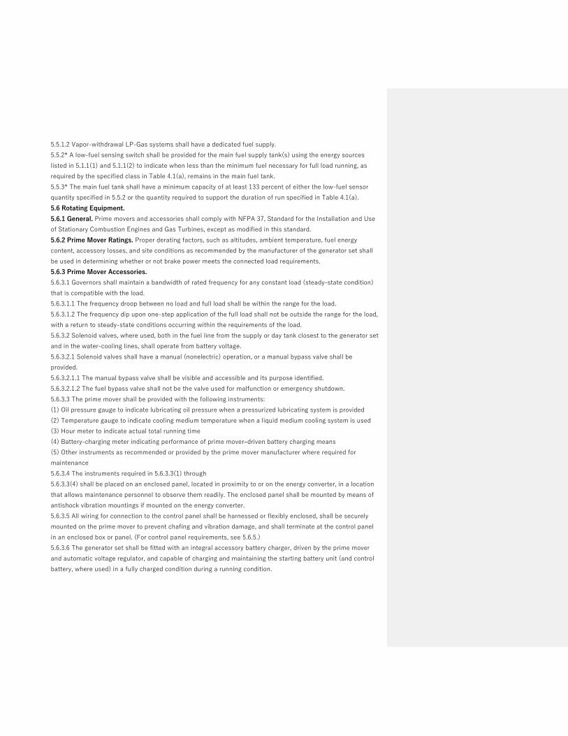
5.5.1.2 Vapor-withdrawal LP-Gas systems shall have a dedicated fuel supply.
5.5.2* A low-fuel sensing switch shall be provided for the main fuel supply tank(s) using the energy sources
listed in 5.1.1(1) and 5.1.1(2) to indicate when less than the minimum fuel necessary for full load running, as
required by the specified class in Table 4.1(a), remains in the main fuel tank.
5.5.3* The main fuel tank shall have a minimum capacity of at least 133 percent of either the low-fuel sensor
quantity specified in 5.5.2 or the quantity required to support the duration of run specified in Table 4.1(a).
5.6 Rotating Equipment.
5.6.1 General. Prime movers and accessories shall comply with NFPA 37, Standard for the Installation and Use
of Stationary Combustion Engines and Gas Turbines, except as modified in this standard.
5.6.2 Prime Mover Ratings. Proper derating factors, such as altitudes, ambient temperature, fuel energy
content, accessory losses, and site conditions as recommended by the manufacturer of the generator set shall
be used in determining whether or not brake power meets the connected load requirements.
5.6.3 Prime Mover Accessories.
5.6.3.1 Governors shall maintain a bandwidth of rated frequency for any constant load (steady-state condition)
that is compatible with the load.
5.6.3.1.1 The frequency droop between no load and full load shall be within the range for the load.
5.6.3.1.2 The frequency dip upon one-step application of the full load shall not be outside the range for the load,
with a return to steady-state conditions occurring within the requirements of the load.
5.6.3.2 Solenoid valves, where used, both in the fuel line from the supply or day tank closest to the generator set
and in the water-cooling lines, shall operate from battery voltage.
5.6.3.2.1 Solenoid valves shall have a manual (nonelectric) operation, or a manual bypass valve shall be
provided.
5.6.3.2.1.1 The manual bypass valve shall be visible and accessible and its purpose identified.
5.6.3.2.1.2 The fuel bypass valve shall not be the valve used for malfunction or emergency shutdown.
5.6.3.3 The prime mover shall be provided with the following instruments:
(1) Oil pressure gauge to indicate lubricating oil pressure when a pressurized lubricating system is provided
(2) Temperature gauge to indicate cooling medium temperature when a liquid medium cooling system is used
(3) Hour meter to indicate actual total running time
(4) Battery-charging meter indicating performance of prime mover–driven battery charging means
(5) Other instruments as recommended or provided by the prime mover manufacturer where required for
maintenance
5.6.3.4 The instruments required in 5.6.3.3(1) through
5.6.3.3(4) shall be placed on an enclosed panel, located in proximity to or on the energy converter, in a location
that allows maintenance personnel to observe them readily. The enclosed panel shall be mounted by means of
antishock vibration mountings if mounted on the energy converter.
5.6.3.5 All wiring for connection to the control panel shall be harnessed or flexibly enclosed, shall be securely
mounted on the prime mover to prevent chafing and vibration damage, and shall terminate at the control panel
in an enclosed box or panel. (For control panel requirements, see 5.6.5.)
5.6.3.6 The generator set shall be fitted with an integral accessory battery charger, driven by the prime mover
and automatic voltage regulator, and capable of charging and maintaining the starting battery unit (and control
battery, where used) in a fully charged condition during a running condition.

5.6.3.6.1 A battery charger driven by the prime mover shall not be required, provided the automatic battery
charger has a highlow rate capable of fully charging the starting battery during running conditions as specified in
5.6.3.6.
5.6.4 Prime Mover Starting Equipment.
5.6.4.1 Starting Systems. Starting shall be accomplished using either an electric starter or a stored energy
starting system.
5.6.4.1.1 Electric starter systems shall start using a positive shift solenoid to engage the starter motor and to
crank the prime mover for the period specified in 5.6.4.2 without overheating, at a speed at least equal to that
recommended by the manufacturer of the prime mover and at the lowest ambient temperature anticipated at the
installation site.
5.6.4.1.2 Other types of stored energy starting systems (except pyrotechnic) shall be permitted to be used where
recommended by the manufacturer of the prime mover and subject to approval of the authority having
jurisdiction, under the following conditions:
(1) Where two complete periods of cranking cycles are completed without replacement of the stored energy
(2) Where a means for automatic restoration from the emergency source of the stored energy is provided
(3) Where the stored energy system has the cranking capacity specified in 5.6.4.2.1
(4) Where the stored energy system has a “black start” capability in addition to normal discharge capability
5.6.4.2* Otto or Diesel Cycle Prime Movers. For otto or diesel cycle prime movers, the type and duration of the
cranking cycle shall be as specified in Table 5.6.4.2.
5.6.4.2.1 A complete cranking cycle shall consist of an automatic crank period of approximately 15 seconds
followed by a rest period of approximately 15 seconds. Upon starting and running the prime mover, further
cranking shall cease.
5.6.4.2.2 Two means of cranking termination shall be utilized so that one serves as backup to prevent
inadvertent starter engagement.
5.6.4.2.3 Otto cycle prime movers of 15 kW and lower and all diesel prime movers shall be permitted to use
continuous cranking methods.
5.6.4.3* Number of Batteries. Each prime mover shall be provided with both of the following:
(1) Storage battery units as specified in Table 5.6.4.2
(2) A storage rack for each battery or battery unit
Table 5.6.4.2 Starting Equipment Requirements
Starting Equipment Requirements
_________________________________________________________________________________________
Level 1 Level 2
(a) Battery unit X X
(b) Battery certification X NA
(c) Cycle cranking X or O O
(d) Cranking limiter time-outs
Cycle crank (3 cycles) 75 sec 75 sec
Continuous crank 45 sec 45 sec
(e) Float-type battery charger X X
dc ammeter X X
dc voltmeter X X

(f) Recharge time 24 hr 36 hr
(g) Low battery voltage alarm contacts X X
______________________________________________________________________________
X: Required. O: Optional. NA: Not applicable
5.6.4.4* Size of Batteries. The battery unit shall have the capacity to maintain the cranking speed
recommended by the prime mover manufacturer through two complete periods of cranking limiter time-outs as
specified in Table 5.6.4.2, item (d).
5.6.4.5 Type of Battery. The battery shall be of the nickel cadmium or lead-acid type.
5.6.4.5.1* Lead-acid batteries shall be furnished as charged when wet. Drain-dry batteries or dry-charged lead-
acid batteries shall be permitted.
5.6.4.5.2 When furnished, vented nickel-cadmium batteries shall be filled and charged and shall have listed flip-
top, flame arrester vent caps.
5.6.4.5.3 The manufacturer shall provide installation, operation, and maintenance instructions and, for batteries
shipped dry, electrolyte mixing instructions.
5.6.4.5.4 Batteries shall not be installed until the battery charger is in service.
5.6.4.5.5 All batteries used in this service shall have been designed for this duty and shall have demonstrable
characteristics of performance and reliability acceptable to the authority having jurisdiction.
5.6.4.5.6 Batteries shall be prepared for use according to the battery manufacturer's instructions.
5.6.4.6* Automatic Battery Charger. In addition to the prime mover– (engine-) driven charger required in
5.6.3.6.1, a battery charger(s), as required in Table 5.6.4.2, shall be supplied for maintaining a charge on both the
starting and control battery unit.
5.6.4.7 All chargers shall include the following characteristics, which are to be accomplished without manual
intervention (i.e., manual switch or manual tap changing):
(1) At its rated voltage, the charger shall be capable of delivering energy into a fully discharged battery unit
without damaging the battery.
(2) The charger shall be capable of returning the fully discharged battery to 100 percent of its ampere-hour
rating within the time specified in Table 5.6.4.2, item (f).
(3) As specified in Table 5.6.4.2, item (e), meters with an accuracy within 5 percent of range shall be furnished.
(4) The charger shall be permanently marked with the
following:
(a) Allowable range of battery unit capacity
(b) Nominal output current and voltage
(c) Sufficient battery-type data to allow replacement
batteries to be obtained
(5) The battery charger output and performance shall be
compatible with the batteries furnished.
5.6.5 Control Functions.
5.6.5.1 A control panel shall be provided and shall contain the following:
(1) Automatic remote start capability
(2) “Run-off-automatic” switch
(3) Shutdowns as required by 5.6.5.2(3)

(4) Alarms as required by 5.6.5.2(4)
(5) Controls as required by 5.6.5.2(5)
5.6.5.2 Where a control panel is mounted on the energy converter, it shall be mounted by means of antivibration
shock mounts, if required, to maximize reliability. An automatic control and safety panel shall be a part of the
EPS containing the following equipment or possess the following characteristics, or both:
(1) Cranking control equipment to provide the complete cranking cycle described in 5.6.4.2 and required by Table
5.6.4.2
(2) Panel-mounted control switch(es) marked “run–off–automatic” to perform the following functions:
(a) Run: Manually initiate, start, and run prime mover
(b) Off: Stop prime mover or reset safeties, or both
(c) Automatic: Allow prime mover to start by closing a remote contact and stop by opening the remote contact
(3) Controls to shut down and lock out the prime mover under any of the following conditions:
(a) Failing to start after specified cranking time
(b) Overspeed
(c) Low lubricating-oil pressure
(d) High engine temperature (An automatic engine shutdown device for high lubricating-oil temperature shall
not be required.)
(e) Operation of remote manual stop station
(4) Individual alarm indication to annunciate any of the conditions listed in Table 5.6.5.2 and with the following
characteristics:
(a) Battery powered
(b) Visually indicated
(c) Have additional contacts or circuits for a common audible alarm that signals locally and remotely when any
of the itemized conditions occurs
(d) Have a lamp test switch(es) to test the operation of all alarm lamps
(5) Controls to shut down the prime mover upon removal of the initiating signal or manual emergency shutdown
(6) The ac instruments listed in 5.6.9.9
5.6.5.3 Engines equipped with a maintaining shutdown device (air shutdown damper) shall have a set of
contacts that monitor the position of this device, with local alarm indication and remote annunciation in
accordance with Table 5.6.5.2.
5.6.5.4 The control panel in 5.6.5.2(4) shall be specifically approved for either a Level 1 or a Level 2 EPS
consistent with the installation.
5.6.5.5 The cranking cycle shall be capable of being initiated by any of the following:
(1) Manual start initiation as specified in 5.6.5.2(2)(a).
(2) Loss of normal power at any automatic transfer switch (ATS) considered a part of the EPSS. Prime mover
shall start upon closing of a remote switch or contacts and shall stop, after appropriate time delays, when switch
or contacts are opened.
(3) Clock exerciser located in an ATS or in the control panel.
(4) Manually operated (test) switch located in each ATS that simulates a loss of power and causes automatic
starting and operation until this switch is reset, to cause the engine circuit to duplicate its functions in the same
manner commercial power is restored after a true commercial power failure.

5.6.5.6* All installations shall have a remote manual stop station of a type to prevent inadvertent or unintentional
operation located outside the room housing the prime mover, where so installed, or elsewhere on the premises
where the prime mover is located outside the building.
5.6.5.6.1 The remote manual stop station shall be labeled.
5.6.6* Remote Controls and Alarms. A remote, common audible
alarm shall be provided as specified in 5.6.5.2(4).
5.6.6.1 Alarms and annunciation shall be powered by the prime mover starting battery unless operational
constraints make this impracticable. In that circumstance an alternate source from the EPS, such as a storage
battery, UPS, or branch circuit supplied by the EPSS, shall be permitted.
5.6.6.2 The following annunciation shall be provided at a minimum:
(1) For Level 1 EPS, local annunciation and facility remote annunciation, or local annunciation and network
remote annunciation
(2) For Level 2 EPS, local annunciation
5.6.6.3 For the purposes of defining the types of annunciation in 5.6.6.2, the following shall apply:
(1) Local annunciation is located on the equipment itself or within the same equipment room.
(2) Facility remote annunciation is located on site but not within the room where the equipment is located.
(3) Network remote annunciation is located off site.
5.6.6.4 An alarm-silencing means shall be provided, and the panel shall include repetitive alarm circuitry so that,
after the audible alarm has been silenced, it reactivates after the fault condition has been cleared and has to be
restored to its normal position to be silenced again.
5.6.6.5 In lieu of the requirement in 5.6.6.4, a manual alarm silencing means shall be permitted that silences the
audible alarm after the occurrence of the alarm condition, provided such means do not inhibit any subsequent
alarms from sounding the audible alarm again without further manual action.
5.6.7 Prime Mover Cooling Systems. Cooling systems for prime movers shall be either forced-air or natural
convection, liquid-cooled, or a combination thereof.
Table 5.6.5.2 Safety Indications and Shutdowns
5.6.7.1 Forced-air-cooled diesel or otto cycle engines shall have an integral fan selected to cool the prime mover
under full load conditions.
5.6.7.2 Liquid-cooled prime movers for Level 1 applications shall be arranged for closed-loop cooling and consist
of one of the following types:
(1) Unit-mounted radiator and fan
(2) Remote radiator
(3) Heat exchanger (liquid-to-liquid)
5.6.7.3 Cooling systems shall prevent overheating of prime movers under conditions of highest anticipated
ambient temperature at the installed elevation (above sea level) when fully loaded.
5.6.7.4* Power for fans and pumps on remote radiators and heat exchangers shall be supplied from a tap at the
EPS output terminals or ahead of the first load circuit overcurrent protective device.
5.6.7.5 The secondary side of heat exchangers shall be a closed-loop cycle, that is, one that recycles the cooling
agent

5.6.7.1 Forced-air-cooled diesel or otto cycle engines shall have an integral fan selected to cool the prime mover
under full load conditions.
5.6.7.2 Liquid-cooled prime movers for Level 1 applications shall be arranged for closed-loop cooling and consist
of one of the following types:
(1) Unit-mounted radiator and fan
(2) Remote radiator
(3) Heat exchanger (liquid-to-liquid)
5.6.7.3 Cooling systems shall prevent overheating of prime movers under conditions of highest anticipated
ambient temperature at the installed elevation (above sea level) when fully loaded.
5.6.7.4* Power for fans and pumps on remote radiators and heat exchangers shall be supplied from a tap at the
EPS output terminals or ahead of the first load circuit overcurrent protective device.
5.6.7.5 The secondary side of heat exchangers shall be a closed-loop cycle, that is, one that recycles the cooling
agent.
5.6.7.6 The installed EPS cooling system shall be designed to cool the prime mover at full-rated load while
operating in the particular installation circumstances of each EPS.
5.6.7.7 A full-load on-site test shall not result in activation of high-temperature pre-alarm or high-temperature
shutdown.
5.6.7.8 For EPSS cooling systems requiring intermittent or continuous waterflow or pressure, or both, a utility,
city, or other water supply service shall not be used.
5.6.7.9 The EPSS cooling system shall be permitted to use utility or city water for filling or makeup water.
5.6.7.10 Design of the EPS cooling system shall consider the following factors:
(1) Remote radiator or heat exchanger sizing
(2) Pipe sizing
(3) Pump sizing
(4) Sufficient shutoffs to isolate equipment to facilitate maintenance
(5) The need for and sizing of de-aeration and surge
(6) Drain valves for cleaning and flushing the cooling system
(7) Type of flexible hoses between the prime mover and the cooling system piping
5.6.8 Prime Mover Exhaust Piping. Where applicable, the exhaust system shall include a muffler or silencer sized
for the unit and a flexible exhaust section.
5.6.9 Generators, Exciters, and Voltage Regulators. Generators shall comply with Article 445 of NFPA 70,
National Electrical Code, and with the requirements of 5.6.9.1 through 5.6.9.9.
5.6.9.1* The generator shall be of drip-proof construction and have amortisseur windings.
5.6.9.2 The generator shall be suitable for the environmental conditions at the installation location.
5.6.9.3 The generator systems shall be factory tested as a unit to ensure operational integrity of all of the
following:
(1) Generator
(2) Exciter
(3) Voltage regulator
5.6.9.4 EPS voltage output, or the output of the transformer immediately down-line from the EPS, at full load
shall match the nominal voltage of the normal source at the transfer switch(es).
5.6.9.5 Exciters, where furnished, shall be of either the rotating type or the static type.

5.6.9.6 Voltage regulators shall be capable of responding to load changes to meet the system stability
requirements of 5.6.9.8.
5.6.9.7 If the system stability requirements of 5.6.9.8 cannot be accomplished, anti-hunt provisions shall be
included.
5.6.9.8 Generator system performance (i.e., prime mover, generator, exciter, and voltage regulator, as applicable
when prototype tested as specified in 5.2.1.2) shall be as follows:
(1) Stable voltage and frequency at all loads shall be provided to full-rated loads.
(2) Values consistent with the user's needs for frequency droop and voltage droop shall be maintained.
(3) Voltage dip at the generator terminals for the maximum anticipated load change shall not cause disruption or
relay dropout in the load.
(4) Frequency dip and restoration to steady state for any sudden load change shall not exceed the user's
specified need.
5.6.9.9 The generator instrument panel for Level 1 applications shall contain the following:
(1) An ac voltmeter(s) for each phase or a phase selector switch
(2) An ac ammeter(s) for each phase or a phase selector switch
(3) A frequency meter
(4) A voltage-adjusting feature to allow ± 5 percent voltage adjustment
5.6.10 Miscellaneous Requirements.
5.6.10.1 Where applicable, the prime mover and generator shall be factory mounted on a common base, rigid
enough to maintain the dynamic alignment of the rotating element of the system prior to shipment to the
installation site.
5.6.10.2 A certification shall be supplied with the unit that verifies the torsional vibration compatibility of the
rotating element of the prime mover and generator for the intended use of the energy converter.
5.6.10.3* Vibration isolators shall be furnished where necessary to minimize vibration transmission to the
permanent structure.
5.6.10.4 The manufacturer of the EPS shall submit complete schematic, wiring, and interconnection diagrams
showing all terminal and destination markings for all EPS equipment, as well as the functional relationship
between all electrical components.
5.6.10.5 The energy converter supplier shall stipulate compliance and performance with this standard for the
entire unit when installed.
5.6.10.6 Where requested, the short circuit current capability at the generator output terminals shall be
furnished.
5.7 Fuel Cell System Equipment
5.7.1 General. Fuel cell systems and accessories shall comply with NFPA 853, Standard for the Installation of
Stationary Fuel Cell Power Systems, except as modified in this standard.
5.7.1.1* Fuel cells are classified by the type of electrolyte used (see 5.2.4). A5.7.1.1 There is a difference in start-up ramp time to full power based on the fuel cell type ranging from seconds to hours. During start-up, fuel cells have an average power output until they reach full power. If needed, additional power supplied from another source, such as a battery or ultra-capacitor, assists with powering the intended load during this time. Fuel cell systems that require high operating temperatures ramp slowly until they

reach full power and an additional start-up power source is not necessary. For these types of fuel cells, they are typically run continuously in order to provide emergency power in the required time period.
5.7.2 Fuel Cell System Ratings. Proper derating factors, such as altitudes, ambient temperature, fuel energy
content, accessory losses, and site conditions as recommended by the manufacturer of the fuel cell system shall
be used in determining whether or not the fuel cell system meets the connected load requirements.
5.7.3 Fuel Cell System Accessories.
5.7.3.1 Fuel Cell System controls/power conditioning systems shall maintain a bandwidth of rated frequency for
any constant load (steady-state condition) that is compatible with the load.
5.7.3.1.1 The frequency droop between no load and full load shall be within the range for the load.
5.7.3.1.2 The frequency dip upon one-step application of the full load shall not be outside the range for the load,
with a return to steady-state conditions occurring within the requirements of the load.
5.7.3.2 Solenoid valves, where used in the fuel line from the supply closest to the fuel cell system and in water-
cooling lines, shall operate from battery voltage.
5.7.3.2.1 Solenoid valves shall have a manual (nonelectric) operation, or a manual bypass valve shall be
provided.
5.7.3.2.1.1 The manual bypass valve shall be visible and accessible and its purpose identified.
5.7.3.2.1.2 The fuel bypass valve shall not be the valve used for malfunction or emergency shutdown.
5.7.3.3 The fuel cell system shall be provided with the following instruments when necessary:
(1) Temperature gauge to indicate cooling medium temperature when a liquid medium cooling system is used
(2) Hour meter to indicate actual total running time
(3) Battery-charging meter indicating performance of fuel cell system powered battery charging means
(4) Other instruments as recommended or provided by the fuel cell system manufacturer where required for
maintenance
5.7.3.4 The instruments required in 5.7.3.3(1) through 5.7.3.3(4) shall be placed on an enclosed panel, located in
proximity to or on the fuel cell system, in a location that allows maintenance personnel to observe them readily.
5.7.3.5 All external wiring for connections to the fuel cell system and its parts, if applicable, shall be in
accordance with Article 692 of NFPA 70.
5.7.3.6 Where applicable, the fuel cell system set shall be fitted with an integral accessory battery charger,
powered by the fuel cell system and automatic controls for charging and maintaining the starting battery unit
(and control battery, where used) in a fully charged condition during a running condition.
Commented [CP5]: Should this be part of Annex A?
Commented [CP6]: Need clarification on the intent of this requirement. Why does the valve need to operate from battery voltage?
Commented [CP7]: Need clarification on intent of this requirement. Is it that a manual bypass valve is required if an electric valve is the primary one?
Commented [CP8]: Can this be the main fuel line valve to the overall fuel cell system?
Commented [CP9]: Not sure of the intent of this valve. It is not requiring a fuel bypass valve for fuel cell systems, correct? Fuel cell systems that are continuously running normally only have one source of fuel, so they primarily have a fuel shutoff valve, not a fuel bypass valve. Also, emergency shutdown of the system, not just fuel?
Formatted: Highlight
Commented [CP10]: Some fuel cell systems are monitored remotely 24/7 and run time data is collected off-site. SOFC are run 24/7 from pipeline natural gas, so not sure if hour meter is needed.
Commented [CP11]: Could be monitored off-site.
Formatted: Highlight
Commented [CP12]: If this information is monitored off-site, this panel would not be necessary. In the case of the Bloom Energy system, maintenance personnel are BE field service staff and they monitor the system from a laptop. Customers also have limited access viewing capability of their system’s operation.
Formatted: Highlight

5.7.4 Fuel Cell System Starting Equipment.
5.7.4.1* Starting Systems. Where applicable, starting shall be accomplished using a stored energy starting
system.
A5.7.4.1 Some fuel cell systems use power from the utility grid for start-up until the fuel cell system is up to
operational status, then it disconnects from grid power and runs independently of the grid.
5.7.4.1.1 Other types of stored energy starting systems (except pyrotechnic) shall be permitted to be used where
recommended by the manufacturer of the fuel cell system and subject to approval of the authority having
jurisdiction, under the following conditions:
(1) Where a means for automatic restoration from the emergency source of the stored energy is provided
(3) Where the stored energy system has the capacity to handle the intended loads until the fuel cell system is
operating
(4) Where the stored energy system has a “black start” capability in addition to normal discharge capability.
5.7.4.3.1 Number of Batteries. Where applicable, a fuel cell system shall be provided with batteries for startup
until the fuel cell system is operating to provide the necessary power to the loads. The fuel cell system shall be
provided with one of the following:
(1) Storage battery units as specified in Table 5.7.4.2, or
(2) Battery or capacitor storage systems that are either incorporated as part of the fuel cell system or installed
as a separate accessory such as a battery rack or storage system.
Table 5.7.4.2 Fuel Cell Starting Equipment Requirements
Fuel Cell Starting Equipment Requirements
____________________________________________________________________________________________________
Level 1 Level 2
(a) Battery Units X X
(b) Battery Certification X X (for other than LA and Nickel)
(c) Power to load 45 sec 45 sec
(d) Automatic battery charger (BMS control) X X
(e) Maximum Recharge time 24 H 36 H
(f) Low battery voltage alarm contacts X X
X: Required. O: Optional
5.7.4.4* Size of Batteries. A battery unit or other storage system provided for startup power for a fuel cell
system shall be sized to provide power to the necessary loads until the fuel cell power system is operating.
5.7.4.5 Type of Battery. The battery shall be of the nickel cadmium, lead-acid type or as noted in 5.7.4.5.3.
Commented [CP13]: Some FC systems use power from the grid for start-up until the FC is up to Balance of Plant status, then it disconnects from grid power and runs independently on NG.
Commented [FLB14R13]: I added Chris explanation above with a few tweaks as annex material.
Commented [FLB15]: Get rid of old technology specific criteria. BMS control that is evaluated per

5.7.4.5.1 Lead-acid batteries shall be furnished as charged when wet. Drain-dry batteries or dry-charged lead-
acid batteries shall be permitted.
5.7.4.5.2 When furnished, vented nickel-cadmium batteries shall be filled and charged and shall have listed flip-
top, flame arrester vent caps.
5.7.4.5.3 In addition to nickel cadmium and lead acid batteries, fuel cell systems may utilize other technology
batteries (e.g. lithium ion) or storage capacitor technology for starting applications. These other storage system
technologies shall be listed to UL 1973.
5.7.4.5.4The manufacturer shall provide installation, operation, and maintenance instructions for the batteries in
accordance with their listing.
5.7.4.5.5 Batteries or capacitor units shall not be installed until their charging mechanism is installed if separate
from the battery or capacitor unit.
5.7.4.5.6 All start up storage systems used in this service shall have been designed for this duty and shall have
demonstrable characteristics of performance and reliability acceptable to the authority having jurisdiction.
5.7.4.5.7 Batteries or capacitors shall be prepared for use according to the battery/capacitor manufacturer's
instructions.
5.7.4.6 Automatic Battery Charger. A battery charger(s), as required in Table 5.7.4.2, shall be supplied for
maintaining a charge on both starting and control battery units as applicable to the fuel cell system.
5.7.4.7 All chargers shall include the following characteristics, which are to be accomplished without manual
intervention (i.e., manual switch or manual tap changing):
(1) At its rated voltage, the charger shall be capable of delivering energy into a fully discharged battery unit
without damaging the battery.
(2) The charger shall be capable of returning the fully discharged battery to 100 percent of its ampere-hour
rating within the time specified in Table 5.7.4.2, item (e).
(3) For float type chargers, meters with an accuracy within 5 percent of range shall be furnished.
(4) The charger, if a separate accessory for charging lead acid or Ni-cad batteries, shall be permanently marked
with the following:
(a) Allowable range of battery unit capacity
(b) Nominal output current and voltage
(c) Sufficient battery-type data to allow replacement batteries to be obtained
(5) The battery charger output and performance shall be compatible with the batteries furnished.
5.7.5 Control Functions.
5.7.5.1 An on-site control panel or remote monitoring control system shall be provided and shall contain the
following:
Commented [CP16]: A remote monitoring control system may be offsite and a panel may not be a required part of the fuel cell system. Items 3-5 apply to FC systems that run continuously.

(1) Automatic remote start capability
(2) “Run-off-automatic” switch function
(3) Shutdowns as required by 5.7.5.2(2)
(4) Alarms as required by 5.7.5.2(3)
(5) Controls as required by 5.7.5.2(4)
5.7.5.2 An automatic control and safety panel or remote monitoring control system shall be a part of the EPS
containing the following equipment or possess the following characteristics, or both:
(1) Panel-mounted control switch(es) marked “run–off–automatic” to perform the following functions for quick-
start fuel cell power systems:
(a) Run: Manually initiate, start of fuel cell system
(b) Off: Stop fuel cell system or reset safeties, or both
(c) Automatic: Allow fuel cell system to start by closing a remote contact and stop by opening the remote
contact
(2) Controls to shut down and lock out the fuel cell system under any of the following conditions:
(a) Failing to start after specified time
(b) Abnormal conditions including high temperatures
(c) Operation of remote manual stop station
(3) Individual alarm indication on a control panel to annunciate any of the conditions listed in Table 5.7.5.2 and
with the following
characteristics:
(a) Battery powered
(b) Visually indicated
(c) Have additional contacts or circuits for a common audible alarm that signals locally and remotely
when any of the itemized conditions occurs
(d) Have a lamp test switch(es) to test the operation of all alarm lamps
(54) Controls to shut down the fuel cell system upon removal of the initiating signal or manual emergency
shutdown
5.7.5.3 (reserved)
5.7.5.4 The control panel or remote monitoring control system in 5.7.5.2(4) shall be specifically approved for
either a Level 1 or a Level 2 EPS consistent with the installation.
5.7.5.5 The startup operation shall be capable of being initiated by any of the following:
(1) Manual start initiation as specified in 5.7.5.2(2)(a) for quick start-up fuel cell systems.
(2) Loss of normal power at any automatic transfer switch (ATS) considered a part of the EPSS. The fuel cell
system shall start-up or switch power to the load upon closing of a remote switch or contacts and shall stop,
after appropriate time delays, when switch or contacts are opened.
(3) Clock exerciser located in an ATS or in the control panel.
(4) Manually operated (test) switch located in each ATS that simulates a loss of power and causes automatic
starting and operation until this switch is reset, to cause the fuel cell system circuit to duplicate its functions in
the same manner commercial power is restored after a true commercial power failure.
Commented [CP17]: For FC systems that are running continuously in order to pick up the load when needed, this function should not be required. Maybe add a comment “for quick start-up fuel cell systems”.
Commented [CP18]: The word “function” is included for gen-sets. In the case of FC systems that are running continuously, this should not be necessary.
Commented [CP19]: This is a FC 1 requirement
Commented [CP20]: Need to add some separate requirements for remote monitoring control system
Commented [CP21]: Is “approved” equivalent to listed, or is it an AHJ’s decision?
Commented [CP22]: Not sure what this is.
Commented [CP23]: Need clarification on this.

5.7.5.6* All installations shall have a remote manual stop station of a type to prevent inadvertent or
unintentional operation located outside the room housing the fuel cell system, where so installed, or elsewhere
on the premises where the fuel cell system is located outside the building.
5.7.5.6.1 The remote manual stop station shall be labeled.
5.7.6* Remote Controls and Alarms. A remote, common audible alarm shall be provided as specified in
5.7.5.2(4). Remote controls and alarms for fuel cell systems shall be in accordance with 5.6.6.1 through 5.6.6.5
except as noted below.
5.7.6.1 Alarms and annunciation need not be powered by a starter battery if the fuel cell system does not rely
upon one (i.e. is under continuous operation).
5.7.7 Fuel Cell Cooling Systems. Cooling systems for fuel cell systems shall be either forced-air or natural
convection, liquid-cooled, or a combination thereof.
Commented [CP24]: If remote monitored, the alarm is for the monitoring station, correct?
Commented [CP25]: Should not be a requirement if a fuel cell system is run continuously and doesn’t use a starting battery.
Commented [FLB26R25]: Revised wording, as 5.6.6.1 allows options other than starting batteries. Changed statement to address continuously running fuel cell systems that do not employ a starting battery.

Public Comment No. 1-NFPA 110-2020 [ Section No. 5.6.4.5 [Excluding any Sub-
Sections] ]
The battery engine starting energy storage device shall be of the nickel-based battery (nickel cadmium,nickel metal-hydride or nickel zinc) or lead-acid type. battery, or electric double-layer capacitor (EDLC) orother energy storage device approved by engine manufacturer and AHJ.
Statement of Problem and Substantiation for Public Comment
Nickel-based batteries and EDLCs offer multiple reliability, maintenance and life benefits over lead-acid battery technology. These benefits increase availability of the critical engine-generator by reducing the risk of failure to start. The requirement for the engine manufacturer and AHJ to sign off on the proposed alternative solutions provides additional verification that the proposed alternative energy storage proposal will deliver the necessary performance.
Related Item
• Definition of engine starting energy storage devices
Submitter Information Verification
Submitter Full Name: William Kaewert
Organization: SENS Stored Energy Systems LLC
Street Address:
City:
State:
Zip:
Submittal Date: Thu Feb 13 10:37:18 EST 2020
Committee: EPS-AAA
National Fire Protection Association Report https://submittals.nfpa.org/TerraViewWeb/ContentFetcher?commentPar...
9 of 120 5/7/2020, 4:56 PM

Public Comment No. 9-NFPA 110-2020 [ Section No. 5.6.5.1 ]
5.6.5.1
A control panel shall be provided and shall contain the following:
(1) Automatic remote start capability
(2) “Run-off-automatic” switch function
(3) Shutdowns as required by 5.6.5.2(3)
(4) Alarms as required by 5.6.5.2(4)
(5) Controls as required by 5.6.5.2(5)
(6) Load Shed controls as required by 5.6.5.2(7)
Statement of Problem and Substantiation for Public Comment
NFPA 70 section 700.4 (B) requires "selective load pick up and load shedding" when both emergency and other loads are served from a common generator. Since that is nearly always the case, it is only reasonable that Level 1 generator sets incorporate load shedding capability.
Note: this PC is associated with a PC for 5.6.5.2(7) and a First Revision for Table 5.6.5.2 (new row v).
Related Item
• FR 24: added row v to table 5.6.5.2
Submitter Information Verification
Submitter Full Name: Timothy Windey
Organization: Cummins Power Generation
Street Address:
City:
State:
Zip:
Submittal Date: Thu Apr 09 11:23:47 EDT 2020
Committee: EPS-AAA
National Fire Protection Association Report https://submittals.nfpa.org/TerraViewWeb/ContentFetcher?commentPar...
10 of 120 5/7/2020, 4:56 PM

Public Comment No. 10-NFPA 110-2020 [ Section No. 5.6.5.2 ]
National Fire Protection Association Report https://submittals.nfpa.org/TerraViewWeb/ContentFetcher?commentPar...
11 of 120 5/7/2020, 4:56 PM

5.6.5.2
National Fire Protection Association Report https://submittals.nfpa.org/TerraViewWeb/ContentFetcher?commentPar...
12 of 120 5/7/2020, 4:56 PM

Where a control panel is mounted on the energy converter, it shall be mounted by means of antivibrationshock mounts, if required, to maximize reliability. An automatic control and safety panel shall be a part ofthe EPS containing the following equipment or possess the following characteristics, or both:
(1) Cranking control equipment to provide the complete cranking cycle described in 5.6.4.2 and requiredby Table 5.6.4.2
(2) Panel-mounted control switch(es) marked “run-off-automatic” to perform the following functions:
(3) Run: Manually initiate, start, and run prime mover
(4) Off: Stop prime mover or reset safeties, or both
(5) Automatic: Allow prime mover to start or stop by operating a remote contact.
(6) Controls to shut down and lock out the prime mover under any of the following conditions:
(7) Failing to start after specified cranking time
(8) Overspeed
(9) Low lubricating-oil pressure
(10) High engine temperature (An automatic engine shutdown device for high lubricating-oiltemperature shall not be required.)
(11) Operation of remote manual stop station
(12) Individual alarm indication to annunciate any of the conditions listed in Table 5.6.5.2 and with thefollowing characteristics:
(13) Battery powered
(14) Visually indicated
(15) Have additional contacts or circuits for a common audible alarm that signals locally and remotelywhen any of the itemized conditions occurs
(16) Have a lamp test switch(es) to test the operation of all alarm lamps
(17) Controls to shut down the prime mover upon removal of the initiating signal or manual emergencyshutdown
(18) The ac instruments listed in 5.6.9.9
(19) Controls to shed level 2 loads and to initiate an overload alarm for EPS that serves both level 1 andlevel 2 loads.
Table 5.6.5.2 Safety Indications and Shutdowns
Level 1
Level 2
Indicator Function (at Battery Voltage) CV S RA
CV S RA
(a) Overcrank X X X
X X O
(b) Low water temperature X NA X
X NA O
(c) High engine temperature pre-alarm X NA X
National Fire Protection Association Report https://submittals.nfpa.org/TerraViewWeb/ContentFetcher?commentPar...
13 of 120 5/7/2020, 4:56 PM

O NA NA
(d) High engine temperature X X X
X X O
(e) Low lube oil pressure X X X
X X O
(f) Overspeed X X X
X X O
(g) Low fuel main tank X NA X
O NA O
(h) Low coolant level X O X
X O X
(i) EPS supplying load X NA NA
O NA NA
(j) Control switch not in automatic position X NA X
X NA X
(k) High battery voltage X NA NA
O NA NA
(l) Low cranking voltage X NA X
O NA O
(m) Low voltage in battery X NA NA
O NA NA
(n) Battery charger ac failure X NA NA
O NA NA
(o) Lamp test X NA NA
X NA NA
(p) Contacts for local and remote common alarm X NA X
X NA X
(q) Audible alarm silencing switch NA NA X
NA NA O
(r) Low starting air pressure X NA NA
O NA NA
(s) Low starting hydraulic pressure X NA NA
National Fire Protection Association Report https://submittals.nfpa.org/TerraViewWeb/ContentFetcher?commentPar...
14 of 120 5/7/2020, 4:56 PM

O NA NA
(t) Air shutdown damper when used X X X
X X O
(u) Remote emergency stop NA X NA
NA X NA
(v) Overload alarm/load shed contact X NA X
NA NA NA
CV: Control panel–mounted visual. S: Shutdown of EPS. RA: Remote audible. X: Required. O: Optional.NA: Not applicable.
Notes:
(1) Item (p) shall be provided, but a separate remote audible signal shall not be required when the regularwork site in 5.6.6 is staffed 24 hours a day.
(2) Item (b) is not required for combustion turbines.
(3) Item (r) or (s) shall apply only where used as a starting method.
(4) Item (i) EPS ac ammeter shall be permitted for this function.
(5) All required CV functions shall be visually annunciated by a remote, common visual indicator.
(6) All required functions indicated in the RA column shall be annunciated by a remote, common audiblealarm as required in 5.6.5.2(4).
(7) Item (g) on gaseous systems shall require a low gas pressure alarm.
(8) Item (b) shall be set at 11°C (20°F) below the regulated temperature determined by the EPSmanufacturer as required in 5.3.1.
Additional Proposed Changes
File Name Description Approved
PC_10.jpgTerra seems to have messed this up (because of the table). Please see the attachment for the change.
Statement of Problem and Substantiation for Public Comment
NFPA 70 section 700.4 (B) requires "selective load pick up and load shedding" when both emergency and other loads are served from a common generator. Since that is nearly always the case, it is only reasonable that Level 1 generator sets incorporate load shedding capability.The new entry in the table made it as an FR in the 1st draft meeting. Now need to pass the text that drives it.
Note: this PC is associated with a PC for 5.6.5.1(6) and a FR for Table 5.6.5.2 row v.
Related Item
• FR 24: Table 5.6.5.2 new row v
Submitter Information Verification
Submitter Full Name: Timothy Windey
Organization: Cummins Power Generation
Street Address:
City:
State:
Zip:
Submittal Date: Thu Apr 09 11:31:56 EDT 2020
National Fire Protection Association Report https://submittals.nfpa.org/TerraViewWeb/ContentFetcher?commentPar...
15 of 120 5/7/2020, 4:56 PM

Committee: EPS-AAA
National Fire Protection Association Report https://submittals.nfpa.org/TerraViewWeb/ContentFetcher?commentPar...
16 of 120 5/7/2020, 4:56 PM


Public Comment No. 40-NFPA 110-2020 [ New Section after 5.6.10.6 ]
TITLE OF NEW CONTENT New section 5.7 Fuel Cell System Equipment
5.7 Fuel Cell System Equipment
5.7.1 General. Fuel cell systems and accessories shall comply with NFPA 853, Standard for the Installation ofStationary Fuel Cell Power Systems, except as modified in this standard.
5.7.1.1* Fuel cells are classified by the type of electrolyte used (see 5.2.4).
A5.7.1.1 There is a difference in start‐up ramp me to full power based on the fuel cell type ranging from seconds to
hours. During start‐up, fuel cells have an average power output un l they reach full power. If needed, addi onal
power supplied from another source, such as a ba ery or ultra‐capacitor, assists with powering the intended load
during this me. Fuel cell systems that require high opera ng temperatures ramp slowly un l they reach full power
and an addi onal start‐up power source is not necessary. For these types of fuel cells, they are typically run
con nuously in order to provide emergency power in the required me period. [CP1]
5.7.2 Fuel Cell System Ratings. Proper derating factors, such as altitudes, ambient temperature, fuel energy content,accessory losses, and site conditions as recommended by the manufacturer of the fuel cell system shall be used indetermining whether or not the fuel cell system meets the connected load requirements.
5.7.3 Fuel Cell System Accessories.
5.7.3.1 Fuel Cell System controls/power conditioning systems shall maintain a bandwidth of rated frequency for anyconstant load (steady-state condition) that is compatible with the load.
5.7.3.1.1 The frequency droop between no load and full load shall be within the range for the load.
5.7.3.1.2 The frequency dip upon one-step application of the full load shall not be outside the range for the load, with areturn to steady-state conditions occurring within the requirements of the load.
5.7.3.2 Solenoid valves, where used in the fuel line from the supply closest to the fuel cell system and in water-coolinglines, shall operate from battery voltage. [CP2]
5.7.3.2.1 Solenoid valves shall have a manual (nonelectric) operation, or a manual bypass valve shall beprovided. [CP3]
5.7.3.2.1.1 The manual bypass valve shall be visible and accessible and its purpose identified. [CP4]
5.7.3.2.1.2 The fuel bypass valve [CP5] shall not be the valve used for malfunction or emergency shutdown.
5. 7.3.3 The fuel cell system shall be provided with the following instruments when necessary:
(1) Temperature gauge to indicate cooling medium temperature when a liquid medium cooling system is used
(2) Hour meter to indicate actual total running time [CP6]
(3) Battery-charging meter indicating performance of fuel cell system powered battery charging means [CP7]
(4) Other instruments as recommended or provided by the fuel cell system manufacturer where required formaintenance
5.7.3.4 The instruments required in 5.7.3.3(1) through 5.7.3.3(4) shall be placed on an enclosed panel, located inproximity to or on the fuel cell system, in a location that allows maintenance personnel to observe them readily.[CP8]
5.7.3.5 All external wiring for connections to the fuel cell system and its parts, if applicable, shall be in accordancewith Article 692 of NFPA 70.
5.7.3.6 Where applicable, the fuel cell system set shall be fitted with an integral accessory battery charger, powered bythe fuel cell system and automatic controls for charging and maintaining the starting battery unit (and control battery,where used) in a fully charged condition during a running condition.
5.7.4 Fuel Cell System Starting Equipment.
5.7.4.1* Starting Systems [CP9] [FLB10] . Where applicable, starting shall be accomplished using a stored energystarting system.
A5.7.4.1 Some fuel cell systems use power from the utility grid for start-up until the fuel cell system is up to
National Fire Protection Association Report https://submittals.nfpa.org/TerraViewWeb/ContentFetcher?commentPar...
17 of 120 5/7/2020, 4:56 PM

operational status, then it disconnects from grid power and runs independently of the grid.
5.7.4.1.1 Other types of stored energy starting systems (except pyrotechnic) shall be permitted to be used whererecommended by the manufacturer of the fuel cell system and subject to approval of the authority having jurisdiction,under the following conditions:
(1) Where a means for automatic restoration from the emergency source of the stored energy is provided
(3) Where the stored energy system has the capacity to handle the intended loads until the fuel cell system is operating
(4) Where the stored energy system has a “ black start ” capability in addition to normal discharge capability.
5.7.4.3.1 Number of Batteries. Where applicable, a fuel cell system shall be provided with batteries for startup untilthe fuel cell system is operating to provide the necessary power to the loads. The fuel cell system shall be providedwith one of the following:
(1) Storage battery units as specified in Table 5.7.4.2, or
(2) Battery or capacitor storage systems that are either incorporated as part of the fuel cell system or installed as aseparate accessory such as a battery rack or storage system.
Table 5.7.4.2 Fuel Cell Starting Equipment Requirements
Fuel Cell Starting Equipment Requirements
___________________________________________________________________________________________________
Level 1 Level 2
(1) Battery Units X X
(2) Battery Certification X X (for other than LA and Nickel)
(3) Power to load 45 sec 45 sec
(4) Automatic battery charger (BMS control) X X
(5) Maximum Recharge time 24 H 36 H
(1) Low battery voltage alarm contacts X X
X: Required. O: Optional
5.7.4.4* Size of Batteries. A battery unit or other storage system provided for startup power for a fuel cell systemshall be sized to provide power to the necessary loads until the fuel cell power system is operating.
5.7.4.5 Type of Battery. The battery shall be of the nickel cadmium, lead-acid type or as noted in5.7.4.5. 3 [FLB11] .
5.7.4.5.1 Lead-acid batteries shall be furnished as charged when wet. Drain-dry batteries or dry-charged lead-acidbatteries shall be permitted.
5.7.4.5.2 When furnished, vented nickel-cadmium batteries shall be filled and charged and shall have listed flip-top,flame arrester vent caps.
5.7.4.5.3 In addition to nickel cadmium and lead acid batteries, fuel cell systems may utilize other technology batteries(e.g. lithium ion) or storage capacitor technology for starting applications. These other storage system technologiesshall be listed to UL 1973.
5.7.4.5.4 The manufacturer shall provide installation, operation, and maintenance instructions for the batteries inaccordance with their listing.
5.7.4.5.5 Batteries or capacitor units shall not be installed until their charging mechanism is installed if separate fromthe battery or capacitor unit.
5.7.4.5.6 All start up storage systems used in this service shall have been designed for this duty and shall havedemonstrable characteristics of performance and reliability acceptable to the authority having jurisdiction.
5.7.4.5.7 Batteries or capacitors shall be prepared for use according to the battery/capacitor manufacturer'sinstructions.
5.7.4.6 Automatic Battery Charger. A battery charger(s), as required in Table 5.7.4.2, shall be supplied formaintaining a charge on both starting and control battery units as applicable to the fuel cell system.
5.7.4.7 All chargers shall include the following characteristics, which are to be accomplished without manual
National Fire Protection Association Report https://submittals.nfpa.org/TerraViewWeb/ContentFetcher?commentPar...
18 of 120 5/7/2020, 4:56 PM

intervention (i.e., manual switch or manual tap changing):
(1) At its rated voltage, the charger shall be capable of delivering energy into a fully discharged battery unit withoutdamaging the battery.
(2) The charger shall be capable of returning the fully discharged battery to 100 percent of its ampere-hour
rating within the time specified in Table 5.7.4.2, item (e).
(3) For float type chargers, meters with an accuracy within 5 percent of range shall be furnished.
(4) The charger, if a separate accessory for charging lead acid or Ni-cad batteries, shall be permanently marked withthe following:
(a) Allowable range of battery unit capacity
(b) Nominal output current and voltage
(c) Sufficient battery-type data to allow replacement batteries to be obtained
(5) The battery charger output and performance shall be compatible with the batteries furnished.
5.7.5 Control Functions.
5.7.5.1 An on-site control panel or remote monitoring control system [CP12] shall be provided and shall contain thefollowing:
(1) Automatic remote start capability [CP13]
(2) “ Run-off-automatic ” switch function [CP14]
(3) Shutdowns as required by 5.7.5.2(2)
(4) Alarms as required by 5.7.5.2(3)
(5) Controls as required by 5.7.5.2(4)
5.7.5.2 An automatic control and safety panel or remote monitoring control system shall be a part of the EPScontaining the following equipment or possess the following characteristics, or both:
(1) Panel-mounted control switch(es) marked “ run – off – automatic ” to perform the following functions for quick-start fuel cell power systems:
(a) Run: Manually initiate, start of fuel cell system
(b) Off: Stop fuel cell system or reset safeties, or both
(c) Automatic: Allow fuel cell system to start by closing a remote contact and stop by opening the remote contact
(2) Controls to shut down and lock out the fuel cell system under any of the following conditions: [CP15]
(a) Failing to start after specified time
(b) Abnormal conditions including high temperatures
(c) Operation of remote manual stop station
(3) Individual alarm indication on a control panel to annunciate any of the conditions listed in Table 5.7.5.2 and withthe following
characteristics: [CP16]
(a) Battery powered
(b) Visually indicated
(c) Have additional contacts or circuits for a common audible alarm that signals locally and remotely whenany of the itemized conditions occurs
(d) Have a lamp test switch(es) to test the operation of all alarm lamps
( 5 4 ) Controls to shut down the fuel cell system upon removal of the initiating signal or manual emergencyshutdown
5.7.5.3 (reserved)
5.7.5.4 The control panel or remote monitoring control system in 5.7.5.2(4) shall be specifically approved [CP17] foreither a Level 1 or a Level 2 EPS consistent with the installation.
5.7.5.5 The startup operation shall be capable of being initiated by any of the following:
National Fire Protection Association Report https://submittals.nfpa.org/TerraViewWeb/ContentFetcher?commentPar...
19 of 120 5/7/2020, 4:56 PM

(1) Manual start initiation as specified in 5.7.5.2(2)(a) for quick start-up fuel cell systems.
(2) Loss of normal power at any automatic transfer switch (ATS) considered a part of the EPSS. The fuel cell systemshall start-up or switch power to the load upon closing of a remote switch or contacts and shall stop, after appropriatetime delays, when switch or contacts are opened.
(3) Clock exerciser located in an ATS or in the control panel. [CP18]
(4) Manually operated (test) switch located in each ATS that simulates a loss of power and causes automatic startingand operation until this switch is reset, to cause the fuel cell system circuit to duplicate its functions in the samemanner commercial power is restored after a true commercial power failure. [CP19]
5.7.5.6* All installations shall have a remote manual stop station of a type to prevent inadvertent or unintentionaloperation located outside the room housing the fuel cell system, where so installed, or elsewhere on the premiseswhere the fuel cell system is located outside the building.
5.7.5.6.1 The remote manual stop station shall be labeled.
5.7.6* Remote Controls and Alarms. A remote, common audible alarm [CP20] shall be provided as specified in5.7.5.2(4). Remote controls and alarms for fuel cell systems shall be in accordance with 5.6.6.1 through 5.6.6.5 exceptas noted below.
5.7.6.1 Alarms and annunciation need not be powered by a starter battery if the fuel cell system does not rely uponone (i.e. is under continuous operation). [CP21] [FLB22]
5.7.7 Fuel Cell Cooling Systems . Cooling systems for fuel cell systems shall be either forced-air or naturalconvection, liquid-cooled, or a combination thereof.
Additional Proposed Changes
File Name Description Approved
NFPA_110_Section_5_Draft_for_submition_w_comments_05-06-2020.docx
Statement of Problem and Substantiation for Public Comment
Task group response to CI 9. Note this is a rewrite of section 5.6, still requires some work. Task group will provide committee with revised wording to consider.
Related Item
• CI 9
Submitter Information Verification
Submitter Full Name: Ronald Smidt
Organization: Atrium Health
Street Address:
City:
State:
Zip:
Submittal Date: Wed May 06 12:32:56 EDT 2020
Committee: EPS-AAA
National Fire Protection Association Report https://submittals.nfpa.org/TerraViewWeb/ContentFetcher?commentPar...
20 of 120 5/7/2020, 4:56 PM

Note the following was produced by a Task group in response to Chair request on CI-9 Change are highlighted and total text will be up loaded with each submission. This is only CH 5 changes 5.2 Energy Converters — General.
5.2.1 Energy converters shall consist only of rotating equipment as indicated in 5.2.4.
5.2.1.1 Level 1 energy converters shall be representative products built from components that have proven
compatibility and reliability and are coordinated to operate as a unit.
5.2.1.1.1 Fuel Cell systems utilized as Level 1 energy converters shall be listed or field labeled to ANSI / CSA
FC1 .
5.2.1.2 The capability of the energy converter, with its controls and accessories, to survive without damage from
common and abnormal disturbances in actual load circuits shall be demonstrable demonstrated by tests on
separate prototype models, or by acceptable tests on the system components as performed by the component
suppliers, or by tests performed in the listing process for the assembly.
5.2.1.3 A separate prototype unit for a rotating type EPS shall be permitted to be utilized in a Level 1 or Level 2
installation, provided that all prototype tests produce no deleterious effects on the unit, and the authority having
jurisdiction, the owner, and the user are informed that the unit is the prototype test unit.
5.2.2* The A rotating equipment prototype unit shall be tested with all typical prime mover accessories that
affect its power output in place and operating, including, but not limited to, the following:
(1) Battery-charging alternator
(2) Water pump
(3) Radiator fan for unit-mounted radiators or oil coolers (or comparable load)
(4) Fuel pump and fuel filter(s)
(5) Air filter(s)
(6) Exhaust mufflers or restriction simulating the maximum backpressure recommended by the prime mover
manufacturer
5.2.3 The energy converter for Level 1 systems shall be specifically designed, assembled, and tested to ensure
system operation under the following conditions:
(1) Short circuits
(2) Load surges due to motor starting
(3) Elevator operations
(4) Silicon controlled rectifier (SCR) controllers
(5) X-ray Imaging equipment
(6) Overspeed, overtemperature, or overload
(7) Adverse environmental conditions
5.2.4 EPS
5.2.4.1 EPS utilizing Rrotating equipment shall consist of a generator driven by one of the following prime mover
types:
(1) Otto cycle (spark ignited)
(2) Diesel cycle
(3) Gas turbine cycle
5.2.4.2 EPS utilizing fuel cell systems shall consist of one or more of the following types:
(1) Proton exchange membrane (PEMFC)
(2) Solid oxide (SOFC)
(3) Molten carbonate (MCFC)

(4) Phosphoric acid (PAFC)
(5) Alkaline (AFC)
5.2.4.2.3 For EPS utilizing rotating equipment, Oother types of prime movers and their associated equipment
meeting the applicable performance requirements of this standard shall be permitted, if acceptable to the
authority having jurisdiction.
5.2.4. 2.3 Where used for Level 1 applications, the a prime mover shall not mechanically drive any equipment
other than its operating accessories and its generator. A fuel cell system shall not energize any other equipment
other than its operating accessories necessary to provide power for the Level 1 application.
5.2.5 The EPS shall be installed in accordance with NFPA 70, National Electrical Code.
5.2.5.1A fuel cell system EPS shall also be installed in accordance with NFPA 853, Installation Standard for
Stationary Fuel Cell Power Systems.
5.3 Energy Converters — Temperature Maintenance.
5.3.1 The EPS shall be heated as necessary to maintain the water jacket and battery temperature determined by
the EPS manufacturer for cold start and load acceptance for the type of EPSS.
5.3.1.1 A fuel cell system type EPS shall be provided with a thermal management system determined sufficient
in accordance with its listing and intended installation location for cold start, if applicable, and load acceptance
for the type of EPSS.
5.3.2 All prime mover heaters shall be automatically deactivated while the prime mover is running. (For
combustion turbines, see 5.3.5.)
5.3.2.1 Air-cooled prime movers shall be permitted to employ a heater to maintain lubricating oil temperature as
recommended by the prime mover manufacturer.
5.3.3 Antifreeze protection shall be provided according to the manufacturer's recommendations.
5.3.4 Ether-type starting aids shall not be permitted.
5.3.5 The ambient air temperature in the EPS equipment room or outdoor housing containing Level I rotating
equipment shall be not less than 4.5°C (40°F).
5.3.6 Fuel cell systems EPS shall be provided with a thermal management system in accordance with its listing.
Fuel cell system EPS shall be installed in accordance with their its listing and manufacturer’s recommended
installation instructions and specifications.
*A5.3.6 The type of thermal management system utilized by a fuel cell system will will be permitted to vary
depending upon the type of fuel cell system and the limitations of its intended installation (e.g. outdoors or
indoors in a controlled environment). Therefore, the fuel cell system is to be installed in accordance with the
manufacturer’s recommended installation instructions and system specifications, and in accordance with its
listing. The ability of the thermal management system to maintain the fuel cell system within its operating
parameters in accordance with its intended installation environment are evaluated as part of its listing.
5.4* Energy Converters — Capacity. The energy converters shall have the required capacity and response to
pick up and carry the load within the time specified in Table 4.1(b) after loss of primary power.
5.5 Energy Converters — Fuel Supply.
5.5.1 The fuel supplies specified in 5.1.1(1) and 5.1.1(2) for energy converters intended for Level 1 use shall not
be used for any other purpose. (For fuel system requirements, see Section 7.9.)
5.5.1.1 Enclosed fuel tanks shall be permitted to be used for supplying fuel for other equipment, provided that
the drawdown level or other passive features are designed into the fuel system to guarantee that the required
quantity of fuel is available for the EPSS.
Commented [CP1]: Do we need to separate rotating equipment vs. fuel cells for clarification between the two?
Commented [RS2R1]: Yes iI think we do.
Commented [RS3]: This section is specific to rotating equipment. I am struggling with how to seprate out the rotation from the fuel cell.
Commented [CP4]: Some EPS fuel cell systems are not intended to be cold started due to long ramp times to full power.

5.5.1.2 Vapor-withdrawal LP-Gas systems shall have a dedicated fuel supply.
5.5.2* A low-fuel sensing switch shall be provided for the main fuel supply tank(s) using the energy sources
listed in 5.1.1(1) and 5.1.1(2) to indicate when less than the minimum fuel necessary for full load running, as
required by the specified class in Table 4.1(a), remains in the main fuel tank.
5.5.3* The main fuel tank shall have a minimum capacity of at least 133 percent of either the low-fuel sensor
quantity specified in 5.5.2 or the quantity required to support the duration of run specified in Table 4.1(a).
5.6 Rotating Equipment.
5.6.1 General. Prime movers and accessories shall comply with NFPA 37, Standard for the Installation and Use
of Stationary Combustion Engines and Gas Turbines, except as modified in this standard.
5.6.2 Prime Mover Ratings. Proper derating factors, such as altitudes, ambient temperature, fuel energy
content, accessory losses, and site conditions as recommended by the manufacturer of the generator set shall
be used in determining whether or not brake power meets the connected load requirements.
5.6.3 Prime Mover Accessories.
5.6.3.1 Governors shall maintain a bandwidth of rated frequency for any constant load (steady-state condition)
that is compatible with the load.
5.6.3.1.1 The frequency droop between no load and full load shall be within the range for the load.
5.6.3.1.2 The frequency dip upon one-step application of the full load shall not be outside the range for the load,
with a return to steady-state conditions occurring within the requirements of the load.
5.6.3.2 Solenoid valves, where used, both in the fuel line from the supply or day tank closest to the generator set
and in the water-cooling lines, shall operate from battery voltage.
5.6.3.2.1 Solenoid valves shall have a manual (nonelectric) operation, or a manual bypass valve shall be
provided.
5.6.3.2.1.1 The manual bypass valve shall be visible and accessible and its purpose identified.
5.6.3.2.1.2 The fuel bypass valve shall not be the valve used for malfunction or emergency shutdown.
5.6.3.3 The prime mover shall be provided with the following instruments:
(1) Oil pressure gauge to indicate lubricating oil pressure when a pressurized lubricating system is provided
(2) Temperature gauge to indicate cooling medium temperature when a liquid medium cooling system is used
(3) Hour meter to indicate actual total running time
(4) Battery-charging meter indicating performance of prime mover–driven battery charging means
(5) Other instruments as recommended or provided by the prime mover manufacturer where required for
maintenance
5.6.3.4 The instruments required in 5.6.3.3(1) through
5.6.3.3(4) shall be placed on an enclosed panel, located in proximity to or on the energy converter, in a location
that allows maintenance personnel to observe them readily. The enclosed panel shall be mounted by means of
antishock vibration mountings if mounted on the energy converter.
5.6.3.5 All wiring for connection to the control panel shall be harnessed or flexibly enclosed, shall be securely
mounted on the prime mover to prevent chafing and vibration damage, and shall terminate at the control panel
in an enclosed box or panel. (For control panel requirements, see 5.6.5.)
5.6.3.6 The generator set shall be fitted with an integral accessory battery charger, driven by the prime mover
and automatic voltage regulator, and capable of charging and maintaining the starting battery unit (and control
battery, where used) in a fully charged condition during a running condition.

5.6.3.6.1 A battery charger driven by the prime mover shall not be required, provided the automatic battery
charger has a highlow rate capable of fully charging the starting battery during running conditions as specified in
5.6.3.6.
5.6.4 Prime Mover Starting Equipment.
5.6.4.1 Starting Systems. Starting shall be accomplished using either an electric starter or a stored energy
starting system.
5.6.4.1.1 Electric starter systems shall start using a positive shift solenoid to engage the starter motor and to
crank the prime mover for the period specified in 5.6.4.2 without overheating, at a speed at least equal to that
recommended by the manufacturer of the prime mover and at the lowest ambient temperature anticipated at the
installation site.
5.6.4.1.2 Other types of stored energy starting systems (except pyrotechnic) shall be permitted to be used where
recommended by the manufacturer of the prime mover and subject to approval of the authority having
jurisdiction, under the following conditions:
(1) Where two complete periods of cranking cycles are completed without replacement of the stored energy
(2) Where a means for automatic restoration from the emergency source of the stored energy is provided
(3) Where the stored energy system has the cranking capacity specified in 5.6.4.2.1
(4) Where the stored energy system has a “black start” capability in addition to normal discharge capability
5.6.4.2* Otto or Diesel Cycle Prime Movers. For otto or diesel cycle prime movers, the type and duration of the
cranking cycle shall be as specified in Table 5.6.4.2.
5.6.4.2.1 A complete cranking cycle shall consist of an automatic crank period of approximately 15 seconds
followed by a rest period of approximately 15 seconds. Upon starting and running the prime mover, further
cranking shall cease.
5.6.4.2.2 Two means of cranking termination shall be utilized so that one serves as backup to prevent
inadvertent starter engagement.
5.6.4.2.3 Otto cycle prime movers of 15 kW and lower and all diesel prime movers shall be permitted to use
continuous cranking methods.
5.6.4.3* Number of Batteries. Each prime mover shall be provided with both of the following:
(1) Storage battery units as specified in Table 5.6.4.2
(2) A storage rack for each battery or battery unit
Table 5.6.4.2 Starting Equipment Requirements
Starting Equipment Requirements
_________________________________________________________________________________________
Level 1 Level 2
(a) Battery unit X X
(b) Battery certification X NA
(c) Cycle cranking X or O O
(d) Cranking limiter time-outs
Cycle crank (3 cycles) 75 sec 75 sec
Continuous crank 45 sec 45 sec
(e) Float-type battery charger X X
dc ammeter X X
dc voltmeter X X

(f) Recharge time 24 hr 36 hr
(g) Low battery voltage alarm contacts X X
______________________________________________________________________________
X: Required. O: Optional. NA: Not applicable
5.6.4.4* Size of Batteries. The battery unit shall have the capacity to maintain the cranking speed
recommended by the prime mover manufacturer through two complete periods of cranking limiter time-outs as
specified in Table 5.6.4.2, item (d).
5.6.4.5 Type of Battery. The battery shall be of the nickel cadmium or lead-acid type.
5.6.4.5.1* Lead-acid batteries shall be furnished as charged when wet. Drain-dry batteries or dry-charged lead-
acid batteries shall be permitted.
5.6.4.5.2 When furnished, vented nickel-cadmium batteries shall be filled and charged and shall have listed flip-
top, flame arrester vent caps.
5.6.4.5.3 The manufacturer shall provide installation, operation, and maintenance instructions and, for batteries
shipped dry, electrolyte mixing instructions.
5.6.4.5.4 Batteries shall not be installed until the battery charger is in service.
5.6.4.5.5 All batteries used in this service shall have been designed for this duty and shall have demonstrable
characteristics of performance and reliability acceptable to the authority having jurisdiction.
5.6.4.5.6 Batteries shall be prepared for use according to the battery manufacturer's instructions.
5.6.4.6* Automatic Battery Charger. In addition to the prime mover– (engine-) driven charger required in
5.6.3.6.1, a battery charger(s), as required in Table 5.6.4.2, shall be supplied for maintaining a charge on both the
starting and control battery unit.
5.6.4.7 All chargers shall include the following characteristics, which are to be accomplished without manual
intervention (i.e., manual switch or manual tap changing):
(1) At its rated voltage, the charger shall be capable of delivering energy into a fully discharged battery unit
without damaging the battery.
(2) The charger shall be capable of returning the fully discharged battery to 100 percent of its ampere-hour
rating within the time specified in Table 5.6.4.2, item (f).
(3) As specified in Table 5.6.4.2, item (e), meters with an accuracy within 5 percent of range shall be furnished.
(4) The charger shall be permanently marked with the
following:
(a) Allowable range of battery unit capacity
(b) Nominal output current and voltage
(c) Sufficient battery-type data to allow replacement
batteries to be obtained
(5) The battery charger output and performance shall be
compatible with the batteries furnished.
5.6.5 Control Functions.
5.6.5.1 A control panel shall be provided and shall contain the following:
(1) Automatic remote start capability
(2) “Run-off-automatic” switch
(3) Shutdowns as required by 5.6.5.2(3)

(4) Alarms as required by 5.6.5.2(4)
(5) Controls as required by 5.6.5.2(5)
5.6.5.2 Where a control panel is mounted on the energy converter, it shall be mounted by means of antivibration
shock mounts, if required, to maximize reliability. An automatic control and safety panel shall be a part of the
EPS containing the following equipment or possess the following characteristics, or both:
(1) Cranking control equipment to provide the complete cranking cycle described in 5.6.4.2 and required by Table
5.6.4.2
(2) Panel-mounted control switch(es) marked “run–off–automatic” to perform the following functions:
(a) Run: Manually initiate, start, and run prime mover
(b) Off: Stop prime mover or reset safeties, or both
(c) Automatic: Allow prime mover to start by closing a remote contact and stop by opening the remote contact
(3) Controls to shut down and lock out the prime mover under any of the following conditions:
(a) Failing to start after specified cranking time
(b) Overspeed
(c) Low lubricating-oil pressure
(d) High engine temperature (An automatic engine shutdown device for high lubricating-oil temperature shall
not be required.)
(e) Operation of remote manual stop station
(4) Individual alarm indication to annunciate any of the conditions listed in Table 5.6.5.2 and with the following
characteristics:
(a) Battery powered
(b) Visually indicated
(c) Have additional contacts or circuits for a common audible alarm that signals locally and remotely when any
of the itemized conditions occurs
(d) Have a lamp test switch(es) to test the operation of all alarm lamps
(5) Controls to shut down the prime mover upon removal of the initiating signal or manual emergency shutdown
(6) The ac instruments listed in 5.6.9.9
5.6.5.3 Engines equipped with a maintaining shutdown device (air shutdown damper) shall have a set of
contacts that monitor the position of this device, with local alarm indication and remote annunciation in
accordance with Table 5.6.5.2.
5.6.5.4 The control panel in 5.6.5.2(4) shall be specifically approved for either a Level 1 or a Level 2 EPS
consistent with the installation.
5.6.5.5 The cranking cycle shall be capable of being initiated by any of the following:
(1) Manual start initiation as specified in 5.6.5.2(2)(a).
(2) Loss of normal power at any automatic transfer switch (ATS) considered a part of the EPSS. Prime mover
shall start upon closing of a remote switch or contacts and shall stop, after appropriate time delays, when switch
or contacts are opened.
(3) Clock exerciser located in an ATS or in the control panel.
(4) Manually operated (test) switch located in each ATS that simulates a loss of power and causes automatic
starting and operation until this switch is reset, to cause the engine circuit to duplicate its functions in the same
manner commercial power is restored after a true commercial power failure.

5.6.5.6* All installations shall have a remote manual stop station of a type to prevent inadvertent or unintentional
operation located outside the room housing the prime mover, where so installed, or elsewhere on the premises
where the prime mover is located outside the building.
5.6.5.6.1 The remote manual stop station shall be labeled.
5.6.6* Remote Controls and Alarms. A remote, common audible
alarm shall be provided as specified in 5.6.5.2(4).
5.6.6.1 Alarms and annunciation shall be powered by the prime mover starting battery unless operational
constraints make this impracticable. In that circumstance an alternate source from the EPS, such as a storage
battery, UPS, or branch circuit supplied by the EPSS, shall be permitted.
5.6.6.2 The following annunciation shall be provided at a minimum:
(1) For Level 1 EPS, local annunciation and facility remote annunciation, or local annunciation and network
remote annunciation
(2) For Level 2 EPS, local annunciation
5.6.6.3 For the purposes of defining the types of annunciation in 5.6.6.2, the following shall apply:
(1) Local annunciation is located on the equipment itself or within the same equipment room.
(2) Facility remote annunciation is located on site but not within the room where the equipment is located.
(3) Network remote annunciation is located off site.
5.6.6.4 An alarm-silencing means shall be provided, and the panel shall include repetitive alarm circuitry so that,
after the audible alarm has been silenced, it reactivates after the fault condition has been cleared and has to be
restored to its normal position to be silenced again.
5.6.6.5 In lieu of the requirement in 5.6.6.4, a manual alarm silencing means shall be permitted that silences the
audible alarm after the occurrence of the alarm condition, provided such means do not inhibit any subsequent
alarms from sounding the audible alarm again without further manual action.
5.6.7 Prime Mover Cooling Systems. Cooling systems for prime movers shall be either forced-air or natural
convection, liquid-cooled, or a combination thereof.
Table 5.6.5.2 Safety Indications and Shutdowns
5.6.7.1 Forced-air-cooled diesel or otto cycle engines shall have an integral fan selected to cool the prime mover
under full load conditions.
5.6.7.2 Liquid-cooled prime movers for Level 1 applications shall be arranged for closed-loop cooling and consist
of one of the following types:
(1) Unit-mounted radiator and fan
(2) Remote radiator
(3) Heat exchanger (liquid-to-liquid)
5.6.7.3 Cooling systems shall prevent overheating of prime movers under conditions of highest anticipated
ambient temperature at the installed elevation (above sea level) when fully loaded.
5.6.7.4* Power for fans and pumps on remote radiators and heat exchangers shall be supplied from a tap at the
EPS output terminals or ahead of the first load circuit overcurrent protective device.
5.6.7.5 The secondary side of heat exchangers shall be a closed-loop cycle, that is, one that recycles the cooling
agent

5.6.7.1 Forced-air-cooled diesel or otto cycle engines shall have an integral fan selected to cool the prime mover
under full load conditions.
5.6.7.2 Liquid-cooled prime movers for Level 1 applications shall be arranged for closed-loop cooling and consist
of one of the following types:
(1) Unit-mounted radiator and fan
(2) Remote radiator
(3) Heat exchanger (liquid-to-liquid)
5.6.7.3 Cooling systems shall prevent overheating of prime movers under conditions of highest anticipated
ambient temperature at the installed elevation (above sea level) when fully loaded.
5.6.7.4* Power for fans and pumps on remote radiators and heat exchangers shall be supplied from a tap at the
EPS output terminals or ahead of the first load circuit overcurrent protective device.
5.6.7.5 The secondary side of heat exchangers shall be a closed-loop cycle, that is, one that recycles the cooling
agent.
5.6.7.6 The installed EPS cooling system shall be designed to cool the prime mover at full-rated load while
operating in the particular installation circumstances of each EPS.
5.6.7.7 A full-load on-site test shall not result in activation of high-temperature pre-alarm or high-temperature
shutdown.
5.6.7.8 For EPSS cooling systems requiring intermittent or continuous waterflow or pressure, or both, a utility,
city, or other water supply service shall not be used.
5.6.7.9 The EPSS cooling system shall be permitted to use utility or city water for filling or makeup water.
5.6.7.10 Design of the EPS cooling system shall consider the following factors:
(1) Remote radiator or heat exchanger sizing
(2) Pipe sizing
(3) Pump sizing
(4) Sufficient shutoffs to isolate equipment to facilitate maintenance
(5) The need for and sizing of de-aeration and surge
(6) Drain valves for cleaning and flushing the cooling system
(7) Type of flexible hoses between the prime mover and the cooling system piping
5.6.8 Prime Mover Exhaust Piping. Where applicable, the exhaust system shall include a muffler or silencer sized
for the unit and a flexible exhaust section.
5.6.9 Generators, Exciters, and Voltage Regulators. Generators shall comply with Article 445 of NFPA 70,
National Electrical Code, and with the requirements of 5.6.9.1 through 5.6.9.9.
5.6.9.1* The generator shall be of drip-proof construction and have amortisseur windings.
5.6.9.2 The generator shall be suitable for the environmental conditions at the installation location.
5.6.9.3 The generator systems shall be factory tested as a unit to ensure operational integrity of all of the
following:
(1) Generator
(2) Exciter
(3) Voltage regulator
5.6.9.4 EPS voltage output, or the output of the transformer immediately down-line from the EPS, at full load
shall match the nominal voltage of the normal source at the transfer switch(es).
5.6.9.5 Exciters, where furnished, shall be of either the rotating type or the static type.

5.6.9.6 Voltage regulators shall be capable of responding to load changes to meet the system stability
requirements of 5.6.9.8.
5.6.9.7 If the system stability requirements of 5.6.9.8 cannot be accomplished, anti-hunt provisions shall be
included.
5.6.9.8 Generator system performance (i.e., prime mover, generator, exciter, and voltage regulator, as applicable
when prototype tested as specified in 5.2.1.2) shall be as follows:
(1) Stable voltage and frequency at all loads shall be provided to full-rated loads.
(2) Values consistent with the user's needs for frequency droop and voltage droop shall be maintained.
(3) Voltage dip at the generator terminals for the maximum anticipated load change shall not cause disruption or
relay dropout in the load.
(4) Frequency dip and restoration to steady state for any sudden load change shall not exceed the user's
specified need.
5.6.9.9 The generator instrument panel for Level 1 applications shall contain the following:
(1) An ac voltmeter(s) for each phase or a phase selector switch
(2) An ac ammeter(s) for each phase or a phase selector switch
(3) A frequency meter
(4) A voltage-adjusting feature to allow ± 5 percent voltage adjustment
5.6.10 Miscellaneous Requirements.
5.6.10.1 Where applicable, the prime mover and generator shall be factory mounted on a common base, rigid
enough to maintain the dynamic alignment of the rotating element of the system prior to shipment to the
installation site.
5.6.10.2 A certification shall be supplied with the unit that verifies the torsional vibration compatibility of the
rotating element of the prime mover and generator for the intended use of the energy converter.
5.6.10.3* Vibration isolators shall be furnished where necessary to minimize vibration transmission to the
permanent structure.
5.6.10.4 The manufacturer of the EPS shall submit complete schematic, wiring, and interconnection diagrams
showing all terminal and destination markings for all EPS equipment, as well as the functional relationship
between all electrical components.
5.6.10.5 The energy converter supplier shall stipulate compliance and performance with this standard for the
entire unit when installed.
5.6.10.6 Where requested, the short circuit current capability at the generator output terminals shall be
furnished.
5.7 Fuel Cell System Equipment
5.7.1 General. Fuel cell systems and accessories shall comply with NFPA 853, Standard for the Installation of
Stationary Fuel Cell Power Systems, except as modified in this standard.
5.7.1.1* Fuel cells are classified by the type of electrolyte used (see 5.2.4). A5.7.1.1 There is a difference in start-up ramp time to full power based on the fuel cell type ranging from seconds to hours. During start-up, fuel cells have an average power output until they reach full power. If needed, additional power supplied from another source, such as a battery or ultra-capacitor, assists with powering the intended load during this time. Fuel cell systems that require high operating temperatures ramp slowly until they

reach full power and an additional start-up power source is not necessary. For these types of fuel cells, they are typically run continuously in order to provide emergency power in the required time period.
5.7.2 Fuel Cell System Ratings. Proper derating factors, such as altitudes, ambient temperature, fuel energy
content, accessory losses, and site conditions as recommended by the manufacturer of the fuel cell system shall
be used in determining whether or not the fuel cell system meets the connected load requirements.
5.7.3 Fuel Cell System Accessories.
5.7.3.1 Fuel Cell System controls/power conditioning systems shall maintain a bandwidth of rated frequency for
any constant load (steady-state condition) that is compatible with the load.
5.7.3.1.1 The frequency droop between no load and full load shall be within the range for the load.
5.7.3.1.2 The frequency dip upon one-step application of the full load shall not be outside the range for the load,
with a return to steady-state conditions occurring within the requirements of the load.
5.7.3.2 Solenoid valves, where used in the fuel line from the supply closest to the fuel cell system and in water-
cooling lines, shall operate from battery voltage.
5.7.3.2.1 Solenoid valves shall have a manual (nonelectric) operation, or a manual bypass valve shall be
provided.
5.7.3.2.1.1 The manual bypass valve shall be visible and accessible and its purpose identified.
5.7.3.2.1.2 The fuel bypass valve shall not be the valve used for malfunction or emergency shutdown.
5.7.3.3 The fuel cell system shall be provided with the following instruments when necessary:
(1) Temperature gauge to indicate cooling medium temperature when a liquid medium cooling system is used
(2) Hour meter to indicate actual total running time
(3) Battery-charging meter indicating performance of fuel cell system powered battery charging means
(4) Other instruments as recommended or provided by the fuel cell system manufacturer where required for
maintenance
5.7.3.4 The instruments required in 5.7.3.3(1) through 5.7.3.3(4) shall be placed on an enclosed panel, located in
proximity to or on the fuel cell system, in a location that allows maintenance personnel to observe them readily.
5.7.3.5 All external wiring for connections to the fuel cell system and its parts, if applicable, shall be in
accordance with Article 692 of NFPA 70.
5.7.3.6 Where applicable, the fuel cell system set shall be fitted with an integral accessory battery charger,
powered by the fuel cell system and automatic controls for charging and maintaining the starting battery unit
(and control battery, where used) in a fully charged condition during a running condition.
Commented [CP5]: Should this be part of Annex A?
Commented [CP6]: Need clarification on the intent of this requirement. Why does the valve need to operate from battery voltage?
Commented [CP7]: Need clarification on intent of this requirement. Is it that a manual bypass valve is required if an electric valve is the primary one?
Commented [CP8]: Can this be the main fuel line valve to the overall fuel cell system?
Commented [CP9]: Not sure of the intent of this valve. It is not requiring a fuel bypass valve for fuel cell systems, correct? Fuel cell systems that are continuously running normally only have one source of fuel, so they primarily have a fuel shutoff valve, not a fuel bypass valve. Also, emergency shutdown of the system, not just fuel?
Formatted: Highlight
Commented [CP10]: Some fuel cell systems are monitored remotely 24/7 and run time data is collected off-site. SOFC are run 24/7 from pipeline natural gas, so not sure if hour meter is needed.
Commented [CP11]: Could be monitored off-site.
Formatted: Highlight
Commented [CP12]: If this information is monitored off-site, this panel would not be necessary. In the case of the Bloom Energy system, maintenance personnel are BE field service staff and they monitor the system from a laptop. Customers also have limited access viewing capability of their system’s operation.
Formatted: Highlight

5.7.4 Fuel Cell System Starting Equipment.
5.7.4.1* Starting Systems. Where applicable, starting shall be accomplished using a stored energy starting
system.
A5.7.4.1 Some fuel cell systems use power from the utility grid for start-up until the fuel cell system is up to
operational status, then it disconnects from grid power and runs independently of the grid.
5.7.4.1.1 Other types of stored energy starting systems (except pyrotechnic) shall be permitted to be used where
recommended by the manufacturer of the fuel cell system and subject to approval of the authority having
jurisdiction, under the following conditions:
(1) Where a means for automatic restoration from the emergency source of the stored energy is provided
(3) Where the stored energy system has the capacity to handle the intended loads until the fuel cell system is
operating
(4) Where the stored energy system has a “black start” capability in addition to normal discharge capability.
5.7.4.3.1 Number of Batteries. Where applicable, a fuel cell system shall be provided with batteries for startup
until the fuel cell system is operating to provide the necessary power to the loads. The fuel cell system shall be
provided with one of the following:
(1) Storage battery units as specified in Table 5.7.4.2, or
(2) Battery or capacitor storage systems that are either incorporated as part of the fuel cell system or installed
as a separate accessory such as a battery rack or storage system.
Table 5.7.4.2 Fuel Cell Starting Equipment Requirements
Fuel Cell Starting Equipment Requirements
____________________________________________________________________________________________________
Level 1 Level 2
(a) Battery Units X X
(b) Battery Certification X X (for other than LA and Nickel)
(c) Power to load 45 sec 45 sec
(d) Automatic battery charger (BMS control) X X
(e) Maximum Recharge time 24 H 36 H
(f) Low battery voltage alarm contacts X X
X: Required. O: Optional
5.7.4.4* Size of Batteries. A battery unit or other storage system provided for startup power for a fuel cell
system shall be sized to provide power to the necessary loads until the fuel cell power system is operating.
5.7.4.5 Type of Battery. The battery shall be of the nickel cadmium, lead-acid type or as noted in 5.7.4.5.3.
Commented [CP13]: Some FC systems use power from the grid for start-up until the FC is up to Balance of Plant status, then it disconnects from grid power and runs independently on NG.
Commented [FLB14R13]: I added Chris explanation above with a few tweaks as annex material.
Commented [FLB15]: Get rid of old technology specific criteria. BMS control that is evaluated per

5.7.4.5.1 Lead-acid batteries shall be furnished as charged when wet. Drain-dry batteries or dry-charged lead-
acid batteries shall be permitted.
5.7.4.5.2 When furnished, vented nickel-cadmium batteries shall be filled and charged and shall have listed flip-
top, flame arrester vent caps.
5.7.4.5.3 In addition to nickel cadmium and lead acid batteries, fuel cell systems may utilize other technology
batteries (e.g. lithium ion) or storage capacitor technology for starting applications. These other storage system
technologies shall be listed to UL 1973.
5.7.4.5.4The manufacturer shall provide installation, operation, and maintenance instructions for the batteries in
accordance with their listing.
5.7.4.5.5 Batteries or capacitor units shall not be installed until their charging mechanism is installed if separate
from the battery or capacitor unit.
5.7.4.5.6 All start up storage systems used in this service shall have been designed for this duty and shall have
demonstrable characteristics of performance and reliability acceptable to the authority having jurisdiction.
5.7.4.5.7 Batteries or capacitors shall be prepared for use according to the battery/capacitor manufacturer's
instructions.
5.7.4.6 Automatic Battery Charger. A battery charger(s), as required in Table 5.7.4.2, shall be supplied for
maintaining a charge on both starting and control battery units as applicable to the fuel cell system.
5.7.4.7 All chargers shall include the following characteristics, which are to be accomplished without manual
intervention (i.e., manual switch or manual tap changing):
(1) At its rated voltage, the charger shall be capable of delivering energy into a fully discharged battery unit
without damaging the battery.
(2) The charger shall be capable of returning the fully discharged battery to 100 percent of its ampere-hour
rating within the time specified in Table 5.7.4.2, item (e).
(3) For float type chargers, meters with an accuracy within 5 percent of range shall be furnished.
(4) The charger, if a separate accessory for charging lead acid or Ni-cad batteries, shall be permanently marked
with the following:
(a) Allowable range of battery unit capacity
(b) Nominal output current and voltage
(c) Sufficient battery-type data to allow replacement batteries to be obtained
(5) The battery charger output and performance shall be compatible with the batteries furnished.
5.7.5 Control Functions.
5.7.5.1 An on-site control panel or remote monitoring control system shall be provided and shall contain the
following:
Commented [CP16]: A remote monitoring control system may be offsite and a panel may not be a required part of the fuel cell system. Items 3-5 apply to FC systems that run continuously.

(1) Automatic remote start capability
(2) “Run-off-automatic” switch function
(3) Shutdowns as required by 5.7.5.2(2)
(4) Alarms as required by 5.7.5.2(3)
(5) Controls as required by 5.7.5.2(4)
5.7.5.2 An automatic control and safety panel or remote monitoring control system shall be a part of the EPS
containing the following equipment or possess the following characteristics, or both:
(1) Panel-mounted control switch(es) marked “run–off–automatic” to perform the following functions for quick-
start fuel cell power systems:
(a) Run: Manually initiate, start of fuel cell system
(b) Off: Stop fuel cell system or reset safeties, or both
(c) Automatic: Allow fuel cell system to start by closing a remote contact and stop by opening the remote
contact
(2) Controls to shut down and lock out the fuel cell system under any of the following conditions:
(a) Failing to start after specified time
(b) Abnormal conditions including high temperatures
(c) Operation of remote manual stop station
(3) Individual alarm indication on a control panel to annunciate any of the conditions listed in Table 5.7.5.2 and
with the following
characteristics:
(a) Battery powered
(b) Visually indicated
(c) Have additional contacts or circuits for a common audible alarm that signals locally and remotely
when any of the itemized conditions occurs
(d) Have a lamp test switch(es) to test the operation of all alarm lamps
(54) Controls to shut down the fuel cell system upon removal of the initiating signal or manual emergency
shutdown
5.7.5.3 (reserved)
5.7.5.4 The control panel or remote monitoring control system in 5.7.5.2(4) shall be specifically approved for
either a Level 1 or a Level 2 EPS consistent with the installation.
5.7.5.5 The startup operation shall be capable of being initiated by any of the following:
(1) Manual start initiation as specified in 5.7.5.2(2)(a) for quick start-up fuel cell systems.
(2) Loss of normal power at any automatic transfer switch (ATS) considered a part of the EPSS. The fuel cell
system shall start-up or switch power to the load upon closing of a remote switch or contacts and shall stop,
after appropriate time delays, when switch or contacts are opened.
(3) Clock exerciser located in an ATS or in the control panel.
(4) Manually operated (test) switch located in each ATS that simulates a loss of power and causes automatic
starting and operation until this switch is reset, to cause the fuel cell system circuit to duplicate its functions in
the same manner commercial power is restored after a true commercial power failure.
Commented [CP17]: For FC systems that are running continuously in order to pick up the load when needed, this function should not be required. Maybe add a comment “for quick start-up fuel cell systems”.
Commented [CP18]: The word “function” is included for gen-sets. In the case of FC systems that are running continuously, this should not be necessary.
Commented [CP19]: This is a FC 1 requirement
Commented [CP20]: Need to add some separate requirements for remote monitoring control system
Commented [CP21]: Is “approved” equivalent to listed, or is it an AHJ’s decision?
Commented [CP22]: Not sure what this is.
Commented [CP23]: Need clarification on this.

5.7.5.6* All installations shall have a remote manual stop station of a type to prevent inadvertent or
unintentional operation located outside the room housing the fuel cell system, where so installed, or elsewhere
on the premises where the fuel cell system is located outside the building.
5.7.5.6.1 The remote manual stop station shall be labeled.
5.7.6* Remote Controls and Alarms. A remote, common audible alarm shall be provided as specified in
5.7.5.2(4). Remote controls and alarms for fuel cell systems shall be in accordance with 5.6.6.1 through 5.6.6.5
except as noted below.
5.7.6.1 Alarms and annunciation need not be powered by a starter battery if the fuel cell system does not rely
upon one (i.e. is under continuous operation).
5.7.7 Fuel Cell Cooling Systems. Cooling systems for fuel cell systems shall be either forced-air or natural
convection, liquid-cooled, or a combination thereof.
Commented [CP24]: If remote monitored, the alarm is for the monitoring station, correct?
Commented [CP25]: Should not be a requirement if a fuel cell system is run continuously and doesn’t use a starting battery.
Commented [FLB26R25]: Revised wording, as 5.6.6.1 allows options other than starting batteries. Changed statement to address continuously running fuel cell systems that do not employ a starting battery.
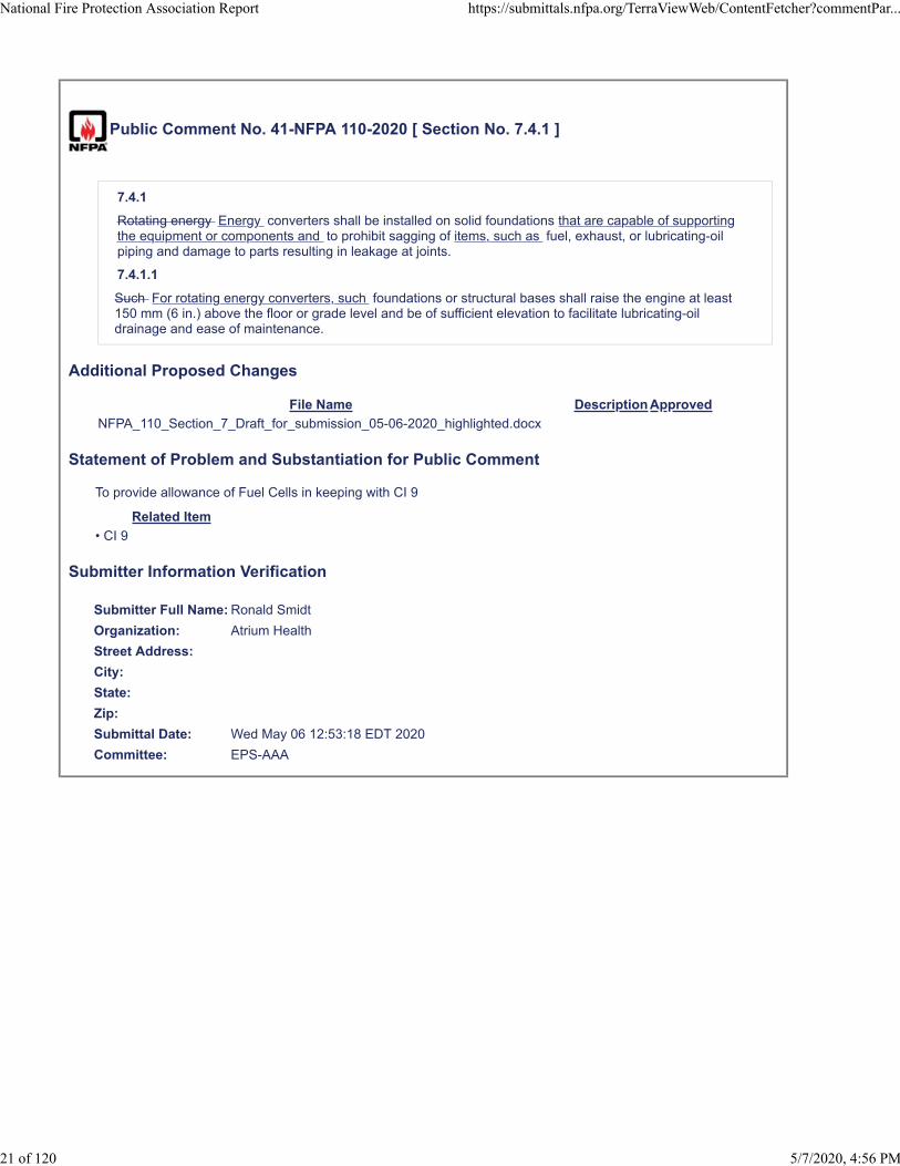
Public Comment No. 41-NFPA 110-2020 [ Section No. 7.4.1 ]
7.4.1
Rotating energy Energy converters shall be installed on solid foundations that are capable of supportingthe equipment or components and to prohibit sagging of items, such as fuel, exhaust, or lubricating-oilpiping and damage to parts resulting in leakage at joints.
7.4.1.1
Such For rotating energy converters, such foundations or structural bases shall raise the engine at least150 mm (6 in.) above the floor or grade level and be of sufficient elevation to facilitate lubricating-oildrainage and ease of maintenance.
Additional Proposed Changes
File Name Description Approved
NFPA_110_Section_7_Draft_for_submission_05-06-2020_highlighted.docx
Statement of Problem and Substantiation for Public Comment
To provide allowance of Fuel Cells in keeping with CI 9
Related Item
• CI 9
Submitter Information Verification
Submitter Full Name: Ronald Smidt
Organization: Atrium Health
Street Address:
City:
State:
Zip:
Submittal Date: Wed May 06 12:53:18 EDT 2020
Committee: EPS-AAA
National Fire Protection Association Report https://submittals.nfpa.org/TerraViewWeb/ContentFetcher?commentPar...
21 of 120 5/7/2020, 4:56 PM

Task group response CI 9 for inclusion of fuel cells
NFPA 110 Emergency and Standby Power Systems
Chapter 7 Installation and Environmental Considerations
7.1 General.
7.1.1 This chapter shall establish minimum requirements and considerations relative to the installation
and environmental conditions that have an effect on the performance of the EPSS equipment such as
the following:
(1) Geographic location
(2) Building type
(3) Classification of occupancy
(4) Hazard of contents
7.1.2 Minimizing the probability of equipment or cable failure within the EPSS shall be a design
consideration to reduce the disruption of loads served by the EPSS.
7.1.3 The EPSS equipment shall be installed as required to meet the user’s needs and to be in
accordance with all of the following:
(1) This standard
(2) The manufacturer’s specifications
(3) The authority having jurisdiction
7.1.4 EPSS equipment installed for the various levels of service defined in this standard shall be designed
and assembled for such service.
7.1.5 When the normal power source is not available, the EPS shall be permitted to serve optional loads
other than system loads, provided that the EPS has adequate capacity or automatic selective load pickup
and load shedding are provided as needed to ensure adequate power to (1) the Level 1 loads, (2) the
Level 2 loads, and (3) the optional loads, in that order of priority. When the normal power is available,
the EPS shall be permitted to be used for other purposes such as peak load shaving, internal voltage
control, load relief for the utility providing normal power, or cogeneration.
7.2 Location.
7.2.1 Indoor EPS Installations. The EPS shall be installed in a separate room for Level 1 installations.
7.2.1.1 The EPS room shall be separated from the rest of the building by construction with a 2‐hour fire
resistance rating.
7.2.1.2 EPSS equipment shall be permitted to be installed in the EPS room.

7.2.1.3 No other equipment, including architectural appurtenances, except those that serve this space,
shall be permitted in the EPS room.
7.2.2 Outdoor EPS Installations.
7.2.2.1 The EPS shall be installed in a suitable enclosure located outside the building and capable of
resisting the entrance of snow or rain at a maximum wind velocity as required by local building codes.
7.2.2.2 EPSS equipment shall be permitted to be installed in the EPS enclosure.
7.2.2.3 No other equipment, including architectural appurtenances, expect those that serve this space,
shall be permitted in the EPS enclosure.
7.2.3 Level 1 EPSS equipment shall not be installed in the same room with the normal service
equipment, where the service equipment is rated over 150 volts to ground and equal to or greater than
1000 amperes.
7.2.4 The rooms, enclosures, or separate buildings housing Level 1 or Level 2 EPSS equipment shall be
designed and located to minimize damage from flooding, including that caused by the following:
(1) Flooding resulting from fire fighting
(2) Sewer water backup
(3) Other disasters or occurrences
7.2.5 Minimizing the possibility of damage resulting from interruptions of the emergency source shall be
a design consideration for EPSS equipment.
7.2.6 The EPS equipment shall be installed in a location that permits ready accessibility and a minimum
of 0.9 m (36 in.) from the skid rails’ outermost point in the directions of access for inspection, repair,
maintenance, cleaning, or replacement. This requirement shall not apply to units in outdoor housings.
7.2.7 Design considerations shall minimize the effect of the failure of one energy converter on the
continued operations of other units.
7.3 Lighting.
7.3.1 The Level 1 or Level 2 EPS equipment location(s) shall be provided with battery‐powered
emergency lighting. This requirement shall not apply to units located outdoors in enclosures that do not
include walk‐in access.
7.3.2 The emergency lighting charging system and the normal service room lighting shall be supplied
from the load side of the transfer switch.
7.3.3 The minimum average horizontal illumination provided by normal lighting sources in the separate
building or room housing the EPS equipment for Level 1 shall be 32.3 lux (3.0 ft‐candles) measured at
the floor level, unless otherwise specified by a replacement recognized by the authority having
jurisdiction.

7.4 Mounting.
7.4.1 Rotating Energy converters shall be installed on solid foundations that are capable of supporting
the equipment or components, and to prohibit sagging of items, such as fuel, exhaust, or lubricating‐oil
piping and damage to parts resulting in leakage at joints.
7.4.1.1 For rotating energy converters, such foundations or structural bases shall raise the engine at
least 150 mm (6 in.) above the floor or grade level and be of sufficient elevation to facilitate lubrication‐
oil drainage and ease of maintenance.
7.4.2 Foundations shall be of the size (mass) and type recommended by the energy converter
manufacturer.
7.4.3 Where required to prevent transmission of vibration during operation, the foundation shall be
isolated from the surrounding floor or other foundations, or both, in accordance with the
manufacturer’s recommendations and accepted structural engineering practices.
7.4.4 The EPS utilizing rotating equipment shall be mounted on a fabricated metal skid base of the type
that shall resist damage during shipping and handling. After installation, the base shall maintain
alignment of the unit during operation.
7.5 Vibration. Vibration isolators, as recommended by the manufacturer of the EPS, shall be installed
either between the EPS utilizing rotating equipment and its skid base or between the skid base and the
foundation or inertia base
7.6 Noise. Design shall include consideration of noise control regulations.
7.7 Heating, Cooling, and Ventilating.
7.7.1 With the EPS running at rated load, ventilation airflow shall be provided to limit the maximum air
temperature in the EPS room or the enclosure housing the unit to the maximum ambient air
temperature required by the EPS manufacturer.
7.7.1.1 Consideration shall be given to all the heat emitted to the EPS equipment room by the energy
converter, uninsulated or insulated exhaust pipes, and other heat‐producing equipment.
7.7.2 Air shall be supplied to the EPS equipment for proper operation combustion .
7.7.2.1 For EPS supplying Level 1 EPSS, ventilation air shall be supplied directly from a source outside the
building by an exterior wall opening or from a source outside the building by a 2‐hour fire‐rated air
transfer system.
7.7.2.2 For EPS supplying Level 1 EPSS, discharge air shall be directed outside the building by an exterior
wall opening or to an exterior opening by a 2‐hour fire‐rated air transfer system.
7.7.2.3 Fire dampers, shutters, or other self‐closing devices shall not be permitted in ventilation
openings or ductwork for supply or return/discharge air to EPS equipment for Level 1 EPSS.
7.7.3 Ventilation air supply shall be from outdoors or from a source outside the building by an exterior
wall opening or from a source outside the building by a 2‐hour fire‐rated air transfer system.

7.7.4 Ventilation air shall be provided to supply and discharge cooling air for radiator cooling of the EPS
when running at rated load.
7.7.4.1 Ventilation air supply and discharge for radiator‐cooled EPS shall have a maximum static
restriction of 125 Pa (0.5 in. of water column) in the discharge duct at the radiator outlet.
7.7.4.2 Radiator air discharge shall be ducted outdoors or to an exterior opening by a 2‐hour rated air
transfer system.
7.7.5 Motor‐operated dampers, when used, shall be spring operated to open and motor closed. Fire
dampers, shutter, or other self‐closing devices shall not be permitted in ventilation openings or
ductwork for supply or return/discharge air to EPS equipment for Level 1 EPSS.
7.7.6 Units housed outdoors shall be heated as specified in 5.3.5.
7.7.7 Design of the heating, cooling, and ventilation system for the EPS equipment room shall include
provision for factors including, but not limited to, the following:
1) Heat
2) Cold
3) Dust
4) Humidity
5) Snow and ice accumulations around housings
6) Louvers
7) Remote radiator fans
8) Prevailing winds blowing against radiator fan discharge air
7.8 Installed EPS Cooling System.
7.8.1 Makeup water hose bibs and floor drains, where required by other codes and standards, shall be
installed in EPS equipment rooms.
7.8.2 Where duct connections are used between the prime mover radiator and air‐out louvers, the ducts
shall be connected to the prime movers by means of flexible sections.
7.9 Fuel System.
7.9.1 Fuel tanks shall be sized to accommodate the specific EPS class.
7.9.1.1 All fuel tanks and systems intended for use with rotating engines shall be installed and
maintained in accordance with NFPA 30, NFPA 37, NFPA 54, and NFPA 58.
7.9.1.1… All fuel tanks and systems for use with fuel cell power systems shall be installed and
maintained in accordance with NFPA 2, NFPA 30, NFPA 31, NFPA 52, NFPA 54, NFPA 55, and NFPA 58. Commented [CP1]: Need to modify numbering

7.9.1.2 Fuel system design shall provide for a supply of clean fuel to the prime mover energy converter.
7.9.1.3 Tanks shall be sized so that the fuel is consumed within the storage life, or provisions shall be
made to remediate fuel that is stale or contaminated or to replace stale or contaminated fuel with clean
fuel.
7.9.2 Fuel tanks shall be close enough to the prime mover energy converter fuel pump to meet the fuel
system requirements, or a fuel transfer pump and day tank shall be provided.
7.9.2.1 If the engine manufacturer’s fuel pump static head pressure limits are exceeded when the level
of fuel in the tank is at a maximum, a day tank shall be utilized.
7.9.3 Fuel piping shall be of compatible metal to minimize electrolysis and shall be properly sized, with
vent and fill pipes located to prevent entry of groundwater or rain into the tank.
7.9.3.1 Galvanized fuel lines shall not be used.
7.9.3.2 Approved flexible fuel lines shall be used between the prime mover energy converter and the
fuel piping.
7.9.4 Day tanks on diesel systems shall be installed below the engine fuel return elevation.
7.9.4.1 The return line to the day tank shall be below the fuel return elevation.
7.9.4.2 Gravity fuel oil return lines between the day tank and the main supply tank shall be sized to
handle the potential fuel flow and shall be free of traps so that fuel can flow freely to the main tank.
7.9.5 Integral tanks of the following capacities shall be permitted inside or on roofs of structures, or as
approved by the authority having jurisdiction:
1) Maximum of 2498 L (660 gal) diesel fuel
2) Maximum of 95 L (25 gal) gasoline fuel
7.9.6 The fuel supply for gas‐fueled and liquid‐fueled prime movers energy converters shall be installed
in accordance with the applicable standards.
7.9.7 Where the gas supply is connected to the building gas supply system, it shall be connected on the
supply side of the main gas shutoff valve and marked as supplying an emergency generator power
source.
7.9.8 The building’s main gas shutoff valve shall be marked or tagged to indicate the existence of the
separate EPS shutoff valve.
7.9.9 The fuel supply for gas‐fueled and liquid‐fueled prime movers energy converters shall be designed
to meet the demands of the prime mover energy converter for all of the following factors, as applicable
to the system:
1) Sizing of fuel lines
2) Valves, including manual shutoff
3) Battery‐powered fuel solenoids

4) Gas regulators
5) Regulator vent piping
6) Flexible fuel line section
7) Fuel line filters
8) Fuel vaporizers (LP‐gas)
9) Ambient temperature effect of fuel tank vaporization rates of LP‐gas where applicable
7.9.10 The fuel storage and supply lines for an EPSS shall be in accordance with this standard or with the
specific authority having jurisdiction, or both.
7.9.11 All manual fuel system valves shall be of the indicating type.
7.9.12 Listed generator subbase secondary containment fuel tanks of 2498 L (660 gal) capacity and
below shall be permitted to be installed outdoors or indoors without diking or remote impounding.
7.9.12.1 A minimum clearance of 0.9 m (36 in.) shall be maintained on all sides.
7.9.13 Automatically actuated valves shall not be permitted in the fuel oil supply or fuel oil return lines
for Level 1 EPSSemergency power supply systems.
7.10 Exhaust System.
7.10.1 The exhaust system equipment and installation, including piping, muffler, and related accessories
for combustion engines and gas turbines, shall be in accordance with NFPA 37 and other applicable
standards.
7.10… The exhaust system equipment and installation, and related accessories for fuel cell power
systems, shall be in accordance with NFPA 853 and other applicable standards.
7.10.2 Exhaust system installation shall be gastight to prevent exhaust gas fumes from entering
inhabited rooms or buildings and terminate in such a manner that toxic fumes cannot reenter a building
or structure, particularly through windows, air ventilation inlets, or the engine air‐intake system.
7.10.3 Exhaust piping shall be connected to the prime mover by means of a flexible connecter and shall
be independently supported thereafter so that no damaging weight or stress is applied to the engine
exhaust manifold or turbocharger.
7.10… Exhaust piping shall be connected to the fuel cell power system by means of a flexible connecter
and shall be independently supported thereafter so that no damaging weight or stress is applied to the
exhaust outlet.
7.10.3.1 A condensate trap and drain valve shall be provided at the low point(s) of the piping unless the
piping is self‐draining.
7.10.3.2 Design consideration shall be given to thermal expansion and the resultant movement of the
piping.
Commented [CP2]: Need to modify numbering
Commented [CP3]: Need to modify numbering

7.10.3.3 For reciprocating engines, mufflers shall be placed as close as practicable to the engine, in a
horizontal position if possible.
7.10.3.4 An approved thimble(s) shall be used where exhaust piping passes through combustible walls
or partitions.
7.10.3.5 For reciprocating engines, the piping shall terminate in any of the following:
1) Rain cap
2) Tee
3) Ell, pointing downwind from the prevailing wind
4) Vertically upward‐oriented stack with suitable provisions for trapping and draining rain and snow
water
7.10.3.6 Design consideration shall be given to the potential heat effect due to proximity to all of the
following:
1) Conduit runs
2) Fuel piping
3) Lighting fixtures
7.10.3.7 Design consideration shall be given to insulating the engine energy converter exhaust systems
in buildings after the flexible section.
7.10.4 For maximum efficiency, operation economy, and prevention of engine damage, the exhaust
system shall be designed to eliminate excessive backpressure on the engine by properly selecting,
routing, and installing the piping size, connections and muffler.
7.10… The fuel cell power system exhaust system shall be designed to eliminate excessive
backpressure on the system by properly selecting, routing, and installing the piping size, connections
and ducting.
7.10.4.1 Exhaust systems shall be installed to ensure satisfactory EPS operation and meet the
requirements of the manufacturer.
7.11 Protection.
7.11.1 The room in which the EPS equipment is located shall not be used for other purposes that are not
directly related to the EPS. Parts, tools, and manuals for routine maintenance and repair shall be
permitted to be stored in the EPS room.
7.11.2 Where fire suppression systems are installed in EPS equipment rooms or separate buildings, the
following systems shall not be used:
1) Carbon dioxide or halon systems, unless prime mover energy converter combustion air is taken from
outside the structure
Commented [CP4]: Adjust numbering

2) An automatic dry chemical system, unless the manufacturers of the EPS certify that the dry chemical
system cannot damage the EPS system, hinder its operation, or reduce its output.
7.11.3 Where the EPS rooms or separate buildings are equipped with fire detection systems, the
installation shall be in accordance with NFPA 72.
7.11.4 Where outdoor and/or rooftop Level 1 EPS installations are required to be protected from
lightning, the lightning protection system(s) shall be installed in accordance with NFPA 780.
7.11.5 In recognized seismic risk areas, EPS and EPSS components, such as electrical distribution lines,
water distribution lines, fuel distribution lines, and other components that serve the EPS, shall be
designed to minimize damage from earthquakes and to facilitate repairs if an earthquake occurs.
7.11.6 For systems in seismic risk areas, the EPS, transfer switches, distribution panels, circuit breakers,
and associated controls shall be capable of performing their intended function after being subjected to
the anticipated seismic shock.
7.12 Distribution.
7.12.1 The distribution and wiring systems within the EPSS shall be installed in accordance with NFPA
70.
7.12.2 Where EPSS’s are installed in health care facilities, the installation of the EPSS shall also be in
compliance with NFPA 99.
7.12.3 If the conduit’s point of attachment to the EPS is on the forcing function side of the EPS vibration
isolation system, a flexible conduit section(s) shall be installed between the EPS unit(s) and any of the
following, so attached:
1) The transfer switch
2) The control and annunciator wiring
3) Any accessory supply wiring, such as jacket water heaters
7.12.3.1 Stranded wire of adequate size shall be used to minimize breakage due to vibration.
7.12.3.2 Bushings shall be installed to protect wiring from abrasion with conduit terminations.
7.12.4 All ac‐powered support and accessory equipment necessary to the operation of the EPS shall be
supplied from the load side of the ATS’s, or the output terminals of the EPS, ahead of the main EPS
overcurrent protection to ensure continuity of the EPSS operation and performance.
7.12.5 When used, the starting battery units shall be located next to the prime mover energy converter
starter to minimize voltage drop.
7.12.5.1 Battery cables shall be sized to minimize voltage drop in accordance with the manufacturer’s
recommendations and accepted engineering practices.
7.12.5.2 Battery charger output wiring shall be permanently connected to the primary side of the starter
solenoid (positive) and the EPS frame (negative), or other grounding location.

7.13 Installation Acceptance.
7.13.1 Upon completion of the installation of the EPSS, the EPS shall be tested to ensure conformity to
the requirements of the standard with respect to both power output and function.
7.13.2 An on‐site acceptance test shall be conducted as a final approval test for all EPSSs.
7.13.2.1 For new Level 1 installations, the EPSS shall not be considered as meeting this standard until
the acceptance tests have been conducted and test requirements met.
7.13.2.2 The test shall be conducted after completion of the installation with all EPSS accessory and
support equipment in place and operating.
7.13.3 The authority having jurisdiction shall be given advance notification of the time at which the
acceptance test is to be performed so that the authority can witness the test.
7.13.4 The EPSS shall perform within the limits specified in this standard.
7.13.4.1 The on‐site installation acceptance test shall be conducted in accordance with 7.13.4.1.1
through 7.13.4.1.4.
7.13.4.1.1 In a new and unoccupied building or facility, with the prime mover energy converter in a cold
start condition and the emergency load at operating level, a normal power failure shall be initiated by
opening all switches or circuit breakers supplying the normal power to the building or facility.
7.13.4.1… For fuel cell power systems that are continuously running, the cold start condition is not
required.
7.13.4.1.2 In an existing occupied building or facility, with the prime mover energy converter in a cold
start condition and the emergency load at operating level, a normal power failure shall be simulated by
operating at least one transfer switch test function or initiated by opening all switches or breakers
supplying normal power to all ATSs that are part of the EPSS being commissioned by this initial
acceptance test.
7.13.4.1… For fuel cell power systems that are continuously running, the cold start condition is not
required.
7.13.4.1.3 When the EPSS consists of paralleled EPSs, the system control function for paralleling and
load shedding shall be verified in accordance with system design documentation.
7.13.4.1.4 For engine generators, Tthe tests conducted in accordance with 7.13.4.1.1 and 7.13.4.1.2
shall be performed in accordance with 7.13.4.1.4(1) through 7.13.4.1.4(12).
1) When the EPSS consists of paralleled EPSs, the quantity of EPSs intended to be operated
simultaneously shall be tested simultaneously with building load for the test period identified in
7.13.4.1(10).
2) The test load shall be all loads that are served by the EPSS. There is no minimum loading requirement
for this portion of the test.
3) The time delay on start shall be observed and recorded.
Commented [CP5]: Need to modify numbering
Commented [CP6]: Need to modify numbering

4) The cranking time until the prime mover starts and runs shall be observed and recorded.
5) The time taken to reach operating speed shall be observed and recorded.
6) The engine start function shall be confirmed by verifying operation of the initiating circuit of all
transfer switches supplying EPSS loads.
7) The time taken to achieve a steady‐state condition with all switches transferred to the emergency
position shall be observed and recorded.
8) The voltage, frequency, and amperes shall be recorded.
9) Where applicable, the prime mover oil pressure and water temperature shall be recorded.
10) The load test with building load, or other loads that simulate the intended load as specified in
Section 5.4 shall be continued for not less than 1.5 hours, and the run time shall be recorded.
11) When normal power is restored to the building or facility, the time delay on retransfer to normal
power for each switch with a minimum setting of 5 minutes shall be recorded.
12) The time delay on the prime mover cooldown period and shutdown shall be recorded.
7.13.4.2 After completion of the test performed in 7.13.4.1, the prime mover shall be allowed to cool for
not less than 5 minutes.
7.13.4.3 A load shall be applied for a 2‐hour, full‐load test. The building load shall be permitted to serve
as part or all of the load, supplemented by a load bank of sufficient size to provide a load equal to 100
percent of the nameplate kW rating of the EPS, less applicable derating factors for site conditions. With
full load applied, the coolant temperature of the generator set shall stabilize at a constant value relative
to outdoor ambient temperature at least 30 minutes prior to completion of the test.
7.13.4.3.1 This full‐load test shall be initiated after the test specified in 7.13.4.1.4 by any method that
starts the prime mover and, upon reaching rated rpm, picks up not less than 30 percent of the
nameplate kW rating for the first 30 minutes, not less than 50 percent of the nameplate kW rating for
the next 30 minutes, and 100 percent of the nameplate kW rating for the next 60 minutes, less
applicable derating factors for site conditions.
7.13.4.3.2 A unity power factor shall be permitted for on‐site testing, provided that rated load tests at
the rated power factor have been performed by the manufacturer of the EPS prior to shipment.
7.13.4.3.3 Where the EPS is a paralleled multi‐unit EPS, each unit shall be permitted to be tested
individually at its rating.
7.13.4.3.4 The data specified in 7.13.4.1(4), 7.13.4.1.4(5), and 7.13.4.1.4(7) shall be recorded at first load
acceptance of the test period identified in 7.13.4.1.4(10).
7.13.4.3.5 The data specified in 7.13.4.1.4(8) and 7.13.4.1.4(9) shall be recorded at first load acceptance
and every 15 minutes thereafter until the completion of the test period identified in 7.13.4.1.4(10).
7.13.4.4 Any method recommended by the manufacturer for the cycle crank test shall be utilized to
prevent the prime mover from running.

7.13.4.4.1 The control switch shall be set at “run” to cause the prime mover to crank.
7.13.4.4.2 The complete crank/rest cycle specified in 5.6.4.2 and Table 5.6.4.2 shall be observed.
7.13.4.4.3 The battery charge rate shall be recorded at 5‐minute intervals for the first 15 minutes or
until charge rate stabilization.
7.13.4.5 All safeties specified in 5.6.5 and 5.6.6 shall be tested on site as recommended by the
manufacturer.
Exception No. 1: It shall be permitted for the engine manufacturer to test and document overcrank, high
engine temperature, low lube oil pressure and overspeed safeties prior to shipment.
Exception No. 2: Where the safety functions are proven to be fail‐safe as demonstrated by monitoring
of normal conditions on engine metering and demonstration that a failed sensor or circuit will not cause
shutdown of the engine, further testing of the safeties is not required.
7.13.4.1…. For continuously running fuel cell power systems, the tests conducted in accordance with
7.13.4.1.1 and 7.13.4.1.2 shall be performed in accordance with 7.13.4.1.4(1) through 7.13.4.1.4(7).
1) When the EPSS consists of paralleled EPSs, the quantity of EPSs intended to be operated
simultaneously shall be tested simultaneously with building load for the test period identified in
7.13.4.1(10).
2) The test load shall be all loads that are served by the EPSS. There is no minimum loading requirement
for this portion of the test.
3) The time delay on transfer shall be observed and recorded.
4) The fuel cell operation shall be confirmed by verifying operation of the initiating circuit of all transfer
switches supplying EPSS loads.
5) The time taken to achieve a steady‐state condition with all switches transferred to the emergency
position shall be observed and recorded.
5) The voltage, frequency, and amperes shall be recorded.
6) The load test with building load, or other loads that simulate the intended load as specified in Section
5.4 shall be continued for not less than 1.5 hours, and the run time shall be recorded.
7) When normal power is restored to the building or facility, the time delay on retransfer to normal
power for each switch with a minimum setting of 5 minutes shall be recorded.
7.13.4.3 A load shall be applied for a 2‐hour, full‐load test. The building load shall be permitted to serve
as part or all of the load, supplemented by a load bank of sufficient size to provide a load equal to 100
percent of the nameplate kW rating of the EPS, less applicable derating factors for site conditions.
7.13.4.3.1 This full‐load test shall be initiated after the test specified in 7.13.4.1.4 by any method that
picks up not less than 30 percent of the nameplate kW rating for the first 30 minutes, not less than 50
percent of the nameplate kW rating for the next 30 minutes, and 100 percent of the nameplate kW
rating for the next 60 minutes, less applicable derating factors for site conditions.
Commented [CP7]: Need to modify numbering
Commented [CP8]: Need to modify numbering
Commented [CP9]: Need to modify numbering

7.13.4.3.2 A unity power factor shall be permitted for on‐site testing, provided that rated load tests at
the rated power factor have been performed by the manufacturer of the EPS prior to shipment.
7.13.4.3.3… Where the EPS is a paralleled multi‐unit EPS, each unit shall be permitted to be tested
individually at its rating.
7.13.4.3.4… The data specified in 7.13.4.1.4(3) and 7.13.4.1.4(4) shall be recorded at first load
acceptance of the test period identified in 7.13.4.1.4(6).
7.13.4.3.5… The data specified in 7.13.4.1.4(5) shall be recorded at first load acceptance and every 15
minutes thereafter until the completion of the test period identified in 7.13.4.1.4(6).
7.13.4.5 All safeties specified in 5.7.5 and 5.7.6 shall be tested on site as recommended by the
manufacturer.
Exception No. 2: Where the safety functions are proven to be fail‐safe as demonstrated by monitoring
of normal conditions on fuel cell system metering and demonstration that a failed sensor or circuit will
not cause shutdown of the energy converter, further testing of the safeties is not required.
7.13.4.6 Items (1) through (4) shall be made available to the authority having jurisdiction at the time of
the acceptance test:
1) Evidence of the prototype test as specified in 5.2.1.2 (for Level 1 systems)
2) For rotating equipment, Aa certified analysis as specified in 5.6.10.2
3) A letter of compliance as specified in 5.6.10.5 or 5.7.8.1
4) A manufacturer’s certification of a rated load test at rated power factor with the ambient
temperature, altitude, and fuel grade recorded.
Commented [CP10]: Need to modify numbering
Commented [CP11]: Need to modify numbering
Commented [CP12]: Need to modify numbering
Commented [CP13]: Need to modify numbering
Commented [CP14]: Need to modify numbering

Public Comment No. 42-NFPA 110-2020 [ Section No. 7.4.4 ]
7.4.4
The EPS EPS utilizing rotating equipment shall be mounted on a fabricated metal skid base of the typethat shall resist damage during shipping and handling. After installation, the base shall maintain alignmentof the unit during operation.
Additional Proposed Changes
File Name Description Approved
NFPA_110_Section_7_Draft_for_submission_05-06-2020_highlighted.docx
Statement of Problem and Substantiation for Public Comment
Task group work in response to CI 9
Related Item
• CI 9
Submitter Information Verification
Submitter Full Name: Ronald Smidt
Organization: Atrium Health
Street Address:
City:
State:
Zip:
Submittal Date: Wed May 06 12:58:32 EDT 2020
Committee: EPS-AAA
National Fire Protection Association Report https://submittals.nfpa.org/TerraViewWeb/ContentFetcher?commentPar...
22 of 120 5/7/2020, 4:56 PM

Task group response CI 9 for inclusion of fuel cells
NFPA 110 Emergency and Standby Power Systems
Chapter 7 Installation and Environmental Considerations
7.1 General.
7.1.1 This chapter shall establish minimum requirements and considerations relative to the installation
and environmental conditions that have an effect on the performance of the EPSS equipment such as
the following:
(1) Geographic location
(2) Building type
(3) Classification of occupancy
(4) Hazard of contents
7.1.2 Minimizing the probability of equipment or cable failure within the EPSS shall be a design
consideration to reduce the disruption of loads served by the EPSS.
7.1.3 The EPSS equipment shall be installed as required to meet the user’s needs and to be in
accordance with all of the following:
(1) This standard
(2) The manufacturer’s specifications
(3) The authority having jurisdiction
7.1.4 EPSS equipment installed for the various levels of service defined in this standard shall be designed
and assembled for such service.
7.1.5 When the normal power source is not available, the EPS shall be permitted to serve optional loads
other than system loads, provided that the EPS has adequate capacity or automatic selective load pickup
and load shedding are provided as needed to ensure adequate power to (1) the Level 1 loads, (2) the
Level 2 loads, and (3) the optional loads, in that order of priority. When the normal power is available,
the EPS shall be permitted to be used for other purposes such as peak load shaving, internal voltage
control, load relief for the utility providing normal power, or cogeneration.
7.2 Location.
7.2.1 Indoor EPS Installations. The EPS shall be installed in a separate room for Level 1 installations.
7.2.1.1 The EPS room shall be separated from the rest of the building by construction with a 2‐hour fire
resistance rating.
7.2.1.2 EPSS equipment shall be permitted to be installed in the EPS room.

7.2.1.3 No other equipment, including architectural appurtenances, except those that serve this space,
shall be permitted in the EPS room.
7.2.2 Outdoor EPS Installations.
7.2.2.1 The EPS shall be installed in a suitable enclosure located outside the building and capable of
resisting the entrance of snow or rain at a maximum wind velocity as required by local building codes.
7.2.2.2 EPSS equipment shall be permitted to be installed in the EPS enclosure.
7.2.2.3 No other equipment, including architectural appurtenances, expect those that serve this space,
shall be permitted in the EPS enclosure.
7.2.3 Level 1 EPSS equipment shall not be installed in the same room with the normal service
equipment, where the service equipment is rated over 150 volts to ground and equal to or greater than
1000 amperes.
7.2.4 The rooms, enclosures, or separate buildings housing Level 1 or Level 2 EPSS equipment shall be
designed and located to minimize damage from flooding, including that caused by the following:
(1) Flooding resulting from fire fighting
(2) Sewer water backup
(3) Other disasters or occurrences
7.2.5 Minimizing the possibility of damage resulting from interruptions of the emergency source shall be
a design consideration for EPSS equipment.
7.2.6 The EPS equipment shall be installed in a location that permits ready accessibility and a minimum
of 0.9 m (36 in.) from the skid rails’ outermost point in the directions of access for inspection, repair,
maintenance, cleaning, or replacement. This requirement shall not apply to units in outdoor housings.
7.2.7 Design considerations shall minimize the effect of the failure of one energy converter on the
continued operations of other units.
7.3 Lighting.
7.3.1 The Level 1 or Level 2 EPS equipment location(s) shall be provided with battery‐powered
emergency lighting. This requirement shall not apply to units located outdoors in enclosures that do not
include walk‐in access.
7.3.2 The emergency lighting charging system and the normal service room lighting shall be supplied
from the load side of the transfer switch.
7.3.3 The minimum average horizontal illumination provided by normal lighting sources in the separate
building or room housing the EPS equipment for Level 1 shall be 32.3 lux (3.0 ft‐candles) measured at
the floor level, unless otherwise specified by a replacement recognized by the authority having
jurisdiction.

7.4 Mounting.
7.4.1 Rotating Energy converters shall be installed on solid foundations that are capable of supporting
the equipment or components, and to prohibit sagging of items, such as fuel, exhaust, or lubricating‐oil
piping and damage to parts resulting in leakage at joints.
7.4.1.1 For rotating energy converters, such foundations or structural bases shall raise the engine at
least 150 mm (6 in.) above the floor or grade level and be of sufficient elevation to facilitate lubrication‐
oil drainage and ease of maintenance.
7.4.2 Foundations shall be of the size (mass) and type recommended by the energy converter
manufacturer.
7.4.3 Where required to prevent transmission of vibration during operation, the foundation shall be
isolated from the surrounding floor or other foundations, or both, in accordance with the
manufacturer’s recommendations and accepted structural engineering practices.
7.4.4 The EPS utilizing rotating equipment shall be mounted on a fabricated metal skid base of the type
that shall resist damage during shipping and handling. After installation, the base shall maintain
alignment of the unit during operation.
7.5 Vibration. Vibration isolators, as recommended by the manufacturer of the EPS, shall be installed
either between the EPS utilizing rotating equipment and its skid base or between the skid base and the
foundation or inertia base
7.6 Noise. Design shall include consideration of noise control regulations.
7.7 Heating, Cooling, and Ventilating.
7.7.1 With the EPS running at rated load, ventilation airflow shall be provided to limit the maximum air
temperature in the EPS room or the enclosure housing the unit to the maximum ambient air
temperature required by the EPS manufacturer.
7.7.1.1 Consideration shall be given to all the heat emitted to the EPS equipment room by the energy
converter, uninsulated or insulated exhaust pipes, and other heat‐producing equipment.
7.7.2 Air shall be supplied to the EPS equipment for proper operation combustion .
7.7.2.1 For EPS supplying Level 1 EPSS, ventilation air shall be supplied directly from a source outside the
building by an exterior wall opening or from a source outside the building by a 2‐hour fire‐rated air
transfer system.
7.7.2.2 For EPS supplying Level 1 EPSS, discharge air shall be directed outside the building by an exterior
wall opening or to an exterior opening by a 2‐hour fire‐rated air transfer system.
7.7.2.3 Fire dampers, shutters, or other self‐closing devices shall not be permitted in ventilation
openings or ductwork for supply or return/discharge air to EPS equipment for Level 1 EPSS.
7.7.3 Ventilation air supply shall be from outdoors or from a source outside the building by an exterior
wall opening or from a source outside the building by a 2‐hour fire‐rated air transfer system.

7.7.4 Ventilation air shall be provided to supply and discharge cooling air for radiator cooling of the EPS
when running at rated load.
7.7.4.1 Ventilation air supply and discharge for radiator‐cooled EPS shall have a maximum static
restriction of 125 Pa (0.5 in. of water column) in the discharge duct at the radiator outlet.
7.7.4.2 Radiator air discharge shall be ducted outdoors or to an exterior opening by a 2‐hour rated air
transfer system.
7.7.5 Motor‐operated dampers, when used, shall be spring operated to open and motor closed. Fire
dampers, shutter, or other self‐closing devices shall not be permitted in ventilation openings or
ductwork for supply or return/discharge air to EPS equipment for Level 1 EPSS.
7.7.6 Units housed outdoors shall be heated as specified in 5.3.5.
7.7.7 Design of the heating, cooling, and ventilation system for the EPS equipment room shall include
provision for factors including, but not limited to, the following:
1) Heat
2) Cold
3) Dust
4) Humidity
5) Snow and ice accumulations around housings
6) Louvers
7) Remote radiator fans
8) Prevailing winds blowing against radiator fan discharge air
7.8 Installed EPS Cooling System.
7.8.1 Makeup water hose bibs and floor drains, where required by other codes and standards, shall be
installed in EPS equipment rooms.
7.8.2 Where duct connections are used between the prime mover radiator and air‐out louvers, the ducts
shall be connected to the prime movers by means of flexible sections.
7.9 Fuel System.
7.9.1 Fuel tanks shall be sized to accommodate the specific EPS class.
7.9.1.1 All fuel tanks and systems intended for use with rotating engines shall be installed and
maintained in accordance with NFPA 30, NFPA 37, NFPA 54, and NFPA 58.
7.9.1.1… All fuel tanks and systems for use with fuel cell power systems shall be installed and
maintained in accordance with NFPA 2, NFPA 30, NFPA 31, NFPA 52, NFPA 54, NFPA 55, and NFPA 58. Commented [CP1]: Need to modify numbering

7.9.1.2 Fuel system design shall provide for a supply of clean fuel to the prime mover energy converter.
7.9.1.3 Tanks shall be sized so that the fuel is consumed within the storage life, or provisions shall be
made to remediate fuel that is stale or contaminated or to replace stale or contaminated fuel with clean
fuel.
7.9.2 Fuel tanks shall be close enough to the prime mover energy converter fuel pump to meet the fuel
system requirements, or a fuel transfer pump and day tank shall be provided.
7.9.2.1 If the engine manufacturer’s fuel pump static head pressure limits are exceeded when the level
of fuel in the tank is at a maximum, a day tank shall be utilized.
7.9.3 Fuel piping shall be of compatible metal to minimize electrolysis and shall be properly sized, with
vent and fill pipes located to prevent entry of groundwater or rain into the tank.
7.9.3.1 Galvanized fuel lines shall not be used.
7.9.3.2 Approved flexible fuel lines shall be used between the prime mover energy converter and the
fuel piping.
7.9.4 Day tanks on diesel systems shall be installed below the engine fuel return elevation.
7.9.4.1 The return line to the day tank shall be below the fuel return elevation.
7.9.4.2 Gravity fuel oil return lines between the day tank and the main supply tank shall be sized to
handle the potential fuel flow and shall be free of traps so that fuel can flow freely to the main tank.
7.9.5 Integral tanks of the following capacities shall be permitted inside or on roofs of structures, or as
approved by the authority having jurisdiction:
1) Maximum of 2498 L (660 gal) diesel fuel
2) Maximum of 95 L (25 gal) gasoline fuel
7.9.6 The fuel supply for gas‐fueled and liquid‐fueled prime movers energy converters shall be installed
in accordance with the applicable standards.
7.9.7 Where the gas supply is connected to the building gas supply system, it shall be connected on the
supply side of the main gas shutoff valve and marked as supplying an emergency generator power
source.
7.9.8 The building’s main gas shutoff valve shall be marked or tagged to indicate the existence of the
separate EPS shutoff valve.
7.9.9 The fuel supply for gas‐fueled and liquid‐fueled prime movers energy converters shall be designed
to meet the demands of the prime mover energy converter for all of the following factors, as applicable
to the system:
1) Sizing of fuel lines
2) Valves, including manual shutoff
3) Battery‐powered fuel solenoids

4) Gas regulators
5) Regulator vent piping
6) Flexible fuel line section
7) Fuel line filters
8) Fuel vaporizers (LP‐gas)
9) Ambient temperature effect of fuel tank vaporization rates of LP‐gas where applicable
7.9.10 The fuel storage and supply lines for an EPSS shall be in accordance with this standard or with the
specific authority having jurisdiction, or both.
7.9.11 All manual fuel system valves shall be of the indicating type.
7.9.12 Listed generator subbase secondary containment fuel tanks of 2498 L (660 gal) capacity and
below shall be permitted to be installed outdoors or indoors without diking or remote impounding.
7.9.12.1 A minimum clearance of 0.9 m (36 in.) shall be maintained on all sides.
7.9.13 Automatically actuated valves shall not be permitted in the fuel oil supply or fuel oil return lines
for Level 1 EPSSemergency power supply systems.
7.10 Exhaust System.
7.10.1 The exhaust system equipment and installation, including piping, muffler, and related accessories
for combustion engines and gas turbines, shall be in accordance with NFPA 37 and other applicable
standards.
7.10… The exhaust system equipment and installation, and related accessories for fuel cell power
systems, shall be in accordance with NFPA 853 and other applicable standards.
7.10.2 Exhaust system installation shall be gastight to prevent exhaust gas fumes from entering
inhabited rooms or buildings and terminate in such a manner that toxic fumes cannot reenter a building
or structure, particularly through windows, air ventilation inlets, or the engine air‐intake system.
7.10.3 Exhaust piping shall be connected to the prime mover by means of a flexible connecter and shall
be independently supported thereafter so that no damaging weight or stress is applied to the engine
exhaust manifold or turbocharger.
7.10… Exhaust piping shall be connected to the fuel cell power system by means of a flexible connecter
and shall be independently supported thereafter so that no damaging weight or stress is applied to the
exhaust outlet.
7.10.3.1 A condensate trap and drain valve shall be provided at the low point(s) of the piping unless the
piping is self‐draining.
7.10.3.2 Design consideration shall be given to thermal expansion and the resultant movement of the
piping.
Commented [CP2]: Need to modify numbering
Commented [CP3]: Need to modify numbering

7.10.3.3 For reciprocating engines, mufflers shall be placed as close as practicable to the engine, in a
horizontal position if possible.
7.10.3.4 An approved thimble(s) shall be used where exhaust piping passes through combustible walls
or partitions.
7.10.3.5 For reciprocating engines, the piping shall terminate in any of the following:
1) Rain cap
2) Tee
3) Ell, pointing downwind from the prevailing wind
4) Vertically upward‐oriented stack with suitable provisions for trapping and draining rain and snow
water
7.10.3.6 Design consideration shall be given to the potential heat effect due to proximity to all of the
following:
1) Conduit runs
2) Fuel piping
3) Lighting fixtures
7.10.3.7 Design consideration shall be given to insulating the engine energy converter exhaust systems
in buildings after the flexible section.
7.10.4 For maximum efficiency, operation economy, and prevention of engine damage, the exhaust
system shall be designed to eliminate excessive backpressure on the engine by properly selecting,
routing, and installing the piping size, connections and muffler.
7.10… The fuel cell power system exhaust system shall be designed to eliminate excessive
backpressure on the system by properly selecting, routing, and installing the piping size, connections
and ducting.
7.10.4.1 Exhaust systems shall be installed to ensure satisfactory EPS operation and meet the
requirements of the manufacturer.
7.11 Protection.
7.11.1 The room in which the EPS equipment is located shall not be used for other purposes that are not
directly related to the EPS. Parts, tools, and manuals for routine maintenance and repair shall be
permitted to be stored in the EPS room.
7.11.2 Where fire suppression systems are installed in EPS equipment rooms or separate buildings, the
following systems shall not be used:
1) Carbon dioxide or halon systems, unless prime mover energy converter combustion air is taken from
outside the structure
Commented [CP4]: Adjust numbering
2) An automatic dry chemical system, unless the manufacturers of the EPS certify that the dry chemical
system cannot damage the EPS system, hinder its operation, or reduce its output.
7.11.3 Where the EPS rooms or separate buildings are equipped with fire detection systems, the
installation shall be in accordance with NFPA 72.
7.11.4 Where outdoor and/or rooftop Level 1 EPS installations are required to be protected from
lightning, the lightning protection system(s) shall be installed in accordance with NFPA 780.
7.11.5 In recognized seismic risk areas, EPS and EPSS components, such as electrical distribution lines,
water distribution lines, fuel distribution lines, and other components that serve the EPS, shall be
designed to minimize damage from earthquakes and to facilitate repairs if an earthquake occurs.
7.11.6 For systems in seismic risk areas, the EPS, transfer switches, distribution panels, circuit breakers,
and associated controls shall be capable of performing their intended function after being subjected to
the anticipated seismic shock.
7.12 Distribution.
7.12.1 The distribution and wiring systems within the EPSS shall be installed in accordance with NFPA
70.
7.12.2 Where EPSS’s are installed in health care facilities, the installation of the EPSS shall also be in
compliance with NFPA 99.
7.12.3 If the conduit’s point of attachment to the EPS is on the forcing function side of the EPS vibration
isolation system, a flexible conduit section(s) shall be installed between the EPS unit(s) and any of the
following, so attached:
1) The transfer switch
2) The control and annunciator wiring
3) Any accessory supply wiring, such as jacket water heaters
7.12.3.1 Stranded wire of adequate size shall be used to minimize breakage due to vibration.
7.12.3.2 Bushings shall be installed to protect wiring from abrasion with conduit terminations.
7.12.4 All ac‐powered support and accessory equipment necessary to the operation of the EPS shall be
supplied from the load side of the ATS’s, or the output terminals of the EPS, ahead of the main EPS
overcurrent protection to ensure continuity of the EPSS operation and performance.
7.12.5 When used, the starting battery units shall be located next to the prime mover energy converter
starter to minimize voltage drop.
7.12.5.1 Battery cables shall be sized to minimize voltage drop in accordance with the manufacturer’s
recommendations and accepted engineering practices.
7.12.5.2 Battery charger output wiring shall be permanently connected to the primary side of the starter
solenoid (positive) and the EPS frame (negative), or other grounding location.

7.13 Installation Acceptance.
7.13.1 Upon completion of the installation of the EPSS, the EPS shall be tested to ensure conformity to
the requirements of the standard with respect to both power output and function.
7.13.2 An on‐site acceptance test shall be conducted as a final approval test for all EPSSs.
7.13.2.1 For new Level 1 installations, the EPSS shall not be considered as meeting this standard until
the acceptance tests have been conducted and test requirements met.
7.13.2.2 The test shall be conducted after completion of the installation with all EPSS accessory and
support equipment in place and operating.
7.13.3 The authority having jurisdiction shall be given advance notification of the time at which the
acceptance test is to be performed so that the authority can witness the test.
7.13.4 The EPSS shall perform within the limits specified in this standard.
7.13.4.1 The on‐site installation acceptance test shall be conducted in accordance with 7.13.4.1.1
through 7.13.4.1.4.
7.13.4.1.1 In a new and unoccupied building or facility, with the prime mover energy converter in a cold
start condition and the emergency load at operating level, a normal power failure shall be initiated by
opening all switches or circuit breakers supplying the normal power to the building or facility.
7.13.4.1… For fuel cell power systems that are continuously running, the cold start condition is not
required.
7.13.4.1.2 In an existing occupied building or facility, with the prime mover energy converter in a cold
start condition and the emergency load at operating level, a normal power failure shall be simulated by
operating at least one transfer switch test function or initiated by opening all switches or breakers
supplying normal power to all ATSs that are part of the EPSS being commissioned by this initial
acceptance test.
7.13.4.1… For fuel cell power systems that are continuously running, the cold start condition is not
required.
7.13.4.1.3 When the EPSS consists of paralleled EPSs, the system control function for paralleling and
load shedding shall be verified in accordance with system design documentation.
7.13.4.1.4 For engine generators, Tthe tests conducted in accordance with 7.13.4.1.1 and 7.13.4.1.2
shall be performed in accordance with 7.13.4.1.4(1) through 7.13.4.1.4(12).
1) When the EPSS consists of paralleled EPSs, the quantity of EPSs intended to be operated
simultaneously shall be tested simultaneously with building load for the test period identified in
7.13.4.1(10).
2) The test load shall be all loads that are served by the EPSS. There is no minimum loading requirement
for this portion of the test.
3) The time delay on start shall be observed and recorded.
Commented [CP5]: Need to modify numbering
Commented [CP6]: Need to modify numbering

4) The cranking time until the prime mover starts and runs shall be observed and recorded.
5) The time taken to reach operating speed shall be observed and recorded.
6) The engine start function shall be confirmed by verifying operation of the initiating circuit of all
transfer switches supplying EPSS loads.
7) The time taken to achieve a steady‐state condition with all switches transferred to the emergency
position shall be observed and recorded.
8) The voltage, frequency, and amperes shall be recorded.
9) Where applicable, the prime mover oil pressure and water temperature shall be recorded.
10) The load test with building load, or other loads that simulate the intended load as specified in
Section 5.4 shall be continued for not less than 1.5 hours, and the run time shall be recorded.
11) When normal power is restored to the building or facility, the time delay on retransfer to normal
power for each switch with a minimum setting of 5 minutes shall be recorded.
12) The time delay on the prime mover cooldown period and shutdown shall be recorded.
7.13.4.2 After completion of the test performed in 7.13.4.1, the prime mover shall be allowed to cool for
not less than 5 minutes.
7.13.4.3 A load shall be applied for a 2‐hour, full‐load test. The building load shall be permitted to serve
as part or all of the load, supplemented by a load bank of sufficient size to provide a load equal to 100
percent of the nameplate kW rating of the EPS, less applicable derating factors for site conditions. With
full load applied, the coolant temperature of the generator set shall stabilize at a constant value relative
to outdoor ambient temperature at least 30 minutes prior to completion of the test.
7.13.4.3.1 This full‐load test shall be initiated after the test specified in 7.13.4.1.4 by any method that
starts the prime mover and, upon reaching rated rpm, picks up not less than 30 percent of the
nameplate kW rating for the first 30 minutes, not less than 50 percent of the nameplate kW rating for
the next 30 minutes, and 100 percent of the nameplate kW rating for the next 60 minutes, less
applicable derating factors for site conditions.
7.13.4.3.2 A unity power factor shall be permitted for on‐site testing, provided that rated load tests at
the rated power factor have been performed by the manufacturer of the EPS prior to shipment.
7.13.4.3.3 Where the EPS is a paralleled multi‐unit EPS, each unit shall be permitted to be tested
individually at its rating.
7.13.4.3.4 The data specified in 7.13.4.1(4), 7.13.4.1.4(5), and 7.13.4.1.4(7) shall be recorded at first load
acceptance of the test period identified in 7.13.4.1.4(10).
7.13.4.3.5 The data specified in 7.13.4.1.4(8) and 7.13.4.1.4(9) shall be recorded at first load acceptance
and every 15 minutes thereafter until the completion of the test period identified in 7.13.4.1.4(10).
7.13.4.4 Any method recommended by the manufacturer for the cycle crank test shall be utilized to
prevent the prime mover from running.

7.13.4.4.1 The control switch shall be set at “run” to cause the prime mover to crank.
7.13.4.4.2 The complete crank/rest cycle specified in 5.6.4.2 and Table 5.6.4.2 shall be observed.
7.13.4.4.3 The battery charge rate shall be recorded at 5‐minute intervals for the first 15 minutes or
until charge rate stabilization.
7.13.4.5 All safeties specified in 5.6.5 and 5.6.6 shall be tested on site as recommended by the
manufacturer.
Exception No. 1: It shall be permitted for the engine manufacturer to test and document overcrank, high
engine temperature, low lube oil pressure and overspeed safeties prior to shipment.
Exception No. 2: Where the safety functions are proven to be fail‐safe as demonstrated by monitoring
of normal conditions on engine metering and demonstration that a failed sensor or circuit will not cause
shutdown of the engine, further testing of the safeties is not required.
7.13.4.1…. For continuously running fuel cell power systems, the tests conducted in accordance with
7.13.4.1.1 and 7.13.4.1.2 shall be performed in accordance with 7.13.4.1.4(1) through 7.13.4.1.4(7).
1) When the EPSS consists of paralleled EPSs, the quantity of EPSs intended to be operated
simultaneously shall be tested simultaneously with building load for the test period identified in
7.13.4.1(10).
2) The test load shall be all loads that are served by the EPSS. There is no minimum loading requirement
for this portion of the test.
3) The time delay on transfer shall be observed and recorded.
4) The fuel cell operation shall be confirmed by verifying operation of the initiating circuit of all transfer
switches supplying EPSS loads.
5) The time taken to achieve a steady‐state condition with all switches transferred to the emergency
position shall be observed and recorded.
5) The voltage, frequency, and amperes shall be recorded.
6) The load test with building load, or other loads that simulate the intended load as specified in Section
5.4 shall be continued for not less than 1.5 hours, and the run time shall be recorded.
7) When normal power is restored to the building or facility, the time delay on retransfer to normal
power for each switch with a minimum setting of 5 minutes shall be recorded.
7.13.4.3 A load shall be applied for a 2‐hour, full‐load test. The building load shall be permitted to serve
as part or all of the load, supplemented by a load bank of sufficient size to provide a load equal to 100
percent of the nameplate kW rating of the EPS, less applicable derating factors for site conditions.
7.13.4.3.1 This full‐load test shall be initiated after the test specified in 7.13.4.1.4 by any method that
picks up not less than 30 percent of the nameplate kW rating for the first 30 minutes, not less than 50
percent of the nameplate kW rating for the next 30 minutes, and 100 percent of the nameplate kW
rating for the next 60 minutes, less applicable derating factors for site conditions.
Commented [CP7]: Need to modify numbering
Commented [CP8]: Need to modify numbering
Commented [CP9]: Need to modify numbering

7.13.4.3.2 A unity power factor shall be permitted for on‐site testing, provided that rated load tests at
the rated power factor have been performed by the manufacturer of the EPS prior to shipment.
7.13.4.3.3… Where the EPS is a paralleled multi‐unit EPS, each unit shall be permitted to be tested
individually at its rating.
7.13.4.3.4… The data specified in 7.13.4.1.4(3) and 7.13.4.1.4(4) shall be recorded at first load
acceptance of the test period identified in 7.13.4.1.4(6).
7.13.4.3.5… The data specified in 7.13.4.1.4(5) shall be recorded at first load acceptance and every 15
minutes thereafter until the completion of the test period identified in 7.13.4.1.4(6).
7.13.4.5 All safeties specified in 5.7.5 and 5.7.6 shall be tested on site as recommended by the
manufacturer.
Exception No. 2: Where the safety functions are proven to be fail‐safe as demonstrated by monitoring
of normal conditions on fuel cell system metering and demonstration that a failed sensor or circuit will
not cause shutdown of the energy converter, further testing of the safeties is not required.
7.13.4.6 Items (1) through (4) shall be made available to the authority having jurisdiction at the time of
the acceptance test:
1) Evidence of the prototype test as specified in 5.2.1.2 (for Level 1 systems)
2) For rotating equipment, Aa certified analysis as specified in 5.6.10.2
3) A letter of compliance as specified in 5.6.10.5 or 5.7.8.1
4) A manufacturer’s certification of a rated load test at rated power factor with the ambient
temperature, altitude, and fuel grade recorded.
Commented [CP10]: Need to modify numbering
Commented [CP11]: Need to modify numbering
Commented [CP12]: Need to modify numbering
Commented [CP13]: Need to modify numbering
Commented [CP14]: Need to modify numbering

Public Comment No. 44-NFPA 110-2020 [ New Section after 7.5 ]
TITLE OF NEW CONTENT 7.5.1
section 7.5 shall not apply to fuel cells.
Additional Proposed Changes
File Name Description Approved
NFPA_110_Section_7_Draft_for_submission_05-06-2020_highlighted.docx
Statement of Problem and Substantiation for Public Comment
Submitting as an alternative to show that section 7.5 does not apply to fuel cells.
Related Public Comments for This Document
Related Comment Relationship
Public Comment No. 43-NFPA 110-2020 [Section No. 7.5] This is an alternative solution
Related Item
• CI 9
Submitter Information Verification
Submitter Full Name: Ronald Smidt
Organization: Atrium Health
Street Address:
City:
State:
Zip:
Submittal Date: Wed May 06 13:03:25 EDT 2020
Committee: EPS-AAA
National Fire Protection Association Report https://submittals.nfpa.org/TerraViewWeb/ContentFetcher?commentPar...
23 of 120 5/7/2020, 4:56 PM

Task group response CI 9 for inclusion of fuel cells
NFPA 110 Emergency and Standby Power Systems
Chapter 7 Installation and Environmental Considerations
7.1 General.
7.1.1 This chapter shall establish minimum requirements and considerations relative to the installation
and environmental conditions that have an effect on the performance of the EPSS equipment such as
the following:
(1) Geographic location
(2) Building type
(3) Classification of occupancy
(4) Hazard of contents
7.1.2 Minimizing the probability of equipment or cable failure within the EPSS shall be a design
consideration to reduce the disruption of loads served by the EPSS.
7.1.3 The EPSS equipment shall be installed as required to meet the user’s needs and to be in
accordance with all of the following:
(1) This standard
(2) The manufacturer’s specifications
(3) The authority having jurisdiction
7.1.4 EPSS equipment installed for the various levels of service defined in this standard shall be designed
and assembled for such service.
7.1.5 When the normal power source is not available, the EPS shall be permitted to serve optional loads
other than system loads, provided that the EPS has adequate capacity or automatic selective load pickup
and load shedding are provided as needed to ensure adequate power to (1) the Level 1 loads, (2) the
Level 2 loads, and (3) the optional loads, in that order of priority. When the normal power is available,
the EPS shall be permitted to be used for other purposes such as peak load shaving, internal voltage
control, load relief for the utility providing normal power, or cogeneration.
7.2 Location.
7.2.1 Indoor EPS Installations. The EPS shall be installed in a separate room for Level 1 installations.
7.2.1.1 The EPS room shall be separated from the rest of the building by construction with a 2‐hour fire
resistance rating.
7.2.1.2 EPSS equipment shall be permitted to be installed in the EPS room.

7.2.1.3 No other equipment, including architectural appurtenances, except those that serve this space,
shall be permitted in the EPS room.
7.2.2 Outdoor EPS Installations.
7.2.2.1 The EPS shall be installed in a suitable enclosure located outside the building and capable of
resisting the entrance of snow or rain at a maximum wind velocity as required by local building codes.
7.2.2.2 EPSS equipment shall be permitted to be installed in the EPS enclosure.
7.2.2.3 No other equipment, including architectural appurtenances, expect those that serve this space,
shall be permitted in the EPS enclosure.
7.2.3 Level 1 EPSS equipment shall not be installed in the same room with the normal service
equipment, where the service equipment is rated over 150 volts to ground and equal to or greater than
1000 amperes.
7.2.4 The rooms, enclosures, or separate buildings housing Level 1 or Level 2 EPSS equipment shall be
designed and located to minimize damage from flooding, including that caused by the following:
(1) Flooding resulting from fire fighting
(2) Sewer water backup
(3) Other disasters or occurrences
7.2.5 Minimizing the possibility of damage resulting from interruptions of the emergency source shall be
a design consideration for EPSS equipment.
7.2.6 The EPS equipment shall be installed in a location that permits ready accessibility and a minimum
of 0.9 m (36 in.) from the skid rails’ outermost point in the directions of access for inspection, repair,
maintenance, cleaning, or replacement. This requirement shall not apply to units in outdoor housings.
7.2.7 Design considerations shall minimize the effect of the failure of one energy converter on the
continued operations of other units.
7.3 Lighting.
7.3.1 The Level 1 or Level 2 EPS equipment location(s) shall be provided with battery‐powered
emergency lighting. This requirement shall not apply to units located outdoors in enclosures that do not
include walk‐in access.
7.3.2 The emergency lighting charging system and the normal service room lighting shall be supplied
from the load side of the transfer switch.
7.3.3 The minimum average horizontal illumination provided by normal lighting sources in the separate
building or room housing the EPS equipment for Level 1 shall be 32.3 lux (3.0 ft‐candles) measured at
the floor level, unless otherwise specified by a replacement recognized by the authority having
jurisdiction.

7.4 Mounting.
7.4.1 Rotating Energy converters shall be installed on solid foundations that are capable of supporting
the equipment or components, and to prohibit sagging of items, such as fuel, exhaust, or lubricating‐oil
piping and damage to parts resulting in leakage at joints.
7.4.1.1 For rotating energy converters, such foundations or structural bases shall raise the engine at
least 150 mm (6 in.) above the floor or grade level and be of sufficient elevation to facilitate lubrication‐
oil drainage and ease of maintenance.
7.4.2 Foundations shall be of the size (mass) and type recommended by the energy converter
manufacturer.
7.4.3 Where required to prevent transmission of vibration during operation, the foundation shall be
isolated from the surrounding floor or other foundations, or both, in accordance with the
manufacturer’s recommendations and accepted structural engineering practices.
7.4.4 The EPS utilizing rotating equipment shall be mounted on a fabricated metal skid base of the type
that shall resist damage during shipping and handling. After installation, the base shall maintain
alignment of the unit during operation.
7.5 Vibration. Vibration isolators, as recommended by the manufacturer of the EPS, shall be installed
either between the EPS utilizing rotating equipment and its skid base or between the skid base and the
foundation or inertia base
7.6 Noise. Design shall include consideration of noise control regulations.
7.7 Heating, Cooling, and Ventilating.
7.7.1 With the EPS running at rated load, ventilation airflow shall be provided to limit the maximum air
temperature in the EPS room or the enclosure housing the unit to the maximum ambient air
temperature required by the EPS manufacturer.
7.7.1.1 Consideration shall be given to all the heat emitted to the EPS equipment room by the energy
converter, uninsulated or insulated exhaust pipes, and other heat‐producing equipment.
7.7.2 Air shall be supplied to the EPS equipment for proper operation combustion .
7.7.2.1 For EPS supplying Level 1 EPSS, ventilation air shall be supplied directly from a source outside the
building by an exterior wall opening or from a source outside the building by a 2‐hour fire‐rated air
transfer system.
7.7.2.2 For EPS supplying Level 1 EPSS, discharge air shall be directed outside the building by an exterior
wall opening or to an exterior opening by a 2‐hour fire‐rated air transfer system.
7.7.2.3 Fire dampers, shutters, or other self‐closing devices shall not be permitted in ventilation
openings or ductwork for supply or return/discharge air to EPS equipment for Level 1 EPSS.
7.7.3 Ventilation air supply shall be from outdoors or from a source outside the building by an exterior
wall opening or from a source outside the building by a 2‐hour fire‐rated air transfer system.

7.7.4 Ventilation air shall be provided to supply and discharge cooling air for radiator cooling of the EPS
when running at rated load.
7.7.4.1 Ventilation air supply and discharge for radiator‐cooled EPS shall have a maximum static
restriction of 125 Pa (0.5 in. of water column) in the discharge duct at the radiator outlet.
7.7.4.2 Radiator air discharge shall be ducted outdoors or to an exterior opening by a 2‐hour rated air
transfer system.
7.7.5 Motor‐operated dampers, when used, shall be spring operated to open and motor closed. Fire
dampers, shutter, or other self‐closing devices shall not be permitted in ventilation openings or
ductwork for supply or return/discharge air to EPS equipment for Level 1 EPSS.
7.7.6 Units housed outdoors shall be heated as specified in 5.3.5.
7.7.7 Design of the heating, cooling, and ventilation system for the EPS equipment room shall include
provision for factors including, but not limited to, the following:
1) Heat
2) Cold
3) Dust
4) Humidity
5) Snow and ice accumulations around housings
6) Louvers
7) Remote radiator fans
8) Prevailing winds blowing against radiator fan discharge air
7.8 Installed EPS Cooling System.
7.8.1 Makeup water hose bibs and floor drains, where required by other codes and standards, shall be
installed in EPS equipment rooms.
7.8.2 Where duct connections are used between the prime mover radiator and air‐out louvers, the ducts
shall be connected to the prime movers by means of flexible sections.
7.9 Fuel System.
7.9.1 Fuel tanks shall be sized to accommodate the specific EPS class.
7.9.1.1 All fuel tanks and systems intended for use with rotating engines shall be installed and
maintained in accordance with NFPA 30, NFPA 37, NFPA 54, and NFPA 58.
7.9.1.1… All fuel tanks and systems for use with fuel cell power systems shall be installed and
maintained in accordance with NFPA 2, NFPA 30, NFPA 31, NFPA 52, NFPA 54, NFPA 55, and NFPA 58. Commented [CP1]: Need to modify numbering

7.9.1.2 Fuel system design shall provide for a supply of clean fuel to the prime mover energy converter.
7.9.1.3 Tanks shall be sized so that the fuel is consumed within the storage life, or provisions shall be
made to remediate fuel that is stale or contaminated or to replace stale or contaminated fuel with clean
fuel.
7.9.2 Fuel tanks shall be close enough to the prime mover energy converter fuel pump to meet the fuel
system requirements, or a fuel transfer pump and day tank shall be provided.
7.9.2.1 If the engine manufacturer’s fuel pump static head pressure limits are exceeded when the level
of fuel in the tank is at a maximum, a day tank shall be utilized.
7.9.3 Fuel piping shall be of compatible metal to minimize electrolysis and shall be properly sized, with
vent and fill pipes located to prevent entry of groundwater or rain into the tank.
7.9.3.1 Galvanized fuel lines shall not be used.
7.9.3.2 Approved flexible fuel lines shall be used between the prime mover energy converter and the
fuel piping.
7.9.4 Day tanks on diesel systems shall be installed below the engine fuel return elevation.
7.9.4.1 The return line to the day tank shall be below the fuel return elevation.
7.9.4.2 Gravity fuel oil return lines between the day tank and the main supply tank shall be sized to
handle the potential fuel flow and shall be free of traps so that fuel can flow freely to the main tank.
7.9.5 Integral tanks of the following capacities shall be permitted inside or on roofs of structures, or as
approved by the authority having jurisdiction:
1) Maximum of 2498 L (660 gal) diesel fuel
2) Maximum of 95 L (25 gal) gasoline fuel
7.9.6 The fuel supply for gas‐fueled and liquid‐fueled prime movers energy converters shall be installed
in accordance with the applicable standards.
7.9.7 Where the gas supply is connected to the building gas supply system, it shall be connected on the
supply side of the main gas shutoff valve and marked as supplying an emergency generator power
source.
7.9.8 The building’s main gas shutoff valve shall be marked or tagged to indicate the existence of the
separate EPS shutoff valve.
7.9.9 The fuel supply for gas‐fueled and liquid‐fueled prime movers energy converters shall be designed
to meet the demands of the prime mover energy converter for all of the following factors, as applicable
to the system:
1) Sizing of fuel lines
2) Valves, including manual shutoff
3) Battery‐powered fuel solenoids

4) Gas regulators
5) Regulator vent piping
6) Flexible fuel line section
7) Fuel line filters
8) Fuel vaporizers (LP‐gas)
9) Ambient temperature effect of fuel tank vaporization rates of LP‐gas where applicable
7.9.10 The fuel storage and supply lines for an EPSS shall be in accordance with this standard or with the
specific authority having jurisdiction, or both.
7.9.11 All manual fuel system valves shall be of the indicating type.
7.9.12 Listed generator subbase secondary containment fuel tanks of 2498 L (660 gal) capacity and
below shall be permitted to be installed outdoors or indoors without diking or remote impounding.
7.9.12.1 A minimum clearance of 0.9 m (36 in.) shall be maintained on all sides.
7.9.13 Automatically actuated valves shall not be permitted in the fuel oil supply or fuel oil return lines
for Level 1 EPSSemergency power supply systems.
7.10 Exhaust System.
7.10.1 The exhaust system equipment and installation, including piping, muffler, and related accessories
for combustion engines and gas turbines, shall be in accordance with NFPA 37 and other applicable
standards.
7.10… The exhaust system equipment and installation, and related accessories for fuel cell power
systems, shall be in accordance with NFPA 853 and other applicable standards.
7.10.2 Exhaust system installation shall be gastight to prevent exhaust gas fumes from entering
inhabited rooms or buildings and terminate in such a manner that toxic fumes cannot reenter a building
or structure, particularly through windows, air ventilation inlets, or the engine air‐intake system.
7.10.3 Exhaust piping shall be connected to the prime mover by means of a flexible connecter and shall
be independently supported thereafter so that no damaging weight or stress is applied to the engine
exhaust manifold or turbocharger.
7.10… Exhaust piping shall be connected to the fuel cell power system by means of a flexible connecter
and shall be independently supported thereafter so that no damaging weight or stress is applied to the
exhaust outlet.
7.10.3.1 A condensate trap and drain valve shall be provided at the low point(s) of the piping unless the
piping is self‐draining.
7.10.3.2 Design consideration shall be given to thermal expansion and the resultant movement of the
piping.
Commented [CP2]: Need to modify numbering
Commented [CP3]: Need to modify numbering

7.10.3.3 For reciprocating engines, mufflers shall be placed as close as practicable to the engine, in a
horizontal position if possible.
7.10.3.4 An approved thimble(s) shall be used where exhaust piping passes through combustible walls
or partitions.
7.10.3.5 For reciprocating engines, the piping shall terminate in any of the following:
1) Rain cap
2) Tee
3) Ell, pointing downwind from the prevailing wind
4) Vertically upward‐oriented stack with suitable provisions for trapping and draining rain and snow
water
7.10.3.6 Design consideration shall be given to the potential heat effect due to proximity to all of the
following:
1) Conduit runs
2) Fuel piping
3) Lighting fixtures
7.10.3.7 Design consideration shall be given to insulating the engine energy converter exhaust systems
in buildings after the flexible section.
7.10.4 For maximum efficiency, operation economy, and prevention of engine damage, the exhaust
system shall be designed to eliminate excessive backpressure on the engine by properly selecting,
routing, and installing the piping size, connections and muffler.
7.10… The fuel cell power system exhaust system shall be designed to eliminate excessive
backpressure on the system by properly selecting, routing, and installing the piping size, connections
and ducting.
7.10.4.1 Exhaust systems shall be installed to ensure satisfactory EPS operation and meet the
requirements of the manufacturer.
7.11 Protection.
7.11.1 The room in which the EPS equipment is located shall not be used for other purposes that are not
directly related to the EPS. Parts, tools, and manuals for routine maintenance and repair shall be
permitted to be stored in the EPS room.
7.11.2 Where fire suppression systems are installed in EPS equipment rooms or separate buildings, the
following systems shall not be used:
1) Carbon dioxide or halon systems, unless prime mover energy converter combustion air is taken from
outside the structure
Commented [CP4]: Adjust numbering

2) An automatic dry chemical system, unless the manufacturers of the EPS certify that the dry chemical
system cannot damage the EPS system, hinder its operation, or reduce its output.
7.11.3 Where the EPS rooms or separate buildings are equipped with fire detection systems, the
installation shall be in accordance with NFPA 72.
7.11.4 Where outdoor and/or rooftop Level 1 EPS installations are required to be protected from
lightning, the lightning protection system(s) shall be installed in accordance with NFPA 780.
7.11.5 In recognized seismic risk areas, EPS and EPSS components, such as electrical distribution lines,
water distribution lines, fuel distribution lines, and other components that serve the EPS, shall be
designed to minimize damage from earthquakes and to facilitate repairs if an earthquake occurs.
7.11.6 For systems in seismic risk areas, the EPS, transfer switches, distribution panels, circuit breakers,
and associated controls shall be capable of performing their intended function after being subjected to
the anticipated seismic shock.
7.12 Distribution.
7.12.1 The distribution and wiring systems within the EPSS shall be installed in accordance with NFPA
70.
7.12.2 Where EPSS’s are installed in health care facilities, the installation of the EPSS shall also be in
compliance with NFPA 99.
7.12.3 If the conduit’s point of attachment to the EPS is on the forcing function side of the EPS vibration
isolation system, a flexible conduit section(s) shall be installed between the EPS unit(s) and any of the
following, so attached:
1) The transfer switch
2) The control and annunciator wiring
3) Any accessory supply wiring, such as jacket water heaters
7.12.3.1 Stranded wire of adequate size shall be used to minimize breakage due to vibration.
7.12.3.2 Bushings shall be installed to protect wiring from abrasion with conduit terminations.
7.12.4 All ac‐powered support and accessory equipment necessary to the operation of the EPS shall be
supplied from the load side of the ATS’s, or the output terminals of the EPS, ahead of the main EPS
overcurrent protection to ensure continuity of the EPSS operation and performance.
7.12.5 When used, the starting battery units shall be located next to the prime mover energy converter
starter to minimize voltage drop.
7.12.5.1 Battery cables shall be sized to minimize voltage drop in accordance with the manufacturer’s
recommendations and accepted engineering practices.
7.12.5.2 Battery charger output wiring shall be permanently connected to the primary side of the starter
solenoid (positive) and the EPS frame (negative), or other grounding location.

7.13 Installation Acceptance.
7.13.1 Upon completion of the installation of the EPSS, the EPS shall be tested to ensure conformity to
the requirements of the standard with respect to both power output and function.
7.13.2 An on‐site acceptance test shall be conducted as a final approval test for all EPSSs.
7.13.2.1 For new Level 1 installations, the EPSS shall not be considered as meeting this standard until
the acceptance tests have been conducted and test requirements met.
7.13.2.2 The test shall be conducted after completion of the installation with all EPSS accessory and
support equipment in place and operating.
7.13.3 The authority having jurisdiction shall be given advance notification of the time at which the
acceptance test is to be performed so that the authority can witness the test.
7.13.4 The EPSS shall perform within the limits specified in this standard.
7.13.4.1 The on‐site installation acceptance test shall be conducted in accordance with 7.13.4.1.1
through 7.13.4.1.4.
7.13.4.1.1 In a new and unoccupied building or facility, with the prime mover energy converter in a cold
start condition and the emergency load at operating level, a normal power failure shall be initiated by
opening all switches or circuit breakers supplying the normal power to the building or facility.
7.13.4.1… For fuel cell power systems that are continuously running, the cold start condition is not
required.
7.13.4.1.2 In an existing occupied building or facility, with the prime mover energy converter in a cold
start condition and the emergency load at operating level, a normal power failure shall be simulated by
operating at least one transfer switch test function or initiated by opening all switches or breakers
supplying normal power to all ATSs that are part of the EPSS being commissioned by this initial
acceptance test.
7.13.4.1… For fuel cell power systems that are continuously running, the cold start condition is not
required.
7.13.4.1.3 When the EPSS consists of paralleled EPSs, the system control function for paralleling and
load shedding shall be verified in accordance with system design documentation.
7.13.4.1.4 For engine generators, Tthe tests conducted in accordance with 7.13.4.1.1 and 7.13.4.1.2
shall be performed in accordance with 7.13.4.1.4(1) through 7.13.4.1.4(12).
1) When the EPSS consists of paralleled EPSs, the quantity of EPSs intended to be operated
simultaneously shall be tested simultaneously with building load for the test period identified in
7.13.4.1(10).
2) The test load shall be all loads that are served by the EPSS. There is no minimum loading requirement
for this portion of the test.
3) The time delay on start shall be observed and recorded.
Commented [CP5]: Need to modify numbering
Commented [CP6]: Need to modify numbering

4) The cranking time until the prime mover starts and runs shall be observed and recorded.
5) The time taken to reach operating speed shall be observed and recorded.
6) The engine start function shall be confirmed by verifying operation of the initiating circuit of all
transfer switches supplying EPSS loads.
7) The time taken to achieve a steady‐state condition with all switches transferred to the emergency
position shall be observed and recorded.
8) The voltage, frequency, and amperes shall be recorded.
9) Where applicable, the prime mover oil pressure and water temperature shall be recorded.
10) The load test with building load, or other loads that simulate the intended load as specified in
Section 5.4 shall be continued for not less than 1.5 hours, and the run time shall be recorded.
11) When normal power is restored to the building or facility, the time delay on retransfer to normal
power for each switch with a minimum setting of 5 minutes shall be recorded.
12) The time delay on the prime mover cooldown period and shutdown shall be recorded.
7.13.4.2 After completion of the test performed in 7.13.4.1, the prime mover shall be allowed to cool for
not less than 5 minutes.
7.13.4.3 A load shall be applied for a 2‐hour, full‐load test. The building load shall be permitted to serve
as part or all of the load, supplemented by a load bank of sufficient size to provide a load equal to 100
percent of the nameplate kW rating of the EPS, less applicable derating factors for site conditions. With
full load applied, the coolant temperature of the generator set shall stabilize at a constant value relative
to outdoor ambient temperature at least 30 minutes prior to completion of the test.
7.13.4.3.1 This full‐load test shall be initiated after the test specified in 7.13.4.1.4 by any method that
starts the prime mover and, upon reaching rated rpm, picks up not less than 30 percent of the
nameplate kW rating for the first 30 minutes, not less than 50 percent of the nameplate kW rating for
the next 30 minutes, and 100 percent of the nameplate kW rating for the next 60 minutes, less
applicable derating factors for site conditions.
7.13.4.3.2 A unity power factor shall be permitted for on‐site testing, provided that rated load tests at
the rated power factor have been performed by the manufacturer of the EPS prior to shipment.
7.13.4.3.3 Where the EPS is a paralleled multi‐unit EPS, each unit shall be permitted to be tested
individually at its rating.
7.13.4.3.4 The data specified in 7.13.4.1(4), 7.13.4.1.4(5), and 7.13.4.1.4(7) shall be recorded at first load
acceptance of the test period identified in 7.13.4.1.4(10).
7.13.4.3.5 The data specified in 7.13.4.1.4(8) and 7.13.4.1.4(9) shall be recorded at first load acceptance
and every 15 minutes thereafter until the completion of the test period identified in 7.13.4.1.4(10).
7.13.4.4 Any method recommended by the manufacturer for the cycle crank test shall be utilized to
prevent the prime mover from running.

7.13.4.4.1 The control switch shall be set at “run” to cause the prime mover to crank.
7.13.4.4.2 The complete crank/rest cycle specified in 5.6.4.2 and Table 5.6.4.2 shall be observed.
7.13.4.4.3 The battery charge rate shall be recorded at 5‐minute intervals for the first 15 minutes or
until charge rate stabilization.
7.13.4.5 All safeties specified in 5.6.5 and 5.6.6 shall be tested on site as recommended by the
manufacturer.
Exception No. 1: It shall be permitted for the engine manufacturer to test and document overcrank, high
engine temperature, low lube oil pressure and overspeed safeties prior to shipment.
Exception No. 2: Where the safety functions are proven to be fail‐safe as demonstrated by monitoring
of normal conditions on engine metering and demonstration that a failed sensor or circuit will not cause
shutdown of the engine, further testing of the safeties is not required.
7.13.4.1…. For continuously running fuel cell power systems, the tests conducted in accordance with
7.13.4.1.1 and 7.13.4.1.2 shall be performed in accordance with 7.13.4.1.4(1) through 7.13.4.1.4(7).
1) When the EPSS consists of paralleled EPSs, the quantity of EPSs intended to be operated
simultaneously shall be tested simultaneously with building load for the test period identified in
7.13.4.1(10).
2) The test load shall be all loads that are served by the EPSS. There is no minimum loading requirement
for this portion of the test.
3) The time delay on transfer shall be observed and recorded.
4) The fuel cell operation shall be confirmed by verifying operation of the initiating circuit of all transfer
switches supplying EPSS loads.
5) The time taken to achieve a steady‐state condition with all switches transferred to the emergency
position shall be observed and recorded.
5) The voltage, frequency, and amperes shall be recorded.
6) The load test with building load, or other loads that simulate the intended load as specified in Section
5.4 shall be continued for not less than 1.5 hours, and the run time shall be recorded.
7) When normal power is restored to the building or facility, the time delay on retransfer to normal
power for each switch with a minimum setting of 5 minutes shall be recorded.
7.13.4.3 A load shall be applied for a 2‐hour, full‐load test. The building load shall be permitted to serve
as part or all of the load, supplemented by a load bank of sufficient size to provide a load equal to 100
percent of the nameplate kW rating of the EPS, less applicable derating factors for site conditions.
7.13.4.3.1 This full‐load test shall be initiated after the test specified in 7.13.4.1.4 by any method that
picks up not less than 30 percent of the nameplate kW rating for the first 30 minutes, not less than 50
percent of the nameplate kW rating for the next 30 minutes, and 100 percent of the nameplate kW
rating for the next 60 minutes, less applicable derating factors for site conditions.
Commented [CP7]: Need to modify numbering
Commented [CP8]: Need to modify numbering
Commented [CP9]: Need to modify numbering

7.13.4.3.2 A unity power factor shall be permitted for on‐site testing, provided that rated load tests at
the rated power factor have been performed by the manufacturer of the EPS prior to shipment.
7.13.4.3.3… Where the EPS is a paralleled multi‐unit EPS, each unit shall be permitted to be tested
individually at its rating.
7.13.4.3.4… The data specified in 7.13.4.1.4(3) and 7.13.4.1.4(4) shall be recorded at first load
acceptance of the test period identified in 7.13.4.1.4(6).
7.13.4.3.5… The data specified in 7.13.4.1.4(5) shall be recorded at first load acceptance and every 15
minutes thereafter until the completion of the test period identified in 7.13.4.1.4(6).
7.13.4.5 All safeties specified in 5.7.5 and 5.7.6 shall be tested on site as recommended by the
manufacturer.
Exception No. 2: Where the safety functions are proven to be fail‐safe as demonstrated by monitoring
of normal conditions on fuel cell system metering and demonstration that a failed sensor or circuit will
not cause shutdown of the energy converter, further testing of the safeties is not required.
7.13.4.6 Items (1) through (4) shall be made available to the authority having jurisdiction at the time of
the acceptance test:
1) Evidence of the prototype test as specified in 5.2.1.2 (for Level 1 systems)
2) For rotating equipment, Aa certified analysis as specified in 5.6.10.2
3) A letter of compliance as specified in 5.6.10.5 or 5.7.8.1
4) A manufacturer’s certification of a rated load test at rated power factor with the ambient
temperature, altitude, and fuel grade recorded.
Commented [CP10]: Need to modify numbering
Commented [CP11]: Need to modify numbering
Commented [CP12]: Need to modify numbering
Commented [CP13]: Need to modify numbering
Commented [CP14]: Need to modify numbering

Public Comment No. 43-NFPA 110-2020 [ Section No. 7.5 ]
7.5* Vibration.
Vibration isolators, as recommended by the manufacturer of the EPS, shall be installed either between therotating equipment and its skid base or between the skid base and the foundation or inertia base. Thissection shall not not apply to Fuel cells.
Additional Proposed Changes
File Name Description Approved
NFPA_110_Section_7_Draft_for_submission_05-06-2020_highlighted.docx
Statement of Problem and Substantiation for Public Comment
Task group response to CI 9
Related Public Comments for This Document
Related Comment Relationship
Public Comment No. 44-NFPA 110-2020 [New Section after 7.5]
Related Item
• CI 9
Submitter Information Verification
Submitter Full Name: Ronald Smidt
Organization: Atrium Health
Street Address:
City:
State:
Zip:
Submittal Date: Wed May 06 13:00:36 EDT 2020
Committee: EPS-AAA
National Fire Protection Association Report https://submittals.nfpa.org/TerraViewWeb/ContentFetcher?commentPar...
24 of 120 5/7/2020, 4:56 PM

Task group response CI 9 for inclusion of fuel cells
NFPA 110 Emergency and Standby Power Systems
Chapter 7 Installation and Environmental Considerations
7.1 General.
7.1.1 This chapter shall establish minimum requirements and considerations relative to the installation
and environmental conditions that have an effect on the performance of the EPSS equipment such as
the following:
(1) Geographic location
(2) Building type
(3) Classification of occupancy
(4) Hazard of contents
7.1.2 Minimizing the probability of equipment or cable failure within the EPSS shall be a design
consideration to reduce the disruption of loads served by the EPSS.
7.1.3 The EPSS equipment shall be installed as required to meet the user’s needs and to be in
accordance with all of the following:
(1) This standard
(2) The manufacturer’s specifications
(3) The authority having jurisdiction
7.1.4 EPSS equipment installed for the various levels of service defined in this standard shall be designed
and assembled for such service.
7.1.5 When the normal power source is not available, the EPS shall be permitted to serve optional loads
other than system loads, provided that the EPS has adequate capacity or automatic selective load pickup
and load shedding are provided as needed to ensure adequate power to (1) the Level 1 loads, (2) the
Level 2 loads, and (3) the optional loads, in that order of priority. When the normal power is available,
the EPS shall be permitted to be used for other purposes such as peak load shaving, internal voltage
control, load relief for the utility providing normal power, or cogeneration.
7.2 Location.
7.2.1 Indoor EPS Installations. The EPS shall be installed in a separate room for Level 1 installations.
7.2.1.1 The EPS room shall be separated from the rest of the building by construction with a 2‐hour fire
resistance rating.
7.2.1.2 EPSS equipment shall be permitted to be installed in the EPS room.

7.2.1.3 No other equipment, including architectural appurtenances, except those that serve this space,
shall be permitted in the EPS room.
7.2.2 Outdoor EPS Installations.
7.2.2.1 The EPS shall be installed in a suitable enclosure located outside the building and capable of
resisting the entrance of snow or rain at a maximum wind velocity as required by local building codes.
7.2.2.2 EPSS equipment shall be permitted to be installed in the EPS enclosure.
7.2.2.3 No other equipment, including architectural appurtenances, expect those that serve this space,
shall be permitted in the EPS enclosure.
7.2.3 Level 1 EPSS equipment shall not be installed in the same room with the normal service
equipment, where the service equipment is rated over 150 volts to ground and equal to or greater than
1000 amperes.
7.2.4 The rooms, enclosures, or separate buildings housing Level 1 or Level 2 EPSS equipment shall be
designed and located to minimize damage from flooding, including that caused by the following:
(1) Flooding resulting from fire fighting
(2) Sewer water backup
(3) Other disasters or occurrences
7.2.5 Minimizing the possibility of damage resulting from interruptions of the emergency source shall be
a design consideration for EPSS equipment.
7.2.6 The EPS equipment shall be installed in a location that permits ready accessibility and a minimum
of 0.9 m (36 in.) from the skid rails’ outermost point in the directions of access for inspection, repair,
maintenance, cleaning, or replacement. This requirement shall not apply to units in outdoor housings.
7.2.7 Design considerations shall minimize the effect of the failure of one energy converter on the
continued operations of other units.
7.3 Lighting.
7.3.1 The Level 1 or Level 2 EPS equipment location(s) shall be provided with battery‐powered
emergency lighting. This requirement shall not apply to units located outdoors in enclosures that do not
include walk‐in access.
7.3.2 The emergency lighting charging system and the normal service room lighting shall be supplied
from the load side of the transfer switch.
7.3.3 The minimum average horizontal illumination provided by normal lighting sources in the separate
building or room housing the EPS equipment for Level 1 shall be 32.3 lux (3.0 ft‐candles) measured at
the floor level, unless otherwise specified by a replacement recognized by the authority having
jurisdiction.

7.4 Mounting.
7.4.1 Rotating Energy converters shall be installed on solid foundations that are capable of supporting
the equipment or components, and to prohibit sagging of items, such as fuel, exhaust, or lubricating‐oil
piping and damage to parts resulting in leakage at joints.
7.4.1.1 For rotating energy converters, such foundations or structural bases shall raise the engine at
least 150 mm (6 in.) above the floor or grade level and be of sufficient elevation to facilitate lubrication‐
oil drainage and ease of maintenance.
7.4.2 Foundations shall be of the size (mass) and type recommended by the energy converter
manufacturer.
7.4.3 Where required to prevent transmission of vibration during operation, the foundation shall be
isolated from the surrounding floor or other foundations, or both, in accordance with the
manufacturer’s recommendations and accepted structural engineering practices.
7.4.4 The EPS utilizing rotating equipment shall be mounted on a fabricated metal skid base of the type
that shall resist damage during shipping and handling. After installation, the base shall maintain
alignment of the unit during operation.
7.5 Vibration. Vibration isolators, as recommended by the manufacturer of the EPS, shall be installed
either between the EPS utilizing rotating equipment and its skid base or between the skid base and the
foundation or inertia base
7.6 Noise. Design shall include consideration of noise control regulations.
7.7 Heating, Cooling, and Ventilating.
7.7.1 With the EPS running at rated load, ventilation airflow shall be provided to limit the maximum air
temperature in the EPS room or the enclosure housing the unit to the maximum ambient air
temperature required by the EPS manufacturer.
7.7.1.1 Consideration shall be given to all the heat emitted to the EPS equipment room by the energy
converter, uninsulated or insulated exhaust pipes, and other heat‐producing equipment.
7.7.2 Air shall be supplied to the EPS equipment for proper operation combustion .
7.7.2.1 For EPS supplying Level 1 EPSS, ventilation air shall be supplied directly from a source outside the
building by an exterior wall opening or from a source outside the building by a 2‐hour fire‐rated air
transfer system.
7.7.2.2 For EPS supplying Level 1 EPSS, discharge air shall be directed outside the building by an exterior
wall opening or to an exterior opening by a 2‐hour fire‐rated air transfer system.
7.7.2.3 Fire dampers, shutters, or other self‐closing devices shall not be permitted in ventilation
openings or ductwork for supply or return/discharge air to EPS equipment for Level 1 EPSS.
7.7.3 Ventilation air supply shall be from outdoors or from a source outside the building by an exterior
wall opening or from a source outside the building by a 2‐hour fire‐rated air transfer system.

7.7.4 Ventilation air shall be provided to supply and discharge cooling air for radiator cooling of the EPS
when running at rated load.
7.7.4.1 Ventilation air supply and discharge for radiator‐cooled EPS shall have a maximum static
restriction of 125 Pa (0.5 in. of water column) in the discharge duct at the radiator outlet.
7.7.4.2 Radiator air discharge shall be ducted outdoors or to an exterior opening by a 2‐hour rated air
transfer system.
7.7.5 Motor‐operated dampers, when used, shall be spring operated to open and motor closed. Fire
dampers, shutter, or other self‐closing devices shall not be permitted in ventilation openings or
ductwork for supply or return/discharge air to EPS equipment for Level 1 EPSS.
7.7.6 Units housed outdoors shall be heated as specified in 5.3.5.
7.7.7 Design of the heating, cooling, and ventilation system for the EPS equipment room shall include
provision for factors including, but not limited to, the following:
1) Heat
2) Cold
3) Dust
4) Humidity
5) Snow and ice accumulations around housings
6) Louvers
7) Remote radiator fans
8) Prevailing winds blowing against radiator fan discharge air
7.8 Installed EPS Cooling System.
7.8.1 Makeup water hose bibs and floor drains, where required by other codes and standards, shall be
installed in EPS equipment rooms.
7.8.2 Where duct connections are used between the prime mover radiator and air‐out louvers, the ducts
shall be connected to the prime movers by means of flexible sections.
7.9 Fuel System.
7.9.1 Fuel tanks shall be sized to accommodate the specific EPS class.
7.9.1.1 All fuel tanks and systems intended for use with rotating engines shall be installed and
maintained in accordance with NFPA 30, NFPA 37, NFPA 54, and NFPA 58.
7.9.1.1… All fuel tanks and systems for use with fuel cell power systems shall be installed and
maintained in accordance with NFPA 2, NFPA 30, NFPA 31, NFPA 52, NFPA 54, NFPA 55, and NFPA 58. Commented [CP1]: Need to modify numbering

7.9.1.2 Fuel system design shall provide for a supply of clean fuel to the prime mover energy converter.
7.9.1.3 Tanks shall be sized so that the fuel is consumed within the storage life, or provisions shall be
made to remediate fuel that is stale or contaminated or to replace stale or contaminated fuel with clean
fuel.
7.9.2 Fuel tanks shall be close enough to the prime mover energy converter fuel pump to meet the fuel
system requirements, or a fuel transfer pump and day tank shall be provided.
7.9.2.1 If the engine manufacturer’s fuel pump static head pressure limits are exceeded when the level
of fuel in the tank is at a maximum, a day tank shall be utilized.
7.9.3 Fuel piping shall be of compatible metal to minimize electrolysis and shall be properly sized, with
vent and fill pipes located to prevent entry of groundwater or rain into the tank.
7.9.3.1 Galvanized fuel lines shall not be used.
7.9.3.2 Approved flexible fuel lines shall be used between the prime mover energy converter and the
fuel piping.
7.9.4 Day tanks on diesel systems shall be installed below the engine fuel return elevation.
7.9.4.1 The return line to the day tank shall be below the fuel return elevation.
7.9.4.2 Gravity fuel oil return lines between the day tank and the main supply tank shall be sized to
handle the potential fuel flow and shall be free of traps so that fuel can flow freely to the main tank.
7.9.5 Integral tanks of the following capacities shall be permitted inside or on roofs of structures, or as
approved by the authority having jurisdiction:
1) Maximum of 2498 L (660 gal) diesel fuel
2) Maximum of 95 L (25 gal) gasoline fuel
7.9.6 The fuel supply for gas‐fueled and liquid‐fueled prime movers energy converters shall be installed
in accordance with the applicable standards.
7.9.7 Where the gas supply is connected to the building gas supply system, it shall be connected on the
supply side of the main gas shutoff valve and marked as supplying an emergency generator power
source.
7.9.8 The building’s main gas shutoff valve shall be marked or tagged to indicate the existence of the
separate EPS shutoff valve.
7.9.9 The fuel supply for gas‐fueled and liquid‐fueled prime movers energy converters shall be designed
to meet the demands of the prime mover energy converter for all of the following factors, as applicable
to the system:
1) Sizing of fuel lines
2) Valves, including manual shutoff
3) Battery‐powered fuel solenoids

4) Gas regulators
5) Regulator vent piping
6) Flexible fuel line section
7) Fuel line filters
8) Fuel vaporizers (LP‐gas)
9) Ambient temperature effect of fuel tank vaporization rates of LP‐gas where applicable
7.9.10 The fuel storage and supply lines for an EPSS shall be in accordance with this standard or with the
specific authority having jurisdiction, or both.
7.9.11 All manual fuel system valves shall be of the indicating type.
7.9.12 Listed generator subbase secondary containment fuel tanks of 2498 L (660 gal) capacity and
below shall be permitted to be installed outdoors or indoors without diking or remote impounding.
7.9.12.1 A minimum clearance of 0.9 m (36 in.) shall be maintained on all sides.
7.9.13 Automatically actuated valves shall not be permitted in the fuel oil supply or fuel oil return lines
for Level 1 EPSSemergency power supply systems.
7.10 Exhaust System.
7.10.1 The exhaust system equipment and installation, including piping, muffler, and related accessories
for combustion engines and gas turbines, shall be in accordance with NFPA 37 and other applicable
standards.
7.10… The exhaust system equipment and installation, and related accessories for fuel cell power
systems, shall be in accordance with NFPA 853 and other applicable standards.
7.10.2 Exhaust system installation shall be gastight to prevent exhaust gas fumes from entering
inhabited rooms or buildings and terminate in such a manner that toxic fumes cannot reenter a building
or structure, particularly through windows, air ventilation inlets, or the engine air‐intake system.
7.10.3 Exhaust piping shall be connected to the prime mover by means of a flexible connecter and shall
be independently supported thereafter so that no damaging weight or stress is applied to the engine
exhaust manifold or turbocharger.
7.10… Exhaust piping shall be connected to the fuel cell power system by means of a flexible connecter
and shall be independently supported thereafter so that no damaging weight or stress is applied to the
exhaust outlet.
7.10.3.1 A condensate trap and drain valve shall be provided at the low point(s) of the piping unless the
piping is self‐draining.
7.10.3.2 Design consideration shall be given to thermal expansion and the resultant movement of the
piping.
Commented [CP2]: Need to modify numbering
Commented [CP3]: Need to modify numbering

7.10.3.3 For reciprocating engines, mufflers shall be placed as close as practicable to the engine, in a
horizontal position if possible.
7.10.3.4 An approved thimble(s) shall be used where exhaust piping passes through combustible walls
or partitions.
7.10.3.5 For reciprocating engines, the piping shall terminate in any of the following:
1) Rain cap
2) Tee
3) Ell, pointing downwind from the prevailing wind
4) Vertically upward‐oriented stack with suitable provisions for trapping and draining rain and snow
water
7.10.3.6 Design consideration shall be given to the potential heat effect due to proximity to all of the
following:
1) Conduit runs
2) Fuel piping
3) Lighting fixtures
7.10.3.7 Design consideration shall be given to insulating the engine energy converter exhaust systems
in buildings after the flexible section.
7.10.4 For maximum efficiency, operation economy, and prevention of engine damage, the exhaust
system shall be designed to eliminate excessive backpressure on the engine by properly selecting,
routing, and installing the piping size, connections and muffler.
7.10… The fuel cell power system exhaust system shall be designed to eliminate excessive
backpressure on the system by properly selecting, routing, and installing the piping size, connections
and ducting.
7.10.4.1 Exhaust systems shall be installed to ensure satisfactory EPS operation and meet the
requirements of the manufacturer.
7.11 Protection.
7.11.1 The room in which the EPS equipment is located shall not be used for other purposes that are not
directly related to the EPS. Parts, tools, and manuals for routine maintenance and repair shall be
permitted to be stored in the EPS room.
7.11.2 Where fire suppression systems are installed in EPS equipment rooms or separate buildings, the
following systems shall not be used:
1) Carbon dioxide or halon systems, unless prime mover energy converter combustion air is taken from
outside the structure
Commented [CP4]: Adjust numbering

2) An automatic dry chemical system, unless the manufacturers of the EPS certify that the dry chemical
system cannot damage the EPS system, hinder its operation, or reduce its output.
7.11.3 Where the EPS rooms or separate buildings are equipped with fire detection systems, the
installation shall be in accordance with NFPA 72.
7.11.4 Where outdoor and/or rooftop Level 1 EPS installations are required to be protected from
lightning, the lightning protection system(s) shall be installed in accordance with NFPA 780.
7.11.5 In recognized seismic risk areas, EPS and EPSS components, such as electrical distribution lines,
water distribution lines, fuel distribution lines, and other components that serve the EPS, shall be
designed to minimize damage from earthquakes and to facilitate repairs if an earthquake occurs.
7.11.6 For systems in seismic risk areas, the EPS, transfer switches, distribution panels, circuit breakers,
and associated controls shall be capable of performing their intended function after being subjected to
the anticipated seismic shock.
7.12 Distribution.
7.12.1 The distribution and wiring systems within the EPSS shall be installed in accordance with NFPA
70.
7.12.2 Where EPSS’s are installed in health care facilities, the installation of the EPSS shall also be in
compliance with NFPA 99.
7.12.3 If the conduit’s point of attachment to the EPS is on the forcing function side of the EPS vibration
isolation system, a flexible conduit section(s) shall be installed between the EPS unit(s) and any of the
following, so attached:
1) The transfer switch
2) The control and annunciator wiring
3) Any accessory supply wiring, such as jacket water heaters
7.12.3.1 Stranded wire of adequate size shall be used to minimize breakage due to vibration.
7.12.3.2 Bushings shall be installed to protect wiring from abrasion with conduit terminations.
7.12.4 All ac‐powered support and accessory equipment necessary to the operation of the EPS shall be
supplied from the load side of the ATS’s, or the output terminals of the EPS, ahead of the main EPS
overcurrent protection to ensure continuity of the EPSS operation and performance.
7.12.5 When used, the starting battery units shall be located next to the prime mover energy converter
starter to minimize voltage drop.
7.12.5.1 Battery cables shall be sized to minimize voltage drop in accordance with the manufacturer’s
recommendations and accepted engineering practices.
7.12.5.2 Battery charger output wiring shall be permanently connected to the primary side of the starter
solenoid (positive) and the EPS frame (negative), or other grounding location.

7.13 Installation Acceptance.
7.13.1 Upon completion of the installation of the EPSS, the EPS shall be tested to ensure conformity to
the requirements of the standard with respect to both power output and function.
7.13.2 An on‐site acceptance test shall be conducted as a final approval test for all EPSSs.
7.13.2.1 For new Level 1 installations, the EPSS shall not be considered as meeting this standard until
the acceptance tests have been conducted and test requirements met.
7.13.2.2 The test shall be conducted after completion of the installation with all EPSS accessory and
support equipment in place and operating.
7.13.3 The authority having jurisdiction shall be given advance notification of the time at which the
acceptance test is to be performed so that the authority can witness the test.
7.13.4 The EPSS shall perform within the limits specified in this standard.
7.13.4.1 The on‐site installation acceptance test shall be conducted in accordance with 7.13.4.1.1
through 7.13.4.1.4.
7.13.4.1.1 In a new and unoccupied building or facility, with the prime mover energy converter in a cold
start condition and the emergency load at operating level, a normal power failure shall be initiated by
opening all switches or circuit breakers supplying the normal power to the building or facility.
7.13.4.1… For fuel cell power systems that are continuously running, the cold start condition is not
required.
7.13.4.1.2 In an existing occupied building or facility, with the prime mover energy converter in a cold
start condition and the emergency load at operating level, a normal power failure shall be simulated by
operating at least one transfer switch test function or initiated by opening all switches or breakers
supplying normal power to all ATSs that are part of the EPSS being commissioned by this initial
acceptance test.
7.13.4.1… For fuel cell power systems that are continuously running, the cold start condition is not
required.
7.13.4.1.3 When the EPSS consists of paralleled EPSs, the system control function for paralleling and
load shedding shall be verified in accordance with system design documentation.
7.13.4.1.4 For engine generators, Tthe tests conducted in accordance with 7.13.4.1.1 and 7.13.4.1.2
shall be performed in accordance with 7.13.4.1.4(1) through 7.13.4.1.4(12).
1) When the EPSS consists of paralleled EPSs, the quantity of EPSs intended to be operated
simultaneously shall be tested simultaneously with building load for the test period identified in
7.13.4.1(10).
2) The test load shall be all loads that are served by the EPSS. There is no minimum loading requirement
for this portion of the test.
3) The time delay on start shall be observed and recorded.
Commented [CP5]: Need to modify numbering
Commented [CP6]: Need to modify numbering

4) The cranking time until the prime mover starts and runs shall be observed and recorded.
5) The time taken to reach operating speed shall be observed and recorded.
6) The engine start function shall be confirmed by verifying operation of the initiating circuit of all
transfer switches supplying EPSS loads.
7) The time taken to achieve a steady‐state condition with all switches transferred to the emergency
position shall be observed and recorded.
8) The voltage, frequency, and amperes shall be recorded.
9) Where applicable, the prime mover oil pressure and water temperature shall be recorded.
10) The load test with building load, or other loads that simulate the intended load as specified in
Section 5.4 shall be continued for not less than 1.5 hours, and the run time shall be recorded.
11) When normal power is restored to the building or facility, the time delay on retransfer to normal
power for each switch with a minimum setting of 5 minutes shall be recorded.
12) The time delay on the prime mover cooldown period and shutdown shall be recorded.
7.13.4.2 After completion of the test performed in 7.13.4.1, the prime mover shall be allowed to cool for
not less than 5 minutes.
7.13.4.3 A load shall be applied for a 2‐hour, full‐load test. The building load shall be permitted to serve
as part or all of the load, supplemented by a load bank of sufficient size to provide a load equal to 100
percent of the nameplate kW rating of the EPS, less applicable derating factors for site conditions. With
full load applied, the coolant temperature of the generator set shall stabilize at a constant value relative
to outdoor ambient temperature at least 30 minutes prior to completion of the test.
7.13.4.3.1 This full‐load test shall be initiated after the test specified in 7.13.4.1.4 by any method that
starts the prime mover and, upon reaching rated rpm, picks up not less than 30 percent of the
nameplate kW rating for the first 30 minutes, not less than 50 percent of the nameplate kW rating for
the next 30 minutes, and 100 percent of the nameplate kW rating for the next 60 minutes, less
applicable derating factors for site conditions.
7.13.4.3.2 A unity power factor shall be permitted for on‐site testing, provided that rated load tests at
the rated power factor have been performed by the manufacturer of the EPS prior to shipment.
7.13.4.3.3 Where the EPS is a paralleled multi‐unit EPS, each unit shall be permitted to be tested
individually at its rating.
7.13.4.3.4 The data specified in 7.13.4.1(4), 7.13.4.1.4(5), and 7.13.4.1.4(7) shall be recorded at first load
acceptance of the test period identified in 7.13.4.1.4(10).
7.13.4.3.5 The data specified in 7.13.4.1.4(8) and 7.13.4.1.4(9) shall be recorded at first load acceptance
and every 15 minutes thereafter until the completion of the test period identified in 7.13.4.1.4(10).
7.13.4.4 Any method recommended by the manufacturer for the cycle crank test shall be utilized to
prevent the prime mover from running.

7.13.4.4.1 The control switch shall be set at “run” to cause the prime mover to crank.
7.13.4.4.2 The complete crank/rest cycle specified in 5.6.4.2 and Table 5.6.4.2 shall be observed.
7.13.4.4.3 The battery charge rate shall be recorded at 5‐minute intervals for the first 15 minutes or
until charge rate stabilization.
7.13.4.5 All safeties specified in 5.6.5 and 5.6.6 shall be tested on site as recommended by the
manufacturer.
Exception No. 1: It shall be permitted for the engine manufacturer to test and document overcrank, high
engine temperature, low lube oil pressure and overspeed safeties prior to shipment.
Exception No. 2: Where the safety functions are proven to be fail‐safe as demonstrated by monitoring
of normal conditions on engine metering and demonstration that a failed sensor or circuit will not cause
shutdown of the engine, further testing of the safeties is not required.
7.13.4.1…. For continuously running fuel cell power systems, the tests conducted in accordance with
7.13.4.1.1 and 7.13.4.1.2 shall be performed in accordance with 7.13.4.1.4(1) through 7.13.4.1.4(7).
1) When the EPSS consists of paralleled EPSs, the quantity of EPSs intended to be operated
simultaneously shall be tested simultaneously with building load for the test period identified in
7.13.4.1(10).
2) The test load shall be all loads that are served by the EPSS. There is no minimum loading requirement
for this portion of the test.
3) The time delay on transfer shall be observed and recorded.
4) The fuel cell operation shall be confirmed by verifying operation of the initiating circuit of all transfer
switches supplying EPSS loads.
5) The time taken to achieve a steady‐state condition with all switches transferred to the emergency
position shall be observed and recorded.
5) The voltage, frequency, and amperes shall be recorded.
6) The load test with building load, or other loads that simulate the intended load as specified in Section
5.4 shall be continued for not less than 1.5 hours, and the run time shall be recorded.
7) When normal power is restored to the building or facility, the time delay on retransfer to normal
power for each switch with a minimum setting of 5 minutes shall be recorded.
7.13.4.3 A load shall be applied for a 2‐hour, full‐load test. The building load shall be permitted to serve
as part or all of the load, supplemented by a load bank of sufficient size to provide a load equal to 100
percent of the nameplate kW rating of the EPS, less applicable derating factors for site conditions.
7.13.4.3.1 This full‐load test shall be initiated after the test specified in 7.13.4.1.4 by any method that
picks up not less than 30 percent of the nameplate kW rating for the first 30 minutes, not less than 50
percent of the nameplate kW rating for the next 30 minutes, and 100 percent of the nameplate kW
rating for the next 60 minutes, less applicable derating factors for site conditions.
Commented [CP7]: Need to modify numbering
Commented [CP8]: Need to modify numbering
Commented [CP9]: Need to modify numbering

7.13.4.3.2 A unity power factor shall be permitted for on‐site testing, provided that rated load tests at
the rated power factor have been performed by the manufacturer of the EPS prior to shipment.
7.13.4.3.3… Where the EPS is a paralleled multi‐unit EPS, each unit shall be permitted to be tested
individually at its rating.
7.13.4.3.4… The data specified in 7.13.4.1.4(3) and 7.13.4.1.4(4) shall be recorded at first load
acceptance of the test period identified in 7.13.4.1.4(6).
7.13.4.3.5… The data specified in 7.13.4.1.4(5) shall be recorded at first load acceptance and every 15
minutes thereafter until the completion of the test period identified in 7.13.4.1.4(6).
7.13.4.5 All safeties specified in 5.7.5 and 5.7.6 shall be tested on site as recommended by the
manufacturer.
Exception No. 2: Where the safety functions are proven to be fail‐safe as demonstrated by monitoring
of normal conditions on fuel cell system metering and demonstration that a failed sensor or circuit will
not cause shutdown of the energy converter, further testing of the safeties is not required.
7.13.4.6 Items (1) through (4) shall be made available to the authority having jurisdiction at the time of
the acceptance test:
1) Evidence of the prototype test as specified in 5.2.1.2 (for Level 1 systems)
2) For rotating equipment, Aa certified analysis as specified in 5.6.10.2
3) A letter of compliance as specified in 5.6.10.5 or 5.7.8.1
4) A manufacturer’s certification of a rated load test at rated power factor with the ambient
temperature, altitude, and fuel grade recorded.
Commented [CP10]: Need to modify numbering
Commented [CP11]: Need to modify numbering
Commented [CP12]: Need to modify numbering
Commented [CP13]: Need to modify numbering
Commented [CP14]: Need to modify numbering

Public Comment No. 45-NFPA 110-2020 [ Section No. 7.7.2 [Excluding any Sub-
Sections] ]
Air shall be supplied to the EPS equipment for combustion proper operation .
Additional Proposed Changes
File Name Description Approved
NFPA_110_Section_7_Draft_for_submission_05-06-2020_highlighted.docx
Statement of Problem and Substantiation for Public Comment
Task group response to CI 9
Related Item
• CI 9
Submitter Information Verification
Submitter Full Name: Ronald Smidt
Organization: Atrium Health
Street Address:
City:
State:
Zip:
Submittal Date: Wed May 06 13:06:26 EDT 2020
Committee: EPS-AAA
National Fire Protection Association Report https://submittals.nfpa.org/TerraViewWeb/ContentFetcher?commentPar...
25 of 120 5/7/2020, 4:56 PM

Task group response CI 9 for inclusion of fuel cells
NFPA 110 Emergency and Standby Power Systems
Chapter 7 Installation and Environmental Considerations
7.1 General.
7.1.1 This chapter shall establish minimum requirements and considerations relative to the installation
and environmental conditions that have an effect on the performance of the EPSS equipment such as
the following:
(1) Geographic location
(2) Building type
(3) Classification of occupancy
(4) Hazard of contents
7.1.2 Minimizing the probability of equipment or cable failure within the EPSS shall be a design
consideration to reduce the disruption of loads served by the EPSS.
7.1.3 The EPSS equipment shall be installed as required to meet the user’s needs and to be in
accordance with all of the following:
(1) This standard
(2) The manufacturer’s specifications
(3) The authority having jurisdiction
7.1.4 EPSS equipment installed for the various levels of service defined in this standard shall be designed
and assembled for such service.
7.1.5 When the normal power source is not available, the EPS shall be permitted to serve optional loads
other than system loads, provided that the EPS has adequate capacity or automatic selective load pickup
and load shedding are provided as needed to ensure adequate power to (1) the Level 1 loads, (2) the
Level 2 loads, and (3) the optional loads, in that order of priority. When the normal power is available,
the EPS shall be permitted to be used for other purposes such as peak load shaving, internal voltage
control, load relief for the utility providing normal power, or cogeneration.
7.2 Location.
7.2.1 Indoor EPS Installations. The EPS shall be installed in a separate room for Level 1 installations.
7.2.1.1 The EPS room shall be separated from the rest of the building by construction with a 2‐hour fire
resistance rating.
7.2.1.2 EPSS equipment shall be permitted to be installed in the EPS room.
7.2.1.3 No other equipment, including architectural appurtenances, except those that serve this space,
shall be permitted in the EPS room.
7.2.2 Outdoor EPS Installations.
7.2.2.1 The EPS shall be installed in a suitable enclosure located outside the building and capable of
resisting the entrance of snow or rain at a maximum wind velocity as required by local building codes.
7.2.2.2 EPSS equipment shall be permitted to be installed in the EPS enclosure.
7.2.2.3 No other equipment, including architectural appurtenances, expect those that serve this space,
shall be permitted in the EPS enclosure.
7.2.3 Level 1 EPSS equipment shall not be installed in the same room with the normal service
equipment, where the service equipment is rated over 150 volts to ground and equal to or greater than
1000 amperes.
7.2.4 The rooms, enclosures, or separate buildings housing Level 1 or Level 2 EPSS equipment shall be
designed and located to minimize damage from flooding, including that caused by the following:
(1) Flooding resulting from fire fighting
(2) Sewer water backup
(3) Other disasters or occurrences
7.2.5 Minimizing the possibility of damage resulting from interruptions of the emergency source shall be
a design consideration for EPSS equipment.
7.2.6 The EPS equipment shall be installed in a location that permits ready accessibility and a minimum
of 0.9 m (36 in.) from the skid rails’ outermost point in the directions of access for inspection, repair,
maintenance, cleaning, or replacement. This requirement shall not apply to units in outdoor housings.
7.2.7 Design considerations shall minimize the effect of the failure of one energy converter on the
continued operations of other units.
7.3 Lighting.
7.3.1 The Level 1 or Level 2 EPS equipment location(s) shall be provided with battery‐powered
emergency lighting. This requirement shall not apply to units located outdoors in enclosures that do not
include walk‐in access.
7.3.2 The emergency lighting charging system and the normal service room lighting shall be supplied
from the load side of the transfer switch.
7.3.3 The minimum average horizontal illumination provided by normal lighting sources in the separate
building or room housing the EPS equipment for Level 1 shall be 32.3 lux (3.0 ft‐candles) measured at
the floor level, unless otherwise specified by a replacement recognized by the authority having
jurisdiction.

7.4 Mounting.
7.4.1 Rotating Energy converters shall be installed on solid foundations that are capable of supporting
the equipment or components, and to prohibit sagging of items, such as fuel, exhaust, or lubricating‐oil
piping and damage to parts resulting in leakage at joints.
7.4.1.1 For rotating energy converters, such foundations or structural bases shall raise the engine at
least 150 mm (6 in.) above the floor or grade level and be of sufficient elevation to facilitate lubrication‐
oil drainage and ease of maintenance.
7.4.2 Foundations shall be of the size (mass) and type recommended by the energy converter
manufacturer.
7.4.3 Where required to prevent transmission of vibration during operation, the foundation shall be
isolated from the surrounding floor or other foundations, or both, in accordance with the
manufacturer’s recommendations and accepted structural engineering practices.
7.4.4 The EPS utilizing rotating equipment shall be mounted on a fabricated metal skid base of the type
that shall resist damage during shipping and handling. After installation, the base shall maintain
alignment of the unit during operation.
7.5 Vibration. Vibration isolators, as recommended by the manufacturer of the EPS, shall be installed
either between the EPS utilizing rotating equipment and its skid base or between the skid base and the
foundation or inertia base
7.6 Noise. Design shall include consideration of noise control regulations.
7.7 Heating, Cooling, and Ventilating.
7.7.1 With the EPS running at rated load, ventilation airflow shall be provided to limit the maximum air
temperature in the EPS room or the enclosure housing the unit to the maximum ambient air
temperature required by the EPS manufacturer.
7.7.1.1 Consideration shall be given to all the heat emitted to the EPS equipment room by the energy
converter, uninsulated or insulated exhaust pipes, and other heat‐producing equipment.
7.7.2 Air shall be supplied to the EPS equipment for proper operation combustion .
7.7.2.1 For EPS supplying Level 1 EPSS, ventilation air shall be supplied directly from a source outside the
building by an exterior wall opening or from a source outside the building by a 2‐hour fire‐rated air
transfer system.
7.7.2.2 For EPS supplying Level 1 EPSS, discharge air shall be directed outside the building by an exterior
wall opening or to an exterior opening by a 2‐hour fire‐rated air transfer system.
7.7.2.3 Fire dampers, shutters, or other self‐closing devices shall not be permitted in ventilation
openings or ductwork for supply or return/discharge air to EPS equipment for Level 1 EPSS.
7.7.3 Ventilation air supply shall be from outdoors or from a source outside the building by an exterior
wall opening or from a source outside the building by a 2‐hour fire‐rated air transfer system.

7.7.4 Ventilation air shall be provided to supply and discharge cooling air for radiator cooling of the EPS
when running at rated load.
7.7.4.1 Ventilation air supply and discharge for radiator‐cooled EPS shall have a maximum static
restriction of 125 Pa (0.5 in. of water column) in the discharge duct at the radiator outlet.
7.7.4.2 Radiator air discharge shall be ducted outdoors or to an exterior opening by a 2‐hour rated air
transfer system.
7.7.5 Motor‐operated dampers, when used, shall be spring operated to open and motor closed. Fire
dampers, shutter, or other self‐closing devices shall not be permitted in ventilation openings or
ductwork for supply or return/discharge air to EPS equipment for Level 1 EPSS.
7.7.6 Units housed outdoors shall be heated as specified in 5.3.5.
7.7.7 Design of the heating, cooling, and ventilation system for the EPS equipment room shall include
provision for factors including, but not limited to, the following:
1) Heat
2) Cold
3) Dust
4) Humidity
5) Snow and ice accumulations around housings
6) Louvers
7) Remote radiator fans
8) Prevailing winds blowing against radiator fan discharge air
7.8 Installed EPS Cooling System.
7.8.1 Makeup water hose bibs and floor drains, where required by other codes and standards, shall be
installed in EPS equipment rooms.
7.8.2 Where duct connections are used between the prime mover radiator and air‐out louvers, the ducts
shall be connected to the prime movers by means of flexible sections.
7.9 Fuel System.
7.9.1 Fuel tanks shall be sized to accommodate the specific EPS class.
7.9.1.1 All fuel tanks and systems intended for use with rotating engines shall be installed and
maintained in accordance with NFPA 30, NFPA 37, NFPA 54, and NFPA 58.
7.9.1.1… All fuel tanks and systems for use with fuel cell power systems shall be installed and
maintained in accordance with NFPA 2, NFPA 30, NFPA 31, NFPA 52, NFPA 54, NFPA 55, and NFPA 58. Commented [CP1]: Need to modify numbering

7.9.1.2 Fuel system design shall provide for a supply of clean fuel to the prime mover energy converter.
7.9.1.3 Tanks shall be sized so that the fuel is consumed within the storage life, or provisions shall be
made to remediate fuel that is stale or contaminated or to replace stale or contaminated fuel with clean
fuel.
7.9.2 Fuel tanks shall be close enough to the prime mover energy converter fuel pump to meet the fuel
system requirements, or a fuel transfer pump and day tank shall be provided.
7.9.2.1 If the engine manufacturer’s fuel pump static head pressure limits are exceeded when the level
of fuel in the tank is at a maximum, a day tank shall be utilized.
7.9.3 Fuel piping shall be of compatible metal to minimize electrolysis and shall be properly sized, with
vent and fill pipes located to prevent entry of groundwater or rain into the tank.
7.9.3.1 Galvanized fuel lines shall not be used.
7.9.3.2 Approved flexible fuel lines shall be used between the prime mover energy converter and the
fuel piping.
7.9.4 Day tanks on diesel systems shall be installed below the engine fuel return elevation.
7.9.4.1 The return line to the day tank shall be below the fuel return elevation.
7.9.4.2 Gravity fuel oil return lines between the day tank and the main supply tank shall be sized to
handle the potential fuel flow and shall be free of traps so that fuel can flow freely to the main tank.
7.9.5 Integral tanks of the following capacities shall be permitted inside or on roofs of structures, or as
approved by the authority having jurisdiction:
1) Maximum of 2498 L (660 gal) diesel fuel
2) Maximum of 95 L (25 gal) gasoline fuel
7.9.6 The fuel supply for gas‐fueled and liquid‐fueled prime movers energy converters shall be installed
in accordance with the applicable standards.
7.9.7 Where the gas supply is connected to the building gas supply system, it shall be connected on the
supply side of the main gas shutoff valve and marked as supplying an emergency generator power
source.
7.9.8 The building’s main gas shutoff valve shall be marked or tagged to indicate the existence of the
separate EPS shutoff valve.
7.9.9 The fuel supply for gas‐fueled and liquid‐fueled prime movers energy converters shall be designed
to meet the demands of the prime mover energy converter for all of the following factors, as applicable
to the system:
1) Sizing of fuel lines
2) Valves, including manual shutoff
3) Battery‐powered fuel solenoids

4) Gas regulators
5) Regulator vent piping
6) Flexible fuel line section
7) Fuel line filters
8) Fuel vaporizers (LP‐gas)
9) Ambient temperature effect of fuel tank vaporization rates of LP‐gas where applicable
7.9.10 The fuel storage and supply lines for an EPSS shall be in accordance with this standard or with the
specific authority having jurisdiction, or both.
7.9.11 All manual fuel system valves shall be of the indicating type.
7.9.12 Listed generator subbase secondary containment fuel tanks of 2498 L (660 gal) capacity and
below shall be permitted to be installed outdoors or indoors without diking or remote impounding.
7.9.12.1 A minimum clearance of 0.9 m (36 in.) shall be maintained on all sides.
7.9.13 Automatically actuated valves shall not be permitted in the fuel oil supply or fuel oil return lines
for Level 1 EPSSemergency power supply systems.
7.10 Exhaust System.
7.10.1 The exhaust system equipment and installation, including piping, muffler, and related accessories
for combustion engines and gas turbines, shall be in accordance with NFPA 37 and other applicable
standards.
7.10… The exhaust system equipment and installation, and related accessories for fuel cell power
systems, shall be in accordance with NFPA 853 and other applicable standards.
7.10.2 Exhaust system installation shall be gastight to prevent exhaust gas fumes from entering
inhabited rooms or buildings and terminate in such a manner that toxic fumes cannot reenter a building
or structure, particularly through windows, air ventilation inlets, or the engine air‐intake system.
7.10.3 Exhaust piping shall be connected to the prime mover by means of a flexible connecter and shall
be independently supported thereafter so that no damaging weight or stress is applied to the engine
exhaust manifold or turbocharger.
7.10… Exhaust piping shall be connected to the fuel cell power system by means of a flexible connecter
and shall be independently supported thereafter so that no damaging weight or stress is applied to the
exhaust outlet.
7.10.3.1 A condensate trap and drain valve shall be provided at the low point(s) of the piping unless the
piping is self‐draining.
7.10.3.2 Design consideration shall be given to thermal expansion and the resultant movement of the
piping.
Commented [CP2]: Need to modify numbering
Commented [CP3]: Need to modify numbering

7.10.3.3 For reciprocating engines, mufflers shall be placed as close as practicable to the engine, in a
horizontal position if possible.
7.10.3.4 An approved thimble(s) shall be used where exhaust piping passes through combustible walls
or partitions.
7.10.3.5 For reciprocating engines, the piping shall terminate in any of the following:
1) Rain cap
2) Tee
3) Ell, pointing downwind from the prevailing wind
4) Vertically upward‐oriented stack with suitable provisions for trapping and draining rain and snow
water
7.10.3.6 Design consideration shall be given to the potential heat effect due to proximity to all of the
following:
1) Conduit runs
2) Fuel piping
3) Lighting fixtures
7.10.3.7 Design consideration shall be given to insulating the engine energy converter exhaust systems
in buildings after the flexible section.
7.10.4 For maximum efficiency, operation economy, and prevention of engine damage, the exhaust
system shall be designed to eliminate excessive backpressure on the engine by properly selecting,
routing, and installing the piping size, connections and muffler.
7.10… The fuel cell power system exhaust system shall be designed to eliminate excessive
backpressure on the system by properly selecting, routing, and installing the piping size, connections
and ducting.
7.10.4.1 Exhaust systems shall be installed to ensure satisfactory EPS operation and meet the
requirements of the manufacturer.
7.11 Protection.
7.11.1 The room in which the EPS equipment is located shall not be used for other purposes that are not
directly related to the EPS. Parts, tools, and manuals for routine maintenance and repair shall be
permitted to be stored in the EPS room.
7.11.2 Where fire suppression systems are installed in EPS equipment rooms or separate buildings, the
following systems shall not be used:
1) Carbon dioxide or halon systems, unless prime mover energy converter combustion air is taken from
outside the structure
Commented [CP4]: Adjust numbering

2) An automatic dry chemical system, unless the manufacturers of the EPS certify that the dry chemical
system cannot damage the EPS system, hinder its operation, or reduce its output.
7.11.3 Where the EPS rooms or separate buildings are equipped with fire detection systems, the
installation shall be in accordance with NFPA 72.
7.11.4 Where outdoor and/or rooftop Level 1 EPS installations are required to be protected from
lightning, the lightning protection system(s) shall be installed in accordance with NFPA 780.
7.11.5 In recognized seismic risk areas, EPS and EPSS components, such as electrical distribution lines,
water distribution lines, fuel distribution lines, and other components that serve the EPS, shall be
designed to minimize damage from earthquakes and to facilitate repairs if an earthquake occurs.
7.11.6 For systems in seismic risk areas, the EPS, transfer switches, distribution panels, circuit breakers,
and associated controls shall be capable of performing their intended function after being subjected to
the anticipated seismic shock.
7.12 Distribution.
7.12.1 The distribution and wiring systems within the EPSS shall be installed in accordance with NFPA
70.
7.12.2 Where EPSS’s are installed in health care facilities, the installation of the EPSS shall also be in
compliance with NFPA 99.
7.12.3 If the conduit’s point of attachment to the EPS is on the forcing function side of the EPS vibration
isolation system, a flexible conduit section(s) shall be installed between the EPS unit(s) and any of the
following, so attached:
1) The transfer switch
2) The control and annunciator wiring
3) Any accessory supply wiring, such as jacket water heaters
7.12.3.1 Stranded wire of adequate size shall be used to minimize breakage due to vibration.
7.12.3.2 Bushings shall be installed to protect wiring from abrasion with conduit terminations.
7.12.4 All ac‐powered support and accessory equipment necessary to the operation of the EPS shall be
supplied from the load side of the ATS’s, or the output terminals of the EPS, ahead of the main EPS
overcurrent protection to ensure continuity of the EPSS operation and performance.
7.12.5 When used, the starting battery units shall be located next to the prime mover energy converter
starter to minimize voltage drop.
7.12.5.1 Battery cables shall be sized to minimize voltage drop in accordance with the manufacturer’s
recommendations and accepted engineering practices.
7.12.5.2 Battery charger output wiring shall be permanently connected to the primary side of the starter
solenoid (positive) and the EPS frame (negative), or other grounding location.

7.13 Installation Acceptance.
7.13.1 Upon completion of the installation of the EPSS, the EPS shall be tested to ensure conformity to
the requirements of the standard with respect to both power output and function.
7.13.2 An on‐site acceptance test shall be conducted as a final approval test for all EPSSs.
7.13.2.1 For new Level 1 installations, the EPSS shall not be considered as meeting this standard until
the acceptance tests have been conducted and test requirements met.
7.13.2.2 The test shall be conducted after completion of the installation with all EPSS accessory and
support equipment in place and operating.
7.13.3 The authority having jurisdiction shall be given advance notification of the time at which the
acceptance test is to be performed so that the authority can witness the test.
7.13.4 The EPSS shall perform within the limits specified in this standard.
7.13.4.1 The on‐site installation acceptance test shall be conducted in accordance with 7.13.4.1.1
through 7.13.4.1.4.
7.13.4.1.1 In a new and unoccupied building or facility, with the prime mover energy converter in a cold
start condition and the emergency load at operating level, a normal power failure shall be initiated by
opening all switches or circuit breakers supplying the normal power to the building or facility.
7.13.4.1… For fuel cell power systems that are continuously running, the cold start condition is not
required.
7.13.4.1.2 In an existing occupied building or facility, with the prime mover energy converter in a cold
start condition and the emergency load at operating level, a normal power failure shall be simulated by
operating at least one transfer switch test function or initiated by opening all switches or breakers
supplying normal power to all ATSs that are part of the EPSS being commissioned by this initial
acceptance test.
7.13.4.1… For fuel cell power systems that are continuously running, the cold start condition is not
required.
7.13.4.1.3 When the EPSS consists of paralleled EPSs, the system control function for paralleling and
load shedding shall be verified in accordance with system design documentation.
7.13.4.1.4 For engine generators, Tthe tests conducted in accordance with 7.13.4.1.1 and 7.13.4.1.2
shall be performed in accordance with 7.13.4.1.4(1) through 7.13.4.1.4(12).
1) When the EPSS consists of paralleled EPSs, the quantity of EPSs intended to be operated
simultaneously shall be tested simultaneously with building load for the test period identified in
7.13.4.1(10).
2) The test load shall be all loads that are served by the EPSS. There is no minimum loading requirement
for this portion of the test.
3) The time delay on start shall be observed and recorded.
Commented [CP5]: Need to modify numbering
Commented [CP6]: Need to modify numbering

4) The cranking time until the prime mover starts and runs shall be observed and recorded.
5) The time taken to reach operating speed shall be observed and recorded.
6) The engine start function shall be confirmed by verifying operation of the initiating circuit of all
transfer switches supplying EPSS loads.
7) The time taken to achieve a steady‐state condition with all switches transferred to the emergency
position shall be observed and recorded.
8) The voltage, frequency, and amperes shall be recorded.
9) Where applicable, the prime mover oil pressure and water temperature shall be recorded.
10) The load test with building load, or other loads that simulate the intended load as specified in
Section 5.4 shall be continued for not less than 1.5 hours, and the run time shall be recorded.
11) When normal power is restored to the building or facility, the time delay on retransfer to normal
power for each switch with a minimum setting of 5 minutes shall be recorded.
12) The time delay on the prime mover cooldown period and shutdown shall be recorded.
7.13.4.2 After completion of the test performed in 7.13.4.1, the prime mover shall be allowed to cool for
not less than 5 minutes.
7.13.4.3 A load shall be applied for a 2‐hour, full‐load test. The building load shall be permitted to serve
as part or all of the load, supplemented by a load bank of sufficient size to provide a load equal to 100
percent of the nameplate kW rating of the EPS, less applicable derating factors for site conditions. With
full load applied, the coolant temperature of the generator set shall stabilize at a constant value relative
to outdoor ambient temperature at least 30 minutes prior to completion of the test.
7.13.4.3.1 This full‐load test shall be initiated after the test specified in 7.13.4.1.4 by any method that
starts the prime mover and, upon reaching rated rpm, picks up not less than 30 percent of the
nameplate kW rating for the first 30 minutes, not less than 50 percent of the nameplate kW rating for
the next 30 minutes, and 100 percent of the nameplate kW rating for the next 60 minutes, less
applicable derating factors for site conditions.
7.13.4.3.2 A unity power factor shall be permitted for on‐site testing, provided that rated load tests at
the rated power factor have been performed by the manufacturer of the EPS prior to shipment.
7.13.4.3.3 Where the EPS is a paralleled multi‐unit EPS, each unit shall be permitted to be tested
individually at its rating.
7.13.4.3.4 The data specified in 7.13.4.1(4), 7.13.4.1.4(5), and 7.13.4.1.4(7) shall be recorded at first load
acceptance of the test period identified in 7.13.4.1.4(10).
7.13.4.3.5 The data specified in 7.13.4.1.4(8) and 7.13.4.1.4(9) shall be recorded at first load acceptance
and every 15 minutes thereafter until the completion of the test period identified in 7.13.4.1.4(10).
7.13.4.4 Any method recommended by the manufacturer for the cycle crank test shall be utilized to
prevent the prime mover from running.

7.13.4.4.1 The control switch shall be set at “run” to cause the prime mover to crank.
7.13.4.4.2 The complete crank/rest cycle specified in 5.6.4.2 and Table 5.6.4.2 shall be observed.
7.13.4.4.3 The battery charge rate shall be recorded at 5‐minute intervals for the first 15 minutes or
until charge rate stabilization.
7.13.4.5 All safeties specified in 5.6.5 and 5.6.6 shall be tested on site as recommended by the
manufacturer.
Exception No. 1: It shall be permitted for the engine manufacturer to test and document overcrank, high
engine temperature, low lube oil pressure and overspeed safeties prior to shipment.
Exception No. 2: Where the safety functions are proven to be fail‐safe as demonstrated by monitoring
of normal conditions on engine metering and demonstration that a failed sensor or circuit will not cause
shutdown of the engine, further testing of the safeties is not required.
7.13.4.1…. For continuously running fuel cell power systems, the tests conducted in accordance with
7.13.4.1.1 and 7.13.4.1.2 shall be performed in accordance with 7.13.4.1.4(1) through 7.13.4.1.4(7).
1) When the EPSS consists of paralleled EPSs, the quantity of EPSs intended to be operated
simultaneously shall be tested simultaneously with building load for the test period identified in
7.13.4.1(10).
2) The test load shall be all loads that are served by the EPSS. There is no minimum loading requirement
for this portion of the test.
3) The time delay on transfer shall be observed and recorded.
4) The fuel cell operation shall be confirmed by verifying operation of the initiating circuit of all transfer
switches supplying EPSS loads.
5) The time taken to achieve a steady‐state condition with all switches transferred to the emergency
position shall be observed and recorded.
5) The voltage, frequency, and amperes shall be recorded.
6) The load test with building load, or other loads that simulate the intended load as specified in Section
5.4 shall be continued for not less than 1.5 hours, and the run time shall be recorded.
7) When normal power is restored to the building or facility, the time delay on retransfer to normal
power for each switch with a minimum setting of 5 minutes shall be recorded.
7.13.4.3 A load shall be applied for a 2‐hour, full‐load test. The building load shall be permitted to serve
as part or all of the load, supplemented by a load bank of sufficient size to provide a load equal to 100
percent of the nameplate kW rating of the EPS, less applicable derating factors for site conditions.
7.13.4.3.1 This full‐load test shall be initiated after the test specified in 7.13.4.1.4 by any method that
picks up not less than 30 percent of the nameplate kW rating for the first 30 minutes, not less than 50
percent of the nameplate kW rating for the next 30 minutes, and 100 percent of the nameplate kW
rating for the next 60 minutes, less applicable derating factors for site conditions.
Commented [CP7]: Need to modify numbering
Commented [CP8]: Need to modify numbering
Commented [CP9]: Need to modify numbering

7.13.4.3.2 A unity power factor shall be permitted for on‐site testing, provided that rated load tests at
the rated power factor have been performed by the manufacturer of the EPS prior to shipment.
7.13.4.3.3… Where the EPS is a paralleled multi‐unit EPS, each unit shall be permitted to be tested
individually at its rating.
7.13.4.3.4… The data specified in 7.13.4.1.4(3) and 7.13.4.1.4(4) shall be recorded at first load
acceptance of the test period identified in 7.13.4.1.4(6).
7.13.4.3.5… The data specified in 7.13.4.1.4(5) shall be recorded at first load acceptance and every 15
minutes thereafter until the completion of the test period identified in 7.13.4.1.4(6).
7.13.4.5 All safeties specified in 5.7.5 and 5.7.6 shall be tested on site as recommended by the
manufacturer.
Exception No. 2: Where the safety functions are proven to be fail‐safe as demonstrated by monitoring
of normal conditions on fuel cell system metering and demonstration that a failed sensor or circuit will
not cause shutdown of the energy converter, further testing of the safeties is not required.
7.13.4.6 Items (1) through (4) shall be made available to the authority having jurisdiction at the time of
the acceptance test:
1) Evidence of the prototype test as specified in 5.2.1.2 (for Level 1 systems)
2) For rotating equipment, Aa certified analysis as specified in 5.6.10.2
3) A letter of compliance as specified in 5.6.10.5 or 5.7.8.1
4) A manufacturer’s certification of a rated load test at rated power factor with the ambient
temperature, altitude, and fuel grade recorded.
Commented [CP10]: Need to modify numbering
Commented [CP11]: Need to modify numbering
Commented [CP12]: Need to modify numbering
Commented [CP13]: Need to modify numbering
Commented [CP14]: Need to modify numbering

Public Comment No. 47-NFPA 110-2020 [ New Section after 7.9.1.1 ]
TITLE OF NEW CONTENT 7.9.1.2 Renumber exsisting sections
7.9.1.1… All fuel tanks and systems for use with fuel cell power systems shall be installed and maintained in
accordance with FC 1
Additional Proposed Changes
File Name Description Approved
NFPA_110_Section_7_Draft_for_submission_05-06-2020_highlighted.docx
Statement of Problem and Substantiation for Public Comment
Task group response to CI 9
Related Public Comments for This Document
Related Comment Relationship
Public Comment No. 48-NFPA 110-2020 [Section No. 7.9.1.2]
Related Item
• CI 9
Submitter Information Verification
Submitter Full Name: Ronald Smidt
Organization: Atrium Health
Street Address:
City:
State:
Zip:
Submittal Date: Wed May 06 13:10:37 EDT 2020
Committee: EPS-AAA
National Fire Protection Association Report https://submittals.nfpa.org/TerraViewWeb/ContentFetcher?commentPar...
26 of 120 5/7/2020, 4:56 PM

Task group response CI 9 for inclusion of fuel cells
NFPA 110 Emergency and Standby Power Systems
Chapter 7 Installation and Environmental Considerations
7.1 General.
7.1.1 This chapter shall establish minimum requirements and considerations relative to the installation
and environmental conditions that have an effect on the performance of the EPSS equipment such as
the following:
(1) Geographic location
(2) Building type
(3) Classification of occupancy
(4) Hazard of contents
7.1.2 Minimizing the probability of equipment or cable failure within the EPSS shall be a design
consideration to reduce the disruption of loads served by the EPSS.
7.1.3 The EPSS equipment shall be installed as required to meet the user’s needs and to be in
accordance with all of the following:
(1) This standard
(2) The manufacturer’s specifications
(3) The authority having jurisdiction
7.1.4 EPSS equipment installed for the various levels of service defined in this standard shall be designed
and assembled for such service.
7.1.5 When the normal power source is not available, the EPS shall be permitted to serve optional loads
other than system loads, provided that the EPS has adequate capacity or automatic selective load pickup
and load shedding are provided as needed to ensure adequate power to (1) the Level 1 loads, (2) the
Level 2 loads, and (3) the optional loads, in that order of priority. When the normal power is available,
the EPS shall be permitted to be used for other purposes such as peak load shaving, internal voltage
control, load relief for the utility providing normal power, or cogeneration.
7.2 Location.
7.2.1 Indoor EPS Installations. The EPS shall be installed in a separate room for Level 1 installations.
7.2.1.1 The EPS room shall be separated from the rest of the building by construction with a 2‐hour fire
resistance rating.
7.2.1.2 EPSS equipment shall be permitted to be installed in the EPS room.

7.2.1.3 No other equipment, including architectural appurtenances, except those that serve this space,
shall be permitted in the EPS room.
7.2.2 Outdoor EPS Installations.
7.2.2.1 The EPS shall be installed in a suitable enclosure located outside the building and capable of
resisting the entrance of snow or rain at a maximum wind velocity as required by local building codes.
7.2.2.2 EPSS equipment shall be permitted to be installed in the EPS enclosure.
7.2.2.3 No other equipment, including architectural appurtenances, expect those that serve this space,
shall be permitted in the EPS enclosure.
7.2.3 Level 1 EPSS equipment shall not be installed in the same room with the normal service
equipment, where the service equipment is rated over 150 volts to ground and equal to or greater than
1000 amperes.
7.2.4 The rooms, enclosures, or separate buildings housing Level 1 or Level 2 EPSS equipment shall be
designed and located to minimize damage from flooding, including that caused by the following:
(1) Flooding resulting from fire fighting
(2) Sewer water backup
(3) Other disasters or occurrences
7.2.5 Minimizing the possibility of damage resulting from interruptions of the emergency source shall be
a design consideration for EPSS equipment.
7.2.6 The EPS equipment shall be installed in a location that permits ready accessibility and a minimum
of 0.9 m (36 in.) from the skid rails’ outermost point in the directions of access for inspection, repair,
maintenance, cleaning, or replacement. This requirement shall not apply to units in outdoor housings.
7.2.7 Design considerations shall minimize the effect of the failure of one energy converter on the
continued operations of other units.
7.3 Lighting.
7.3.1 The Level 1 or Level 2 EPS equipment location(s) shall be provided with battery‐powered
emergency lighting. This requirement shall not apply to units located outdoors in enclosures that do not
include walk‐in access.
7.3.2 The emergency lighting charging system and the normal service room lighting shall be supplied
from the load side of the transfer switch.
7.3.3 The minimum average horizontal illumination provided by normal lighting sources in the separate
building or room housing the EPS equipment for Level 1 shall be 32.3 lux (3.0 ft‐candles) measured at
the floor level, unless otherwise specified by a replacement recognized by the authority having
jurisdiction.
7.4 Mounting.
7.4.1 Rotating Energy converters shall be installed on solid foundations that are capable of supporting
the equipment or components, and to prohibit sagging of items, such as fuel, exhaust, or lubricating‐oil
piping and damage to parts resulting in leakage at joints.
7.4.1.1 For rotating energy converters, such foundations or structural bases shall raise the engine at
least 150 mm (6 in.) above the floor or grade level and be of sufficient elevation to facilitate lubrication‐
oil drainage and ease of maintenance.
7.4.2 Foundations shall be of the size (mass) and type recommended by the energy converter
manufacturer.
7.4.3 Where required to prevent transmission of vibration during operation, the foundation shall be
isolated from the surrounding floor or other foundations, or both, in accordance with the
manufacturer’s recommendations and accepted structural engineering practices.
7.4.4 The EPS utilizing rotating equipment shall be mounted on a fabricated metal skid base of the type
that shall resist damage during shipping and handling. After installation, the base shall maintain
alignment of the unit during operation.
7.5 Vibration. Vibration isolators, as recommended by the manufacturer of the EPS, shall be installed
either between the EPS utilizing rotating equipment and its skid base or between the skid base and the
foundation or inertia base
7.6 Noise. Design shall include consideration of noise control regulations.
7.7 Heating, Cooling, and Ventilating.
7.7.1 With the EPS running at rated load, ventilation airflow shall be provided to limit the maximum air
temperature in the EPS room or the enclosure housing the unit to the maximum ambient air
temperature required by the EPS manufacturer.
7.7.1.1 Consideration shall be given to all the heat emitted to the EPS equipment room by the energy
converter, uninsulated or insulated exhaust pipes, and other heat‐producing equipment.
7.7.2 Air shall be supplied to the EPS equipment for proper operation combustion .
7.7.2.1 For EPS supplying Level 1 EPSS, ventilation air shall be supplied directly from a source outside the
building by an exterior wall opening or from a source outside the building by a 2‐hour fire‐rated air
transfer system.
7.7.2.2 For EPS supplying Level 1 EPSS, discharge air shall be directed outside the building by an exterior
wall opening or to an exterior opening by a 2‐hour fire‐rated air transfer system.
7.7.2.3 Fire dampers, shutters, or other self‐closing devices shall not be permitted in ventilation
openings or ductwork for supply or return/discharge air to EPS equipment for Level 1 EPSS.
7.7.3 Ventilation air supply shall be from outdoors or from a source outside the building by an exterior
wall opening or from a source outside the building by a 2‐hour fire‐rated air transfer system.

7.7.4 Ventilation air shall be provided to supply and discharge cooling air for radiator cooling of the EPS
when running at rated load.
7.7.4.1 Ventilation air supply and discharge for radiator‐cooled EPS shall have a maximum static
restriction of 125 Pa (0.5 in. of water column) in the discharge duct at the radiator outlet.
7.7.4.2 Radiator air discharge shall be ducted outdoors or to an exterior opening by a 2‐hour rated air
transfer system.
7.7.5 Motor‐operated dampers, when used, shall be spring operated to open and motor closed. Fire
dampers, shutter, or other self‐closing devices shall not be permitted in ventilation openings or
ductwork for supply or return/discharge air to EPS equipment for Level 1 EPSS.
7.7.6 Units housed outdoors shall be heated as specified in 5.3.5.
7.7.7 Design of the heating, cooling, and ventilation system for the EPS equipment room shall include
provision for factors including, but not limited to, the following:
1) Heat
2) Cold
3) Dust
4) Humidity
5) Snow and ice accumulations around housings
6) Louvers
7) Remote radiator fans
8) Prevailing winds blowing against radiator fan discharge air
7.8 Installed EPS Cooling System.
7.8.1 Makeup water hose bibs and floor drains, where required by other codes and standards, shall be
installed in EPS equipment rooms.
7.8.2 Where duct connections are used between the prime mover radiator and air‐out louvers, the ducts
shall be connected to the prime movers by means of flexible sections.
7.9 Fuel System.
7.9.1 Fuel tanks shall be sized to accommodate the specific EPS class.
7.9.1.1 All fuel tanks and systems intended for use with rotating engines shall be installed and
maintained in accordance with NFPA 30, NFPA 37, NFPA 54, and NFPA 58.
7.9.1.1… All fuel tanks and systems for use with fuel cell power systems shall be installed and
maintained in accordance with NFPA 2, NFPA 30, NFPA 31, NFPA 52, NFPA 54, NFPA 55, and NFPA 58. Commented [CP1]: Need to modify numbering

7.9.1.2 Fuel system design shall provide for a supply of clean fuel to the prime mover energy converter.
7.9.1.3 Tanks shall be sized so that the fuel is consumed within the storage life, or provisions shall be
made to remediate fuel that is stale or contaminated or to replace stale or contaminated fuel with clean
fuel.
7.9.2 Fuel tanks shall be close enough to the prime mover energy converter fuel pump to meet the fuel
system requirements, or a fuel transfer pump and day tank shall be provided.
7.9.2.1 If the engine manufacturer’s fuel pump static head pressure limits are exceeded when the level
of fuel in the tank is at a maximum, a day tank shall be utilized.
7.9.3 Fuel piping shall be of compatible metal to minimize electrolysis and shall be properly sized, with
vent and fill pipes located to prevent entry of groundwater or rain into the tank.
7.9.3.1 Galvanized fuel lines shall not be used.
7.9.3.2 Approved flexible fuel lines shall be used between the prime mover energy converter and the
fuel piping.
7.9.4 Day tanks on diesel systems shall be installed below the engine fuel return elevation.
7.9.4.1 The return line to the day tank shall be below the fuel return elevation.
7.9.4.2 Gravity fuel oil return lines between the day tank and the main supply tank shall be sized to
handle the potential fuel flow and shall be free of traps so that fuel can flow freely to the main tank.
7.9.5 Integral tanks of the following capacities shall be permitted inside or on roofs of structures, or as
approved by the authority having jurisdiction:
1) Maximum of 2498 L (660 gal) diesel fuel
2) Maximum of 95 L (25 gal) gasoline fuel
7.9.6 The fuel supply for gas‐fueled and liquid‐fueled prime movers energy converters shall be installed
in accordance with the applicable standards.
7.9.7 Where the gas supply is connected to the building gas supply system, it shall be connected on the
supply side of the main gas shutoff valve and marked as supplying an emergency generator power
source.
7.9.8 The building’s main gas shutoff valve shall be marked or tagged to indicate the existence of the
separate EPS shutoff valve.
7.9.9 The fuel supply for gas‐fueled and liquid‐fueled prime movers energy converters shall be designed
to meet the demands of the prime mover energy converter for all of the following factors, as applicable
to the system:
1) Sizing of fuel lines
2) Valves, including manual shutoff
3) Battery‐powered fuel solenoids

4) Gas regulators
5) Regulator vent piping
6) Flexible fuel line section
7) Fuel line filters
8) Fuel vaporizers (LP‐gas)
9) Ambient temperature effect of fuel tank vaporization rates of LP‐gas where applicable
7.9.10 The fuel storage and supply lines for an EPSS shall be in accordance with this standard or with the
specific authority having jurisdiction, or both.
7.9.11 All manual fuel system valves shall be of the indicating type.
7.9.12 Listed generator subbase secondary containment fuel tanks of 2498 L (660 gal) capacity and
below shall be permitted to be installed outdoors or indoors without diking or remote impounding.
7.9.12.1 A minimum clearance of 0.9 m (36 in.) shall be maintained on all sides.
7.9.13 Automatically actuated valves shall not be permitted in the fuel oil supply or fuel oil return lines
for Level 1 EPSSemergency power supply systems.
7.10 Exhaust System.
7.10.1 The exhaust system equipment and installation, including piping, muffler, and related accessories
for combustion engines and gas turbines, shall be in accordance with NFPA 37 and other applicable
standards.
7.10… The exhaust system equipment and installation, and related accessories for fuel cell power
systems, shall be in accordance with NFPA 853 and other applicable standards.
7.10.2 Exhaust system installation shall be gastight to prevent exhaust gas fumes from entering
inhabited rooms or buildings and terminate in such a manner that toxic fumes cannot reenter a building
or structure, particularly through windows, air ventilation inlets, or the engine air‐intake system.
7.10.3 Exhaust piping shall be connected to the prime mover by means of a flexible connecter and shall
be independently supported thereafter so that no damaging weight or stress is applied to the engine
exhaust manifold or turbocharger.
7.10… Exhaust piping shall be connected to the fuel cell power system by means of a flexible connecter
and shall be independently supported thereafter so that no damaging weight or stress is applied to the
exhaust outlet.
7.10.3.1 A condensate trap and drain valve shall be provided at the low point(s) of the piping unless the
piping is self‐draining.
7.10.3.2 Design consideration shall be given to thermal expansion and the resultant movement of the
piping.
Commented [CP2]: Need to modify numbering
Commented [CP3]: Need to modify numbering

7.10.3.3 For reciprocating engines, mufflers shall be placed as close as practicable to the engine, in a
horizontal position if possible.
7.10.3.4 An approved thimble(s) shall be used where exhaust piping passes through combustible walls
or partitions.
7.10.3.5 For reciprocating engines, the piping shall terminate in any of the following:
1) Rain cap
2) Tee
3) Ell, pointing downwind from the prevailing wind
4) Vertically upward‐oriented stack with suitable provisions for trapping and draining rain and snow
water
7.10.3.6 Design consideration shall be given to the potential heat effect due to proximity to all of the
following:
1) Conduit runs
2) Fuel piping
3) Lighting fixtures
7.10.3.7 Design consideration shall be given to insulating the engine energy converter exhaust systems
in buildings after the flexible section.
7.10.4 For maximum efficiency, operation economy, and prevention of engine damage, the exhaust
system shall be designed to eliminate excessive backpressure on the engine by properly selecting,
routing, and installing the piping size, connections and muffler.
7.10… The fuel cell power system exhaust system shall be designed to eliminate excessive
backpressure on the system by properly selecting, routing, and installing the piping size, connections
and ducting.
7.10.4.1 Exhaust systems shall be installed to ensure satisfactory EPS operation and meet the
requirements of the manufacturer.
7.11 Protection.
7.11.1 The room in which the EPS equipment is located shall not be used for other purposes that are not
directly related to the EPS. Parts, tools, and manuals for routine maintenance and repair shall be
permitted to be stored in the EPS room.
7.11.2 Where fire suppression systems are installed in EPS equipment rooms or separate buildings, the
following systems shall not be used:
1) Carbon dioxide or halon systems, unless prime mover energy converter combustion air is taken from
outside the structure
Commented [CP4]: Adjust numbering

2) An automatic dry chemical system, unless the manufacturers of the EPS certify that the dry chemical
system cannot damage the EPS system, hinder its operation, or reduce its output.
7.11.3 Where the EPS rooms or separate buildings are equipped with fire detection systems, the
installation shall be in accordance with NFPA 72.
7.11.4 Where outdoor and/or rooftop Level 1 EPS installations are required to be protected from
lightning, the lightning protection system(s) shall be installed in accordance with NFPA 780.
7.11.5 In recognized seismic risk areas, EPS and EPSS components, such as electrical distribution lines,
water distribution lines, fuel distribution lines, and other components that serve the EPS, shall be
designed to minimize damage from earthquakes and to facilitate repairs if an earthquake occurs.
7.11.6 For systems in seismic risk areas, the EPS, transfer switches, distribution panels, circuit breakers,
and associated controls shall be capable of performing their intended function after being subjected to
the anticipated seismic shock.
7.12 Distribution.
7.12.1 The distribution and wiring systems within the EPSS shall be installed in accordance with NFPA
70.
7.12.2 Where EPSS’s are installed in health care facilities, the installation of the EPSS shall also be in
compliance with NFPA 99.
7.12.3 If the conduit’s point of attachment to the EPS is on the forcing function side of the EPS vibration
isolation system, a flexible conduit section(s) shall be installed between the EPS unit(s) and any of the
following, so attached:
1) The transfer switch
2) The control and annunciator wiring
3) Any accessory supply wiring, such as jacket water heaters
7.12.3.1 Stranded wire of adequate size shall be used to minimize breakage due to vibration.
7.12.3.2 Bushings shall be installed to protect wiring from abrasion with conduit terminations.
7.12.4 All ac‐powered support and accessory equipment necessary to the operation of the EPS shall be
supplied from the load side of the ATS’s, or the output terminals of the EPS, ahead of the main EPS
overcurrent protection to ensure continuity of the EPSS operation and performance.
7.12.5 When used, the starting battery units shall be located next to the prime mover energy converter
starter to minimize voltage drop.
7.12.5.1 Battery cables shall be sized to minimize voltage drop in accordance with the manufacturer’s
recommendations and accepted engineering practices.
7.12.5.2 Battery charger output wiring shall be permanently connected to the primary side of the starter
solenoid (positive) and the EPS frame (negative), or other grounding location.

7.13 Installation Acceptance.
7.13.1 Upon completion of the installation of the EPSS, the EPS shall be tested to ensure conformity to
the requirements of the standard with respect to both power output and function.
7.13.2 An on‐site acceptance test shall be conducted as a final approval test for all EPSSs.
7.13.2.1 For new Level 1 installations, the EPSS shall not be considered as meeting this standard until
the acceptance tests have been conducted and test requirements met.
7.13.2.2 The test shall be conducted after completion of the installation with all EPSS accessory and
support equipment in place and operating.
7.13.3 The authority having jurisdiction shall be given advance notification of the time at which the
acceptance test is to be performed so that the authority can witness the test.
7.13.4 The EPSS shall perform within the limits specified in this standard.
7.13.4.1 The on‐site installation acceptance test shall be conducted in accordance with 7.13.4.1.1
through 7.13.4.1.4.
7.13.4.1.1 In a new and unoccupied building or facility, with the prime mover energy converter in a cold
start condition and the emergency load at operating level, a normal power failure shall be initiated by
opening all switches or circuit breakers supplying the normal power to the building or facility.
7.13.4.1… For fuel cell power systems that are continuously running, the cold start condition is not
required.
7.13.4.1.2 In an existing occupied building or facility, with the prime mover energy converter in a cold
start condition and the emergency load at operating level, a normal power failure shall be simulated by
operating at least one transfer switch test function or initiated by opening all switches or breakers
supplying normal power to all ATSs that are part of the EPSS being commissioned by this initial
acceptance test.
7.13.4.1… For fuel cell power systems that are continuously running, the cold start condition is not
required.
7.13.4.1.3 When the EPSS consists of paralleled EPSs, the system control function for paralleling and
load shedding shall be verified in accordance with system design documentation.
7.13.4.1.4 For engine generators, Tthe tests conducted in accordance with 7.13.4.1.1 and 7.13.4.1.2
shall be performed in accordance with 7.13.4.1.4(1) through 7.13.4.1.4(12).
1) When the EPSS consists of paralleled EPSs, the quantity of EPSs intended to be operated
simultaneously shall be tested simultaneously with building load for the test period identified in
7.13.4.1(10).
2) The test load shall be all loads that are served by the EPSS. There is no minimum loading requirement
for this portion of the test.
3) The time delay on start shall be observed and recorded.
Commented [CP5]: Need to modify numbering
Commented [CP6]: Need to modify numbering

4) The cranking time until the prime mover starts and runs shall be observed and recorded.
5) The time taken to reach operating speed shall be observed and recorded.
6) The engine start function shall be confirmed by verifying operation of the initiating circuit of all
transfer switches supplying EPSS loads.
7) The time taken to achieve a steady‐state condition with all switches transferred to the emergency
position shall be observed and recorded.
8) The voltage, frequency, and amperes shall be recorded.
9) Where applicable, the prime mover oil pressure and water temperature shall be recorded.
10) The load test with building load, or other loads that simulate the intended load as specified in
Section 5.4 shall be continued for not less than 1.5 hours, and the run time shall be recorded.
11) When normal power is restored to the building or facility, the time delay on retransfer to normal
power for each switch with a minimum setting of 5 minutes shall be recorded.
12) The time delay on the prime mover cooldown period and shutdown shall be recorded.
7.13.4.2 After completion of the test performed in 7.13.4.1, the prime mover shall be allowed to cool for
not less than 5 minutes.
7.13.4.3 A load shall be applied for a 2‐hour, full‐load test. The building load shall be permitted to serve
as part or all of the load, supplemented by a load bank of sufficient size to provide a load equal to 100
percent of the nameplate kW rating of the EPS, less applicable derating factors for site conditions. With
full load applied, the coolant temperature of the generator set shall stabilize at a constant value relative
to outdoor ambient temperature at least 30 minutes prior to completion of the test.
7.13.4.3.1 This full‐load test shall be initiated after the test specified in 7.13.4.1.4 by any method that
starts the prime mover and, upon reaching rated rpm, picks up not less than 30 percent of the
nameplate kW rating for the first 30 minutes, not less than 50 percent of the nameplate kW rating for
the next 30 minutes, and 100 percent of the nameplate kW rating for the next 60 minutes, less
applicable derating factors for site conditions.
7.13.4.3.2 A unity power factor shall be permitted for on‐site testing, provided that rated load tests at
the rated power factor have been performed by the manufacturer of the EPS prior to shipment.
7.13.4.3.3 Where the EPS is a paralleled multi‐unit EPS, each unit shall be permitted to be tested
individually at its rating.
7.13.4.3.4 The data specified in 7.13.4.1(4), 7.13.4.1.4(5), and 7.13.4.1.4(7) shall be recorded at first load
acceptance of the test period identified in 7.13.4.1.4(10).
7.13.4.3.5 The data specified in 7.13.4.1.4(8) and 7.13.4.1.4(9) shall be recorded at first load acceptance
and every 15 minutes thereafter until the completion of the test period identified in 7.13.4.1.4(10).
7.13.4.4 Any method recommended by the manufacturer for the cycle crank test shall be utilized to
prevent the prime mover from running.

7.13.4.4.1 The control switch shall be set at “run” to cause the prime mover to crank.
7.13.4.4.2 The complete crank/rest cycle specified in 5.6.4.2 and Table 5.6.4.2 shall be observed.
7.13.4.4.3 The battery charge rate shall be recorded at 5‐minute intervals for the first 15 minutes or
until charge rate stabilization.
7.13.4.5 All safeties specified in 5.6.5 and 5.6.6 shall be tested on site as recommended by the
manufacturer.
Exception No. 1: It shall be permitted for the engine manufacturer to test and document overcrank, high
engine temperature, low lube oil pressure and overspeed safeties prior to shipment.
Exception No. 2: Where the safety functions are proven to be fail‐safe as demonstrated by monitoring
of normal conditions on engine metering and demonstration that a failed sensor or circuit will not cause
shutdown of the engine, further testing of the safeties is not required.
7.13.4.1…. For continuously running fuel cell power systems, the tests conducted in accordance with
7.13.4.1.1 and 7.13.4.1.2 shall be performed in accordance with 7.13.4.1.4(1) through 7.13.4.1.4(7).
1) When the EPSS consists of paralleled EPSs, the quantity of EPSs intended to be operated
simultaneously shall be tested simultaneously with building load for the test period identified in
7.13.4.1(10).
2) The test load shall be all loads that are served by the EPSS. There is no minimum loading requirement
for this portion of the test.
3) The time delay on transfer shall be observed and recorded.
4) The fuel cell operation shall be confirmed by verifying operation of the initiating circuit of all transfer
switches supplying EPSS loads.
5) The time taken to achieve a steady‐state condition with all switches transferred to the emergency
position shall be observed and recorded.
5) The voltage, frequency, and amperes shall be recorded.
6) The load test with building load, or other loads that simulate the intended load as specified in Section
5.4 shall be continued for not less than 1.5 hours, and the run time shall be recorded.
7) When normal power is restored to the building or facility, the time delay on retransfer to normal
power for each switch with a minimum setting of 5 minutes shall be recorded.
7.13.4.3 A load shall be applied for a 2‐hour, full‐load test. The building load shall be permitted to serve
as part or all of the load, supplemented by a load bank of sufficient size to provide a load equal to 100
percent of the nameplate kW rating of the EPS, less applicable derating factors for site conditions.
7.13.4.3.1 This full‐load test shall be initiated after the test specified in 7.13.4.1.4 by any method that
picks up not less than 30 percent of the nameplate kW rating for the first 30 minutes, not less than 50
percent of the nameplate kW rating for the next 30 minutes, and 100 percent of the nameplate kW
rating for the next 60 minutes, less applicable derating factors for site conditions.
Commented [CP7]: Need to modify numbering
Commented [CP8]: Need to modify numbering
Commented [CP9]: Need to modify numbering

7.13.4.3.2 A unity power factor shall be permitted for on‐site testing, provided that rated load tests at
the rated power factor have been performed by the manufacturer of the EPS prior to shipment.
7.13.4.3.3… Where the EPS is a paralleled multi‐unit EPS, each unit shall be permitted to be tested
individually at its rating.
7.13.4.3.4… The data specified in 7.13.4.1.4(3) and 7.13.4.1.4(4) shall be recorded at first load
acceptance of the test period identified in 7.13.4.1.4(6).
7.13.4.3.5… The data specified in 7.13.4.1.4(5) shall be recorded at first load acceptance and every 15
minutes thereafter until the completion of the test period identified in 7.13.4.1.4(6).
7.13.4.5 All safeties specified in 5.7.5 and 5.7.6 shall be tested on site as recommended by the
manufacturer.
Exception No. 2: Where the safety functions are proven to be fail‐safe as demonstrated by monitoring
of normal conditions on fuel cell system metering and demonstration that a failed sensor or circuit will
not cause shutdown of the energy converter, further testing of the safeties is not required.
7.13.4.6 Items (1) through (4) shall be made available to the authority having jurisdiction at the time of
the acceptance test:
1) Evidence of the prototype test as specified in 5.2.1.2 (for Level 1 systems)
2) For rotating equipment, Aa certified analysis as specified in 5.6.10.2
3) A letter of compliance as specified in 5.6.10.5 or 5.7.8.1
4) A manufacturer’s certification of a rated load test at rated power factor with the ambient
temperature, altitude, and fuel grade recorded.
Commented [CP10]: Need to modify numbering
Commented [CP11]: Need to modify numbering
Commented [CP12]: Need to modify numbering
Commented [CP13]: Need to modify numbering
Commented [CP14]: Need to modify numbering

Public Comment No. 46-NFPA 110-2020 [ Section No. 7.9.1.1 ]
7.9.1.1*
All fuel tanks and systems intended for use with rotating engines shall be installed and maintained inaccordance with NFPA 30, NFPA 37, NFPA 54, and NFPA 58.
Additional Proposed Changes
File Name Description Approved
NFPA_110_Section_7_Draft_for_submission_05-06-2020_highlighted.docx
Statement of Problem and Substantiation for Public Comment
Task group response to CI 9
Related Item
• CI 9
Submitter Information Verification
Submitter Full Name: Ronald Smidt
Organization: Atrium Health
Street Address:
City:
State:
Zip:
Submittal Date: Wed May 06 13:08:33 EDT 2020
Committee: EPS-AAA
National Fire Protection Association Report https://submittals.nfpa.org/TerraViewWeb/ContentFetcher?commentPar...
27 of 120 5/7/2020, 4:56 PM

Task group response CI 9 for inclusion of fuel cells
NFPA 110 Emergency and Standby Power Systems
Chapter 7 Installation and Environmental Considerations
7.1 General.
7.1.1 This chapter shall establish minimum requirements and considerations relative to the installation
and environmental conditions that have an effect on the performance of the EPSS equipment such as
the following:
(1) Geographic location
(2) Building type
(3) Classification of occupancy
(4) Hazard of contents
7.1.2 Minimizing the probability of equipment or cable failure within the EPSS shall be a design
consideration to reduce the disruption of loads served by the EPSS.
7.1.3 The EPSS equipment shall be installed as required to meet the user’s needs and to be in
accordance with all of the following:
(1) This standard
(2) The manufacturer’s specifications
(3) The authority having jurisdiction
7.1.4 EPSS equipment installed for the various levels of service defined in this standard shall be designed
and assembled for such service.
7.1.5 When the normal power source is not available, the EPS shall be permitted to serve optional loads
other than system loads, provided that the EPS has adequate capacity or automatic selective load pickup
and load shedding are provided as needed to ensure adequate power to (1) the Level 1 loads, (2) the
Level 2 loads, and (3) the optional loads, in that order of priority. When the normal power is available,
the EPS shall be permitted to be used for other purposes such as peak load shaving, internal voltage
control, load relief for the utility providing normal power, or cogeneration.
7.2 Location.
7.2.1 Indoor EPS Installations. The EPS shall be installed in a separate room for Level 1 installations.
7.2.1.1 The EPS room shall be separated from the rest of the building by construction with a 2‐hour fire
resistance rating.
7.2.1.2 EPSS equipment shall be permitted to be installed in the EPS room.

7.2.1.3 No other equipment, including architectural appurtenances, except those that serve this space,
shall be permitted in the EPS room.
7.2.2 Outdoor EPS Installations.
7.2.2.1 The EPS shall be installed in a suitable enclosure located outside the building and capable of
resisting the entrance of snow or rain at a maximum wind velocity as required by local building codes.
7.2.2.2 EPSS equipment shall be permitted to be installed in the EPS enclosure.
7.2.2.3 No other equipment, including architectural appurtenances, expect those that serve this space,
shall be permitted in the EPS enclosure.
7.2.3 Level 1 EPSS equipment shall not be installed in the same room with the normal service
equipment, where the service equipment is rated over 150 volts to ground and equal to or greater than
1000 amperes.
7.2.4 The rooms, enclosures, or separate buildings housing Level 1 or Level 2 EPSS equipment shall be
designed and located to minimize damage from flooding, including that caused by the following:
(1) Flooding resulting from fire fighting
(2) Sewer water backup
(3) Other disasters or occurrences
7.2.5 Minimizing the possibility of damage resulting from interruptions of the emergency source shall be
a design consideration for EPSS equipment.
7.2.6 The EPS equipment shall be installed in a location that permits ready accessibility and a minimum
of 0.9 m (36 in.) from the skid rails’ outermost point in the directions of access for inspection, repair,
maintenance, cleaning, or replacement. This requirement shall not apply to units in outdoor housings.
7.2.7 Design considerations shall minimize the effect of the failure of one energy converter on the
continued operations of other units.
7.3 Lighting.
7.3.1 The Level 1 or Level 2 EPS equipment location(s) shall be provided with battery‐powered
emergency lighting. This requirement shall not apply to units located outdoors in enclosures that do not
include walk‐in access.
7.3.2 The emergency lighting charging system and the normal service room lighting shall be supplied
from the load side of the transfer switch.
7.3.3 The minimum average horizontal illumination provided by normal lighting sources in the separate
building or room housing the EPS equipment for Level 1 shall be 32.3 lux (3.0 ft‐candles) measured at
the floor level, unless otherwise specified by a replacement recognized by the authority having
jurisdiction.

7.4 Mounting.
7.4.1 Rotating Energy converters shall be installed on solid foundations that are capable of supporting
the equipment or components, and to prohibit sagging of items, such as fuel, exhaust, or lubricating‐oil
piping and damage to parts resulting in leakage at joints.
7.4.1.1 For rotating energy converters, such foundations or structural bases shall raise the engine at
least 150 mm (6 in.) above the floor or grade level and be of sufficient elevation to facilitate lubrication‐
oil drainage and ease of maintenance.
7.4.2 Foundations shall be of the size (mass) and type recommended by the energy converter
manufacturer.
7.4.3 Where required to prevent transmission of vibration during operation, the foundation shall be
isolated from the surrounding floor or other foundations, or both, in accordance with the
manufacturer’s recommendations and accepted structural engineering practices.
7.4.4 The EPS utilizing rotating equipment shall be mounted on a fabricated metal skid base of the type
that shall resist damage during shipping and handling. After installation, the base shall maintain
alignment of the unit during operation.
7.5 Vibration. Vibration isolators, as recommended by the manufacturer of the EPS, shall be installed
either between the EPS utilizing rotating equipment and its skid base or between the skid base and the
foundation or inertia base
7.6 Noise. Design shall include consideration of noise control regulations.
7.7 Heating, Cooling, and Ventilating.
7.7.1 With the EPS running at rated load, ventilation airflow shall be provided to limit the maximum air
temperature in the EPS room or the enclosure housing the unit to the maximum ambient air
temperature required by the EPS manufacturer.
7.7.1.1 Consideration shall be given to all the heat emitted to the EPS equipment room by the energy
converter, uninsulated or insulated exhaust pipes, and other heat‐producing equipment.
7.7.2 Air shall be supplied to the EPS equipment for proper operation combustion .
7.7.2.1 For EPS supplying Level 1 EPSS, ventilation air shall be supplied directly from a source outside the
building by an exterior wall opening or from a source outside the building by a 2‐hour fire‐rated air
transfer system.
7.7.2.2 For EPS supplying Level 1 EPSS, discharge air shall be directed outside the building by an exterior
wall opening or to an exterior opening by a 2‐hour fire‐rated air transfer system.
7.7.2.3 Fire dampers, shutters, or other self‐closing devices shall not be permitted in ventilation
openings or ductwork for supply or return/discharge air to EPS equipment for Level 1 EPSS.
7.7.3 Ventilation air supply shall be from outdoors or from a source outside the building by an exterior
wall opening or from a source outside the building by a 2‐hour fire‐rated air transfer system.

7.7.4 Ventilation air shall be provided to supply and discharge cooling air for radiator cooling of the EPS
when running at rated load.
7.7.4.1 Ventilation air supply and discharge for radiator‐cooled EPS shall have a maximum static
restriction of 125 Pa (0.5 in. of water column) in the discharge duct at the radiator outlet.
7.7.4.2 Radiator air discharge shall be ducted outdoors or to an exterior opening by a 2‐hour rated air
transfer system.
7.7.5 Motor‐operated dampers, when used, shall be spring operated to open and motor closed. Fire
dampers, shutter, or other self‐closing devices shall not be permitted in ventilation openings or
ductwork for supply or return/discharge air to EPS equipment for Level 1 EPSS.
7.7.6 Units housed outdoors shall be heated as specified in 5.3.5.
7.7.7 Design of the heating, cooling, and ventilation system for the EPS equipment room shall include
provision for factors including, but not limited to, the following:
1) Heat
2) Cold
3) Dust
4) Humidity
5) Snow and ice accumulations around housings
6) Louvers
7) Remote radiator fans
8) Prevailing winds blowing against radiator fan discharge air
7.8 Installed EPS Cooling System.
7.8.1 Makeup water hose bibs and floor drains, where required by other codes and standards, shall be
installed in EPS equipment rooms.
7.8.2 Where duct connections are used between the prime mover radiator and air‐out louvers, the ducts
shall be connected to the prime movers by means of flexible sections.
7.9 Fuel System.
7.9.1 Fuel tanks shall be sized to accommodate the specific EPS class.
7.9.1.1 All fuel tanks and systems intended for use with rotating engines shall be installed and
maintained in accordance with NFPA 30, NFPA 37, NFPA 54, and NFPA 58.
7.9.1.1… All fuel tanks and systems for use with fuel cell power systems shall be installed and
maintained in accordance with NFPA 2, NFPA 30, NFPA 31, NFPA 52, NFPA 54, NFPA 55, and NFPA 58. Commented [CP1]: Need to modify numbering

7.9.1.2 Fuel system design shall provide for a supply of clean fuel to the prime mover energy converter.
7.9.1.3 Tanks shall be sized so that the fuel is consumed within the storage life, or provisions shall be
made to remediate fuel that is stale or contaminated or to replace stale or contaminated fuel with clean
fuel.
7.9.2 Fuel tanks shall be close enough to the prime mover energy converter fuel pump to meet the fuel
system requirements, or a fuel transfer pump and day tank shall be provided.
7.9.2.1 If the engine manufacturer’s fuel pump static head pressure limits are exceeded when the level
of fuel in the tank is at a maximum, a day tank shall be utilized.
7.9.3 Fuel piping shall be of compatible metal to minimize electrolysis and shall be properly sized, with
vent and fill pipes located to prevent entry of groundwater or rain into the tank.
7.9.3.1 Galvanized fuel lines shall not be used.
7.9.3.2 Approved flexible fuel lines shall be used between the prime mover energy converter and the
fuel piping.
7.9.4 Day tanks on diesel systems shall be installed below the engine fuel return elevation.
7.9.4.1 The return line to the day tank shall be below the fuel return elevation.
7.9.4.2 Gravity fuel oil return lines between the day tank and the main supply tank shall be sized to
handle the potential fuel flow and shall be free of traps so that fuel can flow freely to the main tank.
7.9.5 Integral tanks of the following capacities shall be permitted inside or on roofs of structures, or as
approved by the authority having jurisdiction:
1) Maximum of 2498 L (660 gal) diesel fuel
2) Maximum of 95 L (25 gal) gasoline fuel
7.9.6 The fuel supply for gas‐fueled and liquid‐fueled prime movers energy converters shall be installed
in accordance with the applicable standards.
7.9.7 Where the gas supply is connected to the building gas supply system, it shall be connected on the
supply side of the main gas shutoff valve and marked as supplying an emergency generator power
source.
7.9.8 The building’s main gas shutoff valve shall be marked or tagged to indicate the existence of the
separate EPS shutoff valve.
7.9.9 The fuel supply for gas‐fueled and liquid‐fueled prime movers energy converters shall be designed
to meet the demands of the prime mover energy converter for all of the following factors, as applicable
to the system:
1) Sizing of fuel lines
2) Valves, including manual shutoff
3) Battery‐powered fuel solenoids

4) Gas regulators
5) Regulator vent piping
6) Flexible fuel line section
7) Fuel line filters
8) Fuel vaporizers (LP‐gas)
9) Ambient temperature effect of fuel tank vaporization rates of LP‐gas where applicable
7.9.10 The fuel storage and supply lines for an EPSS shall be in accordance with this standard or with the
specific authority having jurisdiction, or both.
7.9.11 All manual fuel system valves shall be of the indicating type.
7.9.12 Listed generator subbase secondary containment fuel tanks of 2498 L (660 gal) capacity and
below shall be permitted to be installed outdoors or indoors without diking or remote impounding.
7.9.12.1 A minimum clearance of 0.9 m (36 in.) shall be maintained on all sides.
7.9.13 Automatically actuated valves shall not be permitted in the fuel oil supply or fuel oil return lines
for Level 1 EPSSemergency power supply systems.
7.10 Exhaust System.
7.10.1 The exhaust system equipment and installation, including piping, muffler, and related accessories
for combustion engines and gas turbines, shall be in accordance with NFPA 37 and other applicable
standards.
7.10… The exhaust system equipment and installation, and related accessories for fuel cell power
systems, shall be in accordance with NFPA 853 and other applicable standards.
7.10.2 Exhaust system installation shall be gastight to prevent exhaust gas fumes from entering
inhabited rooms or buildings and terminate in such a manner that toxic fumes cannot reenter a building
or structure, particularly through windows, air ventilation inlets, or the engine air‐intake system.
7.10.3 Exhaust piping shall be connected to the prime mover by means of a flexible connecter and shall
be independently supported thereafter so that no damaging weight or stress is applied to the engine
exhaust manifold or turbocharger.
7.10… Exhaust piping shall be connected to the fuel cell power system by means of a flexible connecter
and shall be independently supported thereafter so that no damaging weight or stress is applied to the
exhaust outlet.
7.10.3.1 A condensate trap and drain valve shall be provided at the low point(s) of the piping unless the
piping is self‐draining.
7.10.3.2 Design consideration shall be given to thermal expansion and the resultant movement of the
piping.
Commented [CP2]: Need to modify numbering
Commented [CP3]: Need to modify numbering
7.10.3.3 For reciprocating engines, mufflers shall be placed as close as practicable to the engine, in a
horizontal position if possible.
7.10.3.4 An approved thimble(s) shall be used where exhaust piping passes through combustible walls
or partitions.
7.10.3.5 For reciprocating engines, the piping shall terminate in any of the following:
1) Rain cap
2) Tee
3) Ell, pointing downwind from the prevailing wind
4) Vertically upward‐oriented stack with suitable provisions for trapping and draining rain and snow
water
7.10.3.6 Design consideration shall be given to the potential heat effect due to proximity to all of the
following:
1) Conduit runs
2) Fuel piping
3) Lighting fixtures
7.10.3.7 Design consideration shall be given to insulating the engine energy converter exhaust systems
in buildings after the flexible section.
7.10.4 For maximum efficiency, operation economy, and prevention of engine damage, the exhaust
system shall be designed to eliminate excessive backpressure on the engine by properly selecting,
routing, and installing the piping size, connections and muffler.
7.10… The fuel cell power system exhaust system shall be designed to eliminate excessive
backpressure on the system by properly selecting, routing, and installing the piping size, connections
and ducting.
7.10.4.1 Exhaust systems shall be installed to ensure satisfactory EPS operation and meet the
requirements of the manufacturer.
7.11 Protection.
7.11.1 The room in which the EPS equipment is located shall not be used for other purposes that are not
directly related to the EPS. Parts, tools, and manuals for routine maintenance and repair shall be
permitted to be stored in the EPS room.
7.11.2 Where fire suppression systems are installed in EPS equipment rooms or separate buildings, the
following systems shall not be used:
1) Carbon dioxide or halon systems, unless prime mover energy converter combustion air is taken from
outside the structure
Commented [CP4]: Adjust numbering

2) An automatic dry chemical system, unless the manufacturers of the EPS certify that the dry chemical
system cannot damage the EPS system, hinder its operation, or reduce its output.
7.11.3 Where the EPS rooms or separate buildings are equipped with fire detection systems, the
installation shall be in accordance with NFPA 72.
7.11.4 Where outdoor and/or rooftop Level 1 EPS installations are required to be protected from
lightning, the lightning protection system(s) shall be installed in accordance with NFPA 780.
7.11.5 In recognized seismic risk areas, EPS and EPSS components, such as electrical distribution lines,
water distribution lines, fuel distribution lines, and other components that serve the EPS, shall be
designed to minimize damage from earthquakes and to facilitate repairs if an earthquake occurs.
7.11.6 For systems in seismic risk areas, the EPS, transfer switches, distribution panels, circuit breakers,
and associated controls shall be capable of performing their intended function after being subjected to
the anticipated seismic shock.
7.12 Distribution.
7.12.1 The distribution and wiring systems within the EPSS shall be installed in accordance with NFPA
70.
7.12.2 Where EPSS’s are installed in health care facilities, the installation of the EPSS shall also be in
compliance with NFPA 99.
7.12.3 If the conduit’s point of attachment to the EPS is on the forcing function side of the EPS vibration
isolation system, a flexible conduit section(s) shall be installed between the EPS unit(s) and any of the
following, so attached:
1) The transfer switch
2) The control and annunciator wiring
3) Any accessory supply wiring, such as jacket water heaters
7.12.3.1 Stranded wire of adequate size shall be used to minimize breakage due to vibration.
7.12.3.2 Bushings shall be installed to protect wiring from abrasion with conduit terminations.
7.12.4 All ac‐powered support and accessory equipment necessary to the operation of the EPS shall be
supplied from the load side of the ATS’s, or the output terminals of the EPS, ahead of the main EPS
overcurrent protection to ensure continuity of the EPSS operation and performance.
7.12.5 When used, the starting battery units shall be located next to the prime mover energy converter
starter to minimize voltage drop.
7.12.5.1 Battery cables shall be sized to minimize voltage drop in accordance with the manufacturer’s
recommendations and accepted engineering practices.
7.12.5.2 Battery charger output wiring shall be permanently connected to the primary side of the starter
solenoid (positive) and the EPS frame (negative), or other grounding location.

7.13 Installation Acceptance.
7.13.1 Upon completion of the installation of the EPSS, the EPS shall be tested to ensure conformity to
the requirements of the standard with respect to both power output and function.
7.13.2 An on‐site acceptance test shall be conducted as a final approval test for all EPSSs.
7.13.2.1 For new Level 1 installations, the EPSS shall not be considered as meeting this standard until
the acceptance tests have been conducted and test requirements met.
7.13.2.2 The test shall be conducted after completion of the installation with all EPSS accessory and
support equipment in place and operating.
7.13.3 The authority having jurisdiction shall be given advance notification of the time at which the
acceptance test is to be performed so that the authority can witness the test.
7.13.4 The EPSS shall perform within the limits specified in this standard.
7.13.4.1 The on‐site installation acceptance test shall be conducted in accordance with 7.13.4.1.1
through 7.13.4.1.4.
7.13.4.1.1 In a new and unoccupied building or facility, with the prime mover energy converter in a cold
start condition and the emergency load at operating level, a normal power failure shall be initiated by
opening all switches or circuit breakers supplying the normal power to the building or facility.
7.13.4.1… For fuel cell power systems that are continuously running, the cold start condition is not
required.
7.13.4.1.2 In an existing occupied building or facility, with the prime mover energy converter in a cold
start condition and the emergency load at operating level, a normal power failure shall be simulated by
operating at least one transfer switch test function or initiated by opening all switches or breakers
supplying normal power to all ATSs that are part of the EPSS being commissioned by this initial
acceptance test.
7.13.4.1… For fuel cell power systems that are continuously running, the cold start condition is not
required.
7.13.4.1.3 When the EPSS consists of paralleled EPSs, the system control function for paralleling and
load shedding shall be verified in accordance with system design documentation.
7.13.4.1.4 For engine generators, Tthe tests conducted in accordance with 7.13.4.1.1 and 7.13.4.1.2
shall be performed in accordance with 7.13.4.1.4(1) through 7.13.4.1.4(12).
1) When the EPSS consists of paralleled EPSs, the quantity of EPSs intended to be operated
simultaneously shall be tested simultaneously with building load for the test period identified in
7.13.4.1(10).
2) The test load shall be all loads that are served by the EPSS. There is no minimum loading requirement
for this portion of the test.
3) The time delay on start shall be observed and recorded.
Commented [CP5]: Need to modify numbering
Commented [CP6]: Need to modify numbering

4) The cranking time until the prime mover starts and runs shall be observed and recorded.
5) The time taken to reach operating speed shall be observed and recorded.
6) The engine start function shall be confirmed by verifying operation of the initiating circuit of all
transfer switches supplying EPSS loads.
7) The time taken to achieve a steady‐state condition with all switches transferred to the emergency
position shall be observed and recorded.
8) The voltage, frequency, and amperes shall be recorded.
9) Where applicable, the prime mover oil pressure and water temperature shall be recorded.
10) The load test with building load, or other loads that simulate the intended load as specified in
Section 5.4 shall be continued for not less than 1.5 hours, and the run time shall be recorded.
11) When normal power is restored to the building or facility, the time delay on retransfer to normal
power for each switch with a minimum setting of 5 minutes shall be recorded.
12) The time delay on the prime mover cooldown period and shutdown shall be recorded.
7.13.4.2 After completion of the test performed in 7.13.4.1, the prime mover shall be allowed to cool for
not less than 5 minutes.
7.13.4.3 A load shall be applied for a 2‐hour, full‐load test. The building load shall be permitted to serve
as part or all of the load, supplemented by a load bank of sufficient size to provide a load equal to 100
percent of the nameplate kW rating of the EPS, less applicable derating factors for site conditions. With
full load applied, the coolant temperature of the generator set shall stabilize at a constant value relative
to outdoor ambient temperature at least 30 minutes prior to completion of the test.
7.13.4.3.1 This full‐load test shall be initiated after the test specified in 7.13.4.1.4 by any method that
starts the prime mover and, upon reaching rated rpm, picks up not less than 30 percent of the
nameplate kW rating for the first 30 minutes, not less than 50 percent of the nameplate kW rating for
the next 30 minutes, and 100 percent of the nameplate kW rating for the next 60 minutes, less
applicable derating factors for site conditions.
7.13.4.3.2 A unity power factor shall be permitted for on‐site testing, provided that rated load tests at
the rated power factor have been performed by the manufacturer of the EPS prior to shipment.
7.13.4.3.3 Where the EPS is a paralleled multi‐unit EPS, each unit shall be permitted to be tested
individually at its rating.
7.13.4.3.4 The data specified in 7.13.4.1(4), 7.13.4.1.4(5), and 7.13.4.1.4(7) shall be recorded at first load
acceptance of the test period identified in 7.13.4.1.4(10).
7.13.4.3.5 The data specified in 7.13.4.1.4(8) and 7.13.4.1.4(9) shall be recorded at first load acceptance
and every 15 minutes thereafter until the completion of the test period identified in 7.13.4.1.4(10).
7.13.4.4 Any method recommended by the manufacturer for the cycle crank test shall be utilized to
prevent the prime mover from running.

7.13.4.4.1 The control switch shall be set at “run” to cause the prime mover to crank.
7.13.4.4.2 The complete crank/rest cycle specified in 5.6.4.2 and Table 5.6.4.2 shall be observed.
7.13.4.4.3 The battery charge rate shall be recorded at 5‐minute intervals for the first 15 minutes or
until charge rate stabilization.
7.13.4.5 All safeties specified in 5.6.5 and 5.6.6 shall be tested on site as recommended by the
manufacturer.
Exception No. 1: It shall be permitted for the engine manufacturer to test and document overcrank, high
engine temperature, low lube oil pressure and overspeed safeties prior to shipment.
Exception No. 2: Where the safety functions are proven to be fail‐safe as demonstrated by monitoring
of normal conditions on engine metering and demonstration that a failed sensor or circuit will not cause
shutdown of the engine, further testing of the safeties is not required.
7.13.4.1…. For continuously running fuel cell power systems, the tests conducted in accordance with
7.13.4.1.1 and 7.13.4.1.2 shall be performed in accordance with 7.13.4.1.4(1) through 7.13.4.1.4(7).
1) When the EPSS consists of paralleled EPSs, the quantity of EPSs intended to be operated
simultaneously shall be tested simultaneously with building load for the test period identified in
7.13.4.1(10).
2) The test load shall be all loads that are served by the EPSS. There is no minimum loading requirement
for this portion of the test.
3) The time delay on transfer shall be observed and recorded.
4) The fuel cell operation shall be confirmed by verifying operation of the initiating circuit of all transfer
switches supplying EPSS loads.
5) The time taken to achieve a steady‐state condition with all switches transferred to the emergency
position shall be observed and recorded.
5) The voltage, frequency, and amperes shall be recorded.
6) The load test with building load, or other loads that simulate the intended load as specified in Section
5.4 shall be continued for not less than 1.5 hours, and the run time shall be recorded.
7) When normal power is restored to the building or facility, the time delay on retransfer to normal
power for each switch with a minimum setting of 5 minutes shall be recorded.
7.13.4.3 A load shall be applied for a 2‐hour, full‐load test. The building load shall be permitted to serve
as part or all of the load, supplemented by a load bank of sufficient size to provide a load equal to 100
percent of the nameplate kW rating of the EPS, less applicable derating factors for site conditions.
7.13.4.3.1 This full‐load test shall be initiated after the test specified in 7.13.4.1.4 by any method that
picks up not less than 30 percent of the nameplate kW rating for the first 30 minutes, not less than 50
percent of the nameplate kW rating for the next 30 minutes, and 100 percent of the nameplate kW
rating for the next 60 minutes, less applicable derating factors for site conditions.
Commented [CP7]: Need to modify numbering
Commented [CP8]: Need to modify numbering
Commented [CP9]: Need to modify numbering

7.13.4.3.2 A unity power factor shall be permitted for on‐site testing, provided that rated load tests at
the rated power factor have been performed by the manufacturer of the EPS prior to shipment.
7.13.4.3.3… Where the EPS is a paralleled multi‐unit EPS, each unit shall be permitted to be tested
individually at its rating.
7.13.4.3.4… The data specified in 7.13.4.1.4(3) and 7.13.4.1.4(4) shall be recorded at first load
acceptance of the test period identified in 7.13.4.1.4(6).
7.13.4.3.5… The data specified in 7.13.4.1.4(5) shall be recorded at first load acceptance and every 15
minutes thereafter until the completion of the test period identified in 7.13.4.1.4(6).
7.13.4.5 All safeties specified in 5.7.5 and 5.7.6 shall be tested on site as recommended by the
manufacturer.
Exception No. 2: Where the safety functions are proven to be fail‐safe as demonstrated by monitoring
of normal conditions on fuel cell system metering and demonstration that a failed sensor or circuit will
not cause shutdown of the energy converter, further testing of the safeties is not required.
7.13.4.6 Items (1) through (4) shall be made available to the authority having jurisdiction at the time of
the acceptance test:
1) Evidence of the prototype test as specified in 5.2.1.2 (for Level 1 systems)
2) For rotating equipment, Aa certified analysis as specified in 5.6.10.2
3) A letter of compliance as specified in 5.6.10.5 or 5.7.8.1
4) A manufacturer’s certification of a rated load test at rated power factor with the ambient
temperature, altitude, and fuel grade recorded.
Commented [CP10]: Need to modify numbering
Commented [CP11]: Need to modify numbering
Commented [CP12]: Need to modify numbering
Commented [CP13]: Need to modify numbering
Commented [CP14]: Need to modify numbering

Public Comment No. 5-NFPA 110-2020 [ Section No. 7.9.1.1 ]
7.9.1.1*
All fuel tanks and systems shall be shall be installed and maintained in accordance with NFPA 30,NFPA 37, NFPA 54, and NFPA 58. NFPA 58, PEI/RP 100, PEI/RP 900, PEI/RP1200 and state/federalregulations. Additionally, they shall have a written maintenance plan that shall include testing, inspections,maintenance records, monthly inspections, emergency procedures, emergency response plans, approvedPPE, response team, and contact list for state/local response teams.
Statement of Problem and Substantiation for Public Comment
NFPA 30 is for Aboveground Storage Tanks and it references being inspected and maintained by API standard 653 and STI standard SP001. NFPA 37 is for the installation and use of stationary combustion engines and gas turbines and the only standards are NFPA 30, API 650 and API 620 – none of which address Underground Storage Tanks (UST).
NFPA 54 & 58 is for natural and LP gas.
The standards for testing and inspecting of Underground Storage Tanks are:PEI/RP100 for installation of UST systems. PEI/RP900 for Inspection and Maintenance of UST systems. PEI/RP1200 for the testing and verification of spill, overfill, leak detection and secondary containment equipment at UST facilities.
The PEI standards are referenced in many situations for USTs just as NFPA is for the fire prevention and API & STI are for Aboveground Storage Tanks (ASTs).
As previously stated in another comment earlier, 8.3.3 requires a written schedule for testing of EPSS equipment. It is done to ensure everyone is maintaining a minimum set of standards and it is written. The same holds true here, it is necessary for facilities to address the minimums necessary to store and maintain safe reliable systems. It helps them address what they have, how to maintain it, when to notify someone if it is not working properly, prevent loss of life, be able to respond to emergencies, and have appropriately trained personnel.
Related Item
• Pulbic Input No. 29-NFPA 110-2019
Submitter Information Verification
Submitter Full Name: Mark Worden
Organization: Fuel Services Group
Street Address:
City:
State:
Zip:
Submittal Date: Mon Feb 17 10:49:56 EST 2020
Committee: EPS-AAA
National Fire Protection Association Report https://submittals.nfpa.org/TerraViewWeb/ContentFetcher?commentPar...
28 of 120 5/7/2020, 4:56 PM

Public Comment No. 48-NFPA 110-2020 [ Section No. 7.9.1.2 ]
7.9.1.2* renumber to 7.9.1.3
Fuel system design shall provide for a supply of clean fuel to the prime mover energy converter .
Additional Proposed Changes
File Name Description Approved
NFPA_110_Section_7_Draft_for_submission_05-06-2020_highlighted.docx
Statement of Problem and Substantiation for Public Comment
Task group response to CI 9
Related Public Comments for This Document
Related Comment Relationship
Public Comment No. 47-NFPA 110-2020 [New Section after 7.9.1.1] Requires renumbering after adding
Related Item
• CI 9
Submitter Information Verification
Submitter Full Name: Ronald Smidt
Organization: Atrium Health
Street Address:
City:
State:
Zip:
Submittal Date: Wed May 06 13:15:03 EDT 2020
Committee: EPS-AAA
National Fire Protection Association Report https://submittals.nfpa.org/TerraViewWeb/ContentFetcher?commentPar...
29 of 120 5/7/2020, 4:56 PM

Task group response CI 9 for inclusion of fuel cells
NFPA 110 Emergency and Standby Power Systems
Chapter 7 Installation and Environmental Considerations
7.1 General.
7.1.1 This chapter shall establish minimum requirements and considerations relative to the installation
and environmental conditions that have an effect on the performance of the EPSS equipment such as
the following:
(1) Geographic location
(2) Building type
(3) Classification of occupancy
(4) Hazard of contents
7.1.2 Minimizing the probability of equipment or cable failure within the EPSS shall be a design
consideration to reduce the disruption of loads served by the EPSS.
7.1.3 The EPSS equipment shall be installed as required to meet the user’s needs and to be in
accordance with all of the following:
(1) This standard
(2) The manufacturer’s specifications
(3) The authority having jurisdiction
7.1.4 EPSS equipment installed for the various levels of service defined in this standard shall be designed
and assembled for such service.
7.1.5 When the normal power source is not available, the EPS shall be permitted to serve optional loads
other than system loads, provided that the EPS has adequate capacity or automatic selective load pickup
and load shedding are provided as needed to ensure adequate power to (1) the Level 1 loads, (2) the
Level 2 loads, and (3) the optional loads, in that order of priority. When the normal power is available,
the EPS shall be permitted to be used for other purposes such as peak load shaving, internal voltage
control, load relief for the utility providing normal power, or cogeneration.
7.2 Location.
7.2.1 Indoor EPS Installations. The EPS shall be installed in a separate room for Level 1 installations.
7.2.1.1 The EPS room shall be separated from the rest of the building by construction with a 2‐hour fire
resistance rating.
7.2.1.2 EPSS equipment shall be permitted to be installed in the EPS room.

7.2.1.3 No other equipment, including architectural appurtenances, except those that serve this space,
shall be permitted in the EPS room.
7.2.2 Outdoor EPS Installations.
7.2.2.1 The EPS shall be installed in a suitable enclosure located outside the building and capable of
resisting the entrance of snow or rain at a maximum wind velocity as required by local building codes.
7.2.2.2 EPSS equipment shall be permitted to be installed in the EPS enclosure.
7.2.2.3 No other equipment, including architectural appurtenances, expect those that serve this space,
shall be permitted in the EPS enclosure.
7.2.3 Level 1 EPSS equipment shall not be installed in the same room with the normal service
equipment, where the service equipment is rated over 150 volts to ground and equal to or greater than
1000 amperes.
7.2.4 The rooms, enclosures, or separate buildings housing Level 1 or Level 2 EPSS equipment shall be
designed and located to minimize damage from flooding, including that caused by the following:
(1) Flooding resulting from fire fighting
(2) Sewer water backup
(3) Other disasters or occurrences
7.2.5 Minimizing the possibility of damage resulting from interruptions of the emergency source shall be
a design consideration for EPSS equipment.
7.2.6 The EPS equipment shall be installed in a location that permits ready accessibility and a minimum
of 0.9 m (36 in.) from the skid rails’ outermost point in the directions of access for inspection, repair,
maintenance, cleaning, or replacement. This requirement shall not apply to units in outdoor housings.
7.2.7 Design considerations shall minimize the effect of the failure of one energy converter on the
continued operations of other units.
7.3 Lighting.
7.3.1 The Level 1 or Level 2 EPS equipment location(s) shall be provided with battery‐powered
emergency lighting. This requirement shall not apply to units located outdoors in enclosures that do not
include walk‐in access.
7.3.2 The emergency lighting charging system and the normal service room lighting shall be supplied
from the load side of the transfer switch.
7.3.3 The minimum average horizontal illumination provided by normal lighting sources in the separate
building or room housing the EPS equipment for Level 1 shall be 32.3 lux (3.0 ft‐candles) measured at
the floor level, unless otherwise specified by a replacement recognized by the authority having
jurisdiction.

7.4 Mounting.
7.4.1 Rotating Energy converters shall be installed on solid foundations that are capable of supporting
the equipment or components, and to prohibit sagging of items, such as fuel, exhaust, or lubricating‐oil
piping and damage to parts resulting in leakage at joints.
7.4.1.1 For rotating energy converters, such foundations or structural bases shall raise the engine at
least 150 mm (6 in.) above the floor or grade level and be of sufficient elevation to facilitate lubrication‐
oil drainage and ease of maintenance.
7.4.2 Foundations shall be of the size (mass) and type recommended by the energy converter
manufacturer.
7.4.3 Where required to prevent transmission of vibration during operation, the foundation shall be
isolated from the surrounding floor or other foundations, or both, in accordance with the
manufacturer’s recommendations and accepted structural engineering practices.
7.4.4 The EPS utilizing rotating equipment shall be mounted on a fabricated metal skid base of the type
that shall resist damage during shipping and handling. After installation, the base shall maintain
alignment of the unit during operation.
7.5 Vibration. Vibration isolators, as recommended by the manufacturer of the EPS, shall be installed
either between the EPS utilizing rotating equipment and its skid base or between the skid base and the
foundation or inertia base
7.6 Noise. Design shall include consideration of noise control regulations.
7.7 Heating, Cooling, and Ventilating.
7.7.1 With the EPS running at rated load, ventilation airflow shall be provided to limit the maximum air
temperature in the EPS room or the enclosure housing the unit to the maximum ambient air
temperature required by the EPS manufacturer.
7.7.1.1 Consideration shall be given to all the heat emitted to the EPS equipment room by the energy
converter, uninsulated or insulated exhaust pipes, and other heat‐producing equipment.
7.7.2 Air shall be supplied to the EPS equipment for proper operation combustion .
7.7.2.1 For EPS supplying Level 1 EPSS, ventilation air shall be supplied directly from a source outside the
building by an exterior wall opening or from a source outside the building by a 2‐hour fire‐rated air
transfer system.
7.7.2.2 For EPS supplying Level 1 EPSS, discharge air shall be directed outside the building by an exterior
wall opening or to an exterior opening by a 2‐hour fire‐rated air transfer system.
7.7.2.3 Fire dampers, shutters, or other self‐closing devices shall not be permitted in ventilation
openings or ductwork for supply or return/discharge air to EPS equipment for Level 1 EPSS.
7.7.3 Ventilation air supply shall be from outdoors or from a source outside the building by an exterior
wall opening or from a source outside the building by a 2‐hour fire‐rated air transfer system.

7.7.4 Ventilation air shall be provided to supply and discharge cooling air for radiator cooling of the EPS
when running at rated load.
7.7.4.1 Ventilation air supply and discharge for radiator‐cooled EPS shall have a maximum static
restriction of 125 Pa (0.5 in. of water column) in the discharge duct at the radiator outlet.
7.7.4.2 Radiator air discharge shall be ducted outdoors or to an exterior opening by a 2‐hour rated air
transfer system.
7.7.5 Motor‐operated dampers, when used, shall be spring operated to open and motor closed. Fire
dampers, shutter, or other self‐closing devices shall not be permitted in ventilation openings or
ductwork for supply or return/discharge air to EPS equipment for Level 1 EPSS.
7.7.6 Units housed outdoors shall be heated as specified in 5.3.5.
7.7.7 Design of the heating, cooling, and ventilation system for the EPS equipment room shall include
provision for factors including, but not limited to, the following:
1) Heat
2) Cold
3) Dust
4) Humidity
5) Snow and ice accumulations around housings
6) Louvers
7) Remote radiator fans
8) Prevailing winds blowing against radiator fan discharge air
7.8 Installed EPS Cooling System.
7.8.1 Makeup water hose bibs and floor drains, where required by other codes and standards, shall be
installed in EPS equipment rooms.
7.8.2 Where duct connections are used between the prime mover radiator and air‐out louvers, the ducts
shall be connected to the prime movers by means of flexible sections.
7.9 Fuel System.
7.9.1 Fuel tanks shall be sized to accommodate the specific EPS class.
7.9.1.1 All fuel tanks and systems intended for use with rotating engines shall be installed and
maintained in accordance with NFPA 30, NFPA 37, NFPA 54, and NFPA 58.
7.9.1.1… All fuel tanks and systems for use with fuel cell power systems shall be installed and
maintained in accordance with NFPA 2, NFPA 30, NFPA 31, NFPA 52, NFPA 54, NFPA 55, and NFPA 58. Commented [CP1]: Need to modify numbering

7.9.1.2 Fuel system design shall provide for a supply of clean fuel to the prime mover energy converter.
7.9.1.3 Tanks shall be sized so that the fuel is consumed within the storage life, or provisions shall be
made to remediate fuel that is stale or contaminated or to replace stale or contaminated fuel with clean
fuel.
7.9.2 Fuel tanks shall be close enough to the prime mover energy converter fuel pump to meet the fuel
system requirements, or a fuel transfer pump and day tank shall be provided.
7.9.2.1 If the engine manufacturer’s fuel pump static head pressure limits are exceeded when the level
of fuel in the tank is at a maximum, a day tank shall be utilized.
7.9.3 Fuel piping shall be of compatible metal to minimize electrolysis and shall be properly sized, with
vent and fill pipes located to prevent entry of groundwater or rain into the tank.
7.9.3.1 Galvanized fuel lines shall not be used.
7.9.3.2 Approved flexible fuel lines shall be used between the prime mover energy converter and the
fuel piping.
7.9.4 Day tanks on diesel systems shall be installed below the engine fuel return elevation.
7.9.4.1 The return line to the day tank shall be below the fuel return elevation.
7.9.4.2 Gravity fuel oil return lines between the day tank and the main supply tank shall be sized to
handle the potential fuel flow and shall be free of traps so that fuel can flow freely to the main tank.
7.9.5 Integral tanks of the following capacities shall be permitted inside or on roofs of structures, or as
approved by the authority having jurisdiction:
1) Maximum of 2498 L (660 gal) diesel fuel
2) Maximum of 95 L (25 gal) gasoline fuel
7.9.6 The fuel supply for gas‐fueled and liquid‐fueled prime movers energy converters shall be installed
in accordance with the applicable standards.
7.9.7 Where the gas supply is connected to the building gas supply system, it shall be connected on the
supply side of the main gas shutoff valve and marked as supplying an emergency generator power
source.
7.9.8 The building’s main gas shutoff valve shall be marked or tagged to indicate the existence of the
separate EPS shutoff valve.
7.9.9 The fuel supply for gas‐fueled and liquid‐fueled prime movers energy converters shall be designed
to meet the demands of the prime mover energy converter for all of the following factors, as applicable
to the system:
1) Sizing of fuel lines
2) Valves, including manual shutoff
3) Battery‐powered fuel solenoids

4) Gas regulators
5) Regulator vent piping
6) Flexible fuel line section
7) Fuel line filters
8) Fuel vaporizers (LP‐gas)
9) Ambient temperature effect of fuel tank vaporization rates of LP‐gas where applicable
7.9.10 The fuel storage and supply lines for an EPSS shall be in accordance with this standard or with the
specific authority having jurisdiction, or both.
7.9.11 All manual fuel system valves shall be of the indicating type.
7.9.12 Listed generator subbase secondary containment fuel tanks of 2498 L (660 gal) capacity and
below shall be permitted to be installed outdoors or indoors without diking or remote impounding.
7.9.12.1 A minimum clearance of 0.9 m (36 in.) shall be maintained on all sides.
7.9.13 Automatically actuated valves shall not be permitted in the fuel oil supply or fuel oil return lines
for Level 1 EPSSemergency power supply systems.
7.10 Exhaust System.
7.10.1 The exhaust system equipment and installation, including piping, muffler, and related accessories
for combustion engines and gas turbines, shall be in accordance with NFPA 37 and other applicable
standards.
7.10… The exhaust system equipment and installation, and related accessories for fuel cell power
systems, shall be in accordance with NFPA 853 and other applicable standards.
7.10.2 Exhaust system installation shall be gastight to prevent exhaust gas fumes from entering
inhabited rooms or buildings and terminate in such a manner that toxic fumes cannot reenter a building
or structure, particularly through windows, air ventilation inlets, or the engine air‐intake system.
7.10.3 Exhaust piping shall be connected to the prime mover by means of a flexible connecter and shall
be independently supported thereafter so that no damaging weight or stress is applied to the engine
exhaust manifold or turbocharger.
7.10… Exhaust piping shall be connected to the fuel cell power system by means of a flexible connecter
and shall be independently supported thereafter so that no damaging weight or stress is applied to the
exhaust outlet.
7.10.3.1 A condensate trap and drain valve shall be provided at the low point(s) of the piping unless the
piping is self‐draining.
7.10.3.2 Design consideration shall be given to thermal expansion and the resultant movement of the
piping.
Commented [CP2]: Need to modify numbering
Commented [CP3]: Need to modify numbering

7.10.3.3 For reciprocating engines, mufflers shall be placed as close as practicable to the engine, in a
horizontal position if possible.
7.10.3.4 An approved thimble(s) shall be used where exhaust piping passes through combustible walls
or partitions.
7.10.3.5 For reciprocating engines, the piping shall terminate in any of the following:
1) Rain cap
2) Tee
3) Ell, pointing downwind from the prevailing wind
4) Vertically upward‐oriented stack with suitable provisions for trapping and draining rain and snow
water
7.10.3.6 Design consideration shall be given to the potential heat effect due to proximity to all of the
following:
1) Conduit runs
2) Fuel piping
3) Lighting fixtures
7.10.3.7 Design consideration shall be given to insulating the engine energy converter exhaust systems
in buildings after the flexible section.
7.10.4 For maximum efficiency, operation economy, and prevention of engine damage, the exhaust
system shall be designed to eliminate excessive backpressure on the engine by properly selecting,
routing, and installing the piping size, connections and muffler.
7.10… The fuel cell power system exhaust system shall be designed to eliminate excessive
backpressure on the system by properly selecting, routing, and installing the piping size, connections
and ducting.
7.10.4.1 Exhaust systems shall be installed to ensure satisfactory EPS operation and meet the
requirements of the manufacturer.
7.11 Protection.
7.11.1 The room in which the EPS equipment is located shall not be used for other purposes that are not
directly related to the EPS. Parts, tools, and manuals for routine maintenance and repair shall be
permitted to be stored in the EPS room.
7.11.2 Where fire suppression systems are installed in EPS equipment rooms or separate buildings, the
following systems shall not be used:
1) Carbon dioxide or halon systems, unless prime mover energy converter combustion air is taken from
outside the structure
Commented [CP4]: Adjust numbering

2) An automatic dry chemical system, unless the manufacturers of the EPS certify that the dry chemical
system cannot damage the EPS system, hinder its operation, or reduce its output.
7.11.3 Where the EPS rooms or separate buildings are equipped with fire detection systems, the
installation shall be in accordance with NFPA 72.
7.11.4 Where outdoor and/or rooftop Level 1 EPS installations are required to be protected from
lightning, the lightning protection system(s) shall be installed in accordance with NFPA 780.
7.11.5 In recognized seismic risk areas, EPS and EPSS components, such as electrical distribution lines,
water distribution lines, fuel distribution lines, and other components that serve the EPS, shall be
designed to minimize damage from earthquakes and to facilitate repairs if an earthquake occurs.
7.11.6 For systems in seismic risk areas, the EPS, transfer switches, distribution panels, circuit breakers,
and associated controls shall be capable of performing their intended function after being subjected to
the anticipated seismic shock.
7.12 Distribution.
7.12.1 The distribution and wiring systems within the EPSS shall be installed in accordance with NFPA
70.
7.12.2 Where EPSS’s are installed in health care facilities, the installation of the EPSS shall also be in
compliance with NFPA 99.
7.12.3 If the conduit’s point of attachment to the EPS is on the forcing function side of the EPS vibration
isolation system, a flexible conduit section(s) shall be installed between the EPS unit(s) and any of the
following, so attached:
1) The transfer switch
2) The control and annunciator wiring
3) Any accessory supply wiring, such as jacket water heaters
7.12.3.1 Stranded wire of adequate size shall be used to minimize breakage due to vibration.
7.12.3.2 Bushings shall be installed to protect wiring from abrasion with conduit terminations.
7.12.4 All ac‐powered support and accessory equipment necessary to the operation of the EPS shall be
supplied from the load side of the ATS’s, or the output terminals of the EPS, ahead of the main EPS
overcurrent protection to ensure continuity of the EPSS operation and performance.
7.12.5 When used, the starting battery units shall be located next to the prime mover energy converter
starter to minimize voltage drop.
7.12.5.1 Battery cables shall be sized to minimize voltage drop in accordance with the manufacturer’s
recommendations and accepted engineering practices.
7.12.5.2 Battery charger output wiring shall be permanently connected to the primary side of the starter
solenoid (positive) and the EPS frame (negative), or other grounding location.

7.13 Installation Acceptance.
7.13.1 Upon completion of the installation of the EPSS, the EPS shall be tested to ensure conformity to
the requirements of the standard with respect to both power output and function.
7.13.2 An on‐site acceptance test shall be conducted as a final approval test for all EPSSs.
7.13.2.1 For new Level 1 installations, the EPSS shall not be considered as meeting this standard until
the acceptance tests have been conducted and test requirements met.
7.13.2.2 The test shall be conducted after completion of the installation with all EPSS accessory and
support equipment in place and operating.
7.13.3 The authority having jurisdiction shall be given advance notification of the time at which the
acceptance test is to be performed so that the authority can witness the test.
7.13.4 The EPSS shall perform within the limits specified in this standard.
7.13.4.1 The on‐site installation acceptance test shall be conducted in accordance with 7.13.4.1.1
through 7.13.4.1.4.
7.13.4.1.1 In a new and unoccupied building or facility, with the prime mover energy converter in a cold
start condition and the emergency load at operating level, a normal power failure shall be initiated by
opening all switches or circuit breakers supplying the normal power to the building or facility.
7.13.4.1… For fuel cell power systems that are continuously running, the cold start condition is not
required.
7.13.4.1.2 In an existing occupied building or facility, with the prime mover energy converter in a cold
start condition and the emergency load at operating level, a normal power failure shall be simulated by
operating at least one transfer switch test function or initiated by opening all switches or breakers
supplying normal power to all ATSs that are part of the EPSS being commissioned by this initial
acceptance test.
7.13.4.1… For fuel cell power systems that are continuously running, the cold start condition is not
required.
7.13.4.1.3 When the EPSS consists of paralleled EPSs, the system control function for paralleling and
load shedding shall be verified in accordance with system design documentation.
7.13.4.1.4 For engine generators, Tthe tests conducted in accordance with 7.13.4.1.1 and 7.13.4.1.2
shall be performed in accordance with 7.13.4.1.4(1) through 7.13.4.1.4(12).
1) When the EPSS consists of paralleled EPSs, the quantity of EPSs intended to be operated
simultaneously shall be tested simultaneously with building load for the test period identified in
7.13.4.1(10).
2) The test load shall be all loads that are served by the EPSS. There is no minimum loading requirement
for this portion of the test.
3) The time delay on start shall be observed and recorded.
Commented [CP5]: Need to modify numbering
Commented [CP6]: Need to modify numbering

4) The cranking time until the prime mover starts and runs shall be observed and recorded.
5) The time taken to reach operating speed shall be observed and recorded.
6) The engine start function shall be confirmed by verifying operation of the initiating circuit of all
transfer switches supplying EPSS loads.
7) The time taken to achieve a steady‐state condition with all switches transferred to the emergency
position shall be observed and recorded.
8) The voltage, frequency, and amperes shall be recorded.
9) Where applicable, the prime mover oil pressure and water temperature shall be recorded.
10) The load test with building load, or other loads that simulate the intended load as specified in
Section 5.4 shall be continued for not less than 1.5 hours, and the run time shall be recorded.
11) When normal power is restored to the building or facility, the time delay on retransfer to normal
power for each switch with a minimum setting of 5 minutes shall be recorded.
12) The time delay on the prime mover cooldown period and shutdown shall be recorded.
7.13.4.2 After completion of the test performed in 7.13.4.1, the prime mover shall be allowed to cool for
not less than 5 minutes.
7.13.4.3 A load shall be applied for a 2‐hour, full‐load test. The building load shall be permitted to serve
as part or all of the load, supplemented by a load bank of sufficient size to provide a load equal to 100
percent of the nameplate kW rating of the EPS, less applicable derating factors for site conditions. With
full load applied, the coolant temperature of the generator set shall stabilize at a constant value relative
to outdoor ambient temperature at least 30 minutes prior to completion of the test.
7.13.4.3.1 This full‐load test shall be initiated after the test specified in 7.13.4.1.4 by any method that
starts the prime mover and, upon reaching rated rpm, picks up not less than 30 percent of the
nameplate kW rating for the first 30 minutes, not less than 50 percent of the nameplate kW rating for
the next 30 minutes, and 100 percent of the nameplate kW rating for the next 60 minutes, less
applicable derating factors for site conditions.
7.13.4.3.2 A unity power factor shall be permitted for on‐site testing, provided that rated load tests at
the rated power factor have been performed by the manufacturer of the EPS prior to shipment.
7.13.4.3.3 Where the EPS is a paralleled multi‐unit EPS, each unit shall be permitted to be tested
individually at its rating.
7.13.4.3.4 The data specified in 7.13.4.1(4), 7.13.4.1.4(5), and 7.13.4.1.4(7) shall be recorded at first load
acceptance of the test period identified in 7.13.4.1.4(10).
7.13.4.3.5 The data specified in 7.13.4.1.4(8) and 7.13.4.1.4(9) shall be recorded at first load acceptance
and every 15 minutes thereafter until the completion of the test period identified in 7.13.4.1.4(10).
7.13.4.4 Any method recommended by the manufacturer for the cycle crank test shall be utilized to
prevent the prime mover from running.

7.13.4.4.1 The control switch shall be set at “run” to cause the prime mover to crank.
7.13.4.4.2 The complete crank/rest cycle specified in 5.6.4.2 and Table 5.6.4.2 shall be observed.
7.13.4.4.3 The battery charge rate shall be recorded at 5‐minute intervals for the first 15 minutes or
until charge rate stabilization.
7.13.4.5 All safeties specified in 5.6.5 and 5.6.6 shall be tested on site as recommended by the
manufacturer.
Exception No. 1: It shall be permitted for the engine manufacturer to test and document overcrank, high
engine temperature, low lube oil pressure and overspeed safeties prior to shipment.
Exception No. 2: Where the safety functions are proven to be fail‐safe as demonstrated by monitoring
of normal conditions on engine metering and demonstration that a failed sensor or circuit will not cause
shutdown of the engine, further testing of the safeties is not required.
7.13.4.1…. For continuously running fuel cell power systems, the tests conducted in accordance with
7.13.4.1.1 and 7.13.4.1.2 shall be performed in accordance with 7.13.4.1.4(1) through 7.13.4.1.4(7).
1) When the EPSS consists of paralleled EPSs, the quantity of EPSs intended to be operated
simultaneously shall be tested simultaneously with building load for the test period identified in
7.13.4.1(10).
2) The test load shall be all loads that are served by the EPSS. There is no minimum loading requirement
for this portion of the test.
3) The time delay on transfer shall be observed and recorded.
4) The fuel cell operation shall be confirmed by verifying operation of the initiating circuit of all transfer
switches supplying EPSS loads.
5) The time taken to achieve a steady‐state condition with all switches transferred to the emergency
position shall be observed and recorded.
5) The voltage, frequency, and amperes shall be recorded.
6) The load test with building load, or other loads that simulate the intended load as specified in Section
5.4 shall be continued for not less than 1.5 hours, and the run time shall be recorded.
7) When normal power is restored to the building or facility, the time delay on retransfer to normal
power for each switch with a minimum setting of 5 minutes shall be recorded.
7.13.4.3 A load shall be applied for a 2‐hour, full‐load test. The building load shall be permitted to serve
as part or all of the load, supplemented by a load bank of sufficient size to provide a load equal to 100
percent of the nameplate kW rating of the EPS, less applicable derating factors for site conditions.
7.13.4.3.1 This full‐load test shall be initiated after the test specified in 7.13.4.1.4 by any method that
picks up not less than 30 percent of the nameplate kW rating for the first 30 minutes, not less than 50
percent of the nameplate kW rating for the next 30 minutes, and 100 percent of the nameplate kW
rating for the next 60 minutes, less applicable derating factors for site conditions.
Commented [CP7]: Need to modify numbering
Commented [CP8]: Need to modify numbering
Commented [CP9]: Need to modify numbering

7.13.4.3.2 A unity power factor shall be permitted for on‐site testing, provided that rated load tests at
the rated power factor have been performed by the manufacturer of the EPS prior to shipment.
7.13.4.3.3… Where the EPS is a paralleled multi‐unit EPS, each unit shall be permitted to be tested
individually at its rating.
7.13.4.3.4… The data specified in 7.13.4.1.4(3) and 7.13.4.1.4(4) shall be recorded at first load
acceptance of the test period identified in 7.13.4.1.4(6).
7.13.4.3.5… The data specified in 7.13.4.1.4(5) shall be recorded at first load acceptance and every 15
minutes thereafter until the completion of the test period identified in 7.13.4.1.4(6).
7.13.4.5 All safeties specified in 5.7.5 and 5.7.6 shall be tested on site as recommended by the
manufacturer.
Exception No. 2: Where the safety functions are proven to be fail‐safe as demonstrated by monitoring
of normal conditions on fuel cell system metering and demonstration that a failed sensor or circuit will
not cause shutdown of the energy converter, further testing of the safeties is not required.
7.13.4.6 Items (1) through (4) shall be made available to the authority having jurisdiction at the time of
the acceptance test:
1) Evidence of the prototype test as specified in 5.2.1.2 (for Level 1 systems)
2) For rotating equipment, Aa certified analysis as specified in 5.6.10.2
3) A letter of compliance as specified in 5.6.10.5 or 5.7.8.1
4) A manufacturer’s certification of a rated load test at rated power factor with the ambient
temperature, altitude, and fuel grade recorded.
Commented [CP10]: Need to modify numbering
Commented [CP11]: Need to modify numbering
Commented [CP12]: Need to modify numbering
Commented [CP13]: Need to modify numbering
Commented [CP14]: Need to modify numbering

Public Comment No. 11-NFPA 110-2020 [ New Section after 7.9.1.3 ]
7.9.1.4 Fuel Storage Tank Maintenance
Fuel storage tanks, both above and below ground, shall have a written fuel storage tank maintenance plan. This plan should address, at a minimum, state and federal requirements for testing, inspections,maintenance, Class A & B Operator training, and Class C Operator training. The plan shall also include aspill response plan, spill kits, OSHA requirements, OSHA training, and emergency contact protocol.
Statement of Problem and Substantiation for Public Comment
There is nothing that addresses the requirements for maintaining the fuel storage tanks. Having a written plan that addresses these items will assist in accomplishing several things, first is ensuring that the facility is compliant with state/federal requirements. Second, is ensuring that the tanks are maintained to prevent further impact to the fuel which is the lifeblood of the Emergency Power System. Third, it ensures the safety of those working with the systems by providing a path to necessary information and guidelines.
Having a written plan is not cumbersome on the facilities with EPS and will only help them maintain these systems to ensure they are operated safely. Most fuel storage tank systems are Underground Storage Tanks (UST) and all NFPA standards only address Aboveground Storage Tanks (AST) as they are under the Fire Code. However, no reference is given to Petroleum Equipment Institute (PEI) as it is with Steel Tank Institute (STI). Lets address the issues facing the facilities. I have personally seen and corrected healthcare facilities that have unknowingly neglected their storage tanks by not having performed required inspections, tests, and were not trained as required. To make matters worse, electrical contractors who service the generators were only doing visual tests of the fuel "in accordance with D975" thus leaving the facility with bad fuel, degraded tanks, bacteria, no tank inspections, and untrained facility personnel. We owe them to just put some guidelines in place to help them keep their systems in just as good of condition as the generators are...
Related Item
• 7.9.1.1
Submitter Information Verification
Submitter Full Name: Mark Worden
Organization: Fuel Services Group
Street Address:
City:
State:
Zip:
Submittal Date: Sat Apr 11 16:16:19 EDT 2020
Committee: EPS-AAA
National Fire Protection Association Report https://submittals.nfpa.org/TerraViewWeb/ContentFetcher?commentPar...
30 of 120 5/7/2020, 4:56 PM

Public Comment No. 49-NFPA 110-2020 [ Section No. 7.9.2 [Excluding any Sub-
Sections] ]
Fuel tanks shall be close enough to the prime mover for the fuel lift (suction head) of the prime mover fuelenergy converter fuel pump to meet the fuel system requirements, or a fuel transfer pump and day tankshall be provided.
Additional Proposed Changes
File Name Description Approved
NFPA_110_Section_7_Draft_for_submission_05-06-2020_highlighted.docx
Statement of Problem and Substantiation for Public Comment
Task group response to CI 9
Related Item
• CI 9
Submitter Information Verification
Submitter Full Name: Ronald Smidt
Organization: Atrium Health
Street Address:
City:
State:
Zip:
Submittal Date: Wed May 06 13:18:06 EDT 2020
Committee: EPS-AAA
National Fire Protection Association Report https://submittals.nfpa.org/TerraViewWeb/ContentFetcher?commentPar...
31 of 120 5/7/2020, 4:56 PM

Task group response CI 9 for inclusion of fuel cells
NFPA 110 Emergency and Standby Power Systems
Chapter 7 Installation and Environmental Considerations
7.1 General.
7.1.1 This chapter shall establish minimum requirements and considerations relative to the installation
and environmental conditions that have an effect on the performance of the EPSS equipment such as
the following:
(1) Geographic location
(2) Building type
(3) Classification of occupancy
(4) Hazard of contents
7.1.2 Minimizing the probability of equipment or cable failure within the EPSS shall be a design
consideration to reduce the disruption of loads served by the EPSS.
7.1.3 The EPSS equipment shall be installed as required to meet the user’s needs and to be in
accordance with all of the following:
(1) This standard
(2) The manufacturer’s specifications
(3) The authority having jurisdiction
7.1.4 EPSS equipment installed for the various levels of service defined in this standard shall be designed
and assembled for such service.
7.1.5 When the normal power source is not available, the EPS shall be permitted to serve optional loads
other than system loads, provided that the EPS has adequate capacity or automatic selective load pickup
and load shedding are provided as needed to ensure adequate power to (1) the Level 1 loads, (2) the
Level 2 loads, and (3) the optional loads, in that order of priority. When the normal power is available,
the EPS shall be permitted to be used for other purposes such as peak load shaving, internal voltage
control, load relief for the utility providing normal power, or cogeneration.
7.2 Location.
7.2.1 Indoor EPS Installations. The EPS shall be installed in a separate room for Level 1 installations.
7.2.1.1 The EPS room shall be separated from the rest of the building by construction with a 2‐hour fire
resistance rating.
7.2.1.2 EPSS equipment shall be permitted to be installed in the EPS room.

7.2.1.3 No other equipment, including architectural appurtenances, except those that serve this space,
shall be permitted in the EPS room.
7.2.2 Outdoor EPS Installations.
7.2.2.1 The EPS shall be installed in a suitable enclosure located outside the building and capable of
resisting the entrance of snow or rain at a maximum wind velocity as required by local building codes.
7.2.2.2 EPSS equipment shall be permitted to be installed in the EPS enclosure.
7.2.2.3 No other equipment, including architectural appurtenances, expect those that serve this space,
shall be permitted in the EPS enclosure.
7.2.3 Level 1 EPSS equipment shall not be installed in the same room with the normal service
equipment, where the service equipment is rated over 150 volts to ground and equal to or greater than
1000 amperes.
7.2.4 The rooms, enclosures, or separate buildings housing Level 1 or Level 2 EPSS equipment shall be
designed and located to minimize damage from flooding, including that caused by the following:
(1) Flooding resulting from fire fighting
(2) Sewer water backup
(3) Other disasters or occurrences
7.2.5 Minimizing the possibility of damage resulting from interruptions of the emergency source shall be
a design consideration for EPSS equipment.
7.2.6 The EPS equipment shall be installed in a location that permits ready accessibility and a minimum
of 0.9 m (36 in.) from the skid rails’ outermost point in the directions of access for inspection, repair,
maintenance, cleaning, or replacement. This requirement shall not apply to units in outdoor housings.
7.2.7 Design considerations shall minimize the effect of the failure of one energy converter on the
continued operations of other units.
7.3 Lighting.
7.3.1 The Level 1 or Level 2 EPS equipment location(s) shall be provided with battery‐powered
emergency lighting. This requirement shall not apply to units located outdoors in enclosures that do not
include walk‐in access.
7.3.2 The emergency lighting charging system and the normal service room lighting shall be supplied
from the load side of the transfer switch.
7.3.3 The minimum average horizontal illumination provided by normal lighting sources in the separate
building or room housing the EPS equipment for Level 1 shall be 32.3 lux (3.0 ft‐candles) measured at
the floor level, unless otherwise specified by a replacement recognized by the authority having
jurisdiction.

7.4 Mounting.
7.4.1 Rotating Energy converters shall be installed on solid foundations that are capable of supporting
the equipment or components, and to prohibit sagging of items, such as fuel, exhaust, or lubricating‐oil
piping and damage to parts resulting in leakage at joints.
7.4.1.1 For rotating energy converters, such foundations or structural bases shall raise the engine at
least 150 mm (6 in.) above the floor or grade level and be of sufficient elevation to facilitate lubrication‐
oil drainage and ease of maintenance.
7.4.2 Foundations shall be of the size (mass) and type recommended by the energy converter
manufacturer.
7.4.3 Where required to prevent transmission of vibration during operation, the foundation shall be
isolated from the surrounding floor or other foundations, or both, in accordance with the
manufacturer’s recommendations and accepted structural engineering practices.
7.4.4 The EPS utilizing rotating equipment shall be mounted on a fabricated metal skid base of the type
that shall resist damage during shipping and handling. After installation, the base shall maintain
alignment of the unit during operation.
7.5 Vibration. Vibration isolators, as recommended by the manufacturer of the EPS, shall be installed
either between the EPS utilizing rotating equipment and its skid base or between the skid base and the
foundation or inertia base
7.6 Noise. Design shall include consideration of noise control regulations.
7.7 Heating, Cooling, and Ventilating.
7.7.1 With the EPS running at rated load, ventilation airflow shall be provided to limit the maximum air
temperature in the EPS room or the enclosure housing the unit to the maximum ambient air
temperature required by the EPS manufacturer.
7.7.1.1 Consideration shall be given to all the heat emitted to the EPS equipment room by the energy
converter, uninsulated or insulated exhaust pipes, and other heat‐producing equipment.
7.7.2 Air shall be supplied to the EPS equipment for proper operation combustion .
7.7.2.1 For EPS supplying Level 1 EPSS, ventilation air shall be supplied directly from a source outside the
building by an exterior wall opening or from a source outside the building by a 2‐hour fire‐rated air
transfer system.
7.7.2.2 For EPS supplying Level 1 EPSS, discharge air shall be directed outside the building by an exterior
wall opening or to an exterior opening by a 2‐hour fire‐rated air transfer system.
7.7.2.3 Fire dampers, shutters, or other self‐closing devices shall not be permitted in ventilation
openings or ductwork for supply or return/discharge air to EPS equipment for Level 1 EPSS.
7.7.3 Ventilation air supply shall be from outdoors or from a source outside the building by an exterior
wall opening or from a source outside the building by a 2‐hour fire‐rated air transfer system.

7.7.4 Ventilation air shall be provided to supply and discharge cooling air for radiator cooling of the EPS
when running at rated load.
7.7.4.1 Ventilation air supply and discharge for radiator‐cooled EPS shall have a maximum static
restriction of 125 Pa (0.5 in. of water column) in the discharge duct at the radiator outlet.
7.7.4.2 Radiator air discharge shall be ducted outdoors or to an exterior opening by a 2‐hour rated air
transfer system.
7.7.5 Motor‐operated dampers, when used, shall be spring operated to open and motor closed. Fire
dampers, shutter, or other self‐closing devices shall not be permitted in ventilation openings or
ductwork for supply or return/discharge air to EPS equipment for Level 1 EPSS.
7.7.6 Units housed outdoors shall be heated as specified in 5.3.5.
7.7.7 Design of the heating, cooling, and ventilation system for the EPS equipment room shall include
provision for factors including, but not limited to, the following:
1) Heat
2) Cold
3) Dust
4) Humidity
5) Snow and ice accumulations around housings
6) Louvers
7) Remote radiator fans
8) Prevailing winds blowing against radiator fan discharge air
7.8 Installed EPS Cooling System.
7.8.1 Makeup water hose bibs and floor drains, where required by other codes and standards, shall be
installed in EPS equipment rooms.
7.8.2 Where duct connections are used between the prime mover radiator and air‐out louvers, the ducts
shall be connected to the prime movers by means of flexible sections.
7.9 Fuel System.
7.9.1 Fuel tanks shall be sized to accommodate the specific EPS class.
7.9.1.1 All fuel tanks and systems intended for use with rotating engines shall be installed and
maintained in accordance with NFPA 30, NFPA 37, NFPA 54, and NFPA 58.
7.9.1.1… All fuel tanks and systems for use with fuel cell power systems shall be installed and
maintained in accordance with NFPA 2, NFPA 30, NFPA 31, NFPA 52, NFPA 54, NFPA 55, and NFPA 58. Commented [CP1]: Need to modify numbering

7.9.1.2 Fuel system design shall provide for a supply of clean fuel to the prime mover energy converter.
7.9.1.3 Tanks shall be sized so that the fuel is consumed within the storage life, or provisions shall be
made to remediate fuel that is stale or contaminated or to replace stale or contaminated fuel with clean
fuel.
7.9.2 Fuel tanks shall be close enough to the prime mover energy converter fuel pump to meet the fuel
system requirements, or a fuel transfer pump and day tank shall be provided.
7.9.2.1 If the engine manufacturer’s fuel pump static head pressure limits are exceeded when the level
of fuel in the tank is at a maximum, a day tank shall be utilized.
7.9.3 Fuel piping shall be of compatible metal to minimize electrolysis and shall be properly sized, with
vent and fill pipes located to prevent entry of groundwater or rain into the tank.
7.9.3.1 Galvanized fuel lines shall not be used.
7.9.3.2 Approved flexible fuel lines shall be used between the prime mover energy converter and the
fuel piping.
7.9.4 Day tanks on diesel systems shall be installed below the engine fuel return elevation.
7.9.4.1 The return line to the day tank shall be below the fuel return elevation.
7.9.4.2 Gravity fuel oil return lines between the day tank and the main supply tank shall be sized to
handle the potential fuel flow and shall be free of traps so that fuel can flow freely to the main tank.
7.9.5 Integral tanks of the following capacities shall be permitted inside or on roofs of structures, or as
approved by the authority having jurisdiction:
1) Maximum of 2498 L (660 gal) diesel fuel
2) Maximum of 95 L (25 gal) gasoline fuel
7.9.6 The fuel supply for gas‐fueled and liquid‐fueled prime movers energy converters shall be installed
in accordance with the applicable standards.
7.9.7 Where the gas supply is connected to the building gas supply system, it shall be connected on the
supply side of the main gas shutoff valve and marked as supplying an emergency generator power
source.
7.9.8 The building’s main gas shutoff valve shall be marked or tagged to indicate the existence of the
separate EPS shutoff valve.
7.9.9 The fuel supply for gas‐fueled and liquid‐fueled prime movers energy converters shall be designed
to meet the demands of the prime mover energy converter for all of the following factors, as applicable
to the system:
1) Sizing of fuel lines
2) Valves, including manual shutoff
3) Battery‐powered fuel solenoids

4) Gas regulators
5) Regulator vent piping
6) Flexible fuel line section
7) Fuel line filters
8) Fuel vaporizers (LP‐gas)
9) Ambient temperature effect of fuel tank vaporization rates of LP‐gas where applicable
7.9.10 The fuel storage and supply lines for an EPSS shall be in accordance with this standard or with the
specific authority having jurisdiction, or both.
7.9.11 All manual fuel system valves shall be of the indicating type.
7.9.12 Listed generator subbase secondary containment fuel tanks of 2498 L (660 gal) capacity and
below shall be permitted to be installed outdoors or indoors without diking or remote impounding.
7.9.12.1 A minimum clearance of 0.9 m (36 in.) shall be maintained on all sides.
7.9.13 Automatically actuated valves shall not be permitted in the fuel oil supply or fuel oil return lines
for Level 1 EPSSemergency power supply systems.
7.10 Exhaust System.
7.10.1 The exhaust system equipment and installation, including piping, muffler, and related accessories
for combustion engines and gas turbines, shall be in accordance with NFPA 37 and other applicable
standards.
7.10… The exhaust system equipment and installation, and related accessories for fuel cell power
systems, shall be in accordance with NFPA 853 and other applicable standards.
7.10.2 Exhaust system installation shall be gastight to prevent exhaust gas fumes from entering
inhabited rooms or buildings and terminate in such a manner that toxic fumes cannot reenter a building
or structure, particularly through windows, air ventilation inlets, or the engine air‐intake system.
7.10.3 Exhaust piping shall be connected to the prime mover by means of a flexible connecter and shall
be independently supported thereafter so that no damaging weight or stress is applied to the engine
exhaust manifold or turbocharger.
7.10… Exhaust piping shall be connected to the fuel cell power system by means of a flexible connecter
and shall be independently supported thereafter so that no damaging weight or stress is applied to the
exhaust outlet.
7.10.3.1 A condensate trap and drain valve shall be provided at the low point(s) of the piping unless the
piping is self‐draining.
7.10.3.2 Design consideration shall be given to thermal expansion and the resultant movement of the
piping.
Commented [CP2]: Need to modify numbering
Commented [CP3]: Need to modify numbering

7.10.3.3 For reciprocating engines, mufflers shall be placed as close as practicable to the engine, in a
horizontal position if possible.
7.10.3.4 An approved thimble(s) shall be used where exhaust piping passes through combustible walls
or partitions.
7.10.3.5 For reciprocating engines, the piping shall terminate in any of the following:
1) Rain cap
2) Tee
3) Ell, pointing downwind from the prevailing wind
4) Vertically upward‐oriented stack with suitable provisions for trapping and draining rain and snow
water
7.10.3.6 Design consideration shall be given to the potential heat effect due to proximity to all of the
following:
1) Conduit runs
2) Fuel piping
3) Lighting fixtures
7.10.3.7 Design consideration shall be given to insulating the engine energy converter exhaust systems
in buildings after the flexible section.
7.10.4 For maximum efficiency, operation economy, and prevention of engine damage, the exhaust
system shall be designed to eliminate excessive backpressure on the engine by properly selecting,
routing, and installing the piping size, connections and muffler.
7.10… The fuel cell power system exhaust system shall be designed to eliminate excessive
backpressure on the system by properly selecting, routing, and installing the piping size, connections
and ducting.
7.10.4.1 Exhaust systems shall be installed to ensure satisfactory EPS operation and meet the
requirements of the manufacturer.
7.11 Protection.
7.11.1 The room in which the EPS equipment is located shall not be used for other purposes that are not
directly related to the EPS. Parts, tools, and manuals for routine maintenance and repair shall be
permitted to be stored in the EPS room.
7.11.2 Where fire suppression systems are installed in EPS equipment rooms or separate buildings, the
following systems shall not be used:
1) Carbon dioxide or halon systems, unless prime mover energy converter combustion air is taken from
outside the structure
Commented [CP4]: Adjust numbering

2) An automatic dry chemical system, unless the manufacturers of the EPS certify that the dry chemical
system cannot damage the EPS system, hinder its operation, or reduce its output.
7.11.3 Where the EPS rooms or separate buildings are equipped with fire detection systems, the
installation shall be in accordance with NFPA 72.
7.11.4 Where outdoor and/or rooftop Level 1 EPS installations are required to be protected from
lightning, the lightning protection system(s) shall be installed in accordance with NFPA 780.
7.11.5 In recognized seismic risk areas, EPS and EPSS components, such as electrical distribution lines,
water distribution lines, fuel distribution lines, and other components that serve the EPS, shall be
designed to minimize damage from earthquakes and to facilitate repairs if an earthquake occurs.
7.11.6 For systems in seismic risk areas, the EPS, transfer switches, distribution panels, circuit breakers,
and associated controls shall be capable of performing their intended function after being subjected to
the anticipated seismic shock.
7.12 Distribution.
7.12.1 The distribution and wiring systems within the EPSS shall be installed in accordance with NFPA
70.
7.12.2 Where EPSS’s are installed in health care facilities, the installation of the EPSS shall also be in
compliance with NFPA 99.
7.12.3 If the conduit’s point of attachment to the EPS is on the forcing function side of the EPS vibration
isolation system, a flexible conduit section(s) shall be installed between the EPS unit(s) and any of the
following, so attached:
1) The transfer switch
2) The control and annunciator wiring
3) Any accessory supply wiring, such as jacket water heaters
7.12.3.1 Stranded wire of adequate size shall be used to minimize breakage due to vibration.
7.12.3.2 Bushings shall be installed to protect wiring from abrasion with conduit terminations.
7.12.4 All ac‐powered support and accessory equipment necessary to the operation of the EPS shall be
supplied from the load side of the ATS’s, or the output terminals of the EPS, ahead of the main EPS
overcurrent protection to ensure continuity of the EPSS operation and performance.
7.12.5 When used, the starting battery units shall be located next to the prime mover energy converter
starter to minimize voltage drop.
7.12.5.1 Battery cables shall be sized to minimize voltage drop in accordance with the manufacturer’s
recommendations and accepted engineering practices.
7.12.5.2 Battery charger output wiring shall be permanently connected to the primary side of the starter
solenoid (positive) and the EPS frame (negative), or other grounding location.

7.13 Installation Acceptance.
7.13.1 Upon completion of the installation of the EPSS, the EPS shall be tested to ensure conformity to
the requirements of the standard with respect to both power output and function.
7.13.2 An on‐site acceptance test shall be conducted as a final approval test for all EPSSs.
7.13.2.1 For new Level 1 installations, the EPSS shall not be considered as meeting this standard until
the acceptance tests have been conducted and test requirements met.
7.13.2.2 The test shall be conducted after completion of the installation with all EPSS accessory and
support equipment in place and operating.
7.13.3 The authority having jurisdiction shall be given advance notification of the time at which the
acceptance test is to be performed so that the authority can witness the test.
7.13.4 The EPSS shall perform within the limits specified in this standard.
7.13.4.1 The on‐site installation acceptance test shall be conducted in accordance with 7.13.4.1.1
through 7.13.4.1.4.
7.13.4.1.1 In a new and unoccupied building or facility, with the prime mover energy converter in a cold
start condition and the emergency load at operating level, a normal power failure shall be initiated by
opening all switches or circuit breakers supplying the normal power to the building or facility.
7.13.4.1… For fuel cell power systems that are continuously running, the cold start condition is not
required.
7.13.4.1.2 In an existing occupied building or facility, with the prime mover energy converter in a cold
start condition and the emergency load at operating level, a normal power failure shall be simulated by
operating at least one transfer switch test function or initiated by opening all switches or breakers
supplying normal power to all ATSs that are part of the EPSS being commissioned by this initial
acceptance test.
7.13.4.1… For fuel cell power systems that are continuously running, the cold start condition is not
required.
7.13.4.1.3 When the EPSS consists of paralleled EPSs, the system control function for paralleling and
load shedding shall be verified in accordance with system design documentation.
7.13.4.1.4 For engine generators, Tthe tests conducted in accordance with 7.13.4.1.1 and 7.13.4.1.2
shall be performed in accordance with 7.13.4.1.4(1) through 7.13.4.1.4(12).
1) When the EPSS consists of paralleled EPSs, the quantity of EPSs intended to be operated
simultaneously shall be tested simultaneously with building load for the test period identified in
7.13.4.1(10).
2) The test load shall be all loads that are served by the EPSS. There is no minimum loading requirement
for this portion of the test.
3) The time delay on start shall be observed and recorded.
Commented [CP5]: Need to modify numbering
Commented [CP6]: Need to modify numbering

4) The cranking time until the prime mover starts and runs shall be observed and recorded.
5) The time taken to reach operating speed shall be observed and recorded.
6) The engine start function shall be confirmed by verifying operation of the initiating circuit of all
transfer switches supplying EPSS loads.
7) The time taken to achieve a steady‐state condition with all switches transferred to the emergency
position shall be observed and recorded.
8) The voltage, frequency, and amperes shall be recorded.
9) Where applicable, the prime mover oil pressure and water temperature shall be recorded.
10) The load test with building load, or other loads that simulate the intended load as specified in
Section 5.4 shall be continued for not less than 1.5 hours, and the run time shall be recorded.
11) When normal power is restored to the building or facility, the time delay on retransfer to normal
power for each switch with a minimum setting of 5 minutes shall be recorded.
12) The time delay on the prime mover cooldown period and shutdown shall be recorded.
7.13.4.2 After completion of the test performed in 7.13.4.1, the prime mover shall be allowed to cool for
not less than 5 minutes.
7.13.4.3 A load shall be applied for a 2‐hour, full‐load test. The building load shall be permitted to serve
as part or all of the load, supplemented by a load bank of sufficient size to provide a load equal to 100
percent of the nameplate kW rating of the EPS, less applicable derating factors for site conditions. With
full load applied, the coolant temperature of the generator set shall stabilize at a constant value relative
to outdoor ambient temperature at least 30 minutes prior to completion of the test.
7.13.4.3.1 This full‐load test shall be initiated after the test specified in 7.13.4.1.4 by any method that
starts the prime mover and, upon reaching rated rpm, picks up not less than 30 percent of the
nameplate kW rating for the first 30 minutes, not less than 50 percent of the nameplate kW rating for
the next 30 minutes, and 100 percent of the nameplate kW rating for the next 60 minutes, less
applicable derating factors for site conditions.
7.13.4.3.2 A unity power factor shall be permitted for on‐site testing, provided that rated load tests at
the rated power factor have been performed by the manufacturer of the EPS prior to shipment.
7.13.4.3.3 Where the EPS is a paralleled multi‐unit EPS, each unit shall be permitted to be tested
individually at its rating.
7.13.4.3.4 The data specified in 7.13.4.1(4), 7.13.4.1.4(5), and 7.13.4.1.4(7) shall be recorded at first load
acceptance of the test period identified in 7.13.4.1.4(10).
7.13.4.3.5 The data specified in 7.13.4.1.4(8) and 7.13.4.1.4(9) shall be recorded at first load acceptance
and every 15 minutes thereafter until the completion of the test period identified in 7.13.4.1.4(10).
7.13.4.4 Any method recommended by the manufacturer for the cycle crank test shall be utilized to
prevent the prime mover from running.

7.13.4.4.1 The control switch shall be set at “run” to cause the prime mover to crank.
7.13.4.4.2 The complete crank/rest cycle specified in 5.6.4.2 and Table 5.6.4.2 shall be observed.
7.13.4.4.3 The battery charge rate shall be recorded at 5‐minute intervals for the first 15 minutes or
until charge rate stabilization.
7.13.4.5 All safeties specified in 5.6.5 and 5.6.6 shall be tested on site as recommended by the
manufacturer.
Exception No. 1: It shall be permitted for the engine manufacturer to test and document overcrank, high
engine temperature, low lube oil pressure and overspeed safeties prior to shipment.
Exception No. 2: Where the safety functions are proven to be fail‐safe as demonstrated by monitoring
of normal conditions on engine metering and demonstration that a failed sensor or circuit will not cause
shutdown of the engine, further testing of the safeties is not required.
7.13.4.1…. For continuously running fuel cell power systems, the tests conducted in accordance with
7.13.4.1.1 and 7.13.4.1.2 shall be performed in accordance with 7.13.4.1.4(1) through 7.13.4.1.4(7).
1) When the EPSS consists of paralleled EPSs, the quantity of EPSs intended to be operated
simultaneously shall be tested simultaneously with building load for the test period identified in
7.13.4.1(10).
2) The test load shall be all loads that are served by the EPSS. There is no minimum loading requirement
for this portion of the test.
3) The time delay on transfer shall be observed and recorded.
4) The fuel cell operation shall be confirmed by verifying operation of the initiating circuit of all transfer
switches supplying EPSS loads.
5) The time taken to achieve a steady‐state condition with all switches transferred to the emergency
position shall be observed and recorded.
5) The voltage, frequency, and amperes shall be recorded.
6) The load test with building load, or other loads that simulate the intended load as specified in Section
5.4 shall be continued for not less than 1.5 hours, and the run time shall be recorded.
7) When normal power is restored to the building or facility, the time delay on retransfer to normal
power for each switch with a minimum setting of 5 minutes shall be recorded.
7.13.4.3 A load shall be applied for a 2‐hour, full‐load test. The building load shall be permitted to serve
as part or all of the load, supplemented by a load bank of sufficient size to provide a load equal to 100
percent of the nameplate kW rating of the EPS, less applicable derating factors for site conditions.
7.13.4.3.1 This full‐load test shall be initiated after the test specified in 7.13.4.1.4 by any method that
picks up not less than 30 percent of the nameplate kW rating for the first 30 minutes, not less than 50
percent of the nameplate kW rating for the next 30 minutes, and 100 percent of the nameplate kW
rating for the next 60 minutes, less applicable derating factors for site conditions.
Commented [CP7]: Need to modify numbering
Commented [CP8]: Need to modify numbering
Commented [CP9]: Need to modify numbering

7.13.4.3.2 A unity power factor shall be permitted for on‐site testing, provided that rated load tests at
the rated power factor have been performed by the manufacturer of the EPS prior to shipment.
7.13.4.3.3… Where the EPS is a paralleled multi‐unit EPS, each unit shall be permitted to be tested
individually at its rating.
7.13.4.3.4… The data specified in 7.13.4.1.4(3) and 7.13.4.1.4(4) shall be recorded at first load
acceptance of the test period identified in 7.13.4.1.4(6).
7.13.4.3.5… The data specified in 7.13.4.1.4(5) shall be recorded at first load acceptance and every 15
minutes thereafter until the completion of the test period identified in 7.13.4.1.4(6).
7.13.4.5 All safeties specified in 5.7.5 and 5.7.6 shall be tested on site as recommended by the
manufacturer.
Exception No. 2: Where the safety functions are proven to be fail‐safe as demonstrated by monitoring
of normal conditions on fuel cell system metering and demonstration that a failed sensor or circuit will
not cause shutdown of the energy converter, further testing of the safeties is not required.
7.13.4.6 Items (1) through (4) shall be made available to the authority having jurisdiction at the time of
the acceptance test:
1) Evidence of the prototype test as specified in 5.2.1.2 (for Level 1 systems)
2) For rotating equipment, Aa certified analysis as specified in 5.6.10.2
3) A letter of compliance as specified in 5.6.10.5 or 5.7.8.1
4) A manufacturer’s certification of a rated load test at rated power factor with the ambient
temperature, altitude, and fuel grade recorded.
Commented [CP10]: Need to modify numbering
Commented [CP11]: Need to modify numbering
Commented [CP12]: Need to modify numbering
Commented [CP13]: Need to modify numbering
Commented [CP14]: Need to modify numbering

Public Comment No. 50-NFPA 110-2020 [ Section No. 7.9.3.2 ]
7.9.3.2
Approved flexible fuel lines shall be used between the prime mover energy converter and the fuel piping.
Additional Proposed Changes
File Name Description Approved
NFPA_110_Section_7_Draft_for_submission_05-06-2020_highlighted.docx
Statement of Problem and Substantiation for Public Comment
Task group response to CI 9, removed term prime mover and replace with a technology neutral term
Related Item
• CI 9
Submitter Information Verification
Submitter Full Name: Ronald Smidt
Organization: Atrium Health
Street Address:
City:
State:
Zip:
Submittal Date: Wed May 06 13:20:35 EDT 2020
Committee: EPS-AAA
National Fire Protection Association Report https://submittals.nfpa.org/TerraViewWeb/ContentFetcher?commentPar...
32 of 120 5/7/2020, 4:56 PM

Task group response CI 9 for inclusion of fuel cells
NFPA 110 Emergency and Standby Power Systems
Chapter 7 Installation and Environmental Considerations
7.1 General.
7.1.1 This chapter shall establish minimum requirements and considerations relative to the installation
and environmental conditions that have an effect on the performance of the EPSS equipment such as
the following:
(1) Geographic location
(2) Building type
(3) Classification of occupancy
(4) Hazard of contents
7.1.2 Minimizing the probability of equipment or cable failure within the EPSS shall be a design
consideration to reduce the disruption of loads served by the EPSS.
7.1.3 The EPSS equipment shall be installed as required to meet the user’s needs and to be in
accordance with all of the following:
(1) This standard
(2) The manufacturer’s specifications
(3) The authority having jurisdiction
7.1.4 EPSS equipment installed for the various levels of service defined in this standard shall be designed
and assembled for such service.
7.1.5 When the normal power source is not available, the EPS shall be permitted to serve optional loads
other than system loads, provided that the EPS has adequate capacity or automatic selective load pickup
and load shedding are provided as needed to ensure adequate power to (1) the Level 1 loads, (2) the
Level 2 loads, and (3) the optional loads, in that order of priority. When the normal power is available,
the EPS shall be permitted to be used for other purposes such as peak load shaving, internal voltage
control, load relief for the utility providing normal power, or cogeneration.
7.2 Location.
7.2.1 Indoor EPS Installations. The EPS shall be installed in a separate room for Level 1 installations.
7.2.1.1 The EPS room shall be separated from the rest of the building by construction with a 2‐hour fire
resistance rating.
7.2.1.2 EPSS equipment shall be permitted to be installed in the EPS room.

7.2.1.3 No other equipment, including architectural appurtenances, except those that serve this space,
shall be permitted in the EPS room.
7.2.2 Outdoor EPS Installations.
7.2.2.1 The EPS shall be installed in a suitable enclosure located outside the building and capable of
resisting the entrance of snow or rain at a maximum wind velocity as required by local building codes.
7.2.2.2 EPSS equipment shall be permitted to be installed in the EPS enclosure.
7.2.2.3 No other equipment, including architectural appurtenances, expect those that serve this space,
shall be permitted in the EPS enclosure.
7.2.3 Level 1 EPSS equipment shall not be installed in the same room with the normal service
equipment, where the service equipment is rated over 150 volts to ground and equal to or greater than
1000 amperes.
7.2.4 The rooms, enclosures, or separate buildings housing Level 1 or Level 2 EPSS equipment shall be
designed and located to minimize damage from flooding, including that caused by the following:
(1) Flooding resulting from fire fighting
(2) Sewer water backup
(3) Other disasters or occurrences
7.2.5 Minimizing the possibility of damage resulting from interruptions of the emergency source shall be
a design consideration for EPSS equipment.
7.2.6 The EPS equipment shall be installed in a location that permits ready accessibility and a minimum
of 0.9 m (36 in.) from the skid rails’ outermost point in the directions of access for inspection, repair,
maintenance, cleaning, or replacement. This requirement shall not apply to units in outdoor housings.
7.2.7 Design considerations shall minimize the effect of the failure of one energy converter on the
continued operations of other units.
7.3 Lighting.
7.3.1 The Level 1 or Level 2 EPS equipment location(s) shall be provided with battery‐powered
emergency lighting. This requirement shall not apply to units located outdoors in enclosures that do not
include walk‐in access.
7.3.2 The emergency lighting charging system and the normal service room lighting shall be supplied
from the load side of the transfer switch.
7.3.3 The minimum average horizontal illumination provided by normal lighting sources in the separate
building or room housing the EPS equipment for Level 1 shall be 32.3 lux (3.0 ft‐candles) measured at
the floor level, unless otherwise specified by a replacement recognized by the authority having
jurisdiction.

7.4 Mounting.
7.4.1 Rotating Energy converters shall be installed on solid foundations that are capable of supporting
the equipment or components, and to prohibit sagging of items, such as fuel, exhaust, or lubricating‐oil
piping and damage to parts resulting in leakage at joints.
7.4.1.1 For rotating energy converters, such foundations or structural bases shall raise the engine at
least 150 mm (6 in.) above the floor or grade level and be of sufficient elevation to facilitate lubrication‐
oil drainage and ease of maintenance.
7.4.2 Foundations shall be of the size (mass) and type recommended by the energy converter
manufacturer.
7.4.3 Where required to prevent transmission of vibration during operation, the foundation shall be
isolated from the surrounding floor or other foundations, or both, in accordance with the
manufacturer’s recommendations and accepted structural engineering practices.
7.4.4 The EPS utilizing rotating equipment shall be mounted on a fabricated metal skid base of the type
that shall resist damage during shipping and handling. After installation, the base shall maintain
alignment of the unit during operation.
7.5 Vibration. Vibration isolators, as recommended by the manufacturer of the EPS, shall be installed
either between the EPS utilizing rotating equipment and its skid base or between the skid base and the
foundation or inertia base
7.6 Noise. Design shall include consideration of noise control regulations.
7.7 Heating, Cooling, and Ventilating.
7.7.1 With the EPS running at rated load, ventilation airflow shall be provided to limit the maximum air
temperature in the EPS room or the enclosure housing the unit to the maximum ambient air
temperature required by the EPS manufacturer.
7.7.1.1 Consideration shall be given to all the heat emitted to the EPS equipment room by the energy
converter, uninsulated or insulated exhaust pipes, and other heat‐producing equipment.
7.7.2 Air shall be supplied to the EPS equipment for proper operation combustion .
7.7.2.1 For EPS supplying Level 1 EPSS, ventilation air shall be supplied directly from a source outside the
building by an exterior wall opening or from a source outside the building by a 2‐hour fire‐rated air
transfer system.
7.7.2.2 For EPS supplying Level 1 EPSS, discharge air shall be directed outside the building by an exterior
wall opening or to an exterior opening by a 2‐hour fire‐rated air transfer system.
7.7.2.3 Fire dampers, shutters, or other self‐closing devices shall not be permitted in ventilation
openings or ductwork for supply or return/discharge air to EPS equipment for Level 1 EPSS.
7.7.3 Ventilation air supply shall be from outdoors or from a source outside the building by an exterior
wall opening or from a source outside the building by a 2‐hour fire‐rated air transfer system.

7.7.4 Ventilation air shall be provided to supply and discharge cooling air for radiator cooling of the EPS
when running at rated load.
7.7.4.1 Ventilation air supply and discharge for radiator‐cooled EPS shall have a maximum static
restriction of 125 Pa (0.5 in. of water column) in the discharge duct at the radiator outlet.
7.7.4.2 Radiator air discharge shall be ducted outdoors or to an exterior opening by a 2‐hour rated air
transfer system.
7.7.5 Motor‐operated dampers, when used, shall be spring operated to open and motor closed. Fire
dampers, shutter, or other self‐closing devices shall not be permitted in ventilation openings or
ductwork for supply or return/discharge air to EPS equipment for Level 1 EPSS.
7.7.6 Units housed outdoors shall be heated as specified in 5.3.5.
7.7.7 Design of the heating, cooling, and ventilation system for the EPS equipment room shall include
provision for factors including, but not limited to, the following:
1) Heat
2) Cold
3) Dust
4) Humidity
5) Snow and ice accumulations around housings
6) Louvers
7) Remote radiator fans
8) Prevailing winds blowing against radiator fan discharge air
7.8 Installed EPS Cooling System.
7.8.1 Makeup water hose bibs and floor drains, where required by other codes and standards, shall be
installed in EPS equipment rooms.
7.8.2 Where duct connections are used between the prime mover radiator and air‐out louvers, the ducts
shall be connected to the prime movers by means of flexible sections.
7.9 Fuel System.
7.9.1 Fuel tanks shall be sized to accommodate the specific EPS class.
7.9.1.1 All fuel tanks and systems intended for use with rotating engines shall be installed and
maintained in accordance with NFPA 30, NFPA 37, NFPA 54, and NFPA 58.
7.9.1.1… All fuel tanks and systems for use with fuel cell power systems shall be installed and
maintained in accordance with NFPA 2, NFPA 30, NFPA 31, NFPA 52, NFPA 54, NFPA 55, and NFPA 58. Commented [CP1]: Need to modify numbering

7.9.1.2 Fuel system design shall provide for a supply of clean fuel to the prime mover energy converter.
7.9.1.3 Tanks shall be sized so that the fuel is consumed within the storage life, or provisions shall be
made to remediate fuel that is stale or contaminated or to replace stale or contaminated fuel with clean
fuel.
7.9.2 Fuel tanks shall be close enough to the prime mover energy converter fuel pump to meet the fuel
system requirements, or a fuel transfer pump and day tank shall be provided.
7.9.2.1 If the engine manufacturer’s fuel pump static head pressure limits are exceeded when the level
of fuel in the tank is at a maximum, a day tank shall be utilized.
7.9.3 Fuel piping shall be of compatible metal to minimize electrolysis and shall be properly sized, with
vent and fill pipes located to prevent entry of groundwater or rain into the tank.
7.9.3.1 Galvanized fuel lines shall not be used.
7.9.3.2 Approved flexible fuel lines shall be used between the prime mover energy converter and the
fuel piping.
7.9.4 Day tanks on diesel systems shall be installed below the engine fuel return elevation.
7.9.4.1 The return line to the day tank shall be below the fuel return elevation.
7.9.4.2 Gravity fuel oil return lines between the day tank and the main supply tank shall be sized to
handle the potential fuel flow and shall be free of traps so that fuel can flow freely to the main tank.
7.9.5 Integral tanks of the following capacities shall be permitted inside or on roofs of structures, or as
approved by the authority having jurisdiction:
1) Maximum of 2498 L (660 gal) diesel fuel
2) Maximum of 95 L (25 gal) gasoline fuel
7.9.6 The fuel supply for gas‐fueled and liquid‐fueled prime movers energy converters shall be installed
in accordance with the applicable standards.
7.9.7 Where the gas supply is connected to the building gas supply system, it shall be connected on the
supply side of the main gas shutoff valve and marked as supplying an emergency generator power
source.
7.9.8 The building’s main gas shutoff valve shall be marked or tagged to indicate the existence of the
separate EPS shutoff valve.
7.9.9 The fuel supply for gas‐fueled and liquid‐fueled prime movers energy converters shall be designed
to meet the demands of the prime mover energy converter for all of the following factors, as applicable
to the system:
1) Sizing of fuel lines
2) Valves, including manual shutoff
3) Battery‐powered fuel solenoids

4) Gas regulators
5) Regulator vent piping
6) Flexible fuel line section
7) Fuel line filters
8) Fuel vaporizers (LP‐gas)
9) Ambient temperature effect of fuel tank vaporization rates of LP‐gas where applicable
7.9.10 The fuel storage and supply lines for an EPSS shall be in accordance with this standard or with the
specific authority having jurisdiction, or both.
7.9.11 All manual fuel system valves shall be of the indicating type.
7.9.12 Listed generator subbase secondary containment fuel tanks of 2498 L (660 gal) capacity and
below shall be permitted to be installed outdoors or indoors without diking or remote impounding.
7.9.12.1 A minimum clearance of 0.9 m (36 in.) shall be maintained on all sides.
7.9.13 Automatically actuated valves shall not be permitted in the fuel oil supply or fuel oil return lines
for Level 1 EPSSemergency power supply systems.
7.10 Exhaust System.
7.10.1 The exhaust system equipment and installation, including piping, muffler, and related accessories
for combustion engines and gas turbines, shall be in accordance with NFPA 37 and other applicable
standards.
7.10… The exhaust system equipment and installation, and related accessories for fuel cell power
systems, shall be in accordance with NFPA 853 and other applicable standards.
7.10.2 Exhaust system installation shall be gastight to prevent exhaust gas fumes from entering
inhabited rooms or buildings and terminate in such a manner that toxic fumes cannot reenter a building
or structure, particularly through windows, air ventilation inlets, or the engine air‐intake system.
7.10.3 Exhaust piping shall be connected to the prime mover by means of a flexible connecter and shall
be independently supported thereafter so that no damaging weight or stress is applied to the engine
exhaust manifold or turbocharger.
7.10… Exhaust piping shall be connected to the fuel cell power system by means of a flexible connecter
and shall be independently supported thereafter so that no damaging weight or stress is applied to the
exhaust outlet.
7.10.3.1 A condensate trap and drain valve shall be provided at the low point(s) of the piping unless the
piping is self‐draining.
7.10.3.2 Design consideration shall be given to thermal expansion and the resultant movement of the
piping.
Commented [CP2]: Need to modify numbering
Commented [CP3]: Need to modify numbering

7.10.3.3 For reciprocating engines, mufflers shall be placed as close as practicable to the engine, in a
horizontal position if possible.
7.10.3.4 An approved thimble(s) shall be used where exhaust piping passes through combustible walls
or partitions.
7.10.3.5 For reciprocating engines, the piping shall terminate in any of the following:
1) Rain cap
2) Tee
3) Ell, pointing downwind from the prevailing wind
4) Vertically upward‐oriented stack with suitable provisions for trapping and draining rain and snow
water
7.10.3.6 Design consideration shall be given to the potential heat effect due to proximity to all of the
following:
1) Conduit runs
2) Fuel piping
3) Lighting fixtures
7.10.3.7 Design consideration shall be given to insulating the engine energy converter exhaust systems
in buildings after the flexible section.
7.10.4 For maximum efficiency, operation economy, and prevention of engine damage, the exhaust
system shall be designed to eliminate excessive backpressure on the engine by properly selecting,
routing, and installing the piping size, connections and muffler.
7.10… The fuel cell power system exhaust system shall be designed to eliminate excessive
backpressure on the system by properly selecting, routing, and installing the piping size, connections
and ducting.
7.10.4.1 Exhaust systems shall be installed to ensure satisfactory EPS operation and meet the
requirements of the manufacturer.
7.11 Protection.
7.11.1 The room in which the EPS equipment is located shall not be used for other purposes that are not
directly related to the EPS. Parts, tools, and manuals for routine maintenance and repair shall be
permitted to be stored in the EPS room.
7.11.2 Where fire suppression systems are installed in EPS equipment rooms or separate buildings, the
following systems shall not be used:
1) Carbon dioxide or halon systems, unless prime mover energy converter combustion air is taken from
outside the structure
Commented [CP4]: Adjust numbering

2) An automatic dry chemical system, unless the manufacturers of the EPS certify that the dry chemical
system cannot damage the EPS system, hinder its operation, or reduce its output.
7.11.3 Where the EPS rooms or separate buildings are equipped with fire detection systems, the
installation shall be in accordance with NFPA 72.
7.11.4 Where outdoor and/or rooftop Level 1 EPS installations are required to be protected from
lightning, the lightning protection system(s) shall be installed in accordance with NFPA 780.
7.11.5 In recognized seismic risk areas, EPS and EPSS components, such as electrical distribution lines,
water distribution lines, fuel distribution lines, and other components that serve the EPS, shall be
designed to minimize damage from earthquakes and to facilitate repairs if an earthquake occurs.
7.11.6 For systems in seismic risk areas, the EPS, transfer switches, distribution panels, circuit breakers,
and associated controls shall be capable of performing their intended function after being subjected to
the anticipated seismic shock.
7.12 Distribution.
7.12.1 The distribution and wiring systems within the EPSS shall be installed in accordance with NFPA
70.
7.12.2 Where EPSS’s are installed in health care facilities, the installation of the EPSS shall also be in
compliance with NFPA 99.
7.12.3 If the conduit’s point of attachment to the EPS is on the forcing function side of the EPS vibration
isolation system, a flexible conduit section(s) shall be installed between the EPS unit(s) and any of the
following, so attached:
1) The transfer switch
2) The control and annunciator wiring
3) Any accessory supply wiring, such as jacket water heaters
7.12.3.1 Stranded wire of adequate size shall be used to minimize breakage due to vibration.
7.12.3.2 Bushings shall be installed to protect wiring from abrasion with conduit terminations.
7.12.4 All ac‐powered support and accessory equipment necessary to the operation of the EPS shall be
supplied from the load side of the ATS’s, or the output terminals of the EPS, ahead of the main EPS
overcurrent protection to ensure continuity of the EPSS operation and performance.
7.12.5 When used, the starting battery units shall be located next to the prime mover energy converter
starter to minimize voltage drop.
7.12.5.1 Battery cables shall be sized to minimize voltage drop in accordance with the manufacturer’s
recommendations and accepted engineering practices.
7.12.5.2 Battery charger output wiring shall be permanently connected to the primary side of the starter
solenoid (positive) and the EPS frame (negative), or other grounding location.

7.13 Installation Acceptance.
7.13.1 Upon completion of the installation of the EPSS, the EPS shall be tested to ensure conformity to
the requirements of the standard with respect to both power output and function.
7.13.2 An on‐site acceptance test shall be conducted as a final approval test for all EPSSs.
7.13.2.1 For new Level 1 installations, the EPSS shall not be considered as meeting this standard until
the acceptance tests have been conducted and test requirements met.
7.13.2.2 The test shall be conducted after completion of the installation with all EPSS accessory and
support equipment in place and operating.
7.13.3 The authority having jurisdiction shall be given advance notification of the time at which the
acceptance test is to be performed so that the authority can witness the test.
7.13.4 The EPSS shall perform within the limits specified in this standard.
7.13.4.1 The on‐site installation acceptance test shall be conducted in accordance with 7.13.4.1.1
through 7.13.4.1.4.
7.13.4.1.1 In a new and unoccupied building or facility, with the prime mover energy converter in a cold
start condition and the emergency load at operating level, a normal power failure shall be initiated by
opening all switches or circuit breakers supplying the normal power to the building or facility.
7.13.4.1… For fuel cell power systems that are continuously running, the cold start condition is not
required.
7.13.4.1.2 In an existing occupied building or facility, with the prime mover energy converter in a cold
start condition and the emergency load at operating level, a normal power failure shall be simulated by
operating at least one transfer switch test function or initiated by opening all switches or breakers
supplying normal power to all ATSs that are part of the EPSS being commissioned by this initial
acceptance test.
7.13.4.1… For fuel cell power systems that are continuously running, the cold start condition is not
required.
7.13.4.1.3 When the EPSS consists of paralleled EPSs, the system control function for paralleling and
load shedding shall be verified in accordance with system design documentation.
7.13.4.1.4 For engine generators, Tthe tests conducted in accordance with 7.13.4.1.1 and 7.13.4.1.2
shall be performed in accordance with 7.13.4.1.4(1) through 7.13.4.1.4(12).
1) When the EPSS consists of paralleled EPSs, the quantity of EPSs intended to be operated
simultaneously shall be tested simultaneously with building load for the test period identified in
7.13.4.1(10).
2) The test load shall be all loads that are served by the EPSS. There is no minimum loading requirement
for this portion of the test.
3) The time delay on start shall be observed and recorded.
Commented [CP5]: Need to modify numbering
Commented [CP6]: Need to modify numbering

4) The cranking time until the prime mover starts and runs shall be observed and recorded.
5) The time taken to reach operating speed shall be observed and recorded.
6) The engine start function shall be confirmed by verifying operation of the initiating circuit of all
transfer switches supplying EPSS loads.
7) The time taken to achieve a steady‐state condition with all switches transferred to the emergency
position shall be observed and recorded.
8) The voltage, frequency, and amperes shall be recorded.
9) Where applicable, the prime mover oil pressure and water temperature shall be recorded.
10) The load test with building load, or other loads that simulate the intended load as specified in
Section 5.4 shall be continued for not less than 1.5 hours, and the run time shall be recorded.
11) When normal power is restored to the building or facility, the time delay on retransfer to normal
power for each switch with a minimum setting of 5 minutes shall be recorded.
12) The time delay on the prime mover cooldown period and shutdown shall be recorded.
7.13.4.2 After completion of the test performed in 7.13.4.1, the prime mover shall be allowed to cool for
not less than 5 minutes.
7.13.4.3 A load shall be applied for a 2‐hour, full‐load test. The building load shall be permitted to serve
as part or all of the load, supplemented by a load bank of sufficient size to provide a load equal to 100
percent of the nameplate kW rating of the EPS, less applicable derating factors for site conditions. With
full load applied, the coolant temperature of the generator set shall stabilize at a constant value relative
to outdoor ambient temperature at least 30 minutes prior to completion of the test.
7.13.4.3.1 This full‐load test shall be initiated after the test specified in 7.13.4.1.4 by any method that
starts the prime mover and, upon reaching rated rpm, picks up not less than 30 percent of the
nameplate kW rating for the first 30 minutes, not less than 50 percent of the nameplate kW rating for
the next 30 minutes, and 100 percent of the nameplate kW rating for the next 60 minutes, less
applicable derating factors for site conditions.
7.13.4.3.2 A unity power factor shall be permitted for on‐site testing, provided that rated load tests at
the rated power factor have been performed by the manufacturer of the EPS prior to shipment.
7.13.4.3.3 Where the EPS is a paralleled multi‐unit EPS, each unit shall be permitted to be tested
individually at its rating.
7.13.4.3.4 The data specified in 7.13.4.1(4), 7.13.4.1.4(5), and 7.13.4.1.4(7) shall be recorded at first load
acceptance of the test period identified in 7.13.4.1.4(10).
7.13.4.3.5 The data specified in 7.13.4.1.4(8) and 7.13.4.1.4(9) shall be recorded at first load acceptance
and every 15 minutes thereafter until the completion of the test period identified in 7.13.4.1.4(10).
7.13.4.4 Any method recommended by the manufacturer for the cycle crank test shall be utilized to
prevent the prime mover from running.

7.13.4.4.1 The control switch shall be set at “run” to cause the prime mover to crank.
7.13.4.4.2 The complete crank/rest cycle specified in 5.6.4.2 and Table 5.6.4.2 shall be observed.
7.13.4.4.3 The battery charge rate shall be recorded at 5‐minute intervals for the first 15 minutes or
until charge rate stabilization.
7.13.4.5 All safeties specified in 5.6.5 and 5.6.6 shall be tested on site as recommended by the
manufacturer.
Exception No. 1: It shall be permitted for the engine manufacturer to test and document overcrank, high
engine temperature, low lube oil pressure and overspeed safeties prior to shipment.
Exception No. 2: Where the safety functions are proven to be fail‐safe as demonstrated by monitoring
of normal conditions on engine metering and demonstration that a failed sensor or circuit will not cause
shutdown of the engine, further testing of the safeties is not required.
7.13.4.1…. For continuously running fuel cell power systems, the tests conducted in accordance with
7.13.4.1.1 and 7.13.4.1.2 shall be performed in accordance with 7.13.4.1.4(1) through 7.13.4.1.4(7).
1) When the EPSS consists of paralleled EPSs, the quantity of EPSs intended to be operated
simultaneously shall be tested simultaneously with building load for the test period identified in
7.13.4.1(10).
2) The test load shall be all loads that are served by the EPSS. There is no minimum loading requirement
for this portion of the test.
3) The time delay on transfer shall be observed and recorded.
4) The fuel cell operation shall be confirmed by verifying operation of the initiating circuit of all transfer
switches supplying EPSS loads.
5) The time taken to achieve a steady‐state condition with all switches transferred to the emergency
position shall be observed and recorded.
5) The voltage, frequency, and amperes shall be recorded.
6) The load test with building load, or other loads that simulate the intended load as specified in Section
5.4 shall be continued for not less than 1.5 hours, and the run time shall be recorded.
7) When normal power is restored to the building or facility, the time delay on retransfer to normal
power for each switch with a minimum setting of 5 minutes shall be recorded.
7.13.4.3 A load shall be applied for a 2‐hour, full‐load test. The building load shall be permitted to serve
as part or all of the load, supplemented by a load bank of sufficient size to provide a load equal to 100
percent of the nameplate kW rating of the EPS, less applicable derating factors for site conditions.
7.13.4.3.1 This full‐load test shall be initiated after the test specified in 7.13.4.1.4 by any method that
picks up not less than 30 percent of the nameplate kW rating for the first 30 minutes, not less than 50
percent of the nameplate kW rating for the next 30 minutes, and 100 percent of the nameplate kW
rating for the next 60 minutes, less applicable derating factors for site conditions.
Commented [CP7]: Need to modify numbering
Commented [CP8]: Need to modify numbering
Commented [CP9]: Need to modify numbering

7.13.4.3.2 A unity power factor shall be permitted for on‐site testing, provided that rated load tests at
the rated power factor have been performed by the manufacturer of the EPS prior to shipment.
7.13.4.3.3… Where the EPS is a paralleled multi‐unit EPS, each unit shall be permitted to be tested
individually at its rating.
7.13.4.3.4… The data specified in 7.13.4.1.4(3) and 7.13.4.1.4(4) shall be recorded at first load
acceptance of the test period identified in 7.13.4.1.4(6).
7.13.4.3.5… The data specified in 7.13.4.1.4(5) shall be recorded at first load acceptance and every 15
minutes thereafter until the completion of the test period identified in 7.13.4.1.4(6).
7.13.4.5 All safeties specified in 5.7.5 and 5.7.6 shall be tested on site as recommended by the
manufacturer.
Exception No. 2: Where the safety functions are proven to be fail‐safe as demonstrated by monitoring
of normal conditions on fuel cell system metering and demonstration that a failed sensor or circuit will
not cause shutdown of the energy converter, further testing of the safeties is not required.
7.13.4.6 Items (1) through (4) shall be made available to the authority having jurisdiction at the time of
the acceptance test:
1) Evidence of the prototype test as specified in 5.2.1.2 (for Level 1 systems)
2) For rotating equipment, Aa certified analysis as specified in 5.6.10.2
3) A letter of compliance as specified in 5.6.10.5 or 5.7.8.1
4) A manufacturer’s certification of a rated load test at rated power factor with the ambient
temperature, altitude, and fuel grade recorded.
Commented [CP10]: Need to modify numbering
Commented [CP11]: Need to modify numbering
Commented [CP12]: Need to modify numbering
Commented [CP13]: Need to modify numbering
Commented [CP14]: Need to modify numbering

Public Comment No. 51-NFPA 110-2020 [ Section No. 7.9.6 ]
7.9.6*
The fuel supply for gas-fueled and liquid-fueled prime movers energy converters shall be installed inaccordance with applicable standards.
Additional Proposed Changes
File Name Description Approved
NFPA_110_Section_7_Draft_for_submission_05-06-2020_highlighted.docx
Statement of Problem and Substantiation for Public Comment
Task group response to CI 9, uses a technology neutral term instead of Prime mover.
Related Item
• CI 9
Submitter Information Verification
Submitter Full Name: Ronald Smidt
Organization: Atrium Health
Street Address:
City:
State:
Zip:
Submittal Date: Wed May 06 13:23:06 EDT 2020
Committee: EPS-AAA
National Fire Protection Association Report https://submittals.nfpa.org/TerraViewWeb/ContentFetcher?commentPar...
33 of 120 5/7/2020, 4:56 PM

Task group response CI 9 for inclusion of fuel cells
NFPA 110 Emergency and Standby Power Systems
Chapter 7 Installation and Environmental Considerations
7.1 General.
7.1.1 This chapter shall establish minimum requirements and considerations relative to the installation
and environmental conditions that have an effect on the performance of the EPSS equipment such as
the following:
(1) Geographic location
(2) Building type
(3) Classification of occupancy
(4) Hazard of contents
7.1.2 Minimizing the probability of equipment or cable failure within the EPSS shall be a design
consideration to reduce the disruption of loads served by the EPSS.
7.1.3 The EPSS equipment shall be installed as required to meet the user’s needs and to be in
accordance with all of the following:
(1) This standard
(2) The manufacturer’s specifications
(3) The authority having jurisdiction
7.1.4 EPSS equipment installed for the various levels of service defined in this standard shall be designed
and assembled for such service.
7.1.5 When the normal power source is not available, the EPS shall be permitted to serve optional loads
other than system loads, provided that the EPS has adequate capacity or automatic selective load pickup
and load shedding are provided as needed to ensure adequate power to (1) the Level 1 loads, (2) the
Level 2 loads, and (3) the optional loads, in that order of priority. When the normal power is available,
the EPS shall be permitted to be used for other purposes such as peak load shaving, internal voltage
control, load relief for the utility providing normal power, or cogeneration.
7.2 Location.
7.2.1 Indoor EPS Installations. The EPS shall be installed in a separate room for Level 1 installations.
7.2.1.1 The EPS room shall be separated from the rest of the building by construction with a 2‐hour fire
resistance rating.
7.2.1.2 EPSS equipment shall be permitted to be installed in the EPS room.

7.2.1.3 No other equipment, including architectural appurtenances, except those that serve this space,
shall be permitted in the EPS room.
7.2.2 Outdoor EPS Installations.
7.2.2.1 The EPS shall be installed in a suitable enclosure located outside the building and capable of
resisting the entrance of snow or rain at a maximum wind velocity as required by local building codes.
7.2.2.2 EPSS equipment shall be permitted to be installed in the EPS enclosure.
7.2.2.3 No other equipment, including architectural appurtenances, expect those that serve this space,
shall be permitted in the EPS enclosure.
7.2.3 Level 1 EPSS equipment shall not be installed in the same room with the normal service
equipment, where the service equipment is rated over 150 volts to ground and equal to or greater than
1000 amperes.
7.2.4 The rooms, enclosures, or separate buildings housing Level 1 or Level 2 EPSS equipment shall be
designed and located to minimize damage from flooding, including that caused by the following:
(1) Flooding resulting from fire fighting
(2) Sewer water backup
(3) Other disasters or occurrences
7.2.5 Minimizing the possibility of damage resulting from interruptions of the emergency source shall be
a design consideration for EPSS equipment.
7.2.6 The EPS equipment shall be installed in a location that permits ready accessibility and a minimum
of 0.9 m (36 in.) from the skid rails’ outermost point in the directions of access for inspection, repair,
maintenance, cleaning, or replacement. This requirement shall not apply to units in outdoor housings.
7.2.7 Design considerations shall minimize the effect of the failure of one energy converter on the
continued operations of other units.
7.3 Lighting.
7.3.1 The Level 1 or Level 2 EPS equipment location(s) shall be provided with battery‐powered
emergency lighting. This requirement shall not apply to units located outdoors in enclosures that do not
include walk‐in access.
7.3.2 The emergency lighting charging system and the normal service room lighting shall be supplied
from the load side of the transfer switch.
7.3.3 The minimum average horizontal illumination provided by normal lighting sources in the separate
building or room housing the EPS equipment for Level 1 shall be 32.3 lux (3.0 ft‐candles) measured at
the floor level, unless otherwise specified by a replacement recognized by the authority having
jurisdiction.

7.4 Mounting.
7.4.1 Rotating Energy converters shall be installed on solid foundations that are capable of supporting
the equipment or components, and to prohibit sagging of items, such as fuel, exhaust, or lubricating‐oil
piping and damage to parts resulting in leakage at joints.
7.4.1.1 For rotating energy converters, such foundations or structural bases shall raise the engine at
least 150 mm (6 in.) above the floor or grade level and be of sufficient elevation to facilitate lubrication‐
oil drainage and ease of maintenance.
7.4.2 Foundations shall be of the size (mass) and type recommended by the energy converter
manufacturer.
7.4.3 Where required to prevent transmission of vibration during operation, the foundation shall be
isolated from the surrounding floor or other foundations, or both, in accordance with the
manufacturer’s recommendations and accepted structural engineering practices.
7.4.4 The EPS utilizing rotating equipment shall be mounted on a fabricated metal skid base of the type
that shall resist damage during shipping and handling. After installation, the base shall maintain
alignment of the unit during operation.
7.5 Vibration. Vibration isolators, as recommended by the manufacturer of the EPS, shall be installed
either between the EPS utilizing rotating equipment and its skid base or between the skid base and the
foundation or inertia base
7.6 Noise. Design shall include consideration of noise control regulations.
7.7 Heating, Cooling, and Ventilating.
7.7.1 With the EPS running at rated load, ventilation airflow shall be provided to limit the maximum air
temperature in the EPS room or the enclosure housing the unit to the maximum ambient air
temperature required by the EPS manufacturer.
7.7.1.1 Consideration shall be given to all the heat emitted to the EPS equipment room by the energy
converter, uninsulated or insulated exhaust pipes, and other heat‐producing equipment.
7.7.2 Air shall be supplied to the EPS equipment for proper operation combustion .
7.7.2.1 For EPS supplying Level 1 EPSS, ventilation air shall be supplied directly from a source outside the
building by an exterior wall opening or from a source outside the building by a 2‐hour fire‐rated air
transfer system.
7.7.2.2 For EPS supplying Level 1 EPSS, discharge air shall be directed outside the building by an exterior
wall opening or to an exterior opening by a 2‐hour fire‐rated air transfer system.
7.7.2.3 Fire dampers, shutters, or other self‐closing devices shall not be permitted in ventilation
openings or ductwork for supply or return/discharge air to EPS equipment for Level 1 EPSS.
7.7.3 Ventilation air supply shall be from outdoors or from a source outside the building by an exterior
wall opening or from a source outside the building by a 2‐hour fire‐rated air transfer system.

7.7.4 Ventilation air shall be provided to supply and discharge cooling air for radiator cooling of the EPS
when running at rated load.
7.7.4.1 Ventilation air supply and discharge for radiator‐cooled EPS shall have a maximum static
restriction of 125 Pa (0.5 in. of water column) in the discharge duct at the radiator outlet.
7.7.4.2 Radiator air discharge shall be ducted outdoors or to an exterior opening by a 2‐hour rated air
transfer system.
7.7.5 Motor‐operated dampers, when used, shall be spring operated to open and motor closed. Fire
dampers, shutter, or other self‐closing devices shall not be permitted in ventilation openings or
ductwork for supply or return/discharge air to EPS equipment for Level 1 EPSS.
7.7.6 Units housed outdoors shall be heated as specified in 5.3.5.
7.7.7 Design of the heating, cooling, and ventilation system for the EPS equipment room shall include
provision for factors including, but not limited to, the following:
1) Heat
2) Cold
3) Dust
4) Humidity
5) Snow and ice accumulations around housings
6) Louvers
7) Remote radiator fans
8) Prevailing winds blowing against radiator fan discharge air
7.8 Installed EPS Cooling System.
7.8.1 Makeup water hose bibs and floor drains, where required by other codes and standards, shall be
installed in EPS equipment rooms.
7.8.2 Where duct connections are used between the prime mover radiator and air‐out louvers, the ducts
shall be connected to the prime movers by means of flexible sections.
7.9 Fuel System.
7.9.1 Fuel tanks shall be sized to accommodate the specific EPS class.
7.9.1.1 All fuel tanks and systems intended for use with rotating engines shall be installed and
maintained in accordance with NFPA 30, NFPA 37, NFPA 54, and NFPA 58.
7.9.1.1… All fuel tanks and systems for use with fuel cell power systems shall be installed and
maintained in accordance with NFPA 2, NFPA 30, NFPA 31, NFPA 52, NFPA 54, NFPA 55, and NFPA 58. Commented [CP1]: Need to modify numbering

7.9.1.2 Fuel system design shall provide for a supply of clean fuel to the prime mover energy converter.
7.9.1.3 Tanks shall be sized so that the fuel is consumed within the storage life, or provisions shall be
made to remediate fuel that is stale or contaminated or to replace stale or contaminated fuel with clean
fuel.
7.9.2 Fuel tanks shall be close enough to the prime mover energy converter fuel pump to meet the fuel
system requirements, or a fuel transfer pump and day tank shall be provided.
7.9.2.1 If the engine manufacturer’s fuel pump static head pressure limits are exceeded when the level
of fuel in the tank is at a maximum, a day tank shall be utilized.
7.9.3 Fuel piping shall be of compatible metal to minimize electrolysis and shall be properly sized, with
vent and fill pipes located to prevent entry of groundwater or rain into the tank.
7.9.3.1 Galvanized fuel lines shall not be used.
7.9.3.2 Approved flexible fuel lines shall be used between the prime mover energy converter and the
fuel piping.
7.9.4 Day tanks on diesel systems shall be installed below the engine fuel return elevation.
7.9.4.1 The return line to the day tank shall be below the fuel return elevation.
7.9.4.2 Gravity fuel oil return lines between the day tank and the main supply tank shall be sized to
handle the potential fuel flow and shall be free of traps so that fuel can flow freely to the main tank.
7.9.5 Integral tanks of the following capacities shall be permitted inside or on roofs of structures, or as
approved by the authority having jurisdiction:
1) Maximum of 2498 L (660 gal) diesel fuel
2) Maximum of 95 L (25 gal) gasoline fuel
7.9.6 The fuel supply for gas‐fueled and liquid‐fueled prime movers energy converters shall be installed
in accordance with the applicable standards.
7.9.7 Where the gas supply is connected to the building gas supply system, it shall be connected on the
supply side of the main gas shutoff valve and marked as supplying an emergency generator power
source.
7.9.8 The building’s main gas shutoff valve shall be marked or tagged to indicate the existence of the
separate EPS shutoff valve.
7.9.9 The fuel supply for gas‐fueled and liquid‐fueled prime movers energy converters shall be designed
to meet the demands of the prime mover energy converter for all of the following factors, as applicable
to the system:
1) Sizing of fuel lines
2) Valves, including manual shutoff
3) Battery‐powered fuel solenoids

4) Gas regulators
5) Regulator vent piping
6) Flexible fuel line section
7) Fuel line filters
8) Fuel vaporizers (LP‐gas)
9) Ambient temperature effect of fuel tank vaporization rates of LP‐gas where applicable
7.9.10 The fuel storage and supply lines for an EPSS shall be in accordance with this standard or with the
specific authority having jurisdiction, or both.
7.9.11 All manual fuel system valves shall be of the indicating type.
7.9.12 Listed generator subbase secondary containment fuel tanks of 2498 L (660 gal) capacity and
below shall be permitted to be installed outdoors or indoors without diking or remote impounding.
7.9.12.1 A minimum clearance of 0.9 m (36 in.) shall be maintained on all sides.
7.9.13 Automatically actuated valves shall not be permitted in the fuel oil supply or fuel oil return lines
for Level 1 EPSSemergency power supply systems.
7.10 Exhaust System.
7.10.1 The exhaust system equipment and installation, including piping, muffler, and related accessories
for combustion engines and gas turbines, shall be in accordance with NFPA 37 and other applicable
standards.
7.10… The exhaust system equipment and installation, and related accessories for fuel cell power
systems, shall be in accordance with NFPA 853 and other applicable standards.
7.10.2 Exhaust system installation shall be gastight to prevent exhaust gas fumes from entering
inhabited rooms or buildings and terminate in such a manner that toxic fumes cannot reenter a building
or structure, particularly through windows, air ventilation inlets, or the engine air‐intake system.
7.10.3 Exhaust piping shall be connected to the prime mover by means of a flexible connecter and shall
be independently supported thereafter so that no damaging weight or stress is applied to the engine
exhaust manifold or turbocharger.
7.10… Exhaust piping shall be connected to the fuel cell power system by means of a flexible connecter
and shall be independently supported thereafter so that no damaging weight or stress is applied to the
exhaust outlet.
7.10.3.1 A condensate trap and drain valve shall be provided at the low point(s) of the piping unless the
piping is self‐draining.
7.10.3.2 Design consideration shall be given to thermal expansion and the resultant movement of the
piping.
Commented [CP2]: Need to modify numbering
Commented [CP3]: Need to modify numbering

7.10.3.3 For reciprocating engines, mufflers shall be placed as close as practicable to the engine, in a
horizontal position if possible.
7.10.3.4 An approved thimble(s) shall be used where exhaust piping passes through combustible walls
or partitions.
7.10.3.5 For reciprocating engines, the piping shall terminate in any of the following:
1) Rain cap
2) Tee
3) Ell, pointing downwind from the prevailing wind
4) Vertically upward‐oriented stack with suitable provisions for trapping and draining rain and snow
water
7.10.3.6 Design consideration shall be given to the potential heat effect due to proximity to all of the
following:
1) Conduit runs
2) Fuel piping
3) Lighting fixtures
7.10.3.7 Design consideration shall be given to insulating the engine energy converter exhaust systems
in buildings after the flexible section.
7.10.4 For maximum efficiency, operation economy, and prevention of engine damage, the exhaust
system shall be designed to eliminate excessive backpressure on the engine by properly selecting,
routing, and installing the piping size, connections and muffler.
7.10… The fuel cell power system exhaust system shall be designed to eliminate excessive
backpressure on the system by properly selecting, routing, and installing the piping size, connections
and ducting.
7.10.4.1 Exhaust systems shall be installed to ensure satisfactory EPS operation and meet the
requirements of the manufacturer.
7.11 Protection.
7.11.1 The room in which the EPS equipment is located shall not be used for other purposes that are not
directly related to the EPS. Parts, tools, and manuals for routine maintenance and repair shall be
permitted to be stored in the EPS room.
7.11.2 Where fire suppression systems are installed in EPS equipment rooms or separate buildings, the
following systems shall not be used:
1) Carbon dioxide or halon systems, unless prime mover energy converter combustion air is taken from
outside the structure
Commented [CP4]: Adjust numbering

2) An automatic dry chemical system, unless the manufacturers of the EPS certify that the dry chemical
system cannot damage the EPS system, hinder its operation, or reduce its output.
7.11.3 Where the EPS rooms or separate buildings are equipped with fire detection systems, the
installation shall be in accordance with NFPA 72.
7.11.4 Where outdoor and/or rooftop Level 1 EPS installations are required to be protected from
lightning, the lightning protection system(s) shall be installed in accordance with NFPA 780.
7.11.5 In recognized seismic risk areas, EPS and EPSS components, such as electrical distribution lines,
water distribution lines, fuel distribution lines, and other components that serve the EPS, shall be
designed to minimize damage from earthquakes and to facilitate repairs if an earthquake occurs.
7.11.6 For systems in seismic risk areas, the EPS, transfer switches, distribution panels, circuit breakers,
and associated controls shall be capable of performing their intended function after being subjected to
the anticipated seismic shock.
7.12 Distribution.
7.12.1 The distribution and wiring systems within the EPSS shall be installed in accordance with NFPA
70.
7.12.2 Where EPSS’s are installed in health care facilities, the installation of the EPSS shall also be in
compliance with NFPA 99.
7.12.3 If the conduit’s point of attachment to the EPS is on the forcing function side of the EPS vibration
isolation system, a flexible conduit section(s) shall be installed between the EPS unit(s) and any of the
following, so attached:
1) The transfer switch
2) The control and annunciator wiring
3) Any accessory supply wiring, such as jacket water heaters
7.12.3.1 Stranded wire of adequate size shall be used to minimize breakage due to vibration.
7.12.3.2 Bushings shall be installed to protect wiring from abrasion with conduit terminations.
7.12.4 All ac‐powered support and accessory equipment necessary to the operation of the EPS shall be
supplied from the load side of the ATS’s, or the output terminals of the EPS, ahead of the main EPS
overcurrent protection to ensure continuity of the EPSS operation and performance.
7.12.5 When used, the starting battery units shall be located next to the prime mover energy converter
starter to minimize voltage drop.
7.12.5.1 Battery cables shall be sized to minimize voltage drop in accordance with the manufacturer’s
recommendations and accepted engineering practices.
7.12.5.2 Battery charger output wiring shall be permanently connected to the primary side of the starter
solenoid (positive) and the EPS frame (negative), or other grounding location.

7.13 Installation Acceptance.
7.13.1 Upon completion of the installation of the EPSS, the EPS shall be tested to ensure conformity to
the requirements of the standard with respect to both power output and function.
7.13.2 An on‐site acceptance test shall be conducted as a final approval test for all EPSSs.
7.13.2.1 For new Level 1 installations, the EPSS shall not be considered as meeting this standard until
the acceptance tests have been conducted and test requirements met.
7.13.2.2 The test shall be conducted after completion of the installation with all EPSS accessory and
support equipment in place and operating.
7.13.3 The authority having jurisdiction shall be given advance notification of the time at which the
acceptance test is to be performed so that the authority can witness the test.
7.13.4 The EPSS shall perform within the limits specified in this standard.
7.13.4.1 The on‐site installation acceptance test shall be conducted in accordance with 7.13.4.1.1
through 7.13.4.1.4.
7.13.4.1.1 In a new and unoccupied building or facility, with the prime mover energy converter in a cold
start condition and the emergency load at operating level, a normal power failure shall be initiated by
opening all switches or circuit breakers supplying the normal power to the building or facility.
7.13.4.1… For fuel cell power systems that are continuously running, the cold start condition is not
required.
7.13.4.1.2 In an existing occupied building or facility, with the prime mover energy converter in a cold
start condition and the emergency load at operating level, a normal power failure shall be simulated by
operating at least one transfer switch test function or initiated by opening all switches or breakers
supplying normal power to all ATSs that are part of the EPSS being commissioned by this initial
acceptance test.
7.13.4.1… For fuel cell power systems that are continuously running, the cold start condition is not
required.
7.13.4.1.3 When the EPSS consists of paralleled EPSs, the system control function for paralleling and
load shedding shall be verified in accordance with system design documentation.
7.13.4.1.4 For engine generators, Tthe tests conducted in accordance with 7.13.4.1.1 and 7.13.4.1.2
shall be performed in accordance with 7.13.4.1.4(1) through 7.13.4.1.4(12).
1) When the EPSS consists of paralleled EPSs, the quantity of EPSs intended to be operated
simultaneously shall be tested simultaneously with building load for the test period identified in
7.13.4.1(10).
2) The test load shall be all loads that are served by the EPSS. There is no minimum loading requirement
for this portion of the test.
3) The time delay on start shall be observed and recorded.
Commented [CP5]: Need to modify numbering
Commented [CP6]: Need to modify numbering

4) The cranking time until the prime mover starts and runs shall be observed and recorded.
5) The time taken to reach operating speed shall be observed and recorded.
6) The engine start function shall be confirmed by verifying operation of the initiating circuit of all
transfer switches supplying EPSS loads.
7) The time taken to achieve a steady‐state condition with all switches transferred to the emergency
position shall be observed and recorded.
8) The voltage, frequency, and amperes shall be recorded.
9) Where applicable, the prime mover oil pressure and water temperature shall be recorded.
10) The load test with building load, or other loads that simulate the intended load as specified in
Section 5.4 shall be continued for not less than 1.5 hours, and the run time shall be recorded.
11) When normal power is restored to the building or facility, the time delay on retransfer to normal
power for each switch with a minimum setting of 5 minutes shall be recorded.
12) The time delay on the prime mover cooldown period and shutdown shall be recorded.
7.13.4.2 After completion of the test performed in 7.13.4.1, the prime mover shall be allowed to cool for
not less than 5 minutes.
7.13.4.3 A load shall be applied for a 2‐hour, full‐load test. The building load shall be permitted to serve
as part or all of the load, supplemented by a load bank of sufficient size to provide a load equal to 100
percent of the nameplate kW rating of the EPS, less applicable derating factors for site conditions. With
full load applied, the coolant temperature of the generator set shall stabilize at a constant value relative
to outdoor ambient temperature at least 30 minutes prior to completion of the test.
7.13.4.3.1 This full‐load test shall be initiated after the test specified in 7.13.4.1.4 by any method that
starts the prime mover and, upon reaching rated rpm, picks up not less than 30 percent of the
nameplate kW rating for the first 30 minutes, not less than 50 percent of the nameplate kW rating for
the next 30 minutes, and 100 percent of the nameplate kW rating for the next 60 minutes, less
applicable derating factors for site conditions.
7.13.4.3.2 A unity power factor shall be permitted for on‐site testing, provided that rated load tests at
the rated power factor have been performed by the manufacturer of the EPS prior to shipment.
7.13.4.3.3 Where the EPS is a paralleled multi‐unit EPS, each unit shall be permitted to be tested
individually at its rating.
7.13.4.3.4 The data specified in 7.13.4.1(4), 7.13.4.1.4(5), and 7.13.4.1.4(7) shall be recorded at first load
acceptance of the test period identified in 7.13.4.1.4(10).
7.13.4.3.5 The data specified in 7.13.4.1.4(8) and 7.13.4.1.4(9) shall be recorded at first load acceptance
and every 15 minutes thereafter until the completion of the test period identified in 7.13.4.1.4(10).
7.13.4.4 Any method recommended by the manufacturer for the cycle crank test shall be utilized to
prevent the prime mover from running.

7.13.4.4.1 The control switch shall be set at “run” to cause the prime mover to crank.
7.13.4.4.2 The complete crank/rest cycle specified in 5.6.4.2 and Table 5.6.4.2 shall be observed.
7.13.4.4.3 The battery charge rate shall be recorded at 5‐minute intervals for the first 15 minutes or
until charge rate stabilization.
7.13.4.5 All safeties specified in 5.6.5 and 5.6.6 shall be tested on site as recommended by the
manufacturer.
Exception No. 1: It shall be permitted for the engine manufacturer to test and document overcrank, high
engine temperature, low lube oil pressure and overspeed safeties prior to shipment.
Exception No. 2: Where the safety functions are proven to be fail‐safe as demonstrated by monitoring
of normal conditions on engine metering and demonstration that a failed sensor or circuit will not cause
shutdown of the engine, further testing of the safeties is not required.
7.13.4.1…. For continuously running fuel cell power systems, the tests conducted in accordance with
7.13.4.1.1 and 7.13.4.1.2 shall be performed in accordance with 7.13.4.1.4(1) through 7.13.4.1.4(7).
1) When the EPSS consists of paralleled EPSs, the quantity of EPSs intended to be operated
simultaneously shall be tested simultaneously with building load for the test period identified in
7.13.4.1(10).
2) The test load shall be all loads that are served by the EPSS. There is no minimum loading requirement
for this portion of the test.
3) The time delay on transfer shall be observed and recorded.
4) The fuel cell operation shall be confirmed by verifying operation of the initiating circuit of all transfer
switches supplying EPSS loads.
5) The time taken to achieve a steady‐state condition with all switches transferred to the emergency
position shall be observed and recorded.
5) The voltage, frequency, and amperes shall be recorded.
6) The load test with building load, or other loads that simulate the intended load as specified in Section
5.4 shall be continued for not less than 1.5 hours, and the run time shall be recorded.
7) When normal power is restored to the building or facility, the time delay on retransfer to normal
power for each switch with a minimum setting of 5 minutes shall be recorded.
7.13.4.3 A load shall be applied for a 2‐hour, full‐load test. The building load shall be permitted to serve
as part or all of the load, supplemented by a load bank of sufficient size to provide a load equal to 100
percent of the nameplate kW rating of the EPS, less applicable derating factors for site conditions.
7.13.4.3.1 This full‐load test shall be initiated after the test specified in 7.13.4.1.4 by any method that
picks up not less than 30 percent of the nameplate kW rating for the first 30 minutes, not less than 50
percent of the nameplate kW rating for the next 30 minutes, and 100 percent of the nameplate kW
rating for the next 60 minutes, less applicable derating factors for site conditions.
Commented [CP7]: Need to modify numbering
Commented [CP8]: Need to modify numbering
Commented [CP9]: Need to modify numbering

7.13.4.3.2 A unity power factor shall be permitted for on‐site testing, provided that rated load tests at
the rated power factor have been performed by the manufacturer of the EPS prior to shipment.
7.13.4.3.3… Where the EPS is a paralleled multi‐unit EPS, each unit shall be permitted to be tested
individually at its rating.
7.13.4.3.4… The data specified in 7.13.4.1.4(3) and 7.13.4.1.4(4) shall be recorded at first load
acceptance of the test period identified in 7.13.4.1.4(6).
7.13.4.3.5… The data specified in 7.13.4.1.4(5) shall be recorded at first load acceptance and every 15
minutes thereafter until the completion of the test period identified in 7.13.4.1.4(6).
7.13.4.5 All safeties specified in 5.7.5 and 5.7.6 shall be tested on site as recommended by the
manufacturer.
Exception No. 2: Where the safety functions are proven to be fail‐safe as demonstrated by monitoring
of normal conditions on fuel cell system metering and demonstration that a failed sensor or circuit will
not cause shutdown of the energy converter, further testing of the safeties is not required.
7.13.4.6 Items (1) through (4) shall be made available to the authority having jurisdiction at the time of
the acceptance test:
1) Evidence of the prototype test as specified in 5.2.1.2 (for Level 1 systems)
2) For rotating equipment, Aa certified analysis as specified in 5.6.10.2
3) A letter of compliance as specified in 5.6.10.5 or 5.7.8.1
4) A manufacturer’s certification of a rated load test at rated power factor with the ambient
temperature, altitude, and fuel grade recorded.
Commented [CP10]: Need to modify numbering
Commented [CP11]: Need to modify numbering
Commented [CP12]: Need to modify numbering
Commented [CP13]: Need to modify numbering
Commented [CP14]: Need to modify numbering

Public Comment No. 52-NFPA 110-2020 [ Section No. 7.9.7 ]
7.9.7*
Where the gas supply is connected to the building gas supply system, it shall be connected on the supplyside of the main gas shutoff valve and marked as supplying an emergency generator Level 1 EnergyConverter .
Additional Proposed Changes
File Name Description Approved
NFPA_110_Section_7_Draft_for_submission_05-06-2020_highlighted.docx
Statement of Problem and Substantiation for Public Comment
Task group response to CI 9, Technology neutral term used.
Related Item
• CI 9
Submitter Information Verification
Submitter Full Name: Ronald Smidt
Organization: Atrium Health
Street Address:
City:
State:
Zip:
Submittal Date: Wed May 06 13:25:28 EDT 2020
Committee: EPS-AAA
National Fire Protection Association Report https://submittals.nfpa.org/TerraViewWeb/ContentFetcher?commentPar...
34 of 120 5/7/2020, 4:56 PM

Task group response CI 9 for inclusion of fuel cells
NFPA 110 Emergency and Standby Power Systems
Chapter 7 Installation and Environmental Considerations
7.1 General.
7.1.1 This chapter shall establish minimum requirements and considerations relative to the installation
and environmental conditions that have an effect on the performance of the EPSS equipment such as
the following:
(1) Geographic location
(2) Building type
(3) Classification of occupancy
(4) Hazard of contents
7.1.2 Minimizing the probability of equipment or cable failure within the EPSS shall be a design
consideration to reduce the disruption of loads served by the EPSS.
7.1.3 The EPSS equipment shall be installed as required to meet the user’s needs and to be in
accordance with all of the following:
(1) This standard
(2) The manufacturer’s specifications
(3) The authority having jurisdiction
7.1.4 EPSS equipment installed for the various levels of service defined in this standard shall be designed
and assembled for such service.
7.1.5 When the normal power source is not available, the EPS shall be permitted to serve optional loads
other than system loads, provided that the EPS has adequate capacity or automatic selective load pickup
and load shedding are provided as needed to ensure adequate power to (1) the Level 1 loads, (2) the
Level 2 loads, and (3) the optional loads, in that order of priority. When the normal power is available,
the EPS shall be permitted to be used for other purposes such as peak load shaving, internal voltage
control, load relief for the utility providing normal power, or cogeneration.
7.2 Location.
7.2.1 Indoor EPS Installations. The EPS shall be installed in a separate room for Level 1 installations.
7.2.1.1 The EPS room shall be separated from the rest of the building by construction with a 2‐hour fire
resistance rating.
7.2.1.2 EPSS equipment shall be permitted to be installed in the EPS room.

7.2.1.3 No other equipment, including architectural appurtenances, except those that serve this space,
shall be permitted in the EPS room.
7.2.2 Outdoor EPS Installations.
7.2.2.1 The EPS shall be installed in a suitable enclosure located outside the building and capable of
resisting the entrance of snow or rain at a maximum wind velocity as required by local building codes.
7.2.2.2 EPSS equipment shall be permitted to be installed in the EPS enclosure.
7.2.2.3 No other equipment, including architectural appurtenances, expect those that serve this space,
shall be permitted in the EPS enclosure.
7.2.3 Level 1 EPSS equipment shall not be installed in the same room with the normal service
equipment, where the service equipment is rated over 150 volts to ground and equal to or greater than
1000 amperes.
7.2.4 The rooms, enclosures, or separate buildings housing Level 1 or Level 2 EPSS equipment shall be
designed and located to minimize damage from flooding, including that caused by the following:
(1) Flooding resulting from fire fighting
(2) Sewer water backup
(3) Other disasters or occurrences
7.2.5 Minimizing the possibility of damage resulting from interruptions of the emergency source shall be
a design consideration for EPSS equipment.
7.2.6 The EPS equipment shall be installed in a location that permits ready accessibility and a minimum
of 0.9 m (36 in.) from the skid rails’ outermost point in the directions of access for inspection, repair,
maintenance, cleaning, or replacement. This requirement shall not apply to units in outdoor housings.
7.2.7 Design considerations shall minimize the effect of the failure of one energy converter on the
continued operations of other units.
7.3 Lighting.
7.3.1 The Level 1 or Level 2 EPS equipment location(s) shall be provided with battery‐powered
emergency lighting. This requirement shall not apply to units located outdoors in enclosures that do not
include walk‐in access.
7.3.2 The emergency lighting charging system and the normal service room lighting shall be supplied
from the load side of the transfer switch.
7.3.3 The minimum average horizontal illumination provided by normal lighting sources in the separate
building or room housing the EPS equipment for Level 1 shall be 32.3 lux (3.0 ft‐candles) measured at
the floor level, unless otherwise specified by a replacement recognized by the authority having
jurisdiction.

7.4 Mounting.
7.4.1 Rotating Energy converters shall be installed on solid foundations that are capable of supporting
the equipment or components, and to prohibit sagging of items, such as fuel, exhaust, or lubricating‐oil
piping and damage to parts resulting in leakage at joints.
7.4.1.1 For rotating energy converters, such foundations or structural bases shall raise the engine at
least 150 mm (6 in.) above the floor or grade level and be of sufficient elevation to facilitate lubrication‐
oil drainage and ease of maintenance.
7.4.2 Foundations shall be of the size (mass) and type recommended by the energy converter
manufacturer.
7.4.3 Where required to prevent transmission of vibration during operation, the foundation shall be
isolated from the surrounding floor or other foundations, or both, in accordance with the
manufacturer’s recommendations and accepted structural engineering practices.
7.4.4 The EPS utilizing rotating equipment shall be mounted on a fabricated metal skid base of the type
that shall resist damage during shipping and handling. After installation, the base shall maintain
alignment of the unit during operation.
7.5 Vibration. Vibration isolators, as recommended by the manufacturer of the EPS, shall be installed
either between the EPS utilizing rotating equipment and its skid base or between the skid base and the
foundation or inertia base
7.6 Noise. Design shall include consideration of noise control regulations.
7.7 Heating, Cooling, and Ventilating.
7.7.1 With the EPS running at rated load, ventilation airflow shall be provided to limit the maximum air
temperature in the EPS room or the enclosure housing the unit to the maximum ambient air
temperature required by the EPS manufacturer.
7.7.1.1 Consideration shall be given to all the heat emitted to the EPS equipment room by the energy
converter, uninsulated or insulated exhaust pipes, and other heat‐producing equipment.
7.7.2 Air shall be supplied to the EPS equipment for proper operation combustion .
7.7.2.1 For EPS supplying Level 1 EPSS, ventilation air shall be supplied directly from a source outside the
building by an exterior wall opening or from a source outside the building by a 2‐hour fire‐rated air
transfer system.
7.7.2.2 For EPS supplying Level 1 EPSS, discharge air shall be directed outside the building by an exterior
wall opening or to an exterior opening by a 2‐hour fire‐rated air transfer system.
7.7.2.3 Fire dampers, shutters, or other self‐closing devices shall not be permitted in ventilation
openings or ductwork for supply or return/discharge air to EPS equipment for Level 1 EPSS.
7.7.3 Ventilation air supply shall be from outdoors or from a source outside the building by an exterior
wall opening or from a source outside the building by a 2‐hour fire‐rated air transfer system.

7.7.4 Ventilation air shall be provided to supply and discharge cooling air for radiator cooling of the EPS
when running at rated load.
7.7.4.1 Ventilation air supply and discharge for radiator‐cooled EPS shall have a maximum static
restriction of 125 Pa (0.5 in. of water column) in the discharge duct at the radiator outlet.
7.7.4.2 Radiator air discharge shall be ducted outdoors or to an exterior opening by a 2‐hour rated air
transfer system.
7.7.5 Motor‐operated dampers, when used, shall be spring operated to open and motor closed. Fire
dampers, shutter, or other self‐closing devices shall not be permitted in ventilation openings or
ductwork for supply or return/discharge air to EPS equipment for Level 1 EPSS.
7.7.6 Units housed outdoors shall be heated as specified in 5.3.5.
7.7.7 Design of the heating, cooling, and ventilation system for the EPS equipment room shall include
provision for factors including, but not limited to, the following:
1) Heat
2) Cold
3) Dust
4) Humidity
5) Snow and ice accumulations around housings
6) Louvers
7) Remote radiator fans
8) Prevailing winds blowing against radiator fan discharge air
7.8 Installed EPS Cooling System.
7.8.1 Makeup water hose bibs and floor drains, where required by other codes and standards, shall be
installed in EPS equipment rooms.
7.8.2 Where duct connections are used between the prime mover radiator and air‐out louvers, the ducts
shall be connected to the prime movers by means of flexible sections.
7.9 Fuel System.
7.9.1 Fuel tanks shall be sized to accommodate the specific EPS class.
7.9.1.1 All fuel tanks and systems intended for use with rotating engines shall be installed and
maintained in accordance with NFPA 30, NFPA 37, NFPA 54, and NFPA 58.
7.9.1.1… All fuel tanks and systems for use with fuel cell power systems shall be installed and
maintained in accordance with NFPA 2, NFPA 30, NFPA 31, NFPA 52, NFPA 54, NFPA 55, and NFPA 58. Commented [CP1]: Need to modify numbering

7.9.1.2 Fuel system design shall provide for a supply of clean fuel to the prime mover energy converter.
7.9.1.3 Tanks shall be sized so that the fuel is consumed within the storage life, or provisions shall be
made to remediate fuel that is stale or contaminated or to replace stale or contaminated fuel with clean
fuel.
7.9.2 Fuel tanks shall be close enough to the prime mover energy converter fuel pump to meet the fuel
system requirements, or a fuel transfer pump and day tank shall be provided.
7.9.2.1 If the engine manufacturer’s fuel pump static head pressure limits are exceeded when the level
of fuel in the tank is at a maximum, a day tank shall be utilized.
7.9.3 Fuel piping shall be of compatible metal to minimize electrolysis and shall be properly sized, with
vent and fill pipes located to prevent entry of groundwater or rain into the tank.
7.9.3.1 Galvanized fuel lines shall not be used.
7.9.3.2 Approved flexible fuel lines shall be used between the prime mover energy converter and the
fuel piping.
7.9.4 Day tanks on diesel systems shall be installed below the engine fuel return elevation.
7.9.4.1 The return line to the day tank shall be below the fuel return elevation.
7.9.4.2 Gravity fuel oil return lines between the day tank and the main supply tank shall be sized to
handle the potential fuel flow and shall be free of traps so that fuel can flow freely to the main tank.
7.9.5 Integral tanks of the following capacities shall be permitted inside or on roofs of structures, or as
approved by the authority having jurisdiction:
1) Maximum of 2498 L (660 gal) diesel fuel
2) Maximum of 95 L (25 gal) gasoline fuel
7.9.6 The fuel supply for gas‐fueled and liquid‐fueled prime movers energy converters shall be installed
in accordance with the applicable standards.
7.9.7 Where the gas supply is connected to the building gas supply system, it shall be connected on the
supply side of the main gas shutoff valve and marked as supplying an emergency generator power
source.
7.9.8 The building’s main gas shutoff valve shall be marked or tagged to indicate the existence of the
separate EPS shutoff valve.
7.9.9 The fuel supply for gas‐fueled and liquid‐fueled prime movers energy converters shall be designed
to meet the demands of the prime mover energy converter for all of the following factors, as applicable
to the system:
1) Sizing of fuel lines
2) Valves, including manual shutoff
3) Battery‐powered fuel solenoids

4) Gas regulators
5) Regulator vent piping
6) Flexible fuel line section
7) Fuel line filters
8) Fuel vaporizers (LP‐gas)
9) Ambient temperature effect of fuel tank vaporization rates of LP‐gas where applicable
7.9.10 The fuel storage and supply lines for an EPSS shall be in accordance with this standard or with the
specific authority having jurisdiction, or both.
7.9.11 All manual fuel system valves shall be of the indicating type.
7.9.12 Listed generator subbase secondary containment fuel tanks of 2498 L (660 gal) capacity and
below shall be permitted to be installed outdoors or indoors without diking or remote impounding.
7.9.12.1 A minimum clearance of 0.9 m (36 in.) shall be maintained on all sides.
7.9.13 Automatically actuated valves shall not be permitted in the fuel oil supply or fuel oil return lines
for Level 1 EPSSemergency power supply systems.
7.10 Exhaust System.
7.10.1 The exhaust system equipment and installation, including piping, muffler, and related accessories
for combustion engines and gas turbines, shall be in accordance with NFPA 37 and other applicable
standards.
7.10… The exhaust system equipment and installation, and related accessories for fuel cell power
systems, shall be in accordance with NFPA 853 and other applicable standards.
7.10.2 Exhaust system installation shall be gastight to prevent exhaust gas fumes from entering
inhabited rooms or buildings and terminate in such a manner that toxic fumes cannot reenter a building
or structure, particularly through windows, air ventilation inlets, or the engine air‐intake system.
7.10.3 Exhaust piping shall be connected to the prime mover by means of a flexible connecter and shall
be independently supported thereafter so that no damaging weight or stress is applied to the engine
exhaust manifold or turbocharger.
7.10… Exhaust piping shall be connected to the fuel cell power system by means of a flexible connecter
and shall be independently supported thereafter so that no damaging weight or stress is applied to the
exhaust outlet.
7.10.3.1 A condensate trap and drain valve shall be provided at the low point(s) of the piping unless the
piping is self‐draining.
7.10.3.2 Design consideration shall be given to thermal expansion and the resultant movement of the
piping.
Commented [CP2]: Need to modify numbering
Commented [CP3]: Need to modify numbering

7.10.3.3 For reciprocating engines, mufflers shall be placed as close as practicable to the engine, in a
horizontal position if possible.
7.10.3.4 An approved thimble(s) shall be used where exhaust piping passes through combustible walls
or partitions.
7.10.3.5 For reciprocating engines, the piping shall terminate in any of the following:
1) Rain cap
2) Tee
3) Ell, pointing downwind from the prevailing wind
4) Vertically upward‐oriented stack with suitable provisions for trapping and draining rain and snow
water
7.10.3.6 Design consideration shall be given to the potential heat effect due to proximity to all of the
following:
1) Conduit runs
2) Fuel piping
3) Lighting fixtures
7.10.3.7 Design consideration shall be given to insulating the engine energy converter exhaust systems
in buildings after the flexible section.
7.10.4 For maximum efficiency, operation economy, and prevention of engine damage, the exhaust
system shall be designed to eliminate excessive backpressure on the engine by properly selecting,
routing, and installing the piping size, connections and muffler.
7.10… The fuel cell power system exhaust system shall be designed to eliminate excessive
backpressure on the system by properly selecting, routing, and installing the piping size, connections
and ducting.
7.10.4.1 Exhaust systems shall be installed to ensure satisfactory EPS operation and meet the
requirements of the manufacturer.
7.11 Protection.
7.11.1 The room in which the EPS equipment is located shall not be used for other purposes that are not
directly related to the EPS. Parts, tools, and manuals for routine maintenance and repair shall be
permitted to be stored in the EPS room.
7.11.2 Where fire suppression systems are installed in EPS equipment rooms or separate buildings, the
following systems shall not be used:
1) Carbon dioxide or halon systems, unless prime mover energy converter combustion air is taken from
outside the structure
Commented [CP4]: Adjust numbering

2) An automatic dry chemical system, unless the manufacturers of the EPS certify that the dry chemical
system cannot damage the EPS system, hinder its operation, or reduce its output.
7.11.3 Where the EPS rooms or separate buildings are equipped with fire detection systems, the
installation shall be in accordance with NFPA 72.
7.11.4 Where outdoor and/or rooftop Level 1 EPS installations are required to be protected from
lightning, the lightning protection system(s) shall be installed in accordance with NFPA 780.
7.11.5 In recognized seismic risk areas, EPS and EPSS components, such as electrical distribution lines,
water distribution lines, fuel distribution lines, and other components that serve the EPS, shall be
designed to minimize damage from earthquakes and to facilitate repairs if an earthquake occurs.
7.11.6 For systems in seismic risk areas, the EPS, transfer switches, distribution panels, circuit breakers,
and associated controls shall be capable of performing their intended function after being subjected to
the anticipated seismic shock.
7.12 Distribution.
7.12.1 The distribution and wiring systems within the EPSS shall be installed in accordance with NFPA
70.
7.12.2 Where EPSS’s are installed in health care facilities, the installation of the EPSS shall also be in
compliance with NFPA 99.
7.12.3 If the conduit’s point of attachment to the EPS is on the forcing function side of the EPS vibration
isolation system, a flexible conduit section(s) shall be installed between the EPS unit(s) and any of the
following, so attached:
1) The transfer switch
2) The control and annunciator wiring
3) Any accessory supply wiring, such as jacket water heaters
7.12.3.1 Stranded wire of adequate size shall be used to minimize breakage due to vibration.
7.12.3.2 Bushings shall be installed to protect wiring from abrasion with conduit terminations.
7.12.4 All ac‐powered support and accessory equipment necessary to the operation of the EPS shall be
supplied from the load side of the ATS’s, or the output terminals of the EPS, ahead of the main EPS
overcurrent protection to ensure continuity of the EPSS operation and performance.
7.12.5 When used, the starting battery units shall be located next to the prime mover energy converter
starter to minimize voltage drop.
7.12.5.1 Battery cables shall be sized to minimize voltage drop in accordance with the manufacturer’s
recommendations and accepted engineering practices.
7.12.5.2 Battery charger output wiring shall be permanently connected to the primary side of the starter
solenoid (positive) and the EPS frame (negative), or other grounding location.

7.13 Installation Acceptance.
7.13.1 Upon completion of the installation of the EPSS, the EPS shall be tested to ensure conformity to
the requirements of the standard with respect to both power output and function.
7.13.2 An on‐site acceptance test shall be conducted as a final approval test for all EPSSs.
7.13.2.1 For new Level 1 installations, the EPSS shall not be considered as meeting this standard until
the acceptance tests have been conducted and test requirements met.
7.13.2.2 The test shall be conducted after completion of the installation with all EPSS accessory and
support equipment in place and operating.
7.13.3 The authority having jurisdiction shall be given advance notification of the time at which the
acceptance test is to be performed so that the authority can witness the test.
7.13.4 The EPSS shall perform within the limits specified in this standard.
7.13.4.1 The on‐site installation acceptance test shall be conducted in accordance with 7.13.4.1.1
through 7.13.4.1.4.
7.13.4.1.1 In a new and unoccupied building or facility, with the prime mover energy converter in a cold
start condition and the emergency load at operating level, a normal power failure shall be initiated by
opening all switches or circuit breakers supplying the normal power to the building or facility.
7.13.4.1… For fuel cell power systems that are continuously running, the cold start condition is not
required.
7.13.4.1.2 In an existing occupied building or facility, with the prime mover energy converter in a cold
start condition and the emergency load at operating level, a normal power failure shall be simulated by
operating at least one transfer switch test function or initiated by opening all switches or breakers
supplying normal power to all ATSs that are part of the EPSS being commissioned by this initial
acceptance test.
7.13.4.1… For fuel cell power systems that are continuously running, the cold start condition is not
required.
7.13.4.1.3 When the EPSS consists of paralleled EPSs, the system control function for paralleling and
load shedding shall be verified in accordance with system design documentation.
7.13.4.1.4 For engine generators, Tthe tests conducted in accordance with 7.13.4.1.1 and 7.13.4.1.2
shall be performed in accordance with 7.13.4.1.4(1) through 7.13.4.1.4(12).
1) When the EPSS consists of paralleled EPSs, the quantity of EPSs intended to be operated
simultaneously shall be tested simultaneously with building load for the test period identified in
7.13.4.1(10).
2) The test load shall be all loads that are served by the EPSS. There is no minimum loading requirement
for this portion of the test.
3) The time delay on start shall be observed and recorded.
Commented [CP5]: Need to modify numbering
Commented [CP6]: Need to modify numbering

4) The cranking time until the prime mover starts and runs shall be observed and recorded.
5) The time taken to reach operating speed shall be observed and recorded.
6) The engine start function shall be confirmed by verifying operation of the initiating circuit of all
transfer switches supplying EPSS loads.
7) The time taken to achieve a steady‐state condition with all switches transferred to the emergency
position shall be observed and recorded.
8) The voltage, frequency, and amperes shall be recorded.
9) Where applicable, the prime mover oil pressure and water temperature shall be recorded.
10) The load test with building load, or other loads that simulate the intended load as specified in
Section 5.4 shall be continued for not less than 1.5 hours, and the run time shall be recorded.
11) When normal power is restored to the building or facility, the time delay on retransfer to normal
power for each switch with a minimum setting of 5 minutes shall be recorded.
12) The time delay on the prime mover cooldown period and shutdown shall be recorded.
7.13.4.2 After completion of the test performed in 7.13.4.1, the prime mover shall be allowed to cool for
not less than 5 minutes.
7.13.4.3 A load shall be applied for a 2‐hour, full‐load test. The building load shall be permitted to serve
as part or all of the load, supplemented by a load bank of sufficient size to provide a load equal to 100
percent of the nameplate kW rating of the EPS, less applicable derating factors for site conditions. With
full load applied, the coolant temperature of the generator set shall stabilize at a constant value relative
to outdoor ambient temperature at least 30 minutes prior to completion of the test.
7.13.4.3.1 This full‐load test shall be initiated after the test specified in 7.13.4.1.4 by any method that
starts the prime mover and, upon reaching rated rpm, picks up not less than 30 percent of the
nameplate kW rating for the first 30 minutes, not less than 50 percent of the nameplate kW rating for
the next 30 minutes, and 100 percent of the nameplate kW rating for the next 60 minutes, less
applicable derating factors for site conditions.
7.13.4.3.2 A unity power factor shall be permitted for on‐site testing, provided that rated load tests at
the rated power factor have been performed by the manufacturer of the EPS prior to shipment.
7.13.4.3.3 Where the EPS is a paralleled multi‐unit EPS, each unit shall be permitted to be tested
individually at its rating.
7.13.4.3.4 The data specified in 7.13.4.1(4), 7.13.4.1.4(5), and 7.13.4.1.4(7) shall be recorded at first load
acceptance of the test period identified in 7.13.4.1.4(10).
7.13.4.3.5 The data specified in 7.13.4.1.4(8) and 7.13.4.1.4(9) shall be recorded at first load acceptance
and every 15 minutes thereafter until the completion of the test period identified in 7.13.4.1.4(10).
7.13.4.4 Any method recommended by the manufacturer for the cycle crank test shall be utilized to
prevent the prime mover from running.

7.13.4.4.1 The control switch shall be set at “run” to cause the prime mover to crank.
7.13.4.4.2 The complete crank/rest cycle specified in 5.6.4.2 and Table 5.6.4.2 shall be observed.
7.13.4.4.3 The battery charge rate shall be recorded at 5‐minute intervals for the first 15 minutes or
until charge rate stabilization.
7.13.4.5 All safeties specified in 5.6.5 and 5.6.6 shall be tested on site as recommended by the
manufacturer.
Exception No. 1: It shall be permitted for the engine manufacturer to test and document overcrank, high
engine temperature, low lube oil pressure and overspeed safeties prior to shipment.
Exception No. 2: Where the safety functions are proven to be fail‐safe as demonstrated by monitoring
of normal conditions on engine metering and demonstration that a failed sensor or circuit will not cause
shutdown of the engine, further testing of the safeties is not required.
7.13.4.1…. For continuously running fuel cell power systems, the tests conducted in accordance with
7.13.4.1.1 and 7.13.4.1.2 shall be performed in accordance with 7.13.4.1.4(1) through 7.13.4.1.4(7).
1) When the EPSS consists of paralleled EPSs, the quantity of EPSs intended to be operated
simultaneously shall be tested simultaneously with building load for the test period identified in
7.13.4.1(10).
2) The test load shall be all loads that are served by the EPSS. There is no minimum loading requirement
for this portion of the test.
3) The time delay on transfer shall be observed and recorded.
4) The fuel cell operation shall be confirmed by verifying operation of the initiating circuit of all transfer
switches supplying EPSS loads.
5) The time taken to achieve a steady‐state condition with all switches transferred to the emergency
position shall be observed and recorded.
5) The voltage, frequency, and amperes shall be recorded.
6) The load test with building load, or other loads that simulate the intended load as specified in Section
5.4 shall be continued for not less than 1.5 hours, and the run time shall be recorded.
7) When normal power is restored to the building or facility, the time delay on retransfer to normal
power for each switch with a minimum setting of 5 minutes shall be recorded.
7.13.4.3 A load shall be applied for a 2‐hour, full‐load test. The building load shall be permitted to serve
as part or all of the load, supplemented by a load bank of sufficient size to provide a load equal to 100
percent of the nameplate kW rating of the EPS, less applicable derating factors for site conditions.
7.13.4.3.1 This full‐load test shall be initiated after the test specified in 7.13.4.1.4 by any method that
picks up not less than 30 percent of the nameplate kW rating for the first 30 minutes, not less than 50
percent of the nameplate kW rating for the next 30 minutes, and 100 percent of the nameplate kW
rating for the next 60 minutes, less applicable derating factors for site conditions.
Commented [CP7]: Need to modify numbering
Commented [CP8]: Need to modify numbering
Commented [CP9]: Need to modify numbering

7.13.4.3.2 A unity power factor shall be permitted for on‐site testing, provided that rated load tests at
the rated power factor have been performed by the manufacturer of the EPS prior to shipment.
7.13.4.3.3… Where the EPS is a paralleled multi‐unit EPS, each unit shall be permitted to be tested
individually at its rating.
7.13.4.3.4… The data specified in 7.13.4.1.4(3) and 7.13.4.1.4(4) shall be recorded at first load
acceptance of the test period identified in 7.13.4.1.4(6).
7.13.4.3.5… The data specified in 7.13.4.1.4(5) shall be recorded at first load acceptance and every 15
minutes thereafter until the completion of the test period identified in 7.13.4.1.4(6).
7.13.4.5 All safeties specified in 5.7.5 and 5.7.6 shall be tested on site as recommended by the
manufacturer.
Exception No. 2: Where the safety functions are proven to be fail‐safe as demonstrated by monitoring
of normal conditions on fuel cell system metering and demonstration that a failed sensor or circuit will
not cause shutdown of the energy converter, further testing of the safeties is not required.
7.13.4.6 Items (1) through (4) shall be made available to the authority having jurisdiction at the time of
the acceptance test:
1) Evidence of the prototype test as specified in 5.2.1.2 (for Level 1 systems)
2) For rotating equipment, Aa certified analysis as specified in 5.6.10.2
3) A letter of compliance as specified in 5.6.10.5 or 5.7.8.1
4) A manufacturer’s certification of a rated load test at rated power factor with the ambient
temperature, altitude, and fuel grade recorded.
Commented [CP10]: Need to modify numbering
Commented [CP11]: Need to modify numbering
Commented [CP12]: Need to modify numbering
Commented [CP13]: Need to modify numbering
Commented [CP14]: Need to modify numbering

Public Comment No. 53-NFPA 110-2020 [ Section No. 7.9.9 ]
7.9.9
The fuel supply for gas-fueled and liquid-fueled prime movers energy converters shall be designed tomeet the demands of the prime mover energy converter for all of the following factors, as applicable :
(1) Sizing of fuel lines
(2) Valves, including manual shutoff
(3) Battery-powered fuel solenoids
(4) Gas regulators
(5) Regulator vent piping
(6) Flexible fuel line section
(7) Fuel line filters
(8) Fuel vaporizers (LP-Gas)
(9) Ambient temperature effect of fuel tank vaporization rates of LP-Gas where applicable
Additional Proposed Changes
File Name Description Approved
NFPA_110_Section_7_Draft_for_submission_05-06-2020_highlighted.docx
Statement of Problem and Substantiation for Public Comment
Task group response to CI 9. technology neutral term used. also all factors may not be applicable to some energy converters.
Related Item
• CI 9
Submitter Information Verification
Submitter Full Name: Ronald Smidt
Organization: Atrium Health
Street Address:
City:
State:
Zip:
Submittal Date: Wed May 06 13:27:25 EDT 2020
Committee: EPS-AAA
National Fire Protection Association Report https://submittals.nfpa.org/TerraViewWeb/ContentFetcher?commentPar...
35 of 120 5/7/2020, 4:56 PM

Task group response CI 9 for inclusion of fuel cells
NFPA 110 Emergency and Standby Power Systems
Chapter 7 Installation and Environmental Considerations
7.1 General.
7.1.1 This chapter shall establish minimum requirements and considerations relative to the installation
and environmental conditions that have an effect on the performance of the EPSS equipment such as
the following:
(1) Geographic location
(2) Building type
(3) Classification of occupancy
(4) Hazard of contents
7.1.2 Minimizing the probability of equipment or cable failure within the EPSS shall be a design
consideration to reduce the disruption of loads served by the EPSS.
7.1.3 The EPSS equipment shall be installed as required to meet the user’s needs and to be in
accordance with all of the following:
(1) This standard
(2) The manufacturer’s specifications
(3) The authority having jurisdiction
7.1.4 EPSS equipment installed for the various levels of service defined in this standard shall be designed
and assembled for such service.
7.1.5 When the normal power source is not available, the EPS shall be permitted to serve optional loads
other than system loads, provided that the EPS has adequate capacity or automatic selective load pickup
and load shedding are provided as needed to ensure adequate power to (1) the Level 1 loads, (2) the
Level 2 loads, and (3) the optional loads, in that order of priority. When the normal power is available,
the EPS shall be permitted to be used for other purposes such as peak load shaving, internal voltage
control, load relief for the utility providing normal power, or cogeneration.
7.2 Location.
7.2.1 Indoor EPS Installations. The EPS shall be installed in a separate room for Level 1 installations.
7.2.1.1 The EPS room shall be separated from the rest of the building by construction with a 2‐hour fire
resistance rating.
7.2.1.2 EPSS equipment shall be permitted to be installed in the EPS room.

7.2.1.3 No other equipment, including architectural appurtenances, except those that serve this space,
shall be permitted in the EPS room.
7.2.2 Outdoor EPS Installations.
7.2.2.1 The EPS shall be installed in a suitable enclosure located outside the building and capable of
resisting the entrance of snow or rain at a maximum wind velocity as required by local building codes.
7.2.2.2 EPSS equipment shall be permitted to be installed in the EPS enclosure.
7.2.2.3 No other equipment, including architectural appurtenances, expect those that serve this space,
shall be permitted in the EPS enclosure.
7.2.3 Level 1 EPSS equipment shall not be installed in the same room with the normal service
equipment, where the service equipment is rated over 150 volts to ground and equal to or greater than
1000 amperes.
7.2.4 The rooms, enclosures, or separate buildings housing Level 1 or Level 2 EPSS equipment shall be
designed and located to minimize damage from flooding, including that caused by the following:
(1) Flooding resulting from fire fighting
(2) Sewer water backup
(3) Other disasters or occurrences
7.2.5 Minimizing the possibility of damage resulting from interruptions of the emergency source shall be
a design consideration for EPSS equipment.
7.2.6 The EPS equipment shall be installed in a location that permits ready accessibility and a minimum
of 0.9 m (36 in.) from the skid rails’ outermost point in the directions of access for inspection, repair,
maintenance, cleaning, or replacement. This requirement shall not apply to units in outdoor housings.
7.2.7 Design considerations shall minimize the effect of the failure of one energy converter on the
continued operations of other units.
7.3 Lighting.
7.3.1 The Level 1 or Level 2 EPS equipment location(s) shall be provided with battery‐powered
emergency lighting. This requirement shall not apply to units located outdoors in enclosures that do not
include walk‐in access.
7.3.2 The emergency lighting charging system and the normal service room lighting shall be supplied
from the load side of the transfer switch.
7.3.3 The minimum average horizontal illumination provided by normal lighting sources in the separate
building or room housing the EPS equipment for Level 1 shall be 32.3 lux (3.0 ft‐candles) measured at
the floor level, unless otherwise specified by a replacement recognized by the authority having
jurisdiction.

7.4 Mounting.
7.4.1 Rotating Energy converters shall be installed on solid foundations that are capable of supporting
the equipment or components, and to prohibit sagging of items, such as fuel, exhaust, or lubricating‐oil
piping and damage to parts resulting in leakage at joints.
7.4.1.1 For rotating energy converters, such foundations or structural bases shall raise the engine at
least 150 mm (6 in.) above the floor or grade level and be of sufficient elevation to facilitate lubrication‐
oil drainage and ease of maintenance.
7.4.2 Foundations shall be of the size (mass) and type recommended by the energy converter
manufacturer.
7.4.3 Where required to prevent transmission of vibration during operation, the foundation shall be
isolated from the surrounding floor or other foundations, or both, in accordance with the
manufacturer’s recommendations and accepted structural engineering practices.
7.4.4 The EPS utilizing rotating equipment shall be mounted on a fabricated metal skid base of the type
that shall resist damage during shipping and handling. After installation, the base shall maintain
alignment of the unit during operation.
7.5 Vibration. Vibration isolators, as recommended by the manufacturer of the EPS, shall be installed
either between the EPS utilizing rotating equipment and its skid base or between the skid base and the
foundation or inertia base
7.6 Noise. Design shall include consideration of noise control regulations.
7.7 Heating, Cooling, and Ventilating.
7.7.1 With the EPS running at rated load, ventilation airflow shall be provided to limit the maximum air
temperature in the EPS room or the enclosure housing the unit to the maximum ambient air
temperature required by the EPS manufacturer.
7.7.1.1 Consideration shall be given to all the heat emitted to the EPS equipment room by the energy
converter, uninsulated or insulated exhaust pipes, and other heat‐producing equipment.
7.7.2 Air shall be supplied to the EPS equipment for proper operation combustion .
7.7.2.1 For EPS supplying Level 1 EPSS, ventilation air shall be supplied directly from a source outside the
building by an exterior wall opening or from a source outside the building by a 2‐hour fire‐rated air
transfer system.
7.7.2.2 For EPS supplying Level 1 EPSS, discharge air shall be directed outside the building by an exterior
wall opening or to an exterior opening by a 2‐hour fire‐rated air transfer system.
7.7.2.3 Fire dampers, shutters, or other self‐closing devices shall not be permitted in ventilation
openings or ductwork for supply or return/discharge air to EPS equipment for Level 1 EPSS.
7.7.3 Ventilation air supply shall be from outdoors or from a source outside the building by an exterior
wall opening or from a source outside the building by a 2‐hour fire‐rated air transfer system.
7.7.4 Ventilation air shall be provided to supply and discharge cooling air for radiator cooling of the EPS
when running at rated load.
7.7.4.1 Ventilation air supply and discharge for radiator‐cooled EPS shall have a maximum static
restriction of 125 Pa (0.5 in. of water column) in the discharge duct at the radiator outlet.
7.7.4.2 Radiator air discharge shall be ducted outdoors or to an exterior opening by a 2‐hour rated air
transfer system.
7.7.5 Motor‐operated dampers, when used, shall be spring operated to open and motor closed. Fire
dampers, shutter, or other self‐closing devices shall not be permitted in ventilation openings or
ductwork for supply or return/discharge air to EPS equipment for Level 1 EPSS.
7.7.6 Units housed outdoors shall be heated as specified in 5.3.5.
7.7.7 Design of the heating, cooling, and ventilation system for the EPS equipment room shall include
provision for factors including, but not limited to, the following:
1) Heat
2) Cold
3) Dust
4) Humidity
5) Snow and ice accumulations around housings
6) Louvers
7) Remote radiator fans
8) Prevailing winds blowing against radiator fan discharge air
7.8 Installed EPS Cooling System.
7.8.1 Makeup water hose bibs and floor drains, where required by other codes and standards, shall be
installed in EPS equipment rooms.
7.8.2 Where duct connections are used between the prime mover radiator and air‐out louvers, the ducts
shall be connected to the prime movers by means of flexible sections.
7.9 Fuel System.
7.9.1 Fuel tanks shall be sized to accommodate the specific EPS class.
7.9.1.1 All fuel tanks and systems intended for use with rotating engines shall be installed and
maintained in accordance with NFPA 30, NFPA 37, NFPA 54, and NFPA 58.
7.9.1.1… All fuel tanks and systems for use with fuel cell power systems shall be installed and
maintained in accordance with NFPA 2, NFPA 30, NFPA 31, NFPA 52, NFPA 54, NFPA 55, and NFPA 58. Commented [CP1]: Need to modify numbering

7.9.1.2 Fuel system design shall provide for a supply of clean fuel to the prime mover energy converter.
7.9.1.3 Tanks shall be sized so that the fuel is consumed within the storage life, or provisions shall be
made to remediate fuel that is stale or contaminated or to replace stale or contaminated fuel with clean
fuel.
7.9.2 Fuel tanks shall be close enough to the prime mover energy converter fuel pump to meet the fuel
system requirements, or a fuel transfer pump and day tank shall be provided.
7.9.2.1 If the engine manufacturer’s fuel pump static head pressure limits are exceeded when the level
of fuel in the tank is at a maximum, a day tank shall be utilized.
7.9.3 Fuel piping shall be of compatible metal to minimize electrolysis and shall be properly sized, with
vent and fill pipes located to prevent entry of groundwater or rain into the tank.
7.9.3.1 Galvanized fuel lines shall not be used.
7.9.3.2 Approved flexible fuel lines shall be used between the prime mover energy converter and the
fuel piping.
7.9.4 Day tanks on diesel systems shall be installed below the engine fuel return elevation.
7.9.4.1 The return line to the day tank shall be below the fuel return elevation.
7.9.4.2 Gravity fuel oil return lines between the day tank and the main supply tank shall be sized to
handle the potential fuel flow and shall be free of traps so that fuel can flow freely to the main tank.
7.9.5 Integral tanks of the following capacities shall be permitted inside or on roofs of structures, or as
approved by the authority having jurisdiction:
1) Maximum of 2498 L (660 gal) diesel fuel
2) Maximum of 95 L (25 gal) gasoline fuel
7.9.6 The fuel supply for gas‐fueled and liquid‐fueled prime movers energy converters shall be installed
in accordance with the applicable standards.
7.9.7 Where the gas supply is connected to the building gas supply system, it shall be connected on the
supply side of the main gas shutoff valve and marked as supplying an emergency generator power
source.
7.9.8 The building’s main gas shutoff valve shall be marked or tagged to indicate the existence of the
separate EPS shutoff valve.
7.9.9 The fuel supply for gas‐fueled and liquid‐fueled prime movers energy converters shall be designed
to meet the demands of the prime mover energy converter for all of the following factors, as applicable
to the system:
1) Sizing of fuel lines
2) Valves, including manual shutoff
3) Battery‐powered fuel solenoids
4) Gas regulators
5) Regulator vent piping
6) Flexible fuel line section
7) Fuel line filters
8) Fuel vaporizers (LP‐gas)
9) Ambient temperature effect of fuel tank vaporization rates of LP‐gas where applicable
7.9.10 The fuel storage and supply lines for an EPSS shall be in accordance with this standard or with the
specific authority having jurisdiction, or both.
7.9.11 All manual fuel system valves shall be of the indicating type.
7.9.12 Listed generator subbase secondary containment fuel tanks of 2498 L (660 gal) capacity and
below shall be permitted to be installed outdoors or indoors without diking or remote impounding.
7.9.12.1 A minimum clearance of 0.9 m (36 in.) shall be maintained on all sides.
7.9.13 Automatically actuated valves shall not be permitted in the fuel oil supply or fuel oil return lines
for Level 1 EPSSemergency power supply systems.
7.10 Exhaust System.
7.10.1 The exhaust system equipment and installation, including piping, muffler, and related accessories
for combustion engines and gas turbines, shall be in accordance with NFPA 37 and other applicable
standards.
7.10… The exhaust system equipment and installation, and related accessories for fuel cell power
systems, shall be in accordance with NFPA 853 and other applicable standards.
7.10.2 Exhaust system installation shall be gastight to prevent exhaust gas fumes from entering
inhabited rooms or buildings and terminate in such a manner that toxic fumes cannot reenter a building
or structure, particularly through windows, air ventilation inlets, or the engine air‐intake system.
7.10.3 Exhaust piping shall be connected to the prime mover by means of a flexible connecter and shall
be independently supported thereafter so that no damaging weight or stress is applied to the engine
exhaust manifold or turbocharger.
7.10… Exhaust piping shall be connected to the fuel cell power system by means of a flexible connecter
and shall be independently supported thereafter so that no damaging weight or stress is applied to the
exhaust outlet.
7.10.3.1 A condensate trap and drain valve shall be provided at the low point(s) of the piping unless the
piping is self‐draining.
7.10.3.2 Design consideration shall be given to thermal expansion and the resultant movement of the
piping.
Commented [CP2]: Need to modify numbering
Commented [CP3]: Need to modify numbering

7.10.3.3 For reciprocating engines, mufflers shall be placed as close as practicable to the engine, in a
horizontal position if possible.
7.10.3.4 An approved thimble(s) shall be used where exhaust piping passes through combustible walls
or partitions.
7.10.3.5 For reciprocating engines, the piping shall terminate in any of the following:
1) Rain cap
2) Tee
3) Ell, pointing downwind from the prevailing wind
4) Vertically upward‐oriented stack with suitable provisions for trapping and draining rain and snow
water
7.10.3.6 Design consideration shall be given to the potential heat effect due to proximity to all of the
following:
1) Conduit runs
2) Fuel piping
3) Lighting fixtures
7.10.3.7 Design consideration shall be given to insulating the engine energy converter exhaust systems
in buildings after the flexible section.
7.10.4 For maximum efficiency, operation economy, and prevention of engine damage, the exhaust
system shall be designed to eliminate excessive backpressure on the engine by properly selecting,
routing, and installing the piping size, connections and muffler.
7.10… The fuel cell power system exhaust system shall be designed to eliminate excessive
backpressure on the system by properly selecting, routing, and installing the piping size, connections
and ducting.
7.10.4.1 Exhaust systems shall be installed to ensure satisfactory EPS operation and meet the
requirements of the manufacturer.
7.11 Protection.
7.11.1 The room in which the EPS equipment is located shall not be used for other purposes that are not
directly related to the EPS. Parts, tools, and manuals for routine maintenance and repair shall be
permitted to be stored in the EPS room.
7.11.2 Where fire suppression systems are installed in EPS equipment rooms or separate buildings, the
following systems shall not be used:
1) Carbon dioxide or halon systems, unless prime mover energy converter combustion air is taken from
outside the structure
Commented [CP4]: Adjust numbering

2) An automatic dry chemical system, unless the manufacturers of the EPS certify that the dry chemical
system cannot damage the EPS system, hinder its operation, or reduce its output.
7.11.3 Where the EPS rooms or separate buildings are equipped with fire detection systems, the
installation shall be in accordance with NFPA 72.
7.11.4 Where outdoor and/or rooftop Level 1 EPS installations are required to be protected from
lightning, the lightning protection system(s) shall be installed in accordance with NFPA 780.
7.11.5 In recognized seismic risk areas, EPS and EPSS components, such as electrical distribution lines,
water distribution lines, fuel distribution lines, and other components that serve the EPS, shall be
designed to minimize damage from earthquakes and to facilitate repairs if an earthquake occurs.
7.11.6 For systems in seismic risk areas, the EPS, transfer switches, distribution panels, circuit breakers,
and associated controls shall be capable of performing their intended function after being subjected to
the anticipated seismic shock.
7.12 Distribution.
7.12.1 The distribution and wiring systems within the EPSS shall be installed in accordance with NFPA
70.
7.12.2 Where EPSS’s are installed in health care facilities, the installation of the EPSS shall also be in
compliance with NFPA 99.
7.12.3 If the conduit’s point of attachment to the EPS is on the forcing function side of the EPS vibration
isolation system, a flexible conduit section(s) shall be installed between the EPS unit(s) and any of the
following, so attached:
1) The transfer switch
2) The control and annunciator wiring
3) Any accessory supply wiring, such as jacket water heaters
7.12.3.1 Stranded wire of adequate size shall be used to minimize breakage due to vibration.
7.12.3.2 Bushings shall be installed to protect wiring from abrasion with conduit terminations.
7.12.4 All ac‐powered support and accessory equipment necessary to the operation of the EPS shall be
supplied from the load side of the ATS’s, or the output terminals of the EPS, ahead of the main EPS
overcurrent protection to ensure continuity of the EPSS operation and performance.
7.12.5 When used, the starting battery units shall be located next to the prime mover energy converter
starter to minimize voltage drop.
7.12.5.1 Battery cables shall be sized to minimize voltage drop in accordance with the manufacturer’s
recommendations and accepted engineering practices.
7.12.5.2 Battery charger output wiring shall be permanently connected to the primary side of the starter
solenoid (positive) and the EPS frame (negative), or other grounding location.

7.13 Installation Acceptance.
7.13.1 Upon completion of the installation of the EPSS, the EPS shall be tested to ensure conformity to
the requirements of the standard with respect to both power output and function.
7.13.2 An on‐site acceptance test shall be conducted as a final approval test for all EPSSs.
7.13.2.1 For new Level 1 installations, the EPSS shall not be considered as meeting this standard until
the acceptance tests have been conducted and test requirements met.
7.13.2.2 The test shall be conducted after completion of the installation with all EPSS accessory and
support equipment in place and operating.
7.13.3 The authority having jurisdiction shall be given advance notification of the time at which the
acceptance test is to be performed so that the authority can witness the test.
7.13.4 The EPSS shall perform within the limits specified in this standard.
7.13.4.1 The on‐site installation acceptance test shall be conducted in accordance with 7.13.4.1.1
through 7.13.4.1.4.
7.13.4.1.1 In a new and unoccupied building or facility, with the prime mover energy converter in a cold
start condition and the emergency load at operating level, a normal power failure shall be initiated by
opening all switches or circuit breakers supplying the normal power to the building or facility.
7.13.4.1… For fuel cell power systems that are continuously running, the cold start condition is not
required.
7.13.4.1.2 In an existing occupied building or facility, with the prime mover energy converter in a cold
start condition and the emergency load at operating level, a normal power failure shall be simulated by
operating at least one transfer switch test function or initiated by opening all switches or breakers
supplying normal power to all ATSs that are part of the EPSS being commissioned by this initial
acceptance test.
7.13.4.1… For fuel cell power systems that are continuously running, the cold start condition is not
required.
7.13.4.1.3 When the EPSS consists of paralleled EPSs, the system control function for paralleling and
load shedding shall be verified in accordance with system design documentation.
7.13.4.1.4 For engine generators, Tthe tests conducted in accordance with 7.13.4.1.1 and 7.13.4.1.2
shall be performed in accordance with 7.13.4.1.4(1) through 7.13.4.1.4(12).
1) When the EPSS consists of paralleled EPSs, the quantity of EPSs intended to be operated
simultaneously shall be tested simultaneously with building load for the test period identified in
7.13.4.1(10).
2) The test load shall be all loads that are served by the EPSS. There is no minimum loading requirement
for this portion of the test.
3) The time delay on start shall be observed and recorded.
Commented [CP5]: Need to modify numbering
Commented [CP6]: Need to modify numbering

4) The cranking time until the prime mover starts and runs shall be observed and recorded.
5) The time taken to reach operating speed shall be observed and recorded.
6) The engine start function shall be confirmed by verifying operation of the initiating circuit of all
transfer switches supplying EPSS loads.
7) The time taken to achieve a steady‐state condition with all switches transferred to the emergency
position shall be observed and recorded.
8) The voltage, frequency, and amperes shall be recorded.
9) Where applicable, the prime mover oil pressure and water temperature shall be recorded.
10) The load test with building load, or other loads that simulate the intended load as specified in
Section 5.4 shall be continued for not less than 1.5 hours, and the run time shall be recorded.
11) When normal power is restored to the building or facility, the time delay on retransfer to normal
power for each switch with a minimum setting of 5 minutes shall be recorded.
12) The time delay on the prime mover cooldown period and shutdown shall be recorded.
7.13.4.2 After completion of the test performed in 7.13.4.1, the prime mover shall be allowed to cool for
not less than 5 minutes.
7.13.4.3 A load shall be applied for a 2‐hour, full‐load test. The building load shall be permitted to serve
as part or all of the load, supplemented by a load bank of sufficient size to provide a load equal to 100
percent of the nameplate kW rating of the EPS, less applicable derating factors for site conditions. With
full load applied, the coolant temperature of the generator set shall stabilize at a constant value relative
to outdoor ambient temperature at least 30 minutes prior to completion of the test.
7.13.4.3.1 This full‐load test shall be initiated after the test specified in 7.13.4.1.4 by any method that
starts the prime mover and, upon reaching rated rpm, picks up not less than 30 percent of the
nameplate kW rating for the first 30 minutes, not less than 50 percent of the nameplate kW rating for
the next 30 minutes, and 100 percent of the nameplate kW rating for the next 60 minutes, less
applicable derating factors for site conditions.
7.13.4.3.2 A unity power factor shall be permitted for on‐site testing, provided that rated load tests at
the rated power factor have been performed by the manufacturer of the EPS prior to shipment.
7.13.4.3.3 Where the EPS is a paralleled multi‐unit EPS, each unit shall be permitted to be tested
individually at its rating.
7.13.4.3.4 The data specified in 7.13.4.1(4), 7.13.4.1.4(5), and 7.13.4.1.4(7) shall be recorded at first load
acceptance of the test period identified in 7.13.4.1.4(10).
7.13.4.3.5 The data specified in 7.13.4.1.4(8) and 7.13.4.1.4(9) shall be recorded at first load acceptance
and every 15 minutes thereafter until the completion of the test period identified in 7.13.4.1.4(10).
7.13.4.4 Any method recommended by the manufacturer for the cycle crank test shall be utilized to
prevent the prime mover from running.

7.13.4.4.1 The control switch shall be set at “run” to cause the prime mover to crank.
7.13.4.4.2 The complete crank/rest cycle specified in 5.6.4.2 and Table 5.6.4.2 shall be observed.
7.13.4.4.3 The battery charge rate shall be recorded at 5‐minute intervals for the first 15 minutes or
until charge rate stabilization.
7.13.4.5 All safeties specified in 5.6.5 and 5.6.6 shall be tested on site as recommended by the
manufacturer.
Exception No. 1: It shall be permitted for the engine manufacturer to test and document overcrank, high
engine temperature, low lube oil pressure and overspeed safeties prior to shipment.
Exception No. 2: Where the safety functions are proven to be fail‐safe as demonstrated by monitoring
of normal conditions on engine metering and demonstration that a failed sensor or circuit will not cause
shutdown of the engine, further testing of the safeties is not required.
7.13.4.1…. For continuously running fuel cell power systems, the tests conducted in accordance with
7.13.4.1.1 and 7.13.4.1.2 shall be performed in accordance with 7.13.4.1.4(1) through 7.13.4.1.4(7).
1) When the EPSS consists of paralleled EPSs, the quantity of EPSs intended to be operated
simultaneously shall be tested simultaneously with building load for the test period identified in
7.13.4.1(10).
2) The test load shall be all loads that are served by the EPSS. There is no minimum loading requirement
for this portion of the test.
3) The time delay on transfer shall be observed and recorded.
4) The fuel cell operation shall be confirmed by verifying operation of the initiating circuit of all transfer
switches supplying EPSS loads.
5) The time taken to achieve a steady‐state condition with all switches transferred to the emergency
position shall be observed and recorded.
5) The voltage, frequency, and amperes shall be recorded.
6) The load test with building load, or other loads that simulate the intended load as specified in Section
5.4 shall be continued for not less than 1.5 hours, and the run time shall be recorded.
7) When normal power is restored to the building or facility, the time delay on retransfer to normal
power for each switch with a minimum setting of 5 minutes shall be recorded.
7.13.4.3 A load shall be applied for a 2‐hour, full‐load test. The building load shall be permitted to serve
as part or all of the load, supplemented by a load bank of sufficient size to provide a load equal to 100
percent of the nameplate kW rating of the EPS, less applicable derating factors for site conditions.
7.13.4.3.1 This full‐load test shall be initiated after the test specified in 7.13.4.1.4 by any method that
picks up not less than 30 percent of the nameplate kW rating for the first 30 minutes, not less than 50
percent of the nameplate kW rating for the next 30 minutes, and 100 percent of the nameplate kW
rating for the next 60 minutes, less applicable derating factors for site conditions.
Commented [CP7]: Need to modify numbering
Commented [CP8]: Need to modify numbering
Commented [CP9]: Need to modify numbering

7.13.4.3.2 A unity power factor shall be permitted for on‐site testing, provided that rated load tests at
the rated power factor have been performed by the manufacturer of the EPS prior to shipment.
7.13.4.3.3… Where the EPS is a paralleled multi‐unit EPS, each unit shall be permitted to be tested
individually at its rating.
7.13.4.3.4… The data specified in 7.13.4.1.4(3) and 7.13.4.1.4(4) shall be recorded at first load
acceptance of the test period identified in 7.13.4.1.4(6).
7.13.4.3.5… The data specified in 7.13.4.1.4(5) shall be recorded at first load acceptance and every 15
minutes thereafter until the completion of the test period identified in 7.13.4.1.4(6).
7.13.4.5 All safeties specified in 5.7.5 and 5.7.6 shall be tested on site as recommended by the
manufacturer.
Exception No. 2: Where the safety functions are proven to be fail‐safe as demonstrated by monitoring
of normal conditions on fuel cell system metering and demonstration that a failed sensor or circuit will
not cause shutdown of the energy converter, further testing of the safeties is not required.
7.13.4.6 Items (1) through (4) shall be made available to the authority having jurisdiction at the time of
the acceptance test:
1) Evidence of the prototype test as specified in 5.2.1.2 (for Level 1 systems)
2) For rotating equipment, Aa certified analysis as specified in 5.6.10.2
3) A letter of compliance as specified in 5.6.10.5 or 5.7.8.1
4) A manufacturer’s certification of a rated load test at rated power factor with the ambient
temperature, altitude, and fuel grade recorded.
Commented [CP10]: Need to modify numbering
Commented [CP11]: Need to modify numbering
Commented [CP12]: Need to modify numbering
Commented [CP13]: Need to modify numbering
Commented [CP14]: Need to modify numbering

Public Comment No. 54-NFPA 110-2020 [ Section No. 7.9.13 ]
7.9.13
Automatically actuated valves shall not be permitted in the fuel oil supply or fuel oil return lines for Level 1emergency power supply systems. EPSS
Statement of Problem and Substantiation for Public Comment
Editorial consistency
Related Item
• CI 9
Submitter Information Verification
Submitter Full Name: Ronald Smidt
Organization: Atrium Health
Street Address:
City:
State:
Zip:
Submittal Date: Wed May 06 13:32:21 EDT 2020
Committee: EPS-AAA
National Fire Protection Association Report https://submittals.nfpa.org/TerraViewWeb/ContentFetcher?commentPar...
36 of 120 5/7/2020, 4:56 PM

Public Comment No. 55-NFPA 110-2020 [ Section No. 7.10.1 ]
7.10.1
The exhaust system equipment
7.10.1.1 Equipment and installation, including piping, muffler, and related accessories for combustionengines and gas turbine , shall be in accordance with NFPA 37 and other applicable standards.
7.10.1.2 Equipment and installation, and related accessories for fuel cell power systems, shall be inaccordance with NFPA 853 and other applicable standards.
Additional Proposed Changes
File Name Description Approved
NFPA_110_Section_7_Draft_for_submission_05-06-2020_highlighted.docx
Statement of Problem and Substantiation for Public Comment
Task group response to CI 9, differentiation of exhaust requirements for fuel cell versus internal combustion equipment.
Related Item
• CI 9
Submitter Information Verification
Submitter Full Name: Ronald Smidt
Organization: Atrium Health
Street Address:
City:
State:
Zip:
Submittal Date: Wed May 06 13:33:52 EDT 2020
Committee: EPS-AAA
National Fire Protection Association Report https://submittals.nfpa.org/TerraViewWeb/ContentFetcher?commentPar...
37 of 120 5/7/2020, 4:56 PM

Task group response CI 9 for inclusion of fuel cells
NFPA 110 Emergency and Standby Power Systems
Chapter 7 Installation and Environmental Considerations
7.1 General.
7.1.1 This chapter shall establish minimum requirements and considerations relative to the installation
and environmental conditions that have an effect on the performance of the EPSS equipment such as
the following:
(1) Geographic location
(2) Building type
(3) Classification of occupancy
(4) Hazard of contents
7.1.2 Minimizing the probability of equipment or cable failure within the EPSS shall be a design
consideration to reduce the disruption of loads served by the EPSS.
7.1.3 The EPSS equipment shall be installed as required to meet the user’s needs and to be in
accordance with all of the following:
(1) This standard
(2) The manufacturer’s specifications
(3) The authority having jurisdiction
7.1.4 EPSS equipment installed for the various levels of service defined in this standard shall be designed
and assembled for such service.
7.1.5 When the normal power source is not available, the EPS shall be permitted to serve optional loads
other than system loads, provided that the EPS has adequate capacity or automatic selective load pickup
and load shedding are provided as needed to ensure adequate power to (1) the Level 1 loads, (2) the
Level 2 loads, and (3) the optional loads, in that order of priority. When the normal power is available,
the EPS shall be permitted to be used for other purposes such as peak load shaving, internal voltage
control, load relief for the utility providing normal power, or cogeneration.
7.2 Location.
7.2.1 Indoor EPS Installations. The EPS shall be installed in a separate room for Level 1 installations.
7.2.1.1 The EPS room shall be separated from the rest of the building by construction with a 2‐hour fire
resistance rating.
7.2.1.2 EPSS equipment shall be permitted to be installed in the EPS room.

7.2.1.3 No other equipment, including architectural appurtenances, except those that serve this space,
shall be permitted in the EPS room.
7.2.2 Outdoor EPS Installations.
7.2.2.1 The EPS shall be installed in a suitable enclosure located outside the building and capable of
resisting the entrance of snow or rain at a maximum wind velocity as required by local building codes.
7.2.2.2 EPSS equipment shall be permitted to be installed in the EPS enclosure.
7.2.2.3 No other equipment, including architectural appurtenances, expect those that serve this space,
shall be permitted in the EPS enclosure.
7.2.3 Level 1 EPSS equipment shall not be installed in the same room with the normal service
equipment, where the service equipment is rated over 150 volts to ground and equal to or greater than
1000 amperes.
7.2.4 The rooms, enclosures, or separate buildings housing Level 1 or Level 2 EPSS equipment shall be
designed and located to minimize damage from flooding, including that caused by the following:
(1) Flooding resulting from fire fighting
(2) Sewer water backup
(3) Other disasters or occurrences
7.2.5 Minimizing the possibility of damage resulting from interruptions of the emergency source shall be
a design consideration for EPSS equipment.
7.2.6 The EPS equipment shall be installed in a location that permits ready accessibility and a minimum
of 0.9 m (36 in.) from the skid rails’ outermost point in the directions of access for inspection, repair,
maintenance, cleaning, or replacement. This requirement shall not apply to units in outdoor housings.
7.2.7 Design considerations shall minimize the effect of the failure of one energy converter on the
continued operations of other units.
7.3 Lighting.
7.3.1 The Level 1 or Level 2 EPS equipment location(s) shall be provided with battery‐powered
emergency lighting. This requirement shall not apply to units located outdoors in enclosures that do not
include walk‐in access.
7.3.2 The emergency lighting charging system and the normal service room lighting shall be supplied
from the load side of the transfer switch.
7.3.3 The minimum average horizontal illumination provided by normal lighting sources in the separate
building or room housing the EPS equipment for Level 1 shall be 32.3 lux (3.0 ft‐candles) measured at
the floor level, unless otherwise specified by a replacement recognized by the authority having
jurisdiction.

7.4 Mounting.
7.4.1 Rotating Energy converters shall be installed on solid foundations that are capable of supporting
the equipment or components, and to prohibit sagging of items, such as fuel, exhaust, or lubricating‐oil
piping and damage to parts resulting in leakage at joints.
7.4.1.1 For rotating energy converters, such foundations or structural bases shall raise the engine at
least 150 mm (6 in.) above the floor or grade level and be of sufficient elevation to facilitate lubrication‐
oil drainage and ease of maintenance.
7.4.2 Foundations shall be of the size (mass) and type recommended by the energy converter
manufacturer.
7.4.3 Where required to prevent transmission of vibration during operation, the foundation shall be
isolated from the surrounding floor or other foundations, or both, in accordance with the
manufacturer’s recommendations and accepted structural engineering practices.
7.4.4 The EPS utilizing rotating equipment shall be mounted on a fabricated metal skid base of the type
that shall resist damage during shipping and handling. After installation, the base shall maintain
alignment of the unit during operation.
7.5 Vibration. Vibration isolators, as recommended by the manufacturer of the EPS, shall be installed
either between the EPS utilizing rotating equipment and its skid base or between the skid base and the
foundation or inertia base
7.6 Noise. Design shall include consideration of noise control regulations.
7.7 Heating, Cooling, and Ventilating.
7.7.1 With the EPS running at rated load, ventilation airflow shall be provided to limit the maximum air
temperature in the EPS room or the enclosure housing the unit to the maximum ambient air
temperature required by the EPS manufacturer.
7.7.1.1 Consideration shall be given to all the heat emitted to the EPS equipment room by the energy
converter, uninsulated or insulated exhaust pipes, and other heat‐producing equipment.
7.7.2 Air shall be supplied to the EPS equipment for proper operation combustion .
7.7.2.1 For EPS supplying Level 1 EPSS, ventilation air shall be supplied directly from a source outside the
building by an exterior wall opening or from a source outside the building by a 2‐hour fire‐rated air
transfer system.
7.7.2.2 For EPS supplying Level 1 EPSS, discharge air shall be directed outside the building by an exterior
wall opening or to an exterior opening by a 2‐hour fire‐rated air transfer system.
7.7.2.3 Fire dampers, shutters, or other self‐closing devices shall not be permitted in ventilation
openings or ductwork for supply or return/discharge air to EPS equipment for Level 1 EPSS.
7.7.3 Ventilation air supply shall be from outdoors or from a source outside the building by an exterior
wall opening or from a source outside the building by a 2‐hour fire‐rated air transfer system.

7.7.4 Ventilation air shall be provided to supply and discharge cooling air for radiator cooling of the EPS
when running at rated load.
7.7.4.1 Ventilation air supply and discharge for radiator‐cooled EPS shall have a maximum static
restriction of 125 Pa (0.5 in. of water column) in the discharge duct at the radiator outlet.
7.7.4.2 Radiator air discharge shall be ducted outdoors or to an exterior opening by a 2‐hour rated air
transfer system.
7.7.5 Motor‐operated dampers, when used, shall be spring operated to open and motor closed. Fire
dampers, shutter, or other self‐closing devices shall not be permitted in ventilation openings or
ductwork for supply or return/discharge air to EPS equipment for Level 1 EPSS.
7.7.6 Units housed outdoors shall be heated as specified in 5.3.5.
7.7.7 Design of the heating, cooling, and ventilation system for the EPS equipment room shall include
provision for factors including, but not limited to, the following:
1) Heat
2) Cold
3) Dust
4) Humidity
5) Snow and ice accumulations around housings
6) Louvers
7) Remote radiator fans
8) Prevailing winds blowing against radiator fan discharge air
7.8 Installed EPS Cooling System.
7.8.1 Makeup water hose bibs and floor drains, where required by other codes and standards, shall be
installed in EPS equipment rooms.
7.8.2 Where duct connections are used between the prime mover radiator and air‐out louvers, the ducts
shall be connected to the prime movers by means of flexible sections.
7.9 Fuel System.
7.9.1 Fuel tanks shall be sized to accommodate the specific EPS class.
7.9.1.1 All fuel tanks and systems intended for use with rotating engines shall be installed and
maintained in accordance with NFPA 30, NFPA 37, NFPA 54, and NFPA 58.
7.9.1.1… All fuel tanks and systems for use with fuel cell power systems shall be installed and
maintained in accordance with NFPA 2, NFPA 30, NFPA 31, NFPA 52, NFPA 54, NFPA 55, and NFPA 58. Commented [CP1]: Need to modify numbering

7.9.1.2 Fuel system design shall provide for a supply of clean fuel to the prime mover energy converter.
7.9.1.3 Tanks shall be sized so that the fuel is consumed within the storage life, or provisions shall be
made to remediate fuel that is stale or contaminated or to replace stale or contaminated fuel with clean
fuel.
7.9.2 Fuel tanks shall be close enough to the prime mover energy converter fuel pump to meet the fuel
system requirements, or a fuel transfer pump and day tank shall be provided.
7.9.2.1 If the engine manufacturer’s fuel pump static head pressure limits are exceeded when the level
of fuel in the tank is at a maximum, a day tank shall be utilized.
7.9.3 Fuel piping shall be of compatible metal to minimize electrolysis and shall be properly sized, with
vent and fill pipes located to prevent entry of groundwater or rain into the tank.
7.9.3.1 Galvanized fuel lines shall not be used.
7.9.3.2 Approved flexible fuel lines shall be used between the prime mover energy converter and the
fuel piping.
7.9.4 Day tanks on diesel systems shall be installed below the engine fuel return elevation.
7.9.4.1 The return line to the day tank shall be below the fuel return elevation.
7.9.4.2 Gravity fuel oil return lines between the day tank and the main supply tank shall be sized to
handle the potential fuel flow and shall be free of traps so that fuel can flow freely to the main tank.
7.9.5 Integral tanks of the following capacities shall be permitted inside or on roofs of structures, or as
approved by the authority having jurisdiction:
1) Maximum of 2498 L (660 gal) diesel fuel
2) Maximum of 95 L (25 gal) gasoline fuel
7.9.6 The fuel supply for gas‐fueled and liquid‐fueled prime movers energy converters shall be installed
in accordance with the applicable standards.
7.9.7 Where the gas supply is connected to the building gas supply system, it shall be connected on the
supply side of the main gas shutoff valve and marked as supplying an emergency generator power
source.
7.9.8 The building’s main gas shutoff valve shall be marked or tagged to indicate the existence of the
separate EPS shutoff valve.
7.9.9 The fuel supply for gas‐fueled and liquid‐fueled prime movers energy converters shall be designed
to meet the demands of the prime mover energy converter for all of the following factors, as applicable
to the system:
1) Sizing of fuel lines
2) Valves, including manual shutoff
3) Battery‐powered fuel solenoids

4) Gas regulators
5) Regulator vent piping
6) Flexible fuel line section
7) Fuel line filters
8) Fuel vaporizers (LP‐gas)
9) Ambient temperature effect of fuel tank vaporization rates of LP‐gas where applicable
7.9.10 The fuel storage and supply lines for an EPSS shall be in accordance with this standard or with the
specific authority having jurisdiction, or both.
7.9.11 All manual fuel system valves shall be of the indicating type.
7.9.12 Listed generator subbase secondary containment fuel tanks of 2498 L (660 gal) capacity and
below shall be permitted to be installed outdoors or indoors without diking or remote impounding.
7.9.12.1 A minimum clearance of 0.9 m (36 in.) shall be maintained on all sides.
7.9.13 Automatically actuated valves shall not be permitted in the fuel oil supply or fuel oil return lines
for Level 1 EPSSemergency power supply systems.
7.10 Exhaust System.
7.10.1 The exhaust system equipment and installation, including piping, muffler, and related accessories
for combustion engines and gas turbines, shall be in accordance with NFPA 37 and other applicable
standards.
7.10… The exhaust system equipment and installation, and related accessories for fuel cell power
systems, shall be in accordance with NFPA 853 and other applicable standards.
7.10.2 Exhaust system installation shall be gastight to prevent exhaust gas fumes from entering
inhabited rooms or buildings and terminate in such a manner that toxic fumes cannot reenter a building
or structure, particularly through windows, air ventilation inlets, or the engine air‐intake system.
7.10.3 Exhaust piping shall be connected to the prime mover by means of a flexible connecter and shall
be independently supported thereafter so that no damaging weight or stress is applied to the engine
exhaust manifold or turbocharger.
7.10… Exhaust piping shall be connected to the fuel cell power system by means of a flexible connecter
and shall be independently supported thereafter so that no damaging weight or stress is applied to the
exhaust outlet.
7.10.3.1 A condensate trap and drain valve shall be provided at the low point(s) of the piping unless the
piping is self‐draining.
7.10.3.2 Design consideration shall be given to thermal expansion and the resultant movement of the
piping.
Commented [CP2]: Need to modify numbering
Commented [CP3]: Need to modify numbering

7.10.3.3 For reciprocating engines, mufflers shall be placed as close as practicable to the engine, in a
horizontal position if possible.
7.10.3.4 An approved thimble(s) shall be used where exhaust piping passes through combustible walls
or partitions.
7.10.3.5 For reciprocating engines, the piping shall terminate in any of the following:
1) Rain cap
2) Tee
3) Ell, pointing downwind from the prevailing wind
4) Vertically upward‐oriented stack with suitable provisions for trapping and draining rain and snow
water
7.10.3.6 Design consideration shall be given to the potential heat effect due to proximity to all of the
following:
1) Conduit runs
2) Fuel piping
3) Lighting fixtures
7.10.3.7 Design consideration shall be given to insulating the engine energy converter exhaust systems
in buildings after the flexible section.
7.10.4 For maximum efficiency, operation economy, and prevention of engine damage, the exhaust
system shall be designed to eliminate excessive backpressure on the engine by properly selecting,
routing, and installing the piping size, connections and muffler.
7.10… The fuel cell power system exhaust system shall be designed to eliminate excessive
backpressure on the system by properly selecting, routing, and installing the piping size, connections
and ducting.
7.10.4.1 Exhaust systems shall be installed to ensure satisfactory EPS operation and meet the
requirements of the manufacturer.
7.11 Protection.
7.11.1 The room in which the EPS equipment is located shall not be used for other purposes that are not
directly related to the EPS. Parts, tools, and manuals for routine maintenance and repair shall be
permitted to be stored in the EPS room.
7.11.2 Where fire suppression systems are installed in EPS equipment rooms or separate buildings, the
following systems shall not be used:
1) Carbon dioxide or halon systems, unless prime mover energy converter combustion air is taken from
outside the structure
Commented [CP4]: Adjust numbering

2) An automatic dry chemical system, unless the manufacturers of the EPS certify that the dry chemical
system cannot damage the EPS system, hinder its operation, or reduce its output.
7.11.3 Where the EPS rooms or separate buildings are equipped with fire detection systems, the
installation shall be in accordance with NFPA 72.
7.11.4 Where outdoor and/or rooftop Level 1 EPS installations are required to be protected from
lightning, the lightning protection system(s) shall be installed in accordance with NFPA 780.
7.11.5 In recognized seismic risk areas, EPS and EPSS components, such as electrical distribution lines,
water distribution lines, fuel distribution lines, and other components that serve the EPS, shall be
designed to minimize damage from earthquakes and to facilitate repairs if an earthquake occurs.
7.11.6 For systems in seismic risk areas, the EPS, transfer switches, distribution panels, circuit breakers,
and associated controls shall be capable of performing their intended function after being subjected to
the anticipated seismic shock.
7.12 Distribution.
7.12.1 The distribution and wiring systems within the EPSS shall be installed in accordance with NFPA
70.
7.12.2 Where EPSS’s are installed in health care facilities, the installation of the EPSS shall also be in
compliance with NFPA 99.
7.12.3 If the conduit’s point of attachment to the EPS is on the forcing function side of the EPS vibration
isolation system, a flexible conduit section(s) shall be installed between the EPS unit(s) and any of the
following, so attached:
1) The transfer switch
2) The control and annunciator wiring
3) Any accessory supply wiring, such as jacket water heaters
7.12.3.1 Stranded wire of adequate size shall be used to minimize breakage due to vibration.
7.12.3.2 Bushings shall be installed to protect wiring from abrasion with conduit terminations.
7.12.4 All ac‐powered support and accessory equipment necessary to the operation of the EPS shall be
supplied from the load side of the ATS’s, or the output terminals of the EPS, ahead of the main EPS
overcurrent protection to ensure continuity of the EPSS operation and performance.
7.12.5 When used, the starting battery units shall be located next to the prime mover energy converter
starter to minimize voltage drop.
7.12.5.1 Battery cables shall be sized to minimize voltage drop in accordance with the manufacturer’s
recommendations and accepted engineering practices.
7.12.5.2 Battery charger output wiring shall be permanently connected to the primary side of the starter
solenoid (positive) and the EPS frame (negative), or other grounding location.

7.13 Installation Acceptance.
7.13.1 Upon completion of the installation of the EPSS, the EPS shall be tested to ensure conformity to
the requirements of the standard with respect to both power output and function.
7.13.2 An on‐site acceptance test shall be conducted as a final approval test for all EPSSs.
7.13.2.1 For new Level 1 installations, the EPSS shall not be considered as meeting this standard until
the acceptance tests have been conducted and test requirements met.
7.13.2.2 The test shall be conducted after completion of the installation with all EPSS accessory and
support equipment in place and operating.
7.13.3 The authority having jurisdiction shall be given advance notification of the time at which the
acceptance test is to be performed so that the authority can witness the test.
7.13.4 The EPSS shall perform within the limits specified in this standard.
7.13.4.1 The on‐site installation acceptance test shall be conducted in accordance with 7.13.4.1.1
through 7.13.4.1.4.
7.13.4.1.1 In a new and unoccupied building or facility, with the prime mover energy converter in a cold
start condition and the emergency load at operating level, a normal power failure shall be initiated by
opening all switches or circuit breakers supplying the normal power to the building or facility.
7.13.4.1… For fuel cell power systems that are continuously running, the cold start condition is not
required.
7.13.4.1.2 In an existing occupied building or facility, with the prime mover energy converter in a cold
start condition and the emergency load at operating level, a normal power failure shall be simulated by
operating at least one transfer switch test function or initiated by opening all switches or breakers
supplying normal power to all ATSs that are part of the EPSS being commissioned by this initial
acceptance test.
7.13.4.1… For fuel cell power systems that are continuously running, the cold start condition is not
required.
7.13.4.1.3 When the EPSS consists of paralleled EPSs, the system control function for paralleling and
load shedding shall be verified in accordance with system design documentation.
7.13.4.1.4 For engine generators, Tthe tests conducted in accordance with 7.13.4.1.1 and 7.13.4.1.2
shall be performed in accordance with 7.13.4.1.4(1) through 7.13.4.1.4(12).
1) When the EPSS consists of paralleled EPSs, the quantity of EPSs intended to be operated
simultaneously shall be tested simultaneously with building load for the test period identified in
7.13.4.1(10).
2) The test load shall be all loads that are served by the EPSS. There is no minimum loading requirement
for this portion of the test.
3) The time delay on start shall be observed and recorded.
Commented [CP5]: Need to modify numbering
Commented [CP6]: Need to modify numbering

4) The cranking time until the prime mover starts and runs shall be observed and recorded.
5) The time taken to reach operating speed shall be observed and recorded.
6) The engine start function shall be confirmed by verifying operation of the initiating circuit of all
transfer switches supplying EPSS loads.
7) The time taken to achieve a steady‐state condition with all switches transferred to the emergency
position shall be observed and recorded.
8) The voltage, frequency, and amperes shall be recorded.
9) Where applicable, the prime mover oil pressure and water temperature shall be recorded.
10) The load test with building load, or other loads that simulate the intended load as specified in
Section 5.4 shall be continued for not less than 1.5 hours, and the run time shall be recorded.
11) When normal power is restored to the building or facility, the time delay on retransfer to normal
power for each switch with a minimum setting of 5 minutes shall be recorded.
12) The time delay on the prime mover cooldown period and shutdown shall be recorded.
7.13.4.2 After completion of the test performed in 7.13.4.1, the prime mover shall be allowed to cool for
not less than 5 minutes.
7.13.4.3 A load shall be applied for a 2‐hour, full‐load test. The building load shall be permitted to serve
as part or all of the load, supplemented by a load bank of sufficient size to provide a load equal to 100
percent of the nameplate kW rating of the EPS, less applicable derating factors for site conditions. With
full load applied, the coolant temperature of the generator set shall stabilize at a constant value relative
to outdoor ambient temperature at least 30 minutes prior to completion of the test.
7.13.4.3.1 This full‐load test shall be initiated after the test specified in 7.13.4.1.4 by any method that
starts the prime mover and, upon reaching rated rpm, picks up not less than 30 percent of the
nameplate kW rating for the first 30 minutes, not less than 50 percent of the nameplate kW rating for
the next 30 minutes, and 100 percent of the nameplate kW rating for the next 60 minutes, less
applicable derating factors for site conditions.
7.13.4.3.2 A unity power factor shall be permitted for on‐site testing, provided that rated load tests at
the rated power factor have been performed by the manufacturer of the EPS prior to shipment.
7.13.4.3.3 Where the EPS is a paralleled multi‐unit EPS, each unit shall be permitted to be tested
individually at its rating.
7.13.4.3.4 The data specified in 7.13.4.1(4), 7.13.4.1.4(5), and 7.13.4.1.4(7) shall be recorded at first load
acceptance of the test period identified in 7.13.4.1.4(10).
7.13.4.3.5 The data specified in 7.13.4.1.4(8) and 7.13.4.1.4(9) shall be recorded at first load acceptance
and every 15 minutes thereafter until the completion of the test period identified in 7.13.4.1.4(10).
7.13.4.4 Any method recommended by the manufacturer for the cycle crank test shall be utilized to
prevent the prime mover from running.

7.13.4.4.1 The control switch shall be set at “run” to cause the prime mover to crank.
7.13.4.4.2 The complete crank/rest cycle specified in 5.6.4.2 and Table 5.6.4.2 shall be observed.
7.13.4.4.3 The battery charge rate shall be recorded at 5‐minute intervals for the first 15 minutes or
until charge rate stabilization.
7.13.4.5 All safeties specified in 5.6.5 and 5.6.6 shall be tested on site as recommended by the
manufacturer.
Exception No. 1: It shall be permitted for the engine manufacturer to test and document overcrank, high
engine temperature, low lube oil pressure and overspeed safeties prior to shipment.
Exception No. 2: Where the safety functions are proven to be fail‐safe as demonstrated by monitoring
of normal conditions on engine metering and demonstration that a failed sensor or circuit will not cause
shutdown of the engine, further testing of the safeties is not required.
7.13.4.1…. For continuously running fuel cell power systems, the tests conducted in accordance with
7.13.4.1.1 and 7.13.4.1.2 shall be performed in accordance with 7.13.4.1.4(1) through 7.13.4.1.4(7).
1) When the EPSS consists of paralleled EPSs, the quantity of EPSs intended to be operated
simultaneously shall be tested simultaneously with building load for the test period identified in
7.13.4.1(10).
2) The test load shall be all loads that are served by the EPSS. There is no minimum loading requirement
for this portion of the test.
3) The time delay on transfer shall be observed and recorded.
4) The fuel cell operation shall be confirmed by verifying operation of the initiating circuit of all transfer
switches supplying EPSS loads.
5) The time taken to achieve a steady‐state condition with all switches transferred to the emergency
position shall be observed and recorded.
5) The voltage, frequency, and amperes shall be recorded.
6) The load test with building load, or other loads that simulate the intended load as specified in Section
5.4 shall be continued for not less than 1.5 hours, and the run time shall be recorded.
7) When normal power is restored to the building or facility, the time delay on retransfer to normal
power for each switch with a minimum setting of 5 minutes shall be recorded.
7.13.4.3 A load shall be applied for a 2‐hour, full‐load test. The building load shall be permitted to serve
as part or all of the load, supplemented by a load bank of sufficient size to provide a load equal to 100
percent of the nameplate kW rating of the EPS, less applicable derating factors for site conditions.
7.13.4.3.1 This full‐load test shall be initiated after the test specified in 7.13.4.1.4 by any method that
picks up not less than 30 percent of the nameplate kW rating for the first 30 minutes, not less than 50
percent of the nameplate kW rating for the next 30 minutes, and 100 percent of the nameplate kW
rating for the next 60 minutes, less applicable derating factors for site conditions.
Commented [CP7]: Need to modify numbering
Commented [CP8]: Need to modify numbering
Commented [CP9]: Need to modify numbering

7.13.4.3.2 A unity power factor shall be permitted for on‐site testing, provided that rated load tests at
the rated power factor have been performed by the manufacturer of the EPS prior to shipment.
7.13.4.3.3… Where the EPS is a paralleled multi‐unit EPS, each unit shall be permitted to be tested
individually at its rating.
7.13.4.3.4… The data specified in 7.13.4.1.4(3) and 7.13.4.1.4(4) shall be recorded at first load
acceptance of the test period identified in 7.13.4.1.4(6).
7.13.4.3.5… The data specified in 7.13.4.1.4(5) shall be recorded at first load acceptance and every 15
minutes thereafter until the completion of the test period identified in 7.13.4.1.4(6).
7.13.4.5 All safeties specified in 5.7.5 and 5.7.6 shall be tested on site as recommended by the
manufacturer.
Exception No. 2: Where the safety functions are proven to be fail‐safe as demonstrated by monitoring
of normal conditions on fuel cell system metering and demonstration that a failed sensor or circuit will
not cause shutdown of the energy converter, further testing of the safeties is not required.
7.13.4.6 Items (1) through (4) shall be made available to the authority having jurisdiction at the time of
the acceptance test:
1) Evidence of the prototype test as specified in 5.2.1.2 (for Level 1 systems)
2) For rotating equipment, Aa certified analysis as specified in 5.6.10.2
3) A letter of compliance as specified in 5.6.10.5 or 5.7.8.1
4) A manufacturer’s certification of a rated load test at rated power factor with the ambient
temperature, altitude, and fuel grade recorded.
Commented [CP10]: Need to modify numbering
Commented [CP11]: Need to modify numbering
Commented [CP12]: Need to modify numbering
Commented [CP13]: Need to modify numbering
Commented [CP14]: Need to modify numbering

Public Comment No. 56-NFPA 110-2020 [ Section No. 7.10.3 [Excluding any Sub-
Sections] ]
Exhaust piping shall be connected to the prime mover by energy converter by means of a flexibleconnector and shall be independently supported thereafter so that no damaging weight or stress is appliedto the engine exhaust manifold or turbocharger converter components .
Additional Proposed Changes
File Name Description Approved
NFPA_110_Section_7_Draft_for_submission_05-06-2020_highlighted.docx
Statement of Problem and Substantiation for Public Comment
Task group response to CI 9. Rewrote section to be technology neutral
Related Item
• CI 9
Submitter Information Verification
Submitter Full Name: Ronald Smidt
Organization: Atrium Health
Street Address:
City:
State:
Zip:
Submittal Date: Wed May 06 13:41:42 EDT 2020
Committee: EPS-AAA
National Fire Protection Association Report https://submittals.nfpa.org/TerraViewWeb/ContentFetcher?commentPar...
38 of 120 5/7/2020, 4:56 PM

Task group response CI 9 for inclusion of fuel cells
NFPA 110 Emergency and Standby Power Systems
Chapter 7 Installation and Environmental Considerations
7.1 General.
7.1.1 This chapter shall establish minimum requirements and considerations relative to the installation
and environmental conditions that have an effect on the performance of the EPSS equipment such as
the following:
(1) Geographic location
(2) Building type
(3) Classification of occupancy
(4) Hazard of contents
7.1.2 Minimizing the probability of equipment or cable failure within the EPSS shall be a design
consideration to reduce the disruption of loads served by the EPSS.
7.1.3 The EPSS equipment shall be installed as required to meet the user’s needs and to be in
accordance with all of the following:
(1) This standard
(2) The manufacturer’s specifications
(3) The authority having jurisdiction
7.1.4 EPSS equipment installed for the various levels of service defined in this standard shall be designed
and assembled for such service.
7.1.5 When the normal power source is not available, the EPS shall be permitted to serve optional loads
other than system loads, provided that the EPS has adequate capacity or automatic selective load pickup
and load shedding are provided as needed to ensure adequate power to (1) the Level 1 loads, (2) the
Level 2 loads, and (3) the optional loads, in that order of priority. When the normal power is available,
the EPS shall be permitted to be used for other purposes such as peak load shaving, internal voltage
control, load relief for the utility providing normal power, or cogeneration.
7.2 Location.
7.2.1 Indoor EPS Installations. The EPS shall be installed in a separate room for Level 1 installations.
7.2.1.1 The EPS room shall be separated from the rest of the building by construction with a 2‐hour fire
resistance rating.
7.2.1.2 EPSS equipment shall be permitted to be installed in the EPS room.

7.2.1.3 No other equipment, including architectural appurtenances, except those that serve this space,
shall be permitted in the EPS room.
7.2.2 Outdoor EPS Installations.
7.2.2.1 The EPS shall be installed in a suitable enclosure located outside the building and capable of
resisting the entrance of snow or rain at a maximum wind velocity as required by local building codes.
7.2.2.2 EPSS equipment shall be permitted to be installed in the EPS enclosure.
7.2.2.3 No other equipment, including architectural appurtenances, expect those that serve this space,
shall be permitted in the EPS enclosure.
7.2.3 Level 1 EPSS equipment shall not be installed in the same room with the normal service
equipment, where the service equipment is rated over 150 volts to ground and equal to or greater than
1000 amperes.
7.2.4 The rooms, enclosures, or separate buildings housing Level 1 or Level 2 EPSS equipment shall be
designed and located to minimize damage from flooding, including that caused by the following:
(1) Flooding resulting from fire fighting
(2) Sewer water backup
(3) Other disasters or occurrences
7.2.5 Minimizing the possibility of damage resulting from interruptions of the emergency source shall be
a design consideration for EPSS equipment.
7.2.6 The EPS equipment shall be installed in a location that permits ready accessibility and a minimum
of 0.9 m (36 in.) from the skid rails’ outermost point in the directions of access for inspection, repair,
maintenance, cleaning, or replacement. This requirement shall not apply to units in outdoor housings.
7.2.7 Design considerations shall minimize the effect of the failure of one energy converter on the
continued operations of other units.
7.3 Lighting.
7.3.1 The Level 1 or Level 2 EPS equipment location(s) shall be provided with battery‐powered
emergency lighting. This requirement shall not apply to units located outdoors in enclosures that do not
include walk‐in access.
7.3.2 The emergency lighting charging system and the normal service room lighting shall be supplied
from the load side of the transfer switch.
7.3.3 The minimum average horizontal illumination provided by normal lighting sources in the separate
building or room housing the EPS equipment for Level 1 shall be 32.3 lux (3.0 ft‐candles) measured at
the floor level, unless otherwise specified by a replacement recognized by the authority having
jurisdiction.

7.4 Mounting.
7.4.1 Rotating Energy converters shall be installed on solid foundations that are capable of supporting
the equipment or components, and to prohibit sagging of items, such as fuel, exhaust, or lubricating‐oil
piping and damage to parts resulting in leakage at joints.
7.4.1.1 For rotating energy converters, such foundations or structural bases shall raise the engine at
least 150 mm (6 in.) above the floor or grade level and be of sufficient elevation to facilitate lubrication‐
oil drainage and ease of maintenance.
7.4.2 Foundations shall be of the size (mass) and type recommended by the energy converter
manufacturer.
7.4.3 Where required to prevent transmission of vibration during operation, the foundation shall be
isolated from the surrounding floor or other foundations, or both, in accordance with the
manufacturer’s recommendations and accepted structural engineering practices.
7.4.4 The EPS utilizing rotating equipment shall be mounted on a fabricated metal skid base of the type
that shall resist damage during shipping and handling. After installation, the base shall maintain
alignment of the unit during operation.
7.5 Vibration. Vibration isolators, as recommended by the manufacturer of the EPS, shall be installed
either between the EPS utilizing rotating equipment and its skid base or between the skid base and the
foundation or inertia base
7.6 Noise. Design shall include consideration of noise control regulations.
7.7 Heating, Cooling, and Ventilating.
7.7.1 With the EPS running at rated load, ventilation airflow shall be provided to limit the maximum air
temperature in the EPS room or the enclosure housing the unit to the maximum ambient air
temperature required by the EPS manufacturer.
7.7.1.1 Consideration shall be given to all the heat emitted to the EPS equipment room by the energy
converter, uninsulated or insulated exhaust pipes, and other heat‐producing equipment.
7.7.2 Air shall be supplied to the EPS equipment for proper operation combustion .
7.7.2.1 For EPS supplying Level 1 EPSS, ventilation air shall be supplied directly from a source outside the
building by an exterior wall opening or from a source outside the building by a 2‐hour fire‐rated air
transfer system.
7.7.2.2 For EPS supplying Level 1 EPSS, discharge air shall be directed outside the building by an exterior
wall opening or to an exterior opening by a 2‐hour fire‐rated air transfer system.
7.7.2.3 Fire dampers, shutters, or other self‐closing devices shall not be permitted in ventilation
openings or ductwork for supply or return/discharge air to EPS equipment for Level 1 EPSS.
7.7.3 Ventilation air supply shall be from outdoors or from a source outside the building by an exterior
wall opening or from a source outside the building by a 2‐hour fire‐rated air transfer system.

7.7.4 Ventilation air shall be provided to supply and discharge cooling air for radiator cooling of the EPS
when running at rated load.
7.7.4.1 Ventilation air supply and discharge for radiator‐cooled EPS shall have a maximum static
restriction of 125 Pa (0.5 in. of water column) in the discharge duct at the radiator outlet.
7.7.4.2 Radiator air discharge shall be ducted outdoors or to an exterior opening by a 2‐hour rated air
transfer system.
7.7.5 Motor‐operated dampers, when used, shall be spring operated to open and motor closed. Fire
dampers, shutter, or other self‐closing devices shall not be permitted in ventilation openings or
ductwork for supply or return/discharge air to EPS equipment for Level 1 EPSS.
7.7.6 Units housed outdoors shall be heated as specified in 5.3.5.
7.7.7 Design of the heating, cooling, and ventilation system for the EPS equipment room shall include
provision for factors including, but not limited to, the following:
1) Heat
2) Cold
3) Dust
4) Humidity
5) Snow and ice accumulations around housings
6) Louvers
7) Remote radiator fans
8) Prevailing winds blowing against radiator fan discharge air
7.8 Installed EPS Cooling System.
7.8.1 Makeup water hose bibs and floor drains, where required by other codes and standards, shall be
installed in EPS equipment rooms.
7.8.2 Where duct connections are used between the prime mover radiator and air‐out louvers, the ducts
shall be connected to the prime movers by means of flexible sections.
7.9 Fuel System.
7.9.1 Fuel tanks shall be sized to accommodate the specific EPS class.
7.9.1.1 All fuel tanks and systems intended for use with rotating engines shall be installed and
maintained in accordance with NFPA 30, NFPA 37, NFPA 54, and NFPA 58.
7.9.1.1… All fuel tanks and systems for use with fuel cell power systems shall be installed and
maintained in accordance with NFPA 2, NFPA 30, NFPA 31, NFPA 52, NFPA 54, NFPA 55, and NFPA 58. Commented [CP1]: Need to modify numbering

7.9.1.2 Fuel system design shall provide for a supply of clean fuel to the prime mover energy converter.
7.9.1.3 Tanks shall be sized so that the fuel is consumed within the storage life, or provisions shall be
made to remediate fuel that is stale or contaminated or to replace stale or contaminated fuel with clean
fuel.
7.9.2 Fuel tanks shall be close enough to the prime mover energy converter fuel pump to meet the fuel
system requirements, or a fuel transfer pump and day tank shall be provided.
7.9.2.1 If the engine manufacturer’s fuel pump static head pressure limits are exceeded when the level
of fuel in the tank is at a maximum, a day tank shall be utilized.
7.9.3 Fuel piping shall be of compatible metal to minimize electrolysis and shall be properly sized, with
vent and fill pipes located to prevent entry of groundwater or rain into the tank.
7.9.3.1 Galvanized fuel lines shall not be used.
7.9.3.2 Approved flexible fuel lines shall be used between the prime mover energy converter and the
fuel piping.
7.9.4 Day tanks on diesel systems shall be installed below the engine fuel return elevation.
7.9.4.1 The return line to the day tank shall be below the fuel return elevation.
7.9.4.2 Gravity fuel oil return lines between the day tank and the main supply tank shall be sized to
handle the potential fuel flow and shall be free of traps so that fuel can flow freely to the main tank.
7.9.5 Integral tanks of the following capacities shall be permitted inside or on roofs of structures, or as
approved by the authority having jurisdiction:
1) Maximum of 2498 L (660 gal) diesel fuel
2) Maximum of 95 L (25 gal) gasoline fuel
7.9.6 The fuel supply for gas‐fueled and liquid‐fueled prime movers energy converters shall be installed
in accordance with the applicable standards.
7.9.7 Where the gas supply is connected to the building gas supply system, it shall be connected on the
supply side of the main gas shutoff valve and marked as supplying an emergency generator power
source.
7.9.8 The building’s main gas shutoff valve shall be marked or tagged to indicate the existence of the
separate EPS shutoff valve.
7.9.9 The fuel supply for gas‐fueled and liquid‐fueled prime movers energy converters shall be designed
to meet the demands of the prime mover energy converter for all of the following factors, as applicable
to the system:
1) Sizing of fuel lines
2) Valves, including manual shutoff
3) Battery‐powered fuel solenoids

4) Gas regulators
5) Regulator vent piping
6) Flexible fuel line section
7) Fuel line filters
8) Fuel vaporizers (LP‐gas)
9) Ambient temperature effect of fuel tank vaporization rates of LP‐gas where applicable
7.9.10 The fuel storage and supply lines for an EPSS shall be in accordance with this standard or with the
specific authority having jurisdiction, or both.
7.9.11 All manual fuel system valves shall be of the indicating type.
7.9.12 Listed generator subbase secondary containment fuel tanks of 2498 L (660 gal) capacity and
below shall be permitted to be installed outdoors or indoors without diking or remote impounding.
7.9.12.1 A minimum clearance of 0.9 m (36 in.) shall be maintained on all sides.
7.9.13 Automatically actuated valves shall not be permitted in the fuel oil supply or fuel oil return lines
for Level 1 EPSSemergency power supply systems.
7.10 Exhaust System.
7.10.1 The exhaust system equipment and installation, including piping, muffler, and related accessories
for combustion engines and gas turbines, shall be in accordance with NFPA 37 and other applicable
standards.
7.10… The exhaust system equipment and installation, and related accessories for fuel cell power
systems, shall be in accordance with NFPA 853 and other applicable standards.
7.10.2 Exhaust system installation shall be gastight to prevent exhaust gas fumes from entering
inhabited rooms or buildings and terminate in such a manner that toxic fumes cannot reenter a building
or structure, particularly through windows, air ventilation inlets, or the engine air‐intake system.
7.10.3 Exhaust piping shall be connected to the prime mover by means of a flexible connecter and shall
be independently supported thereafter so that no damaging weight or stress is applied to the engine
exhaust manifold or turbocharger.
7.10… Exhaust piping shall be connected to the fuel cell power system by means of a flexible connecter
and shall be independently supported thereafter so that no damaging weight or stress is applied to the
exhaust outlet.
7.10.3.1 A condensate trap and drain valve shall be provided at the low point(s) of the piping unless the
piping is self‐draining.
7.10.3.2 Design consideration shall be given to thermal expansion and the resultant movement of the
piping.
Commented [CP2]: Need to modify numbering
Commented [CP3]: Need to modify numbering

7.10.3.3 For reciprocating engines, mufflers shall be placed as close as practicable to the engine, in a
horizontal position if possible.
7.10.3.4 An approved thimble(s) shall be used where exhaust piping passes through combustible walls
or partitions.
7.10.3.5 For reciprocating engines, the piping shall terminate in any of the following:
1) Rain cap
2) Tee
3) Ell, pointing downwind from the prevailing wind
4) Vertically upward‐oriented stack with suitable provisions for trapping and draining rain and snow
water
7.10.3.6 Design consideration shall be given to the potential heat effect due to proximity to all of the
following:
1) Conduit runs
2) Fuel piping
3) Lighting fixtures
7.10.3.7 Design consideration shall be given to insulating the engine energy converter exhaust systems
in buildings after the flexible section.
7.10.4 For maximum efficiency, operation economy, and prevention of engine damage, the exhaust
system shall be designed to eliminate excessive backpressure on the engine by properly selecting,
routing, and installing the piping size, connections and muffler.
7.10… The fuel cell power system exhaust system shall be designed to eliminate excessive
backpressure on the system by properly selecting, routing, and installing the piping size, connections
and ducting.
7.10.4.1 Exhaust systems shall be installed to ensure satisfactory EPS operation and meet the
requirements of the manufacturer.
7.11 Protection.
7.11.1 The room in which the EPS equipment is located shall not be used for other purposes that are not
directly related to the EPS. Parts, tools, and manuals for routine maintenance and repair shall be
permitted to be stored in the EPS room.
7.11.2 Where fire suppression systems are installed in EPS equipment rooms or separate buildings, the
following systems shall not be used:
1) Carbon dioxide or halon systems, unless prime mover energy converter combustion air is taken from
outside the structure
Commented [CP4]: Adjust numbering

2) An automatic dry chemical system, unless the manufacturers of the EPS certify that the dry chemical
system cannot damage the EPS system, hinder its operation, or reduce its output.
7.11.3 Where the EPS rooms or separate buildings are equipped with fire detection systems, the
installation shall be in accordance with NFPA 72.
7.11.4 Where outdoor and/or rooftop Level 1 EPS installations are required to be protected from
lightning, the lightning protection system(s) shall be installed in accordance with NFPA 780.
7.11.5 In recognized seismic risk areas, EPS and EPSS components, such as electrical distribution lines,
water distribution lines, fuel distribution lines, and other components that serve the EPS, shall be
designed to minimize damage from earthquakes and to facilitate repairs if an earthquake occurs.
7.11.6 For systems in seismic risk areas, the EPS, transfer switches, distribution panels, circuit breakers,
and associated controls shall be capable of performing their intended function after being subjected to
the anticipated seismic shock.
7.12 Distribution.
7.12.1 The distribution and wiring systems within the EPSS shall be installed in accordance with NFPA
70.
7.12.2 Where EPSS’s are installed in health care facilities, the installation of the EPSS shall also be in
compliance with NFPA 99.
7.12.3 If the conduit’s point of attachment to the EPS is on the forcing function side of the EPS vibration
isolation system, a flexible conduit section(s) shall be installed between the EPS unit(s) and any of the
following, so attached:
1) The transfer switch
2) The control and annunciator wiring
3) Any accessory supply wiring, such as jacket water heaters
7.12.3.1 Stranded wire of adequate size shall be used to minimize breakage due to vibration.
7.12.3.2 Bushings shall be installed to protect wiring from abrasion with conduit terminations.
7.12.4 All ac‐powered support and accessory equipment necessary to the operation of the EPS shall be
supplied from the load side of the ATS’s, or the output terminals of the EPS, ahead of the main EPS
overcurrent protection to ensure continuity of the EPSS operation and performance.
7.12.5 When used, the starting battery units shall be located next to the prime mover energy converter
starter to minimize voltage drop.
7.12.5.1 Battery cables shall be sized to minimize voltage drop in accordance with the manufacturer’s
recommendations and accepted engineering practices.
7.12.5.2 Battery charger output wiring shall be permanently connected to the primary side of the starter
solenoid (positive) and the EPS frame (negative), or other grounding location.

7.13 Installation Acceptance.
7.13.1 Upon completion of the installation of the EPSS, the EPS shall be tested to ensure conformity to
the requirements of the standard with respect to both power output and function.
7.13.2 An on‐site acceptance test shall be conducted as a final approval test for all EPSSs.
7.13.2.1 For new Level 1 installations, the EPSS shall not be considered as meeting this standard until
the acceptance tests have been conducted and test requirements met.
7.13.2.2 The test shall be conducted after completion of the installation with all EPSS accessory and
support equipment in place and operating.
7.13.3 The authority having jurisdiction shall be given advance notification of the time at which the
acceptance test is to be performed so that the authority can witness the test.
7.13.4 The EPSS shall perform within the limits specified in this standard.
7.13.4.1 The on‐site installation acceptance test shall be conducted in accordance with 7.13.4.1.1
through 7.13.4.1.4.
7.13.4.1.1 In a new and unoccupied building or facility, with the prime mover energy converter in a cold
start condition and the emergency load at operating level, a normal power failure shall be initiated by
opening all switches or circuit breakers supplying the normal power to the building or facility.
7.13.4.1… For fuel cell power systems that are continuously running, the cold start condition is not
required.
7.13.4.1.2 In an existing occupied building or facility, with the prime mover energy converter in a cold
start condition and the emergency load at operating level, a normal power failure shall be simulated by
operating at least one transfer switch test function or initiated by opening all switches or breakers
supplying normal power to all ATSs that are part of the EPSS being commissioned by this initial
acceptance test.
7.13.4.1… For fuel cell power systems that are continuously running, the cold start condition is not
required.
7.13.4.1.3 When the EPSS consists of paralleled EPSs, the system control function for paralleling and
load shedding shall be verified in accordance with system design documentation.
7.13.4.1.4 For engine generators, Tthe tests conducted in accordance with 7.13.4.1.1 and 7.13.4.1.2
shall be performed in accordance with 7.13.4.1.4(1) through 7.13.4.1.4(12).
1) When the EPSS consists of paralleled EPSs, the quantity of EPSs intended to be operated
simultaneously shall be tested simultaneously with building load for the test period identified in
7.13.4.1(10).
2) The test load shall be all loads that are served by the EPSS. There is no minimum loading requirement
for this portion of the test.
3) The time delay on start shall be observed and recorded.
Commented [CP5]: Need to modify numbering
Commented [CP6]: Need to modify numbering
4) The cranking time until the prime mover starts and runs shall be observed and recorded.
5) The time taken to reach operating speed shall be observed and recorded.
6) The engine start function shall be confirmed by verifying operation of the initiating circuit of all
transfer switches supplying EPSS loads.
7) The time taken to achieve a steady‐state condition with all switches transferred to the emergency
position shall be observed and recorded.
8) The voltage, frequency, and amperes shall be recorded.
9) Where applicable, the prime mover oil pressure and water temperature shall be recorded.
10) The load test with building load, or other loads that simulate the intended load as specified in
Section 5.4 shall be continued for not less than 1.5 hours, and the run time shall be recorded.
11) When normal power is restored to the building or facility, the time delay on retransfer to normal
power for each switch with a minimum setting of 5 minutes shall be recorded.
12) The time delay on the prime mover cooldown period and shutdown shall be recorded.
7.13.4.2 After completion of the test performed in 7.13.4.1, the prime mover shall be allowed to cool for
not less than 5 minutes.
7.13.4.3 A load shall be applied for a 2‐hour, full‐load test. The building load shall be permitted to serve
as part or all of the load, supplemented by a load bank of sufficient size to provide a load equal to 100
percent of the nameplate kW rating of the EPS, less applicable derating factors for site conditions. With
full load applied, the coolant temperature of the generator set shall stabilize at a constant value relative
to outdoor ambient temperature at least 30 minutes prior to completion of the test.
7.13.4.3.1 This full‐load test shall be initiated after the test specified in 7.13.4.1.4 by any method that
starts the prime mover and, upon reaching rated rpm, picks up not less than 30 percent of the
nameplate kW rating for the first 30 minutes, not less than 50 percent of the nameplate kW rating for
the next 30 minutes, and 100 percent of the nameplate kW rating for the next 60 minutes, less
applicable derating factors for site conditions.
7.13.4.3.2 A unity power factor shall be permitted for on‐site testing, provided that rated load tests at
the rated power factor have been performed by the manufacturer of the EPS prior to shipment.
7.13.4.3.3 Where the EPS is a paralleled multi‐unit EPS, each unit shall be permitted to be tested
individually at its rating.
7.13.4.3.4 The data specified in 7.13.4.1(4), 7.13.4.1.4(5), and 7.13.4.1.4(7) shall be recorded at first load
acceptance of the test period identified in 7.13.4.1.4(10).
7.13.4.3.5 The data specified in 7.13.4.1.4(8) and 7.13.4.1.4(9) shall be recorded at first load acceptance
and every 15 minutes thereafter until the completion of the test period identified in 7.13.4.1.4(10).
7.13.4.4 Any method recommended by the manufacturer for the cycle crank test shall be utilized to
prevent the prime mover from running.

7.13.4.4.1 The control switch shall be set at “run” to cause the prime mover to crank.
7.13.4.4.2 The complete crank/rest cycle specified in 5.6.4.2 and Table 5.6.4.2 shall be observed.
7.13.4.4.3 The battery charge rate shall be recorded at 5‐minute intervals for the first 15 minutes or
until charge rate stabilization.
7.13.4.5 All safeties specified in 5.6.5 and 5.6.6 shall be tested on site as recommended by the
manufacturer.
Exception No. 1: It shall be permitted for the engine manufacturer to test and document overcrank, high
engine temperature, low lube oil pressure and overspeed safeties prior to shipment.
Exception No. 2: Where the safety functions are proven to be fail‐safe as demonstrated by monitoring
of normal conditions on engine metering and demonstration that a failed sensor or circuit will not cause
shutdown of the engine, further testing of the safeties is not required.
7.13.4.1…. For continuously running fuel cell power systems, the tests conducted in accordance with
7.13.4.1.1 and 7.13.4.1.2 shall be performed in accordance with 7.13.4.1.4(1) through 7.13.4.1.4(7).
1) When the EPSS consists of paralleled EPSs, the quantity of EPSs intended to be operated
simultaneously shall be tested simultaneously with building load for the test period identified in
7.13.4.1(10).
2) The test load shall be all loads that are served by the EPSS. There is no minimum loading requirement
for this portion of the test.
3) The time delay on transfer shall be observed and recorded.
4) The fuel cell operation shall be confirmed by verifying operation of the initiating circuit of all transfer
switches supplying EPSS loads.
5) The time taken to achieve a steady‐state condition with all switches transferred to the emergency
position shall be observed and recorded.
5) The voltage, frequency, and amperes shall be recorded.
6) The load test with building load, or other loads that simulate the intended load as specified in Section
5.4 shall be continued for not less than 1.5 hours, and the run time shall be recorded.
7) When normal power is restored to the building or facility, the time delay on retransfer to normal
power for each switch with a minimum setting of 5 minutes shall be recorded.
7.13.4.3 A load shall be applied for a 2‐hour, full‐load test. The building load shall be permitted to serve
as part or all of the load, supplemented by a load bank of sufficient size to provide a load equal to 100
percent of the nameplate kW rating of the EPS, less applicable derating factors for site conditions.
7.13.4.3.1 This full‐load test shall be initiated after the test specified in 7.13.4.1.4 by any method that
picks up not less than 30 percent of the nameplate kW rating for the first 30 minutes, not less than 50
percent of the nameplate kW rating for the next 30 minutes, and 100 percent of the nameplate kW
rating for the next 60 minutes, less applicable derating factors for site conditions.
Commented [CP7]: Need to modify numbering
Commented [CP8]: Need to modify numbering
Commented [CP9]: Need to modify numbering

7.13.4.3.2 A unity power factor shall be permitted for on‐site testing, provided that rated load tests at
the rated power factor have been performed by the manufacturer of the EPS prior to shipment.
7.13.4.3.3… Where the EPS is a paralleled multi‐unit EPS, each unit shall be permitted to be tested
individually at its rating.
7.13.4.3.4… The data specified in 7.13.4.1.4(3) and 7.13.4.1.4(4) shall be recorded at first load
acceptance of the test period identified in 7.13.4.1.4(6).
7.13.4.3.5… The data specified in 7.13.4.1.4(5) shall be recorded at first load acceptance and every 15
minutes thereafter until the completion of the test period identified in 7.13.4.1.4(6).
7.13.4.5 All safeties specified in 5.7.5 and 5.7.6 shall be tested on site as recommended by the
manufacturer.
Exception No. 2: Where the safety functions are proven to be fail‐safe as demonstrated by monitoring
of normal conditions on fuel cell system metering and demonstration that a failed sensor or circuit will
not cause shutdown of the energy converter, further testing of the safeties is not required.
7.13.4.6 Items (1) through (4) shall be made available to the authority having jurisdiction at the time of
the acceptance test:
1) Evidence of the prototype test as specified in 5.2.1.2 (for Level 1 systems)
2) For rotating equipment, Aa certified analysis as specified in 5.6.10.2
3) A letter of compliance as specified in 5.6.10.5 or 5.7.8.1
4) A manufacturer’s certification of a rated load test at rated power factor with the ambient
temperature, altitude, and fuel grade recorded.
Commented [CP10]: Need to modify numbering
Commented [CP11]: Need to modify numbering
Commented [CP12]: Need to modify numbering
Commented [CP13]: Need to modify numbering
Commented [CP14]: Need to modify numbering

Public Comment No. 57-NFPA 110-2020 [ Section No. 7.10.3.7 ]
7.10.3.7
Design consideration shall be given to insulating the engine energy converter exhaust systems in buildingsafter the flexible section.
Additional Proposed Changes
File Name Description Approved
NFPA_110_Section_7_Draft_for_submission_05-06-2020_highlighted.docx
Statement of Problem and Substantiation for Public Comment
Task group response to CI 9
Related Item
• CI 9
Submitter Information Verification
Submitter Full Name: Ronald Smidt
Organization: Atrium Health
Street Address:
City:
State:
Zip:
Submittal Date: Wed May 06 13:45:05 EDT 2020
Committee: EPS-AAA
National Fire Protection Association Report https://submittals.nfpa.org/TerraViewWeb/ContentFetcher?commentPar...
39 of 120 5/7/2020, 4:56 PM

Task group response CI 9 for inclusion of fuel cells
NFPA 110 Emergency and Standby Power Systems
Chapter 7 Installation and Environmental Considerations
7.1 General.
7.1.1 This chapter shall establish minimum requirements and considerations relative to the installation
and environmental conditions that have an effect on the performance of the EPSS equipment such as
the following:
(1) Geographic location
(2) Building type
(3) Classification of occupancy
(4) Hazard of contents
7.1.2 Minimizing the probability of equipment or cable failure within the EPSS shall be a design
consideration to reduce the disruption of loads served by the EPSS.
7.1.3 The EPSS equipment shall be installed as required to meet the user’s needs and to be in
accordance with all of the following:
(1) This standard
(2) The manufacturer’s specifications
(3) The authority having jurisdiction
7.1.4 EPSS equipment installed for the various levels of service defined in this standard shall be designed
and assembled for such service.
7.1.5 When the normal power source is not available, the EPS shall be permitted to serve optional loads
other than system loads, provided that the EPS has adequate capacity or automatic selective load pickup
and load shedding are provided as needed to ensure adequate power to (1) the Level 1 loads, (2) the
Level 2 loads, and (3) the optional loads, in that order of priority. When the normal power is available,
the EPS shall be permitted to be used for other purposes such as peak load shaving, internal voltage
control, load relief for the utility providing normal power, or cogeneration.
7.2 Location.
7.2.1 Indoor EPS Installations. The EPS shall be installed in a separate room for Level 1 installations.
7.2.1.1 The EPS room shall be separated from the rest of the building by construction with a 2‐hour fire
resistance rating.
7.2.1.2 EPSS equipment shall be permitted to be installed in the EPS room.

7.2.1.3 No other equipment, including architectural appurtenances, except those that serve this space,
shall be permitted in the EPS room.
7.2.2 Outdoor EPS Installations.
7.2.2.1 The EPS shall be installed in a suitable enclosure located outside the building and capable of
resisting the entrance of snow or rain at a maximum wind velocity as required by local building codes.
7.2.2.2 EPSS equipment shall be permitted to be installed in the EPS enclosure.
7.2.2.3 No other equipment, including architectural appurtenances, expect those that serve this space,
shall be permitted in the EPS enclosure.
7.2.3 Level 1 EPSS equipment shall not be installed in the same room with the normal service
equipment, where the service equipment is rated over 150 volts to ground and equal to or greater than
1000 amperes.
7.2.4 The rooms, enclosures, or separate buildings housing Level 1 or Level 2 EPSS equipment shall be
designed and located to minimize damage from flooding, including that caused by the following:
(1) Flooding resulting from fire fighting
(2) Sewer water backup
(3) Other disasters or occurrences
7.2.5 Minimizing the possibility of damage resulting from interruptions of the emergency source shall be
a design consideration for EPSS equipment.
7.2.6 The EPS equipment shall be installed in a location that permits ready accessibility and a minimum
of 0.9 m (36 in.) from the skid rails’ outermost point in the directions of access for inspection, repair,
maintenance, cleaning, or replacement. This requirement shall not apply to units in outdoor housings.
7.2.7 Design considerations shall minimize the effect of the failure of one energy converter on the
continued operations of other units.
7.3 Lighting.
7.3.1 The Level 1 or Level 2 EPS equipment location(s) shall be provided with battery‐powered
emergency lighting. This requirement shall not apply to units located outdoors in enclosures that do not
include walk‐in access.
7.3.2 The emergency lighting charging system and the normal service room lighting shall be supplied
from the load side of the transfer switch.
7.3.3 The minimum average horizontal illumination provided by normal lighting sources in the separate
building or room housing the EPS equipment for Level 1 shall be 32.3 lux (3.0 ft‐candles) measured at
the floor level, unless otherwise specified by a replacement recognized by the authority having
jurisdiction.

7.4 Mounting.
7.4.1 Rotating Energy converters shall be installed on solid foundations that are capable of supporting
the equipment or components, and to prohibit sagging of items, such as fuel, exhaust, or lubricating‐oil
piping and damage to parts resulting in leakage at joints.
7.4.1.1 For rotating energy converters, such foundations or structural bases shall raise the engine at
least 150 mm (6 in.) above the floor or grade level and be of sufficient elevation to facilitate lubrication‐
oil drainage and ease of maintenance.
7.4.2 Foundations shall be of the size (mass) and type recommended by the energy converter
manufacturer.
7.4.3 Where required to prevent transmission of vibration during operation, the foundation shall be
isolated from the surrounding floor or other foundations, or both, in accordance with the
manufacturer’s recommendations and accepted structural engineering practices.
7.4.4 The EPS utilizing rotating equipment shall be mounted on a fabricated metal skid base of the type
that shall resist damage during shipping and handling. After installation, the base shall maintain
alignment of the unit during operation.
7.5 Vibration. Vibration isolators, as recommended by the manufacturer of the EPS, shall be installed
either between the EPS utilizing rotating equipment and its skid base or between the skid base and the
foundation or inertia base
7.6 Noise. Design shall include consideration of noise control regulations.
7.7 Heating, Cooling, and Ventilating.
7.7.1 With the EPS running at rated load, ventilation airflow shall be provided to limit the maximum air
temperature in the EPS room or the enclosure housing the unit to the maximum ambient air
temperature required by the EPS manufacturer.
7.7.1.1 Consideration shall be given to all the heat emitted to the EPS equipment room by the energy
converter, uninsulated or insulated exhaust pipes, and other heat‐producing equipment.
7.7.2 Air shall be supplied to the EPS equipment for proper operation combustion .
7.7.2.1 For EPS supplying Level 1 EPSS, ventilation air shall be supplied directly from a source outside the
building by an exterior wall opening or from a source outside the building by a 2‐hour fire‐rated air
transfer system.
7.7.2.2 For EPS supplying Level 1 EPSS, discharge air shall be directed outside the building by an exterior
wall opening or to an exterior opening by a 2‐hour fire‐rated air transfer system.
7.7.2.3 Fire dampers, shutters, or other self‐closing devices shall not be permitted in ventilation
openings or ductwork for supply or return/discharge air to EPS equipment for Level 1 EPSS.
7.7.3 Ventilation air supply shall be from outdoors or from a source outside the building by an exterior
wall opening or from a source outside the building by a 2‐hour fire‐rated air transfer system.

7.7.4 Ventilation air shall be provided to supply and discharge cooling air for radiator cooling of the EPS
when running at rated load.
7.7.4.1 Ventilation air supply and discharge for radiator‐cooled EPS shall have a maximum static
restriction of 125 Pa (0.5 in. of water column) in the discharge duct at the radiator outlet.
7.7.4.2 Radiator air discharge shall be ducted outdoors or to an exterior opening by a 2‐hour rated air
transfer system.
7.7.5 Motor‐operated dampers, when used, shall be spring operated to open and motor closed. Fire
dampers, shutter, or other self‐closing devices shall not be permitted in ventilation openings or
ductwork for supply or return/discharge air to EPS equipment for Level 1 EPSS.
7.7.6 Units housed outdoors shall be heated as specified in 5.3.5.
7.7.7 Design of the heating, cooling, and ventilation system for the EPS equipment room shall include
provision for factors including, but not limited to, the following:
1) Heat
2) Cold
3) Dust
4) Humidity
5) Snow and ice accumulations around housings
6) Louvers
7) Remote radiator fans
8) Prevailing winds blowing against radiator fan discharge air
7.8 Installed EPS Cooling System.
7.8.1 Makeup water hose bibs and floor drains, where required by other codes and standards, shall be
installed in EPS equipment rooms.
7.8.2 Where duct connections are used between the prime mover radiator and air‐out louvers, the ducts
shall be connected to the prime movers by means of flexible sections.
7.9 Fuel System.
7.9.1 Fuel tanks shall be sized to accommodate the specific EPS class.
7.9.1.1 All fuel tanks and systems intended for use with rotating engines shall be installed and
maintained in accordance with NFPA 30, NFPA 37, NFPA 54, and NFPA 58.
7.9.1.1… All fuel tanks and systems for use with fuel cell power systems shall be installed and
maintained in accordance with NFPA 2, NFPA 30, NFPA 31, NFPA 52, NFPA 54, NFPA 55, and NFPA 58. Commented [CP1]: Need to modify numbering

7.9.1.2 Fuel system design shall provide for a supply of clean fuel to the prime mover energy converter.
7.9.1.3 Tanks shall be sized so that the fuel is consumed within the storage life, or provisions shall be
made to remediate fuel that is stale or contaminated or to replace stale or contaminated fuel with clean
fuel.
7.9.2 Fuel tanks shall be close enough to the prime mover energy converter fuel pump to meet the fuel
system requirements, or a fuel transfer pump and day tank shall be provided.
7.9.2.1 If the engine manufacturer’s fuel pump static head pressure limits are exceeded when the level
of fuel in the tank is at a maximum, a day tank shall be utilized.
7.9.3 Fuel piping shall be of compatible metal to minimize electrolysis and shall be properly sized, with
vent and fill pipes located to prevent entry of groundwater or rain into the tank.
7.9.3.1 Galvanized fuel lines shall not be used.
7.9.3.2 Approved flexible fuel lines shall be used between the prime mover energy converter and the
fuel piping.
7.9.4 Day tanks on diesel systems shall be installed below the engine fuel return elevation.
7.9.4.1 The return line to the day tank shall be below the fuel return elevation.
7.9.4.2 Gravity fuel oil return lines between the day tank and the main supply tank shall be sized to
handle the potential fuel flow and shall be free of traps so that fuel can flow freely to the main tank.
7.9.5 Integral tanks of the following capacities shall be permitted inside or on roofs of structures, or as
approved by the authority having jurisdiction:
1) Maximum of 2498 L (660 gal) diesel fuel
2) Maximum of 95 L (25 gal) gasoline fuel
7.9.6 The fuel supply for gas‐fueled and liquid‐fueled prime movers energy converters shall be installed
in accordance with the applicable standards.
7.9.7 Where the gas supply is connected to the building gas supply system, it shall be connected on the
supply side of the main gas shutoff valve and marked as supplying an emergency generator power
source.
7.9.8 The building’s main gas shutoff valve shall be marked or tagged to indicate the existence of the
separate EPS shutoff valve.
7.9.9 The fuel supply for gas‐fueled and liquid‐fueled prime movers energy converters shall be designed
to meet the demands of the prime mover energy converter for all of the following factors, as applicable
to the system:
1) Sizing of fuel lines
2) Valves, including manual shutoff
3) Battery‐powered fuel solenoids

4) Gas regulators
5) Regulator vent piping
6) Flexible fuel line section
7) Fuel line filters
8) Fuel vaporizers (LP‐gas)
9) Ambient temperature effect of fuel tank vaporization rates of LP‐gas where applicable
7.9.10 The fuel storage and supply lines for an EPSS shall be in accordance with this standard or with the
specific authority having jurisdiction, or both.
7.9.11 All manual fuel system valves shall be of the indicating type.
7.9.12 Listed generator subbase secondary containment fuel tanks of 2498 L (660 gal) capacity and
below shall be permitted to be installed outdoors or indoors without diking or remote impounding.
7.9.12.1 A minimum clearance of 0.9 m (36 in.) shall be maintained on all sides.
7.9.13 Automatically actuated valves shall not be permitted in the fuel oil supply or fuel oil return lines
for Level 1 EPSSemergency power supply systems.
7.10 Exhaust System.
7.10.1 The exhaust system equipment and installation, including piping, muffler, and related accessories
for combustion engines and gas turbines, shall be in accordance with NFPA 37 and other applicable
standards.
7.10… The exhaust system equipment and installation, and related accessories for fuel cell power
systems, shall be in accordance with NFPA 853 and other applicable standards.
7.10.2 Exhaust system installation shall be gastight to prevent exhaust gas fumes from entering
inhabited rooms or buildings and terminate in such a manner that toxic fumes cannot reenter a building
or structure, particularly through windows, air ventilation inlets, or the engine air‐intake system.
7.10.3 Exhaust piping shall be connected to the prime mover by means of a flexible connecter and shall
be independently supported thereafter so that no damaging weight or stress is applied to the engine
exhaust manifold or turbocharger.
7.10… Exhaust piping shall be connected to the fuel cell power system by means of a flexible connecter
and shall be independently supported thereafter so that no damaging weight or stress is applied to the
exhaust outlet.
7.10.3.1 A condensate trap and drain valve shall be provided at the low point(s) of the piping unless the
piping is self‐draining.
7.10.3.2 Design consideration shall be given to thermal expansion and the resultant movement of the
piping.
Commented [CP2]: Need to modify numbering
Commented [CP3]: Need to modify numbering

7.10.3.3 For reciprocating engines, mufflers shall be placed as close as practicable to the engine, in a
horizontal position if possible.
7.10.3.4 An approved thimble(s) shall be used where exhaust piping passes through combustible walls
or partitions.
7.10.3.5 For reciprocating engines, the piping shall terminate in any of the following:
1) Rain cap
2) Tee
3) Ell, pointing downwind from the prevailing wind
4) Vertically upward‐oriented stack with suitable provisions for trapping and draining rain and snow
water
7.10.3.6 Design consideration shall be given to the potential heat effect due to proximity to all of the
following:
1) Conduit runs
2) Fuel piping
3) Lighting fixtures
7.10.3.7 Design consideration shall be given to insulating the engine energy converter exhaust systems
in buildings after the flexible section.
7.10.4 For maximum efficiency, operation economy, and prevention of engine damage, the exhaust
system shall be designed to eliminate excessive backpressure on the engine by properly selecting,
routing, and installing the piping size, connections and muffler.
7.10… The fuel cell power system exhaust system shall be designed to eliminate excessive
backpressure on the system by properly selecting, routing, and installing the piping size, connections
and ducting.
7.10.4.1 Exhaust systems shall be installed to ensure satisfactory EPS operation and meet the
requirements of the manufacturer.
7.11 Protection.
7.11.1 The room in which the EPS equipment is located shall not be used for other purposes that are not
directly related to the EPS. Parts, tools, and manuals for routine maintenance and repair shall be
permitted to be stored in the EPS room.
7.11.2 Where fire suppression systems are installed in EPS equipment rooms or separate buildings, the
following systems shall not be used:
1) Carbon dioxide or halon systems, unless prime mover energy converter combustion air is taken from
outside the structure
Commented [CP4]: Adjust numbering

2) An automatic dry chemical system, unless the manufacturers of the EPS certify that the dry chemical
system cannot damage the EPS system, hinder its operation, or reduce its output.
7.11.3 Where the EPS rooms or separate buildings are equipped with fire detection systems, the
installation shall be in accordance with NFPA 72.
7.11.4 Where outdoor and/or rooftop Level 1 EPS installations are required to be protected from
lightning, the lightning protection system(s) shall be installed in accordance with NFPA 780.
7.11.5 In recognized seismic risk areas, EPS and EPSS components, such as electrical distribution lines,
water distribution lines, fuel distribution lines, and other components that serve the EPS, shall be
designed to minimize damage from earthquakes and to facilitate repairs if an earthquake occurs.
7.11.6 For systems in seismic risk areas, the EPS, transfer switches, distribution panels, circuit breakers,
and associated controls shall be capable of performing their intended function after being subjected to
the anticipated seismic shock.
7.12 Distribution.
7.12.1 The distribution and wiring systems within the EPSS shall be installed in accordance with NFPA
70.
7.12.2 Where EPSS’s are installed in health care facilities, the installation of the EPSS shall also be in
compliance with NFPA 99.
7.12.3 If the conduit’s point of attachment to the EPS is on the forcing function side of the EPS vibration
isolation system, a flexible conduit section(s) shall be installed between the EPS unit(s) and any of the
following, so attached:
1) The transfer switch
2) The control and annunciator wiring
3) Any accessory supply wiring, such as jacket water heaters
7.12.3.1 Stranded wire of adequate size shall be used to minimize breakage due to vibration.
7.12.3.2 Bushings shall be installed to protect wiring from abrasion with conduit terminations.
7.12.4 All ac‐powered support and accessory equipment necessary to the operation of the EPS shall be
supplied from the load side of the ATS’s, or the output terminals of the EPS, ahead of the main EPS
overcurrent protection to ensure continuity of the EPSS operation and performance.
7.12.5 When used, the starting battery units shall be located next to the prime mover energy converter
starter to minimize voltage drop.
7.12.5.1 Battery cables shall be sized to minimize voltage drop in accordance with the manufacturer’s
recommendations and accepted engineering practices.
7.12.5.2 Battery charger output wiring shall be permanently connected to the primary side of the starter
solenoid (positive) and the EPS frame (negative), or other grounding location.

7.13 Installation Acceptance.
7.13.1 Upon completion of the installation of the EPSS, the EPS shall be tested to ensure conformity to
the requirements of the standard with respect to both power output and function.
7.13.2 An on‐site acceptance test shall be conducted as a final approval test for all EPSSs.
7.13.2.1 For new Level 1 installations, the EPSS shall not be considered as meeting this standard until
the acceptance tests have been conducted and test requirements met.
7.13.2.2 The test shall be conducted after completion of the installation with all EPSS accessory and
support equipment in place and operating.
7.13.3 The authority having jurisdiction shall be given advance notification of the time at which the
acceptance test is to be performed so that the authority can witness the test.
7.13.4 The EPSS shall perform within the limits specified in this standard.
7.13.4.1 The on‐site installation acceptance test shall be conducted in accordance with 7.13.4.1.1
through 7.13.4.1.4.
7.13.4.1.1 In a new and unoccupied building or facility, with the prime mover energy converter in a cold
start condition and the emergency load at operating level, a normal power failure shall be initiated by
opening all switches or circuit breakers supplying the normal power to the building or facility.
7.13.4.1… For fuel cell power systems that are continuously running, the cold start condition is not
required.
7.13.4.1.2 In an existing occupied building or facility, with the prime mover energy converter in a cold
start condition and the emergency load at operating level, a normal power failure shall be simulated by
operating at least one transfer switch test function or initiated by opening all switches or breakers
supplying normal power to all ATSs that are part of the EPSS being commissioned by this initial
acceptance test.
7.13.4.1… For fuel cell power systems that are continuously running, the cold start condition is not
required.
7.13.4.1.3 When the EPSS consists of paralleled EPSs, the system control function for paralleling and
load shedding shall be verified in accordance with system design documentation.
7.13.4.1.4 For engine generators, Tthe tests conducted in accordance with 7.13.4.1.1 and 7.13.4.1.2
shall be performed in accordance with 7.13.4.1.4(1) through 7.13.4.1.4(12).
1) When the EPSS consists of paralleled EPSs, the quantity of EPSs intended to be operated
simultaneously shall be tested simultaneously with building load for the test period identified in
7.13.4.1(10).
2) The test load shall be all loads that are served by the EPSS. There is no minimum loading requirement
for this portion of the test.
3) The time delay on start shall be observed and recorded.
Commented [CP5]: Need to modify numbering
Commented [CP6]: Need to modify numbering

4) The cranking time until the prime mover starts and runs shall be observed and recorded.
5) The time taken to reach operating speed shall be observed and recorded.
6) The engine start function shall be confirmed by verifying operation of the initiating circuit of all
transfer switches supplying EPSS loads.
7) The time taken to achieve a steady‐state condition with all switches transferred to the emergency
position shall be observed and recorded.
8) The voltage, frequency, and amperes shall be recorded.
9) Where applicable, the prime mover oil pressure and water temperature shall be recorded.
10) The load test with building load, or other loads that simulate the intended load as specified in
Section 5.4 shall be continued for not less than 1.5 hours, and the run time shall be recorded.
11) When normal power is restored to the building or facility, the time delay on retransfer to normal
power for each switch with a minimum setting of 5 minutes shall be recorded.
12) The time delay on the prime mover cooldown period and shutdown shall be recorded.
7.13.4.2 After completion of the test performed in 7.13.4.1, the prime mover shall be allowed to cool for
not less than 5 minutes.
7.13.4.3 A load shall be applied for a 2‐hour, full‐load test. The building load shall be permitted to serve
as part or all of the load, supplemented by a load bank of sufficient size to provide a load equal to 100
percent of the nameplate kW rating of the EPS, less applicable derating factors for site conditions. With
full load applied, the coolant temperature of the generator set shall stabilize at a constant value relative
to outdoor ambient temperature at least 30 minutes prior to completion of the test.
7.13.4.3.1 This full‐load test shall be initiated after the test specified in 7.13.4.1.4 by any method that
starts the prime mover and, upon reaching rated rpm, picks up not less than 30 percent of the
nameplate kW rating for the first 30 minutes, not less than 50 percent of the nameplate kW rating for
the next 30 minutes, and 100 percent of the nameplate kW rating for the next 60 minutes, less
applicable derating factors for site conditions.
7.13.4.3.2 A unity power factor shall be permitted for on‐site testing, provided that rated load tests at
the rated power factor have been performed by the manufacturer of the EPS prior to shipment.
7.13.4.3.3 Where the EPS is a paralleled multi‐unit EPS, each unit shall be permitted to be tested
individually at its rating.
7.13.4.3.4 The data specified in 7.13.4.1(4), 7.13.4.1.4(5), and 7.13.4.1.4(7) shall be recorded at first load
acceptance of the test period identified in 7.13.4.1.4(10).
7.13.4.3.5 The data specified in 7.13.4.1.4(8) and 7.13.4.1.4(9) shall be recorded at first load acceptance
and every 15 minutes thereafter until the completion of the test period identified in 7.13.4.1.4(10).
7.13.4.4 Any method recommended by the manufacturer for the cycle crank test shall be utilized to
prevent the prime mover from running.

7.13.4.4.1 The control switch shall be set at “run” to cause the prime mover to crank.
7.13.4.4.2 The complete crank/rest cycle specified in 5.6.4.2 and Table 5.6.4.2 shall be observed.
7.13.4.4.3 The battery charge rate shall be recorded at 5‐minute intervals for the first 15 minutes or
until charge rate stabilization.
7.13.4.5 All safeties specified in 5.6.5 and 5.6.6 shall be tested on site as recommended by the
manufacturer.
Exception No. 1: It shall be permitted for the engine manufacturer to test and document overcrank, high
engine temperature, low lube oil pressure and overspeed safeties prior to shipment.
Exception No. 2: Where the safety functions are proven to be fail‐safe as demonstrated by monitoring
of normal conditions on engine metering and demonstration that a failed sensor or circuit will not cause
shutdown of the engine, further testing of the safeties is not required.
7.13.4.1…. For continuously running fuel cell power systems, the tests conducted in accordance with
7.13.4.1.1 and 7.13.4.1.2 shall be performed in accordance with 7.13.4.1.4(1) through 7.13.4.1.4(7).
1) When the EPSS consists of paralleled EPSs, the quantity of EPSs intended to be operated
simultaneously shall be tested simultaneously with building load for the test period identified in
7.13.4.1(10).
2) The test load shall be all loads that are served by the EPSS. There is no minimum loading requirement
for this portion of the test.
3) The time delay on transfer shall be observed and recorded.
4) The fuel cell operation shall be confirmed by verifying operation of the initiating circuit of all transfer
switches supplying EPSS loads.
5) The time taken to achieve a steady‐state condition with all switches transferred to the emergency
position shall be observed and recorded.
5) The voltage, frequency, and amperes shall be recorded.
6) The load test with building load, or other loads that simulate the intended load as specified in Section
5.4 shall be continued for not less than 1.5 hours, and the run time shall be recorded.
7) When normal power is restored to the building or facility, the time delay on retransfer to normal
power for each switch with a minimum setting of 5 minutes shall be recorded.
7.13.4.3 A load shall be applied for a 2‐hour, full‐load test. The building load shall be permitted to serve
as part or all of the load, supplemented by a load bank of sufficient size to provide a load equal to 100
percent of the nameplate kW rating of the EPS, less applicable derating factors for site conditions.
7.13.4.3.1 This full‐load test shall be initiated after the test specified in 7.13.4.1.4 by any method that
picks up not less than 30 percent of the nameplate kW rating for the first 30 minutes, not less than 50
percent of the nameplate kW rating for the next 30 minutes, and 100 percent of the nameplate kW
rating for the next 60 minutes, less applicable derating factors for site conditions.
Commented [CP7]: Need to modify numbering
Commented [CP8]: Need to modify numbering
Commented [CP9]: Need to modify numbering

7.13.4.3.2 A unity power factor shall be permitted for on‐site testing, provided that rated load tests at
the rated power factor have been performed by the manufacturer of the EPS prior to shipment.
7.13.4.3.3… Where the EPS is a paralleled multi‐unit EPS, each unit shall be permitted to be tested
individually at its rating.
7.13.4.3.4… The data specified in 7.13.4.1.4(3) and 7.13.4.1.4(4) shall be recorded at first load
acceptance of the test period identified in 7.13.4.1.4(6).
7.13.4.3.5… The data specified in 7.13.4.1.4(5) shall be recorded at first load acceptance and every 15
minutes thereafter until the completion of the test period identified in 7.13.4.1.4(6).
7.13.4.5 All safeties specified in 5.7.5 and 5.7.6 shall be tested on site as recommended by the
manufacturer.
Exception No. 2: Where the safety functions are proven to be fail‐safe as demonstrated by monitoring
of normal conditions on fuel cell system metering and demonstration that a failed sensor or circuit will
not cause shutdown of the energy converter, further testing of the safeties is not required.
7.13.4.6 Items (1) through (4) shall be made available to the authority having jurisdiction at the time of
the acceptance test:
1) Evidence of the prototype test as specified in 5.2.1.2 (for Level 1 systems)
2) For rotating equipment, Aa certified analysis as specified in 5.6.10.2
3) A letter of compliance as specified in 5.6.10.5 or 5.7.8.1
4) A manufacturer’s certification of a rated load test at rated power factor with the ambient
temperature, altitude, and fuel grade recorded.
Commented [CP10]: Need to modify numbering
Commented [CP11]: Need to modify numbering
Commented [CP12]: Need to modify numbering
Commented [CP13]: Need to modify numbering
Commented [CP14]: Need to modify numbering

Public Comment No. 58-NFPA 110-2020 [ Section No. 7.10.4 ]
7.10.4
For maximum efficiency, operation economy, and prevention of engine damage, the exhaust system shallbe designed to eliminate excessive backpressure on the engine by properly selecting, routing, andinstalling the piping size, connections, and muffler.
New section 7.10.4 (a) Exhaust system shall be designed to eliminate excessive backpressure on thesystem by properly selecting, and routing, and installing the piping size, connections and ducting .
7.10.4. 1
Exhaust systems shall be installed to ensure satisfactory EPS operation and meet the requirements of themanufacturer.
Additional Proposed Changes
File Name Description Approved
NFPA_110_Section_7_Draft_for_submission_05-06-2020_highlighted.docx
Statement of Problem and Substantiation for Public Comment
Task group response to CI 9. Task group felt that some of the verbiage specific to internal combustion engines was important requiring a new section. Numbering must be dealt with.
Related Item
• CI 9
Submitter Information Verification
Submitter Full Name: Ronald Smidt
Organization: Atrium Health
Street Address:
City:
State:
Zip:
Submittal Date: Wed May 06 13:47:26 EDT 2020
Committee: EPS-AAA
National Fire Protection Association Report https://submittals.nfpa.org/TerraViewWeb/ContentFetcher?commentPar...
40 of 120 5/7/2020, 4:56 PM

Task group response CI 9 for inclusion of fuel cells
NFPA 110 Emergency and Standby Power Systems
Chapter 7 Installation and Environmental Considerations
7.1 General.
7.1.1 This chapter shall establish minimum requirements and considerations relative to the installation
and environmental conditions that have an effect on the performance of the EPSS equipment such as
the following:
(1) Geographic location
(2) Building type
(3) Classification of occupancy
(4) Hazard of contents
7.1.2 Minimizing the probability of equipment or cable failure within the EPSS shall be a design
consideration to reduce the disruption of loads served by the EPSS.
7.1.3 The EPSS equipment shall be installed as required to meet the user’s needs and to be in
accordance with all of the following:
(1) This standard
(2) The manufacturer’s specifications
(3) The authority having jurisdiction
7.1.4 EPSS equipment installed for the various levels of service defined in this standard shall be designed
and assembled for such service.
7.1.5 When the normal power source is not available, the EPS shall be permitted to serve optional loads
other than system loads, provided that the EPS has adequate capacity or automatic selective load pickup
and load shedding are provided as needed to ensure adequate power to (1) the Level 1 loads, (2) the
Level 2 loads, and (3) the optional loads, in that order of priority. When the normal power is available,
the EPS shall be permitted to be used for other purposes such as peak load shaving, internal voltage
control, load relief for the utility providing normal power, or cogeneration.
7.2 Location.
7.2.1 Indoor EPS Installations. The EPS shall be installed in a separate room for Level 1 installations.
7.2.1.1 The EPS room shall be separated from the rest of the building by construction with a 2‐hour fire
resistance rating.
7.2.1.2 EPSS equipment shall be permitted to be installed in the EPS room.

7.2.1.3 No other equipment, including architectural appurtenances, except those that serve this space,
shall be permitted in the EPS room.
7.2.2 Outdoor EPS Installations.
7.2.2.1 The EPS shall be installed in a suitable enclosure located outside the building and capable of
resisting the entrance of snow or rain at a maximum wind velocity as required by local building codes.
7.2.2.2 EPSS equipment shall be permitted to be installed in the EPS enclosure.
7.2.2.3 No other equipment, including architectural appurtenances, expect those that serve this space,
shall be permitted in the EPS enclosure.
7.2.3 Level 1 EPSS equipment shall not be installed in the same room with the normal service
equipment, where the service equipment is rated over 150 volts to ground and equal to or greater than
1000 amperes.
7.2.4 The rooms, enclosures, or separate buildings housing Level 1 or Level 2 EPSS equipment shall be
designed and located to minimize damage from flooding, including that caused by the following:
(1) Flooding resulting from fire fighting
(2) Sewer water backup
(3) Other disasters or occurrences
7.2.5 Minimizing the possibility of damage resulting from interruptions of the emergency source shall be
a design consideration for EPSS equipment.
7.2.6 The EPS equipment shall be installed in a location that permits ready accessibility and a minimum
of 0.9 m (36 in.) from the skid rails’ outermost point in the directions of access for inspection, repair,
maintenance, cleaning, or replacement. This requirement shall not apply to units in outdoor housings.
7.2.7 Design considerations shall minimize the effect of the failure of one energy converter on the
continued operations of other units.
7.3 Lighting.
7.3.1 The Level 1 or Level 2 EPS equipment location(s) shall be provided with battery‐powered
emergency lighting. This requirement shall not apply to units located outdoors in enclosures that do not
include walk‐in access.
7.3.2 The emergency lighting charging system and the normal service room lighting shall be supplied
from the load side of the transfer switch.
7.3.3 The minimum average horizontal illumination provided by normal lighting sources in the separate
building or room housing the EPS equipment for Level 1 shall be 32.3 lux (3.0 ft‐candles) measured at
the floor level, unless otherwise specified by a replacement recognized by the authority having
jurisdiction.

7.4 Mounting.
7.4.1 Rotating Energy converters shall be installed on solid foundations that are capable of supporting
the equipment or components, and to prohibit sagging of items, such as fuel, exhaust, or lubricating‐oil
piping and damage to parts resulting in leakage at joints.
7.4.1.1 For rotating energy converters, such foundations or structural bases shall raise the engine at
least 150 mm (6 in.) above the floor or grade level and be of sufficient elevation to facilitate lubrication‐
oil drainage and ease of maintenance.
7.4.2 Foundations shall be of the size (mass) and type recommended by the energy converter
manufacturer.
7.4.3 Where required to prevent transmission of vibration during operation, the foundation shall be
isolated from the surrounding floor or other foundations, or both, in accordance with the
manufacturer’s recommendations and accepted structural engineering practices.
7.4.4 The EPS utilizing rotating equipment shall be mounted on a fabricated metal skid base of the type
that shall resist damage during shipping and handling. After installation, the base shall maintain
alignment of the unit during operation.
7.5 Vibration. Vibration isolators, as recommended by the manufacturer of the EPS, shall be installed
either between the EPS utilizing rotating equipment and its skid base or between the skid base and the
foundation or inertia base
7.6 Noise. Design shall include consideration of noise control regulations.
7.7 Heating, Cooling, and Ventilating.
7.7.1 With the EPS running at rated load, ventilation airflow shall be provided to limit the maximum air
temperature in the EPS room or the enclosure housing the unit to the maximum ambient air
temperature required by the EPS manufacturer.
7.7.1.1 Consideration shall be given to all the heat emitted to the EPS equipment room by the energy
converter, uninsulated or insulated exhaust pipes, and other heat‐producing equipment.
7.7.2 Air shall be supplied to the EPS equipment for proper operation combustion .
7.7.2.1 For EPS supplying Level 1 EPSS, ventilation air shall be supplied directly from a source outside the
building by an exterior wall opening or from a source outside the building by a 2‐hour fire‐rated air
transfer system.
7.7.2.2 For EPS supplying Level 1 EPSS, discharge air shall be directed outside the building by an exterior
wall opening or to an exterior opening by a 2‐hour fire‐rated air transfer system.
7.7.2.3 Fire dampers, shutters, or other self‐closing devices shall not be permitted in ventilation
openings or ductwork for supply or return/discharge air to EPS equipment for Level 1 EPSS.
7.7.3 Ventilation air supply shall be from outdoors or from a source outside the building by an exterior
wall opening or from a source outside the building by a 2‐hour fire‐rated air transfer system.

7.7.4 Ventilation air shall be provided to supply and discharge cooling air for radiator cooling of the EPS
when running at rated load.
7.7.4.1 Ventilation air supply and discharge for radiator‐cooled EPS shall have a maximum static
restriction of 125 Pa (0.5 in. of water column) in the discharge duct at the radiator outlet.
7.7.4.2 Radiator air discharge shall be ducted outdoors or to an exterior opening by a 2‐hour rated air
transfer system.
7.7.5 Motor‐operated dampers, when used, shall be spring operated to open and motor closed. Fire
dampers, shutter, or other self‐closing devices shall not be permitted in ventilation openings or
ductwork for supply or return/discharge air to EPS equipment for Level 1 EPSS.
7.7.6 Units housed outdoors shall be heated as specified in 5.3.5.
7.7.7 Design of the heating, cooling, and ventilation system for the EPS equipment room shall include
provision for factors including, but not limited to, the following:
1) Heat
2) Cold
3) Dust
4) Humidity
5) Snow and ice accumulations around housings
6) Louvers
7) Remote radiator fans
8) Prevailing winds blowing against radiator fan discharge air
7.8 Installed EPS Cooling System.
7.8.1 Makeup water hose bibs and floor drains, where required by other codes and standards, shall be
installed in EPS equipment rooms.
7.8.2 Where duct connections are used between the prime mover radiator and air‐out louvers, the ducts
shall be connected to the prime movers by means of flexible sections.
7.9 Fuel System.
7.9.1 Fuel tanks shall be sized to accommodate the specific EPS class.
7.9.1.1 All fuel tanks and systems intended for use with rotating engines shall be installed and
maintained in accordance with NFPA 30, NFPA 37, NFPA 54, and NFPA 58.
7.9.1.1… All fuel tanks and systems for use with fuel cell power systems shall be installed and
maintained in accordance with NFPA 2, NFPA 30, NFPA 31, NFPA 52, NFPA 54, NFPA 55, and NFPA 58. Commented [CP1]: Need to modify numbering

7.9.1.2 Fuel system design shall provide for a supply of clean fuel to the prime mover energy converter.
7.9.1.3 Tanks shall be sized so that the fuel is consumed within the storage life, or provisions shall be
made to remediate fuel that is stale or contaminated or to replace stale or contaminated fuel with clean
fuel.
7.9.2 Fuel tanks shall be close enough to the prime mover energy converter fuel pump to meet the fuel
system requirements, or a fuel transfer pump and day tank shall be provided.
7.9.2.1 If the engine manufacturer’s fuel pump static head pressure limits are exceeded when the level
of fuel in the tank is at a maximum, a day tank shall be utilized.
7.9.3 Fuel piping shall be of compatible metal to minimize electrolysis and shall be properly sized, with
vent and fill pipes located to prevent entry of groundwater or rain into the tank.
7.9.3.1 Galvanized fuel lines shall not be used.
7.9.3.2 Approved flexible fuel lines shall be used between the prime mover energy converter and the
fuel piping.
7.9.4 Day tanks on diesel systems shall be installed below the engine fuel return elevation.
7.9.4.1 The return line to the day tank shall be below the fuel return elevation.
7.9.4.2 Gravity fuel oil return lines between the day tank and the main supply tank shall be sized to
handle the potential fuel flow and shall be free of traps so that fuel can flow freely to the main tank.
7.9.5 Integral tanks of the following capacities shall be permitted inside or on roofs of structures, or as
approved by the authority having jurisdiction:
1) Maximum of 2498 L (660 gal) diesel fuel
2) Maximum of 95 L (25 gal) gasoline fuel
7.9.6 The fuel supply for gas‐fueled and liquid‐fueled prime movers energy converters shall be installed
in accordance with the applicable standards.
7.9.7 Where the gas supply is connected to the building gas supply system, it shall be connected on the
supply side of the main gas shutoff valve and marked as supplying an emergency generator power
source.
7.9.8 The building’s main gas shutoff valve shall be marked or tagged to indicate the existence of the
separate EPS shutoff valve.
7.9.9 The fuel supply for gas‐fueled and liquid‐fueled prime movers energy converters shall be designed
to meet the demands of the prime mover energy converter for all of the following factors, as applicable
to the system:
1) Sizing of fuel lines
2) Valves, including manual shutoff
3) Battery‐powered fuel solenoids

4) Gas regulators
5) Regulator vent piping
6) Flexible fuel line section
7) Fuel line filters
8) Fuel vaporizers (LP‐gas)
9) Ambient temperature effect of fuel tank vaporization rates of LP‐gas where applicable
7.9.10 The fuel storage and supply lines for an EPSS shall be in accordance with this standard or with the
specific authority having jurisdiction, or both.
7.9.11 All manual fuel system valves shall be of the indicating type.
7.9.12 Listed generator subbase secondary containment fuel tanks of 2498 L (660 gal) capacity and
below shall be permitted to be installed outdoors or indoors without diking or remote impounding.
7.9.12.1 A minimum clearance of 0.9 m (36 in.) shall be maintained on all sides.
7.9.13 Automatically actuated valves shall not be permitted in the fuel oil supply or fuel oil return lines
for Level 1 EPSSemergency power supply systems.
7.10 Exhaust System.
7.10.1 The exhaust system equipment and installation, including piping, muffler, and related accessories
for combustion engines and gas turbines, shall be in accordance with NFPA 37 and other applicable
standards.
7.10… The exhaust system equipment and installation, and related accessories for fuel cell power
systems, shall be in accordance with NFPA 853 and other applicable standards.
7.10.2 Exhaust system installation shall be gastight to prevent exhaust gas fumes from entering
inhabited rooms or buildings and terminate in such a manner that toxic fumes cannot reenter a building
or structure, particularly through windows, air ventilation inlets, or the engine air‐intake system.
7.10.3 Exhaust piping shall be connected to the prime mover by means of a flexible connecter and shall
be independently supported thereafter so that no damaging weight or stress is applied to the engine
exhaust manifold or turbocharger.
7.10… Exhaust piping shall be connected to the fuel cell power system by means of a flexible connecter
and shall be independently supported thereafter so that no damaging weight or stress is applied to the
exhaust outlet.
7.10.3.1 A condensate trap and drain valve shall be provided at the low point(s) of the piping unless the
piping is self‐draining.
7.10.3.2 Design consideration shall be given to thermal expansion and the resultant movement of the
piping.
Commented [CP2]: Need to modify numbering
Commented [CP3]: Need to modify numbering

7.10.3.3 For reciprocating engines, mufflers shall be placed as close as practicable to the engine, in a
horizontal position if possible.
7.10.3.4 An approved thimble(s) shall be used where exhaust piping passes through combustible walls
or partitions.
7.10.3.5 For reciprocating engines, the piping shall terminate in any of the following:
1) Rain cap
2) Tee
3) Ell, pointing downwind from the prevailing wind
4) Vertically upward‐oriented stack with suitable provisions for trapping and draining rain and snow
water
7.10.3.6 Design consideration shall be given to the potential heat effect due to proximity to all of the
following:
1) Conduit runs
2) Fuel piping
3) Lighting fixtures
7.10.3.7 Design consideration shall be given to insulating the engine energy converter exhaust systems
in buildings after the flexible section.
7.10.4 For maximum efficiency, operation economy, and prevention of engine damage, the exhaust
system shall be designed to eliminate excessive backpressure on the engine by properly selecting,
routing, and installing the piping size, connections and muffler.
7.10… The fuel cell power system exhaust system shall be designed to eliminate excessive
backpressure on the system by properly selecting, routing, and installing the piping size, connections
and ducting.
7.10.4.1 Exhaust systems shall be installed to ensure satisfactory EPS operation and meet the
requirements of the manufacturer.
7.11 Protection.
7.11.1 The room in which the EPS equipment is located shall not be used for other purposes that are not
directly related to the EPS. Parts, tools, and manuals for routine maintenance and repair shall be
permitted to be stored in the EPS room.
7.11.2 Where fire suppression systems are installed in EPS equipment rooms or separate buildings, the
following systems shall not be used:
1) Carbon dioxide or halon systems, unless prime mover energy converter combustion air is taken from
outside the structure
Commented [CP4]: Adjust numbering

2) An automatic dry chemical system, unless the manufacturers of the EPS certify that the dry chemical
system cannot damage the EPS system, hinder its operation, or reduce its output.
7.11.3 Where the EPS rooms or separate buildings are equipped with fire detection systems, the
installation shall be in accordance with NFPA 72.
7.11.4 Where outdoor and/or rooftop Level 1 EPS installations are required to be protected from
lightning, the lightning protection system(s) shall be installed in accordance with NFPA 780.
7.11.5 In recognized seismic risk areas, EPS and EPSS components, such as electrical distribution lines,
water distribution lines, fuel distribution lines, and other components that serve the EPS, shall be
designed to minimize damage from earthquakes and to facilitate repairs if an earthquake occurs.
7.11.6 For systems in seismic risk areas, the EPS, transfer switches, distribution panels, circuit breakers,
and associated controls shall be capable of performing their intended function after being subjected to
the anticipated seismic shock.
7.12 Distribution.
7.12.1 The distribution and wiring systems within the EPSS shall be installed in accordance with NFPA
70.
7.12.2 Where EPSS’s are installed in health care facilities, the installation of the EPSS shall also be in
compliance with NFPA 99.
7.12.3 If the conduit’s point of attachment to the EPS is on the forcing function side of the EPS vibration
isolation system, a flexible conduit section(s) shall be installed between the EPS unit(s) and any of the
following, so attached:
1) The transfer switch
2) The control and annunciator wiring
3) Any accessory supply wiring, such as jacket water heaters
7.12.3.1 Stranded wire of adequate size shall be used to minimize breakage due to vibration.
7.12.3.2 Bushings shall be installed to protect wiring from abrasion with conduit terminations.
7.12.4 All ac‐powered support and accessory equipment necessary to the operation of the EPS shall be
supplied from the load side of the ATS’s, or the output terminals of the EPS, ahead of the main EPS
overcurrent protection to ensure continuity of the EPSS operation and performance.
7.12.5 When used, the starting battery units shall be located next to the prime mover energy converter
starter to minimize voltage drop.
7.12.5.1 Battery cables shall be sized to minimize voltage drop in accordance with the manufacturer’s
recommendations and accepted engineering practices.
7.12.5.2 Battery charger output wiring shall be permanently connected to the primary side of the starter
solenoid (positive) and the EPS frame (negative), or other grounding location.

7.13 Installation Acceptance.
7.13.1 Upon completion of the installation of the EPSS, the EPS shall be tested to ensure conformity to
the requirements of the standard with respect to both power output and function.
7.13.2 An on‐site acceptance test shall be conducted as a final approval test for all EPSSs.
7.13.2.1 For new Level 1 installations, the EPSS shall not be considered as meeting this standard until
the acceptance tests have been conducted and test requirements met.
7.13.2.2 The test shall be conducted after completion of the installation with all EPSS accessory and
support equipment in place and operating.
7.13.3 The authority having jurisdiction shall be given advance notification of the time at which the
acceptance test is to be performed so that the authority can witness the test.
7.13.4 The EPSS shall perform within the limits specified in this standard.
7.13.4.1 The on‐site installation acceptance test shall be conducted in accordance with 7.13.4.1.1
through 7.13.4.1.4.
7.13.4.1.1 In a new and unoccupied building or facility, with the prime mover energy converter in a cold
start condition and the emergency load at operating level, a normal power failure shall be initiated by
opening all switches or circuit breakers supplying the normal power to the building or facility.
7.13.4.1… For fuel cell power systems that are continuously running, the cold start condition is not
required.
7.13.4.1.2 In an existing occupied building or facility, with the prime mover energy converter in a cold
start condition and the emergency load at operating level, a normal power failure shall be simulated by
operating at least one transfer switch test function or initiated by opening all switches or breakers
supplying normal power to all ATSs that are part of the EPSS being commissioned by this initial
acceptance test.
7.13.4.1… For fuel cell power systems that are continuously running, the cold start condition is not
required.
7.13.4.1.3 When the EPSS consists of paralleled EPSs, the system control function for paralleling and
load shedding shall be verified in accordance with system design documentation.
7.13.4.1.4 For engine generators, Tthe tests conducted in accordance with 7.13.4.1.1 and 7.13.4.1.2
shall be performed in accordance with 7.13.4.1.4(1) through 7.13.4.1.4(12).
1) When the EPSS consists of paralleled EPSs, the quantity of EPSs intended to be operated
simultaneously shall be tested simultaneously with building load for the test period identified in
7.13.4.1(10).
2) The test load shall be all loads that are served by the EPSS. There is no minimum loading requirement
for this portion of the test.
3) The time delay on start shall be observed and recorded.
Commented [CP5]: Need to modify numbering
Commented [CP6]: Need to modify numbering

4) The cranking time until the prime mover starts and runs shall be observed and recorded.
5) The time taken to reach operating speed shall be observed and recorded.
6) The engine start function shall be confirmed by verifying operation of the initiating circuit of all
transfer switches supplying EPSS loads.
7) The time taken to achieve a steady‐state condition with all switches transferred to the emergency
position shall be observed and recorded.
8) The voltage, frequency, and amperes shall be recorded.
9) Where applicable, the prime mover oil pressure and water temperature shall be recorded.
10) The load test with building load, or other loads that simulate the intended load as specified in
Section 5.4 shall be continued for not less than 1.5 hours, and the run time shall be recorded.
11) When normal power is restored to the building or facility, the time delay on retransfer to normal
power for each switch with a minimum setting of 5 minutes shall be recorded.
12) The time delay on the prime mover cooldown period and shutdown shall be recorded.
7.13.4.2 After completion of the test performed in 7.13.4.1, the prime mover shall be allowed to cool for
not less than 5 minutes.
7.13.4.3 A load shall be applied for a 2‐hour, full‐load test. The building load shall be permitted to serve
as part or all of the load, supplemented by a load bank of sufficient size to provide a load equal to 100
percent of the nameplate kW rating of the EPS, less applicable derating factors for site conditions. With
full load applied, the coolant temperature of the generator set shall stabilize at a constant value relative
to outdoor ambient temperature at least 30 minutes prior to completion of the test.
7.13.4.3.1 This full‐load test shall be initiated after the test specified in 7.13.4.1.4 by any method that
starts the prime mover and, upon reaching rated rpm, picks up not less than 30 percent of the
nameplate kW rating for the first 30 minutes, not less than 50 percent of the nameplate kW rating for
the next 30 minutes, and 100 percent of the nameplate kW rating for the next 60 minutes, less
applicable derating factors for site conditions.
7.13.4.3.2 A unity power factor shall be permitted for on‐site testing, provided that rated load tests at
the rated power factor have been performed by the manufacturer of the EPS prior to shipment.
7.13.4.3.3 Where the EPS is a paralleled multi‐unit EPS, each unit shall be permitted to be tested
individually at its rating.
7.13.4.3.4 The data specified in 7.13.4.1(4), 7.13.4.1.4(5), and 7.13.4.1.4(7) shall be recorded at first load
acceptance of the test period identified in 7.13.4.1.4(10).
7.13.4.3.5 The data specified in 7.13.4.1.4(8) and 7.13.4.1.4(9) shall be recorded at first load acceptance
and every 15 minutes thereafter until the completion of the test period identified in 7.13.4.1.4(10).
7.13.4.4 Any method recommended by the manufacturer for the cycle crank test shall be utilized to
prevent the prime mover from running.

7.13.4.4.1 The control switch shall be set at “run” to cause the prime mover to crank.
7.13.4.4.2 The complete crank/rest cycle specified in 5.6.4.2 and Table 5.6.4.2 shall be observed.
7.13.4.4.3 The battery charge rate shall be recorded at 5‐minute intervals for the first 15 minutes or
until charge rate stabilization.
7.13.4.5 All safeties specified in 5.6.5 and 5.6.6 shall be tested on site as recommended by the
manufacturer.
Exception No. 1: It shall be permitted for the engine manufacturer to test and document overcrank, high
engine temperature, low lube oil pressure and overspeed safeties prior to shipment.
Exception No. 2: Where the safety functions are proven to be fail‐safe as demonstrated by monitoring
of normal conditions on engine metering and demonstration that a failed sensor or circuit will not cause
shutdown of the engine, further testing of the safeties is not required.
7.13.4.1…. For continuously running fuel cell power systems, the tests conducted in accordance with
7.13.4.1.1 and 7.13.4.1.2 shall be performed in accordance with 7.13.4.1.4(1) through 7.13.4.1.4(7).
1) When the EPSS consists of paralleled EPSs, the quantity of EPSs intended to be operated
simultaneously shall be tested simultaneously with building load for the test period identified in
7.13.4.1(10).
2) The test load shall be all loads that are served by the EPSS. There is no minimum loading requirement
for this portion of the test.
3) The time delay on transfer shall be observed and recorded.
4) The fuel cell operation shall be confirmed by verifying operation of the initiating circuit of all transfer
switches supplying EPSS loads.
5) The time taken to achieve a steady‐state condition with all switches transferred to the emergency
position shall be observed and recorded.
5) The voltage, frequency, and amperes shall be recorded.
6) The load test with building load, or other loads that simulate the intended load as specified in Section
5.4 shall be continued for not less than 1.5 hours, and the run time shall be recorded.
7) When normal power is restored to the building or facility, the time delay on retransfer to normal
power for each switch with a minimum setting of 5 minutes shall be recorded.
7.13.4.3 A load shall be applied for a 2‐hour, full‐load test. The building load shall be permitted to serve
as part or all of the load, supplemented by a load bank of sufficient size to provide a load equal to 100
percent of the nameplate kW rating of the EPS, less applicable derating factors for site conditions.
7.13.4.3.1 This full‐load test shall be initiated after the test specified in 7.13.4.1.4 by any method that
picks up not less than 30 percent of the nameplate kW rating for the first 30 minutes, not less than 50
percent of the nameplate kW rating for the next 30 minutes, and 100 percent of the nameplate kW
rating for the next 60 minutes, less applicable derating factors for site conditions.
Commented [CP7]: Need to modify numbering
Commented [CP8]: Need to modify numbering
Commented [CP9]: Need to modify numbering

7.13.4.3.2 A unity power factor shall be permitted for on‐site testing, provided that rated load tests at
the rated power factor have been performed by the manufacturer of the EPS prior to shipment.
7.13.4.3.3… Where the EPS is a paralleled multi‐unit EPS, each unit shall be permitted to be tested
individually at its rating.
7.13.4.3.4… The data specified in 7.13.4.1.4(3) and 7.13.4.1.4(4) shall be recorded at first load
acceptance of the test period identified in 7.13.4.1.4(6).
7.13.4.3.5… The data specified in 7.13.4.1.4(5) shall be recorded at first load acceptance and every 15
minutes thereafter until the completion of the test period identified in 7.13.4.1.4(6).
7.13.4.5 All safeties specified in 5.7.5 and 5.7.6 shall be tested on site as recommended by the
manufacturer.
Exception No. 2: Where the safety functions are proven to be fail‐safe as demonstrated by monitoring
of normal conditions on fuel cell system metering and demonstration that a failed sensor or circuit will
not cause shutdown of the energy converter, further testing of the safeties is not required.
7.13.4.6 Items (1) through (4) shall be made available to the authority having jurisdiction at the time of
the acceptance test:
1) Evidence of the prototype test as specified in 5.2.1.2 (for Level 1 systems)
2) For rotating equipment, Aa certified analysis as specified in 5.6.10.2
3) A letter of compliance as specified in 5.6.10.5 or 5.7.8.1
4) A manufacturer’s certification of a rated load test at rated power factor with the ambient
temperature, altitude, and fuel grade recorded.
Commented [CP10]: Need to modify numbering
Commented [CP11]: Need to modify numbering
Commented [CP12]: Need to modify numbering
Commented [CP13]: Need to modify numbering
Commented [CP14]: Need to modify numbering

Public Comment No. 59-NFPA 110-2020 [ Section No. 7.11.2 ]
7.11.2*
Where fire suppression systems are installed in EPS equipment rooms or separate buildings, the followingsystems shall not be used:
(1) Carbon dioxide or halon systems, unless prime mover energy converter combustion air is taken fromoutside the structure
(2) An automatic dry chemical system, unless the manufacturers of the EPS certify that the dry chemicalsystem cannot damage the EPS system, hinder its operation, or reduce its output
Additional Proposed Changes
File Name Description Approved
NFPA_110_Section_7_Draft_for_submission_05-06-2020_highlighted.docx
Statement of Problem and Substantiation for Public Comment
Task group response to CI 9
Related Item
• CI 9
Submitter Information Verification
Submitter Full Name: Ronald Smidt
Organization: Atrium Health
Street Address:
City:
State:
Zip:
Submittal Date: Wed May 06 13:53:00 EDT 2020
Committee: EPS-AAA
National Fire Protection Association Report https://submittals.nfpa.org/TerraViewWeb/ContentFetcher?commentPar...
41 of 120 5/7/2020, 4:56 PM

Task group response CI 9 for inclusion of fuel cells
NFPA 110 Emergency and Standby Power Systems
Chapter 7 Installation and Environmental Considerations
7.1 General.
7.1.1 This chapter shall establish minimum requirements and considerations relative to the installation
and environmental conditions that have an effect on the performance of the EPSS equipment such as
the following:
(1) Geographic location
(2) Building type
(3) Classification of occupancy
(4) Hazard of contents
7.1.2 Minimizing the probability of equipment or cable failure within the EPSS shall be a design
consideration to reduce the disruption of loads served by the EPSS.
7.1.3 The EPSS equipment shall be installed as required to meet the user’s needs and to be in
accordance with all of the following:
(1) This standard
(2) The manufacturer’s specifications
(3) The authority having jurisdiction
7.1.4 EPSS equipment installed for the various levels of service defined in this standard shall be designed
and assembled for such service.
7.1.5 When the normal power source is not available, the EPS shall be permitted to serve optional loads
other than system loads, provided that the EPS has adequate capacity or automatic selective load pickup
and load shedding are provided as needed to ensure adequate power to (1) the Level 1 loads, (2) the
Level 2 loads, and (3) the optional loads, in that order of priority. When the normal power is available,
the EPS shall be permitted to be used for other purposes such as peak load shaving, internal voltage
control, load relief for the utility providing normal power, or cogeneration.
7.2 Location.
7.2.1 Indoor EPS Installations. The EPS shall be installed in a separate room for Level 1 installations.
7.2.1.1 The EPS room shall be separated from the rest of the building by construction with a 2‐hour fire
resistance rating.
7.2.1.2 EPSS equipment shall be permitted to be installed in the EPS room.

7.2.1.3 No other equipment, including architectural appurtenances, except those that serve this space,
shall be permitted in the EPS room.
7.2.2 Outdoor EPS Installations.
7.2.2.1 The EPS shall be installed in a suitable enclosure located outside the building and capable of
resisting the entrance of snow or rain at a maximum wind velocity as required by local building codes.
7.2.2.2 EPSS equipment shall be permitted to be installed in the EPS enclosure.
7.2.2.3 No other equipment, including architectural appurtenances, expect those that serve this space,
shall be permitted in the EPS enclosure.
7.2.3 Level 1 EPSS equipment shall not be installed in the same room with the normal service
equipment, where the service equipment is rated over 150 volts to ground and equal to or greater than
1000 amperes.
7.2.4 The rooms, enclosures, or separate buildings housing Level 1 or Level 2 EPSS equipment shall be
designed and located to minimize damage from flooding, including that caused by the following:
(1) Flooding resulting from fire fighting
(2) Sewer water backup
(3) Other disasters or occurrences
7.2.5 Minimizing the possibility of damage resulting from interruptions of the emergency source shall be
a design consideration for EPSS equipment.
7.2.6 The EPS equipment shall be installed in a location that permits ready accessibility and a minimum
of 0.9 m (36 in.) from the skid rails’ outermost point in the directions of access for inspection, repair,
maintenance, cleaning, or replacement. This requirement shall not apply to units in outdoor housings.
7.2.7 Design considerations shall minimize the effect of the failure of one energy converter on the
continued operations of other units.
7.3 Lighting.
7.3.1 The Level 1 or Level 2 EPS equipment location(s) shall be provided with battery‐powered
emergency lighting. This requirement shall not apply to units located outdoors in enclosures that do not
include walk‐in access.
7.3.2 The emergency lighting charging system and the normal service room lighting shall be supplied
from the load side of the transfer switch.
7.3.3 The minimum average horizontal illumination provided by normal lighting sources in the separate
building or room housing the EPS equipment for Level 1 shall be 32.3 lux (3.0 ft‐candles) measured at
the floor level, unless otherwise specified by a replacement recognized by the authority having
jurisdiction.

7.4 Mounting.
7.4.1 Rotating Energy converters shall be installed on solid foundations that are capable of supporting
the equipment or components, and to prohibit sagging of items, such as fuel, exhaust, or lubricating‐oil
piping and damage to parts resulting in leakage at joints.
7.4.1.1 For rotating energy converters, such foundations or structural bases shall raise the engine at
least 150 mm (6 in.) above the floor or grade level and be of sufficient elevation to facilitate lubrication‐
oil drainage and ease of maintenance.
7.4.2 Foundations shall be of the size (mass) and type recommended by the energy converter
manufacturer.
7.4.3 Where required to prevent transmission of vibration during operation, the foundation shall be
isolated from the surrounding floor or other foundations, or both, in accordance with the
manufacturer’s recommendations and accepted structural engineering practices.
7.4.4 The EPS utilizing rotating equipment shall be mounted on a fabricated metal skid base of the type
that shall resist damage during shipping and handling. After installation, the base shall maintain
alignment of the unit during operation.
7.5 Vibration. Vibration isolators, as recommended by the manufacturer of the EPS, shall be installed
either between the EPS utilizing rotating equipment and its skid base or between the skid base and the
foundation or inertia base
7.6 Noise. Design shall include consideration of noise control regulations.
7.7 Heating, Cooling, and Ventilating.
7.7.1 With the EPS running at rated load, ventilation airflow shall be provided to limit the maximum air
temperature in the EPS room or the enclosure housing the unit to the maximum ambient air
temperature required by the EPS manufacturer.
7.7.1.1 Consideration shall be given to all the heat emitted to the EPS equipment room by the energy
converter, uninsulated or insulated exhaust pipes, and other heat‐producing equipment.
7.7.2 Air shall be supplied to the EPS equipment for proper operation combustion .
7.7.2.1 For EPS supplying Level 1 EPSS, ventilation air shall be supplied directly from a source outside the
building by an exterior wall opening or from a source outside the building by a 2‐hour fire‐rated air
transfer system.
7.7.2.2 For EPS supplying Level 1 EPSS, discharge air shall be directed outside the building by an exterior
wall opening or to an exterior opening by a 2‐hour fire‐rated air transfer system.
7.7.2.3 Fire dampers, shutters, or other self‐closing devices shall not be permitted in ventilation
openings or ductwork for supply or return/discharge air to EPS equipment for Level 1 EPSS.
7.7.3 Ventilation air supply shall be from outdoors or from a source outside the building by an exterior
wall opening or from a source outside the building by a 2‐hour fire‐rated air transfer system.

7.7.4 Ventilation air shall be provided to supply and discharge cooling air for radiator cooling of the EPS
when running at rated load.
7.7.4.1 Ventilation air supply and discharge for radiator‐cooled EPS shall have a maximum static
restriction of 125 Pa (0.5 in. of water column) in the discharge duct at the radiator outlet.
7.7.4.2 Radiator air discharge shall be ducted outdoors or to an exterior opening by a 2‐hour rated air
transfer system.
7.7.5 Motor‐operated dampers, when used, shall be spring operated to open and motor closed. Fire
dampers, shutter, or other self‐closing devices shall not be permitted in ventilation openings or
ductwork for supply or return/discharge air to EPS equipment for Level 1 EPSS.
7.7.6 Units housed outdoors shall be heated as specified in 5.3.5.
7.7.7 Design of the heating, cooling, and ventilation system for the EPS equipment room shall include
provision for factors including, but not limited to, the following:
1) Heat
2) Cold
3) Dust
4) Humidity
5) Snow and ice accumulations around housings
6) Louvers
7) Remote radiator fans
8) Prevailing winds blowing against radiator fan discharge air
7.8 Installed EPS Cooling System.
7.8.1 Makeup water hose bibs and floor drains, where required by other codes and standards, shall be
installed in EPS equipment rooms.
7.8.2 Where duct connections are used between the prime mover radiator and air‐out louvers, the ducts
shall be connected to the prime movers by means of flexible sections.
7.9 Fuel System.
7.9.1 Fuel tanks shall be sized to accommodate the specific EPS class.
7.9.1.1 All fuel tanks and systems intended for use with rotating engines shall be installed and
maintained in accordance with NFPA 30, NFPA 37, NFPA 54, and NFPA 58.
7.9.1.1… All fuel tanks and systems for use with fuel cell power systems shall be installed and
maintained in accordance with NFPA 2, NFPA 30, NFPA 31, NFPA 52, NFPA 54, NFPA 55, and NFPA 58. Commented [CP1]: Need to modify numbering

7.9.1.2 Fuel system design shall provide for a supply of clean fuel to the prime mover energy converter.
7.9.1.3 Tanks shall be sized so that the fuel is consumed within the storage life, or provisions shall be
made to remediate fuel that is stale or contaminated or to replace stale or contaminated fuel with clean
fuel.
7.9.2 Fuel tanks shall be close enough to the prime mover energy converter fuel pump to meet the fuel
system requirements, or a fuel transfer pump and day tank shall be provided.
7.9.2.1 If the engine manufacturer’s fuel pump static head pressure limits are exceeded when the level
of fuel in the tank is at a maximum, a day tank shall be utilized.
7.9.3 Fuel piping shall be of compatible metal to minimize electrolysis and shall be properly sized, with
vent and fill pipes located to prevent entry of groundwater or rain into the tank.
7.9.3.1 Galvanized fuel lines shall not be used.
7.9.3.2 Approved flexible fuel lines shall be used between the prime mover energy converter and the
fuel piping.
7.9.4 Day tanks on diesel systems shall be installed below the engine fuel return elevation.
7.9.4.1 The return line to the day tank shall be below the fuel return elevation.
7.9.4.2 Gravity fuel oil return lines between the day tank and the main supply tank shall be sized to
handle the potential fuel flow and shall be free of traps so that fuel can flow freely to the main tank.
7.9.5 Integral tanks of the following capacities shall be permitted inside or on roofs of structures, or as
approved by the authority having jurisdiction:
1) Maximum of 2498 L (660 gal) diesel fuel
2) Maximum of 95 L (25 gal) gasoline fuel
7.9.6 The fuel supply for gas‐fueled and liquid‐fueled prime movers energy converters shall be installed
in accordance with the applicable standards.
7.9.7 Where the gas supply is connected to the building gas supply system, it shall be connected on the
supply side of the main gas shutoff valve and marked as supplying an emergency generator power
source.
7.9.8 The building’s main gas shutoff valve shall be marked or tagged to indicate the existence of the
separate EPS shutoff valve.
7.9.9 The fuel supply for gas‐fueled and liquid‐fueled prime movers energy converters shall be designed
to meet the demands of the prime mover energy converter for all of the following factors, as applicable
to the system:
1) Sizing of fuel lines
2) Valves, including manual shutoff
3) Battery‐powered fuel solenoids

4) Gas regulators
5) Regulator vent piping
6) Flexible fuel line section
7) Fuel line filters
8) Fuel vaporizers (LP‐gas)
9) Ambient temperature effect of fuel tank vaporization rates of LP‐gas where applicable
7.9.10 The fuel storage and supply lines for an EPSS shall be in accordance with this standard or with the
specific authority having jurisdiction, or both.
7.9.11 All manual fuel system valves shall be of the indicating type.
7.9.12 Listed generator subbase secondary containment fuel tanks of 2498 L (660 gal) capacity and
below shall be permitted to be installed outdoors or indoors without diking or remote impounding.
7.9.12.1 A minimum clearance of 0.9 m (36 in.) shall be maintained on all sides.
7.9.13 Automatically actuated valves shall not be permitted in the fuel oil supply or fuel oil return lines
for Level 1 EPSSemergency power supply systems.
7.10 Exhaust System.
7.10.1 The exhaust system equipment and installation, including piping, muffler, and related accessories
for combustion engines and gas turbines, shall be in accordance with NFPA 37 and other applicable
standards.
7.10… The exhaust system equipment and installation, and related accessories for fuel cell power
systems, shall be in accordance with NFPA 853 and other applicable standards.
7.10.2 Exhaust system installation shall be gastight to prevent exhaust gas fumes from entering
inhabited rooms or buildings and terminate in such a manner that toxic fumes cannot reenter a building
or structure, particularly through windows, air ventilation inlets, or the engine air‐intake system.
7.10.3 Exhaust piping shall be connected to the prime mover by means of a flexible connecter and shall
be independently supported thereafter so that no damaging weight or stress is applied to the engine
exhaust manifold or turbocharger.
7.10… Exhaust piping shall be connected to the fuel cell power system by means of a flexible connecter
and shall be independently supported thereafter so that no damaging weight or stress is applied to the
exhaust outlet.
7.10.3.1 A condensate trap and drain valve shall be provided at the low point(s) of the piping unless the
piping is self‐draining.
7.10.3.2 Design consideration shall be given to thermal expansion and the resultant movement of the
piping.
Commented [CP2]: Need to modify numbering
Commented [CP3]: Need to modify numbering

7.10.3.3 For reciprocating engines, mufflers shall be placed as close as practicable to the engine, in a
horizontal position if possible.
7.10.3.4 An approved thimble(s) shall be used where exhaust piping passes through combustible walls
or partitions.
7.10.3.5 For reciprocating engines, the piping shall terminate in any of the following:
1) Rain cap
2) Tee
3) Ell, pointing downwind from the prevailing wind
4) Vertically upward‐oriented stack with suitable provisions for trapping and draining rain and snow
water
7.10.3.6 Design consideration shall be given to the potential heat effect due to proximity to all of the
following:
1) Conduit runs
2) Fuel piping
3) Lighting fixtures
7.10.3.7 Design consideration shall be given to insulating the engine energy converter exhaust systems
in buildings after the flexible section.
7.10.4 For maximum efficiency, operation economy, and prevention of engine damage, the exhaust
system shall be designed to eliminate excessive backpressure on the engine by properly selecting,
routing, and installing the piping size, connections and muffler.
7.10… The fuel cell power system exhaust system shall be designed to eliminate excessive
backpressure on the system by properly selecting, routing, and installing the piping size, connections
and ducting.
7.10.4.1 Exhaust systems shall be installed to ensure satisfactory EPS operation and meet the
requirements of the manufacturer.
7.11 Protection.
7.11.1 The room in which the EPS equipment is located shall not be used for other purposes that are not
directly related to the EPS. Parts, tools, and manuals for routine maintenance and repair shall be
permitted to be stored in the EPS room.
7.11.2 Where fire suppression systems are installed in EPS equipment rooms or separate buildings, the
following systems shall not be used:
1) Carbon dioxide or halon systems, unless prime mover energy converter combustion air is taken from
outside the structure
Commented [CP4]: Adjust numbering

2) An automatic dry chemical system, unless the manufacturers of the EPS certify that the dry chemical
system cannot damage the EPS system, hinder its operation, or reduce its output.
7.11.3 Where the EPS rooms or separate buildings are equipped with fire detection systems, the
installation shall be in accordance with NFPA 72.
7.11.4 Where outdoor and/or rooftop Level 1 EPS installations are required to be protected from
lightning, the lightning protection system(s) shall be installed in accordance with NFPA 780.
7.11.5 In recognized seismic risk areas, EPS and EPSS components, such as electrical distribution lines,
water distribution lines, fuel distribution lines, and other components that serve the EPS, shall be
designed to minimize damage from earthquakes and to facilitate repairs if an earthquake occurs.
7.11.6 For systems in seismic risk areas, the EPS, transfer switches, distribution panels, circuit breakers,
and associated controls shall be capable of performing their intended function after being subjected to
the anticipated seismic shock.
7.12 Distribution.
7.12.1 The distribution and wiring systems within the EPSS shall be installed in accordance with NFPA
70.
7.12.2 Where EPSS’s are installed in health care facilities, the installation of the EPSS shall also be in
compliance with NFPA 99.
7.12.3 If the conduit’s point of attachment to the EPS is on the forcing function side of the EPS vibration
isolation system, a flexible conduit section(s) shall be installed between the EPS unit(s) and any of the
following, so attached:
1) The transfer switch
2) The control and annunciator wiring
3) Any accessory supply wiring, such as jacket water heaters
7.12.3.1 Stranded wire of adequate size shall be used to minimize breakage due to vibration.
7.12.3.2 Bushings shall be installed to protect wiring from abrasion with conduit terminations.
7.12.4 All ac‐powered support and accessory equipment necessary to the operation of the EPS shall be
supplied from the load side of the ATS’s, or the output terminals of the EPS, ahead of the main EPS
overcurrent protection to ensure continuity of the EPSS operation and performance.
7.12.5 When used, the starting battery units shall be located next to the prime mover energy converter
starter to minimize voltage drop.
7.12.5.1 Battery cables shall be sized to minimize voltage drop in accordance with the manufacturer’s
recommendations and accepted engineering practices.
7.12.5.2 Battery charger output wiring shall be permanently connected to the primary side of the starter
solenoid (positive) and the EPS frame (negative), or other grounding location.

7.13 Installation Acceptance.
7.13.1 Upon completion of the installation of the EPSS, the EPS shall be tested to ensure conformity to
the requirements of the standard with respect to both power output and function.
7.13.2 An on‐site acceptance test shall be conducted as a final approval test for all EPSSs.
7.13.2.1 For new Level 1 installations, the EPSS shall not be considered as meeting this standard until
the acceptance tests have been conducted and test requirements met.
7.13.2.2 The test shall be conducted after completion of the installation with all EPSS accessory and
support equipment in place and operating.
7.13.3 The authority having jurisdiction shall be given advance notification of the time at which the
acceptance test is to be performed so that the authority can witness the test.
7.13.4 The EPSS shall perform within the limits specified in this standard.
7.13.4.1 The on‐site installation acceptance test shall be conducted in accordance with 7.13.4.1.1
through 7.13.4.1.4.
7.13.4.1.1 In a new and unoccupied building or facility, with the prime mover energy converter in a cold
start condition and the emergency load at operating level, a normal power failure shall be initiated by
opening all switches or circuit breakers supplying the normal power to the building or facility.
7.13.4.1… For fuel cell power systems that are continuously running, the cold start condition is not
required.
7.13.4.1.2 In an existing occupied building or facility, with the prime mover energy converter in a cold
start condition and the emergency load at operating level, a normal power failure shall be simulated by
operating at least one transfer switch test function or initiated by opening all switches or breakers
supplying normal power to all ATSs that are part of the EPSS being commissioned by this initial
acceptance test.
7.13.4.1… For fuel cell power systems that are continuously running, the cold start condition is not
required.
7.13.4.1.3 When the EPSS consists of paralleled EPSs, the system control function for paralleling and
load shedding shall be verified in accordance with system design documentation.
7.13.4.1.4 For engine generators, Tthe tests conducted in accordance with 7.13.4.1.1 and 7.13.4.1.2
shall be performed in accordance with 7.13.4.1.4(1) through 7.13.4.1.4(12).
1) When the EPSS consists of paralleled EPSs, the quantity of EPSs intended to be operated
simultaneously shall be tested simultaneously with building load for the test period identified in
7.13.4.1(10).
2) The test load shall be all loads that are served by the EPSS. There is no minimum loading requirement
for this portion of the test.
3) The time delay on start shall be observed and recorded.
Commented [CP5]: Need to modify numbering
Commented [CP6]: Need to modify numbering

4) The cranking time until the prime mover starts and runs shall be observed and recorded.
5) The time taken to reach operating speed shall be observed and recorded.
6) The engine start function shall be confirmed by verifying operation of the initiating circuit of all
transfer switches supplying EPSS loads.
7) The time taken to achieve a steady‐state condition with all switches transferred to the emergency
position shall be observed and recorded.
8) The voltage, frequency, and amperes shall be recorded.
9) Where applicable, the prime mover oil pressure and water temperature shall be recorded.
10) The load test with building load, or other loads that simulate the intended load as specified in
Section 5.4 shall be continued for not less than 1.5 hours, and the run time shall be recorded.
11) When normal power is restored to the building or facility, the time delay on retransfer to normal
power for each switch with a minimum setting of 5 minutes shall be recorded.
12) The time delay on the prime mover cooldown period and shutdown shall be recorded.
7.13.4.2 After completion of the test performed in 7.13.4.1, the prime mover shall be allowed to cool for
not less than 5 minutes.
7.13.4.3 A load shall be applied for a 2‐hour, full‐load test. The building load shall be permitted to serve
as part or all of the load, supplemented by a load bank of sufficient size to provide a load equal to 100
percent of the nameplate kW rating of the EPS, less applicable derating factors for site conditions. With
full load applied, the coolant temperature of the generator set shall stabilize at a constant value relative
to outdoor ambient temperature at least 30 minutes prior to completion of the test.
7.13.4.3.1 This full‐load test shall be initiated after the test specified in 7.13.4.1.4 by any method that
starts the prime mover and, upon reaching rated rpm, picks up not less than 30 percent of the
nameplate kW rating for the first 30 minutes, not less than 50 percent of the nameplate kW rating for
the next 30 minutes, and 100 percent of the nameplate kW rating for the next 60 minutes, less
applicable derating factors for site conditions.
7.13.4.3.2 A unity power factor shall be permitted for on‐site testing, provided that rated load tests at
the rated power factor have been performed by the manufacturer of the EPS prior to shipment.
7.13.4.3.3 Where the EPS is a paralleled multi‐unit EPS, each unit shall be permitted to be tested
individually at its rating.
7.13.4.3.4 The data specified in 7.13.4.1(4), 7.13.4.1.4(5), and 7.13.4.1.4(7) shall be recorded at first load
acceptance of the test period identified in 7.13.4.1.4(10).
7.13.4.3.5 The data specified in 7.13.4.1.4(8) and 7.13.4.1.4(9) shall be recorded at first load acceptance
and every 15 minutes thereafter until the completion of the test period identified in 7.13.4.1.4(10).
7.13.4.4 Any method recommended by the manufacturer for the cycle crank test shall be utilized to
prevent the prime mover from running.

7.13.4.4.1 The control switch shall be set at “run” to cause the prime mover to crank.
7.13.4.4.2 The complete crank/rest cycle specified in 5.6.4.2 and Table 5.6.4.2 shall be observed.
7.13.4.4.3 The battery charge rate shall be recorded at 5‐minute intervals for the first 15 minutes or
until charge rate stabilization.
7.13.4.5 All safeties specified in 5.6.5 and 5.6.6 shall be tested on site as recommended by the
manufacturer.
Exception No. 1: It shall be permitted for the engine manufacturer to test and document overcrank, high
engine temperature, low lube oil pressure and overspeed safeties prior to shipment.
Exception No. 2: Where the safety functions are proven to be fail‐safe as demonstrated by monitoring
of normal conditions on engine metering and demonstration that a failed sensor or circuit will not cause
shutdown of the engine, further testing of the safeties is not required.
7.13.4.1…. For continuously running fuel cell power systems, the tests conducted in accordance with
7.13.4.1.1 and 7.13.4.1.2 shall be performed in accordance with 7.13.4.1.4(1) through 7.13.4.1.4(7).
1) When the EPSS consists of paralleled EPSs, the quantity of EPSs intended to be operated
simultaneously shall be tested simultaneously with building load for the test period identified in
7.13.4.1(10).
2) The test load shall be all loads that are served by the EPSS. There is no minimum loading requirement
for this portion of the test.
3) The time delay on transfer shall be observed and recorded.
4) The fuel cell operation shall be confirmed by verifying operation of the initiating circuit of all transfer
switches supplying EPSS loads.
5) The time taken to achieve a steady‐state condition with all switches transferred to the emergency
position shall be observed and recorded.
5) The voltage, frequency, and amperes shall be recorded.
6) The load test with building load, or other loads that simulate the intended load as specified in Section
5.4 shall be continued for not less than 1.5 hours, and the run time shall be recorded.
7) When normal power is restored to the building or facility, the time delay on retransfer to normal
power for each switch with a minimum setting of 5 minutes shall be recorded.
7.13.4.3 A load shall be applied for a 2‐hour, full‐load test. The building load shall be permitted to serve
as part or all of the load, supplemented by a load bank of sufficient size to provide a load equal to 100
percent of the nameplate kW rating of the EPS, less applicable derating factors for site conditions.
7.13.4.3.1 This full‐load test shall be initiated after the test specified in 7.13.4.1.4 by any method that
picks up not less than 30 percent of the nameplate kW rating for the first 30 minutes, not less than 50
percent of the nameplate kW rating for the next 30 minutes, and 100 percent of the nameplate kW
rating for the next 60 minutes, less applicable derating factors for site conditions.
Commented [CP7]: Need to modify numbering
Commented [CP8]: Need to modify numbering
Commented [CP9]: Need to modify numbering

7.13.4.3.2 A unity power factor shall be permitted for on‐site testing, provided that rated load tests at
the rated power factor have been performed by the manufacturer of the EPS prior to shipment.
7.13.4.3.3… Where the EPS is a paralleled multi‐unit EPS, each unit shall be permitted to be tested
individually at its rating.
7.13.4.3.4… The data specified in 7.13.4.1.4(3) and 7.13.4.1.4(4) shall be recorded at first load
acceptance of the test period identified in 7.13.4.1.4(6).
7.13.4.3.5… The data specified in 7.13.4.1.4(5) shall be recorded at first load acceptance and every 15
minutes thereafter until the completion of the test period identified in 7.13.4.1.4(6).
7.13.4.5 All safeties specified in 5.7.5 and 5.7.6 shall be tested on site as recommended by the
manufacturer.
Exception No. 2: Where the safety functions are proven to be fail‐safe as demonstrated by monitoring
of normal conditions on fuel cell system metering and demonstration that a failed sensor or circuit will
not cause shutdown of the energy converter, further testing of the safeties is not required.
7.13.4.6 Items (1) through (4) shall be made available to the authority having jurisdiction at the time of
the acceptance test:
1) Evidence of the prototype test as specified in 5.2.1.2 (for Level 1 systems)
2) For rotating equipment, Aa certified analysis as specified in 5.6.10.2
3) A letter of compliance as specified in 5.6.10.5 or 5.7.8.1
4) A manufacturer’s certification of a rated load test at rated power factor with the ambient
temperature, altitude, and fuel grade recorded.
Commented [CP10]: Need to modify numbering
Commented [CP11]: Need to modify numbering
Commented [CP12]: Need to modify numbering
Commented [CP13]: Need to modify numbering
Commented [CP14]: Need to modify numbering

Public Comment No. 60-NFPA 110-2020 [ Section No. 7.12.5 [Excluding any Sub-
Sections] ]
The When used, the starting battery units shall be located next to the prime mover energy converterstarter to minimize voltage drop.
Additional Proposed Changes
File Name Description Approved
NFPA_110_Section_7_Draft_for_submission_05-06-2020_highlighted.docx
Statement of Problem and Substantiation for Public Comment
Task group response to CI 9. Many Fuel Cells do not use batteries.
Related Item
• CI 9
Submitter Information Verification
Submitter Full Name: Ronald Smidt
Organization: Atrium Health
Street Address:
City:
State:
Zip:
Submittal Date: Wed May 06 13:55:25 EDT 2020
Committee: EPS-AAA
National Fire Protection Association Report https://submittals.nfpa.org/TerraViewWeb/ContentFetcher?commentPar...
42 of 120 5/7/2020, 4:56 PM

Task group response CI 9 for inclusion of fuel cells
NFPA 110 Emergency and Standby Power Systems
Chapter 7 Installation and Environmental Considerations
7.1 General.
7.1.1 This chapter shall establish minimum requirements and considerations relative to the installation
and environmental conditions that have an effect on the performance of the EPSS equipment such as
the following:
(1) Geographic location
(2) Building type
(3) Classification of occupancy
(4) Hazard of contents
7.1.2 Minimizing the probability of equipment or cable failure within the EPSS shall be a design
consideration to reduce the disruption of loads served by the EPSS.
7.1.3 The EPSS equipment shall be installed as required to meet the user’s needs and to be in
accordance with all of the following:
(1) This standard
(2) The manufacturer’s specifications
(3) The authority having jurisdiction
7.1.4 EPSS equipment installed for the various levels of service defined in this standard shall be designed
and assembled for such service.
7.1.5 When the normal power source is not available, the EPS shall be permitted to serve optional loads
other than system loads, provided that the EPS has adequate capacity or automatic selective load pickup
and load shedding are provided as needed to ensure adequate power to (1) the Level 1 loads, (2) the
Level 2 loads, and (3) the optional loads, in that order of priority. When the normal power is available,
the EPS shall be permitted to be used for other purposes such as peak load shaving, internal voltage
control, load relief for the utility providing normal power, or cogeneration.
7.2 Location.
7.2.1 Indoor EPS Installations. The EPS shall be installed in a separate room for Level 1 installations.
7.2.1.1 The EPS room shall be separated from the rest of the building by construction with a 2‐hour fire
resistance rating.
7.2.1.2 EPSS equipment shall be permitted to be installed in the EPS room.

7.2.1.3 No other equipment, including architectural appurtenances, except those that serve this space,
shall be permitted in the EPS room.
7.2.2 Outdoor EPS Installations.
7.2.2.1 The EPS shall be installed in a suitable enclosure located outside the building and capable of
resisting the entrance of snow or rain at a maximum wind velocity as required by local building codes.
7.2.2.2 EPSS equipment shall be permitted to be installed in the EPS enclosure.
7.2.2.3 No other equipment, including architectural appurtenances, expect those that serve this space,
shall be permitted in the EPS enclosure.
7.2.3 Level 1 EPSS equipment shall not be installed in the same room with the normal service
equipment, where the service equipment is rated over 150 volts to ground and equal to or greater than
1000 amperes.
7.2.4 The rooms, enclosures, or separate buildings housing Level 1 or Level 2 EPSS equipment shall be
designed and located to minimize damage from flooding, including that caused by the following:
(1) Flooding resulting from fire fighting
(2) Sewer water backup
(3) Other disasters or occurrences
7.2.5 Minimizing the possibility of damage resulting from interruptions of the emergency source shall be
a design consideration for EPSS equipment.
7.2.6 The EPS equipment shall be installed in a location that permits ready accessibility and a minimum
of 0.9 m (36 in.) from the skid rails’ outermost point in the directions of access for inspection, repair,
maintenance, cleaning, or replacement. This requirement shall not apply to units in outdoor housings.
7.2.7 Design considerations shall minimize the effect of the failure of one energy converter on the
continued operations of other units.
7.3 Lighting.
7.3.1 The Level 1 or Level 2 EPS equipment location(s) shall be provided with battery‐powered
emergency lighting. This requirement shall not apply to units located outdoors in enclosures that do not
include walk‐in access.
7.3.2 The emergency lighting charging system and the normal service room lighting shall be supplied
from the load side of the transfer switch.
7.3.3 The minimum average horizontal illumination provided by normal lighting sources in the separate
building or room housing the EPS equipment for Level 1 shall be 32.3 lux (3.0 ft‐candles) measured at
the floor level, unless otherwise specified by a replacement recognized by the authority having
jurisdiction.

7.4 Mounting.
7.4.1 Rotating Energy converters shall be installed on solid foundations that are capable of supporting
the equipment or components, and to prohibit sagging of items, such as fuel, exhaust, or lubricating‐oil
piping and damage to parts resulting in leakage at joints.
7.4.1.1 For rotating energy converters, such foundations or structural bases shall raise the engine at
least 150 mm (6 in.) above the floor or grade level and be of sufficient elevation to facilitate lubrication‐
oil drainage and ease of maintenance.
7.4.2 Foundations shall be of the size (mass) and type recommended by the energy converter
manufacturer.
7.4.3 Where required to prevent transmission of vibration during operation, the foundation shall be
isolated from the surrounding floor or other foundations, or both, in accordance with the
manufacturer’s recommendations and accepted structural engineering practices.
7.4.4 The EPS utilizing rotating equipment shall be mounted on a fabricated metal skid base of the type
that shall resist damage during shipping and handling. After installation, the base shall maintain
alignment of the unit during operation.
7.5 Vibration. Vibration isolators, as recommended by the manufacturer of the EPS, shall be installed
either between the EPS utilizing rotating equipment and its skid base or between the skid base and the
foundation or inertia base
7.6 Noise. Design shall include consideration of noise control regulations.
7.7 Heating, Cooling, and Ventilating.
7.7.1 With the EPS running at rated load, ventilation airflow shall be provided to limit the maximum air
temperature in the EPS room or the enclosure housing the unit to the maximum ambient air
temperature required by the EPS manufacturer.
7.7.1.1 Consideration shall be given to all the heat emitted to the EPS equipment room by the energy
converter, uninsulated or insulated exhaust pipes, and other heat‐producing equipment.
7.7.2 Air shall be supplied to the EPS equipment for proper operation combustion .
7.7.2.1 For EPS supplying Level 1 EPSS, ventilation air shall be supplied directly from a source outside the
building by an exterior wall opening or from a source outside the building by a 2‐hour fire‐rated air
transfer system.
7.7.2.2 For EPS supplying Level 1 EPSS, discharge air shall be directed outside the building by an exterior
wall opening or to an exterior opening by a 2‐hour fire‐rated air transfer system.
7.7.2.3 Fire dampers, shutters, or other self‐closing devices shall not be permitted in ventilation
openings or ductwork for supply or return/discharge air to EPS equipment for Level 1 EPSS.
7.7.3 Ventilation air supply shall be from outdoors or from a source outside the building by an exterior
wall opening or from a source outside the building by a 2‐hour fire‐rated air transfer system.

7.7.4 Ventilation air shall be provided to supply and discharge cooling air for radiator cooling of the EPS
when running at rated load.
7.7.4.1 Ventilation air supply and discharge for radiator‐cooled EPS shall have a maximum static
restriction of 125 Pa (0.5 in. of water column) in the discharge duct at the radiator outlet.
7.7.4.2 Radiator air discharge shall be ducted outdoors or to an exterior opening by a 2‐hour rated air
transfer system.
7.7.5 Motor‐operated dampers, when used, shall be spring operated to open and motor closed. Fire
dampers, shutter, or other self‐closing devices shall not be permitted in ventilation openings or
ductwork for supply or return/discharge air to EPS equipment for Level 1 EPSS.
7.7.6 Units housed outdoors shall be heated as specified in 5.3.5.
7.7.7 Design of the heating, cooling, and ventilation system for the EPS equipment room shall include
provision for factors including, but not limited to, the following:
1) Heat
2) Cold
3) Dust
4) Humidity
5) Snow and ice accumulations around housings
6) Louvers
7) Remote radiator fans
8) Prevailing winds blowing against radiator fan discharge air
7.8 Installed EPS Cooling System.
7.8.1 Makeup water hose bibs and floor drains, where required by other codes and standards, shall be
installed in EPS equipment rooms.
7.8.2 Where duct connections are used between the prime mover radiator and air‐out louvers, the ducts
shall be connected to the prime movers by means of flexible sections.
7.9 Fuel System.
7.9.1 Fuel tanks shall be sized to accommodate the specific EPS class.
7.9.1.1 All fuel tanks and systems intended for use with rotating engines shall be installed and
maintained in accordance with NFPA 30, NFPA 37, NFPA 54, and NFPA 58.
7.9.1.1… All fuel tanks and systems for use with fuel cell power systems shall be installed and
maintained in accordance with NFPA 2, NFPA 30, NFPA 31, NFPA 52, NFPA 54, NFPA 55, and NFPA 58. Commented [CP1]: Need to modify numbering

7.9.1.2 Fuel system design shall provide for a supply of clean fuel to the prime mover energy converter.
7.9.1.3 Tanks shall be sized so that the fuel is consumed within the storage life, or provisions shall be
made to remediate fuel that is stale or contaminated or to replace stale or contaminated fuel with clean
fuel.
7.9.2 Fuel tanks shall be close enough to the prime mover energy converter fuel pump to meet the fuel
system requirements, or a fuel transfer pump and day tank shall be provided.
7.9.2.1 If the engine manufacturer’s fuel pump static head pressure limits are exceeded when the level
of fuel in the tank is at a maximum, a day tank shall be utilized.
7.9.3 Fuel piping shall be of compatible metal to minimize electrolysis and shall be properly sized, with
vent and fill pipes located to prevent entry of groundwater or rain into the tank.
7.9.3.1 Galvanized fuel lines shall not be used.
7.9.3.2 Approved flexible fuel lines shall be used between the prime mover energy converter and the
fuel piping.
7.9.4 Day tanks on diesel systems shall be installed below the engine fuel return elevation.
7.9.4.1 The return line to the day tank shall be below the fuel return elevation.
7.9.4.2 Gravity fuel oil return lines between the day tank and the main supply tank shall be sized to
handle the potential fuel flow and shall be free of traps so that fuel can flow freely to the main tank.
7.9.5 Integral tanks of the following capacities shall be permitted inside or on roofs of structures, or as
approved by the authority having jurisdiction:
1) Maximum of 2498 L (660 gal) diesel fuel
2) Maximum of 95 L (25 gal) gasoline fuel
7.9.6 The fuel supply for gas‐fueled and liquid‐fueled prime movers energy converters shall be installed
in accordance with the applicable standards.
7.9.7 Where the gas supply is connected to the building gas supply system, it shall be connected on the
supply side of the main gas shutoff valve and marked as supplying an emergency generator power
source.
7.9.8 The building’s main gas shutoff valve shall be marked or tagged to indicate the existence of the
separate EPS shutoff valve.
7.9.9 The fuel supply for gas‐fueled and liquid‐fueled prime movers energy converters shall be designed
to meet the demands of the prime mover energy converter for all of the following factors, as applicable
to the system:
1) Sizing of fuel lines
2) Valves, including manual shutoff
3) Battery‐powered fuel solenoids

4) Gas regulators
5) Regulator vent piping
6) Flexible fuel line section
7) Fuel line filters
8) Fuel vaporizers (LP‐gas)
9) Ambient temperature effect of fuel tank vaporization rates of LP‐gas where applicable
7.9.10 The fuel storage and supply lines for an EPSS shall be in accordance with this standard or with the
specific authority having jurisdiction, or both.
7.9.11 All manual fuel system valves shall be of the indicating type.
7.9.12 Listed generator subbase secondary containment fuel tanks of 2498 L (660 gal) capacity and
below shall be permitted to be installed outdoors or indoors without diking or remote impounding.
7.9.12.1 A minimum clearance of 0.9 m (36 in.) shall be maintained on all sides.
7.9.13 Automatically actuated valves shall not be permitted in the fuel oil supply or fuel oil return lines
for Level 1 EPSSemergency power supply systems.
7.10 Exhaust System.
7.10.1 The exhaust system equipment and installation, including piping, muffler, and related accessories
for combustion engines and gas turbines, shall be in accordance with NFPA 37 and other applicable
standards.
7.10… The exhaust system equipment and installation, and related accessories for fuel cell power
systems, shall be in accordance with NFPA 853 and other applicable standards.
7.10.2 Exhaust system installation shall be gastight to prevent exhaust gas fumes from entering
inhabited rooms or buildings and terminate in such a manner that toxic fumes cannot reenter a building
or structure, particularly through windows, air ventilation inlets, or the engine air‐intake system.
7.10.3 Exhaust piping shall be connected to the prime mover by means of a flexible connecter and shall
be independently supported thereafter so that no damaging weight or stress is applied to the engine
exhaust manifold or turbocharger.
7.10… Exhaust piping shall be connected to the fuel cell power system by means of a flexible connecter
and shall be independently supported thereafter so that no damaging weight or stress is applied to the
exhaust outlet.
7.10.3.1 A condensate trap and drain valve shall be provided at the low point(s) of the piping unless the
piping is self‐draining.
7.10.3.2 Design consideration shall be given to thermal expansion and the resultant movement of the
piping.
Commented [CP2]: Need to modify numbering
Commented [CP3]: Need to modify numbering

7.10.3.3 For reciprocating engines, mufflers shall be placed as close as practicable to the engine, in a
horizontal position if possible.
7.10.3.4 An approved thimble(s) shall be used where exhaust piping passes through combustible walls
or partitions.
7.10.3.5 For reciprocating engines, the piping shall terminate in any of the following:
1) Rain cap
2) Tee
3) Ell, pointing downwind from the prevailing wind
4) Vertically upward‐oriented stack with suitable provisions for trapping and draining rain and snow
water
7.10.3.6 Design consideration shall be given to the potential heat effect due to proximity to all of the
following:
1) Conduit runs
2) Fuel piping
3) Lighting fixtures
7.10.3.7 Design consideration shall be given to insulating the engine energy converter exhaust systems
in buildings after the flexible section.
7.10.4 For maximum efficiency, operation economy, and prevention of engine damage, the exhaust
system shall be designed to eliminate excessive backpressure on the engine by properly selecting,
routing, and installing the piping size, connections and muffler.
7.10… The fuel cell power system exhaust system shall be designed to eliminate excessive
backpressure on the system by properly selecting, routing, and installing the piping size, connections
and ducting.
7.10.4.1 Exhaust systems shall be installed to ensure satisfactory EPS operation and meet the
requirements of the manufacturer.
7.11 Protection.
7.11.1 The room in which the EPS equipment is located shall not be used for other purposes that are not
directly related to the EPS. Parts, tools, and manuals for routine maintenance and repair shall be
permitted to be stored in the EPS room.
7.11.2 Where fire suppression systems are installed in EPS equipment rooms or separate buildings, the
following systems shall not be used:
1) Carbon dioxide or halon systems, unless prime mover energy converter combustion air is taken from
outside the structure
Commented [CP4]: Adjust numbering

2) An automatic dry chemical system, unless the manufacturers of the EPS certify that the dry chemical
system cannot damage the EPS system, hinder its operation, or reduce its output.
7.11.3 Where the EPS rooms or separate buildings are equipped with fire detection systems, the
installation shall be in accordance with NFPA 72.
7.11.4 Where outdoor and/or rooftop Level 1 EPS installations are required to be protected from
lightning, the lightning protection system(s) shall be installed in accordance with NFPA 780.
7.11.5 In recognized seismic risk areas, EPS and EPSS components, such as electrical distribution lines,
water distribution lines, fuel distribution lines, and other components that serve the EPS, shall be
designed to minimize damage from earthquakes and to facilitate repairs if an earthquake occurs.
7.11.6 For systems in seismic risk areas, the EPS, transfer switches, distribution panels, circuit breakers,
and associated controls shall be capable of performing their intended function after being subjected to
the anticipated seismic shock.
7.12 Distribution.
7.12.1 The distribution and wiring systems within the EPSS shall be installed in accordance with NFPA
70.
7.12.2 Where EPSS’s are installed in health care facilities, the installation of the EPSS shall also be in
compliance with NFPA 99.
7.12.3 If the conduit’s point of attachment to the EPS is on the forcing function side of the EPS vibration
isolation system, a flexible conduit section(s) shall be installed between the EPS unit(s) and any of the
following, so attached:
1) The transfer switch
2) The control and annunciator wiring
3) Any accessory supply wiring, such as jacket water heaters
7.12.3.1 Stranded wire of adequate size shall be used to minimize breakage due to vibration.
7.12.3.2 Bushings shall be installed to protect wiring from abrasion with conduit terminations.
7.12.4 All ac‐powered support and accessory equipment necessary to the operation of the EPS shall be
supplied from the load side of the ATS’s, or the output terminals of the EPS, ahead of the main EPS
overcurrent protection to ensure continuity of the EPSS operation and performance.
7.12.5 When used, the starting battery units shall be located next to the prime mover energy converter
starter to minimize voltage drop.
7.12.5.1 Battery cables shall be sized to minimize voltage drop in accordance with the manufacturer’s
recommendations and accepted engineering practices.
7.12.5.2 Battery charger output wiring shall be permanently connected to the primary side of the starter
solenoid (positive) and the EPS frame (negative), or other grounding location.

7.13 Installation Acceptance.
7.13.1 Upon completion of the installation of the EPSS, the EPS shall be tested to ensure conformity to
the requirements of the standard with respect to both power output and function.
7.13.2 An on‐site acceptance test shall be conducted as a final approval test for all EPSSs.
7.13.2.1 For new Level 1 installations, the EPSS shall not be considered as meeting this standard until
the acceptance tests have been conducted and test requirements met.
7.13.2.2 The test shall be conducted after completion of the installation with all EPSS accessory and
support equipment in place and operating.
7.13.3 The authority having jurisdiction shall be given advance notification of the time at which the
acceptance test is to be performed so that the authority can witness the test.
7.13.4 The EPSS shall perform within the limits specified in this standard.
7.13.4.1 The on‐site installation acceptance test shall be conducted in accordance with 7.13.4.1.1
through 7.13.4.1.4.
7.13.4.1.1 In a new and unoccupied building or facility, with the prime mover energy converter in a cold
start condition and the emergency load at operating level, a normal power failure shall be initiated by
opening all switches or circuit breakers supplying the normal power to the building or facility.
7.13.4.1… For fuel cell power systems that are continuously running, the cold start condition is not
required.
7.13.4.1.2 In an existing occupied building or facility, with the prime mover energy converter in a cold
start condition and the emergency load at operating level, a normal power failure shall be simulated by
operating at least one transfer switch test function or initiated by opening all switches or breakers
supplying normal power to all ATSs that are part of the EPSS being commissioned by this initial
acceptance test.
7.13.4.1… For fuel cell power systems that are continuously running, the cold start condition is not
required.
7.13.4.1.3 When the EPSS consists of paralleled EPSs, the system control function for paralleling and
load shedding shall be verified in accordance with system design documentation.
7.13.4.1.4 For engine generators, Tthe tests conducted in accordance with 7.13.4.1.1 and 7.13.4.1.2
shall be performed in accordance with 7.13.4.1.4(1) through 7.13.4.1.4(12).
1) When the EPSS consists of paralleled EPSs, the quantity of EPSs intended to be operated
simultaneously shall be tested simultaneously with building load for the test period identified in
7.13.4.1(10).
2) The test load shall be all loads that are served by the EPSS. There is no minimum loading requirement
for this portion of the test.
3) The time delay on start shall be observed and recorded.
Commented [CP5]: Need to modify numbering
Commented [CP6]: Need to modify numbering

4) The cranking time until the prime mover starts and runs shall be observed and recorded.
5) The time taken to reach operating speed shall be observed and recorded.
6) The engine start function shall be confirmed by verifying operation of the initiating circuit of all
transfer switches supplying EPSS loads.
7) The time taken to achieve a steady‐state condition with all switches transferred to the emergency
position shall be observed and recorded.
8) The voltage, frequency, and amperes shall be recorded.
9) Where applicable, the prime mover oil pressure and water temperature shall be recorded.
10) The load test with building load, or other loads that simulate the intended load as specified in
Section 5.4 shall be continued for not less than 1.5 hours, and the run time shall be recorded.
11) When normal power is restored to the building or facility, the time delay on retransfer to normal
power for each switch with a minimum setting of 5 minutes shall be recorded.
12) The time delay on the prime mover cooldown period and shutdown shall be recorded.
7.13.4.2 After completion of the test performed in 7.13.4.1, the prime mover shall be allowed to cool for
not less than 5 minutes.
7.13.4.3 A load shall be applied for a 2‐hour, full‐load test. The building load shall be permitted to serve
as part or all of the load, supplemented by a load bank of sufficient size to provide a load equal to 100
percent of the nameplate kW rating of the EPS, less applicable derating factors for site conditions. With
full load applied, the coolant temperature of the generator set shall stabilize at a constant value relative
to outdoor ambient temperature at least 30 minutes prior to completion of the test.
7.13.4.3.1 This full‐load test shall be initiated after the test specified in 7.13.4.1.4 by any method that
starts the prime mover and, upon reaching rated rpm, picks up not less than 30 percent of the
nameplate kW rating for the first 30 minutes, not less than 50 percent of the nameplate kW rating for
the next 30 minutes, and 100 percent of the nameplate kW rating for the next 60 minutes, less
applicable derating factors for site conditions.
7.13.4.3.2 A unity power factor shall be permitted for on‐site testing, provided that rated load tests at
the rated power factor have been performed by the manufacturer of the EPS prior to shipment.
7.13.4.3.3 Where the EPS is a paralleled multi‐unit EPS, each unit shall be permitted to be tested
individually at its rating.
7.13.4.3.4 The data specified in 7.13.4.1(4), 7.13.4.1.4(5), and 7.13.4.1.4(7) shall be recorded at first load
acceptance of the test period identified in 7.13.4.1.4(10).
7.13.4.3.5 The data specified in 7.13.4.1.4(8) and 7.13.4.1.4(9) shall be recorded at first load acceptance
and every 15 minutes thereafter until the completion of the test period identified in 7.13.4.1.4(10).
7.13.4.4 Any method recommended by the manufacturer for the cycle crank test shall be utilized to
prevent the prime mover from running.

7.13.4.4.1 The control switch shall be set at “run” to cause the prime mover to crank.
7.13.4.4.2 The complete crank/rest cycle specified in 5.6.4.2 and Table 5.6.4.2 shall be observed.
7.13.4.4.3 The battery charge rate shall be recorded at 5‐minute intervals for the first 15 minutes or
until charge rate stabilization.
7.13.4.5 All safeties specified in 5.6.5 and 5.6.6 shall be tested on site as recommended by the
manufacturer.
Exception No. 1: It shall be permitted for the engine manufacturer to test and document overcrank, high
engine temperature, low lube oil pressure and overspeed safeties prior to shipment.
Exception No. 2: Where the safety functions are proven to be fail‐safe as demonstrated by monitoring
of normal conditions on engine metering and demonstration that a failed sensor or circuit will not cause
shutdown of the engine, further testing of the safeties is not required.
7.13.4.1…. For continuously running fuel cell power systems, the tests conducted in accordance with
7.13.4.1.1 and 7.13.4.1.2 shall be performed in accordance with 7.13.4.1.4(1) through 7.13.4.1.4(7).
1) When the EPSS consists of paralleled EPSs, the quantity of EPSs intended to be operated
simultaneously shall be tested simultaneously with building load for the test period identified in
7.13.4.1(10).
2) The test load shall be all loads that are served by the EPSS. There is no minimum loading requirement
for this portion of the test.
3) The time delay on transfer shall be observed and recorded.
4) The fuel cell operation shall be confirmed by verifying operation of the initiating circuit of all transfer
switches supplying EPSS loads.
5) The time taken to achieve a steady‐state condition with all switches transferred to the emergency
position shall be observed and recorded.
5) The voltage, frequency, and amperes shall be recorded.
6) The load test with building load, or other loads that simulate the intended load as specified in Section
5.4 shall be continued for not less than 1.5 hours, and the run time shall be recorded.
7) When normal power is restored to the building or facility, the time delay on retransfer to normal
power for each switch with a minimum setting of 5 minutes shall be recorded.
7.13.4.3 A load shall be applied for a 2‐hour, full‐load test. The building load shall be permitted to serve
as part or all of the load, supplemented by a load bank of sufficient size to provide a load equal to 100
percent of the nameplate kW rating of the EPS, less applicable derating factors for site conditions.
7.13.4.3.1 This full‐load test shall be initiated after the test specified in 7.13.4.1.4 by any method that
picks up not less than 30 percent of the nameplate kW rating for the first 30 minutes, not less than 50
percent of the nameplate kW rating for the next 30 minutes, and 100 percent of the nameplate kW
rating for the next 60 minutes, less applicable derating factors for site conditions.
Commented [CP7]: Need to modify numbering
Commented [CP8]: Need to modify numbering
Commented [CP9]: Need to modify numbering

7.13.4.3.2 A unity power factor shall be permitted for on‐site testing, provided that rated load tests at
the rated power factor have been performed by the manufacturer of the EPS prior to shipment.
7.13.4.3.3… Where the EPS is a paralleled multi‐unit EPS, each unit shall be permitted to be tested
individually at its rating.
7.13.4.3.4… The data specified in 7.13.4.1.4(3) and 7.13.4.1.4(4) shall be recorded at first load
acceptance of the test period identified in 7.13.4.1.4(6).
7.13.4.3.5… The data specified in 7.13.4.1.4(5) shall be recorded at first load acceptance and every 15
minutes thereafter until the completion of the test period identified in 7.13.4.1.4(6).
7.13.4.5 All safeties specified in 5.7.5 and 5.7.6 shall be tested on site as recommended by the
manufacturer.
Exception No. 2: Where the safety functions are proven to be fail‐safe as demonstrated by monitoring
of normal conditions on fuel cell system metering and demonstration that a failed sensor or circuit will
not cause shutdown of the energy converter, further testing of the safeties is not required.
7.13.4.6 Items (1) through (4) shall be made available to the authority having jurisdiction at the time of
the acceptance test:
1) Evidence of the prototype test as specified in 5.2.1.2 (for Level 1 systems)
2) For rotating equipment, Aa certified analysis as specified in 5.6.10.2
3) A letter of compliance as specified in 5.6.10.5 or 5.7.8.1
4) A manufacturer’s certification of a rated load test at rated power factor with the ambient
temperature, altitude, and fuel grade recorded.
Commented [CP10]: Need to modify numbering
Commented [CP11]: Need to modify numbering
Commented [CP12]: Need to modify numbering
Commented [CP13]: Need to modify numbering
Commented [CP14]: Need to modify numbering

Public Comment No. 61-NFPA 110-2020 [ Section No. 7.13.4.1 ]
7.13.4.1
The on-site installation acceptance test shall be conducted in accordance with 7.13.4.1.1 through7.13.4.1.4.
7.13.4.1.1*
In a new and unoccupied building or facility, with the prime mover energy converter in a cold start conditionand the emergency load at operating level, a normal power failure shall be initiated by opening all switchesor circuit breakers supplying the normal power to the building or facility.
new section 7.13.4.1. 1.1 For fuel cells that are continuously running the cold start condition is not required
7.13.4.1. 2*
In an existing occupied building or facility, with the prime mover energy converter in a cold start conditionand the emergency load at operating level, a normal power failure shall be simulated by operating at leastone transfer switch test function or initiated by opening all switches or breakers supplying normal power toall ATSs that are part of the EPSS being commissioned by this initial acceptance test.
7.13.4.1. 2.1 For fuel cells that are continuously running the cold start condition is not required
7.13.4.1. 3
When the EPSS consists of paralleled EPSs, the system control function for paralleling and load sheddingshall be verified in accordance with system design documentation.
7.13.4.1.4
The For engine generators the tests conducted in accordance with 7.13.4.1.1 and 7.13.4.1.2 shall beperformed in accordance with 7.13.4.1.4(1) through 7.13.4.1.4(12).
(1) When the EPSS consists of paralleled EPSs, the quantity of EPSs intended to be operatedsimultaneously shall be tested simultaneously with building load for the test period identified in7.13.4.1.4(10).
(2) The test load shall be all loads that are served by the EPSS. There is no minimum loading requirementfor this portion of the test.
(3) The time delay on start shall be observed and recorded.
(4) The cranking time until the prime mover starts and runs shall be observed and recorded.
(5) The time taken to reach operating speed shall be observed and recorded.
(6)
(7) The time taken to achieve a steady-state condition with all switches transferred to the emergencyposition shall be observed and recorded.
(8) The voltage, frequency, and amperes shall be recorded.
(9) Where applicable, the prime mover oil pressure and water temperature shall be recorded.
(10) The load test with building load, or other loads that simulate the intended load as specified inSection 5.4, shall be continued for not less than 1.5 hours, and the run time shall be recorded.
(11) When normal power is restored to the building or facility, the time delay on retransfer to normal powerfor each switch with a minimum setting of 5 minutes shall be recorded.
(12) The time delay on the prime mover cooldown period and shutdown shall be recorded.
Additional Proposed Changes
File Name Description Approved
NFPA_110_Section_7_Draft_for_submission_05-06-2020_highlighted.docx
Statement of Problem and Substantiation for Public Comment
* The engine start function shall be confirmed by verifying operation of the initiating circuit of all transferswitches supplying EPSS loads.
National Fire Protection Association Report https://submittals.nfpa.org/TerraViewWeb/ContentFetcher?commentPar...
43 of 120 5/7/2020, 4:56 PM

Task group response to CI 9
Related Item
• CI 9
Submitter Information Verification
Submitter Full Name: Ronald Smidt
Organization: Atrium Health
Street Address:
City:
State:
Zip:
Submittal Date: Wed May 06 13:58:59 EDT 2020
Committee: EPS-AAA
National Fire Protection Association Report https://submittals.nfpa.org/TerraViewWeb/ContentFetcher?commentPar...
44 of 120 5/7/2020, 4:56 PM

Task group response CI 9 for inclusion of fuel cells
NFPA 110 Emergency and Standby Power Systems
Chapter 7 Installation and Environmental Considerations
7.1 General.
7.1.1 This chapter shall establish minimum requirements and considerations relative to the installation
and environmental conditions that have an effect on the performance of the EPSS equipment such as
the following:
(1) Geographic location
(2) Building type
(3) Classification of occupancy
(4) Hazard of contents
7.1.2 Minimizing the probability of equipment or cable failure within the EPSS shall be a design
consideration to reduce the disruption of loads served by the EPSS.
7.1.3 The EPSS equipment shall be installed as required to meet the user’s needs and to be in
accordance with all of the following:
(1) This standard
(2) The manufacturer’s specifications
(3) The authority having jurisdiction
7.1.4 EPSS equipment installed for the various levels of service defined in this standard shall be designed
and assembled for such service.
7.1.5 When the normal power source is not available, the EPS shall be permitted to serve optional loads
other than system loads, provided that the EPS has adequate capacity or automatic selective load pickup
and load shedding are provided as needed to ensure adequate power to (1) the Level 1 loads, (2) the
Level 2 loads, and (3) the optional loads, in that order of priority. When the normal power is available,
the EPS shall be permitted to be used for other purposes such as peak load shaving, internal voltage
control, load relief for the utility providing normal power, or cogeneration.
7.2 Location.
7.2.1 Indoor EPS Installations. The EPS shall be installed in a separate room for Level 1 installations.
7.2.1.1 The EPS room shall be separated from the rest of the building by construction with a 2‐hour fire
resistance rating.
7.2.1.2 EPSS equipment shall be permitted to be installed in the EPS room.

7.2.1.3 No other equipment, including architectural appurtenances, except those that serve this space,
shall be permitted in the EPS room.
7.2.2 Outdoor EPS Installations.
7.2.2.1 The EPS shall be installed in a suitable enclosure located outside the building and capable of
resisting the entrance of snow or rain at a maximum wind velocity as required by local building codes.
7.2.2.2 EPSS equipment shall be permitted to be installed in the EPS enclosure.
7.2.2.3 No other equipment, including architectural appurtenances, expect those that serve this space,
shall be permitted in the EPS enclosure.
7.2.3 Level 1 EPSS equipment shall not be installed in the same room with the normal service
equipment, where the service equipment is rated over 150 volts to ground and equal to or greater than
1000 amperes.
7.2.4 The rooms, enclosures, or separate buildings housing Level 1 or Level 2 EPSS equipment shall be
designed and located to minimize damage from flooding, including that caused by the following:
(1) Flooding resulting from fire fighting
(2) Sewer water backup
(3) Other disasters or occurrences
7.2.5 Minimizing the possibility of damage resulting from interruptions of the emergency source shall be
a design consideration for EPSS equipment.
7.2.6 The EPS equipment shall be installed in a location that permits ready accessibility and a minimum
of 0.9 m (36 in.) from the skid rails’ outermost point in the directions of access for inspection, repair,
maintenance, cleaning, or replacement. This requirement shall not apply to units in outdoor housings.
7.2.7 Design considerations shall minimize the effect of the failure of one energy converter on the
continued operations of other units.
7.3 Lighting.
7.3.1 The Level 1 or Level 2 EPS equipment location(s) shall be provided with battery‐powered
emergency lighting. This requirement shall not apply to units located outdoors in enclosures that do not
include walk‐in access.
7.3.2 The emergency lighting charging system and the normal service room lighting shall be supplied
from the load side of the transfer switch.
7.3.3 The minimum average horizontal illumination provided by normal lighting sources in the separate
building or room housing the EPS equipment for Level 1 shall be 32.3 lux (3.0 ft‐candles) measured at
the floor level, unless otherwise specified by a replacement recognized by the authority having
jurisdiction.

7.4 Mounting.
7.4.1 Rotating Energy converters shall be installed on solid foundations that are capable of supporting
the equipment or components, and to prohibit sagging of items, such as fuel, exhaust, or lubricating‐oil
piping and damage to parts resulting in leakage at joints.
7.4.1.1 For rotating energy converters, such foundations or structural bases shall raise the engine at
least 150 mm (6 in.) above the floor or grade level and be of sufficient elevation to facilitate lubrication‐
oil drainage and ease of maintenance.
7.4.2 Foundations shall be of the size (mass) and type recommended by the energy converter
manufacturer.
7.4.3 Where required to prevent transmission of vibration during operation, the foundation shall be
isolated from the surrounding floor or other foundations, or both, in accordance with the
manufacturer’s recommendations and accepted structural engineering practices.
7.4.4 The EPS utilizing rotating equipment shall be mounted on a fabricated metal skid base of the type
that shall resist damage during shipping and handling. After installation, the base shall maintain
alignment of the unit during operation.
7.5 Vibration. Vibration isolators, as recommended by the manufacturer of the EPS, shall be installed
either between the EPS utilizing rotating equipment and its skid base or between the skid base and the
foundation or inertia base
7.6 Noise. Design shall include consideration of noise control regulations.
7.7 Heating, Cooling, and Ventilating.
7.7.1 With the EPS running at rated load, ventilation airflow shall be provided to limit the maximum air
temperature in the EPS room or the enclosure housing the unit to the maximum ambient air
temperature required by the EPS manufacturer.
7.7.1.1 Consideration shall be given to all the heat emitted to the EPS equipment room by the energy
converter, uninsulated or insulated exhaust pipes, and other heat‐producing equipment.
7.7.2 Air shall be supplied to the EPS equipment for proper operation combustion .
7.7.2.1 For EPS supplying Level 1 EPSS, ventilation air shall be supplied directly from a source outside the
building by an exterior wall opening or from a source outside the building by a 2‐hour fire‐rated air
transfer system.
7.7.2.2 For EPS supplying Level 1 EPSS, discharge air shall be directed outside the building by an exterior
wall opening or to an exterior opening by a 2‐hour fire‐rated air transfer system.
7.7.2.3 Fire dampers, shutters, or other self‐closing devices shall not be permitted in ventilation
openings or ductwork for supply or return/discharge air to EPS equipment for Level 1 EPSS.
7.7.3 Ventilation air supply shall be from outdoors or from a source outside the building by an exterior
wall opening or from a source outside the building by a 2‐hour fire‐rated air transfer system.

7.7.4 Ventilation air shall be provided to supply and discharge cooling air for radiator cooling of the EPS
when running at rated load.
7.7.4.1 Ventilation air supply and discharge for radiator‐cooled EPS shall have a maximum static
restriction of 125 Pa (0.5 in. of water column) in the discharge duct at the radiator outlet.
7.7.4.2 Radiator air discharge shall be ducted outdoors or to an exterior opening by a 2‐hour rated air
transfer system.
7.7.5 Motor‐operated dampers, when used, shall be spring operated to open and motor closed. Fire
dampers, shutter, or other self‐closing devices shall not be permitted in ventilation openings or
ductwork for supply or return/discharge air to EPS equipment for Level 1 EPSS.
7.7.6 Units housed outdoors shall be heated as specified in 5.3.5.
7.7.7 Design of the heating, cooling, and ventilation system for the EPS equipment room shall include
provision for factors including, but not limited to, the following:
1) Heat
2) Cold
3) Dust
4) Humidity
5) Snow and ice accumulations around housings
6) Louvers
7) Remote radiator fans
8) Prevailing winds blowing against radiator fan discharge air
7.8 Installed EPS Cooling System.
7.8.1 Makeup water hose bibs and floor drains, where required by other codes and standards, shall be
installed in EPS equipment rooms.
7.8.2 Where duct connections are used between the prime mover radiator and air‐out louvers, the ducts
shall be connected to the prime movers by means of flexible sections.
7.9 Fuel System.
7.9.1 Fuel tanks shall be sized to accommodate the specific EPS class.
7.9.1.1 All fuel tanks and systems intended for use with rotating engines shall be installed and
maintained in accordance with NFPA 30, NFPA 37, NFPA 54, and NFPA 58.
7.9.1.1… All fuel tanks and systems for use with fuel cell power systems shall be installed and
maintained in accordance with NFPA 2, NFPA 30, NFPA 31, NFPA 52, NFPA 54, NFPA 55, and NFPA 58. Commented [CP1]: Need to modify numbering

7.9.1.2 Fuel system design shall provide for a supply of clean fuel to the prime mover energy converter.
7.9.1.3 Tanks shall be sized so that the fuel is consumed within the storage life, or provisions shall be
made to remediate fuel that is stale or contaminated or to replace stale or contaminated fuel with clean
fuel.
7.9.2 Fuel tanks shall be close enough to the prime mover energy converter fuel pump to meet the fuel
system requirements, or a fuel transfer pump and day tank shall be provided.
7.9.2.1 If the engine manufacturer’s fuel pump static head pressure limits are exceeded when the level
of fuel in the tank is at a maximum, a day tank shall be utilized.
7.9.3 Fuel piping shall be of compatible metal to minimize electrolysis and shall be properly sized, with
vent and fill pipes located to prevent entry of groundwater or rain into the tank.
7.9.3.1 Galvanized fuel lines shall not be used.
7.9.3.2 Approved flexible fuel lines shall be used between the prime mover energy converter and the
fuel piping.
7.9.4 Day tanks on diesel systems shall be installed below the engine fuel return elevation.
7.9.4.1 The return line to the day tank shall be below the fuel return elevation.
7.9.4.2 Gravity fuel oil return lines between the day tank and the main supply tank shall be sized to
handle the potential fuel flow and shall be free of traps so that fuel can flow freely to the main tank.
7.9.5 Integral tanks of the following capacities shall be permitted inside or on roofs of structures, or as
approved by the authority having jurisdiction:
1) Maximum of 2498 L (660 gal) diesel fuel
2) Maximum of 95 L (25 gal) gasoline fuel
7.9.6 The fuel supply for gas‐fueled and liquid‐fueled prime movers energy converters shall be installed
in accordance with the applicable standards.
7.9.7 Where the gas supply is connected to the building gas supply system, it shall be connected on the
supply side of the main gas shutoff valve and marked as supplying an emergency generator power
source.
7.9.8 The building’s main gas shutoff valve shall be marked or tagged to indicate the existence of the
separate EPS shutoff valve.
7.9.9 The fuel supply for gas‐fueled and liquid‐fueled prime movers energy converters shall be designed
to meet the demands of the prime mover energy converter for all of the following factors, as applicable
to the system:
1) Sizing of fuel lines
2) Valves, including manual shutoff
3) Battery‐powered fuel solenoids

4) Gas regulators
5) Regulator vent piping
6) Flexible fuel line section
7) Fuel line filters
8) Fuel vaporizers (LP‐gas)
9) Ambient temperature effect of fuel tank vaporization rates of LP‐gas where applicable
7.9.10 The fuel storage and supply lines for an EPSS shall be in accordance with this standard or with the
specific authority having jurisdiction, or both.
7.9.11 All manual fuel system valves shall be of the indicating type.
7.9.12 Listed generator subbase secondary containment fuel tanks of 2498 L (660 gal) capacity and
below shall be permitted to be installed outdoors or indoors without diking or remote impounding.
7.9.12.1 A minimum clearance of 0.9 m (36 in.) shall be maintained on all sides.
7.9.13 Automatically actuated valves shall not be permitted in the fuel oil supply or fuel oil return lines
for Level 1 EPSSemergency power supply systems.
7.10 Exhaust System.
7.10.1 The exhaust system equipment and installation, including piping, muffler, and related accessories
for combustion engines and gas turbines, shall be in accordance with NFPA 37 and other applicable
standards.
7.10… The exhaust system equipment and installation, and related accessories for fuel cell power
systems, shall be in accordance with NFPA 853 and other applicable standards.
7.10.2 Exhaust system installation shall be gastight to prevent exhaust gas fumes from entering
inhabited rooms or buildings and terminate in such a manner that toxic fumes cannot reenter a building
or structure, particularly through windows, air ventilation inlets, or the engine air‐intake system.
7.10.3 Exhaust piping shall be connected to the prime mover by means of a flexible connecter and shall
be independently supported thereafter so that no damaging weight or stress is applied to the engine
exhaust manifold or turbocharger.
7.10… Exhaust piping shall be connected to the fuel cell power system by means of a flexible connecter
and shall be independently supported thereafter so that no damaging weight or stress is applied to the
exhaust outlet.
7.10.3.1 A condensate trap and drain valve shall be provided at the low point(s) of the piping unless the
piping is self‐draining.
7.10.3.2 Design consideration shall be given to thermal expansion and the resultant movement of the
piping.
Commented [CP2]: Need to modify numbering
Commented [CP3]: Need to modify numbering

7.10.3.3 For reciprocating engines, mufflers shall be placed as close as practicable to the engine, in a
horizontal position if possible.
7.10.3.4 An approved thimble(s) shall be used where exhaust piping passes through combustible walls
or partitions.
7.10.3.5 For reciprocating engines, the piping shall terminate in any of the following:
1) Rain cap
2) Tee
3) Ell, pointing downwind from the prevailing wind
4) Vertically upward‐oriented stack with suitable provisions for trapping and draining rain and snow
water
7.10.3.6 Design consideration shall be given to the potential heat effect due to proximity to all of the
following:
1) Conduit runs
2) Fuel piping
3) Lighting fixtures
7.10.3.7 Design consideration shall be given to insulating the engine energy converter exhaust systems
in buildings after the flexible section.
7.10.4 For maximum efficiency, operation economy, and prevention of engine damage, the exhaust
system shall be designed to eliminate excessive backpressure on the engine by properly selecting,
routing, and installing the piping size, connections and muffler.
7.10… The fuel cell power system exhaust system shall be designed to eliminate excessive
backpressure on the system by properly selecting, routing, and installing the piping size, connections
and ducting.
7.10.4.1 Exhaust systems shall be installed to ensure satisfactory EPS operation and meet the
requirements of the manufacturer.
7.11 Protection.
7.11.1 The room in which the EPS equipment is located shall not be used for other purposes that are not
directly related to the EPS. Parts, tools, and manuals for routine maintenance and repair shall be
permitted to be stored in the EPS room.
7.11.2 Where fire suppression systems are installed in EPS equipment rooms or separate buildings, the
following systems shall not be used:
1) Carbon dioxide or halon systems, unless prime mover energy converter combustion air is taken from
outside the structure
Commented [CP4]: Adjust numbering

2) An automatic dry chemical system, unless the manufacturers of the EPS certify that the dry chemical
system cannot damage the EPS system, hinder its operation, or reduce its output.
7.11.3 Where the EPS rooms or separate buildings are equipped with fire detection systems, the
installation shall be in accordance with NFPA 72.
7.11.4 Where outdoor and/or rooftop Level 1 EPS installations are required to be protected from
lightning, the lightning protection system(s) shall be installed in accordance with NFPA 780.
7.11.5 In recognized seismic risk areas, EPS and EPSS components, such as electrical distribution lines,
water distribution lines, fuel distribution lines, and other components that serve the EPS, shall be
designed to minimize damage from earthquakes and to facilitate repairs if an earthquake occurs.
7.11.6 For systems in seismic risk areas, the EPS, transfer switches, distribution panels, circuit breakers,
and associated controls shall be capable of performing their intended function after being subjected to
the anticipated seismic shock.
7.12 Distribution.
7.12.1 The distribution and wiring systems within the EPSS shall be installed in accordance with NFPA
70.
7.12.2 Where EPSS’s are installed in health care facilities, the installation of the EPSS shall also be in
compliance with NFPA 99.
7.12.3 If the conduit’s point of attachment to the EPS is on the forcing function side of the EPS vibration
isolation system, a flexible conduit section(s) shall be installed between the EPS unit(s) and any of the
following, so attached:
1) The transfer switch
2) The control and annunciator wiring
3) Any accessory supply wiring, such as jacket water heaters
7.12.3.1 Stranded wire of adequate size shall be used to minimize breakage due to vibration.
7.12.3.2 Bushings shall be installed to protect wiring from abrasion with conduit terminations.
7.12.4 All ac‐powered support and accessory equipment necessary to the operation of the EPS shall be
supplied from the load side of the ATS’s, or the output terminals of the EPS, ahead of the main EPS
overcurrent protection to ensure continuity of the EPSS operation and performance.
7.12.5 When used, the starting battery units shall be located next to the prime mover energy converter
starter to minimize voltage drop.
7.12.5.1 Battery cables shall be sized to minimize voltage drop in accordance with the manufacturer’s
recommendations and accepted engineering practices.
7.12.5.2 Battery charger output wiring shall be permanently connected to the primary side of the starter
solenoid (positive) and the EPS frame (negative), or other grounding location.

7.13 Installation Acceptance.
7.13.1 Upon completion of the installation of the EPSS, the EPS shall be tested to ensure conformity to
the requirements of the standard with respect to both power output and function.
7.13.2 An on‐site acceptance test shall be conducted as a final approval test for all EPSSs.
7.13.2.1 For new Level 1 installations, the EPSS shall not be considered as meeting this standard until
the acceptance tests have been conducted and test requirements met.
7.13.2.2 The test shall be conducted after completion of the installation with all EPSS accessory and
support equipment in place and operating.
7.13.3 The authority having jurisdiction shall be given advance notification of the time at which the
acceptance test is to be performed so that the authority can witness the test.
7.13.4 The EPSS shall perform within the limits specified in this standard.
7.13.4.1 The on‐site installation acceptance test shall be conducted in accordance with 7.13.4.1.1
through 7.13.4.1.4.
7.13.4.1.1 In a new and unoccupied building or facility, with the prime mover energy converter in a cold
start condition and the emergency load at operating level, a normal power failure shall be initiated by
opening all switches or circuit breakers supplying the normal power to the building or facility.
7.13.4.1… For fuel cell power systems that are continuously running, the cold start condition is not
required.
7.13.4.1.2 In an existing occupied building or facility, with the prime mover energy converter in a cold
start condition and the emergency load at operating level, a normal power failure shall be simulated by
operating at least one transfer switch test function or initiated by opening all switches or breakers
supplying normal power to all ATSs that are part of the EPSS being commissioned by this initial
acceptance test.
7.13.4.1… For fuel cell power systems that are continuously running, the cold start condition is not
required.
7.13.4.1.3 When the EPSS consists of paralleled EPSs, the system control function for paralleling and
load shedding shall be verified in accordance with system design documentation.
7.13.4.1.4 For engine generators, Tthe tests conducted in accordance with 7.13.4.1.1 and 7.13.4.1.2
shall be performed in accordance with 7.13.4.1.4(1) through 7.13.4.1.4(12).
1) When the EPSS consists of paralleled EPSs, the quantity of EPSs intended to be operated
simultaneously shall be tested simultaneously with building load for the test period identified in
7.13.4.1(10).
2) The test load shall be all loads that are served by the EPSS. There is no minimum loading requirement
for this portion of the test.
3) The time delay on start shall be observed and recorded.
Commented [CP5]: Need to modify numbering
Commented [CP6]: Need to modify numbering

4) The cranking time until the prime mover starts and runs shall be observed and recorded.
5) The time taken to reach operating speed shall be observed and recorded.
6) The engine start function shall be confirmed by verifying operation of the initiating circuit of all
transfer switches supplying EPSS loads.
7) The time taken to achieve a steady‐state condition with all switches transferred to the emergency
position shall be observed and recorded.
8) The voltage, frequency, and amperes shall be recorded.
9) Where applicable, the prime mover oil pressure and water temperature shall be recorded.
10) The load test with building load, or other loads that simulate the intended load as specified in
Section 5.4 shall be continued for not less than 1.5 hours, and the run time shall be recorded.
11) When normal power is restored to the building or facility, the time delay on retransfer to normal
power for each switch with a minimum setting of 5 minutes shall be recorded.
12) The time delay on the prime mover cooldown period and shutdown shall be recorded.
7.13.4.2 After completion of the test performed in 7.13.4.1, the prime mover shall be allowed to cool for
not less than 5 minutes.
7.13.4.3 A load shall be applied for a 2‐hour, full‐load test. The building load shall be permitted to serve
as part or all of the load, supplemented by a load bank of sufficient size to provide a load equal to 100
percent of the nameplate kW rating of the EPS, less applicable derating factors for site conditions. With
full load applied, the coolant temperature of the generator set shall stabilize at a constant value relative
to outdoor ambient temperature at least 30 minutes prior to completion of the test.
7.13.4.3.1 This full‐load test shall be initiated after the test specified in 7.13.4.1.4 by any method that
starts the prime mover and, upon reaching rated rpm, picks up not less than 30 percent of the
nameplate kW rating for the first 30 minutes, not less than 50 percent of the nameplate kW rating for
the next 30 minutes, and 100 percent of the nameplate kW rating for the next 60 minutes, less
applicable derating factors for site conditions.
7.13.4.3.2 A unity power factor shall be permitted for on‐site testing, provided that rated load tests at
the rated power factor have been performed by the manufacturer of the EPS prior to shipment.
7.13.4.3.3 Where the EPS is a paralleled multi‐unit EPS, each unit shall be permitted to be tested
individually at its rating.
7.13.4.3.4 The data specified in 7.13.4.1(4), 7.13.4.1.4(5), and 7.13.4.1.4(7) shall be recorded at first load
acceptance of the test period identified in 7.13.4.1.4(10).
7.13.4.3.5 The data specified in 7.13.4.1.4(8) and 7.13.4.1.4(9) shall be recorded at first load acceptance
and every 15 minutes thereafter until the completion of the test period identified in 7.13.4.1.4(10).
7.13.4.4 Any method recommended by the manufacturer for the cycle crank test shall be utilized to
prevent the prime mover from running.

7.13.4.4.1 The control switch shall be set at “run” to cause the prime mover to crank.
7.13.4.4.2 The complete crank/rest cycle specified in 5.6.4.2 and Table 5.6.4.2 shall be observed.
7.13.4.4.3 The battery charge rate shall be recorded at 5‐minute intervals for the first 15 minutes or
until charge rate stabilization.
7.13.4.5 All safeties specified in 5.6.5 and 5.6.6 shall be tested on site as recommended by the
manufacturer.
Exception No. 1: It shall be permitted for the engine manufacturer to test and document overcrank, high
engine temperature, low lube oil pressure and overspeed safeties prior to shipment.
Exception No. 2: Where the safety functions are proven to be fail‐safe as demonstrated by monitoring
of normal conditions on engine metering and demonstration that a failed sensor or circuit will not cause
shutdown of the engine, further testing of the safeties is not required.
7.13.4.1…. For continuously running fuel cell power systems, the tests conducted in accordance with
7.13.4.1.1 and 7.13.4.1.2 shall be performed in accordance with 7.13.4.1.4(1) through 7.13.4.1.4(7).
1) When the EPSS consists of paralleled EPSs, the quantity of EPSs intended to be operated
simultaneously shall be tested simultaneously with building load for the test period identified in
7.13.4.1(10).
2) The test load shall be all loads that are served by the EPSS. There is no minimum loading requirement
for this portion of the test.
3) The time delay on transfer shall be observed and recorded.
4) The fuel cell operation shall be confirmed by verifying operation of the initiating circuit of all transfer
switches supplying EPSS loads.
5) The time taken to achieve a steady‐state condition with all switches transferred to the emergency
position shall be observed and recorded.
5) The voltage, frequency, and amperes shall be recorded.
6) The load test with building load, or other loads that simulate the intended load as specified in Section
5.4 shall be continued for not less than 1.5 hours, and the run time shall be recorded.
7) When normal power is restored to the building or facility, the time delay on retransfer to normal
power for each switch with a minimum setting of 5 minutes shall be recorded.
7.13.4.3 A load shall be applied for a 2‐hour, full‐load test. The building load shall be permitted to serve
as part or all of the load, supplemented by a load bank of sufficient size to provide a load equal to 100
percent of the nameplate kW rating of the EPS, less applicable derating factors for site conditions.
7.13.4.3.1 This full‐load test shall be initiated after the test specified in 7.13.4.1.4 by any method that
picks up not less than 30 percent of the nameplate kW rating for the first 30 minutes, not less than 50
percent of the nameplate kW rating for the next 30 minutes, and 100 percent of the nameplate kW
rating for the next 60 minutes, less applicable derating factors for site conditions.
Commented [CP7]: Need to modify numbering
Commented [CP8]: Need to modify numbering
Commented [CP9]: Need to modify numbering

7.13.4.3.2 A unity power factor shall be permitted for on‐site testing, provided that rated load tests at
the rated power factor have been performed by the manufacturer of the EPS prior to shipment.
7.13.4.3.3… Where the EPS is a paralleled multi‐unit EPS, each unit shall be permitted to be tested
individually at its rating.
7.13.4.3.4… The data specified in 7.13.4.1.4(3) and 7.13.4.1.4(4) shall be recorded at first load
acceptance of the test period identified in 7.13.4.1.4(6).
7.13.4.3.5… The data specified in 7.13.4.1.4(5) shall be recorded at first load acceptance and every 15
minutes thereafter until the completion of the test period identified in 7.13.4.1.4(6).
7.13.4.5 All safeties specified in 5.7.5 and 5.7.6 shall be tested on site as recommended by the
manufacturer.
Exception No. 2: Where the safety functions are proven to be fail‐safe as demonstrated by monitoring
of normal conditions on fuel cell system metering and demonstration that a failed sensor or circuit will
not cause shutdown of the energy converter, further testing of the safeties is not required.
7.13.4.6 Items (1) through (4) shall be made available to the authority having jurisdiction at the time of
the acceptance test:
1) Evidence of the prototype test as specified in 5.2.1.2 (for Level 1 systems)
2) For rotating equipment, Aa certified analysis as specified in 5.6.10.2
3) A letter of compliance as specified in 5.6.10.5 or 5.7.8.1
4) A manufacturer’s certification of a rated load test at rated power factor with the ambient
temperature, altitude, and fuel grade recorded.
Commented [CP10]: Need to modify numbering
Commented [CP11]: Need to modify numbering
Commented [CP12]: Need to modify numbering
Commented [CP13]: Need to modify numbering
Commented [CP14]: Need to modify numbering

Public Comment No. 62-NFPA 110-2020 [ New Section after 7.13.4.5.2 ]
acceptance of fuel cell systems
7.13.4.1…. [CP1] For con nuously running fuel cell power systems, the tests conducted in accordance with
7.13.4.1.1 and 7.13.4.1.2 shall be performed in accordance with 7.13.4.1.4(1) through 7.13.4.1.4(7).
1) When the EPSS consists of paralleled EPSs, the quan ty of EPSs intended to be operated simultaneously shall be
tested simultaneously with building load for the test period iden fied in 7.13.4.1(10).
2) The test load shall be all loads that are served by the EPSS. There is no minimum loading requirement for this
por on of the test.
3) The me delay on transfer shall be observed and recorded.
4) The fuel cell opera on shall be confirmed by verifying opera on of the ini a ng circuit of all transfer switches
supplying EPSS loads.
5) The me taken to achieve a steady‐state condi on with all switches transferred to the emergency posi on shall be
observed and recorded.
5) The voltage, frequency, and amperes shall be recorded.
6) The load test with building load, or other loads that simulate the intended load as specified in Sec on 5.4 shall be
con nued for not less than 1.5 hours, and the run me shall be recorded.
7) When normal power is restored to the building or facility, the me delay on retransfer to normal power for each
switch with a minimum se ng of 5 minutes shall be recorded.
7.13.4.3 [CP2] A load shall be applied for a 2‐hour, full‐load test. The building load shall be permi ed to serve as
part or all of the load, supplemented by a load bank of sufficient size to provide a load equal to 100 percent of the
nameplate kW ra ng of the EPS, less applicable dera ng factors for site condi ons.
7.13.4.3.1 [CP3] This full‐load test shall be ini ated a er the test specified in 7.13.4.1.4 by any method that picks up
not less than 30 percent of the nameplate kW ra ng for the first 30 minutes, not less than 50 percent of the
nameplate kW ra ng for the next 30 minutes, and 100 percent of the nameplate kW ra ng for the next 60 minutes,
less applicable dera ng factors for site condi ons.
7.13.4.3.2 [CP4] A unity power factor shall be permi ed for on‐site tes ng, provided that rated load tests at the
rated power factor have been performed by the manufacturer of the EPS prior to shipment.
7.13.4.3.3… [CP5] Where the EPS is a paralleled mul ‐unit EPS, each unit shall be permi ed to be tested
individually at its ra ng.
7.13.4.3.4… [CP6] The data specified in 7.13.4.1.4(3) and 7.13.4.1.4(4) shall be recorded at first load acceptance of
the test period iden fied in 7.13.4.1.4(6).
7.13.4.3.5… [CP7] The data specified in 7.13.4.1.4(5) shall be recorded at first load acceptance and every 15
minutes therea er un l the comple on of the test period iden fied in 7.13.4.1.4(6).
7.13.4.5 [CP8] All safe es specified in 5.7.5 and 5.7.6 shall be tested on site as recommended by the manufacturer.
Excep on No. 2 : Where the safety func ons are proven to be fail‐safe as demonstrated by monitoring of normal
condi ons on fuel cell system metering and demonstra on that a failed sensor or circuit will not cause shutdown of
the e nergy converter, further tes ng of the safe es is not required.
Additional Proposed Changes
File Name Description Approved
NFPA_110_Section_7_Draft_for_submission_05-06-2020_highlighted.docx
National Fire Protection Association Report https://submittals.nfpa.org/TerraViewWeb/ContentFetcher?commentPar...
45 of 120 5/7/2020, 4:56 PM

Statement of Problem and Substantiation for Public Comment
Task group response to CI 9
Related Item
• CI 9
Submitter Information Verification
Submitter Full Name: Ronald Smidt
Organization: Atrium Health
Street Address:
City:
State:
Zip:
Submittal Date: Wed May 06 14:05:46 EDT 2020
Committee: EPS-AAA
National Fire Protection Association Report https://submittals.nfpa.org/TerraViewWeb/ContentFetcher?commentPar...
46 of 120 5/7/2020, 4:56 PM

Task group response CI 9 for inclusion of fuel cells
NFPA 110 Emergency and Standby Power Systems
Chapter 7 Installation and Environmental Considerations
7.1 General.
7.1.1 This chapter shall establish minimum requirements and considerations relative to the installation
and environmental conditions that have an effect on the performance of the EPSS equipment such as
the following:
(1) Geographic location
(2) Building type
(3) Classification of occupancy
(4) Hazard of contents
7.1.2 Minimizing the probability of equipment or cable failure within the EPSS shall be a design
consideration to reduce the disruption of loads served by the EPSS.
7.1.3 The EPSS equipment shall be installed as required to meet the user’s needs and to be in
accordance with all of the following:
(1) This standard
(2) The manufacturer’s specifications
(3) The authority having jurisdiction
7.1.4 EPSS equipment installed for the various levels of service defined in this standard shall be designed
and assembled for such service.
7.1.5 When the normal power source is not available, the EPS shall be permitted to serve optional loads
other than system loads, provided that the EPS has adequate capacity or automatic selective load pickup
and load shedding are provided as needed to ensure adequate power to (1) the Level 1 loads, (2) the
Level 2 loads, and (3) the optional loads, in that order of priority. When the normal power is available,
the EPS shall be permitted to be used for other purposes such as peak load shaving, internal voltage
control, load relief for the utility providing normal power, or cogeneration.
7.2 Location.
7.2.1 Indoor EPS Installations. The EPS shall be installed in a separate room for Level 1 installations.
7.2.1.1 The EPS room shall be separated from the rest of the building by construction with a 2‐hour fire
resistance rating.
7.2.1.2 EPSS equipment shall be permitted to be installed in the EPS room.

7.2.1.3 No other equipment, including architectural appurtenances, except those that serve this space,
shall be permitted in the EPS room.
7.2.2 Outdoor EPS Installations.
7.2.2.1 The EPS shall be installed in a suitable enclosure located outside the building and capable of
resisting the entrance of snow or rain at a maximum wind velocity as required by local building codes.
7.2.2.2 EPSS equipment shall be permitted to be installed in the EPS enclosure.
7.2.2.3 No other equipment, including architectural appurtenances, expect those that serve this space,
shall be permitted in the EPS enclosure.
7.2.3 Level 1 EPSS equipment shall not be installed in the same room with the normal service
equipment, where the service equipment is rated over 150 volts to ground and equal to or greater than
1000 amperes.
7.2.4 The rooms, enclosures, or separate buildings housing Level 1 or Level 2 EPSS equipment shall be
designed and located to minimize damage from flooding, including that caused by the following:
(1) Flooding resulting from fire fighting
(2) Sewer water backup
(3) Other disasters or occurrences
7.2.5 Minimizing the possibility of damage resulting from interruptions of the emergency source shall be
a design consideration for EPSS equipment.
7.2.6 The EPS equipment shall be installed in a location that permits ready accessibility and a minimum
of 0.9 m (36 in.) from the skid rails’ outermost point in the directions of access for inspection, repair,
maintenance, cleaning, or replacement. This requirement shall not apply to units in outdoor housings.
7.2.7 Design considerations shall minimize the effect of the failure of one energy converter on the
continued operations of other units.
7.3 Lighting.
7.3.1 The Level 1 or Level 2 EPS equipment location(s) shall be provided with battery‐powered
emergency lighting. This requirement shall not apply to units located outdoors in enclosures that do not
include walk‐in access.
7.3.2 The emergency lighting charging system and the normal service room lighting shall be supplied
from the load side of the transfer switch.
7.3.3 The minimum average horizontal illumination provided by normal lighting sources in the separate
building or room housing the EPS equipment for Level 1 shall be 32.3 lux (3.0 ft‐candles) measured at
the floor level, unless otherwise specified by a replacement recognized by the authority having
jurisdiction.

7.4 Mounting.
7.4.1 Rotating Energy converters shall be installed on solid foundations that are capable of supporting
the equipment or components, and to prohibit sagging of items, such as fuel, exhaust, or lubricating‐oil
piping and damage to parts resulting in leakage at joints.
7.4.1.1 For rotating energy converters, such foundations or structural bases shall raise the engine at
least 150 mm (6 in.) above the floor or grade level and be of sufficient elevation to facilitate lubrication‐
oil drainage and ease of maintenance.
7.4.2 Foundations shall be of the size (mass) and type recommended by the energy converter
manufacturer.
7.4.3 Where required to prevent transmission of vibration during operation, the foundation shall be
isolated from the surrounding floor or other foundations, or both, in accordance with the
manufacturer’s recommendations and accepted structural engineering practices.
7.4.4 The EPS utilizing rotating equipment shall be mounted on a fabricated metal skid base of the type
that shall resist damage during shipping and handling. After installation, the base shall maintain
alignment of the unit during operation.
7.5 Vibration. Vibration isolators, as recommended by the manufacturer of the EPS, shall be installed
either between the EPS utilizing rotating equipment and its skid base or between the skid base and the
foundation or inertia base
7.6 Noise. Design shall include consideration of noise control regulations.
7.7 Heating, Cooling, and Ventilating.
7.7.1 With the EPS running at rated load, ventilation airflow shall be provided to limit the maximum air
temperature in the EPS room or the enclosure housing the unit to the maximum ambient air
temperature required by the EPS manufacturer.
7.7.1.1 Consideration shall be given to all the heat emitted to the EPS equipment room by the energy
converter, uninsulated or insulated exhaust pipes, and other heat‐producing equipment.
7.7.2 Air shall be supplied to the EPS equipment for proper operation combustion .
7.7.2.1 For EPS supplying Level 1 EPSS, ventilation air shall be supplied directly from a source outside the
building by an exterior wall opening or from a source outside the building by a 2‐hour fire‐rated air
transfer system.
7.7.2.2 For EPS supplying Level 1 EPSS, discharge air shall be directed outside the building by an exterior
wall opening or to an exterior opening by a 2‐hour fire‐rated air transfer system.
7.7.2.3 Fire dampers, shutters, or other self‐closing devices shall not be permitted in ventilation
openings or ductwork for supply or return/discharge air to EPS equipment for Level 1 EPSS.
7.7.3 Ventilation air supply shall be from outdoors or from a source outside the building by an exterior
wall opening or from a source outside the building by a 2‐hour fire‐rated air transfer system.

7.7.4 Ventilation air shall be provided to supply and discharge cooling air for radiator cooling of the EPS
when running at rated load.
7.7.4.1 Ventilation air supply and discharge for radiator‐cooled EPS shall have a maximum static
restriction of 125 Pa (0.5 in. of water column) in the discharge duct at the radiator outlet.
7.7.4.2 Radiator air discharge shall be ducted outdoors or to an exterior opening by a 2‐hour rated air
transfer system.
7.7.5 Motor‐operated dampers, when used, shall be spring operated to open and motor closed. Fire
dampers, shutter, or other self‐closing devices shall not be permitted in ventilation openings or
ductwork for supply or return/discharge air to EPS equipment for Level 1 EPSS.
7.7.6 Units housed outdoors shall be heated as specified in 5.3.5.
7.7.7 Design of the heating, cooling, and ventilation system for the EPS equipment room shall include
provision for factors including, but not limited to, the following:
1) Heat
2) Cold
3) Dust
4) Humidity
5) Snow and ice accumulations around housings
6) Louvers
7) Remote radiator fans
8) Prevailing winds blowing against radiator fan discharge air
7.8 Installed EPS Cooling System.
7.8.1 Makeup water hose bibs and floor drains, where required by other codes and standards, shall be
installed in EPS equipment rooms.
7.8.2 Where duct connections are used between the prime mover radiator and air‐out louvers, the ducts
shall be connected to the prime movers by means of flexible sections.
7.9 Fuel System.
7.9.1 Fuel tanks shall be sized to accommodate the specific EPS class.
7.9.1.1 All fuel tanks and systems intended for use with rotating engines shall be installed and
maintained in accordance with NFPA 30, NFPA 37, NFPA 54, and NFPA 58.
7.9.1.1… All fuel tanks and systems for use with fuel cell power systems shall be installed and
maintained in accordance with NFPA 2, NFPA 30, NFPA 31, NFPA 52, NFPA 54, NFPA 55, and NFPA 58. Commented [CP1]: Need to modify numbering

7.9.1.2 Fuel system design shall provide for a supply of clean fuel to the prime mover energy converter.
7.9.1.3 Tanks shall be sized so that the fuel is consumed within the storage life, or provisions shall be
made to remediate fuel that is stale or contaminated or to replace stale or contaminated fuel with clean
fuel.
7.9.2 Fuel tanks shall be close enough to the prime mover energy converter fuel pump to meet the fuel
system requirements, or a fuel transfer pump and day tank shall be provided.
7.9.2.1 If the engine manufacturer’s fuel pump static head pressure limits are exceeded when the level
of fuel in the tank is at a maximum, a day tank shall be utilized.
7.9.3 Fuel piping shall be of compatible metal to minimize electrolysis and shall be properly sized, with
vent and fill pipes located to prevent entry of groundwater or rain into the tank.
7.9.3.1 Galvanized fuel lines shall not be used.
7.9.3.2 Approved flexible fuel lines shall be used between the prime mover energy converter and the
fuel piping.
7.9.4 Day tanks on diesel systems shall be installed below the engine fuel return elevation.
7.9.4.1 The return line to the day tank shall be below the fuel return elevation.
7.9.4.2 Gravity fuel oil return lines between the day tank and the main supply tank shall be sized to
handle the potential fuel flow and shall be free of traps so that fuel can flow freely to the main tank.
7.9.5 Integral tanks of the following capacities shall be permitted inside or on roofs of structures, or as
approved by the authority having jurisdiction:
1) Maximum of 2498 L (660 gal) diesel fuel
2) Maximum of 95 L (25 gal) gasoline fuel
7.9.6 The fuel supply for gas‐fueled and liquid‐fueled prime movers energy converters shall be installed
in accordance with the applicable standards.
7.9.7 Where the gas supply is connected to the building gas supply system, it shall be connected on the
supply side of the main gas shutoff valve and marked as supplying an emergency generator power
source.
7.9.8 The building’s main gas shutoff valve shall be marked or tagged to indicate the existence of the
separate EPS shutoff valve.
7.9.9 The fuel supply for gas‐fueled and liquid‐fueled prime movers energy converters shall be designed
to meet the demands of the prime mover energy converter for all of the following factors, as applicable
to the system:
1) Sizing of fuel lines
2) Valves, including manual shutoff
3) Battery‐powered fuel solenoids

4) Gas regulators
5) Regulator vent piping
6) Flexible fuel line section
7) Fuel line filters
8) Fuel vaporizers (LP‐gas)
9) Ambient temperature effect of fuel tank vaporization rates of LP‐gas where applicable
7.9.10 The fuel storage and supply lines for an EPSS shall be in accordance with this standard or with the
specific authority having jurisdiction, or both.
7.9.11 All manual fuel system valves shall be of the indicating type.
7.9.12 Listed generator subbase secondary containment fuel tanks of 2498 L (660 gal) capacity and
below shall be permitted to be installed outdoors or indoors without diking or remote impounding.
7.9.12.1 A minimum clearance of 0.9 m (36 in.) shall be maintained on all sides.
7.9.13 Automatically actuated valves shall not be permitted in the fuel oil supply or fuel oil return lines
for Level 1 EPSSemergency power supply systems.
7.10 Exhaust System.
7.10.1 The exhaust system equipment and installation, including piping, muffler, and related accessories
for combustion engines and gas turbines, shall be in accordance with NFPA 37 and other applicable
standards.
7.10… The exhaust system equipment and installation, and related accessories for fuel cell power
systems, shall be in accordance with NFPA 853 and other applicable standards.
7.10.2 Exhaust system installation shall be gastight to prevent exhaust gas fumes from entering
inhabited rooms or buildings and terminate in such a manner that toxic fumes cannot reenter a building
or structure, particularly through windows, air ventilation inlets, or the engine air‐intake system.
7.10.3 Exhaust piping shall be connected to the prime mover by means of a flexible connecter and shall
be independently supported thereafter so that no damaging weight or stress is applied to the engine
exhaust manifold or turbocharger.
7.10… Exhaust piping shall be connected to the fuel cell power system by means of a flexible connecter
and shall be independently supported thereafter so that no damaging weight or stress is applied to the
exhaust outlet.
7.10.3.1 A condensate trap and drain valve shall be provided at the low point(s) of the piping unless the
piping is self‐draining.
7.10.3.2 Design consideration shall be given to thermal expansion and the resultant movement of the
piping.
Commented [CP2]: Need to modify numbering
Commented [CP3]: Need to modify numbering

7.10.3.3 For reciprocating engines, mufflers shall be placed as close as practicable to the engine, in a
horizontal position if possible.
7.10.3.4 An approved thimble(s) shall be used where exhaust piping passes through combustible walls
or partitions.
7.10.3.5 For reciprocating engines, the piping shall terminate in any of the following:
1) Rain cap
2) Tee
3) Ell, pointing downwind from the prevailing wind
4) Vertically upward‐oriented stack with suitable provisions for trapping and draining rain and snow
water
7.10.3.6 Design consideration shall be given to the potential heat effect due to proximity to all of the
following:
1) Conduit runs
2) Fuel piping
3) Lighting fixtures
7.10.3.7 Design consideration shall be given to insulating the engine energy converter exhaust systems
in buildings after the flexible section.
7.10.4 For maximum efficiency, operation economy, and prevention of engine damage, the exhaust
system shall be designed to eliminate excessive backpressure on the engine by properly selecting,
routing, and installing the piping size, connections and muffler.
7.10… The fuel cell power system exhaust system shall be designed to eliminate excessive
backpressure on the system by properly selecting, routing, and installing the piping size, connections
and ducting.
7.10.4.1 Exhaust systems shall be installed to ensure satisfactory EPS operation and meet the
requirements of the manufacturer.
7.11 Protection.
7.11.1 The room in which the EPS equipment is located shall not be used for other purposes that are not
directly related to the EPS. Parts, tools, and manuals for routine maintenance and repair shall be
permitted to be stored in the EPS room.
7.11.2 Where fire suppression systems are installed in EPS equipment rooms or separate buildings, the
following systems shall not be used:
1) Carbon dioxide or halon systems, unless prime mover energy converter combustion air is taken from
outside the structure
Commented [CP4]: Adjust numbering

2) An automatic dry chemical system, unless the manufacturers of the EPS certify that the dry chemical
system cannot damage the EPS system, hinder its operation, or reduce its output.
7.11.3 Where the EPS rooms or separate buildings are equipped with fire detection systems, the
installation shall be in accordance with NFPA 72.
7.11.4 Where outdoor and/or rooftop Level 1 EPS installations are required to be protected from
lightning, the lightning protection system(s) shall be installed in accordance with NFPA 780.
7.11.5 In recognized seismic risk areas, EPS and EPSS components, such as electrical distribution lines,
water distribution lines, fuel distribution lines, and other components that serve the EPS, shall be
designed to minimize damage from earthquakes and to facilitate repairs if an earthquake occurs.
7.11.6 For systems in seismic risk areas, the EPS, transfer switches, distribution panels, circuit breakers,
and associated controls shall be capable of performing their intended function after being subjected to
the anticipated seismic shock.
7.12 Distribution.
7.12.1 The distribution and wiring systems within the EPSS shall be installed in accordance with NFPA
70.
7.12.2 Where EPSS’s are installed in health care facilities, the installation of the EPSS shall also be in
compliance with NFPA 99.
7.12.3 If the conduit’s point of attachment to the EPS is on the forcing function side of the EPS vibration
isolation system, a flexible conduit section(s) shall be installed between the EPS unit(s) and any of the
following, so attached:
1) The transfer switch
2) The control and annunciator wiring
3) Any accessory supply wiring, such as jacket water heaters
7.12.3.1 Stranded wire of adequate size shall be used to minimize breakage due to vibration.
7.12.3.2 Bushings shall be installed to protect wiring from abrasion with conduit terminations.
7.12.4 All ac‐powered support and accessory equipment necessary to the operation of the EPS shall be
supplied from the load side of the ATS’s, or the output terminals of the EPS, ahead of the main EPS
overcurrent protection to ensure continuity of the EPSS operation and performance.
7.12.5 When used, the starting battery units shall be located next to the prime mover energy converter
starter to minimize voltage drop.
7.12.5.1 Battery cables shall be sized to minimize voltage drop in accordance with the manufacturer’s
recommendations and accepted engineering practices.
7.12.5.2 Battery charger output wiring shall be permanently connected to the primary side of the starter
solenoid (positive) and the EPS frame (negative), or other grounding location.
7.13 Installation Acceptance.
7.13.1 Upon completion of the installation of the EPSS, the EPS shall be tested to ensure conformity to
the requirements of the standard with respect to both power output and function.
7.13.2 An on‐site acceptance test shall be conducted as a final approval test for all EPSSs.
7.13.2.1 For new Level 1 installations, the EPSS shall not be considered as meeting this standard until
the acceptance tests have been conducted and test requirements met.
7.13.2.2 The test shall be conducted after completion of the installation with all EPSS accessory and
support equipment in place and operating.
7.13.3 The authority having jurisdiction shall be given advance notification of the time at which the
acceptance test is to be performed so that the authority can witness the test.
7.13.4 The EPSS shall perform within the limits specified in this standard.
7.13.4.1 The on‐site installation acceptance test shall be conducted in accordance with 7.13.4.1.1
through 7.13.4.1.4.
7.13.4.1.1 In a new and unoccupied building or facility, with the prime mover energy converter in a cold
start condition and the emergency load at operating level, a normal power failure shall be initiated by
opening all switches or circuit breakers supplying the normal power to the building or facility.
7.13.4.1… For fuel cell power systems that are continuously running, the cold start condition is not
required.
7.13.4.1.2 In an existing occupied building or facility, with the prime mover energy converter in a cold
start condition and the emergency load at operating level, a normal power failure shall be simulated by
operating at least one transfer switch test function or initiated by opening all switches or breakers
supplying normal power to all ATSs that are part of the EPSS being commissioned by this initial
acceptance test.
7.13.4.1… For fuel cell power systems that are continuously running, the cold start condition is not
required.
7.13.4.1.3 When the EPSS consists of paralleled EPSs, the system control function for paralleling and
load shedding shall be verified in accordance with system design documentation.
7.13.4.1.4 For engine generators, Tthe tests conducted in accordance with 7.13.4.1.1 and 7.13.4.1.2
shall be performed in accordance with 7.13.4.1.4(1) through 7.13.4.1.4(12).
1) When the EPSS consists of paralleled EPSs, the quantity of EPSs intended to be operated
simultaneously shall be tested simultaneously with building load for the test period identified in
7.13.4.1(10).
2) The test load shall be all loads that are served by the EPSS. There is no minimum loading requirement
for this portion of the test.
3) The time delay on start shall be observed and recorded.
Commented [CP5]: Need to modify numbering
Commented [CP6]: Need to modify numbering

4) The cranking time until the prime mover starts and runs shall be observed and recorded.
5) The time taken to reach operating speed shall be observed and recorded.
6) The engine start function shall be confirmed by verifying operation of the initiating circuit of all
transfer switches supplying EPSS loads.
7) The time taken to achieve a steady‐state condition with all switches transferred to the emergency
position shall be observed and recorded.
8) The voltage, frequency, and amperes shall be recorded.
9) Where applicable, the prime mover oil pressure and water temperature shall be recorded.
10) The load test with building load, or other loads that simulate the intended load as specified in
Section 5.4 shall be continued for not less than 1.5 hours, and the run time shall be recorded.
11) When normal power is restored to the building or facility, the time delay on retransfer to normal
power for each switch with a minimum setting of 5 minutes shall be recorded.
12) The time delay on the prime mover cooldown period and shutdown shall be recorded.
7.13.4.2 After completion of the test performed in 7.13.4.1, the prime mover shall be allowed to cool for
not less than 5 minutes.
7.13.4.3 A load shall be applied for a 2‐hour, full‐load test. The building load shall be permitted to serve
as part or all of the load, supplemented by a load bank of sufficient size to provide a load equal to 100
percent of the nameplate kW rating of the EPS, less applicable derating factors for site conditions. With
full load applied, the coolant temperature of the generator set shall stabilize at a constant value relative
to outdoor ambient temperature at least 30 minutes prior to completion of the test.
7.13.4.3.1 This full‐load test shall be initiated after the test specified in 7.13.4.1.4 by any method that
starts the prime mover and, upon reaching rated rpm, picks up not less than 30 percent of the
nameplate kW rating for the first 30 minutes, not less than 50 percent of the nameplate kW rating for
the next 30 minutes, and 100 percent of the nameplate kW rating for the next 60 minutes, less
applicable derating factors for site conditions.
7.13.4.3.2 A unity power factor shall be permitted for on‐site testing, provided that rated load tests at
the rated power factor have been performed by the manufacturer of the EPS prior to shipment.
7.13.4.3.3 Where the EPS is a paralleled multi‐unit EPS, each unit shall be permitted to be tested
individually at its rating.
7.13.4.3.4 The data specified in 7.13.4.1(4), 7.13.4.1.4(5), and 7.13.4.1.4(7) shall be recorded at first load
acceptance of the test period identified in 7.13.4.1.4(10).
7.13.4.3.5 The data specified in 7.13.4.1.4(8) and 7.13.4.1.4(9) shall be recorded at first load acceptance
and every 15 minutes thereafter until the completion of the test period identified in 7.13.4.1.4(10).
7.13.4.4 Any method recommended by the manufacturer for the cycle crank test shall be utilized to
prevent the prime mover from running.

7.13.4.4.1 The control switch shall be set at “run” to cause the prime mover to crank.
7.13.4.4.2 The complete crank/rest cycle specified in 5.6.4.2 and Table 5.6.4.2 shall be observed.
7.13.4.4.3 The battery charge rate shall be recorded at 5‐minute intervals for the first 15 minutes or
until charge rate stabilization.
7.13.4.5 All safeties specified in 5.6.5 and 5.6.6 shall be tested on site as recommended by the
manufacturer.
Exception No. 1: It shall be permitted for the engine manufacturer to test and document overcrank, high
engine temperature, low lube oil pressure and overspeed safeties prior to shipment.
Exception No. 2: Where the safety functions are proven to be fail‐safe as demonstrated by monitoring
of normal conditions on engine metering and demonstration that a failed sensor or circuit will not cause
shutdown of the engine, further testing of the safeties is not required.
7.13.4.1…. For continuously running fuel cell power systems, the tests conducted in accordance with
7.13.4.1.1 and 7.13.4.1.2 shall be performed in accordance with 7.13.4.1.4(1) through 7.13.4.1.4(7).
1) When the EPSS consists of paralleled EPSs, the quantity of EPSs intended to be operated
simultaneously shall be tested simultaneously with building load for the test period identified in
7.13.4.1(10).
2) The test load shall be all loads that are served by the EPSS. There is no minimum loading requirement
for this portion of the test.
3) The time delay on transfer shall be observed and recorded.
4) The fuel cell operation shall be confirmed by verifying operation of the initiating circuit of all transfer
switches supplying EPSS loads.
5) The time taken to achieve a steady‐state condition with all switches transferred to the emergency
position shall be observed and recorded.
5) The voltage, frequency, and amperes shall be recorded.
6) The load test with building load, or other loads that simulate the intended load as specified in Section
5.4 shall be continued for not less than 1.5 hours, and the run time shall be recorded.
7) When normal power is restored to the building or facility, the time delay on retransfer to normal
power for each switch with a minimum setting of 5 minutes shall be recorded.
7.13.4.3 A load shall be applied for a 2‐hour, full‐load test. The building load shall be permitted to serve
as part or all of the load, supplemented by a load bank of sufficient size to provide a load equal to 100
percent of the nameplate kW rating of the EPS, less applicable derating factors for site conditions.
7.13.4.3.1 This full‐load test shall be initiated after the test specified in 7.13.4.1.4 by any method that
picks up not less than 30 percent of the nameplate kW rating for the first 30 minutes, not less than 50
percent of the nameplate kW rating for the next 30 minutes, and 100 percent of the nameplate kW
rating for the next 60 minutes, less applicable derating factors for site conditions.
Commented [CP7]: Need to modify numbering
Commented [CP8]: Need to modify numbering
Commented [CP9]: Need to modify numbering

7.13.4.3.2 A unity power factor shall be permitted for on‐site testing, provided that rated load tests at
the rated power factor have been performed by the manufacturer of the EPS prior to shipment.
7.13.4.3.3… Where the EPS is a paralleled multi‐unit EPS, each unit shall be permitted to be tested
individually at its rating.
7.13.4.3.4… The data specified in 7.13.4.1.4(3) and 7.13.4.1.4(4) shall be recorded at first load
acceptance of the test period identified in 7.13.4.1.4(6).
7.13.4.3.5… The data specified in 7.13.4.1.4(5) shall be recorded at first load acceptance and every 15
minutes thereafter until the completion of the test period identified in 7.13.4.1.4(6).
7.13.4.5 All safeties specified in 5.7.5 and 5.7.6 shall be tested on site as recommended by the
manufacturer.
Exception No. 2: Where the safety functions are proven to be fail‐safe as demonstrated by monitoring
of normal conditions on fuel cell system metering and demonstration that a failed sensor or circuit will
not cause shutdown of the energy converter, further testing of the safeties is not required.
7.13.4.6 Items (1) through (4) shall be made available to the authority having jurisdiction at the time of
the acceptance test:
1) Evidence of the prototype test as specified in 5.2.1.2 (for Level 1 systems)
2) For rotating equipment, Aa certified analysis as specified in 5.6.10.2
3) A letter of compliance as specified in 5.6.10.5 or 5.7.8.1
4) A manufacturer’s certification of a rated load test at rated power factor with the ambient
temperature, altitude, and fuel grade recorded.
Commented [CP10]: Need to modify numbering
Commented [CP11]: Need to modify numbering
Commented [CP12]: Need to modify numbering
Commented [CP13]: Need to modify numbering
Commented [CP14]: Need to modify numbering
Public Comment No. 63-NFPA 110-2020 [ Section No. 7.13.4.6 ]
7.13.4.6
Items (1) through (4) shall be made available to the authority having jurisdiction at the time of theacceptance test:
(1) Evidence of the prototype test as specified in 5.2.1.2 (for Level 1 systems)
(2) A For rotating equipment a certified analysis as specified in 5.6.10.2
(3) A letter of compliance as specified in 5.6.10.5
(4) A manufacturer’s certification of a rated load test at rated power factor with the ambient temperature,altitude, and fuel grade recorded
Additional Proposed Changes
File Name Description Approved
NFPA_110_Section_7_Draft_for_submission_05-06-2020_highlighted.docx
Statement of Problem and Substantiation for Public Comment
Task group response to CI 9
Related Item
• CI 9
Submitter Information Verification
Submitter Full Name: Ronald Smidt
Organization: Atrium Health
Street Address:
City:
State:
Zip:
Submittal Date: Wed May 06 14:08:35 EDT 2020
Committee: EPS-AAA
National Fire Protection Association Report https://submittals.nfpa.org/TerraViewWeb/ContentFetcher?commentPar...
47 of 120 5/7/2020, 4:56 PM

Task group response CI 9 for inclusion of fuel cells
NFPA 110 Emergency and Standby Power Systems
Chapter 7 Installation and Environmental Considerations
7.1 General.
7.1.1 This chapter shall establish minimum requirements and considerations relative to the installation
and environmental conditions that have an effect on the performance of the EPSS equipment such as
the following:
(1) Geographic location
(2) Building type
(3) Classification of occupancy
(4) Hazard of contents
7.1.2 Minimizing the probability of equipment or cable failure within the EPSS shall be a design
consideration to reduce the disruption of loads served by the EPSS.
7.1.3 The EPSS equipment shall be installed as required to meet the user’s needs and to be in
accordance with all of the following:
(1) This standard
(2) The manufacturer’s specifications
(3) The authority having jurisdiction
7.1.4 EPSS equipment installed for the various levels of service defined in this standard shall be designed
and assembled for such service.
7.1.5 When the normal power source is not available, the EPS shall be permitted to serve optional loads
other than system loads, provided that the EPS has adequate capacity or automatic selective load pickup
and load shedding are provided as needed to ensure adequate power to (1) the Level 1 loads, (2) the
Level 2 loads, and (3) the optional loads, in that order of priority. When the normal power is available,
the EPS shall be permitted to be used for other purposes such as peak load shaving, internal voltage
control, load relief for the utility providing normal power, or cogeneration.
7.2 Location.
7.2.1 Indoor EPS Installations. The EPS shall be installed in a separate room for Level 1 installations.
7.2.1.1 The EPS room shall be separated from the rest of the building by construction with a 2‐hour fire
resistance rating.
7.2.1.2 EPSS equipment shall be permitted to be installed in the EPS room.

7.2.1.3 No other equipment, including architectural appurtenances, except those that serve this space,
shall be permitted in the EPS room.
7.2.2 Outdoor EPS Installations.
7.2.2.1 The EPS shall be installed in a suitable enclosure located outside the building and capable of
resisting the entrance of snow or rain at a maximum wind velocity as required by local building codes.
7.2.2.2 EPSS equipment shall be permitted to be installed in the EPS enclosure.
7.2.2.3 No other equipment, including architectural appurtenances, expect those that serve this space,
shall be permitted in the EPS enclosure.
7.2.3 Level 1 EPSS equipment shall not be installed in the same room with the normal service
equipment, where the service equipment is rated over 150 volts to ground and equal to or greater than
1000 amperes.
7.2.4 The rooms, enclosures, or separate buildings housing Level 1 or Level 2 EPSS equipment shall be
designed and located to minimize damage from flooding, including that caused by the following:
(1) Flooding resulting from fire fighting
(2) Sewer water backup
(3) Other disasters or occurrences
7.2.5 Minimizing the possibility of damage resulting from interruptions of the emergency source shall be
a design consideration for EPSS equipment.
7.2.6 The EPS equipment shall be installed in a location that permits ready accessibility and a minimum
of 0.9 m (36 in.) from the skid rails’ outermost point in the directions of access for inspection, repair,
maintenance, cleaning, or replacement. This requirement shall not apply to units in outdoor housings.
7.2.7 Design considerations shall minimize the effect of the failure of one energy converter on the
continued operations of other units.
7.3 Lighting.
7.3.1 The Level 1 or Level 2 EPS equipment location(s) shall be provided with battery‐powered
emergency lighting. This requirement shall not apply to units located outdoors in enclosures that do not
include walk‐in access.
7.3.2 The emergency lighting charging system and the normal service room lighting shall be supplied
from the load side of the transfer switch.
7.3.3 The minimum average horizontal illumination provided by normal lighting sources in the separate
building or room housing the EPS equipment for Level 1 shall be 32.3 lux (3.0 ft‐candles) measured at
the floor level, unless otherwise specified by a replacement recognized by the authority having
jurisdiction.

7.4 Mounting.
7.4.1 Rotating Energy converters shall be installed on solid foundations that are capable of supporting
the equipment or components, and to prohibit sagging of items, such as fuel, exhaust, or lubricating‐oil
piping and damage to parts resulting in leakage at joints.
7.4.1.1 For rotating energy converters, such foundations or structural bases shall raise the engine at
least 150 mm (6 in.) above the floor or grade level and be of sufficient elevation to facilitate lubrication‐
oil drainage and ease of maintenance.
7.4.2 Foundations shall be of the size (mass) and type recommended by the energy converter
manufacturer.
7.4.3 Where required to prevent transmission of vibration during operation, the foundation shall be
isolated from the surrounding floor or other foundations, or both, in accordance with the
manufacturer’s recommendations and accepted structural engineering practices.
7.4.4 The EPS utilizing rotating equipment shall be mounted on a fabricated metal skid base of the type
that shall resist damage during shipping and handling. After installation, the base shall maintain
alignment of the unit during operation.
7.5 Vibration. Vibration isolators, as recommended by the manufacturer of the EPS, shall be installed
either between the EPS utilizing rotating equipment and its skid base or between the skid base and the
foundation or inertia base
7.6 Noise. Design shall include consideration of noise control regulations.
7.7 Heating, Cooling, and Ventilating.
7.7.1 With the EPS running at rated load, ventilation airflow shall be provided to limit the maximum air
temperature in the EPS room or the enclosure housing the unit to the maximum ambient air
temperature required by the EPS manufacturer.
7.7.1.1 Consideration shall be given to all the heat emitted to the EPS equipment room by the energy
converter, uninsulated or insulated exhaust pipes, and other heat‐producing equipment.
7.7.2 Air shall be supplied to the EPS equipment for proper operation combustion .
7.7.2.1 For EPS supplying Level 1 EPSS, ventilation air shall be supplied directly from a source outside the
building by an exterior wall opening or from a source outside the building by a 2‐hour fire‐rated air
transfer system.
7.7.2.2 For EPS supplying Level 1 EPSS, discharge air shall be directed outside the building by an exterior
wall opening or to an exterior opening by a 2‐hour fire‐rated air transfer system.
7.7.2.3 Fire dampers, shutters, or other self‐closing devices shall not be permitted in ventilation
openings or ductwork for supply or return/discharge air to EPS equipment for Level 1 EPSS.
7.7.3 Ventilation air supply shall be from outdoors or from a source outside the building by an exterior
wall opening or from a source outside the building by a 2‐hour fire‐rated air transfer system.

7.7.4 Ventilation air shall be provided to supply and discharge cooling air for radiator cooling of the EPS
when running at rated load.
7.7.4.1 Ventilation air supply and discharge for radiator‐cooled EPS shall have a maximum static
restriction of 125 Pa (0.5 in. of water column) in the discharge duct at the radiator outlet.
7.7.4.2 Radiator air discharge shall be ducted outdoors or to an exterior opening by a 2‐hour rated air
transfer system.
7.7.5 Motor‐operated dampers, when used, shall be spring operated to open and motor closed. Fire
dampers, shutter, or other self‐closing devices shall not be permitted in ventilation openings or
ductwork for supply or return/discharge air to EPS equipment for Level 1 EPSS.
7.7.6 Units housed outdoors shall be heated as specified in 5.3.5.
7.7.7 Design of the heating, cooling, and ventilation system for the EPS equipment room shall include
provision for factors including, but not limited to, the following:
1) Heat
2) Cold
3) Dust
4) Humidity
5) Snow and ice accumulations around housings
6) Louvers
7) Remote radiator fans
8) Prevailing winds blowing against radiator fan discharge air
7.8 Installed EPS Cooling System.
7.8.1 Makeup water hose bibs and floor drains, where required by other codes and standards, shall be
installed in EPS equipment rooms.
7.8.2 Where duct connections are used between the prime mover radiator and air‐out louvers, the ducts
shall be connected to the prime movers by means of flexible sections.
7.9 Fuel System.
7.9.1 Fuel tanks shall be sized to accommodate the specific EPS class.
7.9.1.1 All fuel tanks and systems intended for use with rotating engines shall be installed and
maintained in accordance with NFPA 30, NFPA 37, NFPA 54, and NFPA 58.
7.9.1.1… All fuel tanks and systems for use with fuel cell power systems shall be installed and
maintained in accordance with NFPA 2, NFPA 30, NFPA 31, NFPA 52, NFPA 54, NFPA 55, and NFPA 58. Commented [CP1]: Need to modify numbering

7.9.1.2 Fuel system design shall provide for a supply of clean fuel to the prime mover energy converter.
7.9.1.3 Tanks shall be sized so that the fuel is consumed within the storage life, or provisions shall be
made to remediate fuel that is stale or contaminated or to replace stale or contaminated fuel with clean
fuel.
7.9.2 Fuel tanks shall be close enough to the prime mover energy converter fuel pump to meet the fuel
system requirements, or a fuel transfer pump and day tank shall be provided.
7.9.2.1 If the engine manufacturer’s fuel pump static head pressure limits are exceeded when the level
of fuel in the tank is at a maximum, a day tank shall be utilized.
7.9.3 Fuel piping shall be of compatible metal to minimize electrolysis and shall be properly sized, with
vent and fill pipes located to prevent entry of groundwater or rain into the tank.
7.9.3.1 Galvanized fuel lines shall not be used.
7.9.3.2 Approved flexible fuel lines shall be used between the prime mover energy converter and the
fuel piping.
7.9.4 Day tanks on diesel systems shall be installed below the engine fuel return elevation.
7.9.4.1 The return line to the day tank shall be below the fuel return elevation.
7.9.4.2 Gravity fuel oil return lines between the day tank and the main supply tank shall be sized to
handle the potential fuel flow and shall be free of traps so that fuel can flow freely to the main tank.
7.9.5 Integral tanks of the following capacities shall be permitted inside or on roofs of structures, or as
approved by the authority having jurisdiction:
1) Maximum of 2498 L (660 gal) diesel fuel
2) Maximum of 95 L (25 gal) gasoline fuel
7.9.6 The fuel supply for gas‐fueled and liquid‐fueled prime movers energy converters shall be installed
in accordance with the applicable standards.
7.9.7 Where the gas supply is connected to the building gas supply system, it shall be connected on the
supply side of the main gas shutoff valve and marked as supplying an emergency generator power
source.
7.9.8 The building’s main gas shutoff valve shall be marked or tagged to indicate the existence of the
separate EPS shutoff valve.
7.9.9 The fuel supply for gas‐fueled and liquid‐fueled prime movers energy converters shall be designed
to meet the demands of the prime mover energy converter for all of the following factors, as applicable
to the system:
1) Sizing of fuel lines
2) Valves, including manual shutoff
3) Battery‐powered fuel solenoids

4) Gas regulators
5) Regulator vent piping
6) Flexible fuel line section
7) Fuel line filters
8) Fuel vaporizers (LP‐gas)
9) Ambient temperature effect of fuel tank vaporization rates of LP‐gas where applicable
7.9.10 The fuel storage and supply lines for an EPSS shall be in accordance with this standard or with the
specific authority having jurisdiction, or both.
7.9.11 All manual fuel system valves shall be of the indicating type.
7.9.12 Listed generator subbase secondary containment fuel tanks of 2498 L (660 gal) capacity and
below shall be permitted to be installed outdoors or indoors without diking or remote impounding.
7.9.12.1 A minimum clearance of 0.9 m (36 in.) shall be maintained on all sides.
7.9.13 Automatically actuated valves shall not be permitted in the fuel oil supply or fuel oil return lines
for Level 1 EPSSemergency power supply systems.
7.10 Exhaust System.
7.10.1 The exhaust system equipment and installation, including piping, muffler, and related accessories
for combustion engines and gas turbines, shall be in accordance with NFPA 37 and other applicable
standards.
7.10… The exhaust system equipment and installation, and related accessories for fuel cell power
systems, shall be in accordance with NFPA 853 and other applicable standards.
7.10.2 Exhaust system installation shall be gastight to prevent exhaust gas fumes from entering
inhabited rooms or buildings and terminate in such a manner that toxic fumes cannot reenter a building
or structure, particularly through windows, air ventilation inlets, or the engine air‐intake system.
7.10.3 Exhaust piping shall be connected to the prime mover by means of a flexible connecter and shall
be independently supported thereafter so that no damaging weight or stress is applied to the engine
exhaust manifold or turbocharger.
7.10… Exhaust piping shall be connected to the fuel cell power system by means of a flexible connecter
and shall be independently supported thereafter so that no damaging weight or stress is applied to the
exhaust outlet.
7.10.3.1 A condensate trap and drain valve shall be provided at the low point(s) of the piping unless the
piping is self‐draining.
7.10.3.2 Design consideration shall be given to thermal expansion and the resultant movement of the
piping.
Commented [CP2]: Need to modify numbering
Commented [CP3]: Need to modify numbering

7.10.3.3 For reciprocating engines, mufflers shall be placed as close as practicable to the engine, in a
horizontal position if possible.
7.10.3.4 An approved thimble(s) shall be used where exhaust piping passes through combustible walls
or partitions.
7.10.3.5 For reciprocating engines, the piping shall terminate in any of the following:
1) Rain cap
2) Tee
3) Ell, pointing downwind from the prevailing wind
4) Vertically upward‐oriented stack with suitable provisions for trapping and draining rain and snow
water
7.10.3.6 Design consideration shall be given to the potential heat effect due to proximity to all of the
following:
1) Conduit runs
2) Fuel piping
3) Lighting fixtures
7.10.3.7 Design consideration shall be given to insulating the engine energy converter exhaust systems
in buildings after the flexible section.
7.10.4 For maximum efficiency, operation economy, and prevention of engine damage, the exhaust
system shall be designed to eliminate excessive backpressure on the engine by properly selecting,
routing, and installing the piping size, connections and muffler.
7.10… The fuel cell power system exhaust system shall be designed to eliminate excessive
backpressure on the system by properly selecting, routing, and installing the piping size, connections
and ducting.
7.10.4.1 Exhaust systems shall be installed to ensure satisfactory EPS operation and meet the
requirements of the manufacturer.
7.11 Protection.
7.11.1 The room in which the EPS equipment is located shall not be used for other purposes that are not
directly related to the EPS. Parts, tools, and manuals for routine maintenance and repair shall be
permitted to be stored in the EPS room.
7.11.2 Where fire suppression systems are installed in EPS equipment rooms or separate buildings, the
following systems shall not be used:
1) Carbon dioxide or halon systems, unless prime mover energy converter combustion air is taken from
outside the structure
Commented [CP4]: Adjust numbering

2) An automatic dry chemical system, unless the manufacturers of the EPS certify that the dry chemical
system cannot damage the EPS system, hinder its operation, or reduce its output.
7.11.3 Where the EPS rooms or separate buildings are equipped with fire detection systems, the
installation shall be in accordance with NFPA 72.
7.11.4 Where outdoor and/or rooftop Level 1 EPS installations are required to be protected from
lightning, the lightning protection system(s) shall be installed in accordance with NFPA 780.
7.11.5 In recognized seismic risk areas, EPS and EPSS components, such as electrical distribution lines,
water distribution lines, fuel distribution lines, and other components that serve the EPS, shall be
designed to minimize damage from earthquakes and to facilitate repairs if an earthquake occurs.
7.11.6 For systems in seismic risk areas, the EPS, transfer switches, distribution panels, circuit breakers,
and associated controls shall be capable of performing their intended function after being subjected to
the anticipated seismic shock.
7.12 Distribution.
7.12.1 The distribution and wiring systems within the EPSS shall be installed in accordance with NFPA
70.
7.12.2 Where EPSS’s are installed in health care facilities, the installation of the EPSS shall also be in
compliance with NFPA 99.
7.12.3 If the conduit’s point of attachment to the EPS is on the forcing function side of the EPS vibration
isolation system, a flexible conduit section(s) shall be installed between the EPS unit(s) and any of the
following, so attached:
1) The transfer switch
2) The control and annunciator wiring
3) Any accessory supply wiring, such as jacket water heaters
7.12.3.1 Stranded wire of adequate size shall be used to minimize breakage due to vibration.
7.12.3.2 Bushings shall be installed to protect wiring from abrasion with conduit terminations.
7.12.4 All ac‐powered support and accessory equipment necessary to the operation of the EPS shall be
supplied from the load side of the ATS’s, or the output terminals of the EPS, ahead of the main EPS
overcurrent protection to ensure continuity of the EPSS operation and performance.
7.12.5 When used, the starting battery units shall be located next to the prime mover energy converter
starter to minimize voltage drop.
7.12.5.1 Battery cables shall be sized to minimize voltage drop in accordance with the manufacturer’s
recommendations and accepted engineering practices.
7.12.5.2 Battery charger output wiring shall be permanently connected to the primary side of the starter
solenoid (positive) and the EPS frame (negative), or other grounding location.

7.13 Installation Acceptance.
7.13.1 Upon completion of the installation of the EPSS, the EPS shall be tested to ensure conformity to
the requirements of the standard with respect to both power output and function.
7.13.2 An on‐site acceptance test shall be conducted as a final approval test for all EPSSs.
7.13.2.1 For new Level 1 installations, the EPSS shall not be considered as meeting this standard until
the acceptance tests have been conducted and test requirements met.
7.13.2.2 The test shall be conducted after completion of the installation with all EPSS accessory and
support equipment in place and operating.
7.13.3 The authority having jurisdiction shall be given advance notification of the time at which the
acceptance test is to be performed so that the authority can witness the test.
7.13.4 The EPSS shall perform within the limits specified in this standard.
7.13.4.1 The on‐site installation acceptance test shall be conducted in accordance with 7.13.4.1.1
through 7.13.4.1.4.
7.13.4.1.1 In a new and unoccupied building or facility, with the prime mover energy converter in a cold
start condition and the emergency load at operating level, a normal power failure shall be initiated by
opening all switches or circuit breakers supplying the normal power to the building or facility.
7.13.4.1… For fuel cell power systems that are continuously running, the cold start condition is not
required.
7.13.4.1.2 In an existing occupied building or facility, with the prime mover energy converter in a cold
start condition and the emergency load at operating level, a normal power failure shall be simulated by
operating at least one transfer switch test function or initiated by opening all switches or breakers
supplying normal power to all ATSs that are part of the EPSS being commissioned by this initial
acceptance test.
7.13.4.1… For fuel cell power systems that are continuously running, the cold start condition is not
required.
7.13.4.1.3 When the EPSS consists of paralleled EPSs, the system control function for paralleling and
load shedding shall be verified in accordance with system design documentation.
7.13.4.1.4 For engine generators, Tthe tests conducted in accordance with 7.13.4.1.1 and 7.13.4.1.2
shall be performed in accordance with 7.13.4.1.4(1) through 7.13.4.1.4(12).
1) When the EPSS consists of paralleled EPSs, the quantity of EPSs intended to be operated
simultaneously shall be tested simultaneously with building load for the test period identified in
7.13.4.1(10).
2) The test load shall be all loads that are served by the EPSS. There is no minimum loading requirement
for this portion of the test.
3) The time delay on start shall be observed and recorded.
Commented [CP5]: Need to modify numbering
Commented [CP6]: Need to modify numbering

4) The cranking time until the prime mover starts and runs shall be observed and recorded.
5) The time taken to reach operating speed shall be observed and recorded.
6) The engine start function shall be confirmed by verifying operation of the initiating circuit of all
transfer switches supplying EPSS loads.
7) The time taken to achieve a steady‐state condition with all switches transferred to the emergency
position shall be observed and recorded.
8) The voltage, frequency, and amperes shall be recorded.
9) Where applicable, the prime mover oil pressure and water temperature shall be recorded.
10) The load test with building load, or other loads that simulate the intended load as specified in
Section 5.4 shall be continued for not less than 1.5 hours, and the run time shall be recorded.
11) When normal power is restored to the building or facility, the time delay on retransfer to normal
power for each switch with a minimum setting of 5 minutes shall be recorded.
12) The time delay on the prime mover cooldown period and shutdown shall be recorded.
7.13.4.2 After completion of the test performed in 7.13.4.1, the prime mover shall be allowed to cool for
not less than 5 minutes.
7.13.4.3 A load shall be applied for a 2‐hour, full‐load test. The building load shall be permitted to serve
as part or all of the load, supplemented by a load bank of sufficient size to provide a load equal to 100
percent of the nameplate kW rating of the EPS, less applicable derating factors for site conditions. With
full load applied, the coolant temperature of the generator set shall stabilize at a constant value relative
to outdoor ambient temperature at least 30 minutes prior to completion of the test.
7.13.4.3.1 This full‐load test shall be initiated after the test specified in 7.13.4.1.4 by any method that
starts the prime mover and, upon reaching rated rpm, picks up not less than 30 percent of the
nameplate kW rating for the first 30 minutes, not less than 50 percent of the nameplate kW rating for
the next 30 minutes, and 100 percent of the nameplate kW rating for the next 60 minutes, less
applicable derating factors for site conditions.
7.13.4.3.2 A unity power factor shall be permitted for on‐site testing, provided that rated load tests at
the rated power factor have been performed by the manufacturer of the EPS prior to shipment.
7.13.4.3.3 Where the EPS is a paralleled multi‐unit EPS, each unit shall be permitted to be tested
individually at its rating.
7.13.4.3.4 The data specified in 7.13.4.1(4), 7.13.4.1.4(5), and 7.13.4.1.4(7) shall be recorded at first load
acceptance of the test period identified in 7.13.4.1.4(10).
7.13.4.3.5 The data specified in 7.13.4.1.4(8) and 7.13.4.1.4(9) shall be recorded at first load acceptance
and every 15 minutes thereafter until the completion of the test period identified in 7.13.4.1.4(10).
7.13.4.4 Any method recommended by the manufacturer for the cycle crank test shall be utilized to
prevent the prime mover from running.

7.13.4.4.1 The control switch shall be set at “run” to cause the prime mover to crank.
7.13.4.4.2 The complete crank/rest cycle specified in 5.6.4.2 and Table 5.6.4.2 shall be observed.
7.13.4.4.3 The battery charge rate shall be recorded at 5‐minute intervals for the first 15 minutes or
until charge rate stabilization.
7.13.4.5 All safeties specified in 5.6.5 and 5.6.6 shall be tested on site as recommended by the
manufacturer.
Exception No. 1: It shall be permitted for the engine manufacturer to test and document overcrank, high
engine temperature, low lube oil pressure and overspeed safeties prior to shipment.
Exception No. 2: Where the safety functions are proven to be fail‐safe as demonstrated by monitoring
of normal conditions on engine metering and demonstration that a failed sensor or circuit will not cause
shutdown of the engine, further testing of the safeties is not required.
7.13.4.1…. For continuously running fuel cell power systems, the tests conducted in accordance with
7.13.4.1.1 and 7.13.4.1.2 shall be performed in accordance with 7.13.4.1.4(1) through 7.13.4.1.4(7).
1) When the EPSS consists of paralleled EPSs, the quantity of EPSs intended to be operated
simultaneously shall be tested simultaneously with building load for the test period identified in
7.13.4.1(10).
2) The test load shall be all loads that are served by the EPSS. There is no minimum loading requirement
for this portion of the test.
3) The time delay on transfer shall be observed and recorded.
4) The fuel cell operation shall be confirmed by verifying operation of the initiating circuit of all transfer
switches supplying EPSS loads.
5) The time taken to achieve a steady‐state condition with all switches transferred to the emergency
position shall be observed and recorded.
5) The voltage, frequency, and amperes shall be recorded.
6) The load test with building load, or other loads that simulate the intended load as specified in Section
5.4 shall be continued for not less than 1.5 hours, and the run time shall be recorded.
7) When normal power is restored to the building or facility, the time delay on retransfer to normal
power for each switch with a minimum setting of 5 minutes shall be recorded.
7.13.4.3 A load shall be applied for a 2‐hour, full‐load test. The building load shall be permitted to serve
as part or all of the load, supplemented by a load bank of sufficient size to provide a load equal to 100
percent of the nameplate kW rating of the EPS, less applicable derating factors for site conditions.
7.13.4.3.1 This full‐load test shall be initiated after the test specified in 7.13.4.1.4 by any method that
picks up not less than 30 percent of the nameplate kW rating for the first 30 minutes, not less than 50
percent of the nameplate kW rating for the next 30 minutes, and 100 percent of the nameplate kW
rating for the next 60 minutes, less applicable derating factors for site conditions.
Commented [CP7]: Need to modify numbering
Commented [CP8]: Need to modify numbering
Commented [CP9]: Need to modify numbering

7.13.4.3.2 A unity power factor shall be permitted for on‐site testing, provided that rated load tests at
the rated power factor have been performed by the manufacturer of the EPS prior to shipment.
7.13.4.3.3… Where the EPS is a paralleled multi‐unit EPS, each unit shall be permitted to be tested
individually at its rating.
7.13.4.3.4… The data specified in 7.13.4.1.4(3) and 7.13.4.1.4(4) shall be recorded at first load
acceptance of the test period identified in 7.13.4.1.4(6).
7.13.4.3.5… The data specified in 7.13.4.1.4(5) shall be recorded at first load acceptance and every 15
minutes thereafter until the completion of the test period identified in 7.13.4.1.4(6).
7.13.4.5 All safeties specified in 5.7.5 and 5.7.6 shall be tested on site as recommended by the
manufacturer.
Exception No. 2: Where the safety functions are proven to be fail‐safe as demonstrated by monitoring
of normal conditions on fuel cell system metering and demonstration that a failed sensor or circuit will
not cause shutdown of the energy converter, further testing of the safeties is not required.
7.13.4.6 Items (1) through (4) shall be made available to the authority having jurisdiction at the time of
the acceptance test:
1) Evidence of the prototype test as specified in 5.2.1.2 (for Level 1 systems)
2) For rotating equipment, Aa certified analysis as specified in 5.6.10.2
3) A letter of compliance as specified in 5.6.10.5 or 5.7.8.1
4) A manufacturer’s certification of a rated load test at rated power factor with the ambient
temperature, altitude, and fuel grade recorded.
Commented [CP10]: Need to modify numbering
Commented [CP11]: Need to modify numbering
Commented [CP12]: Need to modify numbering
Commented [CP13]: Need to modify numbering
Commented [CP14]: Need to modify numbering

Public Comment No. 64-NFPA 110-2020 [ New Section after 8.2.4.1 ]
TITLE OF NEW CONTENT
8.2.5 F or Fuel Cell Systems, a Maintenance Manual should be provided per ANSI/CSA FC 1, Section 7.4.5.
Additional Proposed Changes
File Name Description Approved
Changes_to_NFPA_110_Chapter_8_for_submission_05-06-2020.docx
Statement of Problem and Substantiation for Public Comment
Task group work on CI 9
Related Item
• CI 9
Submitter Information Verification
Submitter Full Name: Ronald Smidt
Organization: Atrium Health
Street Address:
City:
State:
Zip:
Submittal Date: Wed May 06 14:18:24 EDT 2020
Committee: EPS-AAA
National Fire Protection Association Report https://submittals.nfpa.org/TerraViewWeb/ContentFetcher?commentPar...
48 of 120 5/7/2020, 4:56 PM

Chapter 8 Routine Maintenance and Operational Testing 8.1* General.
8.1.1 The routine maintenance and operational testing program shall be based on all of the
following:
(1) Manufacturer’s recommendations
(2) Instruction manuals
(3) Minimum requirements of this chapter
(4) The authority having jurisdiction
8.1.2 Consideration shall be given to temporarily providing a portable or alternate source
whenever the emergency generator is out of service and the criteria set forth in Section 4.3
cannot be met.
8.2* Manuals, Special Tools, and Spare Parts.
8.2.1 At least two sets of instruction manuals for all major components of the EPSS shall be
supplied by the manufacturer(s) of the EPSS and shall contain the following:
(1) A detailed explanation of the operation of the system
(2) Instructions for routine maintenance
(3) Detailed instructions for repair of the EPS and other major components of the EPSS
(4) An illustrated parts list and part numbers
(5) Illustrated and schematic drawings of electrical wiring systems, including operating and
safety devices, control panels, instrumentation, and annunciators
8.2.2 For Level 1 systems, instruction manuals shall be kept in a secure, convenient location,
one set near the equipment, and the other set in a separate location.
8.2.3 Special tools and testing devices necessary for routine maintenance shall be available for
use when needed.
8.2.4 Replacement for parts identified by experience as high mortality items shall be maintained
in a secure location(s) on the premises.
8.2.4.1 Consideration shall be given to stocking spare parts as recommended by the
manufacturer.
8.2.5 For Fuel Cell Systems, a Maintenance Manual should be provided per ANSI/CSA FC 1,
Section 7.4.5.
8.3 Maintenance and Operational Testing.
8.3.1* The EPSS shall be maintained to ensure to a reasonable degree that the system is
capable of supplying service within the time specified for the type and for the time duration
specified for the class.
8.3.2 A routine maintenance and operational testing program shall be initiated immediately after
the EPSS has passed acceptance tests or after completion of repairs that impact the operational
reliability of the system.

8.3.2.1 The operational test shall be initiated at an ATS and shall include testing of each EPSS
component on which maintenance or repair has been performed, including the transfer of each
automatic and manual transfer switch to the alternate power source, for a period of not less
than 30 minutes under operating temperature.
8.3.3 A written schedule for routine maintenance and operational testing of the EPSS shall be
established.
8.3.4* Transfer switches shall be subjected to a maintenance and testing program that includes
all of the following operations:
(1) Checking of connections
(2) Inspection or testing for evidence of overheating and excessive contact erosion
(3) Removal of dust and dirt
(4) Replacement of contacts when required
8.3.5* Paralleling gear shall be subject to an inspection, testing, and maintenance program that
includes all of the following operations:
(1) Checking connections
(2) Inspecting or testing for evidence of overheating and excessive contact erosion
(3) Removing dust and dirt
(4) Replacing contacts when required
(5) Verifying that the system controls will operate as intended
8.3.6* Storage batteries, including electrolyte levels or battery voltage, used in connection with
systems shall be inspected weekly and maintained in full compliance with manufacturer's
specifications.
8.3.6.1 Maintenance of lead-acid batteries shall include the monthly testing and recording of
electrolyte specific gravity. Battery conductance testing shall be permitted in lieu of the testing
of specific gravity when applicable or warranted.
8.3.6.2 Defective batteries shall be replaced immediately upon discovery of defects.
8.3.7 A fuel quality test shall be performed at least annually using appropriate ASTM standards
or the manufacturer’s recommendations.
8.4 Operational Inspection and Testing.
8.4.1* EPSSs, including all appurtenant components, shall be inspected weekly and exercised
under load at least monthly.
8.4.1.1 If the generator set is used for standby power or for peak load shaving, such use shall be
recorded and shall be permitted to be substituted for scheduled operations and testing of the
generator set, providing the same record as required by 8.3.4.5.
8.4.1.2 If a continually operating fuel cell system is used for standby power or for peak load
shaving, such use shall be recorded and shall be permitted to be substituted for scheduled
operations and testing of the fuel cell system, providing the same record as required by 8.5.

8.4.2* Generator sets in service shall be exercised at least once monthly, for a minimum of 30
minutes, using one of the following methods:
(1) Loading that maintains the minimum exhaust gas temperatures as recommended by the
manufacturer
(2) Under operating temperature conditions and at not less than 30 percent of the EPS standby
nameplate kW rating
8.4.2.1 The date and time of day for required testing shall be decided by the owner, based on
facility operations.
8.4.2.2 Equivalent loads used for testing shall be automatically replaced with the emergency
loads in case of failure of the primary source.
8.4.2.3* Diesel-powered EPS installations that do not meet the requirements of 8.4.2 shall be
exercised monthly with the available EPSS load and shall be exercised annually with
supplemental loads at not less than 50 percent of the EPS nameplate kW rating for 30
continuous minutes and at not less than 75 percent of the EPS nameplate kW rating for 1
continuous hour for a total test duration of not less than 1.5 continuous hours.
8.4.2.3.14 The date and time of day for required testing shall be decided by the owner, based on
facility operations.
8.4.2.43.2.1 Equivalent loads used for testing shall be automatically replaced with the
emergency loads in case of failure of the primary source.
8.4.3 The EPS test shall be initiated by simulating a power outage using the test switch(es) on
the ATSs or by opening a normal breaker. Opening a normal breaker shall not be required.
8.4.3.1* Where multiple ATSs are used as part of an EPSS, the monthly test initiating ATSs shall
be rotated to verify the starting function on each ATS.
8.4.4 Load tests of generator sets shall include complete cold starts. An EPS that is continually
running as an energy source meets this requirement.
8.4.5 Time delays shall be set as follows:
(1) Time delay on start:
(a) 1 second minimum
(b) 0.5 second minimum for gas turbine units
(2) Time delay on transfer to emergency: no minimum required
(3) Time delay on restoration to normal: 5 minutes minimum
(4) Time delay on shutdown: 5 minutes minimum
8.4.6 Transfer switches shall be operated monthly.
8.4.6.1* The monthly test of a transfer switch shall consist of electrically operating the transfer
switch from the primary position to the alternate position and then a return to the primary
position.

8.4.6.2 The criteria set forth in Section 4.3 and in Table 4.1(b) shall not be required during the
monthly testing of the EPSS. If the criteria are not met during the monthly test, a process shall
be provided to annually confirm the capability of the system to comply with Section 4.3.
8.4.7* EPSS circuit breakers for Level 1 system usage, including main and feed breakers
between the EPS and the transfer
switch load terminals, shall be exercised annually with the EPS in the “off” position.
8.4.7.1 Circuit breakers rated in excess of 600 volts for Level 1 system usage shall be exercised
every 6 months and shall be tested under simulated overload conditions every 2 years.
8.4.8 EPSS components shall be maintained and tested by qualified person(s).
8.4.9* Level 1 EPSS shall be tested at least once within every 36 months.
8.4.9.1 Level 1 EPSS shall be tested continuously for the duration of its assigned class (see
Section 4.2).
8.4.9.2 Where the assigned class is greater than 4 hours, it shall be permitted to terminate the
test after 4 continuous hours.
8.4.9.3 The test shall be initiated by operating at least one transfer switch test function and then
by operating the test function of all remaining ATSs, or initiated by opening all switches or
breakers supplying normal power to all ATSs that are part of the EPSS being tested.
8.4.9.4 A power interruption to non-EPSS loads shall not be required.
8.4.9.5 The minimum load for this test shall be as specified in 8.4.9.5.1 - , 8.4.9.5.2, or 8.4.9.5.43.
8.4.9.5.1* For a diesel-powered EPS, loading shall be not less than 30 percent of the nameplate
kW rating of the EPS. A supplemental load bank shall be permitted to be used to meet or exceed
the 30 percent requirement.
8.4.9.5.2 For a diesel-powered EPS, loading shall be that which maintains the minimum exhaust
gas temperatures as recommended by the manufacturer.
8.4.9.5.3 For spark-ignited EPSs, loading shall be the available EPSS load.
8.4.9.5.4 For fuel cell system EPSs, loading shall be the available EPSS load.
8.4.9.6 The test required in 8.4.9 shall be permitted to be combined with one of the monthly
tests required by 8.4.2 and one of the annual tests required by 8.4.2.3 as a single test.
8.4.9.7* Where the test required in 8.4.9 is combined with the annual load bank test, the first
portion of the test shall be at not less than the minimum loading required by 8.4.9.5, the last
hour shall be at not less than 75 percent of the nameplate kW rating of the EPS, and the
duration of the test shall be in accordance with 8.4.9.1 and 8.4.9.2.
Commented [EP1]: Added

Public Comment No. 3-NFPA 110-2020 [ New Section after 8.3.7 ]
8.3.8
A written fuel mainteance plan shall be on file and contain elements necessary to test, inspect, maintain,recieve, remove, remidiate, and provide stability/useability for all fuel for emergency generator useage. Additionally, the plan must also include provisions for spill response, emergency procedures, and disasterresupplies.
Statement of Problem and Substantiation for Public Comment
Inherently, anytime there is no guidance - nothing will be done. in 8.3.3 it specifies a written schedule for testing of EPSS - why? why not just say test your EPSS and not tell them why or how? The answer is because it doesn't work. Too often (85% of all inspected) do not have any kind of plan from the generator to the tank, the generator is well maintained but not the fuel or UST/AST and it is starting to catch up to the industry. The requirement to have a plan is not specific to any one group or any bias, it just ensures that the maintenance and the testing is on the forefront and is being conducted which WILL save lives.
Related Item
• Public Input No. 29-NFPA 110-2019 [Section No. 8.3.7]
Submitter Information Verification
Submitter Full Name: Mark Worden
Organization: Fuel Services Group
Street Address:
City:
State:
Zip:
Submittal Date: Mon Feb 17 10:34:02 EST 2020
Committee: EPS-AAA
National Fire Protection Association Report https://submittals.nfpa.org/TerraViewWeb/ContentFetcher?commentPar...
49 of 120 5/7/2020, 4:56 PM

Public Comment No. 14-NFPA 110-2020 [ Section No. 8.3.7 ]
8.3.7
A fuel quality test shall be performed at least annually using appropriate ASTM standards or themanufacturer’s recommendations.
8.3.7 – Diesel fuel maintenance and regular tes ng shall begin the day of installa on and first fill in order to establish
a benchmark guideline for future comparison. Diesel fuel shall be monitored for water on the tank bo om at least
weekly and for degrada on and contamina on no less than twice annually, with a minimum of six months between
tes ng. All tes ng shall be performed using ASTM approved test methods (ASTM D4057 for fuel quality, and ASTM
D7464 for microbial contamina on) and meet engine manufacturer requirements. Fuel tes ng shall be performed on
all diesel fuel sources of EPSS.
8.3.7.1 – All diesel tank bo oms shall be monitored for water at least weekly. If water is detected it is to be removed
immediately to help assure that high quality fuel is maintained.
8.3.7.2 –Tests for contamina on shall include at minimum, Microbial Contamina on per guidelines referenced under
ASTM D6469, Free Water and Sediment (ASTM D2709), and Biodiesel Concentra on (ASTM D7371). Similar,
modified, and proven methods recognized under ASTM shall be accepted. For acceptable values consult with the
engine manufacturer and most current ASTM test documents ‐ ASTM D975, and the Appendix of ASTM D975,
Standard Specifica on for Diesel Fuel Oils.
8.3.7.3 – For diesel fuel stored consecu vely for 12 months or longer, a diesel fuel stability test shall be performed
annually for degrada on. PetroOxy (ASTM D7545) is the accepted ASTM test method for S15 diesel fuels containing
up to a biodiesel blend of 5% and less. Addi onal methods may be acceptable, refer to most current ASTM test
documents ‐ ASTM D975, and the Appendix of ASTM D975, Standard Specifica on for Diesel Fuel Oils.
8.3.7.4 – Any addi onal tes ng requirements shall be determined by equipment manufacturer, government
regula ons, recent test results, and geographical region. Refer to the most current NFPA 110 Annex A, ASTM D975
Appendix, and the CRC Report No. 667, Diesel Fuel Storage and Handling Guide for detailed tes ng and
descrip ons.
8.3.7.5– If diesel fuel is found to be outside of acceptable range in the tes ng listed in 8.3.7.2, the fuel shall be
remediated to bring back to the required fuel quality for long‐term storage specified under ASTM. Remedia on may
be in the form of fuel addi ves, polishing, tank cleaning, or diesel fuel replacement, and will dependent of the test
results received.
8.3.7.5.1 ‐ To ensure that remedia on has had the intended effect on fuel quality, fuel system condi on, or both, any
remedia on effort shall include post‐treatment sampling and tes ng. Sampling and tes ng performed would only
need to reflect what ini ally failed.
8.3.7.5.2 ‐ The op mal period for post‐remedia on sampling and tes ng is between 3‐days and 14‐days a er
treatment has been completed.
Annex Material for 8.3.7.5
To ensure that the factor or factors contribu ng to the need for remedia on have been addressed, best
prac ce is to subsequently sample and test monthly for three months.”
Statement of Problem and Substantiation for Public Comment
I fully support the original revision of Chapter 8.3.7 submitted in August 2019 to the 110 Tech Committee. The current reference to ASTM D975 provides insight into the physical & chemical properties of a fuel sample as they exist at the exact time it is tested and measured against general legal specifications. However, it does not provide adequate insight & specification as to other critical properties that should be considered for appropriate fuel maintenance related to long-term fuel storage. Consideration of these additional fuel properties will inform on the likely future condition of a given lot of fuel, potential problems that may arise and guidance towards remediation.
National Fire Protection Association Report https://submittals.nfpa.org/TerraViewWeb/ContentFetcher?commentPar...
50 of 120 5/7/2020, 4:56 PM

Therefore it is especially critical to our industry, given the reality of today's diesel fuel, that samples are taken at a minimum of every 6 months and imperative that the other components of this revision are adopted to ensure implementation of a basic, proper fuel monitoring, testing & maintenance standard
Related Item
• Fuel testing Recommended Changes
Submitter Information Verification
Submitter Full Name: Jerry Dawson
Organization: Keystone Materials Testing Inc
Street Address:
City:
State:
Zip:
Submittal Date: Mon Apr 20 16:35:44 EDT 2020
Committee: EPS-AAA
National Fire Protection Association Report https://submittals.nfpa.org/TerraViewWeb/ContentFetcher?commentPar...
51 of 120 5/7/2020, 4:56 PM

Public Comment No. 16-NFPA 110-2020 [ Section No. 8.3.7 ]
8.3.7
A fuel quality test shall be performed at least annually using appropriate ASTM standards or themanufacturer’s recommendations.
– Diesel fuel maintenance and regular tes ng shall begin the day of installa on and first fill in order to establish a
benchmark guideline for future comparison. Diesel fuel shall be monitored for water on the tank bo om at least
weekly and for degrada on and contamina on no less than twice annually, with a minimum of six months between
tes ng. All tes ng shall be performed using ASTM approved test methods (ASTM D4057 for fuel quality, and ASTM
D7464 for microbial contamina on) and meet engine manufacturer requirements. Fuel tes ng shall be performed
on all diesel fuel sources of EPSS.
8.3.7.1 – All diesel tank bo oms shall be monitored for water at least weekly. If water is detected it is to be removed
immediately to help assure that high quality fuel is maintained.
8.3.7.2 –Tests for contamina on shall include at minimum, Microbial Contamina on per guidelines referenced
under ASTM D6469, Free Water and Sediment (ASTM D2709), and Biodiesel Concentra on (ASTM D7371). Similar,
modified, and proven methods recognized under ASTM shall be accepted. For acceptable values consult with the
engine manufacturer and most current ASTM test documents ‐ ASTM D975, and the Appendix of ASTM D975,
Standard Specifica on for Diesel Fuel Oils.
8.3.7.3 – For diesel fuel stored consecu vely for 12 months or longer, a diesel fuel stability test shall be performed
annually for degrada on. PetroOxy (ASTM D7545) is the accepted ASTM test method for S15 diesel fuels containing
up to a biodiesel blend of 5% and less. Addi onal methods may be acceptable, refer to most current ASTM test
documents ‐ ASTM D975, and the Appendix of ASTM D975, Standard Specifica on for Diesel Fuel Oils.
8.3.7.4 – Any additional testing requirements shall be determined by equipment manufacturer, governmentregulations, recent test results, and geographical region. Refer to the most current NFPA 110 Annex A,ASTM D975 Appendix, and the CRC Report No. 667, Diesel Fuel Storage and Handling Guide fordetailed testing and descriptions.
8.3.7.5– If diesel fuel is found to be outside of acceptable range in the tes ng listed in 8.3.7.2, the fuel shall be
remediated to bring back to the required fuel quality for long‐term storage specified under ASTM. Remedia on may
be in the form of fuel addi ves, polishing, tank cleaning, or diesel fuel replacement, and will dependent of the test
results received.
8.3.7.5.1 ‐ To ensure that remedia on has had the intended effect on fuel quality, fuel system condi on, or both,
any remedia on effort shall include post‐treatment sampling and tes ng. Sampling and tes ng performed would
only need to reflect what ini ally failed.
8.3.7.5.2 ‐ The op mal period for post‐remedia on sampling and tes ng is between 3‐days and 14‐days a er
treatment has been completed.
Annex Material for 8.3.7.5
To ensure that the factor or factors contribu ng to the need for remedia on have been addressed, best
prac ce is to subsequently sample and test monthly for three months.
Additional Proposed Changes
File Name Description Approved
National Fire Protection Association Report https://submittals.nfpa.org/TerraViewWeb/ContentFetcher?commentPar...
52 of 120 5/7/2020, 4:56 PM

6_Month_Old_Fuel_-_6_Month_Old_Generator_-_Water_Sediment_Microbes.jpg
This is fuel from a 6 month old, newly installed emergency generator for a waste water facility. It's a 1,500 gallon fuel tank. The generator has not even been used in an emergency yet. Fuel is also only 6 months old - visible water, sediment and positive for bacteria. If this can happen to a brand new unit within 6 months, imagine what else is out there. Annual sampling IS NOT enough
Statement of Problem and Substantiation for Public Comment
As an advocate for the On-Site Power Industry who has been working with over 30 diesel fuel industry professionals over the last 2 years in regards to determining an industry consensus on proper fuel maintenance, I would request that the original revision of Chapter 8.3.7 that was submitted by the NFPA Fuels Task Force in August 2019 to the 110 Technical Committee be adopted in its entirety into NFPA 110 for the 2022 Edition.
It is incredibly important fuel sampling be done at a minimum every 6 months in order to ensure the reliability and operability of diesel fuel in a long term storage application (picture from 6 month old generator with 6 month old fuel attached with visible water, sediment, and microbial contamination).
The current edition is too vague - no specific fuel tests required, leaving too much open to interpretation. There is no current follow up process or maintenance requirements, and ASTM D975 testing refers to new fuel, not long term storage.
The submission provided by the Fuels Taskforce in August 2019 represented an industry consensus as to the minimum requirements for proper diesel fuel maintenance in long term storage applications which took years to compile. It provides uniformity in the marketplace which will ultimately protect the end user as each service provider will have a minimum guideline to follow which covers what is most important in monitoring the condition of the fuel rather than relying on inconsistent quotes that reflect each lab or service provider's interpretation as to what NFPA 110 fuel testing should include.
It would be a privilege to present what I have been seeing across the industry when it comes to diesel fuel and discuss my stance at the next Technical Committee meeting. I review lab results daily, and educate and meet with end users regarding the importance of ongoing diesel fuel maintenance. The end users are asking for more direction, and more education on this topic.
Thank you!
RelatedItem
• Support of EGSA Fuels Committee Working Group & NFPA Fuels Taskforce submissions toTechnical Committee
Submitter Information Verification
Submitter FullName:
Michelle Hilger
Organization: Mongoose Power Solutions
Affiliation:Advocate & Liaison for many On-Site Power Industry Dealers /Service Providers across the country
Street Address:
City:
State:
Zip:
Submittal Date: Tue Apr 28 08:29:04 EDT 2020
Committee: EPS-AAA
National Fire Protection Association Report https://submittals.nfpa.org/TerraViewWeb/ContentFetcher?commentPar...
53 of 120 5/7/2020, 4:56 PM

Public Comment No. 17-NFPA 110-2020 [ Section No. 8.3.7 ]
8.3.7
A fuel quality test shall be performed at least annually using appropriate ASTM standards or themanufacturer’s recommendations.
– Diesel fuel maintenance and regular tes ng shall begin the day of installa on and first fill in order to establish a
benchmark guideline for future comparison. Diesel fuel shall be monitored for water on the tank bo om at least
weekly and for degrada on and contamina on no less than twice annually, with a minimum of six months between
tes ng. All tes ng shall be performed using ASTM approved test methods (ASTM D4057 for fuel quality, and ASTM
D7464 for microbial contamina on) and meet engine manufacturer requirements. Fuel tes ng shall be performed
on all diesel fuel sources of EPSS.
8.3.7.1 – All diesel tank bo oms shall be monitored for water at least weekly. If water is detected it is to be removed
immediately to help assure that high quality fuel is maintained.
8.3.7.2 –Tests for contamina on shall include at minimum, Microbial Contamina on per guidelines referenced
under ASTM D6469, Free Water and Sediment (ASTM D2709), and Biodiesel Concentra on (ASTM D7371). Similar,
modified, and proven methods recognized under ASTM shall be accepted. For acceptable values consult with the
engine manufacturer and most current ASTM test documents ‐ ASTM D975, and the Appendix of ASTM D975,
Standard Specifica on for Diesel Fuel Oils.
8.3.7.3 – For diesel fuel stored consecu vely for 12 months or longer, a diesel fuel stability test shall be performed
annually for degrada on. PetroOxy (ASTM D7545) is the accepted ASTM test method for S15 diesel fuels containing
up to a biodiesel blend of 5% and less. Addi onal methods may be acceptable, refer to most current ASTM test
documents ‐ ASTM D975, and the Appendix of ASTM D975, Standard Specifica on for Diesel Fuel Oils.
8.3.7.4 – Any addi onal tes ng requirements shall be determined by equipment manufacturer, government
regula ons, recent test results, and geographical region. Refer to the most current NFPA 110 Annex A, ASTM D975
Appendix, and the CRC Report No. 667, Diesel Fuel Storage and Handling Guide for detailed tes ng and
descrip ons.
8.3.7.5– If diesel fuel is found to be outside of acceptable range in the tes ng listed in 8.3.7.2, the fuel shall be
remediated to bring back to the required fuel quality for long‐term storage specified under ASTM. Remedia on may
be in the form of fuel addi ves, polishing, tank cleaning, or diesel fuel replacement, and will dependent of the test
results received.
8.3.7.5.1 ‐ To ensure that remedia on has had the intended effect on fuel quality, fuel system condi on, or both,
any remedia on effort shall include post‐treatment sampling and tes ng. Sampling and tes ng performed would
only need to reflect what ini ally failed.
8.3.7.5.2 ‐ The op mal period for post‐remedia on sampling and tes ng is between 3‐days and 14‐days a er
treatment has been completed.
Annex Material for 8.3.7.5
To ensure that the factor or factors contribu ng to the need for remedia on have been addressed, best
prac ce is to subsequently sample and test monthly for three months.
Statement of Problem and Substantiation for Public Comment
As an EGSA member, we fully support the original revision of Chapter 8.3.7 submitted in August 2019 to the 110 Tech Committee. The current reference to ASTM D975 provides insight into the physical & chemical properties of a fuel sample as they exist at the exact time it is tested and measured against general legal specifications. However, it does not provide adequate insight & specification as to other critical properties that should be considered for
National Fire Protection Association Report https://submittals.nfpa.org/TerraViewWeb/ContentFetcher?commentPar...
54 of 120 5/7/2020, 4:56 PM

appropriate fuel maintenance related to long-term fuel storage. Consideration of these additional fuel properties will inform on the likely future condition of a given lot of fuel, potential problems that may arise and guidance towards remediation. Therefore it is especially critical to our industry, given the reality of today's diesel fuel, that samples are taken at a minimum of every 6 months and imperative that the other components of this revision are adopted to ensure implementation of a basic, proper fuel monitoring, testing & maintenance standard.
Related Item
• EGSA Fuel Standard
Submitter Information Verification
Submitter Full Name: Salim Rowe
Organization: Semler Industries
Affiliation: EGSA
Street Address:
City:
State:
Zip:
Submittal Date: Tue Apr 28 10:09:17 EDT 2020
Committee: EPS-AAA
National Fire Protection Association Report https://submittals.nfpa.org/TerraViewWeb/ContentFetcher?commentPar...
55 of 120 5/7/2020, 4:56 PM

Public Comment No. 18-NFPA 110-2020 [ Section No. 8.3.7 ]
8.3.7
A fuel quality test shall be performed at least annually using appropriate ASTM standards or themanufacturer’s recommendations.
– Diesel fuel maintenance and regular tes ng shall begin the day of installa on and first fill in order to establish a
benchmark guideline for future comparison. Diesel fuel shall be monitored for water on the tank bo om at least
weekly and for degrada on and contamina on no less than twice annually, with a minimum of six months between
tes ng. All tes ng shall be performed using ASTM approved test methods (ASTM D4057 for fuel quality, and ASTM
D7464 for microbial contamina on) and meet engine manufacturer requirements. Fuel tes ng shall be performed
on all diesel fuel sources of EPSS.
8.3.7.1 – All diesel tank bo oms shall be monitored for water at least weekly. If water is detected it is to be removed
immediately to help assure that high quality fuel is maintained.
8.3.7.2 –Tests for contamina on shall include at minimum, Microbial Contamina on per guidelines referenced
under ASTM D6469, Free Water and Sediment (ASTM D2709), and Biodiesel Concentra on (ASTM D7371). Similar,
modified, and proven methods recognized under ASTM shall be accepted. For acceptable values consult with the
engine manufacturer and most current ASTM test documents ‐ ASTM D975, and the Appendix of ASTM D975,
Standard Specifica on for Diesel Fuel Oils.
8.3.7.3 – For diesel fuel stored consecu vely for 12 months or longer, a diesel fuel stability test shall be performed
annually for degrada on. PetroOxy (ASTM D7545) is the accepted ASTM test method for S15 diesel fuels containing
up to a biodiesel blend of 5% and less. Addi onal methods may be acceptable, refer to most current ASTM test
documents ‐ ASTM D975, and the Appendix of ASTM D975, Standard Specifica on for Diesel Fuel Oils.
8.3.7.4 – Any addi onal tes ng requirements shall be determined by equipment manufacturer, government
regula ons, recent test results, and geographical region. Refer to the most current NFPA 110 Annex A, ASTM D975
Appendix, and the CRC Report No. 667, Diesel Fuel Storage and Handling Guide for detailed tes ng and
descrip ons.
8.3.7.5– If diesel fuel is found to be outside of acceptable range in the tes ng listed in 8.3.7.2, the fuel shall be
remediated to bring back to the required fuel quality for long‐term storage specified under ASTM. Remedia on may
be in the form of fuel addi ves, polishing, tank cleaning, or diesel fuel replacement, and will dependent of the test
results received.
8.3.7.5.1 ‐ To ensure that remedia on has had the intended effect on fuel quality, fuel system condi on, or both,
any remedia on effort shall include post‐treatment sampling and tes ng. Sampling and tes ng performed would
only need to reflect what ini ally failed.
8.3.7.5.2 ‐ The op mal period for post‐remedia on sampling and tes ng is between 3‐days and 14‐days a er
treatment has been completed.
Annex Material for 8.3.7.5
To ensure that the factor or factors contribu ng to the need for remedia on have been addressed, best
prac ce is to subsequently sample and test monthly for three months.
Statement of Problem and Substantiation for Public Comment
As an EGSA member, we fully support the original revision of Chapter 8.3.7 submitted in August 2019 to the 110 Tech Committee. The current reference to ASTM D975 provides insight into the physical & chemical properties of a fuel sample as they exist at the exact time it is tested and measured against general legal specifications. However, it does not provide adequate insight & specification as to other critical properties that should be considered for
National Fire Protection Association Report https://submittals.nfpa.org/TerraViewWeb/ContentFetcher?commentPar...
56 of 120 5/7/2020, 4:56 PM

appropriate fuel maintenance related to long-term fuel storage. Consideration of these additional fuel properties will inform on the likely future condition of a given lot of fuel, potential problems that may arise and guidance towards remediation. Therefore it is especially critical to our industry, given the reality of today's diesel fuel, that samples are taken at a minimum of every 6 months and imperative that the other components of this revision are adopted to ensure implementation of a basic, proper fuel monitoring, testing & maintenance standard.
Related Item
• EGSA Fuel Standard
Submitter Information Verification
Submitter Full Name: Christina Chmielewski
Organization: Semler Indusries
Street Address:
City:
State:
Zip:
Submittal Date: Tue Apr 28 11:01:50 EDT 2020
Committee: EPS-AAA
National Fire Protection Association Report https://submittals.nfpa.org/TerraViewWeb/ContentFetcher?commentPar...
57 of 120 5/7/2020, 4:56 PM

Public Comment No. 19-NFPA 110-2020 [ Section No. 8.3.7 ]
8.3.7
A fuel quality test shall be performed at least annually using appropriate ASTM standards or themanufacturer’s recommendations.
8.3.7 – Diesel fuel maintenance and regular tes ng shall begin the day of installa on and first fill in order to establish
a benchmark guideline for future comparison. Diesel fuel shall be monitored for water on the tank bo om at least
weekly and for degrada on and contamina on no less than twice annually, with a minimum of six months between
tes ng. All tes ng shall be performed using ASTM approved test methods (ASTM D4057 for fuel quality, and ASTM
D7464 for microbial contamina on) and meet engine manufacturer requirements. Fuel tes ng shall be performed on
all diesel fuel sources of EPSS.
8.3.7.1 – All diesel tank bo oms shall be monitored for water at least weekly. If water is detected it is to be removed
immediately to help assure that high quality fuel is maintained.
8.3.7.2 –Tests for contamina on shall include at minimum, Microbial Contamina on per guidelines referenced under
ASTM D6469, Free Water and Sediment (ASTM D2709), and Biodiesel Concentra on (ASTM D7371). Similar,
modified, and proven methods recognized under ASTM shall be accepted. For acceptable values consult with the
engine manufacturer and most current ASTM test documents ‐ ASTM D975, and the Appendix of ASTM D975,
Standard Specifica on for Diesel Fuel Oils.
8.3.7.3 – For diesel fuel stored consecu vely for 12 months or longer, a diesel fuel stability test shall be performed
annually for degrada on. PetroOxy (ASTM D7545) is the accepted ASTM test method for S15 diesel fuels containing
up to a biodiesel blend of 5% and less. Addi onal methods may be acceptable, refer to most current ASTM test
documents ‐ ASTM D975, and the Appendix of ASTM D975, Standard Specifica on for Diesel Fuel Oils.
8.3.7.4 – Any addi onal tes ng requirements shall be determined by equipment manufacturer, government
regula ons, recent test results, and geographical region. Refer to the most current NFPA 110 Annex A, ASTM D975
Appendix, and the CRC Report No. 667, Diesel Fuel Storage and Handling Guide for detailed tes ng and
descrip ons.
8.3.7.5– If diesel fuel is found to be outside of acceptable range in the tes ng listed in 8.3.7.2, the fuel shall be
remediated to bring back to the required fuel quality for long‐term storage specified under ASTM. Remedia on may
be in the form of fuel addi ves, polishing, tank cleaning, or diesel fuel replacement, and will dependent of the test
results received.
8.3.7.5.1 ‐ To ensure that remedia on has had the intended effect on fuel quality, fuel system condi on, or both, any
remedia on effort shall include post‐treatment sampling and tes ng. Sampling and tes ng performed would only
need to reflect what ini ally failed.
8.3.7.5.2 ‐ The op mal period for post‐remedia on sampling and tes ng is between 3‐days and 14‐days a er
treatment has been completed.
Annex Material for 8.3.7.5
To ensure that the factor or factors contribu ng to the need for remedia on have been addressed, best
prac ce is to subsequently sample and test monthly for three months.
Statement of Problem and Substantiation for Public Comment
As an EGSA member, we fully support the original revision of Chapter 8.3.7 submitted in August 2019 to the 110 Tech Committee. The current reference to ASTM D975 provides insight into the physical & chemical properties of a fuel sample as they exist at the exact time it is tested and measured against general legal specifications. However, it does not provide adequate insight & specification as to other critical properties that should be considered for appropriate fuel maintenance related to long-term fuel storage. Consideration of these additional fuel properties will inform on the likely future condition of a given lot of fuel, potential problems that may arise and
National Fire Protection Association Report https://submittals.nfpa.org/TerraViewWeb/ContentFetcher?commentPar...
58 of 120 5/7/2020, 4:56 PM

guidance towards remediation. Therefore it is especially critical to our industry, given the reality of today's diesel fuel, that samples are taken at a minimum of every 6 months and imperative that the other components of this revision are adopted to ensure implementation of a basic, proper fuel monitoring, testing & maintenance standard.
Related Item
• EGSA Fuel Standard
Submitter Information Verification
Submitter Full Name: Loren Semler
Organization: Semler Industries, Inc.
Affiliation: EGSA
Street Address:
City:
State:
Zip:
Submittal Date: Tue Apr 28 13:21:06 EDT 2020
Committee: EPS-AAA
National Fire Protection Association Report https://submittals.nfpa.org/TerraViewWeb/ContentFetcher?commentPar...
59 of 120 5/7/2020, 4:56 PM

Public Comment No. 2-NFPA 110-2020 [ Section No. 8.3.7 ]
8.3.7
A fuel quality test shall be performed at least semi- annually using appropriate ASTM tests to ensure thequality of the fuel is sufficient for operational use. If the fuel quality is below the ASTM standards or themanufacturer’s recommendations. for the tests, the fuel must be treated to bring it up to ASTM qualitystandards or removed and replaced with fresh fuel. ASTM tests should include D1298 API Gravity, D13004Corrosion Copper Strip, D86 Distillation 90% Revovery, D93 Flash Point, D5453 Sulfur, D2709 Sediment &Water, D6304 Suspended Water, D976 Cetane Index (if below 40 cetane index and fuel is treated withadditive, you must test with D613 Cetane Number), Microbial Positive/Negative, and D6217 Particle Count.
Statement of Problem and Substantiation for Public Comment
Diesel fuel does not last as long as it has in the past, hospitals are not able to sustain operations with poor fuel. BP estimates that their diesel fuel will last 6-9 months before noticeable degradation occurs and 3-6 months for bio-diesel. It is common knowledge to ask for no bio-diesel in stored fuel, however, distributors are allowed by law to have up to 5% bio-diesel in your fuel without notifying the customer. Without any wording about testing or what to test we are leaving healthcare facilities vulnerable , where there is no standard - people die. What tests will show that the fuel is good enough to be used, prevent unnecessary corrosion, contains very little water, no biological/algae, and has enough cetane (BTU's) to keep the facility functioning in the event of an emergency. We spell out all the things that the generator must do and be tested to ensure it works when needed, it cannot work without good fuel. I have seen where people just hold the fuel up and call it good and that is doing a disservice to those relying on this for assurance that things are in working order.
Related Item
• Public Input No. 29-NFPA 110-2019 [ Section No. 8.3.7 ]
Submitter Information Verification
Submitter Full Name: Mark Worden
Organization: Fuel Services Group
Street Address:
City:
State:
Zip:
Submittal Date: Fri Feb 14 13:01:02 EST 2020
Committee: EPS-AAA
National Fire Protection Association Report https://submittals.nfpa.org/TerraViewWeb/ContentFetcher?commentPar...
60 of 120 5/7/2020, 4:56 PM

Public Comment No. 20-NFPA 110-2020 [ Section No. 8.3.7 ]
8.3.7
A fuel quality test shall be performed at least annually using appropriate ASTM standards or themanufacturer’s recommendations.
– Diesel fuel maintenance and regular testing shall on the first fill in order to establish a benchmark
guideline for future comparison. Diesel fuel shall be monitored for water on the tank bottom at least
monthly and for degradation and contamination no less than once annually, with a minimum of one
year between testing. All testing shall be performed using ASTM approved test methods (ASTM D4057 for
fuel quality, and ASTM D7464 for microbial contamination) and meet engine manufacturer requirements.
Fuel testing shall be performed on the primary fuel tank only.
8.3.7.1 – All diesel tank bottoms shall be monitored for water at least monthly. If water is detected it is to
be removed immediately to help assure that high quality fuel is maintained.
8.3.7.2 –Tests for contamination shall include at minimum, Microbial Contamination per guidelines
referenced under ASTM D6469, Free Water and Sediment (ASTM D2709), and Biodiesel Concentration
(ASTM D7371). Similar, modified, and proven methods recognized under ASTM shall be accepted. For
acceptable values consult with the engine manufacturer and most current ASTM test documents - ASTM
D975, and the Appendix of ASTM D975, Standard Specification for Diesel Fuel Oils.
8.3.7.3 – For diesel fuel stored consecutively for 12 months or longer, a diesel fuel stability test shall be
performed annually for degradation. PetroOxy (ASTM D7545) is the accepted ASTM test method for S15
diesel fuels containing up to a biodiesel blend of 5% and less. Additional methods may be acceptable,
refer to most current ASTM test documents - ASTM D975, and the Appendix of ASTM D975, Standard
Specification for Diesel Fuel Oils.
8.3.7.5– If diesel fuel is found to be outside of acceptable range in the testing listed in 8.3.7.2, the fuel
shall be remediated to bring back to the required fuel quality for long-term storage specified under ASTM.
Remediation may be in the form of fuel additives, polishing, tank cleaning, or diesel fuel replacement, and
will dependent of the test results received.
8.3.7.5.1 - To ensure that remediation has had the intended effect on fuel quality, fuel system condition, or
both, any remediation effort shall include post-treatment sampling and testing. Sampling and testing
performed would only need to reflect what initially failed.
8.3.7.5.2 - The optimal period for post-remediation sampling and testing is between 3-days and 14-days
after treatment has been completed.
Annex Material for 8.3.7.5
To ensure that the factor or factors contributing to the need for remediation have been addressed,
best practice is to subsequently sample and test monthly for three months.
Statement of Problem and Substantiation for Public Comment
As an active EGSA member, I fully support the basis and intent for the revision of Chapter 8.3.7 submitted in August 2019 to the 110 Tech Committee. The current reference to ASTM D975 needs to be expanded beyond
National Fire Protection Association Report https://submittals.nfpa.org/TerraViewWeb/ContentFetcher?commentPar...
61 of 120 5/7/2020, 4:56 PM

identifying a sample as diesel fuel. I think we need to continue annual fuel sampling and laboratory analysis and we need to expanded and add specific language with regard to chemical & mechanical fuel treatments, retesting after a failed test and the procedure for testing. This is critical to our industry and the emergency systems we support.
Related Item
• EGSA Fuel Working Group Submission
Submitter Information Verification
Submitter Full Name: Bill Keppel
Organization: Davidson Sales Company
Affiliation: EGSA Member
Street Address:
City:
State:
Zip:
Submittal Date: Tue Apr 28 15:06:50 EDT 2020
Committee: EPS-AAA
National Fire Protection Association Report https://submittals.nfpa.org/TerraViewWeb/ContentFetcher?commentPar...
62 of 120 5/7/2020, 4:56 PM

Public Comment No. 22-NFPA 110-2020 [ Section No. 8.3.7 ]
8.3.7
A fuel quality test shall be performed at least annually using appropriate ASTM standards or themanufacturer’s recommendations.
– Diesel fuel maintenance and regular testing shall begin the day of installation and first fill in order toestablish a benchmark guideline for future comparison. Diesel fuel shall be monitored for water on the tankbottom at least weekly and for degradation and contamination no less than twice annually, with a minimumof six months between testing. All testing shall be performed using ASTM approved test methods (ASTMD4057 for fuel quality, and ASTM D7464 for microbial contamination) and meet engine manufacturerrequirements. Fuel testing shall be performed on all diesel fuel sources of EPSS.
8.3.7.1 – All diesel tank bottoms shall be monitored for water at least weekly. If water is detected it is to beremoved immediately to help assure that high quality fuel is maintained.
8.3.7.2 –Tests for contamination shall include at minimum, Microbial Contamination per guidelinesreferenced under ASTM D6469, Free Water and Sediment (ASTM D2709), and Biodiesel Concentration(ASTM D7371). Similar, modified, and proven methods recognized under ASTM shall be accepted. Foracceptable values consult with the engine manufacturer and most current ASTM test documents - ASTMD975, and the Appendix of ASTM D975, Standard Specification for Diesel Fuel Oils.
8.3.7.3 – For diesel fuel stored consecutively for 12 months or longer, a diesel fuel stability test shall beperformed annually for degradation. PetroOxy (ASTM D7545) is the accepted ASTM test method for S15diesel fuels containing up to a biodiesel blend of 5% and less. Additional methods may be acceptable,refer to most current ASTM test documents - ASTM D975, and the Appendix of ASTM D975, StandardSpecification for Diesel Fuel Oils.
8.3.7.3 – For diesel fuel stored consecutively for 12 months or longer, a diesel fuel stability test shall beperformed annually for degradation. PetroOxy (ASTM D7545) is the accepted ASTM test method for S15diesel fuels containing up to a biodiesel blend of 5% and less. Additional methods may be acceptable,refer to most current ASTM test documents - ASTM D975, and the Appendix of ASTM D975, StandardSpecification for Diesel Fuel Oils.
8.3.7.5– If diesel fuel is found to be outside of acceptable range in the testing listed in 8.3.7.2, the fuelshall be remediated to bring back to the required fuel quality for long-term storage specified under ASTM.Remediation may be in the form of fuel additives, polishing, tank cleaning, or diesel fuel replacement, andwill dependent of the test results received.
8.3.7.5.1 - To ensure that remediation has had the intended effect on fuel quality, fuel system condition, orboth, any remediation effort shall include post-treatment sampling and testing. Sampling and testingperformed would only need to reflect what initially failed.
8.3.7.5.2 - The optimal period for post-remediation sampling and testing is between 3-days and 14-daysafter treatment has been completed.
Annex Material for 8.3.7.5
To ensure that the factor or factors contributing to the need for remediation have been addressed,best practice is to subsequently sample and test monthly for three months.
Statement of Problem and Substantiation for Public Comment
As an EGSA member, we fully support the original revision of Chapter 8.3.7 submitted in August 2019 to the 110 Tech Committee. The current reference to ASTM D975 provides insight into the physical & chemical properties of a fuel sample as they exist at the exact time it is tested and measured against general legal specifications. However, it does not provide adequate insight & specification as to other critical properties that should be considered for appropriate fuel maintenance related to long-term fuel storage. Consideration of these additional fuel properties will inform on the likely future condition of a given lot of fuel, potential problems that may arise and guidance towards remediation. Therefore it is especially critical to our industry, given the reality of today's diesel fuel, that samples are taken at a minimum of every 6 months and imperative that the other components of this revision are adopted to ensure implementation of a basic, proper fuel monitoring, testing & maintenance standard.
Related Item
National Fire Protection Association Report https://submittals.nfpa.org/TerraViewWeb/ContentFetcher?commentPar...
63 of 120 5/7/2020, 4:56 PM

• EGSA Fuel Working Group Submission
Submitter Information Verification
Submitter Full Name: Ken Cockerham
Organization: FPC of Nashville
Affiliation: Member, Electrical Generating Systems Association (EGSA)
Street Address:
City:
State:
Zip:
Submittal Date: Tue Apr 28 15:55:56 EDT 2020
Committee: EPS-AAA
National Fire Protection Association Report https://submittals.nfpa.org/TerraViewWeb/ContentFetcher?commentPar...
64 of 120 5/7/2020, 4:56 PM
Public Comment No. 23-NFPA 110-2020 [ Section No. 8.3.7 ]
8.3.7
A fuel quality test shall be performed at least annually using appropriate ASTM standards or themanufacturer’s recommendations.
8.3.7 – Diesel fuel maintenance and regular testing shall begin the day of installation and first fill in order to
establish a benchmark guideline for future comparison. Diesel fuel shall be monitored for water on the tank
bottom at least weekly and for degradation and contamination no less than twice annually, with a minimum of
six months between testing. All testing shall be performed using ASTM approved test methods (ASTM
D4057 for fuel quality, and ASTM D7464 for microbial contamination) and meet engine manufacturer
requirements. Fuel testing shall be performed on all diesel fuel sources of EPSS.
8.3.7.1 – All diesel tank bottoms shall be monitored for water at least weekly. If water is detected it is to be
removed immediately to help assure that high quality fuel is maintained.
8.3.7.2 –Tests for contamination shall include at minimum, Microbial Contamination per guidelines
referenced under ASTM D6469, Free Water and Sediment (ASTM D2709), and Biodiesel Concentration
(ASTM D7371). Similar, modified, and proven methods recognized under ASTM shall be accepted. For
acceptable values consult with the engine manufacturer and most current ASTM test documents - ASTM
D975, and the Appendix of ASTM D975, Standard Specification for Diesel Fuel Oils.
8.3.7.3 – For diesel fuel stored consecutively for 12 months or longer, a diesel fuel stability test shall be
performed annually for degradation. PetroOxy (ASTM D7545) is the accepted ASTM test method for S15
diesel fuels containing up to a biodiesel blend of 5% and less. Additional methods may be acceptable, refer
to most current ASTM test documents - ASTM D975, and the Appendix of ASTM D975, Standard
Specification for Diesel Fuel Oils.
8.3.7.5– If diesel fuel is found to be outside of acceptable range in the testing listed in 8.3.7.2, the fuel shall
be remediated to bring back to the required fuel quality for long-term storage specified under ASTM.
Remediation may be in the form of fuel additives, polishing, tank cleaning, or diesel fuel replacement, and
will dependent of the test results received.
8.3.7.5.1 - To ensure that remediation has had the intended effect on fuel quality, fuel system condition, or
both, any remediation effort shall include post-treatment sampling and testing. Sampling and testing
performed would only need to reflect what initially failed.
8.3.7.5.2 - The optimal period for post-remediation sampling and testing is between 3-days and 14-days after
treatment has been completed.
Annex Material for 8.3.7.5
To ensure that the factor or factors contributing to the need for remediation have been addressed,
best practice is to subsequently sample and test monthly for three months.
8.3.7 – Diesel fuel maintenance and regular testing shall begin the day of installation and first fill
in order to establish a benchmark guideline for future comparison. Diesel fuel shall be monitored
for water on the tank bottom at least weekly and for degradation and contamination no less than
twice annually, with a minimum of six months between testing. All testing shall be performed using
ASTM approved test methods (ASTM D4057 for fuel quality, and ASTM D7464 for microbial
contamination) and meet engine manufacturer requirements. Fuel testing shall be performed on
National Fire Protection Association Report https://submittals.nfpa.org/TerraViewWeb/ContentFetcher?commentPar...
65 of 120 5/7/2020, 4:56 PM

all diesel fuel sources of EPSS.
8.3.7.1 – All diesel tank bottoms shall be monitored for water at least weekly. If water is detected it is
to be removed immediately to help assure that high quality fuel is maintained.
8.3.7.2 –Tests for contamination shall include at minimum, Microbial Contamination per guidelines
referenced under ASTM D6469, Free Water and Sediment (ASTM D2709), and Biodiesel
Concentration (ASTM D7371). Similar, modified, and proven methods recognized under ASTM shall
be accepted. For acceptable values consult with the engine manufacturer and most current ASTM
test documents - ASTM D975, and the Appendix of ASTM D975, Standard Specification for Diesel
Fuel Oils.
8.3.7.3 – For diesel fuel stored consecutively for 12 months or longer, a diesel fuel stability test shall
be performed annually for degradation. PetroOxy (ASTM D7545) is the accepted ASTM test method
for S15 diesel fuels containing up to a biodiesel blend of 5% and less. Additional methods may be
acceptable, refer to most current ASTM test documents - ASTM D975, and the Appendix of ASTM
D975, Standard Specification for Diesel Fuel Oils.
8.3.7.5– If diesel fuel is found to be outside of acceptable range in the testing listed in 8.3.7.2, the fuel
shall be remediated to bring back to the required fuel quality for long-term storage specified under
ASTM. Remediation may be in the form of fuel additives, polishing, tank cleaning, or diesel fuel
replacement, and will dependent of the test results received.
8.3.7.5.1 - To ensure that remediation has had the intended effect on fuel quality, fuel system
condition, or both, any remediation effort shall include post-treatment sampling and testing. Sampling
and testing performed would only need to reflect what initially failed.
8.3.7.5.2 - The optimal period for post-remediation sampling and testing is between 3-days and 14-
days after treatment has been completed.
Annex Material for 8.3.7.5
To ensure that the factor or factors contributing to the need for remediation have been addressed,
best practice is to subsequently sample and test monthly for three months.
8.3.7 – Diesel fuel maintenance and regular testing shall begin the day of installation and first fill
in order to establish a benchmark guideline for future comparison. Diesel fuel shall be monitored
for water on the tank bottom at least weekly and for degradation and contamination no less than
twice annually, with a minimum of six months between testing. All testing shall be performed using
ASTM approved test methods (ASTM D4057 for fuel quality, and ASTM D7464 for microbial
contamination) and meet engine manufacturer requirements. Fuel testing shall be performed on
all diesel fuel sources of EPSS.
8.3.7.1 – All diesel tank bottoms shall be monitored for water at least weekly. If water is detected it is
to be removed immediately to help assure that high quality fuel is maintained.
8.3.7.2 –Tests for contamination shall include at minimum, Microbial Contamination per guidelines
referenced under ASTM D6469, Free Water and Sediment (ASTM D2709), and Biodiesel
Concentration (ASTM D7371). Similar, modified, and proven methods recognized under ASTM shall
be accepted. For acceptable values consult with the engine manufacturer and most current ASTM
test documents - ASTM D975, and the Appendix of ASTM D975, Standard Specification for Diesel
Fuel Oils.
8.3.7.3 – For diesel fuel stored consecutively for 12 months or longer, a diesel fuel stability test shall
be performed annually for degradation. PetroOxy (ASTM D7545) is the accepted ASTM test method
for S15 diesel fuels containing up to a biodiesel blend of 5% and less. Additional methods may be
National Fire Protection Association Report https://submittals.nfpa.org/TerraViewWeb/ContentFetcher?commentPar...
66 of 120 5/7/2020, 4:56 PM

acceptable, refer to most current ASTM test documents - ASTM D975, and the Appendix of ASTM
D975, Standard Specification for Diesel Fuel Oils.
8.3.7.3 – For diesel fuel stored consecutively for 12 months or longer, a diesel fuel stability test shall
be performed annually for degradation. PetroOxy (ASTM D7545) is the accepted ASTM test method
for S15 diesel fuels containing up to a biodiesel blend of 5% and less. Additional methods may be
acceptable, refer to most current ASTM test documents - ASTM D975, and the Appendix of ASTM
D975, Standard Specification for Diesel Fuel Oils.
8.3.7.5– If diesel fuel is found to be outside of acceptable range in the testing listed in 8.3.7.2, the fuel
shall be remediated to bring back to the required fuel quality for long-term storage specified under
ASTM. Remediation may be in the form of fuel additives, polishing, tank cleaning, or diesel fuel
replacement, and will dependent of the test results received.
8.3.7.5.1 - To ensure that remediation has had the intended effect on fuel quality, fuel system
condition, or both, any remediation effort shall include post-treatment sampling and testing. Sampling
and testing performed would only need to reflect what initially failed.
8.3.7.5.2 - The optimal period for post-remediation sampling and testing is between 3-days and 14-
days after treatment has been completed.
Annex Material for 8.3.7.5
To ensure that the factor or factors contributing to the need for remediation have been addressed,
best practice is to subsequently sample and test monthly for three months.
8.3.7 – Diesel fuel maintenance and regular testing shall begin the day of installation and first fill
in order to establish a benchmark guideline for future comparison. Diesel fuel shall be monitored
for water on the tank bottom at least weekly and for degradation and contamination no less than
twice annually, with a minimum of six months between testing. All testing shall be performed using
ASTM approved test methods (ASTM D4057 for fuel quality, and ASTM D7464 for microbial
contamination) and meet engine manufacturer requirements. Fuel testing shall be performed on
all diesel fuel sources of EPSS.
8.3.7.1 – All diesel tank bottoms shall be monitored for water at least weekly. If water is detected it is
to be removed immediately to help assure that high quality fuel is maintained.
8.3.7.2 –Tests for contamination shall include at minimum, Microbial Contamination per guidelines
referenced under ASTM D6469, Free Water and Sediment (ASTM D2709), and Biodiesel
Concentration (ASTM D7371). Similar, modified, and proven methods recognized under ASTM shall
be accepted. For acceptable values consult with the engine manufacturer and most current ASTM
test documents - ASTM D975, and the Appendix of ASTM D975, Standard Specification for Diesel
Fuel Oils.
8.3.7.3 – For diesel fuel stored consecutively for 12 months or longer, a diesel fuel stability test shall
be performed annually for degradation. PetroOxy (ASTM D7545) is the accepted ASTM test method
for S15 diesel fuels containing up to a biodiesel blend of 5% and less. Additional methods may be
acceptable, refer to most current ASTM test documents - ASTM D975, and the Appendix of ASTM
D975, Standard Specification for Diesel Fuel Oils.
8.3.7.5– If diesel fuel is found to be outside of acceptable range in the testing listed in 8.3.7.2, the fuel
shall be remediated to bring back to the required fuel quality for long-term storage specified under
ASTM. Remediation may be in the form of fuel additives, polishing, tank cleaning, or diesel fuel
replacement, and will dependent of the test results received.
8.3.7.5.1 - To ensure that remediation has had the intended effect on fuel quality, fuel system
National Fire Protection Association Report https://submittals.nfpa.org/TerraViewWeb/ContentFetcher?commentPar...
67 of 120 5/7/2020, 4:56 PM

condition, or both, any remediation effort shall include post-treatment sampling and testing. Sampling
and testing performed would only need to reflect what initially failed.
8.3.7.5.2 - The optimal period for post-remediation sampling and testing is between 3-days and 14-
days after treatment has been completed.
Annex Material for 8.3.7.5
To ensure that the factor or factors contributing to the need for remediation have been addressed,
best practice is to subsequently sample and test monthly for three months.
8.3.7 – Diesel fuel maintenance and regular testing shall begin the day of installation and first fill
in order to establish a benchmark guideline for future comparison. Diesel fuel shall be monitored
for water on the tank bottom at least weekly and for degradation and contamination no less than
twice annually, with a minimum of six months between testing. All testing shall be performed using
ASTM approved test methods (ASTM D4057 for fuel quality, and ASTM D7464 for microbial
contamination) and meet engine manufacturer requirements. Fuel testing shall be performed on
all diesel fuel sources of EPSS.
8.3.7.1 – All diesel tank bottoms shall be monitored for water at least weekly. If water is detected it is
to be removed immediately to help assure that high quality fuel is maintained.
8.3.7.2 –Tests for contamination shall include at minimum, Microbial Contamination per guidelines
referenced under ASTM D6469, Free Water and Sediment (ASTM D2709), and Biodiesel
Concentration (ASTM D7371). Similar, modified, and proven methods recognized under ASTM shall
be accepted. For acceptable values consult with the engine manufacturer and most current ASTM
test documents - ASTM D975, and the Appendix of ASTM D975, Standard Specification for Diesel
Fuel Oils.
8.3.7.3 – For diesel fuel stored consecutively for 12 months or longer, a diesel fuel stability test shall
be performed annually for degradation. PetroOxy (ASTM D7545) is the accepted ASTM test method
for S15 diesel fuels containing up to a biodiesel blend of 5% and less. Additional methods may be
acceptable, refer to most current ASTM test documents - ASTM D975, and the Appendix of ASTM
D975, Standard Specification for Diesel Fuel Oils.
8.3.7.3 – For diesel fuel stored consecutively for 12 months or longer, a diesel fuel stability test shall
be performed annually for degradation. PetroOxy (ASTM D7545) is the accepted ASTM test method
for S15 diesel fuels containing up to a biodiesel blend of 5% and less. Additional methods may be
acceptable, refer to most current ASTM test documents - ASTM D975, and the Appendix of ASTM
D975, Standard Specification for Diesel Fuel Oils.
8.3.7.5– If diesel fuel is found to be outside of acceptable range in the testing listed in 8.3.7.2, the fuel
shall be remediated to bring back to the required fuel quality for long-term storage specified under
ASTM. Remediation may be in the form of fuel additives, polishing, tank cleaning, or diesel fuel
replacement, and will dependent of the test results received.
8.3.7.5.1 - To ensure that remediation has had the intended effect on fuel quality, fuel system
condition, or both, any remediation effort shall include post-treatment sampling and testing. Sampling
and testing performed would only need to reflect what initially failed.
8.3.7.5.2 - The optimal period for post-remediation sampling and testing is between 3-days and 14-
days after treatment has been completed.
Annex Material for 8.3.7.5
To ensure that the factor or factors contributing to the need for remediation have been addressed,
best practice is to subsequently sample and test monthly for three months.
8.3.7 – Diesel fuel maintenance and regular testing shall begin the day of installation and first fill
in order to establish a benchmark guideline for future comparison. Diesel fuel shall be monitored
for water on the tank bottom at least weekly and for degradation and contamination no less than
twice annually, with a minimum of six months between testing. All testing shall be performed using
ASTM approved test methods (ASTM D4057 for fuel quality, and ASTM D7464 for microbial
National Fire Protection Association Report https://submittals.nfpa.org/TerraViewWeb/ContentFetcher?commentPar...
68 of 120 5/7/2020, 4:56 PM

contamination) and meet engine manufacturer requirements. Fuel testing shall be performed on
all diesel fuel sources of EPSS.
8.3.7.1 – All diesel tank bottoms shall be monitored for water at least weekly. If water is detected it is
to be removed immediately to help assure that high quality fuel is maintained.
8.3.7.2 –Tests for contamination shall include at minimum, Microbial Contamination per guidelines
referenced under ASTM D6469, Free Water and Sediment (ASTM D2709), and Biodiesel
Concentration (ASTM D7371). Similar, modified, and proven methods recognized under ASTM shall
be accepted. For acceptable values consult with the engine manufacturer and most current ASTM
test documents - ASTM D975, and the Appendix of ASTM D975, Standard Specification for Diesel
Fuel Oils.
8.3.7.3 – For diesel fuel stored consecutively for 12 months or longer, a diesel fuel stability test shall
be performed annually for degradation. PetroOxy (ASTM D7545) is the accepted ASTM test method
for S15 diesel fuels containing up to a biodiesel blend of 5% and less. Additional methods may be
acceptable, refer to most current ASTM test documents - ASTM D975, and the Appendix of ASTM
D975, Standard Specification for Diesel Fuel Oils.
8.3.7.3 – For diesel fuel stored consecutively for 12 months or longer, a diesel fuel stability test shall
be performed annually for degradation. PetroOxy (ASTM D7545) is the accepted ASTM test method
for S15 diesel fuels containing up to a biodiesel blend of 5% and less. Additional methods may be
acceptable, refer to most current ASTM test documents - ASTM D975, and the Appendix of ASTM
D975, Standard Specification for Diesel Fuel Oils.
8.3.7.5– If diesel fuel is found to be outside of acceptable range in the testing listed in 8.3.7.2, the fuel
shall be remediated to bring back to the required fuel quality for long-term storage specified under
ASTM. Remediation may be in the form of fuel additives, polishing, tank cleaning, or diesel fuel
replacement, and will dependent of the test results received.
8.3.7.5.1 - To ensure that remediation has had the intended effect on fuel quality, fuel system
condition, or both, any remediation effort shall include post-treatment sampling and testing. Sampling
and testing performed would only need to reflect what initially failed.
8.3.7.5.2 - The optimal period for post-remediation sampling and testing is between 3-days and 14-
days after treatment has been completed.
Annex Material for 8.3.7.5
To ensure that the factor or factors contributing to the need for remediation have been addressed,
best practice is to subsequently sample and test monthly for three months.
8.3.7 – Diesel fuel maintenance and regular testing shall begin the day of installation and first fill
in order to establish a benchmark guideline for future comparison. Diesel fuel shall be monitored
for water on the tank bottom at least weekly and for degradation and contamination no less than
twice annually, with a minimum of six months between testing. All testing shall be performed using
ASTM approved test methods (ASTM D4057 for fuel quality, and ASTM D7464 for microbial
contamination) and meet engine manufacturer requirements. Fuel testing shall be performed on
all diesel fuel sources of EPSS.
8.3.7.1 – All diesel tank bottoms shall be monitored for water at least weekly. If water is detected it is
to be removed immediately to help assure that high quality fuel is maintained.
8.3.7.2 –Tests for contamination shall include at minimum, Microbial Contamination per guidelines
referenced under ASTM D6469, Free Water and Sediment (ASTM D2709), and Biodiesel
Concentration (ASTM D7371). Similar, modified, and proven methods recognized under ASTM shall
be accepted. For acceptable values consult with the engine manufacturer and most current ASTM
test documents - ASTM D975, and the Appendix of ASTM D975, Standard Specification for Diesel
Fuel Oils.
8.3.7.3 – For diesel fuel stored consecutively for 12 months or longer, a diesel fuel stability test shall
be performed annually for degradation. PetroOxy (ASTM D7545) is the accepted ASTM test method
National Fire Protection Association Report https://submittals.nfpa.org/TerraViewWeb/ContentFetcher?commentPar...
69 of 120 5/7/2020, 4:56 PM

for S15 diesel fuels containing up to a biodiesel blend of 5% and less. Additional methods may be
acceptable, refer to most current ASTM test documents - ASTM D975, and the Appendix of ASTM
D975, Standard Specification for Diesel Fuel Oils.
8.3.7.3 – For diesel fuel stored consecutively for 12 months or longer, a diesel fuel stability test shall
be performed annually for degradation. PetroOxy (ASTM D7545) is the accepted ASTM test method
for S15 diesel fuels containing up to a biodiesel blend of 5% and less. Additional methods may be
acceptable, refer to most current ASTM test documents - ASTM D975, and the Appendix of ASTM
D975, Standard Specification for Diesel Fuel Oils.
8.3.7.5– If diesel fuel is found to be outside of acceptable range in the testing listed in 8.3.7.2, the fuel
shall be remediated to bring back to the required fuel quality for long-term storage specified under
ASTM. Remediation may be in the form of fuel additives, polishing, tank cleaning, or diesel fuel
replacement, and will dependent of the test results received.
8.3.7.5.1 - To ensure that remediation has had the intended effect on fuel quality, fuel system
condition, or both, any remediation effort shall include post-treatment sampling and testing. Sampling
and testing performed would only need to reflect what initially failed.
8.3.7.5.2 - The optimal period for post-remediation sampling and testing is between 3-days and 14-
days after treatment has been completed.
Annex Material for 8.3.7.5
To ensure that the factor or factors contributing to the need for remediation have been addressed,
best practice is to subsequently sample and test monthly for three months.
8.3.7 – Diesel fuel maintenance and regular testing shall begin the day of installation and first fill
in order to establish a benchmark guideline for future comparison. Diesel fuel shall be monitored
for water on the tank bottom at least weekly and for degradation and contamination no less than
twice annually, with a minimum of six months between testing. All testing shall be performed using
ASTM approved test methods (ASTM D4057 for fuel quality, and ASTM D7464 for microbial
contamination) and meet engine manufacturer requirements. Fuel testing shall be performed on
all diesel fuel sources of EPSS.
8.3.7.1 – All diesel tank bottoms shall be monitored for water at least weekly. If water is detected it is
to be removed immediately to help assure that high quality fuel is maintained.
8.3.7.2 –Tests for contamination shall include at minimum, Microbial Contamination per guidelines
referenced under ASTM D6469, Free Water and Sediment (ASTM D2709), and Biodiesel
Concentration (ASTM D7371). Similar, modified, and proven methods recognized under ASTM shall
be accepted. For acceptable values consult with the engine manufacturer and most current ASTM
test documents - ASTM D975, and the Appendix of ASTM D975, Standard Specification for Diesel
Fuel Oils.
8.3.7.3 – For diesel fuel stored consecutively for 12 months or longer, a diesel fuel stability test shall
be performed annually for degradation. PetroOxy (ASTM D7545) is the accepted ASTM test method
for S15 diesel fuels containing up to a biodiesel blend of 5% and less. Additional methods may be
acceptable, refer to most current ASTM test documents - ASTM D975, and the Appendix of ASTM
D975, Standard Specification for Diesel Fuel Oils.
8.3.7.5– If diesel fuel is found to be outside of acceptable range in the testing listed in 8.3.7.2, the fuel
shall be remediated to bring back to the required fuel quality for long-term storage specified under
ASTM. Remediation may be in the form of fuel additives, polishing, tank cleaning, or diesel fuel
replacement, and will dependent of the test results received.
National Fire Protection Association Report https://submittals.nfpa.org/TerraViewWeb/ContentFetcher?commentPar...
70 of 120 5/7/2020, 4:56 PM

8.3.7.5.1 - To ensure that remediation has had the intended effect on fuel quality, fuel system
condition, or both, any remediation effort shall include post-treatment sampling and testing. Sampling
and testing performed would only need to reflect what initially failed.
8.3.7.5.2 - The optimal period for post-remediation sampling and testing is between 3-days and 14-
days after treatment has been completed.
Annex Material for 8.3.7.5
To ensure that the factor or factors contributing to the need for remediation have been addressed,
best practice is to subsequently sample and test monthly for three months.
8.3.7 – Diesel fuel maintenance and regular testing shall begin the day of installation and first fill
in order to establish a benchmark guideline for future comparison. Diesel fuel shall be monitored
for water on the tank bottom at least weekly and for degradation and contamination no less than
twice annually, with a minimum of six months between testing. All testing shall be performed using
ASTM approved test methods (ASTM D4057 for fuel quality, and ASTM D7464 for microbial
contamination) and meet engine manufacturer requirements. Fuel testing shall be performed on
all diesel fuel sources of EPSS.
8.3.7.1 – All diesel tank bottoms shall be monitored for water at least weekly. If water is detected it is
to be removed immediately to help assure that high quality fuel is maintained.
8.3.7.2 –Tests for contamination shall include at minimum, Microbial Contamination per guidelines
referenced under ASTM D6469, Free Water and Sediment (ASTM D2709), and Biodiesel
Concentration (ASTM D7371). Similar, modified, and proven methods recognized under ASTM shall
be accepted. For acceptable values consult with the engine manufacturer and most current ASTM
test documents - ASTM D975, and the Appendix of ASTM D975, Standard Specification for Diesel
Fuel Oils.
8.3.7.3 – For diesel fuel stored consecutively for 12 months or longer, a diesel fuel stability test shall
be performed annually for degradation. PetroOxy (ASTM D7545) is the accepted ASTM test method
for S15 diesel fuels containing up to a biodiesel blend of 5% and less. Additional methods may be
acceptable, refer to most current ASTM test documents - ASTM D975, and the Appendix of ASTM
D975, Standard Specification for Diesel Fuel Oils.
8.3.7.3 – For diesel fuel stored consecutively for 12 months or longer, a diesel fuel stability test shall
be performed annually for degradation. PetroOxy (ASTM D7545) is the accepted ASTM test method
for S15 diesel fuels containing up to a biodiesel blend of 5% and less. Additional methods may be
acceptable, refer to most current ASTM test documents - ASTM D975, and the Appendix of ASTM
D975, Standard Specification for Diesel Fuel Oils.
8.3.7.5– If diesel fuel is found to be outside of acceptable range in the testing listed in 8.3.7.2, the fuel
shall be remediated to bring back to the required fuel quality for long-term storage specified under
ASTM. Remediation may be in the form of fuel additives, polishing, tank cleaning, or diesel fuel
replacement, and will dependent of the test results received.
8.3.7.5.1 - To ensure that remediation has had the intended effect on fuel quality, fuel system
condition, or both, any remediation effort shall include post-treatment sampling and testing. Sampling
and testing performed would only need to reflect what initially failed.
8.3.7.5.2 - The optimal period for post-remediation sampling and testing is between 3-days and 14-
days after treatment has been completed.
Annex Material for 8.3.7.5
To ensure that the factor or factors contributing to the need for remediation have been addressed,
best practice is to subsequently sample and test monthly for three months.
8.3.7 – Diesel fuel maintenance and regular testing shall begin the day of installation and first fill
in order to establish a benchmark guideline for future comparison. Diesel fuel shall be monitored
for water on the tank bottom at least weekly and for degradation and contamination no less than
twice annually, with a minimum of six months between testing. All testing shall be performed using
National Fire Protection Association Report https://submittals.nfpa.org/TerraViewWeb/ContentFetcher?commentPar...
71 of 120 5/7/2020, 4:56 PM

ASTM approved test methods (ASTM D4057 for fuel quality, and ASTM D7464 for microbial
contamination) and meet engine manufacturer requirements. Fuel testing shall be performed on
all diesel fuel sources of EPSS.
8.3.7.1 – All diesel tank bottoms shall be monitored for water at least weekly. If water is detected it is
to be removed immediately to help assure that high quality fuel is maintained.
8.3.7.2 –Tests for contamination shall include at minimum, Microbial Contamination per guidelines
referenced under ASTM D6469, Free Water and Sediment (ASTM D2709), and Biodiesel
Concentration (ASTM D7371). Similar, modified, and proven methods recognized under ASTM shall
be accepted. For acceptable values consult with the engine manufacturer and most current ASTM
test documents - ASTM D975, and the Appendix of ASTM D975, Standard Specification for Diesel
Fuel Oils.
8.3.7.3 – For diesel fuel stored consecutively for 12 months or longer, a diesel fuel stability test shall
be performed annually for degradation. PetroOxy (ASTM D7545) is the accepted ASTM test method
for S15 diesel fuels containing up to a biodiesel blend of 5% and less. Additional methods may be
acceptable, refer to most current ASTM test documents - ASTM D975, and the Appendix of ASTM
D975, Standard Specification for Diesel Fuel Oils.
8.3.7.3 – For diesel fuel stored consecutively for 12 months or longer, a diesel fuel stability test shall
be performed annually for degradation. PetroOxy (ASTM D7545) is the accepted ASTM test method
for S15 diesel fuels containing up to a biodiesel blend of 5% and less. Additional methods may be
acceptable, refer to most current ASTM test documents - ASTM D975, and the Appendix of ASTM
D975, Standard Specification for Diesel Fuel Oils.
8.3.7.5– If diesel fuel is found to be outside of acceptable range in the testing listed in 8.3.7.2, the fuel
shall be remediated to bring back to the required fuel quality for long-term storage specified under
ASTM. Remediation may be in the form of fuel additives, polishing, tank cleaning, or diesel fuel
replacement, and will dependent of the test results received.
8.3.7.5.1 - To ensure that remediation has had the intended effect on fuel quality, fuel system
condition, or both, any remediation effort shall include post-treatment sampling and testing. Sampling
and testing performed would only need to reflect what initially failed.
8.3.7.5.2 - The optimal period for post-remediation sampling and testing is between 3-days and 14-
days after treatment has been completed.
Annex Material for 8.3.7.5
To ensure that the factor or factors contributing to the need for remediation have been addressed,
best practice is to subsequently sample and test monthly for three months.
8.3.7 – Diesel fuel maintenance and regular testing shall begin the day of installation and first fill
in order to establish a benchmark guideline for future comparison. Diesel fuel shall be monitored
for water on the tank bottom at least weekly and for degradation and contamination no less than
twice annually, with a minimum of six months between testing. All testing shall be performed using
ASTM approved test methods (ASTM D4057 for fuel quality, and ASTM D7464 for microbial
contamination) and meet engine manufacturer requirements. Fuel testing shall be performed on
all diesel fuel sources of EPSS.
8.3.7.1 – All diesel tank bottoms shall be monitored for water at least weekly. If water is detected it is
to be removed immediately to help assure that high quality fuel is maintained.
8.3.7.2 –Tests for contamination shall include at minimum, Microbial Contamination per guidelines
referenced under ASTM D6469, Free Water and Sediment (ASTM D2709), and Biodiesel
Concentration (ASTM D7371). Similar, modified, and proven methods recognized under ASTM shall
be accepted. For acceptable values consult with the engine manufacturer and most current ASTM
test documents - ASTM D975, and the Appendix of ASTM D975, Standard Specification for Diesel
Fuel Oils.
8.3.7.3 – For diesel fuel stored consecutively for 12 months or longer, a diesel fuel stability test shall
National Fire Protection Association Report https://submittals.nfpa.org/TerraViewWeb/ContentFetcher?commentPar...
72 of 120 5/7/2020, 4:56 PM

be performed annually for degradation. PetroOxy (ASTM D7545) is the accepted ASTM test method
for S15 diesel fuels containing up to a biodiesel blend of 5% and less. Additional methods may be
acceptable, refer to most current ASTM test documents - ASTM D975, and the Appendix of ASTM
D975, Standard Specification for Diesel Fuel Oils.
8.3.7.3 – For diesel fuel stored consecutively for 12 months or longer, a diesel fuel stability test shall
be performed annually for degradation. PetroOxy (ASTM D7545) is the accepted ASTM test method
for S15 diesel fuels containing up to a biodiesel blend of 5% and less. Additional methods may be
acceptable, refer to most current ASTM test documents - ASTM D975, and the Appendix of ASTM
D975, Standard Specification for Diesel Fuel Oils.
8.3.7.5– If diesel fuel is found to be outside of acceptable range in the testing listed in 8.3.7.2, the fuel
shall be remediated to bring back to the required fuel quality for long-term storage specified under
ASTM. Remediation may be in the form of fuel additives, polishing, tank cleaning, or diesel fuel
replacement, and will dependent of the test results received.
8.3.7.5.1 - To ensure that remediation has had the intended effect on fuel quality, fuel system
condition, or both, any remediation effort shall include post-treatment sampling and testing. Sampling
and testing performed would only need to reflect what initially failed.
8.3.7.5.2 - The optimal period for post-remediation sampling and testing is between 3-days and 14-
days after treatment has been completed.
Annex Material for 8.3.7.5
To ensure that the factor or factors contributing to the need for remediation have been addressed,
best practice is to subsequently sample and test monthly for three months.
8.3.7 – Diesel fuel maintenance and regular testing shall begin the day of installation and first fill
in order to establish a benchmark guideline for future comparison. Diesel fuel shall be monitored
for water on the tank bottom at least weekly and for degradation and contamination no less than
twice annually, with a minimum of six months between testing. All testing shall be performed using
ASTM approved test methods (ASTM D4057 for fuel quality, and ASTM D7464 for microbial
contamination) and meet engine manufacturer requirements. Fuel testing shall be performed on
all diesel fuel sources of EPSS.
8.3.7.1 – All diesel tank bottoms shall be monitored for water at least weekly. If water is detected it is
to be removed immediately to help assure that high quality fuel is maintained.
8.3.7.2 –Tests for contamination shall include at minimum, Microbial Contamination per guidelines
referenced under ASTM D6469, Free Water and Sediment (ASTM D2709), and Biodiesel
Concentration (ASTM D7371). Similar, modified, and proven methods recognized under ASTM shall
be accepted. For acceptable values consult with the engine manufacturer and most current ASTM
test documents - ASTM D975, and the Appendix of ASTM D975, Standard Specification for Diesel
Fuel Oils.
8.3.7.3 – For diesel fuel stored consecutively for 12 months or longer, a diesel fuel stability test shall
be performed annually for degradation. PetroOxy (ASTM D7545) is the accepted ASTM test method
for S15 diesel fuels containing up to a biodiesel blend of 5% and less. Additional methods may be
acceptable, refer to most current ASTM test documents - ASTM D975, and the Appendix of ASTM
D975, Standard Specification for Diesel Fuel Oils.
8.3.7.5– If diesel fuel is found to be outside of acceptable range in the testing listed in 8.3.7.2, the fuel
shall be remediated to bring back to the required fuel quality for long-term storage specified under
ASTM. Remediation may be in the form of fuel additives, polishing, tank cleaning, or diesel fuel
National Fire Protection Association Report https://submittals.nfpa.org/TerraViewWeb/ContentFetcher?commentPar...
73 of 120 5/7/2020, 4:56 PM

replacement, and will dependent of the test results received.
8.3.7.5.1 - To ensure that remediation has had the intended effect on fuel quality, fuel system
condition, or both, any remediation effort shall include post-treatment sampling and testing. Sampling
and testing performed would only need to reflect what initially failed.
8.3.7.5.2 - The optimal period for post-remediation sampling and testing is between 3-days and 14-
days after treatment has been completed.
Annex Material for 8.3.7.5
To ensure that the factor or factors contributing to the need for remediation have been addressed,
best practice is to subsequently sample and test monthly for three months.
8.3.7 – Diesel fuel maintenance and regular testing shall begin the day of installation and first fill
in order to establish a benchmark guideline for future comparison. Diesel fuel shall be monitored
for water on the tank bottom at least weekly and for degradation and contamination no less than
twice annually, with a minimum of six months between testing. All testing shall be performed using
ASTM approved test methods (ASTM D4057 for fuel quality, and ASTM D7464 for microbial
contamination) and meet engine manufacturer requirements. Fuel testing shall be performed on
all diesel fuel sources of EPSS.
8.3.7.1 – All diesel tank bottoms shall be monitored for water at least weekly. If water is detected it is
to be removed immediately to help assure that high quality fuel is maintained.
8.3.7.2 –Tests for contamination shall include at minimum, Microbial Contamination per guidelines
referenced under ASTM D6469, Free Water and Sediment (ASTM D2709), and Biodiesel
Concentration (ASTM D7371). Similar, modified, and proven methods recognized under ASTM shall
be accepted. For acceptable values consult with the engine manufacturer and most current ASTM
test documents - ASTM D975, and the Appendix of ASTM D975, Standard Specification for Diesel
Fuel Oils.
8.3.7.3 – For diesel fuel stored consecutively for 12 months or longer, a diesel fuel stability test shall
be performed annually for degradation. PetroOxy (ASTM D7545) is the accepted ASTM test method
for S15 diesel fuels containing up to a biodiesel blend of 5% and less. Additional methods may be
acceptable, refer to most current ASTM test documents - ASTM D975, and the Appendix of ASTM
D975, Standard Specification for Diesel Fuel Oils.
8.3.7.3 – For diesel fuel stored consecutively for 12 months or longer, a diesel fuel stability test shall
be performed annually for degradation. PetroOxy (ASTM D7545) is the accepted ASTM test method
for S15 diesel fuels containing up to a biodiesel blend of 5% and less. Additional methods may be
acceptable, refer to most current ASTM test documents - ASTM D975, and the Appendix of ASTM
D975, Standard Specification for Diesel Fuel Oils.
8.3.7.5– If diesel fuel is found to be outside of acceptable range in the testing listed in 8.3.7.2, the fuel
shall be remediated to bring back to the required fuel quality for long-term storage specified under
ASTM. Remediation may be in the form of fuel additives, polishing, tank cleaning, or diesel fuel
replacement, and will dependent of the test results received.
8.3.7.5.1 - To ensure that remediation has had the intended effect on fuel quality, fuel system
condition, or both, any remediation effort shall include post-treatment sampling and testing. Sampling
and testing performed would only need to reflect what initially failed.
8.3.7.5.2 - The optimal period for post-remediation sampling and testing is between 3-days and 14-
days after treatment has been completed.
Annex Material for 8.3.7.5
To ensure that the factor or factors contributing to the need for remediation have been addressed,
best practice is to subsequently sample and test monthly for three months.
8.3.7 – Diesel fuel maintenance and regular testing shall begin the day of installation and first fill
in order to establish a benchmark guideline for future comparison. Diesel fuel shall be monitored
National Fire Protection Association Report https://submittals.nfpa.org/TerraViewWeb/ContentFetcher?commentPar...
74 of 120 5/7/2020, 4:56 PM

for water on the tank bottom at least weekly and for degradation and contamination no less than
twice annually, with a minimum of six months between testing. All testing shall be performed using
ASTM approved test methods (ASTM D4057 for fuel quality, and ASTM D7464 for microbial
contamination) and meet engine manufacturer requirements. Fuel testing shall be performed on
all diesel fuel sources of EPSS.
8.3.7.1 – All diesel tank bottoms shall be monitored for water at least weekly. If water is detected it is
to be removed immediately to help assure that high quality fuel is maintained.
8.3.7.2 –Tests for contamination shall include at minimum, Microbial Contamination per guidelines
referenced under ASTM D6469, Free Water and Sediment (ASTM D2709), and Biodiesel
Concentration (ASTM D7371). Similar, modified, and proven methods recognized under ASTM shall
be accepted. For acceptable values consult with the engine manufacturer and most current ASTM
test documents - ASTM D975, and the Appendix of ASTM D975, Standard Specification for Diesel
Fuel Oils.
8.3.7.3 – For diesel fuel stored consecutively for 12 months or longer, a diesel fuel stability test shall
be performed annually for degradation. PetroOxy (ASTM D7545) is the accepted ASTM test method
for S15 diesel fuels containing up to a biodiesel blend of 5% and less. Additional methods may be
acceptable, refer to most current ASTM test documents - ASTM D975, and the Appendix of ASTM
D975, Standard Specification for Diesel Fuel Oils.
8.3.7.3 – For diesel fuel stored consecutively for 12 months or longer, a diesel fuel stability test shall
be performed annually for degradation. PetroOxy (ASTM D7545) is the accepted ASTM test method
for S15 diesel fuels containing up to a biodiesel blend of 5% and less. Additional methods may be
acceptable, refer to most current ASTM test documents - ASTM D975, and the Appendix of ASTM
D975, Standard Specification for Diesel Fuel Oils.
8.3.7.5– If diesel fuel is found to be outside of acceptable range in the testing listed in 8.3.7.2, the fuel
shall be remediated to bring back to the required fuel quality for long-term storage specified under
ASTM. Remediation may be in the form of fuel additives, polishing, tank cleaning, or diesel fuel
replacement, and will dependent of the test results received.
8.3.7.5.1 - To ensure that remediation has had the intended effect on fuel quality, fuel system
condition, or both, any remediation effort shall include post-treatment sampling and testing. Sampling
and testing performed would only need to reflect what initially failed.
8.3.7.5.2 - The optimal period for post-remediation sampling and testing is between 3-days and 14-
days after treatment has been completed.
Annex Material for 8.3.7.5
To ensure that the factor or factors contributing to the need for remediation have been addressed,
best practice is to subsequently sample and test monthly for three months.
8.3.7 – Diesel fuel maintenance and regular testing shall begin the day of installation and first fill
in order to establish a benchmark guideline for future comparison. Diesel fuel shall be monitored
for water on the tank bottom at least weekly and for degradation and contamination no less than
twice annually, with a minimum of six months between testing. All testing shall be performed using
ASTM approved test methods (ASTM D4057 for fuel quality, and ASTM D7464 for microbial
contamination) and meet engine manufacturer requirements. Fuel testing shall be performed on
all diesel fuel sources of EPSS.
8.3.7.1 – All diesel tank bottoms shall be monitored for water at least weekly. If water is detected it is
to be removed immediately to help assure that high quality fuel is maintained.
8.3.7.2 –Tests for contamination shall include at minimum, Microbial Contamination per guidelines
referenced under ASTM D6469, Free Water and Sediment (ASTM D2709), and Biodiesel
Concentration (ASTM D7371). Similar, modified, and proven methods recognized under ASTM shall
be accepted. For acceptable values consult with the engine manufacturer and most current ASTM
test documents - ASTM D975, and the Appendix of ASTM D975, Standard Specification for Diesel
National Fire Protection Association Report https://submittals.nfpa.org/TerraViewWeb/ContentFetcher?commentPar...
75 of 120 5/7/2020, 4:56 PM

Fuel Oils.
8.3.7.3 – For diesel fuel stored consecutively for 12 months or longer, a diesel fuel stability test shall
be performed annually for degradation. PetroOxy (ASTM D7545) is the accepted ASTM test method
for S15 diesel fuels containing up to a biodiesel blend of 5% and less. Additional methods may be
acceptable, refer to most current ASTM test documents - ASTM D975, and the Appendix of ASTM
D975, Standard Specification for Diesel Fuel Oils.
8.3.7.3 – For diesel fuel stored consecutively for 12 months or longer, a diesel fuel stability test shall
be performed annually for degradation. PetroOxy (ASTM D7545) is the accepted ASTM test method
for S15 diesel fuels containing up to a biodiesel blend of 5% and less. Additional methods may be
acceptable, refer to most current ASTM test documents - ASTM D975, and the Appendix of ASTM
D975, Standard Specification for Diesel Fuel Oils.
8.3.7.5– If diesel fuel is found to be outside of acceptable range in the testing listed in 8.3.7.2, the fuel
shall be remediated to bring back to the required fuel quality for long-term storage specified under
ASTM. Remediation may be in the form of fuel additives, polishing, tank cleaning, or diesel fuel
replacement, and will dependent of the test results received.
8.3.7.5.1 - To ensure that remediation has had the intended effect on fuel quality, fuel system
condition, or both, any remediation effort shall include post-treatment sampling and testing. Sampling
and testing performed would only need to reflect what initially failed.
8.3.7.5.2 - The optimal period for post-remediation sampling and testing is between 3-days and 14-
days after treatment has been completed.
Annex Material for 8.3.7.5
To ensure that the factor or factors contributing to the need for remediation have been addressed,
best practice is to subsequently sample and test monthly for three months.
8.3.7 – Diesel fuel maintenance and regular testing shall begin the day of installation and first fill
in order to establish a benchmark guideline for future comparison. Diesel fuel shall be monitored
for water on the tank bottom at least weekly and for degradation and contamination no less than
twice annually, with a minimum of six months between testing. All testing shall be performed using
ASTM approved test methods (ASTM D4057 for fuel quality, and ASTM D7464 for microbial
contamination) and meet engine manufacturer requirements. Fuel testing shall be performed on
all diesel fuel sources of EPSS.
8.3.7.1 – All diesel tank bottoms shall be monitored for water at least weekly. If water is detected it is
to be removed immediately to help assure that high quality fuel is maintained.
8.3.7.2 –Tests for contamination shall include at minimum, Microbial Contamination per guidelines
referenced under ASTM D6469, Free Water and Sediment (ASTM D2709), and Biodiesel
Concentration (ASTM D7371). Similar, modified, and proven methods recognized under ASTM shall
be accepted. For acceptable values consult with the engine manufacturer and most current ASTM
test documents - ASTM D975, and the Appendix of ASTM D975, Standard Specification for Diesel
Fuel Oils.
8.3.7.3 – For diesel fuel stored consecutively for 12 months or longer, a diesel fuel stability test shall
be performed annually for degradation. PetroOxy (ASTM D7545) is the accepted ASTM test method
for S15 diesel fuels containing up to a biodiesel blend of 5% and less. Additional methods may be
acceptable, refer to most current ASTM test documents - ASTM D975, and the Appendix of ASTM
D975, Standard Specification for Diesel Fuel Oils.
8.3.7.3 – For diesel fuel stored consecutively for 12 months or longer, a diesel fuel stability test shall
be performed annually for degradation. PetroOxy (ASTM D7545) is the accepted ASTM test method
for S15 diesel fuels containing up to a biodiesel blend of 5% and less. Additional methods may be
acceptable, refer to most current ASTM test documents - ASTM D975, and the Appendix of ASTM
D975, Standard Specification for Diesel Fuel Oils.
8.3.7.5– If diesel fuel is found to be outside of acceptable range in the testing listed in 8.3.7.2, the fuel
National Fire Protection Association Report https://submittals.nfpa.org/TerraViewWeb/ContentFetcher?commentPar...
76 of 120 5/7/2020, 4:56 PM

shall be remediated to bring back to the required fuel quality for long-term storage specified under
ASTM. Remediation may be in the form of fuel additives, polishing, tank cleaning, or diesel fuel
replacement, and will dependent of the test results received.
8.3.7.5.1 - To ensure that remediation has had the intended effect on fuel quality, fuel system
condition, or both, any remediation effort shall include post-treatment sampling and testing. Sampling
and testing performed would only need to reflect what initially failed.
8.3.7.5.2 - The optimal period for post-remediation sampling and testing is between 3-days and 14-
days after treatment has been completed.
Annex Material for 8.3.7.5
To ensure that the factor or factors contributing to the need for remediation have been addressed,
best practice is to subsequently sample and test monthly for three months.
8.3.7 – Diesel fuel maintenance and regular testing shall begin the day of installation and first fill
in order to establish a benchmark guideline for future comparison. Diesel fuel shall be monitored
for water on the tank bottom at least weekly and for degradation and contamination no less than
twice annually, with a minimum of six months between testing. All testing shall be performed using
ASTM approved test methods (ASTM D4057 for fuel quality, and ASTM D7464 for microbial
contamination) and meet engine manufacturer requirements. Fuel testing shall be performed on
all diesel fuel sources of EPSS.
8.3.7.1 – All diesel tank bottoms shall be monitored for water at least weekly. If water is detected it is
to be removed immediately to help assure that high quality fuel is maintained.
8.3.7.2 –Tests for contamination shall include at minimum, Microbial Contamination per guidelines
referenced under ASTM D6469, Free Water and Sediment (ASTM D2709), and Biodiesel
Concentration (ASTM D7371). Similar, modified, and proven methods recognized under ASTM shall
be accepted. For acceptable values consult with the engine manufacturer and most current ASTM
test documents - ASTM D975, and the Appendix of ASTM D975, Standard Specification for Diesel
Fuel Oils.
8.3.7.3 – For diesel fuel stored consecutively for 12 months or longer, a diesel fuel stability test shall
be performed annually for degradation. PetroOxy (ASTM D7545) is the accepted ASTM test method
for S15 diesel fuels containing up to a biodiesel blend of 5% and less. Additional methods may be
acceptable, refer to most current ASTM test documents - ASTM D975, and the Appendix of ASTM
D975, Standard Specification for Diesel Fuel Oils.
8.3.7.3 – For diesel fuel stored consecutively for 12 months or longer, a diesel fuel stability test shall
be performed annually for degradation. PetroOxy (ASTM D7545) is the accepted ASTM test method
for S15 diesel fuels containing up to a biodiesel blend of 5% and less. Additional methods may be
acceptable, refer to most current ASTM test documents - ASTM D975, and the Appendix of ASTM
D975, Standard Specification for Diesel Fuel Oils.
8.3.7.5– If diesel fuel is found to be outside of acceptable range in the testing listed in 8.3.7.2, the fuel
shall be remediated to bring back to the required fuel quality for long-term storage specified under
ASTM. Remediation may be in the form of fuel additives, polishing, tank cleaning, or diesel fuel
replacement, and will dependent of the test results received.
8.3.7.5.1 - To ensure that remediation has had the intended effect on fuel quality, fuel system
condition, or both, any remediation effort shall include post-treatment sampling and testing. Sampling
and testing performed would only need to reflect what initially failed.
8.3.7.5.2 - The optimal period for post-remediation sampling and testing is between 3-days and 14-
days after treatment has been completed.
Annex Material for 8.3.7.5
To ensure that the factor or factors contributing to the need for remediation have been addressed,
best practice is to subsequently sample and test monthly for three months.
National Fire Protection Association Report https://submittals.nfpa.org/TerraViewWeb/ContentFetcher?commentPar...
77 of 120 5/7/2020, 4:56 PM

8.3.7 – Diesel fuel maintenance and regular testing shall begin the day of installation and first fill
in order to establish a benchmark guideline for future comparison. Diesel fuel shall be monitored
for water on the tank bottom at least weekly and for degradation and contamination no less than
twice annually, with a minimum of six months between testing. All testing shall be performed using
ASTM approved test methods (ASTM D4057 for fuel quality, and ASTM D7464 for microbial
contamination) and meet engine manufacturer requirements. Fuel testing shall be performed on
all diesel fuel sources of EPSS.
8.3.7.1 – All diesel tank bottoms shall be monitored for water at least weekly. If water is detected it is
to be removed immediately to help assure that high quality fuel is maintained.
8.3.7.2 –Tests for contamination shall include at minimum, Microbial Contamination per guidelines
referenced under ASTM D6469, Free Water and Sediment (ASTM D2709), and Biodiesel
Concentration (ASTM D7371). Similar, modified, and proven methods recognized under ASTM shall
be accepted. For acceptable values consult with the engine manufacturer and most current ASTM
test documents - ASTM D975, and the Appendix of ASTM D975, Standard Specification for Diesel
Fuel Oils.
8.3.7.3 – For diesel fuel stored consecutively for 12 months or longer, a diesel fuel stability test shall
be performed annually for degradation. PetroOxy (ASTM D7545) is the accepted ASTM test method
for S15 diesel fuels containing up to a biodiesel blend of 5% and less. Additional methods may be
acceptable, refer to most current ASTM test documents - ASTM D975, and the Appendix of ASTM
D975, Standard Specification for Diesel Fuel Oils.
8.3.7.3 – For diesel fuel stored consecutively for 12 months or longer, a diesel fuel stability test shall
be performed annually for degradation. PetroOxy (ASTM D7545) is the accepted ASTM test method
for S15 diesel fuels containing up to a biodiesel blend of 5% and less. Additional methods may be
acceptable, refer to most current ASTM test documents - ASTM D975, and the Appendix of ASTM
D975, Standard Specification for Diesel Fuel Oils.
8.3.7.5– If diesel fuel is found to be outside of acceptable range in the testing listed in 8.3.7.2, the fuel
shall be remediated to bring back to the required fuel quality for long-term storage specified under
ASTM. Remediation may be in the form of fuel additives, polishing, tank cleaning, or diesel fuel
replacement, and will dependent of the test results received.
8.3.7.5.1 - To ensure that remediation has had the intended effect on fuel quality, fuel system
condition, or both, any remediation effort shall include post-treatment sampling and testing. Sampling
and testing performed would only need to reflect what initially failed.
8.3.7.5.2 - The optimal period for post-remediation sampling and testing is between 3-days and 14-
days after treatment has been completed.
Annex Material for 8.3.7.5
To ensure that the factor or factors contributing to the need for remediation have been addressed,
best practice is to subsequently sample and test monthly for three months.
8.3.7 – Diesel fuel maintenance and regular testing shall begin the day of installation and first fill
in order to establish a benchmark guideline for future comparison. Diesel fuel shall be monitored
for water on the tank bottom at least weekly and for degradation and contamination no less than
twice annually, with a minimum of six months between testing. All testing shall be performed using
ASTM approved test methods (ASTM D4057 for fuel quality, and ASTM D7464 for microbial
contamination) and meet engine manufacturer requirements. Fuel testing shall be performed on
all diesel fuel sources of EPSS.
8.3.7.1 – All diesel tank bottoms shall be monitored for water at least weekly. If water is detected it is
to be removed immediately to help assure that high quality fuel is maintained.
8.3.7.2 –Tests for contamination shall include at minimum, Microbial Contamination per guidelines
referenced under ASTM D6469, Free Water and Sediment (ASTM D2709), and Biodiesel
Concentration (ASTM D7371). Similar, modified, and proven methods recognized under ASTM shall
National Fire Protection Association Report https://submittals.nfpa.org/TerraViewWeb/ContentFetcher?commentPar...
78 of 120 5/7/2020, 4:56 PM

be accepted. For acceptable values consult with the engine manufacturer and most current ASTM
test documents - ASTM D975, and the Appendix of ASTM D975, Standard Specification for Diesel
Fuel Oils.
8.3.7.3 – For diesel fuel stored consecutively for 12 months or longer, a diesel fuel stability test shall
be performed annually for degradation. PetroOxy (ASTM D7545) is the accepted ASTM test method
for S15 diesel fuels containing up to a biodiesel blend of 5% and less. Additional methods may be
acceptable, refer to most current ASTM test documents - ASTM D975, and the Appendix of ASTM
D975, Standard Specification for Diesel Fuel Oils.
8.3.7.3 – For diesel fuel stored consecutively for 12 months or longer, a diesel fuel stability test shall
be performed annually for degradation. PetroOxy (ASTM D7545) is the accepted ASTM test method
for S15 diesel fuels containing up to a biodiesel blend of 5% and less. Additional methods may be
acceptable, refer to most current ASTM test documents - ASTM D975, and the Appendix of ASTM
D975, Standard Specification for Diesel Fuel Oils.
8.3.7.5– If diesel fuel is found to be outside of acceptable range in the testing listed in 8.3.7.2, the fuel
shall be remediated to bring back to the required fuel quality for long-term storage specified under
ASTM. Remediation may be in the form of fuel additives, polishing, tank cleaning, or diesel fuel
replacement, and will dependent of the test results received.
8.3.7.5.1 - To ensure that remediation has had the intended effect on fuel quality, fuel system
condition, or both, any remediation effort shall include post-treatment sampling and testing. Sampling
and testing performed would only need to reflect what initially failed.
8.3.7.5.2 - The optimal period for post-remediation sampling and testing is between 3-days and 14-
days after treatment has been completed.
Annex Material for 8.3.7.5
To ensure that the factor or factors contributing to the need for remediation have been addressed,
best practice is to subsequently sample and test monthly for three months.
8.3.7 – Diesel fuel maintenance and regular testing shall begin the day of installation and first fill
in order to establish a benchmark guideline for future comparison. Diesel fuel shall be monitored
for water on the tank bottom at least weekly and for degradation and contamination no less than
twice annually, with a minimum of six months between testing. All testing shall be performed using
ASTM approved test methods (ASTM D4057 for fuel quality, and ASTM D7464 for microbial
contamination) and meet engine manufacturer requirements. Fuel testing shall be performed on
all diesel fuel sources of EPSS.
8.3.7.1 – All diesel tank bottoms shall be monitored for water at least weekly. If water is detected it is
to be removed immediately to help assure that high quality fuel is maintained.
8.3.7.2 –Tests for contamination shall include at minimum, Microbial Contamination per guidelines
referenced under ASTM D6469, Free Water and Sediment (ASTM D2709), and Biodiesel
Concentration (ASTM D7371). Similar, modified, and proven methods recognized under ASTM shall
be accepted. For acceptable values consult with the engine manufacturer and most current ASTM
test documents - ASTM D975, and the Appendix of ASTM D975, Standard Specification for Diesel
Fuel Oils.
8.3.7.3 – For diesel fuel stored consecutively for 12 months or longer, a diesel fuel stability test shall
be performed annually for degradation. PetroOxy (ASTM D7545) is the accepted ASTM test method
for S15 diesel fuels containing up to a biodiesel blend of 5% and less. Additional methods may be
acceptable, refer to most current ASTM test documents - ASTM D975, and the Appendix of ASTM
D975, Standard Specification for Diesel Fuel Oils.
8.3.7.3 – For diesel fuel stored consecutively for 12 months or longer, a diesel fuel stability test shall
be performed annually for degradation. PetroOxy (ASTM D7545) is the accepted ASTM test method
for S15 diesel fuels containing up to a biodiesel blend of 5% and less. Additional methods may be
acceptable, refer to most current ASTM test documents - ASTM D975, and the Appendix of ASTM
National Fire Protection Association Report https://submittals.nfpa.org/TerraViewWeb/ContentFetcher?commentPar...
79 of 120 5/7/2020, 4:56 PM

D975, Standard Specification for Diesel Fuel Oils.
8.3.7.5– If diesel fuel is found to be outside of acceptable range in the testing listed in 8.3.7.2, the fuel
shall be remediated to bring back to the required fuel quality for long-term storage specified under
ASTM. Remediation may be in the form of fuel additives, polishing, tank cleaning, or diesel fuel
replacement, and will dependent of the test results received.
8.3.7.5.1 - To ensure that remediation has had the intended effect on fuel quality, fuel system
condition, or both, any remediation effort shall include post-treatment sampling and testing. Sampling
and testing performed would only need to reflect what initially failed.
8.3.7.5.2 - The optimal period for post-remediation sampling and testing is between 3-days and 14-
days after treatment has been completed.
Annex Material for 8.3.7.5
To ensure that the factor or factors contributing to the need for remediation have been addressed,
best practice is to subsequently sample and test monthly for three months.
8.3.7 – Diesel fuel maintenance and regular testing shall begin the day of installation and first fill
in order to establish a benchmark guideline for future comparison. Diesel fuel shall be monitored
for water on the tank bottom at least weekly and for degradation and contamination no less than
twice annually, with a minimum of six months between testing. All testing shall be performed using
ASTM approved test methods (ASTM D4057 for fuel quality, and ASTM D7464 for microbial
contamination) and meet engine manufacturer requirements. Fuel testing shall be performed on
all diesel fuel sources of EPSS.
8.3.7.1 – All diesel tank bottoms shall be monitored for water at least weekly. If water is detected it is
to be removed immediately to help assure that high quality fuel is maintained.
8.3.7.2 –Tests for contamination shall include at minimum, Microbial Contamination per guidelines
referenced under ASTM D6469, Free Water and Sediment (ASTM D2709), and Biodiesel
Concentration (ASTM D7371). Similar, modified, and proven methods recognized under ASTM shall
be accepted. For acceptable values consult with the engine manufacturer and most current ASTM
test documents - ASTM D975, and the Appendix of ASTM D975, Standard Specification for Diesel
Fuel Oils.
8.3.7.3 – For diesel fuel stored consecutively for 12 months or longer, a diesel fuel stability test shall
be performed annually for degradation. PetroOxy (ASTM D7545) is the accepted ASTM test method
for S15 diesel fuels containing up to a biodiesel blend of 5% and less. Additional methods may be
acceptable, refer to most current ASTM test documents - ASTM D975, and the Appendix of ASTM
D975, Standard Specification for Diesel Fuel Oils.
8.3.7.3 – For diesel fuel stored consecutively for 12 months or longer, a diesel fuel stability test shall
be performed annually for degradation. PetroOxy (ASTM D7545) is the accepted ASTM test method
for S15 diesel fuels containing up to a biodiesel blend of 5% and less. Additional methods may be
acceptable, refer to most current ASTM test documents - ASTM D975, and the Appendix of ASTM
D975, Standard Specification for Diesel Fuel Oils.
8.3.7.5– If diesel fuel is found to be outside of acceptable range in the testing listed in 8.3.7.2, the fuel
shall be remediated to bring back to the required fuel quality for long-term storage specified under
ASTM. Remediation may be in the form of fuel additives, polishing, tank cleaning, or diesel fuel
replacement, and will dependent of the test results received.
8.3.7.5.1 - To ensure that remediation has had the intended effect on fuel quality, fuel system
condition, or both, any remediation effort shall include post-treatment sampling and testing. Sampling
and testing performed would only need to reflect what initially failed.
8.3.7.5.2 - The optimal period for post-remediation sampling and testing is between 3-days and 14-
days after treatment has been completed.
Annex Material for 8.3.7.5
National Fire Protection Association Report https://submittals.nfpa.org/TerraViewWeb/ContentFetcher?commentPar...
80 of 120 5/7/2020, 4:56 PM

To ensure that the factor or factors contributing to the need for remediation have been addressed,
best practice is to subsequently sample and test monthly for three months.
8.3.7 – Diesel fuel maintenance and regular testing shall begin the day of installation and first fill
in order to establish a benchmark guideline for future comparison. Diesel fuel shall be monitored
for water on the tank bottom at least weekly and for degradation and contamination no less than
twice annually, with a minimum of six months between testing. All testing shall be performed using
ASTM approved test methods (ASTM D4057 for fuel quality, and ASTM D7464 for microbial
contamination) and meet engine manufacturer requirements. Fuel testing shall be performed on
all diesel fuel sources of EPSS.
8.3.7.1 – All diesel tank bottoms shall be monitored for water at least weekly. If water is detected it is
to be removed immediately to help assure that high quality fuel is maintained.
8.3.7.2 –Tests for contamination shall include at minimum, Microbial Contamination per guidelines
referenced under ASTM D6469, Free Water and Sediment (ASTM D2709), and Biodiesel
Concentration (ASTM D7371). Similar, modified, and proven methods recognized under ASTM shall
be accepted. For acceptable values consult with the engine manufacturer and most current ASTM
test documents - ASTM D975, and the Appendix of ASTM D975, Standard Specification for Diesel
Fuel Oils.
8.3.7.3 – For diesel fuel stored consecutively for 12 months or longer, a diesel fuel stability test shall
be performed annually for degradation. PetroOxy (ASTM D7545) is the accepted ASTM test method
for S15 diesel fuels containing up to a biodiesel blend of 5% and less. Additional methods may be
acceptable, refer to most current ASTM test documents - ASTM D975, and the Appendix of ASTM
D975, Standard Specification for Diesel Fuel Oils.
8.3.7.3 – For diesel fuel stored consecutively for 12 months or longer, a diesel fuel stability test shall
be performed annually for degradation. PetroOxy (ASTM D7545) is the accepted ASTM test method
for S15 diesel fuels containing up to a biodiesel blend of 5% and less. Additional methods may be
acceptable, refer to most current ASTM test documents - ASTM D975, and the Appendix of ASTM
D975, Standard Specification for Diesel Fuel Oils.
8.3.7.5– If diesel fuel is found to be outside of acceptable range in the testing listed in 8.3.7.2, the fuel
shall be remediated to bring back to the required fuel quality for long-term storage specified under
ASTM. Remediation may be in the form of fuel additives, polishing, tank cleaning, or diesel fuel
replacement, and will dependent of the test results received.
8.3.7.5.1 - To ensure that remediation has had the intended effect on fuel quality, fuel system
condition, or both, any remediation effort shall include post-treatment sampling and testing. Sampling
and testing performed would only need to reflect what initially failed.
8.3.7.5.2 - The optimal period for post-remediation sampling and testing is between 3-days and 14-
days after treatment has been completed.
Annex Material for 8.3.7.5
To ensure that the factor or factors contributing to the need for remediation have been addressed,
best practice is to subsequently sample and test monthly for three months.
8.3.7 – Diesel fuel maintenance and regular testing shall begin the day of installation and first fill
in order to establish a benchmark guideline for future comparison. Diesel fuel shall be monitored
for water on the tank bottom at least weekly and for degradation and contamination no less than
twice annually, with a minimum of six months between testing. All testing shall be performed using
ASTM approved test methods (ASTM D4057 for fuel quality, and ASTM D7464 for microbial
contamination) and meet engine manufacturer requirements. Fuel testing shall be performed on
all diesel fuel sources of EPSS.
8.3.7.1 – All diesel tank bottoms shall be monitored for water at least weekly. If water is detected it is
to be removed immediately to help assure that high quality fuel is maintained.
8.3.7.2 –Tests for contamination shall include at minimum, Microbial Contamination per guidelines
National Fire Protection Association Report https://submittals.nfpa.org/TerraViewWeb/ContentFetcher?commentPar...
81 of 120 5/7/2020, 4:56 PM

referenced under ASTM D6469, Free Water and Sediment (ASTM D2709), and Biodiesel
Concentration (ASTM D7371). Similar, modified, and proven methods recognized under ASTM shall
be accepted. For acceptable values consult with the engine manufacturer and most current ASTM
test documents - ASTM D975, and the Appendix of ASTM D975, Standard Specification for Diesel
Fuel Oils.
8.3.7.3 – For diesel fuel stored consecutively for 12 months or longer, a diesel fuel stability test shall
be performed annually for degradation. PetroOxy (ASTM D7545) is the accepted ASTM test method
for S15 diesel fuels containing up to a biodiesel blend of 5% and less. Additional methods may be
acceptable, refer to most current ASTM test documents - ASTM D975, and the Appendix of ASTM
D975, Standard Specification for Diesel Fuel Oils.
8.3.7.3 – For diesel fuel stored consecutively for 12 months or longer, a diesel fuel stability test shall
be performed annually for degradation. PetroOxy (ASTM D7545) is the accepted ASTM test method
for S15 diesel fuels containing up to a biodiesel blend of 5% and less. Additional methods may be
acceptable, refer to most current ASTM test documents - ASTM D975, and the Appendix of ASTM
D975, Standard Specification for Diesel Fuel Oils.
8.3.7.5– If diesel fuel is found to be outside of acceptable range in the testing listed in 8.3.7.2, the fuel
shall be remediated to bring back to the required fuel quality for long-term storage specified under
ASTM. Remediation may be in the form of fuel additives, polishing, tank cleaning, or diesel fuel
replacement, and will dependent of the test results received.
8.3.7.5.1 - To ensure that remediation has had the intended effect on fuel quality, fuel system
condition, or both, any remediation effort shall include post-treatment sampling and testing. Sampling
and testing performed would only need to reflect what initially failed.
8.3.7.5.2 - The optimal period for post-remediation sampling and testing is between 3-days and 14-
days after treatment has been completed.
Annex Material for 8.3.7.5
To ensure that the factor or factors contributing to the need for remediation have been addressed,
best practice is to subsequently sample and test monthly for three months.
8.3.7 – Diesel fuel maintenance and regular testing shall begin the day of installation and first fill
in order to establish a benchmark guideline for future comparison. Diesel fuel shall be monitored
for water on the tank bottom at least weekly and for degradation and contamination no less than
twice annually, with a minimum of six months between testing. All testing shall be performed using
ASTM approved test methods (ASTM D4057 for fuel quality, and ASTM D7464 for microbial
contamination) and meet engine manufacturer requirements. Fuel testing shall be performed on
all diesel fuel sources of EPSS.
8.3.7.1 – All diesel tank bottoms shall be monitored for water at least weekly. If water is detected it is
to be removed immediately to help assure that high quality fuel is maintained.
8.3.7.2 –Tests for contamination shall include at minimum, Microbial Contamination per guidelines
referenced under ASTM D6469, Free Water and Sediment (ASTM D2709), and Biodiesel
Concentration (ASTM D7371). Similar, modified, and proven methods recognized under ASTM shall
be accepted. For acceptable values consult with the engine manufacturer and most current ASTM
test documents - ASTM D975, and the Appendix of ASTM D975, Standard Specification for Diesel
Fuel Oils.
8.3.7.3 – For diesel fuel stored consecutively for 12 months or longer, a diesel fuel stability test shall
be performed annually for degradation. PetroOxy (ASTM D7545) is the accepted ASTM test method
for S15 diesel fuels containing up to a biodiesel blend of 5% and less. Additional methods may be
acceptable, refer to most current ASTM test documents - ASTM D975, and the Appendix of ASTM
D975, Standard Specification for Diesel Fuel Oils.
8.3.7.3 – For diesel fuel stored consecutively for 12 months or longer, a diesel fuel stability test shall
be performed annually for degradation. PetroOxy (ASTM D7545) is the accepted ASTM test method
National Fire Protection Association Report https://submittals.nfpa.org/TerraViewWeb/ContentFetcher?commentPar...
82 of 120 5/7/2020, 4:56 PM

for S15 diesel fuels containing up to a biodiesel blend of 5% and less. Additional methods may be
acceptable, refer to most current ASTM test documents - ASTM D975, and the Appendix of ASTM
D975, Standard Specification for Diesel Fuel Oils.
8.3.7.5– If diesel fuel is found to be outside of acceptable range in the testing listed in 8.3.7.2, the fuel
shall be remediated to bring back to the required fuel quality for long-term storage specified under
ASTM. Remediation may be in the form of fuel additives, polishing, tank cleaning, or diesel fuel
replacement, and will dependent of the test results received.
8.3.7.5.1 - To ensure that remediation has had the intended effect on fuel quality, fuel system
condition, or both, any remediation effort shall include post-treatment sampling and testing. Sampling
and testing performed would only need to reflect what initially failed.
8.3.7.5.2 - The optimal period for post-remediation sampling and testing is between 3-days and 14-
days after treatment has been completed.
Annex Material for 8.3.7.5
To ensure that the factor or factors contributing to the need for remediation have been addressed,
best practice is to subsequently sample and test monthly for three months.
8.3.7 – Diesel fuel maintenance and regular testing shall begin the day of installation and first fill
in order to establish a benchmark guideline for future comparison. Diesel fuel shall be monitored
for water on the tank bottom at least weekly and for degradation and contamination no less than
twice annually, with a minimum of six months between testing. All testing shall be performed using
ASTM approved test methods (ASTM D4057 for fuel quality, and ASTM D7464 for microbial
contamination) and meet engine manufacturer requirements. Fuel testing shall be performed on
all diesel fuel sources of EPSS.
8.3.7.1 – All diesel tank bottoms shall be monitored for water at least weekly. If water is detected it is
to be removed immediately to help assure that high quality fuel is maintained.
8.3.7.2 –Tests for contamination shall include at minimum, Microbial Contamination per guidelines
referenced under ASTM D6469, Free Water and Sediment (ASTM D2709), and Biodiesel
Concentration (ASTM D7371). Similar, modified, and proven methods recognized under ASTM shall
be accepted. For acceptable values consult with the engine manufacturer and most current ASTM
test documents - ASTM D975, and the Appendix of ASTM D975, Standard Specification for Diesel
Fuel Oils.
8.3.7.3 – For diesel fuel stored consecutively for 12 months or longer, a diesel fuel stability test shall
be performed annually for degradation. PetroOxy (ASTM D7545) is the accepted ASTM test method
for S15 diesel fuels containing up to a biodiesel blend of 5% and less. Additional methods may be
acceptable, refer to most current ASTM test documents - ASTM D975, and the Appendix of ASTM
D975, Standard Specification for Diesel Fuel Oils.
8.3.7.3 – For diesel fuel stored consecutively for 12 months or longer, a diesel fuel stability test shall
be performed annually for degradation. PetroOxy (ASTM D7545) is the accepted ASTM test method
for S15 diesel fuels containing up to a biodiesel blend of 5% and less. Additional methods may be
acceptable, refer to most current ASTM test documents - ASTM D975, and the Appendix of ASTM
D975, Standard Specification for Diesel Fuel Oils.
8.3.7.5– If diesel fuel is found to be outside of acceptable range in the testing listed in 8.3.7.2, the fuel
shall be remediated to bring back to the required fuel quality for long-term storage specified under
ASTM. Remediation may be in the form of fuel additives, polishing, tank cleaning, or diesel fuel
replacement, and will dependent of the test results received.
8.3.7.5.1 - To ensure that remediation has had the intended effect on fuel quality, fuel system
condition, or both, any remediation effort shall include post-treatment sampling and testing. Sampling
and testing performed would only need to reflect what initially failed.
8.3.7.5.2 - The optimal period for post-remediation sampling and testing is between 3-days and 14-
days after treatment has been completed.
National Fire Protection Association Report https://submittals.nfpa.org/TerraViewWeb/ContentFetcher?commentPar...
83 of 120 5/7/2020, 4:56 PM

Annex Material for 8.3.7.5
To ensure that the factor or factors contributing to the need for remediation have been addressed,
best practice is to subsequently sample and test monthly for three months.
8.3.7 – Diesel fuel maintenance and regular testing shall begin the day of installation and first fill
in order to establish a benchmark guideline for future comparison. Diesel fuel shall be monitored
for water on the tank bottom at least weekly and for degradation and contamination no less than
twice annually, with a minimum of six months between testing. All testing shall be performed using
ASTM approved test methods (ASTM D4057 for fuel quality, and ASTM D7464 for microbial
contamination) and meet engine manufacturer requirements. Fuel testing shall be performed on
all diesel fuel sources of EPSS.
8.3.7.1 – All diesel tank bottoms shall be monitored for water at least weekly. If water is detected it is
to be removed immediately to help assure that high quality fuel is maintained.
8.3.7.2 –Tests for contamination shall include at minimum, Microbial Contamination per guidelines
referenced under ASTM D6469, Free Water and Sediment (ASTM D2709), and Biodiesel
Concentration (ASTM D7371). Similar, modified, and proven methods recognized under ASTM shall
be accepted. For acceptable values consult with the engine manufacturer and most current ASTM
test documents - ASTM D975, and the Appendix of ASTM D975, Standard Specification for Diesel
Fuel Oils.
8.3.7.3 – For diesel fuel stored consecutively for 12 months or longer, a diesel fuel stability test shall
be performed annually for degradation. PetroOxy (ASTM D7545) is the accepted ASTM test method
for S15 diesel fuels containing up to a biodiesel blend of 5% and less. Additional methods may be
acceptable, refer to most current ASTM test documents - ASTM D975, and the Appendix of ASTM
D975, Standard Specification for Diesel Fuel Oils.
8.3.7.3 – For diesel fuel stored consecutively for 12 months or longer, a diesel fuel stability test shall
be performed annually for degradation. PetroOxy (ASTM D7545) is the accepted ASTM test method
for S15 diesel fuels containing up to a biodiesel blend of 5% and less. Additional methods may be
acceptable, refer to most current ASTM test documents - ASTM D975, and the Appendix of ASTM
D975, Standard Specification for Diesel Fuel Oils.
8.3.7.5– If diesel fuel is found to be outside of acceptable range in the testing listed in 8.3.7.2, the fuel
shall be remediated to bring back to the required fuel quality for long-term storage specified under
ASTM. Remediation may be in the form of fuel additives, polishing, tank cleaning, or diesel fuel
replacement, and will dependent of the test results received.
8.3.7.5.1 - To ensure that remediation has had the intended effect on fuel quality, fuel system
condition, or both, any remediation effort shall include post-treatment sampling and testing. Sampling
and testing performed would only need to reflect what initially failed.
8.3.7.5.2 - The optimal period for post-remediation sampling and testing is between 3-days and 14-
days after treatment has been completed.
Annex Material for 8.3.7.5
To ensure that the factor or factors contributing to the need for remediation have been addressed,
best practice is to subsequently sample and test monthly for three months.
8.3.7 – Diesel fuel maintenance and regular testing shall begin the day of installation and first fill
in order to establish a benchmark guideline for future comparison. Diesel fuel shall be monitored
for water on the tank bottom at least weekly and for degradation and contamination no less than
twice annually, with a minimum of six months between testing. All testing shall be performed using
ASTM approved test methods (ASTM D4057 for fuel quality, and ASTM D7464 for microbial
contamination) and meet engine manufacturer requirements. Fuel testing shall be performed on
all diesel fuel sources of EPSS.
8.3.7.1 – All diesel tank bottoms shall be monitored for water at least weekly. If water is detected it is
to be removed immediately to help assure that high quality fuel is maintained.
National Fire Protection Association Report https://submittals.nfpa.org/TerraViewWeb/ContentFetcher?commentPar...
84 of 120 5/7/2020, 4:56 PM

8.3.7.2 –Tests for contamination shall include at minimum, Microbial Contamination per guidelines
referenced under ASTM D6469, Free Water and Sediment (ASTM D2709), and Biodiesel
Concentration (ASTM D7371). Similar, modified, and proven methods recognized under ASTM shall
be accepted. For acceptable values consult with the engine manufacturer and most current ASTM
test documents - ASTM D975, and the Appendix of ASTM D975, Standard Specification for Diesel
Fuel Oils.
8.3.7.3 – For diesel fuel stored consecutively for 12 months or longer, a diesel fuel stability test shall
be performed annually for degradation. PetroOxy (ASTM D7545) is the accepted ASTM test method
for S15 diesel fuels containing up to a biodiesel blend of 5% and less. Additional methods may be
acceptable, refer to most current ASTM test documents - ASTM D975, and the Appendix of ASTM
D975, Standard Specification for Diesel Fuel Oils.
8.3.7.3 – For diesel fuel stored consecutively for 12 months or longer, a diesel fuel stability test shall
be performed annually for degradation. PetroOxy (ASTM D7545) is the accepted ASTM test method
for S15 diesel fuels containing up to a biodiesel blend of 5% and less. Additional methods may be
acceptable, refer to most current ASTM test documents - ASTM D975, and the Appendix of ASTM
D975, Standard Specification for Diesel Fuel Oils.
8.3.7.5– If diesel fuel is found to be outside of acceptable range in the testing listed in 8.3.7.2, the fuel
shall be remediated to bring back to the required fuel quality for long-term storage specified under
ASTM. Remediation may be in the form of fuel additives, polishing, tank cleaning, or diesel fuel
replacement, and will dependent of the test results received.
8.3.7.5.1 - To ensure that remediation has had the intended effect on fuel quality, fuel system
condition, or both, any remediation effort shall include post-treatment sampling and testing. Sampling
and testing performed would only need to reflect what initially failed.
8.3.7.5.2 - The optimal period for post-remediation sampling and testing is between 3-days and 14-
days after treatment has been completed.
Annex Material for 8.3.7.5
To ensure that the factor or factors contributing to the need for remediation have been addressed,
best practice is to subsequently sample and test monthly for three months.
8.3.7 – Diesel fuel maintenance and regular testing shall begin the day of installation and first fill
in order to establish a benchmark guideline for future comparison. Diesel fuel shall be monitored
for water on the tank bottom at least weekly and for degradation and contamination no less than
twice annually, with a minimum of six months between testing. All testing shall be performed using
ASTM approved test methods (ASTM D4057 for fuel quality, and ASTM D7464 for microbial
contamination) and meet engine manufacturer requirements. Fuel testing shall be performed on
all diesel fuel sources of EPSS.
8.3.7.1 – All diesel tank bottoms shall be monitored for water at least weekly. If water is detected it is
to be removed immediately to help assure that high quality fuel is maintained.
8.3.7.2 –Tests for contamination shall include at minimum, Microbial Contamination per guidelines
referenced under ASTM D6469, Free Water and Sediment (ASTM D2709), and Biodiesel
Concentration (ASTM D7371). Similar, modified, and proven methods recognized under ASTM shall
be accepted. For acceptable values consult with the engine manufacturer and most current ASTM
test documents - ASTM D975, and the Appendix of ASTM D975, Standard Specification for Diesel
Fuel Oils.
8.3.7.3 – For diesel fuel stored consecutively for 12 months or longer, a diesel fuel stability test shall
be performed annually for degradation. PetroOxy (ASTM D7545) is the accepted ASTM test method
for S15 diesel fuels containing up to a biodiesel blend of 5% and less. Additional methods may be
acceptable, refer to most current ASTM test documents - ASTM D975, and the Appendix of ASTM
D975, Standard Specification for Diesel Fuel Oils.
8.3.7.3 – For diesel fuel stored consecutively for 12 months or longer, a diesel fuel stability test shall
National Fire Protection Association Report https://submittals.nfpa.org/TerraViewWeb/ContentFetcher?commentPar...
85 of 120 5/7/2020, 4:56 PM

be performed annually for degradation. PetroOxy (ASTM D7545) is the accepted ASTM test method
for S15 diesel fuels containing up to a biodiesel blend of 5% and less. Additional methods may be
acceptable, refer to most current ASTM test documents - ASTM D975, and the Appendix of ASTM
D975, Standard Specification for Diesel Fuel Oils.
8.3.7.5– If diesel fuel is found to be outside of acceptable range in the testing listed in 8.3.7.2, the fuel
shall be remediated to bring back to the required fuel quality for long-term storage specified under
ASTM. Remediation may be in the form of fuel additives, polishing, tank cleaning, or diesel fuel
replacement, and will dependent of the test results received.
8.3.7.5.1 - To ensure that remediation has had the intended effect on fuel quality, fuel system
condition, or both, any remediation effort shall include post-treatment sampling and testing. Sampling
and testing performed would only need to reflect what initially failed.
8.3.7.5.2 - The optimal period for post-remediation sampling and testing is between 3-days and 14-
days after treatment has been completed.
Annex Material for 8.3.7.5
To ensure that the factor or factors contributing to the need for remediation have been addressed,
best practice is to subsequently sample and test monthly for three months.
8.3.7 – Diesel fuel maintenance and regular testing shall begin the day of installation and first fill
in order to establish a benchmark guideline for future comparison. Diesel fuel shall be monitored
for water on the tank bottom at least weekly and for degradation and contamination no less than
twice annually, with a minimum of six months between testing. All testing shall be performed using
ASTM approved test methods (ASTM D4057 for fuel quality, and ASTM D7464 for microbial
contamination) and meet engine manufacturer requirements. Fuel testing shall be performed on
all diesel fuel sources of EPSS.
8.3.7.1 – All diesel tank bottoms shall be monitored for water at least weekly. If water is detected it is
to be removed immediately to help assure that high quality fuel is maintained.
8.3.7.2 –Tests for contamination shall include at minimum, Microbial Contamination per guidelines
referenced under ASTM D6469, Free Water and Sediment (ASTM D2709), and Biodiesel
Concentration (ASTM D7371). Similar, modified, and proven methods recognized under ASTM shall
be accepted. For acceptable values consult with the engine manufacturer and most current ASTM
test documents - ASTM D975, and the Appendix of ASTM D975, Standard Specification for Diesel
Fuel Oils.
8.3.7.3 – For diesel fuel stored consecutively for 12 months or longer, a diesel fuel stability test shall
be performed annually for degradation. PetroOxy (ASTM D7545) is the accepted ASTM test method
for S15 diesel fuels containing up to a biodiesel blend of 5% and less. Additional methods may be
acceptable, refer to most current ASTM test documents - ASTM D975, and the Appendix of ASTM
D975, Standard Specification for Diesel Fuel Oils.
8.3.7.3 – For diesel fuel stored consecutively for 12 months or longer, a diesel fuel stability test shall
be performed annually for degradation. PetroOxy (ASTM D7545) is the accepted ASTM test method
for S15 diesel fuels containing up to a biodiesel blend of 5% and less. Additional methods may be
acceptable, refer to most current ASTM test documents - ASTM D975, and the Appendix of ASTM
D975, Standard Specification for Diesel Fuel Oils.
8.3.7.5– If diesel fuel is found to be outside of acceptable range in the testing listed in 8.3.7.2, the fuel
shall be remediated to bring back to the required fuel quality for long-term storage specified under
ASTM. Remediation may be in the form of fuel additives, polishing, tank cleaning, or diesel fuel
replacement, and will dependent of the test results received.
8.3.7.5.1 - To ensure that remediation has had the intended effect on fuel quality, fuel system
condition, or both, any remediation effort shall include post-treatment sampling and testing. Sampling
and testing performed would only need to reflect what initially failed.
8.3.7.5.2 - The optimal period for post-remediation sampling and testing is between 3-days and 14-
National Fire Protection Association Report https://submittals.nfpa.org/TerraViewWeb/ContentFetcher?commentPar...
86 of 120 5/7/2020, 4:56 PM

days after treatment has been completed.
Annex Material for 8.3.7.5
To ensure that the factor or factors contributing to the need for remediation have been addressed,
best practice is to subsequently sample and test monthly for three months.
8.3.7 – Diesel fuel maintenance and regular testing shall begin the day of installation and first fill
in order to establish a benchmark guideline for future comparison. Diesel fuel shall be monitored
for water on the tank bottom at least weekly and for degradation and contamination no less than
twice annually, with a minimum of six months between testing. All testing shall be performed using
ASTM approved test methods (ASTM D4057 for fuel quality, and ASTM D7464 for microbial
contamination) and meet engine manufacturer requirements. Fuel testing shall be performed on
all diesel fuel sources of EPSS.
8.3.7.1 – All diesel tank bottoms shall be monitored for water at least weekly. If water is detected it is
to be removed immediately to help assure that high quality fuel is maintained.
8.3.7.2 –Tests for contamination shall include at minimum, Microbial Contamination per guidelines
referenced under ASTM D6469, Free Water and Sediment (ASTM D2709), and Biodiesel
Concentration (ASTM D7371). Similar, modified, and proven methods recognized under ASTM shall
be accepted. For acceptable values consult with the engine manufacturer and most current ASTM
test documents - ASTM D975, and the Appendix of ASTM D975, Standard Specification for Diesel
Fuel Oils.
8.3.7.3 – For diesel fuel stored consecutively for 12 months or longer, a diesel fuel stability test shall
be performed annually for degradation. PetroOxy (ASTM D7545) is the accepted ASTM test method
for S15 diesel fuels containing up to a biodiesel blend of 5% and less. Additional methods may be
acceptable, refer to most current ASTM test documents - ASTM D975, and the Appendix of ASTM
D975, Standard Specification for Diesel Fuel Oils.
8.3.7.3 – For diesel fuel stored consecutively for 12 months or longer, a diesel fuel stability test shall
be performed annually for degradation. PetroOxy (ASTM D7545) is the accepted ASTM test method
for S15 diesel fuels containing up to a biodiesel blend of 5% and less. Additional methods may be
acceptable, refer to most current ASTM test documents - ASTM D975, and the Appendix of ASTM
D975, Standard Specification for Diesel Fuel Oils.
8.3.7.5– If diesel fuel is found to be outside of acceptable range in the testing listed in 8.3.7.2, the fuel
shall be remediated to bring back to the required fuel quality for long-term storage specified under
ASTM. Remediation may be in the form of fuel additives, polishing, tank cleaning, or diesel fuel
replacement, and will dependent of the test results received.
8.3.7.5.1 - To ensure that remediation has had the intended effect on fuel quality, fuel system
condition, or both, any remediation effort shall include post-treatment sampling and testing. Sampling
and testing performed would only need to reflect what initially failed.
8.3.7.5.2 - The optimal period for post-remediation sampling and testing is between 3-days and 14-
days after treatment has been completed.
Annex Material for 8.3.7.5
To ensure that the factor or factors contributing to the need for remediation have been addressed,
best practice is to subsequently sample and test monthly for three months.
8.3.7 – Diesel fuel maintenance and regular testing shall begin the day of installation and first fill
in order to establish a benchmark guideline for future comparison. Diesel fuel shall be monitored
for water on the tank bottom at least weekly and for degradation and contamination no less than
twice annually, with a minimum of six months between testing. All testing shall be performed using
ASTM approved test methods (ASTM D4057 for fuel quality, and ASTM D7464 for microbial
contamination) and meet engine manufacturer requirements. Fuel testing shall be performed on
all diesel fuel sources of EPSS.
8.3.7.1 – All diesel tank bottoms shall be monitored for water at least weekly. If water is detected it is
National Fire Protection Association Report https://submittals.nfpa.org/TerraViewWeb/ContentFetcher?commentPar...
87 of 120 5/7/2020, 4:56 PM

to be removed immediately to help assure that high quality fuel is maintained.
8.3.7.2 –Tests for contamination shall include at minimum, Microbial Contamination per guidelines
referenced under ASTM D6469, Free Water and Sediment (ASTM D2709), and Biodiesel
Concentration (ASTM D7371). Similar, modified, and proven methods recognized under ASTM shall
be accepted. For acceptable values consult with the engine manufacturer and most current ASTM
test documents - ASTM D975, and the Appendix of ASTM D975, Standard Specification for Diesel
Fuel Oils.
8.3.7.3 – For diesel fuel stored consecutively for 12 months or longer, a diesel fuel stability test shall
be performed annually for degradation. PetroOxy (ASTM D7545) is the accepted ASTM test method
for S15 diesel fuels containing up to a biodiesel blend of 5% and less. Additional methods may be
acceptable, refer to most current ASTM test documents - ASTM D975, and the Appendix of ASTM
D975, Standard Specification for Diesel Fuel Oils.
8.3.7.3 – For diesel fuel stored consecutively for 12 months or longer, a diesel fuel stability test shall
be performed annually for degradation. PetroOxy (ASTM D7545) is the accepted ASTM test method
for S15 diesel fuels containing up to a biodiesel blend of 5% and less. Additional methods may be
acceptable, refer to most current ASTM test documents - ASTM D975, and the Appendix of ASTM
D975, Standard Specification for Diesel Fuel Oils.
8.3.7.5– If diesel fuel is found to be outside of acceptable range in the testing listed in 8.3.7.2, the fuel
shall be remediated to bring back to the required fuel quality for long-term storage specified under
ASTM. Remediation may be in the form of fuel additives, polishing, tank cleaning, or diesel fuel
replacement, and will dependent of the test results received.
8.3.7.5.1 - To ensure that remediation has had the intended effect on fuel quality, fuel system
condition, or both, any remediation effort shall include post-treatment sampling and testing. Sampling
and testing performed would only need to reflect what initially failed.
8.3.7.5.2 - The optimal period for post-remediation sampling and testing is between 3-days and 14-
days after treatment has been completed.
Annex Material for 8.3.7.5
To ensure that the factor or factors contributing to the need for remediation have been addressed,
best practice is to subsequently sample and test monthly for three months.
8.3.7 – Diesel fuel maintenance and regular testing shall begin the day of installation and first fill
in order to establish a benchmark guideline for future comparison. Diesel fuel shall be monitored
for water on the tank bottom at least weekly and for degradation and contamination no less than
twice annually, with a minimum of six months between testing. All testing shall be performed using
ASTM approved test methods (ASTM D4057 for fuel quality, and ASTM D7464 for microbial
contamination) and meet engine manufacturer requirements. Fuel testing shall be performed on
all diesel fuel sources of EPSS.
8.3.7.1 – All diesel tank bottoms shall be monitored for water at least weekly. If water is detected it is
to be removed immediately to help assure that high quality fuel is maintained.
8.3.7.2 –Tests for contamination shall include at minimum, Microbial Contamination per guidelines
referenced under ASTM D6469, Free Water and Sediment (ASTM D2709), and Biodiesel
Concentration (ASTM D7371). Similar, modified, and proven methods recognized under ASTM shall
be accepted. For acceptable values consult with the engine manufacturer and most current ASTM
test documents - ASTM D975, and the Appendix of ASTM D975, Standard Specification for Diesel
Fuel Oils.
8.3.7.3 – For diesel fuel stored consecutively for 12 months or longer, a diesel fuel stability test shall
be performed annually for degradation. PetroOxy (ASTM D7545) is the accepted ASTM test method
for S15 diesel fuels containing up to a biodiesel blend of 5% and less. Additional methods may be
acceptable, refer to most current ASTM test documents - ASTM D975, and the Appendix of ASTM
D975, Standard Specification for Diesel Fuel Oils.
National Fire Protection Association Report https://submittals.nfpa.org/TerraViewWeb/ContentFetcher?commentPar...
88 of 120 5/7/2020, 4:56 PM

8.3.7.3 – For diesel fuel stored consecutively for 12 months or longer, a diesel fuel stability test shall
be performed annually for degradation. PetroOxy (ASTM D7545) is the accepted ASTM test method
for S15 diesel fuels containing up to a biodiesel blend of 5% and less. Additional methods may be
acceptable, refer to most current ASTM test documents - ASTM D975, and the Appendix of ASTM
D975, Standard Specification for Diesel Fuel Oils.
8.3.7.5– If diesel fuel is found to be outside of acceptable range in the testing listed in 8.3.7.2, the fuel
shall be remediated to bring back to the required fuel quality for long-term storage specified under
ASTM. Remediation may be in the form of fuel additives, polishing, tank cleaning, or diesel fuel
replacement, and will dependent of the test results received.
8.3.7.5.1 - To ensure that remediation has had the intended effect on fuel quality, fuel system
condition, or both, any remediation effort shall include post-treatment sampling and testing. Sampling
and testing performed would only need to reflect what initially failed.
8.3.7.5.2 - The optimal period for post-remediation sampling and testing is between 3-days and 14-
days after treatment has been completed.
Annex Material for 8.3.7.5
To ensure that the factor or factors contributing to the need for remediation have been addressed,
best practice is to subsequently sample and test monthly for three months.
8.3.7 – Diesel fuel maintenance and regular testing shall begin the day of installation and first fill
in order to establish a benchmark guideline for future comparison. Diesel fuel shall be monitored
for water on the tank bottom at least weekly and for degradation and contamination no less than
twice annually, with a minimum of six months between testing. All testing shall be performed using
ASTM approved test methods (ASTM D4057 for fuel quality, and ASTM D7464 for microbial
contamination) and meet engine manufacturer requirements. Fuel testing shall be performed on
all diesel fuel sources of EPSS.
8.3.7.1 – All diesel tank bottoms shall be monitored for water at least weekly. If water is detected it is
to be removed immediately to help assure that high quality fuel is maintained.
8.3.7.2 –Tests for contamination shall include at minimum, Microbial Contamination per guidelines
referenced under ASTM D6469, Free Water and Sediment (ASTM D2709), and Biodiesel
Concentration (ASTM D7371). Similar, modified, and proven methods recognized under ASTM shall
be accepted. For acceptable values consult with the engine manufacturer and most current ASTM
test documents - ASTM D975, and the Appendix of ASTM D975, Standard Specification for Diesel
Fuel Oils.
8.3.7.3 – For diesel fuel stored consecutively for 12 months or longer, a diesel fuel stability test shall
be performed annually for degradation. PetroOxy (ASTM D7545) is the accepted ASTM test method
for S15 diesel fuels containing up to a biodiesel blend of 5% and less. Additional methods may be
acceptable, refer to most current ASTM test documents - ASTM D975, and the Appendix of ASTM
D975, Standard Specification for Diesel Fuel Oils.
8.3.7.5– If diesel fuel is found to be outside of acceptable range in the testing listed in 8.3.7.2, the fuel
shall be remediated to bring back to the required fuel quality for long-term storage specified under
ASTM. Remediation may be in the form of fuel additives, polishing, tank cleaning, or diesel fuel
replacement, and will dependent of the test results received.
8.3.7.5.1 - To ensure that remediation has had the intended effect on fuel quality, fuel system
condition, or both, any remediation effort shall include post-treatment sampling and testing. Sampling
and testing performed would only need to reflect what initially failed.
National Fire Protection Association Report https://submittals.nfpa.org/TerraViewWeb/ContentFetcher?commentPar...
89 of 120 5/7/2020, 4:56 PM

8.3.7.5.2 - The optimal period for post-remediation sampling and testing is between 3-days and 14-
days after treatment has been completed.
Annex Material for 8.3.7.5
To ensure that the factor or factors contributing to the need for remediation have been addressed,
best practice is to subsequently sample and test monthly for three months.
8.3.7 – Diesel fuel maintenance and regular testing shall begin the day of installation and first fill
in order to establish a benchmark guideline for future comparison. Diesel fuel shall be monitored
for water on the tank bottom at least weekly and for degradation and contamination no less than
twice annually, with a minimum of six months between testing. All testing shall be performed using
ASTM approved test methods (ASTM D4057 for fuel quality, and ASTM D7464 for microbial
contamination) and meet engine manufacturer requirements. Fuel testing shall be performed on
all diesel fuel sources of EPSS.
8.3.7.1 – All diesel tank bottoms shall be monitored for water at least weekly. If water is detected it is
to be removed immediately to help assure that high quality fuel is maintained.
8.3.7.2 –Tests for contamination shall include at minimum, Microbial Contamination per guidelines
referenced under ASTM D6469, Free Water and Sediment (ASTM D2709), and Biodiesel
Concentration (ASTM D7371). Similar, modified, and proven methods recognized under ASTM shall
be accepted. For acceptable values consult with the engine manufacturer and most current ASTM
test documents - ASTM D975, and the Appendix of ASTM D975, Standard Specification for Diesel
Fuel Oils.
8.3.7.3 – For diesel fuel stored consecutively for 12 months or longer, a diesel fuel stability test shall
be performed annually for degradation. PetroOxy (ASTM D7545) is the accepted ASTM test method
for S15 diesel fuels containing up to a biodiesel blend of 5% and less. Additional methods may be
acceptable, refer to most current ASTM test documents - ASTM D975, and the Appendix of ASTM
D975, Standard Specification for Diesel Fuel Oils.
8.3.7.3 – For diesel fuel stored consecutively for 12 months or longer, a diesel fuel stability test shall
be performed annually for degradation. PetroOxy (ASTM D7545) is the accepted ASTM test method
for S15 diesel fuels containing up to a biodiesel blend of 5% and less. Additional methods may be
acceptable, refer to most current ASTM test documents - ASTM D975, and the Appendix of ASTM
D975, Standard Specification for Diesel Fuel Oils.
8.3.7.5– If diesel fuel is found to be outside of acceptable range in the testing listed in 8.3.7.2, the fuel
shall be remediated to bring back to the required fuel quality for long-term storage specified under
ASTM. Remediation may be in the form of fuel additives, polishing, tank cleaning, or diesel fuel
replacement, and will dependent of the test results received.
8.3.7.5.1 - To ensure that remediation has had the intended effect on fuel quality, fuel system
condition, or both, any remediation effort shall include post-treatment sampling and testing. Sampling
and testing performed would only need to reflect what initially failed.
8.3.7.5.2 - The optimal period for post-remediation sampling and testing is between 3-days and 14-
days after treatment has been completed.
Annex Material for 8.3.7.5
To ensure that the factor or factors contributing to the need for remediation have been addressed,
best practice is to subsequently sample and test monthly for three months.
8.3.7 – Diesel fuel maintenance and regular testing shall begin the day of installation and first fill
in order to establish a benchmark guideline for future comparison. Diesel fuel shall be monitored
for water on the tank bottom at least weekly and for degradation and contamination no less than
twice annually, with a minimum of six months between testing. All testing shall be performed using
ASTM approved test methods (ASTM D4057 for fuel quality, and ASTM D7464 for microbial
contamination) and meet engine manufacturer requirements. Fuel testing shall be performed on
all diesel fuel sources of EPSS.
National Fire Protection Association Report https://submittals.nfpa.org/TerraViewWeb/ContentFetcher?commentPar...
90 of 120 5/7/2020, 4:56 PM

8.3.7.1 – All diesel tank bottoms shall be monitored for water at least weekly. If water is detected it is
to be removed immediately to help assure that high quality fuel is maintained.
8.3.7.2 –Tests for contamination shall include at minimum, Microbial Contamination per guidelines
referenced under ASTM D6469, Free Water and Sediment (ASTM D2709), and Biodiesel
Concentration (ASTM D7371). Similar, modified, and proven methods recognized under ASTM shall
be accepted. For acceptable values consult with the engine manufacturer and most current ASTM
test documents - ASTM D975, and the Appendix of ASTM D975, Standard Specification for Diesel
Fuel Oils.
8.3.7.3 – For diesel fuel stored consecutively for 12 months or longer, a diesel fuel stability test shall
be performed annually for degradation. PetroOxy (ASTM D7545) is the accepted ASTM test method
for S15 diesel fuels containing up to a biodiesel blend of 5% and less. Additional methods may be
acceptable, refer to most current ASTM test documents - ASTM D975, and the Appendix of ASTM
D975, Standard Specification for Diesel Fuel Oils.
8.3.7.3 – For diesel fuel stored consecutively for 12 months or longer, a diesel fuel stability test shall
be performed annually for degradation. PetroOxy (ASTM D7545) is the accepted ASTM test method
for S15 diesel fuels containing up to a biodiesel blend of 5% and less. Additional methods may be
acceptable, refer to most current ASTM test documents - ASTM D975, and the Appendix of ASTM
D975, Standard Specification for Diesel Fuel Oils.
8.3.7.5– If diesel fuel is found to be outside of acceptable range in the testing listed in 8.3.7.2, the fuel
shall be remediated to bring back to the required fuel quality for long-term storage specified under
ASTM. Remediation may be in the form of fuel additives, polishing, tank cleaning, or diesel fuel
replacement, and will dependent of the test results received.
8.3.7.5.1 - To ensure that remediation has had the intended effect on fuel quality, fuel system
condition, or both, any remediation effort shall include post-treatment sampling and testing. Sampling
and testing performed would only need to reflect what initially failed.
8.3.7.5.2 - The optimal period for post-remediation sampling and testing is between 3-days and 14-
days after treatment has been completed.
Annex Material for 8.3.7.5
To ensure that the factor or factors contributing to the need for remediation have been addressed,
best practice is to subsequently sample and test monthly for three months.
8.3.7 – Diesel fuel maintenance and regular testing shall begin the day of installation and first fill
in order to establish a benchmark guideline for future comparison. Diesel fuel shall be monitored
for water on the tank bottom at least weekly and for degradation and contamination no less than
twice annually, with a minimum of six months between testing. All testing shall be performed using
ASTM approved test methods (ASTM D4057 for fuel quality, and ASTM D7464 for microbial
contamination) and meet engine manufacturer requirements. Fuel testing shall be performed on
all diesel fuel sources of EPSS.
8.3.7.1 – All diesel tank bottoms shall be monitored for water at least weekly. If water is detected it is
to be removed immediately to help assure that high quality fuel is maintained.
8.3.7.2 –Tests for contamination shall include at minimum, Microbial Contamination per guidelines
referenced under ASTM D6469, Free Water and Sediment (ASTM D2709), and Biodiesel
Concentration (ASTM D7371). Similar, modified, and proven methods recognized under ASTM shall
be accepted. For acceptable values consult with the engine manufacturer and most current ASTM
test documents - ASTM D975, and the Appendix of ASTM D975, Standard Specification for Diesel
Fuel Oils.
8.3.7.3 – For diesel fuel stored consecutively for 12 months or longer, a diesel fuel stability test shall
be performed annually for degradation. PetroOxy (ASTM D7545) is the accepted ASTM test method
for S15 diesel fuels containing up to a biodiesel blend of 5% and less. Additional methods may be
acceptable, refer to most current ASTM test documents - ASTM D975, and the Appendix of ASTM
National Fire Protection Association Report https://submittals.nfpa.org/TerraViewWeb/ContentFetcher?commentPar...
91 of 120 5/7/2020, 4:56 PM

D975, Standard Specification for Diesel Fuel Oils.
8.3.7.3 – For diesel fuel stored consecutively for 12 months or longer, a diesel fuel stability test shall
be performed annually for degradation. PetroOxy (ASTM D7545) is the accepted ASTM test method
for S15 diesel fuels containing up to a biodiesel blend of 5% and less. Additional methods may be
acceptable, refer to most current ASTM test documents - ASTM D975, and the Appendix of ASTM
D975, Standard Specification for Diesel Fuel Oils.
8.3.7.5– If diesel fuel is found to be outside of acceptable range in the testing listed in 8.3.7.2, the fuel
shall be remediated to bring back to the required fuel quality for long-term storage specified under
ASTM. Remediation may be in the form of fuel additives, polishing, tank cleaning, or diesel fuel
replacement, and will dependent of the test results received.
8.3.7.5.1 - To ensure that remediation has had the intended effect on fuel quality, fuel system
condition, or both, any remediation effort shall include post-treatment sampling and testing. Sampling
and testing performed would only need to reflect what initially failed.
8.3.7.5.2 - The optimal period for post-remediation sampling and testing is between 3-days and 14-
days after treatment has been completed.
Annex Material for 8.3.7.5
To ensure that the factor or factors contributing to the need for remediation have been addressed,
best practice is to subsequently sample and test monthly for three months.
8.3.7 – Diesel fuel maintenance and regular testing shall begin the day of installation and first fill
in order to establish a benchmark guideline for future comparison. Diesel fuel shall be monitored
for water on the tank bottom at least weekly and for degradation and contamination no less than
twice annually, with a minimum of six months between testing. All testing shall be performed using
ASTM approved test methods (ASTM D4057 for fuel quality, and ASTM D7464 for microbial
contamination) and meet engine manufacturer requirements. Fuel testing shall be performed on
all diesel fuel sources of EPSS.
8.3.7.1 – All diesel tank bottoms shall be monitored for water at least weekly. If water is detected it is
to be removed immediately to help assure that high quality fuel is maintained.
8.3.7.2 –Tests for contamination shall include at minimum, Microbial Contamination per guidelines
referenced under ASTM D6469, Free Water and Sediment (ASTM D2709), and Biodiesel
Concentration (ASTM D7371). Similar, modified, and proven methods recognized under ASTM shall
be accepted. For acceptable values consult with the engine manufacturer and most current ASTM
test documents - ASTM D975, and the Appendix of ASTM D975, Standard Specification for Diesel
Fuel Oils.
8.3.7.3 – For diesel fuel stored consecutively for 12 months or longer, a diesel fuel stability test shall
be performed annually for degradation. PetroOxy (ASTM D7545) is the accepted ASTM test method
for S15 diesel fuels containing up to a biodiesel blend of 5% and less. Additional methods may be
acceptable, refer to most current ASTM test documents - ASTM D975, and the Appendix of ASTM
D975, Standard Specification for Diesel Fuel Oils.
8.3.7.5– If diesel fuel is found to be outside of acceptable range in the testing listed in 8.3.7.2, the fuel
shall be remediated to bring back to the required fuel quality for long-term storage specified under
ASTM. Remediation may be in the form of fuel additives, polishing, tank cleaning, or diesel fuel
replacement, and will dependent of the test results received.
8.3.7.5.1 - To ensure that remediation has had the intended effect on fuel quality, fuel system
condition, or both, any remediation effort shall include post-treatment sampling and testing. Sampling
National Fire Protection Association Report https://submittals.nfpa.org/TerraViewWeb/ContentFetcher?commentPar...
92 of 120 5/7/2020, 4:56 PM

and testing performed would only need to reflect what initially failed.
8.3.7.5.2 - The optimal period for post-remediation sampling and testing is between 3-days and 14-
days after treatment has been completed.
Annex Material for 8.3.7.5
To ensure that the factor or factors contributing to the need for remediation have been addressed,
best practice is to subsequently sample and test monthly for three months.
8.3.7 – Diesel fuel maintenance and regular testing shall begin the day of installation and first fill
in order to establish a benchmark guideline for future comparison. Diesel fuel shall be monitored
for water on the tank bottom at least weekly and for degradation and contamination no less than
twice annually, with a minimum of six months between testing. All testing shall be performed using
ASTM approved test methods (ASTM D4057 for fuel quality, and ASTM D7464 for microbial
contamination) and meet engine manufacturer requirements. Fuel testing shall be performed on
all diesel fuel sources of EPSS.
8.3.7.1 – All diesel tank bottoms shall be monitored for water at least weekly. If water is detected it is
to be removed immediately to help assure that high quality fuel is maintained.
8.3.7.2 –Tests for contamination shall include at minimum, Microbial Contamination per guidelines
referenced under ASTM D6469, Free Water and Sediment (ASTM D2709), and Biodiesel
Concentration (ASTM D7371). Similar, modified, and proven methods recognized under ASTM shall
be accepted. For acceptable values consult with the engine manufacturer and most current ASTM
test documents - ASTM D975, and the Appendix of ASTM D975, Standard Specification for Diesel
Fuel Oils.
8.3.7.3 – For diesel fuel stored consecutively for 12 months or longer, a diesel fuel stability test shall
be performed annually for degradation. PetroOxy (ASTM D7545) is the accepted ASTM test method
for S15 diesel fuels containing up to a biodiesel blend of 5% and less. Additional methods may be
acceptable, refer to most current ASTM test documents - ASTM D975, and the Appendix of ASTM
D975, Standard Specification for Diesel Fuel Oils.
8.3.7.3 – For diesel fuel stored consecutively for 12 months or longer, a diesel fuel stability test shall
be performed annually for degradation. PetroOxy (ASTM D7545) is the accepted ASTM test method
for S15 diesel fuels containing up to a biodiesel blend of 5% and less. Additional methods may be
acceptable, refer to most current ASTM test documents - ASTM D975, and the Appendix of ASTM
D975, Standard Specification for Diesel Fuel Oils.
8.3.7.5– If diesel fuel is found to be outside of acceptable range in the testing listed in 8.3.7.2, the fuel
shall be remediated to bring back to the required fuel quality for long-term storage specified under
ASTM. Remediation may be in the form of fuel additives, polishing, tank cleaning, or diesel fuel
replacement, and will dependent of the test results received.
8.3.7.5.1 - To ensure that remediation has had the intended effect on fuel quality, fuel system
condition, or both, any remediation effort shall include post-treatment sampling and testing. Sampling
and testing performed would only need to reflect what initially failed.
8.3.7.5.2 - The optimal period for post-remediation sampling and testing is between 3-days and 14-
days after treatment has been completed.
Annex Material for 8.3.7.5
To ensure that the factor or factors contributing to the need for remediation have been addressed,
best practice is to subsequently sample and test monthly for three months.
8.3.7 – Diesel fuel maintenance and regular testing shall begin the day of installation and first fill
in order to establish a benchmark guideline for future comparison. Diesel fuel shall be monitored
for water on the tank bottom at least weekly and for degradation and contamination no less than
twice annually, with a minimum of six months between testing. All testing shall be performed using
ASTM approved test methods (ASTM D4057 for fuel quality, and ASTM D7464 for microbial
contamination) and meet engine manufacturer requirements. Fuel testing shall be performed on
National Fire Protection Association Report https://submittals.nfpa.org/TerraViewWeb/ContentFetcher?commentPar...
93 of 120 5/7/2020, 4:56 PM

all diesel fuel sources of EPSS.
8.3.7.1 – All diesel tank bottoms shall be monitored for water at least weekly. If water is detected it is
to be removed immediately to help assure that high quality fuel is maintained.
8.3.7.2 –Tests for contamination shall include at minimum, Microbial Contamination per guidelines
referenced under ASTM D6469, Free Water and Sediment (ASTM D2709), and Biodiesel
Concentration (ASTM D7371). Similar, modified, and proven methods recognized under ASTM shall
be accepted. For acceptable values consult with the engine manufacturer and most current ASTM
test documents - ASTM D975, and the Appendix of ASTM D975, Standard Specification for Diesel
Fuel Oils.
8.3.7.3 – For diesel fuel stored consecutively for 12 months or longer, a diesel fuel stability test shall
be performed annually for degradation. PetroOxy (ASTM D7545) is the accepted ASTM test method
for S15 diesel fuels containing up to a biodiesel blend of 5% and less. Additional methods may be
acceptable, refer to most current ASTM test documents - ASTM D975, and the Appendix of ASTM
D975, Standard Specification for Diesel Fuel Oils.
8.3.7.3 – For diesel fuel stored consecutively for 12 months or longer, a diesel fuel stability test shall
be performed annually for degradation. PetroOxy (ASTM D7545) is the accepted ASTM test method
for S15 diesel fuels containing up to a biodiesel blend of 5% and less. Additional methods may be
acceptable, refer to most current ASTM test documents - ASTM D975, and the Appendix of ASTM
D975, Standard Specification for Diesel Fuel Oils.
8.3.7.5– If diesel fuel is found to be outside of acceptable range in the testing listed in 8.3.7.2, the fuel
shall be remediated to bring back to the required fuel quality for long-term storage specified under
ASTM. Remediation may be in the form of fuel additives, polishing, tank cleaning, or diesel fuel
replacement, and will dependent of the test results received.
8.3.7.5.1 - To ensure that remediation has had the intended effect on fuel quality, fuel system
condition, or both, any remediation effort shall include post-treatment sampling and testing. Sampling
and testing performed would only need to reflect what initially failed.
8.3.7.5.2 - The optimal period for post-remediation sampling and testing is between 3-days and 14-
days after treatment has been completed.
Annex Material for 8.3.7.5
To ensure that the factor or factors contributing to the need for remediation have been addressed,
best practice is to subsequently sample and test monthly for three months.
8.3.7 – Diesel fuel maintenance and regular testing shall begin the day of installation and first fill
in order to establish a benchmark guideline for future comparison. Diesel fuel shall be monitored
for water on the tank bottom at least weekly and for degradation and contamination no less than
twice annually, with a minimum of six months between testing. All testing shall be performed using
ASTM approved test methods (ASTM D4057 for fuel quality, and ASTM D7464 for microbial
contamination) and meet engine manufacturer requirements. Fuel testing shall be performed on
all diesel fuel sources of EPSS.
8.3.7.1 – All diesel tank bottoms shall be monitored for water at least weekly. If water is detected it is
to be removed immediately to help assure that high quality fuel is maintained.
8.3.7.2 –Tests for contamination shall include at minimum, Microbial Contamination per guidelines
referenced under ASTM D6469, Free Water and Sediment (ASTM D2709), and Biodiesel
Concentration (ASTM D7371). Similar, modified, and proven methods recognized under ASTM shall
be accepted. For acceptable values consult with the engine manufacturer and most current ASTM
test documents - ASTM D975, and the Appendix of ASTM D975, Standard Specification for Diesel
Fuel Oils.
8.3.7.3 – For diesel fuel stored consecutively for 12 months or longer, a diesel fuel stability test shall
be performed annually for degradation. PetroOxy (ASTM D7545) is the accepted ASTM test method
for S15 diesel fuels containing up to a biodiesel blend of 5% and less. Additional methods may be
National Fire Protection Association Report https://submittals.nfpa.org/TerraViewWeb/ContentFetcher?commentPar...
94 of 120 5/7/2020, 4:56 PM

acceptable, refer to most current ASTM test documents - ASTM D975, and the Appendix of ASTM
D975, Standard Specification for Diesel Fuel Oils.
8.3.7.3 – For diesel fuel stored consecutively for 12 months or longer, a diesel fuel stability test shall
be performed annually for degradation. PetroOxy (ASTM D7545) is the accepted ASTM test method
for S15 diesel fuels containing up to a biodiesel blend of 5% and less. Additional methods may be
acceptable, refer to most current ASTM test documents - ASTM D975, and the Appendix of ASTM
D975, Standard Specification for Diesel Fuel Oils.
8.3.7.5– If diesel fuel is found to be outside of acceptable range in the testing listed in 8.3.7.2, the fuel
shall be remediated to bring back to the required fuel quality for long-term storage specified under
ASTM. Remediation may be in the form of fuel additives, polishing, tank cleaning, or diesel fuel
replacement, and will dependent of the test results received.
8.3.7.5.1 - To ensure that remediation has had the intended effect on fuel quality, fuel system
condition, or both, any remediation effort shall include post-treatment sampling and testing. Sampling
and testing performed would only need to reflect what initially failed.
8.3.7.5.2 - The optimal period for post-remediation sampling and testing is between 3-days and 14-
days after treatment has been completed.
Annex Material for 8.3.7.5
To ensure that the factor or factors contributing to the need for remediation have been addressed,
best practice is to subsequently sample and test monthly for three months.
8.3.7 – Diesel fuel maintenance and regular testing shall begin the day of installation and first fill
in order to establish a benchmark guideline for future comparison. Diesel fuel shall be monitored
for water on the tank bottom at least weekly and for degradation and contamination no less than
twice annually, with a minimum of six months between testing. All testing shall be performed using
ASTM approved test methods (ASTM D4057 for fuel quality, and ASTM D7464 for microbial
contamination) and meet engine manufacturer requirements. Fuel testing shall be performed on
all diesel fuel sources of EPSS.
8.3.7.1 – All diesel tank bottoms shall be monitored for water at least weekly. If water is detected it is
to be removed immediately to help assure that high quality fuel is maintained.
8.3.7.2 –Tests for contamination shall include at minimum, Microbial Contamination per guidelines
referenced under ASTM D6469, Free Water and Sediment (ASTM D2709), and Biodiesel
Concentration (ASTM D7371). Similar, modified, and proven methods recognized under ASTM shall
be accepted. For acceptable values consult with the engine manufacturer and most current ASTM
test documents - ASTM D975, and the Appendix of ASTM D975, Standard Specification for Diesel
Fuel Oils.
8.3.7.3 – For diesel fuel stored consecutively for 12 months or longer, a diesel fuel stability test shall
be performed annually for degradation. PetroOxy (ASTM D7545) is the accepted ASTM test method
for S15 diesel fuels containing up to a biodiesel blend of 5% and less. Additional methods may be
acceptable, refer to most current ASTM test documents - ASTM D975, and the Appendix of ASTM
D975, Standard Specification for Diesel Fuel Oils.
8.3.7.5– If diesel fuel is found to be outside of acceptable range in the testing listed in 8.3.7.2, the fuel
shall be remediated to bring back to the required fuel quality for long-term storage specified under
ASTM. Remediation may be in the form of fuel additives, polishing, tank cleaning, or diesel fuel
replacement, and will dependent of the test results received.
8.3.7.5.1 - To ensure that remediation has had the intended effect on fuel quality, fuel system
National Fire Protection Association Report https://submittals.nfpa.org/TerraViewWeb/ContentFetcher?commentPar...
95 of 120 5/7/2020, 4:56 PM
condition, or both, any remediation effort shall include post-treatment sampling and testing. Sampling
and testing performed would only need to reflect what initially failed.
8.3.7.5.2 - The optimal period for post-remediation sampling and testing is between 3-days and 14-
days after treatment has been completed.
Annex Material for 8.3.7.5
To ensure that the factor or factors contributing to the need for remediation have been addressed,
best practice is to subsequently sample and test monthly for three months.
8.3.7 – Diesel fuel maintenance and regular testing shall begin the day of installation and first fill
in order to establish a benchmark guideline for future comparison. Diesel fuel shall be monitored
for water on the tank bottom at least weekly and for degradation and contamination no less than
twice annually, with a minimum of six months between testing. All testing shall be performed using
ASTM approved test methods (ASTM D4057 for fuel quality, and ASTM D7464 for microbial
contamination) and meet engine manufacturer requirements. Fuel testing shall be performed on
all diesel fuel sources of EPSS.
8.3.7.1 – All diesel tank bottoms shall be monitored for water at least weekly. If water is detected it is
to be removed immediately to help assure that high quality fuel is maintained.
8.3.7.2 –Tests for contamination shall include at minimum, Microbial Contamination per guidelines
referenced under ASTM D6469, Free Water and Sediment (ASTM D2709), and Biodiesel
Concentration (ASTM D7371). Similar, modified, and proven methods recognized under ASTM shall
be accepted. For acceptable values consult with the engine manufacturer and most current ASTM
test documents - ASTM D975, and the Appendix of ASTM D975, Standard Specification for Diesel
Fuel Oils.
8.3.7.3 – For diesel fuel stored consecutively for 12 months or longer, a diesel fuel stability test shall
be performed annually for degradation. PetroOxy (ASTM D7545) is the accepted ASTM test method
for S15 diesel fuels containing up to a biodiesel blend of 5% and less. Additional methods may be
acceptable, refer to most current ASTM test documents - ASTM D975, and the Appendix of ASTM
D975, Standard Specification for Diesel Fuel Oils.
8.3.7.3 – For diesel fuel stored consecutively for 12 months or longer, a diesel fuel stability test shall
be performed annually for degradation. PetroOxy (ASTM D7545) is the accepted ASTM test method
for S15 diesel fuels containing up to a biodiesel blend of 5% and less. Additional methods may be
acceptable, refer to most current ASTM test documents - ASTM D975, and the Appendix of ASTM
D975, Standard Specification for Diesel Fuel Oils.
8.3.7.5– If diesel fuel is found to be outside of acceptable range in the testing listed in 8.3.7.2, the fuel
shall be remediated to bring back to the required fuel quality for long-term storage specified under
ASTM. Remediation may be in the form of fuel additives, polishing, tank cleaning, or diesel fuel
replacement, and will dependent of the test results received.
8.3.7.5.1 - To ensure that remediation has had the intended effect on fuel quality, fuel system
condition, or both, any remediation effort shall include post-treatment sampling and testing. Sampling
and testing performed would only need to reflect what initially failed.
8.3.7.5.2 - The optimal period for post-remediation sampling and testing is between 3-days and 14-
days after treatment has been completed.
Annex Material for 8.3.7.5
To ensure that the factor or factors contributing to the need for remediation have been addressed,
best practice is to subsequently sample and test monthly for three months.
Statement of Problem and Substantiation for Public Comment
National Fire Protection Association Report https://submittals.nfpa.org/TerraViewWeb/ContentFetcher?commentPar...
96 of 120 5/7/2020, 4:56 PM

As an EGSA member, we fully support the original revision of Chapter 8.3.7 submitted in August 2019 to the 110 Tech Committee. The current reference to ASTM D975 provides insight into the physical & chemical properties of a fuel sample as they exist at the exact time it is tested and measured against general legal specifications. However, it does not provide adequate insight & specification as to other critical properties that should be considered for appropriate fuel maintenance related to long-term fuel storage. Consideration of these additional fuel properties will inform on the likely future condition of a given lot of fuel, potential problems that may arise and guidance towards remediation. Therefore it is especially critical to our industry, given the reality of today's diesel fuel, that samples are taken at a minimum of every 6 months and imperative that the other components of this revision are adopted to ensure implementation of a basic, proper fuel monitoring, testing & maintenance standard.
Related Item
• EGSA Fuel Working Group Submission
Submitter Information Verification
Submitter Full Name: Lanny Slater
Organization: Gen Tech
Affiliation: Member of EGSA
Street Address:
City:
State:
Zip:
Submittal Date: Tue Apr 28 17:07:31 EDT 2020
Committee: EPS-AAA
National Fire Protection Association Report https://submittals.nfpa.org/TerraViewWeb/ContentFetcher?commentPar...
97 of 120 5/7/2020, 4:56 PM

Public Comment No. 24-NFPA 110-2020 [ Section No. 8.3.7 ]
8.3.7
A fuel quality test shall be performed at least annually using appropriate ASTM standards or themanufacturer’s recommendations.
– Diesel fuel maintenance and regular testing shall begin the day of installation and first fill in order to
establish a benchmark guideline for future comparison. Diesel fuel shall be monitored for water on the tank
bottom at least weekly and for degradation and contamination no less than twice annually, with a minimum
of six months between testing. All testing shall be performed using ASTM approved test methods (ASTM
D4057 for fuel quality, and ASTM D7464 for microbial contamination) and meet engine manufacturer
requirements. Fuel testing shall be performed on all diesel fuel sources of EPSS.
8.3.7.1 – All diesel tank bottoms shall be monitored for water at least weekly. If water is detected it is to be
removed immediately to help assure that high quality fuel is maintained.
8.3.7.2 –Tests for contamination shall include at minimum, Microbial Contamination per guidelines
referenced under ASTM D6469, Free Water and Sediment (ASTM D2709), and Biodiesel Concentration
(ASTM D7371). Similar, modified, and proven methods recognized under ASTM shall be accepted. For
acceptable values consult with the engine manufacturer and most current ASTM test documents - ASTM
D975, and the Appendix of ASTM D975, Standard Specification for Diesel Fuel Oils.
8.3.7.3 – For diesel fuel stored consecutively for 12 months or longer, a diesel fuel stability test shall be
performed annually for degradation. PetroOxy (ASTM D7545) is the accepted ASTM test method for S15
diesel fuels containing up to a biodiesel blend of 5% and less. Additional methods may be acceptable, refer
to most current ASTM test documents - ASTM D975, and the Appendix of ASTM D975, Standard
Specification for Diesel Fuel Oils.
8.3.7.3 – For diesel fuel stored consecutively for 12 months or longer, a diesel fuel stability test shall be
performed annually for degradation. PetroOxy (ASTM D7545) is the accepted ASTM test method for S15
diesel fuels containing up to a biodiesel blend of 5% and less. Additional methods may be acceptable, refer
to most current ASTM test documents - ASTM D975, and the Appendix of ASTM D975, Standard
Specification for Diesel Fuel Oils.
8.3.7.5– If diesel fuel is found to be outside of acceptable range in the testing listed in 8.3.7.2, the fuel shall
be remediated to bring back to the required fuel quality for long-term storage specified under ASTM.
Remediation may be in the form of fuel additives, polishing, tank cleaning, or diesel fuel replacement, and
will dependent of the test results received.
8.3.7.5.1 - To ensure that remediation has had the intended effect on fuel quality, fuel system condition, or
both, any remediation effort shall include post-treatment sampling and testing. Sampling and testing
performed would only need to reflect what initially failed.
8.3.7.5.2 - The optimal period for post-remediation sampling and testing is between 3-days and 14-days
after treatment has been completed.
Annex Material for 8.3.7.5
To ensure that the factor or factors contributing to the need for remediation have been addressed,
best practice is to subsequently sample and test monthly for three months.
Statement of Problem and Substantiation for Public Comment
As an EGSA member, we fully support the original revision of Chapter 8.3.7 submitted in August 2019 to the 110 Tech Committee. The current reference to ASTM D975 provides insight into the physical & chemical properties of a fuel sample as they exist at the exact time it is tested and measured against general legal specifications. However,
National Fire Protection Association Report https://submittals.nfpa.org/TerraViewWeb/ContentFetcher?commentPar...
98 of 120 5/7/2020, 4:56 PM

it does not provide adequate insight & specification as to other critical properties that should be considered for appropriate fuel maintenance related to long-term fuel storage. Consideration of these additional fuel properties will inform on the likely future condition of a given lot of fuel, potential problems that may arise and guidance towards remediation. Therefore it is especially critical to our industry, given the reality of today's diesel fuel, that samples are taken at a minimum of every 6 months and imperative that the other components of this revision are adopted to ensure implementation of a basic, proper fuel monitoring, testing & maintenance standard.
Related Item
• EGSA Fuel Working Group Submission
Submitter Information Verification
Submitter Full Name: Nemesio Marrero
Organization: Davidson Sales Company
Affiliation: Member Of EGSA
Street Address:
City:
State:
Zip:
Submittal Date: Wed Apr 29 09:52:50 EDT 2020
Committee: EPS-AAA
National Fire Protection Association Report https://submittals.nfpa.org/TerraViewWeb/ContentFetcher?commentPar...
99 of 120 5/7/2020, 4:56 PM
Public Comment No. 25-NFPA 110-2020 [ Section No. 8.3.7 ]
8.3.7
A fuel quality test shall be performed at least annually using appropriate ASTM standards or themanufacturer’s recommendations.
8.3.7 – Diesel fuel maintenance and regular testing shall begin the day of installation and first fill in order to
establish a benchmark guideline for future comparison. Diesel fuel shall be monitored for water on the tank
bottom at least weekly and for degradation and contamination no less than twice annually, with a minimum
of six months between testing. All testing shall be performed using ASTM approved test methods (ASTM
D4057 for fuel quality, and ASTM D7464 for microbial contamination) and meet engine manufacturer
requirements. Fuel testing shall be performed on all diesel fuel sources of EPSS.
8.3.7.1 – All diesel tank bottoms shall be monitored for water at least weekly. If water is detected it is to be
removed immediately to help assure that high quality fuel is maintained.
8.3.7.2 –Tests for contamination shall include at minimum, Microbial Contamination per guidelines
referenced under ASTM D6469, Free Water and Sediment (ASTM D2709), and Biodiesel Concentration
(ASTM D7371). Similar, modified, and proven methods recognized under ASTM shall be accepted. For
acceptable values consult with the engine manufacturer and most current ASTM test documents - ASTM
D975, and the Appendix of ASTM D975, Standard Specification for Diesel Fuel Oils.
8.3.7.3 – For diesel fuel stored consecutively for 12 months or longer, a diesel fuel stability test shall be
performed annually for degradation. PetroOxy (ASTM D7545) is the accepted ASTM test method for S15
diesel fuels containing up to a biodiesel blend of 5% and less. Additional methods may be acceptable, refer
to most current ASTM test documents - ASTM D975, and the Appendix of ASTM D975, Standard
Specification for Diesel Fuel Oils.
8.3.7.3 – For diesel fuel stored consecutively for 12 months or longer, a diesel fuel stability test shall be
performed annually for degradation. PetroOxy (ASTM D7545) is the accepted ASTM test method for S15
diesel fuels containing up to a biodiesel blend of 5% and less. Additional methods may be acceptable, refer
to most current ASTM test documents - ASTM D975, and the Appendix of ASTM D975, Standard
Specification for Diesel Fuel Oils.
8.3.7.5– If diesel fuel is found to be outside of acceptable range in the testing listed in 8.3.7.2, the fuel shall
be remediated to bring back to the required fuel quality for long-term storage specified under ASTM.
Remediation may be in the form of fuel additives, polishing, tank cleaning, or diesel fuel replacement, and
will dependent of the test results received.
8.3.7.5.1 - To ensure that remediation has had the intended effect on fuel quality, fuel system condition, or
both, any remediation effort shall include post-treatment sampling and testing. Sampling and testing
performed would only need to reflect what initially failed.
8.3.7.5.2 - The optimal period for post-remediation sampling and testing is between 3-days and 14-days
after treatment has been completed.
Annex Material for 8.3.7.5
To ensure that the factor or factors contributing to the need for remediation have been addressed,
best practice is to subsequently sample and test monthly for three months.
Statement of Problem and Substantiation for Public Comment
As an EGSA member, we fully support the original revision of Chapter 8.3.7 submitted in August 2019 to the 110 Tech Committee. The current reference to ASTM D975 provides insight into the physical & chemical properties of a fuel sample as they exist at the exact time it is tested and measured against general legal specifications. However,
National Fire Protection Association Report https://submittals.nfpa.org/TerraViewWeb/ContentFetcher?commentPar...
100 of 120 5/7/2020, 4:56 PM

it does not provide adequate insight & specification as to other critical properties that should be considered for appropriate fuel maintenance related to long-term fuel storage. Consideration of these additional fuel properties will inform on the likely future condition of a given lot of fuel, potential problems that may arise and guidance towards remediation. Therefore it is especially critical to our industry, given the reality of today's diesel fuel, that samples are taken at a minimum of every 6 months and imperative that the other components of this revision are adopted to ensure implementation of a basic, proper fuel monitoring, testing & maintenance standard
Related Item
• EGSA Fuel Working Group Submission
Submitter Information Verification
Submitter Full Name: Carlos Cifuentes
Organization: Davidson Sales Co.
Affiliation: EGSA Member
Street Address:
City:
State:
Zip:
Submittal Date: Wed Apr 29 13:33:44 EDT 2020
Committee: EPS-AAA
National Fire Protection Association Report https://submittals.nfpa.org/TerraViewWeb/ContentFetcher?commentPar...
101 of 120 5/7/2020, 4:56 PM

Public Comment No. 26-NFPA 110-2020 [ Section No. 8.3.7 ]
8.3.7
A fuel quality test shall be performed at least annually using appropriate ASTM standards or themanufacturer’s recommendations.
8.3.7 – Diesel fuel maintenance and regular testing shall begin the day of installation and first fill in order to
establish a benchmark guideline for future comparison. Diesel fuel shall be monitored for water on the tank
bottom at least weekly and for degradation and contamination no less than twice annually, with a minimum
of six months between testing. All testing shall be performed using ASTM approved test methods (ASTM
D4057 for fuel quality, and ASTM D7464 for microbial contamination) and meet engine manufacturer
requirements. Fuel testing shall be performed on all diesel fuel sources of EPSS.
8.3.7.1 – All diesel tank bottoms shall be monitored for water at least weekly. If water is detected it is to be
removed immediately to help assure that high quality fuel is maintained.
8.3.7.2 –Tests for contamination shall include at minimum, Microbial Contamination per guidelines
referenced under ASTM D6469, Free Water and Sediment (ASTM D2709), and Biodiesel Concentration
(ASTM D7371). Similar, modified, and proven methods recognized under ASTM shall be accepted. For
acceptable values consult with the engine manufacturer and most current ASTM test documents - ASTM
D975, and the Appendix of ASTM D975, Standard Specification for Diesel Fuel Oils.
8.3.7.3 – For diesel fuel stored consecutively for 12 months or longer, a diesel fuel stability test shall be
performed annually for degradation. PetroOxy (ASTM D7545) is the accepted ASTM test method for S15
diesel fuels containing up to a biodiesel blend of 5% and less. Additional methods may be acceptable, refer
to most current ASTM test documents - ASTM D975, and the Appendix of ASTM D975, Standard
Specification for Diesel Fuel Oils.
8.3.7.3 – For diesel fuel stored consecutively for 12 months or longer, a diesel fuel stability test shall be
performed annually for degradation. PetroOxy (ASTM D7545) is the accepted ASTM test method for S15
diesel fuels containing up to a biodiesel blend of 5% and less. Additional methods may be acceptable, refer
to most current ASTM test documents - ASTM D975, and the Appendix of ASTM D975, Standard
Specification for Diesel Fuel Oils.
8.3.7.5– If diesel fuel is found to be outside of acceptable range in the testing listed in 8.3.7.2, the fuel shall
be remediated to bring back to the required fuel quality for long-term storage specified under ASTM.
Remediation may be in the form of fuel additives, polishing, tank cleaning, or diesel fuel replacement, and
will dependent of the test results received.
8.3.7.5.1 - To ensure that remediation has had the intended effect on fuel quality, fuel system condition, or
both, any remediation effort shall include post-treatment sampling and testing. Sampling and testing
performed would only need to reflect what initially failed.
8.3.7.5.2 - The optimal period for post-remediation sampling and testing is between 3-days and 14-days
after treatment has been completed.
Annex Material for 8.3.7.5
To ensure that the factor or factors contributing to the need for remediation have been addressed,
best practice is to subsequently sample and test monthly for three months.
Statement of Problem and Substantiation for Public Comment
As an EGSA member, we fully support the original revision of Chapter 8.3.7 submitted in August 2019 to the 110 Tech Committee. The current reference to ASTM D975 provides insight into the physical & chemical properties of a fuel sample as they exist at the exact time it is tested and measured against general legal specifications. However,
National Fire Protection Association Report https://submittals.nfpa.org/TerraViewWeb/ContentFetcher?commentPar...
102 of 120 5/7/2020, 4:56 PM

it does not provide adequate insight & specification as to other critical properties that should be considered for appropriate fuel maintenance related to long-term fuel storage. Consideration of these additional fuel properties will inform on the likely future condition of a given lot of fuel, potential problems that may arise and guidance towards remediation. Therefore it is especially critical to our industry, given the reality of today's diesel fuel, that samples are taken at a minimum of every 6 months and imperative that the other components of this revision are adopted to ensure implementation of a basic, proper fuel monitoring, testing & maintenance standard.
Related Item
• EGSA Fuel Working Group Submission
Submitter Information Verification
Submitter Full Name: Lyndon Risser
Organization: DynaTech Generators
Affiliation: EGSA Member
Street Address:
City:
State:
Zip:
Submittal Date: Wed Apr 29 14:23:54 EDT 2020
Committee: EPS-AAA
National Fire Protection Association Report https://submittals.nfpa.org/TerraViewWeb/ContentFetcher?commentPar...
103 of 120 5/7/2020, 4:56 PM

Public Comment No. 27-NFPA 110-2020 [ Section No. 8.3.7 ]
8.3.7
A fuel quality test shall be performed at least annually using appropriate ASTM standards or themanufacturer’s recommendations.
8.3.7 – Diesel fuel maintenance and regular testing shall begin the day of installation and first fill in order toestablish a benchmark guideline for future comparison. Diesel fuel shall be monitored for water on the tankbottom at least weekly and for degradation and contamination no less than twice annually, with a minimumof six months between testing. All testing shall be performed using ASTM approved test methods (ASTMD4057 for fuel quality, and ASTM D7464 for microbial contamination) and meet engine manufacturerrequirements. Fuel testing shall be performed on all diesel fuel sources of EPSS.
8.3.7.1 – All diesel tank bottoms shall be monitored for water at least weekly. If water is detected it is to beremoved immediately to help assure that high quality fuel is maintained.
8.3.7.2 –Tests for contamination shall include at minimum, Microbial Contamination per guidelinesreferenced under ASTM D6469, Free Water and Sediment (ASTM D2709), and Biodiesel Concentration(ASTM D7371). Similar, modified, and proven methods recognized under ASTM shall be accepted. Foracceptable values consult with the engine manufacturer and most current ASTM test documents - ASTMD975, and the Appendix of ASTM D975, Standard Specification for Diesel Fuel Oils.
8.3.7.3 – For diesel fuel stored consecutively for 12 months or longer, a diesel fuel stability test shall beperformed annually for degradation. PetroOxy (ASTM D7545) is the accepted ASTM test method for S15diesel fuels containing up to a biodiesel blend of 5% and less. Additional methods may be acceptable, referto most current ASTM test documents - ASTM D975, and the Appendix of ASTM D975, StandardSpecification for Diesel Fuel Oils.
8.3.7.3 – For diesel fuel stored consecutively for 12 months or longer, a diesel fuel stability test shall beperformed annually for degradation. PetroOxy (ASTM D7545) is the accepted ASTM test method for S15diesel fuels containing up to a biodiesel blend of 5% and less. Additional methods may be acceptable, referto most current ASTM test documents - ASTM D975, and the Appendix of ASTM D975, StandardSpecification for Diesel Fuel Oils.
8.3.7.5– If diesel fuel is found to be outside of acceptable range in the testing listed in 8.3.7.2, the fuel shallbe remediated to bring back to the required fuel quality for long-term storage specified under ASTM.Remediation may be in the form of fuel additives, polishing, tank cleaning, or diesel fuel replacement, andwill dependent of the test results received.
8.3.7.5.1 - To ensure that remediation has had the intended effect on fuel quality, fuel system condition, orboth, any remediation effort shall include post-treatment sampling and testing. Sampling and testingperformed would only need to reflect what initially failed.
8.3.7.5.2 - The optimal period for post-remediation sampling and testing is between 3-days and 14-daysafter treatment has been completed.
Annex Material for 8.3.7.5
To ensure that the factor or factors contributing to the need for remediation have been addressed,best practice is to subsequently sample and test monthly for three months.
Statement of Problem and Substantiation for Public Comment
As an EGSA member, we fully support the original revision of Chapter 8.3.7 submitted in August 2019 to the 110 Tech Committee. The current reference to ASTM D975 provides insight into the physical & chemical properties of a fuel sample as they exist at the exact time it is tested and measured against general legal specifications. However, it does not provide adequate insight & specification as to other critical properties that should be considered for appropriate fuel maintenance related to long-term fuel storage. Consideration of these additional fuel properties will inform on the likely future condition of a given lot of fuel, potential problems that may arise and guidance towards remediation. Therefore it is especially critical to our industry, given the reality of today's diesel fuel, that samples are taken at a minimum of every 6 months and imperative that the other components of this revision are adopted to ensure implementation of a basic, proper fuel monitoring, testing & maintenance standard.
Related Item
• EGSA Fuel Working Group Submission
National Fire Protection Association Report https://submittals.nfpa.org/TerraViewWeb/ContentFetcher?commentPar...
104 of 120 5/7/2020, 4:56 PM
Submitter Information Verification
Submitter Full Name: John Terry
Organization: EE&O, LLC.
Affiliation: Member of EGSA
Street Address:
City:
State:
Zip:
Submittal Date: Thu Apr 30 09:21:38 EDT 2020
Committee: EPS-AAA
National Fire Protection Association Report https://submittals.nfpa.org/TerraViewWeb/ContentFetcher?commentPar...
105 of 120 5/7/2020, 4:56 PM

Note the following was produced by a Task group in response to Chair request on CI-9 Change are highlighted and total text will be up loaded with each submission. This is only CH 5 changes 5.2 Energy Converters — General.
5.2.1 Energy converters shall consist only of rotating equipment as indicated in 5.2.4.
5.2.1.1 Level 1 energy converters shall be representative products built from components that have proven
compatibility and reliability and are coordinated to operate as a unit.
5.2.1.1.1 Fuel Cell systems utilized as Level 1 energy converters shall be listed or field labeled to ANSI / CSA
FC1 .
5.2.1.2 The capability of the energy converter, with its controls and accessories, to survive without damage from
common and abnormal disturbances in actual load circuits shall be demonstrable demonstrated by tests on
separate prototype models, or by acceptable tests on the system components as performed by the component
suppliers, or by tests performed in the listing process for the assembly.
5.2.1.3 A separate prototype unit for a rotating type EPS shall be permitted to be utilized in a Level 1 or Level 2
installation, provided that all prototype tests produce no deleterious effects on the unit, and the authority having
jurisdiction, the owner, and the user are informed that the unit is the prototype test unit.
5.2.2* The A rotating equipment prototype unit shall be tested with all typical prime mover accessories that
affect its power output in place and operating, including, but not limited to, the following:
(1) Battery-charging alternator
(2) Water pump
(3) Radiator fan for unit-mounted radiators or oil coolers (or comparable load)
(4) Fuel pump and fuel filter(s)
(5) Air filter(s)
(6) Exhaust mufflers or restriction simulating the maximum backpressure recommended by the prime mover
manufacturer
5.2.3 The energy converter for Level 1 systems shall be specifically designed, assembled, and tested to ensure
system operation under the following conditions:
(1) Short circuits
(2) Load surges due to motor starting
(3) Elevator operations
(4) Silicon controlled rectifier (SCR) controllers
(5) X-ray Imaging equipment
(6) Overspeed, overtemperature, or overload
(7) Adverse environmental conditions
5.2.4 EPS
5.2.4.1 EPS utilizing Rrotating equipment shall consist of a generator driven by one of the following prime mover
types:
(1) Otto cycle (spark ignited)
(2) Diesel cycle
(3) Gas turbine cycle
5.2.4.2 EPS utilizing fuel cell systems shall consist of one or more of the following types:
(1) Proton exchange membrane (PEMFC)
(2) Solid oxide (SOFC)
(3) Molten carbonate (MCFC)

(4) Phosphoric acid (PAFC)
(5) Alkaline (AFC)
5.2.4.2.3 For EPS utilizing rotating equipment, Oother types of prime movers and their associated equipment
meeting the applicable performance requirements of this standard shall be permitted, if acceptable to the
authority having jurisdiction.
5.2.4. 2.3 Where used for Level 1 applications, the a prime mover shall not mechanically drive any equipment
other than its operating accessories and its generator. A fuel cell system shall not energize any other equipment
other than its operating accessories necessary to provide power for the Level 1 application.
5.2.5 The EPS shall be installed in accordance with NFPA 70, National Electrical Code.
5.2.5.1A fuel cell system EPS shall also be installed in accordance with NFPA 853, Installation Standard for
Stationary Fuel Cell Power Systems.
5.3 Energy Converters — Temperature Maintenance.
5.3.1 The EPS shall be heated as necessary to maintain the water jacket and battery temperature determined by
the EPS manufacturer for cold start and load acceptance for the type of EPSS.
5.3.1.1 A fuel cell system type EPS shall be provided with a thermal management system determined sufficient
in accordance with its listing and intended installation location for cold start, if applicable, and load acceptance
for the type of EPSS.
5.3.2 All prime mover heaters shall be automatically deactivated while the prime mover is running. (For
combustion turbines, see 5.3.5.)
5.3.2.1 Air-cooled prime movers shall be permitted to employ a heater to maintain lubricating oil temperature as
recommended by the prime mover manufacturer.
5.3.3 Antifreeze protection shall be provided according to the manufacturer's recommendations.
5.3.4 Ether-type starting aids shall not be permitted.
5.3.5 The ambient air temperature in the EPS equipment room or outdoor housing containing Level I rotating
equipment shall be not less than 4.5°C (40°F).
5.3.6 Fuel cell systems EPS shall be provided with a thermal management system in accordance with its listing.
Fuel cell system EPS shall be installed in accordance with their its listing and manufacturer’s recommended
installation instructions and specifications.
*A5.3.6 The type of thermal management system utilized by a fuel cell system will will be permitted to vary
depending upon the type of fuel cell system and the limitations of its intended installation (e.g. outdoors or
indoors in a controlled environment). Therefore, the fuel cell system is to be installed in accordance with the
manufacturer’s recommended installation instructions and system specifications, and in accordance with its
listing. The ability of the thermal management system to maintain the fuel cell system within its operating
parameters in accordance with its intended installation environment are evaluated as part of its listing.
5.4* Energy Converters — Capacity. The energy converters shall have the required capacity and response to
pick up and carry the load within the time specified in Table 4.1(b) after loss of primary power.
5.5 Energy Converters — Fuel Supply.
5.5.1 The fuel supplies specified in 5.1.1(1) and 5.1.1(2) for energy converters intended for Level 1 use shall not
be used for any other purpose. (For fuel system requirements, see Section 7.9.)
5.5.1.1 Enclosed fuel tanks shall be permitted to be used for supplying fuel for other equipment, provided that
the drawdown level or other passive features are designed into the fuel system to guarantee that the required
quantity of fuel is available for the EPSS.
Commented [CP1]: Do we need to separate rotating equipment vs. fuel cells for clarification between the two?
Commented [RS2R1]: Yes iI think we do.
Commented [RS3]: This section is specific to rotating equipment. I am struggling with how to seprate out the rotation from the fuel cell.
Commented [CP4]: Some EPS fuel cell systems are not intended to be cold started due to long ramp times to full power.

5.5.1.2 Vapor-withdrawal LP-Gas systems shall have a dedicated fuel supply.
5.5.2* A low-fuel sensing switch shall be provided for the main fuel supply tank(s) using the energy sources
listed in 5.1.1(1) and 5.1.1(2) to indicate when less than the minimum fuel necessary for full load running, as
required by the specified class in Table 4.1(a), remains in the main fuel tank.
5.5.3* The main fuel tank shall have a minimum capacity of at least 133 percent of either the low-fuel sensor
quantity specified in 5.5.2 or the quantity required to support the duration of run specified in Table 4.1(a).
5.6 Rotating Equipment.
5.6.1 General. Prime movers and accessories shall comply with NFPA 37, Standard for the Installation and Use
of Stationary Combustion Engines and Gas Turbines, except as modified in this standard.
5.6.2 Prime Mover Ratings. Proper derating factors, such as altitudes, ambient temperature, fuel energy
content, accessory losses, and site conditions as recommended by the manufacturer of the generator set shall
be used in determining whether or not brake power meets the connected load requirements.
5.6.3 Prime Mover Accessories.
5.6.3.1 Governors shall maintain a bandwidth of rated frequency for any constant load (steady-state condition)
that is compatible with the load.
5.6.3.1.1 The frequency droop between no load and full load shall be within the range for the load.
5.6.3.1.2 The frequency dip upon one-step application of the full load shall not be outside the range for the load,
with a return to steady-state conditions occurring within the requirements of the load.
5.6.3.2 Solenoid valves, where used, both in the fuel line from the supply or day tank closest to the generator set
and in the water-cooling lines, shall operate from battery voltage.
5.6.3.2.1 Solenoid valves shall have a manual (nonelectric) operation, or a manual bypass valve shall be
provided.
5.6.3.2.1.1 The manual bypass valve shall be visible and accessible and its purpose identified.
5.6.3.2.1.2 The fuel bypass valve shall not be the valve used for malfunction or emergency shutdown.
5.6.3.3 The prime mover shall be provided with the following instruments:
(1) Oil pressure gauge to indicate lubricating oil pressure when a pressurized lubricating system is provided
(2) Temperature gauge to indicate cooling medium temperature when a liquid medium cooling system is used
(3) Hour meter to indicate actual total running time
(4) Battery-charging meter indicating performance of prime mover–driven battery charging means
(5) Other instruments as recommended or provided by the prime mover manufacturer where required for
maintenance
5.6.3.4 The instruments required in 5.6.3.3(1) through
5.6.3.3(4) shall be placed on an enclosed panel, located in proximity to or on the energy converter, in a location
that allows maintenance personnel to observe them readily. The enclosed panel shall be mounted by means of
antishock vibration mountings if mounted on the energy converter.
5.6.3.5 All wiring for connection to the control panel shall be harnessed or flexibly enclosed, shall be securely
mounted on the prime mover to prevent chafing and vibration damage, and shall terminate at the control panel
in an enclosed box or panel. (For control panel requirements, see 5.6.5.)
5.6.3.6 The generator set shall be fitted with an integral accessory battery charger, driven by the prime mover
and automatic voltage regulator, and capable of charging and maintaining the starting battery unit (and control
battery, where used) in a fully charged condition during a running condition.

5.6.3.6.1 A battery charger driven by the prime mover shall not be required, provided the automatic battery
charger has a highlow rate capable of fully charging the starting battery during running conditions as specified in
5.6.3.6.
5.6.4 Prime Mover Starting Equipment.
5.6.4.1 Starting Systems. Starting shall be accomplished using either an electric starter or a stored energy
starting system.
5.6.4.1.1 Electric starter systems shall start using a positive shift solenoid to engage the starter motor and to
crank the prime mover for the period specified in 5.6.4.2 without overheating, at a speed at least equal to that
recommended by the manufacturer of the prime mover and at the lowest ambient temperature anticipated at the
installation site.
5.6.4.1.2 Other types of stored energy starting systems (except pyrotechnic) shall be permitted to be used where
recommended by the manufacturer of the prime mover and subject to approval of the authority having
jurisdiction, under the following conditions:
(1) Where two complete periods of cranking cycles are completed without replacement of the stored energy
(2) Where a means for automatic restoration from the emergency source of the stored energy is provided
(3) Where the stored energy system has the cranking capacity specified in 5.6.4.2.1
(4) Where the stored energy system has a “black start” capability in addition to normal discharge capability
5.6.4.2* Otto or Diesel Cycle Prime Movers. For otto or diesel cycle prime movers, the type and duration of the
cranking cycle shall be as specified in Table 5.6.4.2.
5.6.4.2.1 A complete cranking cycle shall consist of an automatic crank period of approximately 15 seconds
followed by a rest period of approximately 15 seconds. Upon starting and running the prime mover, further
cranking shall cease.
5.6.4.2.2 Two means of cranking termination shall be utilized so that one serves as backup to prevent
inadvertent starter engagement.
5.6.4.2.3 Otto cycle prime movers of 15 kW and lower and all diesel prime movers shall be permitted to use
continuous cranking methods.
5.6.4.3* Number of Batteries. Each prime mover shall be provided with both of the following:
(1) Storage battery units as specified in Table 5.6.4.2
(2) A storage rack for each battery or battery unit
Table 5.6.4.2 Starting Equipment Requirements
Starting Equipment Requirements
_________________________________________________________________________________________
Level 1 Level 2
(a) Battery unit X X
(b) Battery certification X NA
(c) Cycle cranking X or O O
(d) Cranking limiter time-outs
Cycle crank (3 cycles) 75 sec 75 sec
Continuous crank 45 sec 45 sec
(e) Float-type battery charger X X
dc ammeter X X
dc voltmeter X X

(f) Recharge time 24 hr 36 hr
(g) Low battery voltage alarm contacts X X
______________________________________________________________________________
X: Required. O: Optional. NA: Not applicable
5.6.4.4* Size of Batteries. The battery unit shall have the capacity to maintain the cranking speed
recommended by the prime mover manufacturer through two complete periods of cranking limiter time-outs as
specified in Table 5.6.4.2, item (d).
5.6.4.5 Type of Battery. The battery shall be of the nickel cadmium or lead-acid type.
5.6.4.5.1* Lead-acid batteries shall be furnished as charged when wet. Drain-dry batteries or dry-charged lead-
acid batteries shall be permitted.
5.6.4.5.2 When furnished, vented nickel-cadmium batteries shall be filled and charged and shall have listed flip-
top, flame arrester vent caps.
5.6.4.5.3 The manufacturer shall provide installation, operation, and maintenance instructions and, for batteries
shipped dry, electrolyte mixing instructions.
5.6.4.5.4 Batteries shall not be installed until the battery charger is in service.
5.6.4.5.5 All batteries used in this service shall have been designed for this duty and shall have demonstrable
characteristics of performance and reliability acceptable to the authority having jurisdiction.
5.6.4.5.6 Batteries shall be prepared for use according to the battery manufacturer's instructions.
5.6.4.6* Automatic Battery Charger. In addition to the prime mover– (engine-) driven charger required in
5.6.3.6.1, a battery charger(s), as required in Table 5.6.4.2, shall be supplied for maintaining a charge on both the
starting and control battery unit.
5.6.4.7 All chargers shall include the following characteristics, which are to be accomplished without manual
intervention (i.e., manual switch or manual tap changing):
(1) At its rated voltage, the charger shall be capable of delivering energy into a fully discharged battery unit
without damaging the battery.
(2) The charger shall be capable of returning the fully discharged battery to 100 percent of its ampere-hour
rating within the time specified in Table 5.6.4.2, item (f).
(3) As specified in Table 5.6.4.2, item (e), meters with an accuracy within 5 percent of range shall be furnished.
(4) The charger shall be permanently marked with the
following:
(a) Allowable range of battery unit capacity
(b) Nominal output current and voltage
(c) Sufficient battery-type data to allow replacement
batteries to be obtained
(5) The battery charger output and performance shall be
compatible with the batteries furnished.
5.6.5 Control Functions.
5.6.5.1 A control panel shall be provided and shall contain the following:
(1) Automatic remote start capability
(2) “Run-off-automatic” switch
(3) Shutdowns as required by 5.6.5.2(3)

(4) Alarms as required by 5.6.5.2(4)
(5) Controls as required by 5.6.5.2(5)
5.6.5.2 Where a control panel is mounted on the energy converter, it shall be mounted by means of antivibration
shock mounts, if required, to maximize reliability. An automatic control and safety panel shall be a part of the
EPS containing the following equipment or possess the following characteristics, or both:
(1) Cranking control equipment to provide the complete cranking cycle described in 5.6.4.2 and required by Table
5.6.4.2
(2) Panel-mounted control switch(es) marked “run–off–automatic” to perform the following functions:
(a) Run: Manually initiate, start, and run prime mover
(b) Off: Stop prime mover or reset safeties, or both
(c) Automatic: Allow prime mover to start by closing a remote contact and stop by opening the remote contact
(3) Controls to shut down and lock out the prime mover under any of the following conditions:
(a) Failing to start after specified cranking time
(b) Overspeed
(c) Low lubricating-oil pressure
(d) High engine temperature (An automatic engine shutdown device for high lubricating-oil temperature shall
not be required.)
(e) Operation of remote manual stop station
(4) Individual alarm indication to annunciate any of the conditions listed in Table 5.6.5.2 and with the following
characteristics:
(a) Battery powered
(b) Visually indicated
(c) Have additional contacts or circuits for a common audible alarm that signals locally and remotely when any
of the itemized conditions occurs
(d) Have a lamp test switch(es) to test the operation of all alarm lamps
(5) Controls to shut down the prime mover upon removal of the initiating signal or manual emergency shutdown
(6) The ac instruments listed in 5.6.9.9
5.6.5.3 Engines equipped with a maintaining shutdown device (air shutdown damper) shall have a set of
contacts that monitor the position of this device, with local alarm indication and remote annunciation in
accordance with Table 5.6.5.2.
5.6.5.4 The control panel in 5.6.5.2(4) shall be specifically approved for either a Level 1 or a Level 2 EPS
consistent with the installation.
5.6.5.5 The cranking cycle shall be capable of being initiated by any of the following:
(1) Manual start initiation as specified in 5.6.5.2(2)(a).
(2) Loss of normal power at any automatic transfer switch (ATS) considered a part of the EPSS. Prime mover
shall start upon closing of a remote switch or contacts and shall stop, after appropriate time delays, when switch
or contacts are opened.
(3) Clock exerciser located in an ATS or in the control panel.
(4) Manually operated (test) switch located in each ATS that simulates a loss of power and causes automatic
starting and operation until this switch is reset, to cause the engine circuit to duplicate its functions in the same
manner commercial power is restored after a true commercial power failure.

5.6.5.6* All installations shall have a remote manual stop station of a type to prevent inadvertent or unintentional
operation located outside the room housing the prime mover, where so installed, or elsewhere on the premises
where the prime mover is located outside the building.
5.6.5.6.1 The remote manual stop station shall be labeled.
5.6.6* Remote Controls and Alarms. A remote, common audible
alarm shall be provided as specified in 5.6.5.2(4).
5.6.6.1 Alarms and annunciation shall be powered by the prime mover starting battery unless operational
constraints make this impracticable. In that circumstance an alternate source from the EPS, such as a storage
battery, UPS, or branch circuit supplied by the EPSS, shall be permitted.
5.6.6.2 The following annunciation shall be provided at a minimum:
(1) For Level 1 EPS, local annunciation and facility remote annunciation, or local annunciation and network
remote annunciation
(2) For Level 2 EPS, local annunciation
5.6.6.3 For the purposes of defining the types of annunciation in 5.6.6.2, the following shall apply:
(1) Local annunciation is located on the equipment itself or within the same equipment room.
(2) Facility remote annunciation is located on site but not within the room where the equipment is located.
(3) Network remote annunciation is located off site.
5.6.6.4 An alarm-silencing means shall be provided, and the panel shall include repetitive alarm circuitry so that,
after the audible alarm has been silenced, it reactivates after the fault condition has been cleared and has to be
restored to its normal position to be silenced again.
5.6.6.5 In lieu of the requirement in 5.6.6.4, a manual alarm silencing means shall be permitted that silences the
audible alarm after the occurrence of the alarm condition, provided such means do not inhibit any subsequent
alarms from sounding the audible alarm again without further manual action.
5.6.7 Prime Mover Cooling Systems. Cooling systems for prime movers shall be either forced-air or natural
convection, liquid-cooled, or a combination thereof.
Table 5.6.5.2 Safety Indications and Shutdowns
5.6.7.1 Forced-air-cooled diesel or otto cycle engines shall have an integral fan selected to cool the prime mover
under full load conditions.
5.6.7.2 Liquid-cooled prime movers for Level 1 applications shall be arranged for closed-loop cooling and consist
of one of the following types:
(1) Unit-mounted radiator and fan
(2) Remote radiator
(3) Heat exchanger (liquid-to-liquid)
5.6.7.3 Cooling systems shall prevent overheating of prime movers under conditions of highest anticipated
ambient temperature at the installed elevation (above sea level) when fully loaded.
5.6.7.4* Power for fans and pumps on remote radiators and heat exchangers shall be supplied from a tap at the
EPS output terminals or ahead of the first load circuit overcurrent protective device.
5.6.7.5 The secondary side of heat exchangers shall be a closed-loop cycle, that is, one that recycles the cooling
agent

5.6.7.1 Forced-air-cooled diesel or otto cycle engines shall have an integral fan selected to cool the prime mover
under full load conditions.
5.6.7.2 Liquid-cooled prime movers for Level 1 applications shall be arranged for closed-loop cooling and consist
of one of the following types:
(1) Unit-mounted radiator and fan
(2) Remote radiator
(3) Heat exchanger (liquid-to-liquid)
5.6.7.3 Cooling systems shall prevent overheating of prime movers under conditions of highest anticipated
ambient temperature at the installed elevation (above sea level) when fully loaded.
5.6.7.4* Power for fans and pumps on remote radiators and heat exchangers shall be supplied from a tap at the
EPS output terminals or ahead of the first load circuit overcurrent protective device.
5.6.7.5 The secondary side of heat exchangers shall be a closed-loop cycle, that is, one that recycles the cooling
agent.
5.6.7.6 The installed EPS cooling system shall be designed to cool the prime mover at full-rated load while
operating in the particular installation circumstances of each EPS.
5.6.7.7 A full-load on-site test shall not result in activation of high-temperature pre-alarm or high-temperature
shutdown.
5.6.7.8 For EPSS cooling systems requiring intermittent or continuous waterflow or pressure, or both, a utility,
city, or other water supply service shall not be used.
5.6.7.9 The EPSS cooling system shall be permitted to use utility or city water for filling or makeup water.
5.6.7.10 Design of the EPS cooling system shall consider the following factors:
(1) Remote radiator or heat exchanger sizing
(2) Pipe sizing
(3) Pump sizing
(4) Sufficient shutoffs to isolate equipment to facilitate maintenance
(5) The need for and sizing of de-aeration and surge
(6) Drain valves for cleaning and flushing the cooling system
(7) Type of flexible hoses between the prime mover and the cooling system piping
5.6.8 Prime Mover Exhaust Piping. Where applicable, the exhaust system shall include a muffler or silencer sized
for the unit and a flexible exhaust section.
5.6.9 Generators, Exciters, and Voltage Regulators. Generators shall comply with Article 445 of NFPA 70,
National Electrical Code, and with the requirements of 5.6.9.1 through 5.6.9.9.
5.6.9.1* The generator shall be of drip-proof construction and have amortisseur windings.
5.6.9.2 The generator shall be suitable for the environmental conditions at the installation location.
5.6.9.3 The generator systems shall be factory tested as a unit to ensure operational integrity of all of the
following:
(1) Generator
(2) Exciter
(3) Voltage regulator
5.6.9.4 EPS voltage output, or the output of the transformer immediately down-line from the EPS, at full load
shall match the nominal voltage of the normal source at the transfer switch(es).
5.6.9.5 Exciters, where furnished, shall be of either the rotating type or the static type.

5.6.9.6 Voltage regulators shall be capable of responding to load changes to meet the system stability
requirements of 5.6.9.8.
5.6.9.7 If the system stability requirements of 5.6.9.8 cannot be accomplished, anti-hunt provisions shall be
included.
5.6.9.8 Generator system performance (i.e., prime mover, generator, exciter, and voltage regulator, as applicable
when prototype tested as specified in 5.2.1.2) shall be as follows:
(1) Stable voltage and frequency at all loads shall be provided to full-rated loads.
(2) Values consistent with the user's needs for frequency droop and voltage droop shall be maintained.
(3) Voltage dip at the generator terminals for the maximum anticipated load change shall not cause disruption or
relay dropout in the load.
(4) Frequency dip and restoration to steady state for any sudden load change shall not exceed the user's
specified need.
5.6.9.9 The generator instrument panel for Level 1 applications shall contain the following:
(1) An ac voltmeter(s) for each phase or a phase selector switch
(2) An ac ammeter(s) for each phase or a phase selector switch
(3) A frequency meter
(4) A voltage-adjusting feature to allow ± 5 percent voltage adjustment
5.6.10 Miscellaneous Requirements.
5.6.10.1 Where applicable, the prime mover and generator shall be factory mounted on a common base, rigid
enough to maintain the dynamic alignment of the rotating element of the system prior to shipment to the
installation site.
5.6.10.2 A certification shall be supplied with the unit that verifies the torsional vibration compatibility of the
rotating element of the prime mover and generator for the intended use of the energy converter.
5.6.10.3* Vibration isolators shall be furnished where necessary to minimize vibration transmission to the
permanent structure.
5.6.10.4 The manufacturer of the EPS shall submit complete schematic, wiring, and interconnection diagrams
showing all terminal and destination markings for all EPS equipment, as well as the functional relationship
between all electrical components.
5.6.10.5 The energy converter supplier shall stipulate compliance and performance with this standard for the
entire unit when installed.
5.6.10.6 Where requested, the short circuit current capability at the generator output terminals shall be
furnished.
5.7 Fuel Cell System Equipment
5.7.1 General. Fuel cell systems and accessories shall comply with NFPA 853, Standard for the Installation of
Stationary Fuel Cell Power Systems, except as modified in this standard.
5.7.1.1* Fuel cells are classified by the type of electrolyte used (see 5.2.4). A5.7.1.1 There is a difference in start-up ramp time to full power based on the fuel cell type ranging from seconds to hours. During start-up, fuel cells have an average power output until they reach full power. If needed, additional power supplied from another source, such as a battery or ultra-capacitor, assists with powering the intended load during this time. Fuel cell systems that require high operating temperatures ramp slowly until they

reach full power and an additional start-up power source is not necessary. For these types of fuel cells, they are typically run continuously in order to provide emergency power in the required time period.
5.7.2 Fuel Cell System Ratings. Proper derating factors, such as altitudes, ambient temperature, fuel energy
content, accessory losses, and site conditions as recommended by the manufacturer of the fuel cell system shall
be used in determining whether or not the fuel cell system meets the connected load requirements.
5.7.3 Fuel Cell System Accessories.
5.7.3.1 Fuel Cell System controls/power conditioning systems shall maintain a bandwidth of rated frequency for
any constant load (steady-state condition) that is compatible with the load.
5.7.3.1.1 The frequency droop between no load and full load shall be within the range for the load.
5.7.3.1.2 The frequency dip upon one-step application of the full load shall not be outside the range for the load,
with a return to steady-state conditions occurring within the requirements of the load.
5.7.3.2 Solenoid valves, where used in the fuel line from the supply closest to the fuel cell system and in water-
cooling lines, shall operate from battery voltage.
5.7.3.2.1 Solenoid valves shall have a manual (nonelectric) operation, or a manual bypass valve shall be
provided.
5.7.3.2.1.1 The manual bypass valve shall be visible and accessible and its purpose identified.
5.7.3.2.1.2 The fuel bypass valve shall not be the valve used for malfunction or emergency shutdown.
5.7.3.3 The fuel cell system shall be provided with the following instruments when necessary:
(1) Temperature gauge to indicate cooling medium temperature when a liquid medium cooling system is used
(2) Hour meter to indicate actual total running time
(3) Battery-charging meter indicating performance of fuel cell system powered battery charging means
(4) Other instruments as recommended or provided by the fuel cell system manufacturer where required for
maintenance
5.7.3.4 The instruments required in 5.7.3.3(1) through 5.7.3.3(4) shall be placed on an enclosed panel, located in
proximity to or on the fuel cell system, in a location that allows maintenance personnel to observe them readily.
5.7.3.5 All external wiring for connections to the fuel cell system and its parts, if applicable, shall be in
accordance with Article 692 of NFPA 70.
5.7.3.6 Where applicable, the fuel cell system set shall be fitted with an integral accessory battery charger,
powered by the fuel cell system and automatic controls for charging and maintaining the starting battery unit
(and control battery, where used) in a fully charged condition during a running condition.
Commented [CP5]: Should this be part of Annex A?
Commented [CP6]: Need clarification on the intent of this requirement. Why does the valve need to operate from battery voltage?
Commented [CP7]: Need clarification on intent of this requirement. Is it that a manual bypass valve is required if an electric valve is the primary one?
Commented [CP8]: Can this be the main fuel line valve to the overall fuel cell system?
Commented [CP9]: Not sure of the intent of this valve. It is not requiring a fuel bypass valve for fuel cell systems, correct? Fuel cell systems that are continuously running normally only have one source of fuel, so they primarily have a fuel shutoff valve, not a fuel bypass valve. Also, emergency shutdown of the system, not just fuel?
Formatted: Highlight
Commented [CP10]: Some fuel cell systems are monitored remotely 24/7 and run time data is collected off-site. SOFC are run 24/7 from pipeline natural gas, so not sure if hour meter is needed.
Commented [CP11]: Could be monitored off-site.
Formatted: Highlight
Commented [CP12]: If this information is monitored off-site, this panel would not be necessary. In the case of the Bloom Energy system, maintenance personnel are BE field service staff and they monitor the system from a laptop. Customers also have limited access viewing capability of their system’s operation.
Formatted: Highlight

5.7.4 Fuel Cell System Starting Equipment.
5.7.4.1* Starting Systems. Where applicable, starting shall be accomplished using a stored energy starting
system.
A5.7.4.1 Some fuel cell systems use power from the utility grid for start-up until the fuel cell system is up to
operational status, then it disconnects from grid power and runs independently of the grid.
5.7.4.1.1 Other types of stored energy starting systems (except pyrotechnic) shall be permitted to be used where
recommended by the manufacturer of the fuel cell system and subject to approval of the authority having
jurisdiction, under the following conditions:
(1) Where a means for automatic restoration from the emergency source of the stored energy is provided
(3) Where the stored energy system has the capacity to handle the intended loads until the fuel cell system is
operating
(4) Where the stored energy system has a “black start” capability in addition to normal discharge capability.
5.7.4.3.1 Number of Batteries. Where applicable, a fuel cell system shall be provided with batteries for startup
until the fuel cell system is operating to provide the necessary power to the loads. The fuel cell system shall be
provided with one of the following:
(1) Storage battery units as specified in Table 5.7.4.2, or
(2) Battery or capacitor storage systems that are either incorporated as part of the fuel cell system or installed
as a separate accessory such as a battery rack or storage system.
Table 5.7.4.2 Fuel Cell Starting Equipment Requirements
Fuel Cell Starting Equipment Requirements
____________________________________________________________________________________________________
Level 1 Level 2
(a) Battery Units X X
(b) Battery Certification X X (for other than LA and Nickel)
(c) Power to load 45 sec 45 sec
(d) Automatic battery charger (BMS control) X X
(e) Maximum Recharge time 24 H 36 H
(f) Low battery voltage alarm contacts X X
X: Required. O: Optional
5.7.4.4* Size of Batteries. A battery unit or other storage system provided for startup power for a fuel cell
system shall be sized to provide power to the necessary loads until the fuel cell power system is operating.
5.7.4.5 Type of Battery. The battery shall be of the nickel cadmium, lead-acid type or as noted in 5.7.4.5.3.
Commented [CP13]: Some FC systems use power from the grid for start-up until the FC is up to Balance of Plant status, then it disconnects from grid power and runs independently on NG.
Commented [FLB14R13]: I added Chris explanation above with a few tweaks as annex material.
Commented [FLB15]: Get rid of old technology specific criteria. BMS control that is evaluated per

5.7.4.5.1 Lead-acid batteries shall be furnished as charged when wet. Drain-dry batteries or dry-charged lead-
acid batteries shall be permitted.
5.7.4.5.2 When furnished, vented nickel-cadmium batteries shall be filled and charged and shall have listed flip-
top, flame arrester vent caps.
5.7.4.5.3 In addition to nickel cadmium and lead acid batteries, fuel cell systems may utilize other technology
batteries (e.g. lithium ion) or storage capacitor technology for starting applications. These other storage system
technologies shall be listed to UL 1973.
5.7.4.5.4The manufacturer shall provide installation, operation, and maintenance instructions for the batteries in
accordance with their listing.
5.7.4.5.5 Batteries or capacitor units shall not be installed until their charging mechanism is installed if separate
from the battery or capacitor unit.
5.7.4.5.6 All start up storage systems used in this service shall have been designed for this duty and shall have
demonstrable characteristics of performance and reliability acceptable to the authority having jurisdiction.
5.7.4.5.7 Batteries or capacitors shall be prepared for use according to the battery/capacitor manufacturer's
instructions.
5.7.4.6 Automatic Battery Charger. A battery charger(s), as required in Table 5.7.4.2, shall be supplied for
maintaining a charge on both starting and control battery units as applicable to the fuel cell system.
5.7.4.7 All chargers shall include the following characteristics, which are to be accomplished without manual
intervention (i.e., manual switch or manual tap changing):
(1) At its rated voltage, the charger shall be capable of delivering energy into a fully discharged battery unit
without damaging the battery.
(2) The charger shall be capable of returning the fully discharged battery to 100 percent of its ampere-hour
rating within the time specified in Table 5.7.4.2, item (e).
(3) For float type chargers, meters with an accuracy within 5 percent of range shall be furnished.
(4) The charger, if a separate accessory for charging lead acid or Ni-cad batteries, shall be permanently marked
with the following:
(a) Allowable range of battery unit capacity
(b) Nominal output current and voltage
(c) Sufficient battery-type data to allow replacement batteries to be obtained
(5) The battery charger output and performance shall be compatible with the batteries furnished.
5.7.5 Control Functions.
5.7.5.1 An on-site control panel or remote monitoring control system shall be provided and shall contain the
following:
Commented [CP16]: A remote monitoring control system may be offsite and a panel may not be a required part of the fuel cell system. Items 3-5 apply to FC systems that run continuously.

(1) Automatic remote start capability
(2) “Run-off-automatic” switch function
(3) Shutdowns as required by 5.7.5.2(2)
(4) Alarms as required by 5.7.5.2(3)
(5) Controls as required by 5.7.5.2(4)
5.7.5.2 An automatic control and safety panel or remote monitoring control system shall be a part of the EPS
containing the following equipment or possess the following characteristics, or both:
(1) Panel-mounted control switch(es) marked “run–off–automatic” to perform the following functions for quick-
start fuel cell power systems:
(a) Run: Manually initiate, start of fuel cell system
(b) Off: Stop fuel cell system or reset safeties, or both
(c) Automatic: Allow fuel cell system to start by closing a remote contact and stop by opening the remote
contact
(2) Controls to shut down and lock out the fuel cell system under any of the following conditions:
(a) Failing to start after specified time
(b) Abnormal conditions including high temperatures
(c) Operation of remote manual stop station
(3) Individual alarm indication on a control panel to annunciate any of the conditions listed in Table 5.7.5.2 and
with the following
characteristics:
(a) Battery powered
(b) Visually indicated
(c) Have additional contacts or circuits for a common audible alarm that signals locally and remotely
when any of the itemized conditions occurs
(d) Have a lamp test switch(es) to test the operation of all alarm lamps
(54) Controls to shut down the fuel cell system upon removal of the initiating signal or manual emergency
shutdown
5.7.5.3 (reserved)
5.7.5.4 The control panel or remote monitoring control system in 5.7.5.2(4) shall be specifically approved for
either a Level 1 or a Level 2 EPS consistent with the installation.
5.7.5.5 The startup operation shall be capable of being initiated by any of the following:
(1) Manual start initiation as specified in 5.7.5.2(2)(a) for quick start-up fuel cell systems.
(2) Loss of normal power at any automatic transfer switch (ATS) considered a part of the EPSS. The fuel cell
system shall start-up or switch power to the load upon closing of a remote switch or contacts and shall stop,
after appropriate time delays, when switch or contacts are opened.
(3) Clock exerciser located in an ATS or in the control panel.
(4) Manually operated (test) switch located in each ATS that simulates a loss of power and causes automatic
starting and operation until this switch is reset, to cause the fuel cell system circuit to duplicate its functions in
the same manner commercial power is restored after a true commercial power failure.
Commented [CP17]: For FC systems that are running continuously in order to pick up the load when needed, this function should not be required. Maybe add a comment “for quick start-up fuel cell systems”.
Commented [CP18]: The word “function” is included for gen-sets. In the case of FC systems that are running continuously, this should not be necessary.
Commented [CP19]: This is a FC 1 requirement
Commented [CP20]: Need to add some separate requirements for remote monitoring control system
Commented [CP21]: Is “approved” equivalent to listed, or is it an AHJ’s decision?
Commented [CP22]: Not sure what this is.
Commented [CP23]: Need clarification on this.

5.7.5.6* All installations shall have a remote manual stop station of a type to prevent inadvertent or
unintentional operation located outside the room housing the fuel cell system, where so installed, or elsewhere
on the premises where the fuel cell system is located outside the building.
5.7.5.6.1 The remote manual stop station shall be labeled.
5.7.6* Remote Controls and Alarms. A remote, common audible alarm shall be provided as specified in
5.7.5.2(4). Remote controls and alarms for fuel cell systems shall be in accordance with 5.6.6.1 through 5.6.6.5
except as noted below.
5.7.6.1 Alarms and annunciation need not be powered by a starter battery if the fuel cell system does not rely
upon one (i.e. is under continuous operation).
5.7.7 Fuel Cell Cooling Systems. Cooling systems for fuel cell systems shall be either forced-air or natural
convection, liquid-cooled, or a combination thereof.
Commented [CP24]: If remote monitored, the alarm is for the monitoring station, correct?
Commented [CP25]: Should not be a requirement if a fuel cell system is run continuously and doesn’t use a starting battery.
Commented [FLB26R25]: Revised wording, as 5.6.6.1 allows options other than starting batteries. Changed statement to address continuously running fuel cell systems that do not employ a starting battery.

Public Comment No. 29-NFPA 110-2020 [ Section No. 8.3.7 ]
8.3.7
A fuel quality test shall be performed at least annually using appropriate ASTM standards or themanufacturer’s recommendations.
8.3.7 – Diesel fuel maintenance and regular testing shall begin the day of installation and first fill in order to
establish a benchmark guideline for future comparison. Diesel fuel shall be monitored for water on the tank
bottom at least weekly and for degradation and contamination no less than twice annually, with a minimum
of six months between testing. All testing shall be performed using ASTM approved test methods (ASTM
D4057 for fuel quality, and ASTM D7464 for microbial contamination) and meet engine manufacturer
requirements. Fuel testing shall be performed on all diesel fuel sources of EPSS.
8.3.7.1 – All diesel tank bottoms shall be monitored for water at least weekly. If water is detected it is to be
removed immediately to help assure that high quality fuel is maintained.
8.3.7.2 –Tests for contamination shall include at minimum, Microbial Contamination per guidelines
referenced under ASTM D6469, Free Water and Sediment (ASTM D2709), and Biodiesel Concentration
(ASTM D7371). Similar, modified, and proven methods recognized under ASTM shall be accepted. For
acceptable values consult with the engine manufacturer and most current ASTM test documents - ASTM
D975, and the Appendix of ASTM D975, Standard Specification for Diesel Fuel Oils.
8.3.7.3 – For diesel fuel stored consecutively for 12 months or longer, a diesel fuel stability test shall be
performed annually for degradation. PetroOxy (ASTM D7545) is the accepted ASTM test method for S15
diesel fuels containing up to a biodiesel blend of 5% and less. Additional methods may be acceptable, refer
to most current ASTM test documents - ASTM D975, and the Appendix of ASTM D975, Standard
Specification for Diesel Fuel Oils.
8.3.7.3 – For diesel fuel stored consecutively for 12 months or longer, a diesel fuel stability test shall be
performed annually for degradation. PetroOxy (ASTM D7545) is the accepted ASTM test method for S15
diesel fuels containing up to a biodiesel blend of 5% and less. Additional methods may be acceptable, refer
to most current ASTM test documents - ASTM D975, and the Appendix of ASTM D975, Standard
Specification for Diesel Fuel Oils.
8.3.7.5– If diesel fuel is found to be outside of acceptable range in the testing listed in 8.3.7.2, the fuel shall
be remediated to bring back to the required fuel quality for long-term storage specified under ASTM.
Remediation may be in the form of fuel additives, polishing, tank cleaning, or diesel fuel replacement, and
will dependent of the test results received.
8.3.7.5.1 - To ensure that remediation has had the intended effect on fuel quality, fuel system condition, or
both, any remediation effort shall include post-treatment sampling and testing. Sampling and testing
performed would only need to reflect what initially failed.
8.3.7.5.2 - The optimal period for post-remediation sampling and testing is between 3-days and 14-days
after treatment has been completed.
Annex Material for 8.3.7.5
To ensure that the factor or factors contributing to the need for remediation have been addressed,
best practice is to subsequently sample and test monthly for three months.
Statement of Problem and Substantiation for Public Comment
The current reference to ASTM D975 provides insight into the physical & chemical properties of a fuel sample as they exist at the exact time it is tested and measured against general legal specifications. However, it does not provide adequate insight & specification as to other critical properties that should be considered for appropriate fuel maintenance related to long-term fuel storage. Consideration of these additional fuel properties will inform on the likely future condition of a given lot of fuel, potential problems that may arise and guidance towards remediation.
National Fire Protection Association Report https://submittals.nfpa.org/TerraViewWeb/ContentFetcher?commentPar...
106 of 120 5/7/2020, 4:56 PM

Therefore it is especially critical to our industry, given the reality of today's diesel fuel, that samples are taken at a minimum of every 6 months and imperative that the other components of this revision are adopted to ensure implementation of a basic, proper fuel monitoring, testing & maintenance standard.
Related Item
• Consultant
Submitter Information Verification
Submitter Full Name: Tom Wyper
Organization: Fastech
Affiliation: PEI
Street Address:
City:
State:
Zip:
Submittal Date: Thu Apr 30 16:11:42 EDT 2020
Committee: EPS-AAA
National Fire Protection Association Report https://submittals.nfpa.org/TerraViewWeb/ContentFetcher?commentPar...
107 of 120 5/7/2020, 4:56 PM

Public Comment No. 31-NFPA 110-2020 [ Section No. 8.3.7 ]
8.3.7
A fuel quality test shall be performed at least annually using appropriate ASTM standards or themanufacturer’s recommendations.
Additional Proposed Changes
File Name Description Approved
Revision_NFPA_110_Expand_Chapter_8.3.7.docxRevise and expand Section 8.3.7 pertaining to fuel quality testing and maintenance.
Statement of Problem and Substantiation for Public Comment
Fuel chemistry and composition has change significantly during the past dozen years due to society's needs for environmentally friendly fuels that minimize hazardous emissions. Sulfur has been vastly reduced. Additives may be mixed further upstream in the distribution system. Biodiesel fuel can be present within the fuel. The presence of water at tank bottoms can serve as a location for microbes to thrive, creating sludge, slime, and acidic conditions that can clog fuel filters and prevent generators from performing critical tasks when back-up power is needed.
The proposal stresses the importance of monitoring for water and removing water to minimize the formation of microbial activity that can impact fuel quality. ASTM standard test methods are provided to check for microbial contamination, presence of particulates and sediments that can cause filters to become clogged or reduce flow, fuel stability or instablility, and concentration of biodiesel. If fuel quality is found to be inadequate, additional measure are given to remedy the situation.
This proposal is supported by Members of the EGSA.
Related Item
• EGSA Fuel working Group Submission
Submitter Information Verification
Submitter Full Name: Wayne Geyer
Organization: Steel Tank Institute
Affiliation: Member of EGSA
Street Address:
City:
State:
Zip:
Submittal Date: Mon May 04 10:02:52 EDT 2020
Committee: EPS-AAA
National Fire Protection Association Report https://submittals.nfpa.org/TerraViewWeb/ContentFetcher?commentPar...
108 of 120 5/7/2020, 4:56 PM

REVISED CHANGES FOR NFPA 110 (2019 RELEASE) – Chapter 8.3.7 – Diesel Fuel Testing
8.3.7 A fuel quality test shall be performed at least annually using appropriate ASTM standards or the manufacturer’s recommendations
PROPOSED CHANGE TO NFPA 110 (2022 RELEASE) – Chapter 8.3.7 – Diesel Fuel Testing
8.3.7 – Diesel fuel maintenance and regular testing shall begin the day of installation and first fill in order to establish a benchmark guideline for future comparison. Diesel fuel shall be monitored for water on the tank bottom at least weekly and for degradation and contamination no less than twice annually, with a minimum of six months between testing. All testing shall be performed using ASTM approved test methods (ASTM D4057 for fuel quality, and ASTM D7464 for microbial contamination) and meet engine manufacturer requirements. Fuel testing shall be performed on all diesel fuel sources of EPSS.
8.3.7.1 – All diesel tank bottoms shall be monitored for water at least weekly. If water is detected it is to be removed immediately to help assure that high quality fuel is maintained.
8.3.7.2 –Tests for contamination shall include at minimum, Microbial Contamination per guidelines referenced under ASTM D6469, Free Water and Sediment (ASTM D2709), and Biodiesel Concentration (ASTM D7371). Similar, modified, and proven methods recognized under ASTM shall be accepted. For acceptable values consult with the engine manufacturer and most current ASTM test documents - ASTM D975, and the Appendix of ASTM D975, Standard Specification for Diesel Fuel Oils.
8.3.7.3 – For diesel fuel stored consecutively for 12 months or longer, a diesel fuel stability test shall be performed annually for degradation. PetroOxy (ASTM D7545) is the accepted ASTM test method for S15 diesel fuels containing up to a biodiesel blend of 5% and less. Additional methods may be acceptable, refer to most current ASTM test documents - ASTM D975, and the Appendix of ASTM D975, Standard Specification for Diesel Fuel Oils.
8.3.7.4 – Any additional testing requirements shall be determined by equipment manufacturer, government regulations, recent test results, and geographical region. Refer to the most current NFPA 110 Annex A, ASTM D975 Appendix, and the CRC Report No. 667, Diesel Fuel Storage and Handling Guide for detailed testing and descriptions.
8.3.7.5– If diesel fuel is found to be outside of acceptable range in the testing listed in 8.3.7.2, the fuel shall be remediated to bring back to the required fuel quality for long-term storage specified under ASTM. Remediation may be in the form of fuel additives, polishing, tank cleaning, or diesel fuel replacement, and will dependent of the test results received.
8.3.7.5.1 To ensure that remediation has had the intended effect on fuel quality, fuel system condition, or both, any remediation effort shall include post-treatment sampling and testing. Sampling and testing performed would only need to reflect what initially failed.
8.3.7.5.2 The optimal period for post-remediation sampling and testing is between 3-days and 14-days after treatment has been completed.
Annex Material for 8.3.7.5
To ensure that the factor or factors contributing to the need for remediation have been addressed, best practice is to subsequently sample and test monthly for thee months.

Public Comment No. 32-NFPA 110-2020 [ Section No. 8.3.7 ]
National Fire Protection Association Report https://submittals.nfpa.org/TerraViewWeb/ContentFetcher?commentPar...
109 of 120 5/7/2020, 4:56 PM

8.3.7
National Fire Protection Association Report https://submittals.nfpa.org/TerraViewWeb/ContentFetcher?commentPar...
110 of 120 5/7/2020, 4:56 PM

A fuel quality test shall be performed at least annually using appropriate ASTM standards or themanufacturer’s recommendations.
Dear Scott,
We hope this email finds you well!
We need your help! There are only a few days left to support the “Fuel: Fact or Fiction” group effort
to evolve the fuel standards for emergency & standy power systems. We need your feedback
submitted to the NFPA in order to ensure passage of our amendments to:
Standard for Emergency and Standby Power Systems : Section No. 8.3.7
Document Information Alert: Open for Public Comment NOW ( closing date: 5/6/2020 )
Step #1: Access Online
Sign-in or Create Your Profile: https://www.nfpa.org/
Go To : https://www.nfpa.org/codes-and-standards/all-codes-and-standards/list-of-codes-
and-standards/detail?code=110&tab=nextedition
Step #2: Review the Changes
Reference: The Next Edition: 2022 - The next edition is now open for comment
Click : Submit Public Comment Online
Click : + Chapter 8 Routine Maintenance and Operational Testing
Scroll Down and Check the Following Box That States :
8.3.7 A fuel quality test shall be performed at least annually using appropriate ASTM
standards or the manufacturer’s recommendations
Click : Revise First Draft Section (S)
Step #3: Copy & Paste the Following Support (over the current wording):
8.3.7 – Diesel fuel maintenance and regular testing shall begin the day of installation and first fill in
order to establish a benchmark guideline for future comparison. Diesel fuel shall be monitored for
water on the tank bottom at least weekly and for degradation and contamination no less than twice
annually, with a minimum of six months between testing. All testing shall be performed using ASTM
approved test methods (ASTM D4057 for fuel quality, and ASTM D7464 for microbial contamination)
and meet engine manufacturer requirements. Fuel testing shall be performed on all diesel fuel
sources of EPSS.
8.3.7.1 – All diesel tank bottoms shall be monitored for water at least weekly. If water is detected it is
to be removed immediately to help assure that high quality fuel is maintained.
8.3.7.2 –Tests for contamination shall include at minimum, Microbial Contamination per guidelines
referenced under ASTM D6469, Free Water and Sediment (ASTM D2709), and Biodiesel
Concentration (ASTM D7371). Similar, modified, and proven methods recognized under ASTM shall
be accepted. For acceptable values consult with the engine manufacturer and most current ASTM
test documents - ASTM D975, and the Appendix of ASTM D975, Standard Specification for Diesel
Fuel Oils.
8.3.7.3 – For diesel fuel stored consecutively for 12 months or longer, a diesel fuel stability test shall
be performed annually for degradation. PetroOxy (ASTM D7545) is the accepted ASTM test method
for S15 diesel fuels containing up to a biodiesel blend of 5% and less. Additional methods may be
acceptable, refer to most current ASTM test documents - ASTM D975, and the Appendix of ASTM
D975, Standard Specification for Diesel Fuel Oils.
8.3.7.3 – For diesel fuel stored consecutively for 12 months or longer, a diesel fuel stability test shall
National Fire Protection Association Report https://submittals.nfpa.org/TerraViewWeb/ContentFetcher?commentPar...
111 of 120 5/7/2020, 4:56 PM

be performed annually for degradation. PetroOxy (ASTM D7545) is the accepted ASTM test method
for S15 diesel fuels containing up to a biodiesel blend of 5% and less. Additional methods may be
acceptable, refer to most current ASTM test documents - ASTM D975, and the Appendix of ASTM
D975, Standard Specification for Diesel Fuel Oils.
8.3.7.5– If diesel fuel is found to be outside of acceptable range in the testing listed in 8.3.7.2, the
fuel shall be remediated to bring back to the required fuel quality for long-term storage specified
under ASTM. Remediation may be in the form of fuel additives, polishing, tank cleaning, or diesel
fuel replacement, and will dependent of the test results received.
8.3.7.5.1 - To ensure that remediation has had the intended effect on fuel quality, fuel system
condition, or both, any remediation effort shall include post-treatment sampling and testing.
Sampling and testing performed would only need to reflect what initially failed.
8.3.7.5.2 - The optimal period for post-remediation sampling and testing is between 3-days and 14-
days after treatment has been completed.
Annex Material for 8.3.7.5
To ensure that the factor or factors contributing to the need for remediation have been
addressed, best practice is to subsequently sample and test monthly for three months.
Additional Proposed Changes
File Name Description Approved
.1588601591320
.1588601639884
Statement of Problem and Substantiation for Public Comment
As an EGSA member, we fully support the original revision of Chapter 8.3.7 submitted in August 2019 to the 110 Tech Committee. The current reference to ASTM D975 provides insight into the physical & chemical properties of a fuel sample as they exist at the exact time it is tested and measured against general legal specifications. However, it does not provide adequate insight & specification as to other critical properties that should be considered for appropriate fuel maintenance related to long-term fuel storage. Consideration of these additional fuel properties will inform on the likely future condition of a given lot of fuel, potential problems that may arise and guidance towards remediation. Therefore it is especially critical to our industry, given the reality of today's diesel fuel, that samples are taken at a minimum of every 6 months and imperative that the other components of this revision are adopted to ensure implementation of a basic, proper fuel monitoring, testing & maintenance standard.
RelatedItem
• SSECO Solutions PEI member and committee member of recommended practices of gen and boilerapplications
•
Submitter Information Verification
Submitter Full Name: david chrien
Organization: service station equipment - DBA SSeco Solutions Inc
Affiliation: Petroleum equipment institute
Street Address:
City:
State:
Zip:
Submittal Date: Mon May 04 10:08:02 EDT 2020
Committee: EPS-AAA
National Fire Protection Association Report https://submittals.nfpa.org/TerraViewWeb/ContentFetcher?commentPar...
112 of 120 5/7/2020, 4:56 PM

Public Comment No. 68-NFPA 110-2020 [ Section No. 8.3.7 ]
8. 3.7
A fuel quality test shall be performed at least annually using appropriate ASTM standards or themanufacturer’s recommendations.
37 Diesel fuel maintenance and regular testing shall begin the day of installation and first fill in order toestablish a benchmark guideline for future comparison. Diesel fuel shall be monitored for water on thetank bottom at least weekly and for degradation and contamination no less than twice annually, with aminimum of six months between testing. All testing shall beperformed using ASTM approved test methods(ASTM D4057 for fuel quality, and ASTM D7464 for microbrial contamination) and meet enginemanufacturer requirements. Fuel testing shall be performed on all diesel fuel sources of EPSS.
8.3.7.1 - All diesel tank ottoms shall be monitored for water at least weekly. If water is detected it is to beremoved immediately to help assure that high quality fuel is maintained.
8.3.7.2 - Tests for contamination shall include at minimum, Microbrial Contamination per guidelinesreferenced under ASTM D6469, Free Water and Sediment (ASTM D2709), and Biodiesel Concentration(ASTM D7371). Similar, modified, and proven methods recognized under ASTM shall be accepted. Foracceptable values consult with the engine manufacturer and most current ASTM test documents - ASTMD975, and teh Appendix of ASTM D975, Standard Specification for Diesel Fuel Oils.
8.3.7.3 - For diesel fuel stored consecutively for 12 months or longer, a diesel fuel stability test shall beperformed annually for degradation. PetroOxy (ASTM D7545) is the accepted ASTM test method forS15 diesel fuels containing up to a biodiesel blend of 5% and less. Additional methods may beacceptable, refer to most current ASTM test documents - ASTM D975, and the Appendix of ASTM D975,Standard Specification for Diesel Fuel Oils.
8.3.7.5 - If diesel fuel is found to be outside of acceptable range in the testing listed in 8.3.7.2, the fuelshall be remediated to bring back to the required fuel quality for long-term storage specified underASTM. Remediation may be in the form of fuel additives, polishing, tank cleaning, or diesel fuelreplacement, and will be dependent of the test results received.
8.3.7.5.1 - To ensure that remediation has had the intended effect on fuel quality, fuel system condition,or both, any remediation effort shall include post-treatment sampling and testing. Sampling and testingperformed would only need to reflect what initially failed.
8.3.7.5.2 - The optimal period for post-remediation sampling and testing is between 3 days and 14 daysafter treatment has been completed.
Annex Material for 8.3.7.5 To ensure that the factor or factors contributing to the need for remediationhave been addressed, the best practice is to subsequently sample and test monthly for three months.
Statement of Problem and Substantiation for Public Comment
Not only with my experience in my current position, but also in my 2 decades as a fuel storage tank compliance inspector for Virginia DEQ, diesel fuel for emergency generators was rarely tested. Critical care facilities that wished to achieve certain certifications were required to demonstrate hours to days of operational status when disconnected from the grid. Storage tanks installed at hospitals, for example, became larger and larger and the quantity of fuel stored could not be consumed in a reasonable time from exercising generators and the, thankfully, few times that weather created power outages. Fuel is stored for extended time, not turned over and also not adequately tested. We have always been concerned about natural disasters disrupting electrical supply to critical care facilities such as hospitals. When the added stress that pandemic viruses add to a hospital's capabilities, the risk of losing power due to a natural disaster and the emergency generator failing due to fuel quality issues is abhorrent. We have also become so dependent on data storage and processing that the generators that serve those industries must also be ready at any moment. Fuel testing, monitoring and, when needed, remediation is a minor cost compared to the potential losses of a failing backup system.
Related Item
• EGSA Fuel Working Group Submission
Submitter Information Verification
National Fire Protection Association Report https://submittals.nfpa.org/TerraViewWeb/ContentFetcher?commentPar...
113 of 120 5/7/2020, 4:56 PM

Submitter Full Name: Steve Pollock
Organization: STI SPFA
Street Address:
City:
State:
Zip:
Submittal Date: Wed May 06 17:00:55 EDT 2020
Committee: EPS-AAA
National Fire Protection Association Report https://submittals.nfpa.org/TerraViewWeb/ContentFetcher?commentPar...
114 of 120 5/7/2020, 4:56 PM

Public Comment No. 69-NFPA 110-2020 [ Section No. 8.3.7 ]
8.3.7
A fuel quality test shall be performed at least annually using appropriate ASTM standards or themanufacturer’s recommendations.
8.3.7 – Diesel fuel maintenance and regular testing shall begin the day of installation and first fill in order toestablish a benchmark guideline for future comparison. Diesel fuel shall be monitored for water on the tankbottom at least weekly and for degradation and contamination no less than twice annually, with a minimumof six months between testing. All testing shall be performed using ASTM approved test methods (ASTMD4057 for fuel quality, and ASTM D7464 for microbial contamination) and meet engine manufacturerrequirements. Fuel testing shall be performed on all diesel fuel sources of EPSS.
8.3.7.1 – All diesel tank bottoms shall be monitored for water at least weekly. If water is detected it is to beremoved immediately to help assure that high quality fuel is maintained.
8.3.7.2 –Tests for contamination shall include at minimum, Microbial Contamination per guidelinesreferenced under ASTM D6469, Free Water and Sediment (ASTM D2709), and Biodiesel Concentration(ASTM D7371). Similar, modified, and proven methods recognized under ASTM shall be accepted. Foracceptable values consult with the engine manufacturer and most current ASTM test documents - ASTMD975, and the Appendix of ASTM D975, Standard Specification for Diesel Fuel Oils.
8.3.7.3 – For diesel fuel stored consecutively for 12 months or longer, a diesel fuel stability test shall beperformed annually for degradation. PetroOxy (ASTM D7545) is the accepted ASTM test method for S15diesel fuels containing up to a biodiesel blend of 5% and less. Additional methods may be acceptable, referto most current ASTM test documents - ASTM D975, and the Appendix of ASTM D975, StandardSpecification for Diesel Fuel Oils.
8.3.7.3 – For diesel fuel stored consecutively for 12 months or longer, a diesel fuel stability test shall beperformed annually for degradation. PetroOxy (ASTM D7545) is the accepted ASTM test method for S15diesel fuels containing up to a biodiesel blend of 5% and less. Additional methods may be acceptable, referto most current ASTM test documents - ASTM D975, and the Appendix of ASTM D975, StandardSpecification for Diesel Fuel Oils.
8.3.7.5– If diesel fuel is found to be outside of acceptable range in the testing listed in 8.3.7.2, the fuel shallbe remediated to bring back to the required fuel quality for long-term storage specified under ASTM.Remediation may be in the form of fuel additives, polishing, tank cleaning, or diesel fuel replacement, andwill dependent of the test results received.
8.3.7.5.1 - To ensure that remediation has had the intended effect on fuel quality, fuel system condition, orboth, any remediation effort shall include post-treatment sampling and testing. Sampling and testingperformed would only need to reflect what initially failed.
8.3.7.5.2 - The optimal period for post-remediation sampling and testing is between 3-days and 14-daysafter treatment has been completed.
Annex Material for 8.3.7.5
To ensure that the factor or factors contributing to the need for remediation have been addressed,best practice is to subsequently sample and test monthly for three months.
Statement of Problem and Substantiation for Public Comment
As an industry professional working at a company with over 100 years of experience in dealing with fuel related problems, I fully support the original revision of Chapter 8.3.7 submitted in August 2019 to the 110 Tech Committee. The current reference to ASTM D975 provides insight into the physical & chemical properties of a fuel sample as they exist at the exact time it is tested and measured against general legal specifications. However, it does not provide adequate insight & specification as to other critical properties that should be considered for appropriate fuel maintenance related to long-term fuel storage. Consideration of these additional fuel properties will inform on the likely future condition of a given lot of fuel, potential problems that may arise and guidance towards remediation. Therefore it is especially critical to our industry, given the reality of today's diesel fuel, that samples are taken at a minimum of every 6 months and imperative that the other components of this revision are adopted to ensure implementation of a basic, proper fuel monitoring, testing & maintenance standard.
Related Item
National Fire Protection Association Report https://submittals.nfpa.org/TerraViewWeb/ContentFetcher?commentPar...
115 of 120 5/7/2020, 4:56 PM

• Fuel Industry Professional Submission
Submitter Information Verification
Submitter Full Name: Daniel Bordui
Organization: Bell Performance
Street Address:
City:
State:
Zip:
Submittal Date: Wed May 06 18:34:26 EDT 2020
Committee: EPS-AAA
National Fire Protection Association Report https://submittals.nfpa.org/TerraViewWeb/ContentFetcher?commentPar...
116 of 120 5/7/2020, 4:56 PM

Public Comment No. 65-NFPA 110-2020 [ New Section after 8.4.1.1 ]
8.4.1.2
8.4.1.2 If a continually operating fuel cell system is used for standby power or for peak load shaving, such use shallbe recorded and shall be permitted to be substituted for scheduled operations and testing of the fuel cell system ,providing the same record as required by 8. 5 . ..
Additional Proposed Changes
File Name Description Approved
Changes_to_NFPA_110_Chapter_8_for_submission_05-06-2020.docx
Statement of Problem and Substantiation for Public Comment
Task group on CI 9
Related Item
• CI 9
Submitter Information Verification
Submitter Full Name: Ronald Smidt
Organization: Atrium Health
Street Address:
City:
State:
Zip:
Submittal Date: Wed May 06 14:23:46 EDT 2020
Committee: EPS-AAA
National Fire Protection Association Report https://submittals.nfpa.org/TerraViewWeb/ContentFetcher?commentPar...
117 of 120 5/7/2020, 4:56 PM

Chapter 8 Routine Maintenance and Operational Testing 8.1* General.
8.1.1 The routine maintenance and operational testing program shall be based on all of the
following:
(1) Manufacturer’s recommendations
(2) Instruction manuals
(3) Minimum requirements of this chapter
(4) The authority having jurisdiction
8.1.2 Consideration shall be given to temporarily providing a portable or alternate source
whenever the emergency generator is out of service and the criteria set forth in Section 4.3
cannot be met.
8.2* Manuals, Special Tools, and Spare Parts.
8.2.1 At least two sets of instruction manuals for all major components of the EPSS shall be
supplied by the manufacturer(s) of the EPSS and shall contain the following:
(1) A detailed explanation of the operation of the system
(2) Instructions for routine maintenance
(3) Detailed instructions for repair of the EPS and other major components of the EPSS
(4) An illustrated parts list and part numbers
(5) Illustrated and schematic drawings of electrical wiring systems, including operating and
safety devices, control panels, instrumentation, and annunciators
8.2.2 For Level 1 systems, instruction manuals shall be kept in a secure, convenient location,
one set near the equipment, and the other set in a separate location.
8.2.3 Special tools and testing devices necessary for routine maintenance shall be available for
use when needed.
8.2.4 Replacement for parts identified by experience as high mortality items shall be maintained
in a secure location(s) on the premises.
8.2.4.1 Consideration shall be given to stocking spare parts as recommended by the
manufacturer.
8.2.5 For Fuel Cell Systems, a Maintenance Manual should be provided per ANSI/CSA FC 1,
Section 7.4.5.
8.3 Maintenance and Operational Testing.
8.3.1* The EPSS shall be maintained to ensure to a reasonable degree that the system is
capable of supplying service within the time specified for the type and for the time duration
specified for the class.
8.3.2 A routine maintenance and operational testing program shall be initiated immediately after
the EPSS has passed acceptance tests or after completion of repairs that impact the operational
reliability of the system.

8.3.2.1 The operational test shall be initiated at an ATS and shall include testing of each EPSS
component on which maintenance or repair has been performed, including the transfer of each
automatic and manual transfer switch to the alternate power source, for a period of not less
than 30 minutes under operating temperature.
8.3.3 A written schedule for routine maintenance and operational testing of the EPSS shall be
established.
8.3.4* Transfer switches shall be subjected to a maintenance and testing program that includes
all of the following operations:
(1) Checking of connections
(2) Inspection or testing for evidence of overheating and excessive contact erosion
(3) Removal of dust and dirt
(4) Replacement of contacts when required
8.3.5* Paralleling gear shall be subject to an inspection, testing, and maintenance program that
includes all of the following operations:
(1) Checking connections
(2) Inspecting or testing for evidence of overheating and excessive contact erosion
(3) Removing dust and dirt
(4) Replacing contacts when required
(5) Verifying that the system controls will operate as intended
8.3.6* Storage batteries, including electrolyte levels or battery voltage, used in connection with
systems shall be inspected weekly and maintained in full compliance with manufacturer's
specifications.
8.3.6.1 Maintenance of lead-acid batteries shall include the monthly testing and recording of
electrolyte specific gravity. Battery conductance testing shall be permitted in lieu of the testing
of specific gravity when applicable or warranted.
8.3.6.2 Defective batteries shall be replaced immediately upon discovery of defects.
8.3.7 A fuel quality test shall be performed at least annually using appropriate ASTM standards
or the manufacturer’s recommendations.
8.4 Operational Inspection and Testing.
8.4.1* EPSSs, including all appurtenant components, shall be inspected weekly and exercised
under load at least monthly.
8.4.1.1 If the generator set is used for standby power or for peak load shaving, such use shall be
recorded and shall be permitted to be substituted for scheduled operations and testing of the
generator set, providing the same record as required by 8.3.4.5.
8.4.1.2 If a continually operating fuel cell system is used for standby power or for peak load
shaving, such use shall be recorded and shall be permitted to be substituted for scheduled
operations and testing of the fuel cell system, providing the same record as required by 8.5.
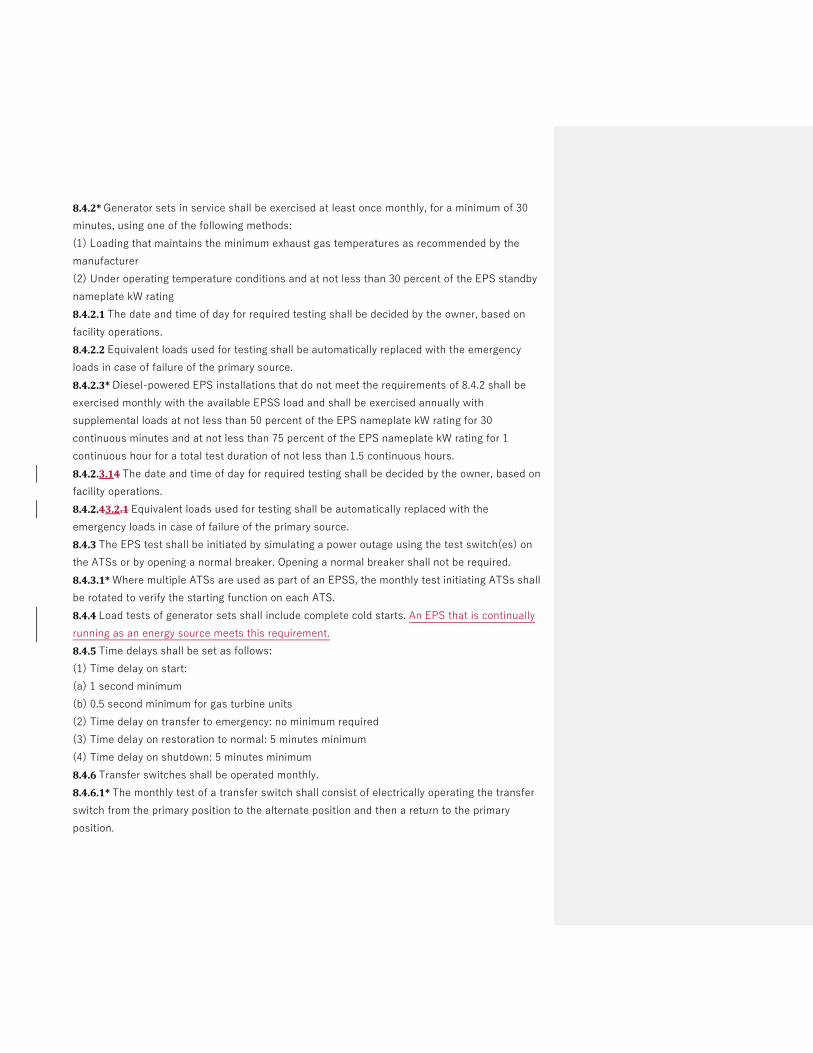
8.4.2* Generator sets in service shall be exercised at least once monthly, for a minimum of 30
minutes, using one of the following methods:
(1) Loading that maintains the minimum exhaust gas temperatures as recommended by the
manufacturer
(2) Under operating temperature conditions and at not less than 30 percent of the EPS standby
nameplate kW rating
8.4.2.1 The date and time of day for required testing shall be decided by the owner, based on
facility operations.
8.4.2.2 Equivalent loads used for testing shall be automatically replaced with the emergency
loads in case of failure of the primary source.
8.4.2.3* Diesel-powered EPS installations that do not meet the requirements of 8.4.2 shall be
exercised monthly with the available EPSS load and shall be exercised annually with
supplemental loads at not less than 50 percent of the EPS nameplate kW rating for 30
continuous minutes and at not less than 75 percent of the EPS nameplate kW rating for 1
continuous hour for a total test duration of not less than 1.5 continuous hours.
8.4.2.3.14 The date and time of day for required testing shall be decided by the owner, based on
facility operations.
8.4.2.43.2.1 Equivalent loads used for testing shall be automatically replaced with the
emergency loads in case of failure of the primary source.
8.4.3 The EPS test shall be initiated by simulating a power outage using the test switch(es) on
the ATSs or by opening a normal breaker. Opening a normal breaker shall not be required.
8.4.3.1* Where multiple ATSs are used as part of an EPSS, the monthly test initiating ATSs shall
be rotated to verify the starting function on each ATS.
8.4.4 Load tests of generator sets shall include complete cold starts. An EPS that is continually
running as an energy source meets this requirement.
8.4.5 Time delays shall be set as follows:
(1) Time delay on start:
(a) 1 second minimum
(b) 0.5 second minimum for gas turbine units
(2) Time delay on transfer to emergency: no minimum required
(3) Time delay on restoration to normal: 5 minutes minimum
(4) Time delay on shutdown: 5 minutes minimum
8.4.6 Transfer switches shall be operated monthly.
8.4.6.1* The monthly test of a transfer switch shall consist of electrically operating the transfer
switch from the primary position to the alternate position and then a return to the primary
position.

8.4.6.2 The criteria set forth in Section 4.3 and in Table 4.1(b) shall not be required during the
monthly testing of the EPSS. If the criteria are not met during the monthly test, a process shall
be provided to annually confirm the capability of the system to comply with Section 4.3.
8.4.7* EPSS circuit breakers for Level 1 system usage, including main and feed breakers
between the EPS and the transfer
switch load terminals, shall be exercised annually with the EPS in the “off” position.
8.4.7.1 Circuit breakers rated in excess of 600 volts for Level 1 system usage shall be exercised
every 6 months and shall be tested under simulated overload conditions every 2 years.
8.4.8 EPSS components shall be maintained and tested by qualified person(s).
8.4.9* Level 1 EPSS shall be tested at least once within every 36 months.
8.4.9.1 Level 1 EPSS shall be tested continuously for the duration of its assigned class (see
Section 4.2).
8.4.9.2 Where the assigned class is greater than 4 hours, it shall be permitted to terminate the
test after 4 continuous hours.
8.4.9.3 The test shall be initiated by operating at least one transfer switch test function and then
by operating the test function of all remaining ATSs, or initiated by opening all switches or
breakers supplying normal power to all ATSs that are part of the EPSS being tested.
8.4.9.4 A power interruption to non-EPSS loads shall not be required.
8.4.9.5 The minimum load for this test shall be as specified in 8.4.9.5.1 - , 8.4.9.5.2, or 8.4.9.5.43.
8.4.9.5.1* For a diesel-powered EPS, loading shall be not less than 30 percent of the nameplate
kW rating of the EPS. A supplemental load bank shall be permitted to be used to meet or exceed
the 30 percent requirement.
8.4.9.5.2 For a diesel-powered EPS, loading shall be that which maintains the minimum exhaust
gas temperatures as recommended by the manufacturer.
8.4.9.5.3 For spark-ignited EPSs, loading shall be the available EPSS load.
8.4.9.5.4 For fuel cell system EPSs, loading shall be the available EPSS load.
8.4.9.6 The test required in 8.4.9 shall be permitted to be combined with one of the monthly
tests required by 8.4.2 and one of the annual tests required by 8.4.2.3 as a single test.
8.4.9.7* Where the test required in 8.4.9 is combined with the annual load bank test, the first
portion of the test shall be at not less than the minimum loading required by 8.4.9.5, the last
hour shall be at not less than 75 percent of the nameplate kW rating of the EPS, and the
duration of the test shall be in accordance with 8.4.9.1 and 8.4.9.2.
Commented [EP1]: Added

Public Comment No. 66-NFPA 110-2020 [ Section No. 8.4.4 ]
8.4.4
Load tests of generator sets shall include complete cold starts.An EPS that is continuously running shallnet be required to meet this requirement
Additional Proposed Changes
File Name Description Approved
Changes_to_NFPA_110_Chapter_8_for_submission_05-06-2020.docx
Statement of Problem and Substantiation for Public Comment
Task group response to CI (
Related Item
• CI 9
Submitter Information Verification
Submitter Full Name: Ronald Smidt
Organization: Atrium Health
Street Address:
City:
State:
Zip:
Submittal Date: Wed May 06 14:26:51 EDT 2020
Committee: EPS-AAA
National Fire Protection Association Report https://submittals.nfpa.org/TerraViewWeb/ContentFetcher?commentPar...
118 of 120 5/7/2020, 4:56 PM

Chapter 8 Routine Maintenance and Operational Testing 8.1* General.
8.1.1 The routine maintenance and operational testing program shall be based on all of the
following:
(1) Manufacturer’s recommendations
(2) Instruction manuals
(3) Minimum requirements of this chapter
(4) The authority having jurisdiction
8.1.2 Consideration shall be given to temporarily providing a portable or alternate source
whenever the emergency generator is out of service and the criteria set forth in Section 4.3
cannot be met.
8.2* Manuals, Special Tools, and Spare Parts.
8.2.1 At least two sets of instruction manuals for all major components of the EPSS shall be
supplied by the manufacturer(s) of the EPSS and shall contain the following:
(1) A detailed explanation of the operation of the system
(2) Instructions for routine maintenance
(3) Detailed instructions for repair of the EPS and other major components of the EPSS
(4) An illustrated parts list and part numbers
(5) Illustrated and schematic drawings of electrical wiring systems, including operating and
safety devices, control panels, instrumentation, and annunciators
8.2.2 For Level 1 systems, instruction manuals shall be kept in a secure, convenient location,
one set near the equipment, and the other set in a separate location.
8.2.3 Special tools and testing devices necessary for routine maintenance shall be available for
use when needed.
8.2.4 Replacement for parts identified by experience as high mortality items shall be maintained
in a secure location(s) on the premises.
8.2.4.1 Consideration shall be given to stocking spare parts as recommended by the
manufacturer.
8.2.5 For Fuel Cell Systems, a Maintenance Manual should be provided per ANSI/CSA FC 1,
Section 7.4.5.
8.3 Maintenance and Operational Testing.
8.3.1* The EPSS shall be maintained to ensure to a reasonable degree that the system is
capable of supplying service within the time specified for the type and for the time duration
specified for the class.
8.3.2 A routine maintenance and operational testing program shall be initiated immediately after
the EPSS has passed acceptance tests or after completion of repairs that impact the operational
reliability of the system.

8.3.2.1 The operational test shall be initiated at an ATS and shall include testing of each EPSS
component on which maintenance or repair has been performed, including the transfer of each
automatic and manual transfer switch to the alternate power source, for a period of not less
than 30 minutes under operating temperature.
8.3.3 A written schedule for routine maintenance and operational testing of the EPSS shall be
established.
8.3.4* Transfer switches shall be subjected to a maintenance and testing program that includes
all of the following operations:
(1) Checking of connections
(2) Inspection or testing for evidence of overheating and excessive contact erosion
(3) Removal of dust and dirt
(4) Replacement of contacts when required
8.3.5* Paralleling gear shall be subject to an inspection, testing, and maintenance program that
includes all of the following operations:
(1) Checking connections
(2) Inspecting or testing for evidence of overheating and excessive contact erosion
(3) Removing dust and dirt
(4) Replacing contacts when required
(5) Verifying that the system controls will operate as intended
8.3.6* Storage batteries, including electrolyte levels or battery voltage, used in connection with
systems shall be inspected weekly and maintained in full compliance with manufacturer's
specifications.
8.3.6.1 Maintenance of lead-acid batteries shall include the monthly testing and recording of
electrolyte specific gravity. Battery conductance testing shall be permitted in lieu of the testing
of specific gravity when applicable or warranted.
8.3.6.2 Defective batteries shall be replaced immediately upon discovery of defects.
8.3.7 A fuel quality test shall be performed at least annually using appropriate ASTM standards
or the manufacturer’s recommendations.
8.4 Operational Inspection and Testing.
8.4.1* EPSSs, including all appurtenant components, shall be inspected weekly and exercised
under load at least monthly.
8.4.1.1 If the generator set is used for standby power or for peak load shaving, such use shall be
recorded and shall be permitted to be substituted for scheduled operations and testing of the
generator set, providing the same record as required by 8.3.4.5.
8.4.1.2 If a continually operating fuel cell system is used for standby power or for peak load
shaving, such use shall be recorded and shall be permitted to be substituted for scheduled
operations and testing of the fuel cell system, providing the same record as required by 8.5.

8.4.2* Generator sets in service shall be exercised at least once monthly, for a minimum of 30
minutes, using one of the following methods:
(1) Loading that maintains the minimum exhaust gas temperatures as recommended by the
manufacturer
(2) Under operating temperature conditions and at not less than 30 percent of the EPS standby
nameplate kW rating
8.4.2.1 The date and time of day for required testing shall be decided by the owner, based on
facility operations.
8.4.2.2 Equivalent loads used for testing shall be automatically replaced with the emergency
loads in case of failure of the primary source.
8.4.2.3* Diesel-powered EPS installations that do not meet the requirements of 8.4.2 shall be
exercised monthly with the available EPSS load and shall be exercised annually with
supplemental loads at not less than 50 percent of the EPS nameplate kW rating for 30
continuous minutes and at not less than 75 percent of the EPS nameplate kW rating for 1
continuous hour for a total test duration of not less than 1.5 continuous hours.
8.4.2.3.14 The date and time of day for required testing shall be decided by the owner, based on
facility operations.
8.4.2.43.2.1 Equivalent loads used for testing shall be automatically replaced with the
emergency loads in case of failure of the primary source.
8.4.3 The EPS test shall be initiated by simulating a power outage using the test switch(es) on
the ATSs or by opening a normal breaker. Opening a normal breaker shall not be required.
8.4.3.1* Where multiple ATSs are used as part of an EPSS, the monthly test initiating ATSs shall
be rotated to verify the starting function on each ATS.
8.4.4 Load tests of generator sets shall include complete cold starts. An EPS that is continually
running as an energy source meets this requirement.
8.4.5 Time delays shall be set as follows:
(1) Time delay on start:
(a) 1 second minimum
(b) 0.5 second minimum for gas turbine units
(2) Time delay on transfer to emergency: no minimum required
(3) Time delay on restoration to normal: 5 minutes minimum
(4) Time delay on shutdown: 5 minutes minimum
8.4.6 Transfer switches shall be operated monthly.
8.4.6.1* The monthly test of a transfer switch shall consist of electrically operating the transfer
switch from the primary position to the alternate position and then a return to the primary
position.

8.4.6.2 The criteria set forth in Section 4.3 and in Table 4.1(b) shall not be required during the
monthly testing of the EPSS. If the criteria are not met during the monthly test, a process shall
be provided to annually confirm the capability of the system to comply with Section 4.3.
8.4.7* EPSS circuit breakers for Level 1 system usage, including main and feed breakers
between the EPS and the transfer
switch load terminals, shall be exercised annually with the EPS in the “off” position.
8.4.7.1 Circuit breakers rated in excess of 600 volts for Level 1 system usage shall be exercised
every 6 months and shall be tested under simulated overload conditions every 2 years.
8.4.8 EPSS components shall be maintained and tested by qualified person(s).
8.4.9* Level 1 EPSS shall be tested at least once within every 36 months.
8.4.9.1 Level 1 EPSS shall be tested continuously for the duration of its assigned class (see
Section 4.2).
8.4.9.2 Where the assigned class is greater than 4 hours, it shall be permitted to terminate the
test after 4 continuous hours.
8.4.9.3 The test shall be initiated by operating at least one transfer switch test function and then
by operating the test function of all remaining ATSs, or initiated by opening all switches or
breakers supplying normal power to all ATSs that are part of the EPSS being tested.
8.4.9.4 A power interruption to non-EPSS loads shall not be required.
8.4.9.5 The minimum load for this test shall be as specified in 8.4.9.5.1 - , 8.4.9.5.2, or 8.4.9.5.43.
8.4.9.5.1* For a diesel-powered EPS, loading shall be not less than 30 percent of the nameplate
kW rating of the EPS. A supplemental load bank shall be permitted to be used to meet or exceed
the 30 percent requirement.
8.4.9.5.2 For a diesel-powered EPS, loading shall be that which maintains the minimum exhaust
gas temperatures as recommended by the manufacturer.
8.4.9.5.3 For spark-ignited EPSs, loading shall be the available EPSS load.
8.4.9.5.4 For fuel cell system EPSs, loading shall be the available EPSS load.
8.4.9.6 The test required in 8.4.9 shall be permitted to be combined with one of the monthly
tests required by 8.4.2 and one of the annual tests required by 8.4.2.3 as a single test.
8.4.9.7* Where the test required in 8.4.9 is combined with the annual load bank test, the first
portion of the test shall be at not less than the minimum loading required by 8.4.9.5, the last
hour shall be at not less than 75 percent of the nameplate kW rating of the EPS, and the
duration of the test shall be in accordance with 8.4.9.1 and 8.4.9.2.
Commented [EP1]: Added

Public Comment No. 67-NFPA 110-2020 [ New Section after 8.4.9.5.3 ]
8.5.9.5.4
8.4.9.5. 4 For fuel cell system E PSs , loading shall be the available EPSS load.
Additional Proposed Changes
File Name Description Approved
Changes_to_NFPA_110_Chapter_8_for_submission_05-06-2020.docx
Statement of Problem and Substantiation for Public Comment
Task group response to CI 9
Related Item
• CI 9
Submitter Information Verification
Submitter Full Name: Ronald Smidt
Organization: Atrium Health
Street Address:
City:
State:
Zip:
Submittal Date: Wed May 06 14:29:01 EDT 2020
Committee: EPS-AAA
National Fire Protection Association Report https://submittals.nfpa.org/TerraViewWeb/ContentFetcher?commentPar...
119 of 120 5/7/2020, 4:56 PM

Chapter 8 Routine Maintenance and Operational Testing 8.1* General.
8.1.1 The routine maintenance and operational testing program shall be based on all of the
following:
(1) Manufacturer’s recommendations
(2) Instruction manuals
(3) Minimum requirements of this chapter
(4) The authority having jurisdiction
8.1.2 Consideration shall be given to temporarily providing a portable or alternate source
whenever the emergency generator is out of service and the criteria set forth in Section 4.3
cannot be met.
8.2* Manuals, Special Tools, and Spare Parts.
8.2.1 At least two sets of instruction manuals for all major components of the EPSS shall be
supplied by the manufacturer(s) of the EPSS and shall contain the following:
(1) A detailed explanation of the operation of the system
(2) Instructions for routine maintenance
(3) Detailed instructions for repair of the EPS and other major components of the EPSS
(4) An illustrated parts list and part numbers
(5) Illustrated and schematic drawings of electrical wiring systems, including operating and
safety devices, control panels, instrumentation, and annunciators
8.2.2 For Level 1 systems, instruction manuals shall be kept in a secure, convenient location,
one set near the equipment, and the other set in a separate location.
8.2.3 Special tools and testing devices necessary for routine maintenance shall be available for
use when needed.
8.2.4 Replacement for parts identified by experience as high mortality items shall be maintained
in a secure location(s) on the premises.
8.2.4.1 Consideration shall be given to stocking spare parts as recommended by the
manufacturer.
8.2.5 For Fuel Cell Systems, a Maintenance Manual should be provided per ANSI/CSA FC 1,
Section 7.4.5.
8.3 Maintenance and Operational Testing.
8.3.1* The EPSS shall be maintained to ensure to a reasonable degree that the system is
capable of supplying service within the time specified for the type and for the time duration
specified for the class.
8.3.2 A routine maintenance and operational testing program shall be initiated immediately after
the EPSS has passed acceptance tests or after completion of repairs that impact the operational
reliability of the system.

8.3.2.1 The operational test shall be initiated at an ATS and shall include testing of each EPSS
component on which maintenance or repair has been performed, including the transfer of each
automatic and manual transfer switch to the alternate power source, for a period of not less
than 30 minutes under operating temperature.
8.3.3 A written schedule for routine maintenance and operational testing of the EPSS shall be
established.
8.3.4* Transfer switches shall be subjected to a maintenance and testing program that includes
all of the following operations:
(1) Checking of connections
(2) Inspection or testing for evidence of overheating and excessive contact erosion
(3) Removal of dust and dirt
(4) Replacement of contacts when required
8.3.5* Paralleling gear shall be subject to an inspection, testing, and maintenance program that
includes all of the following operations:
(1) Checking connections
(2) Inspecting or testing for evidence of overheating and excessive contact erosion
(3) Removing dust and dirt
(4) Replacing contacts when required
(5) Verifying that the system controls will operate as intended
8.3.6* Storage batteries, including electrolyte levels or battery voltage, used in connection with
systems shall be inspected weekly and maintained in full compliance with manufacturer's
specifications.
8.3.6.1 Maintenance of lead-acid batteries shall include the monthly testing and recording of
electrolyte specific gravity. Battery conductance testing shall be permitted in lieu of the testing
of specific gravity when applicable or warranted.
8.3.6.2 Defective batteries shall be replaced immediately upon discovery of defects.
8.3.7 A fuel quality test shall be performed at least annually using appropriate ASTM standards
or the manufacturer’s recommendations.
8.4 Operational Inspection and Testing.
8.4.1* EPSSs, including all appurtenant components, shall be inspected weekly and exercised
under load at least monthly.
8.4.1.1 If the generator set is used for standby power or for peak load shaving, such use shall be
recorded and shall be permitted to be substituted for scheduled operations and testing of the
generator set, providing the same record as required by 8.3.4.5.
8.4.1.2 If a continually operating fuel cell system is used for standby power or for peak load
shaving, such use shall be recorded and shall be permitted to be substituted for scheduled
operations and testing of the fuel cell system, providing the same record as required by 8.5.

8.4.2* Generator sets in service shall be exercised at least once monthly, for a minimum of 30
minutes, using one of the following methods:
(1) Loading that maintains the minimum exhaust gas temperatures as recommended by the
manufacturer
(2) Under operating temperature conditions and at not less than 30 percent of the EPS standby
nameplate kW rating
8.4.2.1 The date and time of day for required testing shall be decided by the owner, based on
facility operations.
8.4.2.2 Equivalent loads used for testing shall be automatically replaced with the emergency
loads in case of failure of the primary source.
8.4.2.3* Diesel-powered EPS installations that do not meet the requirements of 8.4.2 shall be
exercised monthly with the available EPSS load and shall be exercised annually with
supplemental loads at not less than 50 percent of the EPS nameplate kW rating for 30
continuous minutes and at not less than 75 percent of the EPS nameplate kW rating for 1
continuous hour for a total test duration of not less than 1.5 continuous hours.
8.4.2.3.14 The date and time of day for required testing shall be decided by the owner, based on
facility operations.
8.4.2.43.2.1 Equivalent loads used for testing shall be automatically replaced with the
emergency loads in case of failure of the primary source.
8.4.3 The EPS test shall be initiated by simulating a power outage using the test switch(es) on
the ATSs or by opening a normal breaker. Opening a normal breaker shall not be required.
8.4.3.1* Where multiple ATSs are used as part of an EPSS, the monthly test initiating ATSs shall
be rotated to verify the starting function on each ATS.
8.4.4 Load tests of generator sets shall include complete cold starts. An EPS that is continually
running as an energy source meets this requirement.
8.4.5 Time delays shall be set as follows:
(1) Time delay on start:
(a) 1 second minimum
(b) 0.5 second minimum for gas turbine units
(2) Time delay on transfer to emergency: no minimum required
(3) Time delay on restoration to normal: 5 minutes minimum
(4) Time delay on shutdown: 5 minutes minimum
8.4.6 Transfer switches shall be operated monthly.
8.4.6.1* The monthly test of a transfer switch shall consist of electrically operating the transfer
switch from the primary position to the alternate position and then a return to the primary
position.

8.4.6.2 The criteria set forth in Section 4.3 and in Table 4.1(b) shall not be required during the
monthly testing of the EPSS. If the criteria are not met during the monthly test, a process shall
be provided to annually confirm the capability of the system to comply with Section 4.3.
8.4.7* EPSS circuit breakers for Level 1 system usage, including main and feed breakers
between the EPS and the transfer
switch load terminals, shall be exercised annually with the EPS in the “off” position.
8.4.7.1 Circuit breakers rated in excess of 600 volts for Level 1 system usage shall be exercised
every 6 months and shall be tested under simulated overload conditions every 2 years.
8.4.8 EPSS components shall be maintained and tested by qualified person(s).
8.4.9* Level 1 EPSS shall be tested at least once within every 36 months.
8.4.9.1 Level 1 EPSS shall be tested continuously for the duration of its assigned class (see
Section 4.2).
8.4.9.2 Where the assigned class is greater than 4 hours, it shall be permitted to terminate the
test after 4 continuous hours.
8.4.9.3 The test shall be initiated by operating at least one transfer switch test function and then
by operating the test function of all remaining ATSs, or initiated by opening all switches or
breakers supplying normal power to all ATSs that are part of the EPSS being tested.
8.4.9.4 A power interruption to non-EPSS loads shall not be required.
8.4.9.5 The minimum load for this test shall be as specified in 8.4.9.5.1 - , 8.4.9.5.2, or 8.4.9.5.43.
8.4.9.5.1* For a diesel-powered EPS, loading shall be not less than 30 percent of the nameplate
kW rating of the EPS. A supplemental load bank shall be permitted to be used to meet or exceed
the 30 percent requirement.
8.4.9.5.2 For a diesel-powered EPS, loading shall be that which maintains the minimum exhaust
gas temperatures as recommended by the manufacturer.
8.4.9.5.3 For spark-ignited EPSs, loading shall be the available EPSS load.
8.4.9.5.4 For fuel cell system EPSs, loading shall be the available EPSS load.
8.4.9.6 The test required in 8.4.9 shall be permitted to be combined with one of the monthly
tests required by 8.4.2 and one of the annual tests required by 8.4.2.3 as a single test.
8.4.9.7* Where the test required in 8.4.9 is combined with the annual load bank test, the first
portion of the test shall be at not less than the minimum loading required by 8.4.9.5, the last
hour shall be at not less than 75 percent of the nameplate kW rating of the EPS, and the
duration of the test shall be in accordance with 8.4.9.1 and 8.4.9.2.
Commented [EP1]: Added

Public Comment No. 70-NFPA 110-2020 [ Section No. A.4.4.2 ]
A.4.4.2
Typically, Level 2 systems are intended to supply power automatically to selected loads (other than thoseclassed as emergency systems) in the event of failure of the primary source.
Level 2 systems typically are installed to serve loads, such as the following, that, when stopped due to anyinterruption of the primary electrical supply, could create hazards or hamper rescue or fire-fightingoperations:
(1) Heating and refrigeration systems
(2) Communications systems
(3) Ventilation and smoke removal systems
(4) Sewage disposal
(5) Lighting, including unit equipment defined in NFPA 70 (NEC), 700.12
(6) Industrial processes
Additional Proposed Changes
File Name Description Approved
110_A2021_NEC_AAC_FD_CorrelatingNotes.pdf NFPA110_CCNote1
Statement of Problem and Substantiation for Public Comment
NOTE: This Public Comment appeared as CC Note No. 1 in the First Draft Report on First Revision No. 19.
The Correlating Committee notes that unit equipment is not defined in Article 700 and requests clarification from the Technical Committee on the intended application of list item 5.
Related Item
• First Revision No. 19
Submitter Information Verification
Submitter Full Name: CC on NEC-AAC
Organization: NEC Correlating Committee
Street Address:
City:
State:
Zip:
Submittal Date: Thu May 07 16:32:58 EDT 2020
Committee: EPS-AAA
National Fire Protection Association Report https://submittals.nfpa.org/TerraViewWeb/ContentFetcher?commentPar...
120 of 120 5/7/2020, 4:56 PM