Emergency Ultrasound Course
37
THE SAN EMERGENCY ULTRASOUND MANUAL JUSTIN BOWRA 1 Emergency Ultrasound Course Dr Justin Bowra ED Course Manual 1: Basic physics & instrumentation
-
Upload
khangminh22 -
Category
Documents
-
view
4 -
download
0
Transcript of Emergency Ultrasound Course

THE SAN EMERGENCY ULTRASOUND MANUAL
JUSTIN BOWRA 1
Emergency Ultrasound
Course
Dr Justin Bowra
ED Course Manual 1: Basic physics & instrumentation

THE SAN EMERGENCY ULTRASOUND MANUAL
JUSTIN BOWRA 2
Contents
• Course timetable • Introduction • The seven golden rules of critical care US • Physics
o Sound wave basics o Ultrasound appearance of normal tissues o Artifacts
• Instrumentation o Machines o Which probe, which preset? o Ten tips to improve your image o What the hell is…?
! Auto optimize ! Tissue harmonic imaging ! Read & write zoom ! Dynamic range ! Line density ! M-mode ! Doppler
• EFAST • AAA Scanning • Basic procedural guidance
o Probe sterilization o vascular acess o draining effusions o SPC insertion o lumbar puncture
• Credentialing • Maintenance of Skills • Documentation • References and Useful Papers

THE SAN EMERGENCY ULTRASOUND MANUAL
JUSTIN BOWRA 3
Course timetable
Day 1: Core ED ultrasound day: physics, EFAST, AAA, procedural guidance, lung
(Includes 4.5 hours practical sessions)
Time Topic
7.45am Registration & pre-course MCQ
8am Welcome: core ED applications of bedside US: EFAST, AAA, procedural guidance
8.15am Physics & Knobology
9am Vasc access/ basic procedural guidance
10am EFAST (pneumothorax and free fluid in trauma and ectopic pregnancy)
11am Abdominal aortic aneurysm
11.30am Break
11.45 Practical session I (2 hours): image acquisition for EFAST, AAA, probe sterilization & vasc
access
1.45pm Lunch
2.15pm Practical session II (2 hours): image acquisition for EFAST & AAA, foreign body localisation
(ideally abnormal models: phantoms or volunteers)
4.15pm (with coffee) Getting credentialed and staying credentialed in bedside US
4.30pm Practical session III (1 hour): image interpretation and clinical correlation (case based
interpretation: cineloops including normal thorax/abdomen, PTX, pleural fluid, pericardial fluid,
peritoneal fluid)
5.30pm Scanning the lung: method / findings [sliding, A, B, C, effusion] / patterns of disease
6.15pm Close

THE SAN EMERGENCY ULTRASOUND MANUAL
JUSTIN BOWRA 4
Day 2: Critical care day: US in arrest / shock / breathlessness
(Includes 5 hours practical sessions)
Time Topic
8am Welcome & intro: what is critical care US? 8.15am Image optimization for critical care US 8.30am Practical session IV (30 minutes): scanning the lung 9am Practical session V (30 minutes): image interpretation in lung US (case based interpretation:
cineloops including normal lung, PTX, pleural fluid, cardiogenic and non-cardiogenic pulmonary oedema, pneumonia)
9.30am Break 9.45am Basic cardiac echo 1: the questions to ask, and how to scan 10.15am Basic cardiac echo 2: scanning the IVC (full or empty?) 10.30am Basic cardiac echo 3: scanning the ventricles (size, function) 11am Basic cardiac echo 4: pericardial effusion and tamponade 11.30am Basic cardiac echo 5: pericardiocentesis 11.45 Practical session VI (2 hours): scanning the heart and IVC
(At least 4 stations with US machines & healthy volunteers: parasternal heart / subcostal heart & IVC / apical heart / IVC from the RUQ)
1.45pm Lunch 2.15pm Putting it all together: the arrested patient 2.30pm Putting it all together: the shocked patient (what’s the volume status?) 2.45pm Putting it all together: the breathless patient 3pm Critical care US in practice:
• Pitfalls and pratfalls: how not to F*** up with focused US • How to report your findings (including sample pro forma)
3.30pm Break 3.45pm Practical session VII (60 minutes): scanning the arrested / shocked / breathless patient in
practice, including resuscitation simulation

THE SAN EMERGENCY ULTRASOUND MANUAL
JUSTIN BOWRA 5
4.45pm Practical session VIII (60 minutes): image interpretation in basic echocardiography (case based interpretation: cineloops including normal heart, cardiac standstill, hypovolaemia, cardiogenic shock, tamponade, massive PE)
5.45pm post-course MCQ 6.15pm feedback, certificates and close

THE SAN EMERGENCY ULTRASOUND MANUAL
JUSTIN BOWRA 6
Introduction
In the space of a generation, point of care ultrasound (POCUS) has evolved from a novelty to a necessity, nowhere more so than in the critical care environment. In the Emergency Department (ED), its qualities were first appreciated in the care of unstable trauma patients, for whom it is now considered the standard of care. POCUS is:
• Safe (no ionizing radiation) • Rapid • Repeatable • Simple • Portable: since the advent of lightweight machines, the US can literally ‘come to the patient’,
hence the term ‘point of care’. TOP TIP: But it is not the Holy Grail. It is highly operator dependent and can generate misleading images (see artifacts section below). Its use is limited by time constraints, patient position and operator experience. For that reason, in the critical care environment we stick to simple questions, ideally with a binary (yes/no) answer, such as:
• Is there free fluid in the pleural / pericardial / peritoneal space? • Is there a pneumothorax? • Is there an abdominal aortic aneurysm? • Is the IVC full or empty? • Are the lungs wet or dry?
TOP TIP: If in doubt, turn off the machine. Every clinician who uses POCUS will inevitably face a conundrum: the findings on screen do not match the clinical picture. This will usually be due to an error of image acquisition or interpretation. At times like this, remember that you are a full time clinician and at best a part time sonographer. So, simply turn off the machine and go back to doing what you do best: being a clinician. This course is an ideal introduction to POCUS in critical care. It covers the ‘traditional’ ED areas of trauma (EFAST), aortic aneurysm and procedural guidance, as well as the more ‘cutting edge’ core areas of basic lung / heart / IVC in the arrested / shocked / breathless patient. At the end of this course you will not be a sonographer, but you will be able to turn on a machine, pick up a probe and scan a critically ill patient. If you work on the skills and knowledge taught in this course, you will save lives. Good luck! Justin Bowra
Jeremy Harris

THE SAN EMERGENCY ULTRASOUND MANUAL
JUSTIN BOWRA 7
The seven golden rules of critical care US 1. 'Resus-only': Patient must be critically unwell: shocked / breathless / peri-arrest. That's because the US signs of some of these diseases are only reliably present if severe eg massive PE, severe pneumonia. If formal studies are needed after resus, get them. 2. Clinical context is paramount. Make a differential diagnosis list before you switch on the machine. All data must be considered (eg FBC with Hb = 4). 3. Only ask questions that you can answer. Leave the fancy stuff (eg valve disease) to others. 4. Repeat scans are crucial during resuscitation & each time clinical picture changes. 5. 90% = 100%: Every test has its limitations. In a periarrest patient, no study will be 100% accurate. If this bothers you, don't practise critical care. RNSH respiratory physician: 'Would you really thrombolyse a critically ill patientwith suspected PE on the basis of bedside US?'
ED physician answer: 'I spent years doing just that without the benefit of US. Anything that improves my accuracy suits me fine.' 6. When in doubt, be a doctor. You were a clinician before you were a sonographer. If the clinical picture & scan findings don’t agree, believe the clinical picture. ‘What would I diagnose if I didn’t have an US machine?’ 7. A fool with a stethoscope will be a fool with an ultrasound. (Thanks to my co-author Dr Russell McLaughlin for this gem)

THE SAN EMERGENCY ULTRASOUND MANUAL
JUSTIN BOWRA 8
Physics
Sound wave basics What is ultrasound? ‘Ultrasound’ waves are very high frequency, pitched far too high for the human ear. In medicine, we use them in the range of 2-15MHz. A Hertz (Hz) is defined as 1 wave per second, so this means that our US probes send out 2-15 million ultrasound waves per second. Why is frequency important? The lower the frequency, the bigger the actual sound wave. This has two practical consequences:
1. Penetration: low frequency waves are larger. This means they are harder to deflect, and can penetrate further into the body before they are scattered. To ‘see’ deeper images, lower the frequency.
2. Resolution: large, low frequency waves aren’t deflected by tiny objects. This means that they won’t ‘see’ very small structures in the human body. To see fine detail, increase the frequency.
How is a sound wave formed? The piezoelectric crystals are found at the end of the probe that touches the skin, safely sheathed in a casing (coupling) material. The piezoelectric (PE) effect refers to the following property of these crystals:
• If an electromagnetic wave is passed through a PE crystal, it will vibrate. In other words, it has converted the electromagnetic energy into the mechanical energy of a sound wave.
• After sending out the sound wave, the probe switches to receiving mode. It spends about 99% of its time in this mode, ‘waiting’ for the sound wave to bounce back. When it does, the wave makes the crystal vibrate and the whole process is reversed, converting the wave’s energy into an electrical signal.
• This signal is then plotted on the screen attached to the machine, and an image is formed. How is the image formed on screen? The image we see on screen is made up of ‘dots’ of light. Each dot represents the signal of an ultrasound wave that has returned from the body.
• The location of each dot on screen depends on how long it took the echo to return to the probe: dots near the top of the screen represent echoes that returned quickly, and those near the bottom of the screen took much longer. We then assume that the image near the bottom of the screen is deeper. (But this isn’t always true! See ‘reverberation artifact’ below.)
• The brightness of each dot depends on the strength of the returning echoes. If the sound wave bounced off something very reflective (eg bone), more echoes will bounce back, and the image on screen will be brighter. (See below for details.)

THE SAN EMERGENCY ULTRASOUND MANUAL
JUSTIN BOWRA 9
What happens to the sound waves in the human body? Overall: attenuation All sound waves get weaker the further they travel through the human body. Some of them are scattered, some are transmitted, and some are refracted etc. But the general principle is that the further the sound wave goes, the weaker it gets and the less we see on screen. This is less of a problem for larger, low frequency waves, which travel further (see below). Reflection To form an image, sound waves need to bounce back to the probe. This means they need to be reflected. Most of the reflection happens at the borders between organs and tissues. This is because each tissue/organ has a different impedance to the sound wave (in other words, each tissue slows down the sound wave to a different degree). Why is this important? It means that the edges of organs, and the fascial planes between structures such as muscles, appear very ‘bright’ or ‘echogenic’ on the screen. The denser the structure (eg bone, gallstones, metal), the more sound is reflected and the ‘brighter’ (echogenic / hyoerechoic) it looks. (See note below.) Transmission Fluid filled structures offer very little resistance to the sound waves, which easily pass through the fluid without losing much energy. They send no signals back to the probe, so they are dark or anechoic. This makes deeper structures look ‘brighter’ = posterior acoustic enhancement. Scatter When the sound wave hits air (eg in the bowel, or in the lung), most of it is scattered in all directions. Much of it returns to the probe (which is why the air appears bright). Very little, if any, is transmitted to the deeper structures, which remain invisible (which is why bowel air can cause ‘dirty shadowing’). US appearance of normal tissues
Simple fluid is black = ‘anechoic’ (lacking internal echoes). Fluids such as blood, urine and bile appear black or anechoic and exhibit posterior acoustic enhancement (see note above). This helps identify cystic structures (such as cysts, bladder and gallbladder) and tubular structures (ducts and vessels). See image below: the gallbladder (arrowed) is dark, well demarcated, and demonstrates posterior enhancement.

THE SAN EMERGENCY ULTRASOUND MANUAL
JUSTIN BOWRA 10
THE BILE IN THIS GALLBLADDER (ARROWED) IS BLACK (ANECHOIC) AND EVERYTHING
BELOW IT IS BRIGHTER (POSTERIOR ACOUSTIC ENHANCEMENT)
SIMPLE FLUID: ASCITES
(KIDNEY AT BOTTOM OF IMAGE)

THE SAN EMERGENCY ULTRASOUND MANUAL
JUSTIN BOWRA 11
COMPLEX FLUID: SUBCUTANEOUS ABSCESS
COMPLEX FLUID: RIGHT SIDED PLEURAL EFFUSION
IMAGED TRANSVERSELY

THE SAN EMERGENCY ULTRASOUND MANUAL
JUSTIN BOWRA 12
Complex fluid is heterogenous on screen. (See image above.) Dense structures are bright = ‘echogenic’ or ‘hyperechoic’ (highly reflective). The denser the structure (eg bone, gallstones, metal), the more sound is reflected and the ‘brighter’ it looks on screen. But this also means that the sound doesn’t get through to deeper structures, and a ‘shadow’ appears on screen behind (= deep to) the metal/bone/stone. This is called posterior acoustic shadowing and helps identify the dense structure. See image below: the gallstones (arrowheads) within the gallbladder (arrow) are bright and cast a shadow.
THE STONES IN THIS GALLBLADDER (ARROWHEADS) ARE BRIGHT (HYPERECHOIC) AND
CAST A POSTERIOR ACOUSTIC SHADOW (ARROWED).
Some structures are grey. These are typically the solid organs: liver, spleen, kidney, uterus and heart. See the relevant images in this section: the normal liver is grey, and the normal kidney cortex is darker grey.

THE SAN EMERGENCY ULTRASOUND MANUAL
JUSTIN BOWRA 13
IN THIS RIGHT UPPER QUADRANT IMAGE, THE BRIGHT POTENTIAL SPACE OF MORISON’S
POUCH SEPARATES TWO ORGANS: THE LIVER (LARGER AND ON THE LEFT) AND THE KIDNEY (SMALLER AND WITH A RENAL CORTEX A DARKER GREY THAN THE LIVER)
Some structures are anisotropic: their image depends on the angle at which the probe is held. This means that their appearance depends on the angle of the sound waves. Typically these are fibrous structures such as nerves, tendons and muscles. These structures appear ‘grainy’, and if the probe is perpendicular to the direction of the fibres then they are bright. The closer the probe parallels the fibres, the darker they appear because less sound is reflected. In the 2 images below, the same median nerve (arrowed) and surrounding forearm flexor muscles are viewed from slightly different probe angles. On the first image, the probe is held at an angle to the muscle and nerve, which appear dark. On the second image, the probe is held perpendicular to the forearm and the structures appear brighter.

THE SAN EMERGENCY ULTRASOUND MANUAL
JUSTIN BOWRA 14
THE MEDIAN NERVE (ARROWED) AND THE SURROUNDING MUSCLE FIBRES ARE DARK IN
THE 1ST IMAGE (MADE WITH PROBE AT AN ANGLE TO THE SKIN) AND BRIGHTER IN THE 2ND IMAGE (MADE WITH THE PROBE AT RIGHT ANGLES TO THE SKIN).
THEY DEMONSTRATE ANISOTROPY.

THE SAN EMERGENCY ULTRASOUND MANUAL
JUSTIN BOWRA 15
Some structures vary because of their contents. This is typical of the GI tract:
• If a segment of the GIT (stomach, bowel) is fluid-filled it appears black. • If it is gas filled it appears bright white, as the air ‘scatters’ the sound wave.
WARNING! Like dense substances, AIR also appears bright on US. This is because the sound wave is
scattered and some returns to the probe. It can also cause a form of acoustic shadowing, which can be confusing (eg it can mimic gallstones).
________________________________________________________________ Artifacts An artifact is an image on screen that does not correspond to actual anatomic information: in other words, it is a picture of something that ‘isn’t there’. Artifacts may be:
o Bad: artifact may obscure detail or mimic pathology leading to diagnostic uncertainty or error. A classic example is a rib shadow that gets in the way of the structures below… or an edge artifact that mimics free fluid.
o Good: artifacts make up the basis of lung US (see lung chapter later). And acoustic shadowing can help identify structures such as gallstones.
Acoustic shadow As described above, very dense objects cast ‘acoustic shadows’. On the screen one sees the bright object with a black shadow distally. See image of gallstones above. Acoustic enhancement Also as noted above, this artifact occurs when sound passes through an anechoic structure. No echoes are reflected and so they are all available to pass through. More echoes then return to the probe from deeper structures, making them look ‘brighter’ on screen. See images of gallbladder above. Reverberation It’s obvious that the sound waves must ‘bounce’ off structures in the body to form an image. But when they return to the surface of the probe, some of them will ‘bounce’ back from the probe… back into the body! Although weaker by now, some of these waves will repeat the process and return to the probe once more. And every time the waves return to the probe, they will generate an image on screen. But with each repetition, the image will appear ‘deeper’.

THE SAN EMERGENCY ULTRASOUND MANUAL
JUSTIN BOWRA 16
• The waves that form the 2nd image took twice as long as the first (total travel time), so this
image will be twice as deep as the ‘real’ image. • The waves that form the 3rd image took 3 times as long (total travel time), so this image will
be 3x as deep as the ‘real’ image. The result is a ‘ghost’ image (or a series of ‘ghost’ images) deep to the real image. In the image below (reverberation artifact in normal lung), the yellow arrows represent the path that the sound waves travel to create the bright white line that represents the pleura. Notice the second ‘ghost image’ below. This is a reverberation artifact.
Reverberation artefact (air in normal lung)
True image of pleura
‘Ghost’ image of pleura = reverberation artifact
Mirror image Certain structures are called ‘specular reflectors’. They act as ‘mirrors’ and reflect sound waves so perfectly that on the screen two images of the same structures can form: a true image and a ‘mirror’ image. This can be confusing. Examples include:
• Bone (which can generate a mirror image of the muscles and tissues above). In the picture below, ‘ghost’ echoes of the muscle fibres can be seen below the surface of the radius.

THE SAN EMERGENCY ULTRASOUND MANUAL
JUSTIN BOWRA 17
• At the diaphragm: the air above the diaphragm, combined with the smooth curve of the diaphragm itself, can create a ‘mirror image’ of the liver / spleen. This mirror image is seen above the diaphragm. In the picture below, the arrows represent the path of the sound waves as they bounce off the curve of the echogenic diaphragm, into the liver tissue, then back via diaphragm again to the probe. However, the machine can’t tell that this occurred, and plots an image on screen depending on how long it took the waves to return- so it extrapolates the image to the point on screen represented by the dotted line.
Mirror image of liver, seen above the diaphragm
‘False’ image of liver tissue
Liver
• Around the bladder: as in the image below, the air in the bowel next to the bladder, combined with the smooth curve of the bladder wall, can create a

THE SAN EMERGENCY ULTRASOUND MANUAL
JUSTIN BOWRA 18
mirror image of the fluid inside the bladder. This mirror image can resemble free fluid, so be careful! Note the very dark areas to the right and left of the bladder: these are mirror images and not free fluid.
!"#$$%&'
()&&*&')(#+%,'-.'/012'13'4562278'

THE SAN EMERGENCY ULTRASOUND MANUAL
JUSTIN BOWRA 19

THE SAN EMERGENCY ULTRASOUND MANUAL
JUSTIN BOWRA 20
Instrumentation
Machines There are plenty of point-of-care machines out there. The ideal machine should be:
• Lightweight • Robust • Rapid boot-up time • Long battery life • Easy to scan, save & download images • Good image quality • Easy to clean • A warranty that covers everything and lasts several years • And, of course, as cheap as possible!
Probes (transducers)
The probes we commonly use are linear, sector and curved array.
• Linear array probes have a rectangular ‘footprint’ on screen. They produce the highest frequency sound waves, which means they are excellent for superficial work (eg vascular access, DVT, soft tissue foreign body).
• Curved array probes have a curved ‘footprint’ on screen. They produce lower frequency sound waves which can penetrate further, and are ideally suited to abdominal work (eg EFAST, early pregnancy, biliary, renal).
• Sector array probes produce ‘slice-of-pie’-shaped images on screen. Their small footprint means they can ‘look’ between the ribs and are preferred for cardiac scanning.
Curved (A), linear (B), and sector (C) array probes provide differing shapes in the ultrasound field-of-
view.

THE SAN EMERGENCY ULTRASOUND MANUAL
JUSTIN BOWRA 21
Remember the basic principle:
• High frequency = better resolution but less penetration (e.g. good for children & vascular access)
• Low frequency = the opposite (e.g. good for obese patients)
Presets
There are a number of ways to modify your on-screen image. Some are touched on here, but only briefly. For those of us who aren’t expert sonologists, the machines come equipped with certain ‘presets’ that optimize the image for the particular region / purpose. For example, the cardiac preset applies more contrast to the image (because the heart is essentially ‘black and white’ and we don’t need to see as many shades of grey (fine detail) as we might when scanning an organ like the liver.
Which probe, which preset?
PROBE PRESET VASCULAR
ACCESS ✔The linear array probe
Vascular / venous preset
ABDOMEN: FAST, AAA,
EARLY PREGNANCY
✔✔✔Overall, the curved probe is best for the abdomen.
✔The sector probe is nearly as good if only answering simple / urgent questions (is there
FF? is there a AAA? Is there an IUP?)
Abdominal preset (many machines have dedicated aorta / FAST / OG presets, but often these are not required)
LUNG Are you in a hurry? Or performing a screening scan such as EFAST/CCUS?
The curved probe and sector (cardiac) probes are probably as good as each other. Every clinician sonologist has his/her preferences
Some machines come equipped with lung presets, although you can ‘do it yourself’ by:
1. Selecting abdo / FAST

THE SAN EMERGENCY ULTRASOUND MANUAL
JUSTIN BOWRA 22
(mine is the curved probe on the abdominal preset) but there’s no strong evidence either
way.
It’s worth noting that the father of lung US,
Daniel Lichtenstein, advises that a microconvex probe is best so try it if you have one. (I don’t.)
DON’T use the linear array probe if you can
help it. It won’t show anatomical relations (eg you might place the probe on the liver and think
it’s consolidated lung).
Are you looking for artifacts (sliding and B-lines)?
Once again, avoid the linear probe. Its ability to image structures in fine detail means it tends to obliterate artifacts! This is particularly true for B
lines.
By contrast, the very curvature of the images when the curved /sector probes are used tend to bring out the B lines, making them more
obvious.
Are you looking for very fine detail eg pleural thickening, small areas of
consolidation or tiny pneumothorax?
Finally a role for the linear array probe! It is uniquely suited to imaging very superficial
structures (in this case the pleural surface and subpleural pathology).
But the curved probe is not bad here either.
But avoid the sector probe for fine imaging
preset 2. Turning off the fancy filters: THI (tissue harmonic imaging) and compounding/ multibeam (MB): because they make the artifacts harder to see.

THE SAN EMERGENCY ULTRASOUND MANUAL
JUSTIN BOWRA 23
at the lung surface. Although it fits b/w ribs & gets round the back, its poor spatial resolution
and poor near field detail make it the worst choice here.
IVC ✔✔✔Curved probe is best:
• Image quality • Anatomy
✔Sector probe is OK if already switched on (eg for TTE) … and is probably better for imaging between the ribs (eg for imaging the IVC from
the right upper quadrant)
Whatever preset you’re already on is fine
(Abdo / FAST / cardiac)
Initial screening view
heart
Either curved or sector probe is adequate (subcostal window is best if using the curved
probe)
Whatever preset you’re already on is fine
(Abdo / FAST / cardiac) ‘Proper’ focused
cardiac US or trans thoracic
echo (TTE)
✔✔✔Sector probe: its small footprint allows it to fit between the ribs
Cardiac preset (image ‘round the wrong way’)
THE SAN EMERGENCY ULTRASOUND MANUAL
JUSTIN BOWRA 24
Ten tips to improve your image
1. Use more gel! This is because by far the greatest amount of reflection occurs at the surface of skin. Without gel, there would be no image! The gel acts as a ‘coupling medium’ which allows the sound wave to travel into the human body.
TOP TIP Any fluid applied to the skin will transmit sound waves. This is why we can perform sterile procedures (such as central line insertion) using sterile saline or antiseptic solutions on the skin. (BUT protect your probe first: see ‘procedural guidance’ chapter.) ________________________________________________________________
2. Lighting: as dark as possible 3. The right patient position • General principles:
o A critically ill patient can’t move much: what you see is what you get o But don’t be afraid to move the patient if you can.
• Specifics: o Heart: left lateral improves image quality for cardiac imaging o IVC: moving the patient affects IVC caliber, so take this into account o Lungs: whatever the patient position, the same principles apply:
! Air rises (a pneumothorax will be seen in the least dependent portions) ! Fluid sinks (an effusion will be seen in the most dependent portions) ! Consolidation tends to be more pronounced in the most dependent portions too
o DVT: ! Occlusive DVT will be seen whatever the patient position. ! Images improve with:
• Sitting or standing the patient • Valsalva maneuvre
4. The right probe & preset (see above)

THE SAN EMERGENCY ULTRASOUND MANUAL
JUSTIN BOWRA 25
Image from www.answers.com
5. The right probe orientation. To orient yourself to the probe, touch your finger to one side of it and observe which part of the screen records a signal.
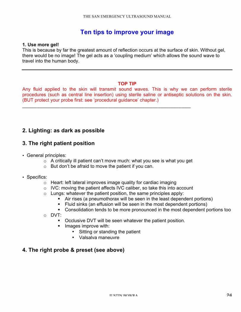
5a. The right probe orientation for IMAGING THE TORSO: •When the probe is placed transversely on the body, keep the probe marker to the patient’s right: structures on the right of the body will appear on the left of the screen (just like an abdominal CT’s orientation)
THE SAN EMERGENCY ULTRASOUND MANUAL
JUSTIN BOWRA 26
IMAGING THE TORSO:
PROBE HELD IN TRANSVERSE POSITION PROBE MARKER POINTS TO PATIENT’S RIGHT.
!
!"#$$%&'&()*+' "%,+'
RESULTING US IMAGE OF PELVIS:
PATIENT’S RIGHT IS ON THE LEFT OF THE SCREEN
When the probe is placed longitudinally on the body, keep the probe marker to the patient’s head: cephalad structures (closer to the head) will now appear on the left of the screen, and caudal structures (closer to the feet) will appear on the right of the screen.

THE SAN EMERGENCY ULTRASOUND MANUAL
JUSTIN BOWRA 27
!
!"#$% &""'%
IMAGING THE TORSO (RIGHT UPPER QUADRANT):
PROBE HELD IN LONGITUDINAL POSITION. PROBE MARKER POINTS TO PATIENT’S HEAD.
!
!"#$% &""'%
RESULTING RIGHT UPPER QUADRANT US IMAGE: PATIENT’S HEAD IS TO THE LEFT OF THE SCREEN
5b. The right orientation for CARDIAC SCANNING: this is tricky! See cardiac section for details. 5c. The right orientation for PROCEDURAL GUIDANCE: this time, forget about the patient & align the left of the screen, the left of the probe and your left hand. 6. The right depth: always set the depth just deeper than the structure you’re scanning.

THE SAN EMERGENCY ULTRASOUND MANUAL
JUSTIN BOWRA 28
7. Overall gain: enough so that fluid just appears black. Any darker and you’ll find it hard to differentiate fat from fluid. Any brighter and you’ll start thinking the fluid has clots in it! 8. Individual TGC sliders: to be honest, just keep these in the middle of the scale. 9. The right frequency (the general tip is to use as high a frequency as possible) 10. Place focal zone at area of interest (some machines eg SonoSites don’t have this function)

THE SAN EMERGENCY ULTRASOUND MANUAL
JUSTIN BOWRA 29
For the smarties: What the hell is…? Auto optimization
• Lets you optimize the image based upon the actual B-Mode data. • You can preset the amount of contrast enhancement (low medium or high) depending upon your
preference. • Then, with the touch of a button you can ‘pretty up’ the image (the sonographers call this ‘the
registrar button’) • BUT if you are in the wrong preset, you’ll get the wrong AO effect... eg if trying to image a heart
using abdo preset. • Remember the Garbage in, garbage out rule. The US machine is not telepathic- if you give it the
wrong info (eg scan using the wrong preset) it will give you the wrong amount of contrast. Tissue harmonic imaging
• This is complicated! • As sound wave travels through tissue, the high-pressure component of the wave travels more
quickly than the rarefactional component. • This distorts the wave and generates higher frequency components (harmonics) deep in the
tissues: eg 3MHz wave creates 6MHz, 12 MHz harmonics Q: So what? A: it turns out that aberrant/artefact signals are too weak to generate harmonic waves. Tissue harmonic imaging takes advantage of this: i.e. displays only the harmonic signals, to deliberately ‘weed out’ the artifacts. THI images often display reduced noise and clutter. (That’s because aberrant/artefact signals are too weak to generate harmonic waves.
• NB harmonic beams are narrower than the original, so spatial resolution is improved and side lobes are reduced.

THE SAN EMERGENCY ULTRASOUND MANUAL
JUSTIN BOWRA 30
TOP TIP Confused? Think of it this way: Harmonics (THI) = ‘another great button’
• Just press the THI button • If it makes the image shittier, press again to turn it off. Easy!
WHEN IS THE T.H.I. BUTTON NO HELP?
1. Near the skin: the waves haven’t had time to generate harmonics, so THI is no use there. 2. In the far field (the harmonic waves have less power, so they fade faster). THI is best for mid-
depth images. 3. When scanning the lung: we need the artifacts for lung scanning! So turn off T.H.I.
Read or Write Zoom? Read Zoom = magnification function. This is the same effect as simply expanding a photo image- it doesn’t actually add data, so the resulting image won’t be better, just bigger. By contrast, write zoom actually rewrites the image using more pixels, gives a much higher definition magnification. (less pixelly/boxy). So, here’s a couple of rules when using the zoom function:
• First, use it! Always zoom your images to maximum (without pixellating the image) to make for easy reading and more accurate caliper placement when measuring small things (eg CBD) • Second, zoom before you freeze, not vice versa. This ensures you are using ‘write zoom’.
Dynamic range a.k.a. compression
This affects how much greyscale information is displayed on screen. • More shades = more info. This is great for imaging the liver, but may be hard to interpret if the
image becomes too soft. • Less shades = less soft= more contrasty, useful for heart & blood vessels
TOP TIP
Watch out: fiddling with dynamic range can affect gain too.
Line Density • Usually we don’t touch this. But it can be useful to improve your cardiac images. • This control basically sets how many ‘lines’ of data make up your US image. • But it’s a trade-off: the more lines of data on screen, the better the image looks = better
spatial resolution …but the longer it takes the probe to ‘draw’ the image. That leads to a slower frame rate and means that fast-moving structures look all blurry.
• Whereas a lower line density means the machine can ‘draw’ the image more rapidly and this allows a better temporal resolution (= great frame rates for crisp images of cardiac valves) but a generally crappier image all round (= lower spatial resolution).

THE SAN EMERGENCY ULTRASOUND MANUAL
JUSTIN BOWRA 31
• So: o A high line density is desirable for high resolution imaging of small parts (thyroid,
breast testes…). o A lower line density is useful in cardiac applications as it allows significantly higher
frame rates.

THE SAN EMERGENCY ULTRASOUND MANUAL
JUSTIN BOWRA 32
M-mode imaging = motion mode. What’s the point? • ‘Surely 2D image is adequate’ • M-mode (motion mode) = movement along a single line of info against time • Theoretically, a single line gives much better sensitivity & resolution
How to do it: • Press ‘M’ button once & a line appears (NB need to press twice on some machines) • Use touch pad / track ball to move the line to area of interest • Press ‘M’ again to plot a graph of what that line sees versus time • Stationary stuff = straight line • Moving things = waves/ dots
M mode pleural: seashore sign (see also Lung US section)

THE SAN EMERGENCY ULTRASOUND MANUAL
JUSTIN BOWRA 33
M mode: LV contracting (see also Basic echocardiography section)
M-mode: pros & cons PROS
" M-mode (motion mode) = movement along a single line of info against time " Single line therefore much better sensitivity & resolution " More accurate dimensions
CONS
" If angles wrong, measurements wrong! " Easier to stuff up than B-mode " IF IN DOUBT, USE B MODE

THE SAN EMERGENCY ULTRASOUND MANUAL
JUSTIN BOWRA 34
What about DOPPLER? The Doppler effect
" Probe sends a sound wave of known frequency " If it hits object moving towards probe, the sound waves ‘bunch together and get smaller’ and
their wavelength decreases. Thus the returning sound wave’s frequency increases. " If object moving away, the sound waves ‘stretch out’ and their wavelength increases. Thus
the returning wave’s frequency decreases. " Here’s the equation: velocity (v) = frequency (f) x wavelength (λ). Velocity doesn’t change, so
as wavelength increases, frequency decreases and vice versa.
So Doppler imaging can show you the direction of flow in a blood vessel.
• Furthermore, the amount of frequency shift is proportional to the velocity of the moving RBCs. The faster the RBCs are moving, the more the sound wave shifts. So Doppler imaging can estimate the rate of flow in a blood vessel.
But you have to get the angles right. The Doppler equation (below) basically states that your measurement will be much more accurate
the more your probe can parallel the direction of the flow. When you think about it, if your probe is
perpendicular to the moving object (eg the RBCs in a vessel) then that object will appear as though
it’s not moving at all. In the equation below, the cosine of 90 degrees is zero.
In practice, if the angle between the probe and the direction of flow is more than 60 degrees, your
velocity assessment will be inaccurate. This is one of the reasons that we avoid Doppler in critical
care.
Doppler equation = (2 x f x v x cosine of Doppler angle)/C
f = transducer frequency (MHZ)
v = velocity of RBCs
C = constant (velocity of sound in soft tissue)

THE SAN EMERGENCY ULTRASOUND MANUAL
JUSTIN BOWRA 35
[Left]. Drawing illustrates the Doppler frequency shift. Ft is the frequency of the transmitted Doppler beam and Fr is the frequency of the Doppler
echo returned to the transducer. [Right]. Drawing illustrates the Doppler beam and Doppler angle used to communicate to the US computer the estimated direction of blood flow.
Image from www.mymedicineworld.net Types of Doppler Continuous wave [CW] Doppler eg good old ‘ankle brachial index’ machine: very sensitive but won’t tell you what point the signal’s coming from! Pulse wave [PW] Doppler The machine sends ‘packets’ of sound waves & waits for each packet to return before sending the next packet. Less sensitive, but locates the site of the signal. PW has 3 variations:
" Colour flow (CF) " Spectral " Power
Colour Flow [CF] Doppler Remember the BART convention (Blue Away, Red Towards)
• Red = towards probe • Blue = away
TOP TIP: Why do we avoid using Doppler in critical care?
THE SAN EMERGENCY ULTRASOUND MANUAL
JUSTIN BOWRA 36
1. Doppler is usually unnecessary. Most of the info we need doesn’t require Doppler. EG we
can tell between arteries and veins using B-mode US, and we can tell if a vein is thrombosed by compressing it.
2. Doppler is complicated. It takes a good working knowledge of Doppler principles to get it right- EG getting the angle right (see above).
3. Doppler is fiddly. It depends on • Operator skill & experience • Angle of insonation (see above) • Pulse repetition frequency (PRF): this means how many ‘packets’ of sound the probe
sends out per second (and it’s completely different from the frequency of the sound waves themselves). If your PRF is set too high, then you may not detect low-flow states. EG it may appear as though there is no flow at all if you image a limb vein using high PRF. And if your PRF is set too low (eg imaging flow across a cardiac valve using a PRF more suited to venous flow) then aliasing will occur. (See below)
4. The conditions that really benefit from Doppler usually are subtle. A classic example is mitral regurgitation. If you detect a regurgitant jet across the mitral valve, is it:
a. A small physiological jet? b. A high flow, large volume jet but your probe is placed at just the wrong angle to
appreciate this?
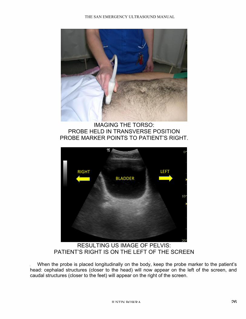
What is aliasing? As velocity increases, signal alters (eg in CF Doppler = lighter shade) until aliasing occurs = then colour reversal occurs [see fig below]
Which way is the flow in this image?
Towards the probe (red)? Away from the probe (blue)?
Is this turbulent flow (eg valve disease) or aliasing (due to normal high velocity jet from LVOT into
AV)?

THE SAN EMERGENCY ULTRASOUND MANUAL
JUSTIN BOWRA 37
Top tip:
In this course, we leave Doppler alone! It doesn’t add much to a resuscitation scan and has the
potential to mislead.
Save it for the formal TTE courses.