Tailgate Emergency Release - TOPIx
39
233 Tailgate Emergency Release Roadside Emergency EMERGENCY MANUAL OPERATION Upper tailgate: If the battery has been disconnected or has discharged, the tailgate can be opened manually as follows: • Fold the rear loadspace cover see, Folding the loadspace cover from inside the vehicle, 130, for instructions. • From the rear loadspace, lever out the plastic tab (see inset). • Pull the tab to release the upper tailgate. • Raise the upper tailgate. Lower tailgate: With the upper tailgate open, push down on the two hidden catches (see upper insets), either side of the tailgate. The catches can be operated either one at a time or simultaneously. H4052 H4233
-
Upload
khangminh22 -
Category
Documents
-
view
5 -
download
0
Transcript of Tailgate Emergency Release - TOPIx
Tailgate Emergency Release
R
Roadside Emergency
EMERGENCY MANUAL OPERATION
Upper tailgate:
If the battery has been disconnected or has discharged, the tailgate can be opened manually as follows:
• Fold the rear loadspace cover see, Folding the loadspace cover from inside the vehicle, 130, for instructions.
• From the rear loadspace, lever out the plastic tab (see inset).
• Pull the tab to release the upper tailgate.
• Raise the upper tailgate.
Lower tailgate:
With the upper tailgate open, push down on the two hidden catches (see upper insets), either side of the tailgate. The catches can be operated either one at a time or simultaneously.
H4052
H4233
233
Wheel Changing
L
Wheel Changing
TOOL KIT
The wheel change tool kit is stowed in the spare wheel well, under an access hatch in the rear loadspace area.
1. Wheel change jack.
2. Spare wheel hatch support stay.
3. Wheel nut brace.
4. Wheel chocks.
5. Tool bag.*
6. Tailgate hinge-stop.*
7. Spare wheel retaining bolt.
8. Spare wheel lifting strap handle.*
WARNINGAfter wheel changing, always secure tools, chocks, jack and replaced wheel in their correct storage positions. Such objects if not properly stowed can become flying missiles in a crash or rollover, potentially causing injury or death.
H3829
16
3
4
5
2
8
7
234

Wheel Changing
R
Care of the jackExamine the jack occasionally, clean and grease the moving parts, particularly the screw thread, to prevent corrosion. To avoid contamination, the jack should always be stowed in its fully closed position.
WHEEL CHANGINGIf possible, choose a safe place to stop away from the main thoroughfare. Always ask your passengers to get out of the vehicle and wait in a safe area away from other traffic.
Note: Switch on the hazard warning lights and set the hazard warning triangle*, a suitable distance behind the vehicle, to alert other road users.
Before changing a wheel, ensure the front wheels are in the straight ahead position (if possible), apply the handbrake, select `P' (Park) and select LOW range in the transfer box.
Turn off the starter switch, remove the key and engage the steering lock. Observe the following precautions:
• Ensure the jack will be positioned on firm, level ground; NEVER on soft ground, or over metal gratings or manhole covers. DO NOT place additional material between the jack and the ground, this may jeopardise the safety of the jacking operation.
• Chock both sides of the wheel diagonally opposite the one to be removed.
If jacking the vehicle on a slope is unavoidable, place the chocks on the downhill side of the two opposite wheels.
• NEVER raise the vehicle with passengers inside, or with a caravan or trailer connected!
Tilt SensorYour vehicle is fitted with a tilt sensor which activates the alarm if the vehicle is tilted fore and aft, or side to side, after it has been locked.
If you wish to have the doors locked while jacking up the vehicle, for any reason, lock the doors by pressing the lock button twice within 10 seconds. If you use the key to lock the doors, turn the key in the driver's door lock towards the rear of the vehicle twice within 10 seconds.
Using wheel chocks
WARNINGBefore raising the vehicle, as an additional safety precaution, it is advisable to chock the road wheels in two places.
If possible, position the vehicle on level ground, chocking both sides of the wheel diagonally opposite the one to be removed.
If jacking the vehicle on a slope is unavoidable, place the chocks on the downhill side of the two opposite wheels.
The wheel chocks are stowed in the spare wheel well, where shown in the TOOL KIT, 234.
H3823
235

Wheel Changing
L
Using the warning triangle*
The warning triangle* is located behind the rear loadspace access hatch. Consult REAR LOADSPACE ACCESS HATCH, 127, for instructions on opening the hatch.
With the access hatch open, depress the tab (arrowed in inset) to release the safety strap and remove the warning triangle case. Open the case and remove the warning triangle assembly.
Fold out the four metal `legs', then lift and fold out the two upper sides of the triangle (see main illustration). Secure the apex of the triangle with the press stud (see inset).
Place the warning triangle at a suitable distance behind the vehicle, to warn other drivers of a possible obstruction.
H4054
H4055
236

Wheel Changing
R
TEMPORARY SPARE*Some vehicles, while fitted with alloy road wheels, have a reduced size steel or alloy wheel as a spare.
This is designated a ‘temporary use spare’ and is shown by having a speed restriction label attached to the wheel. See the warnings below.
WARNINGTHE FOLLOWING PRECAUTIONS MUST BE OBSERVED WHEN THE TEMPORARY USE SPARE WHEEL (Where specified) IS IN USE:
• DRIVE CAUTIOUSLY. The temporary use wheel is for TEMPORARY USE only.
It must be replaced by a standard sized wheel and tyre as soon as possible.
• DO NOT drive at a speed exceeding 80km/h (50 mph)
• The tyre pressure in the temporary use spare wheel/tyre should be as specified in the wheels and tyres section see, WHEELS TYRES, 279.
• It is not permitted to use the vehicle with more than one temporary use spare wheel at a time.
• Should the temporary spare tyre require replacement, use one of the same type and specification.
237

Wheel Changing
L
REMOVING THE SPARE WHEEL
Spare wheel
WARNINGThe wheels are extremely heavy. Take care when lifting and particularly when removing the spare wheel from the rear loadspace and when lifting the replaced wheel back into the spare wheel well.
To access the spare wheel well, it is necessary to fold the rear edge of the loadspace cover forward see, LOADSPACE COVER, 129, for further details.
With the tailgate open:
1. Lift the handle to open the spare wheel access hatch.
2. Unclip the support stay from the underside of the hatch and slot the end into the hole to the side of the spare wheel aperture (solid arrow in inset), to keep the access hatch open.
Unhook the wheel changing jack restraining strap and remove the jack and tailgate hinge-stop. Remove the wheel chocks and wheel nut brace see, TOOL KIT, 234.
3. Loosen the spare wheel retaining bolt, remove bolt and spare wheel.Then fully close the lower tailgate.
1
2
H3824
238

Wheel Changing
R
4. Attach the spare wheel lifting strap handle to the top of the lower tailgate (as inset 4), ensuring that the two lugs engage fully with the corresponding apertures in the top of the tailgate. Once the handle is correctly located, the tailgate is automatically released. Lower the tailgate; the wheel lifting strap automatically raises the wheel out of the spare wheel well and onto the lower tailgate, therefore improving ease of removal.
5. Once the wheel has been lifted onto the tailgate, attach the hinge-stop, to prevent the tailgate from lifting. Remove the spare wheel from the load space area.
H5296
3
4
H5297
5
239
Wheel Changing
L
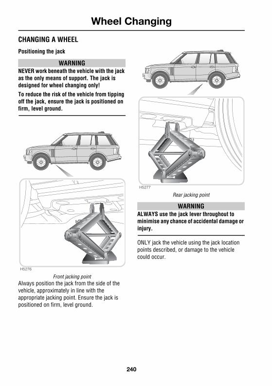
CHANGING A WHEEL
Positioning the jack
WARNINGNEVER work beneath the vehicle with the jack as the only means of support. The jack is designed for wheel changing only!
To reduce the risk of the vehicle from tipping off the jack, ensure the jack is positioned on firm, level ground.
Front jacking pointAlways position the jack from the side of the vehicle, approximately in line with the appropriate jacking point. Ensure the jack is positioned on firm, level ground.
Rear jacking point
WARNINGALWAYS use the jack lever throughout to minimise any chance of accidental damage or injury.
ONLY jack the vehicle using the jack location points described, or damage to the vehicle could occur.
H5276
H5277
240
Wheel Changing
R
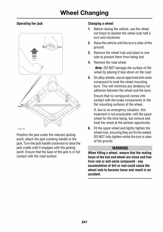
Operating the jack
Position the jack under the relevant jacking point, attach the jack cranking handle to the jack. Turn the jack handle clockwise to raise the jack cradle until it engages with the jacking point. Ensure that the base of the jack is in full contact with the road surface.
Changing a wheel
1. Before raising the vehicle, use the wheel nut brace to slacken the wheel nuts half a turn anti-clockwise.
2. Raise the vehicle until the tyre is clear of the ground.
3. Remove the wheel nuts and place to one side to prevent them from being lost.
4. Remove the road wheel.
Note: DO NOT damage the surface of the wheel by placing it face down on the road.
5. On alloy wheels, use an approved anti-seize compound to treat the wheel mounting bore. This will minimise any tendency for adhesion between the wheel and the bore.
Ensure that no compound comes into contact with the brake components or the flat mounting surfaces of the wheel.
If, due to an emergency situation, this treatment is not practicable; refit the spare wheel for the time being, but remove and treat the wheel at the earliest opportunity.
6. Fit the spare wheel and lightly tighten the wheel nuts, ensuring they are firmly seated. DO NOT fully tighten whilst the tyre is clear of the ground.
WARNINGWhen fitting a wheel, ensure that the mating faces of the hub and wheel are clean and free from rust or anti-seize compound - any accumulation of dirt or rust could cause the wheel nuts to become loose and result in an accident.
H4110
241

Wheel Changing
L
7. Ensure that the space under and around the vehicle is free from obstructions then lower the vehicle and remove the jack and wheel chocks.
8. Fully tighten the wheel nuts in an alternating pattern until all are tightened. DO NOT OVERTIGHTEN by using foot pressure or extension bars on the wheel stud brace, as this could overstress the wheel nuts. Check the wheel nut torque at the earliest opportunity see,WHEELS TYRES, 279.
9. Using a suitable blunt tool, apply light pressure to the rear of the replaced wheel centre cap and remove. Using hand pressure only, fit the centre cap into the newly fitted wheel. Return tools, chocks, jack and the replaced wheel to their correct storage positions.
Note: Storing the wheel in the spare wheel well can be achieved by following the spare wheel removal procedure in the reverse order.
10. REMEMBER to change to `H' (high range) before driving.
11. Finally, check the tyre pressure at the earliest opportunity see,WHEELS TYRES, 279.
For additional information on your tyres see, CARING FOR YOUR TYRES, 220.
242

Wheel Changing
R
LOCKING WHEEL NUTSVehicles may be equipped with a locking wheel nut on each wheel. These are similar to standard wheel nuts, but have a removable cap (1) and can only be removed using the special adaptor (2) provided in the tool kit.
Note: A code number is stamped on the underside of the adaptor. Ensure the number is recorded on the Security Information card supplied with the literature pack. Quote this number if a replacement is required. DO NOT keep the Security Information card in the vehicle.
Use the wheel nut brace to twist the wheel nut cap (1) slightly anti-clockwise and remove.
Insert the adaptor (2) firmly into the locking wheel nut.
Using the wheel nut brace, unscrew the wheel nut and adaptor.
Be sure to return the locking wheel nut adaptor to the correct storage position.
H3835
1
2
243

Emergency Starting
L
Emergency Starting
STARTING AN ENGINE WITH A DISCHARGED BATTERYUsing booster cables (jump leads) from a donor battery, or a battery fitted to a donor vehicle, is the only approved method of starting a vehicle with a discharged battery. This procedure differs to that used to charge a battery, which should not be attempted with the battery connected to the vehicle.
Push or tow starting is NOT recommended!
WARNINGALWAYS wear appropriate eye protection when working with batteries
During normal use, batteries emit explosive hydrogen gas sufficient to cause severe explosions capable of causing serious injury - keep sparks and naked lights away from the engine compartment.
DO NOT attempt to start the vehicle if the electrolyte in the battery is suspected of being frozen.
Make sure BOTH batteries are of the same voltage (12 volts), and that the booster cables have insulated clamps and are approved for use with 12 volt batteries.
DO NOT disconnect the discharged battery.
DO NOT connect positive (+) terminals to negative (-) terminals, and ensure booster cables are kept away from any moving parts in the engine compartment.
Take care when working near rotating parts of the engine.
USING BOOSTER CABLESIf a donor vehicle is to be used, both vehicles should be parked with their battery locations adjacent to each other. Ensure that the two vehicles do not touch.
Apply the handbrakes and ensure that the transmission of both vehicles is set in neutral (`P' or Park for vehicles with automatic transmission).
Turn off the starter switch and ALL electrical equipment of BOTH vehicles, then follow the connection instructions on the following page.
244
Emergency Starting
R
CONNECTING THE BOOSTER CABLES
WARNINGALWAYS use the recommended connection points.
DO NOT attach booster cables to the positive terminal of the vehicle battery. The positive terminal is equipped with a pyrotechnic device, that disconnects the battery as a safety precaution when the vehicle is involved in a collision. Attaching a booster cable to the positive terminal may cause inadvertent firing of the device - this may result in personal injury or death and may damage the vehicle.
ENSURE that each connection is securely made and that there is no risk of the clips accidentally slipping or being pulled from connection points - this could cause sparking, which could lead to explosion or fire.
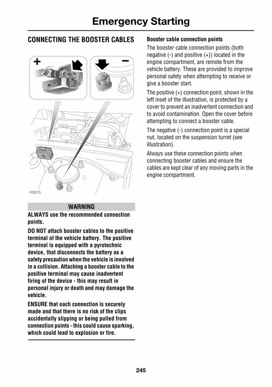
Booster cable connection pointsThe booster cable connection points (both negative (-) and positive (+)) located in the engine compartment, are remote from the vehicle battery. These are provided to improve personal safety when attempting to receive or give a booster start.
The positive (+) connection point, shown in the left inset of the illustration, is protected by a cover to prevent an inadvertent connection and to avoid contamination. Open the cover before attempting to connect a booster cable.
The negative (-) connection point is a special nut, located on the suspension turret (see illustration).
Always use these connection points when connecting booster cables and ensure the cables are kept clear of any moving parts in the engine compartment.
H3915
245

Emergency Starting
L
RECEIVING A BOOSTER START WARNINGDO NOT connect the BLACK cable to the negative terminal of the discharged battery, this could cause sparking, which could lead to fire or explosion. Always use the negative (-) connection point - if in doubt, seek qualified assistance.
Always adopt the following procedure, ensuring the cables are connected in the order shown below:
1. Connect one end of the RED booster cable to the positive (+) terminal of the DONOR battery or the donor vehicle's positive (+) connection point.
2. Connect the other end of the RED booster cable to the positive (+) connection point in the engine compartment of the Range Rover (see left inset).
3. Connect one end of the BLACK booster cable to the negative (-) terminal of the DONOR battery or the donor vehicle's negative (-) connection point.
4. Connect the other end of the BLACK booster cable to the negative (-) connection point in the engine compartment of the Range Rover (see right inset).
WARNINGENSURE that each connection is securely made and that there is no risk of the clips accidentally slipping or being pulled from the connection points/battery terminal - this could cause sparking, which could lead to fire or explosion.
IMPORTANT INFORMATIONEnsure that you have read and fully understood the information and warnings given earlier in this section see, STARTING AN ENGINE WITH A DISCHARGED BATTERY, 244, CONNECTING THE BOOSTER CABLES, 245 and USING BOOSTER CABLES, 244, BEFORE attempting to give or receive a booster start.
H3993
+
+
++
246

Emergency Starting
R
Check that the cables are clear of any moving parts of both engines, then start the engine of the donor vehicle and allow it to idle for a few minutes.
Now start the vehicle with the discharged battery. Once both engines are running normally, allow them to idle for two minutes before switching off the donor vehicle engine.
DO NOT switch on any electrical circuits on the previously disabled vehicle until AFTER the booster cables have been removed.
Disconnecting the booster cables must be an EXACT reversal of the procedure used to connect them, i.e. disconnect the BLACK cable from the negative (-) connection on your vehicle FIRST.
If the vehicle power supply has been interrupted, ABS and DSC will be deactivated (the relevant warning lights will illuminate). They can be reactivated by driving a short distance or by turning the steering wheel from full lock to lock, with the engine running and the vehicle stationary. The ABS and DSC warning lights will extinguish when the systems are reactivated.
GIVING A BOOSTER START
IMPORTANT INFORMATIONEnsure that you have read and fully understood the information and warnings given earlier in this section see STARTING AN ENGINE WITH A DISCHARGED BATTERY, 244, CONNECTING THE BOOSTER CABLES, 245 and USING BOOSTER CABLES, 244, BEFORE attempting to give or receive a booster start.
H3995
+
+
++
247

Emergency Starting
L
WARNINGDO NOT connect the BLACK cable to the negative terminal of the discharged battery, this could cause sparking which, could lead to fire or explosion. Always use the negative (-) connection point. If in doubt, seek qualified assistance.
Always adopt the following procedure, ensuring the cables are connected in the order shown below:
1. Connect one end of the RED booster cable to the positive (+) connection point (see left inset).
2. Connect the other end of the RED booster cable to the positive (+) connection point (if fitted) on the disabled vehicle, or positive (+) terminal of the discharged battery.
3. Connect one end of the BLACK booster cable to the negative (-) connection point (see right inset).
4. Connect the other end of the BLACK booster cable to the negative (-) connection point (if fitted) on the disabled vehicle, or to a good earth point (e.g. an engine mounting or other unpainted metal surface) at least 0.5m from the battery and well away from fuel and brake lines.
WARNINGENSURE that each connection is securely made and that there is no risk of the clips accidentally slipping or being pulled from the connection points/battery terminal - this could cause sparking, which could lead to fire or explosion.
Check that the cables are clear of any moving parts of both engines, then start the engine of the donor vehicle and allow it to idle for a few minutes.
Now start the vehicle with the discharged battery. Once both engines are running normally, allow them to idle for two minutes before switching off the donor vehicle engine.
DO NOT switch on any electrical circuits on the previously disabled vehicle until AFTER the booster cables have been removed.
Disconnecting the booster cables must be an EXACT reversal of the procedure used to connect them, i.e. disconnect the BLACK cable from the negative (-) connection on the previously disabled vehicle FIRST.
248
Towing the Vehicle
R
Towing the Vehicle
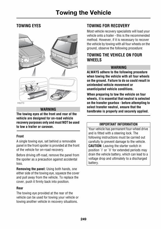
TOWING EYES
WARNINGThe towing eyes at the front and rear of the vehicle are designed for on-road vehicle recovery purposes only and must NOT be used to tow a trailer or caravan.
FrontA single towing eye, set behind a removable panel in the front spoiler is provided at the front of the vehicle for on-road recovery.
Before driving off-road, remove the panel from the spoiler as a precaution against accidental loss.
Removing the panel: Using both hands, one either side of the towing eye, squeeze the cover and pull away from the vehicle. To replace the cover, push it firmly back into position.
RearThe towing eye provided at the rear of the vehicle can be used for towing your vehicle or towing another vehicle in recovery situations.
TOWING FOR RECOVERYMost vehicle recovery specialists will load your vehicle onto a trailer - this is the recommended method. However, if it is necessary to recover the vehicle by towing with all four wheels on the ground, observe the following procedure:
TOWING THE VEHICLE ON FOUR WHEELS
WARNINGALWAYS adhere to the following procedure when towing the vehicle with all four wheels on the ground. Failure to do so could result in unintended vehicle movement or unanticipated vehicle conditions.
When preparing to tow the vehicle on four wheels, it is essential that neutral is selected on the transfer gearbox - before attempting to select transfer neutral, ensure that the handbrake is properly and securely applied.
H5273
IMPORTANT INFORMATIONYour vehicle has permanent four-wheel drive and is fitted with a steering lock. The following instructions must be carried out carefully to prevent damage to the vehicle.CAUTION: Leaving the starter switch in position `I' or `II' for extended periods may drain the vehicle battery, which can lead to a voltage drop and ultimately to a discharged battery.
249

Towing the Vehicle
L
1. Secure the towing attachment from the recovery vehicle to the front towing eye of the vehicle to be recovered see, TOWING EYES, 249.
2. With the handbrake applied, insert the starter key and turn it to position `II'.
3. Place the gear lever in `N' (neutral).
4. Turn the starter switch to position `0'.
5. Insert a fuse (5 amps) into position 37 of the passenger compartment fuse box see, PASSENGER COMPARTMENT FUSE BOX, 253.
6. Turn the starter switch to position `II'. The transfer gearbox will automatically select transfer neutral - wait until the message centre displays `TRANSFER NEUTRAL'.
7. Place the gear lever in `P' (park).
8. Turn the starter switch to position `I' (DO NOT turn the starter switch to position `0').
Note: The transfer gearbox is now in neutral and the steering wheel is unlocked. The vehicle MUST remain in this condition whilst being towed on all four wheels.
9. If required, the starter switch may be turned to position `II', to operate the brake lights and direction indicators.
10. Release the handbrake before towing the vehicle.
WARNINGDO NOT remove the key or turn the starter switch to position `0' while the vehicle is in motion.
Without the engine running, the brake servo and power steering pump cannot provide assistance; greater effort will therefore be required to operate the brake pedal and turn the steering wheel. Longer stopping distances will also be experienced.
After towing on four wheelsTo engage the transfer gearbox after towing, perform the following steps:
1. Apply the handbrake and verify that `N' (neutral) is selected in the main gearbox.
2. Turn the starter switch to position `0'.
3. Remove the fuse from position 37 of the passenger compartment fuse box.
4. Turn the starter switch to position `II'. The transfer gearbox will engage and `TRANSFER NEUTRAL' will extinguish from the message centre display. Press the range change switch to select either HIGH or LOW range.
5. Select `P' (park) in the main gearbox.
6. Turn the starter switch to position `0'.
IMPORTANT INFORMATIONIf the above conditions are met, the vehicle may be towed for up to 6 hours at a maximum speed of 80 km/h (50 mph).If, for any reason, power from the battery is lost and transfer neutral cannot be engaged, the vehicle can still be towed for up to 3 hours at a maximum speed of 48 km/h (30 mph).If the main gearbox cannot be set in neutral, the vehicle must not be towed under any circumstances.
250

Towing the Vehicle
R
TRANSPORTER OR TRAILER LASHING
Pairs of lashing eyes are fixed to the underside of the vehicle - at the front (to the rear of the front wheels) and at the rear (backward of the rear wheels). DO NOT secure lashing hooks or trailer fixings to any other part of the vehicle.
Note: The front and rear lashing eyes are for lashing only and must NOT be used for towing.
H5274
IMPORTANT INFORMATIONOnce the vehicle is loaded onto the trailer and if the vehicle electronics are operational, the electronic air suspension (EAS) must be set to Access height. This should be done BEFORE securing the vehicle to the trailer.
251

Fuses
L
Fuses
FUSESFuses are simple circuit devices which protect electrical equipment against the effects of excess current.
A `blown' fuse is indicated when the electrical equipment it protects becomes inoperative.
Fuses are colour coded to help identify their amperage, as follows:
Fuse colours
Checking or renewing a fuseAlways turn the starter switch to position `O' and switch off the affected electrical circuit before removing a fuse.
WARNINGTo prevent a possible fire or damage to the electrical system, fit only replacement fuses of the same rating and type.Do not replace a blown fuse with a fuse of a higher amperage rating. Always rectify the cause of the failure before replacing a fuse. Seek qualified assistance if necessary.
The fuse removal tweezers are located in the glovebox (arrowed in illustration). Press the tweezers onto the head of the suspect fuse (as shown) and pull to remove. A break in the wire inside the fuse indicates that the fuse has 'blown' and must be replaced.
Always replace a fuse with another of the same value, however, if the replacement fuse blows immediately the circuit MUST be checked by a Land Rover Dealer/Authorised Repairer.
VIOLET 3 ampTAN 5 ampBROWN 7.5 ampRED 10 ampBLUE 15 ampYELLOW 20 ampWHITE 25 ampGREEN 30 ampORANGE 40 amp
H4071
252

Fuses
R
PASSENGER COMPARTMENT FUSE BOX
The passenger compartment fuse box is fitted behind the glovebox; to access the fuses, open the glovebox, then press down on the catches (1) whilst pulling the cover rearwards. The solid arrow in the illustration indicates the location of the fuse removal tool.
Note: There are a number of spare fuses included within the fuse box (see fuse box label).
A label in the fuse box cover shows the circuits protected, the fuse values and their locations. They are also listed on the following page.
H3919
1 1
5
H4058
123456789
101112131415161718192021222324252627282930
313233343536373839404142434445464748495051525354555657585960
253

Fuses
L
Fuse specificationFuse
numberRating (amps)
Circuit protected
1 5 Instruments2 5 Heated rear window,
Rear blower,Heated seats - rear, Cigar lighter / Front Acc socketTrailer socket, Headlamp wash / wipe
3 7.5 Fuel cooler fan (diesel vehicles only)4 5 Exterior lights, Instrument illumination, Approach lamps5 7.5 Diagnostics, Alternator, Transmission6 5 Rear view mirror,
Parking distance control*7 - -8 - -9 5 Brake lights,
Exterior lights, Instrument illumination, Cruise controlSteering wheel audio controls
10 15 Horn11 30 Central locking,
External mirrors,Electric windows - front
12 10 Air conditioning,Heated seats - front*
13 5 Anti-lock Braking System,Dynamic Stability Control,Transmission, Interior clock
14 5 Auxiliary heater (diesel models only),Audio system, On board monitor, On board computer
15 5 Central locking,Diagnostics,Electric windows - front,Power assisted steering
16 - -17 5 Approach lamps18 10 Immobilisation19 - -20 30 Driver's seat,
Steering column adjust21 30 Passenger's seat
254

Fuses
R
22 5 Telephone*, Traffic messaging (TMC)23 15 Steering column adjust24 30 Central locking,
Exterior mirrorsElectric windows - front
25 5 Immobilisation26 30 Windscreen wipers27 20 Glove box light,
Interior lights,Windscreen washers
28 30 Headlight cleaning*29 10 Heated steering wheel*30 - -31 5 Engine management,
Immobilisation32 5 Xenon headlamps33 5 Transmission34 7.5 Air conditioning,
Blower, Heated front screen35 5 Hill descent control (HDC),
Dynamic Stability Control36 - -37 5 Transfer neutral - to be inserted when 4-wheel towing38 - -39 5 Immobilisation40 5 CD autochanger*41 5 Rain sensor*,
Rear window wash / wipe, Headlamp wash / wipe42 5 Vanity mirror illumination43 5 Alarm, Companion44 5 Airbag SRS - DO NOT REMOVE45 5 Instruments46 5 Instruments47 30 Heated screen washers,
Heated wiper blades48 10 DVD player
Fuse number
Rating (amps)
Circuit protected
255

Fuses
L
49 30 Navigation system,*On-board computer,*On-board monitor,*Audio system
50 - -51 10 Anti-lock Braking System,
Dynamic Stability Control,Fuel pump,
52 25 Heated seats - front*53 30 Ignition switch54 15 Transmission55 30 Anti-lock Braking System,
Dynamic Stability Control56 - -57 15 Air suspension58 20 Sunroof59 20 Auxiliary heater (diesel models only),
Independent heater60 30 Central locking,
Electric windows - rear
Fuse number
Rating (amps)
Circuit protected
256

Fuses
R
REAR LOADSPACE FUSE BOX
The fuse box is situated on the right hand side of the loadspace behind the rear loadspace access hatch. Pull the handle to open the panel see, REAR LOADSPACE ACCESS HATCH, 127.
Owners are advised against removing or replacing the relays (identified as R1-R10) and fusible links (MF1-MF3). Failure of any of these items should be investigated by a qualified technician.
H533415 16141 4 6 7 9 10 11 12 17 18
257

Fuses
L
Fuse specification
Fuse number
Rating (amps)
Circuit protected
1 20 Cigar lighter/socket2 10 Navigation system, Audio system,
Telephone,On board monitor,On board computer
3 30 Audio system4 15 Trailer socket5 10 Rear seat entertainment,
VICS (Japan)6 20 Trailer socket7 20 Auxiliary power socket (loadspace)8 5 Rear view camera9 30 Heated rear window
10 20 Rear screen wash/wipe11 10 Heated rear seats*-LH12 15 Rear blower13 10 Heated rear seats*-RH14 5 Remote handset15 25 Fuel pump16 10 Central locking system, tailgate17 50 Trailer socket18 50 Air suspension19 -
258

Bulb Replacement
R
Bulb Replacement
REPLACING BULBSCheck the operation of all exterior lights before you drive the vehicle.
Replacement bulbs
Note: All bulbs must be rated at 12 volts
Note: In certain territories it is a legal requirement to carry spare bulbs, in case of bulb failure. A replacement bulb kit is available as an approved accessory from your Land Rover Dealer/Authorised Repairer.
Halogen bulbsHalogen bulbs are used for main beam, dipped beam and front fog and reverse lights. Take care NOT to touch this type of bulb with your fingers; always use a cloth to handle them. If necessary, clean the bulb with methylated spirits to remove fingerprints.
WARNING• Bi-Xenon light units operate at a high
temperature. If they have recently been in use, allow sufficient time for them to cool down before touching them.
• Used xenon light units contain mercury, which is hazardous and can be injurious to health.
• The xenon system generates up to 28 000 volts and contact with this voltage could lead to a fatality. Ensure that headlights are switched off and switch off the starter switch before working on the system.
• Replacement or maintenance of xenon lights should be carried out only by qualified personnel.
Some vehicles are fitted with Bi-Xenon headlight units. bi Xenon lights provide significantly improved visibility, especially during adverse weather.
The operational life of a Bi-Xenon light is significantly longer than that of a conventional or halogen bulb.
Seek advise about the proper disposal of Bi-Xenon light units from a Land Rover Dealer/Authorised Repairer or your local authority.
IMPORTANT INFORMATIONBefore replacing a bulb, always switch off the starter switch and appropriate lighting switch to prevent any possibility of a short circuit. Only replace bulbs with the same type and specification.
Bulb WattsHeadlights dipped beam (Halogen)
55 (H7)
Headlights main beam 55 (H7)Front side lights 5Direction indicators 21Front fog lights 55 (H7)Side repeater lights 5Reverse lights 6 (H6)Rear fog guard lights 21Tail lights 5Number plate lights 5Door/puddle lights 5Interior lights 6Luggage/footwell lights 5Luggage/tailgate lights 6Glovebox light 5Vanity mirror light 1.2
259
Bulb Replacement
L
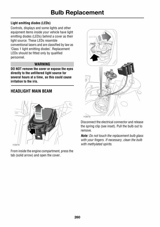
Light emitting diodes (LEDs)Controls, displays and some lights and other equipment items inside your vehicle have light emitting diodes (LEDs) behind a cover as their light source. These LEDs resemble conventional lasers and are classified by law as ‘Class 1 light emitting diodes’. Replacement LEDs should be fitted only by qualified personnel.
WARNINGDO NOT remove the cover or expose the eyes directly to the unfiltered light source for several hours at a time, as this could cause irritation to the iris.
HEADLIGHT MAIN BEAM
From inside the engine compartment, press the tab (solid arrow) and open the cover.
Disconnect the electrical connector and release the spring clip (see inset). Pull the bulb out to remove.
Note: Do not touch the replacement bulb glass with your fingers. If necessary, clean the bulb with methylated spirits.H3878
H3879
260

Bulb Replacement
R
HEADLIGHT DIPPED BEAM
From inside the engine compartment, press the tab (solid arrow) and open the cover.
Disconnect the electrical connector and release the spring clip (see inset). Pull the bulb out to remove.
Note: Do not touch the replacement bulb glass with your fingers. If necessary, clean the bulb with methylated spirits.
H3880
H3881
261

Bulb Replacement
L
FRONT DIRECTION INDICATOR AND SIDELIGHT
Light unit removal
From inside the engine compartment, unscrew the nut (anti-clockwise), to release the light unit (see inset). The nut is attached to a safety strap, which prevents it from falling into the engine.
Keeping hold of the light unit, ease it away from the vehicle body, disengaging the two locating lugs (arrowed).
Bulb replacement
The upper of the two bulbs is the direction indicator, the lower is the sidelight bulb. The removal process is identical for both bulbs.
Having released the light unit form the front of the vehicle, turn the relevant bulb holder 90 anti-clockwise and pull to release. Twist and pull to remove the bulb.
Refitting the light unitWhen refitting the light unit, position the two lugs first, then position the light unit, so that the securing bolt lines up correctly with the thumbwheel. Tighten the nut (turn clockwise) to fix the unit in position.
H3811
H3812
262

Bulb Replacement
R
REAR LIGHT CLUSTER (Tail, indicator and fog lights)
From outside the vehicle and with the tailgate fully open, remove the two retaining screws (as shown). From the side of the vehicle, use a suitable tool to carefully lever the unit away from the vehicle and rearwards, to release the light unit from the vehicle.
Be careful to avoid damage to the paintwork, when levering the light unit from the vehicle. Cover any tool used with a cloth and apply gentle and constant pressure. Do not use excessive force - if in doubt, consult your Land Rover Dealer/Authorised Repairer.
Press the two tabs (arrowed in inset) together, to release the light unit from the lens assembly. Twist and pull the appropriate bulb to release.
The bulbs are located as follows:
1. Rear indicator bulb.
2. Tail light bulb.
3. Rear fog guard light bulb.
Note: The brake lights and high mounted stop light fitted to your vehicle, are LED lights and should be replaced by your Land Rover Dealer/Authorised Repairer if they fail.
H3813
H38143
1
2
263

Bulb Replacement
L
REVERSE LIGHTS
The reverse lights are located on either side of the rear number plate, mounted on the lower tailgate.
With the upper tailgate raised, remove the screw (see inset) to release the light unit from the tailgate.
Twist and pull the bulb holder to release from the rear of the light unit, then pull the bulb to remove.
Note: Do not touch the replacement bulb glass with your fingers. If necessary, clean the bulb with methylated spirits.
H3806
H3807
264

Bulb Replacement
R
NUMBER PLATE LIGHTS
With the upper tailgate open and using a suitable tool, lever the lens from the tailgate (see inset). Pull the bulb to remove.
SIDE REPEATER LIGHT
Push the lens firmly towards the front of the vehicle and withdraw the light unit from the wing. Twist to release the bulb holder from the lens unit, then pull the bulb from its socket.
H3983
H3815
265

Bulb Replacement
L
FRONT FOG LIGHTS
To access the bulb; using a suitable tool, lever the fog light surround panel out of the front bumper. Remove the three securing screws to release the light unit. Ease the unit out of the front bumper.
Depress the two catches (solid arrows in upper inset), then twist and pull to remove the bulb holder from the lens assembly. Pull the bulb from the holder to remove.
Before fitting the replacement bulb, note the `flat' and the tab on the otherwise circular shape of the bulb mounting flange. The tab acts as a key to enable correct positioning of the bulb in the bulb holder.
Note: Do not touch the bulb glass with your fingers. If necessary, clean the bulb with methylated spirits.
H3808
H3809
266

Bulb Replacement
R
DOOR/PUDDLE/LOWER FOOTWELL LIGHTS
With the relevant door open, insert a small flat-bladed screwdriver under the forward edge of the lens. to lever the light unit out of the door. Pull the bulb out to remove.
GLOVEBOX LIGHT
Insert a small flat-bladed screwdriver into the indent (see inset) on the side of the light unit, and carefully prise the unit from the glovebox panel. Remove the bulb from its clips.
H4081
H4082
267

Bulb Replacement
L
UPPER FOOTWELL LIGHTS
Insert a small flat-bladed screwdriver under the side of the light unit and carefully prise the unit out of the footwell.
Twist and pull the bulb holder access the bulb and pull the bulb to remove.
LUGGAGE LIGHTS
Insert a small flat-bladed screwdriver into the indent on the side of the lens and carefully prise the lens from the light unit (see inset).
Slide the metal plate to the right and then pull away from the back of the light unit (see main illustration). Pull the bulb to remove.
H3884
H3810
268

Bulb Replacement
R
TAILGATE LIGHT
Insert a small flat-bladed screwdriver under the lens and carefully prise the lens from the light unit. Pull the bulb to remove.
MAP LIGHT
Insert a small flat-bladed screwdriver into the indent on the side of the lens (as illustrated) and prise the lens from the light unit. Twist the relevant bulb holder anti-clockwise and withdraw from the light unit, then pull the bulb out to remove.
H4081
H3883
269
Bulb Replacement
L
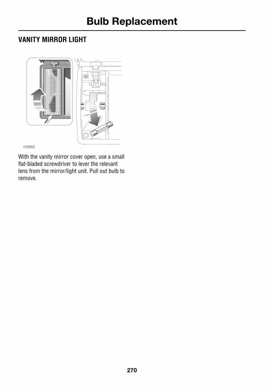
VANITY MIRROR LIGHT
With the vanity mirror cover open, use a small flat-bladed screwdriver to lever the relevant lens from the mirror/light unit. Pull out bulb to remove.
H3882
270

Technical Data
R
Lubricants FluidsLUBRICANTS FLUIDS . . . . . . . . . . . . . . . .273
CapacitiesCAPACITIES . . . . . . . . . . . . . . . . . . . . . . .275
EnginesENGINES . . . . . . . . . . . . . . . . . . . . . . . . . .276
Electrical SystemELECTRICAL SYSTEM . . . . . . . . . . . . . . . .277
SteeringSTEERING . . . . . . . . . . . . . . . . . . . . . . . . .278
Wheels TyresWHEELS TYRES . . . . . . . . . . . . . . . . . . . .279
WeightsVEHICLE WEIGHTS . . . . . . . . . . . . . . . . . .282TOWING WEIGHTS . . . . . . . . . . . . . . . . . .283
DimensionsVEHICLE DIMENSIONS . . . . . . . . . . . . . . .284TOW BAR DIMENSIONS . . . . . . . . . . . . . .285
Fuel ConsumptionFUEL CONSUMPTION . . . . . . . . . . . . . . . .287
271