NFPA 70 1 A95 ROP ARTICLE 402
579
NFPA 70 1 A95 ROP ARTICLE 402 -- FIXTURE WIRES (Log #441) 6-169- (Table 402-3): Reject SUBMITTER: Dan Leaf, Palmdale, CA RECOMMENDATION: In the column headed Applicable Provisions add a reference to Sec. 620-11 (a) for Type Letter conductors SF-1, SF-2, SFF-1, and SFF-2. SUBSTANTIATION: Sec. 620-11 (a) indicates a permitted use in addition to those indicated, and since the applicatioq provisions appear intended to be comprehensive should include this additional use. PANEL ACTION: Reject. PANEL STATEMENT: See Panel Action on Panel Proposal 6-169A. NUMBER OF PANEL MEMBERS ELIGIBLE TO VOTE: I0 VOTE ON PANEL ACTION: AFFIRMATIVE: 10 (Log #CP605) 6-169a- (Table 402-3): Accept SUBMITTER: CMP 6 I RECOMMENDATION: Under "application provisions" column delete file references to various sections of the Code wherever they appear in Table 402-3. SUBSTANTIATION: It is not always necessary to cross reference other Code sections. PANEL ACTIONi Accept NUMBER OF PANEL MEMBERS ELIGIBLE TO VOTE: 10 VOTE ON PANEL ACTION: AFFIRMATIVE: 10 (Log #1126) 6-170 - (Table 402-3): Reject SUBMITTER: Dean K. Wilson, National Fire Alarm Code Correlat- ing Committee RECOMMENDATION: In "Application Provisions" column change "Section 725-16" to "Section 725-16 and 760-16" for types KFF-2, PFF, PGFF, SFF-2, TFF, TFFN and ZFF cables. SUBSTANTIATION: To correlate with the action taken by CMP 16 to permit the use of fine stranded cables lor Fire Alarm Systems. PANEL ACTION: Reject. PANEL STATEMENT: See Panel Action and Substantiation on Proposal 6-169A. NUMBER OF PANEL MEMBERS ELIGIBLE TO VOTE: 10 VOTE ON PANEL ACTION: AFFIRMATIVE: 10 (Log #1959) 6-171 - (402-7): Accept SUBMITTER: Ronald IL Runkles, National Electrical Manufactur, ers Association RECOMMENDATION: Change wording of Section 402-7 to read as follows: 402-7. Number of Conductors in Conduit or Tubing. Tile number of fixture wires permitted in a single conduit or tubing shall not exceed the percentage fill specified in Table 1, Chapter 9. SUBSTANTIATION: This is a companion proposal to that being made by the NEMAJoint Sections Committee on Raceway Wirefill that, if accepted, would remove Table 2 flora Chapter 9 and include the information in several tables of a new appendix. Table 1 of Chapter 9 is intended to become the mandatory code reference for ~ ermitted raceway fill. ANEL ACTION: AccepL NUMBER OF PANEL MEMBERS ELIGIBLE TO VOTE: 10 VOTE ON PANEL ACTION: AIZflIRMATIVE: I0 520-61, and arc lamps used in projection machines shall comply with Section 540-20. Arc lamps used on constant-current systems shall comply with the general requirements of Article 710. SUBSTANTIATION: Section 410-2 should have file paragraph found in Section 410-55. This would be a more suited place for these items because of the heading "application of other articles." " The other objective is to free up Article 410-55 so to add proposals to Part K because the numbering of Sections ran out PANEL ACTION: Accept. NUMBER OF PANEL MEMBERS ELIGIBLE TO VOTE: 9 VOTE ON PMqEL ACTION: AFFIRMATIVE: 9 (Log #3178) 18-2 - (410-2): Accept in Principle SUBMrrTER: D.M. Berlin, Intermatic Inc. RECOMMENDATION: Add new sentence to Article 430-2, Applicati on' to Other Articles: ' "Equipment for use in Low voltage Landscape Lighting Systems and Components shall conform to Article 411". SUBSTANTIATION: This addition will be required when Article 411 - Low Voltage Landscape Lighting Systems & Components is added to the 1996 NationalElectric Code. PANEL ACTION: Accept in Principle. Add a new .,~entence to Section 410-2 at die end of the existing first Isentence to read as follows: i "Lighting s~tems operating at 30 volts or less shall conform to Article 4I 1." PANEL STATEMENT: See Panel Action and statement on Proposal 18-90a. NUMBER OF PANEL MEMBERS ELIGIBLE TO VOTE: 9 VOTE ON PANEL ACTION: AFFIRMA'I- IVE: 9 (Log #3381) 18-3 - (410-2): Accept in Principle SUBMITrER: D.M. Berlin, Intermatic Inc. RECOMMENDATION: Add new sentence to Article 410-2, /,k~, ,plication to Other Articles: ' Equipment for use in Low Voltage Landscape Ligbting Systems and Components shall conform to Article 411 ". SUBSTANTIATION: This addition will be required wben Article 411 -Low Voltage Landscaping Lighting Systems & Components is added to the 1996 National Electric Code. PANEL ACTION: Acceptin Principle. P.M~IEL STATEMENT: See Panel Action and Statement on Proposal 18-90a. NUMBER OF PANEL MEMBERS ELIGIBLE TO VOTE: 9 VOTE ON PANEL ACTION: AFFIRMATIVE: 9 (Log #1989) 18-4- (410-3, Exception): Accept SUBMITTER: Ronald R. Runkles, National Electrical Manufactur- ers Association I RECOMMENDATION: In file exception, delete the last word, "contacts," and in its place, insert tile word, "terminals." SUBSTANTIATION: This proposal originates from'a product standard harmonization effort between NEMA, EEMAC, UL and CSA to develop concurrence between product listing and certifica- tion as per the Canada-United States Free Trade Agreement. The change of termff between "contacts" and "terminals" is editorial in nature, but truly reflects the technical reality of the described devices in secdon 410-3. PANEL ACTION: Accepe NUMBER OF PANEL MEMBERS ELIGIBLE TO VOTE: 9 VOTE ON PANEL ACTION: , AFFIRMATIVE: 9 ARTICLE 410 -- LIGHTING FIXUTRES, LAMPHOLDERS, LAMPS, AND RECEPTACLES (Log #1501) 18-1a- (410-2): Accept SUBMITTER: Nick Malouf, Holly, MI RECOMMENDATION: Revise text as follows: 410-2 Appl!cation of other articles. Equipment for use in hazardous (classified) locations shall conform to Ardc[es 500 through 517. Arc lamps used in theaters shall comply with Section 18-5 - (410-3, Exception No. 2): Accept in Principle (Log #1507) SUBMITTER: Gregory L. Kay, Tecb Lighting RECOMMENDATION: Revise text ,as follows: Correct the wording of the first paragraph for a new Exception No. 2, Section 410-3, of the NEC to add words that were left out due to typographical error. The complete text of the substantiation should be ,as shown below. 457
-
Upload
khangminh22 -
Category
Documents
-
view
0 -
download
0
Transcript of NFPA 70 1 A95 ROP ARTICLE 402

N F P A 7 0 1 A 9 5 R O P
ARTICLE 402 - - FIXTURE WIRES
(Log #441) 6-169- (Table 402-3): Reject SUBMITTER: Dan Leaf, Palmdale, CA RECOMMENDATION: In the co lumn headed Applicable Provisions add a reference to Sec. 620-11 (a) for Type Letter conductors SF-1, SF-2, SFF-1, and SFF-2. SUBSTANTIATION: Sec. 620-11 (a) indicates a permit ted use in addit ion to those indicated, and since the applicatioq provisions appear in tended to be comprehensive shou ld include this additional use. PANEL ACTION: Reject. PANEL STATEMENT: See Panel Action on Panel Proposal 6-169A. NUMBER OF PANEL MEMBERS ELIGIBLE TO VOTE: I0 VOTE ON PANEL ACTION:
AFFIRMATIVE: 10
(Log #CP605) 6-169a- (Table 402-3): Accept SUBMITTER: CMP 6
I RECOMMENDATION: Unde r "application provisions" co lumn delete file references to various sections of the Code wherever they appear in Table 402-3. SUBSTANTIATION: It is no t always necessary to cross reference o ther Code sections. PANEL ACTIONi Accep t NUMBER OF PANEL MEMBERS ELIGIBLE TO VOTE: 10 VOTE ON PANEL ACTION:
AFFIRMATIVE: 10
(Log #1126) 6-170 - (Table 402-3): Reject SUBMITTER: Dean K. Wilson, National Fire Alarm Code Correlat- ing Commit tee RECOMMENDATION: In "Application Provisions" co lumn change "Section 725-16" to "Section 725-16 and 760-16" for types KFF-2, PFF, PGFF, SFF-2, TFF, TFFN and ZFF cables. SUBSTANTIATION: To correlate with the action taken by CMP 16 to permi t the use of fine s t randed cables lor Fire Alarm Systems. PANEL ACTION: Reject. PANEL STATEMENT: See Panel Action and Substantiat ion on Proposal 6-169A. NUMBER OF PANEL MEMBERS ELIGIBLE TO VOTE: 10 VOTE ON PANEL ACTION:
AFFIRMATIVE: 10
(Log #1959) 6-171 - (402-7): Accept SUBMITTER: Ronald IL Runkles, National Electrical Manufactur , ers Association RECOMMENDATION: Change wording of Section 402-7 to read as follows:
402-7. Number of Conductors in Condui t or Tubing. Tile n u m b e r of fixture wires permi t ted in a single condui t or tubing shall no t exceed the percentage fill specified in Table 1, Chapter 9. SUBSTANTIATION: This is a compan ion proposal to that being made by the NEMAJoint Sections Commit tee on Raceway Wirefill that, if accepted, would remove Table 2 flora Chapter 9 and include the information in several tables of a new appendix. Table 1 of Chapter 9 is in tended to become the manda to ry code reference for
~ ermit ted raceway fill. ANEL ACTION: AccepL
NUMBER OF PANEL MEMBERS ELIGIBLE TO VOTE: 10 VOTE ON PANEL ACTION:
AIZflIRMATIVE: I0
520-61, and arc lamps used in projection machines shall comply with Section 540-20. Arc lamps used on constant-current systems shall comply with the general requi rements of Article 710. SUBSTANTIATION: Section 410-2 should have file pa rag raph found in Section 410-55. This would be a more su i ted place for these items because of the head ing "application of o ther articles." "
The o ther objective is to free up Article 410-55 so to add proposals to Part K because the n u m b e r i n g of Sections ran o u t PANEL ACTION: Accept. NUMBER OF PANEL MEMBERS ELIGIBLE TO VOTE: 9 VOTE ON PMqEL ACTION:
AFFIRMATIVE: 9
(Log #3178) 18-2 - (410-2): Accept in Principle SUBMrrTER: D.M. Berlin, Intermatic Inc. RECOMMENDATION: A d d new sentence to Article 430-2, Applicati on' to Other Articles: ' "Equipment for use in Low voltage Landscape Light ing Systems and Componen t s shall conform to Article 411". SUBSTANTIATION: This addit ion will be required when Article 411 - Low Voltage Landscape Light ing Systems & C o m p o n e n t s is added to the 1996 NationalElectr ic Code. PANEL ACTION: Accept in Principle.
Add a new .,~entence to Section 410-2 at die end of the existing first Isentence to read as follows: i "Lighting s~ t ems operat ing at 30 volts or less shall conform to Article 4I 1." PANEL STATEMENT: See Panel Action and s t a tement on Proposal 18-90a. NUMBER OF PANEL MEMBERS ELIGIBLE TO VOTE: 9 VOTE ON PANEL ACTION:
AFFIRMA'I- IVE: 9
(Log #3381) 18-3 - (410-2): Accept in Principle SUBMITrER: D.M. Berlin, Intermatic Inc. RECOMMENDATION: Add new sentence to Article 410-2, / ,k~, ,plication to Other Articles:
' Equ ipment for use in Low Voltage Landscape Ligbting Systems and Componen t s shall conform to Article 411 ". SUBSTANTIATION: This addi t ion will be required wben Article 411 -Low Voltage Landscaping Light ing Systems & Componen t s is added to the 1996 National Electric Code. PANEL ACTION: Accep t in Principle. P.M~IEL STATEMENT: See Panel Action and Sta tement on Proposal 18-90a. NUMBER OF PANEL MEMBERS ELIGIBLE TO VOTE: 9 VOTE ON PANEL ACTION:
AFFIRMATIVE: 9
(Log #1989) 18-4- (410-3, Exception): Accept SUBMITTER: Ronald R. Runkles, National Electrical Manufactur- ers Association
I RECOMMENDATION: In file exception, delete the last word, "contacts," and in its place, insert tile word, "terminals." SUBSTANTIATION: This proposal originates f rom 'a p roduc t s tandard harmoniza t ion effort between NEMA, EEMAC, UL an d CSA to develop concur rence between produc t listing a n d certifica- tion as pe r the Canada-Uni ted States Free Trade Agreement .
The change of termff between "contacts" and "terminals" is editorial in nature, bu t truly reflects the technical reality of the described devices in secdon 410-3. PANEL ACTION: Accepe NUMBER OF PANEL MEMBERS ELIGIBLE T O VOTE: 9 VOTE ON PANEL ACTION: ,
AFFIRMATIVE: 9
ARTICLE 410 - - LIGHTING FIXUTRES, LAMPHOLDERS, LAMPS, AND RECEPTACLES
(Log #1501) 18-1a- (410-2): Accept SUBMITTER: Nick Malouf, Holly, MI RECOMMENDATION: Revise text as follows:
410-2 Appl!cation of o ther articles. Equ ipment for use in hazardous (classified) locations shall conform to Ardc[es 500 th rough 517. Arc lamps used in theaters shall comply with Section
18-5 - (410-3, Exception No. 2): Accept in Principle (Log #1507) SUBMITTER: Gregory L. Kay, Tecb Lighting RECOMMENDATION: Revise text ,as follows: Correct the wording of the first paragraph for a new Except ion No. 2, Section 410-3, of the NEC to add words tha t were left ou t due to typographical error. The complete text of the substant iat ion shou ld be ,as shown below.
457

N F P A 70 - - A 9 5 R O P
SUBSTANTIATION: An exception to Section 410-3 is needed to .permit installation of certain existing nonhazardous lighting systems. Al though the NEC Style Manual specifies that the term "Live Parts" applies only where a shock hazard exists, the te rm "Live Parts" is no t def ined in Article 100.
In accordance with Section 11 0-17(a), guard ing against accidental contact is no t generally required for parts operat ing at less than 50 volts. The voltage limitation proposed, however, is the same as in Section 110-16(a), Exception No. 1.
Low voltage (12 volts) l ighting systems with energized, exposed, un insu la ted parts are listed. T he listed systems include an isolating transformer, so that the un insu la ted parts do no t consti tute an electric shock hazard when installed in accordance with the instructions per Section l10-3(b). PANEL ACTION: Accept in Principle. PANEL STATEMENT: The action that is being proposed is actually covered unde r proposed new Article 411. See the Proposal and Panel Action on Proposal 18-90a. NUMBER OF PANEL MEMBERS ELIGIBLE T O VOTE: 9 VOTE ON PANEL ACTION:
AFFIRMATIVE: 9
(Log #1588) 18-6- (410-3, Exception No. 2-(New)): Accept in Principle SUBMITTER: Gregory L. Kay, Tech Lighting RECOMMENDATION: Add New Exception No. 2: Uninsula ted energized parts shall be permi t ted where they are part of a listed fixture or l ighdng system and are energized at a voltage no greater than 30 volts RMS, 42 volts peak, or 60 volts dc. SUBSTANTIATION: An exception to Section 410-3 is needed to permi t installation of certain existing nonhazardous lighting systems. Al though the NEC Style Manual specifies that the term "Live Parts" is no t def ined in Article 100.
In accordance with Section 110-17(a), guard ing against accidental contact is no t generally required for parts operat ing at less than 50 volts. The voltage limitation proposed, however, is the same as in Section l l0-16(a) , Exception No. 1 . .
Low voltage ( 12 volts) l ight ing systems with energized, exposed un insu la ted parts are listed. The listed systems include an isolating transformer, so that the uninsu[a ted parts do no t consti tute an electric shock, hazard when installed in accordance with the instructions per Section 110-3(b). PANEL ACTION: Accept in Principle.- PANEL STATEMENT: T he action tha t is being proposed is actually covered unde r proposed new Article 411. See the Proposal and Panel Action on Proposal 18-90a. NUMBER OF PANEL MEMBERS ELIGIBLE T O VOTE: 9 VOTE ON PANEL ACTION:
AFFIRMATIVE: 9
(Log #2705) 18-7- (410-3, Exception No. 2-(New)): Accept in Principle SUBMITTER: J im Prior, Transli te Systems RECOMMENDATION: Add a new exception as follows:
Exception No. 2: Where any part of a listed track, fixture or lamp holder operates at a voltage of less than 30 volts, and is installed in a dry location, those parts shall be permi t ted to be exposed. SUBSTANTIATION: It is clearly the in tent ion of the code to prevent l ighting systems and fixtures f rom being installed where they pose a risk of electric shock. Because up until recently the vast majority of all l ighting systems only used direct line voltage supplies, ie 120 volts, it was sufficient for the code to assume live parts in a l ighting system necessarily posed a shock ltazard and therefore had to be insulated. This is why section 410-3 says that "fixtures, lamp holders, lamps and receptacles shall have no live parts normally exposed to contact".
Elsewhere in the code (725-31.725-38) in relation to signaling circuits, class 2 and 3 circuits, exposed conductors are permit ted provided they conform to certain criteria. The key one is that in relation to open conductors (725-31 note 2) the m a x i m u m voltage shall be no t more than 42.4v peak (30volts rms) for dry locations or haft this for wet locations.
Here then is the crux. The code does recognize the difference between low voltage, i.e. where no electric shock hazard exists and high voltage where it does, but no t specifically in relation to Lighting circuits and fixtures. Electrical inspectors therefore can con tend that the code does no t make a specific e n o u g h definition or exception In relation to low voltage lighting.
In the NEC style handbook, page 15, there is a definit ion of 'live parts' - "Electrical conductors, busses, terminals or componen t s that are uninsula ted or exposed a n d a shock hazard exists ~. It does not
define shock hazard but it is clear f rom this definit ion that if no shock hazard exists a part should no t be regarded as live.
It is clear f rom 725-31 that the NEC does no t regard parts with a potential of less than 30 volts as a shock hazard otherwise they would not permit any circuit, whe ther class 1, 2, or 3 to have exposed conductors.
Underwriters Laboratories clearly agree since they define in UL 11574 and 1571 an electric shock as "a risk of electric shock is considered likely to occur at any part if tile potential between the part and ear th g r o u n d or any o ther accessible part is more than 42.4 volts peak..."
They therefore allow in 15.1 (UL 1574) that a "current carrying part that (1) involves a voltage of less than 30 volts and (2) is connected to the secondary circuit of a t ransformer that is electri- cally isolated f rom a primary need not be inaccessible".
We therefore believe that exposed parts should be permi t ted where there is no danger of electric shock and in keeping with bodl the cur ren t NEC and also UL's defini t ion set this uppe r limit at 30 volts RMS.
Inclusion of the word "listed" in the wordina of our exceotion Al though there is no danger of electric shock in low vol~ge
l ighting systems, because of the high currents associated with these systems there can be a h igher risk of bu rn ing or fire than in line voltage systems. In our exper ience many contractors and inspectors, because of their relative unfamiliarity with low voltage systems tend to pay less at tent ion to dais hazard. Whilst this unfamiliarity exists we drink it impor tan t that these lighting fixtures and systems be listed so that the safety engineer ing in the product has due regard to
a. The high tempera ture of the fixtures b. The need for h igher rating of both the wire gauge and the
insulat ing jacket c. Overcurrent protect ion -part icularly in instances where there
are exposed parts d. Adequate means of splicing between power source and bus bar
and between fixture and bus bar. e. Type and specification of transformers.
PANEL ACTION: Accep t in Principle. PANEL STATEMENT: The action that is being proposed is actually covered unde r proposed new Ai-ticle 411. See the Proposal and Panel Action on' ld-90a. NUMBER OF PANEL MEMBERS ELIGIBLE T O VOTE: 9 VOTE ON PANEL ACTION:
AFFIRMATIVE: 9
(Log #2864) 18-8 - (410-3, Exception No. 2-(New)): Accept in Principle SUBMITTER: William T. Fiske, South Cortland, NY RECOMMENDATION: New text as follows:
Add "No. 1" to existing "Exception!': [For new Exception No. 2 to follow]
Exception No. 2: Lighting cable assemblies installed in accordance widl Section 410-108 shall be permit ted to have exposed current- carrying parts operat ing at a potential of not more than 42.4 Volts peak. SUBSTANTIATION: [SUPPLEMENTAL TO PROPOSED SUB- PART S OF ARTICLE 410] PANEL ACTION: Accept in Principle. PANEL STATEMENT: The action that is being proposed is actually covered unde r proposed new Article 411. See the Proposal and Panel Action on Proposal 18-90a. NUMBER OF PANEL MEMBERS ELIGIBLE T O VOTE: 9 VOTE ON PANEL ACTION:
AFFIRMATIVE: 9
(Log #CP1806) 18-8a- (410-4(b), FPN): Accept SUBMITTER: CMP 18
[ RECOMMENDATION: Delete FPN under Section 410-4(b). SUBSTANTIATION: This reference is d e e m e d inappropr ia te for this Section. PANEL ACTION: Accept. NUMBER OF PANEL MEMBERS ELIGIBLE T O VOTE: 9 VOTE ON PANEL ACTION:
AFFIRMATIVE: 9
458

N F P A 70 - - A 9 5 R O P
(Log #199) 18-9- (410-4(c)): Reject SUBMITTER: AlanJacobson, Advanced Fire Protection RECOMMENDATION:- Revise text:
"Reference to NFPA 96 in regard to shutdown of power to all e q u i p m e n t requir ing protection." SUBSTANTIATION: Electricians somet imes say tiLeir is no th ing in the NEC requir ing t hem to supply and install suitable shutdown devices for cooking equ ipmen t unde r a hood which is protected by a fire suppress ion system. PANEL ACTION: Reject. PANEL STATEMENT: The Proposal does no t mee t the require- ments for proposal con ten t as required by Section 3-3.3(c) of the NFPA Regulat ions to contain a s ta tement of the problem and substantiation. NUMBER OF PANEL MEMBERS ELIGIBLE T O VOTE: 9 VOTE ON PANEL ACTION:
AFFIRMATIVE: 9
(Log #1 44) 18-10- (410-4(d)-(New)):. Reject SUBMITTER: Mike Bukacek, IBEW Local 22 RECOMMENDATION: New text:
"No fixture shall be located in a zone measured 3 feet horizontally a n d 8 feet vertically f rom the top of the ba th tub d m unless the fixture is GFCI protected. This zone is all encomp~Lssing and includes the area over the tub." SUBSTANTIATION: Regardless of the type of fixture used, any fixture above a ba th tub is a potential hazard, and for the safety of the homeowner or anyone working on the fixture, it should be GFCI
~ rotected. ANEL ACTION: Reject.
PANEL STATEMENT: Currently Section 410-4(d) prohibits hanging, cord-connected, and pendan t Wpe textures f rom being in ' tile ba th tub zone even with GFCIprotec t ion and permit t ing these fixtures into these areas would reduce safety. There is no technic:fl substantiat ion submit ted dlat identifies a hazard with fixtures that 5.re currently permi t ted in these zones. NUMBER OF PANEL MEMBERS ELIGIBLE T O VOTE: 9 VOTE ON PANEL ACTION:
AFFIRMATIVE: 9
(Log #150) 18-11 - (410-4(d)): Reject SUBMITTER: Bob Bohling, Local 22 IBEW RECOMMENDATION: Incandescent fluorescent, and cord- connec ted fixtures, hang ing or pendant.'; shall be located within an area measured 3 feet horizontally and 8 feet-vertically fi'om top of the bathtub rim. This area above the tub shall haw: e q u i p m e n t that is GFCI protected with no exceptiofls. SUBSTANTIATION: None. PANEL ACTION: Reject. PANEL STATEMENT: Same Panel S ta tement as Proposal 18-9. NUMBER OF PANEL MEMBERS ELIGIBLE T O VOTE: 9 VOTE ON PANEL ACTION:
AFFIRMATIVE: 9 COMMENT ON AFFIRMATIVE:
ROSENBAUM: I agree with the panel action. However, the panel s ta tement leaves the incorrect impression dlat the proposal might be accepted if submi t ted in proper form. Therefore, the panel s ta tement should additionally refer the submit ter to the panel s ta tement on proposal 18-10.
(Log #152) 18-12- (410-4(d)): Reject SUBMITTER: Tim Ortmeier , Local 22 IBEW RECOMMENDATION: Revise text:
"Pendant , f luorescent, and incandescen t fixtures recessed or surface m o u n t shall be located within a zone measu red 3 feet horizontally and 8 feet vertically f rom the top of the ba th tub rim." SUBSTANTIATION: This zone is all encompass ing and includes the zone directly over the tub. These types and locations shall be GFCI protected. PANEL ACTION: Reject. PANEL STATEMENT: Same Panel S ta tement as Proposal 18-9. NUMBER OF PANEL MEMBERS ELIGIBLE T O VOTE: 9 VOTE ON PANEL ACTION:
AFFIRMATIVE: 9
COMMENT ON AFFIRMATIVE: ROSENBAUM: See my c o m m e n t on proposal 18-11.
(Log #155) 18-13- (410-4(d)): Reject SUBMITTER: Doug McKenzie, Hiller Electric RECOMMENDATION: None. SUBSTANTIATION: Correction: Fixtures of incandescent , pendan t and fluorescent, recessed or surface m o u n t shall be located within a zone measured 3 feet (914 ram) horizontally and 8 feet (2.44~ m) vertically t~om the top of the ba th tub rim. This zone is all encompass ing and includes tile zone directly over the tub. Th e types and h:~cations listed shall be GFCI protected. PANEL ACTION: Reject.
• PANEL STATEMENT: The Proposal does not meet the require- ments for proposal con ten t as required by Section 3-3.3 of the NFPA Reticulations to contain the proposed text with the wording to be added, revised and how to revise the text, or deleted. NUMBER OF PANEL MEMBERS E L I G I B L E T O VOTE: 9 VOTE ON PANEL ACTION:
AFFIRMATIVE: 9
(Log #157) 18-14- (410-4(d)): Reject SUBMITTER: Todd L. Oliver, Local 22 IBEW RECOMMENDATION: Revise text:
"Pendant , fluorescent, and incandescent fLxtures recessed or surface m o u n t shall be located within a zone measu red 3 feet horizontally and 8 feet vertically f rom the top of the ba th tub rim." SUBSTANTIATION: This zone is all encompass ing and includes the zone directly over the tub. These types and locations shall 'GFCI
~ rotected. ANEL ACTION: Reject.
PANEL STATEMENT: Same Panel S ta tement on Propos.-d 18-9. NUMBER OF PANEL MEMBERS ELIGIBLE T O VOTE: 9 VOTE O N PANEL ACTION: • AFFIRMATIVE: 9 COMMENT ON AFFIRMATIVE:
ROSENBAUM: See my c o m m e n t on proposal 18-11.
(Log #159i 18-15- (41(;~-4(d)): Reject SUBMITTF.R: Steve Egan, Miller Electric RECOMMENDATION: Should read:
"Pendant , f luorescent, and incandescent-f ixtures recessed or surface m o u n t shall be located within a zone measured 3 feet (914 ram) horizontally and 8 feet (2.44 m) vertically f rom tile top of the bathtub rim. This zone is all encompass ing and includes the zone directly over tile tub. These types and locations shall be GFCI protected also." SUBSTANTIATION: None. PANEL ACTION: Reject. PANEL STATEMENT: Same Panel S ta tement on Proposal 18-9. NUMBER OF PANEL MEMBERS ELIGIBLE TO VOTE: 9 VOTE O N PANEL ACTION:
AFFIRMATIVE: 9 COMMENT ON AFFIRMATIVE:
ROSENBAUM: See my c o m m e n t on proposal 18-11.
(Log#161) 18:16- (410-4(d)): Reject SUBMITTER: Douglas Hoetker, IBEW Local 22 RECOMMENDATION:. To section (410-4(d)) as a national safety s tandard all lights installed over a tub be ground-faul t circuit- interrupters. SUBSTANTIATION: For safety reasons this is a good idea. Because if this r ecommenda t ion would save one life of tile weekend h a n d y m a n it would be worth it. PANEL ACTION: Reject. PANEL STATEMENT: Same Panel S ta tement on Proposal 18-9. NUMBER OF PANEL MEMBERS ELIGIBLE TO VOTE: 9 VOTE ON PANEL ACTION:
AFFIRMATIVE: 9 COMMENT ON AFFIRMATIVE:
ROSENBAUM: See my c o m m e n t on proposal 18-11.
459

N F P A 70 1 A 9 5 R O P
(Log #1529) 18-17 - (410-4(d)): Accept in Principle
Note: It was the action of the Technical Correlating Commit tee that this Proposal be reconsidered and correlated with the action on Proposal 18-19. This action will be considered by the Panel as a Public Comment . SUBMITTER: Patrick White, City of Coral Springs, FL RECOMMENDATION: Revise text as follows:
(d) Pendants: No parts of cord connec ted fixtures, hang ing fixtures, pendan t s , or ceilin~ fans shall be located within a zone m e a s u r e d 3 feet (914 m m ) ~orizontally and 8 feet (2.44 ram) vertically f rom the top of the ba th tub rim. This zone is all encom-
p assing and includes the zone directly over the tub. UBSTANTIATION: Ceiling fans over bathtubs pose the same
potential shock hazard as p e n d a n t lights. As an electrical inspector I f ind that I only can prohib.it a hang ing ceiling fan over or near a bathtub when a light kit is installed. ! believe dlat add ing ceiling fans to dais section will improve safety. PANEL ACTION: Accept in Principle.
Add "or ceiling fans" after the word "pendant" in the existing Code and delete the word "or" after "fixtures" and before "pendant". PANEL STATEMENT: The Panel agrees with the submit ter ' s proposal and the change addresses the concerns of the submitter. NUMBER OF PANEL MEMBERS ELIGIBLE TO VOTE: 9 VOTE ON PANEL ACTION:
AFFIRMATIVE: 9 COMMENT ON AFFIRMATIVE:
KEMPEL: Proposal 18-17 and 18-19 address the same issue and were both Accepted in Principle; however, the Panel was not consistent with its sugges ted wording for Section 410-4(d). One mus t be chosen; the wording specified in 18-17 is preferred.
(Log #2298) 18-18 - (410-4(d)): Accept in Part SUBMITTER: Donald IL Cook, Alabaster, AL RECOMMENDATION: Change to:
ABOVE TUBS. No parts of fixtures shall be located within a zone measured 3 feet (914 ram) horizontally and 8 feet (2.44 m m ) vertically f rom the top of the ba th tub rim. This zone is all encom-
p assing and includes the zone directly over the tub. UBSTANTIATION: ff shock hazard exists because of being able to
touch the fixture, and those hazards are being addressed by the location requi rements established by this section, then the type of fixture, either pendan t or surface m o u n t e d in that space, would not change the hazard. PANEL ACTION: Accept in Part.
I Change the Title of Section 410-4(d) in Code from "(d). Pendants ." to "(d). ABOVE TUBS." PANEL STATEMENT: The Panel accepts the Title change since the submit ter is correct abou t the specific location r e f e r e n c e b u t does no t accept the rest of the proposal. The substant iat ion implies all types of fixtures present the same level of risk of shock. T he Panel does not agree with this premise. T he substantiat ion to Proposal 18- 9 in the 1986 TCR (page 379) clearly indicates that it is the Panel 's in tent to prohibi t all cord-connected fixtures f rom the zone and Pdermit "pe rmanendy installed equ i pmen t in dais zone" (See 18-8 in
ae 1986 TCR). The substant iat ion does no t offer any data that would persuade the Panel tha t the position established in the 1986 TCR is not valid. NUMBER OF PANEL MEMBERS ELIGIBLE TO VOTE: 9 VOTE ON PANEL ACTION:
AFFIRMATIVE: 9
(Log #2324) 18-19- (410-4(d)): Accept in Principle in Part Note: It was the action of the Technical Correlat ing Commit tee
that dais Proposal be reconsidered and correlated with the action on Proposal 18-17. This action will be considered by the Panel as a Public Comment . SUBMITTER: William Lilly, Monroe County Building Dept., FL RECOMMENDATION: Revise t ex tas follows:
No parts of cord-connected fixtures, hang ing fixtures, ceiling fans. or pendan ts shall be located within a zone measu red 3 feet (914mm) horizontally and 8 feet (2.44m) vertically f rom the top of the ba th tub rim. SUBSTANTIATION: Ceiling fans do not fully comply with the definit ions for fixtures, or pendants , and should be listed separately to clarify some of the confusion in the field. PANEL ACTION: Accept in Principle in Part.
Insert the words "ceiling fans," into the existing Code between "hanging fixtures" and "or pendant" to read as follows:
J "No parts of cord-connected fixtures, hang ing fixtures, ceiling fans, or pendants shall be located..."
• PANEL STATEMENT: The Panel accepts the addit ion of the ceiling fan in this area but rejects the delet ion of the second sen tence in the Code, as seems to be indicated in the proposal, since there is no technical substant iat ion for this deletion. NUMBER OF PANEL MEMBERS ELIGIBLE TO VOTE: 9 VOTE ON PANEL ACTION:
AFFIRMATIVE: 9 COMMENT ON AFFIRMATIVE:
KEMPEL: Proposal 18-17 and 18-19 address the same issue and were both Accepted in Principle; however, the Panel was not consistent with its suggested wording for Section 410-4(d). One mus t be chosen; the wording specified in 18-17 is preferred.
(Log #3613) 18-20- (410-4(d)): Reject SUBMITTER: Gerald A. Nave, City of S t . Johnson City, TN RECOMMENDATION: Revise text as follows:
(D) No fixtures shall be installed within a zone measu red 3 feet (914mm) hor izonta l lyand 8 feet (2.44m) vertically from file top of the bathtub rim. This zone shall be all encompass ing and includes the zone directly over the tub or shower.
Exception: Recessed fixtures installed on a GFCI protected circuit. SUBSTANTIATION: I as an Inspector see light f ixtures installed on the wall within easy reach of any one in the tub (whirpool) or shower. I th ink the purpose of the existing proposal was to keep people f rom s tanding on the tub and changing light bulbs. Also some ba throoms are so small that you can reach the fixtures over the sink f rom the bathtubs. I th ink that by installing these fixtures on a GFClpro tec ted circuit would add excellent protect ion with very little if any addit ional cost. I see most of the above fixtures installed a round the (whirlpool) robs. PANEL ACTION: Reject. PANEL STATEMENT: Currently Section 410-4(d) prohibits hanging, cord-connected, and pendan t type fixtures f rom being in the ba th tub zone even with GFCIprotec t ion and permit t ing these fixtures into these areas would reduce safety. There is no technical substantiat ion submi t ted that identifies a hazard with fixtures that are currently permi t ted in these zones.
The substant iat ion implies all types of fixtures present the same level of risk of shock. The Panel does no t agree with dais premise. The substant iat ion to Proposal 18-9 in the 1986 TCR (page 379) clearly indicates that it is the Panel 's in tent to ,prohibit a l /cord- connec ted fixtures f rom the zone and permi t pe rmanent ly installed e q u i p m e n t in this zone" (See 18-8 in the 1986 TCR). The substantia- tion does not offer any data that would persuade the Panel that the
sition established in the 1986 TCR is not valid. ER OF PANEL MEMBERS ELIGIBLE TO VOTE: 9
VOTE ON PANEL ACTION: AFFIRMATIVE: 9
(Log #3656) 18-21 - (410-4(d)): Accept SUBMITI~R: Leon E. Bates III, Indianapolis, IN
I RECOMMENDATION: Add to the first line 410-4(D) "Lighting Track" Before Words "or pendan ts shall be located" SUBSTANTIATION: Article 410-4(D) and or 410-101(C) do not directly forbid this practice, leaving it up to individual interpreta- tion. 410-101(C) forbids installation in d a m p locations. The prohibit ion of pendan ts and hang ing fixtures shou ld be ex tended to include Lighting Tracks as ba th rooms become more of a decorator showplace as well as a m o d e m convenience. PANEL ACTION: Accept. PANEL STATEMENT: The Panel accepts this proposal but jus t coiasiders dais a clarification since track fixtures may also be considered to be banging fixtures. NUMBER OF PANEL MEMBERS ELIGIBLE TO VOTE: 9 VOTE ON PANEL ACTION:
AFFIRMATIVE: 9
(Log #146) 18-22- (410-4(e)-(New)): Reject SUBMITTER: Arnold Strong, Omaha , NE RECOMMENDATION: Add a new (E) as follows:
"Bathtub fixtures. Pendants , recessed or any other lights in order to be located within a zone measured three feet horizontal and eight feet vertically f rom the ' top of the tub rim shall be protected by a g r o u n d fault interrupter ."
460

NFPA 70 1 A95 R O P
SUBSTANTIATION: For the safety of all.persons, ~:ny fixtures or devices located near bathtubs needs to be protected by a g round fault interrupter . . " PANEL ACTION: Reject. PANEL STATEMENT: Same Panel S ta tement on Proposal 18-10. NUMBER OF PANEL MEMBERS ELIGIBLE T O VOTE: 9 VOTE ON'PANEL ACTION:
AFFIRMATIVE: 9
(Log #149) 18-23- (410-4(e)-(New)): Reject SUBMITTER: GregoryJ. Krasa, Omalaa, NE RECOMMENDATION: Add a new (E) as follows:
"Bathtub fixtures. Pendants , recessed or any other lights in order to be located within a zone measured 3 feet horizontal and 8 feet vertically f rom the top of the tub rim shall be protected by a g r o u n d fault interrupter ." SUBSTANTIATION: For the safety of all persons, any fLxtures or devices located near badatubs need to be protected by a g round fault interrupter . PANEL ACTION: Reject. PANEL STATEMENT: Same Panel S ta tement as Proposal 18-10. NUMBER OF PANEL MEMBERS ELIGIBLE T O VOTE: 9 VOTE ON PANEL ACTION:
AFFIRMATIVE: 9
(Log #1152) 18-24- (410-4(e)-(New)): Reject SUBMITTER: Russ Helmick, Irvine, CA RECOMMENDATION: New texc
410-4(e) Switches: Switches shall be located at l e ~ t 5 ft (1.52 m), measured horizontally f rom daepe r ime te r of a tub or shower. SUBSTANTIATION: We have these same requi rements in two section's of Article 680, but never in 410. We need to afford the consumer with better protection in the ba th rooms areas. PANEL ACTION: Reject. PANEL STATEMENT: This could exclude switches f rom some ba th rooms and there is no technical substantiat ion or documenta - t ion of a hazard to justify this p roposed charlge. NUMBER OF PANEL MEMBERS E L I G I B L E T O VOTE: 9 VOTE ON PANEL ACTION:
AFFIRMATIVE: 9
(Log #1988) 18-25 - (410-4(e)-(New)): Reject SUBMITTER: Ronald IL Runldes, National Electrical Manufactur- ers Association RECOMMENDATION: Add the following new paragraph to Article
• 410, Part B: F ~ u r e s in Sports Facilities. Mercury mad metal halide fighting 'fixtures for use in sports facilities or areas where sports are
f layed shall be totally enclosed. ' UBSTANTIATION: W h e n the outer bulb of 'a me.ecury or metal
halide lamp is broken, the bare arc tube can cont inue to emit ultraviolet light. Both CDRH and NEMA m e m b e r companies have d o c u m e n t e d c a s e s ' o f people receiving UV burns by accidental exposure to this light. Al though safety lamps, which ext inguish the arc tube after rup ture of the outer envelope are available, they are no t widely used and have not proved to be .an adequate solution to the problem. Incident reports show that the problem is a lmost always conf ined to sports facilities or areas where sports are played. PANEL ACTION: Reject. PANEL STATEMENT: The documen ta t ion of UV burns by • accidental exposure has not been included so there is no teclmical substant iat ion for a change of th is 'magni tude . Dist~tnces f rom the fixture and the a m o u n t of a t tenuat ion of the ultraviolet l ight are not included in the substantiat ion and tiffs is critical for de te rmin ing the hazard. NUMBER OF PANEL MEMBERS ELIGIBLE T O VOTE: 9 VOTE ON PANEL ACTION:
AFFIRMATIVE: 8 NEGATIVE: Rosenbaum
EXPLANATION OF NEGATIVE: ROSENBAUM: NEMA agrees with the substantiation.
COMMENT ON AFFIRMATIVE: WELLS: While I am incl ined to suppor t the proposal, I concur
with the Panel that more substantiat ion L'; appropria.te to justify a change of this type.
(Log #1157) 18-26- (410-5,410-6, 410-7): Reject SUBMITTER: Robert A. McCullough, Ocean County Constr. Insp. Dept., N N J RECOMMENDATION: R e n u m b e r as 410-4(e), (f), and (g) respectively. SUBSTANTIATION: To allow for addit ion of new section(s) being submit ted. PANEL ACTION: Reject. PANEL STATEMENT: The editorial changes proposed are no t necessary. NUMBER OF PANEL MEMBERS ELIGIBLE T O VOTE: 9 VOTE ON PANEL ACTION:
AFFIRMATIVE: 9
(Log #1156) 18-27- (410-7-(New)): Reject SUBMITTE.R: Robert A. McCul lough, Ocean County Constr. Insp. Dept., NJ . RECOMMENDATION: Add new text:
410-7. Fixtures in Storage Closets. Fixtures in storage closets that contain easily ignitable materials such as paper products, linens, etc., shall be inst:dled as follows:
(A) Fixture types permitted. Listed fixtures of die following types shall be permi t ted to be installed in storage closets:
(1) A surface-mounted or recessed incandescen t fLxture with a completely enclosed lamp.
(2) A surf 'ace-mounted or recessed f luorescent fixture. (B) Fixture types no t permitted. Incandescent fixtures with open
or partially enclosed lamps and p e n d a n t fixtures or lampholders shall no t be permitted.
(C) Location. Fixtures in storage closets shall be permi t ted to be installed as follows:
(1) Surface-mounted incandescent fixtures installed on the wall above the door or on the ceiling, provided there is a m i n i m u m clearance o f 12 inches (305 mm) between the fixture and the nearest point of a storage space.
(2) Surface-mounted f luorescent fixtures installed on the wall above the door or on the ceiling, provided there is a m i n i m u m clearance of 6 inches (152 ram) between the fixture and the nearest point of a storage space.
(3) Recessed incandescent fixtures with a completely enclosed lamp installed in the wall or the ceiling, provided there is a m i n i m u m clearance of 6 inches (152 ram) between the fixture an d tlae neares t point of a storage space.
(4) Recessed f luorescent fixtures installed in the wall or on the ceiling provided there is a m i n i m u m clearance of 6 inches (152 ram) between the fLxture and the neares t po in t of a storage space.
Storage Space: As used in dais section, storage space shall be def ined as a volume b o u n d e d by the sides a n d back closet walls and planes ex tend ing vertically f rom floor to ceiling and parallel to the walls at a horizontal distance of 12 inches (152 mm) or the width of the shelf, whichever is greater, .from the sides and back of the closet wall respectively. SUBSTANTIATION: This new section will cover those closets that are not clothes closets but may contain similar materials, or those that con ta in 'paper products. The only existing sections that could be applied to these types of closets now are 410-5 and 6. 410-5 is a lmost unenforceable unless the material was present dur ing the inspection and the inspector ca rded a t empera ture probe with him. 410-6 is titled fixtures over combust ible material bu t makes reference to highly combustible material. It also doesn ' t contain any clearance requ i rements f rom the fixture to the material, only that the l ampholder mus t be at least 8 feet above the floor. Wha t good is this r equ i r emen t if the material is s tored on shelves? PANEL ACTION: Reject. PANEL STATEMENT: The submit ter provides no teclmical substantiat ion of fire or o ther data to justify ex tending dais require- m e n t to o ther storage areas. Section 410-8 is carefully worded so as to address a specific location. NUMBER O F P A N E L MEMBERS ELIGIBLE T O VOTE: 9 VOTE ON PANEL ACTION:
AFFIRMATIVE: 9
(Log #2273) 18-28- (410-7(a)-(New)): Reject SUBMITTER: Walter W. Harris, Norristown, PA RECOMMENDATION: New text:
410-7(a). Unshie lded Fluorescent Fixtures. Unshie lded fluores- cent fixtures shall no t be installed in show windows.
461 .

N F P A 70 - - A 9 5 R O P
SUBSTANTIATION: O n October 1, 1993 in Norristown, Pennsylva- nia, a shopkeeper in a local store was rearranging her store display window, when a bare steel wire (picture wire) used for hang ing display items, came in contact with the exposed pin ends of an unshie lded f luorescent fixture used in the show window.
According to the Norristown Fire Marshal, "Sparks flew and ignited some paper in the display". T he shopkeepe r had ext inguished the fire, only to have it start again. T he fire was beaten back until the Fire Depa r tmen t arrived, by a passing Pennsylvania State Police Officer, us ing a fire ext inguisher . Loss of life or heavy property damage w ~ prevented by the quick action of the State Trooper. Subsequen t proper ty damage was est imated at $3,000 to $3,500. Fires in display show windows, due to the characteristics of materials displayed therein, can quickly go out of control, disorient ing a n d / o r t rapping any people dmt may be working in the show window. PANEL ACTION: Reject. PANEL STATEMENT: A single incident is statisrically inadequate to j~stify a change of this magni tude .
UMBER OFPANEL MEMBERS ELIGIBLE TO VOTE: 9 VOTE ON PANEL ACTION:
AFFIRMATIVE: 9
SUBSTANTIATION: O n October 1, 1993 in Norristown, Pennsylva- nia, a shopkeeper in a local store was rear ranging he r store display window, when a bare steel wire (picture wire) used for hang ing display items, came in contact with the exposed pin ends of an unshie lded f luorescent fixture used in the show window.
According to the Norristown Fire Marshal, "Sparks flew and ignited some paper in the display". The shopkeeper had ext inguished the fire, only to have it start again. The fire was beaten back until the Fire Depar tmen t arri~)ed, by a passing Pennsylvania State Police Officer, using a fire extinguisher. Loss of life or heavy property damage was prevented by the quick action of the State Trooper . Subsequent property damage was est imated at $3,000 to $3,500.
Fires in display show windows, due to the characteristics of materials displayed therein, can quickly go out of control, disorient- ing a n d / o r U-apping any people tha t may be working in the show window. PANEL ACTION: Reject. PANEL STATEMENT: Same Panel S ta tement as Proposal 18-28. NUMBER OF PANEL MEMBERS ELIGIBLE TO VOTE: 9 VOTE ON PANEL ACTION:
AFFIRMATIVE: 9
(Log #2443) 18-29- (410-7(a)-(New)): Reject SUBMITTER: William A. Morrison III, Media, PA RECOMMENDATION: Add new text:
Uushie lded Fluorescent fixtures shall no t be installed in show windows. 1 SUBSTANTIATION: O n October 1, 1993 in Norristown, Pennsylva- nia, a shopkeeper in a local store was rear ranging he r store display window, when a bare steel wire (picttire wire) used for hang ing display items, came in contact with the exposed pin encls of an uushie lded f luorescent fixture used in the window. According to the Norristown Fire Marshal, "Sparks flew and ignited some paper in the display". The shopkeepe r had ext inguished the fire, only to have it start again. The fire was beaten back until the Fire Depar tmen t arrived, by a passing Pennsylvania State Police Officer, us ing a Fire Extinguisher. Loss of Life or heavy property damage was prevented by the quick action of the State Trooper . Subsequent property damage was est imated at $3,000 to $3,500.
Fires in display windows, due to the characteristics of materials displayed therein, can quickly go out of control, disorient ing a n d / o r t rapping a n y p e o p l e that may be in the window. PANEL ACTION: Reject. PANEL STATEMENT: Same Panel S ta tement as Proposal 18-28. NUMBER OF PANEL MEMBERS ELIGIBLE TO VOTE: 9 VOTE ON PANEL ACTION:
AFFIRMATIVE: 9
(Log #2613) 18-30- (410-7(a)-(New)): Reject SUBMITTER: An thony C. Boccella, Swarthmore, PA RECOMMENDATION: Unshie lded Fluorescent fixtures shall no t be installed in show windows. SUBSTANTIATION: In Norristown, Pennsylvania, a shopkeeper in a local store was rear ranging here store display window, when a b a r e steel wire (picture wire) used for hang ing display items, came " i n contact with the exposed pin ends of an unsh ie lded f luorescent fixture used in the window. According to the Norristown Fire Marshal, "Sparks flew and ignited some paper in the display". The shopkeeper bad ext inguished the fire, only to have it start again. The fire was beaten back until the Fire Depa r tmen t arrived, by a passing Pennsylvania State Police officer, us ing a fire extinguisher. Loss of life or heavy property damage was prevented by the quick action of file State Trooper . Subsequen t property damage was est imated at $3,000 to $3,500.
Fires in display windows, due to the characteristics of materials displayed therein, can quickly go out of control, d isor ient ing a n d / o r raA~Eing any people tha t may be in the window.
L ACTION: Reject. PANEL STATEMENT: Same Panel S ta tement as Proposal 18-28. NUMBER OF PANEL MEMBERS ELIGIBLE TO VOTE: 9 VOTE ON PANEL ACTION:
AFFIRMATIVE: 9
(Log #766) 18-32- (4108-(New)): Reject SUBMITTER: J o h n M. Vargo, City of Lorain, OH RECOMMENDATION: Change to read:
Fixtures in Clothes Closets, Crawl Spaces and Knee Wall Spaces that are used for Storage, Delete 410-8(a), (FPN), (d), (1), (2), (3), an d (4). Add with a completely enclosed lamp to (b) (2). Add crawl
and knee wall spaces. Delete Figure 410-8. ANTIATION: T h i s would include crawl spaces and knee wall
spaces used for storage ttaat are no t now included u n d e r 410- 8(b)(1), (2) and (c). The deletions are needed because they include to m u c h controversial reading that is causing a lot of confusion out in the field. PANEL ACTION: Reject. PANEL STATEMENT: The existing requi rements in Section 410-8 recognize previously d o c u m e n t e d hazards of certain types of fixtures within clothes closets and the m i n i m u m distances fxom fixtures to combust ible materials. See Panel S ta tement on Proposal 18-27 on the extension of these requ i rements to o ther areas. NUMBER OF PANEL MEMBERS ELIGIBLE TO VOTE: 9 VOTE ON PANEL ACTION:
AFFIRMATIVE: 9
(Log #967) 18-33- (410-8): Reject SUBMITTER: Phillip David Martin, City of Chat tanooga, TN RECOMMENDATION: Revise text:
410-8. F'ixtures in Clothes Closets and Laundry Space. SUBSTANTIATION: The laundry space in many new homes and aparunen t s is somet imes small and a shelf or shelves will be placed over the washer and dryer for storage. The p lacement of this sheff near an incadscent surface m o u n t e d light can become a fire [lazard. PANEL ACTION: Reject. PANEL STATEMENT: See Panel S ta tement on Proposal 18-27. NUMBER OF PANEL MEMBERS ELIGIBLE TO VOTE: 9 VOTE ON PANEL ACTION:
AFFIRMATIVE: 9
(Log #1074) 18-34- (410-8): Reject SUBMITTER: A.M. Bryan, Electrical Inspection Office-City of Chat tanooga, TN - RECOMMENDATION: Revised text:
Heading: FIXTURES IN CLOSETS SUBSTANTIATION: Delete the word Clothes so ,as to clarifyany storage closet. PANEL ACTION: Reject. PANEL STATEMENT: See Panel S ta tement on Proposal 18-27. NUMBER OF PANEL MEMBERS ELIGIBLE TO VOTE: 9 VOTE O N PANEL ACTION:
AFFIRMATIVE: 9
(Log #2641 ) 18-31 - (410-7(a)-(New)): Reject SUBMITTER: Walter W. Harris, Norristown, PA RECOMMENDATION: Unshie lded Fluorescent fixtures shall no t be installed in show windows.
18-35 - (4108): Reject (Log #2819) SUBMITTER: Andre 17,. Canal , Middle Depar tmen t Inspection
ncy, Inc. OMMENDATION: Add "linen" to the rifle.
462

N F P A 7 0 - - A 9 5 R O P
SUBSTANTIATION: Lighting fixtures it, linen closets pose'a greater hazard than clothes closets due to the generally smaller dimensions encountered. PANEL ACTION: Reject. PANEL STATEMENT: See Panel Statement on Proposal 18-27. NUMBER OF PANEL MEMBERS ELIGIBLE T O VOTE: 9 VOTE ON PANEL ACTION:
AFFIRMATIVE: 9
PANEL STATEMENT: By removing the specific reference to Section 250-75, the Code then requires that the pole and the base just be bonded. The user would then simply go to Article 250 for any bonding requirements. NUMBER OF PANEL MEMBERS ELIGIBLE T O VOTE: 9 VOTE ON PANEL ACTION:
AFFIRMATIVE: 9
(Log #1073) 18-36- (410-8(d)(2)): Reject SUBMITrER: A.M. Bryan, Electrical Inspection Office-City of Chattanooga, TN RECOMMENDATION: Add:
Where there is no side shef f the wall moun ted fixture may extend to a point parallel to the edge of the door. SUBSTANTIATION: As written a surface mounted fluorescent fixture would have to be a minimum of 18 in. from the side walls, ff there is no storage shelf on the side wall, a fLxture above the door with required spacing from the back.w~l should be allowed to be at least as wide as the door operiing. PANEL ACTION: Reject. PANEL STATEMENT: There is insufficient substantiation to justify a change to allow a surface mounted fluorescent fixture just from a lack of storage sheff. NUMBER OF PANEL MEMBERS ELIGIBLE T O VOTE: 9 VOTE ON PANEL ACTION:
AFFIRMATIVE: 9
(Log #1586) 18-40- (410-i16(a), Exception-(New)): Accept in Principle SUBMITTER: Gregory L Kay, Tech Lighting RECOMMENDATION: Add new exception to Section ~tl0-16(a), as follows:
Exception: Fixtures that are part of a listed low voltage lighting system shall be permit ted to be suppor ted by the means designed
c~fically for that listed system. TANTIATION: Low voltage (12 volts ac) lighting systems with
specially designed fixture supports, NOT involving an outlet box, are listed. The fixtures and support ing means are part of the listed systems, which, also include the mount ing insu'uctions. An excep- tion is needed to permit installation of the fixtures in such systems. PANEL ACTION: Accept in Principle. PANEL STATEMENT: The action that is being proposed is actually covered under proposed newArticle 411. See the Proposal and Panel Action on Proposal 18-90a. NUMBER OF PANEL MEMBERS ELIGIBLE T O VOTE: 9 VOTE ON PANEL ACTION:
AFFIRMATIVE: 9
(Log #1572) 18-37- (410-12): Reject SUBMrrTER: Andrew Rea, Rea Associates RECOMMENDATION: Delete "Receptacle". SUBSTANTIATION: By leaving "Receptacle" in thi:; article, that is saying you don ' t need a receptacle plate to cover the box. All boxes and.devices should be covered. PANEL ACTION: Reject. ' PANEL STATEMENT: The substantiation is in error. Section 410- 12 requires each outlet box to be covered with a plale unless the receptacle covers the outlet box. Typically, f lush-mounted recep- tacles do not cover the box and, consequently, require a plate. Some receptacles, such as quad receptacles, do cover the box and, therefore, do not require a cover plate. NUMBER OF PANEL MEMBERS ELIGIBLE T O VOTE: 9 VOTE ON PANEL ACTION:
AFFIRMATIVE: 9
(Log #442) 18-38- (410-12, Exception-(New)): Accept SUBMITTER: Dan Leaf, Palmdale, CA RECOMMENDATION: Add:
Exception: As provided in Section 410-14(b). SUBSTANTIATION: Installations covered in Sec. 410-14(b)
enerally do not require an outlet cover as the box epens into a ture wiring comparunenc Since the fixture body is not a box
cover, canopy, etc., it is technically not suitable per this section. PANEL ACTION: Accept. NUMBER OF PANEL MEMBERS ELIGIBLE T O VOTE: 9 VOTE ON PANEL ACTION:
AFFIRMATIVE: 9
(Log #1890 ) 18-39- (410-15(b)(1), Exception): Acci~pt in Principle SUBMITTER: Dann Strube, Lanesville, IN RECOMMENDATION: Revise text as follows:
Change the last sentence as follows: Both parts of the hinged pole shall be bonded in accordance with
Section 250-75 Part G of Article 250. SUBSTANTIATION: Section 250-75 is correct only for systems of 250 volts or less, section 250-76 is used ow:r 250 volts. Reference to Part G of Ardcle 250 will cover both voltage levels and will include rules for size and methods of attachment. PANEL ACTION: Accelot in Principle.
[ In Section 410-15(b)(1~, Exception, last sentence, in the Code, [remove the words "in.accordance with Section 250-75." to read as [follows: [ "....within the hinged base. Both parts of the hinged pole shall be I bonded."
(Log #676) 18-41 - (410-16(c)): Reject SUBMITTER: Richard Mc.Allister, Vancouver, WA RECOMMENDATION: Kee[o the first sentence as written. Revise the remaining section to ream: All lighting fixtures shall be positively attached to the suspended
ceiling sys.tem. The a t tachment device shall have a capacity of 100 percent of the lighting fixture weight acting in any direction. SUBSTANTIIATION: Currently, there are many types and styles of "approved" clips. Some keep the f'Lxture from falling down, but do nothing to keep it from lifting. Others keep them from lifting up, but nothing from falling through the grid. Many have no load carrying rating. The inconsistency of the clip types may or may not comply with the intent of the original section. PANEL ACTION: Reject. PANE L STATEMENT: It is not appropriate to put performance requirements and product standards in the C o d e . There are many different methods that can be used for this function with clips being just one of the methods. Clips identified for the use must securely fasten the fixture to the ceiling framing member and, if the clips are
installed, the fixtures should be secure. ER OF PANEL MEMBERS ELIGIBLE TO VOTE: 9
VOTE ON PANEL ACTION: AFFIRMATIVE: 9
. (Log #1167) 18-42 - (410-16(c) (1)-(New) ): Reject SUBMrVI'ER: Victor V. Timpanaro, Municipal Electrical Inspectors Assoc. of NJ, Inc. RECOMMENDATION: Add new text:
(1) -Where a structure is located in a zone 1 or 2 seismic area,.lay- in fixtures in a suspended ceiling shall be independent ly suppor ted to the structural ceiling by adequate means at least on two opposite corners. SUBSTANTI[ATION: Use of "hurricane clips" and screws to "T" bars may not be adequate to prevent fixture from falling and causing serious injury from side-to-side movement due to seismic distur- bance. PANEL ACTION: Reject. PANEL STATEMENT: There is no technical substantiation in file
~i roposal to j ustify the requirement for independen t support of ghting fixtures separate from tile structural ceiling.
NUMBER OF PANEL MEMBERS ELIGIBLE T O VOTE: 9 VOTE ON PANEL ACTION:
AFFIRMATIVE: 9
463

N F P A 7 0 m A 9 5 R O P
(Log #CP1800) 18-42a-(410-16(h), FPN No. 1): Accept SUBMITTER: CMP 18 RECOMMENDATION: In Section 410-16(h), FPN No. 1 add the words "for restrictions for support of overhead conductors."
(FPN No. 1): See Section 225-26 for restrictions for support of overhead conductors. SUBSTANTIATION: The explanation for the section reference as added for clarity and to comply with the NEC Style Manual. PANEL ACTION: Accept. NUMBER OF PANEL MEMBERS ELIGIBLE TO VOTE: 9 VOTE ON PANEL ACTION:
AFFIRMATIVE: 9
(Log #2785) 18-43 - (410-16(h), FPN No. 1, No. 2): Reject SUBMITTER: Alfred A. Fiorello, Fiorello Electric Inc. RECOMMENDATION: Finish references by complying with NEC style manual. SUBSTANTIATION: See NEC style manual. PANEL ACTION: Reject. PANEL STATEMENT: The proposal does not comply with Section 3-3.3(d) of the NFPA Regulations. See Panel Proposals CP18-42a and CP18-43a. NUMBER OF PANEL MEMBERS ELIGIBLE TO VOTE: 9 VOTE ON PANEL ACTION:
AFFIRMATIVE: 9
(Log #CP1801 ) 18-43a- (410-16(h), FPN No. 9): Accept . SUBMITTER: CMP 18 RECOMMENDATION: In Section 410-16(h) FPN No. 2 add the words "for protection of conductors." to read as follows: "(FPN No. 2): See Section 300-5(d) for protection of conductors." SUBSTANTIATION: The explanation for the section reference was added for clarity and to comply with the NEC Style Manual. PANEL ACTION: Accept. NUMBER OF PANEL MEMBERS ELIGIBLE TO VOTE: 9 VOTE ON PANEL ACTION:
AFFIRMATIVE: 9
(Log #3604) 18-44- (410-24(b), Exception-(New)): Reject SUBMITTER: Ray Brown, Columbia Lighting RECOMMENDATION: Add new text as follows:
Exception: A conductor located on the secondaryside of an electric discharge ballast may be smaller than 18AWG, but must be of adequate size for the required lamp load. SUBSTANTIATION: The secondary or lamp load on fluorescent ballasts is typically low. Load is less t h a n . 5 amps for most common lamp types, such as rapid start. Other lamps, such as high output and very high output, operate at .8 and .1.5amps, respectively. Voltage peaks at about 300 for certain slim line lamp types. However, voltage is a function of the wire insulation and not the wire conductor size. Additionally, an allowance to reduce the wire size could create opportunities for innovative secondary circuit design while still providing safe operating conditions and favorable economic and environmental benefits. PANEL ACTION: Reject. PANEL STATEMENT: Many electric-discharge type lighting fixtures are shipped with the lampholders unmounted . Many of these fixtures also have branch circuit wires pulled through their entire length after the fixtures are mounted in a row. For these reasons, the conductor size should not be reduced due to mechanical considerations. NUMBER OF PANEL MEMBERS ELIGIBLE TO VOTE: 9 VOTE ON PANEL ACTION:
AFFIRMATIVE: 9
(Log #1584) 18-45 - (410-27(b), Exception): Accept in Principle SUBMITTER: Gregory L Kay, Tech Lighting RECOMMENDATION: Revise text as follows: After "outfits", insert die following:
", and pendant conductors in listed low voltage lighting systems," SUBSTANTIATION: Some pendan t conductors permanently connected to bi-pin lampholders for 12 vo!t halogen lamps in listed low voltage lighting systems are No. 20.
PANEL ACTION: Accept in Principle. PANEL STATEMENT: The action that is being proposed is actually covered under proposed new Article 411. See the Proposal and Panel Action on Proposal 18-90a. NUMBER OF PANEL MEMBERS ELIGIBLE TO VOTE: 9 VOTE ON PANEL ACTION:
AFFIRMATIVE: 9
(Log #1587) 18-46 - (410-27(c), Exception-(New)): Accept in Principle SUBMITTER: Gregory L. Kay, Tech Lighting RECOMMENDATION: Add new exception to Section 410-27c, as follows:
Exception: Pendant conductors of any length shall no t be required to be twisted together or cabled, provided they are part of a listed low voltage lighting system. SUBSTANTIATION: Listed low voltage lighting systems include pendant conductors up to 6 feet long that are not twisted together or cabled. These systems are safer than, for example, 6 foot long pendants in 120 volt lighting systems, with the conductors twisted together, as now permit ted by Section 410-27(c). PANEL ACTION: Accept in Principle. PANEL STATEMENT: The action that is being proposed is actually covered under proposed new Article 411. See die Proposal and Panel Action on Proposal 18-90a. NUMBER OF PANEL MEMBERS ELIGIBLE TO VOTE: 9 VOTE ON PANEL ACTION:
AFFIRMATIVE: 9
( Log #443 ) 18-47- (410-28(0): Reject SUBMITTER: Dan Leaf, Palmdale, CA RECOMMENDATION: Insert "conductor connections" in lieu of "conductors." SUBSTANTIATION: Edit. Many listed cord pendant fixtures inherently put tension on the cord (conductors.) This is recognized by SeC 400-10 which specifies the tension shall not be put on joints or terminals. PANEL ACTION: Reject. PANEL STATEMENT: The tension must not be put on the conductors and not the terminals so in this case the exist ing requirement in the Section use of "conductors" is correct. The terminal connection tension requirement is already covered in Section 400-10 as ment ioned in the substantiation but Section 410- 28(0 covers specifically the pendan t conductors. NUMBER O F P A N E L MEMBERS ELIGIBLE TO VOTE: 9 VOTE ON PANEL ACTION:
AFFIRMATIVE: 9 COMMENT ON AFFIRMATIVE:
KEMPEL: I believe there is a need for further clarification of the Panel s tatement. The general requirement for fixtures is no tension should be placed on the conductors by the weight of the fixture or by motion of moveableparts . The submitter is correct; there are listed pendant fixtures that are suppor ted by their conductors, but their weight is limited by die ANSI/UL safety standard used to judge it for listing. The Code provides the tools an AHJ needs to deter- mine acceptance of a fixture at the installation site. The installation of a listed cord supported fixture could be approved by the AHJ based on Section 110-3 (a)(1). If the same fixture were not listed, the AHJ has no way of determining compliance with the safety standard and would use Section 410-28(0 to judge the installation.
(Log #444) 18-48- (410-30(c)): Accept SUBMITTER: Dan Leaf, Palmdale, CA RECOMMENDATION: Add:
"or busways" after "outlet box." SUBSTANTIATION: Edit. The last words of the first paragraph "busway plug" infers fLxmres may be suspended below branch circuit lighting busway (a common installation), therefore, such busway which is not an outlet box, should be clearly indicated. PANEL ACTION: Accept. NUMBER OF PANEL MEMBERS ELIGIBLE TO VOTE: 9 VOTE ON PANEL ACTION:
AFFIRMATIVE: 9
464
N F P A 70 - - A 9 5 R O P
(Log #1148) 18-4§ - (410-30(c) (1), Exception): Reject SUBMITTER: Russ Helmick, lrvine, CA RECOMMENDATION: Delete exception. SUBSTANTIATION: The use allowed by this exception is in conflict with 400-8. ff it is ha rd wired, it is a permar ,en t wiring me thod in violation of 400-8 #1. PANEL ACTION: Reject. PANEL STATEMENT: There is no t a conflict between the two Sections. Section 400-8 does not allow flexible cords or cables as a . substi tute for fixed wiring of a s t ructure and Section 410-30(c) (1), Exception is wiring that is part of a listed fixture or fixture assembly, no t fixed wiring of a structure. NUMBER OF PANEL MEMBERS ELIGIBLE TO VOTE: 9 VOTE'ON PANEL ACTION:
AFFIRMATIVE: 8 NEGATIVE: Wells
EXPLANATION OF NEGATIVE: o
WELLS: 410-30(c)(1) was added to the code to enable the fixture to be easily removed for ma in tenance and cleaning, in accordance with 410-7(a)(6) and (a)(8). In so doing, it also wa~ written to comply with 410-7(b) which requires an : l t tachment plug.
The Exception was added to the 1993 Code to reo)gnize a fixture construction which, in my opinion, was in conflict with the NEC.
The Exception is, I believe in conflict with 410-7(h) and 400-7(1) and (4) and the previous in tent of 410-30(c)(1).
(Log #1063) 18-50 - (410-31, FPN-(New)): Reject SUBMITTER: Dennis K. Neitzel, AVO Multi-Amp l(nstitute
• RECOMMENDATION: Add: "(FPN): ,See Table 2,10-13 for Conductor Applications and Insulations." SUBSTANTIATION: Add dais FPN for additional information. PANEL ACTION: Reject. PANEL STATEMENT: The substant iat ion pro~Sdes insufficient information as to the need for this FPN. NUMBER OF PANEL MEMBERS ELIGIBLE TO ~¢OTE: 9 VOTE ON PANEL ACTION:
AFFIRMATIVE: 9
(Log #2328) • 18-51 : (410-37, Exception): Reject
SUBMITTER: Joe Tedesco, Boston, MA RECOMMENDATION: Delete Sect ion/Paragraph: 410-37, Exception SUBSTANTIATION: These products are no longer available. PANEL ACTION: Reject. PANEL STATEMENT: There may still be products on the market, such as a rmored conductors, that may be used to connec t fixtures when the wiring compar tments are no t l ined with metah The submit ter has not provided substant iat ion that these products are no longer manufac tured . NUMBER OF PANEL MEMBERS ELIGIBLE TO VOTE: 9 VOTE ON PANEL ACTION:
AFFIRMATIVE: 9
(Log #445) 18-52- (410-45): Reject SUBMITTER: Dan Leaf, Palmdale, CA RECOMMENDATION: Delete this section, or alternatively, revise as follows:
"All wiring shall be free f rom connect ions whichwould pe rmi t short-circuits or g r o u n d faults when energized, and shall be tested for these defects prior to being connec ted to the circuit. This provision does not apply to e q u i p m e n t g r o u n d i n g connections." SUBSTANTIATION: Edit. This is more a guide than an enforce- able rule, and no.t generally required for o ther equ ' ipment or installations other than in Art. 305 and Arts. 550 and 551 which effectively apply to manufacturers . Per detinit ion o f "g round" in Art. 100 a connect ion to a n6ncurrent-carrying metal part o f a fiz~ture is technically not a g r o u n d since there is no path to ear th prior to being connec ted to the circuit. Even so, "grounds" may be inferred to include e q u i p m e n t g round i ng conductors . PANEL ACTION: Reject. PANEL STATEMENT: This applies to the construct ion of fixtures providing direction for manufac ture rs and testing laboratories so that the fixture will be tested for shorts and g rounds prior to sh!pping the fixture. T he present words are clear and concise as written.
NUMBER OF PANEL MEMBERS ELIGIBLE TO VOTE: 9 VOTE ON PANEL ACTION:
AFFIRMATIVE: 9
(Log #3245) 18-53- (410-50(J)-(New)): Reject SUBMITTER: Alan T. Schroeder, A.T. Schroeder Electrical Contractor RECOMMENDATION: New text as follows:
Prooosal #1 - Require all metallic lampholders to have an internal • g rouhd ing :icrew and to use ~i lamp cord with a g r o u n d i n g conduc to r and a male g r o u n d e d plug.
Proposal #2 - Require all lampholders to be of the captive insert type with'a screw type t ightener to provide a positive t ightening env i ronmen t and also increase the size and dielectric s t rength of the material that separates the l ampholder f rom the metallic outside shelh SUBSTANTIATION: I have had a personal exper ience with a normal table lamp. A house cleaner had jus t f inished washing a den floor and it was still damp. I was about to install a wall switch an d went to turn on the lamp for additional l ighting as the room was dim. Upon touching the shell of the lamp, I received a severe shock that went t h rough my whole body.
The lamp was a s e t of the very popular clown ceramic lamps and are very expensive. Upon inspect ion of the socket, I found that the cord wire frayed "
and was carelessly installed unde r the contact screws an d making contact with the metallic shell of the lampholder .
In my 30 years in the electrical trade, I have heard of complaints of similar incidents. I am amazed that your body has not addressed tiffs issue to date, as all lamps I see are still using the same l ampho lde r sockets and do no t even have polarized cords or male plugs. I see many lamp,; on kitchen counter tops adjacent to sink areas, etc. A popular i tem is the wing nu t type adjustable lamps that are firmly a t tached to desktops, also. PANEL ACTION: Reject. PANEL STATEMENT: The submit ter describes an isolated instance that concerns a frayed cord and a careless installation. Cur ren t s tandards require t inn ing and polarization of the cord and cord cap. There are also dielectric testing requi rements that are part of the listing. NUMBER OF PANEL MEMBERS ELIGIBLE TO VOTE: 9 VOTE ON PANEL ACTION:
AFFIRMATIVE: 9
(Log #1502) 18-54- (410-55-(New)): Reject SUBMITTER: Nick Malouf, Holly, MI RECOMMENDATION: Add new text as follows: 410-55. Lamps and Auxiliary Equipment . Lamps and Auxiliary Equ ipmen t sha i l be operational and i l luminate the in tended area in accordance with the listing and labeling. I l lumination shall comply with requi rements f ound elsewhere in the code. SUBSTANTIATION: With the existing paragraph moved to 410-2 a new paragnlph can be in place u n d e r the beading of Part K. Article 410 would be a suitable place to require the lamps to be operational. Accidents a n d / o r problems could be avoided if the lamps are in working order. It is a fact that hazards can be avoided by illumina- ' t ion and there shou ld be a place to refer to in the code for Lamps and Auxiliary Equipment . PANEL ACTION: Reject. PANEL STATEMENT: Maintenance is covered in Section 90-1(b). In addition, the listing or labeling of l ighting e q u i p m e n t does not include i l lumination characteristics. NUMBER OF PANEL MEMBERS ELIGIBLE TO VOTE: 9 VOTE ON PANEL ACTION:
AFFIRMATIVE: 9
, (Log #1571 ) 18-55 - (410-56, 410-57, 410-58): Reject SUBMITTER: Andrew Rea, Rea Associates RECOMMENDATION: Move Article 410-56, 410-57 and 410-58 f rom this Article to Article 210-7. Leave the wording the s am e , j u s t add to Article 210-7 (Receptacles and Cord Connectors.) SUBSTANTIATION: Why have receptacles and cord connectors in two different articles? Make it easier for the electrician to find if it was all together. Who would look for codes on receptacles in the light fixture Article (410)? PANEL ACTION: Reject.
465

N F P A 70 1 A 9 5 R O P
PANEL STATEMENT: Tile Title of Article 410 includes lighting fixtures, lampholders , lamps, and receptacles so the title clearly reflects that receptacles are covered within this article. NUMBER OF PANEL MEMBERS ELIGIBLE T O VOTE: 9 VOTE ON PANEL ACTION:
AFFIRMATIVE: 9
(Log #2210) 18-56- (410-56 th rough 410-58): Reject SUBMITTER: Rick Meyers, Sparkbusters Electric RECOMMENDATION: Keep the same wording, but move the text to Article 210 where it appears to belong. I would suggest adding paragraphs (g) th rough (o) at the end of Article 210-7. SUBSTANTIATION: Everything else in 410 has to do with lighting. 410-56 th rougb 410-58just seems s.tuck in theJre f rom a time wben receptacles were the screw-in type, inserted into lamp sockets. These code sections should now be put with the other major requi rements for receptacles, in 210. Put t ing them ahoge ther would make them easier to find and less confusing. PANEL ACTION: Reject. PANEL STATEMENT: Same Panel S ta tement as Proposal 18-55. NUMBER OF PANEL MEMBERS ELIGIBLE T O VOTE: 9 VOTE ON PANEL ACTION:
AFFIRMATIVE: 9
(Log #CP1802) 18-56a- (410-56(c)): Accept SUBMITTER: CMP 18 RECOMMENDATION: Add a sentence at the end of tile existing paragraph to read as follows:"Isolated g r o u n d receptacles installed in nonmetal l ic boxes sball be covered with a nonmeta! l ic faceplate. SUBSTANTIATION: Metal plates covering isolated g r o u n d receptacles can not be g r o u n d e d in accordance with Section 410- 56(d) because the metal m o u n t i n g yoke is no t connec ted to the
rANou nd ing terminal. EL ACTION: Accept.
NUMBER OF PANEL MEMBERS ELIGIBLE T O VOTE: 9 VOTE ON PANEL ACTION:
AFFIRMATIVE: 9
(Log #2338) 18-57- (410-56(c)): Accept SUBMITTER: Richard G. B i e r m a n n / R o y L. Hicks, Binational Correlating Commi t tee on the Electrical Codes
[RECOMMENDATION: Revise (addit ions under l ined , delet ions ]overstruck): I Receptacles in tended for the reduct ion of electrical noise as Ipermitted in Section 250-74, Exception No. 4, shall be identified by E~ . . . . . . . ~ . . . . . . . . an orange triangle located on tile face of the
ceptacle. Receptacles so identified shall be used only with ound in~ conductors which are isolated in accordance with Section
[~50-74. Exceotion No. 4. "SUBSTANTIATION: This proposal originates f rom a Product Standards Harmoniza t ion effort between NEMA, EEMAC, UL and C.SA, in accordance with the Canada - Uni ted States Free Trade Agreement of 1987. The Canadian Electrical Code, Part Hrecognizes
tile orange equilateral triangle symbol for this purpose. Receptacles with only orange faces (i.e., no orange-triangle) have been used in both Canada and the Uni ted States for purposes o ther than isolated g r o u n d (i.e., corrosion-resistant receptacles, aesthetic color match ing of e q u i p m e n t panels, etc.). Improper use of an isolated g round receptacle identified by an orange triangle for isolated g round on conventional g r o u n d i n g concluctors'[s mislead- ng to the user o f e q u p m e n t requir ing an iso ated g r o u n d and cou d
result in e q u i p m e n t damage, contrary to Section 90-1. PANEL ACTION: Accept. NUMBER OF PANEL MEMBERS ELIGIBLE T O VOTE: 9 VOTE ON PANEL ACTION:
AFFIRMATIVE: 9
(Log #177) 18-58- (410-56(e)-(New)): Reject SUBMITrER: Andrew G. Armstrong, IBEW #654 RECOMMENDATION: To be added to end of 410-56(E):
"A vertically m o u n t e d g round i ng type receptacle below 6' and above f inished floor shall have tile ~ round ing pin facing up."
SUBSTANTIATION: At dais beigbt the danger of a foreig 9 object coming in contact with a t t achmen t plug is more likely to come from above the receptacle. Therefore striking the g round pin and insuring a fault cur ren t is safely conduc ted to ground. PANEL ACTION: Reject. PANEL STATEMENT: There is no technical substantiat ion to justify facing tile g round ing pin in any direction. NUMBER OF PANEL MEMBERS ELIGIBLE T O VOTE: 9 VOTE ON PANEL ACTION:
AFFIRMATIVE: 8 NEGATIVE: Wells
EXPLANATION OF NEGATIVE: WELLS: While this proposal may be somewhat deficient in the
a m o u n t of substantiation, the Panel has received nearly identical proposals for three code cycles. To me, that is indicative of a problem.
Tile Proposal would be improved if it p roposed adding the following to 410-56(e) "15- and 20-ampere, s traight blade, ground- ing-type receptacles which are vertically m o u n t e d shall have the g round ing contact on top."
(Log #446) 18-59- (410-56(0, (11) Exception No. 2 (New), (i)): Accept in Part SUBMITTER: Dan Leaf, Palmdale, CA RECOMMENDATION: In (f) add:
"At tachment plugs shall be installed so as not to permi t ' exposed live parts when the plug is not inserted into a receptacle."
In (h) add: "Exception No. 2: Movable self-restoring type g r o u n d i n g pole
a t t achmen t plugs shall be permit ted in accordance with the exception for Section 410-58(a)."
Make present Exception No. 1. In (i) delete "raised" in the bead ing and text.
SUBSTANTIATION: In (i) the use of"raised" excludes flat covers for octagon, square, and other boxes used for receptacle mount ing . In (h) the exception would provide correlation with Sec. 410-58(a). For (f) t hep roposa l is for a r equ i rement so obvious a rule shou ld not be needed, but i r a plug is so miswired (load end of a cord) there doesn ' t seem to be a Code section that specifically prohibits it, except for Sec. 551-47(p) for recreational vehicles. Sec. l10-17(a) may be cons t rued as a prohibit ion but a specific rule may be warranted. Tbe definition of a t t achmen t plug and the UL listing information does no t address the condit ion of energized pins or blades when no t inserted into a receptacle. PANEL ACTION: Accept in ParL PANEL STATEMENT: In (f), the substantiat ion contains insuffi- cient justification and argues against die r equ i rement for a Section in the Code deal ing with the issue of a t t achment plugs with exposed live parts when unplugged . The Code is not an instruction manual for un t ra ined personnel .
The Panel rejects the Exception No. 2 issue since tile Panel has removed Section 410-58(a), Exception. See Panel Action and Substantiat ion on Proposal 18-73. In (i), tile Panel accepts the deletion o f t b e word "raised" in tbe beading and text of the existing Code. See Panel Action on Proposal 18-65. NUMBER OF PANEL MEMBERS ELIGIBLE T O VOTE: 9 VOTE ON PANEL ACTION:
AFFIRMATIVE: 9
(Log #1099) 18-60- (410-56(i)): Accept SUBMITTER: Ray C. Mullin, Ray C. Mullin Books RECOMMENDATION: Delete the word "raised" in the bold pr int heading and in the actual sentence of this Section. (i) would then read:
(i) Receptacles in Covers. Receptacles installed in covers shall no t be secured solely by a single screw.
Exception: Devices or assemblies listed and identified for such use. SUBSTANTIATION: Receptacles are available in the market place on 4 inch round covers for a t t achmen t to 4-inch octagon boxes. Tile same problems (hazards) exist whether the receptacle is fas tened by one 6 /32 screw to tile raised cover or to a flat cover. Fastening the receptacle to "any" cover with one screw is quest ionable relative to the mechanical secureness of the device.
In fact, if you look a round at equ ipmen t (i.e. welders, panels, etc., etc.) you will find receptacles fas tened with only one screw. But that 's a UL issuel PANEL ACTION: Accept.
466

N F P A 70 1 A 9 5 R O P
NUMBER OF PANEL MEMBERS ELIGIBLE TO VOTE: 9 VOTE ON PANEL ACTION:
AFFIRMATIVE: 8 NEGATIVE: Rosenbaum
EXPLANATION OF NEGATIVE: ROSENBAUM: See my c o m m e n t on proposal 18-63.
(Log #1503) 18-61 - (4]0-56(0): Reject SUBMITTEPa Nick Malouf, Holly, MI RECOMMENDATION: Revise t ex tas follows:
(I) Receptacles in Raised Covers. Receptacles installed in raised covers shall no t be secured solely by a single screw. See Section 250- 74 Exception 1 for Ground ing Requirements .
Exception: Devices or assemblies listed and identified for such use. SUBSTANTIATION: The required g r o u n d i n g spec!~ed in Section 250-74 Ex 1 is the most missed by installers a n d the raost no ted by inspectors. The additional wording wouki only serve to help everyone whefi discussing receptacles in raised covers. PANEL ACTION: Reject. PANEL STATEMENT: The NEC Style Manual, Section A-3(a) states that explanat ions shall be in die form of Fine Print Notes and 250- 74, Exception No. 1 that the submit ter is referencing does not apply
• to cover-mounted receptacles that are not listed as providing sa t i s fac toryground continuity between the box and d~e receptacle. NUMBER OF PANEL MEMBERS ELIGIBLE TO VOTE: 9 VOTE ON PANEL ACTION:
AFFIRMATIVE: 9
(Log #1882) 18-62 - (410-560)): Accept in Princip.le SUBMITTER: Dann Su-ube, Lanesvtlle, IN RECOMMENDATION: Revise text as follows:
(i) Cover Moun ted Receptacles. Receptacles m o u n t e d on covers shall no t be secured solely by a single screw. SUBSTANTIATION: Not all covers used to m o u n t ~:eceptacles are raised covers, some are flat covers but the problem i~; the same. PANEL ACTION: Accept in Principle. PANEL STATEMENT: See the Panel Action on Proposal 18-65. NUMBEI~. OF PANEL MEMBERS ELIGIBLE TO VOTE: 9 VOTE ON PANEL ACTION:
AFFIRMATIVE: 8 NEGATIVE: Rosenbaum
EXPLANATION OF NEGATIVE: ROSENBAUM: See my c o m m e n t on proposal 18-63.
(Log #1990) 18-63 - (410-56(i)): Accept in Principle SUBMITTEPa Ronald R. Runkles, Natioqal Electrical Manufactur- ers Association RECOMMENDATION: Section 410-56(i) should be revised as follows (new text is under l ined; dele ted text is l ined out):
(i) Receptacles in Raised Covers. Receptacles m o u n t e d k,ot,ll,.d k, eaiseS: to box covers shall not be securely solely by a single screw.
Exception: Devices, ~n-assemb ies, or box covers li,;tect and identified for such use. SUBSTANTIATION: There is no reason to dist inguish raised box covers f rom odaer (e.g., flat) box covers. The stability of a receptacle is best assured by its being secured at more than ore: point by fastening means that may include one or more screws. PANEL ACTION: Accept in Principle. PANEL STATEMENT: See the Panel Action on Proposal 18-65. NUMBER OF PANEL MEMBERS ELIGIBLE TO VOTE: 9 " VOTE ON PANEL ACTION:
AFFIRMATIVE: 7 NEGATIVE: Rosenbaum, Wells
EXPLANATION OF NEGATIVE: ROSENBAUM: This proposal should be accepted. Ev idendy the
panel believes that by accept ing proposal 18-65- the in tent of this - proposal was accepted. However, "box covers" was not added to the exception. NEMA does not believe section 410-560) ' should be revised unless "box covers" are added to the exception.
WELLS: Proposal 18-65 satisfactorily addressed th,.~ issue of delet ing the "raised" cover Limitation. However, it ,did not address the exception port ion of this proposal, nor did the Panel indicate why it rejected the proposed chafige in the exceptie.n.
The revision to the Exception sh6u ld be accepted, for it will clearly state that box covers are permi t ted to have rece- ptacles secured by a single screw if they are lis-ted and identified for the purpose.
(Log #2172) 18-64- (410-56(i)): Accept in Principle SUBMITTER: Ray C. Mullin, Ray C. Mullin Books RECOMMENDATION: Revise to read:
410-56(i) Receptacles. Receptacles shall no t be secured by a single screw. SUBSTANTIATION: Raised covers are not the only problem. Receptacles are also a~'ailable on 4 in. round flat covers, such as those used on a 4 in. octagon outlet box.
Original equ ipmen t manufac ture rs (welders, etc., etc.) m o u n t receptacles on their panels and covers, often t imes fas tened with one screw.
ff the problem really exists, then let us outlaw "one screw fasten- ingII" • PANEL ACTION: Accept in Principle. PANEL STATEMENT: See the Panel Action on Proposal 18-65. NUMBER OF PANEL MEMBERS ELIGIBLE TO VOTE: 9 VOTE ON PANEL ACTION:
AFFIRMATIVE: 8 NEGATIVE,: Rosenbaum
EXPLANATION OF NEGATIVE: ROSENBAUM: See my c o m m e n t on proposal 18-63.
(Log #2851) 18-65 - (410-56(i)): Accept SUBMITTER: David P. Gendler, Ypsilanti, MI
{ RECOMMENDATION: Delete die word "raised" from both places it I appears in this paragraph.
SUBSTANTIATION: This change in the 1993 NEC contr ibuted to solving the problem of loose receptacles m o u n t e d beh ind raised covers (such as 4-inch square covers) by one 6-32 screw. An identical problem exists of loose receptacles m o u n t e d beh ind flat covers (such as 4-inch round of octagonal covers) by one 6-32 screw. The NEC could solve dais problem by delet ing the word "raised" from the
~ aragraph. ANEL ACTION: Accept.
NUMBER OF PANEL MEMBERS ELIGIBLE TO VOTE: 9 VOTE ON PANEL ACTION:
AFFIRMATIVE: 7 NEGATIVE: Rosenbaum, Wells
EXPLANATION OF NEGATIVE: ROSENBAUM: See my c o m m e n t on propodal 18-63.
WELLS: See negative c o m m e n t on Proposal 18-63.
(Log #447) 18-66- (410-57(b)): Accept in Principle SUBMITTER: Dan Leaf, Palmdale, CA RECOMMENDATION: Add:
"A receptac.le shall not be installed within a tub or shower space.". SUBSTANTIATION: Secs. 380-4 and 551-53 do no t permit a switch in a tub or shower space even if GFCI protected. Secs. 680-6(a) (1), 680-6(c), 68041 (a) and (c) require receptacle and switches to be located away f rom pools and spas. It is inconsis tent and unreason- able no t to provide a specific restraint against receptacle installation in a tub or shower space. A receptacle in such spaces encourages and tacitly approves use of electric shavers, hair dryers, radios, etc. in tub and shower spaces. A GFCI protected receptacle canno t assure that all persons, children, elderly, infirm, will be protected against electrocution or o ther effects of shock such as falls or drowning, f f a GFCI type receptacle is installed in such, locations tile line-side terminals are "unprotected" and if moisture enters the outlet, wet surfaces could be energize d. f f a tub or shower is in an area without a basin, the area is not def ined as a ba th room and the receptacle is no t required to be GFCI protected. PANEL ACTION: Accept in Principle.
I Add a newSect ion 410-57(c) with the proposal wording and [change the word "tub" in the proposal to "bathtub" with a new
• Iheading "Bathtub and S|]ower Space" and reletter the existing (c), I(d), and (e) to (d), (e), and (f). PANEL STATEMENT: The Proposal was accepted but the Panel inserted this as a new subsection. The word "tub" was also changed to "bathtub" to be more accurate as to the location. NUMBER OF PANEL MEMBERS ELIGIBLE TO VOTE: 9 VOTE ON PANEL ACTION:
AFFIRMATIVE: 9
467
N F P A 70 - - A 9 5 R O P
(Log #3244) 18-67- (410-57(b)): Accept
.SUBMITTER: Mike McConnaugl~y, TayMacCorpora t ion ] RECOMMENDATION: Revision to 410-57 (b) ] (Deletions shown in quotat ions, addit ions under l ined) ] (b) Wet Locations. A recej~tacle installed "outdoors where [ exposed to weather or" in a other" wet location "s" shall be in a ] weatherproof enclosure, tl~e integrity of which is no t affected when I] the "receptacle is in use ("a t tachment plug cap is inserted")". SUBSTANTIATION: Tbese changes are needed to eliminate r edundan t and otherwise useless verbiage and to alleviate inaccurate interpretat ions of the article. Article 100 very clearly defines wet locations so addit ional defini t ion is no t necessary widtin this article. PANEL ACTION: Accept.
Accept the proposal to read as follows: "(b) Wet Locations. A receptacle installed in a wet location shall
be in a weatherproof enclosure, the integrity of which is no t affected when the a t t achmen t plug cap is inserted." ,. NUMBER OF PANEL MEMBERS ELIGIBLE TO VOTE: 9 VOTE ON PANEL ACTION:
AFFIRMATIVE: 9
(Log #3243) 18-68- (410-57(b), Exception): Accept in Principle in Part SUBMITTER: Mike McConnaughy, TayMac Corporat ion RECOMMENDATION: Revise text as follows:
(Deletions shown in quotat ions, addit ions under l ine) EXCEPTION: An enclosure that is no t weatherproof "only" when
an a t t achmen t Dlu~ can is inserted "a self-closing receptacle cover is closed shall" ~ fie permi t ted "to be used for" where a receptacle is installed in a wet location "outdoors where the receptacle is provided" for use with portable tools or o ther portable equ i pmen t "normally connec ted to the outlet" only when a t tended. An enclosure of this t w e shall be marked for a t t ended usage ot~[V. SUBSTANTIATION: The exception to the 410-57 (b) ts ambiguous and renders the article virtually unenforceable . The widespread abuses of "a t tended usage" type installations were an impor tan t part of the substantiat ion given in two proposals to CMP No. 2 (1993 NEC) that resulted in the addit ion of 210-52 (e) requir ing an addit ional outdoor oude t on one and two family dwellings. Both
[ ~iroposers cited the widespread use of landscape and Christmas ghting, bug zappers and the like, all of which are typically left
una t tended . (see NFPA 70 - A92 TCD proposals 2-190 (Log #51) and 2-192 (Log #52). PANEL ACTION: Accept in Principle in Part.
In the proposal delete the word "may" and replace with the word "shall".
Delete the last sen tence that reads: "An enclosure of this type shall be marked for a t t ended usage
only." The revised proposal should read as follows: Exception: An enclosure tha t is n o t w e a t h e r p r o o f w h e n an
a t t achmen t plug cap is inserted sball be permi t ted where a recep- tacle is ins ta l ledin a wet location for use with portable tools or o ther portable e q u i p m e n t normally connec ted to the outlet only when at tended. PANEL STATEMENT: The use of the word "may" in a Code Section violates the NEC Style Manual A-1 (b) and the delet ion of the last sentence is because the submit ter provided no technical substantia- tion for this requi rement . The words "normally connec ted to the outlet" provide necessary clarification for the requirement . This proposal is i n t ended to clarify existing requi rements and does not change the in ten t of the existing section. NUMBER OF PANEL MEMBERS ELIGIBLE TO VOTE: 9 VOTE ON PANEL ACTION:
AFFIRMATIVE: 9
(Log #1427) 18-69-(410-58): Reject SUBMrrTER: Frank Martucci, Fort Lee, NJ RECOMMENDATION: New addit ion of "device terminals" to rifle:
Grounding-type Receptacles, Adapters, Cord connectors , Attach- men t Plugs, and Device Terminals. SUBSTANTIATION: Note: This proposal is related to proposals for Section 250-45 and 410-58(a). The adopt ion of all three proposals will make the cord and plug connec ted g round i ng system electrocu- t ion-proof and fire proof.
Regulat ions for the internal connect ions of electrical devices have been ignored in the NEC despite the fact that four of six ways to connect a g r o u n d e d power cord to the internal terminals of a device can contr ibute to a fire or electrocution.
A tired, overworked, or unqual i f ied person, or one high on a l coho l , or drugs, could inadvertently wire an original, or replacement , power cord to a device terminal with reversed g rounds (reversed green and white conductors) . This could go unde tec ted because both conductors are g r o u n d e d and the device would always operate safely when plugged into a properly wired outlet. Safely, that is, as far as a macro-shock haza rd i s concerned, but no t safely as far as a fire or micro-shock hazard is concerned.
The reversal of the g round ing conductors at a device terminal permits the metal raceways of branch circuits to carry return cur rent instead of the white conductor . Prolonged, excessive cur rent flow f rom an electric heater, for example, could cause overheating, or arcin~ at metal raceway outlet box connect ions or un ions that could~'result m smoke or fire.
Cur ren t flow permit ted to flow th rough raceways can micro- energize the g round poles of all downsa~eam outlets of a branch circuit, a potential hazard to those vulnerable to mlcro-shock.
Cur ren t flow in metal raceways is detr imental to the accuracy of sensitive moni to r ing devices and other electronic devices.
Last, but no t least, is the a la rming fact that this same innocuous wiring error will cause the metal case of said device to become immediately energized with a full 120 volt'lethal potential the m o m e n t it is powered with an outlet, or extension cord, wired with reversed polarity (reversed black and white conductors) . I refer to electrocutions that occur when power sources are changed, "Russian Roulette" type electrocutions. This is exactly how 5. pat ient was electrocuted dur ing my 24 year t enure in a small metropol i tan hospital. A surgical device, wired with reversed grounds , operated perfectly until moved f rom a properly wired outlet to one wired with reversed polarity (the one with the bullet).
The Dec. 4th, 1986 issue of the NY Times reported the death of a child in (name deleted) hospital that I firmly believe was caused by the improper wiring of an a t t achmen t plug or device terminal. The child was electrocuted when a staff m e m b e r switched plug-in lines for the hear t moni tor and an int ravenous pump.
The July 15, 1985 issue of the Bergen Record repor ted an electro- cution that was probably caused by the improper wiring of an a t t achment plug or device terminal. The article stated that the late (name deleted) was "the SECOND person this m o n t h to have an " accident involving a fan in the warehouse". Al though some o n e was previously sbocked, and the fan obviously sent to the electric shop for testing by an expert, the cause of the shock was no t discovered because i twas tested on a properly wired outer . The fan was t released for service and used safely for one m o n t h until Robert p lugged it into an outlet, or extension cord, wired witll reversed polarity ( the one with the bullet). Jus t recently, and while I was writing dais proposal, the Sept. 2, 1993
issue of the N.Y. Times repor ted the death of three patients when an ALLEGED electrical fault in a respirator caused an explosion and fire only several HOURS after being worked on because of ELEC- TRICAL SHOCK. Here is probably ano the r excellent example of "Russian Roulette" type of hazards that exists in our g round in g system. When REMOVED to the shop and tested on a PROPERLY wired outlet, the respirator no longer gave off electrical shocks. W h e n released for service the respirator chassis again became "HOT" when plugged into the same improper ly wired outlet or extension cord. Ignition was probably caused when the "HOT" chassis contacted a nearby g r o u n d e d device, such as an IV pole or electric bed. Other scenarios could include any one of the 432 "Russian Roulette" type of shock hazards possible when extension cords are used. (see wiring su rveysubmi t t ed with proposal for 410o 58(a).
The thousands of patients who needlessly die each year do so because the cord connec ted g round ing system is no t electrocution proof. Proposals have been submi t ted for Sections 250-45 and dais section, that if adopted, will on~ze and for all end the thousands of needless electrocutions that occur each year for less than a cup of coffee. It will provide super ior protect ion than the type I employed for patients because both g r o u n d i n g conductors will ALWAYS make contact in outlets prior to the circuit conductors .
The wiring survey submi t ted with proposal 410-58(a) will f l ir ther substant iat ion tha t in order to be 100%effective, the device terminals mus t be included in the s tandard.
NOTE: Suppor t ing material is available for review at NFPA Headquarters . PANEL ACTION. Reject. PANEL STATEMENT: Same Panel S ta tement as Proposal 18-70. NUMBER OF PANEL MEMBERS ELIGIBLE TO VOTE: 9 VOTE ON PANEL ACTION:
AFFIRMATIVE: 9
468

N F P A 70 - - A 9 5 R O P
(Log #1425) 18-70- (410-58(a)): Reject SUBMITTER: Frank Martucci, Fort Lee, NJ RECOMMENDATION: Add after first sentence:
Each g round ing pole for cord connectors, a t t achmen t plilgs, and device internal terminals shall have two wiring sites. The cord connectors , a t t achmen t plugs, and device terminals shall be des igned so that only the g r o u n d i n g pole can be wired with two. conductors . SUBSTANTIATION: Note: This propos;tl is related to a proposal for Section 250-45 seeking the adopt ion of two g r o u n d i n g conduc- tors for all cord and plug connec ted equipment . The adopt ion of both proposals will make the cord and plug connec ted g round ing system electrocution proof.
Dur ing my 24 year tenure as head of die electrical depa r tmen t of a small metropol i tan hospital, a patient was electrocuted when an a t t endan t moved the plug in line of a Boyle surgical device from one outlet to another .
I was appalled to discover, for tile first time, that a wiring error as innocuous as reversing the black and white wires in a wal louf le t could actually lead to an electrocution. - "
I could not believe that those in charge of file electrical safety of our citizens did not discover and correct this "Russi.an roulette" type of electrocution hazard dur ing their "what if" testing of cord componen t s and device terminals.
Had they made file proper "what if ' testing, they would have discovered that two g round i ng conductors are necessary to prevent all electrocutions. One to prevent electrocutions genera ted by leakages and g r o u n d faults in electrical devices, and one to prevent electrocutions due to wirin~ faults.
Proper what-if testing, a n a exper imentat ion, would have resulted in the implementa t ion of cords with two g r o u n d i n g conductors similar to the cords I proposed for Section 250-45.
Further testing and exper imenta t ion would have resulted in des igning cord connectors , a t t achmen t plugs, and device internal terminals in accordance with the above new proposal.
These simple modifications will provide a wiring scheme that makes it absolutely impossible to energize tbe g r o u n d poh: of cord componen t s or device terminals. If only the g r o u n d pole can be wired with two conductors , there is no possible way to prevent at least one of the three g r o u n d e d conductors (two green and one white) to be a t tached to it. This will provide file necessary imped- ance to activate the. branch circuit g r o u n d fault circuit interrupter should the metal parts of appliances become energized due to improper wiring. You see, a worker, homeowner , or patient simply canno t provide the necessary impedance required to activate branch circuit g r o u n d fault interrupters. The electrocutiort-proof line and extension cord actually converts b ranch circuit fuses and circuit breakers into GFCIs for personnel .
Adopt ion of both proposals will also provide a visual assurance that the g r o u n d poles, at least, are always properly wired. A white and green, black and green, or black and white a t tached to the same g round ing clamp will be immediately noticed and corrected.
The assured correct wiring of both green conductors will then provide the r edundancy needed to prew.'nt shock h, azards due to logs of primary grounding, line drop, and g round i ng burnout .
Adopt ion of both proposals will cost less than a cup of coffee and provide super ior protect ion than the costly and t ime consuming methods I employed. Three conductor" power cords were replaced with 4 conductor cords in order to provide medical devices with a second g round ing conductor and a separate g r o u n d i n g plug and outlet.
This would be an impossible task toclay since thousands of electrical devices are now used in the average hospital in addit ion to hund reds of extension cords. It would also be an impossible lask to provide dais protection for homes and workplaces.
The adopt ion of both proposals for electrocution.-proofing our g round ing system are direly needed because one o[two ways to wire a wall outlet, four of six ways to wire a male appliartce plug, four of six ways to wire the internal terminals of a41 electrical appliance, and ALL possible ways to wire extension cords, can contr ibute to an electrocution; (see survey-24 hazards smTaced even when a properly wired extension cord was used).
The n u m b e r of possible wiring combinat ions is astronomical when an extension cord is used, 2591 to be exact (see survey). C o m p o u n d i n g the chances for h u m a n error are cords permit ted without color coded conductors . Also, unqual i f ied individuals, or those high on alcohol or drugs, may be the ones installing the components .
Test wiring my system according to the a t tached wiring survey substantiates the need for an electrocut ion-proof cord connec ted g round ing system. You will f ind that exactly one third of a l lpossihle connect ions are shock or electrocution hazards, as ind ica tedby an X in tile wiring survey. A total of 864 hazards surfaced when an extension cord was used. 24 hazards without.
Also note that, except for the one OKwir ing connect ion, exactly two thirds of all the remain ing wiring connect ions will permit the safe operat ion of electrical devices despite a wiring error, as indicated by the dashes. 1727 "safe" wiring errors with extension cords, 47 without. Safe, that is, until the device is p lugged 'into the outlet, or extension cord, that will cause it to become immediate ly energized. Or in "Russian Roulette" parlance, "until p lugged into the power source with the bullet".
Projecting these statistics for the use of two extension cords indicates that 31,104, of the 93,512 possible wiring connect ions , 6X6X6X6XtX6X2, are electrocution hazards. And tha t 66,208 of the connect ions will permi t operat ion despite potentially dangerous wiring errors.
Most f r ightening is file fact that only one or two wiring errors are necessary to cause an electrocution. This is why OSHA pressured National Electrical Technical Code Commit tees to manda te a daily, written, assured g r o u n d i n g program for construct ion sites.
I at tr ibute the rejection of similar proposals made for tlae 1993 code to the fact that I did no t provide sufficient substant ia t ion regarding n umber of electrocutions that occur each year. This can be difficuh because reports of electrocutions are bur ied inside magazines, rxadejournals and local newspapers. I hope file following will be sufficient to substantiate the need for r edundancy and electrocution-proof components .
A NIOSH Publication 87-100 stated an es t ima ted700 Americans are electrocuted on the job each year, and the C o n s u m e r Produlzt Safety Commiss ion estimates 600 persons lose their lives each year by electrocution in and a round the home. ff tile p resen t g r o u n d i n g system works to prevent metal parts of appliances f rom becoming energized from leakages or g round faults, why do 1300 people die in the homes and workplaces each year?
The July 15,1985 issue of the Bergen Record reported an unth ink- able type of electrocution. The article stated that the late (name deleted) was "the SECOND person this m o n t h to have an accident involving a fan in the warehouse". Al though someone was previously sh6cked, and the fan obviously sent to file electric shop t'or testing by an .expert, the cause of the shock was no t discovered because it was t e s t edon a properly wired outlet. The fan was released for service and used safely for one m o n t h until Robert p lugged it into an outlet, or extension cord, wired with reversed polarity, the one with the bullet. Why did this man die even after the fan was involved in a previous accident mad checked by an expert?
This same type of unbelievable electrocution was repor ted in tile Sept.2,1993 issue of the N.Y.Times even while l'was writing proposals for electrical safety. Three patients died when an ALLEGED electrical fault in a respirator caused an explosion and tare only several HOURS after being worked on because of ELECTRICAL SHOCK. Since it was giving off electrical shock, it's more feasible to believe that improper"Russ ian Roulette" cord wiring and not a g r o u n d fault in tile device caused the fatalities. Tha t the shock hazard disappeared when the respirator was tested on a shop outlet. W h e n released for service the respirator chassis again became "HOT" when plugged into an improper ly wired outlet, or extension cord, or in "Russian Roulette" parlance, "tile one with the bullet". Ignition was probably caused when the "HOT" chassis contacted a nearby g r o u n d e d device such as an IV pole or electric bed. Wily did three patients needlessly perish even a scant two hours after it was worked on by hospital engineers? These deaths could have been avoided if code commit tees adop ted my previous proposals.
An article in tile April 1982 issue of the Science Digest enti t led "Cures Tha t Kill" disclosed how some deaths, ra ther than being caused by a disease for which the patient was being treated, were actually caused by an inadvertent electrocution. No one will die if tile metal parts of appliances are properly prevented from becoming energized.
An overview of microshock hazards in hospitals by Frank W. Mayhew (pub.DX-1, 12/71) stated: "The hospital probably provides the most electrically hazardous env i ronmen t to which a person could ever be exposed. It has been est imated that more than 1200 patients are electrocuted each year by currents ,as low as 20 micro- amperes". "l'h¢: t rend is toward increased use of electricity and it can be reasonably ant icipated that the accompanying hazards will increase proportionately". These people perish because unders ized #18 AWG cords, a clear violation of Section 250-05, are powering practically all electrical devices. Two #18 e q u i p m e n t g round ing conductors in all cords will prevent the line drop responsible for most micro-shock electrocutions and ameliorate the exception in Section 250-95 that violates the proper sizing of tile protective equ ipmen t g round ing conductor .
An article bur ied inside the Dec. 5th,1986 issue of tile NewYork Times repor ted a child became electrocuted in (name deleted) Hospital when an a t t endan t inadvertently switched plug in lines for a hear t moni tor and an intravenous pump. Here is the same "Russian Roulette" type of electrocution responsible for the March 15, 1956 dea th of a patient in my hospital. A patient died because an
469
N F P A 70 - - A 9 5 R O P
exper ienced contractor 's electrician installed an explosion-proof outlet with reversed black and white conductors, a qua l i f i ed electrical inspector OK'd the outlet, and an exper ienced factory worker installed an a t t achmen t plug on a surgical device with reversed green and white conductors , ff experienced, qualified workmen and inspectors can make errors tha t can kill people, it becomes extremely p r u d e n t to manda te a built-in system that canno t in any way cause the metal parts of appliances f rom becoming energized. Only two g rounds in all cords plus electrocution-proof componen t s and device terminals can prevent most electrocutions.
A most shocking reason for the lack of repor ted electrocutions, is Mr. Nader ' s revelation in the J u n e 18, 1985 issue of the Star that doctors are e lectrocut ing 5000 patients every year and covering t hem up. This is possible because electrocutions are the only homicides that can be covered up as hear t attacks without ever being detected. They are usually first investigated by the people who commi t them and covered up to prevent bankrup t ing lawsuits, loss of jobs, criminal charges, and possible jail sentences. Mr. Nader is a l luding to a 20 year old report in the Federal Registrar where Dr. Carl Walter disclosed doctors were e lec t rocuung 5000 patients a year. The covered-up electrocutions are beyond a doub t many t imes greater today since thousands of appliances and h u n d r e d s of extension cords are now used in the average hospital. Since they are covered up as hear t attacks the true n u m b e r will never be disclosed and without bodies, it becomes difficult to substant iate that the g round ing system adop ted by our nation, and no t defective devices, is the primary cause of all electrocutions.
In addit ion to the above, there are many electrocut ions tha t go undetected. Dur ing my 24 year t enure as head of the electrical d e p a r t m e n t of a small metropol i tan hospital, I had two occasions to inspect e q u i p m e n t used on patients who s u c c u m b e d to hear t attacks dur ing an operation. An electrocution that occurred on March 15, 1956 was not detected by surgeons or a t tendants because they were insulated with rubber gloves. T he elecu'ocution was uncovered when a m e m b e r of the clean up crew received a shock trying to remove the pat ient g r o u n d i n g plate of a Bovie surgical unit. Had she been wearing rubber gloves, or removed the plug f rom the surgical device before touch ing the plate, the electrocution would have gone undetec ted and the un i t s tored to be used on the nex t patient. W h e n I conf i rmed that the me ta lpa t i en t g r o u n d i n g plate of the surgical uni t was indeed energized, the coroner ' s repor t was changed f rom hear t failure to electrocution.
I discovered ano the r unde tec t ed electrocution while making a rapid electrical safety check on the m o r n i n g of my wife's scheduled cystoscopy. To my dismay, a G.E. motor ized table was newly installed with metal st irrups that would thoroughly g r o u n d a patient. I in fo rmed the head nurse that the un i t was no t to be-used until I installed an isolated power system. W h e n I inqui red "did anyone heave upward and die while on the table?", she blur ted out "yes a black male had a cardiac arrest while unde rgo i ng cryogenic prostate surgery". Doctors and a t tendants were unaware an electric shock caused the cardiac arrest and the un i t was s tored for use on the nex t patient. Upon inspection, I f ound no lethal potential on the probe used for surgery. However, the device was open g r o u n d e d and each t ime the solenoid valve was de-energized, the collapsing lines of force genera ted an inductive intensified cur ren t that had nowhere to go except t h rough the patients body, legs, and the g r o u n d e d stirrups.
A final reason for the lack of media coverage is that, despite the fact that every person who succumbs to a hear t attack migh t have been inadvertently killed by ano the r person, or electrical device, homicide divisions never respond to them. ff my record uncover ing unde tec ted electrocutions is a f r ightening 100%, there is no doub t in my m i n d that homicide divisions would uncover many covered-up or unde tec ted electrocutions. A success rate of only 1% or 2% of the 500,000 who die each year frorri cardiac arrest would uncover 5000 to 10,000 addit ional electrocutions.
4. THE SOLUTION: The purpose of the NEC is to provide s tandards for prevent ing electrocutions and fires. Al though practically every electrocution and many fires are caused by appliance line cords, and extension cords, only a few pages in the entire 700 page NEC are devoted to them. They consist of a bodgepodge of contradictory standards, some of which violate the NEC itself. Or they make s tandards for specific areas such as swimming pools or construct ion sites; In fact, at the present time, the safest place to have your operat ion is a round swimming pools because only there are you protected with a #12 AWG g r o u n d i n g conductor . However you will no t bare the written inspect ion programs m a n d a t e d for construct ion sites to assure the #12 g round ing conduc to r is properly wired and sound.
Since the electrocution of a pat ient March 15,1956, I have been a fanatical user and p r o p o n e n t of r edundancy that cont inues to this day. For 19 years until my ret i rement , patients were protected with a second, redundant , g r o u n d i n g conductor . W hen directed to coristruct a 14 un i t critical andcard iac .ca re unit, I elected to forego
available pat ient centers and voluntarily bu rdened myself and staff designing, constructing, and installing REDUNDANT g r o u n d i n g patient centers. In addit ion to 23000 Hubbell g round ing plugs, every appliance required a second g r o u n d i n g conductor . The c h i l d electrocuted in (name deleted) Hospital and Medical Center, would have survived in my hospital. Every hear t moni to r was redundant ly g r o u n d e d despite ( name deleted) objection and threats to void the warranty. At a later date a representative of the company com- m e n d e d my g round ing system because in no o ther hospital had (name deleted) equ ipmen t func t ioned so well . The r edundan t g round ing I employed is the same r edundancy the
NEC recognizes and ONLY PERMITS in article 517-84 (c) (1) (2), again, only for a specific area, the pat ient bed areas of critical care wards. Had this article been MANDATED, that child in Seattle could never have been electrocuted bya hear t moni to r or pump. Unless mandated , very few hospitals will employ this type of r edundancy because it is t ime consuming and requires the services of a mainte- nance man, who may not always be available every t ime ano the r appliance is assembled a round a patient.
The r edundan t g r o u n d i n g I propose does no t require ma in tenance m e n to attach and remove second conductors each time an appliance is being used. The second g r o u n d i n g conductor is simply built into existing line and extension cords a n d connec ted to a specially des igned wiring site on the g r o u n d i n g poles of male plugs, and cord connectors . The proposed improvemen t provides a simple wiring scheme wbereby it is absolutely impossible to cause an electrocution. The second g r o u n d i n g conductor in a line and extension cord means there now exists three g r o u n d e d conductors , two green and one white. If two of the four possible wiring sites are the g r o u n d i n g poles of plugs and connector bodies, it is impossible to prevent at least one of the g/-ounded conductors to be connec ted to the g r o u n d i n g pole. The same protect ion exists if the wiring scheme is manda ted for the internal terminals of g r o u n d e d ap, j~liances. .
i nere remains only one o ther rare type of wiring hazard existing in the present g r o u n d i n g system that only g round ing r edundancy can minimize or prevent. In the event the single green g round ing conductor in the present g round ing system is carelessly left unconnec ted , the loss of g round ing will cause a shock or electrocu- tion. It is inconceivable that this type o f wiring error could ever be possible with TWO green g r o u n d i n g conductors. However, leaving one g round ing conduc to r unconnec ted , thereby convert ing the r edundan t g r o u n d i n g system to the existing hazardous g r o u n d i n g system, could indeed cause an electrocut ion ONLY if an addit ional wiring error is made. In o ther words, it would take two irresponsible .wiring errors to violate the protection of the electrocut ion-proof line and extension cord. Compare this to the p resen t system whereby as little as one wiring error can cause an electrocution. Fortunately, tiffs type of error, neglect ing to at tach a g r o u n d i n g conductor to a plug, is an extremely rare occurrence, some th ing I have never encoun- tered in over 55 years of experience.
The primary purpose of the wiring scheme is to prevent any type of wiring error f rom causing an electrocution. Howevei', a fr inge benefi t of the inventive componen t s practically el iminates the possibility of miswiring the g round poles. The close proximity of the two g r o u n d pole wiring sites will prevent any other colored conductors than the two green ones to be immediate ly no ted an d corrected. A g r o u n d pole improperly wired with a green and black, green and white, or white and black conductor will be immediate ly not iced and corrected. Therefore , the inventive componen t s themselves provide assurance tha t the impor tan t protective equ ipmen t g round ing poles, at least, will always be properly wired. W h e n properlywired, the inventive componen t s provide all the
benefits of r edundancy so necessary when lives are at stake. Responsible engineers and Code Commit tees are well aware of the merits of redundancy. How safe would air travel be if planes con t inued to fly with one engine? Time and t ime again engine r edundancy has permit ted safe flight despite the loss of one, two, or three engines. How safe would space fl ight be without its many redundant , back-up systems?
How safe can it be to permi t a single, undersized, rarely tested, dgrounding conductor to be the on lypro tec t lon r endered patients,
octors, nurses, and workers a t t ached to, or handl ing, the thousands of electrical appliances and h u n d r e d s of extension cords now in use in the average hospital? Simply put, if you and I c a n p e r i s h f rom inadequate or poor grounding, or the loss of g round ing , then every line and extension cord shou ld require a second, redundant , g round ing conductor .
Instead of g round ing redundancy, however, an exception (violation) in section 250-95 of the code actually permits the life or dea th e q u i p m e n t g r o u n d i n g conductor to be REDUCED 66%, whereby the protective g round ing conductor in appliance line cords used on 20 ampere circuits are permit ted with #18AWG, 7 ampacity conductors .
470

N F P A 70 1 A 9 5 R O P
This is irresponsible because unders ized line and extension cords do not have the dry raceway protection, ,and length limitations, manda ted in article 940-21, for all feeder taps. In stark contrast, line ,and extension cord feeder taps are permi t ted without protective raceways a l though subjected to far greater use and. abuse. They are used in wet environments , and subjected to being run over, twisted, dragged, cut or nicked by power tools, yanked f rom outlets, and used to drag and lift the devices they are a t tached to. The loss of g round ing f rom these abuses, and possible electrocution, substmati- ates the need for a second, redundant , g round in all line and extension cords.
C o m p o u n d i n g t h e chances for the loss of g r o u n d i n g are 15 and 20 ampere circuitbreakers, des igned to in te r rupt cut rents up to 10,000 amperes , if necessary, tha t have the capability to genera te a n d sustain arcing without tripping. I've encoun te red ~;ituations where damaged outlets literally exploded outward with susta ined arcing, in blowtorc h fashion, without t r ipping the circuit breaker. The explosive, arc sustaining, non-tr ipping, features of circuit breakers could have been responsible for the deaths of three pat ients as repor ted in the September 2nd, 1993 issue of the N.Y. Times. The oxygen .fed electrical shor t circuit, probably caused when the "hot" chassis of the respirator touched a g r o u n d e d IV pole or bed, created a blast so fierce, witnesses said it sen t a fireball th rough the window.
A ne ighbor ridiculed the old fashioned "fused" service panel I was installing in the house l.was building. I explained how circuit breakers are one of the primary causes of burns and fires. Six m o n t h s later his house, newly wired with a "modern" circuit breaker panel, was partially destroyed b y a n electrical fire :~tarted by t h e susta ined arcing of a shor ted lamp cord. The explosive, arc creating, feature of circuit breakers, plus its prevalent use, can substantiate the need for a second, redundant , g round ing conductor in every line and extension cord to provide assurance tha t the undersized, violated, protective equ ipmen t g round ing conductor will no t burn open dur ing explosive g r o u n d faults.
The arc c rea t ing , and arc sustaining, feature of circuit breakers can also substantiate the need for r e d u n d a n t groundi ng to prevent shock or electrocution from an excessive line drop in #18 AWG cords and lengthy extension cords.
Exceptions in the NEC permit t ing #18 AWG g r o u n d i n g conductors have probably contr ibuted to the man)' micro-shock electrocutions repor ted in Mr. Mayhew's overview. A patient susceptible to electrocution f rom a micro-shock, mus t not be exposed to any equ ipmen t whereby normal leakage, or increased leakage due to minor g r o u n d fault failures, can cause a voltage drop. The NEC itself, in article 517-84 (c) (1), recognizes dais l ine drop hazard and permits a second, REDUND)i2~I', equ i pmen t g round i ng conductor NOT SMALLER than #10 AWG in the pat ient vicinity of critical care areas.
Patients unde rgo i ng surgery lack dais micro-shock protect ion despite the fact that while lying on a g r o u n d e d motor ized metal table they are subjected to the same bazard of electrocution as a swimming pool or bathtub. Patients, who would never dare to br ing an electrical appliance into the ba th room while SiLtting in a tub of water, are s u r r o u n d e d by a majority of the following electrical devices, some touching, or inserted, into new, and existing, openings of their bodies:
1. Ventilator 2.. Cardiac moni to r 3.. Pulse moni tor 4.. Oxygen analyzer 5.. Volume moni tor 6.. Gas analyzer. 7. Blood pressure moni tor . 8. Electric metal motorized table 9.. Bovie surgical device. 10. Cryogenic surgical device-high leakage solenoid valve. 11 Auxiliary lighting. 12.Electronic microscope. 13. Electronic tourniquet . 14. Blood warmer. 15. Infusion pump. 16. Hyper-hypothermia machine-solenoiyt valve. 17. Blood exchanger machine . 18. S te rnum saw. ., 19. Or thopedic drill. 20. Ear, nose, and throat metal drill. 21. Video camera and monitor . 29. Others could include any of the 300 different electrically
powered medical devices now in use, as reported by the FDA, in the October 15,1987 issue of the Federal Register.
O f course we would be horrif ied to have so many electrical devices a t tached to, or inserted in, our bodies while sitting in a tub of ~ater or swimming pool. Equally horrifying, however, is the fact that
hospital patients are no t in an env i ronment as safe as a swimming pool-. Instead.of #12AWG e q u i p m e n t g round ing conductors , as manda ted by the NEC for swimming pools, practically all powered medical devices use unders ized #18AWG g round ing conductors . In ,'addition, the integrity of the e q u i p m e n t g round ing conduc to r is compromised with the use of extension cords with mult iple receptacle boxes whereby a single extension cord conductor provides equ ipmen t g r o u n d i n g protection for 4 or more medical devices. If we mus t live with unders ized #18AWG e q u i p m e n t g round ing conductors in appliance cords, at least let there be two of them. All extension cords with multiple receptacles sh o u ld definitely be provided with two g r o u n d i n g conductors .
Fur ther c_ompromising electrical safety in the opera t ing room is the extensive proliferation of electrically powered medical devices that make the ~-entral. isolated g round ing systems useless in prevent ing micro-shock. The leakages f rom so many devices has made it necessary to raise the sett ing of the line isolation moni to r so that the alarm will no t soured for a fault hazard of less than 3.7 mill iamperes, three t imes that of moni tors used in bygone days. This puts all patients in jeopardy when defective devices with leakages in magni tudes less than 3.5 mill iamperes are permi t ted to contact moist organs and arteries leading to the heart. A pat ient can become electrocuted without sound ing the alarm, and because the alarm did not sound, the electrocution may go undetec ted .
The g round fault cur ren t in terrupter (GFCI) is the o ther device relied upon to protect the general public f rom electrocutions. Th e NEC recognizes their impor tance and manda tes their use for new installations in specific areas. Here again, a person mus t sustain a t r emendous shock f rom spike currents well above the 5 mil l iamperes required to open the circuit. I, for one, have yet been unable to trip one because of the intense pain. The re is a possibility these devices could cause a weakened hear t to suffer a cardiac arrest.
The GFCI canno t prevent a sustain shock caused by currents less than 5 milliamperes. An insidious feature of a l ternat ing cur ren t is prevent ing a person f rom letting go of an energized device. Some one unable to let go of a drill with a 4 mil l iampere g ro u n d fault, for example, will suffer severe t r auma and neurological damage before being rescued. A nurse, while moving a digital bed scale moni tor to an area she
desired the installation of a wall outlet, g rabbed the g r o u n d e d IV pole of a dialysis unit. She went into immedia te convulsionary shock, shaking, rocking, and unable to let go or cry out. It took two s t renuous at tempts on my part to rip the scale moni to r out of her hand. The moni tor was open g r o u n d e d and its' normal leakage, far less than the 5 mill iamperes requi red to trip GFCIs caused the nurse to suffer severe t r auma because al ternat ing cur ren t prevents letting go.GFCls are rarely tested each mon th , as required, an d there can be fatalities due to ignorance. An article in the l .B.E.W.journal repor ted how a young man became electrocuted when he plugged his extension cord into a s tandard bedroom outlet because his yard GFCI outlet con t inued to trip. This type of accident is b o u n d to happen again and again unless all outlets become GFCIs.
The prevention of electrocutions lies in remedying the cause, no t by device~; that react after permit t ing a debilitating or fatal shock. First provide a second g round ing conductor , and shock proof components , to painlessly prevent electrocutions, then use the GFCI as a last resort shou ld r edundancy fail.
CONCLUSION: Despite thousands of electrocutions every year, the g round ing system still remains without a manda t ed s iandard for the safe use of appliance line and extension cords. The NEC, in article 680-7, m:liadates the use of a properly sized #19 AWG 20 ampacity e q u i p m e n t g round ing conduc to r ONLY for swimming pool areas. Article 305-6 manda tes written daily testing p rograms to assure g round ing integrity, and proper wiring, ONLY on construct ion sites.
Article 517-84 PERMITS, no t MANDATES, the use of r ed u n d an t g round ing only for pat ient critical care areas.
The starldard dais nat ion desperately needs shou ld include the merits of all three of the above articles. The staridard should provide this protect ion for EVERY man,
woman, ~uad child in ANY area of our nation. The s tandard should not require any costly changes to existing
components . The s tandard should ameliorate the violations timt reduce the size
of the e q u i p m e n t g r o u n d i n g conduc to r f rom #12AWG to #18 AWG. The s tandard should include a wiring scheme to prevent fires,
shocks and electrocutions, despite wiring errors, even though the wall outlet remains wired ~ t h reversed polarity.
The stmadard should prevent the flow of cur ren t th rough raceways that could be fatal to patients vulnerable to micro-shock, and.det r imenta l to the accuracy of sensitive moni to r ing devices.
The s tandard should include a wiring scheme that d iminishes the PTOssibility of improper ly wiring the e q u i p m e n t g r o u n d i n g circui~
he electrocution-proof line and extension cord meets all of the above requi rements for a s tandard.
471

N F P A 70 - - A 9 5 R O P
The system I submi t ted for the 1989 NEC technical commit tee report, log #2351, required costly changes in componen t s and outlets. The substant iat ion was no t just if ied either technically, or f rom a cos t /benef i t point of view.
The newly devised electrocut ion-proof line and extension cord should mee t the commit tee ' s approval because it only requires a slight, no cost, change in existing cord componen t s and equ i pmen t terminals. The total cost a m o u n t s to less than a cup of coffee, probably the cheapest cost ever, for a benefi t that will save 7000 lives each year.
I at tr ibute the rejection f rom a technical point of view to the lack of sufficient impressive and proven substantiat ions, hence dais lengthy proposal. First, to prove that there are many more electrocutions than those dedicated to electrical safety are aware of.
Secondly, to prove, with the wiring survey, how inadver tent wiring errors can cause an elect locut ion or fire. And in turn, to prove beyond a doubt that the electrocut ion-proof g r o u n d i n g sysi:em el iminated each and every hazard that surfaced. Third, to empha- size the n ightmar ish proliferation of electrical devices tha t . There are over two t housand electrical devices and 200 extension cords now being used in each hospital. There is no way I could cope with providing r e d u n d a n t g r o u n d i n g for so many electrical devices using the costly, and t ime consuming , me thods I previously employed.
U n d e r p r e s e n t conditions, the easiest way to provide this protec- tion, a n d f o r less than a cup of coffee, is for the code commit tee to manda te all manufac tu re r s to install fine cords, and cord sets, with a second conduc to r built into all cords.
To make the connect ion to the plug electrocution-proof, the code commit tee should manda te all manufac ture rs to modify their wiring devices to provide four wiring sites, two of which are g r o u n d pole sites. Appliance manufac ture rs should also be manda ted to provide four wiring sites inc luding two g round pole sites. Most existing rep lacement plugs, and cord connectors , can be modif ied by simply providing a hole adjacent to the existing g r o u n d pole clamp. The same clamp will t hen connec t both green conduc- tors. Manufacturers of molded plugs and connector bodies need only provide a second wiring site on the g r o u n d poles. Manufactur- ers need only provide a second wiring site on the internal g r o u n d terminals of electrical devices.
For the s tandard to be 100% effective, double grounding, electrocution proof cord components , and electrocution proof appliance terminals shou ld all be adop ted by our nat ion and manda ted as proposed for Section 250-45 and Section 410-58.
Tile single s tandard will e l iminate the hodgepodge of contradictory s tandards tha t now exist.
It will ameliorate file except ion in 250-95 that violates the size of the protective e q u i p m e n t g r o u n d i n g conductor previous code panels were pressured to adopt.
The s tandard will provide a hospital grade e q u i p m e n t g r o u n d i n g s tandard for every one, anywhere, in our nation.
The s tandard will prevent 7000, or more, electrocutions each year, and prevent electricians and electrical workers f rom going to jail because of a wiring error. W he t he r tired, overworked, or h igh on alcohol or drugs, the electrocut ion-proof components , or appliance terminals, canno t be wired to cause an electrocution even though wall outlets remain wired with reversed polarity.
The code panel member s adopt ing redundancy, electrocution proof cord components , a nd appl iance terminals, will have the distinction of be ing responsible for an impor tan t l andmark change in the NEC that will provide a single s tandard for all cord connec ted appliances. Dur ing the 1992 A n n u m meet ing in New Orleans, and dur ing my presentat ion to member s of NEMA in Toronto , spokesmen said my system would no t work if there is no g r o u n d at the branch circuit oudet, This reason for rejection is ludicrous because no system called a g r o u n d i n g system can work, inc luding the present one, if there is no ground . The primary purpose of the NEC is to provide electrical safety t h rough the use o f g rounding . This has been accompl ished for the branch circuit g r o u n d i n g path. Properly sized and protected e q u i p m e n t g r o u n d i n g conductors are manda ted requi rements for wall outlets. None of these s t r ingent requ i rements are manda ted for line and extension cords, hence this proposal.
However to p r eemp t us ing this reason for rejecting dais proposal, check the wiring diagram, i t clearly i l lust ra teshow redundancy, electrocution proof cord components , and appliance terminals will work in one example of g round i ng loss.
The example involves the millions of g r o u n d e d mult iple strip oudets tha t are being sold and used in many older homes that do no t have g r o u n d e d outlets. A three to two wire "suicide" converter is usually s lapped on them without connec t ing the g r o u n d i n g lug, thereby operat ing the 6 or 7 outlets of the strip without grounding . I fa device, wired with reversed g rounds (reversed green and white conductors) is p lugged into any one of the oudets, and switched on, every g r o u n d pole of the remain ing outlets will become charged with a 120 lethal potential.
This same scenario also applies to an open g r o u n d e d branch circuit whereby every remain ing outlet in the room, or rooms, served by the branch circuit, will have energized g r o u n d poles.
Check the diagram, or CAREFULLY make the expe r imen t i n your own home. See how the charge is removed and g r o u n d i n g restored to t h e g r o u n d poles o f the remain ing oudets when a second g round ing conduc to r is connec ted f rom the device case to the g r o u n d pole of the male plug.
Also check the drawings in Figure 1 and 2. A spokesman, in re jec t ingmy proposal at the 1992 annua l meeting, vehement ly ins i s tedboth diagrams are erroneous. Observe bow wrong he was. , See how an a t t achmen t p lug improper ly wired with reversed green and white conductors wi l l indeed allow cur ren t to flo w th rough the metal raceway (figure 1). This cur ren t flow will micro-energize the
pole of all downst ream receptacles served by the same ch circuit, a hazard for patients vulnerable to micro-shock an d
detr imental to the accuracy of sensitive moni to r ing and electronic devices. An arcing condi t ion at any outlet box connect ion will exacerbate the above condit ions and also cause smoke or fire. Figure 2 illustrates how the redundant ly g r o u n d e d electrocution- proof line cord shun t s the re turn heater cur ren t f rom tile metal raceway back to the proper white conductor . Electrocution proof extension cords also provide dais protection. I urge you to send for the wiring surveys, diagrams, and photos, that may be omit ted f rom the TCR.
NOTE: Suppor t ing material is available for review at NFPA Headquarters . PANEL ACTION: Reject. PANEL STATEMENT: The submit ter has provided no statistically valid informat ion or substant iat ion to warrant a change of this magni tude . The Submit ter ' s electrocution statistics are not valid. For example, CPSC repor t for 1988 cites 290 consumer product electrocutions not 600. No statically valid analysis is presented to demons t ra te what port ion of the electrocutions, if any, could be prevented us ing r e d u n d a n t g rounding . All of the instances cited list miswiring and improper ma in tenance or improper installations. Proper care in these areas a long with the use of test e q u i p m e n t to verify the system safety after installing, changing, or main ta in ing the electrical system will result in a safe electrical system. Requi rements in the existing National Electrical Code, if foUowed, will prevent electrical accidents of the type cited in the substantiat ion. Redun- l a l ~ o u n d i n g is no t a substi tute f o r p r o p e r workmanship.
ER OF PANEL MEMBERS ELIGIBLE TO VOTE: 9 VOTE ON PANEL ACTION:
AFFIRMATIVE: 9
(Log #1999) 18-71 - (410-58(a)): Reject SUBMITTER: Frank Martucci, Fort Lee, NJ RECOMMENDATION: Add after first paragraph. Each g rou n d in g pole for cord connectors and a t t achmen t plugs used for extension cords shall have two wiring sites for a t t achmen t to a second, redundant , g r o u n d i n g cord conductor . The cord connectors an d a t t achmen t plugs shall be des igned so tha t only the g round in g pole can be wired with two conductors . SUBSTANTIATION: Note: (See new proposals for 250-45 and 410- 58 seeking the adopt ion of an electrocut ion-proof cord and plug
OUnding system). This proposal provides code committees, who making the changes required to make the system 100%
effective, to at least provide the necessary r edundancy and cord componen t s for making the hazardous extension cord electrocution- proof.
The extensive assured e q u i p m e n t g round ing p rogram for construct ion sites in Section 305-5 (b), substantiates the dire n eed for an electrocution-proof extension cord for all areas of our nation. The p rogram requires written descriptions, compe t en t persons to implement , daily inspect ions and tests, and a written record of the tests. Continuity, a n d p r o p e r terminal connect ion, tests are made before first use, after repair, before use after suspected damage , and thereafter, every three months .
Read the instructions on wrappers of extension cords for fur ther substantiation. For example, a few of the instructions given by the Carol Cable company. DANGER: Electric cords can be hazardous, misuse can result in fire, death, or electric shock. Do not use when wet, do not plug one extension cord into another , never drive, drag, or place objects over cord, do no t wall( on cord, grasp plug to remove from outlet, never unp lug by pul l ing cord, keep away from water, do no t splice, adapt, repair, or modify, do not use if cut, worn, or frayed, inspect periodically for damage, etc, etc. How could the C o n s u m e r Product Protection agency permi t such a hazardous product?
Very few of the above precaut ions are ever heeded in homes, workplaces, and hospitals. They are indeed used when wet, p lugged
472
N F P A 70 - - A 9 5 R O P
into other extension cords, driven over, dragged, unp lugged by pulling from outlets, spliced, repaired, used when worn, and rarely, if ever, inspected periodically. "
C o m p o u n d i n g the hazards are extension cords with equ ipmen t g round ing conductors sized less than branch circuit conductors and g r o u n d fault circuit interrupters. At a t ime when proposals are being submit ted, AND ACCEPTED, for p~rmit t ing an increase in the m i n i m u m g round path requi rements of table 250-95, extension cords are still permi t ted with e q u i p m e n t g round i ng conductors sized substantially lower. This increases the chances of loss of g round ing f rom use and abuse, or g r o u n d i n g bu rnou t when unable to conduct any g round fault likely to be imposed on it.
The undersized e q u i p m e n t g r o u n d i n g conductor in lengthy extension cords also wolates the ad jus tment for voltage drop
• requi rements of Section 250-95 of the NF.C. This means, extension cord equ ipmen t g r o u n d i n g conductors shou ld be increased to sizes even larger than die #12 AWG requi rements of Table 250-95. Yet exception #1 permits use of e q u i p m e n t g r o u n d i n g conductors as low as #18 AWG.
An unders ized equ ipmen t g round i ng conductor in a lengthy extension cord can generate voltage drop from g r o u n d faults less than required to trip g r o u n d fault cur ren t interrupters for personnel (GFCIs). Alternat ing cur rent prevents a person flora "letting go" of an energized device. Some one unable to l e t go of a device with a g r o u n d fault less than required to trip a GFCI will suffer severe t rauma and neurological damage before being resc~aed. A nurse, wifile moving a digital bed scale moni tor ,:o an area she
desired the installation of a wall outlet, g rabbed the g r o u n d e d IV pole of a dialysis unit. She' went into immedia te convulsionary shock, unable to "let go" or cry out. It took two s t renuous at tempts on my part to rip die scale moni tor out of her band. The raonitor was open g r o u n d e d a n d its' normal leakage, far less than the 5 mill iamperes required to trip GFCIs prevented die nurse f rom "letting go."
The prevention of electrocutions lies in Femedying the cause, no t by devices that react after permit t ing a debilitating or possible fatal shock. First provide a second g r o u n d i n g conductor: and shock proof components , to painlessly prevent electrocutions, then use the GFCI as a last resort shou ld r edundancy fail.
ILast, bu t no t least, is the fact that inadver tent wiring errors by the most qualified personnel can cause an electrocution. Qualified personnel were responsible for the e lecuocut ion of a patient March 15, 1956 in my hospital. The pat ient died because ma explosion- proof outlet was wired with reversed polarity, by an EXPERIENCED electrician and OK'd for service by a QUALIFIED electrical inspector. The patient died because a QUALIFIED factory employee wired an a t t achmen t plug to a medica ldevice with reversed green ,and white conductors. A pat ient died because a QUALIFIED person, did not uncover the "Russian Roulette" type of electrocutions built into our g r o u n d i n g system prior to die dea th of a patient.
Tes t wiring in accordance with the wiring survey will prove that each and every time wiring errors caused the exposed metal parts of the appliance to become energized, die charge was el iminated when the second g round i ng conductor was attached. The second g round ing conductor actually converts the branch circuit g r o u n d fault in terrupter into GFCIs for personnel . The second g round ing conductor a t tached to the g r o u n d pole of improper ly wired cord sets will provide the necessary impedance required to blow fuses or activate circuit breakers. The h u m a n body, unde rgo ing shock, or electrocution, unfortunately, canno t provide this impedance.
CONCLUSION: Adopt ion of the proposal will ameliorate the many hazards
associated with die use of extension cords. The wiring scheme was devised because an EXPERIENCED
electrician, a QUALIFIED electrical inspector, and a QUALIFIED factory worker made innocuous wiring errors dlat contr ibuted to an electrocution, ff qualified and exper ienced personnel can be responsible for deadly wiring errors, it becomes p ruden t to adopt a system for cord sets that is electrocution-proof.
In addit ion to prevent ing electrocutions due to wiring errors, the system provides the r edundancy every federal agency manda tes whenever lives are at stake. Redundancy preveffts the electrocutions dlat are caused by die loss of g r o u n d i n g , l i n e drop: and g /ound ing burnout .
This proposal addresses only the cord sets as an al ternate to the prop.osal that includes electrocution proof power cords for appliances. NOTE: Suppor t ing material is available for review at NFPA
Headquarters . PANEL ACTION: Reiect. PANEL STATEMENT: Same Panel S ta tement as F'roposal 18-70. NUMBER OF PANEL MEMBERS ELIGIBLE TO VOTE: 9 VOTE ON PANEL ACTION:
AFFIRMATIVE: 9
(Log #935) 18-72- (410-58(a), FPN-(New)): Reject SUBMITTER: George Anchales, San Bernardino County Building & Safety Dept. RECOMMENDATION: Add a FPN to Section 410-58(a) whicb says:
(FPN): See Section 250-114 for continuity of branch-circuit equ ipmen t g round ing conductors . • SUBSTANTIATION: Pit-tailing die e q u i p m e n t g r o u n d i n g conductor to the receptacle is no t die only way to wire it. Many electricians jus t place the u n b e n t wires unde r one side of the g round ing screw.. Placing this r eminder in the receptacles ground- ing code section would r emind everyone of the continuity require- ments for branch-circuit equ ipmen t g round ing conductors . PANEL ACTION: Reject. PANEL STATEMENT: The Code is no t in t ended to be a manua l for un t ra ined personnel . See Section 90-1(c). Part L covers receptacles, cord connectors, and a t t achmen t caps and has no th ing to do with branch circuit conduc tor continuity. NUMBER OF PANEL MEMBERS ELIGIBLE TO VOTE: 9 VOTE ON PANEL ACTION:
AFFIRMATIVE: 9
(Log #448) 18-73- (410-58(a), Exception): Accept SUBMITTER: Dan Leaf, Palmdale, CA
[RECOMMENDATION: Delete.. SUBSTANTIATION: The last sen tence of Sec. 410-56(h) appears to be at variance with this exception. PANEL ACTION: Accept. NUMBER OF PANEL MEMBERS ELIGIBLE TO VOTE: 9 VOTE ON PANEL ACTION:
AFFIRMATIVE: 9
iLog #CP1803) 18-73a- (410-58(a), Exception): Accept SUBM]TTER: CMP 18
[RECOMMENDATION: Delete Exception. SUBSTANTIATION: Such products are no longer available. PANEL ACTION: Accept. NUMBER OF PANEL MEMBERS ELIGIBLE TO VOTE: 9 VOTE ON PANEL ACTION:
AFFIRMATIVE: 9
(Log #2339) 18-74- (410-58(b) (4)): Accept SUBMITTER: Richard G. B i e r m a n n / R o y L. Hicks, Binational Correlating Commit tee on the Electrical Codes RECOMMENDATION: Revise (addit ions under l ined) :
4) ff file terminal for the e q u i p m e n t g round ing conductor is no t sible, the conductor en t rance bole shall be marked with the word reen" or "~round". the letter(s) "G" or "GR" or the symbol
[" @ " or otherwise identified by a disfictive green color. SUBSTANTIATION: NOTE: This is coordinated with a similar proposal for Section 250-11~/.
This Proposal originates f rom a Product Standards Harmoniza t ion effort between NEMA, EEMAC, UL and CSA, in accordance with the Canadia - Uni ted States Free Trade Agreemen t of 1987. The Canadian Electrical Cod6 Part II permits receptacles, plugs an d connectors to have identified terminals alternatively marked wida the word "ground" or with the letter "G" or "GR" or with the IEC 417 Symbol 5019 (inverted "Christmas Tree"). Due to the present NEC~ requirements , such products marked only with the word "ground" or the letters "G" or "GR" or die symbol (~) canno t be Listed in die U.S. PANEL ACTION: Accept. NUMBER OF PANEL MEMBERS ELIGIBLE TO VOTE: 9 VOTE ON PANEL ACTION: AFFIRMATIVE: 9
(Log #1064) 18-75 - (410-58(e), Exception-(New)): Accept in Principle SUBMITTER: Dennis K. Neitzel, AVO Multi-Amp Institute RECOMMENDATION: Add: "Exception: "See Section 210-7(d) Exception for use of c~round-fault cir~.uit-interrupter-~pe recep-
SUBSTANTIATION: This is needed to clarify that there are o ther " options.
473

N F P A 7 0 ~ A 9 5 R O P
PANEL ACTION: Accept in Principle. I Change Section 410-58(e) to read as follows:
"(e) Use. Grounding-type a t t achmen t plugs shall be used only widl a cord having an e q u i p m e n t g round i ng conductor ." PANEL STATEMENT: Section 410-58(e) was never in t ended to include cords without an e q u i p m e n t g round i ng conductor . Ground ing a t t achmen t plugs mus t be used in accordance with its listing and the g r o u n d i n g terminal of the plug mus t be connec ted to the e q u i p m e n t g round ing conduc to r in the cord. Section 410-58(e) was never in tended to prohibi t grounding- type a t t achmen t plugs f rom being plugged into non-g round ing receptacles. Sec t ion 410-58 cont inues to recognize adapters. NUMBER OF PANEL MEMBERS ELIGIBLE TO VOTE: 9 VOTE ON PANEL ACTION:
AFFIRMATIVE: 9 .
(Log #449) 18-76 - (410-58(e), Exception No. 1, Exception No. 2-(New)): Reject SUBMITTERa Dan Leaf, Palmdale, CA RECOMMENDATION: Add:
Exception No. 1: Grounding-type a t t achmen t plugs shall be permit ted with grounding- type receptacles installed without an equ ipmen t g r o u n d as permi t ted in Section 210-7(d) Exception.
Exception No. 2: As permi t ted in Section 410-58(a) Exception. SUBSTANTIATION: It is naive and unrealistic to require that grounding-type plugs no t be used with u n g r o u n d e d grounding- type receptacles permi t ted by Sec. 210-7(d) Ex., to say no th ing about being unenforceable . The vast majority of persons will no t be aware that those grounding-type receptacles are no t g rounded . If an existing non -g round ing type receptacle at an outdoor location is replaced with a GFCI protected grounding-type receptacle which is no t g rounded , is an outdoor extension cord plug g round i ng terminal to be cut off?. This would create an addit ional potential hazard. What un ique hazard is created wben a grounding-type plug is use " d with the GFCI protected grounding- type receptacle that is no t g r o u n d e d tbat is any different f rom the use o f a nonground ing - type plug?
The hazard f rom a GFCI protected u n g r o u n d e d receptacle is similar to the use of u n g r o u n d e d double- insulated equipment , in that the lack of a g r o u n d creates a shock hazard i f a tool such as a circular saw, or drill, or jigsaw contacts a live wire of a circuit that is no t GFCI protected. PANEL ACTION: Reject. PANEL STATEMENT: See Panel Action and Panel S ta tement on Proposal 18-75 and Panel Proposal 18-73a. NUMBER OF PANEL MEMBERS ELIGIBLE TO VOTE: 9 VOTE ON PANEL ACTION:
AFFIRMATIVE: 9
(Log #450) 18-77- (410-66(c)-(New)): Reject SUBMITTER: Dan Leaf, Palmdale, CA RECOMMENDATION: Add:
(c) In walls or ceilings of concrete, tile, or o ther noncombust ib le material the recessed port ion of fixtures shall be so installed that the front edge will no t be set back more than 1 /4 inch (6.35 mm) . In walls or ceilings of wood or o ther combustible material, the f ront edge shall be flush with the finisb or project therefrom. SUBSTANTIATION: Recessed fixtures contain a hea t source a n d some contain exposed conductors , l f a box setback in a ceiling or wall is resu-icted (whether it is a fixture outlet or j unc t ion box for conductors only, per Sec. 370020, and cabinets are restricted per Sec. 373-3 why should recessed fixture enclosures no t be similarly restricted? If the fixture hous ing is recessed suff ic ient lysome trims may no t close the gap and thereby expose combust ible material finishes to the fixture interior. PANEL ACTION: Reject. PANEL STATEMENT: The submi t te r does not provide any technical substant iat ion or data that shows that there is a problem with cur rent fixture installations. Listing is usually relied upon by the AHJ to indicate that a fixture complies with the NEC. Dur ing the listing investigation, t empera tures on the ceiling or wall surface and fixture hous ings are measured . Any part of the fixture that can contact combust ible materials mus t operate at a t empera ture of 90 degrees C or less per Section 410-65 and the UL/ANSI fixture standards. Listing and the manufac tu re r ' s instructions would already require that the fixture be properly installed. All splices are in tended to be enclosed in a listed fixture. Boxes and cabinets are required to be totally enclosed to contain arcing and sparking while l ighting fixtures have boxes tha t are part of the fixture to contain any arcing and sparking. See Section 410-39. The potential gap
noted by the submit ter would only be subjected to tbe heat of the lamp. NUMBER OF PANEL MEMBERS ELIGIBLE TO VOTE: 9 VOTE ON PANEL ACTION:
AFFIRMATIVE: 9
(Log #1013) 18-78- (410-67(c)): Reject SUBMITTER: Lanny McMahill, City of Phoenix, AZ RECOMMENDATION: Revise the second sen tence as follows (new text under l ined; deleted text s t r ikethrough):
(c) Tap Conductors . Tap conductors of a type suitable for the tempera ture encoun te red shall be permi t ted to run f rom the fixture terminal connect ion to an outlet box placed at least 1 foot (305 mm) " f rom the f ix ture . .Such tap conductors shall be in a r a c e w a y ~ for the ambiet l t t empera tu re or Type AC or MC cable of at least 4 feet (1.22 m) but not more tban 6 feet (1.83 m) in lengtl 3. SUBSTANTIATION: This will fur ther clarify that the racewaymus t also be suitable for the tempera ture encountered . See NEC Sections: 331-4(3); 331-11 Exception No. 2; 351-23(b) (2) . Also see 1993 TCD C o m m e n t #8-70 and 1992 UL/I.A.E.I. Section meet ings report.
NOTE: Suppor t ing material is available for review at NFPA Headquarters . PANEL ACTION: Reject. PANEL STATEMENT: The installation requ i rements of the various types of raceways are f ound in o ther Articles. It is no t necessary to repeat raceway installations requi rements found elsewhere. NUMBER OF PANEL MEMBERS ELIGIBLE TO VOTE: 9 VOTE ON PANEL ACTION:
AFFIRMATIVE: 9 COMMENT ON AFFIRMATIVE:
WELLS: Panel S ta tement should reference Proposals 18-75 an d 18- 73a.
(Log #3713) 18-79- (4100100): Reject SUBMITTER: Ed Stengel, Caframo Ltd. RECOMMENDATION: Add the following under l ined text to revise the first sentence to read: "Lighting track is a manufac tu red assembly des igned to suppor t and energize l ighting fixtures and other l ighting track f i t t in~ identified for the purpose tha t are capable of being readily reposi t ioned on the track." Tile second sen tence remains unchanged . SUBSTANTIATION: Section 410-100 defines the use of l ighting track to suppor t and energize l ighting fixtures. Section 410-101 (a) only places the restriction that l ighting track fittings shall no t be equipped with general -purpose receptacles. Fittings, o ther than lighting fixtures, tbat also represent a defined, l imited load should be acceptable for use with l ighting track. An example of such a l ighting track fitting is presented in the Underwri ters Laboratories Fact Finding Report unde r File E153539, Project 93NK 15503. PANEL ACTION: Reject. PANEL STATEMENT: Same Panel S ta tement as Proposal 18-87. NUMBER OF PANEL MEMBERS ELIGIBLE TO VOTE: 9 VOTE ON PANEL ACTION:
AFFIRMATIVE: 8 NEGATIVE: Kempel
EXPLANATION OF NEGATIVE: , KEMPEL: This proposal should be accepted. See my Explanat ion of Negative Vote for Proposal 18-87.
(Log #451) 18-80 - (410o101 (c) (1)): Accept in Principle SUBMITTER; Dan Leaf, Palmdale, CA RECOMMENDATION: Insert "likely to be" or "normally" between "where" and "subject." SUBSTANTIATION: Edit~ A location or installation that will in an "absolute sense, be subject to, or no t subject to damage from any source, at any time, is difficult or impossible to de termine . Anything that exists is subject to damage. Wiring and equ ipmen t which is protected in accordance with Code is still occasionally damaged, and can on lybe reasonably protected against damage that is likeD' or n o r m ~ l y expected.
In the panel c o m m e n t on proposal 5-73 in the 1992 TCR the c o m m e n t indicated the phrase "likely to be" allowed for probability and is in t ended to exclude considerat ion of ALL possibilities, no mat ter how remote. Sections 110-3(a), 110-16(a) (b) (d), 110-34(d),
474
N F P A 70 ~ A 9 5 R O P
250-42, 250-70, 250-112, 250-117(a), 370-72(f), 384-5, 410-57(e), 410- 90, 422-8(a), 424-14, 513-6(a)(b), 517-11,600-33 (c) are examples where "likely," "normally," "probability" are used to provide a criterion for j udgemen t . PANEL ACTION: Accept in Principle.
Insert "likely to be" between "where" and "subject" and change "subject" to "subjected" to read as follows:
"Lighting tvack shall no t be installed (1) where likely to be subjected tophysical damage; (2)...." PANEL STATEMENT: The panel accepts the concept and made editorial changes for insertion into the Section. NUMBER OF PANEL MEMBERS ELIGIBLE TO VOTE: 9 VOTE ON PANEL ACTION:
AFFIRMATIVE: 9
exceeding 4 feet. ff the in tent of 410-102 is to size circuits only, this should be clarified. ' PANEL ACTION: Accept in Principle.
Change the proposal wording to read as follows: "(FPN):" The 150 VA rating per 2 feet of t rackis for load calcula-
tions only and does no t limit the length of track that can be run or the n u m b e r of fixtures allowed." PANEL STATEMENT: See Panel Action and Pane[ S ta tement on Proposal 18-86. NUMBER OF PANEL MEMBERS ELIGIBL E TO VOTE: 9 VOTE ON PANEL ACTION:
AFFIRMATIVE: 9
(Log #I 162) 18-81 - (410-102): Reject SUBMITTER: Harold Lew Newman, Breaks, OR RECOMMENDATION: Reference: T~tck Lighting
Revise section 410-102 Add "and feeder" to read "for branch circuit and feeder calcula-
tions, a m a x i m u m of two feet for l ighting track or fraction thereof shall be considered 180 volt amperes. SUBSTANTIATION: The 1993 NEC does not spe,zifically address track lighting loads affecting the feeder or service calculation. If it is advisable to require 90 volt amperes per linear foo~:, t hen that load should certainly influence the feeder or service calculations. A show window requires 200 volt amperes per linear foot and it very
clearly affects branch circuit, feeder and service ca].culations. PANEL ACTION: Reject. PANEL STATEMENT: Feeder size is b:Lsed upon the load and the branch circuits. See Section 220-10. NUMBER OF PANEL MEMBERS ELIGIBLE TO VOTE: 9 VOTE ON PANEL ACTION:
AFFIRMATIVE: 9
(Log #2388) 18-84- (410-102, Exception-(New)): Reject. SUBMITTER: Gerald E. Roberds, Atlanta, GA RECOMM1;NDATION: Add an Exception: Where tl)e.lighting track and the a t tached fixtures serve as the general lighting. SUBSTAN'I'IATION: Article 410-102 penalizes the utilization of l ighting track for general lighting.
In the case of one furni ture store I designed, the quanti ty of branch circuits required by 410-102 was 152. The quanti ty required by 220- 3(b) was 58.
I think 410-102 in dais case goes beyond "practical safeguarding" of Article 90-1 and pre-empties "An individual b ranch circuit shall be
~ ermit ted to supply any load for which it is rated." of Article 210-23. ANEL ACTION: Reject.
PANEL STATEMENT: Insufficient technical substant iat ion ltas been provided by the submit ter to justify reducing the VA to tha t for Igleneral l ighting for loa~i calculations.
UMBER ,OF PANEL MEMBERS ELIGIBLE TO VOTE: 9 VOTE ON PANEL ACTION:
AFFIRMATIVE: 9
(Log #3642) 18-83 - (410-102): Accept in Principle SUBMITTER: Thomas E. Purpura, City of Quincy Wire Inspection Dept, MA RECOMMENDATION: Re~5se 410-102. Track Lead as follows:
For branch-circuit calculations, a m a x i m u m of 5 feet (152.4 cm) of l igbting track or fraction thereof shall be considered 180VA. Where multicircuit track is installed, the load r equ i r emen t of this section shall be considered to be divided equally between the circuits. SUBSTANTIATION: The 180 V A per 2 foot of track requ i rement is excessive and not practical in some applications s~Lch as the following: A 50 foot long track in a corridor to light paintings on the walls would require 3 circuits and 3 sets of three way d immers to supply the track. One 20 ampere circuit would be adequate for this with one set of 3 way dimmers . With toda)~ energ¢ efficient light sources it is very unlikely that the load would exceed 180VA per 5 feet of track. The 2 foot r equ i rement has created en fo rcemen t problems where the load on a track is a few amperes and the electrician is required to install mult iple circuits. PANEL ACTION: Accept in I~rinciple. PANEL STATEMENT: The 180 va was never in t eaded to limit the n u m b e r of feet of track on a single branch circuit or the n u m b e r of fixtures on an individual track. This value was picked for load c,'ilculation purposes only and no t to establish eifl'ter footage of track or n u m b e r of fixtures allowed. The use of 150 va is more consistent with the lamp values that would be used in track fixtures installed in 2 feet of track.
See Panel Action on Proposals 18-82 arid 18-86. NUMBER OF PANEL MEMBERS ELIGIBLE TO VOTE: 9 VOTE ON PANEL ACTION:
AFFIRMATIVE: 9
(Log #3268) 18-82- (410-102, FPN-(New)): Accept in Principle SUBMITTER: Gerard M. Plank,Jr., Association of Light ing Manufacturers RECOMMENDATION: New text as foUows:
(FPN): The 180VA rating per 2 feet of track is fi)r calculations only and does not limit the len~.th of track which can be run. SUBSTANTIATION: At mis t ime, municipal electrical inspectors are using article 410-102 to limit the length of run for track lighting to 21 feet per cii-cuit which defeats the purpose ok" track l ighting in m u s e u m s and the like where fixtures are m o u n t e d on centers
(Log #2624) 18-85- (410-102, Exception-(New)): Accept in Principle SUBMITTERz GerardM. Plank,Jr., Association of Light ing Manufacturers RECOMMENDATION: Add:
Exception: Light ing track rated 20 amperes and used for display or accent l ighting only which is no t used to provide general lighting, a m a x i m u m of 2 feet (609.6 ram) of l ighting track or fraction thereof shall be considered 150 VA. SUBSTANTIATION: The cur ren t load value given in Article 410- 102 does not differentiate between 15 and 20 amp track lighting systems. The benefit of using a h igher rated track lighting system is to either allow more fixtures per length or have less feeds per configuration. 20 a m p systems are used in m u s e u m s and the like where fixtures are placed typically on 4 foot centers. PANEL ACTION: Accept in Principle. PANEL STATEMENT: See Panel Action and Sta tement on Proposal 18-86. NUMBER OF PANEL MEMBERS EL~IGIBLE TO VOTE: 9 VOTE ON PANEL ACTION:
AFFIRMATIVE: 9
(Log #2693) 18-86- (410-102, Exception-(New)): Accept in Principle SUBMITTER: Michael O'Boy[e, Ligbtol ier /Gen[yte Incorporated RECOMMENDATION: New text as follows:
Exception: Where l ighting u'ack is used for accent and display lighting only, and is no t used to provide general lighting, a m a x i m u m of 2 feet (609.6turn) of l ighting track or fraction thereof shall be considered 150 VA. SUBSTANTIATION: In accordance with article 210-22(c), the total allowable cont inuous load on a 120 V, 20 A, branch circuit is: 2400 VA x 0.8 = 1920 VA. Therefore , using article 410-102, the maximum1 allowable length of a single circuit l ighting track connec ted to a 120 V, 20 A, circuit is: 1920 VA / 180 VA x 2 ft. = 21.3 feet = 21 feet. feet.
For accent and display l ighting applications, l ighting track is generally p u r c h a s e d i n 8 ft. lengths. Because 21 feet is not evenly divisible by 8, installers are forced to cut the track in order to make the l ighting track installation fit the m a x i m u m allowable length, ff the proposed 150 VA value was used in the load calculation, the m a x i m u m allowable track length woul.d be 25 feet. This would allow three 8 ft. lengths of track to be used and would avoid wasted material.
In accent and display l ighting applications, where general i l lumination is p rov idedby fixed luminaries, tile usefulness of
475
N F P A 70 - - A 9 5 R O P
l ighting track is in the fact that the track l ighting fixtures are able to be easily reposi t ioned a long a relatively long length of l ighting track. In such applications, it is no t advantageous to install an excessive n u m b e r o f l ighting fixtures. It is highly unlikely dlat more than 150VA load will be installed every two feet of track. I feel that the proposed 150 VA limit is sufficient to reduce the change dmt accent and display l ighting track will be overloaded and cause the branch circuit overcurrent protect ion to open the circuit. PANEL ACTION: Accept in Principle.
Delete the words "branch-circuit" and add the word "load" in place of"branch-circuit" in Section 410-102. Accept the "150 VA" r ecommenda t ion in the proposal and change "180 VA" in Section 410-102 to "150 VA'. PANEL STATEMENT: The 180 VA was never in tended. to limit the n u m b e r of feet of track on a single branch circuit or the n u m b e r of fixtures on an individual track. Th i s value was picked for load calculation purposes only and not to establish ei ther footage of track or n u m b e r of fixtures allowed. The use of 150 VA is more consistent with the lamp values that would be used in track fixtures installed in 2 feet of track. See Panel Action on Proposal 18-82. NUMBER OF PANEL MEMBERS ELIGIBLE T O VOTE: 9 VOTE ON PANEL ACTION:
AFFIRMATIVE: 9
(Log #3141) 18-87- (410-104): Reject SUBMITTER: Ed Stengel, Caframo Ltd. RECOMMENDATION: Replace the word f im 'm '~ with the word ~tfiL_fi.D_~ in the first sen tence to result in:
"Lightning track shall be securely m o u n t e d so that each fastening will be suitable for supportin~g the m a x i m u m weight of fix-tm.~
that can be insfalled.' The second sen tence remains unchSaaged. SUBSTANTIATION: This is a compan ion proposal to the proposal to add the text "and o ther li~htin~ track f i t t in~ identified for the
to the first sen tence ofS"ec. 410-100. ~ Sec. 410-104 addresses suppor t for the m a x i m u m weight of fixtures
that can be installed on track. For consistency with Secs. 410-101(a) and (d) which accept l ighting track fittings for installation on l ighting track, dais proposal acknowledges that the weight of all fittings and fixtures should be considered for de te rmin ing suitable suppor t of the l ighting track system. Refer to the Underwri ters Laboratories Fact Finding Report unde r File E153539, Project 93NK15503 inc luded with the compan ion proposal.
NOTE: Suppor t ing material is available for review at NFPA Headquar ters PANEL ACTION: Reject. PANEL STATEMENT: Chang ing the wording to "fittings" hardly communida tes that fans are permit ted. The te rm "fitting" as used in this Section does not fit the definit ion of "fitting" in Article 100 as an accessory such as a locknut, bushing, or o ther part of a wiring system that is in tended to primarily per form a mecbanical rather than an electrical function. A fitting for track is normally that port ion of d~e track fixture that at taches the fixture to the track. A fan canno t be considered a fitting.
Test ing involved the use of incandescent d immers but s tandard incandescent d immers do not have protection against inductive load spikes that may occur with fan motors and will cause p remature failure of the d i m m e r or failure of the motor.
There has been no s tudy on the affect that mult iple fans would have o n t h e track itself and the track m o u n t i n g bardware. The
r l ~ a l would seem to allow dais to occur. ER OF PANEL MEMBERS ELIGIBLE T O VOTE: 9
VOTE ON PANEL ACTION: AFFIRMATIVE: 8 NEGATIVE: Kempel
EXPLANATION OF NEGATIVE: KEMPEL: The proposal shou ld be accepted. The te rm "fitting" as
used in Proposal 18-87, in Section 410-101 (a) and (d), and in UL listings encompass the complete product , no t ju s t the mechanical connect ion part. It includes the light source and other products that may be ident i f ied for the purpose.
In regard to the Panel S ta tement on testing with d immers , the effects of inductive loads on d immers are evaluated du r ing investiga- tion of the d immers for Listing.
The most severe serf-produced dynamic forces on a l ighting track are the vibrations caused by damaged fan blades. The results of the tests to evaluate the effects of vibration caused by the fan u n d e r worst case condi t ions are recorded in the Fact Finding report. In the unlikely event of mult iple fans on a length of track, it would not be reasonable to have more than one fan fit t ing with damaged blades on the track, without being repaired or replaced.
(Log #2865) 18-88- (410 PartS.): Accept in Principle SUBMITTER= William T. Fiske, South Cortland, NY RECOMMENDATION: New text as follows:
S. Light ing Cable Assemblies 410-106. Definition. A l igbt ingcable assembly is a manufac tu red
assembly of bare or insulated cable conductors , with m o u n t i n g hardware, des igned to suppor t and energize l ighting fixtures that are capable of being readily reposi t ioned on the cable.
410-107. Construct ion. (a) Light ing Cable Assembly. A lighting cable assemblyshal l be
listed and approved for the purpose, unless otherwise permi t ted b y special permission. The l ighting cable and associated m o u n t i n g hardware shall be of substantial construci ton to mainta in integrity. The cable ends shall be insulated and capped. Mount ing hardware shall reliably mainta in separat ion of un insu la ted cable conductors of opposite polarity at a distance not less than 1 /4 inch. Conductors shall be corrosion resistant.
(b) Power-Source. A lighting cable assembly power source shall be • Listed, of the isolating-type, and approved for the purpose, unless otherwise permi t ted by special permission. The ou tpu t open circuit voltage shall no t exceed 42.4 Volts peak. The ou tpu t rating shall no t exceed 500 Volt-amperes.
[FPN] - A listed l ighting cable assembly power source includes integral protection evaluated for various fault conditions.
410-108. Installation. (a) Lighting Cable Supply. A lighting cable assemblyshal l be
connec ted to a power source approved for the purpose. The power source shall be pe rmanen t ly connec ted to a branch circuit, bu t shall be permit ted to be provided with a cord and a t t achmen t plug where visible after installation. The power source shall be accessible and installed in accordance with the manufac tu re r ' s instructions. (b) Connec ted Load. The connec ted load on l ighting cable shall no t exceed the rating of the lighting cable. Lighting cable shall be supplied by an approved power source having a rating no t more than that of the cable. Only lighting cable fLxture fittings shall be installed on the l ighting cable.
(c) Locations Not Permitted. Light ing Cable and associated m o u n t i n g hardware shall no t be installed (1) where subject to physical damage; (2) in wet or damp locations; (3) wbere subject to corrosive vapors; (4) in storage battery rooms; (5) in hazardous (classified) locations; (6) where concealed; (7) where ex tended th rough walls or partitions; (8) less than 8 feet (2.44m) above the f inished floor; (9) less than 6 inches (15.25 cm) f rom the f inished ceiling.
(d) Support . Fittings identified for use on the l ighting cable shall be des igned specifically for the cable on which they are to be installed. They sha l l be securely fas tened to the cable and shall be des igned to be su spended directly f rom the cable. Articles o ther than l ighting cable fixture fittings shall no t be suspended f rom the cable.
(e) Wiring Methods. Field wiring between the power source an d the l ighting cable shall comply with Article 300.
Exception: In te rconnect ing wiring me thods specifically approved for the purpose.
(f) Grounding. The l ighting cable power source shall be g r o u n d e d in accordance with Article 250.
410-109. Fastening. A lighting cable assembly shall be securely m o u n t e d so that each fastening will be suitable for suppor t ing the m a x i m u m weight of fixtures that can be installed, in addit ion to the cable tension and weigbt. A lighting cable assembly shall bare a m i n i m u m of two fastening suppor ts and shall be installed in accordance with the manufac tu re r ' s instructions. SUBSTANTIATION: A large and growing body of low-voltage l ighting apparatus is available with construct ion and installation features tha t may no t be fully addressed by the present Code language. The apparen t lack of explicitly Code language leaves authori t ies having jurisdict ion without clear guidel ines for accep- tance or rejection of these products.
This proposal a t tempts to provide authori t ies with acceptance criteria for the installation of "lighting cable assemblies", while delegat ing relevant product safety quest ions to testing and certifica- tion organizations. PANEL ACTION: Accept in Principle. PANEL STATEMENT: The action tha t is being proposed is actually covered u n d e r proposed new Article 411. See the Proposal an d Panel Action on Proposal 18-90a. NUMBER OF PANEL MEMBERS ELIGIBLE T O VOTE: 9 VOTE ON PANEL ACTION:
AFFIRMATIVE: 9
476

N F P A 70 - - A 9 5 R O P
(Log #3358) 18-89 - (410 Part S-(New)): Ac6ept in Principle SUBMITTER: BernardJ. Mezger, American LighfingAssociation RECOMMENDATION: Add new Part S to Article 410 as follows:
S. Low Voltage Li~htin~ of 30 Volts or Less 410-XXX Definition. / ( low voltage lighting system consists of an
isolating power supply with one or more secondar¢ circuits, each power limited and not exceeding 30 V ires (42.4 peak) open circuit and connected to one or more Luminaries per secondary circuit with apprbpriate primary and secondary wiring for the service involved.
410-XXX power Source. (a) Branch Circuit. Low voltage lightingsystems shall be supplied
from a nominal 120V, 15 or 20 ampere branch cir zuit protected by a GFCI.
(b) JIALIIIilIaLZ~.~, The low voltage lighting circuits shall be supplied from the secondary of an isolating transformer, or solid- state circuitry, approved for the purpose and having no direct connection between the primary and secondary circuits.
(c) Overcurrent Protection. The low voltage lighdng system power supply shall bare integral, or inherent , overcurrent protection on the secondary output circuit(s).
(d) Grounding. The low voltage port ion of the :;ystem shall not be grounded.
(e) power Limitatioos. Each secondary circuit of a low voltage lighting system shall be power limited in accordance with its condition of application and shall be so marked.
(1) Dry Locatiorls. Maximums: 30V rms (42.4) peak open circuit, 25A and" 600 VA.
• (2) Wet or Damp Locations. Maximums: 15V inns (21.2 peak) open circuit, 25A and 300 VA.
410-XXX Installation. Low voltage lighting systems shall be permanently installed and the power supply may be permanently connected or cord and a t tachment plug connected to a branch circuit.
(a) Landscane Lighting" Systems. Low ' should be considered we t /damp locations on t taesecondaty circuit and shall be power limited accordingly whether indoors or outdoors. The power supply may be in either a we t /damp or a dry location de )ending on its placement and shall be approved for daat use accordingly. All through-structure wiring shall be Class 1 whether on the primary or secondary of the power supply.
(b) Temperature Limitations. The external sud'aces of low-voltage lighting systems, power supply and Luminaries, sh.all not expose combustible materials to temperatures exceeding 90°C.
(c) Uninsulated Conductors. Low voltage.lighting systems utilizing bare wire conductors in the secondary circutt shall:
(1) be installed in dry locations only, (2) be rigidly supported, and (3) be continuously separated by no less than 3 inches from
opposite polarities; and they shall not: (1) be in contact with combustible material, (2) penetrate any building structure, or (3) be installed less than.7 feet above the finish~.'d floor.
SUBSTANTIATION: The current NEC does not address low voltage lighting systems. This technology is established irt the marketplace and confusion exists because unrelated articles may be interpreted to prohibi t such installations. PANEL ACTION: Accept in Principle. ~ ' PANEL STATEMENT: The action that is being proposed is actually covered under proposed new Article 411. See the Proposal and Panel Action on Proposal 18-90a. NUMBER OF PANEL MEMBERS ELIGIBLE TO VOTE: 9 VOTE ON PANEL ACTION:
AFFIRMATIVE: 9
ARTICLE 411 - - LIGHTING SYSTEMS OPERATING AT 30 VOLTS OR LESS
(Log #CP1804) 18-90a- (411): Accept Note: The Technical Correlating Committee adMses that Article
Scope statement~ and Tides are die resjaonsibility of the Technical Correlating Committee and the Technical Correlating Committee accepts the Panel Action. Itwas the action of the Teclmical Correlating Committee that dais Proposal be referred to Code- Making Panel 14 for comment on Section 411-412). The Technical Correlating Committee directs that the Panel clarify the Panel Action on this Proposal relative to definition. This action will be considered by the Panel as a Public Comment. SUBMITTER: CMP 18 RECOMMENDATION: ARTICLE 41 l - -LIGHTING ,SYSTEMS OPERATING AT 30 VOLTS OR LESS
411-1. Scope. This article covers lighting systems operating at 30 volts or less and their associated components .
411-2. Definition. Al ight ing system consisting of an isolati'ng power supply operating at 30 volts(42.4Vpk) or less, under any load conditions, with one or more secondary circuits, each limited to 600
I VA or less, supplying lighting fixtures and associated equipment I identified for the use.
411-3. Listing Required. Lighting systems operating at 30 Volts or ess shall be listed for the purpose. 411-4. Locations Not Permitted. Lighting systems operating at 30
volts or less shall not be installed (1) where concealed or extended through a buildingwall, unless using a wiring me thod specified in Chapter 3; (2) inhazardous locations; or (3) within 10 feet of pools, spas, and fountains, or similar locations, except as permit ted by Article 680.
411-5. Secondary Circuits. (a) Secondary circuits shall not be grounded. (b) The: secondary circuit shall be insulated from the branch
circuit by an isolating transformer. 411-6. Branch Circuit. Lighting systems opera t inga t 30 Volts or
less shall be supplied from a maximum 20 ampere b ranch circuit. SUBSTANTIATION: The current NEC does not totally address die low voltage lighting systems that are on the market. By establishing a new Article to cover these types of systems, installation of nonhazard- ous low voltage wiring and equipment will be addressed very specifically. T41ese low vol~ge wiring systems are required to be listed with a maximum voltage of 30 volts or 42.4 Vpeak and an isolating txansformer will separate the branch circuit from the secondary low voltage side of the transformer. This new article will cover low voltage landscape arid low voltage interior lighting systems. PANEL ACTION: Accept. NUMBER OF PANEL MEMBERS ELIGIBLE TO VOTE: 9 VOTE ON PANEL ACTION:
AFFIRMATIVE: 9 COMMENT ON AFFIRMATIVE:
MEZGER: I concur with the CMP's action on the proposal presented. However, I believe that it is essential to specifically address the CMP's expressed intent to allow bare conductors and current carrying parts in the secondary circuit of a low voltage lighting system as defined. This would avoid interpretative coriflicts with other parts 6f the code.
I r ecommend adding 411-4(c) to the proposed article 411 (New) as follows:
"(c) Exposed and readily accessible bare conductors and current carrying parts shall be permitted."
(Log #3177) 18-90 - (4Ll-(New)): Accept in Principle SUBMITTER: D.M. Berlin, lntermatic Inc. RECOMMENDATION: New text as follows:
ARTICLE 411 - LOW VOLTAGE LANDSCAPE LIGHTING ,SYSTEMS AND COMPONENTS
411-1. Scope. This article covers Iow-vohage landscape lighting systems and components that consist of a power unit, wiring and lighting fixtures where file maximum secondary output voltage is 15V ac rms. 411-2. Uses Permitted. These lighting systems are for illuminating
garden, walkway, deck and patio areas or similar locations and shall be permitted to be instal ledoutdoors. Power units installed in outdoor wet locations shall be identified as suitable for outdoor use.
411-$. Uses Not Permitted. These lighting systems shall not be installed in swimming pools, spas or fountains. Equipment in or adjacent to swimming pools, spas, fountains and similar locations shall be installed in accordance with Article 680.
4114. Sources of Supply. (a) Primary. The voltage of the branch circuit supplying the power
unitshall not exceed 150 volts to ground. The power unit shal /be permit ted to be cord and plug.
(b) Secondary. The landscape lighting fixtures and components shall be connected to an isolating low voltage power supply listed for the purpose and having no direct electrical connect ion between the primary and secondary. The low voltage portion of the system shall not be grounded. 411-5. Secondary Wiring and Connections. (a) Wiring. Secondary wiring shall be permit ted to consist of any
wiring specified in the listing and installation instructions. Such wiring shall not be concealed in ceilings, floors and walls of buildings unless wired in accordance with Article 300.
Secondm-y wiring shall be permit ted to be: (1) Exposed where not subject to physical damage. (2) Run through holes and secured to structural members of
decks, railings and similar structures. (3) Supported by live vegetation. (b) Connections. Secondary electrical connections between system
components shall be permit ted to be made without an enclosure.
477

N F P A 70 m A 9 5 R O P
SUBSTANTIATION: Low Voltage Landscape Lighting for gardens, waikways, patios, decks, and accent illumination has been in use for almost 30 years. The electrical safety of low voltage landscape lighting and low cost operation have resulte d in a proliferation in both residential and commercial installations throughout North America.
ln~une of 1993, the Canadian Electric Code, Section 30, adopted Subject 2352/2359 which included guidance for installing a n d inspecting low voltage landscape lighting in Canada.
Both, Underwriters Laboratories and C.~nadian Standards Association, have Listed/Certif ied these types of products since 1966. UL Standard 1571 and proposed UL Standard 1838 have established the specific requi rements . Tens of millions of low voltage landscape lighting f'txtures are in use throughout North America manufactured and installed in accordance with these existing standards. Adding proposed Article 411 will clarify questions on low voltage
landscape lighting often raised by inspection authorities. PANEL ACTION: Accept in Principle. PANEL STATEMENT: The action that is being proposed is actually covered under proposed new Article 411. See the Proposal and Panel Action on Proposal 18-90a. NUMBER OF PANEL MEMBERS ELIGIBLE TO VOTE: 9 VOTE ON PANEL ACTION:
AFFIRMATIVE: 9
ARTICLE 422 - - APPLIANCES (Log #1070)
20-2 - (422-3, FPN No. 1 and FPN No. 2-(New)): Reject Note: The Technical Correlating Committee does not agree with
the second sentence of the Panel Statement. SUBMITrER: A.M. Bryan, Electrical Inspection Office-City of Chattanooga, TN RECOMMENDATION: Add:
(FPN No. 1): See NFPA 96, Removal of Smoke & Grease-Laden Vapors.
(FPN No. 2): See NFPA 17, NFPA 17A for.required disconnection of appliances protected by extinguishing systems. SUBSTANTIATION: Requirements of NFPA 96, 17 and 17A are often Overlooked by persons not familiar with those sections of NFPA. PANEL ACTION: Reject. PANEL STATEMENT: It is not in tended nor desired to list every conceiv'a.ble safety code or regulation within the confines of the NEC. Article 500 and other Articles address these areas. NUMBER OF PANEL MEMBERS ELIGIBLE TO VOTE: 12 VOTE ON PANEL ACTION:
AFFIRMATIVE: 12
5 tells us to comply with the manufacturer 's recommendat ion, but Section 220-4(c) says that we must use a 20 ampere branch circuit for the laundry.
This Exception would clear up the conflict so that we will all know that laundry circuits for dwelling units must be rated for 20 amperes. PANEL ACTION: Reject. PANEL STATEMENT: Section 220..4(c) already requires a 20 ampere branch circuit for the laundry circuit but Section 422-5 does take precedence. If the appliance marking requires a maximum 15 ampere circuit then the listing requi rement must be followed. This may require a separate circuit for the appliance mentioned, as well as a 20 ampere branch circuit for other laundry outlets to comply with Section 220-4(c). NUMBER OF PANEL MEMBERS ELIGIBLE TO VOTE: 12 VOTE ON PANEL ACTION:
AFFIRMATIVE: 12
(Log #183) 20-5 - (422-7): Reject SUBMIT'rER: Kenneth Elovitz, Foxboro, MA RECOMMENDATION: Delete section 422-7.
(This section requires central heating equipment other than fixed electric space heaters to be supplied fi'om an individual branch circuit.) SUBSTANTIATION: Under section 90-1 (a) and (b), the purpose of the Code is electrical safety. Under section 90-1 (c), the Code is not a design manual. Section 422-7 does not relate to safety;, it is a design consideration. Moreover, it may be bad advice. If the concern is tO alert occupants to an electrical failure that affects the heating system, it might be smarter to serve the heating system from the same circuit as the kitchen light or other load that occupants a r e almost certain to use daily. Another concern might be to be able to alert someone to a heating system failure during winter while the homeowners are away. f f the house has a receptacle on the same circuit as the heat, the homeowners could leave a lamp on in a window and ask a neighbor to call for service if the light went out. Section 422-7 prohibits that sensible and effective safeguard.
The issue was pointed out toe by Fred Hartwell. The decision to submit the proposal and the substantiation for it are original. PANEL ACTION: Reject. PANEL STATEMENT: This Section was added for safety reasons to provide a separate dedicated branch circuit since loss of heating may involve life safety in some parts of the country. The exception allows other directly related equipment to be connected to the same circuit. A warning light or other indicating means could be added to this circuit and still comply with the Code. NUMBER OF PANEL MEMBERS ELIGIBLE TO VOTE: 12 VOTE ON PANEL ACTION:
AFFIRMATIVE: 12
(Log #452) 20-3 - (422-4): Accept in Principle SUBMITTER: DanLeaf, Palmdale, CA RECOMMENDATION: Insert "branch circuit ratings" in lieu of "conductors" in the first sentence. SUBSTANTIATION: This section refers to branch circuit ratings or size. Nowhere.in this section is a CONDUCTOR size specifically indicated. Sec. 210-3 indicates a branch circuit is ra tedaccording to the overcurrent protection rating. For branch circuit ratings (OCP)
eCified in this section, other Code rules would be sufficient to termine conductor size.
PANEL ACTION- Accept in Principle. Revise the Proposal words by delet ing "ratings" and change to
"branch circuits '. PANEL STATEMENT: The word "ratings" was removed since the word does not appear in the remainder of the Section and the new wording better conforms to the heading. The Panel feels this meets the submitter 's intent. NUMBER OF PANEL MEMBERS ELIGIBLE TO VOTE: 12 VOTE ON PANEL ACTION:
AFFIRMATIVE: 12
(Log #2618) 20-6- (422-8(2)): Reject SUBMITrER: Marc C. Shurdeff, Construction Industry Training Council RECOMMENDATION: Dishwasher circuit to have equipment disconnect, either by cord and plug or switch. Disconnect must be in sight and readily accessible. SUBSTANTIATION: Disconnect would allow safe servicing or chang ingo f equ ipmen t PANEL ACTION: Reject. PANEL STATEMENT: Sections 422-20, 422-21, and 422-22 already requires disconnecting means for appliances. It is not necessary that these disconnects be readily accessible, but just simply to be accessible. Emergency access to the disconnect is not necessary since the branch circuit overcurrent protection device can be used for this function. NUMBER OF PANEL MEMBERS ELIGIBLE TO VOTE: 12 VOTE ON PANEL ACTION:
AFFIRMATIVE: 12
(Log #789) 20-4- (422-5, Exception-(New)): Reject SUBMITTER: Barry F. Tower, Katahdin Electric RECOMMENDATION: Add a new Exception as follows:
Exception: 220-4(c) SUBSTANTIATION: There exists the possibility of a conflict between 422-5 and 220-4(c). The back panel of some automatic washing machines calls for a 15 ampere branch circuit. Section 422-
(Log #2088) 20-7- (422-8(3), Exception No. 1): Reject SUBMITTER: (9wen R.Jackson, Technology Research Corporation RECOMMENDATION: Delete "Exception No. 1: A high pressure spray washer protected by a system of double insulation if such a unit is provided with a pe rmanen t warning indicating that it shall be connected to a receptacle protected by a g round fault circuit interrupter."
478
NFPA 70 - - A95 R o P
SUBSTANTIATION: The referenced exception still requires the use of GFCI's; however a double insulat ion does not guarantee nor is it in tended to provide a water-right compar tment . In field applica- tions, these units are subjected continually to h igh levels of moisture, inducing high probable risk of g r o u n d fault condit ions. The GFCI r equ i r emen t remains unde r the guidel ines of Exception No. 1, however, it coverts the responsibility for protection f rom the original e q u i p m e n t manufac tu re r to the end user. Histori(ally, the consumer will no t heed the warning label, no r wi_'ll he be able to de te rmine if the supply power he is utilizing is so protected. Exception No. 1 is a step backward in providing shock protection to a user of this type of equ i pmen t and seriously dew,,cts f rom the objective of t h i spa rag raph to provide a safe electrical environment . PANEL ACTION: Reject. PANEL STATEMENT: f f t he Exception is removed then the uni t itself mus t have a factory installed GFCI integrated into the un i t itself. The Exception recognizes the added sa fe~ of double insulated spray washers by allowing the GFCI to be located remote f rom the unit. This would discourage the manufac tu re of double insulated units. There i s n o substant iat ion or evidence there has been any field repor ted problems with these units. NUMBER OF PANEL MEMBERS ELIGIBLE T O VOTE: 12 VOTE ON pANEL A C T I O N :
AFFIRMATIVE: 10 NEGATIVE: Franklin, Pea r se '
EXPLANATION OF NEGATIVE: FRANKLIN: I do not concur. I agree with the submi t ted substan-
tiation. PEARSE: The proposal should be accepted. Double insulation is '
no t des igned 'nor evaluatedto afford protect ion against shock hazards in a wet location. Double insulation is evaluated to be equivalent to a system where exposed metal parts ;we grounded . The re is no logic to requi t ing GFCI protect ion for one and exempt ing the other.
(Log #2590) 20-8 - (422-8(3), Exception No. 2): Reject " - SUBMITTER: O v e n R.Jackson, Technology Res,.'arch Corporat ion RECOMMENDATION: Proposed Revision: Exception No. 2: A high-pressure spray washer rated for a "~-phase supply system exceeding 480 volts. . - SUBSTANTIATION: Ground Fault Circuit Interl-upters for 3-phase h ish-pressure spray washers are now commercially available to 480 VOlts . PANEL ACTION: Reject. PANEL STATEMENT: T he Panel is no t aware of any listed g r o u n d fault circuit in terrupters for personnel protect ion for 480 volt or 3
IuMB, ase systems. ER OF PANEL MEMBERS ELIGIBLE T O VOTE: 12
VOTE ON PANEL ACTION: AFFIRMATIVE: 11 NEGATIVE: Pearse
EXPLANATION OF NEGATIVE: PEARSE: The proposal should be accepted. Three phase products
up to 480V/80A are available, as are single phase products up to 240V/60A. Al though products have been sold and are in use, UL 943 Ground Fault Circuit Interrupters do no t have applicable requirements .
(Log#1019) 20-9 - (422-8(d) (1)): Reject SUBMITTER: Lanny McMahill, City of Phoenix, AZ RECOMMENDATION: In the first sentence, delete the words " in tended for dwelling uni t use", and replace with the words: and ins tantaneous - type water heaters.
(d) Specific Appliances. ' (1) Electrically operated kitchen waste disposers ~r,~,,d..d ,%, ~,,.
d;.cl',i.~g a~c shall be permi t ted to be cord-and-plug connec ted with a flexible cord identified for the purpose, t e rmina ted with a grounding-type a t t achmen t plug where all of the following condi- tions are met: SUBSTANTIATION: Flexible cord and plug connect ions should no t be limited to dwelling un i t use. If the use of flexible cord mad plug connect ions are o.k. in dwelling units, t hen they should be o.k. in a lmost all occupancies. Fur thermore , ins tantaneous -type water heaters are presendy listed with power supply cords and cord caps - see 1992 I.A.E.I. Meet ing Report. Also see the 1EP92 TCD c o m m e n t #20-11 (422-8(d)).
NOTE: Suppor t ing material is available for review at NFPA Headquarters . PANEL ACTION: Reject.
PANEL STATEMENT: In commercial applications, these appliances are covered in Section 422-8(c), 430-109, Exception No. 5, and 400-7 for use of cords, if the appliance meets the criteria listed in those Sections. Section 422-8(c) presently covers instantaneous-type water heaters, especially if the water heaters are listed with a cord an d cap. Sections 422-8(d) (1) and (2) provide direct ion for installations of specific appliances that are used in the dwelling unit. The m a x i m u m rating of the ins tan taneous water heater, the length of the cords on the heaters, and the location of the installation have no t been given in the substantiation. This informat ion is impor tan t since these units may no t be installed in the same location as disposals and the wattage may be large. NUMBER OF PANEL MEMBERS ELIGIBLE T O VOTE: 12 VOTE ON PANEL ACTION:
AFFIRMATIVE: 12
(Log #1671) 20-10- (427-8(d)(1)): Reject . SUBMITTER: Robert M. Milatovich, Southwestern Section, IAEI RECOMMENDATION: Delete the following words:
" in tended for dwelling uni t use" and replace with the following words: "and inst~mtaneous-type water heaters"
SUBSTANTIATION: Flexible cord and plug connect ions should no t be limited to dwelling un i t use. ff the use of flexible cord an d plug connect ions are OK in dwelling units, then they should be OK in almost :dl occupancies.
Fur thermore , iustantaneous-type water heaters are presently listed with power supply cords and cord caps.
NOTE: Suppor t ing material is available for review at NFPA headquarters . PANEL ACTION: Reject. PANEL STATEMENT: Same Panel S ta tement as Proposal 20-9. NUMBER OF PANEL MEMBERS ELIGIBLE T O VOTE: 12 VOTE ON PANEL ACTION:
AFFIRMATIVE: 12
(Eog #1823) 20-11 - (422-8(d)(1)): Reject SUBMITTER: Barry F. Tower, Katahdin Electric RECOMMENDATION: Revise text by adding die following sentence ahead of the existing text:
Each electrically operated ki tchen waste disposal shall be supplied by an individual branch circuit. SUBSTANTIATION: The power requ i rements alone would advise the use of a separate circuit. In addit ion to that there exists the locked rotor problem that often accompanies ' the use or misuse of garbage disposals. This could cause unnecessary and unsafe blackouts t h r o u g h o u t the dwelling unit. The kitchen lights could be on that circuit as the text presently exists. PANEL ACTION: Reject. PANEL S'rATEMENT: While the Panel agrees that having an " individual branch circuit for the waste disposal uni t is convenient , the submit ter has failed to supply adequate substant iat ion to require such an irtstallation.. The Code presently' does not prevent such an installation. NUMBER OF PANEL MEMBERS ELIGIBLE T O VOTE: 12 VOTE ON pANEL ACTION:
AFFIRMATIVE: 12
(Log #3212) 20-12- (422-8(d)(1)-(New)): Reject SUBMITTER: J o h n Stricklin, Internat ional Assoc. of Electric,31 Inspectors RECOMMENDATION: Delete the following words:
" in tended for dwelling un i t use" and replace with the following words: "and instantaneous-type water heaters" •
SUBSTANTIATION: Flexible cord and plug connect ions should no t be l imited to dwelling un i t use. ff the use of flexible cord and plug connect ions are O.K. in dwelling units, t hen they shou ld be O.K. in a lmost all occupancies. Fur thermore , instantaneous-type water heaters are presently listed with power supply cords and cord cal~OS. See the 1992 IAEI Meet ing Report.
TE: Suppor t ing material is available for review at NFPA headquarters . PANEL ACTION: Reject.
479

N F P A 70 ~ A 9 5 R O P
PANEL STATEMENT: Same Panel S ta tement as Proposal 20-9. NUMBER OF PANEL MEMBERS ELIGIBLE TO VOTE: 12 VOTE ON PANEL ACTION:
AFFIRMATIVE: 11 NEGATIVE: Helmick
EXPLANATION OF NEGATIVE: HELMICK: This proposal shou ld be accepte~ unless d lere can be
some very good reasons, such as, is this e q u i p m e n t unsafe with cords in o ther occupancies? Will a cord connect ion pose a safety problem for die users? A lot of e q u i p m e n t comes from the manufac tu re r listed with cords at tached, if we remove the cord and hard wire die unit, have we violated die listing?
I, and a lot of o ther persons accept cord connec ted e q u i p m e n t in commercial kitchens, small ki tchens in business type occupancies, and in various o ther locations, especially if the uni t is listed and labeled with a cord.
If the original vote to reject is no t reversed by dais ballot, I will be submit t ing a c o m m e n t for the nex t review in December .
been installing these appl iances on individual branch circuits in order to make serv ic ing / temporary removal of them m u c h safer. The ki tchen lights could be on that circuit as die text presently exists. PANEL ACTION: Reject. PANEL STATEMENT: These appfiances would warrant certain size circnits and the cur ren t rat ing of the appliance would dictate die size of the circuit required for the individual appliance. While the Panel agrees dlat having an individual branch circuit for the dishwasher and compactor is convenient , the submit ter has failed to supply adequate substant iat ion to require such an .installation. The Code presently does not prevent such an installation provided the installation complies with Section 210-23(a) for the limitation of the m a x i m u m permi t ted load for a 15 or 20 ampere branch circuit. NUMBER OF PANEL MEMBERS ELIGIBLE TO VOTE: 12 VOTE ON PANEL ACTION:
AFFIRMATIVE: 12
(Log #662) 20-13- (422-8(d)(2)): Reject SUBMITTER: Glenn W. Zieseniss, Crown Point, IN RECOMMENDATION: Add the words: "factory installed" between "a" and "flexible" to read in part:
• . . connec ted with a factory installed flexible c o r d . . . SUBSTANTIATION: Many t imes die local appliance sales store installs cords which are not die proper size appliance cord to new appliances.
ff die inspector does no t remove tile dishwasher e q u i p m e n t c o m p a r t m e n t cover du r ing an inspect ion of the dwelling, lie may not realize it is no t die proper size.
ff installed by die factory, dais problem shou ld be alleviated. PANEL ACTION: Reject. PANEL STATEMENT: There has been no technical substant iat ion to require tha t all dishwashers and trash compactors have factory installed cords and caps. The informat ion on die p roper size of cord and die cu r ren t rating of the appliance is readily available in the instructions provided with die appl iance and die cur ren t rat ing is on die appliance nameplate . These units can also be permanent ly connected, if die installer prefers, which d len would not involve factory installed cords. NUMBER OF PANEL MEMBERS ELIGIBLE TO VOTE: 12 VOTE ON PANEL ACTION:
AFFIRMATIVE: 12
(Log #1021 ) 20-14- (422-8(d)(2)): Reject SUBMITTER: Lanny McMahill, City of Phoenix, AZ RECOMMENDATION: In the first sentence, delete die words " in tended for dwelling use".
(d) Specific Appliances. (2) Built-in dishwashers and trash compactors h , tc , ,dcd ,%,
,1'~;~.'Aiag ~ac shall be permi t ted to be cord-and-plug connec ted with a flexible cord identified for the purpose, ternmnated with a grounding-type a t t achmen t plug where all of the following condi- tions are met: SUBSTANTIATION: Flexible cord and plug connect ions should no t be limited to dwelling use only. If the use of flexible cord and pallUg connect ions are o.k. in dwellings, then should be o.k. for
mos t all occupancies. PANEL ACTION: Reject. PANEL STATEMENT: In commercial applications, dlese appliances are covered in Section 422-8(c), 430-109, Exception N6. 5, and 400-7. for use of cords, if the appliance meets the criteria listed in those Sections. NUMBER OF PANEL MEMBERS ELIGIBLE TO VOTE: 12 VOTE ON PANEL ACTION:
AFFIRMATIVE: 12
(Log #1824) 20-15- (422-8(d)(2)): Reject SUBMITTER: Barry F. Tower, Katahdin E!ectric RECOMMENDATION: Revise text by adding the following two " sentences ahead of the existing text:
Each built-in electrically opera ted dishwasher shall be suppl ied by an individual branch circuit. Each built-in electrically opera ted trash compactor shall be suppl ied by an individual b ranch circuit. SUBSTANTIATION: The power requi rements alone would advise the use of separate circuits. Most reputable electricians have long
(Log #658) 20-16- (422-8(d)(2)a): Reject SUBMITTER: Glenn W. Zieseniss, Crown Point, IN RECOMMENDATION: Add to the text:
measured f rom the face of the a t t achmen t plug to the plane of the rear of the appliance• SUBSTANTIATION: UL Standard 749 10.3B. states:
The ' l eng th of the flexible cord shall be 3-4 feet (.9 - 1.2 m), measured from the face of die a t t achment plug to the plane of die rear of the appliance. .This chan.ge would make die NEG and the UL Standard have the
same meaning. I had always t h o u g h t the length of any flexible cord is the l e n g t h
f rom point of a t t achmen t of the cord to a device, box, etc. to the plug cap, be it male or female.
O n dishwashers, the cord is usually te rminated at a box near the f ront of the e q u i p m e n t compar tment .
There is a definite difference in the cord length of the NEC an d UL statements . PANEL ACTION: Reject. PANEL STATEMENT: The connect ion points in the appliance will vary. Field installed cords shou ld be limited in length to prevent damage to die cord upon removal and rep lacement of the dish- Washer. The m e t h o d of m e a s u r e m e n t is no t a safety issue• It is in the product s tandard if the cord is provided with the appliance, an d since the cord can be 3 to 4 feet for both factory provided and field installed cords, this length will cover die application. NUMBER OF PANEL MEMBERS ELIGIBLE TO VOTE: 12 VOTE ON PANEL ACTION:
AFFIRMATIVE: 12
(Log #3068) 20-17- (422-8(d)(3), Exception No. 1): Reject SUBMITTER: Larry Miller, National Electrical Mfrs. Association RECOMMENDATION: Delete: "Exception No. 1: A high pressure spray washer . . . . . protected by a system of double insulation if such a uni t is provaded with a p e r m a n e n t warning indicat ing that it shall be connec ted to a receptacle protected by a g r o u n d fault circuit interrupter ." SUBSTANTIATION: This except ion does no t provide for a safe electrical environment :
Reliance on the user to plug into a protected receptacle is no t realisd~ The cord connec ted h igh pressure spray washer is a portable device that is moved f rom location to location. It would be virtually impossible for the operator to now whether the particular receptacle has protection. Statistically, the probability is that it will no t be protected. Tha t is precisely why hair dryers were required to be protected against immers ion .
b. In considerat ion of the above, double insulation is no t an appropriate means of protect ion when used in a wet "electrically hostile" env i ronmen t such as the application of pressure washers. Double insulation was no t in t ended for, and does no t prevent, the en t rance o f water f rom contact ing live electrical parts and, there- fore, does no t provide any protect ion whatsoever against the hazard of electric shock in this envi ronment . PANEL ACTION: Reject. PANEL STATEMENT: Same Panel S ta tement as Proposal 20-7. NUMBER OF PANEL MEMBERS ELIGIBLE TO VOTE: 12 VOTE ON PANEL ACTION:
AFFIRMATIVE: 11 NEGATIVE: Pearse
480

N F P A 70 ~ A 9 5 R O P
EXPLANATION OF NEGATIVE: PEARSE: The proposal should be accepted. Double insulation is
no t designed nor evaluated to afford protect ing against shock hazards in a wet location. Double insulation is evaluated to be equivalent to a system where exposed metal parts ate g rounded . There is no logic to requir ing GFCI protect ion for one and • exempt ing the other.
d isconnect ing rfieans. The branch circuit overcurrent device is i n t ended to be used for d isconnect ing the appliance in dais case. The Panel believes that the proposal would lessen safety since the cord and receptacle are no t accessible dur ing normal servicing of the appliance. NUMBER OF PANEL MEMBERS ELIGIBLE T O VOTE: 12 VOTE ON PANEL ACTION:
AFFIRMATIVE: 12
(Log #3227) 20-18 - (422-8(d) (3), Exception No. 2, No. 3): Reject SUBMITTER: Timothy D. Curry, Curry Electric, Inc. RECOMMENDATION: Revise t ex tas follows:
Delete both exceptions in their entirety and replace with new wording thus: exception #2 -A HIGH PRESSURE SPRAYWASHER RATED OVER 250 VOLTS A N D / O R RA.TI~D FOR A THREE PHASE SUPPLY CURRENT SHALL NO']? BE REQUIRED TO BE PROVIDED WITH FACTORY INSTALLED GROIffND FAULT CIRCUIT INTERRUPTER PROTECTION IN THE SUPPLY CORD IF SUCH A UNIT IS PROVIDED WITH A P E R M A I ' ~ INDICATING THAT IT MUST BE CONNECTED " ] ~ TACLE PROTECTED BY GFCI. SUBSTANTIATION: As discussed in TCR 1990 Log #3740, there are now GFCI units available for hard wiring in the supply circuits to units over 250 volts a n d / o r three phase. PANEL ACTION: Reject. PANEL STATEMENT: Same Panel S ta tement as Proposal 20-8. NUMBER OF PANEL MEMBERS ELIGIBLE T O VOTE: 12 VOTE ON PANEL ACTION:
AFFIRMATIVE: 12
' (Log #1825) 20-19- (422-8(d)(4)-(New)): Reject SUBMITTER: Barry F. Tower, Katahdin Electric RECOMMENDATION: Add the following new test:
Each receptacle outlet dedicated for a s u m p p u m p shaU be supplied by an individual b ranch circuit. Each permanent ly connected water pump motor supplying water f rom a well or o ther source to a dwelling uni t or o ther s t ructure shall be suppl ied by an individual branch circuit. See Article 422-27 for d isconnect ing means for a 15ermanently connec ted motor. SUBSTANTIATION: The power requi rements alone would advise the use of separate circuits. Most reputable electricians have long been installing these appliances on individual branch circuits in order to make serv ic ing/ temporary removal of t hem m u c h safer. The circuit breaker usually serves'as the d isconnect ing means for a water pump. Many water pumps are no w served by a 240 volt circuit (submersible types). A s u m p p u m p shou ld be on ~. dedicated circuit for the same reasons that a freezer in a ba semen t is required to be on a dedicated circuit (210-8 (a) (4) Exception No. 1). PANEL ACTION: Reject. ' PANEL STATEMENT: The Proposal is dealing wilh permanent ly connec ted p u m p motors and Section 422-8 deals with cord and plug connec ted equ ipment . The rating of the p u m p may require a separate b ranch circuit so tile load will de te rmine this r equ i rement
• for a dedicated circuit. Section 210-23 places some limitation on connec ted loads to a branch circuit. NUMBER OF PANEL MEMBERS ELIGIBLE T O VOTE: 12 VOTE ON PANEL ACTION:
AFFIRMATIVE: 12
(Log #437) 20-20- (422-17(b)): Reject SUBMITTER: Dan Leaf, Palmdale, CA RECOMMENDATION: Revise as follows:
"A cord and plug assembly in the supply line to a 'wall-mounted oven or coun te r -moun ted cooking un i t shall be approved for the tempera ture of the space in which it is located." SUBSTANTIATION: The requ i rement of (1), "not to be installed as the disconnect ing means requi red by Section 452-20" is difficult to comprehend . Sec. 422-20 states the d isconnect ing means shall be in accordance with the following Sec. 422-22(a) which permits a p l u g / receptacle as the d isconnect ing means.
It would appear that if t empera ture limitation is a concern it shou ld apply primarily t.o the cord• Most cords have a t empera ture rat ing of 60°C or higher. The U.L. "green book" does not indicate a specific t empera tu re rating for plugs or receptacles. PANEL ACTION: Reject. PANEL STATEMENT: Dur ing repair of a wall-mounted oven or a coun te r -moun ted cooking unit, the cord and plug is no t used as a
(Log #2591) 20-21 - (422-18-(New)): Reject SUBMITTER: Hal Lichtenstein, Atlanta, GA RECOMMENDATION: Add to 422-18:
A fan that weighs more than 35 pounds (15.88 kg), with or wi thout accessories, shall be suppor ted independent ly of the out let box. SUBSTANTIATION: Needed for clarification. The NEC does not. currently address m o u n t i n g ceiling fans that exceed the weight limit indicated in 422-18.
UL 514A (METALLIC'OUTLET BOXES) and UL 514C (NONqVIE- TALLIC OUTLET BOXES, FLUSH-DEVICE BOXES, AND COVERS) provides testing for outlet boxes for designat ion as "acceptable for fan support" and as "acceptable for fixture support ."
The maxilxmm weights that can be supported, by these listed boxes, are 35 pounds for fans and 50 pounds for fixtures.
UL 507 (ELECTRIC FANS) requires the fan manufac tu re r to include the following in the installation instructions packaged with each fan:
A fan, including accessories, that does not exceed 35 p o u n d s ( 15.9 kg) in weight mus t be m o u n t e d to a box marked "acceptable for fan support ." (Reference UL 507, Paragraph 62.1).
A fan that exceeds this weight limit "shall be secured directly to the building suucture ." (Reference UL 507, Par:agraph 64.2).
The NEC, in 410-16(a), addresses the m o u n t i n g of fixtures that exceed the 50 p o u n d (22.7 kg) limit.
Instructions for moun t ing fans that exceed the 35 p o u n d (15.9 kg) limit also needs to be provided in the NEC. PANEL ACTION: Reject. PANEL STATEMENT: Section 422-18 limits fans suppor ted by identified outlet boxes to 35 Ibs. The words already imply that fans weighing more than 35 lbs. mus t be suppor ted independent ly . The proposal will no t add any th ing to this Section. NUMBER OF PANEL MEMBERS ELIGIBLE T O VOTE: 12 VOTE ON PANEL ACTION:
AFFIRMATIVE: 12
(Log #801) 20-22 - (422-21 (b)): Accept in Principle SUBMITTER: Barry F. Tower, Katahdin Electric RECOMMENDATION: Replace head ing "Permanent ly Connec ted Appliances of Greater Rating." with "Permanent ly Connec ted Appliances Rated over 300 Volt Amperes or 1 /8 Horsepower."
In the text replace the words "of greater rating" with ' rated over 300 volt anweres or 1 /8 horsepower." SUBSTANTIATION: This subsect ion canno t s tand alone without • first reading 422-21 (a) to f ind out what '"greater" refers to. It should be able to s tand alone. PANEL ACTION: Accept in Principle.
Remove the words "Pe rmanendy Connec ted " in the Proposal Heading and use the following as a h e a d i n g " Appliances Rated Over 300 Volt AJnperes or 1 /8 Horsepower" and accept the proposal 's addi t ion of the words "rated over 300 volt amperes or 1 /8 horse- power" in place of the words "of greater rating" in the text. PANEL STATEMENT: The Panel feels tha t the head ing of Section 422-21 (b) shou ld be changed but felt tha t the words "Permanently, " Connected" were also r e d u n d a n t in the heading. NUMBER OF PANEL MEMBERS ELIGIBLE T O VOTE: 12 VOTE ON PANEL ACTION:
AFFIP~MAT IVE: 12
(Log #2i84) 20-23 - (422-21(b)): Reject SUBMITTER: Theodore G. Kapela, Suffolk County Elec. Ctrs. Assn. RECOMMENDATION: Revise as follows:
"... locked in thee open position", or, as in the case of an appliance being located outside a locked or not readily accessible location, tile d isconnect ing means shall be located within sight f rom and readily accessible f rom the appliance.
NOTE: Article 422-27 may also require an addit ional s ta tement as above because of the exception. 422-25 has been interpreted by
481
N F P A 70 - - A 9 5 R O P
some inspection agencies as follows: The unit fuse or switch, which -disconnects control power to the relays for resistance heat and motor relays complies with 422-25. FPN No. 2 of 422-21 also refers tO 422-25. SUBSTANTIATION: Article 422-21 (b) leaves an opening with the statement ..or is capable of being locked in the open position, which allows tim use of the service disconnect to be used as the disconnect- ing means in a residence. As explained below, this "loop-hole" allows interpretation of the code which makes it "legal" to omit the disconnect at, with-in sight of or readily-accessible of the Hot T u b / Spa... capable of being locked in the open position only encourages service personnel to work "LIVE" to avoid continuous trips to the basement or service location, or, in the case of service without the homeowner present and the home locked, no means of turning off the power or energizing the circuit for testing.
The 1993 NEC offers a number of sections which deal with particular life safety situations for persons servicing equipment. This proposal strives to correct the life threatening situation(s) which currendy expose persons servicing these units, as noted below.. Specifically, Article 427-55 addresses the same problem, as service
disconnects may be difficult to locate or attain entry to. Article 430- 102 tries to address the problem, but again allows locked in the open position.
Looking at Article 440-14, Air Conditioning Equipment, dais problem is addressed. 440-14(B), Disconnecting Means, Location, calls for specific requirements for disconnect Disconnecting means shall be located within sight from and readily accessible from the air- conditioning or refrigerating equipment. This article solved a problem in servicing these units as there are no exceptions or FPN's. A SPA/Hot Tub are oftenlocated remotely from the overcurrent device. While 422-21 appears to require the remedysought , in effect, if the overcurrent device is too great a distance from the equipment, or the overcurrent device is located in a locked home, the service person may try to work on the circuit while it is ener- gized, rather than make repeated trips.
Note also that heating equipment and supplemental heat used on heat pump systems also require local disconnects as a specific requirement, readily accessible and within sight. Theref6re, the arguments that Article 422-21 already requires a
disconnect can be shown to be untrue considering the above. And, the code has addressed the specific problems encountered in the field when it has been shown that a life-threatening simadon exists, one of the reasons for the NEC in the first place. The following situations highlight the life-threatening situations we have encoun- tered, witnessed, or where we have had the occasion to encounter those personnel direcdy involved in the situation.
When the above articles are applied to residences that include Hot Tubs/SPAS located outdoors or in an open porch, or in the case of electric hot water beaters in an open attached or unattached garage, servicing of the units must be or will probably be accomplished with the circuits live.
Currently, the interpretation of the code in New York, specifically Long Island, is that i fa Spa is located in a residence and direct connected, the circuit breaker may serve as the disconnect, (as are ranges and Electric Hot water heaters).
In dad case of SPAS, specifically the Catalina and Poseidon line from California, the unit is usually located outdoors on a deck, pad, or in a screened room attached or unattached from the house. Servicing of these units is accomplished without the homeowner present, (as in the cases of warranty service), therefore the service technician has no access to the disconnecting means, i.e., the circuit breaker panel. The UL Listed equipment employs the GFI as a disconnect which only disconnects control power, as the units do not employ a master relay terminal to disconnect incoming power. Therefore, as tbe units are normally connected to a 60 amp. 240voh line, the #12 conductors tapped from the terminal block may extend to a length of two feet within the control panel before they encounter a fuse. Additionally, 50% of the wiring is live at all times (#10 THHN) from the terminal blocks to the relays. Additionally, the wiring within these units is NOT routed neady to facilitate service. In fact, knany times, upon opening the control panel cover, the rats nest of wiring only increases the hazards of working on these units live. Without the availability of a disconnect within sight of the unit, the
service technician has no way of disconnecting power to service the unit.
Additionally, many SPA's are located in areas where in order to reach the electrical control panel, one has to go up and down two flights of stairs (as in the case of two units located m Queens, New York), walk 50 feet to the house, go thru the house ,and down a flight of stairs," or in the case of one home in Brookville, Long Island, climb down from the deck, wall approx. 100 feet around the house to enter the basement and go across the basement to the wall five feet from the spa to operate the circuit breaker.
The anthor 's experience in this area is that of the delivery service and authorized warranty repair company for Catalina, Poseidon, Hawkeye and other manufacturers of Spas and Spa Packs. (The controlpanel for the spa heaters - 11 kw and pump motors/blower) . The author 's company has delivered in excess of 3000 of these spas, and has accomplished more than 4000 warranty/paid service calls for these units. Additionally, through discussions with other Electrical Contractors who are members of brother associations (the Nassau Electric League, the Connecticut Electrical Contractors) and various branches of the I/LSE) we have confirmed this problem with these units. We have had two units "crash and burn" because we could not reach
a disconnect in time. We have almost lost a technician because of a wiring error and we could not reach a disconnect. In many cases dmre is a loss of equipment not previously damaged because of a lack of a disconnect to disconnect the ungrounded conductors. In 1/4 of the service calls, we must return another time because of the danger of working on the units without disconnects and the owner is no thome , or we require an additional person on the call soley to operate the disconnect because of its location.
Additionally, see IAEI NEWS - September /October 1991 - page 77 second paragraph upper right dated July 26, 1989; page 79 - second paragraph on right dated September 6, 1989. PANEL ACTION: Reject. PANEL STATEMENT: The Panel feels that the existing wording in Section 422 -21(b) covers inside or outside equipment and the Fine Print Note reference to Section 422-27 covers the disconnecting means of tbose appliances. NUMBER OF PANEL MEMBERS ELIGIBLE TO VOTE: 12 VOTE ON PANEL ACTION:
AFFIRMATIVE: 12
(Log #2297) 20-24- (422-21(b)): Reject SUBMITTER: MichaeIJ.Johnston, City of Phoenix, AZ RECOMMENDATION: Revised text:
422-21 (b) Permanently connected appliances of greater rating. For permanently connected appliances of greater rating, the branch circuit switch or circuit breaker shall be permitted to serve as the disconnecting means where the switch or circuit breaker is withigi sight from the appliance or is capable of being locked in the open position, and tbe appliance is marked with a warning label giving the location of the disconnecting means. SUBSTANTIATION: Tltis will improve overall safety for plumbers and other tradesman that service these appliances who are not electricians by trade and assist them to the safety disconnect to lock it off rather than risk it and work it hot, because it was too much trouble to shut down an electrical panelboard or circuit breaker location. PANEL ACTION: Reject. PANEL STATEMENT: Field applied warning labels on appliances are not feasible. Manufacturers would not have any idea of where these appliances would be installed or where the disconnecting means would be located. NUMBER OF PANEL MEMBERS ELIGIBLE TO VOTE: 12 VOTE ON PANEL ACTION:
AFFIRMATIVE: 12
(Log #1455) 20-25- (422-21(b), FPN): Reject SUBMITTER: Nick Malouf, Holly, MI RECOMMENDATION: Revise (FPN) to an exception:
Exception No. I: For motor-driven appliances of more than 1/8 horsepower, see Section 422-27. SUBSTANTIATION: 422-21(b) (FPN) (No.l) should be changed to 422-21 (b) Exception No. 1 .. This would eliminate the confusion that exists between the rules that apply for 422-21 (b) and 422-27, because a FPN is for information n o t a rule. PANEL ACTION: Reject. PANEL STATEMENT: Tim information given in the Fine Print Note is for information purposes only and does not contain tile requirement but is strictly a reference to that Section. NUMBER OF PANEL MEMBERS ELIGIBLE TO VOTE: 12 VOTE ON PANEL ACTION:
AFFIRMATIVE: 12
482

N F P A , 7 0 ~ A 9 5 R O P
(Log #1456) 20-26 - (422-21 (b), FPN): Reject SUBMITTER: Nick Malouf, Holly, MI RECOMMENDATION: Revise (FPN) as an exception:
Exception No. 2: For appliances employing un i t ~witches, see Section 422-25. SUBSTANTIATION: 422-21 (b) (FPN No.2) sho~tld be cl langed to an exception to the rule. This would el iminate the confusion that exits between the rules that apply for Sections 422-21 (b) and 422-25, because a Fine Print Note is for informat ion n o t a rule. PANEL ACTION: Reject. PANEL STATEMENT: The in fo rmat iong iven in ~:he Fine Print Note is for informat ion purposes o n l y a n d d o e s not contain the r equ i r emen t but is strictly a reference to that Section. NUMBER OF PANEL MEMBERS ELICIBLE T O VOTE: 12 VOTE ON PANEL ACTION:
AFFIRMATIVE: 12
t
(Log #,153) 20-27- (422-22(a)): Accept in Principle SUBMITTER: Dan Leaf, Palmdale, CA RECOMMENDATION: Revise as follows:
"SEPARABLE CONNECTOR OR ATTACHMENT PLUG AND RECEPTACLE. For cord- and plug-connected portable aplz)liances an accessible sep,'u-able connector , or an accessible plug and receptacle shall be permit ted to serve as the d isconnect ing means. Cord- and plug-connected appliances f:tstened in place shall be provided with d isconnect ing means in accordance with Section 422- 21." SUBSTANTIATION: The heading and text of (b) indicate this section applies to portable appliances. The "othelr" cord- and plug- connec ted appliances are not spdcified but appears to be in tended to apply to fixed appliances such as covered in Section 422-8(d). PANEL ACTION: Accept in Principle.
Revise the Proposal wording to read as follows: ":3EPARABLE CONNECTOR OR ATTACHMENT PLUG AND RECEPTACLE. For cord- and p lug-connected appliances, an accessible separable connector , or an accessible p lug and receptacle shall be permi t ted to serve as the d isconnect ing means. Where the sepzxable connector or plug and receptacle are not accessible, cord- and plug-connected appliances shall be provided with d isconnect ing means in accor- dance with Section 422-21." PANEL STATEMENT: In 1978 the Panel decided against us ing the terms "portable, stationary, and fixed" as too diffi,zult to enforce and de te rmine the differences in the terms. The term "portable" really is no t necessary since rials Section addresses cord and plug connec ted appliances, portable or not. The words in the second sentence were " changed for clarification of the mean ing of the word "odaer" in the existing Code Section. NUMBER OF PANEL MEMBERS ELIGIBLE TO VOTE: 12 VOTE ON PANEL ACTION:
AFFIRMATIVE: 12
:(Log'#961) 20-28 - (422-23,. Exception-(New)): Reject SUBMITTER: DonaldJ . Mesite,Jr., Norelco C o n s u m e r Products Company RECOMMENDATION: Add new paragraph (Exception) as follows:
"Exception: Double-insulated products a n d / o r products where both sides of the line are suitably protected (e.g., single-pole o n / o f f switch with over-current protect ing device on opposite side of the line.)" SUBSTANTIATION: Polarization is, of course, a meaningful r equ i r emen t in certain applications in order to el iminate concerns due to electrical stress internal to a product ( thereby reducing the risk of fire or electric shock.) However, these concerns are no t applicable to double-insulated products a n d / o r can be addressed alternatively by protect ing both sides of the line (as in the e.g., stated above.) In these instances, there is no need to require polarization. PANEL ACTION: Reject. PANEL STATEMENT: The polarization of cord- and plug- connec ted appliances enhances safety and ensures that the g r o u n d e d conductor connec t ion in the cord will be connec ted to the g r o u n d e d conductor in the receplacle. Section 200-11 also requires that no g r o u n d e d conductor shall be a t tached to any terminal or lead that could result in reversal of polarity. The Proposed exception is too broad and could result in allowing odaer types of cord- and plug-connected appliances that have Edison-base lampholders and receptacles in the appliance to no t require polarity type caps.
NUMBER OF PANEL MEMBERS ELIGIBLE T o VOTE: 12 VOTE ON PANEL ACTION:
AFFIRMATIVE: 11 NEGATIVE: Uhl
EXPLANATION OF NEGATIVE: UHL: This proposal shou ld be Accepted in Principle. Th e text of
the proposal can be revised to meet the objections of the panel :Ls well as the in tent of the submitter.
Section 422-23 already permits an appliance widmut a single-pole l ine-connected switch, Edison-base lampholder , or a 15- or 20- ampere receptacle to use a non-polarized a t t achmen t plug. Double insulated appliances without lampholders or receptacles should also be permitt e d t o use non-polarized plugs.
Safety is no t improved by requir ing double insulated appliances without integral wiring devices to havepolar ized or g ro u n d in g type plugs. Section 422-23 shou ld be revisedso that specific p roduc t design features can be covered by the appropria te product safety standards.
(Log #1252) 20-29- (422-24): Reject SUBMITTER: J o h n Lepf, Yardville, NJ RECOMMENDATION: Deleted text:
Cord- and plug-connected appliances subject to immersion. Cord- a n d p l u g - c o n n e c t e d portable free-standing hydromassage units and hand-held hair dryers shaU be cons t ruc t ed to provide protect ion for personnel against electrocution when immersed while in the "on" or, "of f 'pos i t ion . SUBSTANTIATION: These i tems referred to are manufac tu red appliances, purchased like a razor or coffee not installed or constructed on the j ob being so controversial to the ~:ode. This section should be deleted.
' PANEL ACTION: Reject. PANEL STATEMENT: The Panel believes that immers ion of f rees tanding hydromassage units and hand-he ld hairdryers should be addressed in the NEC as a means of reducing the n u m b e r of deaths associated with these appliances falling into water. NUMBER OF PANEL MEMBERS E L I G I B L E T O VOTE: 12 VOTE ON PANEL ACTION:
AFFIRMATIVE: 12
(Log #454) 20-30- (422-26): Reject SUBMI'Iq"ER: Dan Leaf, Palmdale, CA RECOMMENDATION: Revise as follows:
"A switch or circuit breaker used as a d isconnect ing m ean s shall (have a marked "on" and "off" position) (plainly indicate whether it is in the open "off" or closed "on" position.)"
(alternate choices in parentheses) SUBSTANTIATION: Edit. It is not clearly stated what is to be indicated (voltage or ampere rating, n u m b e r of poles, on or off, etc.) Sec. 422-25 requires an indication of "off" for un i t switches; Sec. 430-104 requires an indication of off and on positions. A clear indication of what is in tended to be indicated should be provided in this section. PANEL ACTION: Reject. PANEL STATEMENT: Section 380-7 already covers indicating-type switches :rod allows ei ther the open "off" or the closed "on" position for general-use, motor-circuit switches, and circuit breakers. Section 240-81 has similar wording covering circuit breakers. NUMBER OF PANEL MEMBERS ELIGIBLE T O VOTE: 12 VOTE ON PANEL ACTION:
AFFIRMATIVE: 12
(Log #455) 20-31 - (422=27): Reject SUBMITTER: Dan Leaf, Palmdale, CA RECOMMENDATION: Change "permanent ly connected" to "fixed o r s t a t lo nary ." SUBSTANTIATION: Edit. "Pe rmanendy connected" usually infers connect ion by wiring o ther than flexible cord. Where flexible cord is used as permi t ted in Sec. 400-4 for connect ion of f'txed or stationary motor-driven appl iances such as garbage disposers this section shou ld be clearly indicated to apply. PANEL ACTION: Reject. PANEL STATEMENT: The words "permanent ly connected" more correctly addresses all of the appliance connect ions tha t use a p e r m a n e n t wiring method .
483

N F P A 70 m A 9 5 R O P
' NUMBER OF PANEL MEMBERS ELIGIBLE TO VOTE: 12 VOTE ON PANEL ACTION:
AFFIRMATIVE: 12
(Log #1826) 20-32- (422-27): Reject SUBMITTER: Barry F. Tower, Katahdin Electric RECOMMENDATION: Replace the first paragraph with die following:
ff a switch or circuit breaker serves as the d isconnect ing means for a p e r m a n e n d y connec ted motor-driven appliance of more than 1 /8 horsepower, it shall be located within sight f rom the motor and motor controller unless it is capable of being locked in the open position. The d isconnect ing means shall .comply with part I of Article 430. SUBSTANTIATION: The first part added here is "unless it is capable of being locked in die open position". Many times it is no t practical to add ano the r d isconnect within sight f rom a motor controller. It is unnecessary if the existing disconnect is capable of being locked in the open position. Part I of Article 430 already has the lockout exception, and so does 422-21 (b). The other word dlat was added is "motor". The d isconnect ing means should also be within sight f rom the motor as well as the motor controller. This r equ i r emen t is also contained in Article 430-102 (b). This is especially true with a submersible water p u m p down in a well outside of a dwelling unit. Wha t good is it dlat the d isconnect ing means is within sight f rom the controller (pressure switch) in the basemen t if ~. worker is outside working on live 240 volt circuit conductors at die well sight? The worker needs to have a way of locking out the s u p p l y for safety. Very inexpensive lockout devices are available that fit a round circuit breakers in the panelboard for dais purpose. This proposal does not really contain anyth ing new. It j u s t br ings this article in line with the o ther two articles cited here and el iminates a conflict. PANEL ACTION: Reject. PANEL STATEMENT: Lock out procedures for these types of devices are already covered in o ther Sections of the Code. See Section 430-102(b), Exception. Submersible water p u m p s are not covered in Article 422 but are covered in Ardcle 430. NUMBER OF PANEL MEMBERS ELIGIBLE T O VOTE: 12 VOTE ON PANEL ACTION:
AFFIRMATIVE: 12
ARTICLE 424 - - FIXED ELECTRIC SPACE HEATING EQUIP- MENT
(Log #456) 20-33 - (424-12(a)): Accept in Part SUBMITTER: Dan Leaf, Palmdale, CA RECOMMENDATION: In (a) insert "likely to be exposed to physical damage" in lieu of "exposed to severe physical damage."
In (b) add: "or o ther liquids" after "water." SUBSTANTIATION: Edit. A location that will in an absolute sense, be subject to, or no t subject to, damage from any source, at any time, is difficult or impossible to determine. Anything that exists is subject to damage, and can only be reasonably protected against damage dlat is likely or normally expected.
The panel c o m m e n t on proposal 5-73 in the 1992 TCR indicated the phrase "likely to be" allowed for probability and is in t ended to exclude considerat ion of ALL possibilities, no mat ter how remote. Sections 110-3 (a) 8, 110-16 (a) (b) (d), 11 0-34 (d), 250-42, 250-70, 250- 112, 250-117(a), 370-72(0,384-5, 410-57(e), 410-90, 422-8(a), 424- 14, 513-6(a) (b), 517-11,600-33(c) are examples where "likely," "normally," "probability" are used to provide a criterion for j udgemen t .
"Severe" is no t def ined in a Code sense. Does it m e a n a degree of damage result ing in malfunct ion? hazard? inoperation?
The definit ion of wet location includes l i qu i do t he r than water. PANEL ACTION: Accept in Part.
I Accept Pa~t (b) of the Proposal but delete Part (a) of die Proposal. Part (b) would then read as follows: "....so flint water or o ther hquids canno t en ter or accumulate. . ." PANEL STATEMENT: The Panel accepts the added words to include other liquids since die concern is no t ju s t for water but for any o ther liquids that could accumulate . The word "severe", a l though no t uniformily defined, does provide some guidance. Removing "severe" would make the r equ i r emen t overly restrictive. NUMBER OF PANEL MEMBERS ELIGIBLE TO VOTE: 12 VOTE ON 'PANEL ACTION:
AFFIRMATIVE- 12
(Log #772) 20-34- (424-19(1)): Accept SUBMITTER: Douglas A. Florance, Flo-Root, Inc.
IRECOMMENDATION: Replace last word "identified" with I"marked." SUBSTANTIATION: "Identified," as used, does no t agree with definition (Art. 100.)
The identified d isconnect ing means is already selected as suitable. This additional r equ i rement should indicate that they be g rou p ed and marked. PANEL ACTION: Accept.
Delete the Subsection (1) in the rifle. PANEL STATEMENT: The word "identified" only appears ' in the first paragraph of the open ing paragraph, therefore, die Panel believes the submit ter ' s in tent was to change this in Section 424-19. NUMBER OF PANEL MEMBERS ELIGIBLE TO VOTE: 12 VOTE ON PANEL ACTION:
AFFIRMATIVE: 12
(Log #2179) 20-35- (424-35, Exception-(New)): Accept in Part SUBMITI'ER: Louis Chiappone, Delta-Therm Corporat ion RECOMMENDATION: Change last sentence to read:
"The lead wire shall have the following color identification to indicate the circuit voltage on which it is to be used: 120-volt nominal , yellow; 208-volt nominal , blue; 240-volt nominal , red; 277- volt nominal , brown; and 480-volt nominal , orange."
Add exception as follows: Exception: Two buried hea t ing cables rated 240 volts and of equal
wattage shall be permi t ted to be wired in series and connec ted to a 480 volt branch circuit provided that, 1) the series splice is accom- plished within an approvedjunct ior] box us ing an approved wiring m e t h o d and 2) the color code of the leads c o n n e c t e d t o the branch circuit are reidentif ied to indicate 480 volts. SUBSTANTIATION: In industrial applications where buried heat ing cables are used for thermal energy storage, 480 volts is commonly available. The existing paragraph.does not permi t the use of 480 volt beat ing cable assemblies. Article 426, which also covers heat ing cables, does no t impose similar voltage limitations. Our experience finds that 480 volt applications are a small percent- age of die market. We feel it would be unprofi table for us to design, manufac tu re and stock cable assemblies for this small market segment . To reduce inventory costs it is feasible to a ccommoda t ed 480 volt systems by the exception described above. The proposed m e t h o d has been used successfully in the past by other m a n u f a c t u r - ers. There are no addit ional fire or personnel safety issues pre- sented since the cable is e m b e d d e d in sand. PANEL ACTION: Accept in Part.
I Accept the addit ion of "480-volt nominal , orange." to the existing last sentence in the second paragraph in Section 424-35. Delete exception in proposal. PANEL STATEMENT: Section 424-35 deals strictlywith mark ing of the lead wires so the proposed exception does not belong in this Section. The Panel does no t believe that the issue of profitability is a safety concern. The Panel does accept the color coding addit ion of the 480 volt lead wires. NUMBER OF PANEL MEMBERS ELIGIBLE TO VOTE: 12 VOTE ON PANEL ACTION:
AFFIRMATIVE: 12
(Log #457) 20-36- (424-38(c)): Accept SUBMrI"FER: Dan Leaf, Palmdale, CA RECOMMENDATION: Insert "Tile provisions of (b) above" in lieu of "This provision." SUBSTANTIATION: Edit. Subsection (c) is separate from (b); the specific provision referred to should be indicated. PANEL ACTION: Accept. NUMBER OF PANEL MEMBERS ELIGIBLE TO VOTE: 12 VOTE ON PANEL ACTION:
AFFIRMATIVE: 12
(Log #2571 ) 20-37- (424-44(a)): Reject SUBMITTER: William M. Land, Raychem Corporat ion RECOMMENDATION: Revise text as follows:
Change (a) Watts per Linear Foot. Heat ing cables shall no t exceed 16 1 /2 watts per l inear foot (305 m m ) of cable. to
484
N F P A 70 - - A 9 5 R O P
(a/ Watts ne t Linear Foot. Cons tan t ~at tage heat ing cables shall n 0 t exceed 16 1 /2 watts per linear foot (305ram) of cable. SUBSTANTIATION: Constant wattage beat ing cables if too high in wattage, may hea t surfaces above safe and appJ-opriate temperatures . Self-regulating hea t ing cables, now in widespread utse and manufac- tured by a n u m b e r of companies, cannb t overheat, even if h igh wattages at room tempera ture are employed.
Present wording of code was adop ted prior to 1975 when only constant wattage heaters were available. PANEL ACTION: Reject. PANEL STATEMENT: The submit ter has no t pro~rided any technical substantiat ion on self-regulating beat ing cables to justify dais change. NUMBER OF PANEL MEMBERS ELIGIBLE TO VOTE: 12 VOTE ON PANEL ACTION:
AFFIRMATIVE: 12
(Log #222) 20-38- (424-63): Reject SUBMITTER: Bruce Reynolds, Longview, WA RECOMMENDATION: Add new wording as under l ined:
424-63. Fan Circuit Interlock. Means shall be provided to ensure that file fan circuit is energized and there is air flow across the heater when the heater circuit is energized. However, time- or temperature-control led delay in energizing the fan motor shall be
~ ermit ted. UBSTANTIATION: Installations may be made with a single large
fa~n supplying air to several rooms with individual d.ucts with individualized duc t heaters. Objectional air flow to an individual- ized room may be blocked by the room occupants. The tempera ture limit control should operate, but the situation will exist where there is an energized beater with no, or limited, ,air flow. PANEL ACTION: Reject. PANEL STATEMENT: Section 424-64 adequately addresses the submit ter ' s concerns. NUMBER OF PANEL MEMBERS ELIGIBLE TO VOTE: 12 VOTE ON PANEL ACTION:
AFFIRMATIVE: 12
(Log #458) 20-39 - (424-93(a) (2)a): Reject SUBMITTER: Dan Leaf, Palmdale, CA RECOMMENDATION: Insert "likely to be" or "normally". between "where" and "subject." . SUBSTANTIATION: Edit. A location ihat will in an absolute sense, be subject to, or not subject to, damage from any source, at any time, is difficult or impossible to determine. Wiring and e q u i p m e n t can only be reasonable protected against damage that its likely or . • normally expected.
The panel c o m m e n t on proposal 5-73 in tire 1992 TCR indicated tile phrase "likely to be" allowed for probability and is in tended to exclude considerat ion of ALL possibilities, no mat*:er how remote. Sections 110-3(a)8, 110-16(a) (b) (d), 110-34(d), 250-42, 250-70, 250- 112, 250-117(a), 370-72(f), 384-5, 410-57(e), 410-90, 422-8(a), 424- 14, 513-6(a)(b) ,517-11,600-33(c) are examples where "likely," "normally," "probability" are used to provide a criterion for j u d g e m e n t . PANEL ACTION: Reject. PANEL STATEMENT: Adding the proposed wording may introduce confusion. NUMBER OF PANEL MEMBERS ELIGIBLE TO VOTE: 12 VOTE ON PANEL ACTION:
AFFIRMATIVE: 12
ARTICLE 426 - - FIXED O U T D O O R ELECTRIC DE-ICING AND SNOW-MELTING EQUIPMENT
(Log #3109) 20-40- (426-28-(New)): Accept in Principle in Parz SUBMITTER: Paul E. Devine, Advisory Commit tee on the Massachusetts Electrical Code RECOMMENDATION: Add a new Section 426-2~; as follows:
426-28 Euuinmelat Protection. Ground fault protect ion of equipment ' sha l l be provided for b ranch circuits supplying fixed outdoor electric deicing and snow-melt ing e q u i p m e n t not having a metal covering. . SUBSTANTIATION: The present wording in Section 426-53, is incorrectly located. A later proposal by this submit ter to delete that section is in line with the revised wording of the 4~16-28 proposal.
The reference to "not having a metal covering" has been added to. recognize that this style e q u i p m e n t has capacitive leakage character- istics that t end to cause nuisance tr ipping of the GFPE device. This proposal is in tended to correlate with Section 427-22 for identical cables, used for a different purpose. Not all forms of dais type of equ ipment can bep ro t ec t ed in dais ntanner; thus the delet ion of 426-53, and Iocatedhere . PANEL ACTION: Accept in Principle in Part.
In the Proposal delete the words "not having a metal coveting." and add an Exception to state as follows: "Exception. Type MI heat ing cables having a copper shea th and other metal covered cables listed for the purpose shall no t be required to have ground-faul t protec- " t ion of ecLu ipment." PANEL STA.TEMENT: Section 426-27(b) requires a g r o u n d i n g means of some sort so that leakage to g r o u n d can be de tec ted and this outside metal covering provides this path to g round . Type MI hea t ing cable with a copper shea th provides a low impedance path to ground. NUMBER OF PANEL MEMBERS ELIGIBLE TO VOTE: 12 VOTE ON PANEL ACTION:
AFFIRMATIVE: 12
(Log #2348) 20-41 - (426-31): Accept SUBMITTEPe Alfred Maske, Costa Mesa, CA RECOMMENDATION: Remove "vs" preceding 426-31.
Revise 426-31 to read "426-31. Voltage Limitations. The secondary winding of file isolation t ransformer (Section 426-32) connec ted to the i m p e ~ m c e beat ing elements 'shall no t have an ou tpu t greater than 30 volts ac."
Exception to remain as written. SUBSTANTIATION: This will make 426-31 the same as 427-26, which it shou ld be since the principle of protect ion is the same.
A similar proposal was rejected for the '93 code. (See the 1992 TCD, Item 20-43, p. 444). However, that proposal conta ined an error in referencing pipelines, which are covered in Article 427.
The substantiat ion in file 1992 TCD proposal is convincing and should be accepted. 426 arid 427 should have die same require- merits in this case. PANEL ACTION: Accept. NUMBER OF PANEL MEMBERS ELIGIBLE TO VOTE: 12 VOTE ON PANEL ACTION:
AFFIRMATIVE: 12
(Log #1712) 20-42- (426-31, Exception): Reject SUBMITTER: Gregory P. Bierals, Electrical Design Institute RECOMMENDATION: Delete entire reference to file exception. SUBSTANTIATION: The exception appears to be in conflict with the voltage requi rements of the Ground-faul t Circuit In terrupter for personnel . This device is des igned to operate at voltages above the 31 to 80 volt reference in the exception. PANEL ACTION: Reject. - PANEL STATEMENT: There are devices on tile market to handle this type of protection. The Article 100 defini t ion for g r o u n d fault circuit in ter rupter does not specify a particular amperage trip level. Tile original terminology used in this Section was for personnel
ruMBotection at over 30 volts and to a m a x i m u m of 80 volts. ER OF PANEL MEMBERS ELIGIBLE TO VOTE: 12 " "
VOTE ON PANEL ACTION: AFFIRMATIVE: 12
COMMENT ON AFFIRMATIVE: TALKA: In regard to the Panel Statement, it is my unde r s t and ing
that the devices used in these applications do not react to cur ren t to g r o u n d as is specified in the definit ion for GFCIs in Article 100.
, (Log #459) 20-43- (426-50(a)): Reject SUBMITTER: Dan Leaf, Palmdale, CA RECOMMENDATION: Revise last sentence as follows:
"The disconnect ing means shall (have a marked "on" an d "off" position) (plainly indicate whether it is in the open "off" or closed 'on" position.)" (alternate choices in parentheses)
SUBSTANTIATION: It is no t clearly stated what is to be indicated (voltage, ampere rating, n u m b e r of poles, on or off, etc.) Sec. 422- 25 requires an indication of "off" for uni t switches; Sec. 430-104 requires an indication of off and on positions.
485

N F P A 7 0 1 A 9 5 R O P
"Disconnect ing means" would include circuit breakers which are literally not included by the present wording: dlere doesn ' t appear to be a valid reason they should no t be "indicating" type. PANEL ACTION: Reiect. " PANEL STATEMENT: Section 380-7 already covers indicating-type switches and allows ei ther the open "off ' or die closed "on" position for general-use, motor-circuit switches, and circuit breakers. Section 240-81 has similar wording covering circuit breakers. NUMBER OF PANEL MEMBERS ELIGIBLE T O VOTE: 12 VOTE ON PANEL ACTION:
AFFIRMATIVE: 12
(Log #1262) 20-44- (426-53): Accept in Principle SUBMITTER: Ed Slagis, Delta-Tfierm Corporat ion RECOMMENDATION: We specifically request that Mineral Insulated cable systems covered by this article not be required to have g r o u n d fault equ ipm en t protection. We suggest that the w o r d i n g o f 427-22 be used in place of that current ly in 426-53. Tha t is 426-53 would r e a d - - G r o u n d fault protect ion of equ i pmen t shall be provided for b ranch circuits supplying electric hea t ing cables not having a metal braid. SUBSTANTIATION: We request this change for several reasons, ,among which are:
SAFETY - Many deicing and snow melt ing systems are installed primarily as safety devices. Thei r purpose is to prevent personal mjury. This is especially true for e m b e d d e d systems in hand icapped ramps, vehicular bridges and walkways and for roof and gut ter systems over walkways. In addit ion, for m a x i m u m safety, many of these systems are automatically activated. Most of the automatically activated systems are largely un tended . Nuisance t r ipping or t r ipping at g r o u n d faul t levels which will no t h a r m the equ i pmen t can defeat the entire safety purpose for which the e q u i p m e n t was installed. Consider for example an automatically activated snow me ldng system in an apa r t men t en t rance which does no t activate dur ing a n igh t t ime snow fall, or highway bridge deck in a remote moun ta inous area.
HISTORIC EXPERIENCE - We have been des igning and bui lding MI cable systems for approximately 25 years. Our UL listings have been in effect for over 20 years. We are aware of MI cable installa- tions [both ours and our competitors] which have been in operat ion f rom 20 to over 30 years. We have d lousands of installations. We are no t aware of any instances of e q u i p m e n t damage caused by low level g r o u n d faults. The shea th of MI cable is a g o o d g r o u n d p a t h , fllerefore high level g r o u n d faults will safely trip s t a n d a r d breakers.
FIRE - The C o n s u m e r Product Safety Commiss ion has d o c u m e n t e d many fires caused by hea t ing cables. Analysis of these cases indicate dlat the cables were no t MI cable but were of a type which has combust ible materials between the two bus wires of the cable. MI cable has no "combustible materials between either the conductors or between the conductors and the g r o u n d path.
INSTALLATION - The cables cited by the C onsumer Product Safety Commiss ion also have die c o m m o n characteristics of having been improper ly installed by ~do - it - your - sellers" who purchased die cables at retail outlets. All of die MI cable manufac tu re r s that I am aware of sell only to professional electricians a n d / o r contractors and consequent ly file Mlcab les are installed by professionals.
COST/AVAILABILITY- Commercial ly available g r o u n d fault breakers in the 208-240-277 volt ranges and die amperages requi red "for these applications cost as m u c h as $400.00 each. In most cases this is about equal to die cost of the MI cable. For all practical purposes, 480 Volt GFIs are no t commercial ly available. In a related development , a manufac tu re r of non MI cable systems seems to have a r ranged an exclusivity a g r e e m e n t with the most p r o m i n e n t manufac tu re r of GFI's fur ther limiting their availability. T he end result appears to be that the 1993 NEC has:
oudawed 480 volt e q u i p m e n t doubled the cost of installations given one manufac tu re r an unfair advantage shif ted m u c h of the marke t to hydronic systems which are not
control led by the NEC. CONSISTENCY - MI cable has been used for over 40 ye~/rs for
deicing, snow melting, pipe tracing and floor hea t ing applications. The 1993 NEC does no t handle these similar applicat ions consis- tendy. Compare 426-53 to 427-22 and 424.
RELEVANCY- The NEC has become one of the most universally accepted codes in the Uni ted States. However certain paragraphs are universally ignored. Take for example 426-13, Delta-Therm stocks, has cut sheets for, and lists in price sheets, identification . signs. When given the oppor tun i tywe specify and sell diem. We have never had an engineer , owner or inspection agency ask that we provide t h e m and consistently have engineers refuse to specify them and owners refuse to buy diem. We are beg inn ing to get similar response to 426-53.
PANEL ACTION: Accept in Principle. PANEL STATEMENT: See Panel Action and Panel S ta tement on Proposal 20-40. The Panel feels that the submit ter ' s in tent is accompl ished by the reference action and s ta tement . NUMBER OF PANEL MEMBERS ELIGIBLE T O VOTE: 12 VOTE O N PANEL ACTION:
AFFIRMATIVE: 12
(Log #3108) 20-45 - (426-53): Accept SUBMITTER: Paul E. Devine, Advisory Commit tee on the Massachusetts Electrical Code
I RECOMMENDATION: Delete entire section. "SUBSTANTIATION: A new proposal (Section 426-28) is in tended to replace this section. All types of this style e q u i p m e n t canno t be ~rotected with GFPE devices, and shou ld not be located u n d e r Part J . .
PANEL ACTION: Accept. NUMBER OF PANEL MEMBERS ELIGIBLE T O VOTE: 12 VOTE ON PANEL ACTION:
AFFIRMATIVE: 12
(Log #3363) 20-46- (426-53): Reject SUBMYrrER: J im Pauley, Lexington, KY RECOMMENDATION: Revise text as follows:
Insert the word "Individual" before ground-faul t protect ion so that the section reads "Individual ground-faul t protect ion of equip-. ment.. ." SUBSTANTIATION: The addit ion of the word individual clarifies that protect ion is required for die branch circuit feeding the snow melt ing or de-icing equ ipment . Literal wording of the text has lead some to believe, that '~30-95. type of protection, installed on die 1000A or greater service m a m meets the r e q m r e m e n t for GFP on the branch circuit. PANEL ACTION: Reject. PANEL STATEMENT: Adding the word "individual" does no t add any clarity to the Section. The GFP on d~e service main is no t des igned to provide the type of protect ion indicated in this Section for e q u i p m e n t protect ion on tile branch circuit. NUMBER OF PANEL MEMBERS ELIGIBLE T O VOTE: 12 VOTE ON PANEL ACTION:
AFFIRMATIVE: 12
(Log #3575) 20-47- (426-53): Accept in Principle SUBMITTER: WalterJ. Eager, Oregon Depa r tmen t of Transporta- tion RECOMMENDATION: Revise text as follows:
Add the following to the end of Section 426-53: "This r equ i r emen t does no t apply to deicing systems when they consist of UL approved, mineral insulted hea t ing cables with g rounded , moisture-tight, metallic shea ths and these cables are installed in c o m m o n Port land cemen t or asphal t concrete structures, provided tha t file entire systems are installed in accordance with all o ther applicable provisions of the National Electrical Code." SUBSTANTIATION: Section 426-53 does not add a significant factor of electrical e q u i p m e n t protect ion or related personal safety for systems descr ibed in paragraph 3. Application of this section is likely to cause a major increase in vehicular accidents and personal i n ju rydue to skidding on ice. Nuisance t r ipping of the system breakers would render these systems inoperative at t imes when they are needed to per form their safety-enhancing function. Consider ing all e q u i p m e n t protect ion and personal safety factors, Section 426-53 would be counterproduct ive if appl ied to the systems described in paragraph 3, above. Application of Section 426-53 to these systems would violate the purpose stated in Section 90-1. It would cause large added cost which canno t be just i f ied to the taxpaying public.
NOTE: Suppor t ing material is available for review at NFPA headquarters . PANEL ACTION: Accept in Principle. PANEL STATEMENT: See Panel Action and Panel S ta tement on Proposal 20-40. NUMBER OF PANEL MEMBERS ELIGIBLE T O VOTE: 12 VOTE O N PANEL ACTION:
AFFIRMATIVE: 12
486

N F P A 70 1 A95 R O P
(Log #3365) 20-48- (426-53, Exception-(New)): Accept in Principle SUBMITTER= L James Milne, Pyrotenax USA Inc RECOMMENDATION: Add an Exception to 426-5~,. "Equipment Protection" that reads:
This requi rement is unnecessary when using type MI heatin~ cables (Article 330) having a copper sheath that can serve zs an eqmpmen t grounding conductor in compliance with Article 25CL95.
• SUBSTANTIATION: The sheath of Type MI cable with a copper sheath provides a low resistance path to ground as th.e accompany- ing tabulation of file AWG equiwalent of the copper in the sheath shows. There is no technical support for imposing the requirements of this section on copper sheathed Type MI heat ing cable.
NOTE: Support ing material is available for review at NFPA Headquarters. PANEL ACTION: Accept in Principle. PANEL STATEMENT: See Panel Action and Panel ,Statement on Proposal 20-40. NUMBER OF PANEL MEMBERS ELIGIIILE TO VOTE: 12 VOTE ON PANEL ACTION:
AFFIRMATIVE: 12
ARTICLE 427 - - FIXED ELECTRIC HEATING EQUIPMENT FOR PIPELINES AND VESSELS
(Log #1641) 12-1 - (427-22): Accep t SUBMITTER: Morton L. Mullins, Chemical Manuf:,cturers Associ?ttion RECOMMENDATION: Delete wording "not having a metal covering". SUBSTANTIATION: The cont inued occurrence of fires in heating cable installations both with and without ffrounded metal coverings, as exper ienced in our industry, provides t[ae justification for this change. One of our member companies can document at least ten such occurrences, and many more undocumented incidents are suspected.
High impedance faults prevent branch circuit devices from operating, while, allowing sufficient, current to flow to cause the heating cable insulation and jacket to bum.
Ground fault protection is readily available in breakers that trip at 30 ma, and controllers with adjustable trip settings of 5 to 100 ma. This range will cover almost any heating circuit and prevent nuisance trips. A device that trips in milliamps will prevent fires.
These fires are not only expensive, removing and replacing thermal insulation and damaged heating cable, but they pose a safety hazard to personnel. Some of these fires have been experienced in hazardous areas, fortunately without cat~;trophic re:mlts as yet. PANEL ACTION: Accept. NUMBER OF PANEL MEMBERS ELIGIBLE TO VOTE: 11 VOTE ON PANEL ACTION:
AFFIRMATIVE: 10 NEGATIVE: Whittington
EXPLANATION OF NEGATIVE: WHITTINGTON: While the removal ot the phrase "not having a
metal covering" seems reasonable enough from a simplistic viewpoint, the submitter 's substantiation indicates thinking that could lead to "inadvertent trips" of protection devices continuous process liquid movement lines and subsequent crash shutdowns. ' Tile potential environmental and safety concerfis as~ociated with that scenario ovi~rshadow the benefits of increased ground fault protection. This negative ballot serves to emerge the issue and create a forum for better evaluation.
(Log #2196) 12-2 - (427-22): Accept SUBMITTER: Chet Sandberg, Raychem 'RECOMMENDATION: Delete text as follows:
Old: 427-22 Equipment Protection. Ground-fault protection of
equipment shall be provided for branch ,=ircuits supplying electric heating equipment not having a metal covering.,
New: 427-22 Equipment Protection. Ground-fault protection of
equipment shall b6 provided for branch circuits supplying electric j heating equipment. . SUBSTANTIATION: Problems such as arcing faults, fires, shocks and electrocutions will be reduced or prevented by file above modification to the code. As stated in recent IEEE papers (IEEE PCIC Conference St. Louis September 1993) electri~zal componen t installation is now considered a weak link in total sy;tem reliability. Installation or maintenance inadequacies may allow moisture ingress
to electrical heat tracing. This is both a safety and an economic hazard because of possible arcing faults. A properly operating Ground Fault Equipment Protection Device (GFEPD) mitigates the effect of improper installation, maintenance, or operation of electrical heat tracing. PANEL ACTION: Accept,. ' NUMBER OF PANEL MEMBERS ELIGIBLE TO VOTE: 11 VOTE ON PANEL ACTION:
AFFIRMATIVE: 11
(Log #2569) 12-3- (427-22): Accept SUBMITTER: Chet Sandberg, Raychem RECOMMENDATION: Delete text as follows:
Old 427-22 Equipment Protection. Ground-fauh protection of
equipment shall be provided for branch circuits supplying electric heaung equipment not having a metal covering.
New 427-22 Equipment Protection. Ground-fault protection of
equipment shall be provided for branch circuits supply electric heating equipment. SUBSTANTIATION: Problems such as arcing faults, fires, shocks and electrocutions will be reduced or prevented by the above modification to the code. As stated in recent IEEE papers (IEEE PCIC Conference St. Louis September 1993) e lec t r ica lcomponent installation is now considered a weak link in total system reliability. Installation or maintenance inadequacies may allow moisture ingress to electric heat tracing. This is both a safety and an economic hazard becanse of possible arcing faults. A properly operating Ground Fault Equipment Protection Device (GFEPD) mitigates the " effect of improper installation, maintenance, or operation of electrical heat tracing. PANEL ACTION: Accept, PANEL STATEMENT: Editorially cb3.nge "supply" to "supplying". NUMBER OF PANEL MEMBERS ELIGIBLE TO VOTE: r l VOTE ON PANEL ACTION:
AFFIRMATIVE: 11
(Log #3364) 12-4- (427-22): Accept in Principle .. SUBMITTER: Jim Pauley, Lexington, KY RECOMMENDATION: Revise text as follows:
Insert tile word "Individual" before ground-fault protection so that the section reads "Individual ground-fault protection of equip- ment..." SUBSTANTIATION: The addition of die word individual clarifies that protection is required for the branch circuit feeding the electric heating equipment. Literal wording of the text has lead some to believe that 230-95 type of protection installed on the 1000A or greater service main meets the requirement for GFP on this branch circuit. PANEL AC'HON: Accept in Principle.
Revise Code text as follows: "Ground-fault protection of equipment shall be provided for each
branch-circuit...." PANEL STATEMENT: The addition of the word "each" helps to clarify the wording in the text. NUMBER OF PANEL MEMBERS ELIGIBLE TO VOTE: 11 VOTE ON PANEL ACTION:
AFFIRMATIVE: 11
(Log #1484) 12-5 - (427-23): Accept in Principle • SUBMITTER: Ben C.Johnson, Thermon Manufacturing Company RECOMMENDATION: Revise text as follows: Pipelines and vessels - heatingassemblies shall have an overall g rounded metal covering. SUBSTANTIATION: In our 30 years of experience with electric resistance heat tracing, tile circuit protective device, s tandard magnetic breaker or equipment protective device (ground leadage breaker) has consistently openedci rcui t s under fault conditions; however this has not been the case with systems which do not have a
rANounded metal covering on nonmetall ic or metallic pipes or vessels. EL ACTION: Accept in Principle.
PANEL STATEMENT: See Panel Action for Proposal 12-6. NUMBER OF PANEL MEMBERS ELIGIBLE TO VOTE: 11 VOTE ON PANEL ACTION:
AFFIRMATIVE: 11
487
N F P A 70 - - A 9 5 R O P
(Log #1642) 12-6- (427-23): Accept SLIBMITTER: Morton L. Mullins, Chemical Manufacturers Association RECOMMENDATION: Revise section to read:
427-23. Metal Covering. Electric heating equipment shall have a grounded metal covering in accordance with ( a ) o r (b) below:
(a) Heating Wires or Cables. Heating wires or cables shall have a
~ metal covering that surrounds the heating e lement and s wires, if any, and their electrical insulation.
(b) Heating Panels. Heating panels shall have a grounded metal covering over the heating e lement and its electrical insulation on the side opposite the side at tached to the surface to be heated.
The metal covering shall provide an effective ground path. SUBSTANTIATION: The g rounded metal covering performs two safety functions.
It provides a low impedance path for ground fault and branch circuit protection operation. There is no assurance that a metal pipeline will provide flais path. The fault can be isolated by space, or the pipeline can be high impedance, such as stainless steel.
By covering the energized portions of the circuit, it assures that personnel contact will first be with the grounded covering. While ground fault protection is effective, it can theoretically allow a lethal current to flow before operating. The grounded metal covering will shunt dais current away from a person cutting into a cable or panel. As a side benefit, the covering will provide additional mechanical
~ rotection for the cable or panel. ANEL ACTION: Accept.
NUMBER OF PANEL MEMBERS ELIGIBLE TO VOTE: 11 VOTE ON PANEL ACTION:
AFFIRMATIVE: 11
(Log #2213) 12-7 - (427-23): Reject SUBMITTER: Chet Sandberg, Raychem RECOMMENDATION: Revise text as follows:
Old: 427-23 Nonmetallic Pipelines. Heating assemblies in tended for
heating nonmetallic pipelines or vessels sball have an overall ~NOunded metal covering.
ew: 42%23 Metal Covering. Heating assemblies in tended for heating
pipelines or vessels shall have a grounded metal covering, ff corrosion of the metal covering is a possibility, it shall be protected against such corrosion by an overjacket, SUBSTANTIATION: Problems such as arcing faults, fires and shocks will be reduced or prevented by the above modification to the code. As stated in recent IEEE papers (IEEE PCIC Conference St. Louis, September, 1993) electrical componen t installation is now considered a weak link in total system reliability. Installation or maintenance inadequacies may allow moisture ingress to electrical heat tracing. This is both a safety and an economic hazard because of possible arcing faults. A properly operating Ground Fault Equipment Protection Device (GFEPD) installed on a g rounded heating e lement mitigates the effect of improper installation, maintenance, or operation of electrical heat tracing. PANEL ACTION: Reject. PANEL STATEMENT: The in tended requirements of the proposed change are adequately covered by Sections 110-3 and 110-11. NUMBER OF PANEL MEMBERS ELIGIBLE TO VOTE: 11 VOTE ON PANEL ACTION:
AFFIRMATIVE: 10 NEGATIVE: Kelly
EXPLANATION OF NEGATIVE: KELLY: I believe the panel action should be Accept in Part.
Grounded metal covering was accepted in Proposal 12-6, Log 1642. COMMENT ON AFFIRMATIVE:
ERICI~SON: Although I approve the p, anel action, the panel statement should add the word "panel ' between "The" and "does".
(Log #2570) 12-8- (427-23): Reject SUBMITTER: Chet Sandberg, Raychem RECOMMENDATION: Revise text as follows:
Old 427-23 Noametalfic Pipelines Heating assemblies in tended for
heating nonmetallic pipelines or vessels shall have an overall g rounded metal covering.
N e w 42%23 Metal Covering. Heating assemblies in tended for heating
pipelines or vessels shay ' . , i . a l covering, ff corrosion of the metal , , it shall be protected against such corrosion by an overjacket. SUBSTANTIATION: Problems such as arcing faults, fires, and shocks will be reduced or prevented by the above modification to the code. As stated in recent IEEE papers (IEEE PCIC Conference St. Louis September 1993) electrical componen t installation is now considered a weak link in total system reliability. Installation or maintenance inadequacies may allow moisture ingress to electrical heat tracing. This is both a safety and an economic hazard because of possible arcing faults. A properly operating Ground Fault Equipment Protection Device (GFEPD) installed on a g rounded heating e lement mitigates the effect of improper installation, maintenance, or operation of electrical heat tracing.
'PANEL ACTION: Reject. PANEL STATEMENT: See Pane[ s ta tement for proposai 12-7. NUMBER OF PANEL MEMBERS ELIGIBLE TOVOTE: 11 VOTE ON PANEL ACTION:
AFFIRMATIVE: 10 NEGATIVE: Kelly
EXPLANATION O17 NEGATIVE: KELLY: I believe the panel action should be Accept in Part.
Grounded metal covering was accepted in Proposal 12-6, Log 1642.
(Log #1713) 12-9- (42%26, Exception): Reject SUBMITTER: Gregory P. Bierals, Electrical Design Institute RECOMMENDATION: Delete entire reference to the exception. SUBSTANTIATION: The exception appears to be in conflict with the voltage requirements of the Ground-fault Circuit Interrupter for personnel. This device is designed to operate at voltages above the 31 to 80 volt reference in the exception. PANEL ACTION: Reject. PANEL STATEMENT: There are devices presently available for these voltage parameters. NUMBER OF PANEL MEMBERS ELIGIBLE TO VOTE: 11 VOTE ON PANEL ACTION:
AFFIRMATIVE: 11 COMMENT ON AFFIRMATIVE:
ERICKSON: Although I approve the panel action, the panel statement should add a second sentence.
"The definition of Ground-Fanlt Circuit-lnterrupter in Article 100 has no voltage or current requirements or limitations."
(Log #460) 12-10- (427-55(a)): Reject SUBMITTER: Dan Leaf, Palmdale, CA RECOMMENDATION: Revise last sentence as follows:
"The disconnecting means shall (have a marked "on" and "off" position) (plainly indicate whether it is in the open "off" or closed "on" position), and shall be provided with a positive lockout provision in the "off" position." SUBSTANTIATION: It is not clearly stated what is to be indicated (voltage, ampere rating, no. of poles, on or off, etc.). Sec. 422-25 requires an indication of "off" for unit switches; Sec. 430-104 requires an indication of o f f and on premises. PANEL ACTION: Reject. PANEL STATEMENT: The submitter has not provided any substantiation to indicate a problem in the current wording. This Code is not in tended to be a design manual. NUMBER OF PANEL MEMBERS ELIGIBLE TO VOTE: 11 VOTE ON PANEL ACTION:
AFFIRMATIVE: 11
ARTICLE 430 - - MOTORS, MOTOR CIRCUITS AND CONTROL- LERS
(Log #944) 11-1 - (430-2): Reject SUBMITTER: K. L. Paape, Asheville, NC RECOMMENDATION: Redesignate the present text as:
(a) Conductor Sizing and add new paragraph (b) as follows: (b) Conductor Temperature Rating. Motor circuit conductors
between the motor controller and the motor shall have a tempera- ture rating of 75°C.
Exception No. 1: Conductors having a higher temperature rating shall be permitted, provided tbey are sized as if they were rated 75°C.
488 I

N F P A 7 0 ~ A 9 5 R O P
Exception No. 2: Conductors having a 90°C tempera ture rat ing shall be permi t ted to be used at the i rampac i ty where a listed motor controller is marked as being suitable for use with 90°C conductors.
Exception No. 3: Conductors to stationary motors rated at 1 /8 horsepower or less, or to portable motors rated at 1l/3 horsepower or less. " SUBSTANTIATION: Conductors between the motor controller anci the motor have traditionally been l imited to those rated 75°C, or h igher where the h igher rated conductors fire sized as if they were rated 75°C, based on the guidel ines given for motor controllers in the Underwriters Laboratories Elecmcal Construct ion Materials Directory (green Book.) These guidel ines are based on the m a x i m u m tempera ture rise allowed by UL standards to list motor controllers a n d t h e need to duplicate the heat-s inking capability of dte load side conductors a t tached to thermal overloaa relays, in order to maintain the overload relay calibration.
Where specific t empera ture limitations on the choice of conductors exist, they shou ld be stated in the Code. Users of the Code may no t be aware of the limitation stated in the gq-een book. The replace- m e n t of thermal overload relays with solid-state ow:rload relays eliminates the need for load conductors to serve a~ a heat sinK. Permit t ing the use of h igher t empera ture conductors at their full ampacity while following the rules for proper sizinlr will result in lower labor an material costs for motor installations. Cohductors rated 90°C are the most c o m m o n conductors used in industrial installations. There is no need to a.pply a tempera ture limitation to small motors where the branch-circ-ult protective device or an a t t achmen t p lug and receptacle may serve as dae motor controller. PANEL ACTION: Reject. PANEL STATEMENT: The guidel ines for motor controller load- side conductor sizing in the UL Directory referenced by the submit ter are no different than for line-side conductor sizing, and these guidelines are not restricted to motor controllers. The UL guidel ines for conduc tor sizing are consistent with die provisions of Section 110-14(c) of the 1993 NEC. Special provisions on this subject in Article 430 are not needed. NUMBER OF PANEL MEMBERS ELICtBLE T O VOTE: 18 VOTE ON PANEL ACTION:
AFFIRMATIVE: 18 COMMENT ON AFFIRMATIVE:
BAKER: The proposal as submi t ted should reference Section 430- 21, no t 430-2.
(Log #3706) 11-2- (430-2): Reject SUBMITTER: J o h n Grundon , Spencerport , NY RECOMMENDATION: [Italics indicates revised text]:
In the first sentence of 430.2 change the words "shall be based on" the to "shall be sized at 125 % of" the rated input . . . . SUBSTANTIATION: The term "shall be based on" has little m e a n i n g in the context of the Code. Most people would assume that this means that the branch circuit or feeder circuit conductors and shor t circuit g round fault protective devices be set at 100% of the namepla te value. This is contrary to the rest of the code phi losophy that conductors and protectiw. • devices are to be sized at 125% of the nameplate , f f the namepla te on anyn.ppliance or piece of utilization equ ipmen t indicates. that it draws 30 ,~nperes , the conductors a n d protective devices would he required to be sized at 125% or 37.5 Amperes (next h igher size 40 Amperes as per 240- 3(b)). Why would the supply to an adjustable speed drive be different?
Adopt ing dais proposal would el iminate any ambiguit ies as to sizing of conductors supplying adjustable speed drives arid their protective devices.
This is a compan ion proposal to revise the text of 430-6(c). PANEL ACTION: Reject. PANEL STATEMENT: The rules for conductor sizing are in Part B. Not all motor circuit conductors are required to be "sized at 125%'. NUMBER OF PANEL MEMBERS ELIGIBLE TO 'VOTE: 18 VOTE ON PANEL ACTION:
AFFIRMATIVE: 17 NEGATIVE: Ruedi
EXPLANATION OF NEGATIVE: RUEDI: The Panel S ta tement is no t relevant to this proposal. Part
B covers sizing of conductors that are connec ted to a motor. Nowhere in Part B is there a reference to conductors on the line side of power conversion equipment , bu t I believe the in tent is to require a conduc tor ampacity of 125 percent . Section 430-2 is the logical place to clarify dfis intent. In place of the wording suggestec[ by the submitter, I would r e c o m m e n d that the first sente lacebe revised to read: "The incoming b ranch circuit or feeder conductors t opower conversion equ ipm en t included as part of an adju~;table speeddrix, e system shall have an ampacity no t 16ss than 125 percent o f the rated inpu t to the power conversion equipment ."
(Log #3707) 11-3 - (430-2): Accept in Principle SUBMITTER: J o h n Grundon , Spencerport , NY RECOMMENDATION: Add the under l ined words to the second sentence o1" the first paragraph:
ff the power conversion e q u i p m e n t provides overload protect ion for the motor, it shall be durablv marked where nlainlv visible an d addit ional overload protect ion is not required. SUBSTANTIATION: The present requi rements of 430-2 for overload protection for adjustable speed drives is veryvague. There is no way for an inspector to look at a drive installation an d know if the drive has been tested (and listed) for this purpose. Any
' indication of acceptability is buried somewhere in the installation instructions which are usually not available when an inspection occurs. Many designers and installers e r roneous lyassume that a drive has built in overload protection and ' t ha t the drive is a simple rep lacement for a contactor and overload assembly.
The overload t r ipping device internal to the drive may or may not comply with 430-37 for 3-phase ac motors. The asterisk note to Table 430-37 gives an exception for "other approved means" but it is my feeling that tiffs approval is beyond the scope of the local authority. As an inspector, I will only accept the listing repor t as evidence of suitability. Obviously, dais can be a very t ime co n su m in g and expensive proposit ion for everyone. If the drive were plainly. markeda l l doubts would be removed. ' PANEL ACTION: Accept in Principle.
Revise the 2nd sentence of code to read as follows: "Where the power conversion equ ipmen t is marked to indicate that
overload protection is included, addit ional overload protect ion shall no t be required." PANEL STATEMENT: The panel has accepted the proposal in principle and revised the words for clarity, but still meets the submit ter ' s intent. Durability of the marking is already required in Section 110-21. NUMBER OF PANEL MEMBERS ELIGIBLE TO VOTE: 18 VOTE ON PANEL ACTION:
AFFIRMATIVE: 18
(Log #1762) 11-4- (430-2, FPN No. 3-(New)): Accept in Principle SUBMITTER: NEC Correlat ing Commit tee Ad Hoc Subcommit tee on Nonl inear Loads RECOMMENDATION: Add FPN No. 3: Electrical resonance can result front the interaction of the nonsinusoidal currents flora this type of load with power factor correction capacitors. SUBSTANTIATION: The ha rmon ic genera t ing characteristics of adjustable speed drive systems are such that they will create electrical resonance condit ions if power factor correction capacitors are improperly applied.
See Report of the NEC Correlat ing Commit tee Ad Hoc Subcommit- tee on Nordinear Loads in Appendix of dais ROP. PANEL ACTION: Accept in Principle.
Add as u n n u m b e r e d FPN at the end of Section 430-2. PANEL STATEMENT: Editorial. There are no o ther FPN's. NUMBER OF PANEL MEMBERS ELIGIBLE T O VOTE: 18 VOTE O N PANEL ACTION:
AFFIRMATIVE: 18
(Log #1877) 11-5 - (430-3): AccelSt in Part SUBMITTER: Dann Strube, Laneswille, IN RECOMMENDATION: Delete the first paragraph. SUBSTANTIATION: Section 2-3.1.1 manua l of style states that explanatory material should no t be included in the text of the code. Except for the last sentence this material contains no rules an d is only explanatory information. The last sentence is also no t n eed ed since it is also covered b~Section 430=1 Exception No. 2.
' PANEL ACTION: Accept in Part. I Delete only the 2nd sen tence of the first paragraph.
PANEL STATEMENT: Only the second sen tence is explanatory material. The Panel does not agree that rite last sen tence is covered by Section 430-1, Exception No. 2. NUMBER OF PANELMEMBERS ELIGIBLE T O VOTE: 18 VOTE O N PANEL ACTION:
AFFIRMATIVE: 18 COMMENT ON AFFIRMATIVE:
RUEDI: The reference in the Panel S ta tement should be to Exception No. 2.
489
N F P A 70 m A 9 5 R O P
(Log#461) 11-6 - (430-3, Exception): Accept in Principle
Note: The Techncial Correlat ing Commit tee unders t ands that the complete revised text for Section 430-3 Exception is contained in the Recommenda t ion of Proposal l l -6a. SUBMITTER: Dan Leaf, Palmdale, CA RECOMMENDATION: Revise as follows:
Exception: A single deviEe or single set of devices having dais half rating shall be permit ted for both windings if suitable to allow the motor to start. Where time-delay (dual-element) fuses are used as a single set of devices for boda windings, they shall be permit ted to have a rating no t exceeding 150 pe rcen t of the motor full-load current . SUBSTANTIATION: Edi~ "Single device" appears to literally disallow a set (more than one) of fuses, as does "a" time-delay fuse. PANEL ACTION: Accept in Principle.
I In dine code delete "single" in two places. PANEL STATEMENT: The in tent is "to allow" not "suitable to allow". (See defini t ion of"device" in Article 100). See fur ther revisions in CMP-I 1, Proposal 11-6A. NUMBER OF PANEL MEMBERS ELIGIBLE TO VOTE: 18 VOTE ON PANEL ACTION:
AFFIRMATIVE: 16 NEGATIVE: Alexander , Sa~oorita
EXPLANATION OF NEGATIVE: ALEXANDER: The proposal offers no substantiative reason for
chang ing time Code in the first place. Time present wording has existed since the 1975 cycle with no repor ted misinterpretat ions. O the r an,-dogous wordings such as in 430-52, third paragraph and its exception have existed even longer. No cor responding proposals were submi t ted to change dais or o ther similar sections. Wi thout cor responding proposals when changes of dais type are made, users and AHJ's t end to search for distinctions that were no t in tended.
SAPORITA: I am not aware of a single case where the cur ren t wording has caused a problem or a mis interpreta t ion and therefore quest ion the need to make a change. The submiter offers no evidence that a change is required or that a prQblem exists in the field.
(Log #CP1100) l l - 6 a - (430-3, Exception): Accept SUBMITTER: CMP 11 RECOMMENDATION: Revise as follows:
Exception: A short-circuit and ground-faul t protective device shall be permit ted for both windings if the device will allow the motor to start. Where time-delay (dual-element) fuses are used, they shall be permit ted to have a rating not exceeding 150 percent of the motor full-load current. SUBSTANTIATION: The addit ion of "short-circuit and ground- fault protective" is to clarify that the exception applies only to the third paragraph of the main rule, no t also to the second paragraph. PANEL ACTION: Accept. NUMBER OF PANEL MEMBERS ELIGIBLE TO VOTE: 18 VOTE ON PANEL ACTION:
AFFIRMATIVE: 18
(Log #2586) 11-7- (430-5): Reject
Note: It was the action of the Technical Correlat ing Commi t tee that this Proposal be reconsidered and correlatect with the action on Proposal 15-102. This action will be considered b y t h e Panel as a Public Comment . SUBMITTER: Technical Commit tee on Fire Pumps RECOMMENDATION: Add to the Table: Fire Pumps Article 695 SUBSTANTIATION: This addit ion provides a cross reference to the new Article on Fire Pumps. PANEL ACTION: Reject. PANEL STATEMENT: Such a reference is inappropr ia te until proposed new Article 695 has been accepted. T he Panel requests
'Public C o m m e n t to reconsider dais action if Article 695 is accepted. NUMBER OF PANEL MEMBERS ELIGIBLE T O VOTE: 18 VOTE ON PANEL ACTION:
AFFIRMATIVE: 18
(Log #894) 11-8 - (430-6(a), Exception No. 3-(New)): Reject SUBMITTER: Victor V. Timpanaro , Municipal Electrical Inspectors Assoc. of NJ, Inc. RECOMMENDATION: Add new Exception - Excention #3
For motor operated e q u i p m e n t rated 2 HP or lesswith new high efficiency design, the namepla te rating of motor shall apply instead of Part B of this Article. SUBSTANTIATION: High efficiency motors made today have much lower FLA ratings than those listed at Table 430-148. Example: A high efficiency hydromassage tub motor has a FLA rating 7.8 amps while the Table lists a 3 / 4 HP motor rating at 13.8 amps. This would rule out the use of a #1.4 copper conduc tor when applying the 125 percent rule. PANEL ACTION: Reject. PANEL STATEMENT: Part B applies for both namepla te and Table 430-147 tiarough 150 full-load currents. The re is no substant iat ion for l imiting the r ecommenda t ion to motor-operated e q u i p m e n t rated 2 hp or less. There is no way to de te rmine when time exception would apply because "new high efficiency design" is no t def ined . The r ecommenda t ion would manda te installations less safe than currently required.
Time Panel does not agree with submit ter ' s calculations. NUMBER OF PANELMEMBERS ELIGIBLE TO VOTE: 18 VOTE ON PANEL ACTION:
AFFIRMATIVE: 18
(Log #3107) 11-9 - (430-6(a), Exception No. 3): Reject SUBMITTER: Paul E. Devine, Advisory Commit tee on the Massachusetts Electrical Code RECOMMENDATION: Revise Section 430-6(a) by adding a third exception, as follows:
Exception No. 3: Where a motor operated.appl iance is rated in both liorsepower and amperes , the ampere ra t ing on the namepla te shall be permi t ted to de te rmine the circuit characteristics u n d e r dais section. Where applicable, this rat ing shall no t be less than the cur rent marked on the motor nameplate . SUBSTANTIATION: Installation problems arise when appliances that are advertised with "horsepower" ratings, in an effort to "sell" products, do an injustice to the actual situation, that is to establish circuit overcurrent protect ion and wire size. The manufac ture rs "hype" the product at the risk of oversizing both the overcurrent protection and the wire size. An example would be where a product is advertised to deliver some "peak" horsepower when in fact the actual cur ren t draw may not truly represent the power consumpt ion indicated. The 50 percent rule of Section 210-23(a) would be especially hard to apply in these instances. Test ing laboratories rigorously police cur ren t draw on these appliances, and not "peak horsepower" claims. The objectives of the general section of Article 430, are better seryed by the inclusion of dais exception. PANEL ACTION: Reject. PANEL STATEMENT: This proposal, if accepted, is likely to cause confusion. For example, single motor appliances, such as garbage disposers, are marked with motor namepla tes which list both the HP a n d t h e FLA. In such a case, the in tended r equ i r emen t is to follow the HP rating. NUMBER OF PANEL MEMBERS ELIGIBLE TO VOTE: 18 VOTE ON PANEL ACTION:
AFFIRMATIVE: 18
(Log #2655) 11-10 - (430-6(c)): Reject SUBMITTER: Nicholas T. Abbatiello, Spencerport , NY RECOMMENDATION: Revise the title to read: "AC Adjustable voltage and f requency motors." T h e n add to the existing text "For adjustable voltage and frequency speed systems supplying a polyphase induct ion motor with fixed namepla te voltage and f requency values, the motor shall b e p e r m i t t e d to be opera ted below the namepla te values provided the adjustable voltage and f requency drive system proport ionately and s imultaneously changes both the voltage and frequency, and provides overload 15rotection. SUBSTANTIATION: Pulse width modu la ted variable voltage and f requency drives are being used extensively for control l ing the speed of polyphase induct ion motors. When applied to fixed f requency and voltage induct ion motors, and used m accordance with the drive manufac ture r ' s instructions, their use has no t caused problems involving potential fire or shock hazard, or seriously d imin ished the life of the motor. However, there is presently no th ing in the Code
490
N F P A 7 0 1 A 9 5 R O P
that addresses the use of such devices. The proposal as submit ted , would explicitly permi t their usage, especially where they are used wi.'th motors wida fixed voltage and f requency namepla te values. PANEL ACTION: Reject. PANEL STATEMENT: No tp roh ib i t ed b y p r e s e n t code. NUMBER OF PANEL MEMBERS ELIGIBLE T O VOTE: 18 VOTE ON PANEL ACTION:
AFFIRMATIVE: 18
(Log #367'3) 11-11 - (430-6(c)): Reject SUBMITTER: J o h n Grundon , Spencerpor t ,NY RECOMMENDATION: In the first sentence of 430-6(c) change die words "shall be based on" to "shall be sized at 125% of" the m a x i m u m operat ing current. . . SUBSTANTIATION: The term "sball be based on" has little m e a n i n g in the context of the Code. Again there is an assumpt ion daat the sizing of dae conductors, ratings of switdaes and g round fault pr6tecdve devices between die adjustable speed drive and the motor are sized at 100% of the motor nan3eplate. This is contrary to all o ther requ i rements in Article 430 for sizing of motor circuit components . It is a known fact that adjustable speed drives generate ha rmon ic currents which could cause conductors to over heat.
Adopt ing this proposal would el iminate any ambiguit ies as to sizing of the motor circuit componen t s between dae adjustable speed drive and the motor.
This is a compan ion proposal to revise the text of 430-2. PANEL ACTION: Reject. PANEL STATEMENT: There are several different calculations involved in applyingArticle 430• Not all of t hem use 125 %. NUMBER OF PANEL MEMBERS ELIGIBLE TO VOTE: 18 VOTE ON PANEL ACTION:
AFFIRMATIVE: 18
(Log#181) 11-12 - (430-7(a) (2)): Reject SUBMITTER: ILL. Paape, Asheville, NC RECOMMENDATION: Revise 430-7(a) (2) to read (addit ions under l ined) as follows:
"(2) Rated volts, full-load amperes, and m a g i m u m allowafile stall For a mul t i speed motor, full-load amperes and ln_axilll!!m
allowable stall t ime for each speed, excep t . . . " Exception: Motors that are not required to be marked with a code
letter need not he marked with m a x i m u m stall time. SUBSTANTIATION: Section 430-32 specifies the selection of motor overload protection on the basis of motor namepla te fuU-load cur rent without regard to the ability of the overload protective device to respond to a motor overload in the form of a locked-rotor or stalled condition. In order to address dais problem, the motor manufacturer" or motor industry mus t limit to some expressed t ime the abuse each motor can tolerate u n d e r locked-rotor condit ions and still provide reasonable long-term service. Onc, ~ . the m a x i m u m allowable stall t ime is specified, overload protective devices can be selected or developed t 9 disconnect a motor within the specified t ime when a stalled rotor condit ion occurs.
A good port ion of the hund reds of motors that burn' out each year could be saved if the overload protective device were better coordinated with die moto r . .New high-efficiency motors being built and contempla ted (NEMA Design E) create m u c h higher ratios of locked-rotor cur ren t to motor full-load cur rent thart have existed in the past, and many of them will become the victims of bu rnou t if their overload protection is no t coordinated. PANEL ACTION: Reject. PANEL STATEMENT: The motor industry, has reo-mtiy addressed die submit ter ' s concerns in a new NEMA standard, which requires that all polyphase motors (not ju s t Design E) be CaF,able of withstanding locked rotor cur ren t for not less than 12 seconds when the motor is initially at normal operat ing temperature . In view of dais r equ i r emen t the proposed namepla te marking ~hould not be necessary. " NUMBER OF PANEL MEMBERS ELIGIBLE T O VOTE: 18 VOTE ON PANEL ACTION:
AFFIRMATIVE: 18
7(a) (8) Code letter o r locked rotor amperes if an alternating- cur ren t motor rated 1 /2 horsepower or more. On polyphase wound-rotor motors the code letter shall be omitted.
(FPN) :See (b) below SUBSTANTIATION: The code letter is no t sufficient to assure in all cases that motors are properly and safely coordinated with control
~ rotective equ ipment . - ANEL ACTION: Accept.
NUMBER OF PANEL MEMBERS ELIGIBLE T O VOTE: 18 VOTE ON PANEL ACTION:
AFFIRMATIVE: 18
(Log #CP1103) 11-13a- (430-7(a) (9) and FPN -(New)): Accept SUBMITTER: CMP 11 RECOMMENDATION: Add new (9) and new FPN, as follows, and r e n u m b e r existing (9) th rough (13) as (10) d l rough (14).
(9) Design Letter for design B, C, D, or E motors. FPN: Motor design letters definit ions are f ound in NEMA MG1
standards, Part 1, Definitions and in ANSI/IEEE 100 Standards. SUBSTANTIATION: This proposal incorporates the in tent of proposal Nos. 11-14 and 11-15. The location has been ch an g ed to be more appropriate, and a fine print note has been added to provide users of the Code with informat ion concern ing the Design Letter.
• PANEL ACTION: Accept. NUMBER OF PANEL MEMBERS ELIGIBLE T O VOTE: 18 VOTE ON PANEL ACTION:
AFFIRMATIVE: 17 NEGATIVF: Ruedi
EXPLANATION OF NEGATIVE: RUEDI: NEMA has no objection to the wording proposed by the
Panel, but the proposal is incomplete because it does no t address an impor tan t s:ffety concern. Information should be suppl ied with a Design E motor tiaat would alert the installer and inspect ion authorit ies that associated electrical e q u i p m e n t mus t be suitable for the purpose.
( Log #701 ) 11-14 - (430.7(a) (14)-(New)): Accept in Principle SUBMITTER: K. L. Paape, Asheville, NC RECOMMENDATION: Add new item as follows:
(14) Desi~in type if Design E. SUBSTANI IATION:' The motor industry s tandards for high- efficiency Design E motors are scheduled for publication in early 1994. 'Product ion of these motors can follow shortly thereafter, because minimal tooling and manufac tu r ing changes are required. Since the motor industry has acknowledged tha t the present Code provisions for overcurrent protection are not sufficient for the protect ion of Design E motors, these motors mus t be identified so that the steps necessary to protect these motors can be taken. See compan ion proposal for a new Section 430-41. PANEL ACTION: Accept in Principle. PANEL STATEMENT: The submit ter ' s in tent is incorporated in Panel 11 Proposal No. 11-13a. NUMBER OF PANEL MEMBERS ELIGIBLE TO VOTE: 18 VOTE ON PANEL ACTION:
AFFIRMATIVE: 18 COMMENT ON AFFIRMATIVE:
RUEDI: I am suppor t ing Panel Action on this proposal. However, see my negative vote c o m m e n t on Panel Proposal 11-13a.
(Log #CP1102) l l - 14a - (430-7(b)): Accept SUBMITTER: CMP 11
[ RECOMMENDATION: In 2nd paragraph, delete second sentence. SUBSTANTIATION: Revision is to correlate with revision of Table 430o152. See Panel Action on Proposal 11-108. PANEL ACTION: Accept. NUMBER OF PANEL MEMBERS ELIGIBLE T O VOTE: 18 VOTE ON PANEL ACTION:
AFFIRMATIVE: 18
(Log #3054) 11-13 - (430-7(a) (8)): Accept SUBMITTER: Larry Miller, National Ele(xrical Mfrs. Association RECOMMENDATION: Revise Section 43007(a) (8) by adding or locked-rotor amperes to section. It wouM then read:
491

N F P A 70 - - A 9 5 R O P
(Log #3055) 11-15 - (430-7(e)-(New)): Accept in Principle SUBMITTER: Larry Miller, National Electrical Mfrs. Association RECOMMENDATION: N e w t e x t a s follows:
Add Section 430-7£.e_)_ as follows: (el Induct ion Motor Desima Letters Motor Design letters B. C.~D and E are def ined in National
Electrical Manufacturers MG 1 Standards. definitions, or ANSI/IEEE 100 Standards (See com pan i on proposals related to same subject Design B, C, D and E motors) . SUBSTANTIATION: The addit ion of this section is required to suppor t revised Tables 430-150 and 430-151A__ and 430-151 B. which define revised currents for Desima B. C, D and E motors. PANEL ACTION: Accept in Principle. PANEL STATEMENT: The submi t te r ' s in tent is incorporated in Panel 11 Proposal No. 11-13A~ N U M B E R O F PANEL MEMBERS ELIGIBLE T O VOTE: 18 VOTE ON PANEL ACTION:
AFFIRMATIVE: 18 COMMENT ON AFFIRMATIVE:
RUEDI: I am suppor t ing Panel Action on this proposal. However, see my negative vote c o m m e n t on Panel Proposal 11-13a.
(Log #704) 11-16 - (430-8-(New)): Reject SUBMITTER: ILL. Paape, Asheville, NC RECOMMENDATION: Add the u n n u m b e r e d paragraphs shown below.
Motor controllers that are no t marked with a short-circuit in terrupt ing rating shall be marked with one or more short-circuit withstand ratings as def ined below.
Motor Controller Short-Circuit Withstand Rating Definition: At a specified nomina l voltage, the h ighes t cur ren t available at the poin t of installation that can be withstood by a motor controller that is protected by a specified short-circuit overcurrent protective device.
(FPN): Short-circuit ratings are based on test procedures and criteria established by nationally recognized testing laboratories and s tandards (e.g., ANSI /UL 508). For some equipment , awi ths tand rating and an in ter rupt ing rating may be combined into a single term, "short-circuit rating." SUBSTANTIATION: Section 110-10 requires that an installer take into considerat ion the short-circuit withstand ratings of those componen t s of a b ranch circuit which remain passive unde r short- circuit condit ions. PANEL ACTION: Reject. PANEL STATEMENT: T he need for a r equ i r emen t as broad in scope as the submit ter proposes is no t adequately substantiated. Short-circuit ratings for particular controllers are covered in recognized p roduc t standards. N U M B E R OF PANEL MEMBERS ELIGIBLE T O VOTE: 18 VOTE ON PANEL ACTION:
AFFIRMATIVE: 16 NEGATIVE: Saporita, Shapiro
EXPLANATION OF NEGATIVE: SAPORITA: I oppose panel action. Submit ter raises a real and
significant safety issue. Motor controller withstand ra t ing tests are conduc ted by testing laboratories and in some cases marked on the controller. Most controllers are not marked and the installer has difficulty selecting equ ipmen t to install a safe system. Most countries, o ther than the U.S., recognized this prob em and have solved it with Type I1 controller protection.
This proposal should be accepted. All motor controller should be marked wifll a shor t circuit withstand rating.
A more comprehensive defini t ion of shor t circuit withstand ratings is; the m a x i m u m available short-circuit current , at a specified nominal voltage, that an electrical c o m p o n e n t can sustain without the occurrence of extensive damage when protected with a specified overcurrent protective device.
SHAPIRO: Not all motor controllers are listed. This r equ i r emen t would apply to all motor controllers, no t ju s t listed ones. COMMENT ON AFFIRMATIVE:
SCHRAM: The informat ion on motor controller short-circuit ratings is also in UL's Electrical Construct ion Materials Directory.
(Log #164) 11-17- (Table 430-12(b)): Accept
Note: The Technical Correlat ing Commi t tee directs that the Panel clarify the. Panel Action on this Proposal relative to the head ing and subhead ings and to the notes required below Table 430-12(b). This action will be considered by the Panel as a Public Comment . SUBMITTER: Rocky A. Rapposelli, IBEW 654 RECOMMENDATION: Revise table:
Table430-12(b) Terminal Housing Wire- to-WireConnection.s Motor Over 11 inches in Diameter or Less
Cover Opening Minimum DLmenston Usable Volume, Minimum
HP Inches Cubic Inches
1 and smaller 2 1/4 10.5 1 1/2, 2, and 3+ 2 1/2 16.8 5 and 7 1/2 2 7/8 22.4 10 and 15 3 lt/2 36.4
SUBSTANTIATION: Increase all measu remen t s by 40% in Table 430-12(b) to allow more space in terminal hous ing for bend radius and packing of wire-to-wire connections. Also to allow for increase of wire size conductors due to voltage drop and to ensure good electrical connect ion and workmen like manner . The measure- ments that are required now are no t e n o u g h to maintain the bending radius and 6 in. m i n i m u m for a proper connect ion of conductors. PANEL ACTION: Accept. N U M B E R O F PANEL MEMBERS ELIGIBLE T O VOTE: 18 VOTE ON PANEL ACTION:
AFFIRMATIVE: 17 NEGATIVE: Ruedi
EXPLANATION OF NEGATIVE: RUEDI: The proposal should be rejected on the basis tha t the
submit ter did not supply data to substantiate a 40 percent incr.ease in terminal hous ing volume. Larger housings have been available as an
tiOn for over 40 years. MMENT ON AFFIRMATIVE:
BAKER: The following is offered as addit ional substantiat ion of the Panel Action.
The proposed change reflects an increase in the "motor terminal box" space used for field connect ions of motor leads. The d imen- sions in the existing code match those in NEMA MG1-1987 an d MG2-1989, section 2.5, as well as UL 1004 "Standard for Safety- Electric Motors."
This r equ i r emen t for increased terminal box sizes appears to be suppor ted by the s tandard practices of two major industries, the chemical and the automotive industries. The Chemical Industry has a motor s tandard (IEEE841) for "Severe Duty TEFC Squirrel Cage Induct ion Motors - up to and including 500hp." The most recent draft publication of this "T Frame" motor s tandard requires "the terminal box volume shall be a m i n i m u m of twice the volume specified in NEMA MG1-1987, section 11.06.02 with a m i n i m u m of 24 cubic inches." One major manufac tu re r advertises the following oversize condui t box d imens ions for "Severe Duty Motors in the Process Industry".
Condui t Box Volume (in Cubic Inches)
Motor Dia. NEC Size Severe Duty Motor (IEEE841)
180 16 32 250 26 137 $20 55 370 440 330-600 700-1500
Automotive Industry s tandards do not directly require an oversized terminal box, but do require a "U Frame" motor instead of the industry s tandard "T Frame" represented as follows:
Frame Size C o m p a r i s o n " U " v s . " T " ( 1 8 0 0 r p m @ 460V)
HP "U"Frame "T"Frame 5 215 184 10 256 215 20 286 256 50 365 326 100 445 405
492
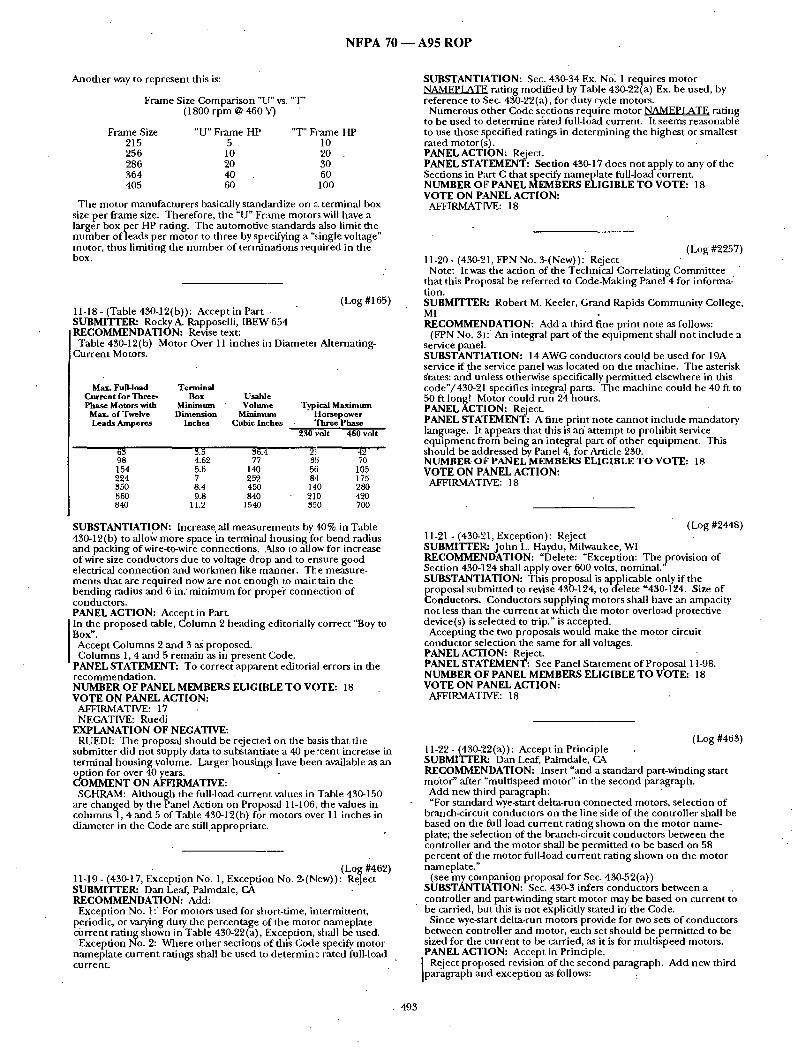
N F P A 70 ~ A 9 5 R O P
Another way to represent this is:
Frame Size Compar i son "Lr' vs. "T" (1800 rpm @ 460 V)
Frame Size " U " F r a m e H P "T"FI~me HP 215 5 10 256 10 20 286 20 30 364 40 60 405 60 100
The motor manufac ture rs basically standardize on z~ terminal box size per f~ame size. Tiaerefore, the "U" Fr:une motors will have a larger box per HP rating. The automotive s tandards also limit the n u m b e r of leads per motor to three by specifying a ",,:ingle voltage" motor, thus limiting the n u m b e r of terminat ions required in the box.
(Log #165) 11-18- (Table 430-12(b)): Accept in Part SUBMITTER: Rocky A. Rapposelli, IBEW 654 RECOMMENDATION: Revise text:
Table 430-12(b) Motor Over 11 inches in Diameter Alternating- Current Motors.
Max. Fun-load Terminal Current for Three- Box Usable Phase Motors with Minimum " Volume Typical Maximmn
Max. of Twelve Dimension Minimttm Horsepower Leads Amperes Inches Cubic Inches Three Phase
230 volt 460 volt
63 3.5 36.4. 21 42 '
98 4.62 77 35 70 154 5.6 140 56 105 224 7 252 84 175 350 8.4 450 140 280 560 9.8 840 210 420 840 11.2 1540 350 700
SUBSTANTIATION: Increase.all measu remen t s by 40% in Table 430-12(b) to allo~v more space in terminal hous ing for bend radius and packing of wire-to-wire connections. Also to allow for increase of wire size conductors due to voltage drop and to ensure good electrical connect ion and workmen like manner . The measure- ments that are requi red now are no t e n o u g h to mainta in the bend ing radius and 6 in. m i n i m u m for propei" connect ion of conductors . PANEL ACTION: Accept in Pare
] In the proposed table, Co lumn 2 heading editorially correct "Boy to I Box". ] Accept Columns 2 a nd 3 as proposed. [ Co lumns 1, 4 and 5 remain as in present Code. "PANEL STATEMENT: To correct appa ren t editorial errors in the
r ecommenda t ion . NUMBER OF PANEL MEMBERS ELIGIBLE TO VOTE: 18 VOTE ON PANEL ACTION:
AFFIRMATIVE: 17 NEGATIVE: Ruedi
EXPLANATION OF NEGATIVE: RUEDi: Tile proposal silould be rejected on the b~ i s that the
submit ter did not supply data to substantiate a 40 percent increase in terminal hous ing volume. Larger housings have been available as an
potiOn for over 40 years. MMENT ON AFFIRMATIVE:
SCHRAM: Al though the full-load cur ren t values in Table 430-150 are changed by the Panel Action on Proposal 11-106, the values in co lumns 1, 4 and 5 of Table 430-12(b) for motors over 11 inches in d iameter in the Code are still.appropriate.
(Log #462) 11-19- (430-17, Exception No. 1, Exception No. 2-(New)): Reject SUBMITTER: Dan Leaf, Palmdale, CA RECOMMENDATION: Add:
Exception No. 1: For motors used for short-time, intermittent , periodic, or varying duty the percentage of the motor namepla te cur ren t rat ing shown in Table 430-22(a), Exception, shall be used.
Exception No. 2: Where o ther sections uf this Code specify motor namepla te cur ren t ratings shall be used to de te rmine rated full-load current .
SUBSTANTIATION: Sec. 430-34 Ex. No~ 1 requires motor NAMEPLATE rating modif ied by Table 430-22(a) Ex. be used, by reference to Sec. 430-22(a), for duty cycle motors.
N u m e r o u s o ther Code sections require motor N / L M E P ~ T E rating to be used to de te rmine rated full-load current. It seems reasonable to use those specified ratings in de te rmin ing the h ighes t or smallest rated motor(s) . PANEL ACTION: Reject. PANEL STATEMENT: Section 430-17 does not apply to any of the Sections in Part C that specify namepla te full-load current. NUMBER O17 PANEL MEMBERS ELIGIBLE TO VOTE: 18 VOTE ON P~LNEL ACTION:
AFFIRMATIVE: 18
(Log #2257) 11-20- (430-21, FPN No. 3-(New)): Reject
Note: It was the action of the Tecimical Correlat ing Commit tee that this Proposal be referred to Code-Making Panel 4 for informa- tion. SUBMITTER: Robert M. Keeler, Grand Rapids Commu n i ty College, MI RECOMMENDATION: Add a third fine pr int note as follows:
(FPN No. 3): An integral part of the equ ipmen t shall no t include a service panel. SUBSTANTIATION: 14 AWG conductors could be used for 19A service if the service panel was located on the machine . Tile asterisk states: and unless otherwise specifically permit ted elsewhere in dais code"/430-21 specifies integral parts. Tile mach ine could be 40 ft to 50 ft long! Motor could run 2h, hours . PANEL ACTION: Reject. PANEL STATEMENT: A fine print note canno t include manda to ry language. It appears that this is an" a t t empt to prohibi t service e q u i p m e n t f rom being an integral part of o ther equipment . This should be addressed by Panel 4, for Article 230. NUMBER.OF PANEL MEMBERS ELIGIBLE TO VOTE: 18 VOTE ON PANEL ACTION:
AFFIRMATIVE: 18
(Log #2448) 11-21 - (430-21, Exception): Reject SUBMITTER: J o h n L. Haydu, Milwaukee, WI RECOMMENDATION: "Delete: "Exception: Tiae provision of Section 430-124 shall apply over 600 volts, nominal . ' SUBSTANTIATION: This proposal is applicable only if the proposal submit ted to revise 430-124, to delete "430-194. Size of Conductors. Conductors supplying motors shall have an ampacity not less than the cur ren t at which d~e motor overload protective device(s) is selected to trip." is accepted.
Accepting the two proposals w o u l d m a k e the motor circuit conductor selection the same for all voltages. PANEL ACTION: Reject. PANEL STATEMENT: See Panel S ta tement of Proposal 11-98. NUMBER OF PANEL MEMBERS ELIGIBLE TO VOTE: 18 VOTE ON PANEL ACTION:
AFFIRMATIVE: 18
(Log #463) 11-22 - (430-22 (a)) : Accept in Principle SUBMITTER: Dan Leaf, Palmdale, CA RECOMMENDATION: Insert "and a s tandard part-winding start motor" after "mult ispeed motor" in the second paragraph.
Add new third paragraph: "For s tandard wye-start delta-run connec ted motors, selection of
branch-circuit conductors on the line side of the controller shall be based on the full load cur ren t rating shown on the motor name- plate; the selection of the branch-circuit conductors between the controller and the motor shall be permi t ted to be based on 58 percent of the motor full-load cur ren t rat ing shown on the motor nameplate ."
(see my compan ion proposal for Sec. 430-52(a)) SUBSTANTIATION: Sec. 430-3 infers conduc to rs between a controller and part-winding start motor may be based on cur ren t to be carried, but this is no t explicitly stated i n t h e Code.
Since wye-start del ta-run motors provide for two sets of conductors between controller and motor, each set shou ld be permi t ted to be sized for the cur ren t to be carried, as it is for mul t i speed motors. PANEL ACTION: Accept in Principle.
Reject p roposed revision of the second paragraph. Add new third paragraph and exception as follows:
• 493

N F P A 70 1 A 9 5 R O P
For a wye-start, delta-run connec ted motor, the selection of branch- circuit conductors on the line side of the controller and the branch- circuit conductors between the controller and the motor shall be based on the motor full-load current .
Exception: Tbe selection of conductors between the controller and the motor shall be permi t ted to be based on 58 percen t of the motor full-load cur ren t provided that the branch-circuit short-circuit and ground-faul t protect ion complies with the requi rements of Section 430-52(a) for wye-start, del ta-run motors. PANEL STATEMENT: The second paragraph of Section 430-22(a) is specific to mul t i speed motors, since it refers to "the h ighes t of the full-load current" ra ther than values f rom tables such as 430-150. The paragraph is no t applicable to part-winding start motors.
The revised wording of the new thi rd paragraph should mee t the submit ter ' s in tent regarding wye-start delta-run connec ted rfiotors. It accepts dae 58 percent conduc to r selection as an exception to the main rule which has long been in effect. It also bases conduc tor selection on motor full-load cur ren t in accordance with Section 430- 6 ra ther than motor namepla te current. See Panel Action on compan ion proposal 11-47. NUMBER OF PANEL MEMBERS ELIGIBLE T O VOTE: 18 VOTE ON PANEL ACTION:
AFFIRMATIVE: 16 NEGATIVE: Alexander , Baker
EXPLANATION OF NEGATIVE: ALEXANDER: I agree with Baker 's comment , no substantive
reason for change has been establisbed. BAKER: This proposal unduly complicates the application of wye-
start delta-¢un motor start ing equ ipment . If the rating of the short- circuit and ground-faul t device based on the motor full load cur ren t rating of Table 150 canno t be considered adequate to protect the motor and its branch circuit conductors on shor t circuits, t hen dera ted conductors should no t be permit ted.
(Log #2794) 11-23- (Table 430-22(a)): Reject SUBMITTER: Alfred A. Fiorello, Fiorello Electric Inc. RECOMMENDATION: Add the following sentence to the note at the bot tom of the table.
"See definit ion of Duty in Article 100." SUBSTANTIATION: Gives a useful reference to a definit ion that cover the duty cycles covered by dais exception. PANEL ACTION: Reject. PANEL STATEMENT: The NEC is not an instruction manua l for un t ra ined persons. NUMBER OF PANEL MEMBERS ELIGIBLE T O VOTE: 18 VOTE ON PANEL ACTION:
AFFIRMATIVE: 17 NEGATIVE: Shapiro
EXPLANATION OF NEGATIVE: SHAPIRO: More then once, l have had electricians ask me where
to f ind definit ions or descript ions of the duty cycles listed in tltis Table. Point ing out die informat ion in Article 100 has usually satisfied them. Adding this reference would be of help to elec .tri- clans who want to be able to use the code book to the fullest.
(Log #464) 11-24 - (430-22(a), Exception No. 2): Accept in Principle SUBMITTER= Dan Leaf, Palmdale, CA RECOMMENDATION: Insert "rectifier" in lieu of "controller." SUBSTANTIATION: If an increase in conduc to r size is warranted due to the type of rectifier, it should be applicable to the entire length of conductors f rom the rectifier. PANEL ACTION: Accept in Principle.
In the r ecommenda t ion , insert "the field wiring terminals of the" before "rectifier" so that the exception no. 2 wil l read as follows:
"Exception No. 2: For direct-current motors opera t ing f rom a rectified single-phase power supply, the conductors between the field wiring terminals of the rectifier and the motor shall have an ampacity of no t less than ..." PANEL STATEMENT: Additional words needed to make it clear that where rectifiers are integral to control equ ipment , the internal wiring shou ld not be replaced. NUMBER OF PANEL MEMBERS ELIGIBLE T O VOTE: 18 VOTE ON PANEL ACTION:
AFFIRMATIVE: 18
(Log #2852) 11-25 - (430-24, Exception No. 4-(New)): Reject SUBMrrTER: DavidP. Gendler , Ypsilanti, MI RECOMMENDATION: Add except ion 4 as follows:
Exception 4: For one- and two-family dwelling feeders or services, conductor ampaci ty shall be permi t ted to be based on the sum of
of the full-load currents of the motors, plus the o ther loads, subject to the requi rements of articles 220 and 310. SUBSTANTIATION: The application of the longstanding rule of 430024 to dwelling services is contrary to the in tent of several o ther sections of the NEC. Given the diversity of loads of a typica/ dwelling, it is unnecessary to include a factor of 125% of largest motor to increase service size.
Section 220017 allows the loads of many fLxed appliances to be reduced by a d e m a n d factor of 75%. For a non-air-condit ioned rural dwelling, it is c o m m o n for the largest motor to be a w a t e r p u m p . Assuming the presence o f three other fixed appliances within the limits of 220017, the present application of these rules requires the pump-load to be increased by 125% and then allows it to be decreased by 75%.
Many o ther d e m a n d factors, including 220016, 220019, and Note 3 followit'lg table 310016,-allow reduct ion of feeder or service size reflecting the diversity of loads of a residence. Section 430-26 also allows feeder size reduct ion for diversity of motor operation.
The unnecessary addit ion of residential feeder or service capacity required by 430-24 is contrary to the in tent of these sections. PANEL ACTION: Reject. PANEL STATEMENT: In many one- and two-family dwellings the air condi t ioner is by far the largest load, and operates continuously. The implication tha t there is diversity in dais load is no t suppor ted by any data. The 75% d e m a n d factor in Secdon 220-17 does not apply to air-condit ioning e q u i p m e n t (and o ther major loads), as specified in the exception. NUMBER OF PANEL MEMBERS ELIGIBLE T O VOTE: 18 VOTE O N PANEL ACTION:
AFFIRMATIVE: 18
(Log #92) 11-26- (430°28): Accept in Principle
Note: Tile foll'owing proposal consists of C o m m e n t 11-11 on Proposal 11-20 in the 1992Annual Meet ing National Electrical Code Technical Commit tee Report. This C o m m e n t was he ld for fur ther study dur ing the process ing of the 1993 NATIONAL ELECTRICAL CODE ~. The r ecommenda t ion in Proposal 11-26 was:
Revise first paragraph (1) as follows: --;(1) be enclosed by ei ther an enclosed controller or a raceway;, be
no t more than 10 feet (3.05 m) in length; and 'be protected by an overcurrent device on the line side of the tap conductor tha t shall no t exceed 100% of the tap conductor ' s ampacity;, or (2)... continue. SUBMITTER: Frederic P. Hartwell, Hartwell Electric Services, Inc. RECOMMENDATION: The proposal should be accepted in principle. Complete the correlation between tile tap rules in Article 240 and here by making one further, minor change: In item (2), revise the second clause to read: "be protected fi-om physical damage and enclosed within a raceway, and be no t more than 25 feet (7.62 m) in length;" SUBSTANTIATION: As an inspector I have been in the position of having to explain to a contractor why tap No. 1, 25 feet long, did not have to be in a raceway but tap No. 2, also 25 feet long, did. Why? Because the first was for a motor and the second for some th in g else. The real reason being tha t different panels had jurisdict ion. The average user of the code only sees the end result for what it is: a pointless distinction. CMP 11 refused to correct dais in 1987, but now the difference will be glaring, as every other difference f rom Article 240 is being i roned out. PANELACTION: Accep t in Principle.
• [ In the r ecommenda t ion , revise as follows: [ Add "suitably" after "be". ]- Delete "and" insert "or". ] Delete "within" insert "in". ] So that Section 430-28 (2) reads as follows: ] "430028 (2) have an ampaci ty of at least one-third that of the feeder [ conductors , be suitably protected f romphys ica l damage or enclosed i in a raceway, and be not more than 25 feet (7.62m) in length."
PANEL STATEMENT: To correlate with Section 240-21(c) (4) to mee t submit ter ' s intent. NUMBER OF PANEL MEMBERS ELIGIBLE T O VOTE: 18 VOTE ON PANEL ACTION:
AFFIRMATIVE: 18
494

N F P A 7 0 - - A 9 5 R O P '
11-27 - (430-28): Reject (Log #737) SUBMITTER: J o n a t h a n P. Grace, Grace Enterprises Inc. RECOMMENDATION: Delete:
1000 percen t for 686 percent or 2 / 3 of lap conductors size. Included: Protection to device and equ i pmen t and not to exceed 125 percent
or I00 percen t of their rating and permissible application. SUBSTANTIATION: Load and supply side of conductors to carry
• . ~ over load pro tec t ion for e q m p m e n t supphed . . pANEL ACTION: Reject. PANEL STATEMENT: The word ing to be changed is no t specified in accordance with Section 3-3.3 of the regnlat ions governing commit tee projects. NUMBER OF PANEL MEMBERS ELIGIBLE TO VOTE: 18 VOTE ON PANEL ACTION:
AFFIRMATIVE: 18
(Log #27~12) 11-28- (430-31): Reject • SUBMITTER: Eric C.Jackson, Brooks &Jackson, Ino RECOMMENDATION: It does not include shor t circuits, g r o u n d faults or supply voltage anomalies such as w)ltage unbalance or s ing lephas ing ." SUBSTANTIATION: There exists a c o m m o n misnomer that conventional overload protection is suitable to guard a motor f rom damage resulting from supply voltage anomalies such as single phas ing and voltage unbalance. There are condi t ioas of motor load condit ions wherein conventional motor overload protection will no t de tec t the adverse cur rent flow created by such a voltage supply anomaly. ANSI/IEEE C37.96-1988 recognizes that a five percent voltage u n b a l a n c e p r o d u c e s a stator negative - sequence cur ren t of 30 percent ful l - loadcurrent . The severity of.this condit ion is indicated by the fact tl~at with dais extra current, flae motor may exper ience a 40-50% increase in t empera ture rise•
The propos'ed language would serve to ~dert the electrical industry that addit ional protection is needed to c i rcumvent the adverse effects of these voltage supply anomalies. Obviously, the cost associated with applying such supplementa l protection mus t be weighed against the critical nature of flae motor app lication. Where unexpec ted motor bu rnou t can be reasonably antici pared to cause substantial monetary loss or safety hazards, this protection should be applied. The provisions of Article 430-44 regarding orderly shutdown could be integrated into the text revision. PANEL ACTION: Reject. PANEL STATEMENT: The panel assumes the r ecommenda t ion is to revise the second sen tence of the second paragraph. Overload, as def ined in dais paragraph and in Article 100 includes overcurrent due to significant voltage unba lance or single phasing, if this overcurrent is sufficient to cause damage or dangerous overheating. The provisions of Part C are in tended to provide protection unde r these conditions. NUMBER OF PANEL MEMBERS ELIGIBLE TO VOTE: 18 VOTE ON PANEL ACTION:
AFFIRMATIVE: 18
(Log #3463) 11-29- (430-31): Reject SUBMITTER: Eric C.Jackson, Brooks &Jackson, Inc. RECOMMENDATION: Revise text:
"It does no t include shor t circuits, g round faults or supply voltage anomal ies such as voltage unba lance or single phasing." SUBSTANTIATION: There exists a c o m m o n mi snomer that conventional overload protect ion is suitable to guard a motor . f rom damage result ing f rom supply voltage anomalies such as single phas ing and voltage unbalance. There are condit ions of mo-tor load condit ions wherein conventional motor overload protection will no t detect the adverse cur ren t flow created by such a voltage supply anomaly. ANSI/IEEE C37.96-1988 recognizes that a five percent voltage unba lance produces a stator negative -sequence cur rent of 30 percent of full-load current . T he severity of dais cond!t ion is indicated by the fact that with this extra current, the motor may experience a 40-50% increase in tempera ture rise.
The p roposed language would serve to :flert the electrical industry that addit ional protection is needed where unexpec ted motor bu rnou t can be reasonably ant icipated to cause sul~;tantial mone ta ry loss or safety hazards. Obviously, the cost associated with applying such supplementa l pro tec t ion mus t be weighed against the critical na ture of the motor application. The provisions of Article 430-44 regarding orderly shutdown could be in tegrated into the text revision.
PANEL ACTION: Reject. PANEL STATEMENT: See Panel S ta tement on Proposal 11-28. NUMBER OF PANEL MEMBERS ELIGIBLE TO VOTE: 18 VOTE ON PANEL ACTION:
AFFIRMATIVE: 17 NEGATIVE: Shapiro
EXPLANATION OF NEGATIVE: SHAPIRO: I am in favor of adding the phrase "or voltage
anomalies" to the text. This Section points out that the alms of Part C are very modest; tha t motor overloads will no t pro tec t motors f rom all of the condit ions which cause motors to fail. This shor t addi t ion would help to fur ther that under s t and ing without a t t empt ing to create an overly specific laundry list of every imaginable problem.
(Log #2587) 11-30- (430-31, FPN-(New)): Reject Note: It was the action of the Technical Correlat ing Commit tee
that this Proposal be reconsidered and correlated with the action on Proposal 15-102. This action will be considered b y t h e Panel as a Public Comment . SUBMITTER: Technical Commit tee on Fire Pumps RECOMMENDATION: Delete existing: Add the following
(FPN): See Article 695 Fire Pumps SUBSTANTIATION: Informat ion is conta ined in new Article 695, Fire Pumps PANEL ACTION: Reject. PANEL STATEMENT: Such a reference is inappropr ia te until proposed new Article 695 has been accepted. The Panel requests Public C o m m e n t to reconsider this action if Article 695 is accepted. NUMBER OF PANEL MEMBERS ELIGIBLE TO VOTE: 18 VOTE ON PANEL ACTION:
AFFIRMATIVE: 18
(Log #2363) 11-31 - (430-32): Accept in Principle SUBMITTER: Noel Williams, Esco Electrical RECOMMENDATION: Insert this new paragraph after "Modifica- tion of this ~alue shall be permi t ted as provided in Section 430-34".
"Where capacitors are connec ted on the load side of the motor overload device the installation shall comply with 460-9." SUBSTANTIATION: Al though the informat ion on resizing motor overload devices is available in Section 460-9, there is 'no recognit ion of tha t section here, a n d n o r eminde r for users of the code that some correction needs to be made• Capacitors fo rpower factor correction are becoming increasingly common , a n d u s e r s of the code frequent ly do no t realize tha t the rules of A(ticle 430 are in any way modif ied by Article 460. If dais proposal is not acceptable there should be a Fine Print Note directing code users to Article 460 for additional information.
. PANEL ACTION: Accept in Principle. ] Add FPN at end of Sec. 430-32(a) (1), as follows: ] (FPN): Where po~oer factor correction capacitors are installed on ] the load side of the motor overload device, see Section 460-9•
." PANEL STATEMENT: The submit ter ' s alternative suggest ion for a fine pr int note is more appropria te because Sec. 430-5 already refers to Sec. 460-9. NUMBER OF PANEL MEMBERS ELIGIBLE TO VOTE: 18 VOTE ON PANEL ACTION:
A_~TIP, MATIVE: 18
(Log #3576) 11-32- (430-32(b)(1), Exception): Reject SUBMITTER: Dan Giblin, Ballwin, MO RECOMMENDATION: Delete dais exception. SUBSTANTIATION: 20 ampere fuses or circuit breakers cannot protect small motors. For example Exhibit #1 shows that a 1.4 ampere motor cannot be protected by a 20 amp fuse or a 20 amp circuit breaker. This proposal will require that small motors be protected ~ manda t ed by Article 430. Exhibit #2 shows the same 1.4 ampere motor being protected by a 1.6 ampere overload relay. A fire started by an unpro tec ted small nonautomadca l ly started motor is a dangerous reality. This proposal complemen t s die C o n s u m e r Product Safety Comfffission's 1994 project "Home Electrical Systems Fires". This proposal will significandy reduce (but not totally eliminate) the n u m b e r of fires caused by small motors.
495

N F P A 7 0 ~ A 9 5 R O P
o o g o 8 o o g ° g 8 g ~ o o g S , : , ~ -
3 0 4 0 ~ Q ' ~ a 7 o 8 0 9 0 ° ~ m -<r ~ o 0 ~ e~
~ , ~ ; ~ P : - . . ~ : . : • .
. M O T O R : : ;~ b & M . I I ( . , , f . ~
. . . . . . . . • . . . . . . . . . . . . . . . . . . . . . . . . . . . . . ~ . . . . . . : . _ . : . . : . . . . . ; •CURVE
. . . i . . . . . .
! . . . . . . .
1
I "
I " I .
i
• " i " " "
- J ~ J - . ~ - , k - L - . = - - . . ~ . . . . l , ,kl. i .
~oA~ip: .... " i • : F U S E '
. . . . . I . . . . . .
' • . . . . i . . . .: ~ . . . . i " : '
. . . . . . . . ; " i . " " '
• • " : . ! " i i " ! : i . ! ' : . . . . "i . . . . . . . ' . " ' . , . : . " " . . . . . ~ . . . . , . . . . . . . . . ; . . . . . -..
. . . . . . . . . . . : . . . . . . . . ; : . . _
] . . , ~ ~ . . . . . . . . : . . . . . . . . . . . . ". . . . . . : . . ! . . . . . . . . . . . . . . . , • : . . =
, : : . . . . . . . . : • , ' . . . . . . . i i ' " ; " " . . . . ~ . . . . ! : , : . . . . . ~ , . . . . . . . . .
: , " i i . . . .
. . . . . . . . . . . . . . . . . . : . . : . . . . ~ . ,
: : • • I . :
: : ; i I : " " : i • •
• • . . . . ~ . . I : • : . . . . . . . . . . . . . ".'6 . 7 . 8 . 9 I 2 3 4 5 6 7 8 9 1 0
• . , ~ , - ' , : , ;
. . , : . . . . . ~ . . - . , , ,
. . . . . . . . ! , : ., I
. , , : • , . . . . . . . . . .
• . " . . . . . . = - ! ~ . . .:
• : ! ; •
. . : : . . . . . . . . . • ! .
I i •
. . . . . . . . . . . . . . . . . . . . . " ' " ' i " ; ' " " : ; • • l • . , . ~1 . . . I ' " I ', .:
. . . . ~ ; • ' e ) . . . . . . I . . . . . . . . . . - . . . . . . ,
:. : - . ! • : . . . . : . . . . . .
. . . . : ' " , " ' : . . . . . . . . . . i ' " ~ " ~ ' " i ' : " " : "
. . . . . . . • . . . . : . . " . . : : . . • . . . . " ; ,
. : . • . . i . ! i
. . . . . . . . : i :: i : i ! fl ~ . : • : • i ! " " ~ •
: ; i : ! ' " i " . .... : - " ' : " ! . . . . . . B
. . . . . : i ! ] i : :
• ; Z O X t ~ P " . . . . . . . . . . e ~ ~ i ~ i i :' - - ~ - - - ¢ J R C u t r ! . , ;
. . . . . . . . . . . . . . . . . J . . . : ,
I " . -
• " " r • ' . . . . ' ~ . . . . . . . . . I ~
! . = : . .
~ . . - . . , , ,
.- -;
: I
. t J • - 1
: . . . . . . . . .
. . . i " " " ~ " " • . . . . . . i . . . . . . . . .
. . . . . I : . . . . i - ! "" "
' . , i i . . : ' : - . ! . . . .
I ; : • I • . = . .
i . ' . : " i "" , . . . . - : . ,
i i ]. . ~ - - . ! . . . . i . . . . : ..- ~.....: . . . . . . , . I - ,, , . . . :
; " " i . . . . .
1 , - il i i = . . . . . ; . . . ' ; ' , . . : . . : . . . . . . . ; . .
|
i " " I ii I : . : . . . . I . . . . . . . . ~I , , . ; . . ; . - . . • . , j . . . ~ . : , , j
. . . . . . , _ , ! : .... . . .] : . . . : . i . . : . ! . . . - ~ ..;::: :.i
. . . . ; . . . . . . . . . . . , . . _ , . . . . . . : : . . . . ,: ,
: . . ' . . . " . " J . ' . . . . . . . . I • . " . : . . - " : : : ' : • " " i "
. . . . . . . . . . . " . . . . . . . . . . . . " . . . . : ' " - • - - :. I ] i : : ' . - ; :
• . . . ~ ~ • , , • _: • . . . . . . . . . . : . . . . . . . . . . . I • . . : . . - - - . . . - : . . . . . . . - t',,~
; : . " i i . . . : • i - T . -
. . . . : " " . . . . I " • - - : : . : ' " " :
: • . .
• . . : •
1
: : . . : : . - .
. . . . . . . . . . . . . . . . - ' = . .
! : ' 1 . . . . .
i . . . . . . . . ! ; ~ . . . . . . ' • . . . . " ! . . . . . . L " . . . . . - : . . . . . . . J , . .~ 20 30 ,o~ooo,o~o,o~_ ~ ~ .8 ~, ~ ~ ~ ~ ~ ~
C U R R E N T I N A M P E R E S " ~ ' ~ 1 ( ~ ' 1 ; ~ 1 I " - I - -
I
4 9 6

N F P A 7 0 .---- A 9 5 R O P
. b .6 . 7 . 8 . 9 i 001 -~ l - r " r ' T ' T
I
I
I I
i I
i i
t, I
" i
" i
2 3 ~ l " ; - , 'T7 I r
5 t~
'i T
C I IR I IEN I , o 60 lOBOg l J ¢ ) I N AMPLRL5o o ° ~ o ° ~ ~ ooo° ( l o ~ o° . . . . , o co~,°°~_
l i 9 10 . . . . . . . . . . . , [ ~ . . . . . . . - . . ~ ~--UI
• , . ' . ~ ,
. . . . . . . . . . . . . .. ,,,., ,
'. A , OVEP, LO,4D R L.#Y I i . . . .
. . !
% :.. ..
I I L I
!
: I
! • u • • • .
• °
• " i
:/ I t i
, . I
'1
i . I
i • , , , ,
i
. .!i .i
, , : ' , j "
. . ;
. . . . . . i . . . . . .
; 1 " I I
14 . . . . . . . . . . . . . .
. . . . " i . . . . . : " "" I i
. . :~ • .~, : i
,~ . . . . . . . . H . . L . . i . . . .
; " . : : •
: , 1 , m m
I " • I •
. 5 . 6 . 7 . 8 . 9 1 2 3 4 5 6 7 8 9 I 0
. . . . . . . . . i . . . . . . , - . • . : • . .
. . . . . .
• . . ' ' " . . . i , I
• - 2 . . . .
• , , • : ' " " 1 , , :
• . i ~ i"' : . . . . . . i '
" , . . . . , - ! , •
: .
• , . . . . ~ ,2 . . . . " ' , • | , •
• ",~ . . . . . . : ' " " i . ' l
1 . . . . : ' i
i 7 - ; - - i i ~
" ; " i ' , " : : , , , ! • , ! . . . .
i " ' " . . . . . . i : . . . . . " : : . . . . : . . . . . . . . . : . ; . ! i . . . . . . . . . . . . . . : . . i . . . . . . - -
: : i . . . . i . . . . : . : i " " ;
m
I
20 30 40 50 60 7080g0~
CURRENT IN AMPERES
. . . . : • • ! . . . . , b
• , , : , , ;
- i : i • . . - . . . . . ! . . : . . . . . . . . . - - . . . " . . . . : ,
, :
! . . . : . . : . . ! . : : .
• i : " i " . . . . . . . . . : . . . . . . . ; . . ;
. . . . . . . . . . . : . i : : : : " , . . . . . i . , • - • ',,,T
i
. : . _ . " . • . . . . . . . . . - . . . . . . . . . . - . ~ : .
4 9 7

N F P A 7 0 1 A 9 5 R O P
PANEL ACTION: Reject. PANEL STATEMENT: No evidence of a problem result ing f rom application of the except ion has been presented. Adequate protection for the motor is provided, since the person operat ing the in-sight motor can be expected to recognize that the motor is overheating, and shu t it off. The referenced CPSC project addresses older h o m e wiring systems, no t overload protect ion of small motors that are not p e r m a n e n d y connected. NUMBER OF PANEL MEMBERS ELIGIBLE TO VOTE: 18 VOTE ON PANEL ACTION:
AFFIRMATIVE: 17 NEGATIVE: Saporita . .
EXPLMqATION OF NEGATIVE: SAPORITPc I oppose panel action. The submit ter ' s proposal has
meri t and will reduce the n u m b e r of fires caused by improperly protected small motors.
The panel s ta tement that protect ion is always provided by the person operat ing the in-sight motor is incorrect. Examples of motors which may be left r u n n i n g while una t t ended are:
1. Bread Makers 2. Portable Space Heaters 3. Dryers 4. Refrigerators 4. Ice Makers 6. Popcoha Makers The CPSC project is concerned with reducing all h o m e fires,
regardless of the age of the residence.
(Log #1203) 11-33- (430-34): Accept SUBMITTER: James D. Cloud, Commonwea l th Insp.
[ RECOMMENDATION: To be written as, motor "nameplate" F.L.C. SUBSTANTIATION: Proposal based on Code written in semi legal terms and exact wording.
For classroom instructions and field calculation also testing. PANEL ACTION: Accept. PANEL STATEMENT: The Panel is accept ing the proposal in order to be consistent with the o ther requi rements in Part C. NUMBER OF PANEL MEMBERS ELIGIBLE TO VOTE: 18 VOTE ON PANEL ACTION:
AFFIRMATIVE: 18
electrician passes a competency exam by using the table FLC for the largest overload, he assumes that he has pe r fo rmed properly and carries this exper ience into the field with him. This change will make the in tent of overload protect ion being specific to the motor apparent . PANEL ACTION: Accept. NUMBER OF PANEL MEMBERS ELIGIBLE TO VOTE: 18 VOTE ON PANEL ACTION:
AFFIRMATIVE: 18
(Log #702) 11-36 - (430-41-(New)): Reject SUBMITTER: K. L. Paape, Asheville, NC RECOMMENDATION: New text:
430-41 Design E Motors. (a) Overload Protection. Motors marked Design E sball be
protected by a Class E overload relay or an overload device or devices having the equivalent protection capabilities. Class E overl.oad relays shall be marked with their class designation.
(b) Class E Overload Relay Definition. An overcurrent relay that ultimately operates (trips) in response to an overload that is equal to or greater than its rating, and also operates in respofise to a motor locked-rotor condit ion in not more than 12 seconds. SUBSTANTIATION: The motor industry has acknowledged that Design E motors will not be protected by the overcurrent protect ion means presently specified in the Code. Since the industry s tandard for these motors specifies that these motors withstand locked-rotor cur ren t for a m i n i m u m stall t ime of 12 seconds, an overload relay that responds to these condit ions and also protects against long time overloads is required. Such overload relays should be be marked for identification.
With the per formance requ i rements of Class E overload relays defined, the motor control industry can provide the overcurrent
~ rotection needed. ANEL ACTION: Reiect.
PANEL STATEMENT: Overcurrent relays are not the only acceptable means of providing overload protection for Design E motors.
N T l ~ a n e l is no t aware of any s tandard for a class E overload relay: ER OF PANEL MEMBERS ELIGIBLE TO VOTE: 18
VOTE ON PANEL ACTION: AFFIRMATIVE: 18
(Log #1682) 11-34- (430-34): Accept SUBMITTER: Greg Lazar, U.S. GSA
[ RECOMMENDATION: Change f rom "Motors with a marked I t empera ture rise ot over 40°C " I To "Motors with a marked tempera ture rise NOT over 40°C " - SUBSTANTIATION: Spelling error in Code. It is correct in the
1990 NEC. PANEL ACTION: Accept. NUMBER OF PANEL MEMBERS ELIGIBLE TO VOTE: 18 VOTE ON PANEL ACTION:
AFFIRMATIVE: 18
(Log #2202) 11-35 - (430-34) : Accept SUBMITTER: D o u g Harvey, Martin County, FL RECOMMENDATION: Revise text as follows:
Where the overload relay selected in accordance with 430-32 (a) (1) and (c) (1) is no t sufficient to start the motor or to carry the load, the nex t h igher size overload relay shall be permit ted to be used, provided the trip cur ren t of the overload does no t exceed the following percentage of motor laatfi_e.p_lA~ full load cur ren t rating.
St~ uck-d,, , , , ,g ' , words are to be deleted, unde r l ined are to be added. SUBSTANTIATION: This is an editorial change that will pu t 430-34 in compliance with 430-6, accord with 430-32 and, I believe, in line with the in tent of the Code making panel. The overloads are intetaded to protect the specific motor f rom overload. This is clear in 430-32 where the word namepla te is used. 430-34 does not currently state namepla te and field installers are us ing excessive values of overload and causing motors to be overworked.which ultimately causes p remature failure. If 130-140% (depend ing on motor specifics) of the motor namepla te will no t carry the load, the installation should be re-evaluated by a qualified eng ineer for the: proper size of the motor used in the installation. This problem is fur ther complicated bya testing agency in tim region which follows the theory that if it does not say nameplate , use table FLC. When an
(Log #2187) 11-37 - (430-51-(New)): Reject SUBMITTER: Vohn N. Peeler, Faith, NC RECOMMENDATION: Add new text ,as follows:
Add a 208-volt co lumn to this table. SUBSTANTIATION: 208 volt motors are very c o m m o n today.
208 volts co lumns have been added to o ther tables in Article 430. PANEL ACTION: Reject. PANEL STATEMENT: The r ecommenda t ion does not conform with Section 10-10(d) of the NFPA Regulations Governing Cormnit- tee Projects. NUMBER OF PANEL MEMBERS ELIGIBLE TO VOTE: 18 VOTE ON PANEL ACTION:
AFFIRMATIVE: 18 COMMENT ON AFFIRMATIVE:
SCHRAM: I assume the submit ter in tended to r e c o m m e n d the addit ion of a 208 Volt co lumn to Table 430-151. While I agree that a 208 Volt co lumn is n e e d e d in Table 430-151, to cor respond with tile 208 Volt co lumns in Tables 430-148 and 430-150, unfor tunate ly the submit ter did not r e c o m m e n d any~alues for a new column. I am making such a r ecommenda t ion in my c o m m e n t on the Panel Action on Proposal 11-107.
11-38- (430-52): Accept (Log #911) SUBMITTER: Pe te r J . Schram, Braintree, MA RECOMMENDATION: Revise Section 430-52 as follows:
430-52. Rating or Setting for Individual Motor Circuit. (a) General. The motor branch-circuit short-circuit and ground-
fault protective device shall complywith (b), and ei ther (c) or (d) below, as applicable.
(b) All Motors. Tile motor branch-ciri:uit short-circuit and ground-faul t protective device shall be capable of carrying the start ing cur ren t of the motor.
(c) Rating or Setting. (1) A protective device having a rating or sett ing no t exceeding
the value calculated according to the values given in Table 430-152 shall be used.
498

N F P A 70 ~ A 9 5 R O P
Exception No. 1: Where the values for branch-circuit short-circuit ,and ground-faul t protective devices de t e rmined by "]7able 430-152 do no t cor respond to tile s tandard sizes or ~tdngs of fuses, nonadjust- able circuit breakers, thermal protective devices, or possible settings of adjustable circuit breakers, die next h igher s tandard size, rating, or possible set t ing shall be permit ted.
Exception No. 2: Following "Table 430-152" add "as modif ied by Exception No. 1," (otherwise same as p resen t Exception No.2.)
(FPN): [same as FPN following present four th full type paragraph of 430-52 (a) ].
(2) [same as present four th full type paragraph o1.:430-52(a)]. (3) [same as present second full type paragraph ¢f 430-52(a)]. (4) [same as present third full type paragraph of,t30-52(a)]. (5) [same as present fifth full type paragraph of 430-52(a)].
(d) Torque Motors. [sanle ,as present 430-52(b)]. SUBSTANTIATION: This proposal has three purposes, substanti- a ted separately below. I ask the Panel to address each on its own merits. The f r s t and , "- is to modify Excep- t ion No. 1 to pe rmi t " e neoessity of first de te rmin ing if the next lower size overcurrent device or set t ing will carry the load. Tile second is to clarify when E x c e p t o n No. 2 can be used. The third is an editorial rewrite.
"Rounding up" was addressed in my C o m m e n t No. 11-26 on Proposal 11-42 for the 1993 NEC processing (see NEG-TCD, page 450). The Panel S ta tement in rejecting the c o m m e n t ("The requi rements of 430-52 are specifically written to keep the excess no h igher than necessary, consistent with the needs of motor opera- tion.") did not, in my opinion, fully comply with Section 11-11 of the NFPA Regulations Governing Commit tee Projects. If the Panel does no t agree with the principle of this part of the proposal, I ask that the Panel S ta tement be sufficiently detailed so as to convey the Panel 's rationale for its action so that rebuttal may be offered. I offered evidence as to why file change was safe, and the Panel chose no t to address this evidence in its s t a t e m e n t
There are at least two reasons most insedlers, at least up until the change in Exception No. 1 in the 1993 NEC, automatically " rounded up," and mos t inspection authorit ies did not quest ion this practice. First, many people assumed Exception No. 1 was the equivalent of what is now 240-3(b), and die wording of Exception No. 1 was not sufficiently clear (before the 1993 NEC) to indicate otherwise. Second, it is no t clear what the word "load" in the phrase "carry the load" means. Section 430-6(a) does not use dais word when referring to the values in Tables 430-147 th rough -150.
Short-circuit and ground-faul t protect ion of conductors can be irt the order of 100O percent of the conductor ampaci~w, and still protect the branch-circuit conductors against damage or b/ l rnout unde r short-circuit or ground-faul t conditions. The intent of ,"rounding down" unless the motor will no t run (Exc. No. l) or will no t start (Exc. No. 2) appears to be to protect the motor controllers, primarily the overload relays, against burnout . This is impor tan t for IEC type controllers, which have less withstand ability than others, bu t shou ld not be a reason for forcing overprotection on the more rugged equipment . Further, any need for extra protect ion of the controller is already covered by the four th full type paragraph of 430-52(a). I have proposed moving this rule to immediately follow Exception No. 2 as 430-52(c) (2) in the editorial reva-ite, to help emphasize it.
The change in Exception No. 2 is to make it clear Exception No. 2 is applicable only if die overcurrent device will no t pe rmi t tile motor to start after " round ing up" per modifietl Exception No. 1. This is no t clear, even in tile 1993 NEC. The reason for modification of Exception No. 1 is to simplify the
selection of tile overcurrent device. I ant not aware that the widespread practice of " rounding up," even where no t necessary to carry the load, has resulted in any f ie ldproblems. Unless file Panel has evidence to tile contrary, dlere should be no tedmica l reason for no t revising Exception No. 1 a long die lines proposed.
The editorial rewrite is, in my opinion, desirable f3r several reasons. As presently written, 430-52(a) is difficult to unders tand, particularly as regards the applicability of the exceptions. It is also difficult for Code users to identify the various rules when writing
~ ecifications, defect notices, etc. Some of the rules are so buried at they are often overlooked. For example, die main rule r ight at
the beginning of die section [proposed to become 430-52(b)] is often overlooked because it doesn ' t have a separate lead-in heading. The editorial rewrite is in tended to help solve these problems.
Also, in 430-52(a), first paragraph, the phrase "Other t h a n . . , in ". (b) below" is really an exception and should be identified in accordance with the NEC Style Manual, Section A-2(a). The editorial rewrite solves this admittedly minor probl:_~m and at the same t ime emphases the impor tance of the rule in proposed 430- 52(b). PANEL ACTION: Accept.
NUMBER OF PANEL MEMBERS ELIGIBLE TO VOTE: 18 VOTE ON PANEL ACTION:
AFFIRMATIVE:" 16 NEGATWE: Wilson, Wood
EXPLANATION OF NEGATIVE: WILSON: The in tent of this section has always been to r o u n d
down first. The Code itself is in tended for the health, welfare and safety of people. Automatically round ing up does no t always provide the best and quickest protection. Thus , this change will no t provide the best electrical protect ion for tile safeguarding of people an d property f rom hazards arising f rom the use of electricity.
WOOD: The rule has always been to r ound down. Th e Panel has always required the motor circuits be protected at thc lowest (safest) possible lew:l. There is nosubs tan t i a t ion for the s t a tement that "most installers automatically r o u n d e d up."
The submit ter appears to be the only one who is confused by the panel 's s ta tements year after year that the in tent is and has been to round down. COMMENT ON AFFIRMATIav'E: SAPORITA: I vote to accept panel action, but wish to comment . Submit ter ' s remarks in the substantiat ion about IEG control
protection do no t completely address the issue of controller short- circuit withstand ratings. Depend ing upon the specific application, IEC controllers may or may no t be as robust 3.s U.S. industry controllers. The real issue is proper controller protect ion ofaU controllers. See my commen t s on proposal 11-16.
While round ing up may provide for ease of field application, it may not address the issue of overall protection. This is of even greater concern if we raise the full load cur ren t values in Table 430-150 as proposed.
(Log #2039) 11-39 - (430-52): Accept in Principle SUBMITTER: J im Carroll, Square D Company RECOMMENDATION: Change second paragraph to read:
An ins tantaneous trip circuit breaker shall be used only if adjust- able and if part of a listed combinat ion controller having coordi- nated motor overload and short-circuit and ground-faul t protection in each conductor, and if ;~ ,,ill ~ w ' " ~ ,z the sett ing is adjusted to no t more than 1300 percen t of full-load motor current . A motor short-circuit protector shall. . . .and ff it will , ~ t ,,t,~,~t~ ~t . . . . . . d-,~,, open tile circuit when 1300 p e r c e n t o f full-load motor cur ren t is exceeded. SUBSTANTIATION: Some confusion exists in the user. communi ty regarding the present wording.
The present wordingis no t technically correct where it says "it will operate at no t more than 1300 percent....". In fact the requ i rement is for the breaker to operate (trip) when the set adjus t lnent is exceeded. The proposed wording will clarify that the m a x i m u m sett ing shou ld be at 1300 percent of full load motor current. PANEL ACTION: Accept in Principle. PANEL STATEMENT: The submit ter ' s in tent is included in Panel Action and Sta tement on Proposal 11-45. NUMBER OF PANEL MEMBERS ELIGIBLE TO VOTE: 18 VOTE ON PANEL ACTION:
AFFIRMATIVE: 18
(Log #855) 11-40- (430-52, Exception): Reject SUBMITTER: Paul G. Cardinal, Houston, "IX RECOMMENDATION: Change last two lines of Section 430-52 Exception to read:
Tile m i n i m u m available trip settings of adjustable ins tan taneous circuit breakers may be greater than 700 percent , bu t not more than 900 pe rcen t when part of a listed combinat ion corttroller. It shall not .be necessary to first apply an ins tan taneous trip circuit breaker at 700 percent. SUBSTANTIATION: In the case of ins tantaneous circuit breakers, electrical contractors can be caught in the middle of a dispute between inspectors and manufacturers . The inspectors interpret "the next h igher s tandard size" as m e n t i o n e d in Section 430-52, paragraph (a) Exception No. 1, to mean the nex t s tandard size ins tantaneous breaker. However, because "an ins tantaneous trip circuit breaker shall be used only if adjustable, and if part of a listed . combinat ion controller," manufac ture rs may interpret "the next h igher s tandard size" to be referring to the next h igher s tandard size combinat ion controller. • Within the list of mos t manufac tu re r ' s combinat ion controllers will be found one or more controllers with a m i n i m u m available ins tantaneous circuit breaker sett ing greater than 700 percent of moi~or full load current . When us ing one of these controllers, the
499

N F P A 7 0 1 A 9 5 R O P
contractors can a t t empt to convince the maniffacturer tha t the device is no t in comphance with the code, to which the manufac- turer responds with their interpretation. The contractor can then try to convince the inspector of code compliance, only to be told that code compl iance is based on the interpretat ion of the body having jurisdict ion.
The contractor is t hen faced with a single undesirable choice. Since the manufac tu re r refuses to list options other than their standards, the contractor mus t buy the new breaker separately and, according to the instruct ions of the inspector, install it in violation of the e q u i p m e n t listing.
Consider ing that the high efficiency motors now installed in mos t cases will require breaker sett ings of 1000 percent or above, I believe that t ime and money can be better spen t o ther than in deliberations concern ing 700 percen t settings. I therefore propose clear cut m i n i m u m ins t an taneous breaker set t ing allowances which encom- pass the s tandard breaker set t ing ranges which listed combinat ion controllers have used for many years to provide safe and reliable operation. PANEL ACTION: Reject. PANEL STATEMENT: The need to permi t ins tan taneous trip circuit breakers tha t are not part of listed combinat ion motor controllers has not been adequately substantiated, and there is no substantiat ion for the r e c o m m e n d e d 900 percent . See Panel Action on Proposal Nos. 11-45 and 11-45A. NUMBER OF PANEL MEMBERS ELIGIBLE T O VOTE: 18 VOTE ON PANEL ACTION:
AFFIRMATIVE: 18 • COMMENT ON AFFIRMATIVE:
RUEDI: I am suppor t ing Panel Action on this proposal, bu t I believe the first part of the Panel S ta tement does no t reflect the submit ter ' s intent. Ttle panel is correct in stating that there is no substantiation for the r e c o m m e n d e d 900 percent . The proposals referenced in the Panel S ta tement should have been 11-45 and 11- 50. If those two proposals are accepted, the problem described by the submit ter should largely be eliminated.
11-41 - (430-52(a)): Reject (Log #1) Note: The following proposal consists of C o m m e n t 11-19 on
Proposal 11-46 in the 1992 Annua l Meeting National Electrical Code Technical Commit tee Report. This C o m m e n t was held for fur ther study dur ing the processing of the 1993 NATIONAL ELECTRICAL CODE. The r ecommenda t i on in Proposal 11-46 was:
Last paragraph: Suitable fuses shall be permi t ted in lieu of devices listed in Table
430-152 for an adjustable speed drive system or a solid state motor controller system provided that the mark ing for rep lacement fuses is
~ rovided adjacent to the fuses. UBMITTER: R: Gerald Irvine, Suffern, NY
RECOMMENDATION: Accept the new text with a change in terminology: Replace "adjustable speed drive" with "adjustable f requency drive" so as to dist inguish the speed control system as an electrical device. SUBSTANTIATION: Tile terminology "adjustable speed drive" may be any mechanical or electrical system for control l ing speed. Use of the te rm "adjustable f requency drive" clearly fits the in ten t ion of the new text. PANEL ACTION: Reject. PANEL STATEMENT: Power conversion e q u i p m e n t is no t l imited to adjustable f requency drives. See Panel Proposal 11-43A. NUMBER OF PANEL MEMBERS ELIGIBLE T O VOTE: 18 VOTE ON PANEL ACTION:
AFFIRMATIVE: 18
(Log.#93) 11-42- (430-52(a)): Reject Note: The following proposal consists of C o m m e n t 11-20 on
Proposal 11-46 in the 1992 Annua l Meeting National Electrical Code Technical Commit tee Report. This C o m m e n t was held for fur ther study dur ing the processing of the 1993 NATIONAL ELECTRICAL CODE. The r ecommenda t ion in Proposal 11-46 was:
Last paragraph: Suitable fuses shall be permi t ted in lieu of devices listed in Table
430-152 for an adjustable speed drive system or a solid state motor controller system provided that the mark ing for rep lacement fuses is
~ rovided adjacent to the fuses. UBMITTER: Frederic P. Hartwell, Hartwell Electrical Services Inc.
RECOMMENDATION: The proposal should be accepted in principle. Add the word "listed" before "adjustable speed drive system" and before "solid state motor controller system."
SUBSTANTIATION: Tile permi t ted rep lacement fuse markings should be verified by a qualified testing laboratory. These are sensitive devices. PANEL ACTION: Reject. PANEL STATEMENT: Special fuses shou ld be allowed whether or no t the solid state controller is listed. Many large or one of a kind solid state controllers are not listed. NUMBER OF PANEL MEMBERS ELIGIBLE T O VOTE: 18 VOTE ON PANEL ACTION:
AFFIRMATIVE: 18
(Log #930) 11-43- (430-52(a)): Reject SUBMITTER: William T. Fiske, Inchcape Test ing Services/ETL Test ing RECOMMENDATION: Add new text at end of oara~-aoh:
"Where the valves for branch-circuit, shor t circuit an~d ground-faul t protective devices de t e rmined by Table 430-152 do not cor respond to the s tandard sizes or ratings of fuses, nonadjustable circuit breakers, thermal protective devices, or possible settings of adjustable circuit breakers, the next lower s tandard size, rating, or possible sett!ng shall be used."
Revised: "Exception No. i: Where the next lower s tandard size, rating or
sett ing is less than the motor full-load cur ren t (as de t e rmined by Table 430-147, Table 430-148, Table 430-149, or Table 430-150, as applicable), the nex t h igher s tandard size, rating, or possible sett ing shall be permit ted." SUBSTANTIATION: Every cycle of Code deliberat ions brings several proposals a t t empt ing to clarify the in ten t of 430-52(a). Panel s ta tements repeat that the in tent is, and always was, to r ound down. A definitive s tatement , with an exception deal ing only with round ing up, and stating the basis by which one may j udge "adequate to carry the load," will end confusion over the in tent of this paragrapb, and the consequen t errors made in the field. PANEL ACTION: Reject. PANEL STATEMENT: See Panel Action and Substantiat ion on Proposal 11-38. NUMBER OF PANEL MEMBERS ELIGIBLE T O VOTE: 18 VOTE ON PANEL ACTION:
AFFIRMATIVE: 16 NEGATIVE: Wilson, Wood
EXPLANATION OF NEGATIVE: WILSON: See commen t s on Proposal 11-38. WOOD: I agree with the submitter . See my C o m m e n t on 11-38.
(Log #CP1101) 11-43a- (430-52(a)): Accept SUBMITTER: CMP 11 RECOMMENDATION: In the last paragraph of 430-52(a) - Delete "an adjustable speed drive system or" and insert "power electronic devices in". SUBSTANTIATION: To make more general lyappl icable , such as to solid state motor controller that do not include speed ad jus tment provision. PANEL ACTION: Accep t NUMBER OF PANEL MEMBERS ELIGIBLE T O VOTE:" 18 VOTE ON PANEL ACTION:
AFFIRMATIVE~ 18
(Log #CP1104) 11-43b- (430-52(a)): Accept SUBMITTER: CMP 11 RECOMMENDATION: Add a new 2nd sentence in the second paraghaph to read as follows:
"An ins tan taneous trip circuit breaker shall be marked to indicate that it is to be used only as part of a listed combinat ion motor controller." SUBSTANTIATION: To provide guidance for tile field. PANEL ACTION: Accept. NUMBER OF PANEL MEMBERS ELIGIBLE T O VOTE: 18 VOTE ON PANEL ACTION:
AFFIRMATIVE: 16 NEGATIVE: Baker, Ruedi
EXPLANATION OF NEGATIVE: BAKER: The substant iat ion for dais proposal is inadequate for the
r e c o m m e n d e d change which is to require additional markings on the circuit breaker. Fur thermore , the new s ta tement is redundanL The first sentence of this paragraph already requires that "An
500
N F P A 7 0 - - A 9 5 R O P
instantaneous trip circuit breaker shall be used only ... if part of a listed combination controller..." Thi~ inspector should be able to enforce this application without additional markings on the circuit breaker.
RUEDI: The requirement that an instantaneous trip circuit breaker be used only if it is part of a listed combination motor controller is clearly spelled out in the Code. Addition of a marking is an unnecessary burden on circuit breaker mannfacturers that , would not prevent abuse of the present requirement. I fa problem exists, it should be addressed by more vigorous enforcement of the Code.
(Log #1637) 11-44-'(430-52(a) and Exception Ntis. 1 and 2): R~Oect SUBMITTER: Morton L. Mullins, C'henticai Manufacturers Association RECOMMENDATION: Revise part (a) to read: ...a protective device having a rating or setting which is eqhal to or die next standard size above die value given in Table 430-152 shall be used.
Delete Exception No. 1 and renumber Exception No. 2 accord- irlgly. SUBSTANTIATION: The 1993 code revisions require a procedure to deterriline correct protective device rating or setting that invoh'es up to three steps of installation and trial before the maximum is reached. This is not a reasonable approach. When regulations are not reasonable, people tend to ignore them compl etely and that is not an acceptable,result. This is happening with th.e present ttxt. "
If the next higher rating or setting is a safe method of protection (as allowed by the 1993 code) then why not allow it. as the first approach rather than going through a lengthy, untimely and sometimes costly method of trying lower ratings or settings.
The procedure in the 1990 code was wordy but reasonable and produced acceptable results.
This new proposal restates the 1990 code procedure in less words and will be accepted in the field. PANEL ACTION: Reject. PANEL STATEMENT: The recommendation would require a ra t ingor setting at least equal to the value' obtained by using Table 430-152. This eliminates the option of making an nstal ation safer than required by the Code, which is the current main rule with exceptions. NUMBER OF PANEL MEMBERS ELIGIBLE TO VOTE: 18 VOTE ON PANEL ACTION:
AFFIRMATIVE: 18
SUBSTANTIATION: This is a companion proposal to other proposals to define and add Design B, C, and D and Design .E motors to the Code. Design B, C, and D motors are basically the present motors addressed in the Code and Design E motors are energy efficient motors.
Instantaneous trip breakers are only used as part of a listed combination controller as allowed in 430-52(a) and only provide the short circuit protection for the circuit. Ideally the setting of these breakers is as low as possible to allow the motor to start without tripping. The motor manufacturers have stated that the peak inrush current on starting is in the range of 1.8 to 2.8 times the LRC. These peak currents must be converted to rms currents to determine the setting of the circuit break, ers. Since the LRC/FLC ratio is approxi- mately 6 an initial setting of 800% of FLC (rms current) would more closely match the low end of this peak current range and would eliminate some of the nuisance tripping that occurs. The upper limit of 1300% (rms current) is unchanged.
For the Design E motors the LRC/FLC ratio is approximately 8. Using the same process this converts to an initial setting of 1100% of FLC (rms current) and upper setting of 1600% of FLC (rms current).
One of the companion proposals is to revise Table 430-152 to show the setting for Design B, C, and D motors at 800% and the setting for Design E motors at 1100%. The change in the Exception matches this change. PANEL ACTION: Accept in Principle.
Revise 2nd paragraph of Section 430-52 (a) as follows: "An instmltaneous trip circuit breaker shall be used only if
adjustable ;rod if part of a listed combination motor controller having coordinated motor overload and short-circuit and ground- fault protection in each conductor, and the setting is adjusted to no more than the value specified in Table 430-152. A motor short- circuit protector shall be permitted in lieu of devices listed in Table 430-152 if the motor short-circuit protector is part of a listed combination controller having coordinated motor overload protection and short-circuit and ground-fault protection in each conductor and it will open the circuit when the value specified in Table 430-152 for instantaneous trip circuit breakers is exceeded."
FPN and Exception remain as recommended. PANEL STATEMENT:
Revised recommendation to correlate the main rule, the Excel> don, and Table 430-152, to correct lack" of correlation in the 1993 Code. Also revised to incorporate intent of Proposal No. 11-39. NUMBER OF PANEL MEMBERS ELIGIBLE TO VOTE: 18 VOTE ON PANEL ACTION:
AFFIR/vlAT IVE: 18
(Log #3056) 11-45 - (430-52(a)): Accept in Principle SUBMITTE~ Larry Miller, National Electrical M:frs. Association RECOMMENDATION: In the second paragraph, and in the Exception to the second paragraph, clarify that the 1300 percent applies to Design, B, C, and D motors and add a reference to 1600 percent for Design E motors. Also in the Exception change 700% to 800% and clarify that it applies to Design B, C, and. D motors and add corresponding values of 1100% for Design E motors. This would now read (new and revised text underlined):
An instantaneous trip circuit breaker shall be used only if adjust- able, and if part of a listed combination controller having coordi- nated motor overload and short-circuit and ground-fault protection in each conductor, and if it will operate at no more than 1300 percent of full-load motor current for Design B. C. and D motors and no more than 1600 percent of full-load motor current for Design E motors. A motor short-circuit protector ,;hall be permitted in lieu of devices listed in Table 430-152 if the motor short-circuit protector is part of a listed combination controller having coordi- nated motor overload and short-circuit and ground-fault protection in each conductor and if it will operate at no more than 1300 " percent of full-load motor current for Desi~ri B. C. and D motors and no more than 1600 percent of full-loacl motor current for Design E motors.
(FUN): (No change to the FPN) Exception: Where the setting specified in Table 430-152 is not
sufficient for the starting current of the motor, the setting of an instantaneous trip circuit breaker shall be permitted to be increased but shall in no case exceed 1300 percent of the motor full-load current for Design B. C. and D motors and no more than 1600 percent of full-load motor current for Design E m,)tors, Trip ~ettings above 800 percent for Design B, C,.and D rrlotors and above 1100% for D e s i ~ E motors shall be permitted where the need has been demonstrated by engineering evaluation. In suizh cases, it shall not be necessary to first apply an instantaneous trip circuit breaker at 800 percent or 1100%.
(Log #3057) 11-46- (430-52(a), FPN-(New)): Reject SUBMITTER: Larry Miller, National Electrical Mfrs. 'Association RECOMMENDATION: Revise textas follows: Add a new FPN after the Exception to the second paragraph to
clarify that a) the setting is a RMS current rather than peak current and that b) the full-loadcurrents being referred to are from Table 430-150. The FPN is applicable to the second paragraph of 430- 52(a) and the Exception to this paragraph a n d i t should be placed accordingly.
The FPN would read: (FPN): The setting is in rms current and is a percentage of the full-
load current values shown in Table 430-150. SUBSTANTIATION: During discussions regarding the proposed changes to Tables 430-150 darough 430-152 to cover the Design B,C,D and E motors, it became obvious that there was confusion over whether the 1300 percent setting was an rms current or a peak current. All the setting referred to in 430-52(a), as well as Table 430- 152, are multiples of FLC which is rms current. The first part of the FPN clarifies that this current setting is an rms setting rather than a peak current setting. Also during the discussions, it was noted by motor manufacturers
that locked rotor current (LRC) for a given horsepower is a constant and that dill load current (FLC) may vary for a given motor but will not exceed the maximum FLC shown in Table 430-150. The LRC/ FLC ratio used to determine the rms current setting is based on the values in Tables 430-150 and 430-151 rather than the actual FLC of a given motor. For this reason, the setting must be based on the maximum FLC shown in Table 430-150. Basing the setting on the values shown in Table 430-150 is consistent with the requirements in Section 430-6(a) which notes that the FLC values are shown in Table 430-150.
The second part of the FPN clarifies that the settings are a
~ ercentage of the values shown in Table 430-150. ANEL ACTION: Reject.
I
501

N F P A 70 - - A 9 5 R O P
PANEL STATEMENT: The panel affirms that the rules in this Section are based on RaMS currents and the motor full-load cur ren t f rom Tables 430-147 th rough 150. We see no need for fur ther clarification in the text. NUMBER OF PANEL MEMBERS ELIGIBLE TO VOTE: 18 VOTE ON PANEL ACTION:
AFFIRMATIVE: 18
(Log #465) 11-47 - (430-52(a) and Exception-(New)): Accept in Principle SUBMITrER: Dan Leaf, Palmdale, CA RECOMMENDATION: Add the following after the last exception (for mul t ispeed motors):
"For a s tandard wye-start delta-run connec ted motor where the [ m i n i m u m size of conductors between the controller and the motor ! is based on 58 percent of the motor full-load current , short-circuit and g round- fauh protection with a rating no t to exceed 58 percent of the above applicable percentage o f t h e full-load cur ren t of the motor shall be provided in each set of conductors between the controller and the motor.
Exception: A single device or single set of devices having a rating no t to exceed 58 percent of the above applicable percentage of the full-load cur ren t of the motor shall be permit ted if suitable to allow the motor to start. Where time-delay (dual-element) fuses are used as a single set of devices they shall b e p e r m i t t e d to have a rat ing not exceeding 150 percent of the fu l l - loadcurrent rating of the motor."
(See my compan ion proposal for Section 430-22(a)). SUBSTANTIATION: w i th reduced start ing cur ren t the proposed OC protection may be feasible in many cases. The pro[3osed ~,alue for time-delay fuses would generally permi t motor starting, and the 150pe rcen t / 58 percen t ratio is less than that of Sec. 430-3 for part- winding start motors and less than the 300 percent rating permi t ted for nont ime-delay fuses for motor circuits. Overload protection is covered in Sec. 430-32(a). PANEL ACTION: Accept in Principle.
Make the following changes in the wording of theproposa l : (1) In the first sen tence delete the word "standard". (2) Delete the period at the end of the first sentence and add the
words "in addit ion to the short-circuit and g round- fauh protection required on the line side of the controller."
(3) In the first sen tence of the exception, delete the word "single" and "or single set of devices". Add the words "on the line side o f the controller" between "permit ted" and "if'. Also, delete "suitable" and insert "it will". PANEL STATEMENT: Revise for clarification and to be consistent with Proposal 11-6.
See definit ion of"device" in Article 100. The word "standard" serves no discernible purpose. The wording
added to the main rule is i n t ended to clarify that short-circuit and g round- fauh protection located between the controller and the motor does not take the place of branch-circuit protect ion on the line side of the controller. The wording of the exception was changed to clarify the location of the short-circuit and ground-faul t protective device(s) that was implied by the proposal bu t not
ecificallystated. See Panel action on compan ion proposal 11-22. ER OF PANEL MEMBERS ELIGIBLE TO VOTE: 18
VOTE ON PANEL ACTION: AFFIRMATIVE: 15 NEGATIVE: Alexander , Baker, Dye
EXPLANATION OF NEGATIVE: ALEXANDER: i agree with Baker /Dye 's comment , no substantive
reason for change has been established. BAKER: See my c o m m e n t on Proposal 11-22. DYE: This r equ i r emen t for 2 addit ional shor t circui t-ground fault
(SC-GF) devices should be rejected. No substant iat ion of a problem is given. Experience has proven the present situation using one shor t circui t-ground fault (SC-GI 0 device presents no problem.
(Log #3105) 11-48 : (430-52(a), Exception and FPN-(New)): Reject SUBMITTER: Paul E. Devine, Advisory Commit tee on the Massachusetts Electrical Code RECOMMENDATION: Revise the first por t ion of Section 430052(a) by adding a third exception and Fine Print Note, as follows:
Exception No. 3: The rat ing of the branch circuit short-circuit and g r o u n d fault protective device shall no t be required to be less than 15 amperes .
(FPN): This exception does no t supersede any restriction(s) imposed by qualified testing laboratories in the process of listing overload relays or o ther componen t s of the motor circuit. See the conc luding two paragraphs of this subsection, and Section 110-3(b).
502
SUBSTANTIATION: The 1993 NEC will, unambiguous ly at last, require these devices, where the calculation does no t come out directly on a s tandard value, to be sized based on the next lower s tandard size. Wi thout this exception, that action effectively favors one type of overcurrent protective device over ano the r in many instances where that is no t necessary.. CMP 11 rejected this exception because some overload relays require less than 15 ampere sizect protective devices. However, that act ion was incorrect because it failed to account for the penul t imate paragraph of this section. Tha t rule expressly provides tha t if there is a rat ing restriction on the overload relay, those restrictions take precedence over the values calculated unde r the main part of the rule.
The 1993 NEC will effectively require the use of fuses on all 480 and 600 volt motors below 5 HP. T h i s is highly inappropriate and inconsis tent with a similar exception for compressor motors covered in Section 440-22(a). PANEL ACTION: Reject. PANEL STATEMENT: The r e c o m m e n d e d new exception conflicts with the r equ i r emen t of the four th full type paragraph of Section 430-52(a). A Fine Print Note is no t mandatory. NUMBER OF PANEL MEMBERS ELIGIBLE TO VOTE: 18 VOTE ON PANEL ACTION:
AFFIRMATIVE: 18 COMMENT ON AFFIRMATIVE:
SCHRAM: The r e c o m m e n d e d new Exception No.3 does no t actually conflict with the four th full type paragraph in Section 430- 52(a), because the except ion would apply only to the immediately preceding main rule. I agree with the submit ter ' s substantiation. However, the proposed new exception has been made unnecessary by the revision of Exception No. 1 in Panel Action on Proposal 11- 38.
RUEDI: While I am voting affirmative, I do no t agree with the first sentence of the Panel Statement. The four th full type paragraph requires that the overload relay manufac tu re r ' s instructions be followed "even if h igher values are allowed as shown above." The submit ter raises-a concern about cases where a calculation per Table 4300152 results in a value tha t is lower than the smallest s tandard rating offered by protective device manufacturers . His proposal is no t relevant if Proposal 11-38 is accepted. But if the port ion of Proposal 11-38 allowing " round ing up" to the nex t h igher protective device rating is no t accepted, then this proposal has meri t and should be accepted in principle. I would r e c o m m e n d revising the text of proposed Exception No. 3 to read: "Where the rating for.a fuse or an inverse t ime circuit breaker de t e rmined by Table 430-152 is lower than the m i n i m u m s tandard rat ing specified in Section 240- 6(a), the m i n i m u m s tandard rating shall be permit ted." No fine print note is necessary.
(Log #2033) 11-49 - (430052(a), Exception No. 1): Accept in Principle SUBMITTER: Bud Swathwood, Electrical Engineer ing & Consult-
' Inc. OMMENDATION: Exception No. 1 delete tile words:
- - a n d the nex t lower s tandard size rating or possible set t ing is no t - - so that the Exception after-- :"adjustable circuit breakers," will read as follows; any of which are adequate to carry the load, the nex t h igher size rating, or sett ing shall be permitted. SUBSTANTIATION: This change will restore the exception similar to the way it was in the 1090 NEC. There was some controversy concern ing the passage of the proposal in the '03 code. Section 4300 6(a) requires that Branch Circuit short-circuit, g r o u n d fault and overload protection be provided for. If this is done in accordance with these requi rements there would be no need for the overriding factor to first " round down" and then " round up". Many times the calculations will no t allow for a " round down" amperage . We mus t resist the temptat ion to "over" protect circuits for the sake of submit t ing proposals. The re was no problem with the Exception as i twas written in the '93 NEC. Itwas not broke and did not need fixing". PANEL ACTION: Accept in Principle. PANEL STATEMENT: See Panel S ta tement and Substant iat ion on Proposal 11-38. NUMBER OF PANEL MEMBERS ELIGIBLE TO VOTE: 18 VOTE ON PANEL ACTION:
AFFIRMATIVE: 16 NEGATIVE: Wilson, Wood
EXPLANATION OF NEGATIVE: WILSON: See commen t s on Proposal 11-38. WOOD: See my c o m m e n t on 11-38.

N F P A .70 - - A95 R O P
(Log #16) 11-50 - (430-52(a), Exception No. 2-(New)): Accept in Principle
Note: The following proposal consists of C o m m e n t 11-27 on Proposal 11-44 in the 1992 Annual Meet ing Nation:d Electrical Code Technical Commit tee Report. This C o m m e n t was held for fur ther study dur ing the processing of the 1993 NATIONAL ELECTRICAL CODE. The r ecommenda t ion in Proposal 11-44 w~s:
• Table 430-152: Under the colu'mn head ing Instm~taneous Trip Breaker / replace the 700 percent values with 1300.
Paragraph 430-52(a): Delete the Exception at the bot tom of the page in its entirety which permits incre~fing the trip value to 1300
~ ercent. UBMITTER: K L Paape, Asheville, NC
RECOMMENDATIONS." Designate the present exception relating to tile sett ing of an instantaneous-tr ip +ircuit breaker as "Except ionNo. 1" and add Exception No. 2 as follows:
Exception No. 2: Where the motor full-load cur ren t is 8 amperes or less, the sett ing of the instantaneous-tr ip circuit breaker rated 15 amperes or less in a listed motor controller that provides coordi- nated motor branch-circuit overload and shor t -orcui t and ground- fault protect ion shall be permi t ted to be increased to the value specified on the controller. SUBSTANTIATION: Underwriters Laboratories h~as developed tests 'Sec. 82F.1 of UL 508) to insure coordinat ion of the circuit breaker
.and overload protective deride for overeurrents ranging from locked-rotor cur ren t to low-levels of fanlt current . Hence, there is no need to restrict the m a x i m u m allowable set t ing to 1300% of full-
"load motor cur ren t where tile contactor por t ion of file combinat ion motor conttol ler has sufficient in ter rupUng capacity to in terrupt low-level short circuits and g round faults arid die overload protective device is serf-protecting.
Adopt ing dais exception will permi t the use of 15 ampere adjust- able-trip circuit breakers with motor FLA's of 8 amperes or less and provide closer overcurrent protect ion for these motor branch circuits than would a 15 ampere inverse-time circuit breaker. .
The 8 ampere value includes the full-luads currents (FLA's) of three-phase motors rated 2 horsepower and less. PANEL ACTION: Accept in Principle.
Change "specified" to ' marked". Change "if' amperes to "8.5". Add "izombinataon" after "listed".
PANEL STATEMENT: Revised for clarification. To correlate with Panel Action on Proposal 11-106.
NUMBER OF PANEL MEMBERS ELIGIBLE T O VOTE: 18 VOTE ON PANEL ACTION:
AFFIRMATIVE: 17 NEGATIVE: Baker
EXPLANATION OF NEGATIVE: BAKER: The wording of Exception 2 is unclear ~md will be
confusing. The reference t h r o u g h o u t the code to a rated value for fuses ancfinverse dine circuit breakers refers to tile cur ren t above which the device may operate which are moderate overloads, no t shor t circuits. The ins tantaneous trip circuit breaker has a continu- ous cur rent rating, i.e., 3, 5, 7, 15, etc. amperes, bu t it does no t trip at these currents. So the wording shou ld be "with cont inuous cur rent r adngo f " instead of "rated". COMMENT ON AFFIRMATIVE:
SAPORITA: I vote to accept panel action with comment . Tiffs pro posal o. peus the door to allowing larger dmn. "430-52 sized",
overcurrent devaces when motor cont rn l le rsare certified by NRTL S to provide Type 2 protection. We'll need to expand this proposal to incqude cur ren t l imiting fuses and cur rent limiting thermal magnet ic circuit breakers.
SCHRAM: Based on Panel Action on Proposal 11-38, this new exception wo~ald be u n d e r Section 430-55-(c) (3).
( Log #180) 11-51 - (430-52(a), Exception No. 2-(New)): Accept in Principle SUBMITTER: K. L. Paape, Asheville, NC RECOMMENDATION: Designate the present exception relating to the set t ing of an instantaneous-tr ip circuit breaker as "Except ionNo. 1" and ad~l Exception No. 2 as follows:
Exception No. 2: Where the motor fnll-load cur ren t is 8 amperes or less, the sett ing of the instantaneou,~tt ip circuit breake'r rated 15
' amperes or less in a listed motor controller tha t provides coordi- nat-ed motor branch-circuit overload and short-ch'cuit and ground- fault protection shall be permi t ted to be increased to the value specified on the controlli~r. SUBSTANTIATION: Underwri ters Laboratories has develooed tests (Sec. 82F.] of UL 508) to insure coordinat ion of the circuit breaker and overload protective device for overcurrents ranging f rom locked-rotor c-urrent to low-levels of fault .current. Hence, there is no need to restrict the m a x i m u m allowable set t ing to 1300 percent of full-load motor cur ren t where the contactor por t ion of the combinat ion motor controller has sufficient intenvupting capacity to in terrupt low-level shor t circuits and g r o u n d faul;~ and the overload protective device is serf-protecting.
Adopt ing this exception will permi t tile use of 15 ampere adjust- able-ttip circuit breakers with motor fitll-load currents (FLA's) of 8
amperes or less and provide closer overcur ren tpro tec t ion for these motor branch circuits than would a 15 ampere inverse-time circuit breaker.
The 8 amoere value includes the FLA's of three-phase motors rated 2 ho r sepo~er and less. " r PANEL ACTION: Accept in Principle. PANEL STATEMENT: See Panel Action on Proposal 11-50. NUMBER OF PANEL MEMBERS ELIGIBLE T O V O T E : 18 VOTE ON PANEL ACTION:
AFFIRMATIVE: 17 NEGATFv'E: Baker
EXPLANATION OF NEGATIVE: BAKER: See my c o m m e n t on Proposal 11-50.
COMMENT O N AFFIRMATIVE: SAPORITA: Accept panel action with comment . See my co m m en t s
on proposal 11-50.
(Log #2272) 11-52 - (430-52(a), Exception No. 2, FPN): Reject SUBMITTER: Walter W. Harris, Norristown, PA RECOMMENDATION: Revise last FPN after paragraph end ing widl "1300 percent of full-load current," to "an instantaneous-tr ip circuit breaker shall be permi t ted to include a damp ing means to accom- modate a t ransieht motor inrush cur ren t without nuisance t r ipping of tile circuit breaker." SUBSTANTIATION: Removes FPN identification an d identifies text as being mandatory. See Section 90-5. PANEL ACTION: Reject. PANEL STATEMENT: Substantiat ion for change r e c o m m e n d e d is no t sufficient. NUMBER OF PANEL MEMBERS ELIGIBLE T O VOTE: 18 VOTE ON PANEL ACTION:
AFFIRMATIVE: 18 COMMENT ON AFFIRMATIVE:
SGHRAM: The r ecommenda t ion does no t remove the FP N identification, bu t ra ther makes the existing FPN mandatory. A FPN should not include manda to ry l anguage . The submit ter does no t explain why he believes mandatory language is necessary or desirable.
(Log #3584) 11-53 - (47,0-52(a), "Exception No. 2 a): Accept in Principle SUBMrrTER: Bill Watkins, Ballwin, MO RECOMMENDATION: Add the words "or a time-delay Class CC fuse" after the word "fuse". The except ion would then read "a. Tile rating of a non time-delay fuse or a time-delay Class CC f u s e n o t exceeding 600 amperes shall be pe rmi t t ed to be increased but shall in no case exceed 400 pe rcen t of the full-load currenL" SUBSTANTIATION: Because of their space saving size and cur rent limiting ability, time-delay Class CC fuses are quicldy becoming tile prefer red choice for many motor circuit protection applications. Time-delay for a Class CC fuse is de t e rmined at 200% for 12 seconds instead of the Class R s tandard of 500% for 10 seconds. Since time- delay Class CC fuses are marked "Time-Delay", they have the same m a x i m u m sizing requ i rements as tile older and larger Class R fuses. Unfortunately, i]ais results i n u n n e c e s s a r y fuse openings when high efficiency motors or long start ing times are encountered .
This change will allow tirne-deFay Class CC fuses to be sized like non-time-delay fuses. Because of their excel lent cu r ren t l imi t ing characteristics, they will provide equivalent or better shor t circmt protect ion than many n6n-time-delay fuses being used today. PANEL ACTION: Accept in Principle.
Revise Section 430-52(a) Exception No. 2 a to r e a d a s follows: "The rating of a non time-delay fuse no t exceeding 600 amperes or
a time-delay-class CC fuse shall be permi t ted to be increased but . shall in no case exceed 400 percen t of the full-load current." • PANEL STATEMENT: Cl~s CC fuses ratings do no t exceed 30 am eres. N ~ E R OF PANEL MEMBERS ELIGIBLE T O VOTE: 18 VOTE ON PANEL ACTION: • AFFIRMATIVE: 18
(Log #1110) 11-54- (430-52(a), Exception No. 2 b. and Table 430-152): Reject SUBMITTER: Alan L. Cardwell, U.S. Army C o w s of Engineers RECOMMENDATION: NEC 430-52(a), Exception 2(b) uses the te rm "time-delay (dual-element) fuse" and Table 430-152 uses the te rm "Dual E lement (Time-Delay) Fuse." In both references the te rm "du;d-element" shou ld be deleted, leaving simply the phrase "time-delay fuse." SUBSTANTIATION: The cur ren t terminology appears to make it mandatory tha t where time-delay fuses are used in motor circuits, they mus t be of the dual -e lement type. "Dual-element" refers to a construct ion m e t h o d by wlticb time-delay is achieved. There is at
503
N F P A 70 - - A 9 5 R O P
least one other construct ion m e t h o d commonly used by major fuse manufacturers to achieve t ime delay (as def ined by UL 198)-. For example, a Gould Shawmut Class RK-5 "Td-onic" TRS, 200-ampere filse uses the "M" effect t echnique to achieve t ime delay. Tha t fuse, however, apparent ly does not meet the requi rements of the references Cited since it is no t a "dual-element" fuse. NEC 430-42(d) implies that the goal is "time-delay" and tha t the m e t h o d for achieving that goal is no t particularly a Code matter. PANEL ACTION: Reject_ PANEL STATEMENT: The ANS I / UL Standard 198C allows the use of time-delay or dual -e lement or both. NUMBER OF PANEL MEMBERS ELIGIBLE T O VOTE: 18 VOTE ON PANEL ACTION:
AFFIRMATIVE: 18 COMMENT ON AFFIRMATIVE:
SCHRAM: It is my unde r s t and ing that the "M" effect referenced does afford a t ime delay.
(Log #1559) 11-55- (430-53(b))! Reject . SUBMITTER: Arnold Wencel, Kehne Electric RECOMMENDATION: In Article 450-53-b omit the words "the most severE" in this sentence. SUBSTANTIATION: The sentence states that each motor shall have individual overload protection. Therefore, the main concern is with shorts and grounds . -How does one de te rmine the absolute most severe normal condit ions that migh t occur? Maybe if the motors were locked and the juice were tu rned on a person could see wtlether the branch circuit fuses would win over the motor r u n n i n g protection.
This is like walking a t ight rop.e Generall)1,, it is better to. use more circuits and use more controls than to gamble on what a single branch circuit can handle .
It would seem that a compe ten t electrician would layout the electrical system in a way so as to make such a study unnecessary. Otherwise, the sen tence is well written and easily unders tood. PANEL ACTION: Reject. PANEL STATEMENT: The second sentence of the submit ter ' s substantiation describes one m e t h o d of de te rmin ing compliance. There are many situations where actual testing is no t needed to de te rmine compliance, especially where the loads are no t concur- rent, or where sequential start ing is employed.
See definit ion of overload. NUMBER OF PANEL MEMBERS ELIGIBLE TO-VOTE: 18 VOTE ON PANEL ACTION:
AFFIRMATIVE: 18
(Log #2626) 11-56 - (430-53(c) (3)): Accept SUBMITTER: J im Panley, Lexington, KY
J RECOMMENDATION: Revise section as follows (deleted text ] shown marked out): I (3) Each circuit breaker is one of the inverse time type If& ~i,.~t , h,o~J,l,,do,,. SUBSTANTIATION: The referenced section of the Code pertains to the HACR circuit breaker for use on heating, air condi t ioning and refrigeration loads. The r equ i r emen t for addit ional listing to meet this code section should be removed for the fol lowingreasons:
1 ) No manufac tu re r has had to modify a s tandard molde~t case circuit breaker to obtain the HACR listing. This means that a s tandard breaker funct ions to provide the required protect ion in dais section. Molded case breakers do not need any special t es t ing to be applied for g roup motor protection, in particular when (1) and (2) of the section are compl ied with.
2) Deleting this unnecessary r equ i r emen t will ha rmon ize the NEC and the Canh.dian Electrical Code relative to th i s application. The CEC has no t required IIACR breakers and has had-no repor ted problems on this practice.
3) The removal of this r equ i r emen t will simplify e q u i p m e n t . markings for the hea t ing a nd air condi t ioning equ i pmen t manufac- turers. PANEL ACTION: Accept. NUMBER OF PANEL MEMBERS ELIGIBLE T O VOTE: 18 VOTE ON PANEL ACTION:
AFFIRMATIVE: 13 NEGATIVE: Alexander , Saporita, Shapiro, Sportini, T rudeau
EXPLANATION OF NEGATIVE: ALEXANDER: In light of the S h a p i r o / T r u d e a n comment s I
believe the Panel should have greater technical substant iat ion for such a signfiicant revision in die Code.
SAPORITA: I oppose panel action. 430-53(c) clearly requires the CB to be specifically listed for g roup motor installation. •Note the NEC® covers two separate installauon examples in 430-53(c); type (1) factory assembled e q u i p m e n t i.e., H V A C e q u i p m e n t a n d typb (2) field installed as separate assemblies.
For type (1) installations - HACR circuit breakers are listed to a specific industry s tandard to verify that the CB meets specific per formance criteria. Not all CB's meet this criteria an-d therefore
are not interchangeable, which compromises safety. The proposer has not supplied aTny technical substant iat ion to suppor t his proposals.
Installations falling unde r type (2) use field installed group motor controllers (magnet ic or manual ) . These controllers are no t listed for use w/CB's (See UL Green Book, Section "MOTOR CONTROL- LER (NJOT)", April 2, 1993 edition, Page 327, penul t imate
is in d i r e r co ,ct with NEC ection 11 3 b) SHAPIRO: Earlier a t tempts to delete this r equ i rement failed because there was no technical substantiation, or because theywere accompanied by technical studies which had flaws that could be pointed., out a n d oojob'ected to. This ptroposai avoids the pitfall of. p rowdmg any detai led test results. T h e proposal takes the specific HACR test and extends it to all o ther g roup-motor applications. This leaves things wide open to abuse.
SPORTINI: There was no technical informat ion suppl ied by the submitter.
I have to br ing up the safety factor again. The changes we make should no t in any way conflict with o ther sections of the Code.
TRUDEAU: I disagree with the panel action and ,am voting to reject the proposal.
Circuit breakers are no t tested to the same s tandard as fuses. To remove the listing r equ i r emen t could compromise the safety that has been demons t ra ted by this p roduc t testing.
No evidence has been shown to indicate a hardship by the installer to obtain these HACR breakers. COMMENT ON AFFIRMATIVE:
RASMUSSEN: Panel Action should be supported. No fuse or circuit breaker is tested or identified by UL for g roup installations by itseff. Either type of protective device becomes-par t of the listed installation when evaluated and identified for the in tended a l ~ lication-
EDI: Panel Action should be suppor ted . The submit ter ' s substant iat ion is factual and persuasive. Motor controllers suitable for g roup motor application, as a condit ion of their listing, ,are teste~d fo-r use with-s]pecific short-circuit protective devices in accordance with Section 430-52(c) (1) and (c) (2). It is this testing of the controller and the protective device together that is important . There is no need for a special listing of the protective device alone.
• (Log #3231 ) 11-57 - (430-53(c) (3)): Accept SUBMITTER: J o h n W. Young, Siemens Energy & A'utomation, Inc.
[ RECOMMENDATION: Delete ".. .and listed f6r group installation." I So that Section 430-53(c) (3) reads: [ (3) Each circuit breaker is one of the inverse time type.
SUBSTANTIATION: N u m e r o u s p r o p o s a l s have been made over the past several Code cycles to revise this Section to have consis tent requi rements for both fuses and circuit breakers. The Code should either require both fuses and circuit breakers to be specifically listed for group-installation or delete this so that ne i ther has to be specifically listed for group installation. T h e presen t Code wording has established the s tandard measure-
men t for acceptability to be any fuse. The test p r o g r a m for acceptability 6f breakers therefore, is to compare them to fuses. All HACR breakers have been demons t r a t ed by ~est to be at least equal to fuses, and in many cases super ior to fuses, for protect ion of g roup installations. These breakers are s tandard inverse time circuit breakers and there have been no indications firom manufac ture rs or f rom UL that any inverse t ime type circuit breaker canno t be HACR rated if tested.
The test is an unnecessary burden placed on breaker manufactur- ers to demons t ra te the breaker is equal to or super ior to a fuse before it can be used. A fuse is automatically accepted because of the Code wordinl~. It is also an unnecessary burden p laced on air condi t ioning e q m p m e n t manufac ture rs to specifically list their products for use v~th HACR breakers. Equ ipmen t is automatically apl~roved for use with fuses.
1 Ice present r equ i r emen t is a restraint placed on the use of breakers for the benefit of fuses. It is t ime to delete the restriction on circuit breakers. PANEL ACTION: Accept. NUMBER OF PANEL MEMBERS ELIGIBLE T O VOTE: 18 VOTE ON PANEL ACTION:
AFFIRMATIVE: 13 NEGATIVE: Alexander, SaAaorita,Shapiro, Sportini, T rudea u
EXPLANATION OF NEGATIVE: ALEXANDER: See c o m m e n t on Proposal 11-56. SAPORITA: I oppose panel action. See my c o m m e n t on 11-56. SHAPIRO: See ~ b m m e n t on Proposal 11-56. SPORTINI: The same commen t s on Proposal 11-56. TRUDEAU: See Proposal 11-56.
COMMENT ON AFFIRMATIVE: RASMUSSEN: See my affirmative c o m m e n t on proposal 11-56. RUEDh See my affirmative c o m m e n t on Proposal 11-56.
504
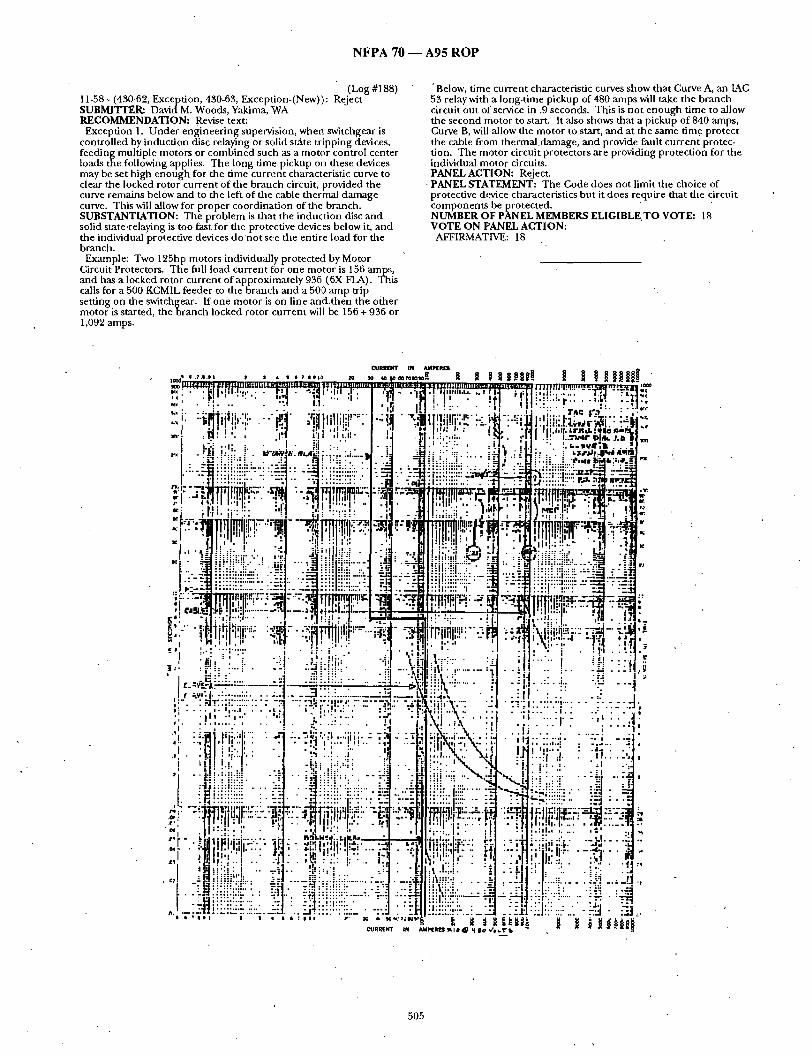
N F P A 7 0 ~ A 9 5 R O P
(Log #188) 11-58 - (430-62, Exception, 430-63, Exception-(New)}: Reject SUBMITTER: David M. Woods, Yakima, WA R E C O M M E N D A T I O N : Revise text:
Exception 1. Under engineering supervision, whe~. switchgear is controlled by induction disc relaying or solid s~ te tripping devices, feeding multiple motors or combined such as a motor control center loads the following applies• The long time pickup on these devices may be set high enough for the time current characteristic curve to clear the locked rotor current of the brancb circuit, provided the curve remains below and to the left of the cable thermal damage curve. This will allow for proper coordination of the branch. SUBSTANTIATION: The problem is that the induction disc and solid state .relaying is too fast for the protective devices below it, and the individual protective devices do 'no t se.e the entire load for the branch.
Example: Two 125hp motors individually protected by Motor Circuit Protectors. The full load current for one motor is 156 amps, and has a locked rotor current of approximately 936 (6X FLA). This calls for a 500 KCMIL feeder to the branch and a 500 amp trip setting on the switchgear, ff one motor is on line and.then the oiher motor is started, the branch locked rotor current will be 156 + 936 or 1,092 amps.
• Below, time current characteristic curves show that Curve A, an IAC 53 relay with a long-time pickup of 480 amps will take the branch circuit out of service in .9 seconds. This is not enough time to allow the second motor to start. It also shows that a pickup of 840 arnps, Curve B, will allow the motor to start, and at the same time protect the cable fi-om thermal.damage, and provide fault current protec- tion. The motor circuit protectors are providing protection for the individual motor circuits. P A N E L A C T I O N : Reject•
• P A N E L S T A T E M E N T : The Code does not limit the choice of protective device cbaracteristics but it does require that the circuit components be protected• ' N U M B E R O F P A N E L M E M B E R S E L I G I B L E . T O V O T E : 18 V O T E O N PANEL A C T I O N :
AFFIRMATIVE: 18
¢ U R R [ N T A M P I [ I t I [ ]
' " . . . . . ~ ' ~ , ; "" ' " . ' " " ; 1 1 ~ f l l : , . ' : . . . . . . . , ; 4 : : ~ 4 , :
-,"' • ."',. .- " " ' : . . ~ ' , . ! i . . ' . "T! ;;l~.i:..'.~..~:. . . . . . . . . T . = " " " / ; ~ . ~ , . . . : _ - - . . . . . . . ~ : • I d I l l : " " . ! " " : " . . . . I : T A r * | ' 3 •
" : " * " ' ~1 J " " • . , 1 : ! i i i i i . l : ~ . ; . ¢ ~ E : ! - ! t r " ' , ' l | t i l , " l . L r l ~ ' L : q I O l l " l ' ~ , | ~""
. ' :. % 1 5 " . , ' g , , * . ' - - : . : ' : : : : ; : : ' . : : . " 1 • i
• : " - " ~ ~ . : i ! i : ! 2 ! : " : r p . ~ : . , . y . = .
. ,!! ,.,~--.-:..-.~ l l | ' ~ ' " . ! ' . L ~ . , !
, . , . | ,
. J t l , l l l p l ' : l l l l ~ l i ' l ,~i *~ : . # " l ' b ; ' . ! ' . ' " ~ [ ] " - ~ ~:
• ~," "-~ "i! ~: !!i[!.:!!d. ' . i~2~:::~::::2 ": " ' i ' :~ : ! "
"--:..-'-~ i!iFiiii,:iiii!:----~.- : ' : - : . . • : r : . : : I ,:": "~'~ ":--:~l
"."-T i l , u , ~ , : ' - - " = ~ , ' . . . . . . , : .
., . . . . . . , :.". • .'" . ~; Ii i ; lr l :.! • =: :
' D : " ' " ,,I I , ' l ~ d ' " ! "
,t; 1~. :~ • ' ~ ' i '. ." I • " ,
. . : i ! . Y !.. ] ~ : : , , i = i " ' = : i : " i . " : . : - : ,
:: - ' ; . . . . . . . . . . i . . . . . "" • . . . . .
• . . ; I . . . . . . . . . . . . . ] , 1
.... ; : i . " ' i ; !.:; '1 .'1 • • , I : :
. . . . "::il' . . . . . . . . . . . . . .
";. i . . ' : . . i ' . . . . : • ~ I'.l ; . . . . . . : ,' ,i, "!1 . . . . . . . . . . . . . . . . . . . . . , rl . , ' " " , i " ' . ; : " ( : . . : ( " ' ' " : ~ . ' ! ; ' : : " : ' i . . . . ' , . ! . . ; : , , - ' 4 ~ i .L : : ' : : .: . . , • : : ; . : . " , : . . .
t ,,,, . ! . " " : 1 - ' . i:!i.!-i~:!~!, i ~I!!~:,: i l ;~:ii " N d.... .~ . . ~ . : . : • . . : . . . . . . .~ . . . . . .~-
.--Jdi:~:~:~ . . . . - ; . :='" ~i::L.:: ....... - . . : . . . - . : : : : : : : : : : : . : : : : : : : : : : : = : : i~i!! i : i !! . . . . . i = ' - ; ~ i : i ! : :-': = • - ' f " k : ' ! i : : ! : " -.=i : • - . . . . . . . . . . . . . . - . . . . . . . I . . . . . " ' . , : : . ' . . . . . . . . . . . . . . . . . . . = . . . . . . . * . . . . . . " . . . . . . . . . . . . . . = "
.~,, . . . "t, . I , I . . . . . . . . . . 1..', . . . . I . - ' l , h . . . . . . . . . . " f . . ' } ]~bl . , , IJ . . . . ' . - . ] . ' 1 ' . . . - HT , ] I,l.I ,,,. | . ' | .... ~ ! . " : . '"~H~=: ,=i .~=:: : . : ' -~ l : : : ! .v: : i l i ' , , I ; , ' * ' :] , ' : :.~, ~ ::: i : ' i l l | ! ; ' . ! I U l : ' : : ' : . ' . ~ : i : :_ ' I !
- H ' : ! :' • " ' t . . I , : : '. "'1 d : ' I ; : , L ' . . . . . . . .:' . I : : " . . " . , . - ~ . - . " " :,., . . . . . . . . . • . ~ . q l . . - . ~ : . ~ l U . - - - . - ~ J - . - - - : ~ ; ' H : ' ; ; ~i ; : .b" " - ~ ; . . . . :~ "" - " l i l l p '1"1,'"'" " 4 ~ . . . . . . . I ~ l l l ' ' ' | ' l . . . . . . . . l / I . . . . . " i ] i i ; : ' l i ~ ' : ' : : ~ i . . . . . . . . . , . , . . . . . . . , . . . . •
,o . • " ' I I ~ f ' l . " I I , " " • I r ~ l . , i - i . : I I . , I : . ' : . . . . . ; I • - - ' . , . I . i . . . . . . ~ • I I ' . J r - . • h I ! . ' I . . i . • ~!~1,, : , . - , I , $ ; ~ : ; .~ j ~ : , , , , . . l ' r~ " . " , ! 1 , , h , , , ,'1
,~; " . . l ! • '. , { ! . . | l l : . . I ; i . ' ~ . . l . d . J . , ,= I "~ : " : I : 1 , 1 ~ . : - d i i : i i . = .. =--~.. -=-,., ; . . . . ;:l • 1 ," .!.;.i. ! • : . ' . l i : : I. ':. . ' " . . : . I ' : I:I . : : : : : . . . . . r l : . . - / - 1 . . . . . . . . . . . . ; : . . . . = : ~ . . . . . . . . . .
- " ~.=1:::::: "':'" " : = I " ' - ~ ' : I : ' : : U ~ ' £ . . . . . . . . . . :'~ . . . . ~" : ~ ' : . : : ' : ' : : " ' . : : ' " : . : ' , : . : : : : : . : . : - . : - . ' - : 1 : . . : ' ! t . : . l : : . . . ~ : " ~ . - : - - : ] ' , . . , , . ~ . . : : : : . : . . : . . . . : . ; I ] . . . T I ' . : ' . : ; : : " . . . . . . . . . . . " ' . . . . . . - i ~ : : : ' : : ' : ' : ' " : . . ' : : : ! ~ ~ : : : : . " : : . [ i~ i : ! : ! : ' ! ......... " - ~ ' - - ' - 1 " 1 : : ' ! ' : . ' : ..... :" : ~ " ' .--El. .
. . . . . . . . . . . . . . . . . . . . . . . . . . . :'::::':":: : " : .. : -~1: ! :1 ! : : :::: ..'. " .~:"J • ":3 , . . . . . . . . . . I :1: . . . . . . . . . . . . . . . . . . t . . . : . I ; . . . . . . . . . . . . . . d . . . . J i i i i I l • i i ; i i i I - ic , ~ i ~ k , , I , : l l ~ w ,
C U R R E N T I N A M P [ R [ S ~ I ~ i ~ | 0 ~ I ; T ' b "
505

N F P A 70 m A 9 5 R O P
(Log #466) 11-59 - (430-62 (a) ): Reject SUBMITTER: Dan Leaf, Palmdaie, CA RECOMMENDATION: Insert "largest" in lieu of "same" in the second paragraph. SUBSTANTIATION: Clarif. For consistency with the first para- graph. The literal wording of dais paragraph indicates one of two or more equal rated overcurrent devices is to be considered the largest, without specifying they mus t also actually be the largest. PANEL ACTION: Reject. PANEL STATEMENT: The present text does not confuse, when both paragraphs are read together as t h e y s h o u l d be. NUMBER OFPANEL MEMBERS ELIGIBLE TO VOTE: 18 VOTE ON PANEL ACTION:
AFFIRMATIVE: 18
(Log #467) 11-60 - (430-62(a), Exception No. 2-iNew) and (b)): Accept in Principle SUBMITTER: Dan Leaf, Palmdale, CA RECOMMENDATION: Add:
"Exception No. 2: Where the rat ing de te rmined by this section is smaller than the rat ing permit ted by Section 240-3(b) the provisions of that section shall be permitted; where the rat ing de t e rmined by this section is larger than the rat ing permi t ted by Section 240-3(c) the provisions of this section shall be permitted".
In (b) change "heavy capacity" to "higher capacity." SUBSTANTIATION: Edit. The provisions of this section (and Sec. 430-63 by reference to this section) do not permi t a round ing up to the next larger s tandard rating, and in some cases would require a feeder OCP device smaller than permi t ted by Sec. 240-3(b), and in some cases would permi t a larger OCP device than permi t ted by Sec. 240-$(c).
The provisions of Secs. 240-3(b), 240-3(c), 240-3(0, and 240-3(h) are rules of equal rank (not exceptions) and it is my assumpt ion the most restrictive rule is to apply if no t modif ied or excepted. The following examples illustrate the confusion that may result.
(1) Service or feeder conductors supplying a wound rotor (largest) 15 HP motor at 208 volts 3-phase with a FLA. of 46.2 amps, and other motor load of 300 arnps. Min imum feeder ampaci ty is 46.2 x 1.25 plus 300, or 358 amps. The largest feeder OCP device is 400 amps,
er Sec. 240-3(b). The largest branch circuit device rating for the gest motor is 46.2 x 1.5 per Sec. 430-52, or 60 amps, ( r ounded
down to s tandard rating). The largest feeder OCP device per this section, is 60 plus 300, or 350 amps ( rounded down to s tandard rating), which is less than permi t ted by Sec. 240-3(b).
(2) Service or feeder conductors supply a 100 HP no Code letter (largest) motor at 208 volts 3-phase with a FLA. of 272.8 amps, and other motor load of 600 amps. M i n i mum feeder ampaci ty Is 272.8 x 1.25 plus 600, or 941 amps. The largest feeder OCP device is 800 amps ( rounded down to s tandard rating) per Sec. 240-3(c). The largest non time-delay fuse for the largest motor branch circuit is 800 amps ( rounded down to s tandard rating) per Sec. 430-52. Per Sec. 430-62 the feeder may be protected at 800 p lus 600, or 1200 amps ( rounded down to s tandard rating), which is greater than permit ted by Sec. 240-3(c).
This same scenario could occur for various motors, hermet ic motor-compressors, d e p e n d e n t on motor type and Code letter, and type of overcurrent devices, and could also occur where the other load consists of smaller motors and l ighting and appliance loads, due to Sec. 430-63 reference to dais section.
The proposed change in (b) is only editorial in nature. PANEL ACTION: Accept in Principle. PANEL STATEMENT: The panel agrees with the submit ter ' s in tent and has incorporated it into the Panel Action taken on Proposal 11- 61. The proposed editorial,, change to,,"higher, capacity" is no longer necessary because the heavy capacity w o r d m g h a s been removed. NUMBER OF PANEL MEMBERS ELIGIBLE TO VOTE: 18 VOTE ON PANEL ACTION:
AFFIRMATIVE: 17 NEGATIVE: Saporita
EXPLANATION OF NEGATIVE: SAPORITA: I oppose panel action. While I agree with panel
action on 11-61, i-t has no th ing to do with the r t u n d i n g - u p allowance of 240-3(b). The intent of 430-62(a) has always been to round down.
(Log #2046) 11-61 - (430-62(b)): Accept in Principle SUBMITTER: Alan L. Cardwell, U.S. Army Corps o fEng inee r s RECOMMENDATION: Revise text as follows:
(b) Large Feeders. For installations where feeders supp l ya specific fixed motor load(s) and consist of conduc tor sizes larger than those
required by Section 430-24, the rat ing or set t ing of the feeder protective devices shall be permit ted to be based on the ampacity of the feeder conductors . SUBSTANTIATION: The paragraph, as it cur rendy exists, requires "future addit ions or changes" in order to use larger feeder protective devices on large-capacity feeders. There are o ther situations where larger feeders and protective devices are desirable: (1) utilizing existing e q u i p m e n t where no future changes are planned. (2) A feeder supplying several motor branch circuits, each of which is protected by an OCPD sized at 125% NPA (t 9 provide OC and SC protection); with several such motors runn ing . The feeder bkr. would be loaded greater than 80% of its rating. PANEL ACTION: Accept in Principle.
Revise the text of Section 430-62(b) to read as follows: (b) Other Installations. Where feeder conductors have an"
ampacity greater than required by Section 430-24, the rat ing or sett ing of the feeder overcurrent 'protective device shall be
~ ermit ted to be based on the ampacity of the feeder conductors . ANEL STATEMENT: The panel agrees with the submit ter ' s point
that "future addit ions or changes" are no t necessary in this require- ment . The panel sees no technical reason to restrict the proposal to "large" feeders to "specific fixed motor loads". NUMBER OF PANEL MEMBERS ELIGIBLE TO VOTE: 18 VOTE ON PANEL ACTION:
AFFIRMATIVE: 18
(Log #470) 11-62- (430-63): Reject SUBMITTER: Dan Leaf, Paimdale, CA RECOMMENDATION: Revise as follows:
"Where a feeder supplies a motor load, and in addit ion a l ighting or a l ighting and appliance load, the feeder overcurrent protective device shall have a rat ing or set t ing sufficient to carry the l ighting or l ighting and appliance load as de t e rmined in accordance with Articles 210 and220 , plus for a single motor, the rating de t e rmined bySect ion 430-52 or 440-22(a) f o r h e r m e t i c refr igerant motor- compressors, and for two oi- more motors the rat ing de t e rmined by Section 430-62." SUBSTANTIATION: Edit. The feeder OCP device shou ld be REQUIRED to be sufficient to carry the load. The permissive phrase "shall be permit ted" also applies to the rating REQUIRED by Sec. 430-62. In essence there is no required rule in this section. Conductors are REQUIRED to be sufficient to carry the load per Sec. 430-2; why not overcurrent devices? The general rules of Secs. 430-52 and 430-62 are no t permissive. PANEL ACTION: Reject. PANEL STATEMENT: Required m i n i m u m conductor sizing is a mat ter of safety.
Max imum overcurrent protective device is also safety related, but m i n i m u m overcurrent protective device sizing is not. NUMBER OF PANEL MEMBERS ELIGIBLE TO VOTE: 18 VOTE ON PANEL ACTION:
AFFIRMATIVE: 18
(Log #1574) 11-63- (430-63, FPN-(New)): Reject SUBMI'FI'ER: Dan Leaf, Palmdale, CA RECOMMENDATION: Add new text as follows: "(FPN). See Sect ion 384-16 for overcurrent protect ion of l ighting and appliance branch-circuit panelboards ." SUBSTANTIATION: The bus bars of a "main lugs only" panelboard are an extension of the feeder conductors . Where the pane lboard is a "lighting and appliance panelboard" per Section 384-14 the provisions of this section and Section 384-16 may permi t or require different overcurrent device ratings. For example consider a "main lugs only" 100A. 120/240V. 10 fusible panel with nont ime-delay fuses as follows: one set of two 50A. fuses for a 3HP motor, seven sets of one 20A. fuses per phase for l ighting and appliance circuits with a compu te r load of 75A. per feeder leg. Section 384-16 requires O.C. protect ion no t over 100A. Sect i tn 430-63 permits O.C. protection rated 50A. plus 75A~ or 125A. The proposed FPN would be useful for Code users. PANEL ACTION: Reject. PANEL STATEMENT: Section 384-16 stands on its own. The Panel is no t aware of the confusion implied by the submitter . NUMBER OF PANEL MEMBERS ELIGIBLE TO VOTE: 18 VOTE ON PANEL ACTION:
AFFIRMATIVE: 18
506

N F P A 70 ~ A 9 5 R O P
(Log #1.868) 11-64 -" (430-72 (a) ( 1 )-(New) ): Reject SUBMITTER: Victor V. Timpanaro , Municipal Electrical Inspectors Assoc. of NJ, Inc. RECOMMENDATION: Add new subseoJon - Voltage Limitation - Control circuit voltage shall no t exceed 120 volts between conduc- tors. SUBSTANTIATION: OSHA and FM insurance companies require control circuit voltage to be limited to 120 volts',as there have been many cases r e p o r t e d o f serious shock hazard when 208, 240, or h igher voltages have been used for control circuits. PANEL ACTION: Reject. - PANEL STATEMENT: Submit ter ' s substant iat ion is incorrect. See 29 CFR 1910.308(c) (1) (i) (B). NUMBER OF PANEL MEMBERS ELIGIBLE T O WOTE: 18 VOTE ON PANEL ACTION:
AFFIRMATIVE: 18
11-65 - (430-72(c), Exception No. 2): "Reject " (Log #2861) SUBMITTER: JosephJ . Andrews, Aiken, SC RECOMMENDATION: Revise Section 430-72(c), Exc. No. 2, to require an overcurrent device rated or set at no t more than 300% of the rated primary cur ren t instead of the 500% now stated. SUBSTANTIATION: This Section, as it stands, disajgrees with section 450-3(b)(1), Exc. No. 1 which requires 300% protectioti. - The 300% provides better t ransformer protection. Modern control circuit fuses are readily available with adequate t ime delays, so that a 500% rating will allow control circuit inrush cur ren~. PANEL ACTION: Reject. PANEL STATEMENT: T he in tent of this Exception is to accommo- date control t ransformers tha t have high inrush currents that will %tective devices set at 300%
R O17 PANEL MEMBERS ELIGIBLE T O VOTE: 18 VOTE ON PANEL ACTION:
AFFIRMATIVE: 18 COMMENT ON AFFIRMATIVE:
SAPORITA: I concur with panel act ion with comment . In the panel s ta tement , the word "trip" should he changed to "open". It ~vould daen cover both fuses and circuit breakers~
(Log #1107) 11-66- (430-73): Accept SUBMITTER: Charles B. Schram, Wilmette, IL RECOMMENDATION: In the second paragraph, change "remote control devices" to "control circuit remote from the motor control- ler ' . SUBSTANTIATION: With the revision of the s e c o n d p a r a g r a p h in the 1993 Code, there have been quest ions concern ing the in tent of "remote control devices" in dais paragraph, a l though the 1993 revision did not change these words. While it can be argued that, f rom the first paragraph, these are obviously the devices connec ted remotely from the motor controller, the proposed revision is in tended to remove any doub t as to what the devices are remote from. Also, the proposed revision removes the limitation to an accidental g r o u n d only in a remote control device, since an accidental g round anywhere between the motor controller and remote control device in the intentionally g rounded side of the control circuit will bypass the control device. PANEL ACTION: Accept. NUMBER OF PANEL MEMBERS ELIGIBLE T O VOTE: 18 VOTE ON PANEL ACTION:
AFFIRMATIVE: 18
(Log #3420) 11-67- (430-81): Reject SUBMrIq 'ER: Joseph Misrahi, Metro Transi t Audiority of Harris County, TX RECOMMENDATION: Change "Part G is in t ended to require suitable controllers for all motors" to "Part G speck~ies requ i rements for suitable controllers for motor". SUBSTAN'I 'IATION: To be consistent widl o ther parts of dais Article 430. The word "all" should be deleted becz.use is no t used in all Articles. This creates ambiguity by implying that when "all" is no t used the Article does not apply to "all".' PANEL ACTION: Reject. PANEL STATEMENT: Present wording is clear.
NUMBER OF PANEL MEMBERS ELIGIBLE T O VOTE: 18 VOTE ON PANEL ACTION:
AFFIRMATIVE: 18
(Log #469) 11-68- (430-83, Exception No. 4-(New)): Accept SUBMITTER: Dan Leaf, Palmdale, CA RECOMMENDATION: Add:
"Exception No. 4: Devices permi t ted by Section 430-81(b) and (c) to serve as controllers shall no t be requi red to be horsepower rated." SUBSTANTIATION: U n d e r the condi t ions of Sec. 430-81, (b) and (c) tile described devices become controllers and ,are subject to the requi rements of the first paragraph of this section. Wha t part of the definit ion of controller excludes these devices? They meet the: definit ion of controller in Art. 100 and Sec. 430-81(a) as do the devices in Excepdons No. 1 and 2 of this section, which do not define t hem but exemp t t hem from HP requirements . The branch circuit prote.ctive device of Sec. 430-81 (b) is exempted from HP requi rements by Sec. 430-83 Ex. No. 2 if it is a circuit breaker, but no t if it is a fuse.
The plug and receptacle permi t ted as a d isconnect ing means for a
~ ortable motor 1 /3 HP or less is exempted f rom HP requi rements ySec. 430-109 Ex. No. 5, and where serving as a controller should
be specifically exempted , otherwise it may literally and logically be inferred as requir ing a HP rating due to more severe duty (starting and stopping). PANEL ACTION: Accept. NUMBER OF PANEL MEMBERS ELIGIBLE T O VOTE: 18 VOTE ON PANEL ACTION:
AFFIRMATIVE: 18
(Log #1206 ) 11-69- (430-83(c) and Exceptions,(New)): Accept in Principle SUBMITTER: K. L. Paape, Asheville, NC RECOMMENDATION: Add new paragraph as follows:
( c ) Locked-Rotor-Current Rating. Each controller for aDes ign E motor shall be marked with a m a x i m u m locked-rotor-current in ter rupt ing rating for each utilization voltage at which it may be appl ied .
Exception No. 1: Controllers rated 2 horsepower or less. Exception No. 2: Controllers marked with a m a x i m u m locked-
rotor indica.ting code letter (Ref: Table 430-7(b)) for each utilization voltage f rom which.the controller m a x i m u m locked-rotor-current in ter rupt ing rating can be de termined .
The locked-rotor-current in ter rupt ing rating of the controller for a Design E motor shall be not less than the locked-rotor cur ren t or equivalent code letter shown on the Design E motor nameplate. . SUBSTANTIATION: The traditional ratios of locked-rotor currents to full-load currents are exceeded by Design E motors, and motor controllers listed for application with other than Design E motors may no t have the ability to in ter rupt the locked-rotor currents of Design E motors. This proposal requires that this.capability be addressed. See compan ion proposal for 430-7(a)(14) which would require that Design E motors be so marked. PANEL ACTION: Accept in Principle.
Add new Exception No. 1 to Section 430-83(a), ,as follows, and r e n u m b e r existing Exception Nos. 1, 2, and 3 as Nos. 2, 3, an d 4.
Exception No. 1: A controller for a Design E motor rated more than 2 horsepower shall also comply with (a), (b) or (c) below
(a) It sha l lbe marked with a locked-rotor cur ren t rating no t less than the locked-rotor cur ren t of the motor specified in Table 430- 151(b).
(b) It shall be marked as suitable for control of Design E motors. (c) It shall have a horsepower rating no t less than 1.3 t imes the
horsepower rating of die motor. PANEL STATEMENT: Controllers rated in horsepower for Design E motors, bu t without a marked locked-rotor cur ren t rating [Option (b)], or derated existing horsepower-rated controllers [Option (c)] are also suitable for control of Design E motors. The 1.3 dera t ing factor is based on a locked-rotor to full-load cur ren t ratio of approximately 8 for Design E motors compared to a ratio of 6 for tests on existing controllers. NUMBER OF PANEL MEMBERS ELIGIBLE T O VOTE: 18 VOTE ON PANEL ACTION:
AFFIRMATIVE: 17 NEGATIVE: Ruedi
EXPLANATION OF NEGATIVE: RUEDI: Only option (b).in the Panel Action on dais proposal is
necessary. Opt ion (a) was originally inc luded at my request because at that t ime NEMA was consider ing the proposal of such a require- men t in its Industrial Control Standards. It has now been decided
507

N F P A 70 - - A 9 5 R O P
that marking a controller with its locked-rotor cur ren t rat ing would introduce u n n e e d e d complexity for installers and inspectors. The 1.3 multiplier in opt ion (c) is no t teclmically correct for many sizes of Design E motors. NEMA would suppor t this proposal if it were revised to read: "Add new Exception No. 1 to Section 430-83(a) as follows, and r e n u m b e r existing Exception Nos. 1, 2, and 3 as Nos. 2, 3, and 4. Exception No. 1: A controller for a Design E motor rated more than 2 horsepower shall be marked as rated for use with a Design E motor."
(Log #468) 11-70- (430-91): Accept
Note: It was the action of the Technical Correlat ing Commit tee that fur ther considerat ion be given to the comment s expressed in the voting. This action will be considered by the, Panel as a Public Comment . SUBMITTER: Dan Leaf, Palmdale, CA RECOMMENDATION: Revise first sentence as follows:
[ "Table 430-91 provides the basis for selecting enclosures for use in ispecific locations not j u d g e d to be hazardous (classified) locations." SUBSTANTIATION: Edit. "Nonhazardous" is evidently in tended to apply to locations not specified by Code as hazardous (classified) locations. In this context Code def ined words should be used.
~ "Nonhazardous" and "hazardous" are dictionary-defined words and do not necessarily indicate nonclassified or classified locations. For example "hazardous" in Sec. 668-32(b) relates to o ther than classified locations. PANEL ACTION: Accept. NUMBER OF PANEL MEMBERS ELIGIBLE TO VOTE: 18 VOTE ON PANEL ACTION:
AFFIRMATIVE: 16 NEGATIVE: Alexander, Saporita
EXPLANATION OF NEGATIVE: ALEXANDER: Suggest the first sentence be revised as follows: "Table 430-91 provides the basis for selecting enclosures for use in
specific ,,,~,,',,,,.o~,.I',,,~ unclassified locations. I am casting a negative vote primarily to get circulation of my
comment . Actually I accept the proposal in principle. I am uncomfor table with the term '~judged". In most industrial si tuations electrical area classification is done by t rained engineers somet imes with comment s f rom the insurer. '~Judged" implies the AHJ makes the determinat ion.
"Unclassified" is sufficient to establish an installation is no t subject to Article 500, 501,502, etc.
SAPORITA: The submit ter ' s in tent would be better served by simply changing the cur ren t sen tence to read: "Table 430-91 provides the basis for selecting enclosures for use in specific locations which are no t hazardous (classified).
(Log #471) 11-71 - (430-92): Reject SUBMITTER: Dan Leaf, Palmdale, CA RECOMMENDATION: Insert "a factory assembly" in lieu of "an assembly". SUBSTANTIATION: Edit. The percept ion is that a factory- assembled unit(s) is in tended, as described in the UL "green book". However a field-fabricated assembly of auxiliary gutter, disconnects, and controllers could be inferred as included. Large cables in a gut ter could be considered a c o m m o n bus. S ec. 725-15 Ex. No. 1 was in tended to apply to field-assembled (motor) control centers. PANEL ACTION: Reject. PANEL STATEMENT: Field assembly of factory-provided sub- assemblies is in tended to be included. NUMBER OF PANEL MEMBERS ELIGIBLE TO VOTE: 18 VOTE ON PANEL ACTION:
AFFIRMATIVE: 18 COMMENT ON AFFIRMATIVE:
RUEDI: I suppor t the Panel Action. However, the Panel S ta tement should have been expanded to clarify that the field assembly of factory-provided motor control center sub-assemblies is in tended to be included. Separate ly-mounted auxiliary gutters, disconnects, and controllers, as described by the submitter , are not included.
(Log #1117) 11-72- (430-92): Reject SUBMITTER: Dan Leaf, Palmdale, CA RECOMMENDATION: Change "a c o m m o n power bus" to "common power busbars".
SUBSTANTIATION: Edit. "Bus" and "busbars" appear to be used interchangably in Part H. This section a n d Section 430-94 uses "bus" and Section 430-97(a) (e) uses "busbars". They are not necessarily the same, since a conduc to r in the form of a wire can also be a "bus" but not a "busbar", and the requi rements of Section 430-97(a)(e) would not apply to such busses. While I d o n ' t recollect seeing any MCC with bus no t in bar form, the proposal would confi rm this as the intent. ]PANEL ACTION: Reject. PANEL STATEMENT: It is no t the in tent to require that the power bus be limited to a busbar. NUMBER OF PANEL MEMBERS ELIGIBLE TO VOTE: 18 VOTE ON PANEL ACTION:
AFFIRMATIVE: 18
(Log #3417) 11-73 - (430-92).: Reject SUBMITTER: Joseph Misrahi, Metro Transi t Authori ty of Harris. County, TX RECOMMENDATION: Change "Part H covers..." to "Part H specifies...". SUBSTANTIATION: To be consistent with o ther parts of this Article 430. PANEL ACTION: Reject. PANEL STATEMENT: Part "H" does no t specify motor control centers. NUMBER OF PANEL MEMBERS ELIGIBLE TO VOTE: 18 VOTE ON PANEL ACTION:
AFFIRMATIVE: 18
(Log #472) 11-74- (430-94): Reject SUBMITTER: Dan Leaf, Palmdale, CA RECOMMENDATION: Revise as follows and delete the second sentence:
"Motor Control Centers shall be provided with overcurrent protection in accordance with Part E of this article." SUBSTANTIATION: Overcur ren t protect ion based on the rating of the c o m m o n bus is at variance with long-standing Code rules for feeder OCP based on motor currents not conduc tor ampacity, an d does no t appear justif ied or consistent. MCC c o m m o n bus is an extension of feeder conductors . Feeder conductors to an auxiliary gut ter f rom which sets of combinat ion motor starters are connec ted (could be considered a field-fabricated MCC) are permi t ted to be protected per Sec. 430-62 and 430-63. Art. 384 does no t require a switchboard to have OCP at the bus rating where supplying motor loads and l ighting and appliance loads; Sec. 430-63 would apply. What is the reason a MCC should have different r equ i rements for sizing OCP than tha t indicated in Sees. 430-62 and 430-63?
The last sen tence appears to be superf luous. For a c o m m o n bus and one feeder the OCP u n d e r o ther rules would have to be "upstream" or in the MCC. Where else could it be? The word "upstream" while commonly used, has been indicated by panel commen t s in the past to be technically undesirable for Code use to indicate lifie-side or supply side location. PANEL ACTION: Reject. ]PANEL STATEMENT: Motor control center loads are too often changed to allow any o ther practical method . See panel proposal 11-74a relative to second sentence. NUMBER OF PANEL MEMBERS ELIGIBLE TO VOTE: 18 VOTE ON PANEL ACTION:
AFFIRMATIVE: 18
11-75 - (430-94): Reject (Log #689) SUBMI'I'TER: William H. Wottlin, Cornelius, OR RECOMMENDATION: Rewrite as follows:
Motor control centers shall be provided with overcurrent protec- tion in accordance with article 240. This p r o t e c t i o n . . . SUBSTANTIATION: a) The existing wording can cause confusion. For example Websters New Collegiate Dictionary has 10 meanings of the word base. Definition n u m b e r 2 "a main ingredient" seems to fit the existing code m e a n i n g a s well as any. In any case if I calculate overcurrent protect ion at 75 percent of the motor control center ampaci ty I can say the overcurrent protect ion is "based" on the bus rating.
b) The overcurrent protect ion for the Motor Control Center should be calculated on the loads the Motor Control Center is feeding, f f t he calculated load is 400 amps and I specify a 600 am p
• 508

N F P A 70 1 A 9 5 R O P
horizontal bus (see typical guide specification used by my coml~anv ) the overcurrent protect ion to the feeder and MCC .,.hould be on tile (.alculated load. To require 600 a m p overcurrent p ro tec t ionwould either require oversizing the f e e d e r o r having a Iow,.-r feeder breaker protect ing the feeder and a larger breaker at the M~2C. Consider a long feeder that is oversized because of voltage drop. If we size overcurrent protec t ion on the feeder size, would the NEC require us to increase tile overcurrent protection?
c) The " c o m m o n p o w e r bus" should be clarified if the existing language is retained. Do you m e a n the horizontal or vertical bus or both? NFPA 90 - A92TCR, Page 388, Proposal 11-64, used the words "horizontal bus rating." PANEL ACTION: Reject. , " PANEL STATEMENT:" It is the panel ' s in tent that tzhe overcurrent protection be based on the rating of the c o m m o n power bus.
See Panel S ta tement on Proposal 11-74. NUMBER OF PANEL MEMBERS ELIGIBLE T O VOTE: 18 VOTE ON PANEL ACTION:
AFFIRMATIVE: 18
(Log #CP1108) 11-74a - (430-94): Accept SUBMITTER: CMP 11 RECOMMENDATION: Revisi. • the second sentence to read as follows:
"This protect ion shall be provided by (1) an overcurrent protective device located ahead of the motor control center ozr ( 2 ) . . • " SUBSTANTIATION: To remove the use of the word "upstream". PANEL ACTION: Accept. NUMBER OF PANEL MEMBERS ELIGIBLE T O VOTE: 18 VOTE ON PANEL ACTION:
AFFIRMATIVE: 18
(Log #1116) I1-76- (430-95): Accept SUBMITTER: Dan Leaf, Palmdale, CA
IRECOMMENDATION: Delete "(neutral)" in the second paragraph. SUBSTANTIATION: Requir ing a main bond ing j u m p e r only for a g r o u n d e d conductor which is a neutral does not correlate well with the definit ion of main bond ing j u m p e r wlfich describes the . connect ion to a_.n_y, g r o u n d e d circuit conductor , not jus t neutrals. Sections 250-23(b), 250-50(a), and 250-53(b) require ~ g r o u n d e d service conductor to be bonded, not ju s t neutrals. Removal of the word "neutral" would provide better correlation wil:h o ther Code requirements . PANEL ACTION: Accept. NUMBER OF PANEL MEMBERS ELIGIBLE T O VOTE: 18 VOTE ON PANEL ACTION:
AFFIRMATIVE: 18
• (Log #473) 11-77- (430-97(0-(New)): Reject SUBMITTER: Dan Leaf, Palmdale, CA RECOMMENDATION: Add:
"(f) CLEARANCE FOR CONDUCTORS ENTERING BUS ENCLOSURES. Wiring space for conductors shall be in accordance with Section 384-10." SUBSTANTIATION: Since MCCs are now specifically covered b); Part H it may be inferred that the "similar enclosure" of Sec. 384-10 is no t in t ended to encompass MCCs. Since busing and construct ion may be similar to switchboards a specific r equ i r emen t for spacing seems warranted. PANEL ACTION: Reject. PANEL STATEMENT: The panel has no evidence of a problem.
Spacing requirements are covered in ANSI /UL Sl~andard 845. NUMBER OF PANEL MEMBERS ELIGIBLE T O VOTE: 18 VOTE ON PANEL ACTION:
AFFIRMATIVE: 18
(Log #1786) 11-78 - (430-102, FPN-(New)): Reject SUBMIT'rER: Gregory P. Bierals, Electrical Desigla Institute RECOMMENDATION: See OSHA 29CFR, Part 1910, Subpart S, Part II for informat ion on L o c k o u t / T a g o n t procedures. SUBSTANTIATION: The OSHA Safety, Related Work Practices associated with workplaces took effect on December 4, 1990 and this ' s tandard contains addit ional information regarding workplace safety
(along with Part I for Electrical Design Safety Standards) that is no t addressed in the NEC. The Code is no t devoted to workplace environments , so the reference to the workplace safety requ i rements in the FPN will be helpful. PANEL ACTION: Reject. PANEL STATEMENT: The National Electrical Code covers design and installation, not operat ing procedures. NUMBER OF PANEL MEMBERS ELIGIBLE T O VOTE: 18 VOTE ON PANEL ACTION:
AFFIRMATIVE: 13 NEGATIVE: Alexander, Baker, Saporita, Shapiro, Sportini
EXPLANATION OF NEGATIVE: ALEXANDER~ I agree with the submitter, at least in principal,
especially since many operat ing procedures require specific installations. W h e n NFPA 70E is reaffirmed it maywell be the appropriate reference.
BAKER: The proposal should be "Accepted in Principle". Thd new FPN shou ld be revised to read: FPN: See NFPA 70E, "Electrical Safety Requi rements for Employee Workplaces" for informat ion on Lockou t /Tagou t procedures. The Panel S ta tement is in a g r e e m e n t with the submit ter ' s substantiat ion s ta tement that the Code does no t cover operat ing procedures. The proposal references those rules regarding workplace safety, a c o m m o n concern for everyone. There are many fine print notes in o ther parts of the Cod.e which make reference to various helpful documents .
SAPORITA: While I agree with the Panel S ta tement in general , reference to OSHA (and to NFPA 70E) is worth the effort if it saves the life of one electrician.
SHAPIRO: I would like to see us accept this proposal in principle. It would be entirely appropriate for us to reference NFPA70E. For me, the n u m b e r one rule in the Electrical Code is, d o n ' t kill the electricianI There are many thousands of people who will never see an OSHA inspector in their workplaces, bu t who do work on machinery and who do use the NEC. Adding a FPN would add to the safety that we all desire.
SPORTINI: The purpose of the Code is the practical safeguarding of persons and property. . . The main purpose of the Code is safety, in this new proposal it gwes a reference to the work place where safet2 is ~ . t _ .
(Log #3169) 11-79- (430-102(a)-(New)): Reject SUBMITTER: T o m J . Paulson, Seattle, WA RECOMMENDATION: Add new text:
ff the identity of the d isconnect canno t be readily de t e rm in ed by visual inspection, t hen the controller shall be clearly identified with a warning label giving the location and identification of the d isconnect ing means. SUBSTANTIATION: Somet imes a d isconnect may be in the same room but because conduits may get "lost" in a condui t rack for example, it. may not be possible to readily identify it. It could be a circuit breaker in one of several panelboards or one of sevei'al separately m o u n t e d devices. PANEL ACTION: Reject. PANEL STATEMENT: Section 110-22, as re ferenced in FPN No. 2 of Section ,t30-101, requires that the d isconnect ing means be identified to indicate its purpose unless located and a r ranged so that the purpose is evident. The submit ter has no t just if ied the need for an additional mark ing on the controller. NUMBER OF PANEL MEMBERS ELIGIBLE T O VOTE: 18 VOTE ON PANEL ACTION:
AFFIRMATIVE: 17 NEGATIVE: Shapiro
EXPLANATION OF NEGATIVE: SHAPIRO: I am in favor o f this proposal with the reservation tha t
the second part of the sentence shou ld read that, "the controller shal l be labeled with the location of the d isconnect ing means." (Rather than, "clearly identified with a warning label giving tfle location...") The submi t te r has a good point. I expect a n d r e q u i r e a lil~hting panel to be labeled with some th ing like "LP-I" if it is no t adjacent to its main. And, I expect to f ind the same "I~P-I" marked on the main disconnect . This is no different.
There arc: t imes when a circuit breaker is the d isconnect for a motor circuit. It is in sight of thecont ro l le r . But, it is one breaker in a group of panels tha t migh t be 50 feet away. We shou ld help to make it easy to locate.
509

N F P A 7 0 1 A 9 5 R O P
(Log #959) 11-80- (430-102(a), Exception No. 1): Reject SUBMITTER: Kristofer G. Anderson , Bath Iron Works Corp. RECOMMENDATION: "For Motor Circuits Over 600 Volts, Nominal , " . . . to be deleted. SUBSTANTIATION: Remove the over 600 volt r equ i r emen t for this exception and allow any d isconnect ing means to be out of sight of the controller if it 's lockable. Disconnect ing means for motors at any voltage can be out of site if Iockable. The Code does no t seem to be consistent in the application of the in tent of this exception. Over 600 volt systems are more hazardous than unde r 600 volts yet are allowed this exception, f f i t ' s safe for over 600 volts, it should be s,'ffe for u n d e r 600 volts. PANEL ACTION: Reject. PANEL STATEMENT: Motor installations over 600 volts are typically main ta ined and serviced by specially qualified personnel , and a remote, Iockable, controller d isconnect ing means is consid- ered acceptable u n d e r these circumstances. The r ecommenda t ion would permit reduced safety for the vast majority of motor installa- tions. Consistency is no t necessary or appropriate in this case. NUMBER OF PANEL MEMBERS ELIGIBLE TO VOTE: 18 VOTE ON PANEL ACTION:
AFFIRMATIVE: 18
(Log #2447) 11-81 - (430-102(b)): Reject SUBMITTER: Shawn Gianella, Union, NJ RECOMMENDATION: Revise t ex tas follows:
(b) motor: Exception - is capable of being locked in the open position - (add
following) and marked with a warning label. SUBSTANTIATION: U n d e r (b) motor of 430-102 - exception should also state "to be marked with a warning label." Many plant electricians simply use [ocks, without stat ing "who" is working on motor or machine . O the r personnel in the plant canno t make reference as to why operat ion is down, may jus t cut lock loosing any afforded protect ion to the pe r son tend ing the motor or operation-- would be concur ren t with (a) controller. PANEL ACTION: Reject. PANEL STATEMENT: While the panel is sympathet ic to the in tent of the proposal, it covers practices tha t are beyond the installation rules of the NEC. See NFPA 70E. NUMBER OF PANEL MEMBERS ELIGIBLE TO VOTE: 18 VOTE ON PANEL ACTION:
AFFIRMATIVE: 18
(Log #2317) 11-82 - (430-102(b); Exception and Exception No. 2-(New)): Rejeizt SUBMITTER: Bud Swathwood, Electrical Engineer ing & Consult-
' Inc. OMMENDATION: Add new text as follows:
Change the existing Exception to #I and add Exception #2: A single d isconnect ing means sltal] be located at the motor controller location for a complete conveyor system where all of the conveyor motors for the system are located in one location and both the control and motor power can be d isconnec ted and locked off. Each motor in the system mus t be marked to show the location of the d isconnect ing means. The drive motors in the system shall no t d e p e n d on plugs at their location for their disconnect ion. " SUBSTANTIATION: A conveyor system sltould be considered as a machine and it shou ld be made clear tha t the d isconnect ing means mus t disengage all power to the comple te system. Many times the drive motors, in. these systems are equ ipped with. HP rated plug caps and bodles as disconnects and are used as a d isconnect ing means for that particular motor, f f the main disconcert ing means at the controller is set at the on position when the motor is p lugged back in the motor starts and may start and a hazard then exists. It should be made very clear tha t the corriplete system should be rendered safe by ONE main d isconnect ing device at ONE location before servicing, replacing, or main ta in ing the drive motors or o ther electrical equ ipmen t on the system. PANEL ACTION: Reject. PANEL STATEMENT: A complete conveyor system may or may not be a single machine , d e p e n d i n g on individual circumstances, in order to me.et condi t ion a. of Section 430-I 12, Exception, permit t ing use o f a s i n g l e d isconnect ing means for more than one motor. Use of properly rated a t t achmen t plugs and receptacles at the individual motor locations is equivalent to us ing d isconnect switches at these locations.
NUMBER OF PANEL MEMBERS ELIGIBLE TO VOTE: 18 VOTE ON PANEL ACTION:
AFFIRMATIVE: 18
(Log #2322) 11-83- (430-102(b), Exception): Reject SUBMITTER: Michae l J . Johns ton , City of Phoenix, AZ RECOMMENDATION: Revise text as follows:
430-102b Exception: Where the d isconnect ing means provided in accordance with Section 430-102(a) is capable of being locked in the open position, and a warning label is affixed to the motor giving the location of the d isconnect ing means. SUBSTANTIATION: This will improve overall safety for handyman, electricians ma in tenance persons and the like and also br ing the code or that exception to the code section 430-102(b). In line with OSHA,,. re. uirements, for lock out ta out. If we are going to allow the l n s , ~ t f r o m ' rule t o g o a w a y ~ e n we can at least give the workman direction to the d isconnect location and g i v e h i m ano the r opportuni ty to lock it off. PANEL ACTION: Reject. PANEL STATEMENT: See Panel Action and Panel S ta tement on Proposal 11-81. NUMBER OF PANEL MEMBERS ELIGIBLE TO VOTE: 18 VOTE ON PANEL ACTION:
AFFIRMATIVE: 18
(Log #2562) 11-84- (430-102(b), Exception): Accept SUBMITTER: Mark N. Shapiro, Farmington Hills, MI RECOMMENDATION: Revised text:
Exception: Where the d isconnect ing means provided in accor- dance with Section 430-102(a) is individually capable of being locked in the openpos i t i on . SUBSTANTIATION: Occasionally a circuit breaker in a panelboard is used as the required motor circuit disconnect . W h e n this is no t in sight of the motor, it is somet imes a rgued that the lock on the cover of the whole pane lboard satisfies the locking requirement . This would clarify that a separate locking means is in tended. PANEL ACTION: Accept.. NUMBER OF PANEL MEMBERS ELIGIBLE TO VOTE: 18 VOTE ON PANEL ACTION:
AFFIRMATIVE: 17 NEGATIVE: Schram
EXPLANATION OF NEGATIVE: SCHRAM: A lock on the cover of a pane lboard clearly does not
satisfy the condi t ion of the present exception because the cover is no t the d isconnect ing means. At tempt ing to clarify what is already very clear could create confusion.
(Log #3213) 11-85- (430-102(b), Exception): Accept SUBMITTER: J o h n Stricklin, International Assoc. of Electrical Inspectors RECOMMENDATION: Revise text:
Exception: Where file d isconnect ing m e a n s provided in accor- dance with Section 430-102(a) is individually capable of being locked in the openpos i t ion . " " SUBSTANTIATION: Occasionally a circuit breaker in a pane lboard is used as the required motor circuit disconnect . W h e n this is no t in s ight of the motor, it is somet imes a rgued that the lock on the cover o f the whole panelboard satisfies the locking requirement . This would clarify that a separate locking means ms intended. PANEL ACTION: Accep t NUMBER OF PANEL MEMBERS ELIGIBLE TO VOTE: 18 VOTE ON PANEL ACTION:
AFFIRMATIVE: 17 NEGATIVE: Schram
EXPLANATION OF NEGATIVE: SCHRAM: Same as explanat ion of negative vote on Proposal 11-84.
11-86 - (430-106): Reject (Log #474) SUBMITTER: Dan Leaf, Palmdale, CA RECOMMENDATION: Revise as follows:
"Where the service d isconnect ing means consists of one, or more than one switch or circuit breaker, an individual service switch or circuit breaker shall be permi t ted to serve as the d isconnect ing
510

N F P A 70 - - A 9 5 R O P
means where: (1) the switch or circuit breaker is ~i th in sight of the controller and complies.with the other requi rements of thts article; (2) the switch or circuit breaker supplies a single motor or group of motors in accordance with the exception for Section 430-112." SUBSTANTIATION: Where a service consists of more than one d isconnect there does not appear to be a safety reason why each individual service d isconnect could not serve as the motor discon- nect if the condit ions are the same as the present text (except for delet ion of the r equ i r emen t that the service supply a single motor) . PANEL ACTION: Reject. PANEL STATEMENT: No technical substantiation. NUMBER O17 PANEL MEMBERS ELIGIBLE T O VOTE: 18 VOTE ON PANEL ACTION:
AFFIRMATIVE: 17 NEGATIVE: Schram
EXPLANATION OF NEGATIVE: SCHRAM: I believe the proposal should either I:,e accepted or
accepted in principle, by delet ion of Se,:tion 43021,96. I agree that there appears to be no safety reason for the restriction in this section.
(Log #68) 11-87- (430-107): Reject
Note: The following proposal consists of C o m m e n t 11-95 on Proposal 11-70 in the 1992 Annua l Meeting National Electrical Code Technical Commit tee Report. This C o m m e n t was he ld for fur ther study dur ing the processing of the 1993 NATIONAL ELECTRICAL CODE. The r ecommenda t ion in Proposal 11-70 ~as:
Section 430-107 Change title f rom readily accessible to location. Remove existing language and have the entire section read as
follows: Section 430-107. Location.
* Motor d isconnect location shall be readily accessible and comply with the following:
(a) Not beh ind doors equipped with lock(s) or locking arrange- ment .
(b) Not within [)anelboards having doors equ ipped with locks or locking a r rangement .
(c) Not requir ing the activation of screws or bohs to gain access. Exception: When more than one motor d isconnect is provided in
the same motor branch circuit, only one of the motor disconnects shall be required to comply with 430-107(a), (b), and (c). SUBMITTER: J o h n L Haydu, Allen-Bradley C ompany Inc. RECOMMENDATION: Instead of Proposal 11-70, add after the present text the following:
Additionally an enclosed disconnect ing means shall be externally operable without exposing the operator to contact with energized parts.
Exception: A power operated switch or circuit breaker shall no t be required to be externally operable by hand to a closed position. SUBSTANTIATION: In the panel s ta tement , rejecting Proposal 11- 70, it was stated that the readily accessible includes the proposed additions.
The following is a quote f rom a recent U.L. letter to prove that paragraph 430-107 can be in terpre ted more than one way:.
"UL's interpretat ion of Section 430-107 of NEC is that the handle of the d i sconnec t means need not be externally operable; tha t is, a d isconnect means within an enclosure does no t need a provision for operat ion with the enclosure cover or door closed."
Additionally it should be considered that 430-10'2 (a) states: "A d isconnec t ing .means shall be located in sight froro the controller location." It is difficult to picture an enclosed disconnect switch, without an externally operable handle , as a visible- d isconnect ing means. PANEL ACTION: Reject. PANEL STATEMENT: .The submit ter ' s concerns are addressed by the Panel Actions and Panel Sta tements on Proposals 11-88 and 11- 89. NUMBER OF PANEL MEMBERS ELIGIBLE T O VOTE: 18 VOTE ON PANEL ACTION:
AFFIRMATIVE: 18
(Log #115) 11-88 - (430-107): Accept in Principle
Note: It was the action of the Technical Correlat ing Commi t tee that fur ther considerat ion be given to file comment s expressed in the voting. This act ion will be considered by the Panel as a Public Comment .
Note: The following proposal consists of C o m m e n t 11-7 on Proposal i 1-70 in the 1992 Annua l Meeting National. Electrical Code Technical Commit tee Re.port. This C o m m e n t was he ld for fur ther study dur ing the process ing of the 1993 NATIONAL ELECTRICAL CODE. Ttle r ecommenda t ion in Proposal 11-70 was:
Section 4"10-107 Change tide f rom readily accessible to location. Remove existing language and have the entire section read as
follows: Section 430-107. Location. Motor disconnect location shall be readily accessible an d comply
with the following: (a) Not beh ind doors equipped with lock(s) or locking arrange-
ment . (b) Not within panelboards having doors equ ipped with locks or
locking a n a n g e m e n t . (c) Not requir ing the activation of screws or bolts to gain access. Exception: W h e n more than one motor d isconnect is provided in
the same motor branch circuit, only one of t h e m o t o r disconnects shall be required to comply with 430-107(a), (b), and (c). SUBMITTER: Mark Shapiro, City of Madison Hts RECOMMENDATION: Accept the proposal except for the following change. In (a) change "not beh ind doors ..." to "not separated by doors..." SUBSTANTIATION: This is a very impor tan t and well t h o u g h t out proposal. As I recall the discussion, we all seem to agree that this is the present in tent of the Code. Yet, these basic safety provisions are violated on a daily basis (no exaggerat ion). Thus , the impor tance of this proposal is tha t it clarifies abas i c safety provision.
The proposal is well t hough t out in tha t it avoids any conflict with Article 100. Noth ing in Article 100 is d imin ished or compromised. . PANEL ACTION: Accept in Principle.
In the proposal 11-70 that was he ld for fur ther study, change Section 430-107 to read as follows:
430-107 Accessibility. The motor d isconnect ing means location shall be readily accessible and comply with the following:
(a) Not separated f rom the controller by doors equ ipped with lock(s) or locking a r rangement . .
(b). Same (c) Same Exception: W h e n more than one motor disconnect ing means is
provided in the same motor circuit in accordance with Section 430- 102 only one of the motor d isconnect ing means shall be required to comply with Sect ion 430-107(a), (b) a n d (c). ,ANEL STATEMENT: To satisfy submit ter ' s concerns and to clarify
the intent of the Panel. NUMBER OF PANEL MEMBERS ELIGIBLE T O VOTE: 18 VOTE ON PANEL ACTION:
AFFIRMATIVE: 14 NEGATIVE: Alexander , Dye, Ruedi, Schram
• EXPLANATION OF NEGATIVE: ALEXANDER: I was opposed to the original 1993 cycle proposal
especially without some form of industr ial exempt ion . My constitu- ency would have been required to have explosion-proof disconnect switches at ever 3, motor [Art 501-6 (b) (1)] when they chose to lock substatiorls for security or safety purposes. Motor disconnects are primarily ma in tenance devices. Shutdowns are accompl ished by operat ing the controller, often f rom remote locations.
With the panel revision to 430-107(a), i.e., requi r ing that the d isconnect not be separated f rom the controller there has been no substanth,e change in the present enforceability of the Code.
DYE: No substantiat ion is given for denying permission to pu t motor disconnects beh ind locked doors. Actually it is necessary for safety reasons and the prevent ion of vandalism to lock doors prevent ing access to electrical equipment , including moto r disconnects in schools, public buildings, apa r tmen t buildings, remote una t t ended envi ronmenta l stations, a n d u n a t t e n d e d p u m p i n g stations; such as, municipal waste water plants and oil p u m p i n g stations.
The a r g u m e n t that readily accessible disconnects are necessary to stop a motor in cases of emergency actually works against safety. Disconnects are not mean t to be the means to stop a motor , push but tons are the means. There is a safety concern that n o n load- break disconnects will.be opened causing severe injury to the operator.
511
N F P A 70 ~ A 9 5 R O P
The a r g u m e n t that l ighting panel circuit breakers (for motors 1 /8 HP and less) used for motor disconnects should be locked out individually no t by an enclosing door is already covered by Section 430-102 (disconnect capable o f being locked) and should be handled by operat ing procedures.
RUEDI: The words "motor d isconnect ing means" shou ld be replaced by the words "disconnect ing means" in both the main rule and the exception. The word "motor" is no t necessary. In fact it could lead to a misinterpretat ion that "motor d isconnect ing means" refers only to a d isconnect ing means at the motor location. Tha t was not the intent. NEMA w o u l d s u p p o r t dais proposal if the word "motor" is deleted.
Editorial comment : To comply with the Style Manual, the exception shou ld begin with the word "Where" rather than "When."
SCHRAM: The words "motor d isconnect ing means" in the first seuteoce and in the exception imply that only the M O T O R disconnect ing means [Section 430-102(b)] is covered by the revised Section 430-107. For example, i f a combinat ion motor controller is located in a room remote f rom the motor, and a readily accessible d isconnect switch is located adjacent to the motor, revised Section 430-107 would appear to require that the d isconnect switch adjacent to the motor mee t all the condi t ions of (a), (b), and (c). Condi t ion (a) would not be me t by this d i sconnec t switch if the room contain- ing the combinat ion motor controller had a Iockable door. I do not believe dais was the in tent of the submit ter or of Panel 11.
I also note some minor editorial problems. The words "lock(s)" and "locks" in (a) and (b) should be changed to be consistent. In (c), '%Vhen" should be "Where", per the NEC Style Manual. COMMENT ON AFFIRMATIVE:
SHAPIRO: I agree with Charles Schram's comments . The word "motor" in the first line is unnecessary and should be dropped. Revise (b) to read, "Not within a pane lboard having a door equipped with a lock or locking a r rangement . " Change "when" to "where" in the Exception.
(Log #1466) 11-89 - (430-107): Reject SUBMITTER: J o h n L. Haydu, Milwaukee, WI RECOMMENDATION: Revise Section 430-107 as shown:
430-107. Readily Accessible. One of the d isconnect ing means shall have an external ooerat in~ handle ~ readily accessible. SUBSTANTIATION: Chffnging the section as proposed, it becomes clear that one d isconnect ing means mus t have an external operat ing handle. PANEL ACTION: Reject. PANEL STATEMENT: This would rule out existing devices such as
wer-operated switching devices, wi thout adequate substantiation. ER OF PANEL MEMBERS ELIGIBLE T O VOTE: 18
VOTE ON PANEL ACTION: AFFIRMATIVE: 18
(Log #2563) 11-90- (430-107): Reject SUBMITTER: Mark N. Shapiro, Farmington Hills, MI RECOMMENDATION: Revise text a:s follows:
O n e of the branch circuit d isconnect ing means shall be readily accessible. SUBSTANTIATION: Wi thout dais clarification, what does Section 430-107 mean? Is any readily accessible d isconnect acceptable? If that 's the case, t hen we already have a readily accessible switch at the service and this Section is unnecessary. PANEL ACTION: Reject. PANEL STATEMENT: Panel Action on Proposal 11-88 satisfies submit ter ' s intent. NUMBER OF PANEL MEMBERS ELIGIBLE T O VOTE: 18 VOTE ON PANEL ACTION:
AFFIRMATIVE: 18 COMMENT ON AFFIRMATIVE:
RUEDI: I suppor t the" Panel Action. The words "branch circuit" are not appropriate because unde r the condit ions of Section 430-112 the d isconnect ing means could be in the feeder circuit. Also, a control panel serving an installation per Section 430-112 often contains a readily accessible main d isconnect ing means, supple- m e n t e d by two or more branch-circuit d isconnect ing means located on its load side and in the same panel. Such branch-circuit d isconnect ing means should no t be required to be readily accessible.
(Log #2137) 11-91 - (430-108): Reject SUBMrI'I 'ER: K. L. Paape, Asheville, NC RECOMMENDATION: Change the title of Section 430-108 from "Every Switch" to "Requi rements" , designate present text as "(a) Every Switch", and add the following paragraph:
(b) Spacings. The disconnect ing means in a motor branch circuit to which the feeder tap conductors are connec ted shall be desig- nated the primary d isconnect ing means for the branch circuit and meet the m i n i m u m spacing requi rements of.Table 430-97. These spacing requi rements shall apply up to the load side of the branch circuit overcurrent protective device or devices.
Exception No. 1: Horsepower-rated a t t achmen t plugs and receptacles for cord-and plug-connected motors.
Exception No. 2: General-use ac snap switches as permi t ted u n d e r Section 430-109.
Exception No. 3: A disconnect ing means widl less than die specified m i n i m u m spacings where adequate means to control t ransient overvoltages are included with the d isconnect ing means. SUBSTANTIATION: The m i n i m u m spacings of Table 430-97 for motor control centers are equivalent to the traditional spacings required of o ther distribution equ ipmen t f rom service ent rance to feeders and have been proven by exper ience to be practical in their ability to withstand t ransient overvoltages induced by l ighming an d the rapid switching of inductive loads. Where the feeder tap conductors are te rminated at a device with less than the distr ibution equ ipmen t spacings, the distribution system spacings are compro- mised. Except for some of the exceptions u n d e r 430-109, for many decades the only switches and circuit breakers used as the branch circuit d isconnect ing means were devices tha t had distribution equ ipmen t spacings. Over the last few years, listed motor controllers with less than distr ibution e q u i p m e n t spacings have been used as motor-branch-circuit d isconnect ing means, thereby increasing the vulnerability of the distribution system to flashover. This degrada- tion and increased risk shou ld not continue.
Exception No. 3 has been added to provide a m e t h o d of salvaging o those d isconnect ing means having less than distr ibution equ ip m en t spacings by directly address ing the primary purpose of spacings. PANEL ACTION: Reject. PANEL STATEMENT: Spacings given in Table 430-97 do not cor respond to the spacings requi red by product s tandards for circuit breakers and fusible switches, in tha t 1/2 inch through-air spacing between live parts and g r o u n d is accepted for daese products. It is no t feasible to expect the authori ty having jurisdict ion to verify electrical spacings of factory-built components . The alleged problem would be better addressed i n p r o d u c t standards. NUMBER OF PANEL MEMBERS ELIGIBLE T O VOTE: 18 VOTE ON PANEL ACTION:
AFFIRMATIVE: 18
(Log #CP1105) 11-91a - (430-109, Exception No. 1-(New)): Accept SUBMITTER: CMP 11 RECOMMENDATION: Add new Exception No. 1, as follows, an d r e n u m b e r existing Exceptions Nos. 1-7 as Nos. 2-8.
Exception No. 1: A motor-circuit switch for a Design E motor rated more than 2 horsepower shall be ei ther (1) marked as rated for a Design E motor, or (2) have a horsepower rating not less than 1.3 t imes the horsepower rating of the motor. SUBSTANTIATION: Existing motor-circuit switches rated more than 2 horsepower may no t be suitable for use with Design E motors at the full switch horsepower rating, because Design E motors larger than 2 horsepower have a locked-rotor to full-load cur ren t ratio of approximately 8, as opposed to a ratio of 6 for tests on existing motor-circuit switches. The proposal allows for switches rated for Design E motors [Opt ion (1)] or for dera t ing existing switclies [Option (2)]. PANEL ACTION: Accept. NUMBER OF PANEL MEMBERS ELIGIBLE T O VOTE: 18 VOTE ON PANEL ACTION:
AFFIRMATIVE: 17 NEGATIVE: Ruedi
EXPLANATION OF NEGATIVE: RUEDI: Only option (1) of the proposed except ion is necessary.
The 1.3 multiplier in opt ion (2) is no t technically correct for m an y sizes of Design E motors. NEMA would suppor t this proposal if it were revised to read: "Add new Exception No. 1 as folloivs, and r e n u m b e r existing Exceptions Nos. 1-7 as Nos. 2-8. Exception No. 1: A motor-circuit switch for a Design E motor rated more than 2 horsepower shall be marked as rated for use with a Design E motor."
512
N F P A 70 - - A 9 5 R O P
(Log #475) 11-92 - (430-109, Exception No. 4): Rejeizt SUBMITTER: Dan Leaf, Palmdale, CA RECOMMENDATION: Revise as follow, s:
"For stat ionary motors rated at more than 40 horsepower direct- current , 100 horsepower polyphase al ternating-current , or. 15 horsepower single-phase al ternating-current , the d isconnect ing means.. ." ( r emainder unchanged) . SUBSTANTIATION: A problem is created due to the fact dmt for single-phase ac motors the highest rated switch generally available at 240 volts is 15 horsepower. The literal wording of this exception in effect manda tes a circuit breaker or molded case svdtch for single phase motors over 15 HP, while permit t ing an alternative for dc or polyphase motors for which adequately HP rated switches are not generally available. Wha t safety considerat ions pre;dudes the same alternatives for single phase motors? PANEL ACTION: Reject. PANEL STATEMENT: The submit ter needs to provide evidence that single-phase AC motors rated more than 15 horsepower are being installed. See Tables 430-148 and 430-151. NUMBER OF PANEL MEMBERS ELIGIBLE TO VOTE: 18 VOTE ON PANEL ACTION:
AFFIRMATIVE: 18
(Log #CP1106) 11-92a - (430-109, Exception No. 5): Accept SUBMITTER: CMP 11 RECOMMENDATION: At end of first sentence in Code text add:
" . . . for o ther than a Design E motor, and for a Design E motor rated 2 horsepower or less. For a Desigrl E motor rated more than 2 horsepower, the a t t achmen t plug and receptacle u:;ed as the d isconnect ing means shall have ratings not less than 1.3 t imes the motor rating, unless marked as rated for use with a Design E motor."
Last sen tence of Exception unchanged . SUBSTANTIATION: Existing a t t achmen t plugs and receptacles rated more than 2 horsepower are no t suitable as flae disconnect ing means for Design E motors at the full p lug/ receptac le horsepower rating, because Design E motors larger than 2 horsepower have a locked-rotor to full-load cur rent ratio of approximately 8, as opposed to a ratio of 6 for tests on existing horsepower-rated plugs and receptacles. The proposal allows for dera t ing the plug/receptacle , or for p lugs and receptacles rated for Design E motors. PANEL ACTION: Accept. I NUMBER OF PANEL MEMBERS ELIGIBLE TO VOTE: 18 VOTE ON PANEL ACTION:
AFFIRMATIVE: 17 NEGATIVE: Ruedi
EXPLANATION OF NEGATIVE: RUED[: The 1.3 mutliplier in the proposed wording is no t
technically correct for many sizes of Design E motors. Inclusion of the word "marked" is no t appropriate, because ho'rsepower ratings of at ta 'chment plugs and receptacles are no t normally marked on these components . Horsepower ratings for Design E motors are expected to be verified by test agencies and d o c u m e n t e d in their publications. NEMA would suppor t this proposal if it were revised to read: "At end of first sen tence in Code text add "...for o ther than a Design E motor, and for a Design E motor rated 2 horsepower or less. For a Design E motor rated more than 2 horsepower, an a t t achmen t plug and receptacle used as the d isconnect ing means shall be rated for use with a De, sign E motor."
i
. (Log #943) 11-93- (430-109, Exception No. 8-(New)): Reject SUBMITTER: K. L. Paape, Asheville, NC RECOMMENDATION: Add the following Exception:
Exception No. 8: For motors rated at,~me horsepower or less, the d isconnect ing means shall be permi t ted to be a lis~:ed manual motor controller having a horsepower rating no t less than the h o ~ e p o w e r rating of the motor. SUBSTANTIATION: The natural impedance of naotor branch circuits for a motor rated at one horsepower or less reduces the t ransient overvoltage to those that will no t flashow:r the reduced clearances permi t ted by industry s tandards for motor controllers, as compared with the electrical spacings fi~r circuit breakers, molded- case switches, enclosed switches, etc. The use ofli:;ted manua l motor controller for this purpose will result in savings of panel space and material cost while providing a satisfactory disconnect ing means for small motors. PANEL ACTION: Reject. PANEL STATEMENT: Listed manua l motor controllers are not tested for line-to-load isolation as are devices suitable for disconnect- ing means.
NUMBER OF PANEL MEMBERS ELIGIBLE TO VOTE: 18 VOTE ON PANEL ACTION:
AFFIRMATIVE: 18
(Log #3651) 11-94- (430-109, Exception No. 8-(New)): Reject SUBMITTER: Josef Kirchodorfer, Weber Protection Inc RECOMMF.NDATION: Add:
Exception No. 8: A protective device in t ended for overload and short-circuit protect ion of componen t s within electrical equipment , including motors and branch-circuits, provided this protective device satisfies the per formance requi rements for circuit breakers complies with the spacing requi rements valid for the in t ended use to obtain insulation coordination. SUBSTANTIATION: At present, a circuit breaker has to satisfy spacing requi rements which are m u c h greater than requi red for insulation coordinat ion or specified for equ ipment . A circuit breaker used for the protect ion of componen t s within eq u ip m en t shall have the per fo rmance of a circuit breaker, bu t need not have larger spacings than required for the equ ipment . More details are given in fax of October 6 to W. O'Grady. PANEL ACTION: Reject. PANEL STATEMENT: This proposal would permi t overcurrent devices, des igned for supplementa ry protection, to be used as d isconnect ing means. This does no t serve the stated purpose of the code. NUMBER OF PANEL MEMBERS ELIGIBLE TO VOTE: 18 VOTE ON PANEL ACTION:
AFFIRMATIVE: 18
• (Log #3058) 11-95 - (430-1 lO(c) (1)3): Accept
"SUBMITTER: Larry Miller, National Electrical Mfrs. Association RECOMMENDATION: Revise t ex tas follows:
Change the reference to "Table 430-151" in the first sentence to read "Table 430-151A or 430-151B". The comple te text of the first sentence would t hen read as:
The locked-rotor cur ren t equivalent to the horsepower rating of each motor shall be selected f rom Table 430-151A or 430-151B. SUBSTANTIATION: A compan ion proposal has been submit ted to separate the informat ion in the present Table 4.~0-151 into two tables in order to provide sufficient room to add locked rotor cur ren t in tbrmat ion for newly developed Design E motors. The new proposed Table 430-151A covers single phase motors similar to Table 430-148 and Table 430-151B covers two and three phase motors, including the Design E motors. The r e c o m m e n d e d change for Section 430-110(c) (1) is to correctly reference both of the Tables which replace the existing Table 430-151. PANEL ACTION: Accept. NUMBER OF PANEL MEMBERS ELIGIBLE TO VOTE: 18 VOTE ON PANEL ACTION:
AFFIRMATIVE: 18
(Log #1694) 11-96- (430-113, FPN-(New)): Reject SUBMITTER: Dick Gilcrist, Auburn , WA RECOMMENDATION: Include unde r NEC 430-113 a new Fine Print Note for reference back to NEC 110-22 for identification for the d isconnect ing means. SUBSTANTIATION: A lot of t e lephone calls f rom electrical contractors asking whether or not the d isconnect ing means has to be identified ,and if so, does each disconnect have to be identified. PANEL ACTION: Reject. PANEL STATEMENT: Such a note is located unde r Section 430- 101,,the general r equ i r emen t for Part I. NUMBER OF PANEL MEMBERS ELIGIBLE TO VOTE: 18 VOTE ON PANEL ACTION:
AFFIRMATIVE: 18
(Log #2419) 11-97 - (430-114-(New), 430-101 FPN): Reject SUBMITTER: J o h n P. Kelly, Eaton Corp. RECOMMENDATION: Add:
430-114: Each d isconnect ing means shall be marked in accordance with Section 110-22. Each o ther device in the motor circuit tha t does no t comply with Part I and daat is likely to be mistaken for a d isconnect ing means shall be marked with a warning label giving
513
N F P A 7 0 1 A 9 5 R O P
instructions to open the supply side d isconnect ing means before servicing this device or its load side equipment .
Delete: 430-101 (FPN No. 2): If new paragraph 430-114 is added, this fine pr int note is redun-
dant. SUBSTANTIATION: Several products, such as a manual motor c tn t ro l le r in an enclosure with padlocking provisions, can be properly used as a motor controller but, by the na ture of the application, can be mistaken for a d isconnect ing means. Such devices are not ' tes ted or listed for use as d isconnect ing means and do not comply with Section 430-108. They should no t be used to d isconnect e q u i p m e n t f rom the source of supply for machinery or electrical equ ipmen t main tenance . In the interest of safety, such installations should include a warning for the e q u i p m e n t user. PANEL ACTION: Reject. PANEL STATEMENT: FPN No. 2 in Section 430-101 satisfies the submit ter ' s concerns. The proposal wording "likely to be mistaken for a d isconnect ing means" is vague and unenforceable . • NUMBER OF PANEL MEMBERS ELIGIBLE T O VOTE: 18 VOTE ON PANEL ACTION:
AFFIRMATIVE: 18
• (Log #2449) 11-98- (430-124): Reject SUBMITTER: J o h n L. Haydu, Milwaukee, WI RECOMMENDATION: Delete: "430-124. Size of Conductors . Conductors supplying motors shall have an ampaci ty no t less than the cur ren t at which the motor overload protective device(s) is selected to trip." SUBSTANTIATION: ff dais proposal is accepted the proposal submi t ted to revise 430-21, to remove "Exception: The provisions of Section 430-124 shall apply over 600 volts, nominal.", would make the motor circuit conduc tor selection the same for all voltages. For a single motor the ampacity of the conductor would be 125% of the full load current .
The present text does no t provide the necessary informat ion .to install conductors based on knowing the motor full load current , or motor horsepower. The current , where the overload protective device is selected to trip, is n o r a readily available informat ion to the installer. All overload rel~iys are marked with the motor full load current , bu t manufac ture rs p roduce overload relays which trip at 115%, or at 120%, or at 125% of the motor full load current . PANEL ACTION: Reject. PANEL STATEMENT: It is i n t ended that motor circuits over 600 volts, nominal , be eng inee red for coordinat ion of the motor and motor circuit protective means, based on known characteristics of the motor anda l l motor circuit components .
See Section 430-125(a). Such coordinat ion, while desirable, is no t considered necessary for the majority of motor installations at 600 volts, nominal , or less. NUMBER OF PANEL MEMBERS ELIGIBLE T O VOTE: 18 VOTE ON PANEL ACTION:
AFFIRMATIVE: 18
(Log #1638) 11-99 - (430-125 (a), Exception) : Reject SUBMITTER: Morton L. Mullins, Chemical Manufacturers Association RECOMMENDATION: Revise text as follows: Exception: Where a motor is vital to operat ion of the plant and the motor should operate to failure if necessary to prevent a greater hazard to persons, and continued motor operation is necessary for safe shutdown of equipment or process, the sens ing device(s) is permi t ted to be connec ted to a supervised annunc ia to r or alarm instead of interrupt- ing the motor circuit.
(Addition indicated in bold print) SUBSTANTIATION: This addit ion would make the wording of the exception for 430-125 more consistent with the wording of the exception for 430-44, and would clarify the in tent of the s tatement . PANEL ACTION: Reject. PANEL STATEMENT: The Panel has conc luded tha t the added wording does no t clarify the intent. In view of the existing phrase, "the motor should operate to failure if necessary". T he need for wording more consistent with the wording of Section 430-44 has not been substantiated. NUMBER OF PANEL MEMBERS ELIGIBLE T O VOTE: 18 VOTE ON PANEL ACTION:
AFFIRMATIVE: 18
(Log #2450) 11-100- (430-126): Reject SUBMITTER: J o h n L. Haydu, Milwaukee, WI • RECOMMENDATION: Delete: "430-126. Rating of Motor Control Apparatus. Motor controllers and motor branch-drcui t disconnect- ing means shall have a cont inuous ampe re rating not less than the cur rent at which the motor overload protective device(s) is selected to trip." SUBSTANTIATION: The present text does no t provide the necessary informat ion to install motor controllers and disconnect devices based on knowing the motor full load current , or motor horsepower. The current , where the overload protective device is selected to trip, is no t readily available informat ion to the installer. All overload relays are marked with the motor full load current, bu t m a n u f a c t u r e r s p r o d u c e overload relays which trip at 115%, or at 120%, or at 125% of the motor full load current .
ff this paragraph is removed, Section G would be applicable for motor controllers and Section H would be applicable for disconnect- ing devices for over 600 volts applications. Sections G and H have no exceptions that the requi rements are not applicable for over 600 volts. Contrarily Section H has r equ i r emen t for over 600 volts in 430-102(a) exception 1. PANEL ACTION: Reject. PANEL STATEMENT: See Panel S ta tement on Proposal 11-98. NUMBER OF PANEL MEMBERS ELIGIBLE T O VOTE: 18 VOTE ON PANEL ACTION:
AFFIRMATIVE: 18
(Log #2639) 11-101 - (430-126): Accept in Principle SUBMITTER: D.E. Kirkendall, NEMASub-Commit tee 3 Medium Voltage Motor Controllers
] RECOMMENDATION: 430-126. Rating of Motor Control Apparatus. The ultimate-trip cur ren t of overcurrent (overload) relays or o ther motor protective devices used, shall not exceed 115%
] of tile controller 's cont inuous cur rent rating. [ Exception: Where the motor branch-circuit d isconnect ing means is I separate f rom the Motor Controller, the disconnect ing means [ cur ren t rat ing shall no t be less than the ult imate trip set t ing of the [ overcurrent relays in the circuit.
SUBSTANTIATION: This proposal was developed in a Jo in t NEMA/UL meet ing to br ing UL 347, NEMA IC,S 2-324 and the NEC requi rements into harmony.
The suggested revision allows full use of the design capability of the controllers and provides clarification for field inspection.
With respect to the exception in the proposal, the isolating switch and contractor of NEMA Class E med ium voltage controllers are designed, tested and rated as a single controller. Justification Point 1 The r equ i r emen t in 430-126 is not consistent with the
requi rements applied to equ ipmen t rated 600 volts or less. 430-126 requires all cur ren t carrying parts of equ ipmen t rated over 600 volts t ohave a cont inuous ampere rat ing equal to the cur rent at which the overcurrent protective device is selected to trip.
For e q u i p m e n t rated 600 volts or less the controller is required to be rated in horsepower and tested at the cur rent cor responding to the mo to r rating. However the overload protective device is typically selected to trip at a cur ren t (110 to 120 percent) above the motor full-load current, thus allowing the controller to be opera ted above its cont inuous rating for protracted periods.
Point 2 The NEMA Standard (ICS 2-324.20.02 below) by which motor controllers have been designed, tested, and applied since 1978 established a safe Service Limit rating for controllers. "ICS 2-324.20.02 The service-limit cur ren t rating shown in Table 2-
324-1 (1.15 times the cont inuous current) represent the m a x i m u m rms current, in amperes, which the controller may be expected to carry for p ro t rac tedper iods in normal service. At service-limit cur ren t ratings, t empera tu re rises may exceed those obta ined by testing the controller at its con t inuous cur ren t rating. The curreiat rating of overload relays or the trip cur ren t of o ther motor protec- tive devices used shall not exceed the service-limit cur ren t rating of the controller."
Industry experience for over 15 years has proven this practice to be sound. PANEL ACTION: Accept in Principle.
[ Change the exception to a 2nd sentence. I Take out "motor" before "controller". PANEL STATEMENT: The proposed exception is no t an exception to the 1st sentence. Deletion-for simplification. NUMBER OF PANEL MEMBERS EEIGIBLE TO VOTE: 18 VOTE O N PANEL ACTION: '
AFFIRMATIVE: 18
514 t
N F P A 70 - - A 9 5 R O P
(Log #936) 11-102- (430-141, FPN-(New)): Reject SUBMITTER: George Anchales, San Bernardino C, ounty Building & Safety Dept. RECOMMENDATION: Add a F.P.N. tha t says:
(F.P.N.): See Section 250-43(k) for motor-operated water pumps including the submersible type. SUBSTANTIATION: This F.P.N. will r emind everyone that motor- operated water p u m p s including the submersible type shall be g r o u n d e d regardless if they are isolated i n a well. PANEL ACTION: Reject. PANEL STATEMENT: The need for dais FPN has not been substantiated. NUMBER OF PANEL MEMBERS ELIGIBLE TO VOTE: 18 VOTE ON PANEL ACTION:
AFFIRMATIVE: 18
(Log #1774) 11-103 - (430-143, FPN No. 2): Accept SUBMITTER: Francis Napolitano, Nick's Electric Inc., Westchester Chapter RECOMMENDATION: Add "equipment" before word "ground- ing". SUBSTANTIATION: To describe the proper conductor and correlate with Section 250-59(b). PANEL ACTION: Accept. NUMBER OF PANEL MEMBERS ELIGIBLE TO I/OTE: 18 VOTE ON PANEL ACTION:
AFFIRMATIVE: 18
(Log #796) 11-104- (430-144, Exception No. ?,-(New)): Accept in Principle
Note: It was the action of the Technic t l Correlating Commit tee that the Panel review its wording of the new Excetion No. 3. Section 430-144 applies to g r o u n d i n g of equipment , while the three Sections in the proposed Exception No. 3 refer to g round i ng of circuits and systems. This action will be considered by the Panel as a Public Comment . SUBMITTER: Dan Leaf, Palmdale, CA
• RECOMMENDATION: Add: "Exception No. 3: Where no t located in a hazardous (clzLssified)
location, controllers in circuits of less than 50-volt~, nominal , where the circuit or system is u n g r o u n d e d as permi t ted I~y Section 250-3(a) Exceptions No. 1 and No. 4, and Section 250-5(a)." SUBSTANTIATION: U n g r o u n d e d controller enclosures in _ unclassified locations in u n g r o u n d e d circuits of 50-volts or less do not appear to p resen t a substantial safety hazard, ax least no more than presented by Ex. No. 1. The proposal would remove manda- tory g r o u n d i n g of certain controller enclosures, for example those for motors which operate dampers , positioners, etc., in Class 1 power-limited or Class 1 remote-control systems of less than 50-volts, which may be u n g r o u n d e d and supply u n g r o u n d e d e q u i p m e n t per Sec. 250430) . The definit ion of e q u i p m e n t may infer a conflict between Sec. 250-430) and dais section.
PANEL ACTION: Accept in Principle. i evise the proposed exception as follows:
Exception No. 3: Where permi t ted or required to be u n g r o u n d e d by Section 250-3, 250-5, or 250-7. PANEL STATEMENT: Revised wording clarifies tha t the exceptions are contained in A r d d e 250. NUMBER OF PANEL MEMBERS ELIGIBLE TO VOTE: 18 VOTE ON PANEL ACTION:
AFFIRMATIVE: 18
- (Log #895) 11-105 - (430-145 (b)): Reject SUBMITTER: Victor V. Timpanaro , Municipal Electlical Inspectors Assoc. of NJ, Inc. RECOMMENDATION: Remove "rigid nonmeta l l ic condui t ." SUBSTANTIATION: It is an establis~hed fact that motors require a flexible supply raceway. The use of rigid nonmetal l ic condui t seems to produce a potential bazard f rom vibration. PANEL ACTI_ON: R e j e c t . . _ - . PANEL STATEMENT: Not all motors require a flexible supply raceway (or cable). Rigid metal raceways are permi t ted u n d e r the first paragraph of (b). No evidence has been provided tha t rigid nonmetal l ic condui t is no t substantially the same @ or_her nonflexibh: wiring me thods allowed in dais gection. NUMBER OF PANEL MEMBERS ELIGIBLE TO VOTE: 18 VOTE ON PANEL ACTION:
AFFIRMATIVE: 18 I . . _ _ _ I - . . .
-- - !Log #CP11.09) l l- lO-Sa-(430-145(b)): Accept - - . SUBMITTER: CMP 11
; RECOMMENDATION: In the second paragraph of the text insert file words "that the leads are s t randed and" after the word "pro- vided ' . Also re loca te the last senten_ce of the first paragraph "where s/a-anded leads. ." . "to become a new third paragraph.
In second paragraph insert the word "equ ipment" between "required grounding" .
To read as follows: _ . - . :. . , "Liquidtigb(flexiBle nonmetal l ic condui t and rigid nonmetal l ic .
condui t shall be permit ted to enclose the leads to the motor provided that the leads are s t randed and file requi red eq u ip m en t g round ing conductor is connec ted to both the motor an d tile box.
Where s t randed leads are used, [)rotei:ted as specified above, they shall no t be larger than No. 10 and shall comply with o ther requi rements of this code for conductors to be used in raceway. SUBSTANTIATION: To clarify the in tent tha t leads within non- metallic condui t are subject to all the requirem(!nts of leads within metallic conduit . PANEL ACTION: Accept. NUMBER OF PANEL MEMBERS ELIGIBLE TO VOTE: 18 VOTE ON PANEL ACTION:
AFFIRMATIVE: 18 COMMENT ON AFFIRMATIVE:
SHAPIRO: I am no t in favor of including the words which make up the new third paragraph. Since solid No. 8 conductors may no t be used in a raceway, the rule sets a basic limit on the application of separa te j tmct ion boxes. Is that our intent?
515

N F P A 7 0 ~ A 9 5 R O P
(Log #3059) 11-106- (Table 430-150): •Accept SUBMIT'rER: Larry Miller, National Electrical Mfrs. Association R E C O M M E N D A T I O N : Change Table 430-150 values and extend range to 500 horsepower. Revise ampere full load currents for three phase induction motors ~ (see companion proposals related to same subject Dgsima B. C. D and E motors).
Table 430-150
FULL-LOAD CURRENTS THREE-PHASE ALTERNATING-CURRENT MOTORS*
~ T E D INDUCTION TYPE DESIGN B. C, D AND E SYNCHRONOUS TYPE H]P SQUIRRE~CAGE AND WOUND-ROTOR UNITY POWER FACTOR+
AMPERES . AMPERES
II5V 200V 208V 230V 460V 575V 2300V 230V 460V 575"V 2300V 1 /2 4.4 2.5 2.4 2.2 1.1 O.9 3 /4 6,4 3._..77 3._..55 3.2 1,6 1,3
1 8.4 4.8 4.6 4.2 2.1 1.7 I 1 /2 12 6.....99 6.....-6 _6 _3 2.4
2 ~ 8,5 8.2 7.4 3.7 3..__~0 3 12.o l l .5 ~ 5.2 4._g. 5 17.5 16.8 ~ 7.6 6.1
7 1/2 26.7 25.7 23.2 11.6 9,3 10 35.0 33.6 30.4 ~ 15 51.5 49.___~5 44.8 22.4 17.9 20 67.9 65.2 59 29.5 23.6 25 82,8 79 ......_66 72 36 28.8 53 26 21 30 95.9 92.2 83.4 41.7 33.4 63 32 26 40 127.7 122.7 11_1 55.5 44.4 83 41 33 50 158.7 152.6 138 69 55.2 13.8- 104 52 42 60 186.3 179.1 162 81 ~ 1__66 123 61 49 12 75 223.1 214.5 194 9__7_7 77.6 19 155 78 62 15
100 305 293 265 132 106 26 202 101 81 20 125 354 341 313 154 123 31 253 126 101 25 150 448 431 39_0 195 156 3_.99 302 151 121 30 200 566 544 492 246 197 49 400 201 161 40 250 630 315 252 6._33 300 74.__Q 37_IQ0 296 74 350 845 423 33__._88 8__44 400 96___55 483 38___66 96 450 1030 515 412 103 500 1180 590 472 11..__~8
*These values of full-load current are for motors running at speeds usual for belted motors and motors with normal torque characteristics. Motors built for especially low speeds or high torques may require more running current, and multispeed motors will have full-load current varying with speed, in which case the nameplate current rating shall be used. +For 90 and 80 percent power factor, the above figures shall be multiplied by 1.1 and 1.25. respectively.
The voltages listed are rated motor voltages. The currents listed shall be permitted for system voltage ranges o f l l0 to 120, 220 to 240,440 to 480, and 550 to 600 volts.
NOTE: ITEMS UNDERLINED ADDED OR CHANGED.
S U B S T A N T I A T I O N : The present Table 430-150 represents values of full-load currents for induction motors which are not representa- tive of present product being provided by motor manufacturers. To properly and safely coordinate motor control equipment, the suggested change proposes current ampere full load values which are consistent with present motor product and National Electrical Manu factu re rs Standards. PANEL A C T I O N : Accept. N U M B E R O F PANEL MEMBERS ELIGIBLE T O V O T E : 18 VOTE ON PANEL A C T I O N :
AFFIRMATIVE: 15 NEGATIVE: Alexander, Baker, Shapiro
E X P L A N A T I O N O F NEGATIVE: ALEXANDER: While the table may need to be revised, or
appended, to recognize Design E motors this wholesale revision for the purposes of including infrequently used low speed motors is excessive especially in most industrial uses. Virtually no current installation would be "legal" and the upgrade costs would often be prohibitive.
BAKER: This proposal and the others from NEMA is the first information about the design E motor. It is described as a ener~w efficient motor, and as such has lower 12 R losses, a higher in rus~ current and a lower power factor than standard NEMA design B motors. However, other information about torque characteristics, etc. has been made available.
The asterisk statement at the bottom of Table 150 indicates that it represents values for %. motors running at speeds usual for belted motors and motors with normal torque characteristics." Further, it states that "... motors built for especially low speeds or high torques..." may have higher full load currents, thus nameplate values shall be used. The values in the proposed table have been repre-
sented as the full load current values for motors of all speeds ~nd all l~__~. • Thus, the FLC values for dae most commonly used motor
~a~ eeds, i.e. 3600, 1800 and 1200 rpm will be considerably less than ose of the proposed table.
Since Table 150 is used as the basis for sizing motor feeder conductors, controller sizes and short-circuit and ground-fault protective devices, these higher currents will unnecessarily increase the size of these equipment components for many ratings with a correspondingincrease in cost to tile electrical industry. Therefore, lbelieve that NEMA should reconsider the values in this
Table, offer a substitute table with lower values for motor FLC values which reflect the usual speeds and torques, as now stated in the footnote. Or else, they should offer the Panel more substantive data than has been currently provided.
From my experience on many large industrial projects involving thousands of motors, I have not found any motor ratings in the 3600 - 900 rpm speed range with full load currents which exceed the values in the existing Table 150, even when "high efficiency" motors are furnished (as theyare known today). This is based on manufacturer 's data furnished on these large design projects involving high efficiency motors, principally 1800, 1200 and 900 rpm designs. These "high efficiency" motors were not labeled as design E motors, so I 'm not certain what differences there may be between these and design E motors.
SHAPIRO: We are accepting thisproposal mainly on the assump- tion that we are preparing the way for a (soon to be seen) flood of Design E, energy efficient motors, which have full load current ratings that are higher than the values presently shown in this Table. I am not convinced that these motors will be as predominant as the majority of the panel seems to take for gra~nted. Therefore, I am hesitant to require all motor circuits l o b e required to be based on these higher figures.
516
N F P A 7 0 ~ A 9 5 R O P
I am also bo thered by implications of dae change that do no t seem to have been given e n o u g h consideration. For e-xample, what do we do when an existing motor is being changed? f f t he revised Table results in the condtictors being toosmal l , they will have to be replaced, even if the new motor pulls no more cur rent than the old one.
We have also voted to revise Section 430-52(a), Ex.. No. 1. The basic rule for motor shor t circuit protection is now to go back to round ing o f fgo ing up. T ha t , p l u s the increased number s in this proposal , resuqt in a double effect on increasing fuse and circuit breaker sizes. Is that what we want? COMMENT ON AFFIRMATIVE:
RUEDI: This proposal deserves support . It is impor tan t to note tha t the motor full-load cur rent values in the proposed table are based on a survey conduc ted by the Washingtbn Stzte Energy Office, f unded by the U.S. Depar tment of Energy and the Bonneville Power Adminislxation. The siarvey included ow.~r 9,000 three-phase motor models currently p r o d u c e d b y 17 manuthcturers . Motors included open drip-proof, totall), enclosed fan-cooled, and explosion-proof designs, 2-pole t h rough 8-pole, rated at all s tandard voltages. This survey provides the most comprehensive, up-to-date, and authorita- tive data available on motor full-load currents. .
(Log #3060) 11-107- (Table 430-151): Accept
Note: It was die action of the Technica l Correlat ing Commit tee flint fur ther considerat ion be given to the comments expressed in the voting. This action will be considered by the P2alel as a Public Comment . SUBMITTER: Larry Miller, National Electrical Mtrs. Association RECOMMENDATION: See sheets provided for proposals t ided Pronosed Revised Tables 430-151A and 430-151B for locked rotor currents. Table 430-151A depicts m a x i m u m locked rotor currents for single phase motors only, with values being unchangi~d. Table 430-151D_ depicts ~ locked rotor currents for three phase-motors with separate values for Desiwn B. C a n d D versus ~ (see compan ion proposals related to s~ame subject Design B. C. D and E motors) .
PROPOSE[) REVISED TABLE 430-151A_
CONVERSI ON TABLE OF SINGLE-PHASE LOCKED ROTOR CURRENTS FOR SELECTION OF DISCONNECTING MEANS AND CONTROLLERS AS DETERMINED FROM HORSEPOWER AND VOLTAGES RATING.
FOR USE ONLY WITH SECTIONS 430-110, 440-12, 440-41 AND 455-8(C)
!L&TED MAXIMUM LOCKED-ROTOR HP CURRENT AMPERES
SINGLE PHASE
l15V 230V 1 /2 58.8 29.4 3 / 4 82.8 41.4
1 96 48 1 f / 2 120 60
2 144 72 3 204 '102 5 336 168
7 1 / 2 480 240 10 6OO 3OO
Note: Items undei ' l ined added.oi- changed.
PROPOSED I~WISED TABLE 430-151B
CONVERSION TABLE OF POLYPHASE DESIGN B, C, D AND E MAXIMUM LOCKED-ROTOR CURRENTS FOR SELECTION OF DISCONNECTING MEANS AND CONTROLLERS AS DETERMINED FROM HORSE- POWER AND VOLTAGE RATING AND DESIGN LETTER.
FOR USE ONLY WITH SECTIONS 430-110, 440-1% 440-41 A N D 455-8(C)
]~dQ~M_I~IM ,MOTOR LOCKED-ROTOR CURRENT AMPERES
R A Z F ~
HP
TWO AND THREE PHASE DESIGN B. C. D AND E
l15V 200V 230V 460V 575V
1 /2 3 / 4 -1
1 1 / 2 2 3 5
7 1 / 2 10 15 2O 25 3O 4O 50 60 75 100 125 150 2 0 0 25O S00 35_._Q 40__~0 ~5__Q- 50____q0
B, C , D E 40 40 . " 7 - -
5_9_0 50 6__q 60 80.
10_.__0 100
13, C, D E B, C, D 2~ .23 20
28.8 25 34.__..55 34.5 3._00 4__66 46 4.._00
57.5 57.5 5_9_0 73.___.._6_6 8_.44 6..~.4
140 9_2 146 210 127
186.3 259 162
516 29O 42o 646 365 50_._Q 775 43.___55 667 948 580 834 1185 725
' _1001 1421 870 177...._~7 1085
J668 2154- - 1450 • 2692 1815
32.&q 2170 8335 4~07 29OO
365O 44OO 510__O 5800 650.____9.0 725O
517
E B , C , D E B , C , D E 20 lO lO _8 _8 2 5 12.5 12.5 1_2_0 lO
40 20 20 16 16 50 25 25 20 20 7__S~ 32 36.5 25.6 29.2
122 4_..65 61 36.8 48.8 18.....33 63.5 91.5 50.8 73.2. 225 81 ~ 64.8 9O. 33___~7 116 16....._99 93 135 449 145 225 Lift 180 562 183 281 146 225 674 218 337 2_7_! 270
29O 412 232 330 1030 ~ 515 29O
435 61.....88 348 494 1545 543 77...__33 434: 618 1873 725 93'7 580 749
908 . ]17] 726 936 2809 _1085 1405 86......88 1124 3745 1450 187.~ 1160 1498 .4688 1825 2344 1460 187__._55 5618 2200 2809 1760 2247 6554 255O 3277 2O4O 2622 7490 2900 3745 2320 2996 8427 325o 4214 2600 3371 9363 3625 ' ~ ~ 3746

N F P A 70 - - A 9 5 R O P
SUBSTANTIATION: The presen t values in Table 430-151 for induct ion motors do no t represen t locked rotor currents for s tandard general purpose product , Design B. C and D being prov idedby motor manufacturers . Also the tables do not reflect values for die new ~ high efficiency motors. To properly and safely coordinate motor control equ ipment , the suggested change proposes cur ren t locked rotor values which are consistent with present motor product and National Electrical Manufacturers Standards.
NOTE: Suppor t ing material is available for review at NFPA Headquarters. PANEL ACTION: Accept.
Delete Table 430-151 and * note, and replace with r e c o m m e n d e d Table 430-151 (a) and 430-151 (b). NUMBER OF PANEL MEMBERS ELIGIBLE T O VOTE: 18 VOTE-ON PANEL ACTION:
AFFIRMATIVE: 18 COMMENT ON AFFIRMATIVE:
SCHRAM: Reference to Section 430-83(c), Exception No. 1 is needed in the headings of Tables 430-151A and 430-151B. This is to correlate with Panel Action on Proposal 11-69.
Also, I r e c o m m e n d tha t a 208V co lumn be added to both tables. I believe dais is die in tent of Proposal 11-37. Since 208V co lumns are in Tables 430-148 and 430-150, there shou ld be cor responding values in Tables 430-151A and 430-151B. Also, 208V hermet ic refr igerant motor-compressors are common , and these tables are for use with Sections 440-12 and 440-41. The following are recom- m e n d e d values for 208V co lumns in T a b l ~ 430-151A and 430-151B. These values were de t e rmined by mult iplying the locked-rotor ampere values in the 230V co lumns of the proposed tables by the ratio of 230 divided by 208.
11-108 - (Table 430-152): Accept in Principle (Log #3061) SUBMITTER: Larry Miller, National Electrical Mfrs. Association RECOMMENDATION: Comple te revision of Table 430-152 as shown and as follows:
(A) Delete the reference to code letters for single phase and wound rotor motors.
(B) Delete the reference to single-phase in die second group . (C) Change reference from Code Letters to Design B, C, D and E
motors. (D) Revise all 700 percent values for Instantaneous Trip Breakers
to 800 percent. (E) Delete High Reactance squirrel-cage motors.
i (F) Revise die Direct-Current f rom two lines to a single line for all ,ratings.
(G) Delete the first footnote to the Table.
430-152. Maximum Rating or Setting of Motor Branch-Circtdt Short-Circult and Ground-Fault Protective Devices
Percent of Fall-Load Current (No change in columm headings)
Type of Motor All single phase motors ..... 800 175 800 250
All ac polyphase moto~-s with full voltage resistor or reactor starting:
Squirrel Cage: Design B, C, D .............
300 175 800 250 Design E ................... 800 175 1100 250
Synchronous ............... 300 175 800 250
All ac polyphase motors with auto transformer starting: S~D uirrel Gage:
eslgn B, (2, D .............. 300 175 800 230 Design E .................... 300 175 1100 950
Synchronous ................ 300 175 800 250
Wound rotor ................. 150 150 800 150
Direct-current (constant voltage) 150 150 950 150
Delete first footnote in Table regarding code letters. (Other Notes to the Table are unchanged)
SUBSTANTIATION: This is a compan i on proposal to o ther proposals to define and add Design B, C, and D and Design E to the Code. Design B, C, and D motors are basically the p resen t motors addressed in file Code and Design E are energy efficient motors. Changes are in Table 430-152 to accurately reflect the motors being manufac tu red today.
(A) Entry applies to all single-phase motors. Code letter reference is no t needed . .
(B) The first entry covers all single-phase motors. Incorrect here. (C & D) The motor manufac ture rs have indicated that motors are
already identified by Design Letters and that Code Letters could be deleted. The Design Letters and the FLC and LRC values are shown in revised Tables 430-150 and 430-151 conta ined in o ther proposals.
Ins tantaneous trip breakers are only used as part of a listed combinat ion controller as allowed in 430-52(a) and only provide die shor t circuit protection for the circuit- Ideally, the settin~ of these breakers is as low as possible to allow the motor to start vnthout tripping. The motor manufac ture rs have stated tha t the peak inrush cur rent on start ing is in the range of 1.8 to 2.8 t imes the LRC. These peak currents mus t be converted to rms currents to de te rmine the sett ing of the circuit breakers. Since the LRC/FLC ration is approximately 6, an initial set t ing of 800% of FLC (rms current) would more closely match the low end of this peak cur ren t range and would el iminate some of the nuisance t r ipping that occurs.. The uppe r limit of 1300% (rms current) is unchanged .
For the Design E motors, the LRC/FLC ratio is approximately 8. Using the same process, this converts to an initial set t ing of 1100% of FLC (rms current) and an uppe r sett ing of 1600% of FLC (rms current) .
(E) High reactanc.e squirrel-cage motors are no t def ined and motor manufac ture rs are no t aware of wha t t he se are.
(F) Direct cur ren t motors are combined into one line and the last line is e l iminated for these breakers.
(G) With the de ledon of the Code Letters in the Table, the footnote referencing the Code Letters is no longer needed. PANEL ACTION: Accept in Principle.
In the proposed Table: 1. Delete all" in Col. 1 first line. 2. Revise the second group of motors deal ing with ac polyphase
motors with fuU-vo[tage resistor or reactor s ta rdng as follows: AC polyphase motors o ther d lan wound-rotor O the r than Design E Design E Values stay the same. 3. Delete all informat ion in the 3rd g roup dealing with ac
polyphase motors with auto t ransformer starting. 4 . R e t a i n wound-rotor and values 5. Retain direct-current (constant voltage) and values. 6. Delete first footnote in table regarding code letters (o ther notes
to the table are unchanged) . PANEL STATEMENT:
Revised to include o ther than Design B, C, and D motors an d to simplify the Table. NUMBER OF PANEL MEMBERS ELIGIBLE T O VOTE: 18 V O T E ON PANEL ACTION:
AFFIRMATIVE: 18 COMMENT ON AFFIRMATIVE:
SHAPIRO: I quest ion the 1100% multiplier for Design E motors. The justification is that the h igher n u m b e r is required because o f the h igher inrush currents seems to have supplan ted the f u n d a m e n - tal question; is it still safe?
(Log #3586) 11-109 - (Table 430-152): Accept Note: It was the action of the Technica l Correlat ing Commit tee
tha t fur ther considerat ion be given to the commen t s expressed in the voting. This action will be considered by file Panel as a Public Comment . SUBMITTER: Bill Watldns, Ballwin, MO
I RECOMMENDATION: Add a nota t ion (**) to the co lumn head ing "Nontime Delay Fuse", with an explanat ion at the bo t tom of the page "**. The values given in the Nont ime Delay Fuse co lumn also cover time-delay Class CC fuses." SUBSTANTIATION: Because o f their space saving size and cur rent l imiting ability, time-delay Class CC fuses are quickly becoming the
~ eferred choice for many motor circuit protection applications. me-delay for a Class CC fuse is de t e rmined at 200% for 12 seconds
instead of the Class R s tandard of 500%fo r 10 seconds. Since time- delay Class CC fuses are marked "Time-Delay", they have the same m a x i m u m sizing requ i rements as the older and larger Class R fuses. Unfor tunate ly this results in unnecessary fuse openings when ltigh efficiency motors or long start ing times are encountered .
This change will allow time-delay Class CC fuses to be sized like nonztime-delay fuses. Because of their excel lent cur ren t l imiting characteristics, they will provide equivalent or better shor t circuit protect ion than many non-time-delay fuses being used today. PANEL ACTION: AccepL
518

N F P A 70 - - A 9 5 R O P
NUMBER OF PANEL MEMBERS ELIGIBLE TO VOTE: 18 " VOTE ON PANEL ACTION:
AFFIRMATIVE: 17 NEGATIVE: Schram
EXPLANATION OF NEGATIVE: SCHRAM: The proposal shou ld be accepted in principle. The
r e c o m m e n d a t i o n a n d t h e Panel Action create a conflict with the "Dual E lement (Time-Delay) Fuse" column. Adding the ** notat ion to both fuse co lumn headings and changing the note to read: "**The values given in the Nont ime Delay Fuse co lumn apply to time-delay Class CC fuses." would resolve this conflict.
ARTICLE 440 - - AIR-CONDITIONING AND REFRIGERATING EQUIPMENT
(Log #476) 11-110- (440-1): Accept
Note: The Technical Corre la t ingComnfi t tee advises that Article Scope s ta tements are the responsibility of die Technical Correlating Commit tee and the Technical Correlat ing Commit tee accepts the Panel A{zdon. SUBMITTER: Dan Leaf, Palmdale, CA
I RECOMMENDATION: Insert "a" in lieu o f "an individual". SUBSTANTIATION: This section infers the provisions of dais article apply to individual branch circuits (see definit ion in Art. 100). In Part D, Branch Circuit Conductors Sec. 440-34 appears to cover a b ranch circuit supplying other th:m one utili zation equip- ment , which is no t an individual circuit. Sec. 440-55 indicates branch circuits as permi t ted in Art. 210 may also not: be individual branch circuits, such as the small appliance branch circuit of Sec. 210-52(b). Sec. 440-62(c) also indicates o ther than an individual branch circuit. This article does provide special considerat ion for branch circuits o ther than individual brmach circuiu;. PANEL ACTION: Accept. NUMBER OF PANEL MEMBERS ELIGIBLE TO VOTE: 18 VOTE ON PANEL ACTION:
AFFIRMATIVE: 18
(Log #2795) 11-111 - (440-3(b)): Accept SUBMITTER= Alfred A. Fiorello, Fiorello Electric hac.
I RECOMMENDATION: Revise second sentence to replace "Examples" with "This equipment" , includes".
• Delete "of such equ i pmen t core". SUBSTANTIATION: Examples should no t be inc luded in manda to ry text. PANEL ACTION: Accept.
Correct typographical errors as follows: In the r ecommenda t ion , delete quo t a t hm marks mad c o m m a after
"equipment ." Change "core" to "are".
NUMBER OF PANEL MEMBERS ELIGIBLE TO VOTE: 18 VOTE ON PANEL ACTION:
AFFIRMATIVE: 18
(Log #477) 11-112- (440-7): Accept SUBMITTER: Dan Leaf, Palmdale, CA
I RECOMMENDATION: Add: "highest" between "szsne" and "rated- load" in the second sentence. SUBSTANTIATION: Edit. The present wording strays f rom the in ten t and literally indicates diat one of two or more motors with the same rated-load current , but no t necessarily the I . ~ C , EST current, shall be considered the largest motor. PANEL ACTION: Accept. NUMBER OF PANEL MEMBERS ELIGIBLE TO VOTEi 18 VOTE ON PANEL ACTION:
AFFIRMATIVE: 18
(Log #3062) 11-113 - (440-12(a) (2)): Accept SUBMITTER: Larry Miller, National Electrical M£~. Association RECOMMENDATION: Revise text as follows:
Change the two references to "Table 430-151" in the paragraph to each read '~I'able 430-151A or 430-151B'.
SUBSTANTIATION: A compan ion proposal has been submit ted to separate the informat ion in the present Table 430-151 into two tables in orde/" to provide sufficient room to add locked rotor cur ren t informat ion for newly developed Design E motors. The new proposed Table 430-151A covers single phase motors similar to Table'430-1,i8"and Table 430-151B covers two and three phase motors, including the Design E motors. The r e c o m m e n d e d change for Section 440-12(a) (2) is to correctly reference both of the Tables which replace the existing Table 430-151. PANEL ACTION: Accep t '" NUMBER OF PANEL MEMBERS ELIGIBLE TO VOTE: 18 VOTE ON PANEL ACTION:
AFFIRMATIVE: 18
(Log #3063) 11-114- (~140-12(b)(1)b): Accept SUBM~TTER: Larry Miller, National Electrical Mfrs. Association RECOMMENDATION: Change the reference to ':Table 430-151" in the paragral:-,i-h to read "Table 430-151A or 430-151B." SUBSTANTIATION: A compan ion proposal has been submi t ted to separate the informat ion in the present Table 430-151 into two tables in order to provide sufficient room to add locked rotor cur ren t informat ion for newly developed Design E motors. The new proposed Table 430-151A covers single phase motors similar to Table 430-148 and Table 430-151B covers two and three phase motors, including the Design E motors. The r e c o m m e n d e d change for Section .140-12 (b) (1)b is to correcdy reference both of the Tables which replace the existing Table 430-151. PANEL ACTION: Accept. NUMBER OF PANEL MEMBERS ELIGIBLE TO VOTE: 18 VOTE ON PANEL ACTION: -
AFFIRMATIVE: 18
(Log #478) 11-115 - (440-12(e)): Reject SUBMITTER: Dan Leaf, Palmdale, CA RECOMMENDATION: Revise as follows:
"Where the rated load or locked-rotor cur ren t as d e t e r m i n e d in (a) and (b) above would indicate a d isconnect ing means in excess o f 100 horsepower polyphase al ternat ing current , 15 horsepower single-phase., alternatin, g-current, o r 40 horsepower, direct-current, the prowslons of Secoon 430-109, Exception No. 4 shall apply." SUBSTANTIATION: Present wording requires a rat ing up to 100 HP for switches on polyphase, single-phase, and dc systems before the exception, can .aPJ}.IlY' Switches. for. single-phase ac an d dc systems are not readily av-,ulable vath HP ratings up to 100 HP. PANEL ACTION: Reject. PANEL STATEMENT: This is no t an exception, it is a r equ i r emen t for any e q u i p m e n t rated more than 100 horsepower, whether it is single-phase, 3-phase, or dc. f f t he e q u i p m e n t is dc, doubtful , or single-phase, also doubtful , and requires a d isconnect rated above 100 HP, the provisions of Section 430-109, Exception No. 4 shall apply. Whe the r switches for s i t igle-ph~e, dc are readily available or not, is no t relevant. NUMBER OF PANEL MEMBERS ELIGIBLE TO VOTE: 18 VOTE ON PANEL ACTION:
AFFIRMATIVE: 18
(Log #2730) 11-116- (440-14): Reject SUBMITTER: ThomasJ . Morosco, I n d e p e n d e n t Electrical Inspection Agency, Inc. RECOMMENDATION: Include p roposed new wording, or identification of wording to be deleted:
Second sen tence - remove the word "within." Th i rd sentence - following "installed on" delete "or within".
SUBSTANTIATION: Disconnects installed within A / C units as permit ted by the present text do not comply with the / .e rm readily accessible in the first sen tence o f this Section and the definit ion of readily accessible in Article 100. The defini t ion prohibits removal of obstacles to gain access for quick operat ion of a disconnect . PANEL ACTION: Reject. PANEL STATEMENT: First sen tence of Section 440-14 states primary r equ i r emen t that d i sconnect ing means is "within s ight f rom and readily access ib le . . . " The second sen tence canno t an d does no t change these basic requirements , ra ther only states tha t the disconnect in~ means is permi t ted to be "on or within." However, it mus t still be ' within s ight f rom and readily accessible."-
519

N F P A 70 - - A 9 5 R O P
NUMBER OF PANEL MEMBERS ELIGIBLE TO VOTE: 18 VOTE ON PANEL ACTION:
AFFIRMATIVE: 18
(Log #1640) 11-117- (440-14, Exception No. 1 and Exception No. 2-(New)): Accept in Principle SUBMITTER: Morton L. Mullins, Chemical Manufacturers Association RECOMMENDATION: Add new text as follows:
N u m b e r the existing exception as No. I and add a new Exception No. 2 as follows:
Exception No. 2: In industrial facilities where the condit ions of ma in tenance and supervision assure that only qualified persons will service the hermet ic refr igerant motor-compressor; the hermet ic equ ipmen t is no t for air condit ioning; and where the d isconnect ing means provided in accordance with Section 430-102(a) is capable of being locked in the open position. SUBSTANTIATION: Hermet ic refr igerant motor-compressors are used in industrial facilities at low and m e d i u m voltage for processes o ther d m n air condit ioning. This process refr igerauon equ i pmen t may be quite large and a motor rated d isconnect no t available. This dProcess refrigeration e q u i p m e n t may be in a hazardous area. A
isconnect ing means located in sight f rom the hermet ic refr igerent motor-compressor for this type of process e q u i p m e n t may introduce additional hazards. PANEL ACTION: Accept in Principle.
[ N u m b e r the existing except ion as No. 2 and add a new Exception ]No. 1 as follows: ] Exception No. 1: Where the d isconnect ing means provided in [accordance with Section 430-102(a) is capable of being locked in the ]open position, and the refrigerating or air condi t ioning e q u i p m e n t ]serves an industrial process in a facility where die condit ions of ]main tenance and supervision assure that only qualified person will ]service tile equ ipment , a d isconnect ing means within sight f rom the l e q u i p m e n t s b a l l n o t be required. PANEL STATEMENT: Changes in r e c o m m e n d e d wording are for clarification and to use mandatory language. NUMBER OF PANEL MEMBERS ELIGIBLE TO VOTE: 18 VOTE ON PANEL ACTION:
AFFIRMATIVE: 18 COMMENT ON AFFIRMATIVE:
DYE: This proposal improves safety by removing the r equ i r emen t for disconnects at the motor for process air condi t ioning and refrigeration e q u i p m e n t in industrial establishments. This improves safety because this d i sconnec t is for large e q u i p m e n t (100 to 5000 HP) and load break disconnects are no t available. Also, the d isconnect would require two (2) more te rminat ion points (at the disconnect) in every motor circuit (most above 480 volts) in a hostile, corrosive, and somet imes classified (hazardous) a tmosphere .
This d isconnect r equ i r em en t does not exist in Article 430 arid there is no justification to require it in Article 440.
Fur thermore , the a r g u m e n t that "qualified persons" is no t def ined " wilt quickly disappear with the i m m i n e n t adopt ion of NFPA 70E revision 1994 out for public comment . NFPA 70E Part I] Safe Work Practices details the t raining requ i rements for a "qualified person". It makes no difference whe the r this "qualified person" is an employee of the company or an outside contractor.
NFPA 70E will be used to update OSHA 1910.331-335 "Safety in Employee Workplaces."
(Log #3585) 11-118 - (440-22(d)-(New)): Reject SUBMITTER; J o h n Finch, Ellisville, MO RECOMMENDATION: Add new texe
440-22(d) Withs tand Rating. Air condi t ioning e q u i p m e n t shall be considered to be protected where available shor t circuit currents do not exceed 5,000 amperes .
Exception No. 1: Where cu r ren t l imiting devices are used to limit the available shor t circuit cu r ren t to 5000 amperes or less.
Exception No. 2: Where the e q u i p m e n t is listed and marked as adequate for the available shor t circuit current. SUBSTANTIATION: There has been much controversy over the application of utilization e q u i p m e n t (such as air condi t ioning equipment ) with regard to available shor t circuit current . This proposal resolves that conu-oversy by set t ing a m i n i m u m value to wifich the majority of air condi t ioning e q u i p m e n t is already tested dur ing the listing process. It opens the door for applying e q u i p m e n t where more than 5000 amperes are available by legitimatizing the cur rent practice of us ing cur ren t l imiting devices to reduce the fault cur ren t to 5000 amperes or less. Al though this proposal will no t
require special marking or addit ional testing, it will allow the HVAC industry the "option" of testing and marking for available shor t circuit currents above 5000 amperes . PANEL ACTION: Reject. PANEL STATEMENT: Submit ter is incorrect in concluding that the "Limited Short-Circuit Testing" done dur ing listing of equ ip m en t is equitable to the "available fault currents" of 5000 amperes. The cur ren t within the equ ipmen t result ing f rom shor t circuits an d ~ o u n d faults within the equ ipmen t is significantly reduced f rom the available fault current" f rom t h e p o w e r system, by the impedance of
the e q u i p m e n t internal wiring a n d c o m p o n e n t s which compromise part of the total impedance specified in Section 110-10.
Fu~.her, submit ter has provided no evidence that a problem exists with the present Code wording. He only states that there is m u c h controversy on this subject. NUMBER OF PANEL MEMBERS ELIGIBLE TO VOTE: 18 VOTE ON PANEL ACTION:
AFFIRMATIVE: 17 NEGATIVE: Saporita
EXPLANATION OF NEGATIVE: SAPORITA= I oppose panel action. Short circuit tests on HVAC
equ ipmen t already include significant amoun t s of cable, so that the componen t s actually "see" m u c h less than 5000 amperes . In addit ion the tests for HACR circuit breakers are at a m a x i m u m of only 5000 amperes. It is presently inappropriate to apply HVAC equ ipmen t where the available shor t circuit cur ren t exceeds 5000 amperes .
(Log #923) 11-119- (440-31): Accept SUBMITTER: Dan Leaf, Pa.lmdale, CA RECOMMENDATION: Change "sizes" to "ampacities" and delete reference to Article 300. " SUBSTANTIATION: Edit. Part D does not directly specify conductor sizes, bu t refers to ampacities, which may vary for the same conductor size. Article 300 relates to wiring methods , no t conductor sizes. PANEL ACTION: Accept.
Present Code to read as follows: "440-31 General. The provisions of Part D and Article 310 specify
the ampacities of.. ." NUMBER OF PANEL MEMBERS ELIGIBLE TO VOTE: 18 VOTE ON PANEL ACTION:
AFFIRMATIVE: 18
(Log #3064) 11-120 - (440-41 (a)): Accept SUBMITTER: Larry Miller, National Electrical Mfrs. Association RECOMMENDATION: Change the reference to "Table 430-151" in the last sentence of the paragraph to read "Table 430-151A or 430- 15lB." SUBSTANTIATION: A compan ion proposal has been submi t ted to separate the informat ion in the present Table 430-151 into two tables in order to provide sufficient room to add locked rotor cur ren t informat ion for newly developed Design E motors. Th e new
roposed Table 430-151A covers single phase motors similar to able 430-148 and Table 430-151B covers two and three phase
motors, including the Design E motors. The r e c o m m e n d e d change for Section 440-41 (a) is to correctly reference both of the Tables which replace the existing Table 430-151. PANEL ACTION: Accept. NUMBER OF PANEL MEMBERS ELIGIBLE TO VOTE: 18 VOTE ON PANEL ACTION:
AFFIRMATIVE: 18
11-121 - (440-54): P, eject (Log #479) SUBMITTER: Dan Leaf, Palmdale, CA RECOMMENDATION: Delete. SUBSTANTIATION: All the requi rements of subsect ion (a) and (b) Are already covered by Sec. 440-52(a)1, 2, 3, and 4. The only apparen t distinction of this section is a specific application to motor- compressors and equ ipmen t NOT cord- and p lug-connected on 15- or 20-ampere 's ingle-phase branch circuits as permi t ted in Art 210. The reference to Art. 210 apparent ly is in tended to indicate branch circuits which supply combinat ion motor and n o n m o t o r loads, since circuits with only motor loads are no t covered by Art. 210.
Despite the specificity of connect ion methods , circuit type and rating, the requi rements of this section do not differ f rom Sec. 440-
520
N F P A 70 - - A95 R O P
52, which also applies to equ i pmen t indicated in this section, and makes this section superfluous. PANEL ACTION: Reject. " PANEL STATEMENT: The requ i rements o f Section 440-52(a) are referenced in Section 440-54(a). Additionally, the requi rements relating to controller and m'otor overload being approved with the short-circuit and ground-faul t protective device for the branch circuit to which e q u i p m e n t is connec ted are necessary additions, as well as Section 440-54(b) specifies the t ime delay requi rements of the short-circuit and ground-faul t protective device. Section 440- 52(a) does no t cover either of these two impor tan t requirements .
The submit ter has overlooked the r equ i r emen t of Section 440- 52(b), where an except ion is needed to make 440-54 and 440-55 applicable to the protect ion of the conu'ol appara tus and branch circuit conductors on 15- and 20-ampere single-ph:tse branch circuits. NUMBER OF PANEL MEMBERS ELIGIBLE TO VOTE: 18 VOTE ON PANEL ACTION:
AFFIRMATIVE: 18
ARTICLE 445 - - GENERATOI~; ( Log #2515)
15-2- (445-1): Accept SUBMITTER: J o h n H. Schwab, Jr., Southeastern Wisconsin Electrical Inspectors Association
[RECOMMENDATION: Revise text as follows: [ Add Article 695 to the existing list of Articles that are referenced to [comply. SUBSTANTIATION: Inasmuch as there is a new ?~rticle 695 on "Fire Pump", it should be referenced. PANEL ACTION: Accept. PANEL STATEMENT: T he Panel Action.applies h" new Article 695 is accepted. NUMBER OF PANEL MEMBERS ELIGIBLE TO VOTE: 17 VOTE ON PANEL ACTION:
AFFIRMATIVE: 15 NOT RETURNED: Klein, Shotwell
(Log #2514) 15-3 - (445-2): Reject " SUBMITTER: J o h n H. Schwab, Jr., Southeastern Wisconsin Electrical Inspectors Association RECOMMENDATION: Revise text as follows:
Add Article 695 to the existing list of Articles that are referenced to cbmply. SUBSTANTIATION: Inasmuch as there is a new Article 695 on "Fire Pump", it should be referenced. PANEL ACTION: Reject. PANEL STATEMENT: The Panel Action on proposal 15-2 accomplishes the submit ter ' s intent. T h e r e is no need to add Article 695 to both Sections 445-1 and 445-2. NUMBER OF PANEL MEMBERS ELIGIBLE TO VOTE: 17 VOTE ON PANEL ACTION:
AFFIRMATIVE: 15 NOT RETURNED: Klein, Shotwell
(Log #2516) 15-4 - (445-4, Exception): Reject SUBMITTER: J o h n H. Schwab, Jr., Southeas tern Wisconsin Electrical Inspectors Association RECOMMENDATION: Add the words "or fire pump" after the word "system". SUBSTANTIATION: The principle is the same for a fire p u m p as it is for any other electrical system. PANEL ACTION: Reject. PANEL STATEMENT: T he cur ren t wording of the exception is general and it allows the authori ty having jurisdict ion to d e e m any electrical system, including those that serve fire pumps, vital for the
rUMBotection of life and property. ER OF PANEL MEMBERS ELIGIBLE TO VOTE: 17
VOTE ON PANEL ACTION: AFFIRMATIVE: 15 NOT RETURNED: Klein, Shotwell
(Log #2107) 15-5- (445-4(a)): Reject
• SUBMITTER: Lawrence A Bey, Onan Corp RECOMMENDATION: Revise "Shall be protected from .overloads" to "Shall be protected f rom "overcurrent".
SUBSTANTIATION: Overload is a def ined te rm that does not include shor t circuit or g r o u n d fault. PANEL ACTION: Reject. PANEL STATEMENT: The proposal changes the in tent of the requirement . "Overloads" is more appropria te than "overcurrent" for this type of equ ipment . NUMBER OF PANEL MEMBERS ELIGIBLE TO VOTE: 17 VOTE ON PANEL ACTION:
AFFIRMATIVE: 15 NOT RETURNED: Klein, Shotwell
• (Log #2106) 15-6- (445-4(a), FPN-(New)): Reject SUBMITTER: Lawrence A Bey, O n a n Corp RECOMMENDATION: Add a new FPN: Acceptable overcurrent means may include detect ion of overcurrent, undervoltage, or both with automatic removal and lockout of genera tor excitation. SUBSTANTIATION: Explains some of the means /dev ices that are in use fo rgene ra to r protection. PANEL ACTION: Reject. PANEL STATEMENT: The NEC is not in tended to be a design . manual . Section 445-4(a) allows o ther acceptable overcurrent means of a type that would be de te rmined by the manufacturer . The language in the proposal is no t appropria te according to the NEC Manual of Style for FPNs. NUMBER OF PANEL MEMBERS ELIGIBLE TO VOTE: 17 VOTE ON PANEL ACTION:
AFFIRMATIVE: 15 NOT RETURNED: Klein, Shotwell
(Log #2105) 15-7- (445-4(a), Exception-(New)): Reject SUBMITTER: Lawrence A Bey, Onan Corp RECOMMENDATION: Add a new exception to 445-4 (a): Exception: These requi rements shall no t apply to engine-generator sets used in emergency and legal ly-requiredstandby systems when limited engine power prevents genera tor overload. SUBSTANTIATION: W h e n the genera tor rated kw is close to the available kw from the engine, the genera tor canno t be overloaded" beyond a modes t loss of insulation system life. Circuit breakers sized to carry genera tor full load cur rent continuously, do not protect the generator . PANEL ACTION: Reject. PANEL STATEMENT: A genera tor may be overloaded for reasons o ther than limited engine power, for example, low power factor. NUMBER OF PANEL MEMBERS ELIGIBLE TO VOTE: 17 VOTE ON PANEL ACTION:
AFFIRMATIVE: 15 NOT RETURNED: Klein, Shotwell
(Log #480) 15-8- (445-4(e)): Reject SUBMITTER: Dan Leaf, Palmdale, CA RECOMMENDATION: Add: "other than the neutral" after "each armature h.'ad":, or alternatively add: "phase" between."armature" and "lead". SUBSTAN'FIATION: "Each a rmature lead" includes a neutral, if present, which would require three OC devices. The text indicates' this is not the in tent as it requires two OC devices. Sec. 530-63 for dc gthenerators, for example, specifies no OC device shall be required for
e neutral. PANEL ACTION: Reject. PANEL STATEMENT: The Panel rejected the submi t te r ' s alterna- tives because the cur ren t language is sufficiently clear since a rmature lead is c o n e c t terminology for this section and phase implies AC systems. NUMBER OF PANEL MEMBERS ELIGIBLE TO VOTE: 17 VOTE ON PANEL ACTION:
AFFIRMATIVE: 15 NOT RETURNED: Klein, Shotwell
(Log #481) 15-9 - (445-5, Exception No. 3-(New)): Reject SUBMITTER: Dan Leaf, Palmdale, CA RECOMMENDATION: Add:
"Exception No. 3: Neutral conductors of direct-current generators, that mus t carry ground-faul t currents, shall no t be smaller than the m i n i m u m required size of the largest phase conductor ."
521
N F P A 70 - - A 9 5 R O P
SUBSTANTIATION: Sec. 240-21 (i) provides for an unspecif ied length of conductors f rom a genera tor to tile first OC device. , Proposal 10-68 in the 1992 TCR to limit this length was rejected. Sec. 250-22 Ex. permits the system g round i ng connect ion at file first system OC dev ice /d i sconnec t means. Sec. 250-93(b) requires tile system g round ing conductor be no t smaller than the largest conductor . Assume the following scenario: the system OC device/ d isconnect means is installed 30 feet f rom tile generator; tile phase conductors are 4 / 0 and a reduced size neutral of No. 8 in accor- dance with Section 220-22 is provided, and which complies with Sec. 215-2. The system g r o u n d i n g conduc to r mus t be 4/0. ff the system is g r o u n d e d at the source (generator) , the neutral will see no dground-fanh currenL However, if the system is g r o u n d e d at the OC
evice /d isconnect means the neutral will carry total ground-faul t current . With this type scenario it seems reasonable to require a neutral size no smaller than the system g r o u n d i n g conductor .
The present reference in the rule to Sec. 250-23(b) is no t appropri- ate for dc genera tors since tha t section covers ac systems, Table 250- 94 is for ac systems, and they do not correlate with Sec. 250-93. PANEL ACTION: Reject. PANEL STATEMENT: SEction 220-22 only permits multiplication of the calculated unba lanced neutral load in excess of 200 amps by a 70% d e m a n d factor. The submit ter ' s scenario would be a violation of existing code language. Section 250-51 requi rements for tile control o f f a n h currents a l readyprovides for a safe installation. Sections 250-22 and 250-93(b) adequately cover these requirements . NUMBER OF PANEL MEMBERS ELIGIBLE TO VOTE: 17 VOTE ON PANEL ACTION:
AFFIRMATIVE: 15 NOT RETURNED: Klein, Shotwell
(Log #482) 15-10- (445-7): Reject SUBMITTER: Dan Leaf, Palmdale, CA RECOMMENDATION: Revise as follows:
"Where live parts of genera tors or controllers operat ing at over 150 volts to g r o u n d are gua rde d against accidental contact by elevation or location accessible only to qualified persons. T he requi rements of Section 430-133 shall apply for generators where file condit ions
isfied in that section are present." TANTIATION: EdiL Sec. 430-133 states specific condit ions
which can be objectively d e t e r m i n e d to enforce the requirements . The present wording of this section is broad and subject to subjective interpretat ion. PANEL ACTION: Reject. PANEL STATEMENT: The in tent of the submi t te r ' s p roposed requi rements are already referenced in dais section and it is no t necessary to restate the requ i rements of ano the r section. T he
d o e s n o t add a n y clarity to the c u . e n t R OF PANEL MEMBERS.ELIGIBLE TO VOTE: 17
VOTE ON PANEL ACTION: AFFIRMATIVE: 15 NOT RETURNED: Klein, Shotwel[
ARTICLE 450 - - TRANSFORMERS AND TRANSFORMER VAULTS
(Log #1555) 13-1 - (450-3 thru 450-7): Reject SUBMITTER-" Arnold Wencel, Robbinsdale, MN RECOMMENDATION: Change 450-7 to become 450-3 and move up the following parts 4 t h rough 7 one n u m b e r each. Tha t is, 450-4 becomes 450-5 and so on. SUBSTANTIATION: This change would place the overcurrent information in 450-7 on the same page with the overcurrent information in the present 450-3. It a lmost seems that 450-7 leads f ight into 450-3. This change should make it easier to get at the needed OCP information. PANEL ACTION: Reject. PANEL STATEMENT: The Panel appreciates submit ter ' s proposal bu t panel in tends to define bvercurrent requiremeut~ for single t ransformers before it def ines overcurrent requ i rements for t ransformers operated in parallel.
In order of importance, Section 450-7 follows 450- twhich addresses secondary ties. NUMBER OF PANEL MEMBERS ELIGIBLE TO VOTE: 11 VOTE ON PANEL ACTION:
AFFIRMATIVE: 11
(Log #2588) 13-2- (450-1,450-3(d)-(New)): Accept in Principle Note: The Technical Cor re l a t ingCommi t t ee advises tha t Article
Scope s ta tements are tile responsibility of file Technical Correlat ing Commit tee and the Technical Correlat ing Commit tee accepts the Panel Action. It was the action of the Technical Correlating Commit tee that this Proposal be referred to Code-Making Panel 15 for iuformation. SUBMITTER: Technical Commi t tee on Fire Pumps RECOMMENDATION: Delete existing 450-3(d)
Add a new paragraph to the end of 450-1 "The Article covers the installation of t ransformers dedicated to
supplying power to a fire p u m p installation as modif ied by Article 695 ' SUBSTANTIATION: Informat ion is conta ined in new Article 695, Fire Pumps. PANEL ACTION: Accept in Principle.
In the r ecommenda t ion , change "The Article" to "This Article". PANEL STATEMENT: Editorial change for clarification.
It is this panel.'s opinion that Section 450-3(d) be included if Article 695 passes ballot.
The panel unders tands that scope issues are u n d e r the pervue of the Correla t ingCommit~ee. NUMBER OFPANEL MEMBERS ELIGIBLE TO VOTE: 11 VOTE ON PANEL ACTION:
AFFIRMATIVE: 11
(Log #3419) 13-3- (450-1): Reject
Note: The Technical Cor re la t ingCommi t t ee advises that Article Scope s ta tements are the responsibility of tile Technical Correlat ing Commit tee and the Technical Correlat ing Commit tee accepts tile Panel Action. SUBMITTER: Joseph Misrahi, Metro Transi t Authori ty of Harris County, TX RECOMMENDATION: Delete "all" f rom scope paragrapb to read:
"This article covers the installation of transformers". SUBSTANTIATION: The word "all" is no t used in all Articles. This creates ambiguity by implying that when "all" is no t used, file Article does not apply to "all".. PANEL ACTION: Reject. PANEL STATEMENT: There are no reports of field problems with PTresent language and it is editorially correct.
he panel unders tands tha t scope issues are u n d e r the pervue of the Cor re la t ingCommit tee . NUMBER OFPANEL MEMBERS ELIGIBLE TO VOTE: 11 VOTE ON PANEL ACTION:
AFFIRMATIVE: 11
(Log #3418) 13-4- (450-2): Reject SUBMITTER: Joseph Misrahi, Metro Transi t Authori ty of Harris County, TX RECOMMENDATION: Change: "Transformer: The word is in tended to mean.. ."
To: "Transformer: An individual transformer. . ." SUBSTANTIATION: To be consistent with style of Section 517-3. Definitions. PANEL ACTION: Reject. PANEL STATEMENT: The present definit ion adequately reflects Nthl~anEel's in ten t for def in ing "transformers".
R OF PANEL MEMBERS ELIGIBLE TO VOTE: 11 VOTE ON PANEL ACTION:
AFFIRMATIVE: 11
522
(Log #890) 13-5 - (450-3 and FPN No. 2-(New)): Reject
Note: See the Appendix to this Report on Proptsa l for tile report of tile ad-hoc Subcommit te on Nonl inear Loads. SUBMITTER: Victor V. Timpanaro , Municipal Electrical Inspectors Assoc. of NJ, Inc. RECOMMENDATION: "ADD? second paragraph - Delete "FPN-2"
Nonl inear currents p roduc ing harmonics detr imental to trans- fo rmer windings calculated at 51 percent of connec ted load shall use "K"-rated t ransformers rated to manufac ture rs standards. SUBSTANTIATION: Enough proof has been submi t ted in recent years to show the deleter ious effect of ha rmon ic currents p roduced by nonl inear loads result ing in damage to t ransformer windings and neutral (g rounded) conduc tor in 3 ¢ 4 wire circuits where c o m m o n g r o u n d e d conductor is installed in 120 v circuits.

N F P A 7 0 - - A 9 5 R O P
PANEL ACTION: Reject. PANEL STATEMENT: Determinat ion of the ha rmonic currentg that will be present at the time of design and installation of a distr ibution system is difficult. These concerns are site specific and require design u n d e r engineer ing supervision. The FPNsuffices to warn of potential dangers. See the NEC Correlat ing Commit tee Ad Hoc Subcommit tee Report on Nonl inear Loads.
See also Panel Action and Panel S ta tement on Proposal 13-8. NUMBER OF PANEL MEMBERS ELIGIBLE TO VOTE: 11 VOTE ON PANEL ACTION:
AFFIRMATIVE: 11
(Log #3223) 13-6- (45003-(New)): Reject SUBMIT'rER: Joseph C. Warren, IBEW Local Union #98 Philadel- phia, PA RECOMMENDATION: New'text as follows:
The secondary overcurrent device shall be a main circuit breaker to s imultaneously in terrupt any single phase, two pha.,;e, or three phase system, and s izedproper ly for the load to be served. SUBSTANTIATION: There seems to be m u c h corffusion in the electrical indusu T as to how to apply the proper code section when it comes to t ransformer secondary protection. Section 384-16(d) tells me that I mus t have secondary protect ion when a u 'ansformer is supplying a panel board. Tile except ion tells me that ' i f I have a singlewinding t ransformer on the secondary and p. cimary side I do not need secondary protection provided I have prunary protection sized properly with section 45003(b) (1) and does no t exceed the value de te rmined by multiplying the pane lboard rating by the secondary to primary voltage ratio, ff 450-3 wouldjlust state that you mus t have secondary protection it would, solve this :onfusion. PANEL ACTION: Reject. PANEL STATEMENT: The present wording is clear. The propo,;al requires a specific type of overcurrent device without substantiation. NUMBER OF PANEL MEMBERS ELIGIBLE TO VOTE: 11 VOTE ON PANEL ACTION:
AFFIRMATIVE: 11
(Log #3622) 13-7- (45003-(New)): Reject SUBMITTER: Joseph C. Warren, IBEW Local Union #98 Philadel- phia, PA RECOMMENDATION: New text as follows:
The secondary overcurrent device shall be a main circuit breaker to s imultaneously in ter rupt any single phase, two ph i ; e , or three phase system and sized properly for the load to be served. SUBSTANTIATION: There seems to be m u c h confusion in tile electrical industry as to how to apply the proper code section when it
• comes to t ransformer secondary protection. Section 384-16(d) tells me that I mus t have secondary protect ion when a t ransformer is supplying a panel board. The exception tells me that if I have a single winding t ransformer on tile secondary and primary side, I do no t need secondary protection provided I have primary protect ion sized properly with section 45003(b)(1) and does not exceed the value de t e rmined by multiplying file panelboard rating by the secondary to primary voltage ratio. If 450-3 would-iust state that you mus t have s e c o n d a ~ protection it would solve this confusion. PANEL ACTION: Reject. PANEL STATEMENT: See Panel Action and Panel S ta tement on Proposal 13-6. NUMBER OF PANEL MEMBERS ELIGIBLE TO VOTE: 11 VOTE ON PANEL ACTION:
AFFIRMATIVE: 11
(Log #1763) 13-8 - (450-3, FPN No. 2): Accept SUBMITTERa NEC Correlating Commit tee Ad Hoc Subcommit tee on Nonl inear Loads RECOMMENDATION: Revise FPN No. 2: N,,,Ah,,.a, ~u,,,.i~to
Nonl inear loads ~ucl', ~. c',cca ;~. di~c',,a, g k 'd~',d,,g,
increase beat in a t ransformer without operat ing its overcurrent protective device. SUBSTANTIATION: Reflects new definit ion of nonl inear load. See Report of the NEC Correlat ing Commit tee Ad Hoc Subcommit tee on Nonl inear Loads in Appendix of this ROP. PANEL ACTION: Accept.
NUMBER OF PANEL MEMBERS ELIGIBLE TO VOTE: 11 VOTE ON PANEL ACTION:
AFFIRMATIVE: 11
(Log #1787) 13-9 - (450-3,. FPN No. 3-(New)) : Accept in Principle
Note: See the Appendix to dais Report on Proposal for the repor t of the ad-hoc Subcommit te on Nonl inear Loads. SUBMITTER: Gregory P. Bierals, Electrical Design Institute RECOMMENDATION: Add FPN No. 3 to read:
For addit ional information, see ANSI/IEEE C57.110. SUBSTANTIATION: Fine Print Note No. 2 was added in 1993 as an explanat ion that nonl inear cur ren t caused by loads such as electric- discharge lightifig and electronic data processing e q u i p m e n t can increase hea t in a t ransformer without having any effect on its over- cur ren t de~ice. The new Fine Print Note wil lbe helpful in accessing information regarding the effects of the ha rmon ic cu r ren t an d de te rmin ing the "k" rating of the t~ns fo rmer ( s ) supplying this nonl inear equipment . • PANEL ACTION: Accept in Principle. PANEL STATEMENT: See Panel Action on Proposal 13-14.
The Panel does not agree with all of tile submi t te r ' s substantiat ion and r e c o m m e n d s tile submit ter see NEC Correlat ing Commi t tee Ad Hoc Subcommit tee Report on Nonl inear Loads. NUMBER OF PANEL MEMBERS ELIGIBLE TO VOTE: 11 VOTE ON PANEL ACTION:
AFFIRMATIVE: 11
(Log #1240) 13-10- (450-3, Exception No. 1-(New)): Reject SUBMITTFR: Ronald P. O'Riley, Innovative Education, Inc. RECOMMENDATION: Add:
Exception No. 1: More than six overcurrent devices permi t ted when installation is in accordance with Section 240-21 0). SUBSTANTIATION: Eliminate a conflict between Sections 450-3 and 240-21 0)-
450-3 Linfits overcurrent devices to six. 240-210) does not limit overcurrent device as long as the ampaci ty
of the conductors is as m u c h or more d tan file total value of the overcurrent devices. PANEL ACTION: Reject. PANEL STATEMENT: It is the Panel ' s in tent tO limit the n u m b e r of overcurrent devices to six.
The Panel feels that the present wording pr/~vides sufficient flexibility for the design o~'these systems without reducing safety. NUMBER OF PANEL MEMBERS ELIGIBLE TO VOTE: 11 VOTE ON PANEL ACTION:
AFFIRMATIVE: 11
(Log #2370) " 13-11 - (450-3(b)(1), Exception No. 4-(New)): Reject
Note: Items the action o f the Technical Correlat ing Commit tee that fur ther considerat ion be given to the comment s expressed in the voting. This action will be considered by the Panel as a Public Comment . SUBMITTER: Noel Williams, Esco Electrical RECOMMENDATION: Add Exception No. 4:
"Where the t ransformer is installed as a control circuit t ransformer in accordance with one of file excepti.ons to 430-72(c)." SUBSTANTIATION: Some of the Exceptions to 430-72(c) are not recognized in Article 450. Unde r the present wording, Exceptions Nos. 1 and 3 to 430072(c) are recognized by Exceptions Nos. 2 an d 4 to 450ol, but the use of the other Exceptions to4~0072(c) creates a violation of 45003(b) (1). PANEL ACTION: Reject. PANEL STATEMENT: Section 430072('c) does no t specify any requi rements for protect ion of transformers. The submit ter provides no substantiat ion that mee t ing the conduc to r protection requi rements of 430072 (c) will always mee t the requ i rements of Section 450-3(b) (1). NUMBER OF PANEL MEMBERS ELIGIBLE TO VOTE: 11 VOTE ON PANEL ACTION:
AFFIRMATIVE: 11 COMMENT ON AFFIRMATIVE:
ROBINSON: I concur with tile Panel Action to Reject this proposal. However, I disagree with the Panel S ta tement since the i-eference in the s ta tement that Section 430072(c) does 'no t sj~ecify protect ion for t ransformers is in error. It is sugges ted that this proposal be reviewed du r ing the Public C o m m e n t stage for a better response to file submit ter ' s concerns .
523
N F P A 7 0 - - A 9 5 R O P
(Log #2735) 1~12- (450-3(b)(3) and (4)-(New)): Reject SUBMITTER: T h o m a s J . Morosco, I n d e p e n d e n t Electrical Inspection Agency, Inc. RECOMMENDATION: Following the last paragraph of (b) (2) add:
(3) Secondary. The secondary conductors of each t ransformer 600 volts, nominal , or less, shall be provided with a d isconnect means and protected by overcurrent devices in accordance with Section 450-3 and Section 310-15.
(4) Location of secondary conduc to r d isconnect means and overcurrent protection. The d isconnec t means and overcurrent
~ rotection for secondary conductors shall be located no t more than 5 feet from the t ransformer where the secondary conductors
receive their supply. SUBSTANTIATION: Section 450-3 does not contain a specific reference to ~ a d i sconnec t or overcurrent protect ion of t ransformer secondary conductors . However, if this Section is technically analyzed, the r equ i r emen t appears to be there abstemi- ously, this proposal would el iminate the mystery and provide a direct " requirement . It also coordinates with requi rements of Section 240- 21 (d) and (j). PANEL ACTION: Reject. PANEL STATEMENT: The submit ter is referred to Section 450-1. Section 450-3 is focused on the protection of t ransformers only. Conductor protection is no t the pervue of Panel 13 and covered elsewhere in the code. NUMBER OF PANEL MEMBERS ELIGIBLE T O VOTE: 11 VOTE ON PANEL ACTION:
AFFIRMATIVE: 11
(Log #483) 13- i3- (450-8(a)): Reject SUBMITTER: Dan Leaf, Palmdale, CA RECOMMENDATION: Insert "likely to be" or "normally" between "are" and "exposed". SUBSTANTIATION: Edit. A location that will, in an absolute sense, be subject to, or no t subject to, damage f rom any source, at any time, is difficult or impossible to de te rmine . Anything that exists is subject to damage. Wiring and e q u i p m e n t protected in accor- dance with Code is still occasionally damaged, and can only be reasonably protected against damage tha t is likely or normally expected.
The panel c o m m e n t on proposal 5-73 in the 1992 TCR indicated the phrase "likely to be" allowed for probability and is in tended to exclude considerat ion of ALL possibilities, no mat ter how remote.
Sections 11 0-3 (a) 8, 110-16(a) (b) (d), 110-34(d), 250-42, 250-70, 250-112, 250-117(a), 370-72(0,384-5, 410-57(e), 410-90, 422-8(a), 424-14, 513-6(a)(b), 517-11,600-33(c) are examples where "likely", "normally", "probability" are used to provide a criterion for j[ut~l~e m e nt.
EL ACTION: Reject. PANEL STATEMENT: The Panel has concluded that the editorial changes of the proposal do not provide any fur ther clarification of the rule[ NUMBER OF PANEL MEMBERS ELIGIBLE T O VOTE: 11 VOTE ON PANEL ACTION:
AFFIRMATIVE: 11
(Log #1091) 13-15- (450-11): Reject SUBMITTER: Peter Walsh, Concord, MA RECOMMENDATION: Revised text:'
Marking. Each t ransformer shall be provided with a namepla te
~ ving the n a m e of the manufacturer ; rated kilovolt-amperes; equency; pr imary and secondary voltage; impedance
m u m notential short-circuit at the secondary terminals of ta-ansform- ers 25kVA and larger; ... SUBSTANTIATION: Equ ipmen t is being installed that does no t comply with paragraphs 110-9 and 230-65 creating safety hazards, ff the t ransformer was marked with the m a x i m u m fault le t- through current , the electricians and the electrical inspectors could match this information with the informat ion given in paragraphs 240-60(c) and 240-83(c). An eng ineer could still calculate the fault cur ren t exactly, bu t without the engineer ' s calculation, the inspector and installer shou ld use the rating shown on the Iwansformer. PANEL ACTION: Reject. PANEL STATEMENT: Sufficient informat ion is already given on the namepla te to allow the s imple calculation of the m a x i m u m possible let th rough short-circuit cur ren t f rom the supply. The m a x i m u m potential short-circuit, at the secondary terminals, is d e p e n d e n t on the system which includes o ther sources such as addit ional t ransformers, genera tors and motors, etc. NUMBER OF PANEL MEMBERS ELIGIBLE T O VOTE: 11 VOTE ON PANEL ACTION:
AFFIRMATIVE: 11
(Log #2092) 13-16- (450-11): Reject SUBMITTER: Duane McNamee, City of Phoenix, AZ RECOMMENDATION: Add the words, "and K-factor if evaluated for non-l inear loads" to the last sentence.
450-11. Marking. Each t ransformer shall be providedwith a namepla te giving the n a m e of the manufacturer ; rated kilovolt- amperes; frequency; primary and secondary voltage; impedance of t ransformers 25 kVA and larger; required clearances for transform- ers with ventilating openings; and the a m o u n t and kind of insulat ing liquid where used. In addition, the namepla te of each dry-type t ransformer shall include the tempera ture class for the insulations system and K-factor if evaluated for non-l inear loads. SUBSTANTIATION: Non-linear loads have increased considerably in recent years. U.L. S tandard 1561 now requires a K-factor marking if the t ransformer has been evaluated for use with non-l inear loads. Prior to 1992 there was no such marking required.
Easier for inspect ion authori ty to verify proper t ransformer was installed pe r des ign documents . Marking relates to proper neutral currents being addressed for the conductor sizes required by NEC 220-22,310-10, and 310-15. PANEL ACTION: Reject. PANEL STATEMENT: Submit ter provides no substantiat ion that "K" factors are the only me thods for deal ing with nonl inear loads.
The K factor in UL 1561 is an optional marking. NUMBER OF PANEL MEMBERS ELIGIBLE T O VOTE: 11 VOTE ON PANEL ACTION:
AFFIRMATIVE: 11
(Log #1764) 13-14- (450-9, FPN and FPN No. 2-(New)): Accept SUBMITTER: NEC Correlat ing Commit tee Ad Hoc Subcommit tee on Nonl inear Loads [ RECOMMENDA .TION: Change existing. FPN to FPN N o. 1 and add FPN No. 2: Addmona l losses may occur in some t ransformers when nonsinusoidal current~ are present, result ing in increased heat in the t ransformer above its rating. See R e c o m m e n d e d Practice for Establishing Trans fo rmer Capability W h e n Supplying Nonsinusoidal Eoad Currents, ANSI/IEEE C57.110-1986, where t ransformers are utilized with nonl inear loads. SUBSTANTIATION: W h e n a t ransformer supplies nonsinusoidal load current , the load losses in the t ransformer are greater than when supplying the equivalent RMS sinusodial currant. The extra hea t ing of the I ransformer mus t be accoun ted for in nonl inear load applications. See Report of the NEC Correlat ing Commit tee Ad Hoc Subcommit tee on Nonl inear Loads in Appendix of this ROP. PANEL ACTION: Accept. PANEL STATEMENT: The panel unders t ands that this is the latest edition of the document . NUMBER OF PANEL MEMBERS ELIGIBLE T O VOTE: 11 VOTE ON PANEL ACTION:
AFFIRMATIVE: 11
(Log #3557) 13-17- (450-13, Exception No. 3-(New)): Accept in Principle SUBMITTER: William E. Bickner, Stillwater, MN RECOMMENDATION: Add a third Exception:
Exception No. 3: Dry-type t ransformers no t exceeding 600 volts, nominal , and 75kVA or less, shall be permit ted to be installed in the space above suspended ceilings with removable panels, provided that the t ransformer is accessible, proper working clearances have been provided, and the space meets the ventilation requi rements of Section 450-9 and is of fire-resistant construction. SUBSTANTIATION: The present exceptions literally do no t permi t t ransformers to be m o u n t e d above suspended ceilings, since they are not "in the open" as provided u n d e r Exception No. L a n d Exception No. 2 does no t provide an except ion to the r equ i r emen t that they be readily accessible. The 75 kVA limit will accommoda te the c o m m o n application involving a 208-v, 3-phase Ixansformer supplying a 200 ampere feeder, which would seem to be no more hazardous than the 50 kVA units now permit ted. PANEL ACTION: Accept in Principle.
I Revise Exception No. 2 in the Code to add the following sentence: I "Transformers so installed shall no t be required to be readily [accessible." I Also, in Exception 2 correlate the wording, regarding 600 volts,
• Iwith the wording in Exception 1, to read:
524
N F P A 7 0 - - A 9 5 R O P
I "Dry type t ransformers 600 volts, nominal , or less z~d riot exceed- ing 50 kVA..." PANEL STATEMENT: No technical substantiation'&as provided to extend the permi t ted kVA to 75, nor to suppor t the substantiation that the increase would be no more hazardous than the 50 kVA units now permitted.
The panel accepts the submit ter ' s assertion that it is not 'clear in Exception No. 2 whether the t ransformer needs to l)e readily accessible, and has therefore added a sentence accordingly.
Word ing change regarding 600 volts is lo t editorial correlation. NUMBER OF PANEL MEMBERS ELIGIBLE TO VOTE: 11 VOTE ON PANEL ACTION:
AFFIRMATIVE: 11 /
(Log #2268) 2-466- (450-14-(New)): Reject SUBMITTER: Dave Thrasher , Grand Rapids Comrauni ty College, MI RECOMMENDATION: Add a new section:
450-? Feeders. Primary and secondary shall be siz,~, at not less than 125% of the respective winding of the t ransformer (primary or secondary) see Article 220-10(b).
(FPN): An oversized neutral may be used to reduce excessive beat ing from ha rmon ic currents. SUBSTANTIATION: 1. Feeders are not. adequately covered in 450.
2. The use of an oversized neutral must: be noted, especially with the use of "K" type transformers. PANEL ACTION: Reject. PANEL STATEMENT: Article 450 deals only with the t ransformer and how it shall be protected. Feeder conductors are covered in o ther articles of the code. NUMBER OF PANEL MEMBERS ELIGIBLE T O VOTE: 10 VOTE ON PANEL ACTION:
AFFIRMATIVE: 10
(Log #3600) 13-18- (450-14-(New)): Reject . SUBMITTERa Charles M. Trout, Main Electric Company RECOMMENDATION: New text as foUows:
450-14. Disconnect ing Means. Every t ransformer covered by this ,article shall have a d isconnect ing means in tile primary supply to the t ransformer. The disconnect ing means shall be in :fight f rom the t ransformer and shall be capable of d isconnect ing the full primary cur rent of the t ransformer. SUBSTANTIATION: The present cotte does no t address discon- nect ing means for t ransformers, 600 volts or less, and allows a potentially dangerous condit ion to exist should a problem occur that could be el iminated by the ability to quickly d isconnect the feeder to the t ransformer. The existing code allows the d isconnect ing means to be in a distribution that could be several floors away from the t ransformer location with its location no t generally known. PANEL ACTION: Reject. PANEL STATEMENT: The presenter does no t substantiate the' need for the d isconnect to be in sight of the transformer. Primary overcurrent protect ion prevents the . t ransformer f rom causing a fire hazard to the building, and safety dur ing maintena , tce can be accompl ished with an adequate Iockout / tagout procedure.
See also NFPA 70E. NUMBER OF PANEL MEMBERS ELIGIBLE T O VOTE: 11 VOTE ON PANEL ACTION:
AFFIRMATIVE: 11
(Log #1022) 13-19- (450-21(b), Exception No. 1): Reject SUBMITTER: Lanny McMahill, City of Phoenix, AE RECOMMENDATION: In the first sen tence change "80C" to 150C and change the word "higher" to lower.
Exception No. 1: Transformers with 150C rise or lower ratings and separated from combust ible material by a fire-resistant, heat- insulat ing barrier or by no t less than 6 feet (1.83 ml, horizontally and 12 feet (3.66 m) vertically. SUBSTANTIATION: T he tempera ture restriction should apply to a m a x i m u m rating and no t to a m i n i m u m rating. Tile lower the tempera ture rise, the less hea t generated. PANEL ACTION: Reject. PANEL STATEMENT: The submit ters substant iat ion does not verify that there are problems with the cur rent wording. The rating called for in the present Code refers to the insulation system and no t to the surface tempera ture o f the enclosure. The proposed Exception
would permit t ransformers with a m a x i m u m tempera ture rise rating less than 80°C to be installed in rooms that are no t of fire-resistant construction, which are no t presently included in the Exception. These t ransformers may present a greater fire hazard than trans- formers rated 80°C rise or above.
• NUMBER OF PANEL MEMBERS ELIGIBLE T O VOTE: 11 VOTE ON PANEL ACTION:
AFFIRMATIVE: 11
(Log #1020) t3-20- (450-21(b)', Exception No. 2): Reject SUBMITTEI~ Lanny McMahill, City of Phoenix, ~Z RECOMMENDATION: Changes "80C" to 150c and change the word "higher" to lower.
Exception No. 2: Transformers with 150C rise or~ lower ratings an d completely.enclosed except for ventilating openings. SUBSTANTIATION: The tempera ture limitation shou ld apply to a m a x i m u m rating and not to a m i n i m u m rating. The lower the tempera ture rise, the less hea t generated. PANEL ACTION: Reject. PANEL STATEMENT: See Panel Action and Panel S ta tement on Proposal 13-19. NUMBER OF PANEL MEMBERS ELIGIBLE T O VOTE: 11 VOTE ON PANEL ACTION:
AFFIRMATIVE: 11
(Log #2976) 13-21 - (450-23): Accept in Principle Note: It w;rs the action of the Technical Correlatiiig Commi t tee
that fur ther considerat ion be given to the comment s expressed in the voting. This action will be considered by the panel as a Public Comment . • SUBMITTER: James L. Goudie, Dow C o m i n g Co~poration RECOMMENDATION: Revise text as follows: ;
450-23 Less Flammable Liquid Insulated Transformers A) Less-Flammable Liquid-Insulated Transformers Installed
Indoors for purposes of this section, a less-flammable liquid is defined.as a listed liquid havin, g a fire point no t less than 300°C. Installauons mus t comply vath all restrictions provided for in the listing of the liquid.
a) Less than or eoual to 35.000 Volts Transformers insulated with less-flammable liquids shall be
installed in non-combust ible buildings in areas ' in which no combustible materials are stored, provided there is a liquid conf inemen t area. Indoor t ransformer installations not meet ing this criteria shall mee t the requ i rements of Section 450-26.
b) Over 35.000Volts " Transformers installed indoors and rated ovei- 35,000 volts shall
mee t the requi rements of Section 450-26. B) Less-Flammable Liquid-lnsulated Transformers Installed
Outdoors Less Flammable, l iquid-insulated t ransformers shall be permit ted to
be installed outdoors a t tached to, adjacent to, or, on the roof when installed in compliance with all the requi rements provided for in the listing of the liquids.
Installations which do not comply with the requirentents provided for in the listing of the liquid shall mee t the requi rements of Section 450-27.
(FPN No. 1): No Change (FPN No. 2): No Change . (FPN No. 3): Effective safeguard design should consider both the
• quant i ty and the bu rn ing characteristics of the liquid to contain fire originating in the t ransformer. SUBSTANTIATION: Language in the 1993 Code has caused confusion over installation requ i rements for LFLI transformers. Evidence of this confusion is i l lustrated in Exhibits [1,2,3,4 and 5]. The controversy centers a round when complying with liquid listing requi rements is necessary and what code requi rements exist when the liquid listing requi rements canno t be met. Because of the exceptions listed in 450-26 there are currently more limitations on the use of less f lammable liquid than mineral oil. Also, the Type I or Type I I bui lding nomenc la tu re is inconsis tent with the rest of Article 450. i
In cases where space separat ion or fire barriers are used to safeguard adjacent structures, fire protection design depends on the size and intensity of a fire originat ing in a t ransformer [6, 7]. Data indicates significant risk of fire spread from outdoor t ransformers to adjacent s tructures when the design does not consider the potential fire hazard [8,9,10].
NOTE: Suppor t ing material is available for review at NFPA Headquarters .
525

N F P A 7 0 m A 9 5 R O P
PANEL ACTION: Accept in Principle. Revise as follows: 450-23 Less-Flammable Liquid-lnsulated Transformers .
Transformers insulated with listed less-flammable liquids having a fire point of no t less than 300°C shall be permit ted to be installed indoors in accordance with (a), (b) or (c) below:
(a) In Type I or II buildings, in areas where all of the following requi rements are met:
1. The t ransformer is ra ted 35,000 volts or less. 2. No combust ible materials are stored. 3. A liquid con f inemen t area is provided. 4. The installation complies with all restrictions provided for in the
listing of the liquid. (b) With an automat ic fire ext inguishing system and a liquid
conf inemen t area, provided die t ransformer is rated 35,000 volts or less.
(c) In accordance with Section 450-26. Less-flammable liquid-filled t ransformers shall be permi t ted to be
installed outdoors, a t tached to, adjacent to, or on the roof of buildings, when installed in compliance with all die requi rements provided for in file listing of die liq'uid. Additional fire safeguards are required when such installations are adjacent to combust ible material, combust ible buildings, fire escapes, or door and window openings. Space separations, fire-resistant barriers, au tomat ic fire ext inguishing systems, and enclosures that confine the liquid of a rup tured t ransformer tank are recognized safeguards. O n e or more of these safeguards shall be applied according to the degree of hazard involved. Type I and Type ii buildings are no t considered combtistible.
FPN No. 1: Type I and Type II buildings are def ined in Types of Building Construct ion, NFPA 220-1992.
FPN No. 2: Present Wording. PANEL STATEMENT: The panel has accepted the proposal in principle and revised the words for clarity, bu t still meets the submit ter ' s intent. NUMBER OF PANEL MEMBERS ELIGIBLE T O VOTE: 11 VOTE ON PANEL ACTION:
AFFIRMATIVE: 10 NEGATIVE: Howells
EXPLANATION OF NEGATIVE: HOWELLS: The Panel Action on Proposal 13-21 (Log 2976) is
rejected because it confuses the issue reladve to the outdoor use of h igh fire point liquid filled transformers. As written, h igh fire point liquid filled t ransformers applied outdoors mus t no t only kneet all of their liquid listing requ i rements but also die requ i rements for conventional t ransformer oil filled units (see Article 450-27).
Therefore , die Panel 's action imposes more restrictions on the outdoor use of h igh fire point liquid filled t ransformers than on their conventional, t ransformer oil filled, counterparts . The ne t result of this would be to inhibi t the use of safer liquids in the outdoor envi ronment .
I do not believe that this was the Panel 's intent. NEMA would change its vote and suppor t the Panel Action if the
wording was.changed to. alleviate this problem. A suggested rewordingwfll be submi t ted later. COMMENT ON AFFIRMATIVE:
YOUNG: Suggest panel consider insert ing a period after the word "applied" and delet ing "according to die degree of hazard involved".
(Log #2977) 13-22 - (450-23): Accept in Principle SUBMITTER: Peter G. Stenborg, Cooper Power Systems RECOMMENDATION: Revise t ex tas follows:
Add the word "each" to the last sen tence so it reads: "Fire barriers, space separation, and compl iance with all of the requi rements p rov idedfor in the listing of the liquid are each recognized safeguards". SUBSTANTIATION: Curren t wording has caused the misinterpre- tation dlat all diree of the recognized safeguards mus t always be used together to comply with Code requirements . Proposed revision clarifies that Code requi rements can be me t by applying any of die three safeguards individually, d e p e n d i n g on the degree of hazard. PANEL ACTION: Accept in Principle. PANEL STATEMENT: See Panel Action and Panel S ta tement on Proposal 13-21. NUMBER OF PANEL MEMBERS ELIGIBLE T O VOTE: 11 VOTE ON PANEL ACTION:
AFFIRMATIVE: 11
(Log #CP1300) 13-22a- (450-24): Accept SUBMITTER: CMP 13 RECOMMENDATION: Revise the FPN to Change "will be" to "may be" to read:
"Safety may be increased". SUBSTANTIATION: Editorial. PANEL ACTION: Accept. . NUMBER OF PANEL MEMBERS ELIGIBLE T O V O T E : 11 VOTE ON PANEL ACTION:
AFFIRMATIVE: 11
(Log #3222) 1 3-23 - (450-41 (C) (1)) : Reject SUBMITTER: Frank Pologruto, IBEW Local Union 98 RECOMMENDATION: Add second sentence:
"Doors to t ransformer vaults shall have a sigh reading: "Dangerous Voltage - Keep Out" SUBSTANTIATION: The same type of wording should apply in art 450-41 (c)(1) as it does in art. 710-43 and 110-34(c), regardless of voltage, either m e d i u m or high voltage. There should be wording included in the voltage warning sign to keep out, thereby instruct ing die public of the danger in the t ransformer vault. There is no voltage warning sign in art 450-41 or reference to 110-34(c). PANEL ACTION: Reject. PANEL STATEMENT: See Panel Action and Panel S ta tement on Proposal 1 3-24. . NUMBER OF PANEL MEMBERS ELIGIBLE T O VOTE: 11 VOTE ON PANEL ACTION:
AFFIRMATIVE: 11
t
(Log #3621 ) 13-24 - (450-41 (c) (1)-(New)): Reject SUBMITTER: Frank Pologruto, IBEW Local Un ion 98 RECOMMENDATION: Add a second sentence:
"Doors to t ransformer vaults, shall have a sign reading, "Dangerous Voltage-Keep Out." SUBSTANTIATION: Tile same type of wording should apply in Art. 450-41 (c)(1) as it does in Art. 710-43 and 110.34(c). Regardless of voltage, ei ther m e d i u m or high voltage there shou ld be wording included in die voltage warning sign to keep out. Thereby instruct- ing the public of the dange r in the t ransformer vault. The re is no voltage warning sign in Art. 450-41 or reference to 110-34(c). PANEL ACTION: Reject. PANEL STATEMENT: Section- 110.34(c) applies to t ransformers over 600 volts in vaults and therefore meets the submit ter ' s intent. See also Section 90-3. NUMBER OF PANEL MEMBERS ELIGIBLE T O VOTE: 11 VOTE ON PANEL ACTION:
AFFIRMATIVE: 11
ARTICLE 455 - - P H A S E CONVERTERS (Log #3296)
13-25 - (455-2-(New)): Accept SUBMITTER: T r u m a n C. Surbrook, Michigan State University RECOMMENDATION: Add the following new definition:
Manufac tured Phase: The manufac tu red or derived phase originates at the phase converter and is no t solidly connec ted to either of the single-phase input conductors . SUBSTANTIATION: Section 455-9 is a r equ i r emen t that single- phase loads are no t to be connec ted to the derived ( m a n u f a c m r t d ) phase . Manufac tured (derived) phase needs to be defined. The present Code uses the te rm derived pbase. A more accepted term used in the industry is m a n u f a c m r e d p h a s e . PANEL ACTION: Accept.
To be placed after the existing FPN. PANEL STATEMENT: NUMBER OF PANEL MEMBERS ELIGIBLE T O VOTE: 11 VOTE ON PANEL ACTION:
AFFIRMATIVE: 11 I
(Log #3297) 13-26 - (455-2): Accept SUBMITTER: T r u m a n C. Surbrook, Michigan State University RECOMMENDATION: Add the fo l lowingbold bead ing to the present definition:
"Phase Converter".
526

N F P A 7 0 ~ A 9 5 R O P
I Dele tedae last sen tence o f t h e present definition, "Phase converters are of two types: static and rotary". T he revised delini t ion should " read as follows: ,
"Phase Converter. A phase converter is an .... to 3.phase electrical power". SUBSTANTIATION: Additional defini t ions are needed and have been p roposed for static and rotary phase converters. PANEL ACTION: Accept. NUMBER OF PANEL MEMBERS ELIGIBLE TO VOTE: 11 VOTE ON PANEL ACTION:
AFFIRMATIVE: 11
(Log #3298) 13-27- (455-2-(New)): Accep t in Principle SUBMITTER: T r u m a n C. Surbrook, Michigan State University RECOMMENDATION: Add the following new delinition:
Static Phase Converter: A device without moving parts to be installed on the line side of a three-phase load to p,}rmit its operat ion from a single-phase supply, and specifically sized to a single load. SUBSTANTIATION: It is impor tan t tha t file installer unde r s t and tha t a static phase converter supplies.only one piece of equipment . Also file phase converter and equ i pmen t are ma tched to each other. PANEL ACTION: Accept in Principle.
I Revise r ecommenda t ion to read as follows: A device without rotating parts, sized for a given three-phase load
to permi t operation f rom a single-phase supply. PANEL STATEMENT: Editorially revised for clarilication. NUMBER OF PANEL MEMBERS ELIGIBLE TO VOTE: 11 VOTE ON PANEL ACTION:
AFFIRMATIVE: 11
(Log #3299) 13-28- (455-2-(New)): Accept in Principle SUBMITrER- T r u m a n C. Surbrook, Michigan Sta,:e University RECOMMENDATION: Add the following new definition:
Rotary Phase Converter: A device consisting of a rotary t ransformer and a capacitor panel usually separate from the rotary t ransformer which permits the operat ion of one or more three-phase loads f rom a single-phase supply. SUBSTANTIATION: It is impor tan t that the installer unde r s t and that a rotary phase converter is permi t ted to supply more than one load and tha t there is a capacitor panel and a rotary uriit usually supplied as separate units. PANEL ACTION: Accept in Principle.
] Revise r ecommenda t ion as follows: I A device consisting of a rotary t ransformer and capacitor panel(s) |wh ich permits the operat ion of three-phase loads fi'om a single-
~ hase supply. ANEL STATEMENT: Editorially revised for clarification.
NUMBER OF PANEL MEMBERS ELIGIBLE TO VOTE: 11 VOTE ON PANEL ACTION:
AFFIRMATIVE: 11
(Log #3295) 13-29- (455-4-(New)): Accept in Principle SUBMITrER: T r u m a n C. Surbrook, Michigan State University RECOMMENDATION: New text as follows:
Add the following new item (7) at the end of this section and replace the period with a c o m m a to read as follows:
", and for a rotary t ransformer (7) rotary uni t three-phase amperes at full-load." SUBSTANTIATION: The ' ro tary t ransformer uni t is tapped f rom the junc t ion point of the single-phase inpu t conductors and the three-phase load conductors . T he full load inpu t cur ren t does no t flow in the tap conductors to the rotaryuni t . These tap conductors should be sized no t less than 125% of the rotary urtit full-load cur ren t because of the inpu t conductors are permi t ted to be sized at 125% of inpu t full-load current. PANEL ACTION: Accept in Principle.
] Revise r ecommenda t ion as follows: , [ Add the following new item (7) at the end of dais section and [replace t h e p e r i o d w i t h a c o m m a to read as follows: [ ", and (7) for a rotary phase converter, three-pha~e amperes at full Iload." . " PANEL STATEMENT: Revise for editorial clarification.
We also revised the te rm "rotary t ransformer" to "rotary phase converter" to be consistent with the rest of the Cod e.
NUMBER OF PANEL MEMBERS ELIGIBLE TO VOTE: 11 VOTE ON PANEL ACTION:
AFFIRMATIVE: 11
(Log #CP1301) 13-29a- (455-6): Accept SUBMITTER: CMP 13
I RECOMMENDATION: Revise the FPN to change "will" to "may" to read as follows:
Single-phase conductors sized to prevent a voltage drop no t exceeding 3 percen t f rom the source of supply to the ]phase converter may help ensure proper start ing a n d operat ion of motor loads. SUBSTANTIATION: Editorial. PANEL ACTION: Accept. NUMBER OF PANEL MEMBERS ELIGIBLE TO VOTE: 11 VOTE ON PANEL ACTION:
AFFIRMATIVE: 11
(Log #1177) 13-30 - (455-6, Exception): Accept SUBMITrER: Ar thur Sharpe, Lansing, MI
! RECOMMENDATION: Add after the word "shall" and before "have" add the words "be permit ted to" read as follows:
" . . . , the conductors shall be permit ted to have an ampac i ty . . . " SUBSTANTIATION: As presently stated, when the condit ions of the exception exist, it is required to use die exception. This will result in a smaller sized conductor when there is no th ing wrong with installing a conduc tor based upon the rule in the main paragraph of this section. PANEL ACTION:' Accept. NUMBER OF PANEL MEMBERS ELIGIBLE TO VOTE: 11 VOTE ON PANEL ACTION:
AFFIRMATIVE: 11
(Log #484) 13-31 - (455-8(b), Exception No. 2-(New)): Reject SUBMITTER: Dan Leaf, Palmdale, CA RECOMMFNDATION: Add: "Exception No. 2: Where the required rat ing for a switch would exceed 15 horsepower, a switch used as the d isconnect ing means shall be pe rmi t t ed to be a general- use or isolating type where plainly marked "Do no t open u n d e r load". -
SUBSTANTIATION: Single-phase 240 volt switches are not generally available with ratings exceeding 15 HP. The literal wording of this section in effect requires a circuit breaker or molded case switch where the HP requ i rements exceed 15 since they are the only alternatives. PANEL ACTION." R~ect . PANEL STATEMENT: It is the in tent to require load break
~ ity for the d isconnect ing means. ER OF PANEL MEMBERS ELIGIBLE TO VOTE: 11
VOTE ON PANEL ACTION: AFFIK.MATIVE: 11
(Log #3065) 13-32 - (455-8(c), Exception No. 2 b): Accept SUBMITTER: Larry Miller, National Electrical Mfrs. Association RECOMMENDATION: Revise text as follows:
Change the reference to 'q 'able 430-151" to read "Table 430-151A or 430-151B". SUBSTANTIATION: A compan ion proposal has been submi t ted to separate the informat ion in the p resen t Table 430-151 into two tables in order to provide sufficient room to add locked rotor cur ren t informat ion for newly developed Design E motors. Th e new proposed Table 430-151A covers single phase motors similar to Table 430-148 and Table 430-151B covers two and three phase motors, including the Design E motors. The r e c o m m e n d e d change for Section 455-8(c) is to correctly reference both of die Tables which replace the existing Table 430-151. PANEL ACTION: Adcept. NUMBER OF PANEL MEMBERS ELIGIBLE TO VOTE: 11 VOTE ON PANEL ACTION:
AFFIRMATIVE: 11
527

N F P A 7 0 ~ A 9 5 R O P
. (Log #3301) 13-33- (455-9)~ Accept SUBMITTER: T r u m a n C. Surbrook, Michigan State University
IRECOMMENDATION: At the end of the sen tence after the word I"the" and 'before "phase", clelete "derived" and replace with r 'manufac tu red" to read as follows: ]...shall no t be connec ted to the "manufac tured" phase. "SUBSTANTIATION: The word derived phase is an old term and manufac tu red phase is used more common l y in the electrical trade. PANEL ACTION: Accept. NUMBER OF PANEL MEMBERS ELIGIBLE TO VOTE: 11 VOTE ON PANEL ACTION:
AFFIRMATIVE: 11
ARTICLE 460 - - CAPACITORS "
(Log #3570) 13-34- (46008(b), Exception): Accept in Principle SUBMITTER= Claude M. Hertz, Nokomis, IL RECOMMENDATION: Revised text as follows:
1993: "Exception: A separate overcurrent device shall no t be required for a capacitor connec ted on the load side of a motor overload protective device".
NEW: "Exception: A separate overcurrent device shall no t be required for a capacitor connec ted on the load side of a motor overcurrentprotect ive device". , SUBSTANTIATION: The 1993 exception is no t consistent with NEC definit ions of overload and overcurrent devices. One cannot substi tute an overcurrent device with an overload device anywhere else in the NEC (nor should they).
Originally, this except ion was just if ied by applying the same reasoning tha t the feeder tap rules were accepted; e.g., when the conductors are "large enough" and the lengths are "short enough", existing overcurrent devices were sufficient to protect the addit ional c o n d u c t o r s without addit ional overcurrent devices unde r short- circuit a n d / o r g r o u n d fault condit ions.
The wording that was used in earlier codes is consistent with the cur rent code and reads: "Exception: A separate overcurrent device shall no t be requi red for a capacitor connec ted on the load side of a motor r u n n i n g overcurrent device".
Aside f rom the fact that the cu r ren t wording is inconsis tent with the code, it creates a real problem in accurately sizing overload
rOtection for motor loads. W hen a capacitor panel is placed on the ad-side of the overload Protective device, the cur ren t th rough this
device is modif ied (it is reduced because of the improved power factor of the resul tant cur ren t which is sum of the motor and the capacitor panel). Regardless what 460-9 says, there is no consis tent industry s tandard (o ther than calculating the theoretical vectorial cur ren t sum of the motor load and the capacitor panel) to "adjust the overload devices for this connect ion.
In many cases, the overload devices are available in finite incre- ments , so using "the nex t size smaller" may result in ei ther over or unde r protected motors, d e p e n d i n g on the capacitor brand. In o ther cases where the overload devices have an infinitely-variable adjustment , the a m o u n t of change that is necessary depends on the power factor of the motor (a capacitor panel with a cur ren t rating of 10% of the motor FLA does not m e a n that the overload be adjusted by 10%; also note that the ad jus tment n e e d e d by the same capacitor panel will be different d e p e n d i n g on the power factor of the motor to which it is applied).
On balance, I would suggest go ing back to the wording that was used in past codes (wbere the overcurrent device for the motor can be used as the overcurrent device for the capacitor unde r specific conditions). However, I feel tha t the except ion should be qualified as to length and conduc to r size as appropriate . PANEL ACTION: Accept in Principle. PANEL STATEMENT: See Panel Action on Proposal 13-36. NUMBER OF PANEL MEMBERS ELIGIBLE T O V O T E : 11 VOTE ON PANEL ACTION:
AFFIRMATIVE: 10 NEGATIVE: Butler
EXPLANATION OF NEGATIVE: BUTLER: Submit ter supplies no substant iat ion for reduc ing the
protection to the tap conductors .
(Log #2726) 13-35- (460-8(b)(1), Exception): Accept in Principle SUBMITTER: LaVerne E. Stetson, U S D e p t of Agr icuhure RECOMMENDATION: Revise the exception to read:
• " A separate overcurrent device shall no t be required for a capacitor connec ted on the load side of a motor controller."
SUBSTANTIATION: The present except ion a long with Section 46009 requires the overload device to be changed after installation and m e a s u r e m e n ( o f cur ren t t h rough the overload device. In m an y instances the overload devices are no t changed which results in a device with a rating that does no t protect the motor f rom overload. This proposed change would permi t the capacitor to be installed to correct for power factor and save line losses and yet no t affect the s tandard selections of overload devices based on motor namepla te and manufac ture rs tested and listed equ ipment . The capacitor would still be connec ted to the motor windings for quick discharg- ing when the motor is s topped which will s u p p l e m e n t or back-up o ther means of capacitor discharge. This also correlates with 455-23 where capacitors are required to be on the line side of motor overload devices to simplify the selection of motor overload devices and yet was no t in t ended to require additional overcurrent
~ rotection or disconnect ion. ANEL ACTION: Accept in Principle.
PANEL STATEMENT: See Panel Action on Proposal 13-36. NUMBER OF PANEL MEMBERS ELIGIBLE T O V O T E : 11 VOTE O N PANEL ACTION:
AFFIRMATIVE: 10 NEGATIVE: Butler
E3~LANATION OF NEGATIVE: BUTLER: Submit ter supplies no substant iat ion for reducing the
protection to the tap conductors .
(Log #33~72) 13-36 - (460-8(b) (1), Exception, 460-8(c) (1) Exception): Accept SUBMITTER: William F. Laidler, Hanover, MA
I RECOMMENDATION: Delete "motor overload protective device" in both exceptions and replace with "motor controller". SUBSTANTIATION: To permi t the connec t ion on ei ther side of the motor overload protective device but retain the restriction to make the connect ion on the load side of the controller contact. By doirigthis , the same purpose will be achieved. PANEL ACTION: Accept. NUMBER OF PANEL MEMBERS ELIGIBLE TO VOTE: 11 VOTE ON PANEL ACTION:
AFFIRMATIVE: 1O NEGATIVE: Butler
EXPLANATION OF NEGATIVE: BUTLER: Submit ter supplies no substant iat ion for reducing the
protect ion to the tap cond-uctors.
(Log #3569) 13-37- (46008(c)): Accept in Principle SUBMYrTER: Claude M. Hertz, Nokomis, IL RECOMMENDATION: Revise t ex tas follows:
48008 (c) Disconnect ing Means (1) A disconnect ing means.. . 1993: "Exception: Where a capacitor is connec ted on the load side
of a motor overload protective device". NEW: "Exception: Where a capacitor is connec ted on the load
side of a motor overcurrent protective device". SUBSTANTIATION: In practice, the "overload protective device" in this application is the motor starter. I really do not think this is appropriate nor consistent with the code to substi tute a motor starter for a disconnect .
The exception in earlier codes is preferable when it s tated "Exception: Where a capacitor is connec ted on the load side of a motor r unn ing overcurrent device". These type of devices are rated as disconnect means as they shou ld be.
Sizing shou ld not be a problem because a power factor capacitor panel reduces the cur ren t th rough the d isconnect ing means, actually ex tend ing its expected life. PANEL ACTION: Accept in Principle. PANEL STATEMENT: See Panel Action on Proposal 13-36. NUMBER OF PANEL MEMBERS ELIGIBLE TO VOTE: 11 VOTE ON PANEL ACTION:
AFFIRMATIVE: 11
(Log #2564) 13-38- (460-8(c)(1), Exception): Accept in Principle SUBMITTER: Mark N. Shapiro, Farmington Hills, MI RECOMMENDATION: Revise the Exception to read:
Where a capacitor is connec ted to the load side of a motor branch circuit d isconnect ing means.. . SUBSTANTIATI O l f f : . . . . .S tandard operat in g p rocedure t h r o u g h o u t industry ts to install capacitors between the contactor and the overloads. This avoids the necessity of ref iguring the overload sizes.
528

N F P A 70 ~ A 9 5 R O P
PANEL ACTION: Accept in Principle. PANEL STATEMENT: See Panel Action on'Propc.sal 13-36. NUMBER OF PANEL MEMBERS ELIGIBLE TO VOTE: 11 VOTE ON PANEL ACTION: • AFFIRMATIVE: 11
(Log #2727) 13-39- (460-8(c)(1), Exception): Accept in Principle SUBMITTER: LaVerne E. Stetson, US Dept of AgTiculture RECOMMENDATION: Revise the exception to read:
"Where a capacitor is connec ted to the load side of a motor "
SUBSTANTIATION: T he present exception a long with Section 460-9 requires the overload device to be changed after installation and m e a s u r e m e n t of cur ren t th rough the overload device. In many instances the overload devices are no t changed wh:.tch results in a device with a rating that does no t protect the motor f rom overload. This proposed change would permi t the capacitor to be installed to correct for power factor and save line losses and yet no t affect the s tandard selections of overload devices based on motor namepla te and manufac turers tested and listed equipment . The capacitor would still be connec ted to the motor windings for quick discharg- ing when the motor is s topped which will supp l emen t or back-up other means of capacitor discharge. This also correlates with 455-23 where capacitors are required to be on the line s de of motor • overload devices to simplify the selection of motor overload devices and yet was not in t ended to require additional ore rcurrent
~ rotection.or disconnection. ANEL ACTION: Accept in Principle.
PANEL STATEMENT: See Panel Action on Proposal 13-36. NUMBER OF PANEL MEMBERS ELIGIBLE TO VOTE: 11 VOTE ON PANEL ACTION:
AFFIRMATIVE: 11
ARTICLE 470 - -RESISTORS AND REACTORS
(Log #485) 13-40- (470-2): Reject SUBMITTER: Dan Leaf, Palmdale, CA • RECOMMENDATION: Insert "likely to be" or "normally" allead of "exposed". SUBSTANTIATION: Edit. A location that will, in an absohtte sense, be subject to, or not subject to damage from anysource , at any time, is difficult or impossible to do:ermine. Wiring and e q u i p m e n t protected in accordance with Code is sdll occasionally damaged, and can only be reasonably protected against damage that is likely or normally expected. The panel c o m m e n t on proposal 5-73 in the 1992 TCR indicated the phrase "likely to be" allowed for' probability and is in tended to exclude considerat ion of ALL possibilities no matter how remote. Sections 110-3(a)8, 110- 16 (a) (b) (d), 11 0034 (d), 250-42, 250-70, 250-112, 2500117 (a), 370- 72(0,384-5, 410-57(e), 410-90, 422-8(a), 424-14, 513-6(a) (b), 51% 11,600-33(c) are examples where "likely", "normally", "probability" are used to provide a criterion for j u d g e m e n t . PANEL ACTION: Reject. PANEL STATEMENT: .The Panel has concluded that the editorial changes of the proposal do no t provide any fur ther clarification of the rule. NUMBER OF PANEL MEMBERS ELIGIBLE TO VOTE: 11 VOTE ON PANEL ACTION:
AFFIRMATIVE: 11
ARTICLE 480 - - STORAGE BATTERIES
(Log #486) 15-I1 - (48003, Exception): Accept SUBMITTER: Dan Leaf, Palmdale, CA
I RECOMMENDATION: Delete. SUBSTANTIATION: Unnecessary exception; See.. 90-3 indicates Art. 800 is i n d e p e n d e n t of o ther articles.., unless specifically referenced in Art. 800. PANEL ACTION: Accept. NUMBER OF PANEL MEMBERS ELIGIBLE TO VOTE: 17 VOTE ON PANEL ACTION:
AFFIRMATIVE: 15 NOT RETURNED: Klein, Shotwell
ARTICLE 500 - - HAZARDOUS (CI,ASSIFIED) LOCATIONS
(Log #1112) 14-2- (50001): Reject
Note: The Technical Correlat ing Commit tee advises that Article Scope s ta tements are the responsibility of the Technical Correlat ing Commit tee and the Technical Correlating Commit tee accepts the Panel Action. SUBMITrER: Tim L. Brantley, Trunkl ine Gas Company RECOMMENDATION: Add paragraph:
"Separately derived D.C. systems such as ignition systems on combust ion engines located in hazardous areas shall conform to Articles 500 th rough 504." SUBSTANTIATION: Articles 500 th rough 504 do not address D.C. voltages in hazardous areas, specifically in our case ignition systems on combust ion engines in Class I Division II areas. If no t properly specified, installed, and main ta ined they can be a pr ime source for
, arcs or sparks because of the h igh voltages generated. Some believe that because they are separately der ivedD. C. systems or because they were installed years ago that they are exempt f rom the N.E.C. I believe there is a hazard here that shou ld be clearly addressed so there is no confusion. PANEL ACTION: Reject. PANEL STATEMENT: Separately derived dc systems are already included in Section 50001 via the phrase "for all voltages". NUMBER OF PANEL MEMBERS ELIGIBLE TO VOTE: 16 VOTE ON PANEL ACTION:
AFFIRMATIVE: 15 NOT RETURNED: Weldon
(Log #CP1400) 14-2a- (500-1): Accept Note: The Technical Correlating Commit tee advises that Article
Scope s ta tements are the responsibility of the Technical Correlating Commit tee and the Technical Correlating Commit tee accepts the Panel Ac t ion SUBMITTER: CMP 14 RECOMMENDATION: The Panel r e c o m m e n d s a Scope change. Insert the words "and electronic" after the words "electrical" in the second line of section 500-1. SUBSTANTIATION: This proposal clarifies that Art. 500 also covers ins t rumentat ion, computers , and other electronic equipment . PANEL ACTION: Accept.
The Panel r e c o m m e n d s a Scope change. Insert the words " and electronic" after the words "electrical" in the second line.of section 500-1. NUMBER ,OF PANEL MEMBERS ELIGIBLE TO VOTE: 16 VOTE ON PANEL ACTION:
AFFIRMATIVE: 15 NOT RETURNED: Weldon
(Log #32;/1 ) 1,t-3 - (500.1,500-2, 500-3, New 505): Accept in Principle
Note: The Technical Correlat ing Commi t t ee advises that Article Scope s ta tements are tile responsibility of the Technical Correlat ing Commit tee and the Technical Correlat ing Commit tee accepts the Panel Action. It was the action of the Technical Correlat ing Commit tee that fur ther considerat ion be given to the comment s expressed in the voting. The Technical Corre la t ing Commit tee directs the Panel to reconsider and clarify the use of the word "approved". The Technical Correlat ing Commit tee directs the Panel riot to include mandatory requi rements in Fine Print Notes t h rough s ta tements of intent. The Techncial Correlat ing Commit tee directs the Panel I.o reconsider the adequacy of the Substantiation. The Technical Correlating Commit tee directs the panel to correlate dais action with the Commit tee on Electrical Equ ipmen t in Chemical Atmospheres relative to the g roup classification of materials. This action will be considered by the Panel as a Public Comment . SUBMITTER: Donald W. Zipse, West Chester, PA RECOMMENDATION: Revise the definit ion of Class I locations to add a Class [, Zone o,
Zone 1, Zone 2 and to add a newArticle 505. Refer to the following for the specific changes /addi t ions .
The changes are all inter-related. Change 1 ' In 500ol, lead-in head ing and first line change ar--M9~ to ~ . Change 2 In 50002, Exception, line 1, change ar'aO4a to ~ . Change 3 In 500-2, 5th paragraph, beg inn ing with "Intrinsically safe
apparatus...", add "...provisions of Articles 501 th rough 503, 505, and 510 th rough 516..."
529 - "
NFPA 70 1 A95 ROP
Change 4 In 500-3, first paragraph, line 1, change zraO~ to "505". Change 5 Change 500-3, change "exception" to Exception No. 1 and add a
]new Exception No. 2 as follows: I Exception No. 2. Equipment . Equ ipmen t in tended specifically for ]Class I, Zone o, Zone 1, or Zone 2 loca t ions as def ined in Section 1500-5(a) (2) shall be marked with the Group identification as def ined lin 505-5(b). I Change 6
In 500-3(c), second paragraph, change "D;,;o~vL, I" to "Division 1. Zone 0. or Zone 1".
Equ ipmen t tha t ltas been approved for a Division 1, Zone O. or Z o n e l location shall be permi t ted in a Division 2 location of the same class and group. Change 7
In 500-3(d), add new Exception as follows after both the second and third paragraphs:
Exception: As required in Article 505-10(b). , Change 8 In 500-5, first paragraph, last line, change "(a) and (b) below" to
"(a)(1), (a)(2), (a)(3), (a)(4) and (b) below" Change 9 Add new second paragraph to Section 500-5 as follows: "ff (a) (2), (a) (3), or (a) (4) below is used in lieu of (a) (1), area
classification, wiring, and e q u i p m e n t selection shall be unde r engineer ing supervision.
Change 10 Change n u m b e r 500-5(a) to 500-5(a) (1), and add new 500-5(a) (2),
(a) (3), and (a) (4) as follows: (a) (2) Class I, Zone 0. A Class I, Zone 0 location is a location (1)
in which ignitible concent ra t ions of f lammable gases or vapors are present continuously;, or (2) in which ignitible concentra t ions of f lammable gases or vapors are present for long periods.
(a) (3) Class I, Zone 1. A Class I, Zone 1 location is a location: (1) in wltich ignitible concentra t ions of f lammable gases or vapors are likely to exist u n d e r normal operat ing conditions; or (2) in which ignitible concentra t ions of f lammable gases or vapors may exist frequently because of repair or ma in tenance operat ions or because of leakage; or (3) in which e q u i p m e n t is operated or processes are carried on, of such a na ture tha t equ i pmen t breakdown or faulty operat ions could result in the release of ignitible concentrat ions of f lammable gases or vapors and also cause s imul taneous failure of electrical equ ipmen t in a m ode to cause the electrical e q u i p m e n t to become a source of ignition; or (4) that is adjacent to a Class I, zone 0 location from which ignitible concentrat ions of vapors could be communica ted , unless communica t ion is prevented by adequate positive-pressure ventilation f rom a source of clean air, and effective safeguards against ventilation failure are provided.
(FPN No. 1): As a guide n de te rmin ing when f l ammab e gases are present continuously, for long periods, or u n d e r normal conditions, refer to API RP 500, R e c o m m e n d e d Practice for Classification of Locations for Electrical Installations of Pet ro leum Facilities. IEC 79- 10, Electrical Appara tus for Explosive Gas Atmospheres , Classifica- tions of Hazaldous Areas, and IP 15 Institute of PetroJeum Area Classification Code for Pet ro leum Installations.
(FPN No. 2): The Zone 0 classification usually includes locations inside vented tanks conta in ing volatile f lammable liquids; inside inadequately vented spraying or coating enclosures where volatile f lammable solvents are used; between the inner and outer roof sections of a floating roof tank; inside open vessels, tanks and pits containing volatile f lammable liquids; and inside inadequately ventilated enclosures conta in ing normally vent ing ins t ruments utilizing or analyzing f lammable fluids a n d vent ing to the inside of the enclosures.
(FPN No. 3): The Zone 1 Classification usually includes locations where volatile f lammable liquids or liquified f lammable gases are t ransferred from one container to another , in areas in the vicinity of spraying and paint ing operat ions where f lammable solvents are used; adequately vent i la teddry ing rooms or compar tmen t s for the evaporation of f lammable solvents; adequately ventilated locations containing fat and oil extraction e q u i p m e n t us ing volatile f lammable solvents; por t ion of c leaning and dyeing plants where volatile f lammable liquids are used; adequately venti lated gas genera tor rooms and other port ions of gas manufac tu r ing plants where f lammable gas may escape; inadequately ventilated p u m p rooms for f lammable gas or for volatile f lammable liquids; the interiors of refrigerators and freezers in which volatile f lammable materials are stored in the open, lightly s toppered, or easily rup tured containers; and o ther locations where ignitible concentrat ions of f lammable vapors or gases are likely to occur in the course of normal operation, but no t classified Zone 0.
(FPN No. 4): It is no t good practice to install electrical e q u i p m e n t in Zone 0 locations except when the e q u i p m e n t is essential to the process or when o ther locations are not feasible. (See Section 500-9,
FPN No. 2). f l i t is necessary to install electrical systerm in Zone 0 locations, it is good practice to install intrinsically safe systems as described by Article 504.
(FPN No. 5): Normal operat ions is considered the situation when plant e q u i p m e n t is operat ing within its design parameters . Minor releases of f lammable material may be part of normal operations. Minor releases include the releases f rom seals that rely on wetting by the fluid being pumped , handled, or processed. Failures that involved repair or shutdown (such as the breakdown of p u m p seals and flange gaskets, and spillages caused by accidents) are no t considered normal operation.
(a) (4) Class I, Zone 2. A Class I, Zone 2 location is a location: (1) in which ignitible concentrat ions of f lammable gases or vapors are not likely to occur in normal operat ion and if they do occur will exist only for a shor t period; or (9) in which volatile liquids, f lammable gases, or f lammable vapors are handled , processed, or used, but in which the liquids, gases, or vapors normally are conf ined within closed containers or closed systems f rom which they can escape only as a result of accidental rupture or breakdown of the containers or system, or as the result of the abnormal operat ion of the equ ip m en t with which the liquids or gases are handled, processed, or used; or (3) in which ignitible concentra t ions of flarrtmable gases or vapors normally are prevented by positive mechanical ventilation, but which may become hazardous as the result of failure or abnormal operat ion of the ventilation equipment ; or (4) that is adjacent to a Class I, Zone 1 location, f rom which ignitible concentra t ions of f lammable gases or vapors could be communica ted , unless such communica t ion is prevented by adequate positive-pressure ventila- tion f rom a source of clean air, and effe'ctive safeguards against ventilation failure are provided.
(FPN No. 1): The Zone 9 Classification usually includes locations where volatile f lammable liquids or f lammable gases or vapors are used, but which would become hazardous only in case of an accident or of some unusual operat ing condit ion.
Change 11 Add a new Exception No. 2 to 501-1, changing the present
exception to Exception No. 1 Exception No. 2: Electric wiring and equ ipmen t in locations
classified as Class I, Zone 0, Zone 1, and Zone 2, in accordancewi th Section 500-5(a) (2) shall comply with Article 505.
Change 12 Add a new Article 505 as follows: ARTICLE 505 - - CLASS I, ZONE LOCATIONS (The submit ter acknowledges the "Scope" is the jurisdict ion of the
Correlating Commit tee and has offered the following for a sugges- tion for the Correlat ing Committee.)
505-1. Scope - - The provision of this article covers an alternate m e t h o d using the Zone concept to meet the requ i rements for electrical equ ipmen t and wiring for all voltages m locations where fire or explosive hazards may exist due to f lammable gases or vapors and f lammable liquids.
505-2. General Requirements . The general rule of this Code shall apply to the electric wiring and e q u i p m e n t in locations classified as Class I, Zone 0, Zone 1, Zone 2.
Exception: As modif ied by this article. 505-5. Grouping and classification of electric apparatus for the
Class I, Zone System. For the purpose of Testing, Approval and Area Classification, various air mixtures (no t oxygen enriched) shall be g rouped as follows:
(a) Group I. Group I electric apparatus is i n t ended for use in mines susceptible to fire d a m p and is no t part of this Code.
(b) Group II. Electric apparatus for all places with an explosive gas a tmosphere o ther than mines susceptible to f i redamp. Electric apparatus of Group II is fur ther subdivided according to the na ture of the gas a tmosphere for which it is in tended as follows:
(1) Group II C. Atmospheres conta in ing acetylene, hydrogen, carbon disulfide, or gases or vapors of equivalent hazard.
(2) Group IIB. Atmospheres conta in ing acetaldehyde, ethylene, town gas (coal gas) (, or gases or vapors of equivalent hazard.
(3) Group II A. Atmospheres conta in ing acetone, ammonia , ethyl alcohol, gasoline, methane , propane, or gases or vapors of equiva- lent hazard.
(FPN No. 1): the gas sub-divisions above are based on the m a x i m u m experimental safe gap (MESG) or the m i n i m u m igniting cur rent (MIC). The test m e t h o d for de te rmin ing the m i n i m u m exper imental safe gap is described in IEC Publication 79-1A (1975).
(FPN No. 2): The Classification of Mixtures of Gases or Vapors @th Air according to their Max imum Experimental Safe Gaps and Min imum Igniting Currents is found in IEC Publication 79-12 (1978).
(FPN No. 3): The mean ing of the different markings mus t carefully be observed to avoid confusion with the markings 9 f the "Class I, Division System".
505-7. Zones Classifications. The classification of the Zones can be ." found in Section 500-5(a).
530

N F P A 7 0 ~ A 9 5 R O P .
5()5-10. Approval and Marking. (a) Approval for Zone and Properties. Equipment that has been
approved for a Zone 0 location shall be permit ted in a Zone 1 or Zone 2 location of the same gas group. Equipment that has been approved for a Zone 1 location shall be permit ted in a Zone 2 location of the same gas group.
Marking. Approved equipment shall be marked to show tile Class, Zone, Gas Group and Temperature Class referenced to a 40°C
I ambienL The Temperature Class marked on equipment shall be as shown in
Table 505-10 (b)
Table 505-10 (b) Classification of Maximum Surface Temperatures for Group II
Electric Apparatus
Temperature Class TI T2 T3 T4 T5 T6 Maximum Surface Temperature (°C) <450 -<300 _<200 <135 -<100 -<85.
505-15. Wiring Methods. (a). Class I, Zone 0. In class I, Zone 0 locations, oa ly the following
wiring methods shall be permitted: (1) Intrinsically safe wiring in tended for Zone 0 use. (2) Rigid metal conduit with listed explosionproof fittings and
boxes containing only non-incendive circuits, providing all conduits 1/2 inch trade size and larger are sealed in accordance with Sections 501-5 (a), (c), and (f).
(b) Class I, Zone 1. In Class I, Zone 1 locations, a)l wiring methods permit ted for Class I, Division 1 locations shall be permitted. In addition, cables approved for hazardous locations with associated cable glands approved for the particular location shall be permitted.
(c) Class I, zone 2. In Class I, Zone 2 locations, all wiring methods permit ted for Class I, Division 2 locations shall be permitted. In
: addition, cables approved for hazardous locations ~i th associated cables glands approved for the particular location shall be permit- ted. 505-20. Equipment. (a) Class I,. Zone0. In Class I, Zone 0 locations, only equipment
specifically hsted and marked as suitable for the Ioc~tion shall be permitted.
(b) Class I, Zone 1. In Class I, Zone 1 locations, only equipment specifically investigated and marked for the location shall be
ermitted. In addition, equipment suitable for Cla~s I, Division 1, cations of the same gas group and similar temperature marking
shall be permitted. (c) Class I, Zone 2. In Class I, zone 2 locations, equipment
specifically investigated and marked for the location shall be permitted. In addition, equipment suitable for Cla~s I, Division 2, locations of the same gas group and similar temperature marking shall be permitted. SUBSTANTIATION: This proposal adds a new cla/;sification system for hazardous (classified) locations that is harmonized with the requirements being developed for the Canadian Eh:ctrical Code. This system will prevent trade barriers between the NEC and CEC,
• provide users with the option to use a "g i9ba l '' system daat is safer and promotes U.S. competitiveness, while leaving the existing system intact. PANEL ACTION: Accept in Principle.
Change 1 - Accept Change 2 - Accept Change 3 - Accept Change 4 - Accept Change 5 - Accept in principle. In proposal, change "marked with
the Group identifications as defined in 505-5(b)" to "grouped in accordance with Section 505-5"
Change 6- Accept in Principle - Change "asld" to "or". Change 7 -Accept in principle. Change "Article 505-10(b)" to "
Section 505-10(b)". Change 7A - Add Exception to Section 500-3(e) immediately after
first paragraph of the section as follows: Exception: Where area classification is iri accord~ace with Sections
500-5(a) (2), (a) (3), and (b) (2), the temperature marking in Section 505-10(b) shall not exceed the ignition temperature of tile specific gas or vapor to be encountered.
Change 8 -Accep t in principle. In proposal, change to read: "In Section 500-5, first paragraph, last line, change "(a) and (b) below" to "either (a)(1) and (b)(1) below, or (a)(2), (a)(3), and (b)(2) below."
Change 9 - Accept in principle. In proposal, change "(a)(4)" to "(b)(2)", and after "(a) (1)" add "and (b)( l )" .
Change 10 - Accept in principle. (1) In proposal, first line, add "and 500-5(b) to 503-5(b)(1)", after
"500-5 (a) (1),".
(2) In proposal, first line, change "(a)(4)" to "(b)(2)". (3) In proposal, at end of (a)(2), after "periods" add "of time ". (4) In proposal, relocate (FPN No. 1) immediately after (a) (2). (5) In proposal, relocate (FPN No. 2) immediately after (FPN No.
1) (Per Change 10 (4) above), and revise first line to read: "This classificatiotl usually includes locations inside vented tanks or vessels containing volatile flammable liquids". Add "containing volatile flammable liquids" after "floating roof tank". Insert "the interior of an exhaust duct that is used to vent ignitible concentrations of gases or vapors" ;.after " t a n k s and pits containing volatile flammable liquids;" and before "and inside inadequately ventilated enclosures".
(6) In proposal, relocate (FPN No. 3) as (FPN) immediately after (a) (3), and change'"The Zone 1 Classification" to "This classifica- tion".
(7) In proposal, relocate (FPN No. 4) as (FPN No. 3) immediately after (FPN No. 2) to (a)(2).
(8) In proposal, relocate (FPN No. 5) a-s (FPN No. 4).immediately after (FPN No. 3) to (a)(2).
(9) In proposal, change (a) (4) to (b) (2), and add "flammable" after 'Seolatile" in th i rdl ine .
(10) In proposal, change (FPN No. 1) after (a)(4) - n o w (b)(2)) - to (FPN).
Change 11. Accept in principle. In proposal, add ",(a)'(3) and (b) (2)" after "500-5(a)(2)". Also change "and" to '~or" after Zone 1. Change 12. Revise proposed new article to read as follows: ARTICLE 505 - CLASS I, ZONE 0, 1, AND 2 LOCATIONS. 505-2. General Requirements. The general rules of this Code shall
apply to the electrical wiring and equipment in locations classified as Class I, Zone 0, Zone 1 or Zone 2.
Exception: As modified by this article. 505-5. Grouping and Classification. For phrposes of testing,
approval, and area classification, various air mixtu?es (not oxygen enriched) shall be grouped as follows.
(FPN): Group 1 electrical apparatus is in tended foc use in underground mines. See Section 90-2(b)(2).
Group II i,; subdivided according to the nature of the gas atmo- sphere, as follows.
(a) Group IIC. Atmospheres containing acetylene, hydrogen, carbon disulfide, or gases or vapors of equivalent l~azard.
(FPN): This grouping is approximately equivalent to Class I, Groups A and B as described in Sections 500-3(a)(1) and (a)(2).
(b) Group liB. Atmospheres containing acetaldehyde, ethylene, towngas (coal gas), or gases or vapors of equivalefit hazard.
(FPN): This grouping is approxxmately equivalent to Class I, Group C as described in Section 500-3(a) (3).
(c) Group IIA. Atmospheres containing acetone, ammonia, ethyl alcohol, gasoline, methane, propane, or gases or vapors of equiva- lent hazard.
(FPN No. 1): This grouping in (c) above is approximately equivalent to Class I, Group D as described in Section 500-3(a)(4).
(FPN No. 2) Tile gas subdivision in (a), (b) and (c) above are based on the maximum experimental safe gap, minimum igniting current, or both. The test apparatus for determining the maximum experimental safe gap is described in IEC Publication 79-1A.(1975) and UL Technical Report No. 58 (1993).
(FPN No. 3): The classification of mixtures of gases or vapors according to their maximum experimental safe gaps and minimum igniting currents is described in IEC publication 790-12 (1978).
(FPN No. ,1): It is necessary that the meaning of the different equipment markings and Group II classifications be carefully • observed to avoid confusion with Class I, Divisions 1 and 2, Groups A, B, C and D.
505-7. Zone Classification. The classification into zones shall be in accordance with Sections 500-5 (a) (2), (a) (3), and (b) (2).
505-10. Approval and Marking. (a) Approval. Equipment that has been approved for a Zone-0
location shall be permitted in a Zone 1 or Zone 2 location of the same gas group. Equ ipment that has been 'approved for a Zone 1 location sh:dl be permitted in a Zone 2 Io~:ation of tile same gas group.
(b) Marking. Approved equipment shall be marked to show the class, zone, gas group, and temperature class referenced to a 40 C ambient.
The temperature class marked on equipment shall be as shown in Table 505-10(b).
Table 505-10(b) Classification of Maximum Surface Temperature for Group II
Electric Apparatus
Temperature Class T1 T2 T3 T4 T5 T6 Maximum Surface Temperature, (°C) <450 _<300 _<200 _<135 <100 <85
531

N F P A 70 - - A 9 5 R O P
505-15 Wiring Methods. (a) Zone 0. In Class I, Zone 0 locations, only the following wiring
methods shall be permit ted. (1) Intrinsically safe wiring in accordance with Article 504. (2) Threaded rigid metal condui t complying with the last
paragraph of Section 500-2 with listed explos ionproof fittings and boxes, or listed Type MI cable with listed fittings suitable for use in Class I, Division 1 locations. The condui t or cable shall contain only intrinsically safe or nonincendive circuits. All conduits 1/2-inch trade size and larger shall be sealed in accordance with Section 501- 5(a), (c), and (d).
(FPN): In applying the sealing requ i rements of Sections 501-5(a), (c), and (d), it is in tended tha t the references to Division 1 be in terpre ted as Zone 0.
(3) Nonconduct ive optical fiber cable with approved energy- limited supply. '
(b) Zone 1. In Class I, Zone 1 locations, all wiring me thods ermit ted for Class I, Division 1 locations and Class I, Zone 0 cations, including requ i rements for sealing, shall be permit ted. In
addition, cables listed for the location, and Type MC cable with a ~,as/vapor-tight con t inuous a l u m i n u m sheath, an overall jacket of ;-uitable polymeric material, e q u i p m e n t g r o u n d i n g conductors in tccordance with Section 250-95, and provided with terminat ion fittings approved for the application shall be permitted. (c) Zone 2. In Class I, Zone 2 locations, all wiring me thods
permit ted for Class I, Division 2, Class I, Division 1 or Division 2, and Class I, Zone 0 or Zone 1 locations, including requi rements for sealing, shall be permit ted. In addition, cables approved for hazardous (classified) locations shall be permi t ted .
505-20. Equ ipmene (a) Zone 0. In Class I, Zone 0 locations, only equ i pmen t specifi-
cally listed and marked as suitable for the !ocation shall be permit- ted.
(b) Zone 1. In Class I, Zone 1, locations, only equ i pmen t specifi- cally listed and marked as suitable for the location shall be permit- ted.
Exception: Equ ipment approved for use in Class I, Division 1 or Class L Z o n e 0 loca t ions of the same gas group and with similar t empera ture marking, if any, shall be permitted.
(c) Zone 2. In Class I, Zone 2 locations, only equipmentspec i f i - cally listed and marked as suitable for the location shall be permit- ted.
Exception: Equ ipmen t suitable for use in Class I, Division 1 or Division 2, or Class I, Zone 0 or Zone 1 locations of the same gas
I g roup and with similar t empera ture marking, if any, shaU be . ~ permitted.
505-25: Ground ing and Bonding. Ground ing and bond ing shall complywith Article 250 a nd Section 501-16. PANEL STATEMENT: Change 5: editorial and to conform to wording in main rule.
Change 7: editorial. Change 7A: Needed to assure that surface tempera ture rules are
followed if zone classification system used. Change 8: Maintains Code n u m b e r i n g of Division 1 and Zone 1 as
subparagraph (a), and Division 2 and Zone 2 as subparagraph(b) , and editorial for greater clarity.
Change 9: Editorial to agree with changes to Change 8. Change 10: (1) Editorial to agree with change in Change 8. (2) Editorial. (3) To make it clear "periods" relate to time, no t some o ther kind
of period. (4) Editorial. (5) Editorial and to include other than "tanks" and also to clarify
contents of floating and to correlate with P 14-89. (6) Editorial. (7) Editorial. (8) Editorial. (9) Editorial and for clarification.
(10) Editorial. Change . l l : Editorial. Also change "and" to "or" after "zone 1". Ghange 12. All changes editorial except as follows. Article title changed for clarification. Proposed Section 505-1 revised as the scope is covered in Section
500-1. Wording of Section 505-5 changed to agree with wording in Section
500-3. Proposed Section 505-5 (a) changed to a FPN because it was for
informat ion only and NEC canno t provide rules for classification in u n d e r g r o u n d mines. FPN's added after Sections 505-5(a), (b), and' (c) for informat ion on relationsltip to Groups A, B, C, and D.
Section 505-5(c) FPN No. 2 - dele ted terms MESG and MIC as these acronyms not used in dais article and expanded information.
Section 505-5(c) FPN No. 4 changed so it canno t be in terpre ted as , a r equ i rement (use of the word "must" deleted).
Section 505-7 changed to be a r equ i r emen t instead of informat ion which would have to be in a FPN.
Section 505-15(b) revised to specify cable type and o ther listed cables, leaving it up the AHJ to figure out what is in tended, or permit t ing any cable the AHJ t hough t suitable. This section also revised to reference sealing requirements . Sections 505-20(b) and (c) revised to require listed equ ipment . The word "investigated" is no t def ined and would permi t a lmost anything. Also last sen tence changed to an except ion and "if any" added after " tempera ture marking" as some equ ipmen t is no t marked with a temperature .
The Panel believes that coordinat ion of the requ i rements interna- tionally is need at this time, and believes the this action on Proposal 14-3 is the best solution at the p re sen t t ime to mee t this need and resolve the problems associated with Proposal 14-35 for the 1993 NEC, as noted in the balloting and n u m e r o u s commen t s on the proposal.
It is therefore permit ted a choice, with safeguards, of either the present NEC classification system, or the internat ional system, which
j u d g e d no less safe. NUMBER OF PANEL MEMBERS ELIGIBLE TO VOTE: 16 VOTE ON PANEL ACTION:
AFFIRMATIVE: 12 NEGATIVE: Kuczka, McGowan, Saban NOT RETURNED: Weldon
EXPLANATION OF NEGATIVE: KUCZKA: At this t ime the Canadian Electrical Code does not
contain a Zone System and even if it did, we disagree that it would cause barriers to trade. There is no substantiat ion that the proposed system would be safer and in some instances the new system would be restrictive to the use of existing e q u i p m e n t because of the. differences between Gas Groups in the two systems.
MCGOWAN: I do not concur with the Panel action on this proposal for the following reason:
There has no t been technical justification shown to suppor t the need for two different hazardous location classification schemes in the NEC.
SABAN: We the people of NECA believe that the existing classification system for hazardous locations is the safest there is. We fur ther believe that any manufac tu re r or constructor shall
comply within the codes for their country within their scope of specifications. When they manufac ture for the Uni ted States they shall complywi th the proper codes. When the Uni ted States manufac tures for ano the r country then we shall conaply within the codes of jurisdiction.
Any changes to harmonize the classification system shall be increased to the Uni ted States. COMMENT ON AFFIRMATIVE:
SCHRAM: Change 12, Section 505-1 was not dele ted (See Panel Statement) , it was revised to read:
"505-1. General. The provisions of this articie cover an al ternate m e t h o d to mee t the requi rements for electrical installfi.tions in Class I hazardous (classified) locations."
In the Panel Statement: Identify Change 6 as editorial. Change 10(5) should read: ". . : floating roof tanks and to correlate with Proposal 14-89 ;'. Change 11, delete second sentence. This was part of the action. Change 12, the reason for the change in Section 505-15(a)(2) is
missing. It should be: "Section 505-15(a)(2) revised to add Type MI cable and optical
fiber cable. A FPN added to clarify how referenced sealing requi rements are to be in terpre ted for Zone 0 locatidns."
(Log #3590) 14-4 - (500-1,500-2, 500-3, New 505): Accept in Principle in Part SUBMITTER: Donald W. Zipse, West Chester, PA RECOMMENDATION: Revise the definit ion of Class I locations to add a Class I, Zone 0, Zone 1, Zone 2 and to add a new Article 505.
Change 1 In 500-1, lead-in heading and first line change n604~ to "505". Change 2 In 500-2, Exception, line 1, change ~-aO4az to "505". Change 3 In 500-3, first paragraph, line 1, change ar'M9~ to "505". Change 4 Change 500-3, change "exception" to Exception No. 1 and add a
new Exception No. 2 as follows: Exception No. 2. Equipment : Equ ipmen t in t ended specifically for
Class L Z o n e 0, Zone 1, or Zone 2 loca t ions as def ined in Section
532
N F P A 70 - - A 9 5 R O P
500-5 (a)(2) shall be marked with the Group Identification as def ined in 505-5(b).
Change 5 In 500-3(d), add new Exception as follows after both the second
and dfird paragraphs: \ Exception: As required in Article 505-10(b). Change 6 In 500-5, first paragraph, last line, change "(a) and (b) below" to
"(a) (1) or (a) (2) and (b) below". Change 7 Add new second paragraph to Section 500-5 as follows: "ff (a) (2) below is used in lieu of.(a) (1), area classification, wiring,
and e q u i p m e n t selection shall be unde r engineer ing supervision". Change n u m b e r 500-5(a) to 500-5(a) (1), and add new 500-5(a) (2),
(a) (3) and (a)(4) as follows: (a) (2) Class I, Zone 0. A Class I, Zone 0 location is a location (1)
in which ignitable concentra t ions of flammabl.e gases or vapors are present continuously; or (2) in which ignitable concentrat ions of f lammable gases or vapors are present for long periods.
(a) (3) Class I, Zone 1. A Class I, Zone 1 location is a location: (1) in which ignitable concentrat ions of f lammable gases or vapors are likely to exist u n d e r normal operat ing conditions; or (2) in which ignitable concentra t ions of f lammable gases or vapors may exist frequently because of repair or ma in tenance operat ions or because of leakage; or (3).in which e q u i p m e n t is operated or processes are carried on, of such a na ture tha t e q u i p m e n t breakdown or faulty operat ions could result in the release of ignitable concentrat ions of f lammable gases or vapors and also cause s imul taneous failure of electrical equ ipmen t in a mode to cause the electricad e q u i p m e n t to become a source of ignition; or (4) tha t is adja~cent to a Class I, Zone 0 location from which ignitable concent ra t ions of gases or vapors could be communica ted , unless communica t ion is prevented by adequate positive-pressure ventilation from a source of clean air, and effective safeguards against ventilation failure are provided.
FPN No. 1. As a guide in de te rmin ing when f lammable gases are present continuously, for long periods, or u n d e r normal conditions, refer to API RP 500, R e c o m m e n d e d Practice for Classification of Locations for Electrical Installations of Pet ro leum Fa.cilities. IEC 79- 10, Electrical Apparatus for Explosive Gas Atmospheres , Classifica- t ions of Hazardous Areas, and IP 15, Institute of Petroleum Area Classification Code for Pet ro leum Installations.
FPN No. 2. The Zone 0 Classification usually includes locations inside vented tanks conta in ing volatile f lammable lic uids; inside inadequate y vented spraying or coating enc osures Where vo atile f lammable solvents are used; between the inner and outer roof sections of a floating roof tank; inside open vessels, tanks and pits containing volatile f lammable liquids; anti inside inadequately ventilated enclosures conta in ing normally vent ing ins t ruments utilizing or analyzing f lammable fluids and vent ing to t h e inside of the enclosures.
FPN No. 3. The Zone 1 Classification usually includes locations where volatile f lammable liquids or l iquelied f lammable gases are t ransferred from one container to another , in areas in the vicinity of spraying and paint ing operat ions where f lammable solvents are used: adequately ventil~.teddrying rooms or compar tmen l s for the evaporation of f lammable solvents; adequately ventilated locations conta in ing fat and oil extraction e q u i p m e n t us ing wflatile f lammable solvents; port ions of c leaning and dyeing plants where f lammable liquids are used; adequately ventilated gas genera tor rooms and other port ions of gas manufac tu r ing plants where fl;mamable gas may escape; inadequately v e n t i l a t e d p u m p rooms for f lammable gas or for volatile f lammable liquids; the interiors of re£dgerators and freezers in which volatile f lammable materials are s tored in the open, l ighdy s toppered, or easily rup tu red containers; and other locations where ignitable concentra t ions of f lammable vapors or gases are likely to occur in the course of normal ope ration, but not. classified Zone 0.
FPN No. 4. It is no t good pv4.ctice to ins,tall electrical e q u i p m e n t in Zone 0 locations except when the e q u i p m e n t is essential to the
cess or when other locations are not feasible. (See Section 500-2, No. 2). f l i t is necessary to install eh:ctrical systems in Zone 0
locations, it is good practice to install intrinsically safe systems as described by Article 504.
FPN No. 5. Normal operat ions is considered the situation when plant e q u i p m e n t is operat ing within its design parmneters. Minor releases of f lammable material may be part of normal operations. Minor releases include the releases f rom seals that rely on wetting by the fluid being pumped , hand led or processed. Failures that involved repair or shutdown (such as the breakdowla of p u m p seals and f lange gaskets, a nd spillages caused by accidents) are no t considered normal operation.
(a) (4) Class I, Zone 2. A Class I, Zone 2 location is a location: (1) in which ignitable concentrat ions of f lammable gases or vapors are no t likely to occur in normal operat ion and, if they do occur, will exist only for a shor t period; or (2) in which volatile liquids,
f lammable gases, or f lammable vapors are handled, processed, or used, bu t in which the liquids, gases, or vapors normally are conf ined within closed containers or closed systems f rom which they can escape ordy as a result of accidental rupture or breakdown of the containers or system, or as the result of the abnormal operat ion of the e q u i p m e n t within which the liquids or gases are handled, processed, or used; or (3) in which ignitable concentrat ions of f lammable gases or vapors normally are prevented by positive mechanic,qal ventilation, but which may become hazardous as the result of failure or abnormal operat ion of the venti lat ion equipment ; or (4) that is adjacent to a Class I, Zone 1 location, f rom which ignitable concentra t ions of f lammable gases or vapors could be communica ted , unless such communica t ion is prevented by adequate positive-pressure ventilation from a source of clean air, and effective safeg~uards against ventilation failure are provided.
FPN No. 1. T h e Zone 2 Classification usually includes locations where volatile f lammable liquids or f lammable gases or vapors are used, bu t which would become hazardous only in case of an accident or of some unusual operat ing condition.
Change 9 Add a new Exception No. 2 to 501-1, chang ing the present
exception to Exception No. 1. Exception No. 2. Electric wiring and e q u i p m e n t in locations
classified as (3lass I, Zone 0; Zone 1 and Zone 2, in accordance with Section 500-5(a)(2) shall comply with Article 505.
Change 10 Add a new rM'ticle 505 as follows: ARTICLE 505 - - CLASS I, ZONE LOCATIONS (The submit ter acknowledges dae "Scope" is the jur isdict ion of the
Correlating Commit tee and has offered the followifig for a sugges- tion for the Correlat ing Commit tee) .
505-1. Scope - - The provision of this article covers a n al ternate m e t h o d using the Zone concept to mee t the requ i rements for electrical equ ipmen t and wiring for all voltages in locations where fire or explosive hazards may exist due to f lammable gases or vapors and f lammable liquids.
505-2. General Requirements . The general rule of this Code shall apply to the electric wiring and e q u i p m e n t in locations classified as Class I, Zone 0, Zone 1, Zone 2. /
Exception: As modif ied by dais article. 505-5. Grouping and classification of electrical Apparatus for the
Class I, Zone: System. For the purpose of Testing, Approval and Area Classification, various air mixtures (no t oxygen enriched) shall be g rouped as follows:
(a) Group I. Group I electrical appara tus is i n t ended for use in mines susce :~tible to fire damp a n d i s no t part of this Code.
(b) Group lI. Electrical Appara tus for all p aces with an explosive gas a tmosphere other than mines susceptible to f i redamp. Electrical Apparatus of Group II is fur ther subdivided according to the na ture of the gas a tmosphere for which it is i n t ended as follows: ( 1 ) Group lIC. Atmospheres conta in ingacety lene , hydrogen, carbon disulfide, or gases' or vapors of equivalent hazard.
(2) Group liB. Atmospheres conta in ing acetaldehyde, ethylene, town gas (coal gas), or gases or vapors of equivalent hazard.
(3) Group IIA. Atmospheres conta in ing acetone; ammonia , ethyl alcohol, gasoline, me thane , propane, or gases or vapors of equiva- lent hazard.
(FPN No. 1): The gas sub-divisions above are based on the ma.)dmum exper imental safe gap (MESG) or the m i n i m u m igniting cur ren t (MIC). The test m e t h o d for de te rmin ing the m i n i m u m experiment=:d safe gap is described in IEC Publication 79-1A (1975).
(FPN No. 2): The Classifications of Mixtures of Gases or Vapors with Air according to their M a x i m u m Exper imental Safe Gaps and Min imum Igniting Currents is found in IEC Publication 79-12 (1978).
(FPN No. 2): The mean ing of the different markings m u s t carefully be observed to avoid confusion with the markings of the "Class I, Division System".
505-7. Zones Classifications. The classification of the Zones can be found in Section 500-5(a).
505-10. Approval and Marking. (a) A royal for Zone and Pro erties. E ui m e a t that has been
approv~eV~or a Z o n e 0 location shP~ll be perqmti~erd in a Zone l or Zone 2 location of the same gas group. Equ ipmen t that has been approved for a Zone 1 location shall be pe rmi t t ed in a Zone 2 location of the same gas group.
(b) Marking. Approved equ ipmen t shall be marked to show the Class, Zone, Gas Group and Tempera tu re Class ret 'erenced to a 40°C ambient .
The Tempera tu re C las smarked on e q u i p m e n t shall be as shown in Table 505-10 (b)
533
N F P A 70 m A 9 5 R O P
Table 505-10 (b) Classification of Maximum Surface Temperatures for Group II
Electrical Apparatus
Temperature Class T1 T2 T3 T4 T5 T6 Maximum Surface Temperature (°C) _<450 _<300 _<200 _<135 _<100 _<85
505-15. Wiring M e t h o d . (a) Class I, Zone 0. In class I, Zone 0 locations, only the following
wiring methods shall be permitted: (1) Intrinsically safe wiring in tended for Zone 0 use. (2) Rigid metal conduit with listed explosionproof fittings and
boxes containing only non-incendive circuits, providing all conduits 1/2 inch trade size and larger are sealed in accordance with Sections 501-5 (a), (c), and (f).
(b) Class I, Zone 1. In Class I, Zone 1 locations, all wiring methods permitted for Class I, Division 1 locations shall be permitted. In addition, cables approved for hazardous locations with associated cable glands approved for the particular location shall be permitted. (c) Class I, Zone 2. IN Class !, Zone 2 locations all wiring methods
permitted for Class I, Division 2 locations shall be permitted. In addition, cables approved for hazardous locations with associated cables glands approved for the particular location shall be permit- ted.
505-20. Equipment. (a) Class I, Zone 0. In Class I, Zone 0 locations, only equipment
specifically listed and marked as suitable for the location shall be permitted.
(b) Class I, Zone 1. In Class I, Zone 1 locations, only equipment specifically investigated and marked for the location shall be
ermitted. In addition, equ ipment suitable for Class I, Division 1, cations of the same gas group and similar temperature marking
shall be permitted. SUBSTANTIATION: This proposal adds a new classification system for hazardous (classified) locations that is harmonized with the requirements being developed for the Canadian Electrical Code. This system will prevent trade barriers between the NEC and CEC, provide users with the option to use a "~.lobal" system that is safer and promotes U.S. competitiveness, whde leaving the existing system intact. PANEL ACTION: Accept in Principle in Part. PANEL STATEMENT: See Proposal 14-3. The Panel believes that Proposal 14-3 is the more complete of the two almost identical proposals, and that acting in detail on proposal 14-3 will satisfy the intent, of the submitter. NUMBER OF PANEL MEMBERS ELIGIBLE TO VOTE: 16 VOTE ON PANEL ACTION:
AFFIRMATIVE: 12 NEGATIVE: Kuczka, McGowan, Saban NOT RETURNED: Weldon
EXPLANATION OF NEGATIVE: KUCZKA: At this time the Canadian Electrical Code does not
contain a Zone System and even if it did, we disagree that it would cause barriers to trade. There is no substantiation that the propose d system would be safer and in some instances the new system would be restrictive to the use 'of existing equipment because of the differences between Gas Groups in the two systems.
MCGOWAN: I do not concur with the Panel action on this proposal for the following reason: There has not been technical justification shown to support the
need for two different hazardous location classification schemes in the NEC.
SABAN: We the people of NECA believe that the existing classification system for hazardous locations is the safest there is. We further believe that any manufacturer or constructor shall
comply within the codes for their country within their scope of specifications. When they manufacture for the United States they shall complywith the proper codes. When the United States manufactures for another country then we shall comply within the codes of jurisdiction. Any changes to harmonize the classification system shall be
increased to the United States.
(Log #987) 14-5 - (500-1, FPN-(New)): Reject SUBMITTER: C.E.Jackson, Jr., McComb, MS RECOMMENDATION: Add a Fine Print Note:
(FPN): NFPA 70E covers electrical safety requirements for employee workplaces. SUBSTANTIATION: ~ Workplace electrocutions, electrical accidents, and electrical injuries continue to occur each year.
Substantiation: Employers should be aware of NFPA 70E, E l e c ~ c ~ Safety Reauirements for Emnlovee Worknlaces. and refer to this standard when developing elect~rical safe~ programs. Improved electrical safety programs, by employers, should reduce or eliminate employee electrocutions, electrical accidents, and electrical injuries. PANEL ACTION: Reject. PANEL STATEMENT: Substantiation has no relation to special requirements for hazardous (classified) locations. The Panel does not believe there is any need for a reference to NFPA 70E in dais article. NUMBER OF PANEL MEMBERS ELIGIBLE TO VOTE: 16 VOTE ON PANEL ACTION:
AFFIRMATIVE: 15 NOT RETURNED: Weldon
(Log #487) 14-6- (500-2): Accept in Principle SUBMITTER: Dan Leaf, Palmdale, CA RECOMMENDATION: Revise first sentence of dae last paragraph as follows:
"Threaded rigid metal conduit and threaded intermediate metal conduit referred to herein shall be ..." ( remainder unchanged). SUBSTANTIATION: Edit. All conduit referred to in Articles 501, 502, and 503 is not required to be threaded, therefore no specifica- tion for threads is required or applicable. For example, see Sections 501-4(b) for FMC, LTFMC, LTFNMC, Section 502-4(a) for LTFMC, LTFNMC, and Sections 502:4(b) and 503-3(a) where threads are not required. PANEL ACTION: Accept in Principle.
In the NEC add the word "threaded" before the word "conduit" in the first line, of the last paragraph. PANEL STATEMENT: T h e r e is no need to refer to the types of conduit. See Panel action on Proposal 14-5a.
NUMBER OF PANEL MEMBERS ELIGIBLE TO VOTE: 16 VOTE ON PANEL ACTION:
AFFIRMATIVE: 15 NOT RETURNED: Weldon
(Log #850) 14-7- (500-2, 500-2 Exception-(New)): Reject SUBMITTER: PeterJ. Schram, Braintree, MA RECOMMENDATION: Revise the last paragraph to read as follows: All conduit referred to herein shall be threaded with an NPT
standard conduit cutting die that provides 3/4-inch taper per foot. Such conduit shall be made up wrenchtight.
Exception: Where the conduit is not part of an explosionproof or dust-ignitionproof enclosure, and it is impractical to make a threaded jo in t tight, a bonding j umpe r shall be used to minimize sparking when fault current flows through the conduit system. SUBSTANTIATION: Flames can propagate through slightly loose conduit joints,particularly in Group A and B locations, such as .where the conduit enters an enclosure required to be explosionproof by Section 501-6(a). Depending on how loose the jo in t is, dust can also enter through the joint .
Present Code wording implies that the only purpose of a wrencht ight jo int is to prevent sparking. In many installations, the conduit system is part of the explosionproof or dnst-ignit ionproof enclosure. PANEL ACTION: Reject. PANEL STATEMENT: See Panel Action on Proposal 14-11. The Panel agrees that threaded joints must be wrench fight. NUMBER OF PANEL MEMBERS ELIGIBLE TO VOTE: 16 VOTE ON PANEL ACTION:
AFFIRMATIVE: 15 NOT RETURNED: Weldon
(Log #851) 14-8- (50002): Accept SUBMITTER: P e t e r L Schram, Braintree, MA
] RECOMMENDATIO'~h Delete the fourth full-t~,e paragraph | ("Wiring of intrinsically s a f e . . , gases and vapors ').
SUBSTANTIATION: No longer needed now that Article 504 is in the Code. Sections 504-30 and 504-70 give the requirements. PANEL ACTION: Accept. NUMBER OF PANEL MEMBERS ELIGIBLE TO VOTE: 16 VOTE ON PANEL ACTION:
AFFIRMATIVE: 15 NOT RETURNED: Weldon
534

N F P A 70 - - A 9 5 R O P
(Log #1213) 14-9 - (500-2): Accept in Principle SUBMITTERi Richard Schwab, Morristown, NJ RECOMMFNDATION: Provide new subsection (a) after FPN No. 1 to read as follows:
"(a). Intrinsically Safe Systems. Intrinsically safe apparatus and wir ing. . .
Include next two paragraphs starting: ' ~ i r i n g of intrinsically safe.. ." and "Installation of intrinsically sa fe . . . " Provide new subsection (b) to read as follows: "(b). Purged and Pressurized Systems. Purged and pressurized
equipment, enclosures, and rooms that provide adequate positive pressure ventilation from a source of cle:m air shall be permitte d in any hazardous (classified) location for which the sy~;tem is approved. Effective safeguards shall be provided against ventilation failure.
(FPN No. 2): Through the exercise of ingenuity.. . . of special equipment required. In some cases, hazlrds may be reduced or hazardous (classified) locations limited or eliminated by purged and pressurized equipment. For further information, s e e . . . Section 4.6.
(FPN No. 3) unchanged. (FPN No. 4) unchanged. (FPN No. 5) unchanged. (FPN No. 6) unchanged. (c) Conduit Requirements. All c o n d u i t . . , shall he utilized."
SUBSTANTIATION: Although purged and pressurized equipment has been accepted as an industry s tandard for protection of electrical equipment in a hazardous (classified) for many years, there are only references in Fine Print Notes, such :as the one in Section 500-2, FPN No. 2 or Section 501-3, FPN and two references in Article 501. The first reference to purged and pressurized equipment in a Code Section is in Section 501-3(a) and only covers enclosures containing meters, instruments, and relays. The second and last Code reference is in Section 501-8(a) dealing with motors and generators in a hazardous (classified) location. There are no references in Article 502 dealing with combustible ,:lust that even allows pressurized equipment as an acceptable method for use in these areas. By the addition of this new subsection recognizing purged and pressurized equipment and rooms in the general requi rement section of Article 500, numerous chartges to Article 501 and 502 can be avoided but yet still recognizing thi~ very acceptable
~ rotection system. ANEL ACTION: Accept in Principle.
PANEL STATEMENT: See Proposal 14-5a. " NUMBER OF PANEL MEMBERS ELIGIBLE TO VOTE: 16 VOTE ON PANEL ACTION:
AFFIRMATIVE: 15 NOT RETURNED: Weldon
(Log #1260) 14-10- (500-2-(New)): Reject SUBMrI ' rER: Richard C. Masek, Bailey Controls Co. RECOMMENDATION: Add a new pa~,tgraph as follows immedi- ately before FPN Iqo. 2:
Nonincendive equipment shall he permit ted in any Division 2 hazardous location for which it is approved. The provisions of Articles 501 through 503 and 510 through 516 shall not be cons!ti- ered applicable to any external circuit which is a nonincendive circuit. SUBSTANTIATION: The code has provided generic exception lbr intrinsically safe apparatus and for pressurized apparatus. However, the allowance for nonincendive equipment is only piecemeal throughout the code. ANSI/ISA SP12.I 2 has for several years been the design documefi t for nonincendive equipmenl~ Although such equipment is marked as suitable, the lack o f a clez:r s tatement in the code accept ingi t has caused confusion. PANEL ACTION: Reject. PANEL STATEMENT: No definition of nonincendive equipment is provided. An acceptable definition is needed ifan~ exemption for such equipment is to be considered. Nonincendive circuits are already covered in the exceptions to sections 501-4(b) and 502-4(.b). NUMBER OF PANEL MEMBERS ELIGIBLE TO 'VOTE: 16 . VOTE ON PANEL ACTION:
AFFIRMATIVE: 1 5 NOT RETURNED: Weldon
(Log #2.575) 14-11 - (500-2): Accept " . . . . . SUBMITI~R: A.W. Ballard; Crouse-Hinds "
l RECOMMENDATION: In the last paragraph, ch:mge "minimize" to "prevent" and delete the last sentence.
SUBSTANTIATION: It is not p ruden t to imply that minimal sparking is acceptable in a hazardous area (including Division 1) even under fault conditions, ff necessary, unions can be used in order to make all joints wrenchtight . . In addition to preventing sparking, v~'enchtightjoints Will "minimize the passage of gases and vapors" through the conduit system. PANEL ACTION: Accept. NUMBER OF PANEL MEMBERS ELIGIBLE TO VOTE: 16 VOTE ON PANEL ACTION.:
AFFIRMATIVE: 15 NOT RETURNED: We[don
(Log #3042) 14-12 - (500-2): Accept in Principle SUBMITTER: Richard Schwab, Morristown, NJ RECOMMENDATION: Provide new subsection (a) after FPN No. 1 to read as fi:,Uows:
"(a) Intrinsically Safe Systems. Intrinsically safe apparatus and wiring..."
Include next two paragraphs starting: "Wiring of intrincsically safe..." and "Installation of intrinsically safe..."
Provide new subsection (b) to read as follows: "(b) Purged and Pressurized Systems. Purged and pressurized
equipment, enclosures, and rooms or buildings that provide adequate positive pressure ventilation from a source of clean air
• shall be permit ted in any hazardous (classified) lobation for which the system is approved.
(FPN No. 2) unchanged. (FPN No. 3) unchanged. (FPN No. 4) unchanged. (FPN No. 5) unchanged. (FPN No. 6) unchanged. (c) Conduit Requirements. All conduit....shall be utilized."
SUBSTANTIATION: Although purged and pressurized equipment has been accepted as an industry standard for protect ion of electrical equipment in a hazardous (classified) for many years, there are only references in Fine Print Notes, such as the one in Section 500-2, FPN No. 2 or Section 501-3, FPN and two references in Article 501. The first reference to purged and pressurized. equipment in a Code Section is in Section 501-3(a) and only covers enclosures containing meters, instruments, and relays. The second and last Code reference is in Section 501-8(a) dealing with motors and generators in a hazardous (classified) Icoation. There are no
, references in Article 502 dealing with combustible dust that even allows pressurized equipment as an acceptable me thod for use in these areas. By the addition of dais new subsection recognizing purged and pressurized equipment and rooms in the general requi rement section of Article 500, numerous changes to Article 501 and 502 can be avoided but yet still ~'ecognizing this very acceptable
~ rotection system. ANELACTION: Accept in Principle.
PANEL STATEMENT: See Proposal 14-5a .... NUMBER ,OF PANEL MEMBERS ELIGIBLE TO VOTE: 16 VOTE ON PANEL ACTION:
AFFIRMATIVE: 15 NOT RETURNED: Weldon
535
(Log #3475) 14-13 - (500-2): Accept in Principle Note: It ~¢as the action of the Technical Correlating Committee
th~tt fur ther consideration be given to the comments expressed in the voting. This action will be considered by.the Panel.as a Public Comment. SUBMI'I~rER;. Herman A. Schouten, 3M Co. .. RECOMMENDATION: New text as follows: -- . - •
Fiber optic cables mad approved fiber optii: devices inhazardous locations shall be installed per article 504-20 and 770-52 except for fiber optic cables or devices that are part of a hybrid, composite, or have conductive cables or devices. They shall then be.installed per articles 500 through 503 . . . . SUBSTANTIATION: The NEC does not address ' the installation of fiber optic cables or devices in hazardous locations. The industry now treats the cable as either a Class II or III conirol circuit. The
Nat ional Electric.Code should cover installing'all electrical and - electronic equipment and theii" associated cabling in hazardous " areas., Despite the opinion running through the. industry that fiber optic cables should no t be in the code at all, electricians and techniciartsare installing these cables in hazardous locations, the NEC should provide the guidelines for them to d o i t safely.
. . - . .
N F P A 70 - - A 9 5 R O P
PANEL ACTION: Accent in Principle. I Revise the proposal a n ~ a d d as a new last paragraph and it's [exception to read as follows: [ Fiber optic cables and fiber optic device approved or listed as [suitable for hazardous (classified) locations shall be installed in ]accordance with Sections 504-20 and 770-52. I Exception: Fiber optic cables or devices that are conductive shall Ibe installed in accordance with Article 500 through 503. PANEL STATEMENT: Editorial: Cllanged to comply with the NEC Style Manual.
See Proposal 14-5a. NUMBER OF PANEL MEMBERS ELIGIBLE TO VOTE: 16 VOTE ON PANEL ACTION:
AFFIRMATIVE: 13 NEGATIVE: Bartkus, Schram NOT RETURNED: Weldon
EXPLANATION OF NEGATIVE: BARTKUS: Optical fiber cable is analogous to an electrical
conductor. Both are safe when they are not connected to an energy source. There needs to be a limitation on the energy level of the light source to permit intrinsically safe wiring methods. Without a limitation the optical fiber cable could be carrying an ignition capable energy.
I would support the Panel Action with this revised wording "Optical fiber cable and fiber optic devices approved or listed as ~ i _ - cally safe system suitable for hazardous (classified) locations shall be nermitted and shall be installed in accordance with Sections 504-20 and 770-52." (Additional wording is underl ined) .
SCHRAM: Proposer has not demonstra ted any need for mention of "fiber optic" cables or devices in Art. 500. Conductive optical fiber cables are already adequately covered in Art. 770 and Sections such as 501-4, 501-4(b) exception, 501-16, and 504-20.
Per Art. 770, correct term is "optical fiber", not "fiber optic".
(Log #1649) 14-14 - (500-2, FPN No. 4): Accept in Principle SUBMITTER: Morton L. Mullins, Chemical Manufacturers Association RECOMMENDATION: Revised existing FPN 4 with the following: After "For fur ther information" insert "in the classification of
locations" the text from "see Flammable..." remains as is until the end of dais paragraph. At the end of this FPN: Delete the "and" before "Fire protection" and replace it with a
comma after "NFPA 820-1992 (ANSI)" add a comma and "API RP 500-1991 Recommended Practice for Classification of Locations for Electrical Installations at Petroleum Facilities, ANSI/ISA S12.10 1988 Area Classification in Hazardous (Classified) Dust Locations, and NFPA 497B Classification, Classification of Class II Hazardous (Classified) Locations for Electrical Installation in Chemical Process Areas 1991. SUBSTANTIATION: This change clarifies that these standards and r ecommended practices can be used to classify and adds three area classification standards that are nationally and internationally recognized.
.PANEL ACTION: Accept in Principle. In the "in the classification" to "on the classifica- proposal change
ition." PANEL STATEMENT: Editorial change that corrects grammar.
See Proposal 14-5a. NUMBER OF PANEL MEMBERS ELIGIBLE TO VOTE: 16 VOTE ON PANEL ACTION:
AFFIRMATIVE: 15 NOT RETURNED: Weldon
(Log #1655) 14-15 - (500-2, FPN No. "/-(New)): Accept in Principle SUBMITTER: Morton L. Mullins, Chemical Manufacturers Association RECOMMENDATION: Add a new FPN 7:
(FPN No. 7): For protection against lightning hazards in classified areas see Lightning Protection Code NFPA 780-1992 and Protection Against Ignitions Arising Out of Static, Lightning, and Stray Currents. API RP2003. SUBSTANTIATION: Lightning strikes have caused explosions in tank farm areas and process vessels that contain flammable vapors, gases, or combustible dusts. There have been a number of such instances in industry. It is essential to recognize national standards for the protection against l ightning induced ignitions.
PANEL ACTION: Accept in Principle. Revise existing FPN No. 5 to read: "For protection against static electricity and lightning hazards, see
r ecommended practice on Static Electricity, NFPA 77-1988 (ANSI), Lightning Protection Code, NFPA 780-1992 (ANSI), and Protection Against Ignitions Arising Out of Static, Lightning, and Stray Currents API RP2003." PANEL STATEMENT: Editorial: Changed because protection
• against ignitions arising out of static, lightning, and stray currents, API RP 2003 is now incorporated in (FPN) No. 5. See Proposal 14-5a. NUMBER OF PANEL MEMBERS ELIGIBLE TO VOTE: 16 VOTE ON PANEL ACTION:
AFFIRMATIVE: 15 NOT RETURNED: Weldon
COMMENT ON AFFIRMATIVE: SCHRAM: It is my unders tanding change was made because API
RP 2003 also covers static electricity, not because it is now incorpo- rated in FPN No. 5.
(Log #CP1403) 14-5a- (500-2(a)): Accept Note: It was the action of tile Technical Correlating Committee
that fur ther consideration be given to the comments expressed in tile voting. This action will be considered by the Panel as a Public Comment. SUBMITTER: CMP 14 RECOMMENDATION: Following the second paragraph of Section 500-2, add the following and delete the remainder of 500-2: (FPN): Through the exercise of ingenuity in the layout of electrical
installations for hazardous (classified) locations, it is frequently possible to locate much of the equipment in less hazardous or in nonhazardous locations and, thus, to reduce the amount of special equipment required. All other applicable rules contained in tiffs Code shall apply to
electrical equipment and wiring installed in hazardous (classified) locations.
Exception: As modified in Articles 500 through 505. All threaded conduit referred to herein shall be threaded with an
NPT standard conduit cutting die that provides 3/4-inch taper per foot. Such conduit shall be made up wrenchtight to (1) minimize sparking when fault current flows through the conduit system, and (2) ensure the explosionproof or dust-ignitionproof integrity of the conduit system where applicable. (FPN) Some equipment provided with metric threads will need
suitable adapters to permit connect ion to rigid conduit with NPT threads.
500-2(a) Protection Techniques. The following shall be acceptable
~ rotection techniques for electrical and electronic equipment in azardous (classified) locations where permitted byArticles 501
through 505. (1) Explosionproof Apparatus. (FPN) Explosionproofapparatus is def ined in Article 100. For
fur ther information, see Explosionproof and Dust-lgnitionproof Electrical Equipment for Use in Hazardous (Classified) Locations, ANSI/UL 1203-1988.
(2) Dust-ignitionproof. (FPN) Dust-ignitionproof equipment is def ined in Section 502-1.
For further information, seeExplos ionproof and Dust-lgnit ionproof Electrical Equipment for Use in Hazardous (Classified)Locations, ANSI/UL 1203-1988.
(3) Purged and Pressurized. (FPN No. 1): In some cases, hazards may be reduced or hazardous
(classified) locations limited or eliminated by adequate positive- pressure ventilation t~om a source of clean air in conjunction with effective safeffuards against ventilation failure.
(FPN No. 2y: For fur ther it~formation, see Purged and Pressurized Enclosures for Electrical Equipment, NFPA 496-1989 (ANSI).
(4) Intrinsically Safe Systems. Intrinsically safe apparatus and wiring shall be permit ted in any hazardous (classified) location for which it is approved, and the provisions of Articles 501 through 503, 505, and 510 through 516 shall not be considered applicable to such installations except as required by Article 504.
Installation of intrinsically safe apparatus and wiring shall be in accordance with the requirements of Article 504.
(FPN) For fur ther information, see Intrinsically Safe Apparatus and Associated Apparatus for Use in Class I, II, and III, Division 1, Hazardous Locanons, ANSI/UL-913-1988.
(5) Nonincendive Circuits. (FPN) Nonincendive circuits are defined in Ar~cle 100. For
fur ther information, see Electrical Equipment for Use in Class I, Division 2 Hazardous (Classified) Locations, ANSI/ISA-S12.12 1984.
536

N F P A 70 - - A 9 5 R O P
(6) Nonincendive Component . A componen t having contacts for making or breal~ing an incentive circuit and the contacting mechanism is constructed so that the componen t is not capable of igniting the specified flammable gas-or vapor-air mixture. The housing o f a nonincedive component is not intended to (1) exclude the flammable aunosphere or (2) contain an explosion.
(FPN) For furdler information see Elecuical Equipment for Use In Class I and II, Division 2, and Class Ill Hazardous (Classified) Locations, UL 1604-1988.
(7) Oil Immersion. (FPN) See Section 501-35(b) (1) Exceptioq a., 501-5(a) (1)
Exception b., 501-6(b) (1), 501-14(b) (1) Exception'a., 502-14(a) (2) Exception, and 502-14(a)(3) Exception. For further information, see Industrial Control Equipment for Use In Hazardous (Classified) Locations, ANSI/UL 698-1985.
(8) Hermetically Sealed. A hermeticall), sealed device shall be sealed against the entrance of an external aunosphere and the seal shall be made by fusion, e.g., soldering, bmazing, welding, or the fusion of glass to metal.
(FPN) See Sections 501-3(b) (1) Exception b; 501-5(a) (1) Exception a; 501-6(b)(1), and 501-14(b)(1) Exception b. For fur ther information, see Electrical Equipment for U,;e in Class I, Division 2 Hazardous (Classified) Locations, ANSI/ISA- S12.12 1984.
500-2 (b) Reference Standards. (FPN No. 1) It is important that the anthodty having jurisdiction
be familiar with recorded industrial experier, ce ,as well as with standards of the National Fire Protection Association, the American Petroleum Institute, and the Instrument Society of/~anedca that may be of use in the classification of various locations, the determinat ion of adequate ventilation and the protection against static electricity and lightning hazards.
(FPN No. 2) For further information or, the classitication of locations, see Flammable and Combustible Liquids Code, NFPA 30- 1993; Drycleaning Plants, NFPA 32-1990; Spray Applications Using Flammable and Combustible Materials, NFPA 33-1989; Dipping and Coatings Processes Using Flammable or Combustibl.e Liquids, NFPA 34-1989; Manufacture of Organic Coatings, NFPA 35-1987; Solvent Extraction Plants, NFPA 36-1993; Fire Protection for Laborattr ies Using Chemicals, NFPA 45-1991; Gaseous Hydrogen Systems at Consumer Sites, NFPA 50A-1994; Liquefied Hydrogen Systems ai Consumer Sites, NFPA 50B-1994; Storage and Handling of Liquefied Petroleum Gases, NFPA 58-1992; Liquefied Petroleum Gases at Utility Gas Plants, NFPA 59-1992; Classification of Class I Hazardous Classified Locations for Electrical Installations in Chemical Process Areas, NFPA 497A-1992; Classification of Class II Hazardous Classified Locations for Electrical Installations in Chemical Process Areas, NFPA 497B-1991; Classification of Gases, Vapors, and Dusts for Electrical Equipment in Hazardous (classified) Locations, NFPA 497M; Wastewater Treaunent and Collection Facilities, NFPA 820- 1992; Classification of Locations for Electrical Installations At Petroleum Facilities,ANSl/APl 500-1992; Area Classification In Hazardous (Classified) Dust Locations, ANSI/ISAS 12.10-1988.
(FPN No. 3) For further ' information on protectioa against static electricity and lightnin~g hazards in hazardous (classified) locations area, see Static Electric, ty, NFPA 77-1993; Lightning Protection Code, NFPA 780-1992; and Protection Against Ignitions Arising Out of Static Lightning and Stray Currents, API RP 2003. (FPN No. 4) For further information on ventilation, see Flam-
mable and Combustible Liquids Code, NFPA 30-19c,3; and Classifica- tion of Locations At Petroleum Facilities, API 500-1992 Section 4.6.
(FPN No. 5) For further information on electrical systems for hazardous (classified) locations 6n offshore oil and gas producing platforms, see Design and Installation of Electrical Stystems for Offsbore Production Platforms, ANSI/API RP 14F-1991. 500-3 Add new paragraphs (g) and (h) as follows:
(g) Optical fiber cables and f ibe r optic devices approved for hazardous (classified) locations shall be installed in accordance with Sections 504-20 and 770-52.
Exception: Optical fiber cables or devices that are conductive shall also be installedin a~:cordance with Articles 500 through 503.
(h) Equipment, regardless of the classification of the location in which it is installed, that depends on a single compression seal, diaphram or tube to prevent flammable or combustible fluids from entering the equipment shall be approved for a Cla~s I, Division 2 location.
Exception: Equipment installed in a Class I, Division 1 location shall be suitable for the Division 1 location.
(FPN) See Section 501-5(t3 (3) for additional requirements. SUBSTANTIATION: Referenc.e to new standards ,~Ldded. See for example, Proposal 14-14.
Reference to protection =gainst lightning standard added. See Proposal 14-5.
Information an compression seals provided. See Proposal 14-20.
Definitions of nonincendive componen t added. See Panel Statement on Proposal 14-95. PANEL ACT]ION: Accept. NUMBER O]V PANEL MEMBERS ELIGIBLE TO VOTE: 16 VOTE ON PANEL ACTION:
AFFIRMATIVE: 14 NEGATIVE: Mobley NOT RETURNED: Weldon
EXPLANATION OF NEGATIVE: MOBLEY: 1. This section should be written so as to r equ i re tha t
equipment provided with metric threads shall be provided by the manufacturer with approved adapter fittings suitable for the location for the inter-connection between metric and NPT threads.
2. 90-1 (c) "This code is not in tended as a design specification nor an instruction manua l . . . " All these referer/ces to ANSI, ISA, UL, etc. should be in the handbook not the Code. COMMENT ON AFFIRMATIVE:
SCHRAM: There is a problem with the phrase "where permit ted by Articles 501 through 505" at the end of 500-2(a). The phrase was in tended to prohibit Division 2 protection methods in Division 1 locations, but as written i tprecludes any protection techniques not specifically ment ioned in the various sections. For example, it prevents 'purged and pressurized switches in Class I, Division 1 locations because Section 501-6 does not mention dais protection method. This is not the intent of Proposal 14-9, nor is it the intent of Panel 14. One method of corredting this is to delete the phrase and include widl each protection technique the Classes and Divisions for which it is suitable.
In the Substantiation, the reference to Proposal 14-5 should be to 14-15. Also, much of the substantiation is missing. The substantia- tion should include all of the following:
Reorganizes Section 500-2 for greater clarity. Present last paragraph relocated and revised per Proposals 14-6 and
14-11. See also Panel Statement on Proposal 14-7. Purged and Pressurized added. See Proposals 14-9 and 14-12. List of protection techniques added to clarify intent. Defininon of hermetically sealed added because it is Currently not •
def ined in NEC. lnformatiou on optical fiber cables added. See Proposal 14-13.
(Log #488) 14-16- (500-3): Reject SUBMITTER: Dan Leaf, Paimdale, CA RECOMMENDATION: Insert "reasonably" between "will" and "ensure", in the first paragraph. SUBSTANTIATION: Edit. The requirements of Arts. 500 through 504 maynot ' in an absolute sense ,guarantee safe.performance under abnormal conditions even if equipment is properly used and maintained. Sec. 90-1 (b) indicate's Code compliance will result in installation "essentially" free from hazard. PANEL ACTION: Reject. PANEL STATEMENT: It is clear aspresent ly stated. NUMBER OF PANEL MEMBERS ELIGIBLE TO VOTE: 16 VOTE ON PANEL ACTION:
AFFIRMATIVE: 15 .NOT RETURNED: We[don
(Log #609) 14-17 - (500-3, FPN No. 14): Accept in Principle
Note: The following proposal consists of C ommen t 14-12 on Proposal 14-30 in the 1992 Annual Meeting National Electrical Code Technical Committee Report. This Comment was held for further study during the processing of tile 1993 NATIONA L ELECTRICAL CODE. Tbe recommendat ion in Proposal 14-50 was :
Replace tile wording for Group F with the following: (FPN No. 14): Group F: Atmospheres containing combustible
carbonaceous dusts, including carbon black, charcoal, coal, or cofil dusts that have more than 8%total en t rapped volatiles (see ASTMD 3175-82 for coal and coke du~ts) or that have been sensitized by other materials that present an explosion hazard. SUBMITTER: Oddvar Huslid, Kaiser Aluminum & Chemical Corporation • RECOMMENDATION: Delete "Coke" SUBSTANTIATION: National Materials Advisory Board, in a report [prepared for OSHAJune 80 (PB80-195456) lists coke with unknown ,gnition sensitivity and explosion severity. NFPA 497M par. 3-5 table 3-5 does not list coke dust.
ff coke du.~;t does not create an explosion danger, why should area where coke dust is present be classified as Class II.
537
N F P A 70 ~ A 9 5 R O P
PANEL ACTION: Accept in Principle. I n the NEC Section 500-3(b) (2) delete "or coke dusts that have
- more than 8 p e r c e n t total en t rapped volatiles," PANEL STATEMENT: Editorial: Coke is no t included as a Group F material in NFPA 497M. NUMBER OF PANEL MEMBERS ELIGIBLE T O VOTE: 16 VOTE ON PANEL ACTION:
AFFIRMATIVE: 15 NOT RETURNED: Weldon
(Log #CP1401 ) 14-2la- (500-3(d)): Accept
Note: It was the action of the Technical Correlat ing Commit tee . that dais Proposal be reconsidered and correlated with the action on Proposal 14-21. It was the action of the Technical Correlating Commit tee that fur ther considerat ion be given to the commen t s expressing in the voting. This action will be considered by the Panel as a Public Comment . SUBMITTER: CMP 14 RECOMMENDATION: In the NEC Section 500-3(d), the first paragraph, add die word "Division," following the word "Class,".
Add a new except ion as follows: "Exception No. 1: Equ ipmen t for Division 1 locations shall no t be
required to be marked with the division." R e n u m b e r the existing exceptions as Nos. 2 t h rough 5.
SUBSTANTIATION: To make it clear that Division 1 equ i pmen t is no t required to be marked with the division. PANEL ACTION: Accept.
In the NEC Section 500-3(d), the first paragraph, add the word" Division," following the word "Class,".
Add a new exception as follows: "Exception No. 1: Equ ipmen t for Division 1 locations shall no t be required to be marked with the division."
R e n u m b e r the existing except ions as No's 2 th rough 5. NUMBER OF PANEL MEMBERS ELIGIBLE T O VOTE: 16 VOTE ON PANEL ACTION:
AFFIRMATIVE: 14 NEGATIVE: Zipse
- NOT RETURNED: Weldon EXPLANATION OF NEGATIVE:
ZIPSE: Adding the word "Division" to the first sen tence would then require all e q u i p m e n t used in Class I, Division 2 locations to be also marked. The Code pe rmi t sgenera l purpose enclosures for certain type of contacts, for solenoidvalves, motors without arcing devices such as TEFC motors, etc. to be used in Division 2.locations now without "Division 2" marking. This would create confusion and added costs, wi thout adding any safety to the installation.
The panel lacked substant iat ion for the change.
(Log #2656) 14-18- (500-3(a)(2), Exception No. 1, No. 2): Reject SUBMITTER: Nicholas T. Abbatiello, Spencerport , NY RECOMMENDATION: Add the words "or for Intrinsically Safe Systems" at the end of each exception. SUBSTANTIATION: The present r equ i r emen t pertains to explosion proof e q u i p m e n t and condui ts where pressure piling can take place within those equ i pmen t enclosures and condui t systems. Since pressure piling can result only from an ignition source within the condui t system or enclosures, there is no need to apply this r equ i r emen t to Intrinsically Safe Systems where the basic premises is that there will be no ignition. PANEL ACTION: Reject. - PANEL STATEMENT: The Panel needs informat ion on the g roup classification based on m i n i m u m igniting current . Als 9 the change, if any, belongs in Article 504. NUMBER OF PANEL MEMBERS ELIGIBLE T O VOTE: 16 VOTE ON PANEL ACTION:
AFFIRMATIVE: 15 NOT RETURNED: Weldon
(Log #'2081) 14-19- (500:3(a)(4), FPN No. 5-(New)): Reject SUBMITTER: Ralph L. Haynes, Sugar Land, TX RECOMMENDATION: Add the following fine pr int note to section 500-3 (a) (4):
(FPN No. 5) Process s t reams are frequent ly a mixture of combus- tible gases a n d / o r liquids. Group ass ignment and auto-ignition tempera ture shou ld be based on the primary const i tuents of the gas or vapor cloud result ing f rom a release. Materials calculated to be
less than 5 mole % of the gas /vapor cloud can be neglected. Materials calculated to be less than 10 mole % oft_he gas /vapor cloud can likewise be neglected after analysis of the condit ious to de te rmine if an accumula t ion of the material in quest ion is likely to occur due to se t t lement or o ther influences. SUBSTANTIATION: Areas are somet imes over classified due to the lack of guidance in this area. Engineers are reluctant to neglect any gas regardless of bow small the concentra t ion might be. PANEL ACTION: Reject. PANEL STATEMENT: There is no technical substantiation to back up the s ta tements that the concentra t ions identified are suitable dividinglines. NUMBER OF PANEL MEMBERS ELIGIBLE T O VOTE: 16 VOTE ON PANEL ACTION:
AFFIRMATIVE: 15 NOT RETURNED: Weldon
COMMENT ON AFFIRMATIVE: SCHRAM: According to my notes, in the Panel Statement, the
word "substantiation" should be "evidence .provided".
(Log #2657) 14-20- (500-3(c)): Accept in Principle
Note: The Technical Correlat ing Commit teee directs the Panel to reconsider and clarify the use of the word "approved". This action will be considered by dae Panel as a Public Comment . SUBMITTER: Nicholas T. Abbatiello, Spencerport , NY RECOMMENDATION: Add.the words after the second paragraph:
"Equipment , regardless of location installed, conta in ing appurte- nances, sensors, probes, etc. which are invasive to a Division 1 or Division 2 location shall be approved for such locations." SUBSTANTIATION: The present r equ i r emen t does no t address this situation. For example, i ra level gauge having an integral signal condi t ioning circuit and electrically energized probe, is placed on storage tank, an ordinary location device would be permit te d unde r the present wording if the signal condi t ioning circuit were outside the tank in a nonhaza rdous area. The same example could be made for a flow measur ing device that is installed in an outdoor f lammable liquid pipe line. NFPA 497A does not require classification of well main ta ined closed piping systems in outdoor locations and an ordinary location flow measur ing device ~?ould be permi t ted u n d e r the present wording def in ing Division 1 and Division 2 locations.
By adding the proposed wording, the requi rements for e q u i p m e n t with invasive sensorswould be addressed. PANEL ACTION: Accept in Principle.-.-
Add the following as new Section 500-3(c) "Equipment , regardless of the classification of the location in which
it is installed, that depends upon a single compress ion seal, d iaphragm, or tube to prevent f lammable or combust ible fluids f rom enter ing the equ ipment , shall be approved for a Class I, Division 2 location.
Exception: Equ ipment installed in a Class I, Division 1 location shall be suitable for the Division 1 location.
(FPN): See Section 501-5(0 (3) for addit ional requirements ." PANEL STATEMENT: The Panel believes that the revised wording is clearer and meets the in tent of the submitter . See also Panel Action on Proposal 14-5a. NUMBER OF PANEL MEMBERS ELIGIBLE T O VOTE: 16 VOTE ON PANEL ACTION:
AFFIRMATIVE: 15 NOT RETURNED: .Weldon
(Log #3481) 14-21 - (500-3(d), FPN-(New)): Accept in Principle Note: It was the action of the Teclmical Correlat ing Commit tee
that fur ther considerat ion be given to file commefats expressed in the voting. This action will be conside'red by the Panel as a Public Comment . l twas the action of the Teclmical correlating Commit tee that this Proposal be reconsidered and correlated with the action on Proposal 14-21a. SUBMITTER: Joseph H. Kuczka, KillarkE[ectric Mfg. Co. RECOMMENDATION: New text as follows:
Add a fine pr in t note after, the first paragraph of 500-~,(d) marking. Equ ipmen t no t marked to indicate a division, or marked "Division 1" or "Div. 1" is suitable for both Division 1 & 2 locations. -Equipment marked."Division 2" or "Div 2" is suitable for Division 2 locations only. . SUBSTANTIATION: Certification agencies permi t products certified for both Division 1 & Division 2 to be m a r k e d w i t h o u t any divisiori marking. The re is a great deal of confusion a m o n g users and inspectors concern ing "Division" suitability and hopefully dais would clear up the issue for them.
538

N F P A 7 0 - - A 9 5 R O P
PANEL ACTION: Accept in Principle. Add a second sentence in the first paragraph as follows: "Listed e,cjuipment no t marked to indicate a division, or marked
"Div. 1 or ' Division 1 shall be suitable for both Division'l and 2 locations." PANEL STATEMENT: The Panel agrees with the submit ters substantiat ion and has revised the proposal to elarif~t the submit ter ' s in tent and to follow the NEC Style manual . NUMBER OF PANEL MEMBERS ELIGIBLE TO VOTE: 16 VOTE ON PANEL ACTION:
AFFIRMATIVE: 13 NEGATIVE: Kuczka, Schram NOT RETURNED: Weldon
EXPLANATION OF NEGATIVE: KUCZKA: The change to the original proposal to add "listed"
would cause an u n d u e burden to users and manufacturers . It would el iminate an impor tan t part of the Code process that permits the Authori ty Having Jurisdiction to use j u d g e m e n t in instances where it is not.practical because of time and money constraints to obtain certification on "special" equ i pmen t that: is a vital part of the industry. This r equ i r emen t would also create a dif terence in mark ing requi rements between "listed" and "un-listed" equipinent .
SCHRAM: The second paragraph of Section 500-3(c) already covers this as does the change per Proposal 14-21a, which clearly indicates Division 1 e q u i p m e n t is no t requi red to be marked for Division 1. Obviously, equ i pmen t marked for Division 2 is not suitable for Division 1. There is no need for this r edundan t information.
(Log #1473) 14-22- (500-3(d), Exception No. 5-(New)): Accept SUBMITTER: William G. Lawrence,Jr. , South Yarmouth, MA RECOMMENDATION: Add new text a~; follows: Approved e q u i p m e n t shall be marked to show the Class, Group, and operat ing tempera ture or tempera ture range referenced to a 40°C ambient~
Excentlon No. 5: Electric equ ipmen t aonroved for onerat ion at ambien t tempera tures exceeding 40°C shall be mal'ke~t with the m a x i m u m ambien t t emnera tu re for which the eaul n m e n t is aDnroved, and the ooer~a.tinff t empera ture or tem'n,~rature ranffe at tha t ambien t temne~ature. ~ " " SUBSTANTIATION: Cur ren t text is inconsistent with p roduc t s tandard, e.g. ANSI /UL 1203, which requires an ambien t temper, t- ture marking when the product is rated for h igher than 40°(3. Many products, particularly process control ins t rumentat ion, are rated for h igher than 40°C. It needs to be clear to an itistaller that tile -marked tempera ture rating is based on the marked ambient , if h igher than 40°C, or 40°C i f a h igher ambien t is no t marked.
Proposed text is also consistent with rule 18-052 (!5) of C~SA C22.2, Part I, the Canadian Electrical Code, added in 1990. PANEL ACTION: Accep t NUMBER OF PANEL MEMBERS ELIGIBLE TO VOTE: 16 VOTE ON PANEL ACTION:
AFFIRMATIVE: 15 NOT RETURNED: Weldon
COMMENT ON AFFIRMATIVE: SCHRAM: The new exception is now Exception No. 6 per the
action on Proposal 14-21a.
(Log #910) 14-23- (500-3(e)): Accept in Principle
Note: The Technical Correlating Commit teee directs the Panel to reconsider and clarify tile use of the word "approved". This action will be considered by the Panel as a Public Comment . SUBMITTER: PeterJ. Schram, Brainttee, MA RECOMMENDATION: 1. Revise the second full-type paragraph ( "Fo rmer ly . . . Group C") to read as follows: "Approved e q u i p m e n t required to be marked in accordance with
(d) above, but which is no t so marked, shall be assum+d to have an operat ing tempera ture as follows:
Group A- 280°C (536°F) Group C- 180°C (356°F) Group B - 280°C (536°F). Group D - 280°C (536°F)" 2. Delete the fine pr int note following this paragraph and delete
the third full-type paragraph. .. SUBSTANTIATION: It has been over 20 years since the tempera- ture marking r equ i r emen twas first established in the 1971 NEC, following a tentative inter im a m e n d m e n t to the lg'68 NEC. The r equ i r emen t has long since been imp lemen ted by tl)e testing
laboratorie.'~ and the manufacturers . However, the p resen t wording of the material proposed for change has not changed significantly since the 1971 NEC. It still implies tile change was recent, an d gives the reason for the change.
I have proposed a revision for the following reasons: (1) to el iminate any inference that the marking r equ i r emen t is new in the NEC; (2) to delete tbe reason for the change, which I do not believe is necessary any longer; (3) to better coordinate the wording with that in the Canadian Electrical Code, Part I, which in t roduced tile marking requ i rement in the 1972 edition; (4) to prepare tile way for the t ime when reference to old equ ipmen t is no longer n eed ed in the Code. PANEL ACTION: Accept in Principle.
Delete everything beyond the fine pr int note beg inn ing with the ! word "Formerly".
PANEL STATEMENT: Historical informat ion for very old equip ~ m e n t can be obtained th rough references to old Code editions. NUMBER OF PANEL MEMBERS ELIGIBLE T O VOTE: 16 VOTE ON PANEL ACTION:
AFFIRMATIVE: 15 NOT RETURNED: Weldon
(Log #954) 14-24- (500-3(f)): Reject SUBMITTER: Pe te r J . Schram, Braintree, MA. RECOMMENDATION: Revise tile second paragraph to read as follows:
"Approved e q u i p m e n t required to be marked in accordance with (d) above, but which is no t so marked, shall be a s sum ed to have an operat ing tempera ture as shown in Table 500-3(0." SUBSTANTIATION: See the substant iat ion for my proposed change in Section 500-3(e). Al though the informat ion in Section 500-3(0 did not appear in he Code until the 1984 edition, the r equ i r emen t for mark ing approved equil~ment for use in Class II locations per Section 500-3(d) also goes Pack to the 1971 NEC. The change proposed in Section 500-3(0 is to coordinate the wording with that proposed for Section 500-3(e), and to indicate that tile mark ing is for an operat ing tempera ture rather an ignition tempera ture as indicated in the present wording. PANEL ACTION: Reject. PANEL STATEMENT: No longer needed because of tile Action On Proposal 14-23. NUMBER OF PANEL MEMBERS ELIGIBLE T O VOTE: 16 VOTE ON PANEL ACTION:
AFFIRMATIVE: 15 NOT RETURNED: Weldon
(Log #2547) 14-25 - (500-3 (g)-(New)) :. Reject SUBMrl"rER: DougKirk, King Technology, Inc. RECOMMENDATION: Approved spark arrest ing splicing should be used inside class rated enclosures whenever possible. SUBSTANTIATION: ff twist-on splicing is made in a Class I enclosure, it shou ld be done with a uni t that el iminates corrosion, gases, vapors f rom gett ing to the electrical splice. "The enclosure should hold the explosion within."
The quest ion is: Why have tile explosion? PANEL ACTION: Reject. PANEL STATEMENT: The Panel does not know what "spark arrestingl~s licing" is as it is not defined., ff p pro oser means the.wire- nu t type ot pressure connector , no exaaence presen ted that such devices present a sparking hazard.
Proposed wording is a r ecommenda t ion , which is no t permi t ted in the NEC. NUMBER OF PANEL MEMBERS ELIGIBLE T O VOTE: 16 VOTE ON PANEL ACTION:
AFFIRMATIVE: 15 NOT RETURNED: Weldon
COMMENT ON AFFIRMATIVE: SCHRAM: According to my copy of the Panel S ta tement agreed
upon at the meet ing, tile word "wire" shou ld be included before "connector".
539

N F P A 70 ~ A 9 5 R O P
(Log #608) 14-26- (500-5): Accept
Note: It was the action of the Technical Correlat ing Commit tee that fur ther considerat ion be given to the comment s expressed in the voting. This action will be considered by the Panel as a Public Comment .
Note: The following proposal consists of C o m m e n t 14-24 on Proposal 14-35 in the 1992 Annua l Meet ing National Electrical Code Teclmical Commit tee Report. This C o m m e n t was held for fur ther study dur ing the processing of the 1993 NATIONAL ELECTRICAL CODE. The r ecommenda t ion in Proposal 14-35 was (see Proposal 14-29 (Log # 1892). SUBMITTER: PeterJ. Schram, Braintree, MA RECOMMENDATION: Reject proposal. SUBSTANTIATION: Same as my Explanat ion of Negative Vote on dais proposal in NEC-TCR.
Since considerat ion of this proposal by CMP 14, it has become increasingly apparen t to me tha t the major purpose of Proposal 1 4- 35 was no t to increase safety in so-called Division 0, but to pe rmi t protection and wiring me thods o ther than now permi t ted in most Division 1 locations. These would be locations where the atmo- spheres are above the lower f lammable limit unde r normal conditions, bu t no t of ten or for long periods of time. The mos t c o m m o n such 'pro tec t ion system is ' increased safety", and the mos t c o m m o n wiring system is special Type MC cable.
Such protect ion and wiring systems are well recognized outside of North America, and where properly designed, installed, and maintained, provide excel lent safety, a long with reduced costs.
I suggest that the submi t te r of Proposal 14-35 consider a different approach, one that will permi t such systems and equipment , yet avoid the problems associatedwith changing the present US classification system, as detai led in the many Reasons for Negative Vote on dais proposal. Al though such a change canno t be consid- ered for the 1993 NEC because it introduces a concept that has not had public review, it could be considered for the 1996 NEC, or if it meets the NFPA requirements , as a TIA for the 1993 NEC.
O n e m e t h o d of doing dais could be to propose suitable exceptions to Sections 501-2(a), 501-3(a), 501-4(a), etc. a long the following lines:
Exception: Equ ipmen t listed as mee t ing the requi rements for increased safety shall be permi t ted in industrial occupancies where all of the following condit ions are met:
(a) The a tmosphere is unlikely to be above the lower f lammable limit more than (figure to be established) pei 'cent of the time, and dais can be d o c u m e n t e d byacma l m e a s u r e m e n t in the location involved or similar locations:
(b) The e q u i p m e n t is u n d e r a regular service and ma in tenance program;
(c) Onlyqual i f ied persons will install, service, and mainta in the equipment . PANEL ACTION: Accept. PANEL STATEMENT: See Proposal 14-3. NUMBER OF PANEL MEMBERS ELIGIBLE TO VOTE: i6 VOTE ON PANEL ACTION:
AFFIRMATIVE: 15 NOT RETURNED: Weldon
COMMENT ON AFFIRMATIVE: SCHRAM: I do no t believe the Panel took the proper action on
dais proposal or on Proposal Nos. 14-29 thru -33, 14-35 thru -48, 14- 50 dlru -59, 14-61, 14-63 thru -72, 14-74 thru -78, 14-82, and 14-93.
The Panel Action on all of these proposals should, I believe, have been "REJECT" because the concept of these proposals was to reject a third division, whe ther it was called a division or a zone. Tha t was certainly and clearly the concept of this proposal. The Panel chose to call the new classification Zone 0 instead of Division 0, and in the Panel 's view dur ing the January, 1994 meeting, dais was sufficient reason to accept a proposal calling for rejection of Division 0. Also it was easier to do because no detai led Panel S ta tement was needed.
I believe the proper action would have been to REJECT this proposal with a PANEL STATEMENT as follows: "The Panel believes that many if no t all of the problems pointed out by the submit ter have been resolved by the Panel Action on Proposal 14-3. See also Panel S ta tement on Proposal 14-3".
I have voted affirmative only because I believe the result will be the same whether the action on dais proposal is '.'Accept" or "Reject".
(Log#611) 14-27- (500-5): Reject
Note: It was the action of file Technical Correlat ing Commit tee that fur ther considerat ion be given to the comment s expressed in the voting. This action will be considered by the Panel as a Public Comment . SUBMITTER: RichardJ. Buschart, PC & E Consul t ing Engineers RECOMMENDATION: As chai rman of NEC, CMP14 and the Ad Hoc Commit tee on Class I, Division 1, I submi t the following
rOposed TIA covering a revised definit ion of Class I, Division 1 cations. This was developed by the Ad Hoc Commit tee after three
meetings. The consensus of the Ad Hoc Commi t tee is that the following TIA
represents a significant improvemen t over the panel ' s action on public c o m m e n t 14-77 and shou ld be accepted as a change to the 1990 NEG.
500-5. Class I Locations. Class I locations are those in which f lammable gases or vapors "are or may be present in the air in
~ antities sufficient to produce explosive or ignitable mixtures. ass I locations shall include those specific in (a) and (b) below.
(a) Class I, Division I. A Class I, Division I location is a location: (1) in which ignitable concentra t ions of f lammable gases or vapors can exist unde r normal operat ion conditions; or (2) in which ignitable concentra t ions of such gases or vapors may exist frequently because of repair or ma in tenance operations or because of leakage; or (3) in whicil breakdown or faulty operat ion of e q u i p m e n t or processes migh t release ignitable concentrat ion of f lammable gases or vapors, and migh t also cause s imul taneous failure of electric equipment .
Class I, Division I is fur ther subdivided into Division 1.0 and 1.1. The f lammable gases or vapors in a Division 1.0 locations are likely to be within the f lammable range cont inuously u n d e r normal operat ing conditions. The r emainder of Division 1 is Division 1.1.
(FPN No. 1): As a guide, t h e p r e s e n c e of gases or vapors within the f lammable range can be regarded as "cont inuous" if they are likely to be present for 1,000 hours per year (ap~.roximately 10% of the t ime in a year) and "frequent" ff they are hkely to be present for 10 hours or more per year (approximately 0.10% of the time in a year) but less than 1,000 hours per year.
(FPN No. 2): It is the in tent that e q u i p m e n t approved for Division 1 be acceptable for use in both Division 1.0 and 1.1.
(FPN No. 3): It is no t good practice to install electrical equ ip m en t in Division 1.0 locations except when the e q u i p m e n t is essential to the process or when other locations are not feasible. (See Section 500-2, FPN No. 2) f l i t is necessary to install electrical systems in Division 1.0 locations, it is good practice to install intrinsically safe systems as described by.Artmle 504.
(FPN No. 4): The Division 1 classification usually includes locations where volatile f lammable liquids or liquefied f a m m a b l e gases are t ransferred f rom one conta iner to another , interiors of spray booths and areas in the vicinity of spraying and pa in t ing operat ions where volatile f lammable solvents are used ; locations conta in ing open tanks or vats of volatile f lammable liquids; drying rooms or compar tments for the evaporation of f lammable solvents; locations conta in ing fat and oil extraction equ ipmen t using volatile f lammable solvents; port ions of c leaning and dyeing plants where f lammable liquids are used; gas genera tor rooms and o ther port ions of gas manufac tud ng plants where f lammable gas may escape; inadequately ventilated p u m p rooms for f lammable gas or for volatile f lammable liquids; the interiors of refrigerators and freezers in which volatile f lammable materials are s to red in open, lightly s toppered, or easily rup tured containers; and all o ther locations where ignitable concentrat ions of f lammable vapors or gases are likely to occur in the course of normal operations.
The Division 1.0 classification usually includes locations inside vented tanks conta in ing volatile f lammable liquids, inside inad- equately ventilated spraying or coating enclosures where volatile f lammable solvents are used; between the inner and outer roof secdons of a floating roof tank; inside open vessels, tanks and pits conta in ing volatile f lammable liquids; and inside inadequately ventilated control panel enclosures conta in ing normal lyven t ing ins t ruments utilizing or analyzing f lammable fluids and vent ing to the inside of the enclosures.
The Division 1.1 classification includes all those Division 1 locations no t classified as Division 1.0.
(b) Class I, Division 2. A Class I, Division 2 location is a location: (1) in which volatile f lanlmable liquids or f lammable gases are handled. , processed, or used, bu t in. which the liquids, vapors, or gases will normally be confined wathin closed containers or closed systems from which they can escape only in case of accidental rupture or breakdown of such containers or systems, or in case of abnormal operat ion of equipment ; or (2) in which ignitable concentra t ions of gases or vapors are normally prevented by positive
540
N F P A 70 - - A 9 5 R O P
mechanical ventilation, and which migh t become hazardous th rough failure or abnormal operat ion of the ventilating equipment ; or (3) that is adjacent to Class I, Division I location and to which ignitable concentra t ion of gases or vapors might cccasionally be communica t ed unless such communica t ion is prevented by adequate positive-pressure ventilation fi-om a source of cleaJa air, and effective safeguards against veniJlation failure are provided.
(FPN No. 1): This classification usually includes locations where volatile . . . . f lammable liquids or flammable, gases or .vap°rs. are t~sed, bu t which, m t h e j u d g e m e n t of the author i ty havingjurisdlct ion, would become hazardous only in case of an accident or of some unusual ly operat ing condition. T he quanti ty of f lammable material that migh t escape in case. of accident, the adequacy of ventila ring e q uipment,. the total area revolved, and the record of the industry or business with respect to explosions or fires are all factors that meri t consider- at ion in de te rmin ing the classification :rod ex ten t of each location.. • (FPN No. 2): Piping without valves, checks, meters, and similar devices would not ordinarily in t roduce a hazardous condi t ion even d'tough used for f lammable liquids or gases. Locz.tions used for die storage of f lammable liquids or of liquefied or compressed gases in sealed containers would no t normally be considered hazardous unless subject to o ther hazardous condit ions also.
Electrical conduits and their associated enclosures separated f rom process fluids by a single seal or barrier shall be classed as a Division 2 location if the outside of the condui t and enclo.,;ures is an unclassified location. SUBSTANTIATION: T he substant iat ion for the ,emergency na ture of this TIA is:
(a) The proposed TIA corrects a previously unknown existing hazard by identifying special high risk :fituations, inside process equipment .
In today's process plants, there is an increasing t rend towards more process and analysis ins t rumenta t ion inside process equipment . This t rend requires recognit ion of these special h igh risk situations by the NEC.
(b) The proposed TIA intends to accomplish recognit ion of an advance in the art of safeguarding buildings by in t roducing a numerical approach to Electrical Area Classification.
Some statements, made in o pposit ion .t° this pro p osal indicate that. no change is necessary and everything is ok. However, the recent history of explosions and incidents indicate o the rwise , ff everything is ok; why has OSHA enacted tile regulat ion Process Safety Manage- m e n t of Highly Hazardous Chemicals, 29CFR1910.119 concern ing
~ rocess safety in chemical processes? ANEL ACTION: Reject.
PANEL STATEMENT: See Proposal 14-3. NUMBER OF PANEL MEMBERS ELIGIBLE TO' VOTE: 16 VOTE ON PANEL ACTION:
AFFIRMATIVE: 15 NOT RETURNED: Weldon
COMMENT ON AFFIRMATIVE: SCHRAM: I do no t believe the Panel took tile proper action on
this proposal or on Proposal Nos. 14-28, 14-34,. 1,t:-49, 14-60, 14-73, 14-79, 14-83, and 14-90. The panel S ta tement does no t complywi th the NFPA Regulations for a rejected proposal. The Panel Action on these proposals should, I believe, have been accept in principle, because the concep t of theseproposa l s was to accept a 3-division or 3-zone classification system. Tha t is exacdywhat tile act ion was on Proposal 14-3. I have voted affirmatiw:ly only because I believe the result will be the same whether the action on dais proposal is "Reject" or "Accept in Principle".
(Log #1648) 14-28- (500-5-(New)): Reject SUBM]TTER: Morton L. Mullins, Chemical Manufacturers Association RECOMMENDATION: Replace existing section 500-5, Class 1 Locations, with the following revised wording developed by the CMP 14 AD HOC commit tee on Class 1. This proposal was developed after three meet ings and submi t ted to the. NFPA as a pro. posed TIA.
500-5. Class I Locations. Class I IocaUons are those m which f lammable gases or vapors are or may be present in the air in
uantit ies sufficient to produce explosive or ignitable mixtures. lass I locations shall include those specified in (a) and (b) below. (a) Class I, Division I. A Class I, Division 1 location is a location:
(1) in which ignitable concent ra t ions of f lammable gases or vapors can exist unde r normal operat ion conditions; or (2) in which ignitable concent ra t ions of such gases or vapors may exist f requent ly because of repair or ma in tenance operat ions or 'because bf leakage; or (3) in which breakdown or faulty operat ion of e q u i p m e n t or processes migh t release ignitable concentra t ion of f lammable gases or vapors, and mi gh t also cause s i m u h a n e o u s fail ure of electric- equ ipmenL
Class I, Division I is fur ther subdivided into Division 1.0 an d 1.1. The flamrnable gases or vapors in a Division 1.0 location are likely to be within the f lammable range cont inuously u n d e r normal operat ing conditions. The remainder of Division 1 is Division 1.1.
(FPN No. 1): As'a guide, tile presence of gases or vapors within the f lammable range can be regarded as "cont inuous" if t h e y a r e likely to be present for 1,000 hours per year (approximately 10% of the t ime in a year) and "frequent ' if they are likely to be present for 10 hours or more pe r year (approximately 0.10% of the t ime in a year) but less than 1,000 hours per year.
(FPN No. 2): It is the in ten t that equ ipmen t approved for Division 1 be acceptable for use in both Division 1.0 and 1.1.
(FPN No. 3): It is no t good practice to install electrical e q u i p m e n t in Division 1.0 locations except when the e q u i p m e n t is essential to the process or when o ther locations are not feasible. (See Section 500-2, FI?N No. 2) f l i t is necessary to install electrical systems in Division 1.0 locations, it is good practice to install intrinsically safe systems as described by.Article 504.
(FPN No. 4): The Division 1 classification usually includes locations where volatile f lammable liquids or liquefied f a m m a b l e gases are transferred f rom one container to another , interiors of spray boodas and areas in the vicinity of spraying an d paint ing operat ions where volatile f lammable solvents are used; locations conta in ing open tanks or vats of volatile f lammable liquids; drying rooms or compar tments for the evaporation of f lammable solvents; locations conta in ing fat arid oil extraction e q u i p m e n t us ing volatile f lammable solvent;s port ions of cleaning and dyeing plants where f lammable liquids are used; gas genera tor rooms an d o ther port ions of gas manufac tu r ing plants where f lammable gas may escape; inadequately v e n t i l a t e d p u m p rooms for f lammable gas or for volatile f lammable liquids; the interiors of refrigerators an d freezers in which volatile f lammable materials are s to red in open; lightly s toppered, or easily rup tu red containers; and all o the r locations where igrdtable concentrat ions of f lammable vapors or gases are likely to occur in the course of normal operations.
The Division 1.0 classification usually includes locations inside vented tanks containing volatile f lammable liquids, inside inad- equately ventilated spraying or coating enclosures where volatile f lammable solvents are used; between the inner and outer roof sections of a floating roof tank; inside open vessels, tanks an d pits containing volatile f lammable liquids; and inside inadequately ventilated control panel enclosures conta in ing normally vent ing ins t ruments utilizing or analyzing f lammable fluids an d vent ing to the inside of the enclosures.
The.Division 1.1 classification includes all those Division 1 locations no t classified as Divisibn 1.0.
(b) Class I, Division 2. A Class I, Division 2 location is a location: (1) in which volatile f lammable liquids or f lammable gases are handled, processed, or used, bu t in which the liquids, vapors, or gases will normally be conf ined within closed containers or closed systems fi'om which they can escape only in case of accidental rupture or breakdown of such containers or systems, or in case of abnormal operat ion of equipment ; or (2) in which ignitable concentra t ions of gases or vapors are normally prevented by positive mechank~ l ventilation, and which migh t bei:ome hazardous th rough failure or abnormal operat ion of the ventilating equipment ; or (3) that is adjacent to Glass I, Division 1 location, an d to which ignitable concentra t ion of gases or vapors migh t occasionally be communica t ed unless such communica t ion is prevented by adequate positive-pressure ventilation from a source of clean air, an d effective safeguards against ventilation failure are provided.
(FPN No. 1): This classification usually includes locations where volatile f lammable liquids or f lammable gases or vapors are used, but which, in the j u d g e m e n t of the authori ty having jurisdict ion, would become hazardous only in case of an accident or of some unusual operat ion condit ion. The quant i ty of f lammable material that migh t escape in case of accident, the adequacy of ventilating equ ipment , the total area inx/olved, and tile record of the industry or business with respect to explosions or fires are all factors that mer i t consider- a~tion in de te rmin ing the classification and ex ten t of each location.
(FPN No. 2): Piping without valves, checks, meters, an d similar devices would not ordinarily in t roduce a hazardous condi t ion even though used for f lammable liquids or gases. Locations used for the storage of f lammable liquids or liquefied or compressed gases in sealed containers would not normally be donsidered hazardous unless subject to o ther hazardous c6ndit ions also.
Electrical condui ts and their associated enclosures separated from process tluids by a single seal or barrier shall be classed as a Division 2 location if the outside of the condui t and enclosures is an unclassified location. SUBSTANTIATION: This proposal restores to the definit ion of Class I locations, section 500-5, those locations where f lammable gases or vapors are likely to be within the f lammable range "continu- ously" u n d e r normal operat ion conditions. These loca t ionsare def ined as Class I Division 1.0 and.are typically inside process
541
N F P A 70 - - A 9 5 R O P
equipment . This proposal indicates that the preferred practice is no t to install electrical e q u i p m e n t in these locations.
The term "continuously" was removed f rom the definit ion of a Class I, Division 1 location in the 1981 NEC and since that t ime there is no recogni t ion o f these unusua l condit ions nor is there any guidance as to the proper installation practice.
Division 1.0 locations do exist and are recognized in the following codes and standards.
• The NEC in Section 300-22 indicates that no wiring system of any type is permi t ted in ducts used to t ransmi t f lammable vapors.
• IEEE Standard 515 Section 69 recognizes h igh risk situations by indicating that "even though approved for Division 1, heat ing cables are not r e c o m m e n d e d for installation in the vapor space of a tank, paint spray booth or similar area."
• U.S. Coast Guard CFR Title 46 parts 111-105-29 and 111-105-31 impose e q u i p m e n t limitations exceeding those for Glass I, Division 1 locat ionsin the interior of cargo tanks on tankships and barges.
• American Pe t ro leum Institute d o c u m e n t RP14F indicates that no electrical equ ipmen t except intrinsically safe 'systems are allowed in areas cont inuously exposed to ignitable concentrat ions of a f lammable.
• The.proposal which was developed by the Ad Hoc Commit tee of Code Panel 14 indicates that:
1 ) A division 1.0 is a location where f lammable concentra t ions exist continuously. The r emainder of a division 1 location is division 1.1.
2) As guidance for cont inuously it is a location where f lammables are present over 1000 hours per year.
3) Electrical e q u i p m e n t shou ld not be installed in Division 1.0. If it is essential, intrinsically safe systems are r ecommended .
4) Equ ipment presently approved for division 1 is acceptable in Division 1.0 and 1.1.
This proposal also provides examples of division 1.0. The need for recogni t ion o f division 1.0 is especially critical in
today's process industry. Compl iance with EPA regulat ions requires installation of ins t rumenta t ion especially analysis ins t rumenta t ion ins ideprocess equ ipment . PANELACTION: Reject. PANEL STATEMENT: See Proposal 14-3. NUMBER OF PANEL MEMBERS ELIGIBLE TO VOTE: lfi VOTE ON PANEL ACTION:
AFFIRMATIVE: 15 NOT RETURNED: Weldon
(Log #1892) 14-29- (500-5): Accept Note: The following proposal consists of C o m m e n t 14-25 on
Proposal 14-35 in the 1992 Annua l Meet ing National Electrical Code Technical Commi t tee Report. This C o m m e n t was he ld for fur ther study dur ing the processing of the 1993 NATIONAL ELECTRICAL CODE. The r ecommenda t i on in Proposal 14-35 was:
Present NEC text included below with proposed revision. Deletions indicated by quota t ions and new text under l ined. 500-5. Class I locations. Class I locations are those in which
f lammable gases or vapors are or may be present in the air in quantities, sufficient, to produce exl?losive, or ignitable mixtures, Class 1 locations shall include those specified in (a) (bl. ~nd (c /be low "and (b) below."
Propose a new (al and (FPN's), (a) Class j[. DiviSi0q 0. A Class I. Divisioq 0 Iocation is a Iocat~0n in
which a hazardous concentra t ion of f lammable ~ases or vat)ors may exist cont inuously or a major port ion of the tim~ ut lder n d r m ~ ooera t ing conditions. '
(FPN No. 11: The vat)or soace of a vented tank and inside a mixin~ tank (or vat1 containirig flahamable liauids are examoles of Division~ 0 locations. ~ "
(FPN No. 2/: The .use o f electrical eoui t )ment in Division 0 Incations shou ld be l imited to eau inm~n[ that is essential to the orocess. Wheneve r nossible, corlsideration should be raven to locating ~e electric~ e o u i o m e n t in a les~ hazardg~s location.
Prot)ose oresent (al be~:ohae~ (b~ with revised text: "(a)" .(.12)." Class I,-iJivision I. A Class I, Division 1 location is a
location: (1) iia'which ignitable concent ra t ions of f lammable gases or vapors can exist, intermit tent ly or neriodicallv, u n d e r normal operat ing condit ions; or (2) in Which"ignitable con6entrat ions of su! :hgases or vapors may exist fi 'equently because of repair or ma in tenance operat ions or because of leakage; or (3) in which breakdown or faulty operat ion of equ i pmen t or processes migh t
- release ignim.ble con/:entrationg of fiar~ninable gases o f vapors, and migh t also cause s imul tanequs£ai lure of electric equipment ; o r ( 4 / that is adjacent to a Class I. Division 0 location, arid ¢o which ignitable concentra t ions of gases or vat)ors migh t occasionally be
communica t ed onless such communica t ions is orevented by a vapor- t ight barrier.
('FPN): This classification usually includes locations where volatile f lammable liquids or liquefied f lammable gases are t ransferred f rom one container to another ; interiors of spray booths and areas in the vicinity of spraying and paint ing operat ions where volatile f lammable solvents are used; locat ions conta in ing open tanks of volatile f lammable liquids; drying rooms or compar tmen t s for the evapora- tion of f lammable solvents; locations conta in ing fat and oil extrac- tion equ ipmen t us ing volatile f lammable solvents; port ions of cleaning and dyeing plants where f lammable liquids are used; gas genera tor rooms and o ther port ions of gas manufac tu r ing plants where f lammable gas may escape; inadequately ventilated p u m p rooms for f lammable gas or for volatile f lammable liquids; the interiors o f refrigerators and freezers in which volatile f lammable materials are s tored in open, lightly s toppered, or easily rup tured containers; and all o ther locations Where ignitable concentra t ions of f lammable vapors or gases are likely to occur in the course of normal operations.
Prooose t)resent (bl becomes (cl with no change. "(bj" LcJ- Class I, Division 2. A Class I, Division 2" location is a
location; (1) in which volatile f lammable liquids or f lammable gases are handled, processed, or used, bu t in which the liquids, vapors, or gases will normally he conf ined within closed containers or closed systems from which they can escape only in case of accidental rupture or breakdown of such containers or systems, or in case of abnormal operat ion of equipment ; or (2) in which ignitable concentrations, o f gases, or vapors, are normally prevented by positive mechanical vendlanon, and which might become hazardous th rough failure or abnormal operat ion of the ventilating equ ipmen t or (3) tha t is adjacent to a Class I, Division 1 location, and to which !gnitable concentra t ions of gases or vapors migh t occasionally be commun ica t ed unless such communica t ion is prevented by adequate positive-pressure ventilation from a source of clean air, and effective. safeguards against ventilation failure are provided.
(FPN No. 1): This classification usually includes locations where volatile f lammable liquids or f lammable gases or vapors are used, but which, in the j u d g e m e n t of the author i ty having jurisdict ion, would become hazardous only in case of an accident or of some unusua l operat ing condition. The quanti ty of f lammable material that m ig h t escape in case of accident, the adequacy of ventilating equ ipment , the total area involved, and the record of the industry or business with respect to explosions or fires are all factors tha t mer i t consider- at ion in de t e rmin ing the classification and extent of each location.
(FPN No. 2): P ip ingwi thou t valves, checks, meters, and similar devices would not ordinarily in t roduce a hazardous condi t ion even though used for f lammable liquids or gases. Locations used for the storage of f lammable liquid s or liquefied or compressed gases in sealed containers would no t normally be considered hazardous" unless subject to o ther hazardous condi t ions also.
Electrical condui ts and their associated ericlosures separated f rom process fluids by a single seal or barrier shall be c lassedas a Division 2'location if the outside of the condui t and enclosures is an unclassified location. SUBMITTER: Edward Foley, I.B.E.W. Local # 98 RECOMMENDATION: Proposal #14-35 shou ld be rejected. SUBSTANTIATION: Division 0 is no t n e e d e d in the National Electrical Code. We have a safe and proven track record with the present classification system and it shou ld be re turned. Any a t t empt to add a Division 0 will greatly impact the safety of our workers who do installations and per form ma in t enance in these locations. At our regular mee t ing of Sep tember 10, 1991 a mot ion was passed unan imous ly for me to send in the above comment . PANEL ACTION: Accept. PANEL STATEMENT: See Proposal 14-3. NUMBER OF PANEL MEMBERS ELIGIBLE TO VOTE: 16 VOTE ON PANEL ACTION:
AFFIRMATIVE: 15 NOT RETURNED: Weldon
(Log #1893) 14-30- (500-5): Accept
Note: The following proposal consists of C o m m e n t 14-26 on Proposal 14-35 in the 1992 Annua l Meet ing National Electrical Code Technical Commit tee Reporg This C o m m e n t was he ld for fur ther study dur ing the processing of the 1993 NATIONAL ELECTRICAL CODE. The r e c o m m e n d a t i o n in Proposal 14-35 was (see Proposal 14-29 ( L o g # 1892). SUBMITTER: Kenne th R Edwards, Internat ional Bro the rhood of Electrical Workers RECOMMENDATION: Proposal 14-35 shou ld be rejected. SUBSTANTIATION: Division O is no t n e e d e d in the National Electrical Code. We have a safe and proven track record with the
542
N F P A 70 - - A 9 5 R O P
present classification system and it should be retained. Any attempt to add a Division 0 will gready impact the safety of our workers who do installations and perform maintenance in locations calling for hazard protection. PANEL ACTION: Accept. PANEL STATEMENT: See Proposal 14-'k NUMBER OF PANEL MEMBERS ELIGIBLE TO VOTE: 16 VOTE ON PANEL ACrlON:
AFFIRMATIVE: 15 NOT RETURNED: Weldon
(Log #1894), 14-31 - (500-5): Accept Note: The following proposal consists of Comrnentt 14-27 on
Proposal 14-35 in the 1992 Annual Meeting Nationzl Electrical Code Technical Committee Report. This Comment was held for further study during the processing of the 1993 NATIONAL ELECTRICAL CODE. The recommendation in Proposal 14-35 was (see Proposal 14-29 (Log # 1892). SUBMITTER: Jack Veazey, IBEW L.U. 850 RECOMMENDATION: Proposal # 14-35 should be rejected. SUBSTANTIATION: To revise the hazardous, Cla~s I, location classification in this proposed manner would lead to confusion both in installation and inspection requirements, thereby creating a reduction in safety conditions to life and property. Division "0" as described in this proposal does not exist in tile real world; A Class I. Division 1 location is hazardous and requirements should not be diluted or separated. PANEL ACTION: Accept. PANEL STATEMENT: See Proposal 14-3.
• NUMBER OF PANEL MEMBERS ELIGIBLE TO VOTE: 16 VOTE ON PANEL ACTION:
AFFIRMATIVE: 15 NOT RETURNED': Weldon
(Log #1896) 14-32- (500-5): Accept Note: The following proposal consists of Comment 14-28 on
Proposal 14-35 in the 1992 Annual Meeting National Electrical Code Technical Committee Report. This Comment was held for furxher study during the processing of the 1993 NATIONAL ELECTRICAL CODE. The recommendation in Proposal 14-35 wz., (see Proposal 14-29 (Log# 1892). SUBMrrTER: Michael R. Becker, The Members o:~" IBEW Local 592 RECOMMENDATION: Proposal 14-35 should be rejected. SUBSTANTIA..TION: Division 0 is not needed in the NEC, Sinize a Division 0 would rarely exist, the acceptance of this proposal would only lead to unnecessary confusion between the two Divisions. This in turn would lead to unsafe Division 1 installations and potential FdanANgEer to many people.
L ACTION: Accept. PANEL STATEMENT: See Proposal 14-3. NUMBER OF PANEL MEMBERS ELIGIBLE TO VOTE: 16 VOTE ON PANEL ACTION:
AFFIRMATIVE: 15 NOT RETURNED: Weldon
" (Log #1898) 14-33- (500-5): Accept Note: The following proposal consists of Comment 14-29 on
Proposal 14-35 in the 1992 Annual Meeting National Electrical Code Technical Committee Report. This Comment was held for further study during the processing of the 1993 NATIONAL ELECTRICAL CODE. The recommendation in Proposal 14-35 ~as (see Proposal 14-29 (Log# 1892). SUBMITTER: Paul Welnak, The Members of IBEW L.U. 494 RECOMMENDATION: Proposal #14-35 should be rejected. SUBSTANTIATION: Division 0 is not needed in the National Electrical Code.
If it isn't broke, don' t fix it. PANEL ACTION: Accept. PANEL STATEMENT: See Proposal 14-3. • NUMBER OF PANEL MEMBERS ELIGIBLE TO 'VOTE: 16' VOTE ON PANEL ACTION:
AFFIRMATIVE: 15 NOT RETURNED: Weldon
(Log #1899) 14-34- (500-5): Reject Note: The following proposal consists of Comment 14-30 on
Proposal 14-35 in the 1992 Annual Meeting National Electrical Code Technical Committee Report. This Comment was held for further study during the processing of the 1993 NATIONAL ELECTRICAL CODE. Thai recommendation in Proposal 14-35 was (see Proposal 14-29 (Log# 1892). . • SUBMITTER: George G. Bentinck, Hockessin, DE RECOMMENDATION: Accept Class I, Division 0 proposal. SUBSTANTIATION: The current area classification scheme may lead to the installation of inappropriate apparatus in locations within the flammable range much of the time. Recognition of Division 0 would allow specific requirements to be set for such locations and permit focus on more versatile Division 1 protection methods such as increased safety. Many U.S. companies are global in nature and even if not are subject to global competition. We must have the same options available to us to remain competitive and safe. PANEL ACTION: Reject. PANEL STATEMENT: See Proposal 14-3. NUMBER OF PANEL MEMBERS ELIGIBLE TO VOTE: 16 VOTE ON PANEL ACTION:
AVVIP.MA'rrvr: 15 NOT RETURNED: Weldon
(Log #1900) 14-35 - (500-5): Accept Note: The following proposal consists of Comment 14-31 on
Proposal 14-35 in the 1992 Annual Meeting National Electrical Code Technical Committee Report. This Comment was held for further study during the processing of the 1993 NATIONAL ELECTRICAL CODE. The recommendation in Proposal 14-35 was (see Proposal 14-29 (Log# 1892). SUBMITTER: Anthony Mussi, Empire Chapter IAEI • RECOMMENDATION: The Panel sbould continue to reject this proposal axed the twenty-three others associated with it: 14-34, 26, 27, 42, 43, 53, 54, 55, 73, 74, 76, 84, 89, 91, 96, 98, 102, 106, 109, 110, 114, 115, m-kd 120. SUBSTANTIATION: The points made by the seven Panel members who voted to reject the Division 0 proposals are very persuasive. In summary, Division 0 is not necessary to ensure safe installations in the U.S., it'wou[d cause unnecessary confusion, and most impor- tantly, it would likely lead to lower levels of safety in Division 1. PANEL ACTION: Accept. PANEL STATEMENT: See Proposal 14-3. NUMBER OF PANEL MEMBERS ELIGIBLE TO VOTE: 16 VOTE ON PANEL ACTION:
AFFIRMATIVE: 15 NOT RETURNED: Weldon
(Log #1902) 14-36 - (500-5): Accept
Note: The following proposal consists of Comment 14-32 on Proposal 14-35 in the 1992 Annual Meeting National Electrical Code Technical Committee Report. This Comment was held for further study during the processing of the 1993 NATIONAL ELECTRICAL CODE. The recommendation in Proposal 14-35 was (see Proposal 14-29 (Log# 1892). SUBMrI~rER: Bernard IL Ebberts, The Members of IBEW LU 24 RECOMMENDATION: Proposal #14-35 should be rejected. SUBSTANTIATION: The present classification has, for over forty (40) years, proven to be a safe method for classifying hazardous a r e a s .
The acceptance of Division 0 and the redefinition of Division 1 will cause confusion in the classifying of hazardous areas, and will weaken present day equipment and installation standards. PANEL ACTION: Accept. PANEL STATEMENT: See Proposal 14-3. NUMBER OF PANEL MEMBERS ELIGIBLE TO VOTE: 16 VOTE ON PANEL ACTION:
AFFIRMATIVE: 15 NOT RETURNED: Weldon
543

N F P A 70 1 A 9 5 R O P
(Log #1903) 14-37- (500-5): Accept Note: The following proposal consists of Comment 14-33 on
Proposal 14-35 in the 1992 Annual Meeting National Electrical Code Technical Committee Report. This Comment was held for further study during the processing of the 1993 NATIONAL ELECTRICAL CODE. The recommendat ion in Proposal 14-35 was (see Proposal 14-29 (Log# 1892). SUBMITTER: Douglas A. Fisher, The Members of IBEW Local Union 474 RECOMMENDATION: Proposal #14-35 should be rejected. SUBSTANTIATION: Division 0 is not needed in the National Electrical Code. We have asafe and proven track record with the present classification system and it should be retained. Any at tempt to add a Division 0 will greatly impact the safety of our workers do installations and perform maintenance in locations calling for hazard protection. PANEL ACTION: Accept. PANEL STATEMENT: See Proposal 14-3. NUMBER OF PANEL MEMBERS ELIGIBLE TO VOTE: 16 VOTE ON PANEL ACTION:
AFFIRMATIVE: 15 NOT RETURNED: Weldon
(Log #1904) 14-38 - (500-5): Accept Note: The following proposal consists of Comment 14-34 on
Proposal 14-35 in the 1992 Annual Meeting National Electrical Code Tedmical Committee Report. This Comment was held for further study during the processing of the 1993 NATIONAL ELECTRICAL CODE. The recommendat ion in Proposal 14-35 was (see Proposal
• 14-29 (Log# 1892). SLIBIMITTER: IL G. Chamberlain, The Members of IBEW Local Union #60 RECOMMENDATION: Proposal #14-35 should be rejected. SUBSTANTIATION: Division Zero is not necessary or needed in the National Electric Code. Confusion in the classification of areas and the lessening of requirements for installation in Division 1 will result in increased danger for our workers installing and maintain equipment in hazardous locations. PANEL ACTION: Accept. PANEL STATEMENT: See Proposal 14-3. NUMBER OF PANEL MEMBERS ELIGIBLE TO VOTE: 16 VOTE ON PANEL ACTION:
AFFIRMATIVE: 15 NOT RETURNED: Weldon
(Log #1905) 14-39- (500-5): Accept Note: The following proposal consists of Comment 14-35 on
Proposal 14-35 in the 1992 Annual Meeting National Electrical Code Technical Committee Report. This Comment was held for further study during the processing of the 1993 NATIONAL ELECTRICAL CODE. The recommendat ion in Proposal 14-35 was (see Proposal 14-29 (Log# 1892). SUBMrVrER: H.James Pelley, Members of IBEW LU 265 RECOMMENDATION: Proposal #14-35 should be rejected. SUBSTANTIATION: Division 0 is not needed in the National Electrical Code. We have a safe and proven track record with the present classification system and it should be retained. Any at tempt to add a Division 0 will greatly impact the safety of our workers who do installations and perform maintenance in locations calling for hazard protection. PANEL ACTION: Accept. PANEL STATEMENT: See Proposal 14-3. NUMBER OF PANEL MEMBERS ELIGIBLE TO VOTE:. 16 VOTE ON PANEL ACTION:
AFFIRMATIVE: 15 NOT RETURNED: Weldon
(Log #1906) 14-40- (500-5): Accept Note: The following proposal consists of Comment 14-36 on
Proposal 14-35 in the 1992 Annual Meeting National Electrical Code Technical Committee Report. This Comment was held for further study during the processing of the 1993 NATIONAL ELECTRICAL CODE. The recommendat ion in Proposal 14-35 was (see Proposal 14-29 (Log# 1892). SUBMITTER: Gary V. Buresh, Members of IBEW LU 271 RECOMMENDATION: Proposal #14-35 should be rejected. SUBSTANTIATION: Adding a Division 0 would call for judgement in hazardous areas - Division I takes care of that without a j udgemen t call. PANEL ACTION: Accept. PANEL STATEMENT: See Proposal 14-3. NUMBER OF PANEL MEMBERS ELIGIBLE TO VOTE: 16 VOTE ON PANEL ACTION:
AFFIRMATIVE: 15 NOT RETURNED: Weldon
(Log #1907) 14-41 - (500-5): Accept Note: The following proposal consists of Comment 14-37 on
Proposal 14-35 in the 1992 Annual Meeting National Electrical Code Technical Committee Report. This Comment was held for further study during the processing of the 1993 NATIONAL ELECTRICAL CODE. The recommendat ion in Proposal 14-35 was (see Proposal 14-29 (Log# 1892). SUBMITTER: Glen McMillan, The members of IBEW Local Union 760 RECOMMENDATION: Proposal #14-35 should be rejected• SUBSTANTIATION: Division 0 is not needed in the National Electrical Code. We have a safe and proven record with the present classification system and it should be retained. Any at tempt to add a Division 0 will greatly impact the safety of our workers who do installations and perform maintenance in locations calling for hazard protection. PANEL ACTION: Accept. PANEL STATEMENT: See Proposal 14-3. NUMBER OF PANEL MEMBERS ELIGIBLE TO VOTE: 16 VOTE ON PANEL ACTION:
AFFIRMATIVE: 15 NOT RETURNED: Weldon
(Log #1908) 14-42- (500-5): Accept Note: The following proposal consists of Comment 14-38 on
Proposal 14-35 in the 1992 Annual Meeting National Electrical Code Technical Committee Report. This Comment was held for fur ther study during the processing of the 1993 NATIONAL ELECTRICAL CODE. The recommendat ion in Proposal 14-35 was (see Proposal 14-29 (Log# 1892). SUBMITTER: John L. Somers, Ttie members of IBEW, L.U. 728 RECOMMENDATION: Proposal #14-35 should be rejected. SUBSTANTIATION: The at tempt to add a Division "0" will have a great impact on the safety of the workers who do installations and
~ erform maintenance in locations calling for hazard protection. We ave a proven track record with the present classification system and
do not need a Division "0" in the National Electrical Code. PANEL ACTION: Accept. " PANEL STATEMENT: See Proposal 14-3. NUMBER OF PANEL MEMBERS ELIGIBLE TO VOTE: 16 VOTE ON PANEL ACTION:
AFFIRMATIVE: 15 NOT RETURNED: Weldon
(Log #1909) 14-43- (500-5): Accept
Note: The following proposal consists of Comment 14-39 on Proposal 14-35 in the 1992 Annual Meeting Nadonal Electrical Code Technical Committee Report. This Comment was held for further study during the processing of the 1993 NATIONAL ELECTRICAL CODE. The recommendat ion in Proposal 14-35 was (see Proposal 14-29 (Log# 1892). SUBMITTER: Gordon M. Ruscher, Members of IBEW LU 86 RECOMMENDATION: Proposal #14-35 should be rejected. ' SUBSTANTIATION: Division 0 is not needed in the National Electrical Code• We have asafe and proven track record with the present classification system and it should be retained. Any at tempt
544
N F P A 70 - - A 9 5 R O P
to add a Division 0 will greatly impact the safety our workers who do installations and per form main tenance in locations (ailing for hazard protection.
NOTE: Suppor t ing material is available for review ;at NFPA Headquarters . PANEL ACTION: Accept. PANEL STATEMENT: See Proposal 14-3. NUMBER OF PANEL MEMBERS ELIGIBLE TO VOTE: 16 VOTE ON PANEL ACTION:
AFFIRMATIVE: 15 N O T RETURNED: Weldon
(Log #1910) 14-44- (500-5): Accept
Note: The following proposal consists of Commen~ 14-40 on Proposal 14-35 in the 1992 Annual Meeting Nationa~I Electrical Code Technical Commit tee Report. This C o m m e n t was held for fur ther study dur ing the processing of the 1993 NATIONAL ELECTRICAL CODE. The r ecommenda t ion in Proposal 14-35 was (see Proposal 14-29 ( L o g # 1892). SUBMITTER: James H. Williams, Members of IBEW LU 80 RECOMMENDATION: Proposal #14-35 should be rejected. SUBSTANTIATION: Division 0 is no t needed in the National Electrical Code. We have a safe and proven track record with the preserit classification system and it shou ld be retained. Any a t tempt to add a Division 0 will greatly impact the safety of workers who do installations and per form ma in tenance in locations ,-~lling for hazard protection. PANEL ACTION: Accept. PANEL STATEMENT: See Proposal 14-3. NUMBER OF PANEL MEMBERS ELIGIBLE TO WDTE: 16 VOTE ON PANEL ACTION:
AFFIRMATIVE: 15 NOT RETURNED: Weldon
(Log #1911) 14-45 - (500-5): Accept
Note: The following proposal consists of C o m m e n t [4-41 on Proposal 14-35 in the 1992 Annua l Meet ing National Electrical Code Technical Commit tee Report. This C o m m e n t was he ld for fur ther study dur ing the processing of the 1993 NATIONAL ELECTRICAI~ CODE. The r ecommenda t ion in Propos:d 14-35 was (see Proposal 14-29 ( L o g # 1892). SUBMITTER: Edward D. Rheaume, Members of IBEW LU 970 RECOMMENDATION: Proposal #14-35 should be rejected. SUBSTANTIATION: Division 0 is no t needed in the National Electrical Code. We have a safe and proven track record with the present classification system and it shouh l be retained. Any a t t empt to add a Division 0 will greatly impact the safety of our workers who do installations and per form ma!n tenance in locations calling for hazard protection.
Back t, r ound : Since 1984 there have been attempt,; to introduce Division 0 into the National Electrical Code. The d:dving force beh ind these proposals has been the Ins t rument Society of America. All of these previous proposals were rejected by the Code making panels because of a lack of technical, factual and scientific substan- tiation.
Prooosal: See Proposal 1 4-35 (Log # 22,14) of the YCIL Essentially these proposals would split the present Class 1, Division 1, location into two classifications. Division 0 locations, would be those locations, where an.explosive mixture rr~ty exist "continuously or a major port ion of the time under" normal operat ing conditions." The major changes will occur in Division 1, Class 1, b e t . u s e the wording of that classification will change to 'Napors can exist ... intermittently or periodically u n d e r normal operat ion conditions."
Arguments : Division 0 shou ld not be permi t ted in the Code for the following reasons:
1. The acceptance of a Division 0 will cause immedia te and " unnecessary confusion i n the procedure of classifying areas and in selecting equipment .
2. The acceptance of less safe installation requi rements in Division 1 as a result of its weaker redefinition.
3. Division 0 as described would almost: never exist in the real world.
4. After more than 40 years of proven experience and safety with the present classification system, Division 0 is no t necessary. PANEL ACTION: Accept. PANEL STATEMENT: See Proposal 14-3.
NUMBER OF PANEI~ MEMBERS ELIGIBLE TO VOTE: 16 VOTE ON PANEL ACTION:
AFFIRMATIVE: 15 NOT RETURNED: Weldon
£Log #1912) 14-46- (500-5): Accept
Note: The following proposal consists of C o m m e n t 14-42 on Proposal 14-35 in the 1992 Annua l Meeting National Electrical Code Technical Commit tee Report. This C o m m e n t was held for fur ther study dur ing the processing of the 1993 NATIONAL ELECTRICAL CODE. The r ecommenda t ion in Proposal 14-35 was (see Proposal 14-29 ( L o g # 1892). SUBMITTER: William Husko, Members of Local #134, IBEW RECOMMENDATION: Proposal No. 14-35, regard ing Section 500- 5, should be ~ by the Code Panel. SUBSTANTIATION: The introduct ion of "Division 0" will only lead to confusion and improper interpretatioia of the requ i rements for Class 1 installations. For example, how does one def ine "a maj6r port ion of the time"? In addition, the present s tandards have been effective in that there is no evidence that points to any pat tern of accidents or incidents s t e m m i n g f rom the lack o f t Division 0 classification.
Background: Since 1984 there have been at tempts to in t roduce Division 0 into the National Electrical Code. The driving force beh ind these proposals has been the Ins t rument Society of America. All of these .previous proposals were rejected by the Code making panels becanse of a lack of technical, factual and scientific substan- tiation.
See Proposal 14-35 (Log # 2244) of the TCIL Essentially these proposals would split the present Class 1, Division 1, location into two classifications. Division 0 locations, would be those locations, where an explosive mixture may exist "cont inuously or a major port ion of the time unde r normal operat ing conditions." The major changes will occur in Division I, Class 1, because the wording of that classification will change to Wapors can exist ... intermit tent ly or periodically unde r normal operat ion conditions."
Arguments Division 0 shou ld not be permi t ted in the Code for the following reasons:
1. The acceptance of a Division 0 will cause immedia te an d unnecessary confusion in the procedure of classifying areas an d in selecting equipment .
2 . The acceptance of less safe installation requi rements in Division 1 a s a result of its weaker redefinit ion.
3. Division 0 as descr ibed would a lmost never exist in the real world.
4. After more titan 40 years of proven experience and safety with the present classification system, Division 0 is no t necessary. PANEL ACTION: Accept. " PANEL STATEMENT: See Proposal 14-3. NUMBER OF PANEL MEMBERS ELIGIBLE TO VOTE: 16 VOTE ON PANEL ACTION:
AFFIRMATIVE: 15 NOT RETURNED: Weldon
£Log #1913) 14-47- (500--5): Accept
Note: The following proposal consists of C o m m e n t 14-43 on Proposal 14-35 in the 1992 Annua l Meeting National Electrical Code Technical Commit tee Report. This C o m m e n t was he ld for fur ther study dur ing the processing of the 1993 NATIONAL ELECTRICAL CODE. The r ecommenda t ion in Proposal 14-35 was (see Proposal 14-29 ( L ~ # 1892). SUBMITTFR: Ray Franklin, Members of IBEW'LU 1 RECOMMENDATION: Proposal #14-35 should be rejected. SUBSTANTIATION: Division 0 is no t n e e d e d in the National Electrical Code. We have a safe and proven track record with tbe present classification system and it shou ld be retained. A n y a t t e m p t to add 'a Di,Asion 0 will greatly impact the safety of our workers who do installations and per form ma in tenance in locations calling for hazard protection. Background Since 1984 there have been a t tempts t o in t ro d u ce
Division 0 into the National Electrical Code. The driving force beh ind these proposals has been the In s t rumen t Society of America. All of these previous proposals were rejected by the Code making panels because of a lack of technical, factual and scientific substan-- tiation.
Pronosal: See Proposal 14-35 (Log # 2244) of the TCR. Essentially these proposals would split the p resen t Class 1, Division 1, location into two classifications. Division 0 locations, would be those locations, where an explosive mixture may exist "continuously or a
545
• I
-. N F P A 7 0 1 A 9 5 R O P
major port ion of the time unde r normal operat ing conditions." The major changes will occur in Division l, Class l, because the wording of that classification will change to "Vapors can exist ... intermit tent ly or periodically u n d e r normal operat ion conditions."
Arguiments: Division 0 should no t be permit ted in the Code for the following reasons:
1. The acceptance of a Division 0 will cause immedia te and unnecessary confusion in the procedure of classifying areas and in selecting equipment .
2. The acceptance of less safe installation requi rements in Division 1 as a result of its weaker redefinit ion. 3. Division 0 as descr ibed would a lmost never exist in the real
world. 4. After more than 40 years o f proven exper ience and safety with
the present classification system, Division 0 is no t necessary. PANEL ACTION: Accept. PANEL STATEMENT: See Proposal 14-3. NUMBER OF PANEL MEMBERS ELIGIBLE T O VOTE: 16 VOTE ON PANEL ACTION:
AFFIRMATIVE: 15 N O T RETURNED: Weldon
.(Log #1914) 14-48- (500-5): Accept
Note: The following proposal consists of C o m m e n t 1444 on Proposal 14-35 in the 1992 Annua l Meeting National Electrical Code Technical Commit tee Report. This C o m m e n t was held for fur ther study dur ing the processing of the 1993 NATIONAL ELECTRICAL CODE. The r ecommenda t ion in Proposal 14-35 was (see Proposal 14-29 ( L o g # 1892). SUBMITTER: Richard E. King, T he Members of IBEW LU 1 RECOMMENDATION: Proposal #14-35 should be rejected. SUBSTANTIATION: Division O is not needed in the National Electrical Code. We have a safe and proven track record with the present classification system and it should be retained. Any a t t empt to add a Division 0 will greatly impact the safety of our workers who do installations and perfor m main tenance in locations calling for hazard protection.
NOTE: Suppor t ing material is available for review at NFPA Headquarters . PANEL ACTION: Accept. PANEL STATEMENT: See Proposal 14-3. NUMBER OF PANEL MEMBERS ELIGIBLE T O VOTE: 16 VOTE ON PANEL ACTION:
AFFIRMATIVE: 15 NOT RETURNED: Weldon
(Log #1916) 14-49- (500-5): Reject
Note: Tile follov~ng proposal consists of C o m m e n t 14-45 on Proposal 14-35 in the 1992 Annua l Meeting National Electrical Code Technical Commit tee Report. This C o m m e n t was held for fur ther study dur ing the processing of t he1993 NATIONAL ELECTRICAL CODE. The r ecommenda t ion in Proposal 14-35 was (see Proposal 14-29 ( L o g # 1892). SUBMITTER: Morton L. Mullins, Chemical Manufacturers Associadon RECOMMENDATION: Vote to re jec tpane l action and to accept the internationally accepted concept bfDivision 0. SUBSTANTIATION: Division 0 locations do exist in very rare situations. There is no validity in rejecting a concept because it is new and different. This concept will provide new opportuni t ies for
~ rotective techniques . ANEL ACTION: Reject.
PANEL STATEMENT: See Proposal 14-3. NUMBER OF PANEL MEMBERS ELIGIBLE T O VOTE: 16 VOTE ON PANEL ACTION:
AFFIRMATIVE: 15 NOT RETURNED: Weldon
(Log #1917) 14-50- (500-5): Accept
Note: The following proposal consists of C o m m e n t 14-46 on Proposal 14-35 in the 1992 Annua l Meet ing National Electrical Code Technical Commi t tee Report. This C o m m e n t was he ld for fur ther study dur ing the processing of the 1993 NATIONAL ELECTRICAL CODE. The r ecommenda t ion in Proposal 14-35 was (see Proposal 14-29 ( L o g # 1892). SUBMITTER: Carrol Burmer , National Electrical Manufacturers Association RECOMMENDATION: This proposal shou ld be rejected, as well as the 23 o ther ones conce rn ing Division 0.
546
SUBSTANTIATION: As NEMA stated in its c o m m e n t with the negative vote on the original proposals:
1. No evidence has been shown to suppor t the claim that the present Code permits potentially dangerous situations. To the contrary, equ ipmen t meet ing the applicable s tandards is des igned and type-tested to assure its safe operat ion in the mos t severe areas def ined as Class I, Division 1.
2. Division I equ ipmen t now properly installed in an area that would be redef ined as Division 0, would become improper or illegal, no t because of what the e q u i p m e n t is, but because it would be labeled Division 1 and installed in Division 0.
3. The t reamaent of inter-zone equipment , such as through-the- wall l ighting fixtures, is no t defined. Such devices are currently properly installed without problems.
4. The proposal are inadequate and incomplete in def in ing both Division Olocations and the equ ipmen t which would be permit ted dlere. PANEL ACTION: Accept. PANEL STATEMENT: See Proposal 14-3. NUMBER OF PANEL MEMBERS ELIGIBLE T O VOTE: 16 VOTE ON PANEL ACTION:
AFFIRMATIVE: 15 NOT RETURNED: Weldon
(Log #1918) 14-51 - (500-5): Accept Note: The following proposal consists of C o m m e n t 14-47 on
Proposal 14-35 in the 1992 Annual Meeting National Electrical Code Technical Commit tee Report. This C o m m e n t was held for fur ther study dur ing the p~ocessing of the 1993 NATIONAL ELECTRICAL CODE. The r ecommenda t ion in Proposal 14-35 was (see Proposal 14-29 (Log#1892 ) . ', SUBMITTER: AnthonyJ . DeLuca, The Members of IBEW L.U. 313 RECOMMENDATION: Proposal #14-35 should be rejected. SUBSTANTIATION: Division 0 is no t needed in the National Electrical Code. We have a safe and proven track record with the present classification system and it shou ld be retained. Any a t tempt to add a Division 0 will greatly impact the safety of our workers who do installations and perform ma in tenance in locations calling for hazard protection. PANEL ACTION: Accept. PANEL STATEMENT: See Proposal 14.3. NUMBER OF PANEL MEMBERS ELIGIBLE TO VOTE: 16 VOTE ON PANEL ACTION:
AFFIRMATIVE: 15 NOT RETURNED: Weldon
(Log #1919) 14-52- (500-5): Accept Note: The following proposal consists of I % m m e n t 14-48 on
Proposal 14-35 in the 1992 Annua l Meeting National Electrical Code Technical Commit tee Report. This C o m m e n t was held for fur ther study dur ing the processing of the 1993 NATIONAL ELECTRICAL CODE. The r ecommenda t ion in Proposal 14-35 was (see Proposal 14-29 ( L o g # 1892). SUBMITTER: Gerald L. Kavanaugh, IBEW L.U 145 RECOMMENDATION: Proposal#14-35 should be rejected. SUBSTANTIATION: Division 0 is no t needed in the National Electrical Code. We have a safe and proven track record with the present classification system and it shou ld be retained. Any a t t empt to add a Division 0 will gready impact the safety of our workers who do installations and perform ma in tenance in locations calling for hazard protection. PANEL ACTION: Accept. PANEL STATEMENT: See Proposal 14-3. NUMBER OF PANEL MEMBERS ELIGIBLE T O VOTE: 16 VOTE O N PANEL ACTION:
AFFIRMATIVE: 15 NOT RETURNED: Weldon
(Log #1920) 14-53- (500-5): Accept
Note: The following proposal consists of C o m m e n t 14-49 on Proposal 14-35 in file 1992 Annua l Meeting National Electrical Code Technical Commit tee Report. This C o m m e n t was he ld for fur ther study dur ing the processing of the 1993 NATIONAL ELECTRICAL CODE. The r ecommenda t ion in Proposal 14-35 was (see Proposal 14-29 ( L o g # 1892). SUBMITTER: Michael R. Becker, The Members of IBEW Local 592 RECOMMENDATION: Proposal 14-35 shou ld be rejected.
N F P A 70 - - A 9 5 R O P /
SUBSTANTIATION: Division O is not needed in the NEC. Since a Division 0 would rarely exist, the acceptance of this proposal would only lead to unnecessary confusion between the two divisions. This in turn would lead to unsafe Divisi.on 1 installations and potential danger to many people.
'PANEL ACTION: Accep~ PANEL STATEMENT: See Proposal 14-3. NUMBER OF PANEL MEMBERS ELIGIBLE TO VOTE: 16 VOTE ON PANEL ACTION:
AFFIRMATIVE: 15 NOT RETURNED: Weldon
(Log #1921) 14-54- (500-5): Accept - , Note: The following proposal consists )f Comment 14-50 on
Proposal 14-35 in the 1992 Annual Meeting National Electrical Code Technical CommitteL ~ Report. This Comment was held for further study during the processing of the 1993 NATIONAL ELECTRICAL CODE. The recommendat ion in Proposal 14-35 w~a, (see'Proposal 14-29 (Log# 1892). SUBMITTER: Ted C.Jensen, The Members of IBEW L.U. 449 RECOMMENDATION: Proposal #14-35 should be: rejected. SUBSTANTIATION: Division 0 is not needed in the National Electrical Code. We have a safe and proven track record with the present classification system and it could be retained. Any at tempt to add a Division 0 will greatly impact the safety of our workers who do installations and perform maintenance in locations (.ailing for hazard protection. PANEL ACTION: Accept. PANEL STATEMENT: See Proposal 14-.3. NUMBER OF PANEL MEMBERS ELIGIBLE TO VOTE:' 16 VOTE ON PANEL ACTION:
AFFIRMATIVE: 1 5 NOT RETURNED: Weldon
(Log #1922) 14-55- (500-5): Accept Note: The following proposal consists of Comment 14-51 on
Proposal 14-35 in the 1992 Annual Meeting National Electrical Code Technical Committee Report. This Comment was held for further study during the processing of the 1993 NATIONAL ELECTRICMLL CODE. The recommendat ion in Proposal 14-35 was (see Proposal 14-29 (Log# 1892). SUBMITTER: Michael Ferr~i , Members of LU 686 RECOMMENDATION: Proposal #14-3!5 should be rejected. SUBSTANTIATION: We believe as a body safety i:; the No. 1 priority we also believe there isn't any reason or know problems with
resent classification system. L ACTION: Accept.
PANEL STATEMENT: See Proposal 14-3. NUMBER OF PANEL MEMBERS ELIGIBLE TO VOTE: 16 VOTE ON PANEL ACTION:
AFFIRMATIVE: 15 NOT RETURNED: Weldon
(Log #1923) 14-56- (500-5): Accept Note: The following proposal consists of Comment 14-52 on
Proposal 14-35 in the 1992 Annual Meedng National Electrical Code Technical Committee Re.port. This Comment was held for further study during the processing of the 1993 NATIONAL ELECTRICAL CODE. The recommendat ion in Proposal 14-35 was (see Proposal 14-29 (Log# 1892). SUBMITTER: James H. Williams, The Members of IBEW LU 80 RECOMMENDATION: Proposal #14-35 should b._ ~ rejected. SUBSTANTIATION: Division 0 is not needed in the National Electrical Code. We have a safe and proven track record with the present classification system and i t should be retained. Anyat tempt to add a Division 0 will greatly impact the safety of workers who do installations and perform maintenance in locations calling for hazard protection. PANEL ACTION: Accept. PANEL STATEMENT: See Proposal 14-3. NUMBER OF PANEL MEMBERS ELIGIBLE TO 'VOTE: 16 VOTE ON PANEL ACTION:
AFFIRMATIVE: 15 NOT RETURNED: Weldon
(Log #1924) 14-57- (500-5): Accept Note: The following proposal consists of Comment 14-53 on
Proposal 14-35 in the 1992 Annual Meeting National Electrical Code Technical Committee Report. This Comment was held for further study during the processing of the 1993 NATIONAL ELECTRICAL CODE. The recommendat ion in Proposal 14-35 was (see Proposal 14-29 (Log# 1892). SUBMITTER: A W Ballard, Crouse-Hinds RECOMMENDATION: Reject this proposal and the other 23 proposals concerning Division 0. SUBSTANTIATION: The Panel members who voted against these proposals made some excellent points. It is clear that Division 0 is not needed for safety, that it would add confusion and complexity which, in fact tends to compromise safety, and of paramount importance, it would' lead to lower levels of safety in Divisions 1 and 2. PANEL ACTION: Accept. PANEL STATEMENT: See Proposal 14-3. NUMBER OF PANEL MEMBERS ELIGIBLE TO VOTE: 16 VOTE ON PANEL ACTION:
AFFIRMATIVE: 15 NOT RETURNED: Weldon
(Log #1925) 14-58- (500-5): Accept Note: The following proposal consists of Comment 14-54 on
Proposal 1,1-35 in the 1992 Annual Meeting National Electrical Code Technical Committee Report. This Comment was held for further study during the processing of the 1993 NATIONAL ELECTRICAL CODE. The recommendat ion in Proposal 14-35 was (see Proposal 14-29 (Log#1892) . " SUBMI'I 'rER: Lynn A. Fieldman, Members of the IBEW Local 176 RECOMMENDATION: Proposal #14-35 should be rejected. ' SUBSTANTIATION: Division 0 is not needed in the National Electrical Code. The present classification system has a proven track record and should be retained. Any at tempt to change Division 1 would greatly affect the safety of the members of Local Union 176. Our member electricians work thousands of man hours per year in operating refineries and petro chemical plants. There have been three major explosions in these plants in the last five years in our jurisdiction alone. We must not water down Class 1 Division 1. We must treat any location where hazardous vapors can exist the same as if they exisied continuously. PANEL ACTION: Accept. PANEL STATEMENT: See Proposal 14-3. NUMBER OF PANEL MEMBERS ELIGIBLE TO VOTE: 16 VOTE ON PANEL ACTION:
AFFIRMATIVE: 15 NOT RETURNED: Weldon
(Log #1926) 14-59- (500-5): Accept Note: The following proposal consists of Comment 14-55 on
Proposal 1 ,t-35 in the 1992 Annual Meeting National Electrical Code Technical Committee Report. This Comment was held for further study during the processing of the 1993 NATIONAL ELECTRICAL CODE. Tile recommendat ion in Proposal 14-35 was (see Proposal 14-29 (Log,# 1892). SUBMITTER: Louis P. Piskur, NECA-IBEW-JATC (Local 176) RECOMMENDATION: Proposal #14-35 should be rejected. SUBSTANTIATION: Changing Class I Division I into two divisions could make unsafe conditions. Keeping this section as is will insure safetyat all times and under all circumstances., PANEL ACTION: Accept. PANEL STATEMENT; See Proposal 14-3. NUMBER OF PANEL MEMBERS ELIGIBLE TO VOTE: 16 VOTE ON PANEL ACTION:
AFFIRMATIVE: 15 NOT RETURNED: Weldoti
(Log #1927) 14-60- (500-5): Reject
Note: The following proposal consists of C ommen t 14-56 on Proposal 14-35 in the 1992 Annual Meeting National Electrical Code Technical Committee Report. This Comment was held for further study during the processing of the 1993 NATIONAL ELECTRICAL CODE. The recommendat ion in Proposal 14-35 was (see Proposal 14-29 (Log# 1892). SUBMITTER: Richard KWeinzler, LeRoy,/qY RECOMMENDATION: Accept proposal for a new Class I, Division 0.
547
N F P A 70 - - A 9 5 R O P
SUBSTANTIATION: The concept of Division 0 is already widely accepted and used. Most major petrochemical and chemical companies recognize that locations which can be within the flammable range for extended periods of time require a higher degree of protection than is provided by explosionproof equipment. By adding Division 0 to the NEC, it will be possible to establish nationally accepted methods of protection and provide uniformity of installations and interpretations. By not recognizing the de facto existence of Division 0, the NEC is abrogating its responsibility to provide adequate regulations for the installation of equipment in hazardous (classified) locations.
Once again, the United States is dragging its heels in recognizing the standards activities o f the rest of the world, the Division 0 (Zone )) concept has been recognized in most of the industrialized nations of the world. Only the U.S. and Canada have failed to accept the concept and Canada is vigorously working for adoption of Division 0. It is only a matter of time before Division 0 will be recognized. Why waitlll PANEL ACTION: Reject. PANEL STATEMENT: See Proposal 14-3. NUMBER OF PANEL MEMBERS ELIGIBLE TO VOTE: 16 VOTE ON PANEL ACTION:
AFFIRMATIVE: 15 NOT RETURNED: Weldon
(Log #1928) 14-61 - (500-5): Accept Note: The following proposal consists of Comment 14-57 on
Proposal 14-35 in the 1992 Annual Meeting National Electrical Code Technical Committee Report. This Comment was held for further study during the processing of the 1993 NATIONAL ELECTRICAL CODE. The recommendat ion in Proposal 14-35 was (see Proposal 14-29 (Log# 1892). SUBMITTER: C. Larry Griffith, The Members of IBEW LU 414 RECOMMENDATION: Proposal #14-35 should be rejected. SUBSTANTIATION: Acceptance of a "NEW" Division split from an existing Division will cause confusion to installer and inspectors. This at tempt to redefine Divisions is not clear and will result in a down grading in the quality of work. Don' t lay to fix something that works and is clearly def ined with something this "judgmental". PANEL ACTION: Accept. NUMBER OF PANEL MEMBERS ELIGIBLE TO VOTE: 16 VOTE ON PANEL ACTION:
AFFIRMATIVE: 15 NOT RETURNED: Weldon
(Log #1929) 14-62- (500-5): Reject
Note: The follovang proposal consists o f Comment 14-58 on Proposal 14-35 in the 1992 Annual Meeting National Electrical Code Technical Committee Report. This Comment was held for further study during the processing of the 1993 NATIONAL ELECTRICAL CODE. The recommendat ion in Proposal 14-35 was (see Proposal 14-29 (Log# 1892). SUBMITTER: Herman Schouten, 3M Company RECOMMENDATION: None. SUBSTANTIATION: The implementat ion of zone "0" classification will improve the ability of manufacturers and users of classified equipment t9 better define the requirements for applicants in classified locations both here in the U.S. and outside its borders. 3M is one of many international companies that would benefit from harmonization of classified equipment standards.
ff the Div "0" classification is not accepted in any form this code cycle then we r ecommend that NEC Panel #14 should form a subcommittee to propose acceptable code literature for consider- ation in the 1994/96 code cycle.
Among the ideals that should be discussed are: 1) Equipment listed as Div"l" when the "new" code is adopted would be accepted as Div"0" up to a certain date. After that date the same equ ipmen t would be required to have a dual label Div "0/1". 2) All new equipment would have to be designed after a certain date under the classification system of Div "0, 1 & 2". 3) The national "approval agencies" and "international approval agencies" should work in concert to harmonize testing procedure to qualify equipment for Div "0, 1 & 2." We believe that Div "0" has merit and should be incorporated into the NEC in a form tha twould be acceptable, enforceable and not decrease the existing level of safety. PANEL ACTION: Reject. PANEL STATEMENT: Violates Section 3-3.3 of The Regulations Governing Committee Projects. Did not provide a recommendat ion (no proposed text).
NUMBER OF PANEL MEMBERS ELIGIBLE TO VOTE: 16 VOTE ON PANEL ACTION:
AFFIRMATIVE: 15 NOT RETURNED: Weldon
(Log #1930) 14-63- (500-5): Accept Note: The following proposal consists of Comment 14-59 on
Proposal 14-35 in the 1992 Annual Meeting National Electrical Code Technical Committee Report. This Comment was held for furtller study during the processing of the 1993 NATIONAL ELECTRICAL CODE. The recommendat ion in Proposal 14-35 was (see Proposal 14-29 (Log# 1892). SUBMrI ' rER: Bill Collette,lr. , Local 26 Member RECOMMENDATION: 14-35 should be rejected. SUBSTANTIATION: Keep the code simple.
Keep the installation safe. PANEL ACTION: Accept. NUMBER OF PANEL MEMBERS ELIGIBLE TO VOTE: 16 VOTE ON PANEL ACTION:
AFFIRMATIVE: 15 NOT RETURNED: Weldon
(Log #1931) 14-64- (500-5): Accept Note: The following proposal consists of Comment 14-60 on
Proposal 14-35 in the 1992 Annual Meeting National Electrical Code Technical Committee Report. This Comment was held for further study during the processing of the 1993 NATIONAL ELECTRICAL CODE. The recommendat ion in Proposal 14-35 was (see Proposal 14-29 (Log # 1892). SUBMITTER:" Daniel E. Erker, the members of Local Union 41, IBEW RECOMMENDATION: Proposal 14-35 should be rejected. SUBSTANTIATION: Division 0 is not needed in the National Electrical Code. We have a safe and proven track record with the present classification system and it should be retained. Anyat tempt to add a Division 0 will greatly impact the safety of our workers who do installations and perform maintenance in locations calling for hazard protection. . PANEL ACTION: Accept. NUMBER OF PANEL MEMBERS ELIGIBLE TO VOTE: 16 VOTE ON PANEL ACTION:
AFFIRMATIVE: lfi NOT RETURNED: Weldon
(Log #1932) 14-65 - (500-5): Accept
Note: The following proposal consists of Comment 14-61 on Proposal 14-35 in the 1992 Annual Meeting National Electrical Code Technical Committee Report. This Comment was held for further study during the processing of the 1993 NATIONAL ELECTRICAL CODE. The recommendat ion in Proposal 14-35 was (see Proposal 14-29 (Log# 1892). SUBMITTER: Francis C Pologruto, IBEW, L.U. 98 RECOMMENDATION: Proposal 14-35 should be rejected. SUBSTANTIATION: Acceptance of this proposal would cause immediate and unnecessary confusion in the procedure of classify- ing areas and in selecting equipment. Also, the acceptance of less safe installation. Requirements in Division 1 as a result of its weaker redefinition. PANEL ACTION: Accept. NUMBER OF PANEL MEMBERS ELIGIBLE TO VOTE: 16 VOTE ON PANEL ACTION:
AFFIRMATIVE: 15 NOT RETURNED: Weldon
(Log #1934) 14-67- (500-5): Accept Note: The following proposal consists of Comment 14-63 on
Proposal 14-35 in the 1992 Annual Meeting National Electrical Code Technical Committee Report. This Comment was held for further study during the processing of the 1993 NATIONAL ELECTRICAL CODE. The recommendat ion in Proposal 14-35 was (see Proposal 14-29 (Log# 1892). SUBMITTER: Lon Ballard, Electrical Equipment in Chemical Au~ospheres Committee RECOMMENDATION: The EECA Committee supports the final Pdanel action on this proposal rejecting the Division 0 concept and
le other related proposals.
548

N F P A 70 - - A 9 5 R O P
SUBSTANTIATION: T he EECA Commit tee agrees with the probability of the confusion that would mos t likely occur with the in t roduct ion of an addit ional Division in a classified location. It would mean somet imes an extensive reclassification and reworking of a classification m a p of areas for large scale p lant operations. This may create fur ther confusion, u n n e e d e d revisions, u n n e e d e d replacements, and thus increased costs. There was the substantia- tion given with the proposal that the Division O co.acept would enhance safety. To the contrary, it appears that it would tend to lower levels of safety in present Divisions 1 and 2. PANEL A C T I O N : Accept. NUMBER OF PANEL MEMBERS ELIGIBLE TO VOTE: 16 VOTE ON PANEL ACTION:
AFFIRMATIVE: 15 NOT RETURNED: Weldon
(Log #1935) 14-68- (500-5): Accept
Note: The following proposalconsis ts of C o m m e n t 14-64 on Proposal 14-35 in the 1992 Annua l Meeting National Electrical Code Technical Commit tee Report. This C o m m e n t wa~ held for fur ther study dur ing the processing of the 1993 NATIONAL ELECTRICAL CODE. The r ecommenda t ion in Proposal 14-35 vras (see Proposal 14-29 ( L o g # 1892). SUBMITTER: Richard Bergstad, Members of IBEW, L.U. 714 RECOMMENDATION: Proposal #14-';5 should l:,e rejected. SUBSTANTIATION: Division 0 is no t needed in the National Electrical Code. We have a safe and proven track record with the present classification system and it shou ld be retained. A n y a t t e m p t to add a Division 0 will greatly impact the safety of our workers who do installations and per form ma in tenance in l oca tons calling for hazard protection.
The language in the existing article is sufficient, f f a Division "0" were added it would tend to confuse the issue of a classified area the majority user of the code is the electrical craftsman, and the addit ion of Division "0" would be redundant . PANEL ACTION: Accept. NUMBER OF PANEL MEMBERS ELIGIBLE TO VOTE: 16 VOTE ON PANEL ACTION:
AFFIRMATIVE: 15 NOT RETURNED: Weldon
(Log #1936) 14-69- (500-5): Accept
Note: The following proposal consist:; of C o m m e n t 14-65 on Proposal 14-35 in the 1992 Annua l Meeting National Electrical Code Technical Commit tee Report. This C o m m e n t w~; held for fur ther study dur ing the processing of the 1993 NATIONAL ELECTRICAL CODE. The r ecommenda t ion in Proposal 14-35 was (see Proposal 14-29 ( L o g # 1892). SUBMITTER: Roy R. Mason, Members of IBEW LU 573 RECOMMENDATION: Proposal #14-35 should be rejected. SUBSTANTIATION: Division 0 is no t n e e d e d in the National Electrical Code. T he present classification system seems to be working quit well.
Division 0 willgreatly impact the safety of our workers who do installations a n d p e r f o r m main tenance in locations calling for hazard protection. PANEL ACTION: Accept. NUMBER OF PANEL MEMBERS ELIGIBLE TO VOTE: 16 VOTE ON PANEL ACTION:
AFFIRMATIVE: 15 NOT RETURNED:" Weldon
(Log #1937) 14-70- (500-5): Accept
Note: The following proposal consists of C o m m e n t 14-66 on Proposal 14-35 in the 1992 Annua l Meetir, g National Electrical Code Technical Commit tee Report. This C o m m e n t was held for fur ther study dur ing the processing of the 1993 NATIONAL ELECTRICAL CODE. The r e c o m m e n d a t i o n in Proposal 14-35 ~aras (see Proposal 14-29 ( L o g # 1892). SUBMITTER: James F. Paladino, The member s of IBEW Local #22 RECOMMENDATION: Proposal #14-35 should be rejected. SUBSTANTIATION: Division 0 is not needed in the National Electrical Code. I think the track record speaks for itself. If you add section 0 it will only add confusion to ~,n already difficult section of the code. In addit ion it will cause confusion with Articles 502 and 503 because they still would have only two divisions. I th ink Class 1 Division 1 would become confusing and mean!ngless.
PANEL ACTION: Accept. NUMBER OF PANEL MEMBERS ELIGIBLE T() VOTE: 16 VOTE ON PANEL ACTION:
AFFIRMATIVE: 15 NOT RETURNED: Weldon
(Log #1938) 14-71 - (500-5): Accept
Note: The following proposal consists of C o m m e n t 14-67 on Proposal 14-35 in the 1992 Annua l Meeting National Electrical Code Technical Commit tee Report. This C o m m e n t was he ld for fur ther study dur ing the processing of the 1993 NATIONAL ELECTRICAL CODE. The r ecommenda t i on in Proposal 14-35 was (see Proposal 14-29 ( L o g # 1892). SUBMITTER: Charles H. Neeland,J.A,T.C.. RECOMMENDATION: Proposal #14-35 should be rejected. SUBSTANTIATION: Division 0 is no t n e e d e d in the National Electrical Code. The National Electrical Code is to safeguard persons and property f rom hazards arising f rom the use of electric- ity. The p recauuons taken in a hazardous location should be the same if the hazard exists cont inuously or occasionally. The potential for injury or damage is ju s t as great. Don ' t cut corners here - - s t i ck with t h e p r o v e n system. . PANEL ACTION: Accept. NUMBER OF PANEL MEMBERS ELIGIBLE TO VOTE: 16 VOTE ON PANEL ACTION:
AFFIRMATIVE: 15 N O T RETURNED: Weldon
(Log #1939) 14-72- (500-5): Accept Note: The following proposal consists of C o m m e n t 14-68 on
Proposal 14-35 in the 1992 Annual Meeting National Electrical Code Technical Commit tee Report. This C o m m e n t was he ld for fur ther study dur ing the processing of the 1993 NATIONAL ELECTRICAL CODE. The r ecommenda t ion in Proposal 14-35 was (see Proposal 14-29 ( L o g # 1892). SUBMITTER: Don Morgan, IBEW LU 756 RECOMMENDATION: I agree dais proposal should be rejected. SUBSTANTIATION: [ have read the commit tee repor t and agree - if it a in ' t broke, d o n ' t fix it. PANEL ACTION: Accept. PANEL STATEMENT: See Proposal 14-3. NUMBE~'~ OF PANEL MEMBERS ELIGIBLE TO VOTE: 16 VOTE ON PANEL ACTION:
AFFIRMATIVE: 15 NOT RETURNED: Weldon
(Log #1940) 14-73- (500-5): Reject Note: The following proposal consists of C o m m e n t 14-69 on
Proposal 14-35 in the 1992 Annua l Meeting National Electrical ( 'ode Technica( Commit tee Report. This C o m m e n t was held for fur ther study dur ing the processing o f the 1993 NATIONAL ELECTRICAL CODE. The r ecommenda t i on in Proposal 14-35 was (see Proposal 14-29 ( L o g # 1892). SUBMITTER: Matt Samojeden, Killark Electric Mfg. Co. RECOMMENDATION: Accept proposal. SUBSTMqTIATION: The real i tems at issue in this proposal are safety and economics.
It is ironic that the member s most conce rned with safety are the manufac ture rs and the representatives that are not users. Th e users are the people that are knowledgeable in both the classification of locations, and the overall safety of the installation. The users are also the ones that have the mos t to lose should an accident occur, and yet all user representatives on the panel are for this proposal.
How would safety be e n h a n c e d if there were a Division 0? First it would emphasize tha t the risks across the p resen t Division I are not uniform. FPN No. 1 of 500-2 presently suggests locating electrical devices irL less hazardous, or even non-hazardous locations. Certainly it would be p ruden t to make an even greater effort to locate these products outside the mos t hazardous areas of the present Division 1 (proposed Division 0).
The re are o ther issues in the p resen t NEC that could be addressed and improve safety i f a Division 0 were added to the NEC. In 500-3, FPN No. 3, there is a caution about us ing exp[os ionproof e q u i p m e n t at ambien t tempera tures lower than -25°C unless they are approved for use at low temperatures . The reason for this warning is that the explosion pressures can be many t imes greater at lower tempera-
549

N F P A 70 - - A 9 5 R O P
tures. In fact, the explosion pressures can be m u c h higher than the 4x required bydrostatic pressure based on explosion tests at room temperature . Has anyone on the Panel seen an enclosure marked for use at t empera tu res below-13°F?. Does anyone on the Panel believe these explosion p roof enclosures are used at these tempera- tures? How m u c h would the risk of enclosure failure be increased if it were in a location that was hazardous a large port ion of the time, and also at a low ambient?
In 500-2, NPT condui t with a 3 / 4 inch taper per foot is required and shall be made u p w r e n c h t i g h t to "minimize" sparking when fault cur ren t flows th rough the condui t system. How does the Panel feel about "minimized" sparking in these locations that are hazardous a large port ion of the time? T he paragraph cont inues that, if it is impractical to make the jo in t tight, a bond ing j u m p e r shall be utilized. This is certainly an appropria te concern to prevent sparking, bu t what potential does this cause for loose jo ints and f lame propagation? Al though 501-4(a) requires 5 fu l l th reads of engagement , what is the possibility for f lame propagat ion when the th readed jo in t is no t t ightened? What abou t a loose th readed jo in t that has NPT condui t in a condui t open ing tha t has s traight pipe threads? There is no r equ i r emen t in the NEC for the female dlreads to be NPT, nor is there any gaging r equ i r emen t for field out NPT condui t threads. It would seem that any of these factors a lone would be of concern especially in Class I, division 1 location that are hazardous continuously, or a large port ion of the time. There can be no assurance that more than one of these factors exist simulta- neously, thereby increasing the risk of failure even more.
Proposal 14-8.3(501-5, FPN) brings at tent ion to the fact that . "excessive leakage and passage of flames may occur th rough the interstices between the s tands of s tandard conductors larger than No. 2 AWG." It also puts the end user and inspector on notice that "The use o f a seaUngfi t t ing alone may not be effective." How m u c h more will the risk of a failure in tbe system be increased if these condit ions exist in a location tha t is hazardous cont inuously or a large port ion of the time?
At the 1991 IEEE Pet ro leum and Chemical Industry Conference, a paper t ided "Electrical Seals" was presen ted by Will E. McBride, P.E., of ARCO. This p a p e r desc r ibesp rob lems the end user has in trying to provide seals that are iustal ledproperly, and safely. Sealing fittings that will no t accomodate the n u m b e r of conductors as permi t ted in tables 3A & 3B, Chapter 9, of the NEC; sealing fittings that are not listed, and us ing a sealing c o m p o u n d in one manufac- turers fitting that has no t been invesugated with that c o m p o u n d are some of the problems they have faced in the "real world". Or~ce again the risk of failure o f the system increases even more when the location is hazardous cont inuously or a large port ion of the time.
The following brochures tha t d o c u m e n t incidents are available f rom the NFPA:
pKGI3 Special data informat ion package of Refineryf i re Incidents. PKG17 Special Data Informat ion Package of Tank Farm Fire
Incidents. PKG11 Special Data Informat ion Package of Fires Involving LP-Gas
and Propane Cylinders, Tanks, and Trucks. PKG15 Special Data Package for Service Station Stxucture Fires. It has been stated b y s o m e that there is no problem with the
existing system. The items above demons t ra te that is no t the case. A Division 0 would not correct the ~roblems completely but would be a good start. Let 's not wait for a body count" before we take a c t i o n . .
It was stated at the beg inn ing o f this substant iat ion that economics is one of the major factors involved in this issue. In fact it is the major obstacle to the approval of dais proposal. Most manufac tu re r s of explosion proof e q u i p m e n t do not want to see a Class I, Division 1 for the following reasons:
1. new me thods of protect ion would be permi t ted in the new Class I, Division 1 locations ( increased safety)
2. new wiring me thods would be permi t ted in Class I, Division 1 locations (a specific type o f MC cable)
3. it would be easier for foreign competi t ion to en ter the North American Market
ff increased safety and cable were permi t ted in the new Class I, Division 1, the sales o f explosion p roof boxes for terminal and splice boxes could be affected dramatically. T he ability to use cable could impact the sales of condui t fittings, boxes, sealing fittings etc. This t echn ique also makes it easier to provide products made f rom non- metallics. The advent of p roduc t that are easier to install and maintain are clearly an advantage to the end user, bu t no necessarily to others. It is unders tandable t hough for the nianufacturers to PTresent all types of reasons to be against this proposal.
here are o ther economic factors. A l though this change could be to the economic de t r imen t of manufacturers , it could benefi t the . end users. These new changes could permi t products more suited to certain applications (non-metall ics incorros ive locations), lower installed costs, less main tenance , and harmoniza t ion in their plants t h roughou t the world.
Some make the case that our existing system is "bullet-proof ' . People that d o n ' t unde r s t and that risks are associated with every m e t h o d of protect ion do not unde r s t and the situation. There a r e statistics and probabilities associated with every system and to imply that our existing system has no problems is unrealistic. PANEL ACTION: Reject. PANEL STATEMENT: See Proposal 14-3. NUMBER OF PANEL MEMBERS ELIGIBLE TO VOTE: 16 VOTE ON PANEL ACTION:
AFFIRMATIVE: 15 N O T RETURNED: Weldon
14-74- (500-5): Accept (Log#1941) Note: The following proposal consists of C o m m e n t 14-70 on
Proposal 14-35 in the 1992 Annua l Meeting National Electrical Code Technical Commit tee Report. This C o m m e n t was held for fur ther study dur ing the processing of the 1993 NATIONAL ELECTRICAL CODE. The r ecommenda t ion in Proposal 14-35 was (see Proposal 14-29 ( L o g # 1892). SUBMITTER: Douglas A. Fisher, The Members of IBEW Local Union 474 RECOMMENDATION: Proposal #14-35 should be rejected. SUBSTANTIATION: Division 0 is no t n e e d e d in the National Electrical Code. We have a safe and proven track record with the present classification system and it shou ld be retained. Any a t t empt to add a Division 0 will gready impact the safety of our workers do installations and per form ma in tenance in locations calling for hazard protection. PANEL ACTION: Accept. PANEL STATEMENT: See Proposal 14-3. NUMBER OF PANEL MEMBERS ELIGIBLE TO VOTE: 16 VOTE ON PANEL ACTION:
AFFIRMATIVE: 15 NOT RETURNED: Weldon
(Log #1942) 14-75 - (500-5): Accept
Note: The following proposal consists of C o m m e n t 14-71 on Proposal 14-35 in the 1992 Annua l Meet ing National Electrical Code Technical Commit tee Report. This C o m m e n t was held for fur ther study dur ing the processing of the 1993 NATIONAL ELECTRICAL CODE. The r ecommenda t ion in Proposal 14-35 was (see Proposal 14-29 ( L o g # 1892). SUBMITTER: Mark H. Ayers, The Members of IBEW LU 34 RECOMMENDATION: Proposal #14-35 should be rejected. SUBSTANTIATION: Division 0 is no t n e e d e d in the National ' Electric Code. Division 0 as descr ibed would a lmost never exist an d thus only confuse classification and installation. PANEL ACTION: Accept. PANEL STATEMENT: See Proposal 14-3. NUMBER OF PANEL MEMBERS ELIGIBLE TO VOTE: 16 VOTE ON PANEL ACTION:
AFFIRMATIVE: 15 NOT RETURNED: Weldon
(Log #1943) 14-76 - (500-5): Accept
Note: Tile following proposal consists of C o m m e n t 14-72 on Proposal 14-35 in the 1992 Annua l Meet ing National Electrical Code Technical Commit tee Report. This C o m m e n t was held for fur ther study dur ing the processing of the 1993 NATIONAL ELECTRICAL CODE. The r ecommenda t i on in Proposal 14-35 was (see Proposal 14-29 ( L o g # 1892). SUBMITTER: Paul H. Eley, Members of I.B.E.W. Local Un ion #32 RECOMMENDATION: Proposal #14-35 shou ld be rejected. SUBSTANTIATION: Division 0 is no t n e e d e d in the National Electrical Code. We have a safe and proven track record with the present classification system and it shou ld be retained. A n y a t t empt to add a Division 0 will greatly impact the safety of our workers who do installations and per form ma in tenance in locations calling for hazard protection. PANEL ACTION: Accept. PANEL STATEMENT: See Proposal 14-3. NUMBER OF PANEL MEMBERS ELIGIBLE TO VOTE: 16 VOTE ON PANEL ACTION:
AFFIRMATIVE: 15 N O T RETURNED: W e l d o n
550
N F P A 70 - - A 9 5 R O P
(Log #19,14) 14-77- (500-5): Accept
Note: The following proposal consists nf C o m m e n t 14-73 on Proposal 14-35 in the 1992 Annua l Meeting National Electrical Code Technical Commit tee Report. This C o m m e n t was h e m for fur ther study dur ing the processing of file 1993 NATIONAl. ELECTRICAL CODE. The r ecomm enda t i on in Proposal 14-35 was (see Proposal 14-29 ( L o g # 1892). SUBMITTER: Laurence F. Neidig, Jr., ]-'he Members of IBEW LU 812 RECOMMENDATION: Proposal #14-35 should be rejected. SUBSTANTIATION: Division 0 is no t n e e d e d in the National Electrical Code. We have a safe and proven track record with the present classification system and it shou ld be retained. Any a t t empt to add a Division 0 will gready impact th(; safety of our workers who do installations and per form ma in tenance in locations calling for hazard protection. PANEL ACTION: Accept. PANEL STATEMENT: See Proposal 14-3. NUMBER OF PANEL MEMBERS ELIGIBLE TO VOTE: 16 VOTE ON PANEL ACTION:
AFFIRMATIVE: 15 NOT RETURNED: Weldon
(Log #1945) 14-78- (500-5): Accept
Note: The following proposal consists of Commer t t 14-25 on Proposal 14-35 in the 1992 Annua l Meeting Natiomd Electrical Code Technical Commit tee Report. This C o m m e n t was he ld for fur ther s tudy dur ing the processing of the 1993 NATIONAl. ELECTRICAL CODE. The r ecomm enda t i on in Proposal 14-35 was (see Proposal 14-29 ( L o g # 1892). SUBMITTER: Robert B Alexander, Laguna Hills, C& RECOMMENDATION: This proposal shou ld be r~jected as well as
n t ~ e r that would create an addit ional Division to Class I. ANTIATION: The points of the dissenting members are well
taken. It is improper to create a new Division simply to "harmonize" die NEC with international codes and s tandards because the deve lopment and application of area cl~.~ifications by internat ional practices are significandy different f rom those of the U.S.
European practice uses are classification for more than selecting electrical equ ipmen t and installations. Tha t is, the location of o ther "ignition sources" are also considered. This skews classified areas f rom U.S. practice, often greatly reducing die size of what would usually be considered a Division 2 area irt U.S. refineries.
In actual practice, Zone 1 is a only slightly more ri ,rorous than Zone 2 as demons t r a t ed by the fact that mos t internationi{l codes and s tandards do no t require a Zone 2 area adjacent to 'Zone 1. Also, virtually every installation acceptable in Zone 2 is al;;o acceptable in Zone 1. This is because more and larger Zone 1 areas are identified in internat ional practice but safety interests do no t ]require full, Division 1 type construction. And while 'Zone 0 is more restrictive than Division 1 in construction, it has very litde application.
It is my opinion, after do ing many major domest ic and interna- tional projects over the last 24 years, that Zone 1, in practice, has as much in c o m m o n with Division 2 as with Division 1 even if Zone 1 has an apparent ly more restrictive definition.
Finally, if there is a need to restrict a few installations to intrinsically safe or some o ther more r igorous constraJction thart usually provided by Division 1, it is more appropriate to identify the installations and write flleir restrictions into the NEC thart to create a new Division for them. As die submit ter states, there is little application for a new Division. PANEL ACTION: Accept. PANEL STATEMENT: T he Panel believes that die action on Proposal 14-3 is the best solution available at the pr,.isent t ime to meet dlese needs a n d resolve die problems. It has therefore permit ted a choice, with safeguards, or ei ther the plresent NEC classification system, or the internat ional system, wl'fich is j u d g e d no less safe. NUMBER OF PANEL MEMBERS ELIGIBLE TO VOTE: 16 VOTE ON PANEL ACTION:
AFFIRMATIVE: 15 NOT'RETURNED: Weldon
14-79 - (500-5): Reject (Log #1946)
Note: The following proposal consists of C o m m e n t 14-75 on Proposal 14-35 in the 1992 Annua l Meeting National Electrical Code Technical C~)mmittee Report. This C o m m e n t was held for fur ther study dur ing the processing of the 1993 NATIONAL ELECTRICAL CODE. The r ecommenda t ion in Proposal 14-35 was (see Proposal 14-20 ( L o g # 1892). SUBMIT'IT.R: Nicholas T Abbatiello, Spencerport , NY RECOMMENDATION: Adopt Division 0I SUBSTANTIATION: The Division 0 concept is one that is very m u c h needed in this country. Division 0 would let the present Division 1 I:,e more finely divided allowing users more latitude to safety install electrical appara tus in light of today's world of realities. What are those realities?
First, there is the reality of the Federal Depa r tmen t of Labor, Occupational and Health Administrat ion. Secondly, there is the National Institute of Occupat ional Safety and Health (NIOSH). In the last twenty or so years, these agencies have profoundly impacted the safety madhygiene of the workplaces that fall u n d e r their jurisdictions. Most m o m e n t o u s of these changes is the reduct ion of most chemi cal vapors, inc luding f lammable vapors, to which employees may be exposed to in the work place.
Before this time, it was no t u n c o m m o n for workers in the work- place to be routinely exposed to concent ra t ions of f lammable vapors easily above 25% of the Lower Flammable Limit (LFL) so long as they were not overcome, intoxicated or anesthetized. These areas were the traditional Division 1 locations and exacdy where the electrical equ ipmen t was located tool Today, it is unlawful to expose anyone to such h igh levels of f lammable vapors. Today 's acceptable figures are in die area of below a few Parts Per Million (PPM), which is far below the LFL. Even with the approved personal protective equipment , unde r OSHA, it is unlawful to have anyone work in an env i ronment in excess of 25% of LFL1
For all intents and purposes, die "Division 0" por t ion of die present Division 1 h:~cations should not exist in most properly m a n a g e d habitable workplace locations, bu t only inside appara tus a n d e q u i p m e n t There are, of course, except ion to this and one migh t be the inside of walk-in paint spray booths where there may be a cont inuous C I D l p l u m e directly in f ront of the spray g u n and occasionally in individual areas, bu t never enveloping the painter. To operate any area completely in a f lammable range would be an invitation to d isas ter even if there were no electrical devices present. Other sources of ignition may be presen t such as an over heated. bearing, or a percussion of static spark.
The present definit ions of hazardous (classified) areas were derived long before those sweeping changes took place and, as such, are not based on the vast majority of the cur ren t real world workplace environments l The ou tcome of this is that the present code requires users to install very expensive and difficult to install electrical apparatus in locations were such appara tus would be very infre- quent ly exposed to f lammable vapors u n d e r normal condit ions but conversely permits explosion proof equ ipmen t in a tmospheres which are cont inuously f lammable as well. (Many countr ies t h roughou t the world do no t permi t explosion proof enclosures alone in cont inuously or f requent ly f lammable hazardous Iocationsl) The Division 0 concept would not make die code less restrictive but would recognize the changes which have mitigated the existence of hazardous exposures to chemicals that have t ranspi red over die past decadesl
Additionally, the difference of the requ i rements between Class 1, Divisions 1 ~md 2 is very great indeed. Presently, a j unc t i o n box in a CID1 area, which could be infrequent ly exposed to f lammable . vapors needs to be approved (explosion proof) while in a CID2 area, which could be exposed infrequently, a simple shee t metal enclo- sure, with minimal ingress protect ion is perfecdy acceptable. There needs to be a smoo the r transit ion phase in this area. The Division 0 concept would be one way to achieve it.
I ask the member s of CMP 14, is the p resen t scheme of requir ing all e q u i p m e n t approved for Division 1 requ i rements of exposure to cont inuous f lammable vapors good? Some will argiae affirmatively since it pro,Ades a more conservative approach. This may be true for most Division 1 areas, bu t I would not bet the farm on it where explosion p roof devices are placed into cont inuously f lammable a tmospheres l Also, since Group C explosion proof motors, one horsepower and below, are virtually impossible to purchase in small quanut ies by "users", Group D rated explosion proof motors are used instead. Is this safe? The Division 0 concept would allow for o ther forms of protect ion dlat are i n d e p e n d e n t of the chemical g roup (besides purging) for motors in Division 1 locations. This is commonly done elsewhere.in the world without any compromise in safety. From a real world s tand point, die Group C motor requi re- m e n t invokes a h igh toll on product ion installations. It is no t the
551

N F P A 7 0 - - A 9 5 R O P
additional expense, bu t the lack of av;ailability. Competi tors outside tile USA are not so e n c u m b e r e d by this so called c*onservatism and can respond more easily to the d e m a n d s of the marketplace. Consequently, they can be more competitive and less restrained in their trade.
What addit ional or marginal benefi t does this procla imed more conservative approach provide? Is it the perceived not ion that people out there d o n ' t really unde r s t and the cur rent requ i rements and there is a need for belt and suspenders to protect t hem from their own ignorance? If this is true, there should be more effort placed on educat ing installers and t radespersons possibly with t raining videos sponsored by tile NFPA and maybe more coverage of hazardous locations in the seminars given when new code editions are issued.
The primary reference s tandard, NFPA 497A, an adapt ion of an American Pet ro leum Institute s tandard, only vaguely addresses what classified areas shou ld and shou l dn ' t be and it is dais which is vague, no t the descript ion of Division 0. On the o ther hand, NFPA 30 addresses tile tssues in more specification or iented format that is far f rom vague and very enforceable. T he incorporat ion of Division 0 descriptions into dais type format in NFPA 30 and other related s tandards would no t be subject to interpretat ion to the "Nebulous t ime e lement" that differentiates tile proposed Division 0 f rom the Division 1 areas and would define the Division 0 requi rement , making it enforceable.
Almost the entire industrialized world, except for the USA and Canada, recognize the Division 0 concept and its need to be there. Canada is coming to grips with this and will very probably be adopt ing Division 0 too. Tha t would leave file USA all by itself, no t only with an c u m b e r s o m e system of weights and measures (because people feel it's too hard to learn metrics), but an outda ted hazard- ous (classified) area electrical code as well. This outda ted code effectively places shackles on manufac ture rs of goods, who in dais case are users of electrical apparatus, when deal ing on the interna- tional market. The negative c o m m e n t abou t a manufac tu re r having to mee t both USA an foreign requ i rements reflects an obtuse att i tude of confrontat ion ra ther that cooperat ion tha t permeates the culture of Uni ted States as opposed to what is f ound in countr ies such as Japan.
Could this rejection of the Division 0 concept be but one of the many reasons contr ibut ing to the USA's ho r r endous trade deficit and present state of our economy? I think yesl It is t ime that file CMP 14 recognizes tile effect that they are having in dais arena, especially with companies who are heavily involved in international trade, which is so vital to our country 's economic well being. These companies by the way, are known as tile user ' s (use electrical e q u i p m e n t ra ther than manufac tu re r or installer), whose representa- fives on CMP 14 have voted affirmatively for Division 0.
For example, in highly technological areas of manufac ture , often t imes the machinery or systems requi red are not domestically available and mus t be purchased f rom foreign suppliers. Where f lammable process are involved, the electrical equ i pmen t is a lmost always incompat ible since those other countr ies recognize the Division 0 concept and approve electrical e q u i p m e n t accordinglyl For such e q u i p m e n t be used in the USA, ei ther it mus t be s t r ipped of the foreign electrical appara tus and all the electrical e q u i p m e n t replaced, or the effort is j u d g e d to be infeasible or it mos t likely be installed in an o f f sho re plant. I ask the CMP 14 members , does this create m u c h needed jobs in the USA? Maybe the answer to dais quest ion is yes for the USA manufacturers(suppl iers) , approval agencies, and installers of electrical equipment . The credibility of file issues raised by the comment s of those casting negative ballots is heavily shadowed by a very blatantly obvious ulterior reason. Tha t reason being a strictly seffserving economic one j u d g i n g by file CMP 14 members , represent ing such concerns (manufac turers and testing agencies they do business with) who voted negatively for Division 0.
The failure of CMP 14 to adopt tile Division 0 concept is symptom- atic of a major flaw of our th inking in the USA that is slowly, bu t surely, u n d e r m i n i n g our economic s t rength an ability to compete with file rest of the world. It seems that the manufac tures a n d approvers of electrical e q u i p m e n t are dictating to tile users what products are going to be on the market. I implore all members of CMP 14 to drink very stronl~ly about the implications of rejecting the Division 0 concept. It may t~e t ime to rise above the narrow self serving special interest groups who t end to wield all the political c lout , less all of the USA's manufacturers , go the way of the USA's steel industry and, even more recently, the USA's automobi le industry who were no t responsive to their cus tomer ' s needs. As a very wise person used to say to me, "Don ' t cut of fyour nose to spite your face." PANEL ACTION: Reject. PANEL STATEMENT: See Proposal 14-3.
NUMBER OF PANEL MEMBERS ELIGIBLE T O VOTE: 16 VOTE ON PANEL ACTION:
AFFIRMATIVE: 15 NOT RETURNED: Weldon
(Log #2095) 14-80- (500-5): Accept SUBMITTER: David N. Bishop, American Pet ro leum Institute Subcommit tee on Electrical Equip. RECOMMENDATION: Delete the last (following) sen tence of Section 500-5.
Electrical condui ts and their associated enclosures separated from
~ rocess fluids by a single seal or barrier shall be classed as a Division location if the outside of the condui t and enclosures is an
unclassified location. SUBSTANTIATION: The sentence serves no purpose, bu t does confuse many who read it. Some have a rgued that if this sentence is included in the NEC, it follows that the inside of similar conduits and enclosures in classified locations (i.e., Division 1 or Division 2) mus t be classified Division 1. ff the outside of the condui t is Division 2, then Section 501-4 (b) is applicable. If file inside of the condui t is Division 2, what are the acceptable wiring methods?
Since the inside of the condui t system described is Division 2, then a wiring m e t h o d described by Section 501-4(b) should be used ins ide the conduit . In a similar manner , wiring inside such condui t in a classified location would require Divisioh 1 wiring methods (in accordance with Section 501-4(2) ins ide the conduit . This could be in terpre ted as requiring, for example, (a) rigid condui t inside rigid condui t or (b) MI cable inside rigid conduit . PANEL ACTION: Accept. NUMBER OF PANEL MEMBERS ELIGIBLE T O VOTE: 16 VOTE ON PANEL ACTION:
AFFIRMATIVE: 15 NOT RETURNED: Weldon
(Log #2295) 14-81 - (500-5): Accept SUBMITTER: David N. Bishop, American Pe t ro leum Institute Subcommit tee on.Electrical Equip.
I RECOMMENDATION: Delete the last (following) sentence of ] Section 500-5: . [ Electrical condui ts and their associated enclosures separated f rom ] process fluids by a single seal or barrier shall be c lassedas a Division [ 2 location if the outside of the condui t and enclosures is an ] unclassified location.
SUBSTANTIATION: The sen tence serves no purpose, but does confuse many who read it. Some have a rgued that if this sen tence is included in the NEC, it follows that the inside of similar conduits and enclosures in classified locations (i.e., Division 1 or Division 2) mus t be classified Division 1. ff the o__utside of the condui t is Division 2, then Section 501-4(b) is applicable, ff the inside of the condui t is Division 2, what are the acceptable wiring methods?
Since the inside of the condui t system described is Division 2, then a w i r i n g m e t h o d described by Section 501-4(b) should be used inside the conduit . In a similar manner , wiring inside such condui t in a classified location would require Division 1 wiring me thods (in accordance with Section 501-4(2)) inside the conduit . This could be in terpre ted as requiring, for example, (a) rigid condui t inside rigid condui t or (b) MI cable inside rigid conduit . PANEL ACTION: Accept. NUMBER OF PANEL MEMBERS ELIGIBLE T O VOTE: 16 VOTE ON PANEL ACTION:
AFFIRMATIVE: 15 NOT RETURNED: Weldon
(Log #1897) 14-82- (500-5, FPN No. 2): Accept
Note: The following proposal consists of C o m m e n t 14-76 on Proposal 14-35 in tile 1992 Annua l Meet ing National Electrical Code Technical Commit tee Report. This C o m m e n t was held for fur ther study dur ing the processing of the 1993 NATIONAL ELECTRICAL CODE. The r ecommenda t ion in Proposal 14-35 was (see Proposal 14- ( L o g # 1892). SUBMITTER: AnthonyJ . DeLuca, Tile Members of IBEW L.U. 313
J RECOMMENDATION: Proposal #14-35 should be rejected. SUBSTANTIATION: Division 0 is no t n e e d e d in file National Electrical Code. We have a safe and proven track record with the present classification system and it shou ld be retained. Any a t t empt
552

N F P A 70 1 A 9 5 R O P
to add a Division 0 will greatly imp~.ct the safety of our workers who do installations and perform main tenance in locations calling for hazard protection. PANEL ACTION: Accep t PANEL STATEMENT: See Proposal 14-3. NUMBER OF PANEL MEMBERS E L I G I B L E T O V O T E : 1 6
VOTE ON PANEL A C T I O N :
AFFIRMATIVE: 15 N O T RETURNED: Weldon
(Log #2120) 14-83- (500-5(a)): Reject S U B M I T T E R : J o h n H. Rannells, American Petroh;um Institute R E C O M M E N D A T I O N : Revise text as follows: .(a) Class I, Division I. A Class I, Division I location is a location: (1)
in which ignitable concentrat ions of f lammable gases or vapors can exist u n d e r normal operat ion conditions; or (2) in which ignitable concent ra t ions of such gases or vapors may exist f requendy because of repair or ma in tenance operat ions or because of leakage; or (3) in which breakdown or faulty operat ion of e q u i p m e n t or processes migbt release ignitable concentra t ions ,of f lammable gases or vapors, and migh t also cause s imul taneous failure of electric equipment .
Class I, Division I is fur ther subdivided into Division 1.0 and Dlvision I.I. The f lammable gases or vapors in a Di,Asioti 1.0 location are likely to be within the f lammable range cont inuously or for long
eriods u n d e r normal operat ing conditions. The remainder of ivision I is Division I.I. (FPN No. 1): As a guide, t h e p r e s e n c e of gases or vapors within the
f lammable range can be regarded as "cont inuous" if they are likely to be present for more than 1,000 hours per year (approximately 10% of the t ime in a year) and "frequent" if t heya re likely to be present for 10 hours or more per year (approximately 0.10% of the t ime in a year) bu t less than 1,000 hours per year. As fur ther guidance, periods of t ime can be regarded as "long periods" if they exceed four (4) hours and "short periods" if they are four (4) hours or less.
(FPN No. 2): It is the in tent that equ i pmen t approved for Division I be acceptable for use in both Division 1.0 and Division 1.1.
(FPN No. 3): It is no t good practice to install electrical e q u i p m e n t in Division 1.0 locations except when the e q u i p m e n t is essential to the process or when other locations are not feasible. (See Section 500-2, FPN No. 2.) If it is necessary to install electrical systems in Division 1.0 locations, it is good practice to install intrinsically safe systems as described by Article 504.
(FPN No. 4): The Division 1 classification usually includes locations where volatile f lammable liquids or liquefied f lammable gases are t ransferred f rom one container to another ; interiors of spray booths and areas in the vicinity of spraying and paint ing operat ions where volatile f lammable solvents are used; locations conta in ing open tanks or vats of volatile f lammable liquids; drying rooms or compar tments for the evaporation of f lammable solvents; locations containing fat and oil extraction equ ipmen t using voladle flamm~.ble solvents; port ions of cleaning and dyeing plants where f lammable liquids are used; gas genera tor rooms and other port ions of ga,~ manufac tu r ing plants where f lammable gas may escape; inadequately ventilated • pump. rooms for. f lammable gas or for.volatile, f lammable liquids', dae interiors of refrigerators and freezers m which volatile f lammable materials are s tored in open, lightly s toppered, or easily rup tured containers; and all o ther locations where ignitable concentrat ions of f lammable vapors or gases are likely to occur in the course of nonna l operations.
The Division 1.0 classification usually includes locations inside vented tanks conta in ing volatile f lammable liquids; inside inad- equately ventilated spraying or coating enclosures ~vhere volatile f lammable solvents are used; between the inner and outer roof sections o f t floating roof tank conta in ing volatile f lammable fluids; inside open vessels, tanks and pits conta in ing volatile f lammable liquids; and inside inadequately ventilated enclosures conta in ing normally vent ing ins t ruments utilizing or asaalyzing f lammable fluids and vent ing to the inside of the enclosures.
The Division I.I classification includes all those Diuision I locations no t classified as Division 1.0. S U B S T A N T I A T I O N : There are three good reasons to subdivide Division I: 1) Safety, 2) Economics, and 3) Normalization. These reasons are expanded u p o n below.
INCREASE SAFETY FOR WORKERS & FACILITIES ' Reduce the n u m b e r of installations in the h ighes t risk (Division 1.0) locations.
- Identify Division 1.0 locations in indu~;try consensus s tandard. - Discourage installations in Division 1.0 locations Allow wider usage of corrosion-resistant materials. - Allow wider usage of plastic and fiberglass e q u i p m e n t
- Eliminate the false security of corroded steel condui t an d enclosures
Reduced exposure to ma in tenance personnel . - Require only operat ions personnel to enter many process areas. Increase the usage of factory-provided seals.
Available in many increased safety enclosures - Miss ing/ improper ly installed seals probably the most f r equen t
NEC violation in classified locations Reduce the confusion over U.S. vs. IEC e q u i p m e n t suitability for
classified locations. - Zone I equ ipmen t often installed in Division I locations ECONOMIC BENEFITS Provide uni form internat ional design criteria. - Reduce training costs for internat ional employees. - Less design errors leading to expensive fires and explosions. Allow high-tech equ ipmen t utilizing increased safety an d o ther
non-U.S, accepted techniques in Division I.I. - Equipment already sold in Europe and Asia by man y U.S.
manufac turers - Canno t safety adopt these techniques for all Division I locations,
which migh t be cont inuously exposed to f lammable gases & vapors. Reduced main tenance cos~ th rough corrosion-resistant materials. - Significant increase in life of many installations in chemical &
salt-air envi ronments - Allow monies dedicated to maif i tenance ' to be used for new
capital prqiects. Increase market for and reduce manufac tu r ing costs of U.S.
manufacturers . - EC market with Eastern Bloc countr ies larger than NAFTA
market. - Pacific Rim market projected to be larger than EC & NAFrA
markets combined within 10 years. - Eliminate dual design and manufac tu r ing costs.
NORMALIZATION OF U.S. STANDARDS WITH THE REST OF THE WORLD
Would allow U.S. organizations to develop internat ional s tandard - Impossible now for U.S. s tandard for classified locations to
become international s tandards without modifications. - Would create possibility for IEEE, API, ISA, etc. classified location
s tandards to become CEN/CENELEC standards ( th rough ISO & IEC).
• U.S. organizat ions/ individuals canno t provide .comments on CEN/CENELEC s tandards until AFTER they are developed.
- Reduce expenses of developing standards. • Do it o_ILC_¢.. No need to revise if submi t to IEC or ISO • Reduce costly internat ional travel.
We need to adopt the Division 0 concept now. Force testing agencies to begin developing appropria te standards. Allow an oppor tuni ty to inf luence CEN/CENELEC standards. Allow normalizat ion of the CEC & the NEC as required by NAFrA. - Canada will adop t Zone 0 Concept for their 1994 CEC.
PANEL ACTION: Reject. PANEL STATEMENT: See Proposal 14-3. N U M B E R O F PANEL MEMBERS E L I G I B L E T O V O T E : 1 6
V O T E O N P A N E L A C T I O N :
AFFIRMATIVE: 15 NOT RETURNED: Weldon
(Log #2658) 14~84 - (500-5(a), (b)): Reject S U B M I T T E R : Nicholas T. Abbatiello, Spencerport , NY R E C O M M E N D A T I O N : Revise parts (a) and (b) to parts (b) and (c) respectively then add:
Class I Division 0. Volumes within closed tanks, process equ ipment , etc. where file vapor concentra t ion in air normally is 80% of the Lower Explosive Limit (LEL) or higher.
' S U B S T A N T I A T I O N : Tile present requirem.ent does no t specifically address the interior volumes of tanks or o ther process e q u i p m e n t such as coating and drying maclfines. Such volumes s h o u l d b e considered more onerous than Class I, Division I areas as presendy described clue to the h igher concentra t ions of flarnmable vapors in air and the greater presence as well. By us ing the "80% of the LEL or higher" the issue of iner t ing and immers ion is excluded f rom the definition since LEL is only relevant to air mixtures, while the issue of a vapor space in excess of the Upper Explosive Limit (UEL) is covered. Concent ra t ions above the UEL are not f lammable since the vapor or gas concentra t ion depletes the concentra t ion of air necessary to suppor t combustion• Al though no t f lammable, volumes above the UEL shoflld be treated as extremely hazardous since the in t roduct ion of air causes it become f lammable. -The 80% is a workable factor and is consistent with o ther values such as applied to surface temperature .
553

t
N F P A 70 ~ A 9 5 R O P
By adopt ing this proposal, locations within tanks and process equ ipmen t will be better clarified. PANEL ACTION: Reject. PANEL STATEMENT: Word ing would require u n r e n t e d tanks where it is the in tent to mainta in the concentra t ion above 100% of the upper f lammable limit cont inuously to be classified Division 0, even t hough such a mixture canno t be ignited. See Panel Action on Proposal 14-3. NUMBER OF PANEL MEMBERS ELIGIBLE T O VOTE: 16 VOTE ON PANEL ACTION:
AFFIRMATIVE: 15 NOT RETURNED: Weldon
(Log #2659) 14-85- (500-5(a)): Reject SUBMITTER: Nicholas T. Abbatiello, Spencerport , NY RECOMMENDATION: Add the words:
"or (4) within the closed volumes of tanks, process equipment , etc. where the format ion of f lammable gas in air mixture is prevented f rom exceeding 80% of the Lower Explosive Limit (LEL) by an approved control system." SUBSTANTIATION: The present r equ i r emen t does no t specifically address the interior volumes of tanks or o ther process e q u i p m e n t such as coating and drying machines . By adding the condit ion of the LEL not normally exceeding 80% of the uppe r explosive limit (UEL) it can be dis t inguished easily f rom a Class I, Division 0 location that has been submi t ted unde r a separate proposal. An approved system would require acceptance by the authori ty having jurisdiction.
Also, the revised wording using the LEL as tile basis for determina- tion would exclude si tuations regarding immers ion or inert ion since percentage of LEL is based upon concentrat ions of vapor in air while iner t ing excludes the air below the point of combust ion and immers ion excludes the air al together.
By adopt ing this proposal, file descript ion of Class I, Division 1 locations within tanks and process e q u i p m e n t will be better clarified. PANEL ACTION: Reject. PANEL STATEMENT: ff the mixture can never exceed 80% of the LEL, the inside of the tank shou ld not be classified.
The Panel does no t agree that the r equ i r emen t mus t specifically address the interior vo lume of tanks.
See also Panel Actions on Proposals 14-3 and 14-84. NUMBER OF PANEL MEMBERS ELIGIBLE TO.VOTE: 16 VOTE ON PANEL ACTION:
AFFIRMATIVE: 15 N O T RETURNED: Weldon
(Log #2114) 14-86- (500-5(a), FPN-(New)): Accept in Part SUBMITTER: J o h n H. Rannells, American Pet ro leum Institute RECOMMENDATION: Add new text as follows:
In some Division 1 locations, ignitable concentra t ions of f lammable gases or vapors may be present cont inuously or for long periods. Examples include the inside of inadequately vented enclosures containing ins t ruments normally v e n u n g f lammable gases or vapors to the interior of the enclosure, the inside of vented tanks contain- ing volatile f lammable liquids, the area between the inner and outer roof sections of a floating roof tank conta in ing volatile f lammable fluids, inadequately ventilated areas within spraying or coating operat ions us ing volatile f lammable fluids, and tile inside of open vessels, tanks and pits normally conta in ing volatile f lammable liquids. Ins t rumenta t ion and electrical equ i pmen t should no t be installed in these locations unless it is essential to the process and other locations are no t feasible. (See Section 500-2, FPN #2.) ff ins t rumenta t ion or electrical e q u i p m e n t is necessary in these locations, it should be approved for the specific application or should consist of intrinsically safe systems as described in Article 504.
As a guide, the presence of gases or vapors within the f lammable range can be regarded as "cont inuous" if they are likely to be
'present for 1,000 hours per year (approximately 10 pe rcen t of the t ime in a year) and "frequent" if they are likely to be present for 10 hours or more per year (approximately 0.10 percen t of the t ime in a year) but less than 1,000 hours per year. As fur ther guidance, periods of t ime can be regarded as "long periods" if they exceed four (4) hours and "short periods" if they are four (4) hours or less. SUBSTANTIATION: The revised FPN identifies certain areas that may contain ignitable concentra t ion of f lammable gas or vapors cont inuously or for long periods, and caut ions the user to use increased at tent ion for these applications.
PANEL ACTION: Accept in ParL Insert the following as a fine print note No. 2 after 500-5 (a) (1). "(FPN No. 2): In some Division 1 locations, ignitible concentra-
tions of f lammable gases or vapors may be present cont inuously or for long periods of time. Examples include" the inside of inad- equately vented enclosures conta in ing ins t ruments normally vent ing f lammable gases or vapors to the interior of the enclosfire, the inside of vented tanks conta in ing volatile f lammable liquids, the area between the inner and outer roof sections of a floating roof tank containing volatile f lammable fluids, inadequately ventilated areas within spraying or coating operat ions us ing volatile f lammable fluids, and the inside of open vessels, tanks and pits normally conta in ing volatile f lammable liquids." PANEL STATEMENT: The last paragraph in the Pi-oposal was not accepted because the material was no t necessary.
The last two sentences of the first paragraph were not accepted because r ecommenda t ions are not permi t ted in the text.
See also Proposals 14-87 and 14-89 for additions. NUMBER O F P A N E L MEMBERS ELIGIBLE T O VOTE: 16 VOTE ON PANEL ACTION:
AFFIRMATIVE: 15 NOT RETURNED: Weldon
(Log #2576) 14-87 - (500-5(a), FPN): Accept in Principle in Part SUBMITTER: A.W. Ballard, Crouse-Hinds RECOMMENDATION: Add a second paragraph to this FPN as follows:
"In some of these locations, ignitable concentra t ions of f lammable gases or vapors may be present cont inuously or for long periods of time. Examples include: the interior of piping, vessels and o ther e q u i p m e n t within process s t reams of f lammable materials; the inside of inadequately ventilated control panel enclosures conta in ing ins t ruments normally vent ing f lammable gases or vapors to the interior of the enclosure; the inside of vented tanks conta in ing volatile f lammable liquids; the area between the inner and outer roof sections of a floating roof tank; inadequately ventilated areas within spraying and coating operations; and the inside of open vessels, tanks and pits normally conta in ing volatile f lammable liquids. Experience has demons t r a t ed the p rudence of avoiding the installation of ins t rumenta t ion or o ther electrical e q u i p m e n t in these particular areas al together or, where it cannot be avoided because it is essential to the process and other locations are not feasible (see Section 500-2, FPN No. 2), the use of electrical e q u i p m e n t or ins t rumenta t ion approved for file specific application or consisting of intrinsically safe systems ,as described in Article 504." SUBSTANTIATION: The additional paragraph includes virtually all of the examples of areas tha t young, inexper ienced designers should be made aware of as deserving special at tention, f f these admittedly l imited areas are deserving of such concern, then riley should be spelled out clearly and no t h idden within a needless and confusing expansion of the present classification scheme, the unde r s t and ing of which would likely require m u c h more d m e and the assistance of expert consultants. Educate, d o n ' t complicate. PANEL ACTION: Accept in Principle in Part.
Insert the following at the end of the fine pr int note accepted in proposal 14-86:
Experience has demons t r a t ed the p rudence of: a) avoiding the installation of ins t rumenta t ion or o ther electric e q u i p m e n t in these particular areas a l together or, b) where it cannot be avoided because it is essential to the process and other locations are no t feasible (see Section 500-2, FPN No. 3), us ing electric e q u i p m e n t or ins t rumenta- tion approved for the specific application or cbnsist ing of intrinsi- cally safe systems as described in Article 504." PANEL STATEMENT: Panel believes the wording in Proposal 14-86 is clearer. The other changes are editorial for clarity. NUMBER OF PANEL MEMBERS ELIGIBLE T O VOTE: 16 VOTE ON PANEL ACTION:
AFFIRMATIVE: 15 NOT RETURNED: Weldon
COMMENT ON AFFIRMATIVE: SCHRAM: In view of the rewrite of Section 500-2, file reference to
FPN No. 3 in file new material should simply be to FPN.
(Log #1552) 14-88- (500-5(a)(1)): Reject SUBMITTER: Walt Crews, Koch Industries RECOMMENDATION: Add a definit ion for Class 1 Division 0 to identify hazardous locations which are cont inuously hazardous. SUBSTANTIATION: None.
554

N F P A 7 0 - - A 9 5 R O P
PANEL ACTION: Reject. PANEL STATEMENT: Violates Section 3-3.3 of The Regulations Governing Committee Projects. No Substantiation provided. NUMBER OF PANEL MEMBERS ELIGIBLE TO VOTE: 16 VOTE ON PANEL ACTION:
AFFIRMATIVE: 15 NOT RETURNED: Weldon
(Log #1788) 14-89 - (500-5(a i (1)" and FPN No. 2.-(New))': Accept in Principle in Part SUBMI'ITrER: Gregory P. Bierals, Electrical Design Institute RECOMMENDATION: Class I, Division O. A Class I, Division 0 location is a location in which ignitable concentrations of flammable gases or vapors may exist condnuousl), during normal operations.
FPN No. 1: The interior of an exhaust duct which is venting hazardous concentrations of gases or vapors is an example o f a location which is continuously hazardous.
FPN No. 2: A Class I, Division 0 location may be continuously hazardous for more than one per cent of the time of normal operation. SUBSTANTIATION: In an attempt to harmonize flae NEC with international standards in this regard, A Class I, Divi:fion O location should be defined in the NEG. The division O location would be similar to Zone O in IEC terminology. This type of location is very limited and it may be determined that such a location is continu-
' ously hazardous more than one per cent of the time of operation. This definition would make it easier to differentiate between a Class I, Division O location and a" Class I Division 1 location which would be hazardous during repair and maintenance operations or less frequently than Division 0. PANEL ACTION: Accept in Principle in Part.
Add file following to tile fine print note in Proposa[ 14-86 to follow "volatile flammable fluids," "die interior of an exhaust duct that is used to vent ignitible concentrations of gases or vapors." PANEL STATEMENT: This is another example of those locations described in Proposal 14-86. The remainder was rejected to correlate with the Panel action taken on F'roposal 14-3. NUMBER OF PANEL MEMBERS ELIGIBLE T O VOTE: 16 VOTE ON PANEL ACTION:
AFFIRMATIVE: 15 NOT RETURNED: Weldon
(Log #1915) 14-90- (500-5(a) and (b)): Reject
Note: The following proposal consists of Comment 14-77 on Proposal 14-35 in the 1992 Annual Meeting National Electrical Code Technical Committee Report. This Comment was held for further study during file processing of the 1993 NATIONAL ELECTRICAL CODE. The recommendation in Proposal 14-35 was (see Proposal 14-29(Log # 1892). SUBMITTER: J. H. Rannells, American Petroleum Institute RECOMMENDATION: Change "Division 1" to "Division 1.1" and change "Division 0" to "Division 1.0" in the sections covered by proposals 14 - 26, 27, 34, 42, 43, 53, 54, 55, 73, 74, 76, 84, 89, 91, 96, 98, 102, 106, 109, 110, 114, 115 and 120.
Change file FPN following the proposed 500-5(b) to "FPN No. 1" and add a new FPN No. 2 as follows:
"Division 1.0 and Division 1.1 subdivide Division 1. Equipment • approved for Division 1 areas is acceptable for use in Division 1.0 and Division 1.1". SUBSTANTIATION: In Division 1 areas the flammable gasses or vapors "can exist under normal operating conditions" while in Division 2 areas file flammable gasses or vapors "will normally be confined." They can exist frequently in Division 1 areas and less frequently in Division 2 areas. The intent of dais comment is to. establish that the presence of flammable gasses or vapors in some current Division 1 areas is virtually continuous, i.e., those mentioned in the RECOMMENDATION as FPN No. 1 :rod FPN No. 2. These
• ai-eas should be classified Division 1.0 whi}e the remainder of the current Division 1 areas would be classified Division 1.1.
Division 1 and Division 2 areas shown in the diagrams ofAPl RP 500-1991 (Recommended Practice for Classification of Locations for Electrical Installation at Petroleum Facilities) and NFPA 497A-1986 (Recommended Practice for Classification of Class I Hazardous (Classified) Locatiohs for Electrical Installations in chemical Process Areas) would not change. The proposed Division 1.0 and Division 1.1 areas would subdivide the presently defined Division 1 areas in the diagrams. Equipment approved for current Divi:;ion 1 areas would continue to be acceptable in the subdivided Division 1 areas, i.e., Division 1.0 and Division 1.1. Confusion betweea current
Division 1 equipment markings and those for the proposed Division 1.0 and 1.1 areas is eliminated by this proposal.
My recollection, as the API representative, is that the part of the SUBSTANTIATION that requires retesting of existing equipment was removed before the January CMP.14 vote. The removal of the "retesting requirement" allowed me to vote for the PANEL ACTION on 14-35. Tlae maintained presence of the "retesting requirement" in the TCR SUBSTANTIATION and in the letter ballot may explain the difference in the vote count that nowappears in the TCR and my recollection and notes of the meeting. PANEL ACTION: Reject. PANEL STATEMENT: See Proposal 14-3. NUMBER OF PANEL MEMBERS ELIGIBLE T O VOTE: 16 VOTE ON PANEL ACTION:
AFFIRMATIVE: 15 NOT RETURNED: Weldon
(Log #2660) 14-91 - (500-5(b)): Reject SUBMITTER: Nicholas T. Abbatiello, Spencerport, NY RECOMMENDATION: Add.the words:
"or (4) within the closed volumes of tanks, process equipment, etc. where the formation of flammable gas in air mixture is prevented by the introduction of an inerting gas via an approved control and regulation system, or by an approved vapor or gas control dilution system maimaining the concentration at or below 25% of the Lower Explosive Limit (LEL)." SUBSTANTIATION: The present requirement does not specifically address the interior volumes of tanks or other process equipment such as coating and drying machines. Under tile present wording, one could state that the interior of a storage tank of a volatile flammable liquid to be Class I Division 2 since the mixture of file vapor and air will normally be above the upper explosive limit (UEL) and not normally be in the flammable range, which is between the LEL and UEL Also, the revised wording would permit the practice, approved by
the authority having jurisdiction, of introducing an inerting medium to tile vapor spade of process equipment to reduce the degree of . flammability or dilution of the vapor to below 25% of file LEL when achieved only by approved systems. Additionally, the 25% limit of the'LEL is used extensively in other NFPA standards when address- ing fammable concentrations.
By adoptin~r dais proposal file description of Class I, Divisi'on 2 locations within tanks and process eqmpment w~ll be better clarified and inerdng and diluting control systems would need to be approved. PANEL ACTION: Reject. PANEL STAI'EMENT" If file mixture can never exceed 25% of the LEL, the inside of file tank should not be classified Division 2.
See also Panel Statement on Proposal 14-85 and Panel Actions on Proposals 14-3, 14-84, and 14-85. NUMBER OF PANEL MEMBERS ELIGIBLE T O VOTE: 16 VOTE ON PANEL ACTION:
AFFIRMATIVE: 15 NOT RETLIRNED: Weldon
(Log #2364) 14-92 - (500-5(b), FPN No. 2): Reject SUBMITTER: Noel Williams, Esco Electrical RECOMMENDATION: Delete the second sentence of FPN No. 2. SUBSTANTIATION: This sentence is in conflict with NFPA 30 which states: "Electrical wiring and equipment located in inside
'x:ooms used for Class I liquids shall be suitable for Class I Division 2 classified locations.." and also conflicts with OSHA standard 29 CFR 1910.106(d) (4) (iii). If not deleted, the wording shou'ld be corrected to agree with these other standards. PANEL ACTION: Reject. PANEL STATEMENT: This fine print note has been in tile NEC since the 1947 edition, when Class I locations Were first divided into Divisions I and 2, and long before the existence of OSHA or NFPA 30 as a Code. The Panel does not believe there is a conflict with other documents, particularly where the documents were developed based on the NEC and with'out the consensus procedure used in developing file NEC, as in file case of OSHA rules, can serve as technical justification for a change in the NEC. Since there is no technical justification submitted with tile proposal. The Panel has no basis for changing the Code.
If file NFPA 30 Committee believes there is a conflict, it is free to submit such technical justification during the present NEC cycle.
555

N F P A 7 0 - - A 9 5 R O P
NUMBER OF PANEL MEMBERS ELIGIBLE T O VOTE: 16 VOTE ON PANEL ACTION:
AFFIRMATIVE: 15 NOT RETURNED: Weldon
(Log #1901) 14.93- (500-5(c) and FPN (New)): Accept
Note: The following proposal consists of C o m m e n t 14-78 on Proposal 14.35 in the 1992 Annua l Meet ing National Electrical Code Technical Commit tee Report. This C o m m e n t was held for fur ther study dur ing the processing of the 1993 NATIONAL ELECTRICAL CODE. The r ecommenda t i on in Proposal 14-35 was (see Proposal 14. ( L o g # 1892).
_SUBMITTER: Jerry K. Sims, The Members of IBEW LU 82 | RECOMMENDATION: Proposal #14.35 should be rejected.
SUBSTANTIATION: Division 0 is no t needed in the National Electrical Code. We have a safe and proven track record with the present classification system and it shou ld be retained. Any a t t empt to add a Division 0 will greatly impact the safety of our workers who do installations and per form ma in tenance in locations calling for hazard protection. PANEL ACTION: Accept. PANEL STATEMENT: See Proposal 14-3. NUMBER OF PANEL MEMB.ERS ELIGIBLE T O VOTE: 16 VOTE ON PANEL ACTION:
• AFFIRMATIVE: 15 NOT RETURNED: Weld'on
(Log #3522) 14-94- (500-8-(New)): Reject SUBMITTER: Nicholas T. Abbatiello, Spencerport , NY RECOMMENDATION: New text as follows:
Add the words: 500-8. Above Class I Locations. For special requi rements above
Class I locations, refer to Sections 511-7, 513-5,514-4, 515-4 and 516- '7. SUBSTANTIATION: The special requ i rements for certain electrical equ ipmen t above Class I locations are f requent ly overlooked in the special occupancies covered by the sections referenced above• By adding the.above proposal, it would provide greater emphas is on these special requirements . PANELACTION: Reject. PANEL STATEMENT: T he rules are already in the Code, and a reference to them via a new section would be in conflict with the NEC Style Manual. Also, no evidence has b e e n p r e s e n t e d to substantiate that these rules are f requent ly overlooked, ff they are overlooked, then it is j u s t as likely that o ther rules in the 510 series of articles will also be overlooked. T he Panel does not believe, based on the informat ion provided, that a reference to the rules for classification of spaces above hazardous locations is needed. NUMBER OF PANEL MEMBERS ELIGIBLE T O VOTE: 16 VOTE ON PANEL ACTION:
AFFIRMATIVE: 15 NOT RETURNED: Weldon
ARTICLE 501 - - CLASS I LOCATIONS
(Log #CP 1404) 14-19a - (501-3(b) (2), Exception): Accept SUBMITTER: GMP 14 RECOMMENDATION: Add the following at the end of the existing exception:
"This exception does not apply to thermionic tubes." SUIK.STANTIATION: The Panel is conce rned with ionization of the air f rom thermionic tubes such as cathode ray tubes. PANEL ACTION: Accept.
Add the following at the end .of the existing exception: "This exception does not apply to thermionic tubes." NUMBER OF PANEL MEMBERS ELIGIBLE T O VOTE: 15 VOTE ON PANEL ACTION:
AFFIRMATIVE: 14 ' NOT RETURNED: Weldon
(Log #3489) 14-95 - (501-3(b) (1), Exception d.-(New)): Accept in Principle SUBMITTER: Travis M. Criswell, Killark~Stahl, Inc. RECOMMENDATION: New text as follows:
add exception "d" d. Enclosed within a nonincedive componenL
SUBSTANTIATION: This exception would permi t the use of a m e t h o d of protection that is covered by the requi rements of ANSI/ ISA 12.10• This m e t h o d of protection provides an acceptable level of risk for Class I, Division 2 locations. PANEL ACTION: Accept in Principle.
J Revise the proposal as follows: "Part of a l isted nonincendive component . "
PANEL STATEMENT: See Proposal 14-5a for definit ion of a nonincendive component . The Panel assumes that the s tandard referenced in the substant iat ion should have been "ANSI/ISA 12.12". The Pane l believes that listing is necessary because tests are
necessary to de termine that the part meets the definition. Nonincendive c o m p o n e n t is no t an enclosure but an assembly.
NUMBER OF PANEL MEMBERS ELIGIBLE T O VOTE: 15 VOTE ON PANEL ACTION:
AFFIRMATIVE: 14 NOT RETURNED: Weldon
(Log #2661 ) 14-96- (501-3(b)(1), Exception c): Accept SUBMITTER: Nicholas T. Abbatiello, Spencerport , NY RECOMMENDATION: Revise part "c" of the exception as follows:
c. In nonincendive circuits. SUBSTANTIATION: The definit ion of Nonincendive Circuits in Article 100 contains all the other informat ion per ta in ing to normal condit ions and releasing of sufficient energy, etc. PANEL ACTION: Accept. NUMBER OF PANEL MEMBERS ELIGIBLE T O VOTE: 15 VOTE ON PANEL ACTION:
AFFIRMATIVE: 14 NOT RETURNED: Weldon
556

N F P A 70 - - A 9 5 R O P
(Log #3267) 14-97- (501-3(b)(2), Exception): Reject SUBMITTER: Nicholas T. Abbat ie l lo ,Spencerport , NY RECOMMENDATION: Add to the end of the exception:
"or the voltages genera ted canno t cause ionization of air." SUBSTANTIATION: A cathode ray tube (CRT) is a form of thermionic tube that is now commonly used for control panel applications. The particular concern with a CRT is that it normally has anode voltages which are commonly in the 20 kilovolt range. Such voltages can cause ionization and corona within the equip- ment . In addition to corona, a flashover could result if moisture, dirt or dus t en tered the enclosure, •which is entirely possible since 501-3 does not have any r equ i r emen t for Ingress protection explicitly covered. Al though corona has not been demons t r a t ed to always be capable
of igniting a f lammable mixture of vapor or gas in air, it certainly should no t be permi t ted even in a CID2 Io~ t i on because of the
~ otential hazard it may pose. ANEL ACTION: Reject.
PANEL STATEMENT: No test data provided to substantiate claim or indicate voltage level in volts. Wi thou t a specific n u m b e r this proposal would be difficult or impossible to enforce. NUMBER OF PANEL MEMBERS ELIGIBLE T O v o ' r E : 15 VOTE ON PANEL ACTION:
AFFIRMATIVE: 14 N O T RETURNED: Weldon
COMMENT ON AFFIRMATIVE: SCHRAM: The Panel S ta tement voted upon at the meet ing also
included a note to see Proposal 14-97a.
(Log #2115) 14-98 - (501-4(a)): Accept in Principle
Note: It was the action of the Technical Correlat ing Commit tee dmt fur ther considerat ion be given to the commen' ts expressed in the voting. This action will be considered by the Panel as a Public
C o m m e n t . SUBMITTER: J o h n H. Rannel[s, AmericaxL Petroleura Institute RECOMMENDATION: Revise text as follows:
(a) Class 1, Division 1. In Class 1, Division 1 locations, th readed rigid metal conduit , th readed steel in termediate metal conduit , Type MI cable with terminat ibn fittings approved for the location, or.Type MC cable with a gas/vapor- t ight cont inuous a l u m i n u m sheath, an overall jacket of suitable polymeric material, g round i ng conductors in accordance widl Section 250-95, and provided with terminat ion fittings approved for the application shall be the wiri~,g m e t h o d employed. All boxes, fittings, and joints shall be th readed for
] connect ion to condui t or cable terminat ions and shal]l be explosion ] proof. Th readed joints sltall be made up with at least five threads I fully engaged. Type MI cable shall be installed and sutpported in a I m a n n e r to avoid tensile stress at the te rminat ion fittings. Where I necessary to" employ flexible connections, as at motor terminals,
• I flexible fittings approved for Class I location shall be used. I Exception: As provided in Section 501-11.
SUBSTANTIATION: Type MC cable with a gas/vapor- t ight cont inuous a l u m i n u m shea th with an overall jacket of suitable material should be allowed in Division I locations. Tbis practice has been followed by the oil and gas producing industry cffshore and in the adjoining marsh lands for many years. This wiring m e t h o d is acceptable to the Minerals M a n a g e m e n t Service (MMS), Depart- men t of the Interior the authori ty having jur isdict ion in the Outer Cont inental Sheff (OCS) and is r e c o m m e n d e d by American Pet ro leum Institute (API) R e c o m m e n d e d Practice RP 14F, "Recom- m e n d e d Practice of Design and Installation of Electri,=al Systems for Of/shore Product ion Platforms". Years of safe practice by the industry and provisions in U.S. Coast Guard regulat ions (CG 259) and IEEE Standard 45re la ted to the use of cable in Division I locations justify the practice.
The re is an established need for wiring methods in Division 1 locations in addit ion to those present lyal lowed by the NEC. Neither rigid condui t (even if coated) nor IMC will survive the moist, salt laden air of the env i ronmen t offshore or in adjacent marsh land locations. Such installations often provide false security;, condui t seriously corroded on the inside canno t all,rays be detected by visual inspection. Also Type MI cable is, in many cases, impractical for such environments ; the hygroscopic insulations in such cables rapidly absorbs moisture f rom the high humidi ty air. It is difficult to install MI cables properly in these locations.
The addit ion of Metal Clad Cable would provide benefits to end- users without compromis ing safety in Class I, Division 1 locations when installed with the proper fittings.
Proper terminat ion fittings provided for grounding , prevent pullout, prevent the entry of moisture, and, when used with a sealing fitting, prevent flame propagation.
Benefits over rigid condui t would be no pressure piling, flexibility, corrosion protection, no condensa t ion that enters into the enclo- sures, as there is in condui t systems, and more cost-effective installafi ons.
Metal Clad (;able has been used successfully for years in Canada and the Canadian Depa r tmen t of Mines Energy and Resources has conduc ted investigative testing concern ing the suitability for Class I, Division 1 Ioc~tions. PANEL ACTION: Accept in Principle.
In the first sentence of the proposal replace make the following changes:
1) Replace "approve" with "listed" in two places. 2) Add "listed for use in Class I, Division 1 locations" after "type
MC cable". 3) Add the word "separate" before "g round ingconduc to r s" . 4) Add "cor ruga ted"before "a luminum sheath" 5) In the four th sen tence add "and MC" after "Type Mr' . 6) In the four th sen tence pluralize "location". 7) In the last sen tence replace "approved" to "listed".
PANEL STATEMENT: Items 1, 2, and 7 changes to assure third party testing. I tem 3 change to make it clear that the shea th alone is no t
permit ted as ihe g r o u n d i n g conductor in this application. - r - - - " - " Item 4 change to assure a cable with better bending and s t rength characteristic;.
I tem 5 and 6 are editorial. NUMBER OF PANEL MEMBERS ELIGIBLE T O VOTE: 15 VOTE ON PANEL ACTION:
AFFIRMATWE: 13 NEGATIVE: Saban NOT RETUICaNED: Weldon
EXPLANATI()N OF NEGATIVE: SABAN: .We the people of NECA believe tha t Type MC cable shall
be limited to intrinsically safe circuits for Class 1 Division 1 locations as per the installation, testing and marking are in compl iance within the standards. COMMENT ON AFFIRMATIVE:
SCHRAM: The Panel act ion is incomplete and confusing: It does not follow what my notes indicate was voted upon at the meeting.
The.lead-in s ta tement was to have been part of I tem 1), to r e ad as follows:
"1) In the first sen tence of the proposal make the following change: replace "approved" with "listed" in two places".
In Item 2 ) t h e words "in the first sentence" shotild be added at t he ' end.
In the Panel S ta tement the phrase " including explosion tests" was to be added at dae end of the first line.
(Log #2389) 14-99 -.(501-4(a)-(New)): Accept in Principle SUBMITTER- James Kushner , Tile Okoni te Company RECOMMENDATION: Revise Section 501-4(a) to read as follows:
(a) Class I Division 1, In Class 1, Division 1 locations, threaded rigid metal conduit , th readed steel in termediate metal conduit , Type M I cable with terminat ions fittings approved for the location, or cont inuous corrugated metal clad cable with a gas /vapor fype metallic sheath with an overall jacket of suitable polymeric material, g r o u n d i n g conductors in accordance with Section 250-95, an d
~ rovided with terminat ion fittings approved for the application shall e the wiring me thod employed. Allboxes, fittings, and joints shall
be d l readed fi)r connect ion to condui t or cable terminat ions and shall be explosion proof. T h r e a d e d joints shall be made up with at least five threads fully engaged. Type MI cable shall be installed and suppor ted in a m a n n e r to avoid tensile stres~ at the te rminat ion fittings. Where necessary to employfiexib[e connect ions as at motor terminals, fle:dble fittings approved for Class I location shall be used.
Exception: ,~s provided in Section 501-11. SUBSTANTIATION: Type MC cable with a con t inuous metal shea th provides a gas /vapor t ight shea th th rough which no gases or vapor can emer the cable core.
Cable terminat ions and seals are commercial ly available tha t will Pthrevent the e atrance of gases or vapors or propagat ion of flame into
e cable core. The CSA Standard C22.2 No. 174M mechanical requi rements for Class I Division 1 Locations are:
3 / C Size 14 AWG - 3 / C Size 6 AWG
Crush Test 1.500 lbs. 2.000 Ibs. Impact Test 25 ft Ibs 50 ft lbs.
The typical value of type MC cable with a cont inuous a l u m i n u m sheath are:
3 / C Size 14 AWG - 3 /C Size 6 AWG
Crush Tes t 5.880 Ibs. 8.850 Ibs. Impact Test .105 ft lbs 210 ft Ibs.
557
N F P A 70 - - A 9 5 R O P
t
It is obvious that the physical withstand capabilities of dais type cable far exceed an establisbed m i n i m u m requirement .
Use of cont inuous corrugated metal clad cable with properly approved te rminat ions in Class I Division I appl ica t ions will provide an option of a more ma in t enance free system with an increase in personnel safety and no increase in possibility of explosion or flame
~ ropagation. ANEL ACTION: Accept in Principle.
PANEL STATEMENT: See Proposal 14-98. NUMBER OF PANEL MEMBERS ELIGIBLE TO VOTE: 15 VOTE ON PANEL ACTION:
AFFIRMATIVE: 13 NEGATIVE: Saban NOT RETURNED: Weldon
EXPLANATION OF NEGATIVE: SABAN: We the people of NECA believe that Type MC cable shall
be l imited to intrinsicMly safe circuits for Class 1 Division 1 locations asthPstandards.er the installation, testing and marking are in compliance within
(Log #3482) 14-100- (501-4(a)): Accept in Principle SUBMITTER: Joseph H. Kuczka, Killark Electric Mfg. Co. RECOMMENDATION: In the 1st paragraph of 501-4(a) delete "OR" f rom the second, line and between "Location" and "shall", insert the following:
or cables approved for hazardous locations with associated cable
~ lands approved for the location. UBSTANTIATION: This proposal would permi t the same wiring
m e t h o d that has been recognized in Canada since 1982 without a ' single known incident. The use of this m e t h o d would permi t
harmoniza t ion between Canada and the Uni ted States, and allow users a safer installation when corrosion is a problem. PANEL ACTION: Accept in Principle. PANEL STATEMENT: See Proposal 14-98. Proposal is too broad. NUMBER OF PANEL MEMBERS ELIGIBLE TO VOTE: 15 VOTE ON PANEL ACTION:
AFFIRMATIVE: 13 NEGATIVE: Saban NOT RETURNED: Weldon
EXPLANATION OF NEGATIVE: SABAN: We the people of NECA believe tha t Type MC cable shall
be limited to intrinsically safe circuits for Class 1 Division 1 locations as per the installation, test ing and marking ai-e in compl iance within thds tandards .
(Log #3524) 14-101 - (501.4(a), Exception-(New)): Accept in Principle SUBMrFrER= Vincent N. LaPorta, Electrical Inspection Depart- m e n t Cllarlotte County Building Dept.,FL RECOMMENDATION: Add ano the r exception to 501-4A in wiring methods . (As referenced in NFPA 820, waste water t r ea tmen t and collection facilities). For location of lift stations, p u m p stations, etc., where electrical submersible p u m p s are installed. Rigid non-metall ic condui t complying with Article 347, shall be permi t ted where bur ied unde r no t less that two (2) feet of earth. Where rigid non-metall ic condui t is used, th readed rigid metal condui t or th readed steel in termediate metal condui t shall be used for the last two (2) feet of the u n d e r g r o u n d run to emergence , or to the poin t of connect ion to the above g round raceway; an e q u i p m e n t g r o u n d i n g conduc to r shall be included to provide electrical continuity of the raceway system and for g round ing of non-cur ren t carrying metal parts. SUBSTANTIATION: After researching the problem with the Charlotte County Utilities Deparmaent, the use of rigid metal condui t does not last in this application in tha t it falls apart in a shor t time. The presence of Hydrogen Sulfide Gas that is p roduced in the tank is highly corrosive to the metal conduit . Hydrogen Sulfide Gas has a Group C classification with an auto-ignition tempera ture of 500°F - 260°C found in NEC 500-3A. PANEL ACTION: Accept in Principle. PANEL STATEMENT: See Proposal 14-102. Tile Panel believes tiffs will solve the submit ter ' s p roblem while main ta in ing adequate safety th rough concrete encasement . Reference to NFPA 820 and g round ing conduc to r rules are not needed, nor is restriction to NFPA 820-type installations j u d g e d necessary. NUMBER OF PANEL MEMBERS ELIGIBLE TO VOTE: 15 VOTE ON PANEL ACTION:
AFFIRMATIVE: 14 NOT RETURNED: Weldon
(Log #3535) 14-102 - (501.4(a), Exceptions No. 1 and No. 2): Accept in Principle SUBMITTER: Peter D. Noval, Jr., Philadelphia, PA RECOMMENDATION: Revise text as follows:
Exception No. 1: As provided in Section 501-11. Exception No. 2: Rigid nonmetal l ic condui t complying with Article
347 shall be permi t ted where encased in a concrete envelope a m i n i m u m of 2 inches thick and bur ied u n d e r not less t han 2 feet (610mm) of earth. Where rigid nonmetal l ic condui t is used, th readed rigid metal condui t or th readed steel in termediate metal condui t shall be used for the last 2 feet (610ram) of the under - g r o u n d run to emergence or to the point of connect ion to the abovegrou nd raceway. SUBSTANTIATION: For m a n y years, the pe t ro leum industry has used, and cont inues to use, nonmetal l ic condui t encased in concrete for duc tbank construct ion within refineries (in u n d e r g r o u n d areas that are Class I, Division 1). W h e n properly constructed, this raceway system offers substantial cost savings in both labor an d materials. PANEL ACTION: Accept in Principle.
In the first sentence of proposed Exc. No. 2., delete " threaded steel in termediate metal condui t ' .
Delete "under" and insert "below the surface". Add: "An e q u i p m e n t g r o u n d i n g conductor shall be inc luded to provided
for electrical continuity of the raceway system and for g r o u n d i n g of nocurrent-carrying metal parts." PANEL STATEMENT: Rigid condui t provides a greater level of protect ion and extra thickness for protect ion against corrosion where the condui t leaves the g round . NUMBER OF PANEL MEMBERS ELIGIBLE TO VOTE: 15 VOTE ON PANEL ACTION: i
AFFIRMATIVE: 14 N O T RETURNED: Weldon
• (Log #I 421 ) 14-103 - (501-4(a), Exception No. 2-(New)): Reject SUBMITTER: GregoryP. Bierals, Electrical Design Institute RECOMMENDATION: Wir ing in intrinsically safe circuits shall be permit ted us ing any of the wiring me thods suitable for wiring in ordinary locations. SUBSTANTIATION: Section 504-20 indicates that intrinsically safe apparatus and wiring shall be permi t ted using any of the wiring me thods suitable for unclassified locations. Intrinsically safe systems are acceptable for Class I, Division 1 applications where properly identified and evaluated for the appropriate condit ions encoun te red in the Class I, Division 1 hazardous location. PANEL ACTION: Reject. PANEL STATEMENT: Al readypermi t t ed by third fullztype paragraph of Section 500-2 and Section 504-20. NUMBER OF PANEL MEMBF.,RS ELIGIBLE TO VOTE: 15 VOTE ON PANEL ACTION:
AFFIRMATIVE: 14 NOT RETURNED: Weldon
(Log #2113) 14-103` - (501-4(a), Exception No. 2-(New)): Accept SUBMITTER: J o h n H. Rannells, Amer ican Pe t ro leum Institute RECOMMENDATION: Add new text as follows:
Change t h e p r e s e n t "Exception" to Section 501-4 (a) to "Exception No. 1", and add "Exception No. 2" as follows: Exception No. 2: As
~ rovided in Section 515-5. UBSTANTIATION: This new exception allows rigid non-metall ic
condui t or approved cables to be used for u n d e r g r o u n d wiring methods , u n d e r specified conditions, even if the location is classified Class I, Division 1. PANEL ACTION: AccepL NUMBER OF PANEL MEMBERS ELIGIBLE TO VOTE: 15 VOTE ON PANEL ACTION:
AFFIRMATIVE: 12 NEGATIVE: Love, Schram N O T RETURNED: Weldon
EXPLANATION OF NEGATIVE: LOVE: Proposal 104 was rejected by the panel and was marked
accepted on the ballot I received. This is the only change I have. SCHRAM: According to my notes, tile Panel voted to reject tiffs
proposal with the following Panel Statement: See Panel Action on Proposal 14-102. Panel does no t believe
direct-buried cable is safe in all hazardous location applications.
558
N F P A 70 - - A 9 5 R O P
(Log #2668) 14-105- (501-4(b)): Reject
Note: Itwas the action of the Technical Correlat ing Commit tee that this Proposal be reconsidered and correlated with the action on Proposal 7-129. This action will be considered by the Panel as a Public Comment . SUBMITTER: E. M. Nesvig, Ins t rument s o d e t y of /u 'ner ica RECOMMENDATION: Add the unde r l ined wording to the first two sentences of the existing text as follows:
(b) Class I, Division 2. In Class I, Division 2 locations, th readed rigid metal conduit , th readed steel..., or Type PLTC cable in accordance with the provisions of Article 725, ~ ) e ITC in cable ways, in raceways, suppor ted by messenger wire. or directly buried where the cable is listed for dais use: or TTpe MI, M(', MV, TC, or SNM cable with approved .... Type ITC. PLTC, MI, MC, MV, TC, or SNM cable shall be permi t ted to be installed in cable tray systems and... SUBSTANTIATION: Evolving low energy electr ical /electronic ins t rumenta t ion technologies, like process control, process moni to r ing and m e a s u r e m e n t applications, (involving intrinsically safe apparatus, nonincendive circuits, bui lding m a n a g e m e n t systems, etc.), cannot use 600 volt insulated cable due to physical limitations within equ ipmen t ent rances and terminal strips. The new cable type is des igned to meet this need, having proven itself to be a safe wiring practice unde r Article 725 as PLTC wiring. Class 2 and Class 3 power sources of Article 725 are too restrictive to handle the varied and diverse nature of the evolving technology, a l though the voltage and ' cu r r en t levels are still on the order of 150 volts or less, and 5 amps or less. This cable is considered vital to Industries requir ing process control.
A proposal has been made for a new Article 341, for tlais ITC cable. PANEL ACTION: Reject. PANEL STATEMENT: Type ITC cable not presently recognized in NEC, and Panel 14 no t provided with technical informat ion on cable. Rejection will be reconsidered if the cable is recognized in Code and technical informat ion shows it is acceptable for uses proposed. NUMBER OF PANEL MEMBERS ELIGIBLE TO VOTE: 15 VOTE ON PANEL ACTION:
AFFIRMATIVE: 12 NEGATIVE: Buschart, Kuczka NOT RETURNED: Weldon
EXPLANATION OF NEGATIVE: BUSCHART: I vote negative to the pam.q action aetd vote to accept
this proposal because type ITC cable, new Article 341, was accepted by CMP 7 and because the propert ies of this cable, as indicated in new Article 341, indicate that it is safe for Class I, Di,Asion 2 locations.
KUCZKA: CMP 7 has recognized the e~zistence of ITC cable.
(Log #2718) 14-106- (501-4(b)): Reject Note: It was the action of the Teclmical Correlating Commit tee
that fur ther considerat ion be given to the commen~; expressed in the voting. This action will be considered, by the Panel as a Public Comment . It was the action of the Technical Correlating Commit- tee that dais Proposal be reconsidered amt correlated with the action on Proposal %65. SUBMITTER: Y. Bonnamour , Alcatel /Cllester Cables RECOMMENDATION: Revise t ex tas follows:
(b) Class I, Division 2. In Class I, Division 2 locations, th readed rigid metal conduit , th readed steel in termedia te mental conduit , enclosed gasketed busways, enclosed gasketed wireways, or Type PLTC cable in accordance with the provisions of Article 725, Type MI, MC, MV, TC, SNM, or LWA cable wifla approved terminat ion fittings shall be the wiring m e t h o d employed. Type .PLTC, MI, MC, MV, TC, SNM, or LWA cable with approved terminat ion fittings shall be the wiring m e t h o d employed. Type PLTG, MI, MC, MV, TC, SNM, or LWA cable shall be permit ted to be installed in cable tray systems and shall be installed in a m a n n e r to avoid tensile stress at the terminat ion fittings. Boxes, fittings, and joints shall no t be required to be explosion proof except as required by Sections 501- 3(b)(1), 501-6(b)(1), a~ad 501-14(b)(1). Where pro:cision mus t be
made for limited flexibility, as at motor terminals, flexible metal condui t with approved fittings, liquid tight flexible nonmetal l ic condui t with approved fittings, or flexible cord approved for extra- hard u'sage a n d provided with approved bushed fittings shall be used. An addit ional conduc tor for g r o u n d i n g shal! be inc luded in the flexible cord. SUBSTANTIATION: Type LWA cable is currently listed as Type TC.. Type TC is approved for Class I, Division 2 locations. This
~ roposal is a compan ion proposal to add a new Article 335- ightweight Armored Cable.
PANEL ACTION: Reject. PANEL STATEMENT: Type LWA cable not presently recognized in NEC. Rejection will be considered if the cable is recognized in the NEG and technical informat ion shows it is acceptable for the use proposed, t?,MP 14 is particularly concerned with g roun d in g per formance if cable a rmor is pe rmi t t ed as g r o u n d i n g means. NUMBER OF PANEL MEMBERS ELIGIBLE TO VOTE: 15 VOTE ON PANEL ACTION:
AFFIRMATIVE: 13 NEGATM~: Buschart NOT RETURNED: Weldon
EXPLANATION OF NEGATIVE: BUSCHAR'r: I vote negative to the panel action and vote to accept
this proposal because type LWA cable, new Article 335, was accepted by CMP 7 and because the properties of dais cable, as indicated in new Article 335, indicate that it is safe for Class I, Division 2 locations. COMMENT ON AFFIRMATIVE:
KUCZKA: NEMA does no t suppor t the use of LWA cable as an open wiring me thod for any application covered by the NEC.
SGHRAM: The NFPA Staff Liaison incorrectly copied the typed Panel S ta tement given to him. In the second senten.ce, the four th word should have been "reconsidered". The last word, last sentence should have been "conductor".
(Log #3326) 14-107 - ' (50]-4(b)): Reject SUBMITTER: David Wechs[er, Union Carbide Corporat ion RECOMMENDATION: Add the under l ined wording to the first two sentences of the existing text as follows:
(b) Class I, Division 2. In Class I, Division 2 locations, th readed rigid metal conduit , th readed steel...or Type PLTG cable in accordance with the provisions of Arficle 725, or Type ITC in cable txays, in raceways, suppor ted by messenger wire. or direcdv bur ied where file c~ble is listed for this use: or ~I'ype MI, MC, MV,TC or SNM cable with approved... Type ITC, PLTC, MI, MC, MV, TC or SNM cable shall be permit ted. to be installed in cable tray systems and... SUBSTANTIATION: Evolving low energy electr ical /electronic ins t rumenta t ion technologies, like process control, process moni to r ing ,and m e a s u r e m e n t applications, (involving intrinsically safe apparatus, nonincendive circuits, bui lding m a n a g e m e n t systems, etc.), canno t use 600 volt insulated cable due to physical limitations within e q u i p m e n t entrances and terminal strips. The new cable-type is des igned to meet dais need, having proven itself to be a safe wiring practice unde r Article 725 as PLTG wiring. Class 2 and Class 3 power sources of Article 725 are too restrictive to handle the varied and diverse nature of the evolving technology, a l though the voltage and cur rent levels are still on the order of 150 volts or less, and 5 amps or less. This cable is considered vital to Industries requir ing process con t ro l
A proposal has been made for a new Article, 341, for dais ITC cable. PANEL ACTION: Reject. PANEL STATEMENT: See Panel S ta tement on Proposal 14-105. NUMBER OF PANEL MEMBERS ELIGIBLE TO VOTE: 15 VOTE ON PANEL ACTION:
AF~IRMAT IVE: 13 NEGATIVF: Kuczka NOT RETURNED: Weldon
EXPLANATION OF NEGATIVE: KUCZKA: CMP 7 has recognized dae existence of ITC cable.
559

N F P A 7 0 ~ A 9 5 R O P
(Log #2662) 14-108- (501-4(b), Exception): Reject SUBMITTER: Nicholas T. Abbatiello, Spencerport , NY RECOMMENDATION: Revise the exception for Nonincendive Wiring as follows:
Exception: Nonincendive wiring shall be permi t ted using any of the me thods suitable for ordinary locations. \ SUBSTANTIATION: The present wording is technically incorrect since it permits wiring in nonincendive circuits only to mee t ordinary location requirements . Only nonincendive wiring should be permit ted to be installed in this manner . Tbe definit ion of Nonincendive Wiring in Article 100 requires cor responding revision, and was submi t ted as a separate proposal. PANEL ACTION: Reject. PANEL STATEMENT: Panel 14 has no t been provided with any informat ion on the proposed change for Article 100, and therefore has no basis for accept ing dais proposal. NUMBER OF PANEL MEMBERS ELIGIBLE T O VOTE: 15 VOTE ON PANEL ACTION:
AFFIRMATIVE: 14 NOT RETURNED: Weldon
strands of cables, in some cases where the mul t i -conductor cable they are contained in do no t require sealing.
Compac t conductors are extremely difficult to pull in condui t and a t p r e s e n t there is no known "approved means" of sealing the individual strands.
The FPN is essentially poorly written since a Code user canno t reasonably de te rmine how it will be applied without consul t ing the AHJ (often mult iple AHJ's) first. Inexper ienced AHJ's of ten err excessively. PANEL ACTION: Reject. PANEL STATEMENT: Substantiat ion for this FPN is provided in Proposal 14-83, pages 1069 and 1070 of the NEG-TCR for the 1993 NEC. Misinterpretat ion or misunder s t and ing by Code users and AHJ's does not consti tute a technical basis for delet ion of the material, f f t he submit ter believes the FPN is poorly written, he is invited to submi t a better version dur ing the period of public review.
It is r e c o m m e n d e d that NFPA consider expand ing the informat ion on this FPN in their National Electrical Code Handbook. NUMBER OF PANEL MEMBERS ELIGIBLE T O VOTE: 15 VOTE O N PANEL ACTION:
AFFIRMATIVE: 14 NOT RETURNED:" Weldon
(Log #1789) 14-109 - (501-4(b), Exception No. 2-(New)): Reject SUBMITTER: Gregory P. Bierals, Electrical Design Institute RECOMMENDATION: Add new Exception No. 2 to read:
Wiring in intrinsically safe circuits shall be permi t ted us ing any of the wiring me thods suitable for wiring in ordinary locations. SUBSTANTIATION: Section 504-20 indicates that intrinsically safe apparatus and wiring shall be permi t ted using any of the wiring methods suitable for unclassified locations. This type of a system would certainly be suitable for Class I, Division 2 applications. PANEL ACTION: Reject. PANEL STATEMENT: See Panel S ta tement on Proposal 14-103. NUMBER OF PANEL MEMBERS ELIGIBLE T O VOTE: 15 VOTE ON PANEL ACTION:
AFFIRMATIVE: 14 NOT RETURNED: Weldon
(Log #1650) 14-112- (501-5(a)(1)-(New)): Accept SUBMITTER: Morton L. Mullins, Chemical Manufacturers Association RECOMMENDATION: Proposal - in the first sen tence after "high temperatures" add "...in normal operation". SUBSTANTIATION: This proposal clarifies the poin t the explosion seals are requi red in condui t systems that en ter an enclosure that contains a switch, relay, or o ther device that can produce an arc in normal operation. Tiffs is indicated in the NFPA book "Electrical Installations in Hazardous Locations" page 167. PANEL ACTION: Accept. NUMBER OF PANEL MEMBERS ELIGIBLE T O VOTE: 15 VOTE ON PANEL ACTION:
AFFIRMATIVE: 14 NOT RETURNED: Wetdon
(Log #1342) 14-110 - (501-5): Accept in Principle SUBMITrER: Ted Schnaare, R osemoun t Inc. RECOMMENDATION: Revise 501-5 to read: Seals in condui t and cable systems shall comply with (a) th rough (f) below. Labeled or listed e o u i n m e n t that is marked "Factory Sealed" or "Seal Not Reouire'd"'shall no t reaui re addit ional sealing. Sealing c o m p o u n d shall be of a type approved for the condit ions and use. Sealing c o m p o u n d shall be used in Type MI cable te rminat ion fittings to exclude moisture and o ther fluids f rom the cable installation. SUBSTANTIATION: The Code needs clarifications with regard "Factory Sealed" equ ipment , f f an organization which is acceptable to the authori ty having jur isdict ion has evaluated the e q u i p m e n t relative to the NEG sealing requirements , addit ional sealing should not be requi red . This is the optimal situation since the conformance of the equ ipmen t is m u c h more easily j u d g e d du r ing the safety examinat ion of the equ ipment . This marking greatly simplifies the sealing requ i rements for labeled and listed e q u i p m e n t and reflects cur ren t practice.
NOTE: Suppor t ing material is available for review at NFPA Headquarters . PANEL ACTION: Accept in Principle. PANEL STATEMENT: See Panel Action on Proposal 14-114, which Panel believes is a better location for the informat ion and will answer the submit ter ' s concerns. NUMBER OF PANEL MEMBERS ELIGIBLE T O VOTE: 15 VOTE ON PANEL ACTION:
AFFIRMATIVE: 14 NOT RETURNED: Weldon
(Log #3270) 14-111 - (501-5, FPN No. 2): Reject SUBMITTER: Robert B. Alexander , Fluor Daniel RECOMMENDATION: Delete dais FPN. SUBSTANTIATION: This FPN implies far more hazard than experience can validate especially in Division 2. There are usually no gases or vapors in Division 2 to migrate and usually no mecha- nism in either Division 1 or 2 to actually t ranspor t gases or vapors. Some inspectors are already interpret ing this, even though it is only an FPN, to require compac t conductors or sealing the individual
(Log #2663) 14-113 - (501-5 (a) ( 1 ), Exception): Reject SUBMITTER: Nicholas T. Abbatiello, Spencerport , NY RECOMMENDATION: Add part "c" of the except ion as follows:
c. In nonincendive circuits. SUBSTANTIATION: Nonincendive Circuits shou ld be added since the contacts would not release sufficient energy to cause an ignition. The contact, therefore, would be no different that a wire splice in its ability to ignite a f lammable gas or vapor mixture in air and shou ld be treated no differently. PANEL ACTION: Reject. PANEL STATEMENT: Would require retest ing of all explosionproofswitches with lengths of conduit . See Proposal 14-62 for 1993 NEC. NUMBER OF PANEL MEMBERS ELIGIBLE T O VOTE: 15 VOTE O N PANEL ACTION:
AFFIRMATIVE: 14 NOT RETURNED: Weldon
(Log #3483) 14-114- (501-5(a)(l)c.-(New)): Accep t i n Principle
Note: The Technical Correlat ing Commit teee directs the Panel to reconsider and clarify the use of the word "approved". This action will be considered by the Panel as a Public Commen t . SUBMITTER: Joseph H. Kuczka, Killark Electric Mfg. Co. RECOMMENDATION: New text as follows:
"G" installed within a chamber conta in ing a factory installed seal. SUBSTANTIATION: There is a great dea l of confusion a m o n g users and inspectors abou t sealing requ i rements because some products conta in ing factory installed seals are required to be marked "Factory Sealed" and others are not. Hopefully this wording in the NEC would correct tile confusion. PANEL ACTION: Accept in Principle.
[ Insert as a new part c. to Section ~01-5(a) (1) Exception: I "Enclosed within a factory-sealed explos ionproof chambe r | app roved for the location and marked factory sealed or equivalent."
PANEL STATEMENT: Panel assumes proposal is for the exception, no t the main rule.
560
N F P A 70 - - A 9 5 R O P
Panel used wording f rom Section 501-6(b) (1) (3) to avoid confusion and added mark ing requirement . NUMBER OF PANEL MEMBERS ELIGIBLE TO VOTE: 15 VOTE ON PANEL ACTION:
AFFIRMATIVE: 14 N O T RETURNED: Weldon
COMMENT ON AFFIRMATIVE: KUCZKA: NEMA agrees with the proposal, except the following
sentence should be added: Factory sealed enclosures do not serve to seal ano ther adjacent explos ionproof enclosure that is required to be sealed.
(Log #2110) 14-115 - (501-5(a)(4)): Accept in Principle Note: The Technical Correlat ing Commit tee directs that the Panel
clarify the Panel Action on this Proposal. This action will be considered by the Panel as a Public Comment . SUBMITTER: J o h n H. Rannells, Americ:m Petrolei:tm Institute RECOMMENDATION: Add a sentence Io the end of Section 501- 5(a) (4) as follows:
The sealing fitting may be located as far as 10 feet f rom the Division 1 boundary, but there shall be no union, coupling, I:,ox, or fitting in the condui t between the sealing fit t ing and the point at which the condui t leaves the Division 1 location. SUBSTANTIATION: At present there is no specificity to the Code. Some inspectors are mis interpre t ing the Code as requir ing that the seal be located within 18" of the boundary, based on 501-5(a) (2) & (3), but this is no t necessary. This proposal will clarify that up to a s tandard length of condui t may be used between the. boundary and the sealing fitting. , PANEL ACTION: Accept in Principle. . •
Revise the first sen tence of Section 501-5(a)(4) in the NEC as I follows after the words "on either side of the boundsay add the [ phrase": " "
"within 10 feet of the boundary of such locations boundary," "PANEL STATEMENT: The Panel beliew:s that the Panel wording is
more concise. Also distances greater than 10 feet are acceptable and have been
used safely, but 10 feet is a practical n u m b e r based on s tandard lengths of conduit . NUMBER OF PANEL MEMBERS ELIGIBLE TO VOTE: 15 VOTE ON PANEL ACTION:
AFFIRMATIVE: 14 NOT RETURNED: Weldon
COMMENT ON AFFIRMATIVE:' SCHRAM: In the Panel Action, my notes indicate the addit ion was
tO be made after the words "on ei ther side of the boundary of such location" and the added words were to be "within 10 feet of the boundary".
In addition, make the same change in Section 501-5(b)(2) in the I second to la~;t line of NEC after "or fitting".
PANEL STATEMENT: Restrictions j u d g e d necessary to assure safety and to limit the use to where such reducers are needed.
Section 501-5(b)(2) changed for correlation purposes . NUMBER OF PANEL MEMBERS ELIGIBLE TO VOTE: 15 VOTE ON PANEL ACTION:
AFFIRMATIVE: 14 NOT RETURNED: Weldon
(Log # 1 6 4 5 ) 14-117- (501-5(b), Exception No. 3-(New)): Reject SUBMITTEIR: Morton L. Mullins, Chemical Manufacturers Association RECOMMENDATION: Exception No. 3: Condu i t systems passing f rom an enclosure or room that is unclassified as a result of type Z Pthurging, into a Class I, Division 2 location shall not , require a seal at
e boundary . SUBSTANTIATION: In many petrochemical facilities, existing control rooms which had previously been classified when utilizing pneumat i c type controls, are now being upgraded with type Z purg ing in accordance with NFPA 496 to accommoda te the mor.e advanced electronic controls. This results in the creation of boundary between a Class I, Division 2 area and a non-hazardous (Z purged) area. Cur ren t requi rements would call for the addi t ion of a new seal to existing c o n d m t systems at the newly created boundary. Because of the i nhe ren t positive pressure within the purged enclosure, the boundary seal is no t required to prevent the migrat ion of f lammable gases or vapor into the purged envi ronmenL PANEL ACTION: Reject. PANEL STATEMENT: If no seal is provided, the condui t is part of t h e p u r g e d system, it is covered in NFPA 496. NUMBER OF PANEL MEMBERS ELIGIBLE TO VOTE: 15 VOTE ON PANEL ACTION:
AFFIRMATIVE: 13 NEGATIVE: Buschart NOT RETURNED: Weldon
EXPLANATION OF NEGATIVE: BUSCHART: I vote negative to the panel act ion and vote to accept
dais proposal because the proposal would define these requi rements in the NEC which is used to install electrical facilities. NFPA 496 is in tended to provide information on purg ing and pressuring. Section 2.2.2 of NFPA 496 indicates that cable and condui t connect ions to a pressurized enclosure shall be sealed as required in Sections 501-5 or 502-5 but provides an exception: , Pressurized raceways d~ imaed as hart of an aooroved system are not reuuired to
"I'l~s excel~t neecls to I~ added 1:o 501-5 and 502-~ so that those who do the installation are aware of it.
(Log #2577) 14-116 - (501-5(a)(4)): Accept in Principle SUBMITTER: A.W. Ballard, Crouse-Hinds RECOMMENDATION: Revise the last sentence to read: "There shall be no union, coupling, box or fitting, except reducers, in the condui t between the sealing fitting and the point at which the condui t leaves the Division 1 location. SUBSTANTIATION: In prior editions of the NEC, the allowable new.work wirefill for condui t was 25% and listed condui t sealing fittings were evaluated for installation suitability, separat ion of conductors and d a m m i n g and pour ing sealing compound , based on that fill. The NEC now permits a 40% fill for .new work, bu t existing sealing fittings are permi t ted only a 25% :fill..
The only immediate , feasible solution for installations utilizing the full 40% condui t flU is the use of.an appropriately larger trade-size sealing fitting with reducers. This" is an acceptable solution for all sealing applications, except at boundar ies where the reducers are prohibi ted since they are considered a type of fitting.
The reducers used i.n this application, however, are different f rom the other products p roh ib i t edby this paragraph; they cannot be disassembled after installation, they have no covers, and they have no volume. After installation they become part of the sealing fitting in the same m a n n e r as the closure plugs in the pour openings.
The other alternative for the installer is to use larger condui t as well, at a 25% wirefill. Besides being more expensive, this also adds volume to the entire run of conduit , ff the larger condui t required is 2 inch or larger, t hen seals will be required at j unc t ion boxes which will fur ther increase the cost of a given installation. PANEL ACTION: Accept in Principle.
I In the proposal change: "except reducers" to "except approved • ~ explos ionproof reducers at the sealing fil ring"
(Log #1646) 14-118- (501-5(b), Exception No. 3-(New)): Accept in Principle SUBMIT'rER: Morton L. Mullins, Chemical Manufacturers Association RECOMMENDATION: Exception No. 3: Condu i t systems passing f rom a Class I, Division 2 location into an unclassified area, wlfich do no t terminate at ,an enclosure conta in ing an ignition source nor provide a path for the t ransmission of f lammable gases to an ignition source, and are no t connec ted to a potential pressurized source of f lamrnablegases or vapors, do no t require a boundary seal. SUBSTANTIATION: In many petrochemical facilities, e q u i p m e n t is added or removed which results in the relocation of boundar ies between Class I, Division 2 locations and unclassified locations. Many of the existing condui t systems do no t te rminate either direcdy or indirecdy at an enclosure conta in ing an ignition source (e.g. condui t s~stem cont inues on to an ignition source) nor do daey contain any pressurized connect ions to any potential f lammable gasses or vapors, ff the condui t system is no t directly or indirectly te rminated at an enclosure (on either side of the boundary) containing an ignition source and does no t have a direct connect ion to a hydrocarbon source, there is no risk of an explosion within the condui t system, and the addit ion of a boundary seal would no t
~ rovide any addit ional degree of safety protection. ANEL ACTION: Accept in Principle.
PANEL STATEMENT: The proposed wording is no t sufficiendy restrictive. See Proposal 14-119. NUMBER OF PANEL MEMBERS ELIGIBLE TO VOTE: 15 VOTE ON PANEL ACTION:
AFFIRMATIVE: 14 NOT RETURNED: Weldon
561
N F P A 7 0 ~ A 9 5 R O P
(Log #2109) 14-119- (501-5(b), Exception No. 3-(New)): Accept in Principle SUBMITTER: J o h n H. Rannells, American Petroleum Institute RECOMMENDATION: Revise text as follows:
Add Exception no. 3 to Section 501-5 (b) as follows: Exception No. 3: Segments of above g r o u n d condui t systems shall
no t be required to be sealed where passing f rom a Class I, Division 2 location into an unclassified location if the following condit ions are met:
(1) No part of the condui t system segmen t passes t h rough a Class I, Division 1 Location where tile condui t contains unions, couplings, boxes, or fittings within 12 inches (305 ram) of the Class I, Division 1 location, and
(2) The condui t system s e g m e n t is located entirely in outdoor locations, and
(3) The condui t system s e g m e n t is no t direcdy connec ted to c anned pumps , process or service connect ions for flow, pressure or analysis measurement , etc., that d e p e n d upon compress ion seals, d iaphragm, or tubes to prevent f lammable or combust ible fluids f rom enter ing the condui t system, and
(4) The condui t system s e g m e n t contains only threaded rigid metal conduit , unions , couplings, condui t bodies and fittings in tile unclassified location, and
(5) The condui t system s e g m e n t is sealed at its entry to each enclosure or fitting hous ing terminals, splices, or taps in Class I, Division 2 locations. SUBSTANTIATION: This proposal is an extension of existing Exception No. 2.
The re is minimal probability that f lammable or combust ible fluids will enter into such conduits that have no connect ion to devices hand l ing f lammable or combustible process fluids. To enter into such condui t systems f rom outside, both the presence of f lanlmable
eS or vapors in the Division 2 area and a large change in ometr ic pressure or t empera ture would be requi red at the same
time. Therefore, seals shou ld not be required at the Division 2 / Unclassified boundar ies of these un ique condui t systems. PANEL ACTION: Accept in Principle.
I Revise paragraph (3) of the proposal as follows: I "(3) The condui t system s e g m e n t is no t directly connec ted to I canned pumps , process or service connect ions for flow, pressure or I analysis measurement , etc., tha t d e p e n d upon a single compress ion Iseal, d iaphragm, or tube to prevent f lammable or combust ible fluids Jfrom en te r ing the condui t system, and" I In (4) de le ted the word "rigid" "PANEL STATEMENT: (3) To correlate with Section 501-5(0 (3).
(4) T o p e r m i t in termedia te metal conduit . NUMBER OF PANEL MEMBERS ELIGIBLE T O VOTE: 15 VOTE ON PANEL ACTION:
AFFIRMATIVE: 13 NEGATIVE: Mobley NOT RETURNED: Wetdon
EXPLANATION OF NEGATIVE: MOBLEY: Section 501-5 is already very lengthy and confusing.
The proposed new except ion will only c o m p o u n d the problems. It requires mee t ing 5 condit ions to allow installing the condui t system without seals.
For the sake of safety, I feel that it would be better to require seals than to write in so many complex exceptions.
(Log#2111) 14-120 - (501-5(b) (2)): Accept in Principle SUBMITTER: J o h n H. Rannells, American Petroleum Institute RECOMMENDATION: Revise text as follows:
The sealing fit t ing may be located as far as 10 feet f rom the Division 2 boundary, but there shall be no union, coupling, box, or fitting in the condui t between the sealing fitting and the point at which the condui t leaves the Division 2 location. SUBSTANTIATION: At present there is no specificity to the Code. Some inspectors are mis in terpre t ing the Code as requir ing that the seal be located within 18" of the boundary, based on 501-5 (a) (2) & (3), but dais is no t necessary. This proposal will clarify that up to a s tandard length of condui t may be used between the boundary and the sea l ing fitting. PANEL ACTION: Accept in Principle.
Revise the proposal to be the same as file Panel Action on Proposal 14-115. PANEL STATEMENT: See Panel S ta tement on Proposal 14-115. NUMBER OF PANEL MEMBERS ELIGIBLE T O VOTE: 15 VOTE ON PANEL ACTION:
AFFIRMATIVE: 14 NOT RETURNED: Weldon
(Log #1656) 14-121 - (501-5(b)(2), Exception No. 2): Accept in Principle SUBMITTER: Morton L. Mullins, Chemical Manufacturers Association RECOMMENDATION: . Revise text as follows:
1. Delete the word "outdoor" f rom the first sentence and delete the second sentence.
2. Insert new second sentence: The unclassified location m u s f b e outdoors or, if the condui t system is all in one room, it may be indoors. SUBSTANTIATION: A 1993 revision added Exception No. 2 to recognize a practice which is obviously safe, bu t which was no t
• explicidy permit ted. This practice should also be permi t ted indoors where the condui t terminates in the same room in which it begins, bu t runs fi-om a classified area to an unclassified area.
With both ends of the condui t in tile same room, there is no pressure to drive gas or vapor which may be present occasionally th rough the condui t to the unclassified area.
Tile second sen tence adds confusion. If it applies to the condui t end which terminates in the unclassified location, there is no j u s t i f c a d o n for concern about an ignition source in that location. If it applies to the end which terminates in the classified area, paragraph (1) still applies and adequately addresses seal require- ments near the ignition source.
NOTE: Suppor t ing material is available for review at NFPA Headquarters . PANEL ACTION: Accept in Principle.
I In the Proposal, i tem 2, change "must" to "shall be", and "may be" to "shall be permi t ted to be".
In addition, in the NEC, change "unclassified area" to "unclassified location", and after "ignition source" add "in normal operation" PANEL STATEMENT: Change in proposal is to conform to NEC Style manual . Change in NEC is to recognize change made by Proposal 14-112 and to follow NEC style. NUMBER OF PANEL MEMBERS ELIGIBLE T O VOTE: 15 VOTE ON PANEL ACTION:
AFFIRMATIVE: 13 NEGATIVE: Mobley NOT RETURNED: Weldon
EXPLANATION OF NEGATIVE: MOBLEY: This is a proposal which will allow condui t systems
without seals u n d e r additional new cii-cumstances. I feel that it is better to install the seals than to look for reasons to leave t hem out.
Gas or vapor may be t ransmit ted th rough a condui t by pressure differential, a bernoulli effect or even differences in concentrat ions.
(Log #2112) 14-122- (501-5(c)-(New)): Reject SUBMITTER: J o h n H. Rannells, American Pet ro leum Institute RECOMMENDATION: Add new text as follows:
501-5 (c) (6). A seal may be as many as two trade sizes larger than the trade size of the condui t it seals if an approved threaded reducer is provided. SUBSTANTIATION: There already is th readed access to the interior of the condui t at seal fitting. With the r equ i r emen t of no t allowing more than 25% fill in seals, this proposal would allow a reasonable m e t h o d to utilize file seal and condui t fill requirements . PANEL ACTION: Reject. PANEL STATEMENT: Not needed, covered by Proposal 14-! 16. NUMBER OF PANEL MEMBERS ELIGIBLE T O VOTE: 15 VOTE O N PANEL ACTION:
AFFIRMATIVE: 14 NOT RETURNED: Weldon
(Log #2578) 14-123 - (501-5(c) (3)): Accept SUBMITTER: A.W. Ballard, Crouse-Hinds
I RECOMMENDATION: Revise to read "...trade size of the condui t or cable sealing fitting...". SUBSTANTIATION: There are two problems with this paragraph. The first is that if reducers were used with a condui t sealing fitting, a fairly c o m m o n occurrence, a less than adequate thickness of sealing c o m p o u n d migh t be installed since the present text relates thickness to the size of the conduit , not the fitting.
The second is that when requi rements for cable seals were added to . tile 1975 NEC, the Code Panel reworded the first sentence of 501-5
so that cable seals were required to comply with (a) th rough (f), but neglected to change the term "trade size of the conduit" in (c)(3). This has lately I~een in terpre ted as permit t ing the thickness of sealing c o m p o u n d in a cable sealing fitting to be 5 /8- inch thick, regardless of the trade size of the fitting.
562

N F P A 70 ~ A 9 5 R O P
This paragraph is both an installation r equ i r emen t and a product construct ion r equ i r emen t and, while the latter type :;hould usually" be avoided or at least changed to a pe r fo lmance requirement , the/re are two reasons it may b e n e e d e d . One is simply that a product may not be listed and an inspector is not in a pos iuon to make perfor- mance tests. A second, more subtle reason is that a certain construct ion may be necessary to ensure the integrity of the installation process, which is more the cm;e here. A sealing fitting mus t have a certain construct ion d imens ion to permi t the installa- tion of the typical sealing c o m p o u n d s utilized to r e suh in a m i n i m u m required thickness. •
This NEC requ i r emen t applies to field-installed seals, no t factory- installed seals made u n d e r control led conditions, which may have a lesser requirement . A more generous margin for error is needed so that seals, whether for condui t or cable, assembled u n d e r condit ions in the field, not in laboratories where test samples are prepared, will perform safely. PANEL ACTION: Accept. NUMBER OF PANEL MEMBERS ELIGIBLE T O VOTE: 15 VOTE ON PANEL ACTION:
AFFIRMATIVE: 11 NEGATIVE: Bartkus, Cospolich, Rannells NOT RETURNED: Weldon
EXPLANATION OF NEGATIVE: BARTKUS: The proposal is unnecessari ly restrictive. It equates
cable sealing fitting with condui t fitting a l though different construc- tion, installation procedure, and materials are used. The accel3tabil- ity of the sealing fitting should be based on per formance testing of sealing fittiiag and cable combinat ion as the Code pJ-esendy permits.
COSPOLICH: The proposl is too restrictive. The re is no technical reason to restrict the thickness of c o m p o u n d s used in cable seals to that of the same criteria as that used for condui t seals. The acceptabiliy of the thickness of c o m p o u n d s in cable seals.should be based on per formance testing.
RANNELLS: I do not concur with the Conmaittee 's Action as follows:
The seal daickness for condui t mus t be equal to the trade size of the conduit . However, cable seals are made of a two-part epoxy and no substant iat ion was given to establish dtat they mus t mee t the same thickness criteria. I suggest tha t the Panel reconsider its action and el iminate the
words "or cable sealing fitting" f rom the final form of Proposal 123.
NUMBER OF PANEL MEMBERS ELIGIBLE T O VOTE: 15 VOTE ON PANEL ACTION:
AFFIRMATIVE: 14 NOT RETIJRNED: Weldon
(Log #2118) 14-126 - (501-5(c) (6)-(New)): Accept SUBMITTER: J o h n H. Rannells, American Pet ro leum Institute
]RECOMMENDATION: Add new text as follows: I The crgss-sectional area of the conductors permi t ted in a seal shall ]no t exceed '25% of die cross-sectional area of a condui t of the same Itrade size unless it is specifically approved for a h igher percentage of Ifi l l. "SUBSTANTIATION: This proposal recognizes that UL currently limits the fill to 25%, but allows future testing to provide seals with h igher percentages of fill. PANEL ACTION: Accept. NUMBER OF PANEL MEMBERS ELIGIBLE T O VOTE: 15 VOTE ON PANEL ACTION:
AFFIRMATIVE: 14 N O T RETURNED: Weldon
(Log #2812) 14-127- (50l-5(c) (6)-(New).): Reject SUBMITTER: Donald A. Ganiere, Ottawa, IL RECOMMENDATION: Add new text:
501-5 (c) (6) Wire fill for seals shall be no greater than 50% of the fill allowed by Chapter 9 tables for the trade size of the sealing fitting. SUBSTANTIATION: It is impossible to properly pack a n d p o u r a sealing fitting when the condui t is filled to .the m a x i m u m allowed by the Chapter 9 tables. PANEL ACTION: Reject. PANEL STATEMENT: Twenty percen t fill is too restrictive. See Proposal 14-125. NUMBER OF PANEL MEMBERS ELIGIBLE T O VOTE: 15 VOTE ON PANEL ACTION:
AFFIRMATIVE: 14 NOT RETURNED: Weldon
-(Log #1651) 14-124 - (501-5(c) (6)-(New)): Accept in Principle SUBMITTER: Morton L. Mullins, Chemical Manuf~tcturers Association RECOMMENDATION: Add a new item 6:
(6) Conductor Fill. The n u m b e r of conductors permit ted in a seal fitting shall be no more than permit ted in "Fable 35.1 of U.L. 886, Out le t Boxes and Fittings for Use in Hazardous (Classified) Locations. SUBSTANTIATION: This proposal clarifies a very impor tan t issue, the m a x i m u m n u m b e r of conductors that are permi t ted in an explosion seal. In some situations it has been a s sumed dmt the m a x i m u m n u m b e r is the same as the m~x imum n u m b e r that are permi t ted in tables 3A and 3B in Chapter 9. T he n u m b e r indicated in U .L 886 is lower than tables 3A and 3B allow and shou ld be used. PANEL ACTION: Accept in Principle. PANEL STATEMENT: See Proposal 14-125, which accomplishes rile in tent of the submitter. Proposal includes mandatory reference t o ano the r s tandard, which is no t in compliance with NEC Style Manual. NUMBER OF PANEL MEMBERS ELIGIBLE T O VOTE: 15 VOTE ON PANEL ACTION:
AFFIRMATIVE: 14 NOT RETURNED: Weldon
(Log #2117) 14-125 - (501-5(c) (6)-(Newi): Accept SUBMrIWER: J o h n H. Rannells, A m e r i ~ a Petroleum Institute
] RECOMMENDATION: Add a Section 501-5(c) (6) as follows: I The cross sectional area of the conductors permi t ted in a seal shall I no t exceed 25% of the cross sectional area of a condui t of the same ]trade size unless it is specifically approved for a higller percentage of If iH. SUBSTANTIATION: Th i sp roposa l recognizes that UL currently limits the fill to 25%, but allows future testing to provide seals with h igher percentages of fill. PANEL ACTION: Accept.
(Log #CP1407) 14-127a- (501-5(d)): Accept SUBMrI'rER: CMP 14 RECOMMENDATION: Add new wording at the beg inn ing of Section 501-5(d) as follows:
"In Class I, Division 1 locations, cable seals shall be located as follows:
(1) Cable shall be sealed at all terminat ions. The sealing fitting shall complywith (c) above. Mul t iconductor Type MC cables with a gas/vapor- t ight cont inuous corrugated a l u m i n u m sheath and an overall jacket of suitable polymeric material shall be sealed with an approved fitting after removing the jacket and any o ther covering so dlat the sealing c o m p o u n d wi l l su r round each individual insulated conductor in such a m a n n e r as to minimize the passage of gases and k, apors."
Change the first sen tence in the first paragrapb as follows: "(3) Each mul t iconduc tor b_able in condui t shall be considered.. ." Add paragraph n u m b e r to second paragraph and revise as follows: "(2) Cables in condui t with a gas/vapor- t ight con t inuous shea th
caTPllable of t ransmit t ing gases or vapors th rough the cable core..." le exception to be located after new paragraph (2).
Renumber tile paragraphs as necessary. SUBSTANTIATION: Required to because of Action on Proposal 14- 98. PANEL AC'I'ION: Accept. NUMBER OF PANEL MEMBERS ELIGIBLE T O VOTE: 15 VOTE ON PANEL ACTION:
AFFIRMATWE: 14 NOT RETURNED: Weldon
(Log #2579) 14-128- (501-5(d), Exception): Accept SUBMITTER: A.W. Ballard, Crouse-Hinds RECOMMENDATION: Starting in the fifth line at the word "prevent", revise wording to "minimize the ent rance of gases or vapors and prevent file propagat ion of flame into the cable core,..".
563

N F P A 70 - - A 9 5 R O P
SUBSTANTIATION: Nei ther condui t nor cable seals absolutely prevent the en t rance of gas; they are required only to minimize it
~ er the air leakage r equ i r emen t in 501-5(e) (2). ANEL ACTION: Accep t
NUMBER OF PANEL MEMBERS ELIGIBLE TO VOTE: 15 VOTE ON PANEL ACTION:
AFFIRMATIVE: 14 NOT RETURNED: Weldon
COMMENT ON AFFIRMATIVE: KUCZKA: NEMA agrees with the proposal, except the following
sentence should be added at the end of the exception: For shielded a n d / o r twisted pair cables, it shall no t be recjuired to remove the shielding material or separate the twisted pair.
(Log #489) 14-129 - (501-5(f)(1), 501-5(f)(3)): Accept in Part SUBMITTER: Dan Leaf, Palmdale, CA RECOMMENDATION: Insert "raceway or cable system capable of t ransmit t ing fluids" in lieu of "conduit" in two places. SUBSTANTIATION: Sec. 501-4(b) permits Type MC cable which if the smoo th or corrugated type can t ransmit liquids. Where intrinsically safe circuits are used for flow, pressure , or analysis measurements , Sec. 504-20 permits o ther than condui t wiring systems, such as EMT, which shou ld be covered in this subsect ion since the exce[~tion to Sec. 504-70 does no t el iminate the seals required by this section. PANEL ACTION: Accept in Part.
I Make the change in two places in Section 501-5(0(3) . Reject the change proposed to Section 501-5(f) (1).
PANEL STATEMENT: The word condui t is no t used in Section 501- 5 ( 0 0 ) . NUMBER OF PANEL MEMBERS ELIGIBLE TO VOTE: 15 VOTE ON PANEL ACTION:
AFFIRMATIVE: 14 NOT RETURNED: Weldon
14-130- (501-5(f) (3)): Reject (Log #1343) SUBMITTER: Ted Schnaare, R osemoun t Inc. RECOMMENDATION: Add to end of section: Labeled or listed process e q u i p m e n t shall no t be connec ted to any process with pressure in excess of the marked m a x i m u m working pressure. Equ ipment of this type shall no t require addit ional process sealing. SUBSTANTIATION: The NEC sealing r equ i r emen t for process connec ted e q u i p m e n t is deficient since the installer has no way of knowing if the e q u i p m e n t relies on a single seal to contain process. Even if he c o n s u l t e d t h e manufac tu re r abou t this point, it is no t practical to expect h im to install an additional process seal that would be capable of conta in ing process pressure in the event of a failure of the primary seal. A s tandard poured seal would not generally be capable of this feat. It may be possible to install a
c oured seal as a secondary process seal if a vent or drain is provided etween the primary and secondary to relieve pressure. Even in this
situation, the pou red seal mus t s tand up against the vent ing pressure and temperature . The CEC handles this problem very effectively. It tells the installer simply no t to connec t the device to a process with pressure in excess of the marked m a x i m u m working pressure. The PdrOCesS seal evaluation is done dur ing the safety examinat ion of the
evice. NOTE: Suppor t ing material is available for review at NFPA
Headquarters . PANEL ACTION: Reject. PANEL STATEMENT: The second sen tence of the proposal would permi t cont inuat ion of a hazardous condi t ion that the Code wordingwas in tended to prevent. NUMBER OF PANEL MEMBERS ELIGIBLE TO VOTE: 15 VOTE ON PANEL ACTION:
AFFIRMATIVE: 14 NOT RETURNED: Weldon
(Log #1647) 14-131 - (501-5(0 (4)-(New)): Reject SUBMIq[q'ER: Morton L. Mullins, Chemical Manufacturers Association RECOMMENDATION: New text:
For condui t systems in Class I, Division 2 locations that are no t direcdy connec ted to ei ther ignition sources or f lammable ~rasses or vapor sources, dril l ing small d iameter (3/16") holes at the tow point of enclosures and condui t fittings shall be permi t ted to prevent the accumula t ion of condensed vapors.
SUBSTANTIATION: Experience has shown that commercial ly available explosion proof condui t drains of tent imes plug up with dirt and are ineffective in dra in ing condensa t ion and rain f rom condui t systems. For Division 1 areas it is essential that the condui t system be "closed" to the outside env i ronmen t and, as such manda te approved condui t seals. However, for Division 2 locations the sealing requi rements of 501-5(b) allows port ions of the condui t system to be "open" to the su r round ing envi ronment . In these cases, industry practice over 'many years has shown that dr i l l ingsmai l holes in enclosures and condui t fittings is the most reliable and effective means to drain the condui t systems. However, even with extensive t~ositive practical experience, some designers are re luctant to specify
is m e t h o d because it is no t recognized within the code as good engineer ing practice. The purpose for th i sproposa l is to improve the safety and reliability of appropr ia te condui t systems within Division 2 areas by recognizing this me thod for dra in ing condui t systems. PANEL ACTION: Reject. PANEL STATEMENT: This is already permi t ted in the NEC in Section 501-5(0 (1). NUMBER OF PANEL MEMBERS ELIGIBLE TO VOTE: 15 VOTE ON PANEL ACTION:
AFFIRMATIVE: 14 NOT RETURNED: Weldon
(Log #2340) 14-132 - (501-6(b) (3)): Reject SUBMITrER: William Oetter, Fulton, GA RECOMMENDATION: Delete text as follows:
"...or fuses shall be permi t ted if they are within general -purpose enclosures, and if they are of a type in which the opera t ing e lement is immersed in oil or o ther approved liquid, or the opera t ing e lement is enclosed within a chamber hermetically sealed against the ent rance of gases and vapors". SUBSTANTIATION: This section allows fuses in Class 1, Div. 2 locations to be in general purpose enclosures if the fuse operat ing e lement is immersed in oil or enclosed within a chamber he rmed- cally sealed against the ent rance of gases and vapors.
There is no way for an Authori ty HavingJurisdict ion to tell whether a fuse is immersed in oil no r if it is truly hermetically sealed. There is no r equ i r emen t in any existing fuse s tandard for such a determina- tion. The clause is unenforceable . •
Even i f a specific fuse was sealed against the entrance" of gases, many fuses "vent" u n d e r overcurrent clearing conditions, expell ing gases and somet imes f laming material. These are acceptable results for fuse testing, bu t in a general purpose enclosure in a Class 1, Div. 2 location this vent ing could be very dangerous . The clause thus allows a potentially dangerous situation. PANEL ACTION: Reject. " PANEL STATEMENT: If the AHJ canno t de te rmine compliance with this requi rement , it should be considered as no t complying. No evidence that there has been a problem in the field with venting. There are hermetically sealed vacuum-type and oil- immersed high- voltage fuses in c o m m o n use. NUMBER OF PANEL MEMBERS ELIGIBLE TO VOTE: 15 VOTE ON PANEL ACTION:
AFFIRMATIVE: 14 NOT RETURNED: Weldon
COMMENT ON AFFIRMATIVE: SCHRAM: My notes indicate there was to be an addit ional
sen tence with the Panel S ta tement indicating the Panel a s sumed the proposal was for Section 501-6(b) (3).
(Log #1652) 14-133 - (501-6(b) ( l)-(New)): Accept in Principle SUBMITTER: Morton L. Mullins, Chemical Manufacturers Association RECOMMENDATION: At the end of this section, add the following:
"or (4) file device is a solid state, switching control without contacts." and delete the "or" before (3). SUBSTANTIATION: Solid state, switching controls without contacts, are not an ignition source u n d e r normal condit ions an d are, therefore, acceptable in division 2. This proposal clarifies this issue. PANEL ACTION: Accept in Principle.
Revise the Proposal as follows: "or (4) file device is a solid state, switching control without
contacts, where the surface tempera ture does no t exceed 80 percent o f the ignition t empera tu re in degrees Celsius of the gas or vapor involved."
564

N F P A 70 - - A 9 5 R O P
PANEL STATEMENT: Added restriction needed for safety. NUMBER OF PANEL MEMBERS ELIGIBLE TO 'VOTE: 15 V O T E O N PANEL ACTION:
AFFIRMATIVE: 14 N O T RETURNED: Weldon
(Log #2116) 14-134 - (501-6(b) (3)): Accept SUBMITTER: J o h n H. Rannells, American Pet ro leum Institute RECOMMENDATION: Revise text as follows:
Revise Section 501-6 (b) (3) by add ing the following words to the end of the present section:
I...or the fuse is a non-indicating, silver-sand, current-l imiting type. SUBSTANTIATION: Fuses of this type are not certified as "hermetically sealed" by a Nationally Recognized Testing Laboratory (NRTL), but their na ture of construct ion limits a~y significant volume o f air, gas or vapor. The risk of the device as an ignition source is minimal dur ing the insignificant t ime it interrupts current ,
articularly since this proposal is l imited to Division 2 applications. eference 501 (6) (b) (2) for a similar applicat ion of this concept.
PANEL ACTION: Accept_ NUMBER OF PANEL MEMBERS ELICIBLE TO VOTE: 15 VOTE ON PANEL ACTION:
AFFIRMATIVE: 13 NEGATIVE: Mobley NOT RETURNED: Weldon
EXPLANATION OF NEGATIVE: MOBLEY: The submit ter did not substantiate hi:; claim that "The
risk of the device as an ignition source is minimal."
(Log #2119) 14-135 - (501-8, FPN No. 2): Accept in Principle
Note: The Technical Correlat ing Commit tee directs that the" Action on this Proposal be rewritten to comply with f l leNEC Style Manual with respect to the word "require". This action will be considered by the Panel as a Public Comment . SUBMITTER: J o h n H. Rannells, American Pet ro leum Institute RECOMMENDATION: Revise text as follows:
(FPN No.2): It is impor tan t to consider thi: risk of ignition due to currents arcing across discontinuit ies and overhe~.ting of parts in mult isection enclosures of large motoe; and generators. Such motors and generators may require equipotential bond ing j u m p e r s across joints in the enclosure and f rom enclosure to ground. When the presence of ignitable gases or vapors is suspected, .clean air purg ing may be required immediate ly prior to and du r ing start-up periods. SUBSTANTIATION: The cur ren t wording, a l though a FPN, has been misinterpreted as requir ing purg ing all motors and generators installed in Class I, Division 2 locations. PANEL ACTION: Accep t in Principle. "
I In the second sentence of the Proposal, delete the word "required" and insert "desirable". PANEL STATEMENT: The word "required" infers a r equ i r emen t which is no t permi t ted in a fine pr int note. NUMBER OF PANEL MEMBERS ELIC, IBLE TO VOTE: 15 VOTE ON PANEL ACTION:
AFFIRMATIVE: 14 NOT RETURNED: Weldon
(Log #1653) 14-136- (501-8(b)-(New)): Reject SUBMITTER: Morton L. Mullins, Chemical Manufacturers Association RECOMMENDATION: In the middle of dais paragraph after the words "with Section 501-3(b)" add the following:
"or thermosta ts enclosed and embedded in the ,,;tator winding". SUBSTANTIATION: Thermos ta t s enclosed and e m b e d d e d in the stator winding are isolated and protected against possible contact with any f lammable vapors tha t may be present in a division 2 location. PANEL ACTION: Reject. PANEL STATEMENT: Word ing would permi t any degree of . enclosure and embedding , and would be subject to many interpreta- tions. Could result in a hazard. It would be difficult to enforce. NUMBER OF PANEL MEMBERS ELIGIBLE TO, VOTE: 15 VOTE ON PANEL ACTION:
AFFIRMATIVE: 13 NEGATIVE: Buschart - NOT RETURNED: Weldon .
EXPLANATION OF NEGATIVE: BUSCHART: I vote negative to the panel action and vote to accept
this proposal if a the rmos ta t is enclosed and e m b e d d e d it canno t contact any f lammable gas or vapor that could be present. For . ignition to occur, a f lammable mus t be present, it mus t diffuse inside the motor enclosure, .it mus t be at a concentra t ion within the f lammable range, the thermos ta t contact mus t open (a very low probabilie,' the motor mus t be overloaded) and motor insulation mus t fail (in which case the motor is damaged) to expose the contact to the f lammable vapor or gas. I believe this design is safe for a Division 2 location.
(Log #1710) 14-137- (501-8(b), FPN-(New)): Reject SUBMITTER: Victor R. Flores, Sugarland, TX RECOMMENDATION: New text as follows:
Add new FPN as follows: General purpose motors used in Div 2 areas shall have the m a x i m u m surface tempera ture marked on nameplate . The tempera ture shall be based on steady state full load operat ion in 40°C ambien t with unrestr ic ted ventilation arid 60 cycle uti l i typower supply. SUBSTANTIATION: Users need this informat ion to properly apply motors. This note should clarify the condit ions for measu remen t s of the tempe rature. " - PANEL ACTION: Reject. PANEL STATEMENT: This would require all manufac ture rs of all ordinary-location motors complying otherwise with dais r equ i r emen t to mark all motors in the event they are used in Division 2 locations. This is no t necessary, since tempera ture limitations of motor insulation systems prevents excessive tempera tures un d e r normal operat ing condit ions for mos t motors. It is onlyvery special high- t empera ture motors in the presence of very low-ignition tempera ture gases and vapors that present a potential problem.
The special requ i rements for types (2) and (3) coordinates with recLuirements in NFPA 496. NUMBER OF PANEL MEMBERS ELIGIBLE TO VOTE: 15 VOTE ON PANEL ACTION:
AFFIRMATIVE: 14 NOT RETURNED: Weldon
(Log #2037) 14-138 - (501-8(b), FPN No. 1): Reject SUBMIT'['EI~ Richard L. Kirby, Sugar Land, TX RECOMMENDATION: Revise FPN 1 to read: For general purposes motors the tempera ture of internal and external surfaces shall no t exceed 80 percent of the ignition t empera tu re of the f lammable a tmosphere unde r normal operat ing conditions. SUBSTANTIATION: To clarify the in tent of the present wording of FPN No. 1. PANEL ACTION: Reject. . ' PANEL STATEMENT: See Panel S ta tement on Proposal 14-137. NUMBER OF PANEL MEMBERS ELIGIBLE TO VOTE: 15 VOTE ON PANEL ACTION:
AFFIRMATIVE: 14 NOT RETI_IRNED: Weldon
(Log #490) 14-139- (501-9(a)(2)): Reject SUBMITTERz Dan Leaf, Palmdale, CA RECOMMENDATION: Insert "likely" or "probable" between "against" and "physi cal". SUBSTANTIATION: Edit. "Protection against physical damage" can be in terpre ted to literally require protect ion from any an d all damage possible. Lighting s tandards (poles), t ransformers, switchboards, etc., installed in median strips, on raised concrete bases, or beh ind barriers are frequent ly damaged even though "protected" by location o/" barrier. In the panel c o m m e n t on Proposal 5-73 in the 1992 TCR tile panel stated the phrase "likely to be" allowed for probability and is in tended to exclude considerat ion of ALL possibUities, no mat ter how remote. The re are n u m e r o u s Code sections where this or similar phras ing is used to provide a criterion foLiudgement . PANEL ACTION: Reject. PANEL STATEMENT: The Panel does not agree this is editorial or that it is needed. The re is no evidence that present wording has resulted in a problem or been misunders tood.
565

N F P A 70 - - A 9 5 R O P
NUMBER OF PANEL MEMBERS ELIGIBLE TO VOTE: 15 VOTE ON PANEL ACTION:
AFFIRMATIVE: 14 NOT RETURNED: Weldon
(Log #2280) 14-140- (501-10(b)(1), Exception No. 3-(New)): Reject SUBMITTER: Joe Tedesco, Boston, MA RECOMMENDATION: Change the Exception unde r b. to Exception No. 3, and add "hazardous (classified)" before the word "locations." SUBSTANTIATION: This is Exception No. 3 to the rule. Addition of specific words to identify the location properly. PANEL ACTION: Reject. PANEL STATEMENT: Tbe exception applies to b..only, no t to a., as would be implied if the change is made. The added wording is no t needed. Present wording is used t h roughou t Article 500 series, and has not presented no problem. NUMBER OF PANEL MEMBERS ELIGIBLE TO VOTE: 15 VOTE ON PANEL ACTION:
AFFIRMATIVE: 14 NOT RETURNED: Weldon
/
(Log #2983) 14-141 - (501-10(b)(1)a, Exception No. 3-(New)): Reject SUBMITTER: CraigM. Wellman, Newark, DE RECOMMENDATION: Add new text:
Exception No. 3: A Tempera tu re controller and a separate over tempera ture interlock are applied. The interlock shall be com- pletel), i n d e p e n d e n t of the controller, shall have manua l reset, and shall limit over tempera ture to 80% of the auto ignition tempera ture by shut t ing off all power to the heater. SUBSTANTIATION: The NEC currently prevents use of electrical heaters in some applications where they would be significandy safer than alternative heat ing methods . Do~xherm and hot oil are commonly used for hea t ing in classified hazardous areas in spite of the fact that both are higldy f lammable.
Electric beaters normally require high power levels dur ing the heat- up phase of operat ion and then automat ic tempera ture controls reduce the power du r ing steady state operation. If controls are misoperated or if they fail, over tempera ture is possible. A c o m m o n practice in industry is to provide over temperature interlocks which can trip o f f t he circuit in that event, before damage occurs. Because the interlocks ar~e i n d e p e n d e n t they are no t subject to failure at the same t ime as the controls and the operat ion is quite safe. This is similar to the concept in Article 424-64.
This exception will improve safety by allowin, g use of safe electrical heaters instead of hazardous hea t ing flmds. PANEL ACTION: Reject. PANEL STATEMENT: The use of the interlock descr ibed meets the r equ i r emen t of Exception No. 2. Therefore daere is no need for a new exception. NUMBER OF PANEL MEMBERS ELIGIBLE TO VOTE: 15 VOTE ON PANEL ACTION:
AFFIRMATIVE: 14 NOT RETURNED: Weldon
(Log #2195) 14-142- (501-10(c)-(New)): Reject Note: It was the action of the Technical Correlat ing Commit tee
that dais Proposal be referred to Code-Making Panel 12 for information. SUBMITTER: Ben C . Johnson , T h e r m o n Manufactur ing Company RECOMMENDATION: New text as follows:
Class 1, Divisions 1 and 2. Ground fault protection of e q u i p m e n t shall be provided for b ranch circuits supplying fixed electric resistance heat ing e q u i p m e n t for pipelines and vessels. SUBSTANTIATION: In our 30 years of experience, the most f requent deficiency in electrical resistance hea t ing e q u i p m e n t has been faults in terminat ions. The terminat ions most commonly fail due to improper installation a n d / o r p ro longed exposure to a variety of gases, vapors, or liquids wbich are both corrosive to the termina- tions and potentially f lammable. This new paragraph will greatly reduce or prevent damage to not only the electrical resistance beat ing equipment , but also to the process e q u i p m e n t to which it is commonly at tached, by reduc ing traveling arcs and a p h e n o m e n o n known as wet fires. PANEL ACTION: Reject.
PANEL STATEMENT: No evidence provided that this has been 'a problem in hazardous (classified) locations. If there is a problem, r equ i r emen t should be considered for Ardcle 427. NUMBER OF PANEL MEMBERS ELIGIBLE TO VOTE: 15 VOTE ON PANEL ACTION:
AFFIRMATIVE: 13 NEGATIVE: Zipse NOT RETURNED: Weldon
EXPLANATION OF NEGATIVE: ZIPSE: Adding the new text would help make a safer installation,
and conform to what many users already do. The system should have a sens ing device to alarm with opt ion to trip.
(Log #1607) 14-143- (501-11): Reject SUBMITTER: Morton L. MuUins, Chemical Manufacturers Association RECOMMENDATION: Delete:
Electric submersible pumps with means for removal without en ter ing the wet-pit shall be considered portable utilization equipment . The extension cord with suitable raceway between the wet-pit and the power source shall be permit ted.
Electric mixers in tended for travel into and out of open-type mixing tanks or vats shall be considered utilization equ ipment .
The revision of the f i r s tpa ragraph shall be as follows: 501-11. Flexible cords, Class 1 Division 1 and 2. A flexible cord
shall be permi t ted only for connect ions between portable l ighting equ ipmen t and o ther portable and mobile electrical utilization e q u i p m e n t and the fixed por t ion of their supply circuit and o ther f ixedelectr ical utilization e q u i p m e n t where the needed degree of m o v e m e n t canno t be provided by the wiring me thods in 501-4. This flexible cord where used, shall (1) .... SUBSTANTIATION: This section of the code is approving exceptions to 501-11 on a case by case basis. The submersible p u m p and electric mixer are pieces of f'ixed electrical utilization equip- m e n t that require a greater degree of m o v e m e n t than is possible with explosion proof (501-4) flexible conduit . Flexible cords in Class 1, Division I and 2 locations are used to give the needed degree of m o v e m e n t to fixed, portable and mobile electrical utilization e q u i p m e n t t h r o u g h o u t the industry. Titis code modifica- tion would allow the fixed, portable and mobile electrical utilization equ ipmen t that needs a greater degree of m o v e m e n t than is possibly by explosion proof flexible condui t to be accepted by the local inspector rather than having t hem approved by the code commit tee on a case by case basis. PANEL ACTION: Reject. PANEL STATEMENT: The use of flexible cords in h a z a r d o u s (classified) locations presents a m u c h more serious hazardous than in o ther locations, and panel wishes to consider each new use, rather than leave the decision to the user and AHJ. NUMBER OF PANEL MEMBERS ELIGIBLE TO VOTE: 15 VOTE ON PANEL ACTION:
AFFIRMATIVE: 13 NEGATIVE: Buschart NOT RETURNED: Weldon
EXPLANATION OF NEGATIVE: BUSCHART: I vote negative to the panel and suppor t the
~ roposer 's substantiation. There is a need to address this problem. propose the following improved wording to the original proposal
to revise the first paragraph of 501-11: A flexible cord shall be permi t ted only for connect ions between
portable l ighdng equ ipmen t and o ther portable and mobile electrical utilization e q u i p m e n t and the fixed port ion of their supply circuit. Flexible cord shall also be permit ted where the fixed wiring me thods of Article 501-4(a) and MC cable canno t provide the necessary degree of m o v e m e n t for fixed electrical utilization equipment , where qualified personnel in an industrial facility will supervise and mainta in the equ ipment , and the flexible cord is protected from damage. Where flexible cords are used, they shall ( l ) . . . e t c .
(Log #1654) 14-144- (501-11): Reject SUBMITTER~ Morton L. Mullins, Chemical Manufacturers Association RECOMMENDATION: Revise text as follows: Delete:
Electric submersible p u m p s with means for removal without en te r ing the wet-pit shall be considered portable utilization e q u i p m e n t The extension cord with suitable raceway between the wet-pit and the power source shall be permit ted.
566

N F P A 7 0 - - A 9 5 R O P
Electric mixers in tended for travel into and out .of open-type mixing tanks or vats shall be considered utilization equipment.
The revision of the first paragraph shall be as follows: 501-11. Flexible cords, Class 1 Division 1 and 2. Aflexible cord
shall be permi t ted only for connections between portable lighting equipment and other portable and mobile electrical utilization equipment and the fixed portion of their supply circuit and o ther f ixedelectrical utilization equipment where the E~eeded degree of movement cannot be provided.by the wiring methods in 501-4. This flexible cord wheri: used, shall (1) .... SUBSTANTIATION: This section of the code is approving exceptions to 501-11 on a case by case basis. The submersible pump and electric mixer are pieces of fixed electrical utilization equip- ment that require a greater degree of movement than is possible with explosion proof (501-4) flexible conduit. Flexible cords in Class 1 Division 1 and 2 locations are used to give the needed degree of movement to fixed, portable and mobile electrical utilization e u ipment throughout the industry. This code modification would ~l~ow the fixed, portable and mobile electrical utilization equipment that needs a greater degree of movement than is possible by explosion proof flexible conduit to be accepted Ic,y the local inspector rather than having them approved by the code committee on a case by case basis. . PANEL ACTION: Reject. PANEL STATEMENT: See Panel Statement on Proposal 14-143. NUMBER OF PANEL MEMBERS ELIGIBLE T O VOTE: 15 VOTE ON PANEL ACTION:
AFFIRMATIVE: 14 NOT RETURNED: Weldon
(Log #2001 ) 14-145- (501-11): Reject SUBMITTER: Frank Martucci, Fort Lee, NJ "RECOMMENDATION: . After existing material add: (a) Cord Sets: Cord sets shall be redundandy grounded, with two insulated copper conductors. The grounding conductors silall be installed in cord sets with the branch circuit conductors supplying the unfixed equip- ment. (1) Grounding poles. Cord connectors and a t tachment plugs shall be provided with two separate wiring sites at: the grounding pole. The cord connectors, a t tachment plugs, and internal wiring terminals shall be designed so that only the grounding pole can be wired with two conductors. SUBSTANTIATION: The extensive assured equipment grounding program for construction sites in Section 305-5 (b), substantiates the dire need for an electrocution-proof extension cord for all hazard- ous areas of our nation. The program requires written descriptions, competent persons to implement, daily inspectic.ns and tests, and a written record of the tests. Continuity, and proper terminal connection, tests are made before first use, after repair, before use after suspected damage, and thereafter, every three months.
Read the instructions on wrappers of extension cords for fur ther substantiation. For example, a few of the instructions given by the Carol Cable Company. DANGER: Electric cords can be hazardous, misuse can result in fire, death, or electric shock. Do not use when wet, do not plug one extension cord into another, never drive, drag, or place objects-over cord, do not walk on cord, .grasp plug to remove from outlet, never unplug by pulling cord, keep away from water, do no t splice, adalbt, repair, or modify, do not use if cut, worn, or frayed, inspect periodically for damage, etc., etc. How.could the Consumer Product Protection Agen t T permit sucb a bazardous product?
Compounding the hazards are extension cords with equipment grounding conductors sized less than branch circuit conductors and g round fault circuit interrupters. At a time when proposals are being submitted, AND ACCEPTED, for permitt ing an increase in the minimum ground path requirements of table 250-95, extension cords are still permit ted with equipment grounding conductors sized substantially lower. This increases the chances of loss of grounding from use and abuse, or grounding burnout when unable to conduct any ground fault likely to be imposed on it.
The undersized equipment grounding conductor in lengthy extension cords also violates the adjustment for voltage drop requirements of Section 250-95 of the NEC. Thi,; means, extension cord equipment grounding conductors should I-,e increased to sizes even larger than the #12 AWG requirements of Table 250-95. Yet exception #1 permi ts use of equ ipment grounding conductors as low as #18 AWG. This could dangerously energize exposed metal parts of appliances when ground faults occur.
Last, but not least, is the fact that inadvertent ~iring errors by even the most qualified personnel can also energize the exposed metal
• parts of appliances. Qualified personnel were responsible for energizing the metal grounding plate that e lecuocuted a patient March 15,1956 in my hospital. The patient died because an
~d~ osion-proof outlet was wired with reversed polari tyby an ERIENCED electriciari and OK'd for service by a QUALIFIED
electrical inspector. The patient died because a QUALIFIED factory. employee wired an a t tachment plug to a medical device with reversed green and white conductors. A patient died because a QUALIFIED person, myself, did not uncover the "Russian Roulette" type of electrocutions built into our grounding system.prior to the death of a patient.
Use of an improperly wired extension cord could also energize the exposed metal parts . . . . . . of an appliance in the presence of explosive gases. An energazed device contacung adjacent g rounded objects wall provide the ignition required to cause an explosion. The Sept. 2, 1993 issue of the N.Y.Times reported the death of three patients caused by at-/energized ventilator that contacted a g rounded object in the presence of oxygen gas. The device was actually worked on for ~Tving shocks just two hours before the accident occurred.
he electrocution proof system I propose will prevent both electrocutions any fires by simply eliminating any chance for the exposed metal parts of appliances from ever becoming energized.
Test wiring in accordance with the at tached wiring survey will prove that each and every time wiring errors caused the exposed metal parts. . of the a~opliance to become ener. gl"zed, the charge was ehmlnated when the second grounding conductor was attached.
CONCLUSION: Adoption of the proposal will ameliorate the many hazards
associated with the use of extension cords. The wiring scheme was devised because an EXPERIENCED
electrician, a QUALIFIED elec~cal inspector, and a QUALIFIED factory worker made innocuous wiring errors that contr ibuted to an electrocution, ff qualified and experienced personnel can be responsible for deadlywiring errors, it becomes pruden t to adopt a system for cord sets that is electrocution-proof.
This proposal addresses only the cord sets as an alternate to the proposal that includes electrocution proof power cords for appnances.
NOTE: Supporting material is available for review at NFPA Headquarters. PANEL ACTION: Reject. PANEL STATEMENT: Substantiation is not convincing, ff electric shock is dae problem, the requi rement belongs in Article 250, not Article 501. Oxygen is not a flammable gas. Extension cords are not
eUMBrmitted by Section 501-11. ER OF PANEL MEMBERS ELIGIBLE T O VOTE: 15
VO TE ON PANEL ACTION: AFFIRMATIVE: 14 NOT RETURNED: Weldon
(Log #2005) 14-146- (501-11): Reject SUBMITTER: Frank Martucci, Fort Lee, NJ RECOMMENDATION: 501-11 (2) substitute two grounding conductors instead of a grounding conductor. (2) contain, in addition to the conductors of the circuit, two grounding conductors complying with Section 400-23. SUBSTANTIATION: This proposal relates to proposals for Section 501-12,250-45, and 410-58, seeking the adoption of electrocution- proof and f i reproof cord and cord set components . The Sept.2,1993 issue of the N.Y.Times reported the death of three
patients when a ventilator caused an explosion and fire only several HOURS after being worked on because of ELECTRICAL SHOCK. The wiring error that caused the metal parts of the ventilator to
. become energized was not discovered because, when re turned to service, the energized chassis caused an oxygen intensified fireball,
~ robably when it contacted a nearby g rounded IV pole or electric ed. The hospital engineers did not locate the problem because of the
"Russian Roulette" type of electrocutions designed into our grounding system. A device can operate safely in one outlet or extension cord and then become immediately energized with a full 120 volt potential when moved to a different power source.
For example, during my 24 year tenure as head of the electrical deparmten t of a small metropolitan hospital, a patient d ied when an attendmat moved a plug-in line for a (name deleted) surgical unit from a properly wired outlet to an outlet wired with reversed polarity. The patient died despite the fact that the outlet was installed by a qualified electrician and inspected by a qualified inspector. The a t tachment plug was also installed by a qualified factory employee.
A similar electrocution was reported in the Dec. 5th, 1986 issue of the New York Times. A child became electrocuted in (name deleted) hospital when an a t tendant also inadvertently switched plug in lines for a he;urt moni tor and an intravenous pump. The plug in lines and medical devices in hospitals are also serviced, and tested, by qualified personrtel.
567
N F P A 70 - - A 9 5 R O P
TheJuly 15,1985 issue of the Bergen Record reported a another "Russian Roulette" type of electrocution. The article stated that the late (name deleted) was "the SECOND person this month to have an accident involving a fan in the warehouse". Although someone was previously shocked, and the fan obviously sent to the electric shop for testing by an expert, the cause of the shock was not discovered. The fan was released for service and used safely for one month until (name deleted) plugged it into the killer outlet, or extension cord (the one with the bullet). The fact that electrocutions and explosive fires can be caused by
equipment previously worked on, or tested, by the most QUALIFIED personnel, substantiates the need for making our cord and plug ~TOunding system electrocution-proof.
he oxygen fed fire that killed three patients Sept. 2,1993 especially substantiates the dire need to prevent the exposed metal parts of appliances from ever becoming energized in areas where explosive chemicals, dust, and gases are located. A "hot" chassis touching the nearest ground is all the arcing required to cause ignition. What purpose is served making the extensive and costly installa-
tions required for hazardous locations if no provision is made to prevent sparks or arcing caused by energized metal parts of appliances. The adopt ion of the above proposal, together with the proposal for Section 501-12, will absolutely prevent the exposed metal parts of appliances from ever becoming energized even though a wall receptacle remains wired with reversed polarity.
Another reason for adopt ion of an electrocution proof cord connected system is to prevent metal raceways from carrying current. Wiring errors can permit safe operation of appliances while using the metal raceway as a circuit conductor. Heating, or arcing, at an explosion proof outlet, box could trigger ignition, o f explosive, gases. The second grounding conductor, together ruth electrocutaon prpof components will shunt any current caused to flow through metal raceways back to the circuit conductor.
Test wiring the electrocution proof line and extension cord according to the wiring survey substantiates the need to prevent wiring errors from energizing metal parts of appliances. . .
The survey was made to prove that the electrocutaon proof hne and extension cord prevents energizing the metal parts of appliances due to any possible wiring error.
A plug in line cord can be at tached to a male plug 6 possible ways and the other end of the cord can be attached to a device 6 possible ways. The device is powered byan outlet that can be wired two ways, properly, or with reversed polarity (reversed white and black wires). A total of 72 wiring connections (6X6X2) are required to make a wiring survey using a device without an extension cord.
The extension cord plug can be wired 6 ways, the extension cord female socket 6 ways, the device plug 6 ways, the device interior 6 ways, and the outlet 2 ways. This means that a total of 2592 (6XfX6X6X2) wiring connections are required to test every wiring connect ion possible when an extension cord is used with a device.
The tests were made with electrocution-proof components . However, the second grounding conductor was not connected, thereby converting the electrocution-proof line and extension cord to the present three wire grounding system. " "
Whenever the device case became energized with a lethal potential, as indicated by an X in the survey, the second grounding conductor of the electrocution-proof line cord or extension cord was con- nected. The smalf D after the X indicates the electrocution hazard was eliminated by the electrocution-proof line cord of the device. The small E behind the X indicates the hazard was eliminated by the electrocution-proof extension cord and that no charge ever reached the device.
24 electrocution hazards surfaced during the survey when the device was used without an extension cord, and a total of 864 electrocution hazards surfaced when the device was used with an extension cord. Yet each and every hazard was immediately eliminated when the disconnected wire of the electrocution-proof line or extension cord was attached.
12 "Russian roulette" electrocutions surfaced when the device was used without an extension cord and 432 "Russian roulette" type of electrocutions surfaced when using an extension cord. These are represented by a dash and an X. (- X). The device funct ioned
~ roperly when plu~ged into a properly wired outlet (P), and then ecame energized immediately after switching to an outlet wired
with reversed polarity (R). A dash (-) over an (s) indicates that the improperly wired device,
plug, or extension cord, permits safe operanon while using the metal raceway, instead of the circuit conductor, to carry return current. A heavy, continuous, flow of current could produce sufficient heating at outlet boxes to create ignition.
The s under (-) indicates the electrocution-proof line cord or extension cord shunted the current back to the circuit conductor. The wiring scheme revolves a round the use of a second, redundant ,
grounding conductor in all cords, and a patented improvement made to existing cord components and appliance terminals that
absolutely prevents the ground pole of cord components , or device terminals, f rom ever becoming energized. By providing cords with a third grounding conductor (two green and one white) it becomes impossible to wire a four site componen t without at least one grounded conductor attached to one of the two sites on the ground pole. This will immediately activate the branch circuit g round fault interrupter if ever a wiring error should energize the case of a device. Adopting the above proposal together with theproposa l for Section
501-12 will provide the necessary redundancy andelect rocut ion- proof components needed for the safe use of appliances and cord sets in hazardous areas.
NOTE: Support ing material is available for review at NFPA Headquarters. PANEL ACTION: Reject. PANEL STATEMENT: See Panel Statement on Proposal 14-145. NUMBER OF PANEL MEMBERS ELIGIBLE TO VOTE: 15 VOTE ON PANEL ACTION:
AFFIRMATIVE: 14 NOT RETURNED: Weldon I
(Log #2007) 14-147- (501-12): Reject SUBMITI'ER: Frank Martucci, Fort Lee, NJ RECOMMENDATION: 501-12 after existing material add: (2) Grounding poles. Cord connectors, a t tachment plug, and the internal terminals of appliances shall be provided with two separate wiring sites at the grounding pole. The cord connectors, a t tachment plugs, and internal wiring terminals shall be designed so that only the grounding pole can be wired with two conductors. SUBSTANTIATION: This proposal relates to proposals for Section 501-11,250-45, and 410-58, seeking the adopt ion of electrocution- proof and f i reproof cord and cord set components .
The Sept.2,1993 issue of file N.Y.Times reported the death of three patients when a ventilator caused an explosion and fire only" several HOURS after being worked on because of ELECTRICAL SHOCK. The wiring error that caused the metal parts of the ventilator to become energized was not discovered because, when re turned to service, the energized chassis caused an oxygen intensified fireball, probably when it contacted a nearby g rounded IV pole or electric bed. The hospital engineers did no t locate the problem because of the
"Russian Roulette" type of electrocutions designed into our gr oundin g system. A device can operate, safely, in one. outlet, or extension cord and then become tmmediately energized w t h a full 120 volt potential when moved to a different power source. For example, during my 24 year tenure as head of the electrical
depar tment of a small metropoli tan hospital, a patient died when an a t tendant moved a plug-in line for a (name deleted) surgical uni t from a properly wired outlet to an outlet wired with reversed polarity. The patient died despite the fact that the outlet was installed by a qualified electrician and inspected by a qualified inspector. The a t tachment plug was also installed by a qualified factory employee. A similar electrocution was repor ted in the Dec. 5th,1986 issue of
the New York Times. A child became electrocuted in (name deleted) hospital when an a t tendant also inadvertently switched plug in lines for a heart moni tor and an intravenous pump, devices always serviced by qualified personnel.
The July 15,1985 issue of the Bergen Record reported another "Russian Roulette" type of electrocution. The article stated that the late (name deleted) was "the SECOND person this month to have an accident involving a fan in the warehouse". Although someone was previously shocked, and the fan obviously sent to flae electric shop for testing by an expert, the cause of the shock was not discovered. The fan was released for service and used safely for one month until (name deleted) plugged it into the killer outlet, or extension cord (the one with the bullet): 0 The fact that electrocutions and explosive fires can be caused by
equipment previously worked on, or tested, by the most QUALIFIED personnel, substantiates the need for making our cord and plug grounding system electrocution-proof. .
The oxygen fed fire that killed three patients Sept. 2,1995 especially substantiates the dire need to prevent the exposed metal parts of appliances from ever becoming energized in areas where explosive chemicals, dust, and gases are located. A "hot" chassis touching the nearest g round is all the arcing required to cause ignition. What purpose is served making the extensive and costly installa-
t ionsrequi red for hazardous locations if noprovis ion is made to prevent sparks or arcing caused by energizedmeta l parts of appliances. The adoption of the above proposal, together with the proposal for Section 501-12, will absolutely prevent the exposed metal parts o f appliances from ever becoming energized even , t hough a wall receptacle remains wired with reversed polarity.
568
N F P A 70 - - A 9 5 R O P .
Another reason for adopt ion of an electrocution proof cord connec ted system is to prevent metal raceways from carrying current. Wiring errors can permi t safe operat ion of appliances while us ing the metal raceway as a circuit conductor . Heating, or arcing, at an explosion proof outlet box could trigger ignition o~ explosive gases. The second g round i ng conductor , together with electrocution proof componen ts will s h u n t any cur ren t cause.d to flow th rough metal raceways back to the circuit conductor .
Tes twir ing according, to the wiring sur /ey submitted., with proposal for 501-11 (2) substanuates the need to prevent wiring errors f rom energizing metal parts of appliances.
The survey was made to prove the electrocution proof.line and extension cord prevents energizing the metal parts of appliances due to any possible wiring error.
A plug-in line cord can be a t tached to a male plug 6 possible wa}~ a n d t h e other end of the cord can be a t tached to a device 6 possible ways. Tile device is powered by an outlet, tha t can be wired two ways, properly, or with reversed polarity (reversed white and black wires). A total of 72 wiring connect ions (6X6X2) are required to make a wiring survey us ing a device without an extension cord. Sfirvey results shown on page A.
The extension cord plug can be wired 6 ways, the extension cord female socket 6 ways, the device plug 6 ways, the device interior 6 ways, and the oude t 2 ways. This m e a n s tha t a total of 2592 (6XtX6XfX2) wiring conriections are required to test every wiring connect ion possible when an extension cord is used with a device. Survey results us ing one extension cord are shown on pages 1 to 12.
The tests were made with electrocution-proof components . However, the second g round i ng conduc to r was not connected, thereby convert ing the electrocut ion-proof line and extension cord to the present three wire g r o u n d i n g system. Whenever the device case became energized with a led~al potential,
as indicated by an X in die survey, the second g round i ng conductor of the electrocution-proof line cord or e.xtension cord was con- nected. The small D after the X indicates the electxocution hazard was e l iminated by the electrocution-proof line cord of the device. The small E beh ind the X indicates the hazard was el iminated by the electrocut ion-proof extension cord and d'lat no charge ever, reached the device. ,
24 electrocution hazards surfaced dur ing the survey when the device was used without an extens ion cord, and a total of 864 electrocution hazards surfaced when the device was used with an extension cord. Yet each and every hazard was immediately el iminated when the d i sconnec ted wire of dae electrocution-proof line or extension cord was at tached.
12 "Russian roulette" electrocutions surfaced when the device was used without an extension cord and 432 "Russian roulette" type of electrocutions surfaced when using an extension cord. These are represented by a dash and an X. (- X) The device func t ioned properly when plugged into a properly ~ r e d oude t (P), and then became energized immediately after switching to ~Ln oude t wired with reversed polarity (R). - .
A dash (-) over an (s) indicates that the improperly wired device, plug, 'or extension cord, pe rmi t s safe operat ion while using the metal raceway, instead of the circuit conductor , to carry return current . A heavy, cont inuous, flow of cur ren t could produce sufficient heat ing at oude t boxes to create ignitiot:t.
The s u n d e r (-) indicates the electrocution-proof line cord or extension cord shun.ted the cur ren t back t o t h e circuit conductor .
The wiring s chem e revolves a r o u n d the use of a second, redundant , g round ing conduc to r in all cords, and a pa tented improvemen t made to existing cord corfiponents and appliance terminals that absolutely prevents the g r o u n d pole of cord components , or device terminals, f rom ever becoming energized. By providing cords with a third g r o u n d i n g conductor (two green and one white) it becomes impossible to wire a four site c o m p o n e n t without at least one
hOunded conductor a t tached to of the two sites on the g r o u n d pole. is will immediate ly acdvate the branch circuit g r o u n d fault
in terrupter if ever a wiring error shou ld energize die case of a device.
Adopt ing the above proposal together with the proposal for Section 501-12 will provide the necessary r edundancy and electrocution- proof componen t s needed for the safe use of appliances and cord sets in hazardous areas. PANEL ACTION: Reject. PANEL STATEMENT: See Panel S ta tement on Proposal .14-145. NUMBER OF PANEL MEMBERS ELIGIBLE TO VOTE: 15 VOTE ON PANEL ACTION:
AFFIRMATIVE: 14 NOT RETURNED: Weldon
(Log #1565) 14-148- (501-13): Reject SUBMI'I 'rEPa DanielJ . Michalak, U.S. Army Corps of Engineers (CEMRO-CD-QM) RECOMMENDATION: Revise section 501-13 to read as follows:
"501-13. Conductor Insulation, Class I, Divisions 1 an d 2. Insula- tion of conductors installed as part of a recognized wiring m e t h o d of section 501-4 shall be approved for exposure to the hazardous gases,
• vapors, or liquids p resen t within the Class I location. As a m in im u m , conductor insulation shall be listed as gasoline and oil resistant." SUBSTANTIATION: 1. "Condensed vapors or liquids" as stated in section 501-13 of the 1993 NEC is redundant . A liquid can be considered as a vapor that has i;ondensed. 2. The use of "a sheath of lead" is environmental ly unsafe. 3. It appears tha t the in ten t of section 501-13 parallels section 310-9 except thatS01-13 applies to hazardous f lammable vapors, gases, and liquids which would have a "deleterious effect" upon the conductor or insulation. See co m m en - taries following sections 310-9, 501-13, and 514-8 in the NEC Handbook. PANEL ACTION: Reject. PANEL STATEMENT: No evidence there is a need to require the insulation to be suitable for exposure to gases or vapors: exposure to liquids is the problem. No deed to require gaso l ineo r oil-resistant insulation if gasoline or oil not present.
Panel believes the te rm "condensed vapors" is helpful, as it serves as a warning that some materials can change state with changes in ambien t conditions. NUMBER OF PANEL MEMBERS ELIGIBLE TO VOTE: 15 VOTE ON PANEL ACTION:
AFFIR.MATIVE: 14 NOT RETURNED: Weldon
(Log #3488) 14-149 - (501-14(b)(1), Exception d.-(New)): Accept in Principle SUBMITTER: Jeffrey s. Stoyanov, Killark-Stahl, Inc. RECOMMENDATION: New text as follows:
Add exception "d". d. Enclosed within a nonincendive componen t .
SUBSTANTIATION: This exception would permi t the use of a m e t h o d of protect ion ' that is covered by the requ i rements of ANSI/ ISA 12.10. This m e t h o d of protection provides an acceptable level of risk for Class I, Division 2 locations. PANEL ACTION: Accept in Principle.
I Change wording of proposal as follows: I "(d) Part of a listed nonincendive component . "
PANEL STATEMENT: See Panel S ta tement on Proposal 14-95. NUMBER OF PANEL MEMBERS ELIGIBLE TO VOTE: 15 VOTE ON PANEL ACTION:
AFFIRMATIVE: 14 NOT RETURNED: Weldon
(Log #2664) 14-150- (501-14(b)(1), Exception c): Accept SUBMIT'rER: Nicholas T. AbbatieUo, Spencerport , NY
[ RECOMMENDATION: Revise part "c" of the exception as follows: I c. .In nonincendive circuits.
SUBSTANTIATION: The definit ion of Nonincendive Circuits in Article 100 contains all the o ther informat ion per ta in ing to nornml condit ions ,and releasing of sufficient energy, etc. PANEL ACTION: Accept. NUMBER OF PANEL MEMBERS ELIGIBLE TOVOTE: 15 VOTE ON PANEL ACTION:
AFFIRMATIVE: 14 NOT RETURNED: Weldon
( Log #CP1405) 14-150a- (501-16(a), FPN 501-16(a),502-16(a),503-16(a)): Accept SUBMIT'li'ER: CMP 14
I RECOMMENDATION: Change present FPN to FPN No. 1 and add [ new FPN No. 2 as follows:
(FPN No. 2): For a g r o u n d e d system, the point of g ro u n d in g I men t i oned in the except ion is the poin t where the g r o u n d e d circuit I conduc tor is connectect to the g r o u n d i n g electrode conductor ."
SUBSTANTIATION: To clarify that the po in t q f g r o u n d i n g is no t the point where the g r o u n d i n g electrode conductor is connec ted if the g r o u n d e d circuit conductor is no t also connec ted at this point, as is permit ted by Exception No. 2 to Section 250-24(a). PANEL ACTION: Accept.
569 1

N F P A 70 m A 9 5 . R O P
NUMBEROF PANEL MEMBERS ELIGIBLE TO VOTE: 15 VOTE ON PANEL ACTION:
AFFIRMATIVE: 14 NOT RETURNED: Weldon
NUMBER OF PANEL MEMBERS ELIGIBLE TO VOTE: 15 VOTE ON PANEL ACTION:
AFFIRMATIVE: 14 NOT RETURNED: Weldon
(Log #3468) 14-151 - (501-16(b)): Reject SUBIVflTTER: D.C. Mohla, Houston , TX RECOMMENDATION: Reword as follows:
An internal e q u i p m e n t g r o u n d i n g conduc to r shall be installed in parallel with the raceway. Liquid t ight flexible metal condui t shall be permit ted as an equ ipmen t g~ounding conductor where:
a) Approved liquid t ight flexible metal condui t 6 feet or less in length, with approved fittings is used.
b) Overcurrent protect ion is l imited to 10 amperes or less. c) The load is n o t a power utilization load.
SUBSTANTIATION: Corrosion on the th readed joints results in discontinuity of the raceways causing sparking du r ing fault condi- tions. The use of internal g round i ng conductor will reduce the cur ren t flowing in the raceways and minimize this hazard. PANEL ACTION: Reject. PANEL STATEMENT: First sentence: no convincing evidence there is a need for such a drastic change in requirements .
Last sentence: already permitted. NUMBER OF PANEL MEMBERS ELIGIBLE TO VOTE: 15 VOTE ON PANEL ACTION:
AFFIRMATIVE: 14 NOT RETURNED: Weldon
(Log #3486) 14-152- (501-16(b)): Reject SUBMITTER: D.C. Mohla, Houston, TX RECOMMENDATION: Reword as follows:
An internal e q u i p m e n t g r o u n d i n g conduc to r shall be installed in
~ arallel with the raceway. Liquid t ight flexible metal condui t shall e permit ted as an equ ipmen t g r o u n d i n g conductor where: a) Approved liquid t ight flexible metal condui t 6 feet or less in
length, with approved fittings is used. b) Overcurrent protection is l imited to 10 amperes or less. c) The load is no t a power utilization load.
SUBSTANTIATION: Corrosion on the th readed joints results in discontinuity of the raceways causing sparking du r ing fault condi- tions. The use of internal g r o u n d i n g conductor will reduce the cur ren t flowing in the raceways and mifiimize dais hazard. PANEL ACTION: Reject. PANEL STATEMENT: See Panel S ta tement on Proposal 14-151. NUMBER OF PANEL MEMBERS ELIGIBLE TO VOTE: 15 VOTE ON PANEL ACTION:
AFFIRMATIVE: 14 NOT RETURNED: Weldon
(Log #955) 14-153- (501-16(b), Exception): Accept SUBMITTER: Peter.] . Schram, Braintree, MA
t . I~COMMENDATION: In the first line, change "areas" to "loca- { nons ." SUBSTANTIATION: To be consistent with wording in Section 500- 5 and t h roughou t Articles 500 and 501. The word "area" is used in the Code as a modif ier for "Classification," such as "area classifica- tion." PANEL ACTION: Accept. NUMBER OF PANEL MEMBERS ELIGIBLE TO VOTE: 15 VOTE ON PANEL ACTION:
AFFIRMATIVE: 14 NOT RETURNED: Weldon
(Log #1874) 14-154- (501-16(b), Exception): Accept SUBMITTER= Dann Slrube, Lanesville, IN RECOMMENDATION: Revise text as follows:
a.) A ~ Listed l iquidtight flexible metal... SUBSTANTIATION: Section 351-9 Exception No. 2 requires that l iquidtight flexible metal condui t used as a g r o u n d i n g means mus t be of the listed type. PANEL ACTION: Accept.
(Log #1004) 14-155 - (501-16(b), Exception a_): Accept SUBMITTER= R.W. Worthing, Auberry, CA
I RECOMMENDATION: In (a) of the exception, delete the word "approved" and replace with "listed". Tha t port ion of the exception will then read "Listed liquidtight flexible metal condui t 6 feet (1.80 m) or less in length, with listed fittings, is used." SUBSTANTIATION: This will now correlate with Exception 2 of Section 351-9 where this material is used as an e q u i p m e n t g ro u n d in g conductor . PANEL ACTION: Accept. NUMBER OF PANEL MEMBERS ELIGIBLE TO VOTE: 15 VOTE ON PANEL ACTION:
AFFIRMATIVE: 14 N O T RETURNED: Weldon
(Log #913) 14-156 - (501-18): Accept in Principle SUBMITTER: Pe te r J . Schram, Braintree, MA RECOMMENDATION: 1. Change lead-in head ing to: "Multiple- Wire Branch Circuits."
2. CAaange "that is part o f a multiwire branch circuit" to "that is part of a circuit with more than one u n g r o u n d e d conductor ."
3. In the exception, del.ete "multiwire." SUBSTANTIATION: By definit ion in Article 100, a multiwire branch circuit can have only one g r o u n d e d conductor . As soon as someone complies with this rule, the circuit canno t be called a multiwire branch circuit. Also, this rule does no t apply if the supplying circuit is a three-phase circuit with 2 g r o u n d e d conductors supplying three single-phase circuits because the supplying three- phase circuit is no t a multiwire circuit, by definition.
The change gets rid of die offending word "multiwire" without c h a n g i n g t h e m e a n i n g or intent. PANEL ACTION: Accept in Principle. PANEL STATEMF.NT: See Panel action on Proposal 14-157.
The Panel believes this will solve the problem without us ing a t e rm that might be confusing. NUMBER OF PANEL MEMBERS ELIGIBLE.TO VOTE: 15 VOTE ON PANEL ACTION:
AFFIRMATIVE: 14 NOT RETURNED: Weldon
(Log #1005 ) 14-157- (501-18): Accept SUBMITTER: ILW. Worthing, Auberry, CA RECOMMENDATION: Revise the text to read:
"In a Class I, Division I location, a multiwire branch circuit shall no t be permitted."
The exception shall remain the same. SUBSTANTIATION: The text of the 1993 Code refers to a multiwire branch circuit in the last sentence. Where a c o m m o n or g r o u n d e d conductor is carried with each u n g r o u n d e d conductor , a multiwire branch circuit does no t exist, see Article 100. PANEL ACTION: Accept. NUMBER OF PANEL MEMBERS ELIGIBLE TO VOTE: 15 VOTE ON PANEL ACTION:
AFFIRMATIVE: 14 NOT RETURNED: Weldon
(Log #1881) 14-158- (501-18): Accept in Principle SUBMITrER: Dann Strnbe, Lanesville, IN RECOMMENDATION: Revise text as follows:
Multiwire Branch Circuits. Muhiwire Branch Circuits shall no t be used in a Class I, Division I location, a separate g r o u n d e d c6nductor shall be installed in each single-phase branch circuit. Tha t is part of a multiwire branch circuit.
Exception to remain unchanged . SUBSTANTIATION: To correct cur ren t wording. PANEL ACTION: Accept in Principle. PANEL STATEMENT: See Panel Action on Proposal 14-157. The Panel believes this will solve the problem in fewer words.
570
N F P A 70 ~ A 9 5 R O P
NUMBER OF PANEL MEMBERS ELIGIBLE TO VOTE: .15 VOTE ON PANEL ACTION:
AFFIRMATIVE: 14 NOT RETURNED: 'Weldon"
(Log #491) 14-159- (501-18, FPN-(New)): Reject SUBMITTER: Dan Leaf, Palmdale, CA RECOMMENDATION: Add:
"(FPN): See Section 514-5 for d isconnect ing means for circuits to or th rough gasoline d ispensing equipment ." SUBSTANTIATION: The exception for this section differs f rom Sec. 514-5 where the d isconnect for circuits mus t open all conduc- tors including g r o u n d i n g conductors, mad circuit breakers with handle ties are no t permitted. The proposal woukl correlate the two sections and be useful to Code users. PANEL ACTION: Reject. PANEL STATEMENT: The Panel does not agree r_hat the informa- tion has to be dupl icated in this section. NUMBER OF PANEL MEMBERS ELIGIBLE TO VOTE: 15 VOTE ON PANEL ACTION:
AFFIRMATIVE: 14 NOT RETURNED: Weldon
ARTICLE 502 - - CLASS [I LOCATIONS
(Log #2390) 141160 - (502-4(a)-(New)): Accept in Principle SUBMITTER: James Kushner , The Okoni te Company RECOMMENDATION: Revise Section 502-4(a) to read as follows:
(a) Class II Division 1, In Class II, Division 1 locations, th readed rigid metal conduit , t i lreaded steel in termediate metal conduit , Type MI cable with terminat ions fittings apploved for the location, or cont inuous corrugated metal d a d cable with a gas /vapor t ight metallic sheath with an overall jacket of suitable pl)lyrneric material, ,wounding conductors in accordance with Section 250-95, and )rovided with te rminat ion fittings approved for the application shall )e the wiring m e t h o d employed. Type MI cable shall be installed
and suppor ted in a m a n n e r to avoid tensile stress at the te rminat ion fittings. SUBSTANTIATION: Type MC cable with a cont inuous metal sheath provides a gas /vapor t ight shea th th rough which no gases or vapor can en ter the cable core.
Cable terminat ions and seals are cormnercially available that will Pthrevent the ent rance of gases or vapors or propagat ion of flame into
e cable core. The CSA Standard C22.2 No. 174M mechanical requi rements for Class I Division 1 Locxtions are:
3 / C Size 14 AWG - 3 / C Size 6 AWG
Crush Tes t 1,500 Ibs. 2.000 lbs. Impact Test 25 ft Ibs 50 ft Ibs.
The typical value of type MC cable with a cont inuous a l u m i n u m sheath are:
3 / C Size 14 AWG - 3 / C Size 6 AWG
Crush Test 5,880 Ibs. 8,850 [bs. Impact Test 105 ft Ibs 210 ft Ibs~
It is obvious that the physical withstand capabilities of tiffs type cable far exceed an established m i n i m u m requirement .
Use of cont inuous corrugated metal clad cable with properly approved te rminat ions in Class II Division 1 appli,zations will provide an option of a more ma in tenance free system with an increase in personnel safety and no increase in possibility of explosion or flame
~ ropagation. ANEL ACTION: Accept in Principle. Make the same changes as in the Pam:l Action for Proposal 14-98,
except refer to "Class II" instead of "Class I". PANEL STATEMENT: See Panel Action and Sta tement on Proposal 1 4-98. NUMBER OF PANEL MEMBERS ELIGIBLE TO VOTE: 16 VOTE ON PANEL ACTION:
AFFIRMATIVE: 15 NOT RETURNED: Weldon
(Log #2669) 14-161 - (502-4(b)): Reject
Note: It v,~as the action of the Technical C°n 'e la t ing Commi t tee that this Proposal be reconsidered and correlated with the action on Proposal 7-.129. This act ion will be considered by the Panel as a Public Comment . SUBMITTER: E.M. Nesvig, Ins t rument Society of America RECOMMENDATION: Add the under l ined wording to the existing text as follows:
(b) Class d , Division 2. In Class II, Division 2 locations, rigid metal conduit , in termediate metal..., or Type MC, MI, or SNM cable with approved terminat ion fittings, or Type PLTC in cable trays, ITC ila cable trays, or Type MC or TC cable installed in ladder, ventilated.. SUBSTANI'IATION: Evolving low energy electr ical /electronic ins t rumenta t ion technologies, like process control, process moni to r ing and m e a s u r e m e n t applications, (involving intrinsically safe appagatus, nonincendive circuits, bui lding m a n a g e m e n t systems, etc.), canno t use 600 volt insulated cable due to physical l imitations within equ ip r t en t en t rances and terminal strips. The new cable type is designed to mee t this need, having proven itseff to be a safe wiring practice unde r Article 725 as PLTC wiring. Class 2 and Class 3 power sources of Article 725 are too restrictive to handle the varied and diverse na ture of the evolving technology, a l t hough the voltage and cur rent levels are still on the order of 150 volts or less, an d 5 amps or less. This cable is considered vital to Industries requir ing process control.
A proposed has been made for a new Article 341, for this ITC cable. PANEL ACTION: Reject. PANEL STATEMENT: See Panel S ta tement on Proposal 14-105. NUMBER OF PANEL MEMBERS ELIGIBLE TO VOTE: 16 VOTE ON PANEL ACTION:
AFFIRMATIVE: 13 NEGATIVE: Buschart, Kuczka
-NOT RETURNED: Weldon EXPLANATION OF NEGATIVE:
BUSCHART: I vote negative to the panel action an d vote to accept dais proposal because type ITC cable new Article 341, was accepted by CMP 7 and because the propert ies of this cable, as indicated in new Article 341, indicate that it is safe for Class I, Division 2 locations.
(Log #2719) 14-162- (502-4(b)): Reject SUBMITTER: Y. Bonnamour , Alcate l /Chester Cables RECOMMENDATION: Revise t ex tas follows:
(b) Class II, Division 2. In Class II, Division 2 locations, rigid metal conduit , in termediate metal conduit , electrical metallic tubing, dus t t ight wireways, or Type MC, MI, SNM, or ~ cable with approved terminat ion fittings, are types PLTC in cable trays, or Type MC, TC, or LWA cable with approved terminat ion fittings, are types PLcable installed in ladder, ventilated t rough, or ventil~.ted channel cable trays in a :;ingle layer, with a s p a c e n o t less than the larger cable d iameter between the two adjacent cables, shall be the wiring m e t h o d employed. SUBSTANTIATION: Type LWA cable is current ly listed as Type TC. Type TC is approved for Class II, Division 2 locations. This proposal is a compan ion proposal to add a new Article 335- Lightweight Armored Cable. PANEL ACTION: Reject. PANEL STATEMENT: See Panel S ta tement on Proposal 14-106. NUMBER OF PANEL MEMBERS ELIGIBLE TO VOTE: 16 VOTE ON 'PANEL ACTION:
AFFIRMATIVE: 15 NOT RETURNED: Weldon
COMMENT ON AFFIRMATIVE: KUCZ~k: NEMA does not suppor t the use of LWA cable as an
open w!ring me thod for any applicat ion covered by the NEC.
571
N F P A 70 - - A 9 5 R O P
(Log #3325) ]4-163- (502-4(b)): Reject Note: It was the action of the Technical Correlat ing Commit tee
that this Proposal be reconsidered and correlated with the action on Proposal 7-129. This act ion will be considered by the Panel as a Public Comment . SUBMITTER: David Wechsler, Un ion Carbide Corporat ion RECOMMENDATION: Add the unde r l ined wording to the existing text as follows:
(b) Class 11, Division 2. In Class II, Division 2 locations, rigid metal conduit , in termedia te metal. . .or Type MC, MI, or SNM cable with a~proved te rminat ion fittings, or Type PLTC in cable trays,
C in cable trays, or Type MC or TC cable installed in ladder, ventilated... SUBSTANTIATION: Evolving low energy electr ical /electronic ins t rumenta t ion technologies, like process control, process moni to r ing and m e a s u r e m e n t applications, (involving intrinsically safe apparatus, non incendive circuits, bui lding m a n a g e m e n t systems, etc.), cannot use 600 volt insulated cable due to physical limitations within e q u i p m e n t en t rances and terminal strips. The new cable type is des igned to mee t this need, having proven itself to be a safe wiring practice unde r Article 725 as PLTC wiring. Class 2 and Class 3 power sources of Article 725 are too restrictive to handle the varied and diverse na ture of the evolving technology, a l though the voltage and cur ren t leve/s are still on the order of 150 volts or less, and 5 amps or less. This cable is considered vital to Industries requir ing process control.
A proposal has been made for a new Article, 341, for this ITC cable. PANEL ACTION: Reject. PANEL STATEMENT: See Panel S ta tement on Proposal 14-105. NUMBER OF PANEL MEMBERS ELIGIBLE TO VOTE: 16 VOTE ON PANEL ACTION:
AFFIRMATIVE: 14 NEGATIVE: Kuczka, NOT RETURNED: Weldon
EXPLANATION OF NEGATIVE: KUCZKA: CMP 7 has recognized the existence of ITC cable.
(Log #1226) 14-164- (502-5): Reject SUBMITTER: Dominic Messing, Saginaw, MI RECOMMENDATION: Delete the word "communica t ion" and replace with the word "connect ion" in the first and second para- graph to read as follows:
"Where a raceway provides connect ion between .... SUBSTANTIATION: The word "communica t ion" as used in this section is no t clear. A more appropria te word should be used. PANEL ACTION: Reject. PANEL STATEMENT: One of the definit ions of Communica t ion in the dictionary is "an act or instance of transmitt ing".
No evidence of a problem with present wording. NUMBER OF PANEL MEMBERS ELIGIBLE TO VOTE: 16 VOTE ON PANEL ACTION:
AFFIRMATIVE: 15 N O T RETURNED: Weldon
(Log #492) 14-165 - (502-5, FPN-(New)): Accept in Principle Note: It was the action of the Technical Correlat ing Commit tee
that fur ther considerat ion be given to the commen t s expressed in the voting. This action will be considered by the Panel as a Public Comment . . S U B - - R : Dan Leaf, Palmdale, CA RECOMMENDATION: Add:
"(FPN): Seals are permit ted, but not required to be, of a type specified in Article 501." SUBSTANTIATION: The r equ i r emen t that seals be p e r m a n e n t and sealing fittings be accessible infers they are to be of a type indicated in Art. 501. This interpretat ion may be reinforced by the use of the word "seal(s)" in Art. 501 which appears to include sealing com- p o u n d and the sealing fitting, such as an EYS. The FPN to Sec. 300- 5(g) uses the word "sealing" for hazardous gas or vapor (not sealing or plugging) which can also infer that seals as indicated in Art. 501 are in tended. "Sealing" as used in Sec. 300-7(a) infers that material
such as duc t seal is suitable. The possibility of different interpreta- tions of this section w6uld be d imin ished by t h e p r o p o s e d FPN. A similar FPN is used in Sec. 504-70. PANEL ACTION: Accept in Principle;
Add a new paragraph and fine print note to Section 502-5 as follows:
"Seals are permit ted, but not required to be, of a type specified in Article 501.
(FPN): Electrical sealing putty is'a m e t h o d of sealing." ' PANEL STATEMENT: The Panel believes this will mee t the submit ter ' s intent, and it coordinates with the wording in Section 504-70.
It a lsoprovides informat ion on one acceptable method . NUMBER OF PANEL MEMBERS ELIGIBLE TO VOTE: 16 VOTE ON PANEL ACTION:
AFFIRMATIVE: 14 NEGATIVE: Schram NOT RETURNED: Weldon
EXPLANATION OF NEGATIVE: SCHRAM: Wording in Panel S ta tement does not comply with NEC
Style Manual . My notes indicate the action was to revise Section 502- 5 to add a new four th paragraph as follows (see Proposal 14-198a). The FPN is OK. "Seals sball no t be required to be explosionproof".
(Log #207) 14-166- (502-8(b)): Accept SUBMITTER: Lattanzi Giovanni, TECNIMONT RECOMMENDATION: Please add:
" . . . totally enclosed water-air coo led . . . " SUBSTANTIATION: Our company shall install in U.S.A. DC variable speed machines in Class II Division 2 Locations.
We believe that totally enclosed water-air cooled motors (with the required surface t empera tu re limits) are in accordance with Section 502-8(b) of NEC 1993 but, as this type is no t specifically ment ioned , some trouble may arise for approval by anthori ty or by insurance company. Our opinion is suppor ted by "The National Electrical Code 1990 Handbook" with the following sentence: (page 712) • "Section 502-8(b) permits all types of totally enclosed motors in Class II, Division 2 Iocauons if the external surface tempera tures without a dus t blanket do no t exceed the tempera tures indicated u n d e r m a x i m u m full load (normal operat ion) condi t ions in Section 500- 3(d) ." PANEL ACTION: Accept.
Insert after "pipe ventilated" NUMBER OFPANEL MEMBERS ELIGIBLE TO VOTE: 16
• VOTE ON PANEL ACTION: AFFIRMATIVE: 15 N O T RETURNED: Weldon
(Log #493) 14-167- (502-9): Reject SUBMITTER: Dan Leaf, Palmdale, CA RECOMMENDATION: In first paragraph of 502-9, i tem (3):
Insert "likely" or "probable" between "against" and "physical." SUBSTANTIATION: "Protection against physical damage" can be literally in terpre ted to m e a n protect ion is required f rom any an d all damage possible. Lighting s tandards (poles), t ransformers, switchboards, etc., installed in median strips, on raised concrete bases, or beh ind barriers are frequent ly damaged, even though "protected" by location or barriers. The panel c o m m e n t on Proposal 5-73 in the 1992 TCR stated the phrase "likely to be" allowed for probability and is in tended to exclude considerat ion of ALL possibilities, no mat ter how remote• The re are n u m e r o u s Code sections where this or similar phras ing is used to provide a criterion for j u d g e m e n t . PANEL ACTION: Reject. PANEL STATEMENT: See Panel S ta temgnt on Proposal 14-139. NUMBER OF PANEL MEMBERS ELIGIBLE TO VOTE: 16 VOTE ON PANEL ACTION:
AFFIRMATIVE: 15 NOT RETURNED: Weldon
(Log #494) 14-168- (502-11 (a) (2), 502-11 (b) (3)): Reject SUBMITYER: Dan Leaf, Palmdale, CA RECOMMENDATION: Insert "likely" or "probable" between "against" and "physical." SUBSTANTIATION: "Protection against physical damage" can be literally in terpre ted to m e a n protect ion is required f rom any an d all
572

N F P A 70 - - A 9 5 R O P
damage possible. Light ing s tandards (poles), t ransformers, switchboards, etc., installed in median su'ips, on raised concrete bases, or beh ind barriers are frequently damaged, even though "protected" by location or barriers. The panel c u t , merit on Proposal 5-73 in the 1992 TCR stated the phl-ase "likely to be" allowed for probability and is in tended to exclude considerat ion of
possibilities, no mat ter how remote. There are n u m e r o u s Code sections where this or similar phras ing is used to provide a criterion o udgement
L ACTION: Reject. " PANEL STATEMENT: See Panel S ta tement on Proposal 14-139. NUMBER OF PANEL MEMBERS ELIGIBLE TO VOTE: 16 VOTE ON PANEL ACTION:
AFFIRMATIVE: 15 NOT RETURNED: Weldon
(Log #2010) 14-169- (502-12(2)): Reject SUBMITrER: Frank Martucci, Fort Lee, NJ RECOMMENDATION: 502-12(2) substi tute two g r o u n d i n g conductors instead of g r o u n d i n g conductor . (2) contain, in addit ion to the conductors of the circuit, two g round i ng conductors complying with Section 400-23. SUBSTANTIATION: Same as proposal for Section 501-11 (2) seeking adopt ion of a cord and plug g round i ng system that prevents cord wiring errors from ehergizing file exposed metal parts of appliances in hazardous Class 1 location:;. The oxygen fed fire that killed three patients Sept. 2, 1993 especially substantiates the dire need to prevent the exposed metal parts of appliances f rom ever becoming energized in areas where explosive chern,icals, dust, and gases are located• A "hot" chassis touching the nearest g r o u n d is all the arcing required to cause ignition.
The proposal also seeks to prevent beadng or arcing in outlet boxes • when improper cord and p!ug wiring errors cause metal raceways to
current. Excessive hea t can be a source of igrdtion. L ACTION: Reject.
PANEL STATEMENT: See Panel S ta tement on Proposal 14-145. NUMBER OF PANEL MEMBERS ELIG[BLE TO VOTE: 16 VOTE ON PANEL ACTION:
AFFIRMATIVE: 15 NOT RETURNED: Weldon
(Log #2000) 14-170- (502-12(a)-(New)): Reject SUBMITTER: Frank Martucci, Fort Lee., NJ RECOMMENDATION: After existing material add:
(a) Cord Sets: Cord sets shall be r e d u n d a n d y g r o u n d e d , with two insulated copper conductors. The g round i ng conductors shall be installed in cord sets with the branch circuit conductors supplying the unf ixed equ ipment . (1) Ground ing poles. Cord connectors and a t t achmen t plugs shall be provided with two separa.te wiring sites at the g round ing pole. The cord connectors , a t t achmen t plugs, and internal wiring terminals shall be des igned so that .0nly the ground- ing pole can be wired with two conductors . SUBSTANTIATION: The extensive assured e q u i p m e n t g round ing • p rogram for.construct ion sites in Section 305-5 (b), substantiates the dire need for an electrocution-proof extension cord for all hazard- ous areas of our nation. The program requires wrilten descriptions, compe ten t persons to implement , daily inspections and tests, and a written record of the tests. Continuity, and proper terminal connect ion, tests are made before first use, after repair, before use after suspected damage, and thereafter, every three months . . • Read the instructions on wrappers of extension curds for fur ther substantiation. For example, a few of the instructions given by the Carol Cable company. DANGER: Electric cords cml be hazardous, misuse can result in fire, death , or elecu-ic shock. Do not use when wet, do not plug one extension cord into another , never drive, drag, or place objects over cord, do no t walk on cord, grasp plug to remove from outlet, never unp lug by pul l ing cord, keep away from water, do no t splice, adapt , repair, or modify, do not use if cut, worn, or frayed, inspect periodically for dama,~ek, etc, etc. How could the Consumer Product Protection Agency permi t such a hazardous product?
C o m p o u n d i n g the hazards are extension cords with equ ipmen t g round ing conductors sized less than branch circuit conductors and g r o u n d fault circuit interrupters. At a t ime when proposals are being submit ted, AND ACCEPTED, for permit t ing zm increase in the m i n i m u m g round path requi rements of table 250-'95, extension cords are still permi t ted with equ i pmen t g round i ng conductors sized substantially lower. This increases the chances of loss of g r o u n d i n g
f rom use and abuse, or g r o u n d i n g bu rnou t when unable to conduc t any g r o u n d fault likely to be imposed on it.
The unders ized e q u i p m e n t g round ing conductor in lengthy extension cords also violates the ad jusunen t for voltage drop requi rements of Section 250-95 of the NEC. This means, extension cord equ ipmen t g r o u n d i n g conductors should be increased to sizes even larger than the #12 AWG requi rements of Table 250-95. Yet exception # 1 permits use of equ ipmen t g r o u n d i n g conductors as low as #18 AWG. This could dangerously energiz e exposed metal parts of appliances when g r o u n d faults occur.
Last, bu t no t least, is the fact that inadver tent wiring errors by even the most qualified personnel can also energize the exposed metal parts of appliances. Qualified personnel were responsible for energizfng the metal g r o u n d i n g plate that electrocuted a pat ient March 15,1956 in my hospital. The pat ient died because an explosion-proof outlet was wired with reversed polarity by an EXPERIENCED electrician and OK'd for service by a QUALIFIED electrical inspector. The 16atient died because a QUALIFIED factory employee wired an a t t achmen t plug to a medical device with reversed green and white conductors . A pat ient died because a QUALIFIED person, myself, d id not uncover the "Russian Roulette" dtype of electrocutions built into our g r o u n d i n g system prior to the
eath of a patient. Use of an improperly wired extension cord could also energize the
exposed metal parts of an appliance in the presence of explosive gases. An energized device contact ing adjacent g r o u n d e d objects will provide the ignition required to cause an explosion. Tile Sept. 2, 1993 issue of the N.Y.Times repor ted dae dea th of three patients caused by an energized ventilator that contacted a g r o u n d e d object in the presence of oxygen gas. The device was actually worked on for giving shocks jus t two hours before the accident occurred.
The elecn ocut ion proof system I propose will prevent both electrocutions any fires by simply el iminat ing and chance for the exposed metal parts of appliances f rom ever becoming energized.
Test wiring in accordance with the a t tached wiring survey will prove that each and every t ime wiring errors caused the exposed metal parts of the appliance to become energized, the charge was e l iminated when the second g round ing conduc to r was attached.
CONCLUSION: Adopt ion of file proposal will ameliorate the many hazards
associated with the use of extension cords. The wiring scheme was devised because an EXPERIENCED
electrician, a QUALIFIED electrical inspector, and a QUALIFIED factory worker made innocuous wiring errors dlat contr ibuted to an electrocution, ff qualified and exper ienced personnel can be responsible for deadly wiring errors, it becomes p rud en t to adopt a' system for cord sets that is electrocution-proof.
This proposal addresses only the cord sets as an al ternate to the pro~.osal that includes electrocution proof power cords for appliances.
NOTE: Suppor t ing material is available for review at NFPA Headquarters . • PANEL ACTION: Reject. PANEL STATEMENT: See Panel S ta tement on Proposal 14-145. NUMBER OF PANEL MEMBERS ELIGIBLE TO VOTE: 16 VOTE ON PANEL ACTION:
AFFIRMATIVE: 15 NOT RETURNED: Weldon
\
(Log #2011 ) 14-171 - (502-13(c)-(New)): Reject SUBMITTER: Frank Martucci, Fort Lee, NJ RECOMMENDATION: 502-13 after existing material add:
(c) Ground ing Poles. Cord connectors, a t t a chmen t plug, an d tile internal terminals of appliances shall be provided with two separate wiring sites at the g round ing pole. The cord connectors , a t t achmen t PdlUgS, and internal wiring terminals shall be des igned so that only
le g round ing pole can be wired with two conductors . SUBSTANTIATION: Same as proposal for Section 501-12(2) seeking adopt ion of a cord and plug g r o u n d i n g system that prevents cord wiring errors f rom energizing the exposed metal parts of appliances in hazardous Class 1 locations. The oxygen fed fire that killed three patients Sep t 2, 1993 especially substantiates the dire need to prevent tile exposed metal parts of appl iances f rom ever becoming energized in areas where explosive chemicals, dust, and gases are located. A "hot" chassis touch ing the neares t g r o u n d is all the arcing required to cause ignition.
The proposal also seeks to prevent heat ing or arcing in outlet boxes when improper cord and plug wiring errors cause metal raceways to carry c u r r e n t Excessive hea t can be a source of ignition. PANEL ACTION: Reject. PANEL STATEMENT: See Panel S ta tement on Proposal 14-145.
573

N F P A 70 - - A 9 5 R 0 P
NUMBER OF PANEL MEMBERS ELIGIBLE TO VOTE: 16 VOTE ON PANEL ACTION:
AFFIRMATIVE: 15 NOT RETURNED: Weldon
NUMBER OF PANEL MEMBERS ELIGIBLE TO VOTE: 16 VOTE ON PANEL ACTION:
AFFIRMATIVE: 15 NOT RETURNED: Weldon
(Log #958) 14-172- (502-14(b)(1), Exception): Accept SUBMITTER: Peter.[ . Schram, Braintree, MA
[RECOMMENDATION: Delete phrase: "that under normal [conditions do not release sufficient energy to ignite a dust layer,." SUBSTANTIATION: This wording is no longer needed, now that a nonincendive circuit is def ined in Article 100. PANEL ACTION: Accept NUMBER OF PANEL MEMBERS ELIGIBLE TO VOTE: 16 VOTE ON PANEL ACTION:
AFFIRMATIVE: 15 NOT RETURNED: Weldon
(Log #1875) 14-173- (502-16(b)): Accept SUBMITTER: Dann Strube, Lanesville, IN
I RECOMMENDATION: Revise text as follows: a.) ~ Listed liquidtight flexible metal...
SUBSTANTIATION: Section 351-9 Exception No. 2 requires that liquidtight flexible metal conduit used as a grounding means must be of the listed type. PANEL ACTION: Accept. NUMBER OF PANEL MEMBERS ELIGIBLE TO VOTE: 16 VOTE ON PANEL ACTION:
AFFIRMATIVE: 15 NOT RETURNED: Weldon
(Log #957) 14-174- (502-16(b), Exception): Accept SUBMITTER: PeterJ. Schram, Braintree, MA RECOMMENDATION: In the first line, change "areas" to "loca- tions." SUBSTANTIATION: To be consistent with wording in Section 500- 6 and throughout Articles 500 and 502. The word "area" is used in tile Code as a modifier for "Classification," such as "area classifica- tion." PANEL ACTION: Accept. NUMBER OF PANEL MEMBERS ELIGIBLE TO VOTE: 16 VOTE ON PANEL ACTION:
AFFIRMATIVE: 15 NOT RETURNED: Weldon
(Log #1006) 14-175- (502-16(b), Exception a.): Accept SUBMITTER: R.W. Worthing, Auberry, CA RECOMMENDATION: In (a) of the exception, delete tile word "approved" and replace with "listed". That portion of the exception will then read "Listed liquidtight flexible metal conduit 6 feet (1.80 m) or less in length, with listed fittings, is used." SUBSTANTIATION: This will now correlate with Exception 2 of Section 351-9 where this material is used as an equipment grounding conductor. PANEL ACTION: Accept. NUMBER OF PANEL MEMBERS ELIGIBLE TO VOTE: 16 VOTE ON PANEL ACTION:
AFFIRMATIVE: 15 NOT RETURNED: Weldon
(Log#915) 14-176- (502-17): Accept in Principle SUBMITTER: Pete rJ . Schram, Braintree; MA RECOMMENDATION: Same as my proposal for Section 501-18. SUBSTANTIATION: Same as my proposal for Section 501-18. PANEL ACTION: Accept in Principle.
Modify text of Section 502-18 in the NEC as follows: "In a Class II, Division 1 location, a multiwire branch circuit shall
not be permitted." PANEL STATEMENT: See Panel Statement on Proposal 14-156. The change coordinates with the change in Proposal 14-157.
(Log #1880) 14-177 - (502-18): Accept in Principle SUBMITTER: Dann Strube, Lanesville, IN RECOMMENDATION: Revise as follows:
Multiwire Branch Circuits. Multiwire Branch Circuits shall not be used in a Class II, Division I location, a separate g rounded conduc- tor shall be installed in each single-phase branch circuit. That is part o f a multiwire branch circuit
Exception to remain unchanged. SUBSTANTIATION: To correct current wording. PANEL ACTION: Accept in Principle. PANEL STATEMENT: See Panel Action on Proposal 14-176. The Panel believes this will solve the problem in fewer words. NUMBER OF PANEL MEMBERS ELIGIBLE TO VOTE: 16 VOTE ON PANEL ACTION:
AFFIRMATIVE: 15 NOT RETURNED: Weldon
ARTICLE 503 - - CLASS III LOCATIONS
(Log #495) 14-178- (503-7(3)): Reject SUBMITTER: Dan Leaf, Palmdale, CA RECOMMENDATION: In first paragraph of 503-7, item (3):
Insert "likely" or "probable" between "against" and "physical." SUBSTANTIATION: "Protection against physical damage" can be literally interpreted to mean protection is required from any and all damage possible. Lighting standards (poles), transformers, switchboards, etc., installed in median strips, on raised concrete bases, or behind barriers are frequently damaged, even dlough "protected". The ~,anel comment on Proposal 5-73 in tile 1992 TCR stated the phrase 'likely to be" allowed for probability and is in tended to exclud4 consideration ofd~_L~ possibilities, no matter how remote. There are numerous Code sections where this phrase is used to provide a criterion for judgement . PANEL ACTION: Reject. PANEL STATEMENT: See Panel Statement on Proposal 14-139. NUMBER OF PANEL MEMBERS ELIGIBLE TO VOTE: 15 VOTE ON PANEL ACTION:
AFFIRMATIVE: 14 NOT RETURNED: Weldon
(Log #496) 14-179- (503-9(b)): Reject SUBMITTER: Dan Leaf, Palmdale, CA RECOMMENDATION: Revise as follows:
"Each fixture shall be protected by a suitable guard where likely to be subject to physical damage." SUBSTANTIATION: Anything that exists "may" be exposed to damage, and a guard is not assurance that damage won ' t occur. Lighting standards (poles), transformers, switchboards, etc., installed in median strips, on raised concrete bases, or behind barriers are frequently damaged, even though "protected". The panel comment on ProposalS-73 in the 1992 TCR stated the phrase "likely to be" allowed for probability and is in tended to exclude consideration of ALL possibilities, no matter how remote. Numer- ous other Code sections use this phrase to provide a criterion for Jl~a~ ement
EL ACTION: Reject. PANEL STATEMENT: See Panel Statement on Proposal 14-139. NUMBER OF PANEL MEMBERS ELIGIBLE TO VOTE: 15 VOTE ON PANEL ACTION: AFFIRMATIVE: 14 NOT RETURNED: Weldon
(Log #2008) 14-180- (503-10(2)): Reject SUBMITTER: Frank Martucci, Fort Lee, NJ RECOMMENDATION: 503-10(2) substitute two grounding conductors instead of a grounding conductor. (2) contain, in addition to the conductors of the circuit, two grounding conductors complying with Section 400-23.
574
' N F P A 70 ~ A 9 5 R O P
SUBSTANTIATION: Same as proposal for Section 501-11 (2) seeking adoption of a cord and plug grounding system that prevents cord wiring errors from energizing the exposed metal parts of appliances in hazardous Class 1 locations. The oxygen fed fire th'it "killed three patients Sept. 2, 1993 especially substantiates the dire need to prevent the exposed metal part~, of appliances from ever becoming energized in areas where expJosive chendcals, dust, and gases are located. A "hot" chassis touching the nearest g round is all the arcing required to cause ignition. .The proposal also seeks to prevent heating or arcing in outlet boxes
when improper cord and plug wiring errors cause metal raceways to carry current. Excessive heat can be a source of ignition. PANEL ACTION: Reject. PANEL STATEMENT: See Panel Statement on Proposal 14-145. NUMBER OF PANEL MEMBERS ELIGIBLE TO VOTE: 15 VOTE ON PANEL ACTION:
AFFIRMATIVE: 14 NOT RETURNED: Weldon
(Log #2004) 14-181 - (503-10(a)-(New)): Reject SUBMITTER: Frank Martucci, Fort Lee, NJ RECOMMENDATION: After existing material add:
(a) Cord Sets: Cord sets shall be redundantly grounded, widl two insulated copper conductors. The grounding conductors shall be installed in cord sets with the branch circuit conductors supplying the unfixed equipment. (1) Grounding poles. Cord connectors and at tachment plugs shall be provided with two separate wiring sites at the grounding pole. The cord connectors, attachrrtent plugs, and internal wiring terminals shall be designed so that only the ground- ing pole can be wired with two conductors. SUBSTANTIATION: The extensive assured equipment grounding program for construction sites in Section 305-5 (b), substantiates the dire need for an electrocution-lSroof exl ension cord for all hazard- ous areas of our nation. The program requires written descriptions, competent persons to implement, daily inspection:; and tests, and a written record of the tests. Gontinuity, and proper terminal connection, tests are made before first use, ,after repair, before use ,after suspected damage, and thereafter, every thre,. ~ months. -
Read the instructions on, wrappers of extension cords for further substandation. For example, a few of the instructic.ns given by the Carol Cable Company. DANGER: Elecuic cords can be hazardous, misuse can result in fire, death, or electric shock. Do not use when wet, do not plug one extension cord into another, never drive, drag, or place objects over cord, do not walk on cord, grasp plug to remove from outlet, never unplug by pulling cord, keep away f rom. water, do not splice, adapt, repmr, or modify, do not use if cut, worn, or frayed, inspect periodically for damage, etc., etc. How could the Consumer Product Protection Agency permit such a hazardous product?
Compounding the hazards are extension cords with equipment grounding conductors sized less than branch circuit conductors and ground fault circuit interrupters. At a time when proposals are being submitted, AND ACCEPTED, for permitt ing an in,zre,'~e in the minimum ground path requirements of table 250-'-95, extension cords are.still permit ted with equipment grounding conductors sized substantially lower. This increases the chances of loss of grounding from use and abuse, or grounding burnout when unable to conduct any ground fault likely to be imposed on it.
The undersized equipment grounding conductor in lengthy extension cords also violates the adjustment for voltage drop requirements of Section 250-95 of the NEG. This naeans, extension cord equipment grounding conductors should be increased to sizes even larger than the #12 AWG requirement;s of Table 250-95. Yet exception #1 permits use of equipment grounding conductors as low as #18AWG. This could dangerously energize exposed metal parts of appliances when ground faults occur.
Last, but not least, is the fact that inadvertent wiving errors by even the most qualified personnel can also energize the exposed metal parts of appliances. Qualified personnel were responsible for energizing the metal grounding plate that electrocuted a patient March 15,1956 in my hospital. The patient died because an explosion-proof outlet was wired with reversed polarity by an EXPERIENCED electrician and OK'd for service I:,y a QUALIFIED electrical inspector. The patient died because a QUALIFIED factory employee wired an attachment.plug to a medical device with reversed green and white conductors, a patient died because a QUALIFIED person, myself, did not uncover the "Russian Roulette" type'of electrocutions built into our grounding system prior to the death of a patient. "Use of an improperly wired extension cord could[ also energize the exposed metal parts of an appliance in the presence of explosive gases. An energized device contacting adjacent g rounded objects wi!l
provide the ignition required to cause an explosion. The Sept. 2, 1993 issue of the N.Y.Times reported the death of three patients caused by an energized ventilator that contacted a g rounded object in the presence of oxygen gas. The device was actually worked on for giving shocks just two hours before the.accident occurred.
The elecn-ocution proof system I propose will prevent both electrocutions and fires by simply el iminat ingany chance for the exposed metal parts of appliances from everbecoming energized. Test wiring in accordance with the wiring survey will prove that
each any every time wiring errors caused the exposed metal parts of the appliance to become energized, the charge was eliminated when file second grounding conductor was attached.
CONCLUSION: Adoption of the proposal will ameliorate the many hazards
associated with the use of extension cords. The wiring scheme was devised because an EXPERIENCED
electrician, a QUALIFIED electrical inspector, and a QUALIFIED factory worker made innocuous wiring errors that contributed to an electrocution. If qualified and experienced personnel can be responsible for deadly wiring errors, it becomes prudefit to adopt a system for cord sets that is electrocution-proof.
This proposal addresses only the cord sets as an alternate to the proposal that includes electrocution proof power cords for appliances.
NOTE: Supporting material is. available for review at NFPA Headquarters. PANEL ACTION: Reject. PANEL STATEMENT: See Panel Statement on Proposal 14-145. NUMBER OF PANEL MEMBERS ELIGIBLE TO VOTE: 15 VOTE ON PANEL ACTION:
AFFIRMATIVE: 14 NOT RETURNED: Weldon
(Log #2009) 14-182 - (503-11 (c)-(New)): Reject • SUBMITTER: Frank Martucci, Fort Lee, NJ RECOMMENDATION: 503-11 after existing material add:
(c) Grounding poles. Cord connectors, a t tachment plug, and die inter/aN terminals of appliances shall be provided with two separate wiring sites at the grounding pole. The cord connectors, a t tachment ' plugs, and internal wiring terminals shall be designed so that only the grounding pole can be wired with two conductors. SUBSTANTIATION: Same as proposal for Section 501-12(2) seeking adoption of a cord and plug grounding system that prevents cord wiring errors from energizing the exposed metal parts of appliances in hazardous Class 1 locations. The oxygen fed fire that killed three patients Sept. 2, 1993 especially substantiates die dire need to prevent the exposed metal parts of appliances from ever becoming energized in areas where explosive chemicals, dust, and gases are located. A "hot" chassis touching a nea rbygrounded object is all the arcing required to cause ignition.
The proposal also seeks to prevent heating or arcing in outlet boxes when improper cord and plug wiring errors cause metal raceways to carry current. Excessi~,e heat can be a source of ignition. PANEL ACTION: Reject. PANEL STATEMENT: See Panel Statement on Proposal 14-145. NUMBER OF PANEL MEMBERS ELIGIBLE TO VOTE: 15 VOTE ON PANEL ACTION:
AFFIRMATIVE: 14 NOT RETURNED: Weldon
iLog #956) 14-183 - (503-16(b), Exception): Accept SUBMITTER: PeterJ. Schram, Braintree, MA
i RECOMMENDATION: In the first line, change "areas" to "loca- tions." SUBSTANTIATION: To be consistent with wording in Section 500- 7 and thrc, ughout Articles 500 and 503. Tbe word "area" is used in the Code as a modifier for "Classification," such as "area classifica- tion." PANEL ACTION: Accept. NUMBER OF PANEL MEMBERS ELIGIBLE TO VOTE: 15 VOTE ON PANEL ACTION:
AFFIRMATIVE: 14 NOT RETURNED: Weldon .C~7~
575
N F P A 7 0 - - A 9 5 R O P
(Log #1873) 14-184- (503-16(b), Exception): Accept SUBMITTER: Dann Strube, kanesville, IN
I RECOMMENDATION: Revise text as follows: a.) ~ Listed liquidtight flexible metal...
SUBSTANTIATION: Section 351-9 Exception No. 2 requires that liquidtight flexible metal conduit used as a grounding means must be of die listed type. PANEL ACTION: Accept. NUMBER OF PANEL MEMBERS ELIGIBLE T O VOTE: 15 VOTE O N PANEL ACTION:
AFFIRMATIVE: 14 NOT RETURNED: Weldon
(Log #1007) 14-185 - (503-16(b), Exception a.): Accept SUBMITTER: R.W. Wordling, Auberry, CA RECOMMENDATION: In (a) of the exception, delete the word "approved" and replace with "listed". That portion of the exception will then read "Listed liquidtight flexible metal conduit 6 feet (1.80 m) or less in length, with listed fittings, is used." SUBSTANTIATION: This will now correlate with Exception 2 of Section $51-9 where this material is used as an equipment grounding conductor. PANEL ACTION: Accept. NUMBER OF PANEL MEMBERS ELIGIBLE T O VOTE: 15 VOTE ON PANEL ACTION:
AFFIRMATIVE: 14 NOT RETURNED: Weldon
ARTICLE 504 - - INTRINSICALLY SAFE SYSTEMS
(Log #3265) 14-186 - (504-2): Accept in Principle SUBMITTER: Steve T.Jackson, EIcon Instruments RECOMMENDATION: New Text: .
504-2 Definitions. Intrinsic Safety Barrier. A network designed to limit file energy
(voltage and current) available to die protected circuit in tile hazardous (classified) location, under specified fault conditions. SUBSTANTIATION: Since most Intrinsically Safe systems contain an Intrinsic Safety Barrier, the NEC would benefi t from having a formal definition. A similar definition is present in ISA-RP12.6-1987 and should be included in die NEC to complete the definition of Intrinsic Safety. While ISA-RP12.6 is included by reference in the NEC, the NEC is die nationally recognized code concerning wiring practices and it is file supersedeing document . ISA-RP 12.6 specifically states "1.2. This r ecommended practice is not intended to be used...as a standard by inspection personnel..." and "2.2 This r ecommended practice should be used in conjunction with nationally recognized coc'tes covering wiring practices,.., such as the NEC. PANEL ACTION: Accept in Principle. Add second fine print note after (FPN) for associated apparatus in
Section 504-2 as follows: "(FPN No. 2.): An example of associated apparatus is an intrinsic
safety barrier, which is a network designed to limit the energy (voltage and current) available to the protected circuit in die hazardous (classified) location, under specified fault conditions." PANEL STATEMENT: The term is not used in Article 504 and it cannot be referenced as proposed. The action of die Panel provides clarification. NUMBER OF PANEL MEMBERS ELIGIBLE T O VOTE: 15 VOTE ON PANEL ACTION:
AFFIRMATIVE: 14 NOT RETURNED: Weldon
(Log #3266) 14-187 - (504-2, 504--4-(New)): Accept in Principle SUBMITTER: Steve T.Jackson, EIcon Instruments RECOMMENDATION: New Text: 1~$504-2 Definitions.
impie Apparatus: Field devices which will nei ther generate or nor store more than 1.2V, 0.1A, 25 mW, 20 microJoules, e.g. dry contacts, light emitt ing diodes, resistance temperature devices (RTDs) and thermocouples. These devices can be used in intrinsi- /ally safety circuits without being approved only as provided in 5044.
504-4 Equipment Approval.
Exception: Simple apparatus as def ined in 504-2 can be used in intrinsically safe circuits without being approved themselves provided that the associated apparatus control drawing shows approved interconnect ion between the simple apparatus and tile associated apparatus. SUBSTANTIATION: The use of simple apparatus as provided for by the control drawing has been recognized as common practice for a long time. ISA-RP12.6-1987 includes a definition for simple apparatus. The use of simple apparatus is described in general terms on the control drawing and an explanatory definition is needed in the NEC to eliminate confusion during installation regarding simple apparatus. PANEL ACTION: Accept in Principle. PANEL STATEMENT: See Pane[ Action on Proposals 14-188 and 14-190. This action satisfies tile submitters intent using more suitable Code
language. NUMBER OF PANEL MEMBERS ELIGIBLE T O VOTE: 15 VOTE ON PANEL ACTION:
AFFIRMATIVE: 14 NOT RETURNED: Weldon
(Log #3646) 14-188 - (504-2-(New)): Accept in Principle SUBMITTER: Thomas Feindel, Digital Equipment Corp RECOMMENDATION: Add:
Simple apparatus: A device that will nei ther generate nor store more dlan 1.2V, 0.1A, 25roW, or 20pJ.
(FPN): Examples are: Switches, thermocouples, light-emitting diodes (LEDs), and connectors. SUBSTANTIATION: The definition of simple apparatus is often misunderstood. This should make it clearer. PANEL ACTION: Accept in Principle.
I At the end of proposed fine print note "(LEDs)," delete "and" and add after "connectors" "and resistance temperature devices (RTDs) ." PANEL STATEMENT: To conform to ISA RP12.6. NUMBER OF PANEL MEMBERS ELIGIBLE T O VOTE: 15 VOTE O N PANEL ACTION:
AFFIRMATIVE: 14 NOT RETURNED: Weldon
(Log #2665) 14-189 - (504-4): Accept in Principle in Part SUBMITTER: Nicholas T. Abbatiello, Spencerport , NY RECOMMENDATION: Revise text as follows:
504-4. Equipment Approval. All intrinsically safe apparatus and associated appai-atus shall be listed for the purpose.
Exception: Approved Simple Apparatus shall be permitted in intrinsically safe circuits. SUBSTANTIATION: The requirements for intrinsically safe and associated intrinsically safe are complex and should not be left up to the authority having jurisdiction with a simple approval. Approval does not require documentat ion of an investigation by persons knowledgeable in the field. Tile term Listed does require that althougll it does not necessarily require that it be investigated by a Nationally Recognized Testing Laboratory but by an agency acceptable to the authority having jurisdiction. The intent here is not to rule out "serf certification" of proprietary type of devices and equipment, but is to t ighten up the acceptance of intrinsically safe and associated equipment. Agencies, organizations, etc. that serf certify equipment would be best advised to maintain thorough and complete certification documents and provide continuing reexami- nation of all subsequent units manufactured. Simple apparatus such as dry contacts, thermocouples, etc. do not require listing but can JpUANSt be approved.
EL ACTION: Accept in Principle in Part. Panel rejects requirement for listing. Accepts in principle the exception.
PANEL STATEMENT: The term "approved equipment" provides option for equipment that is acceptable. See Proposals 14-188 and 14-190.
NUMBER OF PANEL MEMBERS ELIGIBLE T O VOTE: 15 VOTE ON PANEL ACTION:
AFFIRMATIVE: 14 NOT RETURNED: Weldon
576
N F P A 70 - - A 9 5 R O P
(Log #3606) 14-190- (504-4, Exception-(New)): Accept in Prim~iple SUBMITTER: Thomas Feindel, IL Stahl, Inc. RECOMMENDATION: Add:
Exception: Simple apparatus, as described on the control drawing, does not need to be approved. SUBSTANTIATION: It is not understood by some users that simple apparatus does not require separate approval. Thi:; would make it clearer. (A separateproposal is being made to add the definition of simple apparatus in 504-2). PANEL ACTION: Accept in Principle.
Revise the proposed exception as follo'~: "Exception: Simple apparatus, as described on fl~e control
drawing, shall n o t b e required to be approved." In addition, add following exception tu 504-10(a): "Exception: A simple apparatus that does not interconnect
intrinsically safe circuits." PANEL STATEMENT: To complywith NFPA style, manual and comply with ISA 12.6.. NUMBER OF PANEL MEMBERS ELIGIBLE TO VOTE: 15 VOTE ON PANEL ACTION:
AFFIRMATIVE: 14 NOT RETURNED: Weldon
(Log #1164) 14-191 - (504-20): Accept SUBMITTER: E.M. Nesvig, Instrument Society of America
I RECOMMENDATION: Revised with the under l ined wording: Wiring Methods. Intrinsically safe apparatus and wiring shall be
permitted to be installed using any of the wiring methods suitable for unclassified locations, includin~ Chapter 7. and Chanter 8.
ISealing shall he as provided in Section ~ 04-70, and separation shall [be as provided in Section 504-30. SUBSTANTIATION: The revised wording clarifies daat the inherently safe nature of intrinsically safe apparatus permits the use not only the Chapter 1-4 wiring methods, but also wiring methods contained in Chapters 7 and 8.. PANEL ACTION: Accept. NUMBER OF PANEL MEMBERS ELIC',IBLE TO 'VOTE: 15 VOTE ON PANEL ACTION:
AFFIRMATIVE: 14 NOT RETURNED: Weldon
(Log #2524) 14-192 - (504-20): Accept in Principle SUBMITTER: M.S. Griffith, Brown & Root, Inc. RECOMMENDATION: Revise first sentence to read: "Intrinsically safe apparatus and wiring shall be permit ted to be installed using any of the wiring methods suitable for unclassified locations includin~ those oermitted in Article 725 for Class 2 and Class 3
~ ower lil~ited ci~-¢uits," (Revised text is underl ined) UBSTANTIATION: Although it should not be the case, there is
great confusion and the widely held belief by many" that the wiring methods for Class 2/Class 3 power-limi~:ed circuits are uniquely applicable only to those type circuits, even though intrinsically safe circuits can qualify as such. This change would clarify the intent of 504-20 regarding the matter. PANEL ACTION: Accept in Principle. PANEL STATEMENT: This proposal i:~ not sufficiently broad. See Proposal 14-191. NUMBER OF PANEL MEMBERS ELI('IBLE TO VOTE: 15 VOTE ON PANEL ACTION:
AFFIRMATIVE: 14 NOT RETURNED: We[don
(Log #3327) 14-193- (504-20): Accept SUBMITTEPa David Wechsler, Union Carbide Corporation RECOMMENDATION: Revise text as follows:
Revised with the underJined wording: Wiring Methods. Intrinsically safe apparatus and wiring shall be
permitted to be installed using any of the wiring methods suitable for unclassified locations, includin~ Chattier 7 and Chapter 8. Sealing shall be as provided in Section 504-70, and separation shall be as provided in Section 504-30. SUBSTANTIATION: The revised wording clarifi,.~s that the inherently safe nature of intrinsically safe apparatus permits the use not only the Claapter 1-4 wiring methods, but also wiring methods contained in Chapters 7 and 8.
PANEL ACTION: Accept. NUMBER OF PANEL MEMBERS ELIGIBLE TO VOTE: 15 VOTE ON PANEL ACTION:
AFFIRMATIVE: 14 NOT RETURNED: Weldon
(Log #2666) 14-194- (504-30, Exception No. 2-(New)): Reject' SUBMITTER: Nicholas T. Abbatiello Spencerport , NY RECOMMENDATION: Add a second Exception:
Exception No. 2: Intrinsically safe system wiring shall be permit ted not to be separated from Class 2 and Class 3 Circuit wiring meet ing the requirements of Part C of Article 725 or Communications wiring meeting the requirements of Part E of Article 800 when the intrinsically safe wiring is protected by a grounded metal shield or braid capable of carrying fault current from the Class 2, Class 3 or Communications wiring to g r o u n d . . SUBSTANI'IATION: Part C of Article 725 deals with power limited wiring used in ordinary locations. Correspondingly, Part E of Article 800 j0ertains to communications wiring within buildings. The energy on ttlese two wiring systems is limited to levels generally accepted to, be free of fire hazards. Because of die limited energy involved, the dv/pes of g rounded sheaths listed in the present exception are more
1an necessary and g rounded braided or heavy foil shields normally found in cables covered in Articles 725 and 800 would be sufficient. Of course this would not occur in a hazardous classified location since open wiring for Class 2 & 3 and Communications wiring is not permitted. The current wording in Article 725 does not recogiaize Intrinsic
Safety wiring as equivalent to Class 2 & 3 circuit wiring. A separate proposal to add Note 6 to Tables (a) and (b) has been submit ted separately. Since Class 2 & 3 circuit conductors can be run with Communications wiring, th'ere is no need for a corresponding change in Article 800. PANEL ACTION: Reject. PANEL STATEMENT: Panel assumes proposal is for Section 504- 3O(a) (1), :dthough this is not clear in the proposal. A metal braid may be, in effect, a series of rather large holes sur rounded by small- gauge wire: which would not be adequate separation, even dlough cz/pable of carrying the fault current. The metal shield is not defined. NUMBER OF PANEL MEMBERS ELIGIBLE TO VOTE: 15 VOTE ON PANEL ACTION:
AFFIRMATIVE: 1 4 NOT RETURNED: Weldon
(Log #1259) 1'4-195 - (504-30(a) (1) - (a) (3)): Accept Note: The Technical Co ,e l a t i ng Committee directs that the Panel
clarify the introduction of 50 mm ,as flae primary measurement. See 90-9 of the NEC. This action will be considered by the Panel as a Public Cornment. SUBMITTER: Richard C. Masek, Bailey Controls cO.
[ RECOMIV~NDATION: Revise in three places the value 50.8 mm to 50 mm. SUBSTANTIATION: There is a misunderstanding of whether inches or mm is the primary measurement. The committees have adopted the value 50 mm. This has been rounded for U.S.P~ standards to 2 inches. It is the committee 's intent that 50.0 mm is acceptable. The NEC as it now reads would not accept 50.0 ram, but requires a larger value of 50.8 ram. This is not the committee 's intention. Committee 's concerned with this value are ISA SP12 and UL 913. PANEL ACTION: Accept. NUMBER OF PANEL MEMBERS ELIGIBLE TO VOTE:' 15 VOTE ON PANEL ACTION:
AFFIRNLatTIVE: 14 NOT RETURNED: Weldon
(Log #3366) 14-196- (504-50(d)-(New)): Reject SUBMIT'IrEPa Steve T.Jackson, E[con Instruments RECOMMENDATION: New Text Add pas~,tgraph (d) When zener diode barriers are the associated apparatus in an
Intrinsically Safe circuit, the following shall apply for the proper grounding of the circuit. •
A. Intrinsically Safe Apparatus - The I.S. apparatus enclosure or housing shall be grounded, but the circuitry ofdae I.S. apparatus°
577
N F P A 70 1 A 9 5 R O P
must be kept isolated from g r o u n d by a m i n i m u m of 500 Vrms. If this is no t possible, associated apparatus tha t provide isolation shall be used.
(FPN) Tiffs is required because, f fg rounded , I.S. apparatus are connected to g r o u n d e d zener barriers, a difference in potential between the two g rounds can cause g r o u n d loops, which may have enough energy in t hem to create an explosion dur ing fault situations.
B. The zener barrier g rounds shall be g rounded with a supplemen- tal bond ing to the g r o u n d i n g electrode as per Section 504-50 (b). This supplementa l g r o u n d connect ion mus t be:
1. Isolated from panel, power and o ther g r o u n d except at the point it bonds to the g round i ng eleiztrode and used only for zener harriers.
2. Have a resistance r).ot greater than one o h m between the bond point and the zener barriers.
3. Use no less than 12 AWG wire size. 4. The bond shou ld be infallible; therefore, a l u m i n u m or o ther
corrosive materials mus t no t he used. 5. Done in such a way, i.e. g r o u n d bus, that if one or a g roup of the
associated apparatus are disconnected, the o ther associated apparatus in the system remain connec ted to the supplementa l g round ing system.
(FPN No. 1) To complywi th the above requirements , a r edundan t supplementa l g r o u n d i n g connect ion is r ecommended .
(FPN) The above requ i rements ensure the following: (1) zener barriers are not d i sconnec ted f rom g r o u n d d u r i n g m a i n t e n a n c e ; and (2) a direct, low resistance path to the g r o u n d i n g electrode is present, and dur ing fault condit ions the fault cur ren t present on dais g round ing connec t ion is kept within safe limits. SUBSTANTIATION: Ground ing for Intrinsically Safe systems using Zener Diode barriers is critical to ensur ing the safety of the system. Xqhile the responsibility for details on installation have been placed on the control drawing, c o m m o n details such as conduc tor size, resistance and allowed uses of the g round i ng system are not given in enough detail to a l lowproper inspection of the circuit. It is impor tan t to provide clarification on the installation of the Intrinsic Safety Ground ing Conduc to r so that it will no t be confused with o ther e q u i p m e n t grounds . Fur thermore , all of these principles are consistent with ANSI/ISA-RP12.6-1987. PANEL ACTION: Reject. PANEL STATEMENT: Panel believes tha t any special requirements , beyond those in Article 250, shou ld be in the control drawing with the apparatus or barrier. This includes, but is no t restricted to, g round ing conduc to r size, resistance to g round , isolation from other g rounds and redundancy. NUMBER OF PANEL MEMBERS ELIGIBLE TO VOTE: 15 VOTE ON PANEL ACTION:
AFFIRMATIVE: 14 NOT RETURNED: Weldon
(Log #3695) 14-197- (504-51-(New)): Reject SUBMITTER: Mario A. Cash, Rochester, NY RECOMMENDATION: New text as follows:
I propose that the following be added: 504-51 supplementa ry ( redundant ) grounding. Where supplementa ry ( redundant ) g round ing is requi red to provide integral safety for apparatus (such as s h u n t diode barriers) it shall be kept separate f rom other wiring me thods or shall be permi t ted to run with intrinsic safety wiring providing the supp lemen ta ry ( redundan t ) g r o u n d has a 600 volt insulation rating. The supp lemen ta ry ( r edundan t ) g r o u n d shall be identified at the low impedance points of a t tachment . SUBSTANTIATION: I work in a large industrial complex which llas a vast hazardous location area. I've often found most NFPA-70 users can ' t dist inguish the difference between intrinsic safety g r o u n d i n g and e q u i p m e n t g rounding . They also do no t recognize supp lemen- tary ( redundant ) g r o u n d i n g as being part of an intrinsic safety circuit that helps provide the inhe ren t safety. PANEL ACTION: Reject. PANEL STATEMENT: See Panel S ta tement on Proposal 14-196. NUMBER OF PANEL MEMBERS ELIGIBLE TO VOTE: 15 VOTE ON PANEL ACTION:
AFFIRMATIVE: 14 NOT RETURNED: Weldon
14-198- (504-70): Reject (Log#497) SUBMITTER= Dan Leaf, Palmdale, CA RECOMMENDATION: Revise as followsi
"Approved means shall be provided to minimize the passage of f lammable gas or vapors, f lammable liquids, or combust ible dusts
578
from the hazardous (classified) location to an unclassified location th rough raceways or cables. See Section 501-5(0 (3) where the wiring m e t h o d is capable of t ransmit t ing f lammable fluids."
(FPN to remain unchanged . ) SUBSTANTIATION: Flammable liquids shou ld be included. The "condui t and cables" of Sec. 501-5 are l imited to RMC, IMC, Types PLTC, MI, MC, MV, TC, or SNM for fixed (nonflexible) wi r ing methods and do not cover sealing of o ther type raceways or cables which may be used, per Sec. 504-20. Therefore it appears this section does not literally require sealing for wiring me thods such as EMT, RNMC, Type AC cable, etc., or the "raceway" of Sec. 502-5 if o ther than "conduit". If these wiring me thods are used there is no specific r equ i r emen t for sealing o ther than in the four th paragraph of Sec. 500-2.
The present exception is superf luous ,as Secs. 501-5 and 502-5 relating to enclosures only applies to those which may produce arcs, sparks, or h igh temperatures , and no t those conta in ing only intrinsically safe apparatus. This in effect (with rite present exception) clearly leaves the boundary between classified and unclassified locations as the only place where Sec. 501-5 requires sealing.
Sec. 501-5(a)(4) and (b)(2) limit sealing to each "conduit" (RMC or IMC) run at the boundary. Sec. 501-5(d) and (e) (4) limit the boundary seal to certain types of cable construction. Sec. 501- 5(a) (4) and (b) (2) require "sealing fittings", generally considered to be explosion-proof type fittings.
Sec. 502-5 relates to sealing where a dust- igni t ionproof enclosure is involved, which may have no bear ing on this section.
It appears the reference to Sees. 501-5 and 502-5 does no t indicate a clear intent, due to differences in wiring methods , enclosures, and safety considerat ions between intrinsically safe systems and o ther systems. This proposal is i n t ended to provide a better correlation with the nonspecific sealing r equ i r emen t in Sec. 500-2. PANEL ACTION: Reject. PANEL STATEMENT" It is already covered in the exception. NUMBER OF PANEL MEMBERS ELIGIBLE TO VOTE: 15 VOTE ON PANEL ACTION:
AFFIRMATIVE: 14 NOT RETURNED: Weldon
(Log #CP1406) 14-198a- (504-70 and (FPN)): Accept SUBMITTER: CMP 14 RECOMMENDATION: 1. Revise Section 504- 70 to add a new second sentence as follows:
"Such seals shall no t be required to be explosionproof." 2. Delete the FPN.
SUBSTANTIATION: Incorporates the FPN into the text of the section, thus delet ing a FPN that states an intent. See Proposal 14- 198. PANEL ACTION: Accept.
1. Revise Section 504- 70 to add a new second sentence as follows: "Such seals shall no t be requi red to be explos ionproof ."
NUMBER OF PANEL MEMBERS ELIGIBLE TO VOTE: 15 VOTE ON PANEL ACTION:
AFFIRMATIVE: 14 NOT RETURNED: Weldon
(Log #3264) 14-199- (504-80): Accept in Principle
Note: It was ~dle action of the Technical Correlat ing Commit tee that fur ther considerat ion be given to the commen t s expressed in the voting. This action will be considered by the Panel as a Public Comment . $UBMrIq 'ER: Steve T.Jackson, Elcon Ins t ruments RECOMMENDATION: Revised Text:
504-80 Identification. (c) Color Coding. Color coding shall be permit ted to identify
intrinsically safe conductors where riley are colored light blue and no o ther conductors colored light blue are used. Likewise, color coding may be permi t ted to identify intrinsically safe raceways, cable trays or terminal junc t ions where they are colored light blue an d no other raceways, cable trays, or terminal junc t ions are used with a n o n intrinsically safe conductor . SUBSTANTIATION: It is a c o m m o n practice to identify raceways, cable trays and terminal junc t ions as intrinsically safe us ing light blue color coding. Using color coding ig a preferrable m e t h o d since I.S. circuits can be identified immediately, thus reduc ing installation errors.

N F P A 70 - - A 9 5 R O P
PANEL ACTION: Accept in Principle. o504-80 Identification.
(c) Color Coding. Color coding shall be permit ted to identify intrinsically safe conductors where they are colored light blue and where no o ther conductors colored light blue are used. Likewise, color coding shall be permit ted to identify raceway, m, cable trays and unct ion boxes where they are colored light blue and shall contain nly intrinsically safe wiring.
PANEL STATEMENT: Changed to comply with NEC Style Manual and clarify intent. NUMBER OF PANEL MEMBERS ELIGIBLE TO VOTE: 15 VOTE ON PANEL ACTION:
AFFIRMATIVE: 14 NOT RETURNED: Weldon
COMMENT ON AFFIRMATIVE: SCHRAM: According to myno tes , the word "shall" was not
included before "contain" in the second, sentence of the Panel Action.
(Log #498) 14-200 - (504-80, FPN No. 1, FPN No. 2): Accept SUBMITTER: Dan Leaf, Palmdale; CA
I RECOMMENDATION: Change "nonhazardous" ~:o "unclassified" in both FPNs; change "lables" in FPN No. 1 to "labels." SUBSTANTIATION: Edit. "Nonhazardous is no t a Code-defined term and by dictionary defini t ion locations may be hazardous or nonhazardous for reasons o ther than those def ined in Art. 500. Sections 501-5(b) and 504-20 use a correct te rm (per Code) "unclassified". Other Code sections use "hazardous" to mean other than classified locations, e.g. Sec. 668-3'!(b). PANEL ACTION: Accept. NUMBER O17 PANEL MEMBERS ELIGIBLE TO 'VOTE: 15 VOTE ON PANEL ACTION:
AFFIRMATIVE: 14 NOT RETURNED: Weldon
ARTICLE 511 - - COMMERCIAL GARAGES, REPAIR AND STORAGE
(Log #3643) 14-201 - (511-1): Reject
Note: The Technical Cor re la t ingCommi t t ee advises that Article Scope s ta tements are the responsibility of the Technical Correlat ing Commit tee and the Technical Correlat ing Commit tee accepts the Pane[ Action. SUBMITTER: Thomas E. Purpura, City of Quinol Wire Inspect ion
OMMENDATION: Revise 511-1 Scope as follows: These occupancies shall include locations used for service and
repair operations in connect ion with self-propelled vehicles and . vessels ( including passenger automobiles, buses, trucks, tractors, motor boats, etc.) in wh!ch volatile f lammable liquids are used for fuel a n d / o r power. SUBSTANTIATION: There are many buildings used to store boats that contain gasoline, a t present, there is no dea r provision in this code to cover this type of building. Many of these boats are worked on while in these buildings with occasional leakage of gasoline to floor of building.
Portable tools are common l y used on or a round these boats while s tanding on concrete floors. Power is often suppli ed by means of long extension cords, many no t being g rounded .
I feel tha t the above proposed change will add a great deal of safety to these buildings. PANEL ACTION: Reject. PANEL STATEMENT: Article 511 is based on the requi rements on NFPA 88A and 88B, which do no t men t ion motor boats. CMP 14 has no jurisdict ion over the definit ion of serf propelled vehicles.
Area classification is outside the scope of CMP-14 activities, and CMPI4 does no t know whether or no t the requi rements in Article 511 are suitable for storage and repair facilities of motorboats. NUMBER OF PANEL MEMBERS ELIGIBLE TO VOTE: 15 VOTE ON PANEL ACTION:
AFFIRMATIVE: 14 NOT RETURNED: Weldon
579
(Log #3106) 14-202 - (5] 1-1, FPN-(New)): Reject
Note: The Technical Cor re la t ingCommi t t ee advises that Article Scope s ta tements are the responsibility of the Technical Correlat ing Commit tee and the Technical Correlat ing Commit tee accepts the Panel Action. SUBMITTER: Paul E. Devine, Advisory Commit tee on the Massachusetts Electrical Code RECOMMENDATION: Add a fine pr int note as follows:
(FPN): The scope of this article is in tended to include commercial repair and storage facilities for motor boats. SUBSTANTIATION: The parenthet ical expression in the scope paragraph includes the abbreviation "etc.", this adde d fine pr int note gives a, dded informat ion to the reader as to the in tent of the m e a n i n g of the scope. Motor boats are examples of serf-propelled vehicles. PANEL ACTION: Reject. PANEL STATEMENT: See Panel S ta tement on Proposal 14-201. NUMBER OF PANEL MEMBERS ELIGIBLE TO VOTE: 15 VOTE ON PANEL ACTION:
AFFIRMATIVE: 14 NOT RETURNED: Weldon
(Log #844) 14-203- (511-3(a)): Accept SUBMITTER: Joel A. Rencsok, City of Phoenix, AZ RECOMMENDATION: Revise text:
511-3. Class I Locations..Classification u n d e r Article 500. (a) Up to a Level of 18 Inches (457 mm) Above the Floor. For
each floor, the entire area up to a level of 18 inches (457 m m ) above the floor shall be considered t o b e a Class I, Division 2 location
Add: Exception: Where the enforcing agency de te rmines that there is
mechanic~d ventilation providing a m i n i m u m of four air changes per hour. SUBSTANTIATION: To be more consistent with the NEC Style Manual A-2(b) and (a). PANEL ACTION: Accept. NUMBER OF PANEL MEMBERS ELIGIBLE TO VOTE:" 15 VOTE ON PANEL ACTION:
AFFIRMATIVE: 14 NOT RETURNED: Weldon
(Log #892) 14-204- (511-3(a)): Reject SUBMITTER: Victor V. Timpanaro , Municipal Electrical Inspectors Assoc. of NJ, Inc. RECOMMENDATION: Add words in front of: mechanical ventilation so it would read ~ follows:
Adequate positive - (mechanical) ventilation with effective safeguards against ventilation failure, i.e., differential pressure switch installed in exhans t air duct. SUBSTANTIATION: To keep consistent with other sections of chapter 5 of dais Code where positive-mechanical ventilation is required in lieu of classification of a location. PANEL ACTION: Reject. PANEL STATEMENT: No need for the word "adequate" as the m i n i m u m of four air changes per hou r defines what is needed. Ventilation need no t be "positive", mean ingpos i t ive pressure. NUMBER OF PANEL MEMBERS ELIGIBLETO VOTE: 15 VOTE ON PANEL ACTION:
AFFIRMATIVE: 14 NOT RETURNED: Weldon
(Log #1672) 14-205 - (511-3(a), Except ion-(New)) : Accept SUBMITTER: Robert M. Milatovich, Southwestern Section, IAEI RECOMMENDATION: Delete tile following words:
"except where the enforc ing agency de te rmines that there is mechanical ventilation providing a m i n i m u m of four air changes per hour".
Add the following Exception: Excepthm: Where the enforcing agency de te rmines that there is
mechanical ventilation providing a m i n i m u m of four air changes per hour .
N F P A 70 - - A 9 5 R O P
SUBSTANTIATION: To comply with the NEC Style Manual A-2(b). PANEL ACTION: Accept. NUMBER OF PANEL MEMBERS ELIGIBLE TO VOTE: 15 VOTE ON PANEL ACTION:
AFFIRMATIVE: 14 NOT RETURNED: Weldon
(Log #I 673) 14-206- (511-3(b) and Exception-(New)): Reject SUBMITTER: Robert M. Milatovich, Southwestern Section, IAEI RECOMMENDATION: Delete the following words:
"except that any pit or depression in which six air changes per hour are exhausted at the floor level of the pit shall be permitted to be judged by the enforcing agency to be a Class I, Division 2 location".
Add the following Exception: Exception 2". Any pit or depression in which, six air changes, per
hour are exhausted at file floor level of the pit shall be permitted to be judged by the enforcing agency to be a Class I, Division 2 location. SUBSTANTIATION: To be more consistent with the NEG Style Manual A-2(b) a n d (a). PANEL ACTION: Reject. PANEL STATEMENT: The present NEC text conforms with NEC style manual and is clearer. NUMBER OF PANEL MEMBERS ELIGIBLE TO VOTE: 15 VOTE ON PANEL ACTION:
AFFIRMATIVE: 14 NOT RETURNED: Weldon
(Log #843) 14-207- (511-3(b), Exception No. 2-(New)): Reject SUBMITrER: Joel A. Rencsok, City of Phoenix, AZ RECOMMENDATION: Revise text:
(b) Any Pit or Depression Below Hoor Level. Any pit or depres- sion below floor level shall be considered to be a Class I, Division 1 Io~t ion which, shall, extend up to said floor le_v.el ! c,,,.St, ! d,~,! ~ .~ .~,R
Exception: Lubrication and service rooms without dispensing shall be classified in accordance with Table 514-2. Add: Exception No. 2: Any pit or depression in which six air changes
per hour are exhausted at the floor level of the pit shall be 16ermit- ted to be j udged by the enforcing agency to be a Glass I, Division 2 location. SUBSTANTIATION: To be more consistent with the NEC Style Manual A-2(b) and (a). PANEL ACTION: Reject. PANEL STATEMENT: See Panel Statement on Proposal 14-206. NUMBER OF PANEL MEMBERS ELIGIBLE TO VOTE: 15 VOTE ON PANEL ACTION:
AFFIRMATIVE: 14 NOT RETURNED: Weldon
(Log #928) 14-208 - (511-3(d)): Accept Note: It was the action of the Technical Correlating Committee
that fur ther consideration be given to the comments expressed in the voting. This action will be considered by the Panel as a Public Comment. SUBMITFER: Dan Leaf, Palmdale, CA RECOMMENDATION: Chan~e "classified as nonhazardous" to "unclassified, or alternatively, not be c assified. SUBSTANTIATION: Edit. The Code does not classify, specify, or define "nonhazardouS" areas. "Nonhazardous" literally includes consideration of all types of hazards while the hazardous (classified) locations of this Code considers specific limited hazards. The terms "unclassified," "not classified," and "nonclassified" are used in various sections relating to specific hazards, e.g., Sections 500-2, 501- 5(a) (4) Exception, 501-5(b)(2) Exception No. 1,502-5, 511-3(c), 513-4(a) Exception, 516-2(c) Exception, etc. PANEL ACTION: Accept. NUMBER OF PANEL MEMBERS ELIGIBLE TO VOTE: 15 VOTE ON PANEL ACTION:
AFFIRMATIVE: 14 NOT RETURNED: Weldon
COMMENT ON AFFIRMATIVE: SCHRAM: My notes indicate the Panel Action was to include the
statement: "Change.to Unclassified."
(Log #3490) 14-209- (511-4, Exception-(New)): Accept in Principle Note: It was the action of the Technical Correlating Committee
that fur ther consideration be given to the comments expressed in the voting. This action will be considered by the Panel as a Public Comment. SUBMI'Iq'ER: JamesJ . Rogers, Vineyard Haven, MA RECOMMENDATION: Add the following exception to Section 511- 4:
Exception No. 1: Rigid nonmetall ic conduit complying with A r d d e 347 shall be permitted where buried under not less than 2 feet (610ram) of earth. Where rigid nonmetall ic conduit is used, threaded rigid metal conduit or threaded steel intermediate metal conduit shall be used for the last 2 feet (610ram) of the under- ground run to emergence or to the point of connect ion to the above iground raceway;, an equipment grounding conductor shall be ncluded to provide electrical continuity of the raceway system and
~l~ ounding of noncurrent-carrying metal parts. TANTIATION: This is the same exception that applies to
gasoline dispensing areas as def ined in Article 514 and m particular, Section 514-8 Exception No. 2. This same allowance for under- g round nonmetallic raceways should apply to areas under commer- cial repair garages. PANEL ACTION: Accept in Principle. PANEL STATEMENT: See Panel Action and Statement on Proposal 14-102. NUMBER OF PANEL MEMBERS ELIGIBLE TO VOTE: 15 VOTE ON PANEL ACTION:
AFFIRMATIVE: 13 NEGATIVE: Schram NOT RETURNED: Weldon
i
EXPLANATION OF NEGATIVE: SCHRAM: My notes indicate the action included deleting threaded
steel intermediate metal conduit, as was done in action on Proposal 14-102. I would change myvote to AFFIRMATIVE if that change is made. I agree with Panel
Statement on Proposal 14-102.
(Log #3558) 14-210- (511-4, Exception-(New)): Reject SUBMrIq'ER: William E. Bickner, StiUwater, MN RECOMMENDATION: Add the following exception:
Exception: Raceways embedded in a masonry wall or buried beneath a floor shall not be considered to be within the Class 1 location above the floor where the raceways within the classified area are rigid metal conduit or intermediate metal conduit without unions, couplings, boxes, or fittings. SUBSTANTIATION: It is a common practice to embed conduits in concrete within file classified area above a floor to avoid classifica- tion of the raceways beneath the floor. The proposed exception will provide equal assurance that flammable gases will not be transmitted into the conduit system. PANEL ACTION: Reject. PANEL STATEMENT: Already allowed. NUMBER OF PANEL MEMBERS ELIGIBLE TO VOTE: 15 VOTE ON PANEL ACTION:
AFFIRMATIVE: 14 NOT RETURNED: Weldon
(Log #499) 14-211 - (511-6(c)): Accept SUBMI'I*rER: Dan Leaf, Palmdale, CA RECOMMENDATION: Change the present wording to match Section 513-4(d). SUBSTANTIATION: This section only requires "polarized" type receptacles, plugs, etc., whicb are not necessarily grounding types. Sec. 513-4(d)is more comprehensive in requiring grounding type devices and addressing equipment grounding of pendants and ~ i rtables.
EL ACTION: Accept. PANEL STATEMENT: Panel does not agree with all of the substantiation.
580

N F P A 70 - - A 9 5 R O P
NUMBER OF PANEL MEMBERS ELIGIBLE T O VOTE: 15 VOTE ON PANEL ACTION:
AFFIRMATIVE: 14 NOT RETURNED: Weldon
(Log #2688) 14-212- (511-9): Reject
Note:, It was the action of the Technical Correlating Commit tee that this Proposal be reconsidered and correlated widl tile acdon on Proposal 12-86. This action will be considered by the Panel as a Public Comment • SUBMITTER: William G. Wagner, SAE International RECOMMENDATION: See revised text for Section 511-9. Deleted wording is c, ..zz,-d ~.~ and added wording is under l ined.
511-9• Electric Vehicle Charging. (a) C,, . . . . . . d~.,~ ~ I'Ic,.;blc ....,d~ ~ d c . . . . a c c J ~ . . ~ ~ocd f+,
cha, g ;ag ~Lall Lc ~u;~blc i'~, d~c ~-z~'~ v.%ci~;cc ~,,'d "v'v" . . . . d ;'~,
~*t'rewtr. All electrical e tmiDment and wirin~ shall be. installed in accordance with Article 6 ~ . exceot as no16~[ in parts (b) arid (c) 'below_.
• • . _ . ' , L I I t (b) Connector I3~o,~, . . . . . d Location. ~ . . . . . . . . . . . . . . . . . . . . .
~ :d~ , , z , , l . . . . z,,~t. No connector shall be. located within a Class I location as def ined in Section 511-3.
(c) Plug Connect ions to Vehicles. Where plugs are provided for direct connect ion to vehicles, t h e p o i n t of connect ion shall not be within a Class I location as d e f i n e d i n Section 511-3, and, wbere the cord is su spended f rom overhead, it shall be so arrartged that the lowest poin t of sag is at least 6 inches (152. ram) above the floor. -
. t _ L ~ t • ~ 1 . . i J h . A •
Wt. ~ere ~,~ . . . . . L . . . . . , ' t~', v v . . . . . . . . . . . el . . . . . . P'~Js . . . . t ~,,11 . . . . . . . . . . . . . . . . . z . . . . . . . . . . . an a u t o m a u c a r r a n g e m e n t is provided to pull both cord and plug beyond the range of physical damage, no additional connector siaall be required in die cable or at the outlet. SUBSTANTIATION: [Note: This propo~;al is coordinated with a proposal for a new Article 625 - - Electric Vehicle Charging System Equ ipmen t and a revision proposal for Table 400-4.]
Introduction. Safety informat ion that would be applicable to elec~tric vehicle
charging in the 1993 edition of the NEC® is scattered a m o h g various articles and is no t always explicit. Section 511-9 of diLe 1993'Code deals specifically with electric vehicle charging, bu t only as it occurs in commercial service and repair garages, which are classified as hazardous locations.
Before the 1999 NEC® is published, a variety of street and highway worthy electric vehicles, ranging in size f rom one-pm;senger ne ighborhood vehicles to mult i -passenger shutt le buses, are expected to be in product ion and on the road d l roughou t the country. Such vehicles are being field-tesr.ed and manufac tu red in limited number s even today, in response to federal, :;tare, and local clean air regulations. The federal Clean Air Act reqlfires that progressively increasing per.centages of new car sales in certain states be zero emission vehicles beg inn ing in 1998. The only vehicle type that produces no tailpipe emissions is the electric ve]hicle (EV).
It is apparen t that electric vehicle charging will soon be occurr ing in both hazardous and non-hazardous occupancies, including residential, commercial , retail, and public sites. Electric utilities are encourag ing at-home, overnight charging to reduce the impact on their genera t ing systems. Electric vehicle charging will constitute one of the larger, if no t the largest, single electrical loads at a residence.
Large EV drive motors, in the 20 - 100 kW range, mid electric vehicle batteries, in the 20 - 100 kWh range, will be common . " Unique power conversion, battery charging,-control and communi - cation systems and battery teclmologies are being developed to suppor t and charge electric vehicles. The sizing of supply conduc- tors, t h e n e e d for un ique connectors or coupl ing mcans to interface and communica te with EVs, special cord ~q3es, and the ventilation requi rements associated with EV charging are no t obvious to electricians, bui lding inspectors, or un t ra ined consumers .
Clearly, in order to safeguard persons attd property f rom hazards that could arise dur ing EV charging, s,'ffe W requi rements need to be def ined now, for adopt ion in the 1996 edition of the NEC®. The Reports provided, prepared by Underwriters Laboratories, Inc., arid Geomet Technologies , Inc., fur ther suppor t tile need for this new article, as well as a m e n d m e n t s to existing articles.
Section 511-9 Commercia l Garages - Electric Vehicle Charging. Proposed new Article 625 contains the general req~lirements for
electric vehicle charging. In addition to covering the requ i rements for non-hazardous (non-classified) locations, the proposed new Article cross-references Article 500 th rough 516 for their require- mea t s when electric vehicle charging occurs in a ha:'.ardous
(classified) location. Fur thermore , proposed revisions to Table 400- 4 create new cable types stSecific to electric vehicle charging. These cable types are specifically des igned to address the requ i rements encoun te red in automotive applications and env i ronments ( temperature , 'chemical exposure, UV, handling, etc.). The revisions to Section 511-9 delete general requi rements which apply equally to non-hazardous and hazardous locations and cross- reference the general requi rements of the proposed new Article 625.
(a) General. Proposed new Section 625-17 and proposed revisions to Table 400-4 specify that extra-hard usage and hard usage cords be used.
(b) Connector Location. The electric vehicle connectors , as specified i n p r o p o s e d new Section 625-9, provide for protect ion against acc.idental contact of live parts, are polarized and no t in terchangeable with o ther existing wiring devices, provide a means for g r o u n d i n g and insure tha t the connector canno t be discon- nected u n d e r load. Fur thermore , proposed new Section 625-19 mandates automatic means be incorporated for immedia te power shutdown if abnormal c i rcumstances damage the vehicle-connected cable by s t retching it to the point of rup ture or by tearing it ou t of the connector latched into the electric vehicle 's inlet (i.e., when ano the r vehicle collides with a charging electric vehicle, when a vehicle rolls down an incline due to failure to properly set the parking brakes, or when the cable is snagged by a heavy roll-around tool chest or repair apparatus being wheeled with some m o m e n - tum).
(c) Plug Connect ions to Vehicles. Same substantiat ion as (b) above.
N O T E : Suppor / ing material is a~ailable for review at NFPA Headquarters . PANEL ACTION: Reject. . PANEL STAI'EMENT: The Panel is no t opposed to revisions a long the lines proposed, but has not been provided with informat ion on the p roposedword ing of new Article 625, so canno t de te rmine if the proposals are proper f rom the s tandpoin t of safety in and a ro u n d hazardous (classified) locations. The Panel suggests the subrliitter provide this information via a c o m m e n t dur ing the per iod of public review.
The Panel needs informat ion also on the basis of the 6-inch d imens ion p r o p o s e d in Section 511-9 (c). NUMBER OF PANEL MEMBERS ELIGIBLE T O VOTE: 15 VOTE ON PANEL ACTION:
AFFIRMAq- IVE: 13 NEGATIVE.: Strachota NOT RETURNED: Weldon
EXPLANATION OF NEGATIVE: STRACHOTA: I am voting against the Panel Action to reject
Proposal 14-212, Log #2688. The Panel 's s ta tement for rejection of this proposal was based on
the fact that information on proposed wording of new Article 625 lind not been provided to the Panel for review. Since the Panel Meetings, however, NFPA has sent dais informat ion to all Panel 14 Members. In view of this additional information, I am in ag r eem en t with the substantiat ion given by the proposer of 14-212 and believe that dais proposal should be accepted by the Panel.
In addition, the s ta tement for. the Panel 's rejection included the need to justify the 6 in. d imens ion given in Section 511-9(c). This d imens ion i:; in tile cur ren t Code and is no t ~groposed to be changed, therefore the reason for its original acceptance should still be valid. COMMENT O N AFFIRMATIVE:
KUCZKPc NEMA has concern about e l iminat ing the r equ i r emen t for the use of extra hard usage cord.
(Log #500) 14-213- (511-10): Accept SUBMITTER: Dan Le.'ff, Palmdale, CA RECOMMENDATION: Change "provide" to "have." SUBSTANTIATION: Edit. Receptacles per se do not provide GFCI protection. In addition, it should be clear that o ther than GFCI type receptacles are permi t ted to provide the protection. Proposal is similar to o ther sections requir ing GFCI protection. PANEL ACTION: Accep~ NUMBER OF PANEL MEMBERS ELIGIBLE T O VOTE: 15 VOTE ON PANEL ACTION:
AFFIRMATIVE: 14 NOT RETURNED: Weldon
581

N F P A 7 0 - - A 9 5 R O P
(Log #2281) 14-214- (511-10): Accept SUBMITTER: Joe Tedesco, Boston, MA
[RECOMMENDATION: Change word "devices" to "equipment ." SUBSTANTIATION: Equ ipmen t such as a portable l ighting cord drop carries or consumes . See Definitions in Article 100. PANEL ACTION: Accept. NUMBER OF PANEL MEMBERS ELIGIBLE T O VOTE: 15 VOTE ON PANEL ACTION:
AFFIRMATIVE: 14 N O T RETURNED: Weldon
(Log #501 ) 14-215 - (511-11-(New)): Accept in Principle SUBMITTER: Dan Leaf, Paimdale, CA RECOMMENDATION: Add:
"511-XX. GROUNDING. All metal raceways, metal-jacketed cables, and all noncurrent-carrying metal port ions of fixed or portable equ ipment , regardless of voltage, shall be g r o u n d e d as provided in Article 250. Ground ing in Class I areas shall comply with Section 501-16."; SUBSTANTIATION: While the proposed requ i rements are covered elsewhere in the Code, it would be consistent and useful to Code users to provide a specific g round i ng section in this article, similar to those in Articles 513, 514, 515, and 516. PANEL ACTION: Accept in Principle.
I Add the Proposal as a new Section 511-16. Change "areas" to " locations". Also make the same changes to Sections 513-12, 514-7, 515-8, 516-8
and r e n u m b e r all three sections to-16. PANEL STATEMENT: To conform to NEC style and make these
-uMBounding requ i rements the same. ER O F P A N E L MEMBERS ELIGIBLE T O VOTE- 15
VOTE ON PANEL ACTION: AFFIRMATIVE: 14 NOT RETURNED: Weldon
ARTICLE 513 - - AIRCRAFr HANGARS
(Log #CP 1408) 14-215a- (513-1): Accept SUBMIT'rER: CMP 14 RECOMMENDATION: Add "or any j e t fuels" after "gases" and delete '~jet fuels" after "gasoline" in the first sentence.
In the second sentence a f te r the word "or" change to read "aircraft d ra ined and properly purged (unfueled) .
(FPN): See Aircraft Hangars, NFPA 409-1990 (ANSI) for fur ther information." SUBSTANTIATION: To clarify that buildings with aircraft become hangars if the aircraft have any j e t fuel, whe the r a f lammable or combustible liquid, in them.
The cur ren t text is unc lear whether it refers to all j e t fuels or only those mee t ing the defini t ion in NFPA 30 for f lammable liquids. The principle j e t fuel used worldwide is '[JET A" with normally a flash point of 100 degrees F (38 degrees C) or greater. '~]ET A" produc- tion variesgreat iy a r o u n d the world and all j e t fuels delivered and sold as '~ET A" may or may no t actually have a flash point of 100 degrees F (38 degrees C). Most j e t engines today can operate on a wide variety of f lammable and combust ible j e t fuels. Aircraft serviced at military installations and in many internat ional countr ies
• may be refueled with low flash point fuels, therefore, without test ing it is not possible to know if an aircraft contains f lammable or j u s t combustible fuels. PANEL ACTION: Accept. NUMBER OF PANEL MEMBERS ELIGIBLE T O VOTE: 15 VOTE ON PANEL ACTION:
AFFIRMATIVE: 14 N O T RETURNED: Weldon
COMMENT ON AFFIRMATIVE: SCHRAM: My notes also indicate that the Panel accepted as Panel
Proposal 1 4-215b a change in the last sentence of Section 51 3-1 to change "or that have been dra ined and properly purged" to "or aircraft tha t have been dra ined and properly purged (unfueled) ." Also part of this Panel Proposal was to add a new FPN following Section 513-1 to read:
(FPN): See Aircraft Hangers , ANSI/NFPA 409-1990 for fur ther information. The change was made to agree with revisions being made to NFPA 409.
(Log #2059) 14-216- (513-3, Exception-(New)): Reject SUBMITTER: Charles W Forsberg, Carlon Electrical Products, A Lamson & Sessions Co. RECOMMENDATION: Add a new Exception between the first and second paragraphs:
"Exception: PVC rigid nonmetal l ic condui t shall be permi t ted to be installed in or unde r Class I, Division 1 locations." SUBSTANTIATION: PVC RNMC is t h e p r e f e r r e d wiring m e t h o d wh'ere 400 hertz circuits are installed because there is no magnet ic interference. PVC RNMC is resistant to the chemical effect of gasoline or kerosene (jet fuel) in liquid or vapor form.
NOTE: Suppor t ing material is available for review at NFPA H eadquarte rs. PANEL ACTION: Reject. PANEL STATEMENT: This installation is unsafe in a Division 1 location, except as permi t ted in Section 514-4(a). NUMBER OF PANEL MEMBERS ELIGIBLE T O VOTE: 15 VOTE ON PANEL ACTION:
AFFIRMATIVE: 14 NOT RETURNED: Weldon
(Log #3559) 14-217- (513-3, Exception-(New)): Reject SUBMITTER: William E. Bickner, Stillwater, MN RECOMMENDATION: Add the following:
Exception: Wiring bur ied benea th a concrete floor shall not be considered to be within the classified area above the floor where the wiring does not pass t h rough a classified area, or passes th rough Class I, Division 2 areas in rigid metal condui t or in termediate metal condui t without unions, couplings, boxes or fittings. SUBSTANTIATION: Given the training r e q u i r e d o f aircraft mechanics and pilots, and the safety procedures followed in commercial hangars, fuel spills are m u c h less likely in hangars than in commercial garages, a n d h a n g a r s shou ld be afforded the same considerat ion provided by Section 511-4. PANEL ACTION: Reject. PANEL STATEMENT: Below grade locations are places to accumula te spills of f lammable liquids. NUMBER O F P A N E L MEMBERS ELIGIBLE T O VOTE: 15 VOTE ON PANEL ACTION:
AFFIRMATIVE: 14 NOT RETURNED: Weldon
(Log #502) 14-218 - (513-12): Accept in Principle SUBMITTER: Dan Leaf, Palmdale, CA RECOMMENDATION: Add: "Grounding in Class I areas shall comply with Section 501-16." SUBSTANTIATION: The specific requ i rements of Sec. 501-16 are not covered in Sec. 250-78 which is l imited to e q u i p m e n t I__NN the hazardous (classified) area. While Sec. 501-16 is no t abrogated, a reference in rials section similar to Sec. 515-8 would be helpful to Code users. PANEL ACTION: Accept in Principle. PANEL STATEMENT: See Panel Action on Proposal 14-215. NUMBER OF PANEL MEMBERS ELIGIBLE T O V O T E : 15 VOTE ON PANEL ACTION:
AFFIRMATIVE: 14 NOT RETURNED: Weldon
-(Log #178) 14-219- (513-1.3-(New)): Reject SUBMITTER: Richard K. Emmons , Waterford, MI RECOMMENDATION: New text:
"The power source for hangar doors shall be on i n d e p e n d e n t circuits and shall not be d isengaged when the main d isconnect switches for general hangar power are shu t off." SUBSTANTIATION: To allow and to reqtiire dais installation as per NFPA 409 in 6-6.1.2. PANEL ACTION: Reject. PANEL STATEMENT: Currently covered in NFPA 409 Section 2- 7.2. NUMBER OF PANEL MEMBERS ELIGIBLE T O VOTE: 15 VOTE ON PANEL ACTION:
AFFIRMATIVE: 14 NOT RETURNED: Weldon
582

N F P A 70 1 A 9 5 R O P
(Log #2614) 14-220- (513-13-(New)): Reject SUBMITTER: Roger L. Beckermann, Ellisville, MO RECOMMENDATION: (Addition of Article 513-13) Ground-Fault Circuit-Interrupter Protection for Personnel . All 125-volt single- phase 15- and 20-ampere receptacles installed in areas where electrical diagnostic equ ipment , electrical hand tools, or portable l ighting devices are to be used shall provide ground-faul t circuit- in terrupter protect ion for personnel . SUBSTANTIATION: This article is inconsis tent witil~ Article 511 Commercia l Garages. In an Aircraft Hanger , the same circum- stances exist that manda te G.F.C.I. protect ion in Commercia l Garages. Mechanics use electrical h a n d tools in and a round the conductive aircraft, some main tenance requires the mechan ic have part or all of there body th rough a small access panel, while working with portable l ighting and electric hand tools. I feel that it would be appropriate to add this change to Article 513, Insuring Aircraft mechanics the same protect ion as Automobi le mechanics. PANEL ACTION: Reject. PANEL STATEMENT: No evidence there has been a problem in aircraft bangers , as there was in commercial garages. NUMBER OF PANEL MEMBERS ELIGIBLE T O V O T E : 15 VOTE ON PANEL ACTION:
AFFIRMATIVE: 14 NOT RETURNED: Weldon
(Log #927) 14-221 - (513-30(c) (1)): Reject SUBMITTER: Dan Leaf, Palmdale, CA RECOMMENDATION: Add:
"in accordance with Section 300-3(c)" to the last pasagraph. SUBSTANTIATION: Edit. Tbe literal broad wording-may be cons t rued as a m e n d i n g (negating) the requi rements of Section 300- 3(c) as stated in Section 90-3. - PANEL ACTION: Reject. PANEL STATEMENT: Panel canno t identify section proposer wishes revised. NUMBER OF PANEL MEMBERS ELIGIBLE T O VOTE: 15 VOTE ON PANEL ACTION:
AFFIRMATIVE: 14 NOT RETURNED: Weldon
ARTICLE 514 - - GASOLINE DISPENSING AND SERVICE STATIONS
(Log #1566) 14-222- (514): Reject SUBMITTER: DanielJ . Michalak, U.S. Army Corps of Engineers (CEMRO-CD-QM) RECOMMENDATION: Revise the title of Article 514 to read as follows:
"ARTICLE 514 - FUEL DISPENSING AN]3 SERVICE STATIONSr' SUBSTANTIATION: Article 514 applies to fuel d ispensing stations even if the fuel d ispensing station does not dispense ~my gasoline. Calling aJP-4 je t fuel d ispensing station a "g,~soline d ispensing station" is technically incorrect. Al though section 514-1 defines a gasoline d ispensing and service station as "a location where gasoline or o ther volatile f lammable liquids or liquefied f lammable gases are t ransferred to the fuel tanks ( including auxiliary fuel tanks) of serf- propelled vehicles or approved containers", the above proposal clarifies that article 514 does apply to facilities d ispensing fuels o ther thangaso l ine . PANEL ACTION: Reject. PANEL STATEMENT: Using the word "fuel" would appear to include gaseous fuels which are d ispensed as gases. The term "gasoline tations" is a common-use term that- the Panel believes should remain for clarity. NUMBER OF PANEL MEMBERS ELIGIBLE T O VOTE: 15 VOTE ON PANEL ACTION:
AFFIRMATIVE: 14 NOT RETURNED: Weldon
(Log #1567 ) 14-223- (514-1): Reject SUBMIT'rER: DanielJ . Michalak, U.S. Army Corps of Engineers (CEMRO-CD-QM) RECOMMENDATION: Revise the first sentence of section 514-1 t6 read as follows:
"A fuel d ispensing and service station is a location where gasoline or o ther volatile f lammable liquids or liquefied flarnmable gases are t ransferred to the fuel tanks ( including auxiliary fuel tanks) of serf- propelled vehicles or approved containers."
SUBSTANTIATION: This proposal is in conjunct ion with the proposal to revise the title of Article 514 to, "ARTIGLE 514 - FUEL DISPENSING AND SERVICE STATIONS". If the title of Article 514 is changed, then section 514-1 should also be revised to reflect the change. PANEL ACTION: Reject. PANEL STATEMENT: The Panel has rejected Proposal 14-222, so there is no need to change ' t ex t of Section 514-1 as proposed. NUMBER O;V PANEL MEMBERS ELIGIBLE T O VOTE: 15 VOTE ON EANEL ACTION:
AFFIRMATIVE: 14 NOT RETURNED: Weldon
(Log #505) 14-224- (514-2): Reject SUBMITTER: Dan Leaf, Palmdale, CA RECOMMENDATION: Change "solid partition" to "partition which effectively prevents the passage of vapors". , SUBSTANTIATION: Edit. "Solid" can be in terpre ted differently. Does it mean with no openings? (presumably). Does it include a s tud wall with finish on both sides bu t with hollo~, spaces? Does it include hollow masonry or tile block walls? The proposal is in tended to cleai'ly allow for wal lspierced by pipes or raceways where properly sealed; present wording does not clearly address such
~ enetrations. ANEL ACTION: Reject.
PANEL STATEMENT: This section is an extract f rom NFPA 30A, which uses the te rm "solid". Panel does no t agree tile change is editorial, and canno t make the change without a cor responding change in NP~'A 30A. NUMBER OF PANEL MEMBERS ELIGIBLE T O VOTE: 15 VOTE ON PANEL ACTION:
AFFIRMATIVE: 14 NOT RETURNED: Weldon
(Log #CP1410) 14-224a- (514-2): Accept
Note: It wa~; the action of the Technical Cot(ela t ing Commit tee that dlis Proposal be reconsidered and correlated with Section 3-9 of NFPA 58. This action will be considered by the Panel as a Public Comment . SUBMITTEI~2 CMP 14 RECOMMENDATION: Revise Table 514-2 as follows:
1. In the first column, "DispensingDevice (except overhead type)", add superscript 1 and superscript obelisk ,after "dispensing Device" and before "(except overhead type)".
2. In the first column, "Dispensing Device Overhead Type", delete superscript 1 after "Dispensing Device" and add supei 'script obelisk after the superscript asterisk following "Overhead Type".
3. Add obelisk note at end of table as follows: "t(FPN): Area classification inside the dispenser enclosure is covered in AlqSI/UL 87, Power-Operated d ispensing Devices for Pet ro leum Products." SUBSTANTIATION: To conform with NFPA extract policy an d revised Table 7 in NFPA 30A-1933. PANEL ACTION: Accept.
"NUMBER OF PANEL MEMBERS ELIGIBLE T O VOTE: 15 VOTE ON P,~4EL ACTION:
AFFIRMATIVE: 14 NOT RETURNED: Weldon
(Log #1222) 14-225 - (Table 514-2): Accept in Principle SUBMITTEI~: Scott Nurenberg , Pewamo, MI RECOMMENDATION: Add complete reference for "5-1.3"
"... in accordance with NFPA 30A-1990. Section 5-1,3." SUBSTANTIATION: The reference as given in the Code is confusing. PANEL ACTiON: Accept in Principle. PANEL STATEMENT: The wording does not comply with tile NEC style manual .
See Proposal 14-227. NUMBER OF PANEL MEMBERS ELIGIBLE T O VOTE: 15 VOTE ON PAI~IEL ACTION:
AFFIRMATIVE: 14 NOT RETURNED: Weldon
583

N F P A 70 - - A 9 5 R O P
(Log #1224) 14-226- (514, Table 1): Reject SUBMITTER: Dennis Craven, Montrose, MI RECOMMENDATION: Renumber the table from "Table 1" to "Table 514-2." SUBSTANTIATION: The number ing of the table should be consistent with other table references in the Code and in accordance with the style manual. PANEL ACTION: Reject. PANEL STATEMENT: The Panel does not know to which table the proposer refers. There is no Table 1 in Article 514. NUMBER OF PANEL MEMBERS ELIGIBLE TO VOTE: 15 VOTE ON PANEL ACTION:
AFFIRMATIVE: 14 NOT RETURNED: Weldon
In my opinion emergency shut-off control should be required for all gasoline service stations. Full-service onlystations can be, and are routinely changed to serf-service type wida only an attendant for sales transactions. Since the Code is generally not retroactive this section would not apply. PANEL ACTION: Reject. PANEL STATEMENT: This section is extracted from NFPA 30A, and CMP-14 has no jurisdiction or audaority to change dae technical content of the requirement, in accordance with the NFPA policy on extracts. NUMBER O l 7 PANEL MEMBERS ELIGIBLE TO.VOTE: 15 VOTE ON PANEL ACTION:
AFFIRMATIVE: 14 NOT RETURNED: Weldon
(Log. #2580) 14-227- (Table 514-2): Accept SUBMITTER: A.W. Ballard, Grouse-Hinds RECOMMENDATION: In the section covering Lubrication or Service Room - Without Dispensing, in the text beside Non-classified, revise text to read "...that is provided with exhaust ventilation at a
] rate of not.less than 1 cfin per sq ft (0.3 cubic meter per min per ]square meter) of floor area at all times that the building is occupied Jor when vehicles are parked in or over dais area and where exhaust lair is taken from a point within 12 in. (0.3 m) of the floor of the pit, ]below-grade work area, or sub-floor work area." SUBSTANTIATION: A requirement in a table in the NEC should not refer to a paragraph in another NFPA standard for three reasons:
I. An electrical inspector very likely will not have a copy of NFPA 30A with him.
2. Even if he had NFPA 30A, it is likely not enforceable in his jurisdiction, and
3. Even if it were, the referenced paragraph may not be the correct one. Tbe corresponding table in NFPA 30A even refers to the wrong
~ aragraph 6-1.3 instead of 5-1.3. ANEL ACTION: Accept.
NUMBER OF PANEL MEMBERS ELIGIBLE TO VOTE: 15 VOTE ON PANEL ACTION:
AFFIRMATIVE: 14 NOT RETURNED: Weldon
COMMENT ON AFFIRMATIVE: SCHRAM: My notes indicate there was to be a Panel Statement:
See Panel Action on Proposal 14-225.
(Log #503) 14-228- (514-5(b)): Reject Note: It was the action of the Technical Cqrrelating Committee
that dais Proposal be reconsidered and correlated with Section 4-1.2 of NFPA 30A. This action will be considered by the Panel as a Public Comment. SUBMITTER: Dan Leaf, Palmdale, CA ° RECOMMENDATION: Revise as follows:
"(b) SELF~SERVICE STATIONS. Additional emergency control as specified in (a) above shall be installed at a location acceptable to the authority having jurisdiction but not less daan 20 feet (7 m) or more than 100 feet (30 m) from dispensers. The emergency control shall shut offall power to all dispensing equipment at the station. Controls shall be manually resettable only, in a manner acceptable to the authority having jurisdiction. The control shall be identified with a p e r m a n e n t sign suitable for the environment with letters 1 inch (25 mm) that reads: GAS PUMP SHUTOFF." SUBSTANTIATION: Proposal 14-211, Log 26 in the 1992 TCR was for ADDITIONAL control. The present (b) does not specify "additional" and would be satisfied by installation of disconnecting means specified in (a), such as in a panelboard, which is no change from the previous Code.
Location at attended stations should be a specified minimum distance, as for unattended stations, to be reasonably remote from a burning dispenser or vehicle. The hazard of a fire preventing access to a control AT the dispenser is the same for attended or unattended stations. Many attended stations consist of an untrained person in a closed/locked booth who only makes sales transactions.
The present wording of (b) is unclear whether more than one set of controls is intended. The first sentence specifies emergency controls, the second sentence specifies "additional" controls on each GROUP of dispensers (each island?), and the penultimate sentence specifies the control shall shut offall power to ALL DISPENSERS.
Without an identifying sign the average customer (or attendant) would not be aware of the function of such a control.
(Log #1239) 14-229- (514-5(c), FPN): Accept SUBMITTER: PeterJ. Schram, Braintree, MA
I RECOMMENDATION: Change references to NFPA 30A sections to 9-4.6 and 9-5.4, in that order.
• SUBSTANTIATION: The reference to Section 9-4.5 is not correc[ and does not agree with the Panel Action on Proposal 1 4-211 in the TCR for the 1993 NEG. The material in Section 514-5(b) was extracted from Sec. 9-4.5 in NFPA 30A, so flaere is no additional information to be gained by referring to this section. It was intended and voted on by the Panel that the reference be to dae information in NFPA 30A to posting of operating instructions.
In a like manner, the reference to %5.3 of NFPA 30A does no good because 514-5(c) is extracted from NFPA 30A, Sec. %5.3. The reference was intended to be to posting of operating instructions. The changes in reference proposed will refer to the rules in NFPA
30A for posting of operating instructions for attended and unat- tended self-service stations. PANEL ACTION: Accept. NUMBER OF PANEL MEMBERS ELIGIBLE TO VOTE: 15 VOTE ON PANEL ACTION:
AFFIRMATIVE: 14 NOT RETURNED: Weldon
(Log #506) 14-230 - (514-7): Accept in Principle SUBMITTER: Dan Leaf, Palmdale, CA RECOMMENDATION: Add:
"Grounding in Class I locations shall comply with Section 501-16." SUBSTANTIATION: The specific requirements of See. 501-16 are not covered in Sec. 250-78 which is limited to equipment IN the classified location. While Sec. 501-16 is not abrogated, a reference in this section similar to Sec. 515-8 would be useful to Code users. PANEL ACTION: Accept in Principle. PANEL STATEMENT: See Proposal 14-215.
• NUMBER OF PANEL MEMBERS ELIGIBLE TO VOTE: 15 VOTE ON PANEL ACTION:
AFFIRMATIVE: 14 NOT RETURNED: Weldon
(Log #877) 14-231 - (514-8): Reject SUBMITTER: W. Creighton Schwan, Hayward, CA RECOMMENDATION: In tile second sentence, replace "above
~ ruBade" with "in a non-classified area." STANTIATION: It is possible, and may be desirable, to install
tile sealing fitting in an underground run of conduit leaving a classified location in a hand-hole with the cover flush with the surface of the grade. In this case tile emergence would be into a non-classified location, but would not be "above grade." PANEL ACTION: Reject. PANEL STATEMENT: The submitter 's intention is not clear. NUMBER OF PANEL MEMBERS ELIGIBLE TO VOTE: 15 VOTE ON PANEL ACTION:
AFFIRMATIVE: 14 NOT RETURNED: Weldon
(Log #3066) 14-232 - (514-8, Exception No. 2): Accept SUBMITTER: Larry Miller, National Electrical Mfrs. Association RECOMMENDATION: In the third line, change "earth" to read
t "cover". "
584

N F P A 7 0 1 A 9 5 R O P
SUBSTANTIATION: Cover is def ined in Table 300-5 and is more inclusive than the te rm "earth". PANEL ACTION: Accept. NUMBER OF PANEL MEMBERS ELIGIBLE TO VOTE: 15 VOTE ON PANEL ACTION:
AFFIRMATIVE: 14 NOT RETURNED: Weldon
ARTICLE 515 - - BULK STORAGE PLANTS
(Log #504) 14-233- (515-5(a) and (c)): Reject SUBMITTER: Dan Leaf, Palmdale, CA RECOMMENDATION: Revise as follows:
"(a) U n d e r g r o u n d wiring shall be installed in th readed rigid metal condui t or th readed intermediate metal conduit , or, where buried ' unde r not less than 2 feet (610 ram) of earth, shall be permit ted in rigid nonmetal l ic condui t or Type MI cable where installed in accordance with Article 330. Where rigid nonmetal l ic condui t is used, threaded rigid metal condui t or in termediate metal condui t shall be used for the last 2 feet (610 mm) of the condui t run to emergence or to the point of connec t ion to the aboveground raceway or wiring metllod. Any port ion of eleclric wiring or e q u i p m e n t that is below the surface of a ('lass I, Division 1, or Division 2 location (as def ined in Table 515-2) shall be considered to be in a Class I, Division 1 location which shall ex tend at least to the point of emergence above grade.
In (c) delete "or cable with a nonmetal l ic sheath." SUBSTANTIATION: It does no t seem reasonable that require- ments for u n d e r g r o u n d wiring at a bulk s~:orage plan.t are less s t r ingent than for gasoline stations. T he nonmetal l ic cable of (c) (the approved cable of (a)?) is no t permi l ted in Sec. 514-8. Al though Sec. 515-6 states buried raceways u n d e r Class I Locations
are considered to be within Class I Div. 1 locations, this is an appropria te section to reiterate that.
The last sen tence of (a) would require Type MI cable (assuming it is an approved cable of the first sentence) to be inst~dled in conduit .
At emergence . If installed in accordance with Art. 330, Sec. 330- 3(1) that should be sufficient. PANEL ACTION: Reject. PANEL STATEMENT: Panel does no t a~ree with the substantiation. There is difference between gasoline s tauons and bulk storage stations. NUMBER OF PANEL MEMBERS ELIGIBLE TO VOTE: 15 VOTE ON PANEL ACTION:
AFFIRMATIVE: 13 NEGATIVE: Mobley NOT RETURNED: Weldon
EXPLANATION OF NEGATIVE: MOBLEY: It is my personal exper ience u f s o m e 30 years that bulk
storage plants are subject to f r equen t conslxuction activity for expansions, renovations, and repairs. These activities often include excavation for footings, piers, or u n d e r g r o u n d services. Conse- quently, all u n d e r g r o u n d wiring at such locations shou ld have m a x i m u m protection against mechanical damage. This proposal would be a small step in the right direction.
(Log #3067) 14-234- (515-5(a)): Accept • SUBMITTER: Larry Miller, National Electrical Mfrs. Association RECOMMENDATION: In the third line, change "earth" to read "cover". SUBSTANTIATION: Cover is def ined in Table 300-5 and is more inclusive than the te rm "earth". PANEL ACTION: Accept. NUMBER OF PANEL MEMBERS ELIGIBLE TO VOTE: 15 VOTE ON PANEL ACTION:
AFFIRMATIVE: 14 NOT RETURNED: Weldon
ARTICLE 516 - - SPRAY APPLICATION, DIPPING AND COAT- ING PROCESSI~
(Log #507) 14-235- (516.2(d) and (e)): Accept in Part SUBMITTER= Dan Leaf, Palmdale, CA RECOMMENDATION: Revise as follows:
"(d) Adjacent locations that are cut off f rom the def ined Class 1 or Class II locations by t ight partitions without commurdea t ing openings, and within which ~ vapors or corabustible
585
~powders are not likely to be released, shall be unclassified. l in~s orovided with tilzht fitting doors and effective interlocks which will orevent soravin~ooeratio~ns when any door is open shall be oenh i t t ed to be ~:onsiffered as t)artitions ~ t h o u t cohamuriicating bDenin~s." . "
i changes under l ined) In (e) change head ing to "Unclassified Locations" and "classified as
nonhazardo~ts" to "unclassified" in the text. SUBSTANTIATION: Secs. 516-1 and 516-2 indicate dais article only applies to f lammable liquids or vapors, no t those which may be hazardous but not f lammable. The Code does no t classify locations as "nonhazardous" (which literally includes considerat ion of all types of hazards) but uses the terms "hazardous (classified)", "unclassi- fied", "not classified", or "nonclassified" relating to specific hazards. For example. Secs. 500-2, 501-5(a) (4) Ex., 501-(b) (2) Ex No. 1,502- 5, 513-4(a) Ex., 516-2(c) Ex. etc.
If openings are effectively closed dur ing spraying operat ions there does no t appear to be a need to classify the area a round such openings. Since classification is based on dangerous quanti t ies of vapor, dust, or deposits the area outside such open ings would essentially be separated by partitions wiaich o ther sections allow to limit Class I and Class II locations. PANEL ACTION: Accept in Part.
Accep tp ro posal as follows: "(d) Adjacent locations that are cut off f rom the def ined Class I or
Class II locations by fight partitions without communica t ing openings, arid within which f lammable vapors or combust ible powders are not likely to be released, sha l / be u~¢lassificd."
In (e) change head ing to "Unclassified Locations" and "classified as nonhazardous" to "unclassified" in the text- PANEL STATEMENT: Added sen tence changes classification system. This is outside the scope of CMP-14. This 'par t of a proposal should be s u b m i t t e d t o NFPA Commit tee on Finishing Processes for inclusion in NFPA 33. NUMBER OF PANEL MEMBERS ELIGIBLE TO VOTE: 15 VOTE ON PANEL ACTION:
AFFIRMATIVE: 14 NOT RETURNED: Weldon
(Log #508) 14-236- (516-4(c)): Reject SUBMITTER: Dan Leaf, Palmdale, CA RECOMMENDATION: Revise first sen tence as follows:
"High-voltage leads shall be properly insulated and protected where likely to be exposed to physical damage or destructive chemicals." SUBSTANTIATION: Edit. "Shall be... protected from ... damage" appears to require some form of protective barrier or enclosure in all cases. The phrase "likelyto be" allows for a degree of j u d g e m e n t as to probability, as stated in file panel c o m m e n t on Proposal5-73 in the 1992 TCR. PANEL ACTION: Reject. PANEL STATEMENT: Panel does no t agreed this is editorial change. Section 516-4 is extracted material f rom NFPA 33, and NFPA policy on extracts does not permi t this type of change. Proposer can submi t for change in NFPA 33 if he wislaes. NUMBER OF PANEL MEMBERS ELIGIBLE TO VOTE: 15 VOTE ON PANEL ACTION:
AFFIRMATIVE: 14 NOT RETLIRNED: Weldon
' (Log #5.09) 14-237 - (516-8): Accept in Principle SUBMrI 'TER: Dan Leaf, Palmdale, CA RECOMMENDATION: Add:
"Grounding in Class I and Class II locations shall comply with Sections 501-16 and 502-16." SUBSTANTIATION: The specific r equ i rements of Secs. 501-16 a n d . 509-16 are not covered in Sec. 250-78 which is l imited to e q u i p m e n t IN the classified location. While those sections are no t abrogated, a reference in this section similar to Sec. 515-8 would be helpful to Code users. PANEL ACTION: Accept in Principle. PANEL STATEMENT: See Panel action on Proposal 14-215. NUMBER OF PANEL MEMBERS ELIGIBLE TO VOTE: 15 VOTE ON PANEL ACTION:
AFFIRMATIVE: 14 , NOT RETURNED: Weldon

N F P A 70 - - A 9 5 R O P
ARTICLE 517 - - HEALTH CARE FACILITIES
(Log #CP1700) 17-1 - (Article 517): Accept SUBMITTER: CMP 17 RECOMMENDATION: Revise the present text of Article 517 as follows:
517-25, FPN - - change "1990" to "1993" 517-30(a) FPN No. 1 - - change "1990" to "1993" in both places 51%30(a) FPN No. 2 - - change "1990" to "1993" 51%30(b) (4), FPN - - change "1990" to "1993" 51%32(a), FPN - - change "1991" to "1994"
- - change "1991" to "1994" 517-32(b), FPN 517-32(c) (1), FPN 517-32(c) (4), FPN 517-34(b) (1), FPN 517-40, FPN
- - change "1991" to "1994" change "1990" to "1993" change "1985" to "1989"
- - change "1990" to "1993"
517-41 (b), FPN - - change "1990" to "199Y' 517-42, FPN - - change "1990" to "1993" 517-42(a), FPN change "1991" to "1994" 51%42(b) FPN - - change "1991" to "1994" 517-42(c) (1) FPN - - change "1991" to "1994"
517-42(c) (2) FPN - - change "1990" to "1993" 517-43 (b) FPN - - change "1985" to "1989" 517-50(b) (2) FPN - - change "1990" to "1993" 517-50(c)(3) F P N - change "1990" to "1993" Part D Title FPN - - change "1990" to "1993"
517-64(0 FPN - - change"1990" to"1993" SUBSTANTIATION: This corrects references to specify the most current edition per the NEC style manual. PANEL ACTION: Accept. NUMBER OF PANEL MEMBERS ELIGIBLE TO VOTE: 16 VOTE ON PANEL ACTION:
AFFIRMATIVE: 15 NOT RETURNED: Friendlich
(Log #3160) 17-1a- (51%2, FPN-(New)): Reject SUBMITTER: Melvin Wierenga, Ascom, Inc. RECOMMENDATION: Adequately define "Isolation" in an FPN to Article 51%80, or in Article 517-2 or in Article 100A. SUBSTANTIATION: The use of the word "Isolation" (Line 1, Article 517-80) is not clearly definable in the context of"equivalent Insulation". Is !t to mean physical protection of wiring in the patient care areas as provided in Article 300-H? Is it to mean raceways as defined in Articles 345, 346, 347, 348? Is it to mean isolated as defined in Article 517-2, Isolated power, or isolated transformer? Is it to mean isolated as defined in Article 100A? PANEL ACTION: Reject. PANEL STATEMENT: Submitter has not provided proposal text in accordance with 3-3.3(c) of the regulations. In addition, the substantiation offered does not make the submitter 's intent clear. NUMBER OF PANEL MEMBERS ELIGIBLE TO VOTE: 16 VOTE ON PANEL ACTION:
AFFIRMATIVE: 15 NOT RETURNED: Friendlich
(Log #CPI711) 17-2a- (517-3): Accept SUBMITTER: CMP 17 RECOMMENDATION: Add the following definition: Ambulatory Health Care Center. A building or part thereof used to )rovide services or treatment to four or more patients at the same
time and meeting either (1) or (2) below. (1) Those facilities that provide, on an outpatient basis, treatment
for patients that would render them incapable of taking action for serf-preservation under emergency conditions without assistance from others, such as hemodialysis units or freestanding emergency medical units.
(2) Those facilities that provide, on an outpatient basis, surgical treatment requiring general anesthesia. SUBSTANTIATION: To define terminology used in new Section 517-45. To correlate with new requirements in the 1993 edition of NFPA 99. PANEL ACTION: Accept.
NUMBER OF PANEL MEMBERS ELIGIBLE TO VOTE: 16 VOTE ON PANEL ACTION:
AFFIRMATIVE: 15 NOT RETURNED: Friendlich
(Log #1889) 17-2- (51%3): Accept SUBMITrER: Dann Strube, Lanes~ille, IN RECOMMENDATION: Revise text as follows:
In the 2nd sentence delete the term "shall" and reword as follows: The ~overning body of the facility designates these areas in
accoraance... SUBSTANTIATION: Section 4-4.4 of the style manual states that requirements shall not be included in definitidns. PANEL ACTION: Accept. NUMBER OF PANEL MEMBERS ELIGIBLE TO VOTE: 16 VOTE ON PANEL ACTION:
AFFIRMATIVE:. 15 NOT RETURNED: Friendlich
(Log #2012) 17-3 - (517-3): Accept in Principle Note: The Technical Correlating Committee directs that the Panel
clarify the Panel Action on this Proposal to clarify the action related to the definition of the patient care area of a health care faciility. This action will be considered by the Panel as a Public Comment. SUBMITTER: Robert E. Snider, Sherlock, Smith and Adams, Inc. RECOMMENDATION: Combine the definitions of "Patient Care Area" and "Patient Care Areas of a Hospital" into one heading entitled "Patient Care Area". Move the FPN at the end of "Patient Care Area" to the end of the new combined text. Change the sentence "Areas of a ~ in which patient care is administered are classified as...." to read "Areas of a nealth care'facility in which patient care is administered are classified as general care areas, or critical care areas, either of which may be classified as a wet location." SUBSTANTIATION: Many outpatient facilities now have critical care and general care areas similar to those of hospitals. The definition of !~eneral care areas and critical care areas should no longer be lirn~ted to hospitals. Note that 517-10 Exception No. 2 has appropriate wording to exclude patient sleeping areas in nursing homes and residential care facilities from unnecessary requirements. PANEL ACTION: Accept in Principle.
Change the current definition of "Patient Care Areas of a Hospital" to replace all occurrences of the word "hospital" with "Health Care Facihty". Retain the current definition of"Patient Care Area". PANEL STATEMENT: The two definitions are different and need to be separate.
However, the Panel feels that the action taken meets the submitter 's intent. NUMBER OF PANEL MEMBERS ELIGIBLE TO VOTE: 16 VOTE ON PANEL ACTION:
AFFIRMATIVE: 15 NOT RETURNED: Friendlich
(Log #1806) 17-4- (51%3, FPN): Accept SUBMITTEI~ Joe Tedesco, Boston, MA
[ RECOMMENDATION: Delete text as follows: [ Delete the fine print note under the definition of"line isolation I monitor".
SUBSTANTIATION: No longer necessary. PANEL ACTION: Accept. NUMBER OF PANEL MEMBERS ELIGIBLE TO VOTE: 16 VOTE ON PANEL ACTION:
AFFIRMATIVE: 15 NOT RETURNED: Friendlich
(Log #2013) 17-5-(51%10, Exception No. 1): Reject SUBMITTER: Robert E. Snider, Sherlock, Smith and Adams, Inc. RECOMMENDATION: De[ete"Exception No. 1: Part B shall not apply to business offices, corridors, waiting rooms, and the like in clinics, medical and dental offices, and outpatient facilities." SUBSTANTIATION: The exception refers only to areas not defined as patient care areas. The FPN following the definition of Patient Care Areas is more descriptive on areas which are not patient care
586

N F P A 70 - - A 9 5 R O P
areas than die description listed in Exception No. 1. Since Part B only applies to pat ient care areas there is no need for the exception. ff the exception is no t deleted then sugge,;t changing the wording "Exception No. 1: Part B applies only to pat ient care areas in heal th care facilities." PANEL ACTION: Reject. " PANEL STATEMENT: This gu idance is necessary for the proper interpretat ion of the Code. NUMBER OF PANEL MEMBERS ELIGIBLE'TO VOTE: 16 VOTE ON PANEL ACTION:
AFFIRMATIVE: 15 NOT RETURNED: Friendlich
(Log #202) 17-6- (517-10, Exception No. 2): Reject SUBMITTER: Victor V. Timpanaro , TWP of Old Bridge RECOMMENDATION: Should read:
"Part B shall no t apply to pat ient s leeping areas in nurs ing homes and residential care facilities wired in accordance with chapters 1-4 of this Code where it can be established that paragra:ph 1 of patient care are'as in hospital definit ion are not in use, and rdae use of any electrical equ ipmen t as noted is null and void." SUBSTANTIATION: The way Exception 2 is now listed, the quest ion of whether or not die above equ i pmen t may be used in a s leeping area, subjecting the pat ient with the potential of a shock hazard where the body resistance may be compromised either accidentally or by a necessary medical procedure. PANEL ACTION: Reject. . PANEL STATEMENT: This proposal is inappropria~Ee Code language. The proposal s t a t ement "where it can be established ..... " is no t enforceable language. T he existing rule is sufiiciendy clear. NUMBER OF PANEL MEMBERS ELIGIRLE TO VOTE: 16 VOTE ON PANEL ACTION:
AFFIRMATIVE: 15 NOT RETURNED: Friendlich
(Log #962) 17-7- (517-10, Exception No. 2): Accept in Principle
Note: It was the action of the Technical Correlatintr Commit tee diat fur ther considerat ion be given to the comment s expressed in the voting. This action will be considered by the Panel as a Public Comment . SUBMITTER: Victor V. Timpanaro , Municipal Electrical Inspectors Assoc. of NJ, Inc. RECOMMENDATION: Part B shall no t apply to pat ient s leeping areas in nurs ing h o m e and residential care facilities wired in accordance with Chap 1-4 of this Code (add this) wilen it does not meet die criteria def ined unde r Par (1) of definit ion of patient care area of a hospital. SUBSTANTIATION: The definit ion in dtis article clearly shows that if die pat ient can come in contact with anF of the devices or e q u i p m e n t m e n t i o n e d d len it shou ld be considered a pat ient care a r ea . .The Exception should clarify that wiring methods in Chaps #1- 4 may be used o_.~ when it can be established-by die governing authori ty of die institution dlat Done of the items men t ioned in die definit ion Par (1) of this Article will ever be used.
Tile present language of die exception contradicts the above definit ion due to lack of addit ional clarifi,zadon and leaves a wide ranl{e of field controversy which could be avoided by the added clarification.
I believe tha t the in tent of the Exception was to allow for s tandard wiring me thods in the absence of the e q u i p m e n t m e n t i o n e d in the definition.
The added words would leave no opeia ends for dispute as tile original in tent would be clearly explained. PANEL ACTION: Accept in Principle.
I Reword 517-10, Excepuon No. 2 of the (:ode to read as follows: "Part B shall no t apply to areas of nurs ing h o m e s a n d limited care
] facilities wired in accordance with Chapters 1 t h r o u s h 4 of this Code I where these areas are used exclusively as patient s leeping rooms." I Also add a FPN to follow 517-10, Exception No. 2 to read as follows: [ "Patient s leeping areas do not incliJde rooms in whitch patients are ] i n t ended to be placed on life suppor t systems or subjected to I invasive procedures and connec ted to l ine-operated electromedical I devices.'
PANEL STATEMENT: T h e Panel Action accomplislaes the submit ters intent. NUMBER OF PANEL MEMBERS ELIGIBLE TO W)TE: 16 VOTE ON PANEL ACTION:
AFFIRMATIVE: 15 NOT RETURNED: Friendlich
COMMENT ON AFFIRMATIVE: BERNE): Since the new FPN defines rooms which are no t
consideredl~at ient s l e ~ i n g areas, and therefore do no t come u n d e r Exception ~,:,. 2, the FPN language should be included as part of Exception No. 2.
(Log #CP1714) 17-7a - (517-10, Exception No. 2): Accept SUBMITTER: CMP 17 RECOMMENDATION: Replace die old words "res!dential care" with "limited care" in Section 517-10, Exception No. 2, an d Exception No. 3.
Re , lace the old words "residential custodial care" with "limited care ' in the fbllowing Sections:
517-10; 517-18(a), [,2xception No. 2; Headings o:l'Diagrams 517-41(1), (2) and (3); 517-44(b), Exception No. 2
SUBSTANTIATION: This change was in t roduced in the 1993 Code .but was not raade in all places in Article 517. PANEL ACTION: Accept. NUMBER OF PANEL MEMBERS ELIGIBLE TO VOTE: 16 VOTE ON PANEL ACTION:
AFFIRMATIVE: 15 NOT RETURNED: Friendlich
(Log #3029 ) 17-8 - (517-10, Exception No. 3, 517-40(a)): Accept in Principle SUBMITTER: MarvinJ. Fischer, Brookdale Hospital RECOMMENDATION: Revised text as follows:
1. In 517-10, delete Exception 3. 2. In 517-40(a), revise text and insert Exception 3 f rom 517-10 as
follows: 517-40. Essential Electrical Systems for Nursing Homes an d
Limited Care Facilities. (a) Applicabilhy. The requi rements of Part C, Sections 517-40(c)
t h rough 517.44, shall app!y to nurs ing homes and limited care facilities.
Exception No. 1: Freestanding buildings used as nurs ing homes and limited care facilities provided:
a. It maint~tins admit t ing and discharge policies that preclude the provision of care for any patient or resident who may need to be sustained by electrical life-support equ ipment , and
b. Offers no surgical t r ea tmen t requir ing general anesthesia, and c. Provides an automat ic battery-operated system(s) or e q u i p m e n t
that sball be effective for at least 1-1/2 hours and is otherwise in accordance with Section 700-12 and diat shall be capable of supplying lighting for exit lights, exit corridors, stairways, nurs ing stations, medical preparat ion areas, boiler rooms and communica- tion areas. This system shall also supply power to operate all alarm systems.
(b) Inpat ient Hospital Care Facilities. Nursing homes and limited care facilities fllat provide inpat ient hospital care shall comply with die requi rements of Part C, Sections 517-30 th rough 517-35.
(c) Facilities Cont iguous with Hospitals. Nursing homes an d limited care facilities diat are con t iguouswi th a hospital shall be permit ted to have dieir essential electrical systems suppl ied by diat of the hospital.
(FPN): For performance, main tenance , and testing requi rements of essential electrical systems in nurs ing homes and l imited care facilities, see Health Care Facilities, NFPA 99-1990 (ANSI). SUBSTANTIATION: Exception 3 in 517-10 is extracted text f rom NFPA 99. It has been placed incorrecdy in Article 517. Since it pertains only to the essential electrical system, it should be placed unde r 517-40(a).
Cur ren t p lacement is causing confusioia in die field. This proposal is being submi t ted in accordance with dli~ Standards
Counci l ' spol icy on extracts. PANEL ACTION: Accept in Principle.
Revised text as follows: 1. In 517-10, delete Exception 3. 2. In 517-40(a), revise text and insert Exception 3 f rom 517-10 as
follows: ' 517-40. Essential Electrical Systems for Nurs ing Homes and Limited Care Facilities.
(a) Applicability. The requ i rements of Part C, Sections 517-40(c) througil 517-44, shall apply to nurs ing homes and limited care facilities.
Exception: Freestanding buildings used as nurs ing homes and limited care facilities 'provided:
587
N F P A 70 - - A 9 5 R O P
z. It maintains admitt ing and discharge policies that preclude the provision of care for any patient or resident who may need to be sustained by electrical life-support equipment, and
b. Offers no surgical t reatment requiring general anesthesia, and c. Provides an automatic battery-operated system(s) or equipment
that shall be effective for at least 1-1/2 hours and is otherwise in accordance with Section 700-12 and that shall be capable of supplying lighting for exit lights, exit corridors, stairways, nursing stations, medical preparation areas, boiler rooms and communica- tion areas. This system shall also supply power to operate all alarm systems.
(FPN): See Life Safety Code, NFPA 101-1994 (ANSI) (b) Inpatient Hospital Care Facilities. Nursing homes and limited
care facilities that provide inpatient hospital care shall comply with file requirements of Part C, Sections 51%30 through 517-35.
(C) Facilities Contiguous with Hospitals. Nursing homes and limited care facilities that are contiguous with a hospital shall be permitted to have their essential electrical systems supplied by that of the hospital.
(FPN): For performance, maintenance, and testing requirements of essential electrical systems in nursing homes and limited care facilities, see Health Care Facilities, NFPA 9%1993 (ANSI). PANEL STATEMENT: The Panel accepts dais proposal with .editorial corrections. NUMBER OF PANEL MEMBERS ELIGIBLE TO VOTE: 16 VOTE ON PANEL ACTION:
AFFIRMATIVE: 15 NOT RETURNED: Friendlich
(Log #2002) 17-9- (517-11): Reject SUBMITTER: Frank Martucci, Fort Lee, NJ RECOMMENDATION: After existing material add: (a) Cord Sets. Cord Sets used for patient care shall be redundantly grounded with two insulated copper conductors. The g roundingconduc tors shall be installed in line and extension cords with t h e b r a n c h circuit conductors supplying the unfixed equipment.
(1) Grounding poles. Cord connectors and a t tachment plugs shall be provided with two separate wiring sites at the grounding pole. The cord connectors and a t tachment plugs shall be designed so that only the grounding pole can be wired with two conductors. SUBSTANTIATION: The extensive assured equipment grounding program for construction sites in Section 305-5 (b), substantiates the dire need for an electrocution-proof extension cord for all patient care. The program requires written descriptions, competent persons to implement, daily inspections and tests, and a written record of the tests. Continuity, and proper terminal connection, tests are made before first use, after repair, before use after suspected damage, and thereafter, every three months.
Read the instructions on wrappers of extension cords for fur ther substantiation. For example, a few of the instructions given by the Carol Cable company. DANGER: Electric cords can be hazardous, misuse can result in fire, death, or electric shock. Do not use when wet, do not plug one extension cord into another , never drive, drag, or place objects over cord, do not walk on cord, grasp plug to remove from outlet, never unplug by pulling cord, keep away from water, do not splice, adapt, repair, or modify, do not use if cut, worn, or frayed, inspect periodically for damage, etc., etc. How could the Consumer Product Protection Agency permit such a ilazardous product? Compounding the hazards are extension cords with equipment
grounding conductors sized less than branch circuit conductors and ground fault circuit interrupters. At a time when proposals are being submitted, AND ACCEPTED, for permitt ing an increase in the minimum ground path requirements of table 250-95, extension cords are still permit ted with equipment grounding conductors sized substantially lower. This increases the chances of loss of grounding from use and abuse, or grounding burnout when unable to conduct any ground fault likely to be imposed on it. The undersized equipment grounding conductor in lengthy
extension cords also violates the adjustment for voltage drop requirements of Section 250-95 Of the NEC. This means, extension cord equipment grounding conductors should be increased to sizes even larger than the #12 AWG requirements of Table 250-95. Yet exception #1 permits use of equipment grounding conductors as low as #18AWG. This could dangerously energize exposed metal parts of aDpliances when ground faults occur.
Last, but not least, is the fact that inadvertent wiring errors by even the most qualified personnel can also energize the exposed metal parts of appliances. Qualified personnel were responslble for energizing the metal grounding plate that electrocuted a patient March 15,1956 in my hosi~ital. The patient died because an explosion-proof outlet was wired with reversed polarity by an
EXPERIENCED electrician and OK'd for service by a QUALIFIED electrical inspector. The patient died because a QUALIFIED factory employee wired an a t tachment plug to a medical device with reversed green and white conductors. A patient died because a QUALIFIED person, myself, did not uncover the "Russian Roulette"
F e of electrocutions built into our grounding system prior to the eath of a patient. Use of an improperly wired extension cord could also energize the
exposed metal parts of an appliance in the presence of explosive gases. An energized device contacting adjacent g rounded objects will provide the ignition required to cause an explosion. The Sept. 2, 1993 issue of the N.Y.Times repor ted the death of three patients caused by an energized ventilator that contacted a grounded object in the presence of oxygen gas. The device was actually worked on for ~Tving shocks just two hours before the accident occurred.
he e lec t rocut ionproof system I propose will prevent both electrocutions and fires by simply eliminating any chance for the exposed metal pans of appliances from ever becoming energized.
Test wiring in accordance with the at tached wiring survey will prove that each and every time wiring errors caused the exposed metal parts of the appliance to become energized, the charge was eliminated when the second grounding conductor was attached.
CONCLUSION: Adoption of the proposal will ameliorate the many hazards
associated with the use of extension cords. The wiring scheme was devised because an EXPERIENCED
electrician, a QUALIFIED electrical inspector, and a QUALIFIED factory worker made innocuous wiring errors that contributed to an electrocution, ffqualified and experienced personnel can be responsible for deadly wiring errors, it becomes prudent to adopt a system for cord sets that is electrocution-proof.
This proposal addresses only the cord sets as an alternate to the proposal that includes electrocution proof power cords for appuances.
NOTE: Supporting material is available for review at NFPA Headquarters. PANEL ACTION: Reject. PANEL STATEMENT: Performance, maintenance and testing criteria for supply cords and cord sets are addressed in NFPA-99 (see Section 517-1, FPN No. 2)." NUMBER OF PANEL MEMBERS ELIGIBLE TO VOTE: 16 VOTE ON PANEL ACTION:
AFFIRMATIVE: 15 NOT RETURNED: Friendlich
(Log #1320) 17-10- (51%12): Reject SUBMITTER: Kevin F. St. Cyr, Champlain Cable Corporation RECOMMENDATION: Add new text:
Include low smoke, zero halogen wire and cable products as alternate designs in the following NEC Articles: 340, 400, 517, 520, 530, 545, 725,770, 800.
Example: Article 800 CMR-LSOH SUBSTANTIATION: Low smoke, no halogen cable is a safer alternative to existing NEC approved products under flammable combustion. These alternative designs will allow the user or specifier to choose the optional design for "enclosed" applications in such critical areas as high rise buildings, hospitals, schools, central office switches, etc. PANEL ACTION: Reject. PANEL STATEMENT: The proposal did not provide any text. Section 517-12 does not prec]tide the use of any approved wiring method or material in Chapters 1 through 4 of this Code. NUMBER OF PANEL MEMBERS ELIGIBLE TO VOTE: 16 VOTE ON PANEL ACTION:
AFFIRMATIVE: 15 NOT RETURNED: Friendlich
(Log #1423) 17-11 - (517-12): Reject SUBMITTER: Frank Martucci, Fort Lee, NJ RECOMMENDATION: After Article 517-11 Grounding of Receptacles and FLxed Electrical Equipment, add new article: Article 517-12. Grounding of Unfixed Cord and Plug Connected
Electrical Equipment. In areas used for patient care, all noncurrent- carrying conductive surfaces of unfL, ced electrical equipment likely to become energized that are subject to personal contact, operating at over 100 volts, shall be redundantly g rounded with two insulated copper conductors. The grounding conductors shall be installed in line and extension cords with the branch circuit conductors supplying the unfixed equipmenL
588
NFI/A 70 - - A 9 5 R O P
(a) Ground ing poles. Cord connectors , a t t achmen t plugs, and the internal widr/g terminals of unf txed e q u i p m e n t shall be provided with two separate wiring sites at the g round i ng pole. The cord connectors, a t t a chmen tp lugs , and internal wiring terminals of unf ixed e q u i p m e n t shall be des igned so ~.hat only the g round ing
~ ole can be wired with two conductors. UBSTANTIATION: Despite thousands of.electrocutions each and every, year, the OUnding system still remains without the redundancy every other
eral agency manda tes whenever lives are at stake. Substantiation of the loss of lives can be difficult because reports of
electrocutions are bur ied inside magazines, t rade journals and local newspapers.
An article in the April 1982 issue of ' the Science Digest entit led "Cures Tha t Kill" disclosed how some deadas, rather than being caused by a disease for which the patient was being treated, were actually caused by an inadver tent electrocution.
An overview of microshock hazards in hospitals by Frank W. Mayhew (pub.DX-1, 12/71) stated: "The hospital probably provides the most electrically hazardous env i ronmen t to which a person could ever be exposed. It has been est imated that more than 1200 patients are electrocuted each year by currents as low as 20 micro- amperes". The t rend is toward increased use of electricity and it can be reasonably ant icipated that the accompanying h~tzards will increase proportionately".
A most shocking reason for the lack of Media coverage is Mr. Nader 's revelation in the June 18, 1985 issue of the ,Star that doctors are electrocuting 5000 patients every year and covering them up. This is possible because electrocutions are. the only homicides that can be covered up as hear t attacks without ever beir,g detected. They are usually first investigated by the people who corm'nit them and covered up to prevent bankrup t ing lawsuits, loss of jobs, or criminal charges and possible jail sentences.
In addit ion to the above, there are man, /e lec t rocut ions that go undetec ted . Dur ing my 2,4 year t enure a s 'head of the electrical d e p a r u n e n t of a small metropol i tan hospital, I had only two occasions to inspect equ i pmen t used o n patients who succumbed to hear t attacks dur ing an operation. An electrocution that occurred on March 15, 1956 was detected because a m e m b e r of the clean up crew received a shock trying to remove the pat ient g round ing plate o f a Bovie surgical unit_ Had.she been wearing rubber gloves, or removed the plug f rom the surgical device before touching the plate, the elecu:ocution would have gone undetecte,.-I and the uni t s tored to be used on the next patient.
I discovered ano the r unde tec ted electrocution while making a rapid electrical safety check on the morn i ng of my wife's scheduled cystoscopy. To my dismay, a G.E. motor ized table was newly installed with metal stirrups fllat thoroughly g r o u n d e d the patient. I in fo rmed the head nurse ma t the uni t was not to be used until I installed an isolated power system. W h e n I inquired "did anyone heave upward and die while on the table?", she bltirted out "yes a black male had a cardiac arrest while unde rgo ing cryogenic prostate surgery". Doctors and a t tendants were unaware an electric shock caused the cardiac arrest and the uni t was s tored for use on the next patient_ Upon inspection, I found no lethal potential on t h e p r o b e used for surgery. However, the device was open g r o u n d e d and each time the solenoid valve was de-energized, the collapsing lines of force genera ted an inductive intensified cur ren t that had nowhere to go except th rough the patients body, legs, and the g r o u n d e d stirrups. A final reason for the lack of media cow:rage is that, despite tile
fact that every person who succumbs to a hear t attack migh t have been inadvertenfly killed by ano the r person, or electrical device, homicide divisions never respond to them. If my record uncovering undetec ted electrocutions is a fi-ightening 100%, there is no doub t in my mind that homicide divisions woul,] uncover many covered-up or unde tec ted electrocutions. A success rate of only 1% or 2% of the 500,000 who die each year f rom cardiac arrest would uncover 5000 to 10,000 additional electrocutions.
2. C o m p o u n d i n g the chances of inadver tent electrocutions, are the many "Russian Roulette" type of electrocutions desiL.rned into the g round ing system. For example, an appl iance wired with reversed g rounds (white and green wires) will funct ion safely when plugged into properly wired, outlets. However. , when_ p gglu ed into an outlet with reversed polarity, (one with the bullet), the appliance case becomes immediately charged with a lethal l?otential. This is how the first patient was electrocuted in my hospital. In order to use a device with a shorter line cord, an a t t endan t switched the plug in line of a Boyle surgical uni t f rom a properly wired outlet to one wired with reversed polarity.
More recently, an article bur ied inside the Dec. 5,th,1986 issue of the New York Times repor ted file same type of electrocution. A child became electrocuted when an a t tendant also inadvertently switched plug in line:; for a hear t moni tor and an int ravenous pump.
The Sept.2,1993 issue of the N.Y.Times repor ted the dea th of three patients when an ALLEGED electrical fault in a respirator caused an explosion and fire only several HOURS after being worked on because of ELECTRICAL SHOCK. Since it was giving off electrical shocks, the device was obviously removed to the shop, tested by qualified hospital engineers , found FREE of any g r o u n d faults, and released for service. This makes it's quite obvious that improper ' cord wiring and not an ALLEGED g round fault in the device.caused file fatalities. Tile shock hazard disappeared wben the respirator was REMOVED to the shop and tested on a PROPERLY wired outlet. W h e n released for service the respirator chassis again became "HOT" when plugged into an improperly wired out let or extension cord. Ignition was probably, caused when the "HOT" chassis contacted a nearby g r o u n d e d device. Other scenarios could include. any one of the 432 "Russian Roulette" type of shock hazards possible when extension cords are used.
The thousands of patients who needlessly die each year do so because the cord connec ted g round ing system is no t electrocution proof. The ,;ystem adop ted by our nat ion is so insidious in nature that it is possible to "HOT" wire the green conduc to r of an electric drill and operate it safely if p lugged into an outlet with reversed polarity. Incredible as it seems, as pres~/ntly designed, one of two ways to wire a wall outlet, four of six ways to wire a' male appliance plug, four of six ways to wire the internal terminals of an electrical appliance, and ALL possible Ways to wire extension cords, can contr ibute to an electrocution.
The n u m b e r ofpossible wiring combinat ions is astronomical when an extension cord i s used, 2591 to be exact.
C o m p o u n d i n g the chances for h u m a n error are cords permi t ted without color codes. Also, unqual i f ied individuals, or those high on alcohol or drugs, may be the ones installing the components .
Test wiring nay system according to the wiring survey substantiates the need for electrocution proofing our g r o u n d i n g system. You will find that eYaLctly one third of all possible connect ions are shock or electrocution hazards, as indicated by an X in the wiring survey.. A total of 864 hazards surfaced when an extension cord was used. 24 hazards withouL Also note that, except for the one OK wiring connection, exactly
two dairds of all the remain ing wiring connect ions will permit the safe operat ion of electrical devices despite a wiring error, as !ndicated by the dashes. 1727 "safe" wiring errors with extension cords, 47 without. Safe, that is, until the device is plugged into die outlet, or e~:tension cord, that will cause it to become immediately energized. Or in "Russian Roulette" parlance, "until plugged into the power source with the bullet".
Projecting these statistics for the use of two extension cords indicates that 31,104, of the 93,312 possible wiring connections, 6X6X6X6X6X6X2, are electrocution hazards. And that 66,208 of the connection:; will permi t operat ion despite potentially dangerous wiring errors.
Most fr ighxening is the fact that only one or two wiring errors are necessary to cause an electrocution. This is why OSHA pressured National Electrical Techriical Code Commit tees to manda te a daily, written, assnred g round ing program for construct ion sites. Since daily testing programs are impossible in hospitals, it becomes
~ ruden t to adop t an electrocution proof g r o u n d i n g system that is uilt into cords and devices. Test wiring will substantiate that the electrocution proof system I
flPlropose will positively prevent shock,- electrocutions, and cur ren t ow th rough metal raceways that cause micro-shock, fire, and
interferences to moni tors and electronic devices. 3. A second, r edundan t ground, together with electrocut ion-proof
componene; , prevents metal raceways f rom carrying current . In the wiring survey the dashes over an S represen t appliances tha t operate with the metal raceway act ing as the neutral circuit conductor . Should an electrician wire the plug of an electrical device with ' reversed grgunds , for example, a flow of cu r ren t t h rough tile metal raceway will energize the g r o u n d i n g pole of all downst ream receptacles se rvedby the same branch circuit. This could be fatal to patients vulnerable to micro-shock and detr imental . to the accuracy of sensitive mon i to r ing and electronic devices. An arcing condit ion at any outlet box connect ion will exacerbate the above cgndi t ions and possibly cause smoke or fire. The S, indicates the second conductor shun t ed the- cur ren t back to file circuit conductor .
Figure 1 il-lustrates how the improper lywired plug permits heater cur ren t to flow th rough the metal raceway to ground.
Figure 2 illustrates how the redundant ly g r o u n d e d electrocution- proof line cord shun t s the re turn beater cur ren t f rom the metal raceway back to the proper white conductor . Electrocution proof extension cords also provide dais protection.
589

NFPA 70 - - A95 R o P
i , I
~o'r 5 ' 6 13, _?o~ ~ ~ g . . . . . . . ~ , ~ - ~ - . . - . , ~
_ . . . . . k _ _ '.¢,~eO v~,~ Re~eaed
Figure 1
- - - - C o h ? O 5 1 1 V N l e S G ~ R g ~ n V "O~ P ~ 1 4 a ¢ ~ L , R ~ h l L 2- C N ~ g T't~ g
Figure 2
4. THE SOLUTION: The purpose of the NEC is to provide stand,ards for prevent ing electrocutions and fires. A h h o u g h practically every electrocution and many fires are c a u s e d b y appliance line cords, and extension cords, only a few pages in tile entire 700 page NEC are devoted to them. They consist of a hodgepodge of contradictory standards, some of which violate the N'EC itself. Or they make s tandards for specific areas such as swimming pools or construct ion sites. In fact, at the present time, the safest place to have your operat ion is a round swimming pools because only there are you protected with a #12 AWG g r o u n d i n g conductor . However you will no t have the ~Aa-itten inspect ion programs manda t ed for construct ion sites to assure the #12 g round ing conduc to r is properly wired and sound.
Since tile electrocution of a pat ient March 15,1956, I have been a fanatical user and p r o p o n e n t of r edundancy that cont inues to this day. For 19 years until my ret i rement , patients subject to 'electrical shock were protected with a second, r edundan t , g round i ng conductor . W h e n directed to construct a 14 uni t critical and cardiac care unit, I elected to forego available pat ient centers and voluntarily bu rdened myself and staff designing, constructing, and installing
R E D U N D A N T g r o u n d i n g pat ient centers. In addition to 93000 Hubbell g round ing plugs, every appliance required a second g round ing conductor . Tha t child, recently electrocuted in (name deleted), would have survived in my hospital. Every hear t moni tor was redundant ly g r o u n d e d despite (name deleted) objection and threats to void the warranty. At a later date a representative of the company c o m m e n d e d my g round ing system because in no other hospital had (name deleted) equ ipmen t func t ioned so well.
The r edundan t g round ing I employed is file same redundancy the NEC recognizes and ONLY PERMITS in article 517-84 (c) (1) (2), again, only for a specific area, the pat ient bed areas of critical care wards. Had this article been MANDATED, that child in Seattle could never have been electrocuted by a hear t moni to r or pump. Unless mandated , very few hospitals will employ this type of r edundancy because it is t ime consuming and requires the services of a mainte- nance man, who may not always be available every t ime ano the r appliance is assembled a round a patient.
The r e d u n d a n t g r o u n d i n g I propose does no t require ma in tenance m e n to attach and remove s e c o n d c o n d u c t o r s each time an appliance is being used. The second g r o u n d i n g conductor is simply built into existing line and extension cords and connec ted to a specially des igned wiring site on the g r o u n d i n g poles of male plugs, and cord connectors. The proposed improvemen t provides a simple wiring scheme whereby it is absolutely impossible to cause an electrocution. Tile second g r o u n d i n g conductor in a line and extension cord means there now exists three g r o u n d e d conductors, two green and one white. If two o'f tile four possible wiring sites are the g round ing poles of plugs and connector bodies, it is impossible to prevent at least one of the g r o u n d e d conductors to be connec ted to the g round ing pole. The same protection exists if file wiring scheme is manda ted for file internal terminals of g r o u n d e d appliances.
I urge wiring tests be made according to the survey to substantiate conclusively that the electrocution-proof g r o u n d i n g system prevents hazards caused by wiring errors.
5. The primary purpose of the wiring scheme is to prevent any type of wiring error f rom causing an electrocution. However, a fringe benefit of the inventive componen t s practically el iminates the possibility of miswiring the g r o u n d poles. Tile close proximity of the t w o g r o u n d p o l e wiring sites will prevent any other colored conductors than tl~e two green ones to be immediately noted and corrected. A g r o u n d pole improperly wired with a green and black, green and white, or white and black conductor will be immediately noticed and corrected. Therefore , the inventive componen t s themselves provide assurance that the impor tan t protective equ ipmen t g round ing poles, at least, will always be properly wired.
6. When properly wired, the inventive componen t s provide all the benefits of r edundancy so necessary when lives are at stake. Responsible engineers and Code Commit tees are well aware of the merits of redundancy. How safe would air travel be if planes cont inued to fly with one engine? Time and t ime again engine redundancy has permit ted safe flight despite tile loss of one, two, or three engines. How safe would space flight be witllout its many redundant , back-up systems?
How safe can it be to permi t a single, undersized, rarely tested, g round ing conductor to be the only protection rendered patients, doctors, nurses, and workers a t tached to, or handl ing, tlae thousands of electrical appliances and h u n d r e d s of extension cords now in use in the average hospital? Simply put, if you and I can perish from inadequate or poor grounding, or the loss of grounding , then every line and extension cord shou ld require a second, redundant , g round ing conductor .
Instead of g round ing redundancy, however, an exception (violation) in section 250-95 of the code acnmlly permits the life or dea th e q u i p m e n t g r o u n d i n g conductor to be REDUCED 66%, whereby the protective g round ing conductor in appliance line cords used on 20 ampere circuits are permit ted with #18AWG, 7 ampacity conductors.
This is irresponsible because unders ized line and extension cords do not have file dry racewayprotect ion, and length limitations, manda ted in article 240-21, for all feeder taps. In stark contrast,, line and extension cord feeder taps are permit ted witllout protective raceways a l though subjected to far greater use and abuse. They are used in wet environments , and subjected to being run over, twisted, dragged, cut or nicked by power tools, yanked f rom outlets, and used to drag and lift the devices they are a t tached to. The loss of g round ing from these abuses, and possible electrocution, substanti- ates the need for a second, redundant , g r o u n d in all line and extension cords.
C o m p o u n d i n g the chances for the loss of g r o u n d i n g are 15 and 20 ampere circuit breakers, purposely des igned to in te r rupt currents up to 10,000 amperes , if necessary, that have file capability to genera te and sustain arcing without tripping. I've encoun te red situations where damaged outlets literally exploded outward with sustained arcing, in blowtorch fashion, without tr ipping the circuit breaker.
590

N F P A 70 - - A 9 5 R O P
The explosive, arc sustaining, non-tr ipping, features of circuit. breakers could have been responsible for the deaths of three patients as repor ted in the September 2nd, 1993 issue of the N.Y. Times. The oxygen fed electrical shor t circuit, probably caused when the "hot" chassis of the respirator touched a g rounded IV pole or bed, created a blast so fierce, witnesses said it sent a fireball th rough the window. I've also encoun te red line and extension cords that spewed flames, bu rn t open conductors, and caused severe burns, without tr ipping the circuit breaker. :.
A ne ighbor ridiculed the old fashioned "fitsed" set'Ace panel I wa~; installing in the house I was building. I explained how circuit breakers are one of the primary causes of burns and fires. Six m o n t h s later his house, newly wired with a "modern" circuit breaker panel, was partially destroyed by an electaical fire ca'used by the susta ined arcing of a shor ted lamp cord•
The explosive, arc creating, feature of circuit breakers, p lus its prevalent use, can substantiate the need for a second, redundant , g round ing conduc to r in every line and e~tension cord to assure the dProtective e q u i p m e n t g r o u n d i n g circuit is no t the one to burn open
ur ing g r o u n d faults. The arc creating, and arc sustaining, feature of circuit breakers can
also substantiate the need for r edundan t g round i ng to prevent shock or electrocution f rom an excessive line drop in line and extension cords.
7. Exceptions in the NEC permit t ing #1t3 AWG ground ing conductors have probably contr ibuted to the many micro-shock electrocutions reported in Mr. Mayhew's overview. A patient susceptible to electrocution from a micro-shock, mus t not be exposed to any-equipment whereby normal leakage, or increased leakage due to minor g r o u n d fault failures, can cau.,;e a voltage drop. The NEC itself, in article 517-84 (c)(1), recognizes this line drop hazard and permits a second, REDUNDANT, equ i pmen t g round ing conductor NOT SMALLER than #10 AWG in the pat ient vicinity of critical care areas.
Patients unde rgo ing surgery lack this mi cro-shock ]protection despite the fact that while lying on a motorized g r o u n d e d rhetal
• table they are subjected to the same hazard of electrocution as a swimming pool or bathtub. Patients, who would never dare to br ing an electrical appl iance into the ba th room while sitting in a tub of w'ater, are su r rounde d by a majority of the following electrical devices, some touching, or inserted, into new, and existing, openings of their bodies:
1. Ventilator. 2. Cardiac monitor . 3. Pulse monitor• 4. Oxygen analyzer. 5. Volume monitor• 6. Gas analyzer. 7. Blood pressure monitor .
' 8. Electric metal motorized table. 9. Bovie surgical device. 10. Cryogenic surgical device-high leakage solenoid valve. 11. Auxiliary lighting. 12. Electronic microscope. 13. Electronic tourniquet . 14. Blood warmer., 15. Infusion pump• 16. Hyper-hypothermia machine-solenoid valve. 17. Blood exchanger machine. 18.Steruum saw. 19 .Or thopedic drill• 20 .Ear, nose, and throat metal drill. 21. Video camera and monitor . 22. Others could include any of approximately 300 electrically
powered medical devices now in use, as reported, by the Food and Drug Administrat ion, in the October 15,1987 issue of the Federal Register.
Of course we would be horrif ied to haw: so many electrical devices at tached to, or inserted into, our bodies ~yhi[e sitting in a tub of water or swimming pool• Equally horrifying, however, is the fact that hospital patients are no t in an env i ronmen t as safe ~,~ a round swimming pools. Instead of#12AWG protective equ ipmen t g round ing conductors, as manda ted by the NEC for swimming pools, practically all powered medical de,Aces use dangerously unders ized #18AWG g round i ng conductors . In addition, the quality of outlets is compromised by the use of extension cords that convert positive g rounded 23000 outlets to a cluster of 4 or more "U" ~TOUnd outlets.
he use of extension cords, in turn, seriously compromises the integrity of the e q u i p m e n t g round i ng conductor , so necessary to prevent micro-shock. W hen medical devices are plu.z~ed into an extension cord cluster instead of wall-outlets, the equ i pmen t g round ing conductor is in te r rupted in continuity by resistive plugs, receptacles, and splices.
The final affront to electrical safety is allowing a single extension cord conductor provide e q u i p m e n t g round ing protect ion for 4 or more medical devices. Instead of double g round ing to prevent shock or electrocution, the pat ient is subjected to double jeopardy. Th e single, in termi t tendy tested, protective equ ipmen t g r o u n d i n g conductor i,; reduced 66% in AWG size, and the extension cord cluster outlets reduce the a m o u n t of equ ipmen t g round!ng conductors f rom 4 or more conductors to ONE. • Fur ther compromis ing electrical safety in the operat ing room is the extensive proliferation of electrically powered medical devices tha t make the central isolated g round ing systems useless in'prever~ting micro-shock. The leakages f rom so many devices has made it necessary to raise the sett ing of the line isolation moni tor so that the. alarm will no t sound for a fault hazard of less than 3.7 mill iamperes, three t imes that of moni tors used in bygone days. This puts all patients in jeopardy when defective devices with leakages in magni tudes up to 3.5 mill iamperes are permi t ted to contact moist organs and :u-reties leading to the heart. A pat ient can become electrocuted without sound ing the alarm, and because the alarm did• not sound, the electrocution may go undetected.
8. The g r o u n d fault cur ren t in terrupter (GFCI) is-the o ther device relied upon to protect the general public f rom electrocutions. The NEC recognizes their impor tance and manda tes their use for new installations in specific areas. Here again, a person mus t sustain a t r emendous shock f rom spike currents well above the 5 mill iamperes required to open the circuit. There is a slight possibility these devices could electrocute a person weakened by disease.
The GFCI is helpless, however, f rom prevent ing a susta ined shock caused by currents less than.5 milliamperes. An insidious feature of al ternat ing current. is its ability to prevent letting go of an energized appliance. Some one using a drill with a 4 mill iamp g ro u n d fault will be unable to let go and could suffer severe t r auma and neurological " damage before being rescued.
GFCIs are rarely tested each month , as required, and there can be fatalities due to ignorance. An article in the I.B.E.W. journa l repor ted how a young man became electrocuted when he plugged his extension cord into a s tandard bedroom outlet because his yard GFCI outlet con t inued to trip. This type of accident is b o u n d to happen again and again unless all outlets become GFCIs.
The prevention of electrocutions lies in remedying the cause, no t by devices that react after permit t ing a debilitating or fatal shock. First provide a second g round ing conductor , and shock proof componenu; , to painlessly prevent electrocutions, t hen use the GFCI as a last resort shou ld redundancy fail.
CONCLUSION: Despite thousands of electrocutions every year, the g round ing system still remains without a m a n d a t e d s tandard for the safe use of appliance line and extension cords. The NEC, in article 680-7, mandates the use of a properly sized #12 AWG 20 ampacity g round ing conductor ONLY for swimming pool areas. Article 305-6 mandates written daily testing programs to assure g round ing . integrity, and proper wiring, ONLY on construct ion sites. Article 517-84 PERMITS, no t MANDATES, the use of r e d u n d a n t g round ing only for pat ient critical care areas.
The s tandard this nat ion desperately needs should include the merits of all three of the above articles.
The s tandard should provide this protect ion for EVERY man, woman, and child in ANY area of our nation.
The s tandard should no t require any costly changes to existing component:; .
The s tandard should ameliorate the violations that reduce the size of the equ ipmen t g round ing conductor f rom #12AWG to #18 AWG.
The s tandard should include a wiring scheme to prevent fires, shocks, and electrocutions, despite wiring errors, even though the wall outlet remains wired with reversed polarity.
The s tandard should prevent the flow of cur ren t th rough raceways that could be fatal to patients vulnerable to micro-shock, and detr imental to the accuracy of sensitive moni to r ing devices.
The s tandard should include a wiring scheme tha t d iminishes the possibility of improper ly wiring the e q u i p m e n t g r o u n d i n g circuit .
The electrocution-proof line and extension cord meets all of the above requi rements for a stafidard.
The system I submit ted for the 1989 NEC technical 'committee report, log #2351, requi red costly changes in componen t s and outlets. The substantiat ion was not just if ied ei ther technically, or f rom a cos t /benef i t point of view.
The newly devised electrocution-proof line and extension cord should mee t the commit tee ' s approval because it only requires a slight, no cost, change in existing cord componef i ts and equ ipment terminals. The total cost amoun t s to abou t 25 cents for an additional green wire in line cords, and about a dollar for an extra green wire in extension cords, probably the cheapes t cost ever, for a benefit that will save 7000 lives each year.
591
N F P A 7 0 ~ A 9 5 R O P
I attribute the rejection f rom a technical point of view to the lack of sufficient impressive and proven substantiations, hence this lengthy Pthroposal. First, to prove that there are many more electrocutions
an those dedicated to electrical safety are aware of. Secondly, to prove, with 2,664 wiring tests, how inadver tent wiring
errors can cause electrocutions and hazardous cur ren t flow th rough metal raceways. Then , in turn, to prove, with the same wiring survey, that the electrocut ion-proof line and extension cord el iminated every hazard that surfaced.
Third, to emphasize the n igh tmar i sh proliferation of electrical devices. There are over two thousand electrical devices and 200 extension cords now being used in each hospital. There is no way I could cope with providing r e d u n d a n t g r o u n d i n g for so many electrical devices using the costly, and t ime consuming, me thods I previously employed.
U n d e r p r e s e n t conditions, the easiest way to provide this protec- tion, a n d f o r less than a cup of coffee, is for the code commit tee to manda te all manufac ture rs to install line cords with a second conductor built into the line cord.
To make the connec t ion to the plug electrocution-proof, the code commit tee should manda te wiring device manufac ture rs to permi t only the g r o u n d pole of cord componen t s to be wired with two conductors. Appl iance manufac ture rs should also be manda ted to provide only four wiring sites, including two g r o u n d i n g sites at the internal cord terminals of appliances.
Most existing rep lacement plugs, arid cord connectors , can be modif ied by simply drilling a hole adjacent to the existing g r o u n d pole clamp. The same clamp will t hen connec t both green conduc- tors. Manufacturers of molded plugs and connector bodies need only provide a second wiring site on the g r o u n d poles. Manufactur- ers need onlyprovide a second wir ingsi te on the internal g r o u n d terminals of electrical devices.
For the s tandard to be 100% effective, double grounding, electrocution proof cord components , and electyocurion proof appliance terminals should a l lbe adopted for every area of our nat ion as proposed for Article 250-45 and Article 410-58.
The code panel member s adopt ing redundancy, electrocution proof cord components , and appliance terminals, will have the distinction of being responsible for an impor tan t l andmark change in the NEC that will provide a single s tandard for all cord connec ted appliances.
The single s tandard will el iminate the hodgepodge of contradictory s tandards tha t now exist.
It will ameliorate the exception in 2.50-95 that violates the size of the protective e q u i p m e n t g r o u n d i n g conductor previous code panels were pressured to adopt, thus prevent ing shock or elecixocu- tion due to loss of g rounding , line drop, and g round i ng b u r n o u t f rom mass iveg round faults.
ff adopted, the s tandard will also provide hospital grade equ ipmen t g round ing for every one, anywhere, in our nation.
The s tandard will prevent 7000, or more, electrocutions each year, and prevent bankrup t ing lawsuits, cover-ups, or possible jail sentences for electricians and electrical workers for making a wiring error. Whe the r tired, overworked, or high on alcohol or drugs, the electrocution-proof components , or appliance terminals, canno t be wired to cause an electrocution even though wall outlets remain wired with reversed polarity.
Dur ing the 1992 Annual mee t ing in New Orleans, and du r ing my presentat ion to member s of NEMA in Toronto, spokesmen said my system would no t work if the there is no g r o u n d at the wall outlet. The reason for rejection is ludicrous because no system called a g round ing system can work, including the p resen t one, if there is no ground. The p r imary purpose of the NEC is to provide electrical safety t h r o u g h the use of grounding . This has been accomplished for the wall outlet g r o u n d i n g path. Properly sized #12 AWG e q u i p m e n t g round ing conductors , installed in metal condui t or metal jackets, and verification of integrity, in accordance with article 517-81, are manda ted requ i rements for wall outlets in all pat ient care areas.
None of these s t r ingent requi rements are manda ted for the g round ing path of line and extension cords, hence this proposal, ff the undersized, unprotec ted , and rarely tested life protect ing e q u i p m e n t g r o u n d i n g conduc to r cannot be protected in accordance with article 517-81 then at least manda te there be two of them.
However, to p r eemp t us ing the no g r o u n d reason for rejecting this proposal, check d iagram 3. It does indeed illustrate vividly how redundancy and electrocution proof componen t s and appliance terminals will work in one case of g round i ng loss.
The example involves the millions of g r o u n d e d mult iple strip oudets that are being sold and used in older homes without g r o u n d e d outlets. A three to two wire "suicide" converter is usually s lapped on them without connec t ing the g r o u n d i n g lug, thereby powering the 6 or 7 strip outlets without grounding , ff a device, wired with reversed g rounds (reversed green and white conductors) is p lugged into any one of the outlets, and switched on, every
g r o u n d pole of the remain ing outlets will become immediately charged with a 120 lethal potential.
This same scenario also applies to an open g r o u n d e d branch circuit whereby every remain ing oude t in the room, or rooms, served by the branch circuit, will have machro-energized g r o u n d poles.
Check the diagram, or CAREFULLY make the exper iment in your own home. See how the charge is removed and g r o u n d i n g restored to the g r o u n d poles of the r emain ing outlets when a second g round ing conductor is connec ted f rom the device case to the g r o u n d pole of the male plug.
I urge you to send for any charts, diagrams, and photos that may be omit ted from the TCIL
NOTE: Suppor t ing material.is available for review at NFPA Headquarters . PANEL ACTION: Reject. , PANEL STATEMENT: See Panel S ta tement on Proposal 17-9. NUMBER OF PANEL MEMBERS ELIGIBLE T O VOTE: 16 VOTE ON PANEL ACTION:
AFFIRMATIVE/ 15 NOT RETURNED: Friendlich
(Log #1727) 17-12- (517-12): Reject SUBMITTER: James M. Daly, BICC C_~bles Corporat ion RECOMMENDATION: Add a second sen tence to 51%12 w h i c h reads "The insulated conductors or cables and nonmetal l ic raceways shall be listed as Limited Smoke (LS) ". SUBSTANTIATION: Limited smoke wiring me thods should be required for additional protect ion of pa.tients in the event of a fire. These Limited smoke wiring me thods are readily available. PANEL ACTION: Reject. PANEL STATEMENT: The proposal places unreasonable limits on choices of conductors, cables and nonmetal l ic raceways without
rUMBesenting evidence of a problem that justifies the restriction. ER OF PANEL MEMBERS ELIGIBLE T O VOTE: 16
VOTE ON PANEL ACTION: AFFIRMATIVE: 15 NOT RETURNED: Friendlich
(Log #2879) 17-13- (517-12, Exception-(New)): Reject SUBMITTER: L. Bruce McClung, Un ion Carbide Corporat ion RECOMMENDATION: New text as follows:
Exception No. 1: The fixed wiring me thods in hospitals, nurs ing homes, l imited care and supervisory care shall be in metal raceway, nonmetal l ic raceways encased in not less than 2 inches (50.8mm) of concrete, Type MI cable, Type MC cable without an overall nonmetal l ic covering, Type AC cable or o ther factory-assembled multi conduc tor control or power cable that is specifically marked with a n / L S / L C designat ion and listed for the use. SUBSTANTIATION: Tile 1990 Code recognized "/LS" and the 1993 Code recognized " /LC" insulations and outer coverings for conductors for general wiring. Improvemen t in fire safety of conductors and cables has progressed to where its advantage should be allowed as an alternative to presently accepted wiring. See technical paper rifled " Improvemen t in Fire Safety Features of Electrical Conductors and Cables" by L.B. McClung and S. R a m c h a n d r a n that was presented at IEEE-IAS-PCIC 1993 at St. Louis, Missouri. UL now has available a test by which to measure limited smoke (UL1685). UL is actively pursu ing deve lopment of a s tandard test by which to measure low or limited corrosivity of conductors and cables.
NOTE: Suppor t ing material is available for review at NFPA Headquarters . PANEL ACTION: Reject. PANEL STATEMENT: There is no th ing in ?~.rricle 517 tha t prohibits the use of LS/LC cable and, therefore, no exception is required. The other wiring me thods are covered definitively elsewhere in this Article. NUMBER OF PANEL MEMBERS ELIGIBLE T O VOTE: 16 VOTE O N PANEL ACTION:
AFFIRMATIVE: 15 NOT RETURNED: Friendlich
(Log #2880) 17-14- (517-12, Exception No. 2-(New)): Reject SUBMITTER: L. Bruce McClung, Un ion Carbide Corporat ion
.RECOMMENDATION: New text as follows: Exception No. 2: Any temporary electrical power and lighting
wiring shall be made only with hard usage or extra-hard usage cords,
592
N F P A 70 - - A 9 5 R O P
or cables of a type that is specifically marked with a n / L S I L C . designat ion and listed for the use. This listing requiredaent shall become effective January 1, 1997. SUBSTANTIATION: The 1990 Code recognized ",/LS" and the 1993 Code recognized "/LC" insulations mad outer coverings for conductors for general wiring, for flexible cords and cables and for fixture wires. Any exposed rar ing in enclosed spaces 'where products of combust ion would be confined and people (particularly infirm or immobil ized people) a n d / o r sensitive electronic equ i pmen t that are present shou ld have improved fire safety features. ' ;ee copy of technical paper dried " Improvement in Fire Safety Features of . Electrical Conductors and Cables" by L.B. McClung and S. Ramchand ran that was presented at IEEE-IAS-PCIC 1993 at St. Louis, Missouri. UL now has available a test by which to measure limited smoke (UL1685). UL is actively pursuing deve lopment of a s tandard test by which to measure low or l imited corrosivity of conductors and cables. PANEL ACTION: Reject. - " PANEL STATEMENT: The exception is no t clear. The temporary wiring is covered in Article 305. The cords and plu:~ are covered in NFPA-99. NUMBER OF PANEL MEMBERS ELIGI[BLE TO VOTE: 16 VOTE ON PANEL .ACTION:
AFFIRMATIVE: 15 NOT RETURNED: Friendlich
(Log #2881) 17-15 - (517-12, Exception No. 3-(New)): Reje'ct SUBMIT'rER: L. Bruce McClung, Un ion Carbide Corporat ion RECOMMENDATION: New text as follows:
Exception No. 3: Any o ther cables: connec t ing cables, flexible cords with a t t achmen t plug cap or cord ,;et assemblies shall be specifically marked with a n / L , S / L C designat ion and listed for the use. This listing r equ i r emen t shall become effectiv,~January 1, 1997. SUBSTANTIATION: The 1990 Code recognized "/LS" and the 1993 Code recognized " /LC" insulations and outer coverings for conductors for general wiring, for flexible cords and cables and for fixture wires. Any exposed wiring in enclosed spaces where products of combust ion would be conf ined and people (particularly infirm or immobil ized people) a n d / o r sensitive electronic ec~uipment that m'e present shou ld have improved fire safety features. ;>ee technical paper rifled " Improvement in Fire Safer 3" Features of Electrical Conductors and Cables" by L.B. McClung and S. Ramchandran that was presented at IEEE-IAS-PCIC 1993 at St. Louis, Missouri. UL now has available a test by which to measure l imited smoke (UL1685). UL is actively pursu ing deve lopment of a s tandard test by which to measure low or limited corrosivity of conduc tors .and cables.
NOTE: Suppor t ing material is available for review at NFPA Headquarters . PANEL ACTION: Reject. PANEL STATEMENT: It is inappropriate to manda te specific types of cables and cords in an exception. The.use of cables and cords is covered in NFPA-99.
The proposal places unreasonable limits on choices of cables and cords without present ing evidence of a problem that justifies the restriction. NUMBER OF PANEL MEMBERS ELIGIBLE TO VOTE: 16 VOTE ON PANEL ACTION:
AFFIRMATIVE: 15 NOT RETURNED: Friendlich
• (Log #2565) 17-16- (517-13(a)-(New)): Reject SUBMITTER: Mark N. Shapiro, Farmington Hills,.MI RECOMMENDATION: Add a new sentence to the end of the paragraph: The g round i ng conductors .shall be te rmina ted directly to receptacle g r o u n d i n g terminals. SUBSTANTIATION: To clarify that it is no t suffici en t to g round to an outlet box without bond ing to the receptacle.
NOTE: A separate proposal is being submi t ted for Section 250- l14(a) to clarify that these g r o u n d i n g wires.need no t be bonded to metal boxes. PANEL ACTION: Reject . . PANEL STATEMENT: Section 517-13(a) requires an equ ipmen t g round ing conductor to be a t tached to tlae receptz.cle g round ing terminal and Section 250-114 requires mult iple e q u i p m e n t g round ing conductors to be spliced or j o i ned in the box so that the removal of the device will no t in ter rupt the g round ing system.
NUMBER OF PANEL MEMBERS ELIGIBLE TO VOTE: 16 VOTE ON PANEL ACTION:
AFFIRMATIVE: 15 NOT RETURNED: Friendiich
17~17 - (517-13(a), Exception No. 1): Accept in Principle (Log #878) Note: It was the action of the Technical Correlating Commit tee .
that fur ther considerat ion be given to the comments expressed in the voting. This action will be considered by the Panel as a Public Comment . SUBMITTER: W. Creighton Schwan, Hayward, CA RECOMMENDATION: Revise Exception No. 1 as follows, ad d ed words being under l ined:
added and deleted words shown in brackets: [deleted] : Exception No. 1: Metal raceways shall no t be required where Type
MI cable, [:md] or Type MC [and] o r A C cables where d~e outer metal jacket is an approved g round ing means of a listed cable assembly, _ a r ~ . SUBSTANTIATION: In the '93 NEC the Exception is n o t a complete sentence, and is therefore not unders tandable .
It would also help if the Ex.ception was clarified as to whether it is an exception only to the use of raceway, or also to "insulated," "copper," and •"sized in accordance w i t h . . . " No revised wording is offered on these points, because the in tent is no t clear. PANEL ACTION: Accep t in Principle.
[ Revise Section 517-13(a), Exception No. 1 of the Code to read as ]follows: [ "Excepriori No. 1: Metal raceways shall no t be requi red where
• Ilisted types MI, MC~ or AC cables are used, provided the outer metal l a rmor or sh'eath of°the cable is an acceptable g r o u n d i n g re turn |pa th ." PANEL STATEMENT: The in tent of the submit ter ' s proposal is met with the rewording of Exception No. 1. The in tent of the exception is only to provide an alternative to the use of metal raceways as stated in Section 517-13(a). NUMBER OF PANEL MEMBERS ELIGIBLE TO VOTE: 16 VOTE ON PANEL ACTION:
AFFIRMATIVE: 15 NOT RETURNED: Friendlich
COMMEN'F ON AFFIRMATIVE: BERND: :It is no t clear how one would de te rmine if the a rmor or
sheath is arl acceptable g r o u n d i n g re turn path. Presumably, those identified as being suitable elsewhere in the NEC or in the listing" informat ion publ ished by the listing organization would be acceptable. The exception would be clarified if reworded as follows: "Exception No. 1: Metal raceways shall no t be required where listed
'types MI, MC, or AC cables are used, provided the outer metal a rmor or shea th of the cable is identified as an acceptable ground- ing re turn path."
(Log #1267) 17-18- (51%13(a), Exception No. 1): Reject SUBMITTER: Benny A. Figueroa, City of Phoenix, AZ RECOMMENDATION: Add the following sentence:
This assembly mus t be suitable for t~se in a 517 location. SUBSTANTIATION: MC cable that is no t listed for a 517 location is often installed in pat ient care areas. The code as it presently reads, leaves a person to believe that MC. cable of the interlocking type, is suitable for use, in a patient care location. W h e n in fact, there is a listed product to satisfy the requi rements for a r e d u n d a n t g r o u n d
th ' in a 517-13 application. EL ACTION: Reject.
PANEL STATEMENT: See Panel Acrion on Proposal 17-17. Section 517-13(b) requires an ~tcceptable g r o u n d i n g re turn path. NUMBER OF PANEL MEMBERS ELIGIBLE TO,VOTE: 16 VOTE ON PANEL ACTION:
AFFIRMATIVE: 15 NOT RETURNED: Friend[ich
(Log #2058) 17-19 - (517-13(a), Exception No. 1): Reject SUBMITTER: Charles W Forsberg, Carlon Electrical Products, Lamson & Sessions Co. RECOMMENDATION: (1) In the last sentence of Section 517- 13(a), delete "metal" prior to "raceways." ' .
(2) In Exception No. 1, delete "metal" prior to "raceways".
593 ,"

N F P A 70 1 A 9 5 R O P
SUBSTANTIATION: The panel ' s long s tanding r equ i r emen t for " redundant" g round ing where metal raceways or cables are used for branch circuits serving pat ient care areas is commendable , f f the re is ever a break in the g r o u n d i n g path provided by the raceway or cable, the r e d u n d a n t equ ipmen t g round i ng conductor will provide a path for the fault current. This will achieve the desired level of safety.
When nonmetal l ic raceways have been proposed for use with branch circuits serving pat ient care areas, the panel has rejected die proposal because r e d u n d a n t g r o u n d i n g was no t provided.
A compan ion to this proposal has been submi t ted to allow nonmetal l ic raceways with two e q u i p m e n t g r o u n d i n g conductors (Section 51%13(b)). Metal clad cable mee t ing the requ i rements of Section 517-13(a)
and (b) and listed by UL with two equ i pmen t g round i ng conductors is being used for branch circuits serving pat ient care areas.
ff two EGC can be safely connec ted f o r M C cable installations, they can also be safely connec ted for nonmetal l ic raceways. PANEL ACTION: Reject. PANEL STATEMENT: The in tent of the Section 517-13(a) is to ~, rovide two separate g round i ng paths - the "metal raceway" and the 'conductor". The panel disagrees with the substantiat ion and notes that MC
Cable with two paralleled e q u i p m e n t g r o u n d i n g conductors does no t satisfy the r equ i r emen t of Section 5 1 7-13 (b). NUMBER OF PANEL MEMBERS ELIGIBLE TO VOTE: 16 VOTE ON PANEL ACTION:
AFFIRMATIVE: 14 NEGATIVE: Perdue NOT RETURNED: Friendlicb
EXPLANATION OF NEGATIVE: PERDUE: No reason is seen to cont inue to restrict the use of
nonmetal l ic raceway in pat ient care areas. I do no'6 agree with the strict r equ i r emen t for a mechanical g r o u n d i n g path in addit ion to an electri .c,31 g r o u n d i n g path for providing parallel low impedance
~ paths. A r e d u n d a n t low-impedance g round i ng path can acb ievedby other means than on l ya metallic raceway. In
addition, the r equ i r emen t for the separate mechanical g r o u n d path appears to be an arbitrary one with no sound basis for providing any additional protect ion above that provided by an e q u i p m e n t g round ing conductor .
(Log #CP1702) 17-21a- (51%13(a), Exception No. 2, FPN): Accept
Note: It was the action of the Technical Correlat ing Commit tee that fur ther considerat ion be given to the comment s expressed in the voting. This action will be considered by the Panel as a Public Comment . SUBMITTER: CMP 17
I RECOMMENDATION: Add a new FPN after 517-13(a) Exception No. 2 to read as follows:
FPN: It is no t in tended that light fixtures more than %1/2 feet (2.29 meters) above the floor, or light switches,or metallic switch face~lates at any height, be g r o u n d e d by an ins'ulated g round i ng conctuctor. SUBSTANTIATION: This addit ion o f a FPN clarifies the in tent of Section 51%13(a) and el iminates apparen t confusion. PANEL ACTION: Accept. NUMBER OF PANEL MEMBERS ELIGIBLE TO VOTE: 16 VOTE ON PANEL ACTION:
AFFIRMATIVE: 15 NOT RETURNED: Friendlich
COMMENT ON AFFIRMATIVE: BERND: Since the new FPN defines where g r o u n d i n g by an
insulated g r o u n d i n g conductor is no t required, the FPN language should be inc luded as part of Section 517-13(a).
(Log #132) 1%20- (51%13(b)): Reject SUBMITTER: Doug Erickson, American Hospital Assn RECOMMENDATION: Revise 517-13(b) to read:
Methods. In addit ion to the requi rements of Section 517-13(a), all branch circuits serving pat ient care areas shall be provided with a g r o u n d path for fault cur ren t by installation in a metal raceway system or a metallic cable assembly as inc luded in Section 250-91(b). Type MC cable shall have an outer metal jacket tha t is an approved g round ing means. Integrity of this g r o u n d path shall be verified. SUBSTANTIATION: In rewriting the 1984 edition of the National Electrical Code, CMP 17 developed a new section for the 1987
edition (517-81 Grounding) which requires all branch circuits in patient care areas to be provided with a mult iple pathway to ground. CMP 17, in an effort to p rov idegu idance to the user, developed a laundry list of acceptable secondary g r o u n d paths (conduits). In developing dais list of acceptable g round ing paths, the use of flexible metal condui t as pe rmi t t ed in Article 350 was inadver tendy omitted.
Al though the NEC has gone th rough an addit ional revision (1990 edition) since the original oversight, the issue of using flexible metal condui t in patient care areas has no t surfaced until recendy. As state and city building codes bein~ to adopt the 1987 and the 1990 NEC, the conflict of modifying typical electrical installation practices, such as the use of flexible metal condui t whips to: connect l ighting fixtures; separate normal , emergency, and low voltage conductors in patient headwalls; wire fixed equipment ; etc., and the code is beginning to surface. PANEL ACTION: Reject. PANEL STATEMENT: This proposal is the TIA requested in November 1990, based upon the 1990 Code. The 1993 NEC now contains virtually the same word ingproposed . NUMBER OF PANEL MEMBERSELIGIBLE TO VOTE: 16 VOTE ON PANEL ACTION:
AFFIRMATIVE: 15 NOT RETURNED: Friendlich
(Log #1159) 1%21 - (517-13(b)): Reject SUBMITTER: Robert A. McCullough, Ocean County Constr. Insp. Dept.,.NJ RECOMMENDATION: Add under l ined text:
In addit ion to the requ i rements of Section 51%13(a), all branch circuits includin~ lighting, serving patient care areas shall be provided with a ~ round l~ath for fault cur ren t by installation in a metal raceway system or cable assembly. SUBSTANTIATION: This Section as been the subject of differing interpretat ions ever since the rewrite for the 90 cycle. At first glance, ceiling lighting would not be subject to personal contact as described in 51%13(a) and as such would not need the r edund an t grounding. Local switches installed for the overhead lights would be subject to personal contact so we would have a situation where a port ion of the same branch circuit would have to provide r e d u n d a n t g round ing and the other port ion would not. While this could be confusing, it's at least a rule you can apply based solely on 51%13(a). However, when you read 517-13(b), it states "in addit ion to the requi rements of 51%13(a), all b ranch circuits servina nat ient care a r e ~ " (my emphasis.) This language would certainly seem to include any branch circuit serving l ighting in the pat ient care area. By adding the words " including lighting" it's clarified. PANEL ACTION: Reject. PANEL STATEMENT: Ceiling l ighting no t subject to personal contact comes u n d e r the wiring me thods described in Section 517- 13(b). Switches which are subject to personal contact are not conductive surfaces and are no t subject to the r equ i r emen t of Section 517-13(a). NUMBER OF PANEL MEMBERS ELIGIBLE TO VOTE: 16 VOTE ON PANEL ACTION:
AFFIRMATIVE: 15 NOT RETURNED: Friendlich
COMMENT ON AFFIRMATIVE: SCHUCK: Suggest tha t the following text be added to the Panel
S ta tement to refer the submit ter to Panel Proposal 17-21 (a) which provides the clarification which he had sought .
See Panel Proposal and Panel Action on Proposal 17-21 (a).
(Log #2057) 17-22- (517-13(b)): Reject SUBMITTER: Charles W Forsberg, Carlon Electrical Products, A Lamson & Sessions Co. RECOMMENDATION: Revise Section 517-13(b) to read:
(b) Methods. Where branch circuits serving patient care areas are installed in
metal raceway systems or metal cable assembly according to the requi rements of Section 5"17-13(a), the metal raceway systems, or metal cable or shea th assemblies shall qualify as a r e d u n d a n t e q u i p m e n t g round ing re turn path in accordance with Section 250- 91 (b). Type MC and Type MI cable shall have an outer metal a rmor or sheath that is identified as an acceptable g round ing re turn path.
Where branch circuits serving pat ient care areas are installed in a nonmetal l ic raceway, a r e d u n d a n t equ ipmen t g round ing conductor sized in accordance with Table 250-95 shall be connec ted to the e q u i p m e n t chassis and the c o m m o n g r o u n d for the e q u i p m e n t power source.
594

N F P A 70 - - A 9 5 R O P
SUBSTANTIATION: This is a companion.proposa l to a proposal to allow nonmetal l ic raceways in Section 517-13(a). The cur ren t requi rements for metal raceways or cable systems are not changed by this proposal. The second paragraph spells ou t the specific requi rements for r edundan t insulated e q u i p m e n t g l o u n d i n g conductor sized according to Table 250-95.
NFPA 99 permits the use oi 'an isolated power system. In this system the equ ipmen t g round i ng conductor is isolated f rom the metal raceway. Since this single e q u i p m e n t g round i ng conductor provides an adequate level of safety for use in the hospital, a nonmetal l ic raceway with r e d u n d a n t e q u i p m e n t g round ing conductors provides a greater level of safety.
Some types of MC cable currently recog~aized by Section 517-13(b) and listed by UL utilize one e q u i p m e n t g round i ng conductor in conjunct ion with the metal cable sheath, and a-second EGC to provide the r edundancy required b y S e c f o n 517-13~a). ff two EGC can be used safely with this style of MC cable, two EGC can be used safely with nonmetal l ic raceways.
NOTE: Suppor t ing material is available for review at NFPA Headquarters . PANEL ACTION: Reject. PANEL STATEMENT: The addit ion of ~ second e q u i p m e n t g round ing conductor does not introduce a r edundan t path, it merely increases the capacity of the e q u i p m e n t grou, nd ing conduc- tor. Tbe in tent of Section 517-13(b) is to provide two separate means of g r o u n d i n g - the "raceway" and the "condu :tor". NUMBER OF PANEL MEMBERS ELIGIBLE TO VOTE: 16 VOTE ON PANEL ACTION:
AFFIRMATIVE: 14 NEGATIVE: Perdue NOq3' RETURNED: Friendlich
EXPLANATION OF NEGATIVE: PERDUE: See Explanation of Vote on Proposal 17-19.
(Log #1008)" 17-23- (517-17(a)): Reject SUBMITTER: R.W. Worthing, Auberry, CA RECOMMENDATION: Revise the text by inclusion of reference to Section 240-13. Section will read, "ground-fault protection as
fiTed by Sections 215-10, 230-95 or 240-13, " ANTIATION: Because the Panel chose to reference Sections
230-95 and 215-10 in the 1993 Code, it wuuld appear proper to refer to the one other Section which requires GFP, that is Section 240-13. PANEL ACTION: Reject. PANEL STATEMENT: Section 240-13 refers to provisions of Section 230-95 and need not be repeated in this ,~ection. NUMBER OF PANEL MEMBERS ELIGIBLE TO VOTE: 16 VOTE ON PANEL ACTION:
AFFIRMATIVE: 15 NOT RETURNED: Friendlich
(Log #1'009) 17-24- (517-17(a), FPN): Accept
Note: The Technical Correlat ing Commit tee 'd i rects that the Action on this Proposal be rewritten to c,)mply with the NEC Style Manual relative to reokuirements in Fine Print Notes.. This action will be considered by the rane l as a Public Comment . SUBMITTER: R.W. Worthing, Auberry, CA
I RECOMMENDATION: (Alternate 1) J Revise the FPN to include the text following the FI'N. It will t hen I read as follows: | (FPN): The additional levels of ground-faul t protection required ] by Section 517-17(a) are not intended: tdl existing text of (a), (b) land (c).
SUBSTANTIATION: If the text following the existing FPN is advisory only, t hen it shou ld be included as an integral part of the Note. PANEL ACTION: AccepL
J ,Include a., b., and c. in FPN. 'PANEL STATEMENT: The a.,b. ,o follo'Mng the FPN were in tended to be included ifi the FPN per the.errata issued for the 1993.NEC. NUMBER OF PANEL MEMBERS ELIGllBLE TO VOTE: 16 VOTE ON PANEL ACTION:
AFFIRMATIVE: 15 NOT RETURNED: Friendlich
(Log #1010) 17-25 - (517-17(a), FPN and Exception-(New)): Reject Note: The Technical Correlat ing Commit tee directs that the
Action on this Proposal be rewritten to comply witl ! the NEC Style Manual relative to requ i rements in Fine Print Notes. This action will be considered by the Panel as a Public Comment . SUBMITTER: R.W. Worthing, Auberry, CA RECOMMENDATION: (Alternate 2)
Delete the fine print note arid provide an exception with the existing text.
Exception: (a) same as existing text (b) same as existing text (c) same as existing text
SUBSTANTIATION: The cur ren t text in the 1993'Code is confusing as to its intent, is it i n t ended as advisory informat ion only? Is it in tended as an except ion to the rule previously stated? By taking an action on either my alternate 1 or al ternate 2, the Panel will clarify its intent. PANEL ACTION: Reject. PANEL STATEMENT: See Panel Action on Proposal 17-24. NUMBER OF PANEL MEMBERS ELIGIBLE TOVOTE: 16 VOTE ON PANEL ACTION:
AFFIRMATIVE: 15 NOT RETURNED: Friendlicb
(Log #1190) 1%26 - (517-17(d) -(New)): Accept in Principle
Note: It was the action of the Technical Correlat ing Commit tee that this Proposal be referred to Code-Making Panel 2 for informa- tion. SUBMI .TTER; Phillip W. Knight, A.B.C. RECOMMENDATION: Add new text:
(d) Receptacles" G.F.I. type receptacles shall n o t b e required in hospitals except as required unde r paragraph 517-20. SUBSTANTIATION: Until the issuance of the 1993 Code G.F.I. receptacles-were not required in hospitals. In I~revious Code revisions proposals were presented to require mese devices. In every instance ClVlP 17 was not provided with sufficient evidence to require these~ devices. Now in the 1993 CMP 2 has rewritten 210- 8(b) which would include hospitals since it covers eve~ type of occupancy o ther than dwelling. PANEL ACTION: Accept in Principle. Add a new Section 517-21 as follows: 517-21. Ground-Fault Circuit-Interrupter Protection for Personnel. Ground-faul t circuit-interrupter protect ion for personnel shall no t
be required in pat ient ba throoms of hospitals. : PANEL STATEMENT: The addit ion of this new section accom- plishes the submit ter ' s in tent but places the text in a more appropri- ate location. NUMBER OF PANEL MEMBERS ELIGIBLE TO VOTE: 16 VOTE ON "PANEL ACTION:
AFFIRMATIVE: 11. NEGATIVE: Bernd, Duncan, Schuck, Steplowski NOT RETURNED: Friendlich
EXPLANATION OF NEGATIVE: BERND: Receptacles provided in pat ient ba throoms shbuld have
~ll OUnd-fault circuit-interrupter protection for personnel per Section 0-8(b) (1). The mos t likely use of these receptacies is for personal .
g rooming or hygiene purposes, as is the case in residential occupan- cies, and the same hazards should be addressed and similar protection .Pr°vided' The submit ter has no t rovided substantiat ion to treat pauen t ba th rooms differently than al~other ba throoms of hospitals, ba throoms of dwelling units, and ba th rooms of commer- cial, industrial, and all o ther non-dwelling occupancies, wbere ground-faul t circuit-interrupter protection for personnel is required.
DUNCAN: IEEE suppor ts the r equ i r emen t for ground-faul t circuit in ter rupter protection for receptacles in pat ient ba th rooms of hospitals. Patients using ba th rooms may stay one n igh t or remain for several days and use appliances (hair dryers, shavers, curl ing irons) that are b rough t f rom h o m e that warrant the same level of protect ion against shock or injury as when used at h o m e or in a hotel. In addition, because of reduced staffing levels manysmal l and m e d i u m hospitals are no longer testing appliances b rought f rom h o m e before allowing patients to use them in pat ient bath- rooms. Manysta tes including Washington and Massachusetts require ground-faul t circuit in ter rupter protect ion in pat ient ba th rooms in hospitals. SCHUGK: The definit ion of ba th room (as utilized in de te rmin ing the r equ i r emen t for installation of ground-faul t circuit-interrupter protection for personnel) is f ound in Section 210-8 and is no t applicable to heal th care installations where in the basin is located in the pat ient room and the toilet, tub or shower are located in a
595

N F P A 7 0 - - A 9 5 R O P
separate room. Fur thermore , unlike dwelling units, there is no r equ i r emen t in Either Article 210 or Article 517 manda t ing the installation of a receptacle in a pat ient ba th room of a health care facility or in close proximity to a basin, toilet, tub or shower that is accessible to an ambula tory patient.
If, however, a facili .ty elects to install a recentacle in such locations - - narticularlv if the distance between the receptacle atld tile o lumbin~ fi~zture is within the cord 's length of personal ~rooroing ~ ] i a l I ~ it is foolhardy to p resume that patients will no t utilize
ese receptacles for their personal g roomi ng and ludicrous to not provide the same level of protect ion tha t the pat ient is accorded in his or her home.
STEPLOWSKh Receptacles installed in ba th rooms shou ld include ground-faul t circuit- interrupter protect ion in all facilities including hospitals, particularly in pat ient ba throoms, l fanyfac i l i tydes i res not to follow these requirements , receptacles should no t be installed in patient ba throoms.
(Log #CP1712) 17-26a- (517-18(a)): Accept
Note: It was the action of the Technical Correlat ing Commit tee that fur ther considerat ion be given to the comment s expressed in the voting. This act ion will be cofisidered by the Panel as a Public Comment . SUBMITTER: CMP 17
I RECOMMENDATION: Revise Section 517-18(a) to read:
(a) Patient Bed Location. Each pat ient bed location shall be ' supplied by at least two branch circuits; one from the emergency system and one from the normal system; all branch circuits f rom the
|sn°rmal system shall originate in the same panelboard. UBSTANTIATION: This proposal is for clarity. It does not change
the requi rements and uses language consistent with NFPA 99. PANEL ACTION: Accept. NUMBER OF PANEL MEMBERS ELIGIBLE T O VOTE: 16 VOTE ON PANEL ACTION:
AFFIRMATIVE: 14 NEGATIVE: Steplowski NOT RETURNED: Friendlich
EXPLANATION OF NEGATIVE: " • STEPLOWSKh This proposal changes the branch circuit require-
ments for General Care Areas to match the requi rements of Critical Care Areas. The present code (1993) does not require an emer- gency circuit at a pat ient bed location in a General Care Area.
(Log #3242) 17-27- (517-18(c), Exception-(New)): Accept SUBMITTER: Mike McConnanghy, TayMac Corporat ion RECOMMENDATION: Add exception to 517-18(c) Pediatric Locations:
Excention: A recentacle cover may be used in olace o f a tamner- res i s tan t receotacle nrovided such cover, by its cbnstruction, [ihaits imorooer access to t~e e n e r ~ z e d t a r t s of the receotacle. SLfBS'i'ANTIATION: At the ' t ime 'o f this proposal ' there are no test s tandards for t amper resistant receptacles. Tbe test cr i ter iapresent ly being considered by Underwri ters Laboratories does not address the problem of a shor t across the blades of an a t t achmen t plug cap that ts inserted into a t amper resistant outlet. This poses as great a threat t'o safety as does the insert ion of foreign objects into the receptacle. There are many commercial ly available covers tha t have catch or locking features that r ender the receptacle t amper resistant to both potential threats. The article prohibits covers of this type of not s ecifically allowing their use PP/~EL ACTION: Accept. NUMBER OF PANEL MEMBERS ELIGIBLE T O VOTE: 16 VOTE ON PANEL ACTION:
AFFIRMATIVE: 15 NOT RETURNED: Friendlich
(Log #2016) 17-28- (517-19(h)-(New) and 517-63(a)): Reject SUBMrFrER: Robert E. Snider, Sherlock, Smith and Adams, Inc . RECOMMENDATION: Add the following paragraph to Section 517-19:
(h) Battery-Powered Lighting Units. Battery-powered l ighting units or uninterrupt ib le power systems as described in Section700-12 shall be provided for selected light fixtures in critical care areas where closure or end ing of a procedure would be required in order to sustain h u m a n life du r ing failure of the normal and emergency power system.
2. Delete Section 517-63(a) SUBSTANTIATION: 1. It is no t u n c o m m o n for g e n e ~ t o r s to fail to start. This can provide a substantial risk to hospitals with only one generator . Small rural hospitals are particularly at risk. High risk occurs if there is an operat ion or delivery in progress ~.t the time of
~i ower failure. In our exper ience provision of battery-powered gh t ing units in these areas is always desired by the Owner and is
simply considered good eng ineer ing practice. From a liability s tandpoin t for all parties involved, this should be a code require- ment .
2. Section 517-63(a) has similar requ i rements as listed above but as currently written it only applies to operat ing rooms. This should be b roadened to include o ther anes thet iz ing locations such as delivery and non-anesthet iz ing locations such as Labor/Del ivery/Recovery Rooms. PANEL ACTION: Reject. PANEL STATEMENT: This proposal is per formance criteria and falls within the scope of NFPA-99. NUMBER OF PANEL MEMBERS ELIGIBLE TO VOTE: 16 VOTE ON PANEL ACTION:
AFFIRMATIVE: 15 N O T RETURNED: Friendlich
(Log #1318) 17-29- (517-19(a), Exception-(New)): Reject SUBMITTER: Ross Carlisle, Newfield, NY RECOMMENDATION: Add a new Exception as follows:
Exception: (A) On the outside of all electrical panels a bracket shall indicate the panel location number , the panel type and panel feed n u m b e r supplying panel. On the panel bracket include voltage color code on backdrop with 1 inch high letters des ignat ing panel I.D. Protect assembly with a clear t ransparent coveririg. - -
Exception A (1) Where electrical panels are Iocateffin out of sight areas a bracket shall be placed adjacent to door entry or main areas with the panels location number , panel type and feed n u m b e r of panel.
Exception (B) On all electrical devices visibly inc luded the Panel location number , the Panel I.D. and circuit n u m b e r f rom that panel. SUBSTANTIATION: PROBLEM: (A) At present there is No regard for a complete un i form electrical identification system. Electrical panel identification is no t clear for engineers , electricians, ma in tenance personnel , life safety personnel or fire f ighting personnel to use in laymens terms.
With outda ted blueprints, riser d iagrams etc. one canno t in emergency situations, go f rom source to source for fast shutdowns or by-passing of power without proper electrical and panel identifica- tion. With meaningful e lec t r ica land proper pane/ ident i f ica t ion this could be accomplished.
Contractors, ma in tenance personnel , f i reman etc. who are called in dur ing or after fire, flood, hurr icanes, etc. in unfamil iar buildings to restore power or by-pass us ing genera tor power have to sort ou t panels and e q u i p m e n t usually without informat ion in regard to circuits and which panels derived from. Todays s tandards do not require visible informat ion to be on electrical panels or devices.
Electrical Panels presently marked with laminated identification plates with identification that reads EPGKP has very little m e a n i n g other than to the engineer that des igned the project.
Buildings such as schools and o ther public facilities, may at t imes of emergency, become shelters or t emporary heal th care facilities requir ing quick change overs to emergency genera tor systems.
Using a m e t h o d and proper identification system all electrical devices, systems and panels could be left with visible informat ion and like blueprints quick response could be accompl ished el iminat ing hours of searching for information.
RESOLUTION to Exception A All electrical panels shou ld be identified by, the location, (floor
number , co lumn number , bui lding number , etc.) T h e n by the letter P for panel unless an emergency panel which sllould be EP. Whe the r panels are power panels, appliance panels or l ighting panels is no t needed. The next and last part should be the breaker n u m b e r or circuit n u m b e r the panel is fed from. This m e t h o d would allow for all o ther electrical devices to be labeled in the field as to the proper panel in question.
Problem: to Exception A (1) Electrical panels placed by architects design in out of sight areas such as electrical closets, chase ways, jani tor closets, etc. makes it difficult trying to locate the panels if one is unfamil iar with building. This leads to t ime loss, j ob cost an d a frustrating prob lem even using circuit tracers. In emergency situations it is a lmost impossible without blueprints or someone familiar with the building.
RESOLUTION to Exception A (1) Where electrical panels are located beh ind doors in closets, chaseways, etc. Identification of panel I.D. n u m b e r shall be placed on wall or door of closet, ff
596
N F P A 70 - - A 9 5 R O P
panels are located in rooms etc. panel I.D. n u m b e r shall be placed on wall adjacent to room entry f rom corridor.
Problem to Exception (B) Panel directories are helpful bu t alone can not add the informat ion that is nel;ded on a cLaily or emergency basis. There is very little room on directories to cover all conditions.
RESOLUTION: Along with up.dating panel directories install visibly on al! electrical devices ~ e floor n u m b e r or area, the electrical panel n u m b e r and the circuit n u m b e r fi 'om that panel. This will allow quick reference at the point t rouble usually is not iced and then referred back to panel for Iot~tion.
NOTE: Suppor t ing material is available for review at NFPA Headquarters. PANEL ACTION: Reject. PANEL STATEMENT: The requ i rements of Section 384-13 adequately address panelboard markings. Electrical devices are adequately addressed in Section 517-19(a).
Labeling of panelboards is no t addre.,.sed in Section 517-19(a) and, therefore, an exception is inappropria~:e for this section. NUMBER OF PANEL MEMBERSELIGIBLE TO VOTE: 16 VOTE ON PANEL ACTION:
AFFIRMATIVE: 15 NOT RETURNED: Friendlich
(Log #2015) 17-30- (517-19(a), Exception-(New)): Reject SUBMITTER: Robert E. Snider, Sherlock, Smith and Adams, Inc. RECOMMENDATION: Add the following exception:
Exception: Anesthet izing locations shall be permit ted to be suppl ied by power from only the critic:fl b ranch provided that at least two branch circuits are used. SUBSTANTIATION: Most of the clients we have feel it is better to have all emergency power in the OR.'s and Deliw:ry Rooms even if it is f rom a single transfer switch. They are afraid that someone will have life suppor t equ i pmen t p lugged into a norrr~al receptacle When the utility power goes off. The probability of a utility power outage is so m u c h greater than the probability of a transfer switch fal!ure that this should be allowed. PANEL ACTION: Reject. PANEL STATEMENT: This proposal is perform~mce criteria and falls within the scope of NFPA-99. NUMBER OF PANEL MEMBERS ELIGIBLE TO, VOTE: 16 VOTE ON PANEL ACTION:
AFFIRMATIVE: 15 NOT RETURNED: Friendlich
(Log #2027) 17-31 - (517-19(a), Exception-(New)): Accept SUBMITTER: Robert E. Snider, Sherlock, Smith and Adams, Inc. RECOMMENDATION: 1. Add the following exception:
Exception: Critical care locations served f rom two separate transfer switches on the emergency system shall no t be required to have circuits f rom the normal system. SUBSTANTIATION: The purpose of having a normal circuit in a critical care area is to provide r e d u n d z n t power in case there is a failure between the emergency system transfer s~itch and the area being served, f f a n area is served by two transfer switches, it provides for more r edundancy than is now required. Al though this has been allowed by all the AHJ's we have encountered , it is no t technically allowed by Section 517-19(a). This is no t an u n c o m m o n situation and should be allowed by code. The existing FPN at the end of Section 517-33(b) suppor ts this a rgument . PANEL ACTION: Accept.
NUMBER OF PANEL MEMBERS ELIGIBLE TO VOTE: 16 VOTE ON PANEL ACTION:
AFFIRMATIVE: 15 NOT RETURNED: Friendlich \
COMMENT ON AFFIRMATIVE: BERND: Since an except ion to Section 517-19ia ) already exists,
the panel action should be Accept in Principle. The existing exception should become "Exception No. 1" and the new one should be "Exception No. 2."
(Log #CP1713) 17-31a- (517-19(b)): Accept Note: The Technical Correlat ing Commit tee directs tha t the
Action on this Proposal be rewritten to comply with the NEC Style Manual regarding "They may be". and correct the puncuta t ion . This action will be considered by the Panel as a Public Comment . SUBMITTER: CMP 17
I RECOMMENDATION: Revise 517-19(b) to read :
Pat ient Bed Location Receptacles. Each pat ient bed location shall be provided with a m i n i m u m of six receptacles, at least one of which shall be connec ted to the normal system branch circuit requi red in 517-19(a). They may be of the single or duplex types or a combina- t ion of both. All receptacles, whe ther six or mo?e shall be listed "hospital grade" a n d so identified; each receptacle shall be g r o u n d e d to the reference g round ing point by means of an insulated copper equ ipmen t g round ing conductor . SUBSTANTIATION: To clarify the in tent that the normal circuit in 517-19(a) is to serve at least one receptacle. PANEL ACTION: Acckpt. NUMBER OF PANEL MEMBERS ELIGIBLE TO VOTE: 16 VOTE ON PANEL ACTION:
AFFIRMATIVE: 15 NOT RETURNED: Friendlich
I
: (Log #1339) 17-32 - (517-19(e) (1)-(New)): Reject SUBMITrER: Thomas L. Curry, Scalfo Electric, Inc. RECOMMENDATION: Add new text as follows:
517-19(e) (1) In critical care areas used for invasive procedures isolated power systems shall be used. These isolated power systems shall be so des igned and installed as to mee t r equ i rements of Section 517-160. SUBSTANTIATION: Due to the p reponde rance of electrical/ electric devices now used in the various invasive procedures . Considerat ion mus t be given as the total leakage currents available thi-ough the mult iple parallel paths can exceed a dangerous level. PANEL ACTION: Reject. PANEL STATEMENT: This proposal is per formance criteria and falls within the scope of NFPA-99. NUMBER OF PANEL MEMBERS ELIGIBLE TO VOTE: 16 VOTE ON PANEL ACTION:
AFFIRMATIVE: 15 NOT RETURNED: Friendlich
597

NFPA 70 - - A95 ROP
(Log #510) 17-33 - (517-20(b)): Accept in Principle SUBMITI'ER: Dan Leaf, Palmdale, CA RECOMMENDATION: Add:
"except that the signal lamps and audible signal specified in Section 517-160(b) shall be within the wet location, where it is not an anesthetizing location." SUBSTANTIATION: Edit. Where the wet location is not an anesthetizing location the requirement for signals to be in the anesthetizing location is not applicable. PANEL ACTION: Accept in Principle. PANEL STATEMENT: The Panel believes the submitter 's concerns are addressed by the action taken on Panel Proposal 17-65a. NUMBER OF PANEL MEMBERS ELIGIBLE TO VOTE: 16 VOTE ON PANEL ACTION:
AFFIRMATIVE: 15 NOT RETURNED: Friendlich
(Log #2025) 17-34- (Diagram 517-30(1), Diagram 517-30(2), Diagram 517- 30(3)): Reject
Note: It was the action of the Technical Correlating Committee that dais Proposal be referred to Code-Making Panel ,15 for information. SUBMITTER: Robert E. Snider, Sherlock, Smitli and Adams, Inc. RECOMMENDATION: Revise the diagrams as shown on the attached sketches to include automatic transfer switches for fire pumps.
lyp,¢ot I~,q- ,Trect,;cot system - ho.c.tafs
Norrno~ SOUrces Normal SOUrCeS
~" ~ Nocmally open SecondoPf lle I T T / . . . . . . . . . . . . . . . . . . { . . . . . . . . .
Not, e~ent,nt I#od, ~ ~ t l I ' Fire E(lu,l~ment U ~ ~Ctit,co
pump SyStem- brahe h I ~ L;f°te . . . . . . •
b, onch
~'s~e~,ot electr,¢oI system
Air emote Iou,¢e3
;n n
~..: : ............... [~ ~ ,°,oo,o, . . . . . t . , . , ° . ,qo;,m,.~
O v,,' u.t~nt OrOtmC'f,o,, ~ UonuoI SwitCh;rig mpq.~
Ologrom 517-3(}(2)
Small electrical system - hospitals
Nonessential loads
Normal sources
Main~ ~ Equipment systems
Life safety branch
Alternate source
Main
Fire Pump
Critical branch
V Essential etectricol system
N [] Overcurrent protection
~[~_;] Automatic switching equipment
[ ] Delay automatic switching equipment
.v~ ~ Transformer
( ~ Generator
Small electric system-hospitals (single transfer switch)
Normal sources
Nonessential loads
Fire Pump
\ J
Essential electrical system (150 kVA or less)
Alternot
[ ] Ove'rcurrent protection
~- '~ Automatic switchin 9 equipment
Transformer
(~ Generator
S O U r C e
Main
Diagram 517-30(1) Diagram 517-30(3)
598
N F P A 70 1 A 9 5 R O P
SUBSTANTIATION: Revise diagrams to include automat ic transfer switches for fire pumps. ' Note that on Diagram 517-30(2) which contains a double-ended service With a tie-breaker, the connect ion for the fire p u m p is shown the same as o ther feeders rather than ahead of each of the two mains. By utilizing the tie-breaker the fire p u m p can automatically be connec ted to the incoming service which
energized. This is a much more economical m e t h o d than tapping ahead of each main ,and providing a separate transfer switch in addit ion to the one required at tile fire pump. The me thod proposed is now allowed by the new NFPA 20 provided the breakers are sized, appropriately to handle locked rotor current. This can easily be achieved in tile mains or tie breakers by oversizing the breakers but more economically by shedd ing non-essential loads When tile fire p n m p is running . PANEL ACTION: Reject. ' . PANEL STATEMENT: Th i sp roposa l is per formance criteria and falls within the scope of NFPA-99. NUMBER OF PANEL MEMBERS ELIGIBLE TO VOTE: 16 VOTE ON PANEL ACTION:
AFFIRMATIVE: 15 NOT RETURNED: Friendlich
(Log #2018) .17-35 - (517-30(b)(4)): Reject .
"Note: It was the action of the Technical Correlating Commit tee that this Proposal be referred to Code-Making Panel 15 for information. SUBMITTER~ Robert E. Snider, Sherlock, Smith and Adams, Inc. RECOMMENDATION: Add the following sentences to the end of file paragraph:
"Where a fire p u m p is provided it shall be provided with a separate transfer switch dedicated solely for the f i r e p u m p . Jockey pumps and fire p u m p auxiliaries shall be pe rmi t t ed to be connected to the life safety brancil transfer switch." SUBSTANTIATION: T he pu rpose of dais proposal is to help clarify the very confusing issue of how to electrically connec t a fire pump. The first sentence is to clarify that separate transfer switches are to be provided for fire pumps. These transfer switches are typically suppl ied with the fire p u m p controller. The second sentence is to clarify which branch file fire p u m p auxiliaries such as the jockey pump shou ld be on. Since it is part of the fire protection system it is my opinion the jockey p u m p and auxiliaries should be allowed on the life safety branch. Most manufac turers do not allow tile auxiliaries to be connec ted to the same transfer switch as the fire p u m p and claim the fire p u m p will operate properly without the auxiliaries. In any event tile proper electrical branch for tile fire
~ umpauxi l ia r ies to be connec ted to should be clarified. ANEL ACTION: Reject. t
PANEL STATEMENT: This proposal is per formance criteria and falls within the scope of NFPA-99. NUMBER OF PANEL MEMBERS ELIGIBLE TO VOTE: 16 ?COTE ON PANEL ACTION:
AFFIRMATIVE: 15 NOT RETURNED: Friendlich,
tile same raceways, boxes, or cabinets with each o ther or o ther
£ . G k l , ( . , . . o , v , .
The wiring of the equipment system shall be permitted to occt!py the same raceways, boxes, or cabinets of o ther circuits that are not part of the emergency system.
New Article to appear as such: (c) Wiring Requirements . (1) Separation from Other Circuits. Tile life safety branch and
critical branch of the emergency system shall be kept entirely i n d e p e n d e n t of all o ther wiring and e q u i p m e n t and shall not enter the same raceways, boxes, or cabinets with each or o ther wiring.
Except ion no. 1: In transfer eouiDment enclosures. Exceotion No. 2: In exit or en~er~encv li~htin~ fixtures sunnl ied
from (w9 sources, ~ . . . . Excention No. 3: In a c o m m o n Junction box at tached to exit or
emer~¢pcv li~htila~ fLxtures supnl'ied from two sot, tees, Exce-otion b~o. 4:~WiHn~ of twb or more emergency circuits
sunnl ied f rom the same s~urce shall be nermit t~d in the same raceway, cable, box. or cabinet.
Tile wiring of the e q u i p m e n t system shall be permit ted to occvpy the same raceways, boxes, or cabinets of o ther circuits that are not
~ art of the emergency systems. UBSTANTIATION: To make Section 517-30(c) (1) consistent with
the NEC Style Manual Section A-2(b) and be consistent with Section 700-9, Part B of the NEC. Add Exception 4 to be consistent with wiring practices. Such as
Multi-wire and Branch-circuits originating from the s,'une
~ anelboard. ANEL ACTION: Accept in Principle. Replace NEC 517-30(c) (1) with the following: (1) Separation from Other Circuits. Tile life safety branch and
critical branch of the emergency system shall be kept entirely i ndependen t of all o ther wiring and equ ipmen t and shall not enter the same raceways, boxes, or cabinets with each odler or o ther wiring.
Exception No. 1: In transfer equ ipmen t enclosures. Exception No. 2: In exit or emergency lighting f'Lxtures supplied
from two sources. Exception No. 3: In a c o m m o n junc t ion box at tached to exit or
emergency lighting ffLxtures suppl ied from two sources. Exception No. 4: Wiring of two or more emergency circuits
supplied f rom file same branch shall be permit ted in tile same raceway, cable, box, or cabinet.
The wiring of the e q u i p m e n t system shall be permi t ted to occupy tile same raceways, boxes, or cabinets of o ther circuits that are not
~ art of tile emergency system. ANEL STATEMENT: The Panel Action accepts the proposal with
editorial changes. NUMBER OF PANEL MEMBERS ELIGIBLE TO VOTE: '16 VOTE ON PANEL ACTION:
AFFIRMATIVE: 15 NOT RETURNED: Friendlich
(Log #1987) 17-36- (517-30(c), Exception No. 4): Accept SUBMITTER: Ronald R. Runkles, National Electrical Manufactur- ers Association RECOMMENDATION: in Exception No. 4, after "Schedule 40 PVC", add "or electrical nonmetal l ic tubing." SUBSTANTIATION: Electrical nonmetal l ic tubing is listed for concrete encasement . This is ,an appropriate use for electrical nonmetal l ic tubing. PANEL ACTION: Accept. NUMBER OF PANEL MEMBERS ELIGIBLE TO VOTE: 16 VOTE ON PANEL ACTION:
AFFIRMATIVE: 15 NOT RETURNEIJ: Friendlich
( Log # 1074) 17-37 - (517-30(c) (1)): Accept in.Principle SUBMITTER: Robert M. Milatovich, Southwestern Section, IAEI RECOMMENDATION: Revise NEC 517-30(c)(1) as follows:
1st Delete the following words: (c) Wiring Requirements . (1) Separation from Other Circuits. Tl~e life safe W branch and
critical branch of the emergency system shall be kept entirely i ndependen t of all o ther wiring and equ i pmen t a n d shall not enter
(Log #3545) 17-38- (517-30(c)(1)a): Reject SUBMITTER: William E. Bickner, StiUwater, MN RECOMMENDATION: Revise as follows:
In transfer switch enclosures, where the o ther wiring is present only .to connec t power sources to the line (supply) terminals of the transfer equ ipment , SUBSTANTIATION: The present exception has been in terpre ted to permit non-emergency circuits to be connec ted to the load side of n~msfer switches tha t supply life safety and critical branch circuits.
NOTE: Suppor t ing material is available for review at NFPA Headquarters . PANEL ACTION: Reject. PANEL STATEMENT: Sections 517-32 and 517-33 define allowable connect ions to the transfer switches. Fur ther restriction in Section 517-30(c) (1) (a) is no t needed. NUMBER OF PANEL MEMBERS ELIGIBLE TO VOTE: 16 VOTE ON PANEL ACTION:
AFFIRMATIVE: 15 NOT RETURNED: Friendlich
599
N F P A 70 - - A 9 5 R O P
(Log #CP1708) 17-40a - (517-30(C) (3) and Exception -(New)): Accept SUBMITTER= CMP 17 RECOMMENDATION: (1) AFTER "installation in" insert the word " ... nonflexible ..." BEFORE "metal".
(2) ADD A NEW EXCEPTION NO. 6 FOLLOM/ING EXCEPTION NO. 5 AS FOLLOWS: "Exception No.6 : Flexible metal raceways and cable assemblies shall be permit ted to be used !n prefabricated medical headwalls or when necessary for flexible connect ion to equipment ."
(3) ALL THIS SHOULD OCCUR BEFORE THE FINE PRINT NOTE. SUBSTANTIATION: In Chapter 3, Wiring Methods and Materials, flexible metal raceways are not permit ted for use "where subject to physical damage" and therefore shou ld not be permit ted in this application.
Within medical headwalis, flexible metal raceways and cable assemblies are mechanical ly protected. Flexible connect ions to equ ipmen t are required for certain applications. PANEL ACTION: Accept. NUMBER OF PANEL MEMBERS ELIGIBLE T O VOTE: 16 VOTE ON PANEL ACTION:
AFFIRMATIVE: 15 NOT RETURNED: Friendlich
(Log #2931 ) 1%39 - (517-30(c) (3)): Accept in Principle SUBMITTER: L James Milne, Pyrotenax USA Inc RECOMMENDATION: Revise text as follows:
Chan~,e 51%30(c) "Mechanical Protection of the Emergency System' to read: The wiring of the emergency system of a hospital shall be mechanically protected by installation in metal raceways or shall be wired with Type MI cable. SUBSTANTIATION: Article 330-22. "Outer Sheath" requires Type MI cable to he so constructed that the outer shea th provide mechanical protection. Currendy, 517-30(c) (3) allows the use o f electrical metallic tubing to achieve the required mechanical protection. The accompanying tests by ETL clearly demor~tra te the superiority of Type MI mechanical s t rength versus EMT. Adoption of this proposal will allow the use of this cable in heal th care facilities for its most impor tan t f ea tu re - - t he 2 hour fire resistive rating.
NOTE: Suppor t ing material is available for reviewat NFPA Headquarters. PANEL ACTION: Accept in Principle.
I Add a new exception following Section 517-30(c) (3), Exception [ No. 4 and before the FPN as follows: I Exception No. 5: Type MI cable shall be permitted. Where I installed as branch-circuit conductors serving patient care areas, the I installation shall comply with the requ i rements of Section 517-13.
PANEL STATEMENT: This alternative to metal raceways should be included as an exception for consistency. NUMBER OF PANEL MEMBERS ELIGIBLE T O VOTE: 16 VOTE ON PANELACTION:
AFFIRMATIVE: 14 NEGATIVE: Steplowski NOT RETURNED: Friendlich
EXPLANATION OF NEGATIVE: STEPLOWSKh The Emergency System of the Essential Electrical
System consists of the life safety branch and the critical branch. While Type MI cable will provide the mechanical protection required for the emergency system, it is a quest ionable alternate for metal raceways since these circuits mus t comply with the require- ments of Section 51%13. The submitter , in his substantiation, stated that this proposal would allow the use of this cable in heal th care facilities for its mos t impor tan t f ea tu re - - t he 2 hou r fire resistive rating. I canno t find any r equ i r emen t for a 2 hou r fire resistive rating for life safety or critical branch circuit wiring.
(Log #3146) 17-40- (51%30(c)(3), Exception No. 5-(New)): Reject SUBMITTER: William O. Andersen , Jr., AFC/A Monogram Co. " RECOMMENDATION: Add Exception No. 5. Armored, Type AC cables where the outer metal jacket is an approved g round i ng means o f a listed cable assembly, shall no t be required to be enclosed in raceways. SUBSTANTIATION: Documenta t ion has been submit ted in technical suppo~'t of this proposal.
In brief, a rmored cable offers mechanical protect ion comparable to flexible metal conduit:
a. Steel strip thicknesses are the same for FMC and AC in the branch circtut sizes.
b. Armored cables are required to meet more s t r ingent mechanical and electrical tests than flexible metal conduit .
NOTE: Suppor t ing material is available for review at NFPA Headquarters . . PANEL ACTION: Reject. " PANEL STATEMENT:" Section 333-3 precludes the use of type AC cable where subject to physical damage which would not allow it to mee t the requi rements of Section 517-30(c) (3). See Action on Panel Proposal 17-40a. NUMBER OF PANEL MEMBERS ELIGIBLE T O VOTE: 16 VOTE ON PANEL ACTION:
AFFIRMATIVE: 15 N O T RETURNED: Friendlich
(Log #'2023) 17-41 - (51%30(d)): Reject SUBMrlq 'ER: Robert E. Snider, Sherlock, Smith and Adams', Inc. RECOMMENDATION: Add the following paragraph to 517-30 (d): k(1) It shall be permissible to shed part or all of the equ ipmen t ystem loads not required for fire protect ion in order to start a n d / o r
run the fire pump. Critical and Life Safety Branch loads shall no t be shed in order to start or run the fire pump. SUBSTANTIATION: The pu rpose of the text is to clarify which loads within hospitals are allowed to be shed as allowed by NFPA 20 paragraph 6-7.2 which states, "Automatic shedd ing of loads no t required for fire protection is permit ted prior to start ing of the fire p u m p (s)." NFPA 20 appears to allow shedding of the critical and equ ipmen t branch. Shedding of the critical system could put lives in danger that are not even close to the fire and this should not be allowed. PANEL ACTION: Reject. PANEL STATEMENT: Th i sp roposa l is per formance criteria and falls within the scope of NFPA-99. NUMBER OF PANEL MEMBERS ELIGIBLE T O VOTE: 16 VOTE ON PANEL ACTION: .
AFFIRMATIVE: 15 NOT RETURNED: Friendlich
600
(Log #3648) 17-42 - (517-30(d) and (b) (5)-(New)): Reject SUBMITTER: Walt Vernon, California Society of Hospital Engineers RECOMMENDATION: Add (b)(5) as follows:
"Any loads served by the s tandby generators not required to be on the essential system shall be served by their own transfer switch(es), such that these loads shall be shed upon s tandby genera tor overloading, and such that s tandby generators may be sized based upon essential system loads." .
Revise 30(d). as follows (changes under l ined) : "(d) Capacity of Systems. The essential electrical system shall have
adequate capacity to meet the actual d e m a n d likely to be orodu~;¢d by the conoec ted load of all funct ions and equ ipmen t to fie served by each ~ system and branch." SUBSTANTIATION: for 51%30(b) (5):
1. Many facilities would like to provide all loads on the generators , and el iminate the various branches of the essential system. This item would clarify dais issue..
2. Many facilities want to place loads onto the s tandby genera tors that are not required. The addit ion of dais item will allow that only when these loads are isolated from the required essential system loads.
3. This addition will make it clear that the genera tor need only be sized to serve the essential system loads.
SUBSTANTIATION for 517-30(d): 1. Many facilities want to place loads onto the s tandby generators
that are not required. The addit ion of this i tem will allow that only when these loads are isolated from the required essential system loads. 4-
2. To match language in recently updated NFPA 99 (3 . . . . 6.2.4.1 (b) (1)NOTE) . . . .
3. To make it clear that the in tent of this section is to ensure that .. =~ generators are adequately sized to mee t actual d e m a n d load, no t ' ~ necessarily d e m a n d load as calculated unde r the other sections o f this document , Many local authorit ies interpret this section as .. mean ing that generators shall be sized based on calculated connec ted load, as modif ied by Article 220. PANEL ACTION: Reject. PANEL STATEMENT: This proposal is per formance criteria and falls within the scope of NFPA-99.
.7
E-

N F P A 70 - - A 9 5 R O P '~
NUMBEROF PANEL MEMBERS ELIGIBLE TO VOTE: 16 VOTE ON PANEL ACTION:
AFFIRMATIVE: 14 NEGATIVE: Duncan NOT RETURNED: Friendlich
EXPLANATION OF NEGATIVE: DUNCAN: (517-30(d)) IEEE sup.ports resolving once and for all
that generators for health care faohties be sized to meet the actual demand rather than connected load. This is an urgent item as many
• authorities having jurisdiction in California, Washington, and Florida are requiring owners and engineers to size generators based on connected IoacL This results in generators operating in actual and in testing conditions at less than 50% of their ratedcapacity . which is against the manufacturer 's recommendat ions and does not meet the NFPA 99 andJCAH requirements for testing generators. Tfiis proposal would clarify the intent of the code panel which is to size generators based on actual demand.
(517-$0(b) (5)) IEEE supports that standby loads may be con- nected to essential generators in health care facilities if they are served by their own transfer switches such that these loads shall be automatically s h e d u p o n generator overloading. With the number of natural disasters like earthquakes, hurricanes, and floods that disable the utility power systems, it is critical that health care facilities have the ability to use a generator to its fullest capacity for maintaining the hospital in operation during emergency conditions. This proposal requires that these standby loads be antomatically shed so that the generator and the essential loads are fully protected.
(Log #2022) 17-43- (517-30(d), FPN-(New)): Reject SUBMITTER: Robert E. Snider, Sherlock, Smith and Adams, Inc. RECOMMENDATION: Add the following fine print note to 517- 30(d):
(FPN) Where the essential electrical system power source is comprised of two or more generators, it is r ecommended that with one generator out of service the remaining generator(s) should have" the capacity to operate the life safety branch, critical branch, fire pump, and any loads on the equipment system required for fire
~ rotection. UBSTANTIATION: Although two or moregenera to rs are not
required by code, it is a common practice a n d s o m e design guidance is needed for the situation where one generator fails. None of the present NFPA codes address which loads should be shed in the event of a failure of one generator. We have seen much confusion by AHJ's on thi~ matter and many interpretations. Usually NFPA 99 paragraph 3-3.2.1.5 and NFPA 110 paragraph 5-1.6 which address the system when it is "normally used for other purposes" or serves loads "other than Level 1 and Level 2" are incorrectly interpreted. Consistent design guidance is needed throughout the United States. PANEL ACTION: Reject. PANEL STATEMENT: This proposal is performance criteria arid falls within the scope of NFPA-99. NUMBER OF PANEL MEMBERS ELIGIBLE TO VOTE: 16 VOTE ON PANEL ACTION:
AFFIRMATIVE: 15 NOT RETURNED: Friendlich
(Log #2()19) 17-44- (517-31-(New)): Reject SUBMITTER: Robert E. Snider, Sherlock, Smith and Adams, Inc. RECOMMENDATION: Add the following paragraph:
"517-31 Exception: Where fire pumps are provided, the fire pump(s) shall be connected with a dedicated transfer switch to the emergency electrical system." SUBSTANTIATION: Neither Article 517, Article 700, NFPA 20, NFPA 99, NFPA 1Ol, or NFPA 110 requires the f i r epump to be on the essential electrical system. When provided the fire pump is essential to life safety and in the case of hospitals, should be required
' to have connections to normal and essential electrical power. PANEL ACTION: Reject. PANEL STATEMENT: T.hisproposal is performance criteria and falls within the scope of NFPA-99. NUMBER OF PANEL MEMBERS ELIGIBLE TO VOTE: 16 VOTE ON PANEL ACTION:
AFFIRMATIVE: 15 NOT RETURNED: Friendlich
.(Log #2021) 17-45- (517-32(g)-(New), 517-34(b)(6)): Reject SUBMITTER: Robert E. Snider, Sherlock, Smith and Adams, Inc. RECOMMENDATION: Add the following paragraph to 517-32:
"(g) Automadcally operated doors which might be used when evacuating the hospital." And delete 517.-34(b)(6) which reads: "(6) Automatically operated doors."
SUBSTANTIATION: Most people are not familiar with how to exit through automatic doors when the power is off. This'situation has the potential to induce panic and produce an effective block in the exit caused by non-movinl~ people. The panic can also lead to shoving, and pushing and injuries. . could, result. The patient staff trying to evacuate the hospttal ~ t h pauents on stretchers could have similar problems. Thisproposal is in tended to include automatic doors not in the path of egress such as in O.IL Suites but to exclude automatic roll-up doors such as in Warehouse area. PANEL ACTION: Reject. PANEL STATEMENT: Thisproposal is performance criteria and falls within the 'scope of NFPA-99 and is an egress issue in NFPA-101. NUMBER OF PANEL MEMBERS ELIGIBLE TO VOTE: 16 VOTE ON PANEL ACTION: "
AFFIRMATIVE: 15 NOT RETURNED: Friendlich
(Log #2029) 17-46- (517-32(d)): Reject SUBMITTER: Robert E. Snider, Sherlock, Smith and Adams, Inc. RECOMMENDATION: Revise text to read "(d) Communicat ion Systems. Hospital communicat ion systems, where used for issuing instructions during emergency conditions; this shall include nurse call systems and te lephone equipment."
Delete nurse call systems and te lephone equipment from 51% 33(a). SUBSTANTIATION: The purpose is to move nurse c,311 systems and te lephone equipment from the critical branch to the life safety branch. These systems are avery small load on the electrical system and are almost always used for issuing instructions during emer-
n cy conditions. EL ACTION: Reject.
PANEL STATEMENT: Thisproposal is performance criteria and falls within the scope of NFPA-99. NUMBER OF PANEL MEMBERS ELIGIBLE TO VOTE: 16 VOTE ON PANEL ACTION:
AFFIRMATIVE: 15 NOT RETURNED: Friendlich
(Log #2014) 17-47 - (S17-32(g)-(New)): Reject . SUBMITTER: Robert E. Snider, Sherlock, Smith and Adams, Inc. RECOMMENDATION: Add the following paragraph to the list of items to be on the Life Safety Branch:
517-32(g) Fire Pump Auxiliaries. The associated jockey pump(s) and auxiliaries for the f i r epump. ' - SUBSTANTIATION: Neither Article 517, Article 700, NFPA 20, NFPA 99, NFPA 1Ol, or NFPA 110 requires the f i r e p u m p to be on tile essential electrical system. When provided tile fire pump is essential to life safety and in the case of hospitals, should be required to have connections to n9rmal and essential electrical power. Since the jockey pump(s) and auxiliaries are a part of a proper sprinkler system, they should be allowed on the life safety branch. PANEL ACTION: Reject. PANEL STATEMENT: Thisproposal is performance criteria and falls within tlae scope of NFPA-99. NUMBER OF PANEL MEMBERS ELIGIBLE TO VOTE: 1 6 VOTE ON PANEL ACTION:
AFFIRMATIVE: 15 NOT RETURNED: Friendlich
( Log #CP 1704) 17-47a- (517-33(a)(1)): Accept SUBMITTER: CMP 17
[RECOMMENDATION- Change this section to read: I "(1) Critical care areas that utilize anesthetizing gases - task | i l lumination, selected receptacles, and fixed equipment." SUBSTANTIATION: To correlate as extracted text from NFPA 99, 1993 Edidon from Section 3-4.2.2.2(c) 1. PANEL ACTION: Accept.
601

N F P A 70 - - A 9 5 R O P
NUMBER OF PANEL MEMBERS ELIGIBLE TO VOTE: 16 VOTE ON PANEL ACTION:
AFFIRMATIVE: 15 NOT RETURNED: Friendlich
(Log #19) 17-48 - (517-33(a)(8)a): Accept in Principle
Note: The following proposal consists of C o m m e n t 17-51 on Proposal 17-84 in the 1992 Annual Meeting National Electrical Code Tecbnical Commit tee Report. This C o m m e n t was held for fur ther study dur ing the processing o f the 1993 NATIONAL ELECTRICAL CODE. The r ecommenda t ion in Proposal 17-84 was:
Revise to read: "General care beds (at least one duplex receptacle
~ er patient bedroom)". UBMITTER: Pbillip W Knight, Knight Electric Co., Inc.
RECOMMENDATION: In addit ion to the change requir ing normal and critical at the pat ient general care, the list unde r paragraph 8 should include O.R. rooms and delivery rooms since they are def ined as critical care areas by 517-3, thus requi r ing both normal and critical power available as stated in 517-19, but unde r 517- 33(a) (1) fal / into the category of anesthet iz ing locations, which allow only critical power to all receptacles. SUBSTANTIATION: This is a direct conflict between the two sections of the code and requires modification to allow both normal and critical to exist in these t rea tment areas. PANEL ACTION: Accept in Principle. PANEL STATEMENT: The submit ter ' s concerns are addressed in Proposal 17-47a. NUMBER OF PANEL MEMBERS ELIGIBLE TO VOTE: 16 VOTE ON PANEL ACTION:
AFFIRMATIVE: 15 NOTRETURNED: Friendlich
(Log #2026) 17-49 - (517-33 (a) (8)j-(New)) : Reject SUBMrITER: Robert E. Snider, Sherlock, Smith and Adams, Inc. RECOMMENDATION: Add the following: j . Multi-purpose rooms used for Labor and Delivery. SUBSTANTIATION: In the last few years there has been an increasing popularity in a single room used for Labor, Delivery," Recovery and Post-Recovery. These rooms are not listed in any of the above categories but should require critical power. PANEL ACTION: Reject. PANEL STATEMENT: It is no t necessary to add this type of room since it is already covered in Section 517-33(a)(8)a. NUMBER OF PANEL MEMBERS ELIGIBLE TO VOTE: 16 VOTE ON PANEL ACTION:
AFFIRMATIVE: 15 NOT RETURNED: Frieudlich
(Log #2020) 17-50- (517-33(a)(9)): Reject 8UBMITTER: Robert E. Snider, Sherlock, Smith and Adams, Inc. RECOMMENDATION: Revise second sentence to read as follows:
"Single-phase fractional horsepower motors shall be permit ted to be connected to the critical branch." SUBSTANTIATION: There are often small exhaust fans and similar equ ipmen t in labs and clinics that mus t be on essemial power that are not interlocked with 3-phase motors. Presently• the code would require these small motors to be on the equ ipmen t branch. Often these may be the only loads required on the equ i pmen t branch in that area. This requires establishing e q u i p m e n t branch power in the area for a very small a m o u n t of load. These equ i pmen t panels, transformers, etc., take up valuable floor space in a hospital and cause the Owner u n d u e expense in both floor space and electrical equipment . PANEL ACTION: Reject. PANEL STATEMENT: This proposal is per formance criteria and falls within the scope of NFPA-99. NUMBER OF PANEL MEMBERS ELIGIBLE TO VOTE: 16 VOTE ON PANEL ACTION:
AFFIRMATIVE: 15 NOT RETURNED: Friendlicb
. (Log #2522) 17-51 - (517-33(a)(9)): Reject SUBMITTER: J o h n H. Schwab, Jr., Southeastern Wisconsin Electrical Inspectors Association RECOMMENDATION: Change subsection 9 to read as follows: "additional task il lumination, receptacles and selected power circuits needed for critical patient care" (the remain ing language and second sentence to be deleted). SUBSTANTIATION: Article 51%30(2) defines the critical branch of the emergency system of the essential electrical system of a hospital ,as "circuits l imited to ~ patient care". " "
Article 517-30 (3) defines the equ ipmen t system of the essential electrical system as "supply major electrical equ ipmen t necessary for basic hospital operat ion '.
This proposal would help to eliminate confusion as to what should be on "critical" and what should be on the "equipment" b rand ies of hospital power.
Let's stop allowing more changes of faults occurr ing o n t h e ~ " branch which would take out the main critical distribution panel breaker, thus removing the remain ing circuits f rom their power- source. . . . . .
A single phase fractional horsepower exhaus t fan motor does not have any reason to be on critical, bu t should be on the equ ip m en t branch similar to a laboratory fume hood. PANEL ACTION: Reject. PANEL STATEMENT: This proposal is per formance criteria find falls within the scope of NFPA-99. NUMBER OF PANEL MEMBERS ELIGIBLE TO VO'FE: 16 VOTE ON PANEL ACTION: '"
AFFIRMATIVE: 15 ~ NOT RETURNED: Friendlicb
(Log #2581 ) 1%52- (517-33(c)-(New)): Reject SUBMITTER: J o h n H. Schwab, Jr., Southeastern WiSconsin
• .Electrical Inspectors Association RECOMMENDATION: Add the following language: "No heating, ventilating, air condi t ioning equ ipmen t or controls for t hem shall be connec ted to the critical branch of the emergency system." SUBSTANTIATION: Some contractors, eng inee r s /des igne r s , a re trying to use the language in Article 517-33(a) (9) to have air handl ing equ ipmen t a n d / o r their controls be a p a n of the "needed for effective hospital operation." Equipment mus t remain ~ in file emergency e q u i p m e n t b ranch so that any motorman(l/or controls having a fault would no t take out a critical surgery procedure . - PANEL ACTION: Reject. PANEL STATEMENT: This proposal is per formance criteria and falls within the scope of NFPA-99. .. • NUMBER OF PANEL MEMBERS ELIGIBLE TO VOTE:. 16 VOTE ON PANEL ACTION:
AFFIRMATIVE: 15 NOT RETURNED: Friendlich
(Log #CPI701) 17-52a- (517-34, FPN): Accept SUBMITTER: CMP 17. .- ? RECOMMENDATION: Delete FPN.
Add in its place after 517-34(a) (3). Exception• Sequential delayed automatic connect ion to the
alternate power source to prevent overloading the genera tor shall be permit ted where e n g i n e e n n g studies indicate it-is necessary. SUBSTANTIATION: The exisdng FPN contains permissive language which modifies the basic requirement . Per the NEC Style Manual such permission is properly made as an exception, rather than a FPN. PANEL ACTION: Accept. ~ " NUMBER OF PANEL MEMBERS ELIGIBLE TO VOTE: 16' VOTE ON PANEL ACTION:
AFFIRMATIVE: 15- '" NOT RETURNED: Friendlich
- , L "
602
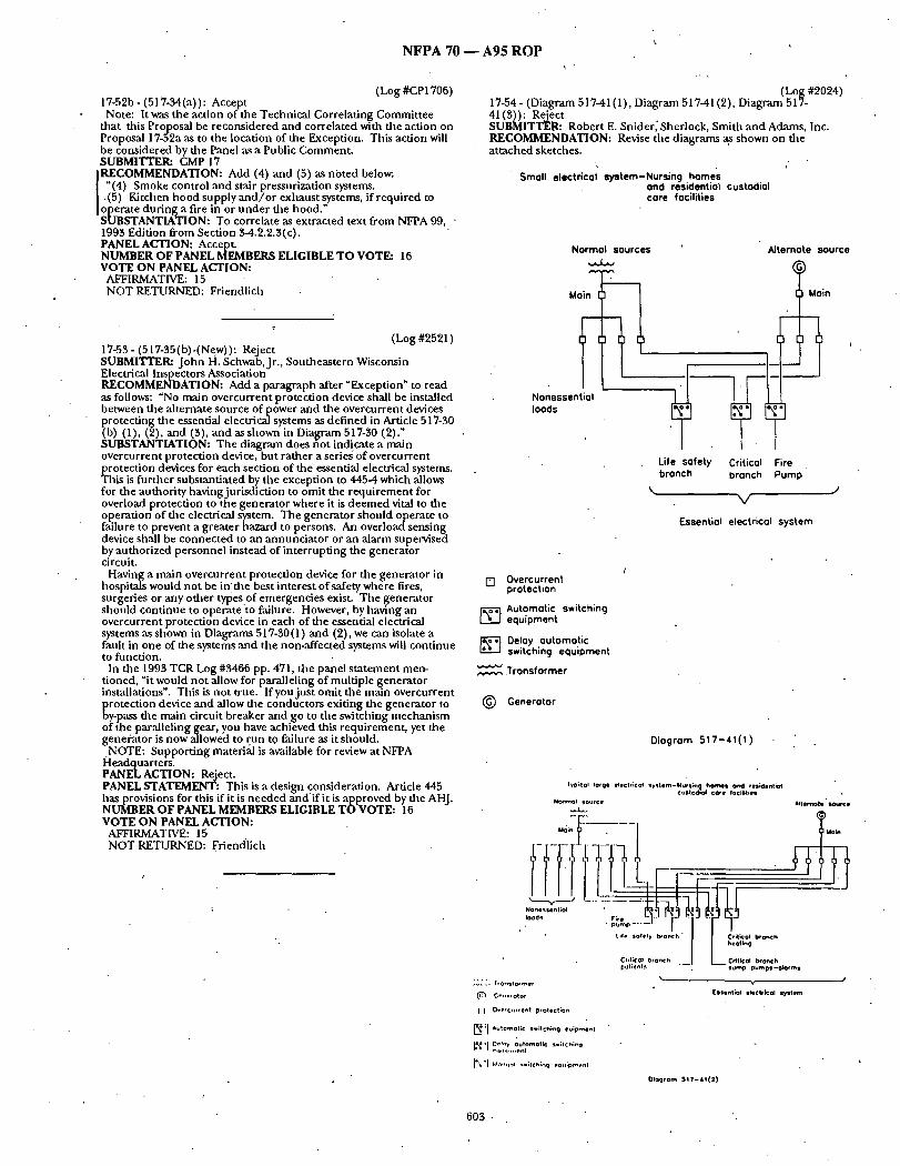
N F P A 70 - - A 9 5 R O P
(Log #CP1706) 17-52b- (517-34(a)): Accept Note: It was the action of the Technical Correlating Commit tee
that t h i s Proposal be reconsidered and correlated with the action on Proposal 17-52a as to the location of the Exception. This action will be considered by the Panel as a Public Comment . SUBMITTER: CMP 17 RECOMMENDATION: Add (4) and (5) as no ted below.
"(4) Smoke control and stair pressurization systems. (5) Kitchen hood supply a n d / o r exhaus t systems, if required to
operate dur ing a fire in or u n d e r d~e hood." SUBSTANTIATION: To correlate as extracted text from NFPA 99, • 1993 Edition f rom Section 3-4.2.2.3(c). PANEL ACTION: Accept. NUMBER OF PANEL MEMBERS ELIGIBLE TO VOTE: 16 VOTE ON PANEL ACTION:
AFFIRMATIVE: 15 NOT RETURNED: Friendlich
¢
(Log #2521) 17-55- (517-35(b)-(Ne.w)): Reject SUBMITTER: J o h n H. Schwab, Jr., Southeastern Wisconsin Electrical Inspectors Association RECOMMENDATION: Add a paragraph after "Exception" to read as follows: "No main overcurrent protection device shall be installed between the al ternate source of power and tile overcurrent devices protect ing the essential electrical systems as def ined in Article 517-30 (b) (1), (2), and (3), and as shown in Diagram 517-30 (2)." SUBSTANTIATION: The diagram does not indicate a main overcurrent protect ion device, bu t rather a series of overcurrent
~ rotection devices for each section of the essential electrical systems. his is fur ther substant iated by the exception to 4454 which allows
for the authori ty baying jurisdict ion to omit the r equ i r emen t for overload protection to the genera tor where it is d e e m e d vital to the operat ion of the electrical system. The genera tor should operate to failure to prevent a greater hazard to persons. An overload sens ing device shall be connec ted to an annunc ia to r or an alarm supervised by author ized personnel instead of in ter rupt ing the genera tor circuit.
Having a main overcurrent protection device for the genera tor in hospitals would not be in' the best interest of safety where fires, surgeries or any other types.of emergencies exist. T he genera tor should cont inue to operate to failure. However, by having an overcurrent protect ion device in each of the essential electrical systems as shown in Diagrams 517-30(1) and (2), we can isolate a fault in one of the systems and the non-affected systems will cont inue to function.
In the 1993 TCR Log #3466 pp. 471, the panel s t a t ement men- tioned, "it would not allow for paralleling of mult iple genera tor installations". This is no t true. f f y o u j u s t omit the main overcurrent protect ion device and allow the conductors exiting the genera tor to by-pass the main. circuit breaker and.go to the. switching, mechan i sm of the para l lehnggear , you have ach,eved thts requirement , yet the generator is now allowed to run tO failure as it should.
NOTE: Suppor t ing material is available for review at NFPA Headquarters . PANEL ACTION: Reject. PANEL STATEMENT: This is a design consideration. Article 445 has provisions for this if it is needed and ' i f it is approved by the AHJ. NUMBER OF PANEL MEMBERS ELIGIBLE T O V O T E : 16 VOTE ON PANEL ACTION:
AFFIRMATIVE: 15 NOT RETURNED: Friendlich
(Log #2024) 17-54 - (Diagram 517-41 (1), Diagram 517-41 (2), Diagram 517- 41 (3)): Reject SUBMITTER: Robert E. Snider[Sherlock, Smith an d Adams, Inc. RECOMMENDATION: Revise the diagrams ~ shown on the a t tached sketches.
k
Small electrical system-Nursin9 homes and residential custodial core focilitles
Normal SOUrCeS
+..~', ,.v-~
Main
Nonessential loads
Alternate source
• t M°;n
Life safety Critical Fire branch branch ' Pump
V
F..ssent;ol electrical system
[] Overcurrent protection
~,~-';] Automotlc switehlng equipment
[ ' ~ Delay automatic switchin 9 equipment
.Transformer
(~ Generator
Diagram 517-41(1)
I~ ;co l torqe etectHcol ,y~tem-Nursm homel and res~entk~ cus(~d?o~ core (acJl;tieSl
. . . .
pal;Grit s StJmp Oump$ -ok3rms
~'," ", h onstor met C~f~p, otot [ssent;QI etectriCol sTstom
[ ~ (~P'current p,olect;on
~ ; I *ulOmOt;C S*;Ich;nq eu;pmenl
IR'I 0'~'"~ ,,.,p~o, . . . . ; ......
l~+ "l l'.In'~,m.l m+;tch;~q +q~l;pmenl
Ologrom $ 1 7 - ~ 1 ( 2 )
~temote ~ r c *
603 -

N F P A 70 - - A 9 5 R O P
Small electric system-Nursing homes and resiclentioI custodial core facilities . (single tronsfer switch)
Normal sources
Nonessential loads
Firi~ Pump
\ J V
~'ssentiol electrical system " (150 kVA or less)
[ ] Overcurrent protection
[•---• Automatic switching equipment
Transformer
(~) Generator
Diagram 517-41(3)
Alternate source
SUBSTANTIATION: Revise diagrams to include automat ic transfer switches for f i r epumps . PANEL ACTION: Reject. PANEL STATEMENT: Th isproposa l is per formance criteria and falls within the scope of NFPA-99. NUMBER OF PANEL MEMBERS ELIGIBLE T O VOTE: 16 VOTE ON PANEL ACTION:
AFFIRMATIVE: 15 NOT RETURNED: Friendlich
(Log #3546) 1")-55- (517-41(d)(1)): Reject SUBMITTER: William E. Bickner, Stillwater, MN RECOMMENDATION: Revise as follows:
In transfer switch enclosures, where the other wiring is present only to connec t power sources to the line (supply) terminals of the transfer equipment , SUBSTANTIATION: The present exception has been interpreted to permit circuits o ther than the life safety branch to be connec ted to the load side of transfer switches.
NOTE: Suppor t ing material is available for review at NFPA Headquarters . PANEL ACTION: Reject. PANEL STATEMENT: See Panel S ta tement on Proposal 17-38. NUMBER OF PANEL MEMBERS ELIGIBLE T O VOTE: 16 VOTE ON PANEL ACTION:
AFFIRMATIVE: 15 NOT RETURNED: Friendlich
COMMENT ON AFFIRMATIVE: SCHUCK: This Panel S ta tement may be in te rpre ted to mean that
"Sections 51%32 and 51%33" define what is to be connec ted to transfer switches installed in Nursing Homes and Limited Care Facilities. Suggest that for clarity, the Panel Sta;cement should read as follows:
Section 517-42 defines allowable (or permissible) load connect ions to the Life Safety Branch transfer switch or switches. Fur ther restriction in Section 517-41(d)(1) is no t needed.
(Log #CP1707) 17-55a- (517-43(a)(3) and (4)): Accept SUBMITTER: CMP 17 RECOMMENDATION: Add (3) and (4) as noted below:
"(3) Smoke control and stair pressurization systems. (4) Kitchen hood supply a n d / o r exhaus t systems, if required to
operate dur ing a fire in or u n d e r the hood." SUBSTANTIATION: To correlate extracted text f rom NFPA 99, 1993 Edition from Section 3-4.2.3.3(b). PANEL ACTION: Accept. NUMBER OF PANEL MEMBERS ELIGIBLE T O VOTE: 16 VOTE ON PANEL ACTION:
AFFIRMATIVE: 15 NOT RETURNED: Friend[ich "
(Log #CP1709) 17-55b - (517-45-(New)): Accept SUBMITTER: CMP 17 RECOMMENDATION: Add new Section 517-45 to read as follows:
517-45 Essential Electrical Systems for Ambulatory Health Care Centers. (a) Applicability. The requi rements of this section shall apply to
those Health Care Facilities described in Section 51%45. (b) x Connect ions. • The essential electrical system shall supply
power for: (1) Task i l lumination which is related to the safety of life and
which is necessary for the safe cessation of procedures in progress. (2) All anesthesia and resuscitative equ ipmen t used in areas
where inhalation anesthetics are adminis tered to patients, including alarm and alert ing devices.
(FPN) See Health Care Facilities, NFPA 99-1993 (ANSI), Sections 13-3.4.1
(3) All electrical l i fe-support equ ipmen t in areas where proce- dures are per formed that require such equ ipmen t for the suppor t of the pat ient 's life.
(c) Alternate Source of Power. (1)x Power Source. The alternate source of power for the system
shall be specifically des igned for this purpose and shall be either a generator , batterysystem, or self-contained battery integral with the equipment . ..
Exception: If critical care areas are present in the facility, the essennal electrical system shall be as required in Sections 51%30 th rough 517-35.
(2) x System Capaci W. The al ternate source of power shall be separate and i n d e p e n d e n t of the normal source and shall have a capacity to sustain-its connec ted loads for a m i n i m u m of I 1 /9 hours after loss of the normal source.
(3) x System Operat ion. The system shall be so a r ranged that, in the event of a failure of the normal power source, the al ternate source of power shall be automatically connec ted to the load within 10 seconds. .
(FPN): See Health Care Facilities, NFPA 99-1993 (ANSI), Sections 3-5.1.2.2(c), Trafisfer Switch Opera t ion for Type Ill with Generator Sets, and 3-5.1.2.2(d), Transfer Switch Operat ion for Type Ill with Battery Systems. SUBSTANTIATION: To correlate with new requi rements in tile 1993 edition of NFPA 99. PANEL ACTION: Accept. NUMBER OF PANEL MEMBERS ELIGIBLE T O VOTE: 16 VOTE ON PANEL ACTION:
AFFIRMATIVE: 15 NOT RETURNED: Friendlich
(Log #CP1710) 17-55c- (517-50): Accept SUBMITTER: CMP 17 RECOMMENDATION: Revise Section 517-50 to read:
"517-50 Essential Electrical Systems for Clinics, Medical an d Dental Offices, and Other Health Care Facilities Not Covered in Sections 517-30, 517-40 and 517-45.
( a ) Applicability. The requi rements of this section shall apply to those health care facilities described in Section 51%50.
(b) x Connect ions. The essential electrical system shall supply power for:
604

N F P A 70 - - A 9 5 R O P
(1) Task illumination which is related to the safety of life and which is necessary for the safe cessation of procedures in progress.
(2) All anesthesia and resuscitative equipment used in areas where inhalation anesthetics are administered to patients, including alarm and alerting devices.
(FPN) See Health Care Facilities, NFPA 99-1993 (ANSI), Sections 14-3.4.1 and 15-3.4.1.
(c) Alternate Source of Power. (1) x Power Source. The alternate source of power for the system
shall be specifically designed for this purpose and shall be either a generator, battery system, or self-contained battery integral with the equipment.
Exception: If electrical life support equipment is required, the essential electrical system shall be as required in Sections 517-30 through 51%35.
(2) kx~ System Capacity. The alternate source of power shall be separate and independen t of the normal source and shall have a capacity to sustain its connected loads for a minimum of 1 1/2 hours after loss of the normal source.
(3) x System Operation. The system shall be so arranged flaat, in the event of a failure of the normal power source, the alternate source of power shall be automatically connected to the load within 10 seconds.
(FPN) See Health Care Facilities, NFPA 99-1993 (ANSI), Sections 3-5.1.2.2(c), Transfer Switch Operation for Type III with Generator Sets, and 3-5.1.2.2(d), Transfer Switch Operation for Type !11 with BatterySystems." SUBSTANTIATION: To correlate with new requirements in the 1993 edition of NFPA 99. PANEL ACTION: Accept. NUMBER OF PANEL MEMBERS ELIGIBLE TO VOTE: 16 VOTE ON PANEL ACTION:
AFFIRMATIVE: 15 / NOT RETURNED: Friendlich
(Log #3104) 1%56- (517-50(b)(3), FPN-(New)): Reject SUBMITTER: Paul E. Devine, Advisory Committee on the Massachusetts Electrical Code RECOMMENDATION: Add the following Fine Print Note:.
(FPN): For the pu.rposes of this section, the term "electrical life support equipment" mcludes electric hemodialysis and other equipment that, if inadvertendy disconnected, could endanger the patients life. SUBSTANTIATION: The growing use of dialysis clinics which.do not have backup emergency power has been the subject of concern in two distinct areas. (1) In the event of a power failure, attendants must have proper lighting to at tend the manual hand-cranking of the hemodialysis equipment and (2) in the event that too few attendants are present to care for the operating equipment, then a real danger exists in terms of patients receiving care. The former is addressed in Section 517-50(b) (1) and needs no further examina- tion, the latter however, must be addressed since the possibility of loss of life ispresent . The issue of life support is addressed in Section 517-~0(a) (2) quite properly but the issue of connect ion to essential system power must be addressed as proposed to ascertain compliance and uniform enforcement. PANEL ACTION: Reject. , . PANEL STATEMENT: The NEC Style Manual prohibits require- ments from being placed in a fine print note. Also, this proposal is performance criteria and falls within the scope of NFPA-99. NUMBER OF PANEL MEMBERS ELIGIBLETO VOTE: 16 VOTE ON PANEL ACTION:
AFFIRMATIVE: 15 NOT RETURNED: Friendlich
(Log#511) 17-57 - (51%61(a), (b), (c)): Accept SUBMITrER: Dan Leaf, Palmdale, CA
I RECOMMENDATION: Add: "(classified)" after "13azardous" in the headings and in (a) (6),
(b) (1), and (b)(2) Exception, and (b)(5). SUBSTANTIATION: Edit. For consistency throughout this section. "Hazardous (classified)" is def ined and used for locations which are hazardous due to specific conditions. A "hazardous" location is not Code-defined and per dictionary definition may be due to a multitude of conditions other than those addressed in this article. Secs. 517-60(a), 517-61 (a) (3) (4)(5), (b) (3) Ex. No. 2, (b)(4) (6),(c) use the word "(classified)" after "hazardofis." PANEL ACTION: Accept.
NUMBER OF PANEL MEMBERS ELIGIBLE TO VOTE: 16 VOTE ON PANEL ACTION:
AFFIRMATIVE: 15 NOT RETURNED: Friendlich
(Log #512) 1%58- (517-62): Accept SUBMrl'q'ER: Dan Leaf, Palmdale, CA RECOMMENDATION: Add: .
"Grounding in Class I locations shall comply with Section 501-16." SUBSTANTIATION: The specific requirements of Sec. 501-16 are not covered in See. 250-78 which is limited to equipment IN the classified location. While Sec. 501-16 is not abrogated, a reference in this section similar to Sec. 515-8 would he helpful to Code users. PANEL ACTION: Accept. NUMBER OF PANEL MEMBERS ELIGIBLE TO VOTE: 16 VOTE ON PANEL ACTION:
AFFIRMATIVE: 15 NOT RETURNED: Friendlidh
(Log #51 S) 1%59 - (517-63(b) (1) and (c) (3)): Accept SUBMITTER: Dan Leaf, Palmdale, CA RECOMMENDATION: Add:
"or cable" after "raceway". SUBSTANTIATION: Edit. The cables permit ted by Sec. 517- (~1 (b) (1) should be included since the separation requirements of Sec. 517-61 (a)(1) are reiterated in dais section for raceways. PANEL ACTION: Accept. PANEL STATEMENT: The Panel believes that the submitter intended to reference in his substantiation Section 517-61 (c)(1) rather than Section 517-61 (a) (1). NUMBER OF PANEL MEMBERS ELIGIBLE TO VOTE: 16 VOTE ON PANEL ACTION:
AFFIRMATIVE: 15 NOT RETURNED: Friendlich
• (Log #2041) 17-60 - (517-63(c), Exception): Accept in Principle SUBMITTEITa Bernard E. Kinsock, Tucson, AZ RECOMMENDATION: Add "Exception: Sections 517-63(c) (1) and (c) (4) shall not apply in other than hazardous (classified) locations. SUBSTANTIATION: The addition would allow the same conditions to apply to fixed lighting branch circuits as is allowed for therapeutic and diagnostic equipment under 517-63 (b). PANEL ACTION: Accept in Principle. PANEL STATEMENT: See Panel Action on Proposal 17-61. NUMBER OF PANEL MEMBERS ELIGIBLE TOVOTE: 16 VOTE ON PANEL ACTION:
AFFIRMATIVE: 15 NOT RETURNED: Friendlich
(Log #2619) 17-61 - (517-63(c), Exception-(New)): Accept SUBMITTER: Bernard E. Kinsock, Tucson, AZ RECOMMENDATION: Add "Exception: Sections 517-63(c) (1) and (c) (4) shall not apply in other-than-hazardous (classified) locations. SUBSTANTIATION: The addition would allow the same conditions to apply to fixed lighting branch circuits as is allowed for therapeutic an.d diagnostic equipment under 517-63(b). PANEL ACTION: Accept. " NUMBER OF PANEL MEMBERS ELIGIBLE TO VOTE: 16 VOTE ON PANEL ACTION:
AFFIRMATIVE: 15 NOT RETURNED: Friendlich
605
(Log #514) 17-62 - (517-64(b) (2) and (b) (4)): Accept in Principle SUBMITTER: Dan Leaf, Palmdale, CA RECOMMENDATION: Change "a nonhazardous location" to "an unclassified location". SUBSTANTIATION: Edit. "Nonhazardous" is evidendy in tended to apply to locations not specified by Code as "hazardous (classified)" locations. Nonhazardous and hazardous are dictionary-defined terms which don ' t necessarily apply to classified and unclassified
N F P A 70 - - A 9 5 R O P
locations. For example "hazardous" in Sec. 668-32(b) relates to other than classified location hazards. PANEL ACTION: Accept in Principle.
[ Change "a nonhazardous location to "an other-than-hazardous I (classified) location". PANEL STATEMENT: The Panel Action is consistent with other terminology in Article 517, Part D and accomplishes the submitter 's intent. NUMBER OF PANEL MEMBERS ELIGIBLE TO VOTE: 16 VOTE ON PANEL ACTION:
AFFIRMATIVE: 15 NOT RETURNED: Friendlich
(Log #2051 ) 17-63- (517-70-(New)): Reject SUBMITTER: Charles W Forsberg, Carlon Electrical Products, A Lamson & Sessions Co. RECOMMENDATION: Add new text as follows: Article 517-70. Wiring Methods. Nonmetallic raceways shall be
permitted for fixed and stationary X-ray equipment and for diagnostic imaging equipment. SUBSTANTIATION: Use of nonmetallic raceways will eliminate electrical interference problems which adversely affect the operation of this equipment. This will recognize current industry manufactur- ing practices which conflicts with present code requirements. PANEL ACTION: Reject. PANEL STATEMENT: The X-ray area is part of the patient care area and this would be in conflict with the requirements of Section 517-13. This substantiation is not accurate and is not supported by data. NUMBER OF PANEL MEMBERS ELIGIBLE TO VOTE: 16 VOTE ON PANEL ACTION:
AFFIRMATIVE: 15 NOT RETURNED: Friendlich
(Log#3162) 17-64- (517-80, Exception-(New)): Reject SUBMITTER: Mel Wierenga, A~com, Inc.. RECOMMENDATION: Add an Exception as follows:
Exception: For listed systems operaung at 25 volts, nominal, or less, wiring installed in accordance with Article 300-4, shall be permitted. SUBSTANTIATION: Current electronic technology provides data, telephone, sound, fire protective, & nurse call signalingsystems that are designed to operate at 5-25 volts. Oudets for Data & Telephone Systems are manufactured using plastic products with receptacles that are sized & configured to minimize or deny accidental contact with wiring. The user equipment is also made from plastic compo- nents to prevent equipment failure' due to static electric discharges. Listed fire alarm & nurse call systems meet standards which have been accepted as appropriate safety standards for those products and usage. When installed in accordance with manufacturer 's instructions. These systems then meet the standard for safety for which onlyhave been listed (eq: 1069 for nurse call). PANEL ACTION: Reject. PANEL STATEMENT: For protection of the patient environment, the requirement . . . . . . for insulation and isolation equal to that required for the electrical distrthutaon system ts still needed for all other systems entering this area. NUMBER OF PANEL MEMBERS ELIGIBLE TO VOTE: 16 VOTE ON PANEL ACTION:
AFFIRMATIVE: 15 NOT RETURNED: Friendlich
(Log #1426) 17-65- (517-81(c)-(New)): Reject SUBMITTER: Frank Martuco, Fort Lee, NJ RECOMMENDATION: New addition: Add (c) Grounding of Cord and Plug Connected Equipment. To
comply with the performance requirements (a) and (b) of this article, all Cord and Plug connected equipment shall be redundantly grounded with two conductors in accordance with Section 517-12.
(1) Grounding poles shall also be in accordance with Section 517- 12. The grounding pole of cord connectors, a t tachment plugs, and internal wiring terminals of appliances shall be provided with two separate wiring sites. The cordconnectors , a t tachment plugs, and internal wiring terminals of unfixed equipment shall be designed so that only the grounding pole can be wired with two conductors. SUBSTANTIATION: Note: (Section 517-12, referred to in above, is a new proposal
seeking the adoption of an electrocution-proof cord and plug grounding system for all patient care)
During my 24 year tenure as chief electrician in a small metropoli- tan hospital, a patient was electrocuted because one of the ground- ing and performance requirements of article 517-81 (a) and (b) was violated.
The performance requirements of (b) in article 517-81 relates only to (a) the branch circuit wiring whereby the ground path for fault current shall be sized according to Table 250-95, installed in grounded metal conduit, intermediate metal conduit, electrical metal tubing, or metal sheathing, and shall have verified integrity.
None of these str ingent requirements are mandated for the ground path of fault currents in line and extension cords, the primary cause of all electrocutions. In fact, jns t about every requirement of 517- 81 (a) is being violated despite the fact that a line or extension cord, when plugged into a hospital wall outlet, becomes an integral part of . that branch circuit.
(]) Instead of#12 AWG conductors, as mandated for the ground path of fault currents in (a) of this article, practically all medical devices are powered with 3 #18 AWG line cords. This unconscio- nable 66% reduction in the ground path, and possible cause of line drop, or loss of grnunding, has probably contributed to many of the micro-shock electrocutions alluded to in Mr. Frank W. Maybew's (DX-I, 12/71) overview. "The hospital probably provides the most electrically hazardous environment to which a person could ever be exposed. It has been estimated that more than 1200 patients are electrocuted each year by currents as low as 20 micro-amperes. The patient sensitive to micro-shock must not be exposed to any
.equipment whereby normal leakage, or increased leakage due to minor ground fault failures, can cause a voltage drop. The t rend is toward increased use of electricity and it can be reasonably anticipated that the accompanying hazards will increase proportion- ately".
The NEC itself, in article 517-84(c) (1), recognizes dais line drop hazard and permits, not mandates a REDUNDANT, grounding cor~ductor NOT SMALLER than #10 in the patient vicinity of critical c a r e a r e a s .
Patients, undergoing an operation, do not have tiffs protection despite being extremely vulnerable to micro-shock when electrical equipmeiat is used inside new, mad existing, body openings. Unable to cry out and alert surgeons, because of the effects of anesthesia, the electrocution of a patient could go undetected.
Permitting a 66% reduction of the ground path for ground faults also increases the chances of loss of grounding and grounding burnout during massive explosive g round faults. A SECOND GROUNDING CONDUCTOR WILL AMELIORATE
THE UNCONSCIONABLE REDUCTION OF THE GROUNDING PATH FOR GROUND FAULTS THAT CAUSE LINE DROP, POSSIBLE LOSS OF GROUNDING, AND GROUNDING BURN- OUT.
(2) A second requirement of Section 517-81 is that the protective equipment grounding conductor of the branch circuit be installed in rigid metal conduit, intermediate metal conduit, metal tubing and other metal jacketed cable. This protection is not mandated for line and extension cords that are also intergral parts branch circuits when plugged into them. In stark contrast, the extensively used, undersized, #18 AWG equipment grounding conductor for most ~tppliances, and #16 and #14 AWG equipment grounding conductors for extension cords, are permitted withont any metal protection despite being yanked from outlets, run over, twisted, nicked, and other abuses. A SECOND GROUNDING CONDUCTOR IN LINE AND EXTEN-
SION CORDS WILL SERVE TO OFFSET THE LOSS OF THE PROTECTION MANDATED IN SECTION 517-81(a) FOR BRANCH CIRCUITS.
(3) A third violation of Section 517-81(a) is the lack of verification of the integrity of the ground path of line or extension cords that become an integral part of a hospital branch circuit. Such verifica- tion of cord ground paths would be an impossible task in hospitals. Unlike the one shot verification required for a branch circuit, undisturbed and protected inside walls, a line or extension cord that becomes an integral path of a branch circuit is subjected to much use and abuse. Tiffs would require costly, time consuming, daily testing of almost 3000 electrical devices and 200 extension cords. A SECOND GROUNDING CONDUCTOR TOGETHER WITH
ELECTROCUTION PROOF COMPONENTS WILL PROVIDE A VISUAL ASSURANCE THAT THE GROUNDING POLE OF COMPONENTS WILL BE ALWAYS PROPERLY WIRED.
(4) A fourth viola.tion of Section 517-81 is the lack of double grounding of the ground path for fault current of the line and extension cords that become an integral part of the same branch circuit. Section 517-81(a) mandates that, in addition to an insulated grounding conductor in accordance with Section 517-11, the protective metal race'#ay must also provide an approved grounding means. What purpose is served if the same redundant requirements of
Section 518-81 do not include the line and extension cords that
606

N F P A 7 0 - - A 9 5 R O P • '
become an integral part of tlie same branch circuit? If wiring the g round ing path of branch circuits with #12 gauge g r o u n d i n g conductors, in addit ion to metal raceways, are necessary to prevent potential differences greater than 40 mV to 500 mV on exposed conductive surfaces in the pat ient vicinity, then all cords plugged into t hem should also be redundant ly grounded . No better a r g u m e n t could be made to substantiate the need for g round path redundancy for all line and extension cords, especially since the existing g round path for practically all medical devices has been unconsc ionable reduced 66% in size.
A recent survey revealed the following medical devices use unders ized #18 AWG equ i pmen t g round i ng conductors .
Ul t rasound Suction p u m p Ventilator Infusion p u m p Defibrillator Incubator EKG.machine Automat ic blood pressure p u m p Fetal moni to r Micr6scope, operat ing type Light source Eu]se Oximeter Patient scale Most of the 200 extension cords, electric beds, anesthesia ma-
chi nes , ,and hyper-hypo thermia machines use unders ized 3 # 16 AWG conductors for the g round i ng path for fault current .
Each and every one of the above medical devices should be powered with TWO #18 or #16 AWG g r o u n d i n g conductors in order to comply with the g round ing r edundancy requi rements of Section ' 518-81.
THE ELECTROCUTION-PROOF LINE AND EXTENSION CORD WILL PROVIDE THE GROUND PATH REDUNDANCY MAN- DATED IN SECTION 517-81 FOR PATIENT CARE BRANCH CIRCUITS~
(5) C o m p o u n d i n g the chances of electrocutions due to the above violations of Section 517-81 are the many "Russian Roulette ~ type of electrocutions des igned into the present g round ing system. For example, ,an appliance wired with reversed grounds . (whi te and green wires) will funct ion safely when plugged inl;o properly wired outlets. However, when plugged into an outlet with reversed polarity, the one with the bullet, the appliance case will become immediately ch ed wath a lethal potenual
l first ~i's~ovei'eatdgd a e R~assian Roulette" t ' e 'of electrocutio Marizh " yp n : 15, 1956 wben a patient was electrocuted when an a t t endan t
switched the plug in line of a (name deleted) surgical uni t f rom a properly wired outlet to one wired with reversed polarity.
More recently, an article bur ied inside the Dec .5 th , 1986 issue of the NewYork Times reported the same type of electrocution. A
• child became electrocuted when an a t t endan t also inadvertendy switched plug in lines for a hear t moni tor and an i n t r avenouspump .
The Sept.2,1993 issue of the N.Y.Times report~:i t!le dea th of three patients when an ALLEGED electrical fault in a respirator caused an explosion and fire only several HOURS after being worked on because of ELECTRICAL SHOCK. Here is an excel lent example of a probable "Russian Roulette" type of shock hazard. W h e n REMOVED to the shop and tested on a PROPERLY wired outlet, the respirator no longer gave off electrical shocks. W hen released for service the respirator chassis again became "HOT" when plugged into the same imp)pro erly wired outlet or extension cord. gnl ition was probably c a u s e d w h e n the "HOT" chassis contacted a nearby g rounded device, such as an IV pole or electric bed. Other scenarios could include any one of the 452 "Russian Roulette" type of.shock hazards possible when extension cords are used. (see survey).
• The . thousands of patients who needlessly die each year do so. because the cord connec ted g r o u n d i n g system is not electrocution proof. The system adop ted by our nat ion is so insidious in nature that it is possible to "HOT" wire the green conductor of an electric drill and operate it safely if p lugged into an outlet with revers'ed polarity. Incredible as it seems, as presently designed, .one of two ways to wire a wall outlet, four of six ways to wire a male appliance plug, four of six ways to wire the internal terminals of an electrical appliance, and ALL possible ways to wire extension cords, can contr ibute to an electrocution. (see survey-24 hazards surfaced even when properly wired extension cords were used. The properly wired extension can act as a c o n d u i t t o connec t outlets or appl ianceswi th shock hazards)
~l'he n u m b e r ofpossible wiring combinat ions is astronomical when an extension cormis used, 2591 to be exact (see survey)
C o m p o u n d i n g the chances for h u m a n error ai'e cords permi t ted without color codes. Also, unqual i f ied individuals, or those h igh on alcohol or drugs, may be the ones installing the components .
Test wiring my system according to the wiring survey substantiates the need for electrocution proofing our g r o u n d i n g system. You will f ind that exactly one third of all possible connect ions are shock or
electrocution hazards, as indicated byan X in the wiririg survey. A total of 864 hazards surfaced when an extension cord was used. 24 hazards withou~ . . . .
Also note tha~,.ex~.ept for t h ~ o n e O K ~ r i n g . c o n n e c t i o h , exactly • two thirds of all the remain ing wi~ng connect ionswil l permi t the
safe operat ion of electrical devices despite a ,~,iring error, as indicated by the dashes.. 1-727-':safe" wiring e g o r s with extensi.on cords, 47 Wi__thout. S~Lfe, that is,ufitil the device is p lugged into the outlet, or extension cord~ that will cause i t t 8 become immediately energized. Or-in "Russian RoulettE" parlance, "tintil p lugged into the power source with the bullet"..
Projecting these statistics f o r t h e use of two extension cords indicates tha t 31,104, of the 93,312 possible wiring connect ions, 6X6XtXtXt__XtX2, are electrocution hazards. And that 6__6,208 of the connect ions will permi t operat ion despite potentially d ~ g e r o u s - wiring errors. ..-. - • -'
Most f r ightening is the fact that only one or two.wiring errors are necessary to cause an electrocution. This is why OSHA pressured National Electrical Ttchnica l Code Commit tees to manda te a daily, written,:assured g round ing prograrmfor .construct ion Si'tes. Since daily testing pi '~grams are impo-ssibl~ in hospitals, it becomes p rudeh t to adop t an elecwocution proof g r o u n d i n g system that is built into cords and devices. "- - " . -
THE ELECTROCUTION PROOF LINE AND EXTENSION CORD PREVENTS THE GROUND POLE.OF COMPONENTS 'OR APPLIANCE-TERMINALS FROM EVER BEGOMIN~ ENERGIZED.
(6) Improper wiring of existin~ line and extension i:brds can . violate the 40 My potential r eqmremen t s of Sectiofi 5i8:81 (b)- (1) by permit t ing the g r o u n d path to carry current. In the wiring su/~ey a dash with an s indicates an appl iance is operat ing with reversed grounds , permit t ing the branch circuit g o u n d pa th- tocar ry c u r r e n t Should a plug of an electric h e a t e r b e w~red with re-,,¥rsed green and white conductors, for example, a heavy flow of cur ren t t h ro u g h the g r o u n d path will micro-energize the g r o u n d i n g pole of all down- stream.receptacles served by the same brancfi circuit._This could be fatal to patients vulnerable to micro-shock and detrimeDtal to the acouracy of sensitive moni to r ing and electronic device~T.he " prevalent use of extension cords permit t ing different ",s~ll.-oudets to serve one pat ient exacerbates the micro-shock hazard.- ,
THE ELECTROCUTION-PROOF LINE AND EXTENSION CORD WILL PREVENT BRANCH CIRCUIT GROUND-PATHCURRENT FLOW BY SHUNTING RETURN CURRENT BACK TO ~FIE . CIRCUIT CONDUCTOR.
THE SOLUTION: The purpose of the NEC is to provide.standards for prevent ing electrocutions and fires. Al though practically every electrocution and many fires are caused by appliance line cords, an'd extension cords, only a few pages in the entire 700 page NEC are devoted to them. They consist of a hodgepodge of contradictory standards, some of which violate the NEC itself. Or thS~;rhake s t r ingent cord s tandards only for specific areas such as swimming pools or construct ion sites. In fact, at the present time, the safest place to have your operat ion is a round swimming pools because only there are you protected with a #12 AWG g r o u n d i n g conductor . However you will no t have the written inspect ion programs
• manda ted for construct ion sites to assure the #12 g rou n d in g conductor is properly wired and sound.
Section 518-81 manda tes verified properly sized double -grounding for branch circuit outlets se rv ingpa t i en t areas, yet permits a single, unprotected, abused, rarely tested, grossly undersized, e q u i p m e n t g round ing conduc to r for practically all medical devices. -
Since the electrocution of a pat ient March 15,1956, I have been a fanatical user and p r o p o n e n t of r edundancy that c o n t i n u ~ ' t o this day. For 19 years until my ret i rement , patients subject to electrical shock wel;e protected with a second, redundant , g r o u n d i n g conductor (see a t tached photos) . When directed to construct a 14 uni t critical and cardiac care unit, I elected to forego available pat ient centers and voluntarily b u r d e n e d myself and staff designing, constructing, and installing REDUNDANT g r o u n d i n g pat ient centers. In addit ion to 23000 Hubbell g r o u n d i n g plugs, ever;/ appliance required a second g r o u n d i n g conductor . Tha t child, recently electrocuted in- (name deleted) and Medical Center, would
.have survived in m}Vhospital. Every hear t moni to r was redundant ly g r o u n d e d despite ( name deleted) objection and threats to void the warranty. At a later date a representative of the company com- m e n d e d my g r o u n d i n g system because in no o ther hospital had (name deleted) equ ipmen t func t ioned so well. The r e d u n d a n t g r o u n d i n g I employed is the same r edundancy the
NEC recognizes and ONLY PERMITS in article 517-84 (c) (1)"(2), again, only for a specific area, the pat ient bed areas of critical care wards. Had this article been MANDATED, tha t child in Seattle.could never have been electrocuted b y a hear t moni to r or pump. Ur]less mandated , very few hospitals will employ this type of . redundancy because it is t ime consuming and requires the services of a mainte- nance man, who may not always be available every t ime ano the r appliance is assembled a round a patient.
607

N F P A 70 - - A 9 5 R O P
• The r edundan t g round ing I propose does not require ma in tenance men to attach and remove s econdeonduc t o r s each time an appliance is being used. The second g r o u n d i n g conductor is simply built into existing line and extension cords a n d connected to a specially des igned wiring site on the g r o u n d i n g poles of male plugs, and cord connectors. The proposed improvement provides a simple wiring scheme whereby it is absolutely impossible to cause ~in electrocution. The second g r o u n d i n g conductor in a line and extension cord means there now exists three g rounded conductors , two green and one white. If two of the four possible wiring sites are the g round ing poles of plugs and connector bodies, it is impossible to prevent at least one of the g r o u n d e d conductors to be connected to the g round ing pole. The same protect ion exists if the wiring scheme is manda ted for the internal terminals of g r o u n d e d appliances.
] u r g e wiring tests be made according to the a t tached survey to subst,~tntiate conclusively that the elecfi 'ocution-proof g round ing system prevents shock and fire hazards caused by wiring errors, and prevents shock or e lectrocut ions due to loss of grounding, line drop, and g round ing burnout .
Further a rgumen t s substant iat ing the need for r edundancy and electrocution-proof componen t s in patient care areas can be found in the associated proposal for Section 517-12.
NOTE: Suppor t ing material is available for review at NFPA Headquarters. PANEL ACTION: Reject. PANEL STATEMENT: See Panel S ta tement on Proposal 17-9. NUMBER OF PANEL MEMBERS ELIGIBLE TO VOTE: 16 VOTE ON PANEL ACTION:
AFFIRMATIVE: 15 NOT RETURNED: Friendlich
(Log #CP1703) 17-65a- (517-160(b)): Accept SUBMITTER: CMP 17
J RECOMMENDATION: Delete the words "the anesthet izing location" in the second sentence.
Replace with the following wording "each area served by the isolated power systemL
I Delete reference as extracted, material on Section 517-160(b). SUBSTANTIATION: This proposal addresses the concerns of P roposa l l 7-33. Where a wet location is not an anesthet iz ing location the signals mus t be available to the personnel in that location. PANEL ACTION: Accept. NUMBER OF PANEL MEMBERS ELIGIBLE TO VOTE: 16 VOTE ON PANEL ACTION:
AFFIRMATIVE: 15 NOT RETURNED: Friendlich
ARTICLE 518 - - PLACES OF ASSEMBLY
(Log #2957) 15-12- (518-1): Reject Note: The Technical Correlat ing Commit tee advises that Article
Scope s ta tements are the responsibility of the Technical Correlat ing Commit tee and the Technical Correlat ing Commit tee accepts the Panel Action.- SUBMITTER: Patricia B. Horton, Allied Tube & Condui t Corpora- tion RECOMMENDATION: Revise 518-1 to read:
This article covers all buildings where the assembly of 100 or more persons in any area of the building, including in the means o f egress, is likely based on the populat ion capacity as de t e rmined by the local bui lding code or, in its absence, by the Life Safety Code, NFPA 101-1993 (ANSI). SUBSTANTIATION: A proposal for the 1993 NEC expressed concern regarding "intent ion and design." This language tells specifically bow populat ion capacity is to be de termined. It also makes it clear the entire bui lding is included if 100 or more persons can assemble in any area, including the areas f t r exiting. Fire does not necessarily stay in one room or space, especially smoke and toxic g a s e s i
See fur ther substantiat ion on proposal to 518-2. I recognize that Scope is the responsibility o f the Correlating Commit tee and seek their concurrence to this change. PANEL ACTION: Reject. PANEL STATEMENT: T he Panel does not agree that it is necessary to extend the assembly area wiring methods to the entire building. The intent of the existing code language is to have all the walls, floor, and ceiling that enclose the assembly area and all required means of egress to be wired in accordance with Section 518-4.
NUMBER OF PANEL MEMBERS ELIGIBLE TO VOTE: 17 VOTE ON PANEL ACTION:
AFFIRMATIVE: 15 NOT RETURNED: Klein, Shotwell
¢
(Log #3151) 15-13- (518-1): Reject Note: The Technical Cor re la t ingCommit tee advises that Article
Scope s ta tements are the responsibility of the Technical Correlating Commit tee and the Technical Correlating Commit tee accepts the Panel Actioh. SUBMITTER: Gregory P. Bierals, Electrical Design Institute RECOMMENDATION: Revised text:
"Assembly occupancies include, bu t are not limited to, all buildings or port ions of buildings used for ga ther ing together 50 or more persons for such purposes as deliberation, worship, enter ta inment , eating, drinking, amusement , or awaiting transportation." SUBSTANTIATION: This informat ion is taken directly f rom Section 4-1.2 of The Life Safety Code, NFPA 101, and Section 518-1 should be consistent with this reference. PANEL ACTION: Reject. PANEL STATEMENT: Consistency is no t required since NFPA 101 focuses on different issues such as egress wl~ile the NEC deals with wiring standards. No substantiat ion is supplied to justify changing from 100 persons to 50 persons. The Panel unders tands that scope issues are unde r the jurisdict ion of the NEC Correlating_Committee. NUMBER OF PANEL MEMBERS ELIGIBLE TO VOTE: 17 VOTE ON PANEL ACTION:
AFFIRMATIVE: 15 NOT RETURNED: Klein, Shotwell
(Log #889) 15-14- (518-1, FPN-(New)): Reject
Note: The Technical Correlat ing Commit tee advises that Article Scope s ta tements are the responsibility of the Technical Correlating Commit tee and the Technical Correlating Commit tee accepts the Panel Action. SUBMITTER: Victor V. Timpanaro , Municipal Electrical Inspectors Assoc. of NJ, Inc. RECOMMENDATION: Add FPN - If local building dept. classifies structure or port ion of a s tructure as an assembly use, even though assembly capacity may be less than designated above, then the more s t r ingent Code will apply. SUBSTANTIATION: More and more smaller areas have been used for assembly I?urposes and the risk of the public 's safety is as impor tant as it is with 100 or morel BOCA uses 50 persons as the criteria. FPN in 518-2 references local bldg. code which can be m u c h lower than the 100. PANEL ACTION: Reject. PANEL STATEMENT: It is unders tood tha t local codes may be more s t r ingent than the NEC to provide a level of safetyperceived as necessary in that community. Also see PS for Proposal 15-13. NUMBER OF PANEL MEMBERS ELIGIBLE TO'VOTE: 17 VOTE ON PANEL ACTION:
AFFIRMATIVE: 15 N O T RETURNED:' Klein, Shotwell
(Log #98) 15-15- (518-2): Reject " '
Note: Tile following proposal consists o f C o m m e n t 15-5 on Proposal 15-10 in the 1992Annual Meet ing National Electrical Code Technical Commit tee Report. This C o m m e n t was held for fur ther stud), dur ing the process ing of the 1993 NATIONAL ELECTRICAL CODE. The r ecommenda t ion in Proposal 15-10 was:
New text: General Classifications. (Add the following locations) Hotel Meeting Rooms Hotel Ballrooms Night Clubs Discotheques
SUBMITTER: Jack Gagliano, Cronse-.Hinds Molded Products (Cam- Lok) RECOMMENDATION: Accept the panel s ta tement .
Restate this proposal with the following classifications added: Carnivals, Circuses and Outdoor Assemblies,
SUBSTANTIATION: In recent years there has been considerable confusion and misunders tand ing by these affected venues as well as the inspect ing agencies. Carnivals have been hardes t hit due to the fact that t heya re referenced in two places in the NEC. These references are found in Article 90-9(a) (1) and in Article 305-3(b).
608
N F P A 7 0 1 A 9 5 R O P
Many anthori t ies have applied only those rule found in Article 305 to the installation of temporary portable power distribution systems used in Carnivals, Circuses and Ou tdoor Assemblies such as rock concerts. All of these venues deal with the public and are so identified in NFPA Life Safety Codes 101 and 102 as places of public assembly.
By specifically including these venues unde r Article 518 they would then be inspected as what they really are, no t Christmas tree l ighting or construct ion sites,
Should proposal 5-233 a m e n d i n g Article 250-99 no t be rejected by CMP 5 in this code cycle; the proposal developed by CMP 15 on single pole separable connectors (15-46) may, depend i ng on local interpretat ion, no t apply to Carnivals, Circuses or Ou tdoor Concerts. By including these specific venues which are not presenfly listed in Article 518-2, and even though the s tatement , "but not l imited too."- _ is included, th.ere is no specific gu idance for local authorities.
B~; taking such action CMP 15 will provide specific guide lines for the Carnival and Circus operators, and the Rock Concer t p romote r to meet the requi rements of the NEC. As the electrical power - d i s t r ibu t ionrequ i rements of these venues are similar to those of the thea'ter, television and mot ion pictures; a commonal i ty of e q u i p m e n t and inspect ion procedures can be established. "
This commen~ would now require inspect ing agencies to enforce • tbeTequi rements of Article 518, and the applii:able port ions of Artii:.le 520 to.s_uch venues. As each move by a carnival or circus " form one site to ano the r is considered a new installation; such -" reinspect ion by different anthorit ies, in some cases, on a daily basis, would apply the same rules and hopefully the same or at least similar intei'j~retatiot~. " ' - " . - PANEL ACTION: Reject. PANEL STATEMENT: Hotel mee t ing rooms and ballrooms, and niglit club discotheques are already covered in the Code. Hotel me~dng rooms are assembly balls or conference rooms. Hotel balli:.ooms are dafice halls. Night club discotheques are dance'halls . Also, it should be-noted that the list in Section~518-2 is no t l imited to those ment ioned . Places of assembly in the NEC are limited to buildings or pori ions the reof and refer to wiring systems in tended for t(~e in a bu i l d ingo r structure. " - ,.. NUMBER OF PANEL MEMBERS ELIGIBLE T,O VOTE: 17 VOTE ON PANE~ ACTION: "'"
AFFIRMATIVE: 15 NOT RETURNED: Klein, Shotwell
15-16- (518-2): Reject
I . (Log #1457)
SUBMITTER: Nick Malouf, Holly, MI RECOMMENDATION: Revise text as fo l lG~: -
List the existing "Places of Assembly" in alphabetical order. SUBSTANTIATION: It would be nice to h~ave the list of classifica- tiori~; in alphabetical order, no t that it's ap.r~blem, but maybe it wotlld look a little more orderly. , --- .: PANEL ACTION: Reject. _ .-- - PANEL STATEMENT: T he Panel agrees with the submit ter ' s substantiat ion that this is no t a problem. ~... NUMBER OF PANEL MEMBERS ELIGIBLE TO VOTE: 17 VOTE ON PANEL ACTION: " " "
AFFIRMATIVE: 13 .~.. NEGATIVE: Bird, Hirschler y. NOT RETURNED: Klein, Shotwell " •
-EXPLANATION OF NEGATIVE: L BIRD: In the i n t e r ~ t of correctness and order, alphabetical listings
should be incorpora ted in the Code whe~(ever possible. HI-ILSCHLER: I opl3~)se this action bec~{ase there is no reasonable
justification for listing Plai:es o f A s s e m b l f i n a r andom order, as they " are at present. The s t a tement at the beg inn ing of the article makes it clear that the places of assembly listed are not an exhaustive listing, bu t ju s t an example. In order to 'help the panel, I submi t that th.e logical alphabetical order for this list is as follows:
Armories Assembly Halls Audi tor iums Audi tor iums within
Business Establ ishments • Mercantile Establ ishments Schools Other Occupanc i e s -
Bo~ling Lanes Cht~rch Chapels Club Rooms Conference Rooms Court Rooms Dance Halls Dining Facilities
609
Exhibition Halls Gymnas iums Mortuary.Chapels Mul_tlpurpose Rooms Museums Places of Awaiting Transpor ta t ion Pool Rooms Restaurants Skating Rinks
15-17- (518-2-(New)): Reject (Log#1798) Note: l twas the action of the TechnicAl Correlat ing Commit tee
that this Proposal be reconsidered and correlated with the action on Proposal 15-133. This action will be considered by file Panel as a Publ ic .Comment . SUBMI'Iq'ER: James M. Daly, BICC Cables Corporat ion RECOMMENDATION: Add"Pr isons" to the list of Places of Assembly. - - SUBSTANTIATION: Prisons should be "included in this category since there are normally more than 100 Occupants in a prison including guards and inmates. PANEL ACTION: Reject. PANEL STATEMENT: P r i s o n s are no t classified.._ as places o f . assembly by the NFPA Life Safety Code, NFPA 101, nor by typical model bui lding codes. The submit ter has .not provided any substant iat ion to treat prisons the same as a s semby ~eas . NUMBER OF PANEL MEMBERS ELIGIBLE TO VOTE: 17 VOTE ON PANEL ACTION:
AFFIRMATIVE: 15 .'. NOT RETURNED: Klein, Shotwell
.. .. (Log #2958) 15-18- (518-2): Reject SUBMITTER: Patricia B. Horton, Allied Tube & Condui t (~orpora- tion .: • RECOMMENDATION: Delete "audi tor iums within" in the list of exai-nples. SUBSTANTIATION: This change is n e e d e d to clarify that where any port ion of a school, mercant i le establ ishment , or busines~ es tabl ishment is des igned or in t ended for the "assembly" of 100 or more persons the entire bui lding mus t comply with the permit ted wiring methods . Because of vandalism, l i fe-threatening situations, and other crime, today's schools, businesses, and stores are purposely hampe r ing exiting - - even though complying technically with tile meaos of egress requirements . (ff you jus t th ink of the last t ime ~,ou visited the supermarke t - - how many exit lanes were blocked off by shopp ing carts?). Additionally, school halls are so j a m m e d the s tudents can barely move many times. Doors are " unsafe ly locked for security reasons. Business and mercarltile' es tabl ishments have half of the exits locked (my exper ience has been mori~ often d3an not). This is a new day, and security needs are
• probably going to be g r e a t e r , n o t less. It doesn ' t make sense to have to exit h u n d r e d s of people f rom a properly protected area, !nto an . improper lypro tec ted area.
Al though the panel bas previously stated their intent is a list which is no t all inclusive and the criteria is assembly of 100 persons, the "audi tor iums within" is focused language. This is a specific area and afiy p ruden t authori ty would a lmost be forced to say audi tor iums are the only port ion of schools, mercant i le arid business establ ishments
• to which518 applies. Please face the chal lenge of today's reality an d make this vitally needed clarification. PANEL ACTION: Reject. " .. PANEL STATEMENT: The Panel does not agree that there.is substantiation to extend the assembly area wiring me thods to the entire building. Violations of egress requ i rements is no t a v'alid reason to require the wiring me thods of Article 518. NUMBER OF PANEL MEMBERS ELIGIBLE TO VOTE: l f f VOTE ON PANEL ACTION:
AFFIRMATIVE: 15 NOT RETURNED: Klein, Shotwell
(Log #3491) 15-19- (518-2): Reject SUBMITTER: JamesJ . Rogers, Vineyard Haven, MA RECOMMENDATION: Add a new third paragraph to Section 518-2 to read as follows:
The requi rements conta ined within this Article are in t ended to be applied to the entire port ion of existing buildings whose u se i s

N F P A 70 - - A 9 5 R O P
converted or changed to any of the uses d e e m e d to be covered by dais Article provided such use will allow the assembly of 100 persons or more. SUBSTANTIATION: This new s ta tement will clarify the fact that retroactive en fo rcemen t is requi red for buildings whose use category is changed or altered to allow the assembly of 100 persons or more. PANEL ACTION: Reject. PANEL STATEMENT: Retroactivity of this nature should be addressed by local ordinances or applicable bui ld ing codes. Note that the NFPA Life Safety Code, NFPA 101, Section9-1.1 addresses this issue for assembly occupancies. NUMBER OF PANEL MEMBERS ELIGIBLE TO VOTE: 17 VOTE ON PANEL ACTION:
AFFIRMATIVE: 15 NOT RETURNED: Klein, Shotwell
(Log #CP1508 ) 15-165 - (518-2, FPN; 530-1, FPN; 540-1, FPN; 540-10, FPN; 700-i, FPN Nos. 2, 4, and 5; 700-7(d); 701-1, FPN No. 1; 701-8(c), FPN; 520- 68(a), Exception No. 2): Accept
Note: The Technical Correlating Commit tee advises that Article Scope s ta tements are the responsibility of the Technical Correlating Commit tee and the Technical Correlat ing Commit tee accepts the Panel Action. SUBMITTER: CMP 15 RECOMMENDATION: Update the edit ion of the reference s tandards appear ing in the Code in the Articles unde r the jurisdic- tion of CMP-15 as f611ows:
1. In Secti on 518-2 ,~FPN), update the edition year of NFPA 101 from "1991" t6 "1994'.
2. In Section 530-1 (FPN), upda te the edidon year of NFPA 40 from "1988" to "1994".
3. In Section 540-1 ~FPN), update the edition year of NFPA 40 from "1988" to "1994".
4. In Section 540-10 (FPN), update the edit ion year of NFPA 101 from "1991" to "1994".
5. In Section 700-1 (FPN No. 2), update the edition year of NFPA 99 from "1990" to "1993".
6. In Section 700-1 (FPN No. 4), update the edition year of NFPA 101 from "1991" to "1994".
7. In Section 700-1 (FPN No. 5), update the edit ion year of NFPA 110 from "1988" to "1993".
8. In Secdon 700-7(d), update the edit ion year of NFPA 110 from "1988" to "1993".
9. In Section 701-1 (FPN No. 1), update the edition year of NFPA 99 from "1990" to "1993". In Section 701-1 (FPN No. 2), update the edition year of NFPA 110 f rom "1988" to "1993". In Section 701-1 (FPN No. 3), update the edit ion year of ANSI/IEEE 446-1987 to the current edition.
10. In Section 701-8(c)(FPN), update the edition year of NFPA 110 from "1988" to "1993".
11. In Section 520-68(a) Exception No. 2, change the units within the parentheses for ".025 inches (635 micrometers)" to "0.025 inches (0.635 ram). SUBSTANTIATION: The Panel Action changes the references to the current edition. The metric uni t revision is consistent with
~ roper metric terminology. ANEL ACTION: Accept.
NUMBER OF PANEL MEMBERS ELIGIBLE TO VOTE: 17 VOTE ON PANEL ACTION:
AFFIRMATIVE: 15 N O T RETURNED: Klein, Shotwell
(Log#515) 15-20 - (518-3(a)): Accept in Principle SUBMITrER: Dan Leaf, Palmdale, CA RECOMMENDATION: Insert "Wiring in" ahead of the first word "Hazardous" in the text. SUBSTANTIATION: Edit. To improve the syntax by specifying the proper subject which is to be installed in accordance vath Art. 500. PANEL ACTION: Accept in Principle.
J Revise 518-3(a) to read: Electrical installations in hazardous (classified) areas located in
places of assembly shall comply with Article 500, Hazardous (Classified) Locations. PANEL STATEMENT: The Panel action satisfies the submit ter ' s in tent to use appropriate language for hazardous locations. NUMBER OFPANEL MEMBERS ELIGIBLE TO VOTE: 17 VOTE ON PANEL ACTION:
AFFIRMATIVE: 15 NOT RETURNED: Klein, Shotwell
(Log #2282) 15-21 - (518-3(b)): Accept in Principle SUBMITTER: Joe Tedesco, Boston, MA RECOMMENDATION: Replace "approved" with "listed." SUBSTANTIATION: The AHJ will use Section 110-2 for any approvals, and listed products are available for this use. PANEL ACTION: Accept in Principle.
Revise 518-3(b) to read: TemporaryWir ing . In exhibit ion halls u sed for display booths, as
in trade shows, the temporary wiring shil l be installed in accordance with Article 305, TemporaryWir ing .
Exc~:l~tion No. 1: Flexible cables and cords listed for extra hard usage in accordance with Note 4 to Table 400-4 shall be permit ted to be laid on floors where protected f rom contact by the general
~ ublic. ANEL STATEMENT: The Panel revision satisfies the submit ter ' s
in tent to require listed cables. The addit ional r equ i r emen t in the " exception was added to be consistent with Article 520. The exception was added to comply with the NEC Manual of Style. NUMBER OF PANEL MEMBERS ELIGIBLE TO VOTE: 17 VOTE ON PANEL ACTION:
AFFIRMATIVE: 12 NEGATIVE: Dud , r , Hirschler, Vannice NOT RETURNED: Klein, Shotwell
EXPLANATION OF NEGATIVE: DUDOI~ This proposal does not have adequate substantiation to
demonst ra te that listed equ ipmen t is ei ther available or required for these products. The r equ i r emen t for listing prevents new or innovative products that might increase safety to be employed in these situations.
HIRSCHLEI~ I oppose this action because nojus t i f icadon was submit ted, either by the p r o p o n e n t or dur ing the panel meeting, indicating that hard usage cables and cords are unsui table for this application. The action eliminates such cables and cords and allows oh'ly ex~a hard usage cables and cords. Whenever an added restriction is place in the NEC over a previously acceptable set o f materials or products, this mus t be accompanied by a justification showing evidence of unsuitability of the i tems to be disallowed.
VANNICE: " In accordance with Note 4 to Table 400-4" should be deleted. This phrase was added because Table 400-4 indicates that HS, HSO, SJOO, SiT, SJTO and SJTOO are extra hard usage. I see n o t h i n g w r o n g w i t h us ing HS and" HSO in this application, s J o o , SJT, SJTO, and SJTOO were identified by mistake as extra hard usage cables. I was shown the NFPA staff's official errata nota ted code book where this problem has been corrected. Part of the reason for el iminat ing thi~ "shopping list" of cable types was to allow new cable designs to be used as soon as a recognized-testing laboratory [iste~t t hem as extra hard usage cabl-es. Note 4 does no t allow for this.
(Log #2882) 15-22- (518-3(b)-(New)): Reject SUBMITTER: L. Bruce McClung, Union Carbide Corporat ion RECOMMENDATION: New text as follows:
Add a second sentence: Any temporary wiring shall be specifically identified with a n / L S / L C designation. This listing r equ i r emen t shall become effective January 1, 1997. SUBSTANTIATION: T h e 1990 Code recognized "/LS" and the 1993 Code recognized "/LC".. insulations, and outer coverings for conductors for general raring, for flexable cords and cables and for fixture wires. Any exposed wiring in enclosed spaces where products of combust ion would be confined and people (particularly infirm or immobi l izedpeople) a n d / o r sensitive electronic equ ipme n t that are present should have improved fire safety features. S e e technical PCaper titled "Improvement in Fire Safety Features of Electrical
onductors and Cables" by L.B. McClung and S. Ramchandran that was presented at IEEE-IAS-PCIC 1993 at St. Louis, Missouri. UL now has available a test by which to measure limited smoke (UL1685). UL is actively pursu ing deve lopment of a s tandard test by which to measure low or limited corrosivity of conductors and cables.
NOTE: Suppor t ing material is available for review at NFPA Headquarters. PANEL ACTION: Reject. PANEL STATEMENT: No substantiat ion was presented indicating present conductors , cables, or nonmetal l ic raceways in places of assembly, theaters, and mot ion picture and television studios have resulted in problems. Present code language does not prohibi t the use of this type of material if desired. NUMBER OF PANEL MEMBERSELIGIBLE TO VOTE: 17 VOTE ON PANEL ACTION:
AFFIRMATIVE: 15 NOT RETURNED: Klein, Shotwell
610
N F P A 7 0 - - A 9 5 . R O P
(Log #1729) 15-23- (518-4): Reject SUBMITTER: James M. Daly, BICC Cables Corporat ion RECOMMFNDATIQN: Add a second sentence to 51.8-4 which reads "The insulated conductors or cables and nonmetal l ic raceways shall be listed as Limited Smoke (LS)". . SUIk~TANTIATION: Limited Smoke wiring methods should be required for additional protect ion of occupants in the event of a fire. These Limited-Srhoke wiring me thods ,'ire readily available. PANEL ACTION: Reject. PANEL STATEMENT: See Panel S ta tement for Proposal 15-22. NUMBER OF PANEL MEMBERS ELIGIBLE T O VOTE: 17 VOTE ON PANEL ACTION:
AFFIRMATIVE: 15. NOT RETURNED: Klein, Shotwell
!,.,:
(Log #1867) 15-24- (518-4): Reject SUBMITTER: Thomas M. Daley, Daley Electrical Co. RI~COMMENDATION: Revise the last line of Section 518-4 to r e a d :
...Type MI cable, type MC cable and type AC cable with insulated- .
~ rUounding conductor . BSTANTIATION: Since AC cable with g round is used. in heal th
care facilities to insure the proper g round i ng to prevent the occurrence of a conductive path from a pat ient to a g r o u n d e d -. " object. I canno t see any reason .why AC with g r o u n d would no t be • "reacceptable wiring m e t h o d in a place of assembly.
O n the o ther hand, interlocking ..t~e MC cable would still not be a wiring m e t h o d for heal th care faciliues. PANEL ACTION: RejecC - ". PANEL STATEMENT: There is no substantiation to expand the . acceptable fixed wfring me thods to the additional wiring me thod as " . p roposed by the-subm| t te r This proposed wiring m e t h o d does not
rbvide the same degree of protect ion as cur ren t wiring methods: UMBER OF PANEL MEMBERS ELIGIBLE T O VOTE: 17
VOTE ON PANEL ACTION: AFFIRMATIVE:" I'5 NOT RETURNED: "Klein, Shotwell
-- . . . . . (Log #2393) 15-25- (518-4)::-Reject . SUBMITTER: J o h n M. Havay, Havay Electrical Contract ing . .". RECOMMENDATION: Revise the last line of Section 518-4 to read: .
...;type MI cable, type MC cable and.type AC cable with insulated IffuB6unding conducfbr . _ . •
STANTIATION: Since AC cable with g round is used in hea l th .care facilities to insure the proper g round i ng to prevent the occurrence of a conductive path f rom a patient to a g r o u n d e d object. I cannot-see any reason why AC with g r o u n d would no t be an.acceptable wiring me t hod in a place o f ~ s e m b l y .
O n the other hand, interioi:king t.yl?e MC cable would still no t be a wiring methodTo?, heal th care faciliues. - PANEL ACTION: Reiect. P;,~IEL STATEMEIqT:. See Panel S ta tement on proposal 15-24. NUMBER O F PANF..L MEMBERS ELIGIBLE T O V O T E : 17 , V~OTE ON PANEL A C T I O N :
A F F I ~ T I V E : 15 N O T RETURNED:. Klein, Shot~well
~ (Log #2820) T~5}26-(518-4): Reject" ... • $UBMITT£R: Andre IL Cabal, Middle D e p a r u n e n t Inspection
_::~gency, Inc. ... -,' Rd~COMM~NDATIQN: Add the words at the end of the sentence:
• "~.&nd a rmored cable conta in ing an insulated copper conduc to r sized i~t accordance with t:ible 250-95". SUBSTANTIATION: It is t ime to app lysome c o m m o n sense in the- application of the uses of MC and AC cables. T he change would
' allow a wiring method.~hat is perfiaitted in the pat ient care area of the hospital to be u sedJn a place of assembly. Th i s section permits
- interlocked a rmor MC ca.ble and since the a rmor !s no t listed for g roun .d ingan equip .ment g r o u n d i n g conduc to r mus t be provided in the assembly. . " .. . - 7"he a rmor of AC cable, however, is code recognized as an
e q u i p m e n t g round i ng conduc to r and this proposal will require an additional g r o u n d i n g conductor in the AC cable assembly.
These two cables are identical twins for all practical purposes ahd th~ use a rmored cable in this occupancy in no way compromises s ~ t y .
. . . : "
. 611
PANEL ACTION: Reject. ' " : . PANEL STATEMF.~T: See Panel S ta tement on proposal 15-24. NUMBER OF PANEL MEMBERS ELIGIBLE T O V O T E : 17 VOTE ON:PANEL ACTION:
AFFIRMATIVE: 15 .. NOT RETURNED: Klein, Shotwell
(Log #2883) 15-27- (5.18-4): Reject SUBMITTER: L. Bruce McClung, Un ion Carbide Corporat ion RECOMMENDATION: Revise to read: The f'gced wiring methods shall be metal raceways, nimmetal l ic raceg~ays enc,qsed in no t less than 2 inches (50.8mm) of concrete, Type MI cable, or T y p e M C cable without an overall n0r~metallic covering, Type AC cable or o ther factorv assembled mult i conduc to r control or power cable tba~ is snecificallv marked with a n / L S / L C designat ion and listed for t11¢ use. SU_BSTANTIATION: The 1990 Code recognized "/L,S" and t h e 1993 Code i-e~ognized " /LC" insulations and outer coverings for conductors for general wiring. Improvemen t in fire safety of c o n d u c t o r s a n d cables has progressed to where its advantage shou ld be allowed.as an alternative to presently accepted wiring. See ~ teclinical paper rifled " Improvement in Fire Safety Features of Electrical Conductors ,and Cables" by L.B. McClung an d S. Ramchand ran that was presen ted at'IEEE-IAS-PCIC 1993 at St. Louis, Missd '~ ' i . .UL now has available a test by whicb to measure limited smoke (UIS1685).~ UL is actively pursu ing deve lopment of a s tandard test bywhich to measure low or lim.it~d corrosivity of conductors andcab les . . NOTE: S f i ~ o r t i n g mfft/:rial is available for review at NFPA Headquarters . ; - - " -- " PANEL ACTION: Reject. _ PANEL STATEMENT: There is no substantiat ion to expand the accep .tpbldfixbSd wi r ingme thods to the additidnal wiring methods wlaich "are marl~ed "/L.S/LC" as proposed by the submitter . These pr:pposed wirir;~ _metl~ods do not provide t h d s a m e degree of
ruMBotection as cur ren t wiring methods . --2~ E R O F P.-ANEIJ MEMBERS E L I G I B L E T O VOTE: 17
VOTE ON PANEL ACTION: AFFIRMATIVE: 15 - ' ~ Q T RETURNED: Kl_ein, Shotwell =,
q
_ --.- - --i: (Log #9685) 1~i-28- (518-4, Excdpfipn-(New)): Reject --
.SUBMITTER:_" Cherries W Forsberg, Cat ion Electrical Products, A L a m s o n & Sessions Co~ ".l~_ CQMMENDATION: Add new excepdb~n: Q'Exception No. (X): Electrical nonme ta l l i c t ub ing an d r i g i d nonmetal l ic condui t shall be 'pe rmi t ted to be ipstalled.in re.staurants,
• " ~.conference and mee t ing rooms in hotels o? m..ptels, d in ing facilities, • .-'and church chapels where: . . ~ . _. ". .. (1) The electrical nonmetal l ic tubing o.r. rigid nonmetal l ic condui t
is installed concealed widain walls, f loors 'and ceilings where the . " :walls, floors and ceilings provide a thermal bar/i~r of material.whii:i~
,has at least a 15-minute finish radng as identifie_d in listings of fire- Fated assemblies: : ~ •
-" (2) The electrical nonmeta l l i c . tub ingo~r ig id nonmetal l ic-condui t " .is installed above suspended ceilings where t h e suspended ceilifigs " -:~provide a thermal barrier-of ma.terial w!aich h ~ at least a 15-!ginute _
finish rating as identified in listings of ft._re-rated assemblies."7 -- _~Electrical nonmetallic-thbing:_and rigid'nonm.etallic condui t are n o t recognizedfor-use in o ther space used for envi ronmenta l ai?-in.
-accordance-with Section 300:22(c)'. - - " . . . . • -SUBS_TANTD.TION: The r equ i r emen t that these raceways.~e. -
• -concealed beh ind a thermal barrier with at least a 15-minutd fliaish. . ra t ingprovides an adequatd level of safety for.these Places bf"
" i :Assembly types ment ioned : in dais proiodsal. - = " ": " ~.This r equ i r emen t is more restrictive than the permi t ted uses of
RNMC in:S~ction 347-2(f) 'and Section 331-3(1). In-a-high .rise build:in.g, which is i 'equired to be of fire-rated ""
cons t ruc t ion , it is difficult to unders tand how ENT can be.:in~talled .-in t h e h i g h e s t floor accord!ng to Sectiori 331-(9) for commer-cial or dwelling occupancies, but in a.first floor Place of Assembly, ENT mus t be encased in not less than 2 in..of concrete.
--7 For allf ire-rated construction, the model bui lding codes dictate the materials that are allowed to be used iri the bui lding e l e m e n t . ENT and RNMC are permitted for fire-rated b'u~l-dlng e lements wl~enthey are used in accordance with the bui lding code requirements .
Aclditionally, for Places of Assembly, the bui lding codes require more exits and egress paths, plus wider doors and balls than.fo.r .~c6mmercial or residential occupancies. Smoke detect ion arid fire

N F P A 70 - - A 9 5 R O P
protection sprinkler systems are required for all fire-rated Places of Assembly.
To suppor t this proposal, Koffel and Associates has prepared a izlaart to show the differences between impor tan t e lements of commercial , residential and Places of Assembly fire-rated occupan- cies. This chart shows, according to the Uni form Building Code, the extra protection required for Places of Assembly.
NOTE: Suppor t ing material is available for review at NFPA Headquarters. PANEL ACTION: Reject. PANEL STATEMENT: No substantiation was provided to recognize wiring methods o ther than those currently listed in Section 518-4. NUMBER OF PANEL MEMBERS ELIGIBLE TO VOTE: 17 VOTE ON PANEL ACTION:
AFFIRMATIVE: 10 NEGATIVE: Dudor, Duncan, Hirschler, Jeusen , Strasser NOT RETURNED: Klein, Shotwell
EXPLANATION OF NEGATIVE: DUDOR: The substantiation submi t ted with this proposal justifies
acceptance of the proposal. This proposal is quite similar to the
[~ roposal that was approved at the 1992 NFPA Annual Meeting as a oor a m e n d m e n t , but was rejected by the Panel at tha t t ime and
later appealed to the NFPA Standards Council. There is no reason to prohibit the use of dais material in the locations specified in the proposal with the restrictions placed on the installation of this material The mater a is restricted to locations where it is no t subject to physical damage of the type cited in discussions as the reasons for restricting the use of this material.
DUNCAN: I do not agree with the panel actioa, we have had a lot of material submit ted to the panel on ENT and RNMC and I do not believe that it would create any hazard if it is installed as recom- mended .
HIRSCHLER: I oppose dais action because the proposal showed that the use of nonmetal l ic raceways (electrical nonmetal l ic tubing (ENT) andlrigid nonmetal l ic condui t (RNMC)) in the occupancies suggested, with the protection r ecommended , would no t introduce any significant additional hazard to the occupants, or h inder escape in any way. In all the occupancies suggested by the p roponen t there is extra protection, in terms of means of egress, already provided by the model bui lding code. ' •
The s tandard material used in ENT and in RNMC is rigid poly(vinyl chloride) (rigid PVC), which is of very low combustibility. In fact, rigid PVC will only burn when subjected to intense heat or flame and will cease burn ing as soon as the source of heat or flame is withdrawn f rom its vicinity. In terms of fire hazard, the key quest ion is: "How big is the fire?" The answer is given by the m a x i m u m beat release rate. A burn ing object will spread a fire to nearby products only if it gives off enough heat to ignite them. Moreover, the hea t " has to be released fast enough no t to be dissipated or lost while traveling th rough the cold mr su r round ing anyth ing not on fire. The rate of heat release has been shown to be m u c h more impor tan t than ei ther ease of ignition, smoke toxicity or flame spread in controll ing the time available for potential victims of a fire to escape. The m a x i m u m rate of hea t released by rigid PVC when it burns is smaller than that of almost any nonmetal l ic material, and is indistinguishable f rom the heat released by the ignition source itself in many cases. Ano the r issue that needs to be addressed with respect to rigid PVC
ENT or RNMC, are its mechanical properties. W h e n ENT or RNMC is installed, especially when protected by a thermal barrier, it offers adequate protection against c rush ing or o ther mechanical insults. It ,also offers added protect ion against shor t circuits as compared to metal raceways, because i f a nail or screw pierces it there is no electrical conduct ion th rough the nonmetal l ic raceway.
Therefore, the r equ i rement for nonmetal l ic raceways to be encased in not less than 2 inches of concrete in all places of assembly unnecessari ly limits their use, without offering any added degree of safety to the public. These products are already allowed to be used in other areas of the same buildings, and they have been shown to have an excellent safety record. JENSEN: The proposer supplied sufficient substantiat ion that
would warrant serious considerat ion for an existing wiring me thod (nonmetall ic conduit) to be used in a hotel, motel, restaurants, conference, mee t ing rooms, d in ing facilities, and church chapels. There has been no evidence to indicate this wiring m e t h o d would be less safe than other approved wiring methods when applied as requested in this proposal.
STRASSER: The r equ i r emen t tha t the ENT and Rigid Nonmetal l ic condui t be concealed beh ind a 15-minute finish rated material is adequate protect ion for the limited places of assembly identified in the Exception. The bui lding codes provide more restrictive requirements for places of assembly in terms of n u m b e r of exits and the size of egress paths. This is additional safety for the occupancies identified in dais Exception.
(Log #125) 15-29 - (518-4, Exception No. 1): Reject
Note: Tile following proposal consists of C o m m e n t 15-8 on Proposal 15-14 in the 1992Annual Meet ing National Electrical Code Technical Commit tee Report. This C o m m e n t was held for fur ther study dur ing the process ing of the 1993 NATIONAL ELECTRICAL CODE. The r ecommenda t ion in Proposal 15-14 was:
Rewrite to read: Ex. l Nonmetal l ic shea thed cable, type AC cable and rigid
nonmetal l ic condui t shall be permi t ted to be installed in those buildings or port ions of buildings that are not required to be fire rated construct ion and not a part of the area of assembly. SUBMITTER: Amos D. Lowrance, Jr., City of Chat tanooga RECOMMENDATION: Revised text:
Ex l - Non-metall ic-sheathed cable, type AC cable, electrical non- metallic tubing, and rigid non-metall ic condui t shall be pe rmi t t ed to be installed in those buildings or port ions of buildings that are not required to be fire rated consu'uct ion and not a part of the area of assembly. SUBSTANTIATION: Occupancy factor should be the only factor in wirin, g. a place, of assembly. . . I t is less. safe to have the wiring methods hsted m this exceptton beh ind a piece of non-rated sheetrock than beh ind a rated piece? If this change was adopted, all places of assembly would mee t this criteria irregardless of the covering on the walls. PANEL ACTION: Reject. PANEL STATEMENT: I fa port ion of a bui lding is not a part of the area of assembly, t hen Section 518-4 would not be applicable and the proposed text would not be needed. NUMBER OF PANEL MEMBERS ELIGIBLE TO VOTE: 17 VOTE ON PANEL ACTION:
AFFIRMATIVE: 15 NOT RETURNED: Klein, Shotwell
(Log #230) 15-30- (518-4, Exception No. 1): Reject SUBMITTER: Amos D. Lowrance,Jr. , City of Chat tanooga RECOMMENDATION: Delete this Exception. SUBSTANTIATION: The fire rat ing of a bui lding or lack thereof should no t dictate the wiring methods used. ff a bui lding seats 100 or more people, then the proximity of an adjacent bui lding should no t be the only criteria in de te rmin ing wiring methods . PANEL ACTION: Reject. PANEL STATEMENT: The substantiat ion does not suppor t such a radical change. The material listed in the Exception shou ld be acceptable and allowed unde r the condit ions stated in the Excep- tion. NUMBER OF PANEL MEMBERS ELIGIBLE T O VOTE: 17 VOTE ON PANEL ACTION:
AFFIRMATIVE: 15 " NOT RETURNED: Klein, Shotwell
(Log #2471 ) 15-31 - (518-4, Exception No. 1): Reject SUBMITTER: David Sniderman, Livonia, MI RECOMMENDATION: 1. In the first paragraph of Section 5184, after "nonmetal l ic raceways", delete "encased in not less than 2 inches (50.8 ram) of concrete".
2. In Exception No. 1: a. Delete file "comma" after "nonmetal l ic-sheathed cable". b. Insert "and" after "nonmetal l ic-sheathed cable". c. Delete "electrical nonmetal l ic tubing and rigid nonmetal l ic
conduit". SUBSTANTIATION: The need to encase nonmetal l ic raceways in 2" of concrete for Places of Assembly electrical installations is an outdated requirement .
These raceways are now sufficiently restricted by their respective Articles in the NEC to justify their use in fire-rated construction. In addition, the building code places adequate restrictions on the use " of the nonmetal l ic raceways.
In my area, I do no t know of any iaazards created by the use of these raceways in non-fire rated Places of Assembly. ff they are safe in combustible construction, I feel t h e y s h o u l d provide more safety in fire-rated construction. PANEL ACTION: Reject. " PANEL STATEMENT: The submit ter has no t provided sufficient substantiation to justify permit t ing combustible type wiring methods in fire-rated construction. Al though they are permit ted in non-fire- rated Places of Assembly, the Panel does not agree that they provide more safety in fi re-rated construction, ff non-fire-rated construct ion is permit ted for the building, then it is reasonable to permi t
612
N F P A 70 - - A 9 5 R O P
nonmetallic wiring methods. However, if fire-rated building construction is required, then it decreases safety to permit combus- tible wiring methods. NUMBER OF PANEL MEMBERS ELIGIBLE TO VOTE: 17 VOTE ON PANEL ACTION:
AFFIRMATIVE: 13 - NEGATIVE: Dudor, Hirschler NOT RETURNED: Klein, Shotwel[
EXPLANATION OF NEGATIVE: DUDOR: The submitter 's substantiation is correct and there is no
need to restrict the use of these materials to be enclosed in 2 inches of concrete. Restrictions on these materials' usage in Article 331 an~:l' 347 are sufficient, to restrict the use of these materials to suitable locations.
HIRSCHLERz I oppose this action because I agree with the submitter that the encasement of nonmetallic raceways in not less than 2 inches of concrete is an outdated requirement. See also my comment on panel action on proposal 15-28.
(Log #2884) 15-32 - (518.4, Exception No. 3-(New)): Reject SUBMITTER: L. Bruce McClung, Union C~arbide Corporation RECOMMENDATION: New text as follows: . .
Exception No. 3: Type NM-B/LS/LC shall 6e permit ted to be installed in restaurants, conference and meet ing roomsl hotels and motels, dining facilities and church or moffuary chapels where the Type NM-B/LS/LC is installed concealed within walls, floors and ceilings where the walls, floors and ceilings provide a thermal barrier of material which has at least a 15 minuti. ~ finish rating as identified ih listings of fire-rated assemblies. " . SUBSTANTIATION: The use of wiring which utilizes new insula- tions and outer coverings that provide limited levels of smoke and corrosivity emissions enhance safety. When electrical fires occur, smoke and the corroslvity of emissions ai-e significant par. ts of the fire hazard.
Smoke and the negative effects of corrosivity are well documented in the following references on serious incidents involving smoke and corrosivity:
(a) Willey, A. E. "How many more Must Die'~? Another Look a t a Continuing Problem (editorial, fires in health care facilities), Fire Journal July/August, 1990, page 4;
(b) lsner, M. S. "NFPA Firelnvestigation Report-Telephone Switching Station Fire", Fire Journal, May June, 1990, pp 73-85; - (c) Beland, B. "Electrical Fire Analysis" (book review),Fire Journal, July/August, 1990, pp 70-71;
(d) Snell, J.E. "Measurin~ Hazards of Products of Combustion from Electrical Systems", Fire Journal, September /October , 1987, pp 108-109;
(e) Roberts, E.W. "Electrical Safety (Electrical Fires)", Fire Journal, July/August, 1087, p21.
The effects of smoke and its associated corrosivity on people and equipment include:
(1) It is frequently identified as the cause of death during fires. (2) It obscures vis ion/ impedes f i ref ight ing/ impedes safe egress. (3) It contributes to victim disorientat ion/excitat ion/incapacita-
tion. (4) It corrodes and irritates. (5) It causes deterioration of electrical equipment. (6) It causes property damages.
See technical paper t ided "Improvement in Fire Safety Features of Electrical Conductors and Cables" by L.B. McClung and S. Ramchandran that was presented at IEEE-IAS-PCIC 1993 at St. Louis, Missouri. UL now has available a test by which to measure limited smoke (UL1685). UL is actively pursuing development of a standard test by which to measure low or limited corrosivity of conductors and cables.
NOTE: Support ing material is available for review at NFPA Headquarters. PANEL ACTION: Reject. PANEL STATEMENT: There is no substantiation to expand the acceptable fixed wiring methods to the additional wiring methods which are marked " /LS/LC" as proposed by the submitter. These proposed wiring methods do not provide the same degree of protection as current wiring methods. NUMBER OF PANEL MEMBERS ELIGIBLE TO VOTE: 17 VOTE ON PANEL ACTION:
AFFIRMATIVE: 15 i NOT RETURNED: Klein, Shotwell
(Log #2885) 15-33 - (518-4, Exception No. 4-(New)): Reject SUBMrrTEI~ L. Bruce McClung, Union Ca(bide Corporation " RECOMMENDATION: Add new text:
Exception N6. 4: Any other cables; connec/ ing cables, flexible cords and a t tachment phig cap or cord set assemblies shall be specifically marked with a n / L S / L C designation and listed for the use. This listing requirement shall become effective January 1, 1997. SUBSTANTIATION:. The 1990 Code recognized "/I_S" and the 1993 Code recognized "/LC" insulations and outer coverings for conductors for general wiring, for flexible cords an cables and for fixture wires. Any exposed wiring in enclosed spaces where products
, of combustion.would be confiried and people (p~ticularly infirm or immobilized people) a n d / o r sensitive eldctronic equipment are p resen t should have improved fire safety features. UL now has available a test by which to measure limited smoke (UL 1685). UL is actively pursuing development of a standard test by which to measure low or limited corrosivity of conductors and cables. PANEL ACTION: Reject. . . PANEL STATEMENT: See Panel Statement on proposal 15-32. NUMBER OF PANEL MEMBERS ELIGIBLE TO VOTE: 17 VOTE ON PANEL ACTION:
AFFIRMATIVE: 15 NOT RETURNED: Klein, Shotwell
(Log #3712) 15-34- (518-5): Accept in Principle in Part SUBMITTER: Kenneth Vannice, Colortran, Inc. Burbank CA RECOMMENDATION: Add to the end of section "Permanently installed, power outlets, provided for the expressed purpose of supplying portable switchboards or distribution equipment shall be permanently marked in the field with the actual available.fault current; however, this requirement does not preclude the use of other unmarked power outlets from supplying portable switchboards or distribution equipment." SUBSTANTIATION: The NEC requires that equipment withstand the available fault current. Portable switchboards are marked with withstand ratings but it is not obvious what the switchboard must withstand. In a permanent system the available fault current is calculated and placed on thedrawings. Equipment is then specified to withstand this current. With portable switchboards being moved from place to place night after night there is no time to calculate the available fault current. The information must be immediately available. PANEL ACTION: Accept in Principle in Part. Add to the end of Section 5_18-5 the following text: "Permanently installed power outlets provided for the specific
purpose of supplyingportable switchboards orpor tab le distribution equipment shall be '~ermanently marked with the actual available fault current." PANEL STATEMENT: The.Panel made other modifications to the submitter 's proposal for cla~i W and conformance with the NEC Manual of Style. The last phrase was deleted because itwas de termined not to be necessary. NUMBER OF PANEL MEMBERS ELIGIBLE TO VOTE: 17 VOTE ON PANEL ACTION: "AFFIRMATIVE: 12
NEGATIVE: Hirschler, Kalbfeld, Lawry NOT RETURNED: Klein; Shotwell
EXPLANATION OF NEG.ATIVE: HIRSCHLER: I am switching from Affirmative to Negative, for the
reasons given by Mr. Lawry. KALBFELD: I am really for dais, but I do not unders tand who is
tghoing to do the marking._ It certainly cannot be the manufacturer of e power outlet. Is this going to be marked by the electrical
contractor? Who knows w_hat the number will be? LAWRY: Although available fault current can be calculated, it is
not always done and sho.wn on plans, and certainly not at each outlet. Available fault current can change if the transformer is changed and then the markin~ would be inaccurate. Furthermore, it is not practical to en f t r ce this requirement. How will the AHJ know i ra particular outlet is for the specific purpose of supplying- portable switchboards, e_~c. and if file available fault current is marked on the outlet ho[~, will he know if it is correct? No substan- tiation was submitted tt~.warrant this additional marking require- ment.
613 J
J

N F P A 70 - - A 9 5 R O P
(Log #CP1509) 15-36a- (518-6): Accept SUBMITTER: CMP 15 RECOMMENDATION: Add a new Section 518-6 to read:
i "Portable equipment . Portable indoor stage-studio lighting equ ipmen t marked "suitable for d a m p locations" shall b6 permit ted to be used outdoors while a t tended in fair weather and barriered
i from the genera lpubl ic . " SUBSTANTIATION: Portable stage-studio lighting equ i pmen t and power distribution systems are somet imes used outdoors. If rain occurs, the equ ipmen t is typically de-energized and a protective cover is installed, before being re-energized. All equ i pmen t is supervised while energized. At tim e n d o f t h e day, thts equipment , is either de-energized and protected, or d i s m a n f l e d a n d stored. The Code already recognizes that indoor e q u i p m e n t can be used outdoors in the rain while a t tended (See Section 410-57(b), Exception). Equ ipment used in this m a n n e r needs to be isolated
• f rom the general public. PANEL ACTION: Accept. NUMBER OF PANEL MEMBERS ELIGIBLE TO VOTE: 17 VOTE ON PANEL ACTION:
AFFIRMATIVE: 10 "NEGATIVE: Dudor, Duncan, Hirschler, Kalbfeld, Lanni NOT RETURNED: Klein, Shotwell
EXPLANATION OF NEGATIVE: DUDOR: The essence of this proposal was rejected in Proposal 15-
36, yet the Panel sees fit to change its m i nd with this proposal with no additional substantiation. I suppor t the Panel 's rejection of this concept in places of assembly per Panel Action to Reject Proposal 15-36. Who is going to supervise the equ i pmen t in an outdoor school assembly area, a teacher who is not t ra ined in electrical safety and the hazards of energized electrical equipment? J
DUNCAN: I believe that the words "for temporary use" should be added ,after the word "outdoors."
HIRSCHLER: I oppose this action for the same reason as the panel rejected proposal 15-36, namely that it does not provide assurance of adequate protection f rom the elements. Fur thermore , as stated in the justification to 15-36, the code already allows indoor equ ipmen t to be used outdoors while a t tended (Art. 410-57(b), Exception). Therefore, the ne t result of dais change would likely be that mos t equ ipmen t used indoors would have to be marked "suitable for damp locations", which is unacceptable.
KALBFELD: ff my memory serves me right, we spoke about adding a "blanket" that would be UL listed to cover it if it started to rain.
LANNI: I vote' negative because the "suitable for Damp Locations" Requi rement is no t required for portable tools, radios, and televisions which are likely to be used outdoors for a specific purpose ,and then removed. Article 410-57(b) does no t even require "fair weather".
(Log #2866) 15-35- (518-6-(New)): Reject SUBMITTER: StephenJ . Skirpan, Skantronics Inc. RECOMMENDATION: Add new section 'as follows:
518-6. Emergency Lighting An emergency lighting system shall be provided in all public areas
of Places of Assembly and shall comply with Article 700, Emergency Systems. SUBSTANTIATION: Places of assembly se ldom have windows. Visibility for public egress is totally d e p e n d e n t on electrical il lumination. Panic, injury and death are possible i f a large g roup of people are left in total darkness dur ing an emergency event. The need for an emergency lighting system in these locations is obvious.
Public authori t ies in municipali t ies such as New York City, Chicago, Los Angeles, etc., realize this danger . These city authorit ies who draft their own electrical code, have manda t ed an approved or listed emergency lighting system in Places of Assembly unde r their jurisdiction.
However, when other public authori t ies adopt NFPA-70, by reference as law, there is no r equ i r emen t for emergency lighting in Places of Assembly.
This is an omission in the NEC which should be corrected. Precedent for this addit ion to the NEC is provided by Ar.ticle 517 which requires emergency lighting e q u i p m e n t in Health Care Facilities. Reference to typical required locations in fine pr int notes of Article 700 does no t manda te these emergency systems. Authori- ties of major cities do manda te these systems in their electrical codes. NFPA-70 should provide the same safety protection for others who totally rely on the NEC for use as law. PANEL ACTION: Reject. PANEL STATEMENT: The Panel believes that the r equ i r emen t for emergency lighting is more appropriately addressed by Building or Life Safety Codes and no t the NEC.
NUMBER OF PANEL MEMBERS ELIGIBLE TO VOTE: 17 VOTE ON PANEL ACTION:
AFFIRMATIVE: 15 NOT RETURNED: Klein, Shotwe!l
(Log #2997) 15-36- (518-6-(New)): Reject SUBMITTER: Kenneth Vannice, US Institute for Theat re Technology Engineer ing Commiss ion RECOMMENDATION: Add new section as follows:
Portable Ecjuipment Outdoors. Portable indoors stage-studio lighting e q m p m e n t and power distribution systems shall be permit ted for non -pe rmanen t use outdoors provided the units are suitable for damp locations, f f ra in or r unn ing water is anticipated, the body of the units shall no t be in contact with the g r o u n d and shall be protected by a flexible or rigid covering that will prevent rain or water f rom enter ing the equipment . SUBSTANTIATION: Portable stage-studio lighting equ ip m en t and , power distribution systems are somet imes used outdoors, ff rain occurs, t he . equ ipmen t is typically de-energized and a protective cover is installed, before being re-energized. All equ ipments supervised while energized. At the e n d o f the day, this equ ipmen t is either de-energized and protected, or d ismant led and stored. The code already recognizes that indoor e q u i p m e n t can be used outdoors in the rain while a t tended (See 410-57(b), Exception). PANEL ACTION: Reject. PANEL STATEMENT: This proposal does not provide assurance of
.protection from the elements. The methods of protection are too Va .Rll e.
NOMBER OF PANEL MEMBERS ELIGIBLE TO VOTE: 17 VOT, E ON PANEL ACTION:
AFFIRMATIVE: 14 NEGATIVE: Vannice NOT RETURNED: Klein, Shotwell
EXPLANATION OF NEGATIVE: VANNICE: The proposal should be accepted. This equ ip m en t is
used unde r these condit ions while a t tended and in fair weather. It also can be barriered from the general public.
ARTICLE 520 - - THEATERS AND SIMILAR LOCATIONS
(Log #2083) 15-37- (520): Reject
Note: The Technical Correlating Commit tee advises that Article Titles are the responsibility of the Technical Correlating Commit tee and the Technical Correlat ing Commit tee accepts the Panel Action. SUBMITTER: Jack W. Kalbfeld, Kalico Technology, Inc. RECOMMENDATION: Change wording to read: Article 520- -Thea te rs and Motion Picture or Television Studios
(with an audience of 100 or more persons) and similar locations. SUBSTANTIATION: The existing title allows an audience of any size (perhaps 2,000 or 3,000) in a studio or television show where the wiring on the stage can be according to Article 530. For example: A 1600 A circuit breaker could be used with 400 A supply wires on the stage as this is allowed in Article 530. Article 518 says in its scope: "100 or more persons," to define a Place of Assembly. Articles 520 and 530 are basically the same, with one exception: Article 520 is a Place of Assembly and Article 530 is a Factory. PANEL ACTION: Reject. PANEL STATEMENT: The Panel does not want to limit the requi rements of this Article to 100 or more persons. Audiences of less than 100persons should also bepro tec ted . NUMBER OF PANEL MEMBERS ELIGIBLE TO VOTE: 17 VOTE ON PANEL ACTION:
AFFIRMATIVE: 14 NEGATIVE: Kalbfeld NOT RETURNED: Klein, Shotwell
EXPLANATION OF NEGATIVE: KALBFELD: The gist of this was lost. A live show has to have the
audience area and stage area according to 520. The same show in the same theater when televised has to have the audience area according to 520 and the stage area can be according to 530. This makes no sense. Both shou ld have the stage area as 520 or both should have the stage area as 530. Smoke from the stage can cause a panic in the audience. We mus t guard against this as this is a place of assembly.
614

N F P A 70 - - A 9 5 R O P
15-38 - (520): Reject , (Log. #2595)
Note: The Technical Correlat ing Commit tee advises that Article Tides are the responsibility of t heTechn ica l Correlating Commit te~ and the Technical Correlat ing Commit tee accepts the Panel Action. SUBMI'VFER: Steven R. Terry, Product ion Arts Light ing Inc. RECOMMENDATION: Change title to read:
Article 520 - Theaters , mot ion pic ture and television studios when ' an audience is n resen t and similar locations. SUBSTANTIATION: T he 1993 Code acknowledged the fact that a mot ion picture of television studio (an industrial workplace) is inherent ly less safe than a Place of Assembly. This was accompl ished by al tering the Scope of 520 and 530 so tha t 520 applied to "specific audience seating areas within mot ion picture and television studios".
However, I believe that this is an unworkable, unsafe compromise for the following reasons.
A. There is rarely, if ever, a physical barrier between "audience seating areas" and the rest o f the studio. The requ i rement that the. audience see the show and be seen by cameras precludes this.
B. It has proven impossible to adequately define the limits of an "audience seating area" within a studio so that the audience is afforded the safety of a Thea te r or Place of Assembly.
Does the audience area extend to the airspace above the audience? How far away from the audience should a. 400 amp feeder protected by a 1600 amp overcurrent device (allowed by the less s t r ingent 530) be routed? These are quest ions tha t even the mos t professional studio electricians and inspectors answer with widely different responses.. Practically. . spe~aking. , it is simply no t possible to isolate the audience wlthlfl the studio to a degree which would allow the safe env i ronment that they are enti t led to, and which exist in a Thea te r or Place of Assembly.
When the David Let terman show tapes at NBC Studios, the audience is sittin~ in a theater where t h e r e happen to be some video camera in operation. They are no t sitt ing in an industrial workplace where they s igned releases acknowledging that they are exposed to condit ions that are potentially more dangerous than those of a Broadway Theater , for example. Tha t is why NBC, ABC, and CBS (on the East Coast at least) follow the rules of 520 for the entire studio space when an audience is present.
In a theater or Place of Assembly, it has proven impossible to segregate the audience area (audi tor ium) f rom the stage area f rom a fire safety poin t of view. Even with fire curtains and deluge curtains, there is no t e n o u g h separat ion to have Article 520 apply to only
of the theater. Tha t is why article 520 applies to all parts of a theater or place of assembly. This should be no different for a studio when an audience is p r e sen t
There has been m u c h confusion over the difference between a "studio", in West Coast terms, which consists of a collection of buildings and back lots, and a "studio" which is a single room within a building, somet imes referred to as a "stage". Obviously, the title of 520 refers to the latter, and this proposed revision would not have blanket applica~tion to the collection of buildings and back lots.
The cur rent wording of the title is simply a license for abuse, as well as being an "accident waiting to happen"; in the absence of a fire rated barrier, the audience is unknowingly exposed to all the potential hazards of an industrial workplace. This should be corrected. PANEL ACTION: Reject. PANEL STATEMENT: The issue of whe ther an audience is present should no t be considered. Article 520 is in tended to apply to these locations regardless whether an audience is present. NUMBER OF PANEL MEMBERS ELIGIBLE TO VOTE: 17 VOTE ON PANEL ACTION:
AFFIRMATIVE: 14 x NEGATIVE: Kalbfeld N O T RETURNED:" Klein, Shotwell
EXPLANATION OF NEGATIVE: KALBFELD: See my c o m m e n t on 15-37.
15-39 - (520-1): Reject (Log #2596) Note: The Technical Correlat ing Commit tee advises that Article
Scopes are the responsibility of the Technical Correlat ing Commit- tee and the Technical Correlat ing Commit tee accepts the i~anel Action. SUBMITTER: Steven R. Terry, Product ion Arts Light ing Inc. RECOMMENDATION: Change wording to read:
This article covers all buildings or that part of a bui lding or s tructure des igned or used for presentat ion, dramatic, musical, mot ion picture projection, or s~milar purposes, and to mot ion nicture or television studios when an audience is nresent. ~UBSTANTIATION: The 1993 Code acknowled~ged the fact that a mot ion picture or television studio (an industrial workplace) is
inherent ly less safe than a Place of Assembly. This was accompl ished by al tering the Scope of 520 and 530 so tha t 520 applied to "specific audience seating areas within mot ion picture and television studios".
However, I believe that this is an unworkable, unsafe compromise for the following reasons:
A. The re is rarely, if ever, a physical barrier between "audience seating areas" and the rest of the studio. The r equ i r emen t that the audience see the show and be seen by cameras precludes dais.
B. It has proven impossible to adequately define the limits of an "audience seating area" within a s tudio so that the audience is afforded the safety of a Thea te r or Place of Assembly.
Does the audience area ex tend to the airspace above the audience? How far away from the audience shou ld a 400 amp feeder protected by a 1600 a m p overcurrent device (allowed by the less s t r ingent 530) be routed? These are quest ions tha t even the mos t professional . s tudio electricians and |nspectors answer with widely different responses. Practically speaking it is simply no t possible to isolate the audience within the studio to a degree wifich would allow the safe env i ronment they are enti t led to, and which exist in a Thea te r or Place of Assembly.
When the David Let te rman show tapes at NBC Studios, the audience is sit t ing in a theater where there h a p p e n to be some video cameras in operation. They are no t sitt ing in an industrial work- place where they s igned released acknowledging that they are exposed to condit ions that are potentially more dangerous than those of a Broadway Theater , for example. Tha t is why NBC, ABC, and CBS (on the East Coast at least) follow the rules of 520 for the entire s tudio space when an audience is present.
In a theater or Place of Assembly, it has proven impossible to segregate the audience area (audi tor ium) f rom the stage area f rom a fire safety poin t of view. Even with fire curtains and deluge curtains, there is no t e n o u g h separat ion to have article 520 apply to only of the theater. Tha t is why article 520 applies to all parts of a theater or place of assembly. This shou ld be no different for a s tudio when an audience is present.
- ' There has been much confusion over the difference between a "studio", in West Coast terms, which consists of a collection of buildings and backlots, and a "studio" which is a single room within a building, somet imes referred to as a %tage". Obviously, the Scope of 520 refers to the latter and this p roposed revision would no t have blanket application to the collection of buildings and back lots.
The cur ren t wording of the Scope paragraph is simply a license for abuse, as well as being an "accident waiting to happen"; in the absence of a fire rated barrier, the audience is unknowingly exposed
• to all the potential haza!'ds of an industrial workplace. T h i s s h o u l d be corrected. PANEL ACTION: Reject. • PANEL STATEMENT: See Panel S ta tement o n p r o p o s a i 15-38. NUMBER OF PANEL MEMBERS ELIGIBLE TOVOTE: 17 VOTE ON PANEL ACTION:
AFFIRMATIVE: 14 NEGATIVE: Kalbfeld N O T RETURNED: Klein, Shotwell
EXPLANATION OF NEGATIVE: KALBFELD: ! believe the scope shou ld be changed to read: "This Article covers all places or part of the bui lding or s tructure
designed. . or, used for.presentation. . , dramatic, musical, mot ion picture projecuon, TV Studios , or similar purpose.. ."
Also see my commen t s of 15-37.
15-40 - (5½0-2-(New)): Accept in Principle (Log #2989) Note: The Technical Correlat ing Commit tee directs that the Panel
clarify the Panel Action on the Proposal with respect to the existing Section 520-2. This act ion will be considered by the Panel as a . Public Comment . The Technical Correlat ing Commit tee directs the Panel to delete the word "protection" in No. 2 of the Panel Action. SUBMI'VrER: Kenne th Vannice, Burbank,-CA RECOMMENDATION: Add the following new section:
520-2. Definitions. Border Light: A permanent ly installed overhead strip l ight Bundled: Cables or conductors that are physically tied, ivrapped,
tacPoed or otherwise periodically b o u n d to~ether. nnec tor Strip: A metal wireway con tmning pendan t or flush
receptacles. Drop Box: A box conta in ing pendan t or flush m o u n t e d receptacles
a t tached to a mul t iconduc tor cable via strain relief, or a multi-pole connector .
Foodightl A border light installed on or in the stage floor a l o n g . the f ront edge of the stage.
Grouped: Cables or conductors posit ioned adjacent to one ano the r but not in con t inuous contact with each other.
615

N F P A 7 0 - - A 9 5 R O P
Portable Equipment: Equ ipmen t fed with portable cords or cables in tended t o b e moved form one place to another .
Proscenium: The wall and arch tha t separates the stage f rom the audi tor ium (house) .
Stand Lamp (Work Light): A portable s tand which contains a general-purpose l ighting fixture or lamp holder with guard for the p ,rl~ . u ose. of providing general i l luminauon on the stage or in the auclltorlum.
Strip Light: A lighting fixture with mult iple lamps a r ranged in a rOW.
Two-Fer: An adapter cable conta in ing one male plug and two female cord connectors used to connec t two loads to one branch circuit. SUBSTANTIATION: It has been noted that the industry-specific words used in Article 520 are no t commonly known to those using the Code result ing in file inconsis tent interpretat ion of this Article. A task group of people f rom the indusuT was assembled to write a similar set of definit ions for inclusion in Article 530. Tha t task
OUp offers the above definit ions for inclusion in Article 520 and lieve that they are necessary for the consistent interpretat ion of
the Code. PANEL ACTION: Accep t in Principle.
I. In the submit ter ' s proposal, rewse the definit ion of the term Foodight to read:
Footiight: A border l ight installed on or in the stage. 2. In the submit ter ' s proposal, add a definit ion for Portable Power
Distribution Unit to read: Portable Power Distribution Unit: A power distr ibution box
qontaining receptacles and overcurrent protection devices. PANEL STATEMENT: The Panel modif ied the submit ter ' s the
r l ~ l for clarification and additional usage. R OF PANEL MEMBERS ELIGIBLE TO VOTE: 17
VOTE ON PANEL ACTION: AFFIRMATIVE: 14 NEGATIVE: Hirschler NOT RETURNED: Klein, Shotwell
EXPLANATION OF NEGATIVE: HIILSCHLER: I oppose this action purely because of the definit ion
of connector strip. I suppor t the panel action on all o ther defini- tions. I r e c o m m e n d that the definit ion of connector strip be changed to:
"Connector Strip: A wireway conta in ing pendan t or flush receptacles".
By simply el iminat ing the word "metal" f rom the proposed definition, since it is an unnecessary restriction, f f th is change were made, the proposal could still be accepted in principle.
(Log #1321) 15-41 - (520-4 and 530-10-(New)): 'Reject SUBMI'IWER: Kevin F: St. Cyr, Champla in Cable Corporat ion RECOMMENDATION: Add new text:
Include low smoke, zero halogen wire and cable products as al ternate designs in the following NEC Articles: 340, 400, 517, 520, 530, 545, 725,770, 800.
Example: Article 800 CMR-L.SOH SUBSTANTIATION: Low smoke, no halogen cable is a safer alternative t 9 existing NEC approved products unde r f lammable combustion. These alternative designs will allow the user or specifier to choose the optional design for "enclosed" applications in
- such critical areas as h igh r i s e buildings, hospitals, schools', central office switches, etc. PANEL ACTION: Reject. PANEL STATEMENT: Tile proposal does no t comply with the NFPA Re~ulations Governing Commit tee Projects because it does not contain r e c o m m e n d e d text as required by Section 3-3.3 NUMBER OF PANEL MEMBERS ELIGIBLE T O VOTE: 17 VOTE ON PANEL ACTION:
AFFIRMATIVE: 15 NOT RETURNED: Klein, Shotwell
(Log #1730) 15-42- (520-4): Reject SUBMITTER: James M. Daly, BICC Cables Corporat ion RECOMMENDATION: Add a second sentence to 520-4 which reads 'q 'he insulated conductors or cables and nonmetal l ic raceways shall be listed as Limited Smoke (IS)". SUBSTANTIATION: Limited Smoke wiring methods should be required for additional protection of occupants in tile event of afire. These Limited Smoke wiring me thods are readily available. PANEL ACTION: Reject.
PANEL STATEMENT: No substantiat ion was presented indicating present conductors, cables, or nonmetal l ic raceways in theaters, and mot ion picture and television studios have resulted in problems. Present code language does not prohibi t the use of this type of material if desired. No test exists to define nonmetal l ic raceways as
R OF PANEL MEMBERS ELIGIBLE T O VOTE: 17 VOTE ON PANEL ACTION:
AFFIRMATIVE: 15 NOT RETURNED: Klein, Shotwell
(Log #2394) 15-43- (520-4): Reject SUBMITTER: J o h n M. Havay, Havay Electrical Contract ing RECOMMENDATION: Revise the last line of Section 520-4 to read:
... type MI cable, type MC cable, and type AC cable with insulated
~ ruBOU nding conductor . STANTIATION: Since AC cable with g round is used in heal th
care facilities to insure the proper g round ing to prevent the occurrence of a conductive path f rom a patient to a g r o u n d e d object. I canno t see any reason why AC with g r o u n d would not be an acceptable wiring me thod in theaters, audience areas of mot ion pictures and television studios and similar locations.
On the other hand, interlocking type MC cable would still not be a wiring me thod for heal th care facilities. • PANEL ACTION: Reject. PANEL STATEMENT: There is no substantiat ion to expand the acceptable fixed wiring methods to the additional wiring m e th o d as proposed by tile submitter. This proposed wiring m e t h o d does not
ruMBovide the same degree of protect ion as cur ren t wi r ingmethods . ER OF PANEL MEMBERS ELIGIBLE T O VOTE: 17
VOTE O N PANEL ACTION: AFFIRMATIVE: 15 NOT RETURNED: Klein, Shotwell
(Log #2886) 15-44- (520-4): Reject SUBMITTER= L. Bruce McClung, Union Carbide Corporat ion RECOMMENDATION: Revise to read: The fixed wiring methods shall be metal raceways, nonmetal l ic raceways encased in no t legs than 2 inches (50.8 ram) of concrete, Type MI cable, ~ r Type MC cable Without an overall nonmetal l ic covering, t w e AC cable or b ther factorv assembled multi conduc tor con~roi br bower cable that is snecificallv marked with a n / L S / L C designat ion a~d listed for the use. SUBSTANTIATION: The 1990 Code recognized "/LS" and the 1993 Code recognized "/LC" insulations and outer coverings for conductors for general wiring. Improvemen t in tire safety of conductors and cables has progressed to where its advantage should be allowed as an alternative to presendy accepted wiring. UL flow has available a test by which to measure limited smoke (UL 1685). UL is actively pursu ing deve lopment of a stan d,3rd test by which to measure low or limited corrosivity of conductors and cables. PANEL ACTION: Reject. PANEL STATEMENT: There is no substantiat ion to expand the acceptable fixed wiring methods to the additi~)nal wir ing methods whic]~ are marked " /L ,S /LC" as proposed by fl~e submitter. These proposed wiring me thods do not provide thg.~aJne degree of DqruMBOtection as cur ren t wiring methods.
ER OF PANEL MEMBERS ELIGIBLE T o VOTE: 17 VOTE ON PANEL ACTION:
AFFIRMATIVE: 15 NOT RETURNED: Klein, Shotwell
('Log #9.37)~. 15-45- (520-4, FPN-(New)): Reject SUBMITTER: George Anchales, San Bernardino County Building & Safety Depe RECOMMENDATION: Add a F.P.N. t0/.~ay:.
(F.P.N.): In places of assembly, all outl ine l ighting shall comply with Article 600. SUBSTANTIATION: Zip cord wiring seems to be the rule instead . of the exception for these buildings. There needs to be some reference in this article abou t tile proper wiring for outline lighting. This is one location for it. PANEL ACTION: Reject. PANEL STATEMENT: The proposal refers to Places of Assembly whlch are covered by Article 518, notArt ic le 520. FPNs should not
616

N F P A 70 1 A 9 5 R O P
include mandatory requirements. Also, the Panel understands that outline lighting installed in Article'518 or 520 occupancies is required to comply with Article 600 except for wiring methods which must complywith Sections 518-4 and 520-4. NUMBER OF PANEL MEMBERS ELIGIBLE TO VOTE: 17 VOTE ON PANEL ACTION:
AFFIRMATIVE: 15 NOT RETURNED: Klein, Shotwell
(Log #CP1504) 15-45a- (520-4, Exception No. 1,520-4 Exception No. 1,530-12, 540- 15,705-1 (FPN), 705-22 (FPN No. 1), 705-22 (FPN No. 2)): Accept Note: The Technical Correlating Committee directs that the Panel
clarify the Panel Action on this Proposal relative to item No. 4. This action will be considered by the Panel as a Public Comment. SUBMITTER: CMP 15 RECOMMENDATION: The Panel notes the following changes in terminology:
1. In Section 520-4 Exception No. 1, change the word "approved" to "listed".
2. In the first sentence of Section 530-12, ~:hange the word "approved" to "listed".
3. In Section 540-15, change the word "approved" to "listed". 4. In Section 705-1 (FPN), replace the words "may be" with
"examples are". 5. In Section 705-22 (FPN No. l ) , replace the word "may" with "are
likely to". 6. In Section 705-22 (I~.N No. 2), replace the word "may" with
"could". 7. In the first sentence of Section 705-40 (FPN No.l) , replace the
word "may" with "could"; in the second and third sentences of Section 705-40 (FPN No. 1), replace the word "may" with "c~a".
8. InSect ion 705-40 (FPN No. 2), replace the word "may" with "Can". SUBSTANTIATION: The Panel responded to directions from tbe NEC Correlating Committee to review the use of the wqrd "ap- proved" in Articles under the~urisdiction of CMP-15. The Panel also reviewed the use of the word may" in several places in Articles under the jurisdiction of CMP-15 and made changes to 'comply with the NEC Manual of Style and the NFPA Style Manual. PANEL ACTION: Accept. NUMBER OF PANEL MEMBERS ELIGIBLE TO VOTE: 17 VOTE ON PANEL ACTION:
AFFIRMATIVE: 15 NOT RETURNED: Klein, Shotwell
(Log #2887) 15-46- (520-4, Exception No. 4-(New)): Reject SUBMITTER: L. Bruce McClung, Union Carbide Corporation RECOMMENDATION: Add new text:
Exception No. 4: Type NM-B/LS/LC shall be permit ted to be installed where tile Type NM-B/LS/LC is installed concealed within walls, floors and ceilings where the walls, floors and ceilingsprovide a thermal barrier of material wllich has at least a 15 minute finish a l~ T as identified in listings of fire-rated assemblies.
ANTIATION: The use of wiring which utilizes new insula- tions and outer coverings that provide limited levels of smoke and corrosivity emissions enhance safety. When electrical fires occur, smoke and the corrosivity of emissions are significant parts of the fire hazard. Smoke and the negb.tive effects of corrosivity are well documented in the f611owing references on serious incidents involving smoke and corrosivity. (a) WileyA. E. "How many more Must Die? Another Look at a Continuing Problem (editorial, fires in health care facilities), Fire Journal ,July/August 1990 p. 4 (b) lsner, M.S. "NFPA Fire Investigation Report - Te lephone Switching Station Fire", Fire journal , May/June 1990, pp 73-85 (c) Beland, B. "Electrical Fire Analysis" (book review) Fire Journal ,July/August . 1990, pp 70-71(d) Snell, i.E. "Measuring Hazards of Products of Combustion for Electrical Systems", Fire Journal Sep tember / October 1987, pp 108-109(e) Roberts, E.W. "Electrical Safety (Electrical Fires)", Fire Journal ,July/August 1987, p. 21. The effects of smoke and its associated corrosivity on people and
equipment include: (1) it is frequently identified as the cause of death during fires, (2) it obscures vis ion/ impedes f irefighting/ impedes safe egress, (3) it contributes to victim disorientat ion/ excitation/incapacitation, (4) it corrodes and irritates, (5) it causes deterioration of electrical equipment, (6) it causes property damage. UL now has available a test by which to measure l imitedsmoke (UL 1685) and UL is actively pursuifig development of a stand test by which to measure low or limited corrosivity of conductors and cables.
PANEL ACTION: R e j e ~ -. PANEL STATEMENT: There is no substantiation to expand the acceptable fixed wiring methods to the additional wiring methods which are marked " /LS/LC" as proposed by the s(ibmitter. These proposed wiring methods do not provide the same degree of
ruMBOtection as current wiring methods. ER OF PANEL MEMBERS ELIGIBLE TO VOTE: 17
VOTE ON PANEL ACTION: AFFIRMATIVE: 15 NOT RETURNED: Klein, Shotwell
(Log#CPISI0) 15-48a- (520-9): Accept SUBMITTER: CMP 15 RECOMMENDATION: Add a new Section 520-9 to read: "Portable equipment. Portable indoor stage-studio lighting equipment marked "suitable for damp locations" sl~all be permitted to be used outdoors while a t tended in fair weather and barriered from the generalpublic ." SUBSTANTIATION: Portable stage-studio lighting equipment and power distribution systems are sometimes used outdoors. If rain occurs, the equipment is typically de-energized and a protective cover is installed, before being re-energized. All equipment is supervised while energized. At the e n d o f t h e day, this equipment, is either de-energized and protected, or dismantled and stored. The Code already recognizes that indoor equipment can be used outdoors in the rain while a t tended (See Section 410-57(b), Exceptign ). Equipment used in tiffs manner needs to be isolated from the general public. PANEL ACTION: Accept. NUMBER OF PANEL MEMBERS ELIGIBLE TO VOTE: 17 VOTE ON PANEL ACTION:
AFFIRMATIVE: 10 NEGATIVE: Dudor, Duncan, Hirschler, Kalbfeld, Lanni NOT RETURNED: Klein, Shotwell
EXPLANATION OF NEGATIVE: DUDOR: The essence of this proposal was rejected in Proposal 15-
48, yet the Panel sees fit to change its mind with this proposal with no additional substantiation. I support the Panel 's rejection of this concept in theaters and similar locations per Panel Action to Reject Proposal 15-48. Who is going to supervise the equipment in an outdoor location, a stage manager who is not trained in electrical safety and the hazards of energized electrical equipment? . DUNCAN: I believe that the words "for temporary use" sbould be . added after the word "outdoors."
HIRSCHLER: I oppose fiais action for the same reason as the panel rejected proposals 15-36 and 15-48, namely that it does not provide assurance of adequate protection from the elements. Furthermore, . as stated in tlae justification to 15-36 and 15-48, the code already allows indoor equipment to be used outdoors while a t tended (Art. 410-57(b), Exception). Therefore, the net result of this change would likely be that most equ ipmen t used indoors would have to be marked "suitable for damp/ocat ions" , which is unacceptable.
KALBFELD: I .thought we had discussed the use of a UL Listed cover.
I_ANNI: I vote negative because the "Suitable for Damp Locations" was construed as a way to"List" indoor equipment which was of ten used outdoors. However, such a listing is not required for power tools, radios, televisions sets, gardening tools and other equipment ment ioned in Article 410-57(b), Exception. Also the "fair weather" requirement is not now required in the code for outdoor use."
617
15-47- (520-9-(New)): Reject (Log #2867) SUBMITTERz StephenJ . Skirpan, Skanu-onics Inc. RECOMMENDATION: Add new section as follows:
520-0 Emergency Lighting. An emergency lighting system shall be provided in all public areas
of theaters, motion picture and television studios and similar locations. The emergency lighting system shall comply with Article 700. t
'SUBSTANTIATION: Theaters, mo t ion picture and television studios and similar locations seldom have windows. Visibility for public egress is totally dependen t on electrical illumination. Panic, Injury and death are possible if a large group of people are left in total darkness during an emergency event. The need for an emergency lightingsystem in these locations is obvious.
Public authorities in municipalities such as NewYork City, Chicago, Los Angeles, etc., realize this danger. These city anthorities, who • draft their own electrical code, have mandated an approved or listed emergency lighting systems in theaters and similar locations under their jurisdiction.

N F P A 70 - - A 9 5 R O P
However, when other public authorities adopt NFPA-70, by reference as law, there is no requirement for emergency lighting in theaters and similar places. This is an omission in the NEC which should be corrected.
Precedent for dais additi'on to the NEC is provided byArticle 517 which requires emergency ligbting in Health Care Facilities. Reference to typical required Io~adons in fine print notes of Article 700 does not mandate these emergency systems. Authorities of major cities do not mandate these systems in their electrical codes. NFPA-70 should provide the same safety protection for others who totally rely on the NEC for use as law. PANEL ACTION: Reject. PANEL STATEMENT: The Panel believes that the requirement for emergency lighting is more appropriately addressed by Building or Life Safety Codes and not the NEC. NUMBER OF PANEL MEMBERS ELIGIBLE TO VOTE: 17 VOTE ON PANEL ACTION:
AFFIRMATIVE: 15 NOT RETURNED: Klein, Shotwell
(Log #2998) 15-48- (520-9-(New)): Reject SUBMITTER: Kenneth Vannice, US Institute for Theatre Technology Engineering Commission RECOMMENDATION: Add new section as follows:
Portable Equipment Outdoors. Portable indoors stage-studio lighting equipment and power distlibution systems shall be permitted for non-permanent use outdoors provided the units are suitable for damp locations, ffraln or running water is anticipated, the body of the units shall not be in contact with file ground and shall be protected by a flexible or rigid covering that will prevent rain or water from entering tile equipment. SUBSTANTIATION: Portable stage-studio lighting equipment and power distribution systems are sometimes used outdoors, ff rain occurs, the equipment is typically de-energized and a protective cover is installed, before being re-energized. All equipments supervised while energized. At the e n d o f the day, this equipment is either de-energized and protected, or d ismanded and stored. The code already recognizes that indoor equipment can be used outdoors in tile rain while a t tended (See 410-57'(b), Exception). PANEL ACTION: Reject. PANEL STATEMENT: This proposal does not provide assurance of protection from tile elements. The methods of protection are too Wag'It e. NUMBER OF PANEL MEMBERS ELIGIBLE TO VOTE: 17 VOTE ON PANEL ACTION:
AFFIRMATIVE: 14 NEGATIVE: Vannice NOT RETURNED: Klein, Shotweil
EXPLANATION OF NEGATIVE: VANNICE: The proposal should be accepted. See my reason for
negative vote to Proposal 15-36.
(Log #1675) 1549 - (520-25(d)): Accept in Principle SUBMITTER: Robert M. Milatovich, Southwestern Section, IAEI RECOMMENDATION: Change "Approved" to "Listed in tile 3rd line."
"ie" Specifically [approved] listed for Iligher voltage operations. Brackets [ ] = Deleted text Bold = Added text
SUBSTANTIATION: Solid state type dimmers are designed for various voltages and must have 3rd party listing as the fact that Electrical Inspectors or AHJ's are not listing agency's. There is no way to determine acceptably of higher voltages unless tested by a 3rd
~ , ~ E L ACTION: Accept in Principle. PANEL STATEMENT: See Panel Action on proposal 15-50. NUMBER OF PANEL MEMBERS ELIGIBLE TO VOTE: 17 VOTE ON PANEL ACTION:
AFFIRMATIVE: 13 NEGATIVE: Dudor, Hirschler NOT RETURNED: Klein, Shotwell
EXPLANATION OF NEGATIVE: DUDOR: Submitter 's substantiation does not support the
requirement that all of these types of devices be listed. Use of new technologies and certain types of existing equipment will be restricted or prohibited by adoption of this proposal. The idea that the only means of determining the suitability of various types of equipment is by third party tesdng agencies performing tests on these pieces of equipment is not acceptable.
HIRSCHLER: I am switching from Affirmative to Negative, for the reasons given by Mr. Dudor.
(Log #3214) 15-50- (520-25(d)): Accept SUBMITTER: John Stricklin, International Assoc. of'Electrical Inspectors
]RECOMMENDATION: Change "Approved" to "Listed" in tile 3rd [line, and delete "specifically" as that word is redundant.
" l e " I . . . listed for higher voltage operations. SUBSTANTIATION: Solid state type dimmers are designed for various voltages and must have 3rd party listing as the fact that Electrical Inspectors or AHJ's are not listing agencies. There is no way to determine acceptability or higher voltages unless tested by a 3rd party. PANEL ACTION: Accept. NUMBER OF PANEL MEMBERS ELIGIBLE TO VOTE: 17 VOTE ON PANEL ACTION:
AFFIRMATIVE: 13 NEGATIVE: Dudor, Hirschler NOT RETURNED: Klein, Shotwell
EXPLANATION OF NEGATIVE: DUDOR: See my comment on Proposal 1549. HIRSCHLER: I am switching from Affirmative to Negative, for the
reasons given by Mr.. Dudor.
(Log #2999) 15-51 - (520-27(c)): Accept in Principle SUBMITTER: Kenneth Vannice, US Institute for Theatre Technology Engineering Commission RECOMMENDATION: Relocate tile last paragraph beginning with "For purposes of computing....." to right after the main title "Stage Switchboard Feeders". SUBSTANTIATION: This paragraph was added in the 1993 code, and although appropriate, it does not fit strictly under subheading (c). Rather it applies to all types of stage switchboard feeders. Located as a part of (c), it implies that only separate feeders to a switchboard can use the maximum load criteria and that egress lighting is only a concern for separate feeders.
ff dais were relocated, then it would be clear how feeders should be sized and how they should not affect egress lighting. PANEL ACTION: Accept !n Principle.
Renumber and rearrange Section 520-27 as follows: "520-27. Stage Switchboard Feeders. (a) Type of Feeder. Feeders supplying stage switchboards shall be
one of the following: (1) Same as existing Section 520-27(a). (2) Same as existing Section 520-27(b). (3) Same as first paragraph of existing Section 520-27(c).
(b) Supply Capacity. Same as second paragraph of existing Section 520-27(c).
(FPN): Same as existing (FPN). PANEL STATEMENT: Ttle Panel Action provides a more appropri- ate Code arrangement. NUMBER OF PANEL MEMBERS ELIGIBLE TO VOTE: 17 VOTE ON PANEL ACTION:
AFFIRMATIVE: 15 NOT RETURNED: Klein, Shotwell
(Log #3000) 15-52- (520-27(c)): Accept in Principle SUBMITTER: Kenneth Vannice,. US Institute for Theatre Technology Engineering Commission " RECOMMENDATION: Add the word "adverse" between-"any'~ and "effect" in the last sentence. SUBSTANTIATION: Tile way it is currendy written automatic transfer to an emergency source is not ,allowed when the normal source overcurrent protection device is opened. T h e p u r p o s e of the requirement is to provide for emergency power in tile unlikely event that tile normal overcurrent device opens due to an 6verload condition. PANEL ACTION: Accept in Principle.
Revise the existing second paragraph of Section 520-27(c) to read : (b) Supply Capacity. For tile purposes of comput ing supply
capacity to switchboards, it sha l /bepermiss ib le to consider the maximum load that the switchboardis in tended to control in a gNen installation, provided that:
618

N F P A 70 - - A 9 5 R O P
[ (1) All feeders supplying the switchboard shall be protected by an [ overcurrent device with a rating no t greater than the ampacity of the
• ] feeder. [ (2) The opening of the overcurrent device shall not affect the [egress or emergency lighting systems. [ (FPN): For computation of stage switchboard feeder loads, see [Section 220-10. , PANEL STATEMENT: The Panel Action satisfies the submitter 's intent not to affect the egress or emergency lighting by the opening of the overcurrent device. The renumber ing is consistent with the Panel 's Action on~npr,roposal 15-51. NUMBER OF PANEL MEMBERS ELIGIBLE TO VOTE: 17 VOTE ON PANEL ACTION:
AFFIRMATIVE: 14 NEGATIVE: Vannice NOT RETURNED: Klein, Shotwell
EXPLANATION OF NEGATIVE: VANNICE: in (2) add " thep rope r (or intended) operation of"
between "affect" and "the". If the main overcurrent device opens the emergency transfer con tac torneeds to transfer to emergency. The present wording could mean that the contactor shall n6t transfer.
(Log #3001 ) 15-53- (520-41): Reject SUBMITTER: Kenneth Vannice, US Institute for Theatre Technology Engineering Commission RECOMMENDATION: Change the text of the section to read as follows:
520-41. Circuit Loads. Footlights, border lights, and such other permanently installed stage lighting tZxtures shall be so arranged that no branch circuit supplying such equipment will carry a load exceeding 20 amperes. SUBSTANTIATION: The use of"proscenium side lights" 'is an archaic term. Such pe rmanen t devices have not been installed in theatres for over 40 years. It is an artifact remaining in the code when this type of lighting existed during the days o f vaudeville.
The addition of other fixed lighting equipment such as perma- nently installed spotlights will now be covered by this secuon of the code. PANEL ACTION: Reject.. PANEL STATEMENT: Proscenium side lights are still in use. NUMBER OF PANEL MEMBERS ELIGIBLE TO VOTE: 17 VOTE ON PANEL ACTION:
AFFIRMATIVE: 15 NOT RETURNED: Klein, Shotwell
(Log #CP1500) 15-54a- (520-42): Accept SUBMITTER: CMP 15
[RECOMMENDATION: Insert in the th i rd sentence between 'wire" [and "with" the following: I"....sized to the ampacity of 60°C (140°F) cords and cables...." SUBSTANTIATION: It is the Panel's intent that the 60°C ampacity requirement should cover the 125°C conductors in the strip and the 90°C drop cords. Recently a national testing laboratory interpreted this section as requiring only the 125°C conductors in the strip to have the 60°C ampaci ty . PANEL ACTION: Accept. . NUMBER OF PANEL MEMBERS ELIGIBLE TO VOTE: 17 VOTE ON PANEL ACTION:
AFFIRMATIVE: 15 NOT RETURNED: Klein, Shotwell
15-54 - (520-42): Reject (Log #3002) SUBMITTER: Kenneth Vannice, US lnstitut¢~ for Theatre Technology Engineering Commission RECOMMENDATION: Delete the word "proscenium". SUBSTANTIATION: The rise of "proscenium" fixed lighting equipment no longer exists. All fixtures used for lighting from the side of the stage are portable. The means for mount ing or support- ing the lighting f'Lxmres may be permanently installed. PANEL ACTION: Reject. PANEL STATEMENT: See Panel Statement on proposallS-53. NUMBER OF PANEL MEMBERS ELIGIBLE TOVOTE: 17 VOTE ON PANEL ACTION:
AFFIRMATIVE: 15 NOT RETURNED: Klein, Shotwel]
(Log #3003) 15-55 - (520-44): Reject
~SUBMI'[TER: Kenneth Vannice, US Institute for Theatre Technology Engineering Commission RECOMMENDATION: Change the title and first paragraph as. follows:
590-44. Border Lights. (a) General. Border lights shall b e . . .
SUBSTANTIATION: The use of "proscenium sidelights" is an archaic term. Such devices have not been installed in theaters for over 40 years. It is an artifact remaining in the code when this type of lighting existed during the days of vaudeville. PANEL ACTION: Reject. PANEL STATEMENT: See Panel Statement on proposal 15-53. NUMBER OF PANEL MEMBERS ELIGIBLE TOVOTE: 17 VOTE ON PANEL ACTION:
AFFIRMATIVE: 15 NOT RETURNED: Klein, Shotwell
15-56- (520-44(b)): Accept in Principle (Log #2190) SUBMITTER: jack W. Kalbfeld, Kalico Technology, Inc. RECOMMENDATION: Add in place of Listed Extra Hard Usage Cords or Cables: G, S, SC, SCE, SCT, SE, SEO, SEOO, SO, SO0, ST, STO, STOO and W. SUBSTANTIATION: When Panel 15 changed the Listing of all of the individual acceptable conductors to "Listed Extra Hard Usage Cords or Cables", we were not aware of the fact that Table 400-4
eCified HS, HSO, SJOO, SIT, SJTO, SJTOO as Extra Hard Usage rds. This means they too can be used in a theater. This was a
mistake. (See companion proposals). [ have requested Panel 6 to make file necessary changes by adding
"See Note 4 or See Note 10" under each phrase dlat says "Extra Hard Usage ". Where Note 4 presently lists all of the cords acceptable in a theater,
Note I0 would be "NOT for use in a theater". I do not care whe ther Panel 6 or Panel 15 takes care of this problem, but one or die other should. PANEL ACTION: Accept in Principle.
I At the end of the first sentence of existing 520-44(b), add "... as provided in Note 4 to Table 400-4." PANEL STATEMENT: The Panel Action more clearly defines die submitter 's intent. NUMBER OF PANEL MEMBERS ELIGIBLE TO VOTE: 17 VOTE ON PANEL ACTION:
AFFIRMATIVE: 13 NEGATIVE: Hirschler, Vannice NOT RETURNED: Klein, Shotwell
EXPLANATION OF NEGATIVE: HIRSCHLER: I oppose this action because no justification was
su]amitted, either by the p roponen t or during die panel meeting, indicating that hard usage cables and cords are unsuitable for this application. Tile action eliminates such cables and cords and allows only extra hard usage cables and cords. Whenever an added restriction is placed in the NEC over a previously acceptable set of materials, or'ja roducls, this must. be accom p anied bya j'ustification showing evidence of unsuitabihty of the items to be disallowed.
VANNICE: This proposal should be rejected. See my reason for negative vote to Proposal 15-21.
(Log #938) 15-57- (520-44(b), FPN-(New)): Reject SUBMITTER: George Anchales, San Bernardino County Building & SafetyDept. RECOMMENDATION: Add a F.P.N. to say:.
(F.P.N.): Inplaces of assembly, all oudine lighting shall comply with Article 600. SUBSTANTIATION: Zip cord wirin~ seems to be the rule instead of the exception for the installations m these buildings. There needs tO be some reference in this section about file proper wiring for outline lighting. PANEL ACTION: Reject. PANEL STATEMENT: See Panel Statement for proposal 15-45. NUMBER OF PANEL MEMBERS ELIGIBLE TO VOTE: 17 VOTE ON PANEL ACTION:
AFFIRMATIVE: 15 NOT RETURNED: Klein, Shotwell
619

L
NFPA 70 - - A95 R'OP
(Log #3004) 15-58- (520-46): Accept in Principle SuBMrrTER: Kenneth Vannice, US Institute for Theat re Teclmology Engineer ing Commiss ion RECOMMENDATION: Change tide of paragraph to read:
Connec tor Strips, Drop Boxes, Floor Pockets and Other Out le t Enclosures. SUBSTANTIATION: "Stage Pockets" is an ant iquated and confusing reference. The only cur ren t use of the word "pocket" in the theatre is a "floor pocket". However there are many other types of outlet enclosures which need to be covered by this paragraph. PANEL ACTION: Accept in Principle.
Change the h e a d i n g o f the paragraph to read: "Connector Strips, Drop Boxes, Pockets and Other Outlet
Enclosures." PANEL STATEMENT: The Panel dele ted the word "floor" because - there are also wall pockets. NUMBER OF PANEL MEMBERS ELIGIBLE TO VOTE: 17 VOTE ON PANEL ACTION:
AFFIRMATIVE: 15 NOT RETURNED: Klein, Shotwell
(Log #3005) 15-59 - (520-47): Accept in Principle SUBMITTER: Kenneth Vannice, US Institute for Theat re Technology Engineer ing Commiss ion . . .
RECOMMENDATION: Change title f rom "Lamps in Scene Docks." to "Backstage Lamps". Change "lamps installed in scene docks shall - be ..." to "Lamps installed in backstage areas, where tlley may come in contact with scenery shall b e . . . ' .
Add the foll6wing exception: Exception: Decorative lamps installed in scenery.
SUBSTANTIATION: The original in tent of this section was to require "basket type" lamp guards over the lighting fixtures in loading docks. This would prevent theatrical scenery being un loaded from crashing into loading dock fixtures and shat ter ing the lamp. '
Since the scenery is in tended to be used primarily backstage, the - focus of this section should be enlarged to encompass all backstage areas as well. PANEL ACTION: Accept in Principle.
I 1. Change the Section head ing f rom "Lamps in Scene Docks." to "Backstage Lamps".
2. Change "Lamps installed in scene docks shall be ..." to "Lamps installed in backstage and ancilliary areas where they can come in contact with scenery shall b e . . . ' .
3. Add the following exception: Exception: Decorauve lamps installed in scenery.
PANEL STATEMENT: The Panel modifications clarify the submit ter ' s in tent to include all areas beh ind the p roscen ium wall. NUMBER OF PANEL MEMBERS ELIGIBLE TOVOTE: 17 VOTE ON PANEL ACTION:
AFFIRMATIVE: 15 NOT RETURNED: Klein, Shotwell
(Log #3006) 15-60- (520-49): Accept SUBMITTER: Kenneth Vannice, US Institute for Theat re Technology Engineer ing Commiss ion
I RECOMMENDATION: Change first sentence as follows: -.... -- " [ . . . o n e switch be ingp laced at a readily accessible location on s tage ,< [ and the other where d e s i g n a t e d . . . "" " SUBSTANTIATION: The ":Stage Manager ' s Position" and
"Electrician's Position" called out in the cu r ren t wording are ant iquated and confus ing references. The stage manager ' s position may consist of a portable desk that can be installed anywhere on the stage or in the audi tor ium. The electrician's position, since the demise of p e r m a n e n t resistance and auto t ransformer switchboards on stage, is more likely.to be a switchboard in the basemen t and a compute r console in a front-of-house control booth. These locations are not permanent , and are no t suitable locations for fire ventilator control. PANEL ACTION: Accept.
J In the first sentence replace the words "... on stage at ei ther the electrician's or stage manager ' s station" with the following "...at a readily accessible location on stage ..." PANEL STATEMENT: Tile Panel Action clarifies the recom- m e n d e d action.
NUMBER OF PANEL MEMBERS ELIGIBLE TO VOTE: 17 VOTE ON PANEL ACTION:
AFFIRMATIVE: 15 "NOT RETURNED: Klein, Shotwell
(Log #3007) 15-61 - (520-49): Accept in Principle
-. SUBMITTER: Kenneth Vannice, US Institute for Theat re _ . Technology Engineer ing Commiss ion
RECOMMENDATION: Change paragraph title to "Fire Ventilator Con t ro l . " .
Change first sen tef ice to read: "Where stage fire ventilators . . . . " SUBSTANTIATION: "Flue Damper" is an ant iquated and incorrect reference to the ventilators over the stage tha t open in case of fire. "Fire Ventilator" more appropriately defines this device. PANEL ACTION: Accept in Principle.
[ 1. Change the section head ing to 'Smoke Ventilator Control." [ 2. Change the first sentence to tea& "Where stage smoke I ventilators . . . . "
- • .. PANEL STATEMENT: The word "smoke" is the correct technical term. NUMBER OF PANEL MEMBERS ELIGIBLE TO VOTE: 17 VOTE ON PANEL ACTION:
AFFIRMATIVE: 15 NOT RETURNED: Klein, Shotwell
(Log #924) 15-62- (520.50(b)): Reject SUBMITTER: Dan Leaf, Palmdale, CA RECOMMENDATION: Insert "all conductors" in lieu of "botli the line and neutral." SUBSTANTIATION: Edit. A 2-wire circuit will no t have a "neutral." PANEL ACTION: Reject. PANEL STATEMENT: It is the Panel 's in tent that all circuit conductors including any neutral be transferred. NUMBER OF PANEL MEMBERS ELIGIBLE TO VOTE: 17 VOTE ON PANEL ACTION:
AFFIRMATIVE: 15 NOT RETURNED: Klein, Shotwell
(Log #3320) 15-63- (520-51): Reject SUBMrI~T_.R: Eric G. L e m m o n , Videotel Engineer ing RECOMMENDATION: As rea~." "The neutral of feeders supplying solid-state 3-phase, 4-wire d immer systems shall be considered a cu rrentqcarrying conductor."
Change to: The neutral of feeders supplying solid-state 3-phase, 4- wire d immer systems shall be sized at 130% of the phase conductors, or larger." SUBSTANTIATION: Al though the neutral of a 3-phase, 4-wire stage light d i m m i n g system can theoretically carry nearly 175% of the phase currents, this scenario is unlikely. Since the color tempera- ture of stage lamps is unacceptable at the settings which cause the
neutral currents, that situation rarely occurs. I have measured average currents dur ing a show to be a round 20% higher in the neutral. . PANEL ACTION: Reject. PANEL STATEMENT: The subject of sizing the neutral conductor
--is covered in Section 520-53(0) and it is no t appropriate to address it
~ Section 520.51. - • R OF PANEL MEMBERS ELIGIBLE TO VOTE: 17
VOTE ON PANEL ACTION: AFFIRMATIVE: 15 NOT RETURNED: Klein, Shotwell
" 620
(Log #3711) 15-64- (520-51-(New)): Accept in Principle in Part SUBMITTER: Kenne th Vannice, Colortran, Inc. Burbank CA RECOMMENDATION: Add to the end of section "Permanent ly installed power outlets, provided for the expressed purpose of supplying portable switchboards shall be p e r m a n e n d y marked m the field with the actual available fault current; however, this require- men t does not preclude the use of o ther u n m a r k e d power outlets f rom supplying portable switchboards." SUBSTANTIATION: Tile NEC requires that e q u i p m e n t withstand the available fault currenL Portable switchboards are marked with withstand ratings but it is no t obvious what the switchboard mus t
N F P A 70 - - A 9 5 R O P
withstandl In a permanent system the available fault current is calculated and placed on the drawings. E q u i p m e n t is then specified to withstand this current. With portable switchboards being moved from place to place night after night there is no time to calculate the available fault current. The information must be immediately ' available. PANEL ACTION: Accept in Principle in Part.
I Add a new last sentence to Section 520-51 to read: ~Permanently installed power oudets provided for the specific
]purpose of supplying portable switchboards orpor tab le distribution ]equtpment shall be permanently marked with the actual available lfauh current ." • PANEL STATEMENT: The Panel made other modifications to the submitter 's proposal for clarity and conformance with the NEC Manual of Style. The last phrase was deleted because it was de termined not to be necessary. NUMBER OF PANEL MEMBERS ELIGIBLE TO VOTE: 17 VOTE ON PANEL ACTION:
AFFIRMATIVE: 12 NEGATIVE: Hirschler, Kalbfeld, Lawry NOT RETURNED: Klein, Shotwell
EXPLANATION OF NEGATIVE:' HIRSCHLER: I am switching from Affirmative to Negative, for the
reasons given by Mr. Lawry. KALBFELD: See my comments for 15-34. LAWRY: Although available fault current can be calculated, it is '
not always done and shown on plans, and certainly not at each oudet. Available fault current can change if the transformer is changed and then the marking would be inaccurate. Furthermore, it is not practical to enforce this requirement. How will the AHJ know i fa particular outlet is for the specific purpose of supplying portable switchboards, etc. and if die available fault current is marked on the outlet how will he know if it is correct? No substan- dation was submitted to warrant this additional marking require- ment.
(Log #CP1505) 15-64a- (520-53(0, Exception): Accept SUBMITTER: CMP 15 RECOMMENDATION: Revise Section 520-53(0 Exception to read: "Exception: Conductors for pilot light circuits having overcurrent protection of not over 15 ,amperes shall be permit ted to have an ampacity less than the rating of the overcurrent device." SUBSTANTIATION: The Panel Action clarifies the Exception as directed by the NEC Correlating Committee. PANEL ACTION: Accept. ' NUMBER OF PANEL MEMBERS ELIGIBLE TO VOTE: 17 VOTE ON PANEL ACTION:
AFFIRMATIVE: 14 NEGATIVE: Vannice NOT RETURNED: Klein, Shotwell
EXPLANATION OF NEGATIVE: VANNICE: The ampere rating should be 20A. The Panel clarified
the exception as directed by the Correlating Committee. The Panel also changed, not clarified, the ampere rating without justification.
(Log #2189) 15-65- (520-53(h)): Accept in Principle SUBMITTER= Jack W. Kalbfeld, Kalico Technology, Inc. RECOMMENDATION: Revise text as follows: Add in place of listed extra hard usage cords or cables: G, S, SC,
SCE, SCT, SE, SEO, SEOO, SO, SOO, ST, STO, STOO and W. SUBSTANTIATION: w h e n Panel 15 changed the Listing of all of the individual acceptable conductors to "Listed Extra Hard Usage Cords or Cables", we were not aware of the fact that Table 400-4
HS, HSO, SJOO, SJT, SjTO, SJTOO as Extra Hard Usage rds. This means they too can be used in a theater. This was a
mistake. (See companion proposals). 1 have requested Panel 6 to make the necessary changes by adding
"See Note 4 or See Note 10" under each phrase that says "Extra Hard Usage ". Where Note 4 presently lists all.of the cords acceptable in a theater,
Note I0 would be "NOT for use in a theater". I do not care whether Panel 6 or P.anel 15 takes care of this problem, but one or the other should.
I PANEL ACTION: Accept in Principle. At the end of the first sentence of existing Section 520-53(h) add
"... as provided in Note 4 to Table 400-4." PANEL STATEMENT: The Panel Action more clearly defines the submitter 's intent.
NUMBER OF PANEL MEMBERS ELIGIBLE TO VOTE: 17 VOTE ON PANEL ACTION:
AFFIRMATIVE: 13 NEGATIVE: Hirschler, Vannice NOT RETURNED: Klein, Shotwell
EXPLANATION OF NEGATIVE: HIRSCHLER: I oppose this action because no justification was
submitted, either by the p roponen t or during the panel meeting, indicating that hard usage cables and cords are unsuitable for this application. The action-eliminates such 6ables and cords and allows only extra hard usage cables and cords. Whenever an added restriction is placed in the NEC over a previously acceptable set of materials or products, this must be accompanied by a.]ustification showing evidence of unsuitability of the items to be disallowed.
VANNICE: This proposal should be rejected. See my re:ison for negative vote to Proposal 15-21.
(Log#516i 15-66 - (520-53(h), Exception No. I b, Exception No. 2 b, and (1)): ~ c t
MITTER: Dan Leaf, Palmdale, CA RECOMMENDATION: Revise Ex. No. Ib and No.2b as follows:
"The supply conductors shall be adequately protected where likely to be subject to physical damage". .
Revise (I) as follows: "All supply conductors and connectors shall be protected where
likely to be subject to physical damage, by an approved means." SUBSTANTIATION: Edit. "Protected fromphysical damage" appears to be a specific requirement to provide a barrier for protection. The proposal would allow for j udgemen t based on Pthrobability as indicated by the panel comment on Proposal 5-73 in'
e 1992 TCI~ PANEL ACTION: Reject. PANEL STATEMENT: T h e proposed text is no t an improvement
• over the current code text. • NUMBER OF PANEL MEMBERS ELIGIBLE TO V O T ~ 17
VOTE ON PANEL ACTION: AFFIRMATIVE: 15 NOT RETURNED: Klein, Sbotwell
!
(Log #3008) 15-67- (520-53(k)-(New)): Accept in Principle SUBMITTER: Kenneth Vannice, US Institute for Theatre Technology Engineering Commission RECOMMENDATION: Add to the end of the first sentence the following: ^ ~,
When.paralleled sets of current carrying Single Pole ~eparaom Connectors are used as input devices, they shall be prominent ly labeled with a caution notice indicating the presence of internal
~ arallel wiring. UBSTANTIATION: It is common industry practice to provide
paralleled inputs of Single Pole Separable Connectors on equipment so that paralleled sets of single conductor feeders may be used for powering high amperage equipment.
In addition, it is common to find multiple power systems, originat- ing from multiple power sources present at a location. This labeling will further serve to caution the installer to be aware that it is important to provide all power connections to a single unit of equipment from a common power source. .
Common industry practice ~s to utilize paralleled sets of single conductor feeder cables when the load requirement of the equip- ment is more than 400 Amperes. By adding the above marking in a readily visible location, on the exterior of the equipment, it will info.rm the installer as to the internal wiring method of the equ,pment. PANEL ACTION: Accept in Principle.
1. Insert a new second sentence to Section 520-53(k) to read: "The connectors shall be rated in amperes and constructed such that differently rated devices cannot be connected together."
2. Insert a new third sentence to Section 520-53(k) to read as follows: - . "Where paralleled sets of current carrying single-pole separable l
connectors are provided as input devices, they sl~all be prominently labeled with a warning indicating the presence of in/frnal parallel connections." " " PANEL STATEMENT: 1. The Panel Action clarifies that single-pole cable connectors must be rated in amperes and non-interchange- able.
2. The Panel Action clarified the wording of the proposal and it is consistent with the NEC Manual o f Style.
, 621
N F P A 70 - - A 9 5 R O P
NUMBER OF PANEL MEMBERS ELIGIBLE TO VOTE: 17 VOTE ON PANEL ACTION:
AFFIRMATIVE: 13 NEGATIVE: Kalbfeld, Vannice NOT RETURNED: Klein, Shotwell
EXPLANATION OF NEGATIVE: KALBFELD: When making the first Panel s t a t ement ! think the
following was forgotten: "Cable connectors, male and female, for flexible conductors shall
be constructed so that the tension on the cord or cable will no t be t ransmit ted to the connections."
VANNICE: Item 1 which was added by the Panel should be deleted. It is no t a clarification i.e. sbmeth!ng that exists and is made more clear. It was never there in the first .place and was added by the Panel without stating a justification.
Connectors with such (max i mum) ampere rating should not mate with others with a different (max imum) ampere rating and they should ,all have a (max imum) ampere rating. However, it is necessary to be able to wire these connectors and use these connectors and protect these connectors with overcurrent devices at various ampacit ies less than their m a x i m u m rating. To not allow this essentially voids exceptions 1 and 2 to part (h). R emember use of this equ ipmen t is l imited to qualified persons.
(Log #3009) 15-68- (520-53(k)): Reject SUBMITTER: Kenne th Vannice, US Institute for Theatre Technology Engineer ing Commiss ion RECOMMENDATION: Add to the end of the first sentence the following:
Section 250-99(a) shall no t apply. SUBSTANTIATION: Section 250-99(a) is not applicable to single- pole separable connectors . Single-pole separable connectors are mated by qualified personnel before the equ i pmen t is energized.
There has been some confusion as to whether Section 250-99(a) aplSlied to a single-pole connectors . "Guides to the NEC" that interpret this paragraph, such as the one written by B.Z. Segall, refer to multi-pole control, circuit, connect ions for. draw-out equ i pmen t such as modula r ctrcult breakers and mulu-pole a t t achment plugs on power supply cords of portable hand-hand , hand-guided, or hand- suppor ted tools or appliances. Section 410-58 fur ther describes grounding-type receptacles, cord connectors and a t t achment plugs as being constructed with one fixed g r o u n d i n g pole in addit ion to the circuit poles, which is a muhi-pole device.
The installer does not.have control over which pole connects first with multi-pole a t t achment plugs and receptacles. Therefore, the g round ing pole is required to be manufac tu red too make-first and break-last. With single-pole connectors, the qualified installer has total control over the order in which they are connected, dins assuring that the g r o u n d can be connec ted first.
Single-pole connect ion systems are now labeled as to which order that they are to be connec ted (See 520-53(k)(3) and 530-21 (3)). Section l10-3(b) requires labeled equ i pmen t to be used or installed in accordance with any instructions included .in the listing or labeling. Section 250-51 requires an effective g round ing path. A qualified installer mus t satisfy this r equ i r emen t before the installa- tion is energized.
Subsection 250-59(c) is one m e t h o d that seems to rely on a qualified person to hook up a separate flexible wire or strap to provide proper equ ipmen t g round i ng on cord-and-plug-connected equipment . Single-pole connectors are used in a professional env i ronment and there is no d o c u m e n t e d loss tha t has shown that there is a problem. PANEL ACTION: Reject. PANEL STATEMENT: tt is the Panel 's position that the require- ments of Section 520-53(k) modify the requi rements of Sect,on 250- 99(a) as provided in Section 90-3 and additional reference to dais subject is no t necessary. NUMBER OF PANEL MEMBERS ELIGIBLE TO VOTE: 17 VOTE ON PANEL ACTION:
AFFIRMATIVE: 15 NOT RETURNED: Klein, Shotwell
(Log #2988) 15-69- (520-53(o)): Accept SUBMITTER: Kenne th Vannice, Colortran, Inc.
r ECOMMENDATION: Add the following to the end of the/first,
third and four th sentences: " . . . shall have an ampacity equal to at least twice the ampac i t y . . . " , " . . . shall have an ampacity of at least 130 p e r c e n t . . . " and " . . . shall have an ampacity equal to at least that of the l a r g e s t . . . ' .
SUBSTANTIATION: The way these sentences are written the neutral mus t be exactly some factor larger dJan some other conductor. This is impractical and unnecessary. PANEL ACTION: Accept.
1. In the first sentence following "equal to", add "at least." 2. In the third sentence following "ampacity of", add "at least." 3. In the Exception following "equal to", add "at least."
PANEL STATEMENT: The Panel Action clarifies the proposed change. NUMBER OF PANEL MEMBERS ELIGIBLE TO VOTE: 17 VOTE ON PANEL ACTION:
AFFIRMATIVE: 15 NOT RETURNED: Klein, Shotwell
(Log #835) 15-70- (520-53(o), Exception-(New)): Reject SUBMI .T~FER: Thomas P. Tyler, Theatrical Dealers Assoc. RECOMMENDATION: Include the following exception:
"Exception No. 2: Where the switchboard is designed for use with 3-phase, 4-wire with g r o u n d supply, and where the primary loads are 208-240VAC (i.e., the supply neutral is no t used to energize the primary loads), and where the supply neutral conductor is used only to energize incidental i tems such as indicator lamps, meters, convenience receptacles, and the like, and where the total branch circuit load of all incidental i tems requir ing a supply neutral conductor is less than 50 percent of the smallest u n g r o u n d e d cur rent carrying supply conductor , then the supply neutral conductor shall have an ampacity equal to that of the largest u n g r o u n d e d cur ren t carrying conductor ." SUBSTANTIATION: We at Airman Stage Lighting Co_ Inc. have developed an au tomated stage l ighting system, (AItstar TM ), whereby the portable switchboard (or power distr ibution rack) is utilized to energize 63 au tomated lighting fixtures, (Starbeams TM ). The Starbeams are considered to be the primary loads of the switchboard, and all fixtures require a voltage between 208-240VAC, single-phase, at approximately 3 amperes each. The switchboard also has several incidental i tems such as meters, pilot lamps, an d convenience receptacles, each with its own individual overcurrent protection. These incidental i tems require a supply neutral conductor. The total branch circuit load of these incidental items is less than 100 amperes. The u n g r o u n d e d cur rent carrying supply conductors and its associated overcurrent protection is rated at 200 amperes. Therefore, we feel that a supply neutral conduc tor sized at 100pe rcen t of the largest u n g r o u n d e d cur ren t carrying supply conductors is more than sufficient. A d iagram of the ~ t a r system is shown below.
NOTE: Suppor t ing material is available for review at NFPA Headquarters. PANEL ACTION: R~ect. PANEL STATEMENT: It is no t practical to write a code rule or exception covering every piece or design of switchboard. NUMBER OF PANEL MEMBERS ELIGIBLE TO VOTE: 17 VOTE ON PANEL ACTION:
AFFIRMATIVE: 15 NOT RETURNED: Klein, Shotwell
(Log #3010) 15-71 - (520-62): Accept SUBMITTER: Kenneth Vannice, US Institute for Theat re Technology Engineer ing Commiss ion
I RECOMMENDATION: Change title and first sen tence of para- [ graph to r e a d : ] Portable Power Distribution Units. Portable power distribution | units shall comply with (a) t h rough (e) below:
SUBSTANTIATION: While still valid for some devices described in Article 530, "Plugging Box" is an ant iquated reference in Article 520 which referred to the devices used with resistance switchboards to provide multiple overcurrent-protected outlets f rom a single d i m m e r output . Modern devices are better def ined by the term "Power Distribution Unit", which is the te rm used in the proposed UL 'standard 1640 covering these devices. PANEL ACTION: Accept. NUMBER OF PANEL MEMBERS ELIGIBLE TO VOTE: 17 VOTE ON PANEL ACTION:
AFFIRMATIVE: 15 NOT RETURNED: Klein, Shotwell
622

( Log #2084) 15-72- (520-62(b)): Accept in Pr indple SUBMITI'ER= Jack W. Kalbfeld, Kalico Technology, Inc.. RECOMMENDATION: Add in place of Listed Extra Hard Usage
. Cords or Cables: G, S, SC, SCE, SCT, SE, SEO, SEOO, SO, SOO, ST, STO, STOO and W. SUBSTANTIATION: When Panel 15"changed the Listing of all of the individual acceptable conductors to "Listed Extra Hard Usage Cords or Cables", we were not aware of the fact that Table 400-4 spedf ied HS, HSO, SJOO, SJT, SJTO, SJTOO as Extra Hard Usage Cords. This means they too can b e used in a theatre. This was a mistake. (See companion proposals).
I have requested Panel 6 t o make the necessary changes by addihg "See Note.4 or See Note10 ~ under each phrase that says "Extra Hard Usage". Where Note 4 presently lists all of the cords acceptable in a theatre,
Note 10 would be "NOT for use in a theatre ". I do no t care whether Panel 6 o/" Panel 15 takes care of this problem, but one or the other should.
" PANEL ACTION: Accept in Principle. ] At the end of the first sentence of existing Section 520-62(b), add ] "... as provided in Note 4 to Table 400-4:" PANEL STATEMENT: The Panel Action more clearly defines the submitter 's intent. NUMBER OF PANEL MEMBERS ELIGIBLE TO VOTE: 17 VOTE ON PANEL ACTION: • AFFIRMATIVE: 13
NEGATIVE: Hirschler, Vannice NOT RETURNED: Klein, Shotwell
EXPLANATION OF NEGATIVE: HIKSCHLER: I oppose this action because no justification was
submitted, ei ther by the p roponen t or during the panel meeting, indicating that hard usage cables and cords are unsuitable for this application. The act ionel iminates such cables and cords and allows only extra hard usage cables and cords. Whenever an added restriction is placed in the NEC over a previously acceptable set of materials or products, this must be accompanied by a justification showing evidence: of unsuitability of the items to be disallowed.
VANNIGE: This proposal should be rejected. See my reason for negative vote to Proposal 15-21.
(Log #939) 15-73- (520-63(b), FPN-(New)): Reject SUBMITIT, R: George Anchales, San Bernardino County Building & Safety Dept. RECOMMENDATION: Add a F.P.N. to say:
(F.P.N.): Outline lightning attached to scenery shall be installed
~ er Article 600. UBSTANTIATION: Zip cord wirin~ and open transformers seem
to be the rule instead of the exception. There needs to be a reference to Article 600 for proper wi(ing
methods. PANEL ACTI. ON: Reject. PANEL STATEMENT: FPNs should not include mandatory . requirements. Also, the Panel understands that outline lighting installed in Articles 518 or 520 Occupancies is required to comply with Article 600 except for wiring methods 'which mt~st comply w i t h Sections 518-4 and 520-4. NUMBER OF PANEL MEMBERS EI.JGIBLE TO VOTE: 17 VOTE ON PANEL ACTION:
AFFIRMATIVE: 15 NOT RETURNED: Klein, Shotwell
(Log #3011 ) 15.74- (520-64): Reject SUBMITTER: Kenneth Vannice, US Institute for Theatre Technology Engineering Commission ' RECOMMENDATION: Delete " . . . and proscenium sidelights . . . . . " SUBSTANTIATION: The use of"proscen ium sidelights ~ i san archaic term. Such devices have not been installed in theatres for over 40 years. It is an artifact remaining in the code when this type of l ighdng existed during the days of vaudeville. PANEL ACTION: Reject. PANEL STATEMENT: Proscenium side lights are still in use. NUMBER OF PANEL MEMBFJ~ ELIGIBLE TO VOTE: 17 VOTE ON PANEL ACTION:
AFFIRMATIVE: 15 NOT RE~I'URNED: Klein, Shotwell
N F P A 7 0 - - A 9 5 R O P
(Log #3012) 15-75 - (520-67): Accept in Principle SUBMITrFJR: Kenneth Vannice, US Institute for Theatre , Technolom¢ Engineering Commission • R E C O ~ A T I O N : Add to the beginning of the ~paragraph the following under l ined words:
Multi-vole senarable cable connectors... SUBST'ANTIA~'ION: Thi~section, which refers to branch circuit equipment, is being misconstrued as applying to a single-pole connectors on feeders. Such single-pole connectors are now covered elsewhere in the Code. Adding the words "multi-pole separable" will avoid any possible confusion and more clearly express
' the intent of this section. Also the term "cable connector" is being thought of as including wire connectors such.as lugs. The contents of this section should no t apply to l u g . Lugs have been used safely for years without meet ing uaese requ,rements. PANEL ACTION: Accept in Principle.
[ 1. Revise the heading of Section 520-67 to r t ad as follows: I "Multipole Branch' Circuit Cable Connectors."
. | 2..Revise the beginning of the first sentence to read: I "Multipole branch circuit cable connectot:s .... "
PANEL STATEMENT: The Panel Action more clearly defines the submitter 's intent. NUMBER OF PANEL MEMBERS ELIGIBLE TO VOTE: 17 VOTE ON PANEL ACTION:
AFFIRMATIVE: 15 • NOT RETURNED: Klein, Shotwell
(Log #3013) 15-76 - (520-67) : .Reject SUBMITrER= Kenneth Vannice, US Institute for Theatre Technology Engineering Commission RECOMMENDATION: Change the word "devices" in the third s e n t e n c e tO " c o n n e c t o r s " ; SUBSTANTIATION: "Devices" as def ined in NEC Article 100 is a broad term that applies no t only to connectors but also to equip- ment such as wire, terminals and breakers. It is not the intent of this section to apply to such equipment . A strictly literal interpretation of the section, as currently written, would disallow much normal, safe equipment. PANEL ACTION: Reject. PANEL STATEMENT: The change is unnecessary and the present code language is adequate. NUMBER OF PANEL MEMBERS ELIGIBLE TO vOTE: 17 VOTE ON PANEL ACTION: ,
• AFFIRMATIVE: 15 NOT RETURNED: Klein, Shotwell
' (Log #2191), 15-77 - (520-68): Accept in Pri.ndple SUBMI 'FI 'F~ Jack W. Kalbfeld,Kalico Technology, Inc. RECOMMENDATION: Add in place of Listed Extra Hard Usage Cords or Cables: G, S, SG, SCE, SCT, SE, SEO, SEOO, SO, SOO, ST, STO, STOO and W. ! SUBSTANTIATION: When Panel 15 changed the Listing of all of the individual acceptable conductors to "Listed Extra Hard Usage Cords or Cables", we were not aware of the fact that Table 400-4 specified HS, HSO, s J o o , SJT, SJTO, SJTOO as Extra Hard Usage Cords. This means they too can be used in a theater. This was a mistake. (See companion proposals).
I have requested Panel 6 to make the necessary changes by adding . "See Note 4 or See Note 10" under each phrase that says "Extra Hard" .. Usage ". Where Note 4 presently lists all of the cords acceptable in a theater,
Note 10 would be "NOT for use in a'theater". I do not care whether Panel 6 or Panel 15 takes care of this problem, but one or the other should. PANEL ACTION: Accept in Principle.
I At the end b f the first sentence of existing Section 520-68(a), add 1%- as provided in Note 4 to Table 400-4."
PANEL STATEMENT: The Panel Action more deaf ly defines the submitter 's intent. NUMBER OF PANEL MEMBERS ELIGIBLE TO VOTE: 17
• VOTE ON PANEL ACTION: AFFIRMATIVE: 13 NEGATIVE: Hirschler, Vannice NOT RETURNED: Klein, Shotwell
EXPLANATION OF NEGATIVE: HIRSCHLER: I oppose this.action because no justification was
submitted, either by the p roponen t or dur ing the panel meeting, indicating that hard usage cables and cords are Unsuitable for this.
623
N F P A 70 - - A 9 5 R O P
application. The action el iminates suda cables and cords and allows only extra ha rd usage cables and cords. Whenever an added restriction is placed in the NEC over a previously acceptable set of materials or products, this mus t be accompan ied by ajnst if icat ion showing evidence of unsuitability of the i tems to be disallowed.
VANNICE: Th~s proposal should be rejected. See my reasbn for negative vote to Proposal 15-21.
(Log #'2888) 15-78- (520.68(a)): Reject SUBMITI'ER: L. Bruce McClung, Un ion Carbide Corporat ion RECOMMENDATION: Revise text=
(a) Conduc to r Type. Flexible conductors , inc ludingcable extensions, used to supply portable stage e q u i p m e n t shall be listed, extra-hard usage cords or cables and shall be specifically identified with an LS /LC desimaation and listed for the use. This listing requ i rement shall become effective January 1, 1997. SU'BSTANTIATION: The 1990 Code recognized "/I_S" and the 1993 Code recognized " /LC" insulations and outer coverings for conductors for general wiring, for flexible cords an cables and for fixture wires. Any exposed rar ing in enclosed spaces where products of combnst ion would be conf ined and people (particularly infirm or immobil ized people) a n d / o r sensitive electronic equ i pmen t are present shou ld have improved fire safety features. UL now has available a test by which to measure l imited smoke (UL 1685). UL is actively pursu ing deve lopment of a s tandard test by which to measure low or l imi ted corrosivity o f conductors ~ad cables. PANEL ACTION: Reject. PANEL STATEMENT: No substantiat ion was presented indicating present conductors, cables, or nonmetal l ic raceways in places of assembly, theaters, and mot ion picture and television studios have resulted in problems. Present code language does not prohibi t the use of this type of material if desired. NUMBER OF PANEL MEMBERS ELIGIBLE TO VOTE: 17 VOTE ON PANEL ACTION:
AFFIRMATIVE: 15 NOT RETURNED: Klein, Shotwell
(Log #517) ' 15-79- (520.68(a), Exception No. 1): Reject SUBMITTER:. Dan Leaf, Palmdale, CA RECOMMENDATION: Insert ".likely to be subject to" in lieu of "subject to severe.". SUBSTANTIATION: Edit. A location that will, in an absolute se,nse, be subject to, or no t subject to damage from anysource , is difficult or impossible to determine. Anything that exists is subject to damage. "Severe" is do t defined; damage is damal~e and can be as sumed to result in malfunct ion, or hazard, etc-, which is to be avoided, whether or not severe. "In the panel c o m m e n t on Proposal 5-73 in the 1992 TCR they
stated the phrase "likely to be" allowed for probability and is in tended to exclude considerat ion of all possibilities no mat ter how remote. Sees. ! 10-3(a)8, 110-16(a) (b) (d), 110-34(d), 250-42, 250-70, 250.112, 950.117(a), 370.72(0,384-5, 410-57(e), 410-90, 422-8(a), 424-14, 513-6(a) (b), 517-1 l, 600-33 (c) are examples where "likely~, "normally ' , "probability" are used to provide a criterion for JFUANdg emenL
EL ACTION: RejecL PANEL STATEMENT: The proposal does not clarify the cur ren t code language. NUMBER OF PANEL MEMBERS ELIGIBLE TO VOTE: 17 VOTE ON PANEL ACTION:
AFFIRMATIVE: 14 NEGATIVE: Bird N O T RETURNED: Klein, Shotwell
EXPLANATION OF NEGATIVE: BIRD: The substantiat ion submi t ted is acceptable and makes a
reasonable call for consistency and clarity in the Code.
?
(Log #2616) 15-80- (520.68(a), Exception No. 4): Reject SUBMITTER= Steven R. Terry, Product ion Arts Light ing lnc~ RECOMMENDATION: Add new Exception No. 4 as follows:
Exception No. 4: Listed, hard usage (Junior Hard Service) Cords shall be permi t ted in breakout assemblies where all of the following condit ions are met:
A. The cords are.utilized to connec t between a single muifi-pole connector conta in ing two or more branch circuits and mult iple two- pole, 3-wire connectors .
B. The longest cord in the breakout assembly does no t exceed 20 feet.
C. The breakout assembly is protected f rom physical damage. D. All branch circuits feeding the breakout assembly are protected
by overcurrenl~ devices rated at no t over 20 amperes . SUBSTANTIATION: It is well known that certain applications in the theatre aJ 'eprotected, and as such do no t require extra hard usage cor.d. 520-68 (a) Exception No. 1 already acknowledges this.
A c o m m o n device in portable theatrical distribution systems is the "multicable breakout". This consists o f an adapter which allows single branch circuits to be "broken out" o f a multicable which generally terminates in mult ipole (7 to 37 pole) connectors on each end, thus allowing single branch circuits to feed individual lights. These breakout assemblies are of shor t length, are no t installed in traffic areas, and are generally secured over their entire length to a pipe, m t ~ , tower, or o ther s t ructure which suppor ts lights. As such, they are protected f rom rolling or flying scenery and other machin- ery or devices which migh t damage cable. Fur thermore , they are never used at branch circuit ratings above 20 amps.
From a prac t ica lpoin t of view, the outside d iameter of typical extra hard usage cords does not allow them to be installed into the cable entry of the commonly used mult ipole connectors . This is the reason that .the industry adopted the Jun io r Hard Service Cords for this application some 20 years ago, and has been ignor ing the r equ i r emen t for extra hard usage cords in this specific application. They have proven themselves safe and trouble-free on an installed base of tens of thousands of assemblies, and there is no reason to require extra hard service cord in this special application where it canno t practically be utilized, and is no t subject to the physical damages that exist elsewhere in the theatre. PANEL ACTION: Reject. PANEL STATEMENT: The Panel believes that Jun io r Hard Service cords do no tp rov ide adequate protect ion for hang ing cables. NUMBER OFPANEL MEMBER S ELIGIBLE TOVOTE: 17 VOTE ON PANEL ACTION:
AFFIRMATIVE: 14 NEGATIVE: Vannice NOT RETURNED: Klein, Shotwell
EXPLANATION OF NEGATIVE: VANNICE: This proposal should be accepted. In general extra
hard usage cable is required because in general it islikely to be on the floor where it is walked on and where scenery migh t roll over it. In the case of l ighting fixtures which are too ho t for portable cable 520-68 exception 2 and 3 allows l ighter duty cable in lengths shor ter than 3.3 R. The reason for the 3.3 ft. limit is to reduce the likeli- hood oft.his cable to be on the floor. This proposal asks for l ighter duty cable because the heavy duty cable d t e s n ' t fit the available connector cable clamps. While the cable is l imited in the proposal to 20 f t a n d protec ted from physical damage it could also be required to be located a foot or so above the floor.
f
(Log #3014) 15-81 - (520-68(b), FPN-(New)): Reject SUBMrVFER: Kenne th Vannice, US Institute for Theat re Technology Engineer ing Commiss ion RECOMMENDATION: Add to the end of the section the following:
(FPN): Considerat ion shall be given to the location or design, or both, of all cords or cables to minimize the hazard that migh t cause failure due to overheating. SUBSTANTIATION: Table 520-44 is based on an ambien t t empera ture of 30C. The tempera ture is often but not always h igher than 30C above commonly used hea t p roduc ing elements. PANEL ACTION: Reject. PANEL STATEMENT: The Code is no t in tended to be a design
ecification based on Section 90-1. ER OF PANEL MEMBERS ELIGIBLE TO VOTE: 17
VOTE ON PANEL ACTION: AFFIRMATIVE: 15 NOT RETURNED: Klein, Shotwell
624

N F P A 70 - - A 9 5 R O P b
ARTICLE 525 - - CARNIVALS, CIRCUSES, FAIRS AND SIMILAR EVENTS
(Log #2350) 15-82- (525-(New)): Accept in Principle
Note: The Technical Correlatingcommittee advises that Article Scope statements are the responsibility of the Technical Correlating Committee and the Technical Correlating Committee accepts the . Panel Action. Itwas the action of the Technical Correlating Committee that this Proposal be referred to Code-making Panel 3 for infohnation. SUBMITTER: Gil Moniz, New Bedford, MA RECOMMENDATION: Add new Article 525- Carnivals, Circus, Fairs, and Similar Events A. General 525-1. Scope. The provisions of this article covers all carnivals,
circus, fairs, and similar functions which use electricity for temporary light, power, heat or communication, and the wiring used to connect the equipment to the source of power.
525-2. Other Articles. WhereVer the requirements of other articles of this Code and Article 525 differ, the requirements of Article 525 shall apply.
525-3. Listing Required. All equipment used shall be listed And installed in confor~lance with that listing, unless otherwise permit- ted by special permission.
B. Installation 525-10. Wiring Methods. Except as modified in this article, wiring
methods shall comply with the applicable requirements of Chapters • 1 through 4 of this Code. Where flexible cords or cables, are used they shall be of the type listed for extra-hard usage, and listed for wet location and sunlight resistance. 525-11. Protection. Flexible cords and cables when run on the "
ground where the public may come in contact, shall be covered with approved non-conductive mats. Cables and mats shall be arranged so as not to be a tripping hazard.
525-12. Splices. Flexible cord and cables shall be used only in continuous lengths without splice or tap. 525-13. Boxes or Fittings. A box or fitting shall be installed at each
conductor connection point, outlet, switch point, or junction point. 520-62.
525-14. Secured. Flexible cords and cables shall be secured within 12 inches (305ram) of every cabinet, enclosure, box, or fitting, and shall be so connected that tension will not be transmitted to joints an terminals.
Exception: Securing will not be required when cables are run alongthe ground and are terminated in a plugging box or byan attachment plug.
525-15. Portable Plugging Boxes. Portable plugging boxes shall comply with Ca) through (f) below.
Ca) Enclosure. The construction shall be such that no current carrying part will be exposed.
(b) Receptacles and Overcurrent Protection. Receptacles shall be rated in amperes and shall have branch-circuit overcurrent protection in the box. Fuses and circuit breakers shall be protected a~c~nst physical damage.
Ground Fault Circuit Interrupters. All 125-volt, single phase, 15- and 20-ampere receptacle outlets shall have ground fault circuit interupter protection for personnel.
(d) Busbars and Terminals. Busbars shall have an ampacity equal to that of the sum of the ampere ratings of all the ciri:uits connected to d~e busbars. Lugs shall be providedfor connections.
(e) Flanged Surface Inlets. Flanged surface inlets (recessed plugs) that are used to accept the power shall be rated in amperes.
(f) Cable Arrangement. Cables shall be adequately protected where they pass through enclosures and be so arranged that tension 'on the cable shall no tbe transmitted to the terminations.
525-16. OvercurrentProtection. Equipmentshallbe protected against overcurrem in accordance with Article 240 of this Code.
525-17. Ground Fault Circuit Protection for Personnel. All 125- volt, singie-pbase, 15- or 20-ampere receptacles installed to supply power to concession stands, stages, or rides shall have ground-fault circuit-interrupter protection for personnel.
C. Grounding 525-20. Grounding. The following equipment shall be grounded:
41) .all metal raceways and metal-sheathed cables; 42) metal frames and enclosures of all equipment, including border lights and portable light fixtures; 43) metal frames of generators, and the trucks or metal platforms they are mountedon: (4) parielboards that are remote from the main supplysource. Grounding, where used, shall be in accordance with Article 250.
525-21. Equipment Grounding Conductor. Equipment grounding • conductor shall be run with the circuit conductors for grounding any noncurrent-carrying equipment. It shall be sized in accoi'dance with table 250-95.
525-22. Gro~/nding Electrode. A grounding electrode complying with the.provisions of 250-83 shall be provided for each structure or ride.
• 5 2 5 - 2 2 . Bonding. The ecjuipment grounding conductor shall be bonded to the disconnecung means and the grounding electrode. The metal parts associated with each ride, concesslon stand, or stage shall be bonded together. This will include metal fencing that is attached to or within 6 feet of any ride, concession stand,or stage.'
525-23. Bonding Conductor. The bonding conductor shall be a copper conductor, insulated, covered or bare not smaller than No. 8.
525-24. Bonding Methods. Connection shall be made by pressure connectors or clamps of stainless steel, brass, copper or copper alloy. SUBSTANTIATION: Carnivals, Circuses, and Fairs do not have a dedicated article but are covered udder articles such as 305, 250, and 240, making it difficult for event holders to comply with the requirements, leaving gray areas which the AHJ may overlook or misinterpret. These events, temporary by definition, should not be given the same latitude given construction sites because they are open to the . . . . public who come in contact with this equipment.. These events uullze electricity under adverse condittons, (i.e.) wet locations, multi potential grounds (metal fe'ncing, rides,.metal concessions on ures) improperly protected and unlisted equipment. . A separate article covering the proper grounding, bonding,
overcurrent protection andphysicalprotection o f equipment is needed. Areas curren@ not covered such as listed equipment, GFCI protection, supplementary grounding for rides, concessions, and similar apparatus the public contacts should be addressed.
This article would make it simpler for the event holder to comply, • and the AHJ to enforce,puttin'g an end to fiazaxdous con'ditions that
exist due to lack of clarification, and the AHJ being too compromis- ing in the latitude given to these evefits. I submit this proposal in the interest of public safety, and respectfully ask this proposal be given careful consideration. Shouldyou find it inappropriate for acceptance in its entirety, at least recognize its need, and take some action to address this subject. PANEL ACTION: Ai:cept in Principle. Add a new Article 525 to read: Article 525-Carnivals, Circuses, Fairs and Similar Events A. General Requirements 525-1. Scope. This article covers the installation of portable wiring
and equipment for carnivals, circuses, exhibitions, fairs, waveling attracuons, and similar functions including wiring in or on all structures.
525-3. Other Articles. (a) Articles 518 and 520 shall'apply to wiring in permanent
structures. (b) Wherever the requirements of other articles of this Code and
Article 525 differ, the requirements of ArtiCle 525 shall apply to the portable wiring and equipment.
525-6. Protection-of Electrical Equipment. . Electrical equipment and wiring.methods in or on rides, conces=
sions, or other units shall be provided with mechanical protection where stich equipment or wiring methods are subject to physical damage.
B. Installation 525-10. Services. Services shall be installed in accordance with
~lpp licable portions of Article 250 and, in addition, shall comply' with following: - .
(a) Guarding. Service equipment shall not be installed in a' !ocation that is accessible to unqualified persons unless the equipment is Iockable.
(b) Mounting and location. Service equipment shall be mounted on solid backing and be installed so as to be protected from the weather unless of weatherproof construction.
525-11. Systems Separation. Rides, concessions,-andequipment supplied from separate elecu'ical systems shall be separated by at least 8 feet 42.44 m) horizontally.
525-I 2. Overhead Conductor Clearances. (a) Vertical. Conductors shall have a vertical clearance to ground
in accordance with Section 225-18. (b) Horizontal. Cbnductors shall have a horizontal clearance of
not less than $ feet 4914 mm) from toted portions of structures and not less than 6 feet (1.83 m) from moving portions of rides• 525-13. Wiring Methods. (a) Type. Unless otherwise provided for in this article, wiring
methodsshall comply with the applicable requirements of Chapters 1 through.4 of this.Code. Where flexible cords or cables are used, they shall be listed for extra-hard usage, wet location, and sunligl~t- resistant. Nonlisted cables, such as welding cable, shall not be dsed.
(b) Single conductor. Single conductor cable shall be permitted only in sizes larger than No. 2 AWG.
(c) Open conductors. Open conductors are proilibited except as part of a listed assembly or festoon lighting installed in accord~mce with Article 225.
625
NFPA 70 m A95 R O P
(d) Splices. Flexible cords or cables shall be cont inuous without splice or tap between boxes or f i t t ing . Cord connectors shall no t be laid on g r o u n d . . . .
(e) Support. (1) Only lighting, signal, communica t ion , and control circuit
wiring shall be suppor ted on structures that suppor t a m u s e m e n t rides.
(2) The wiring for one a m u s e m e n t ride shall no t be installed on a suppor t ing structure of ano the r ride.
(f) Protection. Mult iconductor flexible cords or cables run on the g round where accessible to the public shall be covered with approved nonconduct ive mats. Cables and mats shall be ar ranged so as not to present a tr ipping hazard.
525-14. Boxes and Fittings. A box or fitting shall be installed at each connect ion point, outlet, switchpoint, or junc t ion point .
525-15. Portable Distribution or Termina t ion Boxes. Portable distribution or terminat ion boxes shall complywith (a) th rough (d) below:
(a) Construction. Boxes shall be des igned so that no live parts are exposed to accidental contact. Where installed outdoors the box shall be of weatherproof construct ion and m o u n t e d so that the bot tom of the enclosure is no t less than 6 inches (152 ram) above the ground.
(b) Busbars and Terminals. Busbars shall have an ampere rating no t less than the overcurrent device supplying the feeder supplying the box. Where conductors te rminate directly on busbars, busbar connectors shall be provided.
(c) Receptacles and overcurrent protection. Receptacles shall have overcurrent protection installed within the box. The overcur ren tpro tec t ion shbll no t exceed the ampere rating of the receptacle except as permi t ted in Article 430 for motor loads.
(d) Single-pole connectors. Where single-pole connectors are used, they shall comply with Section 530-22.
525-16. Overcurrent Protection. Overcur ren t protection of e q u i p m e n t and conductors shall be provided in accordance with Article 240.
525-17. Motors. Motors and associated equ ipmen t shall be installed in accordance with Article 430.
C. Ground ing and Bonding. " 525-20. General. All system and equ i pmen t g round ing slaall be in
accordance with Article 250. 525-21. Equipment . The following equ i pmen t connected to the
same source shall be bonded: ( l) metal raceways and metal shea thed cable; (2) metal enclosures of electric equipment ; (3) metal f rames and metal pans of rides, concessions, trailers,
trucks or o ther e q u i p m e n t which contain or suppor t electrical equipment .
525-22. Equ ipmen t Ground ing Conductor . All e q u i p m e n t requir ing g round ing shall be g rounded by an equ i pmen t g r o u n d i n g conductor of a type and size recognized by Section 250-91 (b) and installed in accordance with Article 250. "The equ i pmen t g round ing conductor shall, be bonded to the system g r o u n d e d c o n d u c t o r at the service disco.nnecting means, or in the case of a separately derived system such as a generator , at the genera tor or first d isconnect ing means supplied by the generator . T h e g rounded circuit conductor shall no t be connec ted to the equ i pmen t g round ing condffctor on the load side of the service d isconnect ing means or on the load side of a separately derived system disconnect ing means.
D. Disconnect ing Means. 525-30. Type a n d Location. Each ride and concession shall be
I provided with a fused d isconnect switch or circuit breaker located . I within sight of the ride or concession operator. The disconnect ing [ means shall be readily accessible to the operator, including when the ] ride is in operation. Where accessible to unqual i f ied persons, the . ] enclosure for the switch or circuit breaker shall be of the Iockable ] type. A s h u n t trip device which opens the fused d isconnect or [ circuit breaker when a switch located in the ride operator 's console [ is closed shall be a permissible m e t h o d of open ing the circuit.
PANEL STATEMENT: The Panel Action satisfies the in tent of the submit ter to include a new Article 525 covering Car.nivals, Circuses, Fairs, etc. The task Group of the Panel consideri~d all.of the proposals and included those considered to be significant. In addition, the revisions were made to be consistent with the NEC Manual of Style. NUMBER OF PANEL MEMBERS ELIGIBLE T O VOTE: 17 VOTE ON PANEL ACTION:
AFFIRMATIVE: 14 NEGATIVE: Dudor NOT RETURNED: Klein, Shotwell
EXPLANATION OF NEGATIVE: DUDOR: I am voting negative on this proposal, even though I am
in favor of the proposal, since the revised proposal mailed out to the Panel is no t the same as that which we revised at the Panel meet ing in San Antonio. Several editoria! and significant revisions were not
included in the Panel Action mailed ou t to the Panel members as noted below:
Section 525-3(a) should read: Articles 518 or 520 shall apply to wirin~ in p e r m a n e n t buildings and structures.
Section 525-12(b) shou ld read: Horizontal. Conductors shall have a horizontal clearance of not less than 3 feet (915 ram) f rom fixed port ions of structures and no t less than 6 f ee t (1.83 m) f rom moving port ions of rides.
626
(Log #3030) 15-83 - (525-(New)): Accept in Principle SUBMITTER: Frank Pologruto, IBEW Eastern Code Advisory Group RECOMMENDATION: Create a new article to cover the installation of electrical equ ipmen t and conductors for a m u s e m e n t parks, midways, carnivals and traveling shows. A. General. 306-1 Scope. Tile provisions of this article apply to the inst,'dlation
of electrical equ ipmen t and conductors for a m u s e m e n t parks, midways, carnivals and traveling shows.
306-2 O t h e r Articles. Wherever tile requi rements of o ther articles of this Code and Article 306 differ, the requi rements of Article 306 shall apply.
306-4 Definitions. A m u s e m e n t Ride: One or more open or enclosed compar tments
des igned or in tended to entertain or amuse people by physical moving them by electrically operated equipment .
A m u s e m e n t Park: A tract of land used as a temporary or perma- nen t location for a m u s e m e n t rides and structures.
Concession: One or more structures erected for the purpose of enter ta ining or amus ing people with games or shows and for the d ispensing of food, souvenirs or tickets.
306-8 Suppor t ing of Conductors . (a) Supports. Onlydecorafi.ve lighting, signal, communica t ion and
con.trol circuits shall be suppor ted on structures that suppor t a m u s e m e n t rides. In addition, the circuits listed above for one a m u s e m e n t ride shall no t be installed on a suppor t ing s t ructure of ano ther ride.
(b) Conductor Clearances. Overhead conductors shall have a vertical clearance from g r o u n d of not less than the following:
12 feet (3.66 m) - Across areas accessible to pedestrians. 15 feet (4.57 m) - Across areas accessible to vehicles. 18 feet (5.49 m) -Across highways, streets, lanes and alleys. 306.10 Protection of Electrical Equipment . Mechanical protection
o f electrical equ ipmen t shall be suitable for the condit ions of use for the particular location. Adequate mechanical protect ion shall be provided where e q u i p m e n t or conductors are subject to physical damage.
B. Grounding. 306-12 Groundin.. g. Ground ing shall be in accordance with the
applicable provisions of Article 250. 306-14 Equ ipmen t Grounding. All exposed n o n c u r r e n t carrying
metal parts of fixed electrical equ ipmen t such as motor frames, starters and switch boxes; part of rides, concessions and electrically operated equ ipmen t shall be g rounded by one of the me thods specified in (a) t h rough (b) below.
(a) Use of an e q u i p m e n t g round ing conductor in the supply cord of the equipment .
(b) Connect ion to a separate insulated copper e q u i p m e n t g r o f n d i n g conductor sized in accordance with Table 250-95 and connected to the g r o u n d e d circuit conduc to r at the service d i sconnec t
(c) All exposed non-cur ren t carrying metal parts of rides or s tructures within 5 feet (1.52 mm) of an electrically opera ted ride shall be bonded together to a c o m m o n bond ing grid with a solid, copper conductor , insulated, covered, or bare, no t smaller than No. 8. Connect ions shall be made by listed p r e ~ u r e connectors or d a m p s or o ther listed means.
306-15 Protection from Lightning. Protection shall be provided for safeguarding of persons and property f rom hazards arising f rom exposure to l ightning at a m u s e m e n t sites in open unpro tec ted fields.
(FPN): See NFPA 780-1992, Lightning Protection Code. 306-16 Service Equipment . Service e q u i p m e n t shall be suitable for
use as a service equipment . In addition, it shall be suitable for the short-circuit cur ren t available at its supply te rmina ls . The service e q u i p m e n t and conductors shall be properly sized to carry the loads.
306-17 Guarding. Service e q u i p m e n t sba l / no t be installed in a location that is accessible to unqual i f ied personnel unless the equ ipmen t is Iockable'.
306-18 Installation. (a) Service e q u i p m e n t shall be m o u n t e d on a solid backing of
suitable materials and mus t mee t the condit ions in (1) t h rough (3) below.

/
N F P A 70 - - A 9 5 R O P
(1) Service equipment must be located as to be protected from the weather; or,
(2) Installed in a weatherproof enclosure; or, • (3) Be of a weatherproof construction. 306-20 Disconnecting Means. Each concession and ride shall be rbvided with a fused disconnect switch or circuit breaker suitable r the load and located within sight of the ride or concession.
Where accessible to unqualified persons, enclosures for switches and panelboards shall be Iockable.
D. Wiring Methods and Equipment. 306-24 Wiring Methods. (a) Wiring methods shall be in accordance with Chapter 3 of
Article 400 and suitable for the conditions of use, according to the applicable articles. , ; (b ) Cords, cables and raceways shall be protected from physical.
damage. . (c) Flexible cords shall be of the extra hard usage type and where
exposed to the weather, they shall be of a type suitable for outdoor u s e .
306-25 Termination(s) at Devices. Cabl~ and flexible cords enter ing enclosures containing devices requiring termination shall " he secured to the box with fittings designed for the purpose.
306-26 Equipment. (a) Light ingstreamers shall be made up.of extra hard usage
outdoor flexible cord with pin type sockets or with pig tail sockets attached to the cord by approved means.
(b) Fluorescent fixtures shall not be mounted end-to-end unless " they are identified for that purpose. • "
(c) Incandescent lampholders shall be of the screw base type. 306.27 Emergency Illumination• Where located indoors, emer-
gency illumination slaall be provided and include all required means of egress lighting, illuminated exit s igns;and all o ther lights according to the provisions of Section 700-16. '
E. Motors• .. 306.30 Motors. Moto(s shall be installed in accordance with all the
applicable provisions of Ar'ticle 430• 306-32 Location. Motors shall be installed only in dry locations
unless they are of a type identified for the location. 306-34. Portable Motors. ' Conne~:titns to portable motors shall be
permit ted to be made with flexible cord suitable for outdoor use and of the hard or extra hard type. SUBSTANTIATION: The National Electrical Code presendy covers
' installations of conductors and equipment for carnivals under Article 305, TemporaryWiring. This proposal would gready expand . the scope and the rules for installing electrical equ ipment and conductors in carnivals and similar locations. This proposal closely follows Section 66 of the Canadian Electrical
Code with the necessary provisions to adhere to the present NEC Rules and NFPA Style Manual. The expansion of these Rules will have a two fold effect. First and
foremost, they will enhance publ ic safety by standardizing and expanding the current regulations. Secondly, by following the format of Section 66 of the Canadian Electrical Code they wiU increase t h e harmonization between the two Codes.
Presently, some states havethe i r own standards for these shows and some states have none. The plain fact of the matter is that the nature of these shows, with the constant set-ups and break-downs, leads to a degradation of the electrical equipment and conductors during the life of the show. Electrical inspectors need an enforce- able set of standards that they can use to ensure the public safety for. those who use these rides. At the recent Eastern Section Code/Workshop Meeting for the
International Association of Electrical Inspectors, I handed out copies of this proposal for comments and suggestions. I received " overwhelming suppor t for dais proposal and several comments as to how it could be improved. Many of those suggestions have been incorporated into the final proposal.
Passage of this proposal will be a first step towards ensuring that those who installelectrical equ ipment And conductors for these shows, unders tand the serious nature of their work and more importantly will provide the electrical ifispector with a means for enforcing safe electrical installations. PANEL ACTION: Accept in Principle. PANEL STATEMENT: See Panel Action and Panel Statement on
ER OF PANEL MEMBERS ELIGIBLE TO VOTE: 17 VOTE ON PANEL ACTION:
AFFIRMATIVE: 14 • NEGATIVE: Dudor NOT RETURNED: Klein, Shotwell
EXPLANATION OF NEGATIVE: DUDOR: See comment on Proposal 15-82.
' " I
I 627
ARTICLE 530 m MOTION PICTURE AND TELEVISION STUDIOS AND SIMILAR.LOCATIONS
t (Log #2990) 15-84- (530-2-(New)): Accept ' SUBMITTER: Kenneth Vannice, Burbank, CA RECOMMENDATION: Add to Section 530-2 the following:
Bull Switch: An externally-operated wall-mounted safety switch which may or may no t contain overcurrent protection, that is designed for the connection of portable cables and co rds . • Location (Shooting Location): A place outside a motion picture studio where 'a production or part of it is f i lmed or recorded.
Location Board (Deuce Board): Portable equipment cgntaining a lighting.contactor or contactors and overcurr~nt protection designed for remote control of stage lighting.
Motion Picture Studio (Eot): A building or. group of buildings and other structures designed, constructed or permanently altered for
i use by the en ter ta inment industry for the purpose of motion picture or television production.
Single-Pole Separable Connector: A device which is installed at the ends of. portable,.flexible, sing'le-conductor cable which is used to es tabhsh 'connecnon or thsconnection between two cables or one cable and a single-pole panel-mounted separable connector.
Spider (Cable Splicing Block): A device which contains husbars that are insula tedfrom each other for the purpose of splicing or distributing power to portable cables and cord's that are terminated with single-pole bushbar connectors.
Stage Effect (Special Effect): An electrical or electro-mechanical piece of equipment used to simulate a distinctive visual or audible effect such as wind machines, l ightning simulators, sunset projectors. and the like.
Stage Property:. An article or object used as a'visual eleme/at in a motion picture or television production except painted backgrounds (scenery) and costumes. Stage Set: A specific area set up with temporary scenery and
~roperties designed and arranged for a particular scene in a motion ?ictu~e or television production• • , Stand Lamp (Work Light): A portable stand which contains a
general-purpose lighting fixture or lampholder with guard for the purpose of providing general i l luminauon in the studio or stage. Television Studio o rMot ion Picture Stage (Sound Stage): A
building or portion of a building usually insulated from the outside noise and natural light for use by the en ter ta inment industry for the purpose of mot ionpic ture , television or commercial production. SUBSTANTIATION: It has been noted that the industry-specific words used in Article 530 are not commonly known to those using the Code resulting in the inconsistent interpretation of this Article. In the last'code cycle several definitions were proposed and rejected by CMP 15 because it appeared that there was no agreement among the various factions of the enter ta inment industry. A task group on definitions was formed .to include ' the various factions for their. input. This group offers the above definitions for inclusion in Article 530 and believe that they are necessary for the consistent fnterpretation of the Code. . "" PANEL ACTION: Accept. NUMBER OF PANEL MEMBERS ELIGIBLE TO VOTE: 17 VOTE ON PANEL ACTION:
AFFIRMATIVE: 15 NOT RETURNED: Klgin, Shotwell
(Log #3015) 15-85 - (530-6.(New)): Accept in Principle SUBMrVrER: Kenneth Vannice, US Institute for Theatre Technology Engineering Commission RECOMMEND~TION:-Add new section as follows:
Portable Equipment Outdoors. Portable indoor stage-studio lightin, g q p e ui men t and power distribution systems, stiall be . " permit ted for non-permanent use outdoors .prowded the umts are suitable for damp locations, ff rain or running water is anticipated, the body of the units shall not be in contact ~vfth the ground and shall be protected by a flexible.or rigid covering that will prevent - rain or water from entering the equipment . SUBSTANTIATION: P6rtable stage.studio lighting equipment and power distribution systems are sometimes use~l outdoors. If rain occurs, the equipment is typically de-energdzed and a protective cover is installed, before being re-energized. All equilbment is supervised while energized. At the e n d of the day, this equipment, is either de-energized an-d prbtected, or d i smanf ledand sto-red. The code already recognizes that indoor equipment can be used outdoors in the raln while a t tended (She 410-57(b), Exception). PANEL ACTION: Accept in Principle.
Revise p roposed new Section 530-6to read: Portable equipment. Portable indoor stage-studio lighting
equipment marked "suitable for damp locations" shall be permitted to be used outdoors while a t tended in fair weather.

N F P A 70 1 A 9 5 R O P
PANEL STATEMENT: The Panel Action satisfies the submit ter ' s in tent relative to installing certain equ i pmen t outdoors unde r certain conditions. NUMBER OF PANEL MEMBERS ELIGIBLE T O VOTE: 17 VOTE ON PANEL ACTION:
AFFIRMATIVE: 11 NEGATIVE: Duncan, Hirschler, Kabfeld, Lanni NOTRETURNED: Klein, Shotwell
EXPLANATION OF NEGATIVE: DUNCAN: I believe that the words "for temporary use" should be
added after the word "outdoors." HIRSCHLER: I oppose this action for die same reason'as th6 panel
rejected proposals 15-36 and 15-48, namely that it does no t provide assurance of adequate protect ion from the elements.. The wording in this proposal is even less satisfactory than in 15:36a or 15-48a. Fur thermore, as stated in the justification .t6 1 5-36 and 15-48, the code already allows indoor, e q u i p m e n t to be used 'ou tdoors while a t tended (Art. 410-57(b), Exception). Therefore, the ne t result of diis change would likely be fllat most equ ipmen t used indoors would have to be marked "suitable for d a m p locations", which is unaccept- able.
KALBFELD: See my c ommen t s for 15-36a. LANNI: I vote negative because "suitable for Damp Locations" is
no t required for such e q u i p m e n t as power tools, radios, televisions, and ga rden ing tools now generally used by the public in the outdoor environment .
.(Log #cp1501) 15-88a - (530-11): Accept SUBMITTER: CMP 15 RECOMMENDATION: Add the word "metal" between "approved" and "raceways". SUBSTANTIATION: Metal raceways are necessary to provide
~ hysicalprotect ion in dais envi ronment . ANEL ACTION: Accept.
NUMBER OF PANEL MEMBERS ELIGIBLE T O VOTE: 17 VOTE ON PANEL ACTION:
AFFIRMATIVE: I 1 NEGATIVE: Dudor, Duncan, Hirschler, Strasser NOT RETURNED: Klein, Shotwell
EXPLANATION OF NEGATIVE: DUDOR: This panel proposal does not provide any substant iat ion
to eliminate the permission to use nonmetal l ic raceways in mot ion picture and television studios. The personal beliefs of some panel members , who prefer to use metal raceways, does not justify the
rohibition of a wiring m e t h o d that has been permit ted in these cations for some time without any repor t of adverse occurrences
related to the use of nonmetal l ic raceways. The restrictions on the locations in which nonmetal l ic raceways are permit ted to be used in Article 347 are sufficient to limit its use to locations for wtlich it is suitable.
DUNCAN: I do not believe that the wiring me thods should be limited to metal raceways, the industry uses a great deal of portable wiring us ing flexible cords and cables which are no t provided with pbysical protect ion. '
HIRSCHLER:. . I oppose dais action because no 3"ustificati°n was . submnted , ei ther by.the p r o p o n e n t or o ther panel members dur ing die meeting, indicating that nonmetal l ic raceways are unsuitable for this application. The action el iminates such raceways and allows only metallic raceways. Whenever an added restriction is placed in die NEC over a previously acceptable set of materials or products, this mus t be accompan ied by ajustikication showing evidence of unsuitability of the i tems to be disallowed.
STRASSER: This el iminates nonmetal l ic raceways, an d there is no technical substant iat ion for this elimination.
(Log#1731) 15-86- (530-11): Reject SUBMITTER: James M. Daly, BICC Cables Corporat ion RECOMMENDATION: Add a second sentence to 530-11 which reads "The insulated conductors or cables and nonmetal l ic raceways shall be listed as Limited Smoke (IS)". SUBSTANTIATION: Limited Smoke wiring me thods should be required for additional protect ion of occupants in the event of a fire. These Limited Smoke ~aring me thods are readily available. PANEL ACTION: Reject. PANEL STATEMENT: No substantiat ion was presented indicating present conductors , cables, or nonmetal l ic raceways in theaters, and mot ion picture and television studios have resulted in problems. Present code language does no t prohibi t the use of this type of
material if desired. No test exists to define nonmetal l ic raceways as Type " / IS" . NUMBER OF PANEL MEMBERS ELIGIBLE T O VOTE: 17 VOTE ON PANEL ACTION:
AFFIRMATIVE: 15 NOT RETURNED: Klein, Shotwell
(Log #2395) 15-87- (530o11): Reject SUBMITTER: J o h n M. Havay, Havay Electrical Contract ing RECOMMENDATION: Revise 530-11 to read:
The p e r m a n e n t wiring shall be type MC cable, type Ml cable and type AC cable with insulat ing g r o u n d i n g conductor• SUBSTANTIATION: Since AC cable ruth g round is used in heal th care facilities to insure the p rope r ' g round ing to prevent the occurrence of a conductive path f rom a patient to a g r o u n d e d object. I canno t see any reason why AC with g r o u n d would not be an acceptable wiring m e t h o d in mot ion picture and television studios and similar locations.
On the o ther band, interlocking type MC cable would still no t be a wiring m e t h o d for heal th care facilities. PANEL ACTION: Reject. PANEL STATEMENT: There is no substant iat ion to expand the acceptable fixed wiring me thods to the additional wiring m e th o d as proposed by the submitter . This proposed wiring m e t h o d does no t
ruMBOvide the same degree of pro tec t ion as cur ren t wiring methods . ER OF PANEL MEMBERS ELIGIBLE T O VOTE: 17
VOTE ON PANEL ACTION: AFFIRMATIVE: 15 NOT RETURNED: Klein, Shotwell .
(Log #2889) 15.88- (530-11): Reject SUBMITTER: L. Bruce McClung, Union Carbide Corporat ion RECOMMENDATION: Revise'to read: The p e r m a n e n t wiring shall be metal raceways, non metallic raceways encased in no t less than 2 inches (50.8 m m l of concrete, Type MC cable without an overall nonmetal l ic covering. Type MI cable Tvoe AC cable or o ther factorv assembled multi conductor control or 06wer cable that is snecificallv marked with a n / L S / L C desi~rnation and listed for the use:
• SUBSTANTIATION: The 1990 Code recognized " / I S " and the 1993 Code recognized " /LC" insulations and outer coverings for conductors for general wiring. Improvemen t in fire safety of c6nductors and cables has progressed to where its advantage should be Mlowed as an alternative to presently accepted wiring. UL now has available a test by which to measure l imited smoke (UL 1685). UL is actively pursu ing deve lopment of a s tandard test by which to measure low or limited corrosivity of conductors and cables. PANEL ACTION: Reject. PANEL STATEMENT: There is no substant iat ion to revise the acceptable fixed wiring methods to the additional wiring me thods which are marked "/I_,S/LC" as proposed by the submitter . In addition, there is no substant iat ion to place additional restrictions on nonmetal l ic raceways. NUMBER OF PANEL MEMBERS ELIGIBLE T O VOTE: 17 VOTE ON PANEL ACTION:
AFFIRMATIVE: 15 NOT RETURNED: Klein, Shotwell
(Log #3016) 15.89 - (530-11): Reject SUBMITTER: Kenne th Vannice, US Institute for Theat re Technology Engineer ing Commiss ion RECOMMENDATION: Add the following to tile end before the Exception:
The neutral of feeders supplying solid-state, 3-phase, 4 wire d imming and ballast systems shall be cons idered as a cu r ren t carrying conductor . SUBSTANTIATION: Motion picture and television studios are increasing their use of solid-state switching-mode devices. As recognized previously in Article 520 these dev iceschop the single- phase waveform so that die neutral currents do not cancel an d create harmonics . PANEL ACTION: Reject. PANEL STATEMENT: The submi t te r ' s r e commenda t i on is already covered in Article 310, Notes to Ampacity Tables of 0 to 2000 Volts, Note 10(c).
628
N F P A 7 0 - - A 9 5 R O P
NUMBER OF PANEL MEMBERS ELIGIBLE TO VOTE: 17 VOTE ON PANEL ACTION:
AFFIRMATIVE: 15 NOT RETURNED: Klein, Shotwell
(Log #289O) 15-90- (530-12): Reject SUBMITI'ER: L. Bruce McClung, Union Carbide Corporation RECOMMENDATION: 530-12. Portable Wiring. The wiring for stage set ligh'ting, stage effects, electric equipment used as stage properties, and other wiring not fixed as to location shall be done with approved flexible cords and cables that is specifically marked with a n / L S / L C desitmation and listed for the use. Splices or taps shall be permit ted in~exible cords used to supply stage properties whe're such are made with approved devices and dad circuit is protected at not more fllan 20 amperes. Such cables and cords shall not be fastened by staples or nailing. This listing reqti i rement shall become effectiveJanuary 1, 1997. SUBSTANTIATION: The 1990 Code recognized "/LS" and the 1993 Code recognized "/LC" insulations and outer coverings for " . conductors for general wiring, for flexible cords and cables and for fixture wires. Any exposed wiring in enclosed spaces where products of combustion wotild be confined and people (particularly infirm 9 r immobilized people) a n d / o r sensitive electronii: equipment are present should have improved fire safety features. UL now has , available a test by which to measure limited smoke (UL 1685). UL is actively pursuing development of a standard test by which to measure low or l imited corrosivity of conductors and cables. PANEL ACTION: Reject. " • PANEL STATEMENT: No substantiation Was presented indicating preSent conductors, cables, or nonmetall ic raceways in motion picture and television studios have resulted in problems. There is no justification to restrict currently listed wiring methods to those with a / L S / L C designation. NUMBER OF PANEL MEMBERS ELIGIBLE TO VOTE: 17 VOTE ON PANEL ACTION: .
AFFIRMATIVE: 15 NOT RETURNED: Klein, Shotwell
. . (Log #3180) 15-91 - (530-14i: Reject SUBMITTER: Mike Skinner, Studio City, CA RECOMMENDATION: Add a second sentence as follows:
"Live contacts shall be recessed to prevent accidental contact by
~ ersons or objects." UBSTANTIATION: There have been some manufacturers o f
products other than plugging boxes that have stated that the un- used op..enings of plugging boxes must be covered when energ,ized- DCpluggmg boxes have been used for the last 60 years with t he un- usedpockets open and there. .has not been any documented. accidents or loss due to acodental contact by persons or objects. Tbis is because the contacts are recessed and this equipment is used by professional persons. By including this sentence in the code, the AHJ's will be able to provide uniform enforcement of this subject. PANEL ACTION: Reject. PANEL STATEMENT: The submitter 's intent is already addressd in Sections 530-15(a) and (d). NUMBER OF PANEL MEMBERS ELIGIBLE TO VOTE: 17 VOTE ON PANEL ACTION:
AFFIRMATIVE: 15 NOT RETURNED: Klein, Shotwell
(Log #3017) 15-92- (530-18): Accept SUBMITrER: Kenneth Vannice, US Institute for Theatre Technology Enginedring Commission
IRECOMMENDATION: Add the followifig second sentence to the , [General Section: ".
I The maximum ampacity allowed on a given conductor,, cable or Icord size shall be as given in applicable tables of Articles 310 and 1400. SUBSTANTIATION: There has been some people that have interpreted this Section of the Code to mean that you can overload
• the conductors 400 percent of their rated ampacities. "" This section only allows you to set the overcurrent device 400
rcent to provide for a more flexible power distribution system. is does no t allow you to overload the conductors. .
PANEL ACTION: AccepL
NUMBER OF PANEL MEM ERS ELIGIBLE TO VOTE: 17 VOTE ON PANEL ACTION:
AFFIRMATIVE: 12 NEGATIVE: Bird, Dudor, Hirschler NOT RETURNED: Klein, Shotwell
EXPLANATION OF NEGATIVE: BIRD: The present wording in the code is sufficienL DUD OR: There is nothing in the existing language of this Article
of the NEC that would allow use of cables with the ampacities as noted in the submitter 's substantiation. Sizing of cables for their proper ampacity is adequately covered in other NEC Articles and Sections, specifically Articles 210, 220, 240, and other Sections in this Article. ff the persons who are interpreting the Code to allow such inadequate sizing of conductors are truly d6ing this, perhaps they. are not qualified to perform their j ob functions as designers, installers, and maintainers of electrical systems in motion picture and television studios.
HIRSCHLER: I oppose this action because the additional language i s unnecessary.
(Log #CP1502) 15-93a- (530-18, FEN): Accept SUBMITTER: CMP 15 RECOMMENDATION: Delete the (FPN) under Section 530-18 General. SUBSTANTIATION: The (FPN) no longer represents practices in the industry. PANEL ACTION: Accept. NUMBER OF PANEL MEMBERS ELIGIBLE TO VOTE: 17 VOTE ON PANEL ACTION:
AFFIRMATIVE: 15 NOT RETURNED: Klein, Shotwell
i
(Log #3715) 15-93- (530-18, FPN): Reject " SUBMI'[q'ER: Kenneth Vannice, US Institute for Theatre Technology Engineering Commission RECOMMENDATION: Change the words "20 minutes" at the end of the FPN to "less than 3 hours." SUBSTANTIATION: The 20 minute time limitation was inserted into the Code in 1987. The change was based on misinformation about s tandard industry practice• Filming periods are longer than 20 minutes but are normally operated on a load and no load • . situation.
Electrical distribution equipment used by Motion Picture Studi'os is manufactured based upon the 400 percent rule. The loads place
• upon this equipment is non-continuous which the code currently defines as less than 3 hours.
The equipment is always supervised while energized, and there has not been any documen ted loss due to operating this equ ipment more than 20 minutes with 400 percent overcurrent protection. PANEL ACTION: Reject. PANEL STATEMENT: No substantiation was provided "toincrease the t imepe r iod from "20 minutes" to "less than 3 hours". NUMBER OF PANEL MEMBERS ELIGIBLE TO VOTE: 17" VOTE ON PANEL ACTION:
AFFIRMATIVE: 15 NOT RETURNED: Klein, Shotwel l
15-94 - (550-18(b)): Accept in Principle (Log #3181 ) SUBMITTER: Mike Skinner, Studio City, CA RECOMMENDATION: Revise the last sentence of Subsection 530- 18(b) to read:
"Short-term ratings shall not be [aermitted where equipment is operated with a continuous load.' : . SUBSTANTIATION: The 20 minute time limitation was inserted into the Code in 1987. The change was based on misinformation about standard West Coast industry practice. Filming periods are longer than 20 minutes but are normally operated on a load and no load situatipn. Electrical distribution equipment used by Motion ' Picture Studios is manufactured based upon the 400 percent rule. The loads place upon this equ ipment is non-continuous which the code currently defines as less than 3 hours. The equ ipment is always supervised while energized, and there has not been any documented loss due to operating this .equipment more than 20 minutes with 400 percent overcurrimt protection. PANEL ACTION: Accept in Principle.
1. In the title to Section 530-18,'delete "-Short Time Rating*"
629 i

N F P A 70 - - A 9 5 R O P
] .2. Delete the last sen tence of Section 530-18(b). PANEL STATEMENT: This satisfies the submit ter ' s in tent to eliminate short- t ime ratings. NUMBER OF PANEL MEMBERS ELIGIBLE TO'VOTE: 17 VOTE ON PANEL ACTION:
AFFIRMATIVE: 15 N O T R E T U R N E D : Klein, Shotwell . .
: (Log #3018) 15-95- (530-18(0): Accept SUBMI'VrER: Kenneth Vannice, US Institute for Theat re Technology Engineer ing Commiss ion
[RECOMMENDATION: Revise the text to read: [ Lighting. Work lights, s tand lamps and fixtures, rated 1,000 ~,-atts Ior less and connec ted to dc plugging boxes... SUBSTANTIATION: The way this Subsection is cur rendy written, it could be interpreted to m e a n tha t all fixtures had to be protected.by overcurrent devices rated at no t over 20 amperes. This would no t allow us to use set l ighting fixtures such as the 5,000 watt and the 10,000 watt incandescent spotlights. This subsection addresses fixtures that are used for general work-
area i l lumination. By insert ing the "1,000 watts or less" s t a t ement / i t better dist inguishes between work lights and stage set l ighting fixtures. PANEL ACTION: Accept. NUMBER OF PANEL MEMBERS ELIGIBLE TO VOTE: 17 VOTE ON PANEL ACTION:
AFFIRMATIVE: 15 NOT RETURNED: Klein, Shotwell
(Log #CP1503) 15-95a- (530-21): Accept SUBMITrER: CMP 15 RECOMMENDATION: 1. Add a new Section 530-21 to read:
Plugs and Receptacles. Plugs and receptacles shall be rated in amperes . The voltage rat ing of the plugs and receptacles shall no t be less than the circuit voltage. Plug and receptacle ampere ratings for ac circuits shall no t be less than the feeder or branch circuit overcurrent device ampe re rating. Table 210-21 (b) (2) shall not apply.
2. "Renumber existing Sections 530-21 and 530-22 to Sections 530- 22 and 550-23 respectively. ' SUBSTANTIATION: This material was in tended to be included in the 1993 NEC but was inadvertently omit ted following the NEC TCD .
O C e S $ . , .
EL ACTION: Accept. NUMBER OF PANEL MEMBERS ELIGIBLE TO VOTE: 17 VOTE ON PANEL ACTION:
~"FIRMAT IVE: 15 NOT RETURNED: Klein, Shotwell
(Log #3019) 15-96 -i(530-21): Accept in Principle SUBMrVrER: Kenneth Vannice, US Institute for Theat re Technology Engineer ing Commiss ion RECOMMENDATION: Add to the end of the first sen tence the following:
When paralleled sets of cur ren t carrying Single Pole Separable Connectors are used as i npu t devices, they shall be prominent ly labeled with a caut ion notice indicating the presence of internal
~ acallel wiring. UBSTANTIATION: It is c o m m o n industry practice to provide
paralleled inputs o f Single Pole Separable Connectors on equ ipmen t so tha t paralleled sets o f single conduc to r feeders may be used for powering h igh amperage, equipment .
In addition, it is conunon to f ind mult iple power systems, originat- ing f rom mult iple power sources p resen t at a location. This labeling wili 'further serve to caut ion the installer to be aware tha t it is impor tan t to provide all power connect ions to a single un i t of e q u i p m e n t f rom a c o m m o n power source.
C o m m o n industry practice is to utilize paralleled sets of single conduc tor feeder cables when the load r equ i r emen t of He equip- men t is more than 400 Amperes. By adding the above mark ing | n a readily visible location, on the exterior of the equipment , itwifl inform the installer as to the internal wiring me t hod of the equipment . PANEL ACTION: Accept in Principle.
1. R e n u m b e r existing Sections 530-21 to 530-22:
2. Insert a new second sen tence to r e n u m b e r e d Section 530-22 to read: '~I'he connectors shall be rated ' in amperes and const ructed such that differently rated devices canno t be connec ted together."
3. Insert a new third sentence to r e n u m b e r e d Section 530-22 to read as follows:
"Where paralleled sets of cur ren t carrying single-pole separable connec to r s hre provided as inpu t devices,- they shall be prominent ly labeled with a warning indicating the presence of internal parallel c o n n e c t i o n s . "
PANEL STATEMENT: 1. The Panel Action cla~rifies tha t single-pole separable cable connectors mus t be rated in amperes and non- interchangeable.
2. The Panel Action clarified the wordirig of the proposal and it is consistent with the NEC Manual of Style. • NUMBER OF PANEL MEMBERS ELIGIBLE TO VOTE: 17 VOTE ON PANEL ACTION:
AFFIRMATIVE: 13 NEGATIVE: Kabfeld, Vannice NOT RETURNED: Klein, Shotwell
EXPLANATION OF NEGATIVE: • KALBFELD: See my conunents for 15-67.
VANNICE: Delete i tem 2 of the panel action• See my reason for negative vote to Proposal 15-67.
(Log #3182) 15-97- (530-21): Accept SUBMrVrER: Mike Skinner, Studio City, CA
I RECOMMENDATION: Insert the word "ac" between die w~rds ~Where" and %ingle-pole" in the first sentence. " SUBSTANTIATION: The original action on the 1993 proposals by CMP 15 included the word "ac" in this section. I believe that it was left ou t because of a misunders t and ing du r ing thb c o m m e n t phase. The locking r equ i r emen t for single-pole connectors is to prevent the equ ipmen t g round ing conductor f rom acc identa l lycoming apart.
• An equ ipmen t g r o u n d i n g conductor is no t requi red for dc distribution at 150 volts or less to ground. Therefore, locking connectors should not be a manda to ry r equ i r emen t for dc distribu- tion. PANEL ACTION: Accept.
Take this action to r e n u m b e r e d Section 530-22. NUMBER OF PANEL MEMBERS ELIGIBLE TO VOTE: 17 VOTE ON PANEL ACTION:
AFFIRMATIVE: 15 NOT RETURNED: Klein, Shotwell
(Log #2063) 15-98 - (530 Part G-(New)): Accept
Note: The Technical Correlating Commit tee directs that the Action on this Proposal be rewritten to comply with Section and Paragraph n u m b e r i n g of the NEC Style Manual. The Technical Correlating Commit tee also directs the Panel to comply with the Manual of Style relative to requi rements in Section 530-72(b), FPN No. 3. This action will be considered by the Panel ag a Public Comment . SUBMITTER: Martin Glasband, Illinois Valley Electric Inc. RECOMMENDATION: Article 530 - - Motion Picture and
Television Studios and Simi larLocat ions G. Separately Derived Systems with 60 Volts to Ground 530-70. General. Use of a separately derived 120-volt single-phase
5-wire system with 60 volts on each of two u n g r o u n d e d conductors to a g rounded neutral conduc tor shall be permit ted for the purpose of reducing objectionable noise in aud io /v ideo product ion or o ther similar sensitive electronic e q u i p m e n t locations provided that its use is restricted to electronic e q u i p m e n t only and that all of the requi rements in Sections 530-71 th rough 530-73 are met.
530-71. Wiring Methods. (a) Panelboards and Overcur ren t Protection. Use of s tandard
single-phase panelboards and distr ibution equ ipmen t with a h igher voltage rat ing shall be permit ted. The system shall be clearly marked , on the face of the panel or on the inside of the panel doors. Common- t r ip two-pole circuit breakers tha t are identified for operat ion at the system voltage shall be provided for both un- g r o u n d e d conductors in all feeders and branch circuits.
(b) Junct ion Boxes. All j unc t ion box covers shall be clearly marked to indicate the distr ibution panel and the system voltage.
(c) Color Coding. All feeders and branch-circuit conductors installed u n d e r this section shall be identified'as to system at all splices and terminat ions by color, marking, tagging or equally effective means. The means of identification sha l l be posted at each branch-circuit pane lboard and at the d isconnect ing means for the building.
• ', 630

N F P A 7 0 A 9 5 R O P
(d) Voltage Drop. The voltage drop on any branch circuit shall not exceed 1.5 percent. The combined-voltage drop of feeder and branch circuit conductors shall not exceed 2.5 percent.
550-72. Grounding . . (a) General. The system shall be g rounded as provided in Section
250-26 as a separately derived single-phase 3-wire system. (b) Grounding Conductors Required. Permanently wired
utilization equipment and receptacles shall be grounded by means , of an equipment grounding, conductor, run with the. circuit conductors to an eqmpmen t grounding bus prominently marked '~I'echnical Equipment Ground" in the originating branch-circuit panelboard, The grounding bus shall be connected to the grounded conductor on the line side of the separately derived system's disconnecting means. The grounding conductor shall not be smaller than that specified in Table 250-95 and run with the- feeder conductors. The technical equipment grounding bus need not be bonded to the panelboard enclosure.
Exception: Other grounding methods authorized elsewhere in dais Code shall be permit ted where the impedance of the grounding return path does no t exceed the impedance of equipment ground- ing conductors sized and installed in accordance with Part G of this article. , .
(FPN No. 1): See Section 250-95 for equ ipment grounding conductor sizing requirements where circuit conductors are adjusted in size to compensate for voltage drop.
(FPN No. 2): These requirements limit the impedance of t h e ground fault path where only 60 volts applies to a fault condition instead of the usual 120 volts.
(FPN No. 3): Use of a separate conductor for isolated equipment grounding does not relieve the requirement for grounding the panelboard or raceway system.
530-73. Receptacles. . ' ~ (a) General. Use of standard 125-volt single-phase receptacles and
a t tachment plugs or similarly rated 125-volt locking-type receptacles and plugs sha l lbe permit ted where the following requirements (1-2) a r e m e t .
(1) A ground-fault circuit-interrupter that is identified for operation at the system voltage shall be suitably installed to provide GFCIprotect ion for personnel at all receptacle outlets.
(2) Receptacle covers or faceplates shall be clearly marked as foll6ws (a - e):
a. WARNING b. Do not connect to lighting equipment. c. For electronic equipment use only. d. 60/120 Volts 1¢ AC. e. GFCI Protected (b) Isolated Ground Receptacles. Isolated ground receptacles
slaall be permit ted as descr ibedin Section 250-74 Exception No. 4, however, the branch circuit equipment grounding conductor shall be terminated as required in Section 5~,0-72(b) above. .
Notes: 530-70. Panel members please note that the phrase containing
~restricted to electronic equipment only" has been added and may not appear in the actual text proposal included with some the advance, information packages previously sent. This 120 volt phase configuration is designed specifically to be compatible with electronic loads. At this time, there is no reason for this system other than for ~/ttenuating noise in sensitive electronics. Its use for any other purpose is not r ecommended at this time. (Note also that there have been other revi.sions in both format and text primarily to bring this proposal into conformance with current practace as it P5ertains to outline, language and so forth.)
30-71. Use of equipmen- t with higher voltage ra t ing than the voltage applied is not an unsafe practice, especially when the system voltage is clearly indicated. The installer must still adhere to equipment amperage ratings. Because there are two ungrounded conductors instead of the usual one conductor in this version of a 120 volt system, both circuit wires require overcurent protection. In the case of actuation of a circuit breaker due to a short circuit dr overload, it is likely that equipment would remain energized though non-functional if only one side of the circuit were opened. This could pose an unexpected and unusual danger for 120 V circuits and equipment if 2 pole common trip breakers are not used.
530-71 (b) &(c) Since use of lighting apparatus is not permit ted with this system, more than one system will be present in a building. To reduce the possibility of someone coming in at a later t i me . and tapping into a wrong voltage when extending or installing a branch circuit, appropriate junct ion box and panel [abelin~ is required. As this is a unique system voltage, it should have a distinctive identifica- tion scheme for its phase conductors which has been appropriately specified. 530-71 (d) As a means of limiting circuit length (as a means of
guaranteeing sufficient fault current to actuate an overcurrent device when only 60 volts is present), voltage drop percentages used
here are haft of .what is normally allowed. This limits the length of a typical 20 Amp circuit with #12 ga. wire to approximately 50 ft. under a 10 Amp load. This provision guarantees a minimum amount of fault current in the event of a fault condit ion thus insuring p rompt actuation of circfiit breakers.
530-72(a) For the sake of darification, the system is def ined here as a single phase $ wire system and should be grounded accordingly. A system so grounded is much safer than the 120 volt system. outlined in Art. 517 for purposes of this application.
530-72(b) Pursuant to 530-71 (d) but also with consideration here for equipment grounding conductors as part of a fauk current path, grounding conductors run from all utilization equipment to the grounding terminal are required and with consideration for their size. Use of a conduit or raceway system for equ ipment grounding
I purposes is thereby ruled out. This paragraph requires that larger J grounding conductors run f rom the system's grounding terminal to J the distribution panel shall be used to minimize grounding patl~ [ impedance, once again to insure sufficient fault current and p rompt J actuation of circuit breakers. To provide for a noise-free grounding I terminal for sensitive equipment , the equ ipment grounding here is ] not required to be b o n d e d t o the panelboard, however this does not I exempt proper grounding of the panelboard and raceways. [ .5~-73. To provide for a practical.means of connect ing the vast
majority of equ ipment likely to be used with this system, slmldard . I receptacle outlets are needed. But with the danger of mis-applica- tion of the system such as connect ion to a utility light fixture with an exposed lamp-socket screw shell, safeguards.must be provided to protect personnel. It is said here in Oregon that when s o m e o n e . ignores a warning, particularly an electrical warning, he is a foo l . For a person 's own protection, safety redundancy is needed. GFCI devices pro~,ide this back up if a warn in , is ig? ored. ff someone were later to remove or other~ase somehow circumvent the GFCI device as well ~ ignore the warning, there is no provision anywhere in the Code that can help this person. Nonetheless, even an individual standing in water is exposed to only 60 volts instead of the customary 120. This voltage application is inherently less dangerous, especially when used outdoors.
(Note: it is suggested here that Underwriters Laboratories require electronic equipment manufacturers to provide a two pole power switch on all equipment. Despite polarized plugs on a t tachment cords, a variety of unsafe methods used to open the grounding circuit also make reversing polarity on the equipment possible. Sometimes, under these conditions it may be purely accidental, but it is also known that AC polarity reversal is one of the tricks technicians use on occasion to solve noise problems. Whether the systefii described here or another syst/~m type is applied, it may still be a good idea to require two po!e switching on equipment as a fur ther safeguard.) SUBSTANTIATION: For many years as a t radesman in the electrical indusu-y, I have observed stubborn noise problems which are common to most every audio/v ideo facility. Audio hum and video hum bars~ as well as other forms of AC induced interference, have for many years been a nuisance. These problems persist . despite many efforts to solve the problem includinglow impedance, linear signal reference grids (per FIPS 94) and sophisticated active" power conditioners. Technicians in these facilities customarily resort . . . . . to "lifting" equiip merit gr.ounds to cut the path of "technically. objecuonable grounding o r c m t currents. Desp,te the obwous danger, the practice is. widespread and considered by most techni- cians the simplest way to relieve a fadlity of electric interference. Recently, I spoke with an audio engineer who witnessed ~ e electrocution of a co-worker because of this practice. The problem
"of objectionable noise and the manner in which grounding paths are routinely destroyed as a remedy to noise must be addressed. As explained, the principal cause of electrical interference is not a grounding problem. The cause lies mainly with'conventionally applied power and its inheren t plaase incompatibility with electronic loads. ' '
A 120 volt common mode 60 Hz power signal is the ideal power phase configuration for sensitive sound and video equipment , ff effectively prevents both reactive/capacitive leakage and counter E.M.F. from degrading the signal reference. Simply put, if 120 volt s inglephase power is balanced (60 volts on both circuit wires to ground) across the equipment load, noise disappears. Properl); applied and safe equipment grounding with this piaase application routinely lowers a product ion facility's noise floor even more. Compared to safe grounding methods, the practice of lifting grounding connect ions is rendered frivolous and technic~flly counter-productive.
This proposal resolves two important issues - - the common
~ roblem of electrical interference, and as such, the primary reason ehind flagrant grounding violations in various of audio/video
product ion facilities. I've provided with this proposal 3 magazine articles which explain
and illustrate the simple theory behin d this application. Two were
- (531

"" N F P A 7 0 m A 9 5 R O P
written by myself for REP Magazine, an audio industry trade journal and the third was written by Mr. Fred Hartwell (NEC Technical Committee Panel No. 9) for EC&M Magazine which explains in detail various recommendat ions of how the NEC should be applied.
Since 1988, when the first large scale project of this type was built, rules for safe application of the system have been evolved. As the spirit of the code was applied again and again by engineers and inspectors with varying points of view, safer methods were devel- oped. It is a primary objective to apply this unique system safely and in a manner that would most benefit the industries involved• Among those who have contributed are Mr. Eugene Rubin and Mr. Gary Wilson, senior inspectors for the City of Los Angeles and more recently, Mr. Gary Thompson, senior inspector for the City of
• Portland, Oregon. Mr. Hartwell's article in EC&M provided an outline which clearly lays out most o f the various safety issues involved. There are two additional pages provided with the proposal which provide an explanation for each section and it's purpose. A list of facilities known to me where this system is in use can be compiled and made available upon request to panel members desiring this information.
Please.note that a com. panion proposal su ggesting, an additional part "B added to Article 640 has also been subrmtted. This was . done as a result of some confusion over the proper placement of the" proposal, it is therefore left up to a decision by the Correlating Committee to assign jurisdiction.
NOTE: Supporting material is available for review at NFPA Headquarters. PANEL ACTION: Accept. NUMBER OF PANEL MEMBERS ELIGIBLE T O VOTE: 17 VOTE ON PANEL ACTION:
AFFIRMATIVE: 13 NEGATIVE: Bird, Stewart NOT RETURNED: Klein, Shotwell
EXPLANATION OF NEGATIVE: BIRD: The Code presently allows such a system in a general sense.
Also, the wording of the proposed newpar t has the Code addressing areas of "design,"such as-mandatory m~'nimum voltage drops, for - which proper-substantiation in relation to compatibility with ' available equipment in the market place is not presented•
STEWART: Ibal lo t in opposition to this proposal because, according to my notes, the panel action was to Accept in Principle in Part. Spe-cifically, there was opposition to the subm[tter 's s tatement that standard 125 V ac receptacles be allowed with certain restric- tions. ! disagree with use o f these receptacles since safety would be compromised.
ARTICLE 545 ~ MANUFACTURED BUILDING.
. (Log #2891 ) 19-1 - (545-4(a), Exception No. 1-(New)): Reject SUBMITI'ER: L. Bruce McClung, Union Carbide Corporation RECOMMENDATION; Add new text as follows:
Exception No. 1: In manufactured buildings intended for use in Health Care Facilities or as Places of Assembly or that contain sensitive electronic equipment the conductors and cables shall be in rigid metal conduit, intermediate metal conduit, electrical metallic tubing, metal wireway, surface metal raceway with metal cover, flexible metal conduit, Type MI cable, Type MC cable without an overall non metallic covering, Type AC cable or other factory assembled multi conductor control or power cable that is specifically marked with a n / L S / L C designation and listed for the use. SUBSTANTIATION: The 1990 Code recognized "/LS" and the 1993 Code recognized "/LC" insulations and outer coverings for conductors for general wiring. Improvement in fire safety of conductors and cables has progressed to where its advantage should be allowed as an alternative to presently accepted wiring. See copy of technical paper title "Improvement in Fire Safety Features of Electrical Conductors and Cables" by L•B. McClung and S. Ramcbandran that was presented at IEEE-IAE-PCIC 1993 at SL Louis, Missouri. UL now has available a test by which to measure l imited smoke (UL 1685). UL is actively pursuing development of standard test by which to measure low or limited corrosivity of conductors and cables. NOTE: Supporting material is available for review at NFPA
Headquarters. PANEL ACTION: Reject. PANEL STATEMENT: Wiring methods for health care facilitie~ are covered in Article 517 and places of assembly is covered in Article 518. N U M B E R O F PANEL MEMB.ERS ELIGIBLE TO VOTE: 11 VOTE ON PANEL ACTION:
AFFIRMATIVE: 11
• (Log #1322) 19-2- (545-4(c)-(New)): Reject SUBMrI ' rER: Ke~,in F. St. Cyr, Ch~nplain Cable Corporatibn RECOMMENDATION: Add new text:
Include low smoke, zero halogen wire and cable products as alternate designs in the following NEC Articles: 340, 400, 517, 520, 530, 545, 725, 770, 800.
Example: Article 800 CMR-LSOH SUBSTANTIATION: Low smoke, no halogen cable is a safer alternative to existing NEC approved products under flammable combustion• These alternative designs will allow the user or specifier .t° choose the. o,p tional desi. gn fo? "enclosed". applications in such criUcal areas as high rise bu,ldings, hosp,tals, schools, central office switches, etc. PANEL ACTION: Reject. PANEL STATI/~V[EJqT: These wiring cable products would be permitted if included in the appropriate Articles. N U M B E R O F PANEL MEMBERS ELIGIBLE TO VOTE: I 1 - V O T E ON PANEL ACTION:
AFFIRMATIVE: 11
(Log #CP1921 ) 19-2b- (5,~5-5, FPN): Accept SUBMITTER: CMP 19 --"
I RECOMMENDATION: Delete the Fine Print Note. SUBSTANTIATION: This is redundant and unnecessary . . PANEL ACTION: Accept. N U M B E R O F PANEL MEMBERS ELIGIBLE T O V O T E : 1.1 VOTE ON PANEL ACTION:
AFFIRMATIVE: I l
ARTICLE 547 - - AGRICULTURAL BUILDINGS
(Log #3731 19-2a- (547): Reject ;
Note: The Technical Correla t ingCommit tee advises that Article Scope statements are the responsibility of the Technical Correlatihg Committee and the Technical Correlating Committee accepts the Panel Action. SUBMITTER: Lorenzo O. Olsen, Olsen Engineering, Inc. RECOMMENDATION: Article 547--AgriculmralBuildings. Modify 547-1. Scope., to read: "
Article 547 shall take precedence over Article 250--Grounding, except as referenced in this article to Article 250. The provisions of this article shall apply to the following agricultural buildings or that part of a building or adjacent area as specified in (a.) and (b) 9 r wir ingmethods as specified in (c) below•
(a) Excessive Dust and Dnst with Water. Agricultural buildings where excessive dust and dust with water may accumulate, including all areas of poultry, livestock, and fish conf inement systems, where litter dust, or feed dust, including mineral feed panicles, may accumulate, and adjacent areas of similar or like nature.
(b) Corrosive Atmosphere. Agricultural buildings where a corrosive atmosphere exists. Such buildings include areas where (1) poultry and animal excrement may cause corrosive vapors; (2) corrosive particles may combine with water; (3) the area is damp a n d . wet by reason of periodic washin~g for cleaning and sanitizing wSith water and cleansing agents; (4) similar condiuons exist.
(c) Wiring Methods. . ( l) T h e p o i n t o f c o n n e c t i o n t o t h e supplying utility and the scope o f the premises wiring shall be'fully described; that the division of jurisdictions between the NESC and the NEC codes be clearly defined. (2) The farm secondary electrical system may be a separately-derived system and bonded to the g'ystem grounding conductor at it's source only. (3) The farm may be so wired as to allow the removal of objectionable current over :-
~ r5ounding conductors and within the premises ground (See Section 0). (4) there may be a complete separation in wiring between the •
current-carrying system including the grounded conductor, or neutral, and the equipment g round i ngcondu&or system, except at their common unigrounded source, which is thi~ beginning of dais separately derived grounding system.
NOTE: Detailed wiring methods described in 547-2 to 547-7 inclusive to remain as per the 1993 NEC Code• Article 250, where not in conflict with the requirements of (c) (1) through (c) (4) above, shall be followed. - .
Article 547-8. Grounding Methods. The following provisions may be followed to achieve system unigrounding at the separately derived system source, to eliminate the main bonding jumpers (from neutral to ground) at the separate building distribution pan.elboards, and to eliminate objectionable g round currents with their inherent stray voltage drops.
632 \

N F P A 70 - - A 9 5 R O P , ,
1. All buildings and premises wiring must be under the same ownership.
2. A service disconnecting means and overcurrent protection is provided at the origin of the separately derived system. Unless at full rated service ampacity, branch circuits to the separated buildiiags must have individually rated disconnecting means and overcurrent protection.
3. The equipment grounding conductor is bonded to the grounded circuit conductor at the source of the separately derived system.
4. Agrounding electrode conductor and grounding electrode is provided and connected to the equipment grounding conductor at the source of the separately derived system. 5. The equipment grounding conductor shall be installed in
compliance with Section 250-24(a) Exception No. 2 and Section 250- 51. It shall be electrically continuous from the common separately derived unlgrounded source to each branch circuit utilizauon device. (This grounding continuity system may be referred to as the green wire system). Where allowed metallic conduit, messengers, or other low impedance materials do not provide this continuous path, an equipment grounding conductor green wire shall be used to provide the necessary continuity. This low impedance continuity path is necessary to quickly clear an occasional electrical fault with' their exposed voltage differentials.
6. Each building shall have a grounding electrode system bonded to the equipment grounding conductor system in the building electrical panel. The panel enclosure, all piping, rails, feeders, stanchions and all other fLxed metal fittings or structures or concrete-embedded elements in animal containment areas shall be. bonded and connected to the building grounding electrode system within the building distribution panelboard.
7. All system neutral-to-ground connections (Connections between the grounded conductor or neutral and the equipment grounding conductor system) may be removed, except at the single bonding connection at the separately derived system source.
(FPN No. 1): The building distribution panelboard must have an insulated grounded condu~:tor (neutral) bus bar and a separate equipment grounding conductor bus bar. All bare or green- . insulated wiring of the equipment grounding conductor.system must be removed from the neutral bar and reconnected to the equipment grounding conductor bus bar.
(FPN No. 2): Agrounding electrode conductor and grounding electrode shall be installed at the building distribution panelboard and connected to the equipment grounding conductor bus bar.and panel enclosure.
(FPN No. 3): All existing and normal metallic grounding connections to earth or slab may remain, but be bonded such as to become a part of the equipment grounding conductor system. Extraneous embedded grounding systems are not required as the entire equipment grounding system is at true earth zero potential.
8. To prevent objectionable stray voltage creatin~ currents and voltage transients from entering the separately denver system from primary system sources, the isolator and/or wiring connection between the primary grounded conductor and the secondary unigrounded conductor may be removed. 9. Primary.multiple grounding electrode systems shall be modified
or removed in the premises environment if it is shown to create objectional current or current created magnetic fields in that environment, or voltage transients entering the premises system from thatprimary system, ff the jurisdiction having authority over the described secondary separately derived system so directs.
10. All premise detailed wiring methods, materials and equipment not described above shall be governed by the applicable National Electrical Code articles. SUBSTANTIATION: The reviewing Technical Committee(s) make a thorough analysis of the contents and implications of this rather comprehensive recommendation. These same recommendations are being submitted to the
Wisconsin Department of Industry, Labor and Human Relations, . which is the Wisconsin jurisdictional authority for the NFPA National Electrical Code. The 1993 NEC is still i process of approval.
NOTE: Supporting materifil is available for review at NFPA Headquarters. PANEL ACTION: Reject. PANEL STATEMENT: No technical substantiation. The Proposal encompasses items beyond the purview of the NEC. The supporting material does not support the Recommendation. NUMBER OF PANEL MEMBERS ELIGIBLE TO VOTE: 9 VOTE ONPANEL ACTION: AFFIRMATIVE: 9
(Log #2391) 19-3- (547-1,547-1 (a)): Accept in Part Note: The Technical CorrelatingGommlttee advises that Article
• Scope statements are the responsibility of the Technical Correlating Committee and the Technical Corrdating Committee accepts t h e . Panel Action. SUBMITTER: Barry Bauman, American Society of Agricultural
" Engineers • I RECOMMENDATION: 547-1. Scope. The provisions of this article, ] where buildin~'s are referenced, shall apply to the following [ agricultural bt~ildings and structures or that part of a building or | struc~re or adjacent areas of similar or like nature as specified in | (a) and (b) below. [ .(a!, Exce~.!ve _Dust and Dust with Water . . . . . . ;d ,~dj,,~,~,Z a~ ,.,;., v~
SUBSTANTIATION: Revised text in 547-1. Scope. makes it clear that "nonbuildings", s ~ c m r e s , such as grain bins and silos, which have environments like that of agricultural buildings, are covered by this article.
"adjacent areas of similar or like nature." needs to be in 547-1. Scope. cather'than in 547-1 (a) so it is not interpreted that these
~ rovisions do not apply to 547-1(b). " ANEL ACTION: Accept.in Part.
i In the Proposal: . " 1. Delete "where buildings are referenced" in the first sentence. 2. Delete "and structures' and "or structure" in the first sentence.
PANEL STATEMENT: According to Article 100, see definition of "Building". Meets the intent of the Submitter. NUMBER OF PANEL MEMBERS ELIGIBLE TO VOTE: 9 VOTE ON PANEL ACTION:
AFFIRMATIVE: 9
(Log #1220) 19-4- (547-4): Reject
.SUBMITTER: RickJarczynskl, Clio, MI . RECOMMENDATION: Delete the following sentences:
"Article 320 and Article 520 wiring methods shall be permitted for Section 547-1 (a). Article 347 and Article 351 P~rt B wiring methods shall be permitted." SUBSTANTIATION: These sentences are redundant. In addition they imply restrictions which are not appropriate. Theyare situations where the strength of wiring as permitted in Ar.ticle 502 are needed in any agricultural building, for strength and to avoid damage by animals and equipment. Plastic is often to fragile to
~ rotect against this. ANEL ACTION: Reject.
PANEL STATEMENT: The sentences are permissive, not restrictive. The Proposal would restrict certain wiring methods now permitted without substantiation. NUMBER OF PANEL MEMBERS ELIGIBLE TO VOTE: 9 VOTE ON PANEL ACTION:
AFFIRMATIVE: 9
(Log#1842) 19-5 - (547-4-(New)): Accept in Principle SUBMITrEI~ Dick Gilcrist, Auburn, WA RECOMMENDATION: Add new text as follows:
NEC 547-4 (C) Open cables Open cables in confined livestock areas are to be at an elevation of
8' or more for protection. SUBSTANTIATION: Horses and other livestock chewing non- metallic sheathed cable where accessible to them within the livestock a r e ~
PANEL ACTION: Accept in Principle. ' [ Change the'recommendation to read as follows: [ "547-I0 (new) Physical Protection. . ] All electrical wiring and equipment shall be protected from [physical damage in the areas defined in Section 547-I (a) and(b).". "PANEL STATEMENT: Revised wording will meet the Submitter's intent`
..NUMBER OF PANEL MEMBERS ELIGIBLE TO VOTE: 9 VOTE ON PANEL ACTION:
AFFIRMATIVE: 9
653
N F P A 70 - - A 9 5 R O P
(Log #3183) 19-6- (547-4): Reject SUBMITTER; Patricia B. Horton, .Allied Tube & Conduit Corpora- tion RECOMMENDATION: Replace the first three sentences with the following:
"In agricultural buildings as described in Sections 547-1 (a) and (b) the wiring methods shall be raceways or cables judged suitable for the conditions at that location. Approved termination fittings shall be used. In those locations found in Section 547-1 (a) the require- ments of Article 500 shall be met as applicable. SUBSTANTIATION: Agricultural buildings cover a wide range of buildings. A wide range of wiring methods is also acceptable and should not be limited as the Code currently does. Even nonmetallics have limitations (beyond physical damage). For example, Figure A- 12 of the Delmar. publication "Electrical Raceways. and Other. Wiring Methods" by Richard E. Loyd shows PVC conduit and tubing have only fair or limited service when exposed to such agricultural elements as cottonseed oil, Ritchfield "G" Weed Killer, Soybean Oil, and Turpentine. The same would apply to nonmetall ic jacketed cables. There are applications for each wiring method which may not be suitable. That should not be predetermined.
NOTE: Supporting material is available for review at NFPA • headquarters.
PANEL ACTION: Reject. PANEL STATEMENT: The Proposal is too vague as to the wiring methods and will only lead to problems for the authority having
.~risdiction to enforce. LIMBER OF PANEL MEMBERS ELIGIBLE TO VOTE: 9
VOTE ON PANEL ACTION: AFFIRMATIVE:. 9
(Log #1174) 19-7- (547-5(b)): Reject SUBMITTER: Alfredo Portillo, Flint, MI RECOMMENDATION: Delete the word "watertight" and insert the word "weadaer proof." SUBSTANTIATION! In these areas electronic equipment is frequently installed and a watertight enclosure will not breath. Condensation will occur with change in temperature resulting in electronic equipment. PANEL ACTION: Reject. PANEL STATEMENT: See Fine Print Note in Section 547-4 of the , NEC. NUMBER OF PANEL MEMBERS ELIGIBLE TO VOTE: 9 VOTE ON PANEL ACTION:
AFFIRMATIVE: 9
g-
(Log #1225) 19-8- (547-5(b), FPN): Accept SUBMITTER: Anthony Messing, Harbor Beach, MI RECOMMENDATION: After the word "steels" and before the word "corrode" replace the word "will" with "ma,.v" to read as follows:
"Cast aluminum and magnetic steels ~ corrode in agricultural environments." SUBSTANTIATION: In the FPN it sounds like there is no place for cast aluminum or magnetic steel. These materials, d o n o t corrode in all agricultural environments as defined in this Article. In some situations these are the best materials, because of the strength they offer to physical abuse. PANEL ACTION: Accept. NUMBER OF PANEL MEMBERS ELIGIBLE TO VOTE: 9 VOTE ON PANEL ACTION:
AFFIRMATIVE: 9
( Log #518) 19-9- (547-7(b)): Reject SUBMITTER: Dan Leaf, Palmdale, CA RECOMMENDATION: Insert "is likely to be exposed"• in lieu of "may be exposed." SUBSTANTIATION: Edit. Any lighting fixture "may" be exposed to damage at some time from unforeseen or unlikely conditions or sources. The proposal would allow for j udgemen t of probabilities, as indicated in the panel comment on Proposal 5-73 in the 1992 TCR, and exclude consideration of ALL probabilities, no matter how remote. PANEL ACTION: Reject. PANEL STATEMENT: The words "can", "likely", and "may" are. synonymous.
NUMBER OF PANEL MEMBERS ELIGIBLE TO VOTE: 9 VOTE ON PANEL ACTION:
AFFIRMATIVE: 9
(Log #1221) 19-10- (547-7(c)): Reject SUBMITTER: Chad McCullough, Goodrich, MI RECOMMENDATION: Delete the word watertight.
Replace with weather type. SUBSTANTIATION: A water type enclosure.will allow vapor to enter, but will not allow liquids to escape.
I worked at a horse farm where steam was able to get into fixtures and turned back into liquid. It was unable to escape out of the fixture. PANEL ACTION: Reject. PANEL STATEMENT: See the Fine Print Note in Section 547-4 of the NEC. NUMBER OF PANEL MEMBERS ELIGIBLE TO VOTE: 9 VOTE ON PANEL ACTION:
AFFIRMATIVE: 9
(Log #2505) 19-11 - (547-8, Exception.No. 1)i Reject SUBMITTER: Glenn W. Zieseniss, Crown Point, IN RECOMMENDATION: Revise portions of 547-8 as follows:
Exception No. I: d. The equ ipmen tg round ing conductor is bonded I~o the SYSTEM GROUNDING CONDUCTOR at the service equipment or at thesource of a separately derived system.
Exception No. 2: A metal interior water piping system or other interior metal or metallic piping systems of an agricultt]ral building to which electrical equipment requ i r inggrounding is not attached or in electrical contact shall be pe rmi t t ed to be bonded to the service equipment enclosure, the SYSTEM GROUNDING CONDUC- TOR, or to the equipment grounding terminal bar in a panelboard dlat serves the building by means of an impedance device listed for the purpose, provided that all of the following conditions are complied with: SUBSTANTIATION: This is a companion proposal for a proposal to change 250-23. PANEL ACTION: Reject. PANEL STATEMENT: There is no substantiation to support the recommendation. NUMBER OF PANEL MEMBERS ELIGIBLE TO VOTE: 9 VOTE ON PANEL ACTION:
AFFIRMATIVE: 9
(Log #CP 1922) 19-11a- (547-8(a), FPN): Accept SUBMITTER: CMP 19
[ RECOMMENDATION: Delete the Fine Print Note. ." SUBSTANTIATION: The Fine Print Note is redundant . PANEL ACTION: Accept. NUMBER OF PANEL MEMBERS ELIGIBLE TO VOTE: 9 VOTE ON PANEL ACTION:
AFFIRMATIVE: 9
(Log #519) 5-326- (547-8(a), Exception No. 1): Reject SUBMITFER: Dan Leaf, Palmdale, CA RECOMMENDATION: Revise as folh)ws:
'.'Where supplied by a feeder(s) or branch circuit(s) from a separate building t h e g r o u n d e d conductor .connect ion to the grounding electrode shall not be required on the supply side of the building disconnecting means in or on buildings housing..."
( remainder unchanged) SUBSTANTIATION: The definition of"main bonding jumper" infers the distribution panel is part of the service equipment. Since - a main bonding j u m p e r is technically only present at sei-vice equipment is n o t a correct designation'for this section, which appears to be trying to correlate with Sec. 250-24.---The.Code does not permit a service equipment main bonding jumper . to be omitted, except for impedance grounded systems.
Building disconnect means is proposed in lieu of distribution panelboard, as they are basically required for all such buildings, but
elboards are not. EL ACTION: Reject.
634

N F P A 7 0 - - A 9 5 R O P
PANEL STATEMENT: The submitter has not provided substantia- • don of actual.problems in agricultural buildings as a result of the present code wording. The panel concludes tha t the present code wordingis effective and sufficiendy clear. NUMBER OF PANEL MEMBERS ELIGIBLE TO VOTE: 11 VOTE ON PANEL ACTION:
AFFIRMATIVE: 11
• (Log #3289) 19-12 - (547-8(a), Exception No. 1 c): Reject SUBMITTER: Jona than R. Althouse, Michigan State University RECOMMENDATION: Delete the word "Service" and add the word "A" so the sentence will read as follows:
c. "A" disconnecting means is provided at the distribution point for supply to those buildings. SUBSTANTIATION: A farm central distribution point should not necessarily be required to lie a service. This section deals with the case where a three-wire feeder is replaced with a four-wire feeder with a separate neutral and equipment grounding conductor. When the word service is used, then overcurrent protection is then required at the supply end of an overhead feeder• This is not necessary and is not practical in many installations. It is common practice for a pole top disconnecting means to be installed. If overcurrent protection is required, then it will be necessary to run the conductors down the polo and back up to the top again. At least two states, Wisconsin and Michigan, have put provisions in the state code to delete the word service. It is important that there be a disconnecting means and grounding of the neutral, but there is no need for overcurrent protection. The danger is no greater with a four-wire system than with a three-wire system. PANEL ACTION: Reject• PANEL STATEMENT: See the definitions in Article 100 of the NEC for Services, Service Conductors, and Feeders. NUMBER OF PANEL MEMBERS ELIGIBLE TO VOTE: 9 • VOTE ON PANEL ACTION:
AFFIRMATIVE: 8 NEGATIVE: Banman
EXPLANATION OF NEGATIVE: BAUMAN: ' I agree with the panel action to reject the proposal. I
disagree with the panel statement. Nearly all farmsteads have a disconnecting means at a central distribution point. This may be a switch, a circuit breaker or a transfer switch in a weather proof enclosure. These are shown in the four fi!gures (20a, 20g, 22a and 22b) submit ted from the Agricultural Wiring Handbook. In some . cases, as in Michigan, a distribution center will have both a discon- necting means and overcurrent protection (see figures 20f and 21 attached from the Agricultural Wiring Handbook). At each building there is service equipment that includes a main and branch circuit . disconnecting means and overcurrent protection.
Tile wording "Service disconnect ing means" was selected by the technical subcommittee which developed 547-8(a) which would allow for all the installations shown in the attached figures. The purpose was to provide a disconnecting means, enclosure and termination point for bonding the equipment grounding conductor to the g rounded conductor for four-wire single phase services. The panel statement, as written, imp.lies that the disconnectin..
means shall have overcurrent protecuon at the central 'dtsmbution centers. The result would imply that millions of existing metering and distribution panels on farms are not safe. Yet, no safety problems have been demonstrated. ~ A more appropriate Panel Statement would be - "See the definition
of service equipment in Article 100 of the NEC." The 15resent wording requires a main control and means of cut off of the supply and is a-deqfiate. ' -
NOTE: Support ing material is available for review at NFPA Headquarters.
• " (Log #1088) 19-13 - (547-8(b)): Accept in Principle SUBMITTER: Daniel IV[. Dasho, Public Service Commission of Wisconsin RECOMMENDATION: Revised text:
(b) Concrete Embedded Elements. Wire mesh or other conductive elements ~ shall be provided in the concrete floor of animal conta inment areas toprovide an equipotential plane and shall be
~bonded by an exoosedmeans to the building grounding.electrode system. The bonding conductor shall be copper, insulated, covered or bare; not smaller than No. 8. The means of bonding to wire mesh or conductive elements shall be by pressure connect ions or clamp[s of brass, copper, copper alloy, or an equally substantial a p p r o v e d m e a d o w .
SUBSTANTIATION: "Stray voltage" and its potential adverse effects on animal behavior and product ion and other farm electrical safety deficiencies due to deter iorated wiring a n d / o r inadequate ground- ing is a significant problem on many farms, especially dairy operations. Based on the extensive stray voltage experience of the Wisconsin PSC and Wisconsin electric utilities and the recommenda- tion of the U.S. Depar tment of Agriculture (USDA Handbook No; • 696), we believe equipotential planes (EPP) add to the electrical safety of humans and animals and should be mandatory for new livestock facilities as proposed. EPPsprovide protect ion and safety for both the farmer and his livestock f rom both stray voltage and electrical wiring and equipment failures on the farm. They reduce primary and secondary neutral-to-earth resistances, improve farm and utility system grounding, improve protection coordination and can reduce cow contact voltages on the plane by as much as 1/100th. of their previous values. EPPs are a valuable tool for addressing and correcting stray voltage problems. The incremental cost is modest when installed with original construction as opposed to backfitting later. PANEL ACTION: Accept in Principle! PANEL STATEMENT: See Panel Action and Statement on Proposal 19-14. NUMBER OF PANEL MEMBERS ELIGIBLE TO VOTE: 9 VOTE ON PANEL ACTION:
AFFIRMATIVE: 9
(Log #2392) 19-14- (547-8(b)): Accept in Principle $UBMITI'ER: Barry Banman, American Society of Agricultural Engineers RECOMMENDATION: Revise text as follows:
(b) Concrete Embedded Elements. Wire mesh or other conductive elements ~ ~ !n the concrete floor of animal conf inement areas and be bonded to the buildin~ ~rroundin~ electrode s~ tem to provide an equipotential ~!ane she/'. ~..~ bc . .d . .~- :c. d,~ L~;',,I:,.~ ~,,,uc, dl,i~ ¢,~c;~,~% ~jo~,,,. l h e bonding... SUBSTANTIATION: Agricultural animals may haqe adverse reactions to voltages as low as 0•5 volts. Primary neutral drop on Utility's Multiple-Grounded Distribution System, secondary neutral drop on Utility and Customer systems, and direct and induced . l ightning wil lproduce voltages in access of 0.5 volts on an elei:trical system grounding bus. Eqmpmen t grounding conductors will transfer this voltage to equipment that animals will contact. The accepted way to reduce the voltage that the maimals are exposed to is to install an Equipotential Plane. . PANEL ACTION: Accept in Principle.
In the Proposal after "equipotential plane" add the words "that has a voltage gradient at entrances and exits". . .
Add a Fine Print Note to Read as follows: "One method to establish a voltage gradient is in accordance with
American Society of Agricultural Engineers Standard EP473, Equipotendal Planes in Animal Conta inment Areas." PANEL STATEMENT: Voltage gradient is necessary to protect the animals. NUMBER OF PANEL MEMBERS ELIGIBLE TO VOTE: -9 VOTE ON PANEL ACTION:
AFFIRMATIVE: 9
o
(Log #'2638) 19-15 - (547-8(b)): Accept in Principle SUBMITYER: Gregory L Stark, TX Agri-Business Electric Council RECOMMENDATION: (b) Concrete Embedded Elements. Wire mesh or other conductive elements shall be provided in the concrete floor of animal conf inement areas to provide an equi-potential plane and shall be bonded by an exposed means to the building.ground- ing electrode system. (Rest o f section to remain the same.) SUBSTANTIATION: Domestic livestock are more sensitive to electricity than humans due to lower electrical resistance. Small voltage differences between the concre te f loor and conductive elements bonded to the electrical grounding system in animal
• conf ihement buildings can cause behavioral, production, and injury problems in these types of facilities. In some cases these voltages reach levels high enough to shock-humans who work in these - facilities. Equi-potentialplanes limit the difference in m.a~t~.itude of these voltages to acceptable levels. The concrete floor whlch is ' frequently washed and sanitized is typically a better grounding electrode (lower resistance) than the electrical groundingsystem in the building. In facilities without equipotential-planes, a h u m a n or animal completing a path between the floor and any metallic object bonded to the building grounding system is exposed to the voltage ' difference between the electrical grounding system and earth. This
655
O

N F P A 7 0 - - A 9 5 R O P
requirement would prevent unnecessary behavior, production, and injury problems in these types of facilities and provide additional safety for the animals and operators. PANEL ACTION: Accept in Principle• PANEL STATEMENT: See Panel Action and Statement on proposal" 19-14. NUMBER OF PANEL MEMBERS ELIGIBLE T O VOTE: 9 VOTE ON PANEL ACTION:
AFFIRMATIVE: 9
(Log #3464) 19-16 - (547-8(b)): Accept in Principle SUBMITI'ER: Eric C.Jackson, Brooks &Jackson, Inc. RECOMMENDATION: Re.vise as follows:
"Wire mesh or other conductive elements codlpri.sing the concrete floor of animal conf inement areas shall be installed and properly bonded to the building grounding electrode system to insure the creation of an %quipotential plane." SUBSTANTIATION: 'The existing language of this ardcle suggests that conductive elements of concrete floors could be instal ledm the concrete floor on an optional basis with no related purpose to the creation of an equal potential plane. Failure to bond the concrete floor of an animal conta inment center is a condition whereby electrical distribution system.rneutral-to-earth voltages will, almost without exception, be reflected within ' the facility. Neutral-to-earth potentials are known to be a natural phenomena of electrical distribution systems. If the NEC mandates concrete floors of animal confinement areas be integrated into an equipotential plane, neutral-to-earth voltages could not be reflected within these areas, by NEC definition of an equipotential plane".
In relation to this topic, definitions of both Neutral-to-Earth Voltage and Stray Voltage should be contained within the NEC since they have become common colloquialisms in the investigation and litigation of milk herd health and production problems. Those definitions are included in the subsequent proposals. PANEL ACTION: Accept in Principle. PANEL STATEMENT: See Panel Action and Statement on Proposal 19-14. NUMBER OF PANEL MEMBERS ELIGIBLE T O VOTE: 9 VOTE ON PANEL ACTION:
AFFIRMATIVE: 9
19-17- (547-8(b)-(New)i: Reject (Log#3405) SUBMITTER= Eric C.Jackson, Brooks &Jackson, Inc. RECOMMENDATION: Add new text to read as follows:
Neutral-to-Earth Voltage: The voltage measured between the , neu t ra l /g round point within the serwce entrani:e equipment of a building to an isolated reference electrode driven in the earth eight feet or more from the service entrance grounding electrode. SUBSTANTIATION: See submitted proposal by the undersigned for revised text to the subject NEC article. PANEL ACTION: Reject. PANEL STATEMENT: There is no need for a definition that is not being used in the Article. NUMBER OF PANEL MEMBERS ELIGIBLE T O VOTE: 9 VOTE ON PANEL ACTION:
AFFIRMATIVE: 9
(Log #3466) 19-18- (547-8(b)-(New)): Reject " SUBMI'VrER: Eric C. Jackson, Brooks & Jackson, Inc., RECOMMENDATION: Add new text to read as follows:
Stray Voltage: A small voltage (less than 10 volts) measured between two-points that can be contacted simultaneously by an animal. Because animals respond to the current produced by a voltage and not to voltage directly, the source of the voltage must be able to produce current flow greater than the threshold current needed to elicit a negative response from an animal when the " animal or an equivalent electrical load contacts both points. SUBSTANTIATION: See submitted proposal by the undersigned for revised text tO the subject NEC article. PANEL ACTION: Reject. PANEL STATEMENT: See. Panel Action and Statement on Proposal 19-17. NUMBER OF PANEL MEMBERS ELIGIBLE T O VOTE: 9 VOTE ON PANEL ACTION:
AFFIRMATIVE: 9
(Log #1380) 19-19- (547-8(d)): Accept SUBMITTER: John H. Stricklin, Mm. Home, ID RECOMMENDATION: Delete all of Section 547-8(d). SUBSTANTIATION: The statement o~" requirement of this section is redundant because it is already covered in Sections 250-42(k), 250- 42(I), and 431-42 also 250-43(c). PANEL ACTION: Accept. NUMBER OF PANEL MEMBERS ELIGIBLE T O VOTE: 9 VOTE O N PANEL ACTION:
AFFIRMATIVE: 9 COMMENT ON AFFIRMATIVE: STRICKLIN: In the substantiation the Code Sections referenced
were 250-42(c), 250-43(c), 250--43(k), and 430-142.
(Log #3629) 19-20- (547-8(d)): Reject SUBMITTER: Gary W. Cripps, Maddie's Electrical Service RECOMMENDATION: Revise text as follows:
(d) Water Pumps and Metal Well Casings. The frame of the motor of any water pump shall be g rounded as required for Section 430- 142. Where a submersible p u m p is used in metal well casing, the well casing shall be bonded to the service grounding bus of die panelboard supplying the submersible pump in accordance with Table 250-94. SUBSTANTIATION: Deep well casings are a form of service grounding electrode and should be treated as such by sizing the conductor to handle the fault cuffent that it may be subjected to. PANEL ACTION: Reject. . . PANEL STATEMENT: See Panel Action and Statement on Proposal 19-19. NUMBER OF PANEL MEMBERS ELIGIBLE T O VOTE: 9 VOTE ON PANEL ACTION:
AFFIRMATIVE: 9
ARTICLE 550 - - MOBILE HOMES AND MOBILE HOME PARKS
(Log #1375) 19-21 - (550): Accept in Principle
Note: The Technical Correlating Committee advise; that Article Tides are the responsibility of the T. echnie.al Correlating Committee and the Technical .Correlating Committee accepts the Panel Action. SUBMITTER: John H. Stricklin, Mm. Home, ID RECOMMENDATION: Tide of Article 550.
Mobile and Manufactured Homes and Mobile Home Parks. SUBSTANTIATION: To help the NEC and the Federal Govern- ment closer to harmony so that sometime in the future the Federal Government can use the current addition of the NEC for the wiring of manufactured homes. PANEL ACTION: Accept in Principle.
[ In the Proposal change the wording to read: [ "Mobile Homes, Manufactured Homes, and Mobile Home Parks."
PANEL STATEMENT: More clearly meets the Submitter 's intent. NUMBER OF PANEL MEMBERS ELIGIBLE T O VOTE: 13 " VOTE ON PANEL ACTION:
AFFIRMATIVE: 13
• .. (Log #2283) 19-22- (550): Accept Note: The Technical Correlating Committee advises that Article
Tides are the responsibility of theTechnical Correlating Committee and the Technical Correlating Commi/tee accepts the Panel Action. SUBMITTER: Joe Tedesco, Boston, MA
] RECOMMENDATION: Change the tide as follows: I Article 550 - Mobile Homes, Manufactured Homes, and Mobile | Home Parks • " .
SUBSTANTIATION: See definitions of Mobile Home in Section 550-2. PANEL ACTION: Accept. NUMBER OF PANEL MEMBERS ELIGIBLE T O VOTE: 13 VOTE ON PANEL ACTION: ~ "
AFFIRMATIVE: 13
• - - 636

N F P A 7 0 - - A 9 5 R O P
(LOg #1376) 19-23 -.(550-2): Accept in Principle SUBMITrER= J o h n H. Stricklin, Mtn. Home, ID
|RECOMMENDATION: Delete last paragraph u n d e r the defini t ion [of "mobile home". Move FPN to new definit ion of "manufac tured ] h o m e ~. Add new definit ion 6 f ' m a n u f a c t u r e d home". | "Manufactured Home". A factory assembled s t ructure or sa-uctures [ t ranspor ted in one oi" more sections, that is built on a p e r m a n e n t Ichassis and des igned to be used as a dwelling with" a p e r m a n e n t I founda t ion where connec ted to the requi red utilities, and includes | t h e p lumbing, hearing, air-conditioning, and electric systems | cont ; i ined therein. • •
SUBSTANTIATION: This shou ld clea4" up any misunders tanding . The U.S. Gove rnmen t may say they are all manufac tu red homes bu t the NEC will call t h em differently for classification as to how they can be installed at the site they are set up on. PANEL ACTION: Accept in Pr indple .
I In the second paragraph of the Proposal insert the words ", acceptable to the Authori ty HavingJurisdict ion," after the words "pe rmanen t f o u n d a t i o n " . .
Add as a separate paragraph after the defini t ion to read as follows: "Unless otherwise indicated, the te rm "mobile home" includes
manufac tu red home." [ Change the last paragraph of the definit ion of"Mobi le Home" to read: ' •
"Unlcss otherwise indicated, the term "mobile home" includes manufactured home. Under "Mobile Home" delete theFine Print Note.. PANEL STATEMENT: Meets thc intent of the Submittcr. NUMBER OF PANEL MEMBERS ELIGIBLE TO VOTE: 13 VOTE ON PANEL ACTION:
AFFIRMATIVE: 13
(LOg #2349) 19-24 - (550-2): Reject SUBMITrER: David W. Weber, New Brannfels,'.TX RECOMMENDATION: Move the appliance defini t ions to Article 422 or 100. S ~ A N T I A T I O N : " Editorial. T he three appl iance definit ions are no t un ique to mobile homes, l twou ld be better to have them in the general defini t ions in Sec~ 100 or in the appl iance Article, Sec. 422.
Put t ing them in Sec. 100 or 3,22 would also clarify these terms in o ther occtipancies. . " PANEL ACTION: Reject. PANEL STATEMENT: These definit ions are p e r f n e n t to this Article of the NEC~ NUMBER OF PANEL MEMBERS ELIGIBLE TO VOTE: 13 VOTE ON PANEL A c r I O N :
AFFIRMATIVE: 13
(Log #sl03) 19-25 - (550°2, FPN No. 2-(New)): Reject SUBMITTER: Paul E. Devine, Advisory Commit tee on the Massachusetts Electrical Code RECOMMF.NDATION: Add new text as follows:
Identify the fine pr in t note following the definit ion o f a mobile h o m e in Section 550-2 as (FPN No. l ) and add a second fine pr in t note as follows: o
(FPN No. 2): Manufac tured hous ing that is no t des igned to be" t ransportable on r u n n i n g gear, and tha t is no t p roduced u n d e r regulat ions tha t expressly cover such housing, is classified u n d e r Article 545. SUBSTANTIATION: Manufac tured buildings as def ined in Article 545 are no t mobile h o m e s as def ined here. T he possibility of misinterpretat ion in regards to en fo r cemen t exists without addi- rional information. Ingenera l , if it sits on a p e r m a n e n t foundat ion and was never i n t e n d e d t o be built with integral r u n n i n g gear for transportability, then it 's a manufac tu red building, eve0 though it is t ranspor ted to it 's final rest ing place by portable means. Manufac- tu red h o m e s are similar to mobile homes except tha t they a~,e in tended to be installed on p e r m a n e n t foundat ions . In this case, a p e r m a n e n t service could be installed u n d e r the discretion of the AHJ. The similar wording, (manufac tu red bui lding and manufac- tured home) could be changed to s o m e o ther and different rifle, bu t "" tha t is beyond the present scope o f the NEC. PANEL ACTION: Reject. PANEL STATEMENT: This is already covered in Article 545 of the NEC.
637.
NUMBER OF PANEL MEMBERS ELIGIBLE TO VOTE: 13 VOTE ON PANEL ACTION:
AFFIRMATIVE: 13
(Log #CP1912) 19-25a- (550-2-A~apliance Portable, FPN): Accept S U B ~ CMP 19
]RECOMMENDATION: Remove the word "gas" after the word ["refrigerators ~ f rom the sentence. "SUBSTANTIA'I(ION: See Panel Action and Substant iat ion for
Proposal 19-49(b). PANEL ACTION: Accept. NUMBER OF PANEL MEMBERS ELIGIBLE TO VOTE: 13 " VOTE ON PANEL ACTION:
AFFIRMATIVE: 13 ..
(Log#1271) 19-26 - (55005(a) and (c)): Reject SUBMII~'ER: Larry Miller, National Electrical Mfrs. Association RECOMMENDATION: Revise (delet ions overstruck, addi t ions under l ined) :
(a) Feeder. The power supply to the mobile h o m e shall be a feeder assembly consist ing of no t more than one listed 500ampere mobile h o m e power-supply cord with an integrall~ mo lded or securely a t tached p lug cap, or a pe rmanen t ly installed feeder. [Exceptions u n c h a n g e d ] (c) A t t achmen t Plug Cap_At shall be ,,1Gld~.d ~,~ b.~.7; . ,~' ,~4,
• "~ 'v ' ~..c, G, n;k,c . . . . . ~ . ,.~% . L : d , L~;~ ~cc.~ ~ . a d ~a;~b:c listed. by itself or as Dart of nower-sunnlv cord assembly, for the purpose, and shi l l be naolded in or installed on the flexible cord so tha t it ~ ~ tightly to the cord at the po in t where the cord enters the a t t achmen t plug cap . . . . • SUI~;TANTIATION: 1. As originally worded, this sen tence states that, so long ~ the plug is made of butyl rubber or neoprene , no o ther safety or material suitability r equ i rements can be imposed upon the plug. Plugs of butyl rubber or n e o p r e n e or any candidate • material should be fully evaluated for safety (and safety in the broader sense, n o t j n s t in terms of material suitability) by a listing organization . . . .
2. The original wording is design-specific. "Molded to" an d "adheres tightly to the cord" limits plugs to the molded-on variety, to the exclusion of fully suitable a t t achmen t plugs incorpora t ing cable entry gasket ing or provided with a weather-protective boot . The Ptiroposed wording therefore addresses the si tuation as an applica-
on installation requi rement , no t a design requi rement . PANEL ACTION: Reject. • . PANEL STATEMENT: The Panel believes a molded-on plug will )q~l~tEfi c I d misconnccrions.
R OF PANEL MEMBERS ELIGIBLE TO VOTE: 13 VOTE ON PANEL ACTION:
AFFIRMATIVE: 12 NEGATIVE: Boetler
EXPLANATION OF NEGATIVE: BOETLER: The proposal shou ld have been accepted. Th e field '
wiring of a rep lacement p lug is no more likely to result in misconnec t ions than thi: field wiring o f a r ep lacement cord set.
(Log #647) 19-27 - (550-5(c)): Accept in Part " " SUBMITIER: Brian E. Rock, Hubbell Incorpora ted
]RECOMMENDATION: Revise (delet ions overstruck, addi t ions . ]under l ined) the second sentence: I (c) A t t achmen t Plug Cap .... It shall be ,.~.3:,~'..d ..~ L-=fl , .LL. . , , [aC..r, cac, ..; Gd~c; a~a~, ,--~ .~,;c:, L : . c Lcc.. fva . .~ ~ : ~ L I ~ listed. ]by itself or as par t o f power-supply cord assembly, for the purpose, l and shall be ~ installed oh . ~ ~L,,I: Lc ,;.,,Ideal ~,, the • ]flexible cord so tha t i t ~ seals tightly to the cord at the poin t ]where the cord enters the a t t a chmen t plug cap: . . . . SUBSTANTIATION: 1. As originally worded, this sen tence states that, so long as the plug .is made of butyl rubber or neoprene , no o ther safety or material suitability requiremefi ts can be imposed upon the plug. Plugs of butyl rubber or n e o p r e n e or any candidate material shou ld be fully evaluated for safety (and safety in the broader sense , .no t jus t in terms of material suitability) by a listing organization.
2. The original wording is design-specific. "Molded to" and "adheres tightly to the cord" limits plugs to the molded-on variety, to the exclusion of a / t achmen t plugs incorpora t ing cable entry gasket ing or provided with a weather-protective boot. Wha t is
t

, N F P A 7.0 ~ A 9 5 R O P
sought by installation "tightly to the cord" at the cable entry noint is not mechanical adhesion for strain relief but rather environmental sealing (against dr ipping water or rain) which is not available in every plug of this configuration and should be verified as being present for this application. The proposed wording therefore addresses the situation as an application installation requirement, not a.desigu requirement. PANEL ACTION: Accept in Part.
[ Remove from the NEC under 550-5(c), second sentence, the words ["butyl rubber, neoprene, or other". The remainder of the Proposal lis rejected. PANEL STATEMENT: See Panel Action and Statement on Proposal 19-26. NUMBER OF PANEL MEMBERS ELIGIBLE TO VOTE: 13 VOTE ON PANEL ACTION: .
AFFIRMATIVE: 12 NEGATIVE: Boetler
EXPLANATION OF NEGATIVE: BOETLER: The proposal should have been accepted. The field
wiring of a replacement plug is no more likely to result in misconnections than the field wiring of a replacement cord set.
(Log #649) 19-28- (550-5(c), FPN): Accept in Principle SUBMITIT..R: Brian E. Rock, Hubbell Incorporated RECOMMENDATION: Revise (deletions overstrucl~,, additions underlined) the reference in the (FPN):
(FPN): Complete details, of the 50-ampere plug and receptacle
National Electrical Manufacturers Associa~on Sumdard for Dimensions of Attachment Plugs and Recentades. A N S I / ~ M A , WD 6-1989. Fi~-ure 14-50. SUBSTAI'.'.qTIATION: The referenced ANSI Standard is long obsolete and superseded by the ANSI-ratified NEMA Standard cited. As editorial matters, both the old and new reference provide complete details specifically on the configuration dimensions, not all aspects of the plug and receptacle designs, and the reference to Figure 550-5(c) is needlessly redundant (of. wording of FPNs in Sections 550-23(b), 551-46(c), and 551-81). PANEL ACTION: Accept in Principle. . PANEL STATEMENT: See Panel Action and Statement on Proposal 19-77. NUMBER OF PANEL MEMBERS ELIGIBLE TO VOTE: 13
VOTE ON PANEL ACTION: AFFIRMATIVE: 11 NEGATIVE: Boetler, Hopkins
EXPLANATION OF NEGATIVE: BOETLER: The proposal should have been accepted as submitted.
ANSI/NEMA WD 6-1989 replaces ANSI C73-1972. The reference to " . . A N S I / ~ WD 6-1989, Figure 14-50." is concise. The UL 1681 reference is not an ANSI Std., is not indexed by the specific NEMA configuration numbers required by the code and does not contrib- ute to the FPN.
HOPKINS: While UL 1681 contains the dimensions for a t tachment plugs and receptacles as does NEMA WD 6, the NEG should only reference the ANSI recognized standard. UL 1681 is not an ANSI standard because NEMA is the ANSI designated secretariat for this subject matter and therefore, ANSI will not accept UL 1681 as it is a dupficadon of the NEMA standard. One of ANSl's objectives is to minimize du plicate and conflicting standards. Under this scenario, since UL 1681 is not ANSI approved, NFPA should honor the ANSI objective and not list the UL 1681 standard within the NEC.
" (Log #1275) 19-29- (550-5(e), FPN): Accept in Principle Note: It was the action of the Technical Correlating Committee
that further consideration be given to the comments expressed in the voting. This action will be considered by the Pa~ael as a Public Comment. SUBMIq[qT_.R: Larry Miller, National Electrical Mfrs. Association RECOMMENDATION: Revise (deletions overstruck, additions underlined) the reference in the (FPN):
(FPN): Complete details of the 50-ampere plug and receptacle . ~ a ' , , v . u i,. I~.~.~ ~ . . ~ ( ~ ) can be found in
°tgg~ National Electrical Manufacturers Association Staudagd for Dimensions of At tachment Plugs and Receotades. ANSI/NEMA WE} • 6-1989. Figure 14-50. SUBSTAIqTIATION: The referenced ANSI Standard is long obsolete and superseded by the ANSI-ratified NEMA S m d a r d cited.
As editorial matters, both the old and new reference provide complete details specifically on the configuration dimensions, not all aspects of the plug and receptacle designs, and the reference to Figure 550-5(c) is needlessly redurMant (of. wording of FPNs in Sections 550-23(b), 55146(c), 551-81). PANEL ACTION: Accept in Principle. PANEL STATEMENT: See Panel Action and Statement on Proposal 19-77. NUMBER OF PANEL MEMBERS ELIGIBLE TO VOTE: 13 VOTE ON PANEL ACTION:
AFFIRMATIVE: 11 NEGATIVE: Boefler, Hopkins
EXPLANATION OF NEGATIyE: BOETLER: The prop_osal should have been accepted as submitted.
ANSI/NEMA WD 6-1989 replaces ANSI C73-1972. The reference to ".. .ANSI/NEMAWD 6-1989, Figure 14-50." is concise. The UL 1681 reference is not an ANSI Std., is not indexed by the specific NEMA configuration numbers required by the code and does not contrib- ute to the FPN. ' '
HOPKINS: While UL 168"1 contains the dimensions for a t tachment plugs and receptacles as does NEMA WD 6, the NEC should only reference the ANSI recognized standard. UL 1681 is not an ANSI standard because NEMA is the ANSI designated secretariat for this subject matter and therefore, ANSI will not accept UL 1681 as it is a duplication of the NEMA standard. One of ANSI's objectives is to minimize duplicate and conflicting standards. Under this scenario, since UL 1681 is not ANSI approved, NFPA should honor the ANSI objectig'e and not list the UL 1681 standard within-the NEC.
(Log #3506) 19-30- (550-5(c), Excepfion-(New)): Reject SUBMITTER: ThomasJ . Morosco, Independent Electrical Inspection Agency, Inc. RECOMMENDATION: Add new text as follows:
Exception - The a t tachment cord cap may be a listed dead-front angle cap, with damps, when used for replacement or in a field assembly with a listed mobile home power supply cord. SUBSTANTIATION: This proposal clarifies that when replacing a damaged cord cap, a molded type cap to the flekible cord is not required.
It also identifies the permit ted use of this ty~pe cord cap with a'listed mobile home power supply cord purchased off-the-reel". PANEL ACTION: Reject. • - PANEL STATEMENT: See Panel Action and Panel Statement on ~ I ~ E R 19-26.
OF' PANEL MEMBERS ELIGIBLE TO VOTE: 13 VOTE ON PANEL ACTION:
AFFIRMATIVE: 13
• (Log #CP1913) 19-30a- (550-5(0 (2), FPN No. 1 and 2): Accept S U B ~ CMP 19
[RECOMMENDATION: Delete the 2 Fine Print Notes. " SUBSTANTIATION: The ' requirements are adequately covered in the appropriate Sections of thls Article, PANEL ACTION: Accept. NUMBER OF PANEL MEMBERS ELIGIBLE T o VOTE: 13 VOTE ON PANEL ACTION:
AFFIRMATIVE: 13
(Log #3505) 19-31 - (550-5(g)-(New)): Reject SUBMITrER: ThomasJ . Morosco, Independen t Electrical Inspection Agency, Inc. RECOMMENDATION: Make first paragraph (g) (1) and add (g) (2)
Location. The power supply cord shall b e installed, exposed, at above-grade.location only, and pcbtected from physical damage. ' SUBSTANTIATION: This proposal will clarify that the use of a" Mobile Home power supply flexible cord is only permit ted for exposed installations a n d n o t for direct burial use. PANEL AcrION: Reject. PANEL STATEMENT: The Recommendat ion is contradictory and unenforceabl~ The entire lefigth 9t~the cord cannof be exposed as it has to connect within the mobile home through a raceway or other means. NUMBER OF PANEL MEMBERS ELIGIBLE TO VOTE: 13 VOTE ON PANEL ACTION:
AFFIRMATIVE: 13
638
N F P A 7 0 - - A 9 5 R O P .
• (Log #520) 19-52- (550-7(c), FPN No. 3-(New)): Re je~ S U B ~ Dan Leaf, Palmdale, CA RECOMMENDATION: Add:
"FPN No. 3: See Section 4 ~ - 7 for central_ hea t ing e q u i p m e n t o ther than fixed electric space heating." S U B ~ A N T I A T I O N : Since subsect ion (c)(1) and (2) infer a central hea t ing furnace may be on a circuit with o ther load, the proposed FPN would clarify that this is no t the intent.- T h e r equ i r emen t o f .
•Sec. 422-7 is j u s t as needful for mobile h o m e dwelling units as o ther
P D ~ L ACTION: R~ect . PANEL STATEMENT: Already covered in Section 550-7(c) o f file NEC. "
N U M B E R OF PANEL MEMBERS ELIGIBLE-TO VOTE: 13 VOTE ON PANEL ACTION:
AFFIRMATIVE: 13
(Log #CP 1914) 19-32a- (550-7(i:)(4), FPN No. 1 and No. 2): Accept SUBMITrER: CMP 19 .- -
IRECOMMENDATION: Move the 2 Fine Print Notes to 550-7(c), at | t h e end of the f i r s tparagraph. SU1KSTANTIATION: T he FPNsdo no t apply t o r a n g e branch circuits, bu t to general appliances c~vered in Section 550-7(c).
• PANEL ACTION: Accept. . " ' " -.•- NUMBER OF PANEL ~ E R S ELIGIBLE T O VOTE: 13 . VOTE ON PANEL ACTION:
• AFFIRMATIVE: 13
f . -
(LOg_#521! 19-33- ( 5508 (0 (1 ) ) : Reject - S U B ~ Dan Leaf, palmdald, CA RECOMMENDATION: Revise as follows: - , . .
"Receptacle outlets shall no t be installed within ~Q inches (762 "-. -.. mm) ofa . shower or ba th tub space." . " - SUBSTANTIATION: Edit. "Within t-.each" is superf luous sim:e it is " in effect de f ined as 30 inches, PANEL ACTION: Reject. . . P ~ L STATEMENT: It is the in tent tha t "within reach" is no t necessarily 30" in a straiglR line. NUMBER OFPANEL MEMBERS ELIGIBLE T O VOTE: 13 VOTE ON PANEL ACTION: -AFFIRMATIVE: 13
: (LOg#2599) 19-M- (550-8(g)): Reject . 'SUBMrFrER: Saul R osenbaum Leviton Mf~., Co., lhc. RECOMMENDATION: Revise~550-8(g) as follows: .'-'
(g) Heat Tape Outlet. A hea t tape outlet, if installed, and if located • on the unders ide o f the mobile h o m e at least 3 feet (914 ram) from the outside edge, shall, no t be cous ide ied an ou tdoor receptacle outlet. A hea t tape butlet, if instal, led, shall contain a l i s tedleakage monitoring-type receptacle and shall be located withiia2 feet (610ram) o f the cold water iniet. SUBSTANTIATION: T he UL newspaper clipping se r~ce reports and data f rom the C o n s u m e r Product Safety Commiss ion a n d the " Depar tmen t of Hous ing a n d Urban Development s ub~taotiate tha t there.are fires initiated by pipe hea t ing .tapes. During.previons . .. Panel actions for the 1993 Code. T he Panel agreed tha t the need for such a device existed bu t ques t ioned whether indication a lone was sufficient. This proposal would r e q u i r e / b e product, to have vis. dal " and audible indication. • .
A new type o f receptade , a ."leakage moni to r ing recep'tacle~.or." . "LMR" has been developed and is in the process of being ~:0m, idered . for listing by Underwri ters Laboratories, Inc. to fill the safety v9id between full GFCI protect ion and a regular receptacle with ~ -. overcurrent protection. ~
The LMR is a single receptacle which se~nses dange rous l ea ldge • cur ren t condi t ions and, ins tead o.f switching off the power, it flashes an hategral light and sounds an audible alarm. :\-S :.
It satisfies a need in locations where a loss of power which if.~ uiadetected would cause service problems to the user, while still. alert ing the user to a dange rous shock or fire hazard condiuon_'~ • Which needs correction.
T h e product s t andard l ist ing process will de te rmine the l eve l ,o f ~ leakage cur ren t detect ion a n d specific warning indications. Th i s is similar to the process applie d to many o ther products, inc luding GFGI's.
Proposals are being submi t t ed for requir ing the use of "leakage moni to r ing receptacles~in several Sections of the NEC. It is an t i c ipa ted tha t if requicements for their use are accepted for the 1996 NEC, several manufac ture rs will have listed products available. PANEL ACTION: Reject. PANEL STATEMENT:_See Panel Action a n d S ta tement on Proposal 19-65. • - ~ NUMBER OF PANEL MEMBERS ELIGIBLE T O VOTE: 13 VOTE O N PANEL ACTION:
AFFIP~ATIVE: 12 NEGATIVE:- Stricklin
,EXPLANATION OF NEGATIVE:- STRICKLIN: There is definitely a need for s o m e type of protect ion
for the Heat Tape Outlet. ff the protect ion is installed u n d e r a mobile or manufac tu red h o m e as described in this proposal, wllen this device light or a larm went off, n o n e o f the occupants would be able to hear or see this alarm. T h e hazard would cont inue to exist. l f t hd protect ion were to open the circuit, the pipes would probably freeze. The occupants would t hen remove the protect ion an d t h en there would be an u npi~ot~cted hea t tape outlet. T h e answer could be a protective device with a reniote visual a n d audible indication a long with instruct ions on what to do and what could h a p p e n if the hazard shou ld cont inue to exist. .
(Log #3367) 19-35 - (550-8(g)): Accept - . • . "
Note: • The T_edmical Correlat ing CommiRee directs tha t the Panel clarify the PanelAct~on on this Proposal relative to the use of the te rm ?Ground faul tc i rcui t protect ion for personnel". This action wil lbe considered by the-Panel as a Public Commen t . SUB M r F r E R : Dale H. Schoff, Easy Heat Inc. .
I RECOMMENDATION: Re~;,ise Section 550-8(g) to read: I A hea t tape outlet, if installed, shall be located ori the unders ide of [ the mobile h o m e within.2 feet (610mm) of the cold water inlet. | Grmifid fault circuit protect ion for personnel shall be provided for I the receptacle outlets. -- _ . . . . . .
SUB,~ANTIATION: Present wording allows a hea t tape receptacle to be considered "ind.gor"if located a t least 3 feet in f rom the outside edge a n d does not require the use o f GFCI protection. Th e un ique condit ions u n d e r a mobile h o m e shou ld be considered a
~ otential hazard to electrical appara tus located there an d should no t e restricted to the.3"foot pe r imete r . A GFGI pro tec ted receptacle
will provide a measu i ' e ofsafe ty no t currently' present. • PANEL ACTION: Accep t . " NUMBER OF PANEL MEMBERS ELIGIBLE TO VOTE: 1 3 . VOTE ON PANEL ACTION: ' "
AFFIRMATIVE: 12 NEGATIVE: Stricklin
. EXPLANATION OF NEGATIVE: STRICKLIN: The~e is definitely a need for some type o f p ro tec t ion .
for t h e H e a t - T a p e Outlet .- ff the protection is installed u n d e r a mobile or m a n u f a c t u r e d h o m e asdesc r ibed in this proposal, when thigdevice l ight or alar~9~ .went off, none of the occupants would be able to hea r or see this alarm. T h e hazard would cont inue to exist.
"If the protect ion were to open the drcui t , the pipes would probably freeze. The occupants would t hen remove the protect ion and then there would be ~m dhpro tec ted hea t tape ou t l e t . .The fi~xswer could be a protective device with a remote visual and audible indication
• a long with instruct ions on what to do and what coul d h a p p e n if the hazard shou ld cont inue to exist: . .
iLog #CP1916) / 19-35a- (550-I0(c)): Accept
S U B M r r r R R : CMP 19 RECOMME2qDATION: Ghange~rom "l I /2" . to 1 1/4" in the fifth line o f 550-10(c). SUBSTANTIATION: See Panel Action on proposal 19-86a. PANEL ACTION: Accept. NUMBER OF,PANEL MEMBERS ELIGIBLE T O VOTE: IS VOTE O N PANEL ACTION:
AFFIRMATIVE: 13 ' ..
- . . . . . .
(Log #233O) 19-36- (5~0-10(c)): Reject SUBMITrRR: . Joe Tedesco, Boston, MA , RECOMMENDATION: Change "2-inch" to "1-5/8 inch" an d "4- inch" to "3-1/2 inch" SUBSTANTIATION: To reflect accurate d imens ions . . PANEL ACTION: Reject.
639
N F P A 70 - - A 9 5 R O P
PANEL STATEMENT: See Panel Action and Sta tement on Proposal 10-88. NUMBER OF PANEL MEMBERS ELIGIBLE TO VOTE: 13 VOTE ON PANEL ACTION:
AFFIRMATIVE: 13
(Log #824) 19-37- (550-10(h)): Accept S U B ~ Dan Leaf, Palmdale, CA RECOMMENDATION: Change "4 inches (102 m m ) " to "6 inches (152 mm) ." SUBSTANTIATION: Sec. 300-14 requires at least 6 inches o f free conductor , as a general rule applicable to most installations. Sec. 90- • 1 states this Code contains provisions necessary for safety (p resumed
.to be m i n i m u m requirements . ) I f6 inches o f free conductor is a m i n i m u m for safety in all Installations o ther than recreational vehicles (or mobile homes) , what un ique considerat ion makes a 4 inch length safe for recreational vehicles? The type of s tructure does no t appear to be a considerat ion as far as safety relates to this r equ i r emen t . PANEL ACTION: Accept. NUMBER OF PANEL MEMBERS ELIGIBLE TO VOTE: 13 VOTE ON PANEL ACTION:
AFFIRMATIVE: 12 NEGATIVE: Hopkins
EXPLANATION OF NEGATIVE: HOPKINS: Jus t because an item is not available in the market is
not jnst i t icat ion to delete its reference in the NEC; particularly if the item is a viable product. Deletion f rom the NEC would indicate that a 40 am.p power su'pply assembly is no longer permitted. A 40 ampere power supply assembly, correctlyinstalled, is safe and shou ld remain acceptable.. Also, in checking with two large supply houses, 40 ampere cord sets can be ob t a ined i f the orders are large enough to jns t i fya run of these cords•
(Log #'2284) 19-38- (550-13-(New)): Reject o - "
SUBMITI'ER: Joe "Tedesco, Boston, MA RECOMMENDATION: Move entire section into Chapter 9 as a new Example No. 10 SUBSTANTIATION: Examples belong in Chapter 9. See NEC Style Manual. r
PANEL ACTION: Reject. PANEL STATEMENT: Section 550-13 is a mandatory r equ i r emen t and is required for this Article. NUMBER OF PANEL MEMBERS ELIGIBLE TO VOTE: 13 VOTE ON PANEL ACTION: " AFFIRMATIVE: 13
(Log #CP1917) 19-39b- (550-14(b)-and FPN): Accept SUBMITTER: CMP 19
[RECOMMENDATION: Delete 550-14(b) and the FPN. SUBSTANTIATION: The r equ i r emen t covered by (b) ' is obsolete and in conflict with 550-5(a). PANEL ACTION: Ai:cept. NUMBER OF PANEL MEMBERS ELIGIBLE TO VOTE: 13 VOTE ON PANEL ACTION:
AFFIRMATIVE: 13
(Log #CP1919) 19-39c- (550-21, FPN No. 1 and 2): Accept SUBMITrER: CMP 19 RECOMMENDATION: Delete both FPNs in 550-21. SUBSTANTIATION: R e d u n d a n t informat ion which is already covered in o ther Sections o f dais Article. PANEL A.CTION: Accept. , NUMBER OF PANEL MEMBERS ELIGIBLE TO VOTE: 13 VOTE ON PANEL ACTION:
AFFIRMATIVE: 13
(Log #1 ! 80)' 19-40 - (550-23(a) and Exception No. 1 a): Accept in Principle in Part.
Note: It was the action of the Technical Correlat ing Commit tee • that this Proposal be referred to Code-Making Panel 16 for
Comment . SUBMI'IYrER: J im Simmons , Service Electric RECOMMENDATION: Revise text:
Service Equipment . The mobile h o m e service e q u i p m e n t shall be located adjacent to the mobile h o m e and not m o u n t e d in or on the mobile home. The service e q u i p m e n t shall be located in s ight f rom and no t more than 50 feet from the exterior wall o f the mobile home it serves. • SUBSTANTIATION: Everywhere else in the code a d isconnect ing means is required to be within 50 feet or sight. Why no t make this d isconnect ing means the same for consistency. PANEL ACTION: Accept in Principle in Part.
I In the text of the Code in 550-23(a), change "30 feet" to read "50 I feet". I In the text o f the Code in 550-23(a), Exception No. la, change "30 I feet" to read "50 feet".
PANEL STATEMENT: This will mee t the Submit ter ' s intent. NUMBER OF PANEL MEMBERS ELIGIBLE TO VOTE: 13 VOTE ON PANEL ACTION:
AFFIRMATIVE: 13
(Log #2796) . 19-39- (550-13(6)): Reject SUBMITTER: Alfred A. Fiorello, Fiorello Electric Inc. RECOMMENDATION: Relocate this example, and the second sentence of the text above it to chapter 9, SUBSTANTIATION: Chapter 9 should include dais type o f information. It should no t be included in Article 550. PANEL ACTION: Reject. PANEL STATEMENT: T h e Panel believes tha t the Submit ter in tended to reference Section 550-13(b)(6). For clarity of Article 550, dais example is needed where it is. NUMBER OF PANEL MEMBERS ELIGIBLE TO VOTE: 13 VOTE ON PANEL ACTION:
AFFIRMATIVE: 13
(Log #CP1918) 19-39a- (550-14(a)): Accept SLIIBMITTER: CMP 19
IRECOMMENDATION: Delete the Heading of 550-14(a). • SUBSTANTIATION: With the delet ion of 550-14(b) there is no
longer a need for a subheading. • PANEL ACTION: Accept. " NUMBER OF PANEL MEMBERS ELIGIBLE TO VOTE: 13 VOTE ON PANEL ACTION:
AFFIRMATIVE: 13
(Log #803) 19-41 - (550-23(a), E~ception No. 1): Reject SUBMrFrER: Barry F. Tower, Katahdin Electric RECOMMENDATION: Replace Exception No. 1 with the following:
Exception No. 1: The service e q u i p m e n t shall be permi t ted to be located elsewhere on the premises, provided that it is no t m o u n t e d in or on the mobile home, and provided that all of the following condit ions are met:
a_ An additional d isconnect ing means suitable for use as service equ ipmen t is located in sight f rom and not more than 30 feet (9.14 m) from the exterior wall o f the mobile l iome it serves.
b. This additional d isconnect ing means shall no t be located in or on a mobile home.
c. Ground ing at dais addit ional d isconnect ing means shall be in accordance with Section 250-24. SUBSTANTIATION: As this Exception is now written, it cancels out a lmost all of a r t ide 550. Since part (a) of this exception does not specify that the d isconnect ing means shall no t be located within the mobile home, the existing panelboard in the mobile h o m e would mee t all of those conditions. Does the panelboard contain a d i s c o n n e c t i n g m e a n s suitable for service equipment? Yes. Is it located in sight from and not more than 30 feet (9.14 m) from the exterior wall of the mobile h o m e it serves? Yes. Is it g r o u n d e d according to Section 250-24? Hopefully not, bu t it easily could be. The intent of this exception is to allow the service to be located at a more convenient place, while still having a d isconnect ing means located in a readily accessible (outside) location. The iti tent was no t to allow a mobile home service to be connec ted the same as a bouse. The problem is that Exception No. 1 is an exception to all of part (a) including the part where it states: "not m o u n t e d in or on the mobile home." In effect, p,art (a) is always canceled out by its own
640
N F P A 7 0 - - A 9 5 R O P
Exception No. 1. Worse yet, it now cancels out the four conduc tor feeder r equ i r emen t for all mobile homes in Section 550-24. PANEL ACTION: Reject. PANEL STATEMENT: This is already adequately covered in Sections 550-23(a) and 550-2 . . NUMBER OF PANEL MEMBERS ELIGIBLE TO VOTE: 13 o VOTE ON PANEL ACTION:
AFFIRMATIVE: 13
(Lpg #2301 ) 19-42 - (550-23(a), Exception No. 2): Reject SUBMITTER: Neil F. LaBrake,jr . , Niagara Mohawk Power Corporat ion RECOMMENDATION: (1) Add to Exception No. 2a: "This excludes the service a t t achmen t me thod , service ent rance conduc- tors, and utility meter ing ." .
(2) Add "d," and "e." to Exception No. 2 as follows: "d. The g r o u n d i n g of non-electrical metal parts (frame, siding) .
shall comply with Section 550.11 Grounding. e. The mariufactured h o m e has all r unn in~ gear removed and is
secured to a con t inuous p e r m a n e n t fdunda t ion acceptable to the bui lding authori ty having jurisdiction." - SUBSTANTIATION: (1) Manufac tured homes assembled in factory do no t have all utility .- specific acceptable mete r sockets or knowledge of acceptable service a t t achmen t methods . These" installations are spot ted arid field specified for service a t t achmen t and mete r ing me thods by the individual utiiity. So, the added sen tence to Exception No. 2a will clarify this.
(2) The addit ion of"d." and "e." to Exception No. 2 will provide added guidance where this Exception applies. Double-wide mobile h o m e s h a v e been consider/:H "manufac tured homes".
NOTE: Suppor t ing material is available for review at NFPA Headquarters . ' " .. PANEL ACTION: Reject. PANEL STATEMENT: It is the manufac ture rs ' dealers ' , and - Consumers ' responsibility to ~:omply with local utility requirements . NUMBER,OF PANEL MEMB .ERS ELIGIBLE TO VOTE: 13 . VOTE ON PANEL ACTION:
AFFIRMATIVE: 13
: . " (Log#1377) 19-43 - (550-23(a), Exception No. 2 a-(New)): Accept in Princip!e SUBMITrER: J o h n H. Stricklin, Mm. Home, ID - " RECOMMENDATION: Add to the end of the sentence:
"structure" at the manufac tu r ing site. ' • . SUBSTANTIATION: A lot of jur isdict ions require license to per form electrical work and unless these people that work fo.r the manufacturinl~ company haiti: this licen/;e they may be breaking these ju r i sd icuons laws. " - . ' PANEL ACTION: Accept in Principle. ' •
[ In the existing Code text, in 550-2~(a), Exception No. 2a, after the ] word "structure", add the words "in a m a n n e r acceptable to the ] Authori ty Having Jurisdiction." ." • . - PANEL STATEMENT: This will mee t the Submit ter ' s ifitenC A
manufac tu red hohae is unde r thejt ir isdict ion of HUD until such t ime as it leaves the manufac tu r ing facility. • NUMBER OF PANEL MEMBERSELIGIBLE TO VOTE: 13 VOTE ON PANEL ACTION:
AFFIRMATIVE'. 13
: • . . ( L o g #1689) 19-44 - (550-23(a), Exception No. 2 a): Accept in Principle SUBMITTER: Terry L. Coumeri lh , Pocatello, ID . " RECOMMENDATION: Delete the following:
(a) The service e q u i p m e n t is completely, i/~stalled by die manufac- turer of the structure. SUBSTANTIATION: As a St,Tire of Id,3ho Electrical Inspector, my fellow inspectors and I have been requi red - on n u m e r o u s occasions - to disallow corrections made in the field, to factory installed service e q u i p m e n t tha t was found to be in substantial nbn-couformi ty to the NEC as well as present ing serious electrical safety issues. We.have . also been in a'legal posit ion of havinl~ to require the removal . f rom the manufac tu red home , service eq[ulpment installations tha t were of the h ighes t quality but 9on-fa:ctory mstalled. We find no ele~:trical safety justif ication in restricting these installations to benefi t a s!ffgle class of m a n u f a c t u r e r ; • " PANEL A C T I O N " Accept in Principle. _ . PANEL STATEMENT: See Panel Action and Sta tement on Pdoposal 19-45.
NUMBER OF PANEL MEMBERS ELIGIBLE TO VOTE! 13 VOTE ON PANEL ACTION:
AFFIRMATIVE: 13
• (k'o~ #1478) 19-45 - (550-23(a), Exception No. 3-(New)): Accept in Pdnctple SUBMITTER: Mike Forrister, State of Wyoming RECOMMENDATION: Add new text as follows: 550-23(a) Exception No. 3
Service e q u i p m e n t shall be permi t ted to be installed on a mobile home, provided that all the following condit ions are m ec
a. The mobile h o m e has its r u n n i n g gear removed an d is placed on a p e r m a n e n t foundat ion.
b.. The installation.of the service e q u i p m e n t complies with Article 230.
c. A Ground ing Electrode system is established in compliance with Article 250.81.
(FPN) Footings and founda t ions shall be cons t ruc ted of masonry, concrete or t rea teHwood and shall ex tend below the frost line. (Uni form Building (~ode Sec. 2907) . : SUBSTANTIATION: -A cohamon practice is to remove r u n n i n g gear and fasten a mobile h o m e to a p e r m a n e n t foundat ion. Th e mobile h o m e thus becomes a " ' " " even with . . . . p e r m a n e n t s t ructure s o m e n m e s a basement . It is no t easily removed an.d there is no . reason to require service e q u i p m e n t to be separate f rom struct0re. It shou ld be treat_ed as a manufac tu red building. (Article 545) ." PANEL ACTION: Accept in Principle. PANEL~STATEMENT: See Panel Action and S ta tement on Proposals 19-43 and 19-23. T h i s Panel has no influence on Uni form Building Code. NUMBER OF PANEL MEMB .ERS ELIGIBLE TO VOTE: 13 " VOTE ON PANEL ACTION: .
AFFIRMATIVE: 15 • :
_.~ (Log #522) 19-46 - (550-23(b)): Accept SUBMITTER: Dan Leaf, Palmdale , CA
" i RECOMMENDATION: .Add: I "a~ 120/240 vblts" after "lQ9 amperes ."
SUBSTANTIATION: Edit. Fp~'.corisistency with ot[ler requi rements - o f this article such as Sees. 550-6(d), 550--22, and 550-24(h). -.:PANEL ACTION: Accept. , ~NUMBER OF PANEL MEMBERS ELIGIBLE TO VOTE: 13
VOTE ON PANEL ACTION: AFFIRMATIVE: 13
" (Log #642) 19-47- (550-23(b), FPN): Accept in Priticiple . • SUBIVlITTER: Brian E. Rock, Hubbell Incor~orated RECOMMENDATION: Revise (delet ions overstruck, addi t ions ~/aaderlined) the reference in the (FPN):
(FPN): Comple te details m,r of the 50-ampere ~ lug , e ~ an d configurat ion can be found in ,'22~I ~u, , ,da .~ ,%,
~.; . . . . . . . ; . . . . . f C,~v~, ,"lu~ . . . . d R~v~LL',~o, C7.~.I 7 1972 Nat ional Eltctri¢;~l Manufa, q~urers A~sociation S tandard for Wirin~ Devices - Dimensional Reouirements . ANSI /NEMA WD 6-1988. Fi~nre 14-50. SU.BSTANTIATI'ON: The referenced ANSI S tandard is l'ong obsolete and superseded by the ANSI-ratified NEMA Standard cited. As editorial matters, the wordin .gshould be consistent with the (FP.N) t'o Secti6n 550-5 (c) and should specifically include reference t o t h e receptacle configuratiofl, the subject mat te r addressed by this Section. PANEL ACTION: Accept in Principle. , _ . PANEL~STATEMENT: See Panel Action and S ta tement on Proposal 19-77. - ' ' - NUMBER OF PANEL MEMBERS ELIGIBLE TO VOTE: 13 VOTE ON PANEL ACTION:
AFFIRMATIVE: 11 NEGATIVE: ' Boeder, Hopkins
EXPLAN,~,TION OF NEG~,TIVE: BOETLER: Th'e proposal should have been a2ccepted as submit ted.
ANSIJNEMA WD 6-1989 replaces ANSI C73-1972. Th e reference to "...Jdq. SI/NEMA..-WD 6:1989, "Figure 14-50." is concise. Th e UL 1681 ret~eren~e is no t an ANSIStd. , is n o t i n d e x e d by the specific NEMA co fifi~uration n u m b e r s required by the code a n d does no t contrib- ute toAhe FPN.
HOPKINS: While UL 1681 contains the d imens ions for a t t achmen t plugs grid receptacles as does NEMA WD 6, the NEC sbould only reference t heANSl recognized standard. UL 1681 is dot an ANSI
641

N F P A 70 ~ A 9 5 R O P
standard bemuse NEMA is the ANSI designated secreta]iat for dais subject matter and therefore, ANSI will not accept UL 1681 as it is a duplication of the NEMA standard. One of ANSI's objectives is to minimize duplicate and conflicting standards. Under dais scenario, since UL 1681 is not ANSi approved, NFPA should honor the ANSI objective and not list the UL 1681 standard within the NEC.
(Log #1274) 19-48- (550-23(b), FPN): Accept in Principle SUBMITTER: Larry Miller, National Electrical Mfrs. Association RECOMMENDATION: Revise (deletions overstruck, additions underlined) the reference in tab (FPN):
(FPN): Complete details ~ of the 50-ampere ~lug cap. and £.qf, glZ~LC~ configuration can be found in A2:CI ~t,,.,,A,,.,,1 fv, P,; . . . . . . £,,,.~ , .f C~v~, ~',~g~ ~ , d R,.ccv:,,,.l,.,, C73.17-I 272 National Electrical Manufacturers AssOciation Standard for Wirin~ Devices - Dimensional Reauirements. ANSI/NEMA WD 6-1989. F~'gure 14-50. SUBSTANTIATION: The referenced ANSI Stmadard is long obsolete and superseded by the ANSI-ratified NEMA Standard cited. As editorial matters, the wording should be consistent with the (FPN) to Section 550-5(c) and should specifically include reference to the receptacle configuration, the subject.matter addressed by this Section. PANEL ACTION: Accept in Principle. PANEL STATEMENT: See Panel Action and Statement on Proposal 19-77. ' NUMBER OF PANEL MEMBERS ELIGIBLE TO VOTE: 13 VOTE ON PANEL ACTION:
AFFIRMATIVE: 11 NEGATIVE: Boeder, Hopkins
EXPLANATION OF NEGATIVE: BOETLER: The proposal should have been accepted as submitted.
ANSI/NEMA WD 6-1989 replaces ANSi C73-1972. The reference to " . .ANSI/NEMA WD 6-1989, Figure 14-50." is concise. The UL 1681 reference is not an ANSI Std., is not indexed by the specific NEMA configuration numbers required by the code and does not contrib- ute to the FPN.
HOPKINS: While UL 1681 contains the dimensions for a t tachment plugs and receptacles as does NEMA WD 6, the NEC should only reference the ANSI recognized standard. UL 1681 is not an ANSI standard because NEMA is the ANSI designated secretariat for dais subject matter and therefore, ANSI will not accept UL 1681 as it is a duplication of the NEMA standard. One of ANSI's objectives is to minimize duplicate and conflicting standards. Under this scenario, since UL 1681 is not ANSI approved, NFPA should honor the ANSI objective and not list the UL 1681 standard within the NEC.
(Log #523) ,19-49- (550-24(a), Exception): Accept S U B M I T T E ~ Dan Leaf, Palmdale, CA RECOMMENDATION: Revise as follows:
"Where a mobile home feeder ~ between service equipment and a. mobile home disconnect ing means as covered in Section 550-23(a) Ex. No. 1, it shall be permit ted to omit the equipment grounding conductor where the grounded circuit
g conductor i sg rounded at the disconnectin means as ' in Section 250-24(a)." " SUBSTANTIATION: Edit. To improve syntax. Presenl;wording states "a mobile home feeder .... shall be permitted to omit the equipment g round ingconduc to r ' . Also since the exceptions to See. 250-24 do not apply, the requirements of Sec. 250-24(a) are mandatory, not permissive. PANEL ACTION: Accept. NUMBER OF PANEL MEMBERS ELIGIBLE TO VOTE: 13
V O T E ON PANEL ACTION: AFFIRMATIVE: 13
ARTICLE 551 - - RECREATIONAL VEHICLES AND RECRE- ATIONAL VEHICLE PARKS
(Log #CP1900) 19-49a- (551-1, FPN): Accept
Note: The Technical Correla t ingCommit tee advises that Article Scope statements are the responsibility of the Technical Correlating Committee and the Technical Correlating Committee accepts the Panel Action. SUBMITTER: CMP 19 RECOMMENDATION: Delete the Fine Print Note. SUBSTANTIATION: It is not necessary to repeat what is already in other NFPA documents and the information m the FPN is incorrect because plumbing requirements are part of ANSI A119.2 and not NFPA 501C. PANEL ACTION: Accept. NUMBER OF PANEL MEMBERS ELIGIBLE TO VOTE: 13 VOTE ON PANEL ACTION:
AFFIRMATIVE: 13
(Log #CP1901 ) 19-49b- (551-2-Appliance, Portable, FPN): Accept SUBMITrER: CMP 19 RECOMMENDATION: Delete the word "gas" from the Fine Print Note. SUi~TANTIATION: The information also :ipplies to electric range equipment. PANEL ACTION: Accept. NUMBER OFPANEL MEMBERS ELIGIBLE TO VOTE: 13 VOTE ON PANEL ACTION:
AFFIRMATIVE: 13
(Log #527) 19-50 - (551-2-Low Voltage) : Reject SUBMITTER: Dan Leaf, Palmdale, CA RECOMMENDATION: In the definition of Low Voltage insert "dc" between "volts" and "nominal". SUBSTANTIATION: Edit. Though I cannot state as a fact there are no 24 volts or less ac systems, experience and'rules in this article indicate the covered low-voltage systems are dc. For example Sections 551-4(b), 551-10(c)3, (d), (e)3, (f), and 551-20(b). PANEL ACTION: Reject. PANEL STATEMENT: There is no technical substantiation to
ruMBOhibit low voltage ac systems. ER OF PANEL MEMBERS ELIGIBLE TO VOTE: 13
VOTE ON PANEL ACTION: AFFIRMATIVE: 13
642
N F P A 70 - - A 9 5 R O P
(Log #10) 19-51 - (551-2-Park Trailer): Reject
• " Note: The following proposal consists of Comment 19-54 on Proposal 19-98 in the 1992Annual Meeting National Electrical Code Te~hiaical C9mmitt~/e Report. This Comment was held for fur ther study during the processing of the 1993 NATIONAL ELECTRICAL CODE. The recommendat ion in Proposal 19-98 was: Add the following definition of Park Trailer and revise the existing
definition of Recreational Vehicle as follows (deleted material in. quotations and added material is underl ined):
Park Trailer: A recreational vehicle that meets the followin~
(a) built on a single chassis mounted on wheels, and (b) nrimarilv d e s ~ e d as temnorarv livin~ nuarters for seasonal or
desfifiation eamnin~t which may be connec-tecl to utilities necessary for oneration of'ins~talled fixtures.and annliances, and
(c~ havin~ a trross trailer area not exce'e~lin~ 400 snuare feet in the s e t u n m o d e and "
(d~ "bavin~ a ~ross trailer area not less than 240 sauare feet Recreational ~ehicle: A vehicular-type .unit primarily designed as
temporary living quarters for recreational, camping, or travel use wlti~:h either has its own motive power or is moun ted on or drawn by another vehicle. The b~ ic entities are: travel trailer, camping trailer, truck, caml6er] "and" motor home and hark trailer. SUBMI'VrER: John Soard, Woodland Park In~:. RECOMMENDATION: I support the comment on vote made by
• Mr. Hopkins. My.recommendation ig that the language used by Mr. Hopkins for the definition of "Recreational Vehicle," including travel trailer and Park Trailer, as brought forth in this comment , .be adopted as the new defini t ion 'of"Recreational Vehicle." . SUBSTANTIATION- The definition as listed in Mr. Hopkin's ' comment , will give better clarification in ~:lassifying a Park Trailer as a Recreational Vehicle, since so much coiafusion has surrounded.this
~ roduct type. . . ANEL ACTION: Reject~ •
PANEL STATEMENT: CMP-19 does not agree that a park trailer is used as a "vehicle," and therefore it should not be included within the definition of an RV. Park trailers typically require special highway movement permRs because they exceed 8.5 feet in width. In addition, the U.S. Depar tment of Transportation'~ National Highway Traffic Safety Adminis'tratign does not recognize products that exceed 8.5 feet in width as vehicles. " - NUMBER OF PANEL MEMBERS ELIGIBLE TO VOTE: 13 VOTE ON PANEL ACTION:
AFFIRMATIVE: 12 NEGATIVE: Miller
EXPLANATION OF NEGATIVE: " . MILLER: We disagree with the committee 's action for the
following reasons: 1. The Depar tment of Housing & Urban Development has
provided an exemption from themanufac tu red housing standards for RV park trailers between 320 and 400 square feet, thereby placing the RV park trailer in the category o f a (ecreational vehicle. We do not believe that the National Highway Traffic Safety Administration is in the position to de te rmine whether an RV park trailer is or is not in fact a recreational vehicle.
2. It is inappropriate to define a vehicle solely based on its ability to be conveyeddown a tiighway under either its own power or without a special permit. There are numerous examples o f vehicles that require special permits to be used on many roads.
3. The committee 's action is not in the best interest of the camping consumer. The consumer has shown strong ifiterest in the RV park trailer as evidenced by the growing sales and use of the unit.
4. The committee 's action couldhave an unnecessary and catastrophic impact on major portions of the RV park and camp- ground industry, particularly in states where existing codes preclude the use of units other than recreatiorial vehicles in RV parks and campgrounds. ..
5. The i:6mmittees of NFPA 501C, NFPA 501D, ANSI 119.5 and the Accredited Standards Committee Al19 all agree with the present definition of a recreational vehicle. Those committees have affirmed the definition and inc ludedi t in the 1993 edition of those' standards. As fire safety has been adequately addressed in NEC ~0, Section 551 we see no need for a new Section 552.
19-52 '- (551-4(b)): .Accept in Principle (Log #526) SUBMITTER: Dan Leaf, Palm~lale, CA RECOMMENDATION: Insert "other" between "and" and "direct- current.'.' SUBSTANTIATION: 'Edit. "Battery systems" are direct-current systems and is redundant unless some distinction is made. PANEL ACTION: Accept in Principle•
I Delete the words "direct current" in the first sentence and replace it with "other low voltage". PANEL STATEMENT: Change in wording to include low voltage.ac systems and to correlate with the Panel action on Proposal 19-50. NUMBER OF PANEL MEMBERS ELIGIBLE TO VOTE: 13 VOTE ON PANEL ACTION:
AFFIRMATIVE: 13 T
19-53 - (551-10(a) through (h)): Reject (Log #3438) SUBMITTER: Kent Perkins, RVIA RECOMMENDATION: Remove the current language of 551-10(a- h) and insert a reference to ANSI/RVIA 12V, Chapter 2 through 9. SUBSTANTIATION: Paragraph 90-2 (b)(1 ) implies the NEC was never in tended to cover low voltage DC electrical systems. The scope of the NEC is to cover 120V and larger .electrical systems. For purposes of 12V electrical requirements in recreation vehicles,
aragraph 551-20 through 551-60 provides applicable requirements. For low voltage systems, in recreation vehicles (12-24 Volt DC), paragraphs 551-10(a-h) are p.rovided. These~paragraphs were developed to provide some guidance regarding low voltage systems. However, these requirements are not nearly as comprehensive as those outlined in ANSI/RVIA 12V. These requirements, originally developed for low voltage systems in conversion vehicles, would provide a much more complete/and applicable set of requirements for low voltage systems being installed in recreation vehicles. PANEL ACTION: Reject. , • . PANEL STATI~IENT: Requirements shotild no t be adopted by referen~ze; they should be included in the NEC. " -- NUMBER OF PANEL MEMBERS ELIGIBLE TO VOTE: 13 VOTE ON P/kNEL ACTION:
AFFIRMATIVE: 12 NEGATIVE: Hopkins
EXPLANATION OF NEGATIVE: " HOPKINS: The Panel failed to realize the issues at hand and
simply rejected theproposa l by stating the low voltage requirements need to be inc luded in the NEC." The proposal was based on true need. The desi~gn of low voltage
automotive systems are based on safety philosophtes fl.3at are quite different from those of the NEC. Instead of CaMP 19 ?eco ,~nizing tilese differences, and reacting to our request to be more 'automo- tiye" ihey make exceptions where needed as if using bandaids instead of fixing the problem. As example, braking, cranking and ignition circuits are exempt from the requirements .of Article 551. To address the industry concerns about testing, those low voltage systems that interface with the automotive circuits are to be exempt from testing (19-105). . .
This proposal should be accepted and if the reference is not desired by the panel, no reference should be made. Automobiles are specifically not covered in article 90-2 yet the NEC does not reference the SAE standar&~ that the auto companies are to follow in thei r low voltage system designs. .
CMP 19 should accept this proposal and permit NFPA's RV. committee to reference the appropriate s t ~ d a r d s within NFPA 501C. .~
. d
- (Log #3439) 19-54- (551-10(b) (5)-(New)): Accept SUBMITTER: Kent Perkins, RVIA
[ RECOMMENDATION: Ad~d new text as follows:- • ] 551-10(b) (5) Conductors shall have a minimum insulation rating
I of 90°C for interior installations and 125°C for.all engine comp,'u-t- ] .ment wiring or any under chassis installations wh'ere conductors are I locatffd less than 18 inches (457.2mm) from any componen t of an I internal combustion engine exhaust system.
SUBSTANTIATION: Minimum temperature rating r equ i remen t s ar~ necessary to ensure safety of the installation. This need is rec0gnized by the OEM chassis manufacturers,.who now require the use of m i n i m u m temperature rating 125°C conductors for exterior or under chassis installati9ns. This language is identical to that used for similar requirements in the ANSI/RVIA 12y Standard for Low Voltage Systems in Conversion Vehicles. PANEL ACTION: Accept. NUMBER OF PANEL MEMBERS ELIGIBLE TO VOTE: 13 VOTE ON PANEL ACTION:
AFFIRMATIVE: 13
643

N F P A 70 - - A95 R O p
(Log #524) 19-55 - (551-10(c) (1)): Reject SUBM]ITTER: Dan Leaf, Palmdale, CA RECOMMENDATION: Insert "likely" between "against" and
• "physi~d." SUBSTANTIATION: Edit. "Shall be prdtected" infers a mandatory physical barrier is always required. The proposal would allow for j udgemen t of probabilities, as indicated in the panel comment on Proposal 5-73 in the 1992 TCR re: use of the phrase "likely to be". PANEL ACTION: Reiect. PANEL STATEMENT: Present text is clear and concise and
r l ~ e d language would lead to potential confusion. ER OFPANEL MEMBERS-ELIGIBLE TO VOTE: 13
VOTE ON PANEL ACTION: AFFIRMATIVE: 13
(Log #525) 19-56- (551-10(c) (3) (4) (5) and (e)): Reject. SUBMITTERa Dan Leaf, Palmdale, CA RECOMMENDATION: Revise as follows:
"(3) Direct-current conductors, except metal chassis or flame used as a return path to the source of supply, shall be physically separated by a gap not less than 1/2 inch (12.7 ram) or other approved means, from conductors of a different power source." (remainder unchanged)
In (4) change "ground" to "bonding". In (5) "The chassis bonding terminal of the battery shall be bonded
to the vehicle chassis'with a minimum No. 8, or equivalent, copper conductor. In the event the power lead from the unbonded terminal of the batte'ry is larger than No. 8, the bonding conductor shall be of an equal or larger size." In (e) add a FPN after the table: "FPN: See Section 551-10(b) (3) for single conductors." SUBSTANTIATION: "Battery and" is redundant unless the "other" dc circuits are specif ied. .The chassis return path is permit ted by subsection (b)(1) Exception and should be exempted from a gap requirement. "Ground ' and "grounding" are technically incorrect,
~ er definition, where referring to chassis connections though it has een common for years to refer to vehicle battery systems as negative
"ground" or positive'"ground" it is tecbnically not correct per Code definition. Sec. 250-6(a) uses "bonded to the generator frame".
The present wording"No. 8 AWG copper conductor or equivalent" literally allows other than a copper conductor. Sec. 551-10(b)(1) restricts low voltage wiring to copper conductors. The FPN is proposed to clarify that the "or solid" of the table does
not conflict with Section 551-10(b)(3). PANEL ACTION: Reiect. PANEL STATEMENT: The existing language is clear and condse. See Panel Proposal 19-56a. NUMBER OF-PANEL MEMBERS ELIGIBLE TO VOTE: 13 VOTE ON PANEL ACTION:
AFFIRMATIVE: 13
(Log #CP1903) 19-56a - (551-10(c) (5)): Accept SUBMITTER; CMP 19 RECOMMENDATION: Delete "or equivalent" at the end of the first sentence. SUBSTANTIATION: The NEC indicates in 551-10(b)(1) that copper should be used and no equivalent should be recognized. PANEL ACTION: Accept. NUMBER OF PANEL MEMBERS ELIGIBLE TO VOTE: 13 VOTE ON PANEL ACTION:
AFFIRMATIVE: 13
(Log #3440) 19-57- (551-10(d)): Accept SUBMITTE~ Kent Perkins, RVIA 1,,~, COMMENDATION: In 3rd sentence of paragraph change 1" to
2UBSTANTIATION: The location of venting within 1" of the top and bottom of compar tment doors is very difficult since the compar tment door framing location prevents location of the vents within 1" of the top or bottom. Changing the requirement to 2" would not compromise safety since air circulation at top and bottom is accomplished. PANEL ACTION: Accept. NUMBER OF PANEL MEMBERS ELIGIBLE TO VOTE: 13. VOTE ON PANEL ACTION:
AFFIRMATIVE: 13
(Log #2285) 19-58 - (551-10(e) (1)): Accept SUBMITTER: Joe Tedesco, Boston, MA
I RECOMMENDATION: Add tide: | Table 551-10(e)(1) - LowVoltage Overcurrent Protection SUBSTANTIATION: NEC Style Manual requires a title for tables. CMP 19 should generate proposals to add floes to Section 551-42(8) also. PANEL ACTION: Accept. NUMBER OF PANEL MEMBERS ELIGIBLE TO VOTE: 13 VOTE ON PANEL ACTION:
AFFIRMATIVE: 13
(Log #528) 19-59- (551-20(c) and (f)): Accept in Principle in Part SUBMITTER: Dan Leaf, Palmdale, CA
I RECOMMENDATION: Revise as follows: In (c): "The noncurrent-carrying metal enclosure of the voltage
converter shall be bonded t6 the frame of the vehicle with a minimum No. 8 or equivalent, copper conductor. The bonding conductor for the battery and the metal enclosure shall be permitted" to be the same conductor.7
In (0 insert: "other" between "or", and "direct-current" in the last sentence, . SUBSTANTIATION: Edit. Th~ present wording of (c) permits other than a copper conductor, which is not permitted for low- voltage conductors by Section 550-10 (b) ( 1 ).
The conductor connect ing the battery to.the vehicle frame is technically not a "grounding" conductor, per definition since the vehicle frame is not a grounding electrode. "Bonding" conductor is technically.correct.
In (f) "battery" is a direct-current system and is redundant unless a distinction is made: . PANEL ACTION: Accept in Principle in Part.
In the Proposal: 1. In (c), first sentence, delete the words "or equivalent." 2. Second sentence remains as is in the current text. • 3. In (f) delete the words "direct current" and replace with "other
low-voltage systems." PANEL STATEMENT: 1. The NEC indicates that copper should be used and no equivalent should be recognized.
2. "Bonding" is technic,al, ly incorrect. See the definition of Bonding in Article 100.
3. There is no technical substantiation to prohibit low voltage ac systems. NUMBER OF PANEL MEMBERS ELIGIBLE TO VOTE: 13
', VOTE ON PANEL ACTION: AFFIRMATIVE: 13
(Log #1210) 19-60- (551-30(e)): Reject SUBMITFER: Dan Leaf, Palmdale, CA RECOMMENDATION: Insert the word "or," before (2), (3), and (4). SUBSTANTIATION: Edit. The literal wording indicates termina- tion shall be in each (all) of the items o f ( l ) through (4) or (5). Wherever this format is used in the Code without specifying "one of the following" or other similar specific wording the subsequent numbered requirements, conditions, equipment, etc., all apply• For example Sections 240-60(c), 336-4, 33%3, 352-22, 501-3 (b), 501-11, 502-6(a) (2), 503-7, 503-10, 516-3(c), 551-60(a), 680-52, 690-17, 690- 51,690-52, 705-22, etc. PANEL ACTION: Reject. .. PANEL STATEMENT: The coordinate conjunction "or" used in a series is only employed between the last two words, phrases, or clauses. NUMBER OF PANEL MEMBERS ELIGIBLE TO VOTE: 13 VOTE ON PANEL ACTION:
AFFIRMATIVE: 13
(Log #3441) 19-61 - (551-30(e), Exception-(New)): Accept in Principle SUBMITTEI~ Kent Perkins, RVIA RECOMMENDATION: Add new text as follows:'
Exception: ff the generator supply conductors are installed in a listed liquidtight flexible metal conduit, the panelboard, junct ion box with blank cover, junc.tion box with a receptacle, or enclosed transfer switch will not be subject to the above location require- m e n t s .
644

N F P A 70 - - A 9 5 R O P
SUBSTANTIATION: The requi rements for first t e rminat ion locations were pu t in dais section to limit the lengtl~ of non- l iquidtight flexible conduits which were common l y used to protect the supply conductors f rom the genera to r to first terminat ion. The intent was to prevent mois ture infiltration. I f a l iquidtight condui t is used dais sho01d no t be a concern. ' PANEL ACTION: Accept in Principle.
] The Exception is rejected. Add to the end of the first sen tence in | the Code after the word "conduit" "or listed l iquidtight flexible | conduit ." - .
PANEL STATEMENT: T he new wording more appropriately meets the Submit ter ' s intent• NUMBER OF PANEL MEMBERS ELIGIBLE TO VOTE: 13 VOTE ON pANEL ACTION:
AFFIRMATIVE: 13 --
• - : . (Log #929) 19-62 : (551-41.(c)): Accept
] SUBMrVrER: Dan Leaf, Palmdale, CA RECOMMENDATION: Chmage "129-voh" to " 1 2 5 - v o l t . " •
SUBSTANTL$_.TION: Edit. This section appears to apply more to the receptacle'~than the circuit parameters. The s tandard rating of receptacles at receptacle.outlets is 125-volts and is so designated in o ther Code se.ctions. ' " PANEL ACTION: A ccep t . NUMBER OF:PANEL MEMBF-.RS ELIGIBLE TO VOTE: 13 VOTE ON P.'_.~EL ACTION: "
AFFIRMATIVE: 12 NEGATIVE- Boetler
EXPLANATION OF NEGATIVE: BOETLEP,: The proposal shou ld have been rejected. GFCI
receptacle oiJtlets are.rated 120vac.
(Log #1772) 19-63- (551-41(c)): Accept SUBMITTER: Francis Napolitano, Nick's Electric Inc.; Westehester Chaoter
I REdOMMENDA .TION: Change :'129" to "125". SUBSTANTIATION: To correct ari error in the Code. PANEL ACTION: Accept. NUMBER OF PANEL MEMBERS ELIGIBLE TO VOTE: 13
• VOTE ON PANEL ACTION: AFFIRMATIVE: 12 NEGATIVE:. Boetler
EXPLANATION OF NEGATIVE: BOETLER: The proposal shou ld have been rejected. GFCI
receptacle o'utlets are rated .120vac. *
19-64 -~ (551.41 (c) (1)): Accept " ' (Log #3442i.. SUBMITTER: Kent Perkins, RVIA
| RECOMMENDATION: Dele te the second sen tence of the"
~ aragraph (sentence in brackets). " . " UBSTANTIATION: f f a receptacle outlet is requi red to be GFCI
protected when adjacent to a ba th room lavatory, the additional - r equ i r emeo t of locating the outlet a m i n i m u m of 24 inches f rom the compa r tmen t floor is no t needed. Safety is no t compromised with the receptacle located Within 24" of floor, since any potential saf&y problem related' to water wofild-'result in GFCI bein~ tripped. This change allows design flexibility for manufac ture rs ruth small• . . . ba th room areas a n d minimal .receptacle location options. PANEL ACTION: Accep t NUMBER OF PANEL MEMBERS ELIGIBLE TO'VOTE: 13 VOTE ON. PANEL ACTION:.:.
AFFIRMATIVE: 13
(Log #2597 ) 19-65 - (551.41 (c) (2), Exception): Reject SUBMITTER: Saul Rosenbaum, Leviton Mfg., Co., Inc~ - RECOMMENDATION: Revise 551.41 (c) (2) Exception.as follows: .
Exception: Listed leakage monitoring-type receptacles installed for- appliances in dedicated spa~ces, such as dishwashers, disposals, refrigerators, freezers, and laundry equ ipment . SUBSTANTIATION: A ne~t type of receptacle, a "leakage monitor'-
• ing recep~cle" or "LMR ~ h ~ been developed and is in the process of being cohsidered for listing by Underwri ters Laboratories, Inc. to
fill the safety void between full ~3FCI protect ion and a regular receptacle with overcurrent protection.
The LMR is a single receptacle which senseg dange rous leakage cur ren t condi t ions and, instead of switching off the power, it flashes an integral l ight and sounds an audible alarm. \It s~tisfles a need in locations where a loss of power which if
unde tec ted would cause service p r o b l e m s t o the user, while stil! alert ing the user to a dangerous shock or fire hazard condit ion which needs correction.
The product s t andard listing process will de te rmine the levels of leakage cur ren t detect ion and specific warning indications. This is similar to the process applied to many o ther products, inc luding GFCI %
Proposals are being submi t ted for requir ing the use of "leaka~ge moni to r ing recep.tacles" in several 'Sections of the NEC. It is ant ic ipa ted tha t ff requi rements for their use are accepted for the 1996 NEC, several manufac ture rs will have listed products available. PANEL ACTION: Reject. PANEL STATEMENT: Once this equ ipmen t is listed, ther~ is no th ing in the present wording of the NEC that prohibits it f rom being used. NUMBER OF PANEL MEMBERS ELIGIBLE TO VOTE: 13 VOTE ON PANEL ACTION: .AFFIRMATIVE:. 13
: (Log #3443) 19-66- (551-41 (c i (2), Exception): Reject SUBMITrER: Kent Perkins, RV1A RECOMMENDATION: Revise except ion as follows: " ' "
Receptacles installed for applian'ces in dedicated spaces such as for dishwashers, disposals, refrigerators, freezers, and laundry equip- ment , and for receptacles for interior connect ions of expandable
• room sections and those ac ro~ traffic areas. SUBSTANTIATION: To clarify tha t the receptacles used to provide • power to expandable rooms when located on the units interior and
• receptacles installed within 6 feet of a sink or la W but across an aisle .or entry door passage do no t require GFCI protection. The expandable room's power supply receptacle on interior connggLtions may be within 6 feet of a ki tchen sink, bu t are typically insGall~d low
-. to the floor line and no t in t ended lo t -counter top surface usage. • Industry h ~ treated these receptacles similar to "dedicated "
appl iances ' . Where an aisle or similar traffic area separates a ki tchen and d in ing
area, the receptacle m o u n t e d on the surface of the dinette seat face as an example, should also be exempt frffm GFClprotec t ion . These receptacles are used for clocks, coffee mak~:rs, ande tc . , at the d in ing table and are no t in tended to serve the kitchen counter spaces. Appliance cords across the aisles can lead to other 'safety issues and are prohibi ted by 551-41 (b) (3). PANEL ACTION: Reject. PANEL STATEMENT: GFCI p'rotection shall be provided within 6 ft of a lavoratory or sink counte r regardless of the area an outlet is i n t e n d e d to serve. NUMBER OF PANELMEMBERS ELIGIBEE TO VOTE: 13 VOTE ON TANEL ACTION:
AFFIRMATIVE: 13
(Log #529) '19-67- (55141 (~:)(4), Exdeption): Accept SUBMITTER: Dan Leaf, Palmdale, CA RECOMMENDATION: Delete tile last exception. " ~ "- SUBSTANTIATION: It is ihcomprehehs ib le tha t a safety code
_. would permi t a receptacle in a tub or shower compar tment , even if • .GFCI ~arotecied. This encourages_ use o f electric shavers hMrdryers,
radios, etc. Can a GFCI assure that all persons, children, aged, infirm, will be safe f rom electrocut ion or o ther effects of shock which c~uld lead to falls or drowning? I ra GFCI type receptacle is installed i h s u c h locations the line-side terminals are unprotec ted , . and if moisture enters the out let wet surfaces could be energized. Secs. 680-6(a)(1), 680-6(c), 680-41(a-) (c) require receptacles an d swi tch~ to be located away f rom pools and spas. Secs. 380-4 a n d " .-' 551-53 do not permi t a switch in a tub or shower space even if GFCI protected. Receptacles in silch spaces is inconsis tent and unjustifi- able: " " '- PANEL ACTION: Accept. . " NUMBER OF PANEL MEMBERS ELIGIBLE TO VOTE: 13 VOTE O N ' P A N E L A C T I O N :
AFFIRMATIVE: 13
645

N F P A 70 - - A 9 5 R O P
, (Log #2604) 19-68 - (551-41 (c) (4), Exception): Reject SUBMITTER: Saul Ros~nbaum, Leviton Mfg., Co., Inc. RECOMMENDATION: Revise 551-41 (c) (4) Excep t ion 'as follows:
Exception: Listed leakage monitoring-type receptacles that are located inside of an access panel that is installed on the exterior of the vehicle to supply power for an installed appliance shall no t be required to have ground-faul t circuit-interrupter protection. SUBSTANTIATION: A new type of receptacle, a "leakage monitor- ing receptacle" or "LMR" has been developed and is in the process of being considered for listing by Underwri ters Laboratories, Inc. to fill the safety void between full GFCI protection and a regular receptacle with overcurrent protection.
The LMR is a single receptacle which senses dmagerous leakage cur rent condi t ions and, instead of switching off the power, it flashes an integral light and sounds an audible alarm. • It satisfies a need in locations where a loss of power which if unde tec ted would cause service problems to the user, while still alerting th~ user to a dangerous shock or fire hazard condit ion wlfich needs correction.
The product s tandard listing process will de te rmine the levels of leakage cur ren t detect ion and specific warning indications. This is similar to the process applied to many o ther products, including GFCI's.
Proposals are being submi t ted for requir ing the use of "leakage moni to r ing receptacles" in several Sections of the NEC. It is an t i c ipa ted tha t if requi rements for their use are accepted for the 1996 NEC, several manufac turers will have listed products available. PANEL ACTION: Reject. PANEL STATEMENT: See Panel S ta tement on Proposal 19-65. NUMBER OF PANEL MEMBERS ELIGIBLE TO VOTE: 13 VOTE ON PANEL ACTION:
AFFIRMATIVE: 13
(Log #921) 19-69 - (551-41 (g)): Reject SUBMrFrER: Dan Leaf, Palmdale, CA RECOMMENDATION: Revise text as follows:
"Cables and raceways th rough wood' members shall be installed in compliance with Section 300-4(a)."
(to replace present text) SUBSTANTIATION: Edit. Two-inch by ,l-inch wood studs are a th ing of thepas t . The reduct ion in size o f wood studs has resulted in reduced 1-1/4-inch clearance from the previous l - l / 2 - inch r equ i r emen t in Section 300-3. While they may no t be frequent ly installed' the Type MI cable and raceway wiring me thods permit ted in subsection (a) are no t covered. The provisions of Sec. 300-4(d) are not proposed since Ex. No. 3 to that section specifically exempts recreational vehicles, even though presumably providing for greater safety, while the 1-1/2-inch clearance of dais section presumably provides greater safety than the 1-1/4-inches o f Sec. 300-4(a). Similar installations with different rules do not enhance the Code. PANEL ACTION: Reject. PANEL STATEMENT: The Proposal does not address o ther types of construct ions such as metal f rames and sidings.
The Panel believes that dais Proposal was mean t to be directed to Section 551-47(g). NUMBER OF PANEL MEMBERS ELIGIBLE TO VOTE: 13 VOTE ON PANEL ACTION:
AFFIRMATIVE: 13
(Log #745) 19-70 - (551-42(c)): Accept in Principle SUBMITTER: James L. Bond , Office of Manufac tured Housing, AZ RECOMMENDATION: Revise text:
(c) Two or more 15- or 20.ampere circuits. Two or more 15- or 20- ampere circuits to supply lights, receptacle outlets, and fixed appliance N O T T O EXCEED A TOTAL LOAD REQUIREMENT OF 38-AMPERE. Such recreational vehicles shall be equipped with ONLY A 120-VOLT SINGLE PHASE DISTRIBUTION PANELBOARD 30-AMPERE RATED AND a 30-ampere rated power supply assembly. . " SUBSTANTIATION: The presen t text o f this section has been confusing and in terpre ted to allow eight or more circuits, with a load d e m a n d of up to 80-amperes on a 30-ampere rated power supply assembly. Manufacturers of units have been installing a 120/ 240 volt distr ibution pane lboard with a 30.ampere main breaker and j u m p i n g the legs to supply each leg. This has created a system which can no t properly supply all the circuits provided. To offset this problem the consumer alters the system by replacing the 30-ampere
640
main breaker with a 50-ampere main, t hen they use a 50-ampere male to a S0-ampere female adapter and connec t to a 50.ampere supply with a 30-ampere rated power supply assembly. At this point in u m e the 30-ampere rated power supply assembly becomes the fuse link, which becomes a serious safety hazard. This condit ion is being built into the system because the code is not clear and the change as" requested provides a very clear r equ i r emen t and ' is not unreasonable . If the manufac tu re r can not mee t these demands , then he shou ld go to Section 551-42(D). PANEL ACTION: Accept in Principle. PANEL STATEMENT: .See Panel Action and Sta tement on Panel Proposal 19-70a. NUMBER OF PANEL MEMBERS ELIGIBLE TO VOTE: 13 VOTE ON PANEL ACTION:
AFFIRMATIVE: 13 '
(Log #CP 1904) 19-70a- (551-42(c)): Accept SUBMITTER: CMP 19 RECOMMENDATION: Delete the existing text and replace with the following:
(c) Two to five 15- or 20-ampere circuits. A m a x i m u m of five 15- or 20-ampere circuits to supply lights, "
receptacle outlets, and fixed appliances shall be permit ted. Such recreational vehicles shall be equ ipped with a distr ibution panel board rated at 120-volts m a x i m u m with a 30.ampere rated main power supply assembly. Not .more than two 120.volt thermostatically controlled appliances (i.e., air-condit ioner and water heater) shall be installed m such systems unless appl iance isolation switching, energy m a n a g e m e n t systems or similar me thods are used. SUBSTANTIATION: There is a need to limit the Ioadpermi t t ed on a 30-ampere rated power supply assembly. While test data has shown that a safety problem with 30-ampere systems does not exist, after- market system tamper ing is a potential concern if no limits are imposed. PANEL ACTION: Accept. NUMBER OF PANEL MEMBERS ELIGIBLE TO VOTE: 13 VOTE ON PANEL ACTION:
AFFIRMATIVE: 13
(Log #3444) 19-71 - (551-42(c)): Accept in Principle SUBMITTER: Kent Perkms, RVIA RECOMMENDATION: Revise the last sentence to read:
Such recreational vehicles shall be equ ipped with a 30.a.mpere rated main power supply assembly used in conjunct ion with either a m a x i m u m 120 volt rated vane lboard or a listed ener~cv m a n a g e m e n t system rated at 30 amoe re ma~dmum. ~ "
$ U B S T A N T I A T I O N : ' W h e n us ing a 30 ampere power supply assembly, load calculations are no t required. However, in conjunc- tion with Paragraph 551-45(a) the appropriately rated and listed distribution panelboard is to be used. This means that only
anelboards rated for 120 volts should be permi t ted to be used with . ampere power cords.
An al ternate position allows the use of a listed energy m a n a g e m e n t system rated at 30 ampe re m a x i m u m . . Such a system would allow additional branch circuits bu t would still limit the system to a m a x i m u m of 30 amperes . All 120 volt loads are prioritized and monitored, ff the d e m a n d exceeds 30 ampere , the system sheds the load based on priorities to el iminate a Ioadexceed ing 30 amperes . W h e n the d e m a n d is reduced, the system automatically resumes power to the loads previously shed.
PANEL ACTION: Accept in Principle. PANEL STATEMF, NT: See Panel Action and Sta tement on Panel Proposal 19-70~. NUMBER OF PANEL MEMBERS ELIGIBLE TO VOTE: 13 VOTE ON PANEL ACTION:
AFFIRMATIVE: 13
(Log #746) 19-72- (551-42(c)(2)): Reject SUBMITrER: James L. Bond , Office of Manufac tured Housing, AZ RECOMMENDATION: Revise text:
(2) RECEPTACLES WHICH SERVE LAVATORY OR SINK COUNTER TOP SURFACI~S within 6 feet (1.83 m) of any lavatory or sink. SUBSTANTIATION: The present wording o f this code section is being in terpre ted to mean the receptacles installed at the following

N F P A . 7 0 - - A 9 5 R O P 1
locations'shall be ground-faul tprotected: 1 ) installed in a wall at a table top across a traffic area; 2) installed in a'wall on' the opposite . side of the wall from the sink counter top. PANEL ACTION: Reject PANEL STATEMENT: GFCI protection shall be provided within 6 ft o f a [avoratory or sink counter regardless of the area an outlet is in tended to serve. The Panel be|ieves that this Proposal should be directed tO 551-41(c)(2). NUMBER OF PANEL MEMBERS ELIGIBLE TO VOTE: 13 VOTE ON PANEL ACTION:
AFFIRMATIVE: 13
(Log #cP1905) 19-73a- (551-42(d)): Accept
"SUBMITrER: CMP 19 |RECOMMENDATION: Delete the existing requirement and ] calculation table, and replace with the following: ' ] (d) More than five circuits. " . - ] A 50 ampere 120/240 volt power supply assembly shall be used
• ]where six or more circuits are employed. The load distribution shall | ensure a reasonable current balance between phases. SUBSTANTIATION: Experience and field data have shown that load calculations are not needed to verify safe installation and operation of the. R.V.'s 50 ampere 120/240 volt electrical system. In addition, the existing calculation method is confusing, and in some cases mandates a larger power supply assembly than necessary. PANEL ACTION: Accep t NUMBER OF PANEL MEMBERS ELIGIBLE TO VOTE: • 13 VOTE ON PANEL ACTION:
AFFIRMATIVE: 13
3
iLog #$445) 19-73- (551-42(d)): Reject SUBMITTER: Kent Perkins, RVIA RECOMMENDATION: Revise textas follows:
Revise language in (1) as follows: (1) If any electric lighting is provided directly (not tilrough.a •
voltage converter) by the 120 volt or 120/240 volt system, calculate lighting wattage at 2 volts-arr/peresper square foot using ext.erior' dimensions (enclosure at hitch andcab ) as follows:
Length (feet) width (feet) x 2 = • ' Volt-Amperes Where all lighting is provided only through a voltage converter, the
voltage convener nameplate amperes shall be added in Section 551- .42(d) (7) and the above lighting wattage .calculation shall not be required.
• Add the following sentence to the end of (4): Legs shall be loaded as .equally as possible.
• Revise the language in (5) as follows: (5) Add nameplate amperes for motors and heater loads that are
120 volt or 240 volt directly powered only (devices powered indirectly from a voltage convet:ter are specifically excluded), such as exhaust fans, air conditioners, electric heaters, gas or oil heaters). Also include anticipated loads in these categories where pre-wired outlets or circuits are installed for other than factory installed major a~pliances.
Omit smaller of heating or air condit ioning load, except include any motor common to both function.s,
• Omit the smaller of any load available only through a double-pole, double-throw device.
Revise the language in (7) as follows: (7) Add nameplate amperes of the following appliances. Include
an t idpa ted loads where pre-wired oudets or circuits are installed for other thati factory installed major appliances, but do not duplicate any inchided in (5) above. Use 7 5 % o f the total.
Disposal Water Heater Ovens Converter Cooking Units Dish Washer Clothes Dryer CIothe.~(.Washe r Refrigerator Trash Compactor Ice Maker Microwave
SUBSTANTIATION: (1) Reducing lighting demand to 2 VA p e r sqfiare foot is consistent with the recommendat ion made in the power study report to KENT PERKINS of October, 1990. At the reduced I¢vel, tt still provides 100 waLLs of lighting per 5.5 feet of
. length in an eight foot wide vehicle.
Twelve volt lighting is excluded because the voltage convener input is required to be included in section (7).
(4) Added words to better define the intent of equally loading legs. (5) To prevent doubl ing a load and since the convener input must
be included in section (7), motors powered through a voltage converter are specifically excluded. . . '
(7) Because the usage of appliances included is intermittent, • (confirmed by file Power Study Report reference above), the 75% rule can be safely used without regard to the number of appliances. PANEL ACTION: Reject. " .~ PANEL STATEMENT: See Panel Action and Sta tement on Panel Proposal 1 9.73a. NUMBER OF PANEL MEMBERS ELIGIBLE TO VOTE: 13 VOTE ON PANEL ACTION: • ~
AFFIRMATIVE: 13
(Log #CP1907) 19-74a- (551-44(d)): Accept SUBMITTER: CMP 19
[RECOMMENDATION: Revise the text to read: [ (d) 50-ampere power supply assembly. Recreational vehicles'wired | i n accordance with section 551-42(d) shall use a listed 50-ampere, | 120/240-voh main power supply assembly. . SUBSTANTIATION: This proposed change reflects the changes made to 551-42(c) and (d) and recognizes that 40-ampere power supply assemblies m'e not available. PANEL ACTION: Accept 'NUMBER OF PANEL MEMBERS ELIGIBLE TO VOTE: 13 VOTE ON PANEL ACTION: ,AFFIRMATIVE: 12 NEGATIVE: Hopkins
EXPLANATION OF NEGATIVE: HOPKINS: Just because an item is not available in the mark& is
no t justification to delete its reference in the NEC; particularly if the item is ayiable p roduc t Deletion from the NEC would indicate that a 40 amp power supply assembly is no longer permitted. A 40 ampere power supply assembly, correctly ihstaJled, is ~afe and should remain acceptable. Also, in checking with two large supply houses, 40 amEere cord sets can be ob ta ined i f the orders are large enough to justify a run of these corFls.
( Log #530) 19.74- (551-44(d), Exception No. 1): Reject SUBMITrER: Dan Leaf, Palmdale, CA RECOMMENDATION: Add:
"ff the second power-supply cord is rate~t 15- or 20-amperes it shall be provided with GFCI protection as specified in Section 551-40(c)." SUBSTANTIATION: Sec. 551-40(c) does n.ot cover such an addit ionalpowe(-supply assembly, since it is unlikely there would b'e only one 15-or 20-ampere branch circuit within the vehicle, as
ANEecified in Sec. 551-42 (a) and (b). L ACTION: Reject.
PANEL STATEMENT: See Panel Action and Sta tement on Panel Proposal 19-74b. " ' " NUMBER OF PANEL MEMBERS ELIGIBLE TO VOTE: 13 V O T E O N PANEL ACTION:
AFFIRMATIVE:" 13
• - (Log #GPI906) 19.74b- (551-44(d), Excei>tion No. 1 and 2): Accept SUBMITTER: CMP 19
I RECOMMENDATION: Delete Exceptions No. 1 and No. 2 in 551- 44(d). SUBSTANTIATION: The Exceptions do no t pert,ain io 551-44(d). They pertain to 551-44(c): Two power supply a.ysemblies on a single RV are no longer needed with file proposed changes to 551-42. Further, 551 Part G does not provided capacity for multiple power supply cords. PANEL ACTION: Accept NUMBER OF PANELMEMBERS ELIGIBLE TO VOTE: 13 VOTE ON PANEL ACTION:
AFFIRMATIVE: 13
(Log #771) 19-75- (551-45(a)): Reject 5UBMrI'FER: John M. Vargo, City of Lorain, OH " RECOMMENDATION: Revise text: An equipment grounding terminal bar shall be at tached inside, .
and bonded to, the metal enclosure of the panelboard.
647
N F P A 70 - - A 9 5 R O P
SUBSTANTIATION: Add the words, and bonded to, to eliminate . any confusion. PANEL ACTION: Reject. PANEL STATEMENT: This is a product s tandard requirement . NUMBER OF PANEL MEMBERS ELIGIBLE T O VOTE: 13 VOTE ON PANEL ACTION:
AFFIRMATIVE: 13
(L.og #174) 19-76- (551-46(b)-(New)): Reject SUBMITTER: William W. Weyand, IBEW L U 654 RECOMMENDATION: New text:
"(1) Power cords used for recreational vehicles shall be of extra hard usage cord as f ound ih table 400,4." SUBSTANTIATION: Cords o ther than extra hard usage may be easily damaged due to vehicle traffic, pedestr ian traffic,~and wildlife interference. Damage to the cord may result in injury to personnel , wildlife, or equ ipment . PANEL ACTION: Reject. PANEL STATEMENT: The produc t s tandard already requires extra hard usage cord. NUMBER OF PANEL MEMBERS ELIGIBLE T O VOTE: 13 VOTE ON PANEL ACTION:
AFFIRMATIVE: 13
(Log #648) 19-77 - (551-46(c) (1), FPN): Accept in Principle SUBMI'ITER: Brian E. Rock, Hubbell Incorporated RECOMMENDATION: Revise (deletions overstruck, addit ions under l ined) the reference in the (FPN):
(FPN): Complete details of dais configurat ion can be found in ,%,,c, ;,.,~ i'.',,do,,,d 5 ~ , d , , d ,%N'o°I ~73. i i 1970 ~ t ~ Z R N - F . ~ ; l l J ~ Manufacturers Association Standard for Dimens ions of At tachment Plu~,s and Receotacles. ANSI /NEMA WD 6-1989. Fitmre 5-15. SU~STANTIA'I~ON: The referenced ANSI Standard is long obsolete and superseded by the ANSI-ratified NEMA Standard cited. PANEL ACTION: Accept in Principle.
I At daft end of the proposed recommenda t ion , -add the words "or UL 1681 Wiring Device Configurations." PANEL STATEMENT: Wiring device configurat ions are also covered in UL 1681. NUMBER OF PANEL MEMBERS ELIGIBLE T O VOTE: 13 VOTE ON PANEL ACTION:
AFFIRMATIVE: 11 NEGATIVE: Boetler, Hopkins
EXPLANATION OF NEGATIVE: BOETLER: The proposal shou ld have been accepted as submit ted.
ANSI/NEMA WD 6-1989 r ep lac~ ANSI C73-1972. The reference to " . . .ANSI/NEMAWD 6-1989, Figure 5-15." is concise. The UL 1681 reference is no t an ANSI Std., is no t indexed.by the specific NEMA configuration number s required by the code and d9es not contrib- ute to the FPN.
HOPKINS: While UL 1681 contains the d imens ions for a t t achmen t plugs and receptacles as does NEMA WD 6, the NEC shou ld only reference the ANSI recognized standard. UL 1681 is not an ANSI s tandard because NEMA is the ANSI designated secretariat for dais subject mat ter and therefore, ANSI will no t accept UL 1681 as it is a duplicat ion of the NEMA standard. One of ANSI's objectives is to minimize duplicate and conflicting standards. Unde r this scenario, since UL 1681 is no t ANSI approved, NFPA should hono r the ANSI objective and no t list the UL 1681 s tandard within the NEC
(Log #1276) 19-78- (551-46(c)(1), FPN): Accept in Principle SUBMITTER: Larry Miller, National Electrical Mfrs. Association RECOMMENDATION: Revise (deletions overs~ruck, addit ions under l ined) the reference in the (FPN):
(FPN): Cohaplete details of this configurat ion can be found in ,% ... . i,.,~, ,~Ja~;,,;,,d' 3~ud~ , d ,%N'G, C73. i i-197c~ Manufacturers Association Standard for Dimensions of At tachment Plu~s and Recentacles. ANSI /NEMA WD 6-1989. Fi~,ure 5-15, S ~ T A N T I A 3 [ ' I O N : The referenced ANSI Standard is long obsolete and superseded by the ANSI-ratified NEMA Standard cited. PANEL ACTION: Accept in Principle. PANEL STATEMENT: See Panel Action and Sta tement on Proposal 19-77. NUMBER OF PANEL MEMBERS ELIGIBLE T O VOTE: 13
.VOTE ON PANEL ACTION: AFFIRMATIVE: 11 NEGATIVE: Boefler, Hopkins
EXPLANATION OF NEGATIVE: BOETLER: The proposal shou ld have been accepted as submit ted.
ANSi /NEMA WD 6-1989 replaces ANSI C73-1972. The reference to " . .ANSI /NEMAWD 6-1989, Figure 5-15." is concise. The UL 1681 reference is no t aia ANSI Std., is no t indexed by the specific NEMA configurat ion number s required by the code and does not contrib- ute to the FPN.
HOPKINS: While UL 1681 contains the d imens ions for a t t achmen t plugs and receptacles as does NEMA WD 6, the NEC should only reference the ANSI recognized standard. UL 1681 is no t an ANSI s tandard because NEMA is the ANSI des ignated secretariat for dais subject mat ter and therefore, ANSI will no t accept UL 1681 as it is a duplicat ion of the NEMA standard. One of ANSI's objectives is to minimize duplicate and conflicting standards. Unde r this scenario, since UL 1681 is no t ANSI approved, NFPA should h o n o r the ANSI objective and no t list the UL 1681 s tandard within the NEC.
(Log #644) 19-79 - (551-46(c) (2), FPN): Accept in Principle SUBMITI'ER: Brian E. Rock, Hubbell Incorporated RECOMMENDATION: Revise (deletions overstruck, addit ions under l ined) the reference in the (FPN):
(FPN) Complete details of this configurat ion can be found in ,%,~,.,;~, Nad,, , , . l . . . . . . . ?" C7o0.12 1372 Manufacturers Association Standard for Dimensions o~'Attachment Plu~s and Receotacles. ANSI /NEMA WD 6-1989. Figure 5-20, SUI~STANTIATION: The referenced ANSI Standa'rd is long ~bsolete and superseded by the ANSI-ratified NEMA Standard cited• PANEL ACTION: Accept in Principle. PANEL STATEMENT: See Panel Action on Proposal 19-77. NUMBER OF PANEL MEMBERS ELIGIBLE T O V O T E : 13 VOTE ON PANEL ACTION:
AFFIRMATIVE: 11 NEGATIVE: Boetler, Hopkins
EXPLANATION OF NEGATIVE: BOETLER: The proposal shou ld have been accepted as submit ted.
ANSI/NEMA WD 6-1989 replaces ANSI C73-1972. The reference to " . .ANSI /NEMAWD 6-1989, Figure 5-20.:' is concise. The UL 1681 refererice is no t an ANSI Std., is no t indexed by the specific NEMA confilguration n u m b e r s required by the code and does no t contrib- ute to the FPN.
HOPKINS: While UL 1681 contains the d imens ions for a t t achmen t plugs and receptacles as does NEMA WD 6, the NEC should only reference the ANSi recognized standard. UL 1681 is not an ANSI s tandard because NEMA is the ANSI des ignated secretariat for dais subject mat ter and therefore, .;s, NSI will no t accept UL 1681 as it is a duplicat ion of the NEMAstandard . One of ANSl's objectives is to minimize duplicate and conflicting standards. Unde r this scenario, since UL 1681 is no t ANSI approved, NFPA should hono r the ANSI objective and no t list the UL 1681 s tandard within the NEC.
(Log #1277) 19-80'- (551-46(c) (2), FPN): Accept in Principle SUBMITTER: Larry Miller, National Electrical Mfrs. Association RECOMMENDATION: Revise (deletions overstruck, addit ions under l ined) the reference in the (FPN):
(FPN): Complete details of this configurat ion can be found in ,% . . . . ; ~ . N ~ h v , - - : ; ~ . 'do~ d ,%N'21 C73,. 12-I 372 ~gJ~l~J~ , l~2~Jg~ Manufacturers Association Standard for Dimensions of A t t achmen t P l u ~ and Recentacles. ANSI /NEMA WD 6-1989, ]Sgure 5-20. SUI~TANT1ATION: The referenced ANSI Standard is long obsolete and superseded by the ANSI-ratified NEMA Standard cited. PANEL ACTION: Accept in Pri0ciple. PANEL STATEMENT: See Panel Action on Proposal 19-77. NUMBER OF PANEL MEMBERS ELIGIBLE T O VOTE: 13 VOTE O N PANEL ACTION:
AFFIRMATIVE: 11 NEGATIVE: Boetler, Hopkins
EXPLANATION OF NEGATIVE: BOETLER: The proposal shou ld have been accepted.as submit ted.
ANSI/NEMA WD 6-1989 replaces ANSI C73-1972. The reference to " . .a~NSI/NEMAWD 6-1989, Figure 5-20." is concise. The UL 1681 reference is no t an ANSI Std., is no t indexed by the specific NEMA configurat ion n u m b e r s required by the code and does not contrib- ute to the FPN.
HOPKINS: While UL 1681 contains the d imens ions for a t t achment plugs and receptacles as does NEMA WD 6, the NEC shou ld only reference the ANSI recognized standard. UL 1681 is no t an ANS.! s tandard because NEMA is the ANSI des ignated secretariat for this subject mat ter and therefore, ANSI will no t accept UL 1681 as it is a duplicat ion of the NEMA standard. One of ANSI's objectives is to
648
• " N F P A 7 0 - - A 9 5 R O P
minimize duplicate and conflicting standards. U n d e r this scenario, since UL 1681 is no t ANSI approved, NFPA should h o n o r the ANSI objective and no t list the UL 1681 s tandard within .the NEC.
(Log #645) 19-81 - (551-46(c) (3), FPbl): Reject SUBMITTER: Brian E. Rock, Hubbell Incorporated RECOMMENDATION: Revise (deletions overstruck, addit ions under l ined) the reference in the (FPN):
(FPN): Comple te details of this configurat ion can be found in
Rc...,.v'~d,.o, ,%N.91 CTg.lg 197-" National Electrical Manufacturers Association Standard for Dimensions of A t t achmen t Plu~s and Recentacles. ANSI /NEMA WD 6.1989. Figure 5-30. - SUBSTANTIATION: T he referenced ANSi Standard is long obsolete and superseded by the ANSI-ratified NEMA Standard cited. PANEL ACTION: Reject. . . PANEL STATEMENT: T he Panel was advised by the NEMA Representative that the Proposal was e r roneous and was corrected by Proposal 19-83. • ' NUMBER OF PANEL MEMBERS ELIGIBLE TO VOTE: 13 VOTE ON PANEL ACTION:
AFFIRMATIVE: 12 NEGATIVE: Hopkins
EXPLANATION OF NEGATIVE: HOPKINS: While UL 1681 contains the d imens ions for a t t achmen t
plugs and receptacles as does NEMA WD 6, the NEC shou ld only reference the ANSI recognized standard. UL 1681 is no t an ANSI s tandard because NEMA is the ANSI design~tted secretariat for this subject mat ter and therefore, ANSI will no t accept UL 1681 as it is a duplicat ion of the NEMA standard. One of ANSI's objectives is to minimize duplicate and conflicting standards. Unde r this scenario, since UL 1681 is no t ANSI approved, NFPA should hono r the ANSI objective and no t list the UL 1681 s tandard within the N E C . .
(Log #1263) 19-82 - (551-46(c) (3), FPN): Reject SUBMYVrER: Larry F. Miller, National Electrical Mfrs. Association RECOMMENDATION: Revise (deletions overstruck, addit ions under l ined) the reference in the (FPN):
(FPN): Comple te details of this configurat ion can be found in
~cccV~,.:c~, ,L'.'SI C.3.I.~ 19 ,2 National Electrical Manufactur~r~ Association Standard for Dimensions of A t t achmen t Plutrs and " Receotades . ANSI /NEMA WE) 6 -1989. Fixture 5-50. SUB~C;TANTIATION: The referenced A.NVSI Standard is long obsolete and superseded by the ANSI-ratified NEMA Standard cited. PANEL ACTION: Reject. PANEL STATEMENT: See Panel S ta tement on Proposal 19-81. NUMBER OF PANEL MEMBERS ELIGIBLE TO VOTE: 1S VOTE ON PANEL ACTION:
AFFIRMATIVE: 12 NEGATIVE: Hopkins
EXPLANATION OF NEGATIVE: HOPKINS: While UL 1681 contains the d imens ions for a t t achmen t
plugs and receptacles as does NEMA WD 6, the NEC shou ld only reference the ANSI recognized standard. UL 1681 is no t an ANSI s tandard because NEMA is the ANSI designated secretariat for this . subject mat ter and therefore, ANSI will no t accept UL 1681 as it is a duplicat ion of the NEMA standard. One of ANSI's objectives is to minimize duplicate and conflict ing standards. Unde r this scenario, since UL 1681 is no t ANSI approved, NFPA should h o n o r the ANSI objective and no t list the UL 1681 s tandard within the NEG.
. (Log #1991) 19-83- (551-46(c)(3), FPN): Accept in Principle SUBMITTER: Ronald R. Runkles, National Electrical Manufactur- ers Association RECOMMENDATION: The f i n e p r i n t note should be revised as follows (under l ined text is to be added, l ined out text deleted):
(FPN): Complete details of this i :onfiguration can be found in
P,c~v.'-.clc~, ,%~':~I C, .?,.15-1972 National Electrical Manufa~:turers Association Standard for Dimensions of A t t achmen t Plugs and Recentacles. ANSI /NEMA WD 6.1989. F i b r e "IT. SUBSTANTIATION: Tlie referenced ANSI Standard is long • obsolete and superseded by the ANSI-ratified NEMA s tandard cited. PANEL ACTION: Accept in Principle. PANEL STATEMENT: See Panel A~tion and S ta tement on Proposal 19-77.
NUMBEI~ OF PANEL MEMBERS ELIGIBLE TO VOTE: 13 VOTE ON PANEL ACTION:
AFFIRMATIVE: 11 NEGATIVE: Boetler, Hopkins
EXPLANATION OF NEGATIVE: BOETLER: The proposal shou ld hm/e been accepted as submit ted.
ANSI/NEMA WD 6-1989 replaces ANSI C73-1972. Th e reference to "...ANSI/NEMAWD 6.1989, Figure T-T." is concise. Th e UL' 1681 reference is n o t a n ANSI Std., is no t indexed by the specific NEMA configurat ion n u m b e r s required by the code a n d does no t contrib- • ute to the FPN.
HOPKINS: While UL 1681 contains the d imens ions for a t t achmen t plugs and receptacles as does NEMA WD 6, the NEC should only reference the ANSI recognized standard. UL 1681 is not an ANSI s tandard because NEMA is the ANSI des ignated s.ecretariat for this subject mat ter and therefore, ANSI will no t accept UL 1681 as it is a duplicat ion of the NEMA standardl One of ANSI's objectives is to minimize duplicate and conflicting standards. U n d e r this scenario, since UL 1681 is no t ANSI approved, NFPA should h o n o r the ANSI objective and no t list the UL 1681 s tandard within the N E C . . .
(Log #CP1908) 19-83a - (551-46(c) (4)): Accept SUBMITTER: CMP 19
IRECOMM]ENDATION: Delete the words "40 amperes or." SUBSTANTIATION: 40 ampe re power supply assemblies are no longer available. PANEL ACTION: Accept. - NUMBER OF PANEL MEMBERS ELIGIBLE TO VOTE: 13 VOTE ON PANEL ACTION:
AFFIRMATIVE: 12 NEGATIVE: Hopkins
EXPLANATION OF NEGATIVE: HOPKINS: Jus t because an item is not available in the market is
no t justification to delete its reference in the NEC; particularly if the i tem is a viable product . Deletion f rom the NEC would indicate that a 40 a m p power supply assembly is no longer permit ted. A 40 ampere power supply assembly, correctly installed, is safe and shou ld remain acceptable. Also, in checking with two large supply houses, 40 ampere cord sets can be obta ined if thi: orders are large en o u g h to justify a run of these cords.
(Log #646) 19-84 - (551-46(c) (4), "FPN): Accept in Principle SUBMITTER: Brian E. Rock; Hubbell Incorpora ted RECOMMENDATION: Revise (deletions overstruck, addit ions under l ined) the reference in the (FPN): (FPN.): Complete, detai!s of tl~is co .~gu~fion can be found in .
R~cc~..c'.c~, .*~.'~I C. ~.I .-19,2 National Electrical Manufacturers Association. S tandard for Dimens ions of A t t achmen t Plu~s an d Receotacles. ANSI /NEMA WD 6-1989. Fixture 14-50. SUB~C;TANTIATION: The referenced AIqSI S tandard is long obsolete and superseded by the ANSI-ratified NEMA Standard cited. PANEL ACTION: Accept in Principle. PANEL STATEMENT: See Panel Action and S ta tement on Proposal 19-77. NUMBER OF PANEL MEMBERS ELIGIBLE TO VOTE: 13 VOTE ON PANEL ACTION:
AFFIRMATIVE: 11 NEGATIVE: Boeder, Hopkins
EXPLANATION OF NEGATIVE: " BOETLER: The proposal shou ld hay6 been 'accep ted as submit ted.
ANSI /NEMAWD 6-1989 replaces ANSI C73-1972. Th e reference to " . .akNSI/NEMAWD 6-1989, Figure 14-50." is concise. The-UL 1681 reference is n o t a n ANSI Std., is no t indexed by the specific NEMA configurat ion n u m b e r s requi red by the code and does no t contrib- ute to tile FPN.
HOPKINS: While UL 1681 contains the d imens ions for a t t achmen t plugs and receptacles as does NEMA WD 6, the NEC shou ld only reference the ANSI recognized s tandard. UL 1681 is no t an ANSI s tandard because NEMA is the ANSI des ignated secretariat for this subject mat ter and therefore, ANSI will no t accept UL 1681 as it is a " dupl icat ion of the NEMA standard. O n e of 'ANSl's objectives is to minimize duplicate and conflicting standards. U n d e r this scenario, s ince UL 1681 is no t ANSI approved, NFPA should h o n o r the ANS! objective and no t list the UL 1681 s tandard within the NEC.
x
649

N F P A 7 0 - - A 9 5 R O P • '
(Log #1253) 19-85- (551-46(c)(4), FPN): Accept in Principle SUBMITTER: Larry F. Miller, National Electrical Mfrs. Association RECOMMENDATION: Revise (deletions overstruck, addit ions under l ined) the reference in the (FPN): • (FPN: Com.p.lete,details of,tiffs confi..guration c a n b e found in . . . . . . . . . . . . . . . . . . ."~'~ " ~ , ~ . . . . . . . . . . . . . . . . v . . . . . s o ~ R,.cct, z,,c',ca, ,'='J31 C, 3.1, 19, ~ National Electrical Manufacturer~ Association Standard for Dimensions of A t t achmen t P l u ~ ~II~t Receotacles. ANSI/NEMA WD 6-1989. Fimare 1 4-50, SUBgTANTIATION: The referenced AlqSI Standard is long obsolete and superseded by the ANSI-ratified NEMA Standard cited. PANEL ACTION: Accept in Principle. PANEL STATEMENT: See Panel Action and Sta tement on Proposal 19-77. NUMBER OF PANEL MEMBERS ELIGIBLE T O VOTE: 13 VOTE ON PANEL ACTION:
AFFIRMATIVE: 11 J NEGATIVE: Boetler, Hopkins
EXPLANATION OF NEGATIVE: BOETLER: The proposal should have been accepted as submit ted.
ANSI/NEMA WD 6-1989 replaces ANSI C73-1972. The reference to " . . .ANSI/NEMAWD 6-1989, Figure 14-50." is concise. The UL 1681 reference is no t an ANSI Std., is no t indexed by the specific NEMA configuration n u m b e r s required by the code and does not contrib- ute to the FPN.
HOPKINS: While UL 1681 contains the d imens ions for a t t achmen t plugs and receptacles as does NEMA WD 6, the NEC shou ld only reference the ANSI recognized standard. UL 1681 is no t an ANSI s tandard because NEMA is the ANSI designated secretariat for this subject mat ter and therefore, ANSI will no t accept UL 1681 as it is a duplication of the NEMA standard. One of ANSI's objectives is to minimize duplicate and conflicting standards. Unde r this scenario, since UL 1681 is no t ANSI approved, NFPA should hono r the ANSI objective and not list the UL 1681 s tandard within the NEC.
(Log #3446) 19-87- (551-47(e), Exception No. 2): Accept SUBMITTER: Kent Perkins, RVIA
I RECOMMENDATION: Revise text as follows: Change the word "glued" to "at tached directly".
SUBSTANTIATION: "Glued to the wall panel" is too restrictive for the wooden plate 's means of a t tachment . Other effective means exist. Staples, for example, could be used to attach the wooden
E late to the paneling. ANEL ACTION: Accept.
NUMBER OF PANELMEMBERS ELIGIBLE T O VOTE: 13 • VOTE ON PANEL ACTION:
AFFIRMATIVE: 13
(Log#531) 19-86- (551-47(0 (g), (h), (i), 0) , (n), (p/): Reject SUBMITTER: Dan Leaf, Palmdale, CA RECOMMENDATION: Revise as follows:
In (f) and (g) change "Metal-clad" to "Type MI, Type MC". "(h) Bends in raceways and cables shall comply with the require-
ments of the article covering the wiring m e t h o d u s e d . " ,' "(i) SUPPORTS. (1) Except as permi t ted in (j) below, cables and
flexible condui t shall he secured by ,an approved means at intervals not exceeding 4-1 /2 feet (1.37 m) and within 12 inches (305 ram) of each box, cabinet, condui t body, or o ther cable or condui t termina- tion; (2) rigid metal conduit , in termediate metal conduit , and electrical metallic tubing shall be secured at intervals not exceeding 10 feet (3.05 m) and within 3 feet (914 mm) of each box, cabinet,
• condui t body, or o ther condui t or tubing termination; (3) rigid nonmetal l ic condui t shall be secured in accordance with Section 347-8.
Exception: Lengths no t exceeding 3 feet (914 m m ) at terminat ions where flexibility is necessary."
"0) Where nonmetal l ic-sheathed cable is used, the assembly, including the sheath shall ex tend into the box no t less than 1 / 4 inch (6.35 ram) where a nonmetal l ic-sheathed cable knockout open ing is used. In all instances all permi t ted wiring methods shall be secured to boxes or o ther enclosures.
Exception No. I: Where nonmetal l ic-sheathed cable is used with nonmetal l ic boxes no larger than a nomina l 2 - I /4 inch by 4 inch size, m o u n t e d in walls, and where the cable is fas tened within 8 inches (203 ram) of the box, measu red along.the sheath, securing the cable to the box shall no t be required."
(make present exception, Ex. No. 2)
"(n) Where outdoor or underchass is wiring is 120-or 120/240 volts, nominal , the wiring me thod shall be rigid metal conduit , intermedi- ate metal conduit , electrical metallic tubing, rigid nonmetal l ic conduit , Type MI cable, or Type MC cable that is closely routed against f rames or equ ipmen t enclosures."
"(p) (2) If the receptacle provided for connect ion of the co rd to the branch circuit in the main body of the vehicle is located on tile outside it shall be protected with a ground-faul t circuit-interruptor and be provided with a cover listed for wet locations. A cord located on the outside of a vehicle shall be identified for outdoor use.
(FPN): It is no t in tended that addit ional g round- fauh circuit- in terruptor protection be provided for the receptacle if the main vehicle has only one 15-or 20-ampere branch circuit which complies with Section 551-40(c)." SUBSTANTIATION: Since this section contains requi rements already provided in Chapter 3 it is apparent ly in tended to supplant or modify Chapter 3 requirements . However dais section indicates differences and omissions from Chapter 3 which may cause confusion.
In (f) and (g) "Metal-clad" is apparent ly not inte.nded as a generic term since Type AC is specifically indicated. Since Type MI and MC are technically correct and so specified in Sec. 551-47(a) as wiring systems flaey should be so designated.
In (h) raceways shou ld be included. The radius is not specified to be measured from the inner edge of the bend as specified in Secs. 330-13 and 333-8, and the radius is le'ss than required by Sec. 334-11 for Type MC cable, f f the requi rements of Secs. 330-13, 333-8, and 334-11 are considered necessary for safety, the provisions of this article should not be less.
In (i) since suppor t requi rements are indicated in this article, raceway suppor ts s h o u l d b e included for consistency. The proposal provides for suppor t requi rements no t d e p e n d e n t on "where connected" and includes all boxes, not ju s t "outlet" boxes. Secu red by "approved" means allows the AHJ to accept holes in construct ion members such as studs, for support . The exception is to specifically allow f t r connect ion at appliances, etc., as permi t ted elsewhere in the Code but no t indica ted in .this section." Due to potential problems with vibration no ch,'mge is proposed fo rTypes MI or MC cable to conform to Secs. 330-12 and 334-10(a).
In (j) the definit ion of"out le t" may be cons t rued as no t including boxes designated as "pull", ' ]unct ion," "device" etc. The p r o p o s e d wording is similar to Sec. 370.7(c) and indicates specific require- ments. In (n) 120-or 120/240-volts, nominal , adheres to the voltal~es indicated in this article. "Exposed to moisture or physical d a m a g e ' appears to be superf luous as all such wiring is essentially exposed to moisture or possible damage. Type M! cable per Sec. 330-3 and Type MC cable per Sec. 334-3 are permi t ted in wet locations and can reasonably be considered as adequately protected if routed within or against frames or chassis.
In (p) receptacles, per se, are not listed for wet locations. The FPN is proposed for clarification. PANEL ACTION: Reject. PANEL STATEMENT: Section 551-47 addresses requi rements un ique to recreational vehicle construct ion and are so stated in dais Secuon and Article of the NEC. NUMBER OF PANEL MEMBERS ELIGIBLE T O VOTE: 13 VOTE ON PANEL ACTION:
AFFIRMATIVE: 13
(Log #CP1915) 19-86a- (551-47(g)): Accept SUBMITTER: CMP 19
I RECOMMENDATION: Change f rom "1 1/2" to 1 1/4" in tile fifth [ line of 551-47(g).
SUBSTANTIATION: To be consistent with Section 300-4. . PANEL ACTION: Accept. NUMBER OF PANEL MEMBERS ELIGIBLE T O VOTE: 13 VOTE ON PANEL ACTION:
AFFIRMATIVE: 13
(Log #2331 ) 19-88- (551-47(g)): Reject SUBMITTER: Joe Tedesco, Boston, MA RECOMMENDATION: Change "2-inch" to "1-5/8 inch" and "4- i nch" to "3.1/2-inch" SUBSTANTIATION: To give accurate dimensions. PANEL ACTION: Reject. PANEL STATEMENT: The term 2" by 4" is a nominal d imens ion and commonly recognized term.
' 650
N F P A 70 - - A 9 5 R O P
NUMBER OF PANEL MEMBERS ELIGIBLE TO VOTE: 13 VOTE ON PANEL ACTION:
AFFIRMATIVE: 13
(Log 6°74.7) 19-89- (551-47(k)): Reject SUBMITTER: James L. Bond , Office of Manufactured Housing, AZ RECOMMENDATION: Revise text:
(k) Physical Damage. Where subject tophysical damage (PEN- ETRATION OF THE OUTER C. OVERINGL exposed non-metallic cable shall be protected by SECURING CABLE NOT LESS THAN J,~-INCHES (305 mm~ ABOVE FLOOR. covering boards, guard strips, raceways, or other means ACCEPTABLE TO THE AUTHOR- ITY HAVING IURISDICTION. SUBSTANTIATION: The present text has always.been confusing ,and unclear as to what was considered physical damage and what other means could be used. This change clarifies what is physical damage and leaves other means to the acceptance of the authority having jurisdiction. . . PANEL ACTION: Reject. PANEL STATEMENT: The Proposal would limit the.physical protection to 12".above the floor, and the present wording of the NEC protects all locations. NUMBER OF PANEL MEMBERS ELIGIBLE TO VOTE: 13 VOTE ON PANEL ACTION:
AFFIRMATIVE: 13
( Log ~0727) 19-92- (551~48(b)): Reject SUBMITTER: Dan Leaf, Palmdale, CA RECOMMENDATION: Change "4 inches (102 ram)." to "6 inches (152 ram)." SUBSTANTIATION: Sec. 300-4 requires at least 6 inches of free conductoi" as agenera l rule applicable to most installations. Sec. 90- 1 states this Code contains provisions necessary for safety (p resumed to be minimum requirements) . I f6 iffches of conductor is a minimum for safety in all installations other than recreational vehicles (or mobile homes) what unique consideration makes a 4 inch length safe for recreational vehicles? The type of structure does not appear to be a consideration as far as safety relates to this requirement. PANEL ACTION: Reject. PANEL STATEMENT: 4" is adequate free conductor for the application as measured from the surface of the wall to the back of the device which is standard practice. Also, the submitter did not substantiate the safety hazardas no documentat ion has been
ruMBOvided that 4" is unsafe. . ER OF PANEL MEMBERS ELIGIBLE TO VOTE:. 13
VOTE ON PANEL ACTION: • AFFIRMATIVE: 12
NEGATIVE:. Clarey EXPLANATION OF.NEGATIVE:
CLAREY: If you need to replace a switch or receptacle and the wire has been overheated you would not have enough to make the connect ion and if you have to splice, the splice-defeats the purpose of space saving.
(Log #3447) 19-90- (551-47(k)): Reject SUBMITTER: Kent Perkins, RVIA RECOMMENDATION: Revise the sentence to read:
Where subject to physical damage, exposed non-metallic cable shall be protected by convoluted tubing, covering boards, guard strips, raceways, or other means. SUBSTANTIATION: Convoluted tubing has been used successfully in the automotive industry for many years, protecting wiring from sharp edges, moving pans and heat sources. It is substantial in nature, typically corrugated in design and is split to allow it to go . over r o m e x a n d completely surround the romex. PANEL ACTION: Rejec t . . PANEL STATEMENT: Convoluted tubing is covered by "Other Means" in Section 551-47(k).of the NEC, if it truly does protect from physical dam~tge. . " NUMBER OFPANEL MEMBERS ELIGIBLE TO VOTE: 13 VOTE ON PANEL ACTION:
AFFIRMATIVE:. 13
(Log #3448) 19-91 - (551-47(p)): Accept SUBMITTER: Kent Perkins, RVIA
i RECOMMENDATION: Revise (1) and (4) to read as follows: (1) That port ion o f a branch circuit that is installed in an expand-
able unit shall be permit ted to be connected to the branch circuit in the main body of the vehicle by means of a flexible cord or a t tachment plug and cord listed for hard usage. The cord and its . connections shall conform to all provisions o f Article 400 and shall be considered as a permit ted use under Section 400-7.
(4) If an a t tachment nlu~ and cord ~ s h a l l be installed s 9 as . not to permit exposed'f ire-at tachment plug pins. SUBSTANTIATION: This change facilitates other methods of wiring for expandable units without compromising safety. Using j flexible cord instead of an a t tachment plug and cord should not be a ' problem where used according to the terms of its listing. Methods using flexible cord instead of an a t tachment plug and cord have beeh used for some time without problem. PANEL ACTION: Accept. NUMBER OF PANEL MEMBERS ELIGIBLE TO VOTE: 13 VOTE ON PANEL ACTION-
AFFIRMATIVE: 13 COMMENT ON AFFIRMATIVE:
NISSEN: The UL Listing of flexible cords is in concert with the NEC and the use limitations per Article 400.
(Log #823) 19-93- (551-48(b)): Reject SUBMITTER: Dan Leaf, Palmdale, CA RECOMMENDATION: Change "4 inches (1.02 mrfi)" to "6 inches (152 ram)." SUBSTANTIATION: Sec. 300-14 requires at least 6 inches of free conductor, as a general rule applicable to most installations. Sec. 90- 1 states this Code contains prowsions necessary for safety (presumed to be minimum requirements;) i f6 inches of free conductor is a minimum for safety in all installations o ther than recreational vehicles (or mobile homes), what unique consideration makes a 4 inch len.gth safe for recreational vehicles? The type of structure does not appear to be a consideration as far as safety relates to this requirement. . . . . PANEL ACTION: Reject. PANEL STATEMENT: See Panel Statement on Proposal 19-92. NUMBER OF PANEL MEMBERS ELIGIBLE TO VOTE: 13 VOTE ON PANEL ACTION:
AFFIRMATIVE: 12 NEGATIVE: Clare),
EXPLANATION OFNEGATIVE: CLAREY: If you need to replace a switch or receptacle and the wire
has been overheated you would not have enough to make the " connect ion and if you have to splice, the splice defeats the purpose of space saving.
(Log #3449) 19-94- (551-50): Accept $UBMITTER: Kent Perkins, RVIA
I RECOMMENDATION." Delete second sentence. SUBSTANTIATION: This requirement for insulating splices of the equipment grounding conductor is unique to Article 551 of the NEC and ms unnecessary. Paragraph 110-14 only requires covering with insulation material splices and jo in t s of conductors. Insulation of the e q u i p m e n t g r o u n d splice device is not required in all o ther installations and therefore should not be required in RVs. Need for additional protection of the ground splice due to vibration is no t ' necessary and use of a listed ~plice device according to the terms of its listing is sufficient. The listing of these splice devices does not ' require additional insulation be used. PANEL ACTION: Accept. NUMBER OF PANEL MEMBERS ELIGIBLE TO VOTE: 13 • VOTE ON PANEL ACTION:
AFFIRMATIVE: 12 NEGATIVE: Boeder
EXPLANATION OF N E G A ~ r E : BOETLER: The proposal should have, been rejected. Insulating
splices should be prowded on g rounding conductors to prevent short ing to the terminations of devi~:es as a result of over-the-road motion of an RV.
651
N F P A 70 - - A 9 5 R O P
(Log #2751 ) 19-95 - (551-53(b)): Accept SUBMITTER: John Harvey, State of Wash in~on
[RECOMMENDATION: Delete from the encl'of the sentence the [phrase "if rated at 120 volts, nominal." SUBSTANTIATION: The language is redundant with the existing language found under: E. Nominal 120- or 120/240 Volt Systems, 551-40(b) General Requirements. Paragraph 551-43(b) fall under Section E and d'/erefore the 120 volt criteria is already covered in 5 5 1 - 4 0 ( b ) . PANEL ACTION: Accept. NUMBER OF PANEL MEMBERS ELIGIBLE TO VOTE: 1'3 VOTE ON PANEL ACTION:
' AFFIRMATIVE: 13
(Log #3450) 19-96- (551-55(a), Exception-(New)).: Reject SUBMITTER: Kent Perkins, RVIA RECOMMENDATION: Add the following exception:
Exception: Any recreational vehicle that employs a unitized metal chassis-frame construction to which the metal part, enclosure, etc., is securely fastened with a bolt(s) and nut(s) or by welding or riveting. shall be considered to be bonded. SUBSTANTIATION: When exposed metal parts are bolted, riveted, or welded to a unitized chassis-flame member, additional bonding is not necessary. This exception maintains consistency with the exception found in Paragraph 551-56(b). PANEL ACTION: Reject. PANEL STATEMENT: This is' already covered in Article 100 under "Bonding." NUMBEI~ OF PANEL MEMBERS ELIGIBLE TO VOTE: 13 VOTE ON PANEL ACTION:
AFFIRMATIVE: 13
(Log #532) 19-97- (551-55(b)): Reject SUBMITTER: Dan Leaf, Palmdale, CA RECOMMENDATION: Revise as follows:
"Bare, covered, or insulated equipment grounding conductors shall be permitted. Individually covered or insulated equipment " grounding conductors shall have a continuous outer finish which is either green, or green with one or more yellow stripes. Such identified conductors shall be used only for grounding or bonding of electrical equipment." SUBSTANTIATION: Edit. Present wording literally specifies the
to be green and limits the use of green wires, but does not preclude the use of other color for equ ipmen tg round ing conduc- tors. Color is not specified to be continuous, f fa bare conductor is suitable, a covered conductor should also be suitable, if green- colored. The need for identification as permitted by Sec. 250-7 Ex. No. 1 and 3 is not proposed as it does not appear necessary for recreatignal vehicles. PANEL ACTION: Reject. PANEL STATEMENT: The present wording of 551-55(b) in the NEC adequately addresses the Submitter 's concerns. NUMBER OF PANEL MEMBERS ELIGIBLE TO VOTE: 13 VOTE ON PANEL ACTION:
AFFIRMATIVE: 13
(Log #3451 ) 19-98- (551-56(a), Exception-(New)): Reject SUBMITTERa .Kent Perkins, RVIA- RECOMMENDATION: Add the following exception:
Exception: Any recreational vehicle which employs a unitized metal chassis-frame construction to'which the metal part is securely fastened with a bolt(s) and nut(s) or by welding or riveting shall be considered to be bonded. SUBSTANTIATION: When metal parts are bolted, riveted, or welded to a unitized chassis-frame member, additional bonding is not necessary. This exception maintains consistency with the exception found in Article 551-56(b). PANEL ACTION: Reject. PANEL STATEMENT: See Panel Statement on Proposal 19-96. NUMBER OF PANEL MEMBERS ELIGIBLE TO VOTE: 13 VOTE ON PANEL ACTION:
AFFIRMATIVE: 13
(Log #3452) 19-99- (55J-56(b)): Reject SUBMITTER: Kent Perkins, RVIA RECOMMENDATION: Revise textas follows: Within the stated Exception, after the words "distribution
panelboard", add the following: ", transfer switch a n d / o r metal box."
SUBSTANTIATION: ff bonding the. distribution panelboard to the chassis can be achieved by bolts (with nuts), welding or riveting; then the same principle should apply to other types of metal enclosures such as transfer switches and boxes. When these types of devices are attached to the chassis in dais fashion, continuity is achieved and this practice should be allowed. PANEL ACTION: Reject. PANEL STATEMENT: Electrical equipment should be g rounded in accordance with Section 551-55• NUMBER OF PANEL MEMBERS ELIGIBLE TO VOTE: 13 VOTE ON PANEL ACTION:
AFFIRMATIVE: 13
(Log #728) 19-100- (551-56(c)): Reject SUBMrrTEPa Dan Leaf, Palmdale, CA RECOMMENDATION: Change "Grounding" to "Bonding." SUBSTANTIATION: Edit. This section relates primarily to bonding, not grounding. There is a technical difference between bonding and grounding. The requirements of this subsection which may relate to panelboard grounding terminals are covered by the listed equipment requirements in Sec. 551-45 (a). PANEL ACTION: Reject. PANEL STATEMENT: The present text uses the industry recog- nized designation for such terminals. NUMBER OF PANEL MEMBERS ELIGIBLE TO VOTE: 13 VOTE ON PANEL ACTION:
AFFIRMATIVE: 13
(Log -#CP1909) 19-100a- (551-56(e), FPN): Accept SUBMITTER: CMP 19
IRECOMMENDATION: Delete the Fine Print Note. SUBSTANTIATION: Redundant; Section referenced is just above. PANEL ACTION: Accept. NUMBER OF PANEL MEMBERS ELIGIBLE TO VOTE: 13 VOTE ON PANEL ACTION:
AFFIRMATIVE: 13
(Log #3453) 19-101 - (551-60(a)): Accept in Principle SUBMITTER: Kent Perkins, RVIA ."
]RECOMMENDATION: Revise textas follows: I Add the word "minimum" before "900 volt" and "1080 volt" in the Ifirst sentence. ' SUBSTANTIATION: To clarify the required dielectric test values are not exact values but minimum values. Test equipment is often not capable of exact settings and the next increment above the required minimum value is used. PANEL ACTION: Accept in Principle.
[ In the Recommendat ion replace the word "minimum" with the _]word "nominal".
PANEL STATEMENT: The word "nominal" aizcomplishes the intent of the Submitter. NUMBER OF PANEL MEMBERS ELIGIBLE TO VOTE: 13 VOTE ON PANEL ACTION: "
AFFIRMATIVE: 11 NEGATIVE: Boeder, Hopkins
EXPLANATION OF NEGATIVE: BOETLER: The pt:oposal should have been accepted as submitted.
The word "minimum" is more appropriate than the word "nominal" for a safety requirement. "Nominal" establishes no lower limit.
HOPKINS: The term "minimum" is needed; not "nominal". A typical range of set yalues on a dielectric tester are: 500; 1000; 1250; 1500; 2000; and 2500.
If the manufacturer must select the next highest value (i.e. 1000 for 500 and 1250 for 1080), the value selected is not a "nominal" value.
652
NFi'A 70 - - A95 ROP-
• (LOg #3454) 19-102- (551-60(a)-(New)): Accept SUBMI'I~I'ER: Kent Perkins~ RV1A
I RECOMMENDATION: Add the following as new (4) to the end of the 2nd paragraph:
(4) Receptacles requir ing GFCI pro tec t ion shall be tested for correct funct ion by the use of a GFCI testing device. .
• SUBSTANTIATION: This r equ i r emen t ensures safety by requir ing testing of these GFCI devices. Of ten receptacles installed down- s t ream of GFCI type receptacles and in tended to funct ion as GFCI's are ntis-wired and would no t function. Requi r ing such a test ensures G~Cl~rotec t ion .
ACTION: Accept. NUMBER OF PANEL MEMBERS ELICIBLE T O VOTE: 13 VOTE ON PANEL ACTION:
AFFIRMATIVE: I 1 NEGATIVE: Boetler, Nissen -
EXPLANATION OF NEGATIVE: BOETLER: The proposal shou ld have been rejected. The testing
is already covered by existing NEC requirements• T he preferred m e t h o d for testing GFCIs is to push tile test but ton as described and r e c o m m e n d e d by the GFCI manufacturers . Manufacturers ' r ecommenda t ions for testing are included in the instructions that accompany ihe GFCI product .
NLSSEN: The r equ i r emen t is 'unnecessary because o f the following: A. The r equ i r emen t in (2) requites operational tests to assure that
all e n u i n m e n t is nronerlv connec ted and in workin~ order. B. q'he integral 'tes{ but tons on GFCI's should be used to test GFCIs
because their suitability is evaluated as part of UL Listing. Testers no t listed are known to in t roduce inappropriate test ctirrents tha t may provide false indications oi, in t roduce shock hazard,
• C. Regarding the downst ream receptacles, the Code should no t pi~eclude o ther suitable testers such as voltmeters, nighdights , portable lamps, etc. f rom being employed. Also i tem (3) requires polarity checks to de te rmine that connect ions have been properly made.
(Log #3455) 19-103- (551-60(a)-(New)): Accept SUBMITTER: Kent Perkins, RVIA
[ RECOMMENDATION: Add a new sentence to the end of i s t | paragraph as follows: | The test shall be per formed after branch circuits are complete [ prior to energizing the system and again after all outer coverings I and cabinetry have been secured. "
SUBSTANTIATION: This change fur ther ensures safety by clarifying the dielectric test naust be pe r fo rmed prior to energizing the system and again after all ou ter coverings and cabinetry has been secured, thus minimizing t h e c h a n c e of electr6cution of line personnel or the chance that addit ional potential faults are created after addit ional manufactur ing . PANEL ACTION: Accept. NUMBER OF PANEL MEMBERS ELIGIBLE T O VOTE: 13 VOTE ON PANEL ACTION:
AFFIRMATIVE: 13
(Log #533 ) 19-104- (551-60(b)): Reject SUBMITTER: Dan Leaf, Palmdale, CA RECOMMENDATION: Revise last sen tence as follows: "The
~ otendal shall be applied between each set of circuit conductors." UBSTANTIATION: Edit. Technically there is no "grounded"
conductor per Article 100 definitions. PANEL ACTION: Reject. PANEL STATEMENT: This is a separately derived system with a g r o u n d e d conductor . See Section 551-10(c)(5). NUMBER OF PANEL MEMBERS ELIGIBLE T O VOTE: 13 VOTE ON PANEL ACTION:
AFFIRMATIVE: 13
(Log #i2~0) 19-105 - (551-60(b)): Accept in Principle SUBMITTER: Donald D. Bartz, Winnebago Industries, Inc. RECOMMENDATION: Delete the 12-volt h igh potential testing,
g aragraph n u m b e r 551-60(b). UBSTANTIATION: Accord ing to my unde r s t and ing of this
paragraph, there is no direct ion as to when this test is to be conducted. However, the RVIA Handbook states: "test is to be conducted in the final stages of product ion." This s t a tement
suggests d~at all construction-type activities be comple ted before the test is conducted. Additionally, the rhetoric in the RVIA Handbook regarding the procedure for the test indicates the test be conducted after all construction-type activity is c6mpleted. These s ta tements . indicate tha t they strongly suppor t the theory that the test be comple ted after all construction-type activities are completed.
• Fur thermore , the in ten t o f the test is to detect electrical wire insulat ion breakdown advocating the t~st be comple ted after all construction-type activity is completed. -
Shoul d the a fo remen t ioned position be correct, it is m y u n d e r - " s tanding tha t the following could • occur which will deteriorate the veh ide ' s quality. ' •
Certain devices (moni tor pahel , LPG detector~ added radios) need to Be removed f rom posit ion to gain access to the wiring connec- tions. Disconnect ing these devices f rom their drcu! ts is e i ther by plugs or severing wires. The test is t hen conduc ted and the device is reinstalled. "'.
These actions can cause a n u m b e r of reactions - damag e to the device, damage to the mat ing componen t , cont inui ty problems, and due to the device being reinstalled, faults caused by this reassembly will never be tested for.
• . { . . " . . • .
Accord ing to our chassts sources ff the 12-volt chassis elecuacal system is not completely s e p a r a t e d f r o m the 12-volt h o m e electrical system, the automotive computers and automotive sensors will be damaged dur ing the test. Damage may be not iced shortly after the test an.d the c o m p o n e n t can be replaced. However, the damage can show up at m u c h later date and cause cus tomer dissatisfaction. In ei ther case, replacing th .ese types of componen t s is an expense that is cosdy.
Assurifig dais separat ion is very difficult, if no t impossible, as these circuits use the same g r o u n d i n g system. To d isconnect these componen t s f rom the mutual g r o u n d i n g system, each c o m p o n e n t ' s g r o u n d i n g wire connecdon needs to be d isconnec ted a n d after testing, reconnected. This action, I am sure, would no t be con- d o n e d by EPA, CARB; or the chassis manufac tu re r as daese systems were 'tested and certified to be operat ing correctly at t ime of assembly. Fur thermore , these componen t s control emission engine funct ions which, if t ampered with, may be punishable by law.'
Detecting 12-vOlt electrical faults is difficult when one analyzes what criteria is involved. According to electrical sources, it takes approximately M0-volts to cause an arc to pass t h rough air. Therefore, 600-volts is an appropria te v-glue for testing. However, for a fault to be s ignaled at dais voltage the penet ra t ing object mus t be within .2 m m (0.008 in.) of a conduc to r in free air. W h e n an "" insulat ing material is in t roduced, dais value decreases signifiGandy. " For thermoplast ic insulation (typical for 12-volt wiring), a conserva- tive figure is an addit ional decrease by a factor of five (0.04ram).
At 12-volts, direct contact between conductors is required before cur ren t flow will take place. In o ther words, a shor t circuit mus t exisL A sh'ort circuit is a low resistance si tuation in Which high. cur ren t will flow. Wha t this m e a n s is tha t NEC requiren~ents for over-~-urrent protect ion will ensure that the affected circuit is protected in dais evenL
Therefore , the sma l l r ange of faults which are detectable by high potential testing in reality cause no safety threat. F u r t h e r m o r e , h i g h potential testing can only de tec t faults which ~ occur• These faults may never manifes t themselves and, again, if they do there is no threat to personal ~afety because of NEC guidel ines for safe over- cur ren t protection.
According to my information, the "BigThree" au tomobi le manufac ture rs do not do comple ted vehicle 12-volt testing and it would seem to be a natural for them. Building contractors are no t required to do 110 volt testing on residdntial units which would seem to be a natural for this type of operat ion. Why do we do 12-volt
• testing? Additionally, I resurrected a 1963 A119.2 s tandard and no where within this s tandard is 12-volt t e sdng /nen t ioned . Wha t da ta suppor ts 12-volt testing which showed up in the s tandard in 1970 some seven years later and is tha t da ta still relevant?
Tes t ing of the 12-volt system on RVs appear to be ou tda ted and unnecessagy: RV manufac ture rs today are m u c h more sophisticated in their designs and manufac tu r ing methods . Mat;erials, especially conduc tor insulation, has improved gready with addition" of the 9Q°C and 105°C materials. In my opinion, d ropp ing the 12-volt test.would no t cause problems or unsafe vehicles.
Tile following is a suggested procedure to use when prepar ing for a dielectric 12-volt test is provided to show the complextties of doing the tesL
The following are specific suggest ions for d isconnect ing cur ren t " components :
Lamps - Place switch of any lamp suppl ied with one in off position. Either the positive supply wire o f all o ther lamps mus t be clipped or the bulb mus t be removed. Vent Fans - Place switch of any fan suppl ied with one in off osition. Clip all wires except g r o u n d on vent with power lift.
ater Pumps.- Clip positive supply wire.
653

N F P A 7 0 - - A 9 5 R O P
Furnaces - Furnaces will be suppl ied with four position connectors . Disconnect furnace connec tor and connec t j u m p e r assembly to our wiring. See Figure I, Sheet 5.
Thermos ta t s -All except central system: d isconnect wires.l J a n d J H and reconnect together us ing screw and nut. Central air systems: d isconnect three position connectors f rom our wiring, replace with j u m p e r assembly. See Figure 2, Sheet 5.
Water Heater - d isconnect three position connectors. Power A n t e n n a TVJack - Turn off switch. 12-Volt TVJacks - Disconnect any socket connec ted components . Refrigerators - Disconnect Wires ET and EU. Monitor Panels - Disconnect all connectors and reconnec t j u m p e r
assembly. See Figures 3A and 3B, Shee t 6. Radios and Stereos - Clip positive supply wires and g rounds of hard
wired devices; d isconnect p lug when supplied. R e m e m b e r that the dash radio can be fed by the coach battery hank.
Aux. Start Solenoid - Disconnect wire LIL Batteries - Disconnect positive lead. Converters - Linear type converter: removing any 110-volt source
will cause internal relay to bypass converter circuitry. Electronic converter: d isconnect all 12-volt leads including grounds .
Generator - Disconnect 12-volt connector and positive cable. LP Detector - Clip positive and g r o u n d wires. Inverter - Disconnect two position connectors. All d isconnected wires wh,ch are par t o f theposi t ive 12-volt system
to be tested mus t be isolated from g r o u n d a n d a l l o ther conductors either by insulating, or securing. . in place durin!g test.
All momenta ry smtches va thm the system being test mus t be engaged dur ing test.
The test mus t be repeated if "Three-Way Switches" are used. One of the switches mus t be toggled between tests.
Some componen t s are susceptible to damage when a fault exists. Chassis componen t s which mus t be d isconnected are the electric step control modules, electronic clusters, and EECs (computer) , etc. Following are suggest ions for. d isconnect ing cur ren t components :
Electric Step Module - Disconnect g r o u n d wire. EEC - Chevy A-Body: d isconnect connectors f rom EEC located
below steering co lumn support . Ford A-Body: disdonnect connector f rom EEC located on bulkilead panel ahead of acceierator pedal. Sparton and Oshkosh: d i sconnec t connectors f rom rear of shift control. Ford C.-Body: d isconnect connecto( f rom EEC located on bulkhead panel u n d e r hood ahead of accelerator.
Electronic Cluster - Applies only to Ford and Chevy chassis. A- • Body's: access rear of cluster by t ipping up pod on D, F, G, or remove pod on M, N, P. C-Body's: d isconnect g r o u n d located below dash.
Map, Nox, and Ox Sensors - Separate f rom g r o u n d by ei ther removing c o m p o n e n t or d isconnect ing g round connect ion.
NOTE: Suppor t ing material is available for review at NFPA Headquarters. PANEL ACTION: Accept in Principle. Add an Exception No. 1 to read: "Circuits in te rconnec ted with automotive suppl ied circuits shall no t
be required to be Ifigh voltage tested." Add an Exception No. 2 to read: "Permanent ly installed devices shall no t be required to be high
voltage tested." PANEL STATEMENT: The Panel is concerned that there should be testing conduc ted on certain parts of the low voltage circuits to assure that wiring insulation has no t been damaged du r ing its installation. NUMBER OF PANEL MEMBERS ELIGIBLE T O VOTE: 13 VOTE ON PANEL ACTION:
AFFIRMATIVE: 13
(.Log #3456) 19-107 - (551-60(b)): Accept in Principle SUBMIqVFER: Kent Perkins, RVIA RECOMMENDATION: Revise text as follows:
Add the word "min imum" before "500 volt" and "600 volt" in the first sentence. SUBSTANTIATION: To clarify the required dielectric test values are not exact values but m i n i m u m values. Test equipment ' i s often no t capable of exact settings and the nex t inc rement above the required m i n i m u m value is used. PANEL ACTION: Accept in Princiole.
] n ~ the Recommenda t ion change tl~e word "min imum" to "nomi-
PANEL STATEMENT: See Panel Action and Sta tement on Proposal 19-101. NUMBER OF PANEL MEMBERS ELIGIBLE T O VOTE: 13 VOTE ON PANEL ACTION:
AFFIRMATIVE: 12 NEGATIVE: Hopkins
EXPLANATION OF NEGATIVE: HOPKINS: The term "min imum" is needed; no t "nominal". A '
typical range of set values on a dielectric tester are: 500; 1000; 1250; 1500; 2000; and 2500.
ff the manufac tu re r mus t select the nex t highest value (i.e. 1000 for 500 and '1250 for 1080), the value selected is ho t a "nominal" value.
(Log #3457) 19-108- (551-60(b)-(New)): P, ccept S U B ~ Kent Perkins, RVIA RECOMMENDATION: Add a new sentence to the end o f the 1st paragraph as follows:
The test shall be per formed in the final stages o f product ion after all outer coverings and cabinetry have been secured. SUBSTANTIATION: This change ensures safety by clarifying the dielectric test mus t be per formed afte¢ all outer coverings and cabinetry has beensecu red , thus minimizing the chance that additional faults or potential faults are created after addit ional manufac tur ing . PANEL ACTION: Accept. NUMBER OF PANEL MEMBERS ELIGIBLE T O VOTE: 13 VOTE O N PANEL ACTION:
AFFIRMATIVE: 13
(Log #2038) 19-109- (551-60(c)-(New)): Reject SUBMITI~R: Ralph E. Herzler, Stur~is, MI RECOMMENDATION: (c) Tes t e q u i p m e n t for both 120/240 Volt systems and Low-Voltage systems shall be capable of adjnst ing ou tpu t voltage and include a suitable meter to moni to r ou tpu t voltage. Accuracy shall be main ta ined by annua l reealibration against certified test instruments . SUBSTANTIATION: Many testers in cur ren t use are of the fixed t ransformer type a n d are d e p e n d e n t on a main ta ined line voltage o f 117 Volts. Observed factory line voltages have been as low as 105 Volts, paxticularly when derived f rom one leg o f a three phase system. At 105 Volt inpu t the set t ing for 600 volts would yield only 538 Volts at the prods and the sett ing for 1080 Volts would result in 969 Volt output . PANEL ACTION: Reject. PANEL STATEMENT: The Submit ter ' s concerns were addressed in the Panel Action and Sta tement on Proposal 19-101. NUMBER OF PANEL MEMBERS ELIGIBLE T O VOTE: 13 VOTE O N PANEL ACTION:
AFFIRMATIVE: 13
(Log #31) 19-110- (551-71): Reject
Note: The following proposal consists o f C o m m e n t 19-72 on Proposal 19-123 in the 1992 Annual Meet ing National Electrical Code Technical Commit tee Report. This C o m m e n t w a s held for fur ther study dur ing the processing of the 1993 NATIONAL ELECTRICAL CODE. The r ecommenda t ion in Proposal 19-123 was:
Add the following after the second sentence: "Recreational vehicle parks with 20 or more recreational vehicle
sites shall have 50-ampere, 125/250 volt receptacles conforming to
~l~ ure 551-46(c) at no t less than 5 percent of the site.' BMITrFAR: Colin Johns tone , C a m p g r o u n d Division Recreation
Vehicle Indiana Council RECOMMENDATION: Add the following words after the newly adopted third sentence:
"Sites in a recreation vehicle park that are des ignated for seasona l / p e r m a n e n t occupancy only shall be exempted f rom the total n u m b e r of sites to which the 5 pe rcen t 50 ampere r equ i r emen t shall be applied." SUBSTANTIATION: ff indeed it is the in tent ion of this new requ i remen t to have 50 ampere receptacles available to the RV traveler who may require this service, then the 5 percent of sites r equ i r emen t should apply only to those sites that are generally available to the traveling public. Sites that are designated for seasonal or p e r m a n e n t occupancy are generally, powered to their individual d e m a n d and are no t available for the traveling public, therefore, should be excluded f rom the requi rement . PANEL ACTION: Reject. PANEL STATEMENT: Research and study have shown that the wt~iical p e r m a n e n t or seasonal camper would have a larger un i t
ch would require a larger service.
654
N F P A 70 - - A 9 5 R O P
NUMBER OF PANEL MEMBERS ELIGIBLE TO VOTE: 13 VOTE ON PANEL ACTION:
AFFIRMATIVE: 13
(Log #62) 19-111 - (551-71): Reject Note: The following proposal consists of Comment 19-80 on
Proposal 19-123 in the 1992 Annual Meeting National Electrical Code Technical Committee Report. This Comment was held for further study during the processing of the 1993 NATIONAL ELECTRICAL CODE. The recommendat ion in Proposal 19-123 was: A d d the following after the second sentence: "Recreational vehicle parks'with 20 or more recreational vehicle
sites shall have 50-ampere, 125/250 volt receptacles conforming to Figure 551-46(c) at no t less than 5 percent o f the site. SUBMITTER: EdwardJ. Klim, Jr., MARVAC (Michigan Assoc. of Recreational Vehicles and Campgrounds RECOMMENDATION: Add the following words after the newly adopted third sentence:
"Sites in a recreational, vehicle park that are designated for seasona l /permanent occupancy only shall be exempted from the total number of sites to which the 5 percent 50 ampere requirement shall be applied." SUBSTANTIATION: ff indeed it is the intention of this new requirement to have 50 ampere receptacles available to the RV traveler who may require this service, then the 5 percent of sites requirement should apply only to those sites that are generally available to the traveling public. Sites that are designated for seasonal or pe rmanen t occupancy are generally powered to their individual demand and are not available for the traveling public, therefore, should be excluded from the requiremenL PANEL ACTION: Reject. ' PANEL STATEMENT: See Panel Statement on Proposal 19-110. NUMBER OF PANEL MEMBERS ELIGIBLE TO VOTE: 13 VOTE ON PANEL ACTION:
AFFIRMATIVE: 13
(Log #63) • 19-112 - (551-71): Accept in Principle
Note: The following proposal consists of Comment 19-82 on Proposal 19-123 in the 1992 Annual Meeting National Electrical Code Teclmical Committee Report. This Comment was held for fur ther study during the processing of the 1993 NATIONAL ELECTRICAL CODE. The recommendat ion in Proposal 19-123 was: Add the following after the second sentence: "Recreational vehicle parks with 20 or more recreational vehicle
sites shall have 50-ampere, 125/250 volt receptacles conforming to Figure 551-46(c) at not less than 5 percent o f the site. SUBMITTER: Colin Johnstone, Recreation Vehicle Indiana Council RECOMMENDATION: Add the following words after the newly ' adopted third sentence:
"Sites in a recreational vehicle park that a(e designated for tent occupancy only shall be exempted from the total number of sites to which the 5 percent 50 ampere receptacle requirement shall be applied." SUBSTANTIATION: Sites that are designated for tent occupancy only should be excluded from the requirement to have 5 percent of those sites with 50 ampere receptacles because tent campers do not have heavy electrical demand eampingequipment . Most tent camping parties can quite adequate lybe serviced with 20 ampere receptacles protected with ground fault interrupters. Having 50 ampere receptacles available on teiat camping sites has the potential for creating unsafe conditions bygiving tent campers access to receptacles that are over protected for the amperage drawn by the equipment the tent camper typically uses. PANEL ACTION: Accept in Principle. PANEL STATEMENT: See Panel Action and Statement on Proposal 19-115a. NUMBER OF P~NEL MEMBERS ELIGIBLE TO voTE: 13 VOTE ON PANEL ACTION:
AFFIRMATIVE: 13
(Log #119) 19-113- (551-71): Accept in Principle
Note: The following proposal consists of C ommen t 19-83 on Proposal 19-123 in the 1992 Annual Meeting National Electrical Code Technical Committee Report. This Comment was held for fur ther study during the processing of the 1993 NATIONAL ELECTRICAL CODE. The recommendat ion in Proposal 19-123 was: Add the following after the second sentence: "Recreational vehicle parks with 20"or more recreational vehicle
sites ~hall have 50-ampere, 125/250 volt receptacles conforming to Figure 551-46(c) at not less than 5 percent o f the site. SUBMITTER: Tug Miller, National Campground Owners Associa- tion , RECOMMENDATION: Tent sites shall be excluded from calcula- tion requiring 30 AMP & 50 AMP receptacles. SUBSTANTIATION: Tent sites are included in the definition of "Recreational Vehicle Site". The amperage load needed by tenters is much less than that of an RV. Safety should also require that the only electricity supplied to tent sites should be protected by G.E.I. This would preclude the use of adaptors being used with non-G.F.l. higher amperage receptacles. PANEL ACTION: Accept in Principle. PANEL STATEMENT: See Panel Action and Statement on Proposal 19-115a. NUMBER OF PANEL MEMBERS ELIGIBLE TO VOTE: 13 VOTE ON PANEL ACTION:
AFFIRMATIVE: 13
• (Log #121) 19-114- (551-71): Accept in Principle Note: The following proposal consists of C ommen t 19-84 on
Proposal 19-123 in the 1992 Annual Meeting National Electrical Code Technical Committee Report. This Comment was held for fur ther study during the processing of the 1993 NATIONAL ELECTRICAL CODE. The recommendat ion in Proposal 19-123 was: • Add the following after the second sentence:
"Recreational vehicle parks with 20 or more recreational vehicle sites shall have 50-ampere, 125/250 volt receptacles conforming to Figure 551-46(c) at not less than 5 percent o f the site• SUBMITrER: Tug Miller, National Campground Owners Associa- tion RECOMMENDATION: New text.
Tent sites shall be excluded from calculation requiring 30 amp and 50 amp receptacles. SUBSTANTIATION: Tent sites are included in the definition of "Recreational Vehicle Site." The amperage load neede.d by tenters is much less than that of an RV. Safety should also require that the only electricity supplied to tent sites should be protected by GFI. This would preclude the use of adaptors being used with non-GFI higher amperage receptacles. PANEL ACTION: AcCept in Principle. PANEL STATEMENT: See Panel Action and Statement on Proposal 19-115a. NUMBER OF PANEL MEMBERS ELIGIBLE TO VOTE: 13 VOTE ON PANEL ACTION:
AFFIRMATIVE: 13
(Log#1011) 19-115 - (551-71): Accept in Principle SUBMITTER= ILW. Worthing, Auberry, CA RECOMMENDATION: Delete the text of the last sentence in the first paragraph referring to the GFCI requirement for 20 ampere receptacles. .
Delete the last sentence of the second paragraph dealing with G'FCI protection for 15 and 20 ampere receptacles.
Establish a new third paragraph to read as follows: "All 15-amepre 125-volt and 20-ampere 126-volt receptacles shall
have listed ground-fault circuit-interrupter protection for person- nel." SUBSTANTIATION: It appears that the intent of the Panel is to require the protection recommended . By accepting this proposal, it removes redundant texL PANEL ACTION: Accept in Principle.
! In the Proposal recommendat ion change the wording in the new I third paragraph to read as follows: " . I "All 125-volt, single-phase, 15-and 20-ampere receptacles shall have ] listed ground-fault circuit-interrupter protection for personnel." PANEL STATEMENT: Editorial. NUMBER OF PANEL MEMBERS ELIGIBLE TO VOTE: 13 VOTE ON PANEL ACTION:
AFFIRMATIVE: 13
655
N F P A 70 - - A 9 5 R O P
(Log #CPI910) 19-115a- (551-71): Accept SUBMITTER: CMP 19 RECOMMENDATION: Add the following new text after the first sentence of the first paragraph as follows:
"A m i n i m u m of 5% of all recreational vehicle sites, with electrical supply, shall each be equipped with a 50-ampere, 125/250 volt receptacle conforming to the configurat ion as identified in figure 551-46(c). These electrical supl~lies shall be permi t ted to include additional recep, tacles that have configurat ions in accordance with Section 551.81. '
In the existing second sentence, change"75%" to "70%". Add to the end of this Section the following Exception: "Exception: Dedicated tent sites with a 15 or 20 ampere electrical
supply are permit ted to be excluded when de te rmin ing the percentage of recreational vehicle sites with 30 or 50 ampere receptacles." SUBSTANTIATI.ON: Data was collected and evaluated which indicated that approximately 5% of the recreational vehicles manufac tured in 1993 had a 50-ampere 120/240 volt supply installed. The m i n i m u m 5% requ i remen t proposal for 50 ampere electrical supply on recreational vehicle sites reflects the results of the data. The same data showed that recreational vehicles with a 20- ampere 120 volt electrical supply were approximately 30%. Therefore, 5% for the 50 ampere service was subtracted f rom the 75% previously required for 30 ampere supplies, making the new 30 ampere r equ i r emen t 70%.
The dedicated tent sites should be separated from recreational vehicle sites because they were no t considered or included in the data collected. PANEL ACTION: Accept. NUMBER OF PANEL MEMBERS ELIGIBLE TO VOTE: 13 VOTE ON PANEL ACTION:
AFFIRMATIVE: 13
(Log #3322) 19-116- (551-71): Reject SUBMITTER: .Tug Miller, A.uburn, CA RECOMMENDATION: Revise text as follows:
551-71. Type Receptacles Provided. A m i n i m u m of 75 percent of all recreational vehicle sites with electrical supply shall each be equipped with a 30 ampere , 125 volt receptacle conforming to figure 551-46(c). This stipply shall be permit ted to include additional receptacle configurat ions conforming to section 551-81. The remainder of all recreational vehicle sites with electrical supply shall be equipped with one or more configurat ions conforming to section 551-81. All 20 ampere , 125 volt receptacles shall have listed ground- fault circuit-interrupter protection for personnel .
Additional receptacles shall be ~ for the connect ion of electrical equ ipmen t outside the recreational vehicle within the recreational vehicle park. All such 125 volt, single-phase, 15- and 20 ampere receptacles shall have ground-faul t circuit-interrupter protection for personnel . SUBSTANTIATION: Less than 10 percent of all recreational vehicles produced today are equ ipped with 20 ampere or less cord sets. Those units no t suppl ied with 30 or 50 ampere cords are supplied with 15 ampere cord sets, no t 20 ampere. Virtually no 20 ampere cord sets are used.
The majority of recreational vehicles are equ ipped with outside 15 ampere, 125 volt GFI receptacles. Typical uses migh t be drill motor, barbecue lighter, area lighting, etc. Main tenance personnel will be protected by the additional f..e,q_u.J£.e~ receptacles outside the vehicle. PANEL ACTION: Reject. PANEL STATEMENT: The Submit ter ' s substantiat ion does not clearly state his objective. NUMBER OF PANEL MEMBERS ELIGIBLE T O VOTE: 13 VOTE ON PANEL ACTION:
AFFIRMATIVE: 13
(Log #534) 19-117 - (551-72 and (FPN)): Accept in Principle in Part SUBMITTER: Dan Leaf, Palmdale, CA RECOMMENDATION: Add to the text:
"The neutral shall be permi t ted to be reduced in size below the m i n i m u m required size of the u n g r o u n d e d conductors only for 240- volt line-to-line only, connec ted loads."
Revise FPN as follows: "(FPN): f f the re are no 240-volt connec ted loads, unde r the mos t
severe condit ions of unba lance the neutral will carry the same cur rent as the u n g r o u n d e d conductors supplying the load." SUBSTANTIATION: Edit. The present FPN appears to be almost worded as a rule. T h o u g h it may call a t tent ion to the first sentence
of Sec. 220-22, it differs in that it indicates the neutral has to be the same size as the u n g r o u n d e d conductors even if they are "oversized" for voltage drop. One may choose to oversize only the u n g r o u n d e d conductors for voltage drop on a reasonable assumpt ion of the likelihood of some degree o f load balancing or the actuality of line- to-line connec ted loads such as p e r m a n e n t buildings or permanent ly connected loads. PANEL ACTION: Accept in Principle in Part.
1. Revise the Proposal to read as follows: "The neutral conductors shall no t be reduced in size below the size
of the u n g r o u n d e d conductors for the site distribution. The neutral conductors shall be permi t ted to be reduced in size
below the m i n i m u m required size of the u n g r o u n d e d conductors for 240-volt, line-to-line, pe rmanent ly connec ted loads only."
2. Delete the Fine Print Note in 551-72. PANEL STATEMENT: Unde r the mdst severe condit ions of unbalance, the neutral will carry the same cur ren t as the un-
F o u n d e d conductor . These changes should satisfy the Submit ter ' s ntent .
NUMBER OF PANEL MEMBERS ELIGIBLE T O VOTE: 13 VOTE O N PANEL ACTION:
AFFIRMATIVE: 13
(Log #1771) 19-118- (551-72, FPN): Accept in Princi~ole SUBMI'VrER= Francis Napolitano, Nick s Electric Inc., Westchester Chapter RECOMMENDATION: Delete (FPN) and make it a mandatory rule. SUBSTANTIATION: In its present format the (FPN) is no t explanatory material. PANEL ACTION: Accept in Principle. PANEL STATEMENT: See Panel Action and Sta tement on Proposal . 19-117. NUMBER OF PANEL MEMBERS ELIGIBLE TO VOTE: 13 VOTE O N PANEL ACTION:
AFFIRMATIVE: 13
(Log #CP 1911 ) 19-118a- (551-73(a)): Accept SUBMI'I'I'ER: CMP 19 RECOMMENDATION: Add to the end of the first sentence of the first paragraph the following:
"...and 600 volt-amperes per site equ ipped with only 20 ampere supply facilities that are dedicated to tent sites." SUBSTANTIATION: Dedicated tent sites that are provided with electricity are no t used to supply power to an electrical system in a recreational vehicle; therefore, the calculated load can be consider- ably smaller. PANEL ACTION: Accept. NUMBER OF PANEL MEMBERS ELIGIBLE T O VOTE: 13 VOTE O N PANEL ACTION:
AFFIRMATIVE: 13
(Log #3458) 19-119- (551-73(a)-(New)): Accept in Principle
Note: The Technical Correlating Commi t tee directs that the Action on this Proposal be rewritten to comply with the NEC Style Manual relative to the te rm "made for the h ighes t amperage recepmble." This action will be considered by the Panel as a Public Comment . SUBMITTER= Kent Perkins, RVL~. RECOMMENDATION: Add the following language after the 2nd paragraph of 551-73(a):
(FPN): Where the electrical supply for a recreational vehicle site has more than one receptacle the calculated load would only be made for the largest receptacle. SUBSTANTIATION: The selection of receptacles in electrical supply for recreational vehicle sites is not done to provide more power to the site. It is done to provide the correct receptacle for each application and to el iminate the use of cheaters at the site. The (FPN) would help eliminate the confusion of this matter. PANEL ACTION: Accept in Principle.
[ At the end of the first paragraph of the cur ren t text of the NEC add:
I "Where the electrical supply for a recreational vehicle site has more • [ than one receptacle, the calculated load shall only be made for the
I h ighest amperage receptacle."
656

N F P A 7 0 m A 9 5 R O P
PANEL STATEMENT: This wording will meet the Submitter 's intent. NUMBER OF PANEL MEMBERS ELIGIBLE TO VOTE: 13 VOTE ON PANEL ACTION:
AFFIRMATIVE: 13
(Log #3459) 19-120- (551-73(c)): Accept
• SUBMITTER: Kent Perkins, RVIA RECOMMENDATION: ,Change language to read:
(c) The demand factor for a given number of sites shall apply to all sites indicated. For example: twenty sites calculated at 45 percent of 3600 volt-amperes result in a permissible demand of 1620 volt- amperes per site or a total of 32,400 volt-amperes for twenty sites. SUBSTANTIATION: To make the values in 551-73(c) consistent with the information in Table 551-73. PANEL ACTION: Accept. NUMBER OF PANEL MEMBERS ELIGIBLE TO VOTE: 13 VOTE ON PANEL ACTION:
AFFIRMATIVE: 13
that when the slide out is activated to its ~reatest extension, access and working snace is achieved. SUBSTANTIATION: This requirement, as written, is no t adequate enough to warn park operators how to place this type of uni t 'on a site without encroaching on the installed electric equipment. It is unders tood that an inspector may make a determinat ion as to what is a safe installation. I have provided several photos that show units that do not comply with this section of the NEC. If we agree that the Appendix A, ANSI A119.4, NFPA 501D shows that the stand is 10 ft. rode then we do not need to change the language of the code. Example: A vehicle 102" wide with a 42" slide-out, when placed at the extreme fight side of the stand, leaves exactly 2' of clearance (vehicle 102" + 42" - 144" = 12', stand 10'.+4' setback equals 14'). NOTE: Support ing material is available for review at NFPA
Headquarters. PANEL ACTION: Reject. PANEL STATEMENT: The NEC cannot control the placement of the vehicle at the site. NUMBER OF PANEL MEMBERS ELIGIBLE TO VOTE: 13 VOTE ON PANEL ACTION:
AFFIRMATIVE: 13
( Log #1261 ) 19-121 - (551-73(d)): Reject SUBMITTER: Douglas MacGregor, 'Terralab Engineers lnt'l. RECOMMENDATION: Change "... for the loads supplied..." to %. for the loads applied..."
SUBSTANTIATION: As stated, the loads are not supplied, but are applied to the circuit. The circuit does not supply the loads; loads are applied to the circuit which supplies power. PANEL ACTION: Reject. PANEL STATEMENT: The code uses "apply" or (applied) where
• referencing de m a nd factors and uses "supply" (or supplied) where referencing loads. NUMBER OF PANEL MEMBERS ELIGIBLE TO VOTE: 13 VOTE ON PANEL ACTION:
AFFIRMATIVE: 13
(Log #3460) 19-122 - (551-75,551-77): Accept in Principle SUBMITTER: Kent Perkins, RVIA RECOMMENDATION: Revise text as follows:
Change the language to read: 551-75 Grounding (a) All electrical equipment and installations in recreational
vehicle parks shall be g rounded as required by Article 250 except the recreational vehicle site supply equipment.
(b) Recreational Vehicle Site Equipment (1) Exposed Noncurrent-Carrying Metal Parts...(text as in book) (2) Secondary Distribution Systems...(text as in book) (3) Neutral Conductor Not to Be Used as Equipment
Ground.. .( text as in book) (4) No Connection on the Load Side...(text as in book)
SUBSTANTIATION: Reorganization of the text so that all references to grounding are under the same section for clarification.
Note: The rest of Article 551 would need to be re-identified to reflect the absorption of 551-77 into 551-75.
, PANEL ACTION: Accept in Principle. ] Move Section 551-77 to Section 551-76 and move Section 551-76 to [ Section 551-77 and renumber accordingly. T PANEL STATEMENT: For editorial purposes. This move of text addresses the Submitter 's intenL NUMBER OF PANEL MEMBERS ELIGIBLE TO VOTE: 13 VOTE ON PANEL ACTION:
AFFIRMATIVE: 13
19-123 - (Sequence Number Not Used)
19-124 - (Sequence Number Not Used)
(Log #3323) 19-125- (551-76): Reject SUBMITTER: Tug Miller, Auburn, CA RECOMMENDATION: Revise text as follows:
(c) Access. All site supply equipment shall be accessible by an unobstructed entrance or passageway no t less than 2 feet (610mm) wide and 6 1/2 (1.98mm) high. Recreational Vehicles with slideouts shall be nlaced at the extreme left (t~assenver side) of the stand, so
(Log #652) 19-126 - (551-76(f)-(New)): Accept in Principle SUBMITTER: Brian E. Rock, Hubbell Incorporated RECOMMENDATION: Add:
(f) Marking. Where a 125/250-volt receptacle is used in mobile home service equipment, the service shall be marked as follows:.
"Turn disconnect ing switch or circuit breaker off before inserting or removing plug. Plhg must be fully inserted or removed." The marking shall be located on the service equipment adjacent to
the receptacle outlet. SUBSTANTIATION: Partially engaged at tachment plugs may result in intermit tent neutral (grounded) contact. The loss of neutral could impress momentari ly 250 volts across connected 125-volt equipment, which may cause equipment malfunction or damage, contrary to Section 90-1. This proposed Section 551-76(0 is identical to Section 550-23(g) accepted in the 1993 code cycle for mobile homes and mobile home parks. Recreational vehicles and recreational vehicle parks use the same receptacle and plug configurations and are subject to the same exposure to intermittent neutral risk. PANEL ACTION: Accept in Principle.
Revise the first sentence of the Proposal to read: "(f) Marking. Where the site supply equipment contains a 125/
1 250-volt receptacle, the equipment shall be marked as follows:.." I In the last sentence of the Proposal, delete the word "service." [ Because of the action on Proposal 19-122, this now becomes [ Section 551-77(0.
PANEL STATEMENT: More appropriately meets the Submitter 's intent and clarifies that it applies to recreational vehicles rather than mobile homes. NUMBER OF PANEL MEMBERS ELIGIBLE TO VOTE: 13 VOTE ON PANEL ACTION:
AFFIRMATIVE: 13
(Log #127O) 19-127- (551-76(f)-(New)): Accept in Principle SUBMITTER: Larry Miller, National Electrical Mfrs. Association RECOMMENDATION: Add:
(f) Marking. Where a 125/250 volt receptacle is used in mobile home service equipment, the service shall be marked ks follows:
"Turn disconnect ing switch or circuit breaker off before inserting or removing plug. Plug must be fully inserted or removed."
The marking shall be located on the service equipment adjacent to the receptacle outlet, SUBSTANTIATION: Partially engaged a t tachment plugs may result in intermittent neutral (grounded) contact. The loss of neutral could impress momentarily 250 volts across connected 125-voh equipment, which may cause equipment malfunction or damage, contrary to Section 90-1. This proposed Section 551-76(0 is identical to Section 550-23(g) accepted in the 1993 code cycle for mobile homes and mobile home parks. Recreational vehicles.and recreational vehicle parks use the same receptacle and plug configurations and are subject to the same exposure to intermittent neutral risk.. PANEL ACTION: Accept in Principle. PANEL STATEMENT: See Panel Action and Statement on Proposal 19-126.
657

N F P A 7 0 - - A 9 5 R O P
NUMBER OF PANEL MEMBERS ELIGIBLE T O VOTE: 13 VOTE ON PANEL ACTION:
AFFIRMATIVE: 13
(Log #535) 19-128- (551-77(a) , (d) Except`on-(New)): Accept in Principle in Part SUBMITTER: Dan Leaf, Palmdale, CA
I RECOMMENDATION: In (a) change "a continuous equipment grounding conductor" to "an equipment grounding conductor." I n (d) add:
"Exception: As required in Section 250-24(a) for separate buildings or structures." SUBSTANTIATION: Edit. The word "continuous" may be inferred to prohibit splices, since the definition of EC, C indicates it must be electrically continuous. In the 1992 TCR Proposal 19-92 was accepted to delete "continuous" in Sec. 550-24(a) and the comment by the panel indicated "continuous" is in.terpreted to prohibit splices. If "continuous" does mean unbroken by splices as indicated by that comment, by Secs. 300-13(a) and 517-14, etc., and dictionary definition, and is not so int.ended in this section, it should be deleted.
The exception is proposed as the present wordingvoids Sec. 250-24" (a) in accordance with Sec. 551-3, and conflicts with Sec. 551-75 which requires adherence to Article 250. PANEL ACTION: Accept in Principle in Part.
I Change the Proposal as follows: 1. Add to the last sentence of the first ]~aragraph, "and shall be
permitted to be spliced by listed means. 2. Delete the Proposed Exception. This is now Section 551-76(a) due to the Panel Action 19-122.
PANEL STATEMENT: 1. Meets the Submitter 's intent. 2. Section 250-24(a) cannot apply as the isolated neutral is
required for RV site supply equipment. NUMBER OF PANEL MEMBERS ELIGIBLE T O VOTE: 13 VOTE ON PANEL ACTION:
AFFIRMATIVE: 13
(Log #729) 19-129 - (551-77(c), Except`on-(New)): Reject SUBMITTER: Dan Leaf, Palmdale, CA RECOMMENDATION: Change "neutral" to "grounded." Add: "Exception: Where permitted b)' Section 250-61(a) for supply-side
equipment and Section 250-61 (b) Exceptions No. 2 and No. 3 for load-side equipment." SUBSTANTIATION: Since vehicle site equipment covered by this section may be supplied by 2-wire 120-volt circuits with no "neutral" it appears "grounded" conductor would be more correct. Though the beading of this section indicates it covers vehicle site
equipment the phrase "or equipment within the recreational vehicle park" vastly increases the application to more than vehicle site equipment and amends (negates) the provisions of Sec. 250-61 which permit a g rounded conductor to ground certain equipment. Unless there is a particular hazard peculiar to recreational vehicle parks it seems reasonable to permit some provisions of Sec. 250-61 to apply. PANEL ACTION: Reject. PANEL STATEMENT: Equipment referenced is on the load side of service disconnecting means, and Section 250-61 of the NEC is not applicable. The requirements of Article 551 supersede the requirements of Section 250-61. The recreational vehicle park electrical distribution system is single-phase 120/240-volt, three-wire system (plus ground) which contains a neutral conductor. NUMBER OF PANEL MEMBERS ELIGIBLE T O VOTE: 13 VOTE ON PANEL ACTION:
AFFIRMATIVE: 13
(Log #536) 19-130 - (551-80(b)): Accept in Part SUBMITTER: Dan Leaf, Palmdale, CA RECOMMENDATION: Revise second sentence as follows:
"where ~ subject to physical damage, the conductors or cables shall be protected by rigid metal condu~t, intermediate conduit, or Schedule 80 rigid nonmetallic conduit."
(changes underlined) SUBSTANTIATION: Edit. A location that will, in an absolute sense, be subject to damage, is difficult or impossible to determine. Anything that exists is subject to damage. In the panel comment on
Proposal .5-73" they indicated the phrase "likely to be" allowed for probability and is in tended to exclude consideration of ALL possibilities, no matter how remote. Secs. 110-3(a)8, 110- 16(a) (b)(d), 110-34(d), 250-42, 250-70, 250-112, 250-117(a), 370- 72(0,384-5, 410-57(e), 410-90, 422-8(a), 424-14, 513-6(a)(b), 517-11, 600-33(c) are examples where "likely" "normally" probability are used to provide a criterion for judgement . The correct designation is intermediate METAL conduit . . *in the 1992 TCR PANEL ACTION: Accept in Part.
| In the Proposal: ] 1. Delete the word "likely to be."
• [ 2. The Panel Accepts the inclusion of the word "metal". PANEL STATEMENT: See Panel Statement on Proposal 19-55. NUMBER OF PANEL MEMBERS ELIGIBLE TO VOTE: 13 VOTE ON PANEL ACTION:
AFFIRMATIVE: 13
(Log #650) 19-131 - (551-81, FPN): Reject SUBMITTER: Brian E. Rock, Hubbell Incorporated RECOMMENDATION: Revise (deletions overstruck, additions underlined) the reference in the (FPN): (FPN): Complete details of tbese configurations can be found in
National Electrical Manufacturers Association ,~tan~rcl ~0f Dimensions of Attachment P[u~s and Recentacles. ANSI/NEMA W]D 6-1989. Fi~-ures 14-50. 5-30. and]'5-20. SUBSTAIqTIATION: The referenced ANSI Standard is long obsolete and superseded by the ANSI-ratified NEMA Standard cited. PANEL ACTION: Reject. PANEL STATEMENT: See Pane] Action and Statement on Proposal 19-81. • "
NUMBER OF PANEL MEMBERS ELIGIBLE T O VOTE: 13 VOTE ON PANEL ACTION:
AFFIRMATIVE: 12 NEGATIVE: Hopkins
EXPLANATION OF NEGATIVE: HOPKINS: While UL 1681 contains the dimensions for a t tachment
plugs and receptacles as does NEMA WD 6, the NEC should only reference the ANSI recognized standard. UL 1681 is not an ANSI standard because NEMA is the ANSI designated secretariat for this subject matter and therefore, ANSI will not accept UL 1681 as it is a duplication of the NEMAstandard. One of ANSI's objectives is to minimize duplicate and conflicting standards. Under this scenario, since UL 1681 is not ANSI approved, NFPA should honor the ANSI objective and not list the UL 1681 standard within the NEC.
(Log #1272) 19-132- (551-81, FPN): Reject . SUBMITTER: Larry Miller, National Electrical Mfrs. Association RECOMMENDATION: Revise (deletions overstruck, additions underlined) the reference in the (FPN):
(FPN): Complete details of these configurations can be found in
National Electrical Manufacturers Association ,Standard for Dimensions of Attachment Plu~s and Receptacles. ANSI/NEMA WD 6-1989. Figures 14-50. 5-30. andF5-20. SUBSTAIq'TIATION: The referenced ANSI Standard is long obsolete and superseded by the ANSI-ratified NEMA Standard cited. PANEL ACTION: Reject. PANEL STATEMENT: See Panel Action and Statement on Proposal 19-81. NUMBER OF PANEL MEMBERS ELIGIBLE T O VOTE: 13 VOTE O N PANEL ACTION:
AFFIRMATIVE: 12 NEGATIVE: Hopkins
EXPLANATION OF NEGATIVE: HOPKINS: While UL 1681 contains the dimensions for a t tachment
plugs and receptacles as does NEMA WD 6, the NEC should only reference the ANSI recognized standard. UL 1681 is not an ANSI standard because NEMA is the ANSI designated secretariat for this subject matter and therefore, ANSI will not accept UL 1681 as it is a duplication of the NEMA standard. One of ANSI's objectives is to minimize duplicate and conflicting standards. Under dais scenario, since UL 1681 is not ANSI approved, NFPA should honor the ANSI objective and not list the UL 1681 standard within the NEC.
658

N F P A 70 ~ A 9 5 R O P
(Log #1992) 19-133- (551-81, FPN): Accept in Principle SUBMI'I ' rER: Ronald R. Run, kles, National Electrical Manufactur- ers Association R E C O M M E N D A T I O N : The fine pr int note should be revised as follows (under l ined text is to be added, l ined out text deleted): (FPN.!! Complete dctai!s of tl~.isco .~gurafion can be four~d in
Z'qational Electrical Manufacturers Association Standard for Dimensions of A t t achmen t Plugs and Receptacles. ANSI/NEMA WD 6-1989. Figures 14-50. TT. and 5-20. SUBSTANTIATION: T he referenced ANSI Standards are long obsolete and superseded by the ANSI-ratified NEMA Standard cited. PANEL ACTION: Accept in P r inc ip le . . .
[ At the end of the proposed recommenda t ion , add the words "or J UL 1681 Wiring Device Configurations."
PANEL STATEMFJNT: See Panel Action and Sta tement on Proposal 19-77. NUMBER OF PANEL MEMBERS ELIGIBLE T O V O T E : I 3 VOTE ON PANEL A C T I O N :
AFFIRMATIVE: I l NEGATIVE: Boeder, Hopkins
• E X P L A N A T I O N O F NEGATIVE: BOETLER: The l~roposal shou ld have been accepted as submit ted.
ANSI/NEMA WD 6-1989 replaces ANSI C7S-'1972. The reference to ". .akNSI/NEMA WD 6-1989, Figures 14-50, T T, and 5-20." is concise. The UL 1681 reference is n o t a n ANSI Std., is no t indexed by the specific NEMA configurat ion n u m b e r s required by the code and does no t contr ibute to the FPN.
HOPKINS: While UL 1681 contains the d imens ions for a t t achmen t plugs and receptacles as does NEMA WD 6, the NEC should only reference the ANSI recognized standard. UL 1681 is no t an ANSI s tandard because NEMA is the ANSI des ignated secretariat for this subject mat ter and therefore, ANSI will no t accept UL 1681 as it is a duplicat ion o f the NEMA standard. One of ANSI's objectives is to minimize 'duplicate and conflicting standards. U n d e r this scenario, since UL 1681 is no t ANSI approved, NFPA should hono r the ANSI objective and no t list the UL 1681 s tandard within the NEC.
/
A R T I C L E 5 5 2 - - P A R K T R A I L E R S
(Log #CP1920) 19-133a- (552-(New)): Accept
Note: The Technical Correlat ing Commit tee advises that Article " Scope s ta tements are the responsibility of the Technical Correlat ing Commit tee and the Technical Correlating Commit tee accepts the Panel Action. SUBMITTER: CMP 19 R E C O M M E N D A T I O N : "
Article 552- Park Trailers A. General 552-1. Scope. The provisions of tiffs article cover the electrical
conductors and e q u i p m e n t installed within or on park wailers, not covered fully unde r Articles 550 and 551.
552-2. Definitions ( see Articles 100, 550 and 551 for o ther definitions)
Park Trailer: A uni t tha t meets the following criteria: (a) built on a single chassis m o u n t e d on wheels, and (b) having a gross trailer area not exceeding 400 sq. ft. in the set up mode.
552-3. Other Articles. Wherever the requi rements of o ther articles of this Code and Article 552 differ, the requi rements of Article 552 shall apply.
552-4. General Requirements . A park t ra i le ras specified in Section 552-2 is in tended for seasonal nse. It is no t in tended as a p e r m a n e n t dwelling un i t or for commercial uses such as banks, clinics, offices or similar.
B. Low-Voltage Systems 552-10. Low-Voltage Systems. (a) Low-Voltage Circuits. Low.voltage circuits furn ished and
installed by the park trailer manufacturer , o ther than those related to braking, are subject to this Code. Circuits supplying lights subject to federal or .state res-u!~lations, shall comply with applicable govern- men t regulauons and thts Code.
(b) Low-Voltage Wiring. (1) Copper conductors shall be used for low.voltage circuits.
Exception: Metal chassis or f rame shall be permi t ted as the re turn path to the source of supply. Connect ions to the chassis or f rame shall be made (1) in an accessible location, (2) by means of copper conductors and copper or copper alloy terminals of the solderless type identified for the size of wire used, and (3) mechanical ly secure.
(2) Conductors shall conform to the requi rements for Type HDT, SGT, SGR, or Type SXL or shall have insulation in ae tordance with
Table 310-13 or the equivalent. Conduc to r sizes No. 6 th rough 18 or SAE shall be l i s t ed . .
(FPN): See SAE StandardJ1128-1975 for Types HDT and SXL and SAE Standard ]1127-1980 for Types SGT and SGR.
(3) Single-wire, low.voltage conductors sllall be of the s t randed type.
(4) All insulated low.voltage conductors shall be surface marked at intervals no greater than 4 feet (1.22 m) as follows:
a.. Listed conductors shall be marked.as requi red by the listing agency.
b. SAE conductors shall be marked with the name or logo of the manufacturer , specification designation, and wire gage.
c. Other conductors shall be marked with the n a m e or logo of the manufacturer , t empera ture rating, wire gage, Eonductor material, and insulation thickness. " . ,
c) Low-Voltage Wiring Methods. ((1) Conductors shall be protected against physical damage and
shall be secured. Where insulated conductors are c lamped to the structure, the conductor insulation shall be s u p p l e m e n t e d by an addit ional wrap or layer of equivalent material, except tha t jacketed cables need not be so protected. Wiring shall be routed away f rom sharp edges, mov ing parts, or hea t sources.
(2) Conductors shall be spliced or j o ined with splicing devices that provide a secure connect ion or by brazing, welding, or solder ing with a fusible metal or alloy. Soldered splices shall first be so spliced or jo ined as to be mechanical ly and electrically secure without solder and then soldered. All splices, joints , and free ends of conductors shall be covered with an insulation equivalent to tha t on the conductors .
(3) Ba t t e ryandd i rec t -cur ren tc i rcu i t s sha l l be playsicallyseparated by at least a 1 /2- inch (12.7-ram) gap or o ther approved means f rom circuits of a different power source. Acceptable me thods shall be by clamping, routing, or equivalent means that ensure permanef i t total separation. Where circuits of different power sources cross, the external jai:ket of the nonmeta l l ic -shea thed cables shall be d e e m e d adequate separationl
(4) Ground terminals shall be accessible for service. Th e surface on which g r o u n d terminals make contact shall be c leaned and free f rom oxide or paint, or shall be electrically connec ted th rough use of a cadmium, tin, or zinc-plated internal-external too thed Iockwasher or Iockring terminals. Ground terminal attachil)g screws, rivets or bolts, nuts, and Iockwashers shall be cadmium, tin, or zinc- plated, except rivets shal l be permi t ted to be unanod ized a l u m i n u m when at taching to a l u m i n u m structures.
(5) The chassis-grounding terminal of the battery shall be bonded to the un i t chassis with a m i n i m u m No. 8 copper conductor . In the event the power lead from the battery exceeds No. 8, then the bond ing conductor shall be of an equal size.
(d) Battery Installations. Storagebat ter ies subject to the provisions of this Code shall be securely a t tached to the uni t and installed in an area vapor-tight to the interior and ventilated directly to the exterior of the un ic Where batteries are installed in a comparunen t , the c o m p a r t m e n t shall be ventilated with.openings having a m i n i m u m area of 1.7 square inches (1100 sq ram) at both the top an d at the bottom. Where c o m p a r t m e n t doors are equipped for ventilation, the openings shall be within 2 inches (50.8 ram) of the top and bottom. Batteries shall no t be installed in a c o m p a r t m e n t conta in ing spark- or f lame-producing equipment .
(e) Overcurrent Protection. (1) Low.voltage circuit wiring shall be protected by overcurrent-
protective devices rated no t in excess of the ampaci ty of copper conductors , as follows:
Wlre Slze Ampaclty Wlm Type
18 6 Stranded only 16 8 Stranded only 14 15 Stranded or Solid 12 20 . . Stranded or Solid 10 30 Stranded or Solid
(2) Circuit breakers or fuses shall be of an approved type, including automotive types ~. Fuseholders shall J~e clearly marked with m a x i m u m fuse size and shall be protected against shor t ing and physical damage by a cover or equivalent me-ans. .
(FPN): For fur ther information, see Society of Automotive nq~neers (SAE) Standard for Electric Fuses (Cartridge Type),
I /SAEJ554(b)-I981; Standard for Blade Type Elecwic Fuses, SAEJ1284; and Underwri ters Laboratories Inc. Standard for Automotive Glass Tube Fuses, UL 275-1986.
659
N F P A 70 - - A 9 5 R O P
(3) Higher current -consuming, direct-current appliances such as pumps , compressors, hea ter blowers, and similar rhbtor-driven .~ppffances shall be installed in accordance with the manufac tu re r ' s instructions.
Motors that are control led by automat ic switching or by_ latching- type manual switches shall be protected in accorcL~ce with Section 430-321( c].
(4) The overcurrent-protective device shall be installed in an accessible location on the uni t within 18 inches (457 mm) of the point where the power supply connects to the uni t circuits. If located butside the park'trailer, tfi~ device shall be protected against weather a n d Ehysical damage.
Exception: External low-voltage supply shall be .permit ted to be fused ~ t h i n 18 inches (457 mm") after en te r ing m e uni t or after leaving a metal raceway.
(f) S'witches. Switches shall have a direct-current rating not less than the connec ted load.
(g) Light ing Fixtures. All low-voltage interior l ighting fixtures shgl[ bel~tect.
Exception: Fixtures rated 4 watts or less, employing lamps rated 1.2 watts or less.
C. Combinat ion Electrical Systems 552-20. Combinat ion Electrical Systems. (a) General. Unit wiring suitable for connect ion to a battery or
direct-current supply source shall be permi t ted to be connec ted to a 120-volt source, provided that the enure wiring s ~ t e m and equip- men t are rated and installed in full conformity.v~th Parts A, C, D, and E requi rements covering 120-volt electricaa systems. Circuits fed from altehaating-current trafisformers shall no t supply direct-current appliances.
"(b) Voltage Converters (120-Volt Alternat ing Cur ren t to Low- Voltage Direct Current) . T h e 120-volt a l ternai ing cur ren t side of the voltage converter shall be wired in full conformity with Parts A, C, D, and E requi rements for 120-volt electrical systems.
Exception: Converters suppl ied as an integral part of a listed appliance shall no t be subject to the above.
2x31 converters and t ransformers shall be listed for use in recreation units and designed or equipped to provide over-temperature protection. To de te rmine the converter rating, the following formula shall be applied to the total connec ted load, including averalze battery charging "rate, of all 12-volt equipment :
The't~rst 20 amperes fff load at 100 percent; plus The second 20 amperes of load at 519 percent; plus All load above 40 amperes at 25 percent . Exception: A low-voltage ap]~liance that is controlled by a
momen ta ry switch (normally open") that has no means for holding in the "closed" position shal l no t be considered as a "connected load" when de te rmin ing the required converter rating. Momentar i ly energized appliances sffall be l imited to those used to-prepare the uni t [or occupancy or travel.
(c) Bondin~Vol tage Converter Enclosures. The noncurrent - carrying metaq enclosure of the voltage converter shall be bonded to the fraffae of the uni t with a No. 8 copper conduc to r min imum. The g round ing conductor for the battery and the metal enclosure shall be permit ted to be the same conductor . •
(d) Dual-Voltage Fixtures or Appliances. Fixtures or appliances having both 120-~olt and low-volk/ge connect ions shall b~l is ted for dual voltage.
(e) Autotransformers . Autot ransformers shall no t be used. (f) Receptacles and PlugCaps . Where a park trailer is equ ipped
with a 120-volt or 120/240-vol[al teruat ing-current system, a low- voltage system, or both, receptacles and plug caps o f the low-voltage systeffl shall differ in config?'ration f r o m ' t h t s e 6f the 120-or 120/ - 240-volt system. Where a uni t equ ipped with a battery, or direct- . cur ren t system has an external connect ion for low-voltage power, the connector shall have a configurat ion tha t will no t accep'~ 120-volt
P~)w~/rominal 120-or 120/240-Volt Systems 552-40. 120-or 120/240-Volt, Nominal , Systems. (a) General Requirements . The electrical e q u i p m e n t and material
o fpa rk trailers inaicated for connect ion to a wiring system rated 120 vorts, nominal , 2-wire with ground, or a wiring sys_ tern rated 120/240 volts, nominal , 3-wire with ~round, shall be lis"ted and installed in accordance with the requi rements of Parts A, C, D, and E.
(b) Materials and Eqtupment . Electrical materials, devices, appliances, fittings, and other e q u i p m e n t installed, in tended for use ifi,'or a t tached t f f the park trailer shall be listed. All products shall be used only in the m a n n e r in which they have been tested and found suitable for the in tended use.
552-41. Receptacle Outlets Required. (a) Spacing: Receptacle outlets shall be installed at wall spaces 2
feet (610 runS) wide or more so that no point a long the floor line is more than 6 feet (1.83 m), measured horizontally, f rom an outlet in that space.
Exception No. 1: Bath and hall areas. Exception No. 2: Wail spaces occupied by ki tchen,cabinets
wardrobe cabinets, built- n furni ture, beh ind doors that may open fully against a wall surface, or similar facilities.
(b) Eocation. Receptacle outlets shall be installed: (1 ) A.djacent to counte r tops in the kitchen [at least one on each
side o f the sink if counte r tops are on each side and are 12 inches (305 ram) or over in width].
(2) Adjacent to the refrigerator and gas range space, except where a gas-fire~t refrigerator or c~oking appliance, r~qu~ring no e~ternal electrical connect ion, is factory-instAlled.
(3) Adjacent to counter top spaces of 12 inches (305 ram) or more in ~ d t h that cannot be reached from a receptacle required in
Section 552-41 (b) (1) by a cord of 6 feet (1.83 m) without crossing a uaffic area, cooking appliance, or sink.
(c ) Ground-Fault Circuit-Interrupter Protection. Where provided, each 125-volt, single-phase, 15- or 20-ampere receptacle outlet shall have ground-faul t circuit-interrupter protect ion f6r personnel in the fo l lo~ngloca t lons : - - -
(1) A~ljacent to a ba th room lavatory. (2) Within 6 feet (1.83 m) o f any. lavatory or sink.
Exception: Receptacles installed for appliances in dedicated spaces, such as for dishwashers, disposals, refrigerators, freezers, and laundry e q u i p m e n t -
(3)_ In the ' a rea occupied by a toilet, shower, tub, or any combina- tion thereof.
(4) On the exterior of the unit . Exception: Receptacles that are located inside of an access panel
tha t is installed on the exterior of the un i t to supply power for an installed appliance shall not be required to have ground-faul t circuit- interrupter protection.
The receptacle outlet shall be permit ted in a listed lighting fixture. A receptacle outlet shall no t be installed in a tub or combinat ion tub-shower c o m p a r t m e n t
(d) Heat Tape Ou t l e t A heat tape oudet , if installed, shall be located on the unders ide of the mobile h o m e within 2 feet (610 mm) of the cold water inlet. G round fault circuit protection for personnel shall be provided for the receptacle outlets.
(e) Outdoor Receptacle Outlets. At least one receptacle out let shall be installed outdoors. A receptacle oude t located in a compart- men t accessible f rom the outside of the park trailer shall be considered an outdoor receptacle. Ou tdoor receptacle outlets shall be protected as required in Section 552-41 (c)(4).2.
(f) Receptacle Outlets Not Permitted. (1) Shower or Bathtub Space. Receptacle outlets shall no t be
installed in or within reach [30 inches (762 mm)] o f a shower or bathtub space.
(2) Face-Up Position. A receptacle shall no t be installed in a face- up position in any counter top.
552-43. Power Supply. (a) Feeder. The power supply to the park trailer shall be a feeder
assembly consisting of not more than one listed 30-ampere or 50- ampere park trailer power-supply cord with integral molded cap, or a p e r m a n e n t l y installed feeder.
(b) Power-Supply Cord. If the park trailer has a power-supply cord, it shall be pe rmanen t ly a t tached to the distribution panelboard or to a junction, box permanent ly connected. . . to the distr ibution panelboard, v~th the free end te rminat ing m a molded on attach- merit p lug cap.
Cords with adapters andpig ta i l ends, extension cords, and similar i tems shall no t he a t t ached to , or sh ipped with, a park trailer.
A suitable clamp or the equivalent shall be provided at the distribution panelboard knockout to afford strain relief for the cord to prevent strain f rom being t ransmit ted to the terminals when the power-supply cord is handled in its in tended manner .
The cord shall be a listed type with three-wire 120-volt or four-wire 120~240-volt conductors , one of which shall be identified by a cont inuous green color or a cont inuous green color with one or more yellow stripes for use as the g r o u n d i n g conductor .
552-44. Cord. (a) Permanent ly Connected. Each power-supply assembly shall be
factory suppl ied or factory installed and connec ted directly to the terminals of the distribution panelboard or conductors within a j'unction, box and provided, with means to. prevent strain f rom being t ransmit ted to the terminals. The a m p a o t y of the conductors between each junc t ion box and the terminals of each distr ibution panelboard shall be at least equal to the ampacity of the power- supply cord. The supply end of the assembly shall be equ ipped with an a t t achmen t plug of the type described in Section 552-46(c). Where the cordpasses t h rough the walls or floors, it shall be protected by means of condui t and bushings or equivalent. Tl~e cord assembly shall have p e r m a n e n t provisions for protect ion against corrosion and mechanical damage while the uni t is in transit.
(b) Cord Length. The cord exposed usable length shall be measured from the point of en t rance to the park trailer or the face of the f langed sur face in le t (motor-base attach}nent plug) to the face of the a t t a c h m e n t p l u g at the supply end.
The cord exposedusab le length, measured to the poin t of entry on the uni t exterior, shall be a m i n i m u m of 23 feet (7.0 m) where the
Oint of en t rance is at the side of the unit, or shall be a m i n i m u m 28 et (8.5 m) where ' the point o f en t rance is at the rear of the unit.
The m a x i m u m length shall no t exceed 36 I/2 feet. Where the cord ent rance into the uni t is more than 3 feet (0.9 m)
above the ground, the m i n i m u m cord lengths above shall be increased by the vertical distance of the cord ent rance heights above 3 feet (0.9 m).
(c) At tachment Plugs. (1) Park trailers wired in accordance with Section 552-46(a) shall
have an a t t achmen t plug that shall be 2-pole, 3-wire, groundin. ~g type, rated 30-amperes, 125-volts, c o n f o r m m g to the conf igurauon shown
660

N F P A 70 - - A 9 5 R O P
[in Figure 552-46(c) in tended for use with units rated at 30-amperes, 125-volts.
(FPN): Complete details of dais configuration can be found in National Electrical Manufacturers Association Standard f o r . Dimensions of Attachment Plugs and Receptacles. ANSI/NEMA WD 6-1989, Figure 5-15 or UL 1681 Wiring Device Configurations.
(2) Park trailers having a power-supply assembly rated 50 amperes as permit ted by Section 552-43(b) shall have a 3-pole, 4-wire, grounding-type a t tachment plug rated 50-amperes, 125/250-volts, conforming to the configuration shown in Figure 552-46(c).
(FPN): Complete details of this configuration can be found in National Electrical Manufacturers Association Standard for Dimensions of Attachment Plugs and Receptacles. ANSI/NEMA WD 6-1989, Figure 5-15 or UL 1681 Wiring Dexnce Configurations.
30 ,amp G G 125-volt, 2rpole, 3-wire, grounding type
125/250-volt, 3-pole, 4-wire, grounding type
(d) Labeling at Electrical Entrance. Each park trailer shall have permanently affixed to the exterior skin, at or near the point .of entrance of the power-supply assembly, a label 3 inches (76 mm) by 1 5 /4 inches (44.5 mm) minimum size, made of etched, metal- s tamped or embossed brass, stainless steel, or anodized or alclad aluminum not less than 0.020 inch (508 micrometers) thick, or other suitable material [e.g., 0.005-inch (127-micrometer) thick )lastic laminate], that reads, as appropriate, either: "This connection is for 110-125 volt ac, 60 Hz 30 ampere supply," or "This connection is for 120/240 volt ac, 3-pole, 4-wire 60 Hz
ampere supply." The correct ampere rating shall be marked in the blank space. (e) Location. The point of entrance of a power-supply assembly
shall be located within 15 feet (4.57 m) of the rear, on the left (road) side or at the i'ear, left of the longitudinal center of the unit, within 18 inches (457 mm) of the outside wall.
Exception No. 1 : A park trailer equipped with only a listed flexible drain system or a side-vent drairl system shall be permitted to have the electrical point of entrance located on either side, provided the drain(s) for the plumbing systerfi is (are) located on the sameside.
Exception No. 2: A park trailer shall be permitted to have the electrical point of entrance located more than 15 feet (4.57 m) from the rear. Where this occurs, the distance beyond the 15-foot (4.57- m) dimension shall be added to the cord's minimum length as specified in 551-46(b).
(f) MastWeatherhead or Raceway. Where the calculated load exceeds 50 amperes or where a pe rmanen t feeder is used, the supply shall be by means of:
(1) One mast weatherhead installation, installed in accordance with Article 250, containing four continuous, insulated, color-coded feeder conductors, one of which shall be an equipment grounding conductor; or ,
(2) A metal raceway or rigid nonmetall ic conduit from the disconnecting means ifi the park trailer to the underside of the park trailer, with provisions for the a t tachment to a suitable junct ion box or fitting to the raceway on the underside of the park trailer (with or without conductors as in Section 550-50)(1)).
552-45. Distribution Panelboard. (a) Listed and Appropriately Rated. A listed and appropriately
rated distribution panelboard or other equipment specifically listed for the purpose shall be used. The grounded conductor termination bar shall be insulated from the enclosure as provided in Section 552- 55 (c). An equipment grounding terminal bar shall be a t t a ched inside the metal enclosure of the panelboard.
(b) Location. The distribution panelboard shall be installed in a readily accessible location. Working clearance for the panelboard shall be no less than 24 inches (610 ram) wide and 30 inches (762 mm) deep.
Exception: Where the panelboard cover is exposed to the inside aisle space, then one of the working clearance dimensions shall be permitted to be reduced to a minimum of 22 inches (559 ram). A panelboard is considered exposed where the panelboard cover i.s within 2 inches (50.8 mm) of the aisle's finished surface.
(c) Dead-Front Type. The distribution panelboard shall be of the dead-front type. A main disconnect ing means shall be provided where fuses are used or where more than two circuit breakers are employed. A main overcurrent protective device not exceeding the power-supply assembly rating shall be l~rovided where more than two branch circuits are employed.
552-46. Branch.Circuits. Branch circuits shall be de te rmined in accordance with the following;
(a) Two to five 15 or 20-ampere circuits. Two to five 15- or 20- ampere circuits to supply lights, receptacle outlets, and fixed appliances shall be permitted. Such park trailers shall be equipped with a distribution panelboard rated at 120 volts maximum with a 30- ampere rated main power supply assembly. Not more than two 120 volt thermostatically controlled appliances (i.e., air-conditioner and water heater) shall be installed, in such systems unless appliance isolation switching, energy managment systems or similar methods are used.
(b) More than five circuits. Where more than five circuits are needed, they shall be de te rmined in accordance with the following:
(1) Lighting..Based on 5 volt-amperes per square foot (32.26 VA/sq m) times outside dimensions of the park trailer (coupler excluded) divided by 120 volts to de termine the number of 15-,or 20- ampere lighting area circuits, e.g.,
3 X Length X Width = No. of 15- (or 20-) ampere.circuits 120 X 15 (or 20)
The lighting circuits shall be permit ted to serve built-in gas ovens . with electric service only for lights, clocks or timers, or listed cord- connected garbage disposal units.
(2) Small Appliances. Small appliance branch circuits shall be installed in accordance with Section 220-4(b).
(3) General Appliances. (Including furnace, water heater, range, and central or room air conditioner, etc.) There shall be one or more circuits of adequate ra t ing in acco/'dance with the following:
(FPN No. 1): For the laundrybranch circuit, see Section 220-4(c). (FPN No. 2): For central air conditioning, see Article 440. (a) Ampere rating of fixed appliances not over 50 percent of
circuit rating if lighting outlets (receptacles, o ther than kitchen, dining area, and laundry, considered as lighting outlets) are on the same circuit;
(b) For fixed appliances on a circuit without lighting outlets, the sum of rated amperes shall not exceed the branch-circuit rating. Motor loads or other continuous duty loads shall not exceed 80 percent of the branch-circuit rating; '.
(c) The rating of a single cord- and plug-connected appliance on a circuit having no other outlets shall not exceed 80 percent of the circuit rating;
(d) The rating of a range branch circuit shall be based on the range demand as specified for ranges in Section 552-47(b) (5).
552-47. Calculations. The following method shall be employed in computing the supply-cord and distribution-panelboard load for each feeder assembly for each park trailer in lieu of the procedure shown in Article 220 and shall be based on a 3-wire, 120/240-voh supply with 120-volt loads balanced between the two phases of the 3- wire system. -
(a) Lighting and Small Appliance Load. Lighting Volt-Amperes: Length times width of park trailer floor (outside dimensions) times 3 volt-amperes per square foot; e.g.,
Length X width X 3 ..... . . . . . . . . , ........... lighting volt-amperes. Small ApplianCe Volt-Amperes: Number of circuits times 1,500
volt-amperes for each 20-ampere appliance receptacle circuit (see definition of"Appliance, Portable"with note) including 1,500 volt- amperes for laundry circuit; e.g.,
Number of circuits X 1,500 =. ................ small appliance volt- amperes.
Total: Lighting volt-amperes plus small ~xppliance . . . . . . . . total volt- amperes.
First 5,000 total volt-amperes at 100 percent plus remainder at 35 percent . . . . . volt-amperes to be divided by 240 volts to obtain current (amperes) per leg.
(b) Total Load for Determining Power Supply. Total load for determining power supply is the summation of:
(1) Lighting and small appliance load as calculated in Section 552-47(a).
(2) Nameplate amperes for motors and heater loads (exhaust fans, air conditioners, electric, gas, or oil heating).
Omit smaller of the heating and cooling loads, except include blower 'motor if used as air-conditioner evaporator motor. W~here an
661
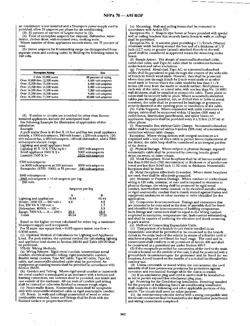
N F P A 70 - - A 9 5 R O P
air condi t ioner is no t installed and a 50-ampere power-supply cord is provided, allow 15 amperes per phase for air condit ioning.
(3) 25 percent of cur ren t of largest motor in (2). (4) Total of namepla te amperes for: disposal, dishwasher, water
heater, clothes dryer, wail-mounted oven, cooking units. Where n u m b e r of these appliances exceeds three, use 75 percent of
total. (5) Derive amperes for f rees tanding range (as dis t inguished f rom
separate ovens and cooking t~nits) by dividing the following values by 240 volts.
Nameplate Rating Use 0 thru 10,000 watts
Over 10,000 thru 12,500 watts Over 12,500 thru 13,500 watts Over 13,500 thru 14,500 watts Over 14,500 thru 15,500 watts Over 15,500 thru 16,500 watts Over 16,500 thru 17,500 watts
80 percent of rating 8,000 volt-amperes 8,400 volt-amperes 8,800 volt-amperes 9,200 volt-amperes 9,600 volt-amperes
10,000 volt-amperes
(6) If oudets or circuits are provided for o ther than factory- installed appliances, include the anticipated load.
See following Example for illustration of application of this calculation.
Example A park trailer floor is 40 feet X 10 feet and has two small appliance
circuits, a 1000-volt-ampere, 240-volt heater, a 200-volt-ampere, 120- volt exhaus t fan, a 400-volt-ampere, 120-volt dishwasher, and a 7000- volt-ampere electric range.
Lighting and small appliance load Lighting 40 X 10 X 3 VA/sq ft = 1200 volt-amperes Small appliance 1500 X 2 .= 3000 volt-amperes Laundry 1500 X 1= 1500 volt-amoeres
5700 volt-amperes 1st 3000 volt-amperes at 100pe rcen t 3000 volt-amperes Remainder (5700 - 3000) at 35 percent 945 volt-amneres
3945 volt-amperes 3945 volt-amperes = 16.44 amperes per leg
240 volts
Lighting and appliances Heater, 1000 VA - - 240 volt = Fan, 200 VA X 120 volt = Dishwasher, 4 0 0 V A - 120 = Range, 7000 VA - - .8 - - 240 =
Totals
A m p e r e s p e r leg
A 16.44 4.2
45.64
B 16.44
4.2 1.7 3.3
47.24
Based on the h igher cur ren t calculated for ei ther leg, a m i n i m u m 50-ampere supply cord is required.
For SI units: one square foot = 0.093 square meter; one foot = 0.3048 meter.
(c) Optional Method of Calculation for Light ing and --Appliance Load. For park trailers, the optional m e t h o d for calculanng lighting and appliance load shown in Section 220-30 and Table 220-30 shall bepermi t t ed .
552-48..Wiring Methods. (a) Wiring Systems. Ri~dd metal conduit , in termediate metal
conduit , electrical metallic tubing, rigid nonmetal l ic conduit , flexible m e t ~ conduit, Type MC cable, Type MI cable, Type AC cable, and nonmetal l ic-sheathed cable shall be permit ted. An equ ipmen t g rouod ing m eans shall be provided in accordance with Section 250-91.
(b) Condui t and Tubing. Where rigid metal condui t or intermedi- ate metal condui t is t e rmina ted at an enclosure with a locknut and bushing connect ion, two locknuts shall be provided, one inside and one outside of the enclosure. All cut ends of condui t and tubing shall be r eamed or other3vise f inished to remove rough edges.
(c) Nonmetal l ic Boxes. Nonmetal l ic boxes shall be acceptable only with nonmetal l ic-sheathed cable or rigid nonmetal l ic conduit .
(d) Boxes. In walls and ceilings const ructed of wood or o ther combustible material, boxes and fittings shall be flush with .the finished surface or project therefrom.
(e) Mount ing . Wail and ceiling boxes shall be m o u n t e d in accordance with Article 370.
Exception No. 1: Snap-in type boxes or boxes provided with special wall or ceiling brackets that securely fasten boxes in walls or ceilings shall be permitted.
Exception No. 2: A wooden plate providing a 1 1 /2- inch (38-mm) m i n i m u m width backing a round the box and of a thickness of 1/2 inch (12.7 mm) or greater (actual) a t tached direcdy to the wall
~ anel shall be considered as approved means for m o u n t i n g outlet o x e s .
(f) Sheath Armor. The shea th of nonmetal l ic-sheathed cable, metal-clad cable, and Type AC cable shall be cont inuous between outlet boxes and other enclosures.
(g) Protected. Metal<lad, Type AC, or nonmetal l ic-sheathed cables shall be permit ted to pass t h rough the centers of the wide side of 2-inch by 4-inch wood studs. However, they shall be protected where they pass thr.ough 2-inch by 2-inch wood studs or at o ther wood studs or f rames where the cable would be less than 1 1 /4 inches (38 ram) from the inside or outside surface. Steel plates on each side of the cable, or a steel tube, with no t less than No. 16 MS(:; wall thickness, shall be installed to protect the cable. These plates or tubes shall be securely held in place. Where nonmetal l ic-sheathed cables pass th rough punched , cut, or drilled slots or holes in metal
• members , the cable shall be protected by bushings or g rommets securely fas tened in the open ing prior to installation of the cable.
(h) Cable Supports. Where connec ted with cable connectors or clamps, cables shall be suppor ted within 12 inches (305 mm) of oude t boxes, distribution panelboards, and splice boxes on appliances. Supports shall be provided every 4 1 /2 feet (1.37 m) at o ther places.
(i) Nonmetal l ic Box without Cable Clamps. Nonmetal l ic-sheathed cables shall be suppor ted within 8 inches (203 mm) of a nonmetal l ic oude t box without cable clamps.
Exception: Where wiring devices with integral enclosures are employed with a loop of extra cable to permit future rep lacement of the device, the cable loop shall be considered as an integral portion of the device.
O) Physical Damage. Where subject to physical d a r ~ g e , exposed nonmetal l ic cable shall be protected by covering boards, guard strips, raceways, or o ther means.
(k) Metal Faceplates. Metal faceplates shall be of ferrous metal no t less than 0.030 inch (762 micrometers) in thickness or of nonfer rous metal no t less than 0.040 inch (1.02 mm) in thickness. Nonmetal l ic faceplates shall be listed.
(I) Metal Faceplates Effectively Grounded. Where metal faceplates are used, they shall be effectively g r o u n d e d . '
(m) Moisture or Physical Damage. Where outdoor or underchassis wiring is 120 volts, nominal , or over and is exposed to moisture or physical damage, the wiring shall be protected by rigid metal conduit , in termediate metal conduit , or by electrical metallic tubing or rigid nonmetal l ic condui t that is closely routed against f rames and e q u i p m e n t enclosures or o ther raceway or cable identified for the application.
(n) C o m p o n e n t lnterconnect ions. Fittings and connectors that are in tended to be concealed at the time of assembly shall be listed and identified for the in terconnect ion of bui lding components . Such fittings and connectors shall he equal to the wiring m e t h o d employed in insulation, t empera ture rise, fault-current withstanding, andsha i l be capable of endur ing the vibration and shock occurr ing in park trailers. ..
(o) Method of Connec t ing Expandable Units. (1) Tha t port ion o f a branch circuit that is installed in an
expandable uni t shall be permi t ted to be connec ted to the branch . circuit in the main body of the vehicle by means of a flexible cord or a t t achment plug and cord listed for hard usage. The cord and its connect ions shall conform to all provisions of Article 400 and shall be considered as a permit ted use unde r Section 400-7.
(2) f f the receptacle provided for connect ion of the cord to the main circuit is located on the outside of the unit, it shall be protected with a
circuit-interrupter for personnel and be listed for wet tions. A cord located on the outside of a uni t shall be identified for
outdoor use. (3) Unless removable or stored within the unit interior, the cord
assembly shall have p e r m a n e n t provisions'for protect ion against corrosion and mechanical damage while the uni t is in trmmiL
(4) f f an a t t achment plug and cord is used it shall be installed so as not to permi t exposed live a t t achmen t plug pins..
(p) Prewiring for Air Condi t ioning Installation. Prewiring installed for the purpose of facilitating future air-condit ioning installation shall conform to the following and o ther applicable port ions of this article. The circuit shall serve no o ther purpose.
(1) An overcurrent-protective device with a rating compatible with the circuit conductors shall be installed in the distr ibution panelboard and wiring connect ions completed.
662

N F P A 70 - - A 9 5 R O P
(2) The load end of the circuit shall terminate in a junction box with a blank cover or a device listed for the purpose. Where a junction box with a blank cover is used, the free ends of the conductors shall be adequately capped or taped.
(3) A label conforming to Section 552-44(b) shall be placed on or adjacent to the junction box and shall read:
AIR-CONDITIONING CIRCUIT. THIS GONNECTION IS FOR AIR CONDITIONERS
RATED 110-125 VOLT AC, 60 HZ AMPERES MAXIMUM. DO NOT EXCEED
CIRCU IT RATING.
An ampere rating, not to exceed 80 percent of the circuit rating, shall be legibly marked in the blank space.
552-49. Conductors and Boxes. (a) Maximum Number of Conductors. The maximum number of
conductorspermitted in boxes shall be in accordance with Section 370-16.
(b) Free Conductor at Each Box. At least 6 inches (152 ram) of free conductor shall be left at each box except where conductors are intended to loop without joints.
552-50. Grounded Conductors. The identification of grounded conductors shall be in accordance with Section 200-6. 552-51. Connection ofTerminals and Splices. Gonductorsplices
and connections at terminals shall be in accordance with Section 110-14. 552-52. Switches. Switches shall be rated as follows: (a) Lighting Circuits. For lighting circuits, switches shall be rated
not less than 10 amperes, 120/125 volts and in no case less than the connected load.
(b) Motors or Other l~oads. For motors or other Io~tds, switches shall have ampere or horsepower ratings, or both, adequate for loads controlled. (An ac general-use snap switch shall be permitted to control a motor 2 horsepower or less with full-load current not over 80percent of the switch ampere rating.)
552-53. Receptacles. All receptacle outlets shall be (1) of the grounding type and (2) installed in accordance with Sections 210-7 and 210-21.
552-54. Lighting Fixtures. (a) General. Any combustible wall or ceiling finish exposed
between the edge of a fixture canopy, or pan and the outlet box, shall be coveredwith noncombustible material dr a material identified for the purpose.
(b) Shower Fixtures. f fa lighting fixture is provided over a bathtub or in a shower stall, it shall be of the enclosed arid gasketed type and listed for the type of installation, and it shall be ground- fault circuit-interrupter protected.
The switch for shower lighting fixtures and exhaust fans, located over a tub or in a shower stall, shall be located outside the tub or shower space.
(c) Outdoor Outlets, Fixtures, Air-Cooling Equipment, Etc. Outdoor fixtures and other equipment shall be listed for outdoor u s e .
552-55. Grounding. (See also Section 552-57 on bonding of noncu rrent-carryi ng metalparts.)
(a) Power-Supply Grounding. The grounding conductor in the supply cord or feeder shall be connected to the grounding bus or other approved grounding means in the distribution panelboard.
(b) Distribution Panelboard. The distribution panelboard shall have a grounding bus with sufficient terminals for all grounding conductors or other approved grounding means.
(c) Insulated Neutral. (1) The grounded circuit conductor (neutral) shall be insulated
from the equipment grounding conductors and fi'om equipment enclosures and other grounded parts. The grounded (neutral) circuit terminals in the distribution panelboard and in ranges, clothes dryers, counter-mounted cooking units, and wall-mbunted ovens shall be insulated from the equipment enclosure. Bonding screws, straps, or buses in the distribuuonpanelboard or in appliances shall be removed and discarded.
(2) Connection of electric ranges and electric clothes dryers utilizing a grounded (neutral) conductor, if cord-connected, shall be made with 4-conductor cord and 3-pole, 4-wire, grounding-type plug caps and receptacles. 552-56. Interior Equipment Groundinl~.
] (a) Exposed Metal Parts. In the electrical system, all exposed ] metal parts, enclosures, frames, lighting f'Lxture canopies, etc., shall ] be effectively bonded to the grounding terminals or enclosure of the ] distribution panelboard. I (b) Equipment Grounding Conductors. Bare wires, green-colored I wires, or green wires with yellow stripe(s) shall be used for equip- ]men t grounding conductors only. I (c) Grounding of Electrical Equipment. Where grounding of I electrical equipment is specified, it shall be permitted as follows:
(1) Connection of metal raceway (conduit or electrical metallic tubing), the sheath of Type MC and Type MI cable where the sheath is identified for grounding, or the armor of Type AC cable to metal enclosures.
(2) A connection between the one or more equipmentground- ing conductors and a metal box by means of a grounding screw, which shall be used for no other purpose, or a listed grounding device.
(3) The equipment grounding conductor in nonmetallic-- sheathed cable shall be permitted to be secured under a screw threaded into the fixture canopy other than a mounting screw or cover screw, or attached to a listed grounding means (plate) in a nonmetallic outlet box for fixture mounting (grounding means shall also be permitted for fixture attachment screws).
(d) Grounding Connection in Nonmetallic Box. A connection between the. one or more grounding conductors brought into a. nonmetalhc outlet box shall be so arranged that a connection canbe made to any fitting or device in that box that requires grounding.
(e)" Grounding Continuity. Where more than one equipment grounding conductor of a branch circuit enters a box, al/such conductors shall be in good electrical contact with each other, and the arrangement shall be such that the disconnection or removal of a receptacle, fixture, or other device fed from the box will not interfere with or interrupt the grounding continuity.
(f) Cord-Connected Appliances. Cord-connected appliances, such as washing machines, clothes dryers refrigerators and the electrical system of gas ranges, etc., shall be grounded by means of an approved cord with equipment grotinding conductor and ground- ing-type attachment plug. 552-57. Bonding of Noncurrent-Garrying Metal Parts'. (a) Required Bonding. All exposed noncurrent-carrying metal
parts that may become energized shall be effectively bonded to the grounding terminal or enclosure of the distribution panelboard.
(b) Bonding Chassis. A bonding conductor shall be connected between any distribution panelboard and an accessible terminal on the chassis. Aluminum or copper-clad aluminum conductors shall not be used for bonding if such conductors or their terminals are exposed to corrosive elements. Exception: Any park trailer that emp.Ioys a unitized metal chassis.
frame construction to which the distribution panelboard is securely fastened with a bolt(s) and nut(s) or by welding or riveting shall be considered to be bonded.
(c) Bonding Conductor Requirements. Grounding terminals shall be of the solderless type and listed as pressure terminal connectors recognized for the wire size used. The bonding conductor shall be solid or stranded, insulated or bare, and shall be No. 8 copper minimum, or equal.
(d) Metallic Roof and Exterior Bonding. The metal roof and exterior covering shall be considered bonded where:
(1) The metal panels overlap one another and are securely attached to the wood or metal frame parts by metal fasteners, and
(2) The lower panel of the metal exterior covering is secured by metal fasteners at each cross member of the chassis, or the lower panel is bonded to the chassis by a metal strap.
(e) Gas, Water, and Waste Pipe Bonding. The gas, water, and waste pipes shall be consideredgroundedif they are bonded to the chassis.
(f) Furnace and Metal Air Duct Bonding. Furnace and metal circulating air ducts shall be bonded.
552-58. Appliance Accessibility and Fastening. Every appliance shall be accessible for inspection, service, repair, and replace'ment without removal of permanent construction. Means shall be provided to securely fasten appliances in place when the park trailer ts in transit. 552-59. Outdoor Outlets, Fixtures, Air-Cooling Equipment, Etc. (a) Listed for Outdoor Use. Outdoor fixtures and equipmentshail
be listed for outdoor use. Outdoor receptacle or convenience outlets shall be ofa gasketed-cover type for use in wet Iocati6ns.
(b)" Outside Heating Equipment, Air-Conditionin g Eq ui p ment ,or Both. A park trailer prowded with a branch circuit designed to energize outside heating equipment or air-conditioning equipment, or both, located outside the park trailer, other than room air conditioners, shall have such branch-circuit conductors terminate in a listed outlet box, or disconnecting means, located on the outside of the park trailer. A label shall be permanently affixed adjacent to the outlet box and contain the following inform~/tion:
This connection is for heating and/or air-conditioning equipment. The branch circuit is rated at not more than . . _ . . . _ ~ p e r e s ,
at ._. .volts , 60-Hertz, ~ c o n d u c t o r ampacity. A disconnecting means shall be located within sight of the equipment.
The correct voltage and ampere rating shall be given. The tag shall be not less than 0.020-inch (508-micrometer) thick etched brass stainless steel, anodized or alclad aluminum, or equivalent. The tag
663

N F P A 70 - - A 9 5 R O P
shall no t be less than 3 inches (76 ram) by 1 3 / 4 inches (44.5 mm) m i n i m u m ~ize.
E. Factory Tests 552-60. Factory Tests (Electrical). Each park trailer shall be
subjected to the following tests: (a) Circuits of 120 Volts or 120/240 Volts. Each park trailer
designed with a 120-volt or a 120/240-volt electrical system shall withstand the applied potential without electrical breakdown of a 1-' minute , nomina l 900-volt dielectric s t rength test, or a 1-second, nominal 1080-volt dielectric s t rength test, with all switches closed,
i between u n g r o u n d e d and g r o u n d e d conductors and the park trailer ground. Dur ing the test, al /switches and o ther controls shall be in the "on" position. Fixtures and p e r m a n e n d y installed appliances shall n o t b e required to withstand this test.
Each park trailer shall be subjected to (1) a continuity test to assure that all metal parts are properly bonded; (2) operational tests to demonst ra te that all equ i pmen t is properly connec ted and in" working order; (3) polarity checks to de termine that connect ions have been properly made; and (4) receptacles requir ing GFCI • )rotection shall be tested for correct funct ion by the nse o f a GFCI testingdevice.
(b) Low-Voltage Circuits. Low-voltage circuit conductors in each lark trailer shall withstand the applied potential without electrical breakdown of a 1-minute, nomina l 500-volt or a 1-second, nominal 600-volt dielectric s t rength test. The potential shall be applied between u n g r o u n d e d and g r o u n d e d conductors .
The test shall be permi t ted on r u n n i n g light circuits before the lights are installed provided the uni t ' s outer covering and interior cabinetry has been secured. The braking circuit shall be permit ted to be tested before being connec ted to the brakes, provided the
wiring has been completely secured. SUBSTANTIATION: Unde r Proposal 19-51, the Panel de t e rmined that park tlallers are not used as vehicles and, therefore, should not be included within the RV definit ion as a basic entity. Additionally, file park trailer has evolved over the years to the point that some requirements within Article 550 are needed to ensure safety. Yet, many requi rements within Article 551 still apply. Tbe needed requirements could not be isolated, and it was, therefore, deter- mined that a new Article specifically for the park trailer was necessary, especially, since approximately 10,000 park trailers are b e i n g p r o d u c e d annually. PANEL ACTION: Accept. NUMBER OF PANEL MEMBERS ELIGIBLE TO VOTE: 12 VOTE ON PANEL ACTION:
AFFIRMATIVE: 11 NEGATIVE: Miller
EXPLANATION OF NE(;ATIVE: MILLER: We disagree with the commit tee ' s action for the
following reasons: 1. The Depar tmen t of Hous ing & Urban Development has
provided an exempt ion from the manufac tu red hous ing standards for RV park trailers between 320 and 400 square feet, thereby
lacing the RV park trailer in the category of a recreational vehicle. e do not believe that the National Highway Traffic Safety
Administrat ion is in the position to de te rmine whether an RV park trailer is or is no t in fact a recreational vehicle.
2. It is inappropriate to define a vehicle solely based on its ability to be conveyed down a highway unde r either its own power or without a special permit. The re are n u m e r o u s examples o f vehicles that require special permits to be used on many roads.
3. The commit tee ' s action is no t in the best interest of the camping consumer . The consumer has shown s t rong interest in the RV park trailer as evidenced by the growing sales and use of the unit.
4. The commit tee ' s action could have an unnecessary and catastrophic impact on major port ions of the RV park and camp- g r o u n d industry, particularly in states where existing codes preclude the use of units o ther than recreational vehicles in RV parks and campgrounds .
5. The commit tees of NFPA 501C, NFPA 501D, ANSI i 19.5 and the Accredited Standards Commit tee A l l 9 all agree with the present definition of a recreational vehicle. Those commit tees have affirmed the definit ion and included it in the 1993 edition of those .standards. As fire safety has been adequately addressed in NEC 70, Section 551 we see no need for a new Section 552.
ARTICLE 553 - - FLOATING BUILDINGS
19-134 - (553-4): Reject (Log #537) SUBMITTER: Dan Leaf, Palmdale, CA RECOMMENDATION: Add: "nor on floating piers, wharfs, docks, or similar floating structures used for the moorage of floating buildings."
SUBSTANTIATION: Floating docks, piers, wharfs may be used for moorage of floating buildings, per Sec. 555-1. Sec. 555-10 prohibits location of service equ ipmen t for su~zh docks or o ther mar ina structures ON the floating structure, but there is no specific rul.e which permits or prohibits services for floating buildings on such floating docks, piers, or wharfs. PANELACTION: Reject. PANEL STATEMENT: This aspect is already covered in Article 555. NUMBER OF PANEL MEMBERS ELIGIBLE TO VOTE: 7 VOTE ON PANEL ACTION:
AFFIRMATIVE: 7
(Log #538) 19-135 - (553-8): Accept SUBMITrER: Dan Leaf, Palmdale, CA RECOMMENDATION: Delete ",~reen" in the last sentence and change "a" before "green" to "an . ' SUBSTANTIATION: Historically the Code has not required a g round ing electrode conductor to be a specific color. Proposals to do so have been rejected (see 1981 Report of NEC Committee,
rOposal 108, and 1983 TCR c o m m e n t on Proposal 5-151). Tile rger size conductors are not readily available with green insulation
a n d there is no provision in this section to permi t tape, paint, etc., at terminations, in lieu of green insulation. PANEL ACTION: Accept. NUMBER OF PANEL MEMBERS ELIGIBLE TO VOTE: 7 VOTE ON PANEL ACTION:
AFFIRMATIVE: 7
(Log #539) 19-136- (553-9): Reject SUBMITTER: Dan Leaf, Palmdale, CA RECOMMENDATION: Revise first sentence as follows:
"The g r o u n d e d circuit conductor (neutral) shall be an insulated conductor identified in conformance with Section 200-6." SUBSTANTIATION: The provisions of Sec. 200-6 which apply to ,all o ther premises, appear to be suitable for floating buildings. PANEL ACTION: Reject. PANEL STATEMENT: This is already covered in Section 200-6 of the NEC. NUMBER OF PANEL MEMBERS ELIGIBLE TO VO:I'E: 7 VOTE ON PANEL ACTION:
AFFIRMATIVE: 7
ARTICLE 555 - - MARINAS AND BOATYARDS
(Log #540) 19-137- (555-1): Accept in Part
Note: The Technical Cor re la t ingGommit tee advises that Article Scope s ta tements are file responsibility of the Technical Correlating Commit tee and the Technical Correlating Commit tee accepts the Panel Action. It was the action of the Technical Correlat ing Commit tee that this Proposal be referred to Code-Making Panel 2 for information. SUBMITI'ER: Dan Leaf, Palmdale, CA RECOMMENDATION: Revise as follows:
"This article covers the installation of wiring and e q u i p m e n t in the areas compris ing fixed or floating piers, wharfs, docks, and o ther areas in marinas, boatyards, boat basins, boathouses, and similar establ ishments o f any occunancv that are used, or in tended for use, . for the purpose of repair, 13erthing, launching,, storage, or fueling of small craft and the moorage of floating bui ld ings ."
(changes under l ined) SUBSTANTIATION: The panel has stated its in tent tha t this article apply to residential occupancies. However that in tent is no t clearly indicated in the text. A not unreasonable interpretat ion is that marinas boatyards, and boat basins are not residential occupancies, and is bolstered by Sec. 210-8(a)(6) relating to boathouses at dwelling units, which indicates that a similar r equ i r emen t in the third paragraph of Sec. 555-3 is no t in tended for residential occupancies. PANEL ACTION: Accept in Part.
[ In the Proposal delete the words "of any occupancy". PANEL STATEMENT: This could be interpreted dais article would be applicable to residential garages where a boat may be stored. NUMBER OF PANEL MEMBERS ELIGIBLE TO VOTE: 8 VOTE ON PANEL ACTION:
AFFIRMATIVE: 8
664

NFPA 70 - - A95 R O P
(Log #3492) 19-138- (555-1-(New)): Reject" Note: The Technical CorrelatingCommittee advises that Article
Scope statements are the responsibility of the Technidal Correlating Committee and the Technical Correlating Committee accepts the Panel Action. SUBMITTER: JamesJ. Rogers, Vineyard Haven, MA RECOMMENDATION: Add a second paragraph to Section 555-1 to read as follows: Buildings located remote from or adjacent to the marina, which are
intendedto be used for the purpose of repair, storage or fueling of small craft or floating buildings shall be wired in accordance with the requirements of Article 511. . SUBSTANTIATION: It is common practice for boaWards and marinas to have large repair and storage facilities located remote from the actual dock and berthing locations. The use of these buildings closelyparallels the uses covered in Article 511. PANEL ACTION: Reject. PANEL STATEMENT: The Scope of Article 511 determines whether such buildings are covered. NUMBER OF PANEL MEMBERS ELIGIBLE TO VOTE: 8 VOTE ON PANEL ACTION:
AFFIRMATIVE: 8
(Log #CP 1924) 19-138a- (555-2, FPN No. 1): Accept Note: The Technical Correlating Committee understands that the
action referenced in the Substantiaion has been taken under Proposal 19-142a. SUBMITI'ER: CMP 19 " ,
[ RECOMMENDATION: Delete the Fine Print Note. - SUBSTANTIATION: The FPN will be rewritten and moved to the Section to which it applies. PANEL ACTION: Accept NUMBER OF PANEL MEMBERS ELIGIBLE TO VOTE: 8 VOTE ON PANEL ACTION:
AFFIRMATIVE: 8
(Log #541) 19-139 - (555-3 and Exception Nos. 1 thru 3-(iqew)): Reject SUBMITrER: Dan Leaf, Palmdale, CA RECOMMENDATION: Change "shore-power receptacles" to "single receptacles" in the first arid second paragraphs.
Revise third paragraph as follows: "Fifteen- and 20-ampere single-phase 125-volt receptacles shall be.
protected by ground-fault circuit-int'erruptors. Exception No. 1: Receptacles supplying shore-power to boats
located at piers, wharfs, and other locations. Exception No. 2: Single receptacles for specific stationary or fixed-
in-place equipment. , ESxception No. 3: Receptacles located where not readily accessible."
SUBSTANTIATION: Prior to the 1987 NEC single receptacles were specified in this section. A proposal in the 1986 TCR (No. 20-4 Log 1280) relating only to an increase in receptacle ratings resulted in an (inadvertent) omissibn of "single" without substantiation or explanation. Sec. 555-4 infers that sinl~le receptacles are intended by use of the
phrases "single receptacle and "individual circuit". Single recep- tacles are not literally required in this article and if multiple types are installed Sec. 555-4 does not apply. Additionally, ifa duplex receptacle of locking and grounding type rated 20-amperes, 125- volts, single phase ac is installed for shore power the third paragraph of this section requiring GFCI protection would not appear to be applicable.
Consideration should be given to deletion of GFCI requirements for other nongeneral-use receptacles for stationary arid fixed equipment or equipment at a height such that inadvertent contact is unlikely, such as lighting fixtures, fans, etc., that may be plug-and cord-connected.. PANEL ACTION: Reject. PANEL STATEMENT: The Proposal may reduce safety in areas where wet contact is likely. NUMBER OF PANEL MEMBERS ELIGIBLE.TO VOTE: 8 VOTE ON PANEL ACTION: "
AFFIRMATIVE: 8
(Log #051) 19-140- (555-3, FPN No. 1): Accept in Principle SUBMITTER: Brian E. Rock, Hubbell Incorporated RECOMMENDATION: Revise (deletions overstruck, additions underlined) the reference in (FPN No. 1):
(FPN): For various configurations and ratings of locking- and grounding-type receptacles and caps, see D;,,,c- ,~IG,,~ Gf ~,~v~, Fiug~ ,~,,,I R,.c~vz,,J,.~ , A.?',SI ~73 137,2, ,~.~ S~/,e'.~mc,,;. A~'~31 C7~- 10g0 National Electrical Manufacturers Association Standard for Dimensions of Attachment Plu~s and Receotacles. ANSI/NEMA WD 6-1080. SUBSTANTIATION: The referenced ANSI Standard is long obsolete and superseded b~ the ANSI-ratified NEMA Standard cited. PANEL ACTION: Accept in Principle. PANEL STATEMENT: See Panel Action and Statment on Proposal 19-77. NUMBER OF PANEL MEMBERS ELIGIBLE TO VOTE: 8 VOTE ON PANEL ACTION:
AFFIRMATIVE: 7 NEGATIVE: Boetler
EXPLANATION OF NEGATIVE: BOETLER: The proposal should have been accepted as submitted.
ANSI/NEMA WD 6-1989 replaces ANSI C73-1972. The reference to "..dkNSI/NEMA WE) 6-1989." is concise. The UL 1681 reference is notan ANSI Std., is not indexed by the specific NEMA configuration numbers required by the code anddoes not contribute to the FPN.
(Log #1273) 19-141 - (555-3, FPN No. 1): Accept in Principle SUBMITTER: Larry Miller, National Electrical Mfrs. Association • RECOMMENDATION: Revise (deletions overstruck, additions underlined) the reference in (FPN No. l ) :
(FPN): For various configurations and ratings of locking- and grounding-type receptacles and caps, see DI ...... ~,,,.~ of C,.v~, P'.a~o ~ .d R.-~Vz,,,.I,.~, ,'..'.~S: C73-1972, a,,d Surf.l,.,;;,.,.;. ,'~J81 CTg~-10g~ National Electrical Manufacturers Associauon Standard for Dimensions of Attachment Plu~s and ReceDtacles. ANSI/NEMA WD
SUBSTANTIATION: The referenced ANSI Standard is long obsolete and superseded by the ANSl-ratified NEMA Standard cited. PANEL ACTION: Accept in Principle. PANEL STATEMENT: See Panel Action and Statement on Proposal 10-77. NUMBER OF PANEL MEMBERS ELIGIBLE TO VOTE: 8 VOTE ON PANEL ACTION:
AFFIRMATIVE: 7 NEGATIVE: Boefler
EXPLANATION OF NEGATIVE: BOETLER: The proposal should have been accepted as submitted.
ANSI/NEMA WD 6-1989 replaces ANSI C73-1972. The reference to "..ANSI/NEMAWD 6-1989." is concise. The UL 1681 reference is notan ANSI Std., is not indexed by the specific NEMA configuration numbers required by the code anddoes not contribute to the FPN.
(Log #542) 19-142- (555-4): Accept
• SUBMITTER: Dan Leaf, Palmdale, CA RECOMMENDATION: Delete "or multiwire". SUBSTANTIATION: Edit. "Muitiwire" is superfluous. A circuit can be individual whether 2-wire or multiwire. A multiwire circuit can be utilized to supply more than one receptacle where connections to a phase wire andneutral is considered an individual circuit. PANEL ACTION: Accept. NUMBER OF PANEL MEMBERS ELIGIBLE TO VOTE: 8 VOTE ON PANEL ACTION:
AFFIRMATIVE: 8
(Log #CP1925) 19-142a- (555-5, FPN No. 1' and No. 2): Accept SUBMITTER: CMP 19
I RECOMMENDATION: The existing FPN will become No. 1 and add FPN No. 2 to read as follows: "Due to the long circuit lengths typical in most marinas and boat yards, feeder conductor sizes found in ampacity tables of Article 310 may be inadequate to maintain the voltage regulation suggested in the Fine Print Notes to Section 210- 19. Total circuit voltage drop is a summation of the voltage drops of each serial circuit segment, where the load for each segment is calculated using the distance, load, and the demand factor for this Section." .
665
N F P A 70 - - A 9 5 R O P
SUBSTANTIATION: Voltage drop considerations are associated with feeders and this information more appropriately addresses the concern. The information belongs under the section on Feeders. PANEL ACTION: Accept. NUMBER OF PANEL MEMBERS ELIGIBLE TO VOTE: 8 VOTE ON PANEL ACTION:
AFFIRMATIVE: 8
(Log #135) 19-143 - (555-5, Exception-(New)): Reject ' SUBMITTER: DavidMyerson, Santa Barbara Waterfront Dept RECOMMENDATION: Add a new Exception as follows:
"In lieu of the above table and subject to approval of the local jurisdiction, feeders and service conductors may be sized to accommodate 125% of the maximum demand meter reading for the previous one year where the marina configuration will be either unchanged or essentially the same as existed during said meter readings.
If any new loads are ,to be introduced to the marina, they shall be served according to the above table." SUBSTANTIATION: In a recent replacement of our Marina 2 electrical system (which serves 195 slips), we needed to install an electrical system rated for a calculated load of 254.7 KVA, based on N.E.G. article 555-5. The maximum demand meter reading provided by Southern California Edison for March 1990 through April 1991 was approximately 37.8 KVA [= 34.0 KW demand reading / 0.9 power factor (assumed) ]. The marina configuration, use, lighting, etc. all r em a ined unchanged. PANELACTION: Reject. PANEL STATEMENT: If demand tables are not correct, they should be revised. The Submitter cites one experience which may not be typical. NUMBER OF PANEL MEMBERS ELIGIBLE TO VOTE: 8 VOTE ON PANEL ACTION:
AFFIRMATIVE: 8
SUBSTANTIATION: For subsection (b) the provisions of Sec. 250- 57(b) Ex. No. 1, b, c, which apply to other premises appear to be suitable for marinas and boatyards. The requirements to be insulated is not changed.
Subsection (c) appears intended to apply to power and lighting circuits, but literally includes equipment, boxes, cabinets, etc., associated with circuits and systems covered by Arts. 640, 670, 725, and 760. Cables and conductors in raceways for those circuits are permitted to be No. 16, 18, or smaller. Ex. No. 2 for Sec. 250-95 provides that the EGC need not be larger than the circuit conduc- tors supplying the equipment. PANELACTION: Reject. PANEL STATEMENT: There is no substantiation to make the change in this Section. NUMBER OF PANEL MEMBERS ELIGIBLE TO VOTE: 8 VOTE ON PANEL ACTION:
AFFIRMATIVE: 8
(Log #3493) 19-147- (555-11-(New)): Reject SUBMrrTER: JamesJ. Rogers, Vineyard Haven, MA RECOMMENDATION: Add a new Section 555-11 to read as follows:
555-11 Circuit Breakers. Circuit breakers installed on docks, piers or other related locations and that are exposed to direct rays of the sun in conjunction with reflective surfaces shall be of the fully nulala~etic type with no thermal elements.
TANTIATION: This language is similar to that contained in NFPA 303 and is necessary for the proper application of circuit breakers used for circuit protection in such areas. PANEL ACTION: Reject. PANEL STATEMENT: This a product standards issue and not safety related. NUMBER OF PANEL MEMBERS ELIGIBLE TO VOTE: 8 VOTE ON PANEL ACTION:
AFFIRMATIVE: 8
(Log #2329) 19-145- (555-5(i)(1)): Reject SUBMITTER: Joe Tedesco, Boston, MA RECOMMENDATION: Revise text as follows:
Change "Article 230" to "Section 230-28" SUBSTANTIATION: Give a more direct reference. PANEL ACTION: Reject. PANEL STATEMENT: Section 230-28 only, is too restrictive. NUMBER OF PANEL MEMBERS ELIGIBLE TO VOTE: 8 VOTE ON PANEL ACTION:
AFFIRMATIVE: 8
(Log #CP1926) 19-145a- (555-6 and FP N No. 1): Accept SUBMITTER: CMP 19
[ RECOMMENDATION: Delete second ~oaragraph and delete Fine [ Print Note No. 1. SUBSTANTIATION: The height of masts cannot be anticipated at the time of installation and, therefore, no open wiring should be
~ ermitted in marinas and boatyards. ANEL ACTION: Accept.
NUMBER OF PANEL MEMBERS ELIGIBLE TO VOTE: 8 VOTE ON PANEL ACTION:
AFFIRMATIVE: 8
(Log #543) 19-146- (555-7(b), Exception No. 2,555-7(c) Exception-(New)): ~ c t
MITTER: Dan Leaf, Palmdale, CA RECOMMENDATION: Add after (b):
"Exception No. 2: An insulated conductor larger than No. 6 shall, at the time of installation, be permitted to be permanently identified as an equipment grounding conductor at each termination and at every point where the conductor is accessible. Identificati()n shall be accomplished by (1) coloring the exposed insulation green, or (2) marking the exposed insulataon with green colored tape or green colored adhesive labels." Add after (c): "Exception: The equipment grounding conductor for circuits
covered by Articles 640, 670, 725, and 760 shall not be required to be larger than the circuit conductors supplying the equipment.".
ARTICLE 600 - - ELECTRIC SIGNS AND OUTLINE LIGHTING
(Log #CP1805) 18-91a- (600): Accept Note: The Technical Correlating Committee advises that Article
Scope statements and Titles are the responsibility of the Technical Correlating Committee and the Technical Correlating Committee accepts the Panel Action. SUBMITTER: CMP 18 RECOMMENDATION:
Revise text as follows: Proposal For 1996 Code Article 600 - Electric Signs and Outline Lighting A~ General 600-1. Scope• This article covers the installation of conductors and
equipment for electric signs, and oudine lighting as def ined in Article 100.
(FPN): As defined in Article 100, electric signs and outline lighting includes all products and installations utilizing neon tubing such as signs, decorative elements, skeleton tubing, or art forms.
600-2. Definitions. (a) Electric-Discharge Lighting; Systems of illumination utilizing
fluorescent lamps, high intensity discharge (HID) lamps, or neon tubing•
(b) Neon Tubing: Electric discharge tubing manufactured into shapes which form letters, parts of letters, skeleton tubing, outline lighting: other decorative elements, or art forms, and filled with various mert gases.
(c) Skeleton Tubing: Neon tubing that is itself the sign or outline lighting and not attached to an enclosure or sign body.
600-3. Listing. Electric signs and outline lighting, fixed, mobile, or portable, shall be listed and installed in conformance with that listing, unless otherwise approved by special pe rmis s ion . .
Exception: Field installedskeleton tubing when installed in conformance with this code.
600-4. Markings. Signs and Outline Lighting Systems: Signs and outline lighting
systems shall be marked with the manufacturer 's name, trademark, or other means of identification; and,.
(a) for incandescent lamp illuminated equipment and systems, with the number of lampholders and maximum wattage per lamp and,
(b) for electric-discharge illuminated equipment and systems, with input voltage, and current rating
Marking(s) shall be visible after installation.
666

N F P A 70 - - A 9 5 R O P
600-5. Branch Circuits (a) Required Branch Circuit. Each commercial building and each
commercial occupancy accessible to pedestrians shall be provided with at least one outlet in an accessible location at each entrance to each tenant space for sign or oudine lighting system use. The outlet(s) shal /be supplied by a branch circuit rated at least 20- amperes, that su pl?lies no other load.
Excepuon: Serwce hallways or cormdors shall not be considered accessible to pedestrians.
(b) Rating. (1) Circuits that supply signs and outline lighting systems contain-
ing incandescent, fluorescent, and high-intensity-discharge forms of illumination shall be rated not to exceed 20 amperes.
(2) Circuits that only supply neon tubing installations shall not be rated in excess of 30 amperes.
(c) Wiring methods: (1) Supply. The wiring method used to supplysigns and outline
lighting systems shall terminatewithin a sign, an outline lighting system enclosure, suitable box, or conduit body.
(2) Enclosures as Pull Boxes. Signs and transformer enclosures shall be permit ted to be used as pull or junct ion boxes for conduc- tors supplying other adjacent signs, outline lighting systems, or floodlights that are part of a sign, and shall be permitted to contain both branch mad secondary circuit conductors.
(3) Metal poles used to support signs shall be permit ted to enclose supply conductors, p rov ided the poles and conductors are installed in accordance with Secdon 410-15(b).
600-6. Disconnects. Each sign and outline lighting system shall be controlled by an externally operable switch or circuit breaker that will open all ungrounded conductors.
Exception No. 1: A disconnecting means shall not be required for an exit directional sign located within a building.
Exception No. 2: For cord-connected signs the a t tachment plug shall be permit ted to serve as the disconnecting means.
(a) Location. The disconnecting means shall be within sight o f the sign or oudine lighting system that it controls. Where the discon- necting means is out of the line of sight from any section that may be energized, the disconnecting means shall be capable of being locked in the open position. Sigt~ or outline lighting systems operated by electronic or electro-
mechanical controUers located external to the sign or outline lighting system shall be permit ted to have a disconnecting means locatedwithin sight of the controller or in the same enclosure with the controller. The disconnecting means shall disconnect the sign dr outline lighting system and the controller from all ungrounded supply conductors. It shall be designed so no pole can be operated independent ly and shall be capable of being locked in the open position.
(b) Control Switch Rating. Switches, flashers, and similar devices controlling transformers and electronic power supplies shall be rated for controlling inductive loads or have a current radng not less than twice the current rating of the transformer.
(F'PN): See Section 380-14 for rating of snap switches. (c) Switches. on Doors. Doors. or covers on. equi. p.ment givin, g
access to umnsulated parts of signs or outline hghnng systems exceeding 600 volts, nominal, and accessible to unqualified persons shall either, be provided with interlock switches that upon opening the doors or covers disconnects the primary circuit, or shall-be . fastened so they cannot be opened with ordinary tools.
600-7. Grounding. Signs and metal equipment o foud ine lighting systems shall be grounded. Listed flexible metal conduit that- encloses the secondary wiring of a transformer.or power supply for use with electrical discharge tubing shall be permitted as a ground- . ing means in lengths not exceeding 100 ft.
Exception No. 1: Metal parts no t likely to be energized and spaced at least 3 /4 in. (19 mm) from neon tubing shall not be required to be bonded.
Exception No. 2: In a listed sign or oudine, lighting system all metal parts on the secondary side of a neon tubing transformer or electronic power supply shall not be required to be bonded ff the secondary circuit is electrically isolated from ground.
600-8. Enclosures. Live parts other than lamps and neon tubing shall be enclosed.
Exception: A transformer or electronic power supply provided with an integral enclo§ure, including a primary and secondary circuit splice enclosure, shall not be required to be provided with an additional enclosure.
(a) Strength. Enclosures shall have ample structural strength and rigidity.
(b) Material. Sign and oudirie lighting system enclosures shall be constructed of metal 9r shall be listed.
(c) Minimum Thickness of.Enclosure Metal. Sheet COl~l~er or aluminum shall be at least 0.020 in. (508 micrometers) tl'ilck. Sheet steel shall be at least 0.016 in. (406 micrometers)(No. 28 MSG) thick.
(d) Protection of Metal. Metal parts o fequ ipmen t sha l l be protected from corrosion.
600-9. Location. (a) Vehicles. A sign o r o u d i n e lighting system equipment shall be
at least 14 ft (4.4 m) above areas accessible to vehicles unless protected from physical damage.
(b) Pedestrians. Neon tubing accessible to pedestrians shall be protected from physical damage.
Exception: Dry-location portable signs. (c) Adjacent t6 Combustible materials. Signs and outline lighting
systems shall be constructed and installed so that adjacent combus-- tible materials shall not be subjected to temperatures in excess of 90°C (194°F).
The spacing between wood or other combustible materials and an incandescent or HID lamp or lamp holder shall not be less thari 2 in. (50.8 mm).
(d) Wet location. Signs and outline lighting system equipment for wet location use shall be weatherproof and have drain holes, as necessary, in accordance with the following:
( i) Drain holes shall not be larger than 1 /2 in. (12.7 mm) or smaller than I / 4 in. (6.35 mm).
(2) Every low point or isolated section of the equipment shall have at least one drain hole.
(3) Drain holes shall be posit ioned such that there will be no external obstructions.
Exception: Drain holes shall not be required in listed watertight equipment.
600-10. Portable or Mobile Signs. (a) Support. Portable or mobile signs shall be adequately
s u p p o r t e d a n d readily movable without the use of tools. (b) Attachment Plug. An at tachment plug shall be provided for
each portable or mobile sign. (c) Wet or Damp Location: Portable or mobile signs in wet or
damp locations shall meet all of the following: (1) Cords. All cords shall be jun ior hard service or hard service
types as designated in Table 4004, and have an equipment g~ounding conductor.
2) Ground Fault Circuit-Interrupter. Portable or mobile signs shall be provided with factory-installed ground-fauh circuit- interrupter protection for personnel. The ground-fault circuit- interrupter, shall be an integral part of the a t tachment plug or shall be located m the power-supply cord within 12 in. (305 ram) of the a t tachment plug.
(d) Dry Location. Portable or mobile signs in dry locations shall meet the foUowin~
(1) Cords. Cords shall be SP-9, SPE-2, SPT,2, or heavier, as designated in Table 400-4. The cord shall not exceed 10 ft (3.05m) in lengx.h. " '
(2) ~,rounding and Polarization. Exposed non-current carrying metal parts of portable signs likely to be energized shall be grounded. Incandescerit and HID illuminated signs not required to be grounded shall be polarized.
B. Field Installed Skeleton Tubing. 600-21. Ballasts, Transformers, and Electronic Power Supplies (a) Accessibility. Ballasts, transformers, and electronic power
supplies shall be located where accessible and shall be securely fastened in place.
(b) Location. Ballasts, transformers, and electronic power supplies shall be installed as near to the lamps or neon tubing as practicable to keep the secondary conductors 'as short as possible. I
(c) Wet location. Ballasts, transformers, and electronic power supplies used in wet locations shall be of the weatherprooi" type or be of the outdoor type and protected from the weather by placement in a sign body or separate enclosure. "
(d) Working Space. Aworking space at least 3 feet (914 ram) high, 3 feet (914 mm) wide, by 3 feet (914 mm) deep shall be provided at each ballast, transformer, and electronic power supply or its enclosure wbere no t installed in a sign.
(e) Attic Locations. Ballasts, transformers, and electronic power supplies shall be permit ted to be located in attics and soft[its provided there is an'access door at least 3 feet (914 mm) by 2 feet (610 mm) an~:l a passageway at least 3 feet (914 ram) high by 2 feet (610 mm) wide with a suitable pe rmanen t walkway at least 12 inches (305 mm) wide extending from the point of entry to each compo- nent.
(f) Suspended Ceilings. Ballasts~ transformers, and electronic power supplies shall be permit ted to be located above suspended ceilings provided their enclosures are securely fastened in place and not d e p e n d e n t upon the suspended ceiling grid for support.
600-22. Ballasts. - . . . . ((b~) Type. Ballasts shall be identified for the use and shall be listed.
Thermal Protection. Ballasts shall be thermally protected. 600-23. Transformers and Electronic Power Supplies. (a) Type. Transformers and electronic power supplies shall be
identified for the use and shall be listed.
667
I
N F P A 70 - - A 9 5 R O P
(b) Secondary Fault Protection. Transformers and electronic power supplies shall have all secondary circuit components isolated or have secondary circuit fault protection.
(c) Voltage. Secondary circutt voltage shall not exceed 15,000 volts, nominal, under any load condition. [ f end grounded, the secondary circuit voltage shall not exceed 7,500 volts, nominal, under any load condition.
(d) Rating. Transformers and electronic power supplies shall have a secondary circuit current rating of not more than 300 milliam- peres.
(e) Secondary Gonnecdons. Secondary circuit outputs shall not be connected in parallel or in series.
600-31. Neon Secondary Gircuit Conductors,1000 volts or less, Nominal.
(a) Wiring Method. Conductors shall be installed using any wiring method included in Chapter 3 suitable for the conditions.
(b) Insulation and Size• Conductors shall be insulated, listed for the purpose, and not smaller than No. 18.
(c) Number of Conductors in Raceway. The number of conduc- tors in a raceway shall be in accordance with Table 1 of Chapter 9.
(d) Installation. Conductors shall be installed so they are not subject to physical damage.
(e) Protection of Leads. Bushings shall be used to protect wires passing through an openin~g, in metal. . "
600-32. Neon Secondary Gircu:t Conductors, Over 1000 volts, nominal.
(a) Wiring Method. Conductors shall be installed on insulators, in rigid metal conduit, intermediate metal conduit, rigid nonmetallic conduit, liquidtight flexible nonmetallic conduit, flexible metal conduit, liquidtight flexible metal conduit, electrical metallic tubing, metal enclosures, glass sleeving, or other equipment listed for the purpose. Only one cdnductor shall be installed per length of conduit, tubing, or sleeving. Electronic power supplies used with metal conduit shall have the conductor p ro tec tedby sleeving listed for the purpose. Metal parts of a building shall not be used as a g rounded or
equipment ~oundin.~ conductor. (b) lnsulauon and Size. Conductors shall be insulated, listed for
the purpose, identified for the voltage and temperature rating, and not smaller than No. 18.
(c) Installation. Conductors shall be installed so they are not subject tophysical damage.
(d) Bends in Conductors. Sharp bends in insulated conductors shall be avoided.
I (e) Spacing. Conductors shall be separated from each other and from all objects other than insulators or neon tubing by a spacing of not less than 1 1/2 inches (38 mm).
(0 Insulators and Bushings. Insulators and bushings for conduc- tors shall be listed for the purpose.
(g) Conductors in Raceways. (1) In damp or wet locations, the insulation on all conductors shall
extend not less than 4 inches (102 mm)beyond the metal conduit or tubing.
(2) In dry locations, the insulation on all conductors shall extend not less than 2 1/2 inches (64 ram) beyofid the metal conduit or tubing.
(h) Between Neon Tubing and Grounded Midpoint. Conductors shall be permit ted to run from the ends of neon tubing to the grounded midpoint of transformers, or electronic, power supplies. listed for the purpose and prowded with terminals at the midpoint. Where such connections are made to the g rounded midpoint, the connections between the high-voltage terminals and the line ends of the neon tubing shall be as short as possible.
(i) Dwelling Occupancies. Equipment having an open circuit voltage exceeding 1,000 volts shall not be installed in or on dwelling occupancies.
600-41. Neon Tubing. (a) Design. The length and design of the tubing shall not cause a
continuous over-current beyond the design loading of the trans- former or electronic power supply.
(b) Support. Tubing shall be suppor ted by listed tube supports. (c) Spacing. Aspacing of not less than 1 inch (25.4 ram) shall be
malntmned between the tubing and the nearest surface, other than its support.
600-42. Electrode Connections. (a) Accessibility. Terminals of the electrode shall not be accessible
to unqualified persons. (b) Electrode Connections. Connections shall be made by use of a
connection device, twistingthe wires to[gether, or use of an electrode receptacle. Connections shall be elecmcally and mechanically secure and shall be in an enclosure listed for the purpose.
(c) Support. The neon tubing and conductor shall be suppor ted not more than 6 inches (152 mm) from the electrode connection.
(d) Receptacles. Electrode receptacles shall be listed for the purpose.
(e) Bushings. Where electrodes penetrate an enclosure, bushings listed for the purpose shall be used, unless receptacles are provided.
(f) Wet Locations. In a wet location, a listed cap or silicon sealant shall be used to close the opening between neon tubing and a receptacle or bushing. SUBSTANTIATION:
The Panel has reviewed and agrees with the substantiation of Proposal 18-91 and has incorporated the action of additional proposals to be reflected in this Panel proposal. 600-1. FPN
There has been considerable confusion and misinterpretation of what is included in the definitions of signs and oudine lighting. The committee concluded that it was important to add a FPN which clearly states this article covers all products utilizing, and installa- tions of neon tubing.
800-2• Definitions. • (a) A definition of electric-discharge lighting was needed so the
article could differentiate between the various types. (b) The current c.ode uses the term electric-discharge tubing. This
could be interpreted to include other light sources such as fluores- cent lamps. The committee elected to use the industry standard practice of referring to the product as neon tubing.
(c) Skeleton Tubing is a specific fm'm of neon tubing installation which could be either a sign or outline lighting, and which must be addressed in the code based on its specific character and wiring needs, rather than whether it is a sign or outline lighting. 600-3 Listing. Skeleton tubing is the only form of sign or oudine lighting for
which a listing cannot be obtained, because it is frequently field installed. All other forms of signs or oudine lighting can be manufactured as l istedproducts.
600-7, Exception No. L Field installed skeleton tubing fi 'equendy involves the use of electrically isolated metal parts such as tube support bases, fasteners, decorative channels over the tubing, etc. which are placed such that there is no potential for them to become electrically energized. Theyare only exposed to the neon tubing. The only potential which exists is the possibility, of capacitance, coupling between, the tubing and metal part. This could result m a "startle factor", sLmilar to a static electric charge. The required minimum 3 / 4 " spacing ensure that, even with the highest voltage transformer, the capacitance coupling will not be significant.
600-7, Exception No. 2 Currendy all dead-metal parts of a listed sign or outline lighting system are required to be grounded. Where an isolating transformer is provided with no ground reference, all parts on the secondary side are still required to be grounded. The secondary of an isolatlng type transformer has a potential to ground of zero (0) volts. Therefore, there is no improvement in safety gained by requiring the grounding of dead-metal parts adjacent to isolatedsecondary circuits. By adding this exception for listed signs and outline lighting systems, NEC . . . . requirements will not suppress research and development of signs and outhne hghtmg systems that may reduce the problems which prdsently exist with ground referenced systems such as, shock hazards, arcing to ground, corona and the generation of ozone, and capacitance coupling.
600-9 (a). The height was changed to be consistent with DOT regulations.
This change eliminates the conflicts that occur because building structures and canopies which are designed to provide clearance for vehicles allowed by DOT regulations, yet signs can not be installed on some of these structures, due to the fact that the current code requires 16 foot clearance. Wet, Damp, and Dry Locations.
Article 600 has been changed to identify these types of locations. rather than indoor and outdoor• Outdoor could be a wet or damp location. Indoor could be a clamp or dry location. The use of wet, damp, and dry will make signs consistent with fixture standards.
600-9(e) Currently all outdoor signs are required to have 2 drain holes.
Outdoor signs located under eaves and canopies can be in damp locations and do not need drain holes.
The current specific of 2 drains was removed as this causes large signs to be provided with insufficient draining and small letters to have too many holes. 600-10(c) (2) The requirements for cords on dry location portable or mobile
signs was reduced to allow proper sizing of cords for small signs which sit on counters or hang in windows. A junior, hard service or hard service typ.e cord weighs too much for this application, and can effect the sign's stability. • 600-10(c)(2), Exception This aligns Article 600 with the similar provisions which exist in Article 410.
600-22(b) and Exception
668
N F P A 70 - - A 9 5 R O P
Many signs and outline lighting systems are installed indoors. Thermal protection is r equ i redfor all other applications using fluorescent ballasts indoor. The technology is readily available. There is great likelihood that outdoor ballasts will either initially, or during ballast replacement, be used in an indoor sign or high-output fluorescent fixtures, therefore, it is appropriate to always require , thermal protection.
Electronic Power Supplies This product has been added to the article. Electronicpower supplies have been developin~ over the past 5 years, a n d a r e , substitute components replacing ferro-magnetic transformers.
600.23(b) The voltage allowances on test has been deleted in favor of the
phrase "under any load condition." This will allow the standard for transformers and electronic power supplies to be established so it reco. gnizes and controls the unique characteristics. . of each product. This will allow the standard to estabhsh taghter tolerances of performance.
600-23(c) The restriction on outline lighting installations to 60 ma has been
eliminated. There is no significant difference in arc temperature between a 60 ma and a 300 ma arc. This restriction was unique to Article 600. Other electric-discharge lighting applications in outline lighting type applications, including cold-cathode lighting, do not have this restriction.
600-51(b) and 600-32(b) This will align Article 600 with Article 410 [410-24(b)]. Sections
600.31 (b) and 600-32(b) apply to the secondary circuit of a transformer or ballast. Currents are restricted by the ballast or transformer to levels where a No. 18 AWG conductor is more than sufficient to avoid heating the conductor. In researching the reason No. 14 AWG was required for neon installdons, itwas de te rmined that, at the time this was adopted, there was no insulation or only cloth type insulation on the conductor. The intent was to provide for a sufficient size to withstand any possible physical abuse. Since that time, polymeric materials were developed to insulate conductors. Due to the voltages involved the insulation is relatively thick and provides a high level of resistance to physical abuse. The requirement for.No. 14 AWG to protect the wire from physical abuse is no longer needed. Also, a No. 14 AWG conductor with the dfick insulation provided tends to be relatively inflexible and often applies pressure to the electrode connection. This pressure creates strain in the glass which can result in a break in the tube at the electrode, and the potential that the broken electrode will touch dead-metal parts.
600-32(a) Liquidtight flexible . . . . . nonmetall ic conduit is currently acceptable
only in wet Iocataons, and where flexabd,ty ~s needed. In actual installations, one of the most common couses of secondary circuit failures is the del{radation of the wire's insulation. This occurs because of capaotance coupling between the wire and a ground
• reference, such as metal conduit, causing a corona effect. The corona produces ozone, which in the confines of conduit, is an aggresive corrosive element. that attacks the insulation. Capacitance coupling increases proportionally with frequency. This is a significant problem when electronic power supplies are used, because they use higher frequencies to help excite the tube. It is not always feasible to connect multiple letter installations with rigid non- metallic conduit. Flexible nonmetall ic conduit is needed to mee t the physical needs of a sign installation, and eliminate capacitance coupling, corona, and the production of ozone. The restriction to one conductor per conduit avoids the potential shorting of conductors, which would then cause the circuit to bypass part of the neon tubing, resulting in the underloading of the transformer, and. it's potential failure. The reasons for the use of sleeving in metal conduit when electronic power supplies are used are: (1) to somewhat center the conductor in the conduit, thus slightly reducing the capacitance coupling, and (2) to reduce the volu(ne of air in the conduit, and there fore / the
• quantity of ozone produced. The th i rdparagraph was added because the only restriction to this ' wiring me thod is "hidden" in Section 250-58. In parts of the country a wiring practice has developed where the building structure, rain gutters, flashing, etc.have been used as a conductor for the secondary circuit of neon installations. The committee wants to make it very clear that this is an unacceptable practice.
600-41 (a) This requirement was changed from over-voltage to overcurrent.
Over-voltage can not be measured in a neon installation. Overcurrent can be measured with a milliamp meter. It is a common practice in the industry to measure the loaded secondacy- circuit current of a neon installation, and compare that with the short-circuit current to de termine proper loading of the trans- former.
600.41(g) This section is changed from the current code where receptacle
and bushing seals may be used, to specifically identify when they must be used. Related changes covering other sections of the NEC have been submitted. PANEL ACTION: Accept. NUMBER OF PANEL MEMBERS ELIGIBLE T O VOTE: 9 V O T E O N PANEL ACTION:
AFFIRMATIVE: 9
(Log #3709) 18-91 - (600): Accept in Principle SUBMITTER: Stephen G. Kieffer/Randall K. Wright, National Electric Sign Association RECOMMENDATION:
Revise text as follows: Proposal For 1996 Code Article 600 - Electric Signs.and Outline Lighting A. General I
600-1. Scope. The article covers the installation of conductors and equipment for electric signs, and outline lighting as def ined in Article 100.
(FPN): As def ined in Article 100, electric signs and outline lighting includes all products and installations utilizing neon tubing such as signs, decorative elements,skeleton tubing, or art forms.
600-'2. Definitions. (a) Electric-Discharge Lighting; Systems of illumination utilizing
fluorescent lamps, high intensity discharge (HID) lamps, or neon tubing.
(b) Neon Tubing: Electric discharge tubing manufactured into shapes which form letters, parts of letters, skeleton tubing, outline lighting, other decorative elements, or art forms, and filled with various inert gases.
(c) Skeleton Tubing: Neon tubing that is itself the sign or outline lighting and not at tached to an enclosure or sign body.
600-3. Listing. Electric signs and outline lighting, fixed, mobile, or p.ortable, shall be listed and installed in conformance with that listing, unless otherwise approved by special permission.
Exception: Field installed skeleton tubing when installed in conformance with this code.
600-4. Markings. Signs and Outline Lighting Systems: signs and outline lighting
systems shall be marked with the manufacturer,s name, trademark, or other suitable means of identification; and,
(a) for incandesizent lamp illuminated, equ ipment and systems, with the number of lampholders and maximum wattage per lamp and,
(b) for electric-discharge illuminated equipment and systems, with input voltage, and current rating.
Marking(s) shall be accessible after installation. 600-5. Branch Circuits (a) Required Branch Circuit. Each commercial building :rod each
commercial occupancy accessible to pedestrians shall be provided with at least one .branch circuit outlet in an accessible location at each entrance to each tenant space for sign or outline lighting . system use. The outer(s) shall be supplied by a branch circuit rated at least a 20-ampere that supplies no o ther load.
Excee.tion: Service hallways or corridors shall no t be considered accessible to pedestria_qs.
(b) Rating. • (1) Circuits that supplysigns and outline lighting systems contain- ing incandescent, fluorescent, and high-intensity-discharge forms of illumination shall be rated not to exceed 20 amperes.
(2) Circuits that only supply neon tubing installations shall not be rated in excess of 30 amperes.
(c) Wiring methods: (1) Supply. The wiring method used to supply signs and oudine
lighting systems shall terminate within a sign, an oudine lighting system enclosure, suitable box, or conduit body.
(2) Enclosures as Pull Boxes. Signs and transformer enclosures shall be permit ted to be used as pull or junct ion boxes for conduc- tors supplying other adjacent signs, a n d o u d i n e lighting systems, or floodlights that are part of a sign, and may contain both branch and secondary circuit conductors.
(3) Metal poles used to support signs shall be permit ted to enclose supply conductors, p rov ided they are installed in accordance with
• 410-15(b). 600-6. Disconnects. Each sign and oudine lighting system shall be
controlled by an externally operable switch or circuit breaker that will open all ungrounded conductors.
Exception No. 1: A disconnect ing means shall not be required for an exit directional sign connected within the scope of Article 700.
669

N F P A 70 - - A 9 5 R O P
Exception No. 2: For cord-connected signs the at tachment plug and receptacle shall be permit ted to serve as the disconnect mea~as.
(a) Location. The disconnecting means should be within sign of the sign or outline lighting system that it controls. Where the disconnecting means is out of the line of sign from any section that may be energized, the disconnecting means shall be capable of being locked in the open position. Signs or outline lighting systems operated by electronic or
etectromechanical controllers located external to the sign or outline lighting system may have a disconnecting means located within sight o f the controller location, or in the same enclosure with the controller. The disconnecting means shall disconnect the sign or outline lighting system, and the controller from all ungrounded supply conductors, shall be designated that no pole can be operated indel~endently, and shall be capable of being locked in the open posiuon.
(b) Control Switch Rating. Switches, flashers, and similar devices controlling transformers and electronic power supplie~ shall be rated for controlling inductive load(s) or have current rating not less than twice the current rating of the transformer.
(FPN): See section 380-14 for rating of snap switches. (c) Switches on Doors. Doors or covers on equipment giving
access to uninsulated parts of signs or outline ligbting systems exceeding 600 volts, nominal, and accessible to unqualified persons shall either be provided with interlock switches that upon opening the doors or covers disconnects the primary circuit, or shall be so fastened that the use of other than ordinary tools will be necessary to open them.
600-7. Grounding. Signs, and metal equipment o foud ine lighting systems shall be grounded in the manner specified in Article 250.
Exception No. 1: Metal parts not likely to be energized and spaced at least 3 /4 in. (19 ram) from neon tubing need not be bonded.
Exception No. 2: In a listed sign or outline lighting system all metal parts on the secondary side of a neon tubing transformer or electronic power supply need not be bonded if the secondary circuit is suitably, electrically isolated from ground.
600-8. Enclosures. Live parts other than lamps and neon tubing shall be enclosed.
Exception: A transformer or electronic power supply provided with an integral enclosure, including primary and secondary circuit splice enclosure, need not be provided with an additional enclosure.
(a) Strength. Enclosures shall have ample strength and rigidity. (b) Material. Sign and outline lighting system enclosure shall be
constructed of metal, or be listed. (c) Minimum Thickness- Enclosure Metal. Sheet copper or
aluminum shall be at least 0.20 in. (508 micrometers) thick. Sheet steel shall be at least 0.16 in. (406 micrometers) thick.
(d) Protection of Metal. Metal parts o f equipment shall be protected from corrosion.
600-9. Location. (a) Vehicles: The bottom of a sign or oudine lighting system
equipment shall not be less than 14 ft (4.4 m) above areas accessible to vehicles.
Exception: The bottom shall be permit ted to be less than 14 ft (4.4 m) above areas accessible to vehicles when protected from physical damage.
(b) Pedestrians: Neon tubing accessible to pedestrians shall be protected from physical damage.
Exception: Dry-location, portable signs. (c) Adjacent to Combustible materials. Signs and outline lighting
systems shall be constructed and installed so that adjacent combus- tible materials will not be.subject to temperatures in excess of 90°C (194°F). The spacing between wood or other combustible materials, and an
incandescent or HID lamp or lamp holder shall be not less than 2 in. (50.8 ram).
(d) Wet location. Signs and outline lighting system equipment for wet location use shall be weatherproof and have drain holes, as necessary, in accordance with the following guidelines:
(1) Drain iloles must be not larger than 1 / 2 in. (12.7 mm) or smaller than 1 /4 in. (6.35 ram).
(2) Every low point or isolated section of the equipment must have at least one drain hole. "
(3) Drain holes must be positioned such that there will be no external obstructions.
Exception: Drain holes need not be provided in listed watertight equipment.
600-10. Portable or Mobile Signs. (a) Support. Portable or mobile signs shall be adequately
suppo r t edand readily movable without the use of tools. (b) Wet or Damp Location: Portable or mobile signs in wet or
damp locations shall meet all of the following requirements: (1) WeatherproofAt tachmentPlug . Awea therproofa t t achment
plug shall be provided for each portable, or mobile sign.
(2) Cords. All cords shall be of the junior hard service or hard service types as designated in Table 400-4, and contain an equip- ment grounding conductor.
(3) Ground Fault Circuit-Interrupt. Portable or mobile signs shall be provided with factory-installed ground-fault circuit-interrupter
~ rotection for personnel. The ground-fault circuit-interrupter shall e an integral part of the a t tachment plug, or shall be located in the
power-supply cord within 12 in. (305 ram) of the a t tachment plug. Conductive supports of a sign specifie d in this section shall be considered part of the sign.
(c) Dry Location. Portable or mobile signs in dry locations shall meet all of the following requirements:
(1) Attachment Plug. An at tachment plug shall be provided for each portable or mobile sign.
(2) Cords. Cords shall be SP-2, SPE-2, SPT-2, or heavier as designated in Table 400-4, and containing an equipment grounding conductor. The cord shall not exceed 10 ft (3.05m) in length.
Exception: For fluorescent and neon illuminated signs an equipment grounding conductor need not be provided if there are not accessible dead metal parts. For incandescent and HID illuminated signs an equipment grounding conductor need not be used, if there are no accessible dead metal parts, and a polarized plug is used.
B. Ballasts, Transformers, and Electronic Power Supplies 600-21. General Requirements. (a) Accessibility. Ballasts, trat~sformers, and electronic power
supplies shall be located where accessible and shall be securely fastened in place.
(b) Location: Ballasts, transformers, and electronic power supplies shall be installed as near to the lamps or neon tubing as practicable to keep the secondary conductors as short as possible.
(c) Wet location. Ballasts, transformers, and electronic power supplies used in wet locations, shall be of the weatherproof type, or be of the outdoor type and protected from the weather by place- ment in a sign body, separate enclosure.
(d) Working Space. A working space at least 3 ft (914 mm) high, 3 ft (944 mm) wide, by 3 ft (944 ram) deep shall be provided at each ballast, transformer, and electronic power supply or its enclosure where not installed in a sign.
(e) Attic Locations. ballasts, transformers, and electronic power supplies shall be permit ted to be located in attics, and soffits, provided there is an access door at least 3 ft (944 mm) by 2 ft (610 mm), and a passageway at least 3 ft (944 mm) high by 2 ft (610 mm) wide, provided with a suitable, permanent , walkway at least 12 in. (305 mm) wide extending from the point of entry to each compo- nent.
(f) Suspended Ceilings: Ballasts, transformers, and electronic power supplies shall be permit ted to be located above suspended ceilings provided their enclosures are securely fastened in place and not dependen t upon the suspended ceiling grid for support.
(FPN): See 600-43(a) for wiring methods. 600-22. Ballasts.
• (a) Type. Ballasts not part of a listed sign or outline lighting system shall be of a type identified for the use, and shall be listed. (b) Thermal Protection. Ballasts shall be thermally protected. Exception: Signs using straight tube lamps with simple reactance
ballasts. 600-23. Transformers and Electronic Power Supplies. (a) Type. Transformers and electronic power supplies not part of
a listed sign or outline lighting system shall be of a type identified for use with neon tubing, and shall be listed.
(b) Voltage. Secondary-circuit voltage shall not exceed 15,000 volts, nominal, under any load condition, f i e n d grounded, the secondary-circuit voltage shall not exceed 7,500 volts, nominal, under any load condition.-
(c) Rating. Transformers and electronic power supplies shall have a secondary-circuit current rating of not more than 300 milliam- peres.
(d) Secondary Connections. Secondary-circuit.outputs shall not be connected in parallel or in series.
C. Neon Secondary Circuit Conductors 600-31. 1000 volts or less, Nominal. (a) Wiring Method. Conductors shall be installed using anywiring
method included in Chapter 3 suitable for the conditions. (b) Insulation and size. Conductors shall be insulated, and of a
typ,: listed for the use and shall not be smaller than No. 18. ( c ) Number of Conductors in Raceway. The number of conduc-
tors in a raceway shall be in accordance with Table 1 of Chapter 9. (d) Installation. Conductors shall be installed so they are not
subject to physical damage. (e) Protection of Leads. bushings shall be employed to protect
wires passing through an opening in metal. 600-32. Over 1000 volts, nominal. (a) Wiring Method. Conductors shall be installed on insulators, in
rigid metal conduit, in intermediate metal conduit, in rigid
670

N F P A 70 m A 9 5 R O P
nonmetallic conduit, in liquidtight flexible nonmetall ic conduit, in flexible metal conduit, in [iquidtight flexible metal conduit, in. " electrical metallic tubing, in metal enclosures, in glass sleeving, or in other listed equipment. Only one conductor shall be installed per length of conduit.
Electronic power supplies used with metal conduit shall have the conductor protected by listed sleeving.
The metal frame of a building shall not be used as grounded or grounding conductor.
(FPN): See Section 600-7 fo rg round ing requirements. (b) Insulation and Size. Conductors shall be insulated, and of a
type identified for the voltage and temperature conditions of the circuit and shall not be smaller than No. 18.
(c) Installation. Conductors shall be installed so they are not subject tophysical damage.
(d) B e n d i n Conductors. Sharp bends in insulated conductors shall be avoided.
(e) Spacing. Conductors shall be separated from each other and from all objects other than insulators or neon tubing by a spacing of not less than 1 1 /2 in. (38 mm) for voltages above 10,000 and not less than 1 in. (25.4 ram) for voltages of 10,000 or less.
(0 Insulators and Bushings. Insulators and bushings for conduc- tors shall be of glass, or shall be listed.
(g) Conductors in Raceways. 1. In damp or wet locations, the insulation on all conductors shall"
extend beyond metal not less than 4 in. (109 ram) for voltages over 10,000, 3 in. (76 mm) for voltages over 5,000 but not exceeding" 10,000, and 2 in. (50.8 ram) for voltages of 5000 or less. 2. In dry locations, the insulation shall extend beyond metal not
less than 2 1/2 in. (64 mm) for voltages over 10,000, 2 in. (50.8 ram) for voltages over 5,000 but not exceeding 10,000, and 1 1/2 in. (38 mm) for voltages of 5,000 or less.
(h) Between Neon Tubing and Grounded Midpoint. Conductors shall be permit ted to run from the ends of neon tubing to the g rounded midpoint of transformers or e lect ronicpower supplies specifically designed for the purpose and providedwith terminals at • the midpoint. Where such connections are made to the grounded midpoint, the connections between the high-voltage terminals and the line ends of the neon tubing shall be as short as possible.
D Neon Tubing, and Electrode Connections. 600-41. Neon Tubing. (a) Design. The tubing shall be of such length and design as to
not cause a continuous over-current beyond the design loading of a transformer or electronic power supply.
(b) Support. Tubing shall be adequately supported on glass, or listed tube supports, and not rely on conductor supports. Tubing supports shall, where practicable, be adjustable.
(c) Contactwith Combustible Materials and Other Surfaces. The tubing shall be free from contact with combustible material and shall be located where not normally exposed to physical damage.
(d) Spacing. The tubing shall be supported to maintain aspacing of not less than 1 /4 in. (6.35 mm) between the tubing and the nearest surface other than its support.
60042. Electrode Connections. (a) Accessibility. Terminals of the electrode shall be inaccessible
to unqualified persons. (b) Electrode Connections. Connections can be r r ~ e byuse of a
connection device, twistingthe wires to~ether, or use of an electrode receptacle. Connections shall be electncaUy and mechanically secure.
(c) Spacing. Electrode connections shall be separated from grounded metal, o ther conductors, and combusuble material by glass, a listed enclosure, or not less than l 1/2 in. (38 mm) or air.
(d) Support. The neon tubing and conductor shall be suppor ted not more than 6 in. (152 mm) from the electrode connection.
(e) Receptacles.. Electrode receptacles shall be listed for the use. Parts that must be removed for tube replacement shall be •held captive.
(f) Bushing. Where electrodes enter the enclosure of signs or outiifie ligbung systems glass or listed bushings shall be sued unless receptacles are provided.
(g) Receptacles and Bushing Seals. For field installed skeleton neon in a wet-location a listed cap or flexible non-conducting sealant shall be used to close the opening between neon tubing and a receptacle or bushing. SUBSTANTIATION: During the December, 1991 meet ing of Code Panel 18 in San Diego, the Panel discussed Article 600. The Panel was concerned about the disorganized and out of date condition of this Article. The Panel members expressed their desire to see the Article rewritten.
The electric sign industry has been aware of significant problems with Article 600. It is difficult for sign companies and electrical inspectors to determine proper performance in accordance with the Article. A wide range of interpretations exits throughout the country.
PANEL ACTION: Accept in Principle. PANEL STATEMENT: See Panel Action and Panel Statement of Proposal 18-91 (a). NUMBER OF PANEL MEMBERS ELIGIBLE TO VOTE: 9 VOTE ON PANEL ACTION:
AFFIRMATIVE: 9
(Log #544) 18-99- (600-2(a), Exception No. 1): Accept in Principle SUBMITTER: Dan Leaf, Palmdale, CA RECOMMENDATION: Delete the wording following "sign." SUBSTANTIATION: Article 700 only covers !egally required emergency systems. Building codes (and others) may require exit signs for occupancies which do not have legally required emergency systems, or exit signs may be provided by choice. All exit signs are assumed to enhance safety and should be covered by this exception. PANEL ACTION: Accept in Principle. PANEL STATEMENT: See Panel Action and Panel Statement on Proposal 18-91 a. NUMBER OF PANEL MEMBERS ELIGIBLE TO VOTE: 9 VOTE ON PANEL ACTION:
AFFIRMATIVE: 9
( Log #9 40 1 ) 18-93 - (600-2(a), Exception No. 2): Accept in Principle SUBMITTER: Richard E. Loyd, Perryville, AR RECOMMENDATION: Relocate Exception 2 so that it now appears as second acceptable condition and is no t a/~ exception to the requirement. Revise as follows: 600-2(a) The disconnect means shall be Io~ t ed witifin sight of the
sign or outline lighting that it controls, or where (insert the present • wording as it now appears in Exception No. 2) S;g,,~ ,,, v~J; , ,c
operated by electronic or electromechanical controllers... SUBSTANTIATION: To clarify the application of Exception No. 2 as an additional condition. This Section and the Exception ,as they now appear have caused confusion in interpret ing the requirements. This change if accepted will clear up dais confusion. PANEL ACTION: Accept in Principle. PANEL STATEMENT: See Panel Action and Panel Statement on Proposal 18-91a. NUMBER OF PANEL MEMBERS ELIGIBLE TO VOTE: 9 VOTE ON PANEL ACTION:
AFFIRMATIVE: 9
' iLog #2408) 18-94- (600-4): Accept in Principle SUBMI'I*TER: Edward Mitchell, City of Los Angeles, CA RECOMMENDATION: Revised text:
Listing Required. Every ~ electric sign of any type, fixed or portable, shall be listed and installed in conformance with that listing, unless otherwise permit ted by special permission. SUBSTANTIATION: Skeleton type signs installed per 600-36 do not require listing. This has been a source of confusion within the code.
This correlates with my proposed change to tile definition of "Electric Sign" in Article 100 which will make it clear that '.'Electric Sign" refers to a self-contained sign of any type. PANEL ACTION: Accept in Principle. • . PANELSTATEMENT: See Panel Action and Panel s t a tement on Proposal 18-91 a. . NUMBER OF PANEL MEMBERS ELIGIBLE TO VOTE: 9 VOTE ON PANEL ACTION:
AFFIRMATIVE: 9
(Log #3140) 18-95 - (600-5, Exception No. 2-(New)): Accept in Principle
. SUBMITTER: Randall IL Wrigh t /S tephen G. Kieffer, Wright Sign Co. RECOMMENDATION: New Exception as follows:
Exception No. 2: Listed flexible metal conduit that encloses file secondary wiring of a transformer or power supply identified for use with electrical discharge tubing as specified in 600-32 sball be
, permit ted as a groundirig means. SUBSTANTIATION: Flexible metal conduit in lengths greater than 6 feet used as a wireway for GTO cable connei:ted to the output of a Listed gas tube sign transformer or power supplyprovides the same level of safety for ~grounding as rigid metallic conduit of the same length. This is pmmaril~, because the output of a gas tube sign
671
N F P A 70 - - A 9 5 R O P
t ransformer or power supply is a very low cur ren t (typically 30 to S00 mA at shor t circuit) and a high voltage (typically 3 kV to 15 kV open circuit).
The t ransformer and power supply is designed to ballast electric discharge tubing became electric discharge tubing dur ing normal operation appears as a conductive load (resistance less than 0). A g r o u n d fault on the ou tpu t is a resistive load (resistance of 0 ohms or greater) and as such will no t cause the primary or inpu t cur ren t to increase. Therefore, regardless of whether rigid or flexible metal condui t is used a round secondary wiring, a fault in die secondary of a gas tube sign t ransformer or power supply will not result in a branch circuit overcurrent protector opening . Also, since the rated ou tpu t is only up to 300 mA at shor t circuit, there is no measurable hea t ing as a result of 300 mA passing th rough flexible metal conduit .
Al though the resistance o f flexible metal condui t is slightly h igher dlan that of rigid metal conduit , the increase has an instgnificant effect on the voltage drop (less than 0.5 V for 100 feet of conduit) and die leakage cur rent to g r o u n d th rough the h u m a n body is very small (less than 5 mA from 100 feet of energized conduit) . There- fore, there is no shock hazard even in wet locations.
Based on earlier tests conduc ted by a manufac tu re r of a l u m i n u m flexible metal condui t that was submit ted to the County of Los Angeles, die Authorit ies HavingJurisdict ion in Sou thern California have accepted a l u m i n u m flexible metal condui t in lengths not exceeding 100 feet with the condui t wall as the g r o u n d i n g path for over 10 years. There have been no field problems repor ted relating to die g round ing th rough the wall of a l u m i n u m flexible metal conduit .
The above considerat ions are additionally substant iated by a Fact- Finding Report on Ground ing of Electrical Signs With Flexible Metal Condui t conduc ted by Underwriters Laboratories, Inc.
NOTE: Suppor t ing material is available for review at NFPA Headquarters. PANEL ACTION: Accept in Principle. PANEL STATEMENT: The Panel accepts the r ecommenda t ion and substantiation of the submit ter and directs the submit ter to see Panel Action and Panel S ta tement on Proposal 18-91a. The Panel has added die I00 foot limitation to Section 600-7 of Proposal 18-91a based upon die .suppor t ing material provided by the submitter. NUMBER OF PANEL MEMBERS ELIGIBLE TO VOTE: 9 VOTE ON PANEL ACTION:
AFFIRMATIVE: 9
(Log #1537) 18-96- (600-6(b)-(New)): Reject SUBMITTER: Todd R. Smith, City of Coral Springs, FL RECOMMENDATION: Add new sentence as follows:
Each sign or outline lighting serving the t enan t occupancy shall be connected to this circuit. SUBSTANTIATION: As an electrical inspector and inspect ing many signs, I have found many signs connec ted to "home" lites of shopp ing centers and alike. This could cause overloads to house circuits and this new sentence would manda te these signs be ho0ked-up to these required sign circuits. This would better clarify the in tent of this section. PANEL ACTION: Reject. PANEL STATEMENT: The substant iat ion does not identify a hazard. NUMBER OF PANEL MEMBERS ELIGIBLE TO VOTE: 9 VOTE ON PANEL ACTION:
AFFIRMATIVE: 9
(Log #3409) 18-97- (600-6(b)): Accept in Principle SUBMITTER: Joe Andre, Construct ion Indus t ryTra in ing Council of Washington RECOMMENDATION: Delete the word "outside" and insert the word "near" in the first sen tence between the words "location" and "the entrance". SUBSTANTIATION: Often t imes a sign.is no t contempla ted or des igned when a t enan t space is built. The r equ i r emen t to provide the circuit outside in no way promotes ei ther safety or convenience, since the type and location of any future sign may not be compatible with the arbitrary location for this circuit.
• Providing a circuit at an accessible location inside the space (above a suspended ceiling near the entrance for instance) meets die in tent of this section without requir ing the installer to mar a finished store or building when it serves no purpose to do so. PANEL ACTION: Accept in Principle. PANEL STATEMENT: See Panel Action and Panel S ta tement on Proposal 18-91a. NUMBER OF PANEL MEMBERS ELIGIBLE TO VOTE: 9 VOTE ON PANEL ACTION:
AFFIRMATIVE: 9
(Log #130) 18-98- (600-6(b), Exception No. 2-(New)): Reject SUBMITrER: William Barnett, City of Gresham RECOMMENDATION: Add Exception No. 2:
"Lighting or receptacle outlets used for installation or servicing the sign e q u i p m e n t shall be permitted." SUBSTANTIATION: Section 600-6(b) could conflict with proposed lighting and receptacle outlets for sign equ ipmen t in attic locations, requir ing an additional circuit in some cases. PANEL ACTION: Reject. PANEL STATEMENT: It is the in tent to have the circuits and outlets dedicated to those signs and to have no other outlets. There is no th ing to prohibi t additional circuits if needed or ?equi red for o ther reasons. NUMBER OF PANEL MEMBERS ELIGIBLE TO VOTE: 9 VOTE ON PANEL ACTION:
AFFIRMATIVE: 9
(Log #2566) 18-99 - (600-12-(New)): Accept in Principle SUBMITTER: Mark N. Shapiro, Farmington Hills, MI RECOMMENDATION: Add new text as follows:
Dwelling Units. Equ ipment having an open circuit voltage exceeding 1,000 volts
shall no t be installed in dwelling un i t s . SUBSTANTIATION: This proposal essentially repeats the language of Section 410-80(b). There are cases where "neon" lighting is being used a long the walls of rooms in houses. With other l ighting in the rooms, it is no t clear whether this is l ighting which is covered by Article 410; or, outl ine lighting, covered byArticle 600. The issue should no t be the definition, but the hazard.
Electrons d o n ' t read the dictionary. PANEL ACTION: Accept in Principle.
Add this new text to a new Section 600.32(i) in proposal 18-91a and change "Units" in the proposal to "occupancies" and add the words "or on" between "in" and "dwelling" to read as follows:
"(i) Dwelling Occupancies . Equ ipment having an open cur ren t voltage exceeding 1,000 volts shall no t be installed in o r o n dwelling OCCUDancies." PANEL STATEMENT: If e q u i p m e n t is listed, there really is no t a problem since o ther electrical e q u i p m e n t within tile dwelling uni t often operates at a m u c h h igher voltage level than 1000 volts. The location in Article 600 was changed to Section 600-32(0 of the revised Article (see PA on Proposal 18-91a) to no t allow field installed skeleton tub ing in a dwelling. NUMBER OF PANEL MEMBERS ELIGIBLE TO VOTE: 9 VOTE ON PANEL ACTION:
AFFIRMATIVE: 8 NEGATIVE: Kempel
EXPLANATION OF NEGATIVE: KEMPEL: Even though the proposed r equ i r emen t has been
included in Part B of Article 600 On FieldInstal led Skeleton Tubing, the wording can be miscons t rued to include all types of sign . equipment . Therefore, the r equ i r emen t should be worded to specifically apply to skeleton tubing.
672

N F P A 70 m A 9 5 R O P
"Dwelling Occupancies" is no t def ined in the Code. To prevent misapplication of this requirement to buildings containing dwelling and commercial occupancies, Code defined terms should be used.
I would vbte AFFIRMATIVE if Section 600-320) would read: 600-320) Dwellings. Skeleton tubing supplied from a source
having an open circuit voltage excedding 1000 volts shall not be installed in dwelling units, nor in one or two family dwellings.
(Log #3215) 18-100 - (600-12-(New)): Accept in Principle SUBMrI ' rER: John Stricklin, International Assoc. of Electrical Inspectors RECOMMENDATION: New text as follows:
Dwelling Units. Equipment having an open circuit voltage exceeding 1,000 volts shall not be installed i0 dwelling units. SUBSTANTIATION: This proposal essentially repeats the language of Section 410-80(b). There are cases where "neon" lighting is being used ,along the walls of rooms in houses. With other lighting in the
• rooms, it is not clear whether this is lighting which is covered by Article 410; or, outline lighting, covered byArticle 600. The issui." should not be the definition, but the hazard. Electrons don ' t read thedictionary. PANEL ACTION: Accept in Principle. PANEL STATEMENT: See Panel Action on Proposal 18-99. ff equipment is listed, there is not a i~roblem since other electrical equipment within the dwelling umt often operates at a much higher voltage level than 1000 volts. The location in Article 600 was changed to Section 600-320) of the revised Article (see PA on Proposal 18-91a) to not allow field installed skeleton tubing in a dwelling. NUMBER OF PANEL MEMBERS ELIGIBLE TO VOTE: 9 VOTE ON PANEL ACTION:
AFFIRMATIVE: 8 NEGATIVE: Kempel
EXPLANATION OF NEGATIVE: KEMPEL: See explanation of negative vote for proposal 1899.
(Log #439). 18-101 - (600-21(a)): Reject SUBMI'I'I'ER: Dan Leaf, Palmdale, CA RECOMMENDATION: Add:
"or as overhead open individual conductors as provided in Article 225." SUBSTANTIATION: Except as covered in See. 305-4(a) and (b) for temporary wiring, and Art. $21, there does n o t a p p e a r to be a specific wiring me thod of Chap. 3 to cover overhead span conduc- tors installed t-o signs. Since Chap. 6 may modify Chap. 2, this section may be construed as not permitt ing overhead open individual conductors to signs. PANEL ACTION: Reject; PANEL STATEMENT: Section 600-21 "applies to secondary conductors so the reference to Article 225 is not relevant. NUMBER OF PANEL MEMBERS ELIGIBLE TO VOTE: 9 VOTE ON PANEL ACTION:
AFFIRMATIVE: 9
(Log #2396) 18-102- (600-31): Reject SUBMITTER: John M. Havay, Havay Electrical Contracting RECOMMENDATION: Revise the end of the last line of 600-31 to read:
...or as type MC cable or as AC cable with insulated grounding conductor. SUBSTANTIATION: Since AC cable with ground is used in health care facilities to insure the. prol?~er grounding, to prevent the occurrence of a coriducuve path from a paUent to a grounded object. 1 cannot see any reason why AC with ground would not be an acceptable wiring method for electric signs and outline lighting.
On the other hand, interlocking ..t~e MC cable would still not be a wiring me thod for health care faciliues. PANEL ACTION: Reject. PANEL STATEMENT: Type A C cable is only rated for 600 volt or less applications and not suitable for operating at over 600 volts. NUMBER OF PANEL MEMBERS ELIGIBLETO VOTE: 9 VOTE ON PANEL ACTION:
AFFIRMATIVE: 9
(Log #2689) 18-103 - (600-31 (a), Exception): Accept in .Principle in Part SUBMITTEPa Charles W. Forsberg, Cation Electrical Products, A Lamson & Sessions Co. RECOMMENDATION: 1. Delete the current Exception.
2. In the third line of Section 600-31(a) after "rigid nonmetallic conduit", add, "in electrical nonmetall ic tubing in accordance with Article 331, in liquidtight flexible nonmetall ic condui t" . SUBSTANTIATION: ENT and LTFNMC will provide a safe wiring. me thod for these applications, because the current is limited to 75 milliamps or less. It should be noted that nei ther EMT and LTFMC is listed for installations over 600 volts, and they are recognized in this section. PANEL ACTION: Accept in Principle in Part.
[ ' , Accept the deleuon of the current exception and the inclusion of liquidtight flexible nonmetallic conduit is in Proposal 18-91a. . PANEL STATEMENT: Section 331-4(6) does not allow ENT for installations over 600 volts. The panel re)ects part of the proposal dealing with ENT. See Proposal 18-91a in the rewrite for these acceptable raceways. NUMBER OF PANEL MEMBF.RS ELIGIBLE TO VOTE: 9 VOTE ON PANEL ACTION:
AFFIRMAT .IVE: 9
(Log #221) 18-104- (600-31(e) (5),(6), and (7)): Accept in Principle SUBMITTER: J immy Evanisko, National Cathode Corp. RECOMMENDATION: Revise text:
(5) Not more than a total of 35 feet (10.8 m) in single conductor from one secondary terminal of a transformer if run is in a 1/2 inch rigid a luminum raceway.
(6) Not more than a total of 45 feet (13.8 m) in single conduc tor from one secondary terminal of a transformer if run in a 1 /2 inch r i ~ non-metallic raceway.
All cases no flex. SUBSTANTIATION: Through our own test~ and E.T.L. tests we have found no problems in using aluminum a n d / o r non-metallic where allowed.
Also, C,S.A. allows up to 52 feet of non-metallic secondary runs. PANEL ACTION: Accept in Principle. PANEL STATEMENT: See Panel Action and Panel Statement on Proposal 18-91a. NUMBER OF PANEL MEMBERS ELIGIBLE TO VOTE: VOTE ON PANEL ACTION:
AFFIRMATIVE: 9
(Log #1382) 18-105- (600-31(e)(4), Exceptions No. 1 and 2-(New)): Accept in Principle SUBMII~'ER: J im Evanisko, National Cathode Corp. RECOMMENDATION: Revise text as follows:. A metal raceway containing a single conductor from one secondary
terminal of a transformer shall not exceed 20 feet (6.1m) in length. Exception: (1) Rigid a luminum 30 feet (9.1) in length. Exception: (2) Rigid plastic 40 feet (19.2) in length where
allowed. SUBSTANTIATION: Problem -Architectural access/location for transformers.
Substantiation - (1) Independen t test lab reports. (2) CSA- Article 30-814/2 and 3. PANEL ACTION: Accept in Principle. PANEL STATEMENT: See Panel Action and Panel Sta tement on Proposal 18-91a. NUMBER OF PANEL MEMBERS ELIGIBLE TO VOTE: 9 VOTE ON PANEL ACTION:
AFFIRMATIVE: 9
(Log#1475) 18-106 - (600-31 (e) (4), Exception No. 1 .and 2-(New)): Accept in Principle SUBMITTER: Jim Evanisko, National Cathode Corp. RECOMMENDATION: Revise text as follows: A metal raceway containing a single conductor from one secondary terminal of a transformer shall no t exceed 20 feet (6.1m) in length.
Exception: (1) Rigid aluminum 30 feet (9.1) in length. (2) Rigid plastic 40 feet (12.2) in length where allowed.
SUBSTANTIATION: Problem - Architectural access/location for transformers.
Substantiation - (1) Independen t test lab reports.
673

N F P A 70 m A 9 5 R O P
(2) CSA- Article 30-814/2 and 3. PANEL ACTION: Accept in Principle. PANEL STATEMENT: See Panel Action and Panel Statement on Proposal 18-91 a. NUMBER OF PANEL MEMBERS ELIGIBLE TO VOTE: 9 VOTE ON PANEL ACTION:
AFFIRMATIVE: 9
(Lbg #545) 18-107 - (600-31 (f)): Accept in Principle SUBMITTER: Dan Leaf, Palmdale, CA RECOMMENDATION: Insert "likely to be" between "not" and "subject". SUBSTANTIATION: Edit A location dlat will, in an absolute sense, be subject to damage, is difficult or impossible to determine. Anything that exists is subject to damage. In the Panel comment on Proposal 5-73 in the 1992TGR they indicated the phrase "likely to be" allowed for probability and excluded consideration of ALL possibilities, no matter how remote. Secs. 110-3(a)8, 110- 16(a) (b)(d), 110-34(d), 250-42, 250-70, 250-112, 250-117(a), 370- 72(0,384-5, 410-57(e), 410-90, 422-8(a), 424-14, 513-6(a) (b), 517-11, and 600-33(c) are examples where "likely", "normally", "probability" are used to provide a criterion for judgement . PANEL ACTION: Accept in Principle. PANEL STATEMENT: This Section does not exist in the rewrite. See Panel Action and Panel Statement on Proposal 18-91a. NUMBER OF PANEL MEMBERS ELIGIBLE TO VOTE: 9 VOTE ON PANEL ACTION:
AFFIRMATIVE: 9
18-108- (600-32): Accept in/~rinciple in Part (Log #2699) SUBMITTER: David Gothard, Campbell, CA RECOMMENDATION: New text as follows:
NEC 600-32 (h). Secondary Fault Protection. Transformers shall have secondary circuit-fauhprotection.
NEC 600-32 (i). Thermal Protection. Transformers shall be thermally protected. SUBSTANTIATION: In the seven years that I have been in the sign business, I have become aware of just about every type of installation problem there is. The conclusion I came to is that over 90% of these Pdroblems could be avoided by just adding secondary circuit-fanh and
lermal protection to the transformer. NOTE: Supporting material is available for review at NFPA
Headquarters. PANEL ACTION: Accept in Principle in Part.
Place in new Section 600-23(b) of Proposal 18-91a rewrite for secondary fault protection with "Secondary Fault Protection" as a heading and existing Section 600-23(b) in the rewrite becomes (c) and existing (c) becomes ( d ) and (d) becomes (e). See Panel Action in Proposal 18-91a. The wording shaU be as f611ows:
"(b) Secondary Fault Protection. Transformers and electronic power supplies silall have all secondary circuit components isolated or have secondary circuit fault protection." PANEL STATEMENT: The submitter 's recommendat ion on secondary fault protection has been accepted and relocated to new subsection in 600-23(b) of the rewrite. Secondary fault protection for transformers is necessary and should be added to the Code. The submitter has not provided technical substantiation to require thermal protection for a transformer. See Panel Action for Proposal 18-91a. NUMBER OF PANEL MEMBERS ELIGIBLE TO VOTE: 9 VOTE ON PANEL ACTION:
AFFIRMATIVE: 9
(Log #3732) .18-108a- (600-32): Reject SUBMITTER: DonaldJ. Bezek, Sr., Kazor Systems, Inc. RECOMMENDATION: Currently cast coil transformers are listed for use in outdoor insect killers, salamander ignitions, and other applications. The cast coil transformers with secondary voltages in excess of 5KV are listed for outdoor applications other than for outdoor sign rise, and have already undergone the required U.L. tests for listing.
We are asking NEC recognition for both, open core and coil and cast coil type transformers be allowed installation inside of outdoor weatherproof sign enclosures. Our device requires multiple (7) transformers for each discreet seven segment display. Even if the transformers installation were allowed with a minimum sign
mount ing height restriction above the ground, this would qualify for the vast major,ty of installations.
Indoor installatiohs of neon window trim with 10 or 15KV connections accessible to the general public have become prevalent, with both a far greater personnel, and fire hazard than our request. SUBSTANTIATION: Our request to allow use of limited secondary voltage gas discharge transformers would provide a dramatic reduction in the potential for fire hazard as compared to the current method of installation. Currently channel letters, as example are wired in series with GTO cable run between the individual letters, and are often powered by a 15KV transformer mounted behind a wall, or in a ceiling cavity. All of the GTO must be run inside a raceway, with thru-bushings into the individual sign housings. Discussion with many sign manufacturers indicates that the most frequent failures, and minor sign fires occur where the GTO cable comes in contact with the metallic connectors. If the transformers could be installed in the individual sign housing the primary (120 VAC) can be run in an NEC approved manner, with the GTO cable and high voltage connections contained only within the individual sign housing.
With NFPA acceptance the transformers could be submitted to U.I.. for listing, to be installed inside the individual weatherproof enclosures that are illuminated by that transformer. The current outdoor rated transformers are as old as neon technology, with the transformer "packed" in tar or other insulating materials. Current state-of-the-art electrical insulating materials mandate that the NFPA at least review superior insulating transformer technology. For many years the electrical power industry has utilized core and coil transformers in outdoor weatherproof housings, and within the past ten years has accepted the cast coil design. The cast coil transformer designs have provided ratings approaching oil filled transformers in BIL, short term overload capability, and moisture rejection in ratings of 5KV and above.
Outdoor sign transformers mounted inside of the sign housing operate in extremely high ambient temperatures. The existing "tar filled" transformers cannot dissipate heat generated by the windings as well as a core and coil, or cast coil type transformer, and may actually fail or catch fire due to their inabi!ity to dissipate heat.
In summary, we are therefore asking for revision to THE NA- TIONAL ELECTRICAL CODE Article 600, 600-32 TRANSFORMERS (as applied to gas discharge, or neon illumination in outdoor enclosed signage.)
1) Open core and coil, or cast coil transformers, of a listed design approved for outdoor installation inside an outdoor weatherproof sign housing be allowed to be installed within the same housing as the illumination; connected to the transformer secondary. (With possible secondary voltage and current limits, or mount ing height restrictions if required.)
Until verbiage is added to approve transformer installation as described, the transformer manufacturers cannot submit to testing agencies (U.L. etc) for listing of core and coil or cast coil transform- ers to be installed in outdoor signage. PANEL ACTION: Reject. PANEL STATEMENT: The proposal does not meet the require- ments of Section 3-3.3 of the Regulations to r ecommend specific wording. NUMBER OF PANEL MEMBERS ELIGIBLE TO VOTE: 9 VOTE ON PANEL ACTION:
AFFIRMATIVE: 9 COMMENT ON AFFIRMATIVE: WELLS: In addition to not providing the Panel with specific
wording, the substantiation provided no test or other data demon- strafing the safety of such equipment for the p roposed application. While numerous newspaper clippings and other anecdotal reports of fires involving neon signs are provided, none of these reports provide information which indicates that open core and coil or cast coil type transformers would have prevented them. No test data in the form of Fact Finding Reports by recognized testing laboratories or even in house comparative data was submitted d e m o n s t r a t n g equivalent of superior performance.
(Log #2052) 18-109- (600-32(c)): Accept in Principle SUBMITTER: Charles W Forsberg, Carlon Electrical Products, A Lamson & Sessions Go. RECOMMENDATION: Add new text as follows:
In the third line between the words "separate metal" and "box", insert the words "or nonmetallic". SUBSTANTIATION: A nonmetallic box or enclosure will provide excellent protection for this application. PANEL ACTION: Accept in Principle. PANEL STATEMENT: See Panel Action and Panel Statement on Proposal 18-91a.
674

N F P A 70 - - A 9 5 R O P
NUMBER OF PANEL MEMBERS ELIGIBLE TO VOTE: 9 VOTE ON PANEL ACTION:
AFFIRMATIVE: 9
( Log #128) 2-467- (600-32(g)-(New)): Reject SUBMITI'ER: William Barnett, City of Gresham RECOMMENDATION: Add to Section 600-32(g) as follows:
(I) Lighting outlet required. A lighting outlet shall be installed at or near the equipment requiring servicing. SUBSTANTIATION: Remote sign transformers and their associated wiring are often installed and serviced by flashlight because of their great distance from attic access points. This is hazardous not only from the voltages involved, but also from walking or crawling on ceiling joists in the dark. PANEL ACTION: Reject. PANEL STATEMENT: Refer to Section 210-70(c). NUMBER OF PANEL MEMBERS ELIGIBLE TO VOTE: I0 VOTE ON PANEL ACTION:
AFFIRMATIVE: 10
(Log #129) 2-468- (O00-32(g)-(New)): Reject SUBMITTER: William Barnett, City of Gresham RECOMMENDATION: Add to Section 600-32(g) as follows:
(2) Receptacle outlet required. A 125-volt, single-phase, 15- or 20- ampere-rated receptacle outlet shall be installed at an accessible location for the servicingof remote sign equipment. The receptacle shall be located within 25 feet of the equ ipmen t The receptacle shall not be connected to the load side of the equipment disconnect- ing means. SUBSTANTIATION: Installation and maintenance of remote sign equipment requires the use of power tools and should be treated the same as HVACand refrigeration equipment in similar locations. PANEL ACTION: Reject. PANEL STATEMENT: The submitter 's substantiation does not " jl~/stify expanding the present requirements.
UMBER OF PANEL MEMBERS ELIGIBLE TO VOTE: 10 VOTE ON PANEL ACTION:
AFFIRMATIVE: 10
(Log #2053) 18-110- (600-36(b)): Accept in Principle SUBMI 'F rE~ Charles W Forsberg, Carlon Electrical Products,.A Lamson & Sessions Co. RECOMMENDATION: Add new text as follows: • In the first line between the words "metal" and "enclosure", insert the words "or nonmetallic". SUBSTANTIATION: A nonmetall ic enclosure is appropriate for
th is application. PANEL ACTION: Accept in Principle. PANEL STATEMENT: See Panel Action and Panel Statement on Proposal 18-91a. - . NUMBER OF PANEL MEMBERS ELIGIBLE TO VOTE: 9 VOTE ON PANEL ACTION:
AFFIRMATIVE: 9"
(Log #2768) 18-111 - (600-36(b)): Accept in Principle SUBMITTER: Joseph L Walsh, Coventry, RI RECOMMENDATION: 600-36(b) Transformers. Transformers shall have secondarv ~round fault orotection and be installed as near as practicable to the gas tubing system. SUBSTANTIATION: The line overcurrent device will not open at the time of a ground fault. " PANEL ACTION: Accept in Principle. PANEL STATEMENT: See Panel Action on Proposal 18-108. The submitter 's recommendat ion on secondary fault protection has been accepted and relocated to new subsection in 600-23(b) of the rewrite, secondary fault protection for transformers is necessary and should be added to the Code. See Panel Action for Proposal 18-91a. NUMBER OF PANEL MEMBERS ELIGIBLE TO VOTE: 9 VOTE ON PANEL ACTION:
AFFIRMATIVE: 9
• (Log #2769) 18-112- (600-36(b), Exception-(New)): Reject SUBMITTER: Joseph L Walsh, Coventry, RI RECOMMENDATION: Exception: Transformers that are listed and fully enclosed in a single unit with a separate compar tment for
~ rimary and secondary conductors. UBSTANTIATION: None.
PANEL ACTION: Reject- • PANEL STATEMENT: The proposal does not meet the require- merits of Section 3-3.3 of theRe~ulat ions to provide substantiation. NUMBER OF PANEL MEMBERS ELIGIBLE TO VOTE: 9 VOTE ON PANEL ACTION:
AFFIRMATIVE: 9
18-113 - (600-36(c)): Accept in Principle . (Log #2054) SUBMITTER: Charles W Forsberg, Cation Electrical Products, A Lamson & Sessions Co. RECOMMENDATION: In the second line after the words "~rounded metal raceway", add the words "or a nonmetallic raceway vath a properly sized equipment grounding conductor". SUBSTANTIATION: RNMC, ENT and LTFNMC are suitable raceways for this application. PANEL ACTION: Accept in Principle. PANEL STATEMENT: See Panel Action and Panel Statement on Proposal 18-91a. " NUMBER OF PANEL MEMBERS ELIGIBLE TO VOTE: 9 VOTE ON PANEL ACTION:
AFFIRMATIVE: 9
(Log #2055) 18-114- (fi0~)-37ib)): Accept in Principle SUBMITTER: Charles W Forsberg, Cation Electrical Products, A Lamson & Sessions Co. RECOMMENDATION: In the second line between the words "metal" and "enclosure", add the words "or nonmetallic". SUB..STANTIATION: A nonmetall ic enclosure will provide adequate protect ion for the transformer in .this application. PANEL ACTION: Accept in Principle. PANEL STATEMENT: See Panel Action and Panel Statement on Proposal 18-91a. NUMBER OF PANEL MEMBERS ELIGIBLE TO VOTE: 9 VOTE ON PANEL ACTION:
AFFIRMATIVE: 9
• (Log #546) 18-115 - (600-37(d)): Accept in Principle • . SUBMITTER: Dan Leaf, Palmdale, CA • RECOMMENDATION: Insert "likely to be" between "not" and "subject". SUBSTANTIATION: Edit. A location that will, in an absolute sense, be subject to damage, is difficult or impossible to determine. Anything that exists is subject to damage. In the Panel comment on
-Proposal 5-73 in the 1992 TCR they indicated the phrase "likely to be" allowed for probability and excluded consideration of ALL possibilities, no matter how remote. Sees. 110-3(a)8, 110- 16(a) (b)(d) , 110-34(d), 250-42, 250-70, 250-112, 250-117(a), 370- 72(0,384-5, 410-57(e), 410-90, 422-8(a), 424-14, 513-6(a)(b), 517-11, and 600:33(c) are examples where "likely", "normally", "probability" are used to provide a criterion for judgement . PANEL ACTION: Accept in Principle. PANEL STATEMENT: See Panel Action and Panel Statement on Proposal 18-91 a. NUMBER OF PANEL MEMBERS ELIGIBLE TO VOTE: 9 VOTE ON PANEL ACTION: .AFFIRMATIVE:- 9
ARTICLE 604 m MANUFACTURED WIRING SYSTEMS
• (Log #2791) 19-148- (604-1): Accept Note: The Technical Corre la t ingCommit tee advises that Article
Scope statements are the responsibility of the Technical Correlating Committee and the Technical Correlating Committee accepts the Panel Action. SUBMITTER: Alfred A. Fiorello, Fiorello Electric Inc. RECOMMENDATION: Change "communication" to "communica- tions".
675

N F P A 70 - - A 9 5 R O P
SUBSTANTIATION: This change was made in the previous code t:ycles. PANEL ACTION: Accept. NUMBER OF PANEL MEMBERS ELIGIBLE TO VOTE: 9 VOTE ON PANEL ACTION:
AFFIRMATIVE: 9
(Log #3414) 19-149- (604-4, Exception No. 2): Accept SUBMITTER: "Andrew Caldwell, Pent .RECOMMENDATION: Add the following:
Exception No #2: For use in outdoor locations where listed for the purpose. SUBSTANTIATION: The rationale behind this request is that Pent, a Division of Group Dekko International Inc. (my employer) has been approached by manufactures of steel prefabricated buildings and canopies to develop a new manufactured wiring system. There is need for an outdoor manufactured wiring system because of several occurrences where water from rain and snow has entered existing field wired systems and caused corrosion of contacts, had filled luminaries (lighting fixtures) full of water, or had caused shorts with shock hazards.
Interview with several end-users have made it clear that there have been accidents involving electrical shock due to these problems. Typical outdoor site are wired with EMT to junct ion boxes without weather tight gaskets and fittings. Canopy drains have become plugged with debris and have upon occasion filled electrical systems with water. In several instances canopies of gasoline service stations and roofs of similar sites have had lighting fixtures fill with water and fall to operate or short out. There typically is no gasket where the electrician secures a pass through bushing between the luminaries and the steel of the roof or canopy, again these are potential leak points. A manufactured wiring system employing liquid-tight conduit, sealed gaskets and enclosures where listed for this application would resolve these problems.
Under a separate cover, I have requested a change to dais article to add liquid-tight conduit as an acceptable form of conduit. PANEL ACTION: Accept. NUMBER OF PANEL MEMBERS ELIGIBLE TO VOTE: 9 VOTE ON PANEL ACTION:
AFFIRMATIVE: 9
(Log #3596) 19-150 - (604-6): Accept in Principle SUBMITTER: Andrew Caldwell, Pent RECOMMENDATION: Revise text as follows:
(2) Conduit shall be listed flexible metal conduit, nlcmllic conduit or linuidtite._ nonmetallic conduit containing
Inominal 600-volt No. 10 or 12 copper insulated conductors with a [bare or insula tedgrounding conductor equivalent in size to the lungrounded conductor. ] The words under l ined are those that i have proposed adding to the |article subsection. SUBSTANTIATION: The rationale for this issue is that there have been several variadous in interpretations of 604-6 from customers, engineers, architects and building inspectors over what types of conduit are permissible for use in Manufactured Wiring Systems. This specifically states allowable constructions and leaves out conduit styles (typically labeled "recognized conduit") not designed and listed as a final enclosure (raceway) such as "appliance flex" or "extra flex" conduit PANEL ACTION: Accept in Principle.
]" In the Proposal, change added wording to "listed liquidtight Iflexible conduit". PANEL STATEMENT: Correct the spelling of "liquidtite" and to clarify that the conduit must be listed. NUMBER OF PANEL MEMBERS ELIGIBLE TO VOTE: 9 VOTE ON PANEL ACTION:
AFFIRMATIVE: 9
(Log #3415) 19:151 - (604-6(2)): Accept in Principle SUBMITrER: Andrew Caldwell, Pent RECOMMENDATION: Revise text as follows:
(2) Conduit shall be listed flexible metal conduit, metallic conduit or liquidtite nonmetall ic conduit containin~ nominal Ca00-voh No. 10 or 12 copper insulated conductors vath a bare or insula tedgrounding conductor equivalent in size to the ungrounded conductoi'.
SUBSTANTIATION: The rationale for this issue is that there have been several variations in interpretation of 604-6 from customers, engineers, architects and building inspectors over what types of conduit are permissible for use in Manufactured Wiring Systems. This specifically states allowable constructions and leaves out conduit styles (typically labeled "recognized conduit") not designed and listed as a final enclosure (raceway)_ such as "appliance flex" or "extra flex" conduit styles. PANEL ACTION: Accept in Principle. PANEL STATEMENT: See Panel Action and Statement on Proposal 19-150. NUMBER OF PANEL MEMBERS ELIGIBLE TO VOTE: 9 VOTE ON PANEL ACTION:
AFFIRMATIVE: 9
(Log #2892) 19-152- (604-6(a)(1)): Reject SUBMYI'rER: L. Bruce McClung, Union Carbide Corporation RECOMMENDATION: Revise text as follows:
(1) Cable shall ,%. i;o;.~d ~,-,,¢,,~d ~LI~ v, , , ,~ . l~ lad ~b l~ Type MC without an overall non metallic covering. T.vpe
AC or other factory assembled multi conductor control or hover cable that is soecificallv marked with an LS/LC desi~natiofi and listed for the hse and contain nominal 600-volt No.~10 or 12 copper insulated conductors with a bare or insulated copper equipment grounding conductor equivalent in size to the ungrounded conductor. SUBSTANTIATION: The 1990 Code recognized "/LS" and the 1993 Code recognized "/LC" insulations and outer coverings for conductors for general wiring.. Improvement in fire safety of conductors and cables has progressed to where its advantage should be allowed as an alternative to presently accepted wiring. See copy of technical paper rifle "Improvement in Fire Safety Features of Electrical Conductors and Gables" by L.B. McGlung and S. Ramchandran that was presented at IEEE-IAS-PCIC 1993 at St. Louis, Missouri. UL now has available a test by which to measure limited smoke (UL1685). UL is actively pursuing development of a standard test by which to measure low or limited corrosivity of conductors and cables. PANEL ACTION: Reject. PANEL STATEMENT: The Submitter 's Recommendat ion is not clear eno'ugh for the Panel to make a determinat ion on the Proposal. There is no substantiation for the additional cable types. NUMBER OF PANEL MEMBERS ELIGIBLE TO VOTE: 9 VOTE ON PANEL A c r I O N :
AFFIRMATIVE: 9
ARTICLE 605 - - OFFICE FURNISHINGS
(Log #2893) 18-116- (605-2): Reject SUBMITTER: L. Bruce McClung, Union Carbide Corporation RECOMMENDATION: Revise textas follows:
605-2. General. Wiring systems shall be Type MC withqut an overall non metallic covering. T w e AC or other factory assembled multi conductor control or t)owex: cable that is soecifica[Iv marked with a n / L S / L C desi~naatior] and listed for the use and identified as suitable for providin~ power for lighting accessories and appliances in wired partitions. These partitions shall not ex t end f rom floor to ceiling. SUBSTANTIATION: The 1990 Code re.cognized " / I S " and the 1993 Code recognized "/LC" insulations and outer coverings for conductors for general wiring. Improvement in fire safety of conductors and cables has progressed to where its advantage should be allowed as an ahernafi~,e to presently accepted wiring. See of technical paper rifled "Improvement in Fire Safety Features of Electrical Conductors and Cables" by L.B. McClung and S. Ramchandran that was presented at IEEE-IAS-PCIG 1993 at St. Louis, Missouri. UL now has available a test by which to measure limited smoke (UL 1685). UL is actively pursuing development of a standard test by which to measure low or limited corrosivity of " conductors and cables.
NOTE: Supporting material is available for review at NFPA headquarters. PANEL ACTION: Reject. PANEL STATEME~IT: The substantiation pro~,ides significant data on the characteristics of flame retardant, LS and LC conductors. However, since the proposal would mandate the use of such conductors to the exclusion of all others the Panel must also be
rovided with substantiation tojust i f T the need .f°r .such a chang..e ~ o data was presented to demonstrate the relauve improvement m
676

N F P A 70 1 A 9 5 R O P
the fire loss. The present wording does not preclude such conduc- tors if recognized by the Code. NUMBER OF PANEL MEMBERS ELIGIBLE TO VOTE: 8 VOTE ON PANEL ACTION:
AFFIRMATIVE: 8
(Log #1338) 18-117- (605-2(d)-(New)): Reject SUBMITTER: T h o m ~ L. Curry, Scalfo Electric, Inc. RECOMMENDATION: Add new text as follows:
605-2(d) Where the wiring system is in tended to supply power to outlets serving appliances containing switching power supplies. Consideration shall be given to high harmonic neutral currents. SUBSTANTIATION: In office environments, partitions contain many computers, printers, etc. All have switching power supply's lending to the problem of harmonics. This excessive current adds to the heat of the conductors and connections. PANEL ACTION: Reject. PANEL STATEMENT: The proposed wording would not resolve any problems because it does not require any specific action. NUMBER OF PANEL MEMBERS ELIGIBLE TO VOTE: 8 VOTE ON PANEL ACTION:
AFFIRMATIVE: 8
(Log #CP1807) 18-117a- (605-3, FPN): Accept SUBMITTER: CMP 18 RECOMMENDATION: Delete this FPN. SUBSTANTIATION: The FPN explanation is no longer relevant. PANEL ACTION: Accept. NUMBER OF PANEL MEMBERS ELIGIBLE TO VOTE: 8 VOTE ON PANEL ACTION:
AFFIRMATIVE: 8
(Log #3608) 18-118- (605-4): Reject SUBMITTER: Andrew Caldwell, Pent RECOMMENDATION: Revise text as follows:
Exception: e. An assembly constructed with a polymeric cover and specifically
designed to be installed in a partition may be permitted in lengths longer than two feet. SUBSTANTIATION: The rationale for this is that there needs to be a method to provide for electrical distribution systems to pass through a.partition not requiring receptacles. Most partitions are four to six feet in width and the two feet implied in article 605-4 does not provide enough length to connect the systems together. In the fieldinstallers end up "creating" a product to interconnect in these inst~.ces. Solutions already exist for panels requiring receptacle , (products listed and recognized to Underwriters Laboratories Inc. Standard 1286.) In the past there has been enough area in the panel baseway to provide solutions using manufactured plugs and listed conduit, presently partition manufacturers are reducing the available area in the partitions. PANEL ACTION: Reject. " PANEL STATEMENT: Section 605-4 deals with the interconnection of partitions that are separated. The proposal is directed toward wiring within a partition and therefore does not apply. NUMBER OF PANEL MEMBERS ELIGIBLE TO VOTE: 8 . VOTE ON PANEL'ACTION:
AFFIRMATIVE: 8
(Log #2412) 18-119- (605-5(b)): Reject SUBMrFTER: Roger D. Burdi, Steelcase Inc. RECOMMENDATION: Revised text: The cord shall not be smaller than No. 18, shall contain an
equ!pment g.r. ounding conductor, and shall be "not hard usage" type minimum.
Exception: grounding conductor is not required if the lighting accessory is double insulated. SUBSTANTIATION: Article 605-5 currently requires "hard usage" type cord for lighting accessories. NEC allows "not hard usage" cord in such applications as vacuum cleaners, window air conditioners and refrigerators. Office lighting accessories installed in office Lpnartitions are a less hostile environment than applications where
ot bard usage" cords are allowed. Also, this allows the use of
additional types of.cords allowed in industry standards, such as U.L. 155. PANEL ACTION: Reject. PANEL STATEMENT: The environment in which the partitions are used requires hard usage cords. NUMBER OF PANEL MEMBERS ELIGIBLE TO VOTE: 8 VOTE ON PANEL ACTION: • AFFIRMATIVE: 8
(Log #1430) 18-120- (605-8(d)): Reject SUBMITTER: ChristopherJ. Colombo, Hanscom Air Force Base, MA RECOMMENDATION: Move 605-8(d) Multiwire Circuits, Not Permitted from 605-8 Freestanding-Type Partitions, Cord- and Plug- Connected to 605-2 General. This will prohibit the use of multiwire circuits from all Office Furnishings. SUBSTANTIATION: I have noted that most loads supplied by these circuits are line to neutral loads. On some occasions, the neutral connections break the neutral but not the phases. This causes the voltages to be re-divided beyond the break. As a result of the changed voltages, equipment can besubjec t to damage. We at Hanscom AFB haye experienced two fires as a result, and Andrews AFB has experienced one. In addition, I note that much of the loads connected are made up of computer equ ipment which has a tendency to induce additional current on the neutrals through harmonics. Probition of multiwire circuits in these applications will eliminate the possibility of overloading the neutrals. PANEL ACTION: Reject. PANEL STATEMENT: Insufficient substantiation has been umOVided to justify such a change.
ER OF PANEL MEMBERS ELIGIBLE TO VOTE: 8 VOTE ON PANEL ACTION: , AFFIRMATIVE: 8
l
ARTICLE 610 - - CRANES AND HOISTS
(Log #2397) 12-11 - (610-11): Accept in Principle
Note: It was the action of the Technical Corre la t ingCommit tee that this Proposal be referred to Code-Making Pane l7 for infornla- don. SUBMrI'IqgR: John M. Havay, Havay Electrical Contracting. RECOMMENDATION: Revise 610-11 to read:
Conductors shall be enclosed in raceways or be Type MC cable, Type MI cable or Type AC cable with insulated grounding conduc- tor. SUBSTANTIATION: Since AC cable with ground is used in health care facilities to insure the proper grounding to prevent the occurrence o f a c'onductive path from a patient to a g rounded object. I cannot see any reason why AC with g round would not be an acceptable wiring method for cranes and hoists.
On the other hand, interlocking ..wi3e MC cable would still not be a wiring me thod for health o r e facilities. PANEL ACTION: Accept in Principle.
I Conductors shall be enclosed in raceways or be type MC cable, type MI cable, or type AC cable with insulated grounding conductor. In theproposal , add a comma PANEESTATEMENT: The comma added to clarify that the equipment grounding conductor is required only with Type AC cable. The Panel recommends that the Correlating Committee notify
CMP-7 of the change made by CMP-12 for proposal 12-11 relating to Section Section 333-4(5). NUMBER OF PANEL MEMBERS ELIGIBLE TO VOTE: 14 VOTE ON PANEL ACTION:
AFFIRMATIVE: 14,
(Log #1979) 12-12- (610-11, Exception No. 3): Accept in Principle SUBMITTER: Ronald IL Runkles, National Electrical Manufactur- ers Association RECOMMENDATION: In the third line of Exception No. 3, add the words, "or nonmetallic" after "liquidtight flexable metal." SUBSTANTIATION: The use of liquidtight flexible nonmetall ic conduit is permit ted in many code sections where flexibility is required. Reference sections 620-39 and 645-5(d) (2). This proposal is a similar application. PANEL ACTION: Accept in Principle.
677

N F P A 70 - - A95 R O P
Revise theproposa l as follows: In the th i rd l ine of Exception No. 3, add the words, "liquidtight
flexible nonmetallic conduit" after "liquiddght flexible metal conduit," PANEL STATEMENT: Added words to conform with NEC style manual. NUMBER OF PANEL MEMBERS ELIGIBLE TO VOTE: 14 VOTE ON PANEL ACTION:
AFFIRMATIVE: 14
(Log #547) 12-13- (610-11, Exception No. 4): Reject SUBMITTER: Dan Leaf, Palmdale, CA RECOMMENDATION: Revise as follows:
"Where mult iconductor or flexible cord is used with a suspended pushbutton station, the station shall be suspended in an approved manner that prevents a strain on the conductor connections." SUBSTANTIATION:. Flexible cord correlates with Ex. No. 5; "suitable strain relief" per Ex. No. 5 indicates a basket-weave type strain relief is suitable. These devices prevent strain on connections but the cord jacket is tensioned (strained). PANEL ACTION: Reject. PANEL STATEMENT: It is already covered by Section 400-10. It is not the Panel's intent to restrict the wiring method for suspended
uuMBShbutton stations to only cords. ER OF PANEL MEMBERS ELIGIBLE TO VOTE: 14
VOTE ON PANEL ACTION: AFFIRMATIVE: 14
(Log #CP1200) 12-14a- (610-11, Exception No. 5): Accept SUBMITTER: CMP 12 RECOMMENDATION: In the Code, Section 610-11, Exception No.5 b. delete the word "hazardous" SUBSTANTIATION: To correlate with language used in Articles 500, 501,502, and 503. PANEL ACTION: Accept.
In the Code, Section 610.11, Exception No.5 b. delete the word "hazardous" PANEL STATEMENT: To correlate with language used in Articles 500, 501,502, and 503. NUMBER OF PANEL MEMBERS ELIGIBLE TO VOTE: 14 VOTE ON PANEL ACTION:
AFFIRMATIVE: 14
. (Log #2287) 12-14- (610-11, Exception No. 5 b): Reject SUBMITTER: Joe Tedesco, Boston, MA RECOMMENDATION: Add "(classified)" in between "hazardous" and "locations." SUBSTANTIATION: This is used everywhere else in the Code. PANEL ACTION: Reject. PANEL STATEMENT: See action and statement for Panel Proposal 12-14A NUMBER OF PANEL MEMBERS ELIGIBLE TO VOTE: 14 VOTE ON PANEL ACTION:
AFFIRMATIVE: 14
(.Log #548) 12-15 - (610.12(a) arid (b)): Accept in Principle in Part SUBMITTER: Dan Leaf, Palmdale, CA RECOMMENDATION: Revise (a) as follows:
"(a) A box or terminal fitting having a separately bushed opening for conductors of different potentials shal lbe used wherever a change is made from a raceway, Type MC cable, or Type MI cable, to open wiring."
In (b) insert "raceway" in lieu of "rigid metal conduit, intermediate metal conduit, o r electrical metallic tubin,~". SUBSTANTIATION: The word "raceway' includes all the presently listed types and also qovers FMC, LTFMC, RNMC, etc., which are apparently included by Sec. 610-11 but not specifically listed in this section. Sec. 610.11 permits all suitable racewg.ys and the proposal correlates that section and this one.
t PANEL ACTION: Accept in Principle in Part.
In the Code, revise the first sentence of (a) as follows: "A box or terminal fitting having a separately bushed hole for each conductor shall be used wherever a change is made from a raceway or cable to open wiring."
PANEL STATEMENT: In (a), substantiation is only provided for using the term "raceway". No substantiation is provided for deleting the second sentence, deleting the words "for each conductor," or for the inclusion of the words "different potentials". In (b), it is the Panel 's intent to restrict this wiring method to rigid metal conduit, intermediate metal conduit or electrical metallic
N ~ E R OV PANEL MEMBERS EUGmLE TO VOTE: 14 VOTE ON PANEL ACTION:
AFFIRMATIVE: 14
(Log #549) 12-16- (610-13, Exception No. 3): Accept in Principle SUBMITTER: Dan Leaf, Palmdale, CA
I RECOMMENDATION: Revise as follows: "Exception No. 3: Where flexibility is necessary, flexible cord shall
be permitted to be used and, where practicable, cable reels or take- up devices shall be used." SUBSTANTIATION: Flexible conductors are not literally an exception to the rule, as Table 310-13 includes stranded (flexible) conouctors. Solid conductors are flexible to a degree, so "flexible" cannot be a synonym for "stranded". (See Ex. No. 2 for Sec. 333-7 where flexibility is ascribed to Type MI cable, only constructed as solid conductors). It appears the intent is to permit flexible cord for traveling cables as indicated by Sec. 400-7(a) (5), and apparently intended to be indicated by Sec. 610.11 Ex. Nos. 3, 4, and 5. PANEL ACTION: Accept in Principle.
In the proposal, delete the word "necessary" and insert the word "required". Insert "or cable" between "flexible cords" and "shall be permitted". Replace the word "practicable" with the word "neces-
psa~EL STATEMENT: The Panel action reinforces the proposal. The Panel agrees with the proposer 's intent, but believes the changes are necessary for clarification. The word "or cable" was added to correlate with Article 400. NUMBER OF PANEL MEMBERS ELIGIBLE TO VOTE: 14 VOTE ON PANEL ACTION:
AFFIRMATIVE: 14
(Log #550) 12-17- ((510-13, Exception No. 4-(New)): Reject SUBMITTER- Dan Leaf, Palmdale, CA RECOMMENDATION: Add:
"Exception No. 4: Maximum operating temperature shall be in accordance with Table 610.14(a)." SUBSTANTIATION: The maximum operating temperature of Table 610-14(a) differs ~-om Table 310-13 for conductor types MTW, PFA, PFAH, FEP, FEPB, TFE, Z and ZW. PANEL ACTION: Reject. PANEL STATEME2ffr: Table 610.14(a) specifically applies to conductors used with short-time rated crane and hoist motors. Inclusion of this exception could lead to confusion in selecting conductors for equipment on cranes and hoists which is not short- time rated.
For short-time rated motors, it is not necessary to include this exception, since Chapter (5 modifies the rules of Chapter 3 as stated in Section 90-3. NUMBER OF PANEL MEMBERS ELIGIBLE TO VOTE: 14 VOTE ON PANEL ACTION:
AFFIRMATIVE: 14
(Log #638) 12-18 - (610-13, Exception No. 5 , Exception No. 6-(New)): Reject SUBMITTER: Dan Leaf, Palmdale, CA RECOMMENDATION: Add the following:
"Exception No. 5: No. 16 conductors shall be permit ted in accordance with Table 610-14(a)."
"Exception No. 6: (Number 16) conductors shall he permit ted in accordance with Table 402-3."
Words in parentheses are an alternate choice if the panel would prefer to limit the use of fixture wire size. SUBSTANTIATION: Compliance with Table 310-13 would appear to include sizes indicated in that table in addition to insulation types and thicknesses, operating temperatures, etc. The only No. 16 conductors indicated in Table 610-14(a) that also comply with Table 310-13 re: size is Type MTW.
Compliance with Table 310-13 conductor sizing limits the application of the minimum conductor size of Sec. 610-14(c) to Type MTW and Type MI cable. Since requirements of this article
678
N F P A 70 - - A 9 5 R O P
literally modify Sec. 402-11 Exception, fixture wires canno t be used for control circuits. Wha t are the safety considerat ions that warrant that exclusion? PANEL ACTION: Reject. . PANEL STATEMENT: Proposed Exception No. 5 is redunclant. The substant iat ion for proposed exception No. 6 provides no technical basis for allowing fixture wire to be used for general, wiring on cranes and hoists. It also does no t address any problems created by no t allowing fixture wire to be used on cranes and hoists. NUMBER O F P A N E L MEMBERS ELIGIBLE T O VOTE: 14 VOTE ON PANEL ACTION:
AFFIRMATIVE: 14
(Log #551) 12-19 - (610-14(d)): Accept in Principle in Part SUBMYFrER= Dan Leaf, Paimdale, CA RECOMMENDATION: Revise latter part as follows:
"... and in no case shall they be smaller than No. 6." Delete table for suppor t distances and wire sizes.
SUBSTANTIATION: This subsect ion relates to contact conductors , as does Part C. Section 610-21 (c) and this subsect ion appear to relate to the same thing, i.e., suppor t of contact conductors (other than rigid types covered by Sec. 610-21(f)).
In addit ion the table indicates two wire sizes for the same distance between suppor ts of 30 feet.
, PANEL ACTION: Accept in Principle in Part. I In the Code, change "0 - 30 feet" in the Table to "less than 30 feet".
PANEL STATEMENT: Section 610-14(d) addresses coritact wires regardless of their location on a crane or hoist. Secton 610-21(c) refers to contact conductors carried a long the runway. The only case where both of these sections would address the same th ing is where.wire is used as a contact conduc tor a long a i'unway. NUMBER OF PANEL MEMBERS ELIGIBLE T O VOTE: 14 VOTE ON PANEL ACTION:
AFFIRMATIVE: 14
(Log #1773) 12-20- (610-21(0(1)): Reject SUBM]TTER: Francis Napolitano, Nick's Electric Inc., Westchester Chapter RECOMMENDATION: Change word "insulating" to "isolating". SUBSTANTIATION: Its t ime to use the correct word and correct a mistake. PANEL ACTION: Reject. PANEL STATEMENT: The word "insulating" does not appear in this section. NUMBER OF PANEL MEMBERS ELIGIBLE T O VOTE: 14 VOTE ON PANEL ACTION:
AFFIRMATIVE: 14
(Log #552) 12-21 - (610-21(h)): Accept SUBMITTER: Dan Leaf, Paimdale, CA RECOMMENDATION: Insert "Crane(s) or hoist(s)" in lieu of "cr"gJ3e o r Cranes" . SUBSTANTIATION: Edit. This r equ i r emen t should also literally apply to hoists covered by this article. PANEL ACTION: Accept. NUMBER OF PANEL MEMBERS ELIGIBLE T O VOTE: 14 VOTE ON PANEL ACTION:
AFFIRMATIVE: 14
(Log #553) 12-22- (610-31): Accept
Note: It was the action of the Technical Correlat ing Commit tee tha t this Proposal be referred to Code-Making Panel 11 for information. SUBMITrER: Dan Leaf, Paimdale, CA RECOMMENDATION/ Revise second sentence as follows:
"Such d isconnect ing means shall consist of a motor circuit switch, circuit breaker, or mo lded case switch." SUBSTANTIATION: An al ternate choice of mo lded case switch should be permit ted, as in See. 430-109, especially since the h ighes t readily available HP rating for motor circuit switches is 50 HP for de at 240 volts and j l5 HP for single-phase ac at 240-volts. No excep- tions for HP rating for motor circuit switches are provided in this section.
PANEL ACTION: Accept. N U M B E R O F PANEL MEMBERS ELIGIBLE T O VOTE: 14 VOTE ON PANEL ACTION:
AFFIRMATIVE: 14
(Log #554) 12-25- (610-32, Exception a): Accep t SUBMITTER: Dan Leaf, Paimdale, CA RECOMMENDATION: Revise as follows:
"A motor circuit switch, circuit breaker, or molded case switch with provisions for locking in the open position shall be provided..."
( r emainder unchanged) "Exception a. The uni t is control led from the g round or floor
level." SUBSTANTIATION: An al ternate choice of mo lded case switch should be permit ted, as in Sec. 430-109, especially since the h ighes t generally available HP rating for motor circuit switches is 50 HP for dc at 240 volts, and 15 HP for single phase ac at 240 volts. No exceptions for HP ratings (motor circuit switch) are provided in dais section and in effect, a circuit breaker is m a n d a t e d where required HP ratings for switches are not available.
In Ex. a the proposed wording is to improve sen tence s t ructure and include installations outdoors or o ther locations where there is no "floor" per se. Sec. 610-31(1) for example uses the phrase "ground or floor level." PANEL ACTION: Accept. NUMBER OF PANEL MEMBERS ELIGIBLE T O VOTE: 14 VOTE ON PANEL .ACTION:
AFFIRMATIVE: 14
(Log #637) 12-24- (610-43 and Exception No. 2): Accept in Principle SUBMITTER: Dan Leaf, palmdale, GA RECOMMENDATION: Delete: "motor control" in the first paragraph.
In Exception No. 2 add: "and protected" between "unit" and "by". SUBSTANTIATION: Edit. The text and except ions following the first paragraph do not indicate any reference or application to overload protection for control circui/~ conductors , which normally do not need or have "overload" protection. Section 610-53 provides for the control circuit conduc to r overcurrent protection which is permit ted to be as h igh as 300% of conduc to r ampacity, which does no t provide overload protection.
In Exception No. 2 "over load devices" are no t controllers, per definition, and do not "control" motors. PANEL ACTION: Accept in Principle.
I In the Code, the f l r s t sen tence change "motor control" to " motor controller". In Exception No. 2, add the words, " a n d protected" between "as a unit" and." by a s ingle ' . PANEL STATEMENT: The use of the words "motor controller" addresses the submit ters in tent to clarify. NUMBER OF PANEL MEMBERS ELIGIBLE T O VOTE: 14 VOTE ON PANEL ACTION:
AFFIRMATIVE: 14
ARTICLE 6 2 0 - - ELEVATORS, DUMBWAITERS, ESCALATORS, AND MOVING WALKS
(Log #1278) 12-25- (620-1): Accept
Note: The Technical Correlat ing Commi t tee advises that Article Scope s ta tements are the responsibility of the Technical Correlating Commit tee and the Technical Correlat ing Commi t tee accepts the Panel Action. SUBMITrER: Ralph E. Droste, Farmington, CT R E C O M M E N D A T I O N : Revised text:
620-1. Scope. This article covers the installation of electric e q u i p m e n t and wiring used in connec t ion with elevators, dumbwait- ers, escalators, moving walks, wheelchair lifts, and stairway chair lifts.
(FPN1): For fur ther informat ion see Safety Code for Elevators and Escalators, ASME/ANSI A17.1"ax990-1993.
£EEN_.R)~ For fur ther idformation, see Elevator and Escalator Electrical E a u i o m e n t Certification Standard. ASME/ANSI A17.5- 1991 (GSA 1344~.1-M911. SUBSTANTIATION: The 1993 edit ion ofASME/ANSI A17.1 will be publ ished in the 4th Quar te r of 1993.
(FPN 2): ASME/ANSI AI7.1 requires that electrical eq u ip m en t be . certified to the requ i rements ofASME AI7 .5 /CSA B44.1. A17.5/
679
• N F P A 70 - - A 9 5 R O P
B44.1 is a ha rmonized version of ANSI /UL 508 and CSA C22.2 No. 14. A17.5/B44.1 recognizes that elevator control e q u i p m e n t operates at in termit tent duty, a h igh n u m b e r of operat ions (=500,000/year) at up to 200-250% of full load cur rent in order to accelerate a mass. UL508/C22.2 No. 14 equ i pmen t normally operates at cont inuous duty, a low.number of operat ions (=3,000/ year) at full load current .
NOTE: Suppor t ing material is available for review at NFPA Headquarters. PANEL ACTION: Accept. PANEL STATEMENT: Mr. Droste submit ted the proposal on behalf of a Task Group appoin ted by the Chai rman of the CaMP 12 for the
~ urpose of re-writing Article 620 on Elevators, Dumbwaiters, scalators, Moving Walks, Wheelchair Lifts, and Stairway Chair Lifts. The Task Group included many of the Principal a n d / o r Alternate
IAE L IBEW, ICEA, IEEE, NEMA, UL, NECA, and NEll members of CMP 12. Representatives f rom NAFSA (National Association of Elevator Safety Authorit ies), Canada and the major elevator manufacturers and installers also participated to give the Subcom- mittee balance from both a techmcal and an interest aspect.
The Panel recognize that the "Scope" is unde r the jurisdict ion of the Correlating Commit tee and makes the r ecommenda t ion as
ER OF PANEL MEMBERS ELIGIBLE TO VOTE: 12 VOTE ON PANEL ACTION:
AFFIRMATIVE: 12
(Log #1279) 12-26- (620-2): Accept SUBMITTER: Ralph E. Droste, Farmington, CT RECOMMENDATION: R e n u m b e r 620-2 as 620-3 and revise as follows: 62~z ~. vol~ge.F~mitatio~s. The ~ ~ volgg.~ ~ , , '
. • I - t , e . . . . . . , . .
go,,., , .; , . , ~c~. shall no t exceed 300 volts between conductors unless otherwise nermi t ted in (a) th rough (¢) below:
(a~ Power Circuits. Brancb circ~uits to door ooerator controllers and door motors and branch circuits and feeders to motor control- leer. drivin~ mach ine motors, mach ine brakes and motor-~enerator sets shall n~t have a circuit voltage in excess of 600 volts. Internal voltages of oower conversion and functionally associated ¢~uiomen~ inclucling t[ae in te rconnect ing wiring, shall be oermi t ted to" ha.re higher vt l tages orovided that-all sucla e n u i n m e n t and wirin~ shall be list"ed for t h d h i t h e r voltages. Where th(~ vbltage exceeds 660 volt~, warning labels 6r si~,ns thKt read "DANGER - HIGH VOLTAGE" shall be 'a t tached to-the e o u i n m e n t and shall be plainly visible
(b) Light ing Circuits. L~gfiting circuits shall comply with the reouirements-of Article 41~.
(~) Heat ing and Air-Condit ioning Circuits. Branch circuits for heat ing a n d ~ r - c o n d i t i o n i n g e n u i o m e n t located on the elevator car shall no t have a circuit voltage in excess 9f 600 volts. SUBSTANTIATION: 620-3~The voltage limitation is to provide protection for the passenger. The greatest danger is energizing some conductive, non-cur ren t carrying part of the ca r / l and ing devices (i.e., operat ing devices) th rough a fault. There is adequate provision for safety in the NEC to protect t rained mechanics when working on equipment . In Section 110-17(a), the requi rements for guard ing live parts against accidental contact are stated only for systems operat ing at 50V or more, which seems to indicate that all voltages at 50V or more are considered hazardous. Since the 1925 edition of the AI7.1 Elevator Code, the m a x i m u m nominal voltage permit ted for operat ing device circuits was limited to 300 volts to ground. The first edition of the Al7.1 Elevator Safety Code (1921) limited the voltages to 750 volts.
620-3(a) Elevator drive technology is us ing voltage levels above 600 volts within the drive cabinet. Voltages over 600 volts should be pe rmi t t edas long as the e q u i p m e n t conforms to the appropriate C~A and ANSI s tandard established unde r the provisions of the Canadian and National Electrical Codes. All elevator/escalator and related electrical e q u i p m e n t has to be certified unde r the provisions of CAN/CSA B44.1-ASME/AI~.SI A17.5, a harmonized North American Standard; therefore, the fire and shock concerns of the Canadian and National Electrical Codes are addressed.
620-3(b) & (c) Added requi rements for Lighting, Heat ing and Air- Condi t ioning Circuits. Deleted "for elevator,.." in open ing paragraph since it is covered in 620-1 (Scope).
NOTE: Suppor t ing material is available for review at NFPA Headquarters. PANEL ACTION: Accept.
NUMBER OF PANEL MEMBERS ELIGIBLE TO VOTE: 12. , VOTE ON PANEL ACTION:
AFFIRMATIVE: 12
(Log #2752) 12-27- (620-2): Reject SUBMITTER= Vincent P. Robibero, Schindler Lifts Ltd. RECOMMENDATION: Complete Proposal Revision: 620-3_. Voltage Limitations. The circuit voltage between any two
conductors used to operate any e q u i p m e n t or circuit of an elevator, dumbwaiter, escalator, moving walk, wheelchair lift, stairway chair lift, rack and pinion elevator, and screw co lumn e evator, shall no t exceed the following in (a) th rough (c) below. Higher voltages shall be permi t ted for f requencies of 25 th rough 60-
hertz al ternat ing cur ren t or for direct current , provided that the current in the system cannot , unde r any conditions, exceed 8 mA for a l ternat ing cur rent or 30mA for direct current. (a) In all locations: 300 volts for all circuits connec ted to or
internal of operat ion controllers, signaling equipment , and operat ing devices. (b) On the car: 300 volts for all circuits connec ted to or internal of
all equ ipmen t installed on a car such as operation, mot ion and motor controllers, driving machines , door operator controllers, door operator motors, signaling equipment , operat ing devices, l ighting and HVAC. (c) In locations other than the car: 600 volts for all circuits
connected to or internal of mot ion and motor controllers, driving machine motors, mach ine brakes, motor-generator sets, l ighting and HVAC equipment . Higher voltages sha l lbe permit ted for driving machine motors, motor-generator sets, the internal voltages of lighting, motor controllers and functionally associated equipment , including the in te rconnect ing wiring, provided that such e q u i p m e n t is listed for the h igher voltage. Where the voltage exceeds 600 volts, warning labels or signs that read, "DANGER, HIGH VOLTAGE" shall be a t tached to the equ ipmen t and shall bepla in ly visible.
Article 620-2: R e n u m b e r Article 620-2. Move Exception paragraph of 620-2(a) and replace wording of open ing paragraph as follows: Proposal: . 620-2 3 . Voltage Limitations. The circuit voltage between any two
conductors used to operate any equ ipmen t or circuit of an elevator, dumbwaiter, escalator, moving walk, wheelchair lift, stairway chair left, rack and pinion elevator, and screw co lumn elevator, shall no t exceed the following in (a) th rougb (c) below.
: Higher voltages shall be permi t ted for f requencies of 25 th rough 60-hertz al ternat ing cur ren t or for direct current, provided that the cur rent in the system cannot , unde r any conditions, exceed 8 mA for al ternat ing cur ren t or 30 mA for direct current. Article 620-2: Revise Wording of Article.620-2 (a), re-letter (b) to _C,
and revise wording including its Exception, and add new wording to new ~b~ with:
Proposal: (a) In all locations: 300 volts for all circuits connected to or
o p e - r a ~ operat ion control lers . .s ignal ing G.cu;~, o~,d equipment , ; . , , . lud;.~ dvv, o w,~zo, ,~GtG,o and operat ing
de~ces . (b) On the Car: 300 volts for all circuits connec ted to or internal of
all eou iomen t installed on a car such as operation, motioct atl(;t motor controllers, driving machines , door onerator controllers, door onerator motors, si~aalin~g eou inment , ooer~.ting devices, l ighting and HVAC. - . . . . . Xver) " (c) In locations other than the car: 600 volts for all circuits connected to or internal of mot ion and motor controllers, driving m a c h i n e motors, mach ine brakes, motor-generator sets,lighting and HVAC enu iomen t lighting, motor controllers and functionally associatecl e'cminment, incl 'uding the in terconnect ing wiring. orovided that s{Jch e n u i o m e n t i's listed for the h igher voltage, ¢Where the voltage ex~:eeds 600 volts, warning lab~els or sign~ t21a~ read. "DANGERS HIGH VOLTAGE" shall be~attached t o t h e eQuinment and shall be nlalnlv visible.
• ~.x~t,G,.,~. Higher voltages shall be permi t ted for driving mach ine motors ,-of motor-genera ted sets the internal voltages of. SUBSTANTIATION: 620-2 r e n u m b e r e d to 620-3 t'o allow new section: 620-2 "Definitions", [Refer to the Article 620 Technical Subcommit tee Report dated July 2, 1993 included in the September 20, 1993 letter to Mr. A.E. Cote, Secretary, NFPA Standards Council by Mr. R. Droste]. Rack and pinion and screw co lumn elevators are inc luded to
complete the list of applicable elevators. The present Exception of Article 620-2(a) is included as positive language in this open ing paragraph.
680

N F P A 7 0 - - A 9 5 R O P
The use of the wording "circuit voltage between any two conductors used to operate" is consis tent with the wording n s e d i n the NFPA 70- 1993 definitions. See wording for NEC definit ions - Voltage (of a Circuit) and Voltage, Nominal as it pertains to circuit operation.
Present Article 620-2(a) and (b) is vague as to which locations voltage limitations apply.• Confusion abou t thi~ Article could cause h igher voltage e q u i p m e n t to be installed into unsafe locations of an elevator and result in shock or fire hazards.
ASME/ANSI A17.1-1984 rule 210.3 was very clear abou t voltage limitations on i.he car, in the hoistway, and in "other locations". This rule applied to all AI7.1 Parts I, !I, and 11I elevators and screw co lumn elevators in Part XVIII. T he rule was deleted in the A17.1C- 1996 supp l emen t as resolution to TR82-44. The rationale for the delet ion was tha t reference to the NEC Article 620-2 adequately " covered the requ i rements of Rule 210-3. Control and operat ing circuits of Rack and Pinion Elevators are limited to 300 volts per ASME/ANSI A17.1-1990 rule 1606.2. Voltage limitations are now clearly def ined in p roposed 620-3(a), (b), and (c) is consistent with these ASME/ANSIAI7.1-1990 rules.
For installat iom other than on the car, h igher voltages for driving machines , and internal voltages of power conversion e q u i p m e n t including: motor controllers and functionally associated equipment , and the intei 'connect ing wiring, are now permi t ted in proposed 620- 3(c). This e q u i p m e n t is covered by the requi rements of the ASME/ ANSI A17.1 a n d C A N / C S A B44.1-ASME/ANSI A17.5 (where mechanical shock is no t considered and effective g round ing can be assured over time). Light ing is covered in NEC Article 410. The presen t Exception of Ar~cle 620-2(b) is now written in positive language in 620-3(c).
NOTE: Suppor t ing material is available for review at NFPA Headquarters . PANEL ACTION: Reject. PANEL STATEMENT: Compl iance with the safety requ i rements of the NEC is evidence tha t installations are adequately des igned and installed specifically in regard with the "practical safeguarding of
ersons and property f rom hazards arising f rom the use of electricity (a) ].
For exampli:, e q u i p m e n t and insulation mus t be classified by type, size, voltage, cur ren t capacity and specific use and mus t be sized to operate safely Under all condit ions without adverse hea t ing effect and is l oaded to a value no greater than it is des igned to carry (90-7, 110-3(b), 310-10, 310-13;...). NUMBER OF PANEL MEMBERS ELIGIBLE T O VOTE: 12 VOTE ON PANEL ACTION:
AFFIRMATIVE: 12
(Log #1280) 12-28- (620-2-Definitions-(New)): Accept SUBMITTER: Ralph E. Droste, Farmington, CT RECOMMENDATION: Add new Section 620-2 to read:
620-2. Definitions. Control S ..~tem. T he overall system governing the starting,
s tppping, direct ion of motion, acceleration, speed, and retardation of t.3ie moving member .
Control, Motor. The operative uni ts of the control.system comprised o f the starter device(s) and power conversion equ ipmen t used to drive an electric motor, or the p u m p i n g uni t used fo 15ower hydraulic control equ ipment .
Controller, Motion. T he electric device(s) for that part of the control system that I~overn the acceleration, speed, retardat ion and s topping of the moving member .
Controqler, Operat ion. T he electric device(s) for that ]part o f the control system that initiate the starting, s topping, and direction of mot ion in response to a signal f rom an opeTatin-g device.
Opera t ing Device. T he car switch, push buttons, key or toggle switch(s), or o ther devices used to a~tivate the operat ion cobb'oiler.
Signal Equipment . Includes audible andv i sua l -equ ipment such as chimes, gongs, lights, and displays that convey informat ion to the
i user. (FPN 1): The motor controller, mot ion controller, and operat ion
controller may be located in a single or a combina t ion of - enclosure(s) .
(FPN 2): Diagram 620-2 is for informat ion only. (Diagram 6202-2 shown on the following pal~e.) SUBSTANTIATION: T o clearly define the terms used in Article 620.
New technology has expanded the traditional m e a n i n g and use of the terms "controller" and "control system". This stems-from the use of the microprocessor and other micro electronics which now permits a control system's and control ler 's funct ions to be physically distr ibuted in different locations• T he use of this new micro technology also changes the "safety" aspects of the use of such equipmen- t when the,? voltage levels are low and their power levels are typically measured in micro and mill,watts. The ndw definit ions recognize this and separates the control system arid controller into its functional parts, while main ta in ing the traditionally def ined
controller in the newly def ined "Motor Controller". It is within this "motor Controller" that the high voltage and h igh power por t ion of the controller is contained, an~t with which the ma~'or traditional safety concerns exist. The rewrite of Article 620 utilizes these definit ions to address and specify t h e o r o p e r safety concerns of these controllers, "Motor", "Motion", and "Operation".
NOTE: Suppor t ing material is available for review at NFPA Headquarters . PANEL ACTION: Accept. NUMBER OF PANEL MEMBERS ELIGIBLE T O VOTE: 12 VOTE O N PANEL ACTION:
AFFIRMATIVE: 12
(Log #1281) 12-29- (620-3): Accept SUBMITTER: Ralph E. D(oste, Farmington, CT RECOMMENDATION: R e n u m b e r 620-$ as 620-4 and revise to read: '
620~$ , . Live Parts Enclosed. All live parts of electric apparatus in the hoistways, at the landings, or in or or on the cars of e | tvators and dumbwaiters or in the wellways or the landings of escalators o r moving walks, or in the runways and machinery, spaces of wheelchair lifts and stairway chair lifts shall be enclosed to protect against accidental contact.
(FPN~: See Si.~ction 110-17 for guard ing of live parts (600 volts, nominal , oi" lessL SUBSTANTIATION: Add (FPN) to alert the reader to the requi rements of Section 110-17. •
NOTE: Suppor t ing material is available for review at NFPA Headquarters . PANEL ACTION: Accept. NUMBER OF PANEL MEMBERS ELIGIBLE T O VOTE: 12 VOTE ON PANEL ACTION:
AFFIRMATIVE: 12
(Log #1282) 12-30- (620-11): Accept SUBMITTER: Ralph E. Droste, Farmington, CT RECOMMENDATION: Revise 620-11 to read as follows:
620-11. Insulation of Conductors . Tile insulation of conductors • - " J • - " " . ' ' - , , " - . . . . . . . u . . . . .
i- ,~.:ng ...l'k;, ~.L..c',cl.-'.. ' .~. , _ . d zz.d.3.ay '.;i';~ shall comply with (a) t h rough £d). below.
(FPN~: One m e t h o d of de t e rmin ing tha t conductors are flame- re tardant is bv testing the c o n d u c t o K t o the "VW-1 (Vertical-Wire) Flame Test" in the R~ference Standard for Electrical Wires. Cables. and Flexible Cords. ANSI /UL 1581-1985.
(a) Hoistway Door Interlock Wiring. The conductors to the hoistway door interlocks f rom the honstway riser shall be flame- re tardant and suitable for a t empera tu re of no t less than 200°C (329°F). Conductors shall be Type SF or equivalent.
(b) Traveling Cables. Traveling cables used as flexible connecdons between the elevator or dumbwmter car or counterweight an d the - raceway shall be of the types of elevator cable listed in Table 400-4 or o ther approved types. _ (c_)0-ffaer x~rlr,n• ~ AI.! con.duc, tops in racew'ays :~, ,~: . . . ;.I,,; ,~...%~f _,.,,.,~,,:, ~ ,¢, . . . . . . . . . . . . ~, . . . . . y. . . . . . . . . . p ~L ,.%,¢~%~, ~ .,,,%, . . . . . ~,~ Y?~."! ~'" ,';''~. ' ~.'~'."~P '~:~ Y, . . . . . . . . ";V °V? ~ ~: ,Y:;':_~?'~' ; ~ "Y'~..
~ , ~,..~'a~,~,~, ,~d ,~,vvL,~ ,,,d'k~ shall have flame-retardant i n su l a t i on . .
Conductors shall be Type MTW, TF, TFF, TFN, TFFN, T H H N , THW, THWN, TW, XHHW, hoistway cable, or an~' o ther conductor with insulation des ignated as f lame retardant . Shnelded conductors shall be permit ted, provided such conductors are insulated for the m a x i m u m nominal-circuit voltage ~nmd-,irr anol ied to any . conductor within the cable or raceway system." "
(d) Insulation. All conductors shall have an insulation voltage rating equal to at least the m a x i m u m nomina l circuit voltage o~ ~ any conductor within the enclosure, cable o~ racewzTy. Insulations and outer cover, nits that are des,rotated with the s u f f i x / LS and are so listed shall be o~rmitted. SUBSTANTIATION: To re tognize f lame-retardant, l imited smoke, low toxicity and low corrosivity nnsulatinl~ mate r i a l s . Deleted "i~lstalled'in connect ion with elevators,... ' s ince it is covered in 620-1 (Scope). To indicate m i n i m u m acceptable ' requi rements for flame- re tardant insulation.
NOTE: Suppor t ing material is available for review at N F P A Headquarters . PANEL ACTION: Accept. NUMBER OF PANEL MEMBERS ELIGIBLE T O VOTE: 12 VOTE ON PANEL ACTION:
AFFIRMATIVE: 12
681

o•
J DOOR
i j OPERATOR
o~
i ! i I
c ~ I I
• I
(X,E~'nNo I
I j k
c ~ I I
= I o m u P i ' ~ - - ~
l
I i ! i ! I !
o m ~ A . O N tON'tooL i • i I i | PoBrgON
r.~M OtWLr~ZTmm ~ 1 ~ |
I
• OPIERATI~I~VIC:EINIERIrACE ! R U N I B l r O P .
~ ; ! = = 1 1 t
I . . m c ~ = J
L.-' - - -o L i !
DICTAllGN
, C(~NrTFtC~.
• STOP CONIROt.
, [~AECI"ION
• A U T ~
MOTION CONTROL
POSII1ON
&
SPEED SENSING
DEVICES
Y OI¢IAI1ON
• P A ~ Gi~l.
• BRN~ CX)NII~I
• MOTOR FIELD OONTROL
• UDN) WEIGHING
EU~'nUC~
PROTEC1WE
OEVICk'S
~ . . . . . . . . . 1 1 MOTOR CONTROLLER J :
I I
OICTATION t i I *
~ w m • m e m n o n J i ~
• , ~ u = o . tj I (X)NTROL
• (x:: M O ~ , ~ ~ l - - ~
, mtxuuJUC i : .
I ' • i ~ t l : l ~ 'rite 1.1~ ! .
I
STOP |
STATUB , 4
mFUT F o H m l STAN0m POWm !
! i o j J * O l e O f ( 6 o ~ o o l o o i c l i o
Mo'eg~
t lMSmq
• MOTOR
PI810N
Z
I
C~ ,,,=
C O N T R O L S Y S T E M
N F P A 70 - - A95 R O P
(Log #1283) 12-31 - (620-12): Accept in Principle SUBMrl~rER: Ralph E. Droste, Farmington, CT
IRECOMMENDATION: Revise 620-12 to read as follows: 620-12 Min imum Size of Conductors . The m i n i m u m size of
conductors ~ d ,%, d ~ . = ~ , , d ~ , , , b . , & . . . . . o . l ' ~ , , . . . . . ; ~ w a l k , • .:,c.A..:,.d, ' ,~ . . . . d .:--.', ";~1 J,.d, :L% ;;h;.,~, o ther than cohductors that fo rm an integral par t o f contro l equipment , shall be as follows:
(a) Travel ing Cables. (1) For l ighting circuits No. 14 ~ AWG conner, exceot No.
20 AWG ~ or larger conductors shall be perhfit ted in parallel provided the ampacity ts equivalent to at least that of No. 14 AWG copper. .
(2) Cw.~ ; - : , ~ . . . . uJ, ~,do;~,,-;,,~, d , ~ ; a , . No,. eO. For o ther circuits. No. 20 AWG CODDer.
(b) Other Wi r ing . Al",',~.,,~,,~c vv.., ,,;.;.~ c,,,,h J, , ~ d , ; ~ . . d ; . ~ No. 24 AWG conner. Smaller size listed conductors shall
be nermit ted. " " SUBSTANTIATION: Clarify that conductors smaller than No. 14 AWG, up to and including No. 20 AWG, may be used in parallel. Rewritten in positive language. In open i ngpa rag raph , dele ted "used for elevators,..." since i~t is covered in 620-1 (Scope). 620-12(b) was revised to permi t smaller than No. 24 AWG lfl isted for the purpose. Shielded cables in te rconnec t ing microprocessors in an elevator distributive system comes in s izes-smal le( than No. 24 AWG.
NOTE: Suppor t ing material is available for review at NFPA Headquarters . PANEL ACTION: Accel2t in Principle.
| D e l e t e t h e word "excep t - in the proposal in (I) and insert a period [after "No. 14 AWG copper".
PANEL STATEMENT: See Panel Action on Proposal 12-32 [620- • 1_2 ~ ) ~ l ] ] a n d conform to the NEC style manual . NUMBER OF PANEL MEMBERS ELIGIBLE TO VOTE: 12 VOTE ON PANEL ACTION:
AFFIRMATIVE: 12 ' p .
Lo #2045) 12-32- (620-12(a)(1) , 6')0-15,620-22(a), 620-85, 620-91, ~2~g91 ('c)): Accept
Note: It was the action of the Technical Correlat ing Commit tee that this Proposal be reconsidered and correlated with the action on Proposal 12-79. This action will be considered by the Panel as a Pub"lie Comment . SUBMITrER: Edward A. Donoghue , National Elevator Industry Inc.
[RECOMMENDATION: 620-12 - Revise as follows: ] 620-12(a)(1): For l ighting circuits, No. 14 AWG copper, ext 'ept No. 120 AWG copper or larger conductors shall be permit ted in parfi.llel - I provided the ampacity is equivalent to at least that of No. 14AWG I copper. [ 620-15 - Revise as follows:
620-15. The Motor Controller Rating..., when the controller l inherent ly limits the available power t~ the motor and is marked as [Dower limited.
620-22 - Revise as follows: 620-22/a ) Car light Source: A'separate b ranch circuit shall supply
h e car hghts, receptacle(s), auxiliary li~htin~ nower source, mad rentilation on cacti elevator car. " ~ ~ " 620-85 - Revise as follows: 620-85. Ground-Fauh Circuit-Interrupter Protection for Personnel.
All 125-volt, single phase, 15-and 20-ampere receptacles installed in machine rooms, machineryspaces , pits, elevator car tops and in escalator and movin~ walk wellways shall have g round- fauh circuit-
I interruLpter protecti6n. ] 620-9I(c)- Add the following paras[raph to 620-91 (c): I Where an addit ional power source ts connec ted to the load side o f I the d isconnect ing means, which allows m o v e m e n t of the car to I permi t evacuation of passengers , the d isconnect ing means required [in Section 620-51 shall include an auxiliary contacL This con(act | shal l cause the addit ional power source to be d isconnected from its | load when the d isconnect ing means is in the open position. "SUBSTANTIATION: Therdfore, the substanffa t iof ishould read as follows:
Substantiation: To harmonize with Canadian Electrical Code requirements . AI7.1 requi rements are covered in Rule 211.2 [C__~A B44 Clause 3.12.13.]. Section Kwas revised to read "Emergency and Standby power Systems."
620-91: A new paragraph (a) explains that for a regenerative elevator, some means are requi red to absorb the reg-enerative power. This may be the power systenh itself, the emergency-or standby-power generator , if the pr ime mover is sufficiently large or a separate load bank provided by-the emergency or s tandby gehera tor s~ t em.
620-15: Editorial, make first section a separate sen tence for clarity. 620-15: In order to properly enforce this rule, the inspector mus t
be able to identify controllers which inherendy limit available power to the motor. A label or mark ing on the controller will serve as this identification.
620-22,~a) ASME A17.1 Rule 204.7(a) (3) requires "auxiliary lighting' which is powered by the car light branch circuit.
620-85: As written 620-85 can be c o n s ~ u e d to mean that machine rooms, machinery spaces, and pits are all in reference to escalator
and moving walks. For clarity, the words "escalator and moving walk wellways" stiould be moved as shown.
620-9"1- The substant iat ion describes that some means shall be rOvided to ei ther absorb regenerative power or prevent the elevator om oversneedin~. However, the rule itself, 620-'91(a), does not.
provide th~ opt io6 of ~asing a device to prevent overspeed in lieu of a r'egenerative a'bsorption m'~ans. The rule, as approve'd by the Cdmmit tee is correct, and the substant iat ion sh6uld be r~vised to delete any reference to an opt ion of either absorpt ion of regenera- tive power or prevent ing overspeed. All reference to oversDeed and
should be deleted f rom the substantiat ion. 620-91 (c): To harmonize with the Canadian Electrical Code
requi rements in Section 38-036(3). The auxiliary contact prevents operat ion of the elevator when the d isconnect ing means is open. " PANEL ACTION: Accept. ~ - NUMBER OF PANEL MEMBERS ELIGIBLE TO VOTE: 12 VOTE ON PANEL ACTION:
AFFIRMATIVE: 12
12-33 - (620-13): Accept " (Log#1284) SUBMITTER: Ralph E. Droste, Farmington, CT RECOMMENDATION: Revise 620-13 to read as follows:
620-13. ~ Feeder and Branch Circuit Conductors . Conductors sha l l have an ampaci ty in accordance with (a) th rough (d) below. :With genera tor field control the conduc to r ampaci ty shall be based o n the namepla te cur ren t rating of the driving motor of the motor- genera tor set which supplies power to the eleq-ator motor. - (FPN 1): The h e a t i n ~ b f cohductors depends on the root-mean- square cur ren t values ,~hich with genera tbr field control are reflected by the namepla te currefft rat ing of the motor-genera tor driving motor ra ther than by the r adng of the elevator motor which repres~ents actfial bu t shor t t ime and ifftermittent full load cur rent v a l u e s . •
. . ~ : See Diagram..-620-13.
683
Common feeder
• Feeder demand factor
Motor feeder short circuit, and ground- fault protection
Disconnecting means
Motor branch short circuit, and ground- fault protection
Branch circuit conductors
External transformer (optional)
Motor controller
Motor control circuits
Motor overload protection
Motor conductors
Motor
Thermal protection
To supply
[3
E[
' U i , J~ /
t3 r 'V~
E-I
()
620-13
620-14
620-61 (c)
620-51
620-61 (d)
620-13
Article 450
.620-13,15
620-61 (a)
620-61 (b)
620-13
Article 430 Part A
Article 430 Part C
Diagram 620-13
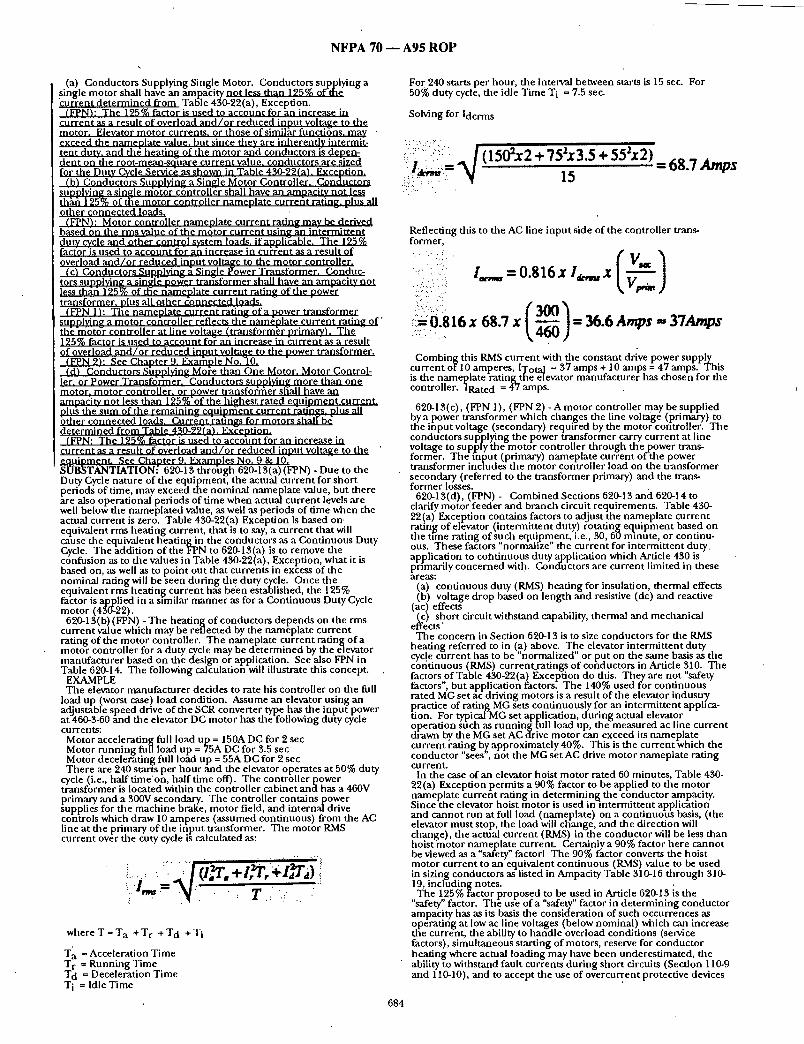
N F P A 70 - - A 9 5 R O P
(a) Conductors Supplying Single Motor. Conductors supplying a single motor shall have an ampacity not less than 125% of the '~;urrent determined from Table 430-22(a), Exception.
(FPN): The 125% factor is used to account for an increase in current as a result of overload a n d / o r reduced inout voltaire to the motor. Elevator motor currents, or those ofsimilhr functitns, may • ¢gceed the nameolate value, but since they are inherently intermit- tent duty, and th~ heatin~ of the motor arid conductors is denen- 0¢nt on the root-mean-so-uare current value, conductors are ~ized for the Duty Cycle Servic~ as shown in Table 430-22(aL Excention.
(b) Condticttrs Suoolvin~ a Single Motor Controller. Conductors st)polvin~ a single nfcft6r c~ntroll~r shall have an amoacitv not less t, hhh 125"°/o of the motor controller nameplate currefit ratln~, plus all other connected loads.
(FPN); Motor controller nameolate current ratin~ may be derived based On the rms value of the m t t o r current nsin~ ~n intermittent duty cycle and other control system loads, if aooli~able. The 125% fac/or'is used to account for ah increase in cuh:ent as a result of overload a n d / o r reduced innut voltatte to the motor controller.
(c) Conductors Suoolvin~ a. Single Power Transformer. Conduc- tors sunolvin~ a sin~l~ bo~er trar~sformer shall have an amoacitv not I~s th:iri i25% of tl~e riamenlate current ratintt of the oow/~r ~raosformer. DIns all other 3onnected loads.
(FPN 1): Tile nameolate current ratin~ of a vower transformer stmolvin~ a motor cofitroller reflects thd'nam6olate current ratin~ of" th~'moto-r controller at line voltage (transformer nrimarv). The 125% factor is used to account fo~ an increase in ~:urrent as a result of overload a n d / o r reduced inout volta~ze to the nower transformer.
(~I '4 2): See Chanter 9. Exarhole No."10. (d) Conductors Shnnlvin~ Mo/'e than One Motor. Motor Control-
ler. or Power Transfdrlner.~Conductors sunolvin~ more than one motor, motor controller, or nower transfofrter sffall have an ;atllpa¢itv not less than 125%'of the highest rated eouioment current. olus t he sum of the remainimt eouiorr~ent current (atih~s. nlus all bther connected loads. Curr~nti-at)nCrs for motors shall'b~ determined from Table 430-22(aL Ex~eotion.
(FPN: The 125% factor is used to account for an increase in current as a result of overload a n d / o r reduced innut voltatte to the ' equipment. See Chanter 9. Examoles No. 9 & 10. SUBSTANTIATION- 620-13 throhgh 620-13(a) (FPN) - Due to the Duty Cycle nature of the equipment, the actual current for short periods of time, may exceed the nominal nameplate value, but there kre also operational periods of time when actualcurrent levels are well beloffthe nameialated value, as well as periods of time when the actual current is zero. Table 430-22(a) Exception is based on. equivalent rms heating current, that is to say, a current that will cause the equivalent heating in the conductors as a Continuous Duty Cycle. The addition of the FPN to 620-13(a) is to remove the confusion as to the values in Table 430-22(a), Exception, what it is based on, as well as to point out that currents in excess of the nominal rating will be seen during the duty cycle. Once the equivalent rms heating current has been established, the 125% fai:tor is applied in a similar manner as for a Continuous Duty Cycle motor (430-22).
620-13(b) (FPN) - The heating of conductors depends on the rms current value which may be reflected by the nameplate current rating of the motor controller. The nameplate current rating of a motor controller for a duty cycle may be determined by the devatur manufacturer based on the design or application. See also FPN in Table 620-14. The following calculation will illustrate this concept.
EXAMPLE The elevator manufacturer decides to rate his controller on the full
load up (worst case) load condition. Assume an elevator using an adjustable speed drive of the SCR converter type has the input power at 460-3-60 and the elevator DC motor has the following duty cycle currents:
Motor accelerating full load up = 150A DC for 2 sec Motor running full load up = 75A DC for 3.5 sec Motor decelerating full load up = 55A DC for 2 sec There are 240 starts per hour and the elevator operates at 50% duty
cycle (i.e., half time'on, half time off). The controller power transformer is located within the controller cabinet and has a 460V primary and a S00V secondary. The controller contains power
pplies for the machine brake, motor field, and internal drive controls which draw 10 amperes (assumed continuous) fi'om the AC line at the primary of the input transformer. The motor RaMS current over the cut), cycle is calculated as:
.... ::
; I - - N ; 7 :: 77;
w h e r e T = T a + T r + T d + T i
T' a = Acceleration Time T r = Running Time T d = Deceleration Time T i = Idle Time
For 240 starts per hour, the interval between starts is 15 sec. For 50% duty cycle, the idle Time T i = 7.5 sec.
Solving for ldcrm s
'.: i.i.":::::".' •.
/tlsex2 + 7s' s.s + = 68. 7 . . . . . . . 15 . - . . - . :
684
Reflecting this to the AC line input side of the controller trans- former,
:::.:: i¢ I.o,., = 0.816 x I ~ x ' (.iii.::. ::: .i:
,i :i :0.816 x 6g.7 x = st.e A ,s = ST ,s . - - . . . .
• " . - . . : ,
Combing this RMS current with the constant drive power supply current ot'10 amperes, ITota I = 37 amps + 10 amps = 47 amps. This is the nameplate rating the elevator manufacturer has chosen for the controller. ]Rated = 47 amps.
620-13(c), (FPN 1), (FPN 9) - A motor controller may be supplied by a power transformer which changes the line voltage (primary) to the input voltage (secondary) required by the motor controller. The conductors supplying the power transformer carry current at line voltage to supply the motor controller through thepower trans- former. The-fnput (primary) nameplate current of-the power transformer includes the motor controller load on the transformer secondary (referred to the transformer primary) and the trans- former losses.
620-13(d), (FPN) - Combined Sections 620-13 and 620-14 to clarify motor feeder and branch circuit requirements. Table 430- 22(a) Exception contains factors to adjust the nameplate current rating of elevator (intermittent duty) rotating equipment based on the time rating of such equipment, i.e., 30, 60 minute, or continu- ous. These fac-tors "norrnalize" the current for intermittent du ty application to cotTtinuous duty application which Article 430 is primarily concerned wit h. Conductors are current limited in these a r e a s :
(a) continuous duty (RMS) heating for insulation, thermal effects (b) voltage drop based on length and resistive (dc) and reactive
(ac) effects (c) short circuit withstand capability, thermal and mechanical
effects' The concern in Section 620-13 is to size conductors for the RMS
heating referred to in (a) above. The elevator intermittent duty cycle current has to be "normalized" or put on the same basis as the continuous (RMS) current_ratings of conductors in Article 310. The factors of Table 450-22(a) Exception do dais. They are not "safety factors", but application factors. The 140% used for continuous rated MG setac driving motors is a result of the elevator industry practice of rating MG sets continuously for an intermittent apph"ca- don. For typical MG set application, during actual elevator operation su-ch as running full load up, the measured ac line current di-awn by the MG set AC drive motor can exceed its nameplate current rating b~, approximately 40%. This is the current which the conductor "sees ', not the MG set AC drive motor nameplate rating cu rre nt.
In the case of an elevator hoist motor rated 60 minutes, Table 430- 22(a) Exception permits a 00% factor to be applied to the motor nameplate current rating in determining the conductor ampacity. Since-the elevator hoist motor is used in intermittent application and cannot run at full load (nameplate) on a continuous basis, (the elevator must stop, the load will change, and the direction will change), the actual current (RMS) in the conductor will be less than hoist motor nameplate current. Certainly a 00% factor here cannot he viewed as a "safety" factorl The 00% factor converts the hoist motor current to an equivalent continuous (RMS) value to be used in sizing conductors as listed in Ampacity Table 310-16 through 310- 19, including notes. The 125% i'actor proposed to be used in Article 620-13 is the
"safety" factor. The use of a "safety" factor in determining conductor ampacity has as its basis the consideration of such occurrences as operating at low ac line voltages (below nominal) which can increase the current, the ability to handle overload conditions (service factors), simultaneous starting of motors, reserve for conductor heating where actual loading may have been underestimated, the ability to withstand fault currentsdur ing short circuits (Section 110-9 and 110-10), and to accept the use of overcu~ent protective devices

N F P A 70 - - A 9 5 R O P
which may by Code (Section 430-40) exceed the con t inuous rating of a conductor by us ing the nex t larger nomina l size device and therefore subject the conduc to r to h igher cont inuous (RMS) current .
Consider the case of a motor with a 15% service factor (allowed overload by design) coupled with a 10% ac line voltage reduct ion dur ing a brown-out (allowed voltage reduction by design). This situation could result in a cumulatave cur rent increase of 25% = (15% + I0%) for an ex tended period of t ime in the conductor su plyin a m o t o r g • . .
~hle proposals for Secuon 620-13 and Chapter 9 Examples No. 9 and I0 where the 125% factor is required in the calculations is appended . The cont inued use of the 125% factor in Article 620 is consistent with the Purpose of the NEC, Article 90"...the practical safeguarding of persons and property from hazards arising f r o m the use of electricity."
NOTE: Suppor t ing material is available for review at NFPA Headquarters . PANEL ACTION: Accept. NUMBER OF PANEL MEMBERS ELIGIBLE TO VOTE: 12 VOTE ON PANEL ACTION:
AFFIRMATIVE: 12
£Log #1285) 12-34 - (620-14): Accept
. SUBMITTER: Raloh E. Droste, Farmington, CT RECOMMENDATION: Deleted and combined with 620-13. SUBSTANTIATION: See substantiat ion for Proposal 12-33 (Log #1284).
NOTE: Suppo r t i ng material is available t'or review at NFPA Headquarters . PANEL ACTION: Accept. NUMBER OF PANEL MEMBERS ELIGIBLE TO VOTE: 12 VOTE ON PANEL ACTION:
AFFIRMATIVE: 12
(Log #1229) 12-35- (620-14(b)): Reject SUBMITTE .R: Tad Drake, Eagle, MI RECOMMENDATION: Delete "reflected to the primary side of the t ransformer" and replace with "times the ratio of secondary voltage over pr imary voltage" to read as follows:
" ... namepla te cu r ren t rat ing of the power conversion e q u i p m e n t t imes the ratio of secondary voltage over nr imarv vo l t age . . . . " SUBSTANTIATION: It is no t cle~ar what'is reqt/ired w~en the word "reflected to the primary" is used. T he proposed wording makes the mean ing of this section exactly clear. PANEL ACTION: Reject. PANEL STATEMENT: "Reflected to the primary side of the t ransformer" is accepted electrical eng ineer ing terminology. See Panel Action on Proposal 12-34 and 12-33. NUMBER OF PANEL MEMBERS ELIGIBLE TO VOTE: 12 VOTE ON PANEL ACTION:
AFFIRMATIVE: 12
(Log#1286) 12-36- (620-15): Accept SUBMITTER: Raloh E. Droste, Farmington, CT RECOMMENDATION: R e n u m b e r 620'15 as 620-14 and revise to
] read: [ 620-14-I-~. Feeder D e m a n d Factor. Feeder conductors of less ] ampaci ty than requi red by Section 620-13 ~ , d 52~-1 ~" shall be I permit ted, subject to the requi rements of CccZIG. 430-2~ ~ , d Table 1 620-,14,~ - -
Table 620-14 4~ Feeder Demand Factors for Elevators
Number of Elevators DF - on aSingle Feeder
I 1.0 2 .95 3 .90 4 .85 5 .82 6 .79 7 .77 8 .75 9' .73
I0 or more .72
(FPN): Demand Factors (DF) are based on 50 percen t duty cycle (i.e., half t ime on and half t ime off). . SUBSTANTIATION: Section 620-15 is r e n u m b e r e d 620-14 as a s tand alone section.
NOTE: Suppor t ing material is available for review a tNFPA Headquarters . PANEL ACTION: Accept. NUMBER OF PANEL MEMBERS ELIGIBLE TO VOTE: 12 VOTE ON PANEL ACTION:
AFFIRMATIVE: "12
(Log #1287) 12-37 - (620-15-(New)): Accept in Principle SUBMITTER: Ralph E. Droste, Farmington, CT RECOMMENDATION: Add new Section 620-15 to read as follows:
620-15. Motor Controller Ratintt. The Motor Controller tt, a t iog shall comolv with Section 430-83."exceot the radn~ shall be oermitted" to be less-than the nomina l ~atin~ of th~ elevator motor. {vhen the controller inherent ly limits the a~Tailable power to the motor.
(FPN): For controller markings see Section 430-8. SUBSTANTIATION: The new rule recognizes that wl~en an elevator application does no t require the full namepla te rating of ' the motor in conjunctio'n with a .motor controller, which limits the available power to the motor, such as an adjustable speed drive system, then a motor controller of smaller rating than the motor nampla te rating is suitable.
NOTE: Suppor t ing material is available for review at NFPA Headquarters . PANEL ACTION: Accept in Principle.
Place a period after Section 430-83. Delete "except", capitalize the "t" in "the" and insert the words "and is marked as power limited" at the end of the s e n t e n c e . PANEL STATEMENT: See Panel Action on Proposal 12-32 (620-15) and the NEC style manual . . NUMBER OF PANEL MEMBERS ELIGIBLE TO VOTE: 12 VOTE ON PANEL ACTION:
AFFIRMATIVE: 12
(Log #1288) 12-38 - (620-21): Accept SUBMI1TER: Ralph E. Droste, Farmington, CT RECOMMENDATION: Revise as follows:
620-21. Wiring Methods. Conductors and ontical fibers located in hoistways, in escalator and moving walk wellw~.ys, in wheelchair lifts, stairway chair lift runways, and machinery spaces, in or on cars, and in mach ine and control rooms, no t including the traveling cables connec t ing the car or counterweigh1; and hoistway wiring, shall be installed in rigid metal conduit , ir~termediate metal conduit , electrical metallic tubing, rigid nonmetal l ic conduit , or wireways, or shall be Type MC, MI or AC cable unless otherwise nermi t ted in (a) t h rough (c~ below. - " " ~aLzammm (1~ Hoistwav~, .C~. Flexible metal condui t or l iquidfight flexible metal condui t
sh~ l be per mi.tt, ed !nho. i s~ays , ,~d ! , ; ,.~,.oJ',,~,,,; ,,;,:d ,..~ ;;.,..~.~;~.',I~
. . . . c' . ; , , , . , 7 o v , , ~ , between risers and limit switches, interlocks, operat ing buttons, and similar devices. '
LILL Cables used in Class 2 power-limited circuits (30 volts R.MS or less or 49 VDC or less) shall be permi t ted to be installed between risers and signal equ ipmen t a n d operat ing devices provided the cables are suppor ted and protected from physical nbtrse ~ and are of a jacketed a.n.d flameTre~r.dan, t t y p e . . . . . . . . . . . . . . . .
rm Car. ' .C~ Flexible metal condui t or l iquidtight flexible metal conduit , of
3 /8- inch nomina l trade size or lar~er, no t exceeding 6 feet (1.83 m) in length shall be permi t ted on ca~ where so located as to be free f rom oil and ff securely fas tened in place.
Hard-service cords and j un io r hard-service cords conforming to the requi rements of Article 400 (Table 400-4) shall be permi t ted as flexible connect ions between the fixed wiring on the car and devices on the car doors or gates. Hard-service cords only shall be" permi t ted as flexible connect ions for the top-of-car operat ing device or the car-top work light. Devices or fixtures shall be g r o u n d e d by means of an e q u i p m e n t g round ing conduc to r run wi th the circuit conductors . Cables with smaller conductors and o ther types an d
685 •

N F P A 70 ~ A 9 5 R O P
thicknesses of insulation and jackets shall be permit ted as flexible connect ions between the fixed wiring on the car and devices on the car doors or gates, if listed for this use.
(c) Flexible cords and cables that are comoonen t s of listed e q u i p m e n t and used in low voltage circuits ~30 volts RMS or less or 42 volts dc or less/shal l be nermrt ted in lengths no t I;9 exceed 6 feet (1.83 m / n r o v i d e d the cords and c~bles are s 'utDorted and nroteo;¢d f romphysica l damage and are of a i acke ted add f lame-retardant
"~3 ) Machine Room and Machinery St)aces. Flexible metal condui t or liqu'idt]ght flexible metal conduit , 9.~
3/8- inch nominal trade size or lar~er, no t exceeding 6 feet (1.83 m) in length, shall be permit ted between control panels mad machine motors, mach ine brakes, motor-genera tor sets, d isconnect ing means, and p u m p i n g uni t motors and valves.
Where motor-generators, mach ine motors, or p u m p i n g uni t motors and valves are located adjacent to or u n d e r n e a t h control equ ipmen t and are provided with extra-length terminal leads not exceeding 6 feet (1.83 m) in length, such leads shall be permit ted to be ex tended to connect direcdy to controller terminal studs widlout egard to die carrying-capacity requi rements of Articles 430 and 445. kuxiliary gutters shal l be permi t ted in mach ine and control ro'oms )etween controllers, starters, and similar apparatus. (c) Flexible cords and cables that are comoonent~ 9f listed
e a d i n m e n t and used in low voltage circuits ~'30 volts RMS or less or 42 volts dc or less1 shall be nerrni~tted in l e n ~ h s not to exceed 6 feet (1.83 m / o r o v i d e d the cords and cables are suonol ' ted and orotectgd from ohvsical damage and are o f a iacketed arid flame-retar 'dant
Ld_)- On existing or listed equ ipment , conductors shall also be permit ted to be ~rouped together and taped or corded without being installed in a raceway. Such cable groups shall be suppor ted at intervals no t over 3 feet (914 ram) and so located as to be fvt-e Rr..O.lgg-L¢~ from physical damage.
(4) Counterweight. Flexible metal conduit , l iquidtight flexible metal conduit , or'flexible cords and cables, or conductors g rouped together and taped or corded that are part of listed equipment , a driving machine, or a driving m a c h i n e b r a k e shall be permit ted on the counterweight assembly, in lengths not to exceed 6 feet (1.83 m) without being installed in a raceway and where located to be fmre pxg.Le..qL~ from physical damage and are of a f lame-retardant tvpe.
LI.). Flexible metal condui t or l iquidtight flexible metal condui t shall be permit ted in escalator and moving walk wellways. Flexible metal condui t or l iquidtight flexible metal conduit , or 3 /8- inch nominal trade size, shall be permit ted in lengths no t in excess of 6 feet (1.83 m).
Lg~ Cables used in Class 2 power-limited circuits (30 volts RMS or less or 42 volts dc or less) shall be permit ted to be installed within escalators and moving walkways provided die cables are suppor ted and protected from physical ~ ~ and are of jacketed and f lame-retardant type.
Hard-service cords conforming to the requi rements of Article 400 (Table 400-4) shall be permit ted as flexible connect ions on escalators and moving walk elevator control panels and disconnect- ing means where the entire control panel and disconnect ing means are a r ranged for removal f rom mach ine spaces as permi t ted in Section 620-72.
(cl Wheelchair Lifts and Stairway Chair Lift Raceways. LI.). Flexible metal condui t or li.q]uidtight flexible metal condui t
shall be permit ted in wheelchair lifts and stairway chair lift runways and machinery spaces. Flexible metal condui t or l iquidtight flexible metal conduit , of 3 /8- inch nomina l trade size, shall be permi t ted in lengths not in excess of 6 feet (1.83 m).
Cables used in Class 2 power-limited circuits (30 volts RMS or less or 42 volts dc or less) shall be permit ted to be installed within wheelchair lifts and stairway chair lift runways and machinery spaces provided the cables are suppor ted a n d p r o t e c t e d from phys i ca l n b ~ a_~ll_~g_ and are of a jacke ted andf lame-retarc lant type. SUBSTANTIATION: 620-21 (a) (1) - See new Section 620-2. Definitions. Similar to present Exception No. 1. The word "abuse" was replaced widl "damage" to agree with other 620-21 subsections.
620-21 (a)(2)(a) -Similar to present Exception Nos. 2 & 5. 620-21(a) (2) (b) - Similar to present Exception No. 3. 620-21 (a) (2) (c) - To permi t shor t lengths of flexible cords and
cables if part of listed e q u i p m e n t such as t ransducers (position, velocity, direction) and used in low voltage circuits.
620-21 (a) (3) (a) - Same as present Exception Nos. 4 and 5. 620-21 (a) (3) (b) - Same as last paragraph of 620-21. 620-21 (a) (3) (c) - To permi t shor t lengths of flexible cords and
cables if part of listed e q u i p m e n t such as t ransducers (position, velocity, direction) and used in low voltage circuits.
620-21 (a) (3) (d) - Same as present Exception No. 4. The word "free" was replaced with "protected" to agree with other 620-21 subsections.
620-21(a)(4) -Same as present Exception No. 7. The word "free" was replaced with "protected" to agree with o ther 620-21 subsections.
620-21(b) (1) -Similar to present Exception Nos. 1 and 5. 620-21 (b) (2) - Similar to ~resent Exception No.1. The word
"abuse" was replaced with damage" to agree with other 620-21 subsections.
620-21(b) (3) - Same as present Exception No. 6. 620-21(c) (1) - Same as p resen t Exception Nos. 1 and 5. 620-21(c) (2) -Same as present Exception No. 1. The word "abuse"
was replaced with "damage" to agree with other 620-21 subsections. NOTE: Suppor t ing material is available for review at NFPA
Headquarters. PANEL ACTION: Accept. NUMBER OF PANEL MEMBERS ELIGIBLE TO VOTE: 12 VOTE ON PANEL ACTION:
AFFIRMATIVE/ 12
12-39 - (620-21): Reject (Log #3664) SUBMITTER: Charles M. Trout, Main Electric Company RECOMMENDATION: At the end of the paragraph, delete die wording "or AC cable." SUBSTANTIATION: Article 333 prohibits the use of AC cable where exposed or subject to excessive moisture or dampness . It also prohibits its use in many areas where die public is involved such as, theaters, places of assembly, in mot ion picture studios, etc. The g round ing capabilities are, in my opinion, suspect at best, and unreliable. Type AC cable was not, in my opinion, in tended for use in areas where the public could be at risk. Elevators and similar equ ipmen t in their hoistway are many t imes areas where consider- able moisture or oil residue is present. Type AC cable cannot be used where subject to physical damage according to Section 333-3. The hoistway and o ther areas involved with elevators and similar equ ipmen t present the possibility of physical damage. There is no n e e d t o use AC cable here. PANEL ACTION: Reject. PANEL STATEMENT: No techncial substantiat ion is provided to
"support the comment . The concerns expressed by the submit ter are adequately addressed by the NEC e.g.
1. Excessive moisture or dampness (110-11,300-6) 2. Grounding capabilities [250-91(b) (6) ] 3. Physical damage. Proper installation (location and support) of
AC cable in hoistways and o ther areas involved with elevators and similar equ ipmen t satisfies NEC (110-12 Article 333). NUMBER OF PANEL'MEMBERS ELIGIBLE TO VOTE: 12 VOTE ON PANEL.ACTION:
AFFIRMATIVE: 11 NEGATIVE: Trou t
EXPLANATION OF NEGATIVE: TROUT: I do not agree with the panel action to reject. I believe
die panel should "Accept in Principle" this proposal and revise the wording by adding "with g round" after AC Cable. This would assure the use of a cable more similar to MC cable which is permi t ted in dais section.
(Log #89) 12-40 - (620-21, Exceptions 1, 2, 4, 5, 6 and 7 (New)): Accept in Principle
Note: The following proposal consists of C o m m e n t 12-35 on Proposal 12-68 in the 1992 Annua l Meeting National Electrical Code Technical Commit tee Report. This C o m m e n t was held ' for fur ther study dur ing the processing of the 1993 NATIONAL ELECTRICAL CODE. The r ecommenda t ion in Proposal 12-68 was:
Insert ",liquidtight flexible metal conduit" after "flexible metal conduit" for the six t imes it appears t h r o u g h o u t the six indicated Exceptions. SUBMITTER: Laurence A. Ward, NEMA RECOMMENDATION: This proposal shou ld be modif ied to include "liquidtight flexible nonmetal l ic conduit" after "liquidtight flexible metal conduit" for the six t imes it appears througl iout the six indicated exceptions. SUBSTANTIATION: NEMA recognizes that this was a CMP proposal but in light of the fact that it considers the s m larity of the. wiring methods NEMA believes that the apparen t modification was overlooked, and that the materials are equivalent.
Liquidtight flexible nonmetal l ic condui t (LFNC) is a proper wiring m e t h o d for these exceptions because it has identical characteristics, except for crush resistance, as l iquidtight flexible metal condui t (LFMC). Since these exceptions cover installations no t subject to physical damage, or recognizing open conductors g rouped or taped together, crush resistance is not an issue.
686

NFPA 70 m A95 ROP
PANEL ACTION: Accept in Principle. PANEL STATEMENT: See Panel Action on proposals 12-41, 42, 43, 44, 45 and 46. NUMBER OF PANEL MEMBERS ELIGIBLE TO VOTE: 12 VOTE ON PANEL ACTION:
AFFIRMATIVE: 12 ..,
(Log #1980) 12-41 - (620-21, Exception No. 1)i Accept in Principle Note: The Technical .Correlating Committee directs that the Panel
clarify the Panel Action on this Proposal" This action will be considered by the Panel as a Public Comment. SUBMITrER: Ronald R. Runkles, National Electrical Manufactur- ers Association RECOMMENDATION: In the first line of the exception, after "liquidtight flexible metal," add "or nonmetallic." SUBSTANTIATION: The use of liquidtight flexible nonmetallic conduit is permit ted in many code sections where flexibility is required. Reference sections 501-4(b), 502-4(a)(2), 620-39, and 645- 5(d) (2). This is a similar application. PANEL ACTION: Accept m Principle. .
Revise 620-21 (a) (1) (a) as follows: Flexible metal conduit or liquidtight flexible metal conduit and
liquidtight flexible nonmetallic conduit shall... PANEL STATEMENT: See proposal 12-38. NUMBER OF PANEL MEMBERS ELIGIBLE TO VOTE: 12 VOTE ON PANEL ACTION:
AFFIRMATIVE: 12
(Log #1981 ) 12-42- (620-21, Exception No. 2): Accept in Principle Note: The Technical Correlating Committee directs that the Panel
clarify the Panel Action on this Proposal. This acdon will be • ' considered by the Panel as a Public Comment. SUBMrrTER: Ronald 1L Runkles, National Electrical Manufactur- ers Association RECOMMENDATION: In the first line of the exception, after "liquidtight flexible metal," ad "or nonmetallic." SUBSTANTIATION: The use of liquidtight flexible nonmetallic conduit is permit ted in many code secdons where flexibility is required. Reference secdons 501-4(b), 502-4(a) (2), 620-39, and 645- 5(d) (2). This is a similar application. PANEL ACTION: Accept m Principle.
. Revise 620-21 (a) (2)a as follows: Flexible metal conduit or li.cjuidtight flexible metal conduit and
liquidtight flexible nonmetalhc conduit shall... PANEL STATEMENT: See Panel action for proposal 12-38. NUMBER OF PANEL MEMBERS ELIGIBLE TO VOTE: 12 VOTE ON PANEL ACTION:
AFFIRMATIVE: 12
(Log #1982) 12-43- (620-21, Exception No. 4): Accept in Principle Note: The Technical Correl=iting Committee directs that the Panel
clarify the Panel Action on this Proposal. This action will be "" considered by the Panel as a Public Comment . SUBMITTER= Ronald IL Runkles, National Electrical Manufactur- ers Association RECOMMENDATION: In the first line of the exception, after "liquidtight flexible metal," add "or nonmetallic." SUBSTANTIATION: The use of liquidtight flexible nonmetall ic conduit is permit ted in many code sections where flexibility is required. Reference sections 501-4(b), 502-4(a) (2), 620-39, and 645- 5(d) (2). This is a similar application. PANEL ACTION: Accept zn Principle.
Revise 620-21 (a) (3) (a) as follows: Flexible metal conduit or li.cjuidtight flexible metal conduit and
liquidtight flexible nonmetalhc conduit shall... PANEL STATEMENT: See Panel action for proposal 12-38. NUMBER OF PANEL MEMBERS ELIGIBLETOVOTE: 12 VOTE ON PANEL ACTION:
AFFIRMATIVE: 12
(Log #1983) [ 12-44- (620-21, Exception No. 5): Accept in Principle
I SUBMITTER: Ronald R. Runkles, National Electrical Manufactur- ers Association RECOMMENDATION: In the first line of the exception, after
""liquidtight flexible metal," add "or nonmetallic."
687
SUBSTANTIATION: The use of liquidtight flexible nonmetall ic conduit is permit ted in many code sections where flexibility is required. Reference sections 501-4(b), 502-4(a) (2), 620-39, and 645- 5(d) (2). This is a similar application. PANEL ACTION: Accept in Principle. PANEL STATEMENT: See panel action for proposals12-42 and 12- 43. NUMBER OF PANEL MEMBERS ELIGIBLE TO VOTE: 12 VOTE ON PANEL ACTION:
AFFIRMATIVE: 12
(Log #1984) 12-45 - (620-21, Exception No. 6): Accept in Principle
Note: The Technical Correlating Committee directs that the Panel clarify the Panel Action on this Proposal. This action will be considered by the Panel as a Public Comment . SUBMITTRR: Ronald R. Runldes, National Electrical Manufactur- ers Association RECOMMENDATION: In the second line of the exception, after "liquldtight flexible metal," add "or nonmetallic.". SUBSTANTIATION: The use of liquidtight flexible" nonmetallic conduit is permit ted in many code sections where flexible is required. Reference sections 501-4(b), 502-4(a)(2), 620-39, and 645- (d) (2). This is a similar application. PANEL ACTION: Accept in Principle.
Reyise 620-21(b)(1) as follows: Flexible metal conduit or liquidtight flexible metal conduit and
liquidtight flexible nonmetallic conduit shall... PANEL STATEMENT: See Panel action forproposa l 12-38. NUMBER OF PANEL MEMBERS ELIGIBLE TOVOTE:' 12
• VOTE ON PANEL ACTION.: AFFIRMATIVE: 12
(Log #1985) 12-46- (620-21, Exception No. 7) : 'Accept in Principle
Note: The Technical Correlating Committee directs that the Panel clarify the Panel Action on this Proposal. This action will be considered by the Panel as a Public Comment. SUBMITTER: Ronald IL Runldes, National Electrical Manufactur- ers Association RECOMMENDATION: In the first line of the exception, after "liquidtight flexible metal," add "or nonmetallic." SUBSTANTIATION: The use of llquidtight flexible nonmetall ic conduit is permit ted in many code sections where flexibility is required. Reference sections 501-4(b), 502-4(a)(2), 620-39, and 645- 5(d) (2). This is a similar application. PANEL ACTION: Accept in Principle.
Revise 620-21 (a) (4) as follows: Flexible metal conduit or liquidtight flexible metal conduit and
liquidtight flexible nonmetallic conduit shall... PANEL STATEMENT: See Panel action for Proposal 1 2 - 3 8 . . . NUMBER OF PANEL MEMBERS ELIGIBLE TOVOTE: 12 VOTE ON PANEL ACTION:
AFFIRMATIVE: 12
(Log #1289) 12-47 - (620-22): Accept in Principle SUBMI'FrF.R: Ralph E. Droste, Farmington, CT RECOMMENDATION: Revise as follows:
620-22. Branch Circuits for Car Lighting, A:~c~G,;w, Receptacle(s~ Ventilation. Heating, and Air Conditioning.
(a) Car Light Sou rce. A ~ ~ branch circuit shall supply the car lights, receptacle(s) and accc~,n ;,.o ventilation on each elevator car.
(b) Air Condit ioning and Heating Source. A ~ ~ p . g l : g ~ branch circuit shall supply the air condit ioning and heating units on each elevator car. SUBSTANTIATION: See 240-21 (a) "Accessories" and "dedicated" are vague terms. To clearly identify equipment permit ted on separate branch circuits.
NOTE: Support ing material is available for review at NFPA Headquarters. PANEL ACTION: Accept in Principle.
Revise as follows: 620-22. Branch Circuits for Car Lighting, Receptacle (s) Ventilation, Heating, and Air Conditioning.
(a) Car Light Source. A separate branch circuit shall supply the car lights, receptacle(s), auxaliary ligilting power source and . ventilation on each elevator car.

NFPA 70 - - A95 ROP
PANEL STATEMENT: See panel action and statement for 12-32. NUMBER OF PANEL MEMBERS ELIGIBLE TO VOTE: 12 VOTE ON PANEL ACTION:
AFFIRMATIVE: 12 COMMENT ON AFFIRMATIVE:
DROSTE: Add to the end of Panel Statement: "(620-22(a))". This clarifies what part of 12-32 is involved.
(Log #2738) 12-48- (620-22(c)-(New)): Reject SUBM]TrER: ThomasJ. Morosco, Independent Electrical Inspection Agency, Inc. RECOMMENDATION: Add:
(c) A disconnect means shall be provided for each designated branch circuit supplying equipment located on or in the elevator car to isolate for servicing. SUBSTANTIATION: Servide persons making repairs or adjustments to an elevator car are usually in a position on top of the car unit and should have total control of the item theyare servicing. PANEL ACTION: Reject. PANEL STATEMENT: Requirements are adequately covered in Proposals 12-66 (620-53), 12-67 (620-54). NUMBER OF PANEL MEMBERS ELIGIBLE TO VOTE: 12 VOTE ON PANEL ACTION:
AFFIRMATIVE: 12
(Log #1291 ) 2-51 - (620-24-(New)): Accept Note: It was the action of the Technical Correlating Committee
that this Prol?osai be reconsidered with reference to illumination levels, which is not a subject covered by the NEC:. This action will be considered by the Panel as a Public Comment. SUBMITTER: Ralph E. Droste, Farmington, CT RECOMMENDATION: Add new Section 620-24 to read:
620-24. Branch Circuit for Hoistway Pit Lighting and Receptacle(s).
(a) A separate branch circuit shall supply the hoistway pit lighting and receptacle(s).
(b) The lighting shall provide an illumination of not less than 54 I lux (5 foot candies) at the pit floor. i (c) The lighting switch shall be so located as to be readily !accessible from the pit access door.
(d) At least one 125 volt, single phase, duplex receptacle shall be ~ provided in the hoistway pit. 'SUBSTANTIATION: To harmonize with the Canadian Electrical Code C.SA C22.1 Section 38-054 and the ASME/ANSI A17.1-1993 Rule 106.1e.
NOTE: Supporting material is available for review at NFPA Headquarters. PANEL ACTION: Accept. NUMBER OF PANEL MEMBERS ELIGIBLE TO VOTE: 12 VOTE ON PANEL ACTION:
AFFIRMATIVE: 12
(Log #888) • 12-49 - (020-23-(New)): Accept in Principle SUBMITTER: Victor V. Timpanaro, Municipal Electrical Inspectors Assoc. of NJ, Inc. RECOMMENDATION: Add new text:
Receptacle Circuit for Hoistway and Machine Room. A branch circuit rated 20 ampere, 125 volt, GFCI protected shall be provided for servicing, maintenance of elevator equipment. SUBSTANTIATION: There doesn ' t appear to be any provision for 125 v, 20 amp receptacle outlets in the areas where servicing of the elevator equipment may take place. PANEL ACTION: Accept in Principle• PANEL STATEMENT: See Panel action for proposals 12-50, 12-51 and 12-79 NUMBER OF PANEL MEMBERS ELIGIBLE TO VOTE: 12 VOTE ON PANEL ACTION:
AFFIRMATIVE: 12
, (Log #1290) 12-50 - (620-23-(New)): Accept Note: It was the action of the Technical Correlating Committee
that this Proposal be reconsidered with reference to illumination levels, which is not a subject covered by the NEC. This action will be considered by the Panel as a Public Comment. SUBMITI'ER: Ralph E. Droste, Farmington, CT RECOMMENDATION: Add new Section 620-23 to read:
620-23. Branch Circuit for Machine Room/Machinery Space Lighting and Receptad e (s).
(a) A separate branch circuit shall supply the machine r o o m / machinery space lighting and receptacle(s).
(b) Tile lighting shall provide an illumination of not less than 108 lux (10 foot candles) at floor level.
(c) The machine room lighting switch shall be located at the point of entry to such machine rooms/machinery spaces.
(d). At least one 125 volt, single phase, duplex receptacle shall be provided in each machine room and machinery space. SUBSTANTIATION: To harmonize with the Canadian Electrical Code CSA C22.1 Section 38-052 and ASME/ANSI A17.1-1993 Rule 101.5.
NOTE: Supporting material is available for review at NFPA Headquarters. PANEL ACTION: Accept. NUMBER OF PANEL MEMBERS ELIGIBLE TO VOTE: 12 VOTE ON PANEL ACTION:
AFFIRMATIVE: 12
(Log #1292) 12-52- (620-31): Accept SUBMrrTER: Ralph E. Droste, Farmington, CT
I RECOMMENDATION: Revise as follows: I 629-31. P ~ c c ~ y T~, , ,&,~ F;~;~L;tS. C , ~ , , d ~ , s ~',,,d', """ 'V"y ~;",I, ]£¢,.d,,u 3,?,0-hT,(b). IL, l ~ d , , , ~ ;,a,.,C . . . . . . . jo r,.~jcc~ ,q,,,,, :l,c
] SUBSTANTIATION: Deleted. The second sentence applies to existing installations and is no longer permitted.
NOTE: Supporting material is available for review at NFPA Headquarters. PANEL ACTION: Accept. NUMBER OF PANEL MEMBERS ELIGIBLE TO VOTE: 12 VOTE ON PANEL ACTION:
AFFIRMATIVE: 12
(Log #1293) 12-53 - (620-32): Accept SUBMITTER: Ralph E. Droste, Farmington, CT
] RECOMMENDATION: Revise as follows: I 620-32. Wireways. Sc,.:~G,, 3,52-5 aL,,l': ,,Gi ~t-'t-'ly iG ;d, ,.,;a~a. The [ sum of the cross-sectional area of the individual conductors in a [ wireway shall not be more than 50 percent of the interior cross- [ sectional area of the wireway. [ Vertical runs of wireways shall be securely supported at intervals not [exceeding 15 feet (4.57 m) and shall have not more than one jo in t [ between supports. Adjoining wireway sections shall be securely [ fastened together to provide a rigid joint. SUBSTANTIATION: Self-explanatory. See Sections 90-3 and 362-5 F.xception No. 3.
NOTE: Supporting material is available for review at NFPA Headquarters. PANEL ACTION: Accept, NUMBER OF PANEL MEMBERS ELIGIBLE TO VOTE: 12 VOTE ON PANEL ACTION:
AFFIRMATIVE: 12
(Log #2056) 12-54 - (020-32-(New)): Accept in Principle in Part SUBMITTER: Charles W Forsberg, Carlon Electrical Products, A Larnson & Sessions Co. RECOMMENDATION: 620-32 Wireways.
(a) Metal wireways. Insert the existing 2 paragraphs as written except add the word "metal" before the word "wireway" wherever it appears in these 2 paragraphs.
(b) Nonmetallic wireways. Section 362-19 shall apply to nonmetal- lic wireways. Vertical runs of nonmetallic wireway shall be suppor ted in accordance with Section 362-22, Exception. SUBSTANTIATION: This is an appropriate use for nonmetallic wireway. It is proper to reference conducior derating and wireway support as specified in Article 362, Part B.
688
N F P A 70 - - A 9 5 R O P
PANEL ACTION: Accept in Principle in Part. I Revise as the heading as follows: "620-32. Metal Wireways and [ Nonmetallic Wireways." PANEL STATEMENT: See Panel Action for Proposal 12-53.
The Panel does not accept the (b) paragraph of the proposal that pertains to Section 362-19. Elevator apphcation use is intermittent, see Section 620-15 in the 1993 NEC. NUMBER OF PANEL MEMBERS ELIGIBLE TO VOTE: 12 VOTE ON PANEL ACTION:
AFFIRMATIVE: 12 COMMENT ON AFFIRMATIVE:
DROSTE: Add to the end of Panel Statement "(i.e. 50% duty cycle)" to explain why 620-15 is being referenced.
(Log #1294) 12-55- (620-33): Accept SUBMITTER: Ralph E. Droste, Farmington, CT
[RECOMMENDATION: Revise as follows: [ 620-33. Number of Conductors in Raceways. The sum of the cross- Isectional area of the ,,p,.,ad,,ts ,,;,d cG,,te~l G. cu;t [conductors in raceways shall not exceed 40 percent of the interior ]cross-sectional area of the" raceway, except as permitted in Section |620-32 for wirewavs. SUBSTANTIATION: Same as present Exception, using positive language.
NOTE: Supporting material is available for review at NFPA Headquarters. PANEL ACTION: Accept. ' NUMBER OF PANEL MEMBERS ELIGIBLE TO VOTE: 12 VOTE ON PANEL ACTION:
AFFIRMATIVE: 12
(Log #1355) 12-56 L (620-35): Accept
• SUBMITTER: Jim Pauley, Square D Company [RECOMMENDATION: Delete the words "Wiring Troughs" so [section reads as follows: I 620-35. Auxiliary Gutters. Auxiliary gutters... SUBSTANTIATION: Wiring troughs are not defined in the NEC. Wireways and auxiliary gutters are described in 362-1 and 374-1 respectively. The use of the term wiring troughs can be misleading
• in the application and proper use of an auxiliary gutter in that it implies a. broader spectrum of use beyond that described in 374-1. PANEL ACTION: Accept. NUMBER OF PANEL MEMBERS ELIGIBLE TO VOTE: 12 VOTE ON PANEL ACTION:
AFFIRMATIVE: 12
(Log #1295) 12-57- (620-36): Accept SUBMITTER: Ralph E. Droste, Farmlngton, CT RECOMMENDATION: Revise as follows:
620-36. Different Systems in O n e Raceway or Traveiing Cable. [Ootical fiber cables and conductors for , ,vc,a; l ,~, t o , t , ol,
p'~Fa,0nu~ devices . oneration. . and motion . . . . control .. power , si g naling , righting, ~ h~iting, and alr-conditmmng orcmts of 600 volts or tess shall be permitted to be run in the same traveling cable or raceway system if all conductors are insulated for the maximum ¢oltage ~ annlied tO any conductor within the cables or raceway system and {f all live parts of the equipment are insulated ['rom ground for this maximum voltage. Such a traveling cable or raceway shall also be permit ted to include shielded conductors a n d / or one or more coaxial cables, if such conductors are insulated for the maximum voltage ~ aDDlied tO any conductor within the cable or raceway system. Condtictors sha l lbe permitted to be covered with suitable shielding for telep.hone, audio, video, or higher frequency communicat ion orcmts. SUBSTANTIATION: See Section 770-52(a) and 620-21. NOTE: Supporting material is available for review at NFPA
H eadquarte vs. PANEL ACTION: Accept. NUMBER OF PANEL MEMBERS ELIGIBLE TOVOTE: 12 VOTE ON PANEL ACTION:
AFFIRMATIVE: 12
(L9g #1296) 12-58- (620-37): Accept Note: The Technical Correlating Committee directs that the
Action on this Proposal be rewritten to comply with the NEC Style Manual in regard to mandatory references, and with regard to the style of Fine Print Notes. This action will he considered by the Panel as a Public Conunent- SUBMI'I"FER: Ralph E. Droste, Farmington, CT RECOMMENDATION: Revise as follows:
620-37. Wiring in Hoistways and Machine Rooms. (a~ Only such electric wiring, raceways, and cables used directly in
connect ion with the elevator or dumbwaiter, including wiring for signals, for communicat ion with the car, for lighting, heating, air conditioning, and ventilating the elevator car, for fire deteizting systems, for pit sump pumps, and for beating, m '~ lighting
the hoistway, shall be permit ted inside the hoistway and the machine room. .Cb.). Bonding of elevator rails (c.nar a n d / o r counterwei~bt) to
li~htnin~ protection system ~n-oundine down conducto~(sL shall bg n~rmitt~d'if reouired bv and-iostalled~n ~,ccordance wid~ NFPA 780. ~I'he liuhtnin~ Drotection s ~ t e m ~roundin~ down conductor(s) shall not be~locate~d'within the hoistwa~v. Elevat(~r rails or other hois~way euuinment shall not be used as tile ~ o u n d i n ~ down conductor for li~htnin~ protection systems.
~ee Section 250-46. Main feeders for supplying power to elevators and dumbwaiters
shall be installed outside the hoistway unless permit ted in (1) a n d
LlJ. Byspecial permission, feeders for elevators shall be permit ted within an existing hoistway if no conductors are spliced within the hoistway. L ~ Feeders shall be permit ted inside the hoistway for elevators
with driving machine motors located in the hoistway or on the car or counterweight- SUBSTANTIATION: (a) Same as opening sentence of 620-37.
(b) I fa l ighming protection system grounding "down" conductor(s) , located outside of the hoistway, is within a critical horizontal distance of the elevator rails, bonding of the rails to the lightning protection system grounding "down" conductor(s) is r equ i redby NFPA 780 to prevent a dangerous side flash between the lightning protection system grounding down" conductor(s) and the elevator rails. A l ighming strike on the building air terminal will be conducted through the lillg htning, plrotection system groundin g "down" conductor(s) , a n d if the elevator rails are riot at the same potential as the lightning protection system grou nding "down" conductor(s) a side flash may occur. Equipment and wiring not associated with the elevator is prohibi ted from being installed in elevator machine rooms and hoistways (620-37). Only electrical equipment and wiring used directly in connect ion with the elevator maybe installed inside the hoistway. (Also see ASME/ANSI A17.1 Rule 102.1 and CAN/CSA-B44 Clause 2.4.1)
(c) (1) (2) Same as present Exception Nos. 1 & 2, using positive language.
NOTE: Support ing material is available for review at NFPA Headquarters. PANEL ACTION: Accept. NUMBER OF PANEL MEMBERS ELIGIBLE TO VOTE: 12 VOTE ON PANEL ACTION: AFFIRMATIVE: 12
(Log #555) 12-59- (620-38): Reject , SUBMITrER: Dan Leaf, Palmdale, CA ',
• RECOMMENDATION: Add: "(Classified)" after "hazardous". SUBSTANTIATION: Edit. The hazardous locations of Art. 511 ,are classified under Art. 500. A location may be hazardous due to other conditions, such.as indicated in Sec. 668-32(b), having nothing to do with Class l, II, or III locations. Since the hazardous locations of this section refer to classified locations it would be consistent with other Code sections to specify them as such. The FPN uses the word "classified." PANEL ACTION: Reject. PANEL STATEMENT: Action taken correlates widl the action iaken I~YuMBCMP-I 4 on Proposal 14-238.
ER OF PANEL MEMBERS ELIGIBLE TO VOTE: 1'2 VOTE ON PANEL ACTION:
AFFIRMATIVE: 12
689
!

N F P A 70 - - A 9 5 R O P
(Log #1297 i 14-238- (620-38): Accept
Note: It was the action of the Technical Correlat ing Commit tee that this Proposal be referred to Code-Making Panel 12 for information. SUBMITTER: Ralph E. Droste, Farmington, CT
, RECOMMENDATION: Revise as follows: 620-38. Electric Equ ipmen t in Garages and Similar Occupancies.
] Electric equ ipmen t and wiring used for elevators, dumbwaiters, [escalators, moving walks, and wheelchair lifts and stairway chair lifts in garages shall comply with the requi rements of Article 511 9gi~ng
. . . . .~u'V','?"~ ' ." '~"~" ~.'~ ,~.'~ .~,'~,~ ° ' " , ~ " . . . . . v . . . . . . . . . . . . . . .
(FPN): Garages used for parking or storage and where no repair work is done in accordance with Section 511-2, are no t classified. SUBSTANTIATION: Local code authori t ies have referenced the above sentence in Section 620-38 as a basis for requir ing explosion- proof elevator e q u i p m e n t in garages used for parking or storage where no repair work is done. As indicated in Section 511-2, parking garages u s e d f o r parking or storage and where no repair work is clone except exchange of parts and rout ine ma in tenance requir ing no use of electrical equipment , open [lame, welding, or use of volatile f lammable liquids are no t classified, and there is therefore no hazardous location involved. The r equ i r emen t in Section 511-2 first appeared in the 1975 edition of the Code as part of Section 511- 1. However, the r equ i r emen t in Section 620-38 first appeared in the 1971 edition of the Code, at a t ime when there was no exempt ion f rom hazardous location classification for some types of garages. It would appear, therefore, that the reason for the last sentence in SectiOn 620-38 still appears in the National Electrical Code is because there was no proposal to revise it when Article 511 was changed.
NOTE: Suppor t ing material is available for review at NFPA Headquarters. PANEL ACTION: Accept. PANEL STATEMENT: The Panel requests that the Correlating Commit tee refer this action to CMP-12 for comment• NUMBER OF PANEL MEMBERS ELIGIBLE TO VOTE: 16 VOTE ON PANEL ACTION:
AFFIRMATIVE: 15 NOT RETURNED: Weldon
(Log #1298) 12-60- (620-39): Accept SUBMITTER: Ralph E. Droste, Farmington, CT
[RECOMMENDATION: 620-39. Sidewalk Elevators. ] Deleted. ISUBSTANTIATION: Requi rements adequately covered in Chapters [1-4 (e.g., 110-11,300-6, 310-8 and 310-9). ] NOTE: Suppor t ing material is available for review at NFPA IHeadquarters. PANEL ACTION: Accept. N U M B E R O F PANEL MEMBERS ELIGIBLE TO VOTE: 12 VOTE ON PANEL ACTION:
AFFIRMATIVE: 12
t (Log #140) 6-172 - (620-41 and 400-4 Note6) : Reject SUBMITTER: Stephen C. Smith, Datwyler Cables (USA) Inc. RECOMMENDATION: 620-41: ADD: Traveling Cables shall be suppor ted by one of the following means:
1) by its steel or Aramid Fiber suppor t ing members ; (balance remains the same). SUBSTANTIATION: We have 15 years internat ional experience with this product . UL has approved such an Aramid (Kevlar~) suppor t p roduc t which allows for l ighter weight suppor t member s without sacrificing strength. Aramid products el iminate the potential of conduc tor damage which could occur f rom steel core strands coming into contact with cur rent carrying conductors . This product addresses the issue and is suppor ted by section 400-4 Note 6 regarding "excessive moisture or corrosive vapors and gases."
NOTE: Suppor t ing material is available for review at NFPA Headquarters. PANEL ACTION: Reject. PANEL STATEMENT: Submit ter has no t provided any recommen- dation for action by the committee. NUMBER OF PANEL MEMBERS ELIGIBLE TO VOTE: 10 VOTE ON PANEL ACTION:
AFFIRMATIVE: 10
(Log #1299) 12-61 - (620-44): Accept SUBMITTER: Ralph E. Droste, Farmington, CT RECOMMENDATION: Revise as follows:
620-44. Installation of Traveling Cables. Traveling cable shall be permit ted to be run without the use of a raceway for a distance not exceeding 6 feet (1.83m) in length as measured f rom the first point of suppor t on the elevator car or hoistway wall, or counterweight where applicable, provided the conductors are g rouped together and t a p e d o r corded, or in the original sheath.
Traveling cables shall be permit ted to be cont inued to elevator . . . . h~l v~ .~L controller enclosures and to elevator car mach ine room connect ions, as fixed wiring, provided they are suitable
i suppor ted and protected f rom physical damage. SUBSTANTIATION: To a~ree with new Definitions in 620-2.
NOTE: Suppor t ing material is available for review at NFPA Headquarters . PANEL ACTION: Accept. NUMBER OF PANEL MEMBERS ELIGIBLE TO VOTE: 12 VOTE ON PANEL ACTION:
AFFIRMATIVE: 12
(Log #1300) 12-62 - (620-51): Accept in Principle SUBMITTER: Ralph E. Droste, Farmington, CT RECOMMENDATION: Revise as follows:
F. Disconnect ing Means and Control 620-51. Disconnect ing Means• Elc;a~G,o, du,,,L.;a~c,~, c~,.,d'aLG,~,
• n i i • • . e . • . - * • i , ~ | n | •
single means for d isconnect ing all u n g r o u n d e d main power supply conductors for each uni t shall be t)rovided and be so d e s i s t e d that no Dole can be onerated indenendent lv . Where multiple-driving mab.hines are cofinected to a single ele;cator, escalator, moving walk, or p u m p i n g unit, there shall be one disconnect ing means to d isconnect the motor(s) and control valve operat ing magnets .
The disconnect inu means for the main tower sunnlv conductors shall no t disconnec't the branch circuit reaui red it~ ~sections 620-~2. 2~ a n d 24.
(a) Type. The d isconnect ing means shall be an enclosed externally operable fused motor circuit switch or c!rcuit breaker eat)able o f b e i n u ~ . ;~ ,g , .d to bc locked in the open position. The d!!co_nnecti_ny ~ea, n s sha!! b e a listeddevice. ?:,, t,;~,v:~i?,~. ~L,~',~ L,,.
• ~ * ~ , ,,,?~*~:-~ :y~,,~ ~,~ . . . . ,~?:~, 7•o~a~. ~s-.,
one drivin~ mach ine disconnect in~ means is s u n , l i e d bv a single feeder, the~overcurrent protective'clevices in eacfi disco'nnect~'ng means shall be selectively coordinated with any m,~--n~4- o ther supply side overcurrent I?rotective devices.
(FPN): For adthtional information, see Safety Code for Elevators a n d Escalators, ASME/ANSI A 1 7 . 1 ~ 1993.
Onerat ion. No nrovision shall be made to t h e n or close this discondectin~z means f rom any o ther har t of the ni-emises, ff snrinklers ar~'installed in hoistwavs, n~achine rooms, or machinery snaces, the disconnect in~ means shall be permit ted to automatitaiLy o'nen the hove r sunnlv t3 the affected ele;cator(s~ nrior to the a~nlicatio'n of wate'r~ No nrovision shall be made to autom~lic,~ally close this d isconnect in~ rfieans. Power shall only be restored bv manual means.
(FPN~: To reduce hazards associated with water on live elevator electrical eau inment .
/._Q. L~cation. The d isconnect ing means shall be located where it is readily accessible to qualified persons.
( l) On elevators without genera tor field control, the disconnect- ing means shall be located within sight of the motor controller L.,,.;c, ,.,,,v,., ~,., ',,, ,~,,~,,, ~ , ~,.,. D _ ~ machines or mot ion and onerat ion controllers ,,; , . , , .u ,,I vo~,.l no t within sight of the d isconnect ing means shall be provided with a manual ly operated switch installed in the control circuit to prevent starting. T h e manual ly opera ted switch(s) shall be installed adjacent to this e q u i p m e n t
Where the drivin~ mach ine is located in a remote machinery spate, a single means for~lisconnectin~ all unm-ounded main hove r sunnlv conductors shall be nrovided an~d be capable of being locked in [ l ie o,sen nosition.
(2) On elevators with genera tor field control, the d isconnect ing means shall be located within sight of the motor ~ for the driving motor of the motor-genera tor set. Driving machines, motor- genera tor sets, or mot ion and onerat ion controllers no t within sight of the d isconnect ing means, shall be provided with a manual ly operated switch installed in the control circuit t o p r e v e n t starting. The manual ly operated switch(s) shall be ins ta l ledadjacent to this equipment .
690
N F P A 7 0 - - A 9 5 R O P
Where the drivin~ maizhine, or the m o t o r ~ e n e r a t o r set is located in a remote machinery soace, a single mean~ for d isconnect in~ all u n g r o u n d e d main oowe~ suoolv conductors , shall be provideci'a~l~l becaoab le of bein~ locked in't i le ooen nosition.
(3) "On escalatorffand moving walks, tile d isconnect ing means shall be installed in the space where the controller is located.
(4) On wheelchair lifts and stairway chair lifts, the d isconnect ing means shall be located within s ight of the motor controller. , , ~ w , , , , ~ d , , ~ :.,.;T,,o.o',,all ~ v . . . . . i t t -d ;,', tl,,= . . . . . . . . ' . . . . . . . ;fl,
(d) Identification & Simas. Where there is more than one driving mach ine in a rnachin~ room, the d isconnect ing means shall be n u m b e r e d to cor respond to the ~ n u m b e r of the driving mach ine that they control.
The disconnect in~ means shall be orovided with a siren to identify the location of the-sunnlv side overc'urrent nrotective-device. SUBSTANTIATION:" B2"0-51 - O p e n i n g pa/agraph, to agree with 430-103. Also removed wording in open ing paragraph since it is a repeat of 620-1 (Scope).
6"20-51 second paragraph - Such systems are i n d e p e n d e n t of the control port ion of the elevator. Passenger safety, comfort, and elevator ma in tenance is e n h a n c e d by separat ing the main power supply conductors f rom the car lighting, et al, supply conductors.
620-51 (a) - To agree with 430-109. Also see new Section 6"20-51 (b). • 620-51 (a) second paragraph - Single elevator installations are typically located in low rise s tructures and the electrical service is close to the elevator equ i pmen t and would no t create a problem for elevator ma in tenance personnel in locating supply side overcurrent devices. Also, simplifies compl iance by use of allavailable types of overcurrent devices.
6"20-51, (b) and (b) (FPN) -ASME/ANSI A17.1, Rule 102.2(c) requires that if sprinklers are installed in hoistways, mach ine rooms, or machinery spaces, a means has to be provided to automatically d isconnect the main line power supply to the affected elevator(s) prior to the application o f water. Water on elevator electrical equ ipmen t can result in hazards such as uncont ro l led car movemen t (wet mach ine brakes), and m o v e m e n t of elevator with open doors (water on safety circuits bypassing car a n d / o r hoistway door interlocks). 620-51 (c) t h rough (c) (4) - To correlate the recluirements with new
Definitions in 6"20-2 and to provide for mechanic ' s safety when e q u i p m e n t is located in remote machinery spaces by requir ing a d i s c o n n e c t i n g m e a n s to open all u n g r o u n d e d main power supply conductors. T h e last sentence in 620-51 (c) (4) was deleted since the r equ i r emen t is covered in Section 620-71(a). '
620-51 (d) - Relocated f rom open ing second paragraph of 620-51- and editorial changes.
620-51 (d) last paragraph -See prop.osal on selective coordinat ion of supply side overcurrent protective devices [6"20-51 (a)]. To assist elevator mechanics to t roubleshoot and help locate supply side overcurrent protective device in case of power loss.
NOTE: Suppor t ing material is available for review at NFPA Headquarters .
. PANEL ACTION: Accept in Principle. ] Relocate the second paragraph of Section 6"20-51 (a) of Proposal 1"2- ] 62 to become a new Section 6"20-62 t ided "Selective Coordination." ] unde r Part G.
PANEL STATEMENT: To correlate with the Action on Proposal 1"2- 63. NUMBER OF PANEL MEMBERS ELIGIBLE T O VOTE: 12 VOTE ON PANEL ACTION:
AFFIRMATIVE: 11 NEGATIVE: Droste
EXPLANATION OF NEGAI"IVE: DROSTE: The Commi t tee Action on Proposal 1`2-6`2 was "Accept in
Principle (APR)". T he "Panel Sta tement" and "change" identified by the Panel is correct. COMMENT ON AFFIRMATIVE:
COOK: According to my notes Proposal 1`2.6"2 should be APR rather than A since we modif ied the submittal.
)
(Log #1215) 12-63 - (620-51(a)): Reject SUBMITTER: Scott R. Mahnke, McMahon Associates, Inc. RECOMMENDATION: Delete 2nd paragraph. SUBSTANTIATION: This is a design considerat ion, no t a provision "considered necessary for safety." PANEL ACTION: Reject. PANEL STATEMENT: The Panel is of the opinion tha t it "is a safety issue". Restoration of elevator service is a safety concern, when el~zators are s topped between floors.
NUMBER OF PANEL MEMBERS ELIGIBLE T O VOTE: 12 VOTE ON PANEL ACTION:
AFFIRMATIVE: 12
(Log #1301 ) '12-64- (620-52): Accept
• SUBMITrER: Ralph E. Droste, Farmington, CT ]RECOMMENDATION: Revise as follows: I 620-52. Power f rom More than one source. [ (a) Single and Multi-Car Installations. On single and multi-car ]installations, equ ipmen t receiving electrical power f rom more than lone source shall be provided with a d isconnect ing mean s for each Isource of electrical power. The d isconnect ing means shall be within ]sight of the e q u i p m e n t served. I (b) Warn ing Sign for Multiple Disconnect ing Means. Where mult iple d isconnect ing means are used and parts of the pm' t~ controllers remain energized f rom a source o ther than the one disconnected, a warning sigh shall be m o u n t e d on or nex t to the d isconnect ing means. The sign shall be clearly legible and shall read "Warning - Parts of the C,,uL, v'. ~ , . I (.~0ntroller Are Not De-energized by This Switch".
(c) In terconnect ion Multi-Car C~,.&J, P ~ l o Controllers. Where . in terconnect ions between c~,u~.J. ~,,,,cl~ controllers are necessary for the operat ion of the system on multi-car installations that remain energized f rom a source o ther than the one disconnected, a warning
mo.o e o n next to the d isconnect ing means. TIATION: To coordinate requ i rements with new
Definitions in 620-2 and to conform with NFPA Style Manual. NOTE: Suppor t ing material is available for review at NFPA
Headquarters . PANEL ACTION: Accept. NUMBER OF PANEL MEMBERS ELIGIBLE T O VOTE: 12 VOTE ON PANEL ACTION:
AFFIRMATIVE: 12
(Log #2739) 12.65- (620-52(d)-(New)): Reject SUBMITTER: ThomasJ . Morosco, I n d e p e n d e n t Electafical Inspection Agency, Inc. RECOMMENDATION: Add:
(d) Where more than one power source is provided, the control panel shall be provided with a sigh ' `warning - contains more than one source supply". SUBSTANTIATION: Individual disconnects for each supply are normally installed remote from the control equ ipment . Proper identification shou ld be placed on the uni t tha t contains more than one source of supply. PANEL ACTION: Reject. PANEL STATEMENT: This is covered by the listing requirements . AI 7.5/C..S A B44.1 Clause 21.7, ANSI/UL508 Clause 59.4 (16th Edition) and CSA C22.2 No. 14 Clause 5.16(1991 Edition) require warnings igns . NUMBER OF PANEL MEMBERS ELIGIBLE T O VOTE: 12 VOTE ON PANEL ACTION:
AFFIRMATIVE: 12
(Log #1302) 12-66 - (620-53) :" Accept SUBMITI 'ER: Ralph E. Droste, Farmington, CT RECOMMENDATION: Revise as follows:
620-53. Car Light, Receptaclets~ and Ventilation ~ , ~ A . . . . . . . ;~o Disconnect ing Means. Elevators shall have a single means for d isconnect ing all u n g r o u n d e d car light, receptacle(s) and ventila- fi.Qn a~d . . . . ~v,l. .o power-supply conductors for tha t elevator car.
The disconnect ing means shall be a . . . . g,.d ;.,~ L,. ~;~pable o fb e in ~ locked in the open position and shall be located in the mach ine room for t h a t e l e ~ t o r car.
Where there is e q u i p m e n t for more than one e l e c t o r car in the mach ine room, the d isconnect ing means shall be n u m b e r e d to cor respond to the identifvin~ n u m b e r of the elevator car whose light source they control, v
The disconne'cting means shall be provided with a ~i~na to identi(v the location of the suonlv side overcurrent orotective device. SUBSTANTIATION:" To clarify requ i remehts and assist elevator mechanics to t roubleshoot in case of power loss.
NOTE: Support ing.mater ia l is available for review at NFPA Headquarters .
691
N F P A 70 - - A 9 5 R O P
PANEL ACTION: Accept. NUMBER OF PANEL MEMBERS ELIGIBLE TO VOTE: 12 VOTE ON PANEL ACTION:
AFFIRMATIVE: 12
I (Log #1303) 12-67 - (620-54): Accept SUBMITTER: Ralph E. Droste, Farmington, CT RECOMMENDATION: Revise as follows:
620-54. Heat ing and Air-Condit ioning Disconnect ing Means. Elevators shall have a single means for d isconnect ing all un- •
r ounded car heat ing and air-condit ioning power-supply conductors for that elevator car. enet'r'at't~.
The disconnect ing means shall be ~ caoable of bein~ locked in the open position and shall be located in the mach ine room for that elevator car.
Where there is equ ipmen t for more than one e l e c t o r car in the machine room, the d isconnect ing means shall be n u m b e r e d to correspond to the identifying n u m b e r of the elevator car whose l igh tsource they cont ro l . ~ " '
The disconnect ing means shall be provided with a s i ~ to identify. the location of the sunnlv side overcurrent nrotectiveclevice, SUBSTANTIATION:" "I'd clarify requ i rements and assist elevator mechanics to t roubleshoot in case of power loss.
NOTE: Suppor t ing material is available for review at NFPA Headquarters . PANEL ACTION: Accept. NUMBER OF PANEL MEMBERS ELIGIBLE TO VOTE: 12 VOTE ON PANEL ACTION:
AFFIRMATIVE: 12
(Log #1304) 12-68- (620-61): Accept in Principle
Note: The Technical Correlat ing Commit tee directs that the Action on this Proposal be rewritten to comply with the NEC Style Manual with regard to the style of Fine Print Notes. This action will be considered by the Panel as a Public Comment . SUBMITTER: Ralph E. Droste, Farmington, CT
]'RECOMMENDATION: Revise as follows: [ G. Overcurrent Protection [ 620-61. Overcurrent Protection. Overcur ren t protection shall be [provided as follows: j !a) Oper~tin~.Oep~?s. ~ntro~ and Si~!ing .Circ.ui~, ]o;g-"li-~s c; , ,u;a, Ooera t in~ devices, control and si~nalin~ circuits shall be protected against °vercur rent in accordanc~ with-the requirements of Sections 725-12 and 725-13.
Class 2 tower- imited circuits shall be orotected a~ainst overcurrent lin accordance with the requi rements ot 'Sections 7'25-31,725-35 and 725-Z6.
(b) Overload Protection for Motors. (1) Duty on elevator and dumbwaiter driving mach ine motors and
driving motors of motor-generators used with genera tor field control shall be ~ rated as intermittent . Such motors shall be
!protected against overload in accordance with Section 430-33. (2) Duty on escalator and moving walk driving mach ine motors
shall be ~ rated as cont inuous . Such motors shall be protected against overload in accordance with Section 430-32.
(3) Escalator and moving walk driving mach ine motors and driving motors of motor-generator sets shall be protected against r unn ing overload as provided in Table 430-37.
(4) Duty on wheelchair lift and stairway chair lift driving mach ine motors shall be t ' t-a~d- rated as intermit tent . Such motors shall be protected against overload in accordance with Section 430-33.
(FPNL' Also see Section 430-44. (¢1 Motor Feeder Short-Circuit and Ground-Fault Protection.
Motor feeder short-circuit and ground-faul t protection shall be as reouired in Article 430. Part E.
(d/ Motor Branch-Circuit. Short-Circuit and Ground-Fa~l~ Protection. Motor branch-circuit, short-circuit and ~round-fault • orotection shall be as reau i red in Article 430. Part I~ ~;UBSTANTIATION: 62"0-61 (a) and (b) - Opera t ing devices, control, signaling, and power-limited circuit conductor overcurrent protection requi rements are cited in the referenced Sections.
620-61 (c) and (d) - To properly identify requi rements for motor feeder, branch-circuit and g r o u n d fault protection.
NOTE.' Suppor t ing material is available for review at NFPA, Headquarters. PANEL ACTION: Accept in Principle.
In the proposal, change "overcurrent" to "overload" in paragraphs (1) and (2).
In paragraph (3), delete "in accordance with Section 430-33" and replace with "as provided in Table 430-37." PANEL STATEMENT: This change is to editorially correct an error in the transit ion between the original and the word processed copy. NUMBER OF PANEL MEMBERS ELIGIBLE TO VOTE: 12 VOTE ON PANEL ACTION:
AFFIRMATIVE: 12
(Log #1305) 12-69- (620-71): Accept in Principle SUBMITrER: Ralph E. Droste, Farmington, CT RECOMMENDATION: Revise as follows:
620-71. Guarding Equipment . Elevator, dumbwaiter , escalator, and moving walk driving machines , motor-generator sets, motor controllers, and disconnect ing means shall be installed in a room or enclosure set aside for that purpose unless otherwise oermi t ted in (a) and (bl below. The room or enclosure shall be secured against unau thor ized access.
(a) Dumbwaiter. Escalator. Movin~ Walk. Wheelchair Lift and Stairway Chair Lift Eauioment . Dffmbwaiter, escalator, moving walk, ot ~ wheelchair lii't and stairway chair lift motor controllers shall be permit ted outside the spaces herein specified, provided they are c-*rdrrsett in ~ ~ with doors or removable panels capable of being locked in the closed position and the disconnect ing means is located adjacent to or is an integral part of the motor controller. Motor controller ~aoh'ret~ ~ for escalator or moving walks shall be permit ted in the balustrading on the side located away from Lhe moving steps or moving treadway, ff the d isconnect ing means is an integral part of the motor controller, it r rm~ shall be operable without open ing the ~ enbirre~.
(b) Elevator Equipment ; Elevator motor controllers and driving machines shall be permit ted outside the sDaces here in specified, provided the motor controllers are in enclosures c;,clvo,.d ~,~
with doors or removable panels capable of being locked in tl~e closed position and the d isconnect ing means is located adjacent to or is an integral part of the motor controller. If the d isconnect ing means is an integral part of the motor controller, it rem~ shall be operable without open ing the ~ SUBSTANTIATION: Same as present Exception Nos. 1 & 2 using
ositive language and to correlate the requi rements with new efinitions in 620-2. On Rack & Pinion,Screw Column and Linear
Induct ion Motor elevators [620-71(b)], the driving mach ine and motor controllers are located on the car or in the hoistway and no t in a separate mach ine room. See ASME/ANSI AI 7 1 Part XVI and XVlll for Rack & Pinion and Screw Column Elevators, respectively.
NOTE: Suppor t ing material is available for review at NFPA Headquarters. PANEL ACTION: Accept in Principle.
Revise the proposal paragraph (a) by delet ing the head ing and insert " (a) Motor Controllers."
In the first paragraph, delete "Dumbwaiter, escalator, moving walk, or wheelchair lift and stairway chair lift" and capitalize "m" in "motor". In paragraph (b) delete " Elevator Equipment" and insert "Driving Machines", also delete "Elevator motor contollers a n d " and insert "Rack and pinion, screw co lumn and linear induct ion motor elevators, dumbwaiter and wheelchair lift and stairway chair lift driving machines shall be permi t ted outside the space herein specified." De le t the rest of (b) in the proposal.
PANEL STATEMENT: Editorial and to address Proposals 12-70, 12- 71, 12-72, 12-73 and 12-74. Reorganized without a change in the requirements . NUMBER OF PANEL MEMBERS ELIGIBLE TO VOTE: 12. VOTE ON PANEL ACTION:
AFFIRMATIVE: 12
(Log #1554) 12-70- (620-71): Accept in Principle SUBMITTER: H.E. Peelle, III, The Peelle Co. RECOMMENDATION: Revise text to read:
Exception No. 1: ~U,LIB;;',~,IT.'2R, E s c a l a t o r - - Exception No. 2: Elevator and dumbwaiters m o t o r - -
SUBSTANTIATION: Most dumbwai ter driving mach ines are installed within the hoistway and no t in a separate room. Machines are usually located at the top o f the hoistway and occasionally at the bottom. These locations have been in effect for many years a n d are acceptable unde r ANSI/A17.1 rules. PANEL ACTION: Accept in Principle. PANEL STATEMENT: See Panel Action on Proposal 12-69. t,~
692

N F P A 70 - - A 9 5 R O P
NUMBER OF PANEL MEMBERS ELIGIBLE TO VOTE: 12 VOTE ON PANEL ACTION:
AFFIRMATIVE: 12
12-71 - (620.71): Accept in i~rinciple in Part (Log#2753) SUBMITTER: Vincent P. Robibero, Schindler Lifts Ltd. RECOMMENDATION: Complete Proposals:
620-71. Guarding Equipment. Elevator, dumbwaiter, escalator, and moving walk drivingmachines, motor -gene~tor sets, motor controllers, and disconnecting means shall-be installed in a room or enclosure set aside for that purpose unless otherwise permit ted in (a) or (b) below. The room or enclosure shall be secured against unauthorized access.
(a) Motor Controllers: Dumbwaiter, escalator, moving walk, wheel chair lift, stairway char lift, rack and pinion elevator, and screw column elevator motor controllers shall be permitted outside the spaces herein specified, provided they are in enclosures with doors or removable panels capable of being locked in the closed position and the disconnecting means is located adjacent to or is an integral part of the motor controller. Motor controller enclosures for escalators or moving walks shall be permitted in the balustrade on the side located away from the movang steps or moving treadway. If the disconnecting means is an integral part of the motor controller, . it shall be operable without opening the enclosure.
(b) Driving Machines: Dumbwaiters, rack and pinion elevator and screw column elevator driving machines shall be permit ted outside the spaces herein specified. Article 620-71; Re;cise wording of Article 620-71 opening paragraph
and Exception No. 1 with: Proposal: 620.71. Guarding Equipment. Elevator, dumbwaiter, escalator,
and moving walk driving machines, motor-generator sets, motor controllers, and disconnecting means shrill be installed in a room or enclosure set aside for that purpose unles~ otherwise nermit ted in (a) or (1~) below. The room or enclosure shall be secured against unauthorized access.
Exc~pt;~. N',,. I: (a~ Motor Controllers: dumbwaiter, escalator, moving walk, wheel chair lift~ ~ stairway chair lift, rack and pinion elevator, and screw column elevator motor controllers shall be
ermitted outside the spaces herein specified, provided they are in enclosures ~ with doors or removable panels
capable of being locked in the closed position and the disconnecting means is located adjacent to or is an integral part of the motor controller. Motor controller ~ ~ for escalators or moving walks shall be permit ted in the balustrade on the side 16cated away from the moving steps or moving treadway. If the disconnecting means is an integral part of the motor controller, it
shall be operable without opening the ~ e a ~ t ' r ~ Article 620-71: Replace the wording of Article 620~71 Exception
No. 2 with: Exc,.v,d~, N,,. 2. (b) Driving Machines: Dumbwaiters, rack and
pinion elevator and screw column elevator driving machines shall be permit ted ou ts ide the spaces herein specified. SUBSTANTIATION: Clarification regarding the cases where motor controllers and driving machines may be installed outside of separate machine rooms is needed particularly for rack and pinion elevators and screw column elevators. Present Article 620-71 Exception No. 1 states the specific t)t~. e of equipment permitted, to have motor controllers located outside of separate machine rooms,
Rack and pinion elevators and screw column elevators are permitted to have their motor controls installed on the car or other approved location. Requirements for noncombustible enclosures of controllers installed on top of the car and electrical interlocks on
. access panels which prevent operation of the machine for this type of equipment are specified in ASME/ANSI A17.1. Since motor controls are covered in Exception 1, with the addition of these types ofelevators, all allowances for motor controllers which may be ' located outside machine room spaces are combined in the proposed Article 620.71 (a). The proposal replaces the present Exception No. 1 and is written in posiuve language. See ASME/ANSI A17.1 Part XVI and XVIII for Rack & Pinion and
Screw Column Elevators, respectively. Present Article 620.71 Exception 2 is not as clear as nor consistent
with the wording in Exception 1. The present Exception 2 duplicates the allowances of Exception No. 1 for motor controllers located outside of machine room spaces. Motor controllers, (now combined in proposed Ai'ticle 620-71 (a)), are d ropped from mention in t he proposed Article 620.71 (b). The proposed Article 620-71 (b) now covers only driving machines and replaces present Exception No. 2.
Only special types of elevators are permit ted to have their driving machines outside separate machine rooms. Dumbwaiters, rack and pinion elevator and screw column type elevator driving machines are permit ted on the car or other approved location. (See 1990 ASME/ANSI A17.1 Part VII rule 700.2 for dumbwaiters, Part XVI rule 1600.2 for Rack & Pinion Elevators, and Part XVIll rule 1800.2 for Screw Column Elevators). These - types of elevator machines are now covered in the proposed Article 620-71 (b) which replaces present Exception No. 2 and i s written in
~ ositive language. ANEL ACTION: Accept in Principle in Part.
PANEL STATEMENT: The Panel accepts the groupings of motor controllers and driving machines, but included linear induction motor elevators in .parts (a) and (b). LIM elevators have their driving machine on the counterweight. See Action for Proposal 12-69. NUMBER OF PANEL MEMBERS ELIGIBLE TO VOTE: 12 VOTE ON PANEL ACTION:
AFFIRMATIVE: 12
(Log #2792) 12-72 - (620.71, Exception No. 1 and No. 2): Accept in Principle SUBMrVrER: AlfredA. Fiorello, Fiorello Electric Inc. RECOMMENDATION: Change the word "must" to "shall". SUBSTANTIATION: To correct violation of the NEC style manual. PANEL ACTION: Accept in Principle. PANEL STATEMENT:. See Panel action for Proposal 12459. NUMBER OF PANEL MEMBERS ELIGIBLE TO VOTE: 12 VOTE ON PANEL ACTION: '
AFFIRMATIVE: 12
• ' . (Lo. ~#2797) 12-73 - (620-71, Excepuon No. 1 and No. 2): Accept m Pnnciple SUBMITTER: Kevin L Brinkman, National WheeI-O-Vator Co., Inc. RECOMMENDATION: Revise text:
Exception No. 1: Dumbwaiter, escalator, and moving walk, ~r -.;',,,.,.',,.LJ,~ l~,. ~ , d ~.~d,-.~.,.y , . ' ,d,; I~;. motor controllers ....
Exception No. 2: Ele .vator, wheelchair lift and stairway chair lift motor controllers and driving machines .... SUBSTANTIATION: Most wheelchair and stairway chairlift driving machines and motor controllers are installed in the car or in a drive cabinet which is an ir/tegral part of the lift mechanism. These locations have been in effect for many years and are acceptable under ANSI A17.1 Rules. PANEL ACTION: Accept in Pr indple . PANEL STATEMENT: See panel action for, Proposal 12-69. NUMBER OF PANEL MEMBERS ELIGIBLE TO VOTE: 12 VOTE ON PANEL ACTION:
AFFIRMATIVE: 12
(Log #2798) 12-74- (620-71ia) and (b)): Accept in Principle SUBMITTER: Kevin L Brinkman, National WheeI-O-Vator Co., Inc. RECOMMENDATION: Revise text:
(a) Dumbwaiter, Escalator, and Moving Walk, WL,.,.',,.',,~d;- L ~ ~ , d Ead,; ; .q C2,.A, . ':ft equipment. Dumbwaiter, escalator, and moving walk . . . . ',,~c',~l,a;; IL~L od, d ~;,d . . . . i ,7,,d, ';,% motor controllers ....
(b) Elevat°r' Wheelchair Lift and Stalrwav Chair Lift' Equipment: Elevator; wheelchair lift and stairway chair lift motor controllers and driving machines... SUBSTANTIATION: Most wheelchair and stairway chairlift driving machines and motor controllers are installed in the car or in a drive cabinet which is an integral part of the lift mechanism. These locations have been in effect for many years and are acceptable under ANSI A17.1 Rules. PANEL ACTION: Accept in Principle. PANEL STATEMENT: See Panel Action for Proposal 12-69. NUMBER OF PANEL MEMBERS ELIGIBLE TOVOTE: 12 VOTE ON PANEL ACTION:
AFFIRMATIVE: 12
693
N F P A 70 - - A 9 5 R O P
(Log #1306) 12-75 - (620-72): Accept Note: The Technical Correlating Committee directs that the
Action on this Proposal be rewritten to comply with the NEC Style Manual with regard to the term "provided that". This action will be considered by the Panel as a Public Comment. " SUBMITTER: Ralph E. Droste, Farmington, CT RECOMMENDATION: Revise as follows: Replace existing 620-72 with the following: 620-72. ~ ' a " cd W o r k i n g ~ d e d about controllers, disconne ng
means and other electrical equipment. The minimum working ~pace shall not be less than specified in Section 110-16(a). Provided that the conditions of maintenance and supervision
assure that only qualified persons will examfne, adjust, service and maintain the eqmpment , the clearance requirements of Section 110- 16(a) shall be waived as permitted in (a) through (d) below, where:
(a) Electrical equipment in (1) through (4) below is provided with [lexible leads to all external connections and is arranged so it can be readily removed from the machinery space.
(1) Controllers and disconnecting means for dumbwaiters, escalators, moving walks, wheelchair lifts and stairway chair lifts installed in the same space with the driving machine.
(2) Controllers and disconnecting means for elevators installed in the hoistway or on the car.
(3) Controllers for door operators. (4) Other electrical equipment installed in the hoistway or on the
c a r .
(b) Live parts of the electrical equipment are suitably guarded, isolated, or insulated and the equipment can be examined, adjusted, serviced or maintained while energized without removal of this protection.
(FPN): See defiriition for "exposed" in Article 100. (c) Electrical equipment is not required to be examined, adjusted,
serviced or maintained while energized. (d) Uninsulated parts are at avoltage no greater than 30 volts
R.MS, 42 volts peak, or 60 volts dc. SUBSTANTIATION: 620-72 through 620-72(a) (4) - Same as present Exception Nos. 1 & 2 using positive language and to correlate the requirements with new Definitions in 620-2. The equipment in 620-72(a) may be moved so that the intended requirements of Section l10-16(a) are complied with.
610-72(b) through (d) - Same as present Secdon 110-16(a) and 110-16(a) Exception No. 2, but in positive language. The conditions described in (b), (c) and (d) guard against electrical shock under the conditions where only qualified persons will examine, adjust, service, and maintain the equipment. Also see 670-5.
NOTE: Supporting material is available for review at NFPA H eadquarte rs. PANEL ACTION: Accept. NUMBER OF PANEL MEMBERS ELIGIBLE TO VOTE: 12 VOTE ON PANEL ACTION:
AFFIRMATIVE: 12
(Log #2754) 12-76- (620-72): Reject SUBMITTER: Vincent P. Robibero, Schindler Lifts Ltd. RECOMMENDATION: 620-72 Working Cleat'aoces Working space shall be about controllers, disconnecting means,
and other electrical equipment. The minimum working space shall not be less than specified in Section 110-16(a).
Provided that the conditions of maintenance and supervision assure that only qualified persons will examine, adjust, service and maintain the equipment, the clearance requirements of Section 110- 16(a) shall be waived as permitted in (a) through (d) below, where:
(a) Electrical equipment in (1) through (5) below is provided with flexible leads to all external connections and it so arranged that it can be readily removed from the space in which it is installed to an area which complies with the reqmrements of Section 110-16(a).
(1) Controllers and disconnecting means for dumbwaiters, escalators, moving walks, wheelchair lifts, and stairway chair lifts installed in the same driving space with the driving machine.
(2) Controllers for door operators. (3) Elevator controllers and disconnecting means installed in the
hoistway where it can be serviced without any interference by a moving car.
(4) Elevator controllers and disconnecting means installed on the car. Such equipment shall be serviceable live on the car only when the car speed is limited to 50 ft . /rain. (0.25 m/s ) .
(5) Other electrical equipment installed in the hoistway or on the G3.r,
(b) Live parts of the electrical equipment are suitably guarded, , isolated, or insulated and the equipment can be examined, adjusted,
serviced, or maintained while energized without removal of its protection.
(FPN): See definition for "exposed" in Article 100. (c) Electrical equipment is not required to be examined, adjusted,
serviced, or maintained while energized. (d) Uninsulated parts are at a voltage no greater than 30 volts .
RMS, 42 volts peak or 60 volts dc. Article 620-72: Replace wording of present article 620-72 with the following:
620-72 Working space shall be about controllers, disconnecting means,
and other electrical equipment. The minimum working space shall not be less than.specified in Section 110-16(a).
Provided that the conditions of maintenance and supervision assure that only qualified persons will examine, adjust, service and maintain the eqm pment, the clearance. . requirements of Section 110- 16(a) shall be waived as permitted m (a) through (d) below, where:
(a) Electrical equipmetit in (1) through (5) below is provided with flexible leads to all external connections and it is so arranged that it can be readily removed from the space in which it is installed to an area which complies with the requirements of Section 110-16(a).
(1) Controllers and disconnecting means for dumbwaiters, escalators, moving walks, wheelchair lifts, and stairway chair lifts installed in the same driving space with the driving machine.
(2) Controllers for door operators. (3) Elevator controllers and disconnecting means installed in the
hoistway where it can be serviced without any interference by a moving car.
(4) Elevator controllers and disconnecting means installed on the car. St]ch equipment shall be servi~:eable live on the car only when the car speed is limited to a 50 ft rain. (0.25m/s).
(5) Other electrical equipment installed in the hoistway or on the c a r .
(b) Live parts of the electrical equipment are suitablyguarded, isolated, or insulated and the equipment can be examined, adjusted, serviced, or maintained while energized without removal of its protection.
(FPN): See definition for "exposed" in Article 100. (c) Electrical equipment is not required to be examined, adjusted,
serviced, or maintained while energized. (d) Uninsutated parts are at avoltage no grea te r than 30 volts
RAMS, 42 volts peak, or 60 volts dc. SUBSTANTIATION: The proposed change is consistent with the present Exception No. 1 using positive language. Misinterpretation, however, of the present Exception No.2 could lead to hazardous situations, especially with high speed elevators which could accidentally take offdragging the controller by its cables into harms way. If, for example, an elevator controller which is installed on the car durin, g normal . . . . . operation, was being serviced while energized on a holstway landing, risk of human injury, electracal and fire hazards, and building damage could result if the elevator was to take off at high speed due to an equipment defect or human error. The equipment permitted by the proposed rule is either limited to low
N eeds which would permit the service personnel to react and stop e elevator or is equipment which does not pose the same hazard
ment ioned above. Same as present Section 110-16(a) and 110-16(a) Exception No. 2,
but in positive language. The conditions described in (b), (c) and (d) guard against electrical shock under the conditions where only qualified persons will examine, adjust, service, and maintain the equipment. See also Section 670-5. PANEL ACTION: Reject. PANEL STATEMENT: Acceptance of the proposed change would not provide a suitable alternate to the existing text. The submitter does not provide substantiation to support the proposed change and does not indicate where a problem has.arisen. NUMBER OF PANEL MEMBERS ELIGIBLE TO VOTE: 12 VOTE ON PANEL ACTION:
AFFIRMATIVE: 12
(Log #1307) 12-77- (620-82): Accept SUBMITTEI~ Ralph E. Droste, Famfington, CT RECOMMENDATION: Revise as follows:
[ 620-82. Electric Elevators. For electric elevators, the frames of all I.motors, elevator machines, controllers, and the metal enclosures for Jail electrical eouiDment c l ~ , , , dc-,%~ in or on the car or in the |hoistway shall be g rounded in accordance with Article 250. SUBSTANTIATION- Editorial. To recognize that all elevator electrical equipment . . . . requires grounding.
NOTE: Supporung material is available for review at NFPA Headquarters. PANEL ACTION: Accept.
694
N F P A 70 - - A 9 5 R O P
NUMBER OF PANEL MEMBERS ELIGIBLE TO VOTE: 12 VOTE ON PANEL ACTION:
AFFIRMATIVE: 12
(Log #1308) 12-78- (620-84): Accept
. SUBMITTER: Ralph E. Droste, Farmington, CT I RECOMMENDATION: Revise as follows: [ 620-84. Escalators, Moving Walks, Wheelchair Lifts, and Stairway ]Chair Lifts. Escalators, moving walks, wheelchair lifts, and stairway J chair lifts shall comply with Article 250. SUBSTANTIATION: Editorial.
NOTE: Supporting material is available for review at NFPA Headquarters. PANEL ACTION: Accept. NUMBER OF PANEL MEMBER~; ELIGIBLE TO VOTE: 12 VOTE ON PANEL ACTION:
AFFIRMATIVE: 12
(Log #1309) 12-79- (620-85): Accept in Principle
Note: It was the action of the Technical Correlating Committee that this Proposal be reconsidered and correlated with the action on Proposal 12-32. This action will be considered by the Panel as a Public Comhaent. SUBMITTER: Ralph E. Droste, Farmington, CT RECOMMENDATION: Revise as follows:
620-85. Ground-Fault Circuit-Interrupter Protection for Personnel. All 125-volt, single-phase, 15- and 20-ampere receptacles installed in escalator and movin~ walk wellwavs, machine rooms, machinery spaces, pits, and eleva.tor car tops shall have ground-fau!t circuit- interrupter protection. SUBSTANTIATION: To require receptacles installed in escalator fi~ad moving walk wellways to have GFCI protection.
NOTE: Supporting material is available for review at NFPA Headquarters. PANEL ACTION: Accept in Principle.
Revise the proposal as follows 620-85. Ground-Fault Circuit-Interrupter Protection for Personnel.
Each 125-volt, single-phase, 15-and 20-ampere receptacle installed in machine rooms, machinery spaces, pits, elevator car tops a_nd in escalator and moving walk wellways, shall be of the ground-fault circuit-interrupter type. PANEL STATEMENT: To clarify that each receptacle is to be of the GFCI type. . .
Also editorial changes for clarification. NUMBER OF PANEL MEMBERS ELIGIBLE TO VOTE: 12 VOTE ON PANEL ACTION:
AFFIRMATIVE: 12
(Log #1 458) 12-80 - (620-85-(New)): Accept in Principle SUBMITTER: Nick Malouf, Holly, MI RECOMMENDATION: Add to existing text:
Location of the "Tes t~Rese t " of the GFCI Protection shall he permanent and located at each protected receptacle. The marking shall be of suilicient durability to withstand the environment involved. SUBSTANTIATION: The tradesperson working with GFCI protected receptacles should be aware of the "Test/Reset" location, not only for the safety aspect of a pretest, but if in the middle of a
job a trip occurs time and money ts saved in the search for the reset. location. PANEL ACTION: Accept in Principle. PANEL STATEMENT: See Panel Action for proposal 12-79. NUMBER OF PANEL MEMBERS ELIGIBLE TO VOTE: 12 VOTE ON PANEL ACTION:
AFFIRMATIVE:. 12
(Log #1003) 12-81 - (620-85, Exception-(New)): Accept in Pdnciplt: SUBMYrTER: R.W. Worthing, Auberry, CA RECOMMENDATION: Add a new exception to read:
"Exception: A single receptacle supplying a permanently inslaIMd sump pump."
SUBSTANTIATION: A parallel exists between Exception No. 3 of Section 210-8(4) and the "pit" described in Section 6~0-85, PANEL ACTION: Acceot in Principle.
J Revise the proposal as ~ollows: "A single receptacle supplying a [ p.erm.an, ently installed sump pump shal lnot require ground-fault
orcmt-mterrupter protection. PANEL STATEMENT: Panel agrees that a parallel exists between Section 210-8(a)(4), ExceptionNo. 3 and proposed revision. NUMBER OF PANEL MEMBERS ELIGIBLETO VOTE: 12 VOTE ON PANEL ACTION:
AFFIRMATIVE: 12
(Log #1310) 12-82- (620-91): Accept $UBMITTER: Ralph E. Droste, Farmington, CT RECOMMENDATION: Revise as follows:
K. C;,+.~v,-~d . K. Emer~encv and Standby Power Systems
" ~ T ' " " , ~ 7~+F: ~ Y~".++ ~'~ " ' " .~s~ ' . ~ ' , " ' . ~]vv'x~. °v~'~. ~, v ' " ' r T ; ' ~ ' "
~_'~" "'~_"_%~ Z"Y_':."':'7%"'%_. ° ...... T'Y77 -i '_Y~. ~¢Y ..... . _. "'"._"?'" '_YYY"W ~'~_~ ....... ? .... '7""_7" ...... v ..... v .........
SUBSTANTIATION: Changed Section K to read "Emergency and Standby Power Systems" (see new Section 620-91). Delete present Section 620-91 to harmonize with the Canadian Electrical Code.
The "overspeed" requirements belong in the Elevator Safety Codes and are covered in ASME Al7.1 Rules 210.2j, 210.9(g) and 210.10. [C~A B44 Clause 3.12.2.12, 3.12.9(h) and 3.12.10 cover equivalent requirements].
NOTE: Supporting matedal is available for review at NFPA Headquarters. PANEL ACTION: Accept. NUMBER OF PANEL MEMBERS ELIGIBLE TO VOTE: 12 VOTE ON PANEL ACTION:
AFFIRMATIVE: 12
(Log#131i) 12-83- (62092): Accept SUBMITTER: Ralph E. Droste, Farmington, CT .
] R E C O M ~ , NDATION:" Re~f._se as follows: . . . . . . . . . . .
I ~ : ~ - ~ • _ '~ , :~ ' . ~ T ~ ' T Y ' x ' y ' ° v ~ , ~ % ~ : ' ~ : " " ,~ ' ; ' . ~_: . . . . . YT".
[ ~vc~[':;.~fit:,.r; dcv:cco ,+. cqa;, cd by g,cd,,,, +" 3 t , ~ ( c ) :ha~ ,4:1'
11~5 v c . c c . . L ~ ; ; ; . . . a t . . d o p t e d . " . . . . . . . i "~ SUBSTANTIATION: Delete Section 620092 for purposes of harmonizing with the Canadian Electrical Code. The requirements are covered in Section 430-89(c), ASME AI7.1 Rule 210.2(0 and CSA B44 Clause 3.12.2.21.
NOTE: Supporting material is available for review at NFPA Headquarters. PANEL ACTION: Accept. NUMBER OF PANEL MEMBERS ELIGIBLE TO VOTE: 12 VOTE ON PANEL ACTION:
AFFIRMATIVE: 12
(Log #556) 12-84 - (6200101): Accept in Principle SUBMITrER: Dan Leaf, Palmdale, CA RECOMMENDATION- Insert "shall be permitted" in lieu of "can". SUBSTANTIATION: Edit. To conform to Code style. PANEL ACTION: Accept in Principle. PANEL STATEMF.NT: See Panel Action for Proposal 12-85. NUMBER OF PANEL MEMBERS ELIGIBLE TOVOTE: 12 VOTE ON PANEL ACTION:
AFFIRMATIVE: 12
695
N F P A 70 - - A 9 5 R O P
(Log #1312) 12.85- (620.101): Accept in Principle SUBMITTER: Ralph E. Droste, Farming, ton, CT RECOMMENDATION: R e n u m b e r 620.101 as 620-91 and revise to read:
K. ]~mergencv and Standby Power Systems 620-91 ~ E m e r g e n c y a n d S t a n d b y Power ~ Elevator(s)
~avr -shall be nermit ted to be powered by an emergency 9.Lilgtl0_~ power s~stem.." . . . . . . . . . . . . . .
(FPN): See ASME/ANSI A17.1-1993. Rule 211.2 and CAN/C, SA- Bt4-1990, Clause 3.12.13 for addit ional information.
WI,,~, ~ d~c c,,,~, g,~,,c 7 v,,.;~, o~o~ . . . . :o dcAg,,~d ~.~ + w ' a~c ~ , i 7 , , ,~ ¢1~¢-1.~, at & tL,,.., d,,. ,.,,.i by ab~,,, v~+,, ,,~;...i,o, ff ,c,1~:, ~d, oi,oli L~
e, pc.,,ad, s a,-y , ; ~,c c',,..~,., s :~,,. oyotC,, ,~,;g',~ s,.,-,-,;. (a) Regenerative Power. For elevator systems that regenerate
nower back into the nower source whicfi is unable to aTbsorb the regenerative power t inder overhaul ing elevator load conditions, a means shall be orovided to absorb this Dower.
'Or)" ~ Other Building Loads. Other bui lding loads, such as power and l ighting shall be permit ted as the enerw¢ absorpt ion IDeans reuuired in (a) nrovided that such loads are automatically connected to the emergency or s tandby nower system ooera t in t t the elevators and are l a rge ' enough to alzgol'6 the elevator rduenera~dve
. t . L ~ . . I - l v t . t _ ~ t _ i t
" ' 7 : Y " " ~'~ = - v v . . . . ~s ~ ' .~ ,-. . . . . . W : , w v~77- , 77~. . . . . . . . . - .
(c) Disconnect ing Means. The disconnect ing means required by Section 620.51 shall d isconnect the elevator f rom both the emergency or s tandby nower system ..i~c, gc,,cy t,,~w..i g,.,-.~c,, and the n o r m ~ power ~ SUBSTANTIATION: To harmonize with Canadian Electrical Code requirements . A17.1 requi rements are covered in Rule 211.2. [CSA B44 Clause 3.12.13]. Section Kwas revised to read "Emergency and Standby Power Systems".
A new paragraph (a) explains that for a regenerative elevator, some means are required to either absorb the regenerative power or prevent the elevator f rom overspeeding. This mh.y be the power system itself, the emergency or s tandby power generator , if the pr ime mover is sufficiendy large, a separate load bank provided by the emergency or s tandby genera tor system, or a governor overspeed device which will stop the elevator if the speed approaches a speed equal to die elevator governor t r ipping speed or a speed in excess of 125 percent of the elevator rated speed, whichever is the lesser.
(b) Other bui lding loads may be considered as an absorption means required in 620-91 (a) as long as they are automatically connected to the emergency or s tandby power source (i.e., canno t be inadvertently omitted) and are large e n o u g h to absorb the regenerative energy without causing the elevator from at ta ining a speed equal to the governor tr ipping speed or a speed in excess of 125 percent of the elevator rated speed, whichever is the lesser.
(c) The disconnect ing means shall d isconnect the elevator from both the emergency or s tandby and the normal power source. This requires that the power transfer switch between the emergency or
• ' s tandby and the normal power systems, as well as the regenerative power absorpt ion means is to be located on the supply side of the elevator d isconnect switch.
NOTE: Suppor t ing material is available for review at NFPA Headquarters. PANEL ACTION: Accept in Principle.
In the proposal, add the following to 620-91 (c) as a new second paragraph:
i "Where an additional power source is connec ted to the load side of ]file d isconnect ing means, which allows m o v e m e n t o f the car to i permit evacuation of passengers, the disconnecti.ng means required im Section 620-51 shall include an auxiliary contact. This contact Ishall cause the addit ional power source to be d isconnected f rom its IIoad when the d isconnect ing means is in the open position."
PANEL STATEMENT:! To correlate with panel action on Proposal 12-32. NUMBER OF PANEL MEMBERS ELIGIBLE TO VOTE: 12 VOTE ON PANEL ACTION:
AFFIRMATIVE: 12
ARTICLE 625 - - ELECTRIC VEHICLE CHARGING SYSTEM EQUIPMENT
(Log #2587) 12-86- (625-(New)): Accept
Note: The Technical Correlat ing Commit tee advises that Article Scope s ta tements and Tides are tile responsibility of the Technical Correlating Commit tee and the Techmcal Correlating Commit tee accepts the Panel Action. The Technical Cor re la t ingCommit tee directs that the Panel clarify the Panel action on this Proposal relative to Secdon 625-29(c), Exception. This action will be considered by the Panel as a Public Comment . SUBMrITER: William G. Wagner, SAil: International RECOMMENDATION: Add new Article 625 to read as follows:
Article 625 - Electric Vehicle Charging System Equ ipment Part A. General 625-1 Scope. The provisions of this article cover the electric
conductors and e q u i p m e n t external to an electric vehicle that connect an electric vehicle to a supply of electricity by conductive or inductive means, and the installation of e q u i p m e n t and devices related to electric vehicle charging.
(FPN): For industrial trucks, see Powered Industrial Trucks, NFPA 505-1992.
625-2 Definitions: Electric Vehicle: An automotive-type vehicle for highway use, such
as passenger automobiles, buses, trucks, vans, and the like, primarily powered by an electric motor tha t draws cur rent f rom a recharge- able storage battery, fuel cell, photovoltaic array, or o ther source of electric current. For the purpose of this article, electric motorcycles and similar type vehicles and off-road self-propelled electric vehicles such as industrial trucks, hoists, lifts, transports, golf carts, airline g round suppor t equipment , tractors, boats, and the like, are not included.
Electric Vehicle Connector: A conductive or inductive device that, by insertion into an inlet on the electric vehicle, establishes connect ion to <an electric vehicle.
Electric Vehicle Non-Vented Storage Battery: A hermedcal ly sealed battery comprised of one or more rechargeable electrochemical cells that has no provision for venting, or the addition of water .or elec.trolyte, or for external m e a s u r e m e n t of electrolyte specific
bE~ec~ic Vehicle Supply Equipment : The conductors , including the ungrounded , g rounded , and equ ipmen t g round ing conductors, die electric vehicle connectors , a t t achmen t plugs, and all o ther fittings, devices, power outlets or apparatuses installed specifically for die p,p,ur ose of delivering energy from the premises wiring to the electric vehicle.
625-3 Other Articles. Wherever the requi rements of o ther articles of this Code and Article 625 differ, the requi rements of Article 625 shall apply.
625-4 Voltages. Unless o ther voltages are specified, die nominal ac system voltages of 120, 120/240, 208Y/120, 240, 480¥/277, 480 and 600 volts shall be used to supply equ ipmen t covered by this article.
625-5 Listed or Labeled. All electrical materials, devices, fittings, and associated equ ipmen t shall be listed or labeled.
part B. WIRING- METHODS 625-8 Feeder- and Branch-Circuit Conductors . Insulated conduc-
tors stlall be the types listed in Table 310-13 that are suitable for feeder and branch circuit wiring. The insulated conductors shall be installed in a raceway or as part of a cable in accordance with Chapter 3. Conductors shall be rated 90°C (194°F). The ampacity of the conductors shall be that of 60°C - (140°F -) conductors for circuits rated 100 amperes and less, and that of 75°C - (167°F -) conductors for circuits rated greater than 100 amperes .
Exception: Conductors rated 60°C or 75°C shall" be permi t ted for b ranch circuits supplying receptacles rated 125-volts, single-phase, 15- and 20-amperes with which portable electric vehicle supply equ ipmen t may be used.
625-9 Electric Vehicle Connectors. The electric vehicle connectors shall complywith (a) t h rough (d) below.
(a) The electric vehicle connectors shall be polarized and shall have a confignr:ition that is non in te rchangeable with receptacles in o ther electricity systems on the premises. T h e electric vehicle connectors using a system of double insulation in accordance with die exception to Section 625-24 shall be nonin te rchangeable with grounding-type electric vehicle connectors . - (b ) The-electric vehicle connectors shall be const ructed and installed so as to guard against inadvertent contact by persons with parts made live f rom die electric vehicle supply equ ipmen t or the electric vehicle batteries.
(c) The coupling o f the electric vehicle connector and inlet shall latch, lock, or c l amp to prevent un in ten t iona l disconnection.
(d) An electric vehicle supply g r o u n d i n g members shall be provided and shall be the firgt to make and the last to break contact with the mat ing inlet.
Exception: EIectric Vehicle connectors us ing a system of double insulaiion in accordance with the exception to Section 625-24.
Par tC. EQUIPMENT CONSTRUCTION 625-13 Electric Vehicle Supply Equipment . This equ ipmen t shall
be permit ted to be fas tened in place or cord- and plug-connected. The equ ipmen t shall have no exposed live parts.
696
N F P A 70 - - A 9 5 R O P
625-14 Rating. Electric vehicle supply equipmentshal l have sufficient rating to supply the load defred. For file purposes of this article, electric-vehicli.~-charging loads shall be considered to be continuous loads.
FPN : Demand factors to he developed based on measured data. ~25-1~ Markings. The electrical vehicle supply.equipmentshall be
marked: "For Use with Electric Vehicles." • - - 625-16 Means of Coupling. The means of coupling to the vehicle
shall be either conductive or inductive. Attachment plugs, cord connectors, couplers, and inlets shall be listed or lab/fled for the purpose.
625-17 Cable. The electric vehicle supply equipment cable shall be type EV, EVJ, EVE, EVJE, EVT, or EN]Tflexible cable as specified in Article 400 and TaBle 4004. Ampao~ties shall be as specified in Table 400-5 (A) for No. 10 and smaller and Table 400-5(B) for No. 8 • and larger. The overall length of the cable shall not exceed the requirements of the site and shall not exceed 25 feet (7.62 m). Other cable types and assemblies listed as being suitable for the p u ~ o s e including optional hybrid communication, signal, and opucal fiber cables shall be permitted. The electric vehicle supply equip.ment .cable shall be p. ermanently wired and secured to the electric velucle supply equtpment or the power outlet of the electric vehicle, suppyl eqdi-merit,.p or connected . . . . i t the electric vehicle suppw equtpment oymeans o t a polarized connector.
625-181nferlock. Elect r icvehide supply equipment shall be provided with an interlock that deenergizes the electric vehicle " connector and its cable whenever the electric vehicle connector is uncoupled from die electric vehicle.
Exception: The power supply cord of the portable electric vehicle supply equipment for direct connection to 125-volts, single-phase, 15- and 2-0-amperes receptacles. - - 625-19 Cable Breakaway. Tile electric vehicle supply equipment or
the cab le /connec tor combinatio/a of the equipmeh~shall b~ provided with an automatic means to deenerg~ze the cable conduc- tors and electric vehicle connector upon exptsure to strain which could result in either cable rupture or separation of the cable form the electric vehicle connector and exposure of live parts.
Exception: Portable e lect r icvehic le-supplyequipmentfor connect ion to receptacle outlets rated a l l 25-v61t~, single-phase, 15- and 20-amperes. " '
PART D. CONTROL AND PROTECTION 625-21 Overcurrent Protection. Overcurrent Protection for
feeders and branch circuits supplying electric vehicle supply equipment shall be sized for continuous duty and shall have a rating of not less than 125 percent of the maximum load of the electric vehicle supply equipment. Where noncont inuous loads are supplied from the shine feeder or branch circuit, the overcurrent device-s-hall have a rating of not less than the sum of the noncont inuous loads plus 125 pe(cent of the continuous loads.
625-22 Ground-Fault Circuit-Interrupter Protection. All electric vehicle supply equipment shall have ground-fault circuit- interrupter protectiori for personnel . Where cord--- and plug-connected elec-tric vehicle supply equipment is used, the ground-fa-ult circuit-inter- rupter sh f l l be an integral part of the ~ittachment plug or shall be located in die power supply cable not more than 12 inches (305 mm) for the a t tachment plug.
625-23 Disconnecting Means. A disconnecting means consisting of a circuit breaker or a sraitch and fuses, and thei(accessories shal lbe provided. - '
For electric vehicl~ supply equipment, rated more than 60 amperes or more than 150 volts to ground, the disconnecting means shall be installed in a readily access~le location. The disconhecting means shall be located in sight from, and not more than 100 feet (30.5 m) from, the electric vehicle supply equipment. The discon- necting means shall be capable of being lockedin the open position. 625-24 Grounding. All electrical equip~ment and installatiofis shall be bonded and grounded in accordance with Article 250.
Exception: Listed electric vehicle supply equipment, listed electric vehide connectors, and listed electric vehicle accessories protected by an approved system of double insulation or its equivalent shall not be required to be grounded, wi le re such a system is employed, the equipment sl~all be distinctly marked.
"625-25 Loss of Primary Source. Means shall be provided such th'at upon loss of voltage from the utility or other eleciric system(s), . energy cannot bebackfed through the electric vehicle supply ' equij3ment to the premises wiring system. Tile electric vehicle shall not be permit ted to serve as a s tandbypower supply.
PARTE: ELECTRIC VEHICLE SUPPLY EQUIPMENT LOCA- TIONS
625-28 Hazardous (Classified) Locations. Where electric vellicle supply equipment or wiring is installed in a hazardous location, the requirements of the appropriate Article 500 through 516 shall apply.
(FPN No. 1): For fur ther information, see Autom-otive and M.'d-fne Service Station Code, NFPA 30A-1990.
(FPN No.2): For commercial repair garages, see Section 511-9. 625-29 Indoor Sites. Indoor sites shall include ihtegral, at tached
and detached residential garages, enclosed and underground parking structures, repair and nonrepair commercial garages, and agricultural buildings. - - -
(a) Location. Th6 electric vehicle supply.equipment shall be located to permit direct connection to the electric vehicle.
(b) Height. The coupling means of the electric vehicle supply equipmerit shall be sto~ed 6r located at a height of not less thhn 18 inches (457 mm) and not more than 48 indies (1.2 m) above the g~ade.
c) Ventilation Required. Where required, mechanical ventilation shall be provided as specified in Table 625-29(c).
Mechanical ventilation shall include both supply and exhaust • [ equipment and shall be permanent ly ins ta l ledand located to intake ] from, and vent directly to, the outdoors. Mechanical ventilation [ shall be sized to provide the nfinimum ventilation specified in Table
625-29(c), in cubic feet per minute (cfm), for each parking space equipped to charge an electric vehicle. This allows got suffictent ventilation for any configuration of electric vehicle supply equip- ment and electric vehicle charging spaces. Mechanicfil-ventiIatlon shall be electrically in te r lockedwi th the electric vetficle charging equipment to operate during the entire electric vehicle charging cycle. Exception: For receptacles at each electric vehicle charging space
identified "For Use With Electric Vehicles," and rated 125 volts, single phase, 15 and 20 amperes, such receptacles shall be switched and mechanical ventilation shall be electrically interlocked through the switch supply-power to the receptacle.
(Table 625-29(c) shown on the following page.) (d) Ventilation Not Required. Where electric vehicle nonvented
storage batteries are used, or where the electric vehicle is listed or labeled as suitable to be charged indoors, mechanical ventilation shall not-be required. If o ther battery systems or other electric vehicles are used, the provisions of Section 625-29(c) shall apply.
(FPN): For fur ther information on electric vehicle batte'ry emissiorf during charging, see Society of Automotive Engineers (SAE) Standard No.J1718.
625-30 Outdoor Sites. Outdoor sites shall include residential carports and driveways, curbside, open parking structures, parking lots and commercial charging facilities.
(a) Location. The electric vehicle supply equipment shall be located to permit direct connection to the electric vehicle.
(b) Height. The coupling means of electric vehicle ~upply equipment shall be stored or located at a height of not less than 24 inches (610 mm) and not more than 48 inches (1.2 m) above the ~E ade.
xception: Equipment listed for the purpose. (c) Protection. All electric vehicle supply equipment located in
wet locations or at an outside site shall be rainproof. If secondary meters are installed, meter sockets without meters installed shall be blanked-off with an approved blanking plate.
697

N F P A 70 - - A 9 5 R O P
. Table 625-29(c) Minimum Mechanical Ventilation
Required in Cubic Feet per Minute (cfm) for Each Parking Space Equipped to Charge an Eleclric Vehicle
Branch Circuit Ampere Rating
15 20
120V
30 40 50 60 100 150 200 250 300 350 400
Single-Phase
208V .37 49 74 99 123 148 246
64 85 128 171 214 256 427
240V or 120/ 240V
Branch Circuit Volta~'e
148 222 296 370 444 740 1110 1480 1850 2221 2591 2961
240V
171 256 342 427 512 854 1281 1708 2135 2562 2989 3416
Three-Phase
480V or 480Y/
74 99 148 197 246 296 493
208V or 208Y/ 120V 277V
600V or 600Y/ $47V
342 512 685 854 1025 1708 2562 3416 4270 5125 5979 6832
427 641 854 1066 1281 2135 3203 4270 5338 6406 7473 8541
For other voltages and currents, minimum mechanical venfihdon shall be permitted to be calculated by means of the following general formula:
Ventilation single phase = O/oils) (Amperes)
48.7
Ventilation three phase = 0/oils) 3(Amperes)
48.7
SUBSTANTIATION: [Note: This proposal is coordinated with revision proposals for Table 400-4 and Section 511-9].
Introduction. Safety informat ion that would be applicable to electric Vehicle
charging in the 1993 edition of the NE C ~ is scattered amongva r ious articles and is no t always explicit. Section 511-9 of the 1993 Code deals specifically with electric vehicle charging, bu t only as it occurs in commercial service and repair garages, which a/e classified as hazardous locations.
Before the 1999 NEC® is published, a variety of street and highway worthy electric vehicles, r ang ing in size f rom one-passenger ne ighborhood vehicles to mult i -passenger shutt le buses, are expected to be in product ion and on the road t h roughou t the country. Such vehicles are being field-tested and manufac tu red in limited number s even today, in response to federal, state, and local clean air regulations. The federal Clean Air Act requires that progressively increasing percentages of new car sales in certain states be zero emission vehicles, beg inn ing in 1998. The only vehicle type that produces no tailpipe emissions is the electric vehicle (EV).
It is apparen t that electric vehicle charging will soon be occurr ing in both hazardous and non-hazardous occupancies, including residential, commercial , retail, and public sites.~Electric utilities are encourag ing at-home, overnight charging to reduce the impact on their genera t ing systems. Electric vehicle charging will constitute one of the larger, if no t the largest, single electrical loads a t a residence.
Large EV drive motors, in the 20- 100 kw range, and electric vehicle batteries, in the 20 - 100 kwh range, will be common . Unique power conversion, battery charging, control and communi - cation systems and battery technol'ogies a r e being developed to suppor t and charge electric vehicles. The sizing of supply conduc- tors, the need for un ique connectors or coupling means to interface and communica te with EVs, special cord types, and the ventilation requirements associated wiih EV charging are no t obvious to electricians, bui lding inspectors, or un t ra ined consumers .
Clearly, in order to safeguard persons and property f rom hazards tha t could arise dur ing EV charging, safety requi rements need to be def ined now, for adopt ion in the 1996 edition of the NECk. The Reports provided, prepared by Underwriters Laboratories, Inc., and Geomet Technologies , Inc., fur ther suppor t the need for this new article, as well as a m e n d m e n t s to existing articles.
The intent of this proposed article for electric vehicle charging, therefore, is to provide fiecessary safety requi rements for electric vehicle charging in one convenient location within the 1996 National Electrical Code@.
NOTE: Suppor t ing material is available for review at NFPA Headquarters . PANEL ACTION: Accep~ NUMBER OF PANEL MEMBERS ELIGIBLE TO VOTE: 13 VOTE ON PANEL ACTION:
AFFIRMATIVE: 12 NEGATIVE: Jones
EXPLANATION OF NEGATIVE: ONES: My notes 'indicate that we voted to accept in principle.
M M E N T O N AFFIRMATIVE: COOK: In Section 625-17 listing all cable types is no t necessary
since reference to Article 400 is adequate. ERICKSON: A panel s ta tement shou ld be added detailing the
member sh ip of the panel task group appoin ted by the panel cha i rman to s iudy this proposal, to enable the public to make input to the task group.
698
N F P A 70 - - A 9 5 R O P
12-87- (625): Accept in Principle (Log #3040) SUBMITI"ER: David W. Roop, virginia Power RECOMMENDATION:
Article 625 - ELECTRIC VEHICLE CHARCINC SYSTEM EgUIPMENT
PART A. GENERAL 625-1. Scope. The provisions of this article cover the electrical
conductors, connectors , and ~ equ i pmen t external to an electric vehicle tha t connec t an electric vehicle to a snpply of electricity by conductive or inductive means, and the installation of equq?rui m e n t and devices, related to electric vehicle char. ~]'ng.
(FPN): For industrial trucks, see Powered Industrial Trucks, NFPA 505-1992.
625-2 Definitions. Electric Vehicle: An automotive-type vehicle for highway use, such
as passenger automobiMs, buses, trucks, vans and the like, primarily powered by an electric motor that draws cur ren t f rom a recharge- able storage battery, fuel cell, photovoltaic array, or o ther source of electric current . For the purpose of this article, electric motorcycles and similar type vehicles and off-road self-propelled electric vehicles such as industrial trucks, hoists, lifts, transports, golf carts, airline g r o u n d suppor t equipment , tractors, boats and the like, are no t included•
Electric Vehlcle Connector . A conductive or inductive device that, by insertion into an inlet on the electric vehicle, establishes connect ion to an electric veiaicle.
Ei+..~;.,;.. ".%';,+I,+ . . . . . . . . . . . . . . . . ~ ,~+ . . . . . t ; " ; ' : ' " ' ;+u '?+t . '~ ~'=,";~
Electric Vehicle Supply Equipment: T he conductors , including the un g rounded. ,grounded. , and e q u ipment tgr ound ing conductors., tire e t , . ~ ,~ v,.t,;d,. ,.v,,,,,.,+;.,.,, z, a t t achmen t plugs, and all o ther fitungs, devices, power outlets or at, v.,~,,z,+zc; e a u i p m e n t external to the. vehicle installed specifically for the puqSose o f delivering e n e r g y . f rom the premises wiring to the electric vehicle charmn~ eouioment .
Electric Vehicle Charmln~ Eouioment: A listed or la"bered clevice . located extgmal to thCVo~mise v+irint+ used to charge electric vehicles. Eou iomen t m~.v be conduc6ve or inductixTe in desi~n as to ~he connect ' ion to the elecl~ric vehicle• This emuioment is external to the v6hicle and does not reside within the electric vehicle. This e q u i p m e n t is seoaratelv hardwired connec ted to the oremise wirin+ .,'rod includes the necessary cables a n d / o r connectors ' to the electric+ vehicle. Thi~ e q u i p m e n t is therefore considered to be an off board device from the electric vehicle•
Conduct ive C h a r ~ n ~ Enuioment: A wDe of Electric Vehicle C h a r ~ n ~ E(inioment'+where'the char~n '~ connect ion to the electric vehicle sl~all'b<~ made th rough a un i~Je cord-and nlu~-connect ion c¢0sistin~ of metal to metal+contacts'to transfer n(~wer to the vehicle•
Inducti+Te Char~in~ Enuiomeet : A woe of Elec(ric Vehicle Charon++ Eouio~nent w]+tere the cimr~nt+ connect ion to the electric .vehic'l+e s'+hali'be made th rough a mamt~et~c couolin~ connect ion. This system does no t use m'e+tal to metal conm.c+t to+transfer Dower to the vehicle•
625-$. Other Articles. Wherever the requ i rements of o ther articles t of this Code and Article 625 differ; the requi rements of Article 625 shall apply•
6~5-4. Voltages. Unless o ther x/oltages are specified, the nominal ac system voltages of 120, 120/240, 208Y/120,240, 480Y/~77, 480 and 600 volts shall be used to supply e q u i p m e n t covered by this articie.
625-5. Listed or Labeled. All J,.,.,.+;., ; , .-- ,,,~.;+;.., ;,,i+, d, . , ;cc, , , ~,zd,,g~ a , d . . . . ;~,~,I' hardwiFed EV c h a f i n g equ i pmen t shall be listed or labeled.
PART B. WIRING METHODS • 625-8. Feeder and Branch Circuit Conductors . Insulated conduc-
tors shall be the types listed in Table 310-13 that are suitable for feeder and branch circuit wiring• T he insulated conductors shall be installed in a raceway or as part of a cable in accordance with Chapter 3. Conductors shall be rated at 90°C (194°F). The ampacity of the conductors shall be that of 60°C (]40°F) conductors for circuits rated 100 amperes and I.ess, and that of 75°C (167°10 conductors for circuits rated greater than 100 amperes .
Exception: Conduaors rated 60~ C or 75+ C shall be permitted for branch drcui~s supplying receptacles rated 125 volts, single phase, 15 and 20
,Y%T~: ~+'~17 t'.':.," , ' t " : . : ~ ~ ' ? " ; ' + , ' , ~ : % " t . . . . . . . . . . . . . . . . . . . . . . . . ,+w, ° " ~ . ' " . ~ " ' V ' l ", '~. ' Y'~, . " , ' ~=+~" ~ " 7 ' ? ; " ' . . . . . . . . . . . .
?~"+ ++ "U*?' .~ • " ' " " ' ? . . . . ~+ '7 +'," . . . . . . 7. ; ; ?~'~¢,~Y'.'+, " ' u : ""+'+~" .~T . . . . . . .
• . t l • J • - . • . j . + . . . . . s | . . ' [ ~ " ~ . . . . . . ° ~ , , 3 ~ v 5 ~ ~ ~ & L . u ~ . ~ , ~ , ~ t ~ , , ~ ~ , , ~ , , , . ~ ~ & + ~ ~ . )
~ " , ' v ~ . : " , ~ ' ~ : ~ " ' :7~ " "~"Y:~ "~'.+':?~' . '+ . . . . . . . i + , , i + l . . . - . . . . . .
,-,'-,;,,, , ~ , ~ , y , . - , , t - ; ':.~,v . . . . . ?+ . . . . . . . . . L " . . . . . . +7 . . . . :~h ' ; ' , + " "
E^~4,~; . . . . E L ~ , L J . ; ~ . . . . . . . ~ , o .~, : ,~ ~.~jo/~,,. ~ fd~. / . / . . : , ~ L . t i ~ , . "
~ . bmpacity. ~lectfic vehicle b ranch circuit shall have sufficient ratin~ to sunt~lv the Ioa~l served, For the purposes of th~s article, electric'+vehicle+char~ng loads shall be considered to be continuous. il~: Demand factors to be developed based o~ measured data., 62~XX. MarkinL, s. The electrical vehicle b ranch circuit shall be
Dzarked: "For Usewi th Electric Vehicles". 62~XX. F~uuinment Attachmen't. The branch circuit wiring shall
be hardwired to the EV cbarmn~ eouiDment. Excebtion: Electric vehicle sut~ab~ e a u ( t m ~ t rated 125 volts or less. single
phrase and 20 amberes or less.
~t , " ' " ! =)'?_': ~'+. ~:!"[~, ~ ' ' ' ' ' : ;'" ~':"" ";',.'_~": " : ' : ' ~'~"+ ....,,,,~t+,+.
+ " ~ ' , ~ ' ~ " ; "%" . -~ +,+ .+%vv7 ='~. ' ~ +~' " ~ ' , . ~ ' ~ '~ FT ' v%°7" ~ . . . . .
/ ~ T % ~ . J r . . . . 1 J I - - - - - - J L . I . . . . . . 1 3 . .
~ T d ~ w ' ~ ' 7 7 " v ' . ~ ; : ' , - 7 ' , ' ; '~ ~ . . . . . .~;+, "~+.~'~ " ~ ' . . ~ ' 7 . E ~ ' v~o-~
• a - -,.+..~+,'; ,-3,% ,+ T ° v ' + t ~ +~, : " " ~ ,= , " " ,~ , ,+ , ' 7 :~ " & " X ' ~ "'~ ^ " ,
. . . . . . . . . . . . C ) . . . . . . . . . g . . . . . . . 7". ' t "" ' , t'::+ T"~ ' : + : " " " :. ' t ' ' " " . " " ' ' . " : ; . i : "'-..":+t'+';";?,+; -'' ~+) ~ . + ~ 1 2~ :.~.~ , : : % + .,,,. Cu~+~ -~.+',+),~,:~ ~. . ! .++. , : , ,U!-s . ,
_'_."~ ; - ' ~ ' ~ '_'+ . . . . . . +'~ ++'iE t ' '~ , +"T+: v ' ' ' ' ; ' : ' , _ ' i " . . . . ? ' - " - ' : . v . . . . . "-,,~,;,~,~
v y - - ~ , ~ , " = ' t +" ~ ' Y ~ . . . . . +, . . . . . . ;4 o . v r . 7 . ~ + , v , . , . , 2 , + + , 3 y ~ . + , + ~ . +
C G G , , , . , . + ; . G f .
" ~ . ~"'+ ~++:" ; ~ h ~" . " , ~ " ' : ' ; j ' + ' T + ' ~ ° " E r ' ~ " ? ? + ' v ; ? h , . ~ 7L'_~ '. ~'+ . . . . t - . I l l . L _ - . - . l • I . . . -
~.:w:.(~a :,~,,-: e,~ ~:L~h:.++:%.. ............ ~ + . T P ~ " ; - ' 7 . r +, . . . . . t r y ~ ' % % 4 " ' o r ~ " . ~ % o77 . . . . . 7:+'~+o~rr+.+,
V i ~ I + I m m + l ~ + l ~ m m , m ~ l £ m l ~ + l ~ U i ~ I ~ L I I % I + g U ~ l 7 ~ U l ~ l l l ~ [ ] +
+ . I L I • i L I . * l p + I " . I I 1 L
~ ' ~ " + " ~ + ' . " : , . . . . . . . ' : . . . . x . . . . . . . . . ,,+- "-; . . . . . "l-,,+v.; . . . . . . ~?+-,+, ~ + v . . . . . . ,+ 7 " t ' ?'" =7 ;~', . . . . . . "~.~ . . . . . ~ . . . . . . ~ . . . . t" ~,"~'h w ; ' ? 7 ~ ~ V I O m l + + l + + U I ~ V ~ t l l ~ l ~ ~ V t I L I ~ + + V l U ~ V U ~ U O U l ~ + V O U m Z l V , l l i ~ L l
..+,+',d ,..;,.,',;. ; , , . . ;d, , . , ,.,=b:,-, , , t . , t . , ,+ .,, ; .v , , . ,=d, - , , , +.,f d ,+ ...+bl. f , , . , , , , d,... ' ,c,.; , ;,+ ~c:,;,+',,+ c¢,u.,_,+z.,, +,r,~ . ~ . . . . . . ,+,f ',;;~ v&,,u,. E+o@K .... Iv,;++:," o '+ : ,L +d .L " o.H~:~ +v-:b . . . . . t f+ . . . . . . . . tL . . l+
. . . . " ~+0£ v , ; " =, ,~;+d 125 ~ , , oi,, £ " ;~o , ;5 ~, 20~,,,], . . . . P,~LI~T D. C O N T R O L AND P R ~ I ~ C T I O N 625-21. Ove rcu r r e . t Protectlon. Overcur ren t protection for
feeders and branch circuits supplying electric vehicle e q u i p m e n t shall be razed for con t inuous duty and shall
have a rating of not less than 125 percent of the m a x i m u m load of the electric vehicle supply equ ipment . Where non-con t innous loads are suppl ied from the same feeder or braneli circuit, the overcurrent device shall have a rat ing of not less than the sum of the non- cont inuous loads plus 125 percen t of the con t inuous loads.
ExceOtion: Circuits suOOlied b~ an assembl+ toee~er with its overcurrc~t devices that is listed for co'ntlnuous o~eration at -i00 bercent o f i ts ratinm.
~+=-zz. ~ . . . . - ."('.:=," c . ~ . a L a . . . . I..'... r , ~ : ~ . . . . . ; : : o" =,:~ ~o/. .o~ • , . • . + . , , e , . • . . - . . . . . . • e
,.,.7.,o7..,-++•,,,. . . . . . r ;+ , , ; , 7 ,~ - . . /,.,,+..,,,.:r+: I . . . . . . ++'. 7 7 :"+'°{,'"~+ k~''+ ~].,#'° , . + . ~ + , - , ~ ; e . + + , + ; o?++.: +o ~o,+,+;+ . . - ":7 r . . . . . . r e ' . , . . . . . . . . . . . . . . . . . . . . • , + + * ~ ~ J ~ , , + , , * / j ~ + , , o + , + + + * + , . , , + , + + 1 . + ~ .
6 9 ~ 9 5 . Disconnect ing Means. A disconnect ing mean s for feeders .and branci~ circu ts s~pplying electric vqbicle c h a f i n g eq u ip m en t
699

N F P A 70 - - A 9 5 R O P
consisting of a circuit breaker or a switch and fuses, and their accessories shall be provided.
For electric v eh i c l em~3 ~ equipment rated greater than 60 amperes or more than 150 volts to grouna, the disconnecting means shag be installed in a readily accessible location. The disconnecting means shag be located in sight from, and not more than l OO feet (30.5)from the electric vehicle~'a'p~t" 3 ~ equipment. This disconnecting means shag be capable of being locked in the open position.
625-24. Grounding. Ag electrical equipment and installations shall be bonded and grounded in accordance with Article 250.
Exception: Listed electric vehicle supply 'equipment, listed electric vehicle connectors and listed electric vehicle accessories protected by an approved system of double insulation or its equivalent shag not be required to be grounded. Wherb such a system is employed, the equipment shall be distinctly marked. ExceOtion: For conductive. (cord- and 1Hurt-connected) s~stems, the
erour~cline electrode, i f installed according" ~ Section 250584 shall be tested to ~ensure a nmximum resistance value of 2~ ohms after the addition of the sutyolcmental electrode. I f ¢ resistan~ value of 2J ohms is not obt~r~ed, ther~ addi¢ional elecCrodes must be installed until t]~is resistance value i~ obtained.
Excebtion: For inductive electric vehicle charMn~" s~stems whose electroma~r- netic ~nterferenee (EMI) trroUnd shielding does~not isolate the ~ower (reauer~c~ (50 Hz/60 Hz } currents between the veh'(cle and the oO'board'EV cl~ar~'mr " eauibment, then the same conditions outlined for ~ou~'ndimr conductiv~e elect'rio vehicle char~n~" s~stems must be followed.
g ~ 2 5 . L,,~, ~ " ° ¢ . . . . . . . . . .
. . . . L , . . • • . a ~
ELECTRIC VEHICLE EQUIPMENT LOCA- TIONS
625-'~8. Hazardous (Classified) Locations. Where electric vehicle supply equ ipmen t or wiring is installed in a hazardous location, the requirements of the appropriate Articles 500 th rough 516 shall apply•
(FPN No. 1): For fur ther information, see Automotive and Marine Service Station code, NFPA 30A-1990.
(FPN No. 2): For commercial repair garages, see Section 511-9• 625-29. Indoor Sites. Indoor sites shall include integral, a t tached
and de tached residential garages, enclosed and u n d e r g r o u n d parking structures, repair and non-repair commercial garages and agricultural buildings.
(a) Location. The electric vehicle m ~ . ~ equ ipmen t shall be located to permit direct connect ion to the electric vehicle.
(b) Height. The coupl ing means of the electric vehicle mmj~y equ ipmen t shall be stored or located at a he igh t of no t less
than 18 inches (0.46m) and no t more than 48 inches (1.22m) above the, grade.. . . . . . . . . . . . . . . . . . . . . . . . . . . . .
,'~;. ," 7 . . . . . ~. Y " . ; ~ " " ~ . / " ' ."~'~ : ;~ T ' ;+Z ' , " , ~ . . . . . . . . . . . . . . . . . . . .
",~.~"7"'7" 7~ '_ '~FY? °': . . . . . . . . . .~" ++?;.?Yv'Y,'7 "~ ":+'J"+°~._. , ~ let 117::7 ~17 ::'"''j 7"+ V~: : . . . . . . :7:~ . . . . . . . . . . . . . . . . . . . . . . . . .
+'+-2 ~,++'7" ~, . . . . . . . . e , - . . , .y , , - 7. L~"'4 ' ~.~' ~, . . . . e+~ ~+,.,~ oyy-+-
,~,.,,t a. ,d +',¢.h :+ v,+l.iel,~ ¢l',~'mle+m +t,a++o. ,M+.:,+.;+d ++t,~al+lat,,
. _ . • . . . . . . ~ . . . . . . L . . + I l . I _ l • l l I _ _ .
¢ l ~ h ;~ v,.:,:,?,e +Lm + l l i ~ C) C'I. .
~-? ::,:/+,:+ oS,; ,~. +~,+::o ~3=:: +° :+.:,:°:+&'/':~::+"::+: °°':::~::'+ +
f~i E--eL P. ,k~ag ~#--,+.~ Eq. . ler=~ :.,, CL . ;g . . . . . EI,-,-~.:~ Vch."L
table not shown for clarit~
~ 1 £ . 1 m L ~ 1 4 1 l ~ I m
" % , a l a t ; - . . . . . (','old,) (:~,,vc, ,+), '4~.7
l I ~ I t . I I + I I + E r + I + ~ _ _ i I 1 £ ~ I . • i # j . . . . . . . . ]
X u ] l + l l t O m U ~ U l l + t l ~ + U + m , f i l l + l + ~ I ~ L I I + V ~ t l l ~ I + t l V t l - -V~ t l t ~U
I + L I I - , . I l . i g l . i . , 1 . , l Oa , L
625-$0. Ou tdoor Sites. Ou tdoor sites shall include residential carp t r t s and driveways, curbside, open parking structures, parking lots and commercial charging facilities.
(a) Location. The electric vehicle ~ ~ equ ipmen t shall be located to permit direct connect ion to the electric vehicle.
(b) Height. The coupl ing means of electric vehicle equ ipmen t shall be stored or located at a he ight of no t less
than 24 inches (0.61m) and no t more than 48 inches (1.22m), above the grade.
Exertion: Equipment listed for the pu~ose. (c) P ro tec t ion . All electric vehicle ~ a . ~ equ ipmen t
located it] wet locations or at an outside site shall be rainproof, ff secondary meters are installed, meter sockets without meters installed shall be blanked-offwith an approved blanking plate.
62~XX. Electric Vehicle Chargi'ng Equipment Site Identification. The Electric vehicle charging eou iomen t shall contain a mechanic, al nrovision to select e i t h e r o f t~vo ]:onditions: " (a) Ou tdoor site or ventilated indoor site,
(b) Non-ventilated indoor site. This orovision shall be set to the annroDriate condit ion irldicaqn~
the nature of the installation site. Tfiis orovision and its selected rote condit ion will be clearly visible for insnection ourooses.
(FPN): Mechanical ventilation reau i ' r ements to be de t e rmined by appropriate code bgdies.
Exceotion: Electric vehicle charmin~ e n u i n m e n t w i thou ta mechanical on-site oromramminat)ro+visibn'shall be labeled and confi+mJred to be restric'ted to no+n+-veqtilated site usage, SUBSTANTIATION: Article 6~5 Substantiation Introduction.
The National Electrical Code ~, Article 625 proposal by the Electric Vehicle Infrastructure Working Council (IWC) is a very broad and encompass ing document . The proposals made have tried to address the mult iple issues that affect the heal th and safety concerns of electric vehicle infrastructure. The information provided in this proposal is extremely important; bowever, certain i tems can b~ mole appropriately addressed in o ther documen t s besides the NEC '~. It] "addition, a potentially hazardous safety concern for conductive charging is no t resolved in the IWC proposal as submit ted.
Therefore, the changes r e c o m m e n d e d for this Article are based on the g round ing concerns that need to be addressed and the enforceability and reasonableness of en fo rcemen t and control by the Authority Having Jurisdiction (AHJ) in relation to some of the i tems proposed.
GROUNDING Due to the detail required to explain the g round ing issue, a
compan ion paper has been provided to fully state this problem. The need for a personnel safety g r o u n d conductor is clearly evident and needed for the conductive charging systems and certain inductive charging systems between the charging equ ipmen t an d electric vehicle. AUTHOR.~TY HAVING IURISDICTION ISSUES The NEC ~ is a working-document that enables installers and
electrical inspectors, (Authority Having Jurisdiction), to inspect and enforce electrical safety issues. The subject mat ter they dea lwi th mus t be ge rmane to the premise electrical system so the AHJ can perform the inspection needed. The Code is unenforceable if the Items to be inspected are: h idden from view, unaccessible for testing or unavailable for inspection. Unfortunately, some of the items suggested for inclusion in the Code will mee t this unenforceable criteria.
I therefore respectfully submit considerat ion be given to exclude. the items that are unenforceable and to request o ther s tandards and code bodies include appropriate sections so that they Can enforce the necessary safety issues. These i tems are specifically out l ined in each section below but generally follow these guid ing principals: - Inductive and conductive cbarging systems should bo th be
allowed by the Code; however, any differences required to ensure the safety of the particular system in the premise wiring should be clearly stated.
Vehicle specific items should not fall in the Code but should be adopted by the Society of Automotive Engineers (SAE), Federal Motor Vehicle Safety Standards (FMVSS), U.S. Depar tment of Transpor ta t ion or appropria te State codes and included in their" appropriate standards.
Electric Vehicle Charging Equ ipmen t for both conductive and inductive systems should be treated like any other appliance. The Code should require labeling or listing by a safety testing agency like Underwri ters Laboratory (UL). This labeling or listing ensures the product is safe for its in tended usage an d
700
NFPA ~/0 - - A95 R O P
environment by rigorous safety standards, i.e., UL Standard 2155, "Electric Vehicle (EV) Systems" - (currently being developed by .UL).
Buildi.ng ventilation requirements should be reviewed and ' developed by the American Society of Heating, Refrigerating and Air-Conditioning Engineers, Inc. (ASHRAE). These items should be included for residential applications in ASHRAE Standard 90.2 and for commercial applications in Standard 90.1. These recommendat ions in turn should be reviewed and requirements necessary adopted by the appropriate building
.. code bodies. • It is unreasonable to assume the AHJ will know the 6/pe of batteries
that may be on any electric vehicle that may be charged at a facility. It is also unreasonable to expect them to inspect the supply or vehicle equ ipment to ensure all safety areas are addressed. It is reasonable to require the AHJ to inspect that the on. premise wiring is correct and that listed or labeled equipment is used.
Substantiation for Article 625 - ELECTRIC VEHICLE CHARGING 625-1. Scope. The scope of the proposed Article 625 should be
in tended to cover all on premise wiring from the service point to the hardwired Electric Vehicle Charging Equipment and the installation of all electrical equipment a n d / o r devices serving the Electric Vehicle Charging Equipment. This article should be specific to on premise electrical equipment that serves ".automotive type" electric vehicle charging equipment.
The wording proposed is specific that premise equipment external to the electric vehicle is the focus of this Article.
625-2. Def'mitlons. Electric Vehicle Non-Vented Storage Battery: Definiti!:~a no longer
needed due to the elimination of all references in NEC"~ Ar~cle 625 to this term.
Electric Vehicle Supply Equipment: This equipment includes all on premise electrical equipment and wiring that serves the off board electric vehicle chargin~ equipment.
Electric Vehicle Charging Equipment: The electric vehicle charging equipment should only include the listed or labeled charging equipment external to the vehicle and external to the premises wiring. This equ ipment is comprised of any internal safety requirements deemed necessary by the listing authority, for example, ground fault protection, equipment cord protection, etc. This equipment also consists of any external cables to connect to the vehicle - whether inductive or conductive. This equipment would also include communicat ion equipment required to perform monitoring, billing, control, or other functions deemed appropriate. This ecjuipment does not reside in the electric vehicle and the re fo re is considered "off board" for the purposes of this Article.
Conductive Chazging Equipment: This definition is needed to ensure that everyone using the Code understands the type of charging system that is being installed. This system requires additional safety groun.ding considerations that the installer and inspector must recogmze to ensure the safety and integrity of the installation.
Inductive Charging Equipment. This definition is necessary to ensure .that everyone using the Code. understands, that. this type of system ts different from the conducuve charging equipment and does not use a metal to metal connection.
625-5. Listed or Labeled. It is important that all Electric Vehicle Charging Equipment be listed or labeled to give the AHJ the assurance that this equ ipment can perform the function required i n a safe manner for its untended usage and environment.
PART B. WIRING METHODS 625-8. Flexible Cable Extensions of Fixed Wiring. This should be
considered a componen t of the Electric Vehicle Charging Equip- ment - conductive or inductive. As a componen t of this equipment, it should meet the safety requirements as defined by the listing or labeling agency. The safety considerations and communications requirements as r ecommended by the IWC proposal would necessitate protective equipment and communication equipment for this cable to reside inside the Electric Vehicle ChargingEquipment . Therefore, this section should be included in the listing agenc?~ standard, if deemed appropriate, and excluded from the NEC ~.
625-9. Electric Vehicle Connectors. All items listed in this section of the proposal pertain to the operation and utilization of the Electric Vehicle Charging Equipment. This section should be included in the listing aKfncy standard, if deemed appropriate, and excluded from the NEC ~ "
(a). Delete and include in listing agency standard. A componen t of the listed or labeledproduct-
(b). Delete and include in listing agency standard. A safety feature of the listed or labeled product that should be considered by the listing or labeling.agency, such as UL.
(e). Delete and include in listing agency standard. A safety feature of the listed or labeled product that should be considered by the listing or labeling agency, such as UL.
(d). Delete and include in listing agency standards. A safety feature of the listed or labeled product that should be considered by the listing or labeling agency, such as UL. This is not r ecommended for all inductive systems, •however, it applies to every conductive system. Please see paper on inductive and conductive system
ounding considerations for a full unders tanding of why this should included in a listing or labelling agency's s tandard for charging
• systems. 625-XX. Ampacity. The circuit serving the Electric Veiticle
Charging Eqmpment must have an ampacity rating capable of handling the continuous current requirements of th i s / t ad . Since the consensus of the industry is that single-phase loads are likely to be Ioriger than three hours, the ampacity of the conductors and other on premise equipment shall be de te rmined assuming the load is continuous, regardless if the application is a branch circuit, feeder, or service entrance, equipment• The demand factors should be applied to size conductors or other electrica~equipment after the data is obtained and included in the 1999 NEC '~.
625-XX. Markings. If a dedicated branch circuit is sized and installed to only serve the Electric Vehicle Charging Equipment, then it should be appropriately marked. This will ensure that future modifications of the facdit), does not assume that additional loading capacity is available from this circuit.
625-XX. Equipment Attachment. It is important that all Electric Vehicle Charging Equipmerit with a single phase voltage rating greater than 125 volts and rated greater than 20 amperes be permanently attached to the on premise wiring. This will ensure that underra ted or inappropriate receptacles are not used to supply this equipment or load.
PART C. EQUIPMENT CONSTRUCTION • This complete section should be deleted since each item listed~s a componen t of the Electric Vehicle Charging Equipment and should be included, if deemed appropriate, by the standards of the listing or labeling agency. Item 825-19; as proposed for this section, could not be de termined to be satisfied for corr~liance by the AHJ if it were to remain a componen t of the NEC '~. All items should be carefully reviewed by the listing or labeling agency and should only be included if they are d e e m e d appropriate for the safe operation of the equipment for the usage and environment approved by the labeling or listing agency.
PARTD. CONTROL AND PROTECTION 625-21. Overcurrent Protection. This section should reflect
Electric Vehicle Charging Equipment load requirements for determining overcurrent protection. This proposal should be modified to agree with the exception of Section 210-22. This exception is in tended to provide for a 100 percent r a t ingof a circuit ffsupplied by an overcurrent device and assembly l is tedby a qualified testin g laboratory for continuous o peration .
625-22. Ground Fault Circuit Interrupter Protection. This section should be included in the standard of the listing or labeling agency, since this section is in tended to provide personnel protection from a failure within the Electric Vehicle Charging Equipment.
625-23. Disconnecting Means. This section was modified to more clearly reflect that the intent of this section is to provide protection for service personnel when servicing the Electric Vehicle Charging Equipment.
625-94. Grounding. This section was modified to reflect ground- ing changes thaf are required when various charging systems are used for electric vehicle charging. As no ted in the companion paper - stray voltage or shock hazard can occur if the service ground is not checked and relies solely on d r ivenground electrodes. The majority of the soil conditions found in the US. will not allow one to obtain a 25 Ohm resistance value with only two driven ground electrodes. Since the electric vehicle is used in all types o f weather conditions and is physically isolated by its tires, the protective ground used must have a low impedance connect ion to earth at only one point- . the service entrance.
This requirement is not necesspa'y for inductive charging systems as • long as a personnel safety ground conductor, (a conductol: capable
of passing 50 Hz/60 Hz current flow), is not connect ing the vehicle to the on premise electrical system. The inductive system, if isolated for 50 Hz/60 Hz current flow, provides ground isolation to prevent the stray voltage and shock hazard concerns that are present with conductive systems. (See companion paper for detail and references on this subject). Highly capad t iveground coupling for Electromag- netic Interference is not considered a safe tygrounding member for the context of this section, f l i t prevents the flow of power frequency (50 Hz/60 Hz) currents. The listing or labeling agency should indicate if the inductive
system has an isolated grounding system for power frequencies. 625-25. Loss of.Primary Source. This section should be included
in the standard of the listing or labeling agency. Since this section is in tended to provide personnel protection from backfeeding from the Electric Vehicle Charging Equipment.
701

N F P A 70 - - A 9 5 R O P
PART E. ELECTRIC VEHICLE SUPPLY EQUIPMENT LOCA- • TIONS
625-29. Indoor Sites. This section should only include those items that can be enforceable by the AHJ.
(a). Location. This section modified to reflect the location of the off board Electric Vehicle Cha r~ng Equipment only.
(b). Height This section modified to reflect the height of the off board Electric Vehicle Charging Equipment only.
(c). Ventilation Required. It is unreasonable to expect the local inspector to have knowledge of all vehicles that may use a facility. This secdon cannot I~ enforced and therefore should not be included in the NEC '~. This topic should be investigated by ASHRAE and appropriate recommendat ions made for residential buildings in 90.2 andcommerc ia l buildings in 90.1. These recom- mendat ions , if deemed appropriate, should be included in the building codes as adop tedby each state. It is r ecommended that model code agencies review and make code changes that they deem
~aP rOpriate and enforceable. This subject should be discussed with tional Conference of States on Building Codes and Standards
(NCSBC, S), Building Officials and Code Adminisg'ators (BOCA) International, International Conference of Building Officials, (ICBO), Soudaern Building Code Congress International (SBCCI), and Council of American Building Officials (CABO).
Appropriate building codes may elect to restrict space to a type of battery system. The type of battery system should be labeled by the SAE as to ventilation requirements. If included as written, this section could pose questions as to how one ensures compliance for vehicles to be charged indoors if vehicles change, occupants change or batteries are replaced. The electric vehicle charging equipment site identification specified in Section 625-XX will insure compliance with any of the building code provisions deemed appropriate.
Table 625-29(c) Minimum Mechanical Ventilation
Required in Cubic Feet per Minute (cfm) for Each Parking Space Equipped to Charge an Electric Vehicle
See secdon 6~5-29 (C) substantiation for exclusion of this section from the NEC '~.
(d). Ventilation Not Required. See secdon 6~r~-29 (C) substantia- tion for exclusion of this section from the NEC '~.
625-30. Outdoor Sites. Slight wording changes made to more accurately reflect the location, height and protection requirements of the off board Electric Vehicle ChargingEquipment .
(a.) Location. Modified to reflect location of the Electric Vehicle Charging Equipment.
(b.) Height Modified to reflect height requirements for the Electric Vehicle Charging Equipment.
(c.) Protection. Modi f ied to reflect rain protection required for the off board Electric Vehicle Charging Equipment.
625-XX. Electric Vehicle Charging Equipment Site Identification. The electrid vehicle charging equipment should be a universal idstallation and should not be uniquely matched to a particular vehicle. Vehicles can and will change. Whether an electric vehicle can be safely charged (battery gassing) indoors or not is de termined solely by the design of the vehicle and its associated on-board systems.
Electric vehicles will have to be tested in accordance with an established SAE test procedure (currently in development) by the electric vehicle manufacturer for safety for indoor charging. Electric vehicles will be type approved according to standard practices of the automotive industry as suitable for:.
(1) Unrestricted charging locations (2) Outdoor or ventilated indoor charging locations only The SAE electric vehicle charging plug and inlet standards
(currently in development) will include requirements for safety interlocks between the electric vehicle charging equipment and the vehicle. The electric vehicle charging equipment wil/contain a two state programming provision to clearly identify the nature of the installation site of the charging equipment.
(a) Outdoor or ventilated indoor location (b) Non-ventilated indoor location The operation of the safety interlock will be such that only
appropriate electric vehicles will be able to charge at the electric vehicle charging equipment as determined by the site programming selection of the electric vehicles charging equipment. The specifica- tions for replacement of electric vehiclebatteries will be in accor- dance with the vehicle manufacturer requirements such that electric vehicle type approval is maintained.
The local inspector will therefore have to insure that: (a) The electric vehicle charging equipment is listed or labeled (b) That the electric vehicle charging equipment programming is
correctly set to identify the nature of the installation site (c) That the appropriate electrical installation practices are
followed i
i
The local inspector will not have to determine the adequacy of indoor ventilation and will not have to inspect the first or any subsequent electric vehicles.
The exception to this provision will require electric vehicle charging equipment built without a mechanical on-site program- ming provision to be restricted to the programming for a non- ventilated indoor location and clearly identified assuch.
NOTE: Supporting material is available for re;view at NFPA Headquarters. PANEL ACTION: Accept in Principle. PANEL STATEMENT: See Panel action for Proposal 12-86 NUMBER OF PANEL MEMBERS ELIGIBLE TOVOTE: 13 VOTE ON PANEL ACTION:
AFFIRMATIVE: 13
ARTICLE 630 - - ELECTRIC WELDERS
(Log #621) 12-88- (630-12(b)): Reject SUBMIT'FER: Dan Leaf, Palmdale, CA RECOMMENDATION: Revise as follows:
(b) EOR.CONDUCTORS. Conductors that supply one or more welders and consistin~ of minimum conductor sizes based on Section 630-11 shall I~e provided with overcurrent nrotection rated or set at not more than 200 percent of the conductor ~ " SUBSTANTIATION: Edit. T h e literal wording of this section would permit feeder (or service) conductors supplying one or more welders plus other load to be improperly protected against overcurrent, by modifying other Code rules. For example, a 2000 ampere rated busway (or other type) feeder supplying one or more welders with a computed load of 300 amperes (per Sec. 630-11) plus other nonwelder 16ads, each welder with overcurrent protection per Sec. 630-12(a). The literal wording modifies other Code rules and states the (feeder) conductors overcurrent device can be rated 4000 amperes. I believe this proposal would correct this perceived problem, but since I don ' t have the expertise, suggest the panel address application of the 200 percent rating (if necessary) for determination of OCP for large capacity feeders supplying other type loads where the feeders may be loaded to near capacity and the 200 percent factor may be necessary to avoid nuisance opening of the feeder overcurrent device. PANEL ACTION: Reject. PANEL STATEMENT: The Panel does not concur with the assumption that referencing other sections of the Code is necessary for clarification of the Code provisions. The Code is not in tended as an instruction manual for untrained persons (90-1 (c)). NUMBER OF PANEL MEMBERS ELIGIBLE TO VOTE: 12 VOTE ON PANEL ACTION:
AFFIRMATIVE: 12
(Log #1464) 12-89- (630-13): Reject SUBMITTER: Nick Malouf, Holly, MI RECOMMENDATION: Add an additional sentence:
A disconnecting means shall be located in sight of mad readily accessible from each welder. SUBSTANTIATION: By adding this sentence it would correlate tile safety related aspect of the purpose for Article 430's Part I.
It has been observed in many commercial and industrial installa- tions that have a disconnecting means as called for in this section of the Code but it does not address the problem of a means of ready accessibility to disconnect welder equipment in an emergency situation or to prevent an injury. PANEL ACTION: Reject. PANEL STATEMENT: Welders have less need of a disconnect than motors, due to their method of operation. Current can be inter- ~ 1 ~ by removing the power c lamp from the electrodes.
ER OF PANEL MEMBERS ELIGIBLE TO VOTE: 12 VOTE ON PANEL ACTION:
AFFIRMATIVE: 12
(Log #630) 12-90- (630-22(b)): Reject SUBMITTER: Dan Leaf, Palmdale, CA RECOMMENDATION: Revise as follows:
"(b) FOR CONDUCTORS. Conductors dlat supply one or more welders and consisting of minimum conductor sizes based or~ Section 630-21 shall be nrovided with overcurrent nrotection rated or set at not more than ~00 percent of the conductor
702
N F P A 70 ---. A 9 5 R O P
SUBSTANTIATION: Edit. The literal wording of this section would ermit feeder conductors supplying one or more welders plus other ad to be improperly protected against overcurrent, by modifying
other Code rules. For example feeder conductors rated 600 amperes supplying one or more welders with a computed load of 200 amperes per Sec. 630-21, plus other non-welder load, each welder with overcurrent protection per Sec. 630-22(a). The literal wording of this section modifies other Code rules and states the (feeder) conductors can be protected at. 1200 amperes. PANEL ACTION: Reject. PANEL STATEMENT: See Panel Statement for Proposal 12-88 NUMBER OF PANEL MEMBERS ELIGIBLE TO VOTE: 12 VOTE ON PANEL 'ACTION:
AFFIRMATIVE: 12
a valid assumption; these are the machines that typically have higher duty cycles. Given that the machines are rated to 50 percent duty cycle the conductors should be equivalently rated unless it has been shown that 630-31 (a) (2) has been applied. PANEL ACTION: Reject. PANEL STATEMENT: The Panel does not concur with the assumption that referencing other sections of the Code is necessary for clarification of Code provisions. This Code is not in tended as an instruction manual for untrained persons. NUMBER OF PANEL MEMBERS ELIGIBLE TOVOTE: 12 VOTE ON PANEL ACTION:
AFFIRMATIVE: 12
(Log #1463) 12-91 - (630-23): Reject SUBMITTER: Nick Malouf, Holly, MI RECOMMENDATION: Add an additional sentence:
A disconnecting means shall be located in sight of and readily accessible'from each welder. SUBSTANTIATION: By adding this sentence it would correlate the safety related aspect of the purpose for Article 430's Part I.
It has been observed in many commercial and industrial installa- • tions that have a disconnecting means as called for in this section of the Code but it does not address the problem of a means of ready accessibility to disconnect welder equipment in an emergency situation or to prevent an injurq/. PANEL ACTION: Reject. PANEL STATEMENT: See Panel Statement for Proposal 12-89. NUMBER OF PANEL MEMBERS ELIGIBLE TO VOTE: 12 VOTE ON PANEL ACTION:
AFFIRMATIVE: 12 /
(Log #628) 12-94- (630-32(b)): Reject SUBMITTER: Dan Leaf, Palmdale, CA RECOMMENDATION: Revise as follows:
"(b) FOR CONDUCTORS. Conductors that supply one or more welders and consistin~ of min imum conductor sizes b~e~l on Section 630-31 shall I~e orovidedwith overcurrent nrotection rated or set at not more than .~00 percent of the conductor 7_qlga_fd.~" SUBSTANTIATION: Edit. The literal ~bording of this section would
[ feeder conductors supplying one or more welders plus other ad to be improperly protected against overcurrent, by modifying
other Code rules. For example, a 2000 ampere rated busway feeder supplying one or more welders ~ t h a computed load of 500 amperes per Sec. 630-31 plus other non-welder load, each welder with overcurrent protection per Sec. 630-32(a). The literal wording states the ( feeder) conductors can be protected at 600 amperes (2000 times 300 %). PANEL ACTION: 'Reject. PANEL STATEMENT: See Panel Statement for Proposal 12-88. NUMBER OF PANEL MEMBERS ELIGIBLE TO VOTE: 12 VOTE ON PANEL ACTION:
".AFFIRMATIVE: 12
(Log #3687) 12-92 - (630031, FPN No. 3): Reject SUBMITTER: David Beneteau, Resistance Welders Manufacturers' Association RECOMMENDATION: Revise textas follows:
The duty cycle is the percentage of time that the load is applied during the integrating period for the machine, u'ansformer or devicE. The standard.integrating period for resistance welders is 1 minute (3,600 cycles on a 60 Hz system). If for example a spot welder makes six 15-cycle welds in 1 minute, this would be a duty cycle of 2.5% (6 multiplied by 15 divided by 3,600, multiplied by 100). A seam welder operating 2 cycles "on'. . .(existing text) SUBSTANTIATION: The 1 minute integrating period, is the standard applied to resistance welding by both the Resistance Welder Manufacturers' Association (RWMA) in Bulletin 16 and the International Organization of Standard in ISO5826. Application of a 1 hour integraun" g period may result in substantial undersizing of the supply conductors. PANEL ACTION: Reject. PANEL STATEMENT: While the integrating time period of 1 minute is probably appropriate for sizing the power semiconductors (which have thermal time constants in this range) use in the equipment, it seems to be inappropriate for the sizing of supply conductors. Tests run by UL to verify and update table 610014(a) showed that the thermal time constant o f co~aper conductors inside of a 30 foot section of raceway is greatly in excess of 1 minute. Using the 1 minute integrating time period could needlessly oversize the supply conductors from a thermal standpoint. In any event, voltage drop considerations, rather than thermal considerations, will likely be the determining factor in sizing the supply conductors as s ta ted in the first sentence of Section 630031. NUMBER OF PANEL MEMBERS ELIGIBLE TO VOTE: 12 VOTE ON PANEL ACTION:
AFFIRMATIVE: 12
(Log #1 ~t62) 12-95- (630-33): Reject SUBMITTER: Nick Malouf, Holly, MI RECOMMENDATION.." Add an additional sentence: A disconnecting means shall be located in sight of and readily
accessible from each welder. SUBSTANTIATION: By adding this sentence it would correlate the safe.ty related aspect of the purpose for Article 430's Part I.
It has been observed in many commercial and industrial installa- tions that have a disconnect ing means as called for in this seckion of the code but it does not address the problem of a means of ready • accessibility to disconnect welder equ ipment in an emergency situation or to prevent an injury. PANEL ACTION: Reject. PANEl: STATEMENT: See Panel Statement for Proposal 12-89. NUMBER OF PANEL MEMBERS ELIGIBLE TO VOTE: 12 VOTE ON PANEL ACTION:
AFFIRMATIVE: 12
(Log #3689) 12-96- (630-34): Accept SUBMITTER: David Beneteau, Resistance Welders Manufacturers' Association RECOMMENDATION: Revise textas follows:
...frequency; primary voltage; rated kVA at 50... SUBSTANTIATION: Semi-colon missing from text. PANEL ACTION: Accept. NUMBER OF PANEL MEMBERS ELIGIBLE TO voTE: 12 VOTE ON PANEL ACTION:
AFFIRMATIVE: 12
(Log #3688) 12-93 - (630o31 (a) (1)): Reject SUBMITTER: David Beneteau, Resistance Welders Manufacturers' Association RECOMMENDATION: Revise text as follows:
...shall not be less than 70 percent of the rated primary cu'rrent. (Delete remaining text in this subsection)
SUBSTANTIATION: By comparison with 630031 (a) (2) it appears that an assumption has been made that a manually operated welder will be operated at a maximum of 25 percent duty cycle. This is not .
ARTICLE 640 - - SOUND RECORDING AND SIMILAR EQUIP- MENT
(Log #557) 16-2- (640-2): Accept - SUBMITTER: Dan Leaf, Palmdale, CA
[RECOMMENDATION: Insert "premises" in lieu of"interior." SUBSTANTIATION: Edit. Present literal wording could be construed as not covering wiring and equipment connected to exterior wiring systems.
703

N F P A 70 - - A 9 5 R O P
PANEL ACTION: Accept. NUMBER OF PANEL MEMBERS ELIGIBLE TO VOTE: 18 VOTE ON PANEL ACTION:
AFFIRMATIVE: 18
(Log #1986) 16-3 - (640-3): • Note: It was the action of the Technical Correlating Committee that this Proposal be reported as Reject to correlate with the action of the Technical Correlating Committee on Proposals 8-232 and 6- 178. This action will be considered by the Panel as a Public Comment. SUBMITTER: Ronald R. Runkles, National Electrical Manufactur- ers Association RECOMMENDATION: C h a n g e the wording of Section 640-3 to read as follows:
640-3. Number of Conductors in Conduit or Tubing. The number of conductors permit ted in a single conduit or tubing shall not exceed the percentage fill specified in Table 1, Chapter 9. SUBSTANTIATION: This ~s a companion proposal to that being made by the NEM_~Joint Sections Committee on Raceway Wirefill that, if accepted, would remove the wirefill tables from Chapter 9 and include the information in several tables of a new appendix. Table 1, Chapter 9, is in tended to become the mandatory code reference for permit ted raceway fill. PANEL ACTION: Accept. PANEL STATEMENT: The acceptance of this proposal by CMP-16 anticipates the acceptance of companion proposals by other Code- Making Panels. NUMBER OF PANEL MEMBERS ELIGIBLE TO VOTE: 18 VOTE ON PANEL ACTION:
AFFIRMATIVE: 18
(Log #558) 16-4 - (640-4, Exception a): Reject SUBMITTER: Dan Leaf, Palmdale, CA RECOMMENDATION: Revise as follows:
"a. The sum of cross-sectional areas of all contained conductors at any cross section of the wireway or gutter shall not exceed 75
~ ercent of the interior cross-sectional area of the wireway or gutter." UBSTANTIATION: Present wording incorrectly infers a gutter is a
raceway. The present wording is also vague, subjective, anct not uniformly enforceable, as there is no practical way to compute the number of conductors permitted, before installation, and no practical way to consistently measure the installation after conduc- tors are installed. The full depth will wary for the same number and size of conductors, depending on whether they are tightly or loosely packed, in a random lay or straight. . parallel lay, and whether conductors are bunched or d ismbuted at an even depth. The wording of Sees. 362-5 and 374-4 provides parameters which can be used to compute number of conductors. PANEL ACTION: Reject. PANEL STATEMENT: No safety problem cited with the present wording of the exception which allows conductor fill based on 75% of the depth of the wireway or gutter. The Panel considers the term raceway to be sufficiently broad as to include gutters in this instance. NUMBER OF PANEL MEMBERS ELIGIBLETO VOTE: 18 VOTE ON PANEL ACTION: • AFFIRMATIVE: 18
(Log #2064) 16-5 - (640 Part B): Reject
Note: It was the action of the Technical Correlating Committee that this Proposal be referred to Code-Making Panel 15 for information. $UBMITrER: Martin Glasband, Illinois Valley Electric Inc. RECOMMENDATION: Article 640 - - SOUND-RECORDING AND SIM lIAR EQU IPMENT
B. Separately Derived Systems with 60 Volts to Ground 640-20. General. Use of a separately derived 120-volt single-phase
3-wire system with 60 volts on each of two ungrounded eondu&ors to a grounded neutral conductor shall be permitted for the purpose of reducing objectionable noise in audio/video production or o-t.her similar sensitive electronic equipment locations provided that its use is restricted to electronic equipment only and that all of the requirements in Sections 640-21 through 640-23 are met.
640-21. Wiring Methods. (a) Panelboards and Overcurrent Protection. Use of standard
single-phase panelboards and distribution equipment with a higher
I
voltage rating shall be permitted. The system shall be clearly marked on the face of the panel or on the inside of the panel doors. Common-trip two-pole circuit breakers that are identified for operation at the system voltage shall be provided for both un- grounded conductors in all feeders and branch circuits.
(b) Junction Boxes. All junct ion box covers shall be clearly marked to indicate the distribution panel and the system voltage.
(c) Color Coding. All feeders and branch-circuit conductors installed under this section shall be identified as to system at all splices and terminations by color, markin~g, tagging or equally effective means. The means of identific, auon shall be posted at each branch-circuit panelboard and at the disconnecting means for the building.
(d) Voltage Drop. The voltage drop on any branch circuit shall not exceed 1.5 percent. The combined voltage drop of feeder and branch circuit conductors shall not exceed 2.5 percent.
640-22. Grounding. (a) General. The system shall be grounded as provided in Section
250-26 as a separately derived single-phase 3-wire system. (b) Grounding Conductors Required. Permanently wired
utilization equipment and receptacles shall be grounded by means of an equipment grounding conductor run with the circuit conductors to an equipment grounding bus prominently marked "Technical Equipment Ground" in the origination branch-circuit panelboard. T h e grounding bus shall be connected to the grounded conductor on the line side of the separately derived system's disconnecting means. The grounding conductor shall not be smaller than that specified in Table 250-95 and run with the feeder conductors. The technical equipment grounding bus need not be bonded to the panelboard enclosure.
Exception: Other grounding methods authorized elsewhere in this Code shall be permit ted where the impedance of the grounding return path does not exceed the impedance of equipment ground- ing conductors sized and installed in accordance with Part B o f this article.
(FPN No. 1): See Section 250-95 for equipment grounding conductor sizing requirements where circuit conductors are adjusted in size to compensate for voltage drop. '
(FPN No. 2): These requirements limit the impedance of the ground fault path where only 60 volts applies to a fault condition instead of the usual 120 volts.
(FPN No. 3): Use of a separate conductor for isolated equipment grounding does not relieve the requirement for grounding the panelboard or raceway system.
640-23. Receptacles. (a) General. Use of standard 125-volt single-phase receptacles and
at tachment plugs or similarly rated 125-volt locking-type receptacles and plugs shall b e permit ted where the following requirements (1-2) a r e m e t .
(1) A ground-fault circuit-interrupter that is identified for operation at the system voltage shall be suitably installed to provide GFCI protect ion for personnel at all receptacle outlets.
(2) Receptacle covers or faceplates shal lbe clearly marked as follows (a-e):
a. WARNING b. Do not connect to lighting equipment c. For electronic equipment use only. d. 60/120 Volts 12 AC, e. GFCI Protected
(b) Isolated Ground Receptacles. Isolated ground receptacles shall be permitted as described in Section 250-74 Exception No. 4, however, the branch circuit equipment grounding conductor shall be terminated as required in Section 640-22(b) above.
Notes: 640-20: Panel members please note that the phrase containing
"restricted to electronic equipment only" has been added and may not appear in the actual text proposal included with some of the advance information packages previouslysent. This 120 volt phase configuration is designed specifically to be compatible with electronic loads. At this time, there is no reason for this system other than for attenuating noise in sensitive electronics. Its use (or any other purpose is no t r ecommended at this time (Note also that there have been other revisions in both format and text primarily to bring this proposal into conformance with current practice as it pertains to outline, language and so forth.)
640-21. Use of equipment with higher voltage rating than the voltage applied is not an unsafe practice, especially when the system voltage is clearly indicated. The installer must still adhere to equipment amperage ratings. Because there are two ungrounded conductors instead of the usual one conductor in this version of a 120 volt system, both circuit wires require overcurrerit protection. In the case of actuation of a circuit breaker due to a short circuit or overload, it is likely that equipment would remain energized though non-functional if only one side of the circuit were opened. This
704

N F P A 70 - - A 9 5 R O P
could pose an unexpected and unusual danger for 120 V circuits and equipment if 2 pole common trip breakers are not used.
640-21 (b) and (c) Since use of lighting apparatus is not permitted with this system, more than one system will be present in a building. To reduce the possibility ofsorfieone coming in at a later time and tapping into a wrong voltage when extending or installing a branch circuit, appropriate junct ion box and panel labeling is required. As this is a unique system voltage, it should have a distinctive identifica- tion scheme for its phase conductors which has been appropriately specified.
640-21(d) As a means of limiting circuit length (as a means of
~e amnteeing sufficient fault current to actuate an overcurrent vice when only 60 volts is present), voltage drop percentages used
here are half of what is normally allowed. This limits the length ofa. typical 20 Amp circuit with #12 ga. wire to approximately 50 ft. under a 10 Amp load. This provision guaranteees a minimum ,'unount of fault current in the event of a fault condition thus insuring p rompt actuation of circuit breakers.
640-22(a) For the sake of clarification, the system is defined here as a single phase 3 wire system and should be grounded accordingly. A system so g rounded is much safer than the 120 volt system oudined in Art. 517 for purposes of this application.
640-22(b) Pursuant to 640-21 (d) but also with consideration here for equipment g rounding conductors as part of a fault current path, grounding conductors run from all utilization equipment to the grounding terminal are required and with consideration for their size. Use of a conduit or raceway system for equipment grounditig purposes is thereby ruled out. This paragraph requires that larger grounding conductors run from the system's grounding terminal to the distribution panel shall be used to minimize grounding path impedance, once again t 9 insure sufficient fault current and prompt actuation of circuit breakers. To provide for a noise-free grounding terminal for sensitive equipment , the equipment grounding here is not required to be b o n d e d t o the panelhoard, however, this does not exempt proper grounding of the panelboard and raceways.
640-23. To provide for a practical means of connect ing the vast majority of equipment likely to be used with dais system, standard receptacle outlets are needed. But with t h e d a n g e r of mis-applica- don of the system such as connection to a utility light fixture with an exposed lamD-socket screw shell, safeguards must be provided to protect personnel. Safety redundancy is needed. GFCI devices • provide this back up i fa warning is ignored. If someone were later to remove or otherwise somehow circumvent the GFCI device ,as well as ignore the warning, there is no provision anywhere in the Code that can l~elp th isperson. Nonetheless even an individual standing in water is exposed to o.nly 60 volts instead of the customary 120. This voltage application is inherently less dangerous, especially when used outdoors.
(Note: it is suggested here that Underwriters Laboratories require electronic equipment manufacturers to provide a two pole power switch on all equipment. Despite polarized plugs on a t tachment cords, a variety of unsafe methods used to open the grounding ' circuit also make reversing polarity on the equipment possible. Sometimes under these conditions it may he purely accidental but, it is also known that AC polarity reversal is one of the tricks technicians use.on occasion to solve noise problems. Whether the system described here or another system is applied, it may still be a good idea to require two pole switching on equipment as a further safeguard. SUBSTANTIATION: For many years as a tradesman in the electrical industry, I have observed stubborn noise problems which are common to most every audio/v ideo facility. Audio hum and video hum bars, as well as other forms of AC induced interference, have for many years been a nuisance. These problems persist despite many efforts to solve the problem includinglow impedance, linear signal reference grids (per FIPS 94) and sophisticated active power conditioners. Technicians in these facilities customarily resort to "lifting" equipment grounds to cut the path of "technically objectionable" grounding circuit cunyents. Despite the obvious danger. , the. practice is widespread . . . . . and considered by most techni- cians the simplest way to relieve a faclhty of electric interference. Recendy, I spoke with an audio engineer who witnessed the electrocution of a co-worker because of this practice. The problem, of objectionable noise and the manner in which grotanding paths are routinely destroyed as a remedy to.noise must be addressed. As explained tile principal cause of electrical interference is not a grounding problem: The cause lies malnlywith conventionally applied power and its inherent phase incompatibility with electronic l o a d s . . A 120 volt common mode 60 Hz power signal is the ideal power
phase configuration for sensitive sound and video equipment. It effectively prevents both reactive/capacitive leakage and counter E.M.F. from degrading the signal reference. Simply put, if 120 volt single phase power is balanced (60 volts on both circuit wires to ground) 'across the equipment load, noise disappears. Properly
applied and safe equipment grounding with this phase application routinely lowers a pi-oduction facility's noise floor even more. Compared to safe grounding methods, the practice ot~ lifting • grounding connections is rendered frivolous and technically counter-productive. This proposal resolves two important issues - - the common
problem of electrical interference, and as such, the primary reason behind flagrant grounding violations in various of audio/video production facilities.
Provided with this proposal were 3 magazine articles which explain and illustrate the sithple theory behind this application. Two were. written by myself for REP Magazine, an audio industry trade journal and the third Was written by Mr. Fred Hartwell (NEC Technical Committee Panel No. 9) for EG&M Magazine which explains in detail various recommendat ions of how the NEC should be applied.
Since 1988, when the first large scale project of this type was built, rules for safe application of the systemhave been evolved. As the " spirit of the code was applied again and again by engineers and inspectors with varying points of view, safer methods were devel- oped. It is a primary objective to apply dais unique system safely and in a manner that would most benefit the industries involved. Among those who have cbntributed are Mr. Eugene Rubin and Mr. Gary Wilson, senior inspectors for the City o f Los Angeles and more recently, Mr. Gary Thompson, seni6r inspector for the City of Portland, Oregon. Mr. Hartwell's article in EC&M provided an oudine which clearly lays out most of the various safety issues involved. I also provided additional pages following the proposal text wh i ch , e...rovide an explanation, for each. section., and it's purpose . A list of faohnes known to me where this system is in use can be compiled and made available upon request to panel members desiring this information.
Please note that a companion proposal suggesting and additional dPart "G" added to Article 530 has also been submitted. Th'.~ was
one as a result of some confusion over the proper placement of the proposal. It is therefore left up to a decision by the Correlating Committee to asign jurisdiction.
NOTE: Supporting material is available for review at NFPA Headquarters. PANEL ACTION: Reject. PANEL STATEMENT: The proposal is a design specification for establishing a low-noise power source for sound-recording or similar
• equipment. Per Section 90-1(c), it is not the intent of the Code to be a design specification.
Specific Problems: 1. Section 640-20 - Use of proposed system is nearly unlimited
regarding location. Audio-video production or similar equipment locations are widespread since such equipment for consumer use is widely available.
9. Section 640-93- The use of either s tandard 125V single phase receptacles or isolated ground receptacles may lead the user to believe that the branch circuit is the usual (hot-N-G) type jacket. Plugging in a 2 wire lamp with a polarized 2 wire plug w~ll put 60V on the terminal that is conventionally grounded.
3. Section 640-23 -Warning labels at receptacles are not sufficient to provide for electrical safety for personnel.
4. Availability of sufficient fault current to prompdy clear a fault-to- ground is a concern. No assurance is p'rovided that the require- merits of Section 250-51 for an effective grounding path are met. NUMBER OF PANEL MEMBERS ELIGIBLE TO VOTE: 18 ' VOTE ON PANEL ACTION:
AFFIRMATIVE: 17 NEGATIVE: Lanni
EXPLANATION OF NEGATIVE: LANNI: The use of this system may be highly beneficial to the
United States' economy and the only safety objection is the inclusion of the standard outlet, f fa user-specific outlet cortfigurati6n is required and Section 250 requirements generally are met, there is- no reason not to accept this p!-oposal in part andpr incipal . Panel.15 has taken this approach.
ARTICLE 645 - - ELECTRONIC COMPUTER/DATA PROCESS- ING EQUIPMENT
(Log #3045) 12-97- i645-(New)): Reject SUBMITTER: Warren H. Lewis, San Juan Caplstrano, cA • ' RECOMMENDATION: Article 645 - Information Technology Equipment, or Electrical "
Business A. General 645-I. Scope. .This article covers listed Information Technology
and Electrical Business Equipment and systems including computer, memory, and peripheral units of all types, video display terminal
705

N F P A 70 - - A 9 5 R O P
units, and the installation and grounding of such equipment including directly related equipment, and all support ing intercon- necting and power supply wiring.
(FPN): For further information, see Protection of Electronic Computer /Data Processing Equipment, NFPA 75-1992 (ANSI).
645-2. Definitions. For the purpose of this article: Communications Cables. Cables connected to, but not listed as a
part of the Information Technology Equipment and Electric . Business. Equipment or system. Such cable are intended to carry signals only.
('FPN): For signaling circuits, refer to Article 725; for fiber optic circuits, refer to Article 770; and for communications circuits, refer to Article 800. For fire protective signaling systems, refer to Article 760.
Computer Room. Any room in which an Information Technology Equipment and Electrical Business Equipment System is installed and which is dedicated to only that use.
Computo- Area. Any area in a room where an Informat ion Technology Equipment and Electrical Business Equipment System is installed and where the room is not dedicated to the installed Information Technology Equipment and Electrical Business Equipment System.
HVAC. Heating, Ventilating and Air-Conditioning equipment (includes modular process cooling types of units as well as general building environmental control systems).
Information Technology/Electrical Business Equipment. Any equipment listed as either Electronic Computer /Data Processing Equipment, or Information Technology Equipment and Electrical Business Equipment. .
(FPN): The giefinition includes equipment listed to any of the following Standards for Safety'. UL No. 478, Electronic Compute r / Data Processing Equipment; UL NO. 1950, Safety of Information Technolo~Jy Equipment and Electrical Business Equipment.
Information Technology/Electrical Business System. Any electronic digital or analog computer, along with all peripheral, support, memory, programmirig, or other directly associated eqmpment . Interconnected. The result of establishing either or both an
electrical signaling or power connection between units of the Information Technology Equipment and Electrical Business Equipment System by the use of any combination of interconnect ing cables.
Interconnect ing Cables. Those inter- or intra-unit cables that are listed as a part o f the Information Technology/Electrical Business Equipment or System and are used to make the various separate units of the system either or both, electrically or logically intercon- nected using any combination of logical, signaling, control, or power (a.c., d.c., or both) circuits.
Inter-Unit. Referring to wiring of any kind routed externally between separate units, cabinets, or both of the Information Teclmology Equipment and Electrical Business Equipment System.
Intra-Unit. Referr ing to wiring of any kind routed internally between abutted and bolted together units, cabinets, or both of the Information Technology Equipment and Electrical Business E~uipment System.
onlinear Load. Any item of load equipment that continuously generates significant harmonic current on the connected branch circuit when energized.
(FPN) Examples of nonlinear loads are saturated core transform- ers, rectifiers, switchmode power supplies, variable speed motor controllers, controlled rectifier circuits, and similar ~tems.
Power Conditioning Equipment. Any electrical equipment that is used to actively improve the reliability or quality of the electrical power, such as an Uninterruptible PowerSupply (UPS), a Motor- Alternator Set (MAS), a Voltage Regulating Transformer (VRT), and similar equipment.
Power Supplywiring. The a t tachment plug cap equipped flexible cord or cable wiring method used between any unit of the Informa- tion Technology Equipment and Electrical Business Equipment System and the branch circuit's outlet and that is l istedas a part of the Information Technology Equipment and Electrical Business Equipment or System.
Raised Floor. A post or pedestal elevatedplafform with removeable panels on which equipment is installed, a n d which creates an intervening space between it and the main buUding's structural sub- flooring in which permitted wiring, cabling, and HVAC air flow may be route d only in accordance with this Codi~. Smoke Detector. A device that detects the visible or invisible
particles of combustion in air. Uninterruptible Power Supply (UPS). Any equipment that after a
loss of its main. input power uses previously s toredenergy, a suitable rapid transfer to an alternate or back-up source of power, or both, to provide continuous output of electrical power after the main input power to the equipment has been lost. Such equipment may be static or electro-mechanical in nature.
(FPN) This type of equipment is generally listed under Standard for Safety No. 1778, Uninterruptible Power Supply (UPS)
B. General Equipment Installation 645-3 General. Information Technology/Electrical Business .
Equipment in tended for installation under this article shall be identified as being suitable for (1) the intended physical environ- ment; and (2) installation in accordance with the manufacturer 's drawings and instructions except where a conflict with this code might, exist.. These. g~eneral requirements, ap, ply to all parts and sections of this article unless otherwise stated.
645-4 Premises Wiring Power Circuits. (a) Continuous Loads. All Information Technology/Electrical
Business Equipment loads shall be considered to be of the continu- ous load type for purposes of computing the ampacity and overcurrent protection device trip ratings of the serving premises wiring power circuits.
(b) Nonlinear Loads. All Information Technology/Electrical Business Equipment shall be considered to be of the 100% nonlin- ear load type which when multiply connected from line-to-neutral on a three-phase, four-wire system, may create high triplen harmonic current on the neutral conductor 's path.
Exception: Equipment designed to reduce neutral harmonic current to levels equivalent to a linear load, shall not be considered to be a nonlinear load.
(b) Feeder Circuit Conductors. The feeder circuit conductors supplying one or more panelboards that serve Information Technology/Electrical Business Equipment, shall have an ampacity not less than 125% of the total connected load.
(c) Branch Circuit Conductors. The branctr circuit conductors supplying one or more units of Information Technology/Electrical Business Equipment shall have an ampacity not less than 125% of the total connected load.
(d) Panelboards and Switchboards. Panelboards and switchboards serving the Information Technology/Electrical Business System shall have a line current bus-bar structure rated to no less than 125% of the total connected load.
Neutral bus-bar structures shall be rated to no less than 125%" of the true rms current from the connected loads or shall be rated to no less than 200% of the trip setting of the main overcurrent device protecting the panelboard or switchboard..
(1) Equipment Grounding. Panelboards or switchboards serving the branch circuits for the Information Technology/Electrical Business Equipment shall be equipped with a suitable type and quantity of listed equipment grounding conductor bus-bars. Such bus bars may be installed on listed insulators within the enclosure if required.
(e) Transformers. Transformers used to provide power to the branch circuits servingthe Information Technology/Electrical Business System shall b e suitably listed to support any connected nonlinear loads and shall have an appropriate K-factor rating.
(FPN) Transformers listed to UL Standard for Safety No. 1561, Dry-Type General Purpose and Power Transformers may be K-factor rated.
(1) Grounding. Transformers used to supply feeders and branch circuits that are connected to the Information Technology Equip- ment and Electrical Business Equipment or System, shall be ac system grounded in accordance with Sections 250-5 and 250-26. Ungrounded, resistance or impedance grounded, secondary operation shall not be permitted. Where equipped with an interwinding electrostatic (Faraday) shield, the shield shall be solidly grounded to, the eq ui p ment grounding terminal within the transformer s enclosure.
(g) Branch Circuit Power Connections. Units of the Information Technology/Electrical Business System shall be permitted to be connected to a branch circuit by any of the following methods:
(1) Power Supply Wiring. By means of a permanently attached flexible cord or cable equipped with an a t tachment plug cap or by a removeable cable or cord-set assembly with an a t tachment plug cap on the supply end and a connector body on the load end.
(2) Direct connection to the branch circuit's conduit or raceway via a suitable field-wiring compartment. (g ) Branch Circuit Grounding. All branch circuits supplying the
Information Technology/Electrical Business Equipment shall conform to the requirements of Article 250.
(FPN No. 1): Where isolated grounding (IG) conductors are run in either feeders, panelboards, or branch circuits, and when IG type receptacles are used on a branch circuit, see Section 250-74, Exception No. 4.
(FPN No. 2): Where the outlet end of a direct connected branch circuit's metal conduit or raceway is to be insulated from the metal enclosure of the uni t of the Information Technology/Electrical Business Equipment being connected to, see Section 250-75, Exception.
(h) Interconnect ing Cable Power Connections. Separate listed units of the Information Technology/Electrical Business System
706

N F p A 7 0 - - A 9 5 R O P ,
shall be permit ted to be in terconnected to other listed units of the Information Technology/Electrical Business System for purposes of obtaining or providing in any combination, inter- or intra-unit a.c. or d.c. power, by any of the following means:
(1) By means of a permanently attached, listed power supply wiring flexible cord or cable equipped with an a t tachment plug cap or by a removeable cable or cord-set assembly with an a t tachment plug cap on the supply end and a connector body on the load end.
(2) By means of direct connect ion between units via a listed interconnect ing cable assembly and via a suitable field widng .compartment at each unit.
(3) Other, specialized listed interconnect ing cabling means. 645-5 Grounding of the Information'Technology/Electrical
Business EqtJipment. All exposed noncurrent-carrying metal parts of an Information Technology/Electrical Business System shall be g rounded in accordance with Article 250 or shall be double insulated. Power systems derived within listed Information Technology/Electrical Business Equipment that supply only other listed units of the Information Technology/Electrical Business System through receptacles or listed interconnect ing cable assemblies supplied as part of this equipment shall not be consid- ered separately derived for the purpose of applying Sections 250- 5(d) and 250-26.
(1) Abutted Units. Equipment enclosures and cabinets that are abutted and where intra-unit interconnecting cables are routed between such enclosures or cabinets, shall be properly grounded and fastened together using bolts or other suitable electro-mechani- cal means that is part of the equipment ' s listing.
(FPN)'. This listed equipment:p rovides the bonding and grounding requirements in accordance with the intent of Article 250.
645-6 Signal Reference Grounding Grids and Planes. It shall be permitted to install single or multiple grounding grids, planes, or both on walls, beneath or overhead the Information Technology/ Electrical Business Equipment and related electrical support equipment of all types. One or more conductors shall be permitted for bonding between any grid or plane and any item of equipment installed either directly above, below, or on the grid or plane, or that penetrates the grid or plane.
(a) Construction of Signal Reference Grounding Grids. Signal reference grids may be constructed of any suitable dimensions using insulated or uninsulated conductors of no smaller than #6 AWG or equivalent. Electrical interconnect ing joints shall onlybe made using approved means, ff suitable, the horizontal support (stringer) and pedestal or post cap system of a raised floor may.be used as a signal reference grounding grid. '
(b) Construction of Signal Reference Grounding Plgnes. Signal reference grounding planes may be constructed of any suitable dimensions using either copper, steel, or aluminum sheet metal of no less than 0.020 Inches (5ram) thick. It shall be permit ted to join the sections of sheet metal together via solder, brazing, welding, or other approved mechanical pressure means.
(c) G r o u n d i n g and Bonding of the Signal Reference Grounding Grid or Plane. Signal reference grounding grids or planes shall be connected to the equipment grounding conductor of each separately derived or solidly inte 'rconnected power source that serves the Information Technology/Electrical Business Equipment in the area bounded by the perimeter of the signal reference grounding grid or plane, or both. Signal reference grids and planes shall be permitted to be bonded together as may be required.-
645-7 Interconnect in$ Cables. Separate Information Technology/ Electrical Business Equipment units ahall be permit ted to be inter- or intra-connected for any single or combination of power, signal and control currents by means of mult lconductor interconnect ing cables and cable assemblies listed for the purpose. When inter-unit interconnect ing cables are installed, such cables shall not be permit ted to be installed inany conduit, wireway, raceway, or other enclosure if the listing of the cable would be violated in any way. Intra-unit cables are not permit ted to be exposed.
(FPN): In order to physically install a listed interconnect ing cable into a conduit, wireway, or raceway it may be required that the cable and its connectors be field disassembled and reassembled in some fashion. However, this is normally a violation of the listing for such cables. Similarly, placing multiple interconnect ing cables into the same conduit, wireway, or raceway may raise the insulation tempera- tures of one or more of the conductors to unsafe levels without suitable derat ing factors being applied.
645-8 Overhead Cable Installation. Cables of all types normally associated With the Information Technology/Electrical Business System may be installed in overhead fashion above the Information Technology/Electrical Business Equipment only if suitable cable supports or tray systems are used. Cables routed vertically may be similarly installed by means of a~ support or tray system that shall be suitably secured in place at both the top and bottom ends. Where the Information Technology/Electrical Business Equipment is listed for the purpose, the end of a cable support or tray system may.be
directly attached to the metal frame or enclosure of the Information Technology/Electrical Business Equipment.
645-9 Extension Cords. Information Technology/Electrical Business Equipment shall not be connected toany source of power by means of an extension cord, unless the Ford is a listed part of the Information Technology/Electrical Business Equipment it is used with.
645-10 Temporary Power Taps. Temporary power taps shall not be used as a general or pe rmanen t substitute for fixe d branch circuit wiring of an adequate nature for fine quantity of Information Technology Equipment and Electrical Business loads to be con- nected.
645-11 Securing Cables and Related Components in Place. Cables ofay type that-are listed as a part of the Information Technology Equipment and Electrical Business Equipment or system that they are being used with, and associated boxes, connectors, plugs, connectors and connector bodies, and receptacles that are part of the listing, shall not be re~luired to be secured in place per Section 300-11.
645-12 General Installation of Equipment. If designed for the purpose, listed Information Technology/Electrical Business Equipment may be installed directly on a floor or floor 's surface covering, on suitable shelves that may be wall-mounted or of the free-standing type, on a suitable table or stand, or on a desk top. Equipment may be physically stacked one unit directly atop another only if this arraJlgement would not violate the equipment ' s listing and where the ar rangement would not otherwise create a hazardous condition. Equipment shall not be installed on materials or inside housings that are combustible.
645-13. Ventilation and Cooling. Information Technology/ Electrical Business Equipment shall only be installed in areas, in rooms, and in arrangements which allow the equipment to obtain required and otherwise sufficient cooling airflow from the ambient environment. Ventilating openings on the Information Technol- ogy/Electri'cal Business Equipment sball not be permit ted to be blocked or occluded by the placement of any equipment or other materials.
645-14 Marking. Each unit of an Information Technology/ Electrical Business System connected to a branch.circuit shall be provided with a manufacturer 's nameplate, which shall also include the input power requirements for voltage, frequency, and maximum load in amperes. Such marking shall also indicate whether the equipment is of the nonlinear load type.
C. Type I Installations 645-15 Scope. This part applies to the installation of Information
Technology/Electrical Business . . . . . . Equipment and related supj?corting equipment as installed m generally occupied areas of a building, including rooms and offices of all types.
645-16 General. Listed Information Technology/Electrical Business Equipment of all types shall be permit ted to be installed in all generally occupied areas of a building, including rooms and offices of all types.
Exception: Where the installation would constitute a clear hazard due to a conflict between the occupancy type and the listing ofd~e equipment. - • "
645-17 Power SupplyWiring. Where run on the surface of a floor, power supply wir ingcords or cordset cables shall be suitably protectedagains t physical damage and shall otherwise be neatly installed.
645-18 Interconnecting, Communication, and Signaling Cables. Where run on the surface of a floor, such cables shall be neatly laid in place and be suitably protected against physical damage. Excess cable lengths shall be neatly stored or shall be otherwise eliminated. When run in overhead fashion, suitable raceway, listed cable support ing means or trays, shall be used for both the hodzontal and vertical positions of the cable's routing. Ve!'tical cfible support ing and tray systems shall be secured in place at each end, and may terminate directly to the equipment being cabled to or from, if that equipment is listed to accept such an attachment.
D. Type II Installations 645-10 Scope. This part applies to the installation of Information
Technology/Electrical Business Equipment in a room dedicated to the Information Technology/Electrical Business System and which is occupied only by personnel needed for the maintenance and functional operation of the installed Information Technology/ Electrical Business Equipment. ..
645-20 General. Unless otherwise noted, all Type I requirements are applicable in the Type II installation. Additionally, a raised floor,ng system is permit ted to be installed with a Type II Installa- tion, but it may not have any HVAC airflow in its enclosed volume. Additionally, the Type II Installation may share the general building HVAC systems for environmental control, or it maybe equipped with a room-dedicated HVAC system, or have a combination of the two.
707 '
N F P A 70 - - A 9 5 R O P
(FPN) A Type II installation may also be additionally des igned to conform to the requi rements of ANSI/NFPA 75, Protection of Information Technology/Electr ical Business Equ ipment 1992 where it is desired to provide an increased level of protection for the Information Technology/Electr ical Business System.
645-21 Raised Flooring. Listed raised flooring with removeable floor panels may be used to create an accessible space or volume between the room's walls, the structural sub-flooring and the surface of the raised f looring so that bui lding electrical wiring, power supply wiring, communica t ions and signaling cables, and l i s t ed lnformat ion Technology/Electr ical Business Equ ipment cabling of all types may be installed beneath the floor 's surface.
(a) Openings. Openings in the raised floor 's surface area for cables shall be suitably protected f rom abrading cables and shall provide a seal a round the penet ra t ing cables to minimize the entrance of debris into the underf loor volume.
(b) Airflow Unde r the Raised F loor . .The underf loor volume shall no t be permit ted to carry any supply or re turn airflow as migh t be ,associated with the any HVAC system.
Exception No. 1: When the airflow is completely isolated from the underf loor volume by being provided within suitable metal duct ing that is directly connec ted to die HVAC system at one end and is - terminated 'd i recdy to a metal vent or register in one or more of the raised floor 's removeable floor panels, at the other end.
Exception No. 2. When all of the power supplywiring, intercon- necting, signal, and communica t ions cables are completely isolated from the underf loor volume by being provided within suitable metal conduit , wireway, or raceway systems for the entire port ion of the wiring or cabling contained in the under f loor volume.
(c) Floor Tile Pullers and Lifters. W h e n a raised floor is installed there shall be no less thar~one suital~e floor tile pul ler or lifter provided for every 5000 ft ~ (464.5 m ' ) of raised floor a r ea . .The floor pullers or lifters shaiLbe easily visible and shall be placed on pe rmanendy installed hangers or in boxes that are clearly identified as to purpose and funct ion as emergency equipment . 645-29 Ground ing of Raised Floors. Unless otherwise provided for
by the listing requirement , all raised floors consisting of metallic pedestal a n d post systems, with or without metal horizontal suppor ts (stringers) between pedestals and posts, are required to be g rounded as follows:
( l ) The per imeter of the raised floor area shall be bonded at least between every other post or pedestal by means of a # 6 AWG or larger, copper conductor•
(2) An additional bond ing conductor to die one required in (1) above, shall be installed at least for every ten (10) posts for pedestals in a straight line and shall be connec ted to the per imeter bond ing conductor at each end.
(3) When any electrical connect i6ns are made below the leveiing jackscrew or any o the r j o i n t of a raised floor 's metal post or pedestal, a suitable bond ing conductor shall be installed across thejackscrew or jo in t to preserve the electrical g r o u n d fault cur ren t path f rom the connect ion to the metal cap at the t o p o f the post or pedestal.
Exception: When t he j o i n t is a suitable g r o u n d fault electrical path as provided' in the listing for the raised floor.
(4) Installed raised floor bond ing conductors shall also be bonded to any accessible structural bui lding steel tha t penetrates the raised floor 's plane, and also a round die per imeter where the accessible structural building steel is within 6 feet (1.83 m) horizontally measured from the per imeter ' s bond ing conductor .
(FPN) For more informat ion see ANSI/NFPA 780, Lightning Protection Code 1992.
(5) By means of a g round i ng conductor , the raised floor bond ing conductor shall be connec ted to the e q u i p m e n t g r o u n d bus bar in each panelboard or switchboard s e t v i n g t h e area bounded by the per imeter of the raised floor. A g round i ng conductor of no less d lan # 6 A W G shall be used for this purpose. If carried in a metallic condui t or raceway as permit ted by dtis Code, then the g round ing conductor shall be bonded to the metal condui t or raceway at each end.
(6) Within the raised floor 's per imeter the raised floor bond ing conductor system may be connec ted at any point to any exposed part of an e q u i p m e n t ' g r o u n d i n g system, to metal piping and duct ing systems, or to electrical or HVAC equipment , and to any uni t of the Information Technology/Electr ical Business System.
645-93 Drains Unde r the Raised Floor. The underf loor areashal l be equipped with a suitable system of drains to allow for adequate r e m o r a / o f any water that migh t otherwise accumula te due to leaks from any cause and thereby affect the wiring or o ther electrical equ ipmen t located in the underf loor area.
Exception No. 1: Where water resistant or watertight electrical wiring methods have been exclusively employed in the area unde r die raised floor and where all connectors for the Information Technology/Electr ical Business System's power supply wiring, interconnect ing, signaling, and communica t ions cables have been
elevated above the surface of the structural sub-flooring to a he igh t designed to ensure reasonable protection from flooding.
Exception No. 2: Where the entire area unde r the raised floor has been effectively equ ipped with a listed water detection and alarm system that also provides for automat ic disconnect ion of all electrical power to the wiring in the underf loor area and to the room's FIVAC and Information Technology/Electr ical Busin.ess Systems in the event that no operator initiated override and reset occurs within a
eCified, reasonable length of t ime from the occurrence of the r m .
645-94 Equipment , Feeders, Branch Circuits, and Outlets. Wh en installed unde r the raised floor, feeders, branch circuits, and outlets, a long with all associated e q u i p m e n t such as boxes and fittings, that are a part of the bui lding wiring system, are required to be installed in conformance with Article 300 - - Wiring Methods, and as required by any other provisions in this Code. Section 300-11 is specifically applicable to this equ ipmen t and wiring.
645-95 Wiring Methods. Only the following feeder and branch circuit conductor wiring methods shall be permit ted to be installed in the area unde r the raised floor: Rigid metal conduit , rigid non- metallic conduit , in termediate metal conduit , electrical metallic tubing, metal wireway, surface metal raceway with metal cover, flexible metal conduit , l iquidtight flexible metal conduit , l iquidtight flexible non-metallic conduit , Type MI cable, Type MC cable, or Type AC cable.
645-96 Overcurrent Devices, Disconnects, and Switches. Overcurrent devices, disconnects, and switches shall no t be
permit ted to be installed in the volume benea th the raised floor 's surface.
(FPN): While the general volume beneath the raised floor is def ined as being accessible due to the removeable floor tile system, die accessibility is no t considered to be p e r m a n e n t due to the f requent relocation of all forms of equ ipmen t that are known to occur in the room volume above the raised floor. This relocation need therefore conflicts with the more impor tan t r equ i r emen t to have overcurrent devices, disconnects, and switches accessible at all times.
645-27 Maintenance Lighting Unde r the Raised Floor. The installation of suitably listed [ightin~ fixtures of the incandescent or f luorescent type shall be permit ted m the volume unde r the raised floor 's surface providing that the fixture also provides suitable mechanical protection to the lamp(s).
• 6 4 5 - 9 8 . Power Supply, Interconnectin. g, Communications. , and. S tgnahng Cable Installauon. The power supply, mte rconnec tmg, communicat ions , and signaling cables a t tached to the Information Technology/Electr ical Business System shall be permit ted to be .installed in the volume beneath the raised floor and silall no t be required to be secured in place or to be enclosed in any condui t or raceway provided they are otherwise installed in accordance with their l istmg's requirements .
(1) Support ing. Interconnect ing, communicat ions , and signaling cables shall be ade.c]uately suppor ted in die horizontal plane if they are generally laid direcdy atop the structural sub-flooring beneath the raised floor, and in die vertical plane if the he igh t of the raised floor does not exceed 30 inches (76.2 cm). Beyond 30 inches (76.2 cm) the cables shall be suppor ted by secur ing them with listed plastic cable ties (or o ther suitable means) to tile neares t raised floor 's pedestal suppor t s tructure or to ano the r form of mechanical s tructure provided specifically for the purpose.
(2) Protection From Damage. Cables in the underf loor area shall be installed without kinks, tanglgd loops, or knots of cabling being created. Tighdy packed concentrat ions of cables shall no t be permit ted if there is reasonable danger of having adjacent hea t ing effects in the cables that mi~bt cause the cable's m a x i m u m permit ted insulation opera t ing ratings to be exceeded.
(FPN): Dur ing handl ing, cables may haye insulation and conduc- tors damaged due to kinks or tangles.
645-99 Abandoned , Unused , or Excessive Cable in the Underf loor Volume. Any type of cabling associated with the Information Technology/Electr ical Business System that is installed in die area beneath the raised floor and tha t is either a b a n d o n e d or is unused , shall be prompt ly removed.
Exception: Deliberately installed aald cond nuafly main ta ined spare or expansion cabling in tended for future use.
645-30 A b a n d o n e d o r Unused Building Electrical Wiring or Equ ipment in the Underf loor Volume. Any a b a n d o n e d or u n u s e d building electrical wiring or e q u i p m e n t located in the underf loor volume shall be prompt ly removed.
Exception: Deliberately installed and continually main ta ined spare or expansion wiring or equ ipmen t in tended for future use.
645-31 Dedicated Disconnect ing Means. A disconnect ing m ean s dedicated for the Information Technology/Electr ical Business System and for the serving HVAC system shall be permit ted to be installed. When installed, such a dedicated d isconnect ing means shall: (1) Remove all power f rom either the feeders, switchboards,
708

N F P A 7 0 - - A 9 5 R O P
~ anelboards, or branch circuits serving the associated Information echnology/Electrical Business System in the room, (2) Remove all
input z.c. and d.c. electrickl power to any UPS or other power conditioning equipment servir/g the association Information Technology/Electrical Business System when such equipment is
~ hysically installed in the same room as the associated Information echnology/Electrical Business System, (3) Remove all power to the
HVAC equipment in the room, (4) Operate f i re /smoke dampers to block-off all HVAC duct openings extending from the room into other areas of the building.
(a) Disconnect Operat ing Means. A manual means of main disconnection such as a clearly marked and easily accessible molded case circuit breaker or a fused disconnect shall be permitted. It shall also be permit ted to provide an operator controlled, electrically operated means of disconnection such as a contactor or shunt-trip in a molded case circuit breaker. Electrically operated disconnecting . means are permitted to be controlled from one or more manually activated remote operating stations.
(1) Automatic Disconnect Operat ing Means. It shall be permi t ted . that electrically operated disconnect systems may also be remotely controlled by other systems such as, but no t limited to fire alarms, smoke detectors and alarms, and similar systems.
(b) Locations of Disconnect Operat ing Means. The main manual disconnecting means or the first remote operating station for the electrically operated main disconnecting means, shall be located as close as is practical to an identified principal exit from the room in which the Information Technology/Electrical Business System is installed.
(c) Number and Type of Disconnecting Means. Asingle, main disconnecting means for removing power simultaneously'from both the Information Technology/Electrical Business System and the HVAC system shall be required for the entire room. Additional d isconnect ingmeans for separate removal ofpow.er from the Information Technology/Electrical Business System and the HVAC system shall also be permitted as needed, and these addit ional disconnect controls may be configured oh a dedicated system or zone basis if required.
(d) Clustering of Disconnecting Means Controls. Whenever manual controls or remote operator controls are provided for separated or zoned means of disconnection of the Information Technology/Electrical Business Equipment and the HVAC System(s), it is required that a main disconnect or remote operator control also be provided in each case at the same location with the separate means controls. In each case, all such controls shall be aocathered together into a conveniently laid-out cluster at eat1
Lion. (FPN): It is the intent of tiffs Code that each operator location be
equipped with a main means of disconnection so that an operator n e e d n o t be required to take two separate actions for the 'complete power shut-down of the entire room under emergency conditions.
(e) Marking, Identifying, and Instructions for Use. All disconnect- ing operating means and controls installed under this section shall be permanently provided with adjacently posted instructions for proper use and shall also be clearly, and plainly permanently marked and identified as to purpose and exact function.
(f) Guarding and Locking. It shall be permitted that any disconnecting means be equipped with a guarding means designed only to show either or both evidence of operation or to prevent accidental operation of the manual disconnect or a remote control for it" It shall not be permit ted to lock-off or otherwise restrict I:;ersonnel access to the manual disconnects or remote operator controls for them.
645-32 Uninterruptible Power Supplies (UPS). UPS systems installed within the Information Technology/Electrical Business Equipment room, and their power supply and output circuits, shall comply with Section 645-31. The disconnecting means shall also disconnect the battery from its load.
Exception No. h Installations qualifying under the provisions'of Article 685. .
Exception No. 2: A disconnecting means complying with Section 645-31 shall not be required for power sources capable of supplying 750 volt-amperes or less and that are derived from UPS equipment or from battery circuits ~ to the Information Technology/ Electrical Business Equipment itself, provided all o ther requirements of Section 645-31 are met.
645-33 Penetrations of the Room's Boundary. All penetrations of the Information Technology/Electrical Business Equipment room for electrical wiring, cabling, or other purposes, shall be in accor- dance with Section 300-21.
645-34 Cables not in Computer Room. Cables extending beyond the computer room's boundary shall be subject to the applicable requirements of this Code.
(FPN): For signaling circuits, refer to Article 725; for fiber optic circuits, refer to Article 770; and for communications circuits, refer to Article 800. For fire protective signaling systerm, refer to Article 760.
E. Type III Installations • 645-55 Scope. This part applies to the installation of In fo rma ton
Technology/Electrical Business Equipment and related support ing equipment installed in a room basically configured as a raised floor, Type II Installation, but with the additional requirements directly associated with having the undert loor volume used to carry supply or return air flow from an HVAC system that is dedicated to the Type ill room in which the Information Technology/Electrical Business System is installed. Wiring and installation methods permit ted for a Type I or a Type I1 Installation shall be permitted in the Type III Installation.
(FPN) A Type III installation may also be additionally designed to conform to the requirements of ANSI/NFPA 75, Protection of Electronic Computer /Data Processing Equipment 1992 where it is desired to provide an increased level of protection for the Informa- tion Technology/Electrical Business System.
645-36 Special Requirements for the Type III Installation. This part only applies provided all applicable Type I and Type II
installation requirements have been met and when all the following conditions are additionally met:
(1) A disconnecting means complying with Section 645-31 is provided.
(2) A separate, HVAC system is provided that is dedicated for the room and which has its air flow separated from all other areas of the occupancy. Any HVAC system that serves other occupancies may also serve the Type Ill Installation room if f i re /smoke dampers are provided at each point of HVAC duct or vent penetrat ion of the room's boundary. Such dampers shall operate on activation of the disconnecting means described in Section 645-31 and also by a smoke detector system, if one. is installed.
(3) Listed Information Technology/Electrical Business Equipment is installed.
(4) The Information Technology/Electrical Business Equipment room is occupied only by those personnel needed for the mainte- nance and functional operation of the !nstalled Information. Technology/Electrical Business Equipment.
(5) The building construction, rooms, or areas and occupancy comply with the applicable building code.
645-57 Ventilation Under Raised Floors. It shall be permitted to use the available volume under the computer room raised floor for HVAC airflow serving the Information Technology/Electrical Business Equipment equipment in the room. No other areas or rooms maybe served by this HVAC air flow.
645-38 Cables Under Raised Floors. When HVAC ventilation is provided beneath the raised floor, then only Information Technol- ogy/Electrical Business E q u i p m e t t cables listed as Type DP and having adequate fire-resistance characteristics suitable for use under raised floors or a computer room, are permit ted to be installed in the volume.
Exception No. h wi len cables are fully enclosed in suitable conduit or other raceway for the entire portion of the path that is carried beneath the raised floor.
Exception No. 2: Interconnect ion cables and power supply cords or cables of all types that are listed prior to July 1, 1994, as a part of the Electronic Computer /Data Processing Equipment or System, or Information Technology/Electrical Business Equipment or System, shall be permit ted to be reinstalled with that equipment"
Exception No. 3: Other cable type designations that satisfy the above requirements are Type TC (Article 340); Types CL2, CL3, and PLTC (Article 725); Type FPL (Article 760): Types OFC and OFN (Article 770); Types CM and MP (Article 800);Type CATV (Article 820). These designations shall also be pe rmi t t ed to have ~;n additional letter P or R.
(FPN): One method of defining fii'e resistance is by establishing that the cables do not spread fire to the top of the tray in the 'Nertical Tray Flame Test" referenced in the Standard for Electrical wires, Cables, and Flexible Cords, ANSI/UL 1581-1985.
Another me thod of defining fire resistance is for the damage (char lengtli) not to exceed 4 feet 11 inches (1.5 m) when performing the ' CSA "Vertical Flame Test - - Cables in Cable Trays," as described in Test Methods for Electrical wires and Cables, CSA (::22.2 No. 0.3-M- 1985 SUBSTANTIATION: (1) U.L. Has eliminated Standard for Safety No. 478 Electronic Computer /Data Processing Equipment and has replaced it.with U.L. 1950, Information Technology Equipment, or Electrical Business Equipment. "['he present Article 645 is now rifled in obsolete fashion as Electronic Computer /Data Processing Equipment '
(2) The design and requirements for the installatio'n of the referenced equipment has been undergoing continual change since the inception of the original Article 645 and since the last major revision in 1990. Accordingly, the Article needs to be updated to account for both current installation practices and needs and to reflect the changing equipment and listing category.
7O9

N F P A 70 m A 9 5 R O P
(3) Not all equ ipme n t as abovegoes into a "computer room," there are several possible forms o f location into which this equip- men t is being installed and the p resen t Article 645 only applies to a formally designated, very expensive form of "computer room." Such a location is no t always desired nor is it always needed to house the available equipment . Therefore, the reality of what kinds of locations and equ ipmen t are available and being used needs to be reflected in the NEC to ensure uniformity of installation for safety for this highly specialized form of equ i pmen t that is found in locations of all types on the premises including "computer rooms" of severa I differing construct ion forms, not ju s t one kind.
(4) A CMP-12 subcommit tee is r e c o m m e n d e d to handle this
~ roposal if there is any problem with its wording. ANEL ACTION: Reject.
PANEL STATEMENT: The proposal would allow installation of Electronic C o m p u t e r / D a t a Processing Equ ipmen t and cabling in general purpose areas with the same relief as is granted for installation in a "computer room" as defined in NFPA 75. It is not the intent ion of the panel that tiffs relief be granted in uncont ro l led a r e a s .
NUMBER OF PANEL MEMBERS ELIGIBLE TO VOTE: 13 VOTE ON PANEL ACTION:
AFFIRMATIVE: 13
(Log #3386) 12-98 - (645): Accept
Note: The Technical Correlat ing Commit tee advises that Article Scope s ta tements are the responsibility of the Technical Correlating Commit tee and the Technical Correlat ing Commit tee accepts the Panel Action. SUBMITTER: Robert Johnson , Digital Equ ipment Corporat ion
IRECOM1V[ENDATION: Replace each occurrence of the te rm ]"electronic c o m p u t e r / d a t a processing equ ipment" with "informa- Ition technology equipment" . SUBSTANTIATION: This te rm is replacing others as a description of compute r based business, p e r s o n a / a n d industrial equipment . It is used by UL 1950 as well as internat ional s tandards as a more inclusive term for the equ i pmen t being addressed by dais section. It will add to the brevity and readability of the s tandard. PANEL ACTION: Accept. - PANEL STATEMENT: T he Panel recognizes that this is unde r the
jurisdict ion of the Correlat ing Commit tee and r e c o m m e n d s the change.
ER OF PANEL MEMBERS ELIGIBLE TO VOTE: 13 VOTE ON PANEL ACTION:
AFFIRMATIVE: 13
(Log #559) 12-99- (645-2, ExcelStion-(New)): Reject SUBMITTER: Dan Leaf, Palmdale, CA RECOMMENDATION: Add: "Exception: Security personnel shall be permit ted to occupy the e q u i p m e n t room". SUBSTANTIATION: Security personnel may be desired for various reasons. Since they would not normally provide ma in tenance or functional operat ion of the equ ipment , a regular presence could be deemed non-compliance with condit ion (4). PANEL ACTION: Reject. " . PANEL STATEMENT: It is already permi t ted unde r Section 645- 2(4). f fsecuri ty is required, it is a funct ional need. NUMBER OF PANEL MEMBERS ELIGIBLE TO VOTE: 13 VOTE ON PANEL ACTION:
AFFIRMATIVE: 13
(Log #2692) 12-100- (645-5(d)-(New)): Reject SUBMITTER; Loren M. Caudill, DuPont RECOMMENDATION: Revis~ text as follows:
1. Unde r 645-5 (d) (5) Change DP to read DPP 2. Change Exception No. 3 to read: Other cable types that satisfy the above requi rements are Type TCP
(Article 340); Type CL2P, CL3P, and PLTCP (Article 725); Type FPLP (Article 760); Type OFCP and OFNP (Article 770); Types CMP and MPP (Article 800); Type CATVP (Article 820).
3. Change the FPN after ExceptiOn No. 3 to read: (FPN): O n e m e t h o d of def in ing low-smoke p roduc ing cable is by
establishing an acceptable value of the smoke p r o d u c e d w h e n tested in accordance with Test for Fire and Smoke Characteristics of Wires and Cables, NFPA 262-1990 (ANSI) to a m a x i m u m peak optical density of 0.5 and a m a x i m u m average optical density of 0.15.
Similarly, one m e t h o d of def in ing fire-resistant cables is by establish- ing m a x i m u m allowable f lame travel distan.ce 5 feet (1.52m) when tested in accordance with the same test. SUBSTANTIATION: It has been shown over the last two code cycles that there is a history of compute r room fires that have involved but may not have originated unde r the raised floor.
It has also been shown that the fuel load even with the chat~ge to the new DP cable is very high.
There were concerns early by IBM" that the only p l enum rated cables available were not suitable for the j ob due to lack of flexibility, connectivity and qualification as well as a cost factor of 10X.
New cables are now listed by UL, sold by major compute r manufac- turers that are as flexible, have easy connectivity properties and are fullyqualified. There are two sizes on the market. The equivalent rep lacement size has a cost factor of abou t 4.X and a new downsized cable which is currently being used has a cost factor of about 2.5X.
The building codes have no t changed their position on this matter and still require p l e n u m rated cables unde r raised floors in compute r rooms. I think it is in the best interest of fire safety and to afford harmoniza t ion with the model building codes to make this area require high fire per formance p l e n u m cable.
NOTE: Suppor t ing material is available for review at NFPA headquarters . PANEL ACTION: Reject. PANEL STATEMENT: Fire loss data does not indicate a need for an upgrade to p l enum grade wiring in this special application. O the r fire protect ion provisions for compute r rooms are sufficient for this application. With the provision for shutdo~aa of HVAC. the u n d e r floor area does not need to be considered a p l enum under fire conditions. NUblBER OF PANEL MEMBERS ELIGIBLE TO VOTE: 13 VOTE ON PANEL ACTION:
A F F I ~ T I V E : 13 COMMENT ON AFFIRMATIVE:
KELLY: While i agree with the panel action I wish to state that the IEEE supports the concept of more Fire Safe Electrical Construct ion Materials.
(Log #99) 12-101 - (645-5(d) (2)): Reject Note: The following proposal consists of C o m m e n t 12-65 on
Proposal 12-121 in tile 1992 Annual Meet ing National Electrical Code Technical Commit tee Report. This C o m m e n t was held for fur ther study dur ing the process ing of the 1993 NATIONAL ELECTRICAL CODE. The r ecommenda t ion in Proposal 12-121 was:
In the first sentence add the words "flame retardant, l imited smoke, l imited corr'osivity" in front of l iquidtight flexible metal or nonmeta l - lic conduit", and in the same sentence, replace "Type MC" with "Type MC/L.S/LC" and replace "Type AC" with "Type A C / L S / L C ' . SUBMITTER: L Bruce McClung, Union Carbide Chemicals and Plastics Company Incorporated RECOMMENDATION: This proposal should be accepted or accepted in principle or accepted in part. SUBSTANTIATION: For three code cycles I have been actively involved in submit t ing proposals for reduced emissions, l imited smoke, l imited corrosivity characteristics in electrical conduc to r s / cables and electrical nonmetal l ic products. The n u m b e r of such proposals has increased in propor t ion to the recognit ion of n eed and availability of products. In 1984, I made 32 proposals for reduced emissions conductors and cables. In 1987, l m a d e 29 proposals for flame retardant, limited smoke conductors /cables an d electrical nonmetal l ic products. In 1990, I made 73 proposals and other people made at least 36 o ther proposals in efforts to obtain recognition and listing for fire safety electrical construct ion mater ia ls /products .
Progress has been slow but steady in communica t ing the need for greater fire safety of electrical installations. Much of the early lack of progress appea red to be based on concerns for sole source of fire safe synthelac materials. T ime and experience of dedicated advocates have erased that stigma. Now the principle deterrents seem to be:
1. Lack of consensus tests by which to measure fire safety param- eters.
2. Lack of a full and in depth under s t and ing of the benefits to be achieved by use of new fire safe electrical construction mater ia ls / products.
3. Concern for the economic impact of new fire safe electrical construct ion mater ia ls /products . 4. As in all things people are resistant to change. In 1986, the NFPA-TAC provided guidance for a fire hazard
analysis. It included ignitability, f lame spread, rate of energy release, as well as smoke toxicity and advised tha t these parameters may be combined in an overall fire hazard analysis by def in ing the context
710
N F P A 70 - - A 9 5 R O P
of proposed materials used, identifying the fire scenarios of concern, developing a quantitative estimate of the magnitudes of hazards to life and evaluating the consequences. A general review of the NFPA-NEC was made to determine the
extent to which it addressed the subject of fire hazard analysis/fire safety. The NEC deals with fire safety but is n o t a t this time addressing all of the fire hazards associated with electricity. No mention is made in the text of the NEC about the ignitability, rate of heat release, total calorific value, c6rrosivity or toxicity of electrical construction materials/products. The present requirements for fire protective issues in the 1993 NEC
include: Fire rated constructions as found in Sections 300-21,331-3(2), 450-
21,450-22,450-23, 450-24, 450-26,450-27, 450-42, 725-2(a), 760-2(a), 770-2(a), 800-52(b) and 820-52(b);
Spread of fire or products of combustion as found in Section 300- 21.
Fire safeguards as found in Sections 450-21,450-22, 450-23, 450-24, 450-26, 450-27 and 450-42;
Flame retardant, fire retardant or materials resistant to spread of fire as found in Table 310-13 and Sections 318-5(f), 328-30,331-1, 340-3, 347-1,351-22, 352-21,725-51 (a), 725-51 (b), 725-51 (c), 723. 51 (d), 725-51(e), 760-17(c) (4), 760-17(c) (5), 760-17(c) (6), 760- 51 (d), 760-51 (e), 760-51 (f), 770-51 (a), 770-51 (b), 770-51 (c), 800- 51 (a), 800-51 (b), 800-51 (c), 800-51 (d), 820-51 (a), 820-51 (b), 820- 51 (c) and 820-51 (d);
Noncombustible materials or separation from combustible materials as found in Section 380-9, 410-56(d), 450-21,450-22, 450- 23 and 450-27;
Less-flammable as found in Section 450-23; Nonflammable as found in Section 450-24; Low smoke as covelted in Sections 725-51 (a), 760-17(c) (4), 760-
51 (d), 770-51 (a), 800-51 (a) and 820-51 (a); and Limited smoke as covered in Table 300-13, Sections 310-61,333-3,
334-24, 336-27, 33%9, 340-6 and Tables 400-4 and 402-3. I have provided 73 proposals for the 1993 NEC seeking methods to
permit conductors, cords, cables and wire as well as flexible electrical nonmetallic tubing, rigid nonmetallic conduit, nonmetallic raceways/boxes/f i t t ings/cabinets to be identified and marked as flame retardant, limited smoke, and limited corrosivity. Some of the 73 were also seeking mandated usage of the LS/LC characteristics. The Code process gives interested parties an opportunity to express
themselves on products and concepts which are 16roposedfor - introduction into the Code. After a product has been accepted conceptually in the Code, changes and modifications are submitted to laboratories like UL where they are investigated to develop criteria a n d / o r against criteria suitable to use to judge the product 's characteristics and capability.
The NEC should not a t tempt to spell out finite performance and construction requirements. This j o b is left to product standards, such as UL's Standards for Safety, which can be revised rapidly and are not constrained by cyclical review of the Code.
Fire safety engineer ing is evolving as a speciality field. Results of forensic studies and experience indicate two directions may be equally effective. Traditional active protection such as fire rated constructions, sprinkler protection, and automatic extinguishing gases, powders, or liquid installations are being supplemented or supplanted by passive protection such as flame retardant, fire resistant, resistant to spread of flame, low smoke, limited smoke, low or limited corrosivity electrical construction materials/products.
With today's synthetic materials for electrical insulation and jacketing, as well as electrical nonmetall ic products, flame retardancy, limited smoke, and low corrosivity can be achieved. There are numerous tests by which to measure fire safety param- eters. True, some 'of them may show one product or another in a more favorable condition. HoWever, as any one of the parameters is lumped in with an overall fire hazard analysis (index), the products with greatest fire safety benefits will emerge. For example, smoke and tbe hazards associated with it are increasingly relevant factors in public awareness of fire safety. Smoke obscures vision. Smoke trritates and corrodes. Smoke impedes safe egress. Smoke contributes to victim disorientation, excitation, and incapacitation. Smoke toxicity is a term used by some to designate the effect on life. However smoke is but one of the parameters to be included in an overall fire hazard analysis.
I am seeking your unders tanding and support to have recognition of these materials in the 1993 NEC. Acceptance of the proposals identified above that just seek recognition will encourage manufac- turers to proceed with broader development of fire safety products. Only the will the choice for installation of more fire safe conduc- tors/cables and electrical nonmetall ic materials result in substantial ifinprovement in safety for people including fire fighters in areas impacted by fire. Hopefully, as your comprehension about the virtues of these fire safety electrical construction materials /products
deepens, your support for the necessary mandated usages will follow. Last but not least, such acceptance will literally help "clear the air." The NEC needs to take the initiative in identifying locations or
areas where fire safe electrical construction materials /products should be mandated~ Such areas would involve concentrations of . people; sensitive signaling, monitoring, diagnostic, security and communication equipment; a n d / o r critical one-of-a-kind libraries, museums or historical artifacts. Article 300-21 is in tended to cover the general requirements for spread of fire o rp roduc t s of combus- tion. It includes, "electrical installations in hollow spaces, vertical shafts, and ventilation or air-handli'ng ducts shall be so made that the possible spread of fire or products of combustion will not be substantially increased. .Openings a round electrical penetrat ions through fire resistant ratedwalls, partitions, floors, or ceilings shall be firestopped using approved methods to maintain the fire- resistance rating;" Wouldn ' t it also be advantageous to at least require "electrical construction materials /products in hollow spaces, vertical shafts and ventilation or air-handling ducts to have fire retardant, limited smoke and limited corrostvity characteristics." Special occupancies already included in the NEC where fire safe materials would provide increased safety involve Articles 517 Health Care Facilities, 518 Places of Assembly, 520 Theaters and Similar Locations, 530 Motion Picture and Television Studios and Similar Locations, 540 Motion Picture Projectors, 545 Manufactured Buildin~gs, 550 Mobile Homes and Mobile Home Parks, 551 Recreataonal Vehicles and Recreational Vehicle Parks, 553 Floating buildings, 555 Marinas and Boatyards, 804 Mannfactured Wiring Systems, 605 Office Furnishings, 620 Elevators, Dumbwaiters, Escalators, Moving Walks, Wheelchair Lifts, and Stairway Chair Lifts, 640 Sound Recording Similar Equipment, 645 Electronic Com- ~uter /Data Processing Equipment, and 685 Integrated Electrical ~ystems.
You are in a position to do something about the Article 645 portion of the NEC. PANEL ACTION: Reject. PANEL STATEMENT: The present Code does not prohibi t optional markings and can be alleviated by design. NUMBER OF PANEL MEMBERS ELIGIBLE TO yCOTE: 13 VOTE ON PANEL ACTION:
AFFIRMATIVE: 13 COMMENT ON AFFIRMATIVE:
ERICKSON: The panel statement is in error. The proposal would make the markings mandatory. I suggest the following panel statement.
"Fire loss data does not indicate a need for an upgrade to LS/LC material in this special application. Other fire protection provisions for computer rooms are sufficient for this application. With the
~ rovisious for shutdown of HVAC, smoke or corrosive products from res under the floor will not be distributed throughout the facility." KELLY: While i agree with the panel action I wish to state that the
IEEE supports the concept of more Fire Safe Electrical Construction Materials.
(Log #1334) 12-102 - (645-5(d) (2)): Reject SUBMITIER: James M. Daly, BICC Cables Corporation • RECOMMENDATION: In the 5th line, change "Type MC cable" to "Type MC cable without an overall nonmetallic covering". SUBSTANTIATION: There is no reason to have a nonmetall ic jacket over the armor or sheath of a Type MC cable in this environ- ment since it is not a corrosive atmosphere. Also no additional combustible material should be added into this area when it is not necessary. PANEL ACTION: Reject. PANEL STATEMENT: Current wording implies acceptance of all N t y ~ C cable styles. A change is unnecessary.
R OF PANEL MEMBERS ELIGIBLETO VOTE: 13 VOTE ON PANEL ACTION:
AFFIRMATIVE: 13
(Log #1996) 12-103 - (645-5(d) (2)): Reject " SUBMITTER: Bernard W. Whittington, Whittington Engineering Inc. RECOMMENDATION: After "Type AC Cable" add the following sentence:
- - Type AC cable. Where increased urotection of corrosion- sensitive information technology eau ibment is required, the use of conductor insulation and iacke-finCindorinted wi~ LS/LC after the snecific wire designation s~hall be Derrriitted. These supply conductors shall 7--
711 ::

N F P A 70 - - A 9 5 R O P
SUBSTANTIATION: Based on the evaluation of the specifying engineer and his knowledge of the impor tance of the equ ipmen t dPurpose and its cost of rep lacement in the event of a fire, he may
e termine that the use of a low-smoke and limited-corrosion electa'ical insulation material is needed for the branch circuit supply conductors. Such an installation can provide increased protection for operat ing personnel as well as protection for sensitive equip- ment . Increasingly, the need for low-smoke and limited-corrosion materials surfaces when analyzing fire reports across the Uni ted States. One example is the J o h n Hancock Building fire (electrical vault) in Boston in August, 1992 where three persons were hospitalized and 35 floors were closed for two days because of corrosive smoke generated. An example of engineer ing evaluation, with respect to protection of both personde[ and-equipment , was the decision to completely wire the electrical system of the tunne l f rom England to France with LS/ LC insulation and jacket ing material. PANEL ACTION: Reject. PANEL STATEMENT: This addit ion to the Code is unnecessary, Such markings are already permit ted in Sections 333-22 and 334-24. There is no need for explicit wording in the Code. Presence of this wording may imply the need or r equ i rement for such marking when it is no t mandated . NUMBER OF PANEL MEMBERS ELIGIBLE TO VOTE: 13 VOTE ON PANEL ACTION:
AFFIRMATIVE: 12 NEGATIVE: Whit t ington
EXPLANATION OF NEGATIVE: WHITTINGTON: The proposal to call a t tent ion to the user of the
NEC that an alternative of increased fire safety for personnifl and equ ipmen t in electrical insulation systems meets a definite need. An LS/LC c o m p o u n d can best be manufac tu red by the use of non- halogen materials. Halogen based compounds contain chlorine, bromine, f luorine or a combinat ion thereof. A recent article in the USA Today newspaper of February 18, 1994 reports on the reques t by a jo in t US - C_.dnadian advisory commission calling for the bann ing of cfilorirle based compounds based on their negati~,e heal th considerations. The other halogens also have negative heal th impacts. The m o v e m e n t begins slowly, as it should, and the NEC (as the leader in.fire safety in th-e electrical communi ty) should do likewise. The acceptance of this proposal is a proper and needed beginning. COMMENT ON AFFIRMATIVE:
KELLY: While I agree with the panel action I wish to state that the IEEE supports the concept of more Fire Safe Electrical Construction Materials.
(Log #2;t03) '12-104 - (645-5(d) (2), Exception-(New)): Reject SUBMITTER: Steven Nissen, Axiom Real Estate Management , Inc. RE. COMMENDATION: A new Exception for 645-5(d)(2), reading:
Branch circuit conductors that are installed in flexible metal condui t or liquid tigbt flexible metal condui t are no t required to be secured per Section 300-11. Branch circuit conductors that are in FMC or LFMC shall be te rminated with a listed device providing strain relief. SUBSTANTIATION: Leaving branch circuit conductors that are in FMC o rLFMC unsecured is c o m m o n practice in the electronic industry. The installations are analogous to the "secondary conductors" o f a PDU, where the same hazards exist (or lack of). My reasons for allowing the new exception:
1 ) Securing of branch circuit conductors in FMC or LFMC will no t add to the safety or fire prevention of the installation. There are no recorded OSHA incidents, to my knowledge. 2) Securing would greatly reduce flexibility of the raised floor operations. 3) Securing adds cost for no incre'ase in personnel safely or fire prevention. 4) Secur ingis often not possible on older installations due to the build up of DD cables. PANEL ACTION: Reject. PANEL STATEMENT: See Panel s t a t ement fo rproposa l 12-I 14. NUMBER OF PANEL MEMBERS ELIGIBLE TOVOTE: 13 VOTE ON PANEL ACTION:
AFFIRMATIVE: 13
(Log #3102) 12-105- (645-5(d)(3)): Reject SUBMITTER: Paul E. Devine, Advisory Commit tee on the Massachusetts Electrical Code RECOMMENDATION: Revise Section 645(d)(3) by adding the following sentence at the end:
The ventilation system shall be so arranged, with approved smoke detection devices, that, upon the sensat ion of fire or products of combust ion in the unde r floor space', the circulation of air will cease.
SUBSTANTIATION: The classification o funde r f loo r spaces as p lenums cont inues with most bui lding code officials. Model building codes, including BOCA, recognize the electrical problems involve.d and will drop the p l e n u m classification if it can be shown that unde r fire conditions, the space will no longer act as a p lenum. The allowance of non-metallic wiring methods in these spaces fur ther solidifies the need to treat these spaces with g rea te r concern, in terms of life safety. The Massachusetts Electrical Code has incorporated dais proposal, and the Massachusetts State Building Code has embraced this proposal as responsible and workable an d has revised that code based on its overwhelming merits. Acceptance of this proposal will pu t a major concern for building officials to rest, and provide a mechan i sm for greater fire safety. PANEL ACTION: Reject. PANEL STATEMENT: No.substantiat ion for the change These requirements are outside the Scope of the NEC. The unde r floor
ace is no t a p l enum in accordance with Section 300-22(d). ER OF PANEL MEMBERS ELIGIBLE TO VOTE:. 13
VOTE ON PANEL ACTION: AFFIRMATIVE: 13
(Log #2862) 12-106- (645-5(d)(5)): Reject SUBMITTER: JosephJ . Andrews, Aiken, SC RECOMMENDATION: Revise text as follows:
Remove the words "....be listed as Type DP cable having...." and replace them with the word ".. .have..". SUBSTANTIATION: I agree with these cables having fire-resistance characteristics, but I don ' t like the use of the term "Type DP" cable. Data Processing or DP cable implies that the cable carries data in the form of electricity. Such cables are already classified in the Code in Article 725 (signaling circuits), Article 770 (fiber optic circuits), and Article 800 (communica t ion circuits). The term "Type DP" should not be used for power cable, since this is misleading to the users. PANEL ACTION: Reject. PANEL STATEMENT: The substantiat ion is incorrect. Type DP has been and cont inues to be a te rm including in te rconnect ing power cables. UL Standard 1690 has specific criteria for DP power and signal cables. NUMBER OF PANEL MEMBERS ELIGIBLE TO VOTE: 13 VOTE O N PANEL ACTION:
AFFIRMATIVE: 13
(Log #1998) 12-107 - (645-5(d) (5), FPN): Reject SUBMITTER: Bernard W. Whit t ington, Whit t ington Engineer ing Inc.
• RECOMMENDATION: and add third and four th sentence to the FPN
One me thod of def inin~ both resistance to the snread of fire and havin~ low smoke is t h a t t h e cables Bass the UL Flame Exnosure Fire Tests in reference Vertical Tray Fire" Prooa~ation and Smoke-Release Test for Electrical and Ootical-Fiber Cal~les'UL 1685-1992. On e m e t h o d of definin~ limi(ed corrosivitv is bv the results of direct exnosure of resisti~tv nrobes to acid ~as genera ted by the cabl¢~ when tested in accordance with ASTI~ E.5.21.70. SUBSTANTIATION: Based on the evaluation of the specifying engineer and his knowledge of the impor tance of the equ ipmen t dPurpose and its cost of rep lacement in the event of a fire, he may
e termine that the use of low-smoke and limited-corrosion electrical insulation material is needed for the cables, oliver than branch circuit supply conductors, that are used for in terconnect ion of information technology equipment . Such an installation can provide increased protection for corrosive-gas sensitive equipment . Increasingly, the need for low-smoke and limited-corrosion materials surfaces when analyzing fire reports across the Uni ted States. One example is the J o h n Hancock Building fire (electrical vault) in Bostin in August, 1992 where three persons were hospitalized and 35 floors were closed for two days because of corrosive smoke gener- ated. An example of engineer ing evaluation, based on protection of both personnel and equipment , was the decision to completely wire the electrical system of the tunne l f rom England to France with LS/ LC insulation and jacket ing materials. PANEL ACTION: Reject. PANEL STATEMENT: This addit ion to the Code is unnecessary. Such markings are already permi t ted without the need for explicit wording, in the Code. Presence. of this wording., may imply the need or r e q m r e m e n t for such marking when ~t ~s no t mandated .
712

N F P A 70 - - A 9 5 R O P
NUMBER OF PANEL MEMBERS ELIGIBLE TO VOTE: 13 VOTE ON PANEL ACTION:
AFFIRMATIVE: 12 NEGATIVE: Whitt ington
EXPLANATION OF NEGATIVE: WHITTINGTON: The proposal to call at tention to the user of the
NEG that an alternative of increased fire safety for personnel and equipment in electrical insulation systems meet~ a definite need. An I_.S/LC compound can best be manufactured by the use of non- halogen materials. Halogen based compounds contain chlorine, bromine, fluorine or a combination thereof. A recent article in the USA Today newspaper of February 18, 1994 reports on the request by a jo in t US - Canadian advisory commission calling for the banning of chlorine based compounds based on their negative health considerations. The other halogens also have negative health impacts. The movement begins slowly, as it should, and the NEC (as the leader in fire safety in the electrical community) should do likewise. The acceptance of this proposal is a proper and needed beginning. COMMENT ON AFFIRMATIVE:
KELLY: While I agree With the panel action I wish to state that the IEEE supports the concept of more Fire Safe Electrical Construction Materials.
(Log #2525) 12-108- (645-5(d) (5), FPN): Reject SUBMITTER: M.S. Gri£fith, Brown & Root, Inc. RECOMMENDATION: Revise the first sentence in the (FPN) to read as follows: "Although type DP cables are not suitable for installation in cable tray, one method of de f in ing . . . " Alternatively, delete the FPN altogether. SUBSTANTIATION: By referring to the "Vertical Tray Flame Test", the FPN ad presently written incorrectly implies that type DP cables ,are suitable ~or installation in cable tray, which is not the dase. Further, this type of cable is not normally subjected to this (tray cable) test so n-o such test results are available, which makes the FPN meaningless. PANELACTION: Reject. PANEL STATEMENT: The Substantiation is incorrect. This test is the basis not only for DP but also CL2, CM, MP and similar cable
e s . "
~ M B E R OF PANEL MEMBERS ELIGIBLE TO VOTE: 13 VOTE ON PANEL ACTION:
AFFIRMATIVE: 13
(Log #1790) 12-109 - (645-5(~t)(5), Exception No'. 1): Accept SUBMITTER: Gregory P. Bierals, Electrical Design Institute
] RECOMMENDATION: Revise Exception to read: ] Where the interconnect ing cables are enclosed in a raceway. SUBSTANTIATION: Presently, the exception states "conduit or raceway". A conduit is a raceway by defimtion. PANEL ACTION: Accept. NUMBER OF PANEL MEMBERS ELIGIBLE TO VOTE: 13 VOTE ON PANEL ACTION:
AFFIRMATIVE: 13
(Log #1791 ) 12-110 - (645-5(d) (5), Exception No. 3): Accept SUBMITTER: Gregory P. Bierals, Electrical Design Institute
] RECOMMENDATION: Revise Exception to read: [ "Other cable type designations that satisfy the above requirement [are Type TC (Article 340): Types CL2, CL5, and PLTC (Article ]725): Types NPLF and FPL (Article 760), etc." SUBSTANTIATION: The NPLF type for nonpower limited fire protective signaling systems was not included here in 1993. PANEL ACTION: Accept. NUMBER OF PANEL MEMBERS ELIGIBLE TO VOTE: 13 VOTE ON PANEL ACTION:
AFFIRMATIVE: 13
(Log #1997 i 12-111 - (645-5(d)(5), Exception No. 3): Reject SUBMITTER: BernardW. Whittington, Whittington Engineering Inc. RECOMMENDATION: Revise last sentence of Exception No. 3 to read:
These designations shall be permitted to have after the specific wire designation and shall be permit ted to have an additional ' letter P or R. v
SUBSTANTIATION: Based on the evaluation of the specifying engineer and his knowledge of the importance of the equipment purpose and its cost of replacement in the event of a fire, he may determine that the use of a low-smoke and limited-corrosion electrical insulation material is needed for the cables, other than ' branch circuit supply conductors,, that are used for interconnect ion of information technology equipment. Such an installation can provide increased protection for corrosive-gas sensitive equipment. Increasingly, the need for low-smoke and limited-corrosion materials surfaces when analyzing fire reports across the United States. One
• example is the John Hancock Building fire (electrical vault) in Boston in August, 1992 where three persons were hospitalized and 35 floors were closed for two days because of corrosive smoke generated. An example of engineer ing evaluation, based on protection of both personnel and equipment, was the decision to completelywire the electrical system of the tunnel flora England to France with LS/LC insulation and jacketing materials. • PANEL ACTION: Reject. PANEL STATEMENT: See Panel Statement for Proposal 12-103. NUMBER OF PANEL MEMBERS ELIGIBLE TO VOTE: 13 VOTE ON PANEL ACTION:
AFFIRMATIVE: 11 NEGATIVE: Kelly, Whittington
EXPLANATION OF NEGATIVE: KELLY: The IEEE supports the concept of more Fire Safe
Electrical Construction Materials and believes the suffix LS/LC should be permitted.
WHITTINGTON: The proposal to call attention to the user of the NEC that an alternative of increased fire safety for personnel and equipment in electrical insulation systems meets a definite need. An LS/LC compound can best be manufactured by the use of non- halogen materials. Halogen based compounds contain chlorine, bromine, fluorine or a combination thereof. A recent article in the USA Today newspaper of February 18, 1994 reports on the request by a jo in t US - Canadian advisory commission calling for the banning of chlorine based compounds based on their negative health considerations. The other halogens also have negative health impacts. The movement begins slowly, as it should, and the NEC (as the leader in fire safety in the electrical community) should do likewise. The acceptance of this proposal is a proper and needed beginning.
(Log #2697) 12-112- (645-5(d)(5), Exce0.tion No.' 3): Reject SUBMITTER: Arthur L. Mmller, Miller Engineering Inc. RECOMMENDATION: Delete text as follows:
Exception No. 3: Other cable type designations that satisfy the above requirement are Type TC (Article 340); Types CL2, CL3, and PLTC (Article 725); Type FPL (Article 760); Types OFC and OFN (Article 770); Types CM and MP (Article 800);Type CATV (Article 820). These desmgnations shall be permit ted to have an additional letter P or R. SUBSTANTIATION: Exception three is contrary to all previous codes. All types listed in this exception are not considered ac~ept- able for p lenum use in other sections of the code. Tile most blatant example being type CM. There is no reason to stuff the floors of data centers with additional combustibles when other products are available. / PANEL ACTION: Reject. PANEL STATEMENT: Special conditions applying to computer rooms are specifically applied to permit such relaxations. With the provision for shutdown of HVAC, the underfloor area does not need to be considered a p lenum under fire conditions. NUMBER OF PANEL MEMBERS ELIGIBLE TO VOTE: 13 VOTE ON PANEL ACTION:
AFFIRMATIVE: 13
(Log #2986) 12-113- (645-5(d)(5), Exception No. 3): Accept SUBMITTER: Stanley Kaufman, AT&T Bell Labs
I RECOMMENDATION: Permit CMG and MPG cables by revising the last sentence of the exception. Change "P or R" to "P or R or G". SUBSTANTIATION: Correlation with sections 800-51(c) and (g). PANEL ACTION: Accept. NUMBER OF PANEL MEMBERS ELIGIBLE TO VOTE: 13 VOTE ON PANEL ACTION:
AFFIRMATIVE: 13
713

N F P A 70 1 A 9 5 R O P
(Log #2778) 12-114- (645-5(e) and FPN-(New)): Reject SUBMITTER: Raymond P. Szpylman, Williamsville, NY RECOMMENDATION: Revise paragraph 645-5(e) and add (FPN) as follows:
645-5(e) Securing in Place. Power cables, communications cables, connecting cables, interconnect ing cables, and associated boxes, connectors, plugs, and receptacles that are listed as part of, or for use ~ t h . electronic compute r /da ta processing equipment shall not be required to be secured in place.
(FPN): Cabling and equipment as described above shall not be required to be secured in place when listed as electronic compu te r / data processing system equipment in accordance with Standard for Safety of Information Technology Equipment including Electrical Equipment, UL 1950-1988. SUBSTANTIATION: This revision of paragraph'645-5(e) is necessary to clarify which cabling, wiring systems and equipment are required to be secured in place under the raised floor of an EC/DP . equipment room. Paragraph 645-5(e) relieves the str ingent requirements of paragraph 645-5 (d)(2) and differentiates between field-installed branch circuit wiring and UL listed EC/DP system equipment with factory-installed cabli ng and branch circuit wiring. An example of this is a free standing, powdr distribution unit with circuit breaker panelboards, listed under UL 1950, with factor~t- installed branch circuit wiring consisting of raceways, wiring and receptacles. The (FPN) is also consistent with the requirements of installing listed EC/DP equipment in accordance with paragraph 645-2(3) and the requirements of Protection of Electronic Com- pu te r /Dam Processing Equipment, Chapter 5, Construction of Computer Equipment, NFPA 75-1992 (ANSI). PANEL ACTION: Reject. PANEL STATEMENT: Field installed wiring using the wiring methods in Chapter 3 of the NEC must be installed in accordance with the requirements of the Article for that wiring method, specifically securing. NUMBER OF PANEL MEMBERS ELIGIBLE TO VOTE: 13 VOTE ON PANEL ACTION:
AFFIRMATIVE: 13
(Log #951) 12-115- (645-11, Exception No. 2): Reject SUBMITTER: Thomas D. Roettger, IBM, Rochester RECOMMENDATION: This is a proposed TIA (Tentative Interim Amendment . )
Delete the following from Exception #2: " . . . or from battery circuits integral to electronic e q u i p m e n t , . . . " Exception #2 to read: "A disconnecting means complying with Section 645-10 shall not be
required for power sources capable of supplying 750 volt-amperes or less derived from UPS equipment provided all o ther requirements of Article 645 are met." SUBSTANTIATION: I) The phrase in 645-11, Exception 2, has . required computers with internal batteries (VA greater than 750) to be equipped with a disconnecting means. Most of these small computers will never be installed in computer rooms and some only temporarily. Nevertheless, Underwriters Laboratories (UL) has required that all these types of computers have a disconnecting m e a n s .
II) The scope of this article covers electronic computer /da ta processing equipment in computer rooms. This phrase now requires all computers have a disconnecting means. This phrase goes beyond the scope of Article 645.
III) Section 645-11 is titled "Uninterruprible Power Supplies (UPS)". The phrase discusses electronic equipment. The phrase does not belong in this section's exceptions. PANEL ACTION: Reject. PANEL STATEMENT: Article 645 applies only to equipment installed within computer rooms that meet the requirements of NFPA 75. The Pane/believes that the manufacturer has the option of varying this equipment for use in and ex tedor to computer r o o n ' ~ .
NUMBER OF PANEL MEMBERS ELIGIBLE TO VOTE: 13 VOTE ON PANEL ACTION:
AFFIRMATIVE: 13
(Log #3384) 12-116- (645-11, Exception No. 2): Accept SUBMITTER: Robert Johnson, Digital Equipment Corporation
[RECOMMENDATION: Revise text as follows: ] Exception No. 2: A disconnect ing means complying with Section 1645-10 shall not be required for power sources capable of supplying
750 volt-amperes or less derived e i ther from UPS equipment or from battery circuits integral to electronic equipment, provided all other requirements of Section 645-11 are met. SUBSTANTIATION: The current wording can be read to either include or exclude battery circuits integral to electronic equipment. The original intent is conveyed in the corrected wording. PANEL ACTION: Accept. NUMBER OF PANEL MEMBERS ELIGIBLE TO VOTE: 13 VOTE ON PANEL ACTION:
AFFIRMATIVE: 13
(Log #952) 12-117- (645-11, Exception No. 3-(New)): Reject SUBMrVrER: Thomas D. Roettger, IBM, Rochester RECOMMENDATION: This is a proposed TIA (Tentative Interim Amendment . )
Add new text: Exception #3: A disconnecting means of complying with Section
645-10 shall not be required for battery circuits integral to electronic computer /da ta processing equipment, whose sole purpose is to provide an orderly shut down of said electronic equipment; provided all other requirements of Article 645 are met. SUBSTANTIATION: The reason computer suppliers provided integral battery back up is to prevent system crashes. Tbese crashes without battery back up can be caused from inadvertent power panel switching, disgruntled employees, etc. Due to the complexity of current computer technologies, power outages require lengthy system IPL's, and lost data. Which, if it is possible to recover the data, yields very expensive and time consuming data recovery. Depending on computer system configuration, the integral battery back supplies may be over the 750 VA a n d / o r the system may require more than 5 minutes to provide an orderly shutdown of the system.
(The 750 VA is from Exception #2 and the 5 minutes is from UL 1950.) Also, the emergency power off (EPO) switch incorporated into a computer system would provide a very critical reliability design point for the entire system.
If the sole intent of the computer supplier is to provide battery back up for an orderly shutdown of the computer system, it does not conflict with the intent of Article 645 to ensure all power is disconnected in fire situations and subsequent fire fighters will no]: be subjected to hazardous surprises. PANEL ACTION: Reject. PANEL STATEMENT: The Panel believes that the present text is necessary to the intent of the this section. Substantiation does not provide evidence of a problem relating to the safeguarding of
• personnel and equipment from hazards arising from the use of electricity. See Section 645-11, Exception No. 1. NUMBER OF PANEL MEMBERS ELIGIBLE TO VOTE: 13 VOTE ON PANEL ACTION:
AFFIRMATIVE: 13
(Log t#97.6) 12-118 - (645-11, Exception No. 3-(New)): Reject SUBMITTER: Henry A. Warner/Bansi R. Patel, Best Power Technology RECOMMENDATION: New text for Article 645, Sectio/a 645-11:
Exception No. 3: A disconnecting mea~s shall not be required for the battery supply circuit and output circuits which are part of listed UPS equipment, provided such listed UPS equipment has a control interface which will disable the UPS function and output circuits either mechanically or electronically. The control inttrface to disable the UPS function and output circuits shall be activated by a control system complying with Section 645-10. SUBSTANTIATION: Best Power Technology, Inc. manufacturers listed UPS systems which range in size from 250VA to 18KVA. These are provided with internal or integral battery systems and output circuits and or receptacles. These systems are all equipped with a control interface circuit which will effectively disable the UPS functionally and turn off the power to the output circuits. This interface is sometimes referred to as an emergency power off (EPO) function. This EPO function can be activatedvia a form "C" contact closure. This contact closure is easily incorporated into the overall control system or control switch at the principle exit doors as required by Section 645-10.
It would appear that the intent of the Code in requiring that ~I'he disconnecting means shall also disconnect the battery from its load" is to ensure that the UPS system is not energized and producing an output. The fundamental problem is the use of the wording "disconnecting means". In Article 100 Definitions reads: "Discon- necting Means: A device or group of devices, or other means by
714

N F P A 70 - - A95 R O P
which the coxaductors can be disconnected from the source of supply." This is generally interpreted to mean some type of mechanical or electo-mechanical device and does not recognize the possibility of an equivalent electronic disconnect or shutdown of the UPS system.
To incorporate the requirements of the existing Code into our equipment would require that either 1) the equipment be com- pletely redesigned and resubmitted for listing or 2) that the customer modify the listed equipment. The first option is unaccept- able to Best Power Technology, Inc. and is unnecessary as the equipment has been designed.with an equivalent level of safety to that required by the Code• ln•~ddition the redesign and listing of a listed product is prohibitively expensive an unnecessary. The equipment has already been investigated for personnel and fire safety by Underwriters Laboratories (UL), Canadian Standards Association (C_,SA) and the German equivalent to UL (TUV). The second option is also unacceptable as it could create a safety hazard, in addition to voiding the listing of the equipment and also b e prohibitively expensive.
By addition of this exception to Section 645-11 the Code is recognizing that manufacturers of listed UPS equipment such as Best Power Teclinology, inc. can provide an equivalent level of safety within the listed equipment itself. This is also consistent with Article 90, Section 90-7. This change to the Code may also encourage other UPS equipment manufacturers, engineers mad system designers to research and design innovative new equipment which can meet or exceed the Code safety requirements. PANEL ACTION: RejecL PANEL STATEMENT: Electronic disconnecting means are no t
ruMBOhibited by the present code. ER OF PANEL MEMBERS ELIGIBLE TO VOTE: 13
VOTE ON PANEL ACTION: AFFIRMATIVE: 13
(Log #s38s) '12-119- (645-11, Exception No. 3): Reject SUBMITTER: Robert Johnson, Digital Equipment Corporation RECOMMENDATION: Add new text as foUows:
Exception No. 3: A disconnecting means complying with Section 645-10 shall not be required for battery circuits integral to informa- tion technology equipment. , whose, sole purpose is to. provide an orderly shutdown of said electromc eqmpment ; prowded all other requirements of Article 645 are met. SUBSTANTIATION: The reason computer suppliers provided integral battery backup is prevention o f system crashes. These crashes without battery backup can be caused from inadvertent power panel switching, disgruntled employees, etc. Due to the complexity of current com~uter technologies, power outages require lengthy system IPL s and lost data. ff it is possible to re'cover the data, data recovery can be very expensive and time consuming. Depending on computer system configuration, the integral battery backup supplies may be over 750 VA a n d / o r the system may require more than 5minu tes to provide an orderly shutdown of the system. (The 750 VA is from Exception #2 and the 5 minutes is from UL 1950.) Also, the emergency power off (EPO) switch Incorporated into a computer system would provide a very critical reliability design point for the entire system.
ff the sole intent of the computer supplier is to provide battery backup for an orderly shutdown of the computer system, it does not conflict with the intent of Article 645 to ensure all power is disconnected in fire situations and subsequent fire fighters will not be subjected to hazardous surprises. PANEL ACTION: Reject. PANEL STATEMENT: See Panel s tatement forproposa l 12-117. NUMBER OF PANEL MEMBERS ELIGIBLE TOVOTE: 13 VOTE ON PANEL'ACTION:
AFFIRMATIVE: 13
(Log #3385) 12-120- (645-16): Reject SUBMITTER; Robert Johnson, Digital Equipment Corporation RECOMMENDATION: Delete entire section 645-16
r . ~ " C k g = , . l = ~ = ~ i . . e i . • _ _ . l a .
• . - I ~ I I I I • . a I I I I * ] I . _ t I I
. . . . . . . . . ? . . . . . . "7~v'"77, " - ~ . . . . . . . . . . . . . : . . . . ~. . . . . . . t ' ? . t~y']~. , . y-lu, ~ . . . . . . . . . . . . . . ~ . . . . . "I . . . . . ~ . . . . . . . . . . . . . . . . . . . .
t3 i fffiON: This clause is unnecessa . It is already covered by section 422-30(a) for equipment outside as well as inside a computer room. The use of listed equipment as required by 645- 2(3) also assures the presence of the needed markings.
PANEL ACTION: Reject. PANEL STATEMENT: The substantiation is not sufficiefit to support the proposed change. The substantiation does not indicate that there is a technical error in the current text or that a problem emsts. NUMBER OF PANEL MEMBERS ELIGIBLE TO VOTE: 13 VOTE ON PANEL ACTION:
AFFIRMATIVE: 13
ARTICLE 646 - - INFORMATION TECHNOLOGY EQUIPMENT IN GENERAL AREAS
(Log #3387) 12-121 - (646-(New)): Accept in Principle Note: It was the action of the Technical Correlating Committee
that this Proposal be referred to Code-Making Panel 16 for action. The Technical Correlating Committee directs that the primary responsibility for interconnect ing wiring outside of the computer room belongs to Panel 16. SUBMITTER: Robert Johnson, Digital Equipment Corporation RECOMMENDATION: Add new text as follows: Article 646 - Information Technology Equipment in General.Areas 646-1. Scope This article covers equipment, power-supplywiring, equipment "
interconnect ing wiring and. grounding . of. information technology equipment and system, including terminal units and personal computers located in areas that do not conform to Article 645.
646-2. Special Requirements This article applies provided all the following conditions are met: (1) Listed information technology equipment is installed. (2) The areas do no t conform to Section 645-2. (3) The building construction, rooms, or areas and occupancy
comply with the applicable building codes. 646-5. Supply circuits and Interconnect ing Cables. (a) Branch Circuit Conductors. The branch circuit supply
conductors suppplying one or more units of information teclinolo gy equipment shall have an ampacity not less than 125 percent of t h e total connected load.
(b) Connecting Cables. The data processing system shall be ermitted to be connected to a branch circuit by any of the Ilowing means listed for the purpose:
(1) Compute r /da ta processing cable and a t tachment plug cap. (2) Flexible cord and an a t tachment plug cap. ' . (3) Cord-set assembly. Where run on the surface of the floor they
shall be protected against physical damage. (c) Interconnect ing Cables. Separate data processing units shall
be permitted to be in terconnected by means of cables and cable assemblies listed for the purpose. Where run on the surface of the floor, they shall be protected against.physical damage.
(d) Under RalsedFloors. Power cables, commumcat ions cables, connect ing cables, interconnect ing cables, and receptacles associ- ated with the data processing equipment shall be permitted under a raised floor provided:
(1) The rm'sed floor is suitable construction and the area under the floor is accessible.
(2) The branch-circuit supply conductors to receptacles or field- wired equipment are in rigid metal conduit, rigid nonmetall ic conduit, intermediate metal conduit, electrical metallic tubing, metal wireway, surface metal raceway with metal cover, flexible metal conduit, liquidtight flexible metal or nonmetall ic conduit, Type MI cable, Type MC cable or type AC cable. These supply conductors shall be installed in accordance with the requi rement of Section 300- 11.
(3) Openings in raised floor for cablesprotec t cables against abrasions and minimize the entrance of debris beneath the floor.
(4) Cables, o ther than those covered in (2).above, shall be listed at Type DP-1, DP-2, or DP-$ cable having adequate fire-resistance characteristics.
Exception No. 1: Where the interconnect ing cables are enclosed in conduit or raceway.
Exception No. 2. in terconnect ing cables listed with equipment manufactured prior to July 1, 1994 shall be permit ted to be reinstalled with that equipment .
Exception No. 3. Other cable type designations that satisfy the above requirement are Type TC (Article 340); Types CL2, CL3, and PLTC (Article 725); Type FPL (Article 760); Types OFC and OFN (Article 770; Types CM and MP (Article 900); Type CATV (Article 820). These designations shall be permit ted to have an additional letter P or R.
(5) Cables and equipment in other space used for environmental air shall comply with 300-22(c)
(e) Securing in Place. Power cables, communicat ions cables, connect ing cables, interconnect ing cables, and associated boxes,
715

N F P A 70 - - A95 R O P
connectors, plugs, and receptacles that are listed as part of, or for, electronic c o m p u t e r / d a t a processing equ i pmen t shall no t be required to be secured in place.
646-7. Penetrat ions Penetrat ions of fire resistant room boundar ies shall be in accor-
dance with Section 300-21. 646-15. Ground ing All exposed noncurrent-carrying metal parts of an electronic
c o m p u t e r / d a t a processing system shall be g rounded in accordance with Article 250 or shall be double insulated. Power systems derived within listed electronic c o m p u t e r / d a t a processing e q u i p m e n t that supply electronic c o m p u t e r / d a t a processing equ i pmen t systems th rough receptacles or cable assemblies suppl ied as part of this equ ipmen t shall no t be considered separately derived for the purpose of applying Section 250-5 (d).
(FPN No. 1): This listed equ ipmen t provides the bond ing and g round ing requi rements in accordance with the in tent of Article 250.
(FPN NO. 2): Where isolated grounding-type receptacles are used, see Section 250-74, Exception No. 4. SUBSTANTIATION: This has been rewritten from port ions of the cur rent Article 645 to separate and clarify those addit ional require- ments whch appy to computers no t installed within a compute r room.. PANEL ACTION: Accept in Principle.
I Introduce this material as part "B" of Article 645 in die NEC. PANEL STATEMENT: T he Panel r e c o m m e n d s that the Scope of Article 645 include "Information Technology Equ ipment in General Areas". The Panel believes due to similarity of equ i pmen t type, it ' warrants that the requ i rements be located in Article 645. NUMBER OE PANEL MEMBERS ELIGIBLE TO VOTE: 13 VOTE ON PANEL ACTION:
AFFIRMATIVE: 12 NEGATIVE: Laney
EXPLANATION O F NEGATIVE: LANEY: The panel action should be to reject because the
submit ter has not provided substantiation. COMMENT ON AFFIRMATIVE:
ERICKSON: The panel s ta tement should be added to, detailing the member sh ip of the panel task group appoin ted by the panel cha i rman to study this proposal, to enab e the public to make input to this task group.
ARTICLE 666 ~ Cathodic Protection System
(Log #1677) i2-122- (666-(New)): Reject
Note: It was the action of the Technical Correlat ing Commit tee that this Proposal be referred to Code-Making Panel 5 for action. This action will be considered by the Panel as a Public Comment . SUBMITTER: Peter N. Munz, Local Union No. 38, I.B.E.W. RECOMMENDATION: Add a new article as follows: Article 666 Cathodic Protection System 666-1. Scope. This article covers the construct ion and installation
of Cadaodic protection systems which impress a cur ren t on metal structures, rebars, tunnels, and u n d e r g r o u n d pipes or tanks to stop deteriorat ion of the metals.
666-2. Definitions. ANODE: (a) Embedded anodes is metal screen that is the other potential
source of energy. (b) Surface m o u n t e d anodes that can coat the concrete to be the
o therpoten t ia l source of energy. (c) Conductive coating anode that is coated on the concrete to
conduct energy. (d) 3-inch d iameter x 60 inches long rod of graphi te or o ther
similar material. Cathodic Conductors are the circuit conductors between the
anodes and the system equipment . Cathode: (a) Rebar, concrete encased pipes or metal raceways (b) U n d e r g r o u n d piping or tanks 666-3 Conductors (a) Conductors shall be protected f rom physical and cbenaical
damage when e m b e d d e d in concrete. (h) Conductor bendin~ radius shall be no less than 10 times the
outside diameter of the insulated conductor . (c) The ampacity of the conductors in the circuit shall no t be less
than 125 percent to the compute r load or smaller than #12 AWG (d) The conductors of the circuit shall mee t the requi rements of
Article 310 of this code. 666-4
(a) Conductor capacity of condui t shall be 40 percen t of the fill of the conduit .
(b) Raceways, when required, shall be installed as one listed in Articles of this code.
(c) Condu i t shall protect the conductors between the anodes and the main equ ipmen t room.
(d) Condu i t and conductor shall have at least an 1-1/2 inches of cover when installed in concrete slab
(e) Condui t shall no t have more than the equivalent of four quar ter bends (360 degrees total) between pull points, e.g., condui t bodies and boxes.
(f) Condui t that crosses expansion joints shall have asl approved fitting.
666-5 Equ ipment (a) Equ ipmen t sha l l be listed for the purpose. (b) System provided with cathodic protection shall have appropri-
ate signs, located at points of entry, warning against separation of units without prior de-energization of without proper j u m p e r s across the sections to be disconnected. NFPA 407-2-4.12
A~ Existing Building Structure Steel 666-7 Terminat ions: .. (a) Conductors shall be connec ted to the bronze anode tie bar by
welding, brazing or approved methods . (b) Anode screen shall be connec ted to the bronze tie bar by
means of spot welding. (c) Conductor connec ted to existing rebars or s tructure steel, shall
be connec ted by exothermic welding or o ther approved methods. B. U n d e r g r o u n d Pipes 666-10 Terminat ions: (a) Clamps for te rminat ing the conductors shall be approved for
purpose for graphi te rod unde rg round . C. Tanks 666-15 Terminat ions: (a) Anodes: (1) Vertical anodes are suspended f rom tank roof and be ing
serviced th rough hand holes with file water in the tank and conductor shall be listed for wet location.
(2) Horizontal anodes are suspended a round file c i rcumference of the tank and serviced only when the tank is drained. SUBSTANTIATION:
Cathodic Protection systems have been in use for many years to guarcl against deter iorat ion of u n d e r g r o u n d piping systems, primarily by the use of chemicals.
In more recent years, it has been used to protect infrastructures and buildings by supplying, th rough rectifiers, a direct cur ren t to oppose the discharge of corrosion cur rent from anodic areas.
We have seen problems arise due to tile inability of Code enforce- men t authori t ies being able to require approval and inspection of installations. There could be det r imenta l effects of bui lding structures and their electrical systems if safeguards are no t realized and are not able to be enforced.
There have been installations of Cathodic Protection Systems for indoor parking garages by unskil led laborers having no knowledge of t he NEC or electricity itseff. These systems can be mult i -zoned and require the installation of large amoun t s of condui t and cabling.
The inclusion of this proposal in the NEC would provide the necessary awareness and allow for the inspection and proper en fo rcemen t for Code compliance of these installations.
NOTE: Suppor t ing material is available for review at NFPA headquarters . PANEL ACTION: Reject. PANEL STATEMENT: Cathodic protection systems which u s e rectifiers are already covered by the NFPA 70. Since rectifiers are utilization equ ipment . NFPA 70 covers such installation including file branch circuit feeding the rectifier, the dc circuit and the g round ing reqirements .
The proposed article could be cons t rued to cover galvanic anode systems. Since these systems ope ra t ea t a fraction of a volt, the Panel believes that they are not hazardous and are not within the Scope of NFPA 70. The Panel r e c o m m e n d s that the Correlat ing Commit tee refer this
to C M P - 5 R OF PANEL MEMBERS ELIGIBLE T O VOTE: 1 I
VOTE ON PANEL ACTION: AFFIRMATIVE: 10 NEGATIVE: Manrice
EXPLANATION OF NEGATIVE: MAURICE: Please note that I have changed my vote on tile above
referenced proposal and would ask each of you likewise to give considerat ion for such. Our basis for rejecting the proposal was unde r the premise tha t Cathodic Protection Systems would operate at j u s t a fraction of a Volt and thus not be considered a hazard. Additionally it is my under s t and ing that we cont inue an effort to correlate with the Canadian Electrical Code. I therefore have provided excerpts f rom the Canadian Electrical Code that no t only
716
: N F P A 7 0 m A 9 5 R O P
show the weight given Cathodic Protection Systems, but also reveal that these systems do operate at voltages well in excess of one (1) volt, and should therefore be regulated.
NOTE: Suppor t ing Material is available for review at NFPA Headquarters .
ARTICLE 668 - - ELECTROLYTIC CELLS
(Log #926) . 12-123 - (668-2 Electrolytic Cell): Accept in Part SUBMITTER: Dan Leaf, Palmdale, CA RECOMMENDATION: In the definit ion of Electrolytic Cell change "receptacle or vessel" to "tank, vat, or o ther vessel." SUBSTANTIATION: Edit. T he scope of Article 100 indicates the definit ion of "receptacle" is to apply wherever it is used t h roughou t the Code. Since the in tended defini t ion of"receptacle" as used in this section is no t the same as Article 100, for technical accuracy it should no t be used. PANEL ACTION: Accept in Part.
[ In the proposal, delete "or o ther vessel." In the definit ion of Electrolytic Cell, change "receptacle or vessel" to "tank or vat ." PANEL STATEMENT: The Panel does not accept "or o ther vessel." A tank or vat covers the types used and does not add anyth ing to the definition. NUMBER OF PANEL MEMBERS ELIGIBLE T O VOTE: 12 VOTE ON PANEL ACTION: r
AFFIRMATIVE: 12
(Log #925) 12-124- (668-11(b)(2)): Accept in Principle in Part SUBMITTER: Dan Leaf, Palmdale, CA
R E C O M M E N D A T I O N : Revise as follows: "By a m i n i m u m 2 / 0 copper g round i ng conductor or a conductor
of equal or greater conductivity," or alternatively, "By a m i n i m u m 2 / 0 copper g r o u n d i n g c o n d u c t o r or equivalent." SUBSTANTIATION: Edit. Ampacit ies of conductors may vary d e p e n d e n t upon insulat ion and other condit ions of use. A 2 / 0 cu. TW insulated conductor u n d e r the condit ions of Table 310-16 has an ampacity of 145 amps; a No. 1 cu. T H H N insulated conductor has ,an ampaci ty of 150 amps. Unde r Table 310-17 a 2 / 0 TW insulated conductor has an ampacity of 225 amps, a 1 / 0 T H H N conduc to r has an ampacity of 260 amps. Tbe smaller conductors could comply with the literal wording of this section, ff an actual area of conduc- tor is i n t ended it should be clarified. PANEL ACTION: At:cept in Principle in Part.
In the proposal, change "conductivity" to "conductance". Delete "or alternatively, "By a m i n i m u m 2 / 0 copper g round ing
conductor or equivalent." PANEL STATEMENT: "Conductance" is the proper term. The
el chose the words that were more appropriate . ER OF PANEL MEMBERS E L I G I B L E T O VOTE: 12
VOTE ON PANEL ACTION: AFFIRMATIVE: 12
(Log #730) . 12-125- (668-30(c)): Accept ' SUBMITTER: Dan Leaf, Palmdale, CA
I RECOMMENDATION: Change "devices" to "equipment ." SUBSTANTIATION: Edit. It appears that the motors and other apparatus indicated are no t "devices" per Art. 100 definition. PANEL ACTION: Accept. - NUMBER OF PANEL MEMBERS ELIGIBLE T O VOTE: 12 VOTE ON PANEL ACTION:
AFFIRMATIVE: 12
(Log #942) '12-126- (668-32(b)(1)): Accept SUBMITTER: Dan Leaf, palmdale, CA -"
[ RECOMMENDATION: Change "Insulated" to "Isolated." SUBSTANTIATION: Edit. Control circuit conductors would normally be insulated. Section 668-21 (a) requires electrically "isolated" circuits, which appears to be the in tent of this section. PANEL ACTION: Accept. NUMBER OF PANEL MEMBERS ELIGIBLE T O VOTE: 12 VOTE ON PANEL ACTION:
AFFIRMATIVE: 12
ARTICLE 669 - - ELECTROPLATING
(Log #560) 12-127- (669-6(a) (b)): Reject SUBMITTER: Dan Leaf, Palmdale, CA RECOMMENDATION: Revise f i r s t sen tence of (a) and (b) as follows: "... provided they are not likely to be subject to physical damage". SUBSTANTIATION: Edit. "Provided they are protected" implies that some kind of barrier, guard, or enclosure is required, t am er than protect ion by elevation or unl ikel ihood of damage . The proposal is i n t ended to clearly indicate a physical barrier such as a aJANard or enclosure is no t in tended.
EL ACTION: Reject. PANEL STATEMENT: The Panel regards appropriate elevation as
ruMBOtection. ER OF PANEL MEMBERS ELIGIBLE T O VOTE: 12
VOTE O N PANEL ACTION: AFFIRMATIVE: 12
ARTICLE 670 - - INDUSTRIAL MACHINERY
(Log #2423) 11-122- (670-1 , 670-2): Accept in Principle
Note: The Technical Correlating Commit tee advises that Article SCope s ta tements are the responsibility of file Technical Correlat ing Commit tee and the Technical Co÷relating Commi t tee accepts the Panel Action. SUBMITTER: J o h n P. Widener , NFPA 79 Commi t tee RECOMMENDATION: Replacing Article 670-1,670-2 as follows:
670-1 Scope. This article covers the definit ion of, the namepla te data for, and the size and overcurrent protect ion of supply conduc- tors to industrial machinery .
670-2 Definition of industrial machinery (machine) : A power- driven mach ine (or a g roup of mach ines working together in a coordinated manner ) , no t portable by h a n d white working, that is used to process material by cutting, forming, pressure, electrical, thermal or optical techniques , lamination, or a combina t ion of these processes. It can include associated e q u i p m e n t used to transfer material or tool ing ( inc ludingf ix tures) , assemble /d isassemble , inspect or test, or package. (The associated electrical eq u ip m en t including the logic controller(s) and associated software or logic together with the mach ine actuators and sensors are considered as part of the industrial machine. )
Definition of industrial manufac tu r ing system: A systematic array of one or more industrial machines not portable by h a n d an d that ihcludes any associated material handl ing, manipulat ing, gauging, measur ing, or inspection equipment . SUBSTANTIATION: 670-1 Substantiation: This allows for the inc lus ion of the new definit ion for industrial mach ine as proposed by the NFPA 79 Commit tee to permi t correlation of the NEC article 670 and the NFPA 79 standard. In addition, the NFPA 79 commit tee is harmoniz ing sections of the 79 s tandard to coincide with the IEC Publication. The IEC 204-1 Standard is more widely accepted an d used than our cur ren t 79 s tandard. It is the in tent of the 79 commit tee to make the NFPA 79 s tandard more usable for not only companies who market internationally bu t also for the smaller manufac turers and users who sell and purchase on a National' basis only. Failing to do this, there will be little need for the 79 docu- ment .
670-2 Substantiation: This will allow the inclusion of o ther types of industrial mach ines without having to cont inuously modify the scope of Article 670 and NFPA 79. Such o ther types of industrial mach ines should be included since the safety issues of their associated electrical equ ipmen t are identical. PANEL ACTION: Accept in Principle.
Retain Fine Print Note in 670-1. PANEL STATEMENT: It is the Panel 's unde r s t and ing that the NFPA 79 Commit tee did not in tend to delete the Fine Print Note. NUMBER OF PANEL MEMBERS ELIGIBLE T O VOTE: 18 VOTE O N PANEL ACTION:
AFFIRMATIVE: 18 COMMENT ON AFFIRMATIVE: .
SCHRAM: I do no t see the need for the definit ion of industrial manufac tu r ing system in Article 670.
11-123 - (670-5): Reject (Log #561) SUBMITTER: Dan Leaf, Palmdale, CA RECOMMENDATION: Add: "to g round" after "150 volts".
717

N F P A 7 0 - - A 9 5 R O P
SUBSTANTIATION: This section should clearly state if the voltage is to ground or line to line. It may be inferred that intent is to apply to voltage to ground since the 2-1/2 feet workspace is the same required in Sec. 110-16 pr ior to the 1978 NEC where the voltage was "to ground". Tile panel statement on comment 11-127 in the 1992 TCD indicated "to ground". PANEL ACTION: Reject. PANEL STATEMENT: It is the Panel 's intent to limit the voltage to 150 volts line-to-line. NUMBER OF PANEL MEMBERS ELIGIBLE TO VOTE: 18 VOTE ON PANEL ACTION:
AFFIRMATIVE: 17 NEGATIVE: Alexander
EXPLANATION OF NEGATIVE: ALEXANDER: I agree with the submitter. In general workspace
requirements are defined in terms of"volts to ground", ff the system is ungrounded then, by definition, voltage to ground is the "greatest voltage between the given conductor and any other conductor of the circuit."
11-124- (670-5): Reject (Log #3335) SUBMITTER: John Grundon, Spencerport , NY RECOMMENDATION: Delete entire paragraph. SUBSTANTIATION: The requirements for safe working clearances are already adequately covered in 11 0-16 (a). Furthermore the scope of Article 670 precludes any equipment which is premanufactured on the machinery. The installer has no control of equipment mounted on the machine and he does not have the right or obligation to alter the equipment. .
If the machinery is delivered with less than 2 1/2 feet access to five ~Pnarts operating not over 15.0 volts, bow can the inspector force the
staller to make the change? He did not install it, rather he contracted to install a feed and overcurrent protection based on 670- 4. Any "on-board" machinery requirements are more appropriately
addressed in NFPA-79 and any subsequent listing requirements. PANEL ACTION: Reject. PANEL STATEMENT: The panel has concluded that the special provisions of this section are sufficient for safety, al though they are different from the provisions of Section 110-16(a). NUMBER OF PANEL MEMBERS ELIGIBLE T O VOTE: 18 VOTE ON PANEL ACTION:
AFFIRMATIVE: 17 NEGATIVE: Schram
• EXPLANATION OF NEGATIVE: SCHRAM: The provisions of Section 670-5 are outside the scope of
Article 670. COMMENT ON AFFIRMATIVE: WOOD: I agree that 670-5 is outside the scope of Article 670.
However, I believe the scope should be changed, not the rule. These clearances are needed for safety.
ARTICLE 675 1 ELECTRICALLY DRIVEN OR CONTROLLED IRRIGATION MACHINES
(Log #CP1923) 19-152a- (675-8(b)): Accept SUBMITTER: CMP 19 RECOMMENDATION: In the first sentence, second line, after "machine" add "shall provide overcurrent protection and..." SUBSTANTIATION: It is not clear that overcurrent protection has to be provided for the machine.
• PANEL ACTION: Accept. NUMBER OF PANEL MEMBERS ELIGIBLE T O VOTE: 9 VOTE ON PANEL ACTION:
AFFIRMATIVE: 9
(Log #635) 19-153- (675-8(b), Exception): Reject SUBMITTER: Dan Leaf, Palmdale, CA RECOMMENDATION: Add: "and molded case switches" after "breakers." SUBSTANTIATION: Edit. Since the provisions of this Chapter may modify Article 430, it does not literally permit the use of molded case switches without a horsepower rating, which Section 430-109 and other Code sections permit. Moldedcase switches are tested and listed for use as motor disconnecting means. PANEL ACTION: Reject. PANEL STATEMENT: Molded caseswitches do not provide overcurrent protection. See Action and Statement on Proposal 19- 152a. NUMBER OF PANEL MEMBERS ELIGIBLE T O VOTE: 9 VOTE O N PANEL ACTION:
AFFIRMATIVE: 9
(Log #562) 19-154- (675-15, Exception-(New)): Reject SUBMITrER: Dan Leaf, Palmdale, CA RECOMMENDATION: Add: "Exception: Rod or pipe electrodes shall not be required to comply with Section 250-84." SUBSTANTIATION: The most feasib~ electrode will be a rod or pipe• Since other electrodes will notgeneral ly be available at this
"structure" the requirement of See. 250-81 for bonding together of all electrodes is not applicable, and the electrode is a "single" electrode of See. 250-84 for which resistance requirements apply. Since the purpose of this electrode is lightning protection the
resistance requirements do not appear to be appropriate. PANEL ACTION: Reject. PANEL STATEMENT: The Submitter 's substantiation is incorrect. NUMBER OF PANEL MEMBERS ELIGIBLE T O VOTE: 9 VOTE ON PANEL ACTION:
AFFIRMATIVE: 9
(Log #3427) 11-125 - (670-5) : Reject SUBMITrER: Paul Dobrowsky, Holley, NY RECOMMENDATION: Delete 670-5. SUBSTANTIATION: The working space dimensions given here are contradictory with 29CFR 1910 Subpart S. Since most industrial machinery is located at places of employment the OSHA regulations apply. Additionally, clearance requirements fo'r machinery and equipment is beyond the scope of Article 670 per 670-1. PANEL ACTION: Reject. PANEL STATEMENT: See Panel Statement on Proposal 11-124. NUMBER OF PANEL MEMBERS ELIGIBLE T O VOTE: 18 VOTE ON PANEL ACTION:
AFFIRMATIVE: 17 NEGATIVE: Schram
EXPLANATION OF NEGATIVE: SCHRAM: The provisions of Section 670-5 are outside the scope of
Article 670. COMMENT ON AFFIRMATIVE: WOOD: See my comment on 11-124.
ARTICLE 680 - - SWIMMING POOLS, FOUNTAINS, AND SIMILAR INSTALLATIONS
(Log #885) 20-49 - (680(a) (1), Exception): Reject SUBMI'Iq'ER: Victor V. Timpanaro, Municipal Electrical Inspectors Assoc. of NJ, Inc. RECOMMENDATION: Add paragraph 2 to existing paragraph:
"GFCI protection for water-pump pool motor shall be required regardless of rated voltage and regardless of whether liard-wired or receptacle supplied." SUBSTANTIATION: The shock hazard.for a 240 volt motor, or one hard wired or receptacle supplied is as real and imminent as the single, twist-lok. Receptacle at 125 volt. PANEL ACTION: Reject. PANEL STATEMENT: The substantiation is incorrect in assuming that permanently connected pool motors and cord- and plug- connected motors have the same shock hazard. There is no supporting data provided to require all pool pump motors to be GFCI protected. NUMBER OF PANEL MEMBERS ELIGIBLE T O VOTE: 11 VOTE ON PANEL ACTION:
AFFIRMATIVE: 11
718

N F P A 70 - - A 9 5 R O P
(Log #1026) 20-51 - (680-1, FPN): Reject SUBMITrER: Lanny McMahill, City of Phoenix, AZ RECOMMENDATION: Delete the last sentence in the "FPN".
(FPN): The term "pool" as used in the balance of this article includes swimming, wading, and p e r m a n e n d y installed therapeuti 'c pools. The te rm "fountain" as used in the balance of this article includes fountains, o rnamenta l pools, display pools, and reflection
UBSTANTIATION: The text is unnecessaryl A dr inking water cooler is an appliance - see NEC Section 440-3(c). Also see 1993 TCD commen t s 20-50 and 20-51.
NOTE: Suppor t ing material is available for review at NFPA Headquarters . PANEL ACTION: Reject. PANEL STATEMENT: Since the te rm "fountain" may be misinter- pre ted in the field, the FPN does provide informat ion that a dr inking.fountain is no t to be included in Article 680. NUMBER OF PANEL MEMBERS ELIGIBLE TO VOTE: 11 VOTE ON PANEL ACTION:
AFFIRMATIVE: 11
. (Log #1027) 20-52- (680-1, FPN): Reject SUBMITTER: Lanny McMahill, City of Phoenix, AZ RECOMMENDATION: In the last sen tence of the "FPN", add the following words: soda fountains or
(FPN): The term "pool" as Used in the balance of this article includes swimming, wading, and permanent ly installed therapeut ic pools. The te rm "fountain" as used in the balance of this article includes fountains, o rnamenta l pools, display pools, and reflection pools. The te rm is no t in t ended to include soda fountains or dr inking water fountains. SUBSTANTIATION: This shou ld help clarify the in ten t of Section 680-1. See the 1995 TGR Proposal 20-58 (680-1, FPN) Panel S ta tement and the 1993 TCD C o m m e n t 20-50 (680-1, FPN) Panel Statement.
NOTE: Suppor t ing material is available for review at NFPA Headquarters . PANEL ACTION: Reject. PANEL STATEMENT: The definit ions and types of founta ins that are covered in Article 680 are clear and an interpretat ion to include soda fountains would not be necessary in the FPN. There has been no substant iat ion that there has been a problem on interpretat ion on dais issue in the field. NUMBER OF PANEL MEMBERS ELIGIBLE TO VOTE: 11 VOTE ON PANEL ACTION:
AFFIRMATIVE: 11
(Log #CP2000) 20-53a ~ (680-4): Accept SUBMITTER: CMP 20 RECOMMENDATION: Add new definition to Section 680-4 to read as follows: "Packaged Spa or Hot T ub Assembly:. Any of the following integral electrical parts: Motor-driven blower, motor-driven pump, filter, heater, light, controls, and wiring, with or without a factory-fabricated spa or tub vessel.'~ SUBSTANTIATION: Provide a definit ion o n p a c k a g e d spa and ho t tub assemblies subject to the requ i rements of Section 680-42. PANEL ACTION: A c c e p t NUMBER OF PANEL MEMBERS ELIGIBLE TO VOTE: 11 VOTE ON PANEL ACTION:
AFFIRMATIVE: 10 NEGATIVE: McNicol
EXPLANATION OF NEGATIVE: MCNIGOL: I concur with the Panel Action to ACCEPT, but find
the r ecommenda t i on faulty as written, ff paraphrased, it states that a filter is a Packaged Spa or Hot Tub Assembly;, or a light is a Packaged Spa or Hot T u b Assembly;, or wiring is a..., and so forth. This was obviously not the Panel 's intent.
Also, the wording"...with or wi thout a factory-fabricated spa or tub vessel."was an a t t empt to create a single definit ion to cover two separate entities. This virtually guaran tees confusion by having one n a m e being used to describe two distinctly different things.
I believe all interests would be best served it two definiti.ons were added to 680-4. I offer the following for consideration. Both of these definit ions take into accoun t existing UL and NSPI s tandards terminology, and are consistent 'with industry nomencla ture .
Self Conta ined Spa or Hot Tub: A factory-fabricated uni t consisting of a spa or hot tub vessel with all water circulating, heating, and control equ ipmen t integral to the unit. E qu i pmen t may include • pumps , air blowers, heaters, lights, controls, sanitizer generators, etc.
Packaged Spa or Hot Tub E q u i p m e n t Assembl'y: A factory- fabricated uni t consisting of water circulating, heating, and control e q u i p m e n t m o u n t e d on a c o m m o n base, i n t ended to operate a spa or ho t tub. Equ ipmen t may include pt/mps, air blowers, heaters, lights, controls, sanitizer generators , etc.
(Log #GP2002) 20-53b- (680-4): Kccept SUBMrITER: CMP 20 o RECOMMENDATION: Replace the existing text in the definit ion for "Permanent ly Installed Swimming, Wading, and Therapeut ic Pools:" to read as follows: " T h o s e that are const ructed in the g r o u n d or partially in .the g round , and all o thers capable of hold ing water in a dep th greater than 42 inches, and all pools installed inside of a building, regardless of water.de[~th, whether or not served by electrical circuits of any n~.ture. Replace the existing text in the definit ion for "Storable Swimming or Wading Pools:" to read as follows: " Those tha t are const ructed on or above the ground, cap~.ble of holding water to a m a x i m u m dep th of 42 inches, or a pool with nonmetall ic , mo lded polymeric walls, or inflatable fabric walls regardless of d imension."
. SUBSTANTIATION: Originally,-there were no storable pools specifically addressed in the NEC. Article 680 was originally written to provide guidance relative to pe rmanen t , in-ground pools and their un ique consu 'uct ion requi rements because of the unusual earth-water-electricity-human body env i ronmen t created in the f inished product . The conduct iv iv /of mois t concrete or metal walls bur ied in the ground, the incorporat ion of large masses of reinforc- ing steel, and the inclusion of stainless steel handrai ls and diving board stands, as well as 120 volt lights into the pool s t ructure all called for the strict wiring, bond ing and g round ing requ i rements in A r t i c l e 6 8 0 . " -
Storable pools, on the o ther hand , are in tended to be temporary structures, without the need for special wiring or modification io the pool site. They are most often sold as one comple te package consisting of the pool walls, a vinyl liner, a p l u m b i n g k i t an~t a- pump/ f i l t e r devi&. It is correct to expect (hat a storable pool will, in fact, be disassembled and stored du r ing the winter months . Regional preferences, weather patterns, economic considerat ions a n d d e s i g n characteristics of the pool, are all factors inf luencing this action.
The original Article 680 defini t ion o f a storablepool was: "One tha t is so constructed tha t it may be readily disassembled for storage and reassembled to its original integrity." The lack of strongly definitive wording, and the inclusion o f t h e word "readily" placed the burden of subjective analysis on the inspect ing authority, without recogniz- ing tha t one individual 's interpretat ion of what consti tutes "readily" can vary widely from that of another . The first a t t empt to provide a r emedy was to change the definit ion of storable pools to include d imens ions of 3 feet wall he igh t and 15 feet m a x i m u m dimension. Then , dur ing the 1981 Code cycle the defini t ion was chan g ed to include the cur ren t d imens ions of a m a x i m u m wall he igh t of 42 inches and a m a x i m u m d imens ion of 18 feet.
Section C. was created within Article 680 to address the special e q u i p m e n t specifications of storable pools, and Underwri ters Laboratories developed a testing and labeling criteria for Listing the p u m p / f i l t e r units des igned especially for these pools. There are four notable aspects of this equipment : 1 ) it mus t have an approved
7~ emof double insulation or its equivaleng 2) it is permit ted to have a ible cord equipped with a parallel blade, g r o u n d i n g type attach-
m e n t plug for electrical connect ion, 3) it mus t have a grounding conductor included in the flexible cord, and 4) the flexible cord is not l imited to 3 feet, as permi t ted in 680-7, bu t is specified by UL to be 25 feet long. This length was chosen in an a t t empt to d i s cou rage the use of extension cords.
The UL labeling r eqd i r emen t for these Listed units includes the wording: "For use with storable pools only", (emphasis added) .
In recen t years many consumers , and members of the swimming pool industry, have found it desirable to use these p u m p / f i k e r units on any above g r o u n d or on g r o u n d pool regardless of the pool 's d imensions, and with no regard for the "storability" of the pool. Proposals have been s u b m i t t e d d u r i n g recen t Code cycles to remove the d imensional restrictions f rom the definit ion of storable pools.
At the close of the 1993 Code mak ing cycle, CaMP 20 assigned a task force to de te rmine the feasibility and titility of chang ing this definition. The task force visited the National Spa & Pool Insti tute 's annua l convent ion du r ing November, 1993. After discussions wi'th n u m e r o u s manufac ture rs of aboye g r o u n d and on g r o u n d pools an d equipment , it became evident that these pools are suppl ied in two distinct versions. O n e version is intended to be disassembled at the end of each swimming season, while the second version, by na tu re of its construction, can be disassembled, but is not likely to be disassembled, nor do the mantffacturers r e c o m m e n d these pools be disassembled, at the end of the swimming season.
719

N F P A 70 - - A 9 5 R O P
Those pools falling into the latter category most f requent ly require special modifications to, and preparat ion of, the pool site, making it infeasible to disassemble them at the end of each swimming season. Manufacturers also pointed out the likelihood of costly damage to the larger units due to shr inkage of the vinyl liner materihl if d ra ined and disassembled at seasons end. These pools, for all intents and purposes, are permanent structures.
Concluding discussions with the manufac ture rs indicated that the main factor differentiat ing the two types of pools was the wall height. The manufac turers of pools not in tended for disassembly, for the most part do no t p roduce pools with wall heights/ess than 48 inches; while those manufac turers of pools specifically in t ended to be disassembled at seasons end do no t p roduce pools with wall heights greater then 42 inches. Surface area of the pools is no t a factor.
In summary, it is the opinion of the task force that the definit ion of a storable pool mus t contain some readily obvious and serf evident e lement that removes any doubt or quest ion as to intent, and eliminates all traces of subjectivity f rom the decision process. The inclusion of a single d imens ion - a 42 inch wall he igh t - accomplishes all of these goals, and fits with cur rent manufac tu r ing practices. PANEL ACTION: Accept NUMBER OF PANEL MEMBERS ELIGIBLE TO VOTE: 11 VOTE ON PANEL ACTION:
AFFIRMATIVE: 11
(Log #3229) 20-53 - (680--4): Reject SUBMITrER: Timothy D. Curry, Curry Electric, Inc. RECOMMENDATION: Revise text as follows:
Delete ~ before fountains and add PONDS after fountains. It will then read: PERMANENTLY INSTALLED FOUNTAINS. PONDS. AND REFLECTION POOLS. Delete entire last sentence of the paragraph. SUBSTANTIATION: This will make it clear that so called storm water retent ion basins a nd o ther bodies of water when equipped with an aerator or circulating pump, for whatever reasons mus t be GFCI protected. There are now GFCI units on the market rated to three phase, 60 amps, 480 volts. We had two deaths in Cincinnati , Ohio at Kings Island, an en te r t a inmen t complex, in a "pool" that was arguably decorative. H u m a n nature and cour t room decision say that all bodies of water are an "attractive nuisance" and shall be treated as such. PANEL ACTION: Reject. PANEL STATEMENT: Listed GFCI units for 480 volts or 3 ph.ase are not presently available on the market. Storm retent ion nasms, sewage t rea tment ponds and similar bodies of water are no t covered unde r the Scope of Article 6810. It would be impractical to require these facilities to comply with Part E. of Article 680. The term "pond" is no t even referred to in Part E covering fountains. NUMBER OF PANEL MEMBERS ELIGIBLE TO VOTE: 11 VOTE ON PANEL ACTION:
AFFIRMATIVE: 11
iLog #1147) 20-54- (680-4-Storable Swimming or Wading Pool): Reject ' SUBMITrER: Russ Helmick, Irvine, CA RECOMMENDATION: In first sentence, delete the word "and", replace with the word "or". SUBSTANTIATION: Some pools or wading areas may exceed one of the two required measuremen t s in the present code, but do hot have to comply with Part A or B of 680. ff a pool or wading area exceeds ei ther the 18 ft or the 42 inch requirement , the installation for all practical purpose is no t storable or portable anymore, bu t yet it does not have to have all the safeguards i n t ended for p e r m a n e n t installations. PANEL ACTION: Reject. PANEL STATEMENT: See Panel Action on Proposal 20-53(b). This answers the submit ter ' s concerns. NUMBER OF PANEL MEMBERS ELIGIBLE TO VOTE: 11 VOTE ON PANEL ACTION:
AFFIRMATIVE: 11
(Log #563) 20-55 - (680-5(c), Exception No. 2): Accept in Principle
. SUBMITTER: Dan Leaf, Palmdale, CA RECOMMENDATION: Add: "or o ther approved types" after "receptacle types". SUBSTANTIATION: Edit. O the r types such as circuit breaker types or those similar to receptacles types but without receptacle contacts
should be included. Subsection (b) contains wording which includes other types. PANEL ACTION: Accept in Principle.
J Remove the word "receptacle" in the existing Exception to read as follows: ". . . .conductors to a feed- through type ground-faul t circuit- in ter rupter shall be permi t ted in the same enclosure." PANEL STATEMENT: The delet ion of the term "receptacle" meets
o~Rser's intent- OF PANEL MEMBERS ELIGIBLE TO VOTE: 11
VOTE ON PANEL ACTION: AFFIRMATIVE: 11
(Log #169) 20-56- (680-6(a), FPN): Reject SUBMITTER: Jeff R. Anderson, IBEW L U 654 RECOMMENDATION: To delete the entire FPN of Section 680-
6Ca). SUBSTANTIATION: The present wording of the FPN is unrealistic in its' content. In mos t cases if there is no oudet within the required distances people will run a supply cord th rough windows, doors, or wherever the closest oude t is located, f f an oude t is located within the required distance and a fence is the barrier a round the pool, ptheople will run the cord th rough the fence instead of over it,
ereby reducing the distance f rom the edge of the pool to the outlet. PANEL ACTION: Reject. PANEL STATEMENT: The FPN does provide some very valuable information to help clarify the mean ing of the measu remen t s in the Section. This information has been used in the field to help both the installer and the inspector comply with this Section. NUMBER OF PANEL MEMBERS ELIGIBLE TO VOTE: 11 VOTE ON PANEL ACTION:
AFFIRMATIVE: 11
(Log #20) 20-57 - (680-6(a) (1)): Accept in Part
Note: The following proposal consists of C o m m e n t 20-72 on Proposal 20-77 in the 1992 Annual Meeting National Electrical Code Technical Commit tee Report. This C o m m e n t was he ld for furdler study dur ing the processing of the 1993 NATIONAL ELECTRICAL CODE. The r ecommenda t ion in Proposal 20-77 was:
Revise as follows: Receptacles on the property shall be located at least 10 feet (3.05
m) Or, it migh t better be in the part E section. 680-57 Receptacles. (New) (1) Receptacles on the property shall be located at least 5 feet (1.52
m) f rom the inside walls of a fountain. (2) 125-volt receptacles located within 10 feet (3.05 m) of the
inside wails of a founta in shall be protected by a ground-faul t circuit- interrupter . SUBMITTER: Lanny McMahill, City of Phoenix RECOMMENDATION: Revised text (added material is under l ined and deleted material is in quotat ions) .
Proposal should be revised: In Section 680-6(a)(3) insert the words
~ eneral purpose" between "125-vo1C and "receptacles located," add e words "or fountain" between ."a pool" and "shall be," and delete
the reference to Section 210-8(a)(3). ...(3) All 125-volt ~eneral puroose receptacles located within 20
feet (6.08 m) of the"inside walls o f a p o o / o r founta in shall be protected by a ground-fault-circuit-interrupter. See Section 210- S(a)(3). SUBSTANTIATION: The intent o f the proposal is to require G.F.C.I. protection for general purpose receptacles located near a fountain. This revised wording would have no effect on o ther mandatory requ i rements for pools. The revised wording would apply to 125-volt general purpose receptacles only and no t to dedicated receptacles. This would permi t the use of non-G.F.C.I. protected receptacle near the foun ta in - - fo r fixed, stationary or dedicated equ ipment . There would be no m i n i m u m distance that 125-volt general purpose receptacles or dedicated receptacles could be installed from the inside walls of a fountain. And, since the present wording o f Section 680-6(a) (3) references Section 210- 8(a) ( 3 ) - - dwelling uni t receptacles only, this reference shoutd be removed. See Table 220-3(b)( ) and ( ); Section 410-101. PANEL ACTION: Accept in Part.
Delete the words "general purpose" and "See Section 210-8(a)(3)." in the proposal and retain the addit ion of "or founta in" in the proposal. PANEL STATEMENT: The r equ i remen t for all receptacles located widfin 20 feet of the inside walls of the pool is more restrictive and
720
N F P A 70 - - A 9 5 R O P
• covers all receptacles used close to the pool or fountain since the safety concern is for all receptacles. The Panel agrees with the
~ t of adding receptacles around fountains to this requirement. ER OF PANEL MEMBERS ELIGIBLE TO VOTE: 11
VOTE ON PANEL ACTION: AFFIRMATIVE: 11
.(.Log #1029) 20-58 - (680-6 (a) (1) ): Reject SUBMrrTER: Lanny McMahill, City of Phoenix, AZ RECOMMENDATION: Delete the words "or fountain" from the end of Section 680-6(a) (1). SUBSTANTIATION: This section is too restrictivel See my 1993 Technical Committee Documentat ion (TCD) Comment #20-72 680- 6(a) (1), hold for fur ther study.
NOTE: Support ing material is available for review at NFPA Headquarters. PANEL ACTION: Reject. PANEL STATEMENT: The substantiation given in the proposal is addressing Section 680-6(a)(3) and not Section 680-6(a) (I) . The restriction to not allow receptacles closer than 10 feet for both pools and fountains is for definite safety considerations and must be retained. NUMBER OF PANEl- MEMBERS ELIGIBLE TO .VOTE: 11 VOTE ON PANEL ACTION:
AFFIRMATIVE: 11
readily accessible from pool level, shall be located a min imum of 10 feet (3.05 m) from, and not more than 20 feet (6.08 m) from the inside wall of the pool, measured horizontally."
"(3) All 125-voltgeneral-use receptacles located within 20 feet (6.08 m) horizontally o f the inside walls of a pool find readily accessible from pool level, shall be protected by a ground-fault circuit- interruptor.. See Section 210-8(a) (3)." SUBSTANTIATION: Edit. The proposal is in tended to (1) clarify receptacle ampere rating; (2) require a receptacle in addition to one provided for portable spa power (this part also applies to outdoor spas mad is no t clear i ra spa power receptacle satlsfies (a)(2)); '(3) specify a horizontal distance; (4) require the receptacles to be readily accessible and at pool (spa) grade; (5) exclude receptacles installed at a vertical or radial distance of 10 feet from pool or spa walls, such as at a second floor deck or balcony, from satisfying (2) or being required to comply with (3); (6) exclude receptacles for lighting fixtures of (b) (3) by specifying general-use; (7)." correlate(a) (3) which requires GFCI for receptacles within 20 feet (radially) with (b)(1) Ex, No. 2, (b)(2) and ,(b)(3). PANEL ACTION: Reject. PANEL STATEMENT: By the addition of the word "horizontally" in the Code, a receptacle that is located vertically above the pool edge may not be considered as requiring protection while the same hazard would exist. The term "general use" is not restrictive enough since all receptacles should be so protected. The substantiation does not provide the rationale for the recommendat ion. NUMBER OF PANEL MEMBERS ELIGIBLE TO VOTE: 11 VOTE ON PANEL ACTION:
AFFIRMATIVE: 11
(Log #752) 20-59- (680-6(a)(1), Exception): Re)ect SUBMITTER: Frank D'Arpa, Electrical Inspector City of Elizabeth,
~ECOMMENDATION: Addition to current text to state the following:
Water pump motors and equipment manufactured with a standard three prong plug need not be required to use a locking type receptacle. SUBSTANTIATION: The reason for support ing my proposal is due to the fact that most, pool pump motors, come factory equipped with a standard three prong plug, on either pe rmanen t or storable pools. PANEL ACTION: Reject. PANEL STATEMENT: The locking-type receptacle wasrequired to deter general purpose appliances and other electrical apparatus from being connected to this outlet. The fact that a product is so " constructed that it cannot be installed in accordance with the NEC is not justification to change the NEC. The submitter has failed to provide any technical substantiation to jnstify this change. NUMBER OF PANEL MEMBERS ELIGIBLE TO VOTE: 11 VOTE ON PANEL ACTION:
AFFIRMATIVE: 11
(Log #1335) 20-60 - (680-6(a) (1), Exception): Reject SUBMITrER: John M. Vargo, City of Lorain, OH RECOMMENDATION: Revise text as follows: Water pump motors for permanently installed pools or fountains
that are provided with power through a receptacle or direct wiring and regardless of location or voltage applied shall be protected by ground-fault circuit-interrupter(s). SUBSTANTIATION: We have water pump motors being installed at outdoor locations that are not required to be protected by ground- fault circuit-interrupter(s). PANEL ACTION: Reject. PANEL STATEMENT: The substantiation is incorrect in assuming that permanently connected pool motors and cord- and plug- connected motors have the same shock hazard. There is no support ing data provided to require all pool pump motors to be GFCI protected. NUMBER OF PANEL MEMBERS ELIGIBLE TO .VOTE: 11 VOTE ON PANEL ACTION:
AFFIRMATIVE: 11
(Log #661) 20-62 - (680-6(a) (2)): Accept SUBMITTER= Glenn W. Zieseniss, Crown Point, IN
I RECOMMENDATION: Add anothei" sentence to read: This receptacle shall he located not more than 6 feet, 6 inches
above floor, platform or grade level serving the pool. SUBSTANTIATION: Since the word "convenience" was deleted from the 1990 NEC, a receptacle moun ted in the ceiling of room for an indoor pool will meet the requirement if it is ten feet away from inside wall of pool. This location is certainly not the intent of requiring a receptacle more than 10 feet and less than 20 feet from inside wall of a pool.
The height of 6 feet, 6 inches was to correlate with NEC Section 210-8(a) (3). PANEL ACTION: Accept. NUMBER OF PANEL MEMBERS ELIGIBLE TO VOTE: 11 VOTE ON PANEL ACTION:
AFFIRMATIVE: l 1
(Log #1465) 20-63 - (680-6(a) (2)): Reject SUBMITTER: JohnJ . Glenowicz, Florence, MA RECOMMENDATION: Revise text as follows:
(2) Where a permanent ly installed pool is installed at a d~.~llk, 8 at least one 125 volt, general purpose receptacle, shall be
installed a minimum of 10 feet (3.05m) from and not more than 20 feet (6.07m) from the inside wall of the pool. SUBSTANTIATION: Shock hazard is not selective as to the environrrient in which a receptacle is installed. GFCI protection at commercial pools is exempt under the current requirement. PANEL ACTION: Reject. PANEL STATEMENT: Section 680-6(a)(3) does presently cover GFCI protection of all receptacles within 20 feet of any pool, including commercial pools, while (a) (2) only requires a receptacle be installed for a dwelling unit pool and is optional for commercial. The. substantiation. . g~iven in the prop.osal is untrue, f f a receptacle is installed m t h m 20 feet of a commercial pool, the receptacle must be GFCI protected. NUMBER OF PANEL MEMBERS ELIGIBLETO VOTE: 11 VOTE ON PANEL ACTION:
AFFIRMATIVE: 11 '
(Log #564) 20-61 - (680-6(a) (2) and (3)): Reject SUBMITTER: Dan Leaf, Palmdale, CA RECOMMENDATION: Revise as follows:
"(2) Where a permanently installed pool is installed at a dwelling unit(s) at least one 15-or 20-ampere 125-volt general-use receptacle,
(Log #3400) 20-64 - (680-6(a) (2)): Reject SUBMITTER: Robert H. Keis, First State Inspectn Agency Inc RECOMMENDATION: Revise text as follows: Where a permanently installed pool is installed at a dwelling
unit(s), at least one 15- or 20-arnoere. 125-volt convenience receptacle outlet shall be located a minimum of 10 feet (3.05 m)
721 ,

N F P A 70 - - A 9 5 R O P
fro m and not more than 20 feet (6.08r~) from the insidewall of the
C ool. New wording is underl ined) UBSTANTIATION: The 1990 Code required a "convenience"
receptacle i n this Section. The word 'convenience ' was removed from the 1993 Code. The question has come up about the type receptacle required. The words now in the Code. only require that a "1 25-volt" receptacle be located in the area. Thts receptacle could be a 125-volt, 300ampere, or 500ampere receptacle. These type outlets are very common at marinas, and RV parks, f fa 15- or 20- ampere convenience outlet is required then it should be so stated. PANEL ACTION: Reject. PANEL STATEMENT: There isn ' t a definition for "convenience" as it is used in the Proposal and the substantiation is addressin~ areas that do not apply to the Section of the Code dealing with smmming
~q~L~ER OF PANEL MEMBERS ELIGIBLE TO VOTE: 11 VOTE ON PANEL ACTION:
AFFIRMATIVE: 11
(Log #1028) 20065 - (680-6(a) (3)): Accept in Part SUBMITTER: Lanny McMahill, City of Phoenix, AZ RECOMMENDATION: Revised text (added material is underl ined and deleted material is in quotations).
Proposal should be revised: In Section 680-6(a)(3) insert the words "general purpose" between "I 25-volt" and "receptacles located," add the words "or fountain" between "a pool" and "shall be," and delete the reference to Section 210-8(a)(3).
...(3) All 125-volt general ouroose receptacles located within 20 feet (6.08 m) of the"inside 6,all~ o f a p o o / o r fountain shall be
g rotected by aground-fault-circuit-interrupter. UBSTANTIATION: The intent of the proposal is to require
G.F.C.I. protection for general purpose receptacles located near a fountain. This revised wording would have no effect on other mandatory requirements for pools. The revised wording would apply to 125-volt general purpose receptacles only and not to. dedicated receptacles. This would permit the use of non-G.F.C.I. protected receptacle near the fountain - - for fixed, stationary or dedicated equipment. There would be no minimum distance that 125-volt general purpose receptacles or dedicated receptacles could be installed from the inside walls o f a fountain. And, since the present wording of Section 680-6(a) (34) references Section 2100 8(a) (3) - - dwelling unit receptacles only, this reference should be removed. See Table 22003(b)(*) and (**) ; Section 4100101. PANEL ACTION: Accept in Part. PANEL STATEMENT: See Panel Action and Panel Statement on Proposal 20-57. NUMBER OF PANEL MEMBERS ELIGIBLE TO VOTE: 11 VOTE ON PANEL ACTION:
AFFIRMATIVE: 11
PANEL ACTION: Reject. PANEL STATEMENT: The FPN provides direction on how to treat these areas and an effective pe rmanen t barrier would not include a picket fence as ment ioned in the substantiation. It is not necessary to include a list of what is not considered an effective permanent barrier. NUMBER OF PANEL MEMBERS ELIGIBLE TO VOTE: 11 VOTE ON PANEL ACTION:
AFFIRMATIVE: I I
(Log #1526) 20067- (680-6(b), Exception No. I): Accept SUBMITTER: Patrick White, City of Coral Springs, FL
I RECOMMENDATION: Add reqluirement for GFI to exception: I Exception No. 1: Existing lighting fixtures and lighting outlets located less than 5 feet (1.59m) measured horizontally from the
I inside walls o f a pool shall be at least 5 feet (1.52m) above the ]surface of the maximum water level and shall be rigidly attached to ]tl?e e.xis.dng structure and shall be protected by a eround-fault i ~-'1 f~;u lt-lnterru nte r. SUBSTANTIA~rlON: Currently the code requires GFI protection of lights and lighting outlets within 5' to 10' of pools and no lights less than 5' from pool. The exception allows lights less than 5' on existing installations without ground-fault protection. This lack of requirement for ground-fault protection appears to be an oversite. If ground-fault protection is p ruden t from 5' to 10' of pool it should also be prudent for less than 5'. PANEL ACTION: Accept. NUMBER OF PANEL MEMBERS ELIGIBLE TO VOTE: 11 VOTE ON PANEL ACTION:
AFFIRMATIVE: 11
( Log #3401 ) 20068 - (680-6 (b) (1), Exception No. 2): Accept SUBMITrER: Robert H. Keis, First State Inspecm Agency Inc RECOMMENDATION: Revise text as follows:
Change ~ in the last sentence of the exception to read "7 feet 6 inches". SUBSTANTIATION: For clarity and consistency with Section 680- 41 (b) (1), which reads "7 feet 6 inches". Both sections cover Lightingfixtures, lighting outlets, and ceiling fan locations over water. One section covers pools and one section covers spas and hot tubs. The dimension is different in each one. The words "7 feet 6 inches" is much more clear on intent. PANEL ACTION: Accept. NUMBER OF PANEL MEMBERS ELIGIBLE TO VOTE: 11 VOTE ON PANEL ACTION:,-
AFFIRMATIVE: 11
(Log #663) 20066- (680-6(a) (3), FPN): Reject SUBMITrER: Glenn W. Zieseniss, Crown Point, IN RECOMMENDATION: Add another sentence toread:
Barriers with multiple openings, other than doors, windows and gates is not considered a pe rmanen t barritr . SUBSTANTIATION: The safety of a permanent barrier is not afforded by spacedpickets of a fence or a lattice type barrier. An example is a 42 !nch high lattice type fence mounted to the wall
of a 48 inch high above ground pool with a GFCI outlet mounted 12 inch high (to top of receptacle) on a receptacle support post placed adjacent to wall of the above ground pool.
Allowing for an 8 inch wide pool wall forming railing it would be 42.75 inches from inside pool wall (not measured to water level) to top of lattice type barrier, then measure straight down from top of lattice type barrier would be 42 inch (barrier height), and 36 inch to top of outlet.
42.75" + 42" + 36" = 120.75" This receptacle location meets the present code and it is placed
adjacent to the pool walll. With the receptacle mounted next to the pool wall, a radio (or other appliance) placed on the 8 inchpool forming rail and the coi-d through the lat t ice,plugged into the receptacle would probably have enough cord for radio to drop into water at least 1 foot. THAT GFCI HAD BETTER WORKII
I have two GFCI receptacles that have failed in the "CLOSED" condition.
This also allows the 5 foot or more requirement of 680-6(a) (1) Exception to now be 0 inches from the pool inside wall. It could be mounted to the pool walll
It is hard to convince an installer or home owner it is an unsafe installation when it does meet the code.
(Log #3571) 20069 - (680-6 (b) (2)-(New)): Reject SUBMI1~'ER: David E. Chartrand, Middle Dept. Inspection Agency RECOMMENDATION: Acid new text as follows:
This is a wet area due to sp lashingof pool water and could cause a path for electrical current to flow through a maintenance man working on the lighting f'ixmres, or lighting outlets. This height requirement should be chan[~ed to 7 feet. A ladder could then be used for insulating the Elecmcian. SUBSTANTIATION: The 5 foot requirement that is there now could endanger maintenance in this area of electrical equipment. PANEL ACTION: Reject. PANEL STATEMENT: The Proposal does not comply with Section 3-3.3 of the NFPA Regulations to provide a clear recommendat ion of the the exact words being asked to be included in this Section. There was no technical substantiation provided for a change. NUMBER OF PANEL MEMBERS ELIGIBLE TO VOTE: l l VOTE ON PANEL ACTION:
AFFIRMATIVE: 11
(Log #3568) 20-70- (68008, Exception No. 3-(New)): Reject SUBMITTER: Joseph Bolesina, Dunedln, FL RECOMMENDATION: Add new text as follows: Article 680-8 Add: Exception No. 3 This does not apply to a pool fully enclosed
by a solid or screened permanent structure.
722

N F P A 70 - - A 9 5 R O P
SUBSTANTIATION: This would reflect the exemption in the National Electrical Safety Code Part 2: Safety rules for overhead lines - 234. The clearances are based on arch of pool cleaning poles and potential contact to power lines. If pool is enclosed this problem does not exist. PANEL ACTION: Reject. PANEL STATEMENT: If a permanent structure is installed over and around the swimming pool, the requirements for clearances over these permanent structures would be found in other Sections of the Code. If the pool is contained within a fully enclosed structure the denning poles and other pool equipment would not come into " cofitact with the overhead conductors. NUMBER OF PANEL MEMBERS ELIGIBLE TO VOTE: 11 VOTE ON PANEL ACTION:
AFFIRMATIVE: 11
(Log #2567) 20-71 - (680-9-(New)): Reject SUBMI'ITER= Mark N. Shapiro, Farmington Hills, MI RECOMMENDATION: Create a new Section 680-9.
Renumber the present Sectiofis 680-9, 10- & 11. Service Entrance Conductors. Service entrance conductors and
service equipment shall not be permitted within 5 feet (1.52m) horizontally from the inside wall of pools. SUBSTANTIATION: We have seen swimming pools within easy reach of service entrance conductors and meter sockets. We see nothing in the present rules to prohibit this. PANEL ACTION: Reject. PANEL STATEMENT: There hasn't been any substantiation provided that there has been a problem concerning this particular situation. No reports are available that indicate that accidents have occurred. In addition, Section 110-16(a) requires proper working clearances be provided in front of this equipment. NUMBER OFPANEL MEMBERS ELIGIBLE TO VOTE: 11 VOTE ON PANEL ACTION:
AFFIRMATIVE: 11
(Log #610) 20-72 - (680-10, Exception No. 1): Reject Note: The following proposal consists of Comment 20-82 on
Proposal 20-94 in the 1992 Annual Meeting National Electrical Code Technical Committee Re.port. This Comment was held for further study during the processing of the 1993 NATIONAL ELECTRICAL CODE. The recommendation in Proposal 20-94 was:
Revise to read: Underground wiring location; Underground wiring, not necessary
to supply the pool equipment, shall not be permit tedunder or within the area extending 5 feet horizontally from the inside wall of the pool. Delete ex 1. Renumber ex. 2 to exception. SUBMITTER: Edward Nelson Beaufort SC RECOMMENDATION: Exception No. 1 should read:
"branch circuit wiring" necessary to supply pool equipment. SUBSTANTIATION: A 200 amp direct burial triplex is "necessa.ry" to supply pool equipment, if it serves a 200 amp panel that provides service to the pool via branch circuits. PANEL ACTION: Reject. , PANEL STATEMENT: Oftenpool equipment is located fairly close to the pool with very minimal distance existing between the building, the pool and the pool equipment. This exception allows feeders to be installed to thepool equipment and would not create a hazard if properly installed. There are already many safety features added to create an ecjuipotential plane where there would be no differences of potentaal. NUMBER OFPANEL MEMBERS ELIGIBLE TO VOTE: 11 VOTE ON PANEL ACTION:
AFFIRMATIVE: 11
(Log #3069) 20-73 - (680-10, Exception No. 2): Accept SUBMITTER: Larry Miller, National Electrical Mfrs. Association RECOMMENDATION: Revise text as follows:
I Revise the third line of minimum burial depth table to read, "nonmetallic raceways listed for direct burial without concrete encasemenC' No change in minimum burial depth. SUBSTANTIATION: This revision corresponds to the heading for column 3 of Table 300-5, and recognizes the use of liquidtight - flexible nonmetallic conduit which may be listed for directburial. PANEL ACTION: Accept.
NUMBER OF PANEL MEMBERS ELIGIBLE TO VOTE: 11 VOTE ON PANEL ACTION:
AFFIRMATIVE: 11
(Log #3526) 20-74 - (680-11-(New)): Reject SUBMITTER= Robert'T. Cahail, Construction Industry Training Council of Washington RECOMMENDATION: Add new text as follows:
Proposal is for the installation of service equipment in pool and spa pump and filter rooms or buildings. Proposal-Service equipment - and panel boards. Equip.ment should be installed in separate room or protected from corrosive vapors and dust. SUBSTANTIATION: My findings working around pool and spa rooms, is the storage of corrosive chemicals and vapors. Corrosion build upon buss bars and wire connections in panels is severe. PANEL AcTIoN: Reject. PANEL STATEMENT: Portable or movable storage of materials is difficult to control after the certificate of occupancy has been issued and would almost be an unenforceable requirement in the Code. No substantiation has been provided in the Proposal to warrant this c h a n f f e . ,
NIfM°BERtOF PANEL MEMBERS ELIGIBLE TO VOTE: 11 VOTE ON PANEL ACTION: AFFIRMATIVE: 11
(Log #223) 20-75 - (680-12-(New)): Accept in Principle in Part SUBMITrER: Michael Dreps, ,Waterloo, IL RECOMMENDATION: New text:
(a) General. The provisions of this article are intended to require a disconnecting . . . . means capable of disconnecting swimming pool, founman, spa, and hot tub equipment including pump motors, heaters, and controllers from the circuit feeder.
(b) Rating and Interrupting Capacity. The ampere rating shall be at least 115 percent of the nameplate rated load current.
(c) Location. Disconnecting means shall be readily accessible and located within sight from pool, spa, or hot tub and shall be located at least 5 feet (1.52 m) horizontally from the inside walls of the pool, spa, or hot tub.
(d) Cord-Connected Equipment. For cord connected fixed or stationary equipment, a separable connector or an attachment plug and receptacle shall be single and of the locking and grounding type and shall be protected by ground-fault circuit interrupter and shall be located at least 5 fedt (1.52 m) horizontally from the inside walls of the pool, spa, or hot tub; shall be permitted to serve as the disconnecting means. SUBSTANTIATION: With the popularity of hot tubs being installed outdoors, in residences, and with service and maintenance being performed by personnel not having access to the premises service equipment panel board, it is necessary to protect personnel similar to the protection air conditioner service personnel receive; by installing a disconnecting means. I have installed a hot tub, and the company selling the hot tub also will service i tand specified a disconnecting means as stated in myproposal. PANEL ACTION: Accept in Principle in Part. Delete the (a), (b), and (d) of the Proposal and remove the word
"readily" in (c) in the Proposal. Change the Section to 680-13 and create a new heading for new Section 680-13. Disconnecting Means. to read .as follows:
"680-13. Disconnecting Means. Disconnecting means shall be accessible, located within sight from pool, spa, or hot tub equipment and shall be located at least 5 feet (1.52 m) horizontally from the inside walls of the pool, spa, or hot tub." PANEL STATEMENT: Proposed Sections (a), (b), and (d) are already covered in other Sections of the Code. The wording in the proposal that was accepted provides a disconnecting means for the pool, spa, and hot tub equipment that will allow the service personnel to more readily disconnect power to these units for servicing purposes. The panel believes that this requirement further enhances safety for service personnel. " NUMBER OF PANEL MEMBERS ELIGIBLE TO VOTE: 11 VOTE ON PANEL ACTION: AFFIRMATIVE: 10 . NEGATIVE: Lester
EXPLANATION OF NEGATIVE: LESTER: I do not agree with the panel's action, because this
change is only for convenience. These requirements are covered in other areas of the NEC, Example 430 Motors, and 422 Appliances.
723
N F P A 70 m A 9 5 R O P
(Log#1151) 20-76 - (680-20 (a) (2)): Reject SUBMITTER: Russ Helmick, It-vine, CA RECOMMENDATION: Review Proposal 20-96 from the 1993 Code cycle, 680-20(a) (2) and then revert to the words in the 1990 NEC contained in 680-20(a) (2). SUBSTANTIATION: I do not feel that this proposal had proper enough substantiation and background to allow the higher voltage
~ otential in pools or spas. ANEL ACTION: Reject.
PANEL STATEMENT: The submitter has failed to provide any technical substantiation. Independent laboratories listing these products evaluate the shock hazard associated with lights that have internal voltages greater than 150 volts. NUMBER OFPANEL MEMBERS ELIGIBLE TO VOTE: 11 VOTE ON PANEL ACTION:
AFFIRMATIVE: 10 NEGATIVE: Franklin
EXPLANATION OF NEGATIVE: FRANKLIN: I do not concur. I agree with the submitted substan-
tiation.
(Log #565) 20-77- (680-20(b) (1)): Reject SUBMITTER: Dan Leaf, Palmdale, CA RECOMMENDATION: Insert "with a metal forming shell" after "Where rigid nonmetall ic conduit is used" in the fourth paragraph. SUBSTANTIATION: Proposal 20-71, log 3321 in the 1992 TCR to delete "metal" from definitions of forming shell and wet-niche lighting fixture was accepted, to allow for nonmetallic equipment. There is no need for the No. 8 conductor where nonmetallic forming shells are installed. PANEL ACTION: Reject. PANEL STATEMENT: The nonmetallic forming shell of the lighting fixture contains a metal insert that requires bonding as well as the other metal parts of the fixture. NUMBER OF PANEL MEMBERS ELIGIBLE TO VOTE: 11 VOTE ON PANEL ACTION:
AFFIRMATIVE: 11
(Log #2101) 20-78 - (680-20(b) (1)):. Reject SUBMITTER: Don Forsman, City of Pascagoula, MS RECOMMENDATION: ~ Language in the 4th paragraph - where rigid non-metallic, conduit is. used,, a No. 8 insulated copper conductor shall be ,nstalled.. . termmauon of the Number 8 conductor (proposed language change)...shall be on the outside of the formin~ shell. SUBSTANTIATION: Reason for chan~e: To move the term!nating terminal away from the deteriorating effects of the pool water. Experience in the field has shown the existing efforts to protect the ius~de termination from the pool water deteriorating effects have not been acceptable.. PANEL ACTION: Reject. PANEL STATEMENT: The bonding conductor installed to the fixture must be protected from physical damageand protected from deterioration. NUMBER OF PANEL MEMBERS ELIGIBLE TO VOTE: 11 VOTE ON PANEL ACTION:
AFFIRMATIVE: 11
(Log #3070) 20-79 - (680-20(b) (1)): Accept SUBMITTER: Larry Miller, National Electrical Mfrs. Association RECOMMENDATION: Revise text as follows:
In the second paragraph, between the words "intermediate metal or rigid nonmetallic", insert "liquidtight flexible nonmetallic".
In the first sentence of the fourth paragraph, change "riled nonmetallic conduit" to read "a nonmetallic conduit". SUBSTANTIATION: When listed for direct burial, liquidtight flexible nonmetallic conduit is a safe wiring method for this applicati on. PANEL ACTION: Accept. NUMBER OF PANEL MEMBERS ELIGIBLE TO VOTE: 11 VOTE ON PANEL ACTION:
AFFIRMATIVE: 11
(Log #3072) 20-80- (680-20(c)): Reject SUBMITTER: Larry Miller, National Electrical Mfrs. Association RECOMMENDATION: Revise text as follows:
In the second paragraph, in the first line, after "intermediate metal conduit" add "liquidtight flexible nonmetall ic conduit in any length". SUBSTANTIATION: Liquidtight flexible nonmetallic conduit is a safe wiring method and is listed for use in buildings when installed in accordance with Article 351. PANEL ACTION: Reject. PANEL STATEMENT: There has been no technical substantiation
~ rovided that would allow lengths greater than those allowed in ection 351-23(b) (3).
NUMBER OF PANEL MEMBERS ELIGIBLE TO VOTE: 11 VOTE ON PANEL ACTION:
AFFIRMATIVE: 10 NEGATIVE: Pearse
EXPLANATION OF NEGATIVE: PEARSE: Proposal would have permit ted "liquidtight flexible
nonmetallic conduit" as a wiring method from a dry-niche fixture to the service equipment or panelboard. Panel rejected on the basis that Section 351-23(b) (3) restricts the ' length.to 6 feet.
(Log #3071 ) 20-81 - (680-20(c), Excep.tion No. 2-(New)): Accept SUBMITTER: Larry Mdler, National Electrical Mfrs. Association RECOMMENDATION: Add new text as follows:
Redesignate the current exception as Exception No. I. Add new Exception No. 2:
Exception No. 2. Electrical nonmetallic tubing shall be permit ted to be used to protect conductors where installed within buildings. SUBSTANTIATION: Electrical nonmetall ic tubing is a safe wiring method listed for use in buildings when installed in accordance with Article 331. The corrosion resistance of this conduit will also be a valuable characteristic in dais application. PANEL ACTION: Accept. NUMBER OF PANEL MEMBERS ELIGIBLE TO VOTE: 11 VOTE ON PANEL ACTION:
AFFIRMATIVE: I 1
(Log #3147) 20-82- (680-20(c), Exception No. 2-(New)): Reject SUBMITTER: William O. Andersen, Jr., AFC/A Monogram Co. RECOMMENDATION: Add a new Exception No. 2 as follows:
Exception No. 2: Listed MC cable with a non-metallic odter covering suitable for the application.
(Present exception becomes No. 1.) SUBSTANTIATION: The use of Jacketed Metal Clad Cables for dry niche fixtures would be consistent with t hep re sen t use of this cable construction for pool associated motors in Section 680-25(c). Jacketed MC Cables suitable for direct burial are listed by UL and appropriately marked for direct burial applications.
NOTE: Supporting material is available for review at NFPA headquarters. PANEL ACTION: Reject. PANEL STATEMENT: The technical substantiation submitted does not address the requirements under Section 334-4 that restricts the use of this cable where chlorine and other chemicals may cause deleterious effects on the cable system. UL 1569 only references direct burial cables and does not address the use of these cables in highly corrosive areas, such as around swimming pools. NUMBER OF PANEL MEMBERS ELIGIBLE TO VOTE: 11 VOTE ON PANEL ACTION:
AFFIRMATIVE: 11
(Log #21) 20-83 - (680-21 (a) (1)) : Accept
Note: Tile Technical Correlating Committee directs that the Panel clarify the Panel Action on this Proposal. This action will be considered by the Panel as a Public Comment.
Note: The following proposal consists of Comment 20-85 on Proposal 20-102 in the 1992 Annual Meeting National Electrical Code Technical Committee Report. This Comment was held for further study during the processing of the 1993 NATIONAL ELECTRICAL CODE. The recommendat ion in Proposal 20-102 was:
After "Bosses", add "or a nonmetallic hub listed for the purpose;" SUBMITTER: I.axmy McMahill, City of Phoenix
[ RECOMMENDATION: Revised text.
724
N F P A 70 - - A 9 5 ROI;
This proposal should be revised: Revise Section 680-21 (a)(1) by adding the words ~ after "with threaded" and delete the words "or bosses." (added material underl ined, deleted material in quotations.)
(1) Equipped with threaded ~ hubs "or bosses"; and. SUBSTANTIATION: Most installers are familiar with the term "hub" (see Article 370), few, however, are familiar with the terra (see Article 370), few, however, are familiar with the term "bosses" (it's used in Article 680 only). The term "entries" is used throughout the Gode, so the revised text should help clarify this issue. PANEL ACTION: Accept. NUMBER OF PANEL MEMBERS ELIGIBLE TO VOTE: 11 VOTE ON PANEL ACTION:
AFFIRMATIVE: 11
£Log #2548) 20-84- (B80-21 (a)(4), Exception a.): Reject SUBMITTER: DougKirk, King Technology, Inc. RECOMMENDATION: Revise text as follows: An approved waterproofing connector and potting compound.. .
SUBSTANTIATION: Potting compound alone does not always keep water flora the splice.
Additional safetyprecautions around pools is needed since water can be present in the deck box without visible evidence. PANEL ACTION: Reject. PANEL STATEMENT: No technical substantiation has been provided to show that a problem has existed that would require this change. NUMBER OF PANEL MEMBERS ELIGIBLE TO VOTE: 11 VOTE ON PANEL ACTION:
AFFIRMATIVE: 11
(Log #22) 20-85 - (680-21 (b) (1)): Accept
Note: The Technical Correlating Committee directs that the Panel clarify the Panel Action on this Proposal. This action will be considered by the Panel as a Public Comment.
Note: The following proposal consists of Comment 20-87 on Proposal 20-105 in the 1992 Annual Meeting National Electrical .Code Technical Committee Report. Th i s Comment was held for fur ther study dur ing the processing of the 1993 NATIONAL ELECTRICAL CODE. The recommendat ion in Proposal 20-105 was: After "Bosses", add "or a nonmetallic hub listed for the purpose;"
SUBMITTER: Lanny McMaltill, City of Phoenix RECOMMENDATION: Revised text. This proposal should be revised: Revise Section 680-21(b)(1) by
addin~ the words ~ after "with threaded" and delete the words or bosses." (added material under l ined and deleted material in quotations)
(1). Equipped with threaded ~ hubs "or bosses"; and SUBSTANTIATION: Most installers are familiar with the term "hub" (see Article 370), few, however, are familiar with the term "bosses" (it's used in Article 680 only). The term "entries" is used throughout the Code, so the revised text should help clarify this issue. PANEL ACTION: Accept. NUMBER OF PANEL MEMBERS ELIGIBLE'TO VOTE: 11 VOTE ON PANEL ACTION:
AFFIRMATIVE: 11
£Log #3399) 20-86 - (680-22(a), Exception No. l-(New)): Reject SUBMIT'rER: Robert H. Keis, First State Inspecm Agency Inc RECOMMENDATION: Add new fine print note or reword Exception to clarify.
(FPN): Welded wire fabric is not considered bonded when tied w~th tie wire. SUBSTANTIATION: Welded wire'fabric is not the usual reinforc- ing steel. The usual reinforcin~ steel used in pools is 3 /8 or I / 2 inch bars several feet long that is tied at intervals of 6 to 8 inches apart with many tie wires per piece of steel rebar. Welded wire fabric is just a little heavier than a coat hanger and used mostly for concrete slab decks and is not in tended to be tied as is rebar. People have been tying dais material with any kind of wire they can find and trying to use the exception to permit it. There is absolutely no way that welded wire fabric reinforcing can be tied with tie wire and made secure. It should be bonded together with split bolts or some other effective means of bonding. Some people have been taking the ends of the material and bending it over ttseff..This is done only
to keel~ the material from jumping out of the concrete when it is pourect. PANEL ACTION: Reject. PANEL STATEMENT: The exception already is clear and concise that reinforcing steel can be tied with tie wire. The enforcement of this should be by the AHJ to ensure that the installation provides the proper bonding for all metal parts in the equipotential plane. NUMBER OF PANEL MEMBERS ELIGIBLE TO VOTE: 11 VOTE ON PANEL ACTION:
AFFIRMATIVE: l 1
(Log #3101 ) 20-87- (680-22(a), Exception No. 2-(New)): Reject SUBMITI'ER: Paul E. Devine, Advisory Committee on the Massachusetts Electrical Code RECOMMENDATION: Add the followin~g as a second exception to Section 680-22(a), renumber ing the remaining two accordingly.
Exception No. 2: Where reinforcing steel is effectively insulated by an encapsulating non-conductive compound at the time of manufacture, it shall be permit ted to be unbonded provided No. 8 or larger bare solid copper conductors are run in the pour around the perimeter of the pool below normal water line, and through the pour at other [ocatious such that no point in the pour, measured through the pour, is more than 15 feet (4.58m) from a bonding conductor . ' SUBSTANTIATION: The use of this type of reinforcing steel, even though tied has no botiding value inherently. In such cases a bonding system must be provided. This proposed exception would not only provide bonding, but would give the design criteria for interpretation purposes.. Where encapsulated reinforcing rod is used, it may be interpreted (under Exception No. 1) that the bonding is not necessary, which was never intended. PANEL ACTION: Reject. PANEL STATEMENT: Section 680-22(b) allows reinforcing steel, bolted or welded metal, or at least a No. 8 solid copper conductor connecting all metal parts to establish this equipotential plane, ff the reinforcing steel is not available then one of the other methods of bonding can be utilized, The existing Code already allows what the Proposal is asking for in the change. I f thd rebar is insulated with an ericapsulated nonconductive material, this is not considered reinforcing steel tha.t is in direct contact with the soil and the pool conci'ete material. NUMBER OF PANEL MEMBERS ELIGIBLE TO VOTE: 11 VOTE ON PANEL ACTION:
AFFIRMATIVE: 11
(Log #CP2004) 20-87a- (680-22(a), Exception No. 4): Accept SUBIMITTER: CMP 20
• ] RECOMMENDATION: Add new Exception No. 4 to read as follows: ["Exception No. 4: Metal parts of listed equipment incorporating an [ approved system of double insulation and providing a means for [ grounding internal nonaccessible, noncur ren t carrying metal parts I shall not be bonded."
SUBSTANTIATION: Cord- and plug-connected double insulated swimming pool filter pumps have been used with above ground and on ground pools, regardless of their size, for many years without any known field related problems. The only location in Article 680 that refers to cord- and plug-connected double insulated swimming pool filter pumps is Part C which deals with storable pools. In order to address cord- and plug-connected double insulated pool filter pumps which are in tended to he installed in accordance with the reqmrements of pe rmanen t pools (Part B), the above revisions are needed. The internal metal parts o f a swimming pool filter pump incorporating a system of doubie insulation shall not be bonded since the act of bonding will 'compromise and void the double insulation system. PANEL ACTION: Accept. NUMBER OF PANEL MEMBERS ELIGIBLE TO VOTE: 11 VOTE ON PANEL ACTION:
AFFIRMATIVE: 11 .
(Log #1532) 20-88- (680-22(a)(6), Exception No. @(New)): Reject SUBMITrER: Pat Richardson, City of Coral Springs, FL RECOMMENDATION: Add new text as follows: Isolated metal narts that are no t likely t0 become ener~z¢~t, SUBSTANTIATION: Article 680-22 (a)(6) would require drip edges of roofs to be bonded vchen.in essence these are mounted to
725

N F P A 70 - - A 9 5 R O P
wood and totally isolated from any incidental contact with electric or ground, therefore, it is a lmost inc6nceivable that you could get any
~ otential hazard. ANEL ACTION: .Reject.
PANEL STATEMENT: f f the re is a possibility that there would be a voltage gradient between any metal points within those def ined areas and the pool then the metal parts mus t be bonded together so that all of these metal parts are at the same potential, hence the equipotential plane bond i ng requi rement . The likelihood of the metal part becoming energized may be a r equ i r emen t for g round ing which is not being addressed in Section 680-22. NUMBER OF PANEL MEMBERS ELIGIBLE TO VOTE: 11 VOTE ON PANEL ACTION:
AFFIRMATIVE: 11
(Log #566) 20-89- (680-22(b)): Accept SUBMITTER: Dan Leaf, Palmdale, CA RECOMMENDATION: Change "These parts" to "The parts - specified in (a) above". SUBSTANTIATION: Edit. Since this is a separate subsect ion there should be a specific and clear indication of what parts are refer- enced. PANEL ACTION: Accept. NUMBER OF PANEL MEMBERS ELIGIBLE TO VOTE: 11 VOTE ON PANEL ACTION:
AFFIRMATIVE: 11
(Log #3406) 20-90- (680022(b) , 680022(b)(3)): Accept in Part
Note: It was the action of the Technical Correlat ing Commit tee that this Proposal be reconsidered and correlated with the action on Proposal 20-89. This action will be considered by the Panel as a Public Comment . SUBMITTER: Raymond Lease, Camp Hill, PA RECOMMENDATION: Revise 680-22(b) to read as follows:
These parts shall be connected to a c o m m o n bond ing grid with a solid or s t randed copper conductor , insulated, covered or bare, not smaller than no. 6. Connec t ion shall be made by pressure connec- tors or clamps of stainless steel, brass, copper or copper alloy. The c o m m o n bond ing grid shall be permi t ted to be any of the following:
(3) A solid or s t randed copper conductor , insulated, covered or bare, no t smaller than No. 6. SUBSTANTIATION: This inspector has conducted inspect ions on new pools since 1966. This inspector has conduc ted state o f Pennsylvania, Depar tment of Environmental Resources required re- inspections on existing pools prior to 1966. This re-inspection is required every 3 years. This procedure was in place prior to the National Electrical Code having an articfe on swimrmng pools.
Prior to 1971 National Electrical Code requi rements many pools were installed us ing s t randed conductors for bonding. Many of these existing pools, now almost 30 years old, are testing better than 5 year old pools that were bonded with a no. 8 solid copper conductor . The flexibility provided by us ing a s t randed copper conductor seems to hold up better than solid in dais type o f environment . Movement caused by the freezing and thawing in this area tends to break the solid conductor .
The 1965 National Electrical Code in Section 68007 makes no men t ion of the No. 8 copper being required to be solid or s trandedl Section 680-7(a) of the 1968 NadonalElectr ical Code does no t require that the No. 8 copper bond ing conductor be solid or stranded.
The prepr int of the proposal a m e n d m e n t s for the 1971 National Electrical Code, Proposal No. 97 is the first t ime the word solid appears. This proposal was not accepted.
The 1971 edition of the National Electrical Code in Section 680- 22(a) contains a newsec t ion and the words "solid copper" are used. How could flais happen. No technical data was submi t ted showing s t randed conductors to be inferior to solid conductors.
The. reason for proposing No. 6 is to br ing section 680-22(b) and section 680-22(b), (3) into conformance with Article 250, section 250-91 (a) and section 250-92 of the 1993 edition o f the National Electrical Code. i submi t to you that a s t randed conductor is a better conduc tor in this usage because it provides a greater flexibility than a solid conductor . PANEL ACTION: Accept in Part,
In Section 680-22(b) in the existing code, add the words "or s t randed" after the word "solid" in both the first sentence in the first
~ aragraph and in subsect ion (3) to read as follows: "These parts shall e connected to a c o m m o n bond ing grid with a solid or s t randed,
copper conduc tor ...... " a n d in subsect ion (3) "(3) A solid or '
s tranded, copper conductor, . . . ."ln the FPN u n d e r Section 680-22, add the words "stranded or" to read as follows: "....that the No. 8 or larger s t randed or solid...." PANEL STATEMENT: The Panel is allowing s t randed conductors to be used for size No 8 and larger bond ing conductors for bond ing in this Section. The Panel felt tha t the use of No. 6 bond ing conductors is already allowed since that Section states No. 8 or larger. The No. 8 is a tried and proven entity. NUMBER OF PANEL MEMBERS ELIGIBLE TO VOTE: 11 VOTE ON PANEL ACTION:
AFFIRMATIVE: 10 NEGATIVE: Lester
EXPLANATION OF NEGATIVE: LKSTEI~ I do not agree with the panel ' s action because the
submit ter did not provide any technical substantiat ion to suppor t his claims. The subm~tter also claimed a No. 8 conductor was not large enough .
(Log #201 ) 20-91 - (680022(b) (3)): Reject SUBMITrER: Victor V. Timpanaro , TWP of Old Bridge RECOMMENDATION: Add words, before not smaller than #8, unbroken or cont inuous . SUBSTANTIATION: I have seen many instances where the #8 is inserted in lug and ano the r #8 leaving file same lug going on to the nex t non-electric metal part of pool become loosened by hand l ing after the electrician leaves the j ob site leaving the potential of the downstream e q u i p m e n t not bonded. At least with tile #8 looped th rough the lug, the downstream parts would still be bonded and the integrity of the bond ing system maintained. At 680-25 (b) (2), the equ ipmen t g round ing conduc to r is required to be without jo in t or splice. Wha t makes the #8 bond ing conductor on a pool (not including a metal wall pool where the wall of pool m a y b e used a s a g round ing grid) any less of a hazard?
I believe the in tent at the above section should be ex tended to 680- 22, bond ing section on pools. Where the installer chooses to pick up each individual non-electric metal part by looping in and out wath the use of a non-pressure lug.
Perhaps the wording could be addressed in such a way as to require
~ ressure connectors as noted in 680-25(b) and if not, then the #8 ond wire shall be cont inuous.
PANEL ACTION: Reject. PANEL STATEMENT:" The need for main ta in ing a nonspl iced conductor for this bond ing conduc to r is no t necessary. Lugs are available that will allow a good connec t ing splice that will maintain the proper bonding. If the installer is improperly us ing the lugs for more conductors than the lug is approved for, Section l10-14(b) is being violated. Proper terminals or lugs mus t be used for any splices in an electrical sys t em. NUMBER OF PANEL MEMBERS ELIGIBLE TO VOTE: 11 VOTE ON PANEL ACTION:
AFFIRMATIVE: 11
(Log #887) 20092 - (680022(b) (3)): Reject $UBMITrER: Victor V. Timpanaro , Municipal Electrical Inspectors Assoc. of NJ, Inc. RECOMMENDATION: Revise text:
(3) A solid, copper conductor , insulated or bare, cont inuous. without svlice, no t smaller than #8. SUBSTANTIATION: Many pool bond ing terminat ions are made by the use of more than one wire u n d e r a lug as file bond wire is looped to o ther non-electric metal parts. The lugs used are not listed for more than one wire so that in effect we could be approving a noncon fo rming installation. In addition, the potential of a loosening bond wire is imminent . A solid and unbroken #8 will ensure the integrity of the bond ing circuit.
This is also consistent with the EC.C at 680°25 (b)(2) requir ing the conductor to be without splice. C. onsistency in the Code is neces- - SaJ'y.
ff pool hazard is as serious as it is made up to be, then we in the inspection industry should make every effort to afford r edu n d an t
~ rotection for the safety of those occupants who in tend to use it. ANEL ACTION: Reject.
PANEL STATEMENT: Same Panel S ta tement as Proposal 20.91. NUMBER OF PANEL MEMBERS ELIGIBLE TO VOTE: 11 VOTE ON PANEL ACTION:
AFFIRMATIVE: 11
726
N F P A 70 m A 9 5 R O P
(Log #3184) 20-93- (680-25(3), Exception No. B-(New)): Reject SUBMITTER: Patricia B. Horton, Allied Tube & Conduit Corpora- tion RECOMMENDATION: Add a sentence to read: "To prevent possible energizing of the ground conductor such
insulation or coverin~ shall not be stripped further than the minimum necessary tor termination." SUBSTANTIATION: Bare wire, such as when the insulation/ sheathing is stripped from Romex, introduces the potential for the ground wire to become energized in panel boards and other termination and junction points. This removal of insulation should be minimized rather than the 5-6 inches of bare conductor that frequently occurs. PANEL ACTION: Reject. PANEL STATEMENT: Nonmetallic sheathed cable does contain a bare conductor that is covered by the outer jacket but the outer jacketing must be stripped thereby exposing the bare equipment grounding conductor whenever the cable is to enter an enclosure. The requirement being asked for in the proposal would make installation into a panelboard or other enclosure almost impossible. NUMBER OF PANEL.MEMBERS ELIGIBLE TO VOTE: I i VOTE ON PANEL ACTION:
AFFIRMATIVE: 11
(Log #1525) 20-97- (680-25(b)(1), Exception No. 3-(New)): Reject SUBMITTER: Patrick White, City of Coral Springs, FL RECOMMENDATION: Add exception:
Exception No. 3: For single family dwelling units any raceway system or metallic cable that provides a not smaller than #12 insulated ground shall bepermitted. SUBSTANTIATION: As the code is currently written adding a pool or spa with light to a single family dwelling can be very difficult if not impossible due to dwelling design (zero lot line, town home, etc.) By allowing these additional methods safety would not be compro- mised as protection of conductors would be equivalent. Presently rigid non-metallic conduit is permitted which according to 347-3(c) is not permitted where subject to physical damage. Physical
rOtection of conductors is not a concern when the wiring is stalled according to the appropriate code article for each method.
This change would allow a greater degree of flexibility for wiring ool and s a lights without com romising safety
- ~,.~ANELA~aON. " Reject. P PANEL STATEMENT: There is no technical substantiation to justify allowing any raceway system or jacketed cable to be installed to supply these pool lighting systems.. NUMBER OF PANEL MEMBERS ELIGIBLE TO VOTE: 11 VOTE ON PANEL ACTION: AFFIRMATIVE: 11
(Log #2821) 20-94- (680-25(b), Exception No. 1): Reject SUBMITTER: Andre R. Cartal, Middle Department Inspection.
ncy, Inc. OMMENDATION: Add "and nonmetallic".
SUBSTANTIATION: This raceway affords the same degree of physical protection as EMT and has the advantage of easier installation due to its flexibility. PANEL ACTION: Reject. PANEL STATEMENT: Electrical nonmetallic tubing is not allowed on a building, only within the building. This raceway is being allowed within a building by new Proposal 20-95 and may sadsfy the submitter's concerns. NUMBER OF PANEL MEMBERS ELIGIBLE TO VOTE: 11 VOTE ON PANEL ACTION:
AFFIRMATIVE: 11
(Log #2690) 20-95 - (680-25(b) (1)-(New)): Accept SUBMITTEI~ Charles W. Forsberg, Cation Electrical Products, A Lamson & Sessions Co.
I RECOMMENDATION: Renumber existing Exception No. 2 to Exception No. 3. Add new Exception No. 2. Exception No. 2: Electrical nonmetallic tubing shall be permitted
to be used to protect conductors where installed within buildings according to the requirements of Article 331. SUBSTANTIATION: Electrical nonmetall ic tubing is a safe wir ing m&thod listed for use in buildings when installed in accordance with Article 331. PANEL ACTION: Accept. NUMBER OF PANEL MEMBERS ELIGIBLE TO VOTE: 11 VOTE ON PANEL ACTION:
AFFIRMATIVE: 11
(Log #8) 20-98- (680-25(c)): Reject
Note: The following proposal consists of Comment 20-99 on Proposal 20-130 in the 1992 Annual Meeting National Electrical Code Technical Committee Report. This Comment was held for further study during the processing of the 1993 NATIONAL ELECTRICAL CODE. The recommendation in Proposal 20-130 was:
Revise Section 680-25(c) Exception No. 3 as follows: Any of the wiring methods recognized in Chapter 3 of this Code
that contain an insulated, covered, or bare eqmpment grounding conductor not smaller than No. 12 shall be permitted to be used in the interior of a one-family dwelling. SUBMITTER: Victor V. Timpanaro, Old Bridge, NJ RECOMMENDATION: Exception No. 3 should read: •
"That EGG must be insulatedeven when using NM and that • exception to 200 should permit taping or marking of the #12 insulated red wire in a 3/'W NM cable to identify it as the EGC." SUBSTANTIATION: I believe the recommendation by Hartwell should read "insulated only" The NEC at 1990-517-13(a) remove NM aspermitted for receptacles oudets recognizing that the "covered" EGC did not provide the intent of CMP. Why do we require insulated EGC if its in raceway yet not if in NM inside house, what about homeowners that pull 12/2 GNM in raceway? PANEL ACTION: Reject. PANEL STATEMENT: Nonmetallic sheathed cable does contain a bare conductor that is covered by the outer jacket but that outer. jacket is considered to protect the conductors and does act as an insulator• The Proposal does not conform to Section 3-3.3 of the NFPA Regulations to provide specific recommendations. NUMBER OF PANEL MEMBERS ELIGIBLE TO VOTE: 11 VOTE ON PANEL ACTION:
AFFIRMATIVE: 11
(Log #3073) 20-96- (680-25(b) (1)-(New)): Accept'in Principle
• SUBMITrER: Larry Miller, National Electrical Mfrs. Association RECOMMENDATION: Add new text as follows: Renumber existing Exception No. 2 to Exception No. 3. Add new
Exception No. 2: Exception No. 2: Electrical nonmetallic tubing shall be permitted
to be used to protect conductors where installed within buildings. SUBSTANTIATION: Electrical nonmetallic tubing is a safe winng method listed for use in buildings when installed in accordance with Article 331. PANEL ACTION: Accept in Principle. PANEL STATEMENT: See Panel Action on Proposal 20-95. The Panel feels this satisfies the submitter's concerns. The addition of the reference to Article 531 in Proposal 20-95 provides clarity. NUMBER OF PANEL MEMBERS ELIGIBLE TO VOTE: 11 VOTE ON PANEL ACTION:
AFFIRMATIVE: 11
/.Log #1123) 20-99- (680-25(c)): Reject SUBMITTER: MichaelA. Guerin, Boxford, MA RECOMMENDATION: Add a new second paragraph (to follow the Exceptions) as follows: "Pool-associated motors shall be protected by GFCI's. This
requirement shall become effective on January 1, 1997." SUBSTANTIATION: Same substantiation as used for new Section 680-42 of the 1993 NEC. See Proposal No. 20-149 for Section 680-42 (TGR, page 569) for the 1993 NEC. See Public Comment No. 20- 115 for Section 680-42 (TGD, page 607) for the 1993 NEC• Proposes same protection as will be required for (similar) hot tubs and spas. PANEL ACTION: Reject. . • " - PANEL STATEMENT: Section 680-25 covers grounding of pool equipment not GFCI protection of equipment. There is no supporting data provided to require all pool pump motors to be GFCI protected• NUMBER OF PANEL MEMBERS ELIGIBLE TO VOTE: II • VOTE ON PANEL ACTION:
AFFIRMATIVE: 11
727

N F P A 70 - - A 9 5 R O P
(Log #1866) 20-100- (680-25(c)): Reject SUBMITTER: Victor V. Timpanaro, Municipal Electrical Inspectors Assoc. of NJ, Inc. RECOMMENDATION: Add: "The branch circuit conductors shall be protected b~ a ground-fault circuit interrupter, regardless of system voltage. SUBSTANTIATION: Code does not require GFI protection except where supplied bya receptacle, or only 120 volts, nominal. The hazard s just as apparent when pump is hard-wired or when voltage is 240 volts. The absence of the above has rightfully led some inspectors to enforce wiring without GFI protection. PANEL ACTION: Reject. PANEL STATEMENT: Same Panel Statement as Proposal 20-99. NUMBER OF PANEL MEMBERS ELIGIBLE TO VOTE: 11 VOTE ON PANEL ACTION:
AFFIRMATIVE: 11
(Log #1459) 20-103- (680-25(c), Exception No. 3): Reject SUBMITTER: JohnJ . Glenowicz, Florence, MA RECOMMENDATION: Revise text z._s follows: add wording to the last sentence; and related structures. SUBSTANTIATION: The current language allows the use of any Chapter 3 wiring methods to be used within single family dwellings, but not accessory structures such as pool houses, garages, and the like. PANEL ACTION: Reject. PANEL STATEMENT: There is a different use of the pog[ house, garage, and similar areas that could affect the wiring. It would be mor~ likely that damage could occur to the pool circuit in these different locations than would be probable in the house structure itself. NUMBER OF PANEL MEMBERS ELIGIBLE TO VOTE: 11 VOTE ON PANEL ACTION:
AFFIRMATIVE: 11
(Log #886) 20-101 - (680-25(c), FPN): Accept in Principle
Note: The Technical Correlating Committee directs that the Action on this Proposal be rewritten to comply with the NEC Style Manual regarding mandatory language in Fine Print Notes. This action will be considered by the Panel as a Public Comment. SUBMITFER: Victor V. Timpanaro, Municipal Electrical Inspectors Assoc. of NJ, Inc. RECOMMENDATION: Revise text:
FPN - (add after Exception #3) The outer sheath of any wiring method recognized in Chapter #3 of this Code is the covering referred to as opposed to an insulated conductor. SUBSTANTIATION: There seems to be a great deal of confusion over what is "covered" as opposed to " ~ " . A FPN in this section would clarify the intent of the CMP and reduce costs raised by misinterpretation. PANEL ACTION: Accept in Principle. Add the following FPN below Section 680-25(c), Exception No. 3 to
read as follows: "The outer sheath of any wiring method recognized in Chapter 3 of this Code is the covering referred to in Exception No. 3 . - PANEL STATEMENT: The words that were used for the FPN to des more d ty
ER OF PANEL MEMBERS ELIGIBLE TO VOTE: I 1 VOTE ON PANEL ACTION:
AFFIRMATIVE: 11
(Log #43) 20-102- (680-25(c), Exception No. 1): Reject
Note: The following proposal consists o f Comment 20-100 on Proposal 20-129 in the 1992 Annual Meeting National Electrical Code Technical Committee Report. This Comment was held for further study during the processing of the 1993 NATIONAL ELECTRICAL CODE. The recommendat ion in Proposal 20-129 was:
Add "or Electrical Non-Metallic Tubing" after Electrical Metallic Tubing, so that article reads as follows:
Exception No. 1: Electrical Metallic Tubing or Electrical Nonme- t.allic Tubing shall be permit ted to be used to protect conductors where instal]fed on or within buildings.
Underl ined words are to be added. SUBMITTER: Charles W Forsberg, Carlon, A Lamson & Sessions Co. RECOMMENDATION: Add a new second sentence to this exception:
"Electrical nonmetallic tubing shall be permit ted to be used to protect conductors where installed on buildings and not exposed to
g hysical damage or direct sunlight, or where installed in buildings. UBSTANTIATION: ENT may be safely used according to the
restrictions contained in the proposed language, without violating the listing of the product. ENT has desirable corrosion resistant characteristics for the pool environment, and its pliability will facilitate difficult installations. PANEL ACTION: Reject. PANEL STATEMENT: Section 331-3 does not allow this product to be used outside in an exposed location. Electrical nonmetallic tubing is not allowed on a building, only within the building. NUMBER OF PANEL MEMBERS ELIGIBLE TO VOTE: 11 VOTE ON PANEL ACTION:
AFFIRMATIVE: 11
(Log #2351 ) 20-104- (680-25(c), Exception No. 3): Reject ° SUBMITTER: Steven P. Walko, Evesham Township, NJ RECOMMENDATION: Delete the phrase "insulated or covered" equipment grounding conductor. SUBSTANTIATION: This eliminates the use of type NM (Romex) cable for the interior of dwelling units this wiring me thod is safe when used in the interior of dwellings and without a clearer or more accurate description of a "covered conductor" is without advantage or purpose.
I r ecommend to the committee that the phrase "insulated or covered" be removed from NEC 680-25(c) exception #3. This will return type NM as a permitted wiring method for the interior of dwelling units.
This change made the installation of swimming pools much costlier and not safer. The lack of insulation on an eqmpmen t grounding conductor inside a dwelling, does not increase the hazards to a'pool user. The possibility of damage is limited within the dwelling unit. The lack of a clear and accurate definition of a covered conductor makes this exception pointless. In many discussions with inspectors in New Jersey, NM does not have a covered grounding conductor. The conductor is bare even though the cable (three conductors) have a covering (sheathing). This elimination of type NM severed limits the types of wiring methods available for use by homeowners. This requires homeowners doing their own work to use MC Cable or conduit back to the panel. Thisincreases the dit~icultydue to unfamiliarity with these products. This decreases the safety factor during installation and brings additional material into the process. All of this increases costs without increasing safety. The phrase "insulated or covered" should be removed from NEC 680-25 (c) exception #3.. PANEL ACTION: Reject. PANEL STATEMENT: Some method of protecting the equipment grounding conductor must be provided. See the Panel Action on Proposal 20-101. NUMBER OF PANEL MEMBERS ELIGIBLE TO VOTE: 11 VOTE ON PANEL ACTION:
AFFIRMATIVE: 11
(Log #229) 20-105- (680-25(d)): Accept SUBMITTER: Len H. Sessler, Cary, NC
I RECOMMENDATION: Revisef irs tsentence to read: "A panelboard, not part of the service equipment or source of a
separately derived system, shall have an equipment grounding conductor installed between its grounding terminal and the grounding terminal of the applicable service equipment or source of a separately derived system. SUBSTANTIATION: Where a remote panelboard supplying a pool is supplied by a separately derived system, the rules covering the grounding conductor need only apply to the feeder between the separately derived system and the panelboard and not all the way back to the service which may be high voltage. This proposal corrects an oversight in the present rules. PANEL ACTION: Accept. NUMBER OF PANEL MEMBERS ELIGIBLE TO VOTE: 11 VOTE ON PANEL ACTION:
AFFIRMATIVE: 11
728

N F P A 70 - - A 9 5 R O P
(Log #1460) 20-106 - (680-25 (d)-(New)): Reject SUBMI'FrER: JohnJ. Glenowicz, Florence, MA RECOMME3qDATION: Add exception #3 as follows:
Exception #3: Any of the wiring methods recognized in Chapter 3 of this Code that contain a covered or insulated equipment grounding conductor, sized in accordance with Section 250-95, and not smaller than No. 12, shall be permitted to be used in the interior of a one family dwelling and related structures, as a feeder to ~t remote panel board not containing equipment mentioned in 680- 25A. SUBSTANTIATION: 680-25C, Exception 3, allows for the use of any Chapter 3 wiring method to be used on the interior of a single family dwelling unic This change would allow for these wiring methods for newly installed panelboards, at single family dwellings to utilize these wiring methods. Currently there are no flexible raceway or cable wirhag methods which can be used. This would bring this requiL;ement into harmony with the allowance of 680-25C Exception 3. PANEL ACTION: Reject. PANEL STATEMENT: The Proposal recommends not covering any of the equipment that is listed in the general Section of 680-25(a) which is all of the pool related equipment. This Panelboard would
~ st be wired in accordance with Chapter 3 wiring methods. UMBER OF PANEL MEMBERS ELIGIBLE TO VOTE: 11
VOTE ON PANEL ACTION: AFFIRMATIVE: 11
(Log #3560) 20-107- (680-25(d), Exception-(New)): Reject SUBMITrER: William E. Bickner, Stillwater, MN RECOMMENDATION: Add a new Exception:
Exception No. 3. Where the service is not in the same building as the panelboard or the panelboard is supplied from a separately derived system, the equipment grounding conductor shall terminate at the grounding terminal of the building disconnecting means or separately derived system and shall not be required to be extended to the service equipment. SUBSTANTIATION: For clarification of intent. PANEL ACTION: Reject. PANEL STATEMENT: Section 250-24(a) or (b) and the Exceptions would cover the application that is being asked for in the proposed Exception. NUMBER OF PANEL MEMBERS ELIGIBLE TO VOTE: 11 VOTE ON PANEL ACTION: AFFIRMATIVE: 11
(Log #1023) 20-108- (680-25(d), Exception No. 1): Reject SUBMITTER: Lanny McMahill, City of Phoenix, AZ RECOMMENDATION: Delete Exception No. 1.
Exception No. 1: The equipment grounding conductor between an existing remote panelboard and the service equipment shall not be required to be in one of the conduits listed in paragraph (d) if the interconnection is by means of a flexible metal conduit or an approved cable assembly with an insulated or covered equipment grounding conductor. SUBSTANTIATION: What constitutes existing? If an electrical installation is new today, does that make it existing tomorrow? Delete this exception completely, revise it, or provide a definition for existing. Th~s exception causes more problems and confusion in the field than it is wortht The Code panel's statement for not deletihg this exception in 1993 was: "The panel believes the exception is necessary to address practical installations in the field." If Code panel 20 continues to fee/this way, then please explain the meaning of practical installations.
NOTE: Supporting material is available for review at NFPA Headquarters. PANEL ACTION: Reject. PANEL STATEMENT: If there is an existing panelboard at the dwelling that could be used to feed the panelboard, there really is no justification to require that the feeder or branch circuits must originate at the service. The feeder to the existing panelboard is already installed so any likelihood thgt damage could occur to that feeder would be remote. NUMBER OF PANEL MEMBERS ELIGIBLE TO VOTE: 11 VOTE ON PANEL ACTION:
AFFIRMATIVE: 11
(Log #1808) 20-109- (680-25(d), Exception No. 1): Reject SUBMITTER: JohnJ. Glenowicz; Florence, MA RECOMMENDATION: Revise text as follows:
Exception No. 1: The equipment grounding conductor between a remote panelboard and the service equipment shall no tbe required to be in one of the conduits listed in paragraph (d) if the intercon- nection is by means of a flexible metal conduit or an approved cable assembly with an insulated or covered equipment grounding ' • conductor. SUBSTANTIATION: None. PANEL ACTION: Reject. PANEL STATEMENT: There is no substantiation at all for the proposed change. Flexible metal conduit cannot exdeed 6 foot when being used as an equipment grounding me,ins and use of this coriduit for grounding purposes in longer lengths would be a violation of Section 250-91(b). NUMBER OF PANEL MEMBERS ELIGIBLE TO VOTE: 11 VOTE ON PANEL ACTION:
AFFIRMATIVE: 11
° (Log #2822) 20-110- (680-25(cl), Exception No. 3-(New)): Reject " SUBMITTER: Andre IL Cartal, Middle Department Inspection
ncy, Inc. . " OMMENDATION: Add Exception No. 3: Panelboards in
separate building or structures shall comply with Section 250-24(A). SUBSTANTIATION: To clarify that the panelboards described inspection 680-25 (d) and Exception No. 1 are in the same building or structure as the service. PANEL ACTION: RejecL PANEL STATEMENT: Section 250-24 already allows what the Proposal is asking be done. Section 680-25(d) does not provide a particular location for this panelboard and, thus, must comply also with the other Articles in the Code. NUMBER OF PANEL MEMBERS ELIGIBLE TO VOTE: 11 VOTE ON PANEL ACTION:
AFFIRMATIVE: 11
(Log #CP2003) 20-110a- (680-28): Accept
Note: The Technical Correlating Committee directs the Panel to clarify Whether the new requirement will be located in Part B or. C. The Technical Correlating Committee also directs the Panel to clarify the wording. This action will be considered by the Panel as a Public Comment. SUBMITTER: CMP 20 RECOMMENDATION: Add a new Section 680-28 to read as follows: "680-28. Above Ground or On Ground Pools. An above i~sOUnd or on gr.ound pool shall be permitted to be provided with a
ted cord- ariaplug-connected pool filter pump incorporating an approved system of double insulation and that provides a means fo r grounding only the internal and non-accessible, non-current carrying metal parts of thepump." SUBSTANTIATION: Cord-andplug-connected double insulated swimming pool filter pumps have been used with above ground and on ground pools, regardless of their size, for many years without any known field related problems. The only location in Article 680 that refers to cord- and plug-connected double insulated swimming pool filter pumps is Part C which deals with storable pools. In order to address cord- and plug-connected double insulated pool filter pomps which are intended to be installed in accordance with the reqmrements of permanenet pools (Part B), the above revisions are needed. The internal metal parts of a swimming pool filter pump incorporating a system of double insulation shall not be bonded since the act of bonding will compromise and void the double insulation system. PANEL ACTION: Accept. NUMBER OF PANEL MEMBERS ELIGIBLE TO VOTE: 11 VOTE ON PANEL ACTION:
AFFIRMATIVE: 11
(Log #1155) 20-111 - (680-33-(New)): Reject SUBMITTER: Russ Helmick, lrvine, CA RECOMMENDATION: Add new text: 680-33: Bonding. When portable or storable swimming pools, spas,
or hot tubs are installed within 5 feet of grounded surfaces, the installation shall comply with 680-92.
729

N F P A 70 - - A 9 5 R O P
SUBSTANTIATION: Some pools, spas, or hot tubs somet imes are really not storable or portable and end up near g r o u n d e d surfaces and could present a real hazard of different potentials to.ground. We need this section enforce our g r o u n d i n g a n d bond ing when it's de t e rmined that the installation falls ou t o fPa r t C. PANEL ACTION: Reject. PANEL STATEMENT: Bonding is no t in tended to be required for a portable or storable pool since the pool is no t a p e r m a n e n t structure. NUMBER OF PANEL MEMBERS ELIGIBLE TO VOTE: 11 VOTE ON PANEL ACTION:
AFFIRMATIVE: 11
(Log #1154) 20-112- (680-34-(New)): Reject SUBMITTER: Russ Helmick, lrvine, CA RECOMMENDATION: Add new text:
Cord and plug connec ted e q u i p m e n t for storable or portable swimming pools, spas, and hot-tubs shall have a m i n i m u m 5 foot cord for indoor locations and a m i n i m u m of a 10 foot cord for outdoor locations with a m a x i m u m length of 20 feet. SUBSTANTIATION: We present ly have receptacle restrictions in these locations of 5 feet indoors and 10 feet outdoors, and to have one within 10 feet indoors and 20 feet outdoors, we need to have some cord length restrictions in Part C t 9 control how close they install their units and also so we d o n ' t end up with cords that are too long. PANEL ACTION: Reject• " PANEL STATEMENT: Equ ipmen t is no t identified, when submit ted to i ndependen t third party labs, whe ther the equ i pmen t is intetaded for indoor or outdoor use. The listing laboratory mus t assume an outdoor location. It canno t be anticipated that a receptacle will be installed in the vicinity of a storable pool and, therefore, 25 foot cords are supplied by the manufac tu re r and required in the listing. NUMBER OF PANEL MEMBERS ELIGIBLE TO VOTE: 11 VOTE ON PANEL ACTION:
AFFIRMATIVE: 11
(Log #567) 20-113- (680-40, Exception No. 1): Reject SUBMITTER: Dan Leaf, Palmdale, CA RECOMMENDATION: Insert "and bolts, straps, and other metal connectors used in the construct ion of wood decks or gazebos, or similar structures." SUBSTANTIATION: Since metal bands and hoops are explicitly exempted, metal connectors used in the construct ion of wood decks and gazebos should be included. Sec. 680-22(a)(6) specifies "all fixed metal parts" which includes i tems in this proposal. PANEL ACTION: Reject. PANEL STATEMENT: This existing Exception jus t excludes the metal hoops and bands f rom the bond ing requirements , bu t all o ther i tems that are in Section 080-22 mus t be bonded in accor- dance with Section 680-22. NUMBER OF PANEL MEMBERS ELIGIBLE TO VOTE: 11 VOTE ON PANEL ACTION:
AFFIRMATIVE: 11
(Log #568) 20-114"- (680-41(a) (d)(e)) : Accept in Principle in Part SUBMITI'ER: Dan Leaf, Palmdale, CA RECOMMENDATION: In (a) insert "general-use" in lieu of "convenience" and add "measured horizontally" at the end of the sentence.
In (a)(1) and (a) (2) add "measured horizontally" at the end of the sentence.
In (d)(5) add "(FPN):" See Section 680-41 (a) and (b) for recep- tacles and switches." 8!n _ (e) insert "solid" ahead of "copper" and delete "solid" after "No.
SUBSTANTIATION: Edit. "Convenience" is no t defined; "general- use" while also no t def ined is used elsewhere in the Code to denote receptacles not in tended for a specific load or purpose, and would indicate a receptacle in addi t ion to one providing power for a spa or hot tub. The phrase "measured horizontally" is proposed for clarification, similar to subsect ion (c), since for an indoor spa a receptacle could be located on a wall or ceiling at a 5 foot distance (radially) yet be reachable f rom the spa. Sec. 680-41 (a) (b) requires certain devices and controls of (d) (5) to
be at least-5 feet f rom a spa and does not permi t the "or bonded"
alternative; this includes receptacles and switches. The proposal would correlate these sections.
In (e) the present wording does no t prohibi t a s t randed conductor if not smaller than a No. 8 solid conductor . Se~. 680-22(b) an d 680- 62(c) are worded without ambiguity, f f i n t en t is to require a solid conductor present wording should be revised. PANEL ACTION: Accept in Principle in Part.
[ Delete the word "convenience" in the first sentence o f existing |Sect ion 680-41(a). Delete the word "solid" in existing Section 680- |41 (e) after the words "...No. 8...". PANEL STATEMENT: The terms "general-use" and "convenience" have been removed f rom other Sections in Article 680 since there really is no t a definit ion on either te rm and this makes all of Article 680 consistent. The horizontal m e a s u r e m e n t on receptacles that are normally m o u n t e d at or near g r o u n d level is no t as critical as switches, lights, and similar devices that are m o u n t e d at a h igher plane f r o m t h e spa level.
The addition of the FPN is no t necessary since the r e c o m m e n d e d • wording does no t add any addit ional clarity.
Thede l e t i on of the word "solid" will comply with other action that has been done for bond ing to allow s t randed No. 8 and larger conductors for this purpose . NUMBER OF PANELMEMBERS ELIGIBLE TO VOTE" 11 VOTE ON PANEL ACTION:
AFFIRMATIVE: 10 NEGATIVE: Lester
EXPLANATION OF NEGATIVE: LESTER: I agree with the panel action except for delet ing the
word "solid." See c o m m e n t 20-90 log #3406.
(Log #904) 20-115 - (680-41(a)(3)): Reject SUBMI'YrER: Victor V. Timpanaro , Municipal Electrical Inspectors Assoc. of NJ, Inc. RECOMMENDATION: Revise text:
"Branch Circuits" that provide power for a spa or ho t tub shall be ~DOUnd-fault circuit in terrupter protected.
elete the word "receptacles" and replace with the under l ined words above. SUBSTANTIATION: 1 canno t see any lesser risk to personnel or e q u i p m e n t if hard-wired, than is cord and plug connected. Par. #3 as written would include 50 amp, 240 volt rated circuits so the a r g u m e n t canno t be because o ther utilization equ ipmen t can be plugged in. PANEL ACTION: Reject. PANEL STATEMENT: By requir ing the branch circuit to be protected by a GFCI, dais action would be too restrictive by requir ing the entire circuit to be protected, hence a GFCI circuit breaker. Th e revised Section 680-42 that has been accepted in Proposal 20-118
ruMBOvides the p rope r protec t ion for the spas. ER OF PANEL MEMBERS ELIGIBLE TO VOTE: 11
VOTE ON PANEL ACTION: AFFIRMATIVE: 11
(Log #2255) 20-116 - (680-41 (f)): Reject SUBMITTER: J o h n Choponis , Grand Rapids Communi ty College, MI RECOMMENDATION: New text:
Drive g r o u n d rod at ho t tub or spa. SUBSTANTIATION: Have g r o u n d rod at ho t tub and g r o u n d all metal parts of hot tub or spa so if any parts fail and GFIbreaker for some reason does no t see ~t, that it has a g round at the tub and is also connected to the house ground. PANEL ACTION: Reject. PANEL STATEMENT: A g round rod is no t required for an equipotential plane. Section 250-91 (c) does allow supplementa l g round ing but this has no th ing to do with the bond ing of the spa. The re has been no technical substant iat ion provided tojnst ify a change to this Section. NUMBER OF PANEL MEMBERS ELIGIBLE TO VOTE: 11 VOTE ON PANEL ACTION:
AFFIRMATIVE: 11
( Log #260"3 ) 20-117 - (680-42-(New)): Reject SUBMITTER:' Saul Rosenbaum, Leviton Mfg., Co., Inc. RECOMMENDATION: Revise Section 680-42 as follows:
680-42. Protection. Spas and hot tubs and associated electrical componen t s shall be pro tec ted by factory-installed ground-faul t circuit-interrupters which are an integral part of the listed product.
730

N F P A 70 - - A 9 5 R O P
SUBSTANTIATION: Because of the availability of spas and hot tubs through retail channels and the tendency for untrained consumer to install them, it is unlikely that the present requirement to be effective 1 / 1 / 9 4 will be met by the consumer. The proposed wording will assure a safe installation and accommo-
dates both the direct-wired types and the cord-and plug-connected ofproducts
L ACTION: Reject. PANEL STATEMENT: The GFCI protection should be on the branch circuit but f o r a listed package assembly that has an integral GFCI. The new Exception wording that was accepted in Proposal 20-118 provides this option. NUMBER OF PANEL MEMBERS ELIGIBLE TO VOTE: 11 VOTE ON PANEL ACTION:
AFFIRMATIVE: 11
(Log #3052) 20-118- (680-42): Accept in Principle SUBMITI'ER: William H. King Jr., u . s . Consumer Product Safety Commission RECOMMENDATION: Revise textas follows:
680-42. Protection. Outlets that supply spas and hot tubs and associated electrical components shall be protected by ground-fault circuit-interrupters.
EXCEPTION: Where listed packaged units are marked to indicate that integral ground-fault circuit-interrupter protection is provided for all equipment within the uni t (blowers, controls, heaters, lights,
~ umps, etc.). UBSTANTIATION: Wording of present text could lead to
confusion for those installing or inspecting installations with regard to the extent of the ground-fault circuit-interrupter protection that may be provided by the manufactu¢er of a packaged unit. Some packaged units may no t provide protection for all circuits within the unit. PANEL ACTION: Accept in Principle.
] Modifythe proposal text to read as follows: [ "680-42. Protection. An outlet that supplies a packaged spa or hot I tub assembly shall be protected by a ground-fault circuit-interrupter. [ EXCEPTION: Where a listed packaged assembly is marked to . ] indicate that integral I~round-fault circuit-interrupter protection is | provided for all electrical parts within the assembly (blowers, | controls, heaters, lights, pumps, wiring, etc.)."
PANEL STATEMENT: Wording of present text could lead to . confusion for those installing or inspecting installations with regard to the electrical parts required to be protected and to the extent of the ground-fault circuit-interrupter protection that may be provided by the manufacturer of a packaged assembly. Some packaged assembly may not provide protection for all circuits within the unit. NUMBER OF PANEL MEMBERS ELIGIBLE TO VOTE: 11 VOTE ON PANEL ACTION:
AFFIRMATIVE: 10 NEGATIVE: McNicol
• EXPLANATION OF NEGATIVE: MCNICOL: In my reason for negative Vote on Proposal 20-53a I
r ecommended a change to the proposed wording of the definitions in 6804. In order to take advantage of those proposed definitions, and provide maximum clarification the following changes are r ecommended to 68042.
680-42 Protection. An outlet that supplies a serf-contained spa or hot tub, or a packaged ho t tub or spa equipment assembly, shall be protected by a ground-fault circuit interrupter.
Exception: Where a listed serf contained unit or listed packaged equipment assembly is marked to indicate that integral ground-fault circuit-interrupter protectiori is provided for all of the electrical parts within the uni t or assembly (pumps, air blowers, heaters, lights, controls, sanitizer generators, etc.).
(Log #CP2001 ) 20-118b- (680-42, FPN): Accept SUBMITTER: CMP 20 •
l RECOMMENDATION: Add a Fine Print Note to Section 680-42.to read as follows: "(FPN): See Section 680-4 for definition of a packaged spa or hot tub assembly." SUBSTANTIATION: The reference is needed to direct the user to the definition of a packaged spa or ho t tub assembly from the revised requirements of Section 680-42. PANEL ACTION: Accept. NUMBER OF PANEL MEMBERS ELIGIBLE T ° VOTE: 11 VOTE ON PANEL ACTION:
AFFIRMATIVE: I0 NEGATIVE: McNicol
EXPLANATION OF NEGATIVE: MCNICOL: 'In my reason for Negative vote on Proposal 20-53a, 1
r ecommended a change to the proposed wording of the definitions in 680-4 for Self Contained Spas or Hot Tubs, and for Packaged Spa or Hot Tub Equipment Assemblies. -
The wording in this FPN would need to be changed to be consis- tent.
The Panel 's Recommendat ion would become: Recommendation: Add a Fine Print Note to Section 680-42 to read as follows: "(FPN):
See Section 680-4 for definitions of a self contained spa or hot tub, and for a packaged spa or hot tub equipment assembly."
(Log #2185) 20-119- (680-45-(New)): Accep t in Principle " SUBMITTER: Theodore G. Kapela, Suffolk County Elec. Ctrs. Assn. RECOMMENDATION: New texu
680-43. Disconnecting Means. A disconnect ing means shall be located within sight f rom and readly accessible from the SPA/Hot Tub Control Pack or motor ( s ) /Hea te r Assembly. This disconnect- ing means shall be capable of interrupting the full load current ,as de te rmined by the electric heater, load plus the motor(s) load as de te rmined in Section 430. SUBSTANTIATION: Article 680-42, requiring the use o f a GFI in 1994, does no t alleviate the problem described below for the same reasons that locked in the open position doesnot -
Article 422-21 (b) leaves an opening with the s ta tement ..or is capable of being locked in the openpos i t ion , Which allows the use of the service disconnect to be usedas the disconnecting means in a residence. As explained below, this "loop-hole" allows interpretation of the code which makes it "legal" to omit the disconnect at, with-in sight of or readily-accessible of the Hot Tub /Spa . . . capable of being !ocked in the open position only encourages service personnel to work "LIVE".to avoid continuous trips to the basement or service location, or, in the case of service without the homeowner present and the home locked, no means of turning of f the power or ener gn'zin ~ the circuit for testing. .
The 1995 NEC offers a number of secuons which deal with particular life safety situations for persons servicing equipment. This proposal strives to correct the life threatening situation(s) which currently expose persons servicing these units, as noted below..
Specifically, Article 427-55 addresses the same problem, as service disconnects may be difficult to locate or attain entry to. Article 430- 102 tries to address the problem but again allows locked in the open position.
Looking at Article 440-14, Air Condit ioning Equipment, this problem is addressed. 440-14(B), Disconnectin~ Means, Location, calls for specific requirements for disconnect Disconnecting means shall be located within sight from and readily accessible from the air- condit ioning or refrigerating equipment. This article solved a problem in servicing these uni~ as there are no exceptions or FPN's. A SPA/Hot Tub are often located remotely from the overcurrent device. While 422-21 appears to require the remedy sought, in effect, if the overcurrent device is too great a distance from the equipment, or the overcurrent device is located in a locked home, the service person may try to work on the circuit while it is ener- gized, rather than make repeated trips. ..
Note also that heating equipment and supplemental heat used on heat pump systems also require local disconnects as a specific requirement, readily accessible and within sight. • Therefore, the arguments that Article 422-21 already requires disconnect can be shown to be untrue considering the above. And, the code has addressed the specific problems encountered in the field when it has been shown that a life-threatening situation exists, one of the reasons for the NEC in the first place. The following situations highlight the life-threatening situations we have encoun- tered, witnessed, or where we have h a d t h e occasion to encounter those personnel directly involved in the situation. • When the Article 422-21 is applied to reside.nces that include Hot Tubs/SPAS located outdoors or in an open porch, or in an open attached or unat tached garage, servicing of the units must be or will probably be accomplished with the circuits live.
Currently, the interpretat ion of the code in New York, specifically Long Island, is that i r a Spa is located in a residence and direct connected, the circuit breaker may serve as the disconnect, (as are ranges and Electric Hot water heaters).
In the case of SPAS, specifically the Catalina and Poseidon line from California, the unit is usually located outdoors on a deck, pad, or in a s c r e e n e d room attached or unat tached from the house. - Servicing of these units is accomplished without the homeowner present, (as in the cases of warranty service), therefore the service technician has no access to the disconnect ing means, i.e., the circuit breaker panel. The UL Listed equipment employs the GFI as a
731

N F P A 70 - - A 9 5 R O P
disconnect which only 'disconnects control power, as the units do no t employ a master relay terminal to d isconnect incoming power. Therefore, as the units are normally connec ted to a 60 amp..240volt line, the #12 conductors tapped from the terminal block may extend to a length of two feet within the control panel before they encounter a fuse. Additionally, 50% of the wiping is live at all t imes (#10 THHN) from the terminal blocks to the relays. Additionally, the wiring within these units is NOT routed neatly to facilitate service. In fact, many times, upon opening the control panel cover, the rats nest of wiring only increases the hazards of working on these units live.
Wi thout the availability of a d isconnect within sight of the unit, the service "technician has no way of d isconnect ing power to service the unit.
Additionally, many SPA's are located in areas where in order to reach the electrical control panel, one has to go up and down two flights of stairs (as in the case of two units located m Queens, New York), walk 50 feet to the house, go thru the house and down a flight of stairs, or in the case of one h o m e in Brookville, Long Island, climb down f rom the deck, wall approx. 100 feet a round the house to enter the basement and go across the basement to the wall five feet from the spa to operate the circuit breaker.
The au thor ' s exper ience in this area is that of the delivery service and authorized warranty repair company for Catalina, Poseidon, Hawkeye and other manufac turers of Spas and Spa Packs. (The con t ro lpane l for the spa heaters - 11 kw and p u m p motors /b lower) . The au thor ' s company has delivered in excess of 3000 of these spas, and has accomplished more than 4000 warranty/paid service calls for these units. Additionally, th rough discussions with other Electrical Contractors who are member s of brother associations (the Nassau Electric League, the Connec t icu t Electrical Contractors) and various branches of the IASE) we have conf i rmed this problem with these units.
We have had two units "crash and b u m " because we could no t reach a disconnect in time. We have almost lost a technician because of a wiring error and we could not reach a disconnect . In many cases there is a loss of e q u i p m e n t not previously damaged because of a lack of a d isconnect to d isconnect the u n g r o u n d e d conductors. In 1 / 4 of the service calls, we mus t re turn ano the r time" because of the dange r of working on the units without disconnects and the owner is no t home, or we require an addit ional person on the call soley to operate the d isconnect because of its location.
Additionally, see IAEI NEWS - S e p t e m b e r / O c t o b e r 1991 - page 77 second paragraph uppe r right dated July 26, 1989; page 79 - second paragraph on r ight da ted September 6, 1989. PANEL ACTION: Accept in Principle. PANEL STATEMENT: The wording in the proposal that was accepted provides a d isconnect ing means for the pool, spa, and ho t tub. equ ipmen t that will allow.the service, personnel to more readily d tsconnect power to these umts for serv~ong purposes. The Panel believes that this r equ i r emen t fur ther enhances safety for service
euMBrsonnel. See Panel Action on Proposal 20.75. ER OF PANEL MEMBERS ELIGIBLE TO VOTE: 11
VOTE ON PANEL ACTION: AFFIRMATIVE: 11
(Log #2539) 20-120- (680-52(b)(3)): Reject SUBMITTER: James L. Mayo, Woodward-Clyde Consul tants RECOMMENDATION: Modify to read: . . . compound in and a round app.roved wet location splicing me thods to prevent the entry of moisture; SUBSTANTIATION: Pott ing c o m p o u n d a long leaves room for gaps and the possibility for failures. M ax i mum safety and waterproofing is obtained when s topping its potential at the source. Newly listed twist-on connectors ~h']l afford-this added safety. PANEL ACTION: Reject. PANEL STATEMENT: Filling the underwater enclosure with a pot t ing c o m p o u n d will effectively limit any liquids that will enter the enclosiJre. This r equ i r emen t already provides adequate protection. The use of newly listed twist-on connei:tors is no t p?ecluded. NUMBER OF PANEL MEMBERS ELIGIBLE TO-VOTE: 11 VOTE ON PANEL ACTION:
AFFIRMATIVE: 11 '
(Log'#3099) 20.121 - (680-60): Reject SUBMITTER: Paul E. Devine, Advisory Commit tee on the Massachusetts Electrical Code RECOMMENDATION: Revise text as follows:
680.60. General The provisions of Part F include therapeut ic pools and tubs. Portable therapeut ic appliances shall complywith Artacle 422.
SUBSTANTIATION: The reference to heal th care facilities has been deleted to be consistent with a proposal by this submi t te r to delete the same wording in the title of Part F. PANEL ACTION: Reject. PANEL STATEMENT: Section'680-60 has been expanded to include heal th care and o ther areas. See Panel Action and Panel S ta tement on Proposal 20.50. NUMBER OF PANEL MEMBERS ELIGIBLE TO VOTE: 11 VOTE ON PANEL ACTION:
AFFIRMATIVE: 11
(Log #3100) 20-50 - (680 Part F.): Accept in Principle
Note: It was the action of the Techmcal Correlat ing Commit tee that this Proposal be referred to Code-Making Panel 17 for information. SUBMITTER: Paul E. Devine, Advisory Commit tee on the Massachusetts Electrical Code RECOMMENDATION: Revise t ex tas follows: I n the title, delete the words "in Health Care Facilities".
SUBSTANTIATION: The use of the words "Health Care Facilities" effectively disregards the installation o f this type of equ ipmen t in o ther locations unde r the same or similar condi t ions of use, such as in athletic training rooms and the like. The g r o u n d fault protection, bond ing and fixture types, etc., mus t be addressed in all Iot~ations. Protection of persons f rom the hazards o f electrical shock cannot be compromised simply because the title of an article excludes all locations. PANEL ACTION: Accept in Principle.
I Delete the words in the Heading for Part F in the existing text and change Heading to read as follows: "F. Pools and Tubs For Thera- peutic Use". Change the words in Section 680-60 to read as follows: '680-60. General. T h e provisions of Part F include pools and tubs for therapeut ic use in heal th care facilities, gymnasiums, athletic t raining rooms, and similar areas. See Section 517-3....." PANEL STATEMENT: The revised head ing and Article 680.60 should satisfy the proposal intent. The reference to Section 517-3 was changed to reflect a change in Article 517 in the 1993 Code. NUMBER OF PANEL MEMBERS ELIGIBLE TO VOTE: 11 VOTE ON PANEL ACTION:
fi,h"FIRMATIVE: 11
(Log #893) 20-122 - (680-70): Reject SUBMITrER: Victor V. Timpanaro , Municipal Electrical Inspectors Assoc. of NJ, Inc. RECOMMENDATION: Add to existing paragraph:
The rating of the branch circuit overcurrent protective device supplying this circuit shall comply with Part B of Article 422. SUBSTANTIATION: This would permit a more c o m m o n sense approach to sizing of branch-circmt, conductors to the .hydr°massa. ge p u m p motor and would help inspectors to make a reahstic apphea- tion of Code rather than us ing 430-6(A) which would require the installer to use Table 430-148 which has m u c h h igher (30 percent in case of 120 v and 3 / 4 HP) FLzL PANEL ACTION: Reject. PANEL STATEMENT: Hydromassage bathtubs are covered by Section 430 since the circulating motor is the primary c o m p o n e n t and the tub doe's not have a namepla te or a rating as an appliance. Article 422 does no t cover hydromassage bathtubs. Section 422-3 requires that Article 430 be used for motor-opera ted appliances, even if someone were to call this an appliance. This motor is the same motor that would be used in a spa o rpool . NUMBER OF PANEL MEMBERS ELIGIBLE TO VOTE: 11 VOTE ON PANEL ACTION:
AFFIRMATIVE: 10 NEGATIVE: McNicol
EXPLANATION OF NEGATIVE: MCNICOL: I believe that the Panel S ta tement is in error. The vast majority of hydromassage bathtubs now reachin~ the
market are listed products, considered by the listing a g e n o e s to be non-cont inuous duty appliances. The listing s tandards for these units require that t h e y b e equ ipped with labeling and marking that shows voltage and ampere ratings of the product , thus making it unnecessary for the installer to look at the motor data plate.
Additionally, hydromassage bathtubs are currently being manufac- tured with electric heaters as well as pumps . The markings on listed units of this type will show the voltage a n d ampere ratings of the combined load, as de t e rmined by the listing agency dur ing the evaluation of the product . These are also considered to be non- cont inuous duty appliances.
732

NFPA 70 - - A95 ROP
Therefore , the Panel Statemerit is in error in advising the' submit ter that these units are no t appliances.
I will no t a t t empt to write a more acceptable Panel S ta tement inasmuch as my lack of exper ience in this specific area causes me to have grea t diffficulty.in f inding a logical t r a i l t h rough the many circuitous motor paths of Sections 240, 422, and 430. COMMENT ON AFFIRMATIVE:
TALKA: With regard to the panel s ta tement , it should be clarified that a circulating p u m p may no t be the only c o m p o n e n t of a hydromassage bathtub, some tubs are now being provided with heaters whose ratings approach those of pumps. Listed hydromassage bathtubs are provided with namepla tes giving the electrical ratings of the tub.
(Log #1452) 20-123- (O80-70(a)-(New)): Reject SUBMITTER: J im Simmons , Service Electric RECOMMENDATION: Add new text as folldws: T he p u m p motor may be cord-and plug-connected to facilitate the removal or d isconnect ion for ma in tenance and repair. SUBSTANTIATION: Most of these tubs are being manufac tu red with a cord and cap installed on the motor , however the existing text in Article 430 does no t allow this type of installation. This would also br ing the text of 680-70 into line with 680-40 and 680-41. PANEL ACTION: Reject. PANEL STATEMENT: Section 430-109, Exception No. 5 addresses this cord and p lug connect ion, unless the motor was restricted by the manufacturer . Section 680-7 also addresses cord and plug connect ion for pumps. A listed p u m p will ei ther be required to be permanent ly installed or provided with a factory installed cord and I~]u~.lu. NUMBER OF PANEL MEMBERS ELIGIBLE TO VOTE: 11 VOTE ON PANEL ACTION:
AFFIRMATIVE: 11
(Log #1178) 20-124- (680-71): Accept in Principle in Part SUBMITTER: Don R. Fowlkes, Electrical Inspe'ctor City of Chat tanooga, TN RECOMMENDATION: Revise text: All receptacles installed within 5 ft or less o f a hydro-nmssage tub or
whi r lpoo / tub shall be GFCIpro tec ted when located separately f rom ba throom area. (As r e q u i r e d i n 680-41a). SUBSTANTIATION: A receptacle installed near a hydro-massage tub is no t required to be GFCI protected less than 5 ft away. T h e . present code will allow a person to use this receptacle while s tanding or sitting in the tub. This could be a potential safety hazard. PANEL ACTION: Accept in Principle in Part.
Add this Sentence to Section 680-70 after the existing sentence to read as follows: ". . .ground-fault circuit-interrupter. All receptacles within 5 ft or less o f a hydromassage tub shall be p ro tec t edby a ground-faul t circuit-interrupter(s)." PANEL STATEMENT: T he revised wording provides claritywhile still a ccep t i ng the concerns of the submitter. NUMBER OF PANEL MEMBERS ELIGIBLE TO VOTE: 11 VOTE ON PANEL ACTION:
AFFIRMATIVE: 11
(Log #3098) , 20-125- (680-72, Exception-(New)): Reject
SUBMITTER: Paul E. Devine, Advisory Commit tee on the Massachusetts Electrical Code RECOMMENDATION: Add a new Section 680-72 and except ion thereto as follows:
680-72 Bonding. All metal surfaces, metal conduit , metal p iping and electric equ ipment , within 5 feet (1.52m) measu red in any direction, of the reside walls of the hydromassage ba th tub and no t separated by a p e r m a n e n t barrier shall be b o n d e d together and to the p u m p motor in accordance with the provisions of Section 680- 41 (e).
F, gg.e,p.fi.¢~ Small conductive surfaces no t likely to become energized, such as air and water je ts and dra in fittings where no t connec ted to metallic piping~ towel bars, mir ror frames, and similar nonelectr ic e q u i p m e n t n e e d no t be bonded. SUBSTANTIATION: In most respects, this type of e q u i p m e n t is the same as hot robs and spas, yet tlie b o n d i n g requi rements are no t specifically addressed, d e p e n d i n g ra ther on the provisions of Chapters 1 t h rough 4 . Exposure to metal parts is j u s t as i m m i n e n t as ho t tubs and spas. The g r o u n d fault protect ion r equ i r emen t for the
tub and associated e q u i p m e n t correctly addresses the possibility of shock hazard and the addit ion of this p roposed section would
~ erly address the bond ing issue. EL ACTION: RejecL
PANEL STATEMENT: These units are ju s t bathtubs with added features. The re is no reason to provide addit ional bond ing for these units or su r round ing equ ipment . NUMBER OF PANEL MEMBERS ELIGIBLE TO VOTE: 11 VOTE ON PANEL ACTION:
AFFIRMATIVE: 11
ARTICLE SSt -
(Log #1661) 19-155- (68]-(New)): Reject SUBMI'I~rEI~ James A. McCool, General Contract ing Service RECOMMENDATION: The following procedure is the one I would follow to wire this ecLu)pment. Please refer to the drawing following the wiring method . Tliis installation would be four (4) 10 h.p., 3 ph., 480 v_ Delta motors.
The p u m p control panel and service e q u i p m e n t are located in a central position for easy access for the utility company as well as the aerator motors to be wired. The panel shou ld consist of one (1) 100 a m p fused d isconnec t feeding four (4) sets of 3-pole fuse blocks, one (1) set for each 10 h.p. motor starter, and one (1) 2-pole fuse block for the control t ransformer. The control t ransformer feeds four (4) t ime delay relays, one for each motor starter, so each one starts separately and no t all at once. Each one is started by an o n / o f f selector switch.
The four (4) motor circuits leave the con t ro lpane l in four (4) 1 in. condui ts t h rough the bo t tom and into the ear th approximately 24 in. deep. Each motor circuit is t hen s tubbed up on the bank of each p o n d for each aerator into a 30 amp, Nema 3R disconnect . The 1 m. conduits are each rigid galvanized and aro bonded to each enclosure. From the d isconnect located on the bank of e a c h p o n d , a 1 in. rigid condui t a g a l n g o e s into the ear th approximate ly 24 in. deep a n d i s bonded accordingly. From this conduit , 1 in. flexlbl¢ non-metall ic condui t is used to travel th rough the water an d dead end into a Nema 3R junc t ion box on the aerator itself. From the
j 'unct ion box the same material.is used. to connec t the motor. .The aerators are normally located va thm 25 ft. of the bank. The wire used for each motor circuit would be a four-conductor tray cable sized accordingly to the length of the circuit and the motor full load
• amps. , O n e of the four conductors is dedicated as a g r o u n d wire an d is bonded to the motor on the aerator, the d i sconnec t on the bank, and to each condui t and end at the e q u i p m e n t g r o u n d in the p u m p control panel itself. The tray cable is llsted for direct burial, s d i t is t r enched into the ear th approximate ly 24 in. deep between each stub-up. Rigid galvanized condui t is only used at each stub-up because of dange r caused by mowing e q u i p m e n t and vehicles. The p u m p control ,panel and each d isconnect switch are capable of being locked in the ' off ' position.
The ~ o u n d i n g means for this e q u i p m e n t is a 5 / 8 in. x 8 ft ' galvamzed g r o u n d rod driven at the service equ ipment . Normally, the utility g rounds one phase of the service drop, a n d it is connec ted to the e q m p m e n t ground. As for the G r o u n d Fault Circuit Interrup-ter protecti- on, 1 mus t d e p e n d on the code-making panel to address this proposal for that dectsion.
pOWER ~ FOR FOUR CA~,POh~O AER~I"(ON
I F m ffi
' I IOTOR '
ii0f0tl .cttllrlm [ ~ - - ~ tO U. ~loteR
I ~ saHm A
COH'IROI. 1"gAgS,
733
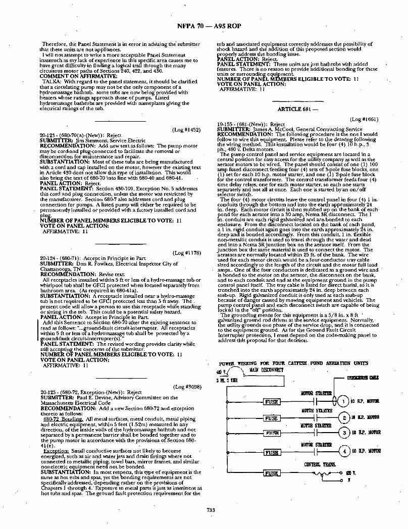

N F P A 7 0 - - A 9 5 R O P
• ~I¢lg0kcl I~R ~ ~ AIHIIA'I'ION PAI~I, 1~1 V.
l 0.tE~I,~'TOII SW. m m m m I
l ~ ...m. 'I~IZ ms~! l v r r ~ , , , , HJ, T
0 ' '
I ""-"' r< 'I~R o ~ OL , - - , . .
o
N
SUBSTANTIATION: There is a growing industry in and a round the area of the United States in which I use the National Electrical Code as an electrical contractor. This particular industry is catfish farming. Equ ipment used in this business are p u m p control panels used as service e q u i p m e n t and motor controllers. The panels are used to operate either one well or are field altered to operate as many as stx aerator motors. The aerators are used to control the oxygen level in the pond which is essential for the fish to live. Aerators are motor driven, paddle type machines tha t float on the water in the pond and are used day and n igh t whenever the oxygen level becomes too low. T h e y a r e normally 10 to 20 hp., 3 ph motors. I have even seen them r u n n i n g while personnel are s t and ing in the water. They have to go into the water to maneuver the seines to ga ther the fish. I have personally wired some of these aerators, but most of the ones in operat ion have been wired by non-qualif ied personnel of the farm itseff or by the company that sells the equipment .
The problem is that I canno t f ind any article in the National. Electrical Code that addresses installations such as these, a l though Article 680 comes close when it addresses fountains. I have discussed this matter with experts at the code seminars that I a t tend on a regular basis. I also contacted Underwriters Laboratories abou t the wire or c~tble used in these applications. As I unders tand it, there are no answers to my quest ions as to wiring methods and types of equ ipmen t used to wire this machinery, i inquired about Ground Fault Circui t Interrupter protection, and the experts I spoke with said it should be essential as the motors are located in the water.
Al though I do not know of anyse r ious injuries or deaths that have o c c u r r e d f r o m faulty installation of the wiring of this equipment , I do know there a.re serious hazards if it is no t done correctly. There is only one problem; what is the correct way to install this wiring? ff the National Electrical Code were to address this, possibly with a separate article, I feel contractors like myself, the insurance companies that insure us, and the industry itself would feel m u c h safer. At least we would be protected.
.This same e q u i p m e n t is used in sewage lagoons for pities to mix the water. I am aware of some being installed at the present t ime, and the inspector having jur isdict ion told me personally tha t he does no t know in what m a n n e r to inspect them. The aerators are no t listed, labeled, or even tested by a listing company such as Underwriters Laboratories.
In conclusion I wish for the code-makingpane l to address this in the National Electrical Code ei ther by adding to Article 547 or Article 680, or possibly creat ing a new article.
Enclosed with this proposal you will find statistics of the catt]sh farming industry, drawings, pictures, and literature of the aerators. If any fur ther information is required, I will be happy to provide it to you.
NOTE: Suppor t ing material is available for. review at NFPA Headquarters. PANEL ACTION: Reject. PANEE STATEMENT: The concerns of the Submit ter are already addressed in the present NEC. See Articles 430 and 547. NUMBER OF PANEL MEMBERS ELIGIBLE TO VOTE: 7 VOTE ON PANEL ACTION:
AFFIRMATIVE: 7
(Log #1662) 19:156- (681-(New)): Reject Note: The Technical Co r r e l adngCommi t t e e advises tha t Article
Scope s ta tements are the responsibility of the Technical Correlating Commit tee and the Technical Correlating Commit tee accepts the Panel Action. SUBMrFTER: James P~ McCool, General Contract ing Service RECOMMENDATION: Add new text as follows:
Proposed New Article: Article 681 -Aera t ion Equ ipment 681-1. Scope. The prowmons'- of this article shall apply to the
installation of e q u i p m e n t used to aerate the water for fish ponds, sewage lagoons, and similar installations.
681-2. Approval of E q u i p m e n t . All e q u i p m e n t used for the installation and operat ion of aerat ing machines shall be approved for the location and m a n n e r in which it is installed.
681-3. Service Equipment . Service equ ipmen t shall be installed according to Article 230.
(a) Disconnects. A disconnect means capable of being locked in the "off ' posit ion shall be located at the bank adjacent to each aerater motor and shall be horse power rated and weather proof. It shall 'be capable of openinl~ all u n g r o u n d e d circuit conductors .
681-4. U n d e r g r o u n d Winng. All wiring t renched u n d e r g r o u n d shall be approved for direct burial and wet locations.
(a) Depth Requirements . All u n d e r g r o u n d wiring shall be of depths as explained in o ther articles of this code, and shall be at least two feet f rom the edge of the bank.
Exception: Wiring tha t pro t rudes into the water. (b) Protection. Wiring to run th rough the water shall be protected
and secured on each end. Protection shall be of a flexible condui t suitable for wet conditions.
681-5. Grounding. All e q u i p m e n t such as service equipment , conduit , stub-ups, j unc t ion boxes, motors, and the aerator f rame itseffshall be g r o u n d e d as specified in Articles 250 and 430.
681-6. Stub-ups. Condui ts to be used shall be of a type to withstand physical damage.
(a) Secured in Place. Condui ts shall be secured by a suitable means, such as wood or steel posts.
(b) Junc t ion Boxes. Junc t ion boxes shall be of an outdoor type an d be secured an protected f rom physical damage.
681-7. Marking. Equ ipmen t sha l l be marked to read: "Disconnect Power Before Servicing. Servicing Shall Be Done By Qualified Personnel Only."
(a) Voltage. Voltage used shall be marked at each disconnect , for example "Caution 480 Volts."
(b) Controllers. Motor starters and controllers shall be marked or n u m b e r e d to match each aerat ing machine .
(c) Timers. Motors control led by t imes shall be marked to read: "This Equ ipment is Automatically Started." SUBSTANTIATION: None.
• PANEL ACTION: Reject. PANEL STATEMENT: See Panel Action and Sta tement on Proposal 19-155. NUMBER OF PANEL MEMBERS ELIGIBLE TO VOTE: 7 VOTE ON PANEL ACTION:
AFFIRMATIVE: 7
ARTICLE 685 - - INTEGRATED ELECTRICAL SYSTEMS
(Log #2040) 12-128- (685-16-(New)): Reject SUBMITTER: Bernard W. Whit t ington, Whit t ington Engineer ing Inc. RECOMMENDATION: Conductors: All exl~osed wiring in enclosed control rooms shall be insulated and jacketed with materials so identified by the sufftx LS/LC after the specific wire designation. Interface with conventional or non-LS/LC wiring shall be made at the nearest connect ion, terminat ion, or splicing point, external to the enclosed control room. The listing requ i rements shall become effectiveJuly 1, 1997., SUBSTANTIATION: W h e r e conventional wiring insulat ion is used, the occurrence of a fire in an-enclosed control room automatically brings quanti t ies of light obscur ing black, disorienting, corrosive smoke. The required use of smoke and corrosion free electrical insulation materials would permi t an operator to best funct ion in br inging a sensitive cont inuous process unit, or units, to an orderly shutdown in a product ion safe, personnel safe, and environmental ly safe, manner . Additionally, the lack of corrosive con ten t of the LS/ LC materials will result in very minimal or no damage to sensitive and impor tan t control devices thereby greatly decreasing the ex ten t of fire damage to non-thermally impacted equ ipmen t areas.
The designation of LS is measurable by UL 1685 while an LC m e a s u r e m e n t s tandard is presently underway by UL. Anothe r
734

N F P A 70 - - A 9 5 R O P
method of defining limited corrosivity is by the results of direct exposure of resistivity probes to acid gas generated by the cables when tested in accordance with ASTM E.t.21 •70. PANEL ACTION: RejecL PANEL STATEMENT: There is no definition of enclosed control rooms. The proposal would add significandy to the expense of cabling in industrial and commercial facilities, while the submitter has submitted no substantiation indicating a problem with present methods. NUMBER OF PANEL MEMBERS ELIGIBLE TO VOTE: 12 VOTE ON PANEL ACTION:
AFFIRMATIVE: 12 COMMENT ON AFFIRMATIVE:
KELLY: While I agree with the panel action I wish to state that the IEEE supports the concept of more Fire Safe Electrical Construction Materials.
ARTICLE 690 ~ SOLAR PHOTOVOLTAIC SYSTEMS
(Log #CP301). 3-163b- (Diagram 690-1 ): Accept
Note: The Technical Corre la t ingCommit tee advises that Article Scope statements are the responsibility of the Technical Correlating Committee and the Technical Correlating Committee accepts the Panel Action. SUBMITTER: CMP 3
J RECOMMENDATION: Change the nomenclature in Diagram 690- I 1 from: '[ "Power Condit ioning Unit Output Circuit" to "Inverter Output l Circuit". In addition, change "Power Condit ioning Unit" to ] "Inverter". J Also, label the connect ion between the fuse and th'e inverter I "inverter input circuit" in both lines. SUBSTANTIATION: Editorial clarification. PANEL ACTION: Accept. NUMBER OF PANEL MEMBERS ELIGIBLE TO VOTE: 13 VOTE ON PANEL ACTION:
AFFIRMATIVE: 13
(Log #2146) 3-164-(Diagram 690-1): Accept
Note: The Technical Correla t ingCommit tee advises that Article . Scope statements are the responsibility of the Technical Correlating Committee and the Technical Correlating Committee accepts the Panel Action. SUBMITTER: John C. Wiles, Sandia National Laboratories RECOMMENDATION: Add new text
C: Grounded conductors not shown. SUBSTANTIATION:. A version of this s ta tement was to be added in the 1993 NEC, but was inadvertendy left out (NFPA 70--A92 TCR Log#1405). Users of the NEC are interpreting this diagram as indicating that all conductors including the ~ o u n d e d conductors must have disconnect switches. Section 690-13 revisions alone are insufficient to fully address this problem. PANEL ACTION: Accept. . . NUMBER OF PANEL MEMBERS ELIGIBLE TO VOTE: 13 VOTE ON PANEL ACTION:
AFFIRMATIVE: 13
(Log #2i47) 3-165 - (690-2-1nverter Inl:iUt Circuit): Accept
. SUBMITTER: John C. Wiles, Sandia National Laboratories I RECOMMENDATION: Add the following definition: I Inverter Input Circuit: Conductors between the inverter ~nd the J battery in stand-alone systems or the conductors between the I inverter and the PV output circuits for grid-connected systems.
SUBSTANTIATION: This change is required because the circuit is not def ined in the 1993 NEC a n d a proposal for the ampacity calculation for this circuit has been submitted for the 1996 NEC. The definition and ampacity calculation are particularly critical for stand-alone PV systems.
NOTE: Support ing material is available for review at NFPA Headquarters. PANEL ACTION: Accept. N.UMBER OF PANEL MEMBF.RS ELIGIBLE TO VOTE: 13 ,VOTE ON PANEL ACTION:
AFFIRMATIVE: .13
(Log #2148) 3-166 - (690-2-Power Condit iong Unit): Accept SUBMI'FrER: John C. Wiles, Sandia National Laboratories RECOMMENDATION: Change the following definition:
Power Conditioning Unlt: to Inverter:.. Equitpment that. is used to change voltage level, or
waveform or both, of electrical energy. Commonly, an reverter (also known as a Power Condit ioning Uni t (PCU), or Power Conversion System (PCS)) is a device that changes direct-current input to an alternating current outpfit. Inverters in stand-alone systems may also include battery chargers that take alternating current from an
:auxiliary source such as a generator and rectify it into direct current for charging batteries. SUBSTA]NTIATION: This change is required because there are over 50,000 stand-alone PV systems that use the more modern term "inverter" and less than 300 grid connected systems using the older term "power condit ioning system". The number of stand-alone systems is increasing at several thousand per year while the number of grid-connected systems is staying relatively constant. PANEL ACTION: Accept. NUMBER OF PANEL MEMBERS ELIGIBLE TO VOTE: 13 VOTE ON PANEL ACTION:
AFFIRMATIVE: 13
• . (Log #2149) 3-167 - (690-2-Power Condit ioning Unit Output Circuit): Accept SUBMITTER: John C. Wiles, Sandia National Laboratories "
l RECOMMENDATION: Change the following definition: I Power Conditioning Unit Output Circuit: to J Inverter Output Circuit: Conductors between the inverter and an J ac load center for stand-alone systems or the conductors between the J inverter and the service equipment or another electric power ] product ion source such as a utility for gr id-connected systems. See I Diagram 690-1. SUBSTANTIATION: This change is required because there are over 50,000 stand-alone PV systems that use the more modern term "inverter" and less than 300 grid connected systems using the older t e rm"power condit ioning system". The number of stand-alone systems is increasing at several thousand per Year while the number of grid-connected systems is staying relatively constant. PANEL ACTION: Accept. NLrMBER OF PANEL MEMBERS ELIGIBLE TO VOTE: 13 VOTE ON PANEL ACTION: • AFFIRMATIVE: 13
(Log #2150) 3-168 - (690-7(a)): Accept in Principle SUBMI'VI~R: John C. Wiles, Sandia National Laboratories RECOMMENDATION: Add the following after the existing sentence in Section 7a.
For three-wire systems including two-wire circuits connected to three-wire systems voltage shall be the highest voltage between any two conductors. SUBSTANTIATION: The system voltage is extremely important in determining the insulation rating on PV source-circuit conductors, the voltage rating of overcurrent devices, and the voltage ratings of disconnects. PV systems can operate at bipolar voltages over 300 volts that will require conductors with more than the standard 600- volt insulation• This definition is needed to clarify and highlight the method of determining the system voltage. Insulation, fuse, and switch breakdowns can occur when insulation and devices with insufficient voltage rating are used. These failure can result in bolted and ground faults. PANEL ACTION: Accept in Principle. .
J Revise the wording in the Proposal to read as follows: J "For three-wire installations including two-wire circuits connected I to three-wire systems, the system voltage shall be the highest rated J voltage between any two conductors."
PANEL STATEMENT: The change adds clarity and provides better ~.mderstanding of the Proposal. " NUMBER OF PANEL MEMBERS ELIGIBLE TO VOTE: 13 VOTE ON PANEL ACTION:
AFFIRMATIVE: 13
(Log #2151) 3-169- (690-7(a), FPN-(New)): Reject SUBMITTER: John C Wiles, Sandia National Laboratories RECOMMENDATION: Add the following FPN:
(FPN) For example, a three-wire, bipolar system hts open-circuit voltages of plus and minus 325 volts. The system voltage is 650 volts.
735
N F P A 70 - - A 9 5 R O P f
SUBSTANTIATION: The system voltage is extremely impor tan t in de te rmin ing the insulation rat ing on PV source-circuit conductors , the. voltage rating of overcurrent devices,, and the voltage ratings of disconnects. PV systems can ol?erate at bipolar voltages over 300 volts that will require conductors w~th more than the s tandard 600-volt
• insulation. This FPN is needed to clarify and highl ight the m e t h o d of de te rmin ing the system voltage. Insulation, fuse, and switch breakdowns can occur when insulation and devices with insufficient voltage rat ing are used. These failures can result in bolted and g round faults. PANEL ACTION: Reject. PANEL STATEMENT: Not Necessary. The Standards Council is concerned about too many Fine Print Notes in the Code. NUMBER OF PANEL MEMBERS ELIGIBLE TO VOTE: 13 VOTE ON PANEL ACTION:
AFFIRMATIVE: 13
(Log #2152) 3-170- (690-7(c)): Reject SUBMITTER: J o h n C. Wiles, Sandia National Laboratories RECOMMENDATION: Change 600 volts to 1500 volts. SUBSTANTIATION: This change is required because PV arrays and
~l id-connected inverters may operate at voltages above 600 volts. ae PV source circuits in systems with these high voltage inverters
will be exposed to these h igher voltages unde r normal conditions, dur ing operat ion of ground-faul t array disabling circuits (Section 690-5), and du r ing fault condit ions. These photovoltaic power systems will he installed in residences and commercial buildingL Equ ipment operat ing at h igher voltages is needed to keep operat ing currents within limits and to maximize per formance while minimiz- ing costs. Increasing this voltage limit and the application of o ther NEC requi rements for systems with voltages over 600 volts will result in safe systems at these h igher voltages. PANEL ACTION: Reject. PANEL STATEMENT: The Panel directs the Task Group on for NEC Article 690 Solar Photovoltaic Systems to prepare a separate Code section for circuits for over 600 volts nonimal . NUMBER OF PANEL MEMBF.RS ELIGIBLE TO VOTE: 13 VOTE ON PANEL ACTION:
AFFIRMATIVE: 12 NEGATIVE: Nicholson
EXPLANATION OF NEGATIVE: NICHOLSON: The following paragraphs state the reasons for my
negative vote on the panel actions for the above proposal. This negative vote came as a result of n u m e r o u s discussions with PV industry and Balance-of-System experts. The issue was also discussed at the Task Group - NEC - Article 690 -Solar Photovoltaic S ~ t ems meet ing on February 25, 1994, with a consensus of the g roup that n u m e r o u s PV systems have been installed that exceed the 600 volt limit today, and that Article 690 should be modif ied as soon as possible to include the installation of PV systems at voltages greater than 600 volts. , Proposal (3-168) 690-7(a) which was passed by CMP 3 describes the me thod of de te rmin ing system voltage at the h ighes t voltage between any two conductors . This definit ion of system voltage will create a situation with existing systems and newly des igned systems for the future to be rated at over 600 volts. T he 600 volt ceiling imposed on the voltage o f solar systems will substantially impede ihe growth of this emerg ing alternative energy source. The same economic reasons for h igher voltages used by utility companies also apply in photovoltaics. The 600 volt rating for residential systems should remain as stated in Section 690-7(c), but the voltage rating for commercial and large PV systems should be allowed up to 1500 volts.
The fol lowingsection should be added to Article 690 to cover the installation of PV systems between 600 volts and 1500 volts. This original submi t ted proposal shou ld be accepted in principle with the following referrals to existing Articles and Sections of the code:
Proposed clarification to Proposal 3-170, Log 2152, CMP 3: Article 690. I. Photovoltaic Systems Opera t ing Over 600 Volts
690-81. Installations. Photovoltalc source and photovoltaic ou tpu t circuits tha t do not contain [ampholders, fixtures, or receptacles and complying with the applicable requi rements for installations over 600 volts shall be permit ted for voltages up to 1500 volts in nonresi- dential applications. All of the applicable requi rements of Article 710 - OVER 600 VOLTS, NOMINAL GENERAL, shall apply.
690-82. Other Sections. Provisions applicable to specific types of installations are included in the following Sections:
Electrical Installations ................. l l0-B Overcurrent Protection ............... 240-H Ground ing .................................... 250-N Surge Arrestors ............................ 280 Wiring. Methods ........................... 300-B Guarding ...................................... 305-7 Busways ......................................... 364-B Pull and Junc t ion Boxes .............. 370-D Portable Cords ............................. 400-C Resistors and Reactors ................. 470-B
(Log #2418) 3-171 - (690-8(b), Exception): Accept SUBMITTER= Dan Leaf, Palmdale, CA RECOMMENDATION: Revise as follows:
"Exception: The allowable ampacity of circuit conductors without an. overcurrent protective device shall no t be less than the' short . c i r c u i t c u r r e n t . ' SUBSTANTIATION: Edit. The subject of the sentence is cur ren t rating and the syntax indicates "it" refers to the cur rent rating, no t the short-circuit current. The sentence can be paraphrased as "the cur rent radng of a circuit.., shall no t exceed the ampacity of the conductors". "Allowable ampacity" is proposed to clearly indicate derat ing due to n u m b e r of conductors o f ambien t tempera ture shall be considered. PANEL ACTION: Accept. NUMBER OF PANEL MEMBERS ELIGIBLE TO VOTE: 13 VOTE ON PANEL ACTION:
AFFIRMATIVE: 12 NEGATIVE: Nicholson
EXPLANATION OF NEGATIVE: NICHOLSON: The following paragraph states the reason for my
negative vote on the panel actions for the above proposal. This negative vote came as a result of n u m e r o u s discussions with PV Industry and Balance-of-System experts. The issue was also discussed at the Task Group - NEC - Article 690 - Photovoltaic Systems mee t ing on February 25, 1994, with a consensus that retaining i.he exception, as modified, would allow installation of PV systems with unpro tec ted conductors that would be unders ized in the event of malfunct ions of equ ipmen t allowing backfeed of cur ren t f rom inverters or batteries.
Fur ther s tudy and discussions have concluded that the exception either needs fur ther clarification to limit the exception to systems where power backfeed is impossible. This FPN is insufficient to insure proper protection for conductors where energy storage used as loads could allow backfeed of cur ren t in excess of the conductor rating. The proposal shou ld be accepted in principle with the clarification to include only systems where power backfeed is impossible.
(Log #2153) 3-172 - (690-8(b) (3)): Accep t '
.SUBMITTER: J o h n C. Wiles, Sandia National Laboratories [ RECOMMENDATION: Revise to Read: ] (3) Inverter Ou tpu t Circuit. The inverter or power condi t ioning i uni t ou tpu t cur ren t rating. SUBST.4~TIATION: This change is required because there are over 50,000 stand-alone PV systems that use the more m o d e m term "inverter" and less than 300 grid connec ted systems us ing the older te rm "power condi t ioning system". The n u m b e r of stand-alone systems is increasing at several thousand per year while the n u m b e r of gr id-connected systems is staying relatively constant. PANEL ACTION: Accept. NUMBER OF PANEL MEMBERS ELIGIBLE TO VOTE: 13 VOTE ON PANEL ACTION:
AFFIRMATIVE: 13
(Log #2154) 3-173 - (690-8(b) (4)-(New)): Accept SUBMITTER: J o h n C~ Wiles, Sandia National Laboratories RECOMMENDATION: New text:
(4) Stand-Alone Inverter Inpu t Circuit. The stand-alone inverter inpu t cur ren t rating when the inverter is p roduc ing rated power at the lowest input voltage.
736
N F P A 70 - - A 9 5 R O P
SUBSTANTIATION: Storage batteries have a decreasing voltage as they are discharged: Stand-alone inverters maintain a constant true RMS output voltage as the input battery voltage decreases by increasing the current drawn from the batteries. PV powered charging'systems or backup generators can allow the-system to operate-at these low voltages-for an ex tended period of time.' Input conductors must have amioacities and overcurrent device ratings- " • based on the increased current found under these operating - conditions. For example, an inverter rated at 2400 Watts would draw 100 amps at 24 volts (nominal 2 volts per cell in a 12-cell battery), ff the batteries were discharged to 21 volts (1.75 volts per cell), the inverter would draw 114 amps. PANEL ACTION: Accept NUMBER OF PANEL MEMBER,S ELIGIBLE TO VOTE: 13 VOTE ON PANEL ACTION:
AFFIRMATIVE: 13
(Log #CP307) 3-163a- (69009(a) FPN,): Accept Note: The Technical Correlating Committee directs that the Panel
clarify the Panel Action on this Proposal. This action will be considered bythe Panel as a Public Comment. SUBMITTER: CMP 3 RECOMMENDATION: The Panel directs the Task Group on NEC . Article 690 Solar Photovoltaic Sytems to consider the followingFine Print Notes that may contain mandatory language in Sections-f900 9(a) and 690013.
In additon, the Panel directs the Task Group to consider the Fine Print Note to Section 690-18 as to to whether or .not it is a product requi rement and whether it should remain in the Code. SUBSTANTIATION: The Panel based this action on the direction of the Correlating Committee for review of all Fine Print Notes for mandato lan a e. PANEL ~r~Ti ~ '~:g~ccep t NUMBER OF PANEL MEMBERS ELIGIBLE TO VOTE: 13 VOTE ON PANEL ACTION:
AFFIRMATIVE: 13
(Log#2155) 3-174- (69009(a), Exception-(New)): Reject SUBMIaWER: John C. Wiles, Sandia National Laboratories RECOMMEND-ATION: New text:
Exception: In two-wire ungrounded photovoltaic systems as permitted by Section 690-41 and the associated direct-current source and load circuits, the overcurrent devices shall be permit ted in only one conductor of each circuit. SUBSTANTIATION: Section 240020(a) requires that all un- g rounded conductors he protected with overcurrent devices: There ~e no exceptions for two-wire ungrounded circuits.
' In a two-ware ungrounded circuit (operating below 50 volts) there • is no connect ion to the ground system and therefore no return path for ground-fault currents should a single g(_ound fault occur. In the two-wire ungrounded circuits, all 'currents flow in the series path defined by the two circuit conductors for each circuit. Overcurrent protection in only one of these conductors for each circuit fully protects that circuit from overcurrents a~nd presents a sfife situation. Requiring overcurrent devices in both ungrounded conductors is not -needed and may decrease overall syste-m reliability and perfor- mance. Circuits affected include the PV source and output circuits, the dc load circuits, if any, and the dc circuit between the'battery and the inverter or power cond i t i on ingun i t
The Canadian Standards Associadon'has similar provisions for ungrounded two-wire circuits (CSA Standard C22.2 Numer 60). PANEL ACTION: Reject. PANEL STATEMENT: The Panel believes additional support data should be provided to iustify the Proposed Exception. NUMBER OF PANEL'MEMBERS ELIGIBLE TO VOTE: 13 VOTE ON PANEL ACTION:
AFFIRMATIVE: 13,
(Log #2156) 3.175 - (690-9(d)-(New)): Accept SUBMITTER: John G Wiles, Sandia National Laboratories RECOMMEND-ATION: New text:
i (d) DC Rating. Overcurrent devices, either fuses or circuit breakers, used i-u any dc portion o f a photovoltaic power system shall be listed for use in direct-current circuits and shall have the
~l~j~ riate voltage, current and interrupt ratings. ANTIATION: Due to the predominance of ac-rated
equipment, it is not commonly recognized that de-rated fuses are av:aila.ble and should be used in dc circuits. AC-rated supplementary fuses and automotive fuses (nonlisted, no dc ratings) are be ing used in PV systems. PV systems use battery banks that can deliver short- circuit currents in excess of the interrupt ratings of commonly used fuses and circuit breakers. DC vtltage, current, and interrupt ratings are needed to safely use tl3ese components . This proposed text clarifies this Section. It also makes clear the intent o f Sei:tion 690-9(c) that the supplemental fuses allowed in certain circuits be listed for dc use. -
PANEL ACTION: Accept. ' I Change the second to last word in the proposed language from I "interr/apC to "interrupting" for editorial p~rposes. - - -
NUMBER OF PANELMEMBERS ELIGIBLETO VOTE: 13 VOTE ON PANEL ACTION:
AFFIRMATIVE: 13
(Log #24) 3-176 - (690ol 00(New)): Reject
Note: The followingproposal consists of Comment 3.111 on Proposal 3.137 in thC1"992 Annual Meeting National Electrical Code Technical Committee Report. This Comment was held for further study during the processing of the 1993 NATIONAL ELECTRICAL CODE. The recommendataon in Proposal 3.137 was:
New text: 690010. Service Requirements. Stand alone photovoltaic systems
used in single family residences or dwellings wath only direct current distributiofi within the residence or dwellifil~ are not required to comply with the service size and rating requ~rements 'of~t_icle 2300 42. These systems are also not requi r td to comply with the branch circuit and feeder requirements o~Article 220. ] n a residence having both ac and dc distribution systems, the ac system shall comply with all applicable articles of this code, but the dc system shal[be exempt from compliance with Articles 220 and 230-42. SUBMITI 'ER/John C Wiles, Southwest Technology Development Institute RECOMM~DATION: New text.
690-10. Service Requirements. ' ' Stand-alone photovoltaic systems used in single family residences or
dwellings with only direct current distribution within the residence or dwelIing are not required to comply with the service size and rating requirements of Article 230-42. These systems are also not reqmred to comply with the branch circuit and feeder requirements of kaxicle 220. In a residence having both ac and dc distrl'bution systems, the ac system shall comply with all applicable articles of this code, but the dc system shall be exempt from compliance with " Articles 220 and 230-42. SUBSTANTIATION: The current state of the art in stand-alone photovoltaic power systems dictates a minimum installed cost of $15 per peak Watt of power. These high costs generally restrict the size of the power generation system. The largest stand-alone residential photovoltaic system known to exist is rated at about 13 kW and this system uses an inverter to provide ac power throughout the dwelling. Direct current only systems generally produce peak powers of 50 Watts to 500 Watts. Higher power outputs are often converted to ac and distributed to the dwelhng in that form. It is not reasonable to impose 600100 amp service entrance requirements on these low current (5-50 amp)systems. Since the high costs of PV systems drive owner /users toward conservation devices and the minimum use of electrical systems, there is virtually no use of or awailability of high power, low voltage appliances like toasters etc. Most dc dwellings also use highly efficient f luorescent lamps for task lighting so the requirement for 3 volt-ampp.s erscluare ~'oot f o r . . lig.h~ina.g c] rcuits is not reasonable. The branch orcu , t reqmrements , i fadl lered to, could not be supplied by the powergenera t ion system and Would not be used to anywhere near ~ e i r full capacity, ff the PV system uses an inverter to supply an ac distribution system in the dwelling, then these proposed additions to the NEC would not apply. PANEL ACTION- Reject. PANEL STATEMENT: There is a lack of field data to support reducing the size of service entrance conductors. NUMBER OF PANEL MEMBERS ELIGIBLE TO VOTE: 13 VOTE ON PANEL ACTION:
AFFIRMATIVE: 13
(Log #2157) 3-177- (6900i 3, Exception No. 1 and Exception No. 2-(New)): . Reiect SUBMITTER: John C~ Wiles, Sandia National Laboratories RECOMMENDATION: After the word "Exception", add No. 1:
Exception No. 2: Where a photovoltaic power source consists of a two-wire ungrounded circuit as permitted-by Section 690-41, the disconnecting means shall be permit ted in only. one conductor. SUBSTANTIATION: Section 690-15 and Article 230 require that all ungrounded conductors have disconnects from the power sources.
I d a two-wire ungrounded system (operating below-50 volts) there is no connect ion go the ground system and therefore no return path for ground-fault currents should a single g round fault occur. In a two-wire ungrounded circuit, all currents tlow in the series path def ined by the two circuit conductors. Disconnecting only bne of these conductors fully disconnects the circuit and presents a safe situation.
Requiring disconnects in both ungrounded conductors is no t needed and would decrease system-reliability and performance. • Circuits effected include the PV source and output circuits, dc l o a d circuits, if'any, and the circuit between the batteries and the inverter or power conditioning unit. The Canadian Standards Association has similar provisions for
uf igrounded two-wire circuits (C~A Standard C22.2 No. 60.) PANEL ACTION: Reject.
737

N F P A 70 - - ~ 9 5 R O P
PANEL STATEMENT: I ra fault to g r o u n d within the supply occurs, a two-pole, two-fuse disconnect, is required, to protect serwce personnel . It should be possible to d isconnect all conductors of a bui lding f rom an external source. NUMBER OF PANEL MEMBERS ELIGIBLE TO VOTE: 13 VOTE ON PANEL ACTION:
AFFIRMATIVE: 13
(Log #2158) 3-178 - (690.15): Accept in Principle SUBMrI ' rER: John C. Wiles, Sandia National Laboratories
[RECOMMENDATION: Revised text: ] 690.15. Disconnect ion of Photovoltaic Equipment . Means shall be ]provided to d isconnect equ ipmen t such as inverters, batteries, ]charge controllers, and the like, f rom all u n g r o u n d e d conductors of lull sources. If the equ ipmen t is energized f rom more than one Isource, the d isconnect ing means shall be g rouped and identified. [Disconnect ing means shall be rated to break circuit currents u n d e r | load. The Exception in Section 690.17 shall apply. SUBSTANTIATION: Some terms have been changed. T he "power condi t ioning unit" has become more commonly known as an "inverter". The "filter assembly" associated with gr id-connected PV systems is not supplied as a separate unit, bu t is built into the inverter and should be deleted. The terms "charge controller" and "batteries" are added to address the tens of thousands o f stand-alone PV power systems havin~ these components . Disconnect ing means that are not "load-break rated may create arcs and may present shock and fire hazards when operated unde r load. Such disconnects are being used . . . . . . in some PV systems in an inappropriate and unsafe manner . R e q m n n g tha t all d tsconnects used m these a rcut t s be "load-break rated" will minimize the possibility of bolted-fault arcs, shocks and fire hazards when they are opera ted unde r load. PANEL ACTION: Accept in Principle.
I Delete the last two sentences in the Proposal and revise the exsisting Section (4) in 690.17, up to the period, to read as follows:
"shal lhave an in ter rupt ing rating su f f ioen t for the nomina l circuit voltage and the cur ren t that is available at the line terminals of the equipment ." PANEL STATEMENT: The required features of a d isconnect are covered in Section 690-17. The Panel believes the revised wording i.s consistent with cur ren t code terminology. NUMBER OF PANEL MEMBERS ELIGIBLE TO VOTE:, 13 VOTE ON PANEL ACTION:
AFFIRMATIVE: 13
(Log #2161) 3-181 - (690-31(b), FPN-(New)): Reject SUBMITTER: J o h n C. Wiles, Sandia National Laboratories RECOMMENDATION: New text:
(FPN): W h e n consider ing the use of UF cable for photovoltaic source circuits, see the Fine Print Note unde r Section 310-13. SUBSTANTIATION: Photovoltaic source circuit wiring is installed in exposed locations that are subject to a tmospher ic moisture including rain. These circuits use direct currents. U n d e r these conditions, the thermoplast ic insulation found on UF cables can dissolve (electroendosmosis) . The exposed locations also subject the cables to a wide range of temperatures f rom 70°C to the lowest ambien t tempera ture of the location. Thermoplas t ic insulated cables may no t have the necessary durability.
The problem of e lectroendosmosis was first identified in the PVG- insulated, direct-current wiring for alarm systems on off-shore dril l ing platforms. PANEL ACTION: Reject. PANEL STATEMENT: The Panel directs the Task Group for NEC Article 690 Solar Photovoltaic Systems to address the concern indicated in the Submit ter ' s p roposed Fine Print Note and Substan- tiation have a Proposal to include the proposed informat ion as a
• r equ i r emen t in Section 690-31 (b). NUMBER OF PANEL MEMBERS ELIGIBLE TO VOTE: 13 VOTE ON PANEL ACTION:
AFFIRMATIVE: 11 NEGATIVE: Bishop, Nicholson
EXPLANATION OF NEGATIVE: BISHOP: The addit ion of the FPN is justif ied by the substantiation.
Action by a task group canno t result in a proposal until the 1999 NEC. This is an unreasonable delay.
NICHOLSON: A condi t ion called (electroendosmosis) can occur with PVC wire u n d e r certain conditions. This safety hazard has been recognized by CMP 6 in Article 310-13 (FPN). In Article 690-31 (B) of the 1993 Code, the use of UF cable in photovoltaic source circuits is ment ioned. The thermoplast ic insulation found in some UF cables are subject to damage caused by the condit ion described as electro endosmosis. In photovoltaic system installations, the a tmospher ic condi t ion described in 310-13 (FPN) occurs on a f requen t basis in solar installations. I feel rejecting this proposal is potentially hazardous to persons and property unaware of the possible dan~.er. To delay this proposal by send ing it to the NEC task group wdl create a condi t ion f rom 1996 to 1999 where the information on this hazard will no t be known to those us ing the NEC Article 690 for guidance. In future submissions, I hope the entire FPN found in 310-13 finds its way directly into 690.31B.
(Log #2159) 3-179 - (690-15, Exception-(New)): Reject SUBMITYER: J o h n C. Wiles, Sandia National Laboratories RECOMMENDATION: New text:
Exception: In an u n g r o u n d e d two-wire system operat ing unde r 50 volts, the d isconnect ing means shall be perm!t ted in only one conductor . SUBSTANTIATION: The Exception is included to make this Section consistent with a new proposal for Section 690-13, Exception No. 2. The terminology "shall bepe rmi t t ed" is used to allow both conductors to be d i sconnec ted if desired.
NOTE: Suppor t ing material is available for review at NFPA Headquarters . PANEL ACTION: Reject. PANEL STATEMENT: See Panel Action and Sta tement on Proposal 3-177. NUMBER OF PANEL MEMBERS ELIGIBLE TO VOTE: 13 VOTE ON PANEL ACTION:
AFFIRMATIVE: 13 t
(Log #2160) 3-180- (690-31(b)): Accept SUBMITTER: J o h n C. Wiles, Sandia National Laboratories
I RECOMMENDATION: Add the word "single-" before the word I "conductor" in the first sentence. -SUBSTANTIATION: The word "conductor" was inadvertently left
in the text of this sentence in the 1993 Edition of the NEC (NFPA 70-A92 TCR, Log #1412). The addit ion of the word "single" revises the sentence and keeps the in tent consistent with the title of the
~ aragraph. ANEL ACTION: Accept.
NUMBER OF PANEL MEMBERS ELIGIBLE TO VOTE: 13 VOTE ON PANEL ACTION:
AFFIRMATIVE: 13
(Log #2162) 3-182 - (690-31(c)-(New)): Accept in Principle
Note: It was the action of the Technical Correlat ing Commit tee that this Proposal be referred to Code-Making Panel fi for comment . SUBMITrER: John C, Wiles,-Sandia National Laboratories .
. [ RECOMMENDATION: New text:" I (c) Flexible Cords and Flexible Cables. Flexible cords and flexible I cables as def ined in Article 400, when used to connect the moving [ parts of tracking PV modules, shall be identified as Hard Service,
Extra Hard Usage, and listed for outdoor use and sunl ight resis- tance. The ampacity figures presented in Table 400-5(A) shall be
I fiaodified by the tempera ture dera t ing factors of Section 310-15 for | equivalent conduc to r tempera ture ratings.
SUBSTANTIATION: Flat-plate photovoltaic modules are frequently m o u n t e d on single-axis tracking devices that follow the path of the sun f rom East to West each day. Some fiat-plate photovoltaic modules and all concent ra t ing photovoltaic modules are m o u n t e d on two-axis tracking devices that follow the sun f rom East to West and North to South each day. As m u c h as 400 degrees of angular mot ion can be required each day.
Chapter 3, "building wire" m e t h o d s - - even using s t randed cables - - do no tp rov ide sufficient flexibility on these tracking systems. Th e use of these stiff cables creates safety problems after a n u m b e r o f years when the conductors fail creating open circuits, bolted faults, or g round faults. Flexible cables and cords (single and mult iple conductor) as permit ted in Section 400.7(a)(10) have the need ed flexibility and provide the necessary envi ronmenta l resistance when identified as out l ined in the proposal. Photovoltaic modules operate in the sunl ight and junc t ion box and back of module tempera tures may exceed 70°C. There are no tempera ture dera t ing factors presented in Article 400. It is appropriate to derate the ampacity of Article 400 cables with the Section 310 tempera ture dera t ing factors to ensure that the insulation tempera tures are not exceeded. The appropriate dera t ing factors f rom Section 310-15 are applied based on the insulation tempera ture rating of the Article 400 cable. PANEL ACTION: Accept it4 Principle.
738
N F P A 70 - - A 9 5 R O P
Make editorial corrections as follows to the Proposal." In the second line, before the word "identified' insert "a type".
Also, in the second line, "hard service and extra hard usage" should be lower case initial caps. In the third line, replace the words "figures presented" with the word 'hralues" andfollowing "Table 400- 5(A)" add in parathensis "based on 30 degrees G." PANEL STATEMENT: The Panel believes that due to the proposed use of ambient correction factors for flexible cords and flexible cables being under the jurisdiction of Article 400 that Panel 6 provide guidance and inclusion in Article 400. NUMBER OF PANEL MEMBERS ELIGIBLE TO VOTE: 13 VOTE ON PANEL ACTION:
AFFIRMATIVE: 13
PANEL ACTION: Accept in Principle in Part. ] Revise the Proposed wording to read as follows: [ ~Exposed noncurrent-carrying metal parts of module frames, I ecjui[?ment, and conductor enclosures shall be grounded regardless I otvoltage." 1 The Panel rejects the Fine Print Note. . .
PANEL STATEMENT: The revised wordin[[ conforms with existing terminology in Section 250-43. The Fine Print Note contains mandatory language which is inconsistent with the Manual'of Style. NUMBER OF PANEL MEMBERS ELIGIBLE TO VOTE: 13 VOTE ON PANEL ACTION:"
AFFIRMATIVE: 13
(Log #2163) 3-183- (690-31(d)-(New)): Accept ,
• SUBMrrTER: John C. Wiles, Sandia National Laboratories I RECOMMENDATION: New text: [ (d) Small-Conductor Cables. Single-conductor cables listed for [ outdoor use, sunlight resistance, and moisture resistance with sizes I No. 16 AWG and No. 18 AWG shall be permitted for module I interconnections when such cables meet the ampacity requirements I of Section 690-8. Section 310-15 shall be used to determine the I cableampacity and temperatu're derating factors. ' . SUBSTANTIATION: Cable manufacturers will not mark cables smaller than No. 14 AWG with the USE, UF, or SE imprints because of wording in the NEC prohibiting the use of cables smaller than this size for USE, SE and UF applicatious. Listing restrictions by Underwriters Laboratories also prevent manufacturers from marking the smaller cables.
Photovoltaic modules can deliver short-circuit currents in the one. to four-amp range depending on the module design and size. The ampadty calculations required by Section 690-8 indicate that Nos. 18 a n d l 6 AWG conductors are adequate for this use. These cable sizes are listed in Tables BIO-16 and 17and the temperature dera~tings are appropriate because module interconnect cables operate in elevated ambient temperatures. This proposal permits the optional use of listed conductors that meet the necessary electrical, environmental, and safety requirements but are not marked with the USE, SE, or UF designations. PANEL ACTION: Accept. NUMBER OF PANEL MEMBERS ELIGIBLE TO VOTE: i3 VOTE ON PANEL ACTION:
AFFIRMATIVE: 12 NEGATIVE: Belle
EXPLANATION OF NEGATIVE: BEILE: The ability of smaller, 16 and 18 awg, singular conductors
to withstand the mechanical abuse of direct burialhas not been substantiated in the proposal.
(Log #2164) 3-184- (690243-(New)): Accept in Principle in Part SUBMITrER: John C~ Wiles, Sandia National Laboratories RECOMMENDATION: Text from 1993 NEC Section 690-43 has been proposed to be renumbered to 690-45. New text: 690-4S. Equipment Grounding. Exposed noncurrent-carrying
metal parts of module frames, equipment, and conductor enclosures of all photovoltaic systems shall be connected with an equipment grounding conductor and grounded regardless of system voltage.
(FPN): Increased surge protection will be afforded if the equip- ment. grounding conductor, for the module, frames is routed m as. direct manner as possible to the grounding electrode or grounding electrode system and not routed with or along the current-carrying conductors. SUBSTANTIATION: This proposal submits new text at the appropriate location to clarify and fully define the requirement to have equipment grounds on all photovoltaic systems - - even those with open-circuit voltages less than 50 volts. High short-circuit currents from battery banks used in'these systems and the possibility of lightning induced surges on these systems require that exposed metal surfaces be grounded even though the system may be u~eounded.
FPN brings attention to a method of reducing surge pickup and increasing safety. PV modules are mounted in high, exposed locations with no nearby stru&ures that might serve as lightning attraction points. The separation of conductors for dc systems is allowed by Section 250-57(b)Ex 2.
Other submissions for renumberin[~ and revising Section E have been submitted and are consistent wRh this proposal. NOTE: Supporting material is available for review at NFPA "
Headquarters.
(Log#2165) 3-185 - (690-43): Accept SUBMrFrER: John C. Wiles, Sandia National Laboratories RECOMMENDATION: Change the section number from 690-43 to 690-45. Text is unchanged. " - SUBSTANTIATION: This revision will renumber the sections in Section E on Grounding. A proposal to renumber Section 696 has also been submitted. This renu .mbering will allow the inse~ ,:~tJ of a new Section in a logical sequence.
NOTE: Supporting material is available for review at NFPA Headquarters. PANEL ACTION: Accept. '. NUMBER OF PANEL MEMBERS ELIGIBLE TO VOTE: 13 VOTE ON PANEL ACTION:
AFFIRMATIVE: 13
(Log #2166) 3-186 - (690-44): Accept in Principle SUBMITTER: John C. Wiles, Sandia National Laboratories RECOMMENDATION: Change the section number on this section to 690-47 in the 1996 NEC and revise the text as shown below.
Revised text: • 690-47. Common Grounding Electrode. The equipment ground-
ing conductor required by Sections 690-43 and 690-45 shall be connected to the grounding electrode or tile grounding electrode conductor that is used to ground the direct current system. If the system is not grounded as permitted by Section 690-41, a separate grounding electrode shall be used. Equipment and system grounding conductors for the dc and ac systems (if present) shall be connected to a single or common grounding electrode. Two or more electrodes that are effectively bonded together shall be considered as a single electrode. SUBSTANTIATIO~h This revision will renumber the sections in Section E on Grounding. A proposal to renumber Section 690-4S has also been submitted. This renumbering will allow the insertion of a new Section in a logical sequence. This text revision will clarify the requirement (not covered
elsewhere) that all groundedsurfaces and grounded conductors (in the ac and/or dc poi'tions of the system) be at one (grounded) potential through the use of a common grounding electrode.
NOTE: Supporting material is available for review at NFPA Headquarters. PANEL ACTION: Accept in Principle. • "
[ In the proposal, change the heading to read as follows: I "Grounding Electrode System". Change the proposed wording to [ read: "A grounding electrode system shall be provided in accor- | dance with ,Sections 250-81 through 250-86."
PANEL STATEMENT: The revised words meet the intent of the Proposal and provides clarity and consistency with common terminology presently in the code. NUMBER-OF PANEL MEMBERS ELIGIBLE TO VOTE: 13 VOTE ON PANEL ACTION:
AFFIRMATIVE: 13
(Log #2167) 3-187- (690-53-(New)): Acceptin Principle SUBMITTER: John C. Wiles, Sandia National Laborat6ries RECOMMENDATION: New text:
690-53. Site Markings. If the markings required by Section 690-52 are not applied by the manufacturer, they shall be applied in the field by the installer using information supplied by the equipment manufacturer and the system designer. , SUBSTANTIATION: Much of the equipment used in photovoltaic power systems is not listed or is custom assembled on site and does not have the required markings. Without these markings, it is difficult, if n.ot impossible, to properly inspect [.he system and
739

N F P A 7 0 - - A 9 5 R O P
determine if conductors, overcurrent devices, and switchgear have been properly rated. System designers and installers have the proper information and can add the required markings toequip- ment not already marked by the manufacturer. PANEL ACTION: Accept in Principle.
[ Change the existing text, in the third sentence of Section 690-52 as [follows, after the word "provided "by the installer at the site". PANEL STATEMENT: The panel believes that the proposed wording is redundant and is best incorporated by providing additional clarification in Section 690-52. NUMBER OF PANEL MEMBERS ELIGIBLE T O VOTE: 13 VOTE ON PANEL ACTION:
AFFIRMATIVE: 13
(Log #2168) 3-188 - (690-71 (c)-(New)): Accept in Principle
.SUBMITTER: John C~ Wiles, Sandia National Laboratories [RECOMMENDATION: New text: [ (c) Current Limiting. A listed, current-limiting, overcurrent device ]shall be installed in each circuit near the batteries where the [available short-circuit current from a battery or battery bank exceeds ]the interrupt ratings of other equipment in that circuit. The I installation of fuses shall comply with Section 690-16. SUBSTANTIATION: Large battery banks are used for ele~:trical storage in photovoltaic (PV) power systems. One of the batteries in these banks can deliver 6000-8000 arnps of short-circuit current. Series and parallel connected batteries can deliver even more short- circuit current. DC-rated circuit breakers, switches and standard fuses used in PV systems have interrupt ratings of 2500-5000 amps. Current-limiting overcurrent devices (usually dc-rated, current- limiting fuses) are needed in all installations with batteries. The only exception would be very small battery systems which have low short-circuit current capabilities.
The reference to Section 690-16 is needed to ensure that a disconnect switch (or pullout fuse holder) is installed between the battery and the fuse to provide a means to remove battery voltage from the fuse for servicing. PANEL ACTION: Accept in Principle.
Make the following changes in the proposal: In the firsi sentence, between "circuit" and "the" remove the word
"near" and insert "adjacent to". In the second line of the first sentence, change "interrupt radngs" to "interruping or withstand ratings", in the last sentence, between "of" and "fuses" insert "current limiting". PANEL STATEMENT: The revised wording to the proposal adds clarity to the intent. The Panel directs the Task Group on NEC Article 690 Solar Photovoltaic Systems to investigate the concerns the panel has regarding the classification of storage.battery areas. NUMBER OF PANEL MEMBERS ELIGIBLE T O V O T E : 13 VOTE ON PANEL ACTION:
AFFIRMATIVE: 13
(Log #2169) 3-189 - (690-72, FPN-(New) ):. Reject SUBMITTER: John C. Wiles, Sandia National Laboratories RECOMMENDATION: New text:
(FPN): Seasonal and daily variations in solar insolation, variations in load currents, and battery al~ing result in batteries being overcharged or undercharged Jn solar photovoltaic systems that do not have charge controllers. Nickel-cadmium battery systems may be subject to thermal runaway when used without charge controllers. SUBSTANTIATION: This FPN addresses the exception on this section which allows PV/battery systems to be used without charge controllers. The variations in the solar insolation and load currents prevent the matching ment ioned in the exception. When batteries
e undercharged, the.y sulfate and cannot accept charge. When they are overcharged, they release excessive amounts of hydrogen gas that poses a safety problem. Thex.also generate excessive, heat when overcharged. At least one dwelhng has burned down m a fire that has been attributed to thermal runaway in a nickel-cadmium battery system that did not have a charge controller. These safety problems require that the FPN be added to dais section. PANEL ACTION: Reject. PANEL STATEMENT: The Panel directs the Task Group for NEC Article 690 Solar Photovoltalc Systems to address the concern indicated in the Submitter 's proposed Fine Print Note and Substan- tiation and the potential impact on the current Exception to Section 690-72 should be reconsidered. NUMBER OF PANEL MEMBERS ELIGIBLE T O VOTE: 13 VOTE ON PANEL ACTION:
AFFIRMATIVE: 13
(Log#2170) 3-190 - (690-74-(New)): Accep t ' SUBMrFrER: John C. Wiles, Sandia National Laboratories
] RECOMMENDATION: New text: I 690-74. Battery Interconnections. Flexible cables as identified in
• [ Article 400 in sizes 2/0 AWG and larger shall be permitted within ] the battery enclosure from battery terminals to a nearby junct ion ] box where they shall be connected to an approved wiring method. [ Flexible battery cables shall also b e p e r m i t t e d between batteries and ] cells within the battery enclosure. Such cables shall be listed for [ hard service use and identified as acid and moisture resistant.
SUBSTANTIATION: Stationary battery banks consist of single batteries or individual battery cells connected in series and parallel to form a battery system. The individual cells have relatively soft lead terminals, and many are encased in soft rubber or use an asphalt pott ing compound, f f the standard THHN or USE-2, stiff, 2 /0 AWG and larger building style conductors are used to connect to these terminals, the stiffness of the large conductors, as they try to straighten out after having beenben t , tends to distort ei ther the cell terminals or the cells themselves or both. The distortion can cause cell failure which may lead to fires and explosions. The use of the appropriate flexible cable (Article 400) from the
terminals to a nearby junct ion box and between the battery terminals will eliminate theprob lem. Flexible, hard-service cables such as types W, G, and welding cable that have been identified as 'acid and moisture resistant are suitable: PANEL ACTION: Accept. NUMBER OF PANEL MEMBERS ELIGIBLE T O VOTE: 13 VOTE ON PANEL ACTION:
AFFIRMATIVE: 13
ARTICLE 695 ~ FIRE PUMPS
(Log #2212) 15-99- (695-(New)): Accept in Principle SUBMITTER: Roger L. Beckermann, Ellisville, MO RECOMMENDATION: New text as follows: ARTICLE 695 - FIRE PUMPS 695-'1. Scope. This article covers electrically driven centrifugal Fire
Pumps (FPN): See NFPA 20-1990 for additional requirements 695-2. Listing Requirements. All motors shall be listed for fire
pump service. - " 695-3. Overcurrent Protection. (a) Feeders. Feeder conductors and taps shall be connected ahead
of all service disconnecting means, there shall be no disconnecting means in the fire p u m p feeder circuit.
(1) Ground fault protection shall not be required for service disconnects 150-600 volts to ground and rated 1000 arnps, or more as required in section 230-95.
(b )Transformers . Secondary o~)ercurrent protection may be omitted when transformer supplies only fire pump installations. Primary overcurrent protection shall be provided in accordance with Section 450-3(a) or 450-3(b). The primary overcurrent rating or setting shall be sufficient to carry the equivalent of the transformer secondary current sum total of the locked-rotor currents of the fire pump motor(s) and associated fire pump accessory equipment indefinitely.
(c) Motors. Overload protection shall not be required where it might introduce or increase hazards.
695-7. Cii-cuit Conductors. (a) Feeder Circuit conductors. Fire pump feeders shall be
physically routed outside of the building. Exception No. 1: Feeders in electric switchgear, and pump room. Exception No. 2: Feeders buried or encased in 2" or more of
con'crete. Exception No. 3: Feeders installed in fire rated MI type cable. (b) Wiring Method. Conductors shall be installed in rigid metal
conduit, intermediate metal conduit, or MI cable. Exception No. 1: Liquidtight flexible metal conduit shall be
permitted in lengths not exceeding 6 feet where flexibility is required. (c) Conductor ampacity. Conductors shall have an ampacity of
125% of the sum of all full load currents of pump(s) , jockey pump, and fire pump auxiliary loads. (d) Voltage Drop. Conductors from source to fire pump motor
shall have a calculated voltage drop of no more than 5% of the source voltage when pump is operating at peak power input and speed.
(1) Voltage drop shall-be permitted to be calculated with the following formula:
WIRE SIZE = 2 x K x L x l (circular mills) V. Drop
740
N F P A 70 - - A 9 5 R O P
Where: Wire Size = Minimum Circular Mill Area of conductor. k = Constant for conductor type, is found by (Resistance her 1000 feet) x C.M. Are~
1000 D = Distance from source to pump motor (one way). I = Full load current. V. Drop = 5% x Source voltage. 695-9. Field Acceptance Testing. Upon completion of the entire
fire pump installation, an operating test shall be made in the presence of the purchaser, local fire officials, controller representa- tive, the pump manufacture or its designated representative, and the authority having jurisdiction.
(FPN): See NFPA 11-20 1990 for additional requirements. SUBSTANTIATION: Presendy, N.E.C. does not list the mandatory requirements for Fire Pump installations set forth in N.F.P.A. 20. N.E.C. does reference N.F.P.A. 20 in section 230-90 exc. 4 (FPN), as an Electrical Inspector I feel there is a n e e d to add a separate section in the 1996 N.E.C. so that Elecwicians, Project Managers, and Field Inspectors have a place to reference these/ire safety requirements.
NOTE: Supporting material is available for review at NFPA Headquarters. PANEL ACTION: Accept in Principle. PANEL STATEMENT: See Pane[ Action & Panel Statement on ~ r l ~ s a l 15-102.
ER OF PANEL MEMBERS ELIGIBLE TO VOTE: 15 VOTE ON PANEL ACTION:
AFFIRMATIVE: 13 NOT RETURNED: Klein, Shotwell
(Log #2390) 15-100- {695-(New)): Accept in Principle SUBMrI ' rER: Charlie Spitzer, Randy's Electric Inc. RECOMMENDATION: Copy'of NFPA 20, 1990, Chapter 6, 6-1 through 6-7.6 to become new Article 431 as follows. Figure 6-3.2 also needs to be altered.
Chapter 6 Electric Drive for Pumps 6-1 General. This chapter oudines the .minimum requirements for
. the source(s) and transmission of electric power to motors driving fire pump.s and the minimum performance requirements of all intermediate equ ipment between the source and the pump, including the motor(s) excepting the fire pump controller, and its accessories. (See Chapter 7.) All electrical equipment shall, as a minimum, comply with NFPA 70, National Electrical Code.
6-2 Power Source(s). Power shall be supplied to the fire pump by one or more of the following sources:
6-2.1 Utility Service. Where power is supplied by a public utility service connection, the service shall be located and arranged to minimize the probability of damage by fire from within the premises and exposing hazards.
ig 6-2.2 Single Power Station. Where power is supplied from a s!ngle private power stadon, the station shall be of noncombustible construction, located and protected to minimize the probability of damage by fire.
6-2.3* O t h e r Sources. 6-2.3.1 Where reliable power cannot be obtained from a private
• power station or utility service, it shall be from two or m o r e o f either o f the above or in combination, or one or more of the above or in combination with an emergency generator (see 6-2.3.2), all as approved by the authority having jurisdiction. The power sources shall be arranged so that a fire at one source will not cause an interruption at the other source(s).
6-2.3.2 Emergency Generator. Where power is supplied by an emergency generator, the generator shall be located and protected in accordance with 6-2.1 and Section 6-7.
6-3 Power Supply Lines. 6-3.1 Circuit Conductors. 6-3.1.1 The fire pump feeder circuit conductors shall be physically
routed outside of the building(s), excluding the electrical switch gear room and the pump room. When the fire pump feeder conductors must be routed through building(s), they shall be buried or enclosed by 2 in. (51 ram) of concrete (or equivalent 1-hour fire resistance) in order to bejud~ged "outside of the building."
6-3.1.2" All pump room wirm~ shall be in rigid, intermediate, or liquidtighf flexible metal condmt.
6-3.1.3 The voltage at the motor shall not drop more than 5 percent below the voltage rating of the motor(s) when the pump(s) are being driven at peak power inpu t and rated speed. - .
6-3.1.4 The voltage at the controller inlet terminals shall not drop more than 15 percent below normal (controller rated voltage) under normal motor starting conditions.
8-3.2 the power supply from the source to the motors shall be. arranged as shown in Figure 6-3.2.
~ . . . . ~ I ~ , . ~ , n . t , , . , - ~ . ,
' ~ ' Y I ~ , . f i ~ , Im @~I | ~ ~ 3 1 ~ l . l i i m m i I
/ ...,,.,w * , ~ t~ .*oJ-.,.o ~ I e . ~ l..,,.,,.o 0'.,Q ~ J.III aa, eal.~l l lao,,o { , . . , . , . , , . i I , . . - , , , . , . , ,
¢ ¢ fl . , - . - , - o
IF" 4 x - . t ' a - ~ , ~ = ~
' " " l 7",~'~" ~ " " ~ " ~ ' ~ " " " -,,L,, p,m**, ,~ , ~
,¢,~p~ ~ S ~n'on qk,ll at ~ , Itlrt, ~ t ~ Itul lom ~'ma4rJ t* l
~ ~MUl. S4kL~I
Figure 6-3.2 Power Supply from Source to Motor.
6-3.3* Tile fire pump feeder shall be connected ahead of all plant disconnecting means (1-7.1.3). There shall be no disconecdng means within the fire pump feeder circuit.
Exception: The isolating switch and disconnect ing means within the fire pump controller (See Chapter 7)
6-3.4 Power Supply Protecting Devices. A means for disconnecting the plant circuits from the plant power supply shall be provided. This disconnecting means shall be accessible in event of a fire in the property protected or in exposing property. It shall not disconnect the power supply to the fire pump feeder circuit.
6-3.4.1 When power supply protected devices (fuses or circuit breakers) are installed in the power supply circuits at private power stations and utility service connections ahead of the f i r e p u m p feeder circuits, such devices shall not open at the sum of the locked rotor currents of the fire pump motor(s) and the maximum plant load.
6-3.4.2 When power supply protective devices (fuses or circuit breakers) are installed in the fire pump feeder circuit, such devices shall not open at the sum of the locked rotor currents of the fire pump motor(s) jockey pump, and associated fire pump accessory e~uipment.
~xception: Emergency power source feeder protection shall be per 6-7.6.
6-3.5 Capacity of Lines. Each line between the power source and the fire pump motor shall be sized at 125 percent of the sum of the full load currents of the fire pump(s) , jockey pump, and fire pump auxiliary load.
6-4 Transformers. 6-4.1 Installation. Transformers shall be installed in accordance
with the requirements of NFPA 70, National Electrical Code. 6-5 Motors. 6-5.1 G e n e r a l . 6-5.1.1 All motors shall be specifidally listed for fire pump service.
741
NFPA 70 - - A95 RoP
Table 6-& 1.1 Horsepower, Locked Rotor Current Motor Designation
Rated Locked Rotor Cur~ot Motor Designation Horsepower Three-Phase (NEC® Locked-Rotor
4 6 0 V o 1 ~ IndicatingCodeLette 0 {~) "A" to and including
5 46 iJ I 7 1/2 04 10 81 H 15 116 G 20 , 145 G 25 183 G 30 217 G 40 290 , G 50 362 G 60' 435 G 75 543 G 100 725 G 125 908 G 150 1085 G 200 1450 G 25O 1825 G 300 2200 G 350 2550 G 400 2900 G 450 325O G 500 3625 G
The locked rotor currents for 460-volt motors are approximately six times the full load 7 i i ' r e n t T~,,~ :.--re-F.-r, dlr, ff ~'alues of locked rotor current for motors "d:J jn @,t,' , ""-i': r, ,A~ ~'~ .tetermined by multiplication ofthevalu¢ r ,,r, ,j ,r,e ,' ,,,. r ~ . . . . "., to the rated voltage.
Code letters of motors for all other voltages shall conform with those shown for 460 volts.
6-5.1.2 All motors shall comply with NEMA Standard MC,-I and be marked as complying with NEMA Design B standards.
6-5.1.3 All motors shall be rated for continuous duty and sball not be used at voltages deviating plus or minus 10 percent of the rated voltage.
6-5.2 Current Limits. 6-5.2.1 All motors shall be of such capacity that at rated voltage
(and on ac motors at rated frequency) their full load ampere rating will not be exceeded under any conditions of pump Ioaff.
Exception: General purpose (open and drip proof) motors shall not have a service factor larger than 1.15. Totally enclosed, fan cooled (TEFC) and totally enclosed nonventilated (TENV) motors shall not have a service factor in excess of 1.0. These service factors shall be in accordance with NEMA Standard MG-1.
6-5.2.2 Motors used at altitudes above 3300 ft (1000 m) shall be operated or derated according to.NEMA Standard MG-1, Part 14.
6-5.3 Marking. 6-5.3.1 Marking of motor terminals shall be in accordance with
NEMA StandardMG-l, Part 2. 6-5.3.2 A nameplate shall be provided in accordance with, National
Electrical Code, Section 430-7. 6-5.3.3 A motor terminal connecting diagram for multiple lead
motors shall be furnished. 6-6 Motor Application. 6-6.1 Where unusual moisture or abrasive dust conditions are
anticipated, motors shall be a special type or specially insulated to withstand such conditions.
6-6.2 Where subject to possible splash of water, motors shall be totally enclosed.
6-6.3 Totally enclosed fan-cooled motors shall be sealed at the joints and have conduit fittings arranged to prevent the entrance of water.
6-6.4 Gurrent-carryingparts of electric motors shall be at least 12 in. (305 ram) above the floor.
6-7 On-Site Power Generator Systems. 6-7.1 Where on-site generator systems are used to supply power to
fire pump motors to ~ e e t the requirements of 6-2.3.1,- they-shall be of sufficient capacity to allow norinal starting and running of the motor(s) driving the fire pump(s) while supplying all other loads connected to the generator.
6-7.2 Automatic shedding of loads not required for fire protection is permitted immediately prior to starting of the fire pum/3(s).
6-7.3 Automatic sequencing of the fire pumps is permitted in accordance with 7-5.2.4.
6-7.4 Transfer of power shall take place within the pump room. 6-7.5 Conductorsbetween the transfer switch and the ge-nerator
source shall comply with 6-3.1 and 6-3.5. 6-7.6 Protective-devices in the on-site power source circuits at the
generator shall allow instantaneous pickup of the full pump room load. SUBSTANTIATION: 99% of all the electrical fire pump installa- tions I look at are wrong and do not meet NFPA 20 Chapter 6. A lot
of electricians and engineers (I guess) don ' t know wimt NFPA 20"is or they don ' t have the NFPA volumes. Havin~ this put in NFPA 70 (NEC) would help electricians/engineers get it right. PANEL ACTION: Accept in Princtple. PANEL STATEMENT: See Pzaael and Panel Statement on Proposal 15-102. NUMBER OF PANEL MEMBERS ELIGIBLE TO VOTE: 15 VOTE ON PANEL ACTION:
AFFIRMATIVE: 13 NOT RETURNED: Klein, Shotwell
742
(Log #2523) 15-101 - (695-(New)): Accept in Principle in Part SUBMITTER: John H. Schwab, Jr., Southeastern Wisconsin Electrical Inspectors Association RECOMMENDATION: Add new Section:
"Fire Pump Service" A. Fire pump power supply conductors shall be recognized as
service conductors. B. F i r epump service conductors shall originate from outside of all
building(s) or structure(s). Exception: Article 230-6(3) may be a permitted source of supply
for fire pump service conductors, but must meet requirements o f Article 450, part (c) and Article 695-xxx(c)
C. Fire pump service conductors shall receive their source of supply ahead of all plant disconnecting means regardless of uuqtzation voltage. See Diagram 695-xx(c) (1) and (2).
D. The fire pump service conductors shall be physically routect outside of all building(s).
Exception No. 1: Where fire pump. service conductors must be rou ted th rough the interior of a braiding, they shall be installed in accord~ce wnth Article 230-6(1) and (2~, or they shall be a listed electrical circuit protective system with a minimum of 1 hour fire resistance rating. The installation shall comply with the restrictions, and instructions provided for in. the listing.
TO f l ~ Dumo ou I oa~ (oac lm~ l
(
ILIDOI¥ 4rlr mq l~vq l l ~ f r om m ~ m mOtOr
Is..,,,.., f ~ oumo moo r u~Wa t l l on v W t x ~
Smnc :ocmnmmm~
'NEC 230
)
S~ncs at n ~ man rifle (iq/~ql) ~Ol~ l r u t t Jk lmm~ m l t a l e
~ t / ~ tO ftl N | C 230
Diagram 695-xx(c)(1)
TO om4e i lm~e mmmm in~ l l t lm i o i = i
TO f ~
E
C0Bmmtton ~ r N I IC ~ ( I l l ~ l )
() iIw ~ a n m ~
Diagram 695-xx(c)(2)
N F P A 7 0 - - A 9 5 R O P
SUBSTANTIATION: 1. This new Section of Article 695 is needed to clarify what a fire p u m p service is and how it is to be installed. Subsection A language is used in many sentences in NFPA 20, Section 6, and it also correlates to language used in Article 230 of NFPA 70.
2. Subsection B is the combin ing of Section 230-2, 230-70(A), 230- 72(B), 517-30(A) FP N No. (1), and 700-12(E). These Sections allow for an addit ional service to be permitted, bu t mus t no t be within the main service d isconnect switch and be installed sufficiently remote f rom the main service. Section 230-70(A) describes the location of the service d isconnect ing means as outside or inside the neares t point of en t rance of the service conductors. Therefore , no place reside a bui lding could then be used as a tap or splice box. T h e only place left to originate fire p u m p service conductors is in the utility t ransformer pad with its own set of conductors f rom the pad or . possibly a tap or splice box m o u n t e d on outside of building. The • exception provides for the source to be inside a t ransformer vault in accordance with Article 450 part c and Article 695-xx(c).
3. This language comes f rom NFPA 20, 1990 Edition and also f rom the NFPA 20 /70 Task Force and proposed changes to NFPA 20 by the later n a m e d Technical Committee.
There shall no t be any interference fi'om any plant loads with the fire p u m p service conductors so they mus t be ahead of all p lant d isconnect ing means.
4. Subsection D is mostly language f rom NFPA 20, Article 6-3, 6- 3.1, 6-3.1.1 and their Substantiation which comes from TCR 1993 20- 67 pp. 138 annua l mee t ing (blue cover). PANEL ACTION: Accept in Principle in Part.
• PANEL STATEMENT: See Panel Action & Panel S ta tement on Proposal 15-102. The Panel is ho t in tend ing to move diagrams and o therde ta i l f rom NFPA 20 at this time. NUMBER OF PANEL MEMBERS ELIGIBLE TO VOTE: 15 VOTE ON PANEL ACTION:
AFFIRMATIVE: 13 NOT RETURNED: Klein, Shotwell
(Log #2589', 15-102- (695-(New)): AccelSt in Principle
Note: The Technical Correlat ing Commit tee advises that Article Scope s ta tements are the responsibility of the Technical Correlai ing Commit tee and the Technical Correlat ing Commit tee accepts the Panel Action. It was the action of the Technical Correlating " Commit tee that fur ther considerat ion be given to the comment s expressed in the voting. This act ion will be considered by the Panel as a Public Comment . SUBMITTERa Technical Commit tee on Fire P u m p s , RECOMMENDATION: Add new Article 695 as follows: 695-1 Scope. (a) Covered. The requi rements of this article shall apply to the
installation me thods for connect ion to the sources, in te rconnect ing conductors, switching and control equ i pmen t dedicated to fire p u m p drivers.
(b) Not covered. The per formance and acceptance testing of the fire p u m p system and the internal wiring of componen t s of the system.
(FPN) See NFPA 20-1993 for fur ther information. 695-2 Application of O the r Articles. Except as required or
p e r m i t t e d b y this article, the installation of electric conductors and equ ipmen t for fire p u m p s shall comply with Chapters 1, 2, 3, and 4.
695-3 Power Source to Electric Motor Driven Fire Pumps. (a)x Power shall be stipplied to the electric motor driven fire
p u m p by one or more of the following: UtilityService. Where power is suppl ied by a public utility service
connect ion, the service shall be located and a r ranged to minimize the possibility of damage byfire f rom within the premises and exlPosing hazards.
SmglePgwer Station. Where power i s suppl ied f rom a single private power station, the station shall be of n o n c o m .bustible ,construction, located and protected to minimize the possibility of damage by fire.
( b ) P o w e r shall be obta ined from a separate service or f rom a tap ahead of a service and shall be installed in accordance with the following:
Section 230-2 Exception No. l Section 230-72 (b) Section 230-89 Exception No. 5 (c) The service conductors to the fire p u m p e q u i p m e n t shaU
terminate in a listed fire p u m p control ler . Exception No. 1: Where permi t ted by the authori ty having
jurisdiction, a d isconnect ing means and power supply protective device(s) shall be pe rmi t t ed t o be installed between the power
~supply and the fire p u m p controller. T he disconnect ing means and
the power supply protective device(s) shall comply with Me following:
(a) The overcurrent protective device(s) shall be selected or set to indefinitely carry the sum of the locked rotor cu r ren t of the fire p u m p motor(s) and th.ejockey p u m p motor(s) and the full load current(s) of the associated fire p u m p accessory e q u i p m e n t when connec ted to this power supply.
(b) The d isconnect ing means shall be Iockable in the "ON" position.
(c) A placard shall be externally installed on the d isconnect ing means stating "Fire Pump Disconnect ing Means." The letters shall . be at least 1 in. (25.4 m m ) . i n height.
(d) A placard shall be placed adjacent to the fire p u m p controller stating the location of this d isconnect ing means and the Iocation of the key (if the d isconnect ing means is locked).
(e) The d isconnect ing means shall be supervised closed by one of the following methods :
1. Central station, proprietary, or remote station signal service. 2. Local s ignal ing service that will cause the sound ing of an
audible signal at a constantly a t t ended point. 3. Locking the d isconnect ing means closed.
, 4. Sealing of d isconnect means and approved weekly recorded inspections when disconnect means are located within fenced enclosures or in buildings u n d e r the control o f the owner.
EXCEPTION NO. 2. Where the service voltage is different f rom the utilization voltage, a t ransformer mee t ing the requi rements of section 695-3 and a service d isconnect ing means a n d p o w e r supply protective device(s) mee t ing the requ i rements of EXCEPTIONNO. 1 shall be installed.
695-4 Multiple Power Source to Electric Motor Driven Fire Pumps (a)x Where reliable power canno t be obtained f rom a source
described in 695-3(a), ~t shall be f rom two or more of ei ther of the above in combinat ion, or one or more of the above in combinat ion with an on-site generator , all as approved by the authori ty having jurisdiction. The power sources shall be a r ranged so tha t a fire at one source will no t cause a in terrupt ion at the o ther source(s) .
(b) Utility service conductors shall te rminate ei ther at a l i s te d combinat ion automat ic transfer switch/f ire p u m p controller or at a service d isconnect ing means and power supply protective device(s) mee t ing the requi rements of Secnon 695-3 EXCEPTION NO. 1.
(c) On-site power genera tor conductors dedicated to fire p u m p s shall originate at the genera tor ou tpu t terminals and te rminate at a d isconnect ing means and overcurrent protective device selected or set to allow ins tan taneous pick up of full p u m p room load.
695-5 Transformers. Where a t ransformer is dedicated to supplying
r ower to a fire p u m p installation, it shall be rated a m i n i m u m of 25% of the rated full-load cur ren t of the s u m of the fire p u m p
motor (s ) , jockey p u m p motor(s) and the full load current(s) o f the associated fire p u m p accessory e q u i p m e n t when connec ted to this power supply. I t shall comply with the provisions of Article 450.
EXCEPTION NO. 1: Secondary overcurrent protect ion shall no t be permit ted.
EXCEPTION NO. 2: Primary overcurrent protection shall be permit ted to be selected or se t 'up to 600% of the rated full-load cur rent of the t ransformer . The selection or set t ing shall be sufficient to indefinitely carry the equivalent of the t ransformer secondary cur ren t sum of the locked-rotor currents of the fire p u m p motor (s ) , jockey p u m p motor(s ) , and the full load current(s) of the associated fire p u m p accessory equ ipmen t when connec ted to this power supply. (FPN) See NFPA 20-1993 Centrifugal Fire Pumps for fur ther information.
695-6 Disconnects and Switches. All power disconnects and switches in the service and feeders to fire p u m p motors shall be supervised in the closed position, to ensure that the fire p u m p power supply , system is functional.
(FPN) See NFPA 20-1993 Centrifugal Fire Pumps for fur ther information.
695-7 Equ ipmen t Location (a)x Electric drive controllers and automat ic transfer switches shall
be located as close as is practical to the motors they control and shall bewi th in sight of the motors.
(b)x Engine drive controllers shall be located as close as is practical to the engines they control and shall be wi th ins igh t of the engines.
(c)x Storage b.atteries shall be rack suppor ted above the floor, secured against displacement , a n d located where they will no t be subjected to excessive temperature , vibration, mechanical injury, or f looding with water.
(d) All energized e q u i p m e n t parts sha H be located at least 12 inches (305 m m ) above the floor level.
(e) Fire p u m p controllers and automat ic transfer switches shall be located or so protected tha t they will no t be damaged by water escaping from pumps or p u m p connect ions .
743
N F P A 70 - - A 9 5 R O P
(f) All equ ipmen t shall be m o u n t e d in a substantial m a n n e r on noncombust ib le suppor t ing structures.
695-8 Power Wiring (a) Service ent rance conductors or fire p u m p feeder conductors or
branch circuit conductors shall be physically routed outside the building(s) and shall be installed as service entrance conductors in compliance with Article 230.
EXCEPTION NO. 1: Where service entrance conductors of fire p u m p feeder conductors or b ranch circuit conductors mus t be routed th rough building(s), they shall be installed under , or enclosed within, no t less than 2 in. (50.Smm) of concrete or brick in accordance with Article 230.
EXCEPTION NO. 2: Fire p u m p feeder conductors or branch circuit conductors shall be permit ted to be rou'ted th rough the building(s) using listed electrical circuit protective systems with a m i n i m u m of one (1) hour fire resistance. The installation shall comply with the restrictions provided for in the listing.
EXCEPTION NO. 3: The feeder conductors or b ranch circuit conductors located in the p u m p room and electric switch gear room.
(b) All p u m p room wiring shall be in rigid, intermediate, or l iquidtight flexible metal condui t or Type M I cable.
(c) Conductors shall be protected against shor t circuit only and as • required or permit ted by the fol!owing:
Section 230-90(a) Exception No. 4 Section 230-94 Exception No. 4 Section 230-95 Exception No. 2 Section 230-208 Section 240-3(a) Section 240-13 Exception No. 2 Section 430-31 Section 430-72(c) Exception No. 5 Section 430-72(b) Exception No. 4
EXCEPTION: Conductors between storage batteries and the enll~'ne.
(c~)x The voltage at the controller inlet terminals shall no t d rop more than fifteen (15) percen t below normal (controller rated voltage) unde r motor start ing conditions.
EXCEPTION: For emergency run mechanical s ta rdng this limitation shall no t apply.
(FPN) See NFPA 20-1993 Centrifugal Fire Pumps.for fur ther information.
(e) A fire p u m p controller shall no t be used as a j unc t ion box to supply other e cJuipment. Electrical supply conductors for pressure ma in tenance (jockey or make-up) pump(s ) shall no t be connec ted to the fire p u m p controller.
(f) Wiring and raceway connect ions to totally enclosed motors shall be installed to prevent the ent rance of moisture and water to the motor.
(g) Battery cables shall be provided in accordance with the engine manufac ture r ' s r ecommenda t ions .
695-9 Control Wiring (a)x External control circuits shall be a r ranged so that failure of
any external circuit (open or shor t circuit) shall no t prevent operat ion of pumps(s ) f rom all o ther internal or external means. Breakage, disconnecting, shor t ing of wires, or loss of power to these circuits may cause cont inuous r u n n i n g of the f i r e p u m p but shall no t prevent the controller(s) f rom start ing the fire pump(s ) due to causes o ther than these external circum.
(b)x No undervoltage, phase loss, f requency sensitive, or o ther sensor(s) shall be installed that prohibi t actuat ion o f t h e electric motor contactor automatically or manually.
(c)x No remote device(s) shall be installed that will prevent automatic operat ion of the transfer switch.
(d) All wiring between the controller and the internal combust ion engine shall be s t randed and sized to cont inuously carry the charging or control currents as required by the controller manufac- turer. Such wiring shall be protected against mechanical injury. Controller manufac tu re r ' s specifications for distance and wire size shall be followed.
(e). All. p u m p room wiring shall, be in rigt'd, intermediate , or l iqutdtlght flexible metal condut t Type MI cable. SUBSTANTIATION: This proposal has been prepared by the Fire
' Pump Commit tee to imp lemen t the direction of the Standards Council to separate fire p u m p electrical equ i pmen t requi rements wherein.NFPA 20 shall have primary jurisdict ion for performance,
• maintenance , and testing and NFPAT0 shall have primary jurisdic- tion for the electrical construct ion and installation criteria.
A task force was set up by the Standards Council consisting of representatives of the Fire P ump Commit tee and the National Electric Code Commit tee to make r ecommenda t ions on which d o c u m e n t (i.e. NFPA 20 or NFPA 70) should contain which requirements . O n e of the r ecommenda t ions of the Task Force was:
"Considerat ion should be given to the idea that a separate article be developed for inclusion in NFPA 70 to consolidate all the i tems which relate to the electrical requirements ."
This proposal represents the th inking of the Fire Pump Commit tee concern ing this r ecommenda t ion .
Most of the proposal is serf-explanatory, and is based on the present requi rements conta ined in NFPA 20. However, tile commit tee believes that additional substantiation is in order for the proposed requi rements covering t ransformers supplying power to a fire p u m p motor.
Section 450-3(d) is proposed to be moved from Article 450 to New 695-5. In addition, substantive changes are proposed to the requi rements for primary overcurrent protection, and to add t ransformer size requirements .
The basic criteria for overcurrent protection in the electrical supply to fire pumps is to provide shor t circuit protect ion only. O v e r l o a d protection is prohibi ted.f rom conductors and motors. This is in tended to assui'e every opportuni ty for a fire p u m p system to provide water for fire suppression, even to sacrifice PANEL ACTION: Accept in Principle.
Revise entire Article to read as follows: Article 695 - - Fire Pumps 695-1. Scope. (a) Covered. This article covers the installation of electric power
sources, in terconnect ing circuits, and switching and control equ ipmen t dedicated to fire p u m p drivers.
(b) Not Covered. This Article does not cover: (1) the performance, maintenance , and acceptance testing of the
fire p u m p system, and the internal wiring of the componen t s of the system;
(2) pressure ma in tenance (jockey or makeup) pumps . (FPN): See NFPA 20-1993 (ANSI) for fur ther information. 695-2 Application of Other Articles. The installation of electrical
conductors and e q u i p m e n t for fire pumps shall comply with Chapters 1, 2, 3, and 4.
Exception: As required or permit ted by this article. 695-3 Power Source to Electric Motor Driven Fire Pumps. (a) Power shall be suppl ied to the electric motor-driven fire p u m p
by one or more of the following: (1) Service. Where power ~s supplied b y a service it shall be
located and ar ranged to minimize the possibility of damage by fire f rom within the premises and exposing hazards.
(2) On-site generat ion. Where power is suppl ied by on-site generat ion, the genera t ion facility shall be located and protected to minimize the possibility of damage by fire. (b) Power obtained from a separate service or f rom a tap allead of
a service disconnect ing means shall be installed in accordance with the following:
(1) Section 230-2, Exception No. 1 (2) Section 230-72(b) (3) Section 230-82, Exception No. 5
(c) The supply conductors f rom the service or on-site generators to the fire p u m p e q u i p m e n t shall te rminate in a listed fire p u m p controller.
Exception No. 1: Ad i sconnec t ing means and overcurrent protective device(s) shall be permi t ted to be installed between the power supply and the listed fire p u m p controller. The disconnect- mg means and the overcurrent protective device(s) shall comply with the following:
(a) The overcurrent protective device(s) shall be selected or set to carry indefinitely the sum of the locked-rotor cur ren t of the fire p u m p motor(s) and the pressure main tenance p u m p motor(s) and the full-load cur ren t of the associated fire p u m p accessory equip- m e n t when connec ted to this power supply.
(b) The d isconnect ing means shall be marked suitable for use as service e q u i p m e n t and shall be Iockable in the "ON" position.
(c) A placard shall be externally installed on the d isconnect ing means stating "Fire Pump Disconnect ing Means". The let tersshall be at least 1 in. (25.4 mm) in height.
(d) Ap laca rd shall be placed adjacent to the fire p u m p controller stating the location of this d isconnect ing means and the location of the key (if the d isconnect ing means is locked).
(e) The disconnect ing means shall be supervised in the closed position by one of the following methods:
(1) Central station, proprietary, or remote station signal device. (2) Local signaling service that will cause the sound ing of an
audible signal at a constantly a t tended point. (3) Locking the d isconnect ing means closed. (4) Sealing of d isconnect ing means and approved weekly
recorded inspections when the d isconnect ing means are located within fenced enclosures or in buildings unde r the control of the o w n e r .
Exception No. 2: Where the supply voltage is different f rom the utilization voltage of the fire p u m p motor, a t ransformer meet ing the requi rements of Section 695-5 and a d isconnect ing means an d overcurrentprotect ive device(s) mee t ing the requi rements of Exception No. 1 shall be installed.
744
N F P A 70 - - A 9 5 R O P
(d) The voltage at the controller line terminals shall no t drop more than fifteen (15) percent below normal (motor rated voltage) under motor starting conditions. The voltage at the controller line terminals shall no t drop more than 5 percent below normal (motor rated voltage) when ,the motor is operating at the motor full-load rating.
Exception: This limitation shall not apply for emergency run mechanical starting.
695-4. Multiple Power Sources to Electric Motor Driven Fire Pumps.
(a) Where reliable power cannot be obtained from a source described in Section fi95-3(a), it shall be from two or more of either of the above in combination, or one or more of the above in combination with an on-site generator, fill as approved by the authority having jurisdiction. The power sources shall be arranged so t h a t a fire at one source will not cause a interruption at the other source•
(b) Supply conductors shall terminate either at a listed combina- tion fire pump controller and power transfer switch, or at a disconnecting means and overcurren.t protective device(s) meet ing the requirements of Section 695-3, Exception No. 1.
(c) On-site power generator conductors dedicated to fire pumps shall originate at the generator output terminals and terminate at a disconnecting means and overcurrent protective device meet ing the requirements of Section 695-3, Exception No. 1.
695-5. Transformers. (a) Sizing. Where a transformer is dedicated to supplying a fire
pump installation, it shall be rated at a minimum of 125% of the sum of:
(1) the rated full-load of the fire pump motor(s); (2) the rated full-load of the pressure maintenance pump
motor(s) when connected to this power supply; and (3) the full load of any associated fire pump accessory equipment
when connected to this power supply. (b) Overcurrent Protection.
(1) Secondary overcurrent protection shall not be permitted. (2) Primary overcurrent protection shall be permit ted to be
selected or set up to 600% of the rated full-load current of the transformer. The selection and setting shall be sufficient to carry indefinitely the equivalent of the transformer secondary current sum of:
(a) the locked-rotor currents o f the fit~e pump motor(s); (b) the locked-rotor currents of the pressure maintenance
pump motor(s) when connected to this supply; and (c) the full-load current(s) of any associated fire pump accessory
equipment when connected to this power supply. 695-6. Disconnects and Switches. All power disconnects and
switches in the supply to fire pump motors shall be supervised in the closed position to ensure that the f ire.pump power supply system is functional.
695-7. Equipment Location. (a) Electric motor driven fire pump controllers and power transfer
switches shall be located as close as is.practical to the motors which they control and shall be within sight of the motors.
(b) Engine drive controllers shall be located as close as is practical t 9 the engines which they control and shall be within sight of the engines.
(c) Storage batteries for diesel engine drives shall be rack supported above the floor, secured against displacement, and located where they will not be subjected to excessive temperature, vibration, mechanical injury, or f looding with water.
(d) All energized equipment parts sh~l be located at least 12 inches (305 mm) above the floor level.
(e) Fire pump controllers and power transfer switches shall be located or so protected that they will not be damaged by water escaping from pumps or pump connections.
(t') All fire pump control equipment shall be mounted in a substantial manner on non combustible support ing structures.
695-8. Power Wiring. (a) Supply conductors shall be physically routed outside
building(s) and shall be installed as service entrance conductors in accordance with Article 230. Where supply conductors can not be physically routed outside buildings, they shall be permitted to be routed through building(s), where installed under, or enclosed within, no t less than 2 inches (50.8 mm) of concrete in accordance with Article 230. •
Exception No. 1: Fire pump supply conductors on the load side of the disconnect ing means aspermi t ted by Section 695-3(c), Excep- tion No. 1 shall be pe rmi t t ed to be routed through building(s) using listed electrical circuit protective systems with a minimum of one (1) hour fire resistance. The installation shall comply with the restrictions provided for in the listing of such systems.
Exception No. 2: The supply conductors located in the fire pump room and electrical switchgear room.
745
(b) All pump room wiring shall be in rigid metal conduit, intermediate metal conduit, or liquidtight flexible metal conduit or Type MI cable.
(c) Conductors shall be protected against short circuit only and as required or permitted by the following:
(1) Section 230-90(a), Exception No. 4 (2) Section'230-94, Exception No: 4 (3) Section 230-95, Exception No. 2 (4) Section 230-208 (5) Section 240-3(a) (6) Section 240-13, Exception No. 2 (7) Section 430-31 (8) Section 430-72(b), Exception No. 4 (9) Section 430-72(c), Exception No. 5
Exception: Conductors between storage batteries and the engine. (d) A fire pump controller shall not be used as a junct ion box to
supply other equipment. Electrical supply conductors for pressure maintenance pump(s) shall no t be connected to the fire pump controller.
(e)x Totally enclosed fan-cooled motors shall be sealed at the joints and have conduit fittings arranged to prevent file entrance of .water.
(f) All wiring from engine controllers and batteries to the engine shall be installed in accordance with the controller manufacturer 's instructions. Such wiring shall be protected against mechanical injury.
(g) Battery cables shall be provided in accordance with the engine manufacturer 's recommendations.
695-9 Control Wiring. (a)x External control circuits shall be arranged so that failure of
any external circuit (open or short circuit) shall no t prevent the operation of pump(s) from all o ther internal or external means. Breakage, disconnecting, short ing of the wires, or loss of power to these circuits may cause continuous running of the fire pump, but shall not prevent the controller(s) from starting the fire pump(s) due to causes other than these external control circuits.
(b)x No undervoltage, phase-loss, frequency-sensitive, or other sensor(s) shall be installed that automatically or manually prohibit actuation of the motor contactor.
(c)x No remote device(s) shall be installed that will prevent automatic operation of the transfer switch.
(d)x All wiring between the controller and the diesel engine shall be stranded ands ized to continuously carry the charging or control currents as required by the controller manufacturer. Such wiring shall be protected a~i 'ns t mechanical injury. Controller manufacturer 's specifications for distance and wire size shall be followed. '(e) All fire pump wiring shall be in rigid metal conduit, intermedi;
ate metal conduit, liquidtight flexible metal conduit, or Type MI cable. PANEL STATEMENT: The Panel 's action satisfies the intent of the submitter to provide an Article on Fire Pumps. The Task Force of the Panel considered all of the submitted proposals for dais Article and included, those items considered significant. In addition, revisions were made to be consistent with the NEC Manual of Style.
Extract References Article 695 NFPA 20-1993 Section fi95-8(e) 6-6.3 695-9 (a) 7-5.2.5 695-9(b) 7-4.5.6 695-9 (c) 7-8.1.3 695-9 (d) 9-3.5.1
NUMBER OF PANEL MEMBERS ELIGIBLE TO VOTE: '15 VOTE ON PANEL ACTION:
AbTIRMAT IVE: !2 NEGATIVE: Dudor NOT RETURNED: Klein, Shotwell
EXPLANATION OF NEGATIVE: DUDOR: The IEEE supports the concept of including specific
requirements for circuits supplying fire pumps. Specific require- ments should include requirements on the permit ted wiring methods suitable for use to such circuits. We believe that such requirements should be essentially identical to those requirements now recommended by Proposals 15-124 and 15-133, as amended by
• the Panel Action. The problem with the r ecommended proposal is that it is too limiting in the allowable types of system configurations that are permit ted to supply fire pumps, specifically electric- motor driven fire pumps. Use of such common system configurations as a double-ended, substation (secondary selective arrangement) with automatic throwover of the fie circuit breaker and having a feeder circuit breaker adequately sized to supply the fire pump, which have many years of proven service in larger industrial and commercial facilities are expressly prohibi ted by this proposal. The increasingly more restrictive requirements that NFPA 2Ohas cont inued to add in recent revisions are not justified in the field experience with the

N F P A 70 - - A 9 5 R O P
many existing systems conf igured as noted above. For example, in order to obtain permission f rom the authori ty having jurisdiction, several requi rements are placed on the design and settings permit- ted for d isconnect switches and overcurrent protective devices tha t migh t be in the supply conductors to the f i r e p u m p motor control- ler, including supervising the position of the d isconnect switch. A more realistic r equ i r emen t would be to rely on the supervised loss- of-phase alarm f rom the motor controller, which is already required by NFPA 20-1993 section 7-4.7(b) to indicate the loss of power to the controller. In addition, con t inued debates on what actually constitutes the service, and actually what are the conductors classified as that are tapped ahead of the service disconnect ing means to serve fire pumps , add to the confusion caused by the wording in this proposal. Wha t the electrical communi ty needs is a proposal that delineates the m i n i m u m necessary requi rements for safe and reliable power supply to fire p u m p installauons, as well as reliable control wiring. COMMENT ON AFFIRMATIVE:
KOVACIK: Al though I am voting to concur with the r e c o m m e n d e d commit tee action on these proposals, I am providing the following comments on specific areas of proposal 15-102 submi t ted by the Fire Pump Committee. These areas will be the subject of Public Commen t s by the Fire Pump Commit tee (NFPA 20). T he Fire P u m p Commit tee has some serious concerns about specific actions taken by CMP-15 in modifying Proposal 15-102. As a m e m b e r of the NFPA 20 Committee, and its haison to CMP-15, I believe that it is impera- tive that these concerns be aired in the Report on Proposals.
A. Extract References - The action taken by CMP-15 on certain Sections of proposed Article 695 is clearly a violation of what is within the NFPA Extract Policy. Proposal 15-102 identified Sections 695-3(a), 695-4(a), and 695-7(a), (b) and (c) as extract material. It is the opinion of the Fire Pump Commit tee that this material remains within its p r imaryscope responsibility. It is our intent ion that these sections or revisions thereof appear in NFPA 20-1996. As stated in the Substant iat ion for Proposal 15-102, the proposal was prepared to implemeri t the direction of the Standards Council. The Standards Council directive a s s i gnedpe r fo rmance requi rements to the Fire Pump committee. The Fire Pump Commit tee believes the Sections noted are indeed per formance requirements . For example, in Section 695-3(a), Proposal 15-102 inc luded a r equ i r emen t for a single power station. This is a pe r fo rmance r equ i r emen t covering the need to protect an on-site power genera t ion facility. Further, Section 695-4(a) is a per formance r equ i r emen t involving the reliability of the electric fire p u m p when power canno t be obtained f rom a source described in Section 695-3(a).
CMP-15 made virtually no substantial changes to ~/ny of the extracted Sections. For some Sections, such as 695-7(b) and (c), CMP-15 made no word changes but removed the superscript. Regarding the Sections CMP-15 modified, the Fire Pump Commit tee beheves there may be better ways of expressing the require.ments in these Sections. However, we maintain that these Sect ionscover requirements which are per formance in nature, and shall be within our primary scope responsibility.
B. Responsibility for the Use of a Disconnect ing Means - CMP-15 modif ied Section 695-3(c) Ex. No. 1 to remove the r equ i r emen t that" the disconnect ing means ahead of the fire p u m p controller shall be allowed only where permit ted by the authori ty having jurisdict ion (AHJ). The Fire Pump Commit tee believes very strongly about the need to restrict the use of a d isconnect ing means in fire p u m p circuits. It has been d o c u m e n t e d that a f i r e p u m p circuit discon- nect ing means left in the open position has .been a major cause of fire p u m p equ ipmen t no t beitig able to operate in. the event of a fire. The fire Pump Commit tee mainta ins that the use of disconnects ahead of the fire p u m p controller should be an exception rather than the rule. Further, the Fire P ump Commit tee believes that when a d isconnect ing means is used, it shall be only where permit- ted by the AHJ. The NEC does no t precisely define "AHJ". How- ever, it is generally believed that the AHJ is the legally appoin ted or authorized electrical inspector. The fire protection communi ty has a broader perspective on what the AHJ is. NFPA 20 does define AHJ, and includes fire depar tments , insurance inspectors, and others. If Section 695-$ (a) is adopted as presently worded, solely the electrical inspector, wi thout inf luence by the insurer or the fire depar tment , will de te rmine whether or not a d isconnect ing means is allowed ahead of the fire p u m p controller.
it: I '!
Wiring Arrangements for Alternate Source of Power
SUBSTANTIATION: This would clarify that regardless of whether it is required or optional, the al ternate source of supply for fire p u m p service conductors shall be wired the same as normal service in accordance with Article 695 Fire Pump Service. This would require that the conductors for the fire p u m p be separate and i ndep en d en t of o ther emerl{ency loads start ing f rom the poin t at which they exit the genera tor itself.
If it is no t wired with the same restrictions, where do you start the conformance to the code? Perhaps you could wire this feeder in non-metall ic sheath cable since it is the al ternate source?
The NFPA 20 TCD for 1993 has a d iagram that clearly shows this to be a fact. Some eng inee r s /des igne r s state, "if it is no t stated, then you do no t have to install the same as the normal source." They seem to th ink that because they have a "paralleling gear" system of power, it would be jus t as reliable. However, this system has main overcurrent protect ion devices which could trip, thereby taking all loads off line f rom the generator .
If you remove the circuit breakers and leave the switching for paralleling, you can achieve this rule.
By add ing this section, it would relieve the "authority having jurisdict ion" (usually the inspector) to exercise the exception to Article 445 -40ve rcu r r en t Protection for Generators, which removes the protect ion of a generator , and have it run to failure so the fire p u m p could cont inue to operate.
NOTE: Suppor t ing material is available for review at NFPA Headquarters . PANEL ACTION: Reject. PANEL STATEMENT: See Panel S ta tement on Proposal 15-101. See Panel Action and Panel S ta tement on Proposal 15-102. NUMBER OF PANEL MEMBERS ELIGIBLE TO VOTE: 15 VOTE ON PANEL ACTION:
AFFIRMATIVE: 13 NOT RETURNED: Klein, Shotwell
(Log #2520) 15-103- (t95-xx-(New)): Reject SUBMITrER: J o h n H. Schwab, Jr., Southeastern Wisconsin Electrical Inspectors Association RECOMMENDATION: Add the following language: " f fan alternate source of power to a fire pun~p is required, or it is installed as an option, it sha l /be installed in accordance with Article 605 Fire Pump Service, and in accordance with Diagram 695 (1) and (2)."
746

N F P A 70 1 A 9 5 R O P
ARTICLE 700 - - EMERGENCY SYSTEMS
15-104 - (700-1): Accept • . (Log #1208) Note: The Technical Correla t ingGommit tee advises that Article
Scope statements are the responsibility of the Technical Correlating Committee and the Technical Correlating Committee accepts the Panel Action. SUBMITTER: John A. Taylor, Birmingham, AL
I RECOMMENDATION: Revise text: t [ The provisions of this article apply to the electrical safety of the [ ~ installation, operation and maintenance of emergency I systems consisting of circuits and equipment in tended to supply, [ distribute and control electricity for illumination or power, or both ] to required facilities when the normal electrical supply or system is | interrupted.
SUBSTANTIATION: Delete the word "design" from 700-1 Scope. Article 90-1 (c) states "This Code is not intended as a design specification nor an instruction manual for untra inedpersous ." Throughou t the Articles in the NEC there is a total of 83 "Scopes"
and none of these, other than Article 700-1 and Article 701-1, contain the word "design." Since the purpose of the Code states it (NEC) is not a design specification it appears that to use the word "design, n" in Article 700 is contradictory and should be deleted. Delenon of this word will not alter or change any meanings or intent of this Article but will provide consistency with other Scopes in other Articles of the NEC and will remove any concept about design criteria. PANEL ACTION: Accept. NUMBER OF PANEL MEMBERS ELIGIBLE TO VOTE: 17 VOTE ON PANEL ACTION:
AFFIRMATIVE: 15 NOT RETURNED: Klein, Shotwell
(Log #856) 15-105 - (700-1, FPN No. 6-(New)): Reject SUBMI'VrER: Peter W. Amos, New York, NY RECOMMENDATION: Add new text:
FPN No. 6 should be added to 700-1 Scop.e (FPN No. 6) When the primary source of power is a utility, the uulity must be notified of the msmilation of the standby generator. ' . SUBSTANTIATION: Many emergency and standby generators are installed without utility notification which becomes a risk to personnel and equipment associated with the primary source of ~AN °wer"
EL ACTION: Reject. EL STATEMENT: '(FPN)s are not permit ted to include
mandatory requirements. As proposed, the (FPN) is not enforce- able. NUMBER OF PANEL MEMBERS ELIGIBLE TO VOTE: 17 VOTE ON PANEL ACTION:
AFFIRMATIVE: 15 NOT RETURNED: Klein, Shotwell
15-106 - (700-4(b)): Accept in Principle (Log #2264) SUBMITrER: Dave Thrasher, Grand Rapids Community College, MI RECOMMENDATION: Improve upon the wording as follows:
... authority having jurisdiction to assure they are maintained in proper operating condition. SUBSTANTIATION: Better wording. PANEL ACTION: Accept in Principle.
Revise Section 700-4(b) to read: "Systems shall be tested periodically on a schedule acceptable to
the anthority having jurisdiction to ensure the systems are main- mined in p r ope r operating condition." PANEL STATEMENT: The Panel Action satisfies the submitter 's intent but improves the wording. NUMBER OFPANEL MEMBERS ELIGIBLE TO'VOTE: 17 VOTE ON PANEL ACTION:
AFFIRMATIVE: 14 NEGATIVE: Bird NOT RETURNED: Klein, Shotwell
EXPLANATION OF NEGATIVE: BIRD: The Code should not expand *'assure" to "ensure."
i
(Log #CP1506) 15 - I l i a - (700-5b, FPN): Accept SUBMITTER: CMP 15 RECOMMENDATION: Replace Section 700-5(b) (FPN) with a new ~aragraph reading: Peak load shaving operation shall be permit ted for satisfying the
test recjuirement of Section 700-4(b) provided all o ther conditions of SecUon 700-4 are met." SUBSTANTIATION: The wording, of the (FPN) could have been considered to be a mandatory requirement . Therefore, it was replaced with a mandatory paragraph as part of the Section. This action was taken at the direction of the NEC Correlating Committee. PANEL ACTION: Accept. ' NUMBER OF PANEL MEMBERS ELIGIBLE TO VOTE: 17 VOTE ON PANEL ACTION:
AFFIRMATIVE: 15 NOT RETURNED: Klein, Shotwell
(Log #1183) 15-107- (700-5(a), Exception-(New)): Reject SUBMITTER: Thomas Heaton, Dual-Lite RECOMMENDATION: New Exception as follows:
Storage battery type equipment (700-12a) provided with listed overcurrent protective devices at both the input and output terminals shall be suitable for an interrupt rating of 10,000 amps. SUBSTANTIATION: In the nearly twenty years of providing e m e ~ e n c y battery inverter systems, we have no t encountered any situauon of equipment degradation due to a fault current condition. We believe this is due in part because the emergency systems are not in tended to interrupt such currents, but rather to rely on "upstream" protection against current at fault levels. It is our content ion that by providing listed overcurrent protective devices as integral compo- nents of the equipment, an adequate current interrupt capability is inherently achieved. Additionally, our low frequency inverter design is inherently current limiting to approximately 200 percent of maximum opera t ingou tpu t while in the emergency mode. PANEL ACTION: Reject. PANEL STATEMENT: The submitter 's substantiation is not valid for the p roposed language. NUMBER OF PANEL MEMBERS ELIGIBLE TO VOTE: 17 VOTE ON PANEL ACTION:
AFFIRMATIVE: 15 NOT RETURNED: Klein, Shotwell
15-108 - (700-5(a), Exception-(New)): Reject (Log #2755) SUBMITTER: J. Thomas Carter, Chloride Systems
• RECOMMENDATION: Add an exception to 700-5(a) as follows: "Sources of power that fulfill requirements of 700-12(a) a n d / o r
700-12(c) shall not be required to be rated for the maximum available fault current at its terminals." SUBSTANTIATION: As covered in sections 700-12(a) and 700- 12(c), storage batteries and Ups systems are approved sources of PnOWer for emergency systems. These sources are not, however,
t ended to break current at maximum fault levels as described in 700-5(a). Overcurrent devices used in,these types of sources of Ptiower are those as defined in section 110-9 having "...an interrup-
on rating sufficient for the nominal circuit voltage and file current that is available at the line terminals of the equipment." A require- ment that the entire system, including these types of sources of supply, be suitable for the maximum fault current at its terminals is unreasonable and unnecessary.
My company has over eighteen years experience with file sources of power as stated above. In this period of time, nei ther we or our field service representatives have ever encountered a system that has failed due to it experiencing a maximum fault current at its terminals. PANEL ACTION: Reject. PANEL STATEMENT: See Panel Statement on Proposal 15-107. There is insufficient substantiation for permitt ing equipment to be
dERbeyond its fault current rating. OF PANEL MEMBERS ELIGIBLE TO VOTE: 17
VOTE ON PANEL ACTION: AFFIRMATIVE: 15 NOT RETURNED: KlEin, Shotwell
747

#"
N F P A 70 - - A 9 5 R O P
(Log #2824) 15-109- (700-5(a), Exception-(New)): Reject SUBMITrER: Robert Schlack, Compute r Power Inc. RECOMMENDATION: Add new t ex t
Exception: When protected by overcurrent protective devices such as fuses or circuit breakers, the sources of power need not be rated for the m a x i m u m fault current. SUBSTANTIATION: In relation to paragraph 700-5(a), the equ ipmen t described in paragraph 700-12, is no t in tended to absorb high fault currents. Overcurrent protective devices such as fuses and circuit breakers per form this function. Selective coordinat ion of input and ou tpu t protective devices should be relied upon to protect the equ ipmen t for which they are in tended to serve. Compute r Power Inc. has been involved in the emergency lighting industry for 26 years; and in that time, we have no recollection of any occurrence where a fault cur ren t has caused o ther b ranch circuits to shu tdown , ' or the emergency lighting e q u i p m e n t to be damaged. It is our content ion that the additional rat ing of the complete system which is m a n d a t e d by this r equ i r emen t is unnecessary when the equ ipmen t is protected by these overcurrent protective devices. Compute r Power therefore, respectfully requests the exception listed above be added to paragraph 700-5 (a). PANEL ACTION: Reject. PANEL STATEMENT: The exception is no t needed because the Code currently permits the type of protection proposed by the submitter. NUMBER OF PANEL MEMBERS ELIGIBLE TO VOTE: 17 VOTE ON PANEL ACTION:
AFFIRMATIVE: 15 NOT RETURNED: Klein, Shotwell
(Log #3669) 15-110- (700-5(a), Exception-(New)): Reject SUBMITTER: T h o m a s H e a t o n , Dual-Lite RECOMMENDATION: New exception as follows:
Sources of power for emergency systems that comply with para- graphs 700-12(a) and 700-1 ~(c) are no t required to be suitable for the m a x i m u m available fault cur ren t at its terminals. . SUBSTANTIATION: The sources of power of paragraph 700-12(a) and 700-12(c) are not in tended to in ter rupt cur ren t at fault levels, but rather are in tended to be sources of emergency power.
Protective devices used in conjunct ion with the emergency power systems are relied upon to have an in terrupt rating sufficient for cur ren t at fault levels (paragraph 11 0-9).
In the nearly twenty years of providing emergency power systems, we have not encoun te red any situation of equ t pmen t degradation, nor have we been apprised by those of the industry of any equip- men t difficulties, due to fault cur ren t conditions. For these reasons, we believe it is overly b u r d e n s o m e to require emergency power sources, of the a fo rement ioned paragraphs, be suitable for maxi- m u m fault cur ren t at its terminals when appropriate in ter rupt rated protective devices, used in conjunct ion with these systems, provide required protection, as with other typical electrical distr ibution systems. PANEL ACTION: Reject. PANEL STATEMENT: See Panel S ta tement on proposal 15-107. There is insufficient substant iat ion for permit t ing equ i pmen t to be
O ~ d E b e y o n d its fault cur ren t rating. R OF PANEL MEMBERS ELIGIBLE TO VOTE: 17
VOTE ON PANEL ACTION: AFFIRMATIVE: 15 NOT'RETURNED: Klein, Shotwell
(Log #2473) 15-111 - (700-5(b)): Reject SUBMITTER: Jamie McNamara, Hastings, MN RECOMMENDATION: In the above three systems tlae wiring is to have no c o m m o n overcurrent protect ion devices unless selectively coordinated. SUBSTANTIATION: To make it clear a problem in one system should no t cause an over cur ren t protection device to open and leave the emergency system dead. T he al ternate power source may be sized to suppI)' all loads at once. PANEL ACTION: Reject. PANEL STATEMENT: This section was in tended to describe specific requi rements to permi t s tandby sources to serve other loads and is no t in tended to provide requi rements for overcurrent protection.
NUMBER OF PANEL MEMBERS ELIGIBLE TO VOTE: 17 VOTE ON PANEL ACTION:
AFFIRMATIVE: 15 NOT RETURNED: Klein, Shotwell
(Log #1805) 15-112- (700-6-(New)): Reject ' SUBMITrER: Gregory P. Bierals, Electrical Design Institute RECOMMENDATION: New text as follows:
The transfer e q u i p m e n t shall include Branch-Circuit Automat ic Transfer Switching systems where d i m m e r systems, energy manage- men t systems, or similar e q u i p m e n t is installed.
FPN. For additional information, see ANSI/NFPA 110 and ANSI/ UL 1008. SUBSTANTIATION: The present reference regarding transfer equ ipmen t discusses the requi rements of automatic transfer of power f rom the normal to the emergency source and the reversal of this operation and the permi t ted use of bypass switching eq u ip m en t to isolate the transfer equipment . However, there is no m e n d o n of Branch-Circuit Automatic Switching Systems that would react to restore power for l ighting and other critical systems i f a failure occurs in these downst ream circuits, regardless of whe ther or no t the normal power source fails. Wi thout this additional protection, the failure of a d i m m e r system could leave an entire area in total darkness. PANEL ACTION: Reject. PANEL STATEMENT: The proposal does no t provide specific requi rements or substamtiat ion to justify acceptance. NUMBER OF PANEL MEMBERS ELIGIBLE TO VOTE: 17 VOTE ON PANEL ACTION:
AFFIRMATIVE: 15 NOT RETURNED: Klein, Shotwell
(Log #2108) 15-1i3- (700-6, 701-7, 702-6-(New)): Reject SUBMITTER: Lawrence A Bey, O n a n Corp RECOMMENDATION: In second sentence, delete "inadvertent". Delete reference to Sect ion 23083. Add reference to "See section 705-43". SUBSTANTIATION: Transfer switches without source-to-source interlocks are being used to parallel a utility source with synchro- nousgenera to r s , controlled by a sync-check relay only.
NOTE: Suppor t ing material is available for review at NFPA . Headquarters . PANEL ACTION: Reject. PANEL STATEMENT: The substant iat ion does not justify the change being r ecommended . No evidence was submi t ted to
~ rohibit the use of equ ipmen t that has a successful per formance istory. '
NUMBER OF PANEL MEMBERS ELIGIBLE TO VOTE: 17 VOTE ON PANEL ACTION:
AFFIRMATIVE: 15 NOT RETURNED: Klein, Shotwell
(Log #569) 15-114 - (700-8(a), Exception-(New)): Accept SUBMITTER: Dan Leaf, Palmdale, CA RECOMMENDATION: Add: "Exception: A sign shall not be required for individual uni t equ ipmen t as specified in Section 700- 12(0". SUBSTANTIATION: Uni t equ ipmen t may be so n u m e r o u s and in so many locations as to make a sign impractical. It a l sodoes no t dPresent the compel l ing reasons to identify the type and Iocadon as
o o ther types o f emergency power supplies. " PANEL ACTION: Accept. NUMBER OF PANEL MEMBERS ELIGIBLE TO VOTE: 17 VOTE ON PANEL ACTION:
AFFIRMATIVE: 15 NOT RETURNED: Klein, Shotwell
748

N F P A 70 - - A 9 5 R O P
(Log #2823) 15.115- (700.8(a), Exception-(New)): Accept in Principle SUBMITTER: Andre R. Cartal, Middle Depar tment Inspection Agency, Inc. • RECOMMENDATION: Add Exception: For uni t equipment covered in Section 700-12(F). SUBSTANTIATION: Many large buildings halve dozens of "unit equipments" throughout ihe building. To require the location of this equipment on a sign serves no purpose and is generally not. enforced. PANEL ACTION: Accept in Principle. PANEL STATEMENT: See Panel Action on proposal 15.114 that satisfies the submitter 's intent. NUMBER OF PANEL MEMBERS ELIGIBLE TO VOTE: 17 VOTE ON PANEL ACTION:
AFFIRMATIVE: 15 NOT RETURNED: Klein; Shotwel l
(Log #38) 15.116- (700-9(b)): Reject '
Note: The following proposal consists of Comment 15-127 on Proposal 15-91 in the 1992 Annual Meeting National Electrical Code Technical Committee Report. This . comment was held for further study during the processing of the 1993 NATIONAL ELECTRICAL CODE. The recommendat ion in Proposal 15-91 was:
Change 700-9(b) Wiring to read: " Wiring from emergency source or emergency source distribution
overcurrent protecnon to emergency loads shall be kept entirely independent of all o ther wiring and equipment, shall not enter the same raceway, cable, box, or cabinet with other wiring, and shall be protected against fire-by direct burial, encasement within 2" of concrete, or have a fire rating of not less than 1 hour. Consideration shall also be given to the location and design of emergency wiring to minimize the hazards that might cause failure due to floods, icing, vandalism and other adverse conditions. SUBMITFER: LannyMcMahill , City of Phoenix RECOMMENDATION: Revised text (new wording is under l ined and deleted material in quotations.) This proposal should be revised and accepted. Change Section 700-9(b) to read as follows: "...shall not enter the same raceway, cable, box, or cabinet with other
• wiring. Feeders shall be: (1) installed under not less than 2 inches (50.8 mm~ of concrete beneath a building or other structure: (2~ encased in concrete or brick not less than-2 inches (50.8 mini thick: 9r (3) nrotet;ted by a minimum 1-hour fire resistance ratin~.
• Consideration shall be given to the location and design of ~mer- gency wiring to minimize the hazards that might cause failure due to floods, "fires",' icing, and vandalism, and other adverse conditions."
(FPN): For the nurpose of this section, wirin~ to fire numns. ~flevators. and smbke control systems shall be c-onsider~d as'feeders. SUBSTANTIATION: See information included with this comment:
(1) N.E.C. Article 700. Emergency Systems. (2) N.F.P.A. 20. Fire Pumps. (3) N.F.P.A. 110. Emergency and Standby Power Systems. (4) Extract from A.S.M.E. Elevator Code and Handbook. (5) Life Safety Code Handbook: Smoke Control and Elevators;
Special provisions for Assembly Occupancies. (6) Newspaper articles: Philadelphia fire. (7) N.F.P.A. Preliminary Investigation Report: One Meridian
Plaza, Philadelphia, PA. (8) Copy of 1989 TCR Proposal # 15-76, and copy of TCD
Comment # 15-55. NOTE: Supporting material is available for review at NFPA
Headquarters. PANEL ACTION: Reject. PANEL STATEMENT: There is no substantiation that 2 in. of concrete encasement or a 1-hour fire resistance rating limits the temperature rise on the conductor insulation to a safe level for one hour. NUMBER OF PANEL MEMBERS ELIGIBLE TO VOTE: 17 VOTE ON PANEL ACTION:
AFFIRMATIVE: 15 NOT RETURNED: Klein, Shotwell
/.Log #117) 15-117- (700-9(b)): Reject' Note: The following proposal consists o f C ommen t 15-128 on
Proposal 15-91 in the 1992 Annual Meeting National Electrical Code Technical Committee Report. This Comment was held for further study during the processing of the 1993 NATIONAL ELECTRICAL CODE. The recommendat ion in Proposal 15-91 was:
Change 700.9(b) Wiring to read: Wiring from emergency source or emergency source distribution
overcurrent protecuon to emergency loads shall be kept entirely independen t of all o ther wiring and equipment , shall no t enter the same raceway, cable, box, or cabinet with other wiring, and shall be
• protected against fire by direct burial, encasement within 2" of concrete, or have a fire rating of not less than 1 hour. Consideration shall also be given to the location and desig n of emergency wiring to minimize the hazards that might cause failure due to flo'ods, icing, vandalism and other adverse conditions. SUBMITTER= LJames Milne, Pyrotenax USA Inc. . RECOMMENDATION: This proposal should be accepted as submitted. SUBSTANTIATION: Since this proposal was written, yet another incident has occurred to point out the need to focus attention on the ability of the emergency electrical to function during fire emergencies. Although analysis o f the tragedy at One Meridian Plaza in Philadelphia is complex, loss of electrical power was a major factor in this fire. The NFPAPreliminary Investigative Report (copy attached) states "The initial attack crew repor ted the electrical power failure on their way to the fire floor, meaning intense heat had pen.etrated into the electrical room (approximately 60 ft from the room of fire origin) and affected both of the main electrical feeders to the building. The masonry enclosure of the 22nd floor electrical room did not extend to the underside of the floor above. The openings allowed heat from the fire to impinge upon 01e feeder conduits, causing them to be destroyed." - - "F, re fighters not only were in complete darkness, but the massive amount of equipment needed to suppress a fire o f this magnitude would now have to be hand carried 20 floors by the fire fighters to staging and then to attack locations. Throughout the night the. incident commander " would commit numerous personnel to the effort of supplying fire attack crews with necessary equipment. As a result, manyf i re fighters spent as much as eight hours within the darkened stairways shuttling equipment through the entire building." This report, and the other documentat ion submitted with the original proposal, provides a compelling case for changes to this article.
T h e p a n e l action on Proposal 15-90 Log # 754 is a tentative step toward placing proper importance on emergency wiring. However without a performance standard (such as "1 hour fire resistance") to which the emergency system must be designed, it is highly unlikely this change willlead to consistent results. How will "to minimize hazards" be interpreted and enforced?
NOTE: Support ing material is available for review at NFPA Headquarters. PANEL ACTION: Reject. PANEL STATEMENT: See Panel Statement on Proposal 15-116. NUMBER OF PANEL MEMBERS ELIGIBLE TO VOTE: 17 VOTE ON PANEL ACTION:
AFFIRMATIVE: 15 NOT RETURNED: Klein, Shotwell,
(Log #2568) 15-118- (700-9(b)): Reject SUBMITTER: Mark N. Shapiro, Farmington Hills, MI RECOMMENDATION: Delete text as follows: Wiring from emergency source or emergency source (delete -
"distribution") overcurrent protection .... SUBSTANTIATION: I do not know what file word "distribution" adds to this sentence. But, I do know that it's presence seems to be causing confusion.
A case in point involves a standby generator ( ~ t h its own, built-in, - overcurrent protection). This generator is tied to a transfer switch which, in turn, feeds a panelboard. The panelboard was in tended to feed both emergency loads and optional standby loads.
The argument given to justify this position was that the panelboard is the "dts" ~ tribution overcurrent protection." Therefore, only the wiring downstream from the panelboard (the raceways and boxes) are required to be separate. PANEL ACTION: Reject. PANEL STATEMENT: Tile Panel believes that the existing language alrealdy addresses the submitter 's concern and requires that only emergency load be permit ted to be connected to the emergency distribution panelboard. •
749
N F P A 70 ~ A 9 5 R O P
NUMBER OF PANEL MEMBERS ELIGIBLE TO VOTE: 17 VOTE ON PANEL ACTION:
AFFIRMATIVE: 15 NOT RETURNED: Klein, Shotwell
(Log #2430) 15-119- (700-9(b), Exception No. 1): Accept in Principle SUBMITTER: Mark N. Shapiro, Farmington Hills, MI RECOMMENDATION: Revise to read:
700-9(b) Exception No. 1: The normal source of power for emergency transfer equipment enclosures. SUBSTANTIATION: When a standby generator is used to power both emergency and standby loads, is one transfer switch allowed or are two required? The present wording of Exception No. 1 leaves it unclear. The proposed wording is an at tempt to clarify that two switches are required. PANEL ACTION: Accept in Principle. PANEL STATEMENT: See Panel Action and Panel Statement on Proposal 15-122. NUMBER OF PANEL MEMBERS ELIGIBLE TO VOTE: 17. VOTE ON PANEL ACTION:
AFFIRMATIVE: 14 NEGATIVE: Bird NOT RETURNED: Klein; Shotwell
EXPLANATION OF NEGATIVE: BIRD: A requirement to have multiple transfer switches can
introduce multiple safety problems as well as cost implications that in themselves may reduce overall safety.
(Log #2472) 15-120- (700-9(b), Exception No. 1): Accept in Principle SUBMITTER: Jamie. McNamara, Hastings, MN RECOMMENDATION: On line side of transfer equipment. SUBSTANTIATION: To make it clear the load side of a emergency transfer switch could not feed nonemergency loads. PANEL ACTION: Accept in Principle. PANEL STATEMENT: See Panel Action and Statement on Proposal 15-122 NUMBER OF PANEL MEMBERS ELIGIBLE TO VOTE: 17 VOTE ON PANEL ACTION:
AFFIRMATIVE: 14 NEGATIVE: Bird NOT RETURNED: Klein, Shotwell
EXPLANATION OF NEGATIVE: BIRD: A requirement to have multiple transfer switches can
introduce multiple safety problems as well as cost implications that in themselves may reduce overall safety.
(Log #3564) 15-121 - (700-9(b), Exception No. 1): Ac.cept in Principle SUBMITTER: William E. Bickner, Stillwater, MN RECOMMENDATION: Revised text:
Exception No. 1: Circuits other than emergency circuits shall be permitted in transfer equipment enclosures only to connect a power source to the line (supply) terminals of the transfer equipment. SUBSTANTIATION: The present exception has been interpreted to permit non-emergency c~rcuits to be connected to the load side of transfer switches that supply emergency circuits.
NOTE: Supporting material is available for review at NFPA Headquarters. PANEL ACTION: Accept in Principle. PANEL STATEMENT: See Panel Action & Panel Statement on proposal 15-122. The proposal would prohibit necessary control circuits from being connected to the transfer switch. NUMBER OF PANEL MEMBERS ELIGIBLE TO VOTE: 17 VOTE ON PANEL ACTION:
AFFIRMATIVE: 14 NEGATIVE: Bird NOT RETURNED: Klein, Shotwell
EXPLANATION OF NEGATIVE: BIRD: A requirement to have multiple transfer switches can
introduce multiple safety problems as well as cost imp!icatlons that in themselves may reduce overall sa$'. ety.
(Log #3679) 15-122- (700-9(b), Exception No. 1): Accept in Principle SUBMIXTER: Marty Kumm, City of St. Louis Park, MN RECOMMENDATION: Revised text:
Exception No. 1: [n the transfer equipment enclosure for the sole numose of connectin~ the normal nower to the eauiDmenu The ~axasfer eouiomerit sh~all not serve any loa~;l~ 9ther ' than emergency
SUBSTANTIATION: I believe this would provide an additional degree of safety and bring installations into closer compliance with the general rule. A present interpretation (which I have provided) allows one transfer switch to serve both emergency and optional standhyloads. This may jeopardize the emergency system if there were to be a problem on the optional standby system. This proposal would eliminate a potential hazard on a life safety system which is ' dyoended upon in the most critical of times.
TE: Supporting material is available for review at NFPA Headquarters. PANEL ACTION: Accept in Principle. Add a new sentence to existing Exception No. 1 to read: The transfer equipment shall supply only emergency loads.
PANEL STATEMENT: The Panel Action satisfies the submitter 's intent to clarify that the transfer switch is not to supply other than emergency loads. NUMBER OF PANEL MEMBERS ELIGIBLE TO VOTE: 17 VOTE ON PANEL ACTION:
AFFIRMATIVE: 13 NEGATIVE: Bird, Johnson NOT RETURNED: Klein, Shotwell
EXPLANATION OF NEGATIVE: BIRD: A requirement to have multiple transfer switches can
introduce multiple safety problems as well as cost implications that in themselves may reduce overall safety. JOHNSON: I agreewith the panel 's intent, however a requirement
for transfer equipment use belongs in 700-6, not in an exception to 700-9(b).
(Log #977) 15-123- (700-9(b), Exception No. 6-(New)): Reject $UBMITTER: Jamie McNamara, Hastings, MN RECOMMENDATION: Add:.
Exception No. 6: In a common junct ion box attached to an emergency source of power that supplies both emergency and non- emergency power. SUBSTANTIATION: To make it clear a junct ion box attached to an emergency power source (emergency generator) could supply emergency and non-emergency power and that emergency and non- emergency~ower are to have no common raceways or overcurrent protection devices. PANEL ACTION: Reject. PANEL STATEMENT: The feeders from the emergency generators to the first overcurrent device of any load, even non-essential ones, must be considered as part of the emergency system to protect system integrity. NUMBER OF PANEL MEMBERS ELIGIBLE TO VOTE: 17 VOTE ON PANEL AcrrION:
AFFIRMATIVE: 15 NOT RETURNED: Klein, Shotwell
(Log #832) 15.124- (700-9(c)-(New)): Accept in Principle
Note: It was the action of tile Technical Correlating Committee that this Proposal be reconsidered and correlated with the action on Proposal 15-17. This action will be considered by the Panel as a ., Public Comment. SUBMI'VrER: Keku Mist-y, Morristown, NJ RECOMMENDATION: Add the following new paragraph (c) to Section 700-9:
(c) Fire Protection. In Assembly occupancies greater than 1000 persons and in buildings above 75fee t (23 m) in height and of any of the following occupancy classes: Assembly, Educational, Residen- tial, Detention ~cr~d Correctional, Business, Mercantile; emergency systems shall meet the following additional requirements.
(1) Feeder-circuit wiring shall be installed either in spaces Pdirotected by fixed fire suppression systems (water sprinklers, carbon
oxide systems, etc.), or shall be a listed electrical circuit protective system with a one (1) hour fire rating.
750

i
N F P A 70 - - A 9 5 R O P
(2) Equipment for feeder circuits (including transfer switches, transformers, panelboards, etc~), shall be either located in spaces protected by fixed fire suppression systems such as water sprinklers, carbon dioxide systems, etc., or in spaces with a one (1) hour fire rating.
(FPN No. 1): For definition of occupancy., class, see Section 4-1 of NFPA 101-1992.
(FPN No. 2): For information on electrical circuit protective systems, see Fire Tests for Electrical Circuit Protective Systems, UL Subject 1794. SUBSTANTIATION: Refer to Comments 15-127, 15.128, 15-129 and 15-130 from NEC 1999 TGD (NFPA 70-AgLrfCD), ,.~hich were held for fur ther study. The Panel 15 Task Group on Emergency " System Installations reviewed these comments, the original proposals that these comments were based on, and other recent events. The Task Group also reviewed existing approved technologies that are available to implement the proposal, as well as possible new technologies that are being developed in this area. Substantiation provided with the previously submitted comments showed that lack of circuit integrity caused early failure of" emergency circuits in high rise buildings. The Task Group believes that the proposal will enhance the performance of emergency systems without imposing undue hardship on those occupancies for which there does not appear to be sufficient substantiation to impose more restrictive wiring and equipment protection requirements.
NOTE: Supporting material is available for review at NFPA Headquarters. PANEL ACTION: Accept in Principle. Add the following new paragraph (c) to Section 700-9 to read: (c) Fire Protection. Emergency systems shall meet the following
additional requirements in Assembly occupancies I~eater than 1000 persons or in buildings above 75 feet (23 m) in hetght with any of the following occupancy classes: Assembly, Educational, Residential, Detention and Correctional, Business, Mercantile;
(I) Feeder-circuit-wiring shall be installed either in spaces fully rotected by approved automatic fire suppression systems (sprin- ers, carbon dioxide systems, etc.), or shall be a listed electrical
circuit protective system with a one (1) hour fire rating. (2) Equipment for feeder circuits (including transfer switches,
t ransformers,panelboards, etc.), shall be either located in spaces fully p ro tec tedby approved automatic fire suppression systems (sprinklers, carbon dioxide systems, etc.) or in spaces with a one (1) hour fire resistance rating.
(FPN No. 1): For definition of occupancy class, see Section 4-1 of NFPA 101-1994.
(FPN No. 2): For information on electrical circuit protective systems, see Fire Tests for Electrical Circuit Protective Systems, UL Subject 1724. PANEL STATEMENT: The Panel Action clarifies and improves the wording of the proposal. NUMBER OF PANEL MEMBERS ELIGIBLE TO VOTE: 17 VOTE ON PANEL ACTION:
AFFIRMATIVE: 13 NEGATIVE: Bird, Strasser NOT RETURNED: Klein, Shotwell
EXPLANATION OF NEGATIVE: BIRD: The purpose of the proposal is acceptable, but the specific
r ecommended change is too limiting as to methods of installation. STRASSER: The requirements in this proposal are excessive.
Documentat ion does not exist to prove that such extreme fire • suppression requirements are necessary to protect properly designed and installed wiring systems.
i
(Log #3680) 15.125- (700-9(c)-(New)): Reject SUBMITI'ER: Marry Kumm, City of St. Louis Park, MN RECOMMENDATION: New text:
B. Circuit Wiring. 700-9 Wiring, Emergency System. C. The fuses or circuit breakers of emervencv circuits shall be
selectively coordinated to allow onlv the d'oses~: nrotective device to the fault to onen. SUBSTANTI~TION: The emergency systems of a bu i ld ingprn tec t the life safety of its occupants. This proposal will help provide a safer building by minimtzing the impact of a fault on the life safety system. If an emergency system is being relied upon due to a fire, flood or some other crisis, there is a better likelihood that a fault
may occur. In such a case a cascading of the system may be catastrophic for its occupants. In the wiring of emergency systems, life safety must be our primary concern. This proposal would provide a better degree of life safety." PANEL ACTION: Reject. PANEL STATEMENT: It is not practical or possible in all cases to provide selective coordination due to equipment design. NUMBER OF PANEL MEMBERS ELIGIBLE TO VOTE: 17 VOTE ON PANEL ACTION:
AFFIRMATIVE: 15 NOT RETURNED: Klein, Shotwell
(Log #94) 15-126 - (700-10-(New)): Accept in Principle in Part
Note: The following proposal consists of Comment 15-130 on Proposal 15-93 in the 1992 Annual Meeting NationalElectrical Code Technical Committee Report. This Comment was held for further study during the processing of the 1993 NATIONAL ELECTRICAL CODE. The recommendat ion in Proposal 15-93 was:
Add a new Section 700-10 to read: 700-10. Fire Separation: Emergency system feeders, wiring to
elevator machine rooms including tile cab lighting disconnecting means, and wiring to fire pumpg s-hall comply with (a) and (b) - below:
(a) All required emergency systems generat ion and distribution equipment shall be located in 2-hour fire resistive rated rooms, closets, or shafts. Equipment, conduit, piping or ductwork alien to the emergency system shall not be Iocatedwithin these rooms, closets, or shafts.
(b) All portion of emergency system feeders located outside rooms, closets or shaf~ required bySectiofi 700-10(a) shall be enclosed within 2-hour fire resistive rated enclosures or be part of an assembly which has a 2-hour fire resistive rating.
(FPN): Details of some such electrical circuit protective assemblies may be found in directories of building materials published by qualified testing laboratories.
Exception to (a) and (b) above: In buildings or structures less than 70 feet (91.3 m) in height, or for new emergency feeders or equipment in existing buildings, alternative methods of protection maybe accepted by the authority having jurisdiction. Such protection shall be permit ted to be less than that required in (a) or (b) above.
(FPN): Alternative methods should be carefully evaluated. Many techniques in tended to prevent the deflection of steel members at high temperatures will not materially increase the survival time of circuits in electric raceways. SUBMI'Iq~R: Frederic P. Hartwell, Hartwell Electrical Services, Inc. RECOMMENDATION: The Proposal should be accepted in principle. Delete the first sentence in the second fine print note, that is recommendatory in character. SUBSTANTIATION: Although it is true, as Mr. Flach points out, that feeders can be lost even with a fire separation, that is beside the point. Fewer of them are lost with tile separation. Many states have years of experience with this principle, all over the countly. The Massachtisetts rule is flexible enough to not discourage building renovations, and yet apply to the greatest occupancy loads. In addition, this proposalconta ins the explanatory information that is essential to consistent and proper enforcement. PANEL ACTION: Accept m Principle in Part. PANEL STATEMENT: See Panel Action on Proposal 15.124. The Panel Action on proposal 15.124 accepts in 13rinciple the concept of subparagraph (a)f i rs t sentence of the submltter 's proposal. The Panel does not accept the requirements of the concepts expressed in the second sentence of the submitter 's proposal nor subparagraph (b) because the Panel does not believe that 2-hour fire resistance rating is necessary. The-submitter did no t submit sufficient substantiation to demonstrate that equ ipment alien to emergency equipment needs to be separated. NUMBER OF PANEL MEMBERS ELIGIBLE TO VOTE: 17 VOTE ON PANEL ACTION:
AFFIRMATIVE: 15 NOT RETURNED: Klein, Shotwell
751

N F P A 70 - - A 9 5 R O P
(Log #116) 15-127- (700-10-(New)): Accept in Principle in Part Note: The following proposal.consists of Comment 15-129 on
Proposal 15-92 in the 1992 Annual Meeting National Electrical Code Technical Committee Report. This Comment was held for further study during the processing of the 1993 NATIONAL ELECTRICAL CODE. The recommendat ion in Proposal 15-92 was: Add new Section: Article 700 - Emergency Systems 700-10. Feeders. In buildings or structures requiring emergency
systems, the following shall apply: (1) All required emergency systems generation and distribution
equipment within buildings or structures shall be located in 2-hour fire resistive rated rooms. Equipment, conduit, piping, or ductwork alien to the room shall not be located within these rooms.
(2) All portions of emergency system feeders within buildings or structures shall be enclosed in 2-hour fire resistive enclosures or be part of an assembly which has a 2-hour fire resistive rating.
(3) For the purpose of this section, wiring to fire pumps and elevators shall be considered as feeders.
Exception: In existing buildings where emergency systems are required, alternative methods of protection may be accepted by the authority having jurisdiction. Such protection may be less than that required by 700-10(1) or (2). SUBMITTER: L James Milne, Pyrotenax USA Inc. RECOMMENDATION: This proposal should be accepted as submitted. SUBSTANTIATION: In response to the panel statement, I am submitting copies of a portion of the substantiation which accompa- nies Proposal 15-91, Log # 3345 along with the recent NFPA Preliminary Investigative Report on the One Meridian Plaza fire in Philadelphia. Excerpts from these reports follows:
I. One NewYork Plaza (NFPA Fire Journal; w. Robert Powers, Super intendent New York Board of Fire Underwriters)
"There was complete destruction on the thirty-third floor from the southeast corner to the northwest corner. A temperature of abut 1500°F was reached - - even the bases of the typist chairs melted." "Telephone and electrical equipment in closets was completely destroyed by melting of plastic parts, burning of insulation and shorting"
Note: On page 23 of th. e report there is a picture captioned "Note the extensive damage to wiring in electrical closet".
II. Westvaco Office Building (NFPA Fire Journal ;James R. Bell, Fire Analysis Specialist in the NFPA's Fire Investigations Depart- ment)
"It as reported that building design, building height, fuel load and configuration, interior fn ish , occupancy, mechanical and electrical systems, and human behavior factors are all interrelated parts of the complex high-rise problem." "The malfunctioning of elevators during fire-fighting operations a t th is fire created a major logistics problem for the fire d e p a r t m e n t a n d extremely hazardous condi- tions for fire fighters and occupants." "In high-rise buildings, elevators may be the only means available to transport fire fighters rapidly to the upper floors to initiate a fire attack. There have been numerous fatalities involving occupants and fire fighters t rapped in elevators on the fire floor."
Ill. Westin Hotel at Copley Place (NFPA Study;, Rita Fahy with Tom Timony)
"In addition, llotel staff informed the officers that the electrical power in the building was "out" arid the emergency generator had operated, but conduit carrying electrical power to the hotel 's smoke control system and portions of the emergency lighting system had been damaged and these systems also were not operating." "The evacuation of the hotel occupants was hampered by the loss of lighting in the enclosed stairways as a result of the fire damage to both the primary and emergency electrical power systems."
IV. One Meridian Plaza (NFPA Preliminary Investigative Report) "The initial attack crew reported the electrical power failure on
their way to the fire floor, meaning intense heat had penetrated into the electrical room (approximately 60 ft from the room of fire origin) and affected both of the main electrical feeders to the building. The masonry enclosure of the 22nd floor electrical room did not extend to the underside of the floor above. The openings allowed heat from the fire to impinge upon the feeder condu i t s , causing them to be destroyed." "Fire fighters not only were in complete darkness, but the massive amount of equipment needed to suppress a fire of this magnitude would now have to be hand carried 20 floors by the fire fighters to staging and then to attack locations. Throughout the night the incident commander would commit numerous personnel to the effort of supplying fire attack crews with necessary equipment. As a result, many fire fighters spent as much as eight hours within the darkened stairways shuttling equipment through the entire building."
NOTE: Supporting material is available for review at NFPA Headquarters.
PANEL ACTION: Accept in Principle in Part. • PANEL STATEMENT: See Panel Action on Proposal 15-124. Panel Action on proposal 15-124 accepts in principle the concept of subparagraph (1) f i rs tsentence of the ' submit ter ' s proposal. The Panel does not accept the requirements of the concepts expressed in the second sentence of the submitter 's proposal nor subparagraph (2) because' the Panel does not believe that 2-hour fire resistance rating is necessary. The submitter did not submit sufficient substantiation to demonstrate that equipment alien to emergency equipment needs to be separated. The submitter 's proposal for subparagraph (3) is covered in newArticle 695. NUMBER OF PANEL MEMBERS ELIGIBLE TO VOTE: 17 VOTE ON PANEL ACTION:
AFFIRMATIVE: 15 NOT RETURNED: Klein, Shotwell
(Log #1025) 15-128- (700-10-(New)): Reject SUBMITTER: Lanny McMahill, City of Phoenix, AZ RECOMMENDATION: Add new Section 700-10 Feeders:
Conductors to the following equipment shall be classified as feeders:
(1) Fire pumps. (2) Switchboards, panelboards, distribution boards and transfer
equipment serving emergency exit illumination and exit signs. (3) Elevators having a travel of 25 ft or more and designated for
Fire Fighters' Service Requirements. (4) Smoke-control systems. (5) Smoke-management systems. (6) Exhaust ventilation systems requiring emergency power. (FPN): For fur ther information regarding wiring and installation
of emergency systems see FPN numbers 3 and 4 to Section 700-1. (a) Location. Feeder conductors shall be (1). physically routed
outside the building(s) and shall be installed as service ent rance conductors in compliance with Section 230-6; or (2) they shall be permitted to be listed electrical circuit protective systems with a minimum of 2 hour fire resistance.
Exception No. 1: In existing-buildings, alternative methods of protection may be accepted by the authority having jurisdiction.
Exception No. 2: Where conductors terminate to equipment, the requirements shall not apply to the point of transition, a distance equal to 10 feet (305 m) or 10 percent of the circuit length, whichever is less. SUBSTANTIATION: See 1992 TCD Comment #15-127 (700-9(b)): Hold for further study. NOTE: Supporting material is available for review at NFPA
Headquarters. PANEL ACTION: Reject. PANEL STATEMENT: The Life Safety Code and Building Codes
ecify what is to be connected to emergency feeders. The Panel es not agree that these requirements need to be included in the
Code. See Panel Action on proposal 15-124. Panel Action on proposal 15-124 accepts in principle the concept of subparagraph (a) (2) of the submitter 's proposal, but the Panel believes that l -hour ' fire resistance is sufficient. The Panel does not accept the submitter 's concept that the conductors must be routed outside the building. The Code is no t retroactively applied to fl.aese buildings. NUMBER OF PANEL MEMBERS ELIGIBLE TO VOTE: 17 VOTE ON PANEL ACTION:
AFFIRMATIVE: 15 NOT RETURNED: Klein, Shotwell
(Log #1315) 15-129- (700-10-(New)): Reject SUBMITTER: H. Robert Schroeder, Trenton, NJ RECOMMENDATION: Add new text to above articles to accommo- date practice of Electromagnetic Pulse (EMP) hardening techniques as promulgated by the Federal Emergency Management Agency (FEMA) document CPG 2-17. Such text will help assure that. EMP protection devices are safely installed in existing as well as new electrical equipment and circuits. SUBSTANTIATION: Since the early 1970's FEMAhas been studying the effects of EMP on critical national defense circuits and systems. A program was developed to bring this EMP protection technology to state, county, andlocal emergency management organizations.
The practice of EMP hardening consists of certain wiring and grounding tectmiques as well as the application of certain surge protection devices on power and communications equipment, usually as a retrofit procedure.
752
N F P A 70 - - A 9 5 R O P
Although FEMA provides technician level training for the use and installation of this equipment through the Emergency Management Institute in Emmitsburg, Md., there are no specific regulations in the NEG to provide for the safe and [proper installation o f these EMP devices. Without such guidance m the NEC, electricians, engineers, and others will have little or no familiarity with the purpose, use, and installation of these devices when they are encoun te r ed in the field. PANEL ACTION: Reject. PANEL STATEMENT: The submitted" did not provide any proposed text in the proposal as rquired by paragrpah 3-3.3 of the Regulations Governing Committee Projects. NUMBER OF PANEL MEMBERS ELIGIBLE TO VOTE: 17 VOTE ON PANEL ACTION:
AFFIRMATIVE: 15 NOT RETURNED: Klein, Shotwell
(Log #1676) 15-130- (700-10-(New)): Reject SUBMITTER: Robert M. Milatovich, Southwestern Section, IAEI RECOMMENDATION: Add newsect ion 700-10. Feeders. Conductors to the following equipment shall be classified as feeders:
(1) Fire pumps. (2) Switchboards, panelboards, distribution boards and transfer
equipment serving emergency exit illumination and exit signs. (3) Elevators having a travel of 25 ft or more and designated for
Fire Fighters' Service Requirements. (4) Smoke-control systems. " ' (5) Smoke-management systems. (6) Exhaust ventilation systems requiring emergency power. . (FPN): For further information regarding wiring andinstal lat ion
of emerger/cy systems see FPN numbers 3 and 4 to Section 700-1. (a) Location. Feeder conductors shall be (1) physically routed
outside the building(s) and shall be installed as service entrance conductors in compliance with section 230.6; or (2) they shall be permitted to be listed electrical circuit protective systems with a minimum of 2 hour fire resistance.
Exception No. 1: In existing buildings, alternative methods of protection may be accepted by the authority having jurisdiction.
Exception No. 2: Where conductors terminate to equipment, the requirements shall not apply to the point of transition, a distance equal to 10 feet; 305 m; or 10 percent of the circuit length, wbichever is less. SUBSTANTIATION: See 1992 TCD Comment#15-127, (700-9(b)): Hold for Further Study.
NOTE: Support ing material is available for review at NFPA Headquarters. PANEL ACTION: Reject. PANEL STATEMENT: See Panel Statement on Proposal 15-128. NUMBER OF PANEL MEMBERS ELIGIBLE TO VOTE: 17 VOTE ON PANEL ACTION:
AFFIRMATIVE: 15 NOT RETURNED: Klein, Shotwell
(Log #'2932) 15-131 - (700-10-(New)): Accept in Principle in Part' SUBMITTER: L James Milne, Pyrotenax USA lnc RECOMMENDATION: Add new Section 700-10:
700-10. Fire Separation: Emergency system feeders, wiring to • elevator machine rooms inc ludingthe cab lighting disconnectin g means, and wiring to fire pumps shall comply with (a) and (b) below:
(a) All required emergency systems generat ion and distribution . equipment shall be located in 2-hour fire resistive rooms, closets or shafts. Equipment, conduit, piping or ductwork alien to the emergencysystem shall not be located within these rooms, closets or shafts.
(b) All portions of emergency system feeders located outside of rooms, closets or shafts required Section 700-10(a) shall be enclosed within 2-hour fire resistive enclosures or be part of an assembly that has a 2-hour fire resistive rating. SUBSTANTIATION: This proposal will provide the additional protection required to assure reliable operation of the emergency system. This proposal is consistent with 700-1. Scope, (FPN No.. 3) which states: "Emergency syste .rm are generally installed in [places of assembly wilere artificial illumination is required for safe exiting and for panic control in buildings subject to occupancyby large numbers of ~ersons, such as hotels, theaters, sports arenas, health care facilities, and similar institutions. Emergency systems may a l s o provide power for such functions as ventilation where essential to maintain life, fire detection and alarm systems, elevators, fire pumps,
public safety communicat ion systems, industrial processes where current interruption would produce serious life safety or health hazards, and similar functions." The temperature generated by a fire in a typical commercia l /
institutional building can range from 1400°F to 1800°F. Typical wiring methods employing exposed metallic raceways do not provide adequate protect ion from this kind of heat. As shown in the Warnock-Hersey repor t of one hour fire endurance testing, 14/2 THHW conductors in conduit failed in 2.5 minutes at a temperature of less than 500 °F. With thousands of feet of emergency wiring routed throughout a commercial building, potential exposure to fire is high. Loss of critical feeders during a fire will disable critical equipment long before it has served its purpose.
The following excerpts from NFPA reports (full reports have been reported) point out the need for protection of emergency wiring:
1. One Meridien Plaza (NFPA Investigative Report) "The initial attack crew reported the electrical power failure on
their way to the fire floor, meaning intense heat had penetra ted into the electrical room (approximately 60 ft from the room of the fire origin) and affected both of the main electrical feeders to the building. The masonry enclosure of the 22nd floor electrical room did not extend to the underside of the floor above. The openings allowed heat from the fire to impinge upon the feeder conduits, causing them to he destroyed." Fire fighters not only were in complete darkness, but the massive amount of equipment needed to suppress a fire of this magnitude would now have to be hand carried 20 floqrs by the fire fighters to.staging and then to attack locations. Throughout the night the incident commander would commit numerous personnel to the effort of supplying fire attack crews with necessary equipment. As a result, many fire fighters spent as much as dight hours within the darkened stairways shutt l ing equipment through the entire building."
2. One NewYork Plaza (NFPA Fire Journal; W. Robert Powers, Super in tendent New York Board of Fire Underwriters)
"There was complete destruction on the thirty-third floor from the southeast corner to the northwest corner. A temperature of about 1500 ° was r eached - - even the bases of the typistchairs melted." "Telephone and electrical equipment in closets was completely
destroyed by melting of plastic parts, burning of insulation and shorting."
3. Westva/:o Office Building (NFPA Fire Journal; James R. Bell, Fire Analysis Specialist in the NFPA's Fire Investi.~tions Department)
"It was repor ted that building design, building height, fuel load " and configuration, interior finish, occupancy, mechanical and
. electrical systems, and human behavior factors are all interrelated parts of the complex higb-rise problem." "Malfunctioning of elevators during fire-fighting operations at this fire created a major logistic, problem for the fire depar tment and extremely hazardous conditions for fire fighters and occup.ants." "In high-rise buildings, elevators may be the only means avmlable to transport fire fighters rapidly to the upper floors to initiate a fire attack. There have been numerous fataliues involving occupants and fire fighters t rapped in elevators on the fire floor.
• 4. Westin Hotel at Copley Place (NFPA Study; Rita Fally with Tom Timony)
"In addition, hotel staff informed the officers that file electrical power in the building was "out" and the emergency generator had operated, but conduit carrying electrical power to the hotel 's smoke control system and portions of the emergency lighting system had been damaged and these systems also were not operating." "The evacuation of the hotel occupants was hampered by the loss of lighting in the enclosed stairways as a result of the fire damage to both the primary and emergency electrical power systems."
5. Forsyth Memorial HOSpltal (NFPA Investigation Report) "To ensure reliability of the alternate power system, high priority
should be given to maintaining continuity of tile source and electrical feeders." "In this fire, the ar rangement of the emergency generator control wiring in the vicinity of the busway caused interruption of tile emergency power to critical-care facilities, in addition to the loss of primary power."
Several state and local governments have adopted requirements that wiring for emergency system be protected from fire including:
Commonwealth of Massachuset ts--2 hour fire resistive rating required for emergency circuits
State of North Carolina - - 2 hour fire resistive rating required for emergency circuits
City of Phoenix - - 2 hour fire resistive rating required for emergency circuits
City of Chicago - - 2 hour fire resistive rating required for emergency circuits
The City of San Francisco is reviewing a code change submitted by the inspection group to require emergency circuit wiring to have a 2 hour fire resistive rating. The Canadian National Building Code now requires emergency circuit wiring to have a 2 hour fire resistive rating.
753

N F P A 70 1 A 9 5 R O P
Due to high profile tragedies such as the World Trade Center (New York City), the Meridien Plaza (Philadelphia) and the First Interstate Building (Los Angeles), there is an ever-increasing awareness that emergency systems must be of t heh ighes t reliability. This proposal, if accepted, will provide a consistent, national requirement to address a serious issue.
NOTE: Supporting material is available for review at NFPA Headquarters. PANEL ACTION: Accept in Principle in Part. PANEL STATEMENT: See Panel Action on proposal 15-124. The Panel Action on proposal 15-1'24 accepts in principle the concept of subparagraph (a) first sentence of the submitter 's proposal. The Panel does not accept the requirements of the concepts expressed in the second sentence of the submitter 's proposal nor subparagraph (b) because the Panel does not believe that 2-hour fire resistance rating is necessary. The submitter did not submit sufficient substantiation to demonstrate that equipment alien to emergency equipment needs to be separated. NUMBER OF PANEL MEMBERS ELIGIBLE T O VOTE: 17
• VOTE ON PANEL ACTION: AFFIRMATIVE: 15" NOT RETURNED: Klein, Shotwell
(Log #3097) 15-132 - (700-10-(New)): Accept in Principle in Part SUBMrrTER: Paul E. Devine, Advisory Committee on the Massachusetts Electrical Code RECOMMENDATION: Add a new Section 7'00-10 as follows:
700-10 Fire Seoaration. Emergency power feeders, wiring to elevator machine rooms includingthe cab lighdng disconnecting means, and wiring to fire pumps shall complywith (a) and (b) below:
(a) All required emergency systems generation and distribution equipment shall be located in 2-hour fire resistive rated rooms, closets and shafts. Equipment, conduit, piping, or ductwork alien to the emergency system shall not be located within these rooms, closets, or shafts.
All portions of emergency system feeders located outside of rooms, closets, or shafts required by Section 700-10(a) shall be enclosed within 2-hour fire resistive rated enclosures or be part of an assembly that has a 2-hour fire resistive rating.
(FPN): Details of some such electrical circuit protective assemblies may be found in directories of building materials published by qualified testing laboratories.
Excention to (al and (bl above: In buildings or structures I.ess than 7"0 feet (2i.3 m) in height, or for new emergency feeders or equipment in existing buildings, alternative methods of protection maybe accepted by the authority having jurisdiction where it is assured that equivalent objectives can be achieved.
(FPN): Many techniques intended to prevent the deflection of steel members at high temperatures wi l lnot materially increase the survival time of circuits in electric raceways. SUBSTANTIATION: This new proposal is meant to extend the spirit of Section 700-9 by providing information necessary to adequately protect emergency system feeders from the hazards of fire. The 2-hour rating given to wiring methods and equipment located within and without of fire resistive rooms will give assurance of system continuity. The exception allows some latitude for older buildings where remodeling may occur and to buildings less than 70 feet with the AHJ making the call in .these instances. The fine I~rint notes refer the reader to directories that may help in the selection of rated assemblies and to point out that standard spray type insulation is not a substitute for listed assemblies. PANEL ACTION: Accept in Principle in Part. PANEL STATEMENT: See Panel Action on Proposal 15-124. The Panel Action on proposal 15-124 accepts in principle the concept of subparagraph (a)f i rs t sentence of the submJtter's proposal. The Panel does not accept the requirements of the concepts expressed in the second sentence of the submitter 's proposal nor subparagraph (b) because the Panel does not believe that 2-hour fire resistance rating is necessary. The submitter did not submit sufficient substantiation to demonstrate that equipment alien to emergency equipment needs to be separated. NUMBER OF PANEL MEMBERS ELIGIBLE T O VOTE: 17 VOTE ON PANEL ACTION:
AFFIRMATIVE: 15 NOT RETURNED: Klein, Shotwell
(Log #833) • 15-133 - (700-12-(New)): Accept in Principle Note: It was the action of the Technical Correlating Committee
that this Proposal be reconsidered and correlated with the action on Proposal 15-17. This action will be considered by the Panel as a Public Comment. SUBMITTER: Keku Mistry, Morristown, NJ RECOMMENDATION: Add the following new fourth paragraph to Section 700-12:
In Assembly occupancies greater than 1000 persons and in buildings above 75 feet (23 m) in height and of any of the following occupancy classes: Assembly, Educational, Residential, Detention and Correctional, Business, Mercantile; equipment for power sources (including transfer switches, generators, transformers, switchgear, distribution panelboards, etc.), except for Unit equipment as described in 700-12(0, shall be located either in spaces protected by fixed fire suppression systems such as water sprinklers, carbon dioxide systems, etc., or in spaces with a one (1) hour fire rating.
(FPN): For definition of occupancy class, see section 4-1 of NFPA 101-1992.
(FPN No. 2): For information on elec~trical circuit protective systems, see Fire Tests for Electrical Circuit Protective Systems, UL Subject 1724. SUBSTANTIATION: Refer to Comments 15-127, 15-128, 15-129 and 15-130 from NEC 1992 TCD (NFPA 70-A92TCD), which were held for fur ther study. The Panel 15 Task Group on Emergency System Installations reviewed these comments, the original proposals that these comments were based on, and other recent events. The Task Group also reviewed existing approved technologies that are available to implement the proposal, as well as possible new technologies that are being developed in this area. S.ubstantiation provided with the previously submitted comments showed that lack of circuit integrity caused early failure of emergency circuits in high rise buildings. The Task Group believes that the proposal will enhance thepe r fo rmance of emergency systems without imposing undue hardship on those occupancies for which there does not appear to be sufficient substantiation to impose more restrictive wiring and equipment 'protect ion requirements.
NOTE: Supporting material is available for review at NFPA Headquarters. PANEL ACTION: Accept in Principle. Add a new fourth paragraph to Section 700-12 to read: Equipment for sources of power as described in Section 700-12 (a)
through (e) where located within Assembly occupancies greater than 1000persons or: in buildings above 75 feet (23 m) in height with any of the following occupancy classes: Assembly, Educational, Residential, Detention and Correctional, Business, Mercantile; shall be installed either in spaces fully protected by approved automatic fire suppression systems (sprinklers, carbon dioxide systems, etc.), or in spaces with a one (1) hour fire rating.
(FPN): For definition of occupancy class, see Section 4-1 of NFPA 101-1994. PANEL STATEMENT: The Panel Action clarifies and improves the wording of the proposal. NUMBER OF PANEL MEMBERS ELICIBLE T O VOTE: 17 VOTE ON PANEL ACTION:
AFFIRMATIVE: 15 NOT RETURNED: Klein, Shotwell
(Log #968) 15-i34- (700-12(a), Exception-(New)): Reject SUBMITTER: HenryA. Warner/Bansi R. Patel, Best Power Technology RECOMMENDATION: New text for Section 700-12(a):
Exception: Where a storage battery is used in conjunction with a
~ enerator set complying with the applicable provisions of Section 00-12(b). The storage battery shall be of suitable rating and "
capacity to supply andmaln ta in the total load for a period of 15 rtiinutes minimum, without the voltage applied to the load falling below 87 1/2 percent of nominal. SUBSTANTIATION: Article 700, Section 700-12, General Require- ments, states that: 'q 'he supply system for emergency purposes, in addition to the normal services to the building and meet ing the general requirements of this section, shall be permit ted to comprise one or more of the types of systems described in (a) through (e) below." The Code has clearly t,'iken into account that multiple systems may be used to support separate emergency system load requirements. In paragraphs (a), (b), and (c) the intent to provide for a minimum support period of 1 1/2 hours is also clear and other standards such as UL 924 (standard for Emergency Lighting and • Power Equipment) also require minimum support times of 1 1 /2 hours or 90 minutes.
754

N F P A 70 1 A 9 5 R O P
However, an emergency power system may be combinations of systems described in paragraphs (a), (b), and (c) working in conjunction with each other to support either as ingle emergency ' load or multiple emergency loads. As an example; where an uninterruptible power supply (c) with a storage battery (a) and is used in conjunction with a generator set (b). The generator could be provided with either an AC output to support the UPS or a DC output to support the storage battery. The total su'pport time required by the existing Code wording could be interpreted as; The 1 1 /2 hours of paragraph (a) plus the 2 hour requirement of paragraph (b), for a total of 3 1/2 hours. In this situation the storage battery is supplemental to the generator set and should not be required to provide aft.additional ! 1/2 hours of support time.
Paragraph (b) (5) allows the use of generator sets with longer starting cycles than 10 seconds, "provided an auxiliary supply will energize the emergency system until the generator can pick up the load." However, the minimum time period that the "auxiliary power supply" must be capable of carrying the load is not .spedfied. Therefore the designer must select the type of auxiliary supply system and if he chooses a storage battery or a UPS sys temhe has to comply with paragraph (a) or paragraph (c) as applicable. The proposed exception to paragraph (a) would automatically take this situation into account.
By allowing the addition of the above excep!ion to paragraph (a); the Code will still be maintaining the minimum 1 1/2 hour requirements through the use o f the storage battery minimum of 15 minutes plus the paragraph (b) generator set min imum of 2 hours. Most generators sets can be brought up to full power within 1 to 2 minutes. There is sufficient safety factor in requiring a 15 minutes minimum support time. This results in a cost savings to the owner in equipment hardware, installation, plus a reduction in the installation hardware space requirements and still maintains the required level of safety. This exception will allow engineers, architects, and system designers to be able to utilize existing or new equipment working in ' conjunction to provide the minimum 1 1/2 hours as required of an emergency power source for emergency system loads. PANEL ACTION: Reject. PANEL STATEMENT: Section 700-12(b)(5) already permits this. The NEC does not specify any particular time beyond that for auxilliary power. NUMBER OF PANEL MEMBERS ELIGIBLE TO VOTE: 17 VOTE ,ON PANEL ACTION:
AFFIRMATIVE: 15 NOT RETURNED: Klein, Shotwell
(Log #970) 15-135 - (700-12(a), Exception-(New)): Reject SUBMITTER: Henry A. Warner/Bansi R. Patel, Best Power Technology RECOMMENDATION: New text for Section 700-12(a):
Exception: Where a storage battery is used in conjunction with a generator set complying with the applicable provisions of Section 700-12(b). The storage battery shall be ofsuttable rating and capacity to supply and maintain the total load for a period of 15 minutes minimum, without the voltage applied to the load fal l ing. below 87 1/2 percent of nominal. SUBSTANTIATION: Article 700, Section 700-12 General Require- ments, states that: "The supply system for emergency purposes, in addition to the normal services to the building and meet ing the general requirements of this section, shall be permitted to comprise one or more of the types of systems described in (a) through (e) below." The Code has clearly taken into account that multiple systems may be used to support separate emergency system load requirements. In paragraphs (a), (b) and (c) the intent to provide for a minimum support period of 1 1 /2 hours is also clear and other standards such as UL 924 (Standard for Emergency Lighting and Power Equipment) also require minimum support t imes'of 1 1/2 hours or 90 minutes.
However an emergency power system may be combinations of systems described in paragraphs (a), (b), and (c) working in conjunction with each other to support either a single emergency load or multiple emergency loads. As an example; Where a uninterruptible power supply (c) with a sl!orage battery (a) and is used in conjunction with a generator set (b). The generator could be provided with either an AC output to support the UPS or an DC output to support the storage battery. The total support time
, required by the existing Code wording could be interpreted as; The 1 1/2 hours of paragraph (a) p!us the 2 hour requirement of paragraph (b), for a total of 3 1/2 hours. In this situation the storage battery is supplemental to the generator set and should not be required to provide an additional 1 1 /2 hours of support time.
Paragraph (b) (5) allows the use o fgenea to r sets.with longer starting cycles than 10 seconds, "provided an auxiliary supply will , energize the emergency system until the generator can pick up the load." However, the minimum time period that the "auxiliary power supply" must be capable of carrying the load is no t specified. - Therefore the designer must select the type of auxiliary supply system and if he chooses a storage battery or a UPS sys temhe has to comply with paragraph (a) or paragraph (c) as applicable. The p.roposed exception to paragraph (a) would automatically take this situation into account.
By allowing the addit ion of the above exception to paragraph (a); the Code will still be maintaining the minimum 1 1/2 hour requirements through the use o f the storage battery minimum of 15 minutes plus the paragaph (b) generator set minimum of 2 hours. Most generators sets can be brought up to full power within 1 to 2 minutes. There is sufficient safety factor in requiring a 15 minute minimum support time. This results in a cost saving,5 to the owner in equipment hardware, installation, plus a reduction in the installation hardware space requirements and still maintains the required level of safety. This ex~:eption will allow engineers, architects, and system designers to be able to utilize existing or new equipment working in conjunction to provide the minimum 1 1/2 hours as required o f an emergency power source for emergency system loads. PANEL ACTION: Reject. PANEL STATEMENT: Section 700-12(b) (5) already permits this. The NEC does not specify any particular time beyond that for auxilliary power. NUMBER OF PANEL'MEMBERS ELIGIBLE TO VOTE: 17 VOTE ON PANEL ACTION:
AFFIRMATIVE: 15 NOT RETURNED: Klein, Shotwell
(Log #969) 15-136- (700-12(b)(2), Exception-(New)): Reject SUBMITTER: Henry A. Warner/Bansi IL Patel, Best Power
"Technology RECOMMENDATION: New text for Section 700-12(b) (2):
Exception: Off-site fuel supply shall be permit ted where a generator set is used in conjunction with a storage battery complying with the applicable provisions of Section 700-12(a) (Exception excluded.) ' SUBSTANTIATION: Where a storage battery is used in conjunction with a generator set and the storage battery has sufficient ampacity to maintain the emergency loads for 1 1 /2 hours as required by paragraph (a), there should be no need to require on-site fuel for the generator set. In this situation the generator set is supplemental to the storage battery. Many municipalities restrict the use of on-site fuel systems to diesel fuel only. Therefore, with existing wording of the code; the designer must provide for an on-site fuel supply, which may significantly increase the cost of the generator set hardware a n d installation.
Paragraph (b) (3i Exception; does not take this situation into account, where the generator set may b~ working in conjunction with a storage battery as the emergency power source. The intent of the 1 1 /2 hour support time can be met by the storage battery. Therefore, the generator set is supplemental to the storage battery and the fuel source restrictions of either paragraphs (b)2 or (b) (3) should not. ap ply. . . " .
The wording "(Exception excluded)" is included to take into account a proposed change which adds an exception to paragrapll (a) of Section 700-12. PANEL ACTION: Reject. PANEL STATEMENT: There is no requirement to have two emergency power systems for the same load. NUMBER OF PANEL MEMBERS ELIGIBLE TO VOTE: 17 VOTE ON PANEL ACTION:
AFFIRMATIVE: 15 NOT RETURNED: Klein, Shotwell
(Log #2104) 15-137- (700-12(b)(3), Exception): Reject SUBMITTER: Lawrence A Bey, Onan Corp RECOMMENDATION: Add to the exception, 'q 'he gas supply shall be connected ahead of ' the main shu to f fand shall be markedas supplying an emergency generator set". SUBSTANTIATION: Reference Sept. /Oct- 1993 NFPAJournal, Investigation Report of the Woburn Nursing Center Fire where evacuation of residents was hampered due to lack of emergency lighting because the gas supply to the engine-generator was m i n e d off .
• 755
N F P A 70 - - A 9 5 R O P
NOTE: Suppor t ing material is available for review at NFPA Headquarters. PANEL ACTION: Reject. PANEL STATEMENT: The NEC canno t dictate gas supply connect ion points. The scope for the fuel supply is covered in NFPA 110, Standard for E m e r g e n c y a n d Standby Power Systems. NUMBER OF PANEL MEMBERS ELIGIBLE TO VOTE: 17 VOTE ON PANEL ACTION:
AFFIRMATIVE: 15 NOT RETURNED: Klein, Shotwe]l
(Log #971) 15-138- (700-12(b)(4), Exception-(New)): Reject SUBMITTER: HenryA. Warner /Bans i R. Patel, Best Power Technology RECOMMENDATION: New text for Section 700-12(b) (4):
Exception: An automat ic charging means i ndependen t of the enerator set shall no t be required, where a genera tor set provides r automatic testing, moni to r ing and alarm annunc ia t ion of the
storage battery condition. SUBSTANTIATION: The intent of the paragraph (b) (4), would appear to be an a t t empt by the Code to ensure tha t the storage battery be capable of providing the necessary energy for control or signal power or s ta r t ingpower for the pr ime mover. This has been done th rough the wording "shall be equipped with an automatic charging means i n d e p e n d e n t of the genera tor set."
Th i s is unders tandable given that the storage battery state of charge may be quest ionable if the system were not exercised at reasonable intervals. However the i n d e p e n d e n t charging means does no t guarantee that the battery will no t fail to provide the required energy when needed. The battery itself may be damaged by the charger th rough either unde rcha rg ing (sulfation), overcharging (excessive gassing and electrolyte loss) or it may fail because it has exceeded its useful life.
Best Power Technology, Inc. has developed a DC genera tor set with automatic operat ion and testing capabilities. This system was specifically developed for use with emergency systems where an
• extremely high level of reliahility is r eqmred to ensure that the system will perform when needed. As part of that r equ i r emen t fully automatic operat ion and test cycling of the system was included in the system design. Also included were specific cranking battery monitoring, test routines, and cranking battery alarm functions. These alarm and control funct ions can also be moni to red remotely via a communica t ions por t or alarm contact closures as required.
Best Power Technology, Inc., now has over 212 uni t /years of system operat ing for this product at sites a round the world. The variety of sites range f rom remote moun ta in top communica t ions facilities to Emergency 911 dispatch centers. The majority of these systems were no t equipped with an i n d e p e n d e n t charging means. The primary reason for the cus tomer ' s no t purchas ing or providing the indepen- den t charger was the added hardware and installation costs. All failures of these systems have been d o c u m e n t e d and analyzed by our Quality Assurance Depar tment . To date; there have only been two failures of the cranking battery and in each case the problem was detected by the moni to r ing and testing routines. This allowed the user to correct the problem before it cotild impact the operat ion of the emergency system. We believe that our system provides a h igher level of safety than that required by the Code, without the a d d e d cost or need for an i n d e p e n d e n t charging means.
By addit ion of this exception to paragraph (b) (4); the Code would allow engineers, architects and designers to utilize such systems without the added burden of providing an unnecessary r edundan t charging means. It also may encourage o ther manufac turers to provide new and innovative solutions to the problem of ensur ing system reliability. PANEL ACTION: Reject. PANEL STATEMEaNT: The Exceptiofi would degrade the integrity of the emergency system. In addition, there is insufficient substan- tiation to suppor t this Exception at this time. NUMBER OF PANEL MEMBERS ELIGIBLE TO VOTE: 17 VOTE ON PANEL ACTION:
AFFIRMATIVE: 14 NEGATIVE: J o h n s o n NOT RETURNED: Klein, ShotwLql
EXPLANATION OF NEGATIVE: JOHNSON: Battery failure is the cause o f half of emergency
generator failures. A system that continually checks theba t t e ry condit ion could prevent most of those failures. It is no t our in tent to dictate the source of keeping the battery charged.
(Log #2102) 15-139- (700-12(e)): Reject
Note: It was the action of the Technical Correlating Commit tee that fur ther considerat ion be given to the comment s expressed in the voting. This action will be considered by the Panel as a Public Comment . SUBMITTER: Lawrence A Bey, t h a n Corp RECOMMENDATION: Delete 700-12 (e) entirely. SUBSTANTIATION: Connect ion ahead of the main does not comply with 700-1 scope "when the normal electrical supply or system is interrupted". Because when the normal supply Js gone so will the emergency supply. PANEL ACTION: Reject. . PANEL STATEMENT: In many places, this means of power supply may be as reliable as an al ternate supply. The AHJ has the opportu- nity to make final decision, and in high-risk occupancies this may not be permit ted. NUMBER OF PANEL MEMBERS ELIGIBLE TO VOTE: 17 VOTE ON PANEL ACTION:
AFFIRMATIVE: 10 NEGATIVE: Dudor, Duncan, Hirschler, Johnson , Lawry NOT RETURNED: Klein, Shotwell
EXPLANATION OF NEGATIVE: . DUDOR: IEEE Std 446-1987, R e c o m m e n d e d Practice for Emergency and Standby Power Systems for Industrial and Commer- cial Applications, does not recognize connect ions ahead of the service as being suitable for a source of power to an emergency system. Al though this particular proposal is not as ~/ell d o c u m e n t e d as similar proposals on this same topic in prior NEC revision cycles, . the facts are still u n c h a n g e d f rom these previous submittals. The NFPA Life Safety Code (NFPA 101) and other model bui lding codes do not consider a connect ion ahead of the service to be suitable as a source of power for emergency lighting. We should not have dais major conflict between our mode l building codes and the National Electrical Code on such a serious life safety issue.
DUNCAN: I agree with the submit ter ' s substantiation. This means of power is unacceptable as an emergency source and should no t be identified as such. This m e t h o d of supplying emergency load should not be recognized in any occupancy regardless of risk. The AHJ should no t be pu t in the position of deciding if this me thod of supply is suitable for use as an emergencysource . Since this m e th o d is no t commonly iased where an emergency source is considered necessary why not ju s t delete it f rom the Code?
HIRSCHLER: I am switching from Affirmative to Negative, for the reasonsgiven by Mr. Lawry. JOHNSON: The proposer has a point. Connect ion ahead of
service does no t concur with the scope. It protects against failure within the bui lding only. It canno t be considered an al ternate supply.
I emphatically disagree with the first sen tence of the panel s tatement .
LAWRY: I agree with the submit ter ' s substantiation. This means of power is unacceptable as an emergency source and sh6uld no t be identified as such. This m e t h o d of supplying emergency load should not be recognized in any occupancy regardless of risk. The AHJ should no t be pu t in the position of deciding if this me thod of supply is suitable for use as an emergencysource . Since dais m e th o d is no t commonly used where an emergency source is considered necessary why not ju s t delete it from the Code?
(L6g #2103) 15-140- (700-12(e)): Reject SUBMITTER: Lawrence A Bey, O n a n Gorp RECOMMENDATION: New text as follows: Add, "in places of assembly only, see Article 518" to end of first
sentence. SUBSTANTIATION: Connect ion ahead of service d isconnect ing means does no t provide complete protection, yet has been used in high-rise buildings because its use is no t restricted by 700-12(e). PANEL ACTION: Reject. PANEL STATEMENT: The submit ter has not provided any substantiation regarding why this me thod should be provided for places of assembly. NUMBER OF PANEL MEMBERS ELIGIBLE TO VOTE: 17 VOTE ON PANEL ACTION:
AFFIRMATIVE: 15 NOT RETURNED: Klein, Shotwell
756
N F P A 70 - - A 9 5 R O P
(Log #3096) 15-141 - (700-12(f)): Reject SUBIVlrVrER: Paul E. Devine, Advisory Committee on the Massachusetts Electrical Code RECOMMENDATION: Delete the second sentence of thi. • second paragraph which reads: "Flexible cord and plug-connection shall be permitted provided
that the cord does not exceed 3 feet (914 mm) in len~.la." SUBSTANTIATION: These units are subject to vandalism and theft. A favorite prank of vandals in Massachusetts was to unplug the unit, resulting in a dead battery. The obvious results could prove disastrous in time of emergency. This dangerous practice has been eliminated since the prohibit ion of cord and plug connected unit equipment in Massachusetts. A companion proposal on Section 701- 11 (f), by this submifter is included to coincide with this proposed deletion. PANEL ACTION: Reject. PANEL STATEMENT: There is insufficient evidence thai: tiffs is a widespread problem. The Code does not prohibit pe rmanen t connect ion of the uni t equipment . NUMBER OF PANEL MEMBERS ELIGIBLE TO VOTE: 17 VOTE ON PANEL ACTION:
AFFIRMATIVE: 15 NOT RETURNED: Klein, Shotwell
(Log #779) 15-142- (700-12(0, Exception-(New)): Reject SUBMITTER: C.M. Monasmith, Richland, WA RECOMMENDATION: After 'q 'hree 'normal lighting circuits" add . "not controlled simultaneously." SUBSTANTIATION: Three individual failures are required before normal lighting is lost. Prohibiting simultaneous control also
a single failure, i.e., loss of contactor control power, causing ss of normal lighting.
PANEL ACTION: Reject. • PANEL STATEMENT: There is insuff ident substantiation to support the recommendat ion. NUMBER OF PANEL MEMBERS ELIGIBLE TO VOTE: 17 VOTE ON PANEL ACTION:
AFFIRMATIVE: 15 NOT RETURNED: Klein, Shotwell
15-143 - (700-16): Reject (Log #138) SUBMITTER: Archie R. Sabin, Arlington County Electric Inspec- tions RECOMMENDATION:" Revise text:
"Emergency illumination shall include, all required means of egress lighting, illuminated exit signs designated fire pump and electric switch gear rooms (service over 800 amp) and all other lights
isfied as necessary to provide required illumination." TANTIATION; In emergencysimat ion where time is critical
lighting is required for service or to maintain system operation. Power outages even when a generator can provide electric for power may not, in many cases, provide illumination where required.
The time lost trying to get lighting and power can be critical. PANEL ACTION: Reject. PANEL STATEMENT: The Life Safety Code and Building Codes specify where emergency illumination is required. The Panel does not agree that these requirements need to be included in the Code. NUMBER OF PANEL I~,IEMBERS ELIGIBLE TO VOTE: 17 VOTE ON PANEL ACTION:
AFFIRMATIVE: .15 NOT RETURNED: Klein, Shotwell
(Log #2868) 15-144- (700-19-(New)): Reject SUBMITTER: StephenJ . Skirpan, Skantronics Inc. RECOMMENDATION: Add new section as follows:
700-19 Branch Circuit Controls In places of assembly, theaters and similar locations where branch
circuit control devices including dimmers, energy management systems, relays or similar equipment are used to control normal illumination, the emergency system shall be completely independen t and physically isolated from the normal branch circuit control
device. The emergency system shall energize when any of the following events occur:
1. The normal power source to the branch circuit control device is interrupted. Energization shall be automatic.
2. Anyde rangemen t oft_he branch circuit control device interrupts power to required illumination. Energization may be manual or automatic.
3. The area fire alarm, if provided, is activated. Energization shall be automatic.
4. A i~anic event requires energization from an accessible manual control switch. SUBSTANTIATION: Article 700 applies to the electrical safety of the design, installation and operation of emergency lighting systems in places of assembly, theaters and similar locations. An intention of this Article is the failure of the normal power source or any e lement of the normal system cannot leave in total darkness any space that requires emergency lighting.
Presently, Article 700 gives no specific guidance to the design, installation, operation or reliabihty of emergency lighting systems in facilities where the normal lighting is controlled by complex branch circuit control devices such as d immer systems and energy manage- ment systems. These devices are now very common in publ ic facilities and present unique safety problems. The present code permits, emergency systems which, are. not corn padble with these dewces and can leave a pubhc space m total darkness.
Section 700-12, General Requirements, states: "Unit equipment in accordance with Section 700-12 (f) shall satisfy d~e applicable requirements of this article." In a large place of assembly or theater where the normal lighting is controlled by a centralized dimmer system, there is no way to activate typical distributed unit equipment if the d immer system falls. Nor is there any requi rement for centralized control of unit equipment for panic events. In this application, unit e q u i p m e n t . . ga'ves a false sense of security. Thou- sands of people carl be left m total darkness.
Dimmer and energy management systems present unique safety pi'oblems in public facilities. The lack of specific reference to these devices has led to various code misinterpretati.ons. Here are common examples:
1. Many consulting engineers believe that it is code compliant to switch the feeders to a d immer system to an alternate (emergency) power source when the normal power is interrupted. The required emergency illumination remains d e p e n d e n t on the d immer system. This is similar to a switch or appliance connected to an emergency circuit.
2. Many elecu'ical contractors have assembled their own transfer when specifications require an emergency system to bypass
ers. They have used genera lpurpose lighting relays and contractors which are not approvedfor t h e p u r p o s e and do not comply with ANSI/NFPA-110 or ANSI/UL-1008. They believe that these standards only apply to main ATS.
3. Many dimmer manufacturers have incorl3orated non-compliant emergency transfer systems in d immer racks tn violation of Sections 700-6,700-9 (a) and 700-9(b). They believe these sections only apply to main ATS. A d immer bypass relay provides the same life safety function as a main ATS and should be subject to the,same standards and codes.
4. Many installed and specified emergency systems only energize when the utility power falls. No method is provided to energize these systems when a branch control system fails or a panic e-vent o c c u r s .
NewYork City is presently revising their electrical code to solve these problems. They will also require automatic emergency system energization due to an area fire alarm signal. This added feature not only protects thepubl ic when the facility is occupied, but also protects responding fire fighters when the facility is occupied. It is an obvious enhancemen t of safety in a facility that has an emergency lighting system.
Presently, Article 700 does not adequately address many serious safety problems created by tile prolific use of d immer systems arid emergency management systems which has become common practice in public spaces.
NOTE: Supporting material is available for review at NFPA Headquarters. PANEL ACTION: Reject. PANEL STATEMENT: Items 1 and 2 in the submitter 's recommen- dation arealready provided for in the Code. Items 3 and 4 ,are issues which should be addressed by NFPA 101 or Building Codes. NUMBER OF PANEL MEMBERS ELIGIBLE TO VOTE: 17 VOTE ON PANEL ACTION:
AFFIRMATIVE: 15. NOT RETURNED: Klein, Shotwell
757
N F P A 70 ~ A 9 5 R O P
(Log #187) 15-145- (700-20): Reject SUBMITTER: DennisJ . Heller, H.F. Lenz Company RECOMMENDATION: Revise the last sentence and add text as follows:
"Switchesconnected in series or 3- and 4-way switches shall no t be used to control general means of egress l ighting in stairways, exit access corridors, l a r g e o p e n areas, etc. 3- and 4-way switches may be used to control critical, task lighting, in areas such as operat ing rooms, or egress lighting, in areas such as large mechanical or electrical rooms, when the switches are accessible only to author ized persons and are connec ted to a b ranch electrical circuit which transfer f rom normal to emergency power th rough an automat ic transfer switch." SUBSTANTIATION: The cur ren t wording of NFPA 70, 700-20, Switch Requirements , requires ei ther parallel switching or some form of remote switching which m a y require relays in order to control critical task l ighting in operat ion rooms, etc., or egress lighting for large mechanical and electrical rooms (with 2 or more doors), .or o ther rooms not requir ing lighting at all t imes and accessible only to author ized persons. Parallel switching is very inconvenient and the use of relays in remote switching schemes downgrades the system reliability. The use of 3 -and 4-way switching schemes downgrades the system reliability. The use of 3 - and 4-way switching for critical branch task l ighting and mechanical and electr icalroom egress lighting, when such rooms are accessible only to authorized persons, would be m u c h more convenient than parallel or remote switching and should not degrade life safety or critical tasks when connec ted to a branch circuit which transfers f rom normal to emergency power th rough an automatic transfer switch. PANEL ACTION: Reject. PANEL STATEMENT: The Panel believes that for emergency circuits, 3- and 4-way switches do no t provide suitable safety and should no t be used. NUMBER OF PANEL MEMBERS ELIGIBLE TO VOTE: 17 VOTE ON PANEL ACTION:
AFFIRMATIVE: 15 NOT RETURNED: Klein, Shotwell
(Log #2869) 15-146- (700-21-(New)): Reject SUBMITTER: StephenJ . Skirpan, Skantronics Inc. RECOMMENDATION: Delete paragraph 2 and exception and replace with the followin~
In places of assembly, theaters and similar places, additional manual control switches may be located in hghtin[[ control rooms, projection booths, stages and similar places access,ble to author ized persons. All emergency manua l l ighting controls shall comply with all of the following requirements:
1. The manual control system shall be a low voltage, Class 2 circuit. 2. The manual control system shall be ar ranged in such m a n n e r
that any d e r a n g e m e n t will no t interfere with automatic transfer to the emergency source.
3. The manual control system shall be ar ranged to prevent the disconnect ion of the emergency source when activated by any automatic control. SUBSTANTIATION: In large theaters or places of assembly, it is desirable to have addit ional emergency control switches backstage and in the l ighting control room and similar places. In an emer- gtlency event, such as a fire, riot or panic, a single control switch in
le lobby may become inaccessible to all persons. Further, these additional locations are m u c h more desirable for fast response by authorized persons in the event of many emergencies.
Additionally, all manual emergency control systems should be required to be fail-safe as provided by requi rements 1, 2 and 3. ie: No combinat ion of open or shor ted control wires or damage to a manual control switch can prevent automat ic energization of the emergencysource . Further, no manua l control switch can de- energize the emergency circuit unless normal power has been restored and is acceptable and no fire a larm signal is active. State of the art emergency systems provide these fail-safe features. Updat ing Section 700-21 will enhance safety in these locations. PANEL ACTION: Reject. PANEL STATEMENT: The submit ter did no t demons t ra te the need for the additional switch locations. NUMBER OF PANEL MEMBERS ELIGIBLE TO VOTE: 17. VOTE ON PANEL ACTION:
AFFIRMATIVE: 15 NOT RETURNED: Klein, Shotwe[l
( Log #2132) 15-147- (700-22): Reject SUBMITTER: Ronald Luxenberg , Burke, VA RECOMMENDATION: Delete "Exterior Lights. Those lights on the exterior"
Replace with "Natural Lightin[{. Those lights on the exterior, of a building or within the bui lding ,n the vicinity of windows, skylights, etc." SUBSTANTIATION: Many buildings today incorporate skylights and windows which by themselves provide i l lumination far in excess of code requi rements for emergency lighting, dur ing daylight hours. Requir ing these litl~hts to be kept on unnecessari ly is contrary to cur ren t energy polictes, which a t tempt to lower electncal consump- tiorl and demand. Modern photoelectr ic controls can ensure that these lights turn on at n ight when they are needed. PANEL ACTION: Reject. PANEL STATEMENT: The section refers to electric l ighting and not to natural l ighting exterior to the building. T h e Panel believes that the emergency funct ion should not be compromised. NUMBER OFPANEL MEMBERS ELIGIBLE TO VOTE: 17 VOTE ON PANEL ACTION:
AFFIRMATIVE: 15 NOT RETURNED: Klein, Shotwell
ARTICLE 701 - - LEGALLY. REQUIRED STANDBY SYSTEMS
(Log #1209) 15-148- (701-1): Accept Note: The Technical Cor re la t ingCommi t t ee advises that Article "
Scope s ta tements are the responsibility of file Technical Correlatifig Commit tee and the Technical Correlat ing Commit tee accepts the Panel Action. SUBMITI"ER: J o h n ~ Taylor, Bi rmingham, AL RECOMMENDATION: Revise text:
The provisions of this article apply to the electrical safety of the installation, operat ion and ma in tenance of legally required
s tandby systems consisting of circuits and equ ipmen t in tended to supply, distribute and control electrii:ity to required facilities for i l lumination or power, or both when the normal electrical supply or system is interrupted. SUBSTANTIATION: Delete the word "design" f rom 701-1 Scope. Article 90-1 (c) states "This Code is not in tended as a design specification nor an instruction manua l for un t ra inedper sons . " T h r o u g h o u t the Articles in the NEC there is a total of 83 "Scopes"
and none of these, o ther than Article 701-1 and Article 700-1, contain the word "design." Since the purpose of the Code states it (NEC) is not a desi~,n specification it appears that to use the word "design" in'Article 701 is contradictory and should be deleted. Deletion of this word will no t alter or change any meanings or in tent of this Article but will provide consistency with other Scopes n other Articles of the NEC and will remove any concept about design criteria. PANEL ACTION: Accept. NUMBER OF PANEL MEMBERS ELIGIBLE TO VOTE: 17 VOTE ON PANEL ACTION:
AFFIRMATIVE: 15 NOT RETURNED: Klein, Shotwell
(Log #570) 15-149- (701-9(a), Exception-(New)): Accept SUBMITTER: Dan Leaf, Palmdale, CA
I RECOMMENDATION: Add: "Exception: A sign shall no t be required for individual uni t equ ipmen t as specified in Section 701- 1 l ( f ) ." - • SUBSTANTIATION: Uni t equ ipmen t may be so n u m e r o u s an d in so many locations as to make a stgn(s) impractical. It also does not present file compel l ing reasons to identify the type and locations as do other types o f s tandby power supplies. PANEL ACTION: Accept. NUMBER OF PANEL MEMBERS ELIGIBLE TO VOTE: 17 VOTE ON PANEL ACTION:
AFFIRMATIVE: 15 N O T RETURNED: Klein, Shotwell
15-150- (701-10): Reject SUBMITTER: Dan Leaf, Palmdaie, CA RECOMMENDATION: Add:
"in accordance with Section 300-3(c)."
. (Lo g # 7 3 1 )
758
N F P A 70 - - A 9 5 R O P
SUBSTANTIATION: Edit. "General wiring" may be construed as wiring for lighting and power other than wiring supplied by a legally required standby system. The literal broad wording may be construed as amending (negating) the requirements of Sec. 300-3(c) relating to over 600-vo|t circuit conductors. PANEL ACTION: Reject. PANEL STATEMENT: The term "general wiring" does include wiring for lighting and power o the r than supplied by the legally required standby sysem. Section 300-3(c) is applicable since Section 701-10 does not modify it. It is unlikely that anyone would intrerpret Section 701-10 to permit over 600 volt circuit conductors in the same raceway, cable, box, or cabinet with conductors of circuits rated 600 volts or less. NUMBER OF PANEL MEMBF_J~q ELIGIBLE TO VOTE: 17 VOTE ON PANEL ACTION:
AFFIRMATIVE: 15 NOT RETURNED: Klein, Shotwell
i
(Log #972) 15-151 - (701-11(a), Exception-(New)): Reject SUBMITrER: Henry A. Warner/Bansi R. Patel, Best Power Technology RECOMMENDATION: New text for Section 701-11 (a):
Exception: Where a storage battery is used in conjunction with a generator set complying with the applicable I~roylsions of Section 701-11 (b). The storage battery shall be of statable rating and capacity to supply a n d maintain the total load for a per iod of 15 minutes minimum, without the voltage applied to the load falling below 87 1/2 percent of nominal. SUBSTANTIATION: Article 701, Section 701-11 General Require- ments, states that: "The supply system for legally required standby purposes, in addition to the normal services to the building and meeting the general requirements of this section, shall be permit ted to comprise one or more of the types of systems described in (a) through (f) below."
The Code panel has clearly taken into account that multiple systems may be used to support separate system load requirements. In paragraphs (a)i (b) a n d (c) the intent to provide for a minimum support per iod of 1 1/2 hours is also clear and other standards such as'tJL 924 (Standard for Emergency Lighting and Power Equip- ment) also require minimum support times of 1 1 /2 hours or 90 minutes.
However a legally required standby power system may be combina- tions of systems described in paragraphs (a), (b), and (c) working in conjunction with each other to support either a single load or multiple system loads. As an example where a uninterruptible power supply (c) with a storage battery (a) and is used in conjunc- tion with a generator set (b). The generator could be provided with either an AC output to support the UPS or a DC output to support the storage battery. The total support time required by the existing
C o d e could be interpreted as; The 1 1/2 hours of paragraph (a) plus the 2 hour requirement of paragraph (b), for a total of 3 1/2 bours. In this situation the storage battery is supplemental to die generator set and should not be required to provide an additional 1 1 /2 hours
• of support time. By allowing the addition of the above exception to paragraph (a);
the Code will still be maintaining the minimum 1 1/2 hour requirements through the use o f the storage battery minimum of 15 minutes plus the paragraph (b) generator set minimum of 2 hours. Most generators sets can be brought up to full power withi .n 1 to 2 minutes; There is sufficient safety factor in requiring a 15 minute minimum support time. This results in a cost savings to the owner in equipment hardware, installation, plus a reduction in the installation Ilardware space requirements and still maintains the required level of safety. This exception will allow engineers, architects, and system
designers to be able to utilize existit;lg or new equipment working in conjunction to provide the minimum 1 1/2 hours as required or a legally required standby power source. PANEL ACTION: Reject. PANEL STATEMENT" The NEC does not spe'cify any particular time beyond that for auxilliary power. The Exception is not necessary in that the present code does not require both sources to m e e t the time spe'cifed for each method. NUMBER OF PANEL MEMBERS ELIGIBLE TO VOTE: 17 VOTE ON PANEL ACTION:
AFFIRMATIVE: 15 NOT RETURNED: Klein, Shotwell
(Log #974) 15-152- (701-11(a), Exception-(New)): Reject SUBMITTEI~a Henry A. Warner/Bansi R. Patel, Best Power Technology RECOMMENDATION: New text for Section 701-11 (a):
Exception: Where a storage battery is used in conjunction with a generator set complying with the applicable provisions of Sections 701-11 (b). The storage battery shall be of sul'table rating and capacity to supply a n d maintain the total load for a period of 15 minutes minimum, without the voltage applied to the load falling below 87 1/2 percent of nominal. SUBSTANTIATION" Article 701, Section 701-11 General Require- ments, states that: "The supply system for legally required standby purposes, in addition to the normal services to the.building and meeting the general requirements of this section, shall be permitted to comprise one or more of the types of systems described in (a) through (f) below." .
The Code panel has clearly taken into account that multiple systems may be used to support separate system load requirements. In "paragraphs (a), (b) and (c) the intent to provide for a minimum support period of 1 1/2 hours is also clear and other standards such a s U L 924 (Standard for Emergency Lighting and Power Equip- ment) also require minimum support umes of 1 1 /2 hours or 90 minutes.
Howeve]" a legally re~luired standby power system may be combina- tions of systems described in paragraphs (a), (b), and (c) working in conjunction with each other to support either a single load or multiple system loads. As an example where a uninterruptible power supply (c) with a storage battery (a) and is used in conjunc- tion with a generator set (b). The generator could be provided with either an AC output to support the UPS or a DC output to support the storage battery. The total support time required by the existing Code could be interpreted as; The 1 1/2 hours of paragraph (a) plus the 2 hour requirement of paragraph (b), for a total of 3 1/2 hours. In diis situation the storage battery is supplemental to the generator set and should not be required to provide an additional 1 1/2 hours of support time.
By allowing the addition of the above exception toparagraph (a); the Code will still be maintaining the minimum 1 1/2 hour requirements through the use o f the storage battery minimum of 15 minutes plus the paragraph (b) generator set min imum of 2 hours. Most generators sets can be brought up to full power within I to 2 minutes; There is sufficient safety factor in requiring a 15 minute minimum support time. This results in a cost savings to the owner in equipment hardware, installatiori, plus a reduction in the installation hardware space requirements and still maintains the required level of safety. This exception will allow engineers, architects, and system
designers to be able to utilize existing or new equipment working in conjunction to provide the minimum 1 1/2 hours as required of a legally required standby power source. PANEL ACTION: Reject. PANEL STATEMENT: See Panel Statement for Proposal 15-151. NUMBER OF PANEL MEMBERS ELIGIBLE TO VOTE: 17 VOTE ON PANEL ACTION:
AFFIRMATIVE: 15 NOT RETURNED: Klein, Shotwell
(Log #1891) 15-153- (701-11 (b), Exception-(New)): Accept in Principle SUBMITTER: Dann Strube, Lanesville, IN " RECOMMENDATION: Add new text as follows:
Add new Exception: Exception: In a separate and uninter rupted are supplied by a
minimum of three normal lighting circuits, a separate branch circuit for uni t equipment shall be permit ted if it originates from the same panelboard as that of the normal lighting circuits and is provided with a lock-on feature. SUBSTANTIATION: This exception is in Section 700-12(0 and should also be allowed for legally required systems. PANEL ACTION: Accept in Principle.
[ Add a new Exception to Section 701-11 (f) to read: I Exception: In a separate and uninter rupted area supplied by a ] minimum of three normal lighting circuits, a separate branch circuit
for unit equipment shall be permit ted if it originates from the same I panelboard as that of the normal lighting circuits and is provided | with a lock-on feature.
PANEL STATEMENT: The Panel Action corrects the location of the added Exception.
759

N F P A 70 - - A 9 5 R O P
NUMBER OF PANEL MEMBERS ELIGIBLE TO VOTE: 17 VOTE ON PANEL ACTION:
AFFIRMATIVE: 15 NOT RETURNED: Klein, Shotwell "
(Log #973) 15-154 - (701-11 (b) (2), Exception-(New)): Reject SUBMITTER: HenryA. Warner/Bansi R. Patel, Best Power Technology RECOMMENDATION: New text for Section 701-11 (b) (2):
Exception: Off-site fuel supply shall be permit ted where a generator set is used in conjunction with a storage battery complying with the applicable provisions of Section 701-11 (a) (Exception excluded). SUBSTANTIATION: Where a storage battery is used in conjunction with a generator set and the storage battery has sufficient ampacity to maintain the legally required standby system loads for 1 1/2 hours as required by paragraph (a). There should be no need to require on-site fuel for the generator set. In this situation the generator set is supplemental to the storage battery. Many municipalities restrict the use of on-site fuel systems to diesel fuel only. Therefore with exisdng wording of the code the designer must provide for an on- site fuel supply which may significantly increase the cost o f the generatbr set hardware and installation.
Paragraph (b) (3) Exception; does not take dais situation into account, where the generator set may be working in conjunction with a storage battery as the emergency power source. The intent of the 1 1/2 hour support time can be met by the storage battery. Therefore the generator set is supplemental to the storage battery and the fuel source restrictions of either paragraphs (b)2 or (b) 3 should not apply. .
The wording "(Exception excluded)" is included to take into account a proposed change which adds an exception to paragraph (a) of Secuon 700-12. A copy of that proposal is attact~ed for informational purposes.
(No at tachment received) PANEL ACTION: Reject. PANEL STATEMENT: There is no requirement to have two emergency power systems for the same load. NUMBER OF PANEL MEMBERS ELIGIBLE TO VOTE: 17 VOTE ON PANEL ACTION:
AFFIRMATIVE: 15 NOT RETURNED: Klein, Shotwell
(Log #975) 15-155 - (701-11(b)(4), Exception-(New)): Reject SUBMITTEPa Henry A. Warner/Bansi R. Patel, Best Power Technology RECOMMENDATION: New text for Section 701-11 (b) (4):
Exception: An automatic charging means independent of the enerator set shall not be required, where a generator set provides r automatic testing, monitoring and alarm annunciat ion of the
storage battery condition. SUBSTANTIATION: Tbe intent of the paragraph (b)(4) would appear to be an at tempt by the Code to ensure that the storage battery be capable of providing the necessary energy for control or signal power or s tar t ingpower for the prime mover. This has been done through the wording "shall be equipped with an automatic charging means independen t of the generator set."
This is understandable given that the storage battery state of charge may be questionable if the system were not exercised at reasonable intervals. However the independen t charging means does not guarantee that the battery will no t fail to provide the required energy when needed. The battery itself may be damaged by the charger through either undercharging (sulfation), overcharging (excessive gassing and electrolyte loss) or it may fail because it has exceeded its useful life.
Best Power Technology, Inc. has developed a DC generator set with automatic operation and testin~ capabilities. This system was specifically developed for use ruth emergency systems where an extremely high level of reliability is required to ensure that the system will perform when needed. As part o f that requirement fully automatic operation and test cycling of the system was included in the system design. Also included were specific cranking battery monitoring, test routines, and cranking battery alarm functions. These alarm and control functions can also be moni tored remotely via a communications port or alarm contact closures as required.
Best Power Technology, Inc. now has over 212 unit /years of system operation for tiffs product at sites around the world. The variety of
sites range from remote mountain top communications facilities to Emergency 911 dispatch centers. The majority of these systems were not equipped with a independent charging means. The primary ga'ven reason for the customers not urchasing or .r°viding. the independent charger was the added°bardware andPinstallauon costs. All failures of these systems have been documented and analyzed by our Quality Assurance Department. To date; there have only been two failures of the cranking battery and in each case the problem was detected by the monitor ing and testing routines. This allowed the user tO correct the problem before it could impact the operation of the emergency system. We believe that our system provides a higher level of safety than that required by the Code, without the added cost or need for a independen t charging means.
By addition of this exception to paragraph (b)(4); the Code would allow engineers, ~trchitects and designers to utilize such systems without the added burden of providing an unnecessary redundant charging means. It also may encourage other mantifacturers.to provide new and innovative solutions to the problem of ensuring system reliability. PANEL ACTION: Reject. ' PANEL STATEMENT: The Exception would 'degrade the integrity of the emergency system. In addition, there is insufficient substan- tiation to support this Exception at dais time. NUMBER OFPANEL MEMBERS ELIGIBLE TO VOTE: 17 VOTE ON PANEL ACTION:
AFFIRMATIVE: 14 NEGATIVE: Johnson NOT RETURNED: Klein, Shotwell
EXPLANATION OF NEGATIVE: . JOHNSON: See comment on 15-138.
(Log #3095) 15-156- (701-11(f)): Reject SUBMITTER: Paul E. Devine, Advisory Committee on the Massachusetts Electrical Code RECOMMENDATION: Delete the second sentence of the second paragraph which reads:
"Fle~ble cord and plug-connection shall be permitted provided that the cord does not exceed 3 feet (914 ram) in length." SUBSTANTIATION: These units are subject to vandalism and theft. A favorite prank of vandals in Massachusetts. was to unplug the unit, resulting in a d e a d battery. The obvmus results could prove disastrous in time of emergency. This dangerous practice has been eliminated since the prohibition of cord and plug connected unit equipment in Massachusetts. A companionproposa l on Section 700- 12(11, by this submitter is included to coincide with this proposed deletion. PANEL ACTION: Reject. PANEL STATEMENT: There is insufficient evidence that dais is a widespread problem. The Code does not prohibit permanent connection of the unit equipment. NUMBER OF PANEL MEMBERS ELIGIBLE TO VOTE: 17 VOTE ON PANEL ACTION:
AFFIRMATIVE: 15 NOT RETURNED: Klein, Shotwell
(Log #787) 15-157- (701-11(f), Exception-(New)): Accept SUBMITI'ER: Don A. Hursey, Durham County Inspections
I RECOMMENDATION: Add new text: Exceptior~: In a separate and uninterrupted area supplied by a
minimum of three normal lighting circuits, a separate branch circuit for unit equipment shall be permitted if it originates from the same panelboard as that of the normal lighting circuits and is provided with a lock-on feature. SUBSTANTIATION: Many times it is preferred to have emergency unit equipment to be installed on a separate branch circuit. This new exception reads identical to the exception of Article 700-12(tl. PANEL ACTION: Accept. NUMBER OF PANEL MEMBERS ELIGIBLE TO VOTE: 17 VOTE ON PANEL ACTION:
AFFIRMATIVE: 15 NOT RETURNED: Klein, Shotwell
7 6 0

N F P A 70 m A 9 5 R O P
ARTICLE 702 - - OPTIONAL STANDBY SYSTEMS
(Log #571) 15-158- (702-2): Accept SUBMITTER: Dan Leaf, Palmdale, CA RECOMMENDATION: Insert "public or private facilities" in lieu of "private busi ness." SUBSTANTIATION: Municipalities and oti{er governmental jurisdictions provide optional standby systems for facilities or property such as police and fire stations, communication centers, pumping stations, sewage treatment plants, etc. The provisions of dais article should be indicated as applying to such facilities. Examples should also be noted in the FPN. PANEL ACTION: AccepL NUMBER OF PANEL MEMBERS ELIGIBLE TO VOTE: 17 VOTE ON PANEL ACTION"
AFFIRMATIVE: 15 NOT RETURNED: Klein, Shotwell
/
(Log #CP1507) 15d58a- (702-5, FPN): Accept SUBMI'Iq'ER: CMP 15 RECOIVllVlENDATION: Delete Section 702-5 (FPN) and add a new second sentence to Section 702-5 to read: "The user ofthe optional standby system shall be permitted to select the load connected to the system." SUBSTANTIATION: The wording of the (FPN) could have been considered to be a mandatory requirement. Therefore, it was replaced with a mandatory sentence as part of the Section. This action was taken at the direction of the NEC Correlating Committee. PANEL ACTION: Accept. N L ~ E R OF PANEL MEMBERS ELIGIBLE TO VOTE: 17 VOTE ON PANEL ACTION:
AFFIRMATIVE: 15 NOT RETURNED: Klein, Shotwell
(Log #213) 15-159- (702-6): Reject SUBMITTER: RhettJohnston, Michigan Electric Cooperative Association RECOMMENDATION: Revise text: " " "702-6. Transfer equipment shall be mandatory on all optional
standby systems and shall be suitable for the intended use and so designed and installed..." SUBSTANTIATION: As generators, particularly portable genera- tors, become more common in rural and remote areas, the likelihood of them being activated improperly increases. Our most serious concern is the very real danger that exists ira generator is activated and energy flows back into the distribution system. This creates a life threatening hazardto lineman working miles away on a powerline. In addition, the generator can be damaged, the system can be overloaded causing damage or there can be unsatisfactory operation of equipment and appliances. A transfer switch between the service meter, the emergency
generator and the main fusebox is essential. The switch must be an enclosed, double-throw, double-pole type, either manual or automatic and with a rating equal to .that of the electric service entrance. The Michigan Electric Cooperative Association represents thirteen
distributors and onepower supply electric cooperative that provides power to more than 500,000 Michigan citizens in rural areas . covering half the state's land area. PANEL ACTION: Reject. PANEL STATEMENT: See Panel Action & Panel Statement on Proposal 15-160: Article 702 does notapply to portable generators as indicated in the submitter's substantmtaon. NUMBER OF PANEL MEMBERS ELIGIBLE TO VOTE: 17 VOTE ON PANEL ACTION:
AFFIRMATIVE: 15 NOT RETURNED: Klein, Shotwell
(Log #3094) 15-160- (702-6): Accept SUBMITTER: Paul E. Devine, Advisory Committee on the Massachusetts Electrical C,~de
! RECOMIVlENDATION: Revise the first paragraph to read as follows: 702-6. Transfer Enuinfflent. Transfer equipment shall be required
and shall be suitable for the intended use and so designed and
installed as to prevent the inadvertent interconnection of normal and alternate sources of supply in any operation of the transfer equipment. SUBSTANTIATION: The insertion of the word "required" solidifies the intent of this section. The present text could be construed fllat this equipment is optional. PANEL ACTION: Accept. PANEL STATEMENT: It is not the Panel's intent that the "transfer equipment" referred to in this section means automatic orany other specffc type of equipment. NUMBER OF PANEL MEMBERS ELIGIBLE TO VOTE: 17 VOTE ON PANEL ACTION:
AFFIRMATIVE: 11 NEGATIVE: Bird, Dudor, Hirschler, Stewart NOT RETURNED: Klein, Shotwell
EXPLANATION OF NEGATIVE: BIRD: The wording proposed will not improve understanding of
the intent of the Code. DUDOR: .The substantiation for this proposal is that the existing
language should be strengthened to require transfer equipment for "Optional Standby Systems". Not all configurations of standby systems require an interconnection between the "normal" system and the "standby" system. For example, a facility may obtain all of its electrical power from on-site generation and the "optional standby" system might consist of separate generators and a separate distribu- tion system from the "normal" system. In this case, why is transfer equipment required? 'Where transfer equipment is needed due to the system configuration, the present language adequately describes the requirements that such transfer equipment must meet.
HIRSCHLER: 1 oppose this action because the additional language is unnecessary. STEWART: I ballot negative to this proposal. Differing with the
submitter's substantiation that transfer equipment should not be optional, in some systems transfer equipment is not needed. In certain industrial applications, optional standby systems are independent, or only connect to other in-plant supplies, not an electric utility and are subject to qualifiedsupervision. Present wording is adequate when transfer equipment is installed. There should not be a requirement for equipment that is optional.
Contract agreements with local electric utilities, include provisions to mandate transfer equipment to assure inadvertent interconnec- tion. Requiring transfer equipment in residential applicaltons is unrealistic.
(Log #572) 15-161 - (702-8(a) Exception-(New)): Accept SUBMYI'rER: Dan Leaf, Palmdale, CA
I RECOMMENDATION: Add: "Exception: Asign shall not be required for individual unit
equipment for standby illumination." SUBSTANTIATION: Unit equipment may be so numerous and in many locations as to make signs ~mpractical. It also does not present the compelling reasons to identify the type and locations as do other
sEof standby power supplies. L ACTION: Accept.
NUMBER OF PANEL MEMBERS ELIGIBLE TO VOTE: 17 VOTE ON PANEL ACTION:
AFFIRMATIVE: 15 NOT RETURNED: Klein, Shotwell
(Log #732) 15-162- (702-9): Reject SUBMITTER: Dan Leaf, Palmdale, CA RECOMMENDATION: Add:
"in accordance with Section 300-3.(c)." SUBSTANTIATION: Edit. "General wirin.g'.' may be construed as wiring for lighting and powei- other than wrong supplied by a legally required standby system. The literal broad wording may be construed as amending (negating) the requirements of Sec. 300-3(c) relating to over 600-volt circuit conductors. PANEL ACTION: Reject. PANEL STATEMENT: See Panel Statement for Proposal 15-150. NUMBER OF PANEL MEMBERS ELIGIBLE TO VOTE: 17 VOTE ON PANEL ACTION:
AFFIRMATIVE: 15" NOT RETURNED: Klein, Shotwe]l
761
N F P A 70 - - A 9 5 R O P
ARTICLE 705 - -
(Log #857) 15-163 - (705-1, FPN No. 2-(New)): Reject
Note: The Technical Correlating Committee advises that Article Scope statements are the responsibility of the Technical Correlating Committee and the Technical Correlating Committee accepts the Panel Action. SUBMITTER: Peter W. Amos, New York, NY RECOMMENDATION: Add new text:
FPN should be added to 705-1 Scope (FPN No. 2) When the [primary source of power is a utility, tile utility must be notified of the installation. SUBSTANTIATION: To avoid any risk to personnel or equipment associated with the primary source of power. PANEL ACTION: Reject. PANEL STATEMENT: FPNs are not permitted to include manda- tory requirements. As proposed, the FPN is not enforceable. NUMBER OF PANEL MEMBERS ELIGIBLE TO VOTE: 17 VOTE ON PANEL ACTION:
AFFIRMATIVE: 15 NOT RETURNED: Klein, Shotwell
15-164 - (Sequence l~umber Not Used)
ARTICLE 710 1 OVER 600 VOLTS, NOUNAL---GENERAL
(Log #988) 1341 - (710-1, FPN-(New)):
Note: The Technical Correla t ingCommit tee advises that Article .Scope statements are the responsibility .°f the Technical. Correlatin. g Committee and the Technical Correlaung Commntee rejects the Panel Action because it does not correlate with actions taken by other Panels. SUBMrI ' rER: C.E.Jackson,Jr., McComb, MS RECOMMENDATION: Add a Fine Print Note:
(FPN): NFPA 70E covers electrical safety requirements for employee workplaces. SUBSTANTIATION: ~ Workplace electrocutions, electrical accidents, and electrical injuries continue to occur each year.
Substantiation: Employers should be aware of NFPA 70E t Elec~cal Safety Reouirements for EmDlovee Worknlaces. and refer to tiffs standard when developing electrical safety programs. Improved electrical safety programs, by employers, should reduce or eliminate employee electrocutions, electrical accidents, and electrical injuries. PANEL ACTION: Accept. PANEL STATEMENT: The panel understands that the scope is under the pervue of the Correlating Committee. NUMBER OF PANEL MEMBERS ELIGIBLE TO VOTE: 11 VOTE ON PANEL ACTION:
AFFIRMATIVE: 11
(Log #1687) 13-42- (710-2): Reject SUBMITTER: Nell F. LaBrake,Jr., Niagara Mohawk Power Corporation RECOMMENDATION: Revise 710-2 to read as:
"710-2. System Voltage Classes: For the purposes of this article, low voltage class is 1,000 volts or less; medium voltage class is greater than, 1,000 and less than 100,000 volts, high voltage class is 100,000 volts and greater up to 230,000 volts, and extra high voltage class is greater than 230,000 volts." SUBSTANTIATION: Section 710-1 identifies the scope of Article 710 as pertaining to circuits and equipment greater than 600 volts, nominal. Section 710.2 is an inaccurate definition of "high voltage." Identifying section 710-2 as "System Voltage Class" will clarify terms used and be consistent with national standards defined in ANSI C84.1 "American National Standard for Electrical Power Systems and Equipment - Voltage Ratings (60 Hz)". Also, some users of electricity have services rated as high as 345 kV, nominal in Niagara Mohawk's service territories.
NOTE: Supporting material is available for review at NFPA Headquarters. PANEL ACTION: Reject. PANEL STATEMENT: Voltage criteria cannot be defined in only one section of this Code. Currently, systems operating between 600 and 1,000 volts are considered "high-voltage" by the NEC. This proposal would exclude these systems from NEC high-voltage requirements. Voltage references must be consistent throughout the NEC.
NUMBER OF PANEL MEMBERS ELIGIBLE TO VOTE: 11 VOTE ON PANEL ACTION:
AFFIRMATIVE: 11
(Log #756) 13-43- (710-4): Reject SUBMITTER: Frants MarvinJensen, IBEW #595 RECOMMENDATION: Delete words "in other identified raceways" SUBSTANTIATION: What are "other identified raceways." I don ' t know of any. Eliminating these words would simplify and clarify the intent of the section. PANEL ACTION: Reject. PANEL STATEMENT: The intent is to permit other suitable racewaysprovided they are identified as defined in Article 100. NUMBER OF PANEL MEMBERS ELIGIBLE TO VOTE: I l VOTE ON PANEL ACTION: • AFFIRMATIVE: I l
(Log #879) 13-44- (710-4(a)): Reject SUBMITTER: W. Creighton Schwan, Hayward, CA RECOMMENDATION: In lines 3 and 4, DELETE "in other identified raceways." SUBSTANTIATION: This requirement is too vague to be followed or enforced. Section 300.2(a) states that wiring methods for voltages over 600 will be specifically permitted elsewhere in this Code.. The subject requirement in Sec. 710-4(a) is not specific. PANEL ACTION: Reject. PANEL STATEMENT: See Panel Action and Panel.Statement on Proposal 14-43. NUMBER OF PANEL MEMBERS ELIGIBLE TO VOTE: 11 VOTE ON PANEL ACTION:
AFFIRMATIVE: 11
(Log #2720) 13-45- (710-4(a)): Note: It was the action of the Technical Correlating Committee
that this Proposal be reported as Reject to correlate with the action of the Technical Correlating Committee on Proposal %65. This action will be considered by the Panel as a Public Comment. SUBMITTER: Y. Bonnamour, Alcatel/Chester Cables RECOMMENDATION: Revise text of first paragraph as follows:
(a) Aboveground Conductors. Aboveground conductors shall be installed in rigid metal conduit, in intermediate metal conduit, in rigid non-metallic conduit, in cable trays, as busways, as cablebus, in other identified raceways, or as open runs of metal-clad or LWA cable suitable for the use and purpose. SUBSTANTIATION: The UL Fact Finding Report shows that Type LWA cable meets the performance requirements for Type MC cable outlined in UL 1569. This. pro osal is a companion proposal to add a new Article 335-
Lightweight Armored Cable. NOTE: Supporting material is available for review at NFPA
headquarters. PANEL ACTION: Accept. NUMBER OF PANEL MEMBERS ELIGIBLE TO VOTE: 11 VOTE ON PANEL ACTION:
AFFIRMATIVE: 11
(Log #1732) 13-46 - (710.4(b), Exception No. 1): Accept SUBMITTER: James M. Daly, BICC Cables Corporation
I RECOMMENDATION: Revise text as fol!ows: [ Change ". . .nonshielded conductor..." to ". . .nonshielded conduc- Itors..." SUBSTANTIATION: Type MC cable is only listed with two or m t r e conductors so the Exception should be plural. PANEL ACTION: Accept. NUMBER OF PANEL MEMBERS ELIGIBLE TO VOTE: 11 VOTE ON PANEL ACTION:
AFFIRMATIVE: 11
762

N F P A 70 - - A 9 5 R O P
(Log #1643) 13-47- (710-4(b), Exception No. 2): Accept in Principle SUBMITTER: Morton L. Mullins, Chemical Manufacturers Association RECOMMENDATION: Replace the words "lead sheath" with "moisture impervious metal sheath" in two places in the Exception. SUBSTANTIATION: Cables that contain lead are being scrutinized by the environmental movement in this country. Lead is being labeled as an ozone deplet ing substance as well as a hazardous waste. The wording "moisture impervious sheath" is a more general term that eliminates the reference to lead, however, it would still allow (for the present) the use of lead covered (sheath) cables. It would also allow the use of new materials such as plastic coated metal sheaths in cable design to protect the conductors from moisture. PANEL ACTION: Accept in Principle.
[ Reword Exception No. 2 as follows: ] Delete first lead sheath in the first sentence and insert proposed ' ] words in this location only. In the present text, delete lead to read I as follows: I "Exception No. 2: Moisture-impervions metal sheath cable with [ nonshie lded conductor where the sheath is g r o u n d e d . . . "
PANEL STATEMENT: Editorial changes for clarity. NUMBER OF PANEL MEMBERS ELIGIBLE TO VOTE: 11 VOTE ON PANEL ACTION:
AFFIRMATIVE: 11
(Log #573) 13-48- (710-4(b)(1), 710-4(b)(4)): Accept in Principle in Part SUBMITTER: Dan Leaf, Palmdale, CA RECOMMENDATION: Insert "minimum cover depth specified in Table 710-3(b)" in lieu of"~roundline;" in (b)(1).
Insert "raceway" between ' unde rg round" and "system." . SUBSTANTIATION: For safety, protection should be provided to a point below the ground line as is required in Sec. 300-5 (d) for 600 volt or less systems.
The wi r ingmethod of the underground system of (b) (4) is not indicated. There doesn ' t appear to be a need to seal a raceway enclosure where it is provided to protect direct-buried conductors where emerging from the ground or where a transition to raceway is made from direct-buried conductors or cables. PANEL ACTION: Accept in Principle in Part.
The panel accepts the submitter 's proposal to Section 710-4(b)(1), correcting his reference to Table 710-4(b) and adding the words "or raceway" after "approved enclosure" in the third sentence of the Code. To read as follows:
"(1) Protection from damage. Conductors emerging from the ground shall be enclosed in approved raceways. Raceways installed on poles shall be of rigid metal conduit intermediate metal conduit, pvc Schedule 80, or equivalent, extending from the minimum cover depth to a point . . . .
Conductors enter ing a building shall be protected by an approved enclosure or raceway from the minimum cover depth to t h e . . . " The panel rejects submitter 's proposal to Section 710-4(b) (4).
PANEL STATEMENT: It is the panel 's intent that all raceways enter ing buildings from underground systems be sealed. NUMBER OF PANEL MEMBERS ELIGIBLE TO VOTE: 11 VOTE ON PANEL ACTION:
AFFIRMATIVE: 11 COMMENT ON AFFIRMATIVE:
FOGARTY: There is a typographical error in the Panel Action. In paragrapla (1) the words ' pre Schedule 80" should be "PVC Schedule 80".
NUMBER OF PANEL MEMBERS ELIGIBLE TO VOTE: 11 VOTE ON PANEL ACTION:
AFFIRMATIVE: 11
(Log #1644) 13-50 - (710-4(b) (2), Exception-(New)): Accept in Principle SUBMITTER: Morton L. Mullins, Chemical Manufacturers Association RECOMMENDATION: Add Exception:
Exception: At splices, metallic shields of direct buried single conductor cables that run for long distances and with maintained spacing between phases shall be permit ted to be interrupted. Where shields are interrupted, each shield section shall be grounded at one
~ oint. UBSTANTIATION: Ampacities of direct buried single conductor
cables that run for long distances and with maintained spacing between phases are greatly affected by shield imrrent heating due to the cable being g rounded at both ends. This often dictates the use of a larger sized conductor. Methods used in industry to reduce this shield heating and associated conductor size impact are to ground the cable at one end only or to ground the cable at both ends and interrupt the metallic shield at a splice, ff there is more than one splice in a run, each cable section shield between interrupted splices would be grounded at one end only. PANEL ACTION: Accept in Principle.
Revise the proposed Exception as follows: Exception: At spli~zes, of an engineered cabling system, metallic
shields of direct buried single conductor cables with maintained spacing between phases shall be permit ted to be interrupted and overlapp .ed. Where shields are interrupted and overlapped, each" shield section shall be grounded at one point. PANEL STATEMENT: The proposal was modified to assure that the shielding would be overlapped so as to provide continuous shielding in a radial diredtion throughout the cable run. NUMBER OF PANEL MEMBERS ELIGIBLE TO VOTE: 11 VOTE ON PANEL ACTION: -
AFFIRMATIVE: 11
(Log #574) 13-51 - (710-7): Reject SUBMITTER: Dan'Leaf, Palmdale, CA RECOMMENDATION: Add: "
"except the provisions of Section 250-33, Exception No. 2 shall not be applicable for enclosures covered in Section 710-4(b)( l)." SUBSTANTIATION: "In accordance with applicable provisions of Article 250" encompasses Exception No. 2 of Sec. 250-33, which is at variance with Sec. 710-4(b) (1) which requires metallic enclosures for protection of direct-buried conductors emerging from the ground at apo le or building to be grounded. PANEL ACTION: Reject. PANEL STATEMENT: Installations over 1,000 volts are not regulated by Section 250-33. Installations over 1,000 volts are regulated by Part M of Article 250 which addresses the submitter 's C o n c e r t ' l s .
NUMBER OF PANEL MEMBERS ELIGIBLE TO VOTE: 11 VOTE ON PANEL ACTION:
AFFIRMATIVE: 11
(Log #1792) 13-49 - (716-4(b) (1)): Accept in Principle SUBMITTER: Gregory P. Bierals, Electrical Design Institute RECOMMENDATION: Revise to read:
"Raceways installed onpo le s shall be of rigid metal conduit, intermediate metal conduit, PVC Schedule 80, or equivalent extending from 18 inches below finished grade to a point 8 feet above finished grade." . SUBSTANTIATION: This section should be consistent with Section 300-5(d) which describes the same type of physical protection for lower voltage systems. PANEL ACTION: Accept in Principle. PANEL STATEMENT: See Panel Action and s ta tement on Proposal 13-48.
(Log #2249) 15-52- (710-20): Reject SUBMrrTER: Rober t A. Cherry, O'Brien & Gere Engineers, Inc. RECOMMENDATION: Change the heading from Overcurrent Protection to Protective Devices. Change the first sentence to read as follows: "Each ungrounded conductor shall be protected by one of the following": Change 720-20(a) to read as follows: "Protective Relays and Current Transformers. Circuit breakers used for protecting AC 3-phase circuits shall have a minimum of three protective current relays operated from three current transformers". In 710-20(a) Exceptions, replace the term "an overcurrent relay" with the term "a protective relay". SUBSTANTIATION: Article 100 defines overcurrent as current in excess of equ ipment rating or conductor ampacity. Overcurrent protection, therefore, must pro~.'de protection for
763

N F P A 70 - - A 9 5 R O P
current in excess of e q u i p m e n t rating or conductor ampacity. In general, the protective requi rements for t ransformers and conduc- tors rated over 600 volts, nominal , do not require overload protection and therefore overcurrent is no t required. The term
~ rotective relay, or protective cur rent relay is a more accurate term. ANEL ACTION: Reject.
PANEL STATEMENT: Present language adequately addresses the panel 's intent.
These devices are protect ing for overcurrent. Proper overcurrent protection of equ ipmen t over 600 volts includes coordinat ion with equ ipmen t damage curves. This results in interrupt ion of cur ren t over specific magni tudes for a given durat ion. The term overcurrent is appropriate. NUMBER OF PANEL MEMBERS ELIGIBLE T O VOTE: l l VOTE ON PANEL ACTION:
AFFIRMATIVE: 11
SUBSTANTIATION: A_KISI Z535 has recently been approved as a s tandard for Environmental and Facility Safety Signs. Requi rements of dais s tandard should be recognized as applicable for the National Electrical Code. This will correlate with proposals for Sections 110- 34(c) pg. 28, 230-203 pg. 87, 370-72(e) pg. 289, and 71045 pg. 750. PANEL ACTION: Accept in Principle in Part. PANEL STATEMENT: See Panel Action on Proposal 1 3-56. NUMBER OF PANEL MEMBERS ELIGIBLE TOVOTE: 11 VOTE ON PANEL ACTION:
AFFIRMATIVE: 11 COMMENT ON AFFIRMATIVE: , FOGARTY: I concur with the r ecommenda t ion and substantiation, however my notes f rom the Panel meet ing indicate the Panel Action was "Accept in Principle" not the "Accept in Principle in Part" shown on the ballot.
(Log #575) 13-53- (710-21(b)(2), 710-21(d)(2)): Reject SUBMITTER: Dan Leaf, Palmdale, CA RECOMMENDATION: Change "will" to "may." SUBSTANTIATION: Edit. M ax i mum fault cur ren t interrupt ion is a
~ ossible condition, no t a certainty. ANEL ACTION: Reject.
PANEL STATEMENT: The certainty of "will" is related to the device a ~ l n o t to the level of fault current.
ER OF PANEL MEMBERS ELIGIBLE T O VOTE: 11 VOTE ON PANEL ACTION:
AFFIRMATIVE: 11
(Log #2640) 13.54- (710-24(i)): Reject SUBMITTER: D.E. Kirkendall, NEMA S u b C o m m i t t e e 3 Medium Voltage Motor Controllers RECOMMENDATION: Revise the first line of paragraph (i) to read:
"On outdoor equ ipmen t external h inged doors or covers shall be provided with stops to hold them in the open position:. SUBSTANTIATION: This proposal was developed in a Joint NEMA/UL meet ing. to bring UL 347, NEMA IC.S 2-324 and the NEC requirements into harmony.
Point 1: In general practice doors stops (wind latches) have been • provided only on outdoor e q u i p m e n t over 600 volts. This practice
has proved to be safe. Point 2: This practice conforms to UL 347 paragraph 6.44: "6.44 External hinged doors or covers for rainproof or raintight
equipment shall be provided with stops to hold them in the open posiuon."
Point 3 :710-24 Paragraphs (C), (D) and (F) require barriers and locks to p reven t accidential contact with energized parts. PANEL ACTION: Reject. PANEL STATEMENT: The submit ter does not provide adequate substantiation for removing door latches f rom indoor equipment .
The panel concludes that latches provide for additional personnel safety. NUMBER OF PANE_L MEMBERS ELIGIBLE T O VOTE: 11 VOTE ON PANEL ACTION:
AFFIRMATIVE: 11
(Log #1520) 13-55 - (710-43): Accept in Principle in Part SUBMI'I ' rER: Charles B. Gustafson, Wisconsin Utilities Association RECOMMENDATION: Revise the text as follows:
Enclosures. All energized switching and control parts shall be enclosed in effectively g r o u n d e d metal cabinets or enclosures. These cabinets or enclosures shall be marked " VCLTAGE I :~F.E~ C, UT" to mee t the reoui rements of/M~SI 7~,53~i and.shall be locked so that only au thor ized 'and qualified persons can enter. Circuit breakers and protective e q u i p m e n t shall have the operat ing means projecting th rough the metal cabinet or enclosure so these units can be reset with open ing locked doors. With doors closed, reasonable safe access for normal operat ion of these units .shall be provided.
(Log #1840) 13-56- (710-43): Accept SUBMITTER: Charles B. Gustafson, Wisconsin Utilities Association RECOMMENDATION: Revise the text as follows:
Enclosures. All energized switching and dontrol parts shall be enclosed in effectively g rounded metal cabinets or enclosures. These cabinets or enclosures shall be marked ~ WARNING w HIGH VOLTAGE m KEEP OUT" and shall be locked so that only author ized and qualified persons can enter. Circuit breakers and protective equ ipmen t shall have the operat ing means projecting th rough the metal cabinet or enclosure so these units can be reset without open ing locked doors. With doors closed, reasonable safe access for normal operat ion of these units shall be provided.
(FPN~: ANSI Z535"Envi ronmenta l and FacUitv Safety Si~qa~" orovides informat ion and accepted ~ood oractice recai 'dir~ warnin~ . . v v v
S ~ S T A N T I A T I O N : ANSI Z535 has recently been approved as a s tandard for Environmental and Facility Safety Signs. Existence of this s tandard should be acknowledged by the National Electrical Code. Present wording of this Rule conflicts with ANSI Z535 which for this situation wouldcal l for a "Warning" sign. Replacing "Danger" with "Warning" as proposed removes this conflict. Safety will be increased by uni form a n d c o n s i s t e n t use of safety signs and th rough greater application of ANSI Z535 as would be encouraged by its reference in the Fine Print Note. This will correlate with proposals for Sections 110-34(c) pg. 28, 230-203 pg. 87, 370-72(e)
gAN" 289, and 710-45 pg. 750. EL ACTION: Accept.
NUMBER OF PANEL MEMBERS ELIGIBLE T O VOTE: 11 VOTE ON PANEL ACTION:
AFFIRMATIVE: 10 NEGATIVE: Young
EXPLANATION OFNEGATIVE: YOUNG: An ANSI Z535 reference in the text of the NEC does no t
meet NFPA style manual requirements . In addition, the word "Warning," indicates advance notice to the possibility of danger , whereas 'danger" indicates that exposure to injury and h a r m is more immedia te and should be a better choice of words.
Exposure to electrical risk is also referred to in NFPA 70E as "danger".
(Log #1521 ) 13-57- (710-45): Accept in Principle SUBMITTER= Charles B. Gustafson, Wisconsin Utilities Association RECOMMENDATION: Revise the text as follows:
Power Cable Connect ions to Mobile Machines. A metallic enclosure shall be provided on the mobile mach ine for enclosing the terminals of the power cable. The enclosure shall include provisions for a so l id connect ion for the g r o u n d wire(s) terminal to effectively g r6und the mach ine frame. U n g r o u n d e d conductors shall be a t tached to insulators or te rminated in approved high- voltage cable couplers (which include g r o u n d wire connectors) of proper voltage and ampere rating. The m e t h o d of cable termina- tion used shall prevent any strain or pull on the cable f rom stressing
• the electrical connections. The enclosure shall have provision for locking so only author ized and qualified persons may open it and sha l lbe marked . . . . . . . . . II:C.II \ . . . . . . . . . . . . GUT." to mee t the reoui remeuts of ANSI Z535, SUBSTANTIATION: ANSI Z535 has recently been approved as a s tandard for Environmental and Facility Safety Signs. Requi rements of this s tandard should,be recognized as applicable for the National
764

N F P A 70 - - A 9 5 R O P
Electrical Code. This will correlate with proposals for Sections 110` 34(c) pg. 28,230`203 pg. 87, 370-72(e) pg. 289, and 710-43 pg. 750. PANEL ACTION: Accept in Principle. PANEL STATEMENT: See Panel Action on Proposal 13-58. NUMBER OF PANEL MEMBF, RS ELIGIBLE T O VOTE: 11 VOTE ON PANEL ACTION:
AFFIRMATIVE: 11
PANEL STATEMENT: The Panel is not aware of any field problems with the present requirement of the Code. The submitter has not
ruMBOvided adequate technical substantiation for recommendation. ER OFPANEL MEMBERS ELIGIBLE TO VOTE: 11
VOTE ON PANEL ACTION: AFFIRMATIVE: 11
(Log#1841) 13-58- (710-45): Accept SUBMITTER: Charles B. Gustafson, Wisconsin UtilitiesAssociation RECOMMENDATION: Revise the text as follows:
Power Cable Connections to Mobile Machines. A metallic enclosure shall be provided on the mobile machine for enclosing the terminals of the power cable. The enclosure shall include provisions for a solid connection for the ground wire(s) terminal to effectively ground the machine frame. Ungrounded conductors shall be attached to insulators or terminated in approved high- voltage cable couplers (which include ground wire connectors) of proper voltage and ampere rating. The method of cable termina: tion used shall prevent any strain or pull on the cable from stressing the electrical connections. The enclosure shall have provision for . locking so only authorized and qualified persons may open it and shall be marked "f~]~:~:R WARNING - - HIGH VOLTAGE m KEEP OUT".
FPN: ANSI ~135 "Environmental and Facility Safetv Sign" provides information and accented ~ood Practice rewardint~ warnln~ si~,ns. SUBSTANTIATION:" ANSi[ Z53~ has recen~tly bee"n appro~Ted~as a standard for Environmental and Facility Safety Sirens. Existence of this standard should be acknowledged by the National Electrical Code. Present wording of this Rule conflicts with ANSI Z535 which for this situation wouldcall for a '%Varning" sign. Replacing "Dan. ger" . . . . with "Warninl~" as pro, posed removes this conflict. Safety will be increased by unRorm aO. dcons,stent use of safety signs and through greater application of ANSI Z535 as would be encouraged by its reference in the Fine Print Note. This will correlate with proposals for Sections 110-34(c) pg. 28, 230`203 pg. 87, 370`72(e)
89, and 710-43 lag. 750. L ACTION: Accept.
NUMBER OF PANEL MEMBERS ELIGIBLE TO VOTE: 11 VOTE ON PANEL ACTION:
AFFIRMATIVE: 10 NEGATIVE: Young
EXPLANATION OF NEGATIVE: YOUNG: An ANSI Z535 reference in the text of the NEC does not
meet NFPA style manual requirements. In addition, the word • "Warning," indicates advance notice to the possibility of danger, whereas 'danger" indicates that exposure to injury and harm is more immediate and should be a better choice of words.
Exposure to electrical risk is also referred to in NFPA 70E as ~danger".
(Log #2506) 13-60-(710`72(e) and (0-(New)): Reject SUBMITTER: Glenn W. Zieseniss, Crown Point, IN RECOMMENDATION: Revise (e) to read:
(e) System Grounding Conductor. The system grounding conductor'shall: (item (1) through (5) to remain as printed.) Add a new item (0 to read: (0 System Neutral Conductor: The system neutral conductor
shall: 1. Be insulated from grounded surfaces after it leaves the system
, s o u r c e .
2. Be insulated for n'ot less than 600 volts. 3. Have not less than the Ampacity of the largest ungrounded
branch circuit conductor. 4. Be installed inthe same raceway or cable tray with the un-
grSounded conductors. . Not be used for any other circuit.
SUBSTANTIATION: This is a companion proposal for a propose. to change 250`23. The Neutral conductor must not be grounded after being bonded
to the system grounding conductor at the source to reduce multiple return paths. The System grounding conductor of (e) shall be part of the rANoundingsystem and sized accordingly.
EL ACTION: Reject.
(Log #733) 13-61 - (710-72(e) (4)): Accept SUBMITrER: Dan Leaf, Palmdale, CA
I RECOMMENDATION: Revise as follov6: "Be installed with the ungrounded conductors in the same raceway,
cable, or cable tray, or where installed as open conductors, in close proximity to the ungrounded conductors.' SUBSTANTIATION: Edit. Sections 710-4 and 710`32 permit metal- clad cable and open runs of conductors. PANEL ACTION: Accept. NUMBER OF PANEL MEMBERS ELIGIBLE TO VOTE: 11 VOTE ON PANEL ACTION:
AFFIRMATIVE: 11
(Log #2507) 13-62- (710`74): Reject SUBMITTER: Glenn W. Zieseniss, Crown Point, IN RECOMMENDATION: Revise 710-4 to read:
710-4. Grounding. All exposed noncurrent-carrying metal parts of the boiler arid associated exposed grounded structures or equip- ment shall be bonded to the pressure vessel or to the SYSTEM GROUNDING CONDUCTOR to which the vesselis connected, in accordance with Section 250-79, except the ampacity of the bonding jumper shall not be less than the ampacity of Section 710-72(e) (3). SUBSTANTIATION: This is a companion proposal for a proposal to change 250-23. PANEL ACTION: Reject. PANEL STATEMENT: See Panel Action and Panel Statement on 13-60. Committee assumes recommendation was submitted to Section 710-74. NUMBER OF PANEL MEMBERS ELIGIBLE TO VOTE: 11 VOTE ON PANEL ACTION:
AFFIRMATIVE: 11
ARTICLE 720 - - CIRCUITS AND EQUIPMENT OPERATING AT LESS THAN 50 VOLTS
(Log #3179) 16-6- (720`l-(New)): Accept Note: The Technical correlatingCommittee advises that Article
Scope statements are the responsibility of the Technical Correlating Committee and the Technical Correlating Committee accepts the Panel Action. SUBMITTER: D.M. Berlin, Intermatic Inc. RECOMMENDATION: Revise exception to !ficlude Article 411. Exceptions to Scope should read: "Exceptions: As covered in Articles 411,551,650, 669, 690, 725,
and 760." SUBSTANTIATION: This addition will be required when Article 411 - Low Voltage Landscape Lighting Systems & Components is added to the 1996 National Electric Code. PANEL ACTION: Accept. PANEL STATEMENT: Editorially change "Exceptions" to "Excep- tion" in theprolbosal. The acceptance of this proposal by CMP-I 6 anticipates the acceptance of companion proposals by other Code- Making Panels. NUMBER OF PANEL MEMBERS ELIGIBLE TO VOTE: .18 VOTE ON PANEL ACTION:
AFFIRMATIVE: 18
765

N F P A 70 - - A 9 5 R O P
(Log #3359) 16-7- (720-1): Accept Note: It was the action of the Technical Correlat ing Commit tee
that this Proposal be reconsidered and correlated with the action on Proposal 16-6. This action will be considered by the Panel as a Public Comment . SUBMITTER: BernardJ . Mezger, American Lighting Association RECOMMENDATION: 720-1: Add Article 410 to Exceptions to read:
Exceptions: As covered in Articles 410, 551,650, 669, 690, 725, and
1 760. . . "SUBSTANTIATION: Proposed Part S addit ion to Article 410 vail ap ply . . . . . . to low voltage lilghting sys terns and will p r eempt the outdated provisions of Arucle 720 w h l c h d o e s no t address the cur rent h g h t m g technology in the marketplace. PANEL ACTION: Accept. PANEL STATEMENT: Editorially change "Exceptions" to "Excep- tion" in theproposa l . The acceptance of this proposal by CMP-16 anticipates the acceptance of compan ion proposals by o ther Code- Making Panels. NUMBER OF PANEL MEMBERS ELIGIBLE TO VOTE: 18 VOTE ON PANEL ACTION:
AFFIRMATIVE: 18
(Log #1189) 16-10- (720-5): Reject SUBMITTER: Saul Rosenbaum, E. Meadow, NY RECOMMENDATION: Delete Secdon 720-5. SUBSTANTIATION: This r equ i r emen t has been in the Code for many years, and its initial reason has long since been obscured an d is currendy.causing confusion in the field. There are many lampholders that are listed by Underwriters Laboratories with ratings other than 660 W. The defini t ion of what is happen in g in the marketplace is that inspite of the listing, some inspectors are looking upon this as a conflict and have, in some cases, restricted the installation of perfecdy safe listed products. PANEL ACTION: Reject. PANEL STATEMENT: While the action on Proposal 16-11 may satisfy the submit ter ' s intent, the Panel believes that provisions of this section as revised by Proposal 16-11 offer reasonable and necessary requirements . NUMBER OF PANEL MEMBERS ELIGIBLE TO VOTE: 18 VOTE ON PANEL ACTION:
AFFIRMATIVE: 18
(Log #712) 16-8 - (720-4): Reject SUBMITI'ER: Dan Leaf, Palmdale, CA RECOMMENDATION: Delete the second sentence. SUBSTANTIATION: Sec. 210-19 adequately covers branch-circuit conductor ampaci ty (size), and Table 210-24 summarizes branch- circuit requi rements for two or more outlets. The r equ i r emen t for m i n i m u m No. 10 conductors applies regardless of load and appears to apply to one duplex receptacle (more than one receptacle) on a small appliance branch-circuit or laundry circuit as required by Sec. 720-7. Such receptacles are limited to 20-ampere rated circuits per Sec. 220-4(b) (c). Therefore the No. 10 r equ i r emen t appears to be only for voltage drop. Code panels have historically indicated voltage drop is ho t a safety issue, and for consistency with that view No. 10 should not be manda ted for circuits which are required or
~ ermit ted to be rated 20-amperes. ANEL ACTION: Reject. ' '
PANEL STATEMENT: The Code does address voltage drop, such as in Sections 210-19 FPN No. 4, 310-15 FPN, and 720-4. T he submit ter has not technically substant iated that voltage drop should no t be a consideration for less than 50 volt circuits. Excessive voltage drop may adversely affect certain products, especially those with motors. NUMBER OF PANEL MEMBERS ELIGIBLE TO VOTE: 18 VOTE ON PANEL ACTION:
AFFIRMATIVE: 18
(Log #1585) 16-9 - (720-4, Exception-(New)): Accept
Note: It was the action of the Technical Correlat ing Commit tee that dais Proposal be reconsidered and correlated with the action on Proposal 16-6. This action will be considered by the Panel as a Public Comment . " ' SUBMITTER" Gregory L Kay, Tech Lighting RECOMMENDATION: Add new excep t ion to Section 720-4, as follows:
Exception: Conductors that are part of a listed low voltage l ighting system. SUBSTANTIATION: Low voltage (12 volts ac) l ighting systems are listed. They include the fixtures and fixture ~endan t conductors that are smaller than No. 12. The exception ts needed to permi t the smaller pendan t conductors to 75 watt m a x i m u m halogen.bi-pin lamps in such systems. PANEL ACTION: Accept. NUMBER OF PANEL MEMBERS ELIGIBLE TO VOTE: 18 VOTE ON PANEL ACTION:
AFFIRMATIVE: 17 NEGATIVE: Katz
EXPLANATION OF NEGATIVE: KATZ: Many low voltage systems have port ions of the system field
wired. Conductors connec ted to the secondary of a supply trans- former could carry currents in excess of 20 amperes. As an example, 4-75 watt MR16 lamps rated at 12 volts would draw 25 amperes.
(Log #1583) 16-11 - (720-5, Except[on-(New)): Accept Note: Itwas the action of the Technical Correlat ing Commit tee
that th!s Proposal be reconsidered and correlated with the action on Proposal 16-6. T h i s action will be considered by the Panel as a Public Comment . SUBMITTER: Gregory L. Kay, Tech Lighting
[ RECOMMENDATION: Add new exception to Section 720-5, as I follows: I Exception: Lampholders that are part of a listed low voltage I l ighting system.
SUBSTANTIATION: Low voltage (12 volts ac) l ighting systems are listed. The lampholders that are part of the l is tedsystems are des igned for MRl l or MR16 halogen bi-pin lamps rated no more than 75 watts. An isolating t ransformer is part of the listed system and the m a x i m u m n u m b e r of lamps that can be connec ted to the t ransformer is l imited by the t ransformer ratin~ and the instructions to substantially less than 660 watts. The exceptxon is needed to permit the type o f lampholders used in 'such systems. PANEL ACTION: Accept. NUMBER OF PANEL MEMBERS ELIGIBLE TO VOTE: 18 VOTE ON PANEL ACTION:
AFFIRMATIVE: 17 'NEGATIVE: Katz
EXPLANATION OF NEGATIVE: KATZ: No substant iat ion was provided to ensure that a lampholder
rated at a g!ven wattage would not accept a lamp of~i h igher wattage. The substant iat ion submi t ted with the proposal indicated the lampholders would be a part of listed systems des igned to use 75 watts lamps. A catalog on listed low vohage systems provided to panel members displayed a fixture apparent ly des igned to accept lamps with a range of 35 to 100 watts.
(Log #2706) 16-12- (720-5, Except[on-(New)): Accept in Principle Note: It was the action of the Technical Correlating Commit tee
that this Proposal be reconsidered and correlated with the action on Proposal 16-6.. This action will be considered by the Panel as a Public Comment . SUBMITTER: J im Prior, Transli te Systems RECOMMENDATION: Add a new except ion as follows:
Exception: Light ing fixtures that are part of a listed system operat ing at less than 30 volts. SUBSTANTIATION: The section does no t take into account mode rn low voltage lighting either outdoor or indoor. For years now low voltage lights operat ing at less than 50 volts have been using lampholders rated f rom 1 watt to approximately 100 watts. Th e section clearly was never in tended to apply to low voltage liglating of the type that is used today. The re are millions of low voltage lights installed a round the country that use lampholders rated less than 660 watts.
It would be prohibitively expensive if a l ampholder in tended for use with a 20 watt lamp had to be rated not less than 660 watts. The real issue is that lamps that exceed the rating of the l ampholder specified by the manufac tu re r should no t be used. In practice this is what electrical inspectors look for. This aspect is already covered in Article 410.
766

N F P A 70 - - A 9 5 R O P
PANEL ACTION: Accept in Principle. See Panel Action on Proposal 16-11.
PANEL STATEMENT: The Panel believes the action it has taken on Proposal 16-11 meets this submi t te r ' s intent. NUMBER OF PANEL MEMBERS ELIGIBLE TO VOTE: 18 VOTE ON PANEL ACTION:
AFFIRMATIVE: 18
• (Log #713) 16-13 - (720-10): Accept .. SUBMrfTER: Dan Leaf, Palmdale, CA RECOMMENDATION: Revise as follows:
"GROUNDING. Ground ing shall be as provided in Article 250." SUBSTANTIATION:" The. present reference to one subsec t ion and one section only, infers tha t requ i rements of o ther sections of Art. 250 are l imited or are a m e n d e d (not required), especially since all applicable sections of Arts. 240 and 480 are invoked by Sections 720- 8 and 720-9. Sec. 250-5(a) covers only ac systems while this article also covers dc systems, yet Sec. 250-3 is pointedly not referenced. Sec. 250-45 covers only cord-and p lug-connected e q u i p m e n t and infers all o ther e q u i p m e n t does no t have g round i ng r e q u i r e m e n t s A reference to Art. 250 would clearly indicat.e that all applicable requi rements of tha t article apply. PANEL ACTION: Accept. ' NUMBER OF PANEL MEMBERS ELIGIBLE TO VOTE: 18 VOTE ON PANEL ACTION:
AFFIRMATIVE: 18 "
(Log #711) 16-14- (720-11-(New)): Reject SUBMITTER: Dan Leaf, Palmdale, CA RECOMMENDATION: Add:
"720-xx. GROUND-FAULT-CIRCUIT-INTERRUPTOR FOR PERSONNEL. Ground-fa.uh circuit-iiaterruptor protection for personnel shall no t be required (where the supply system is ungrounded•)-"
(alternate additional phrase in parentheses) SUBSTANTIATION: The requ i rements of Sec. 210-8 are applicable in accordance with Sec. 90-3. However , if the system is u n g r o u n d e d (at any voltage) a GFCI will no t funct ion and does no t comply with U .L listing condit ions to be used only in a circuit where one conductor is grounded• Even if the system is g r o u n d e d it is likely a GFCI would not funct ion properly in a circuit of less than 50-volts. A specific deviation f rom Sec. 210-8 is needed for practicality and "elimination of the need to apply Sec. 90-4 t6 waive requi rements of Sec. 210-8. PANEL ACTION: Reject. PANEL STATEMENT: T he submit ter has no t provided technical substantiat ion for the s t a t emen t "it is likely a GFCI would no t funct ion properly in a circuit less than 50 volts" nor has evidence been provided t h a t a C=,FC! is appropriate for all 50 volt or less installations. NUMBER OF PANEL MEMBERS ELIGIBLE TO VOTE: 18 VOTE ON PANEL ACTION: '
AFFIRMATIVE: 18
(Log #3634) 16-15- (720-11,725-6, 760-7, 800-6, 820-6.(New)): Accept in Principle SUBMITTER: Ed Stubhs, City ofAdanta , GA RECOMMENDATION: Add new text as follows:
All low voltage cables installed in a suspended ceiling shall be suppor ted above the ceiling no less than 12" above the h ighes t equipment , ducts, fixtures, p lumbing, a / c lines, hea t exhanst,,etc., . installed above the ceiling that is subject to cause damage to the cables. Cables shall no t lay on the ceiling grid. Suppor t shall no t be more than 20 feet apar t for (10) ten cables or less bund led together or separate, and no t more than ten feet apar t for more than 10 cables bund led together. Suppor t shall comply with Article 300-11 Exception: Less than 12 inches shall be allowed if the area above the
s u s p e n d e d ceiling is less than 12 inches and the cables do no t come in contact with any e q u i p m e n t that can damage the cable. SUBSTANTIATION: Dur ing the installation of all wiring me thods used in Chapter 3 of the NEC, each article requires some means of
suppor t for every m e t h o d used on the walls or in the ceilings. When you get to the low voltage Articles of 720, 725, 760, 800, a n d 820, you only f ind two Articles (800-6 and 820-6) having any considerat ion of suppor t ing these conductors or cables no t in a raceway. The only requi rements is a neat and workmanlike manner . What does that mean? Who is to justify workmanlike manner , the authori ty having jurisdiction? To me it sounds more cosmetic. • Look at it this way. Cables can lay on top o f ho t transformers, hot recess fixtuCes, frozen f reon lines, ho t and cold water lines, heat ducts, exhaus t pipes and any o ther f lammable, combustible, greasy, sticky or rusty existing or new location in the ceiling, as long as it's in a "neat and workmanlike manner . " Also, when cables are no t suppor ted off the ceiling tiles, get t ing access above the ceiling
• becomes very difficult and somet imes dangerous when trying to lift tiles and recess fixtures out• Difficulty is also there when trying to replace the tiles or fixture with the cable d ropp ing th rough the openings and somet imes cut or p inched by a lay-in fixture. PANEL ACTION: Accept in Principle.
Add new Sections 720-11,725-7, 760-8, and 770-8 to read as follows: 720-11 Mechanical Execut ion of Work. Circuits operat ing at less
than 50 volts shall be installed in a nea t and workman-like manner . Cables shall be adequately suppor ted by the bui lding structure in ' such a m a n n e r that the cable will no t be d a m a g e d by normal bui lding use. • "
725-7 Mechan ica l Execution of Work. Class 1, Class 2 and Class 3 cil:cuits shall be installed in a neat and workmanlike manner . Cables shall be adequately suppor ted by the bui lding s t ructure in such a m a n n e r that the cable will no t be damaged by normal building use.
(FPN): O n e way to deterrnine accepted industry practice is to refer to nationally recognized s tandards such as ANSI /EIA/TIA 568-1991, Commercial "Building Te lecommunica t ions Wir ing Standard,. ANSI/ EIA/TIA 569-1990, Commercia l Building Standard for Te lecommu- mcauous Pathways and Spaces, and ANSI /EIA/TIA 570-1991, Residential and Light Commercia l Te lecommunica t ions Wiring Standard.
760-8 Mechanical Execution of Work. Fire alarm circuits shall be installed in a nea t and workmanlike manner . Cables shall be adequately suppor t ed by the bui lding s t ructure in such a m a n n e r that the cable will no t be d a m a g e d by normal bui lding use.
(FPN): One way to de te rmine accepted industry practice is to refer to nationally recognized s tandards such as ANSI /EIA/TIA 568-1991, Commercia l Building Te lecommunica t ions Wir ing Standard, ANSI/ EIA/TIA 569-1990, Commercia l Building Standard for Te lecomm u- nications Pathways and Spaces, and ANSI /EIA/TIA 570-1991, Residential and Light Commercia l Te lecommunica t ions Wiring
S t a n d a r d . 770-8 Mechanical Execution of Work. Optical fiber cables shall be
installed in a nea t and workmanlike manner• Cables shall be adequately suppor ted by the bui lding structure in such a m a n n e r that the cable will no t be damaged by normal bui lding use.
(FPN): O n e way to de te rmine accepted industry practice is to refer to nationally recognized s tandards such as ANSI /EIA/TIA 568-1991, Commercia l Building Te lecommunica t ions Wiring Standard, ANSI/ EIA/TIA 569-1990, Commercia l Building Standard for Te lecommu- nications Pathways and Spaces, and ANSI/EIA,/TIA 570-1991, Residential and Light Commercia l Te lecommunica t ions Wiring Standard.
Also, after the first sen tence of section 800-6 add the following: "Cables shall be adequately suppor t ed by the bui lding structure in
such a m a n n e r that the cable will no t be damaged by normal building use." (FPN) One way to de te rmine accepted industry practice is to refer to nationally recognized s tandards such as ANSI /EIA/TIA 568-1991, Commercia l Building Te lecommunica t ions Wir ing Standard, ANSI/ EIA/TIA 569-1990, Commercia l Building Standard for Te lecommu- nications Pathways and Spaces, and ANSI /EIA/TIA 570-1991, Residential and Light Commercia l Te lecommunica t ions Wiring Standard.
Also, after the first sen tence of section 820-6 add the following: "cables shall be adequately sup.ported by the bui lding structure in
such a m a n n e r that the cable w d / n o t be damaged by normal bui lding use." (FPN) One way to de te rmine accepted industry practice is to refer to nationally recognized s tandards such as ANSI /EIA/TIA 568-1991, Commercia l Building Te lecommunica t ions Wir ing Standard, ANSI/ EIA/TIA 569-1990, Commercia l Building Standard for Te lecommu- nications Pathways and Spaces, and ANSI /EIA/TIA 570-1991, Residential and Light Commercia l Te lecommunica t ions Wiring Standard. PANEL STATEMENT: The Panel believes the action it has taken satisfies the in tent of the submitter . Cable installation reqluirements are not clear to the installer and inspector. This action will make
• clear that it is the in ten t of the panel that these cables be installed in a m a n n e r consistent with known industry s tandard practices without giving specific d imens ions in this Code• Revise Proposal 16-24
767
C
N F P A 70 - - A 9 5 R O P
Section 725-4 to reflect the Panel 's action on this proposal. Revise Proposal 16-96 Section 760-4 to reflect the Panel 's acuon on this
R OF PANEL MEMBERS ELIGIBLE'TO VOTE: 18 VOTE ON PANEL ACTION:
AFFIRMATIVE: 17 NEGATIVE: Wechsler
EXPLANATION OF NEGATIVE: WECHSLER: The submit ter ' s r ecommenda t ion per ta ined to "low
voltage" cables addressed unde r Articles 720, 725,760, 800, and 820, which are exceptions to the wiring me thods required by Chapter 3 of the NEC. The power-limited circuits covered by these articles present minimal shock and fire initiation hazards and the submit ter has not provided gO2~ substant iat ion that an unsafe condit ion exists due to installation techniques permi t ted for these cables as cur rendy presented in ' these articles. Fur ther the submit ter ' s substantiation directly challenges "neat and workmanlike manne r" as having no meaning, and I would submi t to the Panel that the panel action on this proposal to include wording ": .cables shall be adequately suppor t ed . . i n such a m a n n e r . , no t be damaged by normal bui lding use' may be considered jus t as meaningless as the original text. Additionally if the Pane / consensus is that references are needed on how to properly install Chapter 7 and 8 cables given all the different occupancies and complexities of real-world conditions, a list of readily available installation manua ls should be referenced, ra ther than the very specific occupancy/c i rcui t s tandards listed in the Pcroposal fpn ' s .
OMMENT ON AFFIRMATIVE: BAGNALL: The Panel Vote on the Ballot "to Accept in P, rinciple"
is correct; however there is a problem with the Fine Print Note (FPN) wording cited in the Panel Action. The problem most likely resulted f rom a second Panel revision to the body of each of the section provisions and failure to revise the FPN appropriately.
To make the FPN more appropria te for the revised section wording, I suggest the FPN be changed to read as follows:
"(FPN): One way to a~sess the m a n n e r of installation for communi - c#tions circuits is to refer to nationally recognized standards.... ." (The balance of the FPN is correct as written). The FPN is the same excej~t for chang ing the wording "determine
accepted industry practice' to the under l ined, italicized, wording shown above. The original section wording referred to "accepted industry practice" but it was d ropped in subsequen t Panel revision.
BRUNSSEN: In Secdons 725-7,760-8, 770-8, 800-6, and 820-6, the flow from the main text to the Fine Print Note is disjointed and does not contribute to a clear unde r s t and ing of the relationship between the main text and the FPN. I suggest the following revision of the FPN in each of the sections above:
"One way to de te rmine accepted industry practice for communica- tions installations is to refer to . . . . "
• (Log #715) 16-16- (720-12-(New)): Reject SUBMrIq'Elta Dan Leaf, Palmdale, CA RECOMMENDATION: Add: "720-xx. FEEDER LOAD. In each dwelling uni t the feeder load for
each 2-wire small appliance circuit required by Section 220-4(b) and each laundry circmt recjuired by Section 220-4(c) shall be computed as the volt-amperes derived f rom multiplying the rating of the branch circuit t imts the nomina l circuit voltage." SUBSTANTIATION: Sec. 220-4(b) requires at least two 20-ampere small appliance branch circuits; Sec. 220-4(c) requires a 20-ampere branch circuit for the laundry circuit required by Sec. 210-52(0. Sec. 210-23 states the load shall no t exceed the branch circuit rating. Since these circuit ratings are limited to 20-amperes the m a x i m u m load for these circuits suppl ied by a 32-voh batterysystem, for example, would be 640-volt-amperes. According to Sec. 90-3 the 1500 voh-amperes feeder load required by Sec. 210-16 is applicable unless modif ied by this Cllapter. A specific deviation f rom the rules. of Sec. 210-16 is needed for practicality and to obviate application of Sec. 90-4 to waive Code requirements . PANEL ACTION: Reject. PANEL STATEMENT: Requi rements for conductor size ahd receptacle rating are addressed in Section 720-4 and 720-7 that the Panel believes appropriately a m e n d earlier requi rements in this Code. See Section 90-3. NUMBER OF PANEL MEMBERS ELIGIBLE TO VOTE: 18 VOTE ON PANEL ACTION:
AFFIRMATIVE: 18
ARTICLE 725 - - CLASS 1, CLASS 2, AND CLASS 3 REMOTE- CONTROL, SIGNALING, AND POWER-LIMITED CIRCUITS
(Log #27) 16-17- (725): Reject
Note: The following proposal consists of C o m m e n t 16-6 on Proposal 16-11 in the 1992 Annua l Meeting National Electrical Code Technical Commit tee Report. This C o m m e n t was held for fur ther study dur ing the processing of the 1993 NATIONAL ELECTRICAL CODE. The r ecommenda t ion in Proposal 16-11 was:
Change tide to read: Class 1, Class 2, Class 3 and Class 4 Remote-Control. . . 725-3 Classifications. After "Class 2", delete "or Class 3" and replace
with "Class 3, or Class 4" 725.3(c) New:. Class 4. Class 1 circuits isolated and restricted for distr ibuted
analog or digital process control ins t rumenta t ion that comply with specifically designated sections of Part B of this article. 725-4 Safety Control Equ ipment - Replace "Class 1" with
in the first sentence. 725-5 Communica t ions Gables - Replace "Class 1" with
in the first sentence. B. Change tide to "Class 1 and Class 4 Circuits" 725-11 title change to: Power Limitations for Class I a n d Class.4 Circuits. 725-11 (a) add "and Class 4" after "Class 1". 725-11 (a) (1) add "or Class 4" after "Class 1." 725-12 Exception 2 add "or Class 4" after "Class 1." 725-14 Wiring Method add "or Class 4" after "Class 1." 725-15 new paragraph following existing Exception 2 c. Class 4 circuits shall no t be permit ted to occupy the same cable,
enclosure, or raceway with electric light or power circuit conductors or Class 1 circuits.
725.16(b) Insulation. First modify first sen tence to read: Insulation on conductors for Class 1 circuits shall be suitable for
600 volts. Next, follow this sen tence with a new sentence: Insulation on conductors for Class 4 circuits shall be suitable for
300 volts. Then, make the sentence beginning "Conductors larger than No.
16 shall comply with Article $10" a new paragraph. Follow this with a new paragraph us ing existing wording with the
addit ion of "for Class 1 circuits" following "No. 18 and 16" as follows: "Conductors in sizes No. 18 and 16 for Class 1 circuits shall be
Tyake ... KFF-2." e ano the r new paragraph reading:
"Conductors in sizes No. 18 and 16 for Class 4 circuits shall comply with Article 402, or be Type MP, MPG, MPP, MPR, CM, CMG, CMR, CMP, NPLF, NPLR, def ined in Article 800."
Follow this with a new paragraph using existing wording with the addit ion of "Class 4" after "Class 1" as follows:
"conductors with other types and thicknesses.. For Class 1 and Class 4 circuit use.
725-17(a) add and Class 4" following "Class 1" in the paragraph title add "or Class 4" following "Class 1" in the text of the paragraph.
725.17(c) add "and Class 4" following "Class 1" in the paragraph tide add "or Class 4" following "Class 1" in the paragraph text.
725-20 add "and Class 4" following "Class 1 ." Add "and Class 4" following "Class 1" in the following sections, 725-
38 (a), 725-38(a) ( 1 ), 725-38(a) (2), 760-52(a), 760-52(a) (1), 760- 52(a) (2), 760-52(a) (3). SUBMITTER: CMP 16 RECOMMENDATION: Change title to read:
Class 1, Class 2, Class 3 and Class 4 Remote-control . . . 725-3 Classifications. After "Class 2", delete "or Class 3" and replace
with "Class 3, or Class 4" 725.3(c) New Class 4. Class 1 circuits isolated and restricted for distr ibuted
analog or digital process control ins t rumenta t ion that comply with specifically desigfiated sections of Part B of this article. 725-4 Safety Control Equ ipment - Replace "Class 1" with "Class 1
or Class 4" in the first sentence. 725-5 Communica t ions Gables - Replace "Class 1" with "Class 1 or
Class 4" in the first sentence. B - Change tide to "Class 1 and Glass 4 Cirimits" 725.11 title change to: Power Limitations for Class 1 and Class 4 Circuits. 725-1 l(a) add "and Class 4" after "Class 1." 725-11 (a) (1) add "or Class 4" after "Class 1." 725-12 Exception 2 add "or Class 4" after "Class 1." 725-14 Wiring Method add "or Class 4" after "Class 1 ." 725-15 new paragraph following existing Exception 2 c. Class 4 circuits shall no t be permi t ted to occupy the same cable,
enclosure, or raceway with electric light or power circuit conductors or Class 1 circuits.
768
N F P A 70 - - A 9 5 R O P
725-16(b) Insulation. First modify first sen tence to read: Insulation on conductors for Class 1 circuitsshall be suitable for
600 volts. Next, follow this sen tence with a new sentence: Insulation on conductors for Class 4 circuits shall be suitable for.
300 volts. Then , make the sen tence beg inn ing "Conductors larger than No.
16 shall comply with Article 310" a new paragraph. Follow this with a new p a r a ~ a p h using existing wording with the
addit ion of "for Class 1 circmts'rfoliowing "No. 18 and 16" as follows: "Conductors in sizes No. 18 and 16 for Class 1 circuits shall be Type
... KFF~2." Make ano the r new paragraph reading: "Conductors in sizes No. 18 and 16 for Class 4 circuits shall comply
with Article 402, or be Type MP, MPG, MPP, MPR, CM, CMG, CMR, CMP, NPLF, NPLR, def ined in Article 800."
Follow this with a new paragraph using existing wording with the addit ion of "Class 4" after "Class 1" as follows:
"conductors with o ther types and thicknesses... For Class 1 and Class 4 circuit use.
725-17(a) add "and Class 4" following "Class 1" in the paragraph title add "or Class 4" following "Class 1" in the text of the paragraph.
725-17(c) add "and Class 4" following "Class 1" in the paragraph title add "or Class 4" following "Class 1" in the paragraph text.
725-20 add "and Class 4" following "Class 1." Add "and Class 4" following "class 1" in the following sections, 725-
38(a), 725-38(a)(1), 725-38(a)(2), 760-52(a), 760-52.(a) (1), 760- 52 (a) (2), 760-52 (a) (3). SUBSTANTIATION: Replace with:
By providing a special physically separate classification o f Class 1 circuit which incorporates a reducedvol tage insulation, equ ipmen t of 300 volts canno t be accidentally infiltrated with o ther circuits having voltage insulation requi rements of 600 volts. An installation us ing needed cabling assemblies that will help assure reliable and safe process controls can be p, rovided.
Section 725-16(b) requires ' insulation suitable for 600 volts" for Class 1 circuits. In the con t inuous process and au tomated manufac- tur ing industries, such as those found in the chemical and petro- leum industries, it is c o m m o n practice to use p rogrammable logic controllers distr ibuted process control systems, and other analog and digital process control ins t rumenta t ion , all which operate on 30 volt or less circuits with power supplies not exceeding 1000 volt- amperes. The nature of these control circuits dictate that multi- conduc tor cable assemblies with variations of twistedpalrs and shields be used. Such assemblies are often no t available in the desired configurat ions and characteristics with insulation voRage ratings above 300 volts. Fur ther in some cases where cable assem- b l ieshaving the 600 volt insulat ion were available, the physical size of the raceway, especially after applying fill factors, becomes too large to accommoda te the available space.
The Panel agrees that an application within Industry has been identified which justifies the creation of a new Article 725 circuit classification. PANEL ACTION: Reject. PANEL STATEMENT: Research into the Class 4 proposal revealed tha t the issues involved Class 2 and Class 3 matters, and were no t appropriate for considerat ion with Class 1 circuits. Changes were naade within Article 725, address ing PLTC and Class 2 and Class 3 circuits to resolve the issues identified in the Class 4 proposals. See action on Proposal 1 6-24. NUMBER OFPANEL MEMBERS ELIGIBLE TO VOTE: 18 VOTE ON PANEL ACTION:
AFFIRMATIVE: 18
(Log #50) 16-18- (725): Reject
Note: The following proposal consists of C o m m e n t 16-16 on Proposal 16-11 in the 1992 Annua l Meet ing National Electrical Code Technical Commi t tee Report. This C o m m e n t was he ld for fur ther study dur ing the processing of the 1993 NATIONAL ELECTRICAL CODE. The r ecommenda t ion in Proposal 16-11 was: '
Change title to read: Class 1, Class 2, Class 3 and Class 4 Remote-Control. . . 725-3 Classifications. After "Class 2", delete "or Class 3" an d replace
with "Class 3, or Class 4" 725-3(c) New:. Class 4. Class 1 circuits isolated and restricted for distr ibuted
analog or digital process control ins t rumenta t ion tha t comply with specifically des ignated sections of Part B of this article. 725-4 Safety Control Equ ipmen t - Replace "Class 1" with
in the first sentence. 725-5 Communica t ions Cables - Replace "Class 1" with "Class 1 or
in the first sentence. B. Change title to "Class 1 and Class 4 Circuits" 725-11 title change to: Power Limitations for Class 1 and Class 4 Circuits. 725-11 (a) add "and Class 4" after "Class 1". 725-11 (a) (1) add "or Class 4" after "Class 1." 725-12 Exception'2 add "or Class 4" after "Class 1." 725-14 Wiring Method add "or Class 4" after "Class 1." 725-15 new paragraph following existing Exception 2 c. Class 4 circuits shall no t be permit ted to occupy the same cable,
enclosure, or raceway with electric light or power circuit conductors or Class 1 circuits.
725-16(b) Insulation. First modify first sen tence to read: Insulation on conductors for Class 1 circuits shall be suitable for
600 volts. Next, follow this sentence with a new sentence: Insulation on conductors for Class 4 circuits shall be suitable for
300 volts. Then , make the sentence beg inn ing "Conductors larger than No..
16 shall comply with Article 310" a new paragraph. Follow this with a new p a r a ~ . . p h us ing existing wording with the
addit ion of "for Class 1 circutts" following "No. 18 and 16" as follows: • " conduc to r s in sizes No. 18 and 16 for Class 1 circuits shall be Tl~ak e ... KFF-2."
e ano the r new paragraph reading: " conduc to r s in sizes No. 18 and 16 for Class 4 circuits shall comply
with Article 402, or be Type MP, MPG, MPP, MPR, CM, CMG, CMR, CMP, NPLF, NPLR, def ined in Article 800." "
Follow this with a new paragraph us ing existing wording with the addit ion of "Class 4" after "Class 1" as follows:.
"conductors with other types and thicknesses.. For Class 1 and Class 4 circuit use.
725-17(a) add and Class 4" following "Class 1" in the paragraph title add "or Class 4" following "Class 1" in the text of the paragraph.
725-17(c) add "and Class 4" following "Class 1" in the paragraph title add "or Class 4" following "Class 1" in the paragrapb text.
725-20 add "and Class 4" following "Class 1." Add "and Class 4" following "Class 1" in the following sections, 725-
38(a), 725-38(a) (1), 725-58(a) (2), 760-52(a), 760-52(a) !1 ), 760- 52(a) (2), 760-52(a) (3). SUBMITTER= David Wechsler, Un ion Carbide Chemicals and Plastics Co. Inc. RECOMMENDATION: 1. Revise title with the addi t ion of a semicolon as follows:
Article 725 - Class 1, Class 2, Class 3, and Class 4 Remote-Control , Signaling, and Power-limited Circuits:
2. Modify paragraph 725-3 with the addit ion of the wording "distributed control," after "signaling"; the inclusion of a c o m m a after Class 4; and the use of "or" following (b) as follows:
725-3. Classifications. A remote-control , signaling, control or power-limited circuit is the port ion o f the wiring system between the load side of the overcurrent device or the power-limited
• supply and all connec ted equipment , and shall be Class 1, Class 2, Class 3, or Class 4, as d e f n e d in (a), or (bL or (c~ below•
3. Delete TCR Integrat ion wording.for 725-3(c) and replace it with the following:
(c~ Class 4c i rcu i t s . Analog. ditrital, or mixed digital-analog. ' distr ibuted control circuits, w~thir~ industrial locations h a v i n ~ oualified personnel servicing the installation, comolving witl~ s'oecificalfv des ignated sections of Part B of this Ariicle v "4. Modify 725711 (a) by dele t ing the words "Class 4" in the title, so it
n o w reads: (a) Class 1 Power-Limited Circuits. These circuits shall be suppi ied
f rom a source having a rated...
769

N F P A 70 - - A 9 5 R O P
5. Modify 725-11 (a) (1) by delet ing the words "Class 4" in the text, so it now reads:
(1) Transformers. Transformers used to supply power-limited Class 1 circuits shall comply...
6. Add new Secdon (c) following 725-11 (b) to address Class 4 as follows:
(¢) Class 4 Ciretjits. C]~s 4 circuit~ shall no t exceed ~'O volts. Powelf in the port ion of the wiring system between the load side of .the overcurre'nt device and connected e u u i n m e n t shall not exceed 1000 VA. Overcurrent nrotect ion at the anqnacities of the cable tyl)¢S used shall be reotJired, ']. Modify Section 725-12 by the creation of two new sub headings,
one for Class 1 and the other for Class 4; delete "Class 4" wording within the Class 1 exception 2 section, and provide the following revised texts, as follows:
725-12. Overcurrent Protection. (al Class 1 circuits. Conductors 14AWG and larger... Exception No. 2: Transformer Secondary Conductors . Class 1 or
Class 4 circuit conductors. (b/ Class 4 circuits. Overcurrent nrotect ion shall be in accordance
with Section 310-15 for Conductors '14 AWG and larger, with no derat ing factors aonlied. Overcurrent orotection shall no t exceed 10 amperes for 16 2kWG. or 7 amneres i'or 18 AWG overcurrent orotegtion for smaller ~au~e conductors shall no t exceed the greater ~)f5 amoeres at an ooer'ating m a x i m u m voltage of 1-20 volts 3 - ' amoere~; at an ooerai ing maTximum voltage o(21-30 volts, or the am b~;ity provided in d~'e listing for that cable.
Excenfion No. 1: Where othe"r articles of this Code uermi t or requir'e o ther overcurrent orotection.
8. Modify section 725-15 by the creation of two new sub headings, one for Class 1 and the o ther for Class 4; and provide the two exceptions unde r 725-15(b) as follows:
725-15. (a) (~l~ss 1 circuit~, Class 1 circuits shall .... b) Gl~tss 4 circuits. Class 4 circuits shall no t be permi t ted to .
occupy the same cable, enclosure, or raceway with electric light or power circuit conductors, or Class 1 circuits.
Exceotion 1: Where Class 4. Class 1. and nower circuit conductors are functionally associated, and the Class 4"conductors are perma- nent ly sep~q'ated f rom tla¢ power and Class 1 conductors bv'a cont inuous firmly fixed nonconduc to r , such as flexible tubing, in
• addit ion to the it-]sulation on the wire. Exceotion 2: Where Class 4 circuits are installed in factory or field-
assem[;~Iied control centers. 9. Modify section 725-16(a) and (b) by the creation of two n e w s u b
headings, one for Class 1 and the other for Class 4; and provide the following ~9.1xlRL¢.~ text modifications, as follows:
725-16. Conductors . (a/Sizes and Use. ¢1) Class 1 Circuits. For Class 1 c i rcui ts .conductors of Nos. 18 and
16 shall be permitteizl..,azrticle 400. ' (2) Class 4 Circuits. For Class 4 circuits, conductors in sizes 12-22
AWG shall be nermi t ted to sunniv loads that do not exceed the ~tmpa~i0es for ' the cables. " " "
(b) Insulation. (1/ Class 1 circuits. Insulation on conductors shall be suitable for
{i00 volts. Condoetors larger than No. 16 shall comPlY with Article 310. Conductors in sizes no. 18 and 16 shall be Tw'e FFH-2. KF-2. KFF-2. PAF. PAFF. PF. PFF. PGF. PGFF. PTF. PTFT:RFH-2. PFHH-2. RFHH-3. SF-2. SFF-2. TF. TFF. TFFN. TFN. ZF. or ZFF. Conductors with other tvoes and thicknesses of insulation shall be oermit ted if listed for Cl~'ss 1 circuit use.
(2/ Class 4 circuits. Insulation on conductors shall be suitable for 300 volts. Conductors shall be listed for Class 4 circuit use. or be PLTC.
Exceotion: Void after lanuarv 3. 1994. Until listed Class 4 conductors are available, o ther conductors meet in~ the reouire- ments for Class 4 circuits and eou inoed with overcurrent orotection for the conductors as reouired ih s'e~ztion 752-12(bl may 13e used. provided the raceway or ]able trav is only Class 4 circui/s and it is visibly rqarked at 15 i'eet in tervalsa long i'ts endre length With o e r m a n e n t labels reading "Class 4 circuits only' . " 10. Modify 725-52(a) ll"eadin~ by inclusion of the wording "Class 4" following Class 1, and replacing "and" with "or" as follows:
(a) Separation f rom Electric Light, Power, Class 1, C I ~ 4, or Nonpower-Limited Fire Protective Signaling Circuit Conductors.
11. Modify 725-52(a) (1) by replacing "and" with a c o m m a following Class 1, as follows:
(1) Open Conductors . Conductors of Class 2 and Class B circuits shall be separated at least 2 inches (50.8 nun) f rom conductors of any electric light, power, Class 1, Class 4, or nonpower-l imited fire protective signaling circuits.
12. Modify both sets of text in Section 725-52(a) (2) by replacing "and" with a c o m m a following Class 1; replacing the "and" follovang "Class 4" with c o m m a and "or", as follows:
(2) In Cable, Cable Trays, Enclosures and Raceways. Conductors of Class 2 and Class 3 circuits shall no t be placed in any cable, cable tray compar tment , enclosure, outlet box, raceway or similar fitting with conductors of electric light, power, Class 1, Class 4. or nonpower-l imited fire protective signaling circuits.
The electric light, power, Class 1, Class 4. or nonpower-l imited fire protective signaling circuits conductors shall be routed within tile enclosure to mainta in a m i n i m u m of 0.25-inch (6.35-mm) separat ion from the conductors of Class 2 and Class 3 circuits.
13. Modify section 725-53(d) by adding "or Class 4" following "Type PLTC" as follows:
725-53(d) Hazardous (Classified) Locations. Cables installed in hazardous (classified) locations shall be Type PLTC o r c l ~ 4 .
14. If Class 4 is accepted, the following are some addit ional suggested changes in o ther articles of the National Electrical Code for corre la t ingpurposes :
a) 250-26(a) Exception 1: Add "or Class 4: following "Class 1". b) 250-26(b) Exception 1: Add "or Class 4: following "clfi.ss 1". c) 250-43 (i): Replace "and Class 3 remote-control and signaling
circuits" with ", Class 3, or Class 4; remote-control and signaling circuits,"
d) 300-1 (a) Exceptign 2: Replace "and Class 3" with "Class 3, and~ Class 4".
e) 300-17 (FPN): Replace "and Class 3" with "Class 3, and Class 4". f) 770-52 (a): Replace the second sentence beginning "Noncon-
ductive optical fiber cables..." with "Nonconductive optical fiber cables shall be permi t ted to occupy the same cable tray or raceway with conductors for Class 4 circuits, or with conductors for electric light, power or Class 1 circuits operat ing at 600 volts or less."
(g) 770-52(a) Exception 1: Replace "or Class 1 circuit." with ", Class 1, or Class 4 circuits." SUBSTANTIATION: The intent of these changes is to ei ther clarify or to resolve issues identified dur ing the public c o m m e n t period. Much effort has been expended to assure that no new informat ion has been added in making these suggested modifications.
Probably one of the first quest ions about dais proposal is why have a new classification? The problem is that the three cur ren t Article 725 classifications, Class 1, Class 2 and Class 3, canno t handle dais sizable application which has evolved due to t r emendous technology advances made in the fields of analog and digital distr ibuted control systems. Such systems are being extensively used in the petroleum, chemical, and related manufac tur ing industries. The need exists to permi t g rouping of these related low voltage, control application circuits together, following a consensus industry practice, to better assure safety and provide controls, such as isolation, especially f rom high voltage appl,cations.
Class 2 is simply no t appropria te due to the wide variety of devices that prevent meet ing the restrictions for a Class 2 circuit.
Class 3, w~th its 300 volt insulation, would safely [oermit dais grouping were it not for the fact that the application mix of circuits may require h igher cur ren t than that permi t ted for Class 3.
Class 1, with its 600 volt insulation, would safely permi t dais g roup ing and handle the h igher ~:urrents. However Class 1 would also permit the mixing power and light circuits. Distributed control circuits, like Class 3 circuits, should NOT be permit ted to be mixed with Class 1 circuits, except where permit ted safeguards, such as barriers, are provided. (See section 725-52 for reference).
Class 4 circuits, as proposed in the modifications above, reflect five impor tant traits. These are:
1 ) Class 4 circuits are specific types of low voltage circuits comprised of ei ther all analog, all digital, or a mixture of digital an d analog, distr ibuted control circuits.
2) Class 4 circuits mus t be run independen t ly f rom other Article 725 circuits.
3) The application for Class 4 circuits is only for use in industrial locations having qualified personnel servicing the ihstallation.
4) While Class 4 circuits are all power-limited, overcurrent protection for the cable is required.
• 5) Conductors mus t ei ther be listed for Class 4 circuit use, or be PLTC.
The following is a specific discussion of each o f the 15 ~uggested changes described above:
1) Tile tide change was suggested to provide clarification that Class 4 is no t a remote-control, signaling circuit• Article 725 now actually addresses four Classfications, Class 1, Class 2, Class 3, and Class 4. These involve remote-control, signaling and power-limited circuits. The term "Distributed control" has n o t . b e e n r e c o m m e n d e d to be added to the tide, since it is desired that Class 4 be the def in ing factor and no t the descriptive words. It is recogni.zed that the title
• and scope are Correlat ing Commit tee items•
I
770
N F P A 7 0 - - A 9 5 R O P
2) In 725-3 the wording "distributed control" was added as this was felt to be an appropria te place in which to begin to describe the type of circuits that are applicable to Class 4. T he word "or" was added since i tems a, b, c, apply no t collectively, bu t as applicable.
3) In 725-5 (c) this modif ied definit ion eliminates references to Class 1, which caused confusion, and specifically defines a Class 4 circuit on the merits of what it is, and where it can be used. The word " ins t rumentat ion" was replaced by the te rm "control", which better describes the application. T he word "process" was also el iminated since it added more confusion than clarification.
4) 725-11 (a) and 725-11 (a)(1 ) was modif ied back to the original text, to reestablish.the fact tha t there are now four, distinct, circuit classifications. It shou ld now be clear that Glass 1, is Class 1, and that Class 4, is Class 4.
5) 725-11 (b) was added u s i n g e x i s t i n g t e x t and concepts a l ready conta ined within Article 725. By providing a separate distinct section, Class 4 has again been established as an i n d e p e n d e n t classification.
6) 725-12 has beenmod i f i ed , as indicated before, to provide for the two classifications unde r discussion in this section, Class 1 and Class 4. The anipacities reflected unde r the Class 4 section were derived ei ther f rom the existing article or extracted f rom Table 725.
7) 725-15 has been modif ied and reorganized to clearly display the two classes u n d e r discussion.
8) 725-16(a) and (b) have also been modified and reorganized to clearly display the two classes unde r discussion. The Classifications for PLTC as a Class 4 cable, which was men t ioned in public c o m m e n t as an unintent ional delet ion from the original draft, and a Class 4 listed cable, also discussed in public comment , have now been addressed.
• 9) 725-52(a), 725-52(a)(1) and 725-52(a)(2), it is clearer us ing "or" as the conjunct ion rather than "and". Fur ther the wording as modif ied is consistent with more recent changes. See 725-52(a) (2) exception 2.
(10) 725-53(d) has been corrected to reflect that Class 4 is an acceptable cable for Hazardous (Classified) locations and is derived from the condit ion of having a r equ i r emen t for a listed Class 4 cable. PANEL ACTION: Reject. PANEL STATEMENT: Research into the Class 4 proposal revealed tha t the issues involved Class 2 and Glass 3 matters, and were no t appropriate for considerat ion with Class 1 circuits. Changes were made within Article 725, address ing PLTC arid Glass 2 and Class 3 circuits to resolve the issues identified in the Glass 4 proposals. See Action on Proposal 16-24. NUMBER OFPANEL MEMBERS ELIGIBLE TO VOTE: 18 VOTE ON PANEL ACTION:
AFFIRMATIVE: 18
(Log #72) 16-19- (725): Reject
Note: The following proposal consists of C o m m e n t 16-9 on Proposal 16-11 in the 1992 Annua l Meeting National Electrical Code Technical Commit tee Report. This C o m m e n t was he ld for fur ther study dur ing the processing of the 1993 NATIONAL ELECTRICAL CODE. The r ecommenda t ion in Proposal 16-11 was:
Change title to read: Class 1, Glass 2, Class 3 and Glass 4 Remote-Control. . . 725-3 Classifications. After "Class 2", delete "or Glass 3" and replace
with ~'Class 3, or Class 4" 725-3(c) New. Class 4. Class 1 circuits isolated and restricted for distril~uted
analog or digital process control ins t rumenta t ion that comply with specifically des ignated sections of Part B of this article. 7 2 5 4 Safety Control Equ ipmen t - Replace "Class 1" with " C I ~ 1 or
C 1 ~ 4 " in the first sentence. 725-5 Communica t ions Cables - Replace "Class 1" with ~ '
C l~s 4" in the first sentence. B. Change title to "Class 1 and Cla~s 4 Circuits" 725-11 title change to: Power Limitations for Glass I and Class 4 Circuits. 725-11 (a) add "and Glass 4" after "Class 1". 725-11 (a) (1) add "or Class 4" after "Class 1." 725-12 Exception 2 add "or Glass 4" after "Class 1." 725-14 Wiring Method add "or Class 4" after "Class 1." 725-15 new paragraph following existing Exception 2 c. Class 4 circmts shall not be permi t ted to occupy the same cable,
enclosure, or raceway with electric light or power circuit conductors or Glass 1 circuits.
725-16(b) Insulation. First modify first sen tence to read: Insulation on conductors for Class 1 circuits shall be suitable for
600 volts.
Next, follow this sen tence with a new sentence: Insulation on conductors for Class 4 circuits shall be suitable for
300 volts. Then , make the sen tence beg inn ing "Conductors larger than No.
16 shall comply with Article 310" a new paragraph. Follow this with a new paragraph us ing existing wording with tile
addit ion of "for Class 1 circuits" following "No. 18 and 16" as follows: "Conductors in sizes No. 18 and 16 for Class 1 circuits shall be
T~ake ... KFF-2." e ano the r new paragraph reading:
"Conductors in sizes No. 1 8 a n d 16 for Class 4 circuits shall comply with Article 402, or be Type MP, MPG, MPP, MPR, CM, CMG, CMR, CMP, NPLF, NPLR, def ined in Article 800."
Follow this with a new paragraph us ing existing wording with the addi t ion of"Class 4" after "Class 1" as follows:
"conductors with o ther types and thicknesses.. For Class 1 and Glass 4 circuit use.
725-17(a) add and Class 4" following "Class 1" in tile paragraph title add "or Glass 4" following "Class 1" in the text of the paragraph.
725-17(c) add "and Class 4" following "Class 1" in the paragraph title add "or Glass 4" following "Class 1" in the paragraph text.
725-20 add "and Class 4" following "Class 1." Add and Class 4" following "Glass 1" in the following sections, 725-
38(a), 725-38(a)(1), 725-38(a)(2), 760-52(a), 760-52(a)(1), 760- 52(a) (2), 760-52(a) (3). SUBMITTER: WilliamJ. Kelly, Eastman Kodak Company, Kodak Park Division RECOMMENDATION: .Revise the paragraph:
"Conductors in sizes No. 18 and 16 for Class 4 circuits shall comply with Article 402, or be type CM, CMG, CMP, CMR, MP, MPT, MPP, MPR, NPLF, or NPLR, as def ined in Article 800." to read:
"Conductors in sizes 18 AWG and 16 AWG for Glass 4 circuits shall comply with Article 402, or be type PLTC. Conductors less than 18 AWGshal l be type PLTC and be provided with overcurrent protection. Raceways conta in ing Class 4 circuits shall be identified with pe rmanen t ly affixed labels with the wording "Class 4 Cirduits." The labels shall be so located as to be visible after installation an d placed so that they may be readily traced th rough the entire length of the installation. Spacing between labels shall no t be more than 25 feet (7.62 meters) ." SUBSTANTIATION: We compl imen t Code Making Panel 16 for the addit ion of the Class 4 Circuits, which would be primarily in tended for use in the discipline of Cont inuous Process, Automat ic Manufactur ing and Building M a n a g e m e n t Control Systems. However, we share the concerns of Messrs. A n n a and Bagnall regarding the possibility of improper installations and need for over cu r ren t protection. To address this concern, we would like to propose minimiz ing the type of cable assemblies, listed for o ther purposes, to j u s t one, while still permit t ing all the conductor types encompassed in Article 402. Additionally, we suggest for consider- at ion tha t overcurrent protect ion be provided for conductor sizes smaller than 18 AWG.
By jus t selecting PLTC type cable, the potential for improper installation will be reduced, while still providing the diversity of designs required by the Cont inuous Process, Automat ic Manufactur- ing and Building M a n a g e m e n t Control Systems technology. PLTC cable is available in a variety of construct ions (shielded, twisted pairs, etc.-) and conductor assemblies (1 pair to 25 pair).
Requir ing inarking on the raceways would even fur ther reduce this ossibility and is presently used for the identification of Intrinsically
e Installations in Article 504. Lastly, PLTC type cables are readily available in many configurat ions that would satisfy the needs for the process control discipline.
The use of conduc to r sizes smal!er than 18 AWG permi t ted in PLTC cables, as well as the originally proposed types, is no t covered by 725-12 Overcur ren t Protection. The overcurrent protection for c o n d u c t o r sizes down to size 22 AWG will no t e n c u m b e r the usage of Class 4 Circuits for use in Con t inuous Process, Automat ic Manufac- tur ing and Building M a n a g e m e n t Control Systems which tradition- ally uses currents in the mill iamp range . PANEL ACTION: Reject. " PANEL STATEMENT: Research into the Class 4 proposal revealed tha t the issues involved Class 2 and Class 3 matters, and were no t appropriate for considerat ion with Class 1 circuits. Changes were made within Article 725, address ing PLTC and Glass 2 an d Class 3 circuits to resolve the issues identified in the Glass 4 proposals. See Action on Prop6sal 16-24. NUMBER OF PANEL MEMBERS ELIGIBLE TO VOTE: 18 VOTE ON PANEL ACTION:
AFFIRMATIVE: 18
771
N F P A 70 m A 9 5 R O P
16.20 - (725): Reject (Log #77) Note: The following proposal consists of C o m m e n t 16-11 on
Proposal 16.11 in the 1992 Annual Meeting National Electrical Code Technical Commit tee Report. This C o m m e n t was held for fur ther study dur ing the processing of the 1993 NATIONAL ELECTRICAL CODE. The r ecommenda t ion in Proposal 16-11 was:
Change title to read: • Class 1, Class 2, Class 3 and Class 4 Remote-Control. . .
725-3 Classifications. After "Class 2", delete "or Class 3" and replace with "Class 3, or Class 4"
725-3(c) New. Class 4. Class 1 circuits isolated and restricted for distr ibuted
analog or digital process control ins t rumenta t ion that comply with specificallydesignated sections of Part B of this article. 725-4 Safety Contrgl Equ ipmen t - Replace "Class 1" with
in the first sentence. 725-5 Communica t ions Cables - Replace "Class 1" with " C l ~ 1 or
in the first sentence. B. Change title to "Class 1 i~nd Class 4 Circuits" 725-11 tide change to: Power Limitations for Class 1 and Class 4 Circuits. 725.11 (a) add "and Class 4" after "Class 1". 725-11 (a) ( 1 ) add "or Class 4" after "Class 1." 725-12 Exception 2 add "or Class 4" after "Class 1." 725-14 Wiring Method add "or Class 4" after "Class 1." 725-15 new paragraph following existing Exception 2 c. Class 4 circuits shall not be permit ted to occupy the same cable,
enclosure~ or raceway with electric light or power circuit conductors or Class 1 circuits.
725-16(b) Insulation. First modify first sen tence to read: Insulation on conductors for Class 1 circuits shall be suitable for
600 volts. Next, follow this sentence with a new sentence: Insulation on conductors for Class 4 circuits shall be suitable for
300 volts. Then , make the sentence beg inn ing aConductors larger than No.
16 shall comply with Article 310" a new paragraph. Follow this with a new paragraph using existing wording with the
addition of" for Class 1 circuits" following "No. 18 and 16" as follows: "Conductors in sizes No. 18 and 16 for Class 1 circuit~ shall be
Tlv~ake ... KFF-2." " e ano the r new paragraph reading:
"Conductors in sizes No. 18 and 16 for Class 4 circuits shall comply with Article 402, or be Type MP, MPG, MPP, MPR, CM, CMG, CMR, CMP, NPLF, NPLR, def ined in Article 800."
Follow.. this with a new paraagra taph using existing wording with the add luon of "Class 4" after "Class 1" as follows:
"conductors with other types and thicknesses.. For Class 1 and Class 4 circuit use.
725.17(a) add and Class 4" following "Class 1" in the paragraph title add "or Class 4" following "Class 1" in the text of the paragraph.
725-17(c) add "and Class 4" following "Class 1" in the paragraph tide add "or Class 4" following "Class 1" in the paragraph text.
725-20 add "and Class 4" following "Class 1." Add "and Class 4" following "Class 1" in the following sections, 725-
38(a), 725-38(a)(1), 725-38(a)(2), 760-52(a), 760-52(a)(1), 760- 52(a) (2), 760-52(a) (3). SUBMITTER: Morton L. Mullins, Chemical Manufacturers Association RECOMMENDATION: Add to the end of last sentence of 725- l l ( a ) :
"Class 4 circuits shall be provided with applicable overcurrent protect ion at the ampacit les of the cable types used." SUBSTANTIATION: Sta tement added to clarify that Class 4 conductors while only requir ing 300 volt insulation, still might require overcurrent protect ion for the ampacity of the conductor depend ing on the cable chose. A c o m m e n t submit ted indicated some confusion over this mat ter and this s ta tement should eliminate any doubts that this is a r equ i r emen t which was never changed. PANEL ACTION: Reject. PANEL STATEMENT: Research into the Class 4 proposal revealed that t.he issues involved Class 2 and Class 3 matters, and ~vere no t appropriate for considerat ion with Class 1 circuits. Changes were made within Article 725, addressing PLTC and Class 2 and Class 3 circuits to resolve the issues identified in the Class 4 proposals. See Action on Proposal 16-24. NUMBER O F P A N E L MEMBERS ELIGIBLE T O VOTE: 18 VOTE ON PANEL ACTION:
AFFIRMATIVE: 18
16-21 - (725): Reject (Log #78) Note: The following proposal consists of C o m m e n t 16-12 on
Proposal 16-11 in the 1992 Annual Meeting National Electrical Code Technical Commit tee Report. This C o m m e n t was he ld for fur ther study dur ing the processing of the 1993 NATIONAL ELECTRICAL CODE. The r ecommenda t ion in Proposal 16.11 was:
Change tide to read: Class 1, Class 2, Class 3 and Class 4 Remote-Control. . . 725-3 Classifications. After "Class 2", delete "or Class 3" and replace
with "Class 3, or Class 4" 725-3 (c) New. Class 4. Class 1 circuits isolated and restricted for distr ibuted
analog or digital process control ins t rumenta t ion that comply with specifically designated sections of Part B of this article. - 725-4 Safety Control Equ ipment - Replace "Class 1" with
in the first sentence. 725-5 Communica t ions Cables - Replace "Class 1" with
in the first sentence. B. Change tide to "Class I and Class 4 Circuits" 725-11 tide change, to: Power Limitations for Class 1 and Class 4 Circuits. 725-11 (a) add "and Class 4" ,after "Class 1". 725-11 (a) (1) add "or Class 4" after "Class 1." 725-12 Exception 2 add "or Class 4" after "Class 1 ." 725-14 Wiring Method add "or Class 4" after "Class 1." 725-15 new paragraph following existing Exception 2 c. Class 4 circuits shall no t be permit ted to occupy the same cable,
enclosure, or raceway with electric light or power circuit conductors or Class 1 circuits.
725.16(b) Insulation. First modify first sen tence to read: Insulation on conductors for Class I circuits shall be suitable for
600 volts. Next, follow this sentence with a new sentence: Insulation on conductors for Class 4 circuits shall be suitable for
300 volts. Then , make the sentence beg inn ing "Conductors larger than No.
16 shall comply with Article 310" a new paragraph. Follow dais with a new paragraph us ing existing wording with the
addit ion of "for Class 1 circuits" following "No. 18 and 16" as follows: "Conductors in sizes No. 18 and 16 for Class 1 circuits shall be
Tl~ake ... KFF-2." e ano the r new paragraph reading:
"Conductors in sizes No. 18 and 16 for Class 4 circuits shall comply with Article 402, or be Type MP, MPG, MPP, MPR, CM, CMG, CMR, CMP, NPLF, NPLR, def ined in Article 800."
Follow this with a new paragraph using existing wording with the addit ion of "Class 4" after "Class 1" as follows:
"conductors with other types and thicknesses.. For Class 1 and Class 4 circuit use.
725-17(a) add and Class 4" following "Class 1" in the paragraph tide add "or Class 4" following ".Class 1" in the text of the paragraph.
725-17(c) add "and Class 4" following "Class 1" in the paragraph title add "or Class 4" following "Class 1" in the paragraph text.
725-20 add "and Class 4" following "Class 1." Add "and Class 4" following "Class 1" in the following sections, 725.
38(a), 725.38(a)(1), 725-38(a)(2), 760-52(a), 760-52(a)(1), 760- 52(a) (2), 760-52(a) (3). SUBMITTER: Morton L. Mullins, Chemical Manufacturers Association RECOMMENDATION: Relocate this paragraph following the existing first paragraph of 725-15 and add the following clarification, so tha t this i tem reads: "Class 4 circuits shall no t be permit ted to occupy the same cable, enclosure, or raceway with electric light or power circuit conductors , or Class 1 circuits, except where the equ ipmen t is functionally associated." SUBSTANTIATION: An impor tan t aspect was missed in transpos- ing the wording as shown in the proposal of the new paragraph. Class 4 circuits mus t be pe rmi t t ed to be te rminated inside-the c o m m o n enclosure for functionali ty reasons. This concept exists in the existing paragraph and should be retained. Additionally this new section more appropriately should follow the first paragraph rather than being p lacedaf te r the exceptions. PANEL ACTION: Reject. " PANEL STATEMENT: Research into the Class 4 proposal revealed that the issues involved Class 2 and Class 3 matters, and were not appropriate for considerat ion with Class 1 circuits. Changes were made within Article 725, addressing PLTC and Class 2 and Class 3 circuits to resolve the issues identified in the Class 4 proposals. See Action on Proposal 16-24. NUMBER O F P A N E L MEMBERS ELIGIBLE T O VOTE:. 18 VOTE ON PANEL ACTION:
AFFIRMATIVE: 18
772

N F P A 70 - - A 9 5 R O P
16-22 - (725): Reject (Log #79) Note: The following proposal cqnsists o f .C ommen t 16-13 on
Proposal 16-11 in the 1992 Annual Meeting National Electrical Code Technical Commit tee Report. This C o m m e n t was held for fur ther study dur ing the processing of the 1993 NATIONAL ELECTRICAL CODE. The r ecommenda t ion in Proposal 16-11 was:
Change title to read: Class 1, Class 2, Class 3 and Class 4 Remote-Control. . . 725-3 Classifications. After "Class 2", delete "or Class 3" and replace
with "Class 3, or Class 4" 725-3(c) New. Class 4. Class 1 circuits isolated and restricted for distr ibuted
analog or digital process control ins t rumenta t ion that complywith. specifically des ignated sections of Part B of this article. 725-4 Safety Control E q u i p m e n t - Replace "Class 1" with
in the first sentence. 725-5 Communica t ions Cables - Replace "Class 1" with "Class 1 or
Class 4" in the first sentence. B. Change title to "Class 1 and Class 4 Circuits" 725-11 title change to: Power Limitat ions for Class 1 and Class 4 Circuits. 725-11 (a) add "and Class 4" after "Class 1". 725-11 (a) (1) add "or Class 4" after "Class 1." 725-12 Exception 2 add "or Class 4" after "Class 1." 725-14 Wiring Method add "or Class 4" after "Class 1." 725-15 new paragraph following existing Exception 2 c. Class 4 circuits shall not be permit ted to occupy the same cable,
enclosure, or raceway with electric light or power circuit conductors or Class 1 circuits.
725-16(b) Insulation. First modify first sen tence to read: Insulation on conductors for Class 1 circuits shall be suitable for '
600 volts. Next, follow this sentence with a new sentence: Insulation on conductors for Class 4 circuits shall be suitable for
300 volts. Then , make the sen tence beg inn ing "Conductors larger than No.
16 shall comply with Article 310" a new paragraph. Follow this with a new p a r a ~ a p h using existing wording with the
addit ion o f" fo r Class 1 circmts" following "No. 18 and 16" as follows: "Conductors in sizes No. 18 and 16 for Class 1 circuits shall be
T/~ake ... KFF-2." e ano the r new paragraph reading:
• "Conductors in sizes No. 18 and 16 for Class 4 circuits shall comply with Article 402, or be Type MP, MPG, MPP, MPR, CM, CMG, CMR, CMP, NPLF, NPLR, def ined in Article 800."
Follow.. this with a new paraa_gra Iaph using existing wording with the adthtaon of "Class 4" after ."Class 1" as follows:
"conductors with o ther types and thicknesses.. For Class 1 and Class 4 circuit use.
725-17(a) add and Class 4" following "Class 1" in the paragraph title add "or Class ~," following "Class 1" in the text o f the paragraph.
725-17(c) add "and Class 4" following "Class 1" in the paragraph title add "or Class 4" following "Class F' in the paragraph text.
725-20 add "and Class 4" following "Class 1." Add "and Class 4" following "Class 1" in the following sections, 725-
38(a), 725-38(a) (1), 725-38(a) (2), 760-52(a), 760-52(a) (1), 760- 52 (a) (2), 760-52 (a) (3). SUBMITTER: Morton L. Mullins, 'Chemical Manufacturers Association RECOMMENDATION: Modify the first sen tence as follows: "For Class 4 circuits, conductors shall complywi th Article 402, or be . Types PLTC, MP, MPP, MPR, or be listed for Class 4 circuit use."
Modify the last sen tence by delet ing the word "Class 4" to read as follows: "Conductors with other types and thicknesses of insulation shall be permi t ted if listed for Class 1 circuit use." SUBSTANTIATION:
Explicit reference to communica t ions cable, and Article 800, has been removed to address public c o m m e d t concerns. The issue appears no t to be with the wiring itself, bu t with the wiring environ- ment /appl ica t ion; as a lmost any 300 volt insulated cable could be used, a l though it is no t likely it would be 14 awg or larger cable. By restricting Class 4 use to industries having qualified personnel a n d . providing a s ta tement clarifying the in tent of providing overcurrent protection for the conductors, adequate controls should exist to " el iminate any confusion, and controls are in place for unques t ion- able verification. PANEL ACTION: Reject. PANEL STATEMENT: Research into the Class 4 proposal revealed that the issues involved Class 2 and Class 3 matters, and were no t appropriate for considerat ion with Class 1 circuits. Changes were made within Article 725, address ing PLTC and Class 2 anal Class 3 circuits to resolve the issues identified in the Class 4 proposals. See Action on Proposal 16-24.
NUMBER OF PANEL MEMBERS ELIGIBLE TO VOTE: 18 VOTE ON PANEL ACTION:
AFFIRMATIVE: 18
16-23 - (725): Reject (Log #80) Note: The following proposal consists of C o m m e n t 16-14 on
Proposal 16-11 in the 1992 Annua l Meeting National Electrical Code Technical Commit tee Report. This Cohament was he ld for fur ther study dur ing the processing of the 1993 NATIONAL ELECTRICAL CODE. The r ecommenda t i on in Proposal 16-11 was:
Change title to read: Class 1, Class 2, Class 3 and Class 4 Remote-Control. . . 725-3 Classifications. After "Class 2", delete "or Class 3" and replace
with "Class 3, or Class 4" 725-3(c) New. Class 4. Class 1 circuits isolated and restricted for distr ibuted
analog or digital process control ins t rumenta t ion that comply with specifically designated sections of Part B of this article. 725-4 Safety Control Equ ipmen t - Replace "Class 1" with "Class 1 or
Class 4" in the first sentence. 725-5 Communica t ions Cables - Replace "Class 1" with "Class 1 or
in the first sentence. B. Cllange title to "Class 1 and Class 4 Circuits" 725-11 title change to: Power Limitations for Class 1 and Class 4 Circuits. 725-11 (a) add "and Class 4" after "Class 1". 725-11 (a) (1) add "or Class 4" after "Class 1." 725-12 Exception 2 add "or Class 4" after "Class 1." 725-14 Wiring Method add "or Class 4" after "Class 1." 725-15 new paragraph following existing Exception 2 c. Class 4 circuits shall no t he permi t ted to occupy the same cable,
enclosure, or raceway with electric light or power circuit conductors or Class 1 circuits.
725-16(b) Insulation. First modify first sen tence to read: Insulation on conductors for Class 1 circuits shall be suitable for
600 volts. Next, follow dais sen tence with a new sentence: Insulation on conductors for Class 4 circuits shall be suitable for
300 volts. Then , make the sen tence beg inn ing "Conductors larger than No.
16 shall comply with Article 310" a new paragraph. Follow this with a new paragraph us ing existing wording with the
addit ion o f" fo r Class 1 circuits" following "No. 18 and 16" as follows: "Conductors in sidles No. 18 and 16 for Class 1 circuits shall be
T~ake ... KFF-2." e ano the r new paragraph reading:
"Conductors in sizes No. 18 and 16 for Class 4 circuits shall comply with Article 402, or be Type MP, MPG, MPP, MPR, CM, CMG, CMR; CMP, NPLF, NPLIL def ined in Article 800."
Follow this with a new paragraph using existing wording with the addit ion of "class 4" after "Class 1" as follows:
"conductors with o ther types and thicknesses.. For Class 1 an d Class 4 circuit use.
725-17(a) add and Class 4" following "Class 1" in the pa rag raph title add "or Class 4" following "Class 1" in the text of the paragraph.
725-17(c) add "and Class 4" following "class 1" in the paragraph title add "or Class 4" following "Class 1" in the paragraph text.
725-20 add "and Class 4" following "Class 1." Add "and Class 4" following "Class 1" in the following sections, 725-
38(a), 725-38(a)(1), 725-38(a)(2), 760-52(a), 760-52(a)(1), 760- 52(a) (2), 760-52(a) (3). SUBMI'FrER: Morton L. Mullins, Chemical Manufacturers Association RECOMMENDATION: Note to Correlat ing Commit tee: ff this proposal for Class 4 wiring is passed, the title of 725 should be changed to: "ARTICLE 725 - CLASS 1, CLASS 2, CLASS 3, AND CLASS 4, REMOTE-CONTROL, SIGNALING, AND .POWER- LIMITED CIRCUITS." SUBSTANTIATION: Title shou ld agree with subject material: PANEL ACTION: Reject. PANEL STATEMENT: Research into the Class 4 proposal revealed that the issues involved Class 2 and Class 3 matters, and were no t appropriate for considerat ion with Class 1 circuits. Changes were made within Article 725, address ing PLTC and Class 2 an d Class 3 circuits to resolve the issues identified in the Class 4 proposals. See Action on Proposal 16-24. NUMBER OFPANEL MEMBERS ELIGIBLE TO VOTE: 18 VOTE ON PANEL ACTION:
AFFIRMATIVE: 18
773
N F P A 70 - - A 9 5 R O P
(Log #2703) 16-24- (725): Accept SUBMITTER: William L Schallhammer, Northbrook, IL RECOMMENDATION: Revise entire Article 725 as shown following:
Article725 Class 1, Class 2, and Class 3 Remote-Control, Signaling, and Power-Limited Circuits
A. General 725-1. Scope. This article covers remote-control, signaling, and
power-limited circuits that are not an integral part of a device or appliance.
(FPN): The circuits described herein are characterized by usage and electrical power limitations that differentiate them from electric light and power circuits and, therefore, alternative requirements to those of Chapters 1 through 4 are given with regard to minimum wire sizes, derating factors, overcurrent protection, insulation requirements, andwir ing methods and materials.
725-2. (new, derived from 725-3) Definitions. For purposes of this article, the followingdefinitions apply:
Class 1 Circuit - The portion of the wiring system between the load side of the overcurrent device or power-limited supply and the connected equipment. The voltage a n d p o w e r limitations of the source are in accordance with Section 725-21.
Class 2 Circuit- The portion of the wiring system between the load side of a Class 2 power source and the connected equipment. Due to its power limitations, a Oass 2 circuit considers safety from a fire initiation s tandpoint and provides acceptable protection from electric shock.
Class 3 Circuit - The portion of the wiring system between the load side of a Class 3 power source and the connected equipment. Due to its power limitations, a Class 3 circuit considers safety from a fire initiation standpoint. Since higher levels of voltage and current than Class 2 are pe~'mitted additional safeguards are specified to provide protection from an electric shock hazard that could be encountered.
725-3. (former 725-2) Locations and Other Articles. Circuits and equipment shall comply with (a), (b), (c), (d), and (e) below. (a) Spread of Fire or Products o f Combustion. Section 300-21. (b) Ducts, Plenums, and Other Air-Handling Spaces. Section 300.
22, where installed in ducts or plenums or other space used for environmental air.
Exception to (b): As permitted in Section 725-61(a) (former 725- 53(a).)
(c) Hazardous (Classified) Locations. Articles 500 through 516, and Article 517, Part D, where installed in hazardous (classtfied) locations.
(d) Cable Trays. Article 318, where installed in cable tray. (e) Motor Control Circuits. Article 430, Part F, where tapped from
the load side of the motor branch-circuit protective device (s) as specified in Section 430-72(a). 725-4 (new) Class 1, Class 2, and Class 3 Circuit Mechanical
Execution of Work. Class 1, Class 2, and Class 3 Circuits shall be installed in a neat and workmanlike manner.
725-5 (former 725-6). Access to Electrical Equipment Behind Panels Designed to Allow Access. Access to equipment shall not be denied byan accumulation of wires and cables that prevents removal of panels, including suspended ~:eiling panels.
725-6 (new former 725-20 & 725-43). Class 1, Class 2 and Class 3 Circuit Grounding. Class 1, Class 2, and Class 3 circuits and equipment shall be grounded in accordance with Article 250.
725-8 (former 725-4 Revised) Safety-Control Equipment. (a) Remote-control circuits for safety-control eqmpmen t shall be
classified as Class 1 if the failure of the equipment to operate introduces a direct fire or life hazard. Room thermostats, water temperature regulating devices, and similar controls used in conjunction withelectrically controlled household heating and air conditioning sball not be considered safety-control equipment.
(b) (former 725-18) Where damage to remote-control circuits for safety control equipment would introduce a hazard, all conductors shall be installed in .rigid metal conduit, intermediate metal conduit, rigid nonmetallic conduit, electrical metallic tubing, Type MI cable, Type MC cable, or be otherwise suitably protected from physical damage.
725-15 (former 725-3 Revised) Class 1, Class 2, and Class 3 Circuit Requirements. A remote-control, signaling, or power-limited circuit shall comply with the following parts of this Article:
(a) Class 1 Circuits. Parts A and B. (b) Class 2 and Class 3 Circuits. Parts A a n d C. B. Class 1 Circuits 725-21 (former 725-11 Revised). Class 1 Circuit Classifications and
Power Source Requirements. Class 1 circuits shall be classified as either Class 1 Power-Limited Circuits where they comply with the
R ower limitations of (a) below, or as Class 1 Remote-Control and ignaling Circuits where they are used for remote control or
signaling purposes and comply with the power limitations of (b) below.
(a) Class 1 Power-Limited Circuits. These circuits shall be supplied from a source having a rated output of not more than 30 volts and 1000 volt-amperes.
(1) Class 1 Transformers. Transformers used to supply power- limited Class 1 circuits shall comply with Article 450.
(2) Other Class 1 Power Sources. Power sources other than transformers shall be protected by overcurrent devices rated at not more than 167 percent of the volt-ampere rating of the source divided by the rated voltage. The overcurrent devices shall not be interchangeable with overcurrent devices of higher ratings. The overcurrent device shall be permitted to be an integral part of the power supply.
(Revised) To comply with the 1000 volt-ampere limitation of Section 725-21 (a), the maximum output VAma x of power sources other than transformers shall be limited to 2500 volt-amperes, and the product of the maximum current Ima x and maximum voltage Vma x shall not exceed 10,000 volt-amperes. These ratings shall be de termined with any overcurrent-protective device bypassed.
(new) VAma x, is the maximum volt-ampere output after one minute of operation regardless of load and with overcurrent
~ rotection bypassed, if used. Current-limiting impedance shall not e bypassed when determining VAma x. (new) Ima x, is the maximum output current under any
noncapacitive load, including short circuit, and with overcurrent protection bypassed, if used. Current-limiting impedance should not be bypassed when determining lmax.-Where a current-limiting impedance, listed for the purpose, or as part of a listed product, is used in combination with a stored energy source, e.g., storage battery, to limit the output current, Ima x limits apply after 5 seconds.
(new) Vmax, is t.he maximum output voltage regardless of load with rated input applied.
(b) Class 1 Remote-Control and Signaling Circuits. These circuits shall not exceed 600 volts. The power output of the source shall not be required to be limited.
725-23 (former 725-12). Class 1 Circuit Overcurrent Protection. Conductors No. 14 and larger shall be protected against overcurrent in accordance with Section 310-15. Derating factors shall not 'be applied. Overcurrent protection shall not exceed 7 amperes for No. 18 conductors and 10 amperes for No. 16.
Exception No. 1: Where other articles of this Code permit or require other overcurrent protection.
(FPN): For example, see Section 430-72 for motors, Section 610-53 for cranes and hoists, and Sections 517-74(b) and 660.9 for X-ray equipment.
Exception No. 2: Transformer Secondary Conductors. Class 1 circuit conductors supplied by the secondary of a single-phase transformer having only a 2-wire (single-voltage) secondary shall be' permitted to be protected by overcurrent protection provided on the primary (supply) side of the transformer, provided this protection is in accordance with Section 450-3 and does not exceed the value de termined by multiplying the secondary conductor ampacity by the secondary-to-primary transformer voltage ratio. Transformer secondary conductors other than 2-wire shall not be considered to be protected by the primary overcurrent protection.
Exception No. 3: Class 1 circuit conductors No. 14 and larger that are tapped from the load side of the overcurrent-protective device(s) of a controlled light and power circuit shall require only shor t -drcuk and ground-fault protection and shall be permit ted to be protected by the branch-circuit overcurrent-protective device (s) where the rating of the protective device(s) is not more than 300 percent of the ampacity of the Class 1 circuit conductor.
725.24 (former 725-13). Class 1 Circuit Overcurrent Device Location. Overcurrent devices shall be located at the point where the conductor to be protecte d receives its supply.
Exception No. 1 : Where the overcurrent device protecting the larger conductor also protects the smaller conductor.
Exception No. 2: Where overcurrent protection is provided in accordance with Section 725-23, Exception No. 2.
725-25 (former 725-14). Glass 1 Circuit Wiring Method~.. Installa- tions of Class 1 circuits shall be in accordance wtth the appropr ia te . articles in Chapter 3.
Exception No. 1 : As provided in Sections 725-26 through 725-28. Exception No. 2: Where other articles of this Code permit or
require other methods. 725-26 (former 725-15 Reformatted). Conductors of Different Circuits in Same Cable, Enclosure, or Raceway.
(a) Two or more Class 1 Circuits. Class 1 circuits shall be permitted to occupy the same cable, enclosure, or raceway without regard to whether the individual circuits are alternating current or dwect current, provided all conductors are insulated for the maximum voltage of any conductor in the 'cable, enclosure, or raceway.
(b) Class 1 Circuits with Power Supply Circuits. Class 1 circuits and power supply circuits shall be permitted to occupy tile same cable,
774

N F P A 7 0 - - A 9 5 R O P •.
enclosure, or raceway only where the e q u i p m e n t powered is - functionally associated.
Exception No. 1: Where installed in factory- or field-assembled control centers.
Exception.No. 2: U n d e r g r o u n d conductors in a manho l e w h e r e . o n e o f the following condit ions is m e e
a. The power supply or Class 1 circuit conductors are in a metal- enclosed cable, or Type UF cable;
b. The conductors are pe rmanen t ly separated f rom the power- supply conductors by a con t inuous firmly fixed nonconduc tor , such as flexible tubing, in addit ion to the insulation o n t h e wire;
c. The conductors are p e r m a n e n d y and effectively separated f rom the power supply conductors and securely fastened to racks, insulators, or o ther approved supports . 725-97.(former 725-16). Class 1 Circuit Conductors .
(a) Sizes and Use. Conductors of sizes No. 18 and 16 shall be permit ted to be used, provided they supply loads that do no t exceed the ampacit ies given in Section 402-5 and are installed in a raceway, an approved enclosure, or a listed cable. Conductors larger than No. 16 shall no t supply loads greater than the ampacit ies given in Section 310-15. Flexible cords shall comply with Article 400.
(b) Insulation. Insulation on condfictors shall be suitable for 600 volts. Conductors larger than No. 16 shall comply with Article 310. Conductors in sizes No. 18 and 16 shall be Type FFH-2, KF-2, KFF-2, PAF, PAFF, PF, PFF, PGF, PGFF, PTF, PTFF, RFH-2, RFHH-2, RFHH- 3, SF-2, SFF-2, TF, TFF, TFFN, TFN, ZF, or ZFF. Conductors with other types and thicknesses of insulation shall be permi t ted if listed for Class 1 circuit use. . .
725-98 (former 725-17). N u m b e r of Conductors in Cable Trays and Raceway, and Derating.
(a) Class 1 Circuit Conductors . Where only Class 1 circuit conductors are in a raceway, the n u m b e r of conductors shall be de t e rmined in accordance with.Section 300-17. T he dera t ing factors
i0ven in Article 310, Note 8(a) of No tes to Ampai:ity T a b l e s o f 0 to 00 Volts shall apply only if such conductors carry con t inuous loads
in excess of 10 percent of the ampacity 6f each conductor . (b) Power-Supply Conductors and Class 1 Circuit ConductOrs.
Where power-supply conductors and Class 1 circuit conductors are permit ted in a raceway in accordance with Section 725-26, the n u m b e r of conductors shall be de t e rmined in accordance with Section 300-17. The dera t ing factors given in Article 310, Note 8(a)- of Notes to Ampacity Tables of 0 to 2000 Volts shall b, pply as follows:
(1) To all conductors where the Class 1 circuit conductors carry cont inuous loads in excess of 10 percent of the ampacity of each conductor and where the total n u m b e r of conductors is more than three.
(2) To the power-supply conductors only, where the Class 1 circuit conductors do no t carry con t inuous loads in excess of 1 0 . percent of the ampacity of each conduc to r and where the n u m b e r of power-supply conductors is more than three.
(c) Class 1 Circuit Conductors in Cable Trays. Where Class 1 circuit conductors are installed in cable trays, they shall comply with the provisions of Sections 318-9 th rough 318-11. 725-29. ( former 725-19) Circuits Extending Beyond One Building. Class 1 circuits that ex tend aerially beyond one bui lding shall also mee t the requ i rements of Article 225.
C. Class 2 and Class 3 Circuits 725-41 (new) Power Sources for Class 2 and Class 3 Circuits. (a) Power Source. ,The power source for a Class 2 or a Class 3
circuit shall be as specified in 1, 2, 3, or 4 below. FPN: Tables l l a and l l b in Chapter 9, provide the requ i rements for
listed Class 2 and Class 3power sources. (1) A listed Class 2 or Class 3 t ransformer. (2) A listed Class 2 or Class 3 power supply. (3) O t h e r listed equ ipmen t marked to identify the Class 2 or Class
3 power source. FPN: Examples o f o ther listed e q u i p m e n t are: a circuit card listed
for use as a Class 2 or Class 3 power source, where used as part of a listed assembly;, a curr 'ent limiting impedance , listed for the purpose, or part of a listed product , used in conjunct ion with a nonpower- limited t ransformer or a s tored energy source, e.g., s torage battery, to limit the ou tpu t current; a thermocouple .
Exception: The rmocoup le s sball no t require listing as a Class 2 power source.
(4) A dry cell battery shrill be considered an inherently limited Class 2 power source, provided the voltage is 30 volts or less and the capacity is equal to or less than that available f rom series connec ted No. 6 carbon zinc cells.
(b) (fo/xner 725-32) In te rconnect ion of Power Sources. Class 2 or Class 3 power sources shall no t have the ou tpu t connect ions paralleled or otherwise in te rconnec ted unle#s listed for such interconnect ion.
725-51 (former 725-37 Revised). Wir ing Methods on Sul)ply Side of the Class 2 or Class 3 Power Source. Conductors and e q m p m e n t on ' the supply side of the power source shall be installed in accordance with the appropriate requ i rements of Chapters 1-4. Transformers or o ther devices suppl ied from electric light or power circuits shall be protected by an overcurrent device rated no t over 20 amperes .
Exception: The inpu t leads of a t ransformer or o ther power source supplying Class 2 and Class 3 circuits shall.be permi t ted to be smaller than No. 14, bu t no t smaller than No. 18 if they are not over 12 inches (305 ram) long and if they have insulation that complies with Section 725-27(b) ( former 725-16(b).)
Supply (0 to 600 volts
AC or DC)
~ . ~ Power Source Section 725-41 (a)l thru (a)3
I I .
Section 725-51
Power Source Section 725-41 (a)l thru (a)3
Power Source Section 725-41(a)1 thru (a)3
Section 725 Part C
I
Section J 725-52 I
I Im .~=
- w , , - I
Figure 725-41 (new) Class 2 and Class 3 Circuits
• 775
N F P A 70 - - A 9 5 R O P
725-52 (former 725-38). Wiring Methods and Materials on Load Side of the Class 2 or Class 3 Power Source. Conductors on the load side of the power source shall be insulated at no t less than the requi rements of Section 725-71 ( former 725-50) and shall be installed in accordance with Sections 725-54 ( former 725-52) and 725-61 (former 725-53).
725-54 (former 725-52 Revised) Installation of Conductors and Equipment .
(a) Separation f rom Electric Light, Power, Class 1, and Nonpower- LimitedFire Alarm Circuit Conductors .
(1) ( former 725-52 (a) (2) Revised) In Cables, Cable Trays, Enclosures, Manholes, Out le t Boxes, and Raceways. Conductors of Class 2 and Class 3 circuits shall no t be placed in any cable, cable tray, compar tment , enclosure, manhole , outlet box, raceway, or similar fitting with conductors of electric light, power, Class 1, and nonpower-l imited fire alarm circuits.
Exception No. 1: Where the conductors of the electric light, power, Class 1, and nonpower-l imited fire alarm circuits are separated by a barrier f rom the Class 2 and Class 3 circuits. In enclosures, Class 2 or Class 3 circuits shall be permi t ted to be installed in a raceway within the enclosure to separate them from Class 1, electric light, power, and nonpower-l imlted fire alarm circuits.
Exception No. 2: Conductors of Class 2 and Class 3 circuits in comparmaents , enclosures, outlet boxes, or similar fittings, where electric light, power, Class 1, or nonpower-l imited fire alarm circuit conductors are in t roduced solely to connec t to the equ ipmen t connected to Class 2 or Class 3 circuits to which the other conduc- tors in the enclosure are connected. The electric light, power, Class 1, and nonpower-l imited fire a larm circuit conductors shall be routed within the enclosure to mainta in a m i n i m u m 0.25-inch (6.35- ram) separat ion f rom the conductors of Class 2 and Class 3 circuits.
Exception No. 3: U n d e r g r o u n d conductors in a manho le where one of the fol lowingcondi t ions is met:
a. The electric light, power, Class 1, and nonpower-l imited fire a larm circuit conductors are in a metal-enclosed cable or Type UF cable;
b. The conductors are p e r m a n e n d y and effectively separated f rom the conductors of the other circuits by a cont inuous and firmly fixed nonconductor , such as flexible tubing, in addit ion to the insulation 9r covering on the wire;
. c. The conductors are pe rmanent ly and effectively separated from conductors of the other circuits and securely fas tened to racks, insulators, or o ther approved supports .
Exception No. 4: As permi t ted by Section 780-6(a) and installed in accoraance with Article 780.
(2) ( former 725-52 (a) (3)) In Hoistways. Class 2 or Class $ circuit conductors shall be installed in rigid metal conduit , rigid nonmetal l ic conduit , in termediate metal conduit , or electrical metallic tubing in hoistways.
Exception: As provided for in Section 620-21, Exception Nos. 1 and 2 for elevators and similar equipment .
(3) ( former 725-52 (a) (1) & (4) Revised) Other Applications. Conductors of Class 2 and Class 3 circuits shall be separated by at least 2 inches (50.8 ram) from conductors of any electric light, power, Class l , or nonpower-l imited fire alarm circuits.
Exception No. 1: Where either (1) all of the electric light, power, Class 1, and nonpower-l imited fire a larm circuit conductors, or (2) all of the Class 2 and Class 3 circuit conductors are in raceway or in metal-sheathed, metal-clad, nonmetal l ic-sheathed, or Type UF cables.
Exception No. 2: Where all of the electric light, power, Class I, and nonpower-l imited fire alarm circuit conductors are permanent ly
_separated from all of the Class 2 and Class 3 circuit conductors bya cont inuous and firmly fixed nonconduc tor , such as porcelain tubes or flexible tubing, in addit ion to the insulation on the conductors.
(b) ( former 725-52 (b)) Conductors of Different Circuits in Same Cable, Enclosure, or Raceway.
(1) Two or More Class 2 Circuits. Conductors of two or more Class 2 circuits shall be pe rmi t t ed within the same cable, enclosure, or raceway, provided all conductors in the cable, enclosure, or raceway are insulated for the m a x i m u m voltage of any conductor.
(2) Two or More Class 3 Circuits. Conductors of two or more Class 3 circuits shall be permi t ted within the same cable, enclosure, or raceway.
(3) Class 2 Circuits with Class 3 Circuits. Conductors of one or more Class 2 circuits shall be permi t ted within the same cable, enclosure, or raceway with conductors of Class 3 circuits, provided that the insulation of the Class 2 circuit conductors in the cable, enclosure, or raceway is at least tha t required t~or Class 3 circuits.
(4) ( former 725-5 partial) Class 2 and Class 3 Circuits with Communica t ions Circuits. Class 2 and Class 3 circuit conductors shall be permi t ted in the same cable with communica t ions circuits, in which case the Class 2 and Class 3 circuits shall be classified as communica t ions circuits and shall mee t the requi rements of Article
800. Tile cables shall be listed as communica t ions cables or mul t ipurpose cables.
Exception: Cables constructed of individually listed Class 2, .Class 3, and communica t ions cables u n d e r a c o m m o n jacket shall no t be required to be classified as communica t ions cables. The fire resistance rating of the composite cable shall be de t e rmined by the per formance of the composite cable.
(5) ( former 725-52 (b) (4)) Class 2 or Class 3 Cables with Other Circuit Cables.Jacketed cables of Class 2 or Class 3 circuits shall he permit ted in the same enclosure or raceway with jacke ted cables of any of the following:
a. Power-limited fire a larm systems in compliance with Article 760.
b. Nonc9nduct ive and conductive optical fiber cables in compliance with Article 770.
c. Communica t ions circuits in compliance with Article 800. d. Communi ty a n t e n n a television and radio distribution systems
in compliance with Article 820. (c) (former 725-42) Circuit Conductors Extending Beyond One
Building. Where Class 2 or Class 3 circuit conductors ex tend beyond one building and are so run as to be subji~ct to accidental contact with electric light or power conductors operat ing at over 300 volts to ground, or are exposed to l ightning on interbui lding circuits on tile same premises, the requi rements of the following shall also apply:
(1) Sections 800-10, 800-12, 800-13, 800-30, 800-31', 800-32, 800- 33, and 800-40 for o ther than coaxial conductors, and
(2) Sections 820-10, 820-33, and 820-40 for coaxial conductors. (d) ( former 725-52 (c)) Suppor t of Conductors . Raceways shall
no t be used as a means of suppor t for Class 2 or Class 3 circuit conductors.
Exception: Except as permit ted by Section 300-11 (b), Exception No. 2. 725-61 (former 725-53). Applications of Listed Class 2, Class 3, an d PLTC Cables. Class 2, Class 3, and PLTC cables shall comply with (a) th rough (g) below.
(a) Plenum. Cables installed in ducts, plenums, and other spaces used for envi ronmenta l air shall be Type CL2P or CL3P.
Exception: Listed wires and cables installed in compliance with Section 300-22.
(b) Riser. Cables installed in vertical runs and penet ra t ing more than one floor, or cables installed in vertical runs in a shaft,-shall be Type CL2R or CL3R. Floor penet ra t ions requir ing Type CL2R or CL3R shall contain only cables suitable for riser or p l enum use.
Exception No. 1: (Revised) Odler cables as covered in Table 725- 61 a n d o t h e r listed wiring methods as covered in Chapter 3, where installed in metal raceways or located in a f i reproof shaft having firestops at each floor.
Exception No. 2: Types CL2, CL3, CL2X, and CL3X cable in one- and two-family dwellings.
(FPN): See Section 300-21 for firestop requi rements for floor penetrations.
(c) (Revised) Cable Trays. Cables installed in cable trays shall b e Type PLTC. Types MPP, MPR, MPG, MP, CMP, CMR, CMG, or CM, where substi tuted for Class 2 or Class 3 cable~ in Table 725-61, s h a l l be permit ted in cable trays in buildings.
(FPN): See Section 800-52 (d) f t r cables permi t ted in cable trays. Exception: Conductors in PLTC cables used for Class 2 thermo-
couple circuits shall be permit ted to be any of the materials used for the rmocouple extension wire.
(d) (Revised) Hazardous (classified) Locations. Cables installed in hazardous (classified) locations shall be Type PLTC. Where the use of PLTC cable is permi t ted in Secdon 501-4(b), 502-4(b), and 504-20, the cable shall be installed in cable trays; in raceways; suppor ted by messenger wire, or otherwise secured by hangers or brackets; or directly buried where the cable is listed for th isuse .
Exception No. 1: For Class 2 circuits as permit ted by Section 501- 4(b), Exception.
Exception No. 2: Conductors in PLTC cables used for Class 2 thermocouple circuits shall be permit ted to be any of the materials used for the rmocouple extension wire.
(e) Other Wiring Within Buildings: Gables installed in bui lding locations other than the locations covered in (a) t h rough (d) above shall be Type CL2 or CL3.
Exception No. 1: Type CL2X or CL3X where installed in a raceway, or o ther wiring me thods as covered in Chapter 3.
Exception No. 2: In nonconcea led spaces where tile exposed length of cable does not exceed 10 feet (3.05 m).
Exception No. 3: Listed Type CL2X, Class 2 cables less than 0.25 inch (6.4 ram) in d iameter and listed Type CLSX, Class 3 cables less than 0.25 inch (6.4 ram) in d iameter installed in one- or two-family or multifamily dwellings.
(f) Cross-Connect Arrays. Type CL2 or CL3 wire or cable shall be used.
776

NFPA 70 --,A95 ROP
(g) (Revised) Class 2 and Class 3 Cable Uses and Permitted Subsdtutions. The uses and permitted substitutions for Class 2 and Class 3 cables listed in Table 725-61 (former Table 725-53) and illustrated in Figure 725-61 (former Figure 725-53) shall be considered suitable for the purpose and shall be permitted.
Table 725-61 (former Table 725-53) Cable Uses and Permitted Substitutions
Cable Type • Use References Permitted Substitutions .....c.g.3...P. . . . . . . . . . . . . . . . . . . $ . ! ~ .s...s...P..!~ p. .u. .m.. .c. .~!~. . . . . . . . . . . . . . . . ; . . 72 . . .5 . -~L.~) . . . . . . . . . . . . . . . . . . . . . . . . . . . . . O . P P , . . ~ P , . . ~ E L . P . . . . . . . . . . . . . . . . . . . . . . . . . . . . . . . . . . . .
CL2P Class 2 Plenum..C.a.b!.e ................. 7.25.:6.1....(a.). .......... " .................. MPP:..C..MP....FP...L..P...C....L3..P ....................... CL3R Class 3 Riser Cable 725-61 (b) MPP, CMP, FPLP, CL3P,
.......................... .............................................................................................................. M.e..~..CM~. ~..T_:.R ...............................
CL2R Class 2 Riser Cable 725-61 (b) MPP,'CMP, FPLP, CL3P, CL2P, ' "" . . . . . . . . . . . . . . . . . . . . . . . . . . . . . . . . . . . . . . . . . . . . . . . . . . . . . . . . . . . . . . . . . . . . . . . . . . . . . . . . . . . . . . . . . . . . i . . . . . . . . . . . . . . . . . . . . . . . . . . . . . . . . . . . . . . . . . . . . . . . . M..P. ~...C.M.~...V...P..L..~..C...L..3R .. . . . . . . . . . . . . . . . . . . .
PLTC Power-Limited Tray. Cable 72..5-61 (c) and (d) . " "~'~" ...................... i~i'£~'~i"~'~.'igi'~; .......................................... Y~"-~I~"iJi'7(~Y'~W~"(~T""~'~UdF~E~~E~:~'~: ........................
MPR, CMR, FPLR, CL31L MPG, MP, CMG, CM, FPL, PLTC
CL2 Class 2 Cable 725-61 (b),(e) and (f) MPP, CMP, FPLP, C~3P, CL2P,MPIL CMR, FPLR, CL3R, CL2R, MPG, MP, CMG, CM,FPL, PLTC~ CL3
CL3X Class 3 Cable, Limited Use "7~gZ~'i"(fi')'a'ffS"~'g~ ............ " : ' ~ ' ~ E ' ~ ' f ; ; FPLP, CL3P, MPR, CMR, FPLR, CL3R, MPG, MP, CMG, CM, FPL, PLTC, CL3, CMX
"~'E~':~ ................. iSi-£~T~i~Z'EiF{i'i~~i"~~ ........... ~'-"~T'0gY'~.~~i'Tgi ................. ~~is7~iST'g~~7~'iJ~'isT~'f:~E" ...........
MPR, C_MR, FPLR, CL3R, CL2R, MPG, MP, CMG, CM, FPL, PLTC~ CL3 r CL2 r CMX r CL3X r
(FPN:) For information on FPLP, FPLR and FPL cables, see Section 760-71 (former 760-50). For information on MPP, MPR, MPG, MP, CMP, CMR, CMG, and CM cables, see Section 800-50.
P l e n u m . _
R i s e r
Genera l Purpose
Owol,ngs ICMX / m c e,o.al, be J I ~ " ~ - - ' ~ " ~ l j ~ permilled to be used in
~ place of Cable B Type CM - Comrnunlcatlons Wires and Cables T.,..: ~7_:'._'3 ............................ ~ I'~]C,eble A shall be Types CL2 and CL3 - Class 2 and Class 3 Remote-Control, permitted to be used in
Signaling, and Power-Limited Cables place of cable B with "lyp, e MP - Multlpulpos e C,~les restrlctlons. See Sec, Type PLTC- Power-Umlled Tray Cable 760-71 (a), (b), and (g) Type FPL - Power-Limited Rre Alarm Cables
F i f f . a • r e 725-61 (former 725-53). le Substitution Hierarchy
777
I
N F P A 70 - - A 9 5 R O P
725-71 (former 725-49, 725-50, and 725-50 (a) Revised). Listing and Marking of Class 2, Class 3, and PLTC Cables. Class 2, Class 3, and PLTC. cables. , installed as wiring within, buildlngs shall, be listed as being reststant to the spread of fire m accordance with (a) th rough (g) below, and shall be marked in accordance with (h) below.
(a) (former 725-51 (a)) Types CL2P and CL3P. Types CL2P and CL3P p l enum cables shall be listed as being suitable for use.in ducts,
~ lenurns, and other space used for envi ronmenta l air and shall also e listed as having adequate fire-resistant and low-smoke-producing
characteristics. (FPN): One me thod of def in inglow-smoke-producing cable is by
establishing an acceptable value of the smoke p r o d u c e d when tested in accordance with Test for Fire and Smoke Characteristics of Wires and Cables, NFPA 262-1990 (ANSI) to a m a x i m u m peak optical density of 0.5 and a m a x i m u m average optical denstty of 0.15. . Similarly one m e t h o d of def ining fire-resistant cables is by establish- . , J ~ m g maxamum allowable flame travel thstance of 5 feet (1.52 m) when tested in accordance with the same test.
(b) ( former 725-51 (b)) Types CL2R and CL3R. Types CL2R and CL3R riser cables shall be listed as being suitable for use in a vertical run in a shaft or f rom floor to floor and shall also be listed as having fire-resistant characteristics capable of prevent ing the carrying of fire f rom floor to floor.
(FPN): One me thod of def in ing fire-resistant characteristics capable of prevent ihg the carrying of fire f rom floor to floor is that the cables pass the requi rements of Test for Flame Propagation Height of Electrical and Optical-Fiber Cable Installed Vertically in Shafts, ANSI /UL 1666-1986.
(c) (former 725-51 (c)) Types CL2 and CL3. Types CL2 and CL3 cables shall be listed as being suitable for general-purpose use, with the exception of risers~ ducts, plenums, and other-space used for envir.onmental air, and shall also be listed as being resistant to the spread of fire.
(FPN): One me thod of def in ing resistant to spread of fire is that the cables do not spread fire to the ' top of the tray in the 'Wertical Tray Flame Test" in Reference Standard for Electrical Wires, Cables and Flexible Cords, ANS I / UL 1581-1985. Anothe r m e t h o d of defining resistant to the spread of fire is for the damage (char length) not to exceed 4 feet 11 inches (1.5 m) when per forming the CSA "Vertical Flame Test * Cables in Cable Trays," as described in Test Methods for Electrical Wires and Cables, C,SA (::22.2 No. 0.3-M- ! 985.
(d) (former 725-51 (d)) Types CL2X and CL3X. Types CL2X and CL3X limited use cables shall be listed as being suitable for use in dwellings and for use in raceway and shall also be listed as being flame-retardant.
(FPN): O n e m e t h o d or" de te rmin ing that cable is f lame-retardant is by testing the cable to the 'NW-1 (Vertical-Wire) Flame Test" in the Reference Standard for Electrical Wires, Cables and Flexible Cords, ANSI /UL 1581-1985.
(e) (former 725-51 (e) Revised) "l'ype PLTC. Type PLTC nonme-. tallic-sheathed, power-limited.tray cable shall be listed as being suitable for cable trays and shall consist of a factory assembly of two or more insulated conductors unde r a nonmetal l ic jacket , marked in accordance with Section 310-11 and Table 725-71. (Former 725-50 (b)) The insulated conductors shall be Nos. 22 th rough 12. The conductor material shall be copper (solid or s t randed) . Insulation on conductors shall be suitable for 300 volts. The cable core shall be either (1) two or more parallel conductors; (2) one or more group assemblies of twisted or parallel conductors; or (3) a combinat ion thereof. A metallic shield or a metallized foil shield with drain
wire(s) shall be permit ted to be applied ei ther over the cable core, over groups of conductors , or both. The cable shall be listed as being resistant to the spread of fire.' T he outer jacket shall be a sunlight- and moisture-resistant nonmetal l ic material.
Exception: Where a smoo th metallic sheath, welded and corru- gated metallic sheath, or interlocking tape a rmor is applied over the nonmetal l ic jacket, an overall nonmetal l ic jacket s h a l / n o t be required. On metall ic-sheathed cable without an overall nonmetal l ic jacket, the information required in Section 310-11 shall be located on the nonmetal l ic jacket u n d e r the sheath.
(FPN): O n e m e t h o d of def in ing resistant to spread of fire is that the cables do no t spread fire to the top.of the tray in the "Vertical Tray Flame Test" in the Reference Standard for Electrical Wires, Cables and Flexible Cords, ANSI /UL 1581-1985.
Another m e t h o d of def ining resistant to the spread of fire is for the damage (char length)' no t to exceed 4 feet, 11 inches (1.5 m) when per forming the CSA 'Wertical Flame Test * Cables in Cable Trays," as described in Tes t Methods for Electrical Wires and Cables, CSA C22.2 No. 0.3-M-1985.
(f) ( former 725-51 (f)) Class 3 Cable Voltage Rating. Class 3 cables shall have a voltage rating of not less than 300 volts.
(g) (former 725-51 (g)) Class 3 Single Conductors . Class 3 single conductors shall no t be smaller than No. 18 and shall be insulated in accordance with Section 725-27(b) (former 725-16(b)).
h) (former 725-50 (a) Revised) Marking. Cables shall be marked in accordance with Table 725-71. Voltage ratings shall no t be marked on the cables. (FPN): Voltage markings on cables may be misinterpreted to suggest that the cables may be suitable for Class 1, electric light and PEower applications.
xception: Voltage markings shall be permit ted where the cable has multiple listings and voltage mark ing is required for one or more of the listings.
Table 725-71 (former 725-50). Cable Markings
Cable Type Listing References Marking CL3P Cla~ 3 Plenum Cable 725-71 (a), (0 and (h) CL2P Class 2 Plenum Cable " 725-71(a) (0 and (h) C, L3R Clans 3 Riser Cable 725-71(b), (0 and (h) CL2R Clans 2 Riser Cable 725-71(b), (t') and (h) PLTC Power-Limited Tray Cable 725-71 (e) and (h) CL3 Class 3 Cable 725-71 (c), (0 and (h) CL2 Class 2 Cable 725-71(c), (0 and (h) C, L3X Class 3 Cable, Lhnited Use 725-71 (d), (0 and (h) CL2X Class 2 Cable, Limited Use 725-71 (d), (t) and (h) (FPN): Class 2 and Class 3 Cable types are listed in descending order of fire resistance rating, and Class 3 cables are listed above Class 2 cables, since Class 3 cables may substitute for Class 2 cables.
Chapter 9 Tables and Examples Tables 1 l a and 11 b. (new) For listing purposes, Tables 1 l a and 1 l b provide the
requ i redpower source limitations for Class 2 and Class 3 power sources. Table 11 a applies for a l ternat ing cur rent sou rces, and Table 11 b applies for direct cur ren t sources.
( former 725-31 Revised) The power for Class 2 and Class 3 circuits shall be either: a) inherent ly limited requir ing no overcurrent protection, or b) not inherent ly l imi ted/ 'equir ing a combinat ion of power source and overcurrent p ro t ec t i on .Power sources des igned for in terconnect ion shall be listed for the purpose. ( former 72~-32 Revised)
As part of the listing the Class 2 or Class 3 power source shall be durably marked where plainly visible to indicate the class of supply and its electrical rating. A Class 2 power source not suitable for wet location use shall be so marked. (former 725-34 Revised) Overcurrent devices, where required, shall be located at the point where the conductor to be protected receives its supply and shall no t be in terchangeable with devices of h igher ratings. The overcurrent device shall be permi t ted as an integral part of the power source. ( former 725-35 and 725-36)
Notes for Tables 11 a and 11 b ( former Tables 725-31 (a) and (b)) Note 1. Vma x Ima x and VAmax are de t e rmined with the cur rent
l imiting impedance it~ the circuit (not bypassed) as follows: Vmax: Max imum ou tpu t voltage regardless of load with rated input
applied. Imax: Max imum ou tpu t cur ren t unde r any noncapacitive load,
including shor t circuit, and with overcurrent protect ion bypassed if used. When a t ransformer limits the ou tpu t current , Imax limits apply after one minute of operation. Where a current-l imiting impedance, listed for the purpose, or as part of a listed produc/~, is used in combinat ion with a nonpower-l imited t ransformer or a stored energy source, e.g., s torage battery, to limit the ou tpu t current, Ima x limits apply after 5 seconds.
VAmax: Max imum volt-ampere ou tpu t after one minute of • operation regardless of load and overcurrent protection bypassed if used.
Note 2. For nonsinusoidal ac, Vma x shall be no t greater than 42.4 volts peak. Where wet contact ( immers ion no t included) is likely to occur, Class 3 wiring methods shall be used or Vma x shall be no t greater than: 15 volts for sinusoidal ac: 21.2 volts peak for nonsinusoidal ac.
Note 3. f f t he power source is a t ransformer , (VA)max is 350 or less when Vma x is 15 or less.
Note 4: For dc in ter rupted at a rate of 10 to 200 Hz, Vma x shall no t be greater than 24.8 volts. Where wet contact ( immers ion not included) is likely to occur, Class 3 wiring me thods shall be used or Vmax shall no t be greater than: 30 volts for cont inuous de; 12.4 volts for dc that is in ter rupted at a rate of 10 to 200 Hz.
778 ¢

~ P A 70 1 A 9 5 R O P
Table 11 a - Class 2 and Class 3 Alternat ing Cur ren t Power Source Limitations ( former Table 725-31 (a)Revised)
Power Source Source voltage Vmax (Volts) (Note 1)
Power Limitations (VA) max (Voh-Amps) (Note 1) Cur ren t Limitations Imax (Amps) (Note 1) Max imum over- cur ren t Protection (Amps) Power 'VA Source (Volt- M a x i m u m Amps) Namepla te Cur ren t Rating (Amos)
Inherent ly Limited Power Source (Overcur ren t protect ion no t required) Class 2 0 though 20 t
8.0
Over 20 and th rough so t
Not Inherent ly Limited Power Source (Overcurrent protect ion Class 2
required) Class 3 Class 3
Over 30 Over 30 and and th rough th rough 150 100
0.005 150/Vmax
.005 x 100 Vmax
.005 lO0/Vmax
Over 30 and th rough 100
Over 100 and th rough 150
0 th rough Over 20 20 t and
th rough soy
250 (Note 3) 250
1000/Vma 1000/Vina X X
5.0 lO0/Vmax
5 . 0 x V m a x I00 t
5.0 lO0/Vmax
250 N.A.
8.0 1000/Vma 1.0 ~X
lO0/Vmax 1.0
5.0 x 100 Vmax
100
lO0/Vmax 5.O lO0/Vmax
100
lO0/Vmax
"J" Voltage ranges shown are for sinusoidal ac in indoor locations or where wet contact is no t likely to occur. For nonsinusoidal or wet contact conditions, see Note 2.
Table 11 b - Class 2 and Class 3 Direct Cur ren t Powei" Source Limitations ( former Table 725-31 (b) Revised)
Power source Source voltage Vmax (Volts) (Note 1)
Power Limitations (VA) max (Volt-Amps) (Note 1) Current Limitations (VA)max (Note 1) Maximum over- current Protection (~ps) Power VA Source (Volt- Maximum Amps) Nameplate Current Rating (Amps)
Inherently Limited Power Source (Overcurrent protection not required)
Class 2 0 through 20~t
8.0 8.0
5.0 x 100 Vmax
Over 20 and through s0?T
I m D Y A v ~ ,
Over 30 and through 6017
150/Vmax
100
100/Vmax
Over 60 and through 150
0.005
.005 x V m a x
.005
Class 3 Over 60 and through " 100
150/Vmax
100
lO0/Vmax
Not Inherently Limited Power Source (Overcurrent protection
Class 2 0 through Over 20 20t~" and
through 60T~
25O (Note 3) 250
1000/Vma 1000/Vma X x
5.0 100/Vmax
5 . 0 x V m a x 100
5.0 100/Vmax
required) Class 3
Over 6 0 Over 100 and and through through 100 150
250 N.A.
1000/Vma 1.0 I X
100/Vmax 1.0
100 100
100/Vmax 100/Vmax
~'~" Voltage ranges shown are for cont inuous dc in indoor locations or where Wet contact is no t likely to occur. For in te r rupted dc or wet contact condit ions, see Note 4.
SUBSTANTIATION: 1. To facilitate comparison with the 1993 edition of the NEC, references to the 1993 section number s have been included in parentheses t h r o u g h o u t the proposal after the new section numbers . These references are to facilitate review, and are no t necessarily to be inc luded in the material p roposed for the 1996 Code.
2. The term "fire protective signaling" has been changed through- out this Article to "fire alarm" to cor respond with a change made in NFPA 72-1993 National Fire Alarm Code.
3. Section 725-2 "Definitions" has been added to help users unders tand the na ture of Class 1, Class 2, and Class 3 Circuits. These defifiitions are composed of material f rom former Section 725-$. Appropria te editorial changes have been made in accordance with these changes.
4. Sections of Article 725 have been combined, simplified, and relocated to position all the installation rec~uirements together, before the listing requirements , to facilitate use of the Code. Sections have been r e n u m b e r e d to accom.modate new Sections and relocated SectiOns, and also to facilitate coordinat ion with like
Sections in Article 7fi0. Numerous editorial changes have been made to sedJons of this article to correlate with these changes.
5. Section 725-4 "Class 1, Class 9, and Class 3 Circuit Mechanical Execution of Work" has been added to address the abuses of workmanship that f requent ly occur in these installations that compromise in tended access to and the integrity of no n Chapter 7 installations in the same area. This section parallels Section 800-6 which was added at the last code cycle.
6. Section 725-6 replaces former sections 725-20 and 43, which were essentially identical. The new tide for this section clarifies that the r equ i r emen t pertains to all Classes of circuits in this Article.
7. The first paxagraph of Section 725-21 has been ad d ed to clarify the fact that there are two types of Class I circuits specified in former Section 725-11. The r emainder of.this Section consists of material f rom former Section 725-11, reformat ted for clarification. Defini- tions for the terms VAmax, Imax, and Vmax were added to replace the former (FPb0 reference to the notes for fo rmer Tables 725-$1 (a) and (b), which were moved to Chapter 9.
779

N F P A 70 - - A 9 5 R O P
8. Section 725-26 is former 725-15, reformat ted to clarify that there are two different groups of circuits being addressed in this section and that the exceptioris apply jns t to the-second group.
9. Section 725-4~ is new and has been in t roduced to define the appropriate power sources for Class 2 and Class 3 circuits. Class 2 ahH Class 3 transformers, Class 1 and Class 2power supplies, and dry cell battery power sources are men t ioned in former Sections of Article 725. New Section 725-41 (a) (3) "Other listed e~luipment marked to identify the Class 2 or Class 3 power source addresses the remainder o fpe rmi t t ed sources for these circuits. .
(a) The tasE group concluded that it is no longer necessary nor practical to evaluate Class 2 and Class 3 power sources, once the), have been installed, to de te rmine if they comply with the limitations in former Tables 725-51 (a) and (b). Listed transformers, power supplies, and other equ ipmen t marked to indicated the Class 2 or Class 3 power source are readily available to manufac turers and installers, and the use of such products enables authorit ies having jurisdiction to quickly evaluate an installation. °
(b) Even the s implest power source, such as a t ransformer, requires extensive testing and construct ion evaluation to de te rmine cohformance with the NEC limitations. The testing requires controlled conditions, special supply, sources, ins t rumenta t ion and other test apparatus that is no t readdy available at an insiallation. Both the testing and construct ion evaluation require special knowledge of p-roduct s tandard requirements , materials, and procedures that are commonly available only th rough qualified ~lectrical testing laboratories.
(c) Based on this conclusion, the listing requi rements fo rpower sources, including Tables 725-51 (a) and Co), and Sections 725-31, 725232, 725-34, 725-35, and 725-36 have been moved to Chapter 9 to separate t hem as far as possible f rom installation requirements . This" information has been reta ined in Chapter 9 as Tables 1 l (a) and 11 (b) to provide directior/for organizations properly equipped and qualified to evaluate these products. -10. Figure 725-41 has been added to clarify the relationships between the Class 2 or Class 5 power sources, their supply and the Class 2 or Class 3 circuits.
11. The Section 725-51 reference to Chapter 5 has been expanded to reference Chapters 1-4 so that all features of the supply side conductors and e q u i p m e n t are properly addressed. Referencing only Chapter 3 focused jus t on the wiring me thods and did no t address o ther impor tan t installation aspects for these circuits such as grounding.
12. Section 725-54 was revised to el iminate the te rm "open conductors" by r ea r r angemen t of the i tems in Section (a) and the relocation of the "open conductor" material to the end of this Section as "Other Applications". The term "open conductors" is not def ined in the Code and has been a source of-much confusion. The
• former Section for conductors "In Shafts" has been combined with the open conduc to r material, as the same considerat ions apply.
13. Section 725-54(b)(4) is fo rmer 725-5, wi thout the first sentence. The first sen tence has been el iminated as being redun- dan t and more appropriate for Chapter 800, where it is addressed in Section 800-52(c)(1).
14. Section 725-61(c) has been revised to clarify the t3/pes of cables that are suitable for use in cable trays and may be substatuted for Class 2 or Class 3 cables in cable tray applicauons.
15. Section 725-61 (d) was modif ied to include permission to secure PLTC by hangers or brackets. Installations made in this m a n n e r would no t subject the cable to any more abuse than it would experience in applications already permi t ted by the Code.
16. Section 725-71 is a composite of fo rmer Sections 726-49, 50, and 51 that addressed the cable listing r e q u i r e m e n t . These sections were combined to br ing all of this inf6rmat ion together in one location so that it is easter for Code users to unders tand and apply.
NOTE: Suppor t ing material is available for review at NFPA - - Headquarters. PANEL ACTION: Accept. NUMBER OF PANEL MEMBERS ELIGIBLE TO VOTE: 18 VOTE ON PANEL ACTION:
AFFIRMATIVE: 18 COMMENT ON AFFIRMATIVE:
BAGNALL: The Panel Action and Statemer/t are correct except that the Pane] also acted to change the "hyphen" to " through" in the third line of Section 725-51 on Page 4 of the Article 725 revision.
(Log #5293) 16-25- (725-1-(New)): Reject SUBMITTER: William F. Robertson, Simons Engineering, Inc. RECOMMENDATION: Add a second paragraph to section 725-1, as follows:
The installation requi rements of remote-control, signaling and power-limited circuits shall be installed in accordance with the provisions of dais Article, which supersede or supp lan t die require- ments of Chapter 3.
SUBSTANTIATION: Nowhere in the Code does it require that remote-control, signaling and power-limited circuits be installed in accordance with the requi rements of Article 725. This is a problem because Class 2 and 3 circuits are commonly installed us ing the criteria of Chapter 3.
For example: - Class 2 and 3 circuits are commonly installed in cable trays using
600 volt insulated two-conductor, shielded, twisted pair, UL listed type TC cable. Section 725-53(c) requi res that Class 2 and 3 cables installed in cable trays be Type PLTC.
- Class 2 and 3 circuits are commonly installed in cable trays with Class I circuits. All cables are rated 600 volts, and cables containing Class 1 circuits are in direct contact with cables containing Class 2 and 3 circuits.
Section 90-3 advises that Chapter 1, 2, 3, and 4 apply generally. Chapters 5, 6, and 7 supp l emen t or modify the general rules.
Section 300-1 advises that Article 300 applies to all installations. Exception No. 2 advises that only those sections referenced in Article 725 shall apply to Class l, 2, and 3 circuits.
The FPN following Section 725-1 advises that Article 725 provides al ternate requi rements to those of Chapters 1 th rough 4.
Nowhere does the Code advise that Class 1, 2 and. 3 circuits SHALL be installed in accordance with the requi rements of Article 725. This should be corrected. PANEL ACTION: Reject. PANEL STATEMENT: Class 1, 2 and 3 circuits are permit ted to be installed in accordance with Chapters 1 t h rough 4 or in accordance with Article 725. The fine pr int note following Section 725-1 is correcL NUMBER OF PANEL MEMBERS ELIGIBLE TO VOTE: 18 VOTE ON PANEL ACTION:
AFFIRMATIVE: 18
(Log #831) 16-26- (725-1, Exception-(New)): Reject SUBMITI'ER: Les Milewski~ Metal Industries RECOMMENDATION: DELETE: "That are no t an integral part of device or appliance." "
ADD: EXCEPTION: Class 2 and Class 3 facttory wiring in lengths not exceeding 4 feet 11 inches (1.5 m) that are an integral part of a device or appliance shall comply with Section 725-16B only.
• SUBSTANTIATION: O n HVAC equipment , m o u n t e d in ceiling plenums, shor t sections or Class 2 or 3 in terconnect ing single conductor wire between control componen t s are used. No code s ta tement exists concern ing these wires. (Section 300-1b also excepts these) This creates conflict and confusion with many local code officials. (Also see 725-51(g) Longer lengths of single
'conductor , even if integral to a device or appliance and factory wired, should comply with article 725. PANEL ACTION: Reject. PANEL STATEMENT: The proposal is improper for the scope of an article, as it addresses a particular feature o f products. In addition, it does no th ing to clarify dae scope, and adds unsubstant i- ated restrictions that would eliminate currendy required and accepted constructions. NUMBER OF PANEL MEMBERS ELIGIBLE TO VOTE: 18 VOT E ON PANEL ACTION:
AFFIRMATIVE: 18
(Log #1657) 16-27- (725-2-(New)): Accept in Principle SL~MITTER: Morton L. Mullins, Chemical Manufacturers Association RECOMMENDATION: Add new text as follows~
Add the following new Section 725-2, and r e n u m b e r existing sections 725-2 thru 725-6 accordingly.
725-2. Definitions. For purposes of this article, the following definitions apply:
Class I Circuit - The port ion of the widng system between the load side o f the overcurrent devi/ze or power-limited supply and the connec ted equ ipment . The voltage and power limitations of the. source shall be in accordance with Section 725-11.
Class 2 Circuit - The port ion of the wiring system between the load side of a Class 2 power source and the connec ted equipment . Due to its power limitations, a Class 2 circuit considers safety f rom a fire initiation s tandpoin t and provides acceptable protection f rom .electric shock.
780
N F P A 70 u A 9 5 R O P
Class 3'Circuit - T h e por t ion o f the wiring system between the load side of a Class 3 power source and the connec ted equipment . Due to its I?ower limitations, a Class 3 circuit considers safety f rom a fire ini t iauon s tandpoint . Since h ighe r levels of voltage and cur ren t than Class 2 are permi t ted addit ional safeguards are specified to provide protection f rom an electric shock hazard tha t could be encountered . SUBSTANTIATION: There has been much confusion over the mean ing of Class 1, Class 2, and Class 3 circuits. By providing these new definit ions in an appropriately designated section, and utilizing wording based on 725-3 (b) FPN, this impor tan t aspect is now clear. PANEL ACTION: Accept in Principle. See Action on Proposal 16-24. PANEL STATEMENT: This action meets the it/tent of the submitter. NUMBER OF PANEL MEMBERS ELIGIBLE T O VOTE: 18 VOTE ON PANEL ACTION:
AFFIRMATIVE: 18
16-28 - (725-3): Reject . (Log #76) Note: The following proposal consists of C o m m e n t 16-19 on
Proposal 16-11 in the 1992 Annua l Meeting National Electrical Code Technical Commit tee Report. This C o m m e n t was he ld for fur ther study dur ing the processing of the 1993 NATIONAL ELECTRICAL CODE. The r ecommenda t ion !n Proposal 16-11 was:
Change title to read: Class 1, Class 2, Class 3 and Class 4 Remote-Control. . . 725-3 Classifications. After "Class 2", delete "or Class 3" and replace
with "Class 3, or Class 4" 725-3(c) New:. • Class 4. Class 1 circuits isolated and restricted for distr ibuted
analog or digital process control ins t rumenta t ion that comply with specifically des ignated sections of Part B of this article. 725-4 Safety Control Equ ipmen t - Replace "Class 1" with
in the first sentence. 725-5 Communica t ions Cables - Replace "Class 1" with
in the first sentence. B. Change title to "Class 1 and Class 4 Circuits" 725-11 title change to: Power Limitations for Class 1 and Class 4" Circuits. 725-11 (a) add "and Class 4" after "Class 1". 725-11 (a) (1) add "or Class 4" after "Class 1." " 725-12 Exception 2 add "or Class 4" after "Class 1." 725-14 Wiring Method add "or Glass 4" after "Class 1." 725-15 new paragraph following existing Exception 2 c. Class 4 circuits shall no t be permit ted to occupy the same cable,
enclosure, or raceway with electric light or power circuit conductors or Class 1 circuits.
725-16(b) Insulation. First modify first sen tence to read: Insulation on conductors for Class 1 circuits shall be suitable for
600 volts. Next, follow this sentence with a new sentence: Insulation on conductors for Class 4 circuits shall be suitable for
300 volts. Then , make the sen tence beg inn ing "Conductors larger than No.
16 shall comply with Article 310" a new paragraph. Follow this with a new paragraph us ing existing wording with the
addit ion of "for Class 1 circuits" following "No. 18 and 16" as follows: "Conductors in sizes No. 18 and 16 for Class 1 circt~its shall be
Type ... KFF-2." Make ano the r new paragraph reading: "Conductors in sizes No. 18 and 16 for Class 4 circuits shall comply
with Article 402, or be Type MP, MPG, MPP, MPR, CM, CMG, CMR, CMP, NPLF, NPLR, def ined in Article 800.".
Follow this with a new paraagra laph us ing existing wording with the addit ion of "class 4" after "Class 1" as follows:
"conductors with other types and thicknesses.. For Class 1 and Class 4 circuit use.
725-17(a) add and Class 4" following "Class 1" in the paragraph title ad.d "or Class 4" following "Class 1" in the text of the paragraph.
725-17(c) add "and Class 4" following "Class 1" in the paragraph title add "or Class 4" following "Class 1" in the paragraph text.
725-20 add "and Class 4" following "Class 1." Add "and Class 4" following "class 1" in the following sections, 725-
38(a), 725-38(a)(1), 725-38(a) (2), 760-52(a), 760-52(a) (1), 760- 52 (a) (2), 760-52 (a) (3). SUBMrVEgRa Morton L. Mullins, Chemical Manufacturers Association RECOMMENDATION: Unde r 725-3 Classifications - after the words "defined in..." make the following modificat ion "(a), or (b), or (c) below." SUBSTANTIATION: This revision is needed to suppor t the new i tem (c) Class 4 circuits paragraph. PANEL ACTION: Reject. PANEL STATEMENT: Research into the Class 4 proposal revealed tha t the issues involved Class 2 and Class $ matters, and were no t appropriate for considerat ion with Class l.circuits. Changes were made within Article 725, address ing PLTC and Class 2 and ClassY3 circuits to resolve the issues identified in the Class 4 proposals. See Action on Proposal 16-24. NUMBER OF PANEL MEMBERS ELIGIBLE T O VOTE: 18 VOTE ON PANEL ACTION:
AFFIRMATIVE: 18
(Log #2405) • 16-29- (725-3(a)): Reject SUBMITTER: Dan Leaf, Palmdale, CA RECOMMENDATION: Add: "Where the voltage and power limitations comply with Section 725-31 for Class 2 circuits, the circuit shall be clearly identified as Class 1 and shall no t stipply equ ipmen t identified or listed as Class 2." SUBSTANTIATION: There seems to be a widespread impression t h a t a circuit canno t . . . . be Class 1 where suppl ied by a Class 2power source. A very mformatave article m t h e J a n . / F e b . 1992 issue of IAE! by Mr. William Scha l lhammer of UL indicated the following: (1) manufac ture rs are identifying circuits suppl ied by Class 2 power sources as Class 1; (2) UL, with the concur rence of NFPAstaf f i s permit t ing such circuits to be classified as Class 1; (3) UL and NFPA agree that tile NE Code does not specify m i n i m u m limits for Class 1 voltage and power (Section 725-11 (b)); (4) it is pei'missible to supply a Class 1 circuit with a Class 2 power source. It was also noted that e q u i p m e n t mus t mee t criteria tha t may be h igher than that required for listed e q u i p m e n t identified as Class 2.
This proposal would apply primarily to remote control an d signal circuits due to the power limitations of Class 2 sources. I realize the present Code does not literally prohibi t what is proposed, however, 1 believe it would provide a clear indication of this for Code users.
NOTE: Suppor t ing material is available for'review at NFPA Headquarters . PANEL ACTION: Reject. PANEL STATEMENT: The proposal introduces a change which would violate a basic concept long embodied in the code which the Panel still supports . Further, t h e p r o p o s e d addit ion would create confusion by m i x i n g c l a s s 1 and Class 2 circuit concepts. NUMBER OF PANEL MEMBERS ELIGIBLE T O VOTE: 18 VOTE ON PANEL ACTION:
AFFIRMATIVE: 18
781
N F P A 70 - - A 9 5 R O P
(Log #75) 16-30- (725-3(c)): Reject
Note: The following proposal consists of C o m m e n t 16-20 ori Proposal 1 6-11 in the 1992 Annua l Meeting National Electrical Code Technical Commit tee Report. This C o m m e n t was held for fur ther study dur ing the processing of the 1993 NATIONAL ELECTRICAL CODE. The r ecommenda t ion in Proposal 16-11 was:
Change title to read: Class 1, Class 2, Class 3 and Class 4 Remote-Control. . . 725-3 Classifications. After "Class 2", delete "or Class 3" and replace
with "Class 3, or Class 4" 725-3(c) New:. Class 4. Class 1 circuits isolated and restricted for distr ibuted
analog or digital process control ins t rumenta t ion that comply with specifically designated sections of Part B of this article. 725-4 Safety Control Equ ipment - Replace "Class 1" with " c l ~ s 1 or
Cl~sA" in the f i rs tsentence. 725-5 Communica t ions Cables - Replace "Cl~s 1" with
ClassA" in the f i r s t sentence . B. Change title to "Glass 1 and Cla.~s 4 Circuits" 725-11 title change to: Power Limitations for Class 1 ~ Circuits. 725-11 (a) add "and Class 4" after "Class 1". 725-11 (a) (1) add "or Class 4" after "Class 1." 725-12 Exception 2 add "or Class 4" after "Class 1." 725-14 Wiring Method add "or Class 4" after "Class 1." 725-15 new paragraph following existing Exception 2 c. Class 4 circmts shall no t be permit ted to occupy the same cable,
enclosure, or raceway with electric light or power circuit conductors or Class 1 circuits.
725-16(b) Insulation. First modify first sen tence to read: Insulation on conductors for Class 1 circuits shall be suitable for
600 volts. Next, follow dais sentence with a new sentence: Insulation on conductors for Class 4 circuits shall be suitable for
300 volts. Then , make the sentence beg inn ing "Conductors larger than No.
16 shall comply with Article 310" a new paragraph. Follow dais with a new p a r a ~ a p h using existing wording with the
addition of"for Class 1 circmts" following"No. 18 and 16" as follows: "Conductors in sizes No. 18 and 16 fgr Class 1 circuits shall be
Tl~ake ... KFF-2." e ano the r new paragrapb reading:
"Conductors in sizes No. 1 8 a n d 16 for Class 4 circuits shall comply with Article 402, or be Type MP, MPG, MPP, MPR, CM, CMG, CMR, CMP, NPLF, NPLR, def ined in Article 800."
Follow this with a new paragraph using existing wording with the addit ion of "Class 4" after "Class 1" as follows:
"conductors with other types and thicknesses.. For Class 1 and Class 4 circuit use.
725-17(a) add and Class 4" following "Class 1" in the paragraph title add "or Class 4" following "Class 1" in the text of the paragraph.
725-17(c) add "and Class 4" following "Class l" in the paragraph title add "or Class 4" following "Class 1" in the paragraph text.
725-20 add "and Class 4" following "Class 1." Add "and Class 4" following "Class 1" in the following sections, 725-
38(a), 725-38(a) (I) , 725-38(a) (2), 760-52(a), 760-52(a) (1), 760- 52(a) (2), 760-52(a) (3). SUBMITTER: Morton L. Mullins, Chemical Manufacturers Association RECOMMENDATION: Modify as follows: "(c) Class 4 Circuits. Class 1 power limited circuits which are isblated and restricted for distributed analog or digital process control ins t rumentat ion, within industrial locations having qualified personnel servicing the installation, and corhDlying with specifically des ignated sections of Part B of this Article.' SUBSTANTIATION: These modifications reinforce the fact that Class 4 circuits permit g roup ing of an entire class of low voltage applications, found exclusively in industrial distr ibuted analog or ditgl'tal process control . . . . . . . ins t rumenta t ion , which may have high cur rent levels, u u h z m g speofically des ignated secuons that will result in safe and controllable installations. Application of the other circuit classifications within dais article would not permit the necessary c o m m o n g roup ing a r r a n g e m e n t that will be acbieved by the Class 4 circuit.
Additionally the words "power-limited" were unintent ional ly omit ted in the proposal, a l though they appeared in the original text. PANEL ACTION: Reject." ' PANEL STATEMENT: Research into the Class 4 proposal revealed that the issues involved Class 2 and Class 3 matters, and were not appropriate for considerat ion with Class 1 circuits. Changes were made within Article 725, address ing PLTC and Class 2 and Class 3 circuits to resolve the issues identified in the Class 4 proposals. See Action on Proposal 16-24.
NUMBER OF PANEL MEMBERS ELIGIBLE TO VOTE: 18 VOTE ON PANEL ACTION:
AFFIRMATIVE: 18
(Log #3294) 16-31 - (725-4): Accept in Pi'inciple SUBMITTER: William F. Robertson, Simons Engineering, Inc. RECOMMENDATION: Revise the first sentence of Section 725-4 as follows:
Remote-control circuits to safety-control equ ipmen t shall be installed in accordance with Section 725-18, if failure of the equ ipmen t to operate in t roduces a direct fire or life hazard. SUBSTANTIATION: Section 725-4 requires that remote-control circuits to safety-control e q u i p m e n t be classified as Class I if failure of the equ ipmen t to operate in t roduces a fire or life hazard. This r equ i r emen t has been in the Code since before the 1968 Code. The intent ofdf is r equ i r emen t is no t clear.
Clearly ~t Class2 or 3 circuit, flae failure of which could cause a fire of life hazard, should no t be placed in a cable tray or raceway with Class 1 cables. Providing 600 volt insulation, as is required by Section 725-16(b) for Class 1 cables, is no t adequate protection.
In my opinion, the in tent of Section 725-4 is to install these cables in such a m a n n e r that they are afforded the physical protection required by Section 725-18.
Section 725-4 should be modif ied to state what is required. PANEL ACTION: Accept in Principle.
See action taken on Section 725-8 of Proposal 16-24. PANEL STATEMENT: While the Panel does no t agree on all points of the submit ter ' s substantiation, the wording of Section 725-8 of Proposal 1 6-24 accomplishes the submit ter ' s intent. NUMBER OF PANEL MEMBERS ELIGIBLE TO VOTE: 18 VOTE ON PANEL ACTION:
AFFIRMATIVE: 18
(Log #6) 16-32 - (725-7 760-7, 770-7, 800-4, 810-5 and 820-3): Accept in Principle
Note: The following proposal cofisists of C o m m e n t 16-22 in the 1992 Annual Meet ing National Electrical Code Technical Commit- tee Report. This C o m m e n t was held for fur ther study dur ing the
~ rocessing of the 1993 NATIONAL ELECTRICAL CODE. UBMITTER: Patrick Clancy, Wauwatosa, WI
RECOMMENDATION: Support: Cable shall be installed in accordance with all listing and labels, and shall be suppor ted within 2' (ft) of junc t ions boxes, or enclosures, and at least every 5 (ft) thereafter. Cables shall be run at r ight angles or parallel to construct ion nylon ties or o ther suitable material can be used.
Exception: Where cable are installed in a raceway system, the raceway shall be installed as per Chapter 3. SUBSTANTIATION: Cable pu t into ceiling become a hazard, they hang worker or catch on tools, this can make you fall. Run on walls a n d / e f t loose chi ldren use them as toys - j u m p rope - or may bite into cable normally volts and cur rent or no t h igh enough to shock but can blow a fuse on the pole disabling p h o n e or ect for elderly who may need them. PANEL ACTION: Accept in Principle. PANEL STATEMENT: See Panel Action and Panel S ta tement on Proposal 16-15. NUMBER OF PANEL MEMBERS ELIGIBLE TO VOTE: 18 VOTE ON PANEL ACTION:
AFFIRMATIVE: 18 '
(Log #1851 ) 16-33 -(725-7-(New)): Accept in Principle SUBMITTER: Douglas Sartwell, Concord, NH RECOMMENDATION: Add new text as follows:
725-7 (new) Mechanical Execution of Work. Circuits and e q u i p m e n t covered in Article 725 shall be installed in
a neat and workmanlike manner . SUBSTANTIATION: Remote control and signaling circuits are often poorly installed (above suspended ceiling for example). This addit ion may provide some improvement . Similar to 800-6 in the '93 NEC.
782

N F P A 70 - - A 9 5 R O P
PANEL ACTION: Accept in Principle. PANEL STATEMENT: See Panel Action and Panel Sta tement for Proposal 16-15. NUMBER OF PANEL MEMBERS ELIGIBLE TO VOTE: 18 VOTE ON PANEL ACTION:
~- ' IRMATIVE: 18
(Log #3696) 16-34- (725-7): Reject SUBMITTER: Mario A. Cash, Rochester, NY RECOMMENDATION: Add new text as follows:
Intrinsic safety barriers limit power and shall be recognized as such in Glass 2 and 3 circuits under Article 725. SUBSTANTIATION: Intrinsic safety barriers no t only provide the safest form of electrical usage, it also has the best forms of power limiting capabilities. NFPA 70 does not acknowledge this any place other than Article 504. PANEL ACTION: Reject. PANEL STATEMENT: Submitter has not def ined intrinsic safety barriers, ff these are components of an intrinsically safe circuit that may be run through hazardous locations, it would not be appropri-
. ate to mix these drcuits with Class 2 and Class 3 circuits. The use of an intrinsically safe power supply for other than intrinsically safe circuits would be confusing to the inspector. NUMBER OF PANEL MEMBERS ELIGIBLE TO VOTE: 18 VOTE ON PANEL ACTION:
AFFIRMATIVE: 17 NEGATIVE: Wechsler
EXPLANATION OF NEGATIVE: WECHSLER: The basic principal suggested by the submitter is
technically correct in that i f a device, like an intrinsic safety barrier, operates within Class 2 or Class 3 power l imitat ions; then f~om a circuit safety s tandpoint it could be used. However, the consensus of the Panel is that devices be listed. Thus if this device was listed as a Class 2 or Class 3 power source, it could be used as the submitter suggests. Therefore, the more appropriate panel action would have been to "accept in principle", referring the submitter to the appropriate section in Article 725 that indicates devices that are listed are acceptable. (Also, the term "intrinsic safety barrier" has now been defined by the action taken by Panel 14 on Proposal 14- 186).
(Log #884) 16-35 - (725-11 (a), FPN-(New)): Reject SUBMITrER: Victor V. Timpanaro, Municipal Electrical Inspectors Assoc. o f NJ, Inc. RECOMMENDATION: Add new text:
FPN - Provide examples of Class I circuits in fine print note. SUBSTANTIATION: The definitions provided leave a lot to be . desired. Many inspectors have reservations as to what is meant by Class I. An explanation of types that is meant would be helpful. PANEL ACTION: Reject. PANEL STATEMENT: The submitter did not supply proposed wording. NUMBER OF PANEL MEMBERS ELIGIBLE TO VOTE: 18 V O T E O N PANEL ACTION:
AFFIRMATIVE: 18
(Log #576) 16-36- (725-12): Reject SUBMITFER: Dan Leaf, Palmdale, CA RECOMMENDATION: Delete: "Derating factors shall not be applied." SUBSTANTIATION: The ampacity correction factors of Tables 310- 16 to 310-19 for temperature are a form of derat ing which should be applied. This section does not reference only Note 8 which is a specific derat ing factor. In addit ion Sec. 725-17 DOES require derat ing re: number of conductors, under certain conditions. PANEL ACTION: Reject. PANEL STATEMENT: The Panel does not agree with the submitter. It is the intent of this section that derating factors not apply to overcurrent protection ampacity calculations. See Panel Action and Panel Statement on Proposal 16-38. NUMBER OF PANEL MEMBERS ELIGIBLE TO VOTE: 18 VOTE ON PANEL ACTION:
AFFIRMATIVE: 18
(Log #2404) 16-37- (725-12-(New)): Reject SUBMITI'ER: Dan Leaf, Palmdale, CA RECOMMENDATION: Add: "A Class 2 p o w e r s o u r c e installed in conformance with Section 725-3(a) shall be considered as providing suitable overcurrent protection." SUBSTANTIATION: This proposal is submit ted in conjunction with my proposal for Section 725-3(a) which if accepted would clearly indicate Class 2 power sources are permit ted for Class 1 circuits. However, Class 2 limited-energy transformers may have a short-circuit current value of 8 amperes, which may be deemed to violate the 7 ampere overcurrent protection required for No.18 conductors. PANEL ACTION: Reject. PANEL STATEMENT: See Panel Action and Statement on Proposal 16-29. NUMBER OF PANEL MEMBERS ELIGIBLE TO VOTE: 18 VOTE ON PANEL ACTION:
AFFIRMAT .IVE: 18
(Log #3330) 16-38 - (725-12): Accept in Pri.nciple SUBMITFER: David Wechsler, Union Carbide Corporation RECOMMENDATION: Revise the second sentence reading: ~Derating factors shall not be applied." as follows:
Derating factors shall apply as specified by Sections 725-16 and 725- 17. SUBSTANTIATION: It is confusing to state in Section 725-12 that refut ing does NOT apply, only to have it sometimes apply as required in Sections 725-16 and 725-17. Section 725-12, t ided "Overcurrent Protection", makes reference to Section 310-15. Se.ction 310-15 entitled "Ampacities" defines permit ted ampacities of conductors and it also references Tables 31 0-16 through 310-19. These tables have notes, one of which is Note 8(a) dealing with derating. This note is referenced in both sections 725-16 and 725- 17. With the r ecommend change in Section 725-12, the aspect of when derat ing is required is clarified. PANEL ACTION: Accept in Principle.
Replace first two sentences of Section 725-12 with the following: "Overcurrent. . protection.for conductors No. 14 and. lar.ger shall be
provided tn accordance with the conductor ampaoty, without applying the derat ing factors of Section $10-15 to the ampacity calculation." PANEL STATEMENT: This more appropriately addresses the submitter 's intent. Section 725-25 o f Proposal 16-24 also needs to be revised accordingly. NUMBER OF PANEL MEMBERS ELIGIBLE TO VOTE: 18 VOTE ON PANEL ACTION:
AFFIRMATIVE: 18 COMMENT ON AFFIRMATIVE:
BRUNSSEN: In the revised sentence in the Panel A~:tion, delete the comma af{er "conductor ampacity" and capitalize the word "section".
(Log #2770) 16-39- (725-14, Exception No. 3-(New)): Reject SUBMI'IWER=, James s. Burr, Missouri City, TX RECOMMENDATION: Add Exception No. 3 as follows:
Exception No. 3: In industrial facilities where serviced by qualified personnel, cables for ins t rument control and signaling circuits, installed under raised floors in control rooms or computer rooms shall not be required to be installed in raceways, enclosures or cable
aU~?ANTIAd shall no t require securing or support. TION: In industrialplants, the quantity of cables
installed under control room floors for DC,S and PLC systems is very. great, making the use of conduit and cable tray impractical ff not impossible. The chance of damage to the cables once installed is negligible. . PANEL ACTION: Reject. PANEL STATEMENT: This proposal would remove all installation rules for Class 1 circuits that are installed under raised floors in control or computer rooms in specified industrial facilities. The submitter offers no evidence or data indicating that the resulting installation would provide the safety offered by the present rules. NUMBER OF PANEL MEMBERS ELIGIBLE TO VOTE: 18 VOTE ON PANEL ACTION:
AFFIRMATIVE: 18
7 8 3

N F P A 7 0 - - A 9 5 R O P
16-40 - (725-15): Reject (Log #2431 ) SUBMITrER: Dale E. Hansen, Kendall, NY RECOMMENDATION: Rearrange Article 725-15 in text. Relocate the text of 725-15 after the text o f 725-16 and r e n u m b e r the text
• articles respectively. This would make the article t ided "Conductors of different circuits in the same cable, enclosure or raceway" 725-16, and make the article dried "Conductors" 725-15. SUBSTANTIATION: This r ea r r angemen t of the two articles would pu t information about conductors of Class I circuits in a logical order. The code would be informing you of the types of conductors permit ted before telling you how they may be mixed with o ther circuits. PANEL ACTION: Reject. PANEL STATEMENT: The Panel does no t believe that clarity or under s t and ing would be improved by reversing the two sections in question. NUMBER OF PANEL MEMBERS ELIGIBLE T O VOTE: 18 VOTE ON PANEL ACTION:
AFFIRMATIVE: 18
(Log #2772) 16-41 - (725-16(a)): Reject SUBMIT/T.R: James s . Burr, Missouri City, TX , RECOMMENDATION: Add the following to Section (a):
"In industrial facilities where serviced by qualified personnel , conductors sized #24 th rough #20 AWG shall be permit ted for ins t rument signal and control circuits." SUBSTANTIATION: Currently there is no provision in the NEC to allow use of smailer conductors for ins t rumenta t ion circuits which are not power limited. Normal cur ren t flow in these circuits is in the mill iamp range and larger conductors should not be required. PANEL ACTION: Reject. PANEL STATEMENT: There is no technical basis for permit t ing No. 24 th rough No. 20 conductors for Class 1 circuits. T h e submit ter indicates tha t ins t rumenta t ion circuits are no t power limited and that normal cur ren t flow is in the mil iampere range. There is no substantiat ion provided as to the m a x i m u m cur ren t or power unde r all condit ions inc lud ing fault or abnormal conditions. NUMBER OF PANEL MEMBERS ELIGIBLE T O VOTE: 18 VOTE ON PANEL ACTION:
AFFIRMATIVE: 18
(Log #2434) 16-42- (725-16(a), Except ion-(New)): Reject SUBMITrER: David R. Griggs, Holley, NY RECOMMENDATION: Add the following exception:
Exception: For Class I power l imited circuits, meet ing the " requi rements of 725-11 (a), conductors of sizes #20 AWG and #22 AWG shall be permit ted when all of the following coriditions are r e e l
1. The circuits are 'installed in an industrial env i ronmen t where condit ions of main tenance , engineer ing, and supervision assure that only qualified personnel will design, install, or service the installa- tion.
2. Each circuit conductor is impedance protected, optically isolated, or t ransformer isolated on the secondary side of the power source. 3 ampere m a x i m u m for 22 AWG, 5 ampere m a x i m u m for #20 AWG.
3. The circuits conductors are it_stalled in a raceway. 4. The raceway contains only Class 1 power limited circuits. 5. The raceway is identified with labels, suitable for the environ-
m e n t that they are installed in, with the following wording, "Class 1 Power limited circuits only, no o ther circuits or wiring are permit- ted". Labels shall be installed as to be readily visible and shall be spaced no greater than 20 feet apar t no r more than 18 inches f rom any opening or j unc t ion box. SUBSTANTIATION: Termina t ion points on many low energy control devices used in electr icai /electronic ins t rumenta t ion will no t accept the 16 AWG and 18 AWG conductors cur rendy specified in 725-16(a). The Impedance protection, optical isolation, or t ransformer isolation r equ i r emen t will effectively limit the m a x i m u m current available to the conduc to r to the values stated in the exception. ' PANEL ACTION: Reject. PANEL STATEMENT: T he submit ter has no t provided substantia- tion that the overcurrent protect ion in the proposal is adequate for the application and tha t such conductors can be safely installed with larger conductors without damage. Since these conductors are to be permit ted in raceway with other. Class 1 conductors , failure of these conductors may adversely affect o ther h igher power circuits, creating
a hazardous condition. There is no cur rent Code type wiring with No. 20 th rough 22 AWG conductor except power limited wifihg. Ins t rument Cable is being proposed unde r a new Section covered by Panel 7. NUMBER OF PANEL MEMBERS E U G I B L E T O VOTE: 18 VOTE ON PANEL ACTION:
AFFIRMATIVE: 18
(Log #59) 16-43- (725-16(b)): Reject
Note: The following proposal consists of C o m m e n t 16-25 on Proposal 16-11 in the 1992 Annua l Meet ing National Electrical Code Technical Commit tee Report. This C o m m e n t was held for fur ther study dur ing the processing of the 1993 NATIONAL ELECTRICAL CODE. The r ecommenda t ion in Proposal 16-11 was:
Change title to read: Class 1, Class 2, Class 3 and Class 4 Remote-Control. . . 725-3 Classifications. After "Class 2", delete "or Class 3" and replace
with "Class 3, or Class 4" 725-3(c) Ne~. Class 4. Class 1 circuits isolated and restricted for distr ibuted
analog or digital process control ins t rumenta t ion that comply with specifically designated secdons of Part B of this article. 7 2 5 4 Safety Control Equ ipmen t - Replace "Class 1" with "Class 1 or
in the first sentence. 725-5 Communica t ions Cables - Replace "Class 1" with " C l ~ 1 or
Class 4" in the first sentence. B. Change title to "Class I and Class 4 Circuits" 725-11 tide change to: Power Limitations for Class 1 and Class 4 Circuits. 725-11 (a) add "and Class 4" after "Class 1". 725-11 (a) (1) add "or Class 4" after "Class 1 ." 725-12 Exception 2 add "or Class 4". after "Class 1." 725-14 Wiring Method add "or Class 4" after "Class 1." 725-15 new paragraph following existing Exception 2 c. Class 4 circuits shall no t be permi t ted to occupy the same cable,
enclosure, or raceway with electric light or power circuit conductors or Class 1 circuits.
725-16(b) Insulation. First modify first sen tence to read: Insulation on conductors for Class 1 circuits shall be suitable for
600 volts. Next, follow this sentence with a new sentence: Insulation on conductors for Class 4 circuitsshall be suitable for
300 volts. Then , make the sentence beg inn ing "Conductors larger than No.
16 shall comply with Article 310" a new paragraph. Follow this with a new paragraph using existing wording with the
addit ion of" for Class 1 circuits" following "No. 18 and 16" as follows: "Conductors in sizes No. 18 and 16 for Class 1 cit:cuit~ shall be
TyDak e ... KFF-2." e another, new. paragratph reading:
"Conductors m s~zes No. 1 8 a n d 16 for Class 4 circuits shall comply with Article 402, or be Type MP, MPG, MPP, MPR, CM, CMG, CMR, CMP, NPLF, NPLR, def ined in Article 800."
Follow this with a new paragraph using existing wording with the addit ion of"Class 4" after "Class 1" as follows:
"conductors with o ther types and thicknesses.. For Class 1 and Class 4 circuit use.
725-17(a) add and Class 4" following "Class 1" in the paragraph tide add "or Class 4" following "Class 1" in the text of the paragraph.
725-17(c) a d d " a n d Class 4" following "Class 1" in the paragraph tide add "or Class 4" following "Class 1 e in the paragraph text.
725-20 add "and Class 4" following "Class 1." Add "and Class 4" following "Class 1" in the following sections, 725-
38(a), 725-38(a) (1), 725-38(a) (2), 760-52(a), 760-52(a) (1), 760- 52 (a) (2), 760-52 (a) (3). SUBMITTER: Patrick E. Phillips, Correlat ing Commit tee on
aling Systems OMMENDATION: "F" is missing from "NPLR" and "NPLFP" is
missing f rom the list of suitable cables. It should also be noted that none of these three types of cables is def ined in Article 800, b u t . ra ther can be found in 760-17. SUBSTANTIATION: These changes are largely editorial a n d are submit ted to produce greater clarity. PANEL ACTION: Reject. " PANEL STATEMENT: Research into the Class 4 "proposal revealed that the issues involved Class 2 and Class 3 matters, and were no t appropriate for considerat ion with Class 1 circuits. Changes were made within Article 725, address ing PLTC and Class 2 and Class 3 circuits to resolve the issues identified in the Class 4 proposals. See action on Proposal 16-24.
784
N F P A 70 - - A 9 5 R O P
NUMBER OF PANEL MEMBERS ELIGIBLE TO VOTE: 18 VOTE ON PANEL ACTION:
AFFIRMATIVE: 18
(Log #2432) 16-44- (72~-16(b)): Reject SUBMITI 'E~ Dale E .Hansen , Kendall, NY RECOMMENDATION: Delete the f i rs tsentence "Insulation on conductors shall be suitable for 600 volts". Locate the sentence beginning with "Conductors in sizes 18 . . . . " a n d ending wi& the words "of ZFF" so it comes before "Conductors larger then No. 1 6 . .
Add subparagraph 1. Conductors for Class I Remote Control and Signaling circuits shall be suitable for 600 volts.
Add subpara$~pb 2. Conductors for Class I Power Limited circuits shall have a mm~mum rating of 300 volts. Where 300 volt conduc- tors are installed in a raceway, the raceway shall be labeled "Class I Power Limited Circuits Only". SUBSTANTIATION: Rearranging the two sentences in 725-16(b) puts the paragraph in order. Adding subparagraphs 1 and 2 would allow you to use S00 volt conductors or cables for circuits at 30 volts ancl 1000 VA maximum.
Some mult iconductor cables rated at 600 volts are difficult to purchase and many times will not fit into a fitting or connector supplied or designed for use with 300 volt cable. C~ass I Power Limited circuits are restricted to 30 volts or less and to have an output rating of 1000 VA maximum. There is no high voltage or high power int roduced on the conductor, and as long as all circuits within the same raceway are Class I Power Limited, 300 volt insulation provides sufficient protection.
795-15 would still require that in an instance where Remote Control and Signaling circuits and power limited circuits were in the same raceway all conductors would need to be rated for 600 volts. '
With the modernization of electrical and electronic technology it is increasingly evident that many if not most of machine control wiring and building functions are being controlled by wiring supplied by circuits in the Power Limited range. Being able to use 300 volt cables for this wiring can gready reduce costs of material and installation and still provide the necessary protection. PANEL ACTION: R~ect.
• PANEL STATEMENT: Changing the order of the sentences in Section'725-16(b) does not improve the clarity of the section. Cables rated at 300 volts are not permitted since mixing of voltage levels of other Class 1 conductors could exceed the rating of the conductor insulation. Section 725-11 (b) requires 600 volt rated conductor insulation. NUMBER OF PANEL MEMBERS ELIGIBLE TO VOTE: 18 VOTE ON PANEL ACTION:
AFFIRMATIVE: 18
(Log #3337) 16-45- (725-16(b)): Reject SUBMITTER: J o h n L Buttolph, III, Silver Lake Corporation RECOMMENDATION: Revise text as follows:
Insulation on conductors shall be suitable for the particular application, but in no case less than S00 volts. Conductors larger than No. 16 shall complywith Article 310.
(FPN): The conductor insulation is no t specified in further detail as reliance is placed on Class 1 power supplies a n d / o r overcurrent protection to l imi t voltage and current to safe values. SUBSTANTIATION: Problem: There is still no entirely satisfactory way to install Electric Storage Heaters that is completely consistent with the letter of the NEC.
Installation of Electric Storage Heaters involves running two cables to the Heater Iocadon: 1) A power feed cable runs direcdy.from the circuit breaker to the Heater. 2) A control cable runs from a special Listed Storage Heat Control Panel to a wall thermostat, and from there to the Storage Heater.
The problem lies with the control cable. The Typical Storage Heater utilizes a control voltage of 240 VAC (120 VAC to ground). Depending on the particular brand name involved, the number of current-carrying conductors required varies from 3 to 5 (plus grounding conductor.) The following items are typically controlled by the control cable: 1) Charge Control Resistor. This resistor (internal to the heater appliance) heats up in direct proport ion to the outside temperature (determined with a thermistor connected to the Control Panel) and influences a fluid-filled capillary tube
which is in turn connected to heater e lement switches in the Storage Heater. By varying the temperature of the charge control resistor, the core storage temperature of the Heater is thereby influenced by the outdoor temperature. The charge/ ;ontrol resistor operates at 240 VAC (120 VAC to ground) and typically will require about 80 miUiamps of current per Storage Heater. 2) Element Feed Relay. In principle, this relay directly controls the Storage Heater heating elements, insuring that they cannot be energized during the "on- peak" hours set by the electric utility company. Control of this relay typically requires 240 VAC and again about 80 miiliamps of current per Storage Heater. 3) Fans. The wall thermostat controls the fan which is also internal to the heater appliance. When the thermostat is calling for heat, the fan will be energized, forcing a small amount room air through the Storage Heater, thereby bringing out the stored heat into the living space. The result is not fan-forced warm air heating in the sense normally visualized. On the contrary, most o f the heat is released to the room via radiation of heat from the warm surfaces of the heater appliance. The purpose of the fan is to bring out jus t enough additional heat to insure precise thermostatic control o f the room temperature. The fans are therefore very quiet and Iow-p owered;, one can easily stop them from turninigtby putting one 's fingers into the blades. As a result, the fans also draw very little current (again, about 80 milliamps per fan, at 240 VAC.)
The'specific problem involves choosing a control cable consistent with the NEC. Voltage and current considerations would seem to rule out Class 2 or Class S materials. This leaves Class 1. Article 725- 16(b) requires insulation to be suitable for 600 volts. Class 1 cable (Tray Cable, Article 340) is theoretically available; but is prohibi- tively expensive to obtain. On the other hand, fire alarm cables are readily available that are Listed for use at 300 volts.
Literally tens of thousands of installations have taken place over the past twenty years using 18 ga 300 volt fire alarm cable with the authorities having jurisdiction citing Article 90-4 in waiving the 600 volt requirement . Since adopt ion of the 1984 NEC we have been protecting the 18 ga control cables with 7-Amp overcurrent protection devices as provided for in 725-12. Other authorities have refused to waive the 600 volt requirement, most notably a former chief electrical inspector in Minnesota, and several local inspectors in Pennsylvania. In these areas, electricians have had to resort to various combinations of 14/2 and 14/3 NM-B cable to satisfy the inspectors. While "legal", this expedient is no t at all satisfactory for the following reasons: 1) Safety. Use of conductors many times larger than actually required to satisfy the loads leads to cramming of wires in thermosta tboxes , crowding of conduit bodies, and , unsatisfactory termination at terminal strips. 2) Confusion. While it is theoretically possible to color-code multiple 14/2 and 14/3 cable runs to simulate, say, a 5-conductor control cable, in the real world it sim p ly does not h a p . . pen . Confusion reign ssu p reme w h e n . . one attempts to dectde which 14 ga black conductor is which. Tins confusion also has a deleterious effect on the over-all safety and serviceability of an installation, l have been involved with many hundreds of installations stretching over nearly twenty years, l can tell you without hesitation that installations run with properly fused I ~ _ a multiwlre S00-volt cable are safer than those controlled with
B. $) Cost. Although safety should never be sacrificed to save money, I must point out that approximately twice as much labor needs to be expended in an installation utilizing NM-B for control cable compared to using 18 ga multiwire cable. Unfortunately, in an effort to save money, many residential installations are per formed by "do-it-yourselfers", and it is simply much more difficult to do a safe installation using NM-B for control cable. With 7-Am[) overcurrent protection, more than eighty Storage
Heaters carl be controlled with one control loop. T h e r e is no conceivable way that voltage higher than 300 VAC could be erroneously introduced into a control cable. As long as overcurrent
teCtion is utilized according to 725-12 and other provisions of the are observed, I can ' t think of any safety consideration that
would be compromised by making this change. I know of not a single problem that has arisen in the field in nearly twenty years as a result of using the Listed S00-volt fire alarm cable.
In addi t ion,] can ' t see why only particular named insulation types should be allowed, for the ~ame reasons. The power cables, typically carrying up to 25 Amperes at 240 VAC, are jacketed with PVC; wily can not the control cables, carrying milliamps, be similarly insu- lated? I therefore also suggest that the long list of allowed insulation types be d ropped in favor of the wording that was applied in the FPN describing Class 2 insulation beginning with the 1978 NEC (and d ropped from the 1987 NEC) (Article725-40.) If the reason for naming only particular insulation types has to do with production of noxious vapors in event of fire, then the use of 300-volt cable with PVC or similar insulation could be limited to installations where NM- B is allowed.
Electric Storage Heating has become quite a large business. Many electric utility companies have become d e p e n d e n t on this appliance for system load factor management , and some have active subsidy
785

l
N F P A 70 - - A 9 5 R O P
programs to encourage its use. At least three dozen electric utility companies have such programs. Massachusetts Electric has recendy embarked on an ambit ious project, aimed., at replacing direct electric heat with the Storage Heaters. This ts m order to slow the defection of their electric heat ing customers in favor of compet ing fuels. These utilities see Electric Storage Heat ing as a means of selling large amoun t s of electric energy when it is readily available: controlled off-peak. Electric Storage Heating, long the d o m i n a n t form of electric Space hea t ing in Europe, has the potential of revolutionizing the electric hea t ing indus t ry in the USA. Perhal~s at
later date a separate Chapter in the NEC deal ing with this subject would be justif ied since the present NEC clearly does no t easily accommodate this useful appliance.
I first submi t ted this proposal in 1990. It w-ds rejected, without comment . I have, I am sure, tried your patience by providing a detailed explanat ion of how the heater works in order that the Commit tee may have a feel for what is being done. I still believe that this proposal is serious enough to warrant some discussion. If it falls short, I would like to h a v e s o m e idea whysafety would be compro- mised. With the e c o n o m y a little iffy, I th ink we need to do all we can to make our installations more competit ive and cost-effective, again, a long as safety considerat ions are not compromised.
" PANEL ACTION: Reject. PANEL STATEMENT: See Panel Action and Sta tement .on Proposal 16-44. NUMBER OF PANEL MEMBERS ELIGIBLE TO VOTE: 18 VOTE ON PANEL ACTION:
AFFIRMATIVE: 18
2. The circuits conductors are installed in a raceway. 3. The raceway contains only class 1 power l imited circuits. 4. The raceway is identified with labels, suitable for the environ-
men t that they are installed in, with the following wording, "Glass 1 Power limited circuits only, no other circuits or wiring is permitted". Labels shall be installed so as to be readily visible and shall be spaced no greater than 20 feet apart nor more than 18 inches f rom any opening or j unc t ion box. SUBSTANTIATION: Article 725-1L a, already limits the m a x i m u m voltage on a Class 1 power l imited circuit to a source of no t more than 30 volts. As the code is cu r r endyworded these circuits can be installed with class 1 remote control and signaling circuits that could reach voltages as h igh as 600 volts. This exception would effectively and safely restrict the mixing of such circuits, allowing conductors with a 300 volt rating to be used. Previous code panel rejections of similar proposals has been based oi~ the possible intrusion by other wiring. I would point ou t tha t this me thod of protect ion (segrega- tion and identification) is currently allowed in o ther parts of the code as an acceptable means of prevent ing possible intrusion by o ther conductors (Article 504 is a classic example). PANEL ACTION: Reject. PANEL STATEMENT: See Panel Acdon and Sta tement on Proposal 16-44. NUMBER OF PANEL MEMBERS ELIGIBLE T O VOTE: 18 VOTE O N PANEL ACTION:
AFFIRMATIVE: 18
( Log #2421 ) 16-46- (725-16(b), Exception-(New)): Reject SUBM]TTER: James D. Cospolich, American Petroleum Institute Subcommit tee on Electrical Equip. J RECOMMENDATION: Add new text:
Exception to (b): In industrial establ ishments only, where conditions of ma in tenance and supervision assure that only qualified persons will service the cable and wiring systems the insulation on conductors for Glass I Remote-Control and Signaling Circuits can be rated for 300 volts provided that 1) such circuits do not exceed 150 volts A.C. or 60 volts D.C., 2) such circuits do not exceed 8 amperes , 3) insulation on conductors in sizes No. 18 and 16 can be PVC with m i n i m u m 13.5 mils wall thickness in addit ion to those listed, and 4) all o ther provisions pertaining to Class 1 circuits are met. SUBSTANTIATION: It has been a long established practice in industry to use 300 volt class insulation systems for ins t rumenta t ion and au tomat ion wiring circuits. Such systems typically consist of shielded and nonsh ie lded twisted pair or triad conductors as well as mult i -conductor cables of various constructions. Many of the state- of-the-art installation and au tomat ion systems used today such as Distributed Control Systems and Programmable Logic Controllers do not technically mee t the criteria for Glass 2 or Class 3 power limited circuits. Article 725 cur rendy requires that Class 1 nonpower limited circuits use 600 volt insulation even though most of these systems actually use 24 to 50 volts. T he 600 volt criteria requires excessive insulation thicknesses, larger cable and conductor diameters, larger terminals, cable terminators, and terminat ion enclosures than is practical or necessary. One may ask why is this _ 600 volt criteria necessary? In industrial establishments, the long established exper ience indicates that this insulation critt/ria does not affect safety or fire related issues. PANEL ACTION: Reject. PANEL STATEMENT: See Panel Action and Sta tement for Proposal 16-44. NUMBER OF PANEL MEMBERS ELIGIBLE T O VOTE: 18 VOTE ON PANEL ACTION;
AFFIRMATIVE: 18
(Log #2435) 16-47- (725-16(b), Exception-(New)): Reject SUBMITTER: David P~ Griggs, Holley, NY RECOMMENDATION: Add the following exception:
Exception: For Class I power l imited circuits, tha t mee t the requi rements of 725-11 (a), conductors,with 300 volt insulation shall be permit ted when all of the following condit ions are met.
1. The,circuits are installed in an industrial env i ronmen t where condit ions of main tenance , engineer ing, and supervision assure that only qualified personnel will design, install, or service the installa- tion.
(Log #2774) 16-48- (725-16(b), Exception-(New)): Reject SUBMYI'FER: James s . Burr~ Missouri City, TX RECOMMENDATION: Add Exception as follows:
Exception: In industrial facilities, where serviced by qualified ' personnel , conductors with 300V rated insulation shall b e p e r m i t t e d for i n s t rumen t signal and control circuits no t exceeding 150 Volts. SUBSTANTIATION: In industrial establishments, i n s t rumen t circuits range from 12VDC to 'a m a x i m u m of 125VDC or 120VAC. There does not appear to be a r equ i rement for 600V rated insula- t ion in these circumstances. PANEL ACTION: Reject. PANEL STATEMENT: See Panel act ion and Sta tement on Proposal 16-44. NUMBER OF PANEL MEMBERS ELIGIBLE T O VOTE: 18 VOTE ON PANEL ACTION:
AFFIRMATIVE: 18
(Log #577) 16-49- (725-17(b)): Reject SUBMITTER: Dan Leaf, Palmdale, CA RECOMMENDATION: Revise as follo~cs:
"Where power-supply and Class 1 circuit conductors are permi t ted in a raceway or cable in accordance widl Section 725-15, the n u m b e r of conductors in a raceway shall be de t e rmined in accordance with Section 300-17." SUBSTANTIATION: Edit. Sec. 725-15 also permits power-supply and Class 1 conductors in the same cable. The proposal is in tended to clarify that the dera t ing factors required by the last sentence apply to such c~.ble installations. PANEL ACTION: Reject. PANEL STATEMENT: The Panel does not believe that the proposed change is only editorial in nature. Al though it is correct that power supply and Class 1 circuit conductors are permi t ted in the same cable in accordance with Section 725-15, the first sentence of Section 725-17(b) applies only to such conductors where installed in raceway. NUMBER OF PANEL MEMBERS ELIGIBLE T O VOTE: 18 VOTE ON PANEL ACTION:
AFFIRMATIVE: 18
786

N F P A 70 - - A 9 5 R O P
(Log #2721) 16.50- (725.18): Accept Note: It was the action of the Technical Correlat ing Commit tee
that this Proposal be reconsidered and correlated with the action on Proposal 7-65. This action will be considered • by the Panel as a . Public Comment . SUBMITTEPa Y. Bonnamour , Alcate l /Chester Cables RECOMMENDATION: Revise text as follows:
725-18. Physical Protection. Where damage to remote-control circuits of safety control equ i pmen t would in t roduce a hazard, as covered in Section 725-4, all conductors of such remote-control circuits shall be installed in rigid metal conduit , in termediate metal conduit , rigid nonmetal l ic conduit , electrical metallic tubing, Type MI cable, Type MC cable, ~ or be otherwise suitably
g rotected f rom physical damage. UBSTANTIATION: T he UL Fact Finding Report shows that Type
LWA cable meets the per formance requi rements for Type MC cable oud ined in UL 1569.
This proposal is a compan ion proposal to add a new Article :3:35- Lighweight Armored Cable.
NOTE: Suppor t ing ma t e r i ~ is available for review at NFPA Headquarters . PANEL ACTION: Accept. PANEL STATEMENT: T he acceptance of this proposal by CMP-16 anticipates the acceptance of a compan ion proposal by Panel 7. Revise Proposal 16-24 section 725-8(b) in like manner . NUMBER OF PANEL MEMBERS ELIGIBLE T O VOTE: 18 VOTE ON PANEL ACTION:
AFFIRMATIVE: 18
(Log #1658) 16.51 - (725-30): Accept in Principle SUBMITTER= Morton L. Mullins, Chemical Manufacturers Assodat ion RECOMMENDATION: ProVide the following: (new) 725-:30 Power Sources for Class 2 and Class :3 Circuits.
(a) Power Source. T h e p o w e r source for a Class 2 or Class 3 circuit shall be as specified in 1, 2, :3, or 4 below.
FPN: Tables l l a and l l b in Chapter 9 provide the requi rements for listed Class 2 and Class 3power sources. "
(1) A listed Class 2 or Class 3 t ransformer. (2) A listed Class 2 or Class 3 power supply. ($) Other listed e q u i p m e n t marke d to identify the Class 2 or Class
:3 power source. FPN: Othe r listed e qu i pmen t may include components , such as: a
circuit card listed for use as a Class 9 or Class 3 power source, when used as part of a listed assembly; or a cur ren t limiting impedance, listed for the 'purpose , or part of a listed product , used in conjunc- tion with a nonpower-l imited t ransformer or a s tored energy source, e.g., storage battery, to limit the ou tpu t current , or a thermocouple .
Exception: The rmocoup le s shall no t require listing as a Class 2 power source.
• (4) A dry cell battery shall be considered an inherent ly l imited Class 2 power source, provided the voltage is 30 volts or less an d the capacity is equal to or less than that available f rom series connec ted . No. 6 carbon zinc cells, t .
Supply "
(0 t o 5 0 0 AC ar OC)
P Ow,~' r-'--e.e Sect,on 72t;-IOla)1 trru (a)3
$ectl4n/ZS-SO(a)I toni (l l i3
Pov~, S~urca ~ SoctJon 72S-)0(a)| t lv~ ( l l 3
Sea,on }'25-37, SKImns 72S-38. i
7 2 ~ 2 . 725-43 ' I
I . Sectmn 725 Psrt C
Figure 725-30 Class 2 and Class 3 Circuits
(new) (b) In te rconnec t ion of Power Sources. Class 2 or Class 3 power sources shall no t have the ou tpu t connect ions paralleled or otherwise in te rconnec ted unless listed for such in terconnect ion.
Delete fo rmer sections 795-32, 725-:34, 725-35, and 725-36. Relocate section 725-31 to Chapter 9 and revise it as follows:
Chapter 9 Tables and Examples . Tables l l a and l l b .
For listing purposes, Tables 1 l a and 1 l b provide the . required power source limitations for Class 2 and Class $ power sources. Table 1 l a applies for a l ternat ing cur ren t sources, and Table l l b applies for direct cur ren t sources.
The power for Class 2 find Class :3 circuits shall be either: a) i nhe rendy limited requi r ing no overcurrent protect ion or b) not inherent ly l imited requi r ing a combina t ion of power source and ove rcu r ren tp ro tecdon . Power sources des igned for in terconnect ion shall be listed for the purpose.
As part .of the listing the Class 2 or Class :3 power source shall be durably marked where plainly visible to indicate the class of supply, and its electrical rating. A Class 2 power source no t suitable for wet
' location use shall be so marked. Overcur ren t devices, where required, shall be located at the point
where the conductor to be protected receives its supply and shall no t be in terchangeable with devices of h igher ratings. The overcurrent device shall be permi t ted as an integral part of the power source.
Power ~ource
Source voltage Vmax (Volts) (Note 1)
Power Limitations (VA) max (Volt.Amps) (Note l )
Current Limitations I max (AmJxs)(Note 1)
Maximum over<urrent Protection (Amps)
Power Source MaJdraum VA (volt.Amps) . Nameplate Ratin~
htherendy Limited Power Source (Overcurrent protection no t required)
T a b l ~ I l a - ~ 2 and ~ $ Alternating Current Power Source Uml tadons
Not Inherently Limited Power Source (Overcurrent protection required)
0 through 20"*
Chtm2
Over 20 and through $0"*
8.0
Over $0 mad through 150"*
0.005
.O05xV max
O a m S
Over $0 and through lO0
150/V max
0 through 20 =*
250 (Note $)
l O00/V max
5.0
5 . 0 x V m a x
8.0
100 5 . 0 x V m a x 100
C lam2
Over 20 and thrnul~h 30"" 250
1000/V max
100/V max
100
100/V max
Class.~
Over S0 and Over 100 a~d through 100 through 150 250 N.A.
1000/3/max ] .0
100/V max 1.0
]00 100
100/V max 100/V max Current (Amp.s) 5.0 ] O0/V max .005 IO0/V max 5.0
** Voltage ranges shown are for sinusoiclal ac in indoor locations or where wet contact is not likely to occur, For nonsinusoiclal o r wet contact concUtions, see Note 9 N o t ~ for Tables l I a and l l b Note 1 .' V max, I max, and VA max are de termined with the current l imit ing impedance in the circuit (not bypassed) as fotlow~: V max: Maximum outpu t voltage regardless of load with rated input applied. I max: Maximum ou tpu t current u n d e r any noncapacitive load, including s h o o cL, x-ult, and with overcurrent protect ion bypassed if used. When a t r an~ormer limits the ou tpu t current,
Ima x limits apply after one minute of operation. Where a curreatdimit ing impedance, listed for the p ~ , o r as par t of a listed product, is used in combinatio o with a nonpower.Umited traa,fformer or a s tored energy source, e.g., storage battery, to limlt the ou tpu t current, ! max limits apply after 5 seconds.
VA max: Ma.~draum volt:ampere ou tpu t attar one minute of opeta t loa regardless of load and ovorcurrent protection bypaaned if used. Note2: fo rnoas innso ida lac , V m a x s h a l l n o t b e g r e a t e r t h a n 4 2 . 4 v o l t s p e a k . W h e r e w e t c ~ t a ¢ t ( i m m e r ~ i ~ n ~ t i ~ c ~ u d e d ) i s ~ i k e ~ y t o ~ c c u r ~ a s s 3 v ~ r i n g m e t h ~ d ~ 8 h a ~ 1 b e u s e d ~ r .
Vmax shall be not greater than: 15 vohs for sinusoidal ac: 21.2 volts peak for aonsinusoldalac. NoteS: l f t he powersource isa tranMormer, (VA) m a x i s 3 5 0 o r l e s s w h e o V max ks 15orleas . . t
Note4: For dc intervapted at a rate of l00 to 200 Hz, V m a x s h a l l n o t b e g r e a t e r t h a n 2 4 . S v o l t s . W h e r e w e t c o a t a c t ( i m m e r s i o n n o t i n c l u d e d ) is likely to occur, C las s3wi f ingmethodasha l l be used o r V max shall not be greater than: $0 volta for condnuons de; 12.4 volts for dc that is in terrupted at the rate of 10 to 200 H~
787
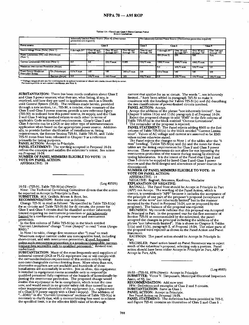
N F P A 70 ~ A 9 5 R O P
Tables t t b - Class 2 and Clam $ Dhreet C u r r e n t p o w e r Sotat-e L imi t t t t ou
Inherently Limited power Source (Note 4) (O~e*current Not Inherently Limited power Sottrce (Overcurrent protection required) protection not requ~-d)
p o w e r s o w c e C, l a u 2 C l a u s . C l am2 C l a u s
Sourcevo l t ageVmax(Vot t s ) (Note t ) 0 th rough20** Over20mad O v e r 3 0 m l d O v e r 6 0 a n d O v e r t 0 ~ d 0 th rough20** O v e r 2 0 a u d O v e r t 0 ~ a d O v e r t 0 0 ~ d t £ r o u ~ t50 t h r o u ~ 100 through 150 P o ~ Limimtion~ (VA) max (VoR-Amps) t h r o u ~ 30** ~ rou~h 60"* ] through 60"" through t00 ,
(Note t ) 250 (Note 3) 250 250 N.A. .
Current Limitat/om (VA) max (Note t ) 8.0 8.0 t 5 0 / V max ! 0.005 t 50 /V max t00d /V max 1000/V max 1000/V max t .0
Maximum overt-current Protecritm (Amps) 5.0 100 /V max 100/V max t .0
Nameplate Power Source M axim um Ratin~ VA (Volt-Amps) 5.0 x V ma.x 100 tOO .005 x V max 100 5.0 x Vmax 100 tOO tOO
Current {AmFa ) 5.0 t 00ca /max lO0~Vmax .005 t 0 0 / V m a x 5.0 100 /V max t 0 0 / V max t 0 0 / V m a x
* * Vo. rage range* shoma are for continuom., de in indoor locations or where w e t c o n tact ia no t llkely to o¢cttr. For mw.rrupted dc or w e t coQtact coQcfitlons, Jee Note 4.
SUBSTANTIATI. ON: There has been m u c h confusion about Class 2 and Class 3 power sources; what they are, what listing, if any, is required, and how they are used in apl?lications, such as a Distrib- u ted Control System (DCS). The revistons made herein, provided th rough a neiv section, i.e., 725-30, a concise, clear summary of the Class 2 and Class 3 power sources, provide a new reference figure (725-30) to indicate how this power source, its supply, and th'e Class 2 and Class 3 wiring m e t h o d relates to each o ther in terms of
licable Code sections and requirements . Clearly Class 2 and 3 circuits can be a DCS or any otl)er type of ins t rumenta t ion
olPlication when based on the appropriate power source. Addition- y, to provide fur ther clarification o f installation vs. listing
requirements , the former Section 725-31, Table 725-31, and Table 725-31 notes have been relocated to Chapter 9 as a reference
rimarily for listing pu rp oses. ~ANEL ACTION: Accept in Principle. PANEL STATEMENT: The wording accepted in Proposal 16-24 refines the concepts and satisfies the submi t te r ' s intent. See action on Proposal 16-24. NUMBER OF PANEL MEMBERS ELIGIBLE TO VOTE: • 18 VOTE ON PANEL ACTION:
AFFIRMATIVE: 18
(Log #2526) 16-52 - (725-31, Table 725-31 (a)-(New)):
Note: The Technical Correlat ing Commit tee directs that the action be repor ted as Accept in Principle in Pa r t SUBMITTER: M.S. Griffith, Brown & Root, Inc. RECOMMENDATION: Revise t ex t a s follows:
Change 725-31 to read as follows: "As specified in Table 725-31 (a) for ac circuits and Table 725-31 (b) for dc drcui ts , the power for Class 2 and Class 3 circuits shall be classified as ei ther inherent ly limited r e q u i r i n g n o overcurrent protect ion or no t inherent ly
by a combinat ion of a power source and o v e r c u r r e n t protection.
In the first co lumn of Table 725-31 (a) in the~block entit led "Current Limitations" change "I max (Amps)" to read "I max (Amps- RMS) :
In Note I to table, cleanse first sen tence after "I max" to read: "Maximum ou tpu t cur ren t unde r any noncapacitive load, including short-circuit, and with overcurrent protection, if used. bvoassed unless such overcurrent orotect ion is a non-interchanlzea~ble current- limitin~ fuse accessible onlv to oualified nersonnel ." l~evised text underffned. SUBSTANTIATION: Many of the mos t frequently used suppliers of industrial control (DGS or PLC) e q u i p m e n t can or will comply with the current-limitations r equ i r emen t of this section only by us ing non- in terchangeable current- l imit ing fuses. More often than not, alternative suppliers are no t available and h u n d r e d s of these installations are successfully in service. Jus t as often, this equ ipmen t is installed in e q u i p m e n t rooms accessible only to resoonsible qualified personnel fully cognizant of the hazards of fntenti~nally by- passing the overcurrent protection. The proposed change would enable this equ ipmen t to be in compliance, which is no t the case now, and would result in no greater safety risk than caused by any other inappropriate alteration of the e q u i p m e n t (i.e., r ep lacement of a Class 2 / 3 power supply with a Class I supply). The addit ion of "...-RMS)" in the "Current Limitations" sections of Table 725-3(a) is necessary to clarify that, with a current-l imiting fuse used to achieve the specified limit, it is the effective RMS value of let- through
cur rent that applies for an ac circuit. The words "~..not inherent ly limited..." have been added in paragraph 725-31 to make it consistent with the headings for Tables 725-31 (a) and (b) describing the two classifications of power-limited circuits involved. PANEL ACTION: Accep t
Accept the addit ion of the phrase "not inherent ly limited". See Chapter 9 tables 11 (a) and 11 (b) paragraph 2 of Proposal 16-24.
Reject the p roposed change to add "RMS" in the first co lumn of Table 725-31 (a) in the block entit led "Current Limitations".
The remainder of the proposal is rejected. PANEL STATEMENT: The Panel rejects adding RMS to the first co lumn of Table 725-31 (a) in the block entit led "Current Limita- tions". Values of AC voltage and cur rent are a s sumed to be RMS values unless otherwise stated.
The Panel rejects the changes to Note 1 of the tables after the "l- max" heading. Tables 725-31 (a) and (b) and the notes for these tables are the listing requi rements for Class 2 and Class 3 power sources. These requi rements do no t allow for not bypassing the overcurrent protection of the source du r ing testing by electrical testing laboratories. It is t h e i n t e n t of the Panel that Class 2 and Class 3 circuits be suppl ied by listed Class 2 and Class 3 power sources and that field designs and alterations of power sources be discontinued. NUMBER OF PANEL MEMBERS ELIGIBLE TO VOTE: 18 VOTE ON PANEL ACTION:
AFFIRMATIVE: 14 NEGATIVE: Bagnall, Brunssen, Kanfman, Wechsler
EXPLANATION OF NEGATIVE: BAGNALL: The Panel Vote should be Accept in Principle in Part
(APP) not Accept. The wording of the Panel Action, which is correct, is unmistakenly "APP" because it includes the acceptance of the principle of one part of the proposer ' s proposal (acceptance of the use of the term" no t inherent ly limited' bu t in the m a n n e r accepted by the Panel in Proposal 16-24, no t as proposed by the proposer) . The balance of the proposal was rejected.
BRUNSSEN: My records indicate that this proposal was Accepted in Principal in Pa r t In the proposed text for the first senten'ce of Section 725-31 as r e c o m m e n d e d by the submit ted, the panel accepted the changes in principal including the addi t ion o f the phrase "not inherent ly limited". This is shown in Chapter 9, Tables l l ( a ) and l l ( b ) , paragraph 2, of Proposal 16-24. The o ther parts of the proposal were rejected as shown in the Panel Action a n d P a n e l S t a t emen t
KAUFMAN: The panel action should be Accept In Principle In Par t
WECHSLER: Panel action based on Panel S ta tement was to reject m u c h of the submit ter ' s proposal, selecting only a portion. Panel action should have been ei ther Accept in Principle in Part, APP; or Accept in Part, APA.
(Log #883) 16-53- (725-31, FPN-(New)): Accep t i n Principle SUBMITTER: Victor V. Timpanaro , Municipal Electrical Inspectors Assoc. of NJ, Inc. RECOMMENDATION: Add new text:
FPN - Definition and examples of Class 2 and 3 circuits. SUBSTANTIATION: Same as Class I. PANEL ACTION: Accept in Principle. • See Panel Action on Proposal 16-24. PANEL STATEMENT: The definit ion has been provided in 725-2, and.Figure 725-41 contains an illustration of Class 2 and Class 3 .
788

N F P A 70 - - A 9 5 R O P
circuits. While the submitter did not include proposed text to guide the Panel in addressing his con~:erns, coincidentally the Panel had
addressed these issues by its action on Proposal 16-24. OF PANEL MEMBERS ELIGIBLE TOVOTE: 18
VOTE ON PANEL ACTION: AFFIRMATIVE: 18
(Log #1714) 16-54 -' (Table 725-31 (a)): Reject SUBMITTER: Gregory P. Bierals, Electrical Design Institute RECOMMENDATION: Revise as follows:
Class 2 Class 3
0 through 20 Over 20 Over 30 through 100 through 30
SUBSTANTIATION: According to the UL General Information Directory, the maximum voltage of a Class 2 power supply is 30 volts. The Table has a reference of an additional column for voltages of over 30 through 100 volts. This does not agree with the listing. ' PANEL ACTION: Reject. PANEL STATEMENT: Inherently limited power sources for Class 2 circuits are permitt~xl to have a maximum voltage in excess of $0 volts. The values given in tables 725-31 (a) and (b) are the listing requirements of the Dower sources. Class 2 power supplies covered in the UL General Dwectory are no t the only appropriate sources for Class 2 circuitry. NUMBER OF PANEL MEMBERS ELIGIBLE TO VOTE: 18 VOTE ON PANEL ACTION:
AFFIRMATIVE: 18
(Log #2667) 16-55 - iTable 725-31 (a) and (b) Note 6-(New)): Reject
Note: Itwas the action of the Technical Correlating Committee that this Proposal be referred to Code-Making Panel 14 for information. SUBMrrTER: Nicholas T. Abhatiello, Spencerport , NY RECOMMENDATION: "Add Note #6 as follows: '
Note 6: Listed associated intrinsicallysafe apparatus entity parameter values of Voc and Isc shall be permitted to meet the values of Vmax, and Imax in Note 1. The VAmax value shall be Pdiermitted to be de te rmined by the product of the Voc and Isc values
vided by four. SUBSTANTIATION: The requirements for intrinsically safe associated apparatus (e.g. zener barriers) are sufficient to meet the requirements of the values in the tables and Section 504-20 permits intrinsically safe wiring to be installed using any of the wiring methods suitable for unclassified locations. In fact, most intrinsically safe associated apparatus is clearly marked with similar values of Isc and Voc instead of Imax and Vmax and behave as a linear circuit between the values of Voc and lsc. The corresponding value of VAmax can easily be de termined by dividinl~ the product of Voc and Isc by four. Practically all associated intrinsically safe apparatus such as zener barriers are listed under ANSI/UL 913 entity parameters and as such certainly satisfy the requirements for the limited
• impedance of Note 1, al though not specifically listed for the Class 2 and 3 circuit limiting impedance. Adopting the proposed wording would then permit Class 2 and Class 3 wiring methods to be used for intrinsically safe wiring when installed to the requirements of Article 504.
NOTE: Support ing materials is available for review at NFPA Headquarters. PANEL ACTION: Reject. PANEL STATEMENT: The notes to Tables 725-31 (a) and (b) are part of the listing requirements for Class 2 and Class 3 power sources. It is not within the Panel 's purview to add an additional note that is in tended to impact the hsting requirements for intrinsically safe apparatus_This proposal is referred to CMP-14 for information. Also see Panel Statement on Proposal 16-54~ NUMBER OF PANEL MEMBERS ELIGIBLE TO VOTE: 18 VOTE ON PANEL ACTION:
AFFIRMATIVE: 17 NEGATIVE: Wechsler
EXPLANATION OF NEGATIVE: WECHSLER: The basic principal suggested by the submitter is
technically correct in that i fa device, like an intrinsic safety barrier, operates within Class 2 or Class 3 power limitations, then from a"
circuit safety s tandpoint it could be used. However, the consensus of the Panel is that devices be listed. Thus if this device was listed as a Class 2 or Class 3 power source, it could be used as the submitter suggests. Therefore, the more appropriate panel action would have been to "accept in principle", referring the submitter, to the appropriate section in Article 725 that indicates devices that are listed are acceptable. (Also, the term "intrinsic safety barrier" has now been def ined by the action taken by Panel 14 on Proposal 14- 186).
(Log #3343) 16-56- (Table 725-31(a), and (b); Notes: 1, 2, 3,): Accept in Principle SUBMITTER: Bruce Skovmand, Vista, CA RECOMMENDATION: Where ever the word "Maximum" or "Max" is used, it should be changed to "Maximum R.M.S." or "MAX. R.M.S." If the tables are not changed, at least the "Notes" should be. SUBSTANTIATION; In A.C~ Theory, the terms Maximum and Peak as applied to a sine ~0"ave are one and the same. The terms R.M.S. and effective are also synonymous. After some studying and head scratching, it becomes apparent that your reference toMaximum Voltage or Current actually means the Maximum R.M.S. or effective value. To clarify this meaning, I make the above proposal. " ' PANEL ACTION: Accept inPrinciple.
] Revise Tables 725-31 (a) and (b) Note 5 to add "peak" after "24.8 I volts" and also after "12.4 volts". PANEL STATEMENT: Make like revision to Proposal 16-24 Chapter 9 Tables l l ( a ) and (b) Note 4. The submitter has reached the correct conclusion when he determines that the maximum voltages and currents in Table 725-31 (a) are the maximum RMS values, not the peak values, unless otherwise noted, The definition of voltage in Article 100 spedfies that the value is RMS. Within this context "maximum" and "peak" are not synonymous. Also, refer to Panel statement on Proposal 16-52. NUMBER OF PANEL MEMBERS ELIGIBLE TO VOTE: 18 VOTE ON PANEL ACTION:
AFFIRMATIVE: 18
(Log #1715) 16~57- (Table 725-31(b)): Reject SI.IBMITTER= Gregory P. Bierals, Electrical Design Institute RECOMMENDATION: Revise as follows:
Class 2 Class 3
0 through 20 Over 20 Over $0 through 100 : through $0
SUBSTANTIATION: According to the UL General Information Directory, the maximum voltage of a Class 2 power supply is 30 volts. The Table has a reference of an additional column for voltages of over 30 through I00 volts. This does no t agree with the listing. PANEL ACTION: Reject. PANEL STATEMF.NT: See Panel Action and Statement on Proposal 16-54. NUMBER OF PANEL MEMBERS ELIGIBLE TO VOTE: 18 VOTE ON PANEL ACTION:
AFFIRMATIVE: 18
(Log #2462 ) 16-58- (725-34): Reject SIdBMITTEP.a Frank Roberts, Exxon Co USA RECOMMENDATION: Add the words, "whether the supply is Inherently Limited or Note Inherently Limited", so that it reads, "Marking. A Class 2 or Class 3 power supply unit shall be durably marked where plainly visible to indicate the class of supply, whether the supply is Inherently Limited or Not Inherently Limited, and its electrical rating." S ~ A N T I A T I O N : This additional information provided by the power supply manufacturer will facilitate the determinat ion by the user as to whether overcurrent protection is required. This should result in more uniformly safe installations.
789

N F P A 70 - - A 9 5 R O P
PANEL ACTION: Reject. PANEL STATEMENT: Cur ren t listing requ i rements for not inherendy limited power supplies require that the overcurrent protection be provaded as an integral part of the power supply. There is no need for the user to be conce rned with this factor. Thus, the marking is no t needed. NUMBER OF PANEL MEMBERS ELIGIBLE T O VOTE: 18 VOTE ON PANEL ACTION:
AFFIRMATIVE: 18
(Log #2527) 16-59 - (725-34): Accept in Part SUBMITTER: M.S. Griffith, Brown & Root, Inc. RECOMMENDATION: At the conclusion of existing text, add: "Exception: Thermocouples , and listed intrinsically safe and nonincendive sources need no t additionally be marked." SUBSTANTIATION: It is very difficult, if no t impossible, to get suppliers of industrial DCS and PLC e q u i p m e n t to "mark" their power supplies as required. Further, no such equ i pmen t is generally available with listed power supplies. Nevertheless, thermocouples , and by definition, intrinsically safe sources and nonincendive sources all have sufficient power-limiting propert ies to qualify as either Class 2 or Class 3 sources. Adding the proposed exception would, for the cases addressed by the exception, simplify the application of the associated equ i pmen t without compromis ing safety and would allow such installations to be in compliance, which is no t the case now. PANEL ACTION: Accept in Part.
The Panel accepts the r ecommenda t ion tha t the rmocouples are not required to be listed or marked. See Panel Action onProposa l 16-24 Section 725-41 (a) (3) Exception. PANEL STATEMENT: T he Panel rejects the r ecommenda t ion regarding intrinsically safe and nonincendive sources. Intrinsically safe and nonincendive sources are no t Class 2 or Class 3 power sources even though they may have power limiting properties. It would be incorrect to describe them in Section 725-34.-Listed class 2 and Class 3 power sources are marked accordingly. NUMBER OF PANEL MEMBERS ELIGIBLE T O VOTE: 18 VOTE ON PANEL ACTION:
AFFIRMATIVE: 17 NEGATIVE: Brunssen
EXPLANATION OF NEGATIVE: BRUNSSEN: This proposal should have been Accepted in
Principal in Part.' The panel accepted only the principal that thermocouples are no t required to be listed or marked. This is shown in Proposal 16-24, Section 725-41(a)(3) Exception. The remainder of the proposal was rejected as indicated in the Panel Statement.
16-60 - (725-34): Reject (Log #3424) SUBMITTER: Paul Dobrowsky, Holley, NY RECOMMENDATION: Add new text as follows:"
Add a second sentence; Marking shall be provided by the manufac tu re r to indicate power supply class of supply and overcurrent protect ion requ i rements a n d / o r restrictions. SUBSTANTIATION: Presently some equ i pmen t has no markings to indicate that they are ei ther a Class 2 or Class 3 power supply. By default they mus t be treated as a Class one power supply including the 600 volt insulation rating. T he operat ing voltage may be only 5 volts. PANEL ACTION: Reject. PANEL STATEMENT: Section 725-34 requires that Class 2 or Class 3 be marked on the power supply. Class 1 power supplies need not be marked. Also see Panel Action and Sta tement on Proposal 16-58. Listing requi rements def ine the markings and overcurrent protec- tion requirements . Also see Proposal 16-24 Section 72541. NUMBER OF PANEL MEMBERS ELIGIBLE T O VOTE: 18 VOTE ON PANEL ACTION:
AFFIRMATIVE: 18
(Log #215) 16-61 - (725-38-(New)): Accept in Principle SUBMITTER: William Barnett, City of Gresham RECOMMENDATION: Add to 725-38 after devices:
"shall be suppor ted in accordance with the appropriate require- men t s of Chapter 3". SUBSTANTIATION: Article 725 does not address Class 2 and 3 cable and wiring system suppor t requirements . Cables that are no t properly suppor ted are subject to abrasion or breakage. Condui t sleeves no t properly suppor ted can fall on people and damage property. Inspectors require the means to ensure proper limited energy installations. PANEL ACTION: Accept in Principle. PANEL STATEMENT: See Panel Action and Panel S ta tement for Proposal 16-15. NUMBER OF PANEL MEMBERS ELIGIBLE T O VOTE: 18 VOTE O N PANEL ACTION:
AFFIRMATIVE: 18
(Log #3348) 16-62- (725-38): Reject SUBMITTER: Bruce Skovmand, Vista, CA RECOMMENDATION: Revise text as follows:
725-38 -Wir ing methods and materials on load side. Conductors on the load side of overcurrent protection, t ransform-
ers and cur ren t l imiting devices shall be insulated at no t less tha t ' the requi rements of 725-50 and shall be installed in accordance with Section 725-52. Any wiring me thods as covered by Chapter #3 an d installed in accordance with Chapter #3 will also be acceptable for Class 2 or 3 circuits. Class 2 or 3 circuits in hazardous (classified) locations shall also conform to the requi rements of Chapter #5.
725-52(a) 1 - Exception #2 Speaks of a firmly fixed non-conductor such as porcelain tubes or flexible tubing. I assume that this refers to the porcelain tubes and loom that was used in knob and tub wiring. These products haven ' t been available for years, however, there is a clear vinyl tubin~ that is readily available in hardware stores. It comes in many sizes and wall thicknesses. Being made of vinyl, it no doub t has far superior dielectric propert ies than the old cotton loom. The only problem that I see is that the tempera ture rating and flame spread are unknown. This products should be
rmissible for use in listed enclosures as men t ioned in 725-52(a)2 ception #1 in lieu of raceways. Raceways are usually bulky,
inflexible and difficult to install in enclosures, such as control panel. This way a separat ion is insured and flame spread and tempera ture r a t i n g s h o u l d n o t be a problem within a wiring enclosure.
725-52(a) 1 Exception #1 allows N.M.C. cable to provide separat ion for open wiring. The jacket on N.M.C. cable has got ten so thin that it actually affords very little mechanical protection. Vinyl tubing should certainly be better than N.M.C. cable. It could also be used in compar tments and gutters to give added protect ion to unpro- tected taps such as allowed in 240-21 (b) a n d 240-21 (c). - SUBSTANTIATION: 725-38 Wiring me thods and matei:ials on load side refers to 724-50 and to be installed in accordance with 725-52. It does not state that any of the wiring me thods as covered by Chapter #3.for line voltage wiring can be used for Class 2 or 3 systems. 300.1 (a) Exception 2 actual lyprohibi ts their use.
I propose that 725-38 be rewritten as above in #3. PANEL ACTION: Reject. PANEL STATEMENT: Section 725-2(c) and Exceptions to Sections 725-53(a), (b) and (e) pe rmi t appropria te usage o f Chapter 3 wiring methods in hazardous locations, p lenums, risers, and other locations in buildings. The proposed changes to this section are no t required. NUMBER OF PANELMEMBERS ELIGIBLE T O VOTE: 18 VOTE O N PANEL ACTION:
AFFIRMATIVE: 18
(Log #2373) 16-63- (725-38, Exception-(New)): Reject SUBMITTER: Noel Williams, Esco Electrical RECOMMENDATION: Add Exception: Class 2 or Class 3 circuits shall be permi t ted to be r edas s i f i edand installed as Class 1 drcui ts if all componen t s o f the circuit are approved for use with Class I drcui ts and the entire circuit is installed in accordance with Part B Class 1 circuits. SUBSTANTIATION: Article 725 shou ld no t restrict low power drcui ts to Class 2 wiring me thods and rules if all componen t s are suitable for Class 1 or general use. As an example, 24 volt drcui ts
790

N F P A 70 - - A95 R O P
are frequently used in control circuits for mechanical equ ipment . If a power supply such as a Class 2 t ransformer is used then all of the circuit falls u n d e r Part C and the restrictions o f 725-52 apply, even when all o ther componen t s such as relays a n d pilot devices are , suitable for 120 volts or higher. PANEL ACTION: Reject. PANEL STATEMENT: T he process descr ibed in the proposal constitutes a reinstallation. In such a case, all r equ i rements for Class 1 circuits would have to be met, including the use of 600 volt insulated conductors . This proposal creates the opportuni ty for confusion and mixing of Class l c i rcu i t s with Class 2 a n d Class 3 circuits. NUMBER OF PANEL MEMBERS ELIGIBLE TO VOTE: 18 VOTE ON PANEL ACTION: "
AFFIRMATIVE: 18
(Log #48)" 16-64- (725-38(a)'(2), Exception No. 2): Reject
Note: I twas the action of ttie Technical Correlating Commit tee that. this Proposal be reconsidered and correlated with the terminol- ogy in Article 370. This action will be considered by the Panel as a Public C o m m e n t . .
Note: The following proposal consists of C o m m e n t 16-32 on Proposal 16-55 in the 1992 Annua l Meeting National Electrical Code Technical Commi t tee Report. This C o m m e n t was held for fur ther study dur ing the processin~ of the 1995, NATIONAL ELECTRICAL CODE. The r e c o m m e n d a u o n in Proposal 16-55 was:
Delete "to which the o ther conductors in the enclosure are connected" f rom the end of the 1st sentence of Exception 2. Also, add the one sen tence paragraph between Exception 2 and Excep- tion 3, to Exception 2, so Exception 2 reads:
Exception No. 2: conductors in compar tments , enclosures, oude t boxes,- or similar f i t t ing , where electric light, power, or Class 1 circuit conductors are in t roduced soley to connei:t to the equ ipmen t connec ted to Class 2 or Class 3 circuits. The electric light, power and Class 1 circui t 'conductors shall be routed within the enclosure to maintain a m i n i m u m 0.25-inch (6.35 ram) separat ion f rom the conductors of Class 2 and Class 3 circuits. SUBMITTER: RogerW. Field, Lowell, MA RECOMMENDATION: Accept in principle and add "device boxes," after "oudet boxes." SUBSTANTIATION: Recognizes change in title of Article 370 in ~i .N t code cycles.
EL ACTION: Reject. PANEL STATEMENT: Device boxes are covered by the te rm "or similar fittings". The list of boxes and wiring enclosures is no t in t ended to be comprehensive. NUMBER OF PANEL MEMBERS ELIGIBLE TO VOTE: 18 VOTE ON PANEL ACTION:
AFFIRMATIVE: 18
(Log 08 $9) 16-65- (725-50770-50,770-50): Reject SUBMITTER: Kevin F. St. Cyr, Champla in Cable Corporat ion RECOMMENDATION: Add new text:
Include low smoke, zero ha logen wire and cable products as al ternate designs in the following NEC Articles: $,40, 400, 517, 520, 55,0, 545, 725, 770, 800.
Example: Article 800 CMR-I.,SOH SUBSTANTIATION: Low smoke, no halogen cable is a safer alternative to existing NEC a.pproved, p roducts, unde r f lammable combust ion. These al ternauve designs roll allow the user or
• specifier to choose the optional des ign for "enclosed" applications in such critical areas as h igh rise buildings, hospitals, schools, central office switch~s, etc. PANEL ACTION: Reject. PANEL STATEMENT." The submit ter has no t provided suggested text nor substantiation. NUMBER OF PANEL MEMBERS ELIGIBLE TO VOTE: 18 VOTE ON PANEL ACTION:
AFFIRMATIVE: 18
(Log #2894) 16-66- (Table 725-50): Reject " SUBMITTER: L. Bruce McClung, Un ion Carbide Corporat ion RECOMMENDATION: Under l ine words to be added.
Modify and add to table:
Table 725-50. Cable Markings
Cable ~ Refetealce ~ k ~
CL3R Class 3 Riser .Cable Secdons 725-51(b) ~1~ and 725-53(b)
C L 3 ~ Class 3 Reduced Hazard Sections 725-61 (b~ t2~ and m~r ~blc
CL2R Class 2 Riser Cable Secdons 725-51 (b) ~ and 725-53(b)
Class 2 R e d u ~ t Hazard Sections 72551 ( b~ (2~ and
SUBSTANTIATION: Fire resistar;ce is not / .he only characteristic by which to measure fire safety of cables. A combust ion of fire safety characteristics can result in an overall safer condi t ion than jus t fire resistance. Therefore at least th ree characteristics for which s tandardized tests are available shou ld be evaluated to recognize a reduced hazard riser cable tha t is as safe or safer to utilize t h an the present Types CL2R and CL34 which are listed on the basis of fire resistance only.
NOTE: Suppor t ing material is available for review at NFPA " Headquarters . PANEL ACTION: Reject. PANEL STATEMENT: See Panel Action and S ta tement on Proposal 16-68. NUMBER OF PANEL MEMBERS ELIGIBLE TO VOTE: 18
V O T E ON PANEL ACTION: AFFIRMATIVE: 17 NEGATIVE:. Hansell
EXPLANATION OF NEGATIVE: HANSELL: As an instructed delegate of the Institute of Electrical
g: Electronics Engineers (IEEE), whose posit ion is that products that enhance or improve fire safety should be favorably considered, I mns t vote against the panel act ion to reject the cable type mark ing suffix RH ( reduced hazard) . T h i s n e w (non-ha logen) product will also decrease fire losses to expensive & sensitive equ ipment .
(Log #2895) 16-67- (725-51(b)): Reject SUBMITrEI~ L Bruce McClung, Union Carbide Corporation RECOMMENDATION: Renumber as (b) (1) Types CL2R and CL3P~ SUBSTANTIATION: To make a place (way) to add (b) (2) Types CL2RH and CL$RH. PANEL ACTION: Reject. PANEL STATEMENT: See Panel Action and S ta tement on Proposal 16-68. NUMBER OF PANEL MEMBERS ELIGIBLE TO VOTE: 18 . VOTE ON PANEL ACTION:
AFFIRMATIVE: 17 NEGATIVE: Hansell
EXPLANATION OF NEGATIVE: HANSELL: See c o m m e n t on Proposal 16-66.
(Log #2896) 16-68- (725-51(b)-(New)): Reject SUBMITrER: L. Bruce McClung, Un ion Carbide Corporat ion RECOMMENDATION: Add (b)(2) Types CL2RH and CL2,RH.
(b)(2) Types CL2RH a n d CLSRH. Types CL2RH and CL3RH riser cable shall be listed as being suitable for use in a vertical run in a shaft or f rom floor to floor and shall also be listed as having adequate fire-resistant, l imited smoke and l imited corrosivity ' characteristics capable of prevent ing the spread of fire or products of combust ion f rom floor to floor.
(FPN): A combinat ion of fire safety features can result in a r educed hazard. O n e m e t h o d of def in ing resistant to spread of fire is that the cables do no t spread fire to the top of the tray in the
791

N F P A 70 - - A 9 5 R O P
"Vertical-Tray Flame Test" in the Reference Standard for Electrical Wires, Cables and Flexible Cords, ANSI /UL 1581-1985. One m e t h o d of def in ing both resistant to spread of fire and limited smoke is that the cablespass the "UL Flame Exposure Fire Tests" in reference Vertical Tray Fire Propagation and Smoke-Release Test for Electrical and Optical-Fiber Cables UL 1685-1992. One m e t h o d of definin, g limited corrosivity is by the results of direct exposure of reststivity probes to acid gas genera ted by the cables when tested m accordance with ASTM E.5.21.70. SUBSTANTIATION: Fire resistance is no t the only characteristic by which to measure fire safety o f cables. A combinat ion of fire safety characteristics can result in an overall safer condit ion than jus t fire resistance. Therefore at least th ree characteristics for which standardized tests are available should be evaluated to recognize a reduced hazard riser cable that is as safe or safer to utilize than the present Types CL2R and CL3R which are listed o n t h e basis of fire resistance only.
Reduced hazards f rom a fire safety viewpoint mus t incorporate ignitability, propagation, hea t release, smoke, corrosivity and toxicity.
The better product will be the one that meets the m i n i m u m acceptable s tandards in each category. Until accepted consensus s tandards for measur ing all six categories are available the industry should concentrate on measur ing and evaluating applications based on the categories tha t can be satisfactorily measured . See copy of summary o f North American and European Fire Tests for Cables and Cable Materials for consensus as well as c o m m o n test protocols t o m e a s u r e ease of i~mition, f lame spread, hea t release rate, smoke, corrosivity and toxioty.
NOTE: Suppor t ing material is available for review at NFPA Headquarters. , PANEL ACTION: Reject. PANEL STATEMENT: T he submit ter has not proposed any applications where RH cables are required to be used. Manufactur- ers can list cables to the RH category without this category being established in the NEC. T he Panel in tends that UL 1666-1992 cont inue to be used as a m i n i m u m requ i remen t for de te rmin ing the resistance to the spread of fire. NUMBER OF PANEL MEMBERS ELIGIBLE TO VOTE: 18 VOTE ON PANEL ACTION:
AFFIRMATIVE: 17 NEGATIVE: Hansell
EXPLANATION OF NEGATIVE: "HANSELL: See c o m m e n t on Proposal 16-66.
(FPN): One m e t h o d of de te rmin ing that cable is f lame-retardant is by testing the cable to the "VW-1 (Vertical-Wire) Flame Test" in the . Reference Standard for Electrical Wires, Cables and Flexible Cords, ANSI /UL 1581-1985. SUBSTANTIATION: Currently articles 725,760 and 800 each have their own cables and there is a complicated cable substi tution chart. This level of complexity has led to installations where the wrong cable has been installed. Consequent ly simplification of the choices of cables and cable substi tut ions should lead to a more nser-friendly Code and a h igher level of compliance. This proposal deals with X- rated class 2 and 3 cables only. Ano the r p roposa l .has been submit ted to deal with CMX cable. PANEL ACTION: Reject. PANEL STATEMENT: The Panel feels that the need to delete this cable type f rom the Code has not been adequately substantiated. NUMBER OF PANEL MEMBERS ELIGIBLE TO VOTE: 18 VOTE ON PANEL ACTION:
AFFIRMATIVE: 18
' (Log #2529) 16-71 - (725-51(e)', Exception No. 2-(New)): Accept in Pr inople SUBMITrER: M.S. Griffith, Brown & Root, Inc. RECOMMENDATION: Change existing "Exception" to "Exception No. 1...". Add "Exception No. 2 ( include text f rom present exception to 725-53(c) which allows the rmocouple extension wire as the conductor material for Type PLTC cable)." SUBSTANTIATION: The exception to solely us ing copper for the conductors for Type PLTC cable more logically belongs after the Ptharagraph that first in t roduces and describes the construct ion of
at type cable. PANEL ACTION: Accep t in Principle.
I In addit ion to the r ecommenda t ion of the submitter, delete the Exception to Section 725-53(c). PANEL STATEMENT: This is a listing r equ i r emen t and it should only appear with the o ther listing requirements . In addition, revise Proposal 16-24 to identify the Exception for Section 725-71 (e) as Exception No. 1 and move the Exception from Section 725-61 (c) to become Section 725-71 (e) Exception No. 2. , NUMBER OF PANEL MEMBERS ELIGIBLE TO VOTE: 18 VOTE ON PANEL ACTION:
AFFIRMATIVE: 18
(Log #2528) 16-69- (725-51 (c), FPN): Reject SUBMITTER: M.S. Grittith, Brown & Root, Inc. RECOMMENDA'H. ON: Revise the first sentence in the (FPN) to read as follows:
"Al th tugh types CL2 and CL3 cables are no t suitable for installa- tion in cable tray unless they are also listed as type TC cable, one me thod of defining..." or, alternatively, delete the FPN entirely. SUBSTANTIATION: By referr ing to the "Vertical Tray Flame Test", the FPN as presently written incorrectly implies that types CL2 and CI.,3 cables are suitable for installation in cable tray, which is no t normally the case. Further, these types of cables are not normally subjected to this (tray cable) test so no such test results are available, which makes the FPN meaningless. PANEL ACTION: Reject. PANEL STATEMENT: T he Panel believes that CL2 and CL3 cables have adequate propert ies for their use in cable trays in buildings. See Panel Action on Proposal 16-90a. NUMBER OF PANEL MEMBERS ELIGIBLE TO VOTE: 18 VOTE ON PANEL ACTION:
AFFIRMATIVE: 18
(Log #907) 16-70 - (725-51 (d)): Reject SUBMI'VrER: Sandy Egesdal /Stanley Kaufman, Honeywell /AT&T RECOMMENDATION: Revise section 725-51 (d) as shown below in order to simplify the permi t ted cables and cable substi tut ions by el iminat ing X-rated cables.
(d) Types CL2X and CL3X. Until lanuarv 1. 1997. Types GL2X and CL3X limited use cables shall be listed as being suitable for use in dwellings and for use in raceway and shall also be listed as being flame~retardant After Ianuarv 1. 1997 the listing of CL2X and CL3X cables shall no t be oerrn i t ted .
(Log #2707) 16-72 - (725-51 (f), FPN): Reject SUBMrVrER: Marcelo M. Hirscbler, Safety Engineer ing Laborato- ries, Inc. RECOMMENDATION: Revised text for the fine pr int note:
(FPN): One m e t h o d of def in ing resistant to spread of fire is that the cables do no t spread fire to the top of the tray in the "Vertical Tray Flame Test" in the Reference Standard for Electrical Wires, Cables and Flexible Cords, ANSI /UL 1581-1985. Alternatively. the m a x i m u m heat release rate of the cables, as tested in the "Standard for Test ing for Smoke Obscurat ion Caused by Burn ing Cables in a Vertical C~nfi~uration." ASTM D5424 (Protocol AL s~all no t exceed 100 kW. Anothe r m e t h o d of def in ing resistant to the spread o f fire is for the
damage (char length) no t to exceed 4 feet, 1 inches (1.5 m) when dPerforming the C-,SA "Vertical Flame Test - Cables in Cable Trays," as
escribed in Test Methods for Electrical Wires and Cables, CSA C22.2 No. 0.3-M-1985. Alternatively. the m a x i m u m hea t release rate of the cables, as tested in the "Standard for Test ing for Smoke Obscurat ion Caused by Burn ing Cables in a Vertical Confi~ruration." ASTM D5424 (Protocol BL shal~l no t exccg~i 100 kW,
Anothe r m e t h o d of def in ing resistant to the soread of fire is for the m a x i m u m heat release rate t~er uni t area of the cables, as tested, at an incident flux of 40 kW/r~ : , according to "Standard Test Method for Heat and Visible Smoke Release Rate's for Materials and Products Using an Oxygen Consumnt ion Calorimeter." ASTM E13~i4. nog tO exceed 200 kX~X,'/m~'."
This replaces the present FPN, text in "underl ine" is to be added. SUBSTANTIATION: It has now been shown that hea t release rate testing is an al ternate way to de te rmine whether a cable resists the spread o f fire.
One of the first quest ions a person migh t wish to ask about the hazard of a fire i s"How big is the fire?" Until fairly recently there was no quantitative way of answering this question. Nowadays, we know that, in quantitative terms, this quest ion is equivalent to asking,
792

N F P A 70 - - A 9 5 R O P ~
"What is the hea t release rate of the fire?" An example may explain the impor tance of hea t release rate. f f a "
cable tray were bu rn ing outdoors, with no comlmstible products a round it, it may b u m , the immedia te consequence of its bu rn ing will be minimal: no th ing else will be ignited. On the o ther hand , if. the same cable tray is inside a compar tment , once it starts bu rn ing it may ignite a nearby product , if it releases (gives off) e n o u g h hea t and does it fast enough , ff the bu rn ing cables release hea t slowly, the cooler air a r o u n d t h e m may be cold e n o u g h to avoid raising the tempera ture f the neares t p roduc t for it to start burning. If the cables release hea t even faster, they could go beyond causing the neares t product to burn, bu t t heycou ld also ignite o ther products fur ther away. As more products burn , the fire gradually becomes more intense. In the same spirit, as more things are burning, more smoke is emitted. This means the visibility in the room decreases, m a k i n g i t more difficult for people to 'escape and more difficult for fire fighters to come in and help potential fire victims. If more smoke is emitted, the air in the room also becomes more toxic, which can also cause a bigger threat to the people in the room.
Recent work, u s i n g a large n u m b e r of cables of different types, has shown that every cable that has had a peak hea t release rate of less than 100 kW, when tested according to ASTM D5424, Standard for. Test ing for Smoke Obscurat ion Caused by Burn ing Cables in a Vertical Configurat ion, has ~ the cable tray test, as regards char length. Moreover, it has also been shown that every cable which, when tested in the cone calorimeter, S tandard Test Method for Heat and Visible Smoke Release Rates for Materials and Products Using an Oxygen C onsumpt i on Calorimeter," ASTM E1354, at an inc ident flux of 40 k W / m , has had a peak hea t release rate no t exceeding 2'00 k W / m z, has ~ t h e cable tray test, as regards char length.
In fact, it is likely tha t cables with even somewhat h igher hea t release rates may pass the test, in most cases. However, the above criteria are being suggested as very conservative estimates, with a significant margin o f safety, for those users interested in having cables listed while testing less material.
It is also possible to obtain hea t release rate results by testing smaller lengths of cable in a bench-scale test. Thus , I feel that .the fine print note needs to be modif ied to express these ideas, as stated above.
NOTE: Suppor t ing material is available for review at NFPA Headquarters . PANEL ACTION: Reject. PANEL STATEMENT: The Panel believes the submit ter is directing his r ecommenda t ion to Section 725-51(c) and (e) FPN no t Section 725-51 (f) FPN. The subst:intiation for this proposal is based upon a limited a m o u n t of data a n d p r e s e n t s a limited correlation. At the p resen t time, the scatter o f data shows that the cone calorimeter should only be used as a research tool for the de;celopment of products and materials. The re is no ag reemen t within the fire communi ty to substantiate tha t the cone calorimeter can adec]uately evaluate early stages and full scale fire per formance charactermtics of wire and cable. NUMBER OF PANEL MEMBERS ELIGIBLE TO VOTE: 18 VOTE ON PANEL ACTION:
AFFIRMATIVE: 18
£Log #47) 16-73 - (725-52-(New)): Reject
Note: The following proposal consists of C o m m e n t 16-51 on Proposal 16-74 in the 1992 Annua l Meeting National Electrical Code Technical Commi t tee Report. This C o m m e n t was he ld for fur ther study dur ing the processing of the 1993 NATIONAL ELECTRICAL CODE. The r e c g m m e n d a u o n in Proposal 16-74 was:
Add new Section 725-52 to read: "Installation of Conductors and Equipment . Conductors and
equ ipmen t on the load side of overcurrent protection, t ransformers and cur ren t l imiting devices shall comply with (a) and (b) below.
(a) Separation f rom Electric Light, Power, Class 1 and Nonpower- limited Fire Protective Sitmalin~ circuit conductors.
(1) O p e n Conductors . ~'Conductors of Class 2 and Class 3 circuits shall be separated at least 2 inches (50.8 mm) f rom conductors of • any electric light, power, Class 1 or 'nonpower- l imited fire protective
Class~anO circuits" n No. 1: Where either: (1) all of the electric light, power, d nonDower-limited fire nrotective simaalin~ circuit
conductors , or (2) all of the Class 55 and Class ~c i r cu~ conductors are in raceway or in metal-sheathed, metal-clad, nonmetall ic- sheathed, or Type UF cables.
Exception .No. 2: Where the conductors are pe rmanen t ly separated f rom the ,conductors o f the o ther circuits by a cont inuous an d firmly fixed nonconduc tor , such as porcelain tubes or flexible tub ing in addit ion to the insulation on the wire.
(2) In Cable, Cable Trays, Enclosures and Raceways. Conductors of Class 2 and Class 3 circuits shall no t be placed in any cable, cable tray, compar tment , enclosure, outlet box, raceway or similar fitting • with conductors of electric light, power, Class 1 and a.tmgg..~e~ limited fire , ro tec t ive signalin~ circuits.
Exception No. 1: WheFe the '~onductors of the differeht circuits are separated by a barrier.
Exception No. 2: Conductors in compar tments , enclosures, outlet boxes, or similar fittings, where electric light, power, Class 1 or nonnower- l imited fire vrotective simaalin~ circuit conductors are in t rdduced solely to connec t to the"equip-ment connec ted to Class 2, or Class 3 circuits to which the o ther conductors in the enclosure are connected. The electric light, power, Class I and nonnower- l imited fire
nrotective simnaling circuit conductors shall be rou ted within the hnclosure to-maintTain a m i n i m u m of 09.25-inch (6.35 m m ) separat ion from the condhctors of Class 2 and Class 3 circuits.
Exception No. 3: U n d e r g r o u n d conductors in a manho le where • one of the following condi t ions is met:
a. The electric light, power, Class 1 and nonpower- l imited fire orotective simaaling circuit conductors are in a metal-enclosed cable br Type U F ~able;
b. The conductors ari." pe rmanen t ly separated f rom the conductors of the o ther circuits by a con t inuous a n d f i r m l y fixed n o n co n d u c to r such as flexible tubing, in addit ion to the insulation or covering on the wire;
c. The conductors are pe rmanen t ly and effectively separated f rom conductors of o ther circuits and securely fas tened to racks, insulators, or o ther approved supports . _
Exception No. 4: As permi t ted by Section 780-6(a) a n d installed in accordance with Article 780.
(3) In Hoistways. Class 3 or Class 3 circuit conductors shall be installed in rigid metal conduit , rigid nonmeta l l ic conduit , interme- diate metal conduit , or electrical metallic tubing in l~oistways.
Exception: As provided for in Section 620-21, Exceptions No. 1 and 2 for elevators and similar equipment .
(4) In Shafts. Class 2 or Class 3 circuit conductors shall be separated by not less than 2 inches (50.8 mm) f rom electric light, power, Class 1, or nonpower-l imited fire protective s ignal ing o rcu i t conductors run in the same shaft.
(B) Conductors o f Different Circuits in Same Cable, Enclosure, or Raceway.
(1) Two or More Class 2 Circuits. Conductors of two or m o r e Class 2circui ts shall be permi t ted with the same cable, enclosure, or raceway provided all conductors in the cable, enclosure, or raceway are insulated for the m a x i m u m voltage of any c o n d u c t o r s . .
(2) Two or More Class 3 Circuits. Conductors of two or more Class 3 circuits shall be permi t ted within the same cable, enclosure or raceway.
(3) Class 2 Circuits with Class 3 Circuits. Conductors of one or more Class 2 circuits shall be pe rmi t t edwi th in the same cable, enclosure, or raceway with conductors of Class 3 circuits provided that the insulation of the Class 2 circuit conductors in the cable,
(4) Class 2 or Class 3 circuits with Othe r Circuits. Jacketed cables of Class 2 or Class 3 circuits shall b e permi t ted in the same enclosure or raceway with jacketed cables of any of the following:
a. Power-limited fire protective s ignal ing systems in compl iance with Article 760.
b. Nonconduct ive and conductive optical fiber cables in compli- ance with Article 770.
c. Communica t ions circuits in compl iance with Article 800. d. Commun i ty a n t e n n a television a n d radio distr ibution systems in
compliance with Article 820. SUBMrI ' rER: Roger W. Field, Lowell, MA RECOMMENDATION: Add "device boxes," after "outlet boxes," in Section 725-52(a)(2) and Section 725-52(a)(2) Exception No. 2. SUBSTANTIATION: Includes a missing box tha t is part of Article 370. PANEL ACTION: Reject. PANEL STATEMENT: Device boxes are covered by the te rm "or similar fittings". The list of boxes and wiring enclosures is no t in tended to be compreilensive. NUMBER OF PANEL MEMBERS ELIGIBLE TO VOTE: 18 VOTE ON PANEL ACTION:
AFFIRMATIVE: 18
793

N F P A 70 - - A 9 5 R O P
' (Log #3344) 16-74- (725-52(2), Exception No. 2): Reject SUBMrVrER: Bruce Skovmand, Vista, CA RECOMMENDATION: For the purpose of this exception, Power Limited Fire Protective Signaling Circuits shall be treated as Class 2 or 3 circuits. Conductors of Class 2 or 3 circuits and conductors of non-class 2 or 3 circuits may occupy a c o m m o n enclosure or compar tmen t only as necessary for connec t ing to e q u i p m e n t and devices that serve both class 2 or 3 and non-class 2 or 3 circuits. The conductors of class 2 or 3 and non<lass 2 or 3 circuits shall be permanent ly and effectively separated from each other by a m i n i m u m separat ion of 0.25 inches (6.35mm) or by raceways, flexible tubing or bgrriers. E qu i pmen t and devices that serve both class 2 and 3 and non-class 2 or 3circui ts shall no t be required to be separated from other equ i pmen t in the enclosure by barriers. SUBSTANTIATION: 725-52(2). Exception #2 is poorly worded, vague and confusing.
725-52 Exception #2 States "Conductors in compar tments , enclosures, oude t boxes, or similar fittings, where electrical light, power Class 1 or Nonpower-l imited fire protective signaling circuit conductors are in t roduced solely to connec t to equ i pmen t con- nected to Class 2 or 3 circuits to which other conductors in the enclosure are connected. . ." etc.
This exception is obviously mean t to cover enclosures that contain basically Class 2 or 3 wiring and equ ipment . Since Class I, power, light, etc., conductors are in t roduced into the enclosure "solely" to connect to the e q u i p m e n t connec ted to Class 2 or 3 circuits, what are the other conductors in the enclosure? They canno t be Class I, power, light, etc., and they canno t be Class 2 or 3. These have already been covered in the paragraph. Since Class 2 and 3 circuits ofte.n mus t also be in t roduced into enclosures that contain basically non-class 2 or 3 wiring and equipment , I propose that 725-52 (2) be rewritten as stated above. PANEL ACTION: Reject. PANEL STATEMENT: The Panel believes that the submit ter in tended to reference Section 725-52(a)(2) Exception No. 2. The wording of Section 725-52(a)(2) Exception No. 2 is necessary even though it may be difficult for the submit ter to follow. The present wording insures that all connect ions are made in the compa r tmen t enclosure outlet box etc., and not somewhere else. There is no substantiation presented for treating power limited fire protective signaling circuits as Class 2 or Class 3 circuits with respect to this Exception. NUMBER OF PANEL MEMBERS ELIGIBLE TO VOTE: 18 VOTE ON PANEL ACTION:
AFFIRMATIVE: 18
. (Log #3347) 16-76 - (725-52(a)(2), Exception No. 1): Reject SUBMITTER: Bruce Skovmand, Vista, CA RECOMMENDATION: .Revise text as follows:
725-52(a) 2 Exception #1 Where the conductors of Class 2 or 3 and Non Class 2 or 3 circuits
are separated by a barrier in enclosures, the separat ion may be provided by raceways, metal sheathed, metal clad, non-metall ic shea thed or U.F. cable or non-conductive flexible tubing. SUBSTANTIATION: 725-52(a)2 Exception #1 allows raceways to be used within an enclosure to separate Class 2 or 3 and non class 2 or 3 conductors.
725-52(a)1 Exception #1 allows raceways, metal sheathed, metal clad, non-metall ic shea thed or U.F. cables to provide separat ion between Class 2 or 3 and non-Glass 2 or 3 conductors, ff this is good enough for open wiring, it should certainly be good e n o u g h in an enclosure. I propose that 725-52(a) (2) Exception #1 be rewritten as stated above in #3 paragraph. "
725-52(a) 1 Exception #2 speaks of a firmly fixed non conductor such as porcelain tubes or flexible tubing. I assume that this refers to the porcelain tubes and loom that was used in knob and tube wiring. These products haven ' t been available for years, however, there is a clear vinyl tubing that is readily available in hardware stores. It comes in many sizes and wall thicknesses. Being made of vinyl, it no doub t has far superior dielectric propert ies than the old cotton loom. The only problem that I see is that the tempera ture rating and flame spread are unknown. This product should be permissible for use in listed enclosures as men t ioned in 725-52(a)2 Exception #1 in lieu of raceways. Raceways are usually bulky, inflexible and difficult to install in enclosures, such as control panels. This way a separat ion is insured and flame spread and tempera ture ,rating should not be a problem within.a wir ing enctosure.
725-52(a)1 Exception #1 allows N.M.C~ cable to provide separation for open wiring. The jacket ton N.M.C. cable has got ten so thin tha t it actually affords very little mechanical protection. Vinyl tubing should certainly better than N.M.C. cable. It could also be u s e d i n compar tments and gutters to give added protection to unpro tec ted .
~fh~/ such as allowed in 240-21 (b) and 240-21 (c). EL ACTION: Reject.
PANEL STATEMENT: This proposal covers only the separat ion of circuit conductors by a barrier in enclosures. It fails to address the entirety o f the main rule and Exception No. 1 which cover separa- tion of conductors in cable, cable tray, compar tments , enclosures, oude t boxes, raceways and similar fittings. No substant iat ion is
ruMBovided for address ing only the separat ion of circuits in enclosures. ER OF PANEL MEMBERS ELIGIBLE TO VOTE: 18
VOTE ON PANEL ACTION: . AFFIRMATIVE: 18
(Log #2530) 16-75 - (725-52(a)(2)): Reject SUBMI'I 'rER: M.S. Griifith, Brown & Root, Inc. RECOMMENDATION: Change first sentence to read as follows: "Individual conductors or conductors as oart of a cable assembly for
, Class 2 and Class 3 circuits shall no t be p/aced in any cable, cable tray, compar tment , enclosure, out let box, raceway, or similar fitting with conductors ~ of electric l i g h t , . . . "
(Revised text under l ined) SUBSTANTIATION: This sen tence as presendywri t ten with the focus only on "conductors" appears to exclude cables f rom the requ i rement which is no t believed to be the intent. Further, the sentence as presently written implies that (individual) conductors are permit ted in cable tray. The sugges ted revision clarifies the r equ i r emen t and once clarified remains consistent with the present wording of Exceptions 1 th rough 3. PANEL ACTION: Reject. PANEL STATEMENT: The Panel does not agree that the use o f the term "conductors" appears to exclude cables f rom the requirements ,
• nor that it implies that individual conductors are permit ted in cable trays. The word conductors means ei ther individual conductors or conductors within cables. NUMBER OF PANEL MEMBERS ELIGIBLE TO VOTE: 18 VOTE ON PANEL ACTION:
AFFIRMATIVE: 18
(Log #3476) 16-77- (725-52(a)(2), Exception No. l-(New)): Reject SUBMITTER: Herman A. Schouten, 3M Co. RECOMMENDATION: Add new text as follows:
Exception No. 1: Where the conductors of the different circuits are separated by a fixed or flexible barrier. In enclosures, Class 2 or 3 circuits shall be permit ted to be installed in a raceway within the enclosure to separate t hem from Class 1. Electric light and power circuits. In raceways, Class 2 or 3 circuits may be pu t in a flexible barrier and occupy the same raceway as Class 1, electric light and power where the different circuits are en ter ing the device when it allows only one entry point. The combin ing of the circuit will be kept as shor t as practical. The flexible barrier shall have the same insulation rat ing as the h ighes t conductor in the raceway. SUBSTANTIATION: Motor and sensor devices somet imes come with only one condui t open ing into the motor or sensor device. To drill and tap a new open ing may void the U.L. listing especially with classified equipment . Normally, electricians have b rough t the power and Class 2 or 3 circuits into a condui t "T" a shor t distafice f rom the device and have used a flexible condui t to connect to the device. This shor t run violates 300-3 (c)(1) and 725-52(a)(2). Exception No. 2 deals with the power for the devices and relates to that small space inside the device.
ff the electrician is allowed to put a jacket of the correct insulation rating a round the conductors to act as a barrier, this would make the installation mee t the in tent of the code and be safe. This jacket can be sl ipped on and heat shrunk.
It is this shor t run to the d~vice that is the problem. An open ing of the exception to include this wiring practice will make real life installations mee t the code.
794
N F P A 70 - - A 9 5 R O P
PANEL ACTION: Reject. PANEL STATEMENT: It is the Panel 's intent that products be designed toprnvide separate means of entry for the different classes of circuits. This will provide for proper separation of circuits as required by the Code. - " NUMBER OF PANEL MEMBER~ ELIGIBLE TO VOTE: 18 VOTE ON PANEL ACTION:
AFFIRMATIVE: 18
' (Log #1127) 16-78- (725-52(a)(2), Exception No. 2): Reject SUBMITrER: Dean K. Wilson, National Fire Alarm Code Correlat- ~I~C C°mmit tee
OMMENDATION: Revise 725-52(a)(2) Exception No. 2: Exception No. 2: Conductors in compartments, enclosures outlet
boxes or similar fittings, where electric light power, Class 1, or nonpower-limited fire alarm circuit conductors are in t roduced soley to connect to the equipment connected to Class 2 or Class 3 circuits to which the other condutors are connected, and
(a) the electric light, power, Class 1, and nonpower-limited fire alarm circuit conductors are routed to maintain a minimum of 0.25 inches (6.35 mm) separation from the conductors and cables of Class 2 and Class 3 circuits, or
(b) The circuit conductors operate at 250v or less, and 150 v or less to g round and also comply with one of the following:
(1) The Class 2 and Class 3 circuits are installed using CI_2,, CL3R, CL3P, CM, CMR, or CMP cables, provided the Class 2 and Class $ cable conductors extending beyond the jacket are separated a minimum of 0.25 inches (6.35 mm) from all o ther conductors, or
(2) The Class 2 and Class 3 circuit conductors are installed in accordance with Section 725-14 up to the compartment , enclosure, outlet box, or similar fitting. SUBSTANTIATION: The revised Exception No. 2 provides a number of methods of installing equivalent protection at different circuit voltages. This provides for greater flexibility in design and installation. Where all circuits are operating at 250 volts or less, the electric
light, power, Class 1 and nonpower-limited fire alarm circuits will be installed using conductors insulated at 600 volts, and the Class 2 and Clas 3 circuits will be insulated at 300 volts minimum. PANEL ACTION: Reject. PANEL STATEMENT: The submitter has not provided substantia- tion that the proposed alternate methods provide the desired protection afforded by present requirements. It is not the intent of this Panel to recognize conductor insulation alone as meet ing the separation requirement between Class 2 or Class 3 circuits and Class 1, electric light, power or nonpower-limited fire alarm circuits. It is suggested that manufacturers continue in their efforts to design e qm pm e n t to meet code requirements. NUMBER OF PANEL MEMBERS ELIGIBLE TO VOTE: 18 VOTE ON PANEL ACTION:
AFFIRMATIVE: 17 NEGATIVE: Mande
EXPLANATION OF NEGATIVE: MANDE: In rejecting this Proposal, the Panel stated thai the
submitter had not provided "substantiation that the proposed alternate methods provide the desired protection afforded by present requirements".
The present requirements were added to the 1990 edition of the Code in response to a Proposal (which was rejected by the Panel) and a Comment (which was Accepted in Principal) by Frederic P. Hartwell (Proposal 16-24 [Log #3070] and Comment 16-30 [Log #2243]). Prior to this change the Code permit ted power supply conductors, in t roduced solely for supplying power to the eqmpmen t connected to Class 2 or Class 3 circuits to which the other conduc- tors in the enclosure are connected, to be in the same outlet box, junct ion box, or similar fitting, or compar tment with Class 2 and Class 3 conductors without any requirement for a partition or physical separation to provide an acceptable level of safety.
Though the less restrictive requirement ivere in affect for decades Pdarior to the 1990 change, no compelling technical substantiation or
ta was provided by the submitter (MrHartwell) to document that anything more substantial than a theoretical safety hazard had ever occurred. I have no knowledge of any actual safety hazards ever having been brought to the Panel 's attention. . -
The 0.25 inch physical separation the Code presently requires is often a~=complished by carefully "dressing" the conductors within an enclosure. Though this might be adequate to have the installation accepted initially, there is no certainty that the separation will still exist after the first service call.
Though it ispossible to maintain the required separation in enclosures with doors or removable covers where the separation can - be checked without disturbing the wiring, "push back ~ situations pose a real problem for both installation and inspection. "Push ba'ck" situauons occur where a componen t (smoke detector, thermostat, etc.) of a system is installed on an outlet box and the componen t is integral with the cover for the box. Typically, the installation conductors and the componen t dangle from the box while the terminations are made and then the wiring is pushed back into the box whet-/the componen t is moun ted on the box.
Thi~proposal seeks to provide alternative methods of installation that offer equivalent protection to that afforded by the 0.25 inch separation. It requires a higher grade of insulation, it limits the length of the cables that can come in contact, and it maintains the 0.25 inch separation requirement between individual conductors extending beyond the cable jacket.
Another alternative would be to adopt Mr. Hartwell's original Proposal and permit the use of taping and cording as equivalent to the 0.25 inch.
Though I agree that the substantiation provided could have been mol:e detailed, it is no less substantial than the original substantia- tion which was adequate to convince the Panel to adopt the change.
NOTE: Supporting material is available for review at NFPA Headquarters.
(Log #1862) 16-79- (725-52(a)(2), Exception No. 5-(New)): Reject SUBMYrrER: Arden L. Munson, Hussmann Corporation RECOMMENDATION: Add flew text as follows:
Exception No. 5: Class 2 Energy Management Wiring, used to control or moni tor electric light, power, of Class 1 circuits, is permit ted to share a common raceway with Class 1 power wiring where the following, conditions are met:
1. The Class 2 raring insulation shall be rated for the 'appl ied voltage of the Class 1 power wiring, and
2. The wiring and control devices shall be listed as suitable for installation within a light, power, Class 1 or non power limited fire
~ rotection signalingcircuit raceway. " UB,STANTIATION: The micro processor based energy manage-
men t equipment used in the food market industry has progressed to a high degree of sophistication. Master controller based systems are being replaced with individual appliance controllers that have the control strategies, diagnostic rouunes, past performance history, and communications all as part of the control. This control will be installed on discrete components of the refrigeration system. For example, each/ 'efrigerator will have it's own controller. The controller will. regulate the flow of refrigerant. , time., and len. gth of defrost, cycling condensate heaters, turning refrigerator hghts on and offas needed, and communicat ing with other controllers for optimizing the overall system efficiency. Other controllers will run • condensin~ units and condensers. Each controller will have programrmng to determine the most efficient settings for the specific equipment being operated. These 'controls take input information in the form of temperature, pressure and pre-loaded instructions. As these controls have become more sophisticated they have also
become smaller. What once had to be mounted in NEMA enclo- sures on the wall may now be mounted within the electrical enclosure on the refrigerator. This enclosure serves as the field .wiring point and also contains the refrigerator wiring. In addition the enclosure is actually a continuous wireway to the adjacent refrigerator section. Field practice is to use this wireway to supply the various branch circuits for each refrigerator section.
Reducing the size of these controls has also reduced the .amount of Pcower required for operation. All controls today will operate from
lass 2 transformers. Since these controls are usually mounted within the field wiring space 'provided on the equipment , a problem exists with commingling the power wiring and the Class 2 wiring,. The controls will have to be wired to.the power wiring, (control of defrost, lights, fans and anti-condensate heaters), wired to the sensors, ( temperature and pressure), and wired to the communica- tion system (usually P.C. based).
Attempting to meet the requirements of Article 725 for the separation of circuits leads to complicated solutions and in some situations creates system malfunctions. The barriers that the manufacturer provides t end to become thrown away during servicing of the equipment. In other situations all of the Class 2 wiring is diverted to the outside of the equipment only to become food for the rodent populadon. Loss of sensor, communicat ions and general control of the equipment ensues. • . • .
795

NFPA 70 - - A95 ROP
Adopt ing this exception will permi t better and safer installations of these micro-processor controls in the refrigeration industry. PANEL ACTION: Reject. PANEL STATEMENT: Class 2 circuit conductors are no t permit ted to occupy the same raceway as Class 1 circuit conductors unless separated by a barrier, for example, in a wireway or gutter. The Panel cont inues to mainta in its position that Class 2 conductors cannot be separated f rom electric light, power, Class 1 and nonpower-l imited fire alarm conductors by conduc to r insulation only. The Panel 's in tent is to mainta in separat ion because the conductor insulation could be damaged ' du r ing installation, fail and impose hazardous condit ions on the Glass 2 circuit and components . NUMBER OF PANEL MEMBERS ELIGIBLE TO VOTE: l g VOTE ON PANEL ACTION:
AFFIRMATIVE: 18
PANEL ACTION: Reject . PANEL STATEMENT: The anecdotal informat ion suppl ied in the substantiation describe installation methods that clearlyviolate the requi rements of this Code. See Panel Action and Panel S ta tement on Proposal 16-79. Also, the process described in the proposal consti tutes a reinstalla-
tion. In such a case, all requi rements for Class 1 cii'cuits would have to be met, including the use of 600 volt insulated conductors. This proposal . . . . . creates the oppor tuni ty for confusion and mixing of Class 1 clrcmts vmh Class 2 and Class $ circuits. NUMBER OF PANEL MEMBERS ELIGIBLE TO VOTE: 18 VOTE ON PANEL ACTION:
AFFIRMATIVE: 18
(Log #3477) 16-80- (725-52(a)(2), Exception No. 5-(New)): Reject SUBMITrER: He rman A. Sehouten , 3M Co. RECOMMENDATION: Add new text as follows: "'
Exception No. 5: Where the conductors of Class 2 or 3 circnits are electronically isolated and have the same insulation rating, they may be in t roduced into the same raceway with Class 1, electric l ighting and power circuit if the device they are te rminat ing in has only one opening, requires both different circuits and the raceway to the device is as shor t as practical. SUBSTANTIATION: Motor and sensor devices somet imes come with only one condui t open ing into the motor or sensor device. To drill and tap a new open ing may void the U.L. listing especially with classified equipment . Normally, electricians have b rough t the power and Class 2 or 3 circuits into a condui t ~T" a shor t distance f rom the device and have used a flexible condui t to connect to the device. This shor t run violates 300-3 (c) (1) and 725-52(a) (2). Exception No. 2 deals with the power for the devices and relates to tha t small space inside the device.
If the Class 2 or 3 circuit were electronically isolated f rom the power system and they had the same insulation rating, then a fault in the condui t would treat all the wires the same as far as fire in concerned. Since the Class 2 circuit is isolated, the h igh voltage would be limited in the damage it would do to the Class 2 or 3 circuit conductors.
This would allow different circuits together in shor t runs where two conduits into a device is no t practical. PANEL ACTION: Reject. PANEL STATEMENT: It is the Panel 's in tent that products be des igned to provide separate means of entry for the different classes of circuits. This will provide for p roper separat ion of circuits as required by the Code. ALso see Panel Act3on and Panel S ta tement on Proposal 16-79. NUMBER OF PANEL MEMBERS ELIGIBLE TO VOTE: 18 VOTE ON PANEL ACTION:
AFFIRMATIVE: 18
(Log #3484) 16-81 - (725-52(a)(2), Exception No. 5-(New)): Reject SUBMITTER: David Fisher, Milwaukee, WI RECOMMENDATION: Add new text a~ follows:
Conductors of Class 2 and Class 3 circuits shall be permit ted to be installed as Class I circuits where the entire circuit is installed using the wiring methods and materials in accordance with Part B, Class I circuits. All materials located in raceways shall be rated for the m a x i m u m voltage of any conductor in the raceway. SUBSTANTIATION: This proposal follows the lead of section 160- 28(a) Exception to address a c o m m o n problem with industrial control wiring. Much of motor control wiring historically operated at 120V is now largely run at low voltage reflecting the widespread use of p rogrammable controllers. These Iowvoltage conductors are commonly run t h rough the same control enclosures and raceways as the power wiring. It is no t completely possible to separate these conductors in an enclosure a n d i t is often impractical to separate these conductors in raceways. The re is no hazard as long as the wiring is 600 volt rated and suitable for the use.
This is no t the same as the c o m m o n problem with HVAC thermo- stat wiring mixed with branch circuit conductors. There , even though the thermosta t wires may be 600V rated, the exposed thermosta t remains vulnerable and a potential hazard. Tha t concern can be properly addressed in industrial control wiring.
(Log #578) 16-82 - (725-52(a) (4), Exception-(New)): Accept
Note: The Technical Correlat ing Commit tee directs tha t the Panel clarify the Panel Action on this Proposal with respect to the addit ion of "MI". This action will be considered by the Panel as a Public Comment . SUBMITTER: Dan Leaf, Palmdale, CA
[ RECOMMENDATION: Add: [ "Exception: Where either (1) all the electric light, power, Class 1, [ and nonpower-l imited fire protect ive signaling cwcuit conductors, or ] (2) all of the Class 2 and Class 3 circuit conductors are in a raceway [ or in T e MI, T e MC, Type UF, or nonmetal l ic-sheathed cables."
S U B S ~ / T ~ Y ~ N : Relaxation of spacing requi rements appear warranted where certain wiring me thods are employed, as permi t ted in subsect ion (a) (1) Exception No. 1. PANEL ACTION: Accept. PANEL STATEMENT: Revise Section 725-54(a) (3) Exception No. 1 of Proposal 16-24 to include type MI cable. NUMBER OF PANEL MEMBERS ELIGIBLE TO VOTE: 18 VOTE ON PANEL ACTION:
AFFIRMATIVE: 16 NEGATIVE: Bagnail, Brunssen
EXPLANATION OF NEGATIVE: BAGNALL: The Panel Vote should be changed to "Accept in
Principle in ParC" The Panel did no t accept the exact wording of the proposer but instead acted to only include Type "Mi" cable to the revision of Article 725 which the Panel already accepted in Proposal 16-24. (The proposer ' s proposed wording is s,gnificantly different than what the Panel accepted in Proposal 16-240
In addition, the Panel S ta tement shown on the Ballot should be moved to the Panel Action section became it is obviously an action and no t a s tatement . The wording should be revised to:
(1) Refer correctly to the exact location [the Exception of Section 725-54 (a) ($)] to which the Panel wanted the add iuon to be made; and
(2) Provide clearer instruction to the Code editor. The following is suggested: PANEL ACTION: Accept in Principle in Part TYPE OF CHANGE: X Add text. O Delete text. O Move text. "Revise Section 725-54 (a) (3), Exception No. 1, of Propnsal 16-24
to include Type MI cable by adding "or MI" after 'Type UF." A new Panel S ta tement should be added; the following is suggested: "the Panel believes that the action taken by the Panel satisfies the
in tent of the proposer." BRUNSSEN: I agree .with Bagnall 's explariation of his negative
vote.
(Log #908) 16-83- (725-52(b) (1)): Accept
. SUBMITTER: Sandy Egesdal /Stanley Kanfman, Honeywell /AT&T [ RECOMMENDATION: Revise section 725-52(b) (1) as shown [ below. [ (1) Two or More.Class 2 Circuits. Conductors of two or more Class [2 circuits shall be permi t ted within the same cable, enclosure, o r ]raceway, , t . . . . ; ;d~" ,,ll c,,adac~v.o ia d-,c ,:abl~, c,.cl,,~a, ~, ~,
class 2 circuits identically to mixtures of class 3 circuits. Since all class 2 cables have to be listed as suitable for class 2, no addit ional requi rements are necessary. Also, since a voltage rating is no t permit ted on the cable, the existing r equ i r emen t is no t enforceable. PANEL ACTION: Accept.
796
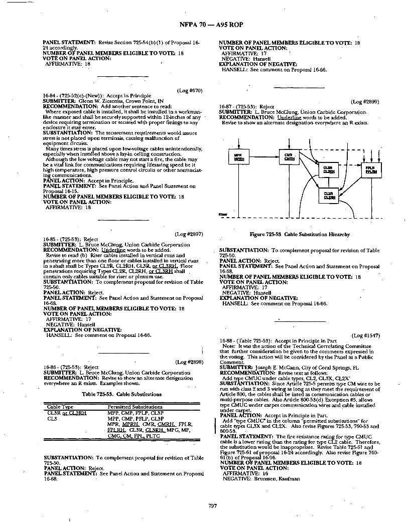
N F P A 70 m A 9 5 R O P
PANEL STATEMENT: Revise Section 725-54(b) (1) of Proposal 16- 24 accordingly. NUMBER OFPANEL MEMBERS ELIGIBLE TO VOTE: 18 VOTE ON PANEL ACTION:
AFFIRMATIVE: 18
NUMBER OF PANEL MEMBERS ELIGIBLE TO VOTE: 18 VOTE ON PANEL ACTION:
AFFIRMATIVE: 17 NEGATIVE: Hansell
EXPLANATION OF NEGATIVE: HANSELL: See comment on Proposal 16-66.
(Log #670) 16-84- (725-52(c)-(New)): Accept in Principle SUBMITrER= Glenn W. Zieseniss, Crown Point, IN RECOMMENDATION: Add another sentence to read: Where exposed cable is installed, it shall be installed in a workman-
like manner and shall be securely supported within 12-inches of any • device requiring termination or secured with proper fittings to any enclosure it may enter. SUBSTANTIATION: The securement requirements would assure stress is not placed upon terminals, causing malfunction of equipment circuits.
Many times stress is placed upon low-voltage cables unintentionally, especially when installed above a lay-in ceiling construction. Although the low voltage cable may not start a fire, the cable may
be a vital link for communications requiring lifesaving speed be it high ti:mperature, high pressure control circuits or other annunciat- ing communications. PANEL ACTION: Accept in Principle. PANEL STATEMENT: See Panel Action and Panel Statement on Proposal 16-15. NUMBER OF PANEL MEMBERS ELIGIBLE TO VOTE: 18
' VOTE ON PANEL ACTION: AFFIRMATIVE: 18
(Log #2899) 16-87- (725-53): Reject .. SUBMI'FIXR: L. Bruce McClung, Union Carbide Corporation. RECOMMENDATION: L~gO_.c.r.ljflgwords to be added.
Revise to show an alternate designation everywhere an R exists.
Rta~
(Log #2897) 16-85 - (725-53): Reject SUBMITTER: L. Bruce McClung, Union Carbide Corporation RECOMMENDATION: ~ w o r d s to be added.
Revise to read (b) Riser cables installed in vertical runs and penetrating more than one floor or cables installed in vertical runs , m a shaft shall be Types CL21L CL2RH, CL2,1L ~ Floor penetrations requiring Types CL21L CL2RH, or ~ 3 R H shall . contain only cables suitable for riser or plenum use. SUBSTANTIATION: To complement proposal for revision of Table 725-50. PANEL ACTION: Reject. PANEL STATEMENT: See Panel Action and Statement on Proposal 16-68. NUMBER OF PANEL MEMBERS ELIGIBLE TO VOTE: 18 VOTE ON PANEL ACTION:
AFFIRMATIVE: 17 NEGATIVE: Hansell
EXPLANATION OF NEGATIVE: HANSELL: See comment on proposal 16-66.
(Log #2898) 16-86- (725-53): Reject SUBMITTER: L. Bruce McClung, Union Carbide Corporation RECOMMENDATION: Revise to show an alternate designation everywhere an R exists. Examples shown.
Table 725-53. Cable Substitutions
Cable Type Permitted Substitutions CL3R or CL31~ CL3
MPP, CMP, FPLP, CL3P MPP, CMP, PFLP, CI~P MPR, MPRH. CMR, CMRH~ FPLIL
• ~LRH, CLSR, C~RH, MPG, MP, CMG r CMf FI'L I PLTC
SUBSTANTIATION: To complement proposal for revision of Table 725-50. PANEL ACTION: Reject. PANEL STATEMENT: See Panel Action and Statement on Proposal ]6-68.
Figure 725-53 Cable Substitution Hiearchy
SUBSTANTIATION: To complement proposal for revision of Table 725-50. PANEL ACTION: Reject. PANEL STATEMENT: See Panel Action and Statement on Proposal 16-68. NUMBER OF PANEL MEMBF~R~ ELIGIBLE TO VOTE: 18 VOTE ON PANEL ACTION:
AFFIRMATIVE: 17 NEGATIVE: Hansell
EXPLANATION OF NEGATIVE: HANSELL: See comment on Proposal 16-66.
(Log #1547) 16-88- (Table 725-53): Accept in Principle in Part Note: It was the action of the Technical Correlating Committee
that further consideration be given to the comments expressed in the voting. This action will be considered by the Panel as a Public Comment SUBMI'ITER: Joseph E. McCann, City of Coral Springs, FL RECOMMENDATION: Revise text as follows: s A ~ M U C under cable types, CL2, CL3X, CL2X'
IATION: Since .Article 725-5 permits type CM wire to be run with class 2 and 3 wiring as long as they meet the requirement of Article 800, the cables shall be listed as communication cables or multi-purpose cables. Also Article 800-53(d) Exception #5, allows type CMUC under carpet communication wires and cable installed under carpet. PANEL ACTION: Accept in.Principle in Part. 'Add "type CMUC" in the column' permitted substitutions" for
cable types CL3X and CL2X. Also revise Figures 725-53, 760-53 and 800-53. PANEL STATEMENT: The fire resistance rating for type CMUC cable is a lower rating than the ratin~ for type CL2 cable. Therefore, the substitution wouid be inappropr,ate. Revise Table 725-61 and Figure 725-61 of proposal 16-24 accordingly. Also revise Figure 760- 61 (b) of Proposal 16-96. NUMBER OF PANEL MEMBERS ELIGIBLE TO VOTE: 18 VOTE ON PANEL ACTION:
AFFIRMATIVE: 16 NEGATIVE: Brunssen, Kaufman
797

N F P A 70 - - A 9 5 R O P
EXPLANATION OF NEGATIVEi BRUNSSEN: This proposal should be rejected because Type
CMUC cable is only permi t ted for use unde r carpets. Adding Type CMUC to Table 725-53 as a permi t ted substi tute for Types CL2X and CI.3X incorrectly implies that it is an acceptable substi tute for those cables in all installations. For similar reasons, it is incorrect for the Panel to also revise Figures 725-53, 760-53, and 800-53. Proposal 16- 94, which was Accepted in Principle, allows the use o f Type CaMUC cable in an Exception to Section725-61 (e) in Proposal 16-24.
KAUFMAN: The panel act ion on th i sproposa l shou ld be changed to accept in principle. Type CMUC cable is permi t ted to substi tute for Types CMG and CM cable u n d e r carpets only in section 800- 53(d) Exception No. 5. Since the substi tution is l imited to installa- tions u n d e r carpet only, Table 800-53 does no t show that Type CMUC cable is a substi tut ion for CMG and CM cables because doing so would indicate substi tut ion is universally accepted. Likewise it would be incorrect to show that Type CMUC could substi tute for Types CL2,CL3,CL3X and CL2X in Table 725-53. It is inappropriate to revise Figures 725-53 and 800-53 for the same reasons. The appropriate action would be to add a new exception to section 725- 53(e) that is identical to 800-53(d) Exception No. 5 as the panel did in its action on proposal 16-94
(Log #1834) 16-89- (725-53(a), Exception, 760-53(a) Exception, 770-53(a) Exception, 800-53(a) Exception arid 820-53(a) Exception): Reject SUBMITTER: Irving Mande, Westport , CT RECOMMENDATION: Revise to read:
"Listed cables installed in accordance with Section 300-22". SUBSTANTIATION: In the 1987 edition of the NEC, CMP 16 in t roduced a very significant code change requir ing that all wiring installed ~ within buildings in accordance with the require° ments of Articles 725, 760, 770, 800 and 820, be listed as being resistant to the spread of fire. Exceptions were included to the general requi rements to exclude wiring that was no t installed exposed and wiring in nonconcea led spaces where the exposed length of cable d i d n o t exceed 10 feet. It was the Panel 's in tent that wiring covered by these exceptions would no t have to mee t the new fire resistant requirements .
Because the installation requi rements were the same for all the affected Articles, CMP 16 made a conscious a t t empt to mainta in correlation between the Articles. As a result, for wiring installed in Risers, Section XXX - 53 (b) Exception No. 1 for Articles 725, 760, 770, 800 and 820 all read "When the cables are enclosed in noncombust ib le tubing or are located in a f i re proof shaft having firestops at each floor"; and for Other Wiring Within Buildings, all Exception No. 1 's read "Where the cables are enclosed in a raceway or noncombust ib le tubing". All Exception No. 's 2 and 3 also used identical wording.
Dur ing the 1993 Code Cycle, CMP 16 made no a t t empt to mainta in the correlation as changes were made in response to Proposals that only addressed one of the Articles but could have app l i ed to all of them. The 3 examples below show how the Exceptions to the requi rements for cables used in Plenums, Risers and Other Wiring Within Buildings appear in the 1993 Code.
~ - Plenum ex: Listed wires and cables installed in compliance with
Section 300-22. 760-53 (a) ex: Types FPLP, FPLR and FPL cable ins ta l led- - 770-53 (a) ex: Types OFNR, OFCR, OFNG, OFN, OFCG a n d OF(;
cables installed - - 800-53 (a) ex: Types CMP, CMR, CMG, CM a n d C M X and
communica t ion wire i n s t a l l e d - - 820-53 (a) ex: Types CATVP, CATVR, CATV and CATVX cables
installed £ r m m p _ l ~ - R i se r s 725-53 (b) ex. 1 Other cables as covered in Table 725-53 and
other listed wiring me thods as covered in Chapter 3, where these are installed in metal raceways or located in a f i reproof shaft having firestops at each floor. " ,
760-53 (b) ex. 1 Where the cables are encased in metal raceway or are l o c a t e d - - . /
770-53 (b) ex. 1 Where types OFNG, OFN, OFCG and OFC are encased in ~ .
800-53 (b) ex. 1 Where the listed cables are encased in---. 820-53 (b) ex. 1 Types C A T V a n d CATVX cables encased in ~ .
aFdLa._nlp_]_~. - O the r Wiring Within Buildings 725-53 (e) ex. 1 Type CL2X or CL3X where installed in raceway or
o ther wiring m e t h o d as covered in Chapter 3. 760-53 (c) ex. 1 Where die cables are enclosed in raceway.
770-53 (c) ex. 1 No exceptions. 800-53 (c) ex. 1 Where listed communica t ions wires and cables are
enclosed in raceway. 820-53 (c) ex. 1 Type C~TVX cable enclosed in raceway. The three samples clearly illustrate both the lack of correlation
between Articles and between Exceptions in the same Section. In Example 1, Article 725 permits the use of any listed cables, while
all the other articles, because they refer to the cables by Type, only Pthermit cables that are specifically listed as being fire resistant. Also,
e te rm "wires" used in 725 is only def ined a n d used in article 800. The correct terminology for Article 725 should be "single and mult iple conduc to r cables". Use of the word "listed" in 725 is misleading since any cables installed in compliance with Section 300- 22 would be acceptable for Class 2 and Class 3 circuits. Adding the type "..____P" cables to the exceptions for 760, 800 and 820 adds confusion because they appear in an exception to a r equ i r emen t for type " P" cable.
Examples no. 2 and 3 show that~similar 'problems exist in the exceptions for Risers and Other Wiring Within Buildings.
In all three examples, specific cable types have been added (e.g. CL2X or CL3X for 725-53 (e) EX. No. 1 in example 3) on the rationale that they were the only types that mee t the requi rements that are available at this time. Since the Types shown actually exceed the requirements , by only listing these Types, all record is lost of what the m i n i m u m requ i r emen t was in tended to be.
Users o f the code could wrongly conclude that these cables are required to be listed as being fire resistant, which is contrary to the original in tent of the exceptions. If the Panel in tended to accept a .change of this magni tude , it should have required better technical substantiat ion than was provided. PANEL ACTION: Reject. , PANEL STATEMENT: The submit ter has provided insufficient technical substant iat ion to justify a reduct ion in the level of safety provided by the existing requ i rements which n a m e specific cable tyiaes. While identical wording tends to p romote correlation an d should be employed where ever possible, the Panel does not believe it is always necessary to archiveprecisely identical wording in the same sei:tions of Articles 795,760, 770 800 and 820 when such identical wording does no t enhance , and in fact may impede, the clarity of thesec t ion . Where appropriate, many sections of these articles already read identically. However, the present requi rements of the sections referenced by the submit ter are clear, and the submit ter has not provided evidence that the proposed revisions would achieve any addit ional clarity or safety. NUMBER OF PANEL MEMBERS ELIGIBLE TO VOTE: 18 VOTE ON PANEL ACTION:
AFFIRMATIVE: 17 NEGATIVE: l .anni
EXPLANATION OF NEGATIVE: LANNI: The 1987 change in the code established asys tem of cable
types and charts which has substantially confused the basic safety issues over which this panel has charge. We have never established that Chapter 3 wiring me thods are unsafe due to fire hazards. Chapter 3 wiring exceeds the requi red voltage and amperage rating allowed in these articles of the code. We have no t substant iated any reason why only the cables men t ioned in the charts are safe to use or why o ther wire types used in raceways are unsafe. For instance, several "over the power wire" systems incorporate energized bui lding wire for signal systems.
Irv Mande is also correct in gu id ing us toward consistency. If not, Irv, Dan Leaf, and others would have us treat the same condit ions with the same rules. Since different wording is subject to interpreta- tion by the Code reader, keeping the same wording is also impor- tanL
The code is the m i n i m u m safety s tandard and should not a t tempt to limit all possible uses of e q u i p m e n t to the use presented in the Code.
( L o g #1835) 16-90 - (725-53(a), Exception No. 1,760-53(a), Exception No. 1,770, Exception No. 1,820-53(b) Exception No. 1): Reject SUBMITTER= Irving Mande, Westport, CT RECOMMENDATION: Revise to correlate with wording used in 800-52(b).
Exception No. 1: "Where the listed cables are encased in metal raceway or are located in a f i reproof shaft having firestops at each floor." SUBSTANTIATION: Same as in my Proposal for 725, 700, 770, 800 and 820-53(a) Exception. PANEL ACTION: ReJect. PANEL STATEMENT: Refer to Panel S ta tement on Proposal 16-89.
798

NFPA 70 - - A95 ROP
NUMBER OF PANEL MEMBERS ELIGIBLE TO VOTE: 18 VOTE ON PANEL ACTION:
AFFIRMATIVE: 17 NEGATIVE: Lanni
EXPLANATION OF NEGATIVE: LANNI: The 1987 change in the code established a system of cable
types and charts which has substantially confused the basic safety issues over which this panel has charge. We have never established that Chapter 3 wiring methods are unsafe due to.fire hazards. Chapter 3 wiring exceeds the required voltage and amperage rating allowed in these articles of the code. We have not substantiated any reason why only the cables mentioned in the charts are safe to use or why other wire types used in raceways are unsafe. For instance, several "over the power wire" systems incorporate energized building wire for signal systems.
Irv Mande is also correct in guiding us toward consistency. If not, Irv, Dan Leaf, and others would have us treat the same conditions with the same rules. Since'differi.=nt wording is subject to interpreta- tion by the Code reader, keeping the same wording is also impor- tant. The code is the minimum safety standard and should not attempt
to limit all possible iJses of equipment to the use presente d in the Code.
, (Log #1660) 16-92- (725-53(d)): Accept , " SUBMrFIT.JI: Morton L. Mullins, Chemical Manufacturers Association RECOMMENDATION: Revise this section with'the underlined wording:. -
(d) I-l~azardous (Classified) Locations. Cables installed in hazardous (classified) locations shall be Type PLTC. Where the use of PLTC cable is permitted in Section 501-4(b). 502-4Cb), imd 504- 20. the cable shall be installed in cable trays; in raceways; suppoi'ted by messenger wire, or otherwise adequately supported: or directly buried where the cable is listed for this use. SUBSTANTIATION: The revised changes provide clarification as to- where in the applicable sections of Articles 500, 501,502, and 504, power-limited tray cable is currently permitted. Additionally clarification is made that since PLTC may be supported by a messager wire and thus has no physical protection to the PLTC, that it is just as acceptable to support PLTC along the side of building, or on a wall, etc. using hangers or brackets. PANEL ACTION: Accept. . PANEL STATEMENT: Proposal 16-24 Section 725-61 (d) needs to be revised accordingly. : NUMBER OF PANEL MEMBERS ELIGIBLE TO ,VOTE: 18 VOTE ON PANEL ACTION:
AFFIRMATIVE:. 18
(Log #CP1605) 16-90a- (725-53(c)): Accept
• SUBMITrER: CMP 16 RECOMMENDATION: Revise Section 725-53(c) to REPLACE THE SENTENCE WITH THE FOLLOWING:
"Cables installed in cable trays outdoors shall he type PLTC. Cables installed in cable trays indoors shall bi~ types PLTC, MPP, MPR, MPG, MP, CMP, CMR, CMG, CM, CL3P, CL3R, CLB, CL2P, CL2R, and CL2."
In addition revise Proposal 16-24 Seedon 725-61 (c) accordingly. SUBSTANTIATION: The added cable types have adequate characteristics and properties for use in cable trays. PANEL ACTION: Accept. NUMBEROF PANEL MEMBERS ELIGIBLE TO VOTE: 18 VOTE ON PANEL ACTION:
AFFIRMATIVE: 18
(Log#1836) 16-93- (725-53(e), 800-53(d), 820-53(c) Exceptions No. 1): Reject SUBMITTER: Irving Mande, Westport, CT RECOMMENDATION: Revise to correlate wit h wording used in 760-53(c) Exception No. 1. "Where the cables are enclosed in raceway."
SUBSTANTIATION: Same as in my proposal for 725, 760, 770, 800 and 820-53 (a) Exception. PANEL ACTION: Reject. ' " PANEL STATEMENT: See Panel Action and Panel Statement on
OF PANEL MEMBERS ELIGIBLE TO VOTE: 18 VOTE ON PANEL ACTION:
AFFIRMATIVE: 18
(Log #] 659) 15-91 - (725-53(c)): Accept in Principle in Part SUBMITI'ER: Morton IS. Mullins, Chemical Manufacturers Association RECOMMENDATION: Revise the wording in existing 725-53(c) with the underlined, as follows:
c) .Cable Trays. Csables installed in cable trays in buildings shall ~ither be Twe PLTC. or the cables nermittedto be substituted for ~ables in (~" below which are listed ~'or use in cable trays. Cables installed iffcable trays outside of buildin~ shall be approved for o0tdoor u~e in cable tray. SUBSTANTIATION: Ithas been unclear how to apply the cable substitutions especially in regard to the use of cable trays. For example the substitutions permit CM to be used in lieu of CL2. While CL2 is not permitted in cable trays, Article 800 which provides the listing for CM cable, does permit CM to be used in cable trays. Thus without reclassifying the Class 2 circuit as a communication circuit, CM may be used as a substitute cable for CL2 and it may be used as a Class 2 circuit in Article 795 in a cable tray. The revised wording makes this original intent clear. PANEL ACTION: Accept in Principle in Part. Accept in principle the first sentence of the submitter's recom-
mended text, using the text of Panel Proposal 16-90A (CP1603). Reject the second sentence of the recommended text. PANEL STATEMENT: The text developed by the Panel on Panel Proposal CP1 6-90A meets the intent of the first sentence of the text recommended by the submitter. The Panel rejects the second sentence of the text recommended by the submitter because the application of a cable listed for outdoor use in cabletraywould be evaluated on its own merits. See Panel Proposal 16-90A. NUMBER OF PANEL MEMBERS ELIGIBLE TO VOTE: 18 VOTE ON PANEL ACTION:
AFFIRMATIVE: 18
(Log #CP 1605 ) 16-93a- (725-55(e), Exception No. 3): Accept SUBMITrF_.R: CMP 16
i RECOMMENDATION= In Section 725-53(e), Exception No. 3 delete "or multifamiiy". " Also make a new Exception No. 4 to read as follows: Listed type CL2X, Class 2 cables less than 0.25 inch (6.4 mm) in
diameter and listed Type CL3X, Class 3 cables less than 0.25 inch (6.4mm) installed in nonconcealed spaces in multifamily dwellings. Make llke change in Section 725=61 (e) (Proposal 16-24). SUBSTANTIATION: Thisproposal will brinl~ about correlation with Sections 800-53 (d) and820-53(c). Eliminating the concealed use of CL. 2X and CL3X in multi£amily dwellings establishes the same wiring rules in multifamily dwellings and commercial buildings. PANEL ACTION: Accept. NUMBER OF PANEl:MEMBERS ELIGIBLE TO VOTE: 18 " VOTE ON PANEL ACTION:
AFFIRMATIVE: 18
(Lo~#]543) 16-94- (725-55(e), Exception No. 4-(New)): Accept in Principle SUBMITTER: Joseph E. McCann, City of Coral Springs, FL RECOMMENDATION: Add new text as follows:
Exception #4: Type CMUC under ca:r pet communication wire and cables approved for installation under carpet. SUBSTANTIATION: Since Article 800-53(d) Exception #5 permits CMUC wire to be used instead of type C~M.' wire, thts would also clarify Table 725-55 cable substitution under CL2, CL2X, CLSX. PANEL ACTION: Accept in Principle.
Add a new Exception No. 5 to secuon 725-53(e) using ttle exact wording from section 800-53(d) Exception No. 5. ,
799

N F P A 70 - - A 9 5 R O P
PANEL STATEMENT: This meets the submi t te r ' s in tent and the Panel believes that the wording in Section 800-53(d) Exception No. 5 is more appropriate. Mddify Proposal 16-24 Section 725-61 (e) by adding Exception No.5 accordingly. NUMBER OF PANEL MEMBERS ELIGIBLE TO VOTE: 18 VOTE ON PANEL ACTION:
AFFIRMATIVE: 18
(Log #2218) 16-95 - (725-53(g)): Reject SUBMITTER: Irving Mande, Westport, CT RECOMMENDATION: Revise text as follows:
Revise 725-53 as follows: 1. Delete 725-53 (g) and replace with: (g) Cable substitutions. CM (power-limited 13 ables, M
ulnpurpose) cables shall be permi t ted to be substi tuted for Class 3 and Class 2 cables, and Class 3 cables for Class 2 cables as shown in Table 725-53 and Figure 725-53.
Exception: MP (mult ipurpose) cables shall be permit ted to be used in place of CM cables until existing inventories are depleted.
(FPN) Changes to Article 760 have el iminated all the differences in requi rements between MP and CM cables and there is no longer a need for both. CM cables are referred to as Communica t ions cables in Article 800.
2. Delete all references to MP and FPL cables'in Table 725-53. 3. Delete all reference to MP and FPL cables in Figure 725-53.
Table 725-53. Cable Substitutions
Cable Type Permit ted Substi tutions
CL3P CMP
CL2P CMP, CL3P
CL3R CMP, CL3P, CMR
CL2R CMP, CL2P, CL3P, CMR, CL3R
CL3 CMP, CL3P, CMR, CL3R, CM, PLTC
CL2 CMP, CL2P,, CL2P,CL3P, CMR, CL3R, CM, CL3, PLTC
CL3X CMP, CL3P, CMR, CL3R, CM, CL3, CMX, PLTC
CL2X CMP, CL3P, CL2P, CMR, CL3R, CL2R, CM, CL3, CL2, CMX, CL3X, PLTC
(FPN): For information on CMX, CM, CMR, and CMP cables, see Section 800-50.
P~:L:OSE
Dvveflings tY i l l ~ W
T ~ ~td - Povelr-/.LmLted ~11~1~, K'ult£purpolle
Figure 725-53. Cable Substi tution Hierarchy
SUBSTANTIATION: This is a compan ion Proposal to that being made by the NFPA Technical Correlat ing.Commit tee on the National Fire Alarm Code that, if accepted, would el iminate the differences in requi rements between MP and CM Cables. As a result, the requi rements for MP and CM cables would be the same and there would no longer be a need for both. Since the use of CM cables is much greater than MP cables, this proposal is directed toward el iminat ing MP cables. Because existing inventories of MP cables meets all the requ i rements for CM cables, this Proposal permits the cont inued use o f MP cables until inventories are depleted. PANEL ACTION: Reject. PANEL STATEMENT: See Panel Action on Proposal 16-202 and
6.2°3 OF PANEL MEMBERS ELIGIBLE TO VOTE: 18
VOTE ON PANEL ACTION: AFFIRMATIVE: 18
ARTICLE 760 - - FIRE PROTECTIVE SIGNALING SYSTEMS
- . . (Log#2702) 16-96 - (760): Accept "
Note: The Techmcal Cor re la t ingCommi t t ee advises that Article Scope s ta tements are the responsibility of the Technical Correlat ing Commit tee and the Technical Correlat ing Commit tee accepts the Panel Action. SUBMITFER: William L. Schal lhammer, Northbrook, IL RECOMMENDATION: Revised entire Article 760 as shown following:
ARTICLE 760 - - FIRE ALARM SYSTEMS A. General 760-1. Scope. This article covers the installation of wiring and
equ ipmen t of fire alarm systems operat ing at 600 volts, nominal , or less.
(FPN No. 1) (Revised): Fire alarm systems include fire alarm,
~o ard 's tour, sprinkler water fow, and sprinkler supervisory systems. r fur ther informat ion on the installation and supervision
requi rements for fire alarm, refer to NFPA 72-1993 - National Fire • Alarm Code
• (FPN No. 2): Class 1, 2, and 3 circuits are def ined in Article 725. 760-2 (New). Definitions. For purposes of this article, the following definitions apply:. ..
Fire Alarm C~rcuit (part of former 760-3). The port ion of the wiring system between the load side of the overcurrent device or the power-limited supply and the connec ted equ ipmen t of all circuits powered and controlled by the fire a larm system. Fire a larm circuits are classified as ei ther nonpower-l imited or power-limited.
800
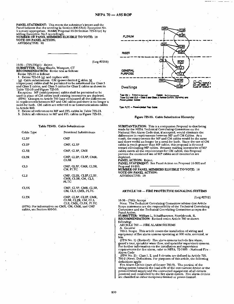

NFPA 70 A95 ROP
Nonpower-Limited Fire Alarm Circuit (NPLFA) (new). "A fire alarm circuit powered by a source that complies with Section 760-21 (former 760-11) and 760-23 (former 760-12). Power-Limited Fire Alarm Circuit (PLFA) (new). A fire alarm'
circuit powered by a source that complies with Section 760-41. 760-3 (former 760-2). Locations andOther Articles. Circuits and
equipment shall complywith (a), (b), (c), (d), and (e) below. (a) Spread of Fire or Products of Combustion. Secdon 300-21. (b) Ducts, Plenums, and Other Air-Handling Spaces. Section 300.
22, where installed in ducts or plenums or other spaces used for environmental air.
Exception to (b): As permitted in Sections 760-30(e)(l)and (2) (former 760-17(e)(1) and (2)) and Section 760.61(a) (former 760- 53(a)).
(c) Hazardous (Classified) Locations. Articles 500 through 516 and Article 517, Part D, where installed in hazardous (classified) locations.
(d) Corrosive, Damp, or Wet Locations. Sections 110.1.1,300.6, and 31.0-9 where installed in corrosive, damp, or wet locations.
(e) Building Control Circuits. Article 725where building control circuits (e.g., elevator capture, fan shutdown) are associated with the fire alarm system.
760-4 (New). Fire Alarm Circuit Mechanical Execution of Work. Fire alarm circuits shall be installed in a neat and workmanlike manner.
760.5 (former 760.7). Access to Electrical Equipment Behind Panels Designed to Allow Access. Access to equipment shall not be deriied by an accumulation of wires and cables that prevents removal of panels, including suspended ceiling panels.
760.6. Fire Alarm Circuit and Equipment Grounding. Fire alarm circuits and equipment shall be grounded in accordance with Article 250.
Exception: DC power-limited fire alarm circuits having a maximum current of 0.030 amperes.
760-7 (former 760-5): Fire Alarm Circuits Extending Beyond One Building. Fire alarm circuits that extend aerially beyond one building shall either meet the requirements of ArticieS00 and be classified as communications circuits, or shall meet the requirements of Article 225.
760.10 (former 760-4). Fire Alarm Circuit Identification. Fire alarm circuits shall be identified at terminal and junction locations, in a manner that will prevent unintentional interference with the signaling circuit during testing and servicing.
760.15 (former 760.3Revised). FireAlarm Circuit Requirements. Fire alarm circuits shall comply with the following parts of this Article:
(a) Nonpower-limited Fire Alarm (NPLFA) Circuits. Parts Aand B.
(b) Power-limited Fire Alarm (PLFA) Circuits. Parts A and C. B. Nonpower-Limited Fire Alarm (NPLFA) Circuits 760.21 (former 760-11). NPLFA Circuit Power Source Require-
ments. The power source of nonpower-limited fire alarm circuits shall comply with Chapters 1 through 4, and the output voltage shall not be more than 600 volts, nominal.
760-23 (former 760-12). NPLFACircuit Overcurrent Protection. Conductors No. 14 and larger shall be protected against overcurrent in accordance with the Section 310-15. Derating factors shall not be applied. Overcurrent protection shall not exceed 7 amperes for No. 18 conductors and 10 amperes for No. 16. Exception: Where other articles of this Code permit or require
other overcurrentprote~tion. 760.24 (former 760-13). NPLFA Circuit Overcurrent Device
Location. Overcurrent devices shall be located at the point where the conductor to be protected receives its supply.
Exception No. 1: Where the overcurrent device protecting the larger conduc.tor also protects the smaller conductor.
Exception No. 2: Transformer secondary conductors. Nonpower- limited fire alfirm circuit conductors supplied by the secondary of a single-phase transformer having only a 2-wire (single voltage) secondary shall be permitted to be protected by overcurrent protection provided by the primary (supply) side of the transformer, provided the protection is in accordance with Section 450-3 and does not exceed the value determined by multiplying the secondary conductor ampacity by the secondary-to- primary mansformer voltage ratio. Transformer secondary conductors other than 2-wire shall not be considered to he protected by the primary overcurrent protection. 760-25 (former 760-14 revised). NPLFA Circuit wiring Methods.
Installations of nonpower-limited fire alarm ci?cuits shall be in accordance with the appropriate articles in Chapter 3.
Exception No. 1: As provided !n Sections 760-26 (former 760-15) through 760.30 (former 760-17).
Exception No. 2: Where other articles of this Code require other methods.
760-26 (former 760-15 Revised). Conductors of Different Circuits in Same Cable, Enclosui'e, or Raceway.
(a) Class 1 with NPLFA Circuits. Class 1 and Nonpower-limited fire alarm circuits shall be permitted to occupy the same cable, enclosure, or raceway without regard to whether the individual circuits are alternating current or direct current, provided all conductors are insulated for the maximum voltage of any conductor in the enclosure or raceway.
(b) Fire Alarm with Power Supply Circuits. Power-supply and fire alarm circuit conductors shall be permitted in the same cable, enclosure, or raceway only where connected to the same equipment.
760-97 (former 760-16 revised). NPLFA Circuit Conductors. (a) Sizes and Use. Only copper conductors shall be permitted to
be used for fire alarm systems. Conductors of Nos. 18 and 16 shall be permitted to be used, provided they supply loads that do not exceed the ampacities given in Table 402-5 and are installed in a raceway, an approved enclosure, or a listed cable. Condhctors larger than No. 16 shall not supply loads greater than the ampacities given in Section 310.15, as applicable.
(b) Insulation. Insulation on conductors shall be suitable for 600 " volts. Conductors larger than No. 16 shall complywith Article 310. Conductors in sizes No. 18 and 16 shall be Type KF-2, PF, PGF, RFH- 2, RFHH-2, RFHH-3, SE-2, TF, TFN, or ZF. Conductors with other types and thickness of insulation shall be permitted if listed for nonpower-limited fire alarm circuit use.
(FPN): For application provisions, see Table 402-3. (c) Conductor Materials. Conductors shall be solid or bunch-
tinned (bonded) stranded copper. Exception No. 1: Stranded copper with a maximum Of 7 strands
for Nos. 16 and 18 shall be permitted. Exception No. 2: Stranded copper with a maximum of 19 strands
for Nos. 14 and larger shall be permitted. Exception to (b) and (c): Wire Types PAF and PTF shall be
permitted only for high-temperature applications between 90°C (194°F) and 250°C (482°F). • • 760-28 (former 760.18). Number of Conductors in Cable Trays and
Raceways, and Derating. (a) NPLFA Circuits and Class 1 Circuits. Where only n/)npower-
limited fire alarm circuit and Class 1 circuit conductors are in a raceway, the number of conductors shall be determined in accor- dance with Section 300-17. The derating factors given in Article 310, Note 8(a) of Notes to Ampacity Tables of 0 to 2000 Volts shall apply if such conductors carry continuous load in excess of 10 percent of the ampacity of each conductor.
(b) Power-Supply Conductors and Fire Alarm Circuit Conductors. Where power-supply conductors and fire alarm circuit conductors are permitted in a raceway in accordance with Section 760.26 (former 760-15), the number of conductors shall be determined in accordance with Section 300-17. The derating factors given in Article 310, Note 8(a) of Notes to Ampacity Tables of 0 to 2000 Volts shall apply as follows:
(1) To all/:onductors where the fire alarm circuit conductors carry continuous loads in excess of 10 percent of the ampacity of each conductor and where the total number of conductors is more than three;
(2) To the power-supply conductors only, where the fire .alarm carcuit conductors do not carry continuous loads in excess of 10 percent of the ampacity of each conductor and where the number of power-supply conductors is more than three..
(c) Cable Trays. Where fire alarm circuit conductors are installed in cable trays, they shall comply with Sections 318-9 through 318-11.
760-30 (former 760-17 Revised). Multiconductor NPLFA Cables. Multiconductor nonpower-limited fire alarm cables that meet the requirements of Section 760-31 shall be permitted to be used on fire alarm circuits operating at 150 volts or less and shall be installed in accordance with (a) through (b) below.
(a) (former 760.17(d) Revised) NPLFA Wiring Method. Multi- conductor nonpower-limited fire alarm circuit cables shall be installed as follows:
(1) In raceway or exposed on surface of ceiling and sidewalls or "fished" in concealed spaces. Where installed exposed, cables shall be adequately supported and terminated in approved fittings and installed in such a way that maximum protection against physical damage is afforded by building construction such as baseb9ards, door flames, ledges, etc. Where located within 7 feet (2.13 m) of tl3.e floor, cables shall be securely fastened in an approved manner at intervals of not more than 18 inches (457 ram).
(2) In metal raceway or rigid nonmetallic conduit where passing through a floor or wall to a height of 7 feet (2.13 m) above the floor unless adequate protection can be afforded by building construction such as detailed in (1) above, or unless an equivalent solid guard is provided.
(3) In rigid metal conduit, rigid nonmetallic conduit, intermedi- ate metal conduit, or electrical metallic tubing where installed in hoistways.
801
N F P A 70 - - A 9 5 R O P
Exception: As provided for in Section 620-21, Exception Nos. 1 and 2 for elevators and similar equipment.
(b) (former 760-17(e)) Applications of Listed NPLFA Cables. The use of nonpower-limited fire alarm circuit cables shall comply with (1) through (4) below.
(1) Ducts and Plenums. Multiconductor nonpower-limited fire alarm circuit cables shall not be installed exposed in ducts or plenums. See Section 300-22(b).
(2) Other Spaces Used for Environmental Air. Cables installed in other spaces used for environmental air shall be Type NPLFIP.
Exception No. 1: Types NPLFR and NPLF cables installed in compliance with Section 300-22(c).
Exception No. 2: Other wiring methods in accordance with Section 300-22(c) and conductors in compliance with Section 760-27(c) (former 760-16)..
(3) Riser.. Cables installed in vertical runs and penetrat ing more than one floor or cables installed in verdcal runs in a shaft shall be Type NPLFR. Floor penetrations requiring Type NPLFR shall " contain only cables suitable for riser or p lenum use.
Exception No. 1: Type NPLF or other cables specified in Chapter 3 that are in compliance with Section 760-27(c) (former 760-16(c)) and encased in metal raceway.
Exception No. 2: Type NPLF cables located in a f i reproof shaft having fire.stops at each floor.
(FPN): See Section 300-21 for firestop requirements for floor penetrations.
(4) Other Wiring Within Buildings. Cables installed in building locations other than the locations covered in (1), (2), and (3) above shall be Type NPLF.
Exception No. 1: Chapter 3 wiring methods with conductors in comphance with Section 760-27(c) (former 760-16(c)).
Exception No. 2: Type NPLFP or Type NPLFR cables shall be permitted.
760-31 (Former 760-17(a)). Listing and Marking of NPLFA Cables. Nonpower-limited fire alarm cables installed as wiring within buildings shall be listed in accordance with (a) through (c) below and as being resistant to the spread of fire in accordance with (d) through (0 below, and shall be marked in accordance with (g) below.
(a). (former 760-17 (c)(1)) NPLFA Conductor Materials. Conduc- tors shall he solid copper or bunch-t inned (bonded) stranded copper.
Exception No. 1: Stranded copper with a maximum of 7 strands t'or No. 16 and No. 18 shall be permitted.
Exception No. 2: Stranded copper with a maximum of 19 strands for Nos. 14 and larger shall be permitted.
(b) (former 760-1-7 (c)(2)) NPLFA Conductor Sizes and Number. The cables shall have two or more No. 18 or larger conductors.
( c ) (former 760-17 (c) (3) NPLFA Conductor and Cable Ratings. Each insulated conductor of the cable shall have a voltage rating of not less than 300 volts. The combination of the insulated conduc- tors and the cable jacket shall have a voltage rating of not less than 600 volts.
(d) (former 760-17 (c)(4)) Type NPLFP. Type NPLFP nonpower- limited fire alarm plenum cable shall be listed as being suitable for use in other space used for environmental air as described in Section 300-22(c) andshal l also be listed as having adequate fire-resistant and low-smoke-producing characteristics.
(FPN): One method of defining low-smoke-producing cable is by establishing an acceptable value of the smoke produced when tested in accordance with the Test for Fire and Smoke Characteristics of Wires and Cables, NFPA 262-1990 (ANSI) to a maximum peak optical density of 0.5 and a maximum average optical density of 0.15. S~milarly, one method of defining fire-resistant cables is by establish- ing maximum allowable flame travel distance of 5 feet (1.52 m) when tested in accordance with the same test.
(e) (former 760-17 (c)(5)) Type NPLFR. Type NPLFR nonpower- limited fire alarm riser cable shall be listed as being suitable for use in a vertical run in a shaft or fi'om floor to floor and shall also be listed as having fire-resistant characteristics capable of preventing the carrying o f fire from floor to floor.
(FPN): One method of defining fire-resistant characteristics capable of preventing the carrying of fire from floor to floor is that the cables pass the Test for Flame Propagation Height of Electrical and Optical-Fiber Cables Installed Vertically in Shafts, ANSI/UL 1666-1986.
(f) (former 760-17 (c)(fi)) Type NPLF. Type NPLF nonpower- limited fh'e alarm cable shall be listed as being suitable for general- purpose fire alarm use, with the exception of risers, ducts, plenums, and other space used for environmental air, and shall also be listed as being resistant to the spread of fire.
(FPN): One method of defining resistant to spread of fire is that the cables do not spread fire to the top of the tray in the Wertical- Tray Flame Test" in the Reference Standard for Electrical Wires, Cables and Flexible Cords, ANSI/UL 1581-1985. Another method of defining resistant to the spread of fire is for the
damage (char length) not to exceed 4 feet 11 inches (1.5 m) when performing the CSA "Vertical Flame Test- Cables in Cable Trays," as described in Test Methods for Electrical Wires and Cables, ,CSA C22.2 No. fl.3-M-1985.
(g) (former 760-17 (b)) NPLFA Cable Markings. Multiconductor nonpower-limited fire alarm cables shall be marked in accordance with Table 760-31(g) (former 760-17(b)). C. Power-Limited Fire Alarm (PLFA) Circuits
760-41 (New). Power Sources for PLFA Circuits. The power source for a power-limited fire alarm circuit shall be as specified in a, b, or c below.
(FPN): Tables 12a and 12b in Chapter 9 provide the listing requirements for power-limited fire alarm circuit sources.
(a) A listed PLEA or Class 3 transformer. (b) A listed PLFA or Class 3 power supply. (c) Listed equipment marked to identify the PLFA power source. (FPN): Examples of listed equipment are: a fire alarm control
panel with integral power source; a circuit card listed for use as a PLFA source, where used as part of a listed assembly; a current limiting impedance, listed for the purpose or part of a listed product, used in conjunction with a nonpower-limited transformer or a s to red energy source,.e.g, storage battery, to limit the output CUlTenL
760-42 (former 760-22) Circuit Marking. The equipment shall be durably marked where plainly visible to indicate each circuit that is a power-limited fire alarm circuit. "
(FPN): See Section 760-52(a), Exception 3 (former 760-28(a), Exception 3) where a power-limited circuit is to be reclassified as a nonpower-limited circuiL
760-51 (former 760-25). Wiring Methods on Supply Side of the PLFA Power Source. Conductors and equipment on the supplyside oft_he power source shall be installed in accordance with the appropriate requirements of Part B and Chapters 1-4. Transformers or other devices supplied from power-supply conductors shall be protected by an overcurrent device r a t e d n o t over 20 amperes.
Exceptiofi: The input leads of a transformer or other power source supplying power-limited fire alarm circuits shall be permit ted to be smaller than No. 14, but not smaller than No. 18, if they are not over 12 inches (305 ram) long and if they have insulation that complies with Section 760-27(b) (former 760-16(b)).
760-52 (former 760-28). Wiring Methods and Materials on Load Side of the PLFA Power Source. Fire alarm circuits on the load side of the power source shall be permit ted to be installed using wiring methods and materials in accordance with either (a) or (b) below.
(a) NPLFA Wiring Methods and Materials. The appropriate articles of Chapter 3, including Section 300-17, shallapply, and, in addition, conductors shall be copper, solid, bunch-t inned, or
[ s tranded with a maximum of 19 strands.
Table 760-31(g) (former 760-17(1>)). NPLFA Cable Markings
Cable Marking
NPLFP NPLFR NPLF
Type
Nonpower-limited fire alarm circuit plenum cable Nonpower-limited fire alarm circuit riser cable Nonpower-limited fire alarm circuit cable
Reference
Sections 760-31 (d) and (g) Secuons 760-31(e) and (g) Sections 760-31(t) and (g)
(FPN): Cable types are listed in descending order of fire resistance rating.
802

N F P A 70 - - A 9 5 R O P
Exception No. I: The derating factors given in Article M0, Note 8(a) of Notes to Ampacity Tables of 0 to 2000 Volts shall not apply.
Exception No. 2: Conductors and multiconductor cables'described in and installed in accordance with Sections 760-27 (former 760-16) and 760-30 (former 760-17) shall be permitted.
Exception No. 3: Power-limited circuits shall be permitted to be reclassified and installed as nonpower-limited circuits if the power- limited fire alarm circuit markings required by Section 760-42 (former 760.22) are eliminated and the entire circuit is installed using the wiring methods and materials in accordance with Part B, Nonpower-Limited Fire Alarm Circuits.
(b) PLFAWiring Methods and Materials. Power-limited fire alarm circuit conductors and cables described in Section 760.71 (former 760-51) shall be installed as follows:
(1) In raceway or exposed on the surface of ceiling and sidewalls or "fished" in concealed spaces.Where installed exposed, cables shall be adequately supported and terminated in approved fittings and installed in such a way that maximum protection against physical damage is afforded by building construction such as baseboard~;, door frames, ledges, etc. Where located within 7 feet (2.13 m) of the floor, cables shall be securely fastened in an approved manner at intervals of not more than 18 inches (457 ram).
(2) In metal raceways or rigid nonmetallic conduit where passing through a floor or wall to a height of 7 feet (2.13 m) above the floor, unless adequate protection can be afforded by building construction such as detailed m (1) above, or unless an equivalent solid guard is provided.
(3) In rigid metal conduit, rigid nonmetallic conduit, intermedi- ate metal conduit, or electrical metallic tubing where installed in hoistways. . Exception: As provided for in Secdon 620-21, Exception Nos. 1
and 2 for elevators and similar equipmen~ 760.54 (former 760-52). Installation of Conductors and Equip-
menL (a) (former 760-52(a)) Separation.from Electric Light, Power Class
1, and NPLFA Circuit Conductors. ' (1) (former 760-52(a)(2)) In Cables, Compartments, Enclosures,
Outlet Boxes, or Raceways. Power-limited circuit conductors shall not be placed in any cable, compartment, enclosure, outlet box, raceway, or similar fitting containing conductors of electric light, power, Class 1, or nonpower-limitedfire alarm circuit couductors.
Exception No. 1: Where the conductors of the electric light, pov~er, Class 1, and nonpower-limited fire alarm circuit conductors are separated by a barrier from the power-limited fire alarm circuits. In enclosures, power-limited fire alarm circuits shall be permitted to be installed in a raceway within the enclosure to separate them from Class 1, electric light, power, and nonpower-limitedfire alarm circifits.
Exception No. 2: Conductors ofpower-limiied fire alarm circuits iu compartments, ericlosures, outlet boxes, or similar fittiugs, where electric light, power, Class 1, or uonpower-limited circuit conductors are introduced solely to connect to the equipment connected to the power-limited fire alarm system or to other circuits controlled by the fire alarm system to which the other conductors in'the enclosure are connected. The electric light, power, Class 1, and nonpower-limited fire alarm circuit conductors shall be routed within the enclosure to maintain a minimum 0.25-inch (6.35-mm) separation from the conductors of power-limited fire alarm circuits.
(2) (Former 760-52(a)(4)) In Hoistways. Power-llmited circuit conductors shall be installed in rigid metal conduit, intermediate metal conduit, or electrical metallic tubing in hoistways.
Exception: As provided for iO Section 620-21, Exception Nos. 1 and 2 for eleyators and similar equipment.
(3) (Former 760~52(a) (1) .and (4)) Other Applications. Power- limited circuit conductors shall be separated at least 2 inches (50.8 mm) from conductors of any electric light, power, Class 1, or nonpower-limited fire alarm circuit conductors.
Exception No. 1: Where either (1) all of the electric light, power, Class 1,.or noupower-limited fire alarm circuit conductors, or (2) all of the power-limited fire alarm circuit conductors are in raceway or in metal-sheathed, metal-clad, nonmetallic-sheathed, or type UF cables.
Exception No 2: Where the all of the electric light, power, Class 1, or nonpower-limited fire'alarm circuit conductors are permanently separated from all of the l~ower-limited fire alarm circuit conductors by a continuous and firmly fixed nonconductor, such as porcelain tubes or ,flexible tubing in addition to the insulation on the wire.
(b) (Former 760-52(b)) Conductors of Different PLFA Circuits, Class 2, Class 3, and Communications Circuits in Same Cable, Enclosure, or Raceway.
(1) Two or More PLFACircuits. Gable and conductors of two or morepower-limited fire alarm circuits, communications circuits, or Class 3circuits shall be permitted in the same cable, enclosure, or raceway.
(2) Glass 2 Circuits With PLFA Circuits. Conductors of one or more Class 2 circuits shall be permitted within the same cable, enclosure, or raceway with conductors of power-limited fire alarm circuits, provided that the insulation of the Class 2 circuit conduc- tors in the cable, enclosure, or raceway is a least that required by the power'-Iimited fire alarm circuits.
(c) (former 760-28 (b) (1) partial) Support of Conductors. Raceways shall not be used as a means of support for power-limited fire alarm circuit conductors.
760-55. Current-Carrying Continuous Line-type Fire Detectors. (a) Application. Listed continuous line-type fire detectors,
including insulated copper tubing of pneumatically ol?erated detectors, employed for both detection and carrying stgnaling currents shall be permitted to be used in power-limited circuits.
(b) (former 760-55(c)) Installation. Continuous line-type fire detectors shall be installed in accordance with Sections 760-42 (former 760-22) through 760-52, (former 760-28) and 760-54. (former 760-52).
760-61 (former 760-53). Applications of Listed PLFA Cables. Power-limited fire alarm cables shall comply with (a) dlrough (c) or, where cable substitution is being made, (d) below.
(a) (former 760-53(a)) Plenum. Cables installed in ducts, plenums, and other spaces used for environmental air shall be Type FPLP.
Exception: ~l'ypes FPLP, FPLR, and FPL cable ihstalled,in compliance with Section 300.22.
(b) (former 760-53(b)) Riser. Cables instailed in vertical runs and penetratingmore than one floor or cables installed in vertical runs in a shaft shall be Type FPLR. Floor penetrations requiring Type FPLR shall contain only cables suitable for riser or plenum use.
Exception No. 1: Where the cables are installed in metal raceway or are located in a fii'eproof shaft having firestops at each floor.
Exception No.,2: Type FPL in one- and two-family dwellings. (FPN): See Section 300-21 for firestop requirements for floor
penetrations. (c) (former 760-53(c)) OtherWiringWithin Buildings. Cables
installed in buildinglocations other than the locations covered in (a) and (b) above shall be Type FPL. ExCeption No. 1: Where the cables are enclosed in raceway. Exception No. 2: Cables specified in Chapter 3 that meet the
requirements of Sections 760-71 (a) and (b)(former 760-51 (a) and (b)) and m'e installed in nonconcealed spaces where the exposed " length of cable does not exceed 10 feet (3.05 m).
(d) (former 760-53(d)) PLFA Cable Uses and Permitted Substitu- tions. The uses and permitted substitutions for power-limited fire alarm circuit cables hsted in Table 760-61(d) (former Table 760-53) and illustrated in Figure
760451(d) (former Figure 760-53) shall be considered suitable for the purpose and shall be permitted., Communications and Class 3 cables shall be permitted to substitute for power-limited fire alarm circuit cables only where the requirements of Sections 760-71 (a), (b), and (c) (former 760.51 (a), (b), and (c)) for multiconductor . cables and Section 760.71(g) (former 760-51(g)) for coaxial cables are satisfied.
Table 760-61 (d) (former T tb le 760-55). Cable Uses and Pemfitted Substitutions
Cable Type Use References
FPLP Power-limited fire aJ~'Tn 760-61 ia) plenum cable
FPLR Power-limRed fire alarm riser 760-61 (b) cable
FPL Power-limited fire alarm cable 780-61 (c)
Permitted Subsdmtions
MPP, C, MP, GL$P
MPP, CMP, FPLP, CL3P, MPR, CMR, C, L3R MPP, CMP, FPLP, CL3P; MPR, CMR, CL3R, FPLR, MPG t MP r CMG r CM~ PLTC~ CL3
(FPN): For informadon on multipurpose cables (MPP, MPR, MPG, MP) =End communications cables (CAMP, CMR, CMG, C,M), see Section 800-50. For inform~don on Class 3 cables (CLBP, CL3R, C, L3, PLTC), see Section 725-71 (former 725-50).
t
803

N F P A 70 - - A 9 5 R O P
Plenum
Riser
General Purpose
Dwellings
Type CM - - Communications Wires and Cables Types CL2 and CL3 - - Class 2 and Class 3 Remote-Control,
Signaling, and Power-Limited Cables Type FPL - - Power-Limited Fire Protective Signaling Cables Type MP - - Multipurpose Cables Type PLTC - - Power-Limited Tray Cable
' - - r --J ] Shall be Perrr ~ ~o be U~d m
Cable A Shall be Permitted
Place of Cable B
[ ~ ' ~ Cable A Shall be Permitted to be Used in Place of Cable B with Restrictions. See Sac. 760-51 (a), (b), and (g)
Figure 76061 (d) (former 760-53) Cable Substitution. Hierarchy
760-71. (Former 760.-49, 50 (partial), 51, and 55(b)). Listing and Marking of PLFA Cables and Insulated Continuous Line-Type Fire Detectors. FPL cables installed as wiring within buildings shall be
! listed in accordance with (a) through (c) below and as be ing resistant to the spread of fire in accordance with (d) through (g) below, and shall be marked in accordance with (h) below. Insu- lated continuous line-type fire detectors shall be listed in accordance witil (i) below.
(a) (former 760-51(a)) Conductor Materials. Conductors shall be solid copper or bunch-t inned (bonded) stranded copper.
Exception No. 1: Stranded copper with a maximum o f 7 strands for Nos. 16 and 18 shall be permit ted.
Exception No. 2: S t randed copper with a maximum of.19 strands for Nos. 14 and larger shall be permitted.
(b) (former 760-51(b)) Sizes and Number. The size and number of conductors in a cable shall meet the requirements of Table 760- 71 (b) (former 760-51). Conductors of No. 26 shall only be
ermitted if spliced with a connector listed as suitable for No. 26 to o. 24 or larger conductors that are terminated on equipment or if
the No. 26 conductors are terminated on equipment listed as suitable for No. 26 conductors.
Table 760-71(b) ( f o r m e r Table 760-51). Min imum Size and N u m b e r o f Conductors Requi red in Cables Used for PLFA Circuits
Size Min imum N u m b e r o f Conductors in Cable 26 AWG 10 24 AWG 6 2"2 AWG 4 19 AWG 2 16 AWG or larger 1
(c) (former 760-51 (c)) Ratings. The cable shall have avoltage rating of no t less than 300 volts.
(d) (former 760-51 (d)) Type FPLP. Type FPLP power-limited fire alarm plenum cable shall be listed as being suitable for use in ducts,
~ lenums, and other space used for environmental air and shall also e listed as having adequate fire-resistant and low-smoke-producing
characteristics. (FPN): One method of defining Iow-smoke-p rodu cing cable is by
establishing an acceptable value of the smoke produced-when tested in accordance with the Test for Fire and Smoke Characteristics of Wires and Cables, NFPA 262-1990 (ANSI) to a maximum peak optical density of 0.5 and a maximum average optical density of O.15. Similarly, one method of defining fire-resistant cables is by establish- ing maximum allowable flame travel distance of 5 feet (1.52 m) when tested in accordance with the same test.
(e) (former 760-51 (e)) Type FPLR. Type FPLR power-limited fir6 alarm riser cable shall be listed as being suitable for use in a vertical run in a shaft or from floor to floor and shall also be listed as having fire-resistant characteristics capable of preventing the carrying of fire from floor to floor.
(FPN): One method o fde fming fire-resistant characteristics capable of preventing the. carrying of fire from floor to floor is that the cables pass the reqmrements of the Standard Test for Flame Propagation Height o f Electrical and Optical-Fiber Cable Installed Vertically in Shafts, ANSI/UL 1666-1986.
(f) (former 760-51 (0) Type FPL. Type FPL power-limited fire alarm cable shall be listed as bein~ suitable for general-purpose fire alarm use, with the exception of risers, ducts, plenums, a n d o t h e r space used for environmental air and shall also be listed as being resistant to the spread of fire.
(FPN): One method of defining resistant to the spread of fire is that the cables do not spread fire to the top of the tray in the "Vertical-Tray Flame Test" in the Reference Standard for Electrical Wires, Cables and Flexible Cords, ANSI/UL 1581-1985.
Another method of defining resistant to the spread of fire is for the damage (char length) not to exceed 4 feet 11 inches (1.5 m) when performing the CSA 'Vertical Flame Test - Cables in Cable Trays," as described in Test Methods for Electrical Wires and Cables, C~A C22.2 No. 0.3-M-1985.
.(g.) (former 760-51 (g) Coaxial Cables. Coaxial cables shall have a minimum of No. 29 copper or 30 percent copper-covered steel center conductor, a voltage ra t ingof not less than 300 volts, and shall be listed as a Type FPLP, FPLR, or FPL cable.
(h) (former 760-50) Cable Mark.ing. The cable shall be marked in accordance with Table 760-71 (h) (former Table 760-50). The voltage rating shall not be marked on the cable.
(FPN): Voltage ratings on cables may be misinterpreted to suggest that the cables may be suitable for Class l, electric light and power applications.
Exception: Voltage markings shall be permitted where the cable has multiple listings and voltage marking is required for one or more of the listings.
Table 760-71(h) (Former Table 760-b0). Cable Markings
Cable ' l ~ e Listing Ref~eacos u ~
FPLP Powerqimited fire alarm plenum cable SeeUons 760-71(d) and (h) FPLR Power-limited fire alarm riser cable Sections 760-71(e) and (h) F ' P L Power-limited fire alarm cable Sections 760-71(0 and (h)
(FPN): Calfle types are listed in descending order of fire re.d.C.ance rating.
804

N F P A 7 0 - - A 9 5 R O P
(i) (former 760-55(b) Insulated Continuous Line-Type Hre Detectors. Insulated continuous line-type fire detectors shall be rated in accordance with (c) above, listed as being resistant to t h e spread of fire in accordance with (d) through (f) above, marked in accordance wi~ (h) above, and the jacket compound shall have a high degree of abrasion resistance.
Chapter 9 Tables and Examples Tables 12a and 12b. (former 760-21 partial) For l ist ingpurposes, Tables 12a and 12b
provide the reqmred power source limitations for power-limited fire alarm sources. Table 12a applies for alternating current sources, and Table 12b applies for direct current sources. (former 760-21 partial) The power for power-limited fire alarm
circuits shall be either:, a) inherently limited requiring no overcurrerit protection, or b) not inherently limited requiring the power to be limited by a combination of power source and overcurrent protect ion.
(former 760-22) As part of the listing, the PLFA power source shall be durably marked where plainly visible to indicate the class of supply and its electrical rating.
(former 760-23 and 760-24) The overcurrent device, where required, shall be located at the point where the conductor to be dProtected receives its supply and shall not be interchangeable with
evices of higher ratings. The overcurrent device shal lbe permitted as an integral 'part of the power source.
Notes for Tables 12a and 12 b (fo .rpaer Tables 760-21 (a) and (b) Notes) Note 1. V : Maximum output voltage regardless of load with
rated i n p u t ~ l i e d . ~ v v. lmax: Maxamum output current under any noncapacitive load,
including short circuit, and with overcurrent protection bypassed if used. When a transformer limits the output current, 1 limits apply after one minute of operation. Where a current-rflJ~'lting impedance, listed for the purpose, is used in combination with a nonpower-limited transformer or a s tored energy source, e.g., storage battery, to limit the output current, lma x limits apply after 5 seconds.
VA : Maximum volt-ampere output after one minute of opera~St{~ regardless of load and overcurrent protect ion bypassed if used. Current limiting impedance shall no t be bypassed when determining I a n d V A . Note 2. If t ~ e ~ t e r sou rc~Xa transformer, (VA)max is 350 or less when V is 15 or less. max
Table 12a. PLFA Alternating Current Power Source Limitations (former Table 760-21 (a))
Power Source
Circuit Voltage Vma x (Volts) (Note 1)
Power Limitations (VA) max (Volt-Amps) (Note I)
Current Limitations Imax(Amps) (Note 1)
Maximum Over-current Protection (Amps)
Inherently Limited Power Source IOvercurrent protection not required)
0 through 20 Over 20 and through 3 0
8.0
Over 30 and through I00
150/VM~
0 through 20
Not Inherently Limited Power Source (Overcurrent protection required)
Over 100 and through 150
250 (Note 2)
1000/VMAx
Over 20 and through 100
250
1000/VMAX
100/VMAX
Power Source Maximum Name-plate Ratings
VA (Volt - Amps)
l I Current : (Amps)
8.0
5.0 x Vmax 100
lO0/Vmax
100
lO0/Vmax
5.0
5.0 xVma x lO0
I O0/Vmax 5.0 5.0
N.A.
1.0
1.0
loo/
lO0/Vmax
805

NFPA 70 - - A95 ROP
Table 12b. PLFA Direct Current Power Source Limitations (former Table 760-21(b))
Circuit Voltage V max (Volts) (Note 1)
Power Limitations (VA) max (Volt-Amps) (Note 1)
Current Limitations Imax(Amps) (Note 1) J
Maximum Over- current Protection (Amps)
Power VA Source (Volt- Maximum Amps) Name-plate Ratings
Current (Amps)
Inherently Limited Power Source ~Overcurrent protection not rec[ulred t
0 through Over 20 and Over 30 and Over 100 20 through 30
5.0x Vmax
5.0 lO0/Vmax
through 100
150/Vmax
lO0/Vmax
and through
250
0.030 x Vmax
0.030
Not Inherently Limited Power Source (Overcurrent protection required I
0 through 20 Over 20 and Over 100 and
250 (Note 2)
1000/Vmax
5.0
5.0 x Vmax
5.0
through 100
250
l O00/Vma x
lO0/Vmax
100
100/Vmax
through 150
9~
1.0
100/Vmax
SUBSTANTIATION: 1. To facilitate compar ison with the 1993 edition of the NEC, references to the 1993 section n u m b e r s have been included in parentheses t h roughou t the proposal after the new section numbers . These references are tofacUitate review, and are no t necessarily to be included in the material proposed for the 1996 Code.
2. Section 760-1 has been revised to correspond with a change made in NFPA 72-1993 Nadonal Fire Alarm Code. This change replaces the term "fire protective signaling" with "fire alarm".
3. Section 760-2 "Definitions" has been added to help users unders tand the na ture of the different types of fire alarm circuits. These definitions are composed of material f rom Section 760-3 of the 1993 National Electrical Code. Appropriate editorial changes have been made in accordance with these changes. '
4. Sections of Article 760 have been combined, simplified, and relocated to position all the ingtallation requi rements together, before the listing requirements , to facilitate use of the Code. Sections have been r e n u m b e r e d to accommoda te new Sections and relocated Sections, and also to facilitate coordinat ion with like Sections in Article 725. Numerous~editodal changes have been made to Sections o f this Article to correlate with these changes.
5. Section 760-4 "Fire Alarm Circuit Mechanical Execution o f Work" has been added to address the abuses of workmanship that frequently occur in these installations that compromise in tended access to and the integrity of non Chapter 7 installations in the same area. This section parallels Section 800-6 which was added at the last code cycle.
6. Section 760-27 has been revised to include, "an approved enclosure" as is permit ted in Article 725 to correlate with that Article. It is appropriate to include enclosures in this Secdon, since the conductors in the race.ways and cables mus t ult imately te rminate in an enclosure.
7. Sections 760-30 and 31 were located at the end of Part B because they are more specific than the rest of Part B material.
8. Section 760-41 is new and has been in t roduced to define the appropriate power sources for fire alarm circuits. Fire alarm circuit "transformers" and "power supplies" may exist as separate equip- ment , so have been addressed separately. Class 3 t ransformers and power supplies are acceptable substi tutes for fire a larm e~uivalents, so they have been included in this Section as alternates. ' Listed
, equ ipmen t marked to identify the PLFA power source" addresses the remainder of pe rmi t t ed sources for these circuits.
(a) The t a skg roup concluded tha t it is no longer necessary nor practical to evaluate PLFA power sources, once they have been installed, to de te rmine if they comply with the limitations in former Tables 760-21 (a) and (b). Listed t ransformers, power supplies, and other e q u i p m e n t marked to indicated the PLFA power source are readily available to manufac turers and installers, and the use of such products enables authori t ies having jurisdict ion to quickly evaluate an installation.
(b) Even the s implest power source, such as a t ransformer, requires extensive testing and construct ion evaluation to de te rmine conformance with the NEC limitations. The testing requires controlled conditions, special supply sources, ins t rumenta t ion an d o ther test apparatus that is no t readily available at an installation. Both the testing and construct ion evaluation require special knowledge of p roduc t s tandard rec]uirements, materials, and procedures that are common ly awaulable only th rough qualified electrical testing laboratories.
(c) Based on this conclusion, the listing requi rements for power sources, including Tables 760-21 (a) and (b), and Sections 760-21, 760-23, and 760-24, have been moved to Chapter 9 to separate them as far as possible f rom installation requirements . This informat ion has been reta ined in Chapter 9 as Tables 12(a) and 12(b) to provide direction for organizations properly ecjuipped and qualified to evaluate these products. Information m 760-22 that pertains to power sources has also been included.
9. The Section 725-51 reference to Chapter 3 has been expanded to reference Chapters 1-4 so that all features of the supply side conductors and equ ipmen t are properly addressed. Referencing only Chapter 3 focused jus t on the wiring me thods and did no t address o ther impor tan t installation aspects for these circuits, such as grounding.
10. Section 760-54 was revised to eliminate the te rm "open • conductors" by r ea r r angemen t o f the i tems in Section (a) and the relocation of the "opeti conductor" mate.rial to the end of this Section as "Other Applications". The term "open conductors" is no t def ined in the Code and has been a source of m u c h confusion. The former Section for conductors "In Shafts" has been combined with the open conduc to r material, as the same considerat ions apply.
11. Section 760-61 (d) was modif ied to include uses and include the uses references to provide this informat ion all in one location for the user.
12. Section 760-71 is a composite of fo rmer Sections 760-49, 50, 51, and 55(b) that addressed the cable and cont inuous line-type fire detector listing requirements . These sections were combined to bring all of this informat ion together in one location so that it is easier for Code users to unde r s t and and apply.
NOTE: Suppor t ing material is available for review at NFPA Headquarters . PANEL ACTION: Accept. NUMBER OF PANEL MEMBERS ELIGIBLE T O VOTE: 17 VOTE ON PANEL ACTION:
AFFIRMATIVE: 17
806

N F P A 70 - - A 9 5 R O P
(Log #1128) 16-97 - (76001): Accept in Principle Note: l twas the action of the Technical Correlating Committee
that this Proposal be reconsidered and correlated with the action on Proposal 16.96. This action will be considered by the Panel as a Public Comment. SUBMITrER: Dean K. Wilson, National Fire Alarm Code Correlat-
Committee OMMENDATION: Revise 76001 Scope as follows:
76001 Scope. This article covers the installation of wiring and equipment of fire alarm ~,, ,~ccdvc ~iga~" c,g systems ia.c, hLq!iag.~ circuits controlled and nowered bv the fire alarm system. ~L v v v v v l w j u v l l u u ~ v . i ~ .
(FPN No. 1): Fire ~ ?, ,,~,.,.i.,. £ ;~1L, , b Systems may include !fire detect ion and alarm notification, guard 's tour, sprinkler waterflow and sprinkler supervisory systems. Circuits controlled and nowered bv the fire alarm swstem include circuits for the control of buildin~ sx~tems safety functions, elevator capture, elevator ]shutdo~tn~ door release, smoke doors and damner control, fire doors !and damner control and fan shutdown. For further information on the installation and ~.t.~, .Li..,. monitorin~ for intem-itv require- ments for ~ ¢,,,~t~.~d,~ a;r~a,d;~r, systems, re~'er to NFPA 72. 1993. National Fire Alarm Code.@
(FPN No. 2) no change SUBSTANTIATION: The Scope was revised to include new terminology and add building safety functions specified in NFPA 72- 1993, National Fire Alarm Code,@ and to define fire alarm circuits to include those powered and controlled from the tire alarm system
~ ower source. • • ANELACTION: Accept in Principle.
] Modify the submitter 's proposal at the end of the phrase "damper Icontrol and fan shutdown" by adding ", but only where these Icircuits are powered b y a n d controlled by the fire alarm system." ]after the word "shutdown". In the phrase of"systems may include lfire detection" delete the word "may". I Editorially change "Fire Alarm Systems" to "Fire alarm systems" in tthe submitter 's FPN No. 1. PANEL STATEMENT: The Panel believes the revised text more accurately expresses the intent of the FPN. NUMBER OFPANEL MEMBERS ELIGIBLE TO VOTE: 17 VOTE ON PANEL ACTION:
AFFIRMATIVE: 17
(Log #2748) 16-98- (760-5):. Accept
tSUBMI'IWER: Roger Wilson, Simplex Time Recorder Co. | RECOMMENDATION: Delete word "Aerially." SUBSTANTIATION: Questions often arise regarding fire protective signaling circuits that extend underground beyond one building.
Substantiation: Circuits have been installed underground in accordance with Articles 800 and 225 for many years.
Removal of "Aerially" clarifies installation of these circuits. PANEL ACTION: Accept. PANEL STATEMENT: Revise Proposal 16-96, Section 76007 accordingly. NUMBER OF PANEL MEMBERS ELIGIBLE TO VOTE: 17 VOTE ON PANEL ACTION:
AFFIRMATIVE: 17
(Log #579) 16-99 - (76006, Exception): Accept SUBMITTER: Dan Leaf, Palmdale, CA
[ RECOMMENDATION: Delete. SUBSTANTIATION: This exception is superfluous as "in accor- dance with Article 250" encompasses Sec. 25003(a) Ex. No. 5 which is essentially the same as this exception. It appears this is not really an exception to the rule since non-grounding of such circuits IS in accordance with Ar t 250. PANEL ACTION: Accept. PANEL STATEMENT: Revise Proposal 16-96, Section 76006 accordingly. NUMBER OF PANEL MEMBERS ELIGIBLE TO VOTE: 17 VOTE ON PANEL ACTION:
AFFIRMATIVE: 17
: (Log #92o) 16-100 - (760-6, Exception No. 2): Reject SUBMITTER: John Gillilan, Radionics, Inc RECOMMENDATION: Add a second Exception to Section 760-6 with modified wording presently used in Exception No. 2 of 250-3(a) as follows:
• • "A direct current system operating at 50 volts or less between conductors." SUBSTANTIATION: As presently structured, the necessity to refer to both article 760 and to Chapter 250 for grounding requirements, leads to a considerable amount of confusion, particularly upon the part of many fire inspectors who correctly interpret Chapter 250 grounding requirements as being a safety factor and consider the criteria to be equally applicable to fire alarm systems.
Chapter 250-3(a) Exception 5, also confuses the issue in errone- onsly referring to Article 760, Part C, when the grounding require- ment is actually in Part A. (760-6.) With both grounding exceptions in Part A of Article 760, much of
the existing confusion cou ldbe eliminated. PANEL ACTION: Reject. PANEL STATEMENT: The Exception already exists in Article 250
.as noted by the submitter. To a d d t h e same Exception here would be superfluous. . NUMBER OF PANEL MEMBERS ELIGIBLE TO VOTE: 17 VOTE ON PANEL ACTION:
AFFIRMATIVE: 17
(Log #1850) 16.101 - (760-7): Aci:ept in Principle SUBMITI 'E~ Douglas Sartwell, Concord, NH RECOMMENDATION: Add new text as follows:
76007 (new) Mechanical Execution of Work. Fire Protective Signaling System wiring and equipment shall be
installed in a neat and workmanlike manner. SUBSTANTIATION: This wiring is often run above suspended ceilings in a less than workmanlike manner . This addition to the code might provide improvement in this area_ Similar to 800-6 in the '93 NEC. PANEL ACTION: Accept in Principle. PANEL STATEMENT: See Panel Action and Panel Statement for R16-15
OF PANEL MEMBERS ELIGIBLE TO VOTE: i7 VOTE ON PANEL ACTION:
AFFIRMATIVE: 17
(kog #2749) 16-102 - (760-82(New)): Accept
Note: The Technical Correlating Committee directs that the Panel clarify the Panel Action on this Proposal. This actionwill be considered by the Panel as a Public Comment. SUBMITTER: Roger Wilson, Simplex Time Recorder Co.
I RECOMMENDATION: Add new text as follows: I 760-8. Fiber Optic Cables. Where tiber.optic cables are utilized for I f i re protectivi: signaling circuits, the cables shall be installed in I accordance with Article 770. SUBSTANTIATION: No ment ion of fiber optic cables is ment ioned in the current Article 760. NFPA 72 now allows the use of fiber optic cables. Inclusion of this new paragraph will clarify installation methods and types of fiber optic cables to be utilized. PANEL ACTION: Accept. • PANEL STATEMENT: The term "fire protective signaling circuits" has been editorially changed to "tire alarm circuits". Also, the term "fiber optic cables has been changed to "optical fiber cables".
Revise Proposal 16-96 Section 760-3 by adding the term "and (f)" to the sentence and adding the new Section 715003(0 accordingly. NUMBER OF PANEL MEMBERS ELIGIBLE TO VOTE: 17 VOTE ON PANEL ACTION:
AFFIRMATIVE: 17
16-103- (760012): Reject SUBMITTER: Dan Leaf, Palmdale, CA RECOMMENDATION: Delete.
(Log#580)
807 o
N F P A 70 - - A 9 5 R O P
SUBSTANTIATION: The'ampacity ~orrection factors of Tables 310. 16 to 310.19 are a form of derating which should be applied. This section does not reference only Note 8 which is a specific derating factor. In addition Sec. 760-18 DOES require derating re: number of conductors under certain conditions. PANEL ACTION: Reject. PANEL STATEMENT: Nosubstantiation is given for deletion of the entire section on overcurrent protection. NUMBER OF PANEL MEMBERS ELIGIBLE TO VOTE: 17 VOTE ON PANEL ACTION:
AFFIRMATIVE: 17
(Log #919) 16-104- (76Q-14-(New)): Reject SUBMYVIXR: John Gillilan, Radionics, lnc RECOMMENDATION: Remove Section 750-14 from Part B, renumbering subsequent sections accordingly, and enter in Part A as section 760-8 with Exception No. 1 reworded as follows:
"As provided in Sections 760-14 through 760-17 for non-power limited circuits and Sections 760-25 through 760-55 for power limited circuits."
(NOTE: Sections 14 through 17 are renumbered as will occur if this proposal is adopted.) SUBSTANTIATION: As currendy structured, the provisions of chapter three are applicable only to power limited circuits and jurisdictional authorities are unable to enforce appropriate sections for non-power limited installations. Examples are: 300-4, 300-5, 300- 12,300-13,300-14, and 300-15 which should apply equally to all types of electrical installations. In moving the reference section from Part B to Part A, it will apply to both power limited and non-power limited applications. PANEL ACTION: Reject.. PANEL STATEMENT: Parts (B) and (C) reference the appropriate
~ ortions of Chapters 1 through 4. Also see Panel Action on Proposal 6-15 which may accomplish some of the submitter's intent.
NUMBER OF PANEL MEMBERS ELIGIBLE TO VOTE: 17 , VOTE ON PANEL ACTION:
AFFIRMATIVE: 17
(Log #1129) 16-105 - (760.14): Accept in Principle Note: The Technical Correlating Committee directs that the Panel
clarify the Panel Action on this Proposal. This action will be considered by the Panel as a Public Comment. SUBMITTER: Dean IL Wilson, National Fire Alarm Code Correlat- ~d~C Committee
OMMENDATION: Revised text: 760-14' Widng Methods. Wiring installations shall be in accor-
dance with Section 300.15(b) of Article 300 and the appropriate articles in Chapter 3. SUBSTANTIATION: To .clarify that boxes are required for nonpower-limited fire alarm circuits. PANEL ACTION: Accept in Principle. Revise the text of Section 760-14 as it appears in the 1993 edition of
]the Code by adding the words at the end of the sentence "including [all sections of Article 300". PANEL STATEMENT: The Panel believes this meets the intent of the submitter. Editodallydelete the words "of Article 300". Also revise Proposal 16-96, on Section 760-25 accordingly. NUMBER OF PANEL MEMBERS ELIGIBLE TO VOTE: 17 VOTE ON PANEL ACTION:
AFFIRMATIVE: 17 COMMENT ON AFFIRMATIVE:
BRUNSSEN: My records indicate that the second sentence of the Panel Statement was erroneously entered here and that it should be deleted.
PANEL ACTION: Accept PANEL STATEMENT: Revise Proposal 16-96, on Section 760-25 Exception No. 2 accordingly. NUMBER OF PANEL MEMBERS ELIGIBLE TO VOTE: 17 VOTE ON PANEL ACTION:
AFFIRMATIVE: 17
(Log #3720) 16-107- (760-15): Reject SUBMITTER: EdwinJ. Spahn, Spahn Engineering Services RECOMMENDATION: Revise text: 760-15 conductors of different circuits in same cable, enclosure, or
raceway Class I and nonpower limited fire protective signaling circuits shall be permitted to occupy. . , in enclosure or raceway. Power supply and fire protective signaling circuits sha l l . . , only when connected to the same equipment
Exceotion: Primarv AC Dower to fire nrotective si~nalin~ control panels" & ~roundintf& bonding condu&ors associat'ed wi~ the AC Dower shall not be ~ermitted within the same raceway as Dower limited fire nrotective si~nalint~ circuits. SUBSTANTIATION: Route h'i'gh voltage AC power cofiductors and grounding and bonding conductors from raceways where magnetic fields from these conductors can couple with fire signal conductors usin~ inductive coupling or capacitive coupling. Routing these conductors next to fire signal lines negates effectiveness of cable shields and raceway metal shell shielding action. Reduces coupling into fire alarm signal conductors when supply AC and grounding and bonding conductors a~e subject to surges from lightning. Enhance isolating effectiveness of control panel power transformer and regulating circuits in control pane!. PANEL ACTION: Reject. PANEL STATEMENT: The submitter does not define the term "primary AC power". It would be inappropriate to include dfis exception since the proposed wording deals with prohibiting AC power circuits in the same raceway aspower limited fire alarm circuit conductors. This is already prohibitedby the requirements in Section 760-52(a) (2). NUMBER OF PANEL MEMBERS ELIGIBLE TO'VOTE: 17 VOTE ON PANEL ACTION:
AFFIRMATIVE: 17
(Log #1130) 16-108- (760-16(b)): Accept SUBMITI~R: Dean K. Wilson, National Fire Alarm Code Correlat- ~j~ Committee
COMMENDATION: Revise as follows: 760-16(b), Insulation. Insulation on conductors shall be suitable
for 600 volts. Conductors larger than No. 16 shall complywith Article 310. Conductors in sizes No. 18 and 16 shall be type KF-2, KFF-2. PF, PFF. PGF, PGFF. RFH-2, ~ SF-2, SFF-2. "IF, TFF. TFN, ~ ZF, or ZFF. Conductors with other types and thicknesses of insulation shall be permitted if listed for nonpower- limited fire t~. .~cdw ~ , , . 2 : , g m~rn circuit use.
(FPN): For application provisions, see Table 402-3. SUBSTANTIATION: See the substantiation for our proposed revision to 760-51. PANEL ACTION: Accept PANEL STATEMENT: The Panel agrees that with the elimination of the unique stranding requirements (see Panel action on Proposal 16-132), these conductor types may now be permitted. Revise Proposal 1 6-96, Section 760.27(b) accordingly. NUMBER OF PANEL MEMBERS ELIGIBLE TO VOTE: 17 VOTE ON PANEL ACTION:
AFFIRMATIVE: 17
(Log #734) 16-106- (750.14, Exception No. 2): Accept SUBMI'VrEI~a Dan Leaf, Palmdale, CA RECOMMENDATION: Add: "or permit" after "require."
' SUikgTANTIATION: ~Edit. Article 225 wiring methods covering open spans are not included in Chapter 3 and does not open spans between buildings or structures. However such open spans are inferred to be ~ as indicated in Section 760-5.
(Log #1132) 16-109 - (760-16(b), Exception and 760-16(c) Exception): Accept SUBMITTER: Dean K. Wilson, National Fire Alarm Code Correlat- ing Committee
[ RECOMMENDATION: Revised text: [ Exception to (b) and (c): Wire types, PAF, PAFF. PTF, and PTFF I shall bepermitted only for high temperature applications between [90°C (194°F) and 250°C (482°F).
808

N F P A 70 - - A 9 5 R O P
SUBSTANTIATION: See the substant iat ion for our proposed revision to 760-51. PANEL ACTION: Accept. PANEL STATEMENT: T he Panel agrees tha t with the el iminat ion of the un ique s t randing requi rements (see Panel action on Proposal 16-132), these conduc to r types may now be permit ted. Revise Proposal 16-96, Section 760-97 Exception to (b) and (c) accordingly. NUMBER OF PANEL MEMBERS ELIGIBLE TO VOTE: 17 VOTE ON PANEL ACTION:
AFFIRMATIVE: 17
• (Log #3392) 1{5-110- (7{50-16(b), Exception No. 1-(New)): Accept in Principle SUBMITI~R: Michael A. Lanni, Los Angeles, CA RECOMMENDATION: Add an exception:
Exception No. 1: Hard usage cables and cords shall be permi t ted on portable systems as def ined in Articles 520 and 530. SUBSTANTIATION: Our industry requires the use o f a p o r t a b l e fire detect ion system incorpora t ing ha rd usage cables a n d c o r d s for installing a system in temporary sets and rooms built within a studio bui lding and removed a n d r e s e t often. PANEL ACTION: Accept in Principle.
Add Exception No. 3 to Section 760-55(c) to read as follows: ] "A portable fire a larm system provided to protect a stage or set ]when not in use shall be permi t ted to use wiring me thods in Jaccordance with Section 530-12." PANEL'STATEMENT: This act ion meets the submit ter ' s intent. Revise Proposal 16-96, Section 760-61 (c) accordingly. NUMBER OF PANEL MEMBERS ELIGIBLE TOVOTE: 17 VOTE ON PANEL ACTION:
AFFIRMATIVE: 17
(Log #1131) 16-111 - (760-16(c) a nd Exception Nos. 1 and 2): Accept SUBMITTER: Dean IC wi lson, National Fire Alarm Code Correlat- ~1~ Commit tee
COMMENDATION: Revised texu 760-16(c) Conductor Materials. Conductors shall be solid or
b . . . . ",-d . . . . . d (Lv,,d~d) s t randed copper. I Delete Exceptions No. I and 2. SUBSTANTIATION: See the substant iat ion for our proposed revision to 7{50-51. PANEL ACTION: Accept. PANEL STATEMENT: Revise Proposal 16-96, Section 760-27(c) and Exceptions Nos. 1 a n d 2 accordingly. NUMBER OF PANEL MEMBERS ELIGIBLE TO VOTE: 17 VOTE ON PANEL ACTION:
AFFIRMATIVE: 17
(Log.#2708) 16-112- (760-17({5), FPN): Reject SUBMITTER: Marcelo M. Hirschler, Safety Engineer ing Laborato- ries, Inc. RECOMMENDATION: Revised text for the fine pr int note:
(FPN): O n e m e t h o d of def in ing resistant to spread of fire is that the cables do no t spread fire to the top of.the tray in the "Vertical Tray Flame Test" in the Reference Standard for Electrical Wires, Cables and Flexible Cords, ANS I / UL 1581-1985. ~]lglxl~ixglyj~i~ m a x i m u m heat release rate of the cables, as tested in the "Standard for Testin~ for Smoke Obscurat ion Caused by Burn ing Gables in a Verti~;# C~nfigurgt, ion." ASTM D5424 (Prot6col AL sfiall no t exceed 100 kW. Ano the r m e t h o d of def in ing resistant to the spread of fire is for the
damage (char length) no t to exceed 4 feet, 1 inches (1.5 m) when per forming the C_,SA "Vertical Flame Tes t - Cables in Cable Trays," as described in Tes t Methods for Electrical Wires and Cables, C.,SA G99.2 No. 0.3:M-1985. Alternativelv. the m a x i m u m hea t release rate of the cables, as tested in the "Standard for Test in~ for Smoke Obscurat ion Caused bv Burn ing Cables in a VerticTal Confiffuration." ASTM D5424 (Protocol B). shall no t exceed 100 kW.
Ano the r m e t h o d of def inin~ resistant to the snread of fire is for the m a x i m u m hea t release rate ffer un i t a rea of the cables, as tested, at an incident flux of 40 k W / ~ 2 , accord ing to "Standard Test Method for Heat and Visible Smoke Release Rates for Materials an d Products Usin~ an O x w e n C o n s u m n t i o n Calorimeter." ASTM E1354. n o t to exceed 200 l<'vV/mg. ''
This replaces the p resen t FPN, text in "under l ine" is to be added. SUBST.4J~rlATION: It has now been shown tha t hea t release rate testin~ is an al ternate way to de te rmine whether a cable resists the spreao of fire.
One of the first quest ions a person migh t wish to ask about the ' hazard of a fire is "How big is the fire?" Until fairly recently there was no quantitative way of answering this quest ion. Nowadays, we know that, in quantitative terms, this ques t ion is equivalent to asking, "What is the hea t release rate of the. fire?".
An example may explain the impor tance of hea t release rate. If a cable way were bu rn ing outdoors, with no combust ib le products a round it, it may burn, the immedia te consequence o f its b u rn in g will be minimal: no th ing else will be ignited. On the o ther h an d , If the same cable tray is inside a compar tment , once it starts bu rn ing it may ignite a nearby product , if it releases (gives off) e n o u g h hea t and does it fast enough . If the bu rn ing cables release hea t slowly, the cooler air a r o u n d t h e m may be cold e n o u g h to avoid raising the t empera tu re f the neares t p roduc t for it to start burning . If the cables release hea t even faster, they could go beyond causing the neares t product to burn, but they could als-o ignite o ther products fur ther away. As more p r o d u c ~ burn , the fire gradually becomes more intense. In the same spirit, as more things are burning , more s m o k e is emitted. This means the visibility in the room decreases, m a k i n g i t more difficult for people to escape and more difficult for tire fighters to come in and help potential fire victims. If more smoke is emitted, the air in the room also becomes more toxic, which can also cause a bigger threat to the people in the room.
Recent work, usinLng a large n u m b e r of cables o f different types, has shown that every cable that has had a peak hea t release rate of less than 100 kW, when tested according to ASTM D5424, S tandard for Test ing for Smoke Obscura t ion Caused by Burn ing Cables in a
Vert ical Configuration, has ~ the cable tray test, as regards char length. Moreover, it has also been shown that every cable which, when tested in the cone calorimeter, S tandard Test Method for Heat and Visible Smoke Release Rates for Materials an d Products Using an Oxygen Consumpt ion Calorimeter," ASTM El 354, at an incident flux of 40 kW,/m z, has had a peak heat release rate n o t exceeding 900 kW/m'mZ, has ~ the cable tray test, as regards char length. ' . "
In fact, it is likely tha t cables with even somewhat h igher hea t release rates may pass the test, in mos t cases. However, the above criteria are being suggested as very conservative estimates, with a significant m a r ~ n o f safety, for those users interested in having cables listed whde testing less material.
It is also possible to obtain h e a t release rate results by testing smaller lengths of cable in a bench-scale test. Thus , I feel tha t the fine pr int note needs to be modif ied to express these ideas, as stated above.
NOTE: Suppor t ing material is available for review at NFPA Headquarters . PANEL ACTION: Reject. PANEL STATEMENT: T h e Panel believes the submi t te r is directing his r ecommenda t ion to 7{50-17(c)({5) FPN no t 760-17({5) FPN. Th e substant iat ion for this proposal is based upon a l imited a m o u n t of data and presents a l imited correlation. At the p resen t time, the scatter of data shows that the cone calor imeter should only be used as a research tool for the deve lopmen t o f products and materials. The re is no ag reemen t within the fire commun i ty to substantiate tha t the cone calorimeter can adequately evaluate early stages an d full scale f i r e p e f f o r m a n c e characteristics of wire and cable. NUMBER OFPANEL MEMBERS ELIGIBLE TO VOTE: 17 VOTE ON PANEL ACTION:
AFFIRMATIVE: 17
809
N F P A 7 0 - - A 9 5 R O P
(Log #2900) 16-113- (760-17(b)): Reject SUBMITTER: L. Bruce McClung, Un ion Carbide Corporat ion RECOMMENDATION: Under l ine words to be added .
Modify and add to table. \
Table 760-17~b) Cable Markings
Cable Marking ~ L F R H
NPLF
Type nonpower - l imited fire nrotective s i ~ a l i n ~ circuit r educed hazard riser cable ~ n o n l o w e r - l imited fire ]protective signalinl~ circuit cable
Reference Sections 760-17(c~ (6~ and 760-17(e~ (4~
Sections 760-17(c).(-73. and 760-17(e)(4)
SUBSTANTIATION: Fire resistance is no t the only characteristic by " which to measure fire safety of cables. A combust ion of fire safety characteristics can result in an overall safer condit ion than jus t fire resistance. Therefore at least three characteristics for which standardized tests are available should be evaluated to recognize a reduced hazard riser cable that is as safe or safer to utilize than the present Types CL2R and CL34 which are listed on the basis of fire resistance only. The need for also limiting smoke and corrosivity is demons t ra ted by condit ions described in the copies of fire report- ing:
Chapel of the Holy Cross in Sedona, Arizona, October 20, 1992. JBOhn Hancock 's home office in Boston, August 24, 1999.
makers Trus t bui lding in Manha t tan , Ju ly 20, 1989. Columbia Seafirst Center in Seatde, July 26, 1988. {ohn F. Kennedy Federal bui lding in Boston,July 8, 1988. Ilinois Bell's central office in Hinsdale, Illinois, May 8, 1988.
Business Insurance Reports of May 29, 1990. PANEL ACTION: Reject. PANEL STATEMENT: See Panel Action and S ta tement on Proposal 16-68. NUMBER OF PANEL MEMBERS ELIGIBLE T O VOTE: 17 VOTE ON PANEL ACTION:
AFFIRMATIVE: 16 NEGATIVE: Hansell
EXPLANATION OF NEGATIVE: HANSELL: See c o m m e n t on Proposal 16-66.
PANEL ACTION: Accept in Principle. Revise the proposal to read as follows: Rewrite Section 760-17(c) (1) and (2) as follows: (1) Conductor Materials. Conductors shall be No. 18 or larger
solid eopl~ ' r or b . . . . I,-d,,,,~d s t randed copper. E~,cct,;.~..,, N... I Delete E- ,~t , GG,, ?,%. 2 Delete. (2) o";zcz a, ,d ,~,~u;~L,.,z Insulated Conductors . Insulated conduc-
tors No. 14 and larger shall be one of the tvoes listed in Table 310-13 or one that is identified for this use. InsulalZed conductors Nos. 18 and 16 shall be in accordance with Section 760-16. TI~.. cab',c~ ~k,d".
P)~E~L~SJ",~T~F~aNT: ~3"he ~ n e l ' ~ r e e s ~ ' a t the changes in conduc tor requ i rements make a clearer correlation with listing requi rements and give more precise guidance to cable manufactur- ers as to how to achieve a proper cable design that will mee t o ther ' requi rements of this section.
Changes to the 15roposal are editorial and the reference to Section 725 has been corrected. Revise Proposal 16-96, Section 760-31(a) and (b) accordingly including substatuting the reference Section 760-27 for Section 760-16. NUMBER OF PANEL MEMBERS ELIGIBLE T O VOTE: 17 VOTE O N PANEL ACTION:
AFFIRMATIVE: 17
, (Log #1133) 16-114- (760-17(c)(1)): Accept in Principle SUBMITTER: Dean K. Wilson, National Fire Alarm Code Correlat- ing Commit tee RECOMMENDATION: Revise 760-17(c) (1) to read:
760-17(c)(1) Conduc to r Materials. Conductors shall beso l id .or b . . . . ",-d . . . . . d s t randed copper.
Ex~ced,,, , ,',%. l: Delete Ex~v, GG,, NG. 2; Delete
SUBSTANTIATION: See the substantiat ion for our proposed revision to 760-51. PANEL ACTION: Accept in Principle.
See Panel Action on Proposal 16-115. PANEL STATEMENT: T he Panel believes that this action meets the in tent of the submitter. See Panel S ta tement on Proposal 16-115. NUMBER OF PANEL MEMBERS ELIGIBLE T O VOTE: 17 VOTE ON PANEL ACTION:
AFFIRMATIVE: 17
(Log #3436) 16-116- (760-17(c)(3), FPN): Accept in Principle SUBMITTER: Paul Dobrowsky, Holley, NY RECOMMENDATION: Add "FPN Cables may be marked 150 volts". SUBSTANTIATION: The UL Standards require the cable to be marked 150 volts in tending to prevent its use for power circuits. This creates confusion for the installer and inspector when a listed NPLFP cable is marked 150 volts bu t the NEC requires 600 volt insulation. PANEL ACTION: Accept in Principle.
Add a sentence at the end of Section 760-17(b) to read as follows: "Nonpower-limited fire alarm circuit cables shall be permit ted to be
marked with a m a x i m u m usage voltage rating of 150 volts." PANEL STATEMENT: The Panel believes this meets the in tent of the submit ter and locating this information in Section 760-17(b) is more appropriate. Revise Proposal 16-96, Section 760-30 (g) accordingly. NUMBER OF PANEL MEMBERS ELIGIBLE T O VOTE: 17 VOTE ON PANEL ACTION:
AFFIRMATIVE: 17 '
(Log #1134) 16-115 - (760-17(c) (1), (c) (2)): Accept in Principle SUBMITrER: Dean K. Wilson; National Fire Alarm Code Correlat- ~]~C Commit tee
OMMENDATION: Rewrite 760-17(c) (1) and (9) as follows: (1) Conductors Materials. Conductors shall be No. 18 or larger
solid ~ or b,.,,cL-d,,,,,.d s t randed copper. Ex,.,.vdG,, ?.'~. I Delete E x ~ v G G , NG. 2 Delete (2) G;z,.o ,,,,d ,',',,..,b,-.~ Insulated Conductors . Insulated conduc-
tors No. 14 and lar~er shall be one of the t w e s listed in Table 310-13 or one t h ~ is identified for use. Insu la teddonduc to rs sizes 18 atlgl 16 shall be in accordance with 725-16. T,~,¢ c,,Ll¢~ o:,,,I': Lc c ;o o.
~ r , n i • .
See the subs tiadon for our proposed revision to 760-51.
(Log#1135) 16-117- (760-17(c) (4)): Accept in Principle SUBMITTER: Dean K. Wilson, National Fire Alarm Code Correlat- ~ Commit tee
COMMENDATION: Delete the word "p lenum" f rom the descript ion of Type NPLFP. SUBSTANTIATION: Since Type NPLFP is not in tended for use exposed in ducts or p lenums, the use of the te rm p l e n u m in the description is confusing. PANEL ACTION: Accep t in Principle.
I In addit ion remove the word "p lenum" in Table 760-17(b) and in the descript ion of type NPLFP, after the word "cable" add the words "for use in o ther space used for envi ronmenta l air". PANEL STATEMENT: For correlation the Panel has also revised Table 760-17(b). Revise Proposal 16-96, Section 760-31(d) a n d Table
• 760-31 (g) accordingly.
810
NFPA 70 - - A95 R O P
NUMBER OF PANEL MEMBERS ELIGIBLE TO VOTE: 17 VOTE ON PANEL ACTION:
AFFIRMATIVE: 16 NEGATIVE: Lease
EXPLANATION OF NEGATIVE: LEASE: While I agree with the action tha t Panel 16 has taken, 1
believe tha t the action taken did not do e n o u g h to alleviate the confusion tha tp resen t ly exists in the field. Inspectors, contractors, electricians andsa le spe r sons have trouble with power-limited fire a larm p l e n u m cable (FPLP) and nonpower-l irmted fire protective signaling c i r cu i tp l enum cable (NPLFP) being listed or marked with the designat ion P a n d having different wiring requi rements or restrictions. In addit ion, the (FPN) to both FPLP and NPLFP are identical. The ques t ion then, "What is the difference in the cables that restrict one (NPLFP) and not the o ther (FPLP) f rom being installed exposed in ducts and plenums?" Try toexp la in the reasoning tha t Panel 16 uses, and they look at you with a blank stare and walk away shaking their heacls, ff both cables are identical in their makeup (fire resistance), why the restriction on one and no t the other? The cables do no t know who or what started the fire. Both types of cable will bu rn at the same rate. ff Panel 16 chooses to mainta in the restriction on cable type (NPLFP), I would suggest that the designat ion be changed to nonpower-l imited fire protective • signaling circuit o ther space cable (NPLFOS).
(Log #2901 ) 16:118- (760-17(c)(fi)): Reject SUBMITYER: L. Bruce McClung, Un ion Carbide Corporat ion RECOMMENDATION: R e n u m b e r as (c)(7) Type NPLF. SUBSTANTIATION: To make a place (way) to add (6) Type NPLFRH. PANEL ACTION: Reject. PANEL STATEMENT: See Panel Action and Sta tement on Proposal 16-68. NUMBER OF PANEL MEMBERS ELIGIBLE TO VOTE: 17 VOTE ON PANEL ACTION:
AFFIRMATIVE: 16 NEGATIVE: Hansell
EXPLANATION OF NEGATIVE: HANSEI.L: See c o m m e n t on Proposal 16-66.
on the categories that can be satisfactorily measured . See attac.hed copy of summary of North Amer ican and European Fire Tests for Cables and Cable Materials for consensus as well as c o m m o n test protocols to measure ease of ignition, f lame spread, hea t release rate, smoke, corrosivity and toxicity. PANEL ACTION: Reject. PANEL STATEMENT: See Panel Action and S ta tement on Proposal 16.68. NUMBER OF PANELMEMBERS ELIGIBLE TO VOTE: 17 VOTE ON PANEL ACTION:
AFFIRMATIVE: 16 NEGATIVE: Hansell
EXPLANATION OF NEGATIVE: HANSELL: See c o m m e n t on Proposal 16-66.
(Log #2531) 16.120- (760-17(c)(6), FPN): Reject SUBMITTERa M.S. Griffith, Brown & Root, Inc. RECOMMENDATION: Revise the first sen tence in the (FPN) to read as follows:
"Although type NPLF cables are no t suitable for installation i n cable tray, one m e t h o d of defining..." Alternatively, delete the
~ ortion of the FPN referring to the vertical tray f lame t e s t UBST.ANTIATION: By referr ing to the 'Vertical Tray Flame Test",
the FPN as presently written incorrectly implies that type NPLF cables are suitable for installation in cable tray, which is no t the case. Further, these types of cable are no t normally subjected to this (tray cable) test so no such test results are available, which makes the FPN meaningless. PANEL ACTION: Reject. PANEL STATEMENT: The Panel does not agree tha t use of the "Vertical Tray Flame Test" implies tha t these cables are suitable for use in cable trays. The FPN is necessary to give guidance on a suitable means on de te rmin ing the fire resistive p'roperties of this cable. NUMBER OF PANEL MEMBERS ELIGIBLE TO VOTE: 17 VOTE ON PANEL ACTION:
AFFIRMATIVE: 17
iLog #2902) 16.119- (760-17(c)(6) and (7)-(New)): Reject SUBMITTER: L. Bruce McClung, Un ion Carbide Corporat ion RECOMMENDATION: R e n u m b e r present (6) to (7) and add new (6) Type NPLFRH.
(6) Type NPLFRH. Type NPLFRH nonpower-l imited fire protective signaling riser cable shall be listed as being suitable for use in a vertical run in a shaft or f rom floor to floor and shall also be listed as having adequate fire-resistant, l imited smoke and limited corrosivity characteristics capable of prevent ing the spread of fire or products of combust ion from floor to floor.
(FPN): A combinat ion of fire safety features can result in a reduced hazard. O n e m e t h o d of def in ing resistant to spread of fire is tha t the cables do no t spread fire to the top of the tray in the "Vertical-Tray Flame T e s t ' i n the Reference Standard for Electrical Wires, Cables and Flexible Cords, ANSI /UL 1581-1985. One m e t h o d of d e f n i n g both resistant to spread of fire and l imited smoke is tha t the cablespass the "UL Flame Exposure Fire Tests" in reference Vertical Tray Fire Propagation and Smoke-Release Test for Electrical and Optical-Fiber Cables UL 1685-1992. One m e t h o d of def in ing limited corrosivity is by the results of direct exposure of resistivity probes to acid gas genera ted by the cables when tested in accordance with ASTM E.5.21.70. SUBSTANTIATION: Fire resistance is no t the only characteristics by which to measure fire safety of cables. A combinat ion of fire safety characteristics can result in an overall safer condit ion than jus t fire resistance. Therefore at least th ree characteristics for which s tandardized tests are available should b'e evaluated to recognize a reduced hazard riser cable tha t is as safe or safer to utilize than the • present Types CL2R and CL3R which are listed on the basis o f fire resistance only.
Reduced hazards f rom a fire safety viewpoint mus t incorporate ignitability, progation, hea t release, smoke, corrosivity and toxicity. T h e better p roduc t will be the one that meets the mi n i i num
acceptable s tandards in each category. Until ac~zepted consensus s tandards for measur ing all six categories are available the industry should concentra te on measur ing and evaluating appl ica t iongbased
t
811
(Log #2903) 16-121 - (760-17(e)): Re j ec t S U B M r v r E R : L. Bruce McClung, Un ion Carbide Corporat ion RECOMMENDATION: Under l ine words to b e a d d e d .
Revise to read (3) Riser. Cables installed in vertical runs and penet ra t ing more than one floor or cables installed in vertical runs in a shaft shall be Types NPLFR, or ~ L F R H . F loorpene t ra t ions requir ing Types NPLFR, or ~ L F R H shall contain only cables suitable for riser or p l e n u m use. SUBSTANTIATION: To c o m p l e m e n t proposal for revision of Table 760-17(b). PANEL ACTION: Reject. PANEL STATEMENT: See Panel Action and S ta tement on Proposal 1 6-68. NUMBER OF PANEL MEMBERS ELIGIBLE TO VOTE: i 7 VOTE ON PANEL ACTION:
AFFIRMATIVE: 16 NEGATIVE: Hansell
EXPLANATION OF NEGATIVE: HANSELL: See c o m m e n t on Proposal 16-66.
• (Log #1136) 16-122- (760-17(e)(1)): Accept SUBMITYER: Dean g. Wilson, Nadonal Fire Alarm Code Correlat-
Commit tee OMMENDATION: Revised text:
760-17(e)(1) Ducts and Plenums. Mul t iconductor nonpower- l imited fire a larm v ' ,,tc,.~;v,. ~;r~,,o.i;,.ts circuit cables, ~IPI,I~I~I~I~]~.L~ shall not be installed exposed in ducts or p lenums. See Section 300-22(b). SUBSTANTIATION: In order to clarify the r equ i r emen t that no nonpower-l imited fire alarm circuit cables be installed exposed in ducts or p lenums, this proposal adds the type" markings to the requirement . . ,

N F P A 70 - - A 9 5 R O P
PANEL ACTION: Accept. PANEL STATEMENT: Revise Propo~sal 1 6-92, Section 760-31 (b) (1) accordingly. NUMBER OF PANEL MEMBERS ELIGIBLE T O VOTE: 17 VOTE ON PANEL ACTION:
AFFIRMATIVE: 17
(Log #581) 16-123- (760-18(a) and (b)): Reject SUBMITTER: Dan Leaf, Palmdale, CA RECOMMENDATION: Revise as follows:
"(a) Where only nonpower-limited fire protective signaling circuits and Class 1 circuit conductors are in a raceway or cable in accor- dance with Section 760-15, the number of conductors in a raceway shall be de te rmined in accordance with Section 300-17." ( remainder unchanged)
"(b) Where power-supply conductors and fire protective signaling circuit conductors are permit ted in a raceway or cable in accordance with Section 760-15, the number of conductors in a raceway shall be de termined in accordance with Section 300-17." (remainder unchanged) SUBSTANTIATION: Section 760-15 permits conductors of different systems in the same cable and the proposal would clarify that the derating factors required in the last sentence of these sections apply to such cable installations. PANEL ACTION: Reject. PANEL STATEMENT: The Panel believes the intent is adequately expressed in the current requirements. NUMBER OF PANEL MEMBERS ELIGIBLE T O VOTE: 17 VOTE ON PANEL ACTION:
AFFIRMATIVE: 17
(Log #3435) 16-124- (760-22): Reject SUBMITTER: Paul Dobrowsky, Holley, NY RECOMMENDATION: Add the following sentence "The power supply shall be marked by the manufacturer to indicate whether it is
g ower limited or non-powerlimited." UBSTANTIATION: The type of system used should be based on
the power supply limitations as designed by ~ e manufacturer. This information should be provided to the installer and inspector. PANEL ACTION: Reject. PANEL STATEMENT: Section 760-22 requires the marking of each power-limited fire alarm circuit. All circuits not so marked are automatically nonpower-limited. NUMBER OF PANEL MEMBERS ELIGIBLE T O VOTE: 17 VOTE ON PANEL ACTION:
AFFIRMATIVE: 17
NUMBER OF PANEL MEMBERS ELIGIBLE T O VOTE: 17 VOTE O N PANEL ACTION:
AFFIRMATIVE: 17
(Log #1137) 16-126- (760-28(a)): Accept SUBMIT'rE]R: Dean K. Wilson, National Fire Alarm Code Correlat- ing Committee
[ RECOMMENDATION: Revised text: I 760-28(a) Nonpowered-lAmited Wiring Methods and Materials. ]The appropriate articles of Chapter 3, including 300-17, shall apply, land, in addition, conductors shall be ~ solid, b . . . . l ,-;~,,~d, I or s t randed .¢,9.p.ILqL -,;~, ~ ,,,o~;,,,,~,,, ,,, ~ ~h ,,,~,L,. "SUBSTANTIATION: Seh the substantiation for our proposed revision to 760-51. PANEL ACTION: Accept.
Make the editorial correction of adding the word "Section" in f ront of "300-17." PANEL STATEMENT: Revise Proposal 16-96, Section 760-52(a) in like manner. NUMBER OF PANEL MEMBERS ELIGIBLE T O VOTE: 17 VOTE O N PANEL ACTION:
AFFIRMATIVE: 17
(Log #1179) 16-127- (760-28(a), Exception No. 3): Reject SUBMITTER: Walter F. Schuchard, Hingham, MA RECOMMENDATION: Revise Exception No. 3 by replacing "installed using the wiring methods and materials in accordance with Part B. Non-Power Limited Fire-Protective Signaling Circuits.'~ with "installed in accordance with Section 760-14." SUBSTANTIATION: The inclusion of all of Part B leads to difficult question of interpretation with respect to whether or not overcurrent protection is provided. Fire Alarm System installation for years has mixed power limited and non-power limited circuits installed in conduit without any modification of the control equ ipmen t Exception No. 3 will still require removal o f the power limited marking identification, but, as revised by this proposal, the question of overcurrent protection of both the power limited and non-power limited circuits is removed from field review and remains the listing laboratories responsibility. PANEL ACTION: Reject. PANEL STATEMENT: The entire Part (b) is apI?licable not just the criteria for the wiring. Equipment should be designed so that power-limited and nonpower-limited circuits maybe installed in separate raceways without modification of the equ ipmen t NUMBER OF PANEL MEMBERS ELIGIBLE T O VOTE: 17 VOTE ON PANEL ACTION:
AFFIRMATIVE: 17
(Log #655) 16-125 - (760-28(a)-(New)): Reject SUBMITTER: Glenn W. Zieseniss, Crown Point, IN RECOMMENDATION: After the exiting last comma alter sentence to read:
", or s t randed with a maximum of 7 strands for No. 16 and 18, or 19 strands where the conductor is No. 14 or larger." SUBSTANTIATION: The control of stranding is required to prevent a single fine strand of wire from completing a circuit, creating the false appearance of a circuit that is operational. The fine strand could remain intact under the current used for the supervisory signal, but burn open when required to carry the higher current of an alarm signal.
Note: The substantiation is copied from the 1993 National Electrical Code Handbook, commentary, page 867 for NEC Section 760-16(c). This should equally apply to the Power Limited circuits of Part C. The 1986 TCRpage 611 Log #1678 substantiation by Mr.
Schuchard notedSect ion 760-16(c) but did no t follow-up on the 7 strand portion or the 19 strand #14 conductor. PANEL ACTION: Reject. PANEL STATEMENT: The Panel has eliminated the unique'
• stranding requirements. See Panel Action on Proposal 16-126 and Proposal 16-132.
(Log #CP 1606) 16-127a- (760-28(b)(1)): Accept SUBMITTER: CMP 16
I RECOMMENDATION: Add a new sentence after the first sentence of Secti6n 760-28(b)(1) to read as follows:
"Cable splices or terminations shall be made in listed fittings, boxes, enclosures, fire alarm devices or utilization equ ipmen t "
In the sentence which follows this new sentence delete the words "and terminated in approved fittings". SUBSTANTIATION: The present Code allows splices and terminations without boxes or fittings. The failure of a circuit often happens at the splices or terminations. This would offer more protection and strain relief to these cables.
Revise Proposal 16-96, Section 760-52(b)(1) accordingly. PANEL ACTION: Accept. NUMBER OF PANEL MEMBERS ELIGIBLE T O VOTE: 17 VOTE ON PANEL ACTION:
AFFIRMATIVE: 15 NEGATIVE: Mande, Wechsler
EXPLANATION OF NEGATIVE: MANDE: No data is provided in the Panel's substantiation to
support the claim that failure of a circuit often happens at the splices or terminations. No mention is made of the frequency at
812

N F P A 70 - - A 9 5 R O P
which circuit failure occurs or the percentage o f these failures that occur at splices ( t h e p r e s e n t code already requires that te rminat ions be made in approved f i t t ings) . Since these circuits are supervised and failure would result in a firouble signal, data should be readily available.
The P a n e l by adop t ing the upgraded requ i rements for mechanical execut ion of work (see Proposal 16.15, Log #3634), has e l iminated the need for repeat ing these requ i rements in individual sections and sub sections. Future revisions of the Code can be simplified by removing r e d u n d a n t restat ing of workmanship requ i rements instead of adding new ones.
WECHSLER: Power-limited circuits inherent ly reduce the risk of shock and fire initiation and thus they are no t subject to Chapter 3 wiring practices. No substant iat ion has been provided to inthcate • that a safety hazard exists with the cur ren t practice, no r is there any reason to p re sume that the mere r equ i r emen t of terminat ion boxes or enclosures will el iminate failures at splices or terminations. Fur thermore , strain relief may or may not be afforded as this is highly d e p e n d e n t on the techniques used in the installation. In addit ion, requir ing cable terminat ions at fire alarm devices and utilization e q u i p m e n t be made in LISTED boxes or enclosures directly conflict.with the Panel 's action on Proposal 16.128. In that proposal, the Panel states, "it is no t the in tent of the Panel to manda te or require a box or enclosure be used on devices or utilization e q u i p m e n t whose listing does not require the use of a box or enc losure ' However, if Proposal 16-127a was accepted, the terminat ion of cables at fire alarm devices would now required that every fire a larm device be pu t into a listed box or enclosure.
(Log #2623) 16-128- (760-28(b)(1)): Reject SUBMITTER: J o h n Mangan, Medford, MA RECOMMENDATION- Revise text as follows:
"All power limited fire alarm system cables or conductors shall be installed in a listed raceway.
Exception No. 1: Listed metallic shea thed cables shall be permit- ' ted.
Exception No. 2: Where "fished" or no t subject to physical damage, listed power l imited fire protective s~gnaling circuit cables shall be permi t ted where instailed, exposed, these cables shall be secured by approved staples, straps, hangers or similar fittings so des igned a n d installed as no t to damage the cable at intervals no t exceeding 6 feet and within 12 inches of every outlet box, cabinet or fitting.
Boxes or enclosures listed as suitable for the purpoge shall be used, and be securely suppor ted , for all fire warning system e q u i p m e n t a n d / o r devices a n d / o r terminat ions." SUBSTANTIATION: T he power limited cab!es are no t being suppor ted above the 7 foot requi rements .
Boxes are not being used to suppoi-t heat or smoke detectors, the cables are poked th rough the ceiling or sidewalls regardless of the type of construct ion and the detectors are held to the surface by toggle bolts or screws or anchors .
Boxes are usually only used on non power limited systems because of voltage.
The present Code allows splices and terminat ions haphazardly without boxes or fittings. PANEL ACTION: Reject. PANEL STATEMENT: The Panel feels tha t insufficient substantia- t ion has been given to require the installation of boxes to suppor t all hea t or smoke detectors, it is no t the in tent of the Panel to manda te or require a box or enclosure be used on devices or utilization
• e q u i p m e n t whose listing does no t require the use of a box or enclosure. Fur ther se~Pane l Action on Proposal 16.15 which treats matters relat ing to support . NUMBER OF PANELMEMBERS ELIGIBLE TO VOTE: 17 VOTE ON PANEL ACTION:
AFFIRMATIVE: 17
(Log #909) 16-129- (760-50, 760-51,760-52): Accept in Principle SUBMITTER: Sandy Egesdal /Stanley g a ~ , Honey~/ell /AT&T RECOMMENDATION: Revise Sections 760-50, 51, and 52 as shown below in order to simplify the permit ted cables and cable substitu- tions.
760-50. Listing, Marking, and Installation of C~bl~ For Power- Limited ~ r e ~ a r m ,~, ,. t', ,,;.,.c:.'vc ~:g, , , , l ; .g Circuit#. C:=abl~.. Power- limited ~ .~;,. t-, ..;.,.,.z~v,~ 5:g,,u.[;ug Cii Cu;~. cables installed as
wiring within buildings shall be listed as being suitable for the purpose, marked in accordance with Table 760-50, and installed in accordance with Section 760-52. The cable voltage rat ing shall no t be marked on the cable.
(FPN): Voltage ratings on cables may be mis interpre ted to suggest that the cables may be suitable for Class 1, electric l ight an d power applications. .
Exception No. 1: Voltage markings shall be permi t ted where the cable has mult iple listings and voltage mark ing is requi red for one or more of the listings.
Exception No. 2: Cable 'substi tut ions as provided for in Section 760-53(e~) shall be considered as suitable for the purpose an d shall be permit ted. • .
See Table 760-53 in the 1993 Edition o f the NEC. (FPN No. 1): See the referenced sections for listing requi rements
and permi t ted uses. (FPN No. 2): Cable types are listed in descend ing order of fire
resistance rating. 760-51. Listing Requi rements ~ . PGwc: ',:;,,~:.,.d .%,.
e~ . . . . Z '~ 76~"~ ''*'6 ~ 7 ' ~ . . . . . :Y . . . . . . 7 "". . . . . ',~,'~:~'~ " ' ~ ' (,&),
(a) Conduc to r Materials. Conductors shall be solid copper or bunch-t i f ined (bonded) s t randed copper.
Exception No. 1: S t randed copper with a m a x i m u m of 7 s trands - for Nos. 16 and 18 shall be per ta ined.
Exception No. 2: S t randed copper with a m a x i m u m of 19 s trands for Nos. 14 and larger shi l l be permit ted.
(b) Sizes and Number . The size and n u m b e r of conductors in a cable shall mee t the requ i rements o f Table 760.51. Coc,~uctorz Gf r
~ T ~ • i i i L " . . J ' ~ I " I " . 1 . . . . I " • • ,
(c) Ratings. The cable shall have a voltage rat ing of not less than 300 volls.
(d) Types MPP and FPLP Cabl~. Tvoe MPP multipurpose plenum cable ~ d Type FPLP power-limited fire alarm plenum cable shall be listed as being suitable for use in ducts, p lenums, and o ther space used for envi ronmenta l air and shall also be listed a shav ing adequate fire-resistant and Iow.smoke-produdng characteristics. Listing o f T w e FPLP cables shall be nermi t ted tintil Ianuarv 1, 1997. Listin~ of Tvbe FPLP cables shall n o i be permi t ted at"ter lafiuarv 1.
(FPN): O n e m e t h o d of def in ing low-smoke-producing cable is by establishing an acceptable value of the smoke p roduced when tested in accordance with the Test for Fire and Smoke Characteristics of Wires and Cables, NFPA 262-1990 (ANSI) to a m a x i m u m peak optical density of 0.5 and a m a x i m u m average optical density of 0.15. Similarly, one m e t h o d of def in ing fire-resistant cables is by establish- ing m a x i m u m allowable f lame travel distance of 5 feet (1.52 m) when tested in accordance with the same test.
(e) Types MPR and FPLR Cabl~. Type MPR mul t ipurpose riser cable and Type FPLR power-limited fire a larm riser cable shall be listed as being suitable for use in a vertical r un in a shaft or from floor to floor and shall also be listed as having fire-resistant, characteristics capable of prevent ing the carrying of fire f rom floor to floor. Listin~ o fTvoe FPLR cables shall be nermi t ted until lanuarv 1. 1997~ Lisfifi~ of Tvoe FPLR cables shall no t be nermi t ted -after l~/nuarv 1. 1997. ~ *"
(FP~I): O n e m e t h o d of def in ing fire-resistant characteristics capable of prevent ing the carrying of fire f rom floor to floor is that the cables pass the requi rements of the Standard Tes t f o r Flame Propagat ion Height of Electrical and Optical-Fiber Cable Installed Vertically in Shafts, ANSI /UL 1666-1986.
(t5 Tvoe MPG Cable. Tvoe MPG genera l -nurnose mul t iouroose cable shall be listed as befr[g suitabl~ for ge/aer'Al-nurnose hse; with the excent ion of risers and[ f l enums , and-shall also b-e listed ;~ being resistant ' to the snread of fife.
(FPN): O n e m e t h o d of def in ing resistant to the spread of fire is for the damage (char l e n ~ h ] no t to exceed 4 feet 11 inches (1.5 m] when oer~'orming the ~¢ertical Flame Tes t - Cables in Cable Trays. 1' as desaribed in Test Methods for'Electrical Wires and Cables. CSA G~R.~ No. 03-M 1985,
(gO Types MP and FPL Cabl~. Type MP mul t ipuroose cable an d Type FPL power-limited fire a larm cable shall be listed as being suitable f6r general -purpose fire a larm use, with the except ion of risers, ducts, p lenums, and o ther space used for envi ronmenta l air and shall also be listed as being resistant to the spread of fire. Listin~ of Tvoe FPL cables shall be ne rmi t t ed until lanuarv I. 1997. Listin~ of Tvbe'FPL cables shall n o i b e nermi t ted a:fterlariuary 1. 1 9 9 7 . ~ " " •
(FPN): O n e mi: thod of def in ing resistant to the spread of fire is tha t the cables do no t spread fire to the top of the tray in the
813

N F P A 7 0 - - A 9 5 R O P
"Vertical-Tray Flame Test" in the Reference Standard for Electrical Wires, Cables and Flexible Cords, ANSI/UL 1581-1985.
Another method of defining resistant to the spre~td of fire is for the damage (char length) n o t t o exceed 4 fee t 11 inches (1.5 m) when performing the CSA 'Vertical Flame Test - Cables in Cable Trays," as described in Test Methods for Electrical Wires and Cables, CSA C22.2 No. 0.3-M-1985. (Jag) Coaxial Cables. Coaxial cables shall have a minimum of No.
22 copper or 30 percent copper-covered steel center conductor, a voltage rating of not less than 300 volts, and shall be listed as a Type FPLP, FPLR, or FPL cableAbr Tvoe MPP. MPR. MPG. or MP.
760-53. A~plications o f ~ ( 3 a b l e s Used For Power-Limited El£g ~ a r m F;, c , , , , z , . c G v , . S;g,,,,l';hg Gircuit~ Etnl~t. Cables used for g4~ower-limited fire ~a rm ~,,. p,,.,;.~,.G;,., o~g,,,,i;,i~ circuit cables shall be listed and comply with (a) through (de) or, where cable substitution is being made, (k'~) below.
(a) Plenum. Cables installed in ducts, plenums, and other spaces used for environmental air shall be Type MPP or Type FPLP.
" Exception: Types MPP. MPIL MPG. MP, FPLP, FPLIL and FPL cable installed in compliance with Section 300-22.
(b) Riser. Cables installed in vertical runs and pene t ra t ingmore than one floor or cables installed in vertical runs in a shaft shall be Type MPRor Type FPLIL Floor penetrations requiring Type MPR or Type FPLR shall contain only cables suitable for riser or p lenum n s e .
Exception No.l: Where the cables are encased in metal raceway or are located in a f i reproof shaft having firestops at each floor.
Exception No.2: T y p e ~ Type FPL in one-and two- family dwellings.
(FPN): See Section 300-21 for firestop requirements for floor penetrations.
(c) Other Wiring Within Buildings. Cables installed in building locations other than the locations covered in (a) and (b) above shall be Type MP. MPG 9r Type FPL.
Exception No. 1: Where the cables are enclosed in raceway. Exception No. 2: Cables specified in Chapter 3 that meet the
requirements of Sections 760-51 (a) and ( b ) a n d are installed in nonconcealed spaces where the exposed length of cable does not exceed 10 feet (3.05 m).
(d~ Cable With No. ")6 Conductors. No. 26 conductors shall only be nermitted if snliced with a connector listed as suitable for No. 26 to lg/o. 24 or lar~'er conductors that are terminated on eau inment or if the No. 26 conductors are terminated on oauinment li'sted as suitable for No. 96 conductors.
(k'~t) Cable Substitutions. The substitutions for multivuroose and fire ~arm e,, , ,c, i;,~,~zcd ,~,,. p, ,,z~Z;v~ ~;~,,--;,,~ G, ~,A~. cables listed in Table 760-53 and illustrated in Figure 760-53 shall be permitted. Communications and Class 3 cables shall be permit ted to substitute for power-limited fire ~a rm 7., c e, ,,zccGv~ ~;gu,,~,~ circuit cables only where the requirements of Sections 760-51 (a), (b), and (c) for mult iconductor cables and Section 760-51 (lag) for coaxial cables are satisfied.
See Figure 760-53 in the 1993 Edition of the NEC.
SUBSTANTIATION: Currently articles 725,760, and 800 each have their own cables and there is a complicated cable substitution char t This level of complexity has led to installations where the wrong cable has been installed. Consequently simplification of the choices of cables and cable substitutions should lead to a more user-friendly Code and a higher level of compliance. This proposal eliminates fire protective signaling cables and substitutes multipurpose cables by prohibit ing the listing of Types FPLP, FPLR, and FPL after a 1 year transition period. In addition the term "fire protective , signaling" has been replaced with "fire alarm" in order to correlate with the new NFPA 72. Also the application requirements for No. 22, 24 and 26 conductors have been moved from the listing section (760-51(b) to the applications section (760-55(d). Other proposals have been submit ted to eliminate X-rated class 2 and 3 and communiclations cables. PANEL ACTION: Accept in Principle.
I Replace the submitter 's proposed text in its entirety with following I action: [ In Section 760-51 (d) (e) and (f) begin the text in the 1993 edition I of the Code with "Until January 1, 1998". PANEL STATEMENT: The action taken by the Panel appears to meet the submitters intent. Reference to multipurpose cables has not been included to correlate with other action taken by the Panel.
I Revise 16-96, Section 760-71 ( d ) ( e ) and (f) accordingly. NUMBER OF PANEL MEMBERS ELIGIBLE TO VOTE: 17 VOTE ON PANEL ACTION:
AFFIRMATIVE: 16 NEGATIVE: Mande
EXPLANATION OF NEGATIVE: • MANDE: Though it has been one of my priority goals to reduce the number of powerlimited cables and simplify the cable substitu- tion chart, the approach the Panel has adopted is the wrong way to achieve the goal.
The action taken by the Panel on this proposal establishes an undesirable p receden t by accepting a code change which primarily serves a market ingpurpose which has no impact on safety.
This change would require that listed FPL cables, which still meet all the performance and constructiofi requirements in Article 760, no longer be listed afterJanuary 1, 1998, even though the require- ments for listing have not been changed, ff the Industry no longer has a need for FPL cables this Code change is not needed to accomplish the goal. Customers will stop buying it and manufactur- ers will stop making it. On the other hand, if a listed manufacturer and customerperceive some advantages in continuing to use FPL cables, the Code should not disallow it, unless safety considerations are involved.
The benefits of simplification will be realized without dais change if the advantages we perceive, iti making CM cables the multipurpose cable that can be substituted for all power-limited applications, materialize. CM cables will become the cable of choice, because it will be lower in cost and reduce inventory requirements, without discontinuing FPL cables.
Also, see my comments on Proposal 16-202 (Log #9221).
814
N F P A 70 - - A95 R O P
(Log #2904) 16-130- (760-50): Reject SUBMITrER: L. Bruce McClung, Union Carbide Corporation RECOMMENDATION: Underl ine words to be added.
Modify and add to table.
Table 760-50. Cable Markings Cable Marking FPLR
Type Power - limited fire protective signaling circuit riser cable Power - limited fire orotective signaling circuit reduced hazard riser cable
Reference Sections 760-51 (e) (],). and 760-53(b) Sections 760-51 (e~ (2~ and 760-53(6~
SUBSTANTIATION" Fire resistance is no t the only characteristic by which to measure fire safety of cables. A combustion of fire safety characteristics can result ih an overall safer condition than jus t f i r e resistance. Therefore at least three characteristics for which standardized tests are available should be evaluated to recognize a reduced hazard riser cable that is as safe or safer to utilize than the present Types CL2R and CL34 which are listed on the basis of fire resistance only. The need for also limiting smoke and corrosivity is demonstra ted by conditions described in copies of fire reporting:
Chapel of the Holy Cross in Sedona, Arizona, October 20, 1992. John Hancock's home office in Boston, August 24, 1992. Bankers Trust building in Manhattan, July 20, 1989. Columbia Seafirst Center in Seattle, July 26, 1988. John F. Kennedy Federal building in Boston, July 8, 1988. Illinois Bell's central office in Hinsdale, Illinois, May 8, 1988. Business Insurance Reports of May 29, 1990.
PANEL ACTION: Reject. PANEL STATEMENT: See Panel Action and Statement on Proposal 1 6.08. NUMBER OF PANEL MEMBERS ELIGIBLE TO VOTE: 17 VOTE ON PANEL ACTION:
AFFIRMATIVE: 16 NEGATIVE: Hansell
EXPLANATION OF NEGATIVE: HANSELL: See comment on Proposal 16-66.
(Log#2750) 16.131 - (760-50, Exception No. ?,-(New)): Reject SUBMITTER: Roger Wilson, Simplex Time Recorder C o. RECOMMENDATION: Add new Exception No. 3 as follows:
Exception No. 3: When installed in conduit, single conductor wires meet ing the requirements of Article 760-16(a), (b)~ and (c) shall be allowed provided the circuits to which they are connected are power limited. SUBSTANTIATION: Presently Type TFN and THHN conductors are being installed with listed power limited cables in this manner . Installers have not and do no t realize that paragraph 760-50 allows only Types FPL, FPLR, FPLP single conductor cables in conduit with multiple conductor cables of these types. Addition o f dais exception'will allow this installation without
violation of code. PANEL ACTION: Reject. PANEL STATEMENT: It is the intent ion of the Panel that the restriction of the requirement of Section 780-50 be maintained. NUMBER OF PANEL MEMBERS ELIGIBLE TO VOTE: 17 VOTE ON PANEL ACTION:
AFFIRMATIVE: 17
(Log #1138) 16-132- (760-51): Accept SUBMITTER: Dean K. Wilson, National Fire Alarm Code Correlat-
~d~ C ommittee COMMENDATION: Revise 760-51 to read:
760-51 Listing Requirements. Power-limited fire Maxm p~ tee t /ve sigrnding ~ cables shall be listed in accordance with (a) through (c) below and, depend ing on the type, (d) through (g) . below.
(a) Conductor Materials. Conductors shall be sol ideoppt 'e or b . . . . L-d . . . . . d (~, , ,d~d) s tranded copper.
E ~ v ~ v , , ?:~. I Delete E,,,.~v~..,, ,*.%. 2 Delete (b) £~,zz.., --:d N', , ,b, . i~ Conductor Size. The size ~,,d u,,,~L,., of
conductors in a mul t iconductor cable shall ,,,.,.~ ~h,. ;,.,t~i . . . . . . . . ,,fT,,bl,. 7~,9-51 not be smaller than No. 24 ex~:ept that conductors
of No. 26 shall only be permit ted if spliced with a connector listed as suitable for No. 26 to No. 24 or larger conductors that are termi- . nated on equipment or if the No. 26 conductors are terminated on equipment l i s ted as suitable for No. 26 conductors. tors shall not be smaller than No. 18. "
Delete Table 760-51. (c) - (g) no change.
SUBSTANTIATION: The present code requires that MP (multipur- pose) cables comply with the stranding restrictions in accordance with exceptions Nos. 1 and 2 of 760-51 (a) and the limitation to the minimum number of conductors in a mult iconductor cable in accordance with 760-51 (b) for FPC cables. Though these restric- tions are not applicable to CM, CL2 and CL3 cables, they become indirectly imposed where MP cables are used for those applications. As a result, MP cables have no t gained wide acceptance.
To correct the problem, it would be necessary to either delete these restrictions as a requi rement for MP cables or delete them as a requi rement for FPL cables . . . .
This proposal is directed toward the second approach, since the first approach would make MP cables unusable for fire alarm applications and, therefore, not truly multipurpose.
The heed for applying these restrictions.to fire alarm cables is not well documented . They are a carry over from the time before Article 760, when installation wiring requirements were included in the NFPA 72 series of the fire allarm signaling standards. Oldtimers on the NFPA 72 Committees cannot recall any documented problems from the use of s t randed wire. Their recollection is that the restrictions sound reasonable, and since there was no opposition to them, they were accepted.
A recent review of the experience available for fire alarm systems using s t randed conductors that did not comply with the core requtrements, and for o ther related systems, such as burglary and temperature control, where s tranding restrictions are not imposed, show no stipport for imposing the restrictions. Theoretical "single strand" connections which could b u m out dur ing the alarm stage are extremely rare and would be detected dur ing the initial or periodic testing required for all fire alarm systems. Acceptance of this proposal will make it possible for the code to
standardize on IMP cables to replace GM, FLP and CL$ cables, reducing the number of cables from eleven to four and do away with the complicated substantiation hierarchy Tables, and make it simpler for installe.rs and inspectors to work with power-limited circuits. PANEL ACTION: Accept. PANEL STATEMENT: Revise Proposfil 16-96 Section 760-71 (a) and (b) in like manner . Also delete Table 760-71(b) of Proposal 16-96. NUMBER OF PANEL MEMBERS ELIGIBLE TO VOTE: 17 VOTE ON PANEL ACTION:
AFFIRMATIVE: 17 COMMENT ON AFFIRMATIVE: KAUFMAN: This is a g o o d proposal but it is incomplete because it
does not address the reasons why fire alarm coaxial cables have special conductor requirements. In discussions with members of the fire alarm industry I have been unable to discover a justification for section 760-51(~g). The panel action should b e ex tended to include delet ion of section 760-51 (g).
(Log #2905) 16.133- (760-51(e)): Reject SUBMITTER: L. Bruce McClung, Union Carbide Corporation RECOMMENDATION: Renumber as (e) (1) Type FPLR. SUBSTANTIATION: To mak~ a place (way) to add (e) (2) Type FPLRH. PANEL ACTION: Reject. PANEL STATEMENT: See Panel Action and Sta tement on Proposal 16-68.
815
N F P A 7 0 - - A 9 5 R O P
NUMBER OF PANEL MEMBERS ELIGIBLE T O VOTE: 17 VOTE ON PANEL ACTION:
AFFIRMATIVE: 16 NEGATIVE: Hansell
EXPLANATION OF NEGATIVE: HANSELL: See c o m m e n t on Proposal 16-66.
(Log #2908) 16-134- (760-51(e)(2)-(New)): Reject SUBMITTER: L..Bruce McClung, Un ion Carbide Corporat ion RECOMMENDATION: Add (e) (2) Type FPLRH
(e) Type NPLFRH power-l imited fire a larm riser cable shall be listed as being su i tab lefor use in a vertical run in a shaft or f rom floor to floor and shall also be listed as having adequate fire- resistant, l imited smoke and l imited corrosivity characteristics capable of prevent ing the spread of fire oi" products of combus t ion from floor to floor.
(FPN): A combinat ion of fire safety features can result in a reduced hazard. O n e m t t h o d of def in ing resistant to spread of fire is that the cables do no t spread fire to the top of the tray in the "vertical-Tray Flame Test" in the Reference Standard for Electrical Wires, Cables and Flexible Cords, ANSI /UL 1581-1985. One m e t h o d of def in ing both resistant to spread of fire and l imited smoke is that the cablespass the "UL Flame Exposure Fire Tests" in reference Vertical Tray Fire Propagat ion and Smoke-Release Test for Electrical and Optical-Fiber Cables UL 1685-1992. O n e m e t h o d of def ining limited corrosivity is by the results o f direct exposure of resistivity probes to acid gas genera ted by the cables when tested in accordance with ASTM E.5.21.70. SUBSTANTIATION: Fire resistance is no t the only characteristics by which to measure fire safety bf cables. A combinat ion o f fire safety characteristics can result in an overall safer condit ion than jus t fire resistance. Therefore at least three characteristics for which s tandardized tests are available should be evaluated to recognize a reduced hazai-d riser cable that is as safe or safer to utilize than the present Types GL2R and CL3R' which are listed on the basis of fire resistance only.
Reduced hazards f rom a fire safety viewpoint mus t incorporate ignitability, progation, hea t release, smoke, corrosivity and toxicity. T h e better product will be the one that meets the m i n i m u m
acceptable s tandards in each category. Until accepted consensus s tandards for measur ing all six categories are available the industry should concentra te on measur ing and evaluating applications based on the categories that can be satisfactorily measured . See copy of summary of North Amer ican and European Fire Tests for Cables and Cable Materials for consensus as well as c o m m o n test protocols to measure ease of ignition, f lame spread, hea t release rate, smoke, corrosivity and toxicity. PANEL ACTION: Reject. PANEL STATEMENT: See Panel Action and Sta tement on Proposal 1 6-68. NUMBER OF PANEL MEMBERS ELIGIBLE T O VOTE: 17 VOTE ON PANEL ACTION:
AFFIRMATIVE: 16 NEGATIVE: Hansell
EXPLANATION OF NEGATIVE: HANSELL: See c o m m e n t on Proposal 16-66.
• (Log #2533) 16-135 - (760-51(f), FPb0: Reject SUBMITTER: M.S. Griffith, Brown & Root, Inc. RECOMMENDATION: Revise the first sentence in the (FPN) to read as follows: "Although type FPL cables are no t suitable for installation in cable tray, one m e t h o d of d e f i n i n g . . . "Alternatively, delete the por t ion of the FPN referring to the vertical tray f lame test. SUBSTANTIATION: By referr ing to the "Vertical Tray Flame Test", the FPN as presently written incorrecdy implies that type FPL cables are suitable for installation in cable tray, which is no t the case. Further, these types of cable are no t normally subjected to this (tray cable) test so no such test results are available, which makes the FPN meaningless. PANEL ACTION: Reject. PANEL STATEMENT: See Panel Action on Proposal 16-120. NUMBER OF PANEL MEMBERS ELIGIBLE T O V O T E : 17 VOTE ON PANEL ACTION:
AFFIRMATIVE: 17
(Log #2709) 16-136 - (760-51(f), FPN): Reject SUBMITI'ER: Marcelo M. Hirschler, Safety Engineer ing Laborato- ries, Inc. RECOMMENDATION: Revised text for the fine pr int note:
(FPN): One me thod of def in ing resistant to spread of fire is that the cables do no t spread fire to the top of the tray in the "Vertical Tray Flame Test" in the Reference Standard for Electrical Wires, Cables and Flexible Cords, ANSI /UL 1581-1985. Alternatively. the m a x i m u m hea t release rate o f the cables, as tested in the "Standard for Testin~ for Smoke Obscurat ion Caused by Burnin~ Cables in a Vertical Conficmration." ASTM D5424 (Protocol AL shall no t exceed 100 kW. Anothe r m e t h o d of def in ing res i s~n t to the spread of fire is for the
damage (char length) no t to exceed 4 feet, 1 inches (1.5 m) when per forming the CSA "Vertical Flame Tes t - Cables in Cable Trays," as described in Test Methods for Electrical Wirqs and Cables, CSA C22.2 No. 0.3-M-1985. Alternatively. the m a x i m u m hea t release rate of the cables, as tested in the "Standard for Testin~ for Smoke Obscurat ion Caused bv Burn inv Cables in a Ver t i~ l Configuration." ASTM D5424 (Protocol BL sha~l no t exceed 100 kW.
Anothe r m e t h o d of definin~ resistant to the snread of fire is for the m a x i m u m heat release rate o-er uni t area of th~ cables, as tested, at an incident flux of 40 kW/na2, accordinv to "Standard Test Method for Heat and Visible Smoke Release Rates for Ma[¢lfiaJS aod Products Usin~ an O x w e n Consumpt ion Calorimeter." ASTM E1354. no t to exceed 200 I ~ / m 2 . "
This replaces the p resen t FPN, text in "under l ine" is to be added. SUBSTANTIATION: It has now been shown that hea t release rate testin~ is an al ternate way to de te rmine whether a cable resists the sprean of fire.
One of the first quest ions a person might wish to ask about the hazard of a fire is "How big is the fire?" Until fairly recently there was no quantitative way of answering this question. Nowadays, we know that, in quantitative terms, this quest ion is equivalent to asking, "What is the heat release rate of the fire?"
An example may explain the impor tance of hea t release rate. I f a cable tray were bu rn ing outdoors, with no combust ible products a round it, it may burn, the immedia te consequence of its bu rn ing will be minimal: no th ing else will be ignited. On the other hand , if the same cable tray is inside a comparunen t , once it starts bu rn ing it may ignite a nearby product , if it releases (gives off) e n o u g h hea t and does it fast enough, ff the bu rn ing cables release heat slowly, the cooler air a r o u n d t h e m may be cold e n o u g h to avoid raising the tempera ture f the neares t p roduc t for it to start burning, ff the cables release hea t even faster, they could go beyond causing the nearest product to burn, bu t theycou ld also ignite o ther products fur ther away. As more products burn, the fire gradually becomes more intense. In the same spirit, as more things are burning, more smoke is emitted. This means the visibility in the room decreases, m a k i n g i t more difficult for people to escape and more difficult for fire f g h t e r s to come in and help potential fire victims: ff more smoke is emitted, the air in the room also becomes more toxic, which can also cause a bigger threa t to the people in the room. • Recent work, u s i n g a large n u m b e r bf cables of different types, has
shown that every cable that has had a peak hea t release rate of less than 100 kW, when tested according to ASTM D5424, S tandard for Tes t ing for Smoke Obscurat ion Caused.by Burn ing Cables in a Vertical Configuration, has ~ the cable tray t~st, as regards char length. Moreover, it has also been shown that every cable which, when tested in the cone calorimeter, S tandard Test Method for Heat and Visible Smoke Release Rates for Materials and Products Using an Oxygen Consumpt ion Calorimeter," ASTM E1354, a t a n incident flux of 40 kW~/m z, has had a peak heat release rate n o t exceeding 200 k W / m z, has ~ the cable tray test, as regards char length. .
In fact, it is likely that cables with even somewhat h igher hea t release rates may pass the test, in mos t cases. Howeve-r, the above criteria are be ing suggested as very conservative estimates, with a significant margin o f safety, for those users interested in having ca~oles listed while testing less material.
It is also possible to obtain heat release rate results by testing smaller lengths of cable in a bench-scale test. Thus, I feel tha t the fine pr int note needs to be modif ied to express these ideas, as stated above.
NOTE: Suppor t ing material is available for review at NFPA Headquarters . PANEL ACTION: Reject. PANEL STATEMENT: The substant iat ion for this proposal is based upon a limited a m o u n t of data and presents a l imited correlation. At the present time, the scatter of data shows tha t the cone calorimeter sh'ould only be used as a research tool for the develop- m e n t of products and materials. There is no a g r e e m e n t within the fire communi ty to substantiate that the cone calor imeter can adequately evaluate early stages and full scale fire pe r fo rmance characteristics of wire and cable.
816

N F P A 70 - - A 9 5 R O P
NUMBER OF PANEL MEMBERS ELIGIBLE TO VOTE: 17 VOTE ON PANEL ACTION:
AFFIRMATIVE: 17
(Log #3269) 16-137- (760-51(g)): Reject ' SUBMITrE~ Eddy R. Houston, Catawba, NC RECOMMENDATION: Revise text as follows:
Coaxial cables shall have a minimum of number 22AWG copper 18% copper coated steel... SUBSTANTIATION: Section 800-51 (G) covering MP Listed Coaxial Cables References 760.51 (G). Both articles 820 & 725 allow for conductivities less than 30% on copper coated steel. The SCTE-IPS document number SP-001 supports an 18% conductivity specifica- tion. The majority of coaxial cables is manufactured to this specification. PANEL ACTION: Reject. PANEL STATEMENT: The substantiation is incorrect. Neither Article 820 nor Article 725 specify the percentage of copper in a coaxial cable conductor• NUMBER OF PANEL MEMBERS ELIGIBLE TO VOTE: 17 VOTE ON PANEL ACTION:
AFFIRMATIVE: 17 COMMENT ON AFFIRMATIVE':
KAUFMAN: See my comment on proposal 16-132.
PANEL STATEMENT: No technical substantiation has been provided for adding the ~hrase "including light and power bonds and grounds". Deletinlg electric light, power" from Exception No. 2 would eliminate,. . with httle justification. ,.circuits where electric light or power cmrcumts have been introduced into the enclosure as described in the Exception. NUMBER OF PANEL MEMBERS ELIGIBLE TO VOTE: 17 VOTE ON PANEL ACTION: • AFFIRMATIVE: 17
(Log #2534) 16-146- (760-52(a)(2)): Reject - " SUBMITTER= M.S. Griffith, Brown & Root, Inc. RECOMMENDATION: Change this section to read as follows: "(2) In Cables, Cable Trays, Compartments, Enclosures, Outlet Boxes, or Raceways. Power limited circuit conductors, either individually or as part of a finished cable assembly, shall not be placed in any cable, cable tray, compartment,..." SUBSTANTIATION: This change is required to support compan- ion proposal to add Type PLTC, power-limited tray cable to section 760-51. PANEL ACTION: Reject. PANEL STATEMENT: See Panel Action on Proposals 16-138 and 16-147. NUMBER OF PANEL MEMBERS ELIGIBLE TO VOTE: 17 VOTE ON PANEL ACTION:
AFFIRMATIVE: 17
,(Log #2532) 16-138- (760-51(h)-(New)): Reject SUBMITrER: M.S. Griffith, Brown & Root, Inc. RECOMMENDATION: To the end of this section add: "(h) Type PLTC. Type PLTC nonmetallic-sheathed, power-limited
tray cable as described in section 725-51 (e)." SUBSTANTIATION: It is often advantageous to install power- limited fire protection circuits in tray and this change would make the practices of Article 760 consistent with Article 725 in this regard. (See also companion proposals for 760-52(a)(2) and 7fi0-53). PANEL ACTION: Reject. PANEL STATEMENT: Section 760-51 covers listingrequirements. The listing requirements for PLTC are in Article 725. NUMBER OF PANEL MEMBERS ELIGIBLE TO VOTE: 17 VOTE ON PANEL ACTION:
AFFIRMATIVE: 17
(Log #3091) 16-159- (760-52): Reject SUBMITrER= EdwinJ. Spahn, Spahn Engineering Services RECOMMENDATION: Revise text as follows:
760-52, (2): In cables, compartments, enclosures, outlet boxes, or raceways. Power limited circuit conductors shall not be placed in any cable, compartment, enclosure, outlet box, raceway, or similar fitting containing conductors of electric light, power, including light & power bonds & ~ounds. Class 1, or non-power-limited fire v v protective signalin~g circuit conductors.
Exception No. 1: Where conductors of different circuits are separated by a partition.
Exception 2: Conductors in compartments, enclosures, outlet boxes, or similar fittings where ~ Class 1, circuit or nonpower-limited conductors are introduced solely to connect to the equipment connected to the power limited fire protective signaling system or...in enclosure are connected. SUBSTANTIATION: Remove low impedance light & power ckts. from proximate location with high impedance audio or DC fire signaling ckts. High Z circuits are vulnerable to electromagnetic and electrostatic fields. Removal of all low Z AC ckts. (i.e. light/- pwr) to outside of metallic shield of cable or other raceway enhances effectiveness of raceway or shield against power (HV) fields. Second advantage, since very many fire signaling circuits float with respect to the raceway, the shell effect of the raceway becomes more effective attenuating pulsed fields resulting from lightning induced surges on low Z power and light ckts. nearby. Put another way, capacitive ~:oupling between pwr/light & signal conductors reduced. Excep- tion 2 becomes closer to Exception 1 in principle .... PANEL ACTION: Reject.
(Log #2907) 16-141 - (760-55): Reject SUBMITTER: L. Bruce McClung, Union Carbide Corporation " RECOMMENDATION: Revise to showan alternate designation everywhere an R exists.
Figure 760-53 Cable Substitution Hierarchy
SUBSTANTIATION: To complement proposal for revision of Table 760-50. PANEL ACTION: Reject. PANEL STATEMENT: See Panel Action and Statement on Proposal 16-68. NUMBER OF PANEL MEMBERS ELIGIBLE TO VOTE: 17 VOTE ON PANEL ACTION:
AFFIRMATIVE: 16 NEGATIVE: Hansell
EXPLANATION OF NEGATIVE: HANSELL: See comment on Proposal 16-66.
t
817
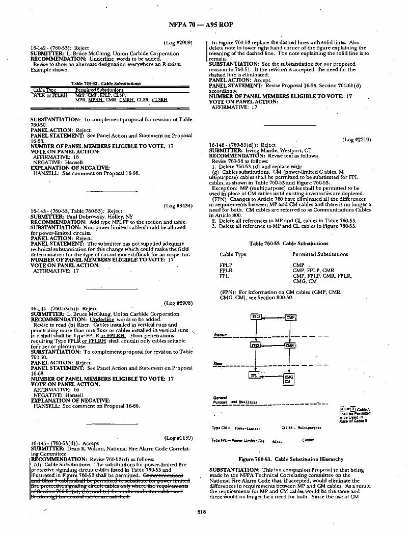
N F P A 70 - - A 9 5 R O P
(Log #2909) 10-142- (760-53,): Reject SUBMITTER: L. Bruce McClung, Union Carbide Corporation RECOMMENDATION: ~ words to be added.
Revise to show an alternate designation everywhere an R exists. Example shown.
Tab le 725-63. Cable Substitutions
Cable Type Permi t t ed Substi tutions FPLR ~ MPP, CMP, FPLP, CL3P,
MPR. ~ CMR, CMRH~ CL3R, C L 3 ~
SUBSTANTIATION: To complement proposal for revision of Table 760-50. PANEL ACTION: Reject. PANEL STATEMENT: See Panel Action and Statement on Proposal 16-68. NUMBER OF PANEL MEMBERS ELIGIBLE TO VOTE: 17 VOTE ON PANEL ACTION:
AFFIRMATIVE: 16 NEGATIVE: Hansell
EXPLANATION OF NEGATIVE: HANSELL: See comment on Proposal 16-66.
(Log #3434) 16-143 - (760-53,, Table 760-53): Reject SUBMrVrER: Paul Dobrowsky, Holley, NY RECOMMENDATION: Add type NPLFP to the section and table. SUBSTANTIATION: Non power-limited cable should be allowed for power-limited circuits. PANEL ACTION: Reject. PANEL STATEMENT: The submitter has not supplied adequate technical substantiation for this change which could make the field determination for the type of circuit more difficult for an inspector. NUMBER OF PANEL MEMBERS ELIGIBLE TO VOTE: 17 VOTE ON PANEL ACTION: j
AFFIRMATIVE: 17
(Log #2908) 16-144- (760-53(b)): Reject SUBMITTER: L. Bruce McClung, Union Carbide Corporation RECOMMENDATION: Underl ine words to be added.
Revise to read (b) Riser. Cables installed in vertical runs and penetrat ing more than one floor or cables installed in vertical runs ,,
a shaft shall be Type FPLRor ~ L R H . Floor penetrations requiring Type FPLR or ~LP-d-I shall contain only cables suitable for riser or p lenum use. SUBSTANTIATION: To complement proposal for revision to Table 760-50. PANEL ACTION: Reject. PANEL STATEMENT: See Panel Action and Statement on Proposal 16-68. NUMBER OF PANEL MEMBERS ELIGIBLE TO VOTE: 17 VOTE ON PANEL ACTION:
AFFIRMATIVE: 16 NEGATIVE: Hansell
EXPLANATION OF NEGATIVE: HANSELL: See cOmment on Proposal 16-66.
(Log #113,9) 16-145 - (760-53(d)): Accept SUBMITTER: Dean K. Wilson, National Fire Alarm Code Correlat- ing Committee
IRECOMMENDATION: Revise 760-53,(d) as follows: [ (d) Cable Substitutions. The substitutions for power-limited fire [protective signaling circuit cables listed in Table760-53 and lillustrated in Fi~gure 760-53, shall be [~ermitted. Cc..;..~,,.;~adGu.;
I In Figure 760-53, replace the dashed lines with solid lines. Also delete note in lower right hand corner of the figure explaining the mearl.ing of the dashed line. The note explaining the solid line is to remain. SUBSTANTIATION: See the substantiation for our proposed revision to 760-51. If the revision is accepted, the need for the dashed line is eliminated. PANEL ACTION: Accept. PANEL STATEMENT: Revise Proposal 16-96, Section 760-61 (d) accordingly. NUMBER OF PANEL MEMBERS ELIGIBLE TO VOTE: 17 VOTE ON PANEL ACTION:
AFFIRMATIVE: 17
(Log #2219) 16-146- (760-53(d)): Reject SUBMrrTER: Irving Mande, Westport, CT RECOMMENDATION: Revise text as follows:
Revise 760-53 as follows: 1. Delete 760-53 (d) and replace with: (g) Cables substitutions. CM (power-limited (3 ables, M
ultapurpose) cables shall be permitted to be substituted for FPL cables, as shown in Table 760-53 and Figure 760-53.
Exception: MP (multipurpose) cables shall be permit ted to be used in place of CM cables until existing inventori~:s are depleted.
(FPN) Changes to Article 760 have eliminated all the differences iri requirements between MP and CM cables and there is no longer a need for both. CM cables are referred to as Communications Cables in Article 800.
2. Delete all references to MP and ( I . cables in Table 760-53,. 3. Delete all reference to MP and CL cables in Figure 760-53.
Cable Type
FPLP FPLR FPL
Table 760-53 Cable Substitutions
Permitted Substitutions
CMP . CMP, FPLP, CMR CMP, FPLP, CMR, FPLR, CMG, CM
(FPN): For information on CM cables (CMP, CMR, CMG, CM), see Section 800-50.
Renum
Germfal pur;x~le and - ~el14,,llS . . . . . . . . .~ ; . . m .
"Type CM- POUer-Ltm:Lted ~lCleS , Hulctpurpose
Type F~. "L-- ~ower-I./rn/tl~ Rn~ ~I,~.--__ CJbles
~ . ~ _ Cable A S~alJ be Pe r rn i~ = ~e USed ir~ Phlc* of Cable $
Figure 760-53. Cable Substitution Hierarchy
SUBSTANTIATION: This is a companion Proposal to that being made by the NFPA Technical Correlating committee on the National Fire Alarm Gode that, if accepted, would eliminate the differences in requirements between MP and GM cables. As a result, the requirements for MP and CM cables.would be the same and there would no longer be a need for both. Since the use of CM
8 1 8

N F P A 70 - - A 9 5 R O P
cables is milch gea te r that MP cables, this proposal is directed toward eliminating MP cables. Because existing inventories of MP cables meets all the requirements for CM cables, this Proposal permits the continued use of MP cables until inventories are depleted. • PANEL ACTION: Reject. PANEL STATEMENT: See Panel Action on Proposal 16-202 and Proposal 16-203. - NUMBER OF PANEL MEMBERS ELIGIBLE TO VOTE: 17 VOTE ON PANEL ACTION:
AFFIRMATIVE: 16 NEGATIVE: Mande ' "
EXPLANATION OF NEGATIVE: MANDE: See my explanation for negative for Proposal 16-202 (Log
#2221)
(Log #2535) 16-147- (760-53(d) and (e)-(Newi): Reject SUBMITrER: M.S. GrRfith, Brown & Root, Inc RECOMMENDATION: Change 760.53(d) to 760-53(e). Add new paragwaph 760-53(d) to read: • ' (d) Cable Trays. Cables installed in trays shall be Type PLTC."
SUBSTANTIATION: This change is re(luired to support compan- ion proposal to add Type PLTC, power-hmited tray cable to section 760-51. PANEL ACTION: Reject. PANEL STATEMENT: The submitter has not provided adequate technical substantiation for this major.change in installation practice in fire alarm circuiu'y. NUMBER OF PANEL MEMBERS ELIGIBLE TO VOTE: 17 VOTE ON PANEL ACTION:
AFFIRMATIVE: 17
ARTICLE 770 - - OPTICAL FIBER CABLES
(Log #1485) 16-148- i770-8-(New)): Reject • SUBMITTER: Bill Pike, Building IndusU-y Consulting Service International RECOMMENDATION: Add new text as follows:
Eouinment intended to be onticallv connected to a telecommunica. tiOfis r~etwork shall be listed for the burnose. SUBSTANTIATION: The new text'mit~ics the text in 800-4 and is required for the oauioment that is onticallv connected to the telecommunications network. PANEL ACTION: Reject. PANEL STATEMENT: This subject is outside the scope of Article 770 Which only covers the installation of optical fiber cables and raceways. NUMBER OF PANEL MEMBERS ELIGIBLE TO VOTE: 17 VOTE ON PANEL ACTION:
AFFIRMATIVE: 16 NOT RETURNED: Stilwell
(Log #2910) 16-149 - (Table 770.50): Reject SUBMITrER: L. Bruce McClung, Union Carbide Corporation RECOMMENDATION: Underline Words to be added,
Modify and add to table.
Table 770-50 Cable Marktn~
' Cable ' Type Reference Marking FPLR Power - limited fire protective Sections 760-51 (e) ( 1 ) and
signaling circuit rber cable 760-53 (b ) Power - limited fire vrotective Sections760-51 fe~ f')) and #tmalin~r'circuit reduced hazard riser cable
SUBSTANTIATION: Fire resistance is not the only characteristic by whtch to measure firesafety of cables. A combusuon of f~re safety characteristics can result in an overall safer condition dianjust fire resistance. Therefore at least three characteristics for which standardized tests are available should be evaluated to recognize a
reduced hazard riser cable that is as safe or safer to utilize than the presentTypes CL2R and CL34 which are listed on the basis of fire resistance only. The need for also limiting smoke and corrosivity is demonstrated by conditions.described in the copies of fire report- mE: Chapel of the Holy Cross in Sedona, Arizona, October 20, 1992. John Hancock's home office in Boston, August 24, 1992. Bankers Trust building in Manhattan,July 20, 1989. Columbia Seafirst Center in Seattle, July 26, 1988. John F. Kennedy Federal building in Boston, July 8, 1988. Illinois Bell's central office in Hinsdale, Illinois, May 8, 1988. Business Insurance Reports of May 29, 1990.
PANEL ACTION: Reiect. PANEL STATEMENT: See Panel Action and Statement on Proposal 16-68. NUMBER OF PANEL MEMBERS ELIGIBLE TO VOTE: 17 VOTE ON PANEL ACTION:
AFFIRMATIVE: 15 NEGATIVE: Hansell NOT RETURNED: Stilwell
EXPLANATION OF NEGATIVE: HANSELL: See comment on Proposal 16-66.
( Log #2911 ) 16-150- i770-51(b)): Reject SUBMITrER: L. Bruce McClung, Union Carbide Corporation RECOMMENDATION: Renumber as (b) (1) Type OFNR and OFCR. SUBSTANTIATION: To make a place (way) to add (b) (2) Type OFNRH and OFCRH. PANEL ACTION: Reject. PANEL STATEMF.NT: See Panel Action and Statement on Proposal 16~68. NUMBER OF PANEL MEMBERS ELIGIBLE TO VOTE: 1 7 VOTE ON PANEL ACTION:
AFFIRMATIVE: 15 NEGATIVE: Hansell NOT RETURNED: Stilwell
EXPLANATION OF NEGATIVE: HANSELL: See comment on Proposal 16-66.
(Log #2912) 16-151.- (770-51(b)(2)-(New)): Reject ' SUBMlq[q'ER: L. Bruce McClung, Union Carbide Corporation RECOMMENDATION: Add (b) (2) Types OFNRH and OFCRH.
(b)(2) Types OFNRH and OFCRH. Types OFNRH and OFCRH nonconductive and conductive optical fiber riser cable shall be listed as being suitable for use in a vertical run in a shaft or from floor to floor and shall also be listed as having.adequate fire- resistant, limited smoke and limited corrosivity characteristics capable of preventing the spread of fire or products of combustion . from floor to floor.
(FPN): A combination of fire safety features can result in a reduced hazard. One method of defining resistant to spread of fire is that the cables do nots[~read fire to the top of the tray in the . "Vertical-Tray Flame Test in the Reference Standard for Electrical Wires, Cables and Flexible Cords, ANSI/UL 1581-1985. One method of defining both resistant to spread of fii'e and limited smoke is that the cablespass the "UL Flame Exposure Fire Tests" in reference Vertical Tray Fire Propagation and Smoke-Release Test for Electrical and Optical-Fiber Cables UL 1685-1992. One method of defining limited corrosivity is by the results of direct exposure of • resistivity probes to acid gas generated by the cables when tested in accordance with ASTM E.5.21.70. SUBSTANTIATION: Fire resistance is not the only characteristics by which to measure fire safety of cables. A combination of fire safety characteristics can result in an overall safer condition thahjnst fire resistance. Therefore at least three characteristics for which standardized tests are available should be evaluated to recognize a reduced hazard riser cable that is as safe or safer to utilize than the present Types CL2R and CL3R which are listed on the basis of fire resistance only. "
Reduced hazards from a fire safety viewpoint must incorporate ignitability, progation, heat release, smoke, corrosivity ann toxicity. The better product will be the one that meets the minimum
acceptable standards in each category. Untilaccepted consensus standards for measuring all six categories are available the industry
819
N F P A 70 - - A95 R O P
should concentrate on measur ing and evaluating applications based on the categories that can be satisfactorily measured . See copy of summary o f North Amer ican and European Fire Tests for Cables and Cable Materials for consensus as well as c o m m o n test protocols to measure ease of ignition, f lame spread, hea t release rate, smoke, corrosivity and toxicity. PANEL ACTION: Reject. PANEL STATEMENT: See Panel Action and Sta tement on Proposal 16-68. NUMBER OF PANEL MEMBERS ELIGIBLE T O VOTE: 17 VOTE ON PANEL ACTION:
AFFIRMATIVE: 15 NEGATIVE: Hansell NOT RETURNED: Stilwell
EXPLANATION OF NEGATIVE: HANSELL: See c o m m e n t on proposal 16-66.
(Log #2710) 16-152- (770-51(c), FPN): Reject SUBMITTER= Marcelo M. Hirschler, Safety Engineer ing Laborato- ries, Inc.. RECOMMENDATION: Revised text for the fine pr int note:
(FPN): O n e m e t h o d of def in ing resistant to spread of fire is that the cables do no t spread fire to the top of the tray in the "Vertical Tray Flame Test" in the Reference Standard for Electrical Wires, Cables and Flexible Cords, ANS I / UL 1581-1985. Ahernativelv. the m~x imum heat release rate of the cables, as tested in the "Staiadard for Testimt for Smoke Obscurat ion Caused by Burnin~ Cables in a Vertical Ggnf i~va t ion ." ASTM D5424 (Protocol AL shall no t exceed 100 kW. Another m e t h o d of def in ing resistant to the spread of fire is for the
damage (char length) no t to exceed 4 feet, 1 inches (1.5 m) when per forming the CSA "Vertical Flame Tes t - Cables in Cable Trays," as described in Test Methods for Electrical Wires and Cables, CSA C22.2 No. 0.3-M-1985. Ahernativelv. the m a x i m u m hea t release rate of the cables, as tested in the "Standard for Tesfin~ for Smoke Obscurat ion Caused by Burn inv Cables in a VerticTal Configuration." ASTM D5424 (Protocol B). shall no t exceed 100 kW.
Ano the r m e t h o d of definina: resistant to the spread of fire is for the m a x i m u m heat release rate o-er un i t area of th~ cables, as tested, at an incident flux of 40 k W / m ~:. accordin~ to "Standard Test Method for Heat and Visible Smoke Release Rat~s for Materials and Products Usin~ an Oxygen Consumot ion Calorimeter." ASTM E1 $54. no t to exceed 200 k~c~/m2." "
This replaces the present FPN, text in "under l ine" is to be added. SUBSTANTIATION: It has now been shown that hea t release rate testing is an al ternate way to de te rmine whether a cable resists the spread of fire.
One of the first quest ions a person migh t wish to ask about the hazard of a fire is "How big is the fire?" Until fairly recently there was no quantitative way of answering this question. Nowadays, we know that, in quantitative terms, this quest ion is equivalent to asking, "What is the heat release rate of the fire?"
An example may explain the impor tance of hea t release rate. f f a cable ~-ay were bu rn ing outdoors, with no combust ible products a round it, it may burn, the immedia te consequence of its bu rn ing will be minimal: no th ing else will be ignited. On the other hand , if the same cable tray is inside a comparmaent , once it starts bu rn ing it may ignite a nearby product , ff it releases (gives off) e n o u g h hea t and does it fast enough . If the bu rn ing cables release hea t slowly, the cooler air a r o u n d t h e m may be cold e n o u g h to avoid raising the tempera ture f the neares t p roduc t for it to start burning, ff the cables release hea t even faster, they could go beyond causing the nearest product to burn, bu t they could also ignite o ther products f u ~ h e r away. As more products burn , the fire gradually becomes more intense. In the same spirit, as more things are burning, more smoke is emitted. This means the visibility in the room decreases, m a k i n g i t more difficult for people to escape and more diff icuh for fire fighters to come in and help potential fire victims. If more
. smoke is emitted, the air in the room also becomes more toxic, which can also cause a bigger threat to the people in the room.
Recent work, u s i n g a large n u m b e r of cables of different types, has shown that every cable that has had a peak hea t release rate of less than 100 kW, when tested according to ASTM D5424, S tandard for Test ing for Smoke Obscurat ion Caused by Burn ing Gables in a Vertical Configuration, has ~ the cable tray test, as regards char length. Moreover, it has also been shown that every cable which, when tested in the cone calorimeter, S tandard Test Method for Heat and Visible Smoke Release Rates for Materials and Products Using an Oxygen Consum2ption Calorimeter," ASTM E1354, at an incident flux of 40 k W / m , has had a peak heat release rate no t
exceeding 200 kW/m2 , has ~ the cable tray test, as regards char length.
In fact, it is likely tha t cables with even somewhat h igher hea t release rates may pass the test, in mos t cases. However, the above criteria are being suggested as very conservative estimates, with a significant m a r ~ n of safety, for those users interested in having cables listed while testing less material.
It is also possible to obtain hea t release rate results by testing smaller lengths of cable in a bench-scale test. Thus, I feel that the fine pr int note needs to be modif ied to express these ideas, as stated above.
NOTE: Suppor t ing material is available for review at NFPA Headquarters . PANEL ACTION: Reject. " PANEL STATEMENT: The Panel believes the submit ter is directing his r ecommenda t ion to Section 770-51 (d) FPN as well as to Section 770-51 (c) FPN. The substant iat ion for this proposal is based u p o n a limited a m o u n t o f data a n d p r e s e n t s a l imited correlation. At the present time, the scatter o f data shows that the cone calorimeter should only be used as a research tool for the deve lopment of products and materials. There is no a g r e e m e n t within the fire communi ty to substantiate that the cone calorimeter can adec~uately evaluate early stages and full scale fire per formance charactertstics of wire and cable. Fur thermore Section 770-51(c) correlates with the Canadian Electric Code and changing it could in t roduce a lack of correlation. NUMBER OF PANEL MEMBERS ELIGIBLE T O VOTE: 17 VOTE ON PANEL ACTION:
AFFIRMATIVE: 16 NOT RETURNED: Stilwell
(Log #3148) 16-153- (770-52(b)(5)-(New)): Reject SUBMITTER: William O. Andersen ,J r . , AFC/A Monogram Co. RECOMMENDATION: Add: (5) Metal Clad Cable in compliance with Article 334. SUBSTANTIATION: Metal Clad Cable conta in ing optical fiber componen t s have been listed by Underwri ters Laboratories since 1989. These composi te cables mee t the requ i rements of Section 770-52 and deserve i 'ecognition in the apphcat ions list. PANEL ACTION: Reject. PANEL STATEMENT: Section 770-52(b) deals only with power limited cables. Fur thermore , this cons~'uction is covered in Section 770-52(a). NUMBER OF PANEL MEMBERS ELIGIBLE T O VOTE: 17 VOTE ON PANEL ACTION:
AFFIRMATIVE: 16 NOT RETURNED: Stilwell
(Log #3150) 16-154- (770-52(d)-(New)): Accept in Principle . SUBMITTER: Gregory P. Bierals, Electrical Design Institute RECOMMENDATION: Add new text as follows:
Suppor t of Optical Fiber Cables. Raceways shall no t be used as a means of Suppor t for Optical Fiber Cables. SUBSTANTIATION: Section 300-11 (b) applies genera l lyand this new section of Article 770 will be consistent with Section 725-52(c), 800-52 (e), and 820-52 (e). PANEL ACTION: Accept in Principle.
See Panel Action on Proposal 16-15. PANEL STATEMENT: The Panel believes the action taken on Proposal 16-15 meets the submit ter ' s intent. NUMBER OF PANEL MEMBERS ELIGIBLE T O VOTE: 17 VOTE ON PANEL ACTION:
AFFIRMATIVE: 16 NOT RETURNED: Stilwell
(Log #2286) 16-155 - (770-53): Accept
.SUBMI"VI'ER: Joe Tedesco, Boston, MA {RECOMMENDATION: Change "may" to "shall be permi t ted to." SUBSTANTIATION: The word "may" was replaced with the proposed words many times t h roughou t the code. This one fell t h rough the cracks? PANEL ACTION: Accept.
820

• N F P A 70 - - A 9 5 R O P
NUMBER OF PANEL MEMBERS ELIGIBLE TO VOTE: 17 VOTE ON PANEL ACTION:
AFFIRMATIVE: 16 NOT RETURNED: Stilwell
(Log #2913) 16-156- (770-53): Reject SUBMITTER: L. Bruce McClung, Union Carbide Corporation RECOMMENDATION: ~ words to be added.
Revise to read (b) Riser cables installed in vertical runs and penetrat ing more than one floor or cables installed in vertical runs m a shaft shall be Types OFNR, ~ OFCR, or OFCRH. Floor penetrations requiring Types OFNR, O ~ R H . OFCR, or OFCRH shall contain only cables suitable for riser or p lenum use. SUBSTANTIATION: To complement proposal for revision of Table 770-50. PANEL ACTION: Reject. PANEL STATEMENT: See Panel Action and Statement on Proposal . 16-68. NUMBF.R OF PANEL MEMBERS ELIGIBLE TO VOTE: 17 VOTE ON PANEL ACTION:
AFFIRMATIVE: 15 NEGATIVE: Hansell NOT RETURNED: Stilwell
EXPLANATION OF NEGATIVE: HANSELL: See comment on Proposal 16-66.
(Log #2914) 16-157- (770-53): Reject SUBMITTER: L. Bruce McClung, Union Carbide Corporation RECOMMENDATION: Revise to show an alternate designation everywhere an R exists. Example shown.
Table 770-53. Cable Substitutions Cable Type OFNRorOFNRH OFCRorOFCRH OFNG, OFN
Permitted Substitutions OFNP OFNP, OFCP, OFNR, OFNRH OFNP, OFNR, OFNRH
SUBSTANTIATION: To complement proposal for revision of Table 770-50. PANEL ACTION: Reject. PANEL STATEMENT: See Panel Action and s ta tement on Proposal 16-68. NUMBER OF PANEL MEMBERS ELIGIBLE TO VOTE: 17 VOTE ON PANEL ACTION:
AFFIRMATIVE: 15 NEGATIVE: Hansell ' NOT RETURNED: Stilwell
EXPLANATION OF NEGATIVE: HANSELL: See comment on Proposal 16-66.
(Log #2915) • 16-158- (770-53): Reject SUBMITTER: L. Bruce McClung, Union Carbide Corporation RECOMMENDATION: Revise to show an alternate designation everywhere an R exists.
Riser
.OFNRtt
L t . . . .
SUBSTANTIATION: None. PANEL ACTION: Reject. PANEL STATEMENT: See Panel Action and Sta tement on Proposal 16-68. NUMBER OF PANEL MEMBERS ELIGIBLE TO VOTE: 17 VOTE ON PANEL ACTION:
AFFIRMATIVE: 15 NEGATIVE: Hansell NOT RETURNED: Stilwell
EXPLANATION OF NEGATIVE: HANSELL: See comment on Proposal 16-66.
16-159 - (770-53(a)): Accept in Principle (Log #2959) SUBMITTER: Patricia B. Horton, Allied Tube & Conduit Corpora- tion RECOMMENDATION: Revise to read:
Also listed p lenum optical fiber raceways, when used with O F N P cable, shall be permitted ....
Delete the last sentence. • SUBSTANTIATION: Where nonmetall ic optical fiber raceway is
permit ted the Code should require that only OFNF cable be used. That is no t clear.in the current langua.ge. Optical fiber cables in OF raceway needs t o b e plenum rated.
. PANELACTION: Accept in Principle. [ Revise the text of the second sentence of the second paragraph of [Section 770-53(a) in the 1993 ed, ition of the Code as follows: I Insert the word "Only" before "Type OFNP". PANEL STATEMENT: The Panel believes the action it has taken meets the submitter 's intent. NUMBER OF PANEL MEMBERS ELIGIBLE TO VOTE: 17 VOTE ON PANEL ACTION:
AFFIRMATIVE: 16 NOT RETURNED: Stilwell
(Log #CP1600) 16-159a- (770-53(d) 770-53(d) through 770-53(e)): Accept . Note: It was the action of the Technical Correlating Committee
that further consideration be given to the comments expressed in the voting. This action will be considered by the Panel as a Public Comment. SUBMITTERa CMP 16
[ RECOMMENDATION: Renumber Section 770-53 (d) t() Section 770-53 (e) and add a new Section 770-53 (d) as follows:
(d) Hazardous (Classified)'Locations. Cables installed in hazardous (classified) locations shall be any type indicated in Table 770-53. Composite cables having current-carrying electrical
. [ conductor, and other electrical components located in hazardous. I (classified) locations shall comply with Chapter 5 of the NEC. SUBSTANTIATION: Optical fiber cables, which transmit light for control; signaling and communicat ion through an optical fiber, the cables, may be used in Hazardous (classified) areas. The electrical or electronic portions of the optical fiber must comply with the Hazardous (classified) area requirements in applicable sections of ' C ~ l ~ e r 5.
L ACTION: Accept. NUMBER OF PANEL MEMBERS ELIGIBLE T O VOTE: 17 VOTE ON PANEL ACTION:
AFFIRMATIVE: 16 NOT RETURNED: StilweU
COMMENT ON AFFIRMATIVE: BRUNSSEN: Editorially revise the second sentence of the
r ecommended text as follows: "Composite cables having current-carrying electrical conductors,
and other electrical or electronic components located in hazardous (classified) locations, shall comply with the requirements of Chapter 5 of this Code." WECHSLER: The Panel 's recommendat ion should also modify the
first sentence of Article 770-53 with the following editorial correction of changing (d) to (e), as follows:
" . . . shal l complywith (a) through re) below."
Figure 770-55 Cable Substitution t
821
N F P A 70 m A 9 5 R O P
ARTICLE 780 - - CLOSED-LOOP AND PROGRAMMED POWER DISTRIBUTION
(Log #97) 10-110 - (780-3(a) and (b) (1)): Accept in Principle Note: The following proposal consists of Comment 10-122 on
Proposal 7-83 in the 1992 Annual Meeting National Electrical Code Technical Committee Report. This Comment was held for further study during the processing of the 1993 NATIONAL ELECTRICAL CODE. The recommendation in Proposal 7-83 was:
Revise text: (a) Type NM, NMC, or NMH. Types NM and NMH cable shall not
be installed: (1) Where...
SUBMITTER: Mark EJohnson, AMP Incorporated RECOMMENDATION." Revised text.
"Outlets of a closed loon nower distribution system shall not be..." "In a closed loon nowerd'istribution system when. a nominal-
operation acknovd~dgement.:." SUBSTANTIATION: A clarification to differentiate between closed loop power distribution systems andprogrammed power distribution systems. This will allow systems whichare upgradable to closed loop to be introduced as long as the protection provided is at least equal to that currently provided by normally wired distribution systems. PANEL ACTION: Accept in Principle.
• PANEL STATEMFJqT: Same Panel Action and Panel Statement as Proposal 10-111. - " NUMBER OF PANEL MEMBERS ELIGIBLE T O VOTE: 11 VOTE ON PANEL ACTION: AFFIRMATIVE: 11
(Log #219) 10-111 - (780-3(a), (b)(1)): Accept in Principle Note: The Technical Correlating Committee directs the Panel to
clarify the Panel Action with respect to each part of the Proposal. This action will be considered by the Panel as a Public Comment. SUBMITrER: Mark E.Johnson, AMP Incorporated RECOMMENDATION: Revise text:
"Outlets of a Closed Loon Power Distribution System sfiall not be.. p,
"In a Closed Loon Power Distribution System when• a nominal- operation acknowledgement..." SUBSTANTIATION: A clarification to differentiate between Closed Loop Power Distribution Systems and Programmed Power Distribu- tion Systems. This will allow Systems which are upgradable to closed loop, to be' introduced as long as the protection provided is at least equal to that currently provided by normally wired distribution systems. PANEL ACTION: Accept in Principle.
J Revise the Proposal by deleting the word "when" and placing the I first part of the sentence "In a Closed Loop Power Distribution JSystem" to the end of the sentence in Section 780-3(b) (1) to read as [ follows: I "A nominal-operation acknowledgement signal is not being I received from the utilization equipmei~t connected to the outlet in a [ Closed Loop Power Distribution System."
PANEL STATEMENT: The revision was editorial by moving the fii'st ~ ¢ I B t of the phrase to the end of the existing sentence.
ER OF PANEL MEMBERS ELIGIBLE T O VOTE: 11 VOTE ON PANEL ACTION:
AFFIRMATIVE: 11
(Log #'2916) 10-112 - (780-49-(New)): Reject SUBMITTER: L. Bruce McClung, Union Carbide Corporation RECOMMENDATION: New text as'follows:
Hybrid cables installed as wiring within buildings shall be listed as resistant to the spread of fire in accordance with Section 780-51. Hybrid cables other than those in rigid metal conduit, intermediate metal conduit, electrical metallic tubing, metal wireway, surface metal raceway with metal cover, flexible metal conduit, or light- weight flexible metal conduit shall be marked with an /LS /L C designation and listed for use. SUBSTANTIATION: The 1990 Code recognized " / IS" and the 1993 Code recognized "/LC" insulations aiid outer coverings for conductors for general wiring, for flexible cords and cables and for fixture wires. Any exposed wiring in enclosed spaces where products
of combustion would be confined and people (particularly infirm or immobilized people) and/or sensitive electronic equipment are present should have improved fire safety features. See copy of technical paper rifled "Improvement in Fire Safety Features of Electrical Conductors and Cables" by L.B. McClung and S. Ramchandran that was presented at IEEE-IAS-PCIC 1993 at St. Louis, Missouri. UL now has available a test by which to measure limited smoke (UL1685). UL is actively pursuing development of a standard test bywhich to measure low or limited corrosivity of conductors and cables.
NOTE: Supporting material is available for review at NFPA Headquarters. PANEL ACTION: Reject. PANEL STATEMENT: These applications do not necessarily require the use of special limited smoke and limited corrosivity type cables but would be more appropriately covered in Chapter 3. NUMBER OF PANEL MEMBERS ELIGIBLE TO VOTE: 11 VOTE ON PANEL ACTION:
AFFIRMATIVE: 11
(Log #2917) 10-113- (780-51-(New)): Reject SUBMITTER= L. Bruce McClung, Union Carbide Corporaflon RECOMMENDATION: New text as follows: 780-51 Listing Requirements. Hybrid cables other than those in
rigid metal conduit, intermediate metal conduit, electrical metallic tubing, metal wireway, surface metal raceway with metal cover, flexible metal conduit, or lightweight flexible metal conduit shall be listed as having limited smoke, limited corrosivity characteristics. SUBSTANTIATION: To complement proposal for new 780-49. PANEL ACTION: Reject. PANEL STATEMENT: Same Panel Statement as Proposal 10-112. NUMBER OF PANEL MEMBERS ELIGIBLE T O VOTE: 11 VOTE O N PANEL ACTION:
AFFIRMATIVE: 11
ARTICLE 790 - - AUTOMATION SYSTEMS 7
(Log #3247) 10-114- (790-(New)): Reject SUBMITTER: Arthur Allison, Smart House, L.P. RECOMMENDATION: ARTICLE 790 - Automation Systems
790-1 Scope. The provisions of this Article apply to premise power distribution systems which provide power control capability through a central controller, through distributed control andsignaling equipment, or through some combination of these.
790-2. General. (a) Other Articles. Except as modified by the requirements of this
article, all other applicable articles of this Code shall apply. (b) Component Parts. All equipment and cables shall be listed
and identified for the purpose. 790-3 Control of Power to Utilization Equipment. The availability
of power to utilization equipment may be controlled by switch, relay, or other power switching device operated eithe/" locally or remotely by a signaling means.
790-4. Cables and Conductors. (a) Hybrid Cable. Hybrid cable as defined in Section 780-6(a)
shall be permitted for use in automation systems. Circuits utilizing hybrid cable shall be protected as follows:
(1) Ground-fault equipment protection. (2) Overcurrent protection. (3) The circuit shall be deenergized in the event of a fault to the
communication or signaling conductors. (b) Cables and Conductors in the Same Cabinet, Panel, or Box.
The power, communication, and signaling conductors of listed hybrid cable are permitted to occupy the same listed cabinet, panel, or outlet box (or similar enclosurehousing the electrical termina- tions of electric light, power circuits or listed power switching devices) without petition or separation. The power, communication, and signaling conductors are permitted to be terminated in the same listed panel, cabinet, or outlet box only if connectors specifi- cally listed for hybrid cable are employed. SUBSTANTIATION: The 1993 National Elecu-ical Code restricts the use of hybrid cable to closed-loop or programmed power distribution systems. Article 790 proposes to expand the use of hybrid cable to automation systems designed for installation in residential and light commercial buildings.
822

N F P A 7 0 - - A 9 5 R O P
The integration of power distribution and electronic control communications in automation systems in various stages of development promises to he a major innovation for power distribu- tion technology. These automation systems will provide man~ new features such as energy management, security, and programmed lighting control. By extending the permitted use of hybrid cable, as proposed under Article 790, the installation of automation systems will become more organized and systematic. This will result in less installer confusion and less chance of mis-wiring conductors, as may happen with multi-cable systems today. Automation systems designed to meet the requirements of this article will also offer many safety enhancements including some of those required under Article 780.
In at least one jurisdiction - Atlanta, Georgia - the electrical ' inspector has questioned the use of hybrid cable installations where closed-loop power was only partially implemented. Other jurisdic- tions have approved such installations. This inconsistent interpreta- tion and application of the code will delay and may totally stall the controlled spread of this new technology throughout the market. The threat of having to remove and replace hybrid cable for fear of electrical inspector rejection of the installation will cause builders to avoid selecting the new technology.
The Canadian Standards Association has approved the use of hybrid cable in "preclosed-loop'power distribution systems. The 1994 Canadian Electric Code will reflect this ruling. This will allow the use of hybrid cable with utilization equipment that does not send a unique signal to the energy controlling equipment. Broader allowance is needed in the National Electrical Code to permit the use of hybrid cable in automation system installations and other
~ reclosed-loop installations. ANEL ACTION: Reject.
PANEL STATEMENT: The information and applications in this new proposed article are already covered in Article 780. NUMBER OF PANEL MEMBERS ELIGIBLE TO VOTE: 11 VOTE ON PANEL ACTION:
AFFIRMATIVE: 11
(Log #3368) 10-115- (790-4(b)(5)): Reject SUBMITTER: Arthur Allison, Smart House, L.P. RECOMMENDATION: Regarding the referenced proposal para~graph 790-4(b) line 5: change .the word "petition" to "parti- t ion . SUBSTANTIATION: None. PANEL ACTION: Reject. PANEL STATEMENT: See Panel Action and Panel Statement on
OF PANEL MEMBERS ELIGIBLE TO VOTE: 11 VOTE ON PANEL ACTION:
AFFIRMATIVE: 11
ARTICLE 795 - - DATA COMMUNICATIONS CIRCUITS
16-160 - (795-(New) ): Reject . ( Log #906) Note: The Technical Correlating Committee recognizes that the
Task Group has been appointed.to consider Proposals 16-160, 16- 161, and 16-169. SUBMI'I~['ER: Stanley Kanfman, AT&T Bell Labs RECOMMENDATION: Establish a new article to cover data communications wiring in buildings.
Chapter 8. Communications Systems ARTICLE 805 - DATA COMMUNICATIONS CIRCUITS A. General 805-I. Scope. This article covers data communications equipment
and circuiis not covered by other artides. This article does not cover the power-supply wiring of a computer system.
805-2. Definitions. Article 100 and Section 800-2 shall apply. 805-3. Other Articles.. (a) Electronic Computer/Data Processing Equipment In an
Electronic Computer/Data Processing Equipment Room. Article 645 shall apply.
(b) Class L Class 2, and Class 3 Remote-Control, Signaling, and Power-Limited Circuits. Article 725 shall apply.
(c) Fire Protective Signaling Systems. Article 760 shall apply (d) Optical Fiber Cables. Article 770 shall apply. (e) Communications Circuits. Article 800 shall apply.
(f) Community Antenna Television and Radio Distribution Systems. Artide 820 shall apply.
805-4. Communications Circuits. Where data communications circuits are run in the same cable as communications circuits, the data communications circuits shall be classified as communications circuits and shall meet the requirements of Article 800.
805-5. Class 2 and Class 3 Circuits. Where class 2 or class 3 circuits are run in the same cable as data communications circuits, the class 2 and class 3 circuits shall be classified as data communications circuits and shall meet the re.qluirements of Article 805. 805-6. Fire Protective Signaling Circuits. Where power-limited fire
protective sitmallng circuits are run in the same cable as data communications circuits, the ' circuits shall be classified as power- limited fire protective signaling circuits and shall meet'the require- ments of Article 760.
805-7. Equipment. Equipment intended to be electrically connected to a data communications network shall be listed for the purpose.
(FPN): One way to determine applicable requirements is to refer to the Standard for Information Technology Equipment ANSI/UL 1950-1991. 805-8. Access to Electrical Equipment Behind Panels Designed to
Allow Access. Access to equipment shall not be denied by an accumulation of wires and cables that prevents removal of panels, including suspended ceiling panels.
805-9. Mechanical Execution of Work. Data communications . circuits and equipment shall be installed in a neat and workmanlike m a . r l n e r .
805-10. Circuits ExtendingBeyond One Building. Datacommuni- cations circuits that extendbeyond one building shall meet the requirements of Article 800.
805-52. Installation of Wires, Cables, and Equipment. Wires and cables carrying data communications circuits shall comply with section 800-52.
805-53. Applications of Wires and Cables. Wires and cables carrying data communications circuits shall comply with (a) through (f) below. (a) Plenum. Cables installed in ducts, plenums, and other spaces
used for environmental air shall be Type CMP. Exception: Types CMP, CMIL CMG, and CM and communications
wire installed in compliance with Section 300-22. (h) Riser. Cables installed in vertical runs and penetrating more
than one floor, or cables installed in vertical runs in a shaft, shall be Type CMIL Floor penetrations requiring Type CMR shall contain. only cables suitable for riser or plenum use.
(FPN): See Section 800-52(b) for firestop requirements for floor penetrations.
Exception No. 1: Where the listed cables are encased in metal raceway or are located in a fireproof shaft having firestops at each floor.
Exception No. 2: Type CM cable in one-and two-fatally'dwellings. (c) Distributing Frames and Cruss-Connect Arrays. Communica-
tions wires shall be used in distributing frames arid cross-connects arrays. • Exception: Types CMP, CavIIL CMG, and CM are permitted to be used.
(d) Other wiring Within Buildings. Cables installed in building locations other than the locations covered in (a), (b), and (c) above shall be Type CMG or Type CM.
Exception No. 1: Where listed communications wires and cables are enclosed in racew-4y.
Exception No. 2: Type CMUC undercarpet communications wires andl cables installed under carpet.
Exception No. 3: Wiring that is less than 95 feet in length and in o n e r o o m .
(iv) Cable Substitutions. Substitutions for communications cables listed in Table 800-53 and il!ustrated in Figure 800-53 shall be
g ermitted. UBSTANTIATION: There exists considerable confusion concern-
ing the type of wiring that should be used to wire computers in buildings outside of a computer room. The National Electrical Code Handbook suggests Class 2 cable, however, some electrical inspec- tors have not permitted Class 2 cable to be used because computer output circuits typically are not classified as class 2 and the output is not marked "class 2" in compliance with section 725-34. A solution to this problem is to establish a new article to cover data communica- tions w, ring in buildings. This proposed article closely follows Article 800 in format and requires the use of communications cables for data communications. Communications cable are commonly used for both voice and data communicatibns in buildings. A typical: application is a local area network that carries both telephone circuits and computer circuits in the same cable. The computer that I am using to write this proposal is wired into a local area network; the computer is also connected to a modem. PANEL ACTION: Reject.
823
N F P A 70 - - A 9 5 R O P
PANEL STATEMENT: The Panel recognizes that there is a need to address requirements for data commumcations circuits extending beyond computer rooms in the Code, but does not feel that this proposal adequately addresses the subject. To aid the Panel in its deliberations it specifically invites public comment on this subject. The Panel fur ther recommends that the Correlating Committee direct that a Task Group be appointed, including members from CMP-12 and CMP-16, to fur ther address unresolved issues. NUMBER OF PANEL MEMBERS ELIGIBLE TO VOTE: 16 VOTE ON PANEL ACTION: AFFIRMATIVE: 15 NEGATIVE: Kaufman
EXPLANATION OF NEGATIVE: KAUFMAN: The panel action should be to accept in principle by
accepting the new text shown below: Theproposa l has been renumbered to Article 795 and renamed
Data Processing Circuits since the panel discussion indicated that chapter 7 was more appropriate than chapter 8 for computer circuits. The scope has been simplified to indicate that this article covers wiring outside for a computer room. A section on energy limitations, taken from the UL standard on data processing circuits, has been added to indicate the expected power level of these circuits. Former section 800-5 was revised to'indicate that these circuits have less energy than class $ circuits therefore cables with class 3 circuits and dataprocess ing circuits need to be treated as class 3 circuits. Section 795-11was revised to include the action on
roposal 16-15. Section 795-52 was inserted as revised by proposal 0-206. Section 795-52(e) was revised to include the action on
proposal 16-211. ARTICLE 795 - DATA PROCESSING CIRCUITS A. General 795-1. Scope. This article covers data processing circuits outside of
a computer room. (FPN) For further information on data processing circuits in a
computer room that complies with "Protection of Electronic Computer /Data Processing Equipment", NFPA 75-1992 (ANSI), see Article 645 - Electronic Computer /Data Processing Equipment.
795-2. Energy Limitations. '] 'he data processing circtiits'covered by this article operate at 30 volts ac maximum, 60 volts dc maximum, 100 VA maximum and 8 amperes maximum. 795-3. Communications Circuits. Where data processing circuits are
run in the same cable as communications circuits, the data process- ing circuits shall be classified as communications circuRs and shall meet the requirements of Article 800.
795-4. Class 2 Circuits. Where class 2 circuits are run in the same cable as data processing circuits, the class 2 circuits shall be classified as data processing circuits and shall meet the requ i remen~ of Article 795.
795-5. Class 3 Circuits. w h e r e class 3 circuits are run in the same cable as data processing circuits, the data processing circuits shall be classified as class 3 circnits and shall meet the requirements of Artihle 725.
795-6. Fire Alarm Circuits. Where power-limited fire alarm circuits are run in the same cable as data processing circuits, the data processing circuits shall be classified as power-limited fire alarm circuits and shall meet the requirements of Article 760.
795-7. Optical Fiber Gables. Where data processing signals are carried by optical fiber cables, Article 770 shall apply.
795-8. CATV Circuits. Where community an tenna television and radio distribution circuits are run in the same cable as data processing circuits, the data processing circuits shall be classified as community an tenna television and radio distribution circuits a n d . shall meet the requirements of Artlcie 820.
795-10. Access to Electrical Equipment Behind Panels Designed to Allow Access. Access to equipment shall not be denied byan accumulation of and cables that prevents removal of panels, including suspended ceiling panels.
795-11.-Mechanical Execution of Work. Data processing circuits ' and equipment shall .be installed in a neat and workmanlike manner. Cables shall be adequately suppor ted by the building structure in such a manner that the cable will not be damaged by normal building use.
(FPN) One method to determine accepted industry practice is to refer to nationally recognized standards such as ANSI/EIA/TIA 568- 1991, Commercial BuildingTelecommunicat ions Wiring Standard, ANSI/EIA/TIA 569-1990, Commercial Building Standard for
.Telecommunications Pathways and Spaces, andANSI /EIA/TIA 570- 1991, Residential and Light Commercial Telecommunications Wiring Standard.
795-12. Circuits Extending Beyon d One Building. Data processing circuits that extend beyond one building shall be classified as communications circuits and meet the re.cjuirements of Article 800.
795-52 .Installation of Data Processing Circuit Cables. Data processing circuit cables shall comply with (a) through (e) below.
(a) Separation from Other Conductors. (1) In Raceways, Boxes, and Cables.
a. Other Power-Limited Circuits. Data processing circuit cables shall be permit ted in the same raceway or enclosure with cables of any of the following: .~
1. Class 2 and Class 3 remote-control, signaling, and power-limited circuits in compliance with Article 725.
2. Power-limited fire alarm systems in compliance with Article 760. 3. Nonconductive and conductive optical fiber cables in compli-
mace with Article 770. 4. Communications cables in compliance with Article 800. 5. Community an tenna television and radio distribution systems in
compliance with Article 820. c. Electric Light or Power Circuits.
1. Data processing circuit conductors shall not be placed in any raceway, compartment , outlet box, junct ion box, or similar fitting with conductors of electric light or power circuits, or Class 1 circuits, or nonpower-limited fire alarm circuits.
Exception No. 1: Where all of the conductors of electric light or power, Class 1, or nonpower-limited fire alarm circuits are separated from all of the conductors of data processing circuits by a barrier.
Exception No. 2: Electric light or power, Class 1, or nonpower- l imited fire alarm circuit conductors in outlet boxes, junct ion boxes, or similar fittings or compartments where such conductors are introduced solely for power supply to data processing equipment or for connect ion to remote-control equipment. The elect/ic l ight or power, Class 1, or nonpower-limited fire alarm circuit conductors shall be routed within the enclosure to maintain a minimum o f ~ 0.25 inch (6.35 ram) separation from the data processing circuit conductors.
2. In shafts. Dataprocessing circuit cables run in the same shaft with conductors of electric light or power, Class 1, or nonpower- limited fire alarm circuits shall be separated from light or power conductors, Class 1, or nonpower-limited fire alarm circuit conduc- tors by not less than 2 inches (50.8 ram).
Exception No. 1: Where ei ther (1) all of the conductors of the electric light or power Class I or nonpower-limited fire alarm circuits, or (2) all o f the conductors of data processing circuits are encased in raceway.
Exception No. 2: Where the electric light or power, Class I or nonpower-limited fire alarm conductors are in a raceway, or in metal-sheathed, metal-clad, nonmetallic-sheathed, or Type UF cables.
(b) Spread of Fire or Products of Combustion. Installations in hollow spaces, vertical shafts, and ventilation or air-handling ducts shall be so made that the possible spread of fire or products o f combustion will no t be substantially increased. Openings around penetrations tfirough fire resistance~ratect~kails, pardtiom, floors, or ceilings shall be f irestopped us ingapproved methods.
(c) Equipment In Other Space U s e d for Environmental Air. Section 300-22(e) shall apply.
(d) Cable Trays. Types MPP, MPR, MPG, and MP multipurpose cables and Types CMP, CMR, CMG, and CM communications cables shall be permit ted to be installed in cable trays.
(e) Support of Conductors. Raceways shall be used for their in tended purpose. Data processing circuit cables shall not be strapped, taped or at tached by any means to the exterioi" of any conduit or raceway as a means of support.
(2) Other Applications. Data processing circuit cables shall be separated at least 2 inches (50.8 ram) from conductors of any electric light or power circuits, Class 1, or nonpower-limited fire alarm circuits.
Exception No. 1: Where the electric light or power, Class 1, or nonpower-limited fire alarm circuit conductors are in a raceway or in metal-sheathed, me.tal-clad, nonmetall ic-sheathed , Type AC, or Type UF cables.
Exception No. 2: Where the data processing circuit cables are permanently separated f rom the conductors of the other circuit by a continuous and firmly fixed nonconductor , such as porcelain tubes or flexible tubing, in addition to the insulation on the wire.
795-53. Applications o f Listed Data Processing Circuit Cables. Wires and cables used for data processing circuits shall comply with (a) through (0 below.
(a) Plenum. Cables installed in ducts, plenums, and other spaces used for environmental air shall be Type-CMP. Exception: Types CMP, CMR, CMG, CM, and CMX, and communi- cations wire installed in compliance with Section $00-22.
(b) Riser. Cables installed m vertical runs and penetrat ing more than one floor, or cables, installed in vertical, runs in a shaft, shall be Type CMR. Floor penetrat ions r.equiring Type CMR shall contain 'only cables suitable for riser or p lenum use.
(FPN): See Section 795-52(b) for firestop requirements for floor ~ enetrations. "
xception No. 1: Where the listed cables are encased in metal raceway or are located in a f i reproof shaft having firestops at each floor.
824

NFPA 70 m A95 RO P
L
(c) Distributing Frames and Cross-Connect Arrays. Communica- tions wires shall be used in distributing frames and cross-connect arrays. Exception: Types CMP, GMR, CMG, and CM shall be permitted to be used.
(d) Other Wiring Within Buildings. Cables installed in building locations other than the locations covered in (a), (b), and (c) above shall be Type CMG or CM.
Exception No. 1: Where listed data processing circuit cables and listed communications wires and cables are enclosed in raceway.
Exception No. 2: Type CMUC undercarpet communications wires and cables installed under carpet.. Exception No. 3 Wiring that is less than 95 feet in length and in one FOORL
(Log #3388) 16.161 - (795-(New)): Reject Note: The Technical Correlating Committee recognizes that the
Task Grouphas been appointed to consider Proposals 16-160, 16- 161, and 16-162. SUBMITTER= Robert Johnson, Digital Equipment Corporation RECOMMENDATION: Create a new Article 647:
647-1. Scope. Separate information technology equipment units shall be permitted to be interconnected by means of type DP cables, or cables and cable assemblies listed for the purpose.
647-50. Listing and Marking of Data Processing Cables. Data processing wires and cables in a buildingshall be listed as being suitable for the purpose; shall be marked in accordance with Table 647-50 and installed in accordance with Section 64%52. The cable voltage ratings shall not be marked on the cable.
(FPN): Voltage markings on cables may be misinterpreted to suggest that the cables may be suitable for Class 1, electric light .and power applications.
Exception No. 1: Voltage markings shall be permitted where the cable has multiple listings and voltage marking is required for one or more of the listings. Exception No. 2: Listing and marking shall not be required where
the cable enters the building from the outside and continuously enclosed in rigid metal conduit or intermediate metal conduit and such conduits are grounded to an electrode in accordance with Section 800-40(b).
Exception No. 3: Listing and marking shall not be required where the length of cable within the building does not exceed 50 feet (15.2 m) and the cable enters the building from the outside and is terminated in an enclosure or on a listed primary protector.
(FPN 1): Splice cases or terminal boxes, both metallic and plastic types, are typically used as enclosures for splicing or terminating data processing cables.
Exception No. 4: Cable substitutions as provided for in Section 647-5B(d) shall be considered as suitable for the purpose and shall be permitted.
647-51. Listing Requirements. Data processing rares and cables shall have a voltage rating and
ampacity in accordance with their application and shall be listed in accordance with Ca) and (b) below:.
(a) Type DP-1P, DP-2P and DP-3P. Type DP data processing plenum cable shall be listed as being suitable for use in ducts,
~ lenums and other space used for environmental air and shall also e listed as having adeq .u:ate fire-resistant and low-smoke-producing
characteristics. (FPN): One method of defining low-smoke-producing cable is by
establishing an acceptable value of the smoke produced when tested • in accordance with Test for Fire and Smoke Characteristics of wires and Cables, NFPA 262-1965 (ANSI) to a maximum peak optical
• density of 0.5 and a maximum average allowable flame travel distance of 5 feet (1.52 m) when tested in accordance with the same test.
(b) Type DP-IG, DP-2G and DP-3G. Type DP general purpose data processing cable shall be listed as being suitable for general purpose use, and under raised floors in accordance with Section 645 and 646, with the exception of risers and plenums, and shall also be listed as being resistaht to the spread of fire.
(FPN): One method of defining resistant to spread of fire is for the damage (char length) not to exceed 4 feet 11 inches (1.5 m) when performing the CSA "Vertical Flame Test-Cables in Cable Trays", as described in Test Methods for Electric Wires and Cables, CSA C22.2 No. 0.3-M-1985.
(c) Type DP-1, DP-2 and DP-3. Type DP data processing cable shall be listed as being suitable for general purpose use, and under raised floors in accordance with Section 645and 646, with the exception of riser and plenums, and shall also be listed as being resistant to the spread of fire.
(FPN): One method of defining resistant to spread of fire is that the cables do not spread fire to the top of the tray in the "Vertical Tray Flame Test" in Reference Standard for Electrical Wires, Cables and Flexible Cords, ANSI/UL 1581-1085. Another method of defining resistant to the spread of fire is for the
damage (char length) not to exceed 4feet 11 inches (1.5 m) when performin~ CSA "Vertical Flame Test-Cables in Cable Trays", as described m Test Methods for Electrical Wires and Cables C, SA C22.2 NO. 0.3-M-1985.
647-52. Installation of Conductors. Conductors from the protector to the equipment or where no
Pthrotector is required, conductors attached to the outside or inside of e buildifig shall comply with (a) through (c) below.
(a) Separation from other conductors. (1) Open Conductors. Conductors shal! be separated at least 2
inches (50.8 ram) from other conductors of any electric light or power drcuits, Class 1, or nonpower-limited fire protective signaling circuits.
Exception No. 1: Where the electric light or power, Class 1, or nonpower-limited fire protective signaling circuit conductors are i n a raceway or in metal-sheathed, metal-clad, nonmetallic-sheathed, .tY~xe AG or Type UF cables. • '
ception No. 2: Where the conductors are permanenily separated from the conductors of the other circuit by a continuous and firmly fixed nonconductor, such as porcelain tubes or flexible tubing, in addition to the insulation on the wire.
(2) In Raceways, Boxes and Cables Ca). Other Power Limited Circuits. Data processing cables shall be
permitted in the same raceway or enclosure with cables of any of the following:
1. Class 2 and Class 3 remote-control, signaling, and power-limited circuits in compliance with Article 725. 2. Power-limited fire protective signaling systems in compliance
with Article 760. $. Nonconductive and conductive optical fiber cables in compli-
ance with Article 770. 4. Community antenna television and radio distribution systems in
compliance withArticle 820. 5. Communication cables in compliance with Article 800. b. Circuits in the Same Cable. Data processing cables shall be
permitted to contain limited energy, Class 1, power and other data
~ rocessing wiring under a common jacket, provided the cable is sted for the purpose of carrying each of the circuits involved. c. Electric Light or Power Circuits 1. Data processing conductors shall not be placed in any raceway,
compartment, outlet box, junction box, or similar fitting with conductors of electric light or power circuits or Class I circuits.
2. Raceways shall not be used as a means of support for data processing conductors, except where permitted by Section 300- 11 (b). Exception No. I: Where the conductors'of the different systems
are separated by a partition. Exception No. 2: Conductors in outlet boxes, junction boxes, or
similar fittings or compartments which are part of listed data processing equipment, designed for the termination of such conductors. (b) Spread of Fire or Products of Combustion. Installations in
hollow spaces, vertical shafts, and ventilation or air-handling ducts shall be so made that the possible spread of fire or products of combustion will not be substantially increased. Openings around penetrations through fire resistance-rated walls, partitions, floors, or ceilings shall bc firestopped using approved methods to maintain the fire resistance rating. (c) Equipment in Other Space Used for Environmental Air.
Section 300-22(c) shall apply. (d) Cable Trays. Communications cables, data processinl~ cables
and multipurpose cables shall be permitted to be installed m cable trays. (e) Support of Conductors. Raceways shall not be used as a means
of support for data processing cables.
825

N F P A 70 - - A95 R O P
64%53. Applications of Listed Data Processing Wires and Cables. Data Processing wires and cables shall comply with (a) through (e)
below: (a) Plenum..Cables installed in ducts, plenums, and other spaces
used for environmental air shall be Type DP-1P, DP-2P or DP-3P. Exception: Cables installed in compliance with Secdon 300-22. (b) Riser. Cables installed in vertical runs and penetrat ing more
than one floor, or cables installed in vertical runs in a shaft, shall be type GL2 R, DP IP, DP 2P or DP 3P. Floor penetrat ions requiring riser type cable shall contain only cables suitable for riser or plenum u s e .
(FPN): See Section 647-52(b) for firestop requirements for floor penetrations.
Exception No. 1: Where the listed cables are encased in metal raceway or are located in a fii 'e-proof shaft having flrestops at each floor.
Exception No. 2: Types DP-1G, DP-2G, DP-3G, DP-1, DP-2 and DP- 3 cable in one- and two-family dwellings.
(c) .Other Wiring Within Buildings. Cables installed in building locations other than the locations covered in (a) and (b) above shall be Type DP-1G, DP-2G, DP-3G, DP-I, DP-2 or DP-3.
Exception No. 1: Where listed Type DP cables are enclosed in raceway.
Exception No. 2: Listed Type DP cables in nonconcealed spaces where the exposed length of cables does not exceed 10 feet (3.05 m).
(d) Cable Sfibstitotions. In general, direct substitutions of type DP-IG, DP-1, DP-2G, DP-2, DP-IP and DP-2P cables cannot be made due to special voltage or ampacity considerations, f fsuch voltage and current conditions are provided for, it may be possible, for example with multiple cables, to allow substitutions.
For flammability purposes, the substitutions for Type DP cables listed in Table 647-53 shall be permitted:
Ca.ble Ty?e DP-3P DP-3G, DP-3
DP-IG I DP-I DP-2P DP-1P DP-2G~ DP-2 DP-IP~ DP-2P~ DP-1G~ DP-1
Table 647-53 Cable Substitutions
Permitted Substitutions MPP~ CMP r FPLP a CI.3P a CL2P MPP, CMP, FPLP, CL3P, CL2P, DPP, MPR, CMR, FPLR, CL3R, CL2R, DPR, MPG. MP t CMG t CM r FPL r CL31CL2 t PLTC DP-II b
(FPN): For Information on FPL, FPLIL and FPLP cables, see Section 760-50. For information on MP, MPR, MPP, CM, CMR, CMP cables, see Section 800-50. For information on CL2, CL2R, CL2P, CL3, CL3R, CL3P cables see Section 725-50. For inforlnadon on flexible cables, see Section 400.
SUBSTANTIATION: This has been rewritten from por t ions of other articles such as 725 and establishes more detailed apDiica/ion requirements than in the current article 645. It is in tended to be compatible with the UL proposal for DP cable issued June 24, 1993. This proposal is meant to accompany other proposals for Articles
645 and Article 646. PANEL ACTION: Reject. PANEL STATEMENT: Reject Proposal 16-161 for the following r e a s o rb$:
1. The submitter has not provided substantiation in violation of Section 3-3.3 of the Re~,ulations Governing Committee Projects.
2. There is no indicauon of the power level to be carr iedby DP cables. DP-1 cable is a 600 volt cable. Will DP-1 cable carry Class I circuits? Since DP-3 cable is called qimited power cable" the panel assumes that DP-1 and DP-2 cables will carry non-power-limited circuits. No provision has been made for separating DP-3 cables (presumably power limited) from DP-1 and DP-2 cables (presumably non-power-limited). Also no provision has been made for separating power-limited from non-power limited circuits within DP cables.
3. Section 647-51 (c) permits non p lenum cable to be run under a raised floor that may be an "other space used for environmental air" in violation of the permit ted wiring methods of Articles 725, 760, 770, 800 and 820.
4. DP-3 cable appears to have the same function as communica- tions cable. The panel sees no reason to unnecessarily proliferate cable types when an existing cable type will suffice.
Furthermore, Panel 16 recommends that Panel 12 consider the following issues when considering proposal 12-121, for a companion PTroposal for new Article 646.
he proposal is far broader than the scope of Article 645 because it eliminates the requirement that the computer be installed in a computer room that complies with NFPA 75. If adopted the
rOposal will conflict with Articles 725,760,.770, 800 and 820 in the IIowing areas:
1. Mixing of signaling circuits and non-power-limited circuits. The prop,osal permits . . . . power and signaling circuits to be in the same cable or condui t Separauon of power-hmlted from non-power- limited circuits is stricdy required in the above articles.
2. Plenum wiring Section 646-2(d) (4) does not correlate with Section 300-22. It
does not correlate with Sections 725-53(a), 760-53(a), 770-53(a), 800-53(a) and 820-53(a). It needs to correlate.
The Panel recognizes that there is a need to address requirements for data communications circuits extending beyond computer rooms in the Code, but does not feel that this proposal adequately addresses the subject. To aid the Panel in its deliberations it specifically invites public comment on this subject. The panel further recommends that the Correlating Committee direct that a Task Group be appointed, including members from CMP-12 and CMP-16, to fur ther address unresolved issues. NUMBER OF PANEL MEMBERS ELIGIBLE TO VOTE: 16 VOTE ON PANEL AC'TION:
AFFIRMATIVE: 15 NEGATIVE: Wadehra
EXPLANATION OF NEGATIVE: WADEHRA: The Panel Action should be changed to "Accept in
Principle in Part" by accepting the new text of "Article 647- Information Technology Circuits" noted below. The wording has been revised to retain only the DP-3 power limited cable.. DP-1 and DP-2 cables have been removed from the proposal based on the issues noted in the Panel StatemenL Other changes include the addition of a DP-3 riser cable, removal o f all cable substitution options except for multipurpose and communications cable, increase of the length noted in 647--53 (c) Exception No. 2 from 10 fit. to 25 ft., and several editorial revisions. The revised wording meets the Submitter 's intent to address requirements for power limited data processing circuits and cables extending beyond the computer room covered by Art. 645.
To supplement the original substantiation, provisions are needed in the code to satisfactorily address information technology circuits and cables that are outside of the computer room. The original proposal a t tempted to develop the necessary requirements, based around a new NEG cable designation. Requirements for a DP cable classification have been added to Art. 645 of the 1993 NEC for under-the-raised-floor applications. The computer and cable industries, in association with UL, have worked together to develop tlPaPrOpriate requirements for DP cable. Steps were taken to insure
t DP cable could be eligible for use in applications outside of the computer room as well. As a result, UL 1690 Data-Processing Cable has been published. Requirements have also been incorporated into UL 1950 Information Technology Equipment to address DP circuits. These requirements for DP circuits in UL 1950 are applicable to all information technology equipment, regardless of whether it is installed inside or outside of the computer room. The Submitter assumed 'that the above activities were widely known and the intent of the proposal, to develop requirements for applications of information technology equipment wiring outside of the computer room, was dear .
Contrary to reason #4 of the Panel Statement, current NEC cable Tr~es do not adequately address the needs of the computer indnsffy.
ere currently is no provision in the NEC for a power limited cable that is suitable for use outside of the computer room, that is acceptable to the listing organization, not limited to connect ion to an NEC Class 2 circuit, compatible with existing cable designs, and has a voltage rating commensurate with computer interface circuits. As an example, communications cable has a 300 V rating based on voltages present on the telecommunications net~tork. Voltages present on computer interface circuits not connected to the telecommunications network are less than 42.4V pk or 60 Vdc. There is no technicaljustifli:ation for all computer interface cables to have a 300 V rating. I also do not want to see proliferation of unnecessary cable types. However DP cable does not fall under this classification. ARTICLE 647 - INFORMATION TECHNOLOGY CIRGUITS 64'7-1. Scope. Separate information technology equipment units
shall be permit ted to be interconnected by means of type DP cables, or cables and cable assemblies listed for the purpose.
647-50. Listing and Marking of Data Processing Cables. Data processing wires and cables in a building shall be listed as being suitable for the purpose, shall be marked in accordance with Table 647-50 and installed in accordance with Section 647-52. The cable voltage ratings shall not be marked on the cable.
(FPN): Voltage markings on cables may be misinterpreted to suggest that the cables may be suitable for Glass 1, electric light and power applications.
i
826

N F P A 70 - - A 9 5 R O P
Exception No. 1: Voltage markings shall be permitted where the cable has multiple listings and voltage marking is required for one or more of the listings.
Exception No. 2: Listing and marking shall not be required where the cable enters the building from the outside and continuously enclosed in rigid metal conddit or intermediate metal conduit and such conduits are grounded to an electrode in accordance with Section 800-40(b).
Exception No. 3: Listing and marking shall not be required where the length of cable within the building does not exceed 50 feet (15.2 m) and the cable enters the building from the outside and is ' terminated in an enclosure or on a listed primary protector.
(FPN): Splice cases or terminal boxes, both metallic and plastic types, are typically used as enclosures for splicing or terminating data processing cables.
Exception No 4: Cable substitutions as provided for in Section 647- 53(d) shall be considered as suitable for the put)oose and shall be permitted.
Table 647-50
Cable Marking Type Reference
DP-3P Data Processing Plenum Cable 647-51(a) and 647-53(a) DP-3R Data Processing Riser Gable 647-51(b) and 647-53(b) DP-3G Data Processing General ' 647-51 (c) and 647.53(c)
Purpose Cable DP-3 Data Processing General 647-51 (d) and 647-53(d)
.. Purpose Gable
(FPN No. 1): Cable tables are listed in descending order or" fire resistance rating.
(FPN No. 2): See the referenced sections for permitted uses. 647-51: Listing Requii'ements. Data processing wires and cables
shall have a voltage rating and ampacity in accordance with their application and shall be listed in accordance with (a) through (d) below:
(a) Type DP-3P. Type DP-3P data processing plenum cable shall be listed as being suitable for use in ducts, plenums and other space used for environmental air and shall also be listed as having adequate fire-resistant and low-smoke-producing characteristics.
(FPN): One method of defining Io~smoke-producing cable is by establishing an acceptable value of the smoke produced when tested in accordance with Test for Fire and Smoke Characteristics of Wires and Cables, NFPA 262-1990 (ANSI) .to a maximum peak optical density of 0.5 and a maximum average optical density of 0.15. Similarly, one method of defining fire-resistant cables is by establish- ing maximum allowable flame travel distance of 5 feet (1.52 m) when tested in accordance with the same test.
(b) Type DP-3IL Type DP-3Rdata processing riser cabie shall be listed as being suitable for use in a vertical run in a shaft and shall also be listed as having fire-resistant characteristics capable of preventing the carrying of fire from floor to floor.
(FPN): One method of defining fire-resistant characteristics capable of preventing the carrying of fire from floor to floor is that the cables pass the requirements of the Standard Test for Flame Propagation Height of Electrical and Optical-Fiber Cable Installed Vertically in Shafts, ANSI/UL 1666-1986.
(c) Type DP-3G. Type DP-3G general-purpose data processing cable shall be listed as being suitable for general purpose use, with the exception of risers and plenums, and shall also be listed as being
• resistant to the spread of fire. (FPN): One method of defining resistant to spread of fire is for the
damage (char-length) not to exceed 4 feet 11 inches (1.5 m)when performing the CSA "Vertical Flame Test-Cables in Cable Trays", as described in Test Methods for Electric Wires and Cables, CSA (322.2 . No. 03-M-1985.
(d) Type DP-3. Type DP-3 general-purpose data processing c.able shall be listed as being suitable for general purpose use, and under raised floors in accordance with Section 645 and 646, with the exception of riser and plenums, and shall also be listed as being resistant to the spread of fire. ' •
(FPN): One method of defining resistant to the spread of fire is that the cables do not spread fire to the top of the tray in the "Vertical Tray Flame Test" in Referefice Standard for Electrical Wires, Cables and Flexible Cords, ANSI/UL 1581-1985.
Another method of defining resistant to the spread of fire is for the damage (char-length) not to exceed 4 feet 11 inches (1.5 m) when performing CSA "Vertical Flame Test-cables in Cable Trays", as described m Test Methods for Electrical Wires and Cables C, SA C22.2 No. 0.3-M-1985.
64%52. Installation of Conductors. Conductors from the protector to the equipment or where no
~ rotector is required, conductors attached to the outside or inside of uilding shall comply with (a) through (c) below. " (a) Separation from other conductors. (1) Open Conductors. Conductors shall be separated at least 2
inches (50.8 ram) from other conductors of any electric light or power circuits, Class 1, or nonpower-limited fire protective signaling c i r c u i t s .
Exception No. 1: Where the electric light or power, C l ~ l, or nonpower-limited fire protective signaling circuit conductors in a raceway or in metal-sheathed, metal-clad, nonmetallic-sheathed type AC or Type UF cables.
Exception No. 2: Where the conductors are permanently separated from the conductors of the other circuit by a continuous and firmly fixed noncondu~;tor, such as porcelain tubes or flexible tubing, in addition to the insulation on the wire."
(2) In Raceways, Boxes and Cables. a. Other Power Limited Circuits. Data processing cables shall be
permitted in the same raceway or enclosure with cables of any of the following:
1. Class 2 and Class 3 remote-control, signaling, and power-limited circuits in compliance with Article 725. 2. Power-limited fire protective signaling systems in compliance
with Article 760. 3. Nonconductive and conductive optical fiber cables in compli-
ance with Article 770. 4. Community antenna television and radio distribution systems in
compliance with Article 820. , 5. Communication cables in compliance with Article 800. b. Electric Light or Power Cirduits. 1. Data processing conductors shall not be placed in any raceway,
compartment, outlet box, junction box, or similar fitting with conductors of electric light orpower circuits or Class 1 circuits.
2. Raceways shall notbe usedas a means of support for data processing conductors, except where permitted Section 300-1 (b).
Exception No. 1: Where the conductors of the different systems are separated by a partition.
Exception No. 2: Conductors in outlet boxes,junction boxes, or similar fittings or compartments which are part of listed data processing equipment, designed for the termination of such conductors.
(b) Spread of Fire or Products of Combustion. Installations in " .. hollow spaces, vertical shafts, and ventilation or air-handling ducts. shall be so made that the possible spread of fire or products of combustion will not be substantially increased. Openings around penetration through resistance-rated walls, partitions, floors, or ceilings shall be firestopped using approved methods to maintain the fire resistance rating. -
(c) Equipment in Other Space Used for Environmental Air. Section 300-22(c) shall apply.
(d) Cable Trays. Communications cables, data processing cables and multipurpose cables shall be permitted to be installed m cable trays.
(e) Support of Conductors. Raceways shall not be used as a means of support for data processing cables.
647-53. Applications of Listed Data Processing Wires and Cables, Data Processing wires and cables shall comply with (a) through (e) below:
(a) Plenum. Cables installed in ducts, plenums, and other spaces used for environmental air shall be Type DP-3P.
Exception: Cables installed in compliance with Section 300-22. (b) Riser. Cables installed in vertical runs and penetrating more
than one floor, or cables installed in vertical runs in a shaft shall be type DP-3R. Floor penetrations requiring riser type cable shall contain only cables sui.table for riser or plenum use.
(FPN): See Section 647-52(b) for firestop requirements for floor penetrations.
Exception No. 1. Where the listed cables are encased in metal raceway or are located in a fire-proof shaft having firestops at each floor.
Exception No. 2: Types DP-3G and DP-3 cable in one- and two- family dwellings.
(c) OtherWiringWithin Buildings. Cables installed in building locations other than the locations covered in (a) and (b) above shall be Type DP-3G or DP-3.
Exception No. 1: Where listed Type DP cables are enclosed in raceway.
Exception No. 2: Listed Type DP cables in nonconcealed spaces where the exposed length of cable does not exceed 25 feet (7.81m) and in one room.
(d) Cable Substitutions. The substitutions for Type DP cables listed in Table 647-53 shall be permitted:
827
N F P A 70 - - A 9 5 R O P
Table 647-53 Cable Substitutions
Cable Type Permitted Substitutions
DP-3P MPP, CMP DP-3R ~ MPP, CMP, DP-3R, MPR, GMR, MPR, GMR DP-3G MPP, CMP, DP-3P, MPR, GMR, DP-3R, MPG,
CMG DP-3 MPP, GMP, DP-3P, MPR, CMR, DP-3R, MPG,
CMG, MP, CM
(FPN): For information on MP, MPR, MPP, CM, CMIL GMP cables, see Section 800-50. COMMENT ON AFFIRMATIVE:
KAUFMAN: I agree with the panel comment that it is unnecessary to establish DP-3 cables since existing cables perforth the same function and the panel has taken steps to eliminate redundant cables by eliminating fire alarm cables and multipurpose cables. However if public comment should indicate that DP cables should be inc luded then the fol lowingtext should be considered: ARTICLE 795 - DATA PROCESSING CIRCUITS A. General 795-1. Scope. This article covers data processing circuits outside of
a computer room. (FPN) For furthe.r information on data processing circuits in a
computer room that complies with "Protection of Electronic Computer /Data Processing Equipment", NFPA 75-1992 (ANSI), see Article 645 - Electronic Computer /Data Processing EquipmenL
795-2. Energy Limitations. The data processing circuits covered by this article operate at 30 volts ac maximum, 60 volts dc maximum, 100 VA maximum and 8 amperes maximum.
795-3. Communications Circuits. Where data processing circuits are run in the same cable as communications circuits, the data process- ing circuits shall be classified as communications circuits and shall meet the requirements .of Article 800.
795-4. Glass 2 Circuits. Where class 2 circuits are run in the same cable as data processing circuits, the class 2 circuits shall be classified as data processing circuits and shall meet the requirements of Article 795.
795-5. Class 3 Circuits. Where class 3 circuits are run in the same • cable as data processing circuits, the data processing circuits shall be
classified as class 3 circuits and shall meet the requirements of Article 725.
795-6. Fire Alarm Circuits. Where power-limited fire alarm circuits are run in the same cable as data processing circuits, the data processing circuits shall be classified as power-limited fire alarm circuits and shall meet the requirements of Article 760.
795-7• Optical Fiber Cables. Where data processing signals are carried by optical fiber cables, Article 770 shall apply.
795-8. GATV Circuits. Where community an tenna television and radio distribution circuits are run in the same cable as data processing circuits, the data processing circuits shall be classified as community an tenna television and radio distribution circuits and shall meet the requirements of Article 820.
795-10. Access to Electrical Equipment Behind Panels Designed to Allow Access. Access to equipment shall not be denied by an accumulation of and cables that prevents removal~of panels, including suspended ceiling panels.
795-11. Mechanical Execution of WorL Data processingcircuits , and equipment shall be installed in a neat and workmanlike manner. Cables shall be adequately suppor ted by the building structure in such a manner that the cable will not be damaged by normal building use.
(FPN) One method to determine accepted industry practice is to refer to nationally recognized standards such as ANSI/EIA/TIA 568- 1991, Commercial BuUdingTelecommunicat ions Wiring Standard, ANSI/EIA/TIA 569-1990, Commercial Building Standard for Telecommunications Pathways and Spaces, andANSI /EIA/TIA 570- 1991, Residential and Light Commercial Telecommunications Wiring Standard.
795-12. Circuits Extending Beyond One Building. Data processing circuits that extend beyond one building shall be classified as communications circuits and meet the requirements of Article 800.
795-50. Listing, Marking, and Installation of Data Processing Cables. Data processing cables installed as wiring within buildings shall be listed as being suitable for the purpose, fi'mrked in a c c o r - dance with Table 795-50, and installed in accordance with Section 795-52.
Exception: Multipurpose cables and communications cables shall be considered as being suitable for the purpose and shall be permit ted to substitute for data processing cables as provided for in Section 795-53(e).
Table 795-50
Cable Type Reference Maxkin~ DP-$P Data Procemia R Plenum Cable Secdotm 795-51{a) and 795-55(a) DP-3R Data Procemia[~ Riser Cable Sectiom 795-51~b) and 795-53Q> I DP-3 Data pro<e~ag General purpose Sectio~ 795-51 (c) and 795-53(d)
Cable
(FPN No. 1): Cable types are listed in descending order of fire resistance rating.
(FPN No. 2): See the referenced sections for permitted uses. 795-51. Listing Requirements. Data processing cables shall be
listed in accordance with (a) through (c) below. (a) Type DP-3P. Type DP-3P data processing plenum cable shall
be listed as being suitable for use in ducts, plenums, and other space used for environmental air and shall also be listed as having adequate fire-resistant and low-smoke-producing characteristics.
(FPN): One method of defining low-smoke-producing cables is by establishing an acceptable value of the smoke produced when tested in accordance with the Test for Fire and Smoke Characteristics of Wires and Cables, NFPA 262-1990 (ANSI) to a maximum peak optical density of 0.5 and a maximum average optical density of 0•15. Similarly, one me thod of defining fire-resistant cables is by establish- ing maximum allowable flame travel distance of 5 feet (1.52 m) when tested in accordance with the same test.
(b) Type DP-3R. Type DP-3R data processing riser cable shall be listed as being suitable for use in a vertical run in a shaft and shall also be listed as having fire-resistant characteristics capable of preventing the carrying of fire from floor to floor.
(FPN): One method of defining fire-resistant characteristics capable of preventing the carrying of fire from floor to floor is that the cables pass the requirements of the Standard Test for Flame Propagation Height of Electrical and Optical-Fiber Cable Installed Vertically in Shafts, ANSI/UL 1666-1986.
(c) Type DP-3. Type DP-3 data processing cable shall be listed as being.suitable .f°r general purpose processin g use ,.with the . exception of risers and plenums, and shall also be hsted as being resistant to the spread of fire.
(FPN): One method of defining resistant to ilae spread of fire is that the cables do not spread fire to the top of the tray in the Wertical-Tray Flame Test" in the Reference Standard for Electrical Wires, Cables and Flexible Cords, ANSI/UL 1581-1985.
Another method of defining resistant to the spread of fire is for the damage (char length) n o t t o exceed 4 fee t 11 inches (.1.5 m) when dPerforming the "Vertical Flame Test-cables in Cable Trays," as
escribed in Test Methods for Electrical Wires and Cables, GSA C22.2 No. 0.3-M-1985.
795-52. Installation of Data Processing Circuit Cables. Data processing circuit cables shall comply with (a) through (e) below.
(a) Separation from Other Conductors. (1) In Raceways, Boxes, and Cables.
a. Other Power-Limited Circuits. Data processing circuit cables shall be permitted in the same raceway or enclosure with cables of any of the following:
1. Class 2 and Glass $ remote-control, signaling, ;~nd power-limited circuits in compliance with Article 725.
2. Power-limited fire alarm systems in compliance with Article 760. 3. Nonconductive and conductive optical fiber cables in compli-
ance with Article 770• 4. Communications cables in compliance with Article 800. ' 5. Community an tenna television and radio distribution systems in
• compliance with Article 820. c. Electric Light or Power Circuits.
1. Data processing circuit conductors sl~all not be placed in any raceway, compartment , outlet box, junct ion box, or similar fitting with conductors of electric light or power circuits, or Class 1 circuits, or nonpower-limited fire alarm circuits. -
Exception No. 1: Where all of the conductors of electric light or OWer, Glass 1, or nonpower-limited fire alarm circuits are separated om all of the conductors of data processing circuits by a barrier.
Exception No. 2: Electric light or power, Class 1, or nonpower- limited fire alarm circuit conductors in outlet boxes, junct ion boxes, or similar fittings or compartments where such conductors are introduced solely for power supply to data processing equipment or for connection to remote-control equipment. The electric light or power, Glass 1, or nonpower-l imited fire alarm circuit conductors shall be routed within the enclosure to maintain a minimum of a 0.25 inch '(6.35 ram) separation from the data processing circuit conductors.
2. In shafts. Data processing circuit cables run in the same shaft with conductors of electric light or power, Class 1, or nonpower- limited fire alarm circuits shall be separated from light or power conductors, Class I, or nonpower-limited fire alarm circuitconduc- tors by not less than 2 inches (50.8 mm).
828
N F P A 70 1 A 9 5 R O P
Exception No. 1: Where either (1) all of the conductors of the electric light or power Class I or nonpower-limited fire alarm circuits, or (2) all of the conductors of data processing circuits are encased in raceway.
Exception No. 2: Where the electric light or power, Class I or nonpower-limited fire alarm conductors are in a raceway, or in metal-sheathed, metal-clad, nonmetallic-sheathed, or Type UF cables.
(b) Spread of Fire or Products of Combustion. Installations in hollow spaces, vertical shafts, and ventilation or air-handling ducts shall be so made that the possible spread oft'ire or products of combustion will not be substantially increased. Openings around penetrations through fire resistance-rated walls,partitions, floors, or ceilings shall be firestopped using approved methods.
(c) Equipment In Other Space Usedfor Environmental Air. Section 300-22(e) shall apply. "
(d) Cable Trays. Types DP-3P, DP-3R, and DP-3 data processing cables, Types MPP, MPR, MPG, and MP multipurpose cables and Types C_2dP, CMR, CMG, and CM communications cables shall be permitted to be installed in cable trays.
(e) Support of Conductors. Raceways shall be used for their intended purpose. Data processing circuit cables shall not be strapped, taped or attached by any means to the exterior of any conduit or raceway as a means of support.
(2) Other Applications. Data processing circuit cables shall be separated at least 2 inches (50.8 re.m) from conductors of any electric light or power circuits, Class 1, or nonpower-limited fire alarm circuits.
Exception No. 1: Where the electric light or power, Class 1, or nonpower-limited fire alarm circuit conductors are in a raceway or in metal-sheathed, metal-clad, nonmetallic-sheathed, Type AC, or Type UF cables.
Exception No. 2: Where the data processing circuit cables are permanently separated from the conductors of the other circuit by a continuous and firmly fixed nonconductor, such as porcelain tubes or flexible tubing, in addition to the insulation on the wire.
795-53. Applications of Listed Data Processing Circuit Cables. Wires and cables used for data processing circmts shall comply with (a) through (t) below.
(a) Plenum. Cables installed in ducts, plenums, and other spaces used for environmental air shall be Type ClVIP or DP-3P. Exception: Types CAMP, DP-3P, CMR, DP-3R, CMG, CM, DP-3 and CMX, and communications wire installed in compl!ance with Section 300-22.
(b) Riser. Cables installed in vertical runs and penetrating more than one floor, or cables installed in vertical runs in a shaft, shall be Type CMR or DP-3R. Floor penetrations requiring Type CMR or DP-3R shall contain only cables suitable for riser or plenum use.
(FPN): See Section 795-52(b) for firestop requirements for floor enetrations.
ception No. 1: Where the listed cables are encased in metal raceway or are located in a fireproof shaft having firestops at each floor.
(c) Distributing Frames and Cross-ConnectArrays. Communica- tions wires shall be used in distributing frames and cross-connect arrays. Exception: Types CMP, DP-3P, CMIL DP-31LCMG, CM and DP-3 shall bepermit ted to be used.
(d) Other Wiring Within Buildings. Cables installed in building locations other than the locations covered in (a), (b), and (c) above shall be Type CMG, CM or DP-3.
Exception No. 1: Where listed data processing cables and listed communications wires and cables are enclosed in raceway. Exception No. 2: Type CMUC undercarpet communications wires
and cables installed under carpet. Exception Nol 3 Wiring that is less than 25 feet in length and in
o n e r o o m .
(e) Cable Substitutions. Substitutions for data processing ~:ables listed in Table 795-53 shall be permitted.
Table 795-53. Cable Substitutions
Cable Type Permitted Substitutions DP-3P MPP, CMP " DP-3R MPP, CMP, DP-3P
MPR, CMR DP-3 MPP, CMP, DP-3P
MPR, CMR, DP-3R MPG 1 CMG~ MP~ CM
(FPN) For information on multipurpose and communications cables, see section 800-51.
ARTICLE 800 - - COMMUNICATIONS CIRCUITS
(Log #2722) 16-162- (800-1): Reject Note: The Technical Correlating Committee recognizes that the
Task Grouphas been appointed to consider Proposals 16-160, 16- 161, and 16-162. SUBMITTER: Stanley Kaufman, AT&T RECOMMENDATION: Revise the scope of Article 800 as shown:
800-1. Scope. This article covers telephone, telegraph (except radio), outside wiring for fire alarm and burglar aXarm, and similar central station systems; and telephone systems not connected to a central station system but using similar types of equipment, methods of installation, and maintenance. It also covers data communica- tions between comt)uters when the comnuters are not contained in a computer room.
(FP'N No. I): For further information for fire alarm, guard tour, ~arinkler waterilow, and sprinkler supervisory systems, see Article
(FPN No. 2): For installation requirements of optical fiber cables, see Article 770.
(FPN No. 3): For further information on comnuters in a comnuter
SUBSTANTIATION: There exists considerable confusion concern- ing the type of wiring that should be used to wire computers in buddings outside of a computer room. The National Electrical Code Handbook suggests Class 2 cable, however some electrical inspectors have not permitted Class 2 cable to be used because computer output drcuits typically are not classified as Class 2 and the output is not marked "Class 2" in compliance with Section 725-34. A solution to this problem is to broaden the scope of Article 800 to cover data communications wiring in buildings. Communications cables are commonly.used for both voice anddata communications in buildings. A typical application is a local area network that carriers both telephone circuits and computer circuits in the same cable. The computer that I am using to write this proposal is wired into a local area network; the/:ompiater is also connected to a modem. PANEL ACTION: Reject. PANEL STATEMENT: The Panel reco[gnizes that there is a need to address requirements for data commumcations circuits extending beyond computer rooms in the Code, but does not feel that this proposal adequately addresses the subject. To aid the Panel in its deliberations it specifically invites public comment on this subject. The Panel further recommends that the Correlating Committee direct that a Task Group be appointed, including members from Panel 12 and Panel 16, to further address unresolved issues. NUMBER OF PANEL MEMBERS ELIGIBLE TO VOTE: 17 VOTE ON PANEL ACTION:
AFFIRMATIVE: 16 NOT RETURNED: Stilwell
(Log #989) 16-163- (800-1, FPN-(New)): Reject Note: The Technical CorreladngCommittee advises that Article
Scope statements are the responsibility of the Technical Correlating Committee and the Technical Correlating Committee accepts the Panel Action. SUBMITTER: C.E.Jackson,Jr., McComb, MS
. RECOMMENDATION: Adda Fine Print Note: (FPN): NFPA 70E covers electrical safety requirements for
employee workplaces? SUBSTANTIATION: ~ Workplace electrocutions, electrical accidents, and electrical injuries continue to occur each year.
Substantiation: Employers should be aware of NFPA 70E, $1~fetv Rgquirements for Emnlovee Workolaces. and refer to this standard when developing elec/.rical safe/y programs. Improved
' electrical safety programs, by employers, shouldreduce or eliminate employee electrocutions, electrical accidents, and electrical injuries. PANEL ACTION: Reject. ' ' " PANEL STATEMENT: Unnecessary and unrelated references to other NFPA documents only clutter the Code. NUMBER OF PANEL MEMBERS ELIGIBLE TO VOTE: 17 VOTE ON PANEL ACTION:
AFFIRMATIVE: 16 NOT RETURNED: Stilwell
829
N F P A 70 - - A 9 5 R O P
(Log #1173) 16-164- (800-3-(New)): Reject SUBMITTER: M.Joseph Roblee, Homer, MI RECOMMENDATION: In the title, the text, and in the fine pr int note, change the word "hybrid" to "composite." This change was made in 770-4(c) and should also be made in this section. SUBSTANTIATION: If a word is changed in one section it should also be changed in o ther related sections of the Code. PANEL ACTION: Reject. PANEL STATEMENT: The word "hybrid" is properly used in Section 800-3. Hybrid power and communica t ions cables a r e described in Section 780-6. NUMBER OF PANEL MEMBERS ELIGIBLE TO VOTE: 17 VOTE ON PANEL ACTION:
AFFIRMATIVE: 16 NOT RETURNED: Stilwell
" telephone" equ ipmen t result ing f rom the effects of overvoltages on. the telecommunications network. No substantiation has been offered that equipment not directly connected to the telecommuni- cations network, and therefore not exposed to these overvoltages, must also be listed.
For example, a modem is considered to he equipment that is directly connected to the telecommunications network and subject to the listing requirement of Art. 800-4. However, a computer that is connected to the data communications or SELV (safety extra low voltage) circuit of the modem would not be exposed to the overvoltages common to the telecommunications network. The modem essentially isolates the computer from the network. In this example, the computer would not be considered to be directly (or elecmcally) connected to the telecommunications network. Common understanding is that Art. 800-4 would apply to the modem and not to the computer. The Panel Statement, as currently worded, would imply that the computer equipment would also fall under Art. 800-4.
(Log #1118 ) 16-165 -_(800-4): Reject SUBMITTER: Patrick H. Lowfie, Jr., Racal-Datacom RECOMMENDATION: Section 800-4: Add the word "direct" after "to be" such tha t the sen tence now reads:
"Equipment in tended to be ~ electrically connec ted to a te lecommunicat ions network shall be listed for the purpose." SUBSTANTIATION: The intent of Section 800-4 is to ensure tha t the equ ipmen t connec t ing to a te lecommunica t ions network by means of a Modular cord, direct wiring or o ther mechan i sm that does no t include, any protect ion f rom the network, mee t the Safety Agency requi rements for protect ion from anomalies that migh t occur which could cause electric shock, fire, or o ther hazardous results.
As I unders tand this Section, it is not the in tent of this Section to require that all e q u i p m e n t that connects to the e o u i n m e n t that
to the T'elecom. network mus t also be listed for the purpose. I have personal experience the local building inspectors will use this section to require that all e q u i p m e n t that connects to equ ipmen t that cgnnects to the Telecom. network be "listed for the purpose."
Where equ ipmen t is no t in tended ever to connec t directly to the Telecom network, it will be listed for purposes, and to s tandards for o ther than such direct connect ion. The way the Section now reads places an unnecessary and onerous bu rden on those manufac ture rs of computers and the like, no t conta in ing m o d e m s or o ther Telecom interface equ ipment , tha t are no t in tended to connec t directly to the Telecom. network. Because o f local interpretat ion of the Building Inspector, they mus t be listed for Telecom connect ion anyway.
Such addit ional listing may require costly testin~ of, or the addit ion of unnecessary componen t s to these products wh=ch serves no purpose o ther than to increase the cost of the product . PANEL ACTION: Reject. PANEL STATEMENT: l t i s no t the in tent of this section that only equ ipmen t directly electrically connec ted to a te lecommunica t ions network be listed for.. the purpose. . This proposal would, eliminate, all requi rements for h sung of e q m p m e n t that is no t directly elecw~cally connected. The listing organization would apply the proper requi rements to the products. NUMBER OF PANEL MEMBERS ELIGIBLE T O VOTE: 17 VOTE ON PANEL ACTION:
AFFIRMATIVE: 15 NEGATIVE: Wadehra NOT RETURNED: Stilwell
EXPLANATION OF NEGATIVE: WADEHR: I agree with the Panel Action but no t with the Panel
Statement. Accordingly, I am voting negative. I have concern that the first two sentences of the Panel S ta tement imply that e q u i p m e n t no t commonly considered to fall u n d e r Art. 800-4 mus t also be listed if connec ted in some m a n n e r to te lecommunica t ions e q u i p m e n t I assume that this was no t in tended by the Panel StatemenL It is r e c o m m e n d e d that the Panel S ta tement be revised to the following: "The Panel does no t feel that the proposal adds additional clarity to the cur rent wording. The l is t ingorganizat ion would apply the proper requ i rements to the products".
I believe tha t the in tent of 800-4 is to apply to equ ipmen t con- nected directly to a t e lecommunica t ion network, including equ ipmen t such as PABXs, te lephones, facsimile equipment , modems, etc. Equ ipmen t of this type would also fall unde r the scope of FCC Part 68 requirements . The c o m m o n theme here is that such e q u i p m e n t is subject to overvoltages f rom l ighming and power line failures due to its direct connect ion to the te lecommuni- cations network. The original substant iat ion for the addit ion of listing requi rements was p rompted f rom n u m e r o u s incidents to
(Log #1857) 16-166- (800-4): Reject ' SUBMITI'ER: Patrick H. Lowrie,Jr., Racal-Datacom RECOMMENDATION: Add the word "directly" after "to be" such that the sentence now reads: "Equipment in t ended to be electrically connec ted to a te lecommunica t ions network shall be listed for this purpose." SUI~TANTIATION: The intent of Section 800-4 is to ensure that the e q u i p m e n t connec t ing to a te lecommunicat ions network by means of a Modular cord, direct wiring or o ther m e c h a n i s m that does no t include any protect ion f rom the network, mee t the Safety Agency requi rements for protect ion from anomalies that might occur which could cause electric shock, fire, or o ther hazardous results.
As I unde r s t and this Section, it is no t the in tent of the Section to require tha t all e q u i p m e n t that connects to the eQuiz~ment that cof inec~ to the T'elecom. network mus t also be listed for the purpose. I have personal experience the local building inspectors
. . . . . /
use thzs secuon to require that all e q m p m e n t that connects to equ ipmen t that connects to the Telecom. network be "listed for the purpose."
Where equ ipmen t is not in tended ever to connect directly to the Telecom. network, it will be listed for purposes , and to s tandards for o the r than such direct connect ion. The way the Section now reads places an unnecessary and onerous bu rden on those manufac ture rs of computers and the like, no t conta in ing m o d e m s or o ther Te lecom interface equipment , that a(e not in tended to connec t directly to the Telecom. network. Because o f the local interpreta- tion of the Building Inspector, they mus t be listed for Telecom connec t ion anyway.
Such addit ional listing may require costly testing of, or the addit ion of unnecessary componen t s to, these products which serves no purpose other than to increase the cost of the product. PANEL ACTION: Reject. PANEL STATEMENT: See Panel Action and Sta tement on Proposal 16-165. NUMBER OF PANEL MEMBERS ELIGIBLE T O VOTE: 17 VOTE ON PANEL ACTION:
AFFIRMATIVE: 16 NOT RETURNED: StilweU
(Log #3355) 16-167- (800-5): Reject SU]BMITTEI~ Roger W. Ohms, City of Banning, CA RECOMMENDATION: Add new text as follows:
Other equ ipmen t shall no t be placed within the working space described in Article 110-16 unless integral to communica t ion system. Exception No. 1: Shall no t apply to cable or wire providing electrical power to communica t ion equ ipment .
Exception No. 2: Communica t ion equ ipmen t in dwellings where service equ ipmen t does not exceed 200 amps. SUBSTANTIATION: Communica t ion e q u i p m e n t and backboards are placed in rooms with electric service equipment , panelboards, t ransformers and o ther electrical apparatus without complying with Article 110-16. Communica t ion and electrical personnel canno t work safely because the working space and equ ipmen t at best have become combined in an inadequate sized equ ipmen t room in many field installations. PANEL ACTION: Reject.
830

- N F P A 70 m A 9 5 R O P
PANEL STATEMENT: The Panel believes this requirement is adequately covered in Section 110-16. NUMBER OF PANEL MEMBERS ELIGIBLE TO VOTE: 17 VOTE ON PANEL ACTION:
AFFIRMATIVE: 16 NOT RETURNED: Stilwell
(Log #682) 16-168 - (8O0-6-(New)): Accept in Principle SUBMITIER: Rober tJensen, Building Industry Consulting Service RECOMMENDATION: Add new text:
Mechanical installations shall be executed with reasonable care and skill and in accordance with accepted industry practice.
(FPN No. 1): One method of defining the acceptable industry practice would be to require installations to be in accordance with manufacturers guidelines. SUBSTANTIATION: The quality or technique of telecommunica- tions wiring installations needs to be addressed for the safety of the PwiUblic, in general, as well as the safety of trades people. This article
II provide the ability to view workmanship of telecommunications installation with guidance from the manufacturer and the telecom- munications indust ry . PANEL ACTION: Accept in Principle. PANEL STATEMENT: See Panel Action and Panel Statement on Proposal 16-15. NUMBER OF PANEL MEMBERS ELIGIBLE TO VOTE: 17 VOTE ON PANEL ACTION:
AFFIRMATIVE: 16 NOT RETURNED: Stilwell
(Log #1486) 16-169 - (800-6): Accept in Principle SUBMITTER: Bill Pike, Building Industry Consulting Service International RECOMMENDATION: Delete the original text and replace With the following:
Mechanical Execution of Work. Mechanical installations shall be executed with reasonable care and skill and in accordance with accepted industry practice.
(FPN No. l i : One method of defining the acceptable industry pracdce would be to require installations to be in accordance Wlih manufacturers guidelines or nationally recognized standards (i.e., ANSI). SUBSTANTIATION: The proposed revised text would add clarity to the intent andsubs tance to qualification of the executio'n; The "" quality or technique of telecommunications cabling installations needs to be addressed for the safety of the public, in general, as well as the safety of trades-people. This article will provide the ability to view workmanship of telecommunications installation with guidafice from the manufacturer and the telecommunications industry. PANEL ACTION: Accept in Principle. PANEL STATEMENT: See Panel Action and Panel Statement on Proposal 16-15. , NUMBER OF PANEL MEMBERS ELIGIBLE .TO .VOTE: 17 VOTE ON PANEL ACTION:
AFFIRMATIVE: 16 NOT RETURNED: Stilwell
.(Log #2793) 16-170- (800-6): Accept SUBM1TTER: Alfred A. Fiorello, Fiorello Electric Inc.
I RECOMMENDATION: Change "communication" to "communica- tions." SUBSTANTIATION: Catch up with previous changes made in the 1987 NEC. PANEL ACTION: Accept. NUMBER OF PANEL MEMBERS ELIGIBLE TO VOTE: 17 VOTE ON PANEL ACTION:
AFFIRMATIVE: 16 NOT RETURNED:" Stilwell
(Log #582) 1'6-171 - (800-7-(New)): Accept in Principle in Part Note: It was the action of the Technical Correlating Committee
that further consideration be given to the comments expressed in the voting. This action will be considered by the Panel as a Public Comment. Itwas the action of the Technical Correlating Comrhit- tee that this Proposal be referred to Code-Making Panel 14 for information. SUBMITTER: Dan Leaf, Palmdale, CA RECOMMENDATION: Add: "800-7. HAZARDOUS (CLASSIFIED) LOCATIONS. Communicat ions circuits and equipment installed in a location which is classified in accordance with Article 500 shall comply with Sections 501-14, 501-16, 502-14, 502-16, 503-12, and 503- 16." SUBSTANTIATION: There doesn ' t appear to be a specific reference in this article re: installation in a hazardous (classified) location. Sections 501-14, 502-14, and 503-14 are clearly applicable requirements but Sec. 90-$ makes Chapter 8 independen t of those requirements unless specifically referenced in Chapter 8. Since Section 500-1 indicates the scope covers all voltages, the Chapter 5. sections re: bonding and grounding are also noted in the proposal.
Sec. 640-12 has a specific requi rement re: classified locations even though not an independen t article and Sec. 810-12 by referencing Art. 640 requires compliance with Art. 500 for equipment and loud pANeakers.
EL ACTION: Accept in Principle in Part. Revise the submitter 's proposed text as follows: Add: .
800-7. HAZARDOUS (Classified) LOCATIONS. Communications circuits and equipment installed in a location that is classified in accordance with Article 500 shall comply with Sections 501-14, 502- 14, and 503-12." PANEL STATEMENT: The Panel accepts inpr inc ip le that p ~ t of the t~ecommendation dealing with Sections 501-14, 502-14 and 503- 12 since these deal with communicat ions systems requirements. The Panel rejects the recommendat ion on Sections 50~1-16, 502-16 and 503-16 smce these are adequately covered by Article 250. Editorially change the word "which" to "that". NUMBER OF PANEL MEMBERS ELIGIBLE TO VOTE: 17 VOTE ON PANEL ACTION:
AFFIRMATIVE: 15 NEGATIVE: Wechsler NOT RETURNED: Stilwell
EXPLANATION OF NEGATIVE: WECHSLER: The Panel 's action may lead to the incorrect
conclusion that the listing requirement of A4"ticle 800-4, for connec t ion to telecommunicat ion network, also means that telephones must be listed for use in hazardous locations. The current requirement in Ardcles 501,502, or 503, is that telephones in hazardous locations be approved, NOT LISTED, for use in hazardous area. There is no substantiation to indicate that the current practice is unsafe or in need of change. For decades . te lephone equipment was and continues to be commercially • available to permit its safe use in all types of electrically classified areas and a requi rement that all te lephone equipment installed in hazardous locations be listed for use m hazardous areas is unwar- ranted. ..
(Log #714) 16-172- (800-7-(New)): Reject SUBMITI'ER: Dan Leaf, Palmdale, CA '~ • RECOMMENDATION: Add:
"800-xx. RACEWAYS. Where a raceway wiring me thod of Chapter 3 is employed for communicat ion circuits covered by this article, the applicable requirements 'of Chapter 3 for raceway support, conduc- tor fill, and number of bends shall apply." SUBSTANTIATION: Sec. 800-6 was-a step in the right direction to provide some control of installation parameters, however, it is very non-specific and subject to wide interpretation (a spatter of paint on a panel cover could be considered not"nea t" ) . Past proposals to - apply Chap. 3 requirements for communicat ion circuit raceways have been rejected with panel comments to the ef fec t tha t certain requirements o f a racew'4y article apply, but not all. Since N.E.C. is a safety code all requirements are considered to be safety-related: Which requirements are considered to be safety-relatedfor communicat ion circuits? The fact is, Sec. 90-3 exempts all require- ments of other chapters unless specifically referenced in Art. 800. While insufficient support of raceways, conductor overfill, and
excessive number of bends may not impact safety re: shock or fire, a . rigid metal conduit or wireway which falls, or damage to conductors
831

N F P A 70 - - A 9 5 R O P
due to overfill or excessive number of bends may impact safety where communication systems are vital to critical operation or life safety.
This proposal provides for a modest application of Chapter 3 rules which are commonly not applied. PANEL ACTION: Reject. PANEL STATEMENT: The submitter has provided no substantia- tion t h a t a problem in this area exists. NUMBER OF PANEL MEMBERS ELIGIBLE TO VOTE: 17 VOTE ON PANEL ACTION:
AFFIRMATIVE: 16 NOT RETURNED: Stilwell
(Log#1316) 16-173- (800-7-(New)): Reject SUBMrIq'ERa H. Rober tSchroeder , Trenton, NJ RECOMMENDATION: Add new text to above articles to ~.ccommo- date practice of Electromagnetic Pulse (EMP) hardening techniques as promulgated by the Federal Emergency Management Agency (FEMA) document CPG 2-17. Such text will help assure that EMP protection devices are safely installed in existing as well as new electrical equipment and circuits. SUBSTANTIATION: Since the early 1970's FEMA has been studying the effects of EMP on critical national defense circuits and systems. A program was developed to bring this EMP protection technology to state, county, andlocal emergency management organizations.
The pracdce of EMP hardening consists of certain wiring and grounding techniques as well as the application of certain surge protection devices on power and communications equipment, usually as a retrofit procedure. Although FEMA provides technician level training for the use and
installation of this equipment through the Emergency Management Institute in Emmitsburg, Md., there are no specific regulations in the NEC to provide for the safe and proper installation of these EMP devices. Without such guidance in the NEC, electricians, engineers, and others will have little or no familiarity with the purpose, use, 'and installation of these devices when they are encoun te r ed in the field. PANEL ACTION: Reject. PANEL STATEMENT: The submitter has not provided recom- mended text and this does not comply with Section 3-3.3 of the "Regulations Governing Committee Projects". NUMBER OF PANEL MEMBERS ELIGIBLE TO VOTE: 17 VOTE ON PANEL ACTION:
AFFIRMATIVE: 16 NOT RETURNED: Stilwell
0
(Log#1716) 16-174- (800-7-(New)): Reject SUBMITI'ER: Gregory P. Bierals, Electrical Design Institute RECOMMENDATION: The working clearance dimensions for communication equipment shall be in accordance with Section 110- 16. SUBSTANTIATION: According to Section 90-3, Chapter 8 covering
, communication systems is i ndependen t of the other chapters of the Code except where specifically referenced in this Chapter. There- fore, the worldng clearance requirements of Section 110-16 (Chapter 1) do not apply to Chapter 8. PANEL ACTION: Reject. PANEL STATEMENT: No substantiation is provided that the working clearances for electric equipment as specified in Section 110-16 are appropriate for communications equipment. NUMBER OFPANEL MEMBERS ELIGIBLETO VOTE: 17 VOTE ON PANEL ACTION:
AFFIRMATIVE: 16" NOT RETURNED: Stilwell
(Log #2701 ) 16-175- (800-7-(New)): Reject SUBMrrTER= Scott Shaw, Northern Telecom, Inc. RECOMMENDATION: Add new text as follows:
800-7. Working Space About Communication Utilization Equip- ment. Sufficient access and ~vorking space shall be provided a n d maintained about communicat ion utilization equipment to permit ready and safe operation and maintenance of such equipment. Paragraph 110-16 and.Table 110-16(a) shall be used to determine
the working spaces with the exception that two foot clear distances will be permitted for conditions L 2 and 3 where all uninsulated
arts are at a voltage no greater than 30 volts RMS, 42 volts peak, or volts de.
SUBSTANTIATION: For over 30 years communicat ion service providers have designed and installed communications equipment rooms with aisle spacings less than three feet. This has been done in order to gain the maximum use of floor space by taking equipment footprint and the spacing between building structural support columns into consideration. This ar rangement has not been shown to cause any electrical safety or fire hazards. The wording in Paragraph 110-16 would require that the acceptability of each installation be d e t e r m i n e d b y the local Authority Having Jurisdic- tion. We are of the opinion that the Authorities Having Jurisdiction typically do not have the information readily available to determine
at such a practice, is acceptable. It should be noted that the International Safety community has recognized that circuits operating at, or less than, 30 volts RMS, 42 volts peak, or 60 volts dc are not considered a risk of electric shock. PANEL ACTION: Reject. PANEL STATEMENT: See Panel Action and Statement on Proposal 16-174. No substantiation was provided to justify the 2-ft clearances about communications equipment under the conditions cited. This would be a major new requirement even though the submitter states that the present ar rangement "has not been shown to cause any electrical safety or fire hazards". The term "International Safety Community" is undefined. NUMBER OF PANEL MEMBERS ELIGIBLE TO VOTE: 17 VOTE ON PANEL ACTION:
AFFIRMATIVE: 16 NOT RETURNED: Stilwell
(Log #583) 16-176- (800-8-(New)): Reject SUBMITTER: Dan Leaf, Palmdale, CA RECOMMENDATION: Add: "800-7. RACEWAYS. Where communication conductors are installed in a raceway the raceway shall be of a type permit ted in Chapter 3 and installed in accordance . with Chapter 3." SUBSTANTIATION: Section 770-5 contains requirements for raceways enclosing optical fiber cables. Whyshould Chapter 3 raceway requirements not also apply to communication conductors? They are commonly installed in raceways, especially in hazardous (classified) locations. There are presendy no specific requirements re: number of bends, support, raceway fill, or other Chapter 3 raceway requirements in this article, which are sorely needed. Tile broad and general requirement of Sec. 800-6 is arguably not specific enough to cover such requirements. PANEL ACTION: Reject. PANEL STATEMENT: See Panel Action and Statement on Proposal 16-172. NUMBER OF PANEL MEMBERS ELIGIBLE TO VOTE: 17 VOTE ON PANEL ACTION:
AFFIRMATIVE: 16 NOT RETURNED: Stilwell
(Log #3581) 16-177- (800-9, 800-12(c), 8~20-33, 800-40(a), 800-50, 820-10(e), 820- 11,820-40(a)-(New)): Reject SUBMYIq'ER: Ed Leeper, Monitor Industries RECOMMENDATION: Add the following section under B. Conductors Outside and Entering Buildings: Section 800-9 Overhead or Underuround Cables on or Enterinu
Buildinc~s. Communications cables vchich serve a buildin~ and wFtich enter tffe buildinu or are mounted directly to flammable ~truetures, and which have a-metallic sheath that is m~ounded at the building. shall be listed for those nurooses. - v
Section 800-12'(c) Enterin'g Buildings. Where a primary protector is installed inside the building and the communicat ions cable servint~ the buildina has a metallic sheath that is ~Tounded at the orotec'tor, that cable shall be listed for the purpose. The t i ~ ~;ommunications wires and cables shall enter the buildinl{ either through a noncombustible, nonabsorbent insulting bushing, or through a metal raceway. The insulating bushing shall n o t b e required where the enter ing communications wires and cables o ~ , . ;,~ . . . . , . ; , , J - o : , ~ , C , , ~ " ¢2,bl¢, (2) pass through masonry;, (3) meet...
(Retain the remainder of this secuon.) Section 800-33 Cable Grounding. Where a metal-sheathed
communications cable enters a building the ~ metallic sheath ~ff
832

N F P A 70 - - A 9 S R O P
c,~;,~,;~,~,.h.~d,,,,~ ,.~bl,.z ,.;,;c, :,,g L,A:~,,gs shall be g rounded as . . close as practicable to the point of en t rance and the cables shall be listed for that nuroose , or the metallic shea th shall be in te r rupted as close to the 'poi 'm of en t rance as practicable by an insu la t ingjo in t or equivalent aevice.
(Retain second paragraph.) Section 800-40(a) (3) &ze. The g round i ng conductor shall no t be
sm~ller than No. 6 conner or euuivalent, excent that where the cable servin~ the buildin~ 1]~ no metallic sheath th~ g roun0 i ng condu~;- tor sh~il no t be sm~ller than No. 14.
Section 800-50. Exception No. 3: Listing and mark ing shall .not be required where the length of cable within the bui lding does no t exceed 50 feet (15.2 m) and the cable enters the bui lding from outside and is t e rmina ted in an enclosure or on a listed primary protector. However. if the cable has a metallic sheath; which is ~grounded at the enclosure or nr imarv nrotector, tha t cable shall be llsted for the pul'~ose. " " • Section 820-10 ('e) On buildings. Where a t tached to buildings, cables shall be listed for that nurnose and shall be securely fas tened in such a m a n n e r that theyw[ll b~ separated f rom other conductors as follows:
(Retain the r emainder of this section.) Section 820-11. Enter ing Buildings. Where a cable enters a
buildin~ and its shield is no t ~ rounded before it enters, biat is mround~d inside, the cable sffall be listed for that nurdose.
(Retain the remainder of this section.) "~.- Section 820-40(a) (3) Size. The g round i ng conductor shall no t be
SUBSTANTIATION: T he purpose of the p roposed changes is to • sagely accommoda te the neu t ra l currents tha t may be imposed on a g r o u n d e d TV or t e lephone cable sileath by a floating neutral condit ion, as created by certain power-system faults:
A house may lose continuity of its neutra l -current re turn path back to t h e p o w e r t ransformer neutral tap (while one or both un- g r o u n d e d conductors remain intact). Where the house has a cont inuous metallic g round i ng connect ion to a conductive water supply system - - or at least to the water supply line of one o ther house - - this connect ion provides an al ternate neutra l -current pa th by way of the g r o u n d i n g systems of the two houses. "
Increasingly, however, houses in many ne ighborhoods lack such metallically in te rconnec ted g round i ng systems. In that case, t h e only metallic "backup grounded, conductor" (in the event of a service cable failure) may be provided by te lephone or TV cable shea th connect ions. These cable shea ths will general ly have high e n o u g h resistance that there will be obvious "flickering light" symptoms ( though the similar use of a p lumbing pa th can go unde tec ted for years). But resid/.~nts may no t unde r s t and what these symptoms mean, or know what to do immediate ly - - or they may no t be home.
Of course nei ther the p lumbing nor the cable shea ths were .. in tended to serve such a backup function; but that fact does no t prevent its h a p p e n i n g in case of an open-circuit g r o u n d e d conduc- tor.
Where no metallic p lumbing path exists, TV or t e lephone cable sheaths can have low e n o u g h resistance (on the order of 1 o h m per h u n d r e d feet, or less) to accept large neutral currents f rom a house - - especially where cable runs are short. But the cable shea ths may no t be able to do so without overheat ing and present ing a fire hazard.
Several s tandard polyethylene~jacketed TV and p h o n e cables we tested began to be in t rouble ("bubbling" and emit t ing quanti t ies of f lammable gases) at a r o u n d 50 amps in free air. Al though 50 amps may represent an unusua l cur ren t unba lance for a well-wired house, it is nevertheless a.possible one - - especially consider ing that a smaller unba lance will grow as l ightbulbs and 120V appliances burn out on the side of the line that is overvoltaged when the neutral bus begins to float.
An appropria te listing s tandard should be established tha t covers this concern. In fact, BELLCORE has set up a r e c o m m e n d e d s tandard for a shield-heat ing test with 60 amps flowil g for 15 minutes without fire, in free air. (.This sh i e ldhea t in test is called out in their Technical Requ i rements TR-NWT-0001I ~ or -000402; and a similar 60 amp shield heat ing test is specified for certain protector cable stubs in ANSI s tandard UL407.) As a result, mus t of the metal-shielded cable now used for t e l ephone service drops already passes what may be an appropriate test at least for the outdoor, free-air situation. But some mandatory test would appear to be needed for all g r o u n d e d metal-sheathed cable ( including ' CATV), installed on f lammable structures; and the non-free-air penetra t ion of a wood wall needs to be addressed.
In addition, a heavier g r o u n d i n g conductor is clearly needed for the fault condit ion where all neutral ' cur ren t f rom a house may be going by way of a cable sheath.
Some te lephone operat ing company proeedures include no t bond ing the pedestal end of a t e lephone service cable sheath, bu t many local t e lephone jur isdict ions do routinely bond both ends. TV cable companies a lmost universally b o n d both ends of their coaxial service cable sheaths directly or indirectly to the power system's mul t i -grounded neutral.
Up to now, the ne ighborhoods where houses lack connect ion to a conductive p lumbing system have mostly been newer ones - - where power-company and househo ld wiring is newer and relatively heavy - - and where power-company distr ibution wiring is typically buried. All o f this makes the loss of a neutral far less likely than in an older ne ighborhood with aerial distr ibution wires.
However, this newer hous ing stock is aging, and older neighbor- hoods are gradually receiving non-conduct ive water main replace- ments or water service lines are being intentionally isolated by cur ren t water utility practices. There fo re past safety exper ience may not accurately guide us for the future. PANEL ACTION: Reject. PANF, L STATI2~t~JqT: The submit ter has provided no data substant iat ing that this proposal will address the problem any better than existing Code. Parameters in the proposal have no t been adequately defined, e .g."cable shall be listed for the purpose." NUMBER OF P A N E L M I ' ~ B E R S ELIGIBLE T O VOTE: 17 VOTE ON PANEL ACTION:
AFFIRMATIVE: 16 NOT RETURNED: Sdiwell
(Log #584) 16-178 - (800-10(a), (b) Exception No. 2): Accept in Principle in Part
S U B M I T r E R : Dan Leaf, Palmdale, CA RECOMMENDATION: In (a) insert "to each other" after "parallel".
In (b)-Ex. No. 2 "(1 ) no t more than 6 feet (1.83 m) of cornmunica- tions overhead conductors, 4 feet (1.22 m) horizontally, pass above the roof overhang and..." SUBSTANTIATION: Edit. Communica t ion conductors an d light or power conductors are never run in parallel, based on what that t e rm is generally unde r s tood to mean, i.e., conductors j o ined together at the ends to form a single conductor .
The proposed revision for Ex. No. 2 would provide for increased conductor length and allow for a greater angle of drop conductors , while main ta in ing the 4 feet m a x i m u m distance f rom the roof edge. This is now permi t ted iri Ex. No. :5 for Sec. 230-24(a) for electric power service drops. "Overhead conductors" in lieu of "service drop'.will allow application of this section for communica t ion conductors between buildifigs on the same premises where they may no t be considered as ~ervice drops. -. PANEL ACTION: Accept in Principle in Part.
Editorially change Secuon 800-10(a) by replacing the expression "in parallel" to "parallel to each other". The Panel rejects the ~ort ion of the proposal to modify Section 800-10(b) Exception No.
PANF.L STATEMENT: No problem is cited with the present rule. To simply change the rule to conform with the rule for power service drops is no t justified. The present rule is i n t ended to apply only to communica t ions service drop conductors , no t all communica t ions overhead conductors which could include large multi-pair cables. NUMBER OF PANEL MEMBERS ELIGIBLE T O VOTE: 17 VOTE ON PANFL ACTION:
AFFIRMATIVE: 16 . . . . . . . . . . NOT RETURNED: Stilwell
COMMENT ON AFFIRMATIVE: BRUNSSEN: There is a typographical error in the Panel Action.
.The first sentence of the Panel Action shou ld ~:ead:...replacing the ¢~xpression "in parallel" with "parallel to each other".
833
I

N F P A 70 - - A 9 5 R O P
(Log #66) 15-179 - (800-10(a) (4)): Reject
Note: The following proposal consists of Comment 16-121 on Proposal 16-239 in the 1992 Annual Meeting National Electrical Code Technical Committee Report. This Proposal was held for further study during the processing of the 1993 NATIONAL ELECTRICAL CODE. The recommendat ion in Proposal 16-239 w a s :
Add to the paragraph: The vertical clearance f rom ground shall comply with the require-
ment of 230-24(b). SUBMI'FrER: L. H. Sessler, Exchange Carriers Standards Associa- tion RECOMMENDATION: Hold for further s tudyand refer to the Joint NEC-NESC Committee for Harmonization. SUBSTANTIATION: Vertical clearances of communications overhead conductors should be coordinated with the NESC since there is an overlap of scopes. See the negative comments of Anna and Bagnall. PANEL ACTION: Reject. PANEL STATEMENT: Proposals 16-239 and 16-383 in the 1992 TCR do not provide any indication that the snagged overhead communicatmns conductors are the result of their not m~eting NESC clearance requirements or are the result of vehicle and equipment he ightsbe ing excessive. No input has been received from the jo in t NEG-NESC Committee for Harmonization on the matter of coordinating vertical clearances from ground for power and communications service drops. It is not appropriate to use electric service drop clearances for communications service drops. NUMBER OF PANEL MEMBERS ELIGIBLE TO VOTE: 17 VOTE ON PANEL ACTION:
AFFIRMATIVE: 16 NOT RETURNED: Stilwell
'SUBSTANTIATION: To improve the reliability of underground splices, listed insulated wire connectors that have been found suitable for direct burial should be required. PANEL ACTION: Reject. PANEL STATEMENT: The Panel believes the submitter has not substantiated any problems and communicat ion splices are not directly buried as stated in the substantiation. NUMBER OF PANEL MEMBERS ELIGIBLE TO VOTE: 17 VOTE ON PANEL ACTION:
AFFIRMATIVE: 16 NOT RETURNED: Stilwell
(Log #1448) 16-183- (800-12(b) Exception): Accept SUBMITTER: MelvinJ. Anna, Exchange Carriers Standards Association RECOMMENDATION: Change Section 800-31 (a) to Section 800- 30(a)(l) . SUBSTANTIATION: The present reference to Section 800-31 (a) is incorrect because Section 800-31(a) does not exist in the 1993 NEC. The correct reference is to Section 800-30(a) (1) which covers the use of fuseless primary protectors.
The incorrect reference to Section 800-31(a). first appeared in the 1990 NEC, most likely as a result of the editorial rewrite of Article 800 for the 1990 NEC. PANEL ACTION: Accept NUMBER OF PANEL MEMBERS ELIGIBLE TO VOTE: 17 VOTE ON PANEL ACTION:
AFFIRMATIVE: 16 NOT RETURNED: StilweU
(Log #1863) 16-180- (800-11,820-11): Reject - SUBMITTER: Patrick Geiger, Bayville, NJ RECOMMENDATION: Revise text as follows:
Include allowable or required burial depth. SUBSTANTIATION: None. PANEL ACTION: Reject. PANEL STATEMENT: The submitter did not supply proposed wording or substantiation. NUMBER OF PANEL MEMBERS ELIGIBLE TO VOTE: 17 VOTE ON PANEL ACTION:
AFFIRMATIVE: 16 NOT RETURNED: Stllwell
(Log #585) 16-181 - (800-11(a)): Accept in Principle SUBMITTER: Dan Leaf, Palmdale, CA RECOMMENDATION: Add: "or Class 1" after "power". SUBSTANTIATION: Sec. 800-52(a) includes separation require- ments for Class 1 conductors within buildings. Where manholes, etc., are used in distribution systems between buildings on the same premises and contain Class 1 conductors which may be as high as 600 volts they should merit the same separation requirements as electric light o rpower circuits. PANEL ACTION: Accept in Principle.
In 800-11 (a), revise text to read in part: "...containing electric light, power, Class 1, or nonpower-limited
[ fire[e_p rrotective signalin g circutt conductors, and shal/be, in section ..." PANEL STATEMENT: Separatmn concerns also include nonpower- limited fire protective signaling circuit conductors as well as Class 1 circuit conductors. NUMBER OF PANEL MEMBERS ELIGIBLE TO VOTE: 17. VOTE ON PANEL ACTION:
AFFIRMATIVE: 16 NOT RETURNED: Stilwell
(Log #2538) 1 6-182 - (800-11 (c)-(New)): Reject SUBMrlq'ER: James L. Mayo, Woodward-Clyde Consultants RECOMMENDATION: Add new part (c) to Section 800-11: Splices shall be made with wire connectors listed for use underground.
(Log #1449) 16-184- (800-12(c)): Accept SUBMITTER: MelvinJ. Anna, Exchange Carriers Standards Association
I RECOMMENDATION: In the first paragraph, second sentence, change Section 800-31(a) to Section 800-30(a) (1). ' SUBSTANTIATION: The present reference to Section 800-31(a) is incorrect because Section 800-31 (a) does not exist in the 1993 NEC. The correct reference is to Section 800-30(a) (1) which covers the use of fuseless primary protectors. • The incorrect reference to Section 800-31 (a) first appeared in the 1990 NEC, most likely as a result of the editorial rewrite of Article 800 for the 1990 NEC. PANEL ACTION: Accept. NUMBER OF PANEL MEMBERS ELIGIBLE TO VOTE: 17 VOTE ON PANEL ACTION:
AFFIRMATIVE: 16 NOT RETURNED: Stilwell
(Log #1487) 16-185- (800-30(a)): Reject SUBMrI'rERe Bill Pike, Building Industry Consulting Service International RECOMMENDATION: Delete and add the following text:
800-30. Protective Devices (a) Application. A listed primary protector shall be provided on each communication circuit, except as provided in Sec fon 800-30(c). Also, a listed primary protector shall be provided on e~ch communication circuit, aerial or underground when that circuit or any portion of which is subject to
• " v " hghtnmg, oltage exceeding 300 V rms due to accidental contact with electric light or power conductor, induction from power line unbalance operation or faults, and ground potential rise• Installa- tion of primary protectors shall also comply with Section 110-3(b).
(FPN No. 1) A communications circuit O n be defined as an active or non-active cable or wire pair.
(FPN No. 2) Delete . (FPN No. 3) Becomes FPN No. 2 with the following revision: Providing a listed protector on a circuit exposed to accidental
contact with power conductors, in accordance with this article will" help protect against other hazards such as lightning and above normal voltages from imposed fault currents in proximity to telecommunications circuits. When protecting a circuitbetween two buildings, providing a listed protector on each end of the circuit affords protection for both buildings.
(FPN No. 4) becomes FPN No. 3
834
N F P A 7 0 - - A 9 5 R O P -'
SUBSTANTIATION: References to geographical descriptions to parcels of Inn.d, such as the term ~block are therefore unnecessary since all circuits require protection. When protecting circuits from accidental contact, lightning and induced voltages itis no longer necessary to have an mdepth description of circuits in a hazardous location since all circuits will have protection. This proposal will harmonize the NEC with the Canadian Electrical Code (CEC) Part 1. PANEL ACTION: Reject. PANEL STATEMENT: There is no safety problem cited. This proposal would remove the exposure status of the communication circuits as a factor in determining whether or not protectors are needed. There is no substantiation for such a major change. The assertion in the substantiation that all circuim requ!re protection is technically incorrect Millions of telephon.e circuits in large metropolitan areas have never had protectors installed because there ts no electrical exposure to be protected against. NUMBER OF PANEL MEMBERS ELIGIBLE TO VOTE:, 17 VOTE ON. PANEL ACTION:
AFFIRMATIVE: 14 NEGATIVE: Hansell, Pike NOT RETURNED: Stilwell
EXPLANATION OF NEGATIVE: HANSELL: Revise 800-30(a) to read: (a) Application. A listed I~rimary protector shall be provided on
each communication circmt entering a building when the circuit is exposed to (1) accidental contact with electric light or power conductors operating at o~ter 300 volts to ground, or (2) lightning. Each exposedinterbuilding circuit on a premises shall be protected by a listed primary protector at each end of the interbuildmg circuit. Installation of primary protectors shall also comply with Section 110- S(b).
(FPN No. 1): The words "exposed to accidental contact with electric light or power conductors' as used in this article mean that the circuit is in such a position that, in case of failure of supports or insulation, contact with another circuit may result.
(FPN No. 2): The words "exposed to lightning" as used in this article mean the circuit is considered to have a lightning exposure unless one or more of the following conditions exist:
1. Circuits in large metropolitan areas where buildings are close together and sufficiendy high.to intercept lightning.
2. Areas having an average of f'ate or fewer thunderstorm days per year and earth resistivity of less than 100 ohm-meters. Such areas are found along the Pacific coast
3. Circuits in interbuiiding cable runs of140 feet (42.7 m) or less, directly buried or in underground conduit, where a continuous metallic cable shield or a continuous metallic conduit containing the cable is bonded to each building grounding electrode system.
(FPN No. 3): The word "premises" as used in this article meansthe land and buildings of a user located on the user side of the utility- user network point of demarcation.
(FPN No. 4): On a circuit not exposed to accidental contact with power conductors or to lightning, providing a listed primary. protector in accordance with this article will help protect against other hazards, such as above-normal voltages induced by fault currents on power circuits in proximity to the communications circuit, or by transient rise in ground potential exceeding 300 volts.
PIKE: This is BIGSI's comment statement to our National Electric Code (NEC) Panel 1'6 Letter Ballot. The comments have been thoroughly discussed by the BICSI Code Committee which repre- sents over 3,500 members. The majorify of the membership are primarily consultants and designers of premises telecommunications systems that focus on media transport. Adding to BICSI's credibility is their close representation with the Telecommunications Associa- tion Indnstry (TIA) TR-41 premises wiring standards and it's Registered Communications Distribution Designer (RCDD) ; professional registration program that examines individuals i telecommunications design proficiency. Currendy BIGSI ha# over 1,300 RCDDs throughout the United States. It is this growing membership that is asking the BICSI Code Committee to pursue improvements in telecommunications safety. One of these safety improvements; proposal 10-185; Article 800-3(a), was felt im'portant enough to cause our favorable ballot response to include comments. The removal of the word "block" and harmonization with the
Canadian Elecurical code (GEG) were drivers in BICSI's proposal - - as seen in our substantiation. We felt that the CEC harmonization will aid designers as the world gets smaller with trade agreements such as the North American Free Trade Agreement (NAFI'A). BIGSI's primary focus, however, has been on the ambiguous use of the term "block", its interpretatio n , and effects on public safety.
We agree with many part~s of the Panel Statement in the Technical Comment Report (TCR). We believe that the millions of telephone circuits in large metropolitan areas do not necessarily need installed protectors. Mainly these protectors are not necessary because of the high-rise buildings, underground facilities, and installation of the majority of these facilities by telephone companies. These compa- nies have the wherewithal to design according to company safety specifications that meet and generally exceedNEG requirements. Many of these safety specifications are examined, tested, and written by Bellcore and implemented by their clients. From a telephone company safety perspective, we can agree with much of,the Panel statemenL
However, many premises telecommunications designers have entered the market place after divestiture and.do not implement the minimum intended safety requirements of this section. The.majority of these inadequately installed systems see by BICSI members are not within the large metropolitan areas, but rather in the widely spread campus office and manufacturitig environments, and in the remote southwest areas of United States. Several of these installations are seen in the Minimum Point of Presence (MPOP) regulated areas where the Local Exchange Carrier (LEC)protects their facilities to an outside cabinet and the extension is left to an un-educated consultant or designer. These types of environments may meet the requirements of a "block" that vary in measure by acres or square miles. The inte.rpretation of the word "block" causes a safety hazard to both the pubhc and technician, and inflicts life threatening. conditions for expansive premises of a variable "block" definition.
• BIGSI feels very strong.about the safety and protection of the public and technicians. Thevoice ofagrowing membership of professional telecommunications designers are seeing hazardouspremises safety conditions by the use of this ambiguous term "block . BICSI proposes that Panel 16 consider working with our assodation by instituting a sub-committee to enhance public safety with premises cabling requirements.
\ . .
(Log #3389) 16-186- (800-32): Reject SUBMITTER: Robert Johnson, Digital Equipment Corporation RECOMMENDATION: Revise text as follows:
800-32 Secondary Protector Requirements. W~,~-~ A secondary protector i~ shall be installed in series with the indoor communica- tions wire and cable between theprimary protector and the equipment, i t and shall be listed for the purpose... SUBSTANTIATION: The primary protector is designed to limit voltages to approximately 600 volts. Fusing may be present for the primary protector but is not designed to protect the indoor communications wire against overcurrent Faults can overload premises wiring by what are known as sneak currents, power crosses at voltages insuffident to operate the primary protector. Past attempts to prevent overload of internal communications wiring have been based on controlling the impedance and fault characteris- tics of the load (telephone). With the growing use of multiple telephones and devices on each line, the unregulated use of inexpensive or unlisted telephone equipment, the use of surge suppression devices and homeowner maintenance of wiring, dependence on the load to prevent overcurrents is unwise. PANEL ACTION: Reject. PANEL STATEMENT: The submitter has not substantiated the need to provide a secondary protector for all indoor communication circuits. NUMBER OF PANEL MEMBERS ELIGIBLE TO VOTE: 17 VOTE ON" PANEL ACTION:
AFFIRMATIVE: 16 NOT RETURNED: Stilwell
835

N F P A 70 - - A 9 5 R O P
NUMBER OF PANEL MEMBERS ELIGIBLE TO VOTE: 17 VOTE ON PANEL ACTION:
AFFIRMATIVE: 16 NOT RETURNED: Stilwell
(Log #3041) 16-187 - ( 800 Part D, 800 Part E, and 800-40 (a) ( 1 ) FPN): Accept in Part SUBMITTER: Bill Pike, Building Industry Consul t ing Service International RECOMMENDATION: Revise 800 D tide to read "D. Grounding Conductor and Grounding Methods". Add (FPN) to 800-40(a)(1) to read:. " (FPN) : 'One m e t h o d of def in ing being suitable for the purpose is
to mee t or exceed the requi rements in UL Listed Standard 83." Revise 800 E. tide to read "E. Communica t ions Wires and Cables
within Buildings". SUBSTANTIATION: Clarification of the g round i ng conductor is needed so as not to be confused with the in tent of communica t ions wires and cables sheath requirements . R e n a m i n g the dries will aid in the clarification of 1) g round ing conductor and 2) communica t ions wire and cable. The addit ion o f a (FPN) will aid in the definit ion of "listed for the purpose". These clarifications are necessary since it has been BIC__~I member s exper ience of inspectors interpretat ion that has resulted unwarranted failed inspections. This clarification will no t impede the in tended safety of these sections. PANEL ACTION: Accept in Part.
J Reject the revision of the Title of part D. Reject the FPN. Accept ] the revision o f the Tide of Part E and editorially capitalize the word I "within" in the Tide of Part E. -PANEL STATEMENT: The reason for rejecting the revision to the Title of Part D is that no fu r ther clarificauon of the title of part D is acl~ieved by the proposal. T he g r o u n d i n g me thods in the tide refer to the g round ing of pr imary protectors and metallic cable shields. The reason for rejecting the FPN is that listing laboratories do not need guidance on how to list g r o u n d i n g conductors. NUMBER OF PANEL MEMBERS ELIGIBLE TO VOTE: 17 VOTE ON PANEL ACTION:
AFFIRMATIVE: 16 NOT RETURNED: Stilwell
• (Log#586) 16-188 - (800-40(a) (2) and (a) (5)-(New)): Reject SUBM1TTER: Dan Leaf, Palmdale, CA RECOMMENDATION: Add to (a)(2): "Aluminum or 'copper-clad a l u m i n u m g r o u n d i n g conductors shall no t be used where m direct contact with m a s o m y or the ear th or where likely to be subject to corrosive conditions. Where used outside a l u m i n u m or copper-clad a l u m i n u m shall no t be installed within 18 inches (457 mm) of the earth."
Add to (a) (5): "The g r o u n d i n g conductor shall no t be installed in cable a rmor or raceways o ther than rigid metal conduit , intermedi- ate metal conduit , electrical metallic tubing, or rigid nonmetal l ic conduit ." SUBSTANTIATION: If the restrictions for a l u m i n u m or copper- clad a l u m i n u m are necessary for safety in Sec. 250-92(a) they are necessary for the g round ing conductors of this section.
Since the insulated g round i ng donductor in cable a rmor would not be in int imate contact with the armor, and flexible metal raceways may introduce h igher impedance there should be restrictions on their use for enc los ing the g r o u n d i n g conductor . Since this article is i ndependen t of Art. 250 there do not seem to be any restrictions on the type of enclosures for g round i ng conductors . PANEL ACTION: Reject. PANEL STATEMENT: A l u m i n u m and copper clad a l u m i n u m conductors are already excluded as they are not corrosion resistant. The submit ter has no t substant iated the proposed change to Section 800-40 (a) (5). NUMBER OF PANEL MEMBERS ELIGIBLE TO VOTE: 17 VOTE ON PANEL ACTION:
AFFIRMATIVE: 16 NOT RETURNED: Stilwell
(Log #587) 16-189- (800-40(b)): Reject SUBMITrER: Dan Leaf, Palmdale, CA RECOMMENDATION: Revise as follows:
"(b) Electrode. The g r o u n d i n g conductor shall be connec ted at an accessible location to one oft_he following: (1) the bui lding or s tructure g r o u n d i n g electrode system as covered in Section 250-81; (2) the g r o u n d e d interior metal water piping system as covered in Section 250-80(a); (3) the service accessible means external to enclosure as covered in Section 250-71 (b); (4) the metal service raceway, i f a rigid type; (5) the metal service equ ipmen t enclosure; (6) the g r o u n d i n g electrode conductor or file metal raceway enclosing the g r o u n d i n g electrode conductor; (7) the g r o u n d i n g conductor or metal raceway enclosing the g round ing conductor , or the g round ing electrode, or the metal enclosure of the bui lding or s tructure disconnectin.g means, which is connec ted to the. i~r.ounding electrode, as covered m SecBon 950-24; (8) any of the mthwdual electrodes descr ibed in Section 250-83, where separated not less than 6 feet (1.83 m) f rom other electrodes and bonded to o ther exisdng electrodes.
For purposes of this section, the mobile h o m e d i s c o n n e c t i n g m e a n s as described in Section 800-30(b), shall be considered accessible." SUBSTANTIATION: Edit. The present wording does no t specify "one" of the following and there is no "or" between the listed g round ing points, thus it appears to require the g r o u n d i n g conductor to be c o n n e c t e d t o each of the locations specified. The proposal indicates any (one) of the points may be used.
In (3) and (4) file word "power" is dele ted to eliminate a possible inferred distinction between "power" and "lighting". In (4~(6) (7) "rigid type" and "metal raceway" i sp roposed since flexible type service raceways or g round ing conduc to r a rmor do no t provide a sui table g round ing path. In (7) suitable g round ing conductor raceways and bui lding disconnect ing m e a n s are included. In (8) electrodes o f Sec. 250-83 are included to provide for conduit , plate electrodes, local metal u n d e r g r o u n d structures, and specifications for corrosion protect ion and installation. It would also permi t these electrodes even where the g round ing points of (1) t h rough (7) are available, to permi t preferable shor t and direct runs to such electrodes, if they are bonded to other, available electrodes, and el iminate possible long and circuitous rout ing of the g r o u n d i n g conductor . It also provides for permi t ted electrodes where none specified in (1) th rough (7) are available. Ti le present (b) (2) is no t clear since it states, in effect, if the
g round ing electrode system as covered in Sec. 250-81 does no t exist, any of the electrodes described in Sec. 250-81 may be used.
Steam pipes are in effect still exc luded by not being listed as a suitable electrode. The present (b)(1) and (b)(2) do no t correlate with the ho t water pipe exclusion as Sec. 250-80(a) does not exclude hot water piping.
If this proposa l is accepted the reference in Sec. 800-41(a) to Sec. 800-40(b) (2) (3) should be changed to 800-40(b) (8). PANEL ACTION: Reject. PANEL STATEMENT: The Panel does no t agree that the present wordin.~ of Section 800-40(b) (1) appears to require that the g round ing conduc to r be connec ted to each of the locations specified. In (3) and (4), the word "power" should no t be deleted since the in tended electrodes are the power service accessible means external to enclosures and the power service raceway. The re is no substant iat ion for requir ing rigid type conduit . In (6) there is no need to revise the wording since the g r o u n d i n g electrode conductor will be enclosed in a metal enclosure that meets the requi rements of Section 250-92(a) and (b). In (7) there is no technical substantia- tion for adding o ther electrodes such as the metal raceway enclosing the g round ing conductor or the metal enclosure of a bui lding or s tructure d isconnect ing means. In (8) there is no substant iat ion for adding any of the electrodes described in Section 950-83. None of these are presendy permit ted for g round ing protectors and cable shields.
There is n o technical substant iat ion for equat ing the individual made elei:trodes of Secdon 250-83 to o ther more effective electrodes . h igher on the list. The present rules allow the use of a pipe or rod electrode only where the o ther electrodes are not available. There is no substant iat ion for e l iminat ing the use of the 5-ft g r o u n d rod or pipe, and none for delet ing the rule prohibi t ing the use of s team or ho t water pipes or l ightning rod conductors for use as electrodes. NUMBER OF PANEL MEMBERS ELIGIBLE TO VOTE: 17 VOTE ON PANEL ACTION:
AFFIRMATIVE: 16 NOT RETURNED: Stilwell
836

N F P A 7 0 - - A 9 5 R O P
(Log #2918) 16-190- (800-50): Reject SUBMITTER: L. Bruce McClung, Union Carbide Corporat ion RECOMMENDATION: ~ w o r d s to be added.
Modify and add to table.
Table 800-50 Cable Markings Cable Type Reference Marking MPRH -Multiouroose reduced Sections 800-51 re) and 800 :
hazarcl riser cable 53(b)" CMR Communications riser Sections 800-51(b)(1) and
cable 800-53(b) CMRH Communications reduced Sections 800-51 fb) f2~ and
~ . 80~53¢b~
SUBSTANTIATION: Fire resistance is no t the only characteristic by which to measure fire safety o f cahles. A combust ion of fire safety characteristics can result in an overall safer condit ion than jus t fire resistance. Therefore at least three characteristics for which s tandardized tests are available should be evaluated to recognize a
• reduced hazard riser cable tha t is as safe or safer to utilize than the present Types CL2R and C L M which are listed on the basis of fire resistance only. The need for also limiting smoke and corrosivityis demons t r a t ed by condit ions described in the copies of fire report-
i'~t~apel~' of the Holy Cross in Sedona, Arizona, October 20, 1992. J o h n Hancock ' s h o m e office in Boston, August 24, 1992. Bankers Trus t bui lding in Manha t tan , Ju ly 20, 1989. Columbia Seali rst Center in Seattle, July 26, 1988. JlOhn F. Kennedy Federal bui lding in Boston, July 8, 1988.
Ilinois Bell's central office in Hinsdale, Illinois, May 8, 1988. Business Insurance Reports of May 29, 1990.
PANEL ACTION: Reject. PANEL STATEMENT: See Panel Action and S ta tement on Proposal 1 6-68. NUMBER OF PANEL MEMBERS ELIGIBLE TO VOTE: 17 VOTE O N PANEL ACTION:
AFFIRMATIVE: 15 NEGATIVE: Hausell NOT RETURNED: Stilwell
EXPLANATION OF NEGATIVE: HANSELL: See c o m m e n t on Proposal 16-66.
(Log #2691) 16-191 - (800-50, Exception-(New)): Reject • - . SUBMITTER: Charles W Forsberg, Cation Electrical Products-A Lamson & Sessions Co. RECOMMENDATION: Add new text as follows:
Exception (X):" L i s t i ngand mark ing shall no t be rhquired where the cable enters the bui lding f rom the outside and is cont inuously enclosed in rigid nonmetal l ic conduit , ENT, or surface nonmetal l ic raceway. SUBSTANTIATION: There is insufficient electrical energy in these cables to initiate a fire within these raceways. These raceways will provide adequate physical protect ion for the cable. These raceways will also provide adequate protect ion for the cable in case of a fire within the room. PANEL ACTION: Reject. . . PANEL STATEMENT: This proposal does not recol~nize that this provision is for protect ion du r ing power fault condilaons such as a power contact to the communica t ions cable outside the building. In the event of a fault, fault currents can flow on the pairs and shield of the cable enter ing the building. T he specified metal condui ts are required to contain possible fire hazards f rom the unlisted cables within. There is no evidence presented tha t nonmetal l ic condui t can contain this possible hazard. NUMBER OF PANEL MEMBERS ELIGIBLE TO VOTE: 17 VOTE ON PANEL ACTION:
AFFIRMATIVE: 16 N O T RETURNED: Stilwell
(Log #1490) 16-192 - (800-50, Exception No. 2): Accept SUBMITTER= Bill Pike, Building Industry Consul t ing Service International RECOMMENDATION: Revise Exception No. 2
Listing and mark ing shall no t be requi red where the cable enters the bui lding f rom the outside and is cont inuously enclosed in rigid me ta l condui t system or in termediate metal condui t system an d such condui t systems are g r o u n d e d to an electrode in accordance with Section 800-40(b). SUBSTANTIATION: The existing wording has been in terpre ted that pullboxes are no t allowed in a bui lding en t rance condui t run. This proposal will clarify the in tent of this section. PANEL ACTION: Accept. PANEL STATEMENT: Editorially add the word "a" in front of "rigid". and add the word "an" ahead of the woi'd "intermediate". NUMBER OF PANEL MEMBERSELIGIBLE T O VOTE: 17 VOTE ON PANEL ACTION:
AFFIRMATIVE: 16 NOT RETURNED: Stilwell
(Log #2220) 16-193 - (800-50, Exception No. 4, Table 800-50): Reject SUBMrIq 'ER: Irving Mande, Westport, CT RECOMMENDATION: Revise text as follows:
1. Delete 800-50 Exception No. 4. 2. Delete all references to MP Cables in Table 80050, as shown
below.
T a b l e 8 0 0 - 5 0 . ' . C a b l e Markings
Cable Type Reference ua~ng
CaMP " Communications plenum Sections 800-51 (a) and 800-53(a) cable
CMR Communications riser Sections 800~1 (b) and 800-68(b) cable
CMG Communications general - Sections 800-51 (c) and 800-53(d) purpose cable
CM Communications general - Sections 800-51 (d) and 800-58(d) " purpose cable, limited use
CMX Communications general - Sections 800-61 (e) and 800-SS(d), purpose cable, limited use Exception Nos. 1, 2, 3, and 4
CMUC Undercarpet Sections 800-51 (f) and 800-tS(d), • - communications wire and Exception No. 5 .
cable
(FPN No. 1): Cable types are listed in deseending order of fire resistance rating. "
_.
(FPN No. 2): See the referenced sections t:or permitted uses.
SUBSTANTIATION: This is a compan ion Proposal to that being made for the NFPA Technical Correlat ing Commit tee on the National Fire Alarm Code that, if accepted, would el iminate the differences in requ i rements between MP and GM cables. As a result, the requi rements for MP and CM cables would be the same an d there would no longer be a need for both. Since the use of CM cables is m u c h greater than MP cables, this proposal is directed toward el iminat ing MP cables. Because existing inventories of MP cables meets all the requ i rements for CM cables, this Proposal dPermits the con t inued use of MP cables unti l inventories are
epleted. " ' - - " , PANEL ACTION: Reject. PANEL STATEMENT: See Panel Action on Proposal 16-202 an d Proposal 1 6-203. NUMBER OF PANEL MEMBERS ELIGIBLE T O VOTE: 17 VOTE ON PANEL ACTION:
AFFIRMATIVE: 15 NEGATIVE: Mande N O T RETURNED: Stilwell
EXPLANATION OF NEGATIVE: " : MANDE: See my explanation for negative for Proposal 16-202 (Log
#2221)
837
N F P A 70 - - A 9 5 R O P
in accordance with (a) through (i) below. Conductors in communi- cations cables, o ther than in a coaxial cable, shall be conner. SUBSTANTIATION: Multiconductor communicat ions cables used in buildings only use copper as a conductor. Currently multipur- pose cables are communications cables that also meet the require-
'm.ents of sections 760-51 (a) and (b). Proposals made by the Technical Correlatinl~ Committee on Signaling Systems will eliminate the restricuons on stranded v~re for use in multipurpose cables leaving the requirement that .multiputrp use cables must have. copper conductors as the primary difference between communica- tions cables and multipurpose cables. This proposal recognizes the universal use of copper conductors and thereby facilitates the wider use of communications cables for fire alarm applications. PANEL ACTION: Accept. NUMBER OF PANEL MEMBERS ELIGIBLE TO VOTE: 17 VOTE ON PANEL ACTION:
AFFIRMATIVE: 16 NOT RETURNED: Stilwell
(Log #2019) 16-197- (800-51(b)): Reject SUBMrr~IT.R: L. Bruce McClung, Union Carbide Corporation RECOMMENDATION: Renumber as (b)(1) Type C, MR. SUBSTANTIATION: T o make a place (way) to add (b) (2) Type CMRH. PANEL ACTION: Reject. PANEL STATEMENT: See Panel Action and Statement on Proposal 16-68. NUMBER OF PANEL MEMBERS ELIGIBLE TO VOTE: 17 VOTE ON PANEL ACTION:
AFFIRMATIVE: 15 NEGATIVE: Hanseli NOT RETURNED: Stilwell
EXPLANATION OF NEGATIVE: HANSELL: See comment on Proposal 16-66.
(Log #2921 ) 16-195- (800-51): Reject SUBMITTER: L. Bruce McClung, Union Carbide Corporation RECOMMENDATION: ~ words to be added.
Revise to read (g) Multipurpose (MP) Cables. Cables that meet the requirements for'Types CMP, CMR, CMRH. CMG, and CM and also sattsfy the requirements of Section 760-51 (a) and (b) for multicon- ductor cables and Section 760-51 (g) for coaxial cables shall be permitted to be listed and marked as Type MPP, MPR, MPRH. MPG and MP respectively. SUBSTANTIATION: To complement proposal for revision of Table 800-50. PANEL ACTION: Reject. PANEL STATEMENT: See Panel Action and Statement on Proposal 16-68. NUMBER OF PANEL MEMBERS ELIGIBLE TO VOTE: 17 VOTE ON PANEL ACTION:
AFFIRMATIVE: 15 NEGATIVE: Hansell NOT RETURNED: Stilwell
EXPLANATION OF NEGATIVE: HANSELL: See comment on Proposal 16-66.
(Log #7) 16-196- (800-51(b)): Accept Note: The following proposal consists of Comment 16-136 on
Proposal 16-301 in the 1992 Annual Meeting National Electrical Code Technical Committee Report. This Comment was held for further study during the processing of the 1993 NATIONAL ELECTRICAL CODE. The recommendat ion in Proposal 16-301 was:
Revise to read as follows: (b) Types CMR. Type CMR communications riser cable shall be
listed as being suitable for use in a vertical run in a shaft and shall also be listed as having fire-resistant, and limited smoke and limited corrosivity producing characteristics capable of preventing the carrying of fire and products of combustion from floor to floor. SUBMITTER: Gerald Lee Doma, Cooper Industries, Belden Division RECOMMENDATION: Add "Or From Floor to Floor" in the only sentence of Article 800-51 (b). Would now read 'q'ype CMR communications riser cable shall be listed as being suitable for use in a vertical run in a shaft ~ and shall also ..." SUBSTANTIATION: To bring Article 800-51 (b) to read the same as Article 725-51 (b) and Article 820-51 (b) and Article 760-51 (e). PANEL ACTION: Accept. NUMBER OF PANEL MEMBERS ELIGIBLE TO VOTE: 17 VOTE ON PANEL ACTION:
AFFIRMATIVE: 16 NOT RETURNED: Stilweli
(Log #2920) 16-198- (800-51(b)(2)-(New)): Reject SUBMrFrER: L. Bruce McClung, Union Carbide Corporation RECOMMENDATION: Add (b) (2) Types CMRH
(b) (2) Type CMRH. Type CMRH communications riser cable shall be listed as beingsuitable for use in a vertical run in a shaft or from floor to floor and shall also be listed as having adequate fire- resistant, limited smoke and limited corrosivity characteristics capable of preventing the spread of fire or products of combustion from floor to floor.
(FPN): A combination of fire safety features can result in a reduced hazard. One method of defining resistant to spread of fire is that.the cables do not spread fire to the top of the tray in the "Vertical-Tray Flame Test in the Reference Standard for Electrical Wires, Cables and Flexible Cords, ANSI/UL 1581-1985. One method of defining both resistant to spread of fire and limited smoke is that the cablespass the "UL Flame Exposure Fire Tests" in reference Vertical Tray Fire Propagation and Smoke-Release Test for Electrical and Optical-Fiber Cables UL 1685-1992. One method of defining limited corrusivity is by the results of direct exposure of resistivity probes to acid gas generated by the cables when tested in accordance with ASTM E.5.21.70. SUBSTANTIATION: Fire resistance is no t the only characteristics by which to measure fire safety of cables. A combination of fire safety characteristics can result in an overall safer condition than just fire resistance. Therefore at least three characteristics for which standardized tests are available should be evaluated to recognize a reduced hazard riser cable that is as safe or safer to utilize than the present Types CL2R and CL3R which are listed on the basis of fire resistance only.
Reduced hazards from a fire safety viewpoint must incorporate ignitability, progation, heat release, smoke, corrosivity and toxicity.
The better product will be the one that meet~ the minimum acceptable standards in each category. Until accepted consensus standards for measuring all six categories are avaifable the industry should concentrate on measuring and evaluating applications based on the categories that can be satisfactorily measured. See copy of summary o f North American and European Fire Tests for Cables and Cable Materials for consensus as well as common test protocols to measure ease of ignition, flame spread, heat release rate, smoke, corrosivity and toxicity. PANEL ACTION: Reject. PANEL STATEMENT: See Panel Action and Statement on Proposal 16-68. NUMBER OF PANEL MEMBERS ELIGIBLE TO VOTE: 17 VOTE ON PANEL ACTION:
AFFIRMATIVE: 15 NEGATIVE: Hansell NOT RETURNED: Stilwell
EXPLANATION OF NEGATIVE: HANSELL: See comment on Proposal 16-66.
16-199- (800-51(d), FPN): Reject (Log #2711) SUBMITTER: Marcelo M. Hirsclder, Safety Engineering Laborato- ries, Inc. RECOMMENDATION: Revised text for the fine print note:
(FPN): One method of defining resistant to spread of fire is that the cables do not spread fire to the top of the tray in the "Vertical Tr'4.y Flame Test" in the Reference Standard for Electrical Wires,
838

N F P A 70 - - A 9 5 R O P
Cables and Flexible Cords, ANS I / UL 1581-1985. ~ ] . ~ f ~ l ~ f l ~ , ~ h ~ m a x i m u m hea t release rate of the cables, as tested in the "Standard for Tes t ing for Smoke Obscurat ion Caused by Burnin~ Gables in a Vertical Configuration." ASTM D5424 CProtocol AL s~all no t exceed 100 kW. Ano the r m e t h o d of def in ing resistant to the spread of fire is for the
damage (char length) no t to exceed 4 feet, 1 inches (1.5 m) when pe r fo rming the GSA "Vertical Flame Test - Gables in Cable Trays," as described in Tes t Methods for Electrical Wires and Gables, CSA C22.2 No. 0.3-M-1985. Alternativel;~. the m a x i m u m hea t release rate of the cables, as tested in the "Standard for Tes t ing for Smoke Obscura t ion Caused bv B urn i ng Gables in a Vertical Configuration." ASTM D5424 CProtocol BL shall no t exceed 100 kW.
Ano the r m e t h o d of def in ing resistant to the snread o f frre is for the m a x i m u m heat release rate n~er un i t a rea of th~ cables, as tested, at im inc ident f lux o f 40 kW/rfi2, according to "Standard Test Method for Heat and Visible Smoke Release Rate's for Materials and Products Using an O x w e n C o n s u m n t i o n Calorimeter." ASTM E1354. no t to exceed 200 k~C/mZ ."
This replaces the p resen t FPN, text in "under l ine" is to be added. SUBSTANTIATION: It has now been shown tha t hea t release rate testinli [ is an al ternate way to de te rmine whether a cable resists the sprean of f r e .
One of the first quest ions a person migh t wish to ask about the hazard of a fire is How big is the fire?" Until fairly recently there was no quantitative way of answering this question. Nowadays, we know that, in quantitative terms, this quest ion is equivalent to asking, ' ~ h a t is the hea t release rate of the fire?"
An example n~/y explain the impor tance of hea t release rate. ff a cable tray were bu rn i ng outdoors, with no combust ible products a round it, it may burn, the immedia te consequence of its bu rn ing will be minimal: no t h i ng else will be ignited. On the o ther hand , if the same cable tray is inside a compar tment , once Jr'starts bu rn ing it may ignite a nearby product , if it releases (gives off) e n o u g h hea t and .does it fast enough , f f t he bu rn i ng cables release hea t slowly, the cooler air a r o u n d t h e m may be cold e n o u g h to avoid raising the t empera tu re f the neares t p roduc t for it to start burning, ff the cables release hea t even faster, they could go beyond causing the neares t p roduc t to burn, bu t they could also ignite o ther products fur ther away. As more products burn , the fire gradually becomes more intense. In the same spirit, as more things are burning, more smoke is emitted. This means the visibility in the room decreases, m a k i n g i t more difficult for people to escape and more difficult for fire fighters to come in and help potential fire victims. If more smoke is emitted, the air in the room also becomes more toxic, which can also cause a bigger threa t to the people in the room.
Recent work, u s i n g a large n u m b e r of cables o f different types, has shown that every cable that has had a peak hea t release rate of less than 100 kW, when tested according to ASTM D5424, S tandard for " Test ing for Smoke Obscurat ion Caused by Burn ing Cables in a Vertical Configurat ion, has ~ the cable tray test, as regards char length. Moreover, it has also been shown that every cable which, when tested in the cone calorimeter, S tandard Test Method for Heat and Visible Smoke Release Rates for Materials and Products Using an Oxygen Consum$ption Calorimeter," ASTM E1354, at an incid%nt f lux of 40 kW,/m , has had a peak hea t release rate no t exceeding 200 kW/m',,,2, has ~ the cable tray test, as regards char length. '
In fact, it is likely tha t cables with even somewhat h igher hea t release rates may pass the test, in mos t cases. However, the above criteria are beinl~ suggested as very conservative estimates, with a significant margnn o f safety, for those users interested in having cables listed while testing less material.
It is also possible to obtain hea t release rate results by testing smaller lengths of cable in a bench-scale test. Thus, I feel that the fine pr in t note needs to be modif ied to express these ideas, as stated above.
NOTE: Suppor t ing material is available for review at NFPA Headquarters . PANEL ACTION: Reject. PANEL STATEMENT: T he substant iat ion for this proposal is based upon a l imited a m o u n t of data and presents a l imited correlation. At the p resen t time, the scatter of da ta shows tha t the cone calorimeter should only be used as a research tool for the develop-" m e n t of products and materials. The re is no a g r e e m e n t within the fire communi ty to substantiate that the cone calorimeter can adequately evaluate early stages and full scale fire per formance
. characteristics of wire and cable. NUMBER OF PANEL MEMBERS ELIGIBLE TO VOTE: 17
• VOTE ON PANEL ACTION: AFFIRMATIVE: 16 NOT RETURNED: Stilwell
(Log #2723) 16-200- (800-51(e)): Reject SUBMITrER: Stanley Kaufman, AT&T RECOMMENDATION: Revise section 800-51 (e) as follows .(the FPN is unchanged) :
(e) Type CMX. Until J anuary 1. 1997. Type CMX limited use communica t ions cable shall be listed as be ing suitable for use in dwellings and for use in raceway and shall also be listed as be ing flame-retardant. After Iatl~ry. 1. 1997. the listing of CMX cable
~ C u r r e n t l y Articles 725,760 and 800 each have their own cables and there is a complicated cable substi tut ion chart. This level of complexity has led to installations where the wrong "cable has been insthlled. Consequent ly simplification of the choices o f cables and cable subst i tut ions shou ld lead to ff more user-friendly Code and a h igher level of. compl iance : This proposal wou ld . el iminate CMX cable which only hasvery l imited use. In the past CMX cable typically was a quadded station wire (cable). Tha t design of cable is available with a C M rating f rom several manufacturers . PANEL ACTION: Reject. PANEL STATEMENT: The Panel feels that the need to delete this cable type f rom the Code has not been adequately substantiated. NUMBER OF PANEL MEMBERS ELIGIBLE TO VOTE: 1'7 VOTE ON PANEL ACTION:
AFFIRMATIVE: 15 NEGATIVE: Kaufman N O T RETURNED: Stilwell
EXPLANATION OF NEGATIVE: • KAUFMAN: I submi t ted this proposal because several installers of cable told me that installations of CMX cable in commercial • buildings were taking place. I invite cable installers to c o m m e n t on this proposal and thereby provide addi t ional substantiation.
• (Log #1140) 16-201 - (800-51 (g)): Accept in Principle SUBMITTER: Dean K. Wilson, National F~re Alarm Code Correlat-
Commit tee OMMENDATION: Revised text:
800-51 (g) Mult ipurpose (MP) Cable.. Cables tha t m ee t the requi rements for Types CMP, GMR, CMG and CM mui t i conduc to r cables ~ d --'..-~ ~:-;o."~, ~ . . . . ~ ; . . . . . . . . a, ~.~ ~ . ~ 7 ,~ -5 ; (~) ~ , d (L) ,~v, ,a,Atlc,.,d~.,.t,,, ,.~b',c~ ~ d where coaxial cables are used. also satisfy the requ i rements of.Section 760-51 (g), shall be permi t ted to be listed and marked as Types MPP, MPR, MPG, a n d MP respectively. SUBSTANTIATION: See the substant iat i6n for our p ro p o sed revision to 760-51. PANEL ACTIQN: Accept in Principle.
See Panel Action on Proposal 16-203. PANEL STATEMENT: The Panel believes that the action it has
• taken on Proposal 16-203 'meets the submit ter ' s intent. NUMBER OFPANEL MEMBERS ELIGIBLE TO VOTE: 17 VOTE ON PANEL ACTION:
AFFIRMATIVE: 16 N O T RETURNED: StilweU
(t~i~22i) 16-202- (800-51(g)): Reject SUBMITrER: Irving Mande, Westport , CT RECOMMENDATION: Revise text as follows:
Delete 800-51 (g) - r e n u m b e r (h) and (i) to (i) a n d (h) in 800-51. SUBSTANTIATION: This is a compan ion Proposal to that being made by the NFPA Technical Correlat ing Commi t tee on the National Fire Alarm Code that, if accepted, would el iminate the differences in requ i rements between MP and GM cables. As a result, the requi rements for MP and CM cables would be the same an d there would no longer be a need for both. Since the use of CM cables is m u c h ~reater than MP cables, thls proposal is directed toward el iminat ing MP cables. Because existing inventories of MP cables meets all the r equ i rements for CM cables, this Proposal permits the con t inued use of MP cables until inventories a r e . depleted. PANEL ACTION: Reject. PANEL STATEMENT: The Panel believes tha t removing MP cables f rom the Code with no specific date for implemen ta t ion leaves the mat ter too open ended.
839

N F P A 70 - - A 9 5 R O P
N U M B E R O F PANEL MEMBERS ELIGIBLE T O VOTE: 17 / VOTE ON PANEL ACTION:
AFFIRMATIVE: 15 NEGATIVE: Mande NOT RETURNED: Stilwell
EXPLANATION OF NEGATIVE: MANDE: There is more than one way of achieving the Panel 's goal
of reducing the n u m b e r of power-limited cables and simplifying the cable substi tution char t to make it more user friendly. The Panel voted to reject this Proposal because it d id not provide a specific cutoff date for the listing of the cables it would like to see discontin- ued. Instead it suppor ted Proposals 16-29 (Log #909) and 16-203 (Log #2984) which do provide a specific cu tof fda te for the listing of FPL and MP cables.
Permit t ing the use of MP cables until inventories are deple ted rather than establishing a cutoff date for listing is only one part of my propt;sal. The more impor tan t part of the proposal is the simplification of the substitution Tables and Figures by only permit t ing mul t ipurpose cables (CM and, until d iscont inued, MP) to be used as a subst i tut ion for CL2, CL.3 and FPL cables. Permit t ing cables marked for a specific application to be used for o ther app!ications can cause confuston dur!ng installation, inspection and serwce.
Accepting this part of the proposal will be of benefi t became it would elicit a gleater public resl?onse than a rejected proposal and be of help in gu id ing the Panel in making a final decision dur ing the c o m m e n t phase o f the revision cycle. .
Accepting this proposal in part could make it possible for the simplified substi tut ion Tables and Figures to appear in the 1996 edition of Code rather than having to wait until the 1999 edition.
(Log #2984) 16-203- (800-51(g)): Accept in Principle SUBMITTER: Stanley Kaufman, AT&T Bell Labs RECOMMENDATION: Eliminate the listing of mul t ipurpose cables effective 1 / 1 / 9 7 by modifying 800-51 (g) as as shown below:.
(g) Mult ipurpose (MP).Cables. ~ i ] . , J g g l l l ~ ~ ~ a b l e s that mee t the requ i rements for Types CMP, CMR, CMG, and CM and also satisfy the requi rements of Sections 760-51(a) and (b) for mul t iconductor cables and Section 760-51 (g) for coaxial cables shall be permit ted to be listed and marked as Types MPP, MPR, MPG, and MP, respectively. After lanuarv 1. 1997. the listing of mul t inuruose cables shall no t be nerrnitted. " - " " SUBSTANTIATION: A series of proposals have been made by the NFPA Technical Correlat ing Commit tee on the National Fire Alarm Code that will el iminate the differences between mul t ipurpose and communica t ions cables. If these proposals are accepted, mult ipur- pose cables will no longer be needed. PANEL ACTION: Accept in Principle.
In the first sentence of the submi t te r ' s proposed text change '~January 1, 1997" to '~January 1, 1998."
Delete the phrase "Sections 760-51(a) and (b) for mul t iconductor cables and" and delete last sen tence of the submit ter ' s proposed texL PANEL STATEMENT: T he Panel believes the da te of January 1, 1998, is a more reasonable cut off date, and that specifying a date beyond which mul t ipurpose cables may be listed is no t necessary. Removing the reference to Section 760-51 (a) and (b) correlates with other action the Panel has taken to remove un ique requi rements for
wer limited fire alarm cable. ER OF PANEL MEMBERS ELIGIBLE T O VOTE: 17
VOTE ON PANEL ACTION: AFFIRMATIVE: 15 NEGATIVE: Mande NOT RETURNED: Stilwell
EXPLANATION OF NEGATIVE: MANDE: I am in opposit ion to this Proposal for the same reasons
as stated in my Substantiat ion for voting to reject Proposal 16-129 as accepted in principal by the Panel. This proposal differs f rom Proposal 16-129 (as revised b y t h e Panel) only in that it addresses MP cables instead of FPL cables.
(Log #2985) 1 6-204 - (800-52): Accept SUBMrFrER: Stanley Kaufman, AT&T Bell Labs RECOMMENDATION: In the open ing paragraph revise "(a) th rough (c) below." to "(a) th rough (e) below."
SUBSTANTIATION: Error correction. PANEL ACTION: Accept- NUMBER OF PANEL MEMBERS ELIGIBLE T O VOTE: 17 VOTE ON PANEL ACTION:
AFFIRMATIVE: 16 N O T RETURNED: Stilwell
(Log #1101) 16-205 - (800-52(a), 800.52(a) (1) and 800.52(a) (2)): Accept in Principle SUBMITTER: Stanley Kaufman, AT&T Bell Labs RECOMMENDATION: Revise Section 800-52(a) as follows:
Rename and r e n u m b e r section 800-52(a) ( i) f rom (1) Open Conductors to (2) Other Applications and r e n u m b e r section 800.52(a) (2) f rom (2) to (1) Section 800-52(a) will then read as follows: 800-52. Installation of Communica t ions Wires, Cables, and
Equipment- Communica t ions wires and cables f rom the protector to the e q u i p m e n t or, where no pro tec tor is required, communica t ions . wires a n d cables a t tached to the outside or inside of the bui lding shall complywi th (a) t h rough (c) below.
(a) Separation from Other Conductors . (1) In raceways, Boxes, and Cables. a. Other Power-Limited Circuits. Communica t ions cables shall be ermit ted in the same raceway or enclosure with cables of any of the Ilowing: 1. Class 2 and Class 3 remote-control, signaling, and power-limited
circuits in compliance with Article 725. 2. Power-limited fire a larm systems in compliance with Article 760. 3. Nonconduct ive and conductive optical fiber cables in compli-
ance with Article 770. 4. Commun i ty a n t e n n a television and radio distr ibution systems in
compliance with Article 820. b. Class 2 and Class 3 Circuits. Class 1 circuits shall no t be run in
the same cable with communica t ions circuits. Class 2 and Class 3 circuit conductors shall be permi t ted in the same cable with communica t ions circuits: in which case the Class2 and Class 3 circuits shall be classified as communica t ions circuits and shall mee t the requi rements of this article. The cables shall be listed as c o m m u n i c a t i o m cables or mul t ipurpose cables.
Exception: Cables constructed of individually listed Class 2, C.lass 3, and communica t ions cables u n d e r a c o m m o n jacke t shall not be required to be classified as communica t ions cable. The fire resmtance rating of the composi te cable shall be de t e rmined by the per formance . . . . o f the composi te cable.
C. Elecmc Light or Power Clrcmts. 1. Communica t ions conductors shall no t be placed in any raceway,
compar tment , outlet box , junc t ion box, or similar fitting with conductors of electric light or power circuits or Class 1. circuits.
Exception No. 1; Where one of the following is encased in raceway: a. All of the conductors of the electric light or power, Class 1, or
nonpower-l imited fire alarm circuits. b. All of the conductors of communica t ions circuits. Exception No. 2: Electric l ight or power, Class 1, or nonpower-
l imited fire alarm circuit conductors in out let boxes , junc t ion boxes, or similar fittings or compar tments where such conductors are in t roduced solely for power supply to communica t ions e q u i p m e n t or for connect ion to remote-control equipment- The electric light or power, Class 1, or nonpower- l imited fire a larm circuit conductors shall be rou ted within the enclosure to mainta in a m i n i m u m of 0.25 inch (6.35 m m ) separat ion from the communica t ions circuits conductors.
2. In shafts. Communica t ions wires and cables run in the same shaft with conductors o f electric light or power, Class 1, or nonpower-l imited fire a larm circuits sha l / be separated f rom light or power conductors , Class 1, or nonpower- l imi tedf i re alarm circuit conductors by not less than 2 inches (50.8 mm) . • Exception No. 1: Where all of the conductors of electric light or
OWer, Class 1, or nonpower-l imited fire a larm circuits are separated om all of the conductors of communica t ions circuits by a barrier. Exception No. 2: Conductors in outlet boxes, junct ion.boxes , or
similar fittings or compar tmen t s where such conductors are in t roduced solely for power supply to communica t ions e q u i p m e n t or for connect ion to remote-control equipment .
The electric light and power, Glass 1 circuTt conductors and nonpower-Iimited fire alarm circuits shall be routed within the enclosure to maintain a m i n i m u m 0.25-inch (6.35 ram) separat ion from the communica t ions conductors.
840

N F P A 70 - - A 9 5 R O P
( 2 ) O the r Applications. Communica t ions wires and cables shall be separated at least 2 inches (50.8 m m ) f rom conductors of any electric l ight or power circuits, Class 1, or nonpower- l imited fire a larm circuits.
Exception No. 1: Where the electric light or power, Class 1, or nonpower-l imited fire a larm circuit conductors are in a raceway or in metal-sheathed, metal-clad, nonmetal l ic-sheathed, Type AC, or Type UF cables.
Exception No. 2: Where the communica t ions wires and cables are pe rmanen t ly separa ted f rom the conductors of the o ther circuit by a cont inuous and firmly fixed nonconduc tor , such as porcelain tubes or flexible tubing, in addi t ion to the insulation on the wire. SUBSTANTIATION: The term open conductor is undef ined and confusing. The p roposed change avoids us ing it and thereby improves the dari ty o f the code. Similar changes have been proposed for Article 725. PANEL ACTION: Accept in Principle.
See Panel Action on Proposal 16-206. • PANEL STATEMENT: T he Panel believes that the proposed text
was submi t ted based on an e r roneous version of the Code. The action taken by t h e P a n e l on Proposal 16-206 appears to mee t the submit ter ' s intent. NUMBER OF PANEL MEMBERS ELIGIBLE TO VOTE: 17 VOTE ON PANEL ACTION:
AFFIRMATIVE: 16 N O T RETURNED: Stilwell
(Log #2724) 16-206- (800-52(a)): Accept ' SUBMITTER: S~Lnley Kaufman, AT&T RECOMMENDATION: Revise Section 800-52(a) as follows:
Rename and r e n u m b e r Section 800-52(a) (1) from: "(1) Open Conductors" to: "(2) Other Applications" and r e n u m b e r Section 800-52(a) (2) from: "(2)" to: "(1)"
SUBSTANTIATION: Use of the term "open conductors" i s confusing because it is undef ined . PANEL ACTION: Accept. NUMBER OF PANEL MEMBERS ELIGIBLE TO VOTE: 17 VOTE ON PANEL ACTION:
AFFIRMATIVE: 16 N O T RETURNED: Stilweli
(Log #588) 16-207- (800-52(a) (2)a): Reject SUBMITrER: Dan Leaf, Palmdale, CA RECOMMENDATION: Change "cables" to "conductors". SUBSTANTIATION: Edit. "Cables" limits the conductors to an assembly as def ined in See. 800-2, and it" this is no t the intent, the word "conductors" shou ld be used to encompass wire and cable as def ined in that section. PANEL ACTION: Reject. PANEL STATEMENT: The Panel specifically in tends only cables be
euMBrmitted with cables of the o ther systems. ER OF PANEL MEMBERS ELIGIBLE TO VOTE: 17
VOTE ON PANEL ACTION: AFFIRMATIVE: 16 NOT RETURNED: Stilwell
(Log #2700) 16-208- (800-52(d)): Reject SUBMITTER; Scott Shaw, Nor thern Telecom, Inc_ RECOMMENDATION: Revise text as follows:
(d) Cable Trays. Types MPP, MPR, MPG, and MP mul t ipurpose cables and Types CMP, CMR, MCG, and CM communica t ions cables shall be permi t ted to be installed in cable t rays . .Where the cables are all communica t ion cables, they shall be allowed to fill 100% of the available space in the tray. SUBSTANTIATION: T he communica t ion industry has for over 30 years used the allowable fill a rea of the ladder racks and cable t roughs to .the m a x i m u m d imens ion of the ladder or t rough without safety problems. This lack of safety problems is due to the fact that the communica t ion cables do no t genera te hea t due to the low
a m o u n t o f cur ren t flowing and it is very se ldom that the communica - tion cables are removed in a system. In addit ion, these cables typically do not p r e s e n t a risk of electric shock. PANEL ACTION: Reject. PANEL STATEMENT: The submi t te r has provided no technical substant iat ion for the u n d u e restriction imposed by h isproposa l . NUMBER OF PANEL MEMBERS ELIGIBLE TO VOTE: 17 VOTE ON PANEL ACTION:
AFFIRMATIVE: 16 N O T RETURNED: Stilwell
(Log #185) 16-209- (800-52(e)): Accept in Principle SUBMITTER: A.W. Pike, Bu i ld ing Industry Consul t ing Service Intl. RECOMMENDATION: Revise text: "
"Communica t ions cables or wires shall no t be s t rapped or taped to exterior of any condui t or raceway, as a means of support ." SUBSTANTIATION: I have received n u m e r o u s calls relating to this paragraph. The text seems to imply tha t a condui t canno t be used as a suppor t ing structure.
I believe the in tent o f the panel is better descr ibed in this proposal. PANEL ACTION: Accept in Principle.
See Panel Action on Proposal 16-211. PANEL STATEMENT: The Panel believes the action taken on Proposal 16-211 meets the submit ter ' s intent. NUMBER OF PANEL MEMBERS ELIGIBLE TO VOTE: 17 VOTE ON PANEL ACTION:
AFFIRMATIVE: 16 N O T RETURNED: Stiiwell
(Log #589) 16-210 - (800-52(e)): Accept in Principle SUBMITI'ERx Dan Leaf, Palmdale, CA RECOMMENDATION: Revise as follows:
"Wiring for communica t ion circuits tha t is located within a fire- ra ted floor or roof /ce i l ing assembly shall no t be suppor ted by d ie ceiling suppor t wires. Piping systems which convey air, liquid, vapor, or o ther material, and raceways or cables for electric light or lSower or Class 1 circuit conductors shall no t be used as a mean s of suppor t for communica t ion conductors." SUBSTANTIATION: Since no t referenced in this article the provisions of See. 300-11 second paragraph do no t apply to communica t ion conductors . Communica t ion cables, with or without raceways, can contr ibute substantial weight to suppor t wires, ff the in tent is to general ly require i n d e p e n d e n t suppor t of communica - tion conductors various piping systems and cables should be included as no t suitable. For one unaware o f the background of r equ i r emen t o f this section, p resen t word ing can be inferred as prohibi t ing installation IN raceways or a t tached to an above the roof raceway mast; both of such installations ARE providing support . PANEL ACTION: Accept in Principle. .
See Panel Action on, Proposal 16-15. PANEL STATEMENT: The Panel believes the action taken on Proposal 16-15 meets the submit ter ' s intent. NUMBER OF PANEL MEMBERS ELIGIBLE TO VOTE: 17 VOTE ON PANEL ACTION:
AFFIRMATIVE: 16 N O T RETURNED: Stilwell
(Log #1489) 16-211 - (800-52(e)): Accept SUBMITTERx Bill Pike, Building Industry Consul t ing Service Internat ional
[RECOMMENDATION: Revise text as follows: Raceways shall be ]used for their i n t ended purpose. Communica t ions cables or wires ]shall no t be s t rapped, taped or a t tached by any means to the exterior Iof any condui t or raceway as a means of support . -SUBSTANTIATION: BICSI has received n u m e r o u s calls relating to this paragraph. The .text seems to imply that a condui t canno t be used as a suppor t ing structure. We believe the in ten t of the panel is better descr ibed in this proposal. The revised text clarifies tha t raceways, installed for in t ended use can be utilized. However, the suppor t of the wire and cable o ther than in tended is no t allowed. This article is necessary to main ta in suppor t ing sQ'uctures f rom being overloaded with weight a n d becoming a hazard to the public a n d workers. Additionally, this article suppor ts Article 800-6 concern ing Mechanical Execut ion of Work. • , PANEL ACTION: Accept.
841 .
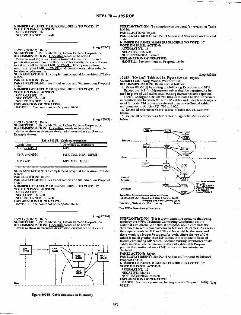
N F P A 7 0 - - A 9 5 R O P
NUMBER OF PANEL MEMBERS ELIGIBLE TO VOTE: 17 VOTE ON PANEL ACTION:
AFFIRMATIVE: 16 NOT RETURNED: Stilwell
(Log #2922) 16-212 - (800-53): Reject SUBMITI'F,R: L. Bruce McClung, Union Carbide Corporat ion RECOMMENDATION: ~ words to be a d d e d . .
Revise to read (b) Riser. Cables installed in vertical runs and pene t ra t ing more than one floor or cables installed in vertical runs m a shaft shall be Types CMR, ~ Floor penet ra t ions requir ing Types CMR, or CMRH shall contain only cables suitable for riser or p l e n u m use. SUBSTANTIATION: To c o m p l e m e n t proposal for revision of Table 800-50. PANEL ACTION: Reject. PANEL STATEMENT: See Panel Action and S ta tement on Proposal 16-68. NUMBER OF PANEL MEMBERS ELIGIBLE T O VOTE: 17 VOTE ON PANEL ACTION:
AFFIRMATIVE: 15 NEGATIVE: Hansell NOT RETURNED: Stilwell
EXPLANATION OF NEGATIVE: HANSELL: See c o m m e n t on Proposal 16-66.
(Log #2923) 16-213- (800-53): Reject SUBMITTER: L. Bruce McClung, Union Carbide Corporation RECOMMENDATION: ~ words to be added.
Revise to show an al ternate designat ion everywhere an R exists. Example shown.
Table 800-53. Cable Substitutions Cable Type Permitted Substitutions MRP o r ~ R H MPP
CMR o rCMRH MPP, CMP, MPR, MPRH
. MPG, MP MPP, MPR, MPRH
SUBSTANTIATION: To c o m p l e m e n t proposal for revision of Table 800-50. PANEL ACTION: Reject. . - PANEL STATEMENT: See Panel Action and S ta tement on Proposal 16-68. NUMBER OF PANEL MEMBERS ELIGIBLE T O VOTE: 17 "
VOTE ON PANEL ACTION: AFFIRMATIVE: 15 NEGATIVE: Hansell NOT RETURNED: Stiiwell
EXPLANATION OF NEGATIVE: HANSELL: See c o m m e n t on Proposal 16-66..
SUBSTANTIATION: To c o m p l e m e n t proposal for revision o f Table 800-50. PANEL ACTION: Reject. PANEL STATEMENT: See Panel Action and Sta tement on Proposal 16-68. NUMBER OF PANEL MEMBERS ELIGIBLE T O VOTE:' 17 VOTE ON PANEL ACTION:
AFFIRMATIVE: 15 NEGATIVE: Hansell NOT RETURNED: Stilwell
EXPLANATION OF NEGATIVE: HANSELL: See c o m m e n t on.Proposal 16-66.
(Log #2222) 16-215 - (800-53(f), Table 800-53, Figure 800-53): Reject SUBMITTER: Irving Mande, Westport , CT RECOMMENDATION: Revise text as follows:
1. Revise 800-53(0 by adding the following Exception and FPN. Exception: MP (mult ipurpose) cables shall b e p e r m i t t e d to be
used in place of CM cables until existing inventories are depleted. (FPN) Chahges to Article 760 have e l iminated all the differences
in requi rements between MP and CM cables and the're is no longer a need for both. CM cables are referred to as power-limited cable, mul t ipurpose in Articles 725,760 and 820.
2. Delete all references to MP cables in Table 800-53, as shown below.
3. Delete all references to MP cables in Figure 800-53, as shown below.
P lenum . . . . . . . -
,
.-- ,-!- - ~ ' ~ . "
Gene~l P u r ~ o s l . . . . "
Dwefltn~ ~ - - ~ ) s~tll ~.e ren"n~-..,'
TYDe ~ - - t'~mmunlcl~cr.s W i rn an," C,a=tes Tycu C.2 and ~ Q CI,sn 2 and Class " ~emote,..C::':.-:~.
Sil;;r.tling, l ad Pfws:- 'mitsC ¢,Jcles Tyl=e F~k-...POwer.Lim/~e,: Rre ' &l.ar= CicJes
Type ~.J"C - - PowllrdAmitrd Trlv e'81.-le
(Log #2924) 16-214- (800-53): Reject SUBMITI~R: L. Bruce McClung, Un i on Carbide Corporat ion RECOMMENDATION: ~ words to he added.
Revise to show an al ternate designat ion everywhere an R exists.
"SUBSTANTIATION: This is a compan ion Proposal to that being made by the NFPA Technical Correlat ing Commit tee on the National Fire Alarm Code that, if accepted, would el iminate the differences in requi rements between MP and CM cables. As a result, the reqifirements for MP and CM cables would be the same an d there would no longer be a need for both. Since the use of CM cables is m u c h greater than MP cables, this proposal is directed toward el iminat ing MP cables. Because existing inventories of MP cables meets all the r equ i i ement s for CM cables, this Proposal permits the cont inued use o f MP cables until inventories are depleted. PANEL ACTION: Reject. PANEL STATEMENT: See Panel Action on Proposal 16-202 an d Proposal 16-203. NUMBER OF PANEL MEMBERS ELIGIBLE T O VOTE: 17 VOTE ON PANEL ACTION:
AFFIRMATIVE: 15 NEGATIVE: Mande NOT RETURNED: Stilwell
EXPLANATION OF NEGATIVE: MANDE: See my explanat ion for negative for Proposal 16-202 (Log
#2221)
Figure 800-53 Cable Substi tution Hierarchy
842
. N F P A 70 - - A 9 5 R O P
ARTICLE 810 - - R A D I O AND TELEVISION E QUIP M E NT
(Log #2787) 16-216- (810-5): Reject SUBMITTER: Alfred A. Fiorello, Fiorello Electric Inc. RECOMMENDATION: Complete reference to Article 100. SUBSTANTIATION: In its p resen t format it doesn ' t mee t the NEC style manual . PANEL ACTION: Reject. PANEL STATEMENT: Submit ter did no t propose wording. The reference is in accordance with the style manual . NUMBER OF PANEL MEMBERS ELIGIBLE TO VOTE: 18 VOTE ON PANEL ACTION:
AFFIRMATIVE: 17 NOT RETURNED: Stilwell
16-217- (810-12): Accep t in Part (Log#590) SUBMITrI~R: Dan Leaf, Palmdale, CA RECOMMENDATION: Revise second and third sentences as follows: "The an tennas or lead-in conductors shall no t be a t tached to an above-the-roof raceway mast used for electric light or oower, or . Class 1 circuit conductors . Theysha l l no t be attache~l to poles or similar structures carrying open electric light or power, circuit conductors , or trolley wires, of over 250 volts between conductors". '
(changes under l ined) SUBSTANTIATION: Class 1 circuits may be reasonably cons t rued as not covered by "light or power" as indicated by explid~ notat ion or "Class 1" with "light or power" in many Code sections. Since Class 1 remote-controlasignalingcircuits are no t power-limited and may be 600 volts it seems reasonable to include t hem in this section. The weight, voltage, and power of non-service conductors at a raceway mast suppor t may equal or exceed that of service conductors a n d warrants a prohibi t ion of a t t achmen t of an t ennas and lead-in conductors . The FPN for Sec. 230-28 appears to be a nebulous basis for prohibi t ing a n t e n n a a t t achmen t to a raceway mast, s ince it is no t a rule, and not specifically referenced in this article. PANEL ACTION: Accept in Part.
I The Panel accepts the addit ion of the words "or lead-in conduc- Itors" after the word "antennas" in the 2nd sen tence of Section 810- 112. T h e Panel rejects the r emainder of the submit ter ' s proposal. PANEL STATEMENT: T h e Panel believes it is necessary to clarify that a n t e n n a lead-in conductors shall no t be a t tached to a mast. The Panel believes tha t the r emainder of the text offer no substantive change. Further , the submit ter ' s substant iat ion has not d o c u m e n t e d a p rob lem that shou ld be addressed. NUMBER OF PANEL MEMBERS ELIGIBLE TO voTE: 18 VOTE ON PANEL ACTION:
AFFIRMATIVE: 17 NOT RETURNED: Sdiwell"
(Log #591) 16-218- (810-20(b)): Reject SUBMITTER: Dan Leaf, Palmdale, CA RECOMMENDATION: Change "combustible" to "easily ignitable". SUBSTANTIATION: Edit. Present wording prohibits installaiion on or neai" wood surfaces of buildings or poles. Sec. 800-30(c) uses the phrase "easily ignitable" for a similar type device. PANEL ACTION: Reject. PANEL STATEME2qT: T he submi t te r has no t provided adequate technical substantiation. NUMBER OF PANEL MEMBERS ELIGIBLE TO VOTE: 18 VOTE ON PANEL ACTION:
AFFIRMATIVE: 17 NOT RETURNED: Stilwell
(Log #592) 16-219- (810-21 (a) and id)-(New)): Accept in Principle in Part S U B M Y I ' ~ R : Dan Leaf, Palmdale, CA RECOMMENDATION: Add the following to (a): "Aluminum or copper-clad a l u m i n u m g round i ng conductors shall no t be used where in direct contact with masonry or the ear th or where subject to corrosive conditions. Where used outside, a l u m i n u m or copper- clad a l u m i n u m shall no t be installed within 18 inches (457 r a m ) o f the earth".
Add the following to (d): "The g r o u n d i n g conductor shall no t be installed in cable a rmor or raceway o ther than rigid metal conduit , in termediate metal conduit , electrical metallic tubing, rigid nonmetal l ic conduit , or as a rmored g r o u n d i n g conductor cable identified for the use. Where run in a r m o r e d cable or metal raceway both ends o f the a r m o r e d cable or raceway shall be bond ed to the
g ound lng conduc to r or the same terminal and electrode to which e g r o u n d i n g conduc to r is connected."
SUBSTANTIATION: Where metal enclosures are used to enclose the g r o u n d i n g conduc to r requ i rements should be provided to ensure an adequate low i.mpedance cur ren t path.
Reswictions for a l u m i n u m and copper-clad a l u m i n u m g r o u n d i n g conductors are indicated in Sec. 250-92(a) for electric power systems, and if necessary for safety it would seem p r u d e n t an d reasonable to have similar restrictions in this article. PANEL ACTION: Accept in Principle in Part.
The Panel accepts the revision to Section 810-21 (a) as proposed. In
g lace of the submi t te r ' s text for (d), add the second sentence of ection 800-40(a)(5) which reads: "Where the g r o u n d i n g conduc to r is run in a metal raceway, both
ends of the raceway shall be b o n d e d to the g r o u n d i n g conductor or the same terminal or electrode to which the g r o u n d i n g conductor is connected."
The Panel rejects the r emainder of the proposal. PANEL STATEMENT: The Panel agrees with the submit ter ' s proposal foi" Section 810-21 (a): The wording the P a n d has taken f rom Section 800-40(a) (5) more adequately and accurately addresses the problem al luded to by this proposal. The Panel rejects the first sen tence of the submit ters text for Section 810-21(d) as being too restrictive and without substantiation. NUMBER OF PANEL MEMBERS ELIGIBLE TO VOTE: 18 VOTE ON PANEL ACTION:
AFFIRMATIVE: 17 N O T RETURNED: Stilwell
(Log #597) 16-220 - (810-21 (d)): Reject S U B ~ Dan Leaf, Palmdale, C_A RECOMMENDATION: Insert "likely to be" between "where" and "exposed". SUBSTANTIATION: Edit. A location that will, in an absolute sense, be subject to damage , is difficult or impossible to determine. Anything tha t exists is/subject to damage. In the panel c o m m e n t on Proposal 5-73 in the 1992 TCR they indicated the phrase "likely to be" allowed for probability and is in t ended to exclude c6nsiderat ion of ALL possibilities, no mat ter how remote. Secs. 110-3(a)8, 110- 16 (a) (b) (d), 110-34(d), 250-42, 250-70, 250-112, 250-117(a), 370- 72(0,384-5, 410-57(e), 410-90, 422-8(a), 424-14, 513-6(a)(b), 517-11, 600-33(c) are examples where "likely", "normally", "probability" are used to provide a criterion for j udgemen t - PANEL ACTION: Reject. PANEL STATEMENT.. The Panel believes the proposal provides no improvemen t over the p resen t wording. An appropr ia te j u d g m e n t is required with ei ther the p resen t wordi~ag or t h e p r o p o s e d wording. NUMBER OF PANEL MEMBERS ELIGIBLE TO VOTE: 18 VOTE ON PANEL ACTION:
AFFIRMATIVE: 17 ' N O T RETURNED: Stilwell
(Log #593) 1 6 - 2 2 1 - (810-21(0): Reject SUBMI'IWER: D a n Leaf, Palmdale, CA RECOMMENDATION: Revise as follows: "(f) ELECTRODE. The g r o u n d i n g conduc to r shall be connec ted
at an accessible location to one of the following: (1) ttie bui lding or s t ructure g r o u n d i n g electrbde system as covered in Section 250-81; (2) the g r o u n d e d interior metal water piping system as covered in Section 250.80(a); (3) the service accessible m e a n s external to enclosures as covered in Section 250-71 (b); (4) the metal service raceway, if a rigid type; (5) the metal service e q u i p m e n t enclosure; (6) the g r o u n d i n g electrode conduc to r or the metal raceway . enclosing the g r o u n d i n g electrode conductor; (7) the g r o u n d i n g conductor or metal raceway enclosing the g round ing conductor , or the g r o u n d i n g electrode, or the metal enclosure of the bui lding or s t ructure d isconnect ing means which is connec ted to the g ro u n d in g electrode, as covered in Section 250-24; (8) any o f the individual electrodes descr ibed in Section 250-83, where separa ted not less than 6 feet (1.83 m) f rom other electrodes and bonded t 9 o ther existing electrodes.
843

N F P A 70 - - A 9 5 R O P
For purposes of this section, the mobile h o m e disconnect ing means as degcribed in Section 550-23 shall be considered accessible fl SUBSTANTIATION: Edit. The p r e s e n t w o r d i n g d o e s n o t s p e c i f y "one" of the listed g round i ng points nor is there an "or" between the listed g round ing points, thus it appears to require the g r o u n d i n g conductor to b d d o n n e c t e d to each of the locations specified. The proposal indicates any (one) of the points may be us&L
In (3) and (4) the word "power" is deleted to eliminate a possible inferred distinction between "power" and "lighting". In ( 4 J a n d (6) "rigid type" and "metal raceway" i sp roposed since flexible type service raceways or g round i ng conductor a rmor do no t prowde a suitable g round ing path. In (7) suitable g r o u n d i n g c o n d u c t o r raceways and bui lding disconnectin, g means, are included. In (8) electrodes of Sec. 250-83 are included as m the present (f)(3), and additionally to permit these electrodes even where the points of (1) th rough (7) are available. This will permi t preferable shor t and direct runs to such electrodes if they are bonded to o ther available electrodes, and eliminate possible long and circuitous rout ing of the g round ing conductor . It also providedfor permit ted use of these ~lectrodes where none specified in (1) th rough (7) are available.
The present (0 (2) is no t clear since it states in effect, if the g round ing electrode system as covered in Sec. 250-81 does no t exist, any of the electrodes described in Sec. 250-81 may be used. PANEL ACTION: Reject. PANEL STATEMENT: See Panel Action and Sta tement on Proposal 16-189. NUMBER OF PANEL MEMBERS ELIGIBLE T O VOTE: 18 VOTE ON PANEL ACTION:
AFFIRMATIVE: 17 NOT RETURNED: Stilwell
(Log #1212) 16-222- (810-21(h)): Reject SUBMITTERa William.J2. Kessler, Kessler and G e h m a n Associates, Inc. RECOMMENDATION: Substitute the following s ta tement at 810- 21(h):
The g round ing conductor shall no t be smaller than No. 10 copper or No_8 a l u m i n u m or equivalent. SUBSTANTIATION: Tile reference to flae use of No. 17 copper- clad steel or bronze shou ld be deleted. No. 17 copper-clad steel or bronze wire is in ~ equivalent to No. 10 copper or No. 8 a l u m i n u m wire. Fur thermore the percentage o f copper-clad to steel is no t stated for the copper-clad steel conductor or the ratio of copper-to-tin stated for the bronze conductor .
NOTE: Suppor t ing material is available for review at NFPA Headquarters. PANEL ACTION: Reject. • PANEL STATEMENT: The sizes of conductors have been chosen for strength_ and durability. The purpose o f this conduc tor is to provide a discharge path for static charges tha t may develop on the an t enna system. NUMBER OF PANEL MEMBERS ELIGIBLE T O VOTE: 18 VOTE ON PANEL ACTION:
AFFIRMATIVE: 17 NOT RETURNED: StilweU
ARTICLE 820 - - COMMUNITY ANTE]QNA TELEVISION AND RADIO DISTRIBUTION SYSTEMS
(Log #735) 16-223- (820-7-(New)): Reject SUBMITTER: Dan Leaf, Palmdale, CA RECOMMENDATION: Add:
"820-7. RACEWAYS. Where coaxial cable is installed in a raizeway, the raceway shall be of a type permit ted in Chapter 3 and installed in accordance with Chapter 3." SUBSTANTIATION: Section 770-5 contains requi rements for raceways enclosing optical fiber cables; isn ' t it reasonable to have o- requirements for raceways enclosing coaxial cable? There are no recluirements for raceways enclosing only coaxial cable, bu t if insLalled in a raceway with optical fiber cable the requi rements of Sec. 770-5 would apply. The feasibility of us ing Sec. 820-6 to enforce suppor t requirements , n u m b e r of bends, etc., is doubtful since it is stib[ect to siibjective and widely different interpretation. PANEL ACTION: Reject. PANEL STATEMENT: See Panel Action and Sta tement on Proposal 16-172. NUMBER OF PANEL MEMBERS ELIGIBLE TO VOTE: 18 VOTE ON PANEL ACTION:
AFFIRMATIVE: 17 NOT RETURNED: Stilwell
(Log #598) 16-224- (820-10(a), (b), and (e)(1)): Accept in Principle SUBMITTERa Dan Leaf, Palmdale, CA RECOMMENDATION: In (a) insert "or Class 1 circuit" between "power" and "conductors".
In (b) insert "or Class 1" between "power" and "circuits". In (e ) ( i ) insert "or Class 1 circuit" be tween "power" and "conduc-
tors". SUBSTANTIATION: Class 1 circuits may be cons t rued as n9 t covered by "light or power" as indicated by specific notat ion of "Class 1" in Secs. 820-11 (a)(b), 820-52(a)(1) and (a)(2)b, and Note 8(a) Ex. No. 1 to Tables 310-16 to 310-19 which indicate power and lighting conductors (Arts. 210, 215, 220, 230) do no t include Art. 725 conductors. Since Class 1 remote-cont ro l / s igna l ing circuits are notpower- l imited and may be 600 volts, it seems reasonable and p ruden t to include t hem in separat ion requirements .
The FPN to Sec. 230-29 is no t a rule, and per Sec. 90-3 would not be b inding on this article if it was a rule unless specifically referenced. The proposal is ho t l imited to a "service" mast, and would be helpful to CATV installers. PANEL ACTION: Accept in Principle.
In 820-10(a),. revise text to read in part: "...located below the electric light, power, Class 1, or nonpower-
limited fire protective signaling circuit conductors and shall no t be..."
In 820-10(b), revise text to read in part: "...kept away f rom electric light, power, Class I, or nonpower-l imited
fire protective signaling circutt conductors so as to avoid..." In 820-10(b), Exception, revise text to read in part: "...proximity to electric light, power, Class I, or nonpower-l imited
fire protective signaling circuit service conductors canno t be...12 inches (305 m m ) f r o m light, power, Class I, or nonpower-l imited fire protective signaling circuit service drops." .
In 820-10(e)(i), revise text to read in part: "...least 4 inches (102 ram) f rom electric light, power, Class l, or
non power-limited fire protective signaling circuit conductors not in raceway or cable..." PANEL STATEMENT: Separation concerns also include nonpower- limited fire protective signaling circuit conductors as well as Class I circuit conductors. NUMBER OF PANEL MEMBERS ELIGIBLE TO VOTE: 18 VOTE ON PANEL ACTION:
AFFIRMATIVE: 17 NOT RETURNED: Stiiwell
(Log #67) 16-225 - (820-10(b))- Reject
Note: The following proposal consists of C o m m e n t 16-158 on Proposal 16-383 in the 1992 Annual Meet ing National Electrical Code Technical Commit tee Report. This C o m m e n t was he ld for fur ther study dur ing the process ing of the 1993 NATIONAL . ELECTRICALtCODE. The r ecommenda t ion in Proposal 16-383 was:
Add to the p~ag raph : The vertical clearance f rom g r o u n d shall comply with the require-
ments of 230-24(b). SUBMITTERa L. H. Sessler, Exchange Carriers Standards Associa- tion RECOMMENDATION: Hold for fur ther s t u d y a n d refer to the Joint NEC-NESC Commit tee for Harmonizat ion. SUBSTANTIATION: Vertical clearances of CATV overhead conductors shou ld be coordinated with the NESC since there is an overlap of scopes. See the negative comments of A n n a and Bagnall. PANEL ACTION: Reject. PANEL STATEMENT: See Panel Action and Sta tement on Proposal 16-179. NUMBER OF PANEL MEMBERS ELIGIBLE TO VOTE: 18 VOTE ON PANEL ACTION:
AFFIRMATIVE: 17 N O T RETURNED: StilweU
(Log #594) 16-226- (820-40(a) (2) and (a) (5)): Reject SUBMrVI'ER: Dan Leaf, Palmdale, CA RECOMMENDATION: Add the following to (a) (2): "Aluminum or copper-clad a l u m i n u m g round ing conductors shall no t be used where in direct contact with masonry or the earth or where subject to corrosive conditions. Where usedou ts ide , a l u m i n u m or copper- clad a l u m i n u m shall no t be installed within 18 inches (457 ram) of the earth".
844
N F P A 70 - - A 9 5 R O P
Add the following to (a)(5): "The grounding conductor shall not be installed in cable armor or raceway other than rigid metal conduit, intermediate metal conduit, electrical metallic tubing, rigid nonmetallic conduit, or as a rmored grounding conductor cable identified for the use. SUBSTANTIATION: Restrictions for a luminum and copper-clad aluminum grounding conductors are indicated in Sec. 250-92(a) for electric power systems, and if necessary for safety it would seem reasonable and prudent to have similar restrictions in this article.
Unless it is in tended to allow any "(flexible) raceway or cable armor to enclose the grounding conductor, specific requirements should be provided. " PANEL ACTION: Reiect. PANEL STATEMENT: Aluminum and copper clad aluminum conductors are already excluded as they are not corrosion resistant. The submitter has not substantiated the proposed change to.Section
ANEL GIBLE TO VOTE: 18 VOTE ON PANEL ACTION:
AFFIRMATIVE: 17 NOT RETURNED: Stilwell
(Log #595) : 16-227- (820-40(b)): Reject SUBMITTER: Dan Leaf, Palmdale, CA RECOMMENDATION: Revise as follows:
"ELECTRODE. The grounding conductor shall be connected at an accessible Iocz/tion to one of the following: (1) the building or structure grounding electrode system as covered in Section 250-81; (2) the g rounded interior metal water piping system as covered in . Section250-80(a); (3) the service accessible haeans external to enclosures as covered in Section 250-71 (b); (4) the metal service raceway, if a rigid type; (5) the metal service equipment enclosure; (6) the grounding d_ectrode conductor or th/: metal raceway enclosing the grounding electrode conductor; (7) the grounding conductor or metal raceway enclosing the grounding cbnductor, or the grounding electrode, or the metal encl-osure of the building or structure disconnecting means which is connected to the grounding electrode, as covered ifi Section 250-24; (8) any of the individual - electrodes described in Section 250-88, where separated not less than 6 feet (1.88 in) f~om other electrodes and t ionded to other existing electrodes." SUBSTANTIATION: Edit. The present wording does not specify "one" of the listed grounding points nor is there an "or" between tile listed grounding points, thus it appears to require the grounding conduc- tot to b d c o n n e c t e d to eaizh of the locations spec- ified. The proposal indicates any (one) of the points may be used.
In (3) and (4) the word "power" is deleted to eliminate a possible inferred distinction between "power" and "lighting". In ( 4 ) and (6) "rigid type" and "metal raceway" is proposed since flexible type service raceways or armor d ° no t provide a suitable grounding path.
In (7) suitable grounding condu-ctor raceways andbu i ld ing - disconnecting means are included. In (8) electrodes of Sec. 250-83 are included as in the present (b) (3), and additionally to permit these electrodes.even where the points of (1) through (7) are available. This will permi t preferable short and direct runs to such electrodes if they are bonded to other available electrodes, and eliminate possible long and circuitous routing of the grounding conductor, it also provides for permit ted use of these electrodes where none specified in (1) through (7) are available.
The present (b) (2) is not clear since it states in effect, if the grounding e lec~ode system as covered in Sec. 250-81 does no t exist, any of the (nonexisting) electrodes described in Sec. 250-81 may be used. PANEL ACTION: Reiect. ' PANEL STATEMENT: See Panel Action and Statement on Proposal 16-189. NUMBER OF PANEL MEMBERS ELIGIBLE TO VOTE: 18 VOTE ON PANEL ACTION:
AFFIRMATIVE: 17 NOT RETURNED: Stilwell
(Log #2925) 16-228- (820-50): Reject SUBMITTER: L. Bruce McClung, Union Carbide Corporation RECOIVIIVIENDATION: ~ w o r d s to be added.
Modify and add to t a b l e . .
Table 820-50 Cable M a r k i n g s
C . a b l e T y p e R e f e r e n c e
Marking CATVR CATV riser cable Secdons 820-51 (b) ( .D. and
820-53(b) ~TVRH CATV reduced hazard ijser Secdons 820-51(b~ f2~ an d
cable 8~Sa tb~
SUBSTANTIATION: Fire resistance is not the only characteristic by which to measure fire safety of cables. A combustion of fire safety characteristics can result in an overall safer condition thanjf is t fire resistance. Therefore at least three characteristics for which standardized tests are available should be evaluated to recognize a reduced hazard riser cable that is as safe or safer to utilize than the present Types CL2R and CL34 which are listed on the basis of fire resistance only. The need for also limiting smoke and corrosivity is demonstra ted by conditions described in the copies of fire report- in :
~hapel of the Holy Cross in Sedona, Arizona, October 20, 1992. JBOhn Hancock's home office in Boston, August 24, 1992.
makers Trust building in Manhattan,July 20, 1989. Columbia Seafirst Center in Seattle, July 26, .1988.
.~ohn F. Kennedy Federal building in Boston, July 8, 1988. Ilinois Bell's central office inHinsdale , Illinois, May 8, 1988.
Business Insurance Reports of May 29, 1990. PANEL ACTION: Reject. PANEL STATEMENT: See Panel Action and Statement on Proposal 1 6-68. NUMBER OF PANELMEMBERS ELIGIBLE TO VOTE: 18 VOTE ON PANEL ACTION:
AFFIRMATIVE: 16 NEG~,TIVE: Hansell NOT RETURNED: Stilwell
EXPLANATION OF NEGATIVE: • HANSELL: See comment on .Proposal 16-66.
(Log #2926) 16-229- (820-51): Reject SLIBMI'Iq~R: L. Bruce McClung, Union Carbide Corporation
• RECOMMENDATION: Renumber as (b)(1) Type CATVR. SUBSTANTIATION: To mfike a place (way) to add (b) (2) Type CATVRH. PANEL ACTION: Reject. PANEL STATEMENT: See Panel Action and Statement on Proposal 1 6-68. NUMBER OF PANEL MEMBERS ELIGIBLE TO VOTE: 18
, VOTE ON PANEL ACTION:. AFFIRMATIVE: 16 NEGATIVE: Hansell NOT RETURNED: Stilwell
EXPLANATION OF NEGATIVE: HANSELL: See comment on Proposal 16-66.
(Log #2927) 16-280- (820-51(b)(2)-(New)): Reject SUBMYFrER: L. Bruce McClung, Unior/Carbide Corporation R E C O I ~ N D A T I O N : Add (b) (2) Type CATVRH.
(b)(2) Type CATVRH. Type CATVRH community anten'na television riser cable shall be listed as being suitable for use in a vertical run in a shaft or from f o o r to floor and shall also be listed as having adeante fire resistant characteristics capable of preventing the spread of fire or products of combustion from flooi" to tool ' . (FPN): A combination of fire safety features can result in a reduced
hazard. One method of defining resistant to spread of fire is that the cables do not spread fire to the top of the tray in the 'Wertical- Tray Flame Test" in the Reference Standard for Electrical Wires, Cables and Flexible Cords ANSI/UL 1581-1985. One method of
. . ' ~ . . . d e f m n g both resistant to spread of fire and hmlted smoke is that the cables pass the "UL Flame Exposure Fire Tests" in reference Vertical Tray Fire Propagation and Smoke-Release Test for Electrical and Optical-Fiber Cables UL 1685-1992. Ohe method o f d e f n i n g limited corrosivity is by the results of direct exposure of resistivity probes to acid gas generated by the cables when tested in accordance with ASTM E.5.21.70. SUBSTANTIATION: Fire resistance is not the only characteristics by which to measure fire safety of cables. A combination of fire safety characteristics can result in an dye .rail safer condition than just fiire resistance. Therefore at least three characteristics for which standardized tests are available should be evaluated to recognize a reduced hazard riser cable that is as safe or safer to utilize than the present Types CL2R and GL3R which are listed on the basis of fire resistance only.
Reduced hazards from a fire safety viewpoint must incorporate ignitability, progation, heat release, smoke, corrosivity and toxicity.
845 • m

N F P A 7 0 - - A 9 5 R O P
The better product will be the one that meets the m i n i m u m acceptable s tandards in each category. Until accepted consensus s tandards for measur ing all six categories are available the industry should concentrate on measur ing and evaluating applications based on the categories that can be satisfactorily measured. See copy of summary of North American and European Fire Tests for Cables and Cable Materials for consensus as well as c o m m o n test protocols to measure ease of ignition, f lame spread, hea t release rate, smoke, corrosivity and toxicity. PANEL ACTION: Reject. PANEL STATEMENT: See Panel Action and S ta tement on Proposal 16-68. NUMBER OF PANEL MEMBERS ELIGIBLE T O VOTE: 18 VOTE ON PANEL ACTION:
AFFIRMATIVE: 16 NEGATIVE: Hansell NOT RETURNED: Stilwell
EXPLANATION OF NEGATIVE: HANSELL: See c o m m e n t on Proposal 16-66.
(Log #2712) 16-231 - (820-51 (c), FPN): Reject SUBMITTER: Marcelo M. Hirschler, Safety Engineer ing Laborato- ries, Inc. RECOMMENDATION: Revised text for the fine pr int note:
(FPN): One m e t h o d of def in ing resistant to spread of fire is that the.cables do no t spread fire to the top of the tray in the "Vertical Tray Flame Test" in the Reference Standard for Electrical Wires, Cables and Flexible Cords, ANSI /UL 1581-1985. ~ d l g x I l B l i ~ w ~ . m a x i m u m heat release rate of the cables, as tested in the "Standard for Testinit for Smoke Obscurat ion Caused bv Burn ing Cables in a Vertical Coo_fit_rotation." ASTM D5424 (Protocol AL shall no t exceed 100 kW. Another m e t h o d of def in ing resistant to the spread of fire is for the
damage (char length) not to exceed 4 feet, 1 inches (1.5 m) when per forming the C_,SA "Vertical Flame Tes t - Cables in Cable Trays," as described in Test Methods for Electrical Wires and Cables, CSA C22.2 No. 0.3-M-1985. Alternatively. the m a x i m u m hea t release I'~;¢ of the cables, as tested in the "Standard for Testin~ for Smoke Obscurat ion Caused by Burn ing Cables in a VerticSal Configuration." ASTM D5424 (Protocol BL sha'fl no t exceed 100 kW, v
Anothe r m e t h o d of definin~ resistant to the soread of fire is for the m a x i m u m heat release rate ~er un i t area of the cables, as tested, at an incident flux of 40 kW/rfi2, accordin~ to "Standard Test Method for Heat and Visible Smoke Release Rat~s for Material~ and Produc~s Usinlt an O x w e n Consumpt ion Calorimeter." ASTM E1354. no t to exceed 200 I(~//m2."
This replaces the present FPN, text in "underl ine" is to be added. SUBSTANTIATION: It has now been shown that hea t release rate testinl~ is an al ternate way to de te rmine whether a cable resists the spreact of fire.
O n e of the first q u, estions a person might wish to ask about the hazard of a fire is How big is the fire?" Until fairly recendy there . was no quantitative way of answering this question. Nowadays, we know that, in quantitative terms, this quest ion is equivalent to asking, "What is the heat release rate of the fire?"
An example may explain the impor tance of hea t release rate. I f a cable tray were bu rn ing outdoors, with no combust ible products a round it, it may burn, the immedia te consequence of its burn ing will be minimal: no th ing else will be ignited. On the other hand , if the same cable tray is inside a compartrnent , once it starts burn ing it may ignite a nearby product, if it releases (gives off) e n o u g h heat and does it fast enough , ff the bu rn ing cables release hea t slowly, the cooler air a r o u n d t h e m may be cold e n o u g h to avoid raising the tempera ture f the nearest p roduc t for it to start burning, ff the cables release hea t even faster, they could go beyond causing the nearest product to burn, but they could also ignite o ther products fur ther away. As more products burn, the fire gradually becomes more intense. In the same spirit, as more things are burning, more smoke is emitted. This means the visibility in the room decreases, m a k i n g i t more difficult for people to escape and more difficult for fire fighters to come in and help potential fire victims, f f m o r e smoke is emitted, the air in the room also becomes more toxic, which can also cause a bigger threat to the people in the room.
Recent work, u s i n g a large n u m b e r of cables of different types, has shown that every cable that has had a peak heat release rate of less than 100 kW, when tested according to ASTM D5424, Standard for Test ing for Smoke Obscurat ion Caused by Burning Cables in a Vertical Configuration, has ~ the cable tray test, as regards char length. Moreover, it has also been shown that every cable which, when tested in the cone calorimeter, S tandard Test Method for Heat
and Visible Smoke Release Rates for Materials and Products Using an Oxygen Consumpt ion Calorimeter," ASTM E1354, at an incident flux o f 40 k W / m 2, has had a peak heat release rate no t exceeding 200 k W / m 2, has ~ the cable tray test, as regards char length.
In fact, it is likely that cables with even somewhat h igher hea t release rates rn~.y pass the test, in mos t cases. However, the above criteria are being suggested as very conservative estimates, with a significant margin o f safety, for those users interested in having. cables listed while testing less material.
It is also possible to obtain heat i'elease rate results by testing smaller lengths of cable in a bench-scale test. Thus, I feel tha t the fine pr int note needs to be modif ied to express these ideas, as stated above.
NOTE: Suppor t ing material is available for review at NFPA Headquarters . PANEL ACTION: Reject. PANEL STATEMENT: The substant iat ion for this proposal is based upon a l imited a m o u n t of data and presents a l imited correlation. At the present time, the scatter of data shows that the cone calorimeter should only be used as a research tool for the develop. men t of products and materials. There is no ag reemen t within the fire communi ty to substantiate that the cone calorimeter can adequately evaluate early stages and full scale firi. ~ per formance characteristics of wire and cable. NUMBER OF PANEL MEMBERS ELIGIBLE T O VOTE: 18 VOTE ON PANEL ACTION:
AFFIRMATIVE: ] 7 NOT RETURNED: Stilwell
' (Log #736) 16-232- (820-52, Exception-(New)): Accept in Principle SUBMITTER: Dan Leaf, Palmdale, CA RECOMMENDATION: Revise as follows:
Raceways or cables shall no t be used as a means of suppor t for coaxial cables no t enclosed in the raceway or cable, no r shall piping systems which convey air, liquid, vapor, or o ther substance be used as a means of support ."
Exception: Aerial cable shall be permit ted to be a t tached to an above-the-roof raceway mast which does not enclose conductors of electric light or power or Class 1 circuits." SUBSTANTIATION: ff the intent is to require i n d e p e n d e n t support , o ther cables and piping systems should be included as not suitable. The present wording can be inferred as prohibi t ing cable in raceway or a t tached to a raceway mast (supported) at a transit ion to open aerial wiring.
' PANEL ACTION: Accept in Princiole. [ Add an Exception to section 820-5~(e) as follows: I "Aerial cable shall be permi t ted to be a t tached to an above-the-roof I raceway-mast which does not enclose or suppor t conductors of | electric light or power circuits."
PANEL STATEMENT: The Panel believes the submit ter should have referenced Section 820-52(e). The in tent of the submit ter ' s revised text for Section 820-52(e) is me t by the action taken on Proposal 16-15. Also, the Panel has revised the wording for the
~ roposed Exception to more accurately express the in tent of this xception.
NUMBER OF PANEL MEMBERS ELIGIBLE T O VOTE: 18 VOTE ON PANEL ACTION:
AFFIRMATIVE: 17 NOT RETURNED: Stilwell
(Log #596) 16-233- (820-52(a)(3)): Aci:ept in Principle SUBMITTER: Dan Leaf, Palmdale, CA RECOMMENDATION: Insert "or Class 1 circuits" between "~ower" and "shall" in the text and between "power" and "conductors in Ex. No. 2. SUBSTANTIATION: Class 1 circuits may be cons t rued as no t covered by "light" or "power", as indicated by specific use of "Class 1" in Sees. 820-11(a) (b), 820-52(a) (1),(a) (2)(b) and Note 8 (a) Ex. No. 1 to Ampacity Tables of 0 to 2000 volts which indicate power an d l ighting conductors (Arts. 210, 215,220, and 2B0) do no t include Art. 725 conductors. Since Class 1 remote-control and signaling circuits are no t power-limited and may be 600 volts, per Sec. 725- 11 (b) it seems reasonable to include t hem in separat ion require- m e a t s . PANEL ACTION: Accept in Principle.
[ Revise Section 820-52(a) (3) as follows: ' [ "In Shafts. Coaxial cables run in file same shaft with conductors of
lelectric light, power, Class 1, or nonpower-l imited fire alarm circuit
846

N F P A 70 - - A 9 5 R O P
conductors shall be separated from electric light, power, Class 1, or nonpower-limited fire alarm circuit conductors by not less than 2 inches (50.8 mm)~"
Revise 890-51 (a)(3) Exception No. 2 as follows: '~Vhere electric light, power, class 1, or nonpower-limited fire
alarm circuit conductors are in raceway, or in metal-sheathed, metal z clad, nonmetal iosheathed, or Type UF cables." PANEL STATEMENT: The Panel believes that the correction meets
• the intent of the submitter and correlates this section with Article 760. NUMBER OF PANEL MEMBERS ELIGIBLE TO VOTE: 18 VOTE ON PANEL ACTION:
AFFIRMATIVE: 17 NOT RETURNED: Stilwell
, (Log #509) 16-234- (820-52(a)(3)): Accept in Principle SUBMITTER: Dan Leaf, Palmdale, CA RECOMMENDATION: Insert "or Class I circuits" between "~ower" and "shall" in the text and between "powcr" and "conductors in Ex. No. 2.. SUBSTANTIATION: Class.1 circuits may be reasonably construed as not covered by "light or power" as indicated by explicit notation of "Class 1" with "light.or power" in many Code sections. S!nce Class 1 remote-control /s ignaling circuits are not power-limited and may be 600 volts it seems reasonable to include them in this section. PANELACTION: Accept in Principle. PANEL STATEMENT: See Panel Action on Proposal 16-233. NUMBER OF PANEL MEMBERS ELIGIBLE TOVOTE: 18 VOTE ON PANEL ACTION:
AFFIRMATIVE: 17 NOT RETURNED: Stilwell
NUMBER OF PANEL MEMBERS ELIGIBLE TO VOTE: 18 VOTE ON PANEL ACTION:
AFFIRMATIVE: 16 NEGATIVE: Hansell NOT RETURNED: StilweU
EXPLANATION OF NEGATIVE: HANSELL: See comment on Proposal 16.66.
(Log #1562) 16-237- (820-53(d)): Reject SUBMITI'ER: Eddy Houston, CommScope, Inc. RECOMMENDATION: Substitutes to include:
CATVP-MPP, CMP, CL2P: CATVR- CATVP, MPP, CMP, CL2P, MPR, CMR, CL2R: CATV-CATVP, MPP, CMP, CL2P, MPR, CMIL CL21L CATVR, MPG, NIP, CMG, CM, CL2: CATVX-CATVP, MPP, CMP, CL2P, CA'IVR, MPR, CL21L CMR, CATV, MPG, NIP, CMG, CM, CL2 SUBSTANTIATION: Coaxial cables listed per class 2 Power Limited Circuit Cables meet or exceed the requirements of Article 820.
PLCC cables are routinely used for CATV "Type' application substitution would eliminate the need for 2 types of s~milar condu ctors. PANEL ACTION: Reject PANEL STATEMENT: Class 2 cables have no voltage ratings whereas all the.other cables in the table havc a 300 volt rating. NUMBER OF PANEL MEMBERS ELIGIBLE TO VOTE: 18 VOTE ON PANEL ACTION:
AFFIRMATIVE: 17 NOT RETURNED: Stilwell
(Log #2928) 16.235- (820-53): Reject . : SUBMI'FrER: L. Bruce McClung, Union Carbide Corporation RECOMMENDATION: Underl ine words to be added.
Revise to read (b) Riser. Cables installed in vertical runs and penetrat ing more than one floor, or cables installed in vertical runs in a shaft shall be Types CATVR, or CATVRH. Floor penetrations requiring Types CATVR, or ~ T V R H shall contain only cables suitable for riser or p lenum use. SUBSTANTIATION: To complement proposal for revision of Table 820-50. ' PANEL ACTION: Reject PANEL STATEMENT: See Panel Action and Statement on Proposal 16-68. NUMBER OF PANEL MEMBERS ELIGIBLE TO VOTE: 18 VOTE ON PANEL ACTION:
AFFIRMATIVE: 16 NEGATIVE: Hansell NOT RETURNED: Stilwell
EXPLANATION OF NEGATIVE: HANSELL: See comment on Proposal 16-66.
(Log #2929) 16.230- (820-53): Reject SUBMI'gTER: L. Bruce McClung, Union Carbide Corporation RECOMMENDATION: ~ w o r d s to be added.
Revise to show an alternate designation everywhere an R exists. Example shown.
Table 800-53. Cable Substitutions Cable Type CATVR 9r CATVRH
CATV
Permitted Sul~titutions CATV, MPP, CMP, MPR, ~ CMR, CMRH
CATVP, MPP, CMP, CATVR, ~TVRH. MPR. MPRI-L C~. C~. MPG, MP, CMG, CM
I
SUBSTANTIATION: To complement proposal for revision of Table 820-50. PANEL ACTION: Reject PANEL STATEMENT: See Panel Action and Statement on Proposal 16-68.
(Log #2223) 16-238- (820-53(d)): Reject ' .. SUBMITI'ER: Irving Mande, Westport, CT RECOMMENDATION: Revise 820-53 as follows:
1. Delete 820-53 (d) and replace with: (g) Cables substitutions. CM (power-limited Cables , M
ultipurpose) coaxial cables shall be permit ted to be substituted for CATV coaxial cables as shown in Table 820-53 and Figure 820-53.
Exception: MP (multipurpose) coaxial cables shall be permit ted to be used in place of CM coaxial cables until existing inventories are depleted.
(FPN) changes to Article 760 have eliminated all the differences in requirements between MP and CM cables and there is no longer a need for both. CM cables are referred to as Communications Cables in Article 800.
2. Delete all references to MP coaxial cables i n Table 820-53, as shown below.
Table 820-55. Coaxial Cable Suh~tmlons
Cable "I~e Permitted Sdbsfitutions
CATVP CMP CATVR CATVP, CMP, CMR CATV CATVP, CMP, CATVR. CMR, CMG. CTI CATVX . CATVP, CMP, CATVR, CMR, CATV. CMG, CM
SUBSTANTIATION: This is a companion Proposal to that being made by the NFPA Technical Correlating Committee on the National Fire Alarm Code that, if accepted, would eliminate the differences in requirements between MP and CM cables. As a result, the requirements for MP and CM cables would be the same and there would no longer be a need for both. Since the use of CM cables is much I;~reater than MP cables, this proposal is directed toward elimihaung MP cables. Because existing inventories of MP cables meets all the requirements for CM cables, this Proposal dPermits the cont inued use of MP cables until inventories are
epleted. PANEL ACTION: Reject PANEL STATEMENT: See Panel Action on Proposal 16-202 and ~ 16.203.
R OF PANEL MEMBERS ELIGIBLE TO VOTE: 18 VOTE ON PANEL ACTION:
AFFIRMATIVE: 16 NEGATIVE: Mande NOT RETURNED: Stilwell
847

N F P A 70 - - A 9 5 R O P
E X P L A N A T I O N O F NEGATIVE: MANDE: See my e x p l a n a t i o n for nega t ive for Proposa l 16-202 (Log
#2221 )
C H A P T E R 9 - - TABLES AND EXAMPLES
(Log #1976) 6-173- ( C h a p t e r 9, Par t A Tables , Notes to Tables) : A c c e p t
Note : It was the ac t ion of the T e c h n i c a l C o r r e l a t i n g C o m m i t t e e t h a t this P roposa l be r e f e r r e d to Code -Mak ing P a n e / 8 for ac t ion. Th is ac t ion will be c o n s i d e r e d by the Pane l as a Publ ic C o m m e n t . SUBMITTER= R o n a l d IL Runkles , Na t iona l .E lec t r i ca l Manufac tu r - ers Associa t ion R E C O M M E N D A T I O N : In C h a p t e r 9, Par t A, Tables , Notes to Tablesi revise all no tes to tables a n d table 1 ( i n c l u d i n g notes) as shown:
Table 1. Percent of Cross Section of Conduit and T u b i n g for Conductors
Number of Conductors 1 2 Over 2
All Conductor Types 53 31 40
Note 1: See Appendix G for condui t and tubing dimensions and for maximum number of conductors and fixture wires permitted in trade sizes of the applicable condui t or tubing.
Note 2: Table 1 applies only to complete condui t or tubing systems and is not intended to apply to sections of conduit or tubing used to protect exposed wiring from physical damage.
Note 3: Equipment grounding or bonding conductors, where installed, sha l lbe included when calculating conduit or tubing filL The actual dimensions of the equipment grounding or bonding conductor (insulated or bare) shall be used in the calculation.
Note 4: Where conduit or tubing nipples having a maximum length not to exceed 24 inches (610 ram) are installed between boxes, cabinets, and similar enclosures, the nipples shall be permitted to be filled to 60 percent of their total cross-sectional area, and Article 310, Note 8(a) of Notes to Ampacity Tables of 0 to 2000 Volts need not apply to this condition.
Note 5: For conductors not included in Chapter 9, such as multiconductor cables, the actual dimensions shall be used.
Note& For combina t ionsofconduc torsofd i f fe ren t sizes, use Tables 5 and 5A in Chapter 9 for dimensions of conductors and Appendix C, Table CI for the applicable condui t or robing dimensions.
Note 7: Where the calculated conductors, all of the same size (total cross-sectional area including insulation), include a decimal fraction, the next higher whole number shall be used where this decimal is 0.8 or larger.
Note 8: Where bare conductors are permit ted by other sections of this Code, the dimensions for bare conductors in Table 8 of Chapter 0 shall bepermit ted.
Note 9: A mult iconductor cable of two or more conductors shall be treated as a single conductor for calculating percentage condui t fill area. For cables that have elliptical cross sections, the cross - sectional area calculation shall be based on using the major diameter of the ellipse as a circle diameter.
(FPN): Table 1 is based on common conditions of proper cabling and al ignment of conductors where the length of the pull and the number of bends are within reasonable limits. It should be . recognized that, for certain conditions, a larger size conduit or a lesser condui t fill should be cons idered .
S U B S T A N T I A T I O N : Th i s is a c o m p a n i o n p roposa l to t h a t b e i n g m a d e by the N E M A J o i n t Se lec t ions C o m m i t t e e on Raceway Wiref i l l that, if accep ted , w o u l d de l e t e all p r e s e n t raceway fill tables a n d crea te new tables in a new a p p e n d i x . These p r o p o s e d changes are necessary to co r re l a t e wi th t h a t p roposa l . PANEL A C T I O N : Accept . PANEL STATEMENT: A c c e p t a n c e is c o n t i n g e n t u p o n s imi la r ac t ion by CMP-8. N U M B E R O F PANEL MEMBERS E L I G I B L E T O V O T E : 10 V O T E O N PANEL A C T I O N :
AFFIRMATIVE: 10
' i L o g #3721) 8-253 - ( C h a p t e r 9, Par t A Tables , Notes to Tables, a n d T a b l e 1):
• Accep t in P r inc ip le S U B M 1 T r E R : Rona ld R. Runldes , Na t iona l Elec t r ica l Manufac tu r - . e~ Assoc ia t ion R E C O M M E N D A T I O N : In C h a p t e r 9, Par t A, Tables, Notes to Fables, revise al l no tes to tables a n d table 1 ( i n c l u d i n g notes ) as
Tabie 1. Percent of Cross S e c t i o n o f Conduit and T u b i n g for Conductors
Number of Conductors 1 2 Over 2
All Conductor Types 53 31 40
Note 1: See Appendix G for condui t and tubing dimensions and for maximum number of conductors and fixture wires permit ted in trade sizes of the applicable condui t or tubing.
Note 2: Table 1 applies only to complete conduit or tubing systems and is not in tended to apply to sections of condui t or tubing used to protect exposed wiring from physical damage. • N o t e 3: Equipment grounding or bonding conductors, where installed, shall be included when calculating condui t or tubing fill. The actual dimensions of the equipment grounding or bonding conductor (insulated or.bare) shall be used in the calculation.
Note 4: Where condui t or tubing nipples having a maximum length not to exceed 24 inches (610 mm) are installed bet~;een boxes, cabinets, and similar enclosures, the nipples shall be permitted to be filled to 60 percent of their total crom-secfional area, and Article 310, Note 8(a) of Notes to ampacity Tables of 0 to 2000 Volts need not a~ply to this condition.
ote 5: For conductors not included in Chapter 9, such as mult iconductor cables, the actual dimensions shall be used.
Note 6: For combinations of conductors of different sizes, use Tables 5 and 5A in Chapter 9 for dimensions of conductors and Appendix C, Table C1 for the applicable condui t or tubing dimensions.
Note 7: Where the calculated conductors, all of the same size (total cross-sectional area includifig insulation), include a decimal fraction, the next higher whole number shall be used where this decimal is 0.8 or larger.
Note 8: Where bare conductors are permit ted by other sections of this Code, the dimensions for bare conductors in Table 8 of Chapter 9 shall be]~ermitted.
Note 9: A muiticonductor cable o f t , to or more conductors shall be treated as a single conductor for calculating percehtage condui t fill area. For cables that have elliptical cross sections, the cross - sectional area calculation shall be based on using the major diameter of the ellipse as a circle diameter.
(FPN): Table 1 is based on common conditions of proper cabling and al ignment of conductors where the length of the pull and the number of bends are within reasonable limits. It should be recognized that, for certain conditions, a larger size conduit or a lesser condui t fill should be considered.
S U B S T A N T I A T I O N : Th i s is a c o m p a n i o n p r o p o s a l to t h a t b e i n g m a d e by the N E M A J o i n t Se lec t ions C o m m i t t e e o n Raceway Wiref i l l that , if accep ted , wou ld de l e t e all p r e s e n t raceway fill tables a n d c rea te new tables in a new a p p e n d i x . These p r o p o s e d changes are necessa ry to co r re l a t e wi th t h a t p roposa l . - -
• PANEL A C T I O N : A c c e p t in Pr inciple . 1. No te 1 revised to read: No te 1: See A p p e n d i x C for the m a x i m u m n u m b e r of c o n d u c t o r s
a n d f ix tu re wi, res, all o f t he s a m e size ( total cross-sect ional a rea i n c l u d i n g insd la t ion ) , p e r m i t t e d in t r ade sizes o f the a p p l i c a b l e c o n d u i t o r tubing .
2. No te 6 revised to read: No te 6: Fo r c o m b i n a t i o n s of c o n d u c t o r s of d i f f e ren t sizes, use
Tab les 5 a n d 5A in C h a p t e r 9 for d i m e n s i o h s of c o n d u c t o r s a n d Tab le 4 in C h a p t e r 9 for the a p p l i c a b l e c o n d u i t o r t u b i n g d i m e n , s l o n s .
3. No te 7 revised to read: No te 7: W h e n ca l cu l a t i ng the m a x i m u m n u m b e r of c o n d u c t o r s
p e r m i t t e d in a c o n d u i t o r t-ubing, al l o f the s a m e size, ( total cross- sec t iona l a r e a i n c l u d i n g i n su l a t i on ) , t he n e x t h i g h e r whole n u m b e r shall be u s e d to d e t e r m i n e the m a x i m u m n u m b e r of c o n d u c t o r s
~ e r m i t t e d w h e n the ca lcu la t ion resul ts in a d e c i m a l of 0.8 or larger . A N E L STATEMENT: 1. Revis ions a re m a d e to N o t e 1 to i nd i ca t e
t h a t raceways e n c l o s i n g c o n d u c t o r s of the s a m e size a re l oca t ed in A p p e n d i x C.
2. Revis ions are m a d e to Note 6 because d i m e n s i o n s of condu i t s a n d tub ings s h o u l d r e m a i n in C h a p t e r 9 for ease of use w h e n ins ta l l ing m i x e d c o n d u c t o r s ized in the s a m e c o n d u i t of tubing .
8 4 8

N F P A 70 ~ A 9 5 R O P
SUBSTANTIATION: Same as 620-13. NOTE: Suppor t ing material is available for review at NFPA
Headquar ters . PANEL ACTION: Accept. NUMBER OF PANEL MEMBERS ELIGIBLE TO VOTE: 10 VOTE ON PANEL ACTION:
AFFIRMATIVE: 10
(Log #! 618) 6-188- (Table B-310-1, Figure-(New)): Reject SUBMITTER: Morton L. Mullins, Chemical Manufacturers Association RECOMMENDATION: Add the following figure to Tables B-310-I
SUPPORT STRUCTURE
CONDUIT
T'f,a 0 OR THREE CONDUCTOR CABLE
L x-t f, t c ~ _ r u . o ~ RAT)o~ )
Z
SUBSTANTIATION: In order for the aanpacities f o u n d in the respective Tables to be properly applied, the conductors a n d / o r cables mus t be installed according to the d imens ions and configura- tions associated with the installation technique. By add ing the above figure, the Code user would have a graphical representa t ion that would help visualize the installation technique and associated ampacity.
There is an old saying, "A picture is worth a t housand words." Today technical writers recognize sentences and paragraphs are the least effective way to communica t e if any o ther m e t h o d is possible. They know the best me thods are figures such as sketches, d iagrams or pictures. Other desirable me thods are tables or lists.
Cur ren t technology makes insert ion of figures in do cu m en t s easy. Increased use of figures is being p r o m o t e d i n organizations concerned about mee t ing users needs.
Experienced, t ra ined people will f ind their way f ~ t e r mad make fewer mistakes if the Code makes more use of figures. The i r addi t ion will enhance safety by reducing errors caused by misreading and misunders tanding . PANEL ACTION: Reject. PANEL STATEMENT: See Panel S ta tement on Proposal 6-188. NUMBER OF PANEL MEMBERS ELIGIBLE TO VOTE: 10 VOTE ON PANEL ACTION:
AFFIRMATIVE: 8 NEGATIVE: McClung, Voltz
EXPLANATION OF NEGATIVE: MCCLUNG: Figures tha t depict cable construct ion mad r o u t i n g /
suppor t will serve to reduce errors in de t e rmin ing correct ampaci ty for any given installation.
VOLTZ: See my c o m m e n t on Proposal 6-118.
SUBSTANTIATION: In order for the mnpacides f o u n d in die respective Tables to be properly applied, the conductors a n d / o r cables mus t be installed according to the d imens ions and configura- t ions associated with the installation technique . By add ing the above figure, the Code user would have a graphical representa t ion tha t would help visualize the installation technique a n d associated ampacity.
The re is an old saying, "A picture is worth a t housand words." Today technical writers recognize sentences and paragraphs are the least effective way to communica t e if any o ther m e t h o d is possible. They know the best me thods are figures such as sketches, d iagrams or pictures. Other desirable me thods are tables or lists.
Cur ren t technology makes insert ion of figures in documen t s easy. Increased use of figures is being promotect in organizat ions conce rned about mee t ing users needs.
Exper ienced, t ra ined people will find their way faster and make fewer mistakes if the Code makes more use of figures, Thei r addi t ion will e n h a n c e safety by reducing errors caused by misreading and misunders tand ing . PANEL ACTION: Reject. PANEL STATEMENT: The Table headings contain adequate informat ion for knowledgeable users to de t e rmine the appropr ia te ampaci ty table to use. The Code is no t i n t ended to be an instruct ion manual . (See 90-1(c)). NUMBER OF PANEL MEMBERS ELIGIBLE T O VOTE: 10 VOTE ON PANEL ACTION:
AFFIRMATIVE: 8 NEGATIVE: McClung, Voltz
EXPLMqATION OF NEGATIVE: MCCLUNG: Figures that depict cable construct ion and r o u t i n g /
suppor t will serve to reduce errors in de t e rmin ing correct ampaci ty for any given installation.
VOLTZ: See my c o m m e n t on Proposal 6-118.
(Log #1619) 6-189- (Table B-310-2, Figure-(New)): Reject SUBMITTER: Morton L. Mullins, Chemical Manufac turers Association RECOMMENDATION: Add the following figure to Table B-310-2
~ - MESSENGER
[ ~ ~ " THREE SINGLE I? ~ " ~ ~ , CONDUCTOR CABLES
I (TYPIr_AL atd_ U_~l" RATIOt, J')
(Log #1620) 6-190- (Table B-310-3, Figure-(New)): Reject S U B M I I I E R : Morton L. Mullins, Chemical Manufacturers Association RECOMMENDATION: Add the following figure to Table B-310-3
MESSENGER
1
THREE CONDUCTOR CABLE ('~'VPI~ AL. £ L ~ U ~ T R A ' T t O N
SUBSTANTIATION: In order for the ampacit ies f o u n d in the respective Tables to be properly applied, the conductors a n d / o r cables mus t be installed according to the d imens ions and configura- tions associated with the installation technique . By add ing the above figu re, the Code . . . . . user would have a graphical representa t ion that would help vasualize the msta l lauon t e c h m q u e and associated ampacity.
The re is an old saying, "A picture is worth a t housand words." Today technical writers recognize sentences and paragraphs are the least effective way to commun ica t e if any o ther m e t h o d is possible. They know the best me thods are figures such as sketches, d iagrams or pictures. Other desirable me thods are tables or lists.
Cur ren t technology makes insert ion of figures in documen t s easy. Increased use of figures is be ing p r o m o t e d i n organizations conce rned about mee t ing users needs.
Experienced, t ra ined people will f ind their way faster and make fewer mistakes if the Code makes more use of figures. Thei r addi t ion will e n h a n c e safety by reduc ing errors caused by misreading mad misunders tanding . PANEL ACTION: Reject. PANEL STATEMENT: See Panel S ta tement on Proposal 6-188. NUMBER OF PANEL MEMBERS ELIGIBLE TO VOTE: 10 VOTE ON PANEL ACTION:
AFFIRMATIVE: 8 NEGATIVE: MClung, Voltz
949
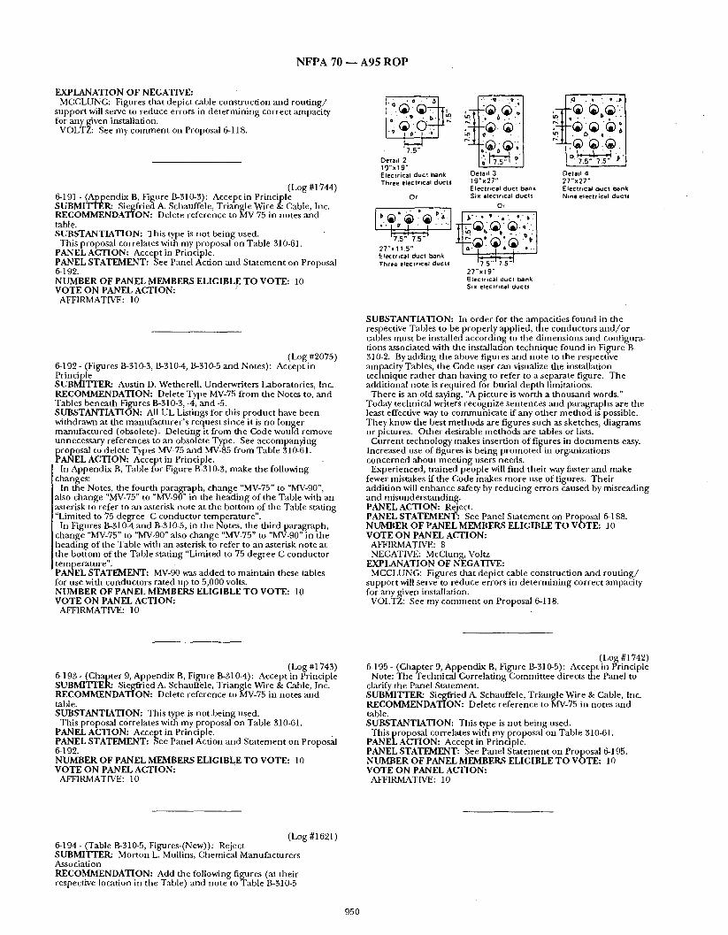
N F P A 70 ~ A 9 5 R O P
EXPLANATION OF NEGATIVE: MCCLUNG: Figures that depict cable construct ion and rou t i ng /
suppor t will serve to reduce errors in de te rmin ing correct ampacity for any given installation.
VOLTZ: See my c o m m e n t on Proposal 6-118.
(Log #1744) 6-191 - (Appendix B, Figure B-310-3): Accept in Principle SUBMITTER: Siegfried A. Scbauffele, Triangle Wire & Cable, Inc. RECOMMENDATION: Delete reference to MV-75 in notes and table. SUBSTANTIATION: This type is not being used.
This proposal correlates with my proposal on Table 310-61. PANEL ACTION: Accept in Principle. PANEL STATEMENT: See Panel Action and S ta tement on Proposal 6-192. NUMBER OF PANEL MEMBERS ELIGIBLE TO VOTE: 10 VOTE ON PANEL ACTION: "
AFFIRMATIVE: 10
(Log #2075) 6-192 - (Figures B-310-3, B-3104, 13-310-5 and Notes): Accept in Principle SUBMITTER: Austin D. Wetherell , Underwri ters Laboratories, Inc. RECOMMENDATION: Delete Type MV-75 f rom the Notes to, and Tables benea th Figures B-310-3, -4, and -5. SUBSTANTIATION: All UL Listings for this product have been withdrawn at the manufac tu re r ' s reques t since it is no longer manufac tu red (obsolete). Delet ing it from the Code would remove unnecessary references to an obsolete Type. See accompanying
~ roposal to delete Types MV-75 a n d MV-85 f rom Table 310-61. ANEL ACTION: Accept in Principle. In Appendix B, Table for Figure B-310-3, make the following
changes: In the Notes, the four th paragraph, change "MV-75" to "MV-90",
also change "MV-75" to "MV-90" in the head ing of the Table with an asterisk to refer to an asterisk note at the bo t tom of the Table stating "Limited to 75 degree C conductor temperature" .
In Figures B-310-4 and B-310-5, in the Notes, the third paragraph, change "MV-75" to "MV-90" also change "MV-75" to "MV-90" in the head ing of the Table with an asterisk to refer to an asterisk note at the bot tom of the Table stating "Limited to 75 degree C conductor temperature" . PANEL STATEMENT: MV-90 was added to mainta in these tables for use with conductors rated up to 5,000 volts. NUMBER OF PANEL MEMBERS ELIGIBLE T O VOTE: 10 VOTE ON PANEL ACTION:
AFFIRMATIVE: 10
~ . ? .
7 . 5 "
OeTad 2 19,.x.19 ~ Electrical duct bank Detad 3 Three elec~rtcal ducts ~g 'x27"
EleclrJcal duct bank Or Six electrical ducts
Or
J • . , o . p -
2 7 " x 1 1 . 5 " J ~ a - ~ \ " ~ ~"~'l. ' • .- ] Ele~:tr~cal duc! bank Three electrical ducts
2 7 " x l 9 " Electrical duct bank Six electrical ducts
• ' , . ..,
[ ~" 7.5" 7,5" ~ '
Oetad 4 27"x27" ¢:leclrlcal docl bank Nine eleclrical ducts
SUBSTANTIATION: In order for the ampacit ies f ound in the respective Tables to be properly applied, the conductors a n d / o r cables mus t be installed according to the d imens ions and configura- tions associated with the installation technique found in Figure B- 310-2. By adding the above figures and note to the respective anlpacity Tables, the Code user can visualize the installation technique ra ther than having to refer to a separate figure. The additional note is required for burial dep th limitations.
There is an old saying, "A picture is worth a t housand words." Today teclmical writers recognize sentences and paragraphs are the least effective way to communica te if any o ther m e t h o d is possible. They know the best me thods are figures such as sketches, d iagrams or pictures. Other desirable me thods are tables or lists.
Cur ren t technology makes insert ion of figures in documen t s easy. Increased use of figures is being p romoted in organizations concerned about mee t ing users needs.
Experienced, t rained people will f ind their way faster and make fewer mistakes if the Code makes more use of figures. Thei r addi t ion will enhance safety by reduc ing errors caused by misreading and misunders tanding . PANEL ACTION: Reject. PANEL STATEMENT: See Panel S ta tement on Proposal 6-188. NUMBER OF PANEL MEMBERS ELIGIBLE TO VOTE: 10 VOTE O N PANEL ACTION:
AFFIRMATIVE: 8 NEGATIVE: McClung, Voltz
EXPLANATION OF NEGATIVE: MCCLUNG: Figures that depict cable construct ion and ro u t i n g /
suppor t will serve to reduce errors in de te rmin ing correct ampaci ty for any given installation.
VOLTZ: See my c o m m e n t on Proposal 6-118.
(Log #1743) 6-193 - (Chapter 9, Appendix B, Figure B-310-4): Accept in Principle SUBMITTER: Siegfried A. Schauffele, Triangle Wire & Cable, Inc. RECOMMENDATION: Delete reference to MV-75 in notes and table. SUBSTANTIATION: This type is no t be i ng used.
This proposal c6rrelates with my proposal on Table 310-61. PANEL ACTION: Accep t in Principle. PANEL STATEMENT: See Panel Action and S ta tement on Proposal 6-192. NUMBER OF PANEL MEMBERS ELIGIBLE T O VOTE: 10 VOTE O N PANEL ACTION:
AFFIRMATIVE: 10
(Log #1742) 6-195 - (Chapter 9, Appendix B, Figure 13-31%5): Accept in Principle
Note: The Technical Correlat ing Commit tee directs fire Panel to clarify the Panel Statement. SUBMITTER: Siegfried A. Schauffele, Triangle Wire & Cable, Inc. RECOMMENDATION: Delete reference to MV-75 in notes an d table. SUBSTANTIATION: This type is no t being used.
This proposal correlates with my proposal on Table 310-61. PANEL ACTION: Accept in Principle. PANEL STATEMENT: See Panel S ta tement on Proposal 6-195. NUMBER OF PANEL MEMBERS ELIGIBLE T O VOTE: 10 VOTE ON PANEL ACTION:
AFFIRMATIVE: 10
(Log #1621 ) 6-194- (Table B-310-5, Figures-(New)): Reject SUBMITTER: Morton L. Mullins, Chemical Manufacturers Association RECOMMENDATION: Add the following figures (at their respective location in the Table) and note to Table B-310-5
950

N F P A 7 0 - - A 9 5 R O P
(Log #1622) 6-196 - (Table B-310-6 arid B-310-7, Figures-(New)): Reject SUBMITTER: Morton L. Mullins, Chemical Manufacturers Association- ~ . RECOMMENDATION: Add the following figures iat their respective location in the Table) and dote to Tables B=310-6 and B- 310-7
Detai l ! 11 5 " x ) 1.5" Elec,trical duct bank One electrical duct
•
o;::,jg. Electrmal duct bank Detad 3 Three electrrcal ducts 1 9 " x 2 7 "
Electrical duet bank Or . S ix electrical ducts
o, ' l ~ " ' ' ' e ' ; . : ", '=: l
= .
Three electrical ducts 2 7 " x 1 9 "
. Electr ical due t bank Six electrical duets
Note: See Notes for all details in figure B-310-2 for burial dep th requirements. , . " SUBSTANTIATION: In order for the ampacities found in the respective Tables to be properly applied, the conductors a n d / o r cables must be installed according to the dimensions and configura- tions associated with the installation technique found/in Figure B- 310-2. Byadding the above figures and note to the respecuve " ampacity Tables, the Code user can visualize t he installation technique rather than having to refer tb a separate figure. The additional note is required for burial depth limitations.
There is an old saying, "A picture is worth a thousand words." Today technical writers recognize sentences and paragraphs are the least effective way to communicate if any other me thod is possible. They know the best methods are figures such as sketches, diagrams or pictures. Other desirable methods are tables or lists.
Current technology.make~ insertion of figures in documents easy. Increased use of figures is being p romoted in organizations ' concerned about meet ing users needs.
Experienced, trained people will f ind daeir way faster and make fewer mistakes if the Code makes more use of figures. Their addition will enhance safety by reducing errors caused by misreading and misunderstanding. PANEL ACTION: Reject. . " PANEL STATEMENT: See Panel Statement on Proposal 6-188. NUMBER OF PANEL MEMBERS ELIGIBLE TO VOTE: 10 VOTE ON PANEL ACTION:
AFFIRMATIVE: 8 NEGATIVE: McClung, Voltz
EXPLANATION OF NEGATIVE: MCCLUNG: Figures that depict cable construction and rou t ing /
support will serve to reduce errors in determining correct ampacity for any given installation.
VOLTZ: See my comment on Proposal 6-118,
(Log #1623) 6-197- (Table B-310-8, Figures-(New)): Reject SUBMITTER: Morton'L. Mullins, Chemical Manufacturers Association RECOMMENDATION: Add the following figures (at their '
,respective location in the Table) and note to Table B-310-8.
Deta,l 5 Detai l 6 Buried 3 Bu.ed 3 conductor conductor cable cables
SUBSTA~ITIATION: In order for the ampacities found in the • respective Tables to be properly applied, the conductors a n d / o r cables must be installed according to the dimensions and configura- tions associated with the installation technique found in Figure B- 310-2. By adding the above figures and note to the respective ampacity Tables, the Code user can visualize the installation technique rather than having to refer to a separate figure. The additional note is required for burial dep th limitations.
There is an old saying, "A picture is worth a thousand words." Today technical writers recognize sentences and paragraphs are the least effective way to communicate if any other me thod is possible. They know the best methods are figures such as sketches, diagrams or pictures. Other desirable methods are tables or lists.
Current technology makes insertion of figures in documents easy. Increased use of figures-is being promoted in organizations concerned about meet ing users needs: Experienced, trained people will f ind their way faster and make
fewer mistakes if the Code makes more use of figures. Their addition will enhance safety by reducing errors caused by misreading and misunderstanding. PANEL ACTION: Reject. PANEL STATEMENT: See Panel Statement on Proposal 6-188. NUMBER OF PANEL MEMBERS ELIGIBLE TO VOTE: 10 VOTE ON PANEL ACTION:
AFFIRMATIVE: 8 NEGATIVE: McClhng, Voltz
EXPLANATION OFNEGATIVE: MCCLUNG: Figures that depict cable construction and rou t ing /
support will serve to reduce errors in de termining correct ampacity for any given installation. VOLTZ: See my comment on Proposal 6-118.
' (Log #1624) 6-198 - (Table I?,-310-9, Figures-(New)): Reject SUBMITTER: Morton L. MuUins, Chemical Manufacturers Association " RECOMMENDATION: Add the following figures (at their respective location in the Table) and note to Table B-310-9.
e e • • o o Detad 7 Deled 8 Buried triDlexed Rut*ed trlplexed cables cables |1 clrcu0t) (2 CirCUits)
Note: See Notes for all details in figure I?-310-2 for burial depth requirements. ' " SUBSTANTIATION: In order for the ampacities found in tile respective Tables to be properly applied, the conductors a n d / o r cables must be installed according to the dimensions and configura- tions associated with the installation technique found in Figure B- 310-2. Byadding the above figures and note to the respective ampacity Tables, the Code user can visualize the installation technique rather than having to refer to a separate figure. The additional note is required for burigl dep th limitations.
There is an old saying, "A picture is worth a thousand words." Today technical writers recognize sentences and paragraphs are the least effective way to communi/zate if any other me thod is possible. They know the best methods are figures such as sketches, diagrams or pictures. Other desirable methods are tables or lists.
Current technology makes insertion of figures in documents easy. Increased use of figures is being p romoted in organizations concerned about meet ing users needs. Exper ienced, t rained people will f ind their way faster and make
fewer mis/akes if the Code makes more use of figures. Their addit ion will enhance safety by reducing errors caused by misreading and misunderstanding. PANEL ACTION: Reject. PANEL STATEMENT: See Panel Sta tement on Proposal 6q88. NUMBER OF PANEL MEMBERS ELIGIBLE TO VOTE: 10 VOTE ON PANEL ACTION:
AFFIRMATIVE: 8 NEGATIVE: McClung, Voltz
Note: See Notes for all details ifi figure B-310-2 for burial depth requirements. "
951
N F P A 7 0 ~ A 9 5 R O P
EXPLANATION OF NEGATIVE:' MCCLUNG: Figures tha t depict cable construct ion and rou t i ng /
suppor t will serve to reduce errors in de te rmin ing correct ampacity for any given installation.
VOLTZ: See my c o m m e n t on Proposal 6-118.
( Log #1625) 6-199- (Table B-310-10, Figures-(New)): Reject SUBMITTER: Morton L. Mullins, Chemical Manufacturers Association RECOMMENDATION: Add the following figures (at their respective location in the Table) and note to Table B-310-10.
Detad 9 Oetall 10 8ur,ed s,ngle conductor Rur¢ed single conductor cables {1 CIrCUIt) cables (2 c,rcu,ts)
Note: See Notes for all details in figure.B-310-2 for burial dep th requirements . SUBSTANTIATION: In order for the ampacit ies f ound in the respective Tables to be properly applied, the conductors a n d / o r cables mus t be installed according to the d imens ions and configura- tions associated with the installation technique found in Figure B- 310-2. By adding the above figures and no te to the respective ampacity Tables, the Code user can visualize the installation technique ra ther than having to refer to a separate figure. The addit ional note is requi red for burial dep th limitations.
There is an old saying, "A picture is worth a t housand words." Today technical writers recognize sentences and paragraphs are the least effective way to communica t e if any o ther m e t h o d is possible. They know the best me thods are figures such as sketches, d iagrams or pictures.. Other desirable me t hods are tables or lists.
Cur ren t technology makes insert ion of figures in documen t s easy. Increased use of figures is being p r o m o t e d i n organizations concerned about mee t ing users needs.
Experienced, t ra ined people will f ind their way faster and make fewer mistakes if the Code makes more use of figures. Thei r addi t ion will enhance safety by reducing errors caused by misreading and misunders tanding . PANEL ACTION: Reject. PANEL STATEMENT: See Panel S ta tement on Proposal 6-188. N ~ E R OF PANEL MEMBERS ELIGIBLE TO VOTE: 10 VOTE ON PANEL ACTION:
AFFIRMATIVE: 8 NEGATIVE: McClung, Voltz
EXPLANATION OF NEGATIVE: M C C L U N G : Figures tha t depict cable cons t rncdon and rou t i ng /
suppor t will serve to reduce errors in de te rmin ing correct ampaci ty for any given installation.
VOLTZ: See my c o m m e n t on Proposal 6-118.
(Log #1626) 6-200- (Table B-310-11, FPN): Accept SUBMITTER: Morton L. Mullins, Chemical Manufacturers Association • RECOMMENDATION: Revise (FPN) as follows: ,
(FPN): The ampacity ' l imit is based on the following .formula for 10 thrn 42 conductors; for 43 and more conductors the ampacity limit shall be calculated by the ad jus tment factor f rom the table above:
A 2 = 0~E5~N (A1) or A 1 whichever is less
A 1 = Ampacity f rom Tables 310-16, 310-18, B-310-01, B-310-6 an d B- 310-7 mult ipl ied by the appropr ia te factor f rom the Table above (B- 310-11).
N = Total n u m b e r of conductors used to obtain mult iplying factor f rom Table above (B-310-11) (i.e. 24 and 42).
E = Desired n u m b e r of cur ren t carrying conductors greater than o[le aEnp.
A 2 = Ampacity limit for cur ren t carrying conductors.
SUBSTANTIATION: The 1990 NEC contains two co lumns (A&B) in Article 310, note to Ampacity Tables for 0 to 2000 vol ts ,Note 8(a) for calculating the ampacity of conductors in raceway or cable where the n u m b e r exceed three. The fine pr int note (FPN) and accompa- nying formula was the basis for co lumn A. Dur ing the 1993 Code cycle, the values in Co lumn A and associated (FPN) were moved to the Appendix B. The basis for the fo rmula variables, A 1 and N were, however, incorrecdy referenced to Article 310, Note to Ampacity Table for 0 to 2000 volts, Note 8(a) instead of the values f ound in Table B-310-11. This change is requi red to correct the basis for the formula.
In addition, corrections were made to the fo rmula so tha t the E variable appeared u n d e r the square root radical and Ampacity Table references were added for A 1 as well as the n u m b e r o f conductors used in the formula. These changes should clarify the formula. PANEL ACTION: Accept. Editorially, in Table B-310-11 in the Code, relocate the asterisks adjacent to "10 th rough 24", "25 th rough 42" and "43 and above" to be located adjacent to the perspective percentage values. PANEL STATEMENT: The factors are the percentage values. NUMBER OF PANEL MEMBERS ELIGIBLE TO VOTE: 10 ' VOTE ON PANEL ACTION:
AFFIRMATIVE: 10
952

N F P A 70 - - A 9 5 R O P
EXPLANATION OF NEGATIVE: MANDE: See my explanation for negative for Proposal 16-202 (Log
#2221)
CHAPTER 9 - - TABLES AND EXAMPLES
(Log #1976) 6-173 - (Chapter 9, Part A Tables, Notes to Tables): Accept
Note: It was the action of the Technical Correlating Committee that this ProposM be referred to Code-Making Panel 8 for action. This action will be considered by the Panel as a Public Comment. SUBMI'FI"ERa Ronald 1L Runkles, National.Electrical Manufactur- ers Association RECOMMENDATION: In Chapter 9, Part A, Tables, Notes to Tables, revise all notes to tables and table 1 (including notes) as shown:
Table 1. Percent of Cross Section of Conduit and Tubing for Conductors
Number of Conductors 1 2 Over 2
All Conductor Types 53 31 40
Note 1: See Appendix C for conduit and tubing dimensions and for maximum number of conductors and fixture wires permitted in trade sizes of the applicable conduit or tubing.
Note 2: Table 1 applies only to complete conduit or tubing systems and is not intended to apply to sections of conduit or tubing used to protect exposed wiring from physical damage. Note 3: Equipment grounding or bonding conductors, where
installed, shall be included when calculating conduit or tubing fill. The actual dimensions of the equipment grounding or bonding conductor.(insulated or bai-e) shall be used in the calculation.
Note 4: Where conduit or tubing nipples having a maximum length riot to exceed 24 inches (610 ram) are installed between boxes, cabinets, and similar enclosures, the nipples shall be permitted to be filled to 60 percent of their total cross-sectional area, and Article 310, NoteS(a) of Notes to Ampacity Tables of 0 to 2000 Volts need not apply to this condition.
Note 5: Foi- conductors not included in Chapter 9, such as multiconductor cables, the actual dimensions shall be used.
Note 6: For combinations of conductors of differefit'sizes, use Tables 5 and 5A in Chapter 9 for dimensions of conductors and AJ)pendix C, Table C1 for the applicable conduit or tubing dii~ensions.
Note 7: 'Where the calculated .conductors, all of the same size (total cross-sectional area including insulation), include a decimal fraction, the next higher whole number shall be used where this decimal is 0.8 or larger.
Note 8: Where bare conductors are permitted by other sections of this Code, the dimensions for bare conductors in Table 8 of Chapter 9 shall be permitted. Note 9: A multiconductor cable of two or more conductors shall
be treated as a single conductor for calculating percentage conduit fill area. For cables that have'elliptical cross sections, the cross - sectional area calculation shall be based on using the major diameter of/.he ellipse as a circle diameter.
(FPN): Table 1 is based on common conditions of proper cabling and alignment of conductors where the length of the pull and the number of bends are within reasonable limits. It should be . recognized that, for certain conditions, a larger size conduit or a lesser conduit fill should be considered.
SUBSTANTIATION: This is a companion proposal to that being made by the NEMAJoint Selections Committee on Raceway Wirefill that, if accepted, would delete all present raceway fill tables and create new tables in a new appendix. These proposed changes are necessary to correlate with that proposal. PANEL ACTION: Accept. PANEL STATEMENT: Acceptance is contingent upon similar action by CMP-8. NUMBER OF PANEL MEMBERS ELIGIBLE T O VOTE: 10 VOTE ON PANEL ACTION:
AFFIRMATIVE: 10
(Log #3721 ) 8-233- (Chapter. 9, Part A Tables, Notes to Tables, and Table 1):
• Accept in Principle SUBMITI3ER: Ronald R. Runkles, National Electrical Manufactur- .ers AssoCiation RECOMMENDATION: In Chapter 9, Part A, Tables, Notes to Tables, revise all notes to tables and table 1 (including notes) as shown:
Table 1. Percent of Cross Section of Conduit amd Tubing for Conductors
Number of Conductors 1 2 Over 2
All Conductor Types 53 31 40
Note 1: See Appendix C for conduit and tubing dimensions and for maximum number of conductors and fixture wires permitted in trade sizes of the applicable conduit or tubing.
Note 2: Table 1 applies only to complete conduit or tubing systems and is not intendedto apply to sections of conduit or tubing used to protect exposed wiring from physical damage. Note 3: Equipment grounding or bonding conductors, where
installed, shall be included when calculating conduit or tubing fill. The actual dimensions of the equipment grounding or bonding conductor (insulated or.bare) shall be used in the calculation.
Note 4: Where conduit of tubing nipples having a maximum length not to exceed 24 inches (610 ram) are installed between boxes, cabinet, and similar enclosures, the nipples shall be permitted to be filled to 60 percent of their total cross-sectional area, and Article 310, Note 8(a) of N0tes to ampacity Tables of 0 to 2000 Volts need not amply to this condition.
ore 5: For conductors not included in Chapter 9, such as multiconductor cables, the actual dimensions shall be used. Note 6: For combinations of conductors of different sizes, use
Tables 5 and 5A in Chapter 9 for dimensions of conductors and Appendix C, Table C1 for the applicable conduit or tubing dimensions.
Note 7: Where the calculated conductors, all of the same size (total cross.sectional area includirig insulation), include a decimal fraction, the next higher whole number shall be used where this decimal is 0.8 or larger. Note 8: Where bare conductors are permitted by other sections of
this Code; the dimensions for bare conductors in Table 8 of Chapter 9 shall be permitted.
Note 9: A multiconductor cable of two or more conductors shall be treated as a single conductor for calculating percentage conduit fill area- For cables that have elliptical cross sections, the cross - secti0nal'area calculation shall be based on using the major diameter of the ellipse as a circle diameter. . '
(FPN): Table 1 is based on common conditions of proper cabling and alignment of conductors where the length of the pull and the number of bends are within reasonable limits. It should be recognized that, for certain conditions, a larger size conduit or a lesser conduit fill should be considered•
SUBSTANTIATION: This is a companion proposal to that being made by the NEMAJoint Selections Commtttee on Raceway Wirefill that, if accepted, would delete all present raceway fill tables and create new tables in a new appenfftx. These proposed changes are necessary to correlate with that proposal.
• PANEL ACTION: Accept in Principle. 1. Note 1 revised to rea~l: Note 1: See Appendix C for the maximum number of conductors
and fixture w~.',r.es, all of the same size (total cross-sectional area including insiilation), permitted in trade sizes of the applicable conduit or tubing.
2. Note 6 revised toread: Note 6i For combinations of conductors of different sizes, use
Tables 5 and 5A in Chapter 9 for dimensioias of conductors and Table 4 in Chapter 9 for the applicable conduit or tubing dimen- sions.
3. Note 7 revised to read: Note 7: When calculating the maximum number of conductors
permitted in a conduit or tubing, all of the same size, (total cross- sectional area including insulation), the next higher whole .number shall be used to determ~me the maximum number of conductors permitted when the calculation results in a decimal of 0.8 or larger. PANEL STATEMENT: 1. ,Revisions are made to Note 1 to indicate that raceways enclosing conductors of the same size are located in Appendix C.
2. Revisions are made to Note 6 because dimensions of conduits and tubings should remain in Chapter 9 for ease of use when installing mixed conductor sized in the same conduit of tubing.
848

N F P A 70 - - A 9 5 R O P
3. Note 7 revisions d arify that the n u m b e r of c o n d u c t o r s p e r m i t t e d in a condui t of tub ing are to be r o u n d e d up no t the size o f the condui t or tubing. NUMBER OF PANEL MEMBERS ELIGIBLE TO VOTE: 14 VOTE ON PANEL ACTION:
AFFIRMATIVE: 14
(Log #3044) 8~232a - (Chapter 9 Part A. Notes to Tables, Note 4): Reject SUBMITTER: Bill Pike, Building Indus t ryConsu l t ing Service Internat ional RECOMMENDATION: Add after the first sentence:
"For communica t ions wires a n d cables, the tables in Chapter 9 do nototapply.a ly." SUBSTANTIATION: T he tables within Chapter 9 are based u p o n electrical conductors a n d no t communica t ion wires andlcables. Electrical conductors carry sufficient amperage genera t ing hea t to warrant the fill capacities as descr ibed in Chapte r 9. Communica - t ion wires and cables~ however, do no t carry the amperage no t release hea t in sufficient quant i ty to require the space within the conduit . This is exemplif ied in the t e l ephone companies where 3.5 inch and larger cables are placed in 4 inch condui t equat ing to over . a 77% fill. These p lacements are conf igured according to coeff ident of friction r a the r than the NEC requ i rements of cables releasing heat. This clarification is necessary since it has been BIC.SI m e m b e r s experience o f inspectors in terpre ta t ion tha t has resul ted unwar- r an ted failed inspections. This clarification will no t impede the in t ended safety of these sections. PANEL ACTION: Rejec t . • PANEL STATEMENT: Condui t fill percentages are no t based upon hea t transfer, notes to ampaci ty tables regulate this. Condu i t fill is l imited to protec t conductors f rom being ph);sically damaged dur ing installation. Commun i ca t i on wire a n d cable is covered in Chapter 8 which is i n d e p e n d e n t (see 90-3) a n d is permi t ted to make its own rules. Article 800 would he the p roper place to have except ions to Chapter 9 on condui t fill. NUMBER OF PANEL MEMBERS ELIGIBLE TO VOTE: 14 VOTE ON PANEL ACTION:
AFFIRMATIVE: 14
(Log #3255) 8-234- (Chapter 9, Table 1): Accept ' SUBMITTER: James M: Daly, BICC Cables Corporat ion
[RECOMMENDATION: Add: Note 7. W h e n pul l ing three [conductors or cables into a raceway, if the ratio of the raceway I.D. to [the conduc to r or cable O.D. is be tween 2.8 a n d 3.2, ja ' ,nming may Ioccur and the nex t larger size raceway shou ld be used. While [ jamming can occur when pul l ing four or more conductors or cables [into a raceway, the probability is very low. SUBSTANTIATION: T h i s caut ion shou ld be inc luded in the NEC since m a n y people are no t aware that even if they follow the 40% fill allowances in Tables 3A, 3B a n d 3C, they can still have a p rob lem with the conduc tors~amming . This can occur when three conduc- tors or cables are be ing pul led into the raceway a n d one conductor slips in between the o ther two conductors particularly at bends where the raceway may be slightly oval.
E x a m p l e : O.D. o f#8 AWG T H H N / T H W N from Table 5, Col. 6 is 0.218 in.
Table 3B permits 3 #8 AWG conductors in a 1 / 2 in. condui t or tub!ng
The I.D. 0 f a 1 /2 in . ' condui t or tub ing is 0.0622 in. While the raceway I.D. is 0.622 in. in straight runs, it may be out of
r o u n d at a bend and one conduc to r may slip in between the o ther two conductors and cause a j a m as the conductors exit t he bend. Assuming there is no variation in the d iameter of the condui t I.D. o r the conductor O.D.s, one conductor usually canno t slip between, the o ther two conductors in a s t ra ight r un since $ x 0.218 in. = 0.654 ", which is greater than the raceway I.D. of 0.622". However at a bend, the major I.D. of the raceway will i n c r e a s e d u e to bending, particu- larly in tubing, to a d iameter slightly larger than 0.654 in. permi t t ing the middle conduc to r to be pul led in between the outer two conductors . As the conductors exit t he b e n d and the raceway I.D. re turns to a normal circle of 0.622 in., the conductors can j am. This can also occur in s t raight f uns where the tolerances of the conductor O.D. or the raceway I.D. permi t the ratio of the raceway I.D. to the conduc to r O.D. to approach 3. •
The j a m ratio of 2 .8 to 3.2, which is to be avoided, is a s tandard industry r e c o m m e n d e d practice. PANEL ACTION: Accept. PANEL STATEMENT: N u m b e r the new note as Note 10. NUMBER OF PANEL MEMBERS ELIGIBLE TO VOTE: 14 VOTE ON PANEL ACTION:
AFFIRMATIVE: 14
(Log #634) 8-235 - ( C h a p t e r 9, Table 1 Note 4): Accept in Principle . SUBMrFFER: William H. poage, Jr., T r e n h o l m State Technical College RECOMMENDATION: Where the c a l c u l a t e d n u m b e r of conduc- tors, all of the same size (total cross-sectional a rea inc luding insulation) includes a decimal of 0.8 or highei', the nex t h igher whole n u m b e r o f conduc tor will be allowed in the condui t or l~Ceway. SUBSTANTIATION: The last 'phrase in Note 4 could be misinter- p re ted so tha t the electrician or eng inee r would use the nex t h igher size condui t if the fraction were 0.8 or higher. Also, the wording "shall be used" in the 1993 code indicates it "must be used" an d is manda to ry (Article 90-5) when the i n t t h t of the no te is to give l imited flexibility by allowing the nex t whole n u m b e r of conduc tor in the conduit . pANEL ACTION: Accept in Pr indpie . PANEL STATEMENT: Refer to Panel Action on Proposal 8-233. NUMBER OF PANEL MEMBERS ELIGIBLE TO VOTE: 14 VOTE ON PANEL ACTION:
AFFIRMATIVE: 14
849
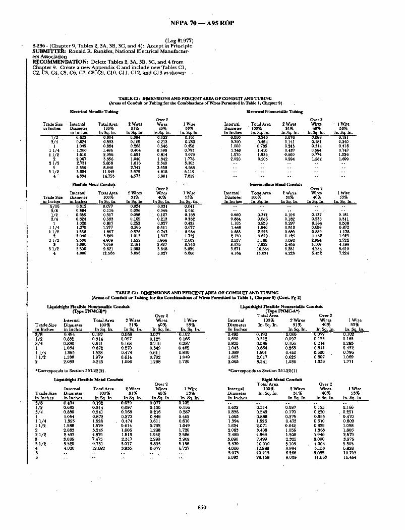
N F P A 70 - - A 9 5 R O P
( L o g #1977) 8-236 - ( C h a p t e r 9, Tables. 2, 3A, 35 , $C, a n d 4): A c c e p t in Pr inc ip le S U B M I T T E R : R o n a l d R. Runkles , Na t iona l Electr ical M a n u f a c t u r - ers Associa t ion R E C O M M E N D A T I O N : De le t e Tab le s 2, 3A, 3B, ~C, a n d 4 f r o m C h a p t e r 9. C rea t e a n e w A p p e n d i x G a n d i nc lude n e w Tab les G1, C2, C3, CA, C5, C6, C7, C8, C9, C10, C l l , C12, a n d C15 as shown:
TABLE CI: DIMENSIONSAND PERCENTAREAOFCONDU1TANDTUBING (Areas of Conduit or Tubing for the Combinadom of Wires Permitted in Table 1, Chapter 9).
Electrical Metallic Tubing Electrical Nonmetallic Tubing
Over 2 Over 2 Trade Size Internal TotalArca, 2 Wtres Wires 1 Wire Internal , TotalArea 2 Wire* Wire* 1 Wire in Inches Dtameter 100% 81% 40% 53% Diameter 100% 3 1 ~ 40% 53%
m Inches In Sq. In. InSq. In. In Sq. In. In. SoL. In. In Inches In. Sq. In. In, Sq..In. - i/2 0 04 o o. 012 0.101 05 0 0.245 0.o70 Inoo 9
sq.in In. 8q. In. 0.151
3/4 0.824 0.583 0.165 0.213 0.283 0.760 0.454 0.141 0.181 0.240 1 1.049 0.864 0.268 0.346 0.458 1.000 0.785 0.243 0.314 0.416
1 1/4 , 1.380 1.490 0.464 0.598 0.793 1.340 ' 1.410 0.437 0.564 0.747 1 1/2 1.610 2.036 0.631 0.814 1.079 1.570 1.936 0.600 0.774 1.026
2 2.007 3.356 1.040 1.342 1.778 2.020 3.205 0.994 1.282 1.699 2 1/2 2.731 5.858 1.816 2.343 3 . 1 0 5 . . . . . . . . . .
3 3.~6 8.846 2.742 3.538 4.688 . . . . . . . . . . 3 1/2 5.834 11,545 3.579 4.618 6 . 1 1 9 . . . . . . . . . .
4 ~ 4.334 14.753 4.573 5.901 7.819 . . . . . . . . . .
Flexible Metal Conduit " . intermediate Metal Conduit Over 2 Over 2
Internal Total Area 2 Wsres Wires t Wtre Internal Total Area 2 Wtres Wires 1 Wire Trade Size Diameter 100% 31% 40% 55% Diameter 100% 31% 40% ; 53% in Inches in Inches In Sq. In. In Sq. In. In Sq. In. In. Sq. In. In Inches In. Sq. In. In Sq. In. In Sq. In. In. Sq. In. .
5/16 0.312 0.077 0.024 0.031 0 . 0 4 1 . . . . . . . . . . 3/8 0.384 0.116 0.056 0.046 0.061 1/2 0.635 0.317 0.098 0 . 1 2 7 0.168 o:&o 0:~2 0.'100 0:;37 0.;81 3/4 0.824 0.533 0.165 0.213 0.282 0.864 0.586 0.182 0.235 0.511
1 1.020 0.817 0.253 0.327 0.~3 1.105 ' 0.959 0.297 0.384 0.508 1 1/4 1.275 1.277 0.390 0.511 0.677 1.448 1.646 0.510 0.638 0.872 1 1/2 1.538 1.857 0.576 0.743 0.984 1.685 2.993 0.689 0.889 1.178
2 2.040 ' 3.209 1.013 1.307 1.732 2.150 3.629 1.125 1.452 1.923 2 1/2 2.500 4.909 1.522 1.964 ' 2.602 2.557 5.135 1.592 2.054 2.722
3 $.000 7.069 2.191 2.827 3.746 3.176 7.922 2.456 3.169 4.199 3 1/2 5.500 9.621 2.983 3.848 5.099 ~.671 10.584 3.281 ' 4.234 5.610
4 4.000 12.566 $.896 5.027 6.660 4.160 13.631 4.226 5.452 7.224
TABLE Cb DIMENSIONS AND PERCENT AREA OF CONDUIT AND TUBING (Area.* of Conduit or Tuldng for the Combinations of Wires Permitted in Table 1, Chapter 9) (Cont. Pg 2)
Liquldtlght FlcxBble Nonmetallic Conduit l J q u i d t ~ t Flexible Noumet~lic Conduit (Type FNMC-B') Total(~e~FNMC,-A*)
Over 2 Over 2 Internal Total Area 2 Wires Wires ' 1 Wire Internal 100% 2 Wires Wires 1 Wire
Trade Size Diameter 100% 31% 40% 55% Diameter In. Sq. In. 31% 40% 55% in Inches in Inches In Sq. In. In Sq. In. In Sq. In. In. Sq. In. In Inches In Sq. In. In Sq. In. In. Sq. In. 3/8 ' 0.494 0.192 0.059 0.077 0.102 0.495 0.192 0.060 0.077 0.102 I/2 0.652 0.514 0.097 0.125 0.166 0.6so 0.512 0.097 0.125 0.165 5/4 0.850 0.541 0.168 0.216 0.287 0.825 0,535 0.166 0.214 0.288 1 1.054 0.872 0.270 0.549 0.462 1.043 0.854 0.265 0.541 0.452 1 1/4 1.595 1.528 0.474 0.611 0.810 1.583 1.501 0.465 0.600 0.796 1 1/2 1.588 1.979 0.614 0.792 1.049 1.605 2.017 0.625 0.807 1.069 2 2.055 5.245 1.006 1.298 1.720 2.063 5.541 1.036 1.336 1.771
*Corresponds to Secdon 551-22(2). *Corresponds to Section 351-22(1)
Liquidtlght Flexible Metal Conduit Rigid Metal Conduit Over 2 Total Area Over 2
Internal Total Area 2 Wires Wires 1 Wire Internal 100% 2 Wires Wires 1 Wire Trade Size Diameter 100% 31% 40% 55% Diameter In. Sq. In. 51% 40% 55% in Inches in Inches In Sq. In. In Sq. In. In Sq. In. In. Sq, In. In Inches In Sq. In. In Sq. In. In. Sq. h 3/8 0.494 0.192 0.059 0.077 0.102 I/2 0.652 0.514 0.097 0.125 0.166 0~632 0~314 0.'097 0~125 07166 5/4. 0.830 0.541 0.168 0.216 0.287 0.856 0.549 0.170 0.220 . 0.291 1 1.054 0.872 0.270 0.349 0.462 1.063 0.888 0.275 0.555 0.470 1 1/4 1.595 1.528 0.474 0.611 0.810 1.594 1.526 0.475 0.610 0.809 1 1/2 1.588 1.979 0.614 0.792 1.049 1.624 2.071 0.642 0.829 1.098 2 2.033 3.245 1.006 1.298 1.720 2.083 5.408 1.056 1.363 ~1.806 2 1/2 2.495 4.879 1.515 1.952 2.586 2.489 4.866 1.508 1.946 2.579 5 5.085 7.475 2.517 2.990 5.96'2 5.090 7.499 2.525 5.000 5.975 3 1/2 5.520 9.731 5.017 5.893 5.158 5.570 10.010 5.105 4.004 5.505 4 4.020 12.692 5.955 5.077 6.727 4.050 12.883 5.994 5.153 6.828 5 . . . . . . . . . . 5.073 20.215 6.266 8.085 10.713 6 . . . . . . . . . . 6.095 29.158 9.059 11.663 15.454
850

N F P A 7 0 - - A 9 5 R O P
TABLE C11 DIMENSIONS AND PERCENT AREA OF CONDUIT AND 'I2LIBING (Areas nf Conduit or Tubing for the Combinatlom of W'n'~ Permitted in Table 1, Chapter 9) (Coat Pg 3)
Rigid PVC Conduit, Schedule 80
Trade Size in Inches
1/2 ~/4
1 1 1 /4 1 1/2
2 21/2
3 S 1/9
4 5 6
Trade Size in Inches
1/2 3/4
1 1 1/4 1 1/2
2 21/2
3 S l / 2
4 5 6
Internal" Toted Area Diameter 100% in Inches In Sq. In.
0.526 0.217 0.722 '0.409 0.936 0.688 1.255 1.257 1.476 1.711 1.913 2.874 2.290 4.119 2.864 .6.442 3.396 8.688 3.786 11.258 4.768 17.855 5.709 25.598
• Type A, Rigi~l PVC Conduit
Internal Total Area Diameter 100% in Inches 0.700 "ino.S~;5 In"
0.910 0.650 1.175 1.084 1.500 1.767 1.720 2.324 2.155 5.647- 2.635 5.453 9.290 8.194 3.690 10.694 4.180 15.723
• Over 2 2 Wires Wires , 1 Wire
51% ' 40% 53% Insq.In. In.sq.In.
0.087 0.115 0.127 0.164 0.217 0.215 0.275 0.365 0.585 0.495 0.656 0.530 0.684 0.907 0.891 1:150 1.1525 1.277 1.647 2.183 1.997 2.577 3.414 2.693 3.475 4.605 5.490 4.505 5.967 5.535 7.14,9. 9.463 7.935 10.239 13. 567
Over 2 . 2 Wires Wires 1 Wire
31% 40% 53% I n , In I n , In In; Sp-
0.119 0.154 0.20'2 0.260 0.345 0.536 0.434 0.575 0.548 0.707 0.957 0.720 0.929 1.231 1.131 1.459 . 1.933 1.690 2.181 ~2.890 2.540 3.278 4.343 3.515 4.278 5.668 4.254 5.489 7.273
Rigid PVC Conduit Schedule 40 And HDPE Conduit
Over 2 Internal Total Area 2 Wires Wires 1 Wire
Diameter 100% 31% 40% 53%. InInches In. In InsqIn Ino In.sq.In.
0.602 0.285 .0.088 i 0.151 0:804 0.508 0.157 0.203 0.269 1.029 0.832 0.258 0.333 0.441 1.360 1.453 0.450 0.581 0.770 1.590 1.986 0.616 0.794 1.052 2.047 3.291 1.020 1.316 1.744 2.445 4.695 1.455 1 .878 2 . 4 8 8 3.042 7.268 2.253 2.907 3.852 3.521 9.737 3.018 3.895 5.161 9.998 12.554 3.892 5.022 6.654 5.016 19.761 6.126 7.904 10.473 6.051 28.567 8.856 11.427 15.141
Type ElK PVC Conduit Over 2
Internal Total Area 2 Wires Wires 1 Wire Diameter 100% 31% 40% 53% InIn~hes In. Sq. In. 'InSq. In. InSq. in. In. Sq. In
3. '74 1;;Ol 57 so 8-i09 Coo s.'4"84 47d16 ' 3.804 11.365 5.523 4.546 6.024 4.289 14.448 4.479 5.779 "~ 7.657 5.316 29.195 6.881 8.878 11.764 6.336 31.530 9.774 12.612 16.711
Table C2: MAXIMUM NUMBER OF CONDUCTORS AND FIXTURE WIRES IN ELECTRICAL METALLIC TUBING (Based on Table 1', Chapte r 9)
Conduc tor Type Size Letters A W G / k c m i l RH 14
12
RHH, RHW, -14 RHW-2 12
RH, RHH, RHW, RHW-2
10 8 6 4 3 2 1
1 /0 2/o 3 / o 4/o 250 30O $5O 4O0 5O0 600 7O0 750 800 9OO IOOO 1250 1500 1750 2OOO
1 /2 $ / 4 1
Condui t Trade Sizes in Inches
1 1 / 4 1 1 / 2 2 2 1 / 2 6 10 16 28 112 169 4 8 13 23 31 51 90 136
4 ' 7 11 3 6 9
20 17
2 5 8 13 1 2 4 7 1 1 3 5 1 1 2 4 1 1 1 4 1 i 1 $ 0 1 1 1 0 1 1 1 0 1 1 1 0 0 1 1 0 0 1 1 0 0 0 1 0 0 0 1 0 0 0 1 0 0 0 1 0 0 0 0 0 0 0 0 0 0 0 0 0 0 0 0
~0 0 0 0 0 0 0 0 0 0 0 0 0 0 O" 0 0 0 0 0 0 0 0 0 0 0 0 0
39 64
27 46 23 38
18 30 9 16 8 13 6 10 5 9 4 7 3 5 2 4 2 4 1 3 1 3 1 1
1 1 1 1 1 1 1 1
• 1 1 0 1 0 1 0 1 0 1 0 1 0 0 0 0 0 0 0 0
80 66
53 28 22 17 15 13
9 7 6 5 5 3 3 3 2
2 1 1 1 1 1 1 1 1 1 1
851
120 100
81 42 34 26 23 20 13 11 10
8 7 5 5 4 4 3 3 2 2 2 1 1 1
1 1 1
3 1/2 221 177
157 131
105 55 44 34 30 26 17 15 13 11
, 9 7 6 6 5 4 4 3 3 3 3 2 1 1 1 1
4 282 227
201 167 ,
135 70 . 56 44 38 33 22 19 17 14 12, 9 8 7 7 6 5 4 4 4 3 3 2 1 1 1
N F P A 7 0 - - A 9 5 R O P
TABLE C2: MAXIMUM NUMBER OF CONDUCTORS AND FIXTURE WIRES IN ELECTRICAL METALLIC TUBING
Type Letters
TW
Conductor Size
AWG/kcmil
Conduit Trade Sizes in Inches
112 8 / 4 1 1 1 / 4 1-1/2 2 .2 1 /2 1 4 8 15 25 43 58 96 168 12 6 11 19. 83 45 74 129. 10 5 8 14 24 33 55 96 8 2 5 8 13 18 30 58
RHH*, RHW*, RHW-2*, THHW, THW, THW-2 '
8.. 81/2 254 " 832 195 255 145 190
81 105
424 S26 248 185
14 6 10 16 28 39 64 112 169 221 282
RI--I H*, RI-tW*, 12 4 8 18 28 31 51 90 186 177 227 RHW-2*, 10 3 6 10 18 24 40 70 106 188 177 THHW, THW
RHH*, RHW*, RHW-2*, TH HW, THW, THW-2
8 1 4 6 10 14 24 42 68 88 106
RHH*, RHW*, RHW-2*, TW, THW, THHW, THW-2
6 1 '" 3 4 8" I I 18 32 48 63 4 1 1 3 6 8 13 24 36 47
1 I 3 5 7 12 20 31 40 2 1 1 2 4 6 10 17 26 34 1 1 1 1 3 4 7 12 18 24
1/0 0 1 I 2 3 6 10 16 20 2 /0 0 I 1 I $ 5 9 13 17 3[0 0 I 1 1 2 4 7 11 15 4 /0 0 0 1 1 1 3 6 9 12 250 0 0 1 1 1 3 5 7 10 800 0 0 1 1 1 2 4 6 8 350 0 0 0 1 1 1 4 6 7 400 0 0 0 1 1 1 ~ 5 7 500 0 0 0 1 1 1 8 4 6 600 0 0 0 1 1 1 2 3 4 700 0 0 ' 0 0 1 1 1 3 4 750 0 0 0 0 1 1 1 3 4 800 0 0 0 0 1 1 1 "3 8 900 0 0 0 0 0 1 1 2 3 1000 0 0 0 0 0 1 1 2 3 1250 0 0 0 0 0 1 1 1 2 1500 0 0 0 0 0 1 1 1 1 1750 0 0 0 0 0 0 1 1 1 2000 0, 0 0 0 0 0 1 1 1
*Types RHH, RHW, and RHW-2 without outer covering.
81 fi0 52 44 $1 26 22 19 16 13 11 10 9 7 6 5 5 5 4 4 3 2 2 1
852

N F P A 7 0 ~ A 9 5 R O P
' T~ e . " Letters
TABLE C2: MAXIMUM NUMBER OF CONDUffI '0I~ kA~ID FIXTURE-WIR~ IN ELECTRICAL METALLIC CONDUIT
Conductor Conduit Trade Size
AWG/kcmil 1/2 3 /4 1 1 1/4 1-1/2 , 2, 2-1/2
Sizes in Inizhes
3 ' 3-1/2 THHN, THWN, ' THWN-2
FEP, FEPB,
1'4 12 10 8 6 4 3 2 "1 1/0 2/O 3/O 4 /0 25O 3OO $50 40O 5OO 600 70O 750 8OO 9OO 1000
1 4 PFA, PFAH, TFE
12 10 8 , 6 4 3 2
PFA, PFAH, 1 TFE
PFA, PFAH, 1/0 TFE, Z 2/0
3/O 4/0.
12 9 5 3 2 1 1 1 1 1 . 0 0 0 0 0 0 0 0 0 0 0 0 0 0
12 9 6 3 2 1 1 1
22 35 01 16 26 45 10 16 28 5 9 16 4 7 12 2 ' 4 , 7 1 3 6 1 3 5 1 1 4 1 1 $ 1 1 , 2 1 1 ! 1 1 - 1 0 1 1 0 1 1 0 1 1 0 0 1 0 0 1 0 0 1 0 0 1 0 0 0 0 0 0 0 0 0 0 0 0
21 34 60 15 25 43 11 18 31
6 10 18 4 7 12 , 3 5 9 2 4 7 1 $ 6
1 2 4
84 138" 61 101. 38 63 22 36 16 26, 10 16
8 13 7 11 5 8 4 7 3 6 3 5 2 4 1 3 1 3
1 2 1 1 1 1 1 1 1 1' 1 1 1 1 1 1 1 1
• 81 134 59 98 42 70 "24 40 17 28 12 2O 10 16 8 13
6 9
241 364 476 176 266 347 111 167 219 64 96 126 46 .69 91 28 43 56 24 36 47 20 30 4O 15 22 29 12 19 25 10 16 20 8 13 17 7 1 1 , 14
.6 9 11 5 7 I0 4 6 9 4 6 8
'3 5 6 2 4 5 2 $ 4
$ 4 1 3 4 1 3 3 1 2 3
234 354 462 171 258 337 122 185 241
70 106 138 50 75 98 35 53 69 29 44 57 24 36 47
16
1 1 1 3 5 8 14 0 1 1 3 4 6 11 0 1 1 2 3 5 9 0 1 1 "1 2 4 8
25
21 17 14 11
33
27 22 18 15
608 443 279 161 116
71 60 51 37 32 26 22 18 15 13
1 1 10 8 7
5 5 4 4
590, 430 309 177 126 88 73 60
42-
35 29 24 19
853 •

N F P A 70 - - A 9 5 R O P
TABLE C2: MAXIMUM NUMBER OF CONDUCTORS AND FIXTURE WIRES IN ELECTRICAL METALLIC TUBING
Type Letters
Conductor Size
AWG/kcmil 14, 12 10 8 6 4 3 2 1
XHH, XHHW, XHHW-2, ZW
14 12 10 8 6 4 3 2
XHH, XHHW, XHHW-2
Conduit Trade Sizes in Inches
1/2 3 /4 1 1 1 /4 1-1/2 2-1/2 14 25' 41 72 98 161 • 282 10 18 29 51 69 114 200
6 11 lS 31 42 70 1 2 2 4 7 11 20 27 44 77 3 5 8 14 19 31 54 1 3 5 9 13 21 37 1 2 4 7 9 15 27 1 1 3 6 8 13 22 " 1 1 2 4 6 10 18 8 15 25 43 58 96 168 6 11 19 33 45 74 129 5 8 14 24 33 55 96 2 5 8 13 18 30 53 1 3 6 10 14 22 39 1 2 4 7 10 16 28 1 1 3 6 8 14 24 1 1 3 5 7 11 20
3 3-1/2 426 556 711 302 394 504 185 241 309 117 153 195
82 107 137" 56 74 94 41 54 69 34 45 57 28 36 46
254 332 424 195 255. 326 145 190 243 81 105 135 60 78 100 43 56 72 36 48 61 31 40 51
1 1 1 1 4 5 8 15 23 30 1/0 1 1 1 3 4 7 13 19 25 2/0 0 1 1 2 3 6 10 16 21 3/0 0 1 1 1 3 5 9 13 17 4 /0 0 1 1 1 2 4 7 11 14 250 0 0 1 1 1 3 6 9 12 300 0 0 1 1 1 3 5 8 10 350 0 0 1 1 1 2 4 7 9 400 0 0 0 1 1 1 4 6 8 500 0 0 0 1 1 1 3 -5 6 600 0 0 0 1 1 1 2 4 5 700 0 0 0 0 1 1 2 3 4 750 0 0 0 0 1 1 1 3 4 800 0 0 0 0 1 1 1 3 4 900 0 0 0 0 1 1 1 3 3 1000 0 0 0 0 0 1 1 2 3 1250 0 0 0 0 0 1 1 1 2 1500 0 0 0 0 0 1 1 1 1 1750 0 0 0 0 0 0 1 1 1 2000 0 0 0 0 0 0 1 1 1
38 32 / 27 22 18 15 13 11 10
8 6 6 5 g 4 4 3 3 2 1
854

/
N F P A 7 0 - - A 9 5 R O P
TABLE C 2 : MAXIMUM NUMBER OF CONDUCTORSAND FIXTURE WIRES IN ELECTRIC, ALMETAI J JC TUBING
Type Conductor Conduit Trade Sizes in Inches " Letters Size
AWG/kcmil 1/2 3/4 1 1 1/4 1 1/2 FFH-2, 18" 8 14 24 41 56 92 RFH-2, 16 7 12 20 34 47 7 8 RFHH-3
SF-2, 18 SFF-2 16
14
SF-1, 18 SFF-1
AF, RFH-I,' 18 RFHH-2, TF, TFF
AF, 16 RFHH-2, TF, TFF
AF 14
TFN, TFFN 18 16
PF, PFF, 18 PGF, PGFF, l0 PAF, PTF, 14 PTFF, PAFF
ZF, ZFF, 18 .. / ZHF, I-IF,. 16 HFF 14
KF-2, 18 KFF-2 16
14 12 10
KF-1, 18 KFF-1 16
• 14 12' 10
AX, XF 12 XFF 10
10 "18 30 52 71 116 8 15 25 43 58 96 7 12 20 34 47 78
18 33 53 92 125 206
14 24 " 39 68 92 152
11 19 31 55 74 123
8 15
22 38 17 29
21 36 16 28 12 21
27 47 20 35 14 25
39 69 27 48 19 33 13 23 8 15
46 82 33 57 22 38 14 25 9 16
4 8 3 6
Note: This table is for concentric stranded conductors only. Table C2A shall be used.
25 43 58 96
63 108 148 244 48 83 113 186
59 103 140 46 79 108 34 60 81
77 133 181. 56 98 133 41 72 98
111 193 262 78 136 185 54 93 127 $7 64 87 25 43 58
133 " 230 313 93 161 220 63 108 148 41 72 98 27 47 64
231 179 15,4
298 220 161
433 305 209 144 96
516 562 244 161 105
13 23 $1 51 10 18 24 40
For compactstrandedconductors,
855

NFPA 70 - - A95 ROP
TABLE C$: MAXIMUM NUMBER OF CONDUCTORS AND FIXTURE WIRES IN'ELECTRICAL NONMETALLIC TUBING'
(Based o n Table 1, Chapter 9)
Type Letters RI-I
RHH, RHW, RHW-2
RI-I, RI--I~,
RI-~-2
TW
Conductor Size
AWG/kcmil 14 12
14 12
10 8 6 4 3 2 1
1/0 2 /0 3/O 4/0 250 300 350 400 500 6OO 700 750 800 90O 1000 1250 1500 1750 2000
14 12 10 8
-ConduitTrade Sizesinlnches I / 2 3 / 4 1 1 1 / 4 ' 1 1 / 2
4 8. " 15 . 27 3 7 3 7 1 2 ' 21 29
$ 6 10 19 26 2 5 9 16 22
1 4 7 13 17 1 1 3 6 9 1 1 3 5 7 1 1 2 4 6 1 1 1 $ 5 0 1 1 3 4 0 1 1 1 3 o o 1 1 2 0 o 1 1 1 o o 1 1 1 0 o 1 1 1 o o o 1 1 o o o 1 1 0 0 o 1 1 o o o 1 1 0 0 0 o 1 o o o o 1 0 o 0 o o o o o o o b o o o o 0 0 0 0 0 0 0 0 0 0 0 0 0 0 0 0 0 0 0 0 0 0 0 0 0 0 0 0 0 0 7 13 2 2 40 55
10 17 31 42 4 7 13 23 32 1 4 7 13 17
261
49
43 36
29 15 12 "9 8 7 5 4 3 3 2 1 1 1 1 1 1 1 1 1 1 1 0 0 0 0
92 71 52 29
Type Letters
TABLE C$: MAXIMUM NUMBER OF CONDUCTORS AND FIXTURE IN ELEC'rRICAL NONMETALLIC TUBING (eog~)
Conductor Size AWG/kcmil 1/2
14 4
ConduitTrade S~esinInches 5/4 1 1 1/4 1 1/2
8 15 27 57 RHH*, RHW,, RHW-2*, THHW, THW, THW-2
RHH*, RHW*, RHW-2*, THAW, THW
• ~ * , RJ-I'W*, RI-IW-2*, THHW, THW, TI-IW-2
RHH*, RHW*, 6 1 RHW-2*,' 4 1 TW, THW, 5 1 THHW, ' 2 I THW-2 1 0
1/o o 2/0 0 3/0 0 4/0 o . 250 o 300 0 35O 0 400 0 500 o 600 0 7OO 0 750 0 800 0 900 0 1000 0 1250 0 1500 0 1750 0 20OO o
*Types Rill-I, R.HW, and RHW-2 without outer covering.
2 4 7 10 17 1 3 5 8 13 1 2 5 7 11 1 2 4 6 9 1 1 3 4 6 1 1 2 3 5 1 1 1 $ 5 0 1 1 2 4 0 1 1 1 3 0 1 I I 2 0 0 I 1 2 0 0 1 1 I 0 0 1 • 1 I 0 0 1 1 1 0 0 0 1 1 0 0 0 I 1 0 0 0 I 1 0 0 0 I I 0 0 0 0 I o o o o 0 .0 0 0 1 0 0 0 0 0 0 0 0 0 0 0 0 0 0 0
856
12 3 7 12 21 29 49 10 3 5 9 17 2S S8 .
8 1 3 5 10 14 23
N F P A 70 - - A 9 5 R O P
Type Letters THHN, THWN, THWN-2
FEP, FEPB, PFA, PFAH, "rFE
PFA, PFAH, 'rFE,
TABLE C$: MAXIMUMNUMBER OF CONDUCTORS AND FIXTURE IN E L E C n ~ C A L N O N M E r ~ t l ] ] C CONDUIT (cont.)
Conduc to r Size AWG/kcmi i
14 ' 1 2 10 8 6 . 4 3 2 1
1 / 0 2 / 0 3 / 0 4 / 0 250 300 350 ' 4O0 5O0 6O0 7O0 750 800 9O0 1000
14 12 IO 8
" 6 4 3 2
Condui t T rade Sizes in I n c h ~ x/2 3/4
10 18 7 13 4 8 2 5 1 3 1 1 1 1 1 1
- 1 1 0 . 1 0 1 0 1 0 o , 0 0 0 0 0 0 0 0 0 0 0 0 0 0 0 0 0 0 0 0 0 0
10 18 7 13 5 9 3 5 1 4 1 2 1 1 1 1 1 1
1 1 1 / 4 I 1 ~ 2 32 58 8 O 2~ 42 58 15 ' 2 6 36
8 15 21 6 11 15 4 7 9 3 5 8 2 5 6 1 $ 5 1 3 4 1 2 3 1 1 3 1 1 2 1 1 1 1 1 1
' 0 1 1 0 1 1 0 1 1 0 1 1 0 0 1 o o 1 0 0 1 0 o 1 0 o 0
Sl 56 77 23 41 56 16 29 40
9 17 23 6 12 16 4 8 11 4 7 9 3 5 8 1 4 5
2 132 96 6O 35 25 '15
-13 11
8 7 5 4
' 4 3 2 2 1 1 1 1 ' 1 1 1 1
.128 93 67 38 27 19 16 13 9
TABLE C,$: MAXIMUM NUMBER O F C O N D U C T O R S AND FIXTURE WIRES IN ELECTRICAL NONMETALLIC CONDUIT
Tn~ Let te~ PFA, PFAH, TFE, Z
X H H j .
xI-mW, XHI-IW-2, ZW
XHH, X H H W XHHW-2
Conduc to r Size
AWG/kcmi l lf /2 1/0" o 2 / 0 0 S/O 0 4{o o 14 12 12 8 10 5 8 3 6 1 4 1 3 1 2 1 1 1
14 7 12 5 10 4 8 1 ' 6 1 4 1
. 3 1 2 1
1 . 0 0 0 0 0 0 0 0 0 0 0 0 0 0 0 0 0 0 0
1 1 /0 2 / 0 S /0 4 / 0 250 3O0 35O 4o0 5o0 600 7oo 75o 8o0 90o 100o 1250 15o0 1750 2o00
Condui t T rade Sizes in Inches 3 / 4 1 1 1 / 4 1 1 / 2
1 1 $ 4 1 1 2 4 1 1 1 3
• 1 1 1 - . - 2 22 s8 68 93 15 ' 27 48 66 9 16 29 40 6 10 18 25 4 7 13 18 3 5 9 12 I 3 6 9 1 $ 5 7 1 2 4 . 6
13 22 40 55 " lO 17 31 42
7 13 23 32 4 . 7 13 17 3 5 9 13 1 4 7 9 1 3 6 ' 8 1 2 5 6 1 1 3 5 1 1 $ 4 1 1 2 3 1 1 1 3 0 1 I 2 0 1 1 1 0 1 1 1 0 1 1 ' 1 0 0 1 1 0 0 1 1 0 0 1 1. 0 0 0 1 0 0 0 1 0 0 0 1 0 0 0 1 0 0 0 0 0 0 0 0 0 0 0 0 0 0 0 0 0 0 0 0
2 7 6 5 4
154 109
67 42 30 20 15 12 10 92 71
' 52 29 21 15 13 11
8 7 6 5 4 3 3 2 1 1 1 1 1 1 1 1 1 1 0 0
8 5 7

N F P A 70 - - A 9 5 R O P
TABLE C$: MAXIMUM N U M B ~ OF CONDUCTORS AND FIX'I13RE WI]tES IN ~J.RCTRICAL NONMETAI.J~C CONDUIT
F~xtt~e Wires
~ype •
tters
Conductor Size AWG/kc rail
FFH-2, - RFH-2, RFHH-3
Conduit Trade Sizes in Inches
SF-2, SFF-2,
SF-I, SFF-I AF, RFH-1, RFHH-2, TF,TFF
1/2 3[4 1 1 1/4 1 1 / 2 2 18 6 12 21 39 5 3 88 16 5 10 18 32 45 74
18 , 8 15 27 49 67 111 16 7 13 22 40 55 92 14 5 10 18 32 45 74 18 15 28 48 86 .119 197
18 11 20 35 64 88 145
AI r , 16 9 16 29 51 71 117 RFHH-2, TFrTFF AF 14 7 13 22 40 55 92 TFN, T FFN 18 18 33 57 102 141 233
16 13 25 43 78 107 '178 PF, PFF, 18 17 31 54 97 133 221 PGF, PGFF, 16 13 24 42 . 75 103 171 PAF, PTF, 14 10 18 31 56 77 128 FFFF. PAFF ZF, Z~F, 18 22 40 70 125 172 285 ZHF, HF, 16 16 29 51 . 92 127 210 HFF . 14 12 22 38 68 93 154 KF-2, 18 31 58 101 182 250 413 KFF-2 16 22 41 71 128 176 291
14 15 ' 28 49 88 121 200 12 I0 19 33 . 60 83 138 10 7 13 22 40 55 92
KF-I. 18, 38 69 121 217 298 493 KFF-1 16 26 49 85 152 209 346
14 18 33 57 102 141 233 12 12 22 38 68 93 154 10 7 14 24 44 61 101
AF, XF, 12 3 7 12 21 29 49 X.FF 10 3 5 9 17 23 38 Note: This table is for concentric stranded conductors only. For compact stranded conductors, Table CSA shall be used.
TABLE CA: MAXIMUM NUMBER OF CONDUCTORS AND ~ WIRES IN
Type Letters
RH
RHH, RHW, RHW-2 RH, RHH, RHW, RHW-2
TW
Conductor Size AWG/koni i
14 12 14 12 10 8 6 4 3 2 1
1/0 2 /0 3/O 4 /0 250 300 350 400 500 6O0 700 750 8OO 9OO 1000 1250 1500 1750 2OOO
14 12 10 8
FLEXIBLE METAL CONDUIT (Based on Table 1, Chapter 9.)
1/2 6 5 4 3 3 1 1 1 1 1 0 0 0 0 0 0 0 0 0 0 0 0 0 0 0 0 0 0 0 0 9 7 5 3
3{4 1 I0 15
8 12 7 11 6 9 5 7 2 4 1 3 1 2 1 I 1 1 1 I 1 I 1 I 0 I" 0 I 0 0 0 0 0 0 0 0 0 0 0 0 0 0. 0 0 0 0 0 0 0 0 0 0 0 0 0 0 0 0
15 23 11 18
8 13 5 7
Condu i tTraae Sizes in Inches 1 1 /4 113/52 2 2 1/2
24 62 94 19 28 50 75 17 25 44 67 14 "21 37 55 II 17 30 45
6 9 15 23 5 7 12 19 4 5 10 14 3 5 8 13 3 4 7 11 1 2 5 7 1 2 4 6 I I 3 5 1 1 3 5 1 1 2 4 1 1 1 3 1 1 1 2 1" 1 I 2 0 1 1~ 1 0 1 1 1 0 1 1 1 0 0 1 1 0 0 1 1 0 0 1 1 0 0 1 1 0 0 1 1 0 0 0 1 0 0 0 1 0 0 0 1 0 0 0 0
36 53 94 141 28 41 72 108 21 30 54 81 11 17 30 45
s s I /2 4 135 184. 240 108 148 193 96 131 171 80 109 142 64 . 8 8 115 34 46 60 27 37 48 21 29 37 18 25 33 16 22 28 10 14 19 9 12 16 8 11 14 7 9 12 6 8 10 4 6 8 4 5 7 3 5 6 3 4 6 3 4 5 2 3 4 1 3 3 1 2 3 1 2 3 1 2 .3 1 ~1 3 1 1 1 - 1 1 1 1 1 1 1 1 1
203 277 361 156 212 277 116 158 207 64 88 115
858

N F P A 7 0 - - A 9 5 R O P
TABLE CA: MAXIMUM NUMBER OF CONDUCTORS AND FIXTURE WIRES IN FLEXIBLE METAL CONDUIT
Type Conductor Conduit Trade Sizes in Inches Letters Size
AwG/kcmi l 1/2 3 /4 1 1 1;/4 1 1;/2 2 2 1(/2 , RHH*, RHW*, 14 6 10 15 24 35 62 94
RI-IW-2*,. THI-IW, THW, TI-IW-2 RHH*, RHW* 12 5 8 12 19 28 50 75 RI-IW-2*, 10 4 6 10 15 ' 22 39 59 THHW t THW RHH*, RHW*, 8 1 4 6 9 13 23 35 RHW-2*, THHW, THW, THW-2 . RHH*, RHW*, . 6 1 3 4 7 10 18 27 RHW-2*, 4 1 ' 1 3 5 7 13 20 TW, THW, 3 1 1 3 . 4 6 11 17 THHW, 2 1 1 2 4 5 10 14 THW-2 ' - 1 1 1 1 2 4 7 10
1/0 0 1 1 1 3 6 9 2 /0 0 1 1 1 3 5 7 3 /0 0 1 1 1 2 .4 6 4 /0 0 0 1 1 1 3 5 250 ' 0 0 1 I I ' 3 4 300 0 0 I 1 I 2 - 3 350 0 - 0 0 1 1 1 3 400 0. 0 0 1 1 1 3 500 0 0 0 1 1 1 2 600 0 0 0 0 1 1 1 700 0 0 0 0 1 1 1 750 0 0 0 0 1 1 1 800 0 0 0 0 1 1 1 900 0 0 0 0 0 1 1 1000 0 0 0 0 0 1 1 1250 0 0 0 0 0 1 1 1500 0 0 0 0 0 0 1 " 1750 0 0 0 0 0 0 1 2000 .0 0 0 0 - 0 0 1
*Types .RHH, RHW, and RHW-2 without outer covering.
3 135
3 1 / 2 . 184 240
108 148 193 85 115 151
51 69 90
39 29 25 21 15 12 10 9 7 6 5 4 4 3 3 2 2 1 1 1 1 1' 1 1
' 53 69 39 51 34 44 29 37 20 26 17 22 14 19 12 16 10 13
8 11 7 9 6 8 6 7 5 6 4 5 3 4 3 4 3 4 3 3 2 3 1 2 1 1
, 1 1 1 1
Type Letters TI-IHN, THWN, THWN-2
FEP, FEPB, PFA, PFAH, TFE,
PFA, PFAH, TFE
TABLE CA: MAXIMUM NUMBER OF CONDUCTORS AND FIXTURE WIRES IN FLEXIBLE METALLIC CONDUIT
Conductor .' Size ~ " - - -Conduit Trade Sizes-in Inches
AWG/kcmil ' 1 /2 3 / 4 1 1 1 /4 ' 1 1 /2 2 2 1/2 14 13 22 12 9 16 10 6 10 8 3 6 6 2 4 4 1 2 3 1 1 2 1 I 1 1 I 1
1/0 1 1 2 /0 0 1 3 /0 0 1 4 /0 0 1 250 0 0 300 0 0 350 0 0 400 0 " 0 500 , 0 0 600 "0 0 700 0 0 750 0 0 800 0 0 900 0 0 1000 , 0 0 .
14 12 21 12 9 15 10 6 11 8 4 6 6 2 4 4 1 3 3 1 2 2~ 1 1 ] 1 1
33 52 76 134 202 24 38 56 98 147 15 24 35 62 93 9 14 20 35 53 6 10 14 25 38 4 6 9 16 24 -3 5 7 13 20 3 4 6 11 17 1 3 4" 8 12 1 2 4 7 10 1 1 3 6 9 1 1 2 5 7 1 1 1 4 6 1 1 1 3 5 1 1 1 3 4 1 1 1 2 3 0 1 1 1 3 0 1 1 1 2 0 0 1 1 1 , 0 0 1 1 1 0 0 1 1 1 0 0 1 1 1 0 0 0 1 1 0 . 0 0 1 1
32 51 74 130 196 24 37 54 95 143 17 26 39 68 103 10 15 22 39 59
7 11 16 28 42 5 7 11 19 29 4 6 9 16 24 3 5 7 . 13 20 2 3 5 9 14
3 1 /2 396 . 289 182 105
76 46 39 33 24 20
• 17 14 12 9 8 7 6 5 4 4 3
. 3 3 3
385 281 201 115
82 57 48 39 27
291 212 134
77 55 34 29 24 18 15 12 10 8 7 6 5 5 4 3 3 2 2 1 1
282 206 148
85 60 42 35 29. 20
4 '
518 378 238 137 99 61 51 43 32
- 27 22 18 15 12 11 9 8 7 5 5 4 4 4 3,
502 367 263 151 107 75 62 51 36
859
N F P A 70 - - A 9 5 R O P
TABLE CA:MAXIMUM NUMBER OF CONDUCTORS AND FIXTURE WIRES IN FLEXIBLE MErAL CO N D U I T
Type Lette~
PFA, PFAH, T F K Z
XHH, XHHW, XHHW-2, ZW
XHH, XHHW, XHHW-2
Conductor Size Conduit Trade Sizes in Inches
AWG{kcmil 1/2 3/4 1 1 1/4 1 1/2 2 2 1/2 S , 3 1/2 1/0 1 1 1 3 4 8 11 17 23 2 /0 1 1 1 2 3 5- 9 14 19 3 /0 0 1 1 1 3 5 8 11 15 4 / 0 0 1 1 1 2 4 6 9 13 14 15 25 3 9 61 89 157 236 340 . 463 12 11 18 28 43 63 111 168 241 329 10 6 11 17 26 39 68 103 148 201 8 4 7 11 17 24 43 65 93 127 6 3 5 7 12 17 30 45 65 89 4 1 3' 5 8 12 21 31 45 51 3 1 2 4 6 8 15 23 3~ 45 2 1 1 3 5 7 12 19 27 • 37 1 1 1 2 4 6 10 15 22 30 14 9 15 23 36 53 94 141 203 277 12 7 11 18 28 41 72 108 156 212 i0 5 8 13 21 30 54 81 i15 158 8 3 5 7 11 17 30 45 64 88 6 1 3 5 8 12 22 33 48 65 4 1 2 4 6 9 16 24 34 47 3 1 1 3 5 7 13 20 29 40 2 1 1 3 4 6 11 . 17 24 33 1 1 1 1 3 5 8 13 18 25
1/0 0 1 1 2 4 7 10 15 21 2 /0 0 1 1 2 3 6 9 13 17 S/0 0 1 1 1 3 5 7 10 14 4 /0 ' 0 1 1 1 2 4 6 9 12 250 • 0 0 1 1 1 $ 5 7 10 300 0 0 1 1 1 3 4 6 8 350 0 0 1 1 1 2 4 5 7 400 0 0 0 1 1 1 3 5 6 500 0 0 0 1 1 1 3 4 5 600 0 0 0 0 1 1 1 3 4 700 0 0 0 0 1 1 1 3 4 750 0 0 0 0 1 1 1 2 3 800 0 0 0 0 1 1 1 2 3 900 0 0 0 0 0 1 1 1 3 1000 0 0 0 0 0 1 1 1 $ 1250 0 0 0 0 0 1 1 1 1 1500 0 0 0 0 0 I I i i 1750 0 0 0 0 0 0 I 1 1 2000 0 0 0 0 0 0 1 1 I
4 SO 24 20 16
605 429 263 166 117 8O 58 49 ~9
361 277 2O7 115 85 61 52 44 32 27 23 19 15 13 11 9 8 7 5 5 4 4 4 3
' 3 2 1 1
TABLE CA: MAXIMUM NUM]$ER O F C O N D U C T O R S AND FIXTURE WIRES IN FLEXIBLE M E r A L C O N D U I T
Fixture W'n'es
Conductor ype Size
ttors AWG/kcmi l 1 /2 FFH-2, 18 8 RFH-2, 16 7 RFI"tH-3 SF-2, 18 11 SFF-2 16 9
14 7 SF-I, 18 19 SFF-I AFJgFH-I, 18 14 RFHH-2, TF, TFF AF, 16 11 R F H H ~ , TF~TFF AF 14 9 TFN, TFFN 18 23
16 17 PF, PFF," 18 22 PGF, PGFF, 16 17 PAF, PTF, 14 12 PTFF. PAFF ZF, Zi~ , 18 ~8 ZHF, I-IF, 16 20 HFF 14 15 KF-2, 18 41 KFF-2 16 28
14 19 12 13 10 9
KF-1, 18 48 KFF-1 16 34
14 23 12 15 10 10
AF, XF, 12 5 XFF 10 ' 4
Conduit Trade Sizes in Inches 3 / 4 1 1 1 { 4 1 1 / 2 2
14 22 35 51 90 12 19 • 29 43 .76
18 28 44 64 113 15 23 3 6 53 94 12 19 29 43 76 32 50 78 114 201
24 37 58 84 148
19 30 47 68 120
15 38 29 36
.28 21
47 35 25 68 48 33 23 15 82 57 38 "25 16 8 6
23 36 53 59 93 135 45 71 103 56 88 128 43 68 99 32 51 74
72 113 165 53 83 121 39 61 89 105 164 239 74 116 168 51 80 116 35 55 80 23 36 53 125 196 285 88 138 200 59 93 135 39 61 89 25 40 58 12 19 28 10 15 22
Note: this table is for concentric s t randed conductors only. For compact s t randed conductors, Table C4A shall be used.
94 237 181 225 174 130
29O 214 157 421 297 2O4 140 94 5O3 B53 237 157 103 50 39
8 6 0

N F P A 70 - - A95 R O P
TABLE C5: MAXIMUM NUMBER OF c o N D U C T O R S AND FIXTURE WIRES IN
Type Letters RH '
Conductor Size AWG/kcmil
RHH, RHW, RHW-2 R.H, RHH,
RHW-2
TW
14 12 10 8 6 4 3 2 1
1 /o 2 /o 3 /o 4/O
. 250 3OO 350 4O0 5OO 6O0 7O0 750 800 9OO 1000 1250 1500 1750 2OOO
14 12 10 8
INTERMEDIATE METAL CONDUIT (Based on Table 1, Cbaptelr 9)
Conduit Trade Size* in Inches 1 /2 3 /4 1 1 1 /4
6 1 1 18 '31 5 9 14 25 4 8 13 22 4 6 11 18 3 5 8 15 1 3 4 8 1 I 3 6 1 1 3" .. 5 1 1 2 4 1 1 1 3 0 .1 1 2 0 I 1 I 0 1 1 I 0 0 1 1 0 0 1 1 O 0 1 1 0 0 0 1
- 0 0 0 I 0 0 0 1 0 0 0 1 0 0 0 0 0 0 0 0 0 0 0 0 0 0 0 0 0 0 0 0 0 ' 0 0 0 0 0 0 0 0 0 0 0 0 0 0 - 0 0 0 0 0
10 17 27 47 7 13 21 36 5 9 15 27 3 5 8 15
11/2 2 21/2 42 , 69 98 34 56 79 30" 49 70 2 5 41 58 20 33 47 10 17 24 8 14 19 6 11 15
' 6 9 13 5 ' ' 8 11 3 5 7 3 4 6 2 4 6 1 3 5 1 3 4 1 1 3 1 1 3 1 1 2 1 1 2 1 1 1 1 1 1 1 1 1 1 1 1 0 1 1 0 1 ' 1 o 1 1 o 1 1 o o 1 0 0 1 0 0 1"
64 104 147 49 80 113 36 59 84 20 33 47
3 151 122 108 89 72 38 30 23 21 18 12 10 9 7 6 5 4 4 3 3 2 2 1 1 1 1 1 1 1 1
228 175 " 130
72
3 1 /2 202 163 144 120 97 50 40 31 28 24 16 14 12 I0
9 6 6 5 5 4 3 3 - 3 3 2 2 1 1 1 I
304 234 174
97
4 261 209 186 154 124
65 52 41 36 31 20
J 18 "15 13 11 8 7 7 6 5 4 4 4 3 $ 3 2 1
1 392 301 224 124
tlCI'S
RHH*, RHW*, RHW-2*, THI-IW~ THW, THW-2 RHH*, RHW*, RHW-2*I THHW, THW R.HH*, RHW*, RHW-2*, THHW, THW, THW-2 RHH*; RHW*, RHW-2*, TW, THW, THHW, THW-2
TABLE C5: MAXIMUM NUMBER OF CONDUCTORS AND FIXTURE WIRES IN INTERMEDIATE METAL CONDUIT
• Conductor Size Conduit Trade Sizes in Inches AWG/kcmil 1 /2 3 /4 1 1 1(/4 1 1 /2 2 2 1 /2
I~ 6 11 18 • 31 . 42 69 98 3 ' 3 1/2 4 151 202 261
12 5 9 14 25 34 56 79 122 163 209 10 4 7 11 19 26 43 61 95 127 163
8 2 4 7 12 16 26 37 57 76 98
k
. 6 1 3 5 4 1 2 4 3 1 1 3 2 1 1 3 1 1 1 1
1 /0 . 1 1 1 2/O 0 1 1 3 /0 0 1 1 4/O 0 1 1 25O 0 0 1 300 0 0 1 350 0 0 1 400 0 0 0 500 0 0 0 600 0 0 0 700 o 0 o 750 0 0 0 8OO 0 0 0 900 0 0 0 1000 0 0 0 1250 0 0-. O 1500 0 0 0 1750 0 0 0 2000 0 " 0 0
9 12 6 9 6 8 5 6 3 4 3 4 2 3 1 3 1 2 1 1 1 1 1 1 1 1 1 1 1 1 0 1 0 1 0 1 0 1 0 0 0 0 0 0 0 0 0 0
20 28 43 58 75 15 21 32 43 56 13 18 28 37 48 11 15 23 31 41
7 11 16 22 28 6 9 14 19 24 5 8 12 .16 20 4 6 10 13 17 4 5 8 11 14 3 4 7 9 12 2 4 6 8 10 2 3 , 5 7 9 1 3 4 6 8 1 2 4 5 7 1 1 3 4 5 1 1 3 4 5 1 1 2 3 4 1 ,1 2 3 4 1 1 2 3 '4 1 1 1 3 3 1 1 1 1 3 1 ' 1 1 1 2 0 1 1 1 • 1 0 1 1 1 1
*Types RHH, RHW, and RHW-2 without outer covering.
861
N F P A 70 - - A 9 5 R O P
LTYPc e t t e r s
T H H N , THWN, THWN-2
TABLE C5: MAXIMUM N I . ~ E R O F C O N D U C T O R S AND FIXTURE WIRES IN INTERMEDIATE METAL C O N D U I T
FEP, FEPB, PFA, PFAH, TFE
PFA, PFAH, Tire
C o n d u c t o r Size A W G / k c m i l 1 / 2
14 14 12 ' 10 10 6 8 3 0 2 4 1 3 1 2 1 1 1
1/0 1 2/0 1 3/0 o 4 / 0 0 250 0 3Oo 0 350 0 400 0 5O0 0 6O0 0 7OO 0 750 o 800 " 0 9OO 0 I000 0 14 13 12 10 10 7 8 4 6 3 4 1 $ 1 2 1 1 1
Condu i t T r a d e Sizes in Inches 3 / 4 1 1 1 / 4 1 1 /2 2 2 1 /2 3 3 1 /2
,24 39 68 91 149 211 326 436 17 . 29 49 67 109 154 238 318 11 18 31 42 68 97 . 150 200
6 10 18 24 39 56 86 115 4 7 13 17 28 40 62 83 3 4 8 I0 17 -25 38 51 2 4 6 9 15 21 32 43 1 3 5 7 12 17 27 36 1 2 4 5 9 13 20 27 1 1 3 4 8 11 17 23 1 1 3 4 6 9 14 19 1' 1 2 3 5 7 12 16 1 1 1 2 4 6 9 1$ 0 1 1 I 3 5 8 I0 0 1 1 1 3 4 7 9 0 1 1 I 2 4 6 8 0 1 1 1 2 3 5 7 0 0 I 1 I $ 4 6 0 0 ~I I I 2 3 5 0 0 I I I I $ 4 0 0 I 1 1 I 3 4 0 0 0 1 1 1 3 4 0 0 0 1 1 1 2 3 0 0 0 I I I 2 3
23 38 66 89 145 205 317 423 17 28 48 65 106 " 150 231 309 12 20 34 46 76 107 166 221
7 11 19 26 43 61 95 127 5 8 14 19 31 44 67 90 3 5 10 13 21 30 47 63 3 4 8 11 18 25 39 52 2 4 6 9 15 21 32 43 1 2 4 6 10 14 22 30
4 562 410 258 149 107
66 56 47 35 29 24 20 17 13 12 10
9 7 6 . 5 5 5 4 4
545 398 285 163 116
81 68 56 39
TABLE C5: MAXIMUM NUMBER OF C O N D U C T O R S AND FIXTURE WIRF_~ IN INTERMEDIATE METAL CONDUIT
. Conduc to r
tters AWG/kcmi i PFA, PFAH, 1 /0 ' T ~ , Z 2/0
3/0 4(4o 12 10 8 6 4 3
1 XHH, 14 XHHW, 12 ~-2, I0 ZW 8
6 4 3
,2 XI-IH, XI-II-FCl, I XHHW-2 1 / o
2 / 0 3/O 4 / 0 250 3OO 35O 400 500 600 700 750 800 900 1000 1250 1500 1750 2000
C o n d u i t T r a d e S ~ e s i n I n c h e s 1 /2 3 / 4 1 1 1{4 1 1 /2 2 2 1 / 2 '
1 1 1 4 5 8 12 1 . 1' 1 3 4 7 10 0 1 1 2 3 6 8 0 1 1 1 3 5- 7
16 28 46 79 107 175 247 11 20 32 56 76 124 175
7 12 20 34 46 76 107 4 7 12 21 29. 48 68 3 5 9 1 5 . 20 33 47 1 3 6 10 14 23 33 1 2 4 - 7 10 17 ' 24 1 1 3 6 8 14 20 1 1 3 5 7 11 16
10 17 27 47 64 104 147 7 13 21 36 49 80 113 5 9 15 27 36 59 84 3 5 8 15 20 33 47 1 4 6 11 15 24 35 1 3 4 8 11 18 25 1 2 4 7 9 15 21 1 1 3 5 7 12 18 1 1 2 4 5 .9 " 13 1 1 1 3 5 8 11 1 1 1 3 4 . 6 9 0 1 1 2 3 5 7 o . 1 1 1 2 4 6 0 0 1 1 1 3 5 0 0 1 1 1 3 4 0 0 1 1 1 3 4 0 0 1 1 1 2 3 0 0 0 1 1 1 3 0 0 0 1 1 1 2 0 0 0 1 1 1 . 1 0 0 0 1 ! 1 1 0 0 0 0 1 1 1 0 0 0 0 1 1 1 0 0 0 0 1 1 1 0 0 0 0 0 1 1 0 0 0 0 0 1 1 0 0 0 0 0 1 1 0 0 0 0 0 0 1
3 19 15 13 10
381 271 166 105
73 50 37 30 25
228 175 130 72 53 39 33 27 20 17 14 12 10
8 7 6 5 4 3 3 3 3 2 2 1 1 1 1
s 1/2 25 21 17 14
510 362 221 140
98 67 49 41 3 3 '
304 234 174 97 71 52 44 37 27 23 19 16 13 11
9 8 7 6 5 4 4 4 3 3 2 1 1 1
4 '" 32
27 22 18
657 466 285 180 127
87 63 53 43
392 301 224 124
92 67 56 47 35 3O
-25 20 17 1 4 12 10
9 8 6 5 5 5 4 4 3 2 2 1
862
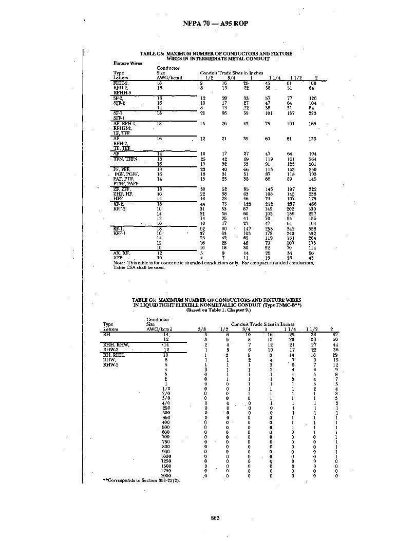
N F P A 70 - - A 9 5 R O P
TABLE C5: MAXIMUM NUMBER O F CONDUCTORS AND FIXTURE WIRES IN INTERMEDIATE METAL CONDUIT
Fixture W'w~ Conductor
Type S i ~ Condui t Trad~ Si~s in ~ c h ~ Letters AWG/kcmU 1/2 3 / 4 1 1 1 /4 1 1 /2 2 FHH-2, 18 0 - 16 26 45 61 100 RFH-2, 16 8 13 22 ~ _ 51 84 RFHH-3 SF-2, 18 12 20 33 57 77 126 SFF-2 16 10 17 27 47 64 104
14 8 13 ,22 38 51 84 S ~ l , 18 21 36 59 101 137 225 SFF-1 AF, RFH-1, 18 15 26 43 75 101 165 RFHH-2, TF, TFF AF, 16 12 21 35 66 81 133 RFH-2, TF, TFF AF 14 10 17 27 47 64 104 TFN, TFFN .18 25 42 69 119 161 264
16 19 32 53 91 123 201 PF, PFF, 18 23 40 66 113 153 250 PGF, PGFF, 16 18 31 51 87 118 193
PAF, PTF, 14 13 23 38 66 8 9 " 145 PTFF, PAFF ZF, ZFF, 18 30 52 85 146 197 322 ZHF, HF, 16 22 ~ 63 108 145 258 HFF , 14 16 28 46 79 107 175 ~ - 2 , 18 44 75 123 212 287 468 KFF-2 16 31 53 87 149 202 330
14 21 36 66 103 139 227 12 14 25 41 .70 95 156 10 "10 17 27 , 47 ' 64 104
I~- l , 18 52 90 147 253 ~ 2 558 KFF-1 1 6 ' 37 63 103 178 240 392
14 25 42 " 69 119 161 264 12 16 28 46 79 107 175 10 10 18 ~ 52 70 114
AX, XF, 12 5 9 14 25 ~ 56 XFF . 10 4 7 11 19 26 43 N o t e : T h i s ~ b l e i s ~ r c o n c e n t f i c s ~ d e d c o n d u c t o r s o n ~ . F o r c o m p a c t s t r a n d e d c o n d u c t o r s , T a b l e C 5 A s h a l l ~ used.
TABLE C6: MAXIMUM NUMBER OF CONDUCTORS AND FIXTURE WIRES IN LIQUIDTIGHT FLEXIBLE NONMETALLIC CONDUIT (Type FNMC-B**)
(Based on Table 1, Chapter 9.)
. Conduc tor Type Size Condui t Trade Sizes in Inches Letters AWG/kcm il 3 / 8 1 / 2 $ / 4 1 1 1 / 4 RH 14, 3 6 10 16 29
12 3 5 8 13 23 RHH, RHW, ~14 2 4 7 12 21 RHW-2 12 1 $ 6 10 17 RH, RHH, 10 1 .3 5 8 14 RHW, 8 1 1 2 4 7 ~ - 2 6 1 1 1 3 6
4 0 1 1 2 4 3 0 1 1 1 4 2 0 1 1 1 3 1 0 0 1 1 1
1 /0 0 0 1 1 1 2/O 0 0 1 1 1 3 / 0 0 0 0 1 1 4/O 0 0 0 1 1 250 0 0 0 0 1 300 0 • 0 0 0 1 350 0 0 0 0 1 400 0 0 ' 0 0 1 500 0 0 0 0 1 600 0 0 0 0 0 700 0 0 0 0 0 750 0 0 0 0 0 800 0 0 0 0 0 900 0 0 0 0 0 1000 0 0 0 0 0 1250 0 0 0 0 0 1500 0 0 0 0 0 1750 0 0 0 0 0 2000 .0 0 0 0 0
**corresponds to Section 351-22(2).
1 1 /2 2 38 62 30 . 50 27 44 22 36 18 29
9 15 7 12 6 9 5 8 4 7 3 5 2 4 1 3 1 $ 1 2 1 1 1 1 1 1 1 1 1 1 1 1 0 1 0 1 0 1 0 1 0 1 0 0 0 0 0 0 0 0
/
8 6 3
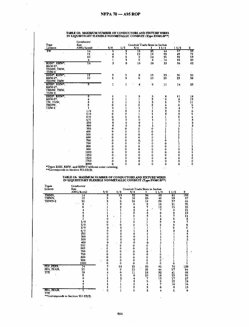
N F P A 70 - - A 9 5 R O P
Type Lettters TW
' RHH*, RHW*, RHW-2*, THHW, THW, THW-2 RHH*, RHW*, RHW-2*. THHW, THW RHH*. RHW*. RHW-2*, THHW, THW, THW-2 RI-IH*, RI-IW*, RHW-2*, TW, TI-IW, THHW, THW-2
TABLE C6: MAXIMUM NUMBER OF CONDUCTORS AND FIXTURE WIRES IN LIQUIDTIGHT FLEXIBLE NONMETAI.J.JC CONDUIT (Type FNMG-B**)
Conduc to r Size Condui t Trade Sizes in Inches AWG/kcmi l 3 / / 8 1 / 2 9 3 / 4 1 1 1 / 4 1 1/72 2
14 ' 15 " ' 25 44 " 9 3 12 4 7 1 2 ' 19 33 43 71 10 3 5 9 14 25 32 53 8 1 3 5 8 . 14 18 29 14 3 6 10 16 29 38 62
. 2000 0 *Types RHH, RHW, and RHW-2 without outer covering. **Corresponds to Section 351-22(2).
12 3 5 8 13 23 ' 30 50 10 1 3 6 10 18 23 39
8 ' 1 1 4 6 11 14 23
6 1 1 3 5 8 11 18 4 1 1 1 3 "6 8 13 3 1 1 1 3 5 7 11 2 0 1 1 2 4 6 9 1 0 1 1 1 "3 4 7
1 / 0 0 0 1 1 2 3 6 2/O 0 "0 1 1 2 3 5 3/O 0 0 1 1 1 2 4 4/O 0 0 0 1 1 1 3 25O 0 0 0 1 1 1 3 300 0 0 0 1 1 1 2 350 0 0 0 0 1 1 1 400 0 0 0 0 1 1 1 500 0 0 0 0 1 1 1 600 0 0 0 0 1 1 1 700 0 0 0\ 0 0 1 1 75O 0 0 0 0 0 1 1 800 0 0 0 0 0 1 1 9OO 0 0 0 0 0 0 1 1000 0 0 0 0 0 - 0 1 1250 0 , 0 0 0 0 0 1 1500 0 0 0 0 0 0 0 1750 0 0 0 0 0 0 0
0 0 0 0 0 0
TABLE C6: MAXIMUM NUMBER OF CONDUCTORS AND FIXTURE WIRES IN L I Q U I D T I G H T FLEXIBLE NONMETALI.IC CONDUIT (Type FNMC-B**)
Types Conduc to r Letters Size
AWG/kcmi l 3 / 8 THHN, 14 THWN, 12 THWN-2 lO
8 6 4 3 2 1
1 / 0 2 / 0 3 / 0 4 / 0 250 300 350 400 500 600 7O0 750 8OO 000 1000
FEP, FEPB, 14 PFA, PFAH, 12
10 8 6 4 3 2
PFA, PFAH, 1 TFE **Corresponds to Section 351-22(2).
C o n d u i t T m d e Sizes in Inches 1 / 2 3 / 4 1 1 1 / 4 I 1 / 2 2
8 13 22 36 63 81 133 5 9 16 26 46 59 97 3 6 10 16 29 37 61 1 3 6 9 16 21 35 1 • 2 4 7 12 15 25 1 1 2 4 : 7 . 9 15 1 1 1 3 6 8 13 1 1 1 3 5 7 11 0 1 1 1 4 5 8 0 1 1 1 3 4 7 0 0 1 1 2 3 6 0 0 1 1 1 3 5 0 0 1 1 1 2 4 0 0 0 1 1 1 3 0 0 0 1 1 1 3 0 0 0 1 1 1 2 0 0 0 0 1 1 1 0 0 0 0 1 1 1 0 0 0 0 1 1 1 0 0 0 0 1 1 1 , 0 0 0 0 0 1 1 0 0 0 0 0 1 1 0 0 0 0 0 1 1 0 0 0 0 0 0 1 7 12 21 35 61 79 129 5 9 15 25 44 57 94 4 6 11 18 32 41 68 1 3 6 10 18 23 39 1 2 4 7 13 17 27 1 1 3 5 9 12 19 1 1 2 4 7 10 16 1 -1 I 3 6 8 13 0 1 1 2 4 5 9
8 6 4
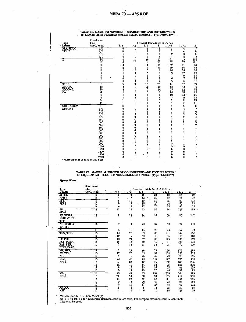
N F P A 7 0 - - A 9 5 R O P
TABLE C6: MAXIMUM NUMBER OF CONDUCTORS AND FIXTURE WIRES IN LIQUIDTIFHT FI.EXn~LE NONMETALLIC CONDUIT (Type FNMC-B**) .
Type Letters PFA, PFAH, T I ~ , Z
Conductor Si~¢ AWG/kcmil
1/0 2/0 ~/0 4/o 14 12 I0 8 6 4 8 2 1
XHH, XHHW, XHHW-2, ZW
14 12 10 8 6 4 8 2
XHH, XHHW, 1 XHHW-2 1/0
• 2/0 8/0 4/0 250 8O0 85O 40O 500 600 70O 750 8OO 9O0 1000 1250 1500 1750 2000
**Corresponds to Section 851-22(2).
Conduit Trade Sizes in Inches 8/8 I / 2 3/4 1 1 1/4
0 I ' 1 . I $ 0 1 1 1 8 0 0 1 1 2 0 0 1 1 1 9 15 26 42 78 6 10 18 80 52 4 6 11 18 82 2 4 7 11 20 1 - 8 5 8 ' 14 I 1 8 5 9 1 1 2 4 7 0 1 1 8 6 0 1 1 2 5 5 9 15 25 44 4 7 12 19 88 8 5 g 14 25 1 $ 5 8 14 1 1 8 5 I0' 1 1 2 4 7 1 1 . 1 8 6 1 1 1 $ 5 0 1, 1 1 4 0 1 1 1 8 0 0 1 1 2 0 0 1 1 1 0 0 1 1 1 0 0 0 1 1 0 0 0 1 1 0 - 0 0 1 1 0 0 0 0 1 0 0 0 0 1 0 0 0 0 1 0 0 0 0 1 0 0 0 0 0 0 " 0 0 0 0 0 0 0 0 0 0 0 0 0 0 0 0 0 , 0 0 0 0 0 0 0 0 0 0 0 0 0 0 0 0 0
11 /2 2 4 7 4 6 8 5 2 4
• 95 156 67 111 41 68 26 48 " 18 80 12 20 9 15 7 12 6 10
57. 98 48 71 82 58 18 29 18 " 22 9 16 8 18 7 11 5 8 4 7 8 6 8 5 2 4 1 8 1 8 1 2 1 1 1 1 1 1 1 1 1 1 1 1 1 1 0 1 0 1 0 1' 0 0 0 0
TABLE C6: MAXIMUM NUMBER OF CONDUCTORS AND FIXTURE WIRES " IN u Q u m T m i c r n ~ x m L E ~ONSmT~-UC CONDUIT c r ~ ~MOB*.)
Fixture Wires
Conductor Type Size Letters AWG/kcmi| ~¢FH-2, 18 RFH-2 16 SF-2, 18 SFF-2 16
14 SF-I, • 18 SFF-I AF, RFH-I, 18 RFH.H-2, TF, T ] ~ AF, RFHH-2, 16 TF, TFF AY 14 Tt~, T t ~ 18
16 PF, PIF, 18 PGF, PGFF, 16 PAF, PTF, 14 PTFF, PAFF HF, HFF, 18 ZF, ZFF, 16 ZHF 14 KF-2, 18 KFF-2 16
14 12 10
KF-1, 18 KFF-1 16
14 12 10
AF, XF, 12 XFF 10
Conduit Trade Sizes in Inches 3(8 1(2 3(4 1 1 1/4 1 1/2 2
5 8 15 24 42 54 89 4 , 7 12 20 35 46 75 6 I I 19 \ 30 53 69 113 5 9 15 25 44 57 93 4 7 12 20 35 46 75
I I 19 33 53 94 122 199 '
8 14 24 39 69 90 147
7 I I 20 32 56 -72
5 9 15 25 44 57 14 23 39 63 I I I 144 I0 17 30 ~ 8 85 110 13 ' 2 1 37 60 105 136 . I0 16 29 46 81 105 7 12 21 35 "61 79
17 28 48 77 136 176 12 20 35 5 7 100 ]29 9 15 26 42 73 95
24 40 70 112 197 255 17 28 49 79 159 180 12 19 34 54 95 123
8 13 23 37 65 85 5 9 15 25 44 57
29 48 83 134 255 304 20 34 58 94 165 214 14 23 39 63 I I I 144
9 15 25 42 73 95 6 I0 17 27 - 48 52 3 5 8 IB 23 30 1 B 6 I0 18 23
• **Corresponds to Section 351-22(2). Note: This table is for concentric stranded conductors only. For compact stranded conductors, Table C.6A shall be used.
865
119
93 235 180 223 173
• 129
288 . 212 156 418 295 202 139 93
499 350 236 156 102. 50 39

N F P A 70 - - A 9 5 R O P
TABLE C7, MAXIMUM NUMBER OF CONDUCTORS AND FIXTURE WIRES IN LIQUIDTIGHT NONMETAIJ.~C CONDUIT (type FNMC-A**) -
(Based on Table 1, f~l,m~ter 9)
Conductor Type Size
tier* AWG/kcmil R]-[ 14
1 2 . RI,-IH, RHW, 14 RHW-2 12 RH, RHH, 10 RI-D~, / 8 RHW-2 6
4 3 2 1
1/0 2/O S/0 4/O 255 300 355 400 500 6OO 700 75O 8OO 9OO 1000 1255 1500 1750 20OO
**Corresponds to Section 351-22(1).
ConduitTrade Sizes in Inches S/S I12 Sl4 1 1 I / 4 I I 1 2 2
3 6 10 16 28 $8 64 3 4 8 1~ 23 31 51 2 4 7 11 20 27 45 l 3 6 9 17 23 38 1 .3 5 8 13 18 30 1 1 2 4 7 9 16 1 1 1 3 5 7 13 0 I I 2 4 6 10 0 1 1 1 4 5 8 0 1 1 1 3 4 7 0 0 1 1 1 3 5 0 0 1 1 1 2 4 0 0 1 1 1 1 4 0 0 0 1 1 1 3 0 0 0 1 .. 1 1 3 0 0 0 0 1 1 1 0 0 0 0 I 1 " 1 0 0 0 0 1 1 1 0 0 0 0 1 1 1
.0 0 0 0 0 1 1 0 0 0 0 0 1 1 0 0 0 0 0 0 1 0 0. 0 0 0 0 1 0 0 0 0 0 0 1 0 0 0 0 0 0 1 0 0 0 0 0 0 1 0 0 0 0 0 0 0 0 0 0 0 0 0 0 0 0 0 0 0 0 0 0 0 0 0 0 0 0
TABLE C7: MAXIMUM NUMBER OF CONDUCTORS AND FIXTURE WIRES IN LIQUIDTIGHT FLEXIBLE NONMETALLIC CONDUIT
(Type FN MC-A**)
~ pe tters
TW
RHH*, RHW* RHW-2*, THHW,-THW, THW-2 RBH*, RHW*, RHW-2*, THHW, THW R]J.J-I *, ~ * , RHW-2*, THHW, THW, THW-2 RHH*, RHW*, RI-IW-2*, TW, THW, THHW, THW-2
Conductor Size Conduit Trade Size* in Inches AWG/kcmil 3 /8 1/2 3 /4 1 1 1/4 1 1/2 2
14 5 . 9 15 24 43 58 96 12 4 7 12 19 33 44 74
-- 10 3 5 9 14 , 2 4 33 55 8 1 3 5 8 13 18 30 14 3 6 10 16 28 38 64
12 10
8
3 4 8 13 23 31 51 1 3 6 10 18 24 40
1 1 4 6 10 14 24
6 1 1 3 4 8 11 18 4 1 1 1 $ 6 8 13 3 1 1 1 3 5' 7 11 2 0 1 1 2 4 6 10 1 0 1 1 1 3 4 7 ,
1 / 0 0 0 1 . 1 2 $ 6 2 / 0 0 0 1 1 1 3 5 3 / 0 . 0 0 1 1 1 2 4 4 / 0 0 0 O" 1 1 1 3 250 0 0 0 1 1 1 3 300 0 0 0 1 1 1 2 350 0 0 0 0 1 1 1 400 0 0 0 0 1 1 1 500 0 0 0 O 1 1 1 600 0 0 0 0 1 .1 1 700 0 0 0 . 0 0 1 1 750 0 0 0 0 0 1 1 800 0 0 0 0 0 1 1 900 0 0 0 0 0 0 1 1000 0 0 0 0 0 ' 0 1 1250 0 0 0 0 0 0 1 1500 0 0 0 0 0 0 1 1750 0 0 0 0 0 0 0
' 2 0 0 0 0 0 0 0 0 ' 0 . 0 STypes RHH, RHW, and RHW-2 without outer covering. ** Corresponds to Section 351-22(1).
8 6 6
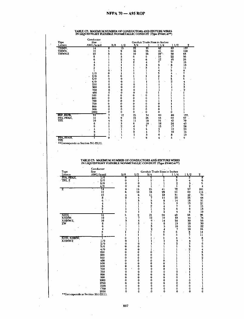
N F P A 7 0 - - A 9 5 R O P
Type Letters THHN, THWN, THWN-2
F E ~ j ~ , - P B ,
PFA, PFAH, TFE
TABLE C7: MAXIMUM NUMBER OF CONDUCTORS AND FIXTURE WIRES IN U Q U I D T I G H T FLEXIBLE NONMETALLIC CONDUIT (Type FNMC-A**)
Conductor Size
AWG/kcmil 14 12 10 8 6 4 5 2 1
1/0 2 /0 3/0 4/0 25O 3OO 35O 4O0 500 6OO 7OO 75O 8OO 9O0 1000
14 12 10 8 6 4 3
, 2 PFA, PFAH, 1 TFE
• **Corresponds to Section 351-T2(1).
Conduit Trade Sizes in Inches
5 9 16 3 6 10 1 3 6 1 2 4 1 1 2 1 1 1 1 1 1 O, 1 1 0 1 I 0 0 1 0 0 1 0 0 I 0 0 0 0 0 0 0 0 0 0 0 0 0 0 0 0 0 0 0 0 0 0 0 0 0 0 0 0 0 0
• 0 0 O 7 12 21 5 9 15 4 6 11 1 3 6 1 2 4 1 1 3 1 1 2 1 1 1 0 1 1
I 1 1 / 4 1 1/2 35 62 83 25 45 60 16 28 ~- 38 9 16 22 6 12 16 4 7 9 3 6 " 8 3 5 7 1 4 5 1 3 4 1 2 3 1 1 3 1 1 2 1 1 1 1 1 1 1 1 . 1 0 1 1 0 1 1 0 1 1 0 1 1 0 0 1 0 0 1 0 0 1 0 0 0 34 60 80 25 44 59 18 31 42 I0 . 18 24 7 13 17 5 9 12
4 7 10 3 6 8 2 4 5
2 137 lOO 63 36 26 16 13 11 8 7 6 5 4
3 2 1 1 1 1 1 1 1 1 133. 97 . 70 40 28 20 16 13 9
TABLE C7: MAXIMUM NUMBER OF CONDUCTORS AND FIXTURE WIRES IN LIQUIDTIGHT FLEXIBLE NONMETALLIC CONDUIT (Type FNMC-A**)
Conductor Type Size Letters AWG/kcmil PFA, PFAH, 1/0
• TFE, Z . 2 / 0 3/0 4 /0
z 14 12 10 8 6 ' '
4 3 2 1
XI-IH, . 14 XHHW; 12 XHHW-2, 10 ZW 8
6 4 3 2
XHH, XHHW, 1 XHHW-2 1/0
2/0 3/O 4/0 250 300 350 400 5OO 6OO 70O 750 800 900 1000 1250 1500 1750 20OO
**Corresponds to Section 351-22(1).
C~nduit Trade sizes in Inches s/8 1/2 V4
o 1 1 0 1 1" 0 0 1 0 0 1 9 15 25 6 10 18 4 6 11 2 4 7 1 $ 5 1 1 - 3 1 1 2 1 1 1 1 1 1 5 9 15 4 7 12 3 5 9 1 3 5 1 1 3 1 1 2 1 1 1 1 1 1 • 1 1 0 1 1 0 0 1 '0 0 1 0 0 1 0 0 0 0 0 0 0 0 0 0 0 0 0 0 0 0 0 0 0 0 0 0 0 0 0 0 0 0 0 0 0 0 0 0 0 0 0 0 0 0 0 • 0 0 0 .0
1 11/4 11/2 2 ] 3 5 8 1 3 4 6 1 2 3 5 1 1 2 4
41 72 97 161 29 51 69 114 18 31 42. 70 11 20 26 44 8 , 14 18 31 5 9 13 21 4 7 9 15 3 6 8 13 2 4 6 I0
24 43 58 96 19 $$ 44 74 14 24 33 55 8 13 18 30 5 10 13 22 4 7 10 16 3 6 8 14 3 5 7 11
• 1 4 5 8 1 3 4 7 1 2 3 6 1 1 3 5 l I , 2 4 1 1 1 3 1 1 1 3 1 1 1 2 0 I I I 0 1 1 1 0 1 1 1 0 1 1 1 0 0 1 1 0 0 1 I 0 0 I I 0 0 0 1 0 0 0 1 o 6 o .1 0 0 0 0 0 0 0 0
867

N F P A 7 0 - - A 9 5 R O P
TABLE C7: MAXIMUM NUMBER OF CONDUCTORS AND FIXTURE WlRF~ IN LIQUIDTIGHT ~ L E NONMETALLIC CONDUIT (Type FNMC,-A**)
Fixture Wires .,i Conductor
Type Size Letters AWG/kcmil 3/8 FFH-2, 18 RFH-2, 16 RFHH-3 SF-2, 18 SFF-2 16
14 SF-1, 18 SFF-1 AF, RFH-I, RFHH-2, "IF, TFF
18
ConduitTrade SizesinInches 1/2 3/4 1 1 I/4 11/2 2
5 8 14 23 41 55 92 4 7 12 20 35 47 77
6 I I ' 18 29 52 70 116 5 9 15 24 43 58 96 4 7 12 20 55 47 77
12 19 35 52 92 124 205
8 14 24 59 68 91 152
AF, RFHH-2, TF r TFF AF 14 TFN, I]~FN 18
16 PF, PFF, 18 PGF, PGFF, 16 PAF, PTF, 14 PTFF. PAFF HF, I-~FF, 18 ZF, ZFF, 16 ZI-IF 14 KF-2, 18 KFF-2 16
14 12 I0
KF-I, 18 KFF-I 16
14 12 10
AF, XF, 12
16 7 I I 19 31 55 74 122
XFF 10 1 3 • **Corresponds to Section 351-22(1). Note: This table is for concentric stranded conductors only. CTA shall be used.
5 9 15 24 43 "58 96 14 22 39 62 109 ' 146 243 10 17 29 47 83 112 185 13 21 37 59 103 139 230 10 16 28 45 80 107 178 7 12 21 34 60 80 133
17 27 47 76 133 179 297 12 20 35 56 98 132 219 9 15 25 41 72 97 161
25 40 69 110 193 260 431 17 28 48. 77 136 183 303 12 19 33 53 94 126 209 8 13 23 36 64 86 143 5 9 15 24 43 58 96
29 48 82 131 231 310 514 21 33 57 92 162 218 361 14 2~2 39 62 109 146 243 9 15 25 41 72 97 161 6 10 17 27 47 63 105 3 4 8 13 23 31 51
6 10 18 ' 2 4 40
For compact stranded conductors, Table
868

N F P A 7 0 - - A 9 5 R O P
TABLE C8: MAXIMUM NUMBER OF C O N D U C T O R S AND FIXTURE WIRES IN
Type Letters R H
Condu~:tor Size AWG/kcmi l
RI-IH; RH'W, Rgw-2 • RI-I, R H H ; ,RHW, RHW-2
L I Q U I D T I G H T FI.ERmI.I~. METAL C O N D U I T (Based on Table 1, ( ~ t e r 9) .
. 3 / 8 1 / 2 14 3 6 1~ 3 5 . 14 2 4 I~ 1 3 10 1 3 8 1 1 6 1 1 4 0 1 3 0 1" 2 0 1 1 0 0
1/o o o 2/O 0 0 3 / 0 o o 4 / 0 0 0 250 0 o 300 0 0 350 0 0 400 0 0 5OO 0 0 6OO 0 0 700 O . 0 750 0 0 800 0 0 900 0 0 lO00 0 0 1250 0 0 1500 0 0 1750 0 o 2000 o . o
Condu i t T rade Sizes in Inches 3 / 4 1 1 1 / 4 ' 1 1 / 2 2 2 1 / ] I0 16 29 38 62 '93 - 8 ' 13 .' 23 30' 50 75 7 12 21 27 44 66 6 10 17 22 36 55 5 8 .14 18 29 44 2, 4 7. 9 ,15 23
• 1 3 6 7 12 18 1 2 4 6 ' 9 14 1 1 4 5 8 13 1 I 3 4 7 11 ' 1 1 1 3 5 7 1 1 1 2 4 6" 1 1 1 , 1 3 5 0 I I 1 3, 4 0 1 1 1 2 4 ' 0 0 1 1 1 " 3 0 0 1 1 1 2 0 0 1 1 1 ' 2 0 0 1 1 1 1 0 0 I I 1 1 0 0 ' 0 1 I 1 0 0 0 0 1 I 0 0 0 0 1 1 0 0 ' 0 0 1 1 0 0 0 0 1 1 0 0 0 0 1 1 0 0 0 0 0 1 0 0 0 0 0 1 0 0 0 0 0 1 0 ~ 0 0 .0 0 0
Type Letters TW
RHH*, RHW*, RHW-2*, THHW, THW. THW-~ RHH*, RHW*. RHW-2*, THHW. RHH*, RHW*. RI-IW-2*/ • THHW/H-IW. .Xn3q-~ RHH*, RHW*, RI--IW-2*, T W T H W
y m g : 2
143 186 " 2 4 3 115 149 195 . 102 1 3 3 173 84 110 144 68 89 116 36 46 61 28 37 48 22 29 38 19 25 33 17 22 29 11 14 19 10 13 16 8" 11 14 7 9 12 6' 8 10 4 6 8 4 5 7 3 5 6 $ 4 6
4 5 2 B 4 I 3 3 I 2 3 1 2 3 1 2 3, 1 1 3 1 1 1 1 1 1 1 1 1 1 1 1
TABLE CA;: MAXIMUM NUMBER OF C O N D U C T O R S AND FIXTURE IN LIQUEDTIGHT FI.i~CI~LE METAL C O N D U I T
C o n d u c t o r Size Condu i t T r a d e Sizes in Inches A w G / k c m i l B{8 1 [ ] 3 [ 4 1 1 1 / 4 1 1 /2 ~; ~ 1{~
~ 14 5 ' " 9 .15 25 44 57 93 " 140 12 4 7 12 19 33 43 71 108 10 3 5 9 14 25 32 53 80 8 1 3 5 8 14 18 29 44
14 3 6 10 16 29 38 62 93
3 s 1/~ 215 " 280 165 215 123 160 68 89
143 186
4 365 280 2O9 116 243
12 3 5 8 13 23 30 50 75 115 149 195 10 1 " 3 6 10 18 23 39 58 89 117 152
1 1 4 6 11 14 23 35 53 70 91
8 11 18 6 8 13 5 7 11 4 6 '9 3 4 7 2 3 6 2 3 5 ! 2 4 1 1 3 1 1 3 1 1 2 1 1 1 1 1 1 1 1 1 1 1 1 0 1 1 0 1 1
6 4 3 2 1
170 2/O 3/O 4/O 250 300 350 4O0 5OO 6O0 7OO 75O
27 2O 17 14 10 8 7 6 5 4 B 3 3 2 1 1 1
1 1 1 0 0 0 0 0 0 0 0 0 0 0 0 0 0
41 53 70 30 40 52 " 26 34 44 22 29 38 15 20 " 26 13" i 7 23 11 15 19 "9 12 16 8 10 13
" B 8 ' I I 5 7 .9 5 6 8 4 6 7 3 5 6 3 4 5 2 3 4 2 3 4
1 3 5 1 1 3 1 i B 1 1 2 1 1 1 0 1 ! 0 1 1 0 1 1 0 0 1 0 .0 1 0 0 1 0 0 0 0 0 0 0 0 0 0 0 0 0 0 0 0 0 0
8 6 9

N F P A 7 0 - - A 9 5 R O P
TABLE C& MAXIMUM NUMBER OF CONDUCTORS AND FIXTURE WIRES IN LIQUIDTIGHT FLEXIBLE ML"TAL CONDUIT
Type . Letters THHN, THWN, THWN-2
Conductor S~e 'Conduit Trade S~es in Inches AWG/kcmil 3/8 1/2 ' 3 /4 1 1 1/4 1 1/2 2 2 1/2
14 8 13 22 36 63 81 133 201 12 5 9 16 26 46 59 97 146 10 3 6 10 16 29 37 61 92 8 1 3 6 9" 16 21 . 35 53 6 1 2 4 7 12 15 25 38 4 1 1 2 4 7 9 15 23 3 1 1 1 3 6 8 13 20 2 1 1 1 3 5 7 11 17 1 0 1 1 1 4 5 ~ 8 " 12
1/0 0 1 .1 1 3 4 7 10 2/0 0 0 1 1 2 3 6 8 3/0 0 0 I 1 1 3 5 7 4/0 0 0 1 1 1 2 4 6 250 0 0' 0 1 1 ,. 1 3 5
' 300 0 0 0 1 1 1 3 4 350 0 0 0 1 1 1 2 3 400 0 0 0 0 1 1 1 3 500" 0 0 0 0 1 1 1 2 600 0 0 0 0 1 1 1 1 700 0 0 0 0 1 1 1 1 750 0' 0 0 0 0 1 1 1 800 0 0 0 0 0 1 1 1 900 0 0 0 0 0 I 1 1 1000 0 0 0 0 0 0 1 1
14 7 12 21 35 61 79 129 195 12 5 9 15. 25 44 57 94 142 10 4 6 l l 18 32 41 68 102 8 ' 1 3 6 10 18 23 39 58 6 1 2 4 7 13 17 27 41 4 1 1 3 5 9 12 19 29 3 1 1 2 4 7 10 16 24
1 1 1 3 6 8 13 20 1 0 1 1 2 4 5 9 14
FF_~, FF_,P~, PFA, PFAH, TFE
PFA, PFAH, TIE
3 3O8 225 141 81'
• 59 36 3O 26 19 16 13 11 9 7 6 5 5 4 3 3 3 2 2 1
299 218 156 89 64 44 37 3O 21
ll~ 401 292 184 106 76 47 4O 33 25 21 17 14 12 10 8 7 6 5 4 4 3 3 3 3
389 284 203 117 83
48 4O 28
523 381 240 138 100 B1 52 44 32 27 23 19 15 12 11 9 8 7 6 5 5 4 4 3
5O7 37O 266 152 108
75 63 52 36
TABLE C& MAXIMUM NUMBER OF CONDUCTORS AND FIXTURE WIRES IN LIQUIIIf r IGHT FLEXIBLE M~I'AL CONDUIT ,
Conductor Type Size Letters AWG/kcmil PFA~ PFAH, 1/0 TFE, Z 2/0
3/0 4/0
Z ' 14 12 10 8 ' 6 4 3 2 1
XHH, 14 XHHW. 12 XHHW-2, 10 ZW 8
6 4 3
XHH. XHHW, 1 XHHW-2 1/0
2/O 3/0 4/0 250.
Conduit Trade Sizes in Inches 3/8 l/X 3 / 4 1 1 114 1 1/R ~ ~ I/R 3 3 118 4
0 1 1 1 3 4 7 I I 18 23 0 1 1 1 3 4 6 9 14 19 0 0 I 1 2 3 5 8 12 16 0 0 1 1 1 2 4 6 I0 13 9 20 26 42 73 95 156 235 360 469 6 14 18 30 52 67 I I I 167 255 332 4 8 I I 18 . 32 41 68 102 156 203 2 5 7 I I 20 26 43 64 99 129 1 4 5 8 14 18 30 45 69 90 1 2 3 5 9 12 20 31 48 62 1 2 2 4 7 9 15 23 35 . 45 1 1 1 3 6 7 12 19 29 38 1 ' I 1 2 5 6 I0 15 23 30 5 12 15 25 44 57 93 140 215 280 4 9 12 19 ' B3 43 71 108 165 215 3 7 9 14 25 32 53 80 123 160 I 4 5 8 14 18 29 44 68 89 1 3 3 6 10 13 22 33 50 66 1 2 2 4 7 9 16 24 36 48 1 1 1 3 6 8 13 20 31 40 1 1 1 3 5 7 11. 17 26 34 0 1 1 1 4 5 8 12 19 25 0 1 1 1 3 4 7 10 16 21 0 0 1 1 2 3 6 9 13 17 0 0 1 1 1 3 5 7 11 14 0 0 1 1 1 • 2 4 6 9 12 0 0 0 1 1 1 3 . 5 7 10
30 25 20 17
611 434 266 168 118 81 59 49 40
365 280 209 116 86 62 52
44 33 28 23 19 16 13
870

N F P A 70 - - A 9 5 R O P
TABLE C8: MAXIMUM NUMBER OF CONDUCTORS AND FIXTURE WIRES IN L I Q U I D T I G H T FLEXIBLE METAL CONDUIT
Fixture Wires
Type Letters FFH-2, RFH-2, RFHH-3 SF-2, 18 6 11 SFFo2 16 5 9
I~ 4 7 SF-1, 18. 11 19 STF-1 AF, RFH-1, 18 8 14 RFHH-2, "IF,
AF, 16 7 11 20 RFHH-2, TF. TFF ~1~ 14 5 9 . 15 'IT'N, TFFN 18 14 23 39
15 I0 17 30 PF, PFF,. 18 13 21 37 PC, F, PGFF, 16 10 -16 29 PAF, FTF, 14 7 12 21
I-IF, H F , 18 17 28 48 ZF, ZFF, ' 16 12 20 35 ZHF 14 9 15 26 " KF-2, 18 24 40 70 KFF-2 16 17 28 49
14 12 19 34 12 8 " 1~, 23 IQ 5 9 15
KF-1, 18 29 48 83 KFF-1 16 20 34 58
14 14 23 39 12 9 15 26 10 6 10 17
AF, XF, 12 3 5 8 XFF 10 2 3 6 Note: This table is for concentric stranded conductors only.
For compact stranded conductors, Table C8A shall be used.
Conductor . Size
AWG/kcmU 3/8 1/2 1 8 . 5 8 16 4 7
Condui tTrade Sizes in Inches 3 /4 1 1 1/4
15 24 42 12 20 35
19 30 53 15 25 44 12 20 35 33 53 94
24 39 69
1 1/2 " 2 54 89 46 75
69 113 57 93 46 75
122 199
90 147
32 56 72 119
25 44 57 93 53 111 144 236 48 85 110 180 60 105 136 223 46 81 105 173 35 61 - 79 129
77 136 176. 288 57 100 129 212 42 73 95 156
112 197 255 418 79 139 180 295
• 54 95 123 202 37 55 85 139 25 44 57 93
134 235 304 499 94 165 214 350 63 111 144 236 42 73 95 156 27 48 52 102 13 23 30 50 10 ' 18 23 39
TABLE C9: MAXIMUM NUMBER OF CONDUCTORS AND FIXTURE WIRES IN RIGID METAL CONDUIT (Based on Table 1, Chapter 9.)
Conductor
Lyp e Size tters ATt~rG/kcmil
R.H / 14
RHH, R a w , ~-tW-2
" RH, RHH, RHW, RHW-2
14 12 10 8 6 4 3 2 1
1/0 2 /0 3 /0 4 /0 250 300 350 400 500 600 700 75O 8OO
' 900 10OO 1250 1500 1750 2OOO
l / ~ "~/4 1 1 1/4 6 10 17 29 5 8 13 23" 4 7 12 21 3 6 10 17 3 5 . 8 14 1 ' 2 4 7 1 1 3 6 1 1 2 4 1 1 2 4 1 1 1 3 O. 1 1 1 0 1 1 1 0 1 1 1 0. 0 1 1 0 0 1 1 0 .0 0 1 0 0 0 1 0 0 0 1 0 0 0 1 0 0 0 1
" 0 0 0 0 0 0 0 0 0 0 0 0 0 0 0 0 ' 0 0 0 0 0 0 0 • 0 0 0 0 0 0 0 0 0 0 0 0 0 0 0 0 0
Condui tTrade Sizes in Inches 1 1 l ~ ~ ~ 1 l ~ 3 s 1 l ~ 4
39 65 93 143 191 246 32 52 75 115 154 198 28 46 66 10"2 136 176 23 $8 55 85 113 146 19 31 44 68 91 118 10 16 23 36 48 61 8 13 18 29 $8 49 5 10 . 14 22 30 $8 5 9 12 19 26 34 4 7 11 17 23 " 29
5 7 I I 15 19 2 4 6 10 13 17 2 4 5 8 11 14 1 3 4 7 10 '12 1 3 , 4 6 8 11 1 1 3 4 6 8 1 I" 2 4 5 7 1 1 2 4 5 6 1 1 1 3 4 6 1 1 1 " ~ 4 5 1 1 1 2 3 4 1 1 1 1 3 4 0 1 1 1 3 3 0 1 1 1 2 3 0 1 1 1 2 3 0 1 1 1 1 3 0 0 1 1 I ' 1 0 0 1 1 1 1 0 0 1 • 1 1 1 0 0 0 1 1 1
5 887 311 276 229 185
97 77 60 53 46 3O 26 23 20 17 13 11 10 9 8 6 6 5 5 5 4 3 3 2 2
6 558- 448 398 33O 267 139 112 87 76 66 44 $8 33 28 24 18 16 15 13 11 9 8 8 7 .7 6 5 4 4 3
-871

N F P A 70 - - A 9 5 R O P i /
TABLE C9,. MAXIMUM NUMBER OF CONDUCTORS AND FIXTURE ~ IN RIGID METAL C O N D U r r
Conductor Type Size Conduit Trade Sizes in Inches "
. Letters AWG/kcmil I12 314 1 1 1/4 1 112 - 2. 2 112 ~ 3 112 TW 14 9 ' ' 15 25 44 59 98 140 216 288
12 7 12 19 33 45 75 107 165 221 10 5 9 14 25 $4 56 80 123 164
- ~ 3 5 8 14 19 31 44 ' 68 91 RHH*, RHW*, 14 6 I0 17 29 39 65 93 143 191
4 , 370
284 212 118 246
THHW, THW, TI-IW-~ RHH*, KI-IW*, RI-IW-2*, THHW. THW RHH*, RHW*, RHW-2 • THHW, THW, T4-1W-2 . RHH*, RHW*, 6 1 RHW-2*, 4 1 TW, THW, 3 I THHW, 2 1 TI-IW-2 I 1
1/0 0 2/0 0 3/0 0 4/0 0 25O 0 300 0 350 0 400 0 5OO 0 6OO 0 700 0 750 0 8OO 0 9O0 0 1000 0 1250 0 1500 0 1750 - 0 2000 O
• "types R.H],-I, R.HW, and RH'W-2 without outer covering.
581 446 332 185 $87
839 644' 48O 267 558
12 5 8 13 23 32 52 75 115 154 198 311 448 10 3 6 10 18 25 41 58 90 120 154 242 350
8 1 4 6 11 15 24 35 54 72 9"2 145 209
3 5 8 11 18 1 3 6 8 14 1 3 5 7 12 1 2 4 6 10 1 1 . 3 4 7 1 1 2 3 6 1 1 - 2 3 5 1 1 1 2 4 0 1 1 1 3 0 1 1 1 3 0 1 1 1 2 0 0 1 1 1 0 0 1 1 1 0 0 1 1 1 0 0 1 1 1 0 0 0 1 1 0 0 0 1 1 0 0 0 1 1 0 0 0 1 1 0 0 0 0 1 0 0 0 0 1 0 0 0 0 1 0 0 0 0 0 0 0 0 0 0
71 53 45 $8 27
' 23 19 16 14 11 9 8 7
. 6 5 4 4 4 4 3 2 2 1 1
27 20 17 14 I0 8 7 6 5 4 3 3 3 2 1 I 1 l 1 1 I 1 1 1
i l l 88 71 60 42 36 31
"26 21 17 15 13 12 10
8 7 7 6 6 5 4 3 3 3
41 55 81 41 26 g5 22 30 15 21 13 18 11 15 9 13 8 10 6 8 5 7 5 6 4 6 3. 5 3 4 2 3 2 3 2 S 1 $ 1 2 1 1 1 ' 1 1 1 1 1
160 120 103 87 61 52
. 44 37 Si 25 2'2 19 17 14 12 I0 10 9 8 8 6 5 4 4
Conductor
Lyp e Size tters AWG/kc-mU
THHN, 14 THWN, 12 THWN-2 10
8 6 4 3 2 1
1/0 2 /0 3/0 4/0 250 300 350 4OO 5O0 6OO 700 75O 8O0 900 ~t00o
PFA, PFAH, 12 TFE 10
8 6 4 3
Pro, rF~a-i, ~, TFE
TABLE C9: MAXIMUM NUMBER OF CONDUCTORS AND FIXTURE WIRF_S IN RIGID METAL CONDUIT
1/2 3 /4 ' 1 - 1 1 / 4 13 22 $0 63 9 16 26 46 6 1O 17 29 3 6 9 16 2 4 7 12 1 2 4 7 1 1 3 6 1 1 3 5 1 1 1 4 1 1 I 3 0 1 1 2 0 1 1 1 0 1 1 1 0 0 1 . 1 o 0 1 1 0 0 1 1 0 0 1 1 0 0 0 1 0 0 0 1 0 0 0 1 0 "0 0 0 0 0 0 0 0 0 0 0 0 0 0 0
12 22 35 61 9 . 16 26 44 6 I I 18 32 3 6 1O 18 2 4 7 13 1' 3 5 9 1 2 4 7 1 1 3 6 1 1 2 4
C0ndui tTrade Sizes in Inches 1 1 / 2 . 2 2 1 / 2 3 3 1 / 2 - 4 5 . 0
85 140 200 809 412 531 833 1202 62 102 146 225 $01 $87 608 877 39 .64 92 142 189 244 $83 552 22 37 53 ~82 109 140 2"21 318 16 27 $8 59 79 101 159 230 10 16 23 36 48 62 98 141 8 14 20 31 41 53 85 120 7 11 17 26 34 44 70 100 5 . 8 12 19 25 33 51 74 4 7 10 16 21 27 45 65 3 6 8 13 18 23 S6 52 3 5 7 11 15 19 30 45 2 4 6 9 . 12 16 25 $0 1 3 5 7 10 13 20 29 1 3 4 6 8" 11 17 25 1 2 3 5 7 10 15 22 1 2 $ 5 7 8 15 20 1 1 2 4 5 7 11 16 1 I 1 3 4 6 9 13 1 1 1 3 4 5 8 11 1 1 1 3 4 5 7 11 1 ~ 1 1 2 3 4 7 10 1 1 1 '2 3 • 6 9 1 1 1 - 1 3, 4 6 8
83 156 194 300 400 515 808 1166 60 99 142 219 292 376 '590 851 43 71 102 157 209 269 423 610 25 41 58 90 120 ~ 154 242 350 17 29 41 64 85 110 "172 249 12 20 29 44 59 77 120 174 " 10 17 24 37 50 64 100 145 8 14 20 31 41 53 83 120 6 9 14 21 28 37 57 83
872

N F P A ' 7 0 - - A 9 5 R O P
TABLE C9, MAXIMUM N U M B E R O F C O N D U C T O R S AND FIXTURE WIRES I N RIGED IVlETAL C O N D U I T
Conductor Type Size Let ters A W G / k c m i l PFA, PFAH, 110 'I'FE; Z 2 1 0 .
3 / 0
Z 14 12 10 8 6 4 3 2 I
X H H , 14 X H H W , 12 XHHW-2, 10 ZW 8
6 4 3 2
XH]~I, XHIL][~/, XI-H'IW-2
1 1 /o 2 / o ~ /0 4 / 0 25O 3OO 35O 4OO 5OO 600. 700, 75O 8OO 9OO 1000 1250 1500 1750 2OOO
C o n d u i t T r a d e Sizesin Inches 1 /2 ~ )4 1 1 1 /4 1 1 /2 2 2 1 / 2 3
1 1 1 3 5 8 11 18 1 1 1 3 4 6 , 9 14 0 1 1 2 3 5 8 12 0 1 1 1 " 2 4 6 I0
15 . 26 4~ 73 I00 ' 1 6 4 234 . 361 10 18 30 52 71 116 166 256
6 . I I 18 32 " 43 71 10'2 157 4 r 7 11 20 27 45 64 99 3 5 8 14 19 3L 45 69 I" " 3 5 9 13 22 31 4 8 - . 1 2 4 7 9 16 " 22 35 I 1 3 6 8 13 19 29 1 1 2 5 6 I0 15 23 9 15 25 44 59 98 140 216 7 12 19 33" 45 75 107 165 5 9 14 25 34 56 80 123 3 5 8 14 19 31 44 68 1 3 6 10 14 23 33 51 1 2 4 7 10 16 24 37 1 1 3 6 8 14 20 31 1 1 3 5 7 ' 12 17 26 1 . 1 1 4 5 9 12 19 1 1 I 3 4 7 I0 - 16 0 1 1 2 3 6 9 13 0 1 1 1 3 5 7 11 0 1 1 1 2 4 6 9 0 0 1 1 1 3 5 7 0 0 1 1 1. 3 4 6 0 0 I 1 1 2 3 6 0 0 1 1 1 2 3 5 0 0 0 1 1 1 2 4 0 0 0 1 1 1 .I 3 0 . 0 0 1 1 1 I , " 3 0 0 0 0 1 1 1, 3 0 0 0 0 1 1 1 2 0 0 0 0 1 ' I 1 2 0 0 0 0 I I I 1 0 0 0 0 0 1 1 1 0 0 0 0 0 1 1 1 0 0 0 0 0 0 1 1 0 0 0 0 0 0 1 1
3 1/2 24 19 16 13
482 342 209 132
93 64 47 39 31
288 221 164 91 68 49 41 35 26 22 18 15 12 10
9 7 7 5 4 4 4 3 3 3 2 1 1 1
4 3O 25 21 17
691 440 26~ 170 120 82 60 5O 4O
37O. 284 212
.118 87
, 6 3 53 45 33 28 23 19 16 13 11 10
9 7 6 5 5 4 4 4 3 2 1 1
5 6 48 69 40 57 33 47 27 39
974 1405 691 997 423 610 267 386 188 , '271 1'29 186
94 136 78 115
9"2 581 839 446 644
,332 48O 185 267
• 137 197 99 143
.84 121 70 101 52 76 44 64 37 53 30 44 25 36 20 30 18 25 15 22 14 20 11 16
9 13 8 11 7 11 7 10 6 9 ' 6 8 4 6 4 5 3 5
4
TABLE C9: MAXIMUM NUMBER OF CONDUCTORS AND FIXTURE WIRES IN RIGID METAL C O N D U I T
Flxtm'e W i r ~ Conductor
Type Size . Letters AWG/kc rail FFH-2, 18 " P-,FH-2, 15 RFHI-I-3 SF-2, 18 SFF-2 16
I I SF-I, 18 ;~//-1 AF, RFH-I, 18 RFHH-2, TF, T / / AF, 16 RFHH-2, "I'T. "rFF AF 14 TFN, TFFN 18
1§ PF, PFF, 18
• PGF, PGFF, • 16 PAF, PTF, P'rFF, I'AFF , ' ]4 PIT, HFF, 18 ZF, ZFF, 16 ZI-IF 14 KF-.2, 18 KFF-2 16
14 12 19
I~- l , 18 KI~-I 15
14 12 IQ
AF, fXF, 12 X l ~ ' ' 10
Conduit Trade Sizes in Inches 1 / 2 3 / 4
8 15 7 12
11 19 .9 15 7 12
19 33
14 25
1 1 1 /4 1 1 /2 24 42 57 20 3.5 48
31/ 53 72 25 44 59 20 ~.5 48 54 94 127
40 69 94
2 94 79
118 98 79
209
155
I I 20 32 56 76 125
59 150 115 - 143 110.
83 184 136 100 267 188 129 89 59
318 224 150 100
65 32 25
9 15 25 44 23, 40 64 111 ,17 30 49 84 21 38 61 105 16 29 47 81
12 22 35 61 28 48 79 135 20 36 58 100 15 26 42 73 40 71 114 197 . 28 50 80 138 19 34 55 95 13 23 38 65 9 15 25 44
48 84 136 23.5 34 59 96 165 23 40 64 I I I 15 26 . 42 73 10 17 28 48 5 8 13 23 3 6 10 18
Note: This table is for concentric stranded conductors only. For compact stranded conductors, Table C9A shall be used.
98 248 189 235 181
136 303 223 164 439" 31o 918 146
98 524 308 248 164 lO7 52 41
8 7 3
N F P A 70 - - A 9 5 R O P
RH
RH]-I, Rl-lr~/, RHW-2 RH, RHH, RHW, RHW-2,
TABLE Cl0: MAXIMUM NUMBER OF CONDUCTORS AND FIXTURE WIRES IN RIGID PVC CONDUIT, SCHEDUI~ 80
(Based on Table 1, Chapter 9.)
Conductor Size Condui tTrade Sizes in Inches
O kcmil 1 3 1 1 1 " " 1 3 $1 .14 4 8 13 23 32 55 79 123 166 215 341 12 3 6 10 19 26 44 63 99 133 173 274 14. 3 5 9 17 23 39 56 88 118 153 243 12 2 4 7 14 19 32 40 73 98 127 202
' I 0 I 3 6 I I 15 26 37 59 79 103 163 8 1 1 3 6 8 13 19 31 41 54 85 6 1 1 2 4 6 11 16 24 35 43 08 4 1 1 1 3 5 8 12 19 26 33 53 3 0 1 1 3 4 7 11 17 23 29 47 2 0 1 1 3 4 6 9 14 20 25 41 1 0 1 1 1 2 4 6 9 13 17 27
1/0 0 0 1 1 1 $ 5 8 11 15 23 2 /0 0 0 1 1 1 3 4 7 10 13 20 3/0 0 0 1 1 1 3 4 6 8 11 17 4/0 0 0 0 1 1 2 3 5 7 9 15 250 0 0 0 1 1 1 2 4 5 7 11 300 0 0 0 1 1 1 2 3 5 6 10 350 0 0 0 1 1 1 1 3 4 5 9 400 0 0 0 0 1 1 1 3 4 5 8 500 0 0 0 0 1 1 1 2 3 4 7 600 0 0 0 0 0 1 1 1 3 3 6 700 0 0 0 0 0 1 1 1 2 3 5 750 0 0 0 0 0 1 1 1 2 3 5 800 0 0 0 0 0 1 1 1 2 3 4 1000 0 0 0 0 0 1 1 1 1 2 4 1250 0 0 0 0 0 0 1 1 1 1 3 1500 0 0 0 0 0 0 1 1 1 1 2- 1750 0 0 0 0 0 0 0 1 1 1 2 2000 0 0 0 0 0 0 0 1 1 1 1
5 490 394 349 29O 234 122 98 77 67 58 38 33 29 25 21 10 14 13 12 10 8 7 7 7 5 4 4 3 . 3
ype tters
"INV
TABLE Cl 0z MA~MUM NUMBER OF CONDUCTORS AND FIX'rURE WIRES IN RIGID PVC CONDUIT, ~ U L E 80
Rm~*, I~I~/~ , RI-IW-2*, . THHW, THW, THW-2 RHH*, RHW*, RHW-2*, THHW. THW RHH*, RHW*, RHW-2*, THHW, THW, THW-~ RHH*, RHW*, RHW-2*, TW, THW, THHW, THW-2
Conductor S~e • CondultTrade SizeslnInches
AWQ/kcndl 1/2 8/~ 1 1 1/4 1 1/2 ~ 2 1/2 ~ 3 1/2 4 14 6 11 20 35 49 82 ' 118 185 250 324 12 5 9 15 27 38 63 91 142 192 248 10 3 6 l l 20 28 47 67 106 143. 185
1 3 6 11 15 26 $7 59' 79 108 14 4 8 13 23 32 55 79 123 166 215
514 394 294 163 841
736 565 #,.21 234 490
12 3 6 10 19 26 - 44 63 99 133 178 274 394 10 2 5 8 15 20 34 49 77 104 135 214 307
8 . "I 3 5 0 12 20 29 46 62 81 128 184
48 62 98 141 85 46 73 105 30 89 68 90 26 33 53 77 18 23 37 54 15 20 32 46 13 17 27 39 11 14 23 33
9 12 19 27 7 9 15 22 6 8 13 19
• 6 7 12 17 5 7 10 15 4 5 9 13 3 4 7 10 3 4 6 9 3 4 6 8 3 3 6 8 2 3 5 7 2 3 5 7 1 2 4 5 1 1 3 4 1 1 3 4 1 1 2 3
6 1 1 3 7 9 . 16 22 35 4 I I $ 5 7 12 17 26 3 1 1 2 4 6 ' I0 "14 22 2 1 1 1 3 5 8 12 19 1 0 I 1 2 3 6 8 13
1/0 0 I I I 3 5 7 11 2/0 0 1 1 1 2 4 6 10
\ 3 / 0 0 0 1 1 1 3 5 8 4/0 0 0 1 1 1 3 4 7 250 0 0 0 1 1 2 3 5 300 0 0 0 1 1 1 3 5 350 0 0 0 1 1 1 2 4 400 0 0 0 1 1 I 2 4 500 0 0 0 1 I 1 1 3 600 0 0 0 0 1 1 I 2 700 0 0 0 0 1 I 1 2 750 0 0 0 0 0 1 1 1 800 0 0 0 0 0 1 I 1 900 '0 0 0 0 0 I I I 1000 0 0 0 0 0. 1 I ' 1 1250 0 0 0 0 0 1 1 1 1500 0 0 0 0 0 0 I 1 1750 0 0 0 0 0 0 I I 2000 0 0 0 0 . 0 0 0 I
s'rvpes RHH, RHW, and RHW-2 without outer covefin~.
874
N F P A 70 - - A 9 5 R O P
Type Letters THHN,
. T H W ~ THWN-2
- I;E,P; FEPB, PFA, PFAH, TFE
Conductor Size
AWGlkcmil 14
'12 I0 8 6 4 3 2
. 1 I / 0 2 /0 3/0 4/0 250 " 3OO 350 4OO 500 600. 700 75O 8OO 9OO
1{~9 14 12 10 8
6 4 3
PFA, PFAH,
PFA, PFAH, TEE, Z
1/o 2/0 3/0 4/O
TABLE CI0: MAXIMUM NUMBER OF CONDUCTORS AND FIXTURE WIRES IN . RIGID PVC CONDUIT, S(~IEDULE 8 0
ConduitTrade Sizes in Inches 1/2 3/4 1 1 1/4 1 1/2 2 2 1/2 ~ 3 1/2 4 5
9. 17 28 51 70 118 170 265 358 464 736 1055 6 12 20 37 51 86 124 193- 261 338 537 770 4 7 13 23 32 54 78 122 164 213 338 485 2 4 7 13 18 31 45 70 95 123 195" 279 I 3 5 9 13 22 32 51 68 89 141 202 1 1 3 6 8 14 20 31 42 54 86 124 1 1 3 5 7 12 17 26 35 46" 73 105 1 1 2 4 6 10 14 22 30 39 61 88 0 1 1 3 4 7 10 16 22 29 45 65 0 1 1 2 3 6 9 14 18 24 38 55 0 1 1 1 3 5 7 .11 15 20 32 46 0 1 1 1 2 4 6 9 13 17 26 38 0 0 1 1 1 3 5 , 8 10 " 14 22 31 0 0 ' 1 1 1 3 4 6 8 11 18 25 0 0 0 1 1 2 3 5 7 9 15 22 0 0 0 1 1 1 3 5 6 8 13 19 0 0 0 1 I. 1 3 4 6 "7 12 17 0 0 0 1 1 1 2 3 5 6 10 14 0 0 0 . 0 1 1 1 3 _ 4 5 8 12 0 0 0 0 1 1 1 2 3 4 7 10 0 0 0 0 1 1 1 2 . 3 4 7 9 0 0 0 0 1 1 1 2 3 4 6 9 0 0 0 0 0 1 1 1 3 3 6 8 0 0 0 0 0 1 1 I 2 5 5 7 8 16 27 49 68 115 164 257 347 ' 450 714 1024 6 12 20 36 50 84 120 188 253 328 521 747 4 8 14 26 36 60 86 135 182 235 374 556 2 5 8 15 20 34 49 77 104 135 214 307 1 3 6 10 14 24 35 55 74 96 152 218 1 2 4 7 10 17 24 38 ' 52 67 106 153 1 1 3 6 8 14 20 32 43 56 89 127 1 1 3 5 7 12 17 26 35 46 73 105 I I I " 3 5 8 I I 18 25 32 51 73
0 1 1 3 4 7 10 15 20 27 42 61 0 1 I 2 3 5 8 12 17 22 35 50 0 1 1 "1 2 4 6 10 14 18 29 41 0 0 1 1 1 4 5 8 11 15 24 34
~pe Letters
XHHj XHHW, XI-DiW-2, ZW
X]-IH, XHHW, XHHW-2
TABLE Cl0: MAXIMUM NUBER OF' CONDUCTORS AND FIXTURE WIRES IN RIGID PVC CONDUIT, SCTtEDUI~ 80
Conductor Size AWG/kcmil
14 10 12 7 1 0 4 8 3 6 2 4 1 3 1 2 1 1 o 14 6 12 5 10 3 8 1 6 1 4 1 3 1
1 0 1/0 0 2 /0 0 3/o o
• 4 / 0 0
25O 0
1/2 3/4
19 14 8 5 4 2 2 1 1 11 9 6 3 2 1 1 1 1 1 1 1 0 0
1 1 1/4
33 59 23 42 14 26 9 10 6 11 4 8 3 5 2 . 5 2 4
• 20 • 35 15 27 ~1 20 6 11 4 8 3 0 3 5 2 4 1 3 1 2 1 1 1 1 1 1 1 1
Conduit Trade Sizes in Inches 1 1/2 2 2 1/2 3 3 1/2 4 5
82 138 198 310 418 542 860 1233 58 98 141 220 297 ~385 610 875 36 60 86 135 182 235 374 536 22 38 54 85 115 149 236 339 16 20 38 60 81 104' 166 238 11 18 26 41 55 72 114 164 8 13 19 30 40 52 83 119 6 11 16 25 33 43 69 99 5 9 13 20 27 35 56 80 49 82 118 185 250 324 514 736' 38 63 91 142 192 248 394 565 28 47 67 106 143 185 294 421 15 26 37 59 79 103 163 234 11 19 28 43 59 76 121 173 8. 14 20 31 42 55 87. 325 7 12 17 26 36 47 74" 106 6 10 14 22 30 39 62 89 4 7 10 16 22 29 "46 66 3 6 9 14 19 24 39 56 3 5 7 11 16 20 32 46 2 4 6 9 13 17 27 58 I 3 5 8 11 14 22 32 1 3 4 6 9' 11 18 26
87~
N F P A 70 - - A 9 5 R O P
TABLE CI0: ~ NUMBER OF CONDUCTORS AND FIXTURE WIRES IN RIGID PVC CONDUIT,
SC3~IEDULE 80 Fixture Metres
Conduc~r Ty~, " Size Conduit Trade Si~s in Inches L e t ~ AWG/kcmi[ 1 /2 $/4 1 1 1/4 1 1/2 FFH-2, 18 6 11 19 34 47 79 RFH-2, 16 5 9 16 28 $9 67 RFI-IH4 SF-2, 18 7 14 24 4$ 59 100 SFF-2 16" 6 11 20 $5 49 82
14 5 9 16 28 39 67 S"F-1, 18 15 25 42 76 105 177 SFF-1 AF, RFH-I, 18 10 18 31 56 77 150 R F I - ~ , TF. TFF AF, 16 8 15 25 45 62 105 RFHH~, TF, T FF AF ~ 6 11 20 35 49 82 TFN, T FFN 18 16 29 50 90 124 209
IO 12 22 38 68 95 159 PF, PFF, 18 15 28 47 85 118 198 PGF, PGFF, 16 11 22 36 66 91 153 PAF, PTF, 14 8 16 27 49 68 I15 PT~. P A ~ ZF, ZFF, 18 19 $6 61 110 152 255 ZH~,I-IIZ, 16 14 27 45 81 112 188
14 I0 19 33 59 - 82 158 KF-2, KFF~ 18 28 5B 88 159 220 ~71
16 19 37 62 112 155 261 14 13 25 43 77 107 179 12 9 17 29 53 75 123 ~9 6 ' 11 20 85 49 82
K1;';I, 18 ~ 63 I06 Ig0 263 442 141TF-1 16 23 44 74 153 185 $10
14 16 29 50 . 90 124 209 12 10 19 $$ 59 82 138 | 0 7 13 21 39 54 90
AF, XF, 12 3 6 10 lg 26 44 XFF I0 2 5 8 15. - 20 $4 Nom: Th~ mble h ~rconcentxics t randedconducm~ only. t Forcomo~ts t randedconductom, Table C10Ashallbeused.
T A B L E C I h M A X I M U M N U M B E R O F C O N D U C T O R S A N D F I X T U R E W I R E S I N R I G I D P V C C O N D U I T , S C H E D U L E 40 A N D H D P E C O N D U I T ( B a s e d o n T a b l e 1, C h a p t e r 9.)
C o n d u c t o r Size
T y p e A W G / C o n d u i t T r a d e Sizes in I n c h e s . . . L.e..t.t...e.r..s. ...................................................... .k...c.....~.! ....................... .1./.~. . . . . . . . . . . . . ..3.../.....4. . . . . . . . . . . . . . . . . . . . . . ! . . . . . . . . . . . . . 1 - . k L . ' L ! ~ l L ~ . . . . . . . . . . . . . . . . . ~. ................ ~=1. / .~ . .............. .3. ............ ~ L / . . . 2 ......................... ~ ........................ .5.. . . . . . . . . . . . . .
R H 14
RI-I H , R H W , 14 . . ~ : ~ ........................................... .1..~ ................
R H , - R H H , 10 R H W , 8 R H W - 2 6
4 3 2 1
1 / 0 2 / 0 3 / 0 4 / 0 250 300 350 400 500 600 700 750 800 9 0 0
. 1000 1250 1500 1750
, 2 0 0 0
5 9 16 28 38 6~ 4 8 12 22 30 50 4 7 11 20 27 45 3 5 ' 9 l 0 22 37 2 4 7 13 18 30 1 2 4 7 9 15 1 1 3 5 7 12 1 1 2 4 .6 10 1 1 1 4 5 8 1 1 1 3 4 7 0 1 1 1 3 5 0 1 1 1 2 4 0 0 1 1 I 3 0 0 1 1 1 0 0 1 1 ,1 2 0 0 0 1 1 1 0 0 0 1 1 1 0 0 0 1 1 1 0 0 0 1 1 1 0 0 0 0 1 1 0 ~ 0 0 0 1 I 0 0 0 0 0 1 O 0 0 0 0 1 0 0 0 0 0 1 0 0 0 0 0 1 0 0 0 0 0 1 0 0 0 0 0 0 0 0 0 0 0 0 0 0 0 0 0 0 0 0 0 0 0 0
9O 7 2 .64 53
43 22 18 14 12 10
7 6 5 4 4
2 2 1 1 1 1 1 1 1 1 1 1
. 1 0
139 186 112 150
99 133 82 110 66 89 35 40 28 37 22 29 19 25 16 22 11 14
9 13 8 11 7 9 6 8 4 6 4 5 3 5 3 4 3 4 2 , 3 1 3 1 2 1 2 1 2 1 1 1 1 1 1 1 1 1 1
240 378 193 3 0 4 171 269 142 2 2 4 115 181
60 9 4 48 76 37 59 3 3 52 28 45 19 29 16 2 6 14 22 12 19 10 16
8 12 7 11 6 10 6 9 5 8 4 6 3 6 . 3 5 $ - 5 3 5 3 4 1 1 3 1 2 1 2
876

N F P A 70 - - A 9 5 R O P
TABLE CI I, MAXIMUM NUMBER OF CONDUCTORS AND FIXTURE WIRES IN RIGID PVC CONDUIT, SCHEDULE 40 AND HDPE CONDUIT
Conductor Size
._Type AWO/ Letien kcmil 1/~ 514 1. 1-1/4 1-1[~ TW 14 8 14 ' 24 42 57
12 6 11 18 82 44 lO 4 8 15 24 52 8 2 4 7 15 18
14 5 9 16 28 38 RHH*,RHW*, RHWr2*,
RHIt*, RttW*, RH'W-2*, . THItW. ~ II.HIt*, R . H ~ , RttW-2*, ' I~ t tW, THW, TttW-~ P.I-rH*, RItW*, RHW-2*, TW, THW, THHW, THW-2
12 4 8 12 22 SO 10 5 6 10 17 24
8 1 3 6 10 14
6 1 4 1 3 1 2 1 1 0
1/0 0 2/0 0 5/0 0 4/0 0 25O 0 500 0 55O 0 4OO 0 500 0 600 0 7OO 0 750 o 800 0 9OO 0 1000 0 1250" 0 1500 0 1750 0 2000 .0
*Twes RHH, RHW, and R.HW-2 without outer coverir~.
2 4 8 11' 1 3 6- 8 1 5 5 7 1 2 4 6 1 1 5 4 1 1 2 3 1 1 1 3 1 1 1 2 0 1 1 1 0 1 1 1 0 1 1 I 0 0 1 1 0 0 I 1 0 0 1 1 0 0 0 1 0 0 0 I O 0 0 1 0 0 0 1 0 0 0 0 0 0 0 O• O• 0 0 0 0 0 0 0 0 0 0 0
'0 0 0 0
Conduit Trade SizesinInches ~' ~-II~ .s S-l/~ 4 94 135 209 280 361 72 105 160 215 277 54 77 119 160 206 SO 43 66 89 115 63 90 139 186 240
5 6 568 8 ~ 436 651 325 470 181 261 878 546
50 72 112 150 19$ 304 439 59 56 87 117 150 287 545
23 53 52 70 90 142 205
18 26 40 53 69 13 19 30 40 51 11 16 25 34 44 10 14 22 29 37
7 10 15 2O 26 6 8 13 17 2"2 5 7 11 15 19 4 6 9 12 16 5 5 8 10 15 5 4 6 8 I I 2 5 5 7 9 1 5 " 5 6 8 1 3 4 6 7 I 2 • 5 5 . 6 1 1 3 4 5 1 1 2 3 4 1 1 2 5 4 1 1 2 3 4 1 1 1 3 $ 1 1 1 2 $ 1 1 1 1 2 1 1 1 1 1 0 1 - 1 1 1 0 1 1 1 1
109 157 81 117 69 100 59 85 41 60 35 51 30 43 25 56 21 3O 17 25 15 21 13 19 12 17 10 14 8 11 7 10 6 10 6 0. 6 8 5 7 4 6 3 5 5 4 5 4
T/LRLE C l h MAXIMUM NUMBER OF CONDUCTORS AND FIXTURE WIRES IN RIGID PVC CONDUIT, SCHEDULE 40 AND EIDPE CONDUIT
Type Letters THHN, THWN, THWN-2
FEP, FEPB, PFA, PFAH, TFE
PFA, PFAH, TFE
Conductor . Size
AWG/ kcmil
14 12 10 8 6 4 5 2 1
1/0 2/0 5/0 4/0 250 500. 550 400 5OO 6O0 700 750 8O0 90O
IQOQ 14 12 10 8 6 4 5
1
I 1 2 314 I I 21
8 15 5 9 3 5 I 4 I ' 2 1, I I I I I I I 0 I - 0 I 0 I 0 0 0 0 0 0 0 0 0 0 0 0 0 0 0 0 0 0 0 0 0 0
I I 20 8 15 6 10 5 6 2 4 1 3
• 1 2 1 1 1 1
1 l d t 4 " 1-1/2 34 60 , 82 • 25 43 59 15 27 57
9 16 21 6 11 15 4 7 9 S 6 8 5 5 7 1 S 5 1 3 4 1 2 1 1 S 1 l '2 1 I 1 1 1 1 I 1 I 0 1 1.
"0 1 I 0 1 1 0 0 1 0 0 1 0 0 I 0 0 I 0 0 0
~S 58 79 24 42 58 17 30 41 10 17 24
7 12 17 5 8 12 4 7 10 3 6 8 2 4 5
Conduit Trade Sizes in Inches
155 193 299 401 517 99 141 218 203 377 62 89 157 184 238 S6 51 79 106 137 26 $7 57 77 99 16 2'2 55 47 61 13 19 30 40 51 I I 16 25 53 43 8 12 18 25 32 7 10 15 21 27 6 8 B 17 22 5 7 11 14 18 4 6 9 12 15 S 4 7 I0 12 $ 4 6 8 11 2 S 5 7 9 I $ 5 6 8 I 2 4 ' 5 7 I I 3 4 5 1 1 5 4 5 1 1 2 $ 4 1 1 2 3 4 1 1 2 3 4 1 1. I 5 $
151 188 290 389 50"2 96 137 212 284 366 69 98 152 204 263 39 -56 87 117 150 28 40 62 85 107 19 28 45 . 58 75 16 25 36 48 62 13 19 30 40 51 9 13 20 28 ' 36
815 594 374 216 156
96 81 68 5O 42 55 29 24 2O 17 15 15 11 9 8 7 7 6 6
790 577 414 237 169 118 98 81 56
6 1178 859 541 S12 225 13~ 11'~ 98 7~ 61 51 42 ~5 28 24 21 19 16 B
' 11 11 10
9 8
1145 854 598 3 ~ 24¢ 170 142 117
81.
877
N F P A 70 - - A 9 5 R O P
TABLE Clh MAXI MNUMBER OF CONDUCTORS AND FIXTURE WI RE SI N RIGID PVC CONDUIT, SCHEDULE 40 AND HDPE CONDUIT
_Type , ].,etters PFA, PFAH, TEE, Z
XHH, XHHW, 'XHHW-2, ZW
Conductor Size
A W G / kcrail 1 /2 3 / 4 1 1-1/4 1-I /2 2
1 /0 ' I 1 1 3 4 8 2 / 0 0 1 1 3 4 6 3 /0 0 1 1 2 3 5 I / 0 0 1 1 1 2 4 14 13 24 40 70 95 158 12 9 17 28 49 68 112 10 6 10 17 30 41 69 8 3 " 6 11 19 26 43 6 2 4 7 13 18 30 4 1 3 5 9 12 21 3 1 2 4 6 9 15 2 1 1 • 3 5 7 12
1 1 2 4 6 10 14 8 14 24 42 57 94 12 6 11 18 32 44 72 10 4 8 13 24 32 54 8 2 4 7 13 18 30 6 1 3 5 10 13 22 4 1 2 4 7 9 16 3 1 1 3 6 8 13 :~ 1 1 3 5 7 11 1 1 1 1 $ 5 8
1 / 0 1 1 1 3 4 7 2 / 0 0 1 1 2 3 6 3 / 0 0 1 1 1 3 5 4 /0 0 1 1 1 2 4 250 0 0 1 1 1 3 300 0 0 1 I 1 . 3 350 0 0 1 1 1 2 400 0 0 0 1 1 1 500 0 0 0 1 1 1 600 0 0 0 1 1 1 700 0 0 0 0 1 1 750 0 0 0 0 I 1 800 0 0 0 0 l I 900 0 0 0 0 1 1 1000 0 0 0 0 0 I 1250 0 0 0 0 0 1 1500 0 0 0 0 0 1 1750 0 0 0 0 0 0 2000 0 0 0 0 0 0
XHH, XHHW, XHHW-2
C o n d u i t T r a d e S i z e s i n I n c h e s 2-1/2 3 ~ 1 / 2
• 11 17 .23 9 14 19 7 12 16 6 9 13
226 350 469 160 248 333
98 152 204 62 96 129 43 67 " 90 30 46 62 22 34 45 18 28 38 14 23 30
135 209 280 103 160 215
77 119 160 43 66 89 32 49 66 23 35 48 19 30 40 16 25 34 12 19 25 10 16 21
8 13 17 7 11 14 6 9 12 5 7 10 4 6 8 3 5 7 3 5 6 2 4 5 1 3 4 1 3 4 1 2 1 2 3 1 2 3 1 1 3 1 1 1 1 1 1 1 1 1 1 1 1
3O 24 2O 16
605 429 263 166 116 8O 58 49 89
861 277 206 115
85 61 52 44 32 27 23 19 15 13 11
9 8 7 5 5 4 4 4 3 3 2 1 1
47 39 32 26
952 675 414 261 184 126
92 77 62
568 436 325 181 134
97 82 69 51 43 36 30 24 20 17 15 13 I I
9 8
' 7 7 6 6 4 4
,3 3
68 56 46 38
1376 976 598 378 265 183 133 I I I 90
8 2 2 631 470 261 193 140 118
99 74 62 52 43 35 29 25 22 19 16 13 11 I I 10
9 8 6 5 5 4
TABLE C11 : MAXIMUM NUMBER OF CONDUCI 'ORS AND FIXTURE WlRI~ IN RIGID PVC CONDUIT, SCHEDULE 40 AND HDPE CONDUIT
Fmttrre ~wes
Conductor S~e
Type AWG/ ' Conduit Trade Sizes m I n c h ~ Let~rs kcmll " 1/2 3 /4 1 1-1/4 1-1/2 FFH-2, 18 8 14 23 40 54 RFI-I-2, 16 6 12 19 33 46 RFHR-~ SF-2, 18 10 17 29 50 69 SFF-2 16 j 8 14 24 '" 42 57
14 6 12 19 33 46 SF-1, . 18 17 31 51 89 122 SFF-I AF, RFH-I, 18 13 "23 38 66 90 RFHH-2, TF, Tire AF, RFHH-2, TF.TFF AF TFN, TFFN
PF, PFF, PC, F, PGFF, PAF, P'rF, PTFF. pAFF I-IF, HFF, ZF, ZFF, ZHF KF-2, KFF-2
K~-I, KFF-I,
2 90 76
i14 94 76
202
149
14 8 14 24 42 57 94 18 20 37 60 105 144 239 ~5 16 28 45 80 i i 0 183 18 19 35 57 I00 137 227 16 15 27 44 77 106 175 14 11 20 33 58 79 131
18 25 45 74 129 176 292 15 18 33 54 95 130 216 ]~ 13 24 40 70 95 158 18 36 55 107 187 256 424 16 26 46 75 132 180 299 14 17 31 52 90 124 205 12 12 22 35 62 85 141 ~0- 8 14 24 42 57 94 18 43 78 128 223 305 505 15 30 55 90 157 214 $55 14 20 ' 37 50 105 144 239 12 13. 24 40 70 95 158 |Q 9 16 26 45 52 103
4 8 12 22 30 50 3 6 10 17 24 59
AF, XF, 12 i0
Note: T h ~ table is for concentric stranded conductors only. For compact stranded conductors, Table Cl lAsha l l be used.
878
16 i0 18 30 53 .73 120
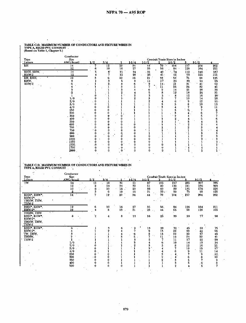
. N F P A 70 - - A95 R O P
TABLE "C 12: MAXIMUM NUMBER OF CONDUCTORS AND FIXTURE WIRESIN TYPE A, RIGID PVC CONDUIT . (Based on Table 1, Chapter 9.)
Conductor Type Size Letters AWG/kcmil RH 14
RHH, RHW," • RI-IW-8
RH, RHH, RHW, RHW-2
14
IO 8 6 4 3 .2 1
1/o 2/0 3/o 4 /0 250 300
. 350 4O0 500 6O0 700 750 800 . 900 1000
- 1250 1500. 1750 2000 .
1 /2 7 6 5 4 3 1 1 1 1 1 o o o o o o o o o o o o o o o o - o .0 o 0
3 /4 12 lO
9 " 7 6 3 2. 1 1 1
', 1 1 1 1 o o o 0 o o o o o o o o o 0 o 0
1 20 16 15 12 10
5 4 3 3 2 1 " ' 1" 1 1 1 1 1'.
"" 0 o o o o o o
'* o" o o 0 o
0
l d ) 4 34 27 24 20 16
8 6 5 4 4 2 2 1 1 1 1 1 1 1 1 0 0 0 0 0 0 0 0 0 0
TABLE C12: ' MAXIMUM-NUMBER OF C()NDUCTORS'AND FIXTURE WIRES IN TYPEA, RIGIDEVC CONDUIT . ', ' , ' .
"" Conductor Type Size Lettem AWG/kcmil i / 2 3 /4 TW 14 11 18
12 8 14 10 . . 6 10
8 . 3 6 RHH*,RHW*, 14 ' 7 12 RHW-2*, ,. THHW, THW, TgW-~
12 10
RI-IH*, RHW*, Panv-~*,- THHW, THW RHH*, RHW*, RHW-2*, THHW, "I'HW, THW- 2 RHH*, RHW*, RHW-2*, TW TI-IW, THHW, THW-2
6 4 3 2 1
1/0 2 /0 s / o . 4 /0
" 250 3OO 350 . 4O0 500
• 1 " "1"174 31 51 24 39 18 " 29 10 16 20 34
6 4
2
10 8
4
16 13
8
27 21
12
1 3 1 2 1 1 1 1 1 1 1 1 0 1 . 0 1 0 1 0 0 .
• 0 0 0 0" 0 0 0 0
6 ' 9 4 7 4 '6 3 5 1 3 1 3 1" 2 1 1 1 1 1 1 1 1 1 1 1 1 0 1
Conduit Trade Sizes in Inches 1 d / 2
44 35
.31 26 21 11
• 9 7 6 5 3 3 2 1 1 1 1 1 1 1 1 1
• 1 1 0 0 0 0 0 0
2 70. 56 49 41
J 33 17 14.
°'. 11 9 8 5 5 4 3 3 1 1 1 1 1 1 1. 1 1 1 1 I 0 0 0
~ 1 / 2 104
84 • • 74
61 •50'
26 21 16 14 12 8 7 6 "" 5 4 3 3
' 2 2 1 1 1 1 1 1 1 1 1 i 1
3 157 126 112
93 75 39 31 24 21 18 12 10 9 8 7 5~ 4 . 4 4 3 2 2 1
"1 1 1 1 1 1 1
Condui tTradeSizes in Inches 1-1/2 2 2-~I~ s
67 105 157 235 51 80 120 181 38 60 89' 135 21 . ,33 ~. 50 75 44 70 104 157
35 28 :
16
204 164 146 121 98 51
- 41.' 32 28 24 16 14 12 10 9 7 6 5 5 4 3 3 3 3 2 2 I I 1 I
13 9 8 7 5 4 3 3" 2 1 1 1 1 1
S-~I2 3O7 236 176 98
2O4
262 211 187 155 1.25
65 52 -41 3 6 31 20 ' 18 15 : 13 11 8 7 7 6 5 4 4 4 3 3 3 2 . 1" 1 1 "
4 .
395 3O3 226 125 262
56. 84 126 164 211 44 65 98 128 165
26 39 59 77 98
20 30 ' 45 59 75 15 22 33 44 56 13 19 29 37 48 11 16 24 32 41
7 11 17 22 "29 6 10 14 19 .24 5 8 12 16 21 4 7 10 13 17 4 6 9 11 14 3 4 7 9 .12. 2 4 6 8 10 2- . 3 5 7 9 1 3 5 . 6 8 1 2 4 5 7
879

N F P A 70 - - - A 9 5 ROP
TABLE C12: M.4~JMUM NUMBER OF CONDUCTORS AND FIXTURE WIRES IN TYPE A, RIGID PVC C ONDUIT
Conductor Size
~ e A W G / tters kcmil
THHN , 14 THWN, 12 THWN-2 I0
8 6 4 3 2 1
1 / o ' , 2 /0
3/0 4/0 25O 3OO 350 4OO 500 6OO 7OO
' 750 800 900
FEP, FEPB, 14 PFA, PFAH, 12 TFE 10
8 6 4 3
PFA, PFAH, 1 TFE
1/2 3 /4 " 1 1-1/4 16 27 44 73 11 19 32 53
7 " 12 20 33 4 7 12 19 3 5 8 14
• . "I 3 5 . 8 1 2 4 7 1" 1 3 6 1 1 2 4 1 1 2 4 I 1 I 3, o 1 1 2 O. ° 1 I I 0 I l 1 0 0 1 1 0 0 1 1 0 0 1 1 0 0 1 1 O, 0 0 1 0 0 0 1 0, 0 0 • 1 0 0 0 1 0 0 0 0 0 0 0 0
15 26 • 43 70 11 19 31 51
8 13 22 37 4 "8 13 21 " 3 ~ 5 9 . 1 5 . 1 4 6 10 ' 1 3 5 8 1 2 4. 7 1 1 3 5
• Conduit Trade Sizes in Inches 1-1/2
96 70 44 25 18 11 9 8 6 5 4 3 3 2 1 1 1 I 1 1 1 I 1 1
93 68 48 28 20 14 11 9 6
2 2-1/2 3 3-1/2 4 150 225 " 338 441 566 109 164 246 321 412 69 103 155 202 260 40 59 89 117 150 28 43 64 84 108 17 26 39 52 6 6
, 15 22 33 44 56 12 19 28 37 47 9 14 21 27 35 8 I I 17 23 29 6 10 14 19 24 5 8 12 16 20 4 6 lO 13 . 17 3 5 8 10 14 $ 4 7 9 12 2 4 6 8 10 2 3 5 7 9 1 3 4 6 7 1 2 3 5 .6 1 1 3 4 5 I I -3 4 5 I I 3 4 " 5 1 1 2 3 4 1 1 2 3 4
146 218 327 427 549 106 '-159 239 312 400
76 114 171 224 287 '44 65 98 128 165 ~31 .46 70 91 117 21 32 49 64 82 18 27 4O 53 68 15 22 33 4 4 . 56
• I0 15 23 30' 39
TABLE C12: MAXIMUM NUMBER OF CONDUCTORS AND FIXTURE WIRES IN TYPE A, RIGID PVC CONDUIT
Conductor Size
~ e ' ' AWG/ tters kcmil
PFA, PFAH 1/0 TFE, Z 2/0
3 /0 4/0
Z 14 12 10 8 6 4 3 2 1
XHH. XHHW.. X.HHW-2, ZW
14 12 10 8 6 4 3
XHH, XHHW, XHHW-2 1/o
2/0 3/0 4/0' 250 300 35O 400 500 600 700 750 800 900 1000 1250 1500 1750 2000
1/2 1 1 1 0
18 13
8 ' 5 3 2 1 1 1
11 8 6 3 2 1 1 1 1 1 1 0 0 0 0 0 0 0 . 0 0 0 0 0 0 0
- 0 0 0
3 /4 1 1 " 2 " 1 1
. 1 1. 1. 1
31 52 22 37 13 22
8 14 6" 10 4 7
: 3" 5 2 4 1 3
18 ' 31 14 24 10 ° 18
6 10 4 7 3 " 5 2 4 1 3 1 3 1 2 1" 1 1 1 1 1 1 1 0 1 0 1
• 0 1 0 1 0 0 0 0 0 0 0 0 0 0 0 0 0 0 0 0 0 0 0 0
Conduit Trade Sizes in 1-1/4 1-1/2
4 3 3
'-2 85
37 23 16 11 8 7 5
51 39 29 16 12 8 7 6 4 4 3 2 1 1 1 1 1 1 1 1 1 1 0 0 0 0 0 0
5 4 3 3
112 79 48 30 21 15 11 9 7
67 51 38 21 15 11 9 8 6 5 4 3 3 2 1 1 1 1 1 1 1 1 1. 1 0 0 0 0
Inches 2 2-112 8 13 7 " lO 6 9 5 7
175 263 124 186
76 114 4 8 72 34 5O 23 35 17 25 14 21 11 17
105 157 80 120
6 0 89 33 5O 24 37 18 26 15 22 12 19
9 14 • 8 12
6 10 5 8 4 7 3 5 3 5 3 4 2 3 1 3 1' 2 1 1 1 1 1 1 1 1
. 1 1 1 1 1 1 1 1 0 1
3 3-1/2 4 19 25 32 16 21 27 13 17 22 11 14 .18
395 515 " 661 280 365 469 171 . 224 287~ 108 141 181
76 99 127 52 68 88 38 50 64 32 41 53 26 33 43
235 307 395" 181 236 303 135 176 226 75 98 125 55 72 93 4O 52 67 34 44 57 28 37 48 21 28 35
- 18 " 23 30 15 19 25 12 16 • 20 • 10 13 17
8 11 14 7 9 12 6 8 10 5 7 9 4 6 8 3 5 6 3 4 5 3 4 5 3 4 5 2 3 4 2 3 4 1 2 3 1 1 2 1 1 2 1 1 1
880

I- . .
N F P A 70 - - A 9 5 R O P
T A B L E C I 2: M A X I M U M N U M B E R O F C O N D U C T O R S C)R F I X T U R E W I R E S I N R I G I D P V C C O N D U I T
F t x t u r e W i r e s
• • C o n d u c t o r Size
T y p e * A W G / L e t t e ~ ~¢ff~| FFH-2 18 RFH:2 , 16 R F H H - 3 SF-2, 18 SFF-2 16
. 1 4 SF-1, / 18
AF, RFH-1 , 18 R F H H - 2 , "IF, TFF AF, • 16 R F H H-2,
A F .14 T F N , T F F N 18
16 PF, PFF, 18 PGF, PGFF, 16 PAF, P T F 1 4
-PTFF. PAFF HF, HFF, • 18 ZF, ZFF, 16 Z H F 1 4 KF-2, 18 KFF-2 16
1 4 12 10
KF-1, 18 KFF-1 16
1 4 • 12 1 0 ,
AF, XF, 12
10 18 9 15
1 3 22 11 18
9 15 2 3 4 0
17 29
C o n d u i t T r a d e S i i es i n I n c h e s
3O 25
3 7 31 25 66
4 9
1 - 1 / 4 4 8 41
" 6 1 51
" 41 108
80
1 4 2 4 39 \
65
11 28 21 2 6 2O 15
' ~4 25 18 4 9 '
, 3 5 2 4 16 11 5 9 41 . 28 18 12
6
18 31 4 7 " 7 9 36 60 45 7 4 3 4 58 26 4 5
58 96 42 71 31 52 8 4 140 5 9 9 8 4 0 6 7 28 4 6 18 3 ]
100 167 70 . 1 1 7 4 7 79 31 52 .20 3 4 10 16
5 1 , 1 2 8
9 8 122
9 4 70
157 . . 116
85 2 2 8 160 110
76 51
272 191 128
85 55 2 7
X F F I 0 . 4 8 . 13 . 21 No te : T h i s t a b l e is f o r c o n c e n t r i c s t r a n d e d c o n d u c t o r s only . F o r c o m p a c t s t r a n d e d c o n d u c t o r s , T a b l e u s e d . - ,
1 - 1 / 2 6 4 5 4
8 1 , 6 7 5 4
143
105
85
6 7 169 129 160 1 2 4
9 3
206 152 112
' 300 211 13.5 , 100
6 7 3 5 7 251 169 1 1 2 .
7 3 35 2 8 .
C 1 2 A sha l l be"
lOO 85
127 105
85 2 2 4
165
134
105 265 202. 251 1 9 4 ~ 146
3 2 4 239 175 4 7 0 331 228 1 5 7 105 561 3 9 4 265 175 115
5 6 4 4
T A B L E C13: M A X I M U M N U M B E R ' O F C O N D U C T O R S I N ', T Y P E EB, P V C C O N D U I T
( B a s e d o n T a b l e 1 , C h a p t e r 9 . ) "
. C o n d u c t o r S i ze
A W G / k c m i l
R H
R H H , R H W , RHW-~ R H , R H H R H W , R H W - 2
1 4
1 4
6 ' •
4 "3 2 1
1 / o 2 / o 3 / o 4 / o 25o
7 4 5 9 5 3 4 4 35 18 15 11 10
9 . 6 5 4 4 3 2
166 134 119
9 8 79 41
• 33 26
'. 23 20" 13 11 10
8 7 5
C o n d u i t T r a d e S i z e s i n ' I n c h e s ~ 1 / ~ 4 5
2 1 7 276 175 2 2 2 155 197 128 163 104 132
5 4 69 4 3 3 4 30 26 17 15 13 1 1 "
9 7
55 4 3 38 33 21 19 16 1 4 12
9
4 2 4 341 3 0 3 251 203 106 85 6 6 5 8 5O 33 29 25 22" 18 14
603 485 4 3 0 3 5 7 288 151 1'21
9 4 83 7 2 4 7 41 36
• 31 2 6 20
8 8 1
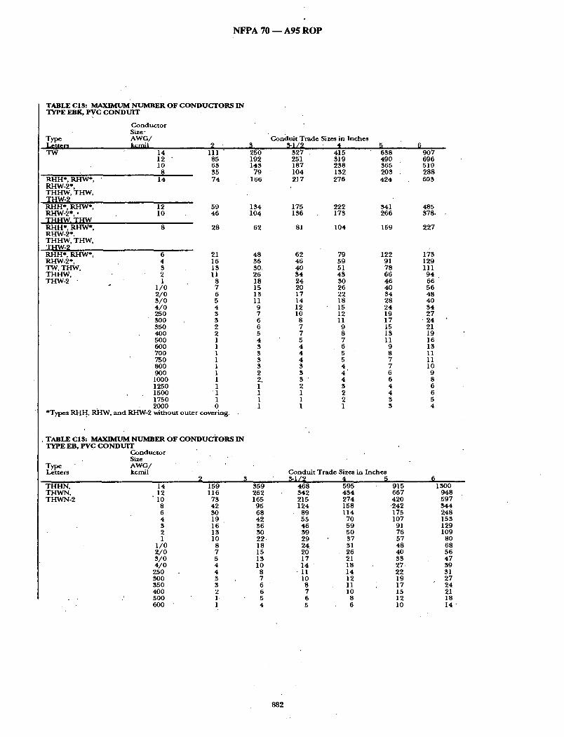
N F P A 70 m A 9 5 R O P
T A B L E C13: M A X I M U M ' N U M B E R O F C O N D U C T O R S 1N T Y P E EBK, P V C C O N D U I T
C o n d u c t o r Size"
T y p e A W G / L e t t e r s k c m i i T W 14
12 ' 10
" ~ - I H * , RH3h/*, ' . 14 RHW-2* , T H H W , T H W , T H W - 2 R H H * , R H W * , RHW-2* , ' T H ~ V V . T H W R H H * , RI-IW*, RI-IW-2*. T H H W , T H W , T H W - 2 R H H * , R H W * , R H W - 2 * , TW, T H W , T H H W , T H W - 2 "
2 111
85 6 3 35 7 4
3 2 5 0 192 143
7 9 166
" C o n d u i t T r a d e Sizes in I n c h e s ~ 1 / 2 4
3 2 7 . 415 251 319 187 2 3 8 104 132 2 1 7 2 7 6
5 6 3 8 490 365 203 4 2 4
6 9 0 7 696 519 2 8 8 603
12 5 9 1 3 4 175 2 2 2 341 485 10 4 6 104 136 173 2 6 6 378,
8 28 62 81 104 159 2 2 7
21 16 13 11
8 7 6 5 4 3 3 2 2 1 1 1 1 1 1 1 1
' 1 1
6 4 3 2 1
1 / 0 2 / O 3 / O 4 / O 25O BOO 35O 40O 5OO 6 0 0 7OO 75O 8OO 9OO
1000 1250 1500 1750 2 0 0 0 0
*Types R H H , l ~ I W , a n d R H W - 2 w i t h o u t o u t e r c o v e r i n g .
4 8 36 30. 26 18 15 13 11 9 7 6 6 5 4 3 3 3 3 2 2. 1 1 1 1
359 2 6 2 165
95 68 4 2 3 6 30 2 2 18 15 13 10
8 7 6 6 5 4
T A B L E C13: M A X I M U M N U M B E R O F C O N D U C T O R S I N T Y P E EB, P v c C O N D U I T
C o n d u c t o r Size
T y p e " A W G / L e t t e r s k c m i l
62 79 122 173 4 6 5 9 91 129 4 0 51 7 8 111 3 4 4 3 66 9 4 2 4 30 4 6 6 6 20 2 6 40 5 6 17 22 3 4 48 1 4 18 28 4O 12 15 2 4 3 4 10 12 19 2 7
8 11 1 7 ' 2 4 7 9 15 21 7 8 1B 19 5 7 11 16 4 6 9 13 4 5 8 11 4 5 7 11 3 4 .. 7 lO 3 4 6 9 3 ' 4 6 8 2 3 4 6 1 2 4 6 1 2 3 5 1 1 B 4
C o n d u i t T r a d e Sizes in I n c h e s
4 6 8 595 342 4 3 4 215 2 7 4 1 2 4 158
89 1 1 4 5 5 70 4 6 59 3 9 5 0 2 9 " 3 7 2 4 31 20 26 17 21 1 4 " 18
• 11 1 4 10 12
8 11 7 10 6 8 5 6
T H H N , T H W N , T H W N - 2
14 159 • 12 116
10 7 3 8 4 2 6 B0 4 19 3 16 2 13 1 10
1 / 0 8 2 / 0 7 3 / 0 5 4 / 0 4
250 4 BOO 3 350 B 4 0 0 2 5 0 0 1, 600 1
9 1 5 6 6 7 42O
2 4 2 175 107
91 76 5 7 4 8 4 0 33 27 . 2 2 19 17 15 12 10
1500 9 4 8 5 9 7 3 4 4 2 4 8 153 129 109
80 68 5 6 4 7 39 31 2 7 2 4 21 1 8 14
8 8 2
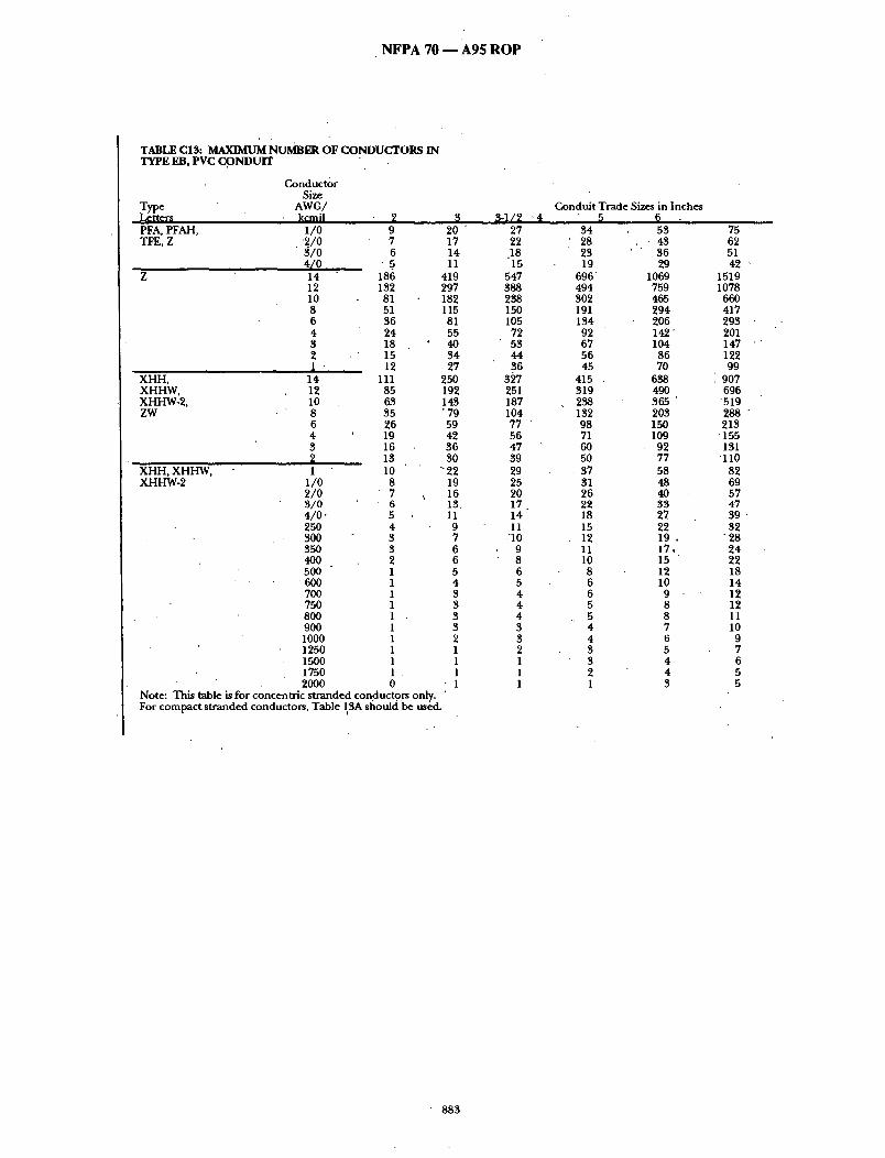
NFPA 70 - - A 9 5 ROP
TABLE C13: MAXIMUM NUMBER OF CONDUCTORS IN TYPE EB, evc CONDUIT
Type , J~et ters PFA, PFAH, TFE, Z
X H H , XHHW, XHHW-2, ZW
X H H , XHHW, XHHW-2
Conductor Size
AWG/ kcm il
1/0 • '2/0
3 /0 4/0 14 12 I0 8 6 4 3 2 I '
14 12 10 8 6 4 3
1 1/0 2/0 S/o 4/0 . 25O 3OO 350 4O0 500
• 600 7OO 75O 8OO 90O 1000 1250 1500 1750
2 9 7 6
• 5_ 186 132 81 51 36 24 18 15 12
111 85 63 35 26 19 16 13 10 8 7 6 5 4 3 3 2 1 1 1 1 1 1 1 1 1 1
2OO0 0 Note: This table is for concentric stranded conductors only. ' For compact stranded conductors, Table 13A should be used.
20 17 14 11
419 297 182 115 81 55 40 34 27
250 192 143 "79 59 42 36 30 22 19 16 13. 11 9 7 6 6 5 4 8 3 3 3 2 1 1 1
• 1
~ 1 / 2 27 22
.18 15
547 388 238 150 105
72 53 44 36
3~7 251 187 104 77 56 47 39 29 25 20 17 14 11
"10 9 8 6 5 4 4 4 3 3 2 1 1 1
"4 Conduit Trade Sizes in Inches
34 28 23 19
696 494 302 191 134 02 67 56 45
415 319 238 132 98 71 6O 5O 37 31 26 22 18 15 12 11 10 8 6 6 5 5 4 4 3 3 2 1
53 , , • 4 3
36 29
• 1069 759 465 294 206 142" 104 86 70
638 490 365 203 150 109 92 77 58 48 4O 33 27 22 1 9 . 17. 15 12 10
9 8 8 7 6 5 4 4 3
75 62 51 42
1519 1078
66O 417 293 201 147 122 99
907 696
519 288 213
'155 131
'110 82 69 57 47 39 32
'28 24 22 18 14 12 12 11 10 9 7 6 5 5
883

N F P A 70 m A 9 5 R O P
SIJBSTANTIATION: Dur ing therev is ion process for the 1993, NEC • a Task Group was fo rmed by the cha i rmen of CMPs 6 and 8 to address proposals that stated the wirefill tables and conductor d imens ion table in C h a p t e r 9 cohta ined many errors. This Task Group pe r fo rmed its wQrk du r ing the c o m m e n t period for the 1993 Code and repor ted its results to CMP 8 at the mee t ing to consider public comments . CMP 8 considered the work of the Task Group, but f o u n d the r e c o m m e n d e d new wirefill tables to be overly restrictive and held C o m m e n t No. 8-232 for fu r ther study. CMP 6 subsequent ly he ld for fu r ther study C ommen t s Nos. 6.106 and 6.110 that dealt with correct ing errors in the tables fo r conductor dirhensions (correct ing 'conductor d imensions .would have fu r ther increased errors in the wirefill tables):
The panel s t a t ement on Comment .No . 8-232 indicated a desire for a new Task Force to be fo rmed that ,~ould include a broader.cross- s ec t i ono f in t e r e s t ed parties. Soon after the 1993 Code was adopted, NEMA fo rmed a Jo in t Section c o m m i t t e e (Jsc) on Raceway Wirefill that inc luded representat ives of all interested Subdivisions of NEMA. The following NEMA Sections were represented on th i sJo in t Sections C.ommittee: Polymer Raceway Sections (5TC); Steel Rigid Condui t and EMT Section (SRN), Building Wire and Cable Section (7RV); the Wir ing Device Section (5WD); and the Condui t Fittings Section (5FB). NEMA believes.this commit tee makeup is responsive to tha t reques ted by CMP 8. In addition, the proposed delet ion of present Table 6, Chapter 9, has been circulated to NEMA's Power & Control Cable Section (TVR) for comment .
Because each condui t or tub ing presently being manufac tu red has a different internal d iameter (with one exception) and the main objective of the original proposer , plus the apparen t wishes of CMP 8 was to e l iminate the errors in the p resen t wirefill tables, t he JSC conc luded tha t the only way to completely el iminate errors was to dex;elop wirefill tables for each type of condui t to tubing. T heJSC also ~bncluded that it would be best not to include these new tables in Chapter 9, ra ther they shou ld b e p l a c e d in an append ix to the code for reference' purposes . T he idea presented is to keep presen t Table t , Chapter 9 (as a m e n d e d ) , with its applicable notes to mainta in the manda to ry provisions of permissible percentage fill, a n d t h e n have the actual fill Cables in a new Appendix C. T he conductor d imens ions and propert ies tables would remain in Chapter 9.
,PANEL ACTION: Accept in Principle. Accept with the following revisions: 1. The title o f C2 is "Maximum N u m b e r of Conductors and fLxture
wires in electrical metallic tubing" 2. The head ing in Table C-2, "Condui t Trade Sizes in Inches" is
changed to "Trade Sizes in inches" 3: The title of C-3 is "M ax i mum N u m b e r of Conductors and fixture
wires in electrical nonmeta l l ic tubing" 4. Delete the 3 / 8 co lumn f rom Tables C-6, C-7, and C-8. 5. Delete the 5 /16 t rade size f rom Table C-1. 6. Replace the p resen t Table 4 in Chapter 9 with the p roposed
Table C-1. R e n u m b e r Tables C-2 t h rough C-13 to C-1 t h rough C-12. Retain. the title, Table 4. PANEL STATEMENT: 1-3. Editorial
4. ,The,3/8 co lumn is dele ted as the n u m b e r of cables in 3 / 8 in condui t is already specified in Table 350-3.
5. The 5 /16 trade size is no t recognized b y t h e Code 6. Table 4 is essential to the user when pe r fo rmi ng calculations to
detern~ine the m a x i m u m n u m b e r of conductors permi t ted in condui t and tubing. NUMBER OF PANEL MEMBERS ELIGIBLE TO VOTE:' 14 VOTE ON PANEL ACTION:
AFFIRMATIVE: 14 COMMENT ON AFFIRMATIVE:
FORSBERG: My notes show that the head ing of Tables C-2 and C-3 was changed to read, " tubing trade size in inches."
(Log #2230) 8£237- (Chapter 9, Table 3): Accept in Pnncip le SUBMITTER: T o m Henry, Code Electrical Classes, Inc. RECOMMENDATION: New text and revise text as follows:
Change table 3A, B, C and add new tables D and E. SUBSTANTIATION: I submi t ted for the 1993 code tha t Table 3 conta ined exactly 230 errors and you rejected my proposal of change which would have corrected the table. Instead, you accepted f6r the 1993 code the installation of RH insulation into the table. Only the good lord knows how many errors Table 3 contains nowl Example, try installing n ine #14RH conductors in a 1/2" conduit . I tried it, and I had to tape four of t hem to the outside o f the conduit .
x
PANEL ACTION: Accept in Principle.. PANEL STATEMENT: Refer to Panel Action on proposal 8-236 NUMBER OF PANEL MEMBERS ELIGIBLE TO VOTE: 14 VOTE ON PANEL ACTION:
AFFIRMATIVE: 14 ' 1 "
(Log #2231 ) 8-238 - (Chapter 9, Table 3): Accept in Principle SUBMITrER: T o m Henry, Code Electrical Classes, Inc. RECOMMENDATION:. Revise Table 3A, 3B, 3C correct ing the 2 3 0 errors these tables now contain in calcul~ttlng the n u m b e r of conductoi-s permi t ted in a conduit . I have personally spen t rOany hours inothese tables correcting t h e m and add ing two new tables 3D and 3E.
Using Tables '4 and 5 and the decimal 0.8 factor f rom note 3 Table 1 . - •
SUBSTANTIATION: Table 3A presently contains 69 errors. 30 errors are made by showing TW-XHHW insulations #14-8. O n e error on #2/0 TW in a 5" condui t should be 28 ho t 29. 38 errors ~ e made on FEPB #6-2 as they are not the same size as TW, THW, etc. Table 3B contains 160 errors by showing T H W N - T H H N as the same as Table 5 co lumn 9 conductors FEB, FEPB, FEPN, TFE, PF, PFA, PFAH, PGF, PTF, Z, ZF, ZFF. Table 3C has only 1 error, # 3 R H H R H W 3-1/2" condui t shou ld read 21 no t 22. I r e c o m m e n d approving the revised and new tables I have submi t ted for a better Table 3 with consistency. At the present~ Table 3B shows 136 conductors #8 in a 4" condui t bu t could be 153 or 187 a difference of 51 conductors . We need a better table than this.
NOTE: Suppor t ing material is availab, le for review at NFPA Headquarters . PANEL ACTION: Accept in Principle. PANEL STATEMENT: Refer to Panel Action on Proposal 8-236 N .UMBER OF PANEL MEMBERS ELIGIBLE TO VOTE: 14 VOTE ON PANEL ACTION:
AFFIRMATIVE: 14
(Log #52) 8-239 - (Chapter 9, Table 3): Accept in Principle
Note: The following proposal consists of C o m m e n t 8-227 on Proposal 8-263 in the 1992 Annua l Meet ing National Electrical Code Technical Commi t tee Report . This Commer i t was he ld for fur ther study dur ing the process ing of the 1993 NATIONAL ELECTRICAL CODE. The r e c o m m e n d a t i o n in ProposaJ 8-263 was:
Revise Table 3A, 3B, 3C correct ing the 230 erroi's these tables now contain in calculating the n u m b e r of conductors permi t ted in a
' coduic I have personally spen t m a n y hour s in these, tables correct ing t h e m and adding two ne~v tables 3D and 3E. "The following pages I 'm submi t t ing is Table 3 in it 's corrected form Table 3A, 3B, 3C, 3D, and 3E.
Tables 3A, 3B and 3C in a corrected form and Tables 3D an d 3E are new tables.
In the new Table 3E I s t i l ld idn ' t know the calculation. For PFA, PFAH, Table 310-13 shows in sizes t h r o u g h 4 / 0 but in the
existing 1990 NEC Table 5. Footnotes states the d imens ions in Co lumn 9 sizes 1 t h rough 4/.0 are for TFF and Z only. Wha t abou t PFA and PFAH? Using Tables 4 and 5 and the decimal 0.8 factor f rom Note 3 Table 1. SUBMITTER: T o m Henry, Code Electrical Classes Inc. RECOMMENDATION: Revise Tables 3A, 3B, 3C and add two ne~/ Tables 3D, 3E. SUBSTANTIATION: I sent to you the corrected Tables 3A, 3B, 3C, 3D, 3E.
I was rejected because I d id no t include all 230 errors or changes. I am now send ing you my notes a n d calculations.
Please change these tables, no way are they 'correct in their p resen t form.
NOTE: Suppor t ing material is available for review at NFPA Headquarters . PANEL ACTION: Accept in Principle. PANEL STATEMENT: Refer to Panel Action on Proposal 8-236 NUMBER.OF PANEL MEMBERS ELIGIBLE TO VOTE: 14 VOTE ON PANEL ACTION:
AFFIRMATIVE: 14
884
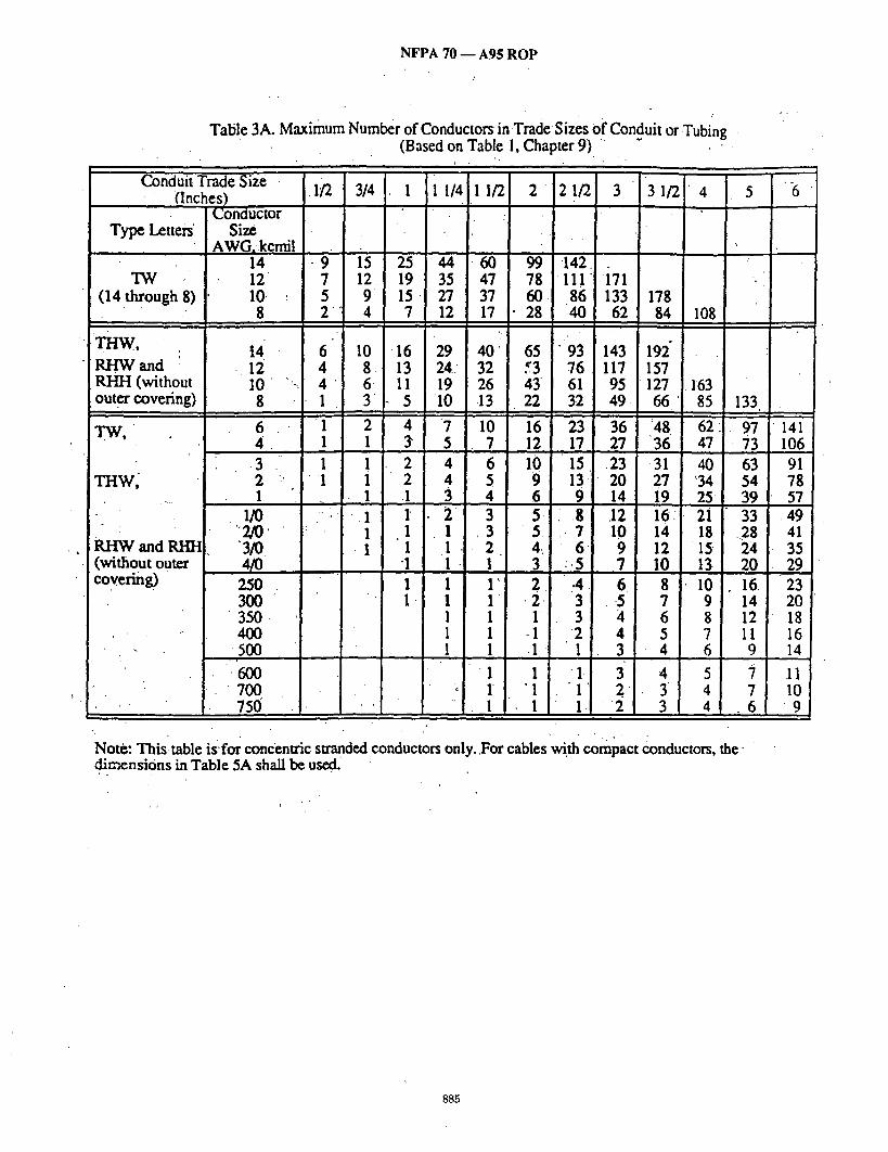
NFPA 70 - - A95 ROP z
Tatile 3A. Maximum Number of Conductors in TradeSizes of Conduit or.Tubing . (Based on Table 1, Chapter 9)." "
r . . J. .
TW (14 through 8)
Conduit Trade Size (Inches)
Conductor Type Letters' Size
AWG,kemil 14
: 12 10, • 8
raw, RHW and RHH (without outer covering)
TW,
raw
RHW and KI-IH (without outer covering)
t4 -12
1 0 "-. 8 "
6 .
~3 2 , , .
1 1/0
3/0
250 3 0 0 :
3 5 0 . 400
5 0 0
'600 • 700
750
• 1/2 3/4 1 1 1/4 11/2 2 2 1 / 2 3 ' 31 /2] ' 4 i !
• 9 15 25 44 7 12 19 35 5 9 15 27 2 4 7 12
6 10 -16 29 4 8. 13 24: 4 6- II 19 1 3 - 5 10
1 2 4 7 1 1 3" 5 1 1 2 4
'I 1 2 4 .. -,,,. 1 .1 3 '-, . 1 t 2
I I I . 1 1 1
"1 I - . 1 1
1 1 1 1 I
Note: This. table isfor concentric stranded dimensions in,Table 5A shall be used:
60 99 142 i 47 7s i 111 171 , 37 i 60. ,86 133 178 17 • 28 40 62 84 108
I
4 0 65 "93 143!192" 32 53 76 117 1157 26 43 61 95 ~ 127 163 • 13. 22 32 4 9 1 66 ' 85 133
, i 10 16 23 36 48 .62:J 97 7 12 17 27 '36 47 73
i , I
6 10 15 .23 .31 40 63 5 9 13 20 27 ~34 54 4 6 9 14 19 25- 39
|
3 5' " ,8 12 16' 2i 33 , 3 5. - 7 10 14 18 ..28
2 4: 6 9 12 15 24 i I0. 13. 20 1 3 :.5 7 , ,
1' 2 ,4 6. : 8 10 16. 1 . 2 , 3 . .5 7. 9 14 1 1 3 4 : 6 8 12 1 -1 2 4 [ 5 7 1t 1 -1 ~ 1 3 i 4 6 . 9
1 1 1 3 4 5 7 1 "1 1 2 . 3 4 7 1 1 1 .I 2 3- 4 6
conductors only..For cables wi.th compact conductors, the
5 ~6
[ i41 106 91 78 57
.49 41 35 29
• 23 20 18 16 14
11 10
9
885

N F P A 70 - - A 9 5 R O P
Table 3B. Maximum Number of Conductors in Trade Sizes of Conduit or Tubing. (Based on Table 1, Chapter 9)
/
Conduit Trade Size (Inches)
Conductor Type. Letters. Size
AWG~ kcmil
14 12 10
' ' 8
T H ~ N , .
THHN
6 4 3
-2 1
1/0 210 3/0 4/0.
250 300 350 400
500 " 600 ,
700 750
112 [ 3/4 11 1/41 1/2 Z 1/2 !12 4 5
t 13 24: 69 ~4 i 54 10 18 51 r0 ~ 1 14 $4 6 11 ' 32 14 13 )4 60 3 " 5 16 !2 36 51 79 06 136
1 4 11 t5 ~6 ~7 57 76i ~8 154 1 2 7 9 16 !2 35 47 50 94
1 1 6 8 13 19 29 39 51 80 1 1 5 7 11 16 25 33 , ~,3 67
1 3 5 8 12 18 25 32 5 0
• 1 3 4- 7 10 15 21 27 42 1 2 3 6 8, 13 17 2 2 35
' 1 - 1 " 3. 5 7 11 14 18 29 • 1 l . 2 4 6 9 12 15 24
' [" 1 1 3 4 10 1 2 20 ' " 1 I 3 4 8 11. 17
1 1 2 3 7 9 /15 • 1 I 1 3 6 8 13
1 1 2 4 5 7 11 • 1 1 1 3 4 5 )
• . 1 1 1 3 4 5 t " ",- .~ . 71 .1 -1 "2 3 4
37 !6 98 72
61 51
.35
.28 24 21 19
16, i3 11 11
Note: This table is for concentric stranded, conductors only. For Cables with-compact conductors, the dimensions ~.~ Table 5A shall be used. ' "
886

NFPA 70 D A9~5 ROP
Table 3C Maximum Number of Conductors.in Trade Sizes Of Conduit or Tubing (Based on Table 1, Chapter 9)
Tyt~Letters
Rtt
Conduit Trade Size • • (Inches).
Conductor Size
AWG; kcmil
1,4 I 12
.- , • .
RI-I (I0 through 750)
RHw,
:14 " 12 I0 '8,
" 6 4 3 2 I
RHH
(with outer covering)
I/0
3~ , 4/0
250 ,. ', 300' 350 4OO
500 6O0 7OO 750 '
• 1/2 3/4 1' 11/4 11/2 ' 2 21/2 "3 31 /2 4 5 6
15 4 •
3 3 2 I'
I ' I
I
• ° ' I - - . - .
9 . 1 4 2 6 35 58 83 128 172 221 I ~"7 12 . ,21 29 4 8 69 106 142 183
,'6 10 18 25 4i. 58 90 121 ,155 .5 9. 15- 21 .35 50 77 103 132 4 7 13 18 29 41 64. 86 110
'2 ' 4 i 7 9 16 22 35 .47 60 94 137 t
1 2 5 6 11 15 24 32 4i 64 93 1 1 3 5 8 12" -18 24 31' 50 72 1 -1 3 •4 7 10' 16 21. 28 4 4 63 1 1 3 4 : "6 9 t4 ,19 24 38 56 f I I 3 5 7 II 14 18 29 42
"4 I i i" 2 4 6 9 12 16 25 37 1 1 1 ' 3 5 8 •11 14 22 32 1 I I 3 4' 7 9 12 19 28 I • 1 "I 2 4 6 8 I0 16 24
" I I 'I 3 5 6 8 13 19 1 I I' 3 4 5 7 II 17 1 1 1 2 4 5 6 10 1•5 1 1 1 •1 3 4 6 9 14
1 1 I" 1 ~3 4 5 8 .11 1 -1 1 .2 3 4 6 9 1.' 1 1 1: 3 3 6-. . 8
.,1 1 1 3 3 5 8
Note: This table is for concentric stranded conductors only. For cables with compact conductors, the dimensions in Table 5A, shall'be Used.
887
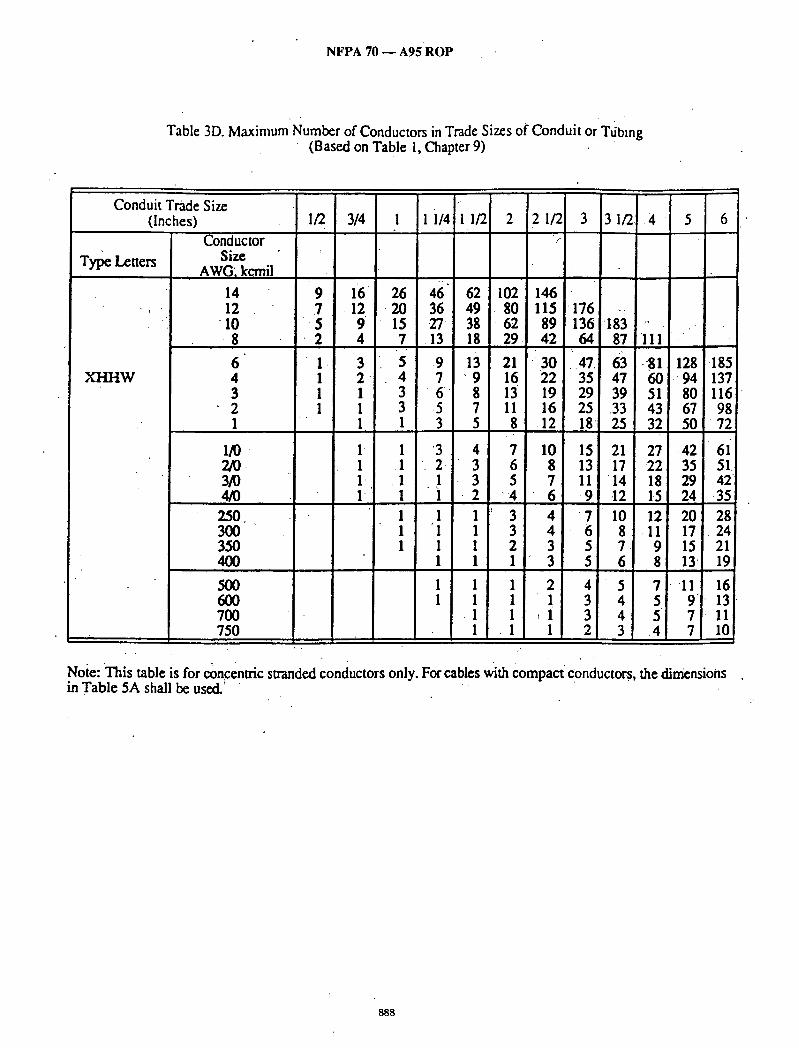
N F P A 70 - - A 9 5 R O P
Table 3D. Maximum Number of Conductors in Trade Sizes of Conduit or Ttibmg (Based on Table 1, Chapter 9)
Conduit Trade Size (Inches) '
Conductor Type Letters Size
AWG', k~mil
14 12
' -10 8
6 XHHW 4
3 2
.' 1
1 / 0 2/0. 3/0 4/0 250. 300 350 400
500 600 700 750
/"
9 .7 5 2
16 26 46 62 102 146 .12 -20 36 49 80 115 176 -.
9 15 27 38 62 89 136 "183 4 7 .13 18 29 42 64 87
3 5 ,9 13 21 "30 ..47 63 2 4 7 ' 9 16 22 35 47 1 3 6 8 13 19 29 39 1 3 .5 7 11 16 25 .33 1 1 3 5 8 12 18 25
I' 1 '3 4 7 10 15 21 I .I '2. 3 6 8 13 17 l' . I l 3 5 7 II "14 I" I - ] 2 "4 6 -9 12
I I I 3 4 "7 I0 1 "I I 3 4 6 8 1 1 1 2 3 .5 7
1 1 1 3 5 6
1 1 1 2 4 5 1 1 1 1 3 4
-1 1 I1 3 4 1 .1 1 2 3
III
-81 128 .185 60 9 4 137 51 80 116 43 67 98 32 50 72!
27 ,42 61 22 • 35 51. 18 29 42 ~5 24 .35
12 20 28 .II 17 24 9 15 21 8 13 19
7 11 16 5 9 13 5 7 l-11 .4 7 lOI
Note: This table is for concenu'ic swanded conductors only. For cables with Compact conductors, the dimensions in Table 5A shall be used.' " "
888

NFPA 70 - - A95 ROP
Table 3E. Maximum Number of Conductors in Trade Size s of Conduit or Tubing (Based on Table 1, Chapter 9)"
Conduit Trade Size [ (.Inches) /2 I4 1 t/4 1 1/2 2 2 1/~ 3 3 1F, 4 5
Type Leuers
FEP, FEPB, PFA,. PFAH, Z
FEPB,
Z
FEP, • T F ~ $ '
PFA, . PFAH
TI~,
Z .
ConduCtor Size
AWG,.kcmil
8 6 4 3
.2
14 12 10
8 6 4 3 2 I
I/O .2/o 3/o 4/0.
.
'x •
3 :4 39- i9 94 1"54 ' " 0 8 29 2 71 1.16 167 " 7 3 " 21 ;8 52 .85 121 186 .-.
4 7 [2 ,2. 30 49. 70 i08 145 [87 1 3 4 8 .11 18 27 4o 5 5 71 161 1 1 3 6 8 14 20 30 41 53 83 120 i" 1 3 5 7 12 17 26 35 45 71 "10'3 I I 2 4 6" I0 -14 22 30 38 60 87
3 "~ 6 lO 8' 24 40 -57 "88 119 1"53 2 4 7 3 17 28 41 63 84 [08 171 I 3 5 9 12 20 28 44 59' -.76 1.19 •172 ! 4 7 10 16 24 36 49 63 99 143 -I 3 6 g 13 19 30 40 '52 . 82 119 I .2 4 6 . 9 '14 21 28 36 57 83
I I. I'] 3 5 8 II"' !7 23 30 47 ,69 1 1 1 3 4 7 I0 - 15 20 . 26 41' 59
I I I" 3. "5, 7 -12 .16 20 32 47, ,, 1 1 1 2 4 6 10 13 17 26~ 38
• , , . . • • _
Note: This table is for concentric stranded conduct'ors only. For cables withc0mpact, conductors, the dimensions in Table 5A shall be used.
889
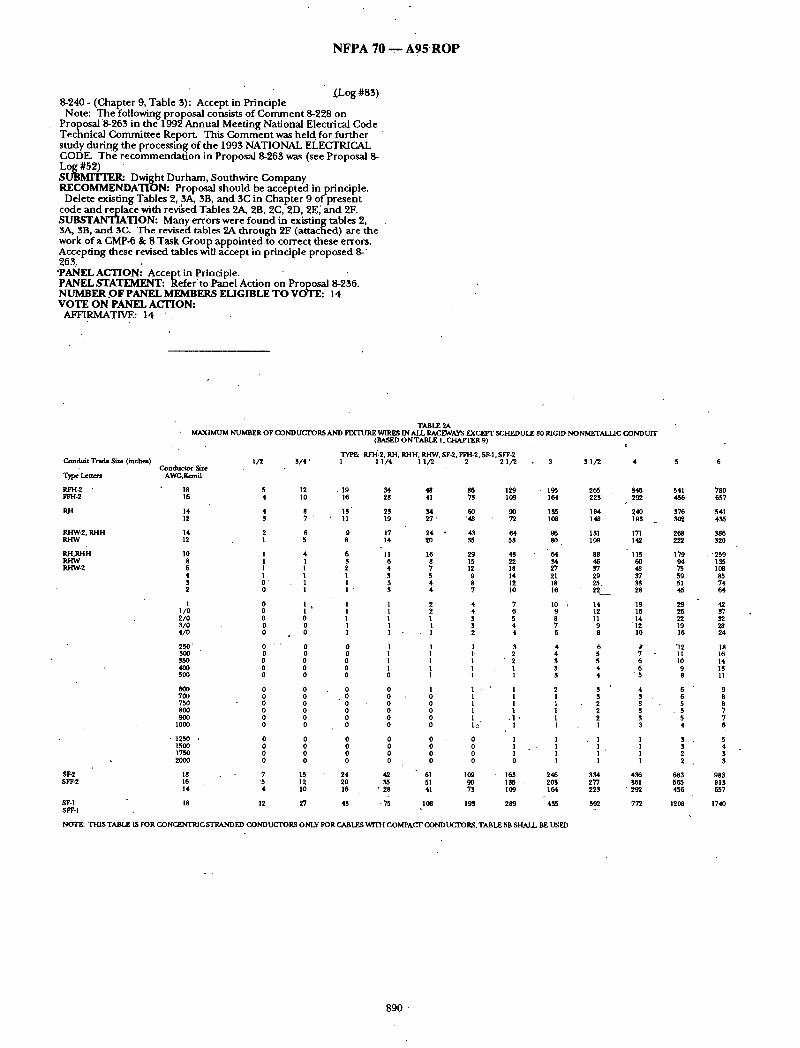
N F P A 7 0 - - - A 9 5 ' R O P
_(Log #83) 8-240- (Chapter 9, Table 3): Accept in Principle Note: The following proposal consists of Comment 8-228 on
Proposal 8-263 in the 1992 Annual Meeting National Electrical Code Technical Committee Report. This Comment was held. for further study during the processing of the 1993 NATIONAL ELECTRICAL CODE. Th'e recommendation in Proposal 8-263 was (see Proposal 8- Log #52) . SUBMITTER: Dwight Durham, Soumwire ~ompany RECOMMENDATION: Proposal Should be accepted in principle. Delete existing Tables 2, 3A, 3B, and 3C in Chapter 9 of present
code and replace with revi~ed T~tbles 2A, 2B, 2C, 2D, 2E,' and 2F. SUBSTANTIATION: Many errors were found in existing tables 2, . 3#,, SB,.and 3C. The revised tables 2A. through 2F (attached) are the work ofa CMP-6 & 8 Task Group appointed to correct these errors. Accepting these revised tables will accept in principle proposed 8-' 263. "PANEL ACTION: Accept in Principle. " " PANEL STATEMENT: Refer'to Panel Action on Proposal 8-236. NUMBER .OF PANEL MEMBERS ELIGIBLE TO VOTE: 14 VOTE ON PANEL ACTION:
AFFIRMATIVE: 14 "
TABLE 2A MAXIMUM N U M B E R OF CONDUCTORS AND FIXTURE Vt/IRES IN ALL RACEWAYS EXCEPT S C H E D U L E 80 RIGID NONMETALLIC C O N D U I T
Condui t Trade Size ( inches) I / 2 3 / 4 ' C o n d u c t o r S/z¢
T~pe Le t t e~ AWG Jt~mll
RFH-2 ' 18 5 12 FFH-2 16 4 10
RJ-I 14 4 8 12 3 7 "
RHW-2. RHH 14 2 6 R H W 12 1 5
R H , R H H 10 1 4 8 I I
RHW-2 6 I 1 4 l 1 S O' 1 2 0 1
1 0 1 I / 0 0 I
a
2 / 0 0 0 S / 0 o o 4 / 0 0 0
250' 0 ' ' 0 300 0 0 35O 0 0 4OO 0 0 900 0 0
6OO 0 0 700 0 0 750 0 0 800 0 0 9OO 0 0
1000 0 0
• 1250 . 0 0 1500 0 0 1750 0 0 2000 0 0
SF-2 18 7 19 SFF-2 16 '5 12
14 4 10
12
( BASED O N TABLE 1, ~ 9)
TYPE: P, FH-2. KH, RHH, RHW, SF-2, FFH-2, SF-1, SFF-2 1 1 1 / 4 1 1 / 2 2 2 1 / 2 ~ 3 1 / 2 4
• 19 M 16 28
13 2S 11 19
9 17 8 14
6 11 3 6 2 4 1 $ I 3 I " $
I , 1 1 1 I 1 ! 1
0 1 0 1 0 1 0 1 0 0
0 0 0 0 0 0 0 0 0 0 0 0
0 0 0 0 0 0 0 0
24 42 2O ~ 16 " 28
7;
48 86 129 41 73 109
$4 60 g0 2 7 ' "48 72
24 43 64 20 55 53
16 29 43 8 lS 22 7 12 18 5 9 14 4 8 12 4 7 10
2 ~ 7 2 6 1 $ 5
. 2 4
1 3
1 1 ' 2 1 1 1 1 1 1
1 1 - ' 1 0 1 I 0 1 1 0 1 1 0 1 .1 0 1~ 1
0 0 1 0 0 1 0 0 1 0 0 0
61 109 • 163 51 90 155 41 73 109
I¢~ 193 289
195 164
108
g6 80
64 54 '27 21 18 16
I0 , 9 8 7 6
$ 3 $
2 1 1 1 1 1
1 1 1 1
246 203 164
495 SF-1 18 27 43 SFF-1
NOTE: T H I S TABLE IS FOR CONCENTRIC STRANDED CONDUCFt~OP~ ONLY FOR CABLES ~fflTH COMPACT CONDUCTORS,TABLE 5B SHALL BE USED
2f~ 346 225 292
184 240 148 195
131 171 109 142
88 115 46 60 Y/ 29 25,
14 12 11
9 8
6 5 5 4 4
3 3 2 2 2 1
• 1 1 1 1
$34 277 223
592
48 37 33 28
19 16 14 12 10
6 6
" 5
4 3 . $ 3 3 3
1 1 1 1
456
292
77'2
5 6
541 780 456 657
376 541 ~02 4~5
268 386 222 ~20
179 • ' 259 94 1~5 75 108 59 85 51 74 45 64
29 42 26 37 22 Y2 19 28 16 24
"12 18 11 16 10 14 9 13 8 11
6 9 6 8 5 8
• 5 7 5 7 4 6
3 5 $ 4 2 $ 2 $
68S g85 565 813 456 657
1208 1740
890
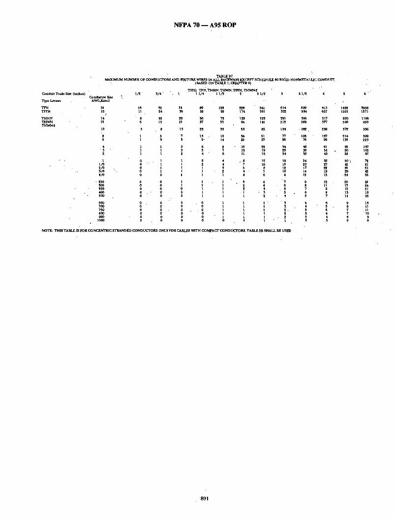
NFPA 70 - - A95 ROP
Coad td t Trade Size (inf.he~)
t ~
TFN TFFN
T H H N T H W N THWN-2
: TABLE 2C . MAXIMUM NUMBER O F CONDUC'TORS AND FIXTURE WIRES IN A L L RAC~VAYS EXCEPT SC~I EDU 1R. 80 RIGID NONMETALLIC CONDUIT.
;/2' ~ / 4 " . 1 S S l / 2 4 C o n d ~ t o r S~e "
AWG,B~nfl
18 14 16 I I 24
r 14 " 8 18 12 6 IS
10 $ 8
8 1 5 6 1 3
4 1 1 " $ l 1
2 I 1
1 0 , . I 1 / 0 0 1 2 / 0 , 0 I S / 0 ". 0 I 4 / 0 0 0
• 250 0 0 ~ 0 0 0
400 0 . " 0 500' 0 0
600 0 0 700 0 0 750 0 800 0 900 0 0
lO00 0 0
(BASED O N TABLE I , C H A F I ~ R 9)
TYPE: TFI~, T H H N, T H W N , TFFN. ~ 2 1 1/4 1 I / 2 2 2 l / 2
51 89 ]28 228 68 9~ 174
29 50 7S 129 21 5'1 55 94
1~ 25 ~,5 59
7 13 19 M 5 9- 14 25
$ 6 8 15 S 5 7 13 2 4 6 11
I $ 4 . - 8 1 2 4 ? 1 1 $ 5 I 1 2 4 - 1 I l 4
| 1 1 5 I 1 1 2 0 1 I 2 0 1 1 . 1 0 1 1 I
0 , 0 1 1 0 0 I I 0 0 1 l 0 0 l 1 0 0 1 1 0 0 0 I
341 514 261 $9~
193 291 141 212
89, I~4
51 77 ~7 56
2S M 19 29 16 24
12' 18 10 15
8 ]2 7 10 6 8
" 7 6 5 5 4
" S $ 2 , 2
1
NOTE: T H I S T A B L E IS FORC, ON(~C STRANDED CONDUCI"OI~ ONLY FORC&BI~ wrI'H COMPACI" C O N D U I L ~ O I ~ , T A B L E 5B S H A L L B E USED
699 913 5 M 697
S96 517 289 $77
- 182 2 ~
105 l~7 76 99
~k~ 4S
24 ~ 20 27
14 18 12 15
9 12 8 11 7 9 6 8 5 7
4 6 4 5 3 5 3 4 S 4 S 3
1428 1091
809 590
S ~
214 155
95 80 68
50~ 42
29 ,24
17 15 IS 11
9 8 7 7 6 6
6
2055 1571
1166 850
5 ~
so9 22~
I f 6 9'7
6] 51 42
28 24 21 19 16
IS 11 l l
' I 0 9 8
8 9 1
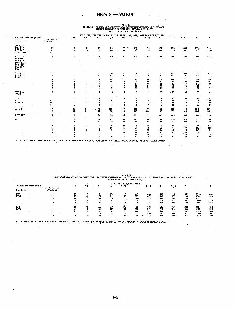
NFPA 70 - - A 9 5 R O P
• C o n d u i t T r a d e Size (inches)
'l~e ~tters
PF, PGFF PGF, PFF I~'F, PAF PTI~. PAFF
PF, PGFF PGF,PFF PIV, PAF PTFF. PAFF TFE, FEP PFA, FEPB PFAH
TFE. FEP PFA. FEPB PFAH
1/2
TABLE 2D MAXIMUM NUMBER OF CONDUCrORS AND FIXTUR.K WIRES IN AIL RAC~AYS
EXCEI~r SCHEDULE 80 RIGID NONMETAI.ZJC CONDUIT • (BASED ONTABLE I. CHAP'rER�) •
TYPE: FEP, FEPB, TFE, PF. PFA, FrFF. PGFF. PFF. PAF. PAFF. PFAH. PGF, P]"F, Z, ZF. ZFF 4
3 / 4 1 1 1 / 4 1 1 /2 2 2 1 /2 °3 C o n d u c t o r Size
AWG,Kcmfl
18 13 30 49 84 122 * 216 324 487 " 16 l0 23 38 65 94 167 250 377
14 8 17 28 49 70 125 188 282
TFE. PFA PFAH
TEE 1 /0 0 1 . 1 3 4 7 l J 17 PFA 2 / 0 0 1 I 2 3 6 9 14 PFAH, Z 3/0 0 1 " I 1 3 5 7 II
4 / 0 0 1 I 1 2 4 6 9
ZF. ZFF 18 17 39 • 63 109 157 279 417 628 16 ' 1 3 29 46 80 116 206 308 463
Z. ZF. ZFF 14 9 " 21 34 59 85 151 226 340
Z 12 6 15 24 42 60 107 160 241 1O 4 9 15 25 37 66 98 148
8 2 5 9 16 23 41 62 93 6 1 4 6 . 11 16 29 43 66 4 1 3 4 8 11 20 3o 45 $ 1 1 3 5 8 14 22 33
\ 2 1 l 3 5 7 12 18 27 " I ~ 1 1 1 4 5 I0 15 22
3 1 /2
663 513
$85
12 5 13 20 36 51 91 137 206 " 281 10 4 9 15 25 37 c~ 98 148 201
2 5 8 14 21 ~ 56 85 115 6 1 4 6 10 15 27 40 60 82 4 I 2 4 7 • 10 19 28 42 57 3 I 1 3 6 9 15 23 35 48 2 I 1 3 5 7 13 19 29 39
I 0 1 1 ' 3" 5 9 13 20 - 27
NOTE: T H IS TABLE IS FOR CONCENTRIC SrRAND ED C O N D U C r O R S ONLY FOR CABLES W I T H COMPACT CONDUCTORS, TABLE 5B SHALL BE USED
23 19 15 13
855 631
463
329 201
127 89 61 45 37 $5
- 4
866 669
502
1354 1047
785
366 573 263 411
151 255 107 168
75 117 62 97 51 80
~6 56
3O 47 2f, " 38 20 32 16 26
1116 1745 823 1287
605 046
429 671 263 411
166 260 117 182
80 125 58 92
• 49 76 39 62
1950 1508
1131
825 592
339 241 169 140 116
. 6 7 56 46 37
2513 1854
1362
966 592
374 263 181 132 l lO
89
. 'Condui t Trade Size (inches)
• "Iype Letters
KF-2 KFF-2
KF-I KFF-I
TABLE 2F MAXIMUM NUMBER OF CONDUCTORS AND FIX'I3JRE WIRES IN ALL RACEWAYS EXCEPT SCHEDLrLE 80 RIGID NONMETAIL~C CONDUIT
C o n d u c t o r Size AWG,Kcmil
18 16 14 12 10
18 16 14 12 l0
(BASED O N TABLE 1, C.J-[AFI~R 9)
TYPE: KF-I, KF-2, KFF-1, KI~-2 1 /2 3 / 4 1 1 1 / 4 1 I / 2 2 2 1 / 2 3 4
25 57 18 40 12 27 8 19 5 12
30 "68 21 48 14 32
9 21 6 14
3 1 /2 5 6
91 158 228 405 666 912 1241 1620 2533 3648 64 . 111 160 285 427 642 874 1141 1785 2570 44 ' 76 110 196 ~ 293 442 601 784 1227 1767 30 53 76 135 202 304 414 540 - 844 1216 20 35 51 90 1 $5 203 277 361 565 813
. 109 189 272 483 722 1087 1480 1931 3021 4350 76 132 191 339 507 764 1040 1357 2122 3056 51 89 128 228 341 514 699 • 913 1428 2056 34 59 85 151 226 " 340 463 605 946 1362 22 $5 55 99 148 222 303 3~i 618 890
NOTE: T H ~ T A B L E ~ F ~ R C ~ N C ` E N T R 1 C S T R A N D E D C ~ N D U C T ~ R S * ~ N L Y ~ ) R C A B L E S w ~ T H C ~ M P A C T C ~ U ~ T ~ 5 B S ~ B E U ~ "
8 9 2

N F P A 7 0 -- A 9 5 R O P
(Log #1071 ) 8-241 - (Chapter 9 Table 3A): Accept in Principle SUBMIT1"RR: A.M. Bryan, Electrical Inspection Office-City of
' Chattanooga, TN RECOMMENDATION: Correct typo error, 1st heading Type Letters. As printed "TW, XHI-IW (14 through 18)" Correct to (14 through 8) SUBSTANTIATION: Clarification, correct typo error. PANEL ACTION: Accept in Principle., PANEL STATEMENT: Refer to PanelAction on proposal 8-236. NUMBER OF PANEL MEMBERS ELIGIBLE TOVOTE: 14 VOTE .ON PANEL ACTION:
AFFIRMATIVE: 14
• ' " (Lo~g~#84) 8-242 - (Chapter 9, Tables 3D, 3E, SF and 4A): Accept in Principle Note: The followingproposal consists of Comment 8-231 on
Proposal 8-271 in the 1-992 Annual Meeting National Electrical Code Technical Committee Report. This Comment was held for further study during the processing of the 1993 NATIONAL ELECTRICAL CODE. The recommendation in Proposal 8-271 was: • Add new tableg 3D, 3E, 5F, and 4A w'nich show the maximum number of conductors in trade sizes of Schedule 80 PVC conduit (40 ~ ercent fill based on actual internal volume).
UBMITIER: Dwight Durham, Southwire Company RECOMMENDATION: Change panel action from accept to accept in principle. Accept new revised tables BA, 3B, 3C, 3D, 3E, 3F, a n d 4A (attached) instead of those contained in the proposal. SUBSTANTIATION: The i-evised tables are the wdrk of a CMP-6 & 8 .Task Group appointed to correct errors in the existing conductor and conduit dimensions and conduit fill tables. Accepting these revised tables will accept in principle proposal 8-271. PANEL ACTION: Accept in Principle. PANEL STATEMENT: Refer to Panel Action on proposal 8-236. NUMBER OF PANEL MEMBERS ELIGIBLE TO-VOTE: 14 VOTE ON PANEL ACTION:
AFFIRMATIVE: 14
TABLE 3D.
HAXIMUM NUMBER O F CONDUCTORS IN TRADE SIZES OF SCIIEDULE 80 PVC' RIGID NONMETALLIC CONDUI T
Conduit Trade Size /
. n ~ . . . ) . . . , ,~ +. 2 = . s ~ eL. i ÷ 5 Conductor
Size "; Type Letters AWG, kcnlU
TW, X I I I I W 14 6 I2 21 38 52 87 i 2 5 ' ] .95 (14 through g) 12 5 10 16 29 41 68 9B 153
, I0 4 7 12 23 31 53 76 119 207 8 1 3 6 I0 15 25 35 56 97 154
R I I W and R I I I I .. 14' (without outer 12 covering), l0 T I I W ~ 8
TW, 6 4
" i ' I IW, 3 2 I
FEPB (6 through 2), R I I W and R I I I I (with- out oulcr covering)"
,io 2/0 31o 410 25O 300 350 400 500
600 700 750
4 I0" 13 24 34 57 . 82 i28 3 6 i t 20 28 46 . 6 7 z 0 4 zB2 3 5 9 16 22 37 54 84 147 1 2 4 B z l ~ z9 28 44 76 z 2 z z74
- 1 1 3 6 8 14 20 '32 56 88 127 2 4 6 10 '15 24 42 66 95
2 "4 5 9 13 20 36 57 82 1 3 4 8 11 17 31 49 70
2 } 5 8 13 22 35 51
1 2 2 4 . '7 i i 19 30 44 1 2 4 6 .9 16 26 37 -I". 2 3 5" 8 13 22 31
, , i Z, 3 4 ~ 11 is 26 1 i 2 3 5 9 14 21
1 2 3 4~ 8 13 18 1 1 2 . m 4 ? ~ 11 16 i "i . 2 .3 6 i0 14
1 2" 3' 5 8 12
10 9 8'
rod.clots only. For c~hle~ wilh 0mln:.'! ('¢mduchw~. l|w ,t;.w.shm~ in Ta|d¢ %A ~h.,U ~,,. i,~,..I Note: This lahh" ;" r . , . ennccntric sir;reded cond.clors ¥. For cables wilh ¢.mn:,cl
895

TABLE 3E.
~XIMUM NUMBER OF CONDUCTORS IN TRADE SIZES OF PVC SCHEDULE 80 RIGID NONMETALLIC CONDUIT. (BASED ON TABLE X, CIIAPTER 9)
oo ~D
Type Le t t e r s
Condu i t T rade Size ( Inches) '½ % 1 1¼ 114 2 214 3 "3.~ 4 5 ~.
• .o
T'l IWN,
"1-1"111 N, FEP (14 through 2), FEI)B (14 through 8), PF'A ( 14 through 4/0) . P,I~AII (14 |l)rough 4/0)
( 14 through 4/0) X I I I I W (4 through 5()0 kc,nil)
~(Hliw•
C o n d u c t o r S ize
A W G , kcmi l 1 4 12 10
6 4. 3 2 !
2/0 3/0
• 4 / 0
250 300 350 400 500
• 600 700 ' 750
'i0 i~-20 33 58 81 135 194 8 14 24 43 60 i00 144 "
5 9 15 27 38 64 ,92 143 2 4 7 .13 18 31 45 70 123
i
1 3 5 . 9 13 22 32 50 88 140 1 2 3 6 8 13 20 31 54 86
1 2 5 7 ii 17 .26 46 73 1 2 4 5 9 14 22 ~ 38 61 1 1 3 4 7 i0 16 . 28. 45
1 2 3 6 8 13 24 38 1 1 3 5 . 7 ii 20 32 1 1 2 4 "6" 9 16 26
1 1 3 .t 5 :" 8 14 22 1
1 i 2 "4 6 '1i 18 "i 1 2 3. 5 9 15
1 2 3 4 8 13 • 1 1 2 4 7 12
: ' 8 . . [ . Ii 6 600 700 750
I hi', table i~ f~¢ •c..ccncri¢
. . ."
~.lltai|t|cd ¢ o n d , c l ~ ) r , o , l y . . |"t)r ¢a|)Jcr. ~' i lh co#Itl~acl t '~mdut'hPr,, the dml¢'~|'~ti,l~. ##1 l'.o~h" ~*.% , h . t l l ' t ~ u~r . l
"6
200 123 104 88 65
55 46 38 3i 25 22 19 17
14 ii i0 9
166 11 i0 9
I
Ul

TABLE 3F. MAXIMUM NubIBER OF CONDUCTORS IN TRADE SIZES OF SCIIEDULE 80 PVC RIGID NONMETALLIC CONDUIT. , (BASED ON TABLE X, CHAPTER 9)
O0
i llW.
RI ' I l l
(with outer covering)
Type Letters.
Conduit Trade Size (Inches)
" Conductor Size ..
AWG. kcmll
+.14 12.. 10
' " " ' . ' 8 ,
6 4 3
" '2 i
t/o . 2/0 310 4/o
.. 250 ,':, 300 350 400
500 600 70O 750
2 5 8 -15 21 36 51 80 140 2 4 7 13 18 30 .44 68 . 119 2 3 6 iI 15 25 36 57 99 158 'i 2 3 6 8' 13 20 31 54 86
1 . 2 4 5 9 13 21 37- 58 .'I 1 3 4 7 i0 ' 16 28 44
"i .2 . 3 '6 9 14 .- 25 40 1 2 3 " 5 8 12. 22 35 1 ".1 2 4 6 9 16 26
+
1 2 3 • 5 8 14 23 1 1 . 3 4 . 7 12 20
• 1 1 •2" 4 ." 6 " . ii 17 1 1 ,. 2 ' 3 5 9.. 15
,, i
I 1 2 4 7 12 1 1 2 3 6 i0"
-i. 2 3 6 9 .i 2 3 5 8
i 1 2 4 7 i. .2 -3 6 I .I 3 5 1 1 : 3 5
123 "
84 64 57 50 .38
33 29 25 21
17 15 13. .!2
i0 8
7 7
I
O 9
• Note: This fable is for concentric stranded conductors 0nly. For cables with compact conductors, + the dimensions in Table 5A shall be. used
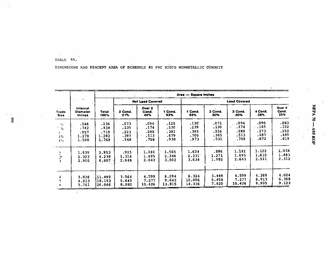
TABLE 4A.
DIMENSIONS AND PERCENT AREA OF SCHEDULE 80 PVC RIGID NONMETALLIC CONDUIT
O0 ~D C~
Trade Size
I
1 t,~
"Pt
4
h
• Area - - Square inches,
° Not Lead Covered
Internal Diameter
Inches
.546
.742
.957 1.278 1.500
1.939 2.323 2.900
3.826 4.813 5.761
Total 100%
.236
.434 ;719
1.282 1.769
2.953 4-.238 6.607
11.498 18.191 26.066
2 Cond. 3 1 %
.o73
.135
.223
.397
.548
.915 1.314 2.048
3.564 5.640 8.080
Over 2 Cond. 4 0 %
.094 :
.174
.288
.513
.708
1.181 1.695 2.643
4.599 ~.277
10.426
I Cond. ' 53%
.i25
. 2 3 0
.381
.679
.938
1.565 2.246 3.502
6.094 9.642
13.815
1 C o n d . 5 5 %
.130 ~
.239
.395
.705 .973
1.624 2.331 3.634
6.324 i0.006 14.336
2 Cond. 3 0 %
.071 •
.130
.216
.385
.531
.886 1.271 1.982
3.449 5.458 7.820
Lead Covered
3 C o n d . • 4 0 %
.094
.174 .288 .513 .708
1.181 1.695 2.643
4.599 7.277
10.426
4 Cond. 38%-
.090 • .165 .273 .487 .672
1.122 1..610 2.511
4.369 6.913 9.905
Over 4 Cond. 35%
.083
.152
.252
.449
.619
1.034 1.483 2. 312
4.024 • 6. 364 9.12~
5 CD
I
tim

O0
",4"
. - TABLE 3A '. • ~ X M , l a M J M S ~ OF ~ / V ~ Pu(i U l ~ WIRES IN'IRN:)E 81Z~ OF SO'IBXJME 80 F B ~ NQNMETN.UC ~
c 0 , v ~ T r i m Sze 0hems) Cond.~ Sze
"type I .aUm AWG.KcmU
RFH-2 16 FFH-2 16
m "i4 12
~tW 8 ~ 6
4' ' 3
2
1 1R
75O
IOO0
1~-2 18 SFF-2 tS
14
1/2 3/4 3 3"I/2 4
(BASED ON T.NSLE I, CHAPTER 9)
TYPe: F~-2, ~ . n~-i, nHW, Sr~. m+,~., SF.t, SFF-~, • 't 'i I /4 'i I/2 ~' 2 'V~
6 11 19 34 47 79 113. " 5 9 16 29 40 67 .96
177 1GO
239 202
4 3
3 2
I 1 1 1 1 0
0 0 3 0 0
0 0 0 0 0
0 0 0 0 0 0
8 ".
6
5 4
3 1 I 1 1 1
1 - 0 0 0 0
O' 0 0 0 0
0 0 0 0 0 0
• 13 .°10
' 9
8
6 3 2 I ! I
23 32 19 26
• 17 23 14 19
11 15 6 8 5 8 $ 6 3 .4 $ 4
1 1 2 1 1 . - I-.....
, 1 1 1 1 1 1 1 1 1
0 0
- 0 0 0
0 0
• 0 ,
0 0 0
0 O' 0 0
1 I 1 1. - 1 1 1 1 0 I
55 79 44 63
39 56 32 46
2e s7 14- 19 I1 16 8 "12 7 * I1 6 9
4' - 6 4 6 3 4 ' 3 4 2 3
1 2 1 ,2
• I 1 1 1 1 1
1 1 1. 1 0 0
0 0 I 0 0 .1 0 0 I 0 0 1 0 0 1 0 0 I
123 ,166 99 133
88 118 73 98
69 79 31 41 25 33 19 26 1 7 23 14 20
9 " 13 8 11 7 10 6 6 5 7
4 5 3 S 3 " 4 3 4 2 3
I $ 1 2 I 2 1 2 1 I 1 1
7 14 6 12 5 9 -
24 20 16
0 0 0 1 I 0 0 0 I I O 0 0 0 1 0 0 0 0 1
43 35 29
SF-1 18 13 25 42 76 SFF-1
100.. 49 82 40 67
143 224 118 185 96 .-150
105 177 253 396
I 1 1 1
302 25O 20~
NOTE: ~ L q TAB.E 18 I:OR ~ I C STRAM3B) CONDUCTORS ONLY FOR GABJES W I l l COMPAGT C O ~ T/IdBLE 58 SHN.L BE US I:n
310 2e2
218 173
163 127
108 54 43 34 29 2S
17 lS IS 11 9
7 ' 6
5 5 4
3 $ 3 8 2 2
1 I 1 1
324 262
680
41~ 415
s41 -274
244" 2O2
163 8S. 68 53 47 41
27 2 3 20 17 15
11 ". 10 .9 8. 7
6 5 s ~ 5 4 4
3 2
.2 I
514 415
1099
6
."toe 595
49o 394
s,18 29o
234 122 98 77 67
5 6
38 33 29 25 21
16 14 13 12 1o
8 7 1 1 6 6
4 4 z
_z
890 7.38. 595
1575
Z
- . 1
I
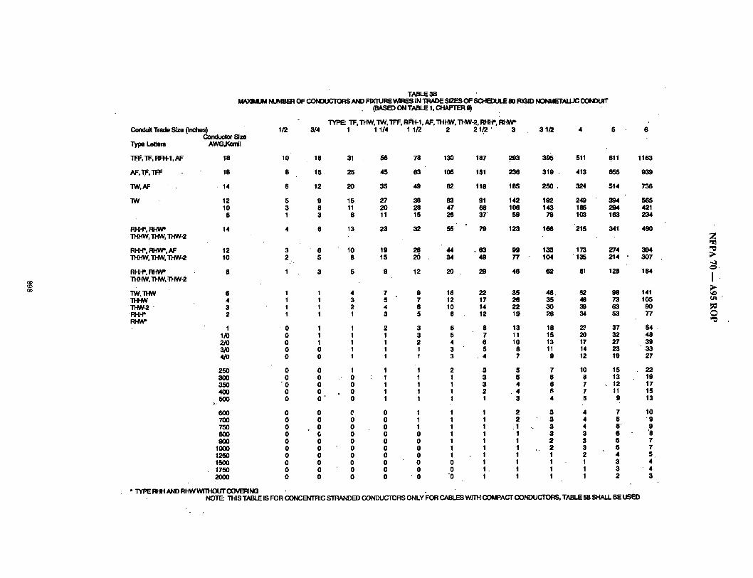
O0 ~O OO
TABLE 38 MAXIMUM MJMBB:I OF OOMXC'IORS N~ID FIXTURE WIRES IN ~ SIZES OF SCHEDULE 50 R G D NONME'TALLIC CONDUIT
Conduit Trade Size (inches) I /2 Conductor SJze
Type Lettem AWG,Kom~
Tff, 'n=, m'H-1,AF 18 10
AF.TF.TFF 16 8
"IW, AF . 14 6
"IW 12 5 10 3
8 1
RHPP. RHW* 14 4 THHW. THW. THW-2
R I ~ . R H ~ . AF • n-ii-~. "n-~. "~w-2
RHI-P, ~ T H I ~ , "~tW, ~I-IW-2
" I W , ~
"~W-2 - FH~"
3/4 3 1/2 4 5 6
18
15
12
12 3 " 6 10 2 5
8 I 3
(BASE£) ON TABLE 1, C:ItAPTER 9)
TYPE: "n=, THW, "ZW, TFF, RFIt-|, AF, THHW, THW-2, I~H ' , mtW" 1 1 1/4 1 1/2 2 2 1./2 " 3
6 I I 4 1 1 3 1 I 2- 1 I
I O I I /0 O 1 2/0 O I 3/0 O O 4/O 0 O
250 O O 3OO O O 350 "0 O 4OO 0 O 5OO 0 O
o.
6OO O O 700 0 0 750 0 0 8OO 0 0 50O 0 0
1000 0 0 1250 0 0 1500 0 0 1750 0 0 20OO 0 0
31 , 56 78 130
25 48 63 105
20 35 48 82
15 27 38 63 11 20 28 47 6 11 15 26
13 23 32 55
10 19 26. 44 8 15 20 . 34
5 9 12 20
187 29~ 395 511 811 1163
151 236 319 . 413 655 939
118 185 2 5 0 . 324 514 736
91 142 192 249 394 565 68 106 143 18G 294 421 37' 59 79 1 ~ 163 234
79 123 166 215 341 4.90
7 9 16 5 7 12 4 6 10 3 5 8
2 3 6 1 3 5 I 2 4 1 1 3 1 t 3
1 1 2 1 1 1 t 1 1 t 1 1 1 1 1
0 1 1 0 1 1 0 1 1 0 0 1 0 0 I 0 0 1 0 0 1 0 0 0 0 0 0 0 ' 0 "0
. 6 3 99 49 77
29 46
133 173 104 ' 135
62 81
22 35 48, 82 17 26 35 .46 14 22 30 39 12 19 26 34
8 13 18 23 7 11 15 20 6 10 13 17 5 8 11 14
• 4 7 9 12
3 5 7 10 3 5 6 8 3. 4 6 7 2 . 4 ~; 7 1 3 4 S
e 1 2 o I 2 o 1 . I o I I o I I o I I o I I o I I 0 1. 1 0 1 1
3 4 3 4 3 4 3 3 2 $ 2 $ 1 2 1 1 1 1 1 1
274 214 •
128
98 73 63 53
37 32 27 23 19
15 13
.. 12 11 9
7 6 6" 6 5 S 4 3 3 2
* TYPE R-g'I AND RI-N4 WTI'HOUT COVB~ING ~ - . NOTE: THIS TABLE IS FOR CONCB~'RIC STRANDED CONDUCTORS ONLY FOR CABLES w]'rH COMPACT CONDUCTORS, TABLE 5B SHALL BE U6ED
394 307
184
141 105 9O 77
54 46 39 33 27
22 19 17 15 13
10 "9
9 '8 7 7 S 4 4 3
"-4
I Ui "
O "¢
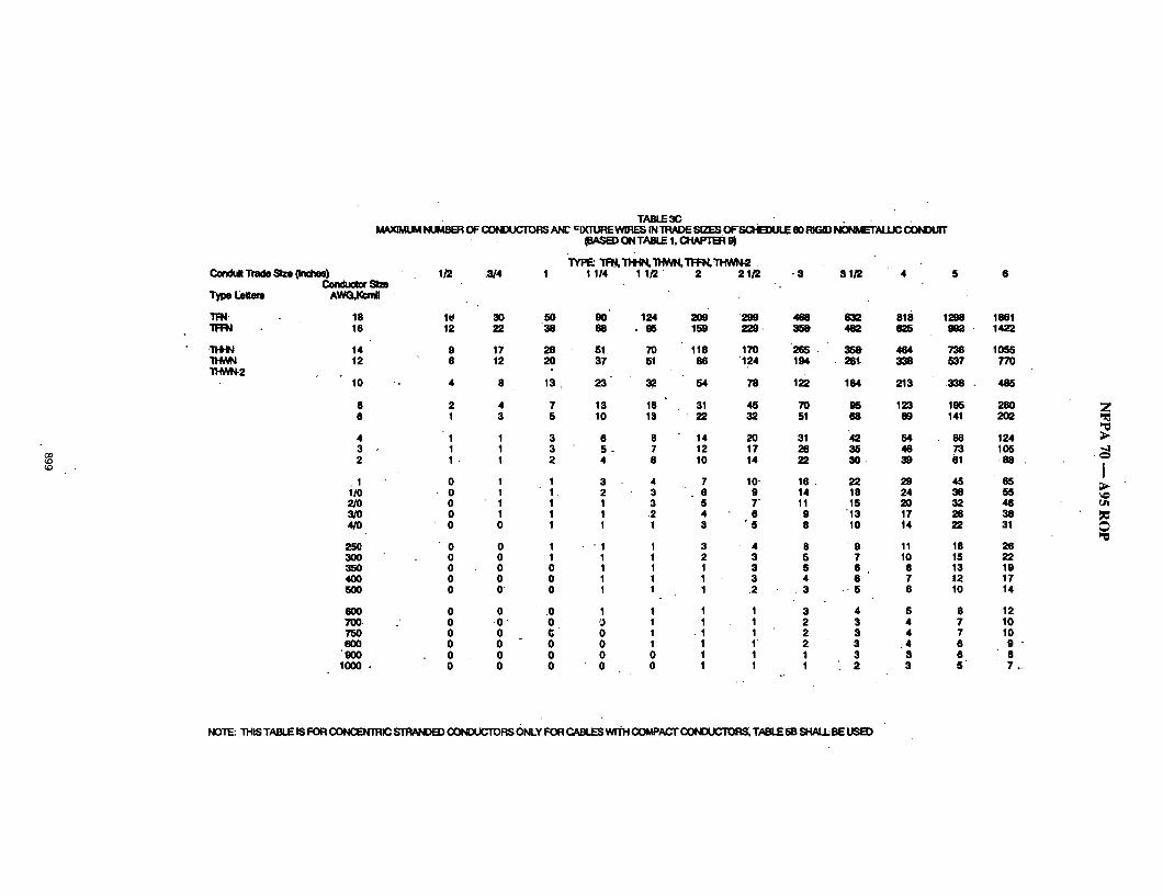
O0
TABLE 3C MAX]M~ NUM.~ OF CONOUCXORS ~ ~ ~ .~ T ~ [ ~ S~ES ~SCHBOULZ e 0 . ~ O ~ A L U C C0NO~"
Condult Trade Size 0nches) Conductor 81ze
Type l:ettenl AWG,Kanll
T IN 18 TFFN 16
"ITI4N 14 "n-lV, N 12 THWN-2
10 --
8 6
4 3 2
. I 1/0 2/0 3/O 4/O
25O 3OO 35O 4OO 5OO
6OO 700: 7S0 8OO
"900 1 0 0 0 ,
I ~ ..~4 I 31Q 4
(BASB) ON TABLE 1, CHAPT~ 9)
W P ~ "n~'m~l,~'r~'~'n-i~, 1 1/4 1 1/2 " 2 2 1/2 "8
l t( 12
9 6
4
2 1
1 1 1
0 0 0 0 0
0 0 0 0 0
0 0 0 0 0 0
3O 5O 22 38
17 28 12 20
8 13
4 7 3 S
1 3 1 3 1 2
1 1 1 1 1 1 1 1 0 1
0 1 0 1 0 0 0 0 O 0
0 O O 0 0 (; 0 0 0 0 0 0
9O 124 68 • 96
51 71) 37 51
23 32
13 18 10 13
6 8 5 . 7 4 6
3 4 2 3 1 3 1 2 1 1
-1 1 1 1 I 1 1 1 1 1
1 1 1
0 1 0 1 0 0 0 0
290 468 632 818 1298 159 229. 358" 482 825 Im~
118 170 265 • 358 464. 736 88 "124 194 . 28t 338 537
54 78 122 164 213 338 .
31 45 79 95 123 195 • 22 32 51 68 89 141
14 20 31 '42 54 88 12 17 26 35 46 73 10 14 22 30 . 39 61
7 lO, 1 6 . 22 29 45 6 9 14 18 24 38 5 T 11 15 20 32 4 6 9 '13 17 26 3 " 5 8 10 t4 22
3 4 8 ' 9 11 18 2 3 5 7 10 15 1 3 5 6 8 13 1 3 4 6 7 ~2 1 .2 . 3 , 5 6 10
1 1 3 4 5 8 1 1 2 $ 4 7
• 1 1 2 $ 4 7 1 I ~ 2 3 .4 6 1 1 1 3 3 6 1 1 1 : 2 3 5
1861 1422
1055 77O
485
280 2O2
124 105
88 •
65 55 48 38 31
26 22 19 17 14
12 10 10 9 - 8 7o-
Z
"-4
I u i
P: 0
NOTE: "IHIS TABLE I$ FOR ~ I C ~ CONDUCTORS ONLY FOR CABLES WI"~ COMPACT CONIXJCTORS, TABUE 58 SHALI~ ~ ~
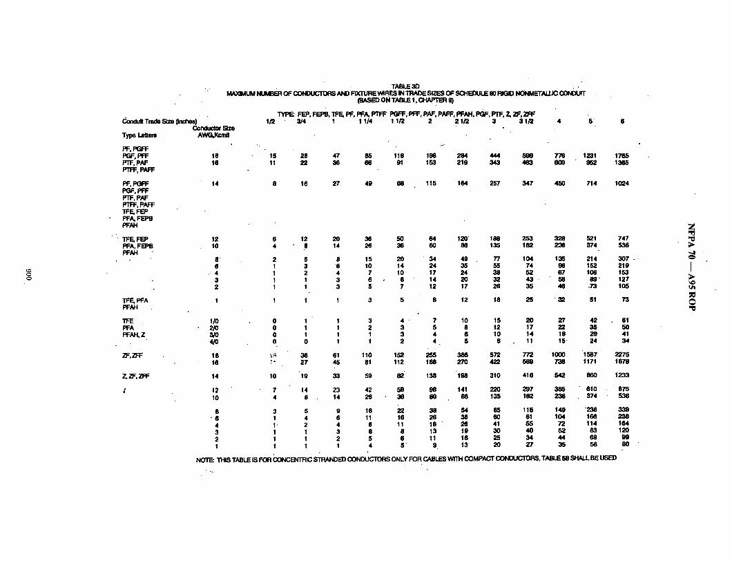
c)
Conduit Trade Size ~ ) Conduc~ Slze
Type Lelte~s AWG,IO:mll
PF, PGR= PGF, PFF 18 PTF, PAF 16 P' i I-I-., PAr'R:
PF, PGFF 14 PGF, PFF PTF, PAF I-" i I.-P, PAR = TFE. FEP PFA, FEPB PFAH
"fFF., FEP PFA. FEPB PFAH
TABLE 3D MAXIMUM ~ OF ~ AND FIXTURE WIRES IN TRADE SI2]ES OF SCHB:)ULE 80 RIGID N G N M E T ~ coNDuf f
(BASED ON TNBLE 1, CHN:q'ER 9)
TYPE: FEP;FEPIB.TFE, PF, PFA, PTFF PGFF,'RFF, PAF, PAFF, PFAH, PQF, PTF, Z,2F,2]=F I /2 3/4 1 1 1/4 1 1/2 2 2 1/2 3 3 1/2 4 5
15 28 47 85 118 198 284 444 599 776 1231 1765 11 22 38 66 91 153 219 343 463 600 ~ 952 1365
8 16 27 49 68 115 164 257 347 450 714 1024
TFE,PFA I PFAH
TFE PFA PFAH, Z
2F,2P'F
12 6 12 20 36 50 84 120" 188 253 328 521 747 10 4 8 14 26 38 60 86 135 182 236 374 " 536
8' 2 5 8 15 20 " 34 49 77 104 135 214 3 0 7 . - 6 1 3 8 10 14 24 35 55 74 96 152 219
.- 4 1 2 4 7 10 17 24 38 52 67 106 153 3 1 1 3 8 8 14 20 32 43 - 56 89" 127 2 . 1 1 3 5 7 12 17 25 35 46 .73 105
1 1 1 3 5 8 12 18 25 " 32 51 73
1/0 2/0
3/0 4/0
18 16
7.., 2F. 2)=F 14
12 10
8 " 6
4 3 2 1
0 1 1 3 4 " 7 10 15 20 27 42 61 0 1 1 2 3 5 8 12 17 22 35 50 0 1 I 1 3 4 6 10 .14 18 29 41 0 0 1 1 2 4 • 5 8 11 15" 24 34
"~.~. 36 61 110 152 255 386 572 772 1000 "1587 2275 ~" 27 45 81 112 188 270 422 569 738 1171 1678
10 '19 33 59 82" 138 "198 310 418 542 860 1233
7 14 23 42 58 98 141 220 297 385 610 875 4 8 14 26 38 60 86- 135 182 236 374 536
3 5 9 16 22 38 54 85 115 149 236 3,39 1 4 6- 11 16 26 38 60 81 104 166 238 1" 2 4 8 11 18 " 26 41 55 72 114 164 1 1 3 6 8 13 19 30 40 52 83 120 1 1 2 5 6 11 16 25 34 44 69 99 1 1 1 4 5" 9. 13 20 27 35 56 80
NO'[~ THIS TABLE IS FOR (:~ONCB'~R'RIC STRANDED CONDUCTORS ONLY FOR CABLES WITH COMPACT CONDUCTORS, TABLE 5B SHALL BE U6EO.
7
• -4 '
I ;>
~D ,o
• TABLE 3E M A X ~ NtJM~R OF ~ AND FIXnJRE W ~ . S tN'mAOE S~ES OF SGHEDULE 80 RI(~D ~ ~ ~
Condult T ~ Slze (bx:hes) Cor~_ _ __,,~_ Size
Type Lettms AWG,Kcmll
)0-1HW, ZW 14 X}tHW-2 12 )0t1-1 10
8
6 4 3 2 ,
1 X}IHW-2 110 )011-I, .2/0
3/O 4/0 .
2 ~ 3OO 350 4OO ,5OO
6OO 7OO 75O 8OO 9OO
1000
1250 1500 .1750 2OOO
1/2 3/4. 1 3 31/2 4 •
(BASED ON TABLE 1, CHAPTE~ 9)
~ )o~w, ZW,)O~H, X~W~2 1.1/4 1 1/2 " 2 2 1/2
5 5 " 27 20
118 91 68
1 11 37
12 20 9 15 6 11
3 $
3 4 I 3 1 3 1 2
1" . '1 1 1 1 1 1 1 0 1
0 1 0 1 0 0 0 0 0 0
0 0 0 0 0 0 0 0 0 0 0 0
0 0 0 0 0 0 0 0
0 0 0 0 0
" I 0
• 0 0 O"
. 0
0 0 0 0 0 0'
48 38 28
15
' 11 8 7 6
4 4 3 2 1
1 1 1 1 1
1 1 1 1 0 0
0 0 0 0
82 03 47
26
19 14 12 10
7 6 5 4 3
3 2 1 1 1
1 1 1 1 1 1
1' 1 0 0
0 0 0 0 0 0 0 0
28 26 17 14
10 9 7 6
"5
I I I I I
.I
185 "142 106
59
43 31 27 .22
17 14 12 10 8
6 5 5 4 3
3 2 2
" 2 "" 1
1
1 1 1 1.
250 " 324 lg2 248 143 185
_ 79 103
59 76 42 55 36 47
"30 39
22 29 19 24" 18 20 13 17"" 11 14
9 1i 7 10
-.6 ' 8 6 8 5 6
4 5 3 .4 3 4
. 3 " 4 3 3 2 3
I 2 I I 1 I
..1 I
NOTE: THIS TAELE IS FOR CONCENTRIC STRANDED CONDUCTORS ONLY FOR ~ WITH COMPACT" CONIXJCTORS, TABLE 5B.SHALL BE US~)
5 6
514 736 394 .565 294 :421
163 234
121 173 87 . 126
"74 106 ,~ e~
46 66 39. 56 32 47 27 " 39" 22 32"
18 26 15 22
• 14 20 • 12 17
10 14
8 : 12- 7 10 7 9 6' 9 6 8 5 7.
4 6 3 5 3 - 4 2 4
Z
,-,I
I
O
T.NBLE 3F ~ NUMBER OF ~ AND FIXTURE~RES IN "~IADE ~ ! = ~ OF SCHB~JLE 80 ~ ~ L K ; CONDU(T
Conduit Trade Size (inches) I /2 ~ S l z e
Type Lettem AWG,Kcmll.
KF-2 18. .28 I~'F-2 16 ". 20
14 " 13 ,12 9 10 6
I~:-1 18 ' 33 I'(FF-I 16 .23.
14- .10 12 10 10 7.
3/4 I
(EASED ON TABLE 1, CI,1N:'TER 9)
TYPE: K]::-I; I,O::-2,i,(]=F-1, Klq::-2 1 1/4 1 1/2 2 2 I /2 3 $1/2 4 5 6
53 59 37 62 25 43 17 29 12 20
63 106 44 74 30 50 19 33 13 21
159 " 221 371 112. 155 " 281 77 107 179 53 73 123 35 49 82
190 263 442 153 185 310 90 124 "209
.59 82 198 39 54. 90
53:1 374 257 177 118
.831 885. 4O2 2 7 7 1 8 5
633 891' 445 696 299 468 198 310 129 203
' 1.121 1452' 2304 . 790 1023 1023.
543 " 703 1116 a n 454 ~ea
• 250 324 514
1336 Sm 6 3 2 418 273
1732 12t7 .
818 542 354
2747 1930 -1296 ,860 .562"
3303 2327 1600 1101 736
3938 2767
" 1861 1233 8O6
7
-.,4
i ;>
Ui
.@
NOTE: THIS TABLE IS FOR CONC~qTRIC STRANDED CO~E~ICTO~. ONLY.FOR CABLESWtTH COMPACT ~ R S , TABLE 58 SHALL BE
TABLE 4A • DIMENSIONS ;AND PERCENT ;avq EA OF SCHEEXJLE 80 RIGID NON~ETALUC CONIXJff
AREASOF CONDUITOR "IIJBING FOR THE COIVlBINATIONS OF WIRES ~'~--g~li l l :u IN TABLE 1, O4Ak'i z:~ 9
Trade Size
1/2 3/4 I
1 1 / 4 1 1/2
2 21/2 3 31/2 "
4 5 5
Internal lTmzneter Inches
.526
.722
.936 1.255 1 ;476
'I .913 2.290 2.864 3.326
3.786 • ' 4;768
5.7O9
¥OUd 100%
.217 .409 .688
1.237 1;711
2.874 4.119 6.442 8.688
11.255 17.855 25.598:
60~
.130
.245 A13"
- "~742 • 1.0Q7
i .724 2.471 3.865 5.213
6.755 10.713 15.359
1 Cond. 53%
.115 .217 .365 .656
_ . . 9 0 7
1.523 2.183
• 3:414 4.505
5.967 9.463
13.567
• o "
Ovm2 2 Cond. Cond.
31% 40%
.067 .O97 • .127 .164 • .213 .275 ..3~ . .455 .530 ,584
4
,891 i .150 1.277 1.64B 1,997 2.577 • 2.693 3.475
3.490 4.503 5.535 •7.142 7.935 10.239
1Cond. ' 2 Cond. 55%. 3 0 %
;119 .065 .225 , .123 .378 .206 .680 ;371 " 1
.941' .513
1.5Sl .e4~. 2.265 .1.238 3.543 1.933 4.778 ' 2 : 6 0 6
• 8.192 3.377 9;820 5.357
14.079" 7,679
~ Covered
3:Cond. ,10%
.087
.164
.275 ,495
. . ( ~ 4 ,
1;150 1,648 2.577 3.475
4.503 17.142
• 10.239
4 ~
• ,082 .155 .261
• ~ .479
1.092 1.565
• 2:448 3.301"
' 4.278 6 ; 7 8 5 9.727
" ( ~ 4 Cond. 35%
.075
.143
.241
.433
.599
1,006 1.442 2.255 3.041
3.940 3,249
8.959
Z
I
N F P A 70 m A 9 5 R O P
iLog #780) 8-243 - (Chapter 9, Table 4): Reject SUBMIT'FEll: Elliot Gray, Gerritos, CA RECOMMENDATION: Add 60 percent column to Table 4 to reflect area available for fill for nipples as permitted in Note 3 to Tables of Chapter 9.
Table 4. Dimensions and Percent Area of Conduit and of Tubing • Areas of Conduit .or Tubing for the Combinations of Wires Permitted in Table 1, Chapter 9, and Note 3 for Nipples .
Area ~ Square Inches
Not l.~ad Covered Lead Covered Internal Over 2. Over 4
Trade Diameter Total 2 Cond. Cond. 1 Cond. Nipples Nipples 1 Cond. 2 Cond. 3 Cond. 4 Cond. Cond. Size Inches 100% 31%. 40% 53% ~0"% 66% 55% 30% 40% 38% 35%
1/2 .622 .30 .09 .12 .16 .18 .18 .17 .09 .12 .11 .11 3/4 .824 .53 .16 .21 .28 .32 .32 .29 .16 .21 .20 .19 1 1.049 .86 .27 .34 .46 .52 .52 .47 .26 .34 .33 .30 1 1/4 1.380 1.50 .47 .60 .80 .90" .90 .83 .45 . .60 .57 .53 1 1/2 1.610 2.04 ".63 .82 1.08 1.22 1.22 1.12 .61 .82 .78 .71 2 2.067 3.36 1.04 1.34 1.78 2.02 2.02 1.85 1.01 1.34 .128 1.18 2 1/2 2.469 4.79 1.48 1.92 2.54 2.87 2.87 2.63 1.44 1.92 1.82 " 1.68 3 3.068 7.38 2.29 2.95 3.91 4.43 4.43 4.06 2.21 2.95 2.80 2.58 3 1/2 3.548 9.90 3.07 3.96 5.25 5.94" 5.94 5.44 • 2.97 3.96 3.76 3.47 4 4.026 12.72 3.94 5.0,9 6.74 7.63 7.63 7.00 _ 3.82 5.09 4.83 4.45 5 5.047 20.00 6.20 8.00 10.60 12.00 12.00 - 11.00 6.00 8.00 7.60 7.00 6 6.065 28.89 8.96 11.56 15.31 17.33 17.33 15.89 8.67 11.56 10.98 10.11
SUBSTANTIATION:' None. PANEL ACTION: Reject. - PANEL STATEMENT: Practically all conduit and tubing has different dimensions. Panel has accepted new tables for each type to be included in chapter 9, Table 4 (see proposal 8-236). Proposed Table 4 contains dimensions for all types of conduit and tubing and the 60% permitted fill areas can easily be calculated fa'om informa- tion in these tables. The.Panel views the 60% fill as a seldom used quantity and does not see a need to provide this additional information. NUMBER OF PANEL MEMBERS ELIGIBLE TO VOTE: 14 VOTE ON PANEL ACTION:
AFFIRMATIVE: 14
(Log #2"229) 8-244 - (Chapter 9, Table 4): Reject SUBMITrER: Tom Henry, Code Electrical Classes, Inc.
-RECOMMENDATION: Revise text as follows: • Add a new column under "not lead covered" for "Nipple fill 60%" Trade Size Nipple Fill 60% " " • 1/2" .18 3/4" .318 1" .516 1-1/4" " .9
and so on. SUBSTANTIATION: By adding"nipple fill 60%" you would have a complete table by listing all of the raceway fills 31%, 40%, 53% and 60%: • PANEL ACTION: Reject. " PANEL STATEMENT: .Refer to Panel Statement on Proposal 8-243. NUMBER OF PANEL MEMBERS ELIGIBLE T O VOTE: 14 VOTE ON PANEL ACTION:
AFFIRMATIVE: 14
. (Long #2683) 8-245 - (900-4 Table 4 and Table 4B-(New)): Accept in Prindple SUBMITTER: Edwin K. Rodkey, Cation Elecu-ical Products-A Lamson & Sessions Co. RECOMMENDATION: Add new text as follows:
1. Renumber current Table 4 to read: Table 4A. 2.. Add Table 4B. Dimensions and percent area of rigid PVC
condui t , Schedule 80.
Table 4B. Dimensions and Percent Area of Rigid PVC Conduit, Schedule 80
• - Internal • Trade Diameter T o t a l Over 2
Size In Inches Area 2 ~ r e s Wires In 100% In 31% In 40% In
Inches Sq. In. sq . hl. Sq. In.
1 /2 0.526 "0.217 0.067 - 0.087 3 /4 0.722 - 0.409 0.127 ' 0.164 1 0.936 0.688 0.213 0.275 1 1 /4 '1.255 1.237 0.383 0.495 1 1 /2 1.476 '1.711 0.530 0.684 2 1.913 2.874 0.891 1.150 2 1 /2 -2.290 4.119 1.277 1.647 3 2.864 6.442 1.997 2.577. 3 1 /2 3.326 8.688 2.693 3.475 4 3.786 "11.258 3.490 4.503 5 4.768 '17.855 5.535 7.142 6 5.709 25.598 7.935 10.239
I Wire. 53% In Sq. In.
0.115 0.217 0.365 0.656 0.907 1.523 2.183 . 3.414 4.6O5 5.967 9.463
13.567
SUBSTANTIATION: Due to the smalle'r I.D. of RNMC-80, a separate table is necessary to provide this information of the code user. PANEL ACTION: Accept in Principle. PANEL STATEMENT: Refer to Panel Action on Proposal 8-236. NUMBER OF PANEL MEMBERS ELIGIBLE T O VOTE: 14 VOTE ON PANEL ACTION:
AFFIRMATIVE: 14
904
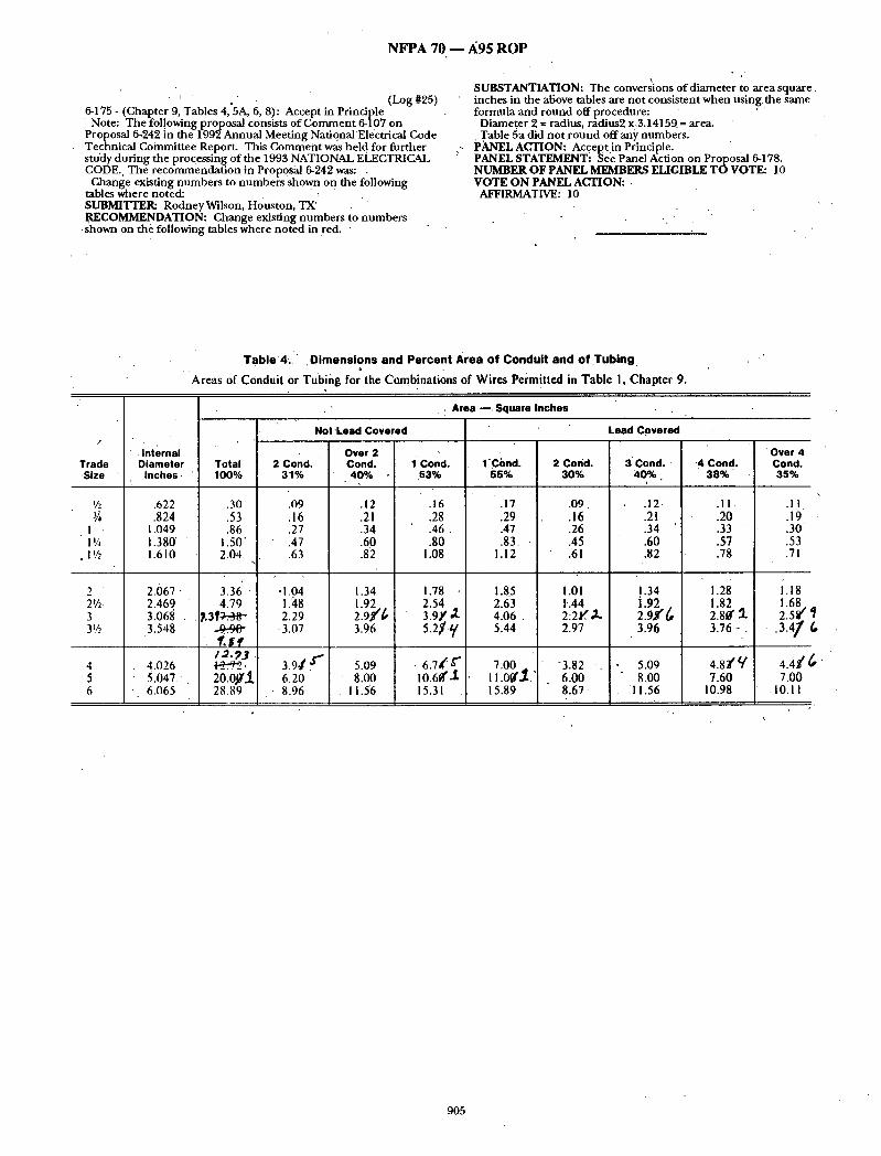
NFPA 70 m A95 RO P
' ' . . ( L o g # 2 5 ) 6-175 - (Chapter 9, Tables 4, 5A, 6, 8): Accept in Principle
Note: The fol.lowing proposal consists o f Commen t 6-107 on Proposal 6-242 in the 1992 Annual Meeting National'Electrical Code Technical Committee Report. This Comment was held for fur ther study during the processing of the 1993 NATIONAL ELECTRICAL 'CODE., The recommendat ion in Proposal 6-242 was: .
Change existing numbers to numbers shown on the following tables where noted: : SUBMITTER: Rodney Wilson, Houston, TX' RECOMMENDATION: Change existing numbers to numbers
-shown on the following tables where no ted in ~'ed. '
SUBSTANTIATION: The conversions of d iameter to area square. inches in the above tables are not consistent when using,the same formula and round off procedure:
Diameter 2 = radius, radius2 x,3.14159. = area. Table 5a did n o t r o u n d offany numbers.
PANEL ACTION: Accept in Principle. " PANEL STATEMENTi See Panel Action on Proposal 6-178. NUMBER OF PANEL MEMBERS ELIGIBLE TOVOTE: 10 VOTE ON PANEL ACTION:
AFFIRMATIVE: lO
Table '4l., ' . Dimensions and Percent Area of Condui t and of T u b i n g o
' Areas of Conduit or Tubing for the Combinations of Wires Permitted in Table !, Chapter 9.
f , ,
" . Internal Trade Diameter ,Size ' Inches.
I/z .622 3~ .824
I 1.049 I i~ 1.380' "
• 1!5 1.610
2 ' 2.067" 2V.,- 2.469 ' 3 3.068 . 3V., 3.548
4 4.026 . 5 5.047.
6 6.065
Total 100%
.30
.53
.86 1.50" 2.04
j ,
3.36 4.79
P.3F/--.96" - g - 9 0 "
q.~f /0.~3 .~:-7"2. 2 0 . 0 9 1 28.89
• - , Area ~,Square Inches
Not 'Lead Covered
2 Cond. 31%
.09
.16
.27
.47
.63
:
• 1.04
I.~8 2.29 3.07
3.9¢ d " 6.20
• 8.96
Over 2 Cond. 40%
.12
.21
.34
. 6 0
.82
1.34 1.92 2 . 9 f / , 3.96
5.09 8 . 0 0
11..56
1' Cond. .53%
.16
.28
.46
.80 1 . 0 8
1 . 7 8 2.54 3.9Y 5.2~¢.q
• 6.74 / 10.6~'~ 15.31
1 -Cbnd . 2 Cond. 55% 30%
.17 .09
.29 .16
.47 .26
.83. • .45 1.12 .61
1 . 8 5 1 .0 I 2.63 1.44 4.06 . 2:21~', ,~L 5.44 2.97
7.00 ,, -3.82 -. I 1 .0~ ' ,~ . 6.00 15.89 8.67
Lead Covered
Over 4 3' C o n d . '. '4 Cond. Cond.
4 0 % . 38% 3 5 0
.12-
.21
.34
. 6 0
.82
! .34
1.92 . 2.9/(,, 3.96
• 5 . 0 9 8 . 0 0
I 1 . 5 6
.II.
.20
.33
.57
.78
1.28 1 . 8 2 2.8¢' 5. 3.76 -.
4 . 8 ~ 7.60
10 .98
.11.
.19
.30'
.53
.71
1.18 1 . 6 8 2.5~ ,3.4/ 6
4.4t6 7.00
.10.11
905
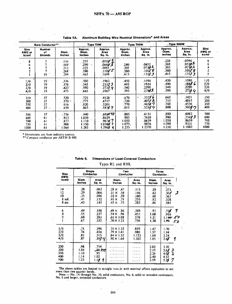
NFPA 'J0 - - A95 ROP
Table 5A. Aluminum Building Wire Nominal Dimensions* and Areas
Bare Conductor** . Typo'THW Type THHN .Type XHHW
Size Number Appro x . Approx. AWG or of Diam. Diam. Area
kcmil Strands Inches Inches Sq. In.
I/0. 2/0 3/0 4/0
250 300 350 400
500 600 700 750
1000
7 7 7 7
1 9
1 9 ' ' 19 19 19
37 37 37 37 ,
37 61 61 61 61
.134
.169
.213
.268
.299
,336 .376 .423 ' .475
.520
.570 ~ •616 .659
,:736 .813 .877 .908
1.060
.255 • .290 .335 .390 .465
.500
.545
.590
.645
.725
.775
.820 -
.865 .
.940 1.050 I . I I 0 IdSO 1.285
.o5,¢1.
.066p',,1
.0881
. l l 9 t f , , r"
.1698
.1963
.233Z3
.273r, q
.3267
.4128
.4717
.5281 .587~ 7
.69M)'~0
.8659
.967~ 7 1.038g 7 1.296g q
Approx. Approx. Diam• Area Inches • S q . l ~
.240 .0452 .
.305 .0731[t'~
.360. . 1 0 1 2 ' f
.415 .135~,3
.450 .1590 ,.495 .1924 .540 2290 .595 1 2 7 8 ~
.670 ' . 3 5 2 / ~
.720 . 4 0 7 f ~
.770 . 4 6 5 ~ q
.815 521~'7
.885 .6151
.985 .7620 1.050 .8659 1.075, .9076 1.255 1.2370
Approx• Approx. Diam. Area Inches Sq. In.
.224 .0394 _
.260 .0530" "$
.305 .073.0'.1.
.360 .101fp
.415 .135~ 3
.450 .1590
.490 . 1 8 8 ~ ¢
.540 .2290
.590 . 2 7 3 ? q
.660 .3421 . 7 1 5 .4015
.760 .4536
.800 . 5 0 2 f q
.880 .6082
.980 . 7 5 4 ~ 3 1.050 .8659 i.090 .9331 1.230 1.1882
Size AWG or
kcmil
i/o 2/o
3 / 0 4/o
250 300 350 400
500 600 700 750
1000
* l)imensions are from industry sources ** Compact conductor per ASTM B 400
Table 6. Dimensions of Lead-Covered Conductors
Types RL and RHL
Size AWG- kcmil
14 12 IO 8 sol 8 str.
6 4 -2 I
i/o 2/O 3/0 4/O
250 300 350 400 500
Single Conductor
Two Conductor
Diam. Inches
Three Conductor.
Area • Sq. In.
59 .62
- .68 .82 .86
.97 1.08 1.21 1.38
1.47 1.57 1.69 1.85 •
Diam. • Area Inches Sq• In•
.28 .062
.29 .066.
.35 • .096
.41 .132
.43 .145
.49 .188
.55 .237
.60 .283
.67 .352
.71 .396
.76 .454
.81 .515
.87 . 5 9 J ~ i
.98 .754 1.04 ..,g6 . ~ ] 1.10 .95 1.14 1.02 1.23 I.O' f
Diam• Area Inches Sq. In.
. 28× •47 .115
. 3 1 x :54 .146
.35X .59 .180
.41 × .71 .255
.43 X .75 .282
.49 x .86 .369
.54× .96 " .457
.61 X 1.08 .578
.70 X 1.23 .756
.74 x 1.32 .859 • .79 x 1.41 .980 .84 x 1.52 1.123 .90 X 1.64 1.302
2.02 2.15 2.26 2.40
2.59
.'273
.3oY -; .363
.528
.581
I .916
1.14~ ¢f '0 I:tg ,.¢'0
1.70 1.94 2.24 ,/
3.20 3.61 3 4.0-~ 1 4.52 5.2f F
The above cables are limited to straight runs or with nominal offsets equivalent to not more than two quarter bends..
N o t e - - No. 14 through,No. 10, solid conductors; No. 8, solid or stranded conductors: No. 6 and larger, stranded conductors.
906

NFPA 70 - - A95 ROP
Table 0. Conductor Propert ies
Conductors DC Re'stance I t 7S*C (i67~F)
, Aa~be- Sine Area Stranding Overall ' Copper num
AWG/ Cir. Quart- Diam. Diam. Area Uncoated Coated " ohm/ kcmlJ Mill tlty In. In. In.: ohm/MFT ohm/MFT MFT
18 1620 1 - - 0.040 0.001 7.77 8.08 12.8 18 1620 7 0.015 0,046 0,002 7.95 8.45 13.1 16 2580 I~ - - 0.051 0.OO2 4.89 5.08 8.05 16 2580 7 0,019 0.058 0.003 4.99 5.29 8.21 14i 4110 I - - 0,064 0.003 3.07 3.19 5.06 14 " 4110 '7 ' 0.024 0,073 0.004 3.14 3.26 5.17 I 2 6530 I 0.081 0.OO5 1.93 " 2.01 3.18 12 6530 7 0.0"30 0.092 0.eel'/ • 1.98 2.05 3.25 10 10380' I 0,102 0.008 1:21 1.26 2.00 10 10380 7 0.0"38 0.116 0.011 1.24 1.29" 2.04 .8 16510 I 0.128 0,013 0.764 0.786 1.26 8 16510 7 0 .~9 0.146 0.017 ! 0,778 0.809 1.28 6 26240 7 0 , 0 6 1 0,184 0,027 0.491 0.510 0.808 4 41740 7 0.077 " 0.232 0.042 0.308 0.321 0,508 3 52620 7 0.087 0.260 0.053 0.245 0.2~4 0.403 2 66360 7 0,097 0.292 0.067 0.194 0.201 0.319 I 83690 19 0.066 0.332 0.087 0.154 0.160 0.253
I /0 105600 19 0.074 0.373 0,109 0.122 0.127 0.201 2/0 133100 19 0.084 0.419 .0.138 0.0967 I 0.10) . 0.159 3/0 167800 19 0,094 0,470 0.173 0.0766 0.0797 0.126
.4/0 211600 19 0.106 0.528 0.219 0.0608 0.0626 0.leo 250 - - 37 0.082 0.575 0.260 0.0515 0.0535 0.0847 300 - - 37 0.090, 0.630 0.312 0.0429 0.0446 0.0707 350 - - 37 0.097 0.681 0.364 0.0367 0.0382 ' 0.0605 400 - - 37 0.104 0.728 0.416 0.0321 0.0331 " 0.0529 500 - - 37 0.116 0.813 0.519 0.0258 0.0265 0.0424 600 - - . 61 0.099 0.893 0.626 0.0214 0.0223 0.0353 700 - - 61' 0,107 0.964 0,730 0.0184 0.0189 0.0303 750 - - 61 0.111 0.998 0,782 0.0171 0.0176 0.0282 800 - - 61 0:114 1.03 0.83/13 0.0161 0.0166 0.0265 900 - - 61 0.122 1.09 0.980. 0.0143 0.0147 0.0235
leo0 - - ' 61 0.128 1.15 1.04~ 0.0129 0.0132 ~0.0212 1250~ - - 91 0.117 1.29 1.3~, [ 0.0103 0.0106 0.0169' 15001 - - 91 0.128 1.41 i.Sr~l 0.00858. 0.OO883 0.0141 1750 - - .127 0.117 1.52 1.8/f.t 0.00735 0.00756 0.0121 2000 - - 127 0.126 1:63 2.09 0.00643 0.OO662 0.0106
" The~e resistance values are valid ON LY 'for the pa~mcters as given. Using conductors having coated strands, different strandin8 type, and especially, other temperatures, change the resistance. " " - . :
Formula for temperature change: R2 = Rt [l+a(Tr75)] where: a~ - 0.00323. a ~ = 0.00330. , , , . .
Conductors with compact and compressed strandin 8 have about 9 percent and 3 percent. respe~ively, smiler bar F con, ductor diameters than those shown. See Table 5A for actual 'compact cable dimensions.
The IACS conductiviiies used: hare copper ~ 100~. aluminum = 61%. Class B stranding is listed as well as solid for some sizes. Its overall diameter and arco is
that of its circumscribing circle. (FPN): The construction information is per. NEMA" WC8-1976 (Ray 5-1980). The
'resistance is calculated per National Bureau of Standards Handbook 100. dated 1966. and Handbook 109. dated 1972.
i
. In te rna l T r a d e D iame te r "_~a-e ' I nches
"½ ~622 .824
I 1.049 I *~ 1.380 11,6 1.610
2 , 2,067 21/z 2 .469 3 .3.068 3'/1 ' 3.548
4.026 5.047 6.065
Table 4. Dimensions and Percent Area of Conduit end of Tubing
Areas of Conduit or Tubing for the Combinations of Wires Permitted in T a b l e t . Chapter 9.
, . Area - - 8cluaro Inches
[ No t L i e d C o v e r e d
I " O v e r 2 '
T o t a l 2 C o n d . C o n d . I C o n d . I C o n d . 2" C o n d . 1OO% 3 1 % 4 0 % 53% 65% 3 0 %
• 30 .09 .12 .'16 .17 .09 .53 .16 .21 .28 .29 .16. .86 .27 .34 .46 .47 - .26
1.50 .47 .60 .80 .83 .45 2~04 .63 .82 . i~08 1.12 .61
Lead C o v e r e d
3 C o n d . ~40%
12 21 .34 .60 :82
4 C o n d .
.11
.20
.33
._57
.78
3.36 1.04 1.34 1.78 1.85 1.01 1.34 • 1.28 4.79 1.48 1.92 2.54 2.63 1.44 1.92 1.82
-~q "~38 2.29 .~ ~ ~.~- -3":94 4.06 .tz-2":-.-.-.-.-.-.ff~ t.'", -2=95 z.fl -2:80- .~q-9:9~ 3.07 3.96 f,.j.q -5:-2ry - 5.44 "2.97 3.96 ~ 3.76
,~'~-.~ J.'J5 3.9~ 5.09 I.~5 ~ 7.00 3.82 5.09' ~.r-~ v"-2e~ 6.20 8.00 , , .t ,0-~60- ~.,o 4+:00 6.00 8.00 7.60
28.8 t, • 8.9~S 11.56 15.31 15.89 "8.67 I 1.56 10.98
Over 4 C o ~ .
.11
.19
.30
.53
.71
1.18 1.68
• Sl 2, f-",
,'t/, -4-:4~r'-
7.00 I0.11
9 0 7
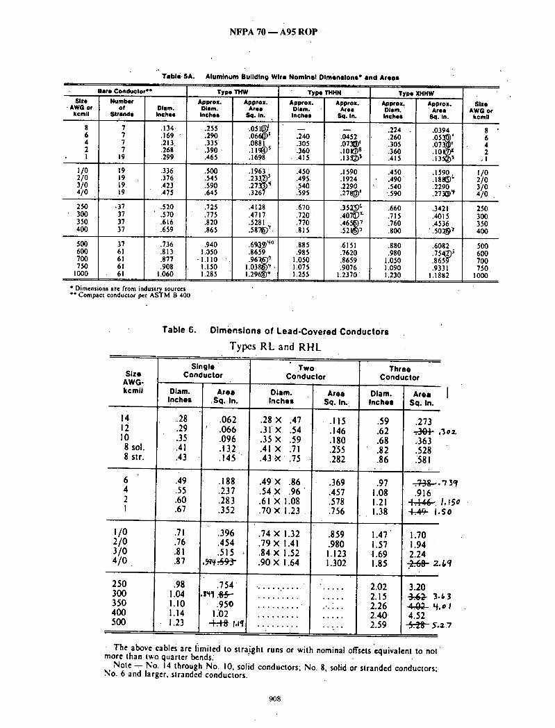
NFPA 70 - - A95 ROP
Table 5A.
Bare CondMctor *e
Size - AWG or
kcmtl
~/o 2/0 31o 41o
250 300 350 400
500 600 700 750
I000
Number of Diam.
Strands Inches
7 .134 7 .169 7 .213 7 .268
19 .299
19 .336 19 .376 19. .423 19 .475
• 37 .520 37 ~.570 37 .616 37 .659
37 .736 61 .813 61 .877 6t .908 61 1.060
* Dimensions ate from industrysourccs "* Compact conductor per ASTM B 400
AlumlnumBulldlngWlro Nominal Dimensions" am
Type THW Type~rHHN Approx. Dlsm. Inches
.255 ,290 .335 .390- .465
.500
.545
.590
.645
.725
.775
.820 •865
.940 1.050
"l.llO 1,1,50 1.285
Approx. Approx. Area Diam.
8q. In. Inches
.051~) I. .0661~' .0881
. t l ~ ~
.1698
.1963
.233~ 3
.273~ q
.326?
.4128
.4717
.5281
.58"~ ~.
.690~ ~°
.8659
.96"~'; 1 . 0 3 8 ~ , 1.296~ q
i
,240 .305 .360
• .415
.450
.495.
.540
.595
.670
.720
.770
.815
.885
.985 1.050
'I.075 1,255
Approx. Area
Sq. In.
.0452
.O?3G)'
.tO~S-
.13~[,~ ~
.1590
.1924
.2290
.27~'
.35:~ c
.407© ~"
.465~) "/
.521@~
.6151
.7620
.8659
.9076 1.2370"
Areae
Type Approx~ Diem. Inches
.224
.260
.305
.'360
.415
.450
.490"
.540 '.590
.660
.715
.760
.800
.880
.980 1.050 1.090 1.230
XHHW
Approx. Area
Sq. In.
.0394
.05~'
.073~'
.1590
.188~ ~
.2290
.273~) ~
.3421
.4015
.4536 • .5o~)
.6082
.8659
.9331 !.1882
Size AWG or
kcmll
8 6 4 2
, l
I/O 2/0 3/0 4/0 .
250 300 350 400
500 600 700 750
1000
Table 6. Dimensions of Lead-Covered Conductors
Typcs RL and RHL
Size AWG- kcml l
4
I0 8 sol. 8 sir.
6 4 2 I
i/o 2/o 3/o 4/o
250 300 350 400 500
Single Conductor
Diam. Area Inches Sq. In.
.28 .062 .29 ' .066 .35 .096 .41 .i32 .43 .145
.49 .188
.55 .237
.60 .283
.67 .352
.71 .396
.76 .454
.81 .515
.87 : ,~¥ .-t~-3-
.98 .754 1.04 .s~1 .Sx~ --- I.I0 .950 I. 14 I .'02 1.23 -t-s-Hi I.Iq
Two Conductor
Diam. Inches
.28 X .47
. 31X .54
.35 X .59
.41 X .71
.43 .X .75
.49 X .86
.54 X .96"
.61 X 1.08
.70 × 1.23
.74 X 1.32
.79 X 1.41
.84 X 1.52
.90 X i.64
Area Sq. In .
.115
.146
. lg0
.255
.282
.369
.457
.578
.756
.859
.980 1.123 1.302
Three Conductor
Diam. Area Inches Sq. In.
.59 .273
.62 " " '
.68 .363
.82 .528
.86 .58 I
.97 ~ . 1.08 .916 1.21 ~ , 1.38 ~ I So
! . 4 7 !.70 i.57 1.94 ! .69 2.24 1.85 2 ~8 2./,q . . .
2.02 3.20 2.15 ~ 3.63 2.26 ~ 4.o I 2.40 4.52 2.59 "6-.-.-.-.-.-.-.-.-~- Y, a7
02.
3of
Io 15o
The above cables are I~mited to straight runs or with nominal offsets "equivalent to not more than two quarter bends.
Note - - No. 14 through No. 10, solid conductors; No. 8, solid or stranded conductors; No. 6 and largcr,,stranded conductors.
908

NFPA 70 -- A95 ROP
)
Size Area AWG/ Cir. kcmii Mils,
18 1620 18 1-620 16 2580 16 -2580 1 4 411.0 14 4110
12 6530 12 6530 I0 10380 I0 10380 8 16510 8 16510 6 26240 4 41740' 3 52620 2 66360 ,I 83690
i/o io56oo 2/0 133100 3/0! 167800
~. 410 211600 250 -- 300 350 -- - 400 -- 500 -- 600 700 750 -- 800 9o0 -- 1000 --" 1250 - - 1500 1750 -- 2000 --
Tabie 8.
Conductorl
C o n d u c t o r P r o p e r t i e s
OC Resistance at 75"C (167'11: i-
• Stranding I Ouan- O i a m , Olam;
t l ty. In. In. 1 - - 0 . 040 "7 0.015 0.046 I - - 0.05) 7 0.019 0.058 I -- 0.064 7 0.024 0.073 I . ~ 0.081 7 0.030 0.092 I . -- 0.102 7 0.038 0.I 16 I __ 0.128 7 0.049 O. 146
• 7 0.061 0.184 7 0.077 0.232
7 0.087 0.260 7 0 . 0 9 7 0.292
19 0.066 0.332 ' 19 0.074 0.373. 19 0.084 0.419 19 0.094 0.470 19. 0.106 0.528 37'' 0.082 0.575" 37 0.090 0.630 37 0.097 0.681 37 0.104 0.728 37 i 0.I16, 0.813 61 0.099 0.893 61 O, 107 0.964 61 O. I I I 0.998 61 0.114, 1.0"3 61 0.122 1.09 61 • 0.128 1.15 91 0. I 17 1.29 91 0.128 1.41 127 0.117 1.52 127 O. 126 1.63
• " Aiumi- • Overal l • Copper num
Are~ i I ~ Uncoated I .Co;;ted ohm/
in.: ohm / MFT / o h m / M F T MFT 0.001 7.77 8.08 12.8 - 0.002 7.95 8.45 13.1 0.002" 4.89 5.08 8.05 - 0.003 4.99 5.29 8.21 0.003 3.07 " 3.19 5.06 0.004 3.14 3.26 5.17
O.O05s 1.93 . 2.01 3.18 ~0.0~6) !.98 ,2.05 3:25 , 0.008 1.21 1.26 2.00 0.011 1.24 1.29 2.04 0.013 0.764 0.786 1:26 0.017 0.778 0.809 118 0.027- 0.491 " 0.510 0.808 0.042 0.308 0.321 0.508 0.053 0.245 0.254 ' 0.403 0.067 0.194 0 .201 0.319' 0.087 0.154 0.160 0.253 - 0.109 0.122 0.127 0.201 " 0.138 0.096"/ 0. I01 0.159 0..I.73 0.0766- 0.0797 '0.126 0.219 , 0.0608 0.0626 0.100 0.260 0.0515 0.0535 0.0847 0.312 0.0.429 "" 0.0446 0.0707 0.364 0.0367" 0.038'2 0.0605
i
o.416,o.o321 o.o331 0.0529 0.519 0.0258 0.0265 0.0424 0.626 0.0214 0.0223 0.0353 0.730 0.0184 0.0189:0.0303 0.782_ : 0.0171 0.0176. 0.0282 0 .83~ 0.0i61 0 .0166 0.0265 0 3 1 ~ ~ 0.0143 0.0147 0.0235 !.04 0.0129 0.0132 0.0212 1.30) I 0:0103 0.0106 0.0169 I .~5~ . ~" 0 .00858 0 .00883 ! 0.0141
• i . l ~ ' 0.00735 0.00756 0.0121 2.09 0.00643 0.00662 0.0106
, - | ., . " , ," " "
the resistance. " Formula for temperature change: R2 = Ri [1+a(Tr75)].where: ~ = 0.00323, aAC =
0.00330. ' . . . . ' " " " " .Conductors With compact and compressedstra.ndmg have about 9 percent and 3 pcrceni,
respectively, smaller bare conductol" diameters than those shown. Sea= Table 5A for accrual comoact cable dimensions. " " " alumin
The IACS conductivities used: bare copper =. 100%, um= 61%. Class B stranding is listed as well as solid for some sizes.lts overall diameter and area is
that of its circumscribing circle. (FPN): 'The construction information is per NEMA WC8-1976 (Roy 5-1980).'The
resistance is calculated per National Bureau of Standards Handbook 100, dated 1966, and Handbook 109, dated 1972.
9O9

NFPA 70 - - A95 ROP
• (Log #82) 6-176 - (Chapter 9, Tables 4, 5A, 6 and 8): Accept in Principle
Note: The following proposal consists of Comment 6-107 on Prol3osal 6-242 in the 1992 Annual Meeting Nati6nal Electrical Code Technical Committee Report. This Comment was held for fur ther " study during the processing of the 1995 NATIONAL ELECTRICAL CODE. The recommendat ion in Proposal 6-242 was (see Proposal 6- 175 (Log #25). SUBMITTER: Dwight Durham, Soutfiwire Company RECOMMENDATION: Replace existing Tables 5A,5B, and 8 with revised Tables 5A, 5B, and 8 (attached). Add new Table 5C. Accept revisions to Table 6 as shown in the proposal.
SUBSTANTIATION: Er(ors were found in existing Tables 5A, 5B, and 8. The revised Tables 5A, 5B, and 8 are the work o f a CMP-6 & 8 Task Group appoin ted to correct these errors. Table 5C is added to cover conduit fill when Schedule 80 Rigid Nonmetallic (~onduit is" used. No manufacturer o f lead-covered conductors could be located tojnstify the dimensions in Table 6; however, the submitter o f proposal 6-242 is correct on area calculations. Table 4 is u'n(ie'r the
risdiction of CMP-8. " Note: In the at tached Table8 the asterisks are.merely to highlight
the proposed changes. Do ho t consider them as part of the changes. PANEL ACTION: Accept in Principle. . PANEL STATEMENT: See Panel Action on ProlSosal 6-178. NUMBER OF PANEL MEMBERS ELIGIBLE TOVOTE: 10 VOTE ON PANEL ACTION:
AFFIRMATIVE: '10
Table 5A Compact Alumlnum Building Wire Nominal Dimensions and Areas
. . . . . . . . ; : : : ' ; : : d u e : o : : . . . . . . . . . . . . . . . . . - ~f~: ;~q ' "~'=" . . . . . . . . . . . . . . . . . . . . . . . . . . . . T y p e THHN . T Y P e XHl~" . . . . . . . . . . . . . . . . . . . . • Size Number Approx. Approx. Approx. Approx. Approx. Approx. Slze
AWG or of Diam. Diam. Area Diam. Area- Diam. Area AWG or kcmll Strands lqches Inches Su. In. Inches Su.ln. Inches SQ,In. kcmll
8 7 .134 .254 .051 - - . 2 2 4 . 0 3 9 8 6 7 .169 .289 .066 .239 .045 .259 .053 6 4 7 .213 .333 .087 .305 .073 ;303 .072 4 2 7 .268 .388 .118 .360 .102 .358 .101 2 1 1~ . .299 .459 .166 .4i3 .134 ,40~ ,~ 1'
1/0 19 .336 .496 .193 .450 .159 .446 .156 1/0 2/0 19 .376 o .536 .226 .490 • .189 .486 • .186 2/0 3~0 19 . 4 2 3 ' .583 .267 .537 .227 .533 .223 3 /0 4[0 1~ ,475 .635 .~17 ,~8~ .27~ - ~ ' ,26~ ~/0 250 37 " . 5 2 0 . 7 1 0 ' .396 .656 .338 . 6 5 0 .332 250 300 . . 37 . 5 7 0 .760 .454 .706 .392 .700 .385 300 350 37 " .616 .806 .510 .752 .444 ".746 .437 350"s 400 37 . 6 ~ .04~ -566 . 7 ~ .496 .... , 7 5 ~ -40~ 490
"500- 37 .736 .926 .674 .872 .597 .866 .589 500 600 61 .813 1 .033 .838 :971 .741 .973 .744' 600 700 61 . 8 7 7 1 .097 .945 1 .035 .841 1 .037 . 9 4 5 700 750 61 .908 1 .128 .999 1 .066 .893 1 .068 .896 750 t
1000 6 1 . 1 .060 1 .280 1 .287 1 .218 1 . 1 6 5 1 .220 1 .169 .'" 1000
*Compact conductor per ASTM B 400
910
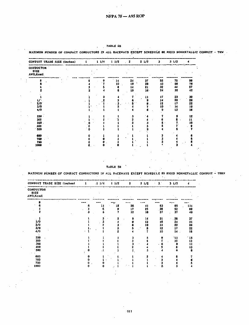
N F P A 70 - - A 9 5 R O P
TABLE SD
HAXIMUM NUMBER OF COMPACT CONDUCTORS IN ALL RACEWAYS EXCEPT SCHEDULE: 80.RIGID NONMETALLIC"CO~;OUIT - THW .
CONDUIT TRADE S i Z E ( inches) 1 1 114 I 112 2 . 2 1/2 3 3 112 4
CO,'4DUCTOR SIZE
AWG,Kcmil.
8 6 4 2
i 2 /0 3 / 0 4 / 0
250 , 300 350 , 400
" SO0
6O0 100 150
IO00
. . . . . . . . . ; . . . . . . . . . . - . . . . . . . . . . . . . . . . . . . " ; - T . . . . . . . . . . ' - ' - - "
5 9 14 4 ' 7 10. 3 5 ' 8 2 4 6
•1 1
24 19 14 10
3 4 7 .2 3 6
:I" 1 2 4 1 . 1, i 4
1 1 1 3 1 " 1 "1 3 0 1 1 2
"0 1 1 1 0 . 1 1 1
0 1 1 1 0 0 1 1 o o . 1 1 O, 0 0 I •
37 28 21" 16.
11 9 8 . 7 6
"4 4 3 3 3 \
1 1 1 1
55 75 98 43 58 76 3 2 44 57 24 32 42
17 23 30 14 20 26 12 17 22 10 14 19 9. 12 16
/
7 9 12 6 8 - 11 5 . ~ lo 5 7 . 9 4 5 1
3 4 6 3 4 S 3 4 S ' 3 4
TABLE SO' '
MAXIHU~,I NUMBER OF COFIPACT CONDUCTORS IN ALL RACEWAYS EXCEPT SCIIEDULE 80 RIGID NONHETALLIC CONDUIT - TIIHH
CONDUIT TRADE SIZE ( inches) 1 -1 114 i 1/2 2 2 112 3 . 3 112 4
CONDUCTOR SIZE
AICG,Kcmil
6 .6 ! 1 15' 4 4 6 9 2 3 5 7
1 1 3 5 ilO 1 3 4 .21o I 2 3 310 1. 1 3 41o 1 [ z
250 1 1 I 300 I ' I 1 350 . 1 1 1 400 1 1 1
• 500 0 • 1 1
600 0 I I. 700 0 1 ~ I . 750 0 . 0 1
1000 0 0 / I
28. 17 12
9 8 6
41 25 18
14 12 10
5 ~8 4 7
3 5 3 5 3 4 2 4 ! 3
1 .2 1 ! ! 1 1 !
63 85 38 52 27 : 37
2! .28 18 24 15 20 12 17 10 14 ,
8 ~lt 7 10
, 6 8 5 8' 4 6
4 $ 3 4
'3 4 2. 3
111 69 49
37 31 26 22 18
" I S 13 1! 1o
$
7 6 $ 4
911
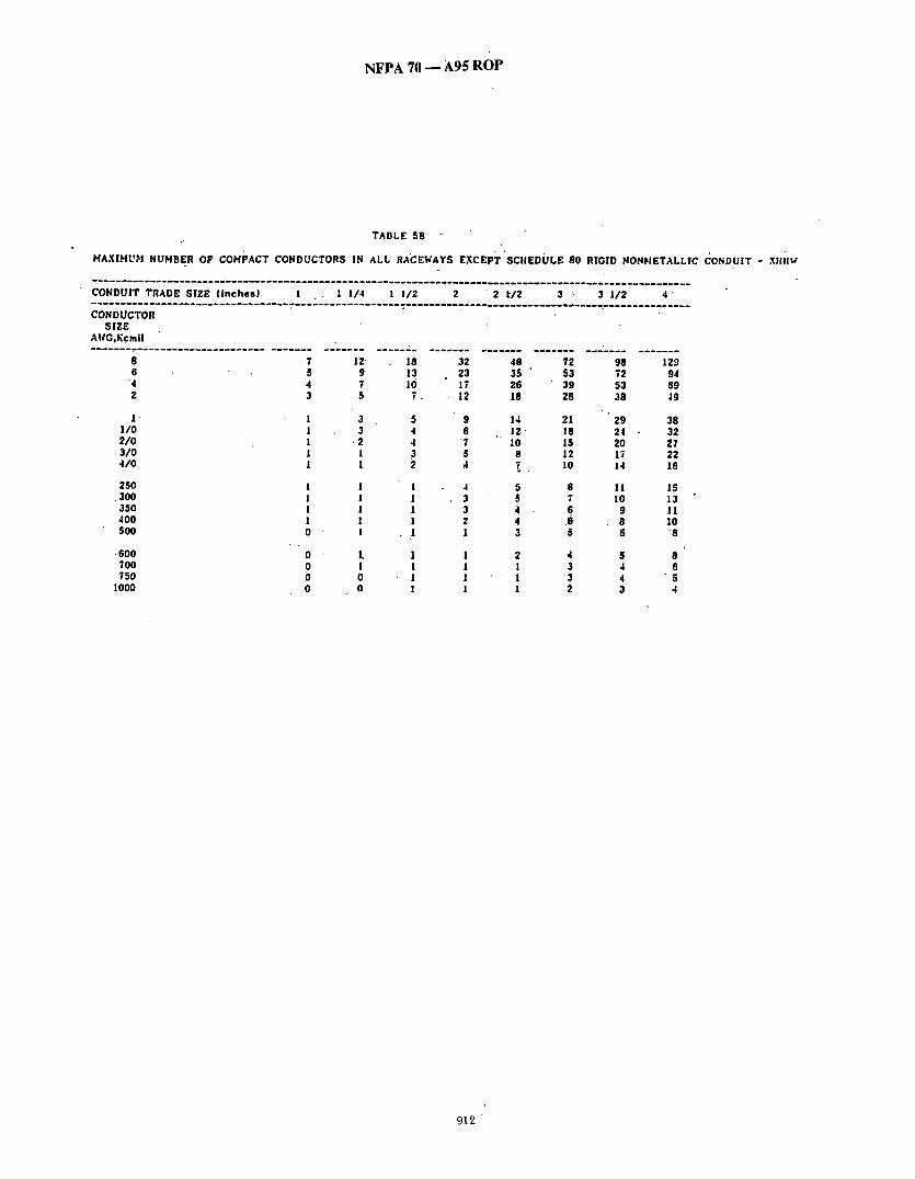
N F P A 70 - - A 9 5 R O P
TABLE 5B
HAXIHUbl NUHBEIq OF COMPACT CONDUCTORSIN ALL RACEWAYS E X c E P T ' s c I I E D O L E 80 RIGID NONIqETALLIC CONDUIT - XIIH~
CONDUIT TRADE SIZE ( inches) I l 1/4 1 1/2 2 " 2 t / 2 3 - 3 1/2 4" . . . . . . . . . . . . . . . . . . . . . . . . . . . . . . . . . . . . . . . ~_ - . . . . . . . . . . . . . .: . . . . . . . . . - . . . . . . . . . . . . . . . . . . . . . . . . . . . . . . . . . . . . . . . CONDUCTOR
SIZE • AICG,Kcmil
8 ' 7 1 2 18 3 2 48 72 98 129 6 5 9 13
'4 4 7 10 2 3 5 7 .
1 1 3 5 1 /0 l 3 4 2/0 1 .2 4 310 1 I 4/0 1 1 2
25O 1 1 1 .300 1 1 1 350 1 1 1 400 1 1 i 500 0 l 1
• 600 0 1, 1 700 0 1 1 750 0 0 1
1000 0 0 !
23 35 " 53 72 94 17 26 39 53 69 12 18 28 38 49
9 14 21 29 38 8 12" 18 24 32
7 10 t5 20 ~7 5 8 12 17 22
4 $ 8 11 15 3 5 7 10 13 3 4 6 9 11 2 4 .6 8 lO 1 3 5 6 8
l 2 4 5 6 1 ! 3 4 6 1 1 3 4 - 5 1 l 2 3 4
912

N F P A 70 - - A95 R O P
TABLE 5C
HAXIHUH NUHBER OF COHPACT CONDUCTORS 'IN TRADE" SIZES OF SCIIEDULE 80 RIGID KOI~HETALLIC CONDUIT - TIIt¢
CONDUIT TRADE SIZE ( i nches ) . 1 . 1 1/4 1 1/2 2 2 1/2 3 3 1/2 4, . . . . . . . . . . . . . . . . . . . . . . . . . . . . . . . . . . . . : . . . . . . . . . . . . . . . . . . . . . . . . . . . . . . _ ' . . . . . . . . . . . . . . . . . . . . . . . . . . . . . . . . . . . . . -
CONDUCTOR SIZE
AVG,Kcmll
8 5 9 6 4 7 4 3 5
, 2 2 I
1 1 3 1/o I ° 2 210 ! l 3 /0 1 1 410 1 1
13 22 10 17
8 13 6 9
• 7 6 5 . 4 3
250 1 1 1 3 300 " 1 l t 2 350 0 1" 1 1 400 .0 1 1 1 50O 0 1 1 1
600 O 1 700 0 0 750 0 0
IOOO o . o
32 : 50 68 88 25 39 52 :68 19 29 40 52 14 22 29 3~
10 1 5 ' 21 27 8 13 18 23 7 11 15 20 6 ~ 9 13 , 17 5 8 11 14
4 6 9 11 3 5 7 10 3 5 7 9 3 4 6 8 2 " 4 5 6
1 ~ 3 4 5 1 2 3 3 1 2 . 3 4 1 1 2 3
• TAI'H.K 5C
HAXI.xlUSI NUHOER OF COHPACT CONDUCTORS IN TRADE SIZES OF SCIIEDULE 80 RIGID NONHETAI.LIC CO~;DUiT - TII||I~
CONDUIT TRADE SIZE •(inches.) - I 1 I /4 1 I / 2 2 , 2 112 " 3 3 1/2 4 . . . . . . . . . . . . . . _ . . . . . . . . . . y-.~ . . . . . . . . .:.:. . . . . . . . . . . . . . . . . . . . . . . . . . . . . . . . . . . . . . . . . . . . . . . . . . . . . . . . . . . . . . ~.. '_ . . CO.~DU~TOR
SIZE At4G.KcmiI
8 6 ~ - " " 6 4 4 2 2 •
1 I" l /O I 2/0 l • 3 /0 1 4/0 1
250 1 300 I 350 ' ! 400 O 500 . 0
600 0 700 O
• 750 0 I000 0
i.1 7 5
3 3 2 1
.1
1 1 1 1 I
1 O. 0
15 9 6
5 4 3 ,3 2
1 1 I 1 1
1 1 '1 1
25 15 I I
8 7 6 . 5 4
3" 3 2 2 1
1 1
' I 1
30 "22 16
12 10
8 7 d
5 4
57 77 lO0 35 47 "61 25 34 44
• 19 ~ 26 33 ,16 22 28 13 18 24 11 15 20
9 12 16
7 10 ,13 6 9 1,1
3 6 8 10" 3 5 .7 9 3 4 6 7
t ' 3 4 6 3 4 " 5 3 4 . 5
I 1 3 4
913
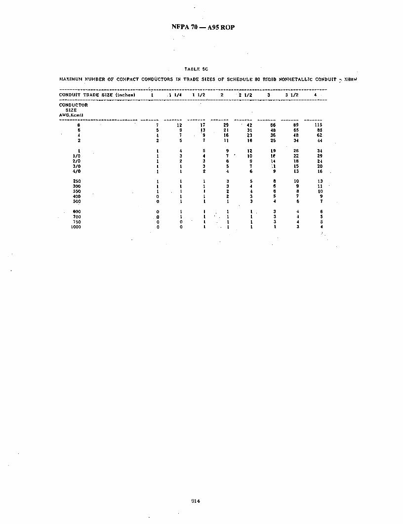
N F P A 70 - - A95 R O P
TABLE 5C
IqAXIHUH NUHBER OF CO~IPACT CONDUCTORS IN TRADE SIZES OF SCHEDULE 80 RIGID NON~'IETALLIC CONDUIT -. XHIIW
. . . . . . . . . . . . . . . . . . . . . . . . . . . . . . . . . ~ . . . . . . . . . . . . . . . . . . . . . . . . . . . . . . . . . . ~ . . . . . . . . . . . . . . . . . . . . . . . . . . . . . . . . .
CONDUIT TRADE SIZE ( inches) 1 .1 114 I 1/2 2 ' 2 1/2 3 3 I / 2 4 .
CONDUCTOR SIZE
AWG,Kcmil
8 7 12 17 6 5 9 13 4 4 T '9 2 Z 5 ;
1 1/0 2/0 3 /0 4 /0
250 300 350 400 500
600 700 T50
1000
1 4 5 1 3 4 1 Z 3 1 1 3 1 1 2
1 1 1 1 1 1 1 1 1 0 1 1 0 1 1
0 1 1 . 0 1 1
0 0 1 0 0 I
29 42 66 89 115 21 31 48 65 85 16 23 36 48 62 U 16 25 34 44
9 12 19 26 34 7 ~ 10 1~ 22 29 6 9 t4 18 24 5 7 LI 15 20 4 6 9 13 16
3 5 8 10 13 3 4 6 9 11 2 4 6 8 10 2 3 5 ? 9 1 3 4 6 T
1 1 . 3 4 6 1 I 3 4 5 1 1 3 4 5 1 1 1 3 4
)
914

NFPA 70 - - A95 ROP
Table 8 . . . Conductor Propert ies
Conduct°n;
Size Area Stranding ' " A W G / 'C dr. Quar t - Diam. kcmll :, ....Mils * , tity , in..
1 8 1620, 1 • 18 1620 I 7 ,'0"015 r X 6 2 5 5 0 ." ~ - -
16, 2580 , 7 i 0.019 14 4110 " 1 14, .4110 7 .,' 0.024 12 6 5 3 0 : 1 - - 12, " 6530 , 7..., 0.030 10 1'0380 i . - - ! 0 1.0380 , 7 ! 0 . 0 3 8 . , 8 16510 . 1 8 16510 , 7 , 0.049 6 2 6 2 : 4 0 7 ' 0 . 0 6 1
41740 7.'0.077 I 52620 , 7 0.087
2 66360 7 10.097 I 83690 19 !0.066
l / o l, o56oo , .19 , 0.074 2/0 133100 19 0.084 3/0 167800 • 19 0.094 l 4/0 i 211600, . 1 9 , 0.106 I 250 ~ 37 0.082 300 _ i 37 : 0.090"
3 5 0 , - - l 37 , ! 0.097 100 - - - 37 i 0.104 500 -- 37 0.116 600 ~ 61 0.099
I ! I
700 ~ 61 0:107 750 ~ 61 " 0.111 800 ~ , 61 0.114
, !
9001 ~ '61 i 0.122 I000; ~ i 61 I 0.128
1 1250 ~ ., 91 , 0. I17 , 1500 -- 91 0.128 1750 , - - 127 0.117 2000 - - 127 0.126
Overall
Diam. Area • In. , In."
0.040 I 0.001 "0.046 0.002
,l
0.051 0.002 0.058 0.003 0.064 0.003 0.073 ! 0.004. 0.081 0.005 0.092 0.006'
I
0.'102, 0.008 o.116,01o11 0.128 i 0.013 0.146 J 0.017
I
0.184 0.027/ 0.232 0.042 0.260 , 0:053' 0.292 0.067 0.33210.087! 0.37~: '0 .109 ! 0.4 I~"~ " 0 . 1 3 7 ~
0.528 0.219
0.681
0.964 0.998 0.782
D C Res ls tanc e a t 7 5 " 0 ( 1 6 7 1 : )
Aluml- Col)per num
U n c o a t e d C o a t e d o h m / ohm/MFT',ohm,/MFT~ MFT 7.77 8 . 0 8 12.8 7.95 8.45 13. I 4.89 5:08 4.99 5.29 3.07 ' 3.19 3.14 3.26 1.93 2 . 0 1 1.98 2.05
!
1.21 I,.26 , L24, 1.29
8.05 8.21 .5.06 5.17 3.18 3.25 2.00 2.04,
0.764 0.778 0.491 , 0.308 0.245 0.L94
0,786 1 1.26 0.809 !I.28
I
0.510 0.808 0.321 0.508 0.254 0.403 0,201 0.319
0.154 ~i 0.122 r ~ .~0.096T 1 0.101 ' 0.159
0.470 0.17 0.0766 0.0797 o.126 0.0608 0.0626 0.I00
| I I ;
0.575 0.260 0.0515 0.0535 0.0847 0.630" 0.312 0.0429 13.0a~6 0.0707
0.364 10.0367 0.0382 ~ 0.0605 ! I I ;
0.728 i 0.416 j 0.0321 0.0331 . 0.0529 0.813 0.519 0.0258 0 . 0 2 6 5 / 0.0424 0.893 , 0.626 , 0.0214 I, 0.0223 l 0.0353
, 0.730 0.0184 0.0!89 0.0303 0.0171 ' 0.0176 0.0282
1.030 0.834 0.0161 0.0166 0.0265 I i I ;
!.09 ¥-~. ~'0.940 i 0.0143 0.0147 0.0235 i.15 ~'4~ 1.04Z~ r~O.0129 0.0132 0.0212 !.2 q !3 -00103 0.0106 0.0169 1.412~'1.5~:-0.00858 i 0.00883 0.0141 I'.52'(o'~ ~'I .gZq 9 ~ 0.00735 10.00756 0.0121 !.632.~2.09~..!;.0.00643 .: 0-00662 0.0106
0,160 0.253 0.127 0.201
These resistance values are valid ONLY for the parameters as given. Using conductors having coated strands, different stranding type, and especially, other temperatures, change" the resistance.
Formula for temperatui'e change: R2 = gt [ i+a(Tr75.)] where: a~, = 0.00323, aAc = 0.00330.
Conductors with'compact and compressed stranding have about 9 percent and 3 percent, respectively, smaller bare conductor diameters than those shown. See Table 5A for actual compact eab!e dimensions.
The IACS conductivities used: bare copper ffi 100%, aluminum L,: 61%. . Class B stranding is listed as well as solid for some sizes, its Ovcra~iameter and area is
that of its circumscribingcircle. . ' ; ~ 6 ~ - (FPN): The construction information is per NEMA WC-'8-193~6 " ( ~ i l a ~ ) . The
resistance is calculated per National Bureau of Standards Handbook 100. dated 1966, and Handbook 109, dated 1972.
915

N F P A 70 - - A 9 5 R O P
(Log #85) 8-246 - ( C h a p t e r 9, Tab le 4): Re jec t
Note : T h e fo l lowing p r o p o s a l consis ts o f C o m m e n t 8-232 6'n , . P roposa l 8-267 in the 1992 Anr iua l M e e t i n g Na t iona l Elec t r ica l C o d e
T e c h n i c a l C o m m i t t e e Repo r t . Th i s C o m m e n t was h e l d fo r f u r t h e r ' s tudy d u r i n g the p i ' ocess ing of t he 1993 N A T I O N A L E L E C T R I C A L CODE. T h e r e c o m m e n d a t i o n in P roposa l 8-267 was:
A d d a co lumf i u n d e r n o t l ead cove red for N i p p l e Fill 60% T r a d e Size N i p p l e 60% 1 /2" .18 3 / 4 " .318 1" .516 1 1/4" .9 1 1 / 2 " 1.224 A n d so on
S U B M I T T E R : Dwigh t D u r h a m , Sou thwi re C o m p a n y ' R E C O M M E N D A T I O N : De le t e e x i s t i n g Tab le 4 in t he p r e s e n t c o d e a n d a c c e p t rev i sed T a b l e 4 ( a t t a c h e d ) . • . SUBSTANTIATION: T h e rev ised tab le 4 ( a t t a ched ) is t he work of a CMP-6 & 8 Task G r o u p tha t was a p p o i n t e d to co r r ec t e r ro rs in c o n d u c t o r a n d c o n d u i t d i m e n s i o n s , a n d c o n d u i t fill tables. A c c e p t i n g th is rev ised Tab le 4 will still a c c e p t in p r i n c i p l e in pa r t p roposa l 8-267.
NOTE: S u p p o r t i n g m a t e r i a l is a v a l l a b i e f o r review a t NFPA H e a d q u a r t e r s . PANEL A C T I O N : Reject . ]PANEL S T A T E M E N T : Refer to Pane l S t a t e m e n t on P r o p o s a l 8-243. N U M B E R OF PANEL MEMBERS ELIGIBLE TO VOTE: 14 V O T E O N PANEL A C T I O N :
AFFIRMATIVE: 14
(Log #203) 8-247- ( C h a p t e r 9, T a b l e 4 (New)) : "Reject S U B M I T T E R : J a c k E. Pullizzi, H o l m d e l , NJ R E C O M M E N D A T I O N : A d d 60% fill row. S U B S T A N T I A T I O N : N i p p l e fill ba sed in 60% fill b u t n o t ab le : - exist2g. PANEL A C T I O N : Reject . PANEL S T A T E M E N T : Refe r to Pane l S t a t e m e n t on P r o p o s a l 8-243
• NUMBER OF PANEL MEMBERS ELIGIBLE TO VOTE: 14 VOTE O N PANEL A C T I O N :
AFFIRMATIVE: 14,
' (Log #1072) 6-177 - ( C h a p t e r 9, T a b l e 5): A c c e p t in P r i n c i p l e S U B M I T r E R : A.M. Bryan, E lec t r ica l I n s p e c t i o n Office-City of C h a t t a n o o g a , , T N .. R E C O M M E N D A T I O N : N o t e a t t he b o t t o m of T a b l e 5.
D i m e n s i o n s of T H W in sizes 14 t h r u No. 8. ( h y p h e n or l o n g space) Nos. 6 T H W a n d l a rge r a re the same as TW. S U B S T A N T I A T I O N : T h i s n o t e is easi ly m i s u n d e r s t o o d un less a t t e n t i o n is g iven to t he fac t t h a t i t is c o m p o s e d of two s ta te /nents . Th~ h y p h e n or sps a c i n g will h e l p in r e a d i n g this note . PANEL A C T I O N : A c c e p t in Pr inc ip le . P A N E L S T A T E M E N T : See Pane l Ac t ion on P roposa l 6-178. N U M B E R OF PANEL MEMBERS ELIGIBLE T O V O T E : 10 V O T E O N P A N E L A C T I O N :
AFFIRMATIVE: 10
TABLE 4 DIMENSIONS AND PERCENT AREA OF CONDUIT AND OF TUBING*
AREAS OF CONDUIT OR.TUBING FOR THE COMBINATIONS OF WIRES PERMrvI ED IN TABLE 1, CHAPTER 9
AREA - SQUARE INCHES Not Lead Covered Lead
Covered Internal Over2
Trade Diameter Total Nipple 1 Con& 2 Cond. Cond. 1 Cond. 2 Cond. • 3 Cond. 4 Cond. Size Inches 100% 60% • 53%. 31%' 40% " 55% 30% 40% 38%
1/2 .500 .196 .118 ;104 .061 .078 .108 .059 .078 .074 3/4 .750 .442 .265 .234 .137 .177 .243 .133 .177 .168 1 .950 .709 .425 .376 .220 .284 .390 .213 .284 .269 1 1/4 1.250 1.227 " .736 .650 .380 -.491 .675 .368 .491 .466 1 1/2 1.500 1.826 1.096 .968 .566 .730 1.004 .548 .730 .594
,974 2 2.000 3.142 1.885 1.665 1.257 ' 1.728 ..943 1.257 1.194 1/2 2.445 4.695 2.817 2.488 1.455 1.878 2.582 1.409 1.878 1.784
3 3.000 7.069 4.241 ' 3.747 2.191 2.8"28 3.888 2.121~ 2.828 2.686 3 1/2 __ 3.500 9.621 5.773 5.099 ' 2.983 3.848 5.292 2.885 3.848 3.656
4 3.998 12.554 7.532 6.654 3.892 5.022 6.905 3.766 5.022 4.771 5 5.000 19.635 11.781' 10.407 6.087 7.854 10.799 5.891 - 7.854 7.461 5 6.000 "28.274 . 16.954 14.985 8.765 11.310 15.551 . 8.482 11.310 10.744
Dimensions and percent area of conduit and of tubing other thanSchedule 80 Rigid Non-Metallic Conduit. See Table 4A for Schedule 80 Rigid Non-Metallic Conduit dimensions.
Over 4 Cond. 35%.
.059 .155 .248 .429 .639
1.100 1.643 2.474 3.367
4.394 6.872 9.896
916

NFPA 70 .-- A95 ROP
_(Log # 1 9 6 0 ) 6-178 - ( C h a p t e r 9, T a b l e s 5, 5B, 6 , a n d 8):. A c c e p t
No te : T h e T e c h n i c a l C o r r e l a t i n g C o m m i t t e e d i r ec t s t he P a n e l to ver i fy its a c t i o n re la t ive to T a b l e 5A. Also, see P r o p o s a l s 6-175 a n d 6- 176. T h e T e c h n i c a l C o r r e l a t i n g C o m m i t t e e d i r e c t s t h e P a n e l to" d e v e l o p a H e a d i n g f o r A p p e n d i x C. T h i s a c t i o n will be c o n s i d e r e d b y t h e P a n e l as a P u b l i c C o m m e n t . '" ' . , S U B M I T T E R : R o n a l d R. R u n k l e s N a t i o n a l E lec t r i ca l M a n u f a c t u r - " " ers A s s o c i a t i o n ' ' " . " R E C O M M E N D A T I O N : D e l e t e T a b l e s 5B a n d 6. Ad i t n e w T a b l e s C2A, C3A, CAA, C5A, C6A, C7A, C8A, C9A, C1OA, C l l A , C12A, a n d C13A. to n e w A p p e n d i x C~ Revise T a b l e s 5 a n d 8 as s h o w n :
" r A B L E i 2 2 ~ MAXIMUM N U M B E R O F C O M P A C T C O N D U C T O R S IN ELECTRICAL M ETAI l J C T U B I N G (Based on Tab le 1, Chap t e r 9)
C o n d u c t o r Type Size Letters A W G / k c m i l THW, 8 THW-2 6 T H H W 4
2 1
1 / 0 2/O 3 / 0 4 /O 25O 300 350
• 400 5OO 6OO 7O0
- . 750 • 1000
• T H H N , " THWN, THWN-2
8 6 " 4 2
,1 1 / 0 2 / 0 - 3 / 0 4 / 0 250 300 350 400",, 500 600 7O0 750
1000
1 / 2 3/4" 1 " 1 1 / 4 2 1 1
.1 1 1 0
- 0 0 O' o 0 0 0 0 0 0 o
"1 1 1 1 1 0 0 0 0 0. 0 0 0
-0 0 . 0
4 6 11 '3 5 9 '. 2 . 4 "6 1 3 5 1 1 3 1 1 3 1 1 2 1 1 1 1 1 1 0 1 1 0 , 1 1 0 1 1 0 0 " 1 0 • 0 1 0 0 1 0 0 1 " 0 0 0 0 0 " 0
0
3 4 8 1 3 6 1 2 4 1 1 3 1 1 3 1 1 2 1 1 1 1 1 1
• 0 1 1 0 1 " 1 0 "' 1 1 0 0 1 . 0 " 0 . 1 0 0 ' 1 0 0 ' 1 0 0 0
TABLE C2A: MAXIMUM N U M B E R O F C O M P A C T C O N D U C T O R S IN ELECTRICAL METALLIC. T U B I N G
C o n d u c t o r ype , S i z e .
tiers " A W G / k c m i l 1 / 2 X H H W , .
• XHHW-2 8 3 6 " 1 4 1 2 1 1 1
1 / 0 1 2 / 0 1 3 / 0 0 , 4 /O 0 250 0 300 0 350 0 4 0 0 . 0. 500 0 600 0 700 0 750 0
1000 0
3 / 4 1 1 1 / 4 5 8 15 4 6 11 3 4 8 1 3 6 1 2 4 1 1 • 3 1 1 3" 1 1 2 1 1 1
• ' I I I
0. 1 1 0 1 1 0 1 0 0 0 0 0 . 0 1
. 0 0 1 0 0 0
Defini t ion: C o m p a c t s t r a n d i n g is the resul t o f a m a n u f a c t u r i n g process where the interstices (voids be tween s t r and wires) are vir tual ly 'e l iminated.
1 1 / 2 ' 16 12 9 7 4 4 3
• 3 2 1 1 1 1 1 1 1 1 ' 1
i s 1 1
8 6 5 4" 3 3
' " 1
1 1 1 1 1
- 1
C o n d u i t T r a d e Sizes in Inches 2 -- 2 1 / 2 3 . , 4 .
26 2O 15
• 11 8 7
, 5 5
, 4 -
3 3
. 2 : 1 1 1 1
' 1 " 1
29 -.18 .13 10 ' 8
7 6 5 4 3 3 2 1 1 1 1 1
46 ' 35 26 19 13 12 10
8 7 5
5 4 4 3 2" 2 1 1
32 2 3 o 1 7 . 14 12
• 10 8 6
. 5 5 4 ' 4 3 2
: 2 1
69 53 - 40 29 21 18 15 "13 11
8 - 7 6 6 5 4 3 3. 2
• 7 8
48 34 26 2 2 18 15 12 10, " . 8 7 6 5 4 4 4 3
3 1 / 2 9O 7O 52" 38 27 23 20 17 14" 11
9 8 8 6 5 4 4 3
102 63 45
• 34 29 24 20
• !6 13 11 10 9 7
.6 5 5 3
C o n d u i t T r a d e Sizes in Inches 1 1 / 2 2 2 1 / 2 3 a 1/2
" 20 34 59 90 11~ !5 2 5 . 11 18 3 2 48 63 8 13 23 34 45 6 " 10 5 8 14 22 - 2 9 4 7 3 6 , 10 15 20 3 5 8 13 17 2 4 % 10 " 13 1 3 6 • 9 11 1 ' 3 . 5 8 10
1 1 2 4 . , 7 9 1 1 1 I 1 I..
1 1 2 4 . 5 1 1 2 3 5 1 1 1 3 4
the , s t andard c o n d u c t o r ~ compressed to the ex t an t
44 66
17 26
12 18
4 6 3 4 '
87
3 4 -
24
7 . 6
115 89 67 49 . 34 30 25 21 18 14 12 11 . 10 8 7 6 5 4
130 81 58 43 37 3O 25 21 16 1 4 . 12 11
9 7 7
' 6 4
149 111 81 58 43 37 31 25 21 17 14 13 11
9 8 7 6 5
t h a t .
' 9 1 7

NFPA 70 - - .A95 ROP
TABLE C3A: MAXIMUM NUMBER OF COMPACT CONDUCTORS IN ELECTRICAL NONMETALLIC TUBING (Based on Table.l , Chapter 9)
Conductor Type Size Conduit Trade Sizes in Inches Letters AWG/kcmil 1 / 2 3 /4 1 1 1 /4 1 1 /2 THW, THW-2, THHW
THHN, THWN,
8 6. 4 2 1
1/0 2 /0 3 /0 4 /0 250 300 350 4OO 5OO 6OO 7O0 75O
1000 8 6 4
' 2 1
1/0 2 /0 3 /0 4 /0 250 300 350 4O0 500. 6OO 7O0 750 1000
1 1 1 1 0 0 0 ',, 0 0 0 0 0 0 0 0 0 0 0
' .
1 1 1 1 1 0 0 0 0 0 0 0 0 0 0 0 0
3 6 2 4 1 3 1 2 1 1 1 1 1 1 1 1 0 1 0 1
• 0 1 0 0 0 0 0 0 0 0 0 0 0 0, 0 0
4 2 4 1 3 1 2
• 1 1 1 1 1 1 1 1 0 1 0 1 0 "1. 0 0 0 0 0 0 0 0
• 0 0 0 0
11
6 4 " 3 3 2 1 1 1 1 1 1 1 1 0 0 0
12 7 5 4 $ 3 2 1 1 1 1 1 1 1 1 1 0
15 11 8 6 4 4 3 3 2 1 1 1 1 1 1 1 1 0
10 7 5 5 4 3 2 1 1 1 1 1 1
TABLE C3A: MAXIMUM NUMBER OF COMPACT CONDUCTORS iN ELECTRICAL NONMETALLIC TUBING
Conductor Type Size Conduit Trade Sizes in Inches Letters AWG/kcmil : "1/2 3 /4 1 1 1 /4 1 1 /2
25 19 14 10
28 17 12
9 8 6 5- 4 3 3 2 2
-1 1 1. 1 1
XHHW, XHHW-2
• ' 8 ~2 4 8 14 19 ' '32 6 1 3 6 10 14 24 4 1 2 4 7. 10 17 "
' 2 1 ' 1 3 5 7 12 1 1 1 2 4 5 9
1/0 1 1 1 3 5 8 2 /0 0 1 1 3. 4 7 3/O 0 1 ' 1. 2 3 5 4 / 0 0 1 1 1 3 4 250 0 0 1 1 1 " 3 300 0 0 1 1 1 3 350 0 0 1 1 1 3 400 0 0 1 1 1 2 500 0 0 0 1 1 1 600 0 0 0 1 " 1 1 700 0 0 0 1 1 1 750 0 0 0 1 1 ' 1 1000 ' 0 0 0 0 1 1
Definition: comp~tct stranding is the result of a manufacturing processwhere the standard conductor is compressed to the extent that the interstices (voids between strand wires) are virtually.eliminated.
918
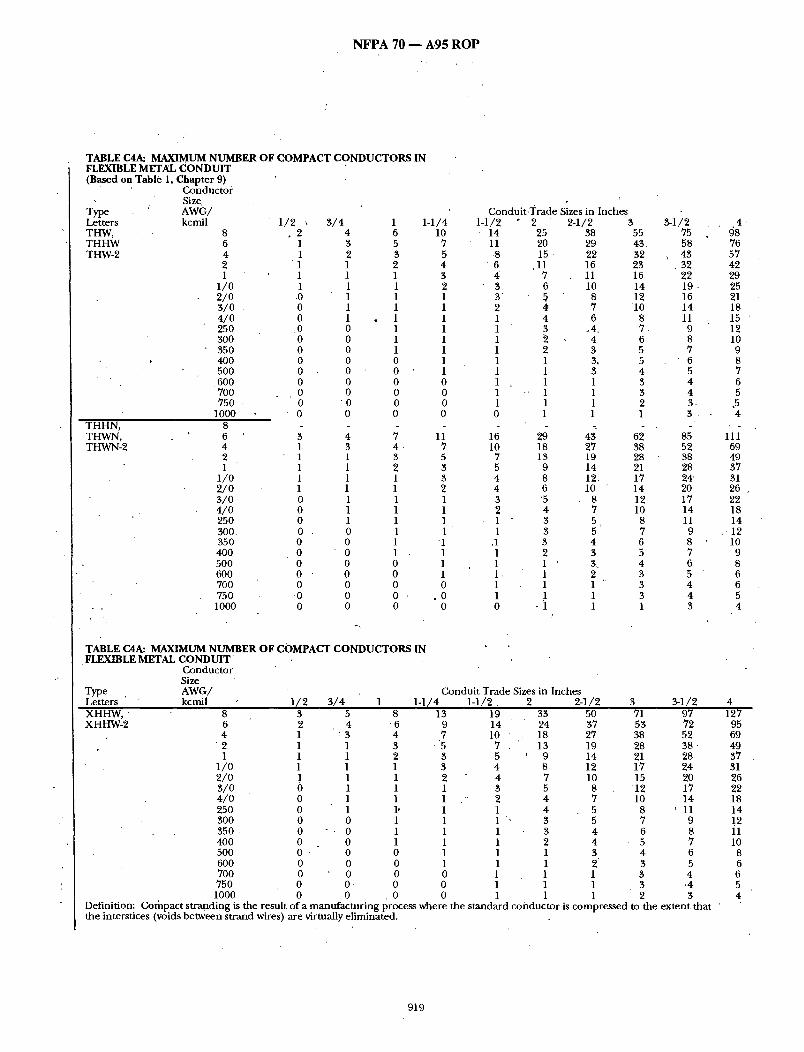
NFPA 70 - - A 9 5 R O P
TABLE C4A: MAXIMUM NUMBER OF COMPACT CONDUCTORS IN FLEXIBLE METAL CONDUIT (Based on Table 1, Chapte r 9)
Conductor Size. AWG/ kcmil
Type Letters THW, THHW THW-2
8 6 4 2 1
1/o 2/0 3/0 4/0 25O 300 350 4O0 5OO
.600 7OO 750
1000 THHN, THWN, THWN-2
8 6 4 2 1
1 /0 2/0 3/0 4/0 250 300. 35O 4OO 50O 6OO 7OO 750 1000
1/2 , . 2
1 1 1 1 1
.0 0 0
.0 0 0 0 0 0 0 0 0
3 /4 1 1-1/4 4 6 10 3 5 7 2 3 5 1 2 4 1 1 3 1 1 2 1 1 1 1 1 1 1 1 1 0 1 1 0 1 1 0 1 1 0 0 1 0 0 1 0 0 0 0 0 0
"0 0 0 0 0 0
3 4 7 1- 3 4 1 1 3 1 1 2 1 1 1 1 1 1 0 1 1 0 1 1 0 1 1 0 . 0 1 0 0 1 0 0 1 0 0 0 0 ' 0 0 0 0 0
O 0 0 0 0 0
TABLE CAA: MAXIMUM NUMBER OF COMPACT CONDUCTORS IN FLEXIBLE METAL C O N D U I T
Conductor Size
Type AWG/ Letters ' kcmil 1 /2 3 / 4 1 1-1/4
11 7 5 3 3
2 1 1 1 1
'1 1 1 1 0
, 0 0
Conduit. 'I 'rade Sizes 1-1/2
14 11 ,8
6 4' 3. 3 2 1 1 1 1 1 1 1 1 1 0
16 10
7 5 4 4 3 2 1 1
,1 1 1 1- 1 1 0
in Inches 2 2-1/2 3
25 38 55 20 29 43. 15. 22 32
.11 16 23 7 11 16 6 10 14 5 8 12 ¢ 7 10 4 6 8 3 ,4. 7. 2 4 6 2 3 5 1 3, 5 1 3 4 1 1 3
• ' 1 1 3 1 1 2 1 1 1
29 43 62 18 27 38 13 19 28
9 14 21 8 12. 17 6 10 ~ 14 "5 8 12 4 • 7 10 3 5 L 8 3 5 7 3 4 6 2 3 5 1 3. 4 1 2 3 1 1 3
1 3 • 1 1 1
r
Conduit Trade Sizes in Inches 1-1 /2 . 2
3-1/2 75 58
, 43 • 32
22 19- 16 14 11
9 8 7 6 5 4 4 3. 3
85 52 38 28 24' 20 17 14 11 9 8 7 6 5 4 4 3
4 ~8 76 57 42 29 25 21 18 15 12 10 9 8 7 6 5
,5 4
111 69 49 37 31 26 22 18 14
-12 10
9 8 6 6 5 4
XHHW, XHHW-2
8 6 4
"2 1
1 /0 2/0 3/0 4 /0 250 3O0 350 • 4O0 5OO 6OO 7O0 750 1000
3 5 8 13 2 4 "6 9 1 : 3 4 7 1 1 3 "5 1 1 2 3 1 1 1 3 ! 1 1 2 0 1 1 1 0 1 1 1 0 1 1, 1 0 0 1 1 0 " . 0 1 1 0 0 1 1 0 , 0 0 1 0 0 0 1 0 0 0 0 0 0- 0 0 0 0 . 0 0
Definition: Compact stranding is the result of a manufacturing process where the interstices (voids between strand wires) are virtually eliminated.
19 14 10 "
7 . "
5 4 4 3 2 1
1 1 1 1 1 1 1
~ 1 / 2 3 9 1 / 2 4 33 50 71 97 127 24 37 53 72 95 18 27 38 52 69 13 19 28 38 ' 49
9 14 21 28 37 8 12 17 24 31 7 10 15 20 26 5 8 12 17 22 4 7 10 14 18 4 5 8 ' 11 14 3 5 7 9 !2 3 4 6 8 11 2 4 5 7 10 1 3 4 6 8 1 2 3 5 6 1 1 3 4 6 1 1 3 .4 5 1 1 2 3 4
the standard conductor is compressed to the extent that
919
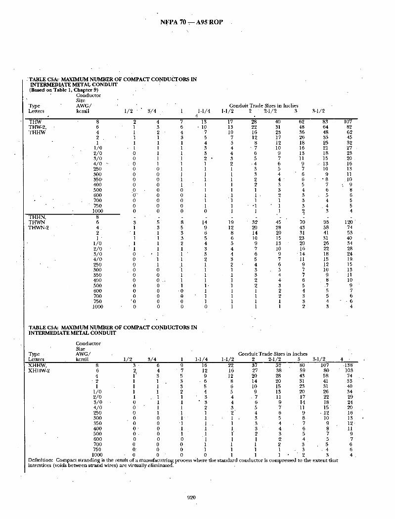
N F P A 70 ~--- A 9 5 R O P /
-'TABLE CSA:' MAXIMUM NUMBER OF COMPACT CONDUCTORS IN INTERMEDIATE METAL CONDUIT (Based on Talkie 1, Chapter 9)
Conductor Size
Type AWG/ Letters kcmil 1 /2 3 /4 1 1-1/4
4 THW THW-2, THHW
8 6 4 2 . 1
1 /0 2/O 3/O 4 /0 - 250 3OO 35(Y 4O0
• 500 6OO 7OO 75O
1000 THHN, THWN THWN-2
8 6 4. 2 1
1/0 2/o 3/o 4/0 250 300 350 40O 500 6OO 7O0 750 1000
3 1 1 1 1 1 0 0 0 0 0 0 0 0 0
"0 0
4 7 3 6 2 ' 4 1 3 1 1 1 1 1 1 1 1 1 1 0 1 0 1 0 1 0 1 0 0 0 0 0 0 0 0 0 0
; a 3 5 1 3 1 3 1 2 1 1
• 1 . 1 ' 1 1 1 ' .1 0 1 0 1 0 . , 1 0 1 0 -0 0 0 0 0 0 0
Conduit Trade Sizes in Inches 1-1/2 2 2-1/2 3
13 17 28 - 10 13 22
7 10 16 5 7 12 4 5 8 3 4 " 7 3 4 6 2 • 3 5 1 2 - 4 1 1 3 1 1 3 1 1 2 1 1 2 1 1 1 1 1 1 1 ' 1 1 1 1 "1 0 1 1
TABLE CSA: MAXIMUM NUMBER OF COMPACT CONDUCTORS IN INTERMEDIATE METAL CONDUIT
Conductor Size
Type • AWG/ Letters kcmil 1 /2 3 /4 1 1-1/4
14 19 " 32 9 12 20 6 8 14 5 6 10 4 5 9 3 4 7 3 4 6 2 3 5 1 2 4 1 1 3 1 1 3 1 1 2 1' 1 2 1 1 1 1 1 1 1 1 1 0 1 1
3-1/2
40 62 83 31 48 64 23 36 48 17 26 35 12 18 25 10 16 21 9 13 18 7 11 15 6 9 ., 13 5 7 10 4 6 9 4 6 ' 8 3 5 7 3 4 6 2 3 5 1 3 4 1 3- 4 1 2 3
45 70 93 28 43 58 20 31 41 15 23 31 13 20 26 10 16 22 9 "14 18 7 11 15 6 9 12 5 .7 10 4 7 9 4 6 8 3 5 .7 2 4 5 2 3 5 1 3 4 1 2 3
Conduit Trade Sizes in Inches ' 1-1/2 2 2-1/2 3 3-1/2
107 82 62 45 32 27 23 20 16 13 11
, 1 0 \ 9
8
120 74 53 4O 34 28 24 19 15 13 11 10 9 7 6
- 6 4
XHHW, XHHW-2
8 3" 6 9 16 6 2 4 7 12 4 iJ 3 5 9
2 1 1 3 - 6 1 1 1 3 5
1/0 1 1 2 4 2 /0 1 1 1 ' 3 3 /0 0 1 1 ' 3 4 /0 0 1 1 2 250 0 1 1 1 300 0 0 1 1 35O 0 0 1 1 400 0 0 1 1 5OO 0 . 0 1 1 600 0 0 0 1 700 0 0 0 1 750 0: 0 0 1 1000 0 0 0 0
Definition: Compact stranding is the result of a manufacturing process Where interstices (voids between strand wires) are virtually eliminated.
22 37 52 80 107 16 27 38 59 80 12 20 28 43 58
8 14 20 31 41 6 10 15 23 31 5 9 . 13 20 26 4 . 7 11 17 22 4 6 9 14 18 3 5 7 11 1 5
2 4 6 9 -12 1 • 3 5 8 10 1 3 4 , 7 9 1 3 4 6 8 1' 2 3 5 7 1 1 2 4 5 1 1 2 3 5 1 1 1 . 3 . 4 1 1 1 2 3
the standard conductor is compressed to the extent that
-138 103 74 53 4O 34 29 24 20 16 13 1 2 11 9 7
6 4
920

N F P A 70 - - A 9 5 R O P
TABLE C6A: MAXIMUM NUMBER OF COMPACT CONDUCTORS IN LIQUIDTIGHT FLEXIBLE NONMETALLIC CONDUIT (Type FNMC-B**) (Based on T a b l e 1, C h a p t e r 9)
Conductoty Size
.Type ' AWG/ . Conduit Trade Sizes in Inches Letters kcmil 3 /8 1 /2 3 /4 1 1-1/4 1-1/2 2 THW 8 THW-2, 6 THHW 4
2 1
1 /0 2/O 3/O 4/0 250 3OO 350 400 5OO 6OO 700 75O 1000
THHN, 8 THWN, 6 THWN-2 4
2 1
i / 0 2/O 3 /0 4/O' 25O 3OO 35O 40O 5OO 6O.O 7OO 75O 1000
**Corresponds to Section 351-22(2).
1 2 4 1 1 3 1 '" 1 2 1 1 1 0 1 1 0 1 1 0 0 1 0 0 1 0 0 1 0 0 0 0 0 0 0 0 0 0 0 0 0 0 0 0 0 0 0 0 0
. 0 0 0 0 0 0
1 2 4 1 1 3 1 • 1 1 0 1 1 0 1. 1 0" 1 1 0 0 1 0 0 . 1 0 0 1 0 0 0 0 0 . 0 0 0 0 0 0 0 0 0 0 0 0. 0 0 0 0 0 0 ~', .0
7 5 4 3 1 1 1 1 1 1 1. .1 0 0 0 0 0 0
,4 3 2 1 1 1 1
. 1 1 1 1 0 0 0 0 0
12 9 7 5 3 3 2 1 1 1 .1 1 1 1 1" 1 0 0
13 8 6 4 4 3 2 1 1 1 1 1 1 1 1 1 0
15 12
9 6 4 4 3 3 2 1 1 1 1 1 1 1 1 1
17 11 7 ~ 6
,5 4 3 3 1 1 1 1 1 1 1 1 1
25 19 14 11
7 6 5 4 4 3 2 2 1 1
' 1 1 1 1
17 12
• 9 8 6 5 4 3 3 2 2 1 1 1 1
.1
TABLE C6A: MAXIMUM NUMBER OF COMPACT CONDUCTORS IN LIQUIDTIGHT FLEXIBLE NONI~ETALLIC CONDUIT (Type FNMC-B**)
Conductor .Size
Type AWG/ Conduit Trade Sizes in Inches Letters kcmil 3 /8 1 /2 3 /4 1 1-1/4 • 1-1/2 XHHW, XHHW-2
8 1 3 5 9 15 6 1 2 4 6 11
• 4 - 1 1 3 4 8 2 1 1 1 3 6 1 0 1 1 . 2 4
1 /0 0 1 1 1 4 2 /0 0 1 1 1 3 3 /0 0 0 1 1 2 4/O 0 0 1 1 1 250 0 0 1 . 1 1 3O0 • 0 0 0 1 1 350 0 0 0 1 ' 1 400 0 0 0 1 1 500 0 0 0 0 1 600 0 0 0 0 1 7OO 0 0 0 0 1 750 0 0 0 0 1
20 33 15 24 11 17 7 12 6 9 5 8 4 7 3 5 3 4 1 3 1 3 1 3 1 2 1 1 1 1 1 1 1 1
1000 0 0 0 0 0 1 1 Definition: Gompact stranding is the result of a manufacturing process where the standard conductor is compressed to the extent that the interstices (voids between s t randMres) are virtually eliminated.
921
. ' .

N F P A 7 0 - - A 9 5 R O P
TABLE C7A: MAXIMUM NUMBER OF COMPACT CONDUCTORS IN LIQUIDTIGHT FLEXIBLE NONMETALLIC CONDUIT'(Type FNMC-A**) (Based on Table 1, Chapter 9.)
Conductor Size
Type AWG/ Conduit Trade Sizes in Inches ldetters kcmil 3 /8 1/2 3 /4 1 I -1 /4 1-1/2 THW, 8 1 2 4 6 THW-2 6 1 1 3 5 THHW 4 1 1 2 4
2 1 ,1 1 3 1 0 1 1 1
1 /0 0 1 1 1 2 /0 0 0 1 1 3/O 0 0 1. 1 4 /0 0 0 1 1 250 0 0 0 1 300 0 0 0 1 350 0 0 0 1 400 0 0 0 0 500 0 0 0 0 600 0 0 0 0 700 0 0 0 0 750 0 0 0 0
1000 0 0 0 0 THHN, 8 THWN, 6 1 2 4 7 THWN-2 4 1 1 3 4
2 1 1 1 3 1 " .0 1 1 • 2
1/0 0 1 1 1 2/0 0 1 1 1 3/0 0 0 1 1 4 /0 0 0 1 1 250 0 0 1 1 300 0 0 0 1 350 0 0 0 1 400 0 0 0 1 500 0 0 0 0
' 600 0 0 0 0 700 0 0 0 0 750 0 0 0 " 0
1000 0 0 0 . 0 • *Corresponds to Section 351-22(1).
11 9 7 5 3 3 2 1 1 1 1 I 1 1 1 1 0 0
16 12 9 6 4 4 3 3 2 1 1 1 1 1 1 1 1 1
13 18 • 8 11
6 8 4 6 3 5 3 4 2 3 1 3 1 1 1 1 1 1 1 1 1 1 1 1 1 1 1 1 0 1
TABLE C7A: MAXIMUM NUMBER OF COMPACT CONDUCTORS IN LIQUIDTIGHT FLEXIBLE NONMETALLIC CONDUIT (Type FNMC-A)
Conductor Size
Type AWG/ Conduit Trade Sizes in Inches Letters kcmil 3 /8 1 /2 3 / 4 1 1-1/4 1-1/9
26 2O 15 11
8 7 5 5 4 3 3 2
1 1. 1 .1 1 1
29 18 13 10
8 7 6 5 3 3 3 2 1
1 1 1 1
XHHW. XHHW-2
8 6 4 2 1
1 /0 2/O 3 /0 4 /0 25O 390 350 400 5OO 6OO 7OO 75O 1000
1 3, 5 8 15 20 34 1 2 4 6 11 15 25 1 1 3 " 4 8 11 18 1 "1 1 3 6 8 13 0 1 1 2 4 6 10 0 1 1 1 3 5 8 0 1 1 1 .3 4 . 7 0 0 1 1 2 3 6 0 0 1 1 1 3 5 0 0 1 1 1 2 ~4 0 0 0 1 1 1 3 0 0 0 " 1 1 1 3 0 0 0 1 1 1 2 0 0 0 0 1 1 1 0 0 0 0 1 '1 1 0 0 0 0 1. 1 1 0 0 0 , 0 , 1 - 1 1 0 0 0 0- 0 1. ' 1
Definition: Compact stranding is the result of a manufacturing process where, the s~andard conductor is compressed to the extent that the interstices (voids between s~and wires) are virtually eliminated.
922

N F P A 70 - - A 9 5 R O P
TABLE C8A: MAXIMUM NUMBER OF COMPACT CONDUCTORS IN i LIQUIDTIGHT FLEXIBLE METAL CONDUIT (Based on Table 1, Chapter 9.)
Conductor Size
Type A W G , 2 Letters kcmil 3 /8 1 /2 3 /8 1 1-1/4
Conduit T radeS izes in lnches 1-1/2 2 2-1/2 9 1 / 2
THW, THW-2, • THHW .
8 1 6 1 4 1 2 1 1 0
1 /0 0 2 /0 • 0 3 /0 o 4 /0 0 250 0 300 0 350 0 400 " 0 500 0 600 0 700 0 75O ' 0 1000 0
THHN, .THWN, THWN-2 ,
8 6 4 2 1
1 /0 2/O 3 /0 4 / 0 , 250 300 350 400 5OO 600
'7OO 750 1000
1 1 1 0 0 0 0 0 0 0 0
.0 0 0 0 0
0
2 4 7 1 3 5 1 \ 2 4 1 1 3 1 1 1 1 1 1 0 1 1 0 1 1 0 1 1 0 0 1
' 0 0 1 0 0 1 0 0 0 0 0 0 0 0 0 0 0 0 0 0 0 0 0 0
2 4 7 1 3 4 1 1 3 1 1 2 1 1 1 1 1 1 0 ' 1 1 0 1 1 0 1 1 0 0 1 0 0 1 0 0 1 0 0 0
.0 0 0 0 0 0 0 0 0 0 0 0
12 9 7 5 3 3 2 1 1 1 1 1
• 1 1 1 1 0 0
13 8 6 4 4 3 2 1 1 1
.1 1 1 1 1 1 0
15 12 9 6 4 4 3 3 2 1 1 1 1 1 1 1 1 1
11 7 6 5 4 3 3 1 1 1 1 1 1 1 1
"1
25 19 14 ' 11
7 6 5 4 4 3 2
,2 1
.1 1. 1 1 1
28 17 12 9 8 6 5 4 3 3 2 2 1 1 1 1 1
38 58 29 45 22 3~ 16 25 11 17 10 15 8 13 7 11 .6 9 4 7 4 6 3 5 3 5 3 4 1 3 1 3 1 3 1 1
43 ' 66 26 41 19 29 14 22 12 19 _ I 0 ' 15 8 13 7 I0 5 8 4 7 4 6 3 5 3 5 2 4 1 3 1 3
76 59 44 32 23 2O 16 14 12 9 8 7 6 5 4 4 3 3
• "86 53 38 28 24
• 20 17 14 11 9
' 8 .7 6. 5 4 4 3
9 9 77 57 42 3O 26 21 18 15 12 10 9 8 . 7 6 5 5 4
l l 2 69 50 37 32 26 22 18 14 12 11 9 8 6 6 5, 4
TABLE C8A: MAXIMUM N U M B E R o F COMPACT CONDUCTORS IN LIQUIDTIGHT FLEXIBLE METAL CONDUIT
Conductor Size
Type AWG/ Letters kcmil 3 /8 1 /2 3 /4 1
C o n d u i t T r a d e S i z e s i n l n c h ~ 1-1/4 1-1/2 2 2-1/2 9 1 / 2
XHHW, XHHW-2
8 1 3 5 9 15 20 33 49 6 1 2 4 6 11 15 24 37 4 1 \ 1 3 4 . 8 11 17 26 2 1 1 1 3 6 7 • 12 19 1 0 1 1 2 4 6 9 14
1/0 0 1 1 1 4 5 8 12 2 /0 0 1 1 1 3 4 7 10 3/O 0 0 1 1 2 3 5 8 4 /0 0 0 1 1 1 3 4 7 250 0 0 1 1 1 1 3 5
-300 0 " 0 0 1 1 1 3 5 350 0 0 0 1 1 1 3 4 400 0 0 0 1 1 1 2 4 500 0 0 0 0 1 1 1 3 600 0 0 0 0 I 1 .1 2 700 0 0 ' 0 0 1 1 1 1 750 " 0 "0 0 0 1 1 1 1
1000 .0 0 0 0 0 1 1 1 Definition: Compact stranding ig the result of a manufacturing process where the standard conductor is corhpressed to interstices (voids between strand .wires) are virtually eliminated. . . -
76 56 41 29 22 19 16 13 11
8 7
' 6 6 5 4 3 3 2
the extent that the
98. 129 73 95 53 69 38 50 28 37 24 32. 20 27 17 22. 14 18 11 15 9 12 8 11 7 10 6 8 5 6 4 6 4 5 3 4
923

N F P A 70 m A 9 5 R O P
TABLE C9~" MAXIMUM NUMBER OF COMPACT CONDUCTORS IN RIGID METAL CONDUIT ( B a s e d on T a b l e 1, C h a p t e r 9.)
/Conductor ,. Size
Type AWG/ Letters kcmil 1 /2 3 / 4 1 1-1/4 1-1/2 "
Conduit Trade Sizes in Inches 2 2-1/2 3 3-1'/2
THW, THW-2, THHW.
8 6 4 2 1
1/0 2 /0 3 /0 4 /0 250 3OO 350 4O0 500 -
6OO 700 750. 1000
THHN, THWN, THWN-2
8 6 4 2 1
1 /0 2/O 3/O 4 /0 25O
• 300 35O 4O0 5OO 6OO 7OO 75O
1000
2 4 7 12 1 3 5 9 1 2 4 7 1 1 3 5 1 1 1 3 1 1 1 3 0 1 1 2 0 1 1 1 0 1 1 1 0 0 1 1 0 0 1 1 0 0 1 1 0 0 1 1 0 0 0 1
. 0 o o 1 o .o o 1 o o o o o o o o
16 26 38 59 78. " 12 20 29 45 60
9 15 22 34 45 7 11 16 25 33
, 5 8 11 17 23 4 7 10 15 20 3 6 8 13 17 3 5 7 11 14 2 4 6 9 12 1' 3 4 7 9 1 3 4 6 8 1 2 3 5 7 1 1 3 5 7' 1 1 3 4 5 1 1 1 3 4 1 1 1 3 4 1 1 1 3 4 n 1 1 1 1 3
2 5 8 13 18 1 3 5 8 11 1 1 3 6 8 1 1 2 4 6 1 1 1 4 5 1 . 1 1 3 4 0 1 1 2 3 0 1 1 1 3 0 1 0 1 2 0 0 0 1 1 0 : 0 0 1 1 0 0 0 1 1 0 0 0 '. 1 .1 0 0 0 1 1 0 0 0 i 1 0 0 0 1 ~ 1 0 0 0 0 1
30 43 66 18 26 41 13 19 29 10 14 22 8 12 19 7 10 15 6 8 13 5 7 10 4 5 8 3 4 .7 3 4 6 2 3 5 1 3 5 1 2 , 4 . 1 1 3 1 1 3 1 1 2
88 55 39 29 25 ?1. 17 14 11 10
8 7 6 5
'4 4 3
101 78 58 43 30 26 22 1 9 ' 15" 12 11 .9 8 7 6 5 5 4
1t4 70 50 38 32 26 22 18 14 12 11 10
8 6 6 5 4
158 122
91 67 47 41 34 29 24 19 17 15 13
.11 9 8 7 6
179 110
79 60 51 42 35 29 23 20 17 15 13 10 9 9 6
TABLE C9A: MAXIMUM NUMBER OF COMPACT CONDOCTORS IN RIGID METAL CONDUIT
Conductor • Size
.Type AWG/ Letters kcmil 1 /2 3 /4 1 1-1/4 1-1/2
Conduit Trade Sizes in Inches 2 2-1/2 3 3 t l /2 4 5
XHHW, XHHW-2
8 3 5 9 6 2 4 6 4 1 3 5 2 1 1 3 1 1 1 2
1 / 0 '1 1 1 2/O 1 1 1 3/O 0 1 1 4/O 0 1 1 250 0 1 1 300 0 0 1 350 0 0 1 t00 0 0 1 500 . 0 0 0 600 0 0 0 700 0 0 ' 0 750. 0 0 0
15 11 8 6 4 4 3 2 1
1000 • 0 0 .0 0 Definition: Compact stranding is the result of a manufacturing process where between strand wires) are " • eliminated•
21 15 11
8 6 5 4 3 3
,2 1 1
. ' l '
1
1 1 1
34 49 76 101 25 " 36 56 .75 1 8 , " 26 41 55 13' 19 .' 29 39 10 14 22 29 8 12 19 25 7 10 16 21 6 8 ' 13 17 5 7 11 '1"4." 4 5 8 11 3 • 5 7 10 3 4 ' 6 9 2 4 6 8 1 3 5 6 1 ' 2 4 5 1 1 3 1 1" 3. 4 1 1. 2 3
the standard conductor is compressed to the extent
130 205 97 152 70 110 50 79 . 38 60 32 51 27 .' 43 22 .35 19 29 15 23 13 20 11 18 10 16
8 13 7 ~ 10 6 9 5 8 4 , 7
that the interstices (voi~
924

N F P A 70 - - A 9 5 R O P
TABLE CIOA: MAXIMUM NUMBER O F COMPACT C O N D U C T O R S IN R I G I D PVC C O N D U I T , SCHEDULE 80 (Based on Table 1, Cllapter 9.)
Conductor Size
Type A W G / Letters • kcmil T H W THW-2, T H H W
8 6 4 2 1
1 /0 2 /0 3 /0 4 /0 250, 300 '350 4OO 500 6OO 700 - 75O 1000
T H H N , THWN, THWN-2
8 6
, 4 2 1 "
1 /0 2/O 3 /0 4/O 250 300 " 350 400 500 600 7OO 75O I000
1/2 3 / 4 1 1-1/4 1 3 1 2 1 1 1. 1 o 1 o 1 o 1 o o o J , o o o o o o o o o o o o o o . o o o o o
i ; 1 1 1 1 1 1 0 1 0 1 0 1 0 0 0 "0 0 0 0 0 0 0 0 ,• 0 0 0 0 " . 0 0 0 0 .0
1-1 / 2 2 ~Conduit Trade Sizes in Inches -
2-1/2 3 3-1/2
1 1 1 1 1 0 0 0 0
• 0 0 0 0
. 3 2 1 1 1' 1 1 1 1 0 0 0 0 0 0 0
9 - 13 7 ' 10 5 7 4 5 3 4 2 3 1 3 1 2 1 1 1 1 1 1 1 1 1 1 1 1 0 1 0 1 0 1 0 0
11 15 6 9 5 6
5 3 4 2 3 1 3 1 2 1 1 1 1 1 1 1 1 1 1 1 1 0 1 0 1 0 0
22 17 13
9 6 6 5 4 3 2 2 1 1 1 1 1 ' 1. 1
d 15 11
8 7 6 5 4 3 3 2 1 I 1 1 1 1
32 50 25 39 18 29
• l'S 21 9 15 8 13 7 11 6 9 5 8 4 6 3 5 3 . 5 3 4 2 $ 1 3 1 2 1 2 1 1
36 57 22 , 35 16 25 12 - 19 10 16
8 13 7 11 6 9 4 -7 4 6 3 5. 8 5 2 4 1 3 1 3 1 3 1 1
68 52 39 29 20 17 15 12 10 8 7 6 6 5 4 3 3 2
7~ 47 34 25 22 18 15 12 10
8 7 6 5 4 4 4 3
4 5 88 140 68 108 51 81 37 60 26 42 23 36 19 .30 16 26 13 22 11 17
9 15 8 13 7" 12 6 10 5 8
4 7 4 7 3 5
61 98 44 7 0 , 33 53 28 45 23 37
"19 31 16 ' 25 12 20
'11 17 9 15 8 13 7 11 6 9 5 8 5 8 3 5
200 155
' 116 85 60 52 44 37 31 25 21 19 17 14 12 10
• 10 8
226 140° 100
75 64 53 44 37 29 25 22 19 16 13 t 2 11
8
TABLECIOA: MAXIMUM NUMBER O F COMPACT C O N D U C T O R S IN " RIGID PVC CONDUIT, SCHEDULE 80
Conduct<)r Size
Type AWG/ Letters kcmil " 1 /2 3 / 4 1 1-1/4 X H H W , • 8 1 4 7 12 " XHHW-2 6 1 3 5 9
4 " 1 1 3 6 2 1 1 2 5 1 I 1 I 3
1 /0 0 1 1 3 2 /0 0 1 1 2
• 3 /0 0 1 1 1 4 /o 0 0 1 1 250 0 0 1 1 300 0 0 1 I 350 0 0 1 ' 1 400 0 0 0 1 500 0 0, 0 1 600 0 0 0 1 700 0 0 0 - 0 750 0 0 0 0 1000 0 0 0 0
Condui t Trade Sizes ifi Inche~ 1-1/2" 2 ' 2 4 / 2 3 3 4 / 2 4' 5
17 29 42 65 88 114 181 13 21 31 48 65 85 134 9 15 22 35 47 .61 98 6 11 16 25 34 4 4 70 5 8 "12 19 25 33 53 4 7 10 16 22 28 45 3 6 8 "13 "" 18. 24 38 3 5 7 11 15 19 31 2 4 6 9 12 16 26 "1 3 5 7 10 ' 13 21 1 3 4 6 8 11 17 1 2 3 5 7 10 " 15 1 1 3 5 7 9 14- 1 1 2 4 5 7 11 1 1 1' 3 4 6 9 1 1 1 3 4 5 8 1 1 1 2 3 5 7 0 1 1 1 3 3 6
to the e x ~ n t that the inte~tices (voids Definition: Compact s t randing is the result of a manufac tur ing process where the s tandard conductor is compressed between strand wires) are virtually criminated. -
260 • 193
140 100
75 64 54 44 37 30 25 22 20 17 13 12 11
8
9 2 5

N F P A 70 - - A 9 5 R O P
TABLE C l l A : MAXIMUM N U M B E R O F C O M P A C T C O N D U C T O R S IN R I G I D P'VC C O N D U I T , S C H E D U L E 40 AND H D P E C O N D U I T (Based on Table 1, Chap te r 9.)
Conduc to r Size
Type A W G / 'Let ters kcmil 1 / 2 3 / 4 1 1-1/4 " 1-1/2 T H W THW.-2,
8 6" 4 2 1
1 / 0 2/O 3 / 0 4 / 0 250 300 350 4OO 5OO 6OO 7OO 75O 1000
T H H N , THWN~ THWN-2
8 6 4 2 1
1 /0 2 / 0
• 3 / 0 4 / 0 250 300 350 400 500 6oo 700 750 1000
1 4 6 11 1 3 5 9 1 1 3 6 1 1 2 5 1 1 1 3 0 1 1 3 0 1 1 2 0 1 1 1 0 1 1 1 0 0 4 1 0 0 1 1 , 0 0 1 1 0 0 0 1 0 0 0 1 0 0 0 1 0 0 0 . 0
' - 0 0 0 0 0 0 0 0
1 2 4 8 1 1 3 5 1 1 2 4 1 1 1" 3 0 1 1 3 0 1 1 ~ 2 0 1 1 " 1 0 0 1 1 0 • 0 1 1 0 0 1 1 0 0 l 1 0 0 0 1 0 0 0 1 0 0 0 1 0 0 0 1 0 0 0 0
TABLE C1LM MAXIMUM N U M B E R O F C O M P A C T C O N D U C T O R S I N R I G I D PVC C O N D U I T , S C H E D U L E 40 A N D H D P E C O N D U I T
Conduc to r Size
Type A W G / Letters kcmil 1 / 2 3 / 4 1 1-1/4
15 1 2
9 6 4 4
' 3
17 11 .
8 6 5 4 3 3 1 1 1 1 1 1 1 1 1
Condu i t T r a d e Sizes in Inches 2-1 /2
26 37 20 28 15 21 11 15 7 11 6 9 5 8
• 5 . 7 4 5 3 4 2 4 2 3
. 1 3 1 2 1 1 1 1 1 1 1 1
29 41 18 25 13 18
9 14 8 ' 12 7 9 5 8 4 6 3 5 3 4 3 4 2 3 1 3 1 2 1 1 1 1 1 1
3 ~ 1 / 2 4 5 6 57 75 98 155 224 44 59 76 119 173
"33 44 57 89 129 24 32 42 66 95 17 23 29 46 67 15 20 25 40 58 12 16 21 34 49
'~10 14 18 29 42 9 12,, 15 24 35 7 9 12 19 " 27 6 8 10 16 24 5 7 9 15. 21 5 6 8 13 19" 4 5 7 11 16 3 4 5 9 13 3 4 5 8 12 2 3 5 7 11 1 3 4 6 9
6 ; 8 ; 11{ 17; " 2 5 ; 40 53 68 108 156
• 28 38. 49 77 112 21 29 37 58 84 18 24 31 49 72 15 20 26 41 59 12 17 22 "34 50 10 14 18 28 41 8 11 14 22 32 ,7 9 12 19 28 6 8 10 17 24
• 5 7 9 15 22 4 6 8 13 18 4 5 6 10 15 3 4 5 9 13"
3 4 5 8 12 2 3 4 6 9
Condu i t T r a d e Sizes in Inches 1-1/2 " "2 2-1/2 3 $--1/2
X H H W , X H H W - 2
8 3 6 1 4 1 2 1 1 1
1 / 0 - 1 2 / 0 1 3/O 0
• 4 / 0 0 250 0 300 0 350 0 400 0 5OO 0 600 0 700 0 75O 0
5 8 4 6 2 4 1 3 1 2 ' 1 1 1 1 1 1 1 1 0 1 0 1 0 1 0 1 0 0 0 0 0 0 0 : 0
14 20 33 47 73 11 15 25 35 55 8 11 18 25. 40 5 8 13 18 28 4 6 9 14 21
3 5 8 12 18 3 4 7 10 15 2 3 " 5 8 12 1 3 5 7 10 1 1 4 5 8 1 1 3 4- 7 1 1 3 4 6 1 1 2 3 5 1 1 1 3 4 1 x 1 2 4 1 1 1 1 3 . 1 1 1 1 "3
1000 . 0 0 0 0 1 1 1 2 3 Defini t ion: Com pac t s t randing is the result o f a m a n u f a c t u r i n g process where the s t andard conduc tor is compressed to the ex t en t between s t rand wires) are virtually el iminated•
4 5 6 99 127 200 290 73 "94 149 215 53 ' 68 108 156 38 49 77 112 29 37 58 84 24 31 49 72 20 26 42 60 17 22 34 50 14 18 29 42 11 14 23 33 9 12 19 28 8 I I 17 25 7 10 15 22 6 8 13 18 5 6 I0 15 4 5 9 13 • 4 5 8 12
4 6 9 that t he in t e r sdces (voids
9 2 0
N F P A 70 - - A 9 5 R O P
TABLE C12A: MAXIMUM NUMBER OF COMPACT CONDUCTORS IN TYPE A RIGID PVC CONDUIT
"(Based'on Table 1, Chapter 9.) Conductor Size ' AWG/ kcmil
THW, THW-2 THHW
8 6 4 2 1
1 /0 2/O 3 /0 4/0 250 300 350. 4OO 5OO
-600 • 700 750 1000 .
1/2
THHN, THWN, THWN-2
81
6 4. 2 1
1./o .2/0 3 /0 • 4/O 25O 3OO 35O 4O0 500. 6OO 7OO 75O
1 0 0 0
3 • 2
1 .1 1 1 1 0 0 0 0
• 0 0 0 0 0 0
"0
3 /4 5 , 4 3 1 y"
1 1 1 1 ' ."
1 0 0 0 0 0 0 0 0
Conduit Trade Sizes i n Inches 1 1-1/4
8 14 6 10 5 8 3 6 2 4 1 3 1 . 3 1 2 1 1 1 1 1 1 1 1 1 1 1 1 0 1 0 1 o 1 0 0
1-1/2 2 ~ 1 / 2 18 2 8 42 14 22 33 10 16 24
7 1 2 18 5 8 13 4 7 11 4 6 9 3 5 8 3 '4 6 1 3 5
" 1 3 4 1 "2 4 1, 2 3 1 1 3 1 1 2 1 1 • 1 1 1 1 1 1 1
• '3 5 , 9 15 20 32 1 3 6 9 , . 12 20 1 2 4 7 , 9 14 1 1 3 5 ,7 10 1 1" 2 , . 4 6 9 1 1 1 3 5 7 1 1 1 3 4 6 0 1 1 2 3 5 0 1 1 1 2 4 0 1 1 1 1 3 0 0 1 1 1 3 0 0 1 1 1 2 0 0 1 1 1 2 0 0 0 1 1 1 0 0 0 1 1 1 0 0 0 1 1 1 0 0 0 0 1 1
48 30 21 16 13 11
9 8 6 5 4 4 3 3 2 2 1
3 ~ 1 / 2 64 84 49 65 37 48 27 36 19 " 25 16 21 14 18 12 15
• 10 13_ 8 10 7 9 5 8 5 7 4 6 3 5 3 4 3 4
2 3
72 94 45 58 32 42 24 31 2O 27 17 22 .14 18 11 15
9 12 8 10 7 9 6 8
7 ' 4 5
• 3
2 3
4 107
83 . 62
46 32 28 23' 20 17 13 11 10 9 8 6 5 5 4
121 75 54 4O 34 28 24 19 15 13 11 10 9 7
' 0 '
6 . "
4
TABLE CI2A: MAXIMUM NUMBER OF COMPACT CONDUCTORS IN TYPE A, RIGID PVC CONDUIT .
Conductor Size
AWG/ Conduit Trade Sizes in Inches Type Letters kcmil 1 /2 3 / 4 1 1-1/4 1-1/2 2 2-1/2 • 3 XHHW, XHHW-2
8 4 6 3 4 1 2 1 1 1
1/0 1 2/0 1 3/O 1 4/O 0 250 0 300 0 350 0 4O0 0 500 0 600 0' 700 0 750 0 1000 0
6 11 5 8 3 6 2 " 4 1 3 1 2 1 1 1 1 1 1 1 1 1 1 0 1 0 1 0 1 0 0 0 0 0 0 0 0
18 23 37 " 55 83 ,13 17 27 41 62
9 12 20 30 45 7 ~" 9 14 21 32 5 7 10 16 24 4 6 9 13 20 3 5 7 11. , 17 3 4 .6 9 14 2 3 5 8 12 1 2 4 6 . 9 1 1 3 5 8 1 1 3 5 7 1 1 3 4 ' 6 1 1 2 3 1 - 1 1 3 1 1 • 1 2 1 1 1 2 0 1 1 1
Definition: CompaCt stranding is the result of a manufacturing process where the interstices (voids between strand wires) are virtually eliminated.
the standard conductor is compressed
108 139 80 103 58 75 42 54 31 40 - 27 "'34 22 29 18 -24 15 20 12 16 10 13
9 12 8 11
5 7 9 4 5, 7 3 5 ' 6 3 4 6 2 3 4
to the extent that
927

NFPA 7 0 " - - A 9 5 R O P
T A B L E C13A: MAXIMUM NUMBER o F COMPACT C O N D U C T O R S IN TYPE EB, PVC C O N D U I T ' (Based on T a b l e 1, Chapter 9.)
.Conductor Size
A W G / " Condu i t Trade Sizes in Inches Type Le t te r s . kcmil 2 3-1/2 4 THW, THW-2 T H H W
8 6 4 2 1
1 / 0 2/O 3/O 4/O 250 3OO 35O 4O0 500 6O0 7O0 '750 1000
THHN, THWN, T H W N - 2
3O 23 17 13 .9 8 6 5 4 3 3 3 2 1 1 1 1 1
8 6 34 4 21 2 15 1 11
1 / 0 9 2/0 8 3/0 6 4 / 0 5 250 4 300 ;~ 350 3 4O0 3 500 2 600 1 70O 1 75O 1
1000 1
68 89 52 69 39 51 29 38 20 26 17 23 15 19 12 16- 10 14
8 11 7 9 6 8 6 7 5 6 4 5 3 4 3 4 2 3
77 100 47 62
3 4 o 44 25 33 22 28 18 23 15 20 12 15 l0 13
8 l l 7 9 6 8 5 ' 7 4 6 4 5 4 5 3 3
113 87 65 48 34 29 24 21 17 14 12 11 10 8 6 6
128 79 57 42 36 30 25 2O 16 14 12 11 9 7 6 6 4
174 134 100
~4 52 45 38 32 27 21 19 1T 15 12 10 9 8
.7 '
.'196 121
87 65 56 46 38 32 25 22' 19
1 7 14 11 10
9 7
247 191 143 105
74 64 54
"46 " 38
30 26 .24 21 18 14 13 12
9
2)9 172 i 24
93 79 65 55 45 35 31 27 24 20 16 14 14 10
TABLE C13A: MAXIMUM NUMBER OF COMPACT C O N D U C T Q R S IN TYPE EB, PVC C O N D U I T
Conduc to r Siie
Type A W G / Condu i t Trade Sizes in Inches Letters - kcmil 2 3 3-1/2 4 -" XHHW," XHHW-2
• 8 39 6 29 4 21 2 15 1 11
1 /o 9 2 / 0 8 3 /0 6
, 4 / 0 5 250 4 300 4 350 3 4O0 3 500 2 600 1 70O 1 750 t
88 115 146 65 85 109 47 62 79 34 44 57 25 35 42 22 28 36 18 24 30 15 20 25 12 1 6 21 10 13 17
8 11 14 7 , 10 12 7 9 11 5 7 9 4 6 7 4 5 6 3 5 6
225 167 121
87 65 56 47 38 32 26 22 19 17 14 11 10
9 1000 1 3 4 5 7
Definition: Compac t s t randing is the result of a manufac tu r ing process where the s tandard conduc to r is compressed to the ex ten t that the interstices (voids between s t rand wires) are virtually el iminated.
320 238 172 124
93 79 67 55 46 37 31 28 25 20 16 14 13 10
928
N F P A 70 m A 9 5 R O P
SF_2TABLE__ NO. 5 - D I M E N S I O N S O F INSULATED C O N D U C T O R S AND F I X T U R E WIRE ,~:m, TYPE: RFH-2, RH, RHW, "" "IYPE: "IF, T H W , TW, TFF, RFH-1, FFH-2, SF-1, SFF-2 AF, T H H W , THW-2, R H H * , RHW* "
TYPE
RFH-2
F F H - 2 . '
R H
R J-I, RHH RHW
RHW-2
SF-2 SFF-2
SF-I
SFF-1
].
SIZE
- 18
~6 14
12
• 14' 12
10 8
6 4
3 2
1 1 / 0 2/o 3 / 9 4 / 0
250 300 350 400 500
600 700 750 800 900 1O00
1250 1500 1750
l 2000
18 16 14
18
APPROX. DIAM.
I N C H E S
0.136
0.148
0.163
0.182
0.193 0.212
0.236 O.326
0.364 0.412 "
0 . 4 4 ' 0.472
0.582 0.622 0.668 O.72 O.778
0.895 "0.95
1.001 1.048 1.133
1.243 1.314 1 .348 . 1,38 1.444 1.502
1.729 1.852 1.966 2.072
0.121 0.133 0.148
0.091 I I
P,ox II nl s~. iN. 0.0145
0.0172
0.020
0.0293
0.0437 0.0835
0.1041 0.1333
0.1521 0.175
0.266 0.3039 0.3505 0.4072 0.4754
0.5291 0.7088 0.787 0.8626 1.0082
1.3561 1.4272 1.4957 1.6377 1.7719
2.3479 2.6938 3.0357 3.3719
I o ) l l
0.0139 0.0172
0.0065
T Y P E
T ~
WW, AP-
T W
RHH*, RHW*, RHW-2* T H H W , T H W , THW-2
APPROX. . APPROX. DIAM. AREA
INCHm S q IN O.lO6 I 0.0088 0.118 . [ 0.0109
0.133 [ ' 0.0139
0.152 0.0181
0.176 ' 0.0243 0.236 0.0437
0.163 0.0209
] -* I 8 ~ ~i ~ VA)LJB :,1 -" L ~ F • ~ ) ] l l | : t ' )g iy~, i
| | I -* kv*)Jglll -* kh P,[OI, waling)
| |1 -* I~ lJ t l ~v , v iJB t4 -" kv*v~ 1V,[i[ u]l[O],~,~
" SIZE
I : 1 8 I 16 I 14
10 8
I 14
6 4 3 2
1 " I / 0
2 / 0 3 / 0 4 / 0 ,
250 3OO 350 40O 5OO
600 • 700
750 80O 9OO 1000 1250
1 5 0 0 1750 2000
TW, T H W T H H W THW-2 l h q H * R H W * . " • RHW-2*
0.304 .0.0726 0.352 0.0973 0.38 - 0.1134 0.412 0.1333
0.492 0:1901 0.532 0.2223 0.578 0.2624 0.53 0.3117 0.688 0.3718
/ E IN:) fllJ*"~,,R|
0.918 0.6619 1.003 0.7901
m m '. ,~. i 1.184 I . I01 1.218 1.1652" 1.25 ~ 1.2272 1.314 1.3561 1.372 1.4784 1.539 1.8602
1.662 2.1695 1.776 2.4773 '1.882 2.7818
*TYPES R H H , R_HW, & RHW-2 Wi thou t O u t e r Cover ing
9 2 9
N F P A 70 - - A 9 5 R O P
TABLE NO. 5 - DIMENSIONS OF INSULATED CONDUCTORS AND FIXTURE WIRE "IYPE: TFN, THHN, THWN, TFFN, THWN "TYPE: FEP, FEPB, TFE, PF, PFA,
PTEF, PGFF, PFF, PAF, PAFF, PFAH, PGF, PTF, Z, ZF, ZFF
TYPE SIZE SIZE
I TFN 18
• I APPROX.DIA~.
INCHES
I
PRox Ii II .Roxo S~. IN. " '. TYPE INCHES
0.084 0.0055 TFFN 16 0.096 0.0133 THHN 14 0.111 0.0097 THWN 12 THWN. -2
10
. 8
4 3. 2
1 1/0 210 310 41o
250 300 350 400 500
600
700 750 800 900 1000
0.13 0.0133 .
0.164 0.0211
0.216 0.0366 0.254 0.0507
0.324 0.0824 0.352 0.0973 0.384 0.1158
0.446. 0.1562 0.486 0.1855 0.532 0.2223 0.584 0.2679 0.642 0.3237
0.711 0.397 0.765 , 0.4608 0.817 0.5242 0.864 0.5863 0.949 0.7073
1.051 0.8676
1.122 0.9887 1.155 1.0496 1.188 1.1085 t.252 1.2311 1.31 1.3478
PF r PGFF PGF I PFF 18 .0.086 PTF 1 PAF 16 0.098 PTFFt PAFF
PF¢ PGFF 14 0.113
APPROX. AREA
sQ. IN..
0.0058 0.0075
0.01 /
PTF l PAF PTFF, PAFF ~E~ FEP PFAt FEPB PFAH TFE~ FEP PFA t FEPB PFAH
~ E PFAH ~ E PFA. PFAH, Z.
Z, ZF, ZFF
12 0.132 0.0137 10 0.156 0.0191
8 0.206 0.0333
I ~,~Y ,XeI, l | ]lg~ wXIFtlE
5[¢,],'~ wlOI~Yl'
1
1/0 2/0 3/o 4/O
0.422 0.1399
0.462 0.1676 0.508 0.2027 0.56 0.2463 0.618 0.3
I n n ~ i ~ t ~
I I m l i X ~ [ l ~
8 0.196. 0.0302
~lgl,'Y ,~ Ill,' l' ~[I]~ -~ V.,h+
930

N F P A 7 0 - - A 9 5 R O P
TABLE NO. 5 - DIMENSIONS OF INSULATED CONDUCTORS AND FIXTURE WIRE -.
TYPE: XHH'W, ZW, XHH, XHHW-2 . KF-1, KF-2, KFF-1, KFF-2
XHHW, ZW XHHW-2 XHH
14{: I: |',~"m
XHH
KF-2 KFF-2
• .TYPE
-,j
SIZE 14 12 10
2 1
1/0 2/0
3 / 0 4 /0
APPROX. DIAM.
INCHES 0.133 0.152 0.176
0.236
.0322 0.35 0.382 0,442 0,482 0,528 0.58 0.638
250 0.705 300 0.76 350 0.811 400 0.858
-0.943 500
6do- 700 750 800 900
1000
1250 1500 1750
18 16 14 12 10
t~
14 12 10
1,053 1,124 1,158 1.19. 1,254
KtJ
1,479 1.602 1.716
0.063
.0.09 0,109 0.133
0,057 0,069" 0,084
0,127
APPROX. AREA
SQ. IN. 0.01~9 0.0181 0.0243
0.0437
lionS 0.0814 tXoI~I,~
0.1146
0.1534 0.1825 0.219 0,2642 0.3197
l
0.6984
0.8709 0.9923
1.2351 1.3519
m
0.0031 0.0044 0.0064 0:0093 0.0139
0.0026 0.0037 0.0055 0.0083 0.0127
931

N F P A 70 ~ A 9 5 R O P
Table 8. Conductor Proper t ies
Size A W G /
' kcmil
Area Cir.
Mills Quoyl- tit-] .
Conductors Strandin~
Diam. In.
18 1620 1 18 1620 7 0.015
2580 1 16 16 2580
4110' 4110 6530 6550
I 0 3 8 0 , 1 0 3 8 0 16510 16510
14 14 12 12 10 10 8 1 8 7 6 ' 2624O 7 4 41740 7 3, 52620 7
17 66360 83690 105600 133100 167800 " 211600
i19 119
19 119 i19 : 37 3 7
37 37 37 61 61 61
:61 61 61 91
91 127 127
ko19
0.024
0.030/
0.038
0,049 0,061 0,077 0.082 0.097 0.066 0.074 0.084 0.094 0.106 0.082 0.090 0.097 0.104 0.116 . 0.099 0.107 0.111 0,114 0.122 0,128 0.117
0.128 0.117 0.126
' Overall
' Diam. " Area In. in.2
0,040 0,001 0.046 0.002 0,051 . " 0.002 0,058 0.005
0.064 0.003 '0.075 ,, - 0.004 0.081 0,005 0.092 0.006 0.102 0.008 0,116 0.011 0.128 0.013 0.146 0.017 ' 0.184 0.027 0.232 O.042 0,260 0.053
0.067 0.087 " 0,109 0.137 0.178 0.219 0.260 0.312 0,364 0.416 0.519 0.626
0.964 0.730 0.998 0.782 1.030 0.834 1.094 0,940 1.1'52 1.042 1,284 1.805 -
1.412 • 1 .566 1.526 1.829 1.632 2.092
0.292 0.332 0.372 0.418 0,470 0.528 0.575 0.630 0.681 0.728 0.818 0.893
2 1 1/0 2 /0 S/O' 4,/O 25O 300 S50 400 500
"600 700 750 800 900 1000 1250
1500 1750 2000
DC Resistance at 75°C /167°F}
Uncoated" o h m / k F r
7.77 7.95 4.89 4.99 3.07" 3.14 1.93 1.98
i1.21 1.24 0.764 0.778 0.491 O.so8 0.245 0.194. 0.154 0.122 0,0967 0.0766 0.0608 0.0515 0.0429 0,0367 0.0321 . 0.0258 " 0.0214 0.0184 0:0171 0.0161 0.0143
'0 .0129 0.0103
0.00858 0.00735 0.00643
Copper
Coated ohm/kl~ 8.08 8.45, .
5.08 5,29 8.19 8.26 2.01 2.05 1.26 1.29 0.786 0.809 0.510 0"321 0.254 0.201 0,160 0.127 0.101 0.0797 0.0626 0.0535 0.0446 0.0382 0.0331 0.0265 0.0223 0.0189 0.0176 0.0166 0,0147 0.0132 0.0106
0.00883 0.00756 0.00662 '
12.8 13.1 8.05 8.21 5.06 5.17 3.18 3.25 2.00 2.04 1.26 1.28 0.808 0,508 0.408 0.319 0,253 0.201 0,159 0.126 0.100 0.0847 0.0707 0.0605 0.0529 0.0424 0.0353 0.0305 0.0282 0.0266 0.0255 0.0212 0.0169
0.0141 0.0121 0.0106
Aluminum .
o h m / k F r
These resistance values are valid ONLY for ~ e parameters as given• Us ing conductors having coated strands, dif feredt s t randing type, and, especially, o ther temperatures changes the resistance.
Formula.for temperature change: R 2 = R1 [1 + ot(T 2 - 75) Where: ~cu = 0.00323 tXAL = 0.00330.
Conductors with compact and compressed s t randing have about 9 percent and 3 'percent , respectively, smaller bare conductor d iameters than those shown. See Table 5A for actual compact cable dimensions. , , "
The IACS conductlvities used: bare copper = 100%, a luminum = 61%. . ' Class B s t randing is listed as well as solid for some sizes. Its overa l ld iameter and area is that of its c i rcumscribing circle. (FPN): The construction informat ion is per NEMA WC8-1988. The resistance is calculated pe r National Bureau of Standards H a n d b o o k 100, dated 1966
and H a n b o o k 109, dated 1972.
9 3 2
NFPA 70 - - A95 ROI~.
SUBSTANTIATION: Present Tables 5 and 8 have errors. Tables GgA th rough C13A (Appendix C) are i n t ended to replace Table 5B. Products covered by Table 6 are no longer manufac tured .
• Dur ing the revision process for tile 1993, NEC a Task Group was fo rmed by the cha i rmen of CMPs 6 and 8 to address proposals that stated the wirefill tables and conductor d imens ion tables in Chapter 9 conta ined many errors. T h i s Task Group pe r fo rmed its work dur ing the c o m m e n t p e r i o d for the 1993 Code and repor ted its results to CMP 8 at the mee t ing to consider public comments . CMP 8 considered the work of the Task Group, but f ound the recom- m e n d e d new wirefill tables to be overly restrictive and held C o m m e n t No. 8-232 for fur ther study. CMP 6 subsequent ly he ld for fur ther study C o m m e n t s Nos. 6-106 and 6-110 that dealt with correcting errors in the tables for conductor d imens ions (correcting conductor dirfiensions would have fu r ther increased errors in the wirefill tables).
The panel s ta tement on C o m m e n t No. 8-232 indicated a desire for • a new Task Force to be fo rmed tha t would include a broader cross- section of interested pasties. Soon after the 1993 Code was adopted, NEMA fo rmed a Joint Section Commit tee (JSC) on Raceway W'lrefill tha t inc luded representatives of all interested Subdivisions of NEMA. The followiflg NEMA Sections were represented "on th isJo in t Sections Committee: Polymer Raceway Section (STC); Steel Rigid Condui t and EMT Section (5RN); Building Wire and Cable Section
• (TRV); the Wir ing Device Section (SWD); and the Condui t Fittings Section (5FB). NEMA believes this commit tee makeup is responsive to tha t reques ted by CMP 8. In addit ion, the p roposed delet ion of present Table 6, Chapter 9, has been circulated to NEMA's Power & Control Cable Section (7VR) for comment . ' ,
Because each condui t or tub ing presently being manufac tu red has a different iriternal d iameter (with one exception) and the main objective of the original proposer , plus the apparen t wishes of CMP 8 was to el iminate the errors in the present wirefill tables, t he JSC conc luded tha t the only way to completely el iminate errors was to develop wirefill tables for each type of condui t to tubing. TheJSC also concluded that it would be best no t to include these new tables in Chapter 9, ra ther they should be placed in an appendix to "the code for reference purposes. The idea" presented is to keep presen t Tab le1 , Chapter 9 ( a s amended ) , with its applicable notes to mainta in the manda to ry provisions of permissible percentage fill, and then have t heac tua l fill tables in a new Appendix C: The conductor d imens ions and propert ies tables would remain in Chapter 9.
NOTE: Suppor t ing material is available for review at NFPA Headquarters . PANEL ACTION: Accept. • - NUMBER OF PANEL MEMBERS ELIGIBLE TO VOTE: 10 VOTE ON PANEL ACTION:
AFFIRMATIVE: "10
(Log #3402) ,6-179 - (Chapter 9, Table 5): Accept in Principle SUBMITTER: Robert H. Keis, First State Inspectu Agency lnc
• RECOMMENDATION: In the obelisk note in the second line of the footnotes, add an addi t ional space be/:ween "No. 8. Nos 6 T H W m " Sentence would then would look like "No. 8 ' Nos. 6 .THW and large'r - - " SUBSTANTIATION: It is very difficult to separate the rheaning between the two sentences in this line, they seem to run together into one sen tence ins tead of two. If an addit ional space or two were added, it seems tha t it would make it easier, to read. PANEL ACTION: Accept in Principle. PANEL STATEMENT: See Panel Action on Proposal 6-178. NUMBER OF PANEL MEMBERS ELIGIBLE TOVOTE: 10 VOTE ON PANEL ACTION:.
AFFIRMATIVE: 10
(Log #81) 6-180 - (Chapter 9, Table 5): Accept in Principle
Note: The following proposal consists o f C o m m e n t 6-110 on Proposal 6-227 in the 1992 Annua l Meet ing National Electrical Code Technical Commit tee Report. This C o m m e n t was he ld for fur ther s tudy dur ing the processing of the 1993 NATIONAL ELECTRICAL CODE• .The r ecommenda t i on in Proposal 6-227 was:
The footnotes to Table 5 ***in co lumns 8 and 9 the values shown for Sizes No. 1 t h ro u g h 4 /
o are for TFE and Z on ly . The r ight -hand values in Co lumns 8~and 9 are for FEpB, Z, Z F and ZFF, if it is made in sizes above #2 wh e re ' would I f ind the area sq. in. f rom Table 5? . SUBMITTER: Dwight Durham, Southwire Company RECOMMENDATION: .Replace Table 5 in Chapte r 9 of the 1990 NE C with revised Table 5 : . (Table 5 shown,on following pages.) SUBSTANTIATION: The existing Table 5 conta ined m a n y errors. The revised Table 5 (attached) is the work of a CMP-6 & 8 Task Grdup appoi~ated to correct these errors.: Accel~ting this c o m m e n t
• will accept in principle proposal 6-227. PANEL ACTION: Accept in Principle. PANEL STATEMENT: See Panel Action on Proposal 6-178. NUMBER OF PANEL MEMBERS ELIGIBLE TOVOTE: 10 VOTE ON PANEL ACTION:
AFFIRMATIVE: 10
(Log #1750) 6-181 - (Chapter 9, Table 6): Accep t SUBMITTER: Siegfried A. Schauffele, Tr iangle Wire & Cable, Inc.
I RECOMMENDATION: Delete THHW. Dele teRL. " , - -
SUBSTANTIATION: Presence of T H H W is in er ror (a m i s p r i n t ) . . Type R is no longer perv0itted, it is no t shown in Table 310-13.
PANEL ACTION: Accept. ~ NUMBER OF PANELMEMBERS ELIGIBLE TO VOTE: 10 VOTE ON PANEL ACTION:
AFFIRMATIVE: 10
(Log #1"961i 6-182- (Chapter 9, Table 6): Accept SUBMITTER: Ronald R. Runkles National Electrical Manufactur- ers Association RECOMMENDATION: Delete Table 6, Chapter 9, Dimens ions of Lead-covered Conductors . SUBSTANTIATION: Members of IGEA repor t tha t they are no t manufactt~ring UL listed Type RL and RHL cables. UL has repor ted no activity regard ing use of labels for Type RL a n d RHL cables. Reference to Type T H H W in Table 6 is er roneous . T H H W is no t a , lead-covered condui:tor and, therefore, should no t have been included in this table. The re is no need to con t inue this table in the nex t edit ion of the NEC to cover wire products which are n o t being manufac tured . _ . PANEL ACTION: Accept. NUMBER OF PANEL MEMBERS ELIGIBLE TO VOTE: 10 VOTE ON PANEL ACTION:
AFFIRMATIVE: 1 0
(Log #2078) 6-183 - (Chapter 9, Table 6): A&ept in Principle SUBMITTER: Austin D. Wetherell , Underwri ters Laboratories, Inc. RECOMMENDATION: Revise the por t ion of th 'e h e a d i n g o f T a b l e 6 tha t reads "Types RL, RHL, and THHW", to read '°Type RHL". " SUBSTANTIATION: The inclusion o f T H H W in the table in the 1993 NEC was an eft-or. Type T H H W is no t a. lead covered conductor . The d imens ions of Type T H H W i:onductors are giyen in Table 5. Conductor Type "R" Was de le ted f rom the NEC at least 25 years ago (it doesn ' t appear in the 1968 Code) as obsolete. There- fore, lead covered Type R, des ignated"RL", is also obsolete. PANEL ACTION: Accept in Prificiple.. PANEL STATEMENT: See Panel Action ori Proposal 6-178. NUMB. ER OF PANEL MEMBERS ELIGIBLE TOVOTE: 10 VOTE ON PANEL ACTION:
AFFIRMATIVE: 10 .
933

'NFPA 70 ~ A95 ROP
TABLE NO.5 DIMENSIONS OF INSULATED CONDUCTORS .~'qD FIXTURE WIRE
TYPE: XHHW, ZW, XHH, XHHW-2 KF-I, KF-2, KFF-I, KFF-2
TYPE
XHHW,ZW XHHW-2 XHH
DIAM." SIZE INCHES
APPROX. APPROX. AREA SQ. IN.
14 0.i33 12 0.152 i0 0.176
0.0139 0.0181 0.0243
; 8 0.236 0.0437
6 0.274 0.0590 4 0.322 0.0814 3 0;350 0.0962 2 0~382 0.1146
XHHW XHHW-2 XHH
1 1 / o 2/0 3)0 4/0
0.442 0.1534 0.482 0.1825 0.528 0.2190 0.580 0.2642 0.638 0.3197
250 0.705 0.3904 300 0.760 0.4536 350 0.811 0.5166 400 0.858 0.5782 500 0.943 0.6984
KF-2 KFF-2
KF-I KFF-I
600 700
,750 800 900
i000
1250 1500 1750 2000
1.053 0.8709 I~124 0.9923 1.158 1.0532 1.190 1.1122 1.254 1.2351 1.312 1.3519.
1.479 1.602 1.716 1.822
1.7180 2~0157 2.3127 2.6073
i8 16 14 12 I0
0.063 0.075 0.090 0.109 0.133
0.0031 0.0044 0.0064 0.0093 0.0139
18 16 14 12 I0
0.057 0.069 0.084 0.103 0.127
010026 0.0037 0.0055 0.0083 0;0127
934
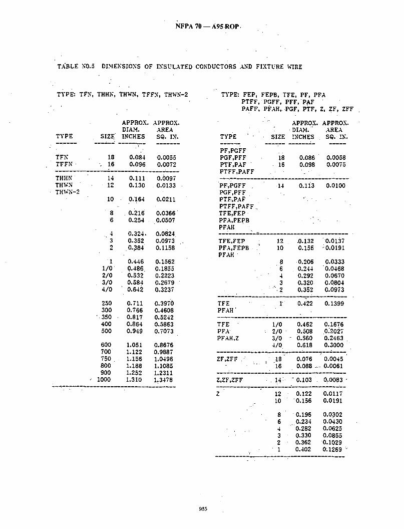
1NFPA 70 - - A95.ROP.
T.~BLE N0.5 DIHENSIONS OF INSULATED CONDUCTORS .~N'D FIXTURE WIRE
TYPE: TFN, THHN, THWN, TFFN, THWN-2
TYPE SIZE ~
TFN 18 TFFN . 16
APPROX. APPROX. DIAM. AREA INCHES S@. IN.
0.084 0.0055 0,096 0.0072
THHN 14 0.111 0.0097 THWN 12 0.130 0.0133 THWN-2
I 0 0.164 0.0211
8 6
0.216 0.0366 0,254 0.0507
4 0,324, 0.0824 3 0.352 0,0973 2 .0.384 0.1158
1 1/0 2/0 3/0 4/0
250 300
" 350 400 500
0:446 0.1562 0 ,486 0.1855 0,532 0,2223 0.584 0.2679 0,642 0.3237
0.711 0.3970 0.766 0.4608 0,817 0.5242 0.864 0.5863 0.949 0.7073
600 700 750 8O0 9OO
1000
1.051 0.8676 L122 0.9887 1.156 1.0496 1.188 1.1085 1.252 1.2311 1.310 1.3478
TYPE: FEP, FEPB, TFE, PF, PFA
TYPE
PTFF, PGFF, PFF, PAF PAFF, PFAH, PGF, PTF, Z, Z F, ZFF
"" APPROX. APPROX.
PF,PGFF PGF,PFF PTF,PAF PTFF,PAFF
"" " DIAM. "" AREA SIZE INCHES S@. IN.
i8 16
0.086 0.0058 0.098 0.0075
P ,P FF PGF,PFF PTF-,PAF PTFF,PAFF .= TFE;FEP • PFA,FEpB PFAH
14 0.1i3 0.0100
TFE,FEP PFA,FEPB PFAH "
12 10
6 4 3
= " 2
.0.132 0.156
0.206 0.244 0,292 0.320 0,352
0 .0137 : 0 . 0 1 9 1
0,0333 "0.0468 O.06TO 0.0804 0.0973
TFE ! ~ 0.422 0.1399 PFAH"
TFE 1/0 0.462 0,1.676 P F A 2/0 0.508 0.2027 PFAH,Z 3/0 0.560 0.2463
4 /0 0.618 0.3000
ZF,ZFF ' 18 0.076 0.0045 16 0,088 ..... 0.0061
Z,ZF,ZFF 14 -0.103 0.0083 "
Z 12 0.122 10 0,156
8 0.196 6 0.234 4 .... 0.282 3 0.330 2 0.362 1 0.402
0.0117 0.0191
0.0.302 0,0430 0.0625 0.0855
0.1029 O; 1269 ~
935

"NFP.~ 70 -- A95 ROP
TABLE N0.5 DIMENSIONS OF INSULATED CONDUCTORS AND FIXTURE WIRE
• TYPE:.RFH-2, RH, RHH, RHW 5 SF-2 TYPE: TF, THW, TW, TFF-, RFH-I FFH-2, SF-1 , S F F - 2 AF, THHW, THW-2, 'RHH*, RHW~
TYPE SIZE SIZE
APPROX. APPROX. DIAM. AREA
INCHES SQ. IN.
RPH-2 FFH-2
TYPE
RFH-I,AF
RH 14 0.163• 0.0209 12 0.182 0.0260
RHW-2,RH 1a 0.193 0.0293 RHW 12 0,212 0.0353
RH,RHH RHW RHW-2
APPROX. APPROX. DIAIq. AREA
INCHES SQ. IN.
18 0.136 0:0145 18 , 0.106 0.0088 16 0.148 0.0172
AF,TF,TFF . 16 0.118 0.0109
" 10 0,236 0,0437 8 0,326 0,0835
6 0,364 0,1041 4 0.412 0.1333 3 0.440 0.1521 2 0.472 0.1750
1 0.582 0.266O 1/0 0.622 0.3039 2/0 0.668 0.3505 3/0 0.720 0.4072 4/0 0,778 0,4754
0.895 0.6191 0.950 0.7088 1.001 0.7870 1.048 0.8626 1.133 1.0082
1,243 1.2135 1.314 1.3561 1.348 1.4272 1.380 1.4957 i.444 1.6377 1.502 . 1.7719
250 300 350 400 "500
1.729 2.3479 1.852 2.6938 1.966 3.0357 2+072 3.3719
SF-2 S F F - 2
6 0 0 700 750 800. 900
1000
0.121 0.0115 0.133 0.0139 0.148 0.0172
SF-I SFF-1
1250 1500 1750 2000
18 16 14
18 0,091 0,0065
• TW,AF 14 0.133 0.0139
TW 12 0.152 0.0181 I0 0.176 • 0.0243
8 0.236 0.0437
RHH*,RHW* 14 0.163 0.0209 THHW,THW,THW-2
RHH*,RH~,.* 12 0.182 0.0260 THHW,TH~.¢ i0 0.206 0.0333
RHH*,RHW* g 0.266 0.0556 THHh','~Hh',THh'-2,
TW,THXC THHW THW-2 RHH* RHW*
6 0,304 0,0726 4 0,352 0,0973 3 0,380 0,1134
• 2. 0,412 0,1333
i 0.492 0.1901 1/0 0.532 0.2223 2/0 0.578 0.2624 3/0 0.630 0.3117 4/0 0.688 0.3718
250 0.765 0.4596 300 0.820 0.5281 350 0.871 0.5958 400 0.918 0.6619 5 0 0 1.003 0.7901
600 1.113 0~9729 700 1.184 I.I010
j 750 1.218 i.i652 800 1.250 1.2272 900 1,314 1,3561
1000 1~372 1,4784 1250 1,539 1,8602
1500 1.662 2,1695 1750 1.776 ~ '-- "-- . " t ' [ 13 2000 1.882 2.7818
:~ TYPE RHH AND RHW WITHOUT COVERiXG
936

N F P A 7 0 - - A 9 5 R O P •
(Log #24436) 6-184- (Chapter 9 Table 8): Reject - S.UBMITTER: Steven Mitchell Steven Mitchell Elecu._ai Contract-
~d~COMMENDATION: Under the heading copper there is - uncoated and coated. Change coated to t i n n e d o r soldered which is what coated means, not insulated as some electricians believe both con t rac to r s~ joumeymen and it confuses apprentices. SUBSTANTIATION: It adds confusion to all people in this trade whether y o u n g o r old. PANEL ACTION: Reject. PANEL STATEMENT: Coated is used in the Code to describe a metallic material" (see the 250 degree C columns in Tables 310-18 and 310-19 for example). , . NUMBER OF PANEL MEMBERS ELIGIBLE T O VOTE: 1 0 VOTE ON PANEL ACTION:
AFFIRMATIVE: 10
(Log'#1204) 6-185 - (Chapter 9, Table 9): Reject SUBMITTER: WilliamJ. Stone, Long Beach,CA .
• RECOMMENDATION: Revise text: • Xu (Reactance) for allwires in steel conduit. Reactance for 410 AWG is larger than 250 kcmill (0.051 | /1000 feet and 0.052 I / 1000 feet respectively.) It would seem more logical for those two values to be re;eersed. SUBSTANTIATION: This appears to be a typographical error. I have consulted other cable.tables and cannot find one where the - t rend stated above occurs. PANEL ACTION: Reject. " . PANEL STATEMENT: The values in the table are based on the RHH conductors (see note 1). There is a change in.insulation thickness between 4 /0 awg and 250 kcmil that should account for the 950 kcmil to have a larger reactance. . . NUMBER OF PANEL MEMBERS ELIGIBLE T O VOTE: 10 VOTE O N PANEL ACTION:
AFFIRMATIVE: 10
6-18(i - (Chapter 9, Table 9): Reject • SUBMITTER: StanJohn~tgn, Marion, IA
RECOMMENDATION:
(Log #3246)
Is:
PVC, AL. Conduits
10 .050 " 8 .052 6" .051 2 .045 1 .046
x
Should be:
PVC, AL Conduits .
10 .052 .051 ..
6 .050 2 .046 L .045
Steel Conduit .063 .065 .064 .057 .057
Steel Conduit .065 .064 .063 .057 .057
SUBSTANTIATION: Reactance should decrease for increasing wire sizes. The values must have been transposed during typing.
NOTE: Support ing material is available for review at NFPA Headquarters. • PANEL ACTION: Reject;, PANEL STATEMENT: The values in 'the table'are based on the RHH conductors (see'note 1 ) . Therd is a change in insulation thickness between 10 awg a0d 8 awg, and between 2 awg and 1 awg that should account.for the larger conductors having a larger reactance. N U M B E R OF PANEL MEMBERS ELIGIBLE T O VOTE: 10 V O T E ON PANEL ACTION:
AFFIRMATIVE: - 10
6.187- (Chapter 9, TaiMe 0): Accept . . (Log#3261) Note: The Technical Correlating Committee instructs the P:hael to
reconsider the validity of the Proposal. This adtion will be consid- e r e d b y t h e Panel as aPublic Comment. " ~' " - SUBMITTER: Lawrence R. Walsh, Randalls Islkfid, NY " RECOMMENDATION: Note 2 "Effeckiye Z" !s defined as R ' cos(them) +iX sin (them), where ."them" is the power factor angle of the circuit. Multiplying current by effective impedance gives a good approximation for line-to-neutral voltage drop. Effective impedance.
[,values shown in this table are valid only at .85 power factor. ,[ For other circuit power factor (PF), effective impedance can be
calculated from R and X L values given in th is table as follows: Z c = R x PF.+jX L sin[arccos (PF)]. -. ' ' -
SUBSTANTIATION: The use of a lower case ']" before thCthe reactance should 'help remind the reader that their is a vectori relationship between resistance and reactance. The formula as
. presently sh-own suggests theaddi t ion of two scalar values. PANEL ACTION: Accept. NUMBER OF PANEL MEMBERS ELIGIBLE T O VOTE: 10 VO TE O N PANEL ACTION:
AFFIRMATIVE: 10
(Log #2684) 8-248 - (Chapter 9 New Table X): Accept in Pr inciple . , SUBMITTER= Edwin K. Rodkey, Cation Electrical Products-A Larmon & Sessions Co. RECOMMENDATION: Acld new Table Xi Maximum number of conductors in rigid PVC conduit, Schedule 80: (See Table X on following pages.) " - . SUBSTANTIATION: Because of the small I.D. of RNMC-~30, a separate conductor fill table is necessary to provide this information
• for the code user. PANEL ACTION: Accept in Principle• -- PANEL STATEMENT: Refer to Panel Action on Proposal 8-236. NUMBER OF PANEL MEMBERS ELIGIBLE T O VOTE: 14 V O T E ON PANEL ACTION:
AFFIRMATIVE: 14
o37

NFPA 7 0 - - A 9 5 ROP . .
TABLE X~ ' .MAXIMUM NUMBER OF CONDUCTORS X/d RIGID PVC CONDUIT, SCHEDULE 80 (Based on Table 1, Chapter 9.)
Conductor . . Type Size . Lettem AWG/kcmll 1/2 3/4 1 1 1/4
Conduit,Trade Sizes In Inches 1 1/2 2 2 1/2 3 3 1/2 4 5
RH 14 4 8 13 23 12 3 6 10 19
RHH, RHW, . R H W - 2
14 S 5 9 12 2 4 7
RH, RHH, RHW, R H W - 2
10 8 6 4
. 3 2 1
1/o 2/0 s/0 4/0 250 300 350 400 50O 600 700 7So 8O0 900 1000 1250
1500 1750 2000
I 3 I I I 1 I . I 0 I 0 1 0 1 0 0
0 0 0 0 0 0 0 0 0 0 0 0 0 0 0 0 -0 0 0 0 0 0 0 0 0 0 0 0 0 0 0 0 0 0 0 0
3 2 55 79 123 166 215 341 490 26 44 63 99 133 173 274 394
17 ~ 2 3 14 19
39 56 88 118 153 243 349 32 46 73 98 127 202 290
6 11 15 26 37 59 3 6 8 13 1 9 31 2 4 6 11 16 24 1 3 . 5 8 ' 12 19 1 3 4 7 11 17 1 3 4 6 9~ 14 1 1 2 .4 6 9 1 1 1 3 5 8 1 1 1 3 4 7 1 1 1 3 4 6 0 1 1 2 3 5 0 1 1 1 2 4 0 1 1 1 2 3 0 1 1 1 1 3 0 0 1 1 1 3 0 0 1 1 1 2 0 0 0 1 1 1 0 0 0 1 1 1
0 0 0 1 I 1 0 0 0 1 1 1 0 0 0 1 1 1 0 0 0 1 1 1 0 0 0 0 I 1 0 0 0 0 I I 0 0 0 0 O. 1 0 0 0 0 0 I
79 41 33 26 23 20 13 11 10
8 7 5 5 4 4 . 3 3 2 2 2 1 1 1 1 1 1
lO3 54
3 33 29 25 17 15 13 11
163 85 68 53 47 41 27
"23 20
1 7 9 15 7 11 ~ 6 10 5 9 5 8 4 7 3 6 3 5 3 5 3 4 2 4 2 4 1 3 1 2 . 1 2 1 1
234 122
98 77 67 58 38 33 29 25 21 16 14 13 12 10
8 7 7 7 6 5 4 4 3 3
938

N F P A 70 - - A 9 5 R O P
TABLE~)~( "MAXIMUM NUMBER OF CONDUCTORS ..~/~/ RIGID PVC CONDUIT. SCHEDULE 80
Type Lettem
Conductor Sbm AWG/kcmii 1/2 3/4'
Conduit Trade 81~s In Inches 1 1 1/4 1 112 2 2112 3 3112 4 5 6
14 12 10 8
6 11 5 9 $ 6 1 3
20 + 35 49 8 2 118 . 185 250 324 514 736 15 27 38 63 91 142 192 248 394 56S i l 20 28 47 6? 106 143 185 294 421 6 11 15 28 37 59 79 103 163 234
RHH*, RHW*. RHW-2*. THHW. THW. THW-~2
14 4 8 13 23 32 55 79 123 166 215 341 490
RHH*, RHW', RHW-2*. THHW, THW
RHH*; RHW*. RHW-2*. THHW, THW. THW-2
. +"
t2 10
RHH*. RHW*. 6 RHW-2*. 4 TW, THW. 8 THHW. 2 THW-2 1
I t0 2/O
• S/0 4/O 250 300 350 40O
+500 600 79O 750 80O 90O +_ 1000 1250 1500 1750 2OOO
6 10 5 8
19 28, 44 -6S 15 20 34 49
99 133 173 274 394 77 104 135 214 3 0 7
1 $ 5 9 12 20 29 46 62 61 128 184 /
t 1 1 1 1 I 1
• 0 1 0 1 O. 1 0 O 0 •
/ 0 0 0 0 0 0 O- 0 0 0 0 0 0 O+ 0 0 0 0 0 0 0 0 0 0 O- +0 0 0 0 0 0 0 0 0 0 0 0 0 . 0 . 0 "0 0
S S 2 4 1 $ 1 2 1 1 1 1 1 + 1 1 1 0 1 0 1 0 1
I 1
? 9 16 22 35 48 62 98 141 5 " 7 12 17 -.26~ 35 46 + 73 105
6 10 14 _22 3O 39 63 9O 5" 8 12 19 26 33 5S 77 8 6 $ 5 2 4 ! 3 1 S -I 2 1 + I 1 1 1 1 1 1 0 0 0
8 13 18 23 3 7 54 7 1 1 15 20- 82 46 6 10 13 17 2? :Jg" 5 8 I1 14 23 . 33 4 7 9 12 "19 27 $ 5 7 9 15 22
3 5 6 8 13 19~ 4 6 7 4 5 7 $ 4 5 2 8 4 2 3 4 1 $ 4 1 3 $
1 - + 1 2 $ 2 S 1 2 1 1 1 1 1 1
2 t 2 1 ! 1 t 1 -1 1 1 1 1 1
0 0 0 0 0 0 "'" 0 1 1-1" 1
0 ° O_ " 1. 1 1 0 0 0 1 1 0 0 0 1 " 1 o - o o o- 1
12 17 10 15 9 .13 - 7 10 6 9 6 8
S ~S 5 7 , 5 7 4 5 3. 4 S 4 2 3
* Types RHH. RHW. and RHW-2 wllhout DUrra, covedng.
939

N F P A 70 - - A 9 5 R O P
TABLE4~X MAXIMUM NUMBER.OFCONDUCTORS Z'II( RIGID PVC CONDUIT. SCHEDULE 80
Type Letters
THHN, THWN, THWN-2
Conductor Size Conduit Trade Sizes in Inches AWG/k~U 1/2 3/4 I 1 I /4 1 1/2 2 2 I /2 3 3 1/2 4 ~ 5 , 6
t4 12 10 8 6 4 3 2 1
1/0 2/O ~ o 4/0 250 3O0 3 5 0 400 500 6O0 700 75O 8O0 g00 1000
g .17 28 51 70 118 170 265 358 464 738 1055 O 12 20 37 51 86 124 193 261 338 537 770 4 2 4 1 3 1 1 1 1 1 1 0 1 0 1 0 1 0 1 0 0 0 0 0 0 0 0 0 0 0 0 0 0 0 0 0 0 0 0 0 0 0 0
7 13 23 32 54 78 122 164 21'3 338 485 . 7 13 18 31 45 70 95 123 195 279 5 3 3 2 1 3 4 1 2 3 1 1 3 1 1 2 1 1 1 1 1 1 0 1 1 0 1 1 0 1 1 0 1 1" 0 0 1 0 0 1 0 ~ 0 1' 0 0 1 0 0 0 0 0 0
9 13 22 32 51 68 89 141 202 6 8 14 20 31 42 54 86 124 5 7 12 17 26 35 46 73 , 105 4 . 6 10 14 22 30 39 61 . 6 8
1 1 1 1 1
1
7 10 16 .22 29 45 65 6 9 14 18 24 38 55 5 7 11 15 20 32 46 4 6 9 13 i 7 25 38 3 5 8 10 14 22 31 3 , 4 6 2 3 5 1 3 5 1 3 , 4 1 2 3
1 3 1 2 1 2 1 2 1 1 1 1
8 11 16 25 7 9 15 22 6 8 13 19 6 7 12 17 5 6 10 14 4 5 5 12 3 4 7 10 3 4 7 9 $ 4 / 6 9 3 3 6 6 2 5 5 7
FEP, FEPB, PFA. PFAH. "TFE
14 12 10 6 6 4 3 2
PFA, PFAH, 1 TFE
PFA, PFAH, TFE, Z
1/o. 2/0
• 4 /0
8 10 27 49 68 115 104 257 347 450 714 1024 6 12 20 36 50 84 120 188 253 328 521. 747" 4 8 14 26 35 60 86 135 182 235 374 536 2 - 5 1 $ 1 2 1 1 1 1.
1 1
8 15 20 34 49 77 104 135 214 307 6 10 14 24 35 55 74 96 152 218 4 7 10 17 24 38 52 67 ~06 153 3 6 8 14 . 2 0 32 43 56 89 127 3 " 5 7 12 .17 25 35 46 73 105
1 3 5 8 11 18 25 32 51 73
0 1 1 0 ° 1 1 0 1 1 0 0 . 1
3 4 2. 3 1 2 1 1
7 10 15. 20 27 ~ 42 61 5 8 12 17 22 35 50 4 6 10 14 18 2 9 41 4 5 6 11 15 24 34
940
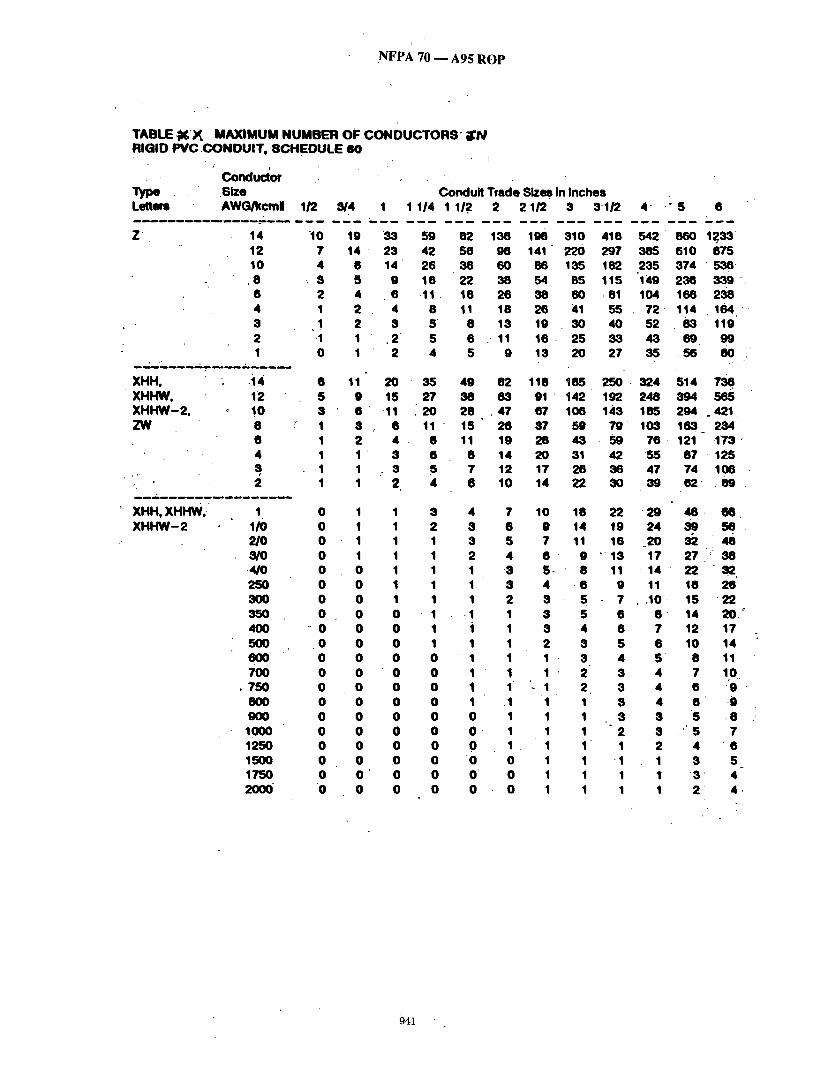
J
.NFPA 70 - - A 9 5 R O P
TABLE ; K ) ~ M A X I M U M NUMBER OF CONDUCTORS" ; N RIGID PVC C O N D U I T , SCHEDULE 80
I i
Conductor Type .Size Condui t Trade Sizes in Inches Lettem AWG/kcml 1/2 8/4 I 1 I14 1 11.2 2 2 I /2 3 3112
Z
XHH. XHHW, XHHW-2 . ZW
~ XHH, XHHW,- X H H W - 2
4" " 5
14 10 12 • 10 4 8 ; 8 6 2 4 1 3 1 2 -1 1 0
.14 12 !0 8 6 4 s 2
1 1/0 2/O S/O .4/0 25O 33O 350 40O 5OO 6OO 7oo
• •50 -800 9OO 1000 1250 1500 1•50 2OOO"
19 14 - 23
8 5 4 2 2 1 1
33 59 82 138 198 310 418 542 860 1233 42 58 98 141" 220 297 385 610 875
14' 26 36 60 86 135 182 235 374 ' 536" 9 16 22 38 54 85 115 "149 238 339 6 .11 • 16 26 35 60 • 81 104 166 238 4 8 11 18 26 41 55 •2 114 • 154 " 3 5' 8 13 19 30 40 52 83 119
,2" 5 6 . 11 16 . 25 33 43 6 9 9 9 2 4 5 9 13 20 2 • 85 56 80
6 5 8 1 1 1
1 1
11 20 56 49 82 118 185 250 324 514 •36 9 15 27 38 63 0 1 1 4 2 192 248 394 ~ " 6 ' 11 20 28 , 47 67 106 143 185 294 °421 8 0 11 - 15 26 8• 59 • 9 103 163_ 234 2 4 . . 8 11 19 28 43 59 •6 121 .1'73 1 ' 8 6 8 14 20 31 -42 55 8• • 125 1 . S S • 1 2 1 17 26 36 4• •4 106 1 2 4 6 10 14 22 30 39 62" . 89
0 0 0 0 0 0 0 0
° 0 .0 0 0 0 0 0 0 0 0 0 0
1 1 S 1 1 2 1 1 1 1 1 1 0 1 1 0 1 1 0 1 1 0 0 • 1 0 0 1 0 0 1 0 0 0 0 0 0 0 0 0 0 0 0 0 0 0 0 0 0 0 0 0 0 0 0 O ' 0 0 0 0 0
4 • 3 8 8 5 2 4 1 .8 1 8 1 2
• 1 1 i 1 1 1 1 1 1 " 1 1 1 1 ~ .1 0 1 O 1 0 1 . 0 0 O 0 0 o
10 9
6 5 -~ 8 4 .6 8 5 $ 5 3 4 2 8 1 8 1 2 1 2 1 1 1 1 1 1 1 1 1 1 1 1 1 1
16 22 2 9 46 . 66 14 19 24 39 56
11 • 1 4 22 " 82, 9 11 18 26 7 , .10 - 15 2 2 6 8 ' 14 20.'7 6 ? 12 1• 5 6 10 14 4 5' 8 11 s 4 • 1to 3 4 6 9 " $ 4 6 .9 8 8 5 • 8 2 3 " 5 • 1 2 4 6
• 1 1 3 5 1 1 3 ' 4 1 1 2 4-
941
N F P A . 7 0 - - A 9 5 R O P
(Log #3090) • 8-249"- (Chapter 9, NewTable ) : Reject
SUBMITrER: Goran Hag, Opti-Com Manufac tur ing Network, Inc. RECOMMENDATION: Add new Table 11, Expansion character is- . , tics of Rigid Epoxy Fiberglass Condui t
Table 11. Expansion Characteristics of Rigid Epoxy Fi.bse~l._ ass Conduit. Coefficient of Thermal Expansion = 1.0 x 10 : in./in./°F
Lengt'h Ch~ange in Temperature I.,ength Change in Temperature" inches per 100 fL 'Changesin inches per 100 ft. " Change in of epoxy Degres F of epoxy Degrees F fiberglass conduit fiberglass conduit
0.06 5 lO 15 2o 25 30 3 5 40 , 4 5 50 55 6o 65 • 70 75 80 85 9O 95
lOO
0.12 0.18
.0.24 0.30 0.36 0.42 0.48 0.54 0.60 0.66 0.72 0.78 0.84 0•90 0.96 1.02. 1.08 1.14' 1.20
105 , • 1.26 110 1.32 115 1.38 120 1.44 125 1.50 130 1.56 135 1.62 140 1.68 145 1.74 150 1.80 155 1.86 160 1.92 165 1.98 170 2.O4 175 2.10 180 2.16 185 2.22 190 2.28 195 2.34
• 200 2.40
PANEL ACTION: Reject. PANEL STATEMENT: The Panel agrees that the submit ter is technically correct. The Code does not prohibi t eng ineer ing calculations in order to be more precise.
The values arldved at by adding volt-amperes will provide a larger value, thus resul t ing in a degree of safety. NUMBER OF PANEL MEMBERS ELIGIBLE TO v o T E : 10 VOTE ON PANEL ACTION:
AFFIRMATIVE: 10
(Log #2612) 11-125 - ' (Chapter 9 Part B. Examples): Reject -. SUBMITTER: Joseph Misrahi, Metro Transi t Authori ty of Harris County, TX RECOMMENDATION: Add paragraph: "Power factor, calculations in the following examples are based, for convenience , on the assumpt ion that all loads have the same power factor." SUBSTANTIATION: Loads in volt-amperes canno t be added unless they have the same power factor• PANEL ACTION: Reject. PANEL STATEMENT: The examples are not in tended to be tutorial. Examples do not address power factor. N U M B E R O F PANEL MEMBERS ELIGIBLE TO VOTE: 18 VOTE ON PANEL ACTION:
AFFIRMATIVE: 18
SUBSTANTIATION: This is a compan i on proposal to 347-9, 'FPN. PANEL ACTION: Reject. PANEL STATEMENT: T he submi t te r provides no substant iat ion to verify the accuracy of the coefficient of linear thermal expans ion used to genera te the tables . NUMBER OF PANEL MEMBERS ELIGIBLE T ° VOTE: 14 VOTE ON PANEL ACTION:
AFFIRMATIVE: 15 NEGATIVE: Forsberg
EXPLANATION OF NEGATIVE:- FORSBERG: It is unreasonable to reject the proposal based on the
panel s ta tement . The coefficient was developed by the submit ter -based on physical t e s t i ng . and is included in the manufac tu re r ' s p roduct literature. Tha t shou ld be adequate verification
(Log #2228) 2-469 - (Chapter 9 B. Examples): A.ccept
Note: T h e T e c h n i c a l Correlat ing Commi t tee directs tha t the A c t i o n o n this Proposal be rewritten to comply with .the NEC Style Manual to read as follows: "Fractions of an Ampere." Except where the c6mputaf ions result in a fraction of an ampe re 0.5 or-larger, such fractions shall be permi t ted to be dropped." SUBMITTER: T o m Henry, Code Electrical Classes, Inc.
[RECOMMENDATION: Revise text as follows: Fractions. o f an ampere . Except where the com. puta t ions result in a
fraction of an ampere 0.5 or larger, such fracUons may be dropped. ]SUBSTANTIATION: Remove f rom text the word "major"• 0?3-is InOt a' major fraction, it is exactly one-half. ] If I own .Sstock in a company and you own .5 stock, who is the Imaior stock holder? PANEL ACTION: Accept. NUMBER OF PANEL MEMBERS ELIGIBLE TO VOTE: 10 VOTE ON PANEL ACTION:
AFFIRMATIVE: 10
2-470 - (Chapter 9B): Reject (L?g #2308) S U B M I T T E R : J o s e p h Misrahi, Metro Transi t Authori ty o f Harris County, TX
• RECOMMENDATION: A d d p a r a g r a p h : Power factor, calculations in the following examples are based, f o r convenience, on the ~ssumption that all loads have the same power factor. SUBSTANTIATION: Loads in volt-amperes can not be added unless they have the same Power factor.
(Log #3722) 12-129- (Chapter 9 B. Examples): Reject SUBMITTER: Tom. Henry, ,Code Electrical Classe~, Inc. RECOMMENDATION: Revise text as follows:
Fractions of an ampere . Except where the computa t ions result in a fraction of an ampere 0.5 or larger, such fractions may 'be dropped. SUBSTANTIATION: ]Remove f rom text the word "major". 0.5 is no t a m ~ o r fraction, it is exactly one-tialf.
If I own .5 stock in a company and you own .5 stock, who is the p ~ E stock holder? ' j
L ACTION: Reject. , PANEL STATEMENT: The te rm "major" fraction is a p roper mathemat ica l term. Also, the r e s t o f the p roposed revision is no t in accordance with the NEC style mz~nual. NUMBER OF PANEL MEMBERS ELIGIBLE TO VOTE: 10 VOTE ON PANEL ACTION:
AFFIRMATIVE: 10
(Log #3723) 11-127- (Chapter 9 Part B. Exampfes): Reject
Note: It was the action of the Technical Correlat ing Commi t tee tha t this Proposal be recons idered and correlated with the action on Proposal 2-469. This act ibn will be considered by the Panel as a Ptiblic Commen t . " • , SUBMIT'IER: T o m Henry, Code Electrical Classes, Inc~ RECOMMEN.DATION: .Revise text as follows:
Fractions of an ampere . Except where the computa t ions / ' e su l t in a fraction of an ampe re 0.5 or larger, such fractions may be dropped . SUBSTANTIATION: ]Remove f rom text the word "major". 0.5 is - no t a m ~ o r fraction, it is exactly one-half. "
If I own .5,stock in a company and you own .5 stock, who is the p I ~ E stocl~ holder?
L ACTION: Reject./ PANEL STATEMENT:- In Code usage, "major" means 0.5 or more. NUMBER OF PANEL MEMBERS ELIGIBLE TO VOTE: 18 VOTE ON PANEL ACTION: " '
AFFIRMATIVE: 17 NEGATIVE: Schram
EXPLANATION OF NEGATIVE: SCHRAM: I believe the proposal shou ld be accepted. The
p roposed revision simplifies the text wi thout chang ing the effect of the note.
942
N F P A 70 - - A 9 5 R O P
(Log #3724) 12-130 - (Chapter 9B): Accept in Principle SUBMITTER: Joseph Misrahi, Metro Transi t Authori ty of Harris County, TX RECOMMENDATION: Add paragraph: Power factor, calculations in the foliowing examples are based, for convenience, on the assumpt ion that all loads have the same power factor. SUBSTANTIATION: Loads in volt-amperes can not be added unless they have the same power factor. PANEL ACTION: Accept in Principle. " ,
I Add paragraph: "Power factor. Calculations in the following ] examples are based, for convenience, on the assumpt ion that all [ loadshave the same power factor." ,'
PANEL STATEMENT: .Editorial change to p roposed wording. NUMBER OF PANEL MEMBERS ELIGIBLE TO VOTE: 10 VOTE ON PANEL ACTION:
AFFIRMATIVE: 10
(Log #3725) 11-128 - (Chapter 9 Part B. Examples): Reject SUBMITTER: Joseph Misrahi, Metro Transi t Authori ty of Harris County, TX RECOMMENDATION: Add paragraph: Power factor, calculations in the following examples are based, for convenience, on the assumpt ion that all loads have the same power factor. SUBSTANTIATION: Loads in volt-amperes can not be added unless they have the same power factor. PANEL ACTION: Reject. PANEL STATEMENT: See Panel S ta tement on l~roposal 11-126. NUMBER OF PANEL MEMBERS ELIGIBLE TO VOTE: 18 VOTE ON PANEL ACTION: • AFFIRMATIVE: 18
(Log #3726) 12-131 - (Chapter 9 Part B. Examples): Accept in Principle SUBMITTEPa Joseph Misrahi, Metro Transi t Authori ty of Harris County, TX RECOMMENDATION: Add paragraph: "Power factor, calculations in the following examples are based, for convenience, on the assumpt ion that.all loads have the same power factor. SUBSTANTIATION: Loads in volt-amperes canno t be added unless they have the s a m e p o w e r factor. PANEL ACTION: Accept in Principle.
Add paragraph: "Power factor. Calculations in the following lexamp!es are based, for convenience, on the assumpt ion that all [ Ioadshave the same power factor." PANEL STATEMENT: Editorial change to p roposed wording. NUMBER OF PANEL MEMBERS ELIGIBLE TO VOTE: 10 VOTE ON PANEL ACTION:
AFFIRMATIVE: 10
(Log #794) 2-471 - (Chapter 9, Example l (b) ) : Accept in Principle SUBMITTER: Barry F. Tower, Katahdin Electric RECOMMENDATION: Revise text by add ing the following:
Add the following line above the last line ( the one tha t begins with an asterisk) in tha t example: • . .
"Therefore, this dwelling shall be permi t ted to be served by a 100- ampe re service." . SUBSTANTIATION: The prob lem is tha t this is supposed to be an example showing what size service is permit ted, bu t it leaves the reader with noth ing . As it is, it is no t really an example because no conclusion is reached. It raises more ques t ions than it answers. Is a 100,-ampere service permi t ted when one line (line B) comes out to 104 amperes? PANEL ACTION: Accept in Principle.
Add the following before the last paragraph after the totals: "Therefore, this dwelling shall be permi t ted to be served by a
service rated 110 amperes ." PANEL STATEMENT: Section 230-42 requires 'service-entrance conductors to be of sufficient size to carry the loads as compu ted in Article 220. Note No. 3 to the Ampacity Tables permi t a 110 ampere rated service in dais case. The p roposed r ecommenda t i on would
• provide a service size that is inadequate for the load served.
NUMBER OF PANEL MEMBERS ELIGIBLE TO VOTE: 10 VOTE ON PANEL ACTION:
AFFIRMATIVE: 10 /
(Log #1235) 2-472 - (Chapter 9, Example 2(a)): Reject SUBMIT'rERa Dean Huiater, Wadena Techanical College RECOMMENDATION: In the example Feeder Neutral Load the dishwasher is taken at 1200 VA. I believe this is incorrect because it should be calculated u n d e r the s tandard m e t h o d as in example 1 (b). Assuming the dishwasher in example 2(a) is 120V, without any other 120V load to balance it, - the neutral would carry the full 10A. (Just as in example 1 (b)). SUBSTANTIATION:
General l ighting 5,100 Range at 70% 5,600 Dryer at 70% 3.500
14,200
A N 59.1
D.W. 10 10 Mtr load?
69.1 Amps
+ 240 = 59.1A ,
B
(should you calculate mtr. toad on Dishwasher)
PANEL ACTION: Reject. ' PANEL STATEMENT: Some of these neutra l loads are a s sumed loads. The 120 volt dishwasher load maybe balanced by any of the small appliance branch circuit loads. By evenly distr ibuting the circuit load in accordance with Section 220-4(d) the neutral load could be fur ther reduced in some instances. NUMBER OF PANEL MEMBERS ELIGIBLE TO VOTE: 10 VOTE ON PANEL ACTION:
AFFIRMATIVE: 10
(Log #600) 2-473 - (Chapter 9, Example No. 2(b)): Reject SUBMITTER: Dan Leaf, Palmdale, CA RECOMMENDATION: Revise as follows:
- "Dwelling has a floor area of 1500 feet exclusive of unoccup ied cellar, unf in i shed attic, open porches, and garage. It has two 20- ampere small appl iance circuits, one 20-ampere laundry circuit, two 4-kW wall m o u n t e d ovens, one 5.1 kW counte r m o u n t e d cooking unit, a 4.5 kW water heater, a 1.2 kW dishwasher, a 5-kW clothes dryer, a 20-ampere 230-volt air condi t ioning hermet ic compressor unit, a 1 /2 HP .-115-volt central forced air h~at ing unit, a 1 /3-HP 115- volt food waste disposer, and a 1.5 kW pe rmanen t ly connec ted ba th room space heater . Assume kW ratings are equal to kVA.
PROPOSAL
AIR CONDITIONING EQUIPMENT kVA CALCULATION: _ Central air condi t ioning unit- 20 amperes x 1.25 (Section 440-7)
x 240 volts =. ................................................................. 6.0 kVA Central forced air hea t ing unit- 9.8 amperes (Table 430-148)
x 120 volts ..................................................................... 1.176 kVA Assume P.F. = 1. Total air condi t ioning load .............. 7.176 kVA
LOAD INCLUDED AT 100 %
Air condi t ioning e q u i p m e n t (see below) Space hea te r (omit-see Section 220-21)
OTHER LOAD 1500 sq. ft at 3 volt-amperes per ft .................................... 4.5 kVA Two small appliance orcui ts at 1500 volt-amperes e a c h . 3.0 kVA Laundry circuit ................................................................... 1.5 kVA Two ovens ........................................................................... 8.0 kVA One cooking uni t ............................................................... 5,1 kVA Water hea te r ....................................................................... 4.5 kVA Dishwasher ............................. : ......... ~. ............................... :. 1.2 kVA Dryer 5.0 kVA Food waste disposer- 7.2 amperes
(Table 430-148) x 120 volts .............................................. 864 kVA Total connec ted o ther load ............................... :... 33.664 kVA
1st 10 kVAat 100% ............................................ , ........... 10.0 kVA Remainder at 40% (23.664 x .4) .................................. 9.466 kVA
Total ne t compu ted o ther load ......................... 19.466 kVA
943
N F P A 70 - - A 9 5 R O P
Other load ................................... '. .................. ;... 19.466 kVA Air condi t ioning e q u i p m e n t ..................... : ....... 7.176 kVA Total load ...................... : .................................... 26.642 kVA =
26642 volt- amperes ÷ 240 volts = 111 amperes ( m i n i m u m u n g r o u n d e d service conduc to r ampacity) '
FEEDER NEUTRAL LOAD PER SECTIONS 220-16 and 220-22 It is a s sumed tha t the two 4 kVA wall m o u n t e d ovens are suppl ied by one circuit, the 5.1 kVA' coun te r m o u n t e d cooking un i t is suppl ied by an individual b ranch circuit, and the 120-volt ctrcuits are
• reasonably balanced across the u n g r o u n d e d service conductors .
1500 sq. ft. at 3 volt-amp~res per ft ............................... 4.5 kVA Two small appliance circuits at 1500 volt
-amperes each .............................................................. 3.0 kVA Laundry circuit at 1500 volt-amperes ........................... 1.5 kVA
Total .................................................................... 9.0 kVA
(Log #2188) 2-475 - (Chapter 9, Example 3) : Reject SUBMITrER: Vohn N. Peeler, Faith, NC RECOMMENDATION: Add new text as follows:
Please add a motor load to the store bui lding in this example. SUBSTANTIATION: There is considerable confusion in sizing feeders and overcurrent devices which supply combinat ion motor and o ther loads. An example showing this would be greatly appreciated. PANEL ACTION: Reject. PANEL STATEMENT: The presen t example is clear. Refer to Example No. 8. NUMBER OF PANEL MEMBERS ELIGIBLE TO VOTE: -10 VOTE ON PANEL ACTION:
AFFIRMATIVE: 10
3.0 kVAat 100 % ................................................ 3.0 kVA 9.0 kVA minus 3.0 kVA at 35% .......................... 2.1 kVA Total .................................................................... 5.1 kVA
Two 4 kVA ovens plus one 5A kVA cooking uni t - total 13.1 kVA Table 220-19 permits 55% d e m a n d factor-13.1 kVA x .55 = 7.2 kVA
Feeder capacity 7.2 kVA x .7 (Section 220-22) ............ 5.04 kVA Clothes dryer at 5.0 kVA x .7 (Section 220-22) ............ 3.5 kVA Dishwasher ..................................................................... 1.2 kVA Forced air heatei" un i t ................................................... 1.176 kVA Food waste disposer ........................................................ 864 kVA
Total 16.680 kVA = 16680 volt-amperes + 240 volts = 70.3 amperes ( m i n i m u m neutral service conductor arnpacity)
SUBSTANTIATION: I believe tlae proposed example indicates a more realistic.and c o m m o n situation for a dwelling• Most new homes have a disposer mad forced air hea t ing uni t which are nol~ presently indicated. Additionally it is more likely tha t a central air condi t ioning uni t would be installed instead of six room air condit ioners. W h e n a central air condi t ioning un i t and central forced air hea t ing un i t are installed the furnace blower is normal ly part of the air condi t ioning system and should be considered air
• . . . . t , , . . .
c o n d i u o m n g e q m p m e n t as indicated m Sec. 440-3(b). For consistency the proposal indicates the 25 percen t addit ional
load for the largest motor (air condi t ioning compressor) required by Section 440-7, and to indicate that the 100 p e i c e n t r equ i r emen t of Table 220-30(1) does not void Section 440-7. T he presen t example does no t indicate if one of the 7-ampere room air condi t ioning units is the largest motor• While the literal wording of Table 220-30(1) may appear to void section 440-7 the "standard" calculation of Example No.1 (b).applies Section 430-24. The optional m e t h o d usually produces a lower'load calculation than the "standard" m e t h o d and exclusion of the 25 percent of the largest motor does no t seem warranted. PANEL ACTION: Reject. PANEL STATEMENT: This example is used to show the applicat ion of Table 220-30: The r e c o m m e n d e d example does no t satisfy the original objective of utilizing this table for Air Condi t ion ing loads, NUMBER OF PANEL MEMBERS ELIGIBLE TO VOTE: 10 VOTE ON PANEL ACTION:
AFFIRMATIVE: 10
(Log #1384) 2-474- (Chapter 9, Example 3): Reject SUBMITTER: Paul Stephens, Sunnyvale, CA RECOMMENDATION: Revise to read as follows:
M i n i m u m size feeders (or service conductors) required for 120/ 240 volt, 3-wire system 32, 450 volt-amperes ÷ 240 volts = 135
s amu~r .~ ITIATION : ~ o r . o This change will b r ing example into conform- mace with section 240-3 which says " c o n d u c t o r . . . shall b e p r o t e c t e d in accordance with their ampacit ies. PANEL ACTION: Reject. PANEL STATEMENT: See Panel Action on Proposals 2-221; 2-404; 2-424 and 2-476. NUMBER OF PANEL MEMBERS ELIGIBLE TO VOTE: 10 VOTE ON PANEL ACTION:
AFFIRMATIVE: 10
(Log #3085) 2-476- (Chapter 9 Example No. 3): Accept
Note: It was the action of the Technical Correlat ing Commit tee that fur ther considerat ion be given to the commen t s expressed in the voting. This action will be considered by the Panel as a Public Comment . SUBMITTER: Larry Miller, National Electrical Mfrs. Association RECOMMENDATION: Revise second line in the section "Min imum Size Feeders (or Service) Conductors Required" to read:
] (2~",400) 32.450 volt-amperes ÷ 240 volts = ('1-t-0) 135 amperes I Service or feeder conduc to r is (N,,. I) 1 /0 Cu per Table 310-16... ] The r ema inde r of section does no t change. SUBSTANTIATION: This proposed change is to correlate with changes to Sections 210-22(c), 220-3(a) and 220-10(b) in order to properly select conductors (branch circuit) and overcurrent devices, The change will insure proper conduc to r ampaci ty selection that agrees with the conduc to r sizes with which the e q u i p m e n t has been tested. This is necessary to prevent overheat ing of the conduc to r insulat ion at the te rminat ion in the overcurrent device plus insure the overcurrent dev icepe r fo rms as originally calibrated•
The 1993 change to section 220-3 that s ingled out the branch circuit overcurrent protect ion coupled with the change in section 210-3 changing the word "classification" to "rating" created the p rob lem in that these changes now only require the overcurrent device to be dera ted to 8 0 % r a t h e r than the branch circuit ( the conductors) and the overcurrent device when used with con t inuous loads. The changes in the 1993 cod~ in Section 110-14(c) poin t ou t that the te rminat ions mus t be considered in the selection of conductors and their associated ampacities. This relat ionship with the te rminat ions was apparent ly no t addressed in the changes to - Section 210-3 and 220-3.
UL testing for all overcurrent devices has the cable test size based on previous code rules which did require dera t ing of the conduc- tors. The above changes, in some cases, pe rmi t the use of conduc- tors smaller in size than those with which the e q u i p m e n t was tested.
A compar ison shee t (At tachment A to proposal to 210-22(c)) shows the permissible conduc tor sizes when section 240-3 is considered and compares t hem to the sizes the e q u i p m e n t was tested with per the UL standard. The shaded areas (in co lumn 7) indicate conduc tor sizes smaller than those used for t empera tu re test purposes.
I n d e p e n d e n t tests have conf i rmed the use of these smaller sized conductors will cause the terminals to run at elevated tempera tures and may result in insulat ion failure on the conductors .
Also, test data (At tachment B to proposal to 210-22(c)) f rom several manufac tu re r s indicate a significant t empera tu re increase (8% to 20%) when devices are wired with the smaller conductors as currently permit ted, by only consider ing the 125% factor on the overcurrent device and no t the conductor . The UL s tandard test conduc tor size has for many years been based on 125% of the cont inuous load. An example of the p rob lem is a 125 ampere overcurrent device
which is tested us ing a #1 AWG 75 degree conductor . The presen t code now permits the use of a #2 AWG 75 degree conductor . Th e article f rom EC&M (submit ted with proposal 210-22(c)) indicates the complicat ions this change in the code has added to the selection process for conductors .
The re are compan ion proposals for Sections 210-22(c), 220-3(a) and 220-10(b).
The 1993 NEC change removed the 25% safety factor on conduc- tors and the proposed changes will reinstate this safety factor back into the NEC. PANEL ACTION: Accept. PANEL STATEMENT: See Panel Action on Proposals 2-221, 2-404 and 2-424.
944

N F P A 70 m A 9 5 R O P
NUMBER OF PANEL MEMBERS ELIGIBLE TO VOTE: 10 VOTE ON PANEL ACTION:
AFFIRMATIVE: 9 NEGATIVE: McClendon
EXPLANATION OF NEGATIVE: MCCLENDON: The article f rom EC & M referenced by the
p roposed change indicated that there is solid technical basis for removing the 125% allowance for con t inuous loading for the conductor , and leaving in place the 125% allowance for 9vercurrent devices. I believe tha t more extensive testing shou ld be conduc ted based on cur ren t code rules. The tests indicated in the proposal did show tempera ture increases with smaller wire as opposed to larger wire as one migh t expect. T he substant iat ion provided, however, does no t demons t ra te that the result ing t empera tu res will result in insulation or e q u i p m e n t failure.
Wire insulation has been improved to obtain h igher a mpacides without deterioration. This i mprovemen t can be applied by the proper selection of .conductor and overcurrent device unde r the existing code text.
(Log #718) 2-477 - (Chapter 9, Examples 4(a), 4(b), 5(a), 5(b)): Accept
Note: TheTechr l i ca l Correlat ing Commit tee directs that the te rm "subfeeder" be replaced with the te rm "feeder" whereever it occurs in the Chapter 9 Examples. SUBMITTER: Dan Leaf, Palmdale, CA RECOMMENDATION: Change the word "Subfeeder" to "Feeder" in the boldface head ing "Min imum Size Subfeeder Required for Each Dwelling Unit." SUBSTANTIATION: Edit. "Subfeeder" is no t Code-defined. The def ined term. "feeder" is used elsewhere t h r o u g h o u t the examples and adequately and accurately covers tile conductors i n t e n d e d t o be covered by the "subfeeder" designation. Articles 215 and 220 do no t designate conductors as subfeeders , no r do other articles. PANEL ACTION: Accept. NUMBER OF PANEL MEMBERS ELIGIBLE TO VOTE: 10 VOTE ON PANEL ACTION:
AFFIRMATIVE: 10
(Log #1125) 2-478 - (Chapter 9, Example 5A): Reject SUBMITrER: T o m Henry, Code Electrical Classes, Inc. RECOMMENDATION:
Example 5a format would show 60kw per phase for an "equivalent" 3e load??
TOTAL 120 kw NAMEPLATE LOAD
00 w C 1 60kw
23kw from T.220-19 is the TOTAL LOAD
A, B
7 6 6 6 ~ 6 w
C 1 7666w
[208/120v J The total d e m a n d for 8 - 12 kw ranges shou ld be 23 kw as Table 220-19 shows, w h y a m I penalized for pu t t ing t hem on a three-phase system? Please use kw in Example 5a, a range is a resistive load (watts) no t inductive volt-amps.
Using your equivalent three-phase load formula for a connec ted load of 120 kw on a three-phase system: 120kw/2 phases = 60 kw per phase x 3 phases = 180 kw equivalent three-phase load. Why am I being penalized for us ing a three-phase system? I was always t augh t it is more advantageous to use three phase rather than single phase. With file Table 5a equivalent formula I have a h igher equivalent load than the original connec t ed load of 120kw.
945

N F P A 70 - - A 9 5 R O P
EXAMPLE 5A
240/120v ]
.a !
10 single-phase ranges on a three-phase 208/120v system.
[ 208/120v
A B
The total connec ted load for 10 - 12kw ranges would be 120,000 watts (not va).
Example 5a shows m a x i m u m n u m b e r between any two phase legs = 4
2 x 4 = 8. Table 220-19 d e m a n d = 23,000 watts (not va) Per phase d e m a n d 23,1000/2 = 11,500 watts (not va) x 3 = 34,500
watts (no t va). Equivalent three-phase load 34,500.
The following wi!l show your equivalent three phase format of d iv id ingby 2 phases and mult iplying by 3 phases for an equivalent three-phase load. Forget the d e m a n d factor for now and use connec ted load.
240/120v ]
A 1
On a single phase 240/120v system all 10 ranges 120 kw are connec ted to t ransformer "C" the only one with a neutral. Con- nected load to t ransformer "C" is 120 kw. SUBSTANTIATION: None. PANEL ACTION: Reject. PANEL STATEMENT: T he submi t te r ' s substant iat ion does not justify c h a n g i n g the p resen t language. NUMBER OF PANEL MEMBERS ELIGIBLE TO VOTE: 10 VOTE ON PANEL ACTION:
AFFIRMATIVE: 10
' (Log #3319) 2-479 - (Chapter 9, Example No. 5(a)): Reject SUBMITTER: Eric G. L e m m o n , Videotel Engineer ing RECOMMENDATION: Change the m e t h o d of calculating 8kw range cur ren t draw so tha t the result is 29 amps, no t 38 amps as shown. SUBSTANTIATION: An electric range is a simple, resistive load. W h e n an appl iance des igned and rated for 240 VAC is operated on 208VAC, the cur ren t goes down. The range which draws 33 amps at 240 VAC (as shown in example 4(a) ) will draw only 29 am p s at 208 VAC. The 38 amps calculated in Ex. 5(a)"is absurd. PANEL ACTION: Reject. PANEL STATEMENT: This calculation is based u p o n Section 220- 3(c) Except ion No. 2 and Section 220-19 with Table 220-19.
In these cases ei ther the actual namepla te value (less than 12kw at " 240 volt) or the kw value fTom Table 220-19 and the namepla te voltage mus t be used. NUMBER OF PANEL MEMBERS ELIGIBLE TO VOTE: 10 VOTE ON PANEL ACTION:
AFFIRMATIVE: 10
(Log #3599) 2-480- (Chapter 9, Example No. 5(a)): Accept in Principle SUBMITTER: Charles M. Trout , Main Electric C o m p a n y RECOMMENDATION: U n d e r M i n i m u m N u m b e r of Branch Circuits Requi red for Each Dwelling Unit . In the sen tence delete "as permi t ted by Section 220-22." SUBSTANTIATION: Section 220-22 may allow a d e m a n d factor to 70% for ranges bu t it does no t allow a reduct ion in the neutral capacity for tha t port ion of the load that consists of the g r o u n d e d conductor of a 3-wire circuit consisting of two phase wires "and the neutral of a 4-wire, 3-phase wye connec ted system. FPN No. 1 refers
u to Example 5(a) Chapter 9 which does no t comply with 220-22. EL ACTION: Accept in Principle.
Delete reference as stated in dais proposal. A d d reference "Section 210-19(b)." PANEL STATEMENT: The reduct ion in the range neutral is
rmi t ted u n d e r section 210-19(8). ER OF PANEL MEMBERS ELIGIBLE TO VOTE: 10
VOTE ON PANEL ACTION: AFFIRMATIVE: 10
(Log #1228) 2-481 - (Chapter 9 Example 6(a)): Accept SUBMITTER: AI Keown, BC, MI RECOMMENDATION: Part A, Second line it reads "rating is 39kw."
It should read 38kw. SUBSTANTIATION: In Table 220-19 it is 38kw. PANEL ACTION: Accept. PANEL STATEMENT: This was errata for 2nd pr in t ing in Table 220-19.
946

N F P A 70 m A 9 5 R O P
NUMBER OF PANEL'MEMBERS ELIGIBLE TO VOTE: 10 VOTE ON PANEL ACTION: '
AFFIRMATIVE: 10
(Log #206) 11-129 - (Chapter 9, Example No. 8):. Reject SUBMITTER: Jack E. Pullizzi, Holmdel , NJ RECOMMENDATION: Revise text:
Feeder circuit reads: "plus the sum of the full-load currents of the o ther motors, or
100 + 40 + 34 arUl~Sest O.C.P.D. FLC 30Hp FLC 25Hp = 174"
TANTIATION: To f ind feeder shor t circuit - g r o u n d fault device use largest device in group plus F.L.C. of o ther motors. Seems you added 40 twice instead. PANEL ACTION: Reject. PANEL STATEMENT: T h e two 30-horsepower wound-rotor motors would have short-circuit arid ground-faul t protect ion at 150% of 40 amperes , which is 60 amperes . Therefore , the 100 or 110 ampere . device for the one 25-horsepower motor is the largest. NUMBER OF PANEL MEMBERS ELIGIBLE TOVOTE: 18 VOTE ON PANEL ACTION:
AFFIRMATIVE: 18 .'
( Log #912) 11-13()- (Chapter 9, Example No. 8): Accept in Principle SUBMITI 'ER: PeterJ. Schram, Bralntree, MA RECOMMENDATION: U n d e r the head ing "Branch-Circuit Short- Circuit and Ground-Fault ," revise the second t h r g u g h last sentence to read as follows:
"The nex t larger s tandard size fuse is 110 amperes (Sections 240-6 and 430-52(c), Exception No.I) . f f a time-delay fuse is to be used because the moto r will no t start with a 11 0 .ampere nont ime-delay fuse, the m a x i m u m s tandard size permi t ted is 75 amperes (Section 430-52(C), Exception No.2b). f f a nont ime-delay fuse is to be used because the motor will no t start with a 110-ampere nont ime-delay fuse, the value shall be permi t ted to be increased to the nex t s tandard size, 125 amperes , because this rat ing does not exceed 400 percen t (see Section 430-52(c), Exception No. 2a.)"
Unde r the head ing "Feeder Circuit": Line 3, change "100" to "110." Line 4, change "100" to "110." Line 5, change "180" to "190."
SUBSTANTIATION: Proposed or similar changes needed to correlate with changes I have p roposed for Section 430-52. PANEL ACTION: Accept in Principle. Revise Example No. 8 in Code, as follows:
First paragraph. Revise motor descript ions to: "25-horsepower, namepla te cu r ren t 34.0 amperes , Design B, service
factor 1.15 and two 30-horsepower Wound-rotor induct ion motors (namepla te pr imary cur ren t 40.0 amperes , namepla te secondary cur ren t 65 amperes , 40°C rise) on a 460-volt, 3-phase, 60 hertz supply."
Second ParagTaph. In second line change 34 to 36. In third line change calculation to 36 amperes x 1.25 = 45 aml3eres. In fifth line change 40 to 41.7. In sixth line change calculation to 41.7 amperes x 1.25 = 52 amperes .
Th i rd Paragraph. Change to: "The feeder ampaci ty requi red will be 125 percen t of 41.7 plus 41.7
plus 36, or 130 amperes (Section 430-24)." Pa r ag raph headed "Overload". In second line change 3116 to 34.
In third line change 39.5 to 42.5. In four th line change 3.4 to 40.0. In fifth line change 45.5 to 50.0.
Paragraph headed "Branch-circuit short-circuit and ground-fault". In third l |ne change 34 to 36. In four th line change 102 to 108. Revise the second t h rough last sentence to read as follows:
"The nex t larger s tandard fuse is 110 amperes (Sections 240-6 and 430-52(c), Exception No. 1). I f a time-delay fuse is to be used because the motor will no t start with a 110 ampe re n o n time-delay fuse, the m a x i m u m s tandard size permi t ted is 80 amperes (Section 430-52 (c), Except ion No. 2b). If a non time-delay fuse is to be used but the motor will no t start with a l l 0 - a m p e r e non time-delay fuse, the value is permi t ted to be increased to the nex t s tandard size, 125 amperes , because this rat ing does no t exceed 400 percent (See Section 430-52(c), Except ion No. 2 a)."
Paragraph headed "feeder circuit". In th i rd line change 100 to 110 in two places. In four th line, change 40 to 41.7 in two places, an d change 180 to 193. PANEL STATEMENT: Changes are to correlate with Panel Action on Proposal Nos. 11=106 and 11-108, in addi t ion to the changes needed to correlate with Proposal No. 11-38 for Section 430-52. NUMBER OFPANEL MEMBERS ELIGIBLE TO VOTE: 18 VOTE ON PANEL ACTION:
AFFIRMATIVE: 18
( Log #601 ) 12-132 - (Chapter 9, Example 9): Accept in Part SUBMITI'ER: Dan Leaf, Palmdale, CA RECOMMENDATION: Revise as follows:
"FEEDER AMPACITY DETERMINATION FOR GENERATOR FIELD CONTROL. De te rmin ing conduc to r ampaci ty for a group of six elevators on a single feeder. (See Sections 430-24, 430-26, 620-13, 620.15, and Table 620-15). De te rmine the conduc to r ampaci ty for a feeder supplying the six elevators. The system is genera tor field conffol. The ac drive motor horsepower rat ing of.the largest MG set for one elevator is 40 horsepower, and the remain ing elevators each have a 30-horsepower ac drive motor for their MG sets. Each controller draws 10 ampe re s to operate relays, power supplies, an d the door operator. The line power is 460-volts, 3-phase, 60 Hz ac. The MG sets are rated cont inuous . Namepla te cu r ren t ratings are a s sumed to be the same as those in Table 430.150.
Conduc to r ampaci ty is de t e rmined as follows: (a) Per Section 620- 13 the namepla te full-load cur ren t for the 30.horsepower ac motors is 40- amperes; for the 40-horsepower moto r ac motor , 52 amperes . (b) Per Section 430-24, Except ion No. 1, de te rmine the am p e re rat ing for each motor used for o ther than con t inuous duty f rom Table 430-22(a) Exception. (c) Per Table 430-22(a) Exception, for in termi t ten t duty us ing a con t inuous rated moto r the percentage of fiameplat/~ cu r ren t rat ing to be used is 140 percent . (d) For the 30- horsepower ac drive motors, 1.4 x 40 amperes = 56 amperes . For the 40 horsepower ac drive moto r 1.4 x 52 amperes '= 73 amperes . (e) Per Section 620-13(b) the total conduc tor ampaci ty is 1.25 x the largest motor namepla te cu r ren t plus the sum of the r emain ing motor currents- (1.25 x 52) plus (5 x 40) = 265 amperes . (f) Per Section 620-15 and Table 620.15, the feeder conduc to r ampaci ty shall be permi t ted to be reduced by the use of a d e m a n d factor. For six elevators the d e m a n d factor is .79. The feeder conduc tor motor ampaci ty is therefore .79 x 265 amperes = 209 amperes . (g) Per Section 430-24 the total feeder ampaci ty is the sum of the motor duty cycle currents and the cgnu'ol ler currents. Total cur ren t = 209 plus (6 x l0) = 269 amperes . (h) This total cur ren t shall be permi t ted to be used to select the m i n i m u m feeder conduc tor amp ac i t y . ' SUBSTANTIATION: "Size" is changed to "ampacity" as the calculation de te rmines conduc to r ampacity. Not necessarily size, which may vary due to conduc to r material, insulation, derating, etc. -
The presen t example refers to Sec. 620-13 which states ampaci ty ratings shall be based on ~ cur ren t ratings, an d which provides a FPN to explain why. The example t hen completely tgnores, and does no t apply Sec. 620.13; when is this section to be applicable? It indicates in (a) the motor currents are to be taken f rom Table 430.150, which may not be the same as namepla te values. The example ignores Sec. 620-13(b) and applies Section 43O-24 in (e). Section 90-3 states Chapte r 6 may .amend Chapter 4. Th e provi-
sions of Section 620.13 literally a m e n d Section 430-6(a) re: Table 430-150 and Section 430-24 re: applicat ion of the 1.25 multiplier to the 140 percen t factor of Table 430-22(a) Exception. The re is a direct conflict between these sections which is only resolved by applying Section 90-3. The exampl.e ignores Section 90-3 by arbitrarily applying Section 430--24 in lieu of Section 620.13. PANEL ACTION: Accept in Part.
I Panel accepts °n ly the f° l l °wing title change"FEEDER AMPACITY I DETERMINATION FOR GENERATOR FIELD C O N T R O L "
PANEL STATEMENT: See Panel act ion for Proposal 12-133. New example is based on t he rewrite in proposal 12-33. NUMBER OF PANEL MEMBERS ELIGIBLE TO VOTE: 10 VOTE ON PANEL ACTION:
AFFIRMATIVE: 10
947

N F P A 70 - - A 9 5 R O P
(Log #1313) 12-133- (Chapter 9, Example 9): Accept
Note: It was the action o f the Technical Correlat ing Commit tee tha t this Proposal be clarified and correlated with the action on Proposal 12-132 regard ing the Example 9 title. This act ion will be considered by the Panel as a Public Comment . SUBMITTER: Ralph E. Droste, Farmington, C T RECOMMENDATION: Revise as follows:
Replace Example No. 9 with the following to reflect revised requi rements in Section 620-13.
Chapter 9 - Tables and Examples Example 9. Feeder Size Determinat ion for Genera tor Field
Control. (See Sections 620-13, 620-14, 620-61, Table 620-14 and Table 430-
22(a) Exception.) Dete rmine tiae conduc to r ampaci ty for a 460-volt 3-phase, 60 Hz ac
feeder supplying a g roup of six elevators. , The 460-volt-ac drive motor namepla te rat ing of the largest MG set
for one elevator is 40 horsepower, and 52 amperes and the remain- ing elevators, each have a 30-horsepower, 40-ampere, ac drive motor rating for their MG sets. In addi t ion to a motor controller, each elevator has a separate m o t i o n / o p e r a t i o n controller ra ted 10 " amperes (constant) to operate rmcropr6cessors, relays, power supplies, and the elevator car door operator. The MG sets a r e r a t e d c o n t i n u o u s .
Conduc to r ampaci ty is de t e rmi ned as follows: (a) Per Sections 620-13(d) and 620-61(b) (1) use Table 430-22(a)
Exception for In te rmi t ten t Duty (elevators). For in termi t ten t duty us ing a con t inuous rated motor , the percentage of namepla te curr~nt rat ing to be used is 140%. - - -
(b) For the-30-horsepower ac drive motors, 1.4 x 40 amps = 56 amps. For the 40-horsepower ac drive motors, 1.4 x 52 amps = 73
~(~'c~S;rhe total conduc to r ampaci ty is 1.25 x largest motor cur ren t plus the sum of all the remain ing motor currents = (1.25 x 73) + (5 x 56) = 371 amps.
(d) Per Section 620-14 and Table 620-14, the conduc to r (feeder) ampacity shall be permi t ted to be reduced by the use of a d e m a n d factor. C o n s t a n t loads are no t included. (See Section 620-14, FPN). For six elevators, the d e m a n d factor is .79. The feeder diverse ampacity is, therefore, .79 x 371 amps = 293 amps.
(e) The total feeder ampaci ty is die sum of the diverse cur ren t and the (controller) cons tan t current . I total = 293 + (6 x 10) = 353
~.('~'t)eS:This ampaci ty shall be permi t ted to be used to select the wire size.
See Diagram for Example No. 9.
FEEDER P~,d[L i
i
620-13(I)
C0NTRI~.~R
t R T "
TO ADDITIONAL ELEVATOR C~RI I
"~ ACHINE R ~
Example No. 9
948 [
SUBSTANTIATION: Same as 620-13. IaNOTE: Suppor t ing material is available for review at NFPA
eaclquarters. P A N E L ACTION: Accept. NUMBER OF PANEL MEMBERS ELIGIBLE T O VOTE: 10 VOTE ON PANEL ACTION:
AFFIRMATIVE: 10
(Log #1314) , 12-134 - (Chapter 9, Example 10~." Accept
SUBMI'I[TEK: Ralph E. Droste, ea rming ton , CT RECOMMENDATION: Replace ExamlSle No. 10 with th, e following to reflect revised requ i rements in Section 620-13.
Chapter 9 - Tables and Examples Exainple 10. Feeder Size Dete rmina t ion for Adjustable Speed
Drive Control. (See Sections 620-13, 620-14, Table 620-14 and 430-22(a),
Exception.) [ Dete rmine the conductor ampacitT for a 460-volt, 3-phase, 60 Hz ac feeder supplying a g r o u p of six identical elevators. The system is ad jus tab l~peec~ SCR dc drive, the power t ransformers are external to the drive (motor controller) cabinet. Each elevator has a separate m o t i o n / o p e r a t i o n controller connec ted to the load side of the main line d isconnect switch ra ted 10 amperes (constant) to operate microprocessors, relays, power supplies, and the elevator car door operator. Each t ransformer is rated'95 kVA with an efficiency of 90%.
Gonductor ampaci ty is de t e rmined as follows: (a) Calculate the namepla te rating of the t ransformer:
I = 9 5 x 1 0 0 0 = 1 3 3 a m p s ~3 x 460 x .90
(b) Per Section 620-13(d), for six elevators, the total conduc to r ampaci ty is 1.25 x largest cur ren t plus the s u m of all t he remain ing currents = (1.25 X 133) + (5 x 133)= 831 amps.
(c) Per Section 620-14 and Table 620-14, tile conduc tor (feeder) ampaci ty shall be permi t ted to be reduced by the use of a d e m a n d factor. Cons tant loads are not included. (See FPN 620-14). For six elevators, the d e m a n d factor is .79. The feeder diverse ampaci ty is, therefore, .79 x 831 amps = 657 amps.
(d) The total feeder ampaci ty is tile sum of the diverse cu r ren t and the (controller) cons tant current. I total = 657 + (6 x 10) = 717
"--~(°~'e~S'This ampaci ty shall be permi t ted to be used to select the wire size.
See Diagram for Example No. 10.
I I I " I OPSlQATION
'11 I I OPEI~T,CS
ql L - -J
I I I I I ~ T m .
ql . I I I ~ ~ & ~ , m T ~ s ~ s ~ , , , ~ s v s ' r ~ i i I ~ ~ ~ l J . ~ . I ~ o ( : .
BRANCH \ ¢KT PANEl.
_o%+__.. TO AODITIONAk ELEVATOR
."IACHtNE R00 "~1
Example No. 10

N F P A 70 - - A 9 5 R O P
SUBSTANTIATION: Same as 620-13. NOTE: Supporting material is available for review at NFPA
Headquarters. PANEL ACTION: Accept. NUMBER OF PANEL MEMBERS ELIGIBLE TO VOTE: 10 VOTE ON PANEL ACTION:
AFFIRMATIVE: 10
(Log #1618) 6-188- (Table B-310-1, Figure-(New)): Reject SUBMrITER: Morton L. Mullins, Chemical Manufacturers Association RECOMMENDATION: Add the following figure to Tables B-310-1
SUPPORT' STRUCTURE ~ J
CONDUIT T~o oR . ~ THREE CONDUCTOR CABLE
L
{.'r'.t ptc,~ _r u.us"r F~.T~O~ )
SUBSTANTIATION: In order for the ampacities found in the respective Tables to be properly applied, the conductors a n d / o r cables . . . . . . . must be installed according to the dimensions and configura- taons associated vath the mstallauon techmque. By adding the above figure, the Code user would have a graphical representat ion that would help visualize the installation technique and associated ampacity.
There is an old saying, "A picture is worth a thousand words." Today technical writers recognize sentences and paragraphs are the least effective way to communicate if any other me thod is possible. They know the best methods are figures such as sketches, diagrams or pictures. Otl)er desirable methods are tables or lists.
Current technology makes insertion of figures in documents easy. Increased use of figures is being p r o m o t e d i n organizations concerned about meet ing users needs.
Experienced, trained people ~vill f ind their way faster and make fewer mistakes if the Code makes more use of figures. Their addit ion will enhance safety by reducing errors caused by misreading and misunderstanding. PANEL ACTION: Reject. PANEL STATEMENT: See Panel Statement on Proposal 6-188. NUMBER OF,PANEL MEMBERS ELIGIBLE TO VOTE: 10 VOTE ON PANEL ACTION:
AFFIRMATIVE: 8 NEGATIVE: McClung, Voltz
EXPLANATION OF NEGATIVE: MCCLUNG: Figures that depict cable construction and rou t ing /
support will serve to reduce errors in de termining correct ampacity for any given installation.
VOLTZ: See my comment on Proposal 6-118.
SUBSTANTIATION: In order for the ampacities found in the ' respective Tables to be properly applied, the conductors a n d / o r cables.must be installed according to the dimensions and configura- tions associated with the installation technique. By adding the above figure, the Code user would have a graphical representat ion that would help visualize the installation technique and associated ampacity. . .
There is an old saying, "A picture is worth a thousand words." Today technical writers recognize sentences and paragraphs are the least effective way to communicate if any other me thod is possible. They know the best methods are figures such as sketches, diagrams or pictures. Other desirable methods are tables or lists.
Current technology makes insertion of figures in documents easy. Increased use of figures is being promotecl in organizations concerned about meet ing users needs.
Experienced, trained people will f ind their way faster and make fewer mistakes if the Code makes more use of figures. Their addition will enhance safety by reducing errors caused by misreading and misu'nderstanding. PANEL ACTION: Reject. .PANEL STATEMENT: The Table headings contain adequate information for knowledgeable users to de termine the appropriate ampacity table to use. The Code is not in tended to be an instruction manual. (See 90-1(c)). NUMBER OF PANEL MEMBERS ELIGIBLETO VOTE: 10 VOTE ON PANEL ACTION:
AFFIRMATIVE: 8 NEGATIVE: McClung, Voltz
EXPLANATION OF NEGATIVE:, MCCLUNG: Figures that depict cable construction and rou t ing /
support will serve to reduce errors in determfning correct ampacity for any given installation.
VOLTZ: See my comment on Proposal 6-118.
(Log #1619) 6-189- (Table B-310-2, Figure-(New)): Reject SUBMITTER: Morton L. Mullins, Chemical Manufacturers Association. RECOMMENDATION: Add the following figure to Table B-310-2
: ~ ~ ' MESSENGER
I ~ - - ~ " ~ - - ~ ' ~ k ~ ) " THREE SINGLE !'- , CO.OOCTOR CASt.ES
I ('TYPIcaL Z LLU.%*"I" RATI OkJ.~
(Log #1620) 6-190- (Table B-310-3, Figure-(New)): Reject SUBMITTER: Morton L. Mullins, Chemical Manufacturers Association RECOMMENDATION: Add the following figure to Table B-310-3
MESSENGER
1
THREE CONDUCTOR CABLE t C~OIC,~L. r u~,e . rRA-rlo~ ~
SUBSTANTIATION: In order for the ampacities found in the respective Tables to be properly applied, t he conductors a n d / o r cables must be installed according to the dimensions and configura- tions associated with the installation technique. By adding the above figure, the Code user would have a graphical representat ion that would help visualize the installation technique and associated ampacity.
There is an old saying, '% picture is worth a thousand words." Today technical writers recognize sentences and paragraphs are file least effective way to communicate if any other me thod is possible. They know the best methods are figures such as sketches, diagrams or pictures. Other desirable methods are tables or lists.
Current technology makes insertion of figures in documents easy. Increased use of figures is being p r o m o t e d i n organizations concerned about meet ing users needs.
Experienced, t rained people will f ind their way faster and make fewer mistakes if the Code makes more use of figures. Their addit ion will enhance safety by reducing errors caused by misreading and misunderstanding. PANEL ACTION: Reject. PANEL STATEMENT: See Panel Statement on Proposal 6-I 88. NUMBER OF PANEL MEMBERS ELIGIBLE TO V, OTE: 10 VOTE ON PANEL ACTION:
AFFIRMATIVE: 8 NEGATIVE: MClung, Voltz
949

N F P A 70 - - A 9 5 R O P
EXPLANATION OF NEGATIVE: MCCLUNG: Figures that depict cable construction and rou t ing /
support will serve to reduce errors in determining correct ampacity for any given installation.
VOLTZ: See my comment on Proposal 6-118.
(Log #1744) 6-191 - (Appendix B, Figure B-31003): Accept in Principle SUBMITTER: Siegfried A_ Schattffele, Triangle Wire.& Cable, Inc. RECOMMENDATION: Delete reference to MV-75 in notes and table. SUBSTANTIATION: This type is not being used.
This proposal correlates with my proposal on Table 310-61. PANEL ACTION: Accept in Principle. PANEL STATEMENT: See Panel Action and Statement on Proposal 6-192. NUMBER OF PANEL MEMBERS ELIGIBLE TO VOTE: 10 VOTE ON PANEL ACTION: "
AFFIRMATIVE: 10
"<) ( ~ . ' ... ,1~) ~
; . . " . . ' . ~
De,a,, 2 *: 19"x19" Electrical d u c t {Dank O e t a d 3 Three e lec t r ica l duc ts t g " x 2 7 "
Electr*cal duct bank Or Six electrical dUCtS
Or { ~' - " ' * "D~"
27"x 11.5" la ' . . - . . o . . I
2 T x 1 9 " Elec t r ica l duc t bank SiX electrical dUCtS
~ ~. ~ . . . ~ t ~ c'.7.5- 7.5" p
Deta i l 4 27"x27" Electt*¢al duct bank N i n e e lec t r i ca l ducts
(Log #2075) 6-192 - (Figures B-310-3, B-310-4, B-310-5 and Notes): Accept in Principle SUBMITTER: Austin D. Wetherell, Underwriters Laboratories, Inc. RECOMMENDATION: Delete Type MV-75 from the Notes to, and Tables beneath Figures B-310-3, -4, and -5. SUBSTANTIATION: All UL Listings for this product have been withdrawn at the manufacturer 's request since it is no longer manufactured (obsolete). Deleting it from the Code would remove unnecessary references tO an obsolete Type. See accompanying
~ roposal to delete Types MV-75 and MV-85 from Table 310-61. ANEL ACTION: Accept in Principle. In Appendix B, Table for Figure B-310-3, make the following
changes: In the Notes, the fourth paragraph, change "MV-75" to "MV-90",
also change "MV-75" to "MV-90" in the heading of the Table with an asterisk to refer to an asterisk note at the bottoin of the Table stating "Limited to 75 degree C conductor temperature".
In Figures B-310-4 and B-310-5, in the Notes, the third paragraph, change "MV-75" to "MV-90" also change "MV-75" to "MV-90" in the heading of the Table with an asterisk to refer to an asterisk note at the bottom of the Table stating "Limited to 75 degree C conductor temperature". PANEL STATEMENT: MV-90 was added to maintain these tables for use with conductors rated up to 5,000 volts. NUMBER OF PANEL MEMBERS ELIGIBLE TO VOTE: 10 VOTE ON PANEL ACTION:
AFFIRMATIVE: 10
SUBSTANTIATION: In order for the ampacities found in the respective Tables to be properly applied, the conductors mad/or cables must be installe d according to the dimensions and configura- tions associated with the installation technique found in Figure B- 310o2. By adding the above figures and note to the respective ampacity Tables, the Code user can visualize the installation technique rather than having to refer to a separate figure. The additional note is required for burial dep th limitations.
There is an old saying, "A picture is worth a thousand words." Today technical writers recognize sentences and paragraphs are the least effective way to communicate if any other me thod is possible. ' They know the best methods are figures such as sketches, diagrams or pictures. Other desirable methods are tables or lists.
Current technology makes insertion of figures in documents easy. Increased use of figures is being p romoted in organizations concerned about meet ing users needs.
Experienced, t rained people will f ind their way faster and make fewer mistakes if the Code makes more use of figures. Their addition will enhance safety by reducing errors caused by misreading and misunderstanding. PANEL ACTION: Reject. PANEL STATEMENT: See Panel Statement on Proposal 6-188. NUMBER OF PANEL MEMBERS ELIGIBLE TO VOTE: 10 VOTE ON PANEL ACTION:
AFFIRMATIVE: 8 NEGATIVE: McClung, Voltz
EXPLANATION OF NEGATIVE: MCCLUNG: Figures that depict cable construction and rou t ing /
support will serve to reduce errors in determining correct ampacity for any given installation.
VOLTZ: See my comment on Proposal 6-118.
(Log #1743) 6-193 - (Chapter 9, Appendix B, Figure B-310-4): Accept in Principle SUBMITTER: Siegfried A. Schauffele, Triangle Wire & Cable, Inc. RECOMMENDATION: Delete reference to MV-75 in notes and table. SUBSTANTIATION: This type is not .being used.
This proposal c6rrelates with my proposal on Table 310061. PANEL ACTION: Accept in Principle. PANEL STATEMENT: See Panel Action and Statement on Propos~ 6-192. NUMBER OF PANEL MEMBERS ELIGIBLE TO VOTE: 10 VOTE ON PANEL ACTION:
AFFIRMATIVE: 10
(Log #1742) 6-195 - (Chapter 9, Appendix B, Figure B-31005): Accept in Principle
Note: The Technical Correlating Committee directs the Panel to clarify the Panel Statement. SUBMITTER: Siegfried A. Schauffele, Triangle Wire & Cable, Inc. RECOMMENDATION: Delete reference to MV-75 in notes and table. SUBSTANTIATION: This type is not being used.
This proposal correlates with my proposal on Table 310-61. PANEL ACTION: Accept in Principle. PANEL STATEMENT: See Panel Statement on Proposal 6-195. NUMBER OF PANEL MEMBERS ELIGIBLE TO VOTE: 10 VOTE ON PANEL ACTION:
AFFIRMATIVE: 10
(Log #1621) 6-194- (Table B-310-5, Figures-(New)): Reject SUBMIT'rER: Morton L. Mullins, Chemical Manufacturers Association RECOMMENDATION: Add the following figures (at their respective location in the Table) and note to Table B-310-5
950
N F P A 70 - - A 9 5 R O P
REPORT
OF THE
NEC CORRELATING COMMITTEE
AD HOC SUBCOMMITI'EE ON
NONLINEAR LOADS
EXECUTIVE SUMMARY
During the revision cycle preparing for the 1993 National Electrical Code (NEC), it became evident from concerns expressed in proposals and comments 1 that there may be growing fire safetyproblems in circuits and equipment supplying nonlinear electric loads. Electrical loads having nonlinear characteristics ard not new. What is new is the expanded presence of nonlinear loads on circuits and equipment not designed tO accommodate them.
For this reason, a task group composed of interested parties was created to recommend to the National Electrical Code Committee what direc- tion should be taken in its standards that would result in improving the sarfeguarding of persons and'property from conditions that may he introduced by nonlinear loads. This group was designated the NEC Correlating Committee Ad Hoc Subcommittee on Nonlinear Loads. The scope of this subcommittee was:
1. To study the effects of electrical loads producing substantial cur- rent distortion upon electrical system distribution components including, but not limited to:
A.- Distribution transformers, current transformers and others. B. Switchboards and panel boards. C. Phase and neutral feeder conductors. D. Phase and neutral branch circuit conductors. E. Proximate data and communication conductors.
2. To study harmful effects, if any, to the system components from overheating resulting from these load characteristics.
3. To make recommendations for methods to minimize the harmful effects of nonlinear loads considering, all means including com- pensating methods at load sources.
4 . To prepare proposals, if necessary, to amend the National Electri- cal Code, where amelioration to fire safety may be achieved..
The subcommittee reviewed technical literature and elecfrical theory on the fundamental nature of harmonic distortion. We reviewed the requirements in and proposals for the 1993 NEC regarding nonlinear loads. The conclusion of the subcormnittee is that while nonlinear loads can cause undesirable operational effects, including additional heating, no significant threat to persons and property has been ad- equately substantiated.
The subcommittee agrees with the present code text regarding nonli n- ear loads. However, the subcommittee recommends the inclusion of a definition of nonlinear load, revised text reflecting that definition, fine print notes calling attention to the effects of nonlinear loads, and permitting the paralleling of neutral condt/ctors in existing installa- tions under engineering supervision.
1See Appendix Afor proposals for the 1993 NEC concerning potential effects of nonlinear loads.
SUBCOMMITrEE MEMBERSHIP
The subcommittee was comprised of the following individuals:
W J J l o h n W. Troglia, P.E., Chairman sconsin Electric Power Company
William O. Andersen, Jr. AFC/A Monogram Company
David A. Barnard Acme Electric Corp., Transformer Div.
Kenneth Bowes Northeast Utilities (Rep. EEl EL&PG)
Henry L. Claussen Technical Power Services
David A. Dini, P.E. Underwriters Laboratories Inc.
Donald G. Fischer Square D Company
(Alt. to Ronald Reed)
Michael Friedman National Institutes of Health
Allen F. Knickrehm The Knickrehm Company (Rep. N.E.C.A~)
I
Thomas F. Landers, P.E. AMP Incorporated
Bryan L. Lundgren, P.E.
Daieep Mohla Union Carbide Chemicals and Plastics, Inc. (Rep. IEEE)
Mark (3. Ode National Fire Protection Association (Non-voting member)
Robert A. Philibert, P.E. RAPCO Associates, Inc. " (Alt. to Henry Claussen)
Ronald H. Reed, P.E. Square D Company (Rep. NEMA)
Robert R. Sallaz City of Akron, Ohio (Rep. IAEI)
Rhonda Wright Ontario Hydro (Non-voting member)
953

N F P A 7 0 - - A 9 5 R O P
DEFINITIONS (ARTICLE 100)
Nonl inear loads are re ferenced in the NEC in Note 10(c) to Tables 31 0- 16 through-19 , and also in the fine ~)rint no te n u m b e r 2 to Section 450- 3. In addition, Section 220-22 and a fine pr int note to Section 210-4(a) allude to nonl inear loads a l though they are not specifically described as such. We r e c o m m e n d tha t the te rm "nonl inear load" be def ined in
• Article 100 as follows:
(new) Nonl inear load: A load where the waveshape of the steady state cur ren t does not follow the waveshape o f t h e applied voltage.
We do not believe tha t it shou ld be the position of the NEC to de te rmine when a load becomes non l inea r , or to ~stablish t h r e sho lds o f nonlinearity. Rather, we r e c o m m e n d tha t a fine pr int note be added to the above definit ion tO help identify nonl inear loads:
(new) (FPN): Electronic equ ipment , electronic/electr ic-discharge lighting, adjustable speed drive systems, and similar e q u i p m e n t may be non l inea r loads. .
We also r e c o m m e n d tha t the following sections of the NEC be revised to reflect the above defini t ion of n o n h n e a r load and clarify d ae inten- tion of a wye-connected system:
Section 210-4(a) fine pr int note - -
A 3-phase, 4-wire wye-connected power system used to supply power to c.,,,,FuZc, ~,~zc,,.~ o, od,.~, 0~,,,i',~ ~ ' ~ , ~.A~ l ~ d s nonl inear loads may necessitate that the. power system design allow for the possibility of h igh ha rmonic neutral i:urrents.
Section 220-22, last s e n t e n c e -
There shall be no reduct ion of the neutral capacity for that por t ion of the load that consists of clccZ,~c~zcl,,~gc ligl,due, , clcc;.,o,Ac c~. ,puZc, /d . .~ , r', . . . . . i.~s, ,.i sla~l~, cq~; t, . . . . . . ~, non l inea r loads nn~ suppl ied f rom a 4-wire, w/e-connec ted , ?,-phase system ....
Section 2.20-22 fine pr int note no. 2 --:
A 3-phase, 4-wire wve-connected power system used to supply I~ower to c, . . ,euc,. , ~)s;.£,,.~ ,., ,,d,,., , ; , , i l~ clc~u~,A,, l.,ad~ nonl inear loads may necessitate that the power system design allow for the possibility of h igh ha rm on i c neutral currents.
Tables 310-16 to-19, note 10(c) - -
On a 4-wire, 3-phase wye circuit where the major por t ion of the load consists of non l inea r loads su,.l, .,~ clccu ~ i s , . l . , ~ gc llgLd,,g, ,.Icc- u...~;c c . . . . . t . u & . / & . ~ t . . . . ~ , ; . . ~ , o. ~;af i l . . cqu;~. . . . . . . ;. there are ha rmon ic currents present in the neutral conductor , and the neutral shall be considered to be a current-carrying conductor .
Section 4 5 0 - 3 -
(.FPN No] 2) i ~'~"~1i:~-'~7. cd . . . ; . .~ ~...ocd L z Nonl inear loads suc!~ .~.
oi zia~il., cquya~c ,X can increase hea t in a t ransformer without operat ing its overcurrent protective device.
NEUTRAL CONDUCTORS IN S-PHASE, 4-WIRE WYE-CONNECTED SYSTEMS (ARTICLE $10)
Overview
Anecdotal stories of overheated neutral conductors failing or causing fires were often heard by m e m b e r s of the subcommit tee , bu t no substant iated evidence of such events was provided. The subcommi t tee recognizes some lack of data on fires directly related to the nonl inear characteristics of certain loads maybe due to the confidential na tu re of the data.
Lacking this documenta t ion , no proposals are r e c o m m e n d e d to addi- tionally increase the size of neutral conductors for the specific purpose of address ing a p rob lem that may be related to the use of nonl inear loads. However, the subcommi t tee does agree tha t with 3-phase, 4-wire wye-connected power systems, the system design mus t consider the possibility of h igh ha rmon i c neutral cu r r en t swhen non l inea r loads are used.
Fire Documenta t ion Search
The subcommit tee contacted several sources for fire informat ion, , including insurance companies , g o v e r n m e n t agencies, consultants,
fire depar tments , c o m p o n e n t manufac ture rs and NFPA. The ' insur - ance companies , consul tants and c o m p o n e n t manufac tu re r s were no t able to provide any documen ta t ion because of the confidential issues involvedand the difficulty in sp&ifi cally identifying cases where electri- cal ha rmon ic distortion was the cause of the fire. No informat ion was available f rom gove rnmen t agencies. The NFPA repor t "S~ecial Analy- sis Package, Compute r Equ ipmen t and Compu te r Areas ' da ted May 1993, provided informat ion on computer- re la ted fires originat ing in electronic rooms or areas. This repor t did not provide informat ion on distr ibuted or networked compute r systems in the office envi ronment . Fire depa r tmen t sources were no t able to provide informat ion that was specific to fires caused by harmonics .
Concern for Neutral Conduc to r Sizin~
Power supplies commonly used in computers and m o d e m office e q u i p m e n t have been identified as causing neutral conduc to r over- load ing [1]. High concent ra t ions of these non l inea r loads on the electrical distr ibution system within buildings using 3-phase, 4-wire wye- connec ted circuitry have been identified as a source of concern. Th e concern is that theoretically nonl inear loads can cause a m a x i m u m of 1.73 t imes the phase conductor cur ren t to flow in the neutral conduc- tor.
Section 220-22 of the NEC does not pe rmi t reduct ion of the neutral capacity for that por t ion of the load that consists of nonl inear load in
~ -6Phase, 4-wire wye-connected systems. Also, Note 10(c) to Tables 310- to -19 requires tha t the neutral conduc tor be considered a current-
carrying conductor in 3-phase, 4-wire wye circuits where the major por t ion of the load consists of non l inea r loads. We believe that "major port ion" has been in terpre ted to m e a n greater than 50%. However, the subcommi t tee could no t identify how the greater than 50% criteria for nonl inear loads is to be measu red or otherwise de te rmined .
The Likelihood of Nonl inear Loads in Installations
The subcommi t tee acknowledges. that it is a lmost impossible to assure that only l inear loads will be used in any installation, especially those involving circuits with receptacles for co rd -connec ted equ ipment . Therefore, we assume that some a m o u n t of nonsinusoidal cur ren t is likely to exist in any installation.
Nonl inear Load Trends
The proliferation of electronic e q u i p m e n t since the 1980s has pro- duced an increasing concent ra t ion of nonl inear loads in office build- ings and residential dwellings. The m o d e m office env i ronm en t has been particularly no ted as having a high density of compute r s an d other electronic equipment . The Environmenta l Protection Agency (EPA) Energy Star p rogram encourages manufac tu re r s to decrease energy consumpt ion of computers . The impact of the EnergyStar compl iant
, compu te r e q u i p m e n t is no t yet available. We are also aware of manu- facturer design efforts to provide more linear power supplies in re- sponse to internat ional compliance to IEC Standard 555-2 [2]. The u m i n g and impact of this effort is unknown.
Should Neutral Conductors be Oversized?
There is concern that because tt{e theoretical m a x i m u m neutral cur- ren t is 1.73 t imes the balanced phase conduc to r current, there is a potential for neutral conduc tor overheat ing in 3-phase, 4-wire wye- connec ted power systems. The subcommi t tee acknowledges this theo- retical basis; however, in reviewing d o c u m e n t e d informat ion, fires at t r ibuted to the use of non l inea r loads could not be identified.
We reviewed all the data tha t was made available to the . subcommit tee regarding measu remen t s of circt/its which contain nonl inear loads. These datawere obta ined f rom consultants, equ ipmen t manufacturers , and test ing laboratories, and inc luded h u n d r e d s of feeder and branch circuits involving 3-phase, 4-wire wye-connected systems with nonl inear loads. These data revealed that many circuits had neutral conduc tor cur ren t grea ter than the phase conductor current, and approximately 5% of all circuits repor ted had neutral conduc tor cur ren t exceeding . 125% of the h ighes t phase conductor current. O n e d o c u m e n t e d survey with data collected in 1988 f rom 146 3-phase compu te r power system sites de t e rmined that 3.4% of the sites had neutral cur ren t in excess of the rated system fulMoad cur ren t [3].
954.

N F P A 70 - - A 9 5 ' R O P
According to Section 384-16(c), the total con t inuous load on any overcurrent device located in a pane lboard shall no t exceed 80% of its rating (the except ion 'being assemblies listed for con t inuous operat ion at 100% of its rating): Since the ' neutral conduc tor is usually no t connec ted to an overcurrent device, dera t ing for con t inuous operat ion is no t necessary. Therefore , neutral conduc tor ampaci ty is usually 195% of the m a x i m u m cont inuous cur ren t allbwed by the overcurrent device.
t
Neutral Conduc to r as a Cur ren t Carrvin~ Conductor
The evidence is that in 3-phase, 4-wire wye-connected circuits in installations wi th nonl ineai - loads the neutral conduc tor is a cur ren t carrying conductor , even with a balanced load. It is the consensus of the subcommit tee that Note 10(c) to Tables 310-16 to 19 adequately recognizes this addit ional source of heating.
Temnera tu r e Limitat ions of Conductors
The potential hea t ing effects caused by non l inea r loads suppl ied by 3-phase, 4-wire wye-connected systems is well docu~mented [4]. The a m o u n t of hea t ing in a conduc to r includes the I~R losses and the f r e q u e n c y d e p e n d e n t skin effect losses. As the f requency increases, the skin effect resistance increases. We feel tha t considerat ion should be given to the potential increased hea t ing effect due ha rmon ic f requen- cies in the following proposals:
We r e c o m m e n d tha t the following except ion No. 4 and fine pr int note be added to Section 310-4:
(new) Exception No. 4: Under engineering s*Jpervision, grounded neutral conductors in sizesNo. 2 A WG and larger shall be permitted to be run in parallel for ekisting installations.
(FPN): This except ion can be utilized to alleviate overheat ing of neutral conductors in existing installations due to h igh con ten t of tr iplen ha rmon ic currents.
We r e c o m m e n d tha t the following words be added to item No. 2 in Section 310-10:
2. Heat gehera ted internal lyin the conductor as the result of load cur ren t flow, includin~ fundamen ta l and ha rmon ic currents.
' ELECTRICAL RESONANCE AT HARMONIC F R E Q u E N c I E S ' (ARTICLE 4$0).
Electrical resonance at ha rmon i c f requencies occurs when the induc- t ive.and capacitive reactances are equal in the system. This parallel resonance creates an in~:rease in system impedance at or n e a r a mult iple (harmonic) of the fundamenta l . Parallel resonance causes an ampli- fied cu r ren t to oscillate between the energy storage in the inductance and the energys torage in the capacitance. T he sources of induc tance are often d o m i n a t e d b y the impedance of the line and the disfribution t ransformer. Line conductor capacitance and power factor correction capacitors are c o m m o n sources of capacitance which create a parallel resonance condit ion. Chang ing load condit ions, As well as the switch- ing of power factor correction capacitors, create a dynamic system
' response.
The effect of add ing s h u n t connec ted capacitive reactance to a system, (see.Fig. 1), is to lower the f requency of the system resonance poin t according to the equation:
£= 1.
, 0..~
Z~Or~ns) 0.1s
0.1
O.OS
0
;'" ~\ ~ / z ¢
i / . . . . . . . .
.0 : ~ . ° . x I .
Fig. 1 - Impedance vs. Frequency at 480 Volt Bus
Series resonance is a low ilfipedance to the flow of h a r m o n i c c u r r e n t . Series resonance can result f rom the combinat ion of capacitor, banks and line or t ransformer inductance in series. An example is a distribu- tion t ransformer with power factor correction capacitors conne¢:ted on th e secondary. This will appear as a series circuit when viewed f rom the t ransformer primary.
Parallel resonance occurs when the system resonan t f requency nears a ha rmon ic f requency and an increase in harmonicvol tage results (due to the ha rmon ic cur ren t f rom nonl inear loads and elevated system impedance) . Parallel resonance between a nonl inear ldad an d power factor correction capacitor can create an over voltage condi t ion an d insulat ion failure of the capacitor. A n e x a m p l e of this si tuation is an adjustable speed drive with power factor correct ion capacitors applied.
Series resonance circuits can develop where large h a r m o n i c currents can flow in capacitors with relatively small ha rmon ic voltages. IEEE519- 1992, Recommended Practice~ and Requirements for Harmonic Control' in ElectHcalPowerSystems [5], Sectibn 5.0 covers this subject mat ter in detail and is a valuable reference. .
A major concern of capacitor hea t ing at ha rmon ic f requencies arises f rom the possibility of system resonance. This effect imposes voltages and currents which are considerably h igher thari would be the case with no resonance.
The reactance of a capacitor varies with f requency and the capacitor will act as a low impedance path for the h igher ha rmon ic currents (as the f requency is increased). This effect increases the hea t ing an d dielectric stress on the capacitor. As the voltage on the capacitor is increased, corona, insulation degradat ion and breakdown can occur. F requen t switching of non l inea r magne t ic (iron core) components ,
I such as t ransformers and reactors, can produce ha rmon ic currents that will add to the loading of capacitors.
/ t
955

NFPA 70 -- A95 ROP
ANSI/IEEE Standard No. 18-1980, Shunt Power Capacitors provides r e c o m m e n d e d limits on the voltage, current , and reactive power for. capacitor banks. Details of this s tandard are as follow~:
1) The RMS voltage appl ied to the capacitor should be less than 110%' of the rated RMS voltage.
2) The peak voltage should be limited to 120% of the rated RMS voltag e t imes 1.4.
3) The RaMS current in the capacitor bank should ' be l imited to 180% of the rated RMS current . Fur ther l imiting the RMS cu r r en t to 135% of ra tedRMS current 'has been proposed. This reduced rating would match the conductor and switch ratings of Sections 460-8(a) and 460-24.
4) The total reactive power provided by the capacitor shou ld be less than 135% of the rated capacitor kVAr.
In order to limit the overheat ing o f capacitors at ha rmon ic f requen- cies, the use of capacitors for power factor correction and in ha rmon ic filters should follow the voltage, current , and reactive power limits specified in the ANSI/IEEE Standard No. 18-1980 [6].
We r e c o m m e n d a fine pr int note No. 1 addit ion to Section 430-2 Adjustable Speed Drive Systems covering the use of capacitors for power factor correction on this nonl inear load. The characteristics of the adjustable speed drive systems are such to create resonance condi- tions if capacitors are improper ly applied for power factor correction. Power factor correct ion with ha rmon ic filtering can be safely applied to dais type of load t h r o u g h proper design, however, the design is beyond the scope of the NEC.
Section 430-2 fine pr in t note - -
(new) (FPN): Electrical resonance can result f rom the interaction of the nonsinusoidal currents f rom this type of load mad f rom power factor correction capacitors.
TRANSFORMERS (ARTICLE 450)
Transformer overheat ing will occur when the t empera tu re rat ing of the winding insulation system ,or o ther componen t s is exceeded. Transformers are rated in average winding tempera ture rise above a m a x i m u m allowable ambien t tempera ture . T he hottest spot winding tempera ture is de t e rmined by addirJg a s tandard hot test spot tempera- ture differential to the average winding t empera tu re rise and the ambien t tempera ture . The hot test spot t empera tu re mus t no t exceed the insulation system temperature .
UL 1561 Standard for Safety Dry-Type General Purpose and Power Trans- formers [7], specifies the m a x i m u m acceptable tempera ture rises in Table 17.1. This table specifies the t ransformer winding insulation system for six classes of t ransformers ,and hot tes t spot differentials as follows:
ANSI/IEEE C57.12.00-1987, GeneralRequirement*for Liquid-Immersed DistTibution, Power, and Regulating Transformers [8], a n d ANSI/IEEE C57.12.01-1979, General Requirements for Dry-Type Distribution and Power Transformers [9] also specify tempora ture condit ions for t ransformers rated 601 volts or h igher in the h ighes t voltage winding. These s tandards relate to t ransformers having load currents with a ha rmon ic factor of less than 0.05 per unit.
The hea t genera ted by the t ransformer is a result of the load an d no- load losses. The no-load losses result f rom the excitation of the primary winding with no secondary load. The no-load losses (core loss) is of minor concern unless the bus voltage supplying the pr imary winding is severelydistorted. Load Losses (PLL) are referred to impedance losses, which include the total IZR losses (PDc) of the windings plus the stray losses. The stray losses are due to stray e lect romagnet ic flux in the t ransformer windings, core, core clamps, bush ing ends, static enclo- sures and o ther t ransformer components . The stray losses are divided between the winding eddy-current losses (PEG) and the o ther stray losses (PosL). The total load losses in the t ransformer can be expressed a s :
PLL = PDC + PEC + POSL
We can conclude that when a t ransformer supplies nonsinusoidal load current , the load losses in the t ransformer are greater t h an when supplying the equivalent RMS sinusoidal current . The addit ional losses with nonsinusoidal cur ren t are due to the winding eddy-current losses (PEc), which are a s sumed proport ional to the f requency squared, the load cur ren t squared, and the other stray losses (PosL)- Certain nonl inear loads with high f requency componen t s also may cause increased hottest spot differential t empera tures on t ransformer com- ponents due to heat dissipated f rom addit ional stray.losses, (PosL). Tank beat ing in certain t ransformer designs, sucb as 3-legged core, has been shown as the cause of excess hea t ing of t ransformers. This addit ional tank hea t ing effect may not be fully accoun ted for in the ANSI/IEEE C57.110-1986, /bT~RE Recommended Practice for Eatablishing Transformer Capability When Supplying Nonsinusoidal Load Currents [ 10 ]. This d o c u m e n t does pertain directly to the t empera tu re rise capabili- ties of t ransformer windings supplying nonsinusoidal load currents.
We r e c o m m e n d the addi t ion of a fine pr int note n u m b e r 2 to Section 450-9 to recognize the addit ional hea t ing effects of nonsinusoidal load currents on t ransformer windings.
(new) (FPN No. 2): Additional losses may occur in some transform- ers when non-sinusoidal currents are present, result ing in increased beat in the t ransformer above it's rating. See R e c o m m e n d e d Practice for Establishing Trans former Capability W h e n Supplying Nonsinusoidal Load Currents, ANSI/IEEE C57.110-1986, when t ransformers are utilized with nonl inear loads.
We also s tudied t ransformer ove rhea t ingdue to nonl inear loading an d how it relates to loading of t ransformers. U n d e r non l inea r load conditions, the i n c r e a s e d h e a t i n g effects of the h igh f requency har- mon ic currents or zero s e q u e n c e circulating currents mus t be ac- counted for in t ransformer loading. The re are several me th o d s out- . l ined below that are available to deal with overheat ing of t ransformers due to nonl inear loading.
MAXIMUM ACCEPTABLE TEMPERATURE RISES TRANSFORMER WINDING INSULATION SYSTEMS (RESISTANCE
Insulation Ambient (Deq,C)
Class 105 40 Class 130 40 Class 155 40 Class 180 40 Class 200 40 Class 220 40.
METHOD)
hottest Spot Deg., Differenti~l ~ F
10 55 99 30 60 108 30 85 153 30 Ii0 198 30 130 234 30 150 270
956
. N F P A 7 0 - - A 9 5 R O P
Derating of existing transformers can be used to limit the amount of load on a transformer. There are two methods curreridy be ingused: theANSI/IEEE C57.110-1986 [10] m e t h o d a n d t h e crestfactor method. ANSI/IEEE C57.110-1986 [10] specifies two methods for rating trans- former load capabilities based upon the increased heating (watts loss) at harmonic frequencies. This type of calculation accounts for the specific load and transformer design, however it requires a complete harmonic analysis, detailed transformer information, and a complex calculation.
The crest factor me thod has been published in a CBEMA Information Letter [ 11 ], however, it is an approximate "rule of thumb" method with a limited usefulness (some single-phase, line-to-neutral connected loads). The calculation is based upon the sinewave crest factor of 1:414 divided by the measured load crest factor. Measurement of crest factors can provide an indication for some harmonic load current situations, however, derat ing of a transformer should account for both the specific load characteristics and the transformer characteristics. The crest factor me thod does no t account for either of these in a comprehensive manner . Transformer derat ing methods must account for varying load conditions and future load expansion as the transformer nameplate may not reflect the derated value.
Oversizing transformers can also limit the heating effects Of t h e transformer. This can provide the additional transformer loss reserve needed to supply the nonlineax load. The available fault current (transformer impedance) , physical size, and economic considerations are some of the potential drawbacks to oversizing transformers.
Specification of transformers with a higher insulation rating can provide a cost effective method for dealing with the increased heating effects of nonlinear loads. This approach by itself has limitations due to a lack of knowledge of the transformer core temperature. Changing from a dry-type to a l iquid filled transformer also increases the capabil- ity of the transforhaer to dissipate heat.
Transformer high temperature protection incorporating alarm status and opening of the input overcurrent device responds to the increased heating caused by the nonlinear load. This me thod also offers an advantage of recognizing the heating ~ffects of zero sequence currents circulating in a delta t ransformer winding by Iripping tile input c i rcu i t breaker.. Failure of the protection system however, could result.in transformer overheating.
K-factor rated transformers, meet ing the UL 1561 Standard [7] pro- vide an effective means of control oft_he heating of a transformer. The K-factor rating is based u~og~ the ANSI/IEEE C57.110-1986 [ 10] ca] cu-' lation me thod of lh(pu) ~hZto describe the addi t i0n~ heating or watts loss that will occur in the transformer supplying a specific nonlinear load. in addit ion to compensat ing for the heating effects, the trans- former can operate at a 10% over excitation condition and the con- struction of the transformer 's neutral bus is sized to carry 200% of the ra tedsecondaryl ine current. The K-factor transformer can be specified in size (kVA), K-factor rating'(4, 91 13, ...), and nominal impedance. The main drawback to the use of the K-factor isin determining what K- factor to specify. Again;detailed information of the load characteristics are required for the sel.ection of the proper K-factor transformer. We agree with recent code panel acuon to reject the additional labelling of all transformers with a K-factor rating. A general purpose transformer does not require a K1 marking, and a transformer for use with nonlinear loads (K-factor greater than 1) is covered bythe UL 1561 Standard [7].. In order to meet the requirements of the UL 1561 Standard, the K-factor .rating must be marked on the transformer.
The loading of a transformer must account for the total load including tbe increased heating effects ,of nonlinear load currents. Several methods for dealing with the heating effects of nonlinear loads have been presented inc'l'uding; derating, oversizing, increased insulation ratings, thermal protection systems, and K-factor transformers. The opt imum method for dealing with transformer overheating will vary depending upon several technical and economic factors, and should be considered in the design phase for the electrical system.
We agree with recent NEC changes to place a second fine print note after Section 450-3 to recognize the heating in a transformer supplying nonlinear loads.
MECHANICAL VIBRATIONS AT HARMONIC FREQUEI~CIES "
Mechanical vibration of power system components due to nonlinear power flow occurswhenamechanica l resonance condition occurs. The resonance manifests itself in the form of vi.bration and corresponding structu re borne audible noise. Power system components are designed to operate at the nominal frequency of 60 Hz. U n d e r conditions involving certain cablelengths, swi tchboard/panelboard terminations, t ransformer windings, a r id /or bus bar construction, mechanical vibra- tions arise when the system is excited by the critical harmonic fre- quency. Individual components have a mechanical resonance point and as they are 6ombined, the natural frequency of the entire system is changed. Because the number of possible combinations of power system components is large, the development of a guideline as to When mechanical vibration willoccur, is difficult.
There is little information available on this subject, in fact much of the information comes in the form of anecdotal case histories. The case his tor ies inc lude: . 16osened c o n n e c t i o n s in swi tchboards a n d panelboards, physical movement of conductors in raceways, loosened
sulation spacers in dry-type transformers, and increased vibration in all the above power system components . In many of these instances the connected loads have been adjustable speed drive systems. An increase in audible noise is often the first indication of a mechanical vibration problem. Periodic inspection and maintenance of systems supplying nonlinear loads may b~/the most practical means for identification and solution of the problem.
NO LOAD AND OVER VOLTAGE OPERATION OF TRANSFORMERS GENERATING HARMONICS
The transformer may be the most common harmonic producing device on the power system. The ratio, of magnetizing voltage to magnetizing current is nonlinear~at the most economical operating
~ oint. The exciting current often contains 30% to 50% (or even igher) third harmonic, depend ing on the grade of core steel and the
operating flux density. It must b e noted,' however, "that the exciting current of a distribution Iransformer is usually less than 5% of the load current.
Over voltage operation of a t ransformer will significantly increase the harmonic content of the exciting current. The graph in Figure 2 illustrates the harmonic content of the exciting current for flux densi- tie~ of 1.5 Tesla through 1.8 Tesla. Flux density is directly proportional to excitation voltage, therefore, operating the transformer above its rated voltage means operating the core at proportionally higher flux density.
The graph illustrates that as the flux density is increased the fu ndamen- tal current becomes a smaller port ion of the total RMS current while each harmonic becomes a larger port ion of the total RMS current.
Also shown oh the graph is the relation of K-factor and flux density. At 1.5 Tesla the K factor equals 2, but as the' flux d~:nsity is increased the K factor becomes 4, 9, and 12 for Tesla values of 1.6, 1.7 and 1.8, respectively. However, aspreviously stated, the excif ingcurrent is less than 5% of the rated load current of the transformer. Therefore if the load on the transformer is linear, the K-factor of the load and exciting current calculated together would be greatly reduced to .the.l~oint where the over excitatibn voltage effect would add an mslgnttlcant amount to the total losses on the transformer.
o
The effect of adding 5% exciting current from the graph in Figure 2 at 1.8 Tesla (equivalent to a K-factor of 12) to a t ransformer whose load is linear results in a ne t K-factor of 1.022 for both currents. 'The corresponding derat ing for a K-gctor of 1.022 is 0.999 us ingthe ANSI/ IEEE C57.110-1986 [10] calculations. This illustrates the insignificant effect of over voltage on the heating of a transformer.
957

N F P A 70 - - A 9 5 R O P
TRANSFORMER EXCITATION COREFLUX DENSITY vs HARMONICS. . .
I
I - - Z ,LLI r r r r 23 0 or) :s r r _J
0 I - - LL 0
0-
80- 70" 60-
C hl h3 h5 h7 h9
HARMONIC SERIES
I I 1.5T; K2 I 1.6T; 1(4 k ~ 1.7T; 1(9 ~ 1.8T; K12 ]
EFFECT OF HARMONIC CURRENTS ON OVERCURRENT PROTECTION DEVICES
We have reviewed published literature on the effects of harmonic current distortion on overcurrent protection devices [4][12]. None of the literature has identified harmonic distortion as an increased safety risk to circuit breakers or fuses. There is, however, some indication that nonsinusoidal current could cause nuisance tripping or opening of these devices from additional heating.
EFFECTS OF HARMONICS ON PROXIMATE DATA AND COM- MUNICATION CONDUCTORS
The harmonic currents and voltages associated with nonlinear loads can induce currents and voltages in communication circuits that parallel the power conductors. When these induced currents flow in the communication circuits theyproduce voltages. Ifthesevoltages are not cancelled, the result is noise in the circuit. Communication circuits that have twisted pairs a n d / o r are shielded minimize the problem. The problem is most likely to appear when power circuits and communica- tion circuits are in close proximity to each other.
We have studied the possible effects of harmonic current distortion on proximate data and communication conductors. Specifically consid- ered was fire protective signaling systems as described in Article 760 of the NEC. Information was obtained fro m sources involved in the listing of products of this type. We found that data and communication circuits are usually powered from an isolated supply, thus induced
currents from the main power circuit are normally not a concern. If an interference problem does occur, the sophisticated nature of the
' system would normally cause it to react in a manner that would warrant immediate attention. Furthermore, we note that Section 760-28(b) (1) of the 1993 NEC was amended to indicate, "Raceways shall not be used as a means of support for power-limited fire protection signaling conductors." We believe this will further reduce the likelihood of harmonic currents having harmful effects on proximate conductors.
REDUCING HARMONIC CURRENTS
Eliminating harmonic currents from the electric distribution system is an important topic for many different reasons. The management of harmonic distortion must also be concerned with controlling the flow of harmonic currents, and preventing them from entering the distribu- tion system where they can cause voltage distortion.
Mitigation Devices
The available mitigation devices to reduce the effects of nonlinear load currents are divided into two main categories of passive and active devices.
Passive filtering devices include series reactors, series:connected par- allel-resonant filters, parallel-connected series resonant filter (shunt connected harmonic traps), double-tuned parallel filters, high pass filters, or combinations of the above. These filtering devices are usually
958

N F P A 70 - - A95 R O P
des igned for a specific load configurat ion and mus t avoid filtering ha rmon ic currents frDm other sources.
Also included in passive devices are t ransformers inc luding the delta- wye configuration, the zero sequence ha rmon i c traps ( zig-zag, ScottTT), and phase multiplication t ransformer connect ions. The delta-wye configurat ion reduces the balance port ions of zero-sequence currents f rom flowing to the supply by circulating t hem in the delta winding. .
The zero Sequence trap reduces the zero sequence currents by redis- t r ibuting them a m o n g the phases. The presence of the 'zero sequence trap could produce a safety hazard due to 'an increase in available shor t circuit cur ren t and neutral conduc tor loading. Precautions to elimi- nate back feed problems, thermal overload, and compensa t ion for fault cur ren t increase mus t be accoun ted for in the design. The NEC in Section 450-5 does not address the use of the zero sequence ha rmon ic trap.
Phase multiplication systems (six-phase system for reduct ion of the 5th " and 7th harmonics) use phase cancellation by d i sp lacement between the primary and secondary windings. Loads mus t be equally ra ted and balanced to achieve ha rmon i c cancellation.
Active filtering devices in clude the active boost converter in corporated into switch mode power supplies (SMPS); and ha rmon ic injection devices.
The active boost converter, loca ted between the rectifier and power supply capacitor, can effectively turn a highly nonl inear load into a linear load. There is also a significant improvemen t in the power factor of the load. The boost converter circuit requires ades ign change by the . SMPS manufac tu re r and some addit ional cost. Active ha rmon ic injection devices are becoming commercial ly avail-
able in a range of sizes. T he technolol~gy utilizes the injection of ou t of phase ha rmon ic currents proport ional to the load characteristics. The device is no t load d e p e n d e n t so it can be used on any nonl inear load within its rating. This offers an attractive advantage over all the .o ther mit igation techniques that are load (and often supply) dependen t . The other techniques , both passive and active, require eng inee r ing studies and modification to the exis t ing power system or SMPS.
Standards
• We have s tudied h a r m o n i c distort ion p roduced f rom non l inea r loads, and unde r s t and tha t devices such as informat ion technology equip- ment , e lectronic/electr ic discharge lighting, and adjustab'le' spee d drive systems can have inpu t cur ren t with total h a r m o n i c distortion in excess of 30% THD, and in m a n y cases greater than 100% or even 200% THD [ 13] [ 14] [ 15 ]. We know that passive filters and active devices can be incorporated into the design of many non l inea r products to effec- tively t 'educe or even el iminate ha rmon ic distort ion [16] [17]..
The inf luence of s tandards to regulate acceptable levels of ha rmon ic cur ren t distortion f rom non l inea r loads has been slow to develop in the U.S. However, we do no t believe that it shou ld be the posit ion of the NEC to manda t e these limits. Rather, we would encourage s tandards organizations, such as UL, NEMA, CBEMA, etc. to work with manufac- turers of nonl inear load products to establish requ i rements for reduc- ing ha rmon ic distortion.
We have reviewed several s t anda rds re la t ing to h a r m o n i c s a n d nonsinusoidal load currents. An anno ta t ed bibliography of these staridards is inc luded in A p p e n ~ x C.
MEASUREMENT OF NONSINUSOIDAL VOLTAGES AND CURRENTS
The m e a s u r e m e n t of nonsinusoidal voltages and currents mayrequ i re e q u i p m e n t different f rom the conventional meters used to measure sinusoidal waveforms. Many vol.tage and cur ren t meters respond only to the peak value o f a waveform, and indicate a value that is equivalent to the RMS value of a sinusoidal, waveform. For a sinusoidal waveform the RMS value will be 70.7 percen t of the peak value. Meters of this type are known as "average r e spond ing meters" and will only give a true indication if the waveform be ing measu red is sinusoidal. Both analog and digital meters may be average r e spond ing inst ruments . Voltages and currents which "are nonsinusoidal , such as those with h a rm o n ic frequencies , canno t be accurately measu red us ing an average respond- ing meter . Only a mete r tha t measures "true RMS" can b e ' u s e d to" correctly measure the RIVIS value of a nonsinusoidal waveform.
We . r ecommend that informat ion on the proper measurement , of voltages and currents on systems conta in ing non l inea r loads be in- c luded in the NECHandbook [ 18]. To assist in this, we are providing an qllustration (see I11. 1) on p roper m e a s u r e m e n t techniques._
959

N F P A 70 - - A95 R O P
PROPER CURRENT MEASUREMENTS
Linear Loads
Sinusoidal Current
L ~ A ~ A 1 l l l l l l 1 U l | l l l ~ l l V / !
C L A M P - O N A M M E T E R S
Average True Responding RMS
ok ok
Nonlinear Loads
Nonsinusoidal Current
A A I I I I ,
I II I/ V
@ not ok ok
Ill. 1
960
• N F P A 7 0 - - A 9 5 R O P
[l]
[2]
[s]
[4]
[5]
t6i [7]
[8]
[9]
[10]
REFERENCES
Freund, A~, "Double the neutral and derate the transformer - or elsel" EC&M, December 1988, pp. 81~86.
IEC Standard 555-2 (1982), Disturbances in Supply Syste'ms Caused by Household Appliances and Similar Equipment- Part 2: Harmonics.
Gruzs, T. M., "A survey of neutral currents in three-phase computer power systems," r g ~ Transactions on Industry Applica-
• tions, vol. 26, no. 4,July/August 1990, pp. 719-725.
IEEE Task Force Report, "Effects of harmonics on equipment," IE.F.F, Transactions on Power Delivery, vol. 8, no. 2, April 1993, pp. 672-680.
IEEE Standard 519-1992, Recommended Practices and Require- ments for H~monic Control in Electric Power Systems.
ANSI/IEEE Standard 18-1980, Shunt Power Capacitors~
Underwriters Laboratories Standard for Safety, UL 1561, Dry- Type General Purpose and Power Transformers, First Edition.
ANSI/IEEE Standard C57.12.00-1987, General Requirements for Liquid:Immersed Distribution, Power and Regulating Trans- formers. "
ANSI/IEEE Standard C57.12.01-1989, General Requirements for Dry-Type Distribution and Power Transformers Including Those with Solid Cast and/or Resin-Encapsulated Windings.
ANSI/IEEE Standard C57.110-1986, Recommended Practice for Establishing Transformer Capability When Supplying Nousinusoidal Load Currents.
[ 11 ] "Three Phase Power Sou rce Overloading Caused by Small Co m- puters and Electronic Office Equipment," CBEMA Information Letter, Computer and Business Equipment Mannfactu rers Asso- ciation, Washington, D.C.
[12] J. P. Brozek, "The effects of harmonics on overcurrent protec- tion devices," Proc. 1990 ~F. . Industry Applications Socze~y, pp 1965-1967.
[13] Bkrbr6, 1L E., Carroll, B. W., Doyle, M. T.,Grady, W. M., "Field measurements and preliminary study of harmonic distortion caused by distribution single-phase ASD heat pumps," Proc. of the Second International Conference on Power QualiO: End-Use Applica- tions andPerspeetives, pp B-13:1-5. •
[14] Ailing, W. R., Morse, O. C., Verderber, R. 1~, "Harmonics from compactfluorescent lamps," Conf. Record of the 1991 IF..REIndustry. Applications Society Annual Meeting, pp 1853-1858.
[15] Underwriters Laboratories Inc., Report of Febrt/arv 18 and 19. 1992 Meetinlz 0fthe IndustryAdvisory Grouo (IAG) of UL for
Subject i286, April 17, 1§92.
[16] Behera, A. K., Spalagler, J.~ "Power factor correction techniques used for fluorescent lamp ballast," Conf. Record of the 1991 11~1~1~. Industry Applications Sode~y Annual Meeting, pp 1836-1841..
[17] Key, T., Lal, J., "Comparison of standards limiting harmonic distortion in power systems," Presented at the Commercial Power Systems Technical Conference, Memphis, TN., 1991.
[18] Caloggero,J., Earley, M., Murray, R., National Electrical Code Handbook, Batteryma~rch Park, Quincy, Ma., National Fire Pro- tection Association.
961

NFPA 70 -- A95 ROP
A P P E N D I X A
PROPOSALS FOR THE 1993 NEC CONCERNING POTENTIAL EFFECTS OF
NONLINEAR LOADS
Prooosal #
t
1 9 9 3 b'BC PROPOSALS (TCR) REFERRED TO THE AD HOC 8UBCOMMITTBB ON NONLIJFEAR LOAD8
L o a # TCR P a a e t NEC S e c ~ $ o n
1-56 3404 i0 2-26 2401 46 2-355 2481 92 2-356 3405 93 2-357 1474 93 3-2 3401 45 3-4 1843 85 3-5 3400 89 3-6 3405 93
• 3,-112 3270 205 6-19 1845 210 6-114 3402 234
6-13( 3403 235
10-79 1501 135 13-40 1502 402 13-51 2148 405
100, Electronic Equipment 210-4, Ex 1&2 (New) 220-22 220-22 & FPN (New) 220-22 & FPN #2 (New) 210-4(c), Ex #3 (New) 215-4 (c) (New) 220-3(c) (5), FPN #6 (New) 220-22 & FPN (New) 300-X (New) 310-4, Ex #4 (New) 310 Article - Notes to Ampacity Tables of O-2kV, Note 8 Table, FPN 310 Article - Note 10(c) & FPN 240-22, Ex#3 (New) 4 5 0 - 3 (b) 4 5 0 - 1 1
Comment
3-1 3-2 6-62
\
1993 TeD COM]KENTfJ it.RLKTRD TO lgONLINRKR LOID8 !
Conunent on # Proposal # TCD P a a e #
3-2 151 2593 3-2 151 2661 6-130 298 89
NEC Section
210-4(c), Ex #3 210-4(c), Ex #3 310 - Note lO(c) & FPN
962

N F P A 70 - - A95 R O P
i
l.og # 3404 1-~6- (Article 100, ~ec~ronlc Equipment): R~jec~ SUB.MITT~R: Jim MomveL ~GA. Inc. i~F.COM.q4~NDATION: Add new cleCu~fion 8s foUows: Elzctronic F.quipmeu,: Equipmen, with .Humouic .c~reu, p rodu.cing power suppUcs such u persoul compute .n, osta'p ..rocessm& omce? moorstory, mcmc~
• . variable L,~quan~/controuen or ~ equspmem. L '
SUBSTANTIATION* Vm'ious m'xicle.s offl~ code refer to "data proczmn8 or sdmilsr equipmem"..u ~usinil l ~ . o n i c .c, mzn, ".m ~ s l / power distribution system; in reauty, oats processmii eqmpmem ss
portion of equipment thst amy typicaJly be found in 8ny buildin S that will cause harmomc currents. '
NOTE: Supporting M,terild Availsble for Review at NFPA Headquarters. PANEL ACTION: Reject P ~ ' E L STATEME~'r: The term "electmaic equipmem" is not u~d in the lq~C. A/thoulh much of elecumnic equipmzm produces Imrmomc curren~ nm MI e~__~mic equipment cam be m c~fmed.. VOTE ON PANEL ACTION: Ummimoualy Affurmauve.
I.o8 # 2401 ~ - ~ (~;0.4. F.scepaou No. ; J =-~ew)): ~ i e a ~ ' S Note: The Conzhttinj Commi~.e will refer ~ Proposld to
the Coher ing Committee Ad Hoc Subcommittee on Nonlinux Loads. SUBMITTER: Ch~les M. Trout, Msin Elecu'iual Co., Inc. " P..ECOIMLq4LENDATION: New tezt.
210.4 MulUwim Brunch ~ . (,) C, a n d . Add-,, Exceptm No. s m re.,~ ~umwi~ .~nmc~
sludl nm be uszd to supply eiecsmmc computer/dam pmam~fl eqmpmznt iacludia 8 ter,.,;.,-t uuim. Add in Exc~'Ip~m No. 2 m rod: Mul~vi~ tmm~ ~r~lim dudl um be used to supply elecuic~
l i tmus fizmm. SUBSTANTIATION: Problems ~ e tx.~,,-",ll to surhce ou tluma. qm:~c ~ of iMullaCtou wha~ ~ cuma.m m t ~ p=e.n..u=d that iacre.u= tl~ cumin beial ~ ou uz neumu . c o ~ . or. ,,,,,-,,,,,.~ circuits with thek owu iadividual azun'M would ~ this pmblzm.. PANEL ACTION: Reje~. PANEL STATEMENT: SubsmmiatJou immfflcieut to jus t~ the proposed action. - ', " VOTE ON PANEL ACTION: Un'"{mm~sly AJ~mmiv~
I,o8 # 2481 2-3~$- (220-22): Reject- . ' ' • Seaeury's Nm: The Cormlmi~j C o m ~ i m will refer this Propou/to
the Coneh, m 8 Commlnee Ad Hoc Subcommimm oa Nmdinua~ Lamu~ SUBMITTER: Greflo~J P. Blends. Davie, FL R E C O ~ A T I O N : Add new sentence to but Immlps~ Duz to hammoaic cuaeam juesem in the neumd conductm of duze.phmm
~m~-wim .We symm* mlqdyi~ql, t - p m u m ~ o~ dm*pm~mdq *ad offtee mm:him~ It m y b~ m~omIT m im:mm~ mmmd c~xmr /m e.limin,te ove.mud~l. . " SUBSTANTIATION~ W h m , laq~ ~ of d m - ~ 811 offu:~ ram:hiram rare ~ lim~.to-neumd o11 du~,-plum~ 208/120 vok power symms chain is iacmmali evidence dun new powes mchaOlOl~ may c=wm 8 ~urcs of undm~ecl hatmoaic cunzms. This coaditioa rosy produce • m k of ovedoedia8 ~ n uacl ~ comJucu~ especi~y the neumd. U' the phase conduclors ate loaded to dle~r nac~d ratinS, the neumd conductar may be loaded to 173% o f the mt~l.
=,
3-6- ('220.~'~ n d FPN-(New)): . Lol # 3405 .~'s No~e: The ~rrelstiUi committee wUl refer this Propoul m
~f,~Teis.ti~{ t . ~ . i ~ . Ad..H~. S.ulxo.mmiaee oa No~liae~ z ne L~,laun8 ~m"nee mn~s maz um ~on ha n~corded u "Rejec~
becau~ n~ommenchum~ lanlluqle m am pemmabk in Fine Print Nou~ S U B - - R : Join Momve~ Minneapolis, MN RECOMMENDATION: Rzvisz lsm aenmnce and add ackUdoul m;;_,~_ u d ~ u foUmv:: 'r~re thi!! be no reducUoa of the n e ~ . . . . ~ f ~ tlu~ poniou of the
Io,d wUicU comim of ~ _,~,ic_" .-di~...roSe t,~um,s.equ{pmmu. ~ ,he load consism of more thsn ~Jr, og clecu'omc eqmpmem supplied fnxn • four ~ w y e ~ ttu~.phaJe sysmm, me muimum ua~u~:ed.. load Mudl be cowidered u 200 percem of the load ou tae ~ a c a con~___~__ . . . . . .
(TPN): See Article 100 foc deflaitioa ofelectrouic equt~mznt. SUBSTA,qTIATION: ~ phase, fouz wire w,/e ~____q that have loads compmed primarily of electronic equipmeat wiJl haw umm~J cutmmm coukl ha up m twice the plmse __-.~____,,~__ cumin , this p ~ x J . , would p~k{e wffJcieat ueumm{ conducwf ~ fro' the rmulum Hmnonic C U f ~ B U L
Note: SupponinsMaterhd Available For Rzview At NFPA H e a d q u l ~ . PANEL ACTION. Accept in Principle ' -
• Add 8 new f'me pint noce Lqer sectioa 220.22 rout n u m ~ it u no. Z Renumber cximin.ll FPN u no. l . The new free print nine roads the stone u the new FPN
~,~'__~ to Section 210-4(*), - " PANEL STATEMENT: Same u Psu~l Suuzmzm ms Pmpo~ 3-2 #3401). VOTE ON PANEL ACTION: Unsmi~n'aSly
Loll# 14/4 2-357- (220-22, FPN No.2-(New)): Reject,
t h ~ ' s Note: The Conzladnii Commiaee will refer this Proposal m dnli Commim~ .~1 Hac Subcomminee on Nonlinear Loads.
SuBMrlTER: Jumie McNsmam, Hutin8. MN RECOMMENDATION: Add • second fuse print note u follows: It has been found in electric d i ~ ¢ lishtLqlk .electronic computer/dst8
pmczuinl or similu equipazm ,h,t mere may-t~ hu~ quaa~ of neuuui cuauu (due to ~ ) wbeu mpplied h'om •4,-wire w,l= coam:ted 3- Muse symm. T3temfoee. it may be necewarT.to install ms ovmizzd neutral tlum what 8ppem to be sd~luaW under conventiouJ cskuJudons- 175q~ inc~.uz in the neumdcupeci~ should be adequate. Althoush each cssc should be incfividmdly deteanined, in smsJier bruch cimuits, it may be u~visable to ismudl a s e p m ~ fuJl.s~t,d neumd'fm eve~ unwounded conductm. SUBSTANTIA'rION: Due m dm clnmic incma~ of elecu~nic equipmem bcin8 ~ it 8ppemm ~ ~ ~ National Eh~ricM r',v~, addmsm the problem of neumd _,~,~4,_,~_~ bein 8 overloaded due m H ~ dissm'tioa of c u ~ wavefoau.
• 963
N F P A 70 - - A95 R O P
LOll # 3,~01 l,+og # 3 ~ 3-2. (21o-+(c), F.m:mmion No. 3-(New)): . ~-s. C22o-~(cX~ FI'N..,,d (@-c~rmv)): i ~ j ~ Secretary's No~_: ~ Correhttin i Comm+~ will refe~ this Proposal to ~S~mm/'s Note: 7 ~ Carrel•t• i C o • a i n u wiU refa this Proposal to
th~ Correla~in$ Commim~ Ad Ho~ Sulx~mmim~ on NonUn•uLoMs. u~ ~.m~emtmi ~.~mm,'Xee Ad HO~ Sul~:ommiu•e em Noulin•m. Loads. The Con'elaun8 Comu~_ix~.e dinm~ Ibat the ~ be n~otd•d u " l~ je~ ' SUBMrrFEI~ Jim Mo~vedr~ HGA,
__J~__uSe recomm•adatory hutjtmge iS not p z ~ l z in Fine Print No~s. RECOMMF~Q~ATION: P.~ise i i~ ($), add l i~ (6) a~l add ~ u SU'B]VffTTER: Jim Momvek. HOA. In~ • foUow¢ R~COMMENDA'rION: Add ~zcepdoa Number 3 u foUowl: ~(~ Oudels for elect~0nic equipmem....~0 voit-lmperes p~ oudet. . Branch circuit wirinl for 15 or 2Ompere, 120 ~'oit recepuic~,sludl be _(F~pN) S~ A~Je" 100 for ~ n of elecuronic equip~nt.
wuzd to two w~rz, sinl/e phase circuits onJy. . ( 6 ) "Other ouum....180 volt-•riper• pet oudm. + SUBSTANTIATION: Ths~ phue, four wire wye m~dti-ch~-'uit bomenul S U B S ' r ~ T I O N : Electronic equipment will cause Haxmonic tbst have loads CO•laUd primarily of Hm'monicctmznt produ~l cuaznm m Ibe neutral conductoa thlt couJd be..up Io t~dce the currents in elecmz~ equipment will experi•nce neutrld cunemstb~ could equal of plume conductors.. Since thz m. '~ri~ of e ~ equipment is cord ~ d exceed plume conductor cur ie• . I f the plumz conducmn m loaded to , p l u J + c o ~ . t h i s proF~ud wW ~low Mditimud capacity iu due neuural mu.i~um cap~cit~ 8Uowed I~ d~. N.E.C ~ azumd conductor wiU be ' conouooPl m~ 1511mon~ caners. s u ~ a : ~ to c u m m up to twtce meir mum cspecip/. ' 1 ~ propoul will Note: Supportinjl~htteri,d Avli~bk For Review At NFPA Hes~qu~nm. eliminate the co•anon nzumd for ra:zptscle circuits which lave d~ PANEL ACTION: Reject
p t o b ~ t T of Hstmmdc current ~ equipment s~l thaefmz , PANEL STATYMENT: See Psazl S~emat oa Proposal 3-2 (Log # most susce~'bie to Hmumuic cummt p~obimm. 3401). PANEL ACTION: AccelX in Principle " VOTE ON P
• nay ~u~ prim ame f o ~ Sectkm 210.4(8) to read: ANY~ ACTION: Unsaimoudy A~Grm~ve. (FPN): Whmver Ou~.phme, foW.w~re power symmm m used m
supply powm' to compare' sysumm o¢ mbm, similm' •leclroaic ioad~ dm power sym~ desian sbou/d eUow for the pa~biU~y of Isiah lummnic 2-356-(220-22): B~mt. . Loll # ~05 neUlrld ~ t to •void pol~lild probh~m." SecletllT'l Note+The ~ ~olmnit~8 wiU refer thil Propl3ul to PANEL STATEMENT: 1"~ Pmel remlpd~ tlut lummmic cumenm the ~orrelmtinl Commi~ Ad Hoc Sulx:emmiaze ea Nom/in~ Lade smociau~l widi ' similar ¢i~u, oal¢ SI.RIMrrTER: Jim Momv~lr.. HGA, mmpu~.rl~m pmowi~ ~ w p m m sad loads ue a result of rqdcUy ~tnain I mchnoioa~ The Pmel does not f e e / RECOMMENDATION: ~vise hu~ ~amnm and iukl
r m(emnmmh~tions m feasible mt this time. timt specific code solutions a , Nnumce md (FPN) u follows: , TeclutolosY to Mdn~m flsis co~em is cuneafly und~ dzveb~xnmu md iS "rbem sludl tm no mductioa of the ummul ~ fo~ that ~ of tim wouldnotl~,~-~,p/~-amtommtdatecoderequinunents~tthislis~. Them " . k ~ w h k ~ . c o ~ o f • l e c t r l c - d i a c h m ~ i i p t x ~ e q ~ WhemtJ~ ' am cunendy accepud~ desip methods available to ~ ~i~ pmblmm, i o ~ ~ ~ morn dam ~ of ~ oquipmmg ~ E, om 8 Tb¢ Puml recommends that other articles of ~ Code alto;rid Mds'~ tim four wire, wye.couecmd time-plume symu. the muimum ~ a m c e d issue. Icud sludl be ~----~u.,ed u 200 pen:m• of the laed am tl~ UnlmUm~ , VOTE ON PANEL ACTION: Unmm(mnuldy AJ~urmal~.. c o n d u c ~ COMMENT ON VOTE: MADER: In tim fine imm no~ to be imerted followinj Section 210.~a)
m described um~r Prowl Acttoa, the wO~ "to ~ pou~ial Izmbhmu" should Im •moved u ~ey m sulm~uous to ~ immu.
L,o8 # 184~ 3-~. (215-4): l ~ e a ~Sz~,t~ m's No•: Tim C.m~laflnl Co•mira•will refer this Papa•/ to
tinl Committee Ad ~ S-__~,~sinee ou Nmdinmu' Loads, S ~ ~ ~ C ~ ~ i RECObLMF.NDATION: Add the followin 8 m ,~Nmtion 215-4: "(c) Cam•am Neual/Amp~t T. Where the •ajar portioR of the Jmd
SuppLied by m 4-wire, 3-plume wT• feeder iS ¢OmlmS~l of ~ pmauin 8 and similu equip•eat, ,he sap•city of the common mumd ~ be 200~ of dm unlro~cled conduamL" . . SUBSTA3qTIATION: l"m umjortty of computer md odmt e!___-,~muic equipment bei~ used umUy um • s ~ Mode Power Supply (SMPS) to cony• dm in•mini AC volu~ to low land DC voluqp. "rlmm Io~do m um-lbuumr ~ d'' ~ Oarrem drmmn Im mot m ~ wmnt lint bmumd mhon imam at cumm ~ mlt cycb. w ~ mulq~ Jmda m 0mad m .ltm-. Io.neumd voltNP lmm m 4-wire, 3-1dan wyo feecl~r, throe c u m ~ ~ n~ cu,coi . . . t . - oommoo nemm,81 u wmdd ~ ~ ~ ~tdtlb, ltNm' loedL Evm undm. b;dmnced IoaNI modlflons. ,~- ~ mumd ammu c u be u hilln ml.73ttmmtlmplmmcm, mum. Slamnoovemmmupmtani0mis . pmm~lal Im tho ¢ommam umm~ dm mmmi~ Imnnomk: omem ¢ u mmo mmm,1 o,,idm~mbql md mm m pommlsl fire m~u-~,. ~ ~,0,~. pfopmad will pawi~ m~U~tkieu --pm¢i~ m 'm- -------- n•,m'ul w e "m,-~,,, ~ peo4d•m. PANIEZ, ACTION: PAh'EL STATEMENT: See Proud Actiom md Sum••st am Pmpo~ 3-2
S•BS•ANTIATISam Article 100 far defhdtiom of e l m equipmem. ON:. "rbnm plum, fore w~re wye feedm xbag Imve Imde
~ prim•fly of e! __ _e~,oaic equip•are will lunm neumd cmnmm tlmu could Im up to twice tim phue coaductor cuazatx "13m propm~ would provide mfflcimu mmmd ~ _ _,,'~__ cqmc~ fro' tim read•at Ha'manic
PANEL ACTION: P.e~mr. - . PANEL S T A ~ : T~micsi dam w u om fumishaf wids dm
~ : ~ ON PANEL ACTION: Ummimo~y ,~qnnadve.
964

N F P A 70 - - A95 R O P
• L~ # s ~ 0 S-I 1 ~- (Ar~cle S00-X-(New)): . i~jea . " Secretary's No~: Th.e Corr_elaon~l Commitme will refer thi,
Propmal to me ~.a~rremun8 ~ m u u e e Ad Hoc Subcommiuee on Nonlinear Lmu~ " " SIJBI~ ~ sz.Rs Warren H. Lewis, L m ~ Consulting Services ~ ~ T I O N : A r t i c l e ~ J 0 0 - - W'u~ng ~ethod~ '
A new Jeaion needs to be added (s6mewhere) w~th wording u
follow, in underlined unto- " A r t i c l e ~ 0 0 , * * - - - N e u m d C o n d u c t o r A m p ~ i e ) , , -* '
nenmu connec~a iml~J~Umt pronuce sq~nifi~mt narmomc currenu ( i . e . , non-finear loads) in ~ l l d o n to cun~ent a~ the fundamental ' _frequency of the ac supply, the am ./.:~ty o.f the enure neumd from (and within) the ac supply to the ouuet mtm be rated to ha~cUe
• the entire expected rms current in the path. Thb indudas all equipment neumd bw4x~u,.witching/..u..mufer con~cm, ~erminab, and conductors connec~d mereto, as weu u neuu'm pins in elecmcal
c'~l~ffthe~etoe ~ c l ~ of'detailed i n E ~ o n re theloud mind =nud amount of tins cun~nt that is likely to q~pe& in the indicm~l paxh when the circuit is hdly loaded an esumauon factor ~ x the
L ~ # 184~ : 6,19. (Sl0.4. ~ No. 4-(New)): ~ " -
Sec~uuT', rvoce:. The CorrelaUn~ Commiuee will refer this Pml~o~ to the Cm~ehUng Cmmmu~e .~1 Hoc Subcommittee on Nonlinear Loed~ . . SUIb~,-s Lm ~ C.'Cammeil. IU[COMglDII~TION, Add • new Escepdon No. 4 u folio~z
"Exception No. 4: On a 4.wire, !l.pluu~ w,/e cimsit where the major L=or~on of the load c o n m a of data p .mceming or mnilsr equipment
. thaz p m d u a m harmonic current, conauamu ima/ler than 1/0 to in pmu. f = t h . . m , o n of th.
(FP~: See Section 1115,4, (c)" SUIBTA/~TIATIONs Data procmning and similar electronic equipment that is connec~d line-to.neumd on a 4.wire, ~ w~e circuit produce h i ~ iese¼ of harmonic current in (he neuural of the
• , r ,
drcWL | w n under h l n m M IoM mmlldom, the nemrd c u . r u t c ~ u ~ l.~J flmm the idumecurrenc To Kcommoda,-d~b c u r r e m .
. n m ~ . m n d u n ~ mum ~ u m ~ e ~ This c o m p l i c s ~ the i m a l ~ ampa~ty of the auociated line conductor .current . r ~ . p ~ b e . uon in cs~'ubUn I conduit fill, ~ ¢ o n d u a m and tmuimuton d
the neumd c o n d o . ~ ~ thiJ ~ win permit used u a minimumva/ue for establishing me required ampaciff m • ~ o f p m ~ e ~ d nona'M conchzcu~s ~ wine ~ as the in&ca~,d path.: " phme conduc~ for 3.plum, ~ c~rcuia mpplymg them noo.
(FPN): On~ erue-rnu ~ d ~ g bummmenu c ~ ~ u~d to n u ~ the ~ a z ~ d L • . neceswry current measuremenu on circuhs ~ t h harmonic currenm P A N E L A C T I O N , ~ ' " r fim,~ng in them. The - - , of other formj .of'~uum~uum. en- ~ g~e .nd~ produce dgni.qcam error readinp on me ,ow4ide aria which ~" relied PANKL ~ F A ~ t Wl~m the load allom a conduczor mtal~r on. can allow dangerous candidons relined m excem current now in alum | I 0 AWG' a tingle c°nduct°r d P r ° ~ size may ewiI7 be conductors and equipment m go undetected until an elecuNc~d ' installed. A dedi~md nmmll for • th]ree wE, z, ~ to nmmll cfr~q~
will mm'cou~ ma~ ~ peublzn~ No sul~andas~m has bern f-~lureoccur~ . . - W m ~ d e d _ m p ~ U ~ _ I X U ' M ~ c e m d u c u ~ s ~ d u m l / O A W ~ " flUBSTANTL~TIONs The eximing wording of the NEC" b nm now V O T I O N P A N ~ A C T I O N ~ U ~ ~ m s l h e . " adequate m de~ ~ the increasing problem of high harmonic C O I d M ~ N T O N V O T ~ current, in the neumd path resulting from the ever incremdng use of VOLT~ lh~n ~ I qq~d with the P I N ! to reject ~ nondinear loads being connected in]ine-m.neun'al fashion o~the I believe there may ue ,m~e inmaJJadona, espeaa~ in ~ ' w b m m th~ ~ a ~ / ~ O V ~ c , t h r e e ~ . h - - e ~ n . ~are~,sever~ca~of' ,mmng. d m ~im d , , ch a~ , e d m ~ n ~ . e ~ burned out equipment have been reported and unofficial derating e q u ~ m c thm~mr_l~nm ~ ' ~ ~ e dmud ~c~ci~y in , ~ neu~-L Th- procedures h a ~ been circulated in the field co dmd ~ t h the
e~ecuve manner ~ t dem nm neglect any~. ~ o n of ~e ~ t h ~ ~ d ce~Udom ~e cun~nt co~d ~ l.?~ d m ~ ~ e ph~e c u m ~ might be subjected to m o~,rcurrent condnion. ' these exim:hnS_ - cam, it maTbe easier m ~ m ~ • pm'M~ condlJ~8~ TypicMly, a mmdmum current not in excem of 1.75z or 1 ~t% ofthe that b 8mMl~ dum 1/0 A WG rather dum a dnS]e condm:u~ of the
line current is ezpecmd in the subject ~ bm more current that proper size for the neua-m. " . "
this is possible under mine condiuont. Hence, a recommendatinn \ A ~ e ~ inmadlatiom, bo~.ver, I am in qFeement wtth the for • ~ or 200% factor is provided, in any case, rating of the neuu'~ path to only • Ix or 100% vMue U com pa~d to me amociated.line. conducm~ is not ~ adequate, nor ~ e . " _~_ • The submmer does not know where in the Article that this new . &.114- (Ardde $10, Noms to Ampactty Tables of 0 m ~000 Vol~ Nora
ip..nt i, to it i n . NEC® u oppmed to sc•um'inE pm'u of i t dwoughout siem'zl sectiom ' ~ I " i O C , 5 ~ , , ~ in a conf~dng manner. . " . . . AJtho~lh not m~lrem.'a in thi* proPomd, it Mu~.dd ~ notea umt . ~ , J I l ~ s - s ssml Jint I d ~ HGA~ Inc. .
highharmonic current, m ~e.neuu~ path ~U inermue leme, in ~e I U K ~ M M ~ q I ~ T I O N s Add parq lnq~ (c) m d ( Y P ~ m
- (c) Neumd'c=nducmn 8 u p p ~ - ~ equlpmmu. Where the
l a m e ~|u. ~ may 8bio need to be l o o k ~ at m d coordinmed with 100 ~ m ' ~ l ~ s t ~ n dm prolmetl in mine fmd~Ion. . . . . (IqPN): SeeAr~Ide ' d d e c u m ~ equtimuu. P.4,NZL'ACTIONi l~jea SIUIST.4,~rMTION, Three phme, f=ur Wire wye mulii.~.cult ' '
MI x ~ . o~u~. .. elecum~ equim~t ~1 l u ~ neumu cummm mm coum ue up m v o ' r l ON PANi~ A~rgON, U m m i m o u ~ A ~ r m a d ~ . ~ the ~ comductor cummmm. This IX'Opo~ mxdd m~c~mdy
dmmm d~ neumd cooduc~r to mkl~ Imnd~the nmulumt Hammmic ~ , . . = - o l L .
NOT~ ~ ~ A v ~ s ~ e ' F ~ ~ N~A Hesdm~m~H • IL*A,'¢I~ ~ O N , ~ , PANZL S T A ~ The p,,~m~ ,ddreue, ,~1~d ,~q ~ dN
~m. t v o ~ ON P ~ m . ~ ' rgous u ~ A m m u ~
965

• ' N F P A 70 - - A95 RO P
iO(c) snd FPN.(New)): A!cept in Principle_ ' ~ s Now: l t w u the 8ltton of'the Cmvllldnll Commtuee ~ t ~ _ ~ _ ~ ~ r e c o ~ ~ ~ ~ ~ ~ o n on
i.6 . L ' . '
~ # 1502 l s.,4o. ( i~).S.~)): ~ m l ~ d p l e , .
~ ' i i~oi: ~e ~ ~ ~ u e e ~ ~e~ • ~ , . ~ to. me ~ * , , ~ ~ n = e ~ Xoc Subcommiuee on
~ O ~ U f l l l i ~ -
, ~ l l M I J ~ l l i l O N I ~ p i 4 ~ ~ ~ ~ a ' ~ ~ ~ i , i • ' .,~im ~ . ~ . ~ l e c ° i / h d ~ u ~ m ~ i l P i
l ~ ~ O N i Riq~me ~mrdJ~ u tk)Uo~ ~ W ~ I ~ ~ M ~ e ~ n l
me ~ ~ d e ~ ~ h ~ . e~ecu~c~ or m ~ l . ~ere m.e ~ currenu ~ . a ~ t i,, ~ neumu ~ ~ mid ~ n e u ~ ~ ~ ~ m ~ • ~i,~,..i. ~ conductor. ' I I m l r l e m ~ l e ~ ( s ) ~ / . . r i ~ i ~ f o l ~ : ~ I ! 1 ~ I ~ one i i ! t , , l ! i I n d / / g l ~ e c o i l t ~ i
c i ' ~ p m e n , du~ nmT be ~ . ~ I n m~r ~ m i ~ SUllST, tN 'nATION, Tim i, m ~ ~ me d r e c ~ c i ' ~ cime ~ m ~ cummm. ~ * , I M ~ ~ ~ ~ p i n ~ e i r i m ~ in com~_ m' ~ ~ -
H i q ~ . wtliding 1 8 ~ ~ a n d ~ ~ | ~ m ~ d
o , . , , , . . , . • .
~ ~ . . ( ~ N ~ 2 ) : ~ ~ u ~ / ~ u ~ .
" ( F ~ : See ~ I00 tot ddIMtJon d I equipm~t." i l t i ~ ~ . . i 8 ~ i / t l i P ~ ~ A T ~ ~ e , u ~ ~ more _ _ ~ m, en:un~m ~ - t ~ ~ / ~ i ~ / l i ~ i / P ~ A ~ The Pmsel qrees wJdl dte mbmitte~s In,sin VOTIONPANI~ACI1ONI U m m l a o u ~ A ~ r m i i ~ - . ~ a x ~ k ~ M ~ m ~ m T ~ N ~ u ~ - e ~ u ~ W ~ m ~
V O T I ON P A ~ ACIIONi lo. t. No. # l s o i
• Note: ~ e ~ l ' r e ~ I ~ m l l t e ~ l l ~ e r _l~raqpmad - to the Corre/tnti Conumt~e Ad Hoc Subcommi~,e oa Nonline,r ~ ~ i i l . iu Divid Q Gri~dl, Dutid C. Giri~ih lad ~moci i5
~ p ~ ~ i am o v e m m ~ l ~ e which a / ~ -,, i
~ p n i n l ml el ih $ p i cmiduclon io ~ i c m m ~ ~ , ~
c imic S I , ' m T ~ T i O N , "l 'hi im ~ ~ ~ ~ "
current ~ , ' ~ p i ~ u c l r current i a m
i l ~ i " l / i l o ~ i
l i t i ~ d / t m m i sad I I m ldpks whib life i0 1 I00~ ~ i l l i d i ~ l l i i
NOTE: ~ ~ Avilable For R ~ e v At Nlf~A !t us:ler~
/ d r e u the ~ d d e ~ "rhe P u ~ believes dUt d~e ~ i ~ 8oeJ ~ d die Scope ~ l ~ ~ ~ e c u ~ ~
~ m ~ u e e . YOTI ON P ~ ACTION, U.,-,,~.,~_ - ~ A l a m h ~
~ ~ 11 NOT V ~ , ~ l o a
~ ~ O N OF NOT ~ ~ T O N : ~ I w a i l to ~ ~ ~ ~ ~ '
reasons, I llei ! should nm role ~ die peotxaIL ~ r e ~ i l l ~ noi ~ ~ ~ d ~ ~ I m ~ commenm ~ d ~ ~ mem~m m die m ~ C O ~ ON VOT~
~ , re41~_~ ~ l ( ~ Io be (FiN No. I)" and dim
' ~ # 8 9 - (Ankle S l O ~ i o ~ ~ d O Io I V i i ~
10(c) ~ ~ e , , ) . i "
Cmmin ie d m d i ~ be recmnidetl~51and ~ u l d t
/ l l / / l l l l d . ~ l l l / i i l ~
ON MIOIOIM. ~ 6-1S0' n C O ~ T I O N : i l e i , , i l t m l l l ~ " ".
i l ~ i / / / ~ l l 8 / l
~ M ¢ ~ ~ ' ~ l / I p m i m / I i q l l l m l l t Is. imMI poliim_ -
cram bbtmoelc cummm. HGA's fldd mse m~ i a 6 : m ~ dmt
~iimpm~ m C sm'~u / d i ~ ' u i l " , NCTrZ: ~ i a m r l m l l i ~ A , ~ A
v ~ r ~ O N r A N n . ~ n O N , U ~ ~
966

NFPA 70 - - A95 R O P
i, Oll # 11148 • Loll # tSgS 1S61.(450.11): ~ 4 . . r . .
~ i - (t10-4_(c1. Ezceptton No. $): m r . c ~ in Prtndpie SUBkut-sr..~ W'dltrdMay, atyorPhoeniz SU BMrrTI~ Kenneth Vsnalce, U.q. InJtitote For Thesu~ E/FF.~MMENDATIONs After the words "insuisdoa system" in the T e c h n o l o r / " " " stn:ond senl~M~ insert • new untence. Each trmufm3nef dud1 lume • COMMENT O N P R O P O S A L NUMBLY: S . t ' ~ isbel indicstinSettherthemimbiUtyformnus0tdslcun~mtlomb~tth KECOMIO.NDATION: The or~tas l proposal dtould, be • K fsctor not _.m_~__,~tding ! o r the suiud~ty for n o n . ~ u t o i d a l Joeds j rejeaed. The concept ,behind tlbe FI~ the pmmi added is w i t h • K F x u ~ n o t ~ 4 , ! & ~ 0 o r ~ 0 , w h t d s m ~ i s s q p p k s l ~ . ~ 8cceputble. • ' ' StJIIffrANTJ[ATIONt Uulem od/orwlse ~ ~ s r e ~ S U B S T A N T I A T I O N : The concern In 'vslid. but the . d~i l ln~_ _ ~ ' s i n . u s c k l s l t T ~ l ' l ~ d s . T l ~ i n c r u s e i n ~ ~ o - implementation is too restrictt~. Dl~l iowed I ~ ' t l ~ d a u i m i d s l l o ~ b ~ ~ e ~ , n o t ~ f o r t h e ~ , m PmP°ml- is t he wir ing ° (3"110V -recePead~. - ° h e Per - -PtLme. ° a • run bocs~, with poumdai ~ 8rid flr~ liamrd. T h e h k h e r ~ , ~ ~uum ~ e ~ the ~ e ~ the neun l be~ suiud~y ~requency e ( theThm.moatcs in a d d l d m to the "tldn •Erect" in i b e • been [ n ~ . __ ca~tiuaOn n~quU~s u, mdorm4n~ fbr ncm41nexr, h~maak: laed~ w
Re~tto the FPN ,f°t, Section .210~( • ) in propomd S-I to . . • r e i d : . . . . . A ~ w ~ e besed on A N S i / • s T • CS7,11~1986 p s ~ 10 wouM
T h r e e . p h u e , four.mire power s~stesm used to supply hmmsKfsc tora ( IS . power to computer ~ t e u u or otoer similar' etectronJc NOTE: S u p p o t t h t s M m ~ h d A v ~ i h t b l e F o r ~ ' A t N F I P A lomb nm7 neceuitme thmdm p o ~ y Otmm dailpt.aliow for dm H , pomlbtlity o f hJRh hsrmonic n~mmi curre~u. : " " P H ~ O N s Itzfect PANEL STAT]r.ldENT: The Panel Action addresses the P A N l a . J ' r A ~ I Wil/toutso0mplete " . e ~ • a ! / t h ~ a ( t h e ~ concern ~ the Correlstinl[ Commit~me and reaffltuu the factor" m Imetibly de • f l ed in either or both d ~ ~ 8rsJcJe or need for the oristnai Panel Swtement+for propoml ~-I (Io 8 the ANSI Scmdaid, CMPlS ben ~ t ~ with which to 8S401). Further action may follow u • result o f the a u m t h e p r o p e r N E C C 0 d e r e v t s t m ~ sctioa by •be kai Hoc subcommiuee oa NoaUnesr loads. VOTE ON" PANEL ACTIONs VOTE O N PANEL ACTION: U u n i m o u d y Affirmative AF/IRMATIV~: 11
I.o8 # I1161 S-t - ( t l 0 - 4 ( c ) . Exception No. $): Reject SUBMITTER: T i m Curry, Curry Electric
• COM M ENT O N P R O P O S A L N U M B U L : S-t RECOMMENDATION: This propoeal Id~ould be accepted. i~.commend uain 8 tim ~ lanilUalie not the pmtel's lanKUalie., SUBSTANTIATION: I think the Intention i s that on any service, whether sinsie phase or three phase the neutral
~ n ezczed d ~ CSlpSclty o( the neumd (it sbmmd)' due to Hsrmonic loads. PANEL ACTION: Re.jeer PANEL STATEMINT. See Panel Action tad Panel, Statement on comment 5-1 ~vl~, ~ 9 5 ) . . ' VOTE O N PANEL ACTION: U'un imous ly A f n r m s t l ~
s
ANNOTATED BIBLIOGRAPHY OF
STANDARDS RELATING T O HARMONICS AND NONSINUSOIDA L LOAD CURRENTS .
IEEE RECOMMENDED PRACTICES AND REQUIREMENTS FOR HARMONIC C O N T R O L IN ELECTRICAL POWER SYSTEMS
(IEEE 519-1992)
Current Status: Approved June ' 18, 1992, IEEE Standards Board. Approved January 4, 1993, Amerc ian National Standards Institute.
Scone of Standard: This r e c o m m e n d e d practice is i n t ended to establish goals for the design of electrical systems which include both linear and non l inea r loads. T he voltage a n d current 'waveforms " which may, exist t h r o u g h o u t the system are descr ibed 'and waveform goals for the system designer are established. T he interface between sources and loads is described as the poin t of c o m m o n coupl ing (PCC), and observance of the design goals will minimize interfer- ence between electrical equ ipment .
Impact of Standard: This r e c o m m e n d e d practice includes limits of voltage distort ion by the tltility and cur ren t distort ion by the cus tomer at the PCC. T he voltage.distortion limits for a general system ar e 5% THD. T he cur ren t distort ion limits expressed in terms of ha rmon ic cur ren t distort ion as a per cent of m a x i m u m d e m a n d load cur ren t vary f rom 5% to 20% d e p e n d i n g u p g n the m a x i m u m shor t circuit ciarrent at the PCC. It s h o u l d b e no ted tha t these cur ren t limits were chosen to limit the ha rmon ic injection f rom individual customers so that they will no t cause unacceptable voltage distort ion levels for normal system characteristics. The l imits do no t represent /evels necessarily associated with the safe operat ion of system components .
I~OT VOTING: ID~LANATION OF NOT VOTING:.
CAiILTON: As ! wss m u d ~ w sumsd the Psad _ _meett~ for medicsi
IEEE RI~COMMENDED PRACTICE F O R ESTABLISHING TRANSFORMER CAPABILITY WHEN SUPPLYING
NONSINUSOIDAL LOAD CURRENTS (ANSI/IEEE C57.110-1986)
c u r r e n t Status: Approved J u n e 19, 1986, IEEE Standards Board. Approved Augus t 21, 1987, Amer ican National Standards Institute.
Scone of Standard: This r e c o m m e n d e d practice applies to dry-type distr ibution and power t ransformers , and immersed distribution, power, and regulat ing t ransformers when subjected to n o n s i n u s o i d a l load currents having a ha rmon ic factor exceeding 0.05 per unit . Harmonic factor is def ined as the ratio of the effective value of all of. the ha rmonics to the effectiv-e value of the fundamenta l .
Imoact of Standard: This r e c o m m e n d e d ~rac'tice establishes un i form m e t h o d s for de t e rmin ing file capability of t ransformers to supply " nons inusoidal load currents of known characteristics, wi thout loss of no rma l life expectancy. ' Two me thods •re, described. Th e first is i n t ended for those with access to detai led informat ion on loss density distribution w i th in the t ransformer windings. Th e second m e t h o d is less accurate and is in t ended for use by those with access only to t ransformer certified test data. The r e c o m m e n d e d practice is applicable for evalfiating the feasibility of a p p l ~ n g non l inea r loads to existing t ransformers and for specifying new t ransformers to _ supply non l inea r loads.
AMERICAN NATIONAL STANDARD SPECIFICATION FOR HIGH-FREQUENCY FLUORESCENT LAMP BAIJ,ASTS
(C82.11-1993)
Curren t Status: Proposed draft of s tandard distr ibuted for letter ballot on December 15, 1992. Ballots due March 19, 1993.
Scone of Standard: This s t andard is in tended to cover t~igh freciuency ballasts which have ra ted olSen-circuit voltages of 2000 volts or less and are in t ended to operate at a supply f requency of 50 Hz or 60 Hz.
967
NFPA 70 - - A95 ROP
Imoact of Standard: An inpu t cur ren t ha rmon i c distort ion measure- me 'n t is specified as a safety r equ i r emen t for protect ion of the neutral wire in 3-phase, 4-wire wye-connected systems where the neutral wire is the same size as the phase wire. M a x i m u m ~zurrent ha rmon ic limits are specified as follows: 2nd ha rmon ic - 5%; 3rd ha rmon ic - 30%; individual harmonics > l l t h - 7%; odd triplets, 30%; ha rmon ic factor (distortion factor) - 32%. Band width is hmi ted to 2kHz. A note to the table of limits indicates that lower limits are u n d e r considerat ion.
DISTURBANCES IN SUPPLY SYSTEMS CAUSED BY HOUSE- HOLD
APPLIANCES AND'sIMILAR E ~ U I P M E N T - pART 2: HARMOI~- I t ~*..*O
(IEC 555-2)
Cur ren t Status: Publ ished by the Internat ional EleOxotechnical Commiss ion in 1982. A m e n d m e n t s were issued in October, 1985 and September, 1988. New edition being developed by IEC Technical Commi t tee 77A.
Scope of Standard: Applicable to electrical and electronic equip- m e n t for househo ld and similar use at voltages 240V or less single phase and 415V and less t h r e e p h a s e , 50 or 60 Hz. The s tandard gives general requ i rements andpe rmis s ib l e values of ha rmon ic componen t s of the inpu t cur ren t which may be p roduced by equ ipmen t tested individually u n d e r specified conditions.
Impact of Staodard: Limits of m a x i m u m permissible ha rmon ic currents are given as follows:
Harmonic Max Amperes Odd harmonics:
3 2.30 5 1.14 7 0.77 9 0.40 ii 0.33 13 0.21 15-39 0.15 times (15/n)
Even Harmonics: 2 1.08 4 0.43 6 0.30 8-40 0.23 times (8/n)
where n = harmonic order number
UL 1561 STANDARD F O R SAFETY DRY-TYPE GENERAL PURPOSE AND POWER TRANSFORMERS
(ANSI/UL 1561-1988)
Curren t Status: First edition, January 9, 1986 in effect. Approved as ANSI /UL 1561-1988 November 17 1988. Various revisions have been added since first issued.
ScoPe of Standard: These requ i rements cover general purpose an d po~¥r t ransformers of the air-cooled, dry, ventilated, and nonvent i la ted types ra ted no more t han 500 kVA single-phase or no' more than 1500 kVA three-phase to be exnployed in accordance with the National Electrical Code, NFPA 7.0.
ImPact of Standard: This s t andard contains basic construct ion an d per formance requ i rements for products covered by Underwri ters Laboratories unde r the scope of this standar~L These requi rements are based upon sound enginee 'r ing principles, research, records of test and field experience, and an appreciat ion of the problems of manufac ture , installation, and use derived f rom consultat ion with and informat ion obta ined f rom manufacturers , users, inspect ion authorities, and others having experience.
Requi rements for K-factor ratings were added to the s tandard in July of 1992. The K-factor is descr ibed as a rating optionally applied to a t ransformer indicating its suitability for use with loads tha t draw nonsinusoidal currents. The K-factor equals:
.~ I h (pu)ah2 hml
Ih (pu ) = the rms cur ren t at ha rmon ic "b" (per uni t of rated rms load current) , and
h = the ha rmon ic order
Pressure terminal connectors for field wiring of the neutral conduc tor on a t ransformer, marked with a K-factor rat ing will accommoda te a conduc tor sized for at least 200 percen t of the line cur rent based on the t ransformer full load rating. K-factor ra ted t ransformers are marked "Suitable for nonsinusoidal cu r ren t load with K-factor no t to exceed ~ " The blank shall be filled i n w i t h a K-fact6r rat ing of 4, 9, 13, 20, 30, 40, or 50.
Similar requ i rements for K-factor ratings are also found in the Standard for Transformers , Distribution, Dry-Type - - Over 600 Volts, UL 1562.
Practical me thods are given for the m e a s u r e m e n t technique. A m e n d m e n t s to the s tandard presen t special ha rmon ic limit requ i rements for television receivers and l ighting ballasts. Limits for ligl'/ting ballasts expressed as a m a x i m u m percentage of the , fundamen ta l cur ren t are as follows: 2nd ha rmon ic - 5%; 3rd ha rmon ic - 30% times 16ower factor; 5th ha rmon i c - 7%; 7th ha rmon ic - 4%; 9th ha rmon i c - 3%; other odd ha rmonics to the 39th - 2%. Use of the internat ional s tandard varies f rom country to country. However, a May 3, 1989 directive of the European Communi t i e s of Member States relating to laws for e lectromagnet ic compatibility manda tes EMC requirements , including IEC 555-2, effective January 1, 1996. In the u . s . , Underwri ters Laboratories in a bulletin da ted August 7, 1991 a n n o u n c e d that manufac ture rs of f luorescent ballasts can voluntarily have their products tested to the ha rmonic cur ren t limits of IEC 555-2 and mark their product - appropriately to show compliance. Latest version of the new
~ roposed 555=2 s tandard can be found in d o c u m e n t 7A(Secretariat)82, da ted September 1992.
968